matest-catalog-2018-eng.pdf - Buch & Holm
640
CATALOGUE 2018 10th Edition
-
Upload
khangminh22 -
Category
Documents
-
view
1 -
download
0
Transcript of matest-catalog-2018-eng.pdf - Buch & Holm

CATALOGUE 201810th Edition

2
WHY WE HAVE NEVER STOPPED GROWING...
1986
2012
2017
2018
Matest is an Italian company founded in 1986 by the family that still run and manage operations. Thanks to its strong capital, the company is a forerunner in technological innovation and in continuous expansion.
With an increasingly wide and comprehensive range of products, Matest is both a global player and a leading manufacturer of material testing equipment for the building industry.

Paola Maestroni - Managing DirectorRoberto Maestroni - President
...Because of our ability to constantly adapt our future strategies to stay ahead of changing customer needs, new competitors and evolving technology, while remaining a family-run company focused on medium to long-term planning.”
There is such a lot to discover in the 10th edition of our general catalogue, due to the dedication of the Matest team, who are the driving force behind the new products to be found in each and every sector of our range.The synergy created with Pavetest has resulted in a global partnership which offers the most complete and dependable range of pavement materials testing equipment; a position confirmed by the vast majority of the market, especially customers involved in R&D, with whom we continue to develop innovative solutions.
Our awareness of having become a global player with a strong brand identity has also allowed for greater product specialization. Steeltest is in fact the new brand that reflects the quality and functionality inherent in our wide range of equipment for steel testing.Tecnotest, the company recognizable by the “Elephant” in its logo that became a well-known brand in the material testing equipment industry, is now the property of Matest, evidence of our willingness to guarantee continuity with its customers.
Our manufacturing capacity and warehouse space have been further enlarged in 2017 in order to increase productivity and accommodate higher stock levels, so as to provide better and timelier customer service; convinced as we are that this is the way forward to satisfy the market expectations.Matest have grown by capitalizing on lessons learned and relationships created, both inside and outside the company.
Many thanks to our collaborators, international partners, distributors and customers, to whom we are sincerely grateful for the contributions they have made, their allegiance and commitment in sustaining the values we all share that will allow us to face future challenges…and continue growing!
4
APSDual blade concept for perfect parallel cutting. The next generation fully automated asphalt sawing system.
WE CALL IT SIMPLY INNOVATION.
Since taking its first steps into the world of concrete testing right up to the most recent and complex solutions for dynamic pavement testing, Matest continues to invest strongly into the research and development of highly-advanced technology for a sector in continuous evolution.
Its team of engineers are committed to ensuring stringent compliance of products with the major international standards, starting at the original drawing board right through to assembly and testing, without losing sight of the importance of an ergonomic and appealing design.
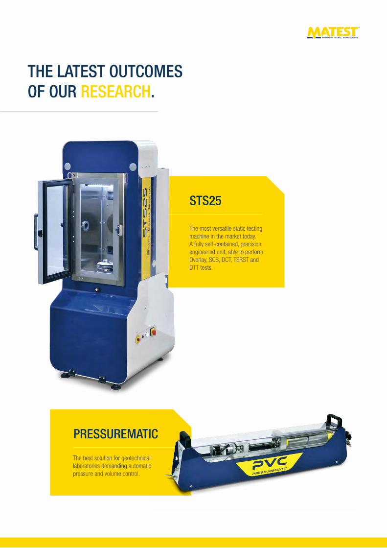
THE LATEST OUTCOMES OF OUR RESEARCH.
PRESSUREMATIC
The best solution for geotechnical laboratories demanding automatic pressure and volume control.
The most versatile static testing machine in the market today.A fully self-contained, precision engineered unit, able to perform Overlay, SCB, DCT, TSRST and DTT tests.
STS25

6
#GLOBALCUSTOMERS
A wide variety of customers, from research centers to general
contractors, geotechnical laboratories to asphalt, concrete and cement
manufacturers, government authorities and ministries to
professional consultants.
#GLOBALRANGE
More than 5,000 products, from basic equipment,
strictly in compliance with the latest standards and
security directives, to the most advanced system, in
order to serve research entities and test all building
industry materials.
#GLOBALMANYTIMES.
Matest brand’s global presence encompasses all sectors of material
testing, as witnessed by its widespread network of distributors and
agents, ready to satisfy the requirements of every kind of customer
on every continent.

A renewed, interactive web site makes consultation of our complete on-line catalogue
easier and quicker. In addition to the usual product search by code, description or
Standard, the new release also allows catalogue consultation by test type.
#GLOBALCOMMUNICATION
A first class technical assistance provided by a team of Product
Specialist, qualified in their specific field, and a solid network of
experienced distributors, trained to locally serve our customers.
#GLOBALSERVICE
#GLOBALPRESENCE
Strong participation in exhibitions, conferences and
international events in over 150 countries.
8
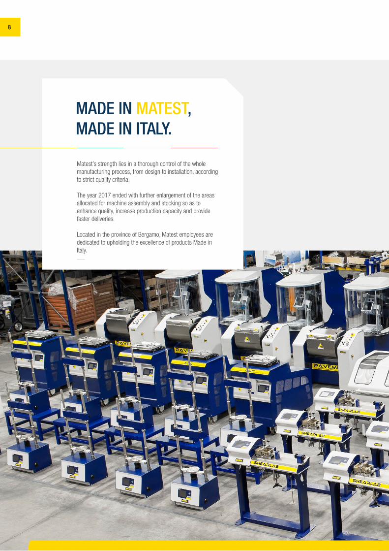
MADE IN MATEST,MADE IN ITALY.
Matest’s strength lies in a thorough control of the whole manufacturing process, from design to installation, according to strict quality criteria.
The year 2017 ended with further enlargement of the areas allocated for machine assembly and stocking so as to enhance quality, increase production capacity and provide faster deliveries.
Located in the province of Bergamo, Matest employees arededicated to upholding the excellence of products Made in Italy.
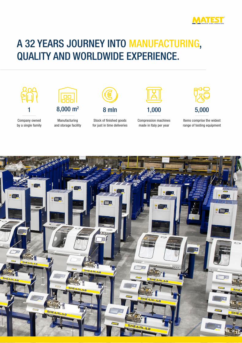
1
Company owned by a single family
Items comprise the widest range of testing equipment
Manufacturing and storage facility
Compression machines made in Italy per year
Stock of finished goodsfor just in time deliveries
1,0008 mln8,000 m2
A 32 YEARS JOURNEY INTO MANUFACTURING, QUALITY AND WORLDWIDE EXPERIENCE.
5,000
10
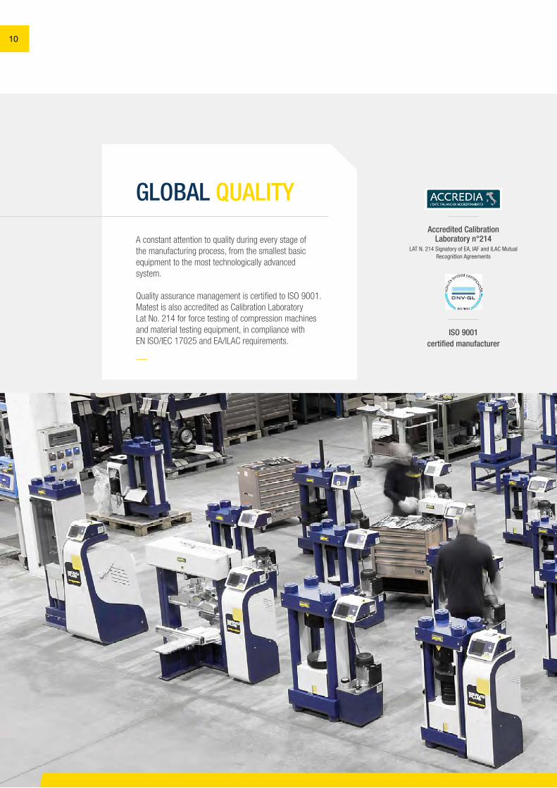
GLOBAL QUALITY
A constant attention to quality during every stage of the manufacturing process, from the smallest basic equipment to the most technologically advanced system.
Quality assurance management is certified to ISO 9001. Matest is also accredited as Calibration Laboratory Lat No. 214 for force testing of compression machines and material testing equipment, in compliance with EN ISO/IEC 17025 and EA/ILAC requirements.
Accredited Calibration Laboratory n°214
LAT N. 214 Signatory of EA, IAF and ILAC Mutual Recognition Agreements
ISO 9001 certified manufacturer
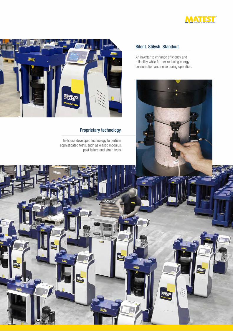
An inverter to enhance efficiency and reliability while further reducing energy consumption and noise during operation.
In-house developed technology to perform sophisticated tests, such as elastic modulus,
post failure and strain tests.
Silent. Stilysh. Standout.
Proprietary technology.
12
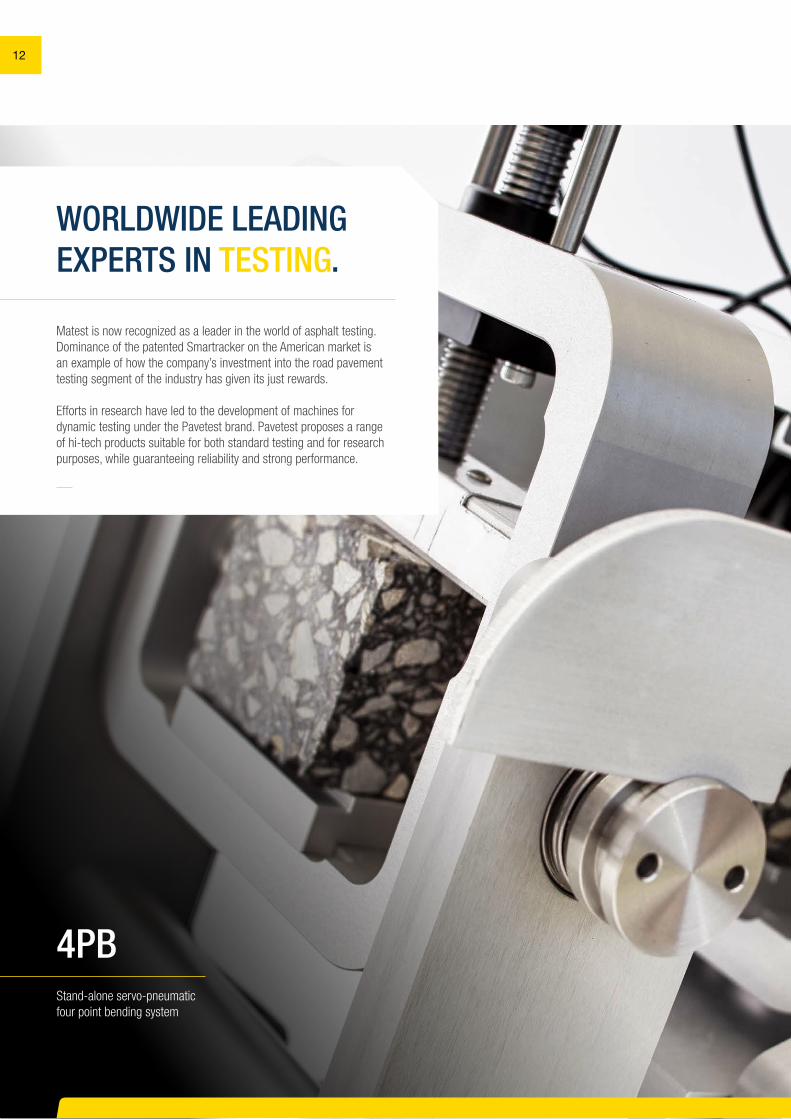
WORLDWIDE LEADING EXPERTS IN TESTING.
Matest is now recognized as a leader in the world of asphalt testing.Dominance of the patented Smartracker on the American market is an example of how the company’s investment into the road pavement testing segment of the industry has given its just rewards.
Efforts in research have led to the development of machines for dynamic testing under the Pavetest brand. Pavetest proposes a range of hi-tech products suitable for both standard testing and for research purposes, while guaranteeing reliability and strong performance.
Stand-alone servo-pneumatic four point bending system
4PB
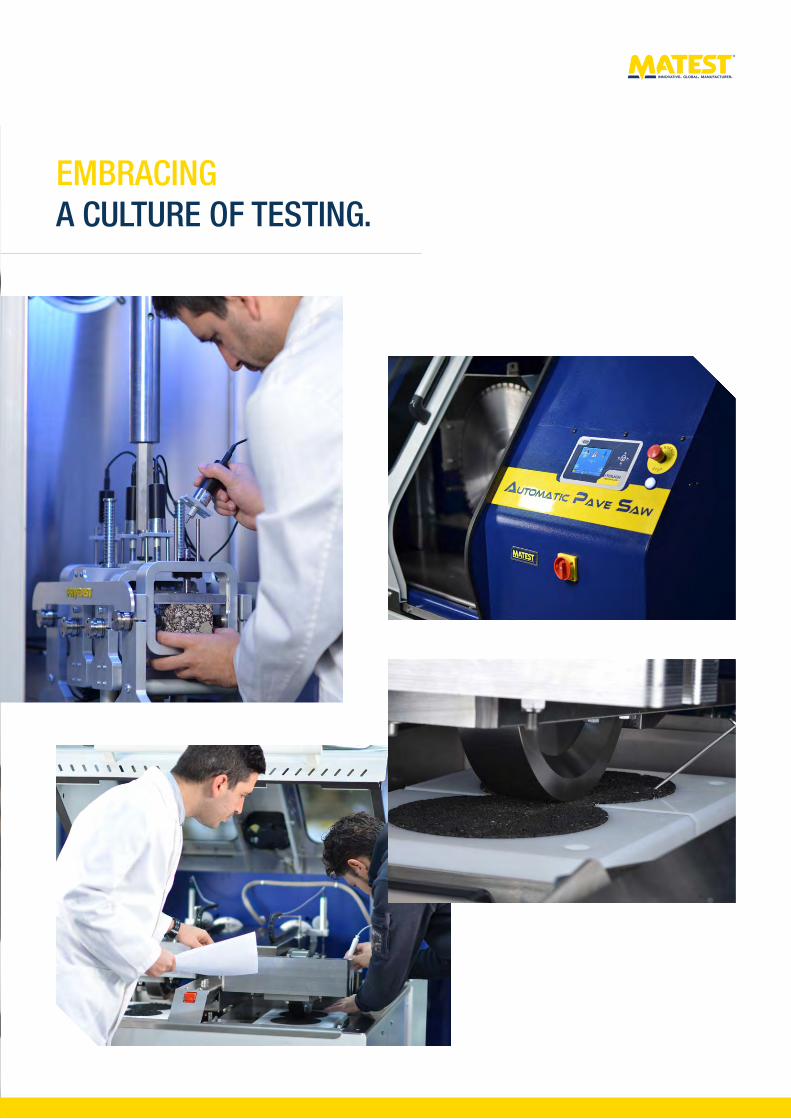
EMBRACING A CULTURE OF TESTING.
14
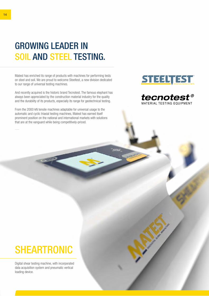
GROWING LEADER IN SOIL AND STEEL TESTING.
Matest has enriched its range of products with machines for performing tests on steel and soil. We are proud to welcome Steeltest, a new division dedicated to our range of universal testing machines.
And recently acquired is the historic brand Tecnotest. The famous elephant has always been appreciated by the construction material industry for the quality and the durability of its products, especially its range for geotechnical testing.
From the 2000 kN tensile machines adaptable for universal usage to the automatic and cyclic triaxial testing machines, Matest has earned itself prominent position on the national and international markets with solutions that are at the vanguard while being competitively-priced.
Digital shear testing machine, with incorporated data acquisition system and pneumatic vertical loading device.
SHEARTRONIC
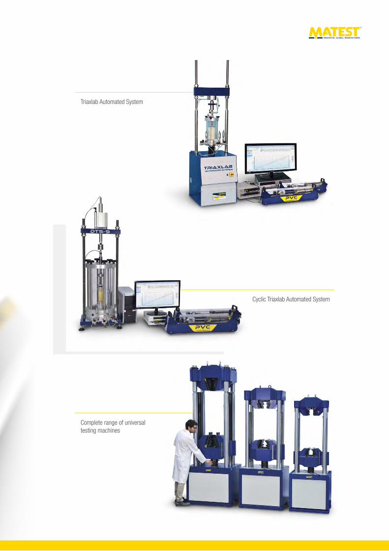
Triaxlab Automated System
Complete range of universal testing machines
Cyclic Triaxlab Automated System
SECTION A | AGGREGATES - ROCKS
MAIN FEATURES
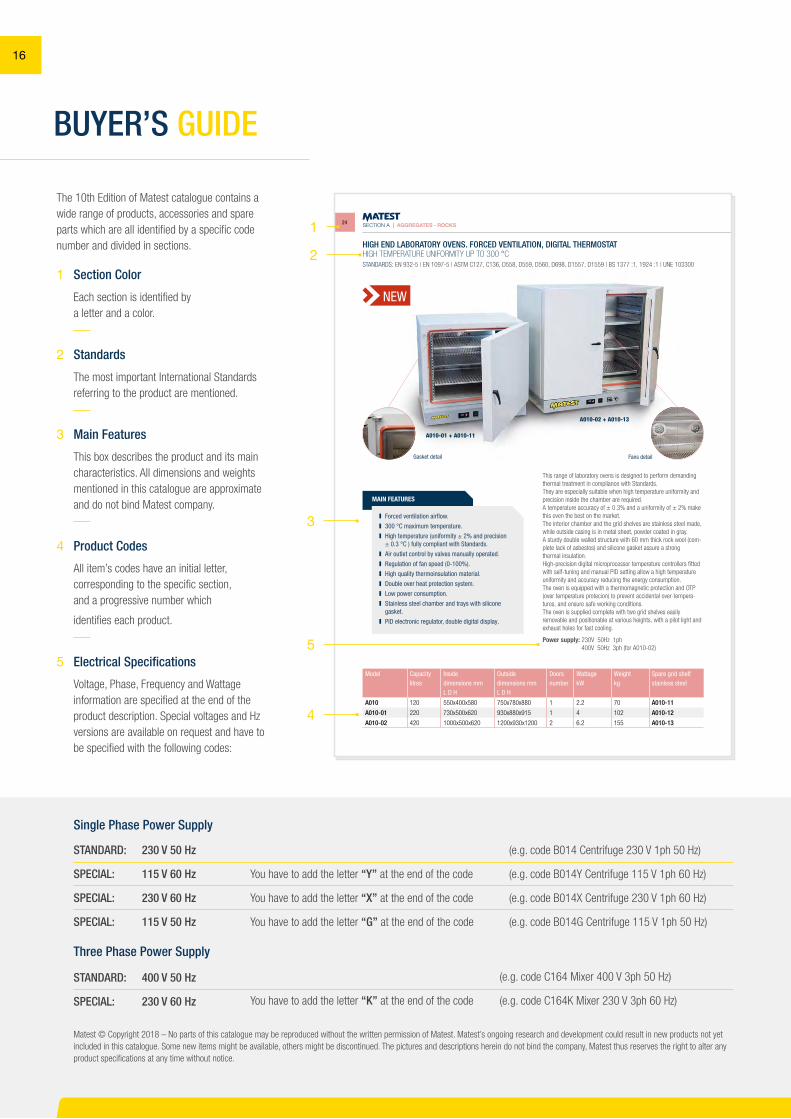
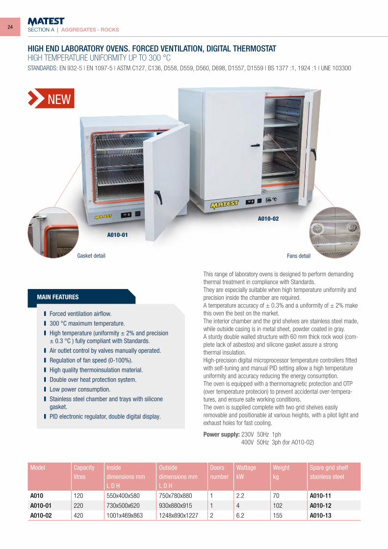
HIGH END LABORATORY OVENS. FORCED VENTILATION, DIGITAL THERMOSTATHIGH TEMPERATURE UNIFORMITY UP TO 300 °CSTANDARDS: EN 932-5 | EN 1097-5 | ASTM C127, C136, D558, D559, D560, D698, D1557, D1559 | BS 1377 :1, 1924 :1 | UNE 103300
This range of laboratory ovens is designed to perform demanding thermal treatment in compliance with Standards.They are especially suitable when high temperature uniformity and precision inside the chamber are required.A temperature accuracy of ± 0.3% and a uniformity of ± 2% make this oven the best on the market.The interior chamber and the grid shelves are stainless steel made, while outside casing is in metal sheet, powder coated in gray.A sturdy double walled structure with 60 mm thick rock wool (com-plete lack of asbestos) and silicone gasket assure a strongthermal insulation.High-precision digital microprocessor temperature controllers fitted with self-tuning and manual PID setting allow a high temperature uniformity and accuracy reducing the energy consumption.The oven is equipped with a thermomagnetic protection and OTP (over temperature protecion) to prevent accidental over-tempera-tures, and ensure safe working conditions.The oven is supplied complete with two grid shelves easily removable and positionable at various heights, with a pilot light and exhaust holes for fast cooling.
Power supply: 230V 50Hz 1ph 400V 50Hz 3ph (for A010-02)
Model Capacity Inside Outside Doors Wattage Weight Spare grid shelflitres dimensions mm dimensions mm number kW kg stainless steel
L D H L D H
A010 120 550x400x580 750x780x880 1 2.2 70 A010-11
A010-01 220 730x500x620 930x880x915 1 4 102 A010-12
A010-02 420 1000x500x620 1200x930x1200 2 6.2 155 A010-13
Forced ventilation airflow. 300 °C maximum temperature. High temperature (uniformity ± 2% and precision
± 0.3 °C ) fully compliant with Standards. Air outlet control by valves manually operated. Regulation of fan speed (0-100%). High quality thermoinsulation material. Double over heat protection system. Low power consumption. Stainless steel chamber and trays with silicone
gasket. PID electronic regulator, double digital display.
NEW
A010-01 + A010-11
Gasket detail Fans detail
A010-02 + A010-13
24
16
1
2
3
4
5
BUYER’S GUIDE
STANDARD:
SPECIAL:
SPECIAL:
SPECIAL:
230 V 50 Hz
115 V 60 Hz
230 V 60 Hz
115 V 50 Hz
(e.g. code B014 Centrifuge 230 V 1ph 50 Hz)
(e.g. code B014Y Centrifuge 115 V 1ph 60 Hz)
(e.g. code B014X Centrifuge 230 V 1ph 60 Hz)
(e.g. code B014G Centrifuge 115 V 1ph 50 Hz)
You have to add the letter “Y” at the end of the code
You have to add the letter “X” at the end of the code
You have to add the letter “G” at the end of the code
You have to add the letter “K” at the end of the code
STANDARD:
SPECIAL:
400 V 50 Hz
230 V 60 Hz
(e.g. code C164 Mixer 400 V 3ph 50 Hz)
(e.g. code C164K Mixer 230 V 3ph 60 Hz)
The 10th Edition of Matest catalogue contains a wide range of products, accessories and spare parts which are all identified by a specific code number and divided in sections.
Voltage, Phase, Frequency and Wattage information are specified at the end of the product description. Special voltages and Hz versions are available on request and have to be specified with the following codes:
5 Electrical Specifications
Matest © Copyright 2018 – No parts of this catalogue may be reproduced without the written permission of Matest. Matest’s ongoing research and development could result in new products not yet included in this catalogue. Some new items might be available, others might be discontinued. The pictures and descriptions herein do not bind the company, Matest thus reserves the right to alter any product specifications at any time without notice.
Single Phase Power Supply
Three Phase Power Supply
Each section is identified by a letter and a color.
1 Section Color
The most important International Standards referring to the product are mentioned.
2 Standards
This box describes the product and its main characteristics. All dimensions and weights mentioned in this catalogue are approximate and do not bind Matest company.
3 Main Features
All item’s codes have an initial letter, corresponding to the specific section, and a progressive number which
identifies each product.
4 Product Codes
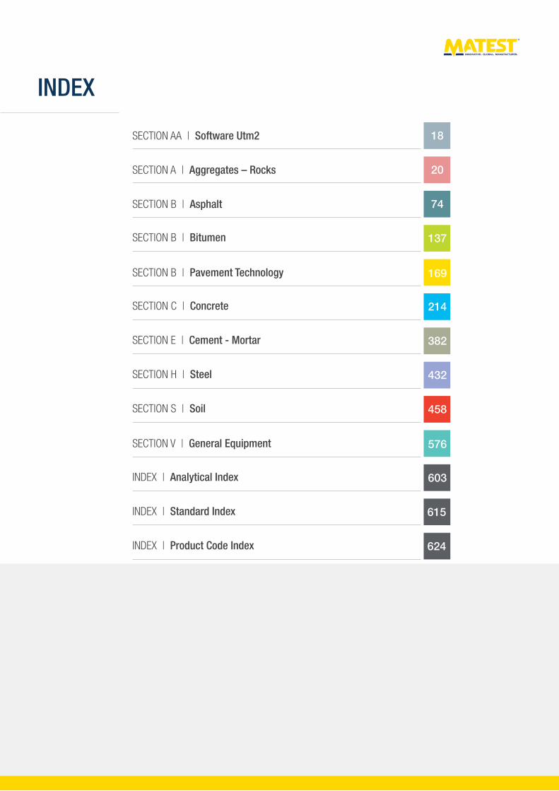
INDEX
SECTION AA | Software Utm2
SECTION A | Aggregates – Rocks
SECTION B | Asphalt
SECTION B | Bitumen
SECTION B | Pavement Technology
SECTION C | Concrete
SECTION E | Cement - Mortar
SECTION H | Steel
SECTION S | Soil
SECTION V | General Equipment
INDEX | Standard Index
INDEX | Analytical Index
INDEX | Product Code Index
18
20
74
137
169
214
382
432
458
576
603
615
624
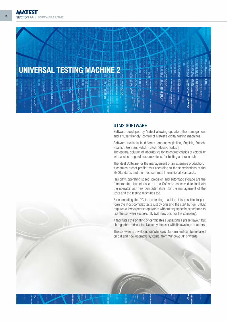
SECTION AA | SOFTWARE UTM2
UTM2 SOFTWARESoftware developed by Matest allowing operators the management and a “User friendly” control of Matest’s digital testing machines.
Software available in different languages (Italian, English, French, Spanish, German, Polish, Czech, Slovak, Turkish).The optimal solution of laboratories for its characteristics of versatility with a wide range of customizations, for testing and research.
The ideal Software for the management of an extensive production. It contains preset profile tests according to the specifications of the EN Standards and the most common International Standards.
Flexibility, operating speed, precision and automatic storage are the fundamental characteristics of the Software conceived to facilitate the operator with few computer skills, for the management of the tests and the testing machines too.
By connecting the PC to the testing machine it is possible to per-form the most complex tests just by pressing the start button. UTM2 requires a low expertise operators without any specific experience to use the software successfully (with low cost for the company).
It facilitates the printing of certificates suggesting a preset layout but changeable and customizable by the user with its own logo or others.
The software is developed on Windows platform and can be installed on old and new operative systems, from Windows XP onwards.
UNIVERSAL TESTING MACHINE 2
18
SECTION AA | SOFTWARE UTM2
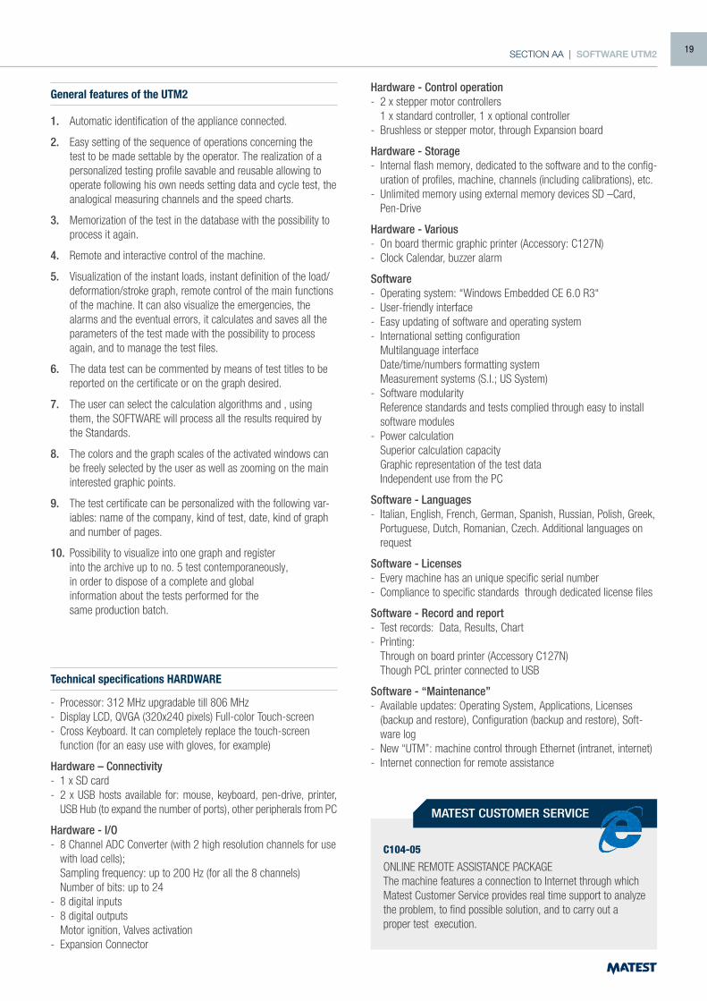
General features of the UTM2
1. Automatic identification of the appliance connected.
2. Easy setting of the sequence of operations concerning the test to be made settable by the operator. The realization of a personalized testing profile savable and reusable allowing to operate following his own needs setting data and cycle test, the analogical measuring channels and the speed charts.
3. Memorization of the test in the database with the possibility to process it again.
4. Remote and interactive control of the machine.
5. Visualization of the instant loads, instant definition of the load/deformation/stroke graph, remote control of the main functions of the machine. It can also visualize the emergencies, the alarms and the eventual errors, it calculates and saves all the parameters of the test made with the possibility to process again, and to manage the test files.
6. The data test can be commented by means of test titles to be reported on the certificate or on the graph desired.
7. The user can select the calculation algorithms and , using them, the SOFTWARE will process all the results required by the Standards.
8. The colors and the graph scales of the activated windows can be freely selected by the user as well as zooming on the main interested graphic points.
9. The test certificate can be personalized with the following var-iables: name of the company, kind of test, date, kind of graph and number of pages.
10. Possibility to visualize into one graph and register into the archive up to no. 5 test contemporaneously, in order to dispose of a complete and global information about the tests performed for the same production batch.
Technical specifications HARDWARE
- Processor: 312 MHz upgradable till 806 MHz- Display LCD, QVGA (320x240 pixels) Full-color Touch-screen- Cross Keyboard. It can completely replace the touch-screen
function (for an easy use with gloves, for example)
Hardware – Connectivity- 1 x SD card- 2 x USB hosts available for: mouse, keyboard, pen-drive, printer,
USB Hub (to expand the number of ports), other peripherals from PC
Hardware - I/O- 8 Channel ADC Converter (with 2 high resolution channels for use
with load cells); Sampling frequency: up to 200 Hz (for all the 8 channels) Number of bits: up to 24 - 8 digital inputs- 8 digital outputs Motor ignition, Valves activation- Expansion Connector
C104-05
ONLINE REMOTE ASSISTANCE PACKAGEThe machine features a connection to Internet through which Matest Customer Service provides real time support to analyze the problem, to find possible solution, and to carry out a proper test execution.
Hardware - Control operation- 2 x stepper motor controllers 1 x standard controller, 1 x optional controller- Brushless or stepper motor, through Expansion board
Hardware - Storage- Internal flash memory, dedicated to the software and to the config-
uration of profiles, machine, channels (including calibrations), etc.- Unlimited memory using external memory devices SD –Card,
Pen-Drive
Hardware - Various- On board thermic graphic printer (Accessory: C127N)- Clock Calendar, buzzer alarm
Software- Operating system: “Windows Embedded CE 6.0 R3“- User-friendly interface- Easy updating of software and operating system - International setting configuration Multilanguage interface Date/time/numbers formatting system Measurement systems (S.I.; US System) - Software modularity Reference standards and tests complied through easy to install
software modules- Power calculation Superior calculation capacity Graphic representation of the test data Independent use from the PC
Software - Languages- Italian, English, French, German, Spanish, Russian, Polish, Greek,
Portuguese, Dutch, Romanian, Czech. Additional languages on request
Software - Licenses- Every machine has an unique specific serial number- Compliance to specific standards through dedicated license files
Software - Record and report- Test records: Data, Results, Chart- Printing: Through on board printer (Accessory C127N) Though PCL printer connected to USB
Software - “Maintenance”- Available updates: Operating System, Applications, Licenses
(backup and restore), Configuration (backup and restore), Soft-ware log
- New “UTM”: machine control through Ethernet (intranet, internet)- Internet connection for remote assistance
MATEST CUSTOMER SERVICE
19
SECTION AAGGREGATES - ROCKS
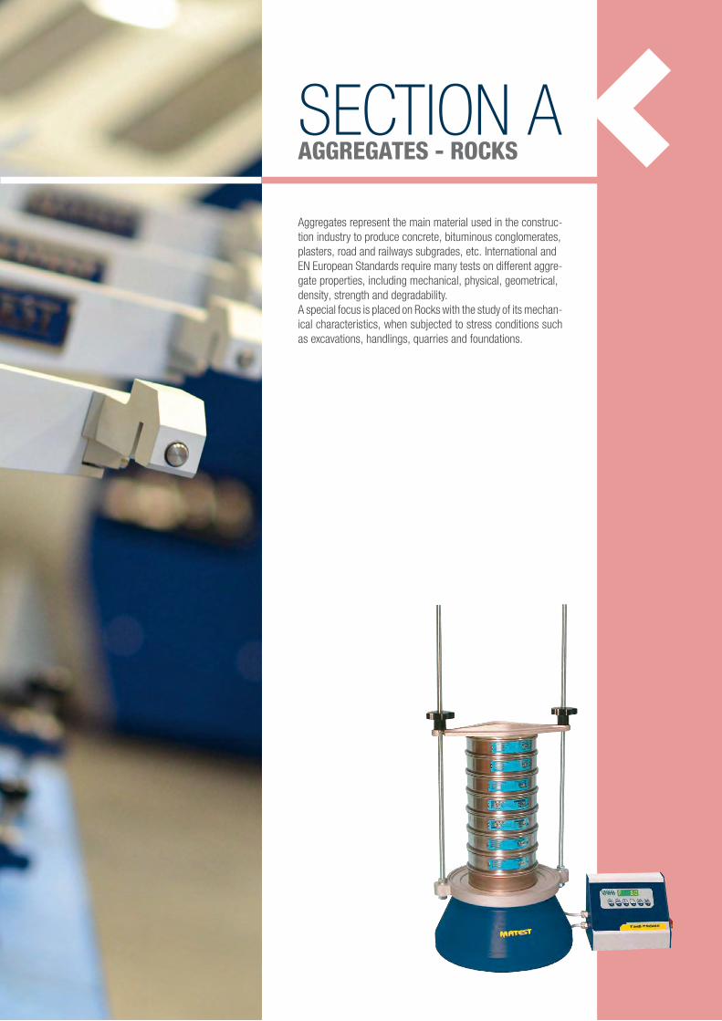
Aggregates represent the main material used in the construc-tion industry to produce concrete, bituminous conglomerates,plasters, road and railways subgrades, etc. International andEN European Standards require many tests on different aggre-gate properties, including mechanical, physical, geometrical,density, strength and degradability.A special focus is placed on Rocks with the study of its mechan-ical characteristics, when subjected to stress conditions such as excavations, handlings, quarries and foundations.
SECTION A | AGGREGATES - ROCKS
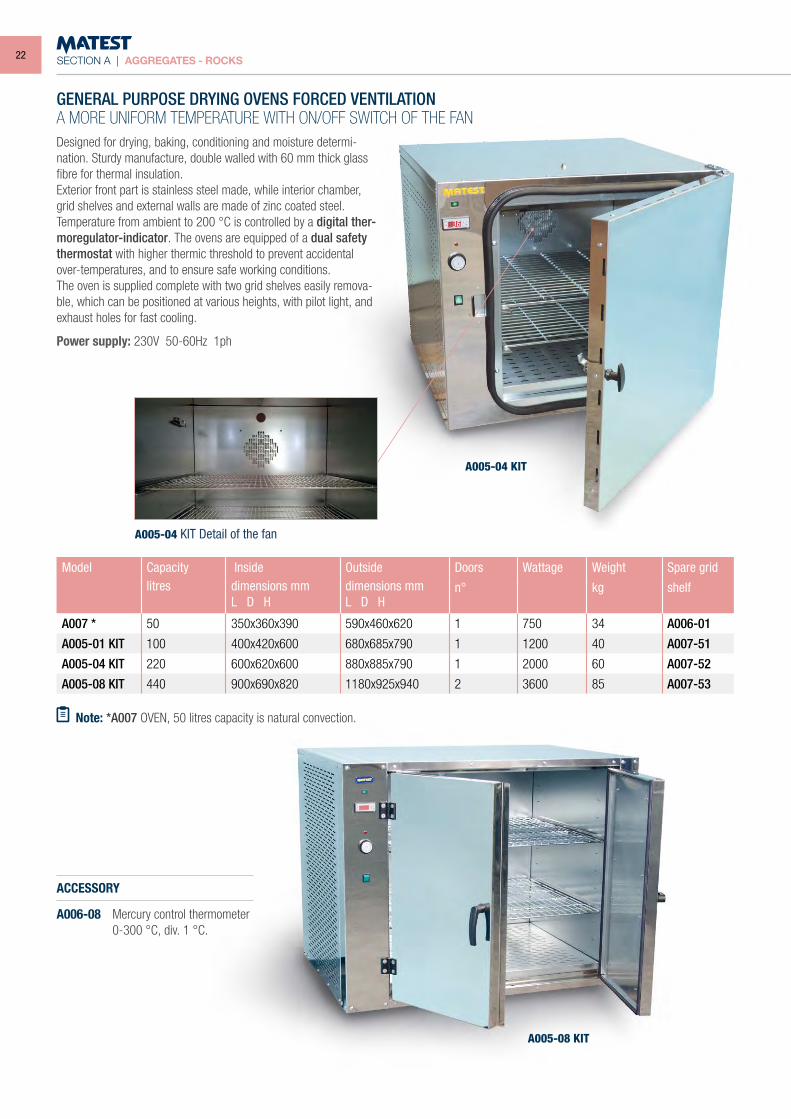
Designed for drying, baking, conditioning and moisture determi-nation. Sturdy manufacture, double walled with 60 mm thick glass fibre for thermal insulation.Exterior front part is stainless steel made, while interior chamber, grid shelves and external walls are made of zinc coated steel.Temperature from ambient to 200 °C is controlled by a digital ther-moregulator-indicator. The ovens are equipped of a dual safety thermostat with higher thermic threshold to prevent accidental over-temperatures, and to ensure safe working conditions.The oven is supplied complete with two grid shelves easily remova-ble, which can be positioned at various heights, with pilot light, and exhaust holes for fast cooling.
Power supply: 230V 50-60Hz 1ph
GENERAL PURPOSE DRYING OVENS FORCED VENTILATIONA MORE UNIFORM TEMPERATURE WITH ON/OFF SWITCH OF THE FAN
Model Capacity Inside Outside Doors Wattage Weight Spare gridlitres dimensions mm
L D Hdimensions mmL D H
n° kg shelf
A007 * 50 350x360x390 590x460x620 1 750 34 A006-01
A005-01 KIT 100 400x420x600 680x685x790 1 1200 40 A007-51
A005-04 KIT 220 600x620x600 880x885x790 1 2000 60 A007-52
A005-08 KIT 440 900x690x820 1180x925x940 2 3600 85 A007-53
Note: *A007 OVEN, 50 litres capacity is natural convection.
A005-04 KIT
A005-08 KIT
A005-04 KIT Detail of the fan
ACCESSORY
A006-08 Mercury control thermometer 0-300 °C, div. 1 °C.
22
SECTION A | AGGREGATES - ROCKS
Model Capacity Inside Outside Doors Wattage Weight Spare gridlitres dimensions mm
L D Hdimensions mmL D H
n° kg shelf steel
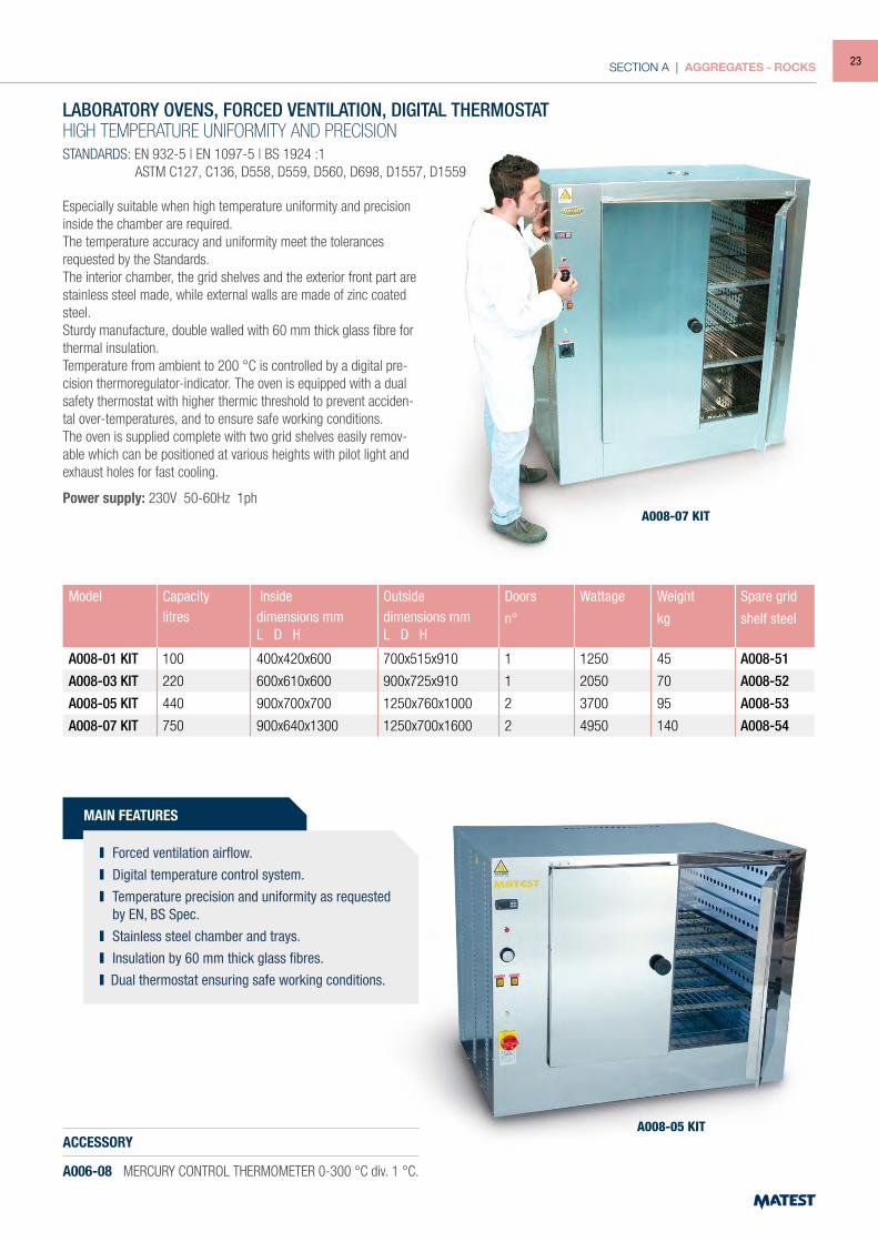
A008-01 KIT 100 400x420x600 700x515x910 1 1250 45 A008-51
A008-03 KIT 220 600x610x600 900x725x910 1 2050 70 A008-52
A008-05 KIT 440 900x700x700 1250x760x1000 2 3700 95 A008-53
A008-07 KIT 750 900x640x1300 1250x700x1600 2 4950 140 A008-54
A008-05 KIT
A008-07 KIT
LABORATORY OVENS, FORCED VENTILATION, DIGITAL THERMOSTAT HIGH TEMPERATURE UNIFORMITY AND PRECISIONSTANDARDS: EN 932-5 | EN 1097-5 | BS 1924 :1 ASTM C127, C136, D558, D559, D560, D698, D1557, D1559
ACCESSORY
A006-08 MERCURY CONTROL THERMOMETER 0-300 °C div. 1 °C.
Especially suitable when high temperature uniformity and precision inside the chamber are required.The temperature accuracy and uniformity meet the tolerances requested by the Standards.The interior chamber, the grid shelves and the exterior front part are stainless steel made, while external walls are made of zinc coated steel.Sturdy manufacture, double walled with 60 mm thick glass fibre for thermal insulation.Temperature from ambient to 200 °C is controlled by a digital pre-cision thermoregulator-indicator. The oven is equipped with a dual safety thermostat with higher thermic threshold to prevent acciden-tal over-temperatures, and to ensure safe working conditions.The oven is supplied complete with two grid shelves easily remov-able which can be positioned at various heights with pilot light and exhaust holes for fast cooling.
Power supply: 230V 50-60Hz 1ph
MAIN FEATURES
Forced ventilation airflow. Digital temperature control system. Temperature precision and uniformity as requested
by EN, BS Spec. Stainless steel chamber and trays. Insulation by 60 mm thick glass fibres. Dual thermostat ensuring safe working conditions.
23
SECTION A | AGGREGATES - ROCKS
MAIN FEATURES
HIGH END LABORATORY OVENS. FORCED VENTILATION, DIGITAL THERMOSTATHIGH TEMPERATURE UNIFORMITY UP TO 300 °CSTANDARDS: EN 932-5 | EN 1097-5 | ASTM C127, C136, D558, D559, D560, D698, D1557, D1559 | BS 1377 :1, 1924 :1 | UNE 103300
This range of laboratory ovens is designed to perform demanding thermal treatment in compliance with Standards.They are especially suitable when high temperature uniformity and precision inside the chamber are required.A temperature accuracy of ± 0.3% and a uniformity of ± 2% make this oven the best on the market.The interior chamber and the grid shelves are stainless steel made, while outside casing is in metal sheet, powder coated in gray.A sturdy double walled structure with 60 mm thick rock wool (com-plete lack of asbestos) and silicone gasket assure a strongthermal insulation.High-precision digital microprocessor temperature controllers fitted with self-tuning and manual PID setting allow a high temperature uniformity and accuracy reducing the energy consumption.The oven is equipped with a thermomagnetic protection and OTP (over temperature protecion) to prevent accidental over-tempera-tures, and ensure safe working conditions.The oven is supplied complete with two grid shelves easily removable and positionable at various heights, with a pilot light and exhaust holes for fast cooling.
Power supply: 230V 50Hz 1ph 400V 50Hz 3ph (for A010-02)
Model Capacity Inside Outside Doors Wattage Weight Spare grid shelflitres dimensions mm dimensions mm number kW kg stainless steel
L D H L D H
A010 120 550x400x580 750x780x880 1 2.2 70 A010-11
A010-01 220 730x500x620 930x880x915 1 4 102 A010-12
A010-02 420 1001x469x863 1248x890x1227 2 6.2 155 A010-13
Forced ventilation airflow. 300 °C maximum temperature. High temperature (uniformity ± 2% and precision
± 0.3 °C ) fully compliant with Standards. Air outlet control by valves manually operated. Regulation of fan speed (0-100%). High quality thermoinsulation material. Double over heat protection system. Low power consumption. Stainless steel chamber and trays with silicone
gasket. PID electronic regulator, double digital display.
NEW
A010-01
Gasket detail Fans detail
A010-02
24
SECTION A | AGGREGATES - ROCKS
A022N
A024N
A023-01N
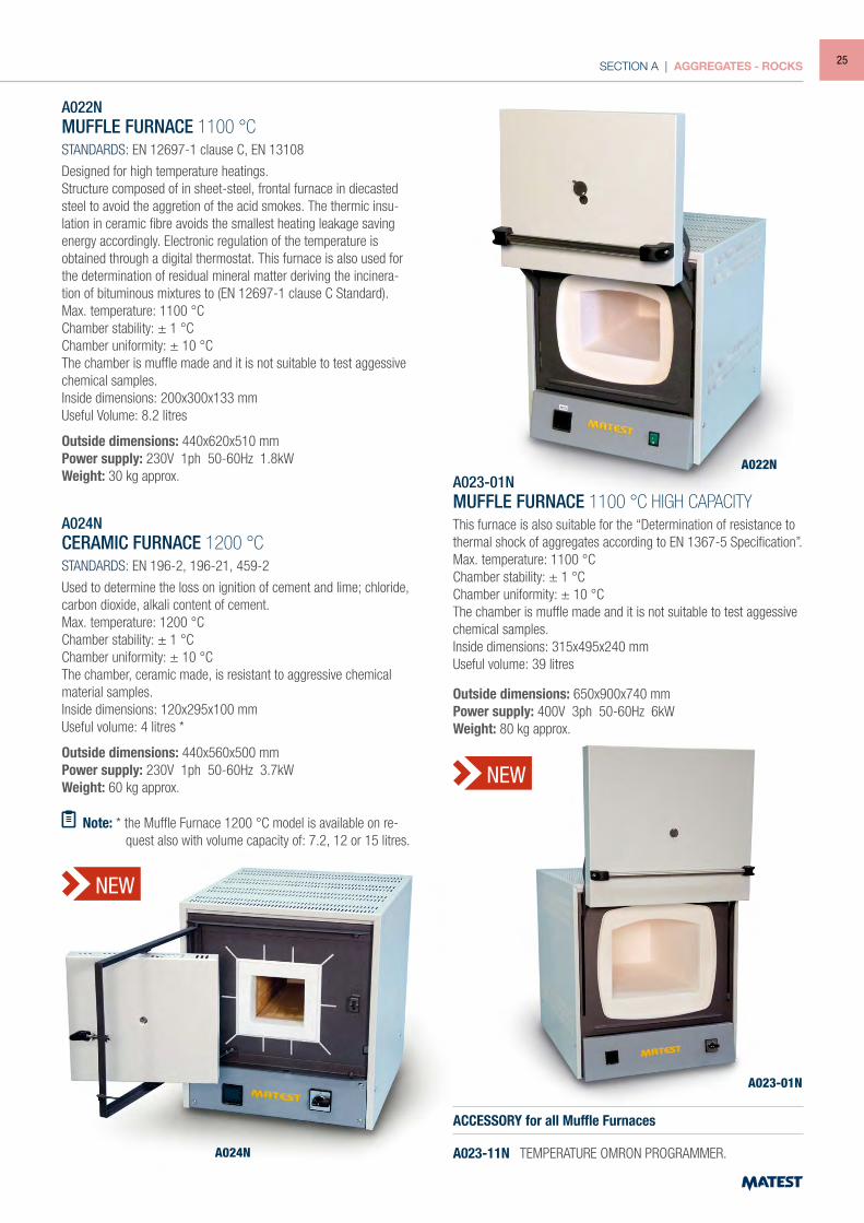
A022NMUFFLE FURNACE 1100 °CSTANDARDS: EN 12697-1 clause C, EN 13108
Designed for high temperature heatings.Structure composed of in sheet-steel, frontal furnace in diecasted steel to avoid the aggretion of the acid smokes. The thermic insu-lation in ceramic fibre avoids the smallest heating leakage saving energy accordingly. Electronic regulation of the temperature is obtained through a digital thermostat. This furnace is also used for the determination of residual mineral matter deriving the incinera-tion of bituminous mixtures to (EN 12697-1 clause C Standard).Max. temperature: 1100 °CChamber stability: ± 1 °CChamber uniformity: ± 10 °CThe chamber is muffle made and it is not suitable to test aggessive chemical samples.Inside dimensions: 200x300x133 mmUseful Volume: 8.2 litres
Outside dimensions: 440x620x510 mmPower supply: 230V 1ph 50-60Hz 1.8kWWeight: 30 kg approx.
A024N CERAMIC FURNACE 1200 °CSTANDARDS: EN 196-2, 196-21, 459-2
Used to determine the loss on ignition of cement and lime; chloride, carbon dioxide, alkali content of cement.Max. temperature: 1200 °CChamber stability: ± 1 °CChamber uniformity: ± 10 °CThe chamber, ceramic made, is resistant to aggressive chemical material samples.Inside dimensions: 120x295x100 mmUseful volume: 4 litres *
Outside dimensions: 440x560x500 mmPower supply: 230V 1ph 50-60Hz 3.7kWWeight: 60 kg approx.
Note: * the Muffle Furnace 1200 °C model is available on re-quest also with volume capacity of: 7.2, 12 or 15 litres.
A023-01NMUFFLE FURNACE 1100 °C HIGH CAPACITYThis furnace is also suitable for the “Determination of resistance to thermal shock of aggregates according to EN 1367-5 Specification”.Max. temperature: 1100 °CChamber stability: ± 1 °CChamber uniformity: ± 10 °CThe chamber is muffle made and it is not suitable to test aggessive chemical samples.Inside dimensions: 315x495x240 mmUseful volume: 39 litres
Outside dimensions: 650x900x740 mmPower supply: 400V 3ph 50-60Hz 6kWWeight: 80 kg approx.
ACCESSORY for all Muffle Furnaces
A023-11N TEMPERATURE OMRON PROGRAMMER.
NEW
NEW
25

SECTION A | AGGREGATES - ROCKS
C313NTEMPERATURE AND HUMIDITY CONTROLLEDCABINET 535 LITRES CAPACITYSTANDARDS: EN 196-1, EN 1367-1, EN 12390-2, EN 12390-9
Designed for all research and control laboratories to perform: coldand/or hot temperature measurement at controlled humidity condi-tions, any kind of freezing/thawing tests and accelerated curingtests. Used to cure concrete (EN 12390-2) and cement specimens(EN 196-1) and analyze the behavior to freezing and thawing ofaggregates (EN 1367-1) and concrete (EN 12390-9).Internal and external frame is made of stainless steel AISI 304.Polyurethane insulation: 60 mm thick.Internal ventilation.Door with 180° opening angle, equipped magnetic gasket and integrated heater against freezing.Shelves can be taken off and adjustable in height; adjustable feet.Temperature and humidity sensors wall mounted inside cabinetThe cabinet is supplied with a two stage filter; mechanic and mixed ionic/cationic resins. It works with demineralized, softened waters, or tap water with hardness rate up to 300 ptm assuring an excellent functioning along the time.Equipped with microprocessor temperature/humidity controller with integrated cycles multiple segments programmer.
panel mount 144×130mm format 5" color graphic display 50 programs with 100 segments and real time clock Logging function with PC interface (optional)
Visual alarm for minimum and maximum temperatureSupplied complete with 3 adjustable shelves suitable to withstand weights up to 40 kg
Inside dimensions: 590x670x1360 mmOverall dimensions: 710x820x2080 mmPower supply: 230V 1ph 50-60Hz 2570WWeight: 170 kg approx.
C313-01NTEMPERATURE AND HUMIDITY CONTROLLED CABINET 1200 LITRES CAPACITYSame as C313N model, but with an internal capacity of 1200 liters.Internal ventilation.Door with 180° opening angle, equipped magnetic gasket and integrated heater against freezing.Shelves can be taken off and adjustable in height; adjustable feet.Temperature and humidity sensors wall mounted inside cabinetVisual alarm for minimum and maximum temperatureSupplied complete with 6 adjustable shelves suitable to suitable to withstand weights up to 40kg.
Inside dimensions: 1300x670x1360 mmOverall dimensions: 1500x820x2080 mmPower supply: 230V 1ph 50-60Hz 2900WWeight: 230 kg approx.
MAIN FEATURES
Real-Time display of temperature and humidity parameters.
High quality thermal insulation material. Temperature control from -30 to +70 °C with high
stability (± 0.15 °C). Humidity control from 20% to 95% with ± 5%
stability and ± 1% accuracy (within temperature +10 to +70 °C).
CLIMATIC CABINETSThe climatic cabinet is available in two versions:
C313N Temperature and humidity controlled from -30 to +70 °C and 20% to 95% respectively for testing concrete
(EN 12390-2), cement (EN 196-1), aggregates (EN 1367-1) and many other applications.
C316N Only temperature controlled from -30 to +70 °C for the determinations of the behavior and resultance to freezing
and thawing of aggregates (EN 1367-1) and different other applications on concrete and building materials.
NEW
C313N
26
SECTION A | AGGREGATES - ROCKS
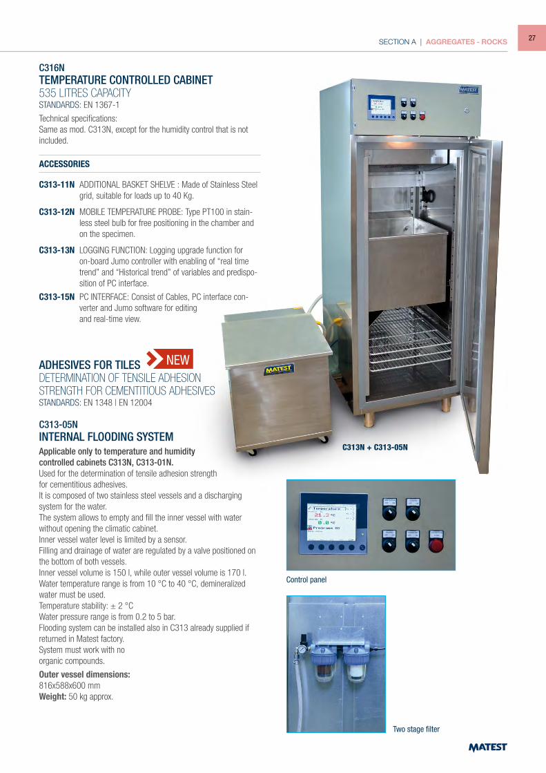
C316NTEMPERATURE CONTROLLED CABINET535 LITRES CAPACITYSTANDARDS: EN 1367-1
Technical specifications:Same as mod. C313N, except for the humidity control that is not included.
ACCESSORIES
C313-11N ADDITIONAL BASKET SHELVE : Made of Stainless Steel grid, suitable for loads up to 40 Kg.
C313-12N MOBILE TEMPERATURE PROBE: Type PT100 in stain-less steel bulb for free positioning in the chamber and on the specimen.
C313-13N LOGGING FUNCTION: Logging upgrade function for on-board Jumo controller with enabling of “real time trend” and “Historical trend” of variables and predispo-sition of PC interface.
C313-15N PC INTERFACE: Consist of Cables, PC interface con-verter and Jumo software for editing
and real-time view.
ADHESIVES FOR TILESDETERMINATION OF TENSILE ADHESIONSTRENGTH FOR CEMENTITIOUS ADHESIVESSTANDARDS: EN 1348 | EN 12004
C313-05NINTERNAL FLOODING SYSTEMApplicable only to temperature and humiditycontrolled cabinets C313N, C313-01N.Used for the determination of tensile adhesion strength for cementitious adhesives.It is composed of two stainless steel vessels and a discharging system for the water.The system allows to empty and fill the inner vessel with water without opening the climatic cabinet.Inner vessel water level is limited by a sensor.Filling and drainage of water are regulated by a valve positioned on the bottom of both vessels.Inner vessel volume is 150 l, while outer vessel volume is 170 l.Water temperature range is from 10 °C to 40 °C, demineralized water must be used.Temperature stability: ± 2 °CWater pressure range is from 0.2 to 5 bar.Flooding system can be installed also in C313 already supplied if returned in Matest factory.System must work with noorganic compounds.
Outer vessel dimensions:816x588x600 mmWeight: 50 kg approx.
C313N + C313-05N
NEW
Two stage filter
Control panel
27
SECTION A | AGGREGATES - ROCKS
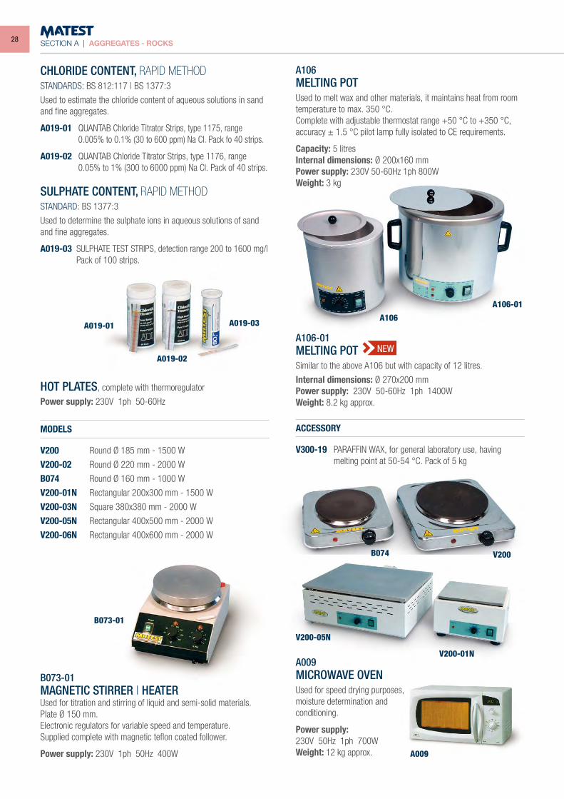
CHLORIDE CONTENT, RAPID METHODSTANDARDS: BS 812:117 | BS 1377:3
Used to estimate the chloride content of aqueous solutions in sand and fine aggregates.
A019-01 QUANTAB Chloride Titrator Strips, type 1175, range 0.005% to 0.1% (30 to 600 ppm) Na Cl. Pack fo 40 strips.
A019-02 QUANTAB Chloride Titrator Strips, type 1176, range 0.05% to 1% (300 to 6000 ppm) Na Cl. Pack of 40 strips.
SULPHATE CONTENT, RAPID METHODSTANDARD: BS 1377:3
Used to determine the sulphate ions in aqueous solutions of sand and fine aggregates.
A019-03 SULPHATE TEST STRIPS, detection range 200 to 1600 mg/l Pack of 100 strips.
HOT PLATES, complete with thermoregulator
Power supply: 230V 1ph 50-60Hz
MODELS
V200 Round Ø 185 mm - 1500 W
V200-02 Round Ø 220 mm - 2000 W
B074 Round Ø 160 mm - 1000 W
V200-01N Rectangular 200x300 mm - 1500 W
V200-03N Square 380x380 mm - 2000 W
V200-05N Rectangular 400x500 mm - 2000 W
V200-06N Rectangular 400x600 mm - 2000 W
B073-01MAGNETIC STIRRER | HEATERUsed for titration and stirring of liquid and semi-solid materials. Plate Ø 150 mm.Electronic regulators for variable speed and temperature.Supplied complete with magnetic teflon coated follower.
Power supply: 230V 1ph 50Hz 400W
A106MELTING POTUsed to melt wax and other materials, it maintains heat from room temperature to max. 350 °C.Complete with adjustable thermostat range +50 °C to +350 °C, accuracy ± 1.5 °C pilot lamp fully isolated to CE requirements.
Capacity: 5 litresInternal dimensions: Ø 200x160 mmPower supply: 230V 50-60Hz 1ph 800WWeight: 3 kg
A106-01MELTING POTSimilar to the above A106 but with capacity of 12 litres.
Internal dimensions: Ø 270x200 mmPower supply: 230V 50-60Hz 1ph 1400WWeight: 8.2 kg approx.
ACCESSORY
V300-19 PARAFFIN WAX, for general laboratory use, having melting point at 50-54 °C. Pack of 5 kg
A009MICROWAVE OVENUsed for speed drying purposes,moisture determination andconditioning.
Power supply:230V 50Hz 1ph 700WWeight: 12 kg approx.
A019-01
A019-02
B073-01
A106-01
A106
B074
A009
V200-05N
V200-01N
V200
A019-03
NEW
28
SECTION A | AGGREGATES - ROCKS
A028
A028-02
A028-11
A025 KIT
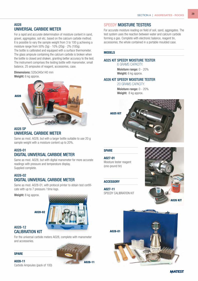
A028UNIVERSAL CARBIDE METERFor a rapid and accurate determination of moisture content in sand, gravel, aggregates, soil etc, based on the calcium carbide method. It is possible to vary the sample weight from 3 to 100 g achieving a moisture range from 50% (3g) - 10% (20g) - 2% (100g).The bottle is calibrated and equipped with a surface thermometer.The glass ampoule containing the calcium carbide is broken when the bottle is closed and shaken, granting better accuracy to the test.The instrument comprises the testing bottle with manometer, small balance, 25 ampoules of reagent, accessories, case.
Dimensions: 520x340x140 mmWeight: 6 kg approx.
A028 SPUNIVERSAL CARBIDE METERSame as mod. A028, but with a larger bottle suitable to use 20 g sample weight with a moisture content up to 20%.
A028-01DIGITAL UNIVERSAL CARBIDE METERSame as mod. A028, but with digital manometer for more accurate readings with pressure and temperature display.Supplied complete.
A028-02DIGITAL UNIVERSAL CARBIDE METERSame as mod. A028-01, with protocol printer to obtain test certifi-cate with up to 7 pressure / time logs.
Weight: 8 kg approx.
A028-12CALIBRATION KITFor the universal carbide meters A028, complete with manometer and accessories.
SPARE
A028-11Carbide Ampoules (pack of 100)
SPEEDY MOISTURE TESTERSFor accurate moisture reading on field of soil, sand, aggregates. The test system uses the reaction between water and calcium carbide forming a gas. Complete with electronic balance, reagent tin, accessories; the whole contained in a portable moulded case.
MODELS
A025 KIT SPEEDY MOISTURE TESTER 6 GRAMS CAPACITY. Moisture range: 0 - 20% Weight: 6 kg approx.
A026 KIT SPEEDY MOISTURE TESTER 20 GRAMS CAPACITY. Moisture range: 0 - 20% Weight: 8 kg approx.
SPARE
A027-01Moisture tester reagent (one-pound tin)
ACCESSORY
A027-11SPEEDY CALIBRATION KIT
A026 KIT
A028-01
29
SECTION A | AGGREGATES - ROCKS
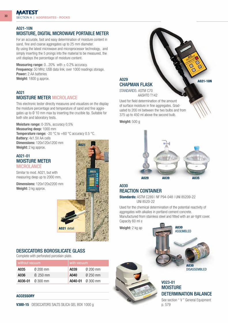
A021-10NMOISTURE, DIGITAL MICROWAVE PORTABLE METERFor an accurate, fast and easy determination of moisture content in sand, fine and coarse aggregates up to 25 mm diameter.By using the latest microwave and microprocessor technology, and simply inserting the 5 prongs into the material to be measured, the unit displays the percentage of moisture content.
Measuring range: 0...20% with ± 0.2% accuracy.Frequency: 50 MHz; USB data link; over 1000 readings storage.Power: 2 AA batteriesWeight: 1800 g approx.
A021MOISTURE METER MICROLANCEThis electronic tester directly measures and visualizes on the display the moisture percentage and temperature of sand and fine aggre-gates up to Ø 10 mm max by inserting the crucible tip. Suitable for both site and laboratory tests.
Moisture range: 0-35%, accuracy 0.5%Measuring deep: 1000 mmTemperature range: -20 °C to +60 °C accuracy 0.5 °C.Battery: 4x1.5V AA cellsDimensions: 120x120x1200 mmWeight: 2 kg approx.
A021-01MOISTURE METERMICROLANCESimilar to mod. A021, but withmeasuring deep up to 2000 mm.
Dimensions: 120x120x2200 mmWeight: 3 kg approx.
DESICCATORS BOROSILICATE GLASSComplete with perforated porcelain plate.
ACCESSORY
V300-15 DESICCATORS SALTS SILICA GEL BOX 1000 g
A029CHAPMAN FLASKSTANDARDS: ASTM C70 AASHTO T142
Used for field determination of the amount of surface moisture in fine aggregates. Grad-uated to 200 ml between the two bulbs and from 375 up to 450 ml above the second bulb.
Weight: 500 g
A030REACTION CONTAINERStandards: ASTM C289 | NF P94-048 | UNI 85209-22 UNI 8520-22
Used for the chemical determination of the potential reactivity of aggregates with alkalies in portland cement concrete.Manufactured from stainless steel and fitted with an air-tight cover.Capacity 60 ml approx.
Weight: 2 kg approx.
V023-01MOISTUREDETERMINATION BALANCESee section “ V ” General Equipment p. 579
A021 detail
A021
without vacuum with vacuum
A035 Ø 200 mm A039 Ø 200 mm
A036 Ø. 250 mm A040 Ø 250 mm
A036-01 Ø 300 mm A040-01 Ø 300 mm
A021-10N
A029 A039 A035
A030ASSEMBLED
A030DISASSEMBLED
30
SECTION A | AGGREGATES - ROCKS
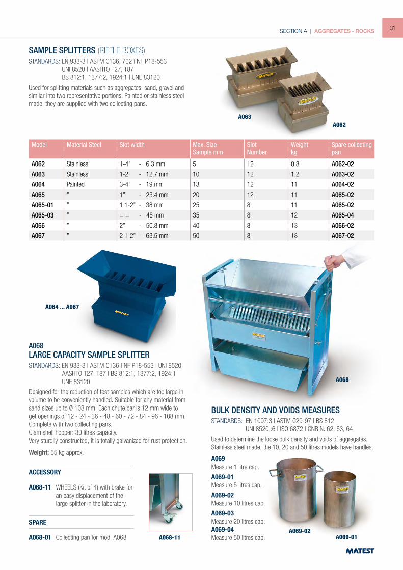
SAMPLE SPLITTERS (RIFFLE BOXES)STANDARDS: EN 933-3 | ASTM C136, 702 | NF P18-553 UNI 8520 | AASHTO T27, T87 BS 812:1, 1377:2, 1924:1 | UNE 83120
Used for splitting materials such as aggregates, sand, gravel and similar into two representative portions. Painted or stainless steel made, they are supplied with two collecting pans.
Model Material Steel Slot width Max. Size Slot Weight Spare collectingSample mm Number kg pan
A062 Stainless 1-4” - 6.3 mm 5 12 0.8 A062-02
A063 Stainless 1-2” - 12.7 mm 10 12 1.2 A063-02
A064 Painted 3-4” - 19 mm 13 12 11 A064-02
A065 ” 1” - 25.4 mm 20 12 11 A065-02
A065-01 ” 1 1-2” - 38 mm 25 8 11 A065-02
A065-03 ” = = - 45 mm 35 8 12 A065-04
A066 ” 2” - 50.8 mm 40 8 13 A066-02
A067 ” 2 1-2” - 63.5 mm 50 8 18 A067-02
A068LARGE CAPACITY SAMPLE SPLITTERSTANDARDS: EN 933-3 | ASTM C136 | NF P18-553 | UNI 8520 AASHTO T27, T87 | BS 812:1, 1377:2, 1924:1 UNE 83120
Designed for the reduction of test samples which are too large in volume to be conveniently handled. Suitable for any material from sand sizes up to Ø 108 mm. Each chute bar is 12 mm wide to get openings of 12 - 24 - 36 - 48 - 60 - 72 - 84 - 96 - 108 mm. Complete with two collecting pans.Clam shell hopper: 30 litres capacity.Very sturdily constructed, it is totally galvanized for rust protection.
Weight: 55 kg approx.
ACCESSORY
A068-11 WHEELS (Kit of 4) with brake for an easy displacement of the large splitter in the laboratory.
SPARE
A068-01 Collecting pan for mod. A068
BULK DENSITY AND VOIDS MEASURESSTANDARDS: EN 1097:3 | ASTM C29-97 | BS 812 UNI 8520 :6 | ISO 6872 | CNR N. 62, 63, 64
Used to determine the loose bulk density and voids of aggregates.Stainless steel made, the 10, 20 and 50 litres models have handles.
A069Measure 1 litre cap.
A069-01Measure 5 litres cap.
A069-02Measure 10 litres cap.
A069-03Measure 20 litres cap.A069-04Measure 50 litres cap.
A063A062
A064 ... A067
A068
A069-02A069-01A068-11
31
SECTION A | AGGREGATES - ROCKS
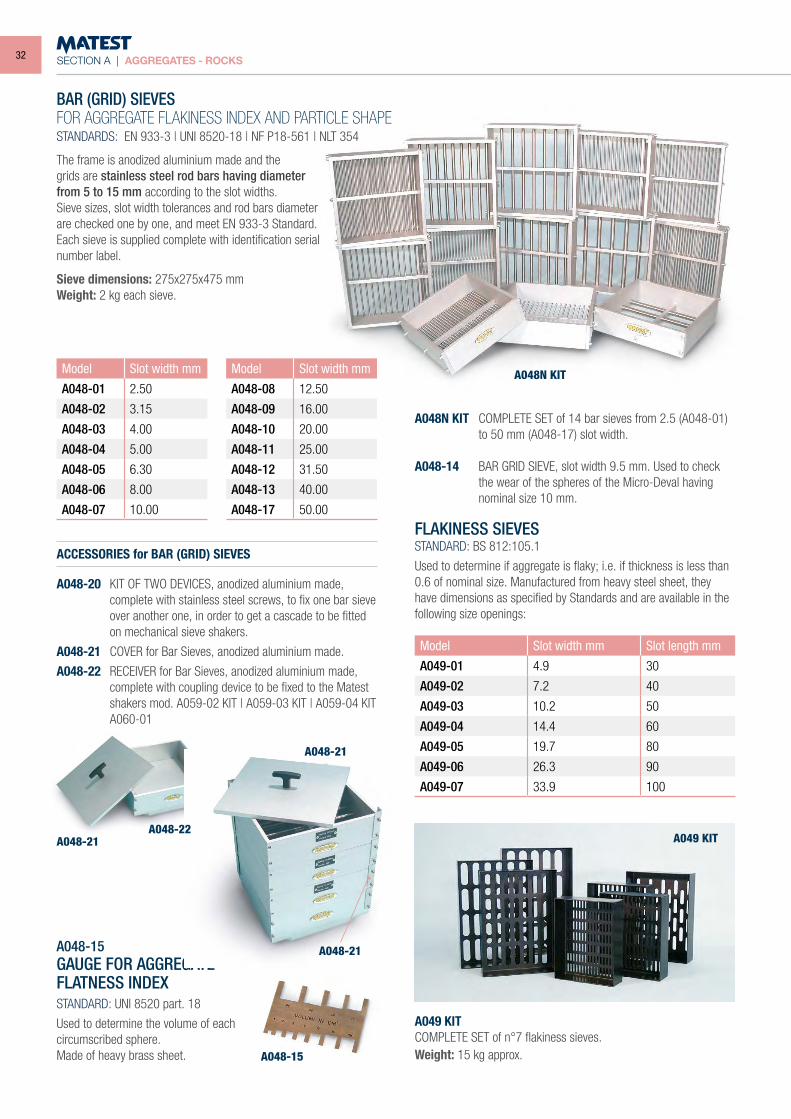
BAR (GRID) SIEVESFOR AGGREGATE FLAKINESS INDEX AND PARTICLE SHAPESTANDARDS: EN 933-3 | UNI 8520-18 | NF P18-561 | NLT 354
The frame is anodized aluminium made and thegrids are stainless steel rod bars having diameterfrom 5 to 15 mm according to the slot widths.Sieve sizes, slot width tolerances and rod bars diameterare checked one by one, and meet EN 933-3 Standard.Each sieve is supplied complete with identification serialnumber label.
Sieve dimensions: 275x275x475 mmWeight: 2 kg each sieve.
ACCESSORIES for BAR (GRID) SIEVES
A048-20 KIT OF TWO DEVICES, anodized aluminium made, complete with stainless steel screws, to fix one bar sieve over another one, in order to get a cascade to be fitted on mechanical sieve shakers.
A048-21 COVER for Bar Sieves, anodized aluminium made.
A048-22 RECEIVER for Bar Sieves, anodized aluminium made, complete with coupling device to be fixed to the Matest shakers mod. A059-02 KIT | A059-03 KIT | A059-04 KIT A060-01
A048-15GAUGE FOR AGGREGATE FLATNESS INDEXSTANDARD: UNI 8520 part. 18
Used to determine the volume of each circumscribed sphere.Made of heavy brass sheet.
A048N KIT COMPLETE SET of 14 bar sieves from 2.5 (A048-01) to 50 mm (A048-17) slot width.
A048-14 BAR GRID SIEVE, slot width 9.5 mm. Used to check the wear of the spheres of the Micro-Deval having nominal size 10 mm.
FLAKINESS SIEVESSTANDARD: BS 812:105.1
Used to determine if aggregate is flaky; i.e. if thickness is less than 0.6 of nominal size. Manufactured from heavy steel sheet, they have dimensions as specified by Standards and are available in the following size openings:
A049 KITCOMPLETE SET of n°7 flakiness sieves.Weight: 15 kg approx.
Model Slot width mm
A048-01 2.50
A048-02 3.15
A048-03 4.00
A048-04 5.00
A048-05 6.30
A048-06 8.00
A048-07 10.00
Model Slot width mm
A048-08 12.50
A048-09 16.00
A048-10 20.00
A048-11 25.00
A048-12 31.50
A048-13 40.00
A048-17 50.00
Model Slot width mm Slot length mm
A049-01 4.9 30
A049-02 7.2 40
A049-03 10.2 50
A049-04 14.4 60
A049-05 19.7 80
A049-06 26.3 90
A049-07 33.9 100
A048N KIT
A048-21A048-22
A048-21
A048-21
A048-15
A049 KIT
32
SECTION A | AGGREGATES - ROCKS
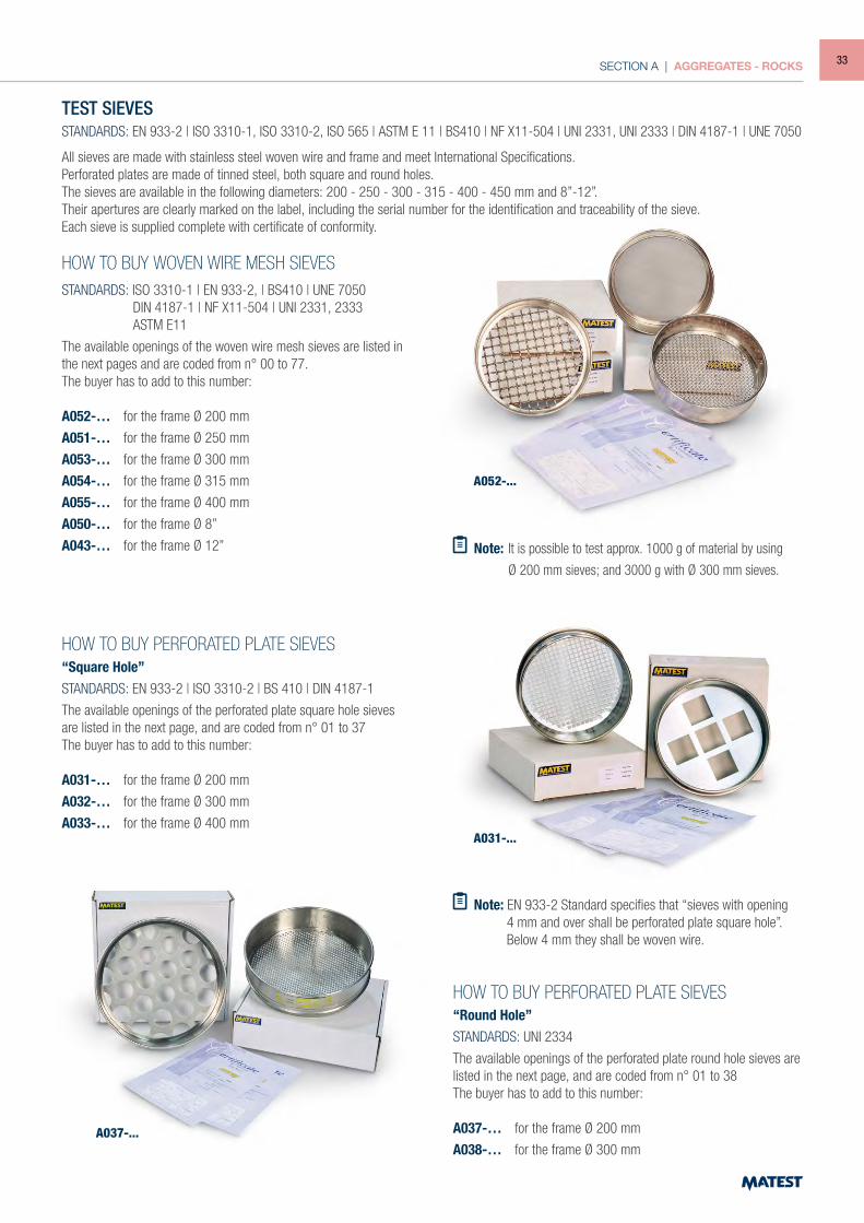
TEST SIEVESSTANDARDS: EN 933-2 | ISO 3310-1, ISO 3310-2, ISO 565 | ASTM E 11 | BS410 | NF X11-504 | UNI 2331, UNI 2333 | DIN 4187-1 | UNE 7050
All sieves are made with stainless steel woven wire and frame and meet International Specifications.Perforated plates are made of tinned steel, both square and round holes.The sieves are available in the following diameters: 200 - 250 - 300 - 315 - 400 - 450 mm and 8”-12”.Their apertures are clearly marked on the label, including the serial number for the identification and traceability of the sieve.Each sieve is supplied complete with certificate of conformity.
HOW TO BUY WOVEN WIRE MESH SIEVESSTANDARDS: ISO 3310-1 | EN 933-2, | BS410 | UNE 7050 DIN 4187-1 | NF X11-504 | UNI 2331, 2333 ASTM E11
The available openings of the woven wire mesh sieves are listed in the next pages and are coded from n° 00 to 77.The buyer has to add to this number:
A052-… for the frame Ø 200 mm
A051-… for the frame Ø 250 mm
A053-… for the frame Ø 300 mm
A054-… for the frame Ø 315 mm
A055-… for the frame Ø 400 mm
A050-… for the frame Ø 8”
A043-… for the frame Ø 12”
HOW TO BUY PERFORATED PLATE SIEVES“Square Hole”STANDARDS: EN 933-2 | ISO 3310-2 | BS 410 | DIN 4187-1
The available openings of the perforated plate square hole sieves are listed in the next page, and are coded from n° 01 to 37The buyer has to add to this number:
A031-… for the frame Ø 200 mm
A032-… for the frame Ø 300 mm
A033-… for the frame Ø 400 mm
Note: It is possible to test approx. 1000 g of material by using
Ø 200 mm sieves; and 3000 g with Ø 300 mm sieves.
Note: EN 933-2 Standard specifies that “sieves with opening 4 mm and over shall be perforated plate square hole”.
Below 4 mm they shall be woven wire.
HOW TO BUY PERFORATED PLATE SIEVES“Round Hole”STANDARDS: UNI 2334
The available openings of the perforated plate round hole sieves are listed in the next page, and are coded from n° 01 to 38The buyer has to add to this number:
A037-… for the frame Ø 200 mm
A038-… for the frame Ø 300 mmA037-...
A052-...
A031-...
33
SECTION A | AGGREGATES - ROCKS
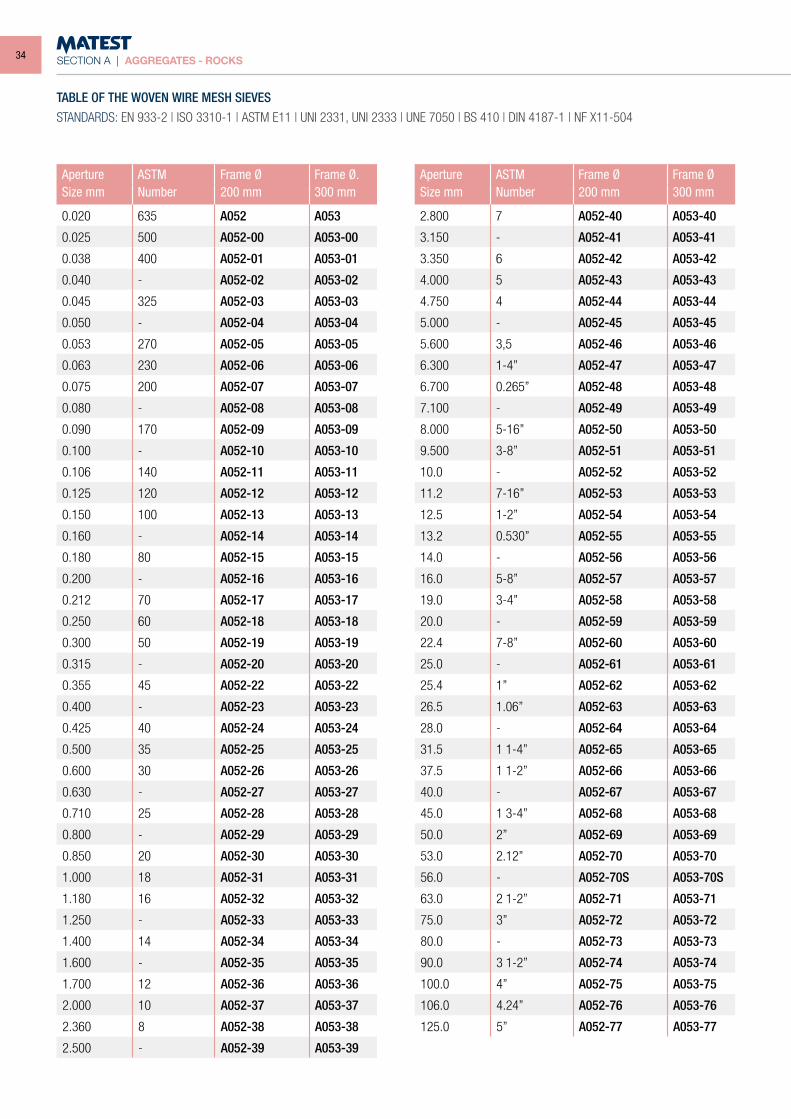
TABLE OF THE WOVEN WIRE MESH SIEVESSTANDARDS: EN 933-2 | ISO 3310-1 | ASTM E11 | UNI 2331, UNI 2333 | UNE 7050 | BS 410 | DIN 4187-1 | NF X11-504
Aperture ASTM Frame Ø Frame Ø.Size mm Number 200 mm 300 mm
0.020 635 A052 A053
0.025 500 A052-00 A053-00
0.038 400 A052-01 A053-01
0.040 - A052-02 A053-02
0.045 325 A052-03 A053-03
0.050 - A052-04 A053-04
0.053 270 A052-05 A053-05
0.063 230 A052-06 A053-06
0.075 200 A052-07 A053-07
0.080 - A052-08 A053-08
0.090 170 A052-09 A053-09
0.100 - A052-10 A053-10
0.106 140 A052-11 A053-11
0.125 120 A052-12 A053-12
0.150 100 A052-13 A053-13
0.160 - A052-14 A053-14
0.180 80 A052-15 A053-15
0.200 - A052-16 A053-16
0.212 70 A052-17 A053-17
0.250 60 A052-18 A053-18
0.300 50 A052-19 A053-19
0.315 - A052-20 A053-20
0.355 45 A052-22 A053-22
0.400 - A052-23 A053-23
0.425 40 A052-24 A053-24
0.500 35 A052-25 A053-25
0.600 30 A052-26 A053-26
0.630 - A052-27 A053-27
0.710 25 A052-28 A053-28
0.800 - A052-29 A053-29
0.850 20 A052-30 A053-30
1.000 18 A052-31 A053-31
1.180 16 A052-32 A053-32
1.250 - A052-33 A053-33
1.400 14 A052-34 A053-34
1.600 - A052-35 A053-35
1.700 12 A052-36 A053-36
2.000 10 A052-37 A053-37
2.360 8 A052-38 A053-38
2.500 - A052-39 A053-39
Aperture ASTM Frame Ø Frame ØSize mm Number 200 mm 300 mm
2.800 7 A052-40 A053-40
3.150 - A052-41 A053-41
3.350 6 A052-42 A053-42
4.000 5 A052-43 A053-43
4.750 4 A052-44 A053-44
5.000 - A052-45 A053-45
5.600 3,5 A052-46 A053-46
6.300 1-4” A052-47 A053-47
6.700 0.265” A052-48 A053-48
7.100 - A052-49 A053-49
8.000 5-16” A052-50 A053-50
9.500 3-8” A052-51 A053-51
10.0 - A052-52 A053-52
11.2 7-16” A052-53 A053-53
12.5 1-2” A052-54 A053-54
13.2 0.530” A052-55 A053-55
14.0 - A052-56 A053-56
16.0 5-8” A052-57 A053-57
19.0 3-4” A052-58 A053-58
20.0 - A052-59 A053-59
22.4 7-8” A052-60 A053-60
25.0 - A052-61 A053-61
25.4 1” A052-62 A053-62
26.5 1.06” A052-63 A053-63
28.0 - A052-64 A053-64
31.5 1 1-4” A052-65 A053-65
37.5 1 1-2” A052-66 A053-66
40.0 - A052-67 A053-67
45.0 1 3-4” A052-68 A053-68
50.0 2” A052-69 A053-69
53.0 2.12” A052-70 A053-70
56.0 - A052-70S A053-70S
63.0 2 1-2” A052-71 A053-71
75.0 3” A052-72 A053-72
80.0 - A052-73 A053-73
90.0 3 1-2” A052-74 A053-74
100.0 4” A052-75 A053-75
106.0 4.24” A052-76 A053-76
125.0 5” A052-77 A053-77
34
SECTION A | AGGREGATES - ROCKS
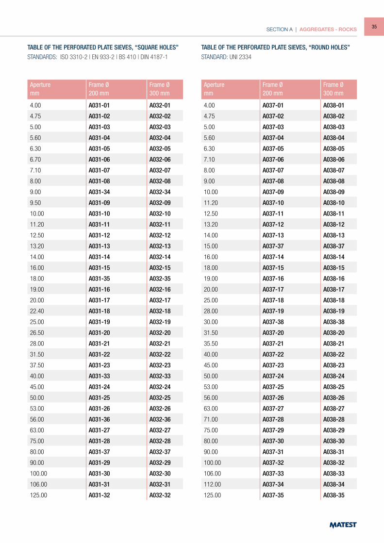
TABLE OF THE PERFORATED PLATE SIEVES, “SQUARE HOLES”STANDARDS: ISO 3310-2 | EN 933-2 | BS 410 | DIN 4187-1
TABLE OF THE PERFORATED PLATE SIEVES, “ROUND HOLES”STANDARD: UNI 2334
Aperture Frame Ø Frame Ømm 200 mm 300 mm
4.00 A031-01 A032-01
4.75 A031-02 A032-02
5.00 A031-03 A032-03
5.60 A031-04 A032-04
6.30 A031-05 A032-05
6.70 A031-06 A032-06
7.10 A031-07 A032-07
8.00 A031-08 A032-08
9.00 A031-34 A032-34
9.50 A031-09 A032-09
10.00 A031-10 A032-10
11.20 A031-11 A032-11
12.50 A031-12 A032-12
13.20 A031-13 A032-13
14.00 A031-14 A032-14
16.00 A031-15 A032-15
18.00 A031-35 A032-35
19.00 A031-16 A032-16
20.00 A031-17 A032-17
22.40 A031-18 A032-18
25.00 A031-19 A032-19
26.50 A031-20 A032-20
28.00 A031-21 A032-21
31.50 A031-22 A032-22
37.50 A031-23 A032-23
40.00 A031-33 A032-33
45.00 A031-24 A032-24
50.00 A031-25 A032-25
53.00 A031-26 A032-26
56.00 A031-36 A032-36
63.00 A031-27 A032-27
75.00 A031-28 A032-28
80.00 A031-37 A032-37
90.00 A031-29 A032-29
100.00 A031-30 A032-30
106.00 A031-31 A032-31
125.00 A031-32 A032-32
Aperture Frame Ø Frame Ømm 200 mm 300 mm
4.00 A037-01 A038-01
4.75 A037-02 A038-02
5.00 A037-03 A038-03
5.60 A037-04 A038-04
6.30 A037-05 A038-05
7.10 A037-06 A038-06
8.00 A037-07 A038-07
9.00 A037-08 A038-08
10.00 A037-09 A038-09
11.20 A037-10 A038-10
12.50 A037-11 A038-11
13.20 A037-12 A038-12
14.00 A037-13 A038-13
15.00 A037-37 A038-37
16.00 A037-14 A038-14
18.00 A037-15 A038-15
19.00 A037-16 A038-16
20.00 A037-17 A038-17
25.00 A037-18 A038-18
28.00 A037-19 A038-19
30.00 A037-38 A038-38
31.50 A037-20 A038-20
35.50 A037-21 A038-21
40.00 A037-22 A038-22
45.00 A037-23 A038-23
50.00 A037-24 A038-24
53.00 A037-25 A038-25
56.00 A037-26 A038-26
63.00 A037-27 A038-27
71.00 A037-28 A038-28
75.00 A037-29 A038-29
80.00 A037-30 A038-30
90.00 A037-31 A038-31
100.00 A037-32 A038-32
106.00 A037-33 A038-33
112.00 A037-34 A038-34
125.00 A037-35 A038-35
35
SECTION A | AGGREGATES - ROCKS
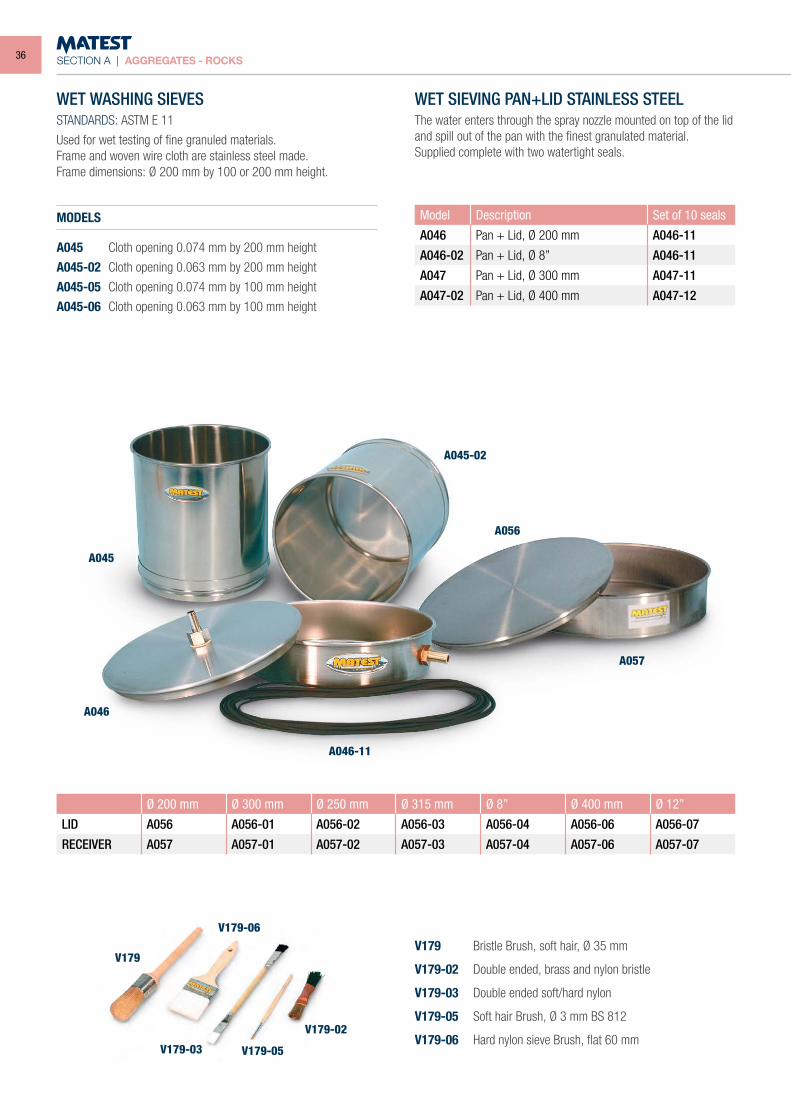
WET WASHING SIEVESSTANDARDS: ASTM E 11
Used for wet testing of fine granuled materials.Frame and woven wire cloth are stainless steel made.Frame dimensions: Ø 200 mm by 100 or 200 mm height.
MODELS
A045 Cloth opening 0.074 mm by 200 mm height
A045-02 Cloth opening 0.063 mm by 200 mm height
A045-05 Cloth opening 0.074 mm by 100 mm height
A045-06 Cloth opening 0.063 mm by 100 mm height
WET SIEVING PAN+LID STAINLESS STEELThe water enters through the spray nozzle mounted on top of the lid and spill out of the pan with the finest granulated material.Supplied complete with two watertight seals.
Model Description Set of 10 seals
A046 Pan + Lid, Ø 200 mm A046-11
A046-02 Pan + Lid, Ø 8” A046-11
A047 Pan + Lid, Ø 300 mm A047-11
A047-02 Pan + Lid, Ø 400 mm A047-12
Ø 200 mm Ø 300 mm Ø 250 mm Ø 315 mm Ø 8” Ø 400 mm Ø 12”
LID A056 A056-01 A056-02 A056-03 A056-04 A056-06 A056-07
RECEIVER A057 A057-01 A057-02 A057-03 A057-04 A057-06 A057-07
A045
V179 Bristle Brush, soft hair, Ø 35 mm
V179-02 Double ended, brass and nylon bristle
V179-03 Double ended soft/hard nylon
V179-05 Soft hair Brush, Ø 3 mm BS 812
V179-06 Hard nylon sieve Brush, flat 60 mm
V179
V179-06
V179-03 V179-05
V179-02
A045-02
A056
A057
A046-11
A046
36
SECTION A | AGGREGATES - ROCKS
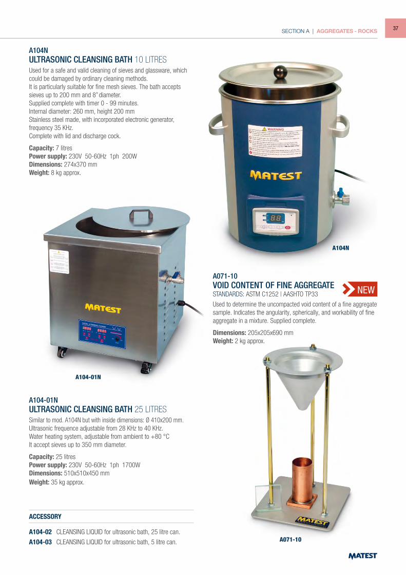
A104NULTRASONIC CLEANSING BATH 10 LITRESUsed for a safe and valid cleaning of sieves and glassware, which could be damaged by ordinary cleaning methods.It is particularly suitable for fine mesh sieves. The bath accepts sieves up to 200 mm and 8” diameter.Supplied complete with timer 0 - 99 minutes.Internal diameter: 260 mm, height 200 mmStainless steel made, with incorporated electronic generator, frequency 35 KHz.Complete with lid and discharge cock.
Capacity: 7 litresPower supply: 230V 50-60Hz 1ph 200WDimensions: 274x370 mmWeight: 8 kg approx.
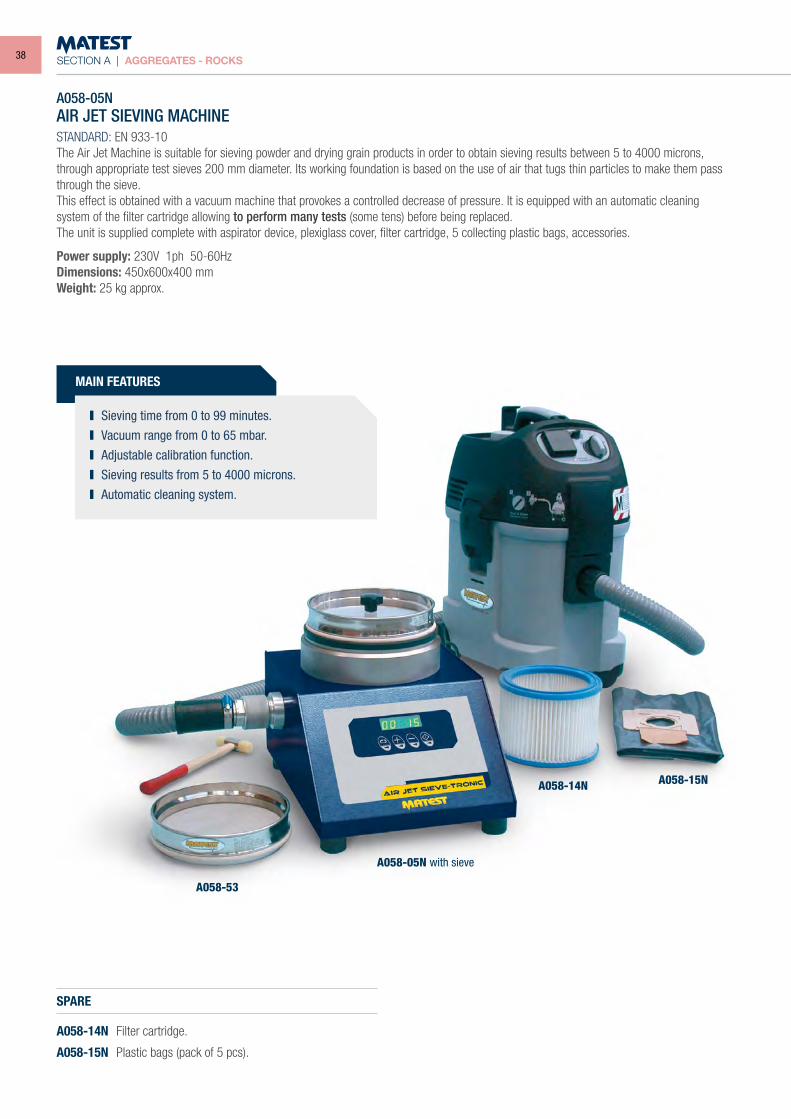
A104-01NULTRASONIC CLEANSING BATH 25 LITRESSimilar to mod. A104N but with inside dimensions: Ø 410x200 mm.Ultrasonic frequence adjustable from 28 KHz to 40 KHz.Water heating system, adjustable from ambient to +80 °CIt accept sieves up to 350 mm diameter.
Capacity: 25 litresPower supply: 230V 50-60Hz 1ph 1700WDimensions: 510x510x450 mmWeight: 35 kg approx.
ACCESSORY
A104-02 CLEANSING LIQUID for ultrasonic bath, 25 litre can.
A104-03 CLEANSING LIQUID for ultrasonic bath, 5 litre can.
A104N
A104-01N
A071-10VOID CONTENT OF FINE AGGREGATESTANDARDS: ASTM C1252 | AASHTO TP33
Used to determine the uncompacted void content of a fine aggregate sample. Indicates the angularity, spherically, and workability of fine aggregate in a mixture. Supplied complete.
Dimensions: 205x205x690 mmWeight: 2 kg approx.
A071-10
NEW
37
SECTION A | AGGREGATES - ROCKS
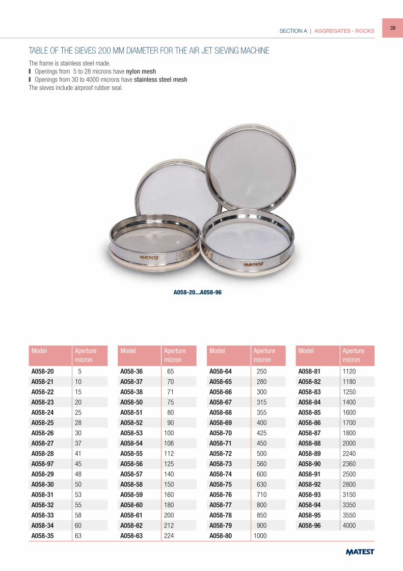
A058-05NAIR JET SIEVING MACHINESTANDARD: EN 933-10The Air Jet Machine is suitable for sieving powder and drying grain products in order to obtain sieving results between 5 to 4000 microns, through appropriate test sieves 200 mm diameter. Its working foundation is based on the use of air that tugs thin particles to make them pass through the sieve.This effect is obtained with a vacuum machine that provokes a controlled decrease of pressure. It is equipped with an automatic cleaning system of the filter cartridge allowing to perform many tests (some tens) before being replaced.The unit is supplied complete with aspirator device, plexiglass cover, filter cartridge, 5 collecting plastic bags, accessories.
Power supply: 230V 1ph 50-60Hz Dimensions: 450x600x400 mmWeight: 25 kg approx.
SPARE
A058-14N Filter cartridge.
A058-15N Plastic bags (pack of 5 pcs).
A058-53
A058-14N A058-15N
A058-05N with sieve
MAIN FEATURES
Sieving time from 0 to 99 minutes. Vacuum range from 0 to 65 mbar. Adjustable calibration function. Sieving results from 5 to 4000 microns. Automatic cleaning system.
38
SECTION A | AGGREGATES - ROCKS
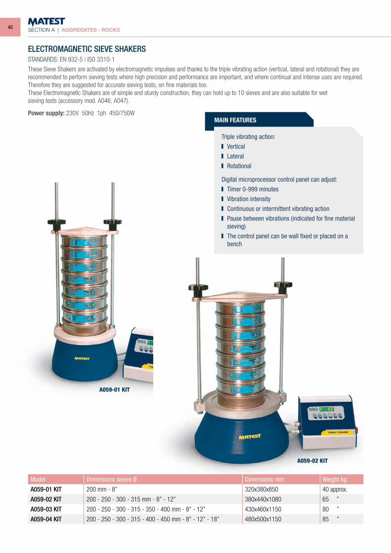
TABLE OF THE SIEVES 200 MM DIAMETER FOR THE AIR JET SIEVING MACHINEThe frame is stainless steel made. Openings from 5 to 28 microns have nylon mesh Openings from 30 to 4000 microns have stainless steel mesh
The sieves include airproof rubber seal.
Model Aperturemicron
A058-20 5
A058-21 10
A058-22 15
A058-23 20
A058-24 25
A058-25 28
A058-26 30
A058-27 37
A058-28 41
A058-97 45
A058-29 48
A058-30 50
A058-31 53
A058-32 55
A058-33 58
A058-34 60
A058-35 63
Model Aperturemicron
A058-36 65
A058-37 70
A058-38 71
A058-50 75
A058-51 80
A058-52 90
A058-53 100
A058-54 106
A058-55 112
A058-56 125
A058-57 140
A058-58 150
A058-59 160
A058-60 180
A058-61 200
A058-62 212
A058-63 224
Model Aperturemicron
A058-64 250
A058-65 280
A058-66 300
A058-67 315
A058-68 355
A058-69 400
A058-70 425
A058-71 450
A058-72 500
A058-73 560
A058-74 600
A058-75 630
A058-76 710
A058-77 800
A058-78 850
A058-79 900
A058-80 1000
Model Aperturemicron
A058-81 1120
A058-82 1180
A058-83 1250
A058-84 1400
A058-85 1600
A058-86 1700
A058-87 1800
A058-88 2000
A058-89 2240
A058-90 2360
A058-91 2500
A058-92 2800
A058-93 3150
A058-94 3350
A058-95 3550
A058-96 4000
A058-20...A058-96
39
SECTION A | AGGREGATES - ROCKS
MAIN FEATURES
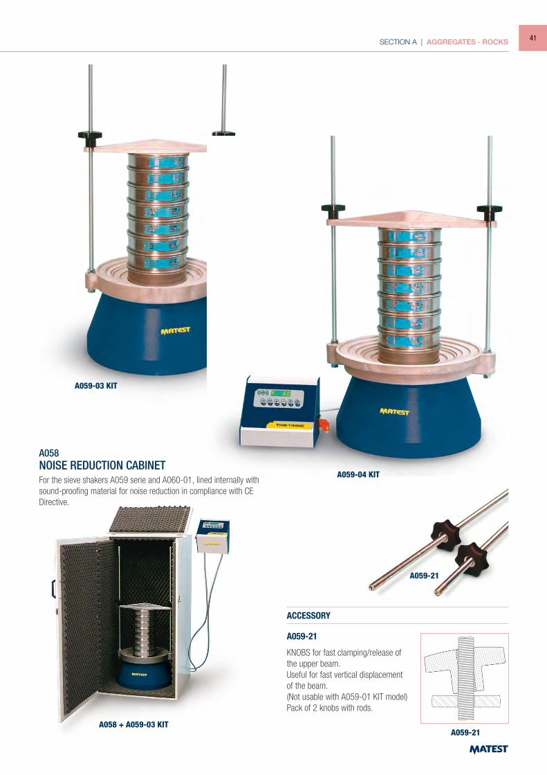
ELECTROMAGNETIC SIEVE SHAKERSSTANDARDS: EN 932-5 | ISO 3310-1
These Sieve Shakers are activated by electromagnetic impulses and thanks to the triple vibrating action (vertical, lateral and rotational) they are recommended to perform sieving tests where high precision and performance are important, and where continual and intense uses are required. Therefore they are suggested for accurate sieving tests, on fine materials too.These Electromagnetic Shakers are of simple and sturdy construction, they can hold up to 10 sieves and are also suitable for wetsieving tests (accessory mod. A046, A047).
Power supply: 230V 50Hz 1ph 450/750W
A059-02 KIT
A059-01 KIT
Triple vibrating action: Vertical Lateral Rotational
Digital microprocessor control panel can adjust: Timer 0-999 minutes Vibration intensity Continuous or intermittent vibrating action Pause between vibrations (indicated for fine material
sieving) The control panel can be wall fixed or placed on a
bench
Model Dimensions sieves Ø Dimensions mm Weight kg
A059-01 KIT 200 mm - 8” 320x380x850 40 approx.
A059-02 KIT 200 - 250 - 300 - 315 mm - 8” - 12” 380x440x1080 65 ”
A059-03 KIT 200 - 250 - 300 - 315 - 350 - 400 mm - 8” - 12” 430x460x1150 80 ”
A059-04 KIT 200 - 250 - 300 - 315 - 400 - 450 mm - 8” - 12” - 18” 480x500x1150 85 ”
40
SECTION A | AGGREGATES - ROCKS
ACCESSORY
A059-21
KNOBS for fast clamping/release of the upper beam.Useful for fast vertical displacement of the beam. (Not usable with A059-01 KIT model)Pack of 2 knobs with rods.
A059-03 KIT
A059-04 KIT
A059-21
A059-21A058 + A059-03 KIT
A058NOISE REDUCTION CABINETFor the sieve shakers A059 serie and A060-01, lined internally with sound-proofing material for noise reduction in compliance with CE Directive.
41
SECTION A | AGGREGATES - ROCKS
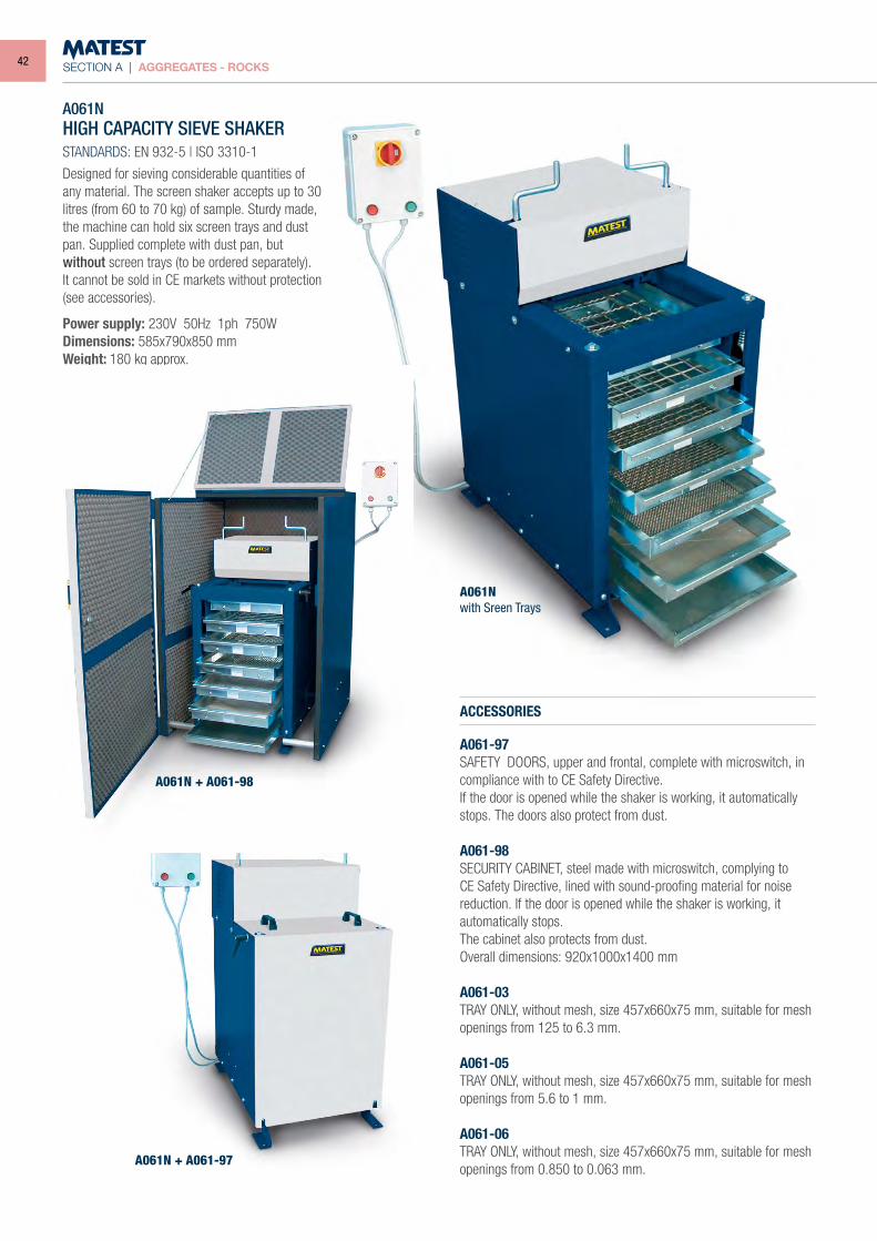
A061NHIGH CAPACITY SIEVE SHAKERSTANDARDS: EN 932-5 | ISO 3310-1
Designed for sieving considerable quantities of any material. The screen shaker accepts up to 30 litres (from 60 to 70 kg) of sample. Sturdy made, the machine can hold six screen trays and dust pan. Supplied complete with dust pan, butwithout screen trays (to be ordered separately).It cannot be sold in CE markets without protection(see accessories).
Power supply: 230V 50Hz 1ph 750WDimensions: 585x790x850 mmWeight: 180 kg approx.
ACCESSORIES
A061-97SAFETY DOORS, upper and frontal, complete with microswitch, in compliance with to CE Safety Directive.If the door is opened while the shaker is working, it automatically stops. The doors also protect from dust.
A061-98SECURITY CABINET, steel made with microswitch, complying to CE Safety Directive, lined with sound-proofing material for noise reduction. If the door is opened while the shaker is working, it automatically stops. The cabinet also protects from dust.Overall dimensions: 920x1000x1400 mm
A061-03TRAY ONLY, without mesh, size 457x660x75 mm, suitable for mesh openings from 125 to 6.3 mm.
A061-05TRAY ONLY, without mesh, size 457x660x75 mm, suitable for mesh openings from 5.6 to 1 mm.
A061-06TRAY ONLY, without mesh, size 457x660x75 mm, suitable for mesh openings from 0.850 to 0.063 mm.
A061N + A061-98
A061N + A061-97
A061Nwith Sreen Trays
42
SECTION A | AGGREGATES - ROCKS
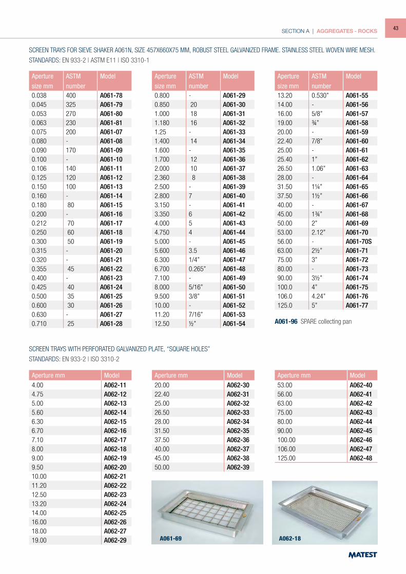
SCREEN TRAYS FOR SIEVE SHAKER A061N, SIZE 457X660X75 MM, ROBUST STEEL GALVANIZED FRAME. STAINLESS STEEL WOVEN WIRE MESH.
STANDARDS: EN 933-2 | ASTM E11 | ISO 3310-1
Aperture ASTM Modelsize mm number
0.038 400 A061-780.045 325 A061-790.053 270 A061-800.063 230 A061-810.075 200 A061-070.080 - A061-080.090 170 A061-090.100 - A061-100.106 140 A061-110.125 120 A061-120.150 100 A061-130.160 - A061-140.180 80 A061-150.200 - A061-160.212 70 A061-170.250 60 A061-180.300 50 A061-190.315 - A061-200.320 - A061-210.355 45 A061-220.400 - A061-230.425 40 A061-240.500 35 A061-250.600 30 A061-260.630 - A061-270.710 25 A061-28
Aperture ASTM Modelsize mm number
0.800 - A061-290.850 20 A061-301.000 18 A061-311.180 16 A061-321.25 - A061-331.400 14 A061-341.600 - A061-351.700 12 A061-362.000 10 A061-372.360 8 A061-382.500 - A061-392.800 7 A061-403.150 - A061-413.350 6 A061-424.000 5 A061-434.750 4 A061-445.000 - A061-455.600 3.5 A061-466.300 1/4” A061-476.700 0.265” A061-487.100 - A061-498.000 5/16” A061-509.500 3/8” A061-5110.00 - A061-5211.20 7/16” A061-5312.50 ½” A061-54
Aperture ASTM Modelsize mm number
13.20 0.530” A061-5514.00 - A061-5616.00 5/8” A061-5719.00 ¾” A061-5820.00 - A061-5922.40 7/8” A061-6025.00 - A061-6125.40 1” A061-6226.50 1.06” A061-6328.00 - A061-6431.50 1¼” A061-6537.50 1½” A061-6640.00 - A061-6745.00 1¾” A061-6850.00 2” A061-6953.00 2.12” A061-7056.00 - A061-70S63.00 2½” A061-7175.00 3” A061-7280.00 - A061-7390.00 3½” A061-74100.0 4” A061-75106.0 4.24” A061-76125.0 5” A061-77
A061-96 SPARE collecting pan
SCREEN TRAYS WITH PERFORATED GALVANIZED PLATE, “SQUARE HOLES”
STANDARDS: EN 933-2 | ISO 3310-2
Aperture mm Model4.00 A062-114.75 A062-125.00 A062-135.60 A062-146.30 A062-156.70 A062-167.10 A062-178.00 A062-189.00 A062-199.50 A062-2010.00 A062-2111.20 A062-2212.50 A062-2313.20 A062-2414.00 A062-2516.00 A062-2618.00 A062-2719.00 A062-29
Aperture mm Model20.00 A062-3022.40 A062-3125.00 A062-3226.50 A062-3328.00 A062-3431.50 A062-3537.50 A062-3640.00 A062-3745.00 A062-3850.00 A062-39
Aperture mm Model53.00 A062-4056.00 A062-4163.00 A062-4275.00 A062-4380.00 A062-4490.00 A062-45100.00 A062-46106.00 A062-47125.00 A062-48
A061-69 A062-18
43
SECTION A | AGGREGATES - ROCKS
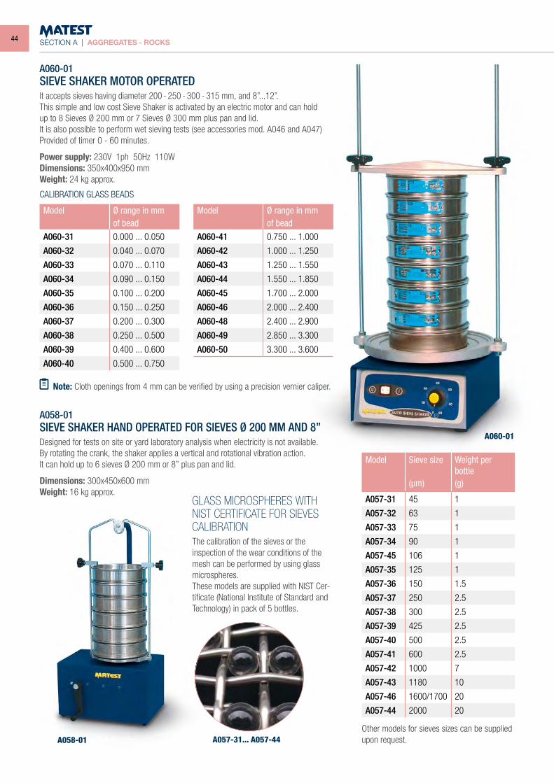
A060-01
A058-01 A057-31... A057-44
A060-01SIEVE SHAKER MOTOR OPERATEDIt accepts sieves having diameter 200 - 250 - 300 - 315 mm, and 8”...12”.This simple and low cost Sieve Shaker is activated by an electric motor and can holdup to 8 Sieves Ø 200 mm or 7 Sieves Ø 300 mm plus pan and lid.It is also possible to perform wet sieving tests (see accessories mod. A046 and A047)Provided of timer 0 - 60 minutes.
Power supply: 230V 1ph 50Hz 110WDimensions: 350x400x950 mmWeight: 24 kg approx.
A058-01SIEVE SHAKER HAND OPERATED FOR SIEVES Ø 200 MM AND 8”Designed for tests on site or yard laboratory analysis when electricity is not available.By rotating the crank, the shaker applies a vertical and rotational vibration action.It can hold up to 6 sieves Ø 200 mm or 8” plus pan and lid.
Dimensions: 300x450x600 mmWeight: 16 kg approx.
GLASS MICROSPHERES WITH NIST CERTIFICATE FOR SIEVES CALIBRATIONThe calibration of the sieves or the inspection of the wear conditions of the mesh can be performed by using glass microspheres.These models are supplied with NIST Cer-tificate (National Institute of Standard and Technology) in pack of 5 bottles.
Model Ø range in mmof bead
A060-31 0.000 ... 0.050
A060-32 0.040 ... 0.070
A060-33 0.070 ... 0.110
A060-34 0.090 ... 0.150
A060-35 0.100 ... 0.200
A060-36 0.150 ... 0.250
A060-37 0.200 ... 0.300
A060-38 0.250 ... 0.500
A060-39 0.400 ... 0.600
A060-40 0.500 ... 0.750
Model Ø range in mmof bead
A060-41 0.750 ... 1.000
A060-42 1.000 ... 1.250
A060-43 1.250 ... 1.550
A060-44 1.550 ... 1.850
A060-45 1.700 ... 2.000
A060-46 2.000 ... 2.400
A060-48 2.400 ... 2.900
A060-49 2.850 ... 3.300
A060-50 3.300 ... 3.600
Note: Cloth openings from 4 mm can be verified by using a precision vernier caliper.
Model Sieve size Weight per bottle
(µm) (g)
A057-31 45 1
A057-32 63 1
A057-33 75 1
A057-34 90 1
A057-45 106 1
A057-35 125 1
A057-36 150 1.5
A057-37 250 2.5
A057-38 300 2.5
A057-39 425 2.5
A057-40 500 2.5
A057-41 600 2.5
A057-42 1000 7
A057-43 1180 10
A057-46 1600/1700 20
A057-44 2000 20
Other models for sieves sizes can be supplied upon request.
CALIBRATION GLASS BEADS
44
SECTION A | AGGREGATES - ROCKS
A071
A070
A073NA081-01
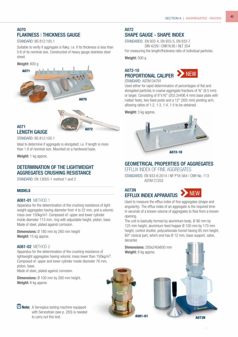
A070FLAKINESS | THICKNESS GAUGESTANDARD: BS 812:105.1
Suitable to verify if aggregate is flaky; i.e. if its thickness is less than 0.6 of its nominal size. Constructed of heavy gauge stainless steel sheet.
Weight: 600 g
A071LENGTH GAUGESTANDARD: BS 812:105.1
Ideal to determine if aggregate is elongated; i.e. if length is more than 1.8 of nominal size. Mounted on a hardwood base.
Weight: 1 kg approx.
DETERMINATION OF THE LIGHTWEIGHTAGGREGATES CRUSHING RESISTANCESTANDARD: EN 13055-1 method 1 and 2
MODELS
A081-01 METHOD 1Apparatus for the determination of the crushing resistance of light-weight aggregates having diameter from 4 to 22 mm, and a volumic mass over 150kg/m3. Composed of: upper and lower cylinder inside diameter 113 mm, ring with adjustable height, piston, base.Made of steel, plated against corrosion.
Dimensions: Ø 180 mm by 260 mm heightWeight: 15 kg approx.
A081-02 METHOD 2Apparatus for the determination of the crushing resistance of lightweight aggregates having volumic mass lower than 150kg/m³. Composed of: upper and lower cylinder inside diameter 76 mm, piston, base.Made of steel, plated against corrosion.
Dimensions: Ø 100 mm by 200 mm height.Weight: 6 kg approx.
Note: A Servoplus testing machine equipped with Servostrain (see p. 283) is needed
to carry out this test.
A072SHAPE GAUGE - SHAPE INDEXSTANDARDS: EN 933-4, EN 933-5, EN 933-7 DIN 4226 | CNR N.95 | NLT 354For measuring the length/thickness ratio of individual particles.
Weight: 500 g
A073NEFFLUX INDEX APPARATUS
Used to measure the efflux index of fine aggregates (shape and angularity). The efflux index of an aggregate is the required time in seconds of a known volume of aggregates to flow from a known opening.The unit is basically formed by aluminium body, Ø 90 mm by 125 mm height, aluminium feed hopper Ø 100 mm by 170 mm height, control shutter, polycarbonate funnel having 85 mm height, 60° conical part, which end has Ø 12 mm, base support, valve, decanter.
Dimensions: 200x240x600 mmWeight: 8 kg approx.
GEOMETRICAL PROPERTIES OF AGGREGATESEFFLUX INDEX OF FINE AGGREGATESSTANDARDS: EN 933-6:2014 | NF P18-564 | CNR No. 113 ASTM C1252
NEW
NEWA072-10PROPORTIONAL CALIPERSTANDARD: ASTM D4791Used either for rapid determination of percentages of flat and elongated particles in coarse aggregate fractions of ⅜" (9.5 mm) or larger. Consisting of 8"x16" (203.2x406.4 mm) base plate with rubber feets, two fixed posts and a 12" (305 mm) pivoting arm, allowing ratios of 1:2, 1:3, 1:4, 1:5 to be obtained.
Weight: 3 kg approx.
A072
A072-10
45
SECTION A | AGGREGATES - ROCKS
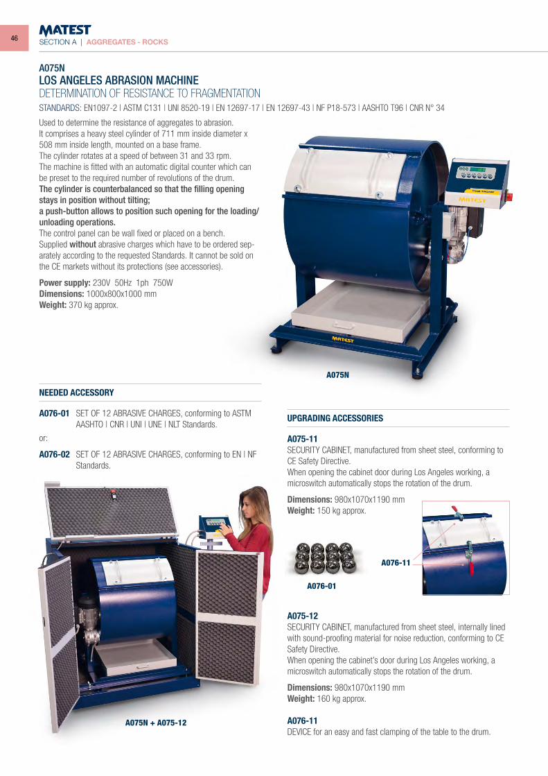
A075NLOS ANGELES ABRASION MACHINEDETERMINATION OF RESISTANCE TO FRAGMENTATIONSTANDARDS: EN1097-2 | ASTM C131 | UNI 8520-19 | EN 12697-17 | EN 12697-43 | NF P18-573 | AASHTO T96 | CNR N° 34
NEEDED ACCESSORY
A076-01 SET OF 12 ABRASIVE CHARGES, conforming to ASTM AASHTO | CNR | UNI | UNE | NLT Standards.
or:
A076-02 SET OF 12 ABRASIVE CHARGES, conforming to EN | NF Standards.
UPGRADING ACCESSORIES
A075-11SECURITY CABINET, manufactured from sheet steel, conforming to CE Safety Directive.When opening the cabinet door during Los Angeles working, a microswitch automatically stops the rotation of the drum.
Dimensions: 980x1070x1190 mmWeight: 150 kg approx.
A075-12SECURITY CABINET, manufactured from sheet steel, internally lined with sound-proofing material for noise reduction, conforming to CE Safety Directive.When opening the cabinet’s door during Los Angeles working, a microswitch automatically stops the rotation of the drum.
Dimensions: 980x1070x1190 mmWeight: 160 kg approx.
A076-11DEVICE for an easy and fast clamping of the table to the drum.
A075N
A075N + A075-12
A076-11
A076-01
Used to determine the resistance of aggregates to abrasion.It comprises a heavy steel cylinder of 711 mm inside diameter x 508 mm inside length, mounted on a base frame.The cylinder rotates at a speed of between 31 and 33 rpm.The machine is fitted with an automatic digital counter which can be preset to the required number of revolutions of the drum.The cylinder is counterbalanced so that the filling opening stays in position without tilting;a push-button allows to position such opening for the loading/unloading operations.The control panel can be wall fixed or placed on a bench.Supplied without abrasive charges which have to be ordered sep-arately according to the requested Standards. It cannot be sold on the CE markets without its protections (see accessories).
Power supply: 230V 50Hz 1ph 750WDimensions: 1000x800x1000 mmWeight: 370 kg approx.
46
SECTION A | AGGREGATES - ROCKS
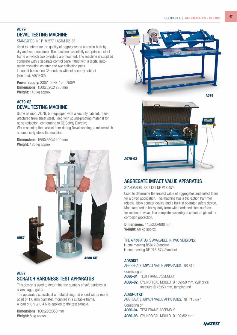
A079DEVAL TESTING MACHINESTANDARDS: NF P18-577 | ASTM D2-33
Used to determine the quality of aggregates to abrasion both by dry and wet procedure. The machine essentially comprises a steel frame on which two cylinders are mounted. The machine is supplied complete with a separate control panel fitted with a digital auto-matic revolution counter and two collecting pans.It cannot be sold on CE markets without security cabinet(see mod. A079-02).
Power supply: 230V 50Hz 1ph 750WDimensions: 1500x520x1280 mmWeight: 140 kg approx.
A079-02DEVAL TESTING MACHINESame as mod. A079, but equipped with a security cabinet, man-ufactured from sheet steel, lined with sound-proofing material for noise reduction, conforming to CE Safety Directive.When opening the cabinet door during Deval working, a microswitch automatically stops the machine.
Dimensions: 1650x650x1400 mmWeight: 180 kg approx.
A087SCRATCH HARDNESS TEST APPARATUSThis device is used to determine the quantity of soft particles in coarse aggregates.The apparatus consists of a metal sliding rod ended with a round point of 1.6 mm diameter, mounted in a suitable frame.A load of 8.9 ± 0.4 N is applied to the test sample.
Dimensions: 160x200x350 mmWeight: 8 kg approx.
AGGREGATE IMPACT VALUE APPARATUSSTANDARDS: BS 812 | NF P18-574
Used to determine the impact value of aggregates and select them for a given application. The machine has a trip-action hammer release, blow counter device and a built-in operator safety device. Manufactured in heavy duty form with hardened steel surfaces for minimum wear. The complete assembly is cadmium plated for corrosion protection.
Dimensions: 445x300x880 mmWeight: 60 kg approx.
THE APPARATUS IS AVAILABLE IN TWO VERSIONS: one meeting BS812 Standard one meeting NF P18-574 Standard
A080KITAGGREGATE IMPACT VALUE APPARATUS. BS 812
Consisting of:A080-04 TEST FRAME ASSEMBLY
A080-02 CYLINDRICAL MOULD, Ø 102x50 mm, cylindrical measure Ø 75x50 mm, tamping rod.
A080-01KITAGGREGATE IMPACT VALUE APPARATUS. NF P18-574
Consisting of:A080-04 TEST FRAME ASSEMBLY
A080-03 CYLINDRICAL MOULD, Ø 102x52 mm.
A079
A080 KIT
A087
A079-02
47
SECTION A | AGGREGATES - ROCKS
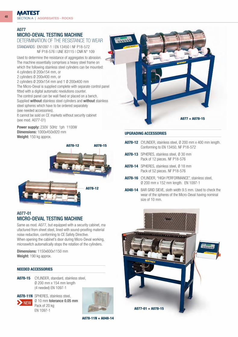
A077MICRO-DEVAL TESTING MACHINE DETERMINATION OF THE RESISTANCE TO WEARSTANDARDS: EN1097-1 | EN 13450 | NF P18-572 NF P18-576 | UNE 83115 | CNR N° 109
Used to determine the resistance of aggregates to abrasion.The machine essentially comprises a heavy steel frame onwhich the following stainless steel cylinders can be mounted:4 cylinders Ø 200x154 mm, or2 cylinders Ø 200x400 mm, or2 cylinders Ø 200x154 mm and 1 Ø 200x400 mm The Micro-Deval is supplied complete with separate control panel fitted with a digital automatic revolutions counter.The control panel can be wall fixed or placed on a bench.Supplied without stainless steel cylinders and without stainless steel spheres which have to be ordered separately(see needed accessories).It cannot be sold on CE markets without security cabinet(see mod. A077-01)
Power supply: 230V 50Hz 1ph 1100WDimensions: 1000x450x920 mmWeight: 150 kg approx.
A077-01MICRO-DEVAL TESTING MACHINESame as mod. A077, but equipped with a security cabinet, man-ufactured from sheet steel, lined with sound-proofing material for noise reduction, conforming to CE Safety Directive.When opening the cabinet’s door during Micro-Deval working, a microswitch automatically stops the rotation of the cylinders.
Dimensions: 1150x600x1150 mmWeight: 190 kg approx.
NEEDED ACCESSORIES
A078-15 CYLINDER, standard, stainless steel, Ø 200 mm x 154 mm length (4 needed) EN 1097-1
A078-11N SPHERES, stainless steel, Ø 10 mm tolerance 0.05 mm Pack of 20 kg EN 1097-1
UPGRADING ACCESSORIES
A078-12 CYLINDER, stainless steel, Ø 200 mm x 400 mm length. Conforming to EN 13450, NF P18-572
A078-13 SPHERES, stainless steel, Ø 30 mm Pack of 12 pieces. NF P18-576
A078-14 SPHERES, stainless steel, Ø 18 mm Pack of 52 pieces. NF P18-576
A078-16 CYLINDER, “HIGH PERFORMANCE”, stainless steel, Ø 200 mm x 152 mm length. EN 1097-1
A048-14 BAR GRID SIEVE, sloth width 9.5 mm. Used to check the wear of the spheres of the Micro-Deval having nominal size of 10 mm.
A077 + A078-15
A078-12
A078-12
A077-01 + A078-15
A078-11N + A048-14
A078-15
NEW
48
SECTION A | AGGREGATES - ROCKS
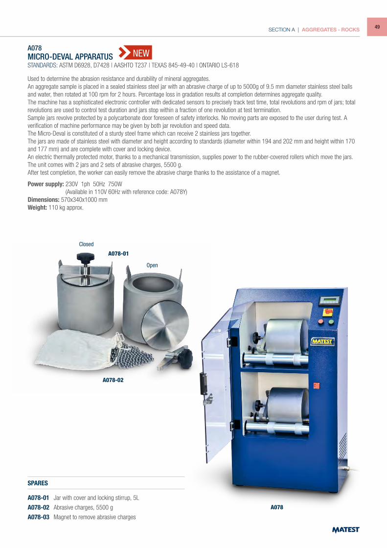
Used to determine the abrasion resistance and durability of mineral aggregates.An aggregate sample is placed in a sealed stainless steel jar with an abrasive charge of up to 5000g of 9.5 mm diameter stainless steel balls and water, then rotated at 100 rpm for 2 hours. Percentage loss in gradation results at completion determines aggregate quality.The machine has a sophisticated electronic controller with dedicated sensors to precisely track test time, total revolutions and rpm of jars; total revolutions are used to control test duration and jars stop within a fraction of one revolution at test termination.Sample jars revolve protected by a polycarbonate door foreseen of safety interlocks. No moving parts are exposed to the user during test. A verification of machine performance may be given by both jar revolution and speed data.The Micro-Deval is constituted of a sturdy steel frame which can receive 2 stainless jars together.The jars are made of stainless steel with diameter and height according to standards (diameter within 194 and 202 mm and height within 170 and 177 mm) and are complete with cover and locking device.An electric thermally protected motor, thanks to a mechanical transmission, supplies power to the rubber-covered rollers which move the jars.The unit comes with 2 jars and 2 sets of abrasive charges, 5500 g.After test completion, the worker can easily remove the abrasive charge thanks to the assistance of a magnet.
Power supply: 230V 1ph 50Hz 750W (Available in 110V 60Hz with reference code: A078Y)Dimensions: 570x340x1000 mmWeight: 110 kg approx.
A078 MICRO-DEVAL APPARATUSSTANDARDS: ASTM D6928, D7428 | AASHTO T237 | TEXAS 845-49-40 | ONTARIO LS-618
SPARES
A078-01 Jar with cover and locking stirrup, 5L
A078-02 Abrasive charges, 5500 g
A078-03 Magnet to remove abrasive charges
NEW
A078-02
A078-01
Closed
Open
A078
49
SECTION A | AGGREGATES - ROCKS
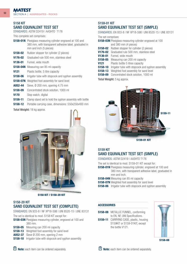
S158-20 KITSAND EQUIVALENT TEST SET (COMPLETE)STANDARDS: EN 933-8 | NF XP18-598 | UNI 8520-15 | UNE 83131
The set is identical to mod. S158 KIT except for:S158-03N Plexiglass measuring cylinder, engraved at 100 and 380 mm.S158-05 Mesuring can 200 ml capacity S158-13 Weighted foot assembly for sand level A052-37 Sieve Ø 200 mm, opening 2 mmS158-10 Irrigator tube with stopcock and syphon assembly
S159-01 KITSAND EQUIVALENT TEST SET (SIMPLE)STANDARDS: EN 933-8 | NF XP18-598 | UNI 8520-15 | UNE 83131
The set comprises:S158-03N Plexiglass measuring cylinder engraved at 100 and 380 mm (4 pieces)S158-02 Rubber stopper for cylinder (2 pieces)V176-02 Graduated rule 500 mm, stainless steelV136-01 Funnel, wide mouthS158-05 Measuring can 200 ml capacityV121 Plastic bottle 5 litres capacityS158-10 Irrigator tube with stopcock and syphon assemblyS158-13 Weighted foot assembly for sand levelS158-09 Concentrated stock solution, 1000 ml
Total Weight: 5 kg approx.
S159 KITSAND EQUIVALENT TEST SET (SIMPLE)STANDARDS: ASTM D2419 | AASHTO T176
The set is identical to mod. S159-01 KIT except for:S158-01N Plexiglass measuring cylinder, engraved at 100 and 380 mm, with transparent adhesive label, graduated in
mm and inch.S158-04N Mesuring can 85 ml capacity S158-07N Weighted foot assembly for sand level S158-06 Irrigator tube with stopcock and syphon assembly
ACCESSORIES
S158-08 METALLIC FUNNEL, conforming to EN, NF, UNI Specifications.S159-11 CARRYING CASE, plastic, housing
S159KIT or S159-01KIT, except the bottle V121.
S158-08
S159-01 KIT
S159-11
S158 KIT / S158-20 KIT
S158 KITSAND EQUIVALENT TEST SETSTANDARDS: ASTM D2419 | AASHTO T176
This complete set comprises:
S158-01N Plexiglass measuring cylinder engraved at 100 and 380 mm, with transparent adhesive label, graduated in mm and inch (5 pieces)
S158-02 Rubber stopper for cylinder (2 pieces)
V176-02 Graduated rule 500 mm, stainless steel
V136-01 Funnel, wide mouth
S158-04N Measuring can 85 ml capacity
V121 Plastic bottle, 5 litre capacity
S158-06 Irrigator tube with stopcock and syphon assembly
S158-07N Weighted foot assembly for sand level
A052-44 Sieve, Ø 200 mm, opening 4.75 mm
S158-09 Concentrated stock solution, 1000 ml
V170 Stop watch, digital
S158-11 Clamp stand set to hold the syphon assembly with bottle
S158-12 Portable carrying case, dimensions: 550x250x400 mm
Total Weight: 18 kg approx.
Note: each item can be ordered separately. Note: each item can be ordered separately.
50
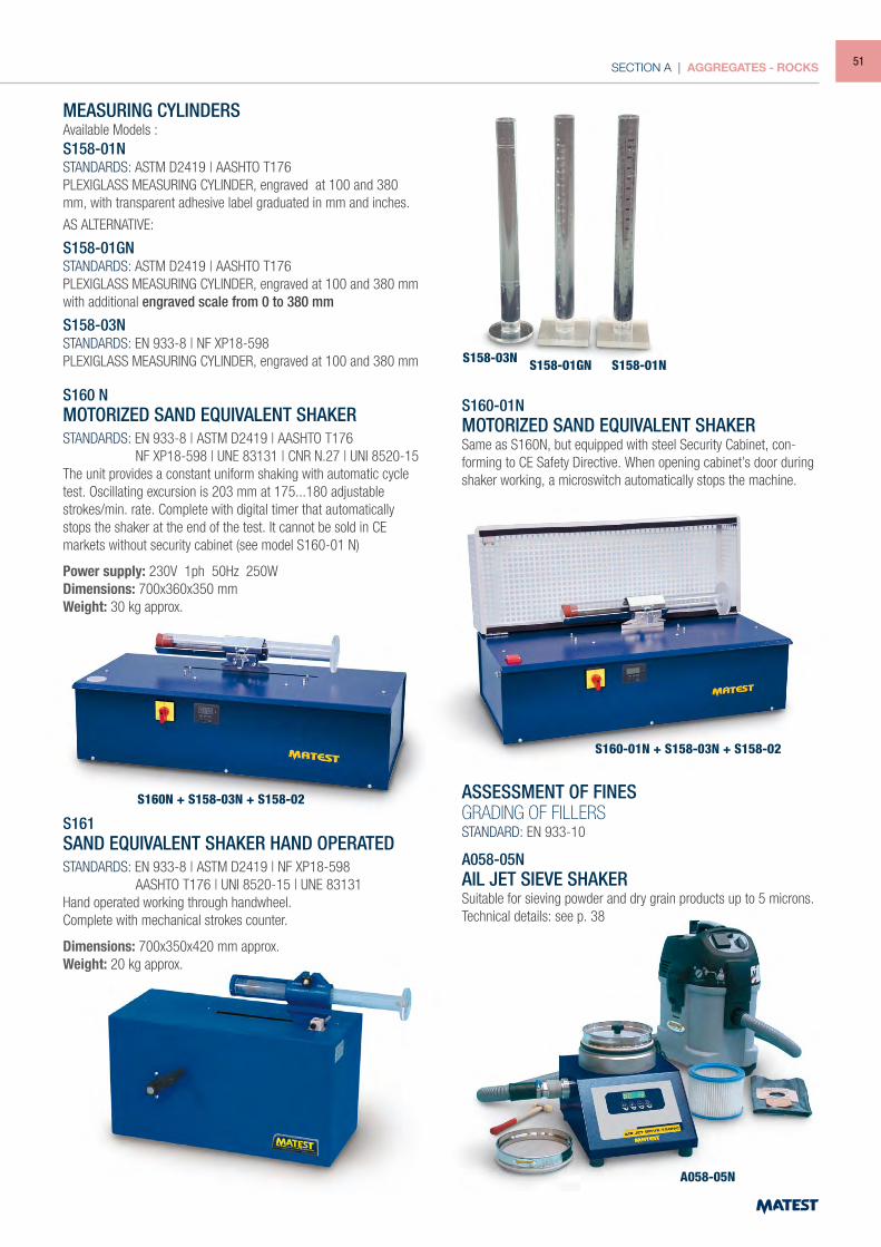
SECTION A | AGGREGATES - ROCKS
S161 A058-05N
S160N + S158-03N + S158-02
S160-01N + S158-03N + S158-02
S160 NMOTORIZED SAND EQUIVALENT SHAKERSTANDARDS: EN 933-8 | ASTM D2419 | AASHTO T176 NF XP18-598 | UNE 83131 | CNR N.27 | UNI 8520-15The unit provides a constant uniform shaking with automatic cycle test. Oscillating excursion is 203 mm at 175...180 adjustable strokes/min. rate. Complete with digital timer that automatically stops the shaker at the end of the test. It cannot be sold in CE markets without security cabinet (see model S160-01 N)
Power supply: 230V 1ph 50Hz 250WDimensions: 700x360x350 mm Weight: 30 kg approx.
S160-01NMOTORIZED SAND EQUIVALENT SHAKERSame as S160N, but equipped with steel Security Cabinet, con-forming to CE Safety Directive. When opening cabinet’s door during shaker working, a microswitch automatically stops the machine.
S161SAND EQUIVALENT SHAKER HAND OPERATEDSTANDARDS: EN 933-8 | ASTM D2419 | NF XP18-598 AASHTO T176 | UNI 8520-15 | UNE 83131Hand operated working through handwheel.Complete with mechanical strokes counter.
Dimensions: 700x350x420 mm approx.Weight: 20 kg approx.
S158-03N S158-01GN S158-01N
MEASURING CYLINDERS Available Models : S158-01NSTANDARDS: ASTM D2419 | AASHTO T176PLEXIGLASS MEASURING CYLINDER, engraved at 100 and 380 mm, with transparent adhesive label graduated in mm and inches.
AS ALTERNATIVE:
S158-01GNSTANDARDS: ASTM D2419 | AASHTO T176 PLEXIGLASS MEASURING CYLINDER, engraved at 100 and 380 mm with additional engraved scale from 0 to 380 mm
S158-03NSTANDARDS: EN 933-8 | NF XP18-598PLEXIGLASS MEASURING CYLINDER, engraved at 100 and 380 mm
ASSESSMENT OF FINESGRADING OF FILLERSSTANDARD: EN 933-10
A058-05NAIL JET SIEVE SHAKERSuitable for sieving powder and dry grain products up to 5 microns.Technical details: see p. 38
51
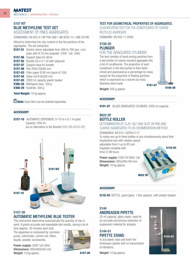
SECTION A | AGGREGATES - ROCKS
S157 KITBLUE METHYLENE TEST SETASSESSMENT OF FINES AGGREGATESSTANDARDS: EN 933-9 | NF P94-068 | UNI 8520-15 | UNE 83180
Utilized to determine the clay content in the fine portions of the aggregates. The set comprises:S157-01 Electric stirrer adjustable from 400 to 700 rpm, com-
plete with Ø 70 mm propeller. 230V 1ph 50HzS157-06 Support base for stirrerS157-02 Burette 50 x 0.1 ml with stopcockS157-07 Support base for buretteS157-08 Pan 200x150x80 mmS157-03 Filter paper Ø 90 mm (pack of 100)S157-04 Glass rod Ø 8x300 mmS157-05 2000 ml capacity plastic beakerV300-28 Methylene blue, 100 gV300-29 Kaolinite, 500 g
Total Weight: 10 kg approx.
ACCESSORY
S157-10 AUTOMATIC DISPENSER, 0-10 ml x 0.1 ml grad. Capacity 1000 ml (as an alternative to the Burette S157-02+S157-07)
S157-20 AUTOMATIC METHYLENE BLUE TESTER This instrument determines automatically the quantity of clay in sand. It grants accurate and repeatable test results, saving a lot of time (approx. 30 minutes each test). The apparatus is composed by: precisionpump, colorimeter, control unit, filters,liquids, powder, accessories.
Power supply: 230V 1ph 50Hz Dimensions: 300x400x350 mm Weight: 10 kg approx.
TEST FOR GEOMETRICAL PROPERTIES OF AGGREGATES. CLASSIFICATION TEST FOR THE CONSTITUENTS OF COARSE RECYCLED AGGREGATESTANDARD: EN 933-11:2009
ACCESSORY
V101-07 GLASS GRADUATED CYLINDER, 2000 ml capacity
B022 SPBOTTLE ROLLERDETERMINATION OF CLAY, SILT AND DUST IN FINE AND COARSE AGGREGATES TO BS SEDIMENTATION METHODSTANDARDS: BS 812 | ASTM C117To rotate one up to three bottles or jars simultaneously about their longitudinal axis with rotation speed, adjustable from 0 up to 85 rpmSupplied complete withtimer 0-99 hours
Power supply: 230V 50-60Hz 1phDimensions: 385x295x160 mmWeight: 10 kg approx.
S144ANDREASEN PIPETTE,25 ml capacity, glass made, used for an accurate and precise extraction of suspension material for analysis.
S144-01PIPETTE STAND,to accurately raise and lower the Andreasen pipette with no transmission of vibrations.
Weight: 10 kg approx.
ACCESSORY
S132-03 BOTTLE, pyrex glass, 1 litre capacity, with airtight stopper.
Note: Each item can be ordered separately.
S156-20 PLUNGERFOR THE GRADUATED CYLINDERThe test consists of hand sorting particles from a test portion of coarse recycled aggregate into a list of constituents. The proportion of each constituent in the test portion is then deter-mined and expressed as a percentage by mass, except for the proportion of floating particles which is expressed as a volume by mass.Stainless steel made
Weight: 500 g approx.
S157 KIT
B022 SP
S132-03
S156-20V101-07
S157-20
S144-01
S144
S157-10
52
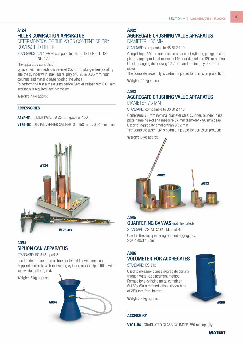
SECTION A | AGGREGATES - ROCKS
A124
V175-03
A084
A082
A083
A086
A124FILLER COMPACTION APPARATUSDETERMINATION OF THE VOIDS CONTENT OF DRYCOMPACTED FILLER.STANDARDS: EN 1097-4 comparable to BS 812 | CNR N° 123 NLT 177
The apparatus consists of:cylinder with an inside diameter of 25.4 mm; plunger freely sliding into the cylinder with max. lateral play of 0.20 ± 0.05 mm; four columns and metallic base holding the whole.To perform the test a measuring device (vernier caliper with 0.01 mm accuracy) is required: see accessory.
Weight: 4 kg approx.
ACCESSORIES
A124-01 FILTER PAPER Ø 25 mm (pack of 100).
V175-03 DIGITAL VERNIER CALIPER 0 - 150 mm x 0.01 mm sens.
A084SIPHON CAN APPARATUSSTANDARD: BS 812 - part 2
Used to determine the moisture content at known conditions. Supplied complete with measuring cylinder, rubber pipes fitted with screw clips, stirring rod.
Weight: 5 kg approx.
A082AGGREGATE CRUSHING VALUE APPARATUSDIAMETER 150 MMSTANDARD: comparable to BS 812:110
Comprising 150 mm nominal diameter steel cylinder, plunger, base plate, tamping rod and measure 115 mm diameter x 180 mm deep. Used for aggregate passing 12.7 mm and retained by 9.52 mm sieve.The complete assembly is cadmium plated for corrosion protection.
Weight: 20 kg approx.
A083AGGREGATE CRUSHING VALUE APPARATUSDIAMETER 75 MMSTANDARD: comparable to BS 812:110
Comprising 75 mm nominal diameter steel cylinder, plunger, base plate, tamping rod and measure 57 mm diameter x 90 mm deep. Used for aggregate smaller than 9.52 mmThe complete assembly is cadmium plated for corrosion protection.
Weight: 8 kg approx.
A085QUARTERING CANVAS (not illustrated)
STANDARD: ASTM C702 - Method B
Used in field for quartering soil and aggregates.Size: 140x140 cm
A086VOLUMETER FOR AGGREGATESSTANDARD: BS 812
Used to measure coarse aggregate density through water displacement method.Formed by a cylindric metal containerØ 150x350 mm fitted with a siphon tubeat 250 mm from bottom.
Weight: 3 kg approx.
ACCESSORY
V101-04 GRADUATED GLASS CYLINDER 250 ml capacity
53
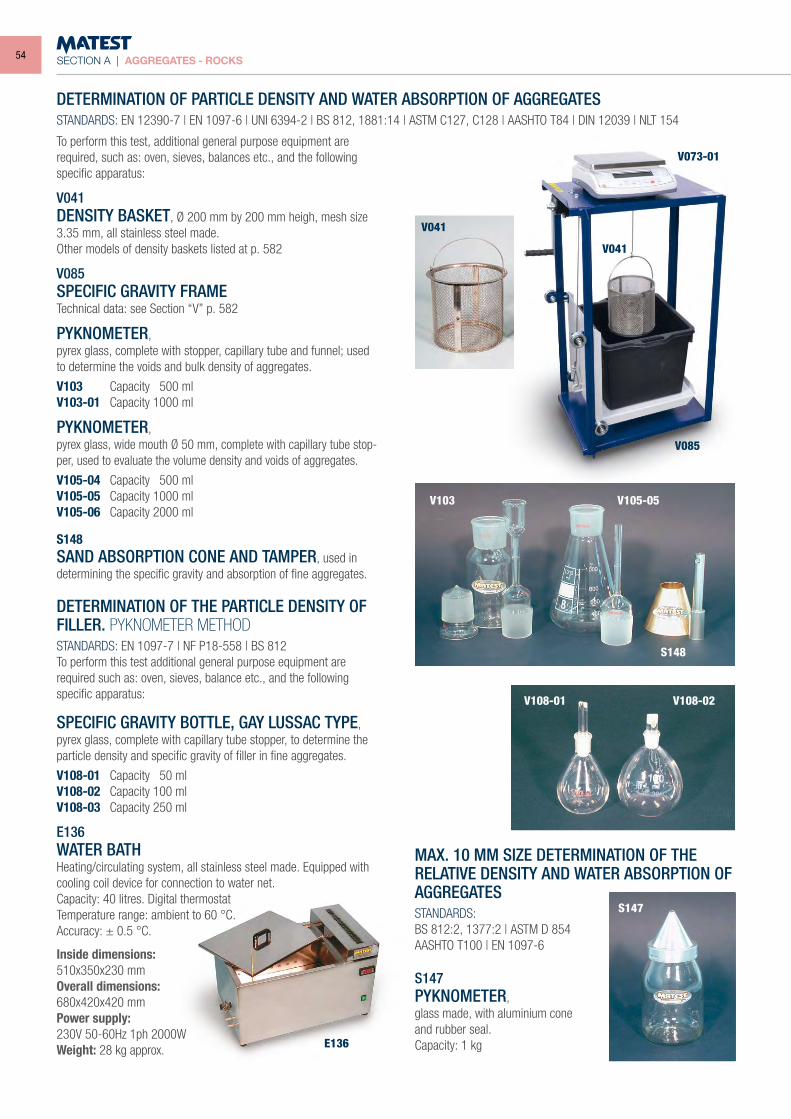
SECTION A | AGGREGATES - ROCKS
To perform this test, additional general purpose equipment are required, such as: oven, sieves, balances etc., and the following specific apparatus:
V041DENSITY BASKET, Ø 200 mm by 200 mm heigh, mesh size 3.35 mm, all stainless steel made.Other models of density baskets listed at p. 582
V085SPECIFIC GRAVITY FRAMETechnical data: see Section “V” p. 582
PYKNOMETER,pyrex glass, complete with stopper, capillary tube and funnel; used to determine the voids and bulk density of aggregates.
V103 Capacity 500 mlV103-01 Capacity 1000 ml
PYKNOMETER,pyrex glass, wide mouth Ø 50 mm, complete with capillary tube stop-per, used to evaluate the volume density and voids of aggregates.
V105-04 Capacity 500 mlV105-05 Capacity 1000 mlV105-06 Capacity 2000 ml
S148SAND ABSORPTION CONE AND TAMPER, used in determining the specific gravity and absorption of fine aggregates.
DETERMINATION OF THE PARTICLE DENSITY OF FILLER. PYKNOMETER METHODSTANDARDS: EN 1097-7 | NF P18-558 | BS 812To perform this test additional general purpose equipment are required such as: oven, sieves, balance etc., and the following specific apparatus:
SPECIFIC GRAVITY BOTTLE, GAY LUSSAC TYPE, pyrex glass, complete with capillary tube stopper, to determine the particle density and specific gravity of filler in fine aggregates.
V108-01 Capacity 50 mlV108-02 Capacity 100 mlV108-03 Capacity 250 ml
E136WATER BATHHeating/circulating system, all stainless steel made. Equipped with cooling coil device for connection to water net.Capacity: 40 litres. Digital thermostatTemperature range: ambient to 60 °C.Accuracy: ± 0.5 °C.
Inside dimensions:510x350x230 mmOverall dimensions:680x420x420 mmPower supply:230V 50-60Hz 1ph 2000WWeight: 28 kg approx.
DETERMINATION OF PARTICLE DENSITY AND WATER ABSORPTION OF AGGREGATESSTANDARDS: EN 12390-7 | EN 1097-6 | UNI 6394-2 | BS 812, 1881:14 | ASTM C127, C128 | AASHTO T84 | DIN 12039 | NLT 154
MAX. 10 MM SIZE DETERMINATION OF THE RELATIVE DENSITY AND WATER ABSORPTION OF AGGREGATESSTANDARDS:BS 812:2, 1377:2 | ASTM D 854AASHTO T100 | EN 1097-6
S147PYKNOMETER,glass made, with aluminium coneand rubber seal.Capacity: 1 kgE136
S147
V108-01
V103
V041
V085
V041
V073-01
V105-05
S148
V108-02
54
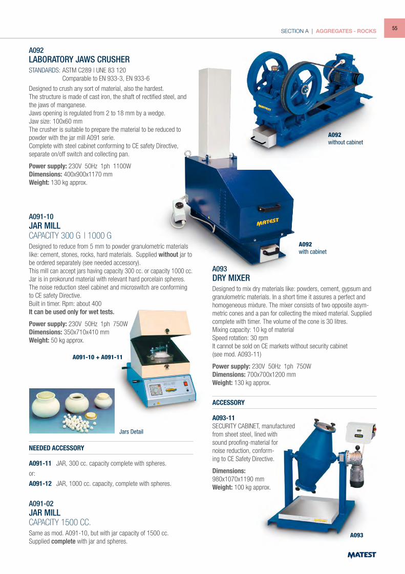
SECTION A | AGGREGATES - ROCKS
A092LABORATORY JAWS CRUSHERSTANDARDS: ASTM C289 | UNE 83 120 Comparable to EN 933-3, EN 933-6
Designed to crush any sort of material, also the hardest.The structure is made of cast iron, the shaft of rectified steel, and the jaws of manganese.Jaws opening is regulated from 2 to 18 mm by a wedge.Jaw size: 100x60 mmThe crusher is suitable to prepare the material to be reduced to powder with the jar mill A091 serie.Complete with steel cabinet conforming to CE safety Directive, separate on/off switch and collecting pan.
Power supply: 230V 50Hz 1ph 1100WDimensions: 400x900x1170 mmWeight: 130 kg approx.
A091-10JAR MILLCAPACITY 300 G | 1000 GDesigned to reduce from 5 mm to powder granulometric materials like: cement, stones, rocks, hard materials. Supplied without jar to be ordered separately (see needed accessory).This mill can accept jars having capacity 300 cc. or capacity 1000 cc.Jar is in prokorund material with relevant hard porcelain spheres.The noise reduction steel cabinet and microswitch are conforming to CE safety Directive.Built in timer. Rpm: about 400It can be used only for wet tests.
Power supply: 230V 50Hz 1ph 750WDimensions: 350x710x410 mmWeight: 50 kg approx.
A093DRY MIXERDesigned to mix dry materials like: powders, cement, gypsum and granulometric materials. In a short time it assures a perfect and homogeneous mixture. The mixer consists of two opposite asym-metric cones and a pan for collecting the mixed material. Supplied complete with timer. The volume of the cone is 30 litres.Mixing capacity: 10 kg of materialSpeed rotation: 30 rpmIt cannot be sold on CE markets without security cabinet(see mod. A093-11)
Power supply: 230V 50Hz 1ph 750WDimensions: 700x700x1200 mmWeight: 130 kg approx.
ACCESSORY
A093-11SECURITY CABINET, manufactured from sheet steel, lined with sound proofing-material for noise reduction, conform-ing to CE Safety Directive.
Dimensions: 980x1070x1190 mmWeight: 100 kg approx.
NEEDED ACCESSORY
A091-11 JAR, 300 cc. capacity complete with spheres.
or:
A091-12 JAR, 1000 cc. capacity, complete with spheres.
A091-02JAR MILLCAPACITY 1500 CC.Same as mod. A091-10, but with jar capacity of 1500 cc.Supplied complete with jar and spheres.
A092without cabinet
A092with cabinet
A091-10 + A091-11
A093
Jars Detail
55
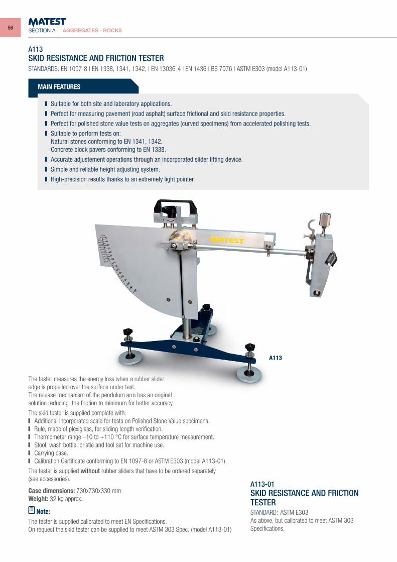
SECTION A | AGGREGATES - ROCKS
A113SKID RESISTANCE AND FRICTION TESTERSTANDARDS: EN 1097-8 | EN 1338, 1341, 1342, | EN 13036-4 | EN 1436 | BS 7976 | ASTM E303 (model A113-01)
The tester measures the energy loss when a rubber slideredge is propelled over the surface under test.The release mechanism of the pendulum arm has an originalsolution reducing the friction to minimum for better accuracy.
The skid tester is supplied complete with: Additional incorporated scale for tests on Polished Stone Value specimens. Rule, made of plexiglass, for sliding length verification. Thermometer range –10 to +110 °C for surface temperature measurement. Stool, wash bottle, bristle and tool set for machine use. Carrying case. Calibration Certificate conforming to EN 1097-8 or ASTM E303 (model A113-01).
The tester is supplied without rubber sliders that have to be ordered separately(see accessories).
Case dimensions: 730x730x330 mmWeight: 32 kg approx.
Note:The tester is supplied calibrated to meet EN Specifications.On request the skid tester can be supplied to meet ASTM 303 Spec. (model A113-01)
A113
MAIN FEATURES
Suitable for both site and laboratory applications. Perfect for measuring pavement (road asphalt) surface frictional and skid resistance properties. Perfect for polished stone value tests on aggregates (curved specimens) from accelerated polishing tests. Suitable to perform tests on:
Natural stones conforming to EN 1341, 1342. Concrete block pavers conforming to EN 1338. Accurate adjustement operations through an incorporated slider lifting device. Simple and reliable height adjusting system. High-precision results thanks to an extremely light pointer.
A113-01SKID RESISTANCE AND FRICTION TESTERSTANDARD: ASTM E303As above, but calibrated to meet ASTM 303 Specifications.
56
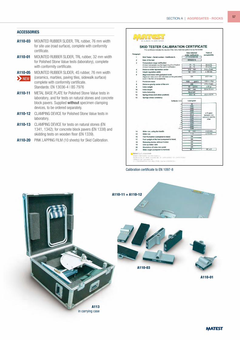
SECTION A | AGGREGATES - ROCKS
A110-11 + A110-12
A110-03
A110-01
ACCESSORIES
A110-03 MOUNTED RUBBER SLIDER, TRL rubber, 76 mm width for site use (road surface), complete with conformity certificate.
A110-01 MOUNTED RUBBER SLIDER, TRL rubber, 32 mm width for Polished Stone Value tests (laboratory), complete with conformity certificate.
A110-05 MOUNTED RUBBER SLIDER, 4S rubber, 76 mm width (ceramics, marbles, paving tiles, sidewalk surface) complete with conformity certificate.
Standards: EN 13036-4 | BS 7976
A110-11 METAL BASE PLATE for Polished Stone Value tests in laboratory, and for tests on natural stones and concrete block pavers. Supplied without specimen clamping devices, to be ordered separately.
A110-12 CLAMPING DEVICE for Polished Stone Value tests in laboratory.
A110-13 CLAMPING DEVICE for tests on natural stones (EN 1341, 1342); for concrete block pavers (EN 1338) and skidding tests on wooden floor (EN 1339).
A110-20 PINK LAPPING FILM (10 sheets) for Skid Calibration.
A113in carrying case
Calibration certificate to EN 1097-8
NEW
57
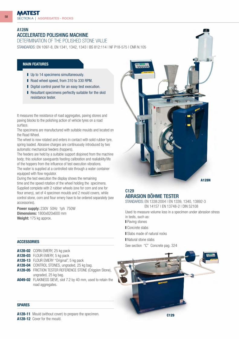
SECTION A | AGGREGATES - ROCKS
A128N
C129
A128NACCELERATED POLISHING MACHINEDETERMINATION OF THE POLISHED STONE VALUE
STANDARDS: EN 1097-8, EN 1341, 1342, 1343 | BS 812:114 | NF P18-575 | CNR N.105
ACCESSORIES
A128-02 CORN EMERY, 25 kg packA128-03 FLOUR EMERY, 5 kg packA128-13 FLOUR EMERY “Original”, 5 kg packA128-04 CONTROL STONES, ungraded, 25 kg bag.A128-05 FRICTION TESTER REFERENCE STONE (Criggion Stone),
ungraded, 25 kg bag.A049-02 FLAKINESS SIEVE, slot 7.2 by 40 mm, used to retain the
road aggregates.
SPARES
A128-11 Mould (without cover) to prepare the specimen.A128-12 Cover for the mould.
C129ABRASION BÖHME TESTERSTANDARDS: EN 1338:2004 | EN 1339, 1340, 13892-3 EN 14157 | EN 13748-2 | DIN 52108Used to measure volume loss in a specimen under abrasion stress in tests, such as: Paving stones
Concrete slabs
Slabs made of natural rocks
Natural stone slabs
See section “C” Concrete pag. 324
It measures the resistance of road aggregates, paving stones and paving blocks to the polishing action of vehicle tyres on a road surface.The specimens are manufactured with suitable moulds and located on the Road Wheel.The wheel is now rotated and enters in contact with solid rubber tyre, spring loaded. Abrasive charges are continuously introduced by two automatic mechanical feeders (hoppers).The feeders are held by a suitable support disjoined from the machine body; this solution saveguards feeding calibration and realiability/life of the hoppers from the influence of test execution vibrations.The water is supplied at a controlled rate through a water container equipped with flow regulator.During the test execution the display shows the remainingtime and the speed rotation of the wheel holding the specimens.Supplied complete with 2 rubber wheels (one for corn and one for flour emery), set of 4 specimen moulds and 2 mould covers, while control stone, corn and flour emery have to be ordered separately (see accessories).
Power supply: 230V 50Hz 1ph 750WDimensions: 1800x820x600 mmWeight: 175 kg approx.
MAIN FEATURES
Up to 14 specimens simultaneously. Road wheel speed, from 310 to 330 RPM. Digital control panel for an easy test execution. Resultant specimens perfectly suitable for the skid
resistance tester.
58
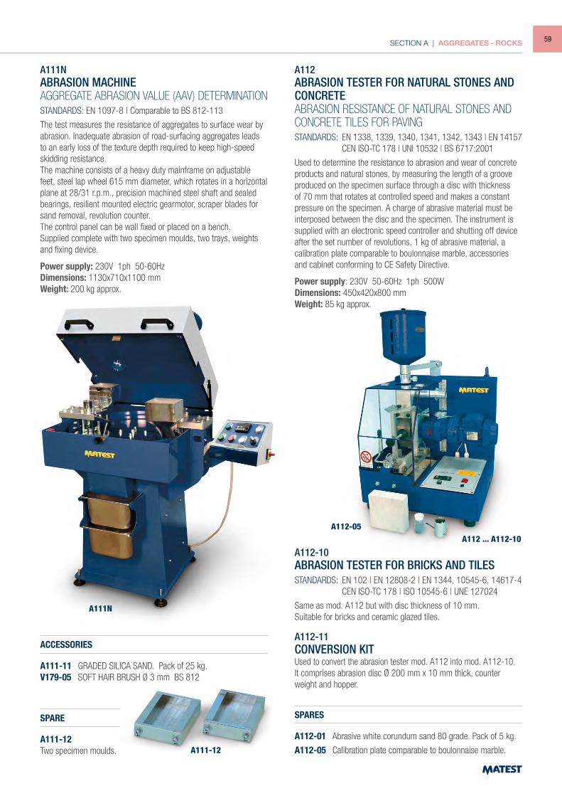
SECTION A | AGGREGATES - ROCKS
A111NABRASION MACHINEAGGREGATE ABRASION VALUE (AAV) DETERMINATION
STANDARDS: EN 1097-8 | Comparable to BS 812-113
The test measures the resistance of aggregates to surface wear by abrasion. Inadequate abrasion of road-surfacing aggregates leads to an early loss of the texture depth required to keep high-speed skidding resistance.The machine consists of a heavy duty mainframe on adjustable feet, steel lap wheel 615 mm diameter, which rotates in a horizontal plane at 28/31 r.p.m., precision machined steel shaft and sealed bearings, resilient mounted electric gearmotor, scraper blades for sand removal, revolution counter.The control panel can be wall fixed or placed on a bench.Supplied complete with two specimen moulds, two trays, weights and fixing device.
Power supply: 230V 1ph 50-60HzDimensions: 1130x710x1100 mm Weight: 200 kg approx.
ACCESSORIES
A111-11 GRADED SILICA SAND. Pack of 25 kg.V179-05 SOFT HAIR BRUSH Ø 3 mm BS 812
SPARE
A111-12Two specimen moulds.
A112ABRASION TESTER FOR NATURAL STONES AND CONCRETEABRASION RESISTANCE OF NATURAL STONES ANDCONCRETE TILES FOR PAVINGSTANDARDS: EN 1338, 1339, 1340, 1341, 1342, 1343 | EN 14157 CEN ISO-TC 178 | UNI 10532 | BS 6717:2001
Used to determine the resistance to abrasion and wear of concrete products and natural stones, by measuring the length of a groove produced on the specimen surface through a disc with thickness of 70 mm that rotates at controlled speed and makes a constant pressure on the specimen. A charge of abrasive material must be interposed between the disc and the specimen. The instrument is supplied with an electronic speed controller and shutting off device after the set number of revolutions, 1 kg of abrasive material, a calibration plate comparable to boulonnaise marble, accessories and cabinet conforming to CE Safety Directive.
Power supply: 230V 50-60Hz 1ph 500WDimensions: 450x420x800 mmWeight: 85 kg approx.
A112-10ABRASION TESTER FOR BRICKS AND TILESSTANDARDS: EN 102 | EN 12808-2 | EN 1344, 10545-6, 14617-4 CEN ISO-TC 178 | ISO 10545-6 | UNE 127024
Same as mod. A112 but with disc thickness of 10 mm.Suitable for bricks and ceramic glazed tiles.
A112-11CONVERSION KITUsed to convert the abrasion tester mod. A112 into mod. A112-10.It comprises abrasion disc Ø 200 mm x 10 mm thick, counter weight and hopper.
SPARES
A112-01 Abrasive white corundum sand 80 grade. Pack of 5 kg.
A112-05 Calibration plate comparable to boulonnaise marble.A111-12
A111N
A112-05A112 ... A112-10
59
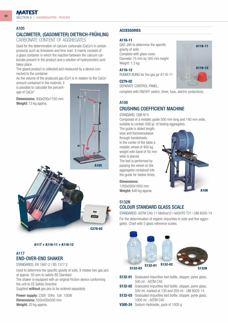
SECTION A | AGGREGATES - ROCKS
A117 + A116-11 + A116-12
C279-02
S132-03S132-01 S132-02
S132N
A105
CALCIMETER, (GASOMETER) DIETRICH-FRÜHLINGCARBONATE CONTENT OF AGGREGATESUsed for the determination of calcium carbonate (CaCo3) in certain products such as limestone and lime marl. It mainly consists of a glass container in which the reaction between the calcium car-bonate present in the product and a solution of hydrocloridric acid takes place.The gased product is collected and measured by a device con-nected to the container.As the volume of the produced gas (Co2) is in relation to the CaCo2 amount contained in the material, it is possible to calculate the percent-age of CaCo3
Dimensions: 400x200x1100 mmWeight: 13 kg approx.
A117END-OVER-END SHAKERSTANDARDS: EN 1997-2 | BS 1377:2
Used to determine the specific gravity of soils, it rotates two gas jars at approx. 50 rpm to satisfy BS Standard.The shaker is equipped with an original friction device conforming the unit to CE Safety Directive.Supplied without gas jars to be ordered separately
Power supply: 230V 50Hz 1ph 150WDimensions: 550x430x500 mmWeight: 20 kg approx.
ACCESSORIES
A116-11GAS JAR to determine the specificgravity of soils.Complete with glass cover.Diameter 75 mm by 300 mm heightWeight: 1.3 kg
A116-12RUBBER BUNG for the gas jar A116-11
C279-02SEPARATE CONTROL PANEL,
complete with ON/OFF switch, timer, fuse, electric protections.
A108
CRUSHING COEFFICIENT MACHINESTANDARD: CNR N°4Composed of a metallic guide 500 mm long and 140 mm wide, suitable to contain 500 gr. of testing aggregates.The guide is slided length-wise and transversalwise through handwheels.In the center of the table a metallic wheel of 400 kg weight with band of 50 mm wide is placed.The test is performed by passing the wheel on the aggregates contained into the guide for twelve times.
Dimensions:1200x500x1850 mmWeight: 640 kg approx.
S132NCOLOUR STANDARD GLASS SCALESTANDARDS: ASTM C40-11 Method D | AASHTO T21 | UNI 8020-14
For the determination of organic impurities in soils and fine aggre-gates. Chart with 5 glass reference scales.
S132-01 Graduated impurities test bottle, stopper, pyrex glass, 500 ml - ASTM C40
S132-02 Graduated impurities test bottle, stopper, pyrex glass, 500 ml, marked at 130 and 200 ml - UNI 8020-14
S132-03 Graduated impurities test bottle, stopper, pyrex glass, 1000 ml - ASTM C40
V300-24 Sodium Hydroxide, pack of 1000 g
A105
A116-11
A116-12
A108
60
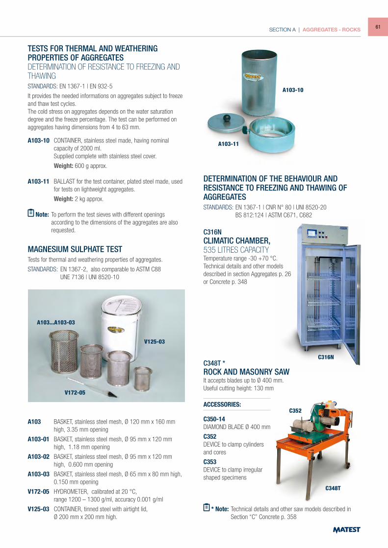
SECTION A | AGGREGATES - ROCKS
TESTS FOR THERMAL AND WEATHERINGPROPERTIES OF AGGREGATESDETERMINATION OF RESISTANCE TO FREEZING AND THAWINGSTANDARDS: EN 1367-1 | EN 932-5
It provides the needed informations on aggregates subject to freeze and thaw test cycles.The cold stress on aggregates depends on the water saturation degree and the freeze percentage. The test can be performed on aggregates having dimensions from 4 to 63 mm.
A103-10 CONTAINER, stainless steel made, having nominal capacity of 2000 ml.
Supplied complete with stainless steel cover.
Weight: 600 g approx.
A103-11 BALLAST for the test container, plated steel made, used for tests on lightweight aggregates.
Weight: 2 kg approx.
Note: To perform the test sieves with different openings according to the dimensions of the aggregates are also requested.
MAGNESIUM SULPHATE TESTTests for thermal and weathering properties of aggregates.
STANDARDS: EN 1367-2, also comparable to ASTM C88 UNE 7136 | UNI 8520-10
A103 BASKET, stainless steel mesh, Ø 120 mm x 160 mm high, 3.35 mm opening
A103-01 BASKET, stainless steel mesh, Ø 95 mm x 120 mm high, 1.18 mm opening
A103-02 BASKET, stainless steel mesh, Ø 95 mm x 120 mm high, 0.600 mm opening
A103-03 BASKET, stainless steel mesh, Ø 65 mm x 80 mm high, 0.150 mm opening
V172-05 HYDROMETER, calibrated at 20 °C, range 1200 – 1300 g/ml, accuracy 0.001 g/ml
V125-03 CONTAINER, tinned steel with airtight lid, Ø 200 mm x 200 mm high.
DETERMINATION OF THE BEHAVIOUR AND RESISTANCE TO FREEZING AND THAWING OF AGGREGATESSTANDARDS: EN 1367-1 | CNR N° 80 | UNI 8520-20 BS 812:124 | ASTM C671, C682
C316NCLIMATIC CHAMBER,535 LITRES CAPACITYTemperature range -30 +70 °C.Technical details and other modelsdescribed in section Aggregates p. 26or Concrete p. 348
C348T *ROCK AND MASONRY SAWIt accepts blades up to Ø 400 mm.Useful cutting height: 130 mm
* Note: Technical details and other saw models described in Section “C” Concrete p. 358
ACCESSORIES:
C350-14DIAMOND BLADE Ø 400 mm
C352DEVICE to clamp cylindersand cores
C353DEVICE to clamp irregularshaped specimens
A103...A103-03
V125-03
V172-05
C348T
C352
C316N
A103-11
A103-10
61
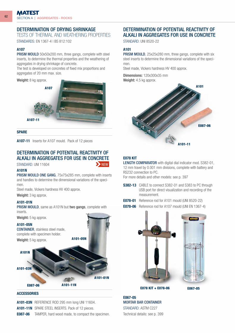
SECTION A | AGGREGATES - ROCKS
DETERMINATION OF DRYING SHRINKAGETESTS OF THERMAL AND WEATHERING PROPERTIESSTANDARDS: EN 1367-4 | BS 812:102
A107PRISM MOULD 50x50x200 mm, three gangs, complete with steel inserts, to determine the thermal properties and the weathering of aggregates in drying shrinkage of concrete.The test is developed on concretes of fixed mix proportions and aggregates of 20 mm max. size.
Weight: 8 kg approx.
SPARE
A107-11 Inserts for A107 mould. Pack of 12 pieces
DETERMINATION OF POTENTIAL REACTIVITY OF ALKALI IN AGGREGATES FOR USE IN CONCRETESTANDARD: UNI 11604
A101NPRISM MOULD ONE GANG, 75x75x285 mm, complete with inserts and handles to determine the dimensional variations of the speci-men.Steel made, Vickers hardness HV 400 approx.
Weight: 3 kg approx.
A101-01NPRISM MOULD, same as A101N but two gangs, complete with inserts.
Weight: 5 kg approx.
A101-05NCONTAINER, stainless steel made,complete with specimen holder.
Weight: 5 kg approx.
DETERMINATION OF POTENTIAL REACTIVITY OF ALKALI IN AGGREGATES FOR USE IN CONCRETESTANDARD: UNI 8520-22
A101PRISM MOULD, 25x25x280 mm, three gangs, complete with six steel inserts to determine the dimensional variations of the speci-men.Steel made, Vickers hardness HV 400 approx.
Dimensions: 120x300x35 mmWeight: 4.5 kg approx.
ACCESSORIES
A101-03N REFERENCE ROD 295 mm long UNI 11604.
A101-11N SPARE STEEL INSERTS. Pack of 12 pieces.
E087-06 TAMPER, hard wood made, to compact the specimen.
E078 KITLENGTH COMPARATOR with digital dial indicator mod. S382-01, 12 mm travel by 0.001 mm divisions, complete with battery and RS232 connection to PC.For more details and other models: see p. 397
S382-13 CABLE to connect S382-01 and S383 to PC through USB port for direct visualization and recording of the measurement.
E078-01 Reference rod for A101 mould (UNI 8520-22)
E078-06 Reference rod for A107 mould (UNI EN 1367-4)
E067-05MORTAR BAR CONTAINERSTANDARD: ASTM C227
Technical details: see p. 399
A107 A101
A101-11
E087-06
E067-05E078 KIT + E078-06
A107-11
A101N
A101-11NE087-06
A101-03N
A101-01N
A101-05N
NEW
62
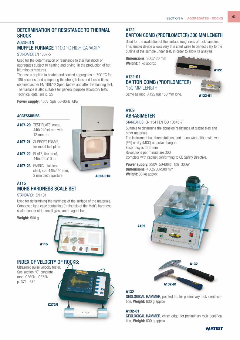
SECTION A | AGGREGATES - ROCKS
DETERMINATION OF RESISTANCE TO THERMAL SHOCKA023-01NMUFFLE FURNACE 1100 °C HIGH CAPACITYSTANDARD: EN 1367-5
Used for the determination of resistance to thermal shock of aggregates subject to heating and drying, in the production of hot bituminous mixtures.The test is applied to heated and soaked aggregates at 700 °C for 180 seconds, and comparing the strength loss and loss in fines, obtained as per EN 1097-2 Spec. before and after the heating test.The furnace is also suitable for general purpose laboratory testsTechnical data: see p. 25
Power supply: 400V 3ph 50-60Hz 6Kw
ACCESSORIES
A107-20 TEST PLATE, metal, 440x240x4 mm with 12 mm rim
A107-21 SUPPORT FRAME, for metal test plate.
A107-22 PLATE, fire proof, 445x250x10 mm
A107-23 FABRIC, stainless steel, size 445x250 mm, 2 mm cloth aperture A023-01N
A109ABRASIMETERSTANDARDS: EN 154 | EN ISO 10545-7
Suitable to determine the abrasion resistance of glazed tiles and other materials.The instrument has three stations, and it can work either with wet (PEI) or dry (MCC) abrasive charges.Eccentricy is 22.5 mmRevolutions per minute are 300Complete with cabinet conforming to CE Safety Directive.
Power supply: 230V 50-60Hz 1ph 300WDimensions: 400x700x500 mmWeight: 38 kg approx.
A115MOHS HARDNESS SCALE SETSTANDARD: EN 101
Used for determining the hardness of the surface of the materials.Composed by a case containing 9 minerals of the Moh’s hardness scale, copper strip, small glass and magnet bar.
Weight: 500 g
INDEX OF VELOCITY OF ROCKS:Ultrasonic pulse velocity tester.See section “C” concretemod. C369N...C372Np. 371...372
A122BARTON COMB (PROFILOMETER) 300 MM LENGTHUsed for the evaluation of the surface roughness of rock samples.This simple device allows very thin steel wires to perfectly lay to the outline of the sample under test, in order to allow its analysis.
Dimensions: 300x120 mmWeight: 1 kg approx.
A122-01BARTON COMB (PROFILOMETER)150 MM LENGTHSame as mod. A122 but 150 mm long.
A132GEOLOGICAL HAMMER, pointed tip, for preliminary rock identifica-tion. Weight: 600 g approx
A132-01GEOLOGICAL HAMMER, chisel edge, for preliminary rock identifica-tion. Weight: 600 g approx
A109
A115
C372N
A132-01
A132
A122-01
A122
63
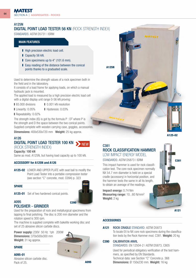
SECTION A | AGGREGATES - ROCKS
A125N
A121
A095
C390
A125-02
C381
A125NDIGITAL POINT LOAD TESTER 56 KN (ROCK STRENGTH INDEX)STANDARDS: ASTM D5731 | ISRM
ACCESSORY for A125N and A126
A125-02 LOWER AND UPPER PLATE with seat ball to modify the Point Load Tester into a portable compression tester
(see section “C” concrete, mod. C094) p. 323
SPARE
A125-01 Set of two hardened conical points.
C381ROCK CLASSIFICATION HAMMERLOW IMPACT ENERGY MODELSTANDARDS: ASTM D5873 | ISRM
This impact hammer is used for rock classifi-cation test. The core rock specimen normally NX 54.7 mm diameter is held on a special cradle (accessory) in horizontal position, and the hammer tests the same in all its length, to obtain an average of the readings.
Impact energy: 0.74 NmMeasuring range: 10...60 N/mm2
Weight: 2 kg
ACCESSORIES
A121 ROCK CRADLE STANDARD: ASTM D5873 To locate EX to NX core rock specimens during the classifica-
tion tests by the Rock Hammer mod. C381. Weight: 20 kg
C390 CALIBRATION ANVIL STANDARDS: EN 12504-2 | ASTM D5873, C805
Used for periodical obligatory verification of the test ham-mers, as specified by EN Standards.
Technical data: see Section “C” Concrete p. 368 Dimensions: Ø 150x230 mm. Weight: 16 kg
A095POLISHER - GRINDERUsed for the preparation of rock and metallurgical specimens from lapping to final polishing. The disc is 200 mm diameter and the rotation speed is 300 rpm. The machine is supplied complete with bakelite working disc and set of 25 abrasive silicon carbide discs.
Power supply: 230V 50 Hz 1ph 200WDimensions: 370x500x300 mmWeight: 31 kg approx.
SPARE
A095-01Abrasive silicon carbide disc. Pack of 25.
MAIN FEATURES
High precision electric load cell. Capacity 56 kN. Core specimens up to 4" (101.6 mm). Easy reading of the distance between the conical
points thanks to a graduated scale.
Used to determine the strength values of a rock specimen both in the field and in the laboratory.It consists of a load frame for applying loads, on which a manual hydraulic jack is mounted.The applied load is measured by a high precision electric load cell with a digital display unit range 0-56 kN proving:
65.000 divisions 0.001 kN resolution
Linearity: 0.05% Hysteresis: 0.03%
Repeatability: 0.02%
The strength index (IS) is got by the formula P : D2 where P isthe strength and D the space between the two conical points.Supplied complete with wooden carrying case, goggles, accessories.
Dimensions: 400x530x720 mm Weight: 25 kg approx.
A126DIGITAL POINT LOAD TESTER 100 KN(ROCK STRENGTH INDEX)Capacity: 100 kNSame as mod. A125N, but having load capacity up to 100 kN.
NEW
64
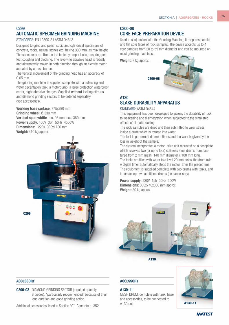
SECTION A | AGGREGATES - ROCKS
C299AUTOMATIC SPECIMEN GRINDING MACHINESTANDARDS: EN 12390-2 | ASTM D4543
Designed to grind and polish cubic and cylindrical specimens of concrete, rocks, natural stones etc. having 380 mm. as max height.The specimens are fixed to the table by proper bolts, ensuring per-fect coupling and blocking. The revolving abrasive head is radially and alternatively moved in both direction through an electric motor actuated by a push button. The vertical mouvement of the grinding head has an accuracy of 0.05 mm.The grinding machine is supplied complete with a collecting and water decantation tank, a motorpump, a large protection waterproof carter, eight abrasive charges. Supplied without locking stirrups and diamond grinding sectors to be ordered separately(see accessories).
Working base surface: 775x280 mmGrinding wheel: Ø 330 mmVertical span width: min. 95 mm max. 380 mmPower supply: 400V 3ph 50Hz 4500WDimensions: 1220x1080x1730 mmWeight: 410 kg approx.
ACCESSORY
C300-02 DIAMOND GRINDING SECTOR (required quantity: 8 pieces), “particularly recommended” because of their
long duration and good grinding action.
Additional accessories listed in Section “C” Concrete p. 352
C300-08CORE FACE PREPARATION DEVICEUsed in conjunction with the Grinding Machine, it prepares parallel and flat core faces of rock samples. The device accepts up to 4 core samples from 20 to 55 mm diameter and can be mounted on most grinding machines.
Weight: 7 kg approx.
A130SLAKE DURABILITY APPARATUSSTANDARD: ASTM D4644This equipment has been developed to assess the durability of rock to weakening and disintegration when subjected to the simulated effects of climatic slaking.The rock samples are dried and then submitted to wear stress inside a drum which is rotated into water.The test is performed different times and the wear is given by the loss in weight of the sample.The system incorporates a motor drive unit mounted on a baseplate which revolves two (or up to four) stainless steel drums manufac-tured from 2 mm mesh, 140 mm diameter x 100 mm long.The tanks are filled with water to a level 20 mm below the drum axis.A digital timer automatically stops the motor after the preset time.The equipment is supplied complete with two drums with tanks, and it can accept two additional drums (see accessory).
Power supply: 230V 1ph 50Hz 250WDimensions: 350x740x300 mm approx.Weight: 30 kg approx.
ACCESSORY
A130-11MESH DRUM, complete with tank, baseand accessories, to be connected toA130 unit.
C300-08
C299
A130
A130-11
65
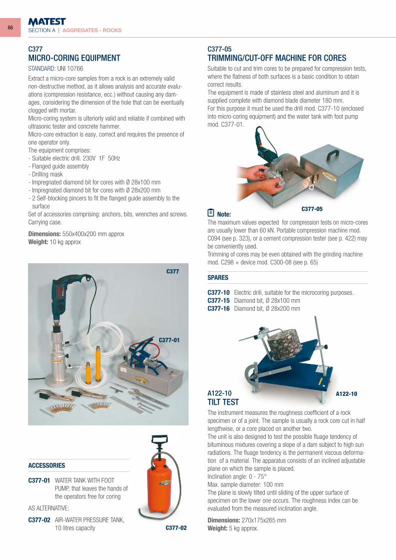
SECTION A | AGGREGATES - ROCKS
C377MICRO-CORING EQUIPMENTSTANDARD: UNI 10766
Extract a micro-core samples from a rock is an extremely valid non-destructive method, as it allows analysis and accurate evalu-ations (compression resistance, ecc.) without causing any dam-ages, considering the dimension of the hole that can be eventually clogged with mortar.Micro-coring system is ulteriorly valid and reliable if combined with ultrasonic tester and concrete hammer.Micro-core extraction is easy, correct and requires the presence of one operator only.The equipment comprises:- Suitable electric drill. 230V 1F 50Hz- Flanged guide assembly- Drilling mask- Impregnated diamond bit for cores with Ø 28x100 mm- Impregnated diamond bit for cores with Ø 28x200 mm- 2 Self-blocking pincers to fit the flanged guide assembly to the
surfaceSet of accessories comprising: anchors, bits, wrenches and screws.Carrying case.
Dimensions: 550x400x200 mm approxWeight: 10 kg approx
ACCESSORIES
C377-01 WATER TANK WITH FOOT PUMP, that leaves the hands of the operators free for coring
AS ALTERNATIVE:
C377-02 AIR-WATER PRESSURE TANK, 10 litres capacity
SPARES
C377-10 Electric drill, suitable for the microcoring purposes.C377-15 Diamond bit, Ø 28x100 mmC377-16 Diamond bit, Ø 28x200 mm
C377-05TRIMMING/CUT-OFF MACHINE FOR CORESSuitable to cut and trim cores to be prepared for compression tests, where the flatness of both surfaces is a basic condition to obtain correct results.The equipment is made of stainless steel and aluminum and it is supplied complete with diamond blade diameter 180 mm.For this purpose it must be used the drill mod. C377-10 (enclosed into micro-coring equipment) and the water tank with foot pump mod. C377-01.
Note:The maximum values expected for compression tests on micro-cores are usually lower than 60 kN. Portable compression machine mod. C094 (see p. 323), or a cement compression tester (see p. 422) may be conveniently used.Trimming of cores may be even obtained with the grinding machine mod. C298 + device mod. C300-08 (see p. 65)
C377
C377-01
C377-02
C377-05
A122-10TILT TESTThe instrument measures the roughness coefficient of a rock specimen or of a joint. The sample is usually a rock core cut in half lengthwise, or a core placed on another two.The unit is also designed to test the possible fluage tendency of bituminous mixtures covering a slope of a dam subject to high sun radiations. The fluage tendency is the permanent viscous deforma-tion of a material. The apparatus consists of an inclined adjustable plane on which the sample is placed.Inclination angle: 0 - 75°Max. sample diameter: 100 mmThe plane is slowly tilted until sliding of the upper surface of specimen on the lower one occurs. The roughness index can be evaluated from the measured inclination angle.
Dimensions: 270x175x265 mm Weight: 5 kg approx.
A122-10
66
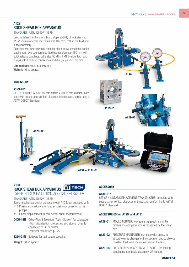
SECTION A | AGGREGATES - ROCKS
A129ROCK SHEAR BOX APPARATUSSTANDARDS: ASTM D5607* | ISRM
Used to determine the strength and slope stability of rock size max 115x125 mm or cores max. diameter 102 mm, both in the field and in the laboratory.Complete with two horizontal rams for shear in two directions, vertical loading ram, two bourdon tube load gauges diameter 150 mm with quick release couplings, calibrated 50 kN x 1 kN division, two hand pumps with hydraulic connections and dial gauge 25x0.01 mm.
Dimensions: 600x250x460 mmWeight: 46 kg approx.
ACCESSORY
A129-03* SET OF 4 DIAL GAUGES 10 mm stroke x 0.002 mm division, com-plete with supports for vertical displacement measure, conforming to ASTM D5607 Standard.
A131ROCK SHEAR BOX APPARATUSCYBER-PLUS 8 EVOLUTION ACQUISITION SYSTEMSTANDARDS: ASTM D5607* | ISRMSame mechanical design as basic model A129, but equipped with:n° 2 Pressure transducers for load acquisition, connected to the
pumps.n° 1 Linear displacement transducer for shear measurement.
C405-15N Cyber-Plus 8 Evolution “Touch-Screen” for data acqui-sition, visualization, processing and storing, directly connected to PC or printer.
Technical details: see p. 377
S224-21N Software for test data processing.
Weight: 50 kg approx.
ACCESSORY
A131-01*SET OF 4 LINEAR DISPLACEMENT TRANSDUCERS, complete with supports, for vertical displacement measure, conforming to ASTM D5607 Standard.
ACCESSORIES for A129 and A131
A129-01 MOULD FORMER, to prepare the specimen in the dimensions and geometry as requested by the shear box.
A129-02 PRESSURE MAINTAINER, complete with pump, to absorb volume changes of the specimen and to allow a constant load to be maintained during the test.
A129-04 BRITISH GYPSUM CRYSTACAL PLASTER, for casting specimens into mould assembly, 25 kg bag.
A129
A129-01
A129-02
A131 + A131-01
A129-03
67
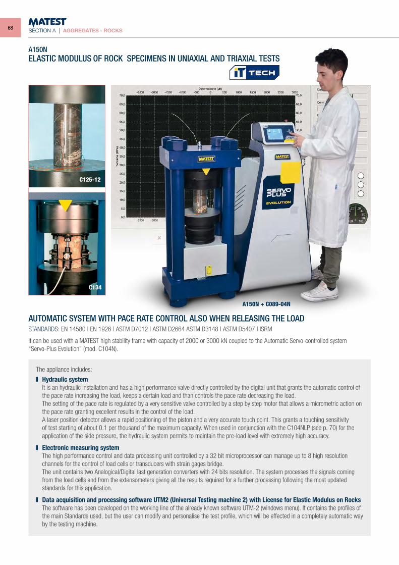
SECTION A | AGGREGATES - ROCKS
A150NELASTIC MODULUS OF ROCK SPECIMENS IN UNIAXIAL AND TRIAXIAL TESTS
The appliance includes:
Hydraulic system It is an hydraulic installation and has a high performance valve directly controlled by the digital unit that grants the automatic control of
the pace rate increasing the load, keeps a certain load and than controls the pace rate decreasing the load. The setting of the pace rate is regulated by a very sensitive valve controlled by a step by step motor that allows a micrometric action on
the pace rate granting excellent results in the control of the load. A laser position detector allows a rapid positioning of the piston and a very accurate touch point. This grants a touching sensitivity
of test starting of about 0.1 per thousand of the maximum capacity. When used in conjunction with the C104NLP (see p. 70) for the application of the side pressure, the hydraulic system permits to maintain the pre-load level with extremely high accuracy.
Electronic measuring system The high performance control and data processing unit controlled by a 32 bit microprocessor can manage up to 8 high resolution
channels for the control of load cells or transducers with strain gages bridge. The unit contains two Analogical/Digital last generation converters with 24 bits resolution. The system processes the signals coming
from the load cells and from the extensometers giving all the results required for a further processing following the most updated standards for this application.
Data acquisition and processing software UTM2 (Universal Testing machine 2) with License for Elastic Modulus on Rocks The software has been developed on the working line of the already known software UTM-2 (windows menu). It contains the profiles of
the main Standards used, but the user can modify and personalise the test profile, which will be effected in a completely automatic way by the testing machine.
C125-12
C134
AUTOMATIC SYSTEM WITH PACE RATE CONTROL ALSO WHEN RELEASING THE LOADSTANDARDS: EN 14580 | EN 1926 | ASTM D7012 | ASTM D2664 ASTM D3148 | ASTM D5407 | ISRM
It can be used with a MATEST high stability frame with capacity of 2000 or 3000 kN coupled to the Automatic Servo-controlled system“Servo-Plus Evolution” (mod. C104N).
A150N + C089-04N
68
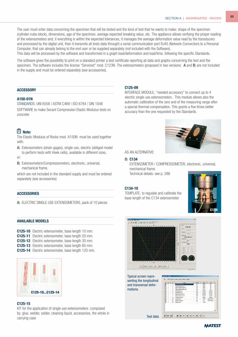
SECTION A | AGGREGATES - ROCKS
The user must enter data concerning the specimen that will be tested and the kind of test that he wants to make: shape of the specimen (cylinder-cube-block), dimensions, age of the specimen, average expected breaking value, etc. The appliance allows verifying the proper reading of the extensometers and, if everything is within the expected tolerances, it manages the average deformation value read by the transducers and processed by the digital unit, than it transmits all tests data throught a serial communication port RJ45 (Network Connection) to a Personal Computer, that can already belong to the end user or be supplied separately (not included with the Software).This data will be processed by the software and transformed in a graph load/deformation and load/time, following the specific Standards.
The software gives the possibility to print on a standard printer a test certificate reporting all data and graphs concerning the test and the specimen. The software includes the license “Servonet” mod. C123N. The extensometers (proposed in two versions: A and B) are not included in the supply and must be ordered separately (see accessories).
ACCESSORY
A150-01NSTANDARDS: UNI 6556 | ASTM C469 | ISO 6784 | DIN 1048
SOFTWARE to make Secant Compression Elastic Modulus tests on concrete
Note:The Elastic Modulus of Rocks mod. A150N must be used together with:
A) Extensometers (strain gages), single use, electric (obliged model to perform tests with Hoek cells), available in different sizes,
or:
B) Extensometers/Compressometers, electronic, universal, mechanical frame,
which are not included in the standard supply and must be ordered separately (see accessories)
ACCESSORIES
A) ELECTRIC SINGLE USE EXTENSOMETERS, pack of 10 pieces
AVAILABLE MODELS
C125-10 Electric extensometer, base length 10 mm.C125-11 Electric extensometer, base length 20 mm.C125-12 Electric extensometer, base length 30 mm.C125-13 Electric extensometer, base length 60 mm.C125-14 Electric extensometer, base length 120 mm.
C125-15KIT for the application of single use extensometers composed by: glue, welder, solder, cleaning liquid, accessories, the whole in carrying case
C125-09INTERFACE MODULE, “needed accessory” to connect up to 4 electric single use extensometers . This module allows also the automatic calibration of the zero and of the measuring range after a special thermal compensation. This grants a five times better accuracy than the one requested by the Standards.
AS AN ALTERNATIVE:
B) C134 EXTENSOMETER / COMPRESSOMETER, electronic, universal,
mechanical frame. Technical details: see p. 286
C134-10TEMPLATE, to regulate and calibrate the base length of the C134 extensometer
C134
Typical screen repre-senting the longitudinal and transversal defor-mations.
Test data
C125-10...C125-14
69
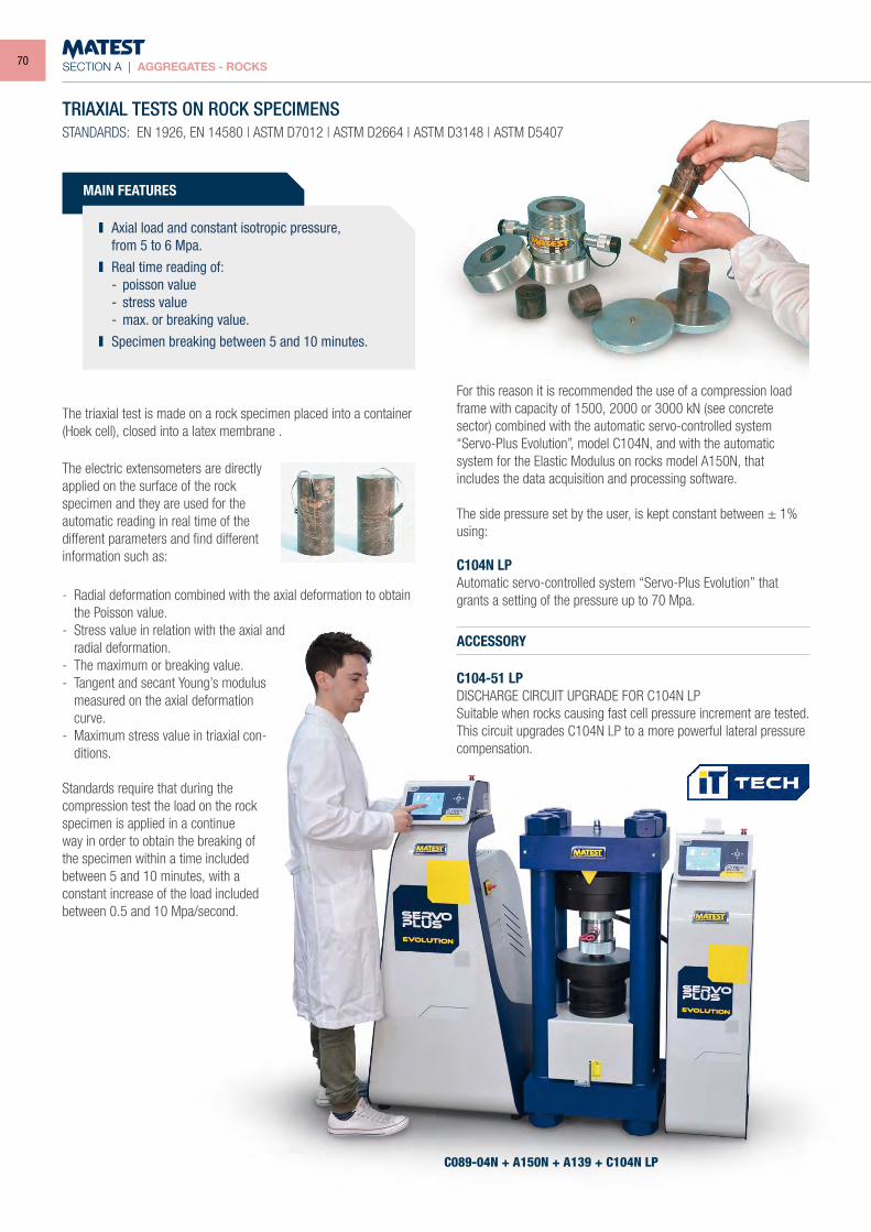
SECTION A | AGGREGATES - ROCKS
The triaxial test is made on a rock specimen placed into a container (Hoek cell), closed into a latex membrane .
TRIAXIAL TESTS ON ROCK SPECIMENSSTANDARDS: EN 1926, EN 14580 | ASTM D7012 | ASTM D2664 | ASTM D3148 | ASTM D5407
The electric extensometers are directly applied on the surface of the rock specimen and they are used for the automatic reading in real time of the different parameters and find different information such as:
- Radial deformation combined with the axial deformation to obtain the Poisson value.
- Stress value in relation with the axial and radial deformation.
- The maximum or breaking value.- Tangent and secant Young’s modulus
measured on the axial deformation curve.
- Maximum stress value in triaxial con-ditions.
Standards require that during the compression test the load on the rock specimen is applied in a continue way in order to obtain the breaking of the specimen within a time included between 5 and 10 minutes, with a constant increase of the load included between 0.5 and 10 Mpa/second.
For this reason it is recommended the use of a compression load frame with capacity of 1500, 2000 or 3000 kN (see concrete sector) combined with the automatic servo-controlled system“Servo-Plus Evolution”, model C104N, and with the automatic system for the Elastic Modulus on rocks model A150N, that includes the data acquisition and processing software.
The side pressure set by the user, is kept constant between ± 1% using:
C104N LPAutomatic servo-controlled system “Servo-Plus Evolution” that grants a setting of the pressure up to 70 Mpa.
ACCESSORY
C104-51 LPDISCHARGE CIRCUIT UPGRADE FOR C104N LPSuitable when rocks causing fast cell pressure increment are tested. This circuit upgrades C104N LP to a more powerful lateral pressure compensation.
MAIN FEATURES
Axial load and constant isotropic pressure, from 5 to 6 Mpa. Real time reading of:
- poisson value - stress value - max. or breaking value. Specimen breaking between 5 and 10 minutes.
C089-04N + A150N + A139 + C104N LP
70
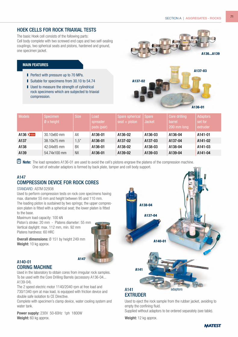
SECTION A | AGGREGATES - ROCKS
HOEK CELLS FOR ROCK TRIAXIAL TESTSThe basic Hoek cell consists of the following parts:Cell body complete with two screwed end caps and two self-sealing couplings, two spherical seats and pistons, hardened and ground, one specimen jacket.
Models Specimen Size Load Spare spherical Spare Core drilling AdaptorsØ x height spreader seat + piston Jacket barrel set for
pads (pair) 200 mm long extruder
A136 30.10x60 mm AX A136-01 A136-02 A136-03 A136-04 A141-01
A137 38.10x75 mm 1,5” A136-01 A137-02 A137-03 A137-04 A141-02
A138 42.04x85 mm BX A136-01 A138-02 A138-03 A138-04 A141-03
A139 54.74x100 mm NX A136-01 A139-02 A139-03 A139-04 A141-04
NEW
Note: The load spreaders A136-01 are used to avoid the cell’s pistons engrave the platens of the compression machine. One set of extruder adaptors is formed by back plate, tamper and cell body support.
A140-01CORING MACHINEUsed in the laboratory to obtain cores from irregular rock samples. To be used with the Core Drilling Barrels (accessory A136-04...A139-04).The 2 speed electric motor 1140/2040 rpm at free load and 730/1340 rpm at max load, is equipped with friction device and double safe isolation to CE Directive.Complete with specimen’s clamp device, water cooling system and water tank.
Power supply: 230V 50-60Hz 1ph 1800WWeight: 60 kg approx.
A141EXTRUDERUsed to eject the rock sample from the rubber jacket, avoiding to empty the confining fluid.Supplied without adaptors to be ordered separately (see table).
Weight: 12 kg approx.
A147COMPRESSION DEVICE FOR ROCK CORESSTANDARD: ASTM D2938Used to perform compression tests on rock core specimens having max. diameter 55 mm and height between 95 and 110 mm.The loading piston is sustained by two springs; the upper compres-sion platen is fitted with a spherical seat; the lower platen is fitted to the base.Maximum load capacity: 100 kNPiston’s stroke: 20 mm - Platens diameter: 55 mmVertical daylight: max. 112 mm, min. 92 mmPlatens hardness: 60 HRC
Overall dimensions: Ø 151 by height 249 mmWeight: 10 kg approx.
A136...A139
A137-02
A137-03
A136-01
A138-04
A137-04
A140-01
A141
A147
adaptors
MAIN FEATURES
Perfect with pressure up to 70 MPa. Suitable for specimens from 30.10 to 54.74 Used to measure the strength of cylindrical
rock specimens which are subjected to triaxial compression.
71
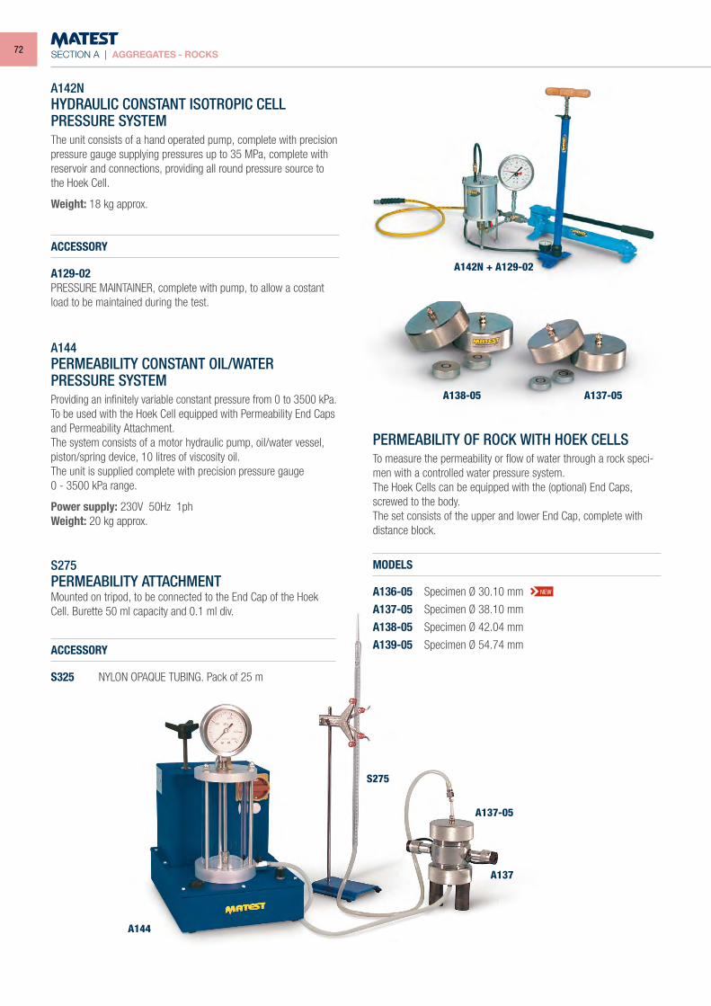
SECTION A | AGGREGATES - ROCKS
A142NHYDRAULIC CONSTANT ISOTROPIC CELLPRESSURE SYSTEMThe unit consists of a hand operated pump, complete with precision pressure gauge supplying pressures up to 35 MPa, complete with reservoir and connections, providing all round pressure source to the Hoek Cell.
Weight: 18 kg approx.
ACCESSORY
A129-02PRESSURE MAINTAINER, complete with pump, to allow a costant load to be maintained during the test.
PERMEABILITY OF ROCK WITH HOEK CELLSTo measure the permeability or flow of water through a rock speci-men with a controlled water pressure system.The Hoek Cells can be equipped with the (optional) End Caps, screwed to the body.The set consists of the upper and lower End Cap, complete with distance block.
MODELS
A136-05 Specimen Ø 30.10 mm
A137-05 Specimen Ø 38.10 mm
A138-05 Specimen Ø 42.04 mm
A139-05 Specimen Ø 54.74 mm
S275PERMEABILITY ATTACHMENTMounted on tripod, to be connected to the End Cap of the Hoek Cell. Burette 50 ml capacity and 0.1 ml div.
ACCESSORY
S325 NYLON OPAQUE TUBING. Pack of 25 m
A144PERMEABILITY CONSTANT OIL/WATERPRESSURE SYSTEMProviding an infinitely variable constant pressure from 0 to 3500 kPa.To be used with the Hoek Cell equipped with Permeability End Caps and Permeability Attachment.The system consists of a motor hydraulic pump, oil/water vessel, piston/spring device, 10 litres of viscosity oil.The unit is supplied complete with precision pressure gauge0 - 3500 kPa range.
Power supply: 230V 50Hz 1phWeight: 20 kg approx.
NEW
A144
S275
A138-05
A142N + A129-02
A137-05
A137-05
A137
72
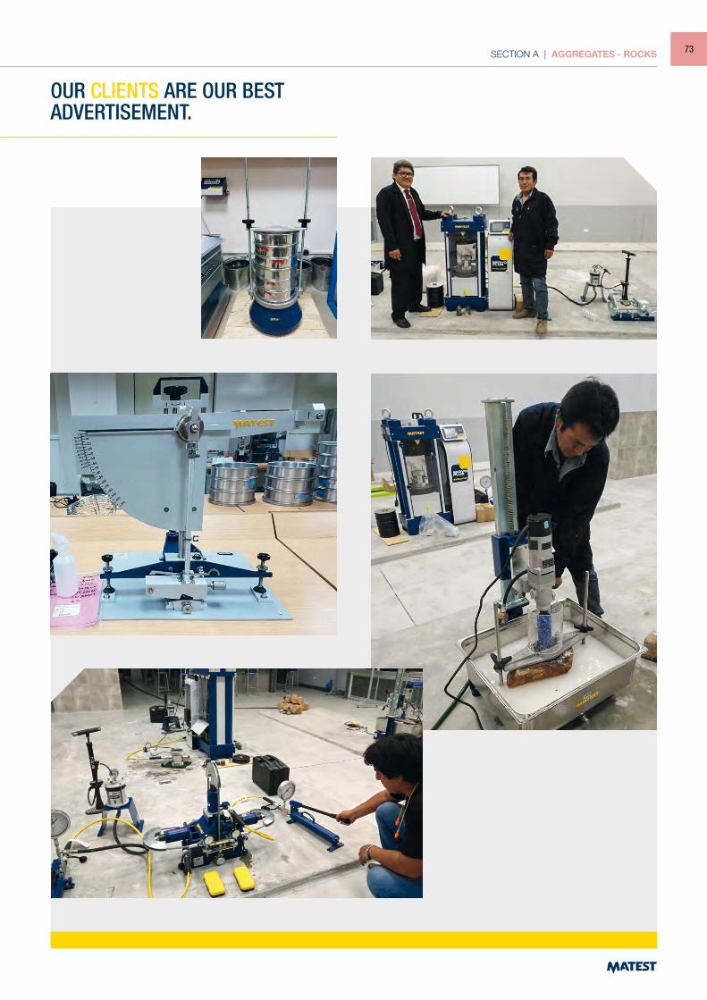
SECTION A | AGGREGATES - ROCKS
OUR CLIENTS ARE OUR BEST ADVERTISEMENT.
73
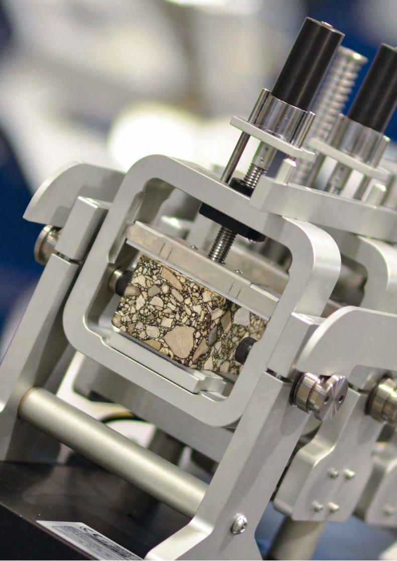
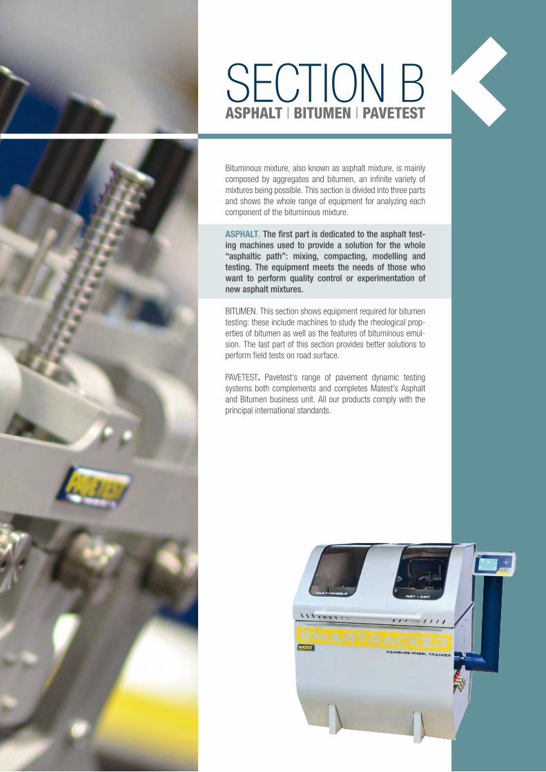
SECTION BASPHALT | BITUMEN | PAVETEST
Bituminous mixture, also known as asphalt mixture, is mainly composed by aggregates and bitumen, an infinite variety of mixtures being possible. This section is divided into three parts and shows the whole range of equipment for analyzing each component of the bituminous mixture.
ASPHALT. The first part is dedicated to the asphalt test-ing machines used to provide a solution for the whole “asphaltic path”: mixing, compacting, modelling and testing. The equipment meets the needs of those who want to perform quality control or experimentation of new asphalt mixtures.
BITUMEN. This section shows equipment required for bitumen testing: these include machines to study the rheological prop-erties of bitumen as well as the features of bituminous emul-sion. The last part of this section provides better solutions to perform field tests on road surface.
PAVETEST. Pavetest’s range of pavement dynamic testing systems both complements and completes Matest’s Asphalt and Bitumen business unit. All our products comply with the principal international standards.
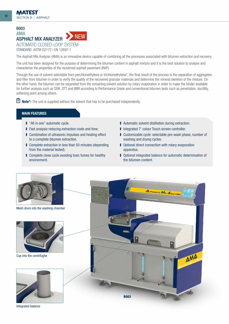
SECTION B | ASPHALT
B003 AMAASPHALT MIX ANALYZER
AUTOMATIC CLOSED-LOOP SYSTEMSTANDARD: ASTM D2172 | EN 12697-1
The Asphalt Mix Analyzer (AMA) is an innovative device capable of combining all the processes associated with bitumen extraction and recovery.
The unit has been designed for the purpose of determining the bitumen content in asphalt mixture and it is the best solution to analyse and characterize the properties of the reclaimed asphalt pavement (RAP).
Through the use of solvent selectable from perchloroethylene or trichloroethylene*, the final result of the process is the separation of aggregates and filler from bitumen in order to verify the quality of the recovered granular materials and determine the mineral skeleton of the mixture. On the other hand, the bitumen can be separated from the remaining solvent solution by rotary evaporation in order to make the binder available for further analysis such as DSR, DTT and BBR according to Performance Grade and conventional bitumen tests such as penetration, ductility, softening point among others.
MAIN FEATURES
NEW
B003
Note*: The unit is supplied without the solvent that has to be purchased independently.
“All in one” automatic cycle. Fast analysis reducing extraction costs and time. Combination of ultrasonic impulses and heating effect
to a complete bitumen extraction. Complete extraction in less than 50 minutes (depending
from the material tested). Complete close cycle avoiding toxic fumes for healthy
environment.
Automatic solvent distillation during extraction. Integrated 7’ colour Touch screen controller. Customizable cycle: selectable pre-wash phase, number of
washing and drying cycles. Optional direct connection with rotary evaporation
apparatus. Optional integrated balance for automatic determination of
the bitumen content.
Mesh drum into the washing chamber
Cup into the centrifughe
Integrated balance
76
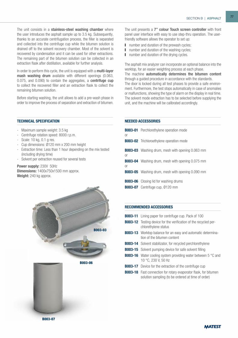
SECTION B | ASPHALT
The unit consists in a stainless-steel washing chamber where the user introduces the asphalt sample up to 3.5 kg. Subsequently, thanks to an accurate centrifugation process, the filler is separated and collected into the centrifuge cup while the bitumen solution is drained off to the solvent recovery chamber. Most of the solvent is recovered by condensation and it can be used for other extractions. The remaining part of the bitumen solution can be collected in an extraction flask after distillation, available for further analysis.
In order to perform this cycle, the unit is equipped with a multi-layer mash washing drum available with different openings (0.063, 0.075, and 0.090) to contain the aggregates, a centrifuge cup to collect the recovered filler and an extraction flask to collect the remaining bitumen solution.
Before starting washing, the unit allows to add a pre-wash phase in order to improve the process of separation and extraction of bitumen.
TECHNICAL SPECIFICATION
- Maximum sample weight: 3.5 kg- Centrifuge rotation speed: 8000 r.p.m.- Scale: 10 kg, 0.1 g res.- Cup dimensions: Ø120 mm x 200 mm height - Extraction time: Less than 1 hour depending on the mix tested
(including drying time)- Solvent per extraction reused for several tests
Power supply: 230V 50HzDimensions: 1400x750x1500 mm approx.Weight: 240 kg approx.
NEEDED ACCESSORIES
B003-01 Perchlorethylene operation modeor
B003-02 Trichloroethylene operation mode
B003-03 Washing drum, mesh with opening 0.063 mmor
B003-04 Washing drum, mesh with opening 0.075 mmor
B003-05 Washing drum, mesh with opening 0.090 mm
B003-06 Closing lid for washing drums
B003-07 Centrifuge cup, Ø120 mm
RECOMMENDED ACCESSORIES
B003-11 Lining paper for centrifuge cup. Pack of 100
B003-12 Testing device for the verification of the recycled per-chlorethylene status
B003-13 Worktop balance for an easy and automatic determina-tion of the bitumen content
B003-14 Solvent stabilizator, for recycled perchlorethylene
B003-15 Solvent pumping device for safe solvent filling
B003-16 Water cooling system providing water between 5 °C and 10 °C, 230 V, 50 Hz
B003-17 Device for the extraction of the centrifuge cup
B003-18 Fast connection for rotary evaporator flask, for bitumen solution sampling (to be ordered at time of order)
The unit presents a 7’’ colour Touch screen controller with front panel user interface with easy to use step-thru operation. The user-friendly software allows the operator to set up:
number and duration of the prewash cycles; number and duration of the washing cycles; number and duration of the drying cycles.
The asphalt mix analyzer can incorporate an optional balance into the worktop, for an easier weighting process at each phase.The machine automatically determines the bitumen content through a guided procedure in accordance with the standards.The door is locked during all test phases to provide a safe environ-ment. Furthermore, the test stops automatically in case of anomalies or malfunctions, showing the type of alarm on the display in real time. The solvent mode extraction has to be selected before supplying the unit, and the machine will be calibrated accordingly.
B003-03
B003-06
B003-07
77
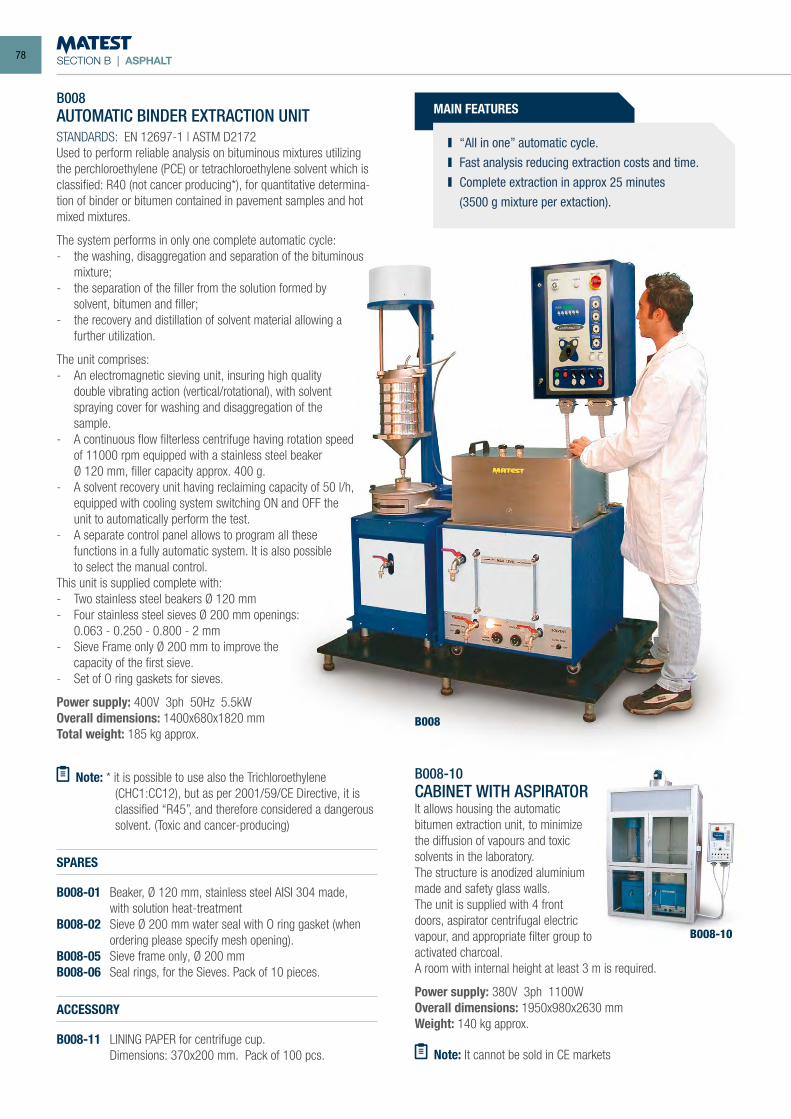
SECTION B | ASPHALT
B008
B008AUTOMATIC BINDER EXTRACTION UNITSTANDARDS: EN 12697-1 | ASTM D2172Used to perform reliable analysis on bituminous mixtures utilizing the perchloroethylene (PCE) or tetrachloroethylene solvent which is classified: R40 (not cancer producing*), for quantitative determina-tion of binder or bitumen contained in pavement samples and hot mixed mixtures.
The system performs in only one complete automatic cycle:- the washing, disaggregation and separation of the bituminous
mixture;- the separation of the filler from the solution formed by
solvent, bitumen and filler;- the recovery and distillation of solvent material allowing a
further utilization.
The unit comprises:- An electromagnetic sieving unit, insuring high quality
double vibrating action (vertical/rotational), with solvent spraying cover for washing and disaggregation of the sample.
- A continuous flow filterless centrifuge having rotation speed of 11000 rpm equipped with a stainless steel beaker
Ø 120 mm, filler capacity approx. 400 g.- A solvent recovery unit having reclaiming capacity of 50 l/h,
equipped with cooling system switching ON and OFF the unit to automatically perform the test.
- A separate control panel allows to program all these functions in a fully automatic system. It is also possible to select the manual control.
This unit is supplied complete with:- Two stainless steel beakers Ø 120 mm- Four stainless steel sieves Ø 200 mm openings: 0.063 - 0.250 - 0.800 - 2 mm- Sieve Frame only Ø 200 mm to improve the
capacity of the first sieve.- Set of O ring gaskets for sieves.
Power supply: 400V 3ph 50Hz 5.5kWOverall dimensions: 1400x680x1820 mmTotal weight: 185 kg approx.
Note: * it is possible to use also the Trichloroethylene (CHC1:CC12), but as per 2001/59/CE Directive, it is classified “R45”, and therefore considered a dangerous solvent. (Toxic and cancer-producing)
ACCESSORY
B008-11 LINING PAPER for centrifuge cup. Dimensions: 370x200 mm. Pack of 100 pcs.
SPARES
B008-01 Beaker, Ø 120 mm, stainless steel AISI 304 made, with solution heat-treatmentB008-02 Sieve Ø 200 mm water seal with O ring gasket (when
ordering please specify mesh opening).B008-05 Sieve frame only, Ø 200 mmB008-06 Seal rings, for the Sieves. Pack of 10 pieces.
B008-10CABINET WITH ASPIRATORIt allows housing the automatic bitumen extraction unit, to minimize the diffusion of vapours and toxic solvents in the laboratory.The structure is anodized aluminium made and safety glass walls.The unit is supplied with 4 front doors, aspirator centrifugal electric vapour, and appropriate filter group to activated charcoal. A room with internal height at least 3 m is required.
Power supply: 380V 3ph 1100WOverall dimensions: 1950x980x2630 mmWeight: 140 kg approx.
Note: It cannot be sold in CE markets
B008-10
MAIN FEATURES
“All in one” automatic cycle. Fast analysis reducing extraction costs and time. Complete extraction in approx 25 minutes
(3500 g mixture per extaction).
78
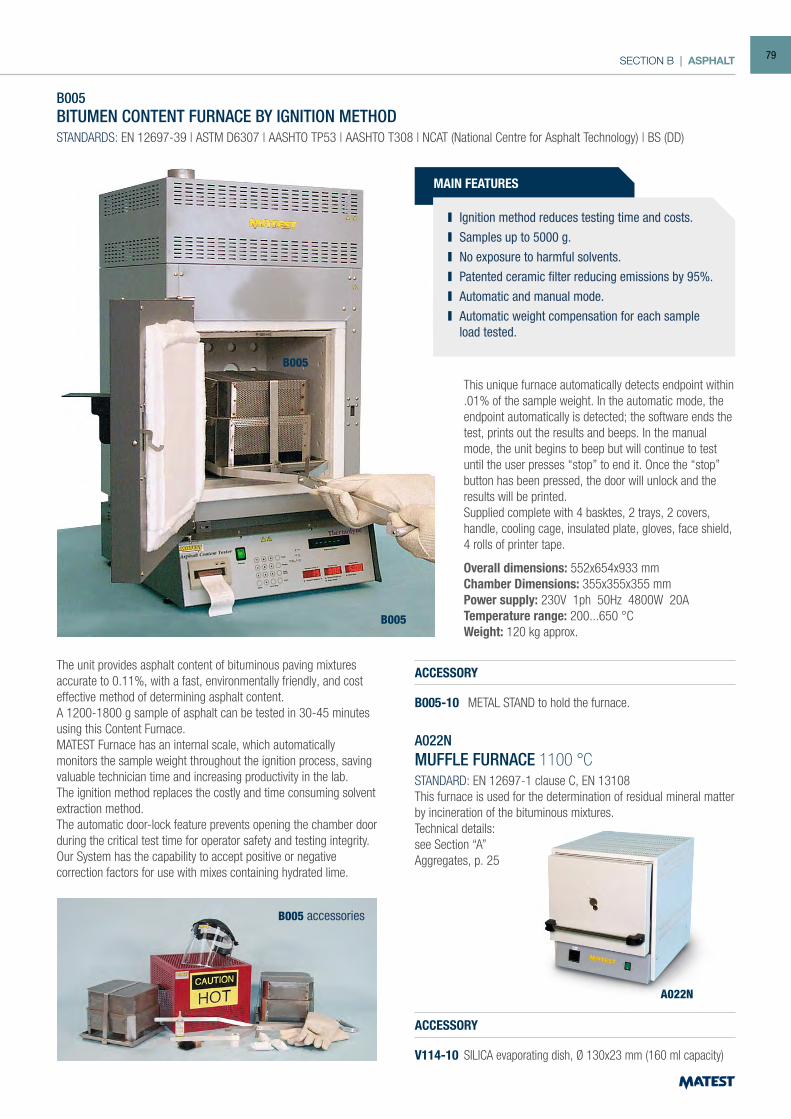
SECTION B | ASPHALT
MAIN FEATURES
B005BITUMEN CONTENT FURNACE BY IGNITION METHODSTANDARDS: EN 12697-39 | ASTM D6307 | AASHTO TP53 | AASHTO T308 | NCAT (National Centre for Asphalt Technology) | BS (DD)
The unit provides asphalt content of bituminous paving mixtures accurate to 0.11%, with a fast, environmentally friendly, and cost effective method of determining asphalt content.A 1200-1800 g sample of asphalt can be tested in 30-45 minutes using this Content Furnace.MATEST Furnace has an internal scale, which automatically monitors the sample weight throughout the ignition process, saving valuable technician time and increasing productivity in the lab. The ignition method replaces the costly and time consuming solvent extraction method.The automatic door-lock feature prevents opening the chamber door during the critical test time for operator safety and testing integrity. Our System has the capability to accept positive or negative correction factors for use with mixes containing hydrated lime.
ACCESSORY
B005-10 METAL STAND to hold the furnace.
A022NMUFFLE FURNACE 1100 °CSTANDARD: EN 12697-1 clause C, EN 13108This furnace is used for the determination of residual mineral matter by incineration of the bituminous mixtures.Technical details:see Section “A”Aggregates, p. 25
ACCESSORY
V114-10 SILICA evaporating dish, Ø 130x23 mm (160 ml capacity)
A022N
B005
B005 accessories
Ignition method reduces testing time and costs. Samples up to 5000 g. No exposure to harmful solvents. Patented ceramic filter reducing emissions by 95%. Automatic and manual mode. Automatic weight compensation for each sample
load tested.
This unique furnace automatically detects endpoint within .01% of the sample weight. In the automatic mode, the endpoint automatically is detected; the software ends the test, prints out the results and beeps. In the manual mode, the unit begins to beep but will continue to test until the user presses “stop” to end it. Once the “stop” button has been pressed, the door will unlock and the results will be printed.Supplied complete with 4 basktes, 2 trays, 2 covers, handle, cooling cage, insulated plate, gloves, face shield, 4 rolls of printer tape.
Overall dimensions: 552x654x933 mmChamber Dimensions: 355x355x355 mmPower supply: 230V 1ph 50Hz 4800W 20ATemperature range: 200...650 °CWeight: 120 kg approx.
B005
79
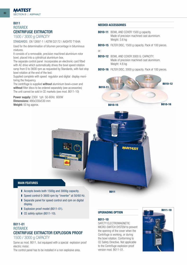
SECTION B | ASPHALT
B011ROTAREXCENTRIFUGE EXTRACTOR1500 / 3000 g CAPACITYSTANDARDS: EN 12697-1 | ASTM D2172 | AASHTO T164A
Used for the determination of bitumen percentage in bituminous mixtures.It consists of a removable, precision machined aluminium rotor bowl, placed into a cylindrical aluminium box.The separate control panel incorporates an electronic card fitted with AC drive which automatically drives the bowl speed rotation ramp from 0 to 3600 rpm as requested by Standards, with fast stop bowl rotation at the end of the test.Supplied complete with speed regulator and digital display moni-toring the frequency.The centrifuge is supplied without aluminium bowl+cover and without filter discs to be ordered separately (see accessories)The unit cannot be sold in CE markets (see mod. B011-10)
Power supply: 230V 1ph 50-60Hz 600WDimensions: 480x330x530 mmWeight: 50 kg approx.
B011-01ROTAREXCENTRIFUGE EXTRACTOR EXPLOSION PROOF1500 / 3000 g CAPACITYSame as mod. B011, but equipped with a special explosion proof electric motor.The control panel has to be installed in a non explosive area.
NEEDED ACCESSORIES
B010-11 BOWL AND COVER 1500 g capacity. Made of precision machined cast aluminium. Weight: 3.6 kg
B010-15 FILTER DISC, 1500 g capacity. Pack of 100 pieces.
or:
B010-12 BOWL AND COVER 3000 G. CAPACITY. Made of precision machined cast aluminium. Weight: 4.6 kg
B010-16 FILTER DISC, 3000 g capacity. Pack of 100 pieces.
UPGRADING OPTION
B011-10SAFETY ELECTROMAGNETIC MICRO-SWITCH SYSTEM to prevent the opening of the cover when the Centrifuge is working, or during the bowl rotation. Conforming to CE Safety Directive. Not applicable to the Centrifuge explosion proof version mod. B011-01.
B010-11B010-12
B010-16B010-15
B011-10
MAIN FEATURES
Accepts bowls both 1500g and 3000g capacity. Speed control 0-3600 rpm by “inverter” at 50/60 Hz. Separate panel for speed control and rpm on digital
display. Explosion proof model (B011-01). CE safety option (B011-10).
B011
80
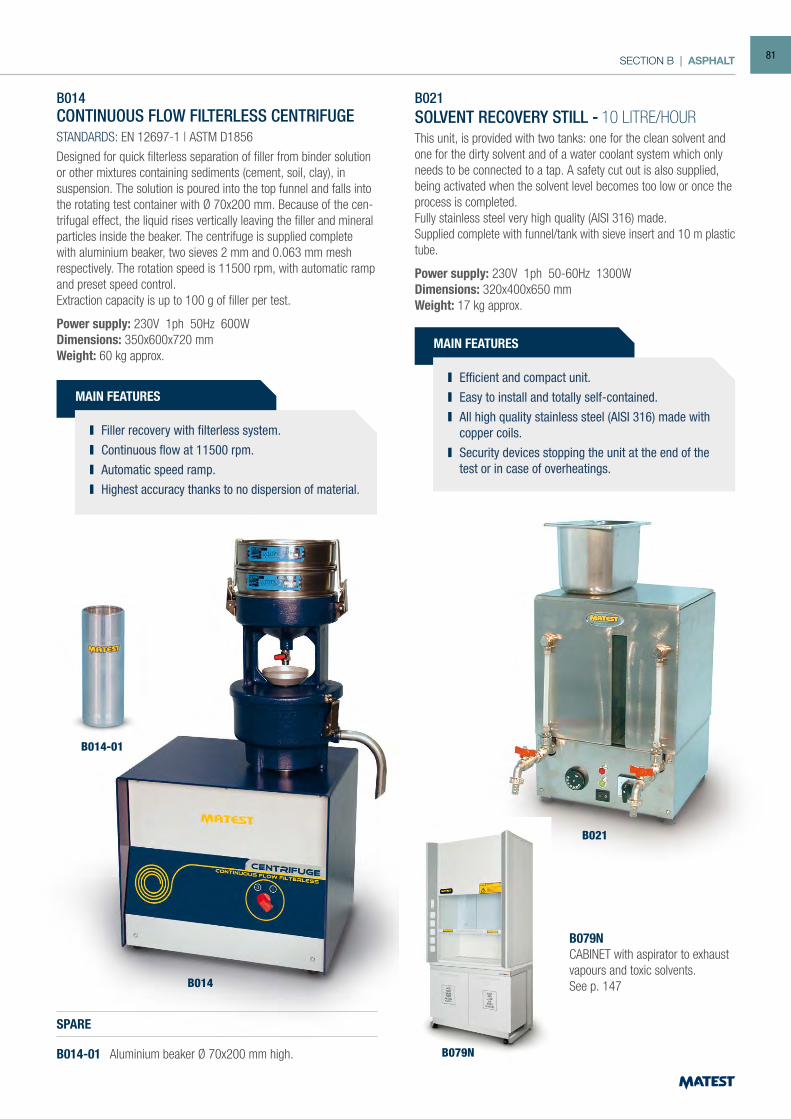
SECTION B | ASPHALT
B014CONTINUOUS FLOW FILTERLESS CENTRIFUGESTANDARDS: EN 12697-1 | ASTM D1856
Designed for quick filterless separation of filler from binder solution or other mixtures containing sediments (cement, soil, clay), in suspension. The solution is poured into the top funnel and falls into the rotating test container with Ø 70x200 mm. Because of the cen-trifugal effect, the liquid rises vertically leaving the filler and mineral particles inside the beaker. The centrifuge is supplied complete with aluminium beaker, two sieves 2 mm and 0.063 mm mesh respectively. The rotation speed is 11500 rpm, with automatic ramp and preset speed control.Extraction capacity is up to 100 g of filler per test.
Power supply: 230V 1ph 50Hz 600WDimensions: 350x600x720 mmWeight: 60 kg approx.
SPARE
B014-01 Aluminium beaker Ø 70x200 mm high.
B021SOLVENT RECOVERY STILL - 10 LITRE/HOURThis unit, is provided with two tanks: one for the clean solvent and one for the dirty solvent and of a water coolant system which only needs to be connected to a tap. A safety cut out is also supplied, being activated when the solvent level becomes too low or once the process is completed.Fully stainless steel very high quality (AISI 316) made.Supplied complete with funnel/tank with sieve insert and 10 m plastic tube.
Power supply: 230V 1ph 50-60Hz 1300WDimensions: 320x400x650 mmWeight: 17 kg approx.
B014-01
B014
B021
MAIN FEATURES
Efficient and compact unit. Easy to install and totally self-contained. All high quality stainless steel (AISI 316) made with
copper coils. Security devices stopping the unit at the end of the
test or in case of overheatings.
MAIN FEATURES
Filler recovery with filterless system. Continuous flow at 11500 rpm. Automatic speed ramp. Highest accuracy thanks to no dispersion of material.
B079NCABINET with aspirator to exhaust vapours and toxic solvents.See p. 147
B079N
81
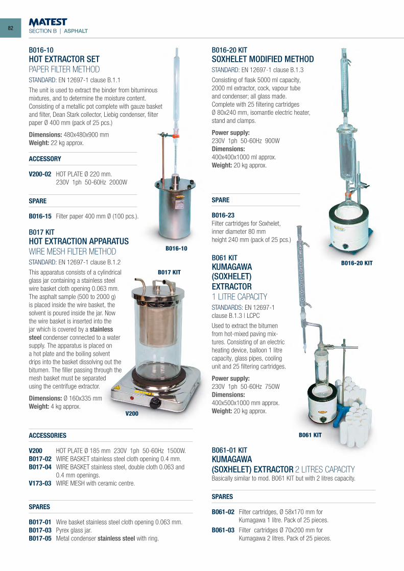
SECTION B | ASPHALT
B016-10HOT EXTRACTOR SETPAPER FILTER METHODSTANDARD: EN 12697-1 clause B.1.1
The unit is used to extract the binder from bituminous mixtures, and to determine the moisture content.Consisting of a metallic pot complete with gauze basket and filter, Dean Stark collector, Liebig condenser, filter paper Ø 400 mm (pack of 25 pcs.)
Dimensions: 480x480x900 mmWeight: 22 kg approx.
ACCESSORY
V200-02 HOT PLATE Ø 220 mm. 230V 1ph 50-60Hz 2000W
SPARE
B016-15 Filter paper 400 mm Ø (100 pcs.).
B017 KITHOT EXTRACTION APPARATUSWIRE MESH FILTER METHODSTANDARD: EN 12697-1 clause B.1.2
This apparatus consists of a cylindrical glass jar containing a stainless steel wire basket cloth opening 0.063 mm.The asphalt sample (500 to 2000 g) is placed inside the wire basket, the solvent is poured inside the jar. Now the wire basket is inserted into the jar which is covered by a stainless steel condenser connected to a water supply. The apparatus is placed on a hot plate and the boiling solvent drips into the basket dissolving out the bitumen. The filler passing through the mesh basket must be separated using the centrifuge extractor.
Dimensions: Ø 160x335 mmWeight: 4 kg approx.
ACCESSORIES
V200 HOT PLATE Ø 185 mm 230V 1ph 50-60Hz 1500W.B017-02 WIRE BASKET stainless steel cloth opening 0.4 mm.B017-04 WIRE BASKET stainless steel, double cloth 0.063 and 0.4 mm openings.V173-03 WIRE MESH with ceramic centre.
SPARES
B017-01 Wire basket stainless steel cloth opening 0.063 mm.B017-03 Pyrex glass jar.B017-05 Metal condenser stainless steel with ring.
B016-20 KIT SOXHELET MODIFIED METHOD STANDARD: EN 12697-1 clause B.1.3
Consisting of flask 5000 ml capacity, 2000 ml extractor, cock, vapour tubeand condenser; all glass made. Complete with 25 filtering cartridgesØ 80x240 mm, isomantle electric heater, stand and clamps.
Power supply:230V 1ph 50-60Hz 900W Dimensions:400x400x1000 ml approx. Weight: 20 kg approx.
SPARE
B016-23Filter cartridges for Soxhelet, inner diameter 80 mmheight 240 mm (pack of 25 pcs.)
B061 KITKUMAGAWA(SOXHELET)EXTRACTOR1 LITRE CAPACITYSTANDARDS: EN 12697-1 clause B.1.3 | LCPC
Used to extract the bitumen from hot-mixed paving mix-tures. Consisting of an electric heating device, balloon 1 litre capacity, glass pipes, cooling unit and 25 filtering cartridges.
Power supply:230V 1ph 50-60Hz 750WDimensions:400x500x1000 mm approx.Weight: 20 kg approx.
B061-01 KITKUMAGAWA(SOXHELET) EXTRACTOR 2 LITRES CAPACITYBasically similar to mod. B061 KIT but with 2 litres capacity.
SPARES
B061-02 Filter cartridges, Ø 58x170 mm for Kumagawa 1 litre. Pack of 25 pieces.
B061-03 Filter cartridges Ø 70x200 mm for Kumagawa 2 litres. Pack of 25 pieces.
B016-10
B016-20 KIT
B017 KIT
V200
B061 KIT
82
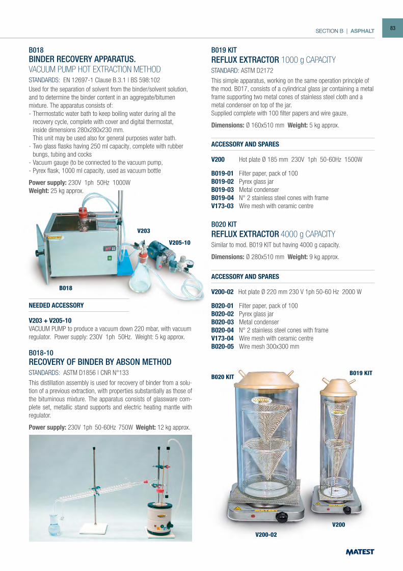
SECTION B | ASPHALT
B018
B020 KIT
V200-02
V200
B019 KIT
V203
V205-10
B018BINDER RECOVERY APPARATUS.VACUUM PUMP HOT EXTRACTION METHODSTANDARDS: EN 12697-1 Clause B.3.1 | BS 598:102Used for the separation of solvent from the binder/solvent solution, and to determine the binder content in an aggregate/bitumen mixture. The apparatus consists of: - Thermostatic water bath to keep boiling water during all the
recovery cycle, complete with cover and digital thermostat, inside dimensions 280x280x230 mm. This unit may be used also for general purposes water bath.- Two glass flasks having 250 ml capacity, complete with rubber
bungs, tubing and cocks- Vacuum gauge (to be connected to the vacuum pump,- Pyrex flask, 1000 ml capacity, used as vacuum bottle
Power supply: 230V 1ph 50Hz 1000WWeight: 25 kg approx.
NEEDED ACCESSORY
V203 + V205-10VACUUM PUMP to produce a vacuum down 220 mbar, with vacuum regulator. Power supply: 230V 1ph 50Hz. Weight: 5 kg approx.
B018-10RECOVERY OF BINDER BY ABSON METHODSTANDARDS: ASTM D1856 | CNR N°133
This distillation assembly is used for recovery of binder from a solu-tion of a previous extraction, with properties substantially as those of the bituminous mixture. The apparatus consists of glassware com-plete set, metallic stand supports and electric heating mantle with regulator.
Power supply: 230V 1ph 50-60Hz 750W Weight: 12 kg approx.
B019 KITREFLUX EXTRACTOR 1000 g CAPACITYSTANDARD: ASTM D2172
This simple apparatus, working on the same operation principle of the mod. B017, consists of a cylindrical glass jar containing a metal frame supporting two metal cones of stainless steel cloth and a metal condenser on top of the jar. Supplied complete with 100 filter papers and wire gauze.
Dimensions: Ø 160x510 mm Weight: 5 kg approx.
ACCESSORY AND SPARES
V200 Hot plate Ø 185 mm 230V 1ph 50-60Hz 1500W
B019-01 Filter paper, pack of 100B019-02 Pyrex glass jarB019-03 Metal condenserB019-04 N° 2 stainless steel cones with frameV173-03 Wire mesh with ceramic centre
ACCESSORY AND SPARES
V200-02 Hot plate Ø 220 mm 230 V 1ph 50-60 Hz 2000 W
B020-01 Filter paper, pack of 100B020-02 Pyrex glass jarB020-03 Metal condenserB020-04 N° 2 stainless steel cones with frameV173-04 Wire mesh with ceramic centreB020-05 Wire mesh 300x300 mm
B020 KITREFLUX EXTRACTOR 4000 g CAPACITYSimilar to mod. B019 KIT but having 4000 g capacity.
Dimensions: Ø 280x510 mm Weight: 9 kg approx.
83
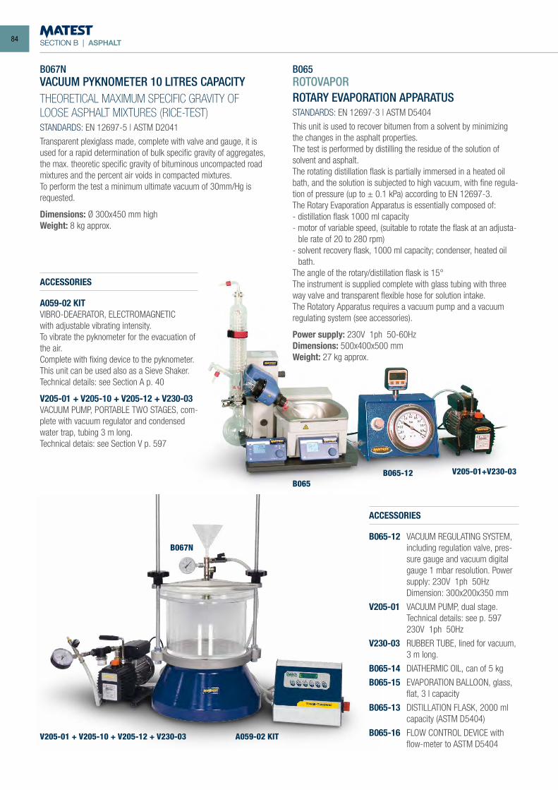
SECTION B | ASPHALT
B067NVACUUM PYKNOMETER 10 LITRES CAPACITYTHEORETICAL MAXIMUM SPECIFIC GRAVITY OF LOOSE ASPHALT MIXTURES (RICE-TEST)STANDARDS: EN 12697-5 | ASTM D2041
Transparent plexiglass made, complete with valve and gauge, it is used for a rapid determination of bulk specific gravity of aggregates, the max. theoretic specific gravity of bituminous uncompacted road mixtures and the percent air voids in compacted mixtures.To perform the test a minimum ultimate vacuum of 30mm/Hg is requested.
Dimensions: Ø 300x450 mm highWeight: 8 kg approx.
ACCESSORIES
A059-02 KITVIBRO-DEAERATOR, ELECTROMAGNETICwith adjustable vibrating intensity. To vibrate the pyknometer for the evacuation of the air.Complete with fixing device to the pyknometer.This unit can be used also as a Sieve Shaker.Technical details: see Section A p. 40
V205-01 + V205-10 + V205-12 + V230-03VACUUM PUMP, PORTABLE TWO STAGES, com-plete with vacuum regulator and condensed water trap, tubing 3 m long.Technical detais: see Section V p. 597
B065 ROTOVAPORROTARY EVAPORATION APPARATUS STANDARDS: EN 12697-3 | ASTM D5404
This unit is used to recover bitumen from a solvent by minimizing the changes in the asphalt properties. The test is performed by distilling the residue of the solution of solvent and asphalt. The rotating distillation flask is partially immersed in a heated oil bath, and the solution is subjected to high vacuum, with fine regula-tion of pressure (up to ± 0.1 kPa) according to EN 12697-3. The Rotary Evaporation Apparatus is essentially composed of: - distillation flask 1000 ml capacity - motor of variable speed, (suitable to rotate the flask at an adjusta-
ble rate of 20 to 280 rpm) - solvent recovery flask, 1000 ml capacity; condenser, heated oil
bath. The angle of the rotary/distillation flask is 15° The instrument is supplied complete with glass tubing with three way valve and transparent flexible hose for solution intake. The Rotatory Apparatus requires a vacuum pump and a vacuum regulating system (see accessories).
Power supply: 230V 1ph 50-60HzDimensions: 500x400x500 mmWeight: 27 kg approx.
B065B065-12 V205-01+V230-03
A059-02 KIT
B067N
V205-01 + V205-10 + V205-12 + V230-03
ACCESSORIES
B065-12 VACUUM REGULATING SYSTEM, including regulation valve, pres-sure gauge and vacuum digital gauge 1 mbar resolution. Power supply: 230V 1ph 50Hz
Dimension: 300x200x350 mm
V205-01 VACUUM PUMP, dual stage. Technical details: see p. 597
230V 1ph 50Hz
V230-03 RUBBER TUBE, lined for vacuum, 3 m long.
B065-14 DIATHERMIC OIL, can of 5 kg
B065-15 EVAPORATION BALLOON, glass, flat, 3 l capacity
B065-13 DISTILLATION FLASK, 2000 ml capacity (ASTM D5404)
B065-16 FLOW CONTROL DEVICE with flow-meter to ASTM D5404
84
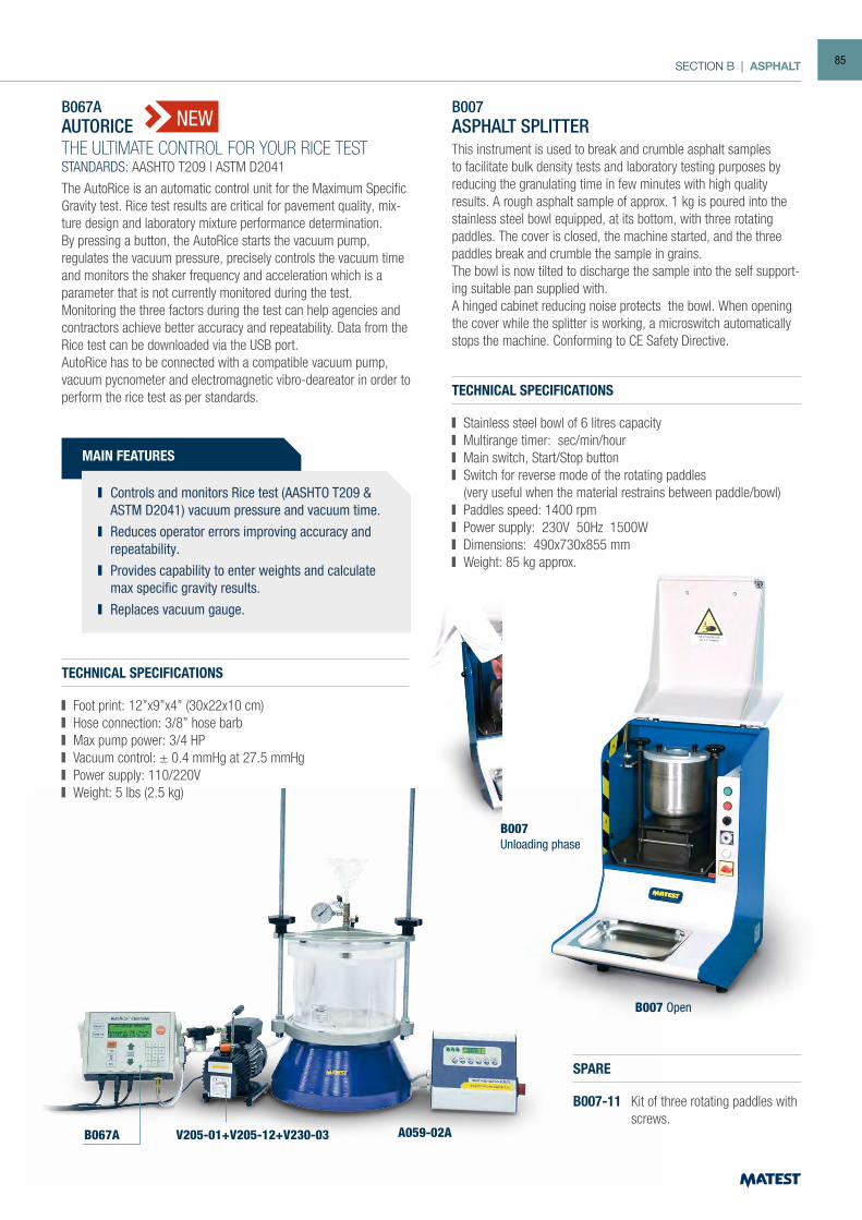
SECTION B | ASPHALT
B007 Open
B007ASPHALT SPLITTERThis instrument is used to break and crumble asphalt samples to facilitate bulk density tests and laboratory testing purposes by reducing the granulating time in few minutes with high quality results. A rough asphalt sample of approx. 1 kg is poured into the stainless steel bowl equipped, at its bottom, with three rotating paddles. The cover is closed, the machine started, and the three paddles break and crumble the sample in grains.The bowl is now tilted to discharge the sample into the self support-ing suitable pan supplied with.A hinged cabinet reducing noise protects the bowl. When opening the cover while the splitter is working, a microswitch automatically stops the machine. Conforming to CE Safety Directive.
TECHNICAL SPECIFICATIONS
Stainless steel bowl of 6 litres capacity Multirange timer: sec/min/hour Main switch, Start/Stop button Switch for reverse mode of the rotating paddles
(very useful when the material restrains between paddle/bowl) Paddles speed: 1400 rpm Power supply: 230V 50Hz 1500W Dimensions: 490x730x855 mm Weight: 85 kg approx.
MAIN FEATURES
Controls and monitors Rice test (AASHTO T209 & ASTM D2041) vacuum pressure and vacuum time.
Reduces operator errors improving accuracy and repeatability.
Provides capability to enter weights and calculate max specific gravity results.
Replaces vacuum gauge.
B067AAUTORICETHE ULTIMATE CONTROL FOR YOUR RICE TESTSTANDARDS: AASHTO T209 | ASTM D2041
The AutoRice is an automatic control unit for the Maximum Specific Gravity test. Rice test results are critical for pavement quality, mix-ture design and laboratory mixture performance determination.By pressing a button, the AutoRice starts the vacuum pump, regulates the vacuum pressure, precisely controls the vacuum time and monitors the shaker frequency and acceleration which is a parameter that is not currently monitored during the test. Monitoring the three factors during the test can help agencies and contractors achieve better accuracy and repeatability. Data from the Rice test can be downloaded via the USB port.AutoRice has to be connected with a compatible vacuum pump, vacuum pycnometer and electromagnetic vibro-deareator in order to perform the rice test as per standards.
TECHNICAL SPECIFICATIONS
Foot print: 12”x9”x4” (30x22x10 cm) Hose connection: 3/8” hose barb Max pump power: 3/4 HP Vacuum control: ± 0.4 mmHg at 27.5 mmHg Power supply: 110/220V Weight: 5 lbs (2.5 kg)
B067A V205-01+V205-12+V230-03 A059-02A
NEW
SPARE
B007-11 Kit of three rotating paddles with screws.
B007Unloading phase
85
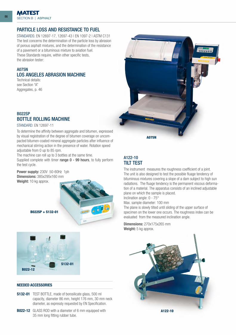
SECTION B | ASPHALT
PARTICLE LOSS AND RESISTANCE TO FUELSTANDARDS: EN 12697-17, 12697-43 | EN 1097-2 | ASTM C131The test concerns the determination of the particle loss by abrasion of porous asphalt mixtures, and the determination of the resistance of a pavement or a bituminous mixture to aviation fuel.These Standards require, within other specific tests,the abrasion tester:
A075NLOS ANGELES ABRASION MACHINETechnical details:see Section “A”Aggregates, p. 46
B022SPBOTTLE ROLLING MACHINESTANDARD: EN 12697-11
To determine the affinity between aggregate and bitumen, expressed by visual registration of the degree of bitumen coverage on uncom-pacted bitumen-coated mineral aggregate particles after influence of mechanical stirring action in the presence of water. Rotation speed adjustable from 0 up to 85 rpm.The machine can roll up to 3 bottles at the same time.Supplied complete with timer range 0 - 99 hours, to fully perform the test cycle.
Power supply: 230V 50-60Hz 1phDimensions: 385x295x160 mm Weight: 10 kg approx.
NEEDED ACCESSORIES
S132-01 TEST BOTTLE, made of borosilicate glass, 500 ml capacity, diameter 86 mm, height 176 mm, 30 mm neck diameter, as expressly requested by EN Specification.
B022-12 GLASS ROD with a diameter of 6 mm equipped with 35 mm long fitting rubber tube.
A075N
B022-12
S132-01
B022SP + S132-01
A122-10TILT TESTThe instrument measures the roughness coefficient of a joint. The unit is also designed to test the possible fluage tendency of bituminous mixtures covering a slope of a dam subject to high sun radiations. The fluage tendency is the permanent viscous deforma-tion of a material. The apparatus consists of an inclined adjustable plane on which the sample is placed.Inclination angle: 0 - 75°Max. sample diameter: 100 mmThe plane is slowly tilted until sliding of the upper surface of specimen on the lower one occurs. The roughness index can be evaluated from the measured inclination angle.
Dimensions: 270x175x265 mmWeight: 5 kg approx.
A122-10
86
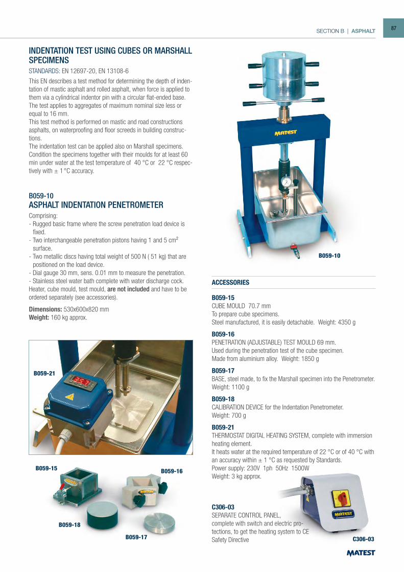
SECTION B | ASPHALT
B059-10
INDENTATION TEST USING CUBES OR MARSHALL SPECIMENSSTANDARDS: EN 12697-20, EN 13108-6
This EN describes a test method for determining the depth of inden-tation of mastic asphalt and rolled asphalt, when force is applied to them via a cylindrical indentor pin with a circular flat-ended base. The test applies to aggregates of maximum nominal size less or equal to 16 mm.This test method is performed on mastic and road constructions asphalts, on waterproofing and floor screeds in building construc-tions.The indentation test can be applied also on Marshall specimens.Condition the specimens together with their moulds for at least 60 min under water at the test temperature of 40 °C or 22 °C respec-tively with ± 1 °C accuracy.
B059-10ASPHALT INDENTATION PENETROMETERComprising:- Rugged basic frame where the screw penetration load device is
fixed.- Two interchangeable penetration pistons having 1 and 5 cm²
surface.- Two metallic discs having total weight of 500 N ( 51 kg) that are
positioned on the load device.- Dial gauge 30 mm, sens. 0.01 mm to measure the penetration.- Stainless steel water bath complete with water discharge cock.Heater, cube mould, test mould, are not included and have to be ordered separately (see accessories).
Dimensions: 530x600x820 mmWeight: 160 kg approx.
ACCESSORIES
B059-15CUBE MOULD 70.7 mmTo prepare cube specimens.Steel manufactured, it is easily detachable. Weight: 4350 g
B059-16PENETRATION (ADJUSTABLE) TEST MOULD 69 mm.Used during the penetration test of the cube specimen.Made from aluminium alloy. Weight: 1850 g
B059-17BASE, steel made, to fix the Marshall specimen into the Penetrometer. Weight: 1100 g
B059-18CALIBRATION DEVICE for the Indentation Penetrometer.Weight: 700 g
B059-21THERMOSTAT DIGITAL HEATING SYSTEM, complete with immersion heating element.It heats water at the required temperature of 22 °C or of 40 °C with an accuracy within ± 1 °C as requested by Standards.Power supply: 230V 1ph 50Hz 1500WWeight: 3 kg approx.
C306-03SEPARATE CONTROL PANEL,complete with switch and electric pro-tections, to get the heating system to CE Safety Directive
B059-21
B059-15 B059-16
C306-03 B059-17
B059-18
87
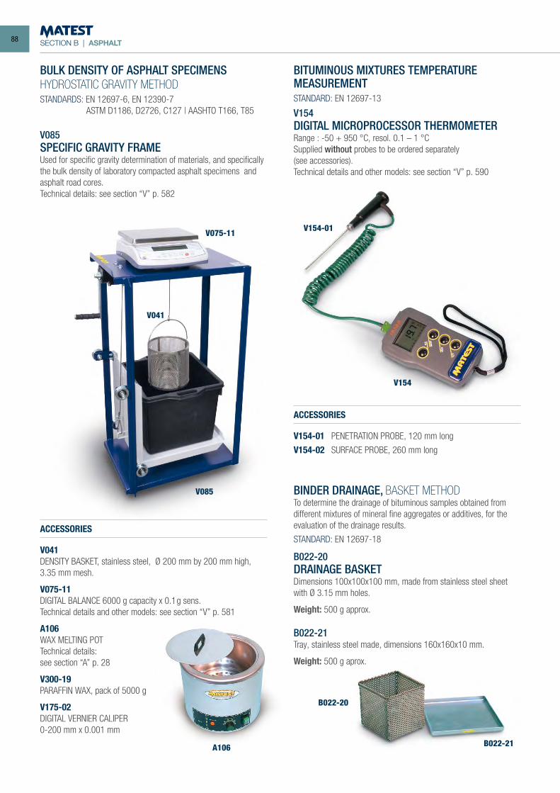
SECTION B | ASPHALT
BULK DENSITY OF ASPHALT SPECIMENSHYDROSTATIC GRAVITY METHODSTANDARDS: EN 12697-6, EN 12390-7 ASTM D1186, D2726, C127 | AASHTO T166, T85
V085SPECIFIC GRAVITY FRAMEUsed for specific gravity determination of materials, and specifically the bulk density of laboratory compacted asphalt specimens and asphalt road cores.Technical details: see section “V” p. 582
ACCESSORIES
V041DENSITY BASKET, stainless steel, Ø 200 mm by 200 mm high, 3.35 mm mesh.
V075-11DIGITAL BALANCE 6000 g capacity x 0.1g sens.Technical details and other models: see section “V” p. 581
A106WAX MELTING POTTechnical details:see section “A” p. 28
V300-19PARAFFIN WAX, pack of 5000 g
V175-02DIGITAL VERNIER CALIPER0-200 mm x 0.001 mm
V085
V041
V075-11
A106
B022-20
V154
V154-01
B022-21
BITUMINOUS MIXTURES TEMPERATUREMEASUREMENTSTANDARD: EN 12697-13
V154DIGITAL MICROPROCESSOR THERMOMETERRange : -50 + 950 °C, resol. 0.1 – 1 °CSupplied without probes to be ordered separately(see accessories).Technical details and other models: see section “V” p. 590
ACCESSORIES
V154-01 PENETRATION PROBE, 120 mm long
V154-02 SURFACE PROBE, 260 mm long
BINDER DRAINAGE, BASKET METHODTo determine the drainage of bituminous samples obtained from different mixtures of mineral fine aggregates or additives, for the evaluation of the drainage results.
STANDARD: EN 12697-18
B022-20DRAINAGE BASKETDimensions 100x100x100 mm, made from stainless steel sheet with Ø 3.15 mm holes.
Weight: 500 g approx.
B022-21Tray, stainless steel made, dimensions 160x160x10 mm.
Weight: 500 g aprox.
88
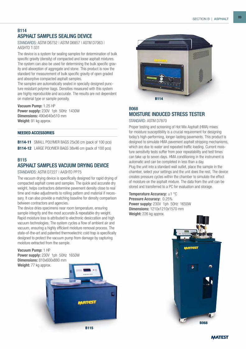
SECTION B | ASPHALT
B114ASPHALT SAMPLES SEALING DEVICESTANDARDS: ASTM D6752 | ASTM D6857 | ASTM D7063 | AASHTO T-331
The device is a system for sealing samples for determination of bulk specific gravity (density) of compacted and loose asphalt mixtures.The system can also be used for determining the bulk specific grav-ity and absorption of aggregate and stone. This product is now the standard for measurement of bulk specific gravity of open graded and absorptive compacted asphalt samples. The samples are automatically sealed in specially designed punc-ture resistant polymer bags. Densities measured with this system are highly reproducible and accurate. The results are not dependent on material type or sample porosity.
Vacuum Pump: 1.25 HPPower supply: 230V 1ph 50Hz 1430W Dimensions: 490x640x510 mmWeight: 91 kg approx.
NEEDED ACCESSORIES
B114-11 SMALL POLYMER BAGS 25x36 cm (pack of 100 pcs)
B114-12 LARGE POLYMER BAGS 38x46 cm (pack of 100 pcs)
B115ASPHALT SAMPLES VACUUM DRYING DEVICE
STANDARDS: ASTM D7227 | AASHTO PP75
The vacuum drying device is specifically designed for rapid drying of compacted asphalt cores and samples. The quick and accurate dry weight, helps contractors determine pavement density close to real time and make adjustments to rolling pattern and material if neces-sary. It can also provide a matching baseline for density comparison between contractors and agencies. The device dries specimens near room temperature, ensuring sample integrity and the most accurate & repeatable dry weight. Rapid moisture loss is attributed to electronic desiccation and high vacuum technologies. The system cycles a flow of ambient air and vacuum, ensuring a highly efficient moisture removal process. The state-of-the-art and patented thermoelectric cold trap is specifically designed to protect the vacuum pump from damage by capturing moisture extracted from the sample.
Vacuum Pump: 1 HPPower supply: 230V 1ph 50Hz 1650W Dimensions: 810x600x880 mm Weight: 77 kg approx.
B114
B115B068
B068MOISTURE INDUCED STRESS TESTERSTANDARD: ASTM D7870
Proper testing and screening of Hot Mix Asphalt (HMA) mixes for moisture susceptibility is a crucial requirement for designing today’s high-performing, longer-lasting pavements. This product is designed to simulate HMA pavement asphalt stripping mechanisms, which are due to water and repeated traffic loading. Current mois-ture sensitivity tests suffer from poor repeatability and test times can take up to seven days. HMA conditioning in the instrument is automatic and can be completed in less than a day. Plug the unit into a standard wall outlet, place the sample in the chamber, select your settings and the unit does the rest. The device creates pressure cycles within the chamber to simulate the effect of moisture on the asphalt mixture. The data from the unit can be stored and transferred to a PC for evaluation and storage.
Temperature Accuracy: ±1 °CPressure Accuracy: 0.25%Power supply: 230V 1ph 50Hz 1650WDimensions: 1210x1210x1570 mm Weight: 226 kg approx.
89
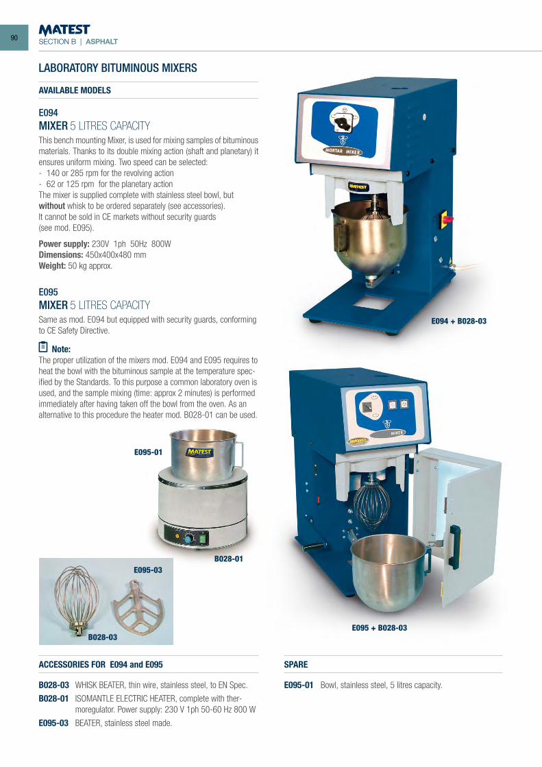
SECTION B | ASPHALT
LABORATORY BITUMINOUS MIXERS
AVAILABLE MODELS
E094MIXER 5 LITRES CAPACITYThis bench mounting Mixer, is used for mixing samples of bituminous materials. Thanks to its double mixing action (shaft and planetary) it ensures uniform mixing. Two speed can be selected:- 140 or 285 rpm for the revolving action- 62 or 125 rpm for the planetary actionThe mixer is supplied complete with stainless steel bowl, butwithout whisk to be ordered separately (see accessories).It cannot be sold in CE markets without security guards(see mod. E095).
Power supply: 230V 1ph 50Hz 800WDimensions: 450x400x480 mmWeight: 50 kg approx.
E095MIXER 5 LITRES CAPACITYSame as mod. E094 but equipped with security guards, conforming to CE Safety Directive.
Note:The proper utilization of the mixers mod. E094 and E095 requires to heat the bowl with the bituminous sample at the temperature spec-ified by the Standards. To this purpose a common laboratory oven is used, and the sample mixing (time: approx 2 minutes) is performed immediately after having taken off the bowl from the oven. As an alternative to this procedure the heater mod. B028-01 can be used.
ACCESSORIES FOR E094 and E095
B028-03 WHISK BEATER, thin wire, stainless steel, to EN Spec.
B028-01 ISOMANTLE ELECTRIC HEATER, complete with ther-moregulator. Power supply: 230 V 1ph 50-60 Hz 800 W
E095-03 BEATER, stainless steel made.
B028-01
E095-01
B028-03
E095-03
SPARE
E095-01 Bowl, stainless steel, 5 litres capacity.
E094 + B028-03
E095 + B028-03
90
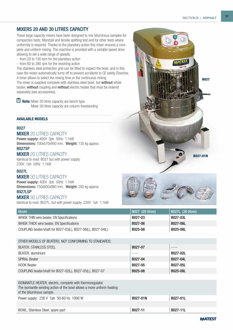
SECTION B | ASPHALT
Note: Mixer 20 litres capacity are bench type. Mixer 30 litres capacity are column freestanding type.
AVAILABLE MODELS
MIXERS 20 AND 30 LITRES CAPACITYThese large capacity mixers have been designed to mix bituminous samples for compaction tests, Marshall and tensile splitting test and for other tests where uniformity is required. Thanks to the planetary action this mixer ensures a com-plete and uniform mixing. The machine is provided with a variable speed drive allowing to set a wide range of speeds:- from 20 to 130 rpm for the planetary action- from 60 to 390 rpm for the revolving actionThe stainless steel protection grid can be lifted to inspect the bowl, and in this case the motor automatically turns off to prevent accidents to CE safety Directive. A timer allows to select the mixing time or the continuous mixing.The mixer is supplied complete with stainless steel bowl, but without whisk beater, without coupling and without electric heater that must be orderedseparately (see accessories).
Model B027 (20 litres) B027L (30 litres)
WHISK THIN wire beater, EN Specifications B027-03 B027-03L
WHISK THICK wire beater, EN Specifications B027-06 B027-06L
COUPLING beater/shaft for B027-03(L), B027-06(L), B027-04(L) B025-08 B025-08L
OTHER MODELS OF BEATERS, NOT CONFORMING TO STANDARDS:
BEATER, STAINLESS STEEL B027-07 -----
BEATER, aluminium ----- B027-02L
SPIRAL Beater B027-04 B027-04L
HOOK Beater B027-05 B027-05L
COUPLING beater/shaft for B027-02(L), B027-05(L), B027-07 B025-08 B025-08L
ISOMANTLE HEATER, electric, complete with thermoregulator.The isomantle winding action of the bowl allows a more uniform heatingof the bituminous sample.
Power supply: 230 V 1ph 50-60 Hz 1000 W B027-01N B027-01L
BOWL, Stainless Steel, spare-part B027-11 B027-11L
B027-01N
B027
B027MIXER 20 LITRES CAPACITYPower supply: 400V 3ph 50Hz 1.1kWDimensions: 700x570x950 mm. Weight: 135 kg approx.B027SPMIXER 20 LITRES CAPACITYIdentical to mod. B027 but with power supply:230V 1ph 50Hz 1.1kW
B027LMIXER 30 LITRES CAPACITYPower supply: 400V 3ph 50Hz 1.1kWDimensions: 750x600x960 mm. Weight: 200 kg approx.B027LSPMIXER 30 LITRES CAPACITYIdentical to mod. B027L, but with power supply: 230V 1ph 1.1kW
91
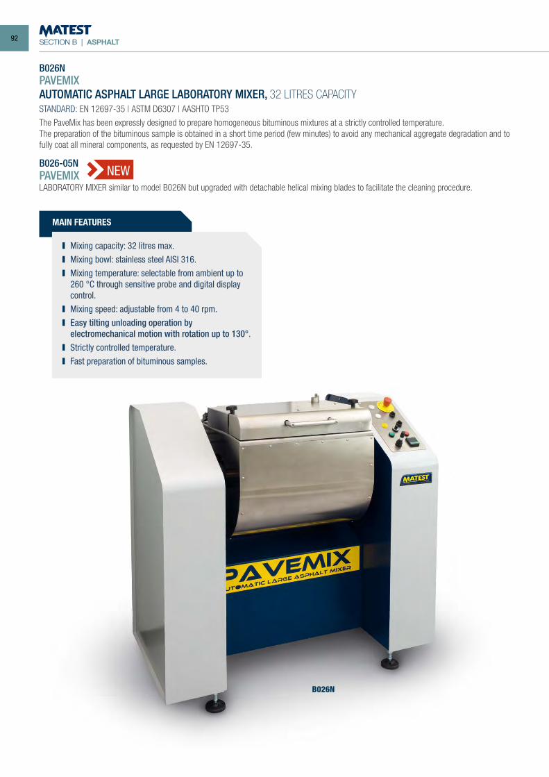
SECTION B | ASPHALT
B026NPAVEMIXAUTOMATIC ASPHALT LARGE LABORATORY MIXER, 32 LITRES CAPACITYSTANDARD: EN 12697-35 | ASTM D6307 | AASHTO TP53
The PaveMix has been expressly designed to prepare homogeneous bituminous mixtures at a strictly controlled temperature.The preparation of the bituminous sample is obtained in a short time period (few minutes) to avoid any mechanical aggregate degradation and to fully coat all mineral components, as requested by EN 12697-35.
B026-05NPAVEMIXLABORATORY MIXER similar to model B026N but upgraded with detachable helical mixing blades to facilitate the cleaning procedure.
B026N
MAIN FEATURES
Mixing capacity: 32 litres max. Mixing bowl: stainless steel AISI 316. Mixing temperature: selectable from ambient up to
260 °C through sensitive probe and digital display control.
Mixing speed: adjustable from 4 to 40 rpm. Easy tilting unloading operation by
electromechanical motion with rotation up to 130°. Strictly controlled temperature. Fast preparation of bituminous samples.
NEW
92
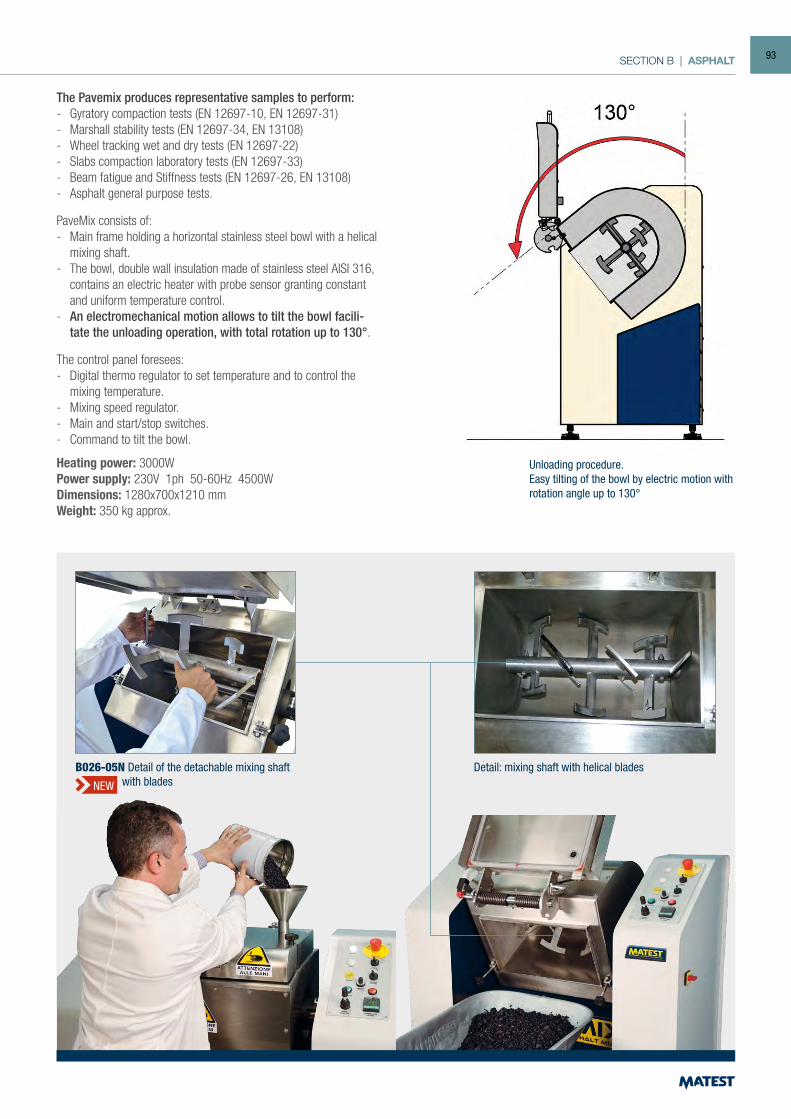
SECTION B | ASPHALT
The Pavemix produces representative samples to perform:- Gyratory compaction tests (EN 12697-10, EN 12697-31)- Marshall stability tests (EN 12697-34, EN 13108)- Wheel tracking wet and dry tests (EN 12697-22)- Slabs compaction laboratory tests (EN 12697-33)- Beam fatigue and Stiffness tests (EN 12697-26, EN 13108)- Asphalt general purpose tests.
PaveMix consists of:- Main frame holding a horizontal stainless steel bowl with a helical
mixing shaft.- The bowl, double wall insulation made of stainless steel AISI 316,
contains an electric heater with probe sensor granting constant and uniform temperature control.
- An electromechanical motion allows to tilt the bowl facili-tate the unloading operation, with total rotation up to 130°.
The control panel foresees:- Digital thermo regulator to set temperature and to control the
mixing temperature.- Mixing speed regulator.- Main and start/stop switches.- Command to tilt the bowl.
Heating power: 3000WPower supply: 230V 1ph 50-60Hz 4500WDimensions: 1280x700x1210 mmWeight: 350 kg approx.
Unloading procedure.Easy tilting of the bowl by electric motion with rotation angle up to 130°
Detail: mixing shaft with helical bladesB026-05N Detail of the detachable mixing shaft with bladesNEW
93
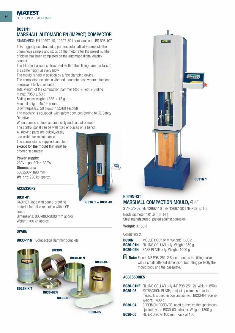
SECTION B | ASPHALT
B031N1MARSHALL AUTOMATIC EN (IMPACT) COMPACTORSTANDARDS: EN 12697-10, 12697-30 | comparable to: BS 598:107
This ruggedly constructed apparatus automatically compacts the bituminous sample and stops off the motor after the preset number of blows has been completed on the automatic digital display counter.The trip mechanism is structured so that the sliding hammer falls at the same height at every blow.The mould is held in position by a fast clamping device. The compactor includes a vibrated concrete base where a laminate hardwood block is mounted.Total weight of the compaction hammer (Rod + Foot + Sliding mass): 7850 ± 50 gSliding mass weight: 4535 ± 15 gFree fall height: 457 ± 5 mmBlow frequency: 50 blows in 55/60 secondsThe machine is equipped with safety door, conforming to CE Safety Directive.When opened it stops automatically and cannot operate.The control panel can be wall fixed or placed on a bench.All moving parts are quickly/easily accessible for maintenance.The compactor is supplied complete, except for the mould that must be ordered separately.
Power supply:230V 1ph 50Hz 300WDimensions:500x500x1890 mmWeight: 220 kg approx.
ACCESSORIES
B030-01NF FILLING COLLAR only (NF P98-251-2). Weight: 850gB030-03 EXTRACTION PLATE, to eject specimens from the
mould. It is used in conjunction with B030-04 receiver. Weight: 1400 g
B030-04 SPECIMEN RECEIVER, used to receive the specimens ejected by the B030-03 extruder. Weight: 1300 g
B030-05 FILTER DISC Ø 100 mm. Pack of 100
B029N-KITMARSHALL COMPACTION MOULD, Ø 4”STANDARDS: EN 12697-10 | EN 12697-30 | NF P98-251-2
Inside diameter. 101.6 mm (4”)Steel manufactured, plated against corrosion.
Weight: 3.150 g
Consisting of:
B030N MOULD BODY only. Weight: 1300 gB030-01N FILLING COLLAR only. Weight: 850 gB030-02N BASE PLATE only. Weight: 1000 g
Note: French NF P98-251-2 Spec. requires the filling collar with a small different dimension, but fitting perfectly the mould body and the baseplate.
B031N 1
B031N 1 + B031-01
B029N KIT
B030N
B030-01N
B030-02N
B030-03
B030-04
B030-05
ACCESSORY
B031-01CABINET, lined with sound-proofing material for noise reduction within CE limits.Dimensions: 800x800x2000 mm approx.Weight: 100 kg approx.
SPARE
B033-11N Compaction Hammer complete
94
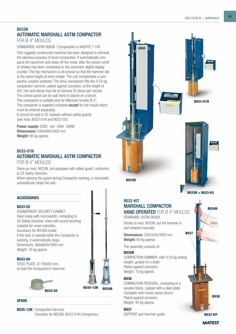
SECTION B | ASPHALT
B033NAUTOMATIC MARSHALL ASTM COMPACTORFOR Ø 4” MOULDSSTANDARDS: ASTM D6926 | Comparable to AASHTO T 245
This ruggedly constructed machine has been designed to eliminate the laborious process of hand compaction. It automatically com-pacts the specimen and stops off the motor after the preset number of strokes has been completed on the automatic digital display counter. The trip mechanism is structured so that the hammer falls at the same height at every stroke. The unit incorporates a com-paction wooden pedestal. The drive mechanism lifts the 4.53 kg. compaction hammer, plated against corrosion, to the height of457 mm and allows free fall at nominal 55 blows per minute.The control panel can be wall fixed or placed on a bench. This compactor is suitable only for Marshall moulds Ø 4“. The compactor is supplied complete except for the mould which must be ordered separately.It cannot be sold in CE markets without safety guards(see mod. B033-01N and B033-03)
Power supply: 230V 1ph 50Hz 300WDimensions: 540x400x1600 mmWeight: 95 kg approx.
B033-01NAUTOMATIC MARSHALL ASTM COMPACTORFOR Ø 4” MOULDSSame as mod. B033N, but equipped with safety guard, conforming to CE Safety Directive.When opening the guard during Compactor working, a microswitch automatically stops the unit.
ACCESSORIES
B033-03SOUNDPROOF SECURITY CABINETSteel made with microswitch, complying to CE Safety Directive, lined with sound-proofing material for noise reduction.Accessory for B033N model.If the door is opened while the Compactor is working, it automatically stops.Dimensions: 660x660x1900 mmWeight: 70 kg approx.
B033-04STEEL PLATE, Ø 100x50 mm,to heat the Compaction’s Hammer.
B032-KITMARSHALL COMPACTORHAND OPERATED FOR Ø 4” MOULDSSTANDARD: ASTM D6926
Similar to mod. B033N, but the hammer is liftedand released manually.
Dimensions: 320x320x1600 mmWeight: 60 kg approx.
The assembly consists of:
B034NCOMPACTION HAMMER, with 4.53 kg sliding weight, guided on a shaft.Plated against corrosion.Weight: 10 kg approx.
B036COMPACTION PEDESTAL, consisting of a wooden block, capped with a steel plate. Complete with mould clamp device.Plated against corrosion.Weight: 42 kg approx.
B037SUPPORT and hammer guide.
SPARE
B035-12N Compaction Hammer Complete for B033N, B033-01N Compactors.
B033N
B033-04B035-12N B034N
B033-01N
B033N + B033-03
B032 KIT
B036
B037
B034N
95
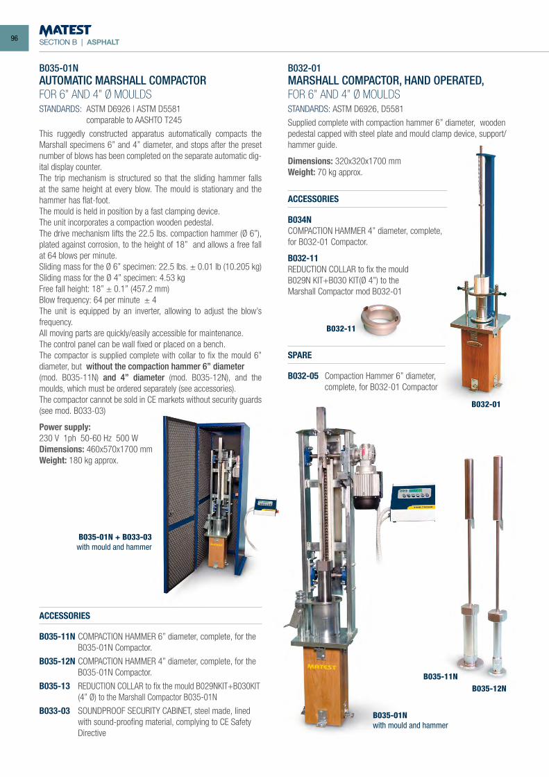
SECTION B | ASPHALT
B032-01MARSHALL COMPACTOR, HAND OPERATED,FOR 6” AND 4” Ø MOULDSSTANDARDS: ASTM D6926, D5581
Supplied complete with compaction hammer 6” diameter, wooden pedestal capped with steel plate and mould clamp device, support/hammer guide.
Dimensions: 320x320x1700 mmWeight: 70 kg approx.
ACCESSORIES
B034NCOMPACTION HAMMER 4” diameter, complete,for B032-01 Compactor.
B032-11REDUCTION COLLAR to fix the mouldB029N KIT+B030 KIT(Ø 4”) to theMarshall Compactor mod B032-01
SPARE
B032-05 Compaction Hammer 6” diameter, complete, for B032-01 Compactor
B035-01NAUTOMATIC MARSHALL COMPACTORFOR 6” AND 4” Ø MOULDSSTANDARDS: ASTM D6926 | ASTM D5581 comparable to AASHTO T245
This ruggedly constructed apparatus automatically compacts the Marshall specimens 6” and 4” diameter, and stops after the preset number of blows has been completed on the separate automatic dig-ital display counter.The trip mechanism is structured so that the sliding hammer falls at the same height at every blow. The mould is stationary and the hammer has flat-foot.The mould is held in position by a fast clamping device.The unit incorporates a compaction wooden pedestal.The drive mechanism lifts the 22.5 lbs. compaction hammer (Ø 6”), plated against corrosion, to the height of 18” and allows a free fall at 64 blows per minute.Sliding mass for the Ø 6” specimen: 22.5 lbs. ± 0.01 lb (10.205 kg)Sliding mass for the Ø 4” specimen: 4.53 kgFree fall height: 18” ± 0.1” (457.2 mm)Blow frequency: 64 per minute ± 4The unit is equipped by an inverter, allowing to adjust the blow’s frequency.All moving parts are quickly/easily accessible for maintenance.The control panel can be wall fixed or placed on a bench.The compactor is supplied complete with collar to fix the mould 6” diameter, but without the compaction hammer 6” diameter(mod. B035-11N) and 4” diameter (mod. B035-12N), and the moulds, which must be ordered separately (see accessories).The compactor cannot be sold in CE markets without security guards (see mod. B033-03)
Power supply:230 V 1ph 50-60 Hz 500 WDimensions: 460x570x1700 mmWeight: 180 kg approx.
ACCESSORIES
B035-11N COMPACTION HAMMER 6” diameter, complete, for the B035-01N Compactor.
B035-12N COMPACTION HAMMER 4” diameter, complete, for the B035-01N Compactor.
B035-13 REDUCTION COLLAR to fix the mould B029NKIT+B030KIT (4” Ø) to the Marshall Compactor B035-01N
B033-03 SOUNDPROOF SECURITY CABINET, steel made, lined with sound-proofing material, complying to CE Safety Directive
B032-01
B032-11
B035-01N + B033-03with mould and hammer
B035-01Nwith mould and hammer
B035-11NB035-12N
96
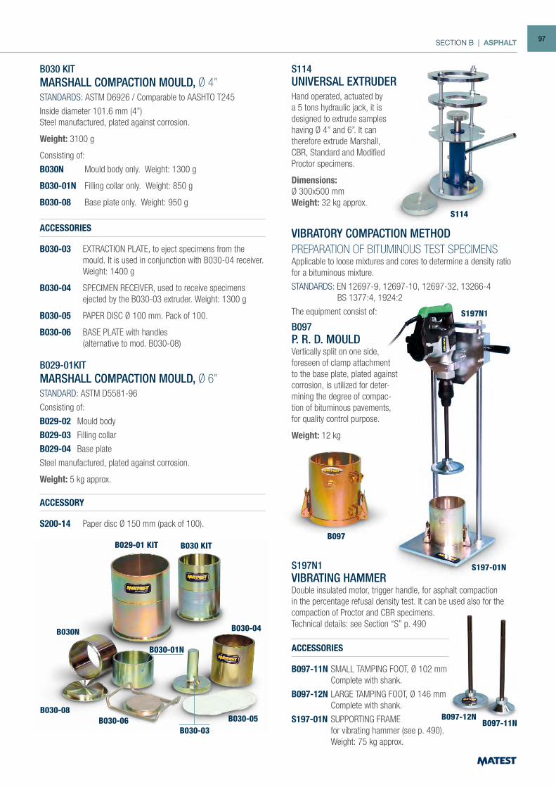
SECTION B | ASPHALT
S114
B030 KIT
B030-08B030-06
B030-03
B030-01N
B030-04
B030-05
B030N
B030 KITMARSHALL COMPACTION MOULD, Ø 4”STANDARDS: ASTM D6926 / Comparable to AASHTO T245
Inside diameter 101.6 mm (4”)Steel manufactured, plated against corrosion.
Weight: 3100 g
Consisting of:
B030N Mould body only. Weight: 1300 g
B030-01N Filling collar only. Weight: 850 g
B030-08 Base plate only. Weight: 950 g
ACCESSORIES
B030-03 EXTRACTION PLATE, to eject specimens from the mould. It is used in conjunction with B030-04 receiver. Weight: 1400 g
B030-04 SPECIMEN RECEIVER, used to receive specimens ejected by the B030-03 extruder. Weight: 1300 g
B030-05 PAPER DISC Ø 100 mm. Pack of 100.
B030-06 BASE PLATE with handles (alternative to mod. B030-08)
B029-01KITMARSHALL COMPACTION MOULD, Ø 6”STANDARD: ASTM D5581-96
Consisting of:
B029-02 Mould body
B029-03 Filling collar
B029-04 Base plate
Steel manufactured, plated against corrosion.
Weight: 5 kg approx.
S114UNIVERSAL EXTRUDERHand operated, actuated by a 5 tons hydraulic jack, it is designed to extrude samples having Ø 4” and 6”. It cantherefore extrude Marshall, CBR, Standard and Modified Proctor specimens.
Dimensions:Ø 300x500 mmWeight: 32 kg approx.
B029-01 KIT
VIBRATORY COMPACTION METHODPREPARATION OF BITUMINOUS TEST SPECIMENS Applicable to loose mixtures and cores to determine a density ratio for a bituminous mixture.
STANDARDS: EN 12697-9, 12697-10, 12697-32, 13266-4 BS 1377:4, 1924:2
The equipment consist of:
S197N1VIBRATING HAMMERDouble insulated motor, trigger handle, for asphalt compaction in the percentage refusal density test. It can be used also for the compaction of Proctor and CBR specimens.Technical details: see Section “S” p. 490
B097-12N
S197N1
S197-01N
B097
B097-11N
B097P. R. D. MOULDVertically split on one side, foreseen of clamp attachment to the base plate, plated against corrosion, is utilized for deter-mining the degree of compac-tion of bituminous pavements, for quality control purpose.
Weight: 12 kg
ACCESSORIES
B097-11N SMALL TAMPING FOOT, Ø 102 mm Complete with shank.
B097-12N LARGE TAMPING FOOT, Ø 146 mm Complete with shank.
S197-01N SUPPORTING FRAME for vibrating hammer (see p. 490). Weight: 75 kg approx.
ACCESSORY
S200-14 Paper disc Ø 150 mm (pack of 100).
97
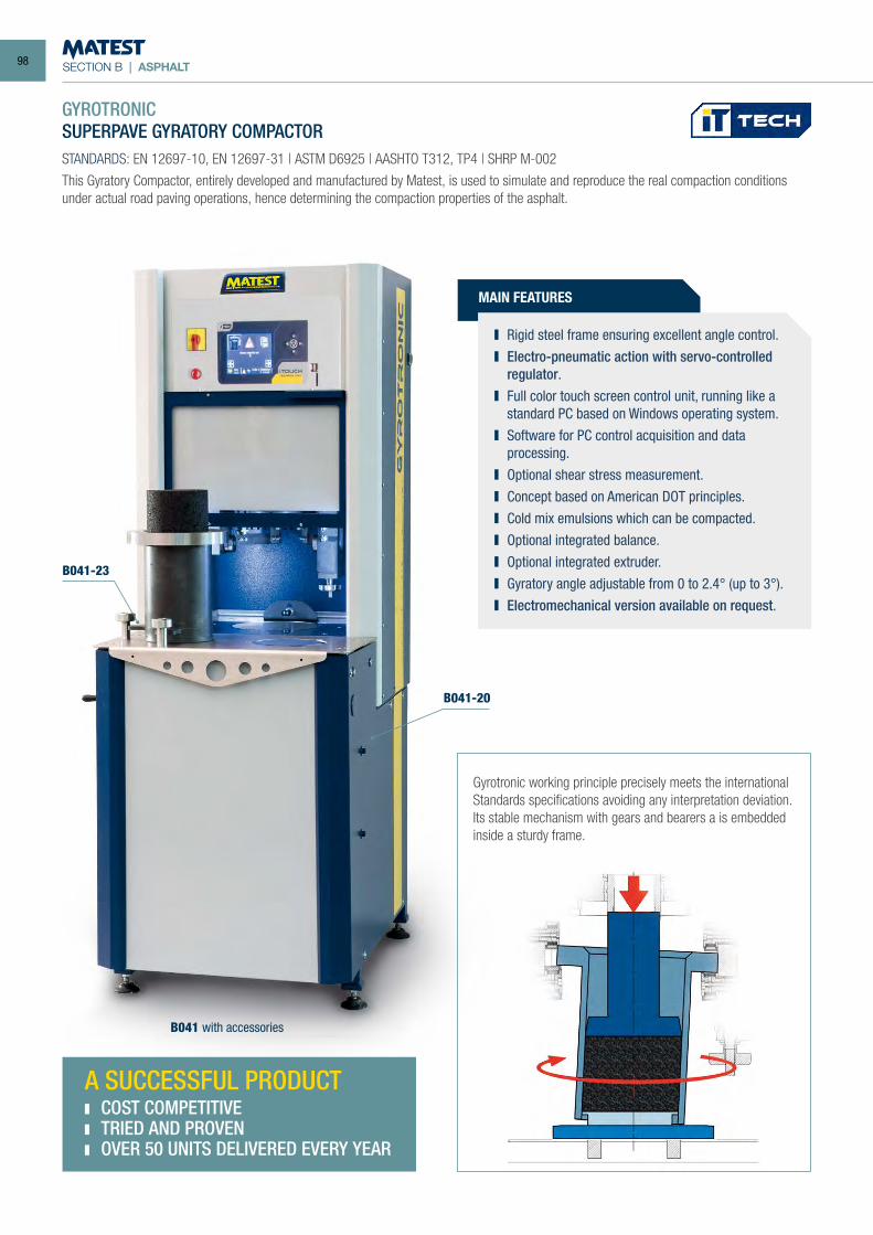
SECTION B | ASPHALT
GYROTRONICSUPERPAVE GYRATORY COMPACTORSTANDARDS: EN 12697-10, EN 12697-31 | ASTM D6925 | AASHTO T312, TP4 | SHRP M-002
This Gyratory Compactor, entirely developed and manufactured by Matest, is used to simulate and reproduce the real compaction conditions under actual road paving operations, hence determining the compaction properties of the asphalt.
Gyrotronic working principle precisely meets the international Standards specifications avoiding any interpretation deviation.Its stable mechanism with gears and bearers a is embedded inside a sturdy frame.
MAIN FEATURES
Rigid steel frame ensuring excellent angle control. Electro-pneumatic action with servo-controlled
regulator. Full color touch screen control unit, running like a
standard PC based on Windows operating system. Software for PC control acquisition and data
processing. Optional shear stress measurement. Concept based on American DOT principles. Cold mix emulsions which can be compacted. Optional integrated balance. Optional integrated extruder. Gyratory angle adjustable from 0 to 2.4° (up to 3°). Electromechanical version available on request.
B041-23
B041-20
B041 with accessories
A SUCCESSFUL PRODUCT COST COMPETITIVE TRIED AND PROVEN OVER 50 UNITS DELIVERED EVERY YEAR
98
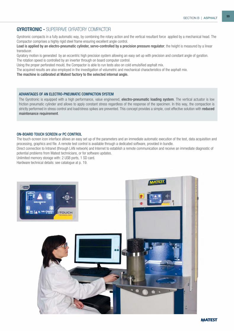
SECTION B | ASPHALT
GYROTRONIC - SUPERPAVE GYRATORY COMPACTORGyrotronic compacts in a fully automatic way, by combining the rotary action and the vertical resultant force applied by a mechanical head. The Compactor comprises a highly rigid steel frame ensuring excellent angle control. Load is applied by an electro-pneumatic cylinder, servo-controlled by a precision pressure regulator; the height is measured by a linear transducer.Gyratory motion is generated by an eccentric high precision system allowing an easy set up with precision and constant angle of gyration.The rotation speed is controlled by an inverter through on board computer control.Using the proper perforated mould, the Compactor is able to run tests also on cold emulsified asphalt mix. The acquired results are also employed in the investigation of volumetric and mechanical characteristics of the asphalt mix.The machine is calibrated at Matest factory to the selected internal angle.
ON-BOARD TOUCH SCREEN or PC CONTROLThe touch-screen icon interface allows an easy set up of the parameters and an immediate automatic execution of the test, data acquisition and processing, graphics and file. A remote test control is available through a dedicated software, provided in bundle.Direct connection to Intranet (through LAN network) and Internet to establish a remote communication and receive an immediate diagnostic of potential problems from Matest technicians, or for software updates.Unlimited memory storage with: 2 USB ports, 1 SD card.Hardware technical details: see catalogue at p. 19.
The Gyrotronic is equipped with a high performance, value engineered, electro-pneumatic loading system. The vertical actuator is low friction pneumatic cylinder and allows to apply constant stress regardless of the response of the specimen. In this way, the compaction is strictly performed in stress control and load/stress spikes are prevented. This concept provides a simple, cost effective solution with reduced maintenance requirement.
ADVANTAGES OF AN ELECTRO-PNEUMATIC COMPACTION SYSTEM
99
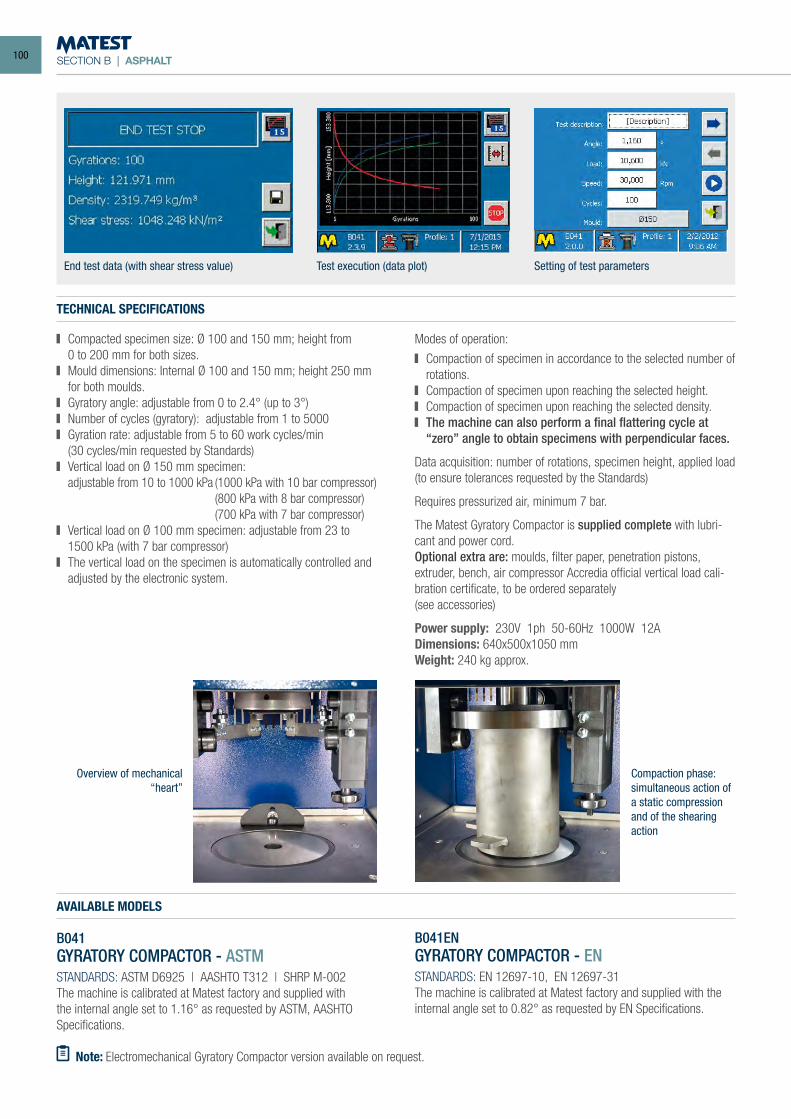
SECTION B | ASPHALT
TECHNICAL SPECIFICATIONS
Compacted specimen size: Ø 100 and 150 mm; height from 0 to 200 mm for both sizes. Mould dimensions: Internal Ø 100 and 150 mm; height 250 mm
for both moulds. Gyratory angle: adjustable from 0 to 2.4° (up to 3°) Number of cycles (gyratory): adjustable from 1 to 5000 Gyration rate: adjustable from 5 to 60 work cycles/min
(30 cycles/min requested by Standards) Vertical load on Ø 150 mm specimen:
adjustable from 10 to 1000 kPa (1000 kPa with 10 bar compressor) (800 kPa with 8 bar compressor)
(700 kPa with 7 bar compressor) Vertical load on Ø 100 mm specimen: adjustable from 23 to
1500 kPa (with 7 bar compressor) The vertical load on the specimen is automatically controlled and
adjusted by the electronic system.
Modes of operation:
Compaction of specimen in accordance to the selected number of rotations.
Compaction of specimen upon reaching the selected height. Compaction of specimen upon reaching the selected density. The machine can also perform a final flattering cycle at
“zero” angle to obtain specimens with perpendicular faces.
Data acquisition: number of rotations, specimen height, applied load (to ensure tolerances requested by the Standards)
Requires pressurized air, minimum 7 bar.
The Matest Gyratory Compactor is supplied complete with lubri-cant and power cord.Optional extra are: moulds, filter paper, penetration pistons, extruder, bench, air compressor Accredia official vertical load cali-bration certificate, to be ordered separately(see accessories)
Power supply: 230V 1ph 50-60Hz 1000W 12ADimensions: 640x500x1050 mmWeight: 240 kg approx.
AVAILABLE MODELS
B041ENGYRATORY COMPACTOR - ENSTANDARDS: EN 12697-10, EN 12697-31The machine is calibrated at Matest factory and supplied with the internal angle set to 0.82° as requested by EN Specifications.
B041GYRATORY COMPACTOR - ASTMSTANDARDS: ASTM D6925 | AASHTO T312 | SHRP M-002The machine is calibrated at Matest factory and supplied with the internal angle set to 1.16° as requested by ASTM, AASHTO Specifications.
End test data (with shear stress value) Test execution (data plot) Setting of test parameters
Note: Electromechanical Gyratory Compactor version available on request.
Overview of mechanical “heart”
Compaction phase: simultaneous action of a static compression and of the shearing action
100
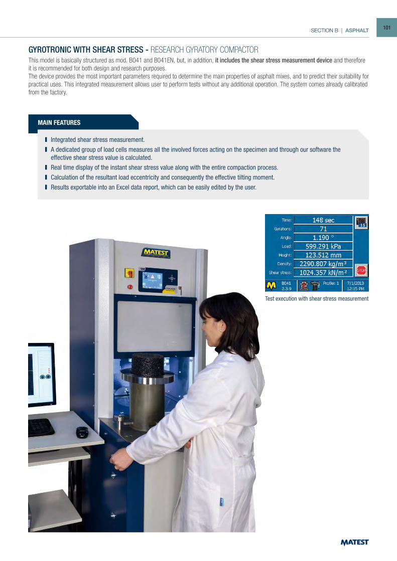
SECTION B | ASPHALT
Test execution with shear stress measurement
MAIN FEATURES
Integrated shear stress measurement. A dedicated group of load cells measures all the involved forces acting on the specimen and through our software the
effective shear stress value is calculated. Real time display of the instant shear stress value along with the entire compaction process. Calculation of the resultant load eccentricity and consequently the effective tilting moment. Results exportable into an Excel data report, which can be easily edited by the user.
GYROTRONIC WITH SHEAR STRESS - RESEARCH GYRATORY COMPACTORThis model is basically structured as mod. B041 and B041EN, but, in addition, it includes the shear stress measurement device and therefore it is recommended for both design and research purposes.The device provides the most important parameters required to determine the main properties of asphalt mixes, and to predict their suitability for practical uses. This integrated measurement allows user to perform tests without any additional operation. The system comes already calibrated from the factory.
101
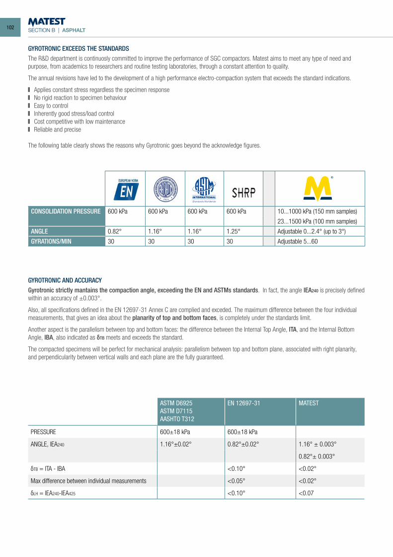
SECTION B | ASPHALT
GYROTRONIC EXCEEDS THE STANDARDSThe R&D department is continuosly committed to improve the performance of SGC compactors. Matest aims to meet any type of need and purpose, from academics to researchers and routine testing laboratories, through a constant attention to quality.
The annual revisions have led to the development of a high performance electro-compaction system that exceeds the standard indications.
Applies constant stress regardless the specimen response No rigid reaction to specimen behaviour Easy to control Inherently good stress/load control Cost competitive with low maintenance Reliable and precise
The following table clearly shows the reasons why Gyrotronic goes beyond the acknowledge figures.
GYROTRONIC AND ACCURACYGyrotronic strictly mantains the compaction angle, exceeding the EN and ASTMs standards. In fact, the angle IEA240 is precisely defined within an accuracy of ±0.003°.
Also, all specifications defined in the EN 12697-31 Annex C are complied and exceded. The maximum difference between the four individual measurements, that gives an idea about the planarity of top and bottom faces, is completely under the standards limit.
Another aspect is the parallelism between top and bottom faces: the difference between the Internal Top Angle, ITA, and the Internal Bottom Angle, IBA, also indicated as δTB meets and exceeds the standard.
The compacted specimens will be perfect for mechanical analysis: parallelism between top and bottom plane, associated with right planarity, and perpendicularity between vertical walls and each plane are the fully guaranteed.
ASTM D6925ASTM D7115AASHTO T312
EN 12697-31 MATEST
PRESSURE 600±18 kPa 600±18 kPa
ANGLE, IEA240 1.16°±0.02° 0.82°±0.02° 1.16° ± 0.003°
0.82°± 0.003°
δTB = ITA - IBA <0.10° <0.02°
Max difference between individual measurements <0.05° <0.02°
δLH = IEA240-IEA425 <0.10° <0.07
CONSOLIDATION PRESSURE 600 kPa 600 kPa 600 kPa 600 kPa 10...1000 kPa (150 mm samples)
23...1500 kPa (100 mm samples)
ANGLE 0.82° 1.16° 1.16° 1.25° Adjustable 0...2.4° (up to 3°)
GYRATIONS/MIN 30 30 30 30 Adjustable 5...60
102
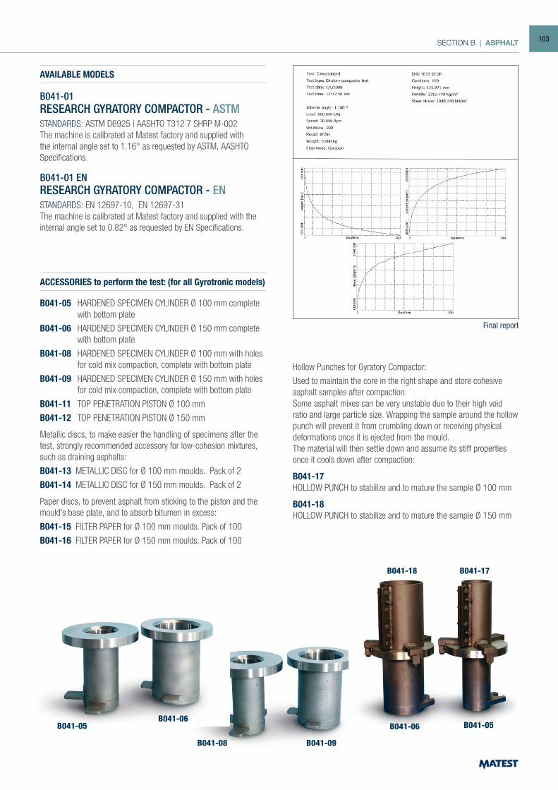
SECTION B | ASPHALT
ACCESSORIES to perform the test: (for all Gyrotronic models)
B041-05 HARDENED SPECIMEN CYLINDER Ø 100 mm complete with bottom plate
B041-06 HARDENED SPECIMEN CYLINDER Ø 150 mm complete with bottom plate
B041-08 HARDENED SPECIMEN CYLINDER Ø 100 mm with holes for cold mix compaction, complete with bottom plate
B041-09 HARDENED SPECIMEN CYLINDER Ø 150 mm with holes for cold mix compaction, complete with bottom plate
B041-11 TOP PENETRATION PISTON Ø 100 mm
B041-12 TOP PENETRATION PISTON Ø 150 mm
Metallic discs, to make easier the handling of specimens after the test, strongly recommended accessory for low-cohesion mixtures, such as draining asphalts:
B041-13 METALLIC DISC for Ø 100 mm moulds. Pack of 2
B041-14 METALLIC DISC for Ø 150 mm moulds. Pack of 2
Paper discs, to prevent asphalt from sticking to the piston and the mould’s base plate, and to absorb bitumen in excess:
B041-15 FILTER PAPER for Ø 100 mm moulds. Pack of 100
B041-16 FILTER PAPER for Ø 150 mm moulds. Pack of 100
Hollow Punches for Gyratory Compactor:
Used to maintain the core in the right shape and store cohesive asphalt samples after compaction.Some asphalt mixes can be very unstable due to their high void ratio and large particle size. Wrapping the sample around the hollow punch will prevent it from crumbling down or receiving physical deformations once it is ejected from the mould.The material will then settle down and assume its stiff properties once it cools down after compaction:
B041-17HOLLOW PUNCH to stabilize and to mature the sample Ø 100 mm
B041-18HOLLOW PUNCH to stabilize and to mature the sample Ø 150 mm
Final report
AVAILABLE MODELS
B041-01RESEARCH GYRATORY COMPACTOR - ASTMSTANDARDS: ASTM D6925 | AASHTO T312 7 SHRP M-002The machine is calibrated at Matest factory and supplied with the internal angle set to 1.16° as requested by ASTM, AASHTO Specifications.
B041-01 ENRESEARCH GYRATORY COMPACTOR - ENSTANDARDS: EN 12697-10, EN 12697-31The machine is calibrated at Matest factory and supplied with the internal angle set to 0.82° as requested by EN Specifications.
B041-08
B041-05B041-06
B041-09
B041-06
B041-18
B041-05
B041-17
103
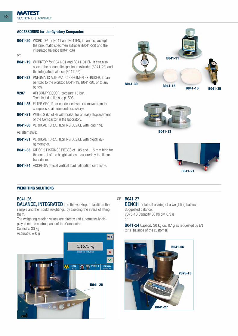
SECTION B | ASPHALT
B041-27BENCH for lateral bearing of a weighting balance.Suggested balance:V075-13 Capacity 30 kg div. 0.5 gor:
B041-24 Capacity 30 kg div. 0.1g as requested by EN(or a balance of the customer)
B041-26BALANCE, INTEGRATED into the worktop, to facilitate the sample and the mould weightings, by avoiding the stress of lifting them.The weighting reading values are directly and automatically dis-played on the control panel of the Compactor.Capacity: 30 kgAccuracy: ± 6 g
B041-27
B041-06
B041-26
B041-31
B041-30B041-35
B041-33
B041-15B041-16
B041-21
V075-13
WEIGHTING SOLUTIONS
OR
ACCESSORIES for the Gyratory Compactor:
B041-20 WORKTOP for B041 and B041EN, it can also accept the pneumatic specimen extruder (B041-23) and the integrated balance (B041-26)
or:
B041-19 WORKTOP for B041-01 and B041-01 EN, it can also accept the pneumatic specimen extruder (B041-23) and the integrated balance (B041-26)
B041-23 PNEUMATIC AUTOMATIC SPECIMEN EXTRUDER, it can be fixed to the worktop B041-19, B041-20, or to any bench.
V207 AIR COMPRESSOR, pressure 10 bar. Technical details: see p. 598
B041-35 FILTER GROUP for condensed water removal from the compressed air. (needed accessory).
B041-21 WHEELS (kit of 4) with brake, for an easy displacement of the Compactor in the laboratory.
B041-30 VERTICAL FORCE TESTING DEVICE with load ring.
As alternative:
B041-31 VERTICAL FORCE TESTING DEVICE with digital dy-namometer.
B041-33 KIT OF 2 DISTANCE PIECES of 105 and 115 mm high for the control of the height values measured by the linear transducer.
B041-34 ACCREDIA official vertical load calibration certificate.
104
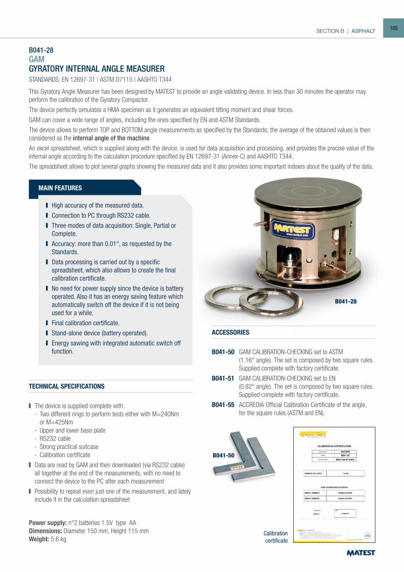
SECTION B | ASPHALT
B041-28GAMGYRATORY INTERNAL ANGLE MEASURERSTANDARDS: EN 12697-31 | ASTM D7115 | AASHTO T344
This Gyratory Angle Measurer has been designed by MATEST to provide an angle validating device. In less than 30 minutes the operator may perform the calibration of the Gyratory Compactor.
The device perfectly simulates a HMA specimen as it generates an equivalent tilting moment and shear forces.
GAM can cover a wide range of angles, including the ones specified by EN and ASTM Standards.
The device allows to perform TOP and BOTTOM angle measurements as specified by the Standards; the average of the obtained values is then considered as the internal angle of the machine.
An excel spreadsheet, which is supplied along with the device, is used for data acquisition and processing, and provides the precise value of the internal angle according to the calculation procedure specified by EN 12697-31 (Annex-C) and AASHTO T344.
The spreadsheet allows to plot several graphs showing the measured data and it also provides some important indexes about the quality of the data.
TECHNICAL SPECIFICATIONS
The device is supplied complete with: - Two different rings to perform tests either with M=240Nm or M=425Nm - Upper and lower base plate - RS232 cable - Strong practical suitcase - Calibration certificate
Data are read by GAM and then downloaded (via RS232 cable) all together at the end of the measurements, with no need to connect the device to the PC after each measurement
Possibility to repeat even just one of the measurement, and lately include it in the calculation spreadsheet
Power supply: n°2 batteries 1.5V type AA Dimensions: Diameter 150 mm, Height 115 mmWeight: 5.6 kg
ACCESSORIES
B041-50 GAM CALIBRATION-CHECKING set to ASTM (1.16° angle). The set is composed by two square rules. Supplied complete with factory certificate.
B041-51 GAM CALIBRATION-CHECKING set to EN (0.82° angle). The set is composed by two square rules. Supplied complete with factory certificate.
B041-55 ACCREDIA Official Calibration Certificate of the angle, for the square rules (ASTM and EN).
Calibrationcertificate
B041-28
B041-50
MAIN FEATURES
High accuracy of the measured data. Connection to PC through RS232 cable. Three modes of data acquisition: Single, Partial or
Complete. Accuracy: more than 0.01°, as requested by the
Standards. Data processing is carried out by a specific
spreadsheet, which also allows to create the final calibration certificate.
No need for power supply since the device is battery operated. Also it has an energy saving feature which automatically switch off the device if it is not being used for a while.
Final calibration certificate. Stand-alone device (battery operated). Energy sawing with integrated automatic switch off
function.
105
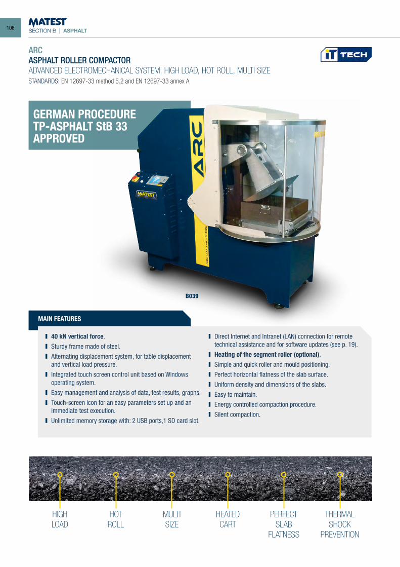
SECTION B | ASPHALT
HIGHLOAD
HOTROLL
MULTISIZE
HEATEDCART
PERFECTSLAB
FLATNESS
THERMALSHOCK
PREVENTION
ARCASPHALT ROLLER COMPACTORADVANCED ELECTROMECHANICAL SYSTEM, HIGH LOAD, HOT ROLL, MULTI SIZESTANDARDS: EN 12697-33 method 5.2 and EN 12697-33 annex A
B039
MAIN FEATURES
40 kN vertical force. Sturdy frame made of steel. Alternating displacement system, for table displacement
and vertical load pressure. Integrated touch screen control unit based on Windows
operating system. Easy management and analysis of data, test results, graphs. Touch-screen icon for an easy parameters set up and an
immediate test execution. Unlimited memory storage with: 2 USB ports,1 SD card slot.
Direct Internet and Intranet (LAN) connection for remote technical assistance and for software updates (see p. 19).
Heating of the segment roller (optional). Simple and quick roller and mould positioning. Perfect horizontal flatness of the slab surface. Uniform density and dimensions of the slabs. Easy to maintain. Energy controlled compaction procedure. Silent compaction.
GERMAN PROCEDURETP-ASPHALT StB 33APPROVED
106
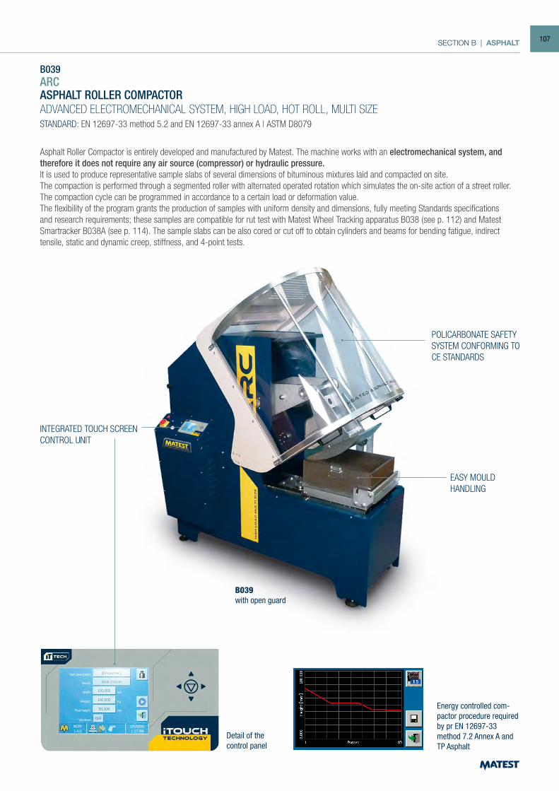
SECTION B | ASPHALT
B039ARCASPHALT ROLLER COMPACTORADVANCED ELECTROMECHANICAL SYSTEM, HIGH LOAD, HOT ROLL, MULTI SIZESTANDARD: EN 12697-33 method 5.2 and EN 12697-33 annex A | ASTM D8079
Asphalt Roller Compactor is entirely developed and manufactured by Matest. The machine works with an electromechanical system, and therefore it does not require any air source (compressor) or hydraulic pressure.It is used to produce representative sample slabs of several dimensions of bituminous mixtures laid and compacted on site. The compaction is performed through a segmented roller with alternated operated rotation which simulates the on-site action of a street roller. The compaction cycle can be programmed in accordance to a certain load or deformation value. The flexibility of the program grants the production of samples with uniform density and dimensions, fully meeting Standards specifications and research requirements; these samples are compatible for rut test with Matest Wheel Tracking apparatus B038 (see p. 112) and Matest Smartracker B038A (see p. 114). The sample slabs can be also cored or cut off to obtain cylinders and beams for bending fatigue, indirect tensile, static and dynamic creep, stiffness, and 4-point tests.
Detail of the control panel
B039with open guard
POLICARBONATE SAFETY SYSTEM CONFORMING TO CE STANDARDS
INTEGRATED TOUCH SCREENCONTROL UNIT
EASY MOULDHANDLING
Energy controlled com-pactor procedure required by pr EN 12697-33 method 7.2 Annex A and TP Asphalt
107
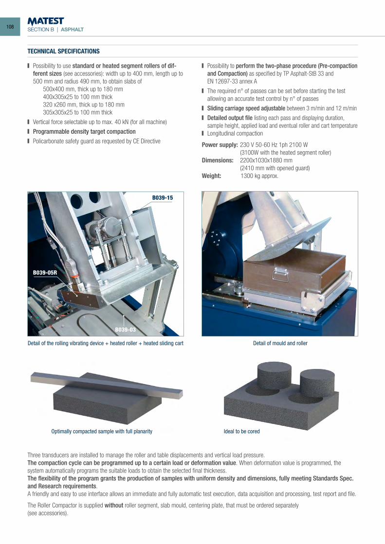
SECTION B | ASPHALT
Three transducers are installed to manage the roller and table displacements and vertical load pressure.The compaction cycle can be programmed up to a certain load or deformation value. When deformation value is programmed, the system automatically programs the suitable loads to obtain the selected final thickness.The flexibility of the program grants the production of samples with uniform density and dimensions, fully meeting Standards Spec. and Research requirements.A friendly and easy to use interface allows an immediate and fully automatic test execution, data acquisition and processing, test report and file.
The Roller Compactor is supplied without roller segment, slab mould, centering plate, that must be ordered separately(see accessories).
TECHNICAL SPECIFICATIONS
Possibility to use standard or heated segment rollers of dif-ferent sizes (see accessories): width up to 400 mm, length up to 500 mm and radius 490 mm, to obtain slabs of
500x400 mm, thick up to 180 mm 400x305x25 to 100 mm thick 320 x260 mm, thick up to 180 mm 305x305x25 to 100 mm thick
Vertical force selectable up to max. 40 kN (for all machine)
Programmable density target compaction Policarbonate safety guard as requested by CE Directive
Possibility to perform the two-phase procedure (Pre-compaction and Compaction) as specified by TP Asphalt-StB 33 and
EN 12697-33 annex A
The required n° of passes can be set before starting the test allowing an accurate test control by n° of passes
Sliding carriage speed adjustable between 3 m/min and 12 m/min
Detailed output file listing each pass and displaying duration, sample height, applied load and eventual roller and cart temperature
Longitudinal compaction
Power supply: 230 V 50-60 Hz 1ph 2100 W (3100W with the heated segment roller)Dimensions: 2200x1030x1880 mm (2410 mm with opened guard)Weight: 1300 kg approx.
Optimally compacted sample with full planarity Ideal to be cored
Detail of mould and rollerDetail of the rolling vibrating device + heated roller + heated sliding cart
B039-15
B039-03
B039-05R
108
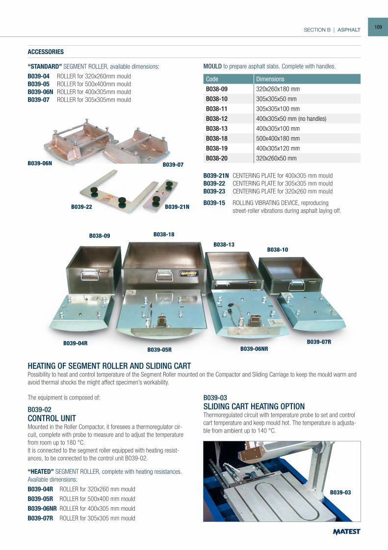
SECTION B | ASPHALT
ACCESSORIES
“STANDARD” SEGMENT ROLLER, available dimensions:
B039-04 ROLLER for 320x260mm mouldB039-05 ROLLER for 500x400mm mouldB039-06N ROLLER for 400x305mm mouldB039-07 ROLLER for 305x305mm mould
Code Dimensions
B038-09 320x260x180 mm
B038-10 305x305x50 mm
B038-11 305x305x100 mm
B038-12 400x305x50 mm (no handles)
B038-13 400x305x100 mm
B038-18 500x400x180 mm
B038-19 400x305x120 mm
B038-20 320x260x50 mm
HEATING OF SEGMENT ROLLER AND SLIDING CARTPossibility to heat and control temperature of the Segment Roller mounted on the Compactor and Sliding Carriage to keep the mould warm and avoid thermal shocks the might affect specimen’s workability.
The equipment is composed of:
B039-02 CONTROL UNIT Mounted in the Roller Compactor, it foresees a thermoregulator cir-cuit, complete with probe to measure and to adjust the temperature from room up to 180 °C. It is connected to the segment roller equipped with heating resist-ances, to be connected to the control unit B039-02.
“HEATED” SEGMENT ROLLER, complete with heating resistances. Available dimensions:
B039-04R ROLLER for 320x260 mm mould
B039-05R ROLLER for 500x400 mm mould
B039-06NR ROLLER for 400x305 mm mould
B039-07R ROLLER for 305x305 mm mould
B039-03SLIDING CART HEATING OPTIONThermoregulated circuit with temperature probe to set and control cart temperature and keep mould hot. The temperature is adjusta-ble from ambient up to 140 °C.
B039-06N
B039-22 B039-21N
B039-07
B038-09
B039-04RB039-05R B039-06NR
B039-07R
B038-18
B038-13B038-10
B039-03
B039-21N CENTERING PLATE for 400x305 mm mouldB039-22 CENTERING PLATE for 305x305 mm mouldB039-23 CENTERING PLATE for 320x260 mm mould
B039-15 ROLLING VIBRATING DEVICE, reproducing street-roller vibrations during asphalt laying off.
MOULD to prepare asphalt slabs. Complete with handles.
109
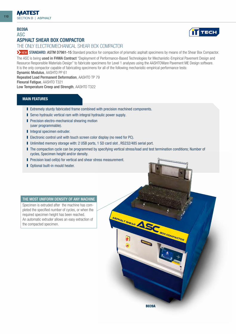
SECTION B | ASPHALT
Extremely sturdy fabricated frame combined with precision machined components. Servo hydraulic vertical ram with integral hydraulic power supply. Precision electro-mechanical shearing motion
(user programmable). Integral specimen extruder. Electronic control unit with touch screen color display (no need for PC). Unlimited memory storage with: 2 USB ports, 1 SD card slot , RS232/485 serial port. The compaction cycle can be programmed by specifying vertical stress/load and test termination conditions; Number of
cycles, Specimen height and/or density. Precision load cell(s) for vertical and shear stress measurement. Optional built-in mould heater.
THE MOST UNIFORM DENSITY OF ANY MACHINESpecimen is extruded after the machine has com-pleted the specified number of cycles, or when the required specimen height has been reached.An automatic extruder allows an easy extraction of the compacted specimen.
B039A
MAIN FEATURES
NEW
B039AASCASPHALT SHEAR BOX COMPACTORTHE ONLY ELECTROMECHANICAL SHEAR BOX COMPACTOR STANDARD: ASTM D7981-15 Standard practice for compaction of prismatic asphalt specimens by means of the Shear Box Compactor.
The ASC is being used in FHWA Contract “Deployment of Performance-Based Technologies for Mechanistic-Empirical Pavement Design and Resource Responsible Materials Design” to fabricate specimens for Level 1 analyses using the AASHTOWare Pavement ME Design software. It is the only compactor capable of fabricating specimens for all of the following mechanistic-empirical performance tests:Dynamic Modulus, AASHTO PP 61Repeated Load Permanent Deformation, AASHTO TP 79Flexural Fatigue, AASHTO T321Low Temperature Creep and Strength, AASHTO T322
110
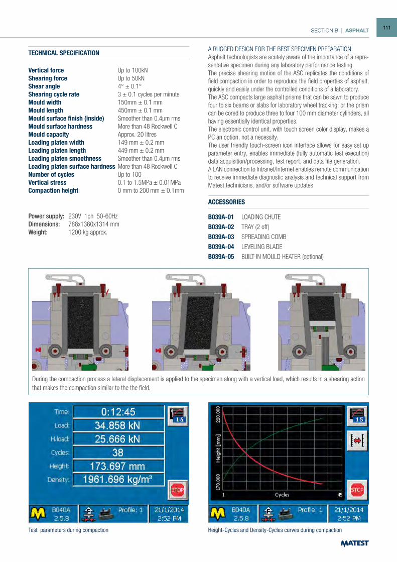
SECTION B | ASPHALT
TECHNICAL SPECIFICATION
Vertical force Up to 100kN Shearing force Up to 50kNShear angle 4° ± 0.1°Shearing cycle rate 3 ± 0.1 cycles per minuteMould width 150mm ± 0.1 mmMould length 450mm ± 0.1 mmMould surface finish (inside) Smoother than 0.4µm rmsMould surface hardness More than 48 Rockwell CMould capacity Approx. 20 litresLoading platen width 149 mm ± 0.2 mmLoading platen length 449 mm ± 0.2 mmLoading platen smoothness Smoother than 0.4µm rmsLoading platen surface hardness More than 48 Rockwell CNumber of cycles Up to 100Vertical stress 0.1 to 1.5MPa ± 0.01MPaCompaction height 0 mm to 200 mm ± 0.1mm
Power supply: 230V 1ph 50-60HzDimensions: 788x1360x1314 mmWeight: 1200 kg approx.
ACCESSORIES
B039A-01 LOADING CHUTE
B039A-02 TRAY (2 off)
B039A-03 SPREADING COMB
B039A-04 LEVELING BLADE
B039A-05 BUILT-IN MOULD HEATER (optional)
Test parameters during compaction Height-Cycles and Density-Cycles curves during compaction
During the compaction process a lateral displacement is applied to the specimen along with a vertical load, which results in a shearing action that makes the compaction similar to the the field.
A RUGGED DESIGN FOR THE BEST SPECIMEN PREPARATION Asphalt technologists are acutely aware of the importance of a repre-sentative specimen during any laboratory performance testing.The precise shearing motion of the ASC replicates the conditions of field compaction in order to reproduce the field properties of asphalt, quickly and easily under the controlled conditions of a laboratory.The ASC compacts large asphalt prisms that can be sawn to produce four to six beams or slabs for laboratory wheel tracking; or the prism can be cored to produce three to four 100 mm diameter cylinders, all having essentially identical properties.The electronic control unit, with touch screen color display, makes a PC an option, not a necessity.The user friendly touch-screen icon interface allows for easy set up parameter entry, enables immediate (fully automatic test execution) data acquisition/processing, test report, and data file generation.A LAN connection to Intranet/Internet enables remote communication to receive immediate diagnostic analysis and technical support from Matest technicians, and/or software updates
111
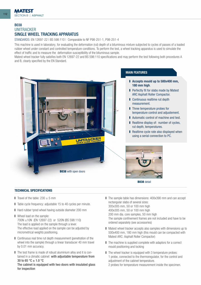
SECTION B | ASPHALT
B038 UNITRACKERSINGLE WHEEL TRACKING APPARATUS STANDARDS: EN 12697-22 | BS 598:110 | Comparable to NF P98-251-1, P98-251-4
This machine is used in laboratory, for evaluating the deformation (rut) depth of a bituminous mixture subjected to cycles of passes of a loaded rubber wheel under constant and controlled temperature conditions. To perform the test, a wheel tracking apparatus is used to simulate the effect of traffic and to measure the deformation susceptibility of the bituminous sample. Matest wheel tracker fully satisfies both EN 12697-22 and BS 598:110 specifications and may perform the test following both procedures A and B, clearly specified by the EN Standard.
TECHNICAL SPECIFICATIONS
Travel of the table: 230 ± 5 mm
Table cycle frequency: adjustable 15 to 40 cycles per minute.
Hard rubber tyred wheel having outside diameter 200 mm
Wheel load on the sample: 700N ±10N (EN 12697-22) or 520N (BS 598:110) The load is applied on the sample through a lever. The effective load applied on the sample can be adjusted by
micrometrical weights positioning.
Continuous real time rut depth measurement (penetration of the wheel into the sample) through a linear transducer 40 mm travel
by 0.01 mm accuracy.
The test frame is made of robust aluminium alloy and it is con-tained in a climatic cabinet with adjustable temperature from 30 to 65 °C ± 1.0 °C
The cabinet is equipped with two doors with insulated glass for inspection
The sample table has dimensions: 400x390 mm and can accept rectangular slabs of several sizes:
305x305 mm, 50 or 100 mm high 400x305 mm, 50 or 100 mm high 200 mm dia. core samples, 50 mm high The sample confinement frames are not included and have to be
ordered separately (see accessories)
Matest wheel tracker accepts also samples with dimensions up to 500x400 mm, 180 mm high (this mould can be compacted with Matest ARC: Asphalt Roller Compactor)
The machine is supplied complete with adaptors for a correct mould positioning and locking
The wheel tracker is equipped with 3 temperature probes: 1 probe, connected to the thermoregulator, for the control and
adjustment of the cabinet temperature. 2 probes for temperature measurement inside the specimen.
B038 detail
B038 with open doors
MAIN FEATURES
Accepts mould up to 500x400 mm, 180 mm high.
Perfectly fit for slabs made by Matest ARC Asphalt Roller Compactor.
Continuous realtime rut depth measurement.
Three temperature probes for temperature control and adjustement.
Automatic control of machine and test. Realtime display of: number of cycles,
rut depth, temperatures. Realtime cycle rate also displayed when
using a serial connection to PC.
112
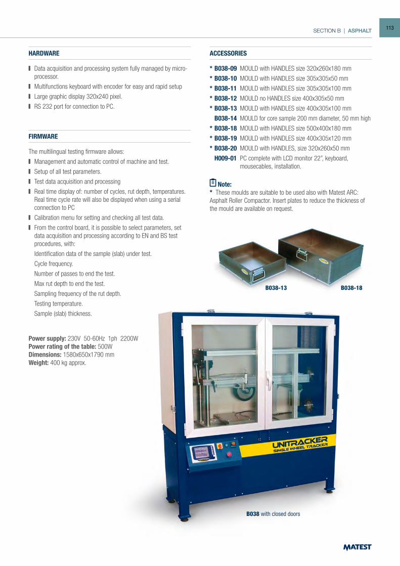
SECTION B | ASPHALT
B038 with closed doors
B038-13 B038-18
HARDWARE
Data acquisition and processing system fully managed by micro-processor.
Multifunctions keyboard with encoder for easy and rapid setup
Large graphic display 320x240 pixel.
RS 232 port for connection to PC.
FIRMWARE
The multilingual testing firmware allows:
Management and automatic control of machine and test.
Setup of all test parameters.
Test data acquisition and processing
Real time display of: number of cycles, rut depth, temperatures. Real time cycle rate will also be displayed when using a serial
connection to PC
Calibration menu for setting and checking all test data.
From the control board, it is possible to select parameters, set data acquisition and processing according to EN and BS test procedures, with:
Identification data of the sample (slab) under test.
Cycle frequency.
Number of passes to end the test.
Max rut depth to end the test.
Sampling frequency of the rut depth.
Testing temperature.
Sample (slab) thickness.
ACCESSORIES
* B038-09 MOULD with HANDLES size 320x260x180 mm
* B038-10 MOULD with HANDLES size 305x305x50 mm
* B038-11 MOULD with HANDLES size 305x305x100 mm
* B038-12 MOULD no HANDLES size 400x305x50 mm
* B038-13 MOULD with HANDLES size 400x305x100 mm
B038-14 MOULD for core sample 200 mm diameter, 50 mm high
* B038-18 MOULD with HANDLES size 500x400x180 mm
* B038-19 MOULD with HANDLES size 400x305x120 mm
* B038-20 MOULD with HANDLES, size 320x260x50 mm
H009-01 PC complete with LCD monitor 22”, keyboard, mousecables, installation.
Note:* These moulds are suitable to be used also with Matest ARC: Asphalt Roller Compactor. Insert plates to reduce the thickness of the mould are available on request.
Power supply: 230V 50-60Hz 1ph 2200W Power rating of the table: 500W Dimensions: 1580x650x1790 mm Weight: 400 kg approx.
113
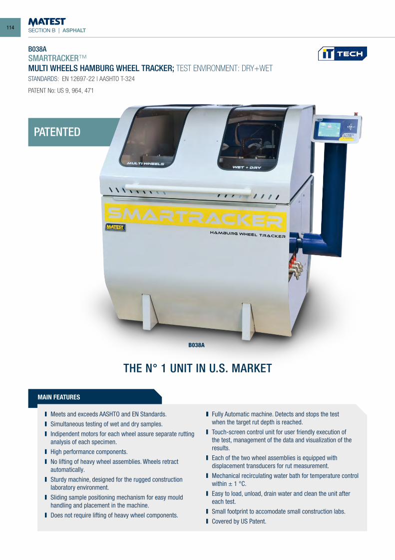
SECTION B | ASPHALT
B038ASMARTRACKER™MULTI WHEELS HAMBURG WHEEL TRACKER; TEST ENVIRONMENT: DRY+WETSTANDARDS: EN 12697-22 | AASHTO T-324
PATENT No: US 9, 964, 471
MAIN FEATURES
Meets and exceeds AASHTO and EN Standards. Simultaneous testing of wet and dry samples. Indipendent motors for each wheel assure separate rutting
analysis of each specimen. High performance components. No lifting of heavy wheel assemblies. Wheels retract
automatically. Sturdy machine, designed for the rugged construction
laboratory environment. Sliding sample positioning mechanism for easy mould
handling and placement in the machine. Does not require lifting of heavy wheel components.
Fully Automatic machine. Detects and stops the test when the target rut depth is reached.
Touch-screen control unit for user friendly execution of the test, management of the data and visualization of the results.
Each of the two wheel assemblies is equipped with displacement transducers for rut measurement.
Mechanical recirculating water bath for temperature control within ± 1 °C.
Easy to load, unload, drain water and clean the unit after each test.
Small footprint to accomodate small construction labs. Covered by US Patent.
B038A
PATENTED
THE N° 1 UNIT IN U.S. MARKET
114
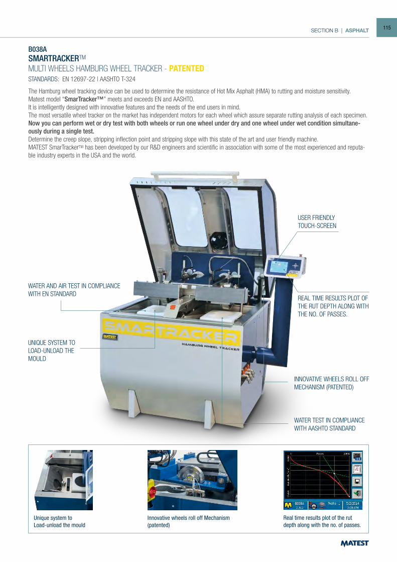
SECTION B | ASPHALT
B038ASMARTRACKERTM
MULTI WHEELS HAMBURG WHEEL TRACKER - PATENTEDSTANDARDS: EN 12697-22 | AASHTO T-324
The Hamburg wheel tracking device can be used to determine the resistance of Hot Mix Asphalt (HMA) to rutting and moisture sensitivity. Matest model “SmarTracker™” meets and exceeds EN and AASHTO.It is intelligently designed with innovative features and the needs of the end users in mind. The most versatile wheel tracker on the market has independent motors for each wheel which assure separate rutting analysis of each specimen. Now you can perform wet or dry test with both wheels or run one wheel under dry and one wheel under wet condition simultane-ously during a single test. Determine the creep slope, stripping inflection point and stripping slope with this state of the art and user friendly machine. MATEST SmarTrackerTM has been developed by our R&D engineers and scientific in association with some of the most experienced and reputa-ble industry experts in the USA and the world.
Innovative wheels roll off Mechanism (patented)
INNOVATIVE WHEELS ROLL OFFMECHANISM (PATENTED)
Unique system toLoad-unload the mould
UNIQUE SYSTEM TOLOAD-UNLOAD THEMOULD
Real time results plot of the rut depth along with the no. of passes.
REAL TIME RESULTS PLOT OF THE RUT DEPTH ALONG WITH THE NO. OF PASSES.
WATER TEST IN COMPLIANCEWITH AASHTO STANDARD
USER FRIENDLYTOUCH-SCREEN
WATER AND AIR TEST IN COMPLIANCEWITH EN STANDARD
115
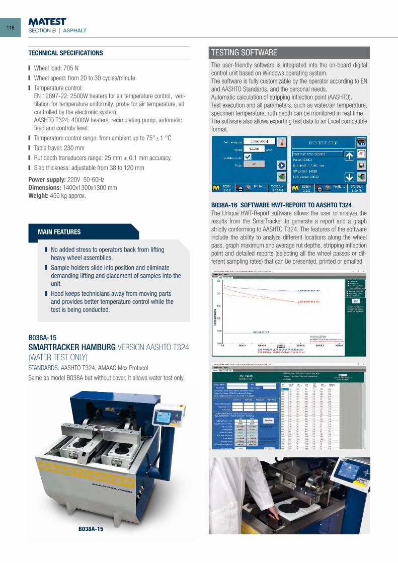
SECTION B | ASPHALT
MAIN FEATURES
No added stress to operators back from lifting heavy wheel assemblies.
Sample holders slide into position and eliminate demanding lifting and placement of samples into the unit.
Hood keeps technicians away from moving parts and provides better temperature control while the test is being conducted.
TESTING SOFTWAREThe user-friendly software is integrated into the on-board digital control unit based on Windows operating system.The software is fully customizable by the operator according to EN and AASHTO Standards, and the personal needs. Automatic calculation of stripping inflection point (AASHTO). Test execution and all parameters, such as water/air temperature, specimen temperature, ruth depth can be monitored in real time.The software also allows exporting test data to an Excel compatible format.
TECHNICAL SPECIFICATIONS
Wheel load: 705 N
Wheel speed: from 20 to 30 cycles/minute.
Temperature control: EN 12697-22: 2500W heaters for air temperature control, ven-
tilation for temperature uniformity, probe for air temperature, all controlled by the electronic system.
AASHTO T324: 4000W heaters, recirculating pump, automatic feed and controls level.
Temperature control range: from ambient up to 75°± 1 °C
Table travel: 230 mm
Rut depth transducers range: 25 mm ± 0.1 mm accuracy.
Slab thickness: adjustable from 38 to 120 mm
Power supply: 220V 50-60HzDimensions: 1400x1300x1300 mmWeight: 450 kg approx.
B038A-15SMARTRACKER HAMBURG VERSION AASHTO T324(WATER TEST ONLY)STANDARDS: AASHTO T324, AMAAC Mex Protocol
Same as model B038A but without cover, it allows water test only.
B038A-15
B038A-16 SOFTWARE HWT-REPORT TO AASHTO T324The Unique HWT-Report software allows the user to analyze the results from the SmarTracker to generate a report and a graph strictly conforming to AASHTO T324. The features of the software include the ability to analyze different locations along the wheel pass, graph maximum and average rut depths, stripping inflection point and detailed reports (selecting all the wheel passes or dif-ferent sampling rates) that can be presented, printed or emailed.
116
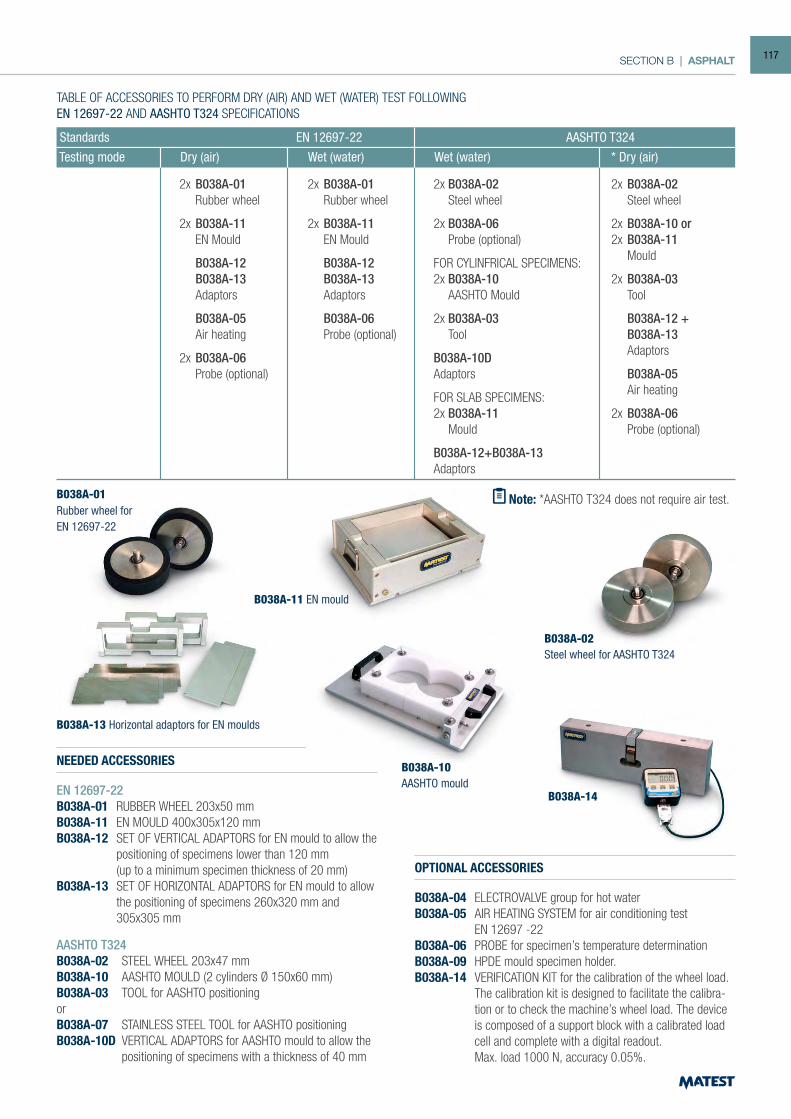
SECTION B | ASPHALT
NEEDED ACCESSORIES
EN 12697-22B038A-01 RUBBER WHEEL 203x50 mmB038A-11 EN MOULD 400x305x120 mm B038A-12 SET OF VERTICAL ADAPTORS for EN mould to allow the
positioning of specimens lower than 120 mm (up to a minimum specimen thickness of 20 mm)B038A-13 SET OF HORIZONTAL ADAPTORS for EN mould to allow
the positioning of specimens 260x320 mm and 305x305 mm
OPTIONAL ACCESSORIES
B038A-04 ELECTROVALVE group for hot waterB038A-05 AIR HEATING SYSTEM for air conditioning test EN 12697 -22B038A-06 PROBE for specimen’s temperature determinationB038A-09 HPDE mould specimen holder.B038A-14 VERIFICATION KIT for the calibration of the wheel load. The calibration kit is designed to facilitate the calibra-
tion or to check the machine’s wheel load. The device is composed of a support block with a calibrated load cell and complete with a digital readout.
Max. load 1000 N, accuracy 0.05%.
B038A-13 Horizontal adaptors for EN moulds
B038A-01Rubber wheel forEN 12697-22
B038A-02Steel wheel for AASHTO T324
B038A-10AASHTO mould
AASHTO T324B038A-02 STEEL WHEEL 203x47 mmB038A-10 AASHTO MOULD (2 cylinders Ø 150x60 mm)B038A-03 TOOL for AASHTO positioningorB038A-07 STAINLESS STEEL TOOL for AASHTO positioningB038A-10D VERTICAL ADAPTORS for AASHTO mould to allow the
positioning of specimens with a thickness of 40 mm
B038A-14
B038A-11 EN mould
Standards EN 12697-22 AASHTO T324 Testing mode Dry (air) Wet (water) Wet (water) * Dry (air)
2x B038A-01 Rubber wheel
2x B038A-11 EN Mould
B038A-12 B038A-13 Adaptors
B038A-05 Air heating
2x B038A-06 Probe (optional)
2x B038A-02 Steel wheel
2x B038A-10 or2x B038A-11 Mould
2x B038A-03 Tool
B038A-12 + B038A-13 Adaptors
B038A-05 Air heating
2x B038A-06 Probe (optional)
2x B038A-01 Rubber wheel
2x B038A-11 EN Mould
B038A-12 B038A-13 Adaptors
B038A-06 Probe (optional)
2x B038A-02 Steel wheel
2x B038A-06 Probe (optional)
FOR CYLINFRICAL SPECIMENS:2x B038A-10 AASHTO Mould
2x B038A-03 Tool
B038A-10DAdaptors
FOR SLAB SPECIMENS:2x B038A-11 Mould
B038A-12+B038A-13Adaptors
TABLE OF ACCESSORIES TO PERFORM DRY (AIR) AND WET (WATER) TEST FOLLOWINGEN 12697-22 AND AASHTO T324 SPECIFICATIONS
Note: *AASHTO T324 does not require air test.
117
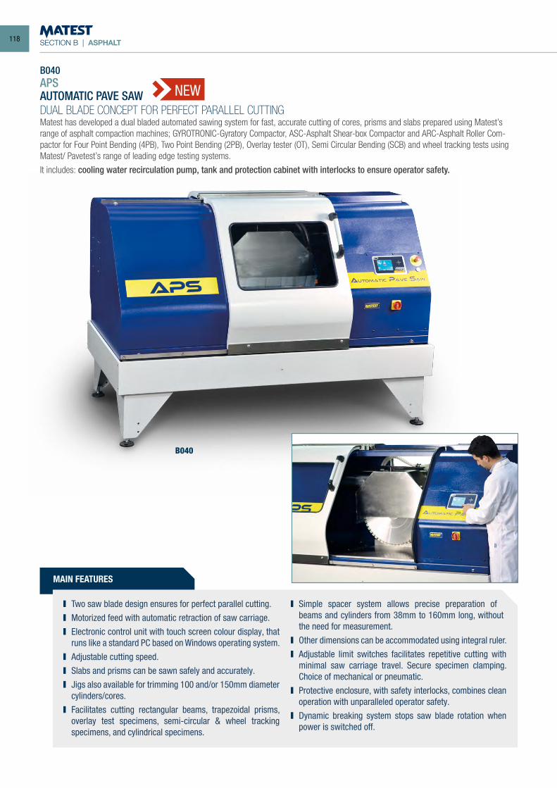
SECTION B | ASPHALT
B040APSAUTOMATIC PAVE SAWDUAL BLADE CONCEPT FOR PERFECT PARALLEL CUTTINGMatest has developed a dual bladed automated sawing system for fast, accurate cutting of cores, prisms and slabs prepared using Matest’s range of asphalt compaction machines; GYROTRONIC-Gyratory Compactor, ASC-Asphalt Shear-box Compactor and ARC-Asphalt Roller Com-pactor for Four Point Bending (4PB), Two Point Bending (2PB), Overlay tester (OT), Semi Circular Bending (SCB) and wheel tracking tests using Matest/ Pavetest’s range of leading edge testing systems.
It includes: cooling water recirculation pump, tank and protection cabinet with interlocks to ensure operator safety.
MAIN FEATURES
Two saw blade design ensures for perfect parallel cutting. Motorized feed with automatic retraction of saw carriage. Electronic control unit with touch screen colour display, that
runs like a standard PC based on Windows operating system. Adjustable cutting speed. Slabs and prisms can be sawn safely and accurately. Jigs also available for trimming 100 and/or 150mm diameter
cylinders/cores. Facilitates cutting rectangular beams, trapezoidal prisms,
overlay test specimens, semi-circular & wheel tracking specimens, and cylindrical specimens.
Simple spacer system allows precise preparation of beams and cylinders from 38mm to 160mm long, without the need for measurement.
Other dimensions can be accommodated using integral ruler. Adjustable limit switches facilitates repetitive cutting with
minimal saw carriage travel. Secure specimen clamping. Choice of mechanical or pneumatic.
Protective enclosure, with safety interlocks, combines clean operation with unparalleled operator safety.
Dynamic breaking system stops saw blade rotation when power is switched off.
B040
NEW
118
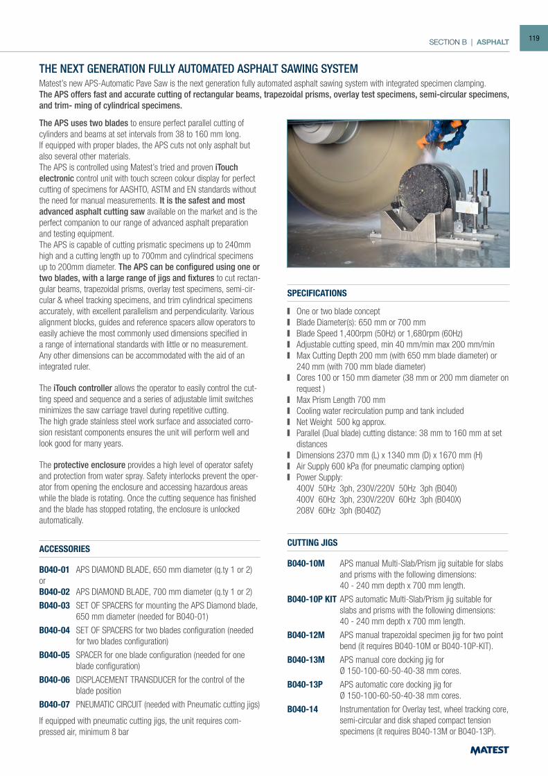
SECTION B | ASPHALT
THE NEXT GENERATION FULLY AUTOMATED ASPHALT SAWING SYSTEMMatest’s new APS-Automatic Pave Saw is the next generation fully automated asphalt sawing system with integrated specimen clamping.The APS offers fast and accurate cutting of rectangular beams, trapezoidal prisms, overlay test specimens, semi-circular specimens, and trim- ming of cylindrical specimens.
The APS uses two blades to ensure perfect parallel cutting of cylinders and beams at set intervals from 38 to 160 mm long.If equipped with proper blades, the APS cuts not only asphalt but also several other materials.The APS is controlled using Matest’s tried and proven iTouch electronic control unit with touch screen colour display for perfect cutting of specimens for AASHTO, ASTM and EN standards without the need for manual measurements. It is the safest and most advanced asphalt cutting saw available on the market and is the perfect companion to our range of advanced asphalt preparation and testing equipment.The APS is capable of cutting prismatic specimens up to 240mm high and a cutting length up to 700mm and cylindrical specimens up to 200mm diameter. The APS can be configured using one or two blades, with a large range of jigs and fixtures to cut rectan-gular beams, trapezoidal prisms, overlay test specimens, semi-cir-cular & wheel tracking specimens, and trim cylindrical specimens accurately, with excellent parallelism and perpendicularity. Various alignment blocks, guides and reference spacers allow operators to easily achieve the most commonly used dimensions specified in a range of international standards with little or no measurement. Any other dimensions can be accommodated with the aid of an integrated ruler.
The iTouch controller allows the operator to easily control the cut-ting speed and sequence and a series of adjustable limit switches minimizes the saw carriage travel during repetitive cutting.The high grade stainless steel work surface and associated corro-sion resistant components ensures the unit will perform well and look good for many years.
The protective enclosure provides a high level of operator safety and protection from water spray. Safety interlocks prevent the oper-ator from opening the enclosure and accessing hazardous areas while the blade is rotating. Once the cutting sequence has finished and the blade has stopped rotating, the enclosure is unlocked automatically.
SPECIFICATIONS
One or two blade concept Blade Diameter(s): 650 mm or 700 mm Blade Speed 1,400rpm (50Hz) or 1,680rpm (60Hz) Adjustable cutting speed, min 40 mm/min max 200 mm/min Max Cutting Depth 200 mm (with 650 mm blade diameter) or
240 mm (with 700 mm blade diameter) Cores 100 or 150 mm diameter (38 mm or 200 mm diameter on
request ) Max Prism Length 700 mm Cooling water recirculation pump and tank included Net Weight 500 kg approx. Parallel (Dual blade) cutting distance: 38 mm to 160 mm at set
distances Dimensions 2370 mm (L) x 1340 mm (D) x 1670 mm (H) Air Supply 600 kPa (for pneumatic clamping option) Power Supply:
400V 50Hz 3ph, 230V/220V 50Hz 3ph (B040) 400V 60Hz 3ph, 230V/220V 60Hz 3ph (B040X) 208V 60Hz 3ph (B040Z)
ACCESSORIES
B040-01 APS DIAMOND BLADE, 650 mm diameter (q.ty 1 or 2)orB040-02 APS DIAMOND BLADE, 700 mm diameter (q.ty 1 or 2)
B040-03 SET OF SPACERS for mounting the APS Diamond blade, 650 mm diameter (needed for B040-01)
B040-04 SET OF SPACERS for two blades configuration (needed for two blades configuration)
B040-05 SPACER for one blade configuration (needed for one blade configuration)
B040-06 DISPLACEMENT TRANSDUCER for the control of the blade position
B040-07 PNEUMATIC CIRCUIT (needed with Pneumatic cutting jigs)
If equipped with pneumatic cutting jigs, the unit requires com-pressed air, minimum 8 bar
CUTTING JIGS
B040-10M APS manual Multi-Slab/Prism jig suitable for slabs and prisms with the following dimensions:
40 - 240 mm depth x 700 mm length.
B040-10P KIT APS automatic Multi-Slab/Prism jig suitable for slabs and prisms with the following dimensions:
40 - 240 mm depth x 700 mm length.
B040-12M APS manual trapezoidal specimen jig for two point bend (it requires B040-10M or B040-10P-KIT).
B040-13M APS manual core docking jig for Ø 150-100-60-50-40-38 mm cores.
B040-13P APS automatic core docking jig for Ø 150-100-60-50-40-38 mm cores.
B040-14 Instrumentation for Overlay test, wheel tracking core, semi-circular and disk shaped compact tension specimens (it requires B040-13M or B040-13P).
119
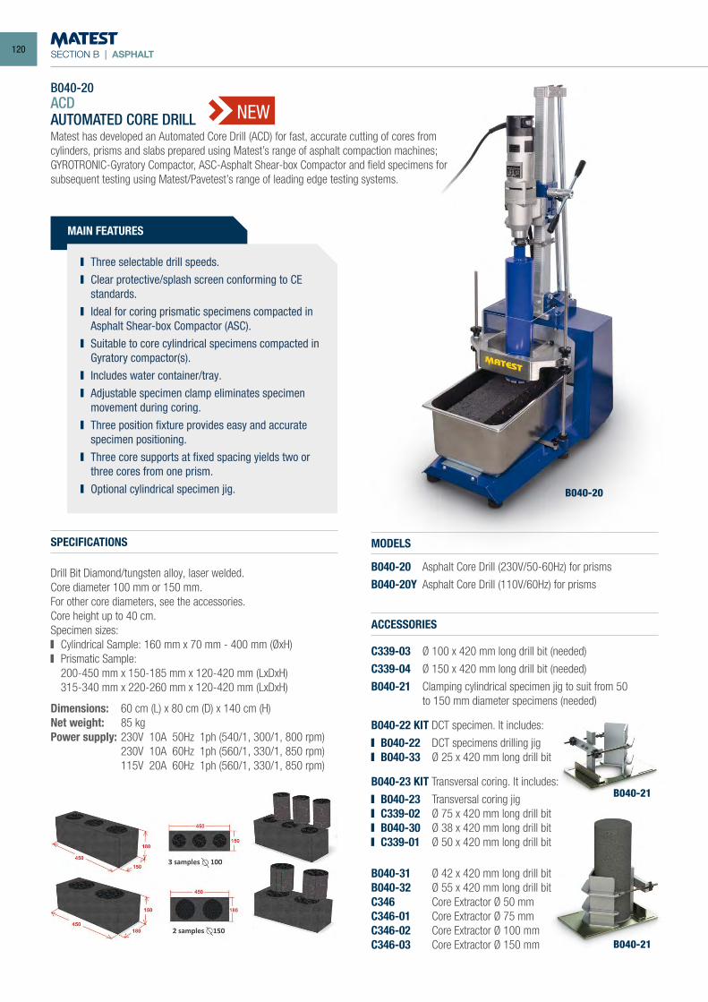
SECTION B | ASPHALT
ACDAUTOMATED CORE DRILLMatest has developed an Automated Core Drill (ACD) for fast, accurate cutting of cores from cylinders, prisms and slabs prepared using Matest’s range of asphalt compaction machines; GYROTRONIC-Gyratory Compactor, ASC-Asphalt Shear-box Compactor and field specimens for subsequent testing using Matest/Pavetest’s range of leading edge testing systems.
MAIN FEATURES
Three selectable drill speeds. Clear protective/splash screen conforming to CE
standards. Ideal for coring prismatic specimens compacted in
Asphalt Shear-box Compactor (ASC). Suitable to core cylindrical specimens compacted in
Gyratory compactor(s). Includes water container/tray. Adjustable specimen clamp eliminates specimen
movement during coring. Three position fixture provides easy and accurate
specimen positioning. Three core supports at fixed spacing yields two or
three cores from one prism. Optional cylindrical specimen jig.
SPECIFICATIONS
Drill Bit Diamond/tungsten alloy, laser welded.Core diameter 100 mm or 150 mm.For other core diameters, see the accessories.Core height up to 40 cm.Specimen sizes: Cylindrical Sample: 160 mm x 70 mm - 400 mm (ØxH) Prismatic Sample:
200-450 mm x 150-185 mm x 120-420 mm (LxDxH) 315-340 mm x 220-260 mm x 120-420 mm (LxDxH)
Dimensions: 60 cm (L) x 80 cm (D) x 140 cm (H)Net weight: 85 kgPower supply: 230V 10A 50Hz 1ph (540/1, 300/1, 800 rpm) 230V 10A 60Hz 1ph (560/1, 330/1, 850 rpm) 115V 20A 60Hz 1ph (560/1, 330/1, 850 rpm)
MODELS
B040-20 Asphalt Core Drill (230V/50-60Hz) for prisms
B040-20Y Asphalt Core Drill (110V/60Hz) for prisms
B040-20
B040-20
ACCESSORIES
C339-03 Ø 100 x 420 mm long drill bit (needed)
C339-04 Ø 150 x 420 mm long drill bit (needed)
B040-21 Clamping cylindrical specimen jig to suit from 50 to 150 mm diameter specimens (needed)
B040-22 KIT DCT specimen. It includes:
B040-22 DCT specimens drilling jig B040-33 Ø 25 x 420 mm long drill bit
B040-23 KIT Transversal coring. It includes:
B040-23 Transversal coring jig C339-02 Ø 75 x 420 mm long drill bit B040-30 Ø 38 x 420 mm long drill bit C339-01 Ø 50 x 420 mm long drill bit
B040-31 Ø 42 x 420 mm long drill bitB040-32 Ø 55 x 420 mm long drill bitC346 Core Extractor Ø 50 mmC346-01 Core Extractor Ø 75 mmC346-02 Core Extractor Ø 100 mmC346-03 Core Extractor Ø 150 mm
B040-21
B040-21
NEW
120
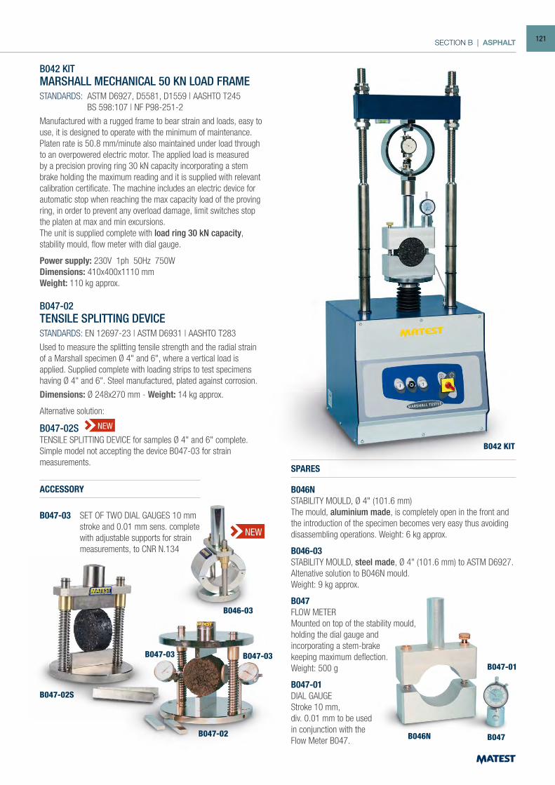
SECTION B | ASPHALT
B042 KITMARSHALL MECHANICAL 50 KN LOAD FRAMESTANDARDS: ASTM D6927, D5581, D1559 | AASHTO T245 BS 598:107 | NF P98-251-2
Manufactured with a rugged frame to bear strain and loads, easy to use, it is designed to operate with the minimum of maintenance.Platen rate is 50.8 mm/minute also maintained under load through to an overpowered electric motor. The applied load is measured by a precision proving ring 30 kN capacity incorporating a stem brake holding the maximum reading and it is supplied with relevant calibration certificate. The machine includes an electric device for automatic stop when reaching the max capacity load of the proving ring, in order to prevent any overload damage, limit switches stop the platen at max and min excursions.The unit is supplied complete with load ring 30 kN capacity, stability mould, flow meter with dial gauge.
Power supply: 230V 1ph 50Hz 750WDimensions: 410x400x1110 mmWeight: 110 kg approx.
B047-02TENSILE SPLITTING DEVICESTANDARDS: EN 12697-23 | ASTM D6931 | AASHTO T283
Used to measure the splitting tensile strength and the radial strain of a Marshall specimen Ø 4" and 6", where a vertical load is applied. Supplied complete with loading strips to test specimens having Ø 4" and 6". Steel manufactured, plated against corrosion.
Dimensions: Ø 248x270 mm - Weight: 14 kg approx.
Alternative solution:
B047-02STENSILE SPLITTING DEVICE for samples Ø 4" and 6" complete. Simple model not accepting the device B047-03 for strainmeasurements.
SPARES
B046NSTABILITY MOULD, Ø 4" (101.6 mm) The mould, aluminium made, is completely open in the front and the introduction of the specimen becomes very easy thus avoiding disassembling operations. Weight: 6 kg approx.
B046-03STABILITY MOULD, steel made, Ø 4" (101.6 mm) to ASTM D6927. Altenative solution to B046N mould.Weight: 9 kg approx.
B047FLOW METERMounted on top of the stability mould,holding the dial gauge andincorporating a stem-brakekeeping maximum deflection.Weight: 500 g
B047-01DIAL GAUGEStroke 10 mm,div. 0.01 mm to be usedin conjunction with theFlow Meter B047.
B047-02
B047-02S
B046N B047
B047-01
B042 KIT
B047-03B047-03
B046-03
NEW
NEW
ACCESSORY
B047-03 SET OF TWO DIAL GAUGES 10 mm stroke and 0.01 mm sens. complete with adjustable supports for strain measurements, to CNR N.134
121
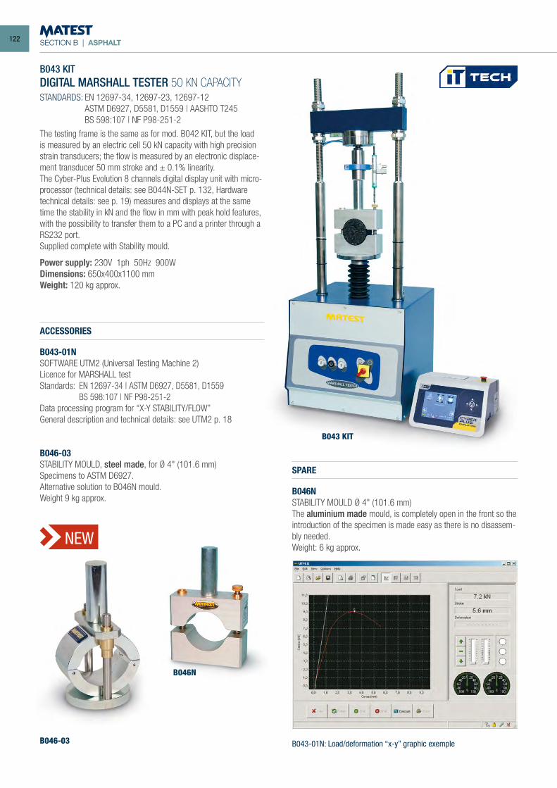
SECTION B | ASPHALT
B043 KITDIGITAL MARSHALL TESTER 50 KN CAPACITYSTANDARDS: EN 12697-34, 12697-23, 12697-12 ASTM D6927, D5581, D1559 | AASHTO T245 BS 598:107 | NF P98-251-2
The testing frame is the same as for mod. B042 KIT, but the load is measured by an electric cell 50 kN capacity with high precision strain transducers; the flow is measured by an electronic displace-ment transducer 50 mm stroke and ± 0.1% linearity.The Cyber-Plus Evolution 8 channels digital display unit with micro-processor (technical details: see B044N-SET p. 132, Hardware technical details: see p. 19) measures and displays at the same time the stability in kN and the flow in mm with peak hold features, with the possibility to transfer them to a PC and a printer through a RS232 port.Supplied complete with Stability mould.
Power supply: 230V 1ph 50Hz 900WDimensions: 650x400x1100 mmWeight: 120 kg approx.
ACCESSORIES
B043-01NSOFTWARE UTM2 (Universal Testing Machine 2)Licence for MARSHALL testStandards: EN 12697-34 | ASTM D6927, D5581, D1559 BS 598:107 | NF P98-251-2Data processing program for “X-Y STABILITY/FLOW”General description and technical details: see UTM2 p. 18
B046-03STABILITY MOULD, steel made, for Ø 4" (101.6 mm) Specimens to ASTM D6927.Alternative solution to B046N mould.Weight 9 kg approx.
SPARE
B046NSTABILITY MOULD Ø 4" (101.6 mm) The aluminium made mould, is completely open in the front so the introduction of the specimen is made easy as there is no disassem-bly needed.Weight: 6 kg approx.
B043 KIT
B046-03
B046N
B043-01N: Load/deformation “x-y” graphic exemple
NEW
122
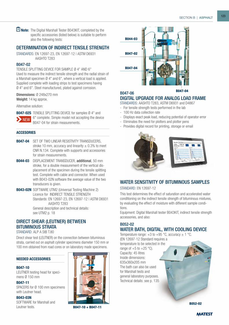
SECTION B | ASPHALT
NEW
Note: The Digital Marshall Tester B043KIT, completed by the specific accessories (listed below) is suitable to perform also the following tests:
DIRECT SHEAR (LEUTNER) BETWEENBITUMINOUS STRATA STANDARD: ALP A StB T.80
Direct shear test (LEUTNER) on the connection between bituminous strata, carried out on asphalt cylinder specimens diameter 150 mm or 100 mm obtained from road cores or on laboratory made specimens.
DETERMINATION OF INDIRECT TENSILE STRENGTHSTANDARDS: EN 12697-23, EN 12697-12 | ASTM D6931 AASHTO T283
B047-02TENSILE SPLITTING DEVICE FOR SAMPLE Ø 4” AND 6”Used to measure the indirect tensile strength and the radial strain of a Marshall specimen Ø 4" and 6", where a vertical load is applied.Supplied complete with loading strips to test specimens havingØ 4" and 6". Steel manufactured, plated against corrosion.
Dimensions: Ø 248x270 mmWeight: 14 kg approx.
Alternative solution:
B047-02S TENSILE SPLITTING DEVICE for samples Ø 4" and 6" complete. Simple model not accepting the device B047-04 for strain measurements.
ACCESORIES
B047-04 SET OF TWO LINEAR RESISTIVITY TRANSDUCERS, stroke 10 mm, accuracy and linearity ± 0.3% to meet CNR N.134. Complete with supports and accessories for strain measurements.
B044-03 DISPLACEMENT TRANSDUCER, additional, 50 mm stroke, for a double measurement of the vertical dis-placement of the specimen during the tensile splitting test. Complete with cable and connector. When used with B043-02N software the average value of the two transducers is given.
B043-02N SOFTWARE UTM2 (Universal Testing Machine 2) Licence for INDIRECT TENSILE STRENGTH Standards: EN 12697-23, EN 12697-12 | ASTM D6931 AASHTO T283 General description and technical details: see UTM2 p. 18
WATER SENSITIVITY OF BITUMINOUS SAMPLESSTANDARD: EN 12697-12
This test determines the effect of saturation and accelerated water conditioning on the indirect tensile strength of bituminous mixtures, by evaluating the effect of moisture with different sample condi-tions. Equipment: Digital Marshall tester B043KIT, indirect tensile strength accessories, and also:
B052-02WATER BATH, DIGITAL, WITH COOLING DEVICETemperature range: +3 to +95 °C, accuracy ± 1 °C.(EN 12697-12 Standard requires atemperature to be selected in the range of +5 to +25 °C).Capacity: 45 litresInside dimensions: 635x360x205 mmThe bath can also be used for Marshall tests and general laboratory purposes. Technical details: see p. 135
NEEDED ACCESSORIES
B047-10LEUTNER testing head for speci-mens Ø 150 mm
B047-11SPACERS for Ø 100 mm specimens with Leutner head.
B043-03NSOFTWARE for Marshall andLeutner tests. B047-10 + B047-11
B052-02
B047-04
B047-02
B047-04
B044-03
B047-06DIGITAL UPGRADE FOR ANALOG LOAD FRAMESTANDARDS: AASHTO T283, ASTM D6931 and D4867- For tensile strength tests performed in the lab- 100 Hz data collection rate- Displays exact peak load, reducing potential of operator error- Eliminates the need for plotters and plotter pens- Provides digital record for printing, storage or email
123
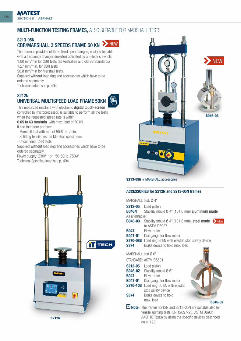
SECTION B | ASPHALT
MULTI-FUNCTION TESTING FRAMES, ALSO SUITABLE FOR MARSHALL TESTS
S213-05NCBR/MARSHALL 3 SPEEDS FRAME 50 KNThe frame is provided of three fixed speed ranges, easily selectable with a frequency changer (inverter) activated by an electric switch:1.00 mm/min for CBR tests (as Australian and old BS Standards)1.27 mm/min. for CBR tests50.8 mm/min for Marshall tests.Supplied without load ring and accessories which have to be ordered separately.Technical detail: see p. 494
NEW
S212N UNIVERSAL MULTISPEED LOAD FRAME 50KNThis motorized machine with electronic digital touch-screencontrolled by microprocessor, is suitable to perform all the tests when the requested speed rate is within:0.05 to 63 mm/min with max. load of 50 kNIt can therefore perform:- Marshall test with rate of 50.8 mm/min.- Splitting tensile test on Marshall specimens.- Unconfined, CBR tests.Supplied without load ring and accessories which have to be ordered separately.Power supply: 230V 1ph 50-60Hz 750WTechnical Specifications: see p. 494
ACCESSORIES for S212N and S213-05N frames
MARSHALL test, Ø 4":
S212-05 Load pistonB046N Stability mould Ø 4" (101.6 mm) aluminium madeAs alternative:B046-03 Stability mould Ø 4" (101.6 mm), steel made to ASTM D6927B047 Flow meterB047-01 Dial gauge for flow meterS370-08S Load ring 30kN with electric stop safety deviceS374 Brake device to hold max. load
MARSHALL test Ø 6"
STANDARD: ASTM D5581
S212-05 Load pistonB046-02 Stability mould Ø 6"B047 Flow meterB047-01 Dial gauge for flow meterS370-10S Load ring 50 kN with electric stop safety deviceS374 Brake device to hold max. load
Note: The frames S212N and S213-05N are suitable also for tensile splitting tests (EN 12697-23, ASTM D6931,
AASHTO T283) by using the specific devices described on p. 123
S213-05N + MARSHALL accessories
S212N
B046-02
NEW
NEW
B046-03
124
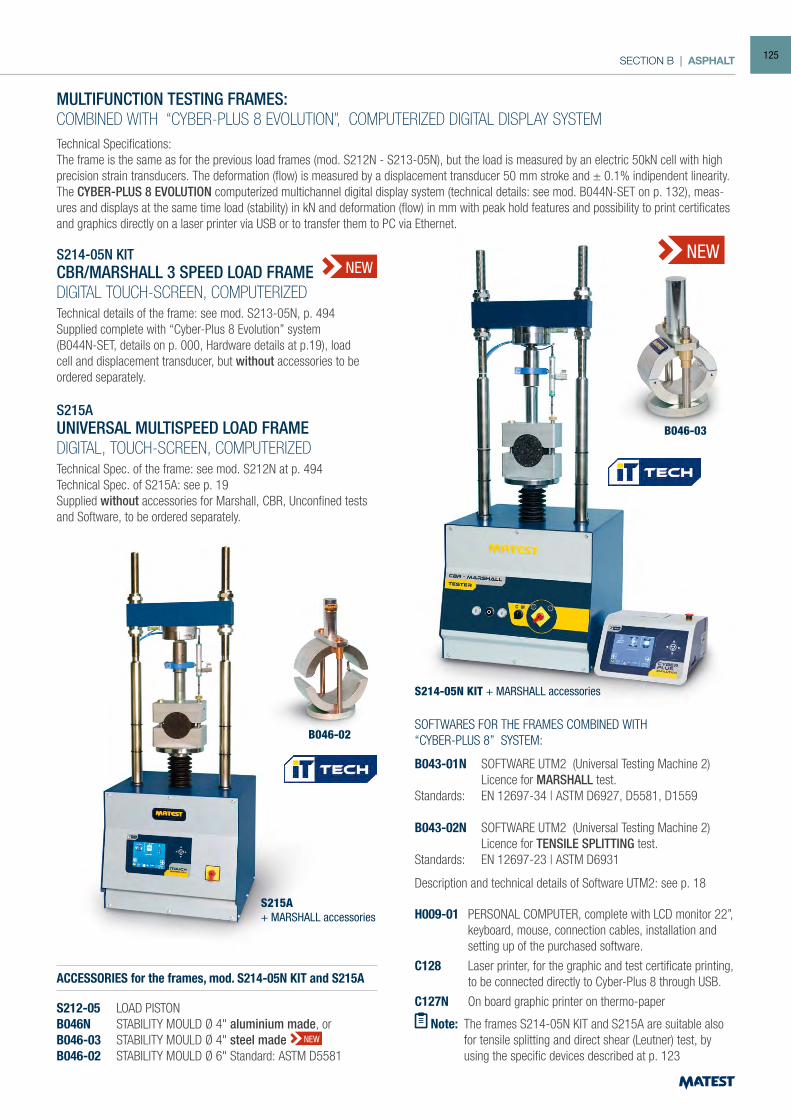
SECTION B | ASPHALT
Note: The frames S214-05N KIT and S215A are suitable also for tensile splitting and direct shear (Leutner) test, by using the specific devices described at p. 123
S214-05N KIT + MARSHALL accessories
S215A+ MARSHALL accessories
B046-02
MULTIFUNCTION TESTING FRAMES:COMBINED WITH “CYBER-PLUS 8 EVOLUTION”, COMPUTERIZED DIGITAL DISPLAY SYSTEMTechnical Specifications:The frame is the same as for the previous load frames (mod. S212N - S213-05N), but the load is measured by an electric 50kN cell with high precision strain transducers. The deformation (flow) is measured by a displacement transducer 50 mm stroke and ± 0.1% indipendent linearity.The CYBER-PLUS 8 EVOLUTION computerized multichannel digital display system (technical details: see mod. B044N-SET on p. 132), meas-ures and displays at the same time load (stability) in kN and deformation (flow) in mm with peak hold features and possibility to print certificates and graphics directly on a laser printer via USB or to transfer them to PC via Ethernet.
S214-05N KITCBR/MARSHALL 3 SPEED LOAD FRAMEDIGITAL TOUCH-SCREEN, COMPUTERIZEDTechnical details of the frame: see mod. S213-05N, p. 494Supplied complete with “Cyber-Plus 8 Evolution” system(B044N-SET, details on p. 000, Hardware details at p.19), load cell and displacement transducer, but without accessories to be ordered separately.
S215AUNIVERSAL MULTISPEED LOAD FRAMEDIGITAL, TOUCH-SCREEN, COMPUTERIZEDTechnical Spec. of the frame: see mod. S212N at p. 494Technical Spec. of S215A: see p. 19Supplied without accessories for Marshall, CBR, Unconfined tests and Software, to be ordered separately.
ACCESSORIES for the frames, mod. S214-05N KIT and S215A
S212-05 LOAD PISTONB046N STABILITY MOULD Ø 4" aluminium made, orB046-03 STABILITY MOULD Ø 4" steel madeB046-02 STABILITY MOULD Ø 6" Standard: ASTM D5581
SOFTWARES FOR THE FRAMES COMBINED WITH“CYBER-PLUS 8” SYSTEM:
B043-01N SOFTWARE UTM2 (Universal Testing Machine 2) Licence for MARSHALL test.Standards: EN 12697-34 | ASTM D6927, D5581, D1559
B043-02N SOFTWARE UTM2 (Universal Testing Machine 2) Licence for TENSILE SPLITTING test.Standards: EN 12697-23 | ASTM D6931
Description and technical details of Software UTM2: see p. 18
H009-01 PERSONAL COMPUTER, complete with LCD monitor 22”, keyboard, mouse, connection cables, installation and setting up of the purchased software.
C128 Laser printer, for the graphic and test certificate printing, to be connected directly to Cyber-Plus 8 through USB.
C127N On board graphic printer on thermo-paper
NEW
NEW
NEW
B046-03
125
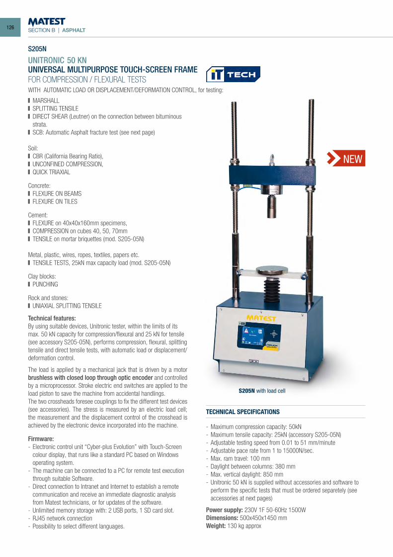
SECTION B | ASPHALT
S205N
UNITRONIC 50 KNUNIVERSAL MULTIPURPOSE TOUCH-SCREEN FRAMEFOR COMPRESSION / FLEXURAL TESTSWITH AUTOMATIC LOAD OR DISPLACEMENT/DEFORMATION CONTROL, for testing:
S205N with load cell
Technical features:By using suitable devices, Unitronic tester, within the limits of its max. 50 kN capacity for compression/flexural and 25 kN for tensile (see accessory S205-05N), performs compression, flexural, splitting tensile and direct tensile tests, with automatic load or displacement/deformation control.
The load is applied by a mechanical jack that is driven by a motor brushless with closed loop through optic encoder and controlled by a microprocessor. Stroke electric end switches are applied to the load piston to save the machine from accidental handlings. The two crossheads foresee couplings to fix the different test devices (see accessories). The stress is measured by an electric load cell; the measurement and the displacement control of the crosshead is achieved by the electronic device incorporated into the machine.
Firmware:- Electronic control unit “Cyber-plus Evolution” with Touch-Screen
colour display, that runs like a standard PC based on Windows operating system.
- The machine can be connected to a PC for remote test execution through suitable Software.
- Direct connection to Intranet and Internet to establish a remote communication and receive an immediate diagnostic analysis from Matest technicians, or for updates of the software.
- Unlimited memory storage with: 2 USB ports, 1 SD card slot.- RJ45 network connection- Possibility to select different languages.
TECHNICAL SPECIFICATIONS
- Maximum compression capacity: 50kN- Maximum tensile capacity: 25kN (accessory S205-05N)- Adjustable testing speed from 0.01 to 51 mm/minute- Adjustable pace rate from 1 to 15000N/sec.- Max. ram travel: 100 mm- Daylight between columns: 380 mm- Max. vertical daylight: 850 mm- Unitronic 50 kN is supplied without accessories and software to
perform the specific tests that must be ordered separetely (see accessories at next pages)
Power supply: 230V 1F 50-60Hz 1500WDimensions: 500x450x1450 mmWeight: 130 kg approx
MARSHALL SPLITTING TENSILE DIRECT SHEAR (Leutner) on the connection between bituminous
strata. SCB: Automatic Asphalt fracture test (see next page)
Soil: CBR (California Bearing Ratio), UNCONFINED COMPRESSION, QUICK TRIAXIAL
Concrete: FLEXURE ON BEAMS FLEXURE ON TILES
Cement: FLEXURE on 40x40x160mm specimens, COMPRESSION on cubes 40, 50, 70mm TENSILE on mortar briquettes (mod. S205-05N)
Metal, plastic, wires, ropes, textiles, papers etc. TENSILE TESTS, 25kN max capacity load (mod. S205-05N)
Clay blocks: PUNCHING
Rock and stones: UNIAXIAL SPLITTING TENSILE
NEW
126
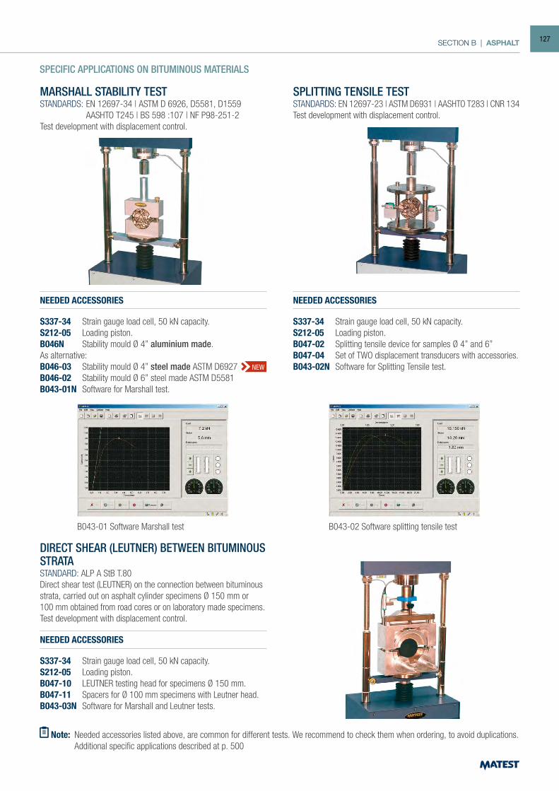
SECTION B | ASPHALT
SPECIFIC APPLICATIONS ON BITUMINOUS MATERIALS
MARSHALL STABILITY TESTSTANDARDS: EN 12697-34 | ASTM D 6926, D5581, D1559 AASHTO T245 | BS 598 :107 | NF P98-251-2Test development with displacement control.
SPLITTING TENSILE TESTSTANDARDS: EN 12697-23 | ASTM D6931 | AASHTO T283 | CNR 134Test development with displacement control.
DIRECT SHEAR (LEUTNER) BETWEEN BITUMINOUSSTRATA STANDARD: ALP A StB T.80 Direct shear test (LEUTNER) on the connection between bituminous strata, carried out on asphalt cylinder specimens Ø 150 mm or100 mm obtained from road cores or on laboratory made specimens. Test development with displacement control.
NEEDED ACCESSORIES
S337-34 Strain gauge load cell, 50 kN capacity. S212-05 Loading piston. B047-10 LEUTNER testing head for specimens Ø 150 mm. B047-11 Spacers for Ø 100 mm specimens with Leutner head. B043-03N Software for Marshall and Leutner tests.
Note: Needed accessories listed above, are common for different tests. We recommend to check them when ordering, to avoid duplications. Additional specific applications described at p. 500
B043-02 Software splitting tensile testB043-01 Software Marshall test
NEW
NEEDED ACCESSORIES
S337-34 Strain gauge load cell, 50 kN capacity.S212-05 Loading piston.B046N Stability mould Ø 4” aluminium made.As alternative:B046-03 Stability mould Ø 4” steel made ASTM D6927B046-02 Stability mould Ø 6” steel made ASTM D5581B043-01N Software for Marshall test.
NEEDED ACCESSORIES
S337-34 Strain gauge load cell, 50 kN capacity.S212-05 Loading piston.B047-02 Splitting tensile device for samples Ø 4” and 6”B047-04 Set of TWO displacement transducers with accessories.B043-02N Software for Splitting Tensile test.
127
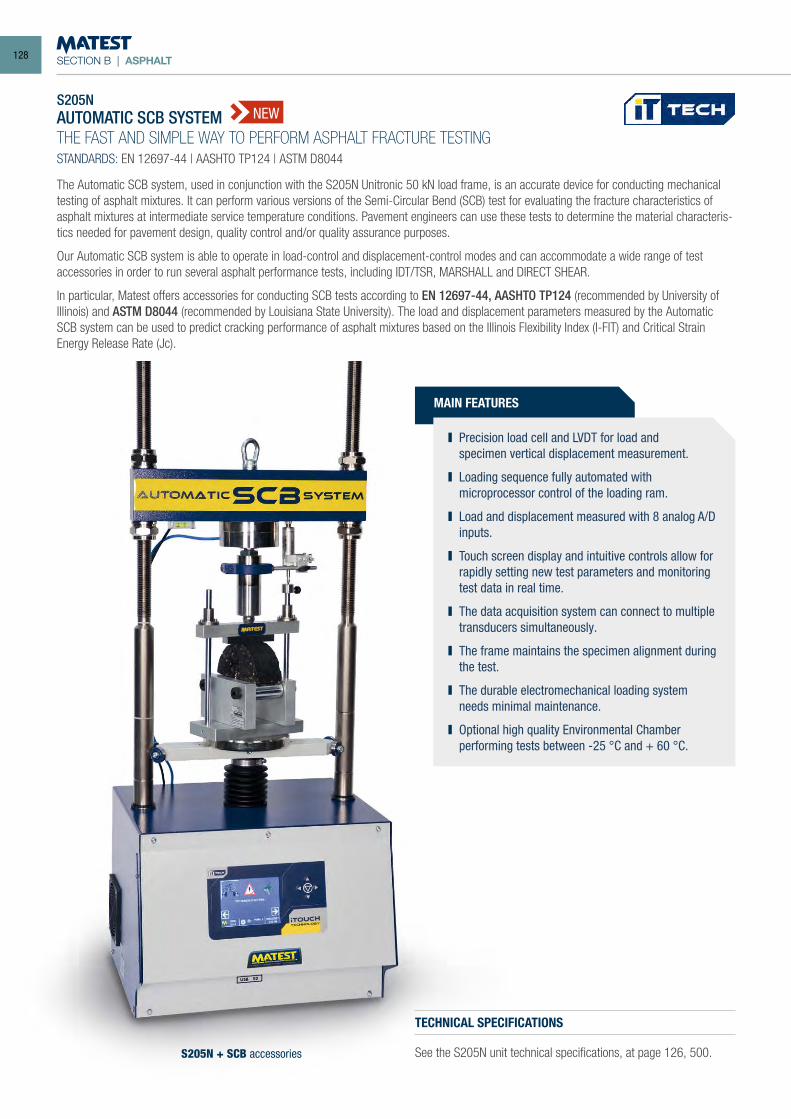
SECTION B | ASPHALT
S205NAUTOMATIC SCB SYSTEMTHE FAST AND SIMPLE WAY TO PERFORM ASPHALT FRACTURE TESTINGSTANDARDS: EN 12697-44 | AASHTO TP124 | ASTM D8044
MAIN FEATURES
Precision load cell and LVDT for load and specimen vertical displacement measurement.
Loading sequence fully automated with microprocessor control of the loading ram.
Load and displacement measured with 8 analog A/D inputs.
Touch screen display and intuitive controls allow for rapidly setting new test parameters and monitoring test data in real time.
The data acquisition system can connect to multiple transducers simultaneously.
The frame maintains the specimen alignment during the test.
The durable electromechanical loading system needs minimal maintenance.
Optional high quality Environmental Chamber performing tests between -25 °C and + 60 °C.
S205N + SCB accessories
TECHNICAL SPECIFICATIONS
See the S205N unit technical specifications, at page 126, 500.
The Automatic SCB system, used in conjunction with the S205N Unitronic 50 kN load frame, is an accurate device for conducting mechanical testing of asphalt mixtures. It can perform various versions of the Semi-Circular Bend (SCB) test for evaluating the fracture characteristics of asphalt mixtures at intermediate service temperature conditions. Pavement engineers can use these tests to determine the material characteris-tics needed for pavement design, quality control and/or quality assurance purposes.
Our Automatic SCB system is able to operate in load-control and displacement-control modes and can accommodate a wide range of test accessories in order to run several asphalt performance tests, including IDT/TSR, MARSHALL and DIRECT SHEAR.
In particular, Matest offers accessories for conducting SCB tests according to EN 12697-44, AASHTO TP124 (recommended by University of Illinois) and ASTM D8044 (recommended by Louisiana State University). The load and displacement parameters measured by the Automatic SCB system can be used to predict cracking performance of asphalt mixtures based on the Illinois Flexibility Index (I-FIT) and Critical Strain Energy Release Rate (Jc).
NEW
128
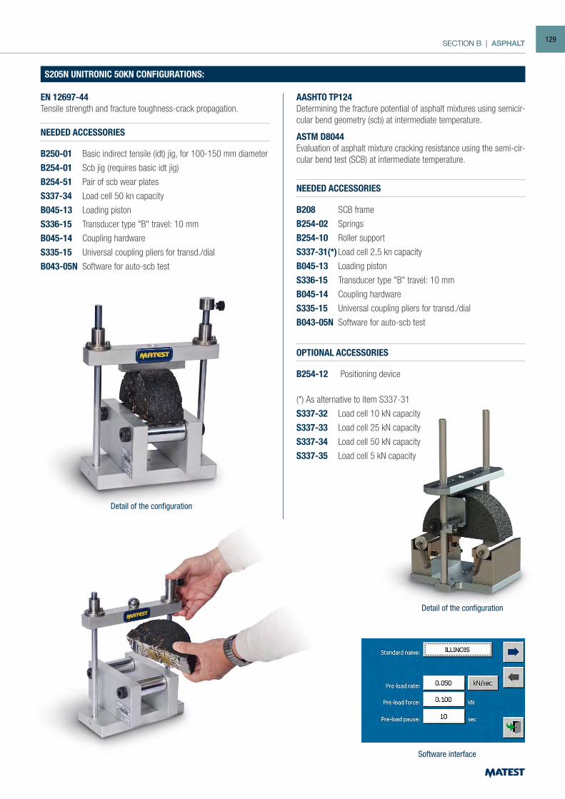
SECTION B | ASPHALT
S205N UNITRONIC 50KN CONFIGURATIONS:
EN 12697-44Tensile strength and fracture toughness-crack propagation.
NEEDED ACCESSORIES
B250-01 Basic indirect tensile (idt) jig, for 100-150 mm diameter
B254-01 Scb jig (requires basic idt jig)
B254-51 Pair of scb wear plates
S337-34 Load cell 50 kn capacity
B045-13 Loading piston
S336-15 Transducer type "B" travel: 10 mm
B045-14 Coupling hardware
S335-15 Universal coupling pliers for transd./dial
B043-05N Software for auto-scb test
Detail of the configuration
Detail of the configuration
Asphalt specimen positioning
AASHTO TP124Determining the fracture potential of asphalt mixtures using semicir-cular bend geometry (scb) at intermediate temperature.
ASTM D8044Evaluation of asphalt mixture cracking resistance using the semi-cir-cular bend test (SCB) at intermediate temperature.
NEEDED ACCESSORIES
B208 SCB frame
B254-02 Springs
B254-10 Roller support
S337-31(*) Load cell 2,5 kn capacity
B045-13 Loading piston
S336-15 Transducer type "B" travel: 10 mm
B045-14 Coupling hardware
S335-15 Universal coupling pliers for transd./dial
B043-05N Software for auto-scb test
OPTIONAL ACCESSORIES
B254-12 Positioning device
(*) As alternative to item S337-31
S337-32 Load cell 10 kN capacity
S337-33 Load cell 25 kN capacity
S337-34 Load cell 50 kN capacity
S337-35 Load cell 5 kN capacity
Software interface
129
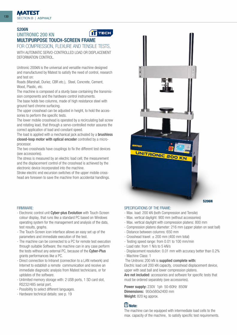
SECTION B | ASPHALT
S206N
S206NUNITRONIC 200 KNMULTIPURPOSE TOUCH-SCREEN FRAMEFOR COMPRESSION, FLEXURE AND TENSILE TESTS,WITH AUTOMATIC SERVO-CONTROLLED LOAD OR DISPLACEMENT DEFORMATION CONTROL.
Unitronic 200kN is the universal and versatile machine designed and manufactured by Matest to satisfy the need of control, research and test on:Roads (Marshall, Duriez, CBR etc.), Steel, Concrete, Cement, Wood, Plastic, etc.The machine is composed of a sturdy base containing the transmis-sion components and the hardware control instruments.The base holds two columns, made of high resistance steel with ground hard chrome surfacing.The upper crosshead can be adjusted in height, to hold the acces-sories to perform the specific tests.The lower mobile crosshead is operated by a recirculating ball screw and rotating lead, that through a servo-controlled motor assures the correct application of load and constant speed.The load is applied with a mechanical jack activated by a brushless closed-loop motor with optical encoder controlled by a micro-processor.The two crossheads have couplings to fix the different test devices (see accessories).The stress is measured by an electric load cell; the measurement and the displacement control of the crosshead is achieved by the electronic device incorporated into the machine. Stroke electric end excursion switches of the upper mobile cross-head are foreseen to save the machine from accidental handlings.
SPECIFICATIONS OF THE FRAME:- Max. load: 200 kN (both Compression and Tensile)- Max. vertical daylight: 900 mm (without accessories)- Max. vertical daylight with compression platens: 800 mm- Compression platens diameter: 216 mm (upper platen on seat ball)- Distance between columns: 650 mm- Crosshead travel: ± 200 mm (400 mm total)- Testing speed range: from 0.01 to 100 mm/min- Load rate: from 1 N/s to 5 kN/s- Displacement resolution: 0.01 mm with accuracy better than 0.2%- Machine Class: 1 The Unitronic 200 kN is supplied complete with:Electric load cell 200 kN capacity, crosshead displacement device, upper with seat ball and lower compression platens.Are not included: accessories and software for specific tests that must be ordered separately (see accessories).
Power supply: 230V 1ph 50-60Hz 850WDimensions: 950x560x2400 mmWeight: 820 kg approx.
Note:The machine can be equipped with intermediate load cells to the max. capacity of the machine, to satisfy specific test requirements.
FIRMWARE:- Electronic control unit Cyber-plus Evolution with Touch-Screen
colour display, that runs like a standard PC based on Windows operating system for the management and analysis of the data, test results, graphs.
- The Touch-Screen icon interface allows an easy set up of the parameters and immediate execution of the test.
- The machine can be connected to a PC for remote test execution through suitable Software; the machine can in any case perform the tests without any external PC, because of the Cyber-Plus grants performances like a PC.
- Direct connection to Intranet (connection to a LAN network) and Internet to establish a remote communication and receive an immediate diagnostic analysis from Matest technicians, or for uptdates of the software.
- Unlimited memory storage with: 2 USB ports, 1 SD card slot, RS232/485 serial port.
- Possibility to select different languages.- Hardware technical details: see p. 19
130
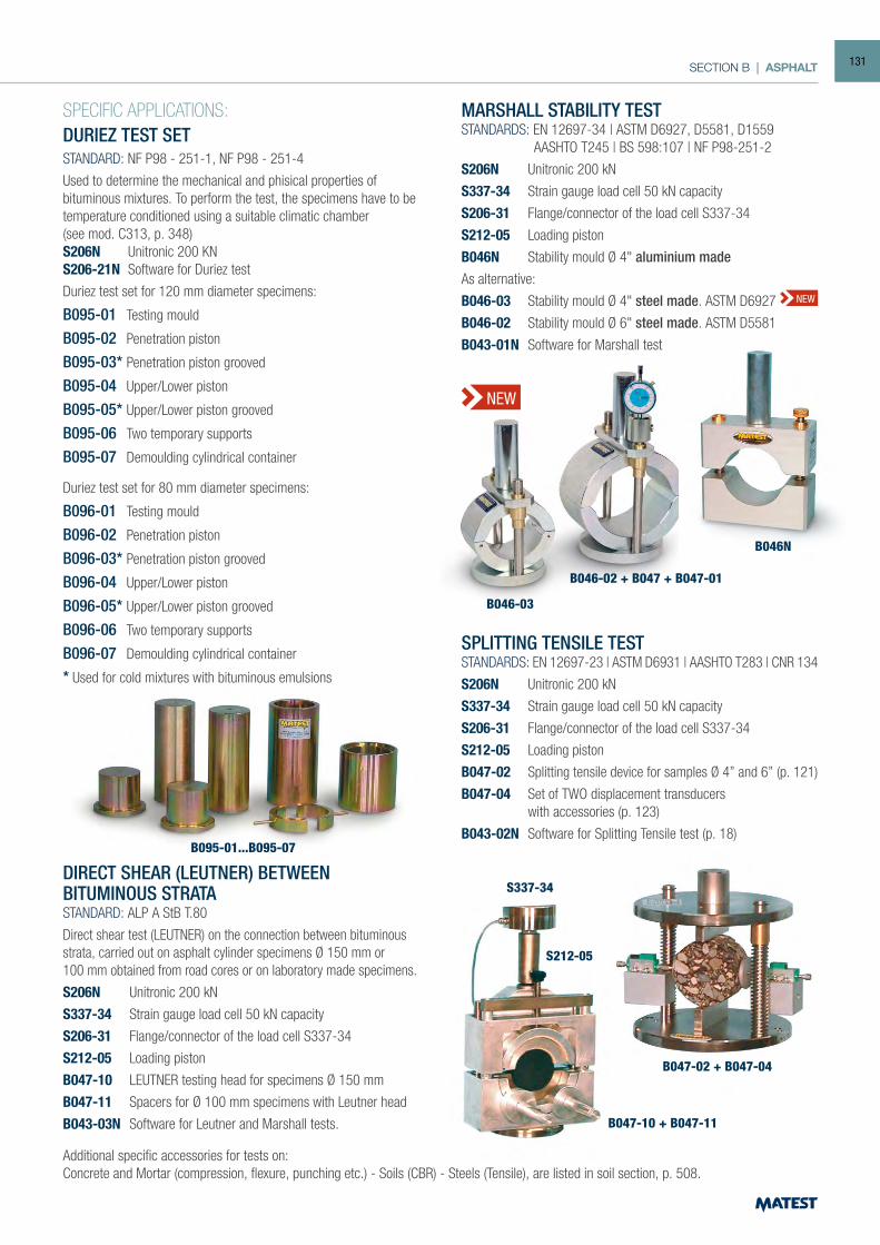
SECTION B | ASPHALT
DIRECT SHEAR (LEUTNER) BETWEENBITUMINOUS STRATASTANDARD: ALP A StB T.80
Direct shear test (LEUTNER) on the connection between bituminous strata, carried out on asphalt cylinder specimens Ø 150 mm or100 mm obtained from road cores or on laboratory made specimens.
S206N Unitronic 200 kN
S337-34 Strain gauge load cell 50 kN capacity
S206-31 Flange/connector of the load cell S337-34
S212-05 Loading piston
B047-10 LEUTNER testing head for specimens Ø 150 mm
B047-11 Spacers for Ø 100 mm specimens with Leutner head
B043-03N Software for Leutner and Marshall tests.
MARSHALL STABILITY TESTSTANDARDS: EN 12697-34 | ASTM D6927, D5581, D1559 AASHTO T245 | BS 598:107 | NF P98-251-2
S206N Unitronic 200 kN
S337-34 Strain gauge load cell 50 kN capacity
S206-31 Flange/connector of the load cell S337-34
S212-05 Loading piston
B046N Stability mould Ø 4" aluminium madeAs alternative:
B046-03 Stability mould Ø 4" steel made. ASTM D6927
B046-02 Stability mould Ø 6" steel made. ASTM D5581
B043-01N Software for Marshall test
B046-02 + B047 + B047-01
B046-03
B046N
SPLITTING TENSILE TESTSTANDARDS: EN 12697-23 | ASTM D6931 | AASHTO T283 | CNR 134
S206N Unitronic 200 kN
S337-34 Strain gauge load cell 50 kN capacity
S206-31 Flange/connector of the load cell S337-34
S212-05 Loading piston
B047-02 Splitting tensile device for samples Ø 4” and 6” (p. 121)
B047-04 Set of TWO displacement transducers with accessories (p. 123)
B043-02N Software for Splitting Tensile test (p. 18)
S212-05
S337-34
Additional specific accessories for tests on:Concrete and Mortar (compression, flexure, punching etc.) - Soils (CBR) - Steels (Tensile), are listed in soil section, p. 508.
B047-10 + B047-11
B047-02 + B047-04
NEW
NEW
SPECIFIC APPLICATIONS:DURIEZ TEST SETSTANDARD: NF P98 - 251-1, NF P98 - 251-4
Used to determine the mechanical and phisical properties of bituminous mixtures. To perform the test, the specimens have to be temperature conditioned using a suitable climatic chamber(see mod. C313, p. 348)S206N Unitronic 200 KNS206-21N Software for Duriez test
Duriez test set for 120 mm diameter specimens:
B095-01 Testing mould
B095-02 Penetration piston
B095-03* Penetration piston grooved
B095-04 Upper/Lower piston
B095-05* Upper/Lower piston grooved
B095-06 Two temporary supports
B095-07 Demoulding cylindrical container
Duriez test set for 80 mm diameter specimens:
B096-01 Testing mould
B096-02 Penetration piston
B096-03* Penetration piston grooved
B096-04 Upper/Lower piston
B096-05* Upper/Lower piston grooved
B096-06 Two temporary supports
B096-07 Demoulding cylindrical container
* Used for cold mixtures with bituminous emulsions
B095-01...B095-07
131
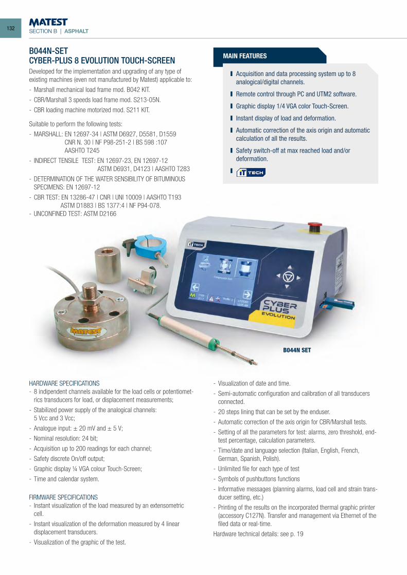
SECTION B | ASPHALT
B044N SET
B044N-SETCYBER-PLUS 8 EVOLUTION TOUCH-SCREENDeveloped for the implementation and upgrading of any type of existing machines (even not manufactured by Matest) applicable to:
- Marshall mechanical load frame mod. B042 KIT.
- CBR/Marshall 3 speeds load frame mod. S213-05N.
- CBR loading machine motorized mod. S211 KIT.
Suitable to perform the following tests:
- MARSHALL: EN 12697-34 | ASTM D6927, D5581, D1559 CNR N. 30 | NF P98-251-2 | BS 598 :107 AASHTO T245
- INDIRECT TENSILE TEST: EN 12697-23, EN 12697-12 ASTM D6931, D4123 | AASHTO T283
- DETERMINATION OF THE WATER SENSIBILITY OF BITUMINOUS SPECIMENS: EN 12697-12
- CBR TEST: EN 13286-47 | CNR | UNI 10009 | AASHTO T193 ASTM D1883 | BS 1377:4 | NF P94-078.- UNCONFINED TEST: ASTM D2166
MAIN FEATURES
Acquisition and data processing system up to 8 analogical/digital channels.
Remote control through PC and UTM2 software.
Graphic display 1/4 VGA color Touch-Screen.
Instant display of load and deformation.
Automatic correction of the axis origin and automatic calculation of all the results.
Safety switch-off at max reached load and/or deformation.
HARDWARE SPECIFICATIONS- 8 indipendent channels available for the load cells or potentiomet-
rics transducers for load, or displacement measurements;
- Stabilized power supply of the analogical channels: 5 Vcc and 3 Vcc;
- Analogue input: ± 20 mV and ± 5 V;
- Nominal resolution: 24 bit;
- Acquisition up to 200 readings for each channel;
- Safety discrete On/off output;
- Graphic display ¼ VGA colour Touch-Screen;
- Time and calendar system.
FIRMWARE SPECIFICATIONS- Instant visualization of the load measured by an extensometric
cell.
- Instant visualization of the deformation measured by 4 linear displacement transducers.
- Visualization of the graphic of the test.
- Visualization of date and time.
- Semi-automatic configuration and calibration of all transducers connected.
- 20 steps lining that can be set by the enduser.
- Automatic correction of the axis origin for CBR/Marshall tests.
- Setting of all the parameters for test: alarms, zero threshold, end-test percentage, calculation parameters.
- Time/date and language selection (Italian, English, French, German, Spanish, Polish).
- Unlimited file for each type of test
- Symbols of pushbuttons functions
- Informative messages (planning alarms, load cell and strain trans-ducer setting, etc.)
- Printing of the results on the incorporated thermal graphic printer (accessory C127N). Transfer and management via Ethernet of the filed data or real-time.
Hardware technical details: see p. 19
132
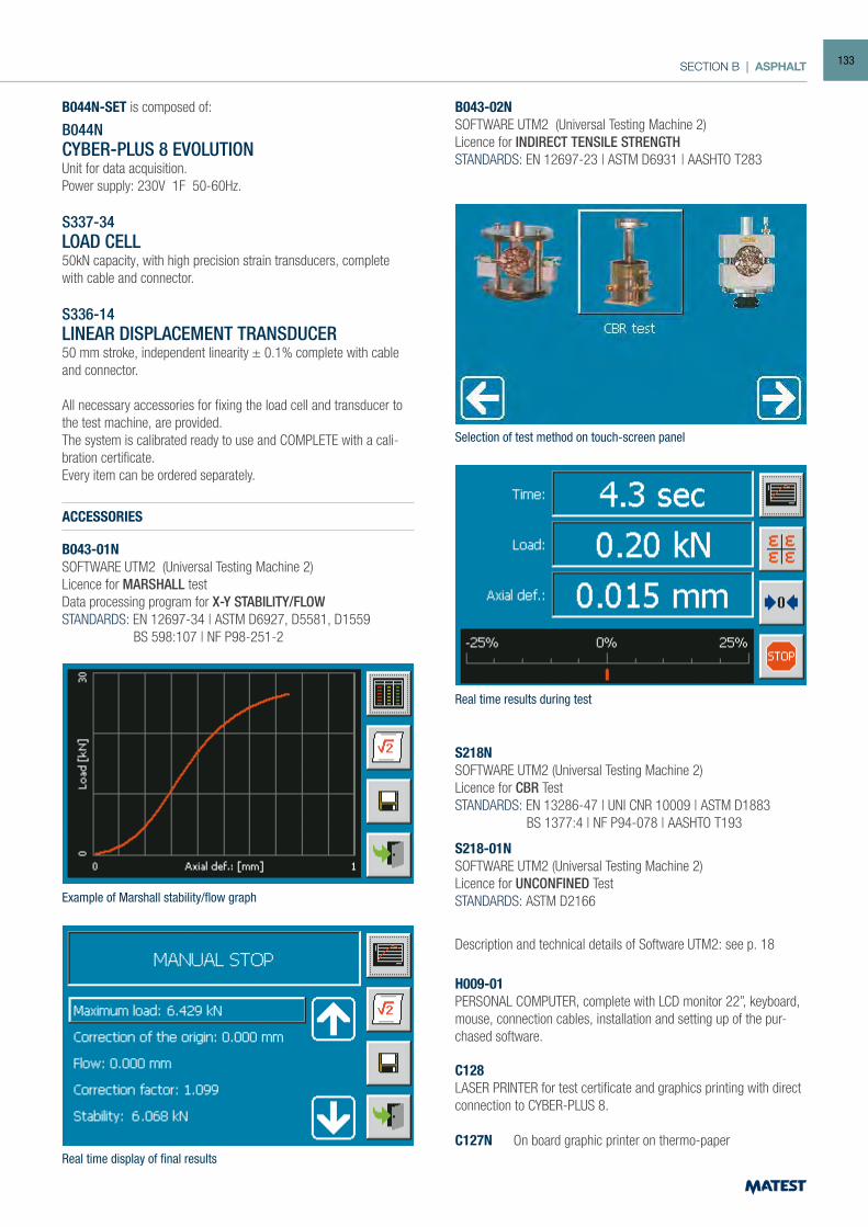
SECTION B | ASPHALT
Selection of test method on touch-screen panel
Real time results during test
Example of Marshall stability/flow graph
Real time display of final results
B044N-SET is composed of:
B044NCYBER-PLUS 8 EVOLUTIONUnit for data acquisition.Power supply: 230V 1F 50-60Hz.
S337-34LOAD CELL50kN capacity, with high precision strain transducers, complete with cable and connector.
S336-14LINEAR DISPLACEMENT TRANSDUCER50 mm stroke, independent linearity ± 0.1% complete with cable and connector.
All necessary accessories for fixing the load cell and transducer to the test machine, are provided.The system is calibrated ready to use and COMPLETE with a cali-bration certificate.Every item can be ordered separately.
ACCESSORIES
B043-01NSOFTWARE UTM2 (Universal Testing Machine 2)Licence for MARSHALL testData processing program for X-Y STABILITY/FLOWSTANDARDS: EN 12697-34 | ASTM D6927, D5581, D1559 BS 598:107 | NF P98-251-2
B043-02NSOFTWARE UTM2 (Universal Testing Machine 2)Licence for INDIRECT TENSILE STRENGTHSTANDARDS: EN 12697-23 | ASTM D6931 | AASHTO T283
S218NSOFTWARE UTM2 (Universal Testing Machine 2)Licence for CBR TestSTANDARDS: EN 13286-47 | UNI CNR 10009 | ASTM D1883 BS 1377:4 | NF P94-078 | AASHTO T193
S218-01NSOFTWARE UTM2 (Universal Testing Machine 2)Licence for UNCONFINED TestSTANDARDS: ASTM D2166
Description and technical details of Software UTM2: see p. 18
H009-01PERSONAL COMPUTER, complete with LCD monitor 22”, keyboard, mouse, connection cables, installation and setting up of the pur-chased software.
C128LASER PRINTER for test certificate and graphics printing with direct connection to CYBER-PLUS 8.
C127N On board graphic printer on thermo-paper
133
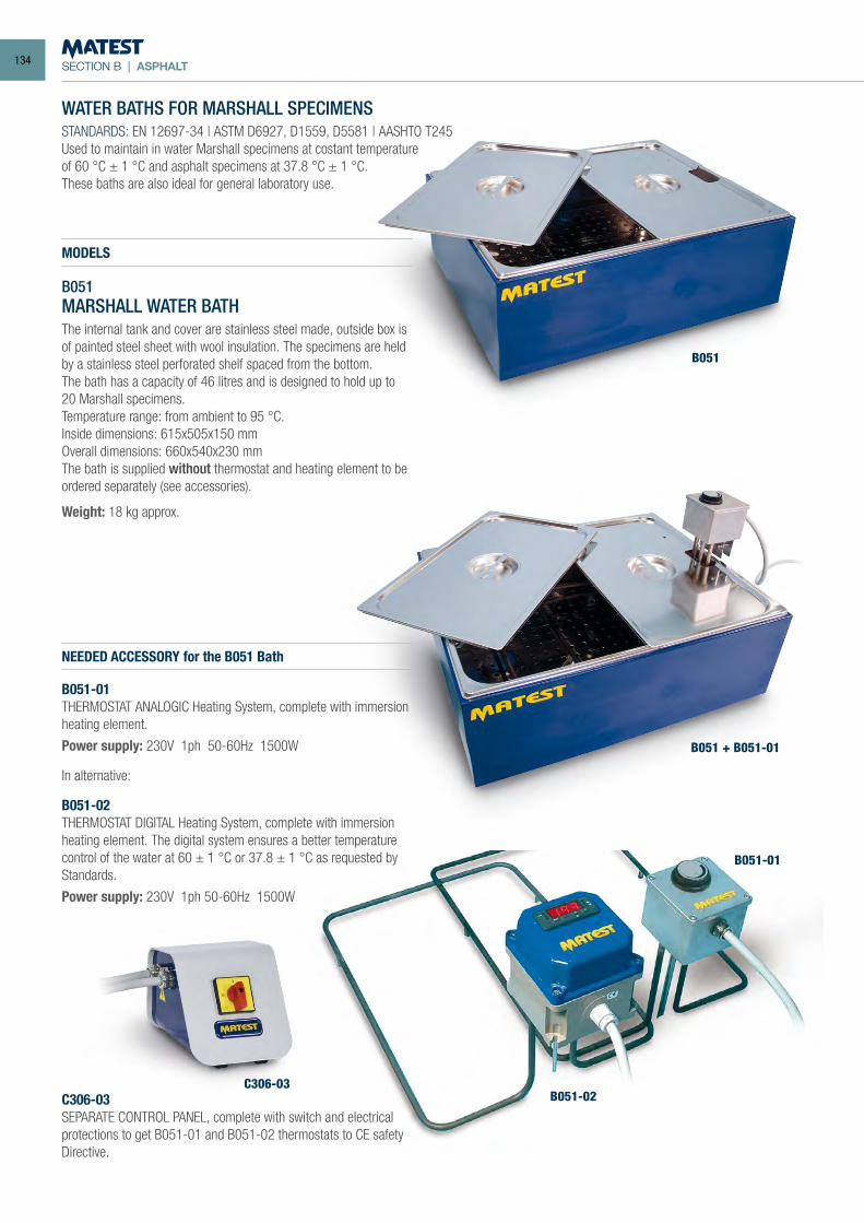
SECTION B | ASPHALT
WATER BATHS FOR MARSHALL SPECIMENSSTANDARDS: EN 12697-34 | ASTM D6927, D1559, D5581 | AASHTO T245Used to maintain in water Marshall specimens at costant temperatureof 60 °C ± 1 °C and asphalt specimens at 37.8 °C ± 1 °C.These baths are also ideal for general laboratory use.
MODELS
B051MARSHALL WATER BATHThe internal tank and cover are stainless steel made, outside box is of painted steel sheet with wool insulation. The specimens are held by a stainless steel perforated shelf spaced from the bottom.The bath has a capacity of 46 litres and is designed to hold up to 20 Marshall specimens.Temperature range: from ambient to 95 °C.Inside dimensions: 615x505x150 mmOverall dimensions: 660x540x230 mmThe bath is supplied without thermostat and heating element to be ordered separately (see accessories).
Weight: 18 kg approx.
NEEDED ACCESSORY for the B051 Bath
B051-01THERMOSTAT ANALOGIC Heating System, complete with immersion heating element.
Power supply: 230V 1ph 50-60Hz 1500W
In alternative:
B051-02THERMOSTAT DIGITAL Heating System, complete with immersion heating element. The digital system ensures a better temperature control of the water at 60 ± 1 °C or 37.8 ± 1 °C as requested by Standards.
Power supply: 230V 1ph 50-60Hz 1500W
C306-03SEPARATE CONTROL PANEL, complete with switch and electrical protections to get B051-01 and B051-02 thermostats to CE safety Directive.
B051
B051 + B051-01
B051-01
B051-02C306-03
134
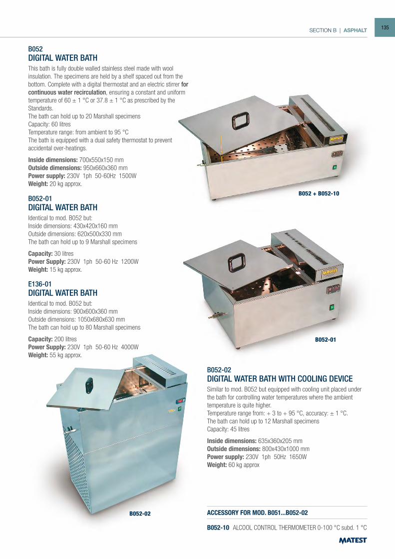
SECTION B | ASPHALT
B052DIGITAL WATER BATHThis bath is fully double walled stainless steel made with wool insulation. The specimens are held by a shelf spaced out from the bottom. Complete with a digital thermostat and an electric stirrer for continuous water recirculation, ensuring a constant and uniform temperature of 60 ± 1 °C or 37.8 ± 1 °C as prescribed by the Standards.The bath can hold up to 20 Marshall specimensCapacity: 60 litresTemperature range: from ambient to 95 °CThe bath is equipped with a dual safety thermostat to prevent accidental over-heatings.
Inside dimensions: 700x550x150 mmOutside dimensions: 950x660x360 mmPower supply: 230V 1ph 50-60Hz 1500WWeight: 20 kg approx.
B052-01DIGITAL WATER BATHIdentical to mod. B052 but:Inside dimensions: 430x420x160 mmOutside dimensions: 620x500x330 mmThe bath can hold up to 9 Marshall specimens
Capacity: 30 litresPower Supply: 230V 1ph 50-60 Hz 1200WWeight: 15 kg approx.
B052-02DIGITAL WATER BATH WITH COOLING DEVICESimilar to mod. B052 but equipped with cooling unit placed under the bath for controlling water temperatures where the ambient temperature is quite higher.Temperature range from: + 3 to + 95 °C, accuracy: ± 1 °C.The bath can hold up to 12 Marshall specimensCapacity: 45 litres
Inside dimensions: 635x360x205 mmOutside dimensions: 800x430x1000 mmPower supply: 230V 1ph 50Hz 1650WWeight: 60 kg approx
B052 + B052-10
B052-01
B052-02 ACCESSORY FOR MOD. B051...B052-02
B052-10 ALCOOL CONTROL THERMOMETER 0-100 °C subd. 1 °C
E136-01DIGITAL WATER BATHIdentical to mod. B052 but:Inside dimensions: 900x600x360 mmOutside dimensions: 1050x680x630 mmThe bath can hold up to 80 Marshall specimens
Capacity: 200 litresPower Supply: 230V 1ph 50-60 Hz 4000WWeight: 55 kg approx.
135
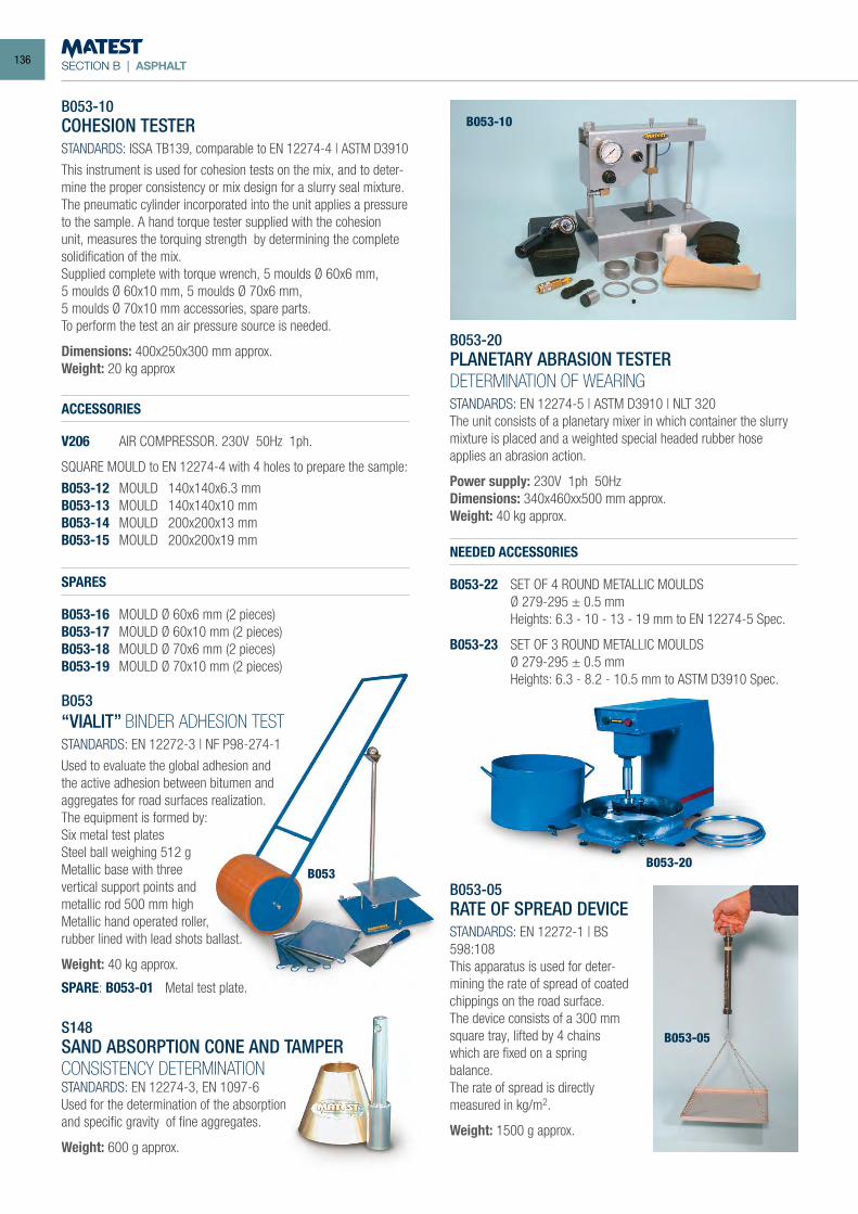
SECTION B | ASPHALT
B053-10 COHESION TESTER
STANDARDS: ISSA TB139, comparable to EN 12274-4 | ASTM D3910
This instrument is used for cohesion tests on the mix, and to deter-mine the proper consistency or mix design for a slurry seal mixture. The pneumatic cylinder incorporated into the unit applies a pressure to the sample. A hand torque tester supplied with the cohesion unit, measures the torquing strength by determining the complete solidification of the mix.Supplied complete with torque wrench, 5 moulds Ø 60x6 mm,5 moulds Ø 60x10 mm, 5 moulds Ø 70x6 mm,5 moulds Ø 70x10 mm accessories, spare parts.To perform the test an air pressure source is needed.
Dimensions: 400x250x300 mm approx. Weight: 20 kg approx
ACCESSORIES
V206 AIR COMPRESSOR. 230V 50Hz 1ph.
SQUARE MOULD to EN 12274-4 with 4 holes to prepare the sample:
B053-12 MOULD 140x140x6.3 mmB053-13 MOULD 140x140x10 mmB053-14 MOULD 200x200x13 mmB053-15 MOULD 200x200x19 mm
SPARES
B053-16 MOULD Ø 60x6 mm (2 pieces)B053-17 MOULD Ø 60x10 mm (2 pieces)B053-18 MOULD Ø 70x6 mm (2 pieces)B053-19 MOULD Ø 70x10 mm (2 pieces)
B053“VIALIT” BINDER ADHESION TESTSTANDARDS: EN 12272-3 | NF P98-274-1
Used to evaluate the global adhesion and the active adhesion between bitumen and aggregates for road surfaces realization.The equipment is formed by:Six metal test platesSteel ball weighing 512 gMetallic base with three vertical support points and metallic rod 500 mm highMetallic hand operated roller, rubber lined with lead shots ballast.
Weight: 40 kg approx.
SPARE: B053-01 Metal test plate.
S148SAND ABSORPTION CONE AND TAMPERCONSISTENCY DETERMINATIONSTANDARDS: EN 12274-3, EN 1097-6Used for the determination of the absorptionand specific gravity of fine aggregates.
Weight: 600 g approx.
B053-20PLANETARY ABRASION TESTERDETERMINATION OF WEARINGSTANDARDS: EN 12274-5 | ASTM D3910 | NLT 320The unit consists of a planetary mixer in which container the slurry mixture is placed and a weighted special headed rubber hose applies an abrasion action.
Power supply: 230V 1ph 50HzDimensions: 340x460xx500 mm approx.Weight: 40 kg approx.
B053-05RATE OF SPREAD DEVICESTANDARDS: EN 12272-1 | BS 598:108This apparatus is used for deter-mining the rate of spread of coated chippings on the road surface.The device consists of a 300 mm square tray, lifted by 4 chains which are fixed on a spring balance.The rate of spread is directlymeasured in kg/m2.
Weight: 1500 g approx.
B053-10
B053-20B053
B053-05
NEEDED ACCESSORIES
B053-22 SET OF 4 ROUND METALLIC MOULDS Ø 279-295 ± 0.5 mm Heights: 6.3 - 10 - 13 - 19 mm to EN 12274-5 Spec.
B053-23 SET OF 3 ROUND METALLIC MOULDS Ø 279-295 ± 0.5 mm Heights: 6.3 - 8.2 - 10.5 mm to ASTM D3910 Spec.
136
SECTION BASPHALT | BITUMEN | PAVETEST
Bituminous mixture, also known as asphalt mixture, is mainly composed by aggregates and bitumen, an infinite variety of mixtures being possible. This section is divided into three parts and shows the whole range of equipment for analyzing each component of the bituminous mixture.
ASPHALT. The first part is dedicated to the asphalt testing machines used to provide a solution for the whole “asphaltic path”: mixing, compacting, modelling and testing. The equip-ment meets the needs of those who want to perform quality control or experimentation of new asphalt mixtures.
BITUMEN. This section shows equipment required for bitumen testing: these include machines to study the rheological properties of bitumen as well as the features of bituminous emulsion. The last part of this section pro-vides better solutions to perform field tests on road sur-face.
PAVETEST. Pavetest’s range of pavement dynamic testing sys-tems both complements and completes Matest’s Asphalt and Bitumen business unit. All our products comply with the prin-cipal international standards.
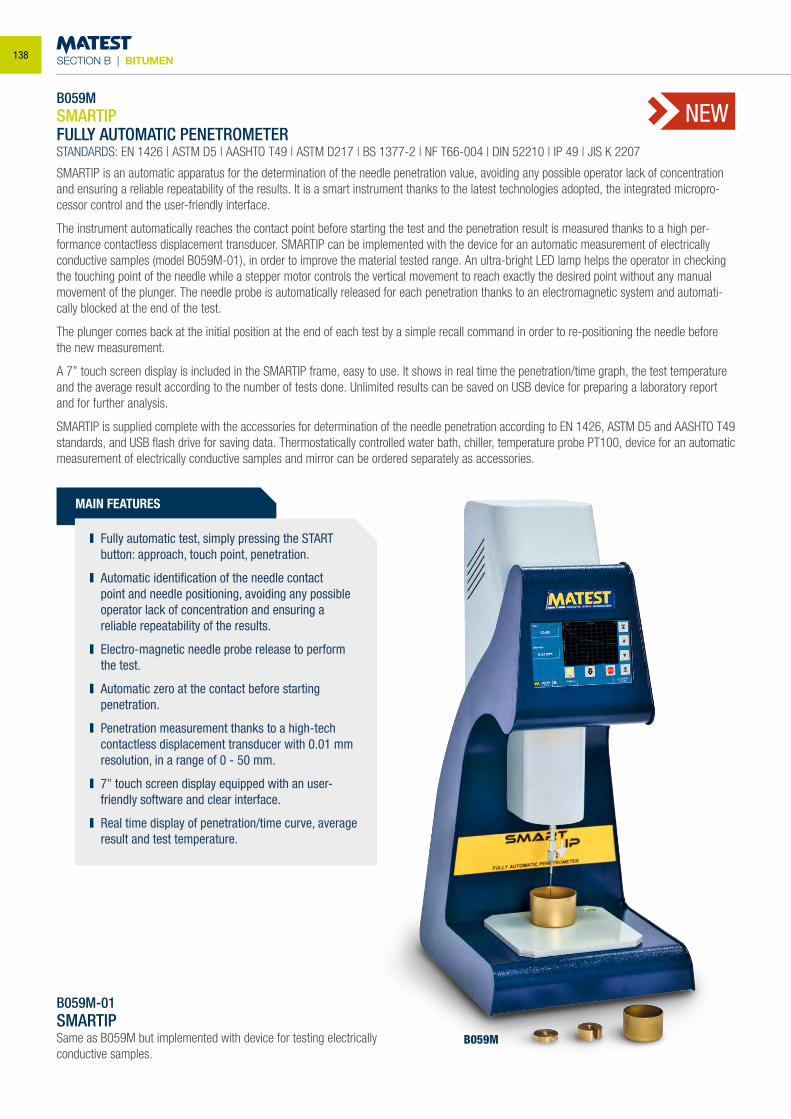
SECTION B | BITUMEN
B059MSMARTIPFULLY AUTOMATIC PENETROMETERSTANDARDS: EN 1426 | ASTM D5 | AASHTO T49 | ASTM D217 | BS 1377-2 | NF T66-004 | DIN 52210 | IP 49 | JIS K 2207
SMARTIP is an automatic apparatus for the determination of the needle penetration value, avoiding any possible operator lack of concentration and ensuring a reliable repeatability of the results. It is a smart instrument thanks to the latest technologies adopted, the integrated micropro-cessor control and the user-friendly interface.
The instrument automatically reaches the contact point before starting the test and the penetration result is measured thanks to a high per-formance contactless displacement transducer. SMARTIP can be implemented with the device for an automatic measurement of electrically conductive samples (model B059M-01), in order to improve the material tested range. An ultra-bright LED lamp helps the operator in checking the touching point of the needle while a stepper motor controls the vertical movement to reach exactly the desired point without any manual movement of the plunger. The needle probe is automatically released for each penetration thanks to an electromagnetic system and automati-cally blocked at the end of the test.
The plunger comes back at the initial position at the end of each test by a simple recall command in order to re-positioning the needle before the new measurement.
A 7” touch screen display is included in the SMARTIP frame, easy to use. It shows in real time the penetration/time graph, the test temperature and the average result according to the number of tests done. Unlimited results can be saved on USB device for preparing a laboratory report and for further analysis.
SMARTIP is supplied complete with the accessories for determination of the needle penetration according to EN 1426, ASTM D5 and AASHTO T49 standards, and USB flash drive for saving data. Thermostatically controlled water bath, chiller, temperature probe PT100, device for an automatic measurement of electrically conductive samples and mirror can be ordered separately as accessories.
MAIN FEATURES
Fully automatic test, simply pressing the START button: approach, touch point, penetration.
Automatic identification of the needle contact point and needle positioning, avoiding any possible operator lack of concentration and ensuring a reliable repeatability of the results.
Electro-magnetic needle probe release to perform the test.
Automatic zero at the contact before starting penetration.
Penetration measurement thanks to a high-tech contactless displacement transducer with 0.01 mm resolution, in a range of 0 - 50 mm.
7" touch screen display equipped with an user-friendly software and clear interface.
Real time display of penetration/time curve, average result and test temperature.
B059M-01SMARTIPSame as B059M but implemented with device for testing electrically conductive samples.
NEW
B059M
138
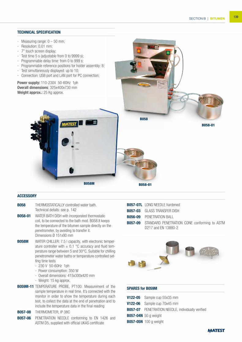
SECTION B | BITUMEN
TECHNICAL SPECIFICATION
- Measuring range: 0 – 50 mm;- Resolution: 0,01 mm;- 7” touch screen display;- Test time 5 s (adjustable from 0 to 9999 s);- Programmable delay time: from 0 to 999 s;- Programmable reference positions for holder assembly: 8;- Test simultaneously displayed: up to 10;- Connection: USB port and LAN port for PC connection;
Power supply: 110-230V 50-60Hz 1phOverall dimensions: 325x400x730 mmWeight approx.: 25 Kg approx.
ACCESSORY
B058 THERMOSTATICALLY controlled water bath. Technical details: see p. 142
B058-01 WATER BATH DISH with incorporated thermostatic coil, to be connected to the bath mod. B058.It keeps the temperature of the bitumen sample directly on the penetrometer, by avoiding to transfer it.
Dimensions Ø 151x90 mm
B058M WATER CHILLER: 7.5 l capacity, with electronic temper-ature controller with ± 0.1 °C accuracy and fluid tem-perature range between 5 and 30°C. Suitable for chilling penetrometer water baths or temperature controlled set-ting time tests
- 230 V 50-60Hz 1ph - Power consumption: 350 W - Overall dimensions: 415x300x420 mm - Weight: 15 kg approx.
B059M-11 TEMPERATURE PROBE, PT100: Measurement of the sample temperature in real time. It’s connected with the monitor in order to show the temperature during each test, to collect the data at the end of penetration and to include the temperature data in the final reading
B057-08 THERMOMETER, IP 38C
B057-06 PENETRATION NEEDLE conforming to EN 1426 and ASTM D5, supplied with official UKAS certificate
SPARES for B059M
V122-05 Sample cup 55x35 mm
V122-06 Sample cup 70x45 mm
B057-07 PENETRATION NEEDLE, individually verified
B057-04N 50 g weight
B057-05N 100 g weight
B057-07L LONG NEEDLE hardened
B057-03 GLASS TRANSFER DISH
B056-09 PENETRATION BALL
B057-09 STANDARD PENETRATION CONE conforming to ASTM D217 and EN 13880-2
B058M B058-01
B058
B058-01
139
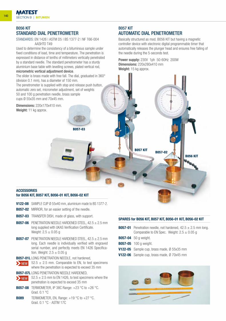
SECTION B | BITUMEN
B056 KITSTANDARD DIAL PENETROMETERSTANDARDS: EN 1426 | ASTM D5 | BS 1377-2 | NF T66-004 AASHTO T49Used to determine the consistency of a bituminous sample under fixed conditions of load, time and temperature. The penetration is expressed in distance of tenths of millimeters vertically penetrated by a standard needle. The standard penetrometer has a sturdy aluminium base table with levelling screws, plated vertical rod, micrometric vertical adjustment device.The slider is brass made with free fall. The dial, graduated in 360° (division 0.1 mm), has a diameter of 150 mm.The penetrometer is supplied with stop and release push button, automatic zero set, micrometer adjustment, set of weights50 and 100 g penetration needle, brass samplecups Ø 55x35 mm and 70x45 mm.
Dimensions: 220x170x410 mm.Weight: 11 kg approx.
B057 KITAUTOMATIC DIAL PENETROMETERBasically structured as mod. B056 KIT but having a magnetic controller device with electronic digital programmable timer that automatically releases the plunger head and ensures free falling of the needle during the 5-seconds test.
Power supply: 230V 1ph 50-60Hz 200WDimensions: 220x280x410 mm Weight: 15 kg approx.
ACCESSORIESfor B056 KIT, B057 KIT, B056-01 KIT, B056-02 KIT
V122-08 SAMPLE CUP Ø 55x40 mm, aluminium made to BS 1377-2.
B057-02 MIRROR, for an easier setting of the needle.
B057-03 TRANSFER DISH, made of glass, with support.
B057-06 PENETRATION NEEDLE HARDENED STEEL, 42.5 ± 2.5 mm long supplied with UKAS Verification Certificate.
Weight: 2.5 ± 0.05 g
B057-07 PENETRATION NEEDLE HARDENED STEEL, 42.5 ± 2.5 mm long. Each needle is individually verified with engraved serial number, and perfectly meets EN 1426 Specifica-tion. Weight: 2.5 ± 0.05 g
B057-01L LONG PENETRATION NEEDLE, not hardened, 52.5 ± 2.5 mm. Comparable to EN, to test specimens
where the penetration is expected to exceed 35 mm
B057-07L LONG PENETRATION NEEDLE HARDENED, 52.5 ± 2.5 mm to EN 1426, to test specimens where the
penetration is expected to exceed 35 mm
B057-08 TERMOMETER, IP 38C Range: +23 °C to +26 °C. Grad. 0.1 °C
B089 TERMOMETER, EN, Range: +19 °C to +27 °C. Grad. 0.1 °C - ASTM 17C
SPARES for B056 KIT, B057 KIT, B056-01 KIT, B056-02 KIT
B057-01 Penetration needle, not hardened, 42.5 ± 2.5 mm long. Comparable to EN Spec. Weight: 2.5 ± 0.05 g
B057-04 50 g weight.
B057-05 100 g weight.
V122-05 Sample cup, brass made, Ø 55x35 mm
V122-06 Sample cup, brass made, Ø 70x45 mm
B057-03
B057 KIT
B056 KITB057-02
NEW
NEW
140
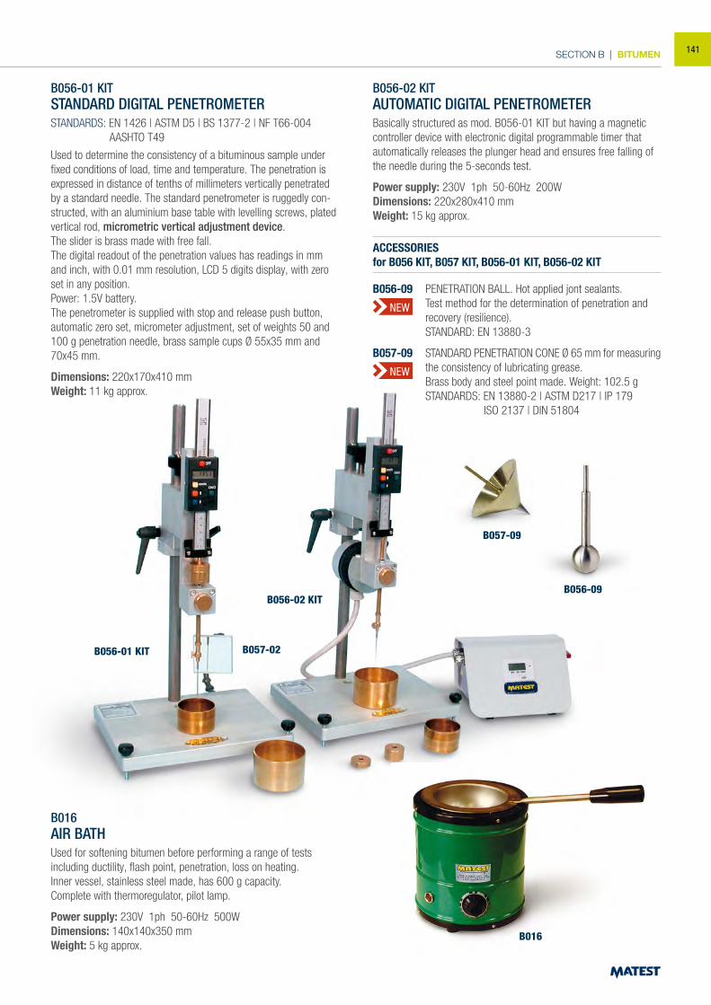
SECTION B | BITUMEN
NEW
B056-01 KITSTANDARD DIGITAL PENETROMETERSTANDARDS: EN 1426 | ASTM D5 | BS 1377-2 | NF T66-004 AASHTO T49
Used to determine the consistency of a bituminous sample under fixed conditions of load, time and temperature. The penetration is expressed in distance of tenths of millimeters vertically penetrated by a standard needle. The standard penetrometer is ruggedly con-structed, with an aluminium base table with levelling screws, plated vertical rod, micrometric vertical adjustment device.The slider is brass made with free fall.The digital readout of the penetration values has readings in mm and inch, with 0.01 mm resolution, LCD 5 digits display, with zero set in any position. Power: 1.5V battery. The penetrometer is supplied with stop and release push button, automatic zero set, micrometer adjustment, set of weights 50 and 100 g penetration needle, brass sample cups Ø 55x35 mm and 70x45 mm.
Dimensions: 220x170x410 mmWeight: 11 kg approx.
B056-02 KITAUTOMATIC DIGITAL PENETROMETERBasically structured as mod. B056-01 KIT but having a magnetic controller device with electronic digital programmable timer that automatically releases the plunger head and ensures free falling of the needle during the 5-seconds test.
Power supply: 230V 1ph 50-60Hz 200WDimensions: 220x280x410 mmWeight: 15 kg approx.
B016AIR BATHUsed for softening bitumen before performing a range of tests including ductility, flash point, penetration, loss on heating.Inner vessel, stainless steel made, has 600 g capacity.Complete with thermoregulator, pilot lamp.
Power supply: 230V 1ph 50-60Hz 500WDimensions: 140x140x350 mmWeight: 5 kg approx.
B056-01 KIT
B056-02 KIT
B057-02
B016
ACCESSORIESfor B056 KIT, B057 KIT, B056-01 KIT, B056-02 KIT
B056-09 PENETRATION BALL. Hot applied jont sealants. Test method for the determination of penetration and recovery (resilience). STANDARD: EN 13880-3
B057-09 STANDARD PENETRATION CONE Ø 65 mm for measuring the consistency of lubricating grease.
Brass body and steel point made. Weight: 102.5 g STANDARDS: EN 13880-2 | ASTM D217 | IP 179 ISO 2137 | DIN 51804
B057-09
B056-09
NEW
141

SECTION B | BITUMEN
B058
B058-01
B060
B056 KIT
B058THERMOSTATICALLY CONTROLLED WATER BATH FOR PENETROMETERProvides water at the required temperature of 25 ± 0.1 °C.The unit consists of a stainless steel water bath 10 litres capacity with wool insulation, immersion heater with digital thermostat, motor pump with connections, cooling coil device, current water operated, to maintain a constant temperature of the bath when room temperature is slightly higher.The bituminous sample is immersed into the water bath, and placed on the penetrometer only at the time of the test, by eventually using the transfer dish (accessory mod. B057-03).
Power supply: 230V 1ph 50-60Hz 350WDimensons: 375x335x420 mmWeight: 12 kg approx.
ACCESSORY
B058-01WATER BATH DISH with incorporated thermostatic coil, to be con-nected to the bath mod. B058.It keeps the temperature of the bitumen sample directly on the penetrometer, by avoiding to transfer it.Dimensions Ø 151x90 mm
B060BACON SAMPLERSTANDARDS: EN 58 | CNR N° 81, N° 98 ASTM D140 | AASHTO T40Used to obtain asphalt or oil samples from variouslevels within a storage tank by the “thief” method.Made from brass. Capacity 237 ml
Dimensions: Ø 50x250 mmWeight: 2 kg approx.
B090BREAKING VALUE OF CATIONIC BITUMENEMULSIONS: MINERAL FILLER METHODSTANDARDS: EN 13075-1 | IP 494
Equipment for the determination of the breaking value of cationic emulsions, (manual version) comprising:Filler feeding pan, complete with support base and clamp, nickel spatula, two round porcelain dishes.
Weight: 2 kg approx.
B090
B090-12
S157-06
B090-11
B090-10
ACCESSORIES for Automatic Version
B090-10 ELECTRIC STIRRER having 260 rpm, 230V 50-60Hz 1ph
S157-06 SUPPORT BASE for stirrer.
B090-11 PROPELLER for electric stirrer.
B090-12 METALLIC CONTAINER, 500 ml capacity.
B090-19 REFERENCE FILLER, original Forshammar, recommended by EN Spec. Bucket of 10 kg
B090-20N REFERENCE FILLER, 25 kg where SIO² content and Volumetric Mass conform to EN 13075-1; while grading composition does not conform.
B058 detail
142
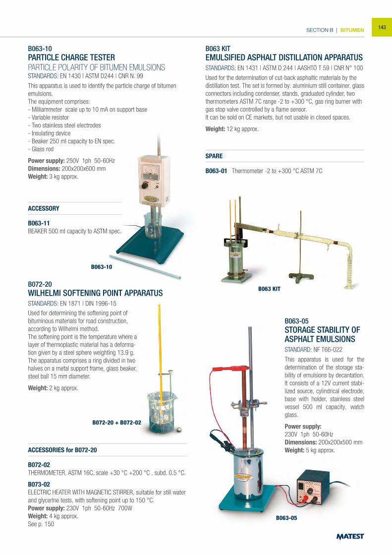
SECTION B | BITUMEN
B063-10PARTICLE CHARGE TESTERPARTICLE POLARITY OF BITUMEN EMULSIONSSTANDARDS: EN 1430 | ASTM D244 | CNR N. 99
This apparatus is used to identify the particle charge of bitumen emulsions.The equipment comprises:- Milliammeter scale up to 10 mA on support base- Variable resistor- Two stainless steel electrodes- Insulating device- Beaker 250 ml capacity to EN spec.- Glass rod
Power supply: 250V 1ph 50-60HzDimensions: 200x200x600 mmWeight: 3 kg approx.
ACCESSORY
B063-11BEAKER 500 ml capacity to ASTM spec.
B072-20 WILHELMI SOFTENING POINT APPARATUS STANDARDS: EN 1871 | DIN 1996-15
ACCESSORIES for B072-20
B072-02 THERMOMETER, ASTM 16C, scale +30 °C +200 °C , subd. 0.5 °C.
B073-02 ELECTRIC HEATER WITH MAGNETIC STIRRER, suitable for still water and glycerine tests, with softening point up to 150 °C. Power supply: 230V 1ph 50-60Hz 700W Weight: 4 kg approx.See p. 150
B063 KITEMULSIFIED ASPHALT DISTILLATION APPARATUSSTANDARDS: EN 1431 | ASTM D 244 | AASHTO T 59 | CNR N° 100
Used for the determination of cut-back asphaltic materials by the distillation test. The set is formed by: aluminium still container, glass connectors including condenser, stands, graduated cylinder, two thermometers ASTM 7C range -2 to +300 °C, gas ring burner with gas stop valve controlled by a flame sensor.It can be sold on CE markets, but not usable in closed spaces.
Weight: 12 kg approx.
SPARE
B063-01 Thermometer -2 to +300 °C ASTM 7C
B063-05 STORAGE STABILITY OF ASPHALT EMULSIONS STANDARD: NF T66-022
This apparatus is used for the determination of the storage sta-bility of emulsions by decantation. It consists of a 12V current stabi-lized source, cylindrical electrode, base with holder, stainless steel vessel 500 ml capacity, watch glass.
Power supply:230V 1ph 50-60HzDimensions: 200x200x500 mm Weight: 5 kg approx.
Used for determining the softening point of bituminous materials for road construction, according to Wilhelmi method. The softening point is the temperature where a layer of thermoplastic material has a deforma-tion given by a steel sphere weighting 13.9 g. The apparatus comprises a ring divided in two halves on a metal support frame, glass beaker, steel ball 15 mm diameter.
Weight: 2 kg approx.
B063-10
B063 KIT
B063-05
B072-20 + B072-02
143
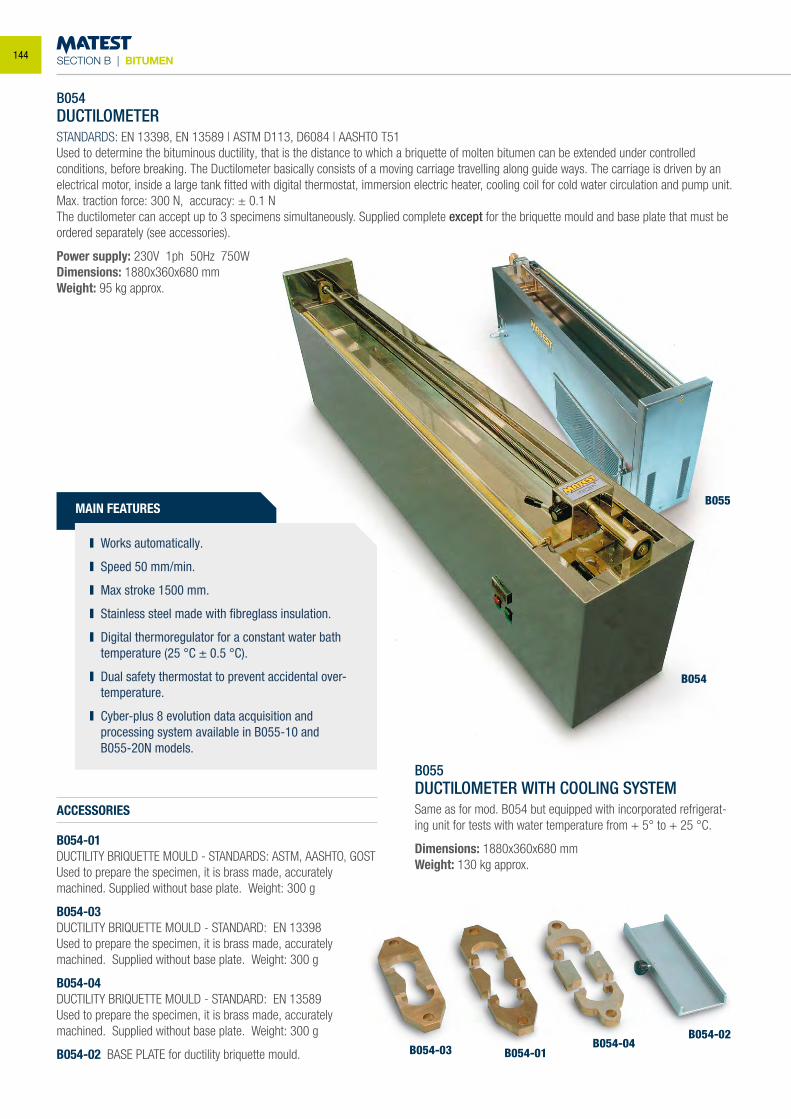
SECTION B | BITUMEN
B054-03 B054-01B054-04
B054-02
B054
B055
B054DUCTILOMETERSTANDARDS: EN 13398, EN 13589 | ASTM D113, D6084 | AASHTO T51Used to determine the bituminous ductility, that is the distance to which a briquette of molten bitumen can be extended under controlled conditions, before breaking. The Ductilometer basically consists of a moving carriage travelling along guide ways. The carriage is driven by an electrical motor, inside a large tank fitted with digital thermostat, immersion electric heater, cooling coil for cold water circulation and pump unit.Max. traction force: 300 N, accuracy: ± 0.1 NThe ductilometer can accept up to 3 specimens simultaneously. Supplied complete except for the briquette mould and base plate that must be ordered separately (see accessories).
Power supply: 230V 1ph 50Hz 750WDimensions: 1880x360x680 mmWeight: 95 kg approx.
B055DUCTILOMETER WITH COOLING SYSTEMSame as for mod. B054 but equipped with incorporated refrigerat-ing unit for tests with water temperature from + 5° to + 25 °C.
Dimensions: 1880x360x680 mmWeight: 130 kg approx.
ACCESSORIES
B054-01DUCTILITY BRIQUETTE MOULD - STANDARDS: ASTM, AASHTO, GOSTUsed to prepare the specimen, it is brass made, accurately machined. Supplied without base plate. Weight: 300 g
B054-03DUCTILITY BRIQUETTE MOULD - STANDARD: EN 13398 Used to prepare the specimen, it is brass made, accurately machined. Supplied without base plate. Weight: 300 g
B054-04DUCTILITY BRIQUETTE MOULD - STANDARD: EN 13589 Used to prepare the specimen, it is brass made, accurately machined. Supplied without base plate. Weight: 300 g
B054-02 BASE PLATE for ductility briquette mould.
MAIN FEATURES
Works automatically.
Speed 50 mm/min.
Max stroke 1500 mm.
Stainless steel made with fibreglass insulation.
Digital thermoregulator for a constant water bath temperature (25 °C ± 0.5 °C).
Dual safety thermostat to prevent accidental over-temperature.
Cyber-plus 8 evolution data acquisition and processing system available in B055-10 and
B055-20N models.
144
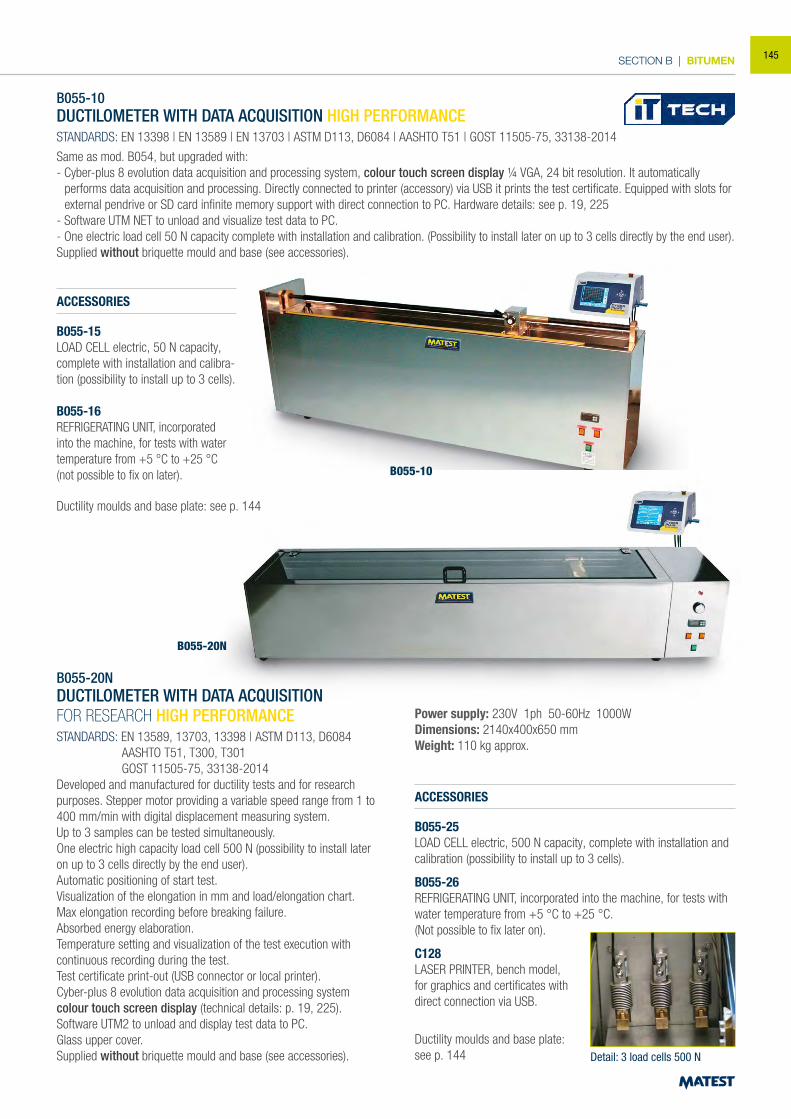
SECTION B | BITUMEN
B055-10DUCTILOMETER WITH DATA ACQUISITION HIGH PERFORMANCE
STANDARDS: EN 13398 | EN 13589 | EN 13703 | ASTM D113, D6084 | AASHTO T51 | GOST 11505-75, 33138-2014
Same as mod. B054, but upgraded with:- Cyber-plus 8 evolution data acquisition and processing system, colour touch screen display ¼ VGA, 24 bit resolution. It automatically
performs data acquisition and processing. Directly connected to printer (accessory) via USB it prints the test certificate. Equipped with slots for external pendrive or SD card infinite memory support with direct connection to PC. Hardware details: see p. 19, 225
- Software UTM NET to unload and visualize test data to PC.- One electric load cell 50 N capacity complete with installation and calibration. (Possibility to install later on up to 3 cells directly by the end user).Supplied without briquette mould and base (see accessories).
ACCESSORIES
B055-15LOAD CELL electric, 50 N capacity, complete with installation and calibra-tion (possibility to install up to 3 cells).
B055-16REFRIGERATING UNIT, incorporated into the machine, for tests with water temperature from +5 °C to +25 °C (not possible to fix on later).
Ductility moulds and base plate: see p. 144
B055-20NDUCTILOMETER WITH DATA ACQUISITIONFOR RESEARCH HIGH PERFORMANCESTANDARDS: EN 13589, 13703, 13398 | ASTM D113, D6084 AASHTO T51, T300, T301 GOST 11505-75, 33138-2014Developed and manufactured for ductility tests and for research purposes. Stepper motor providing a variable speed range from 1 to 400 mm/min with digital displacement measuring system.Up to 3 samples can be tested simultaneously.One electric high capacity load cell 500 N (possibility to install later on up to 3 cells directly by the end user).Automatic positioning of start test. Visualization of the elongation in mm and load/elongation chart. Max elongation recording before breaking failure.Absorbed energy elaboration. Temperature setting and visualization of the test execution with continuous recording during the test.Test certificate print-out (USB connector or local printer).Cyber-plus 8 evolution data acquisition and processing system colour touch screen display (technical details: p. 19, 225).Software UTM2 to unload and display test data to PC.Glass upper cover.Supplied without briquette mould and base (see accessories).
ACCESSORIES
B055-25LOAD CELL electric, 500 N capacity, complete with installation and calibration (possibility to install up to 3 cells).
B055-26REFRIGERATING UNIT, incorporated into the machine, for tests with water temperature from +5 °C to +25 °C.(Not possible to fix later on).
C128LASER PRINTER, bench model, for graphics and certificates with direct connection via USB.
Ductility moulds and base plate: see p. 144
Power supply: 230V 1ph 50-60Hz 1000WDimensions: 2140x400x650 mmWeight: 110 kg approx.
B055-10
B055-20N
Detail: 3 load cells 500 N
145
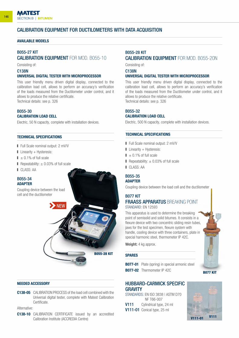
SECTION B | BITUMEN
B055-28 KIT
CALIBRATION EQUIPMENT FOR DUCTILOMETERS WITH DATA ACQUISITION
B055-27 KITCALIBRATION EQUIPMENT FOR MOD. B055-10Consisting of:
C138NUNIVERSAL DIGITAL TESTER WITH MICROPROCESSORThis user friendly menu driven digital display, connected to the calibration load cell, allows to perform an accuracy’s verification of the loads measured from the Ductilometer under control, and it allows to produce the relative certificate.Technical details: see p. 326
B055-30CALIBRATION LOAD CELLElectric, 50 N capacity, complete with installation devices.
TECHNICAL SPECIFICATIONS
Full Scale nominal output: 2 mV/V
Linearity + Hysteresis:
± 0.1% of full scale
Repeatability: ± 0.03% of full scale
CLASS: AA
TECHNICAL SPECIFICATIONS
Full Scale nominal output: 2 mV/V
Linearity + Hysteresis:
± 0.1% of full scale
Repeatability: ± 0.03% of full scale
CLASS: AA
B055-28 KITCALIBRATION EQUIPMENT FOR MOD. B055-20NConsisting of:
C138NUNIVERSAL DIGITAL TESTER WITH MICROPROCESSORThis user friendly menu driven digital display, connected to the calibration load cell, allows to perform an accuracy’s verification of the loads measured from the Ductilometer under control, and it allows to produce the relative certificate.Technical details: see p. 326
B055-32CALIBRATION LOAD CELLElectric, 500 N capacity, complete with installation devices.
B055-34ADAPTERCoupling device between the load cell and the ductilometer
B055-35ADAPTERCoupling device between the load cell and the ductilometer
NEEDED ACCESSORY
C138-05 CALIBRATION PROCESS of the load cell combined with the Universal digital tester, complete with Matest Calibration Certificate.
Alternative:
C138-10 CALIBRATION CERTIFICATE issued by an accredited Calibration Institute (ACCREDIA Centre)
NEW
AVAILABLE MODELS
B077 KIT
B077 KITFRAASS APPARATUS BREAKING POINTSTANDARD: EN 12593
This apparatus is used to determine the breaking point of semisolid and solid bitumes. It consists in a flexure device with two concentric sliding resin tubes, jaws for the test specimen, flexure system with handle, cooling device with three containers, plate in special harmonic steel, thermometer IP 42C.
Weight: 4 kg approx.
SPARES
B077-01 Plate (spring) in special armonic steel
B077-02 Thermometer IP 42C
HUBBARD-CARMICK SPECIFIC GRAVITYSTANDARDS: EN ISO 3838 | ASTM D70 NF T66-007V111 Cylindrical type, 24 mlV111-01 Conical type, 25 ml
V111-01 V111
146
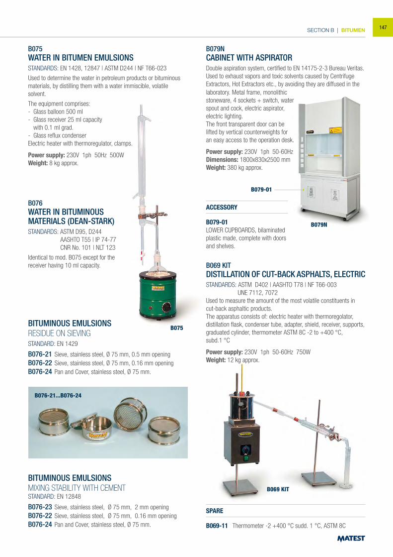
SECTION B | BITUMEN
B075WATER IN BITUMEN EMULSIONSSTANDARDS: EN 1428, 12847 | ASTM D244 | NF T66-023
Used to determine the water in petroleum products or bituminous materials, by distilling them with a water immiscible, volatile solvent.
The equipment comprises:- Glass balloon 500 ml- Glass receiver 25 ml capacity with 0.1 ml grad.- Glass reflux condenserElectric heater with thermoregulator, clamps.
Power supply: 230V 1ph 50Hz 500WWeight: 8 kg approx.
B076WATER IN BITUMINOUSMATERIALS (DEAN-STARK)STANDARDS: ASTM D95, D244 AASHTO T55 | IP 74-77 CNR No. 101 | NLT 123
Identical to mod. B075 except for the receiver having 10 ml capacity.
BITUMINOUS EMULSIONSRESIDUE ON SIEVINGSTANDARD: EN 1429
B076-21 Sieve, stainless steel, Ø 75 mm, 0.5 mm openingB076-22 Sieve, stainless steel, Ø 75 mm, 0.16 mm openingB076-24 Pan and Cover, stainless steel, Ø 75 mm.
BITUMINOUS EMULSIONSMIXING STABILITY WITH CEMENTSTANDARD: EN 12848
B076-23 Sieve, stainless steel, Ø 75 mm, 2 mm openingB076-22 Sieve, stainless steel, Ø 75 mm, 0.16 mm openingB076-24 Pan and Cover, stainless steel, Ø 75 mm.
B069 KITDISTILLATION OF CUT-BACK ASPHALTS, ELECTRICSTANDARDS: ASTM D402 | AASHTO T78 | NF T66-003 UNE 7112, 7072Used to measure the amount of the most volatile constituents in cut-back asphaltic products.The apparatus consists of: electric heater with thermoregolator, distillation flask, condenser tube, adapter, shield, receiver, supports, graduated cylinder, thermometer ASTM 8C -2 to +400 °C,subd.1 °C
Power supply: 230V 1ph 50-60Hz 750WWeight: 12 kg approx.
B075
B069 KIT
B076-21...B076-24
SPARE
B069-11 Thermometer -2 +400 °C sudd. 1 °C, ASTM 8C
B079N
B079-01
B079NCABINET WITH ASPIRATORDouble aspiration system, certified to EN 14175-2-3 Bureau Veritas.Used to exhaust vapors and toxic solvents caused by Centrifuge Extractors, Hot Extractors etc., by avoiding they are diffused in the
ACCESSORY
B079-01LOWER CUPBOARDS, bilaminated plastic made, complete with doors and shelves.
laboratory. Metal frame, monolithic stoneware, 4 sockets + switch, water spout and cock, electric aspirator, electric lighting.The front transparent door can be lifted by vertical counterweights foran easy access to the operation desk.
Power supply: 230V 1ph 50-60HzDimensions: 1800x830x2500 mmWeight: 380 kg approx.
147
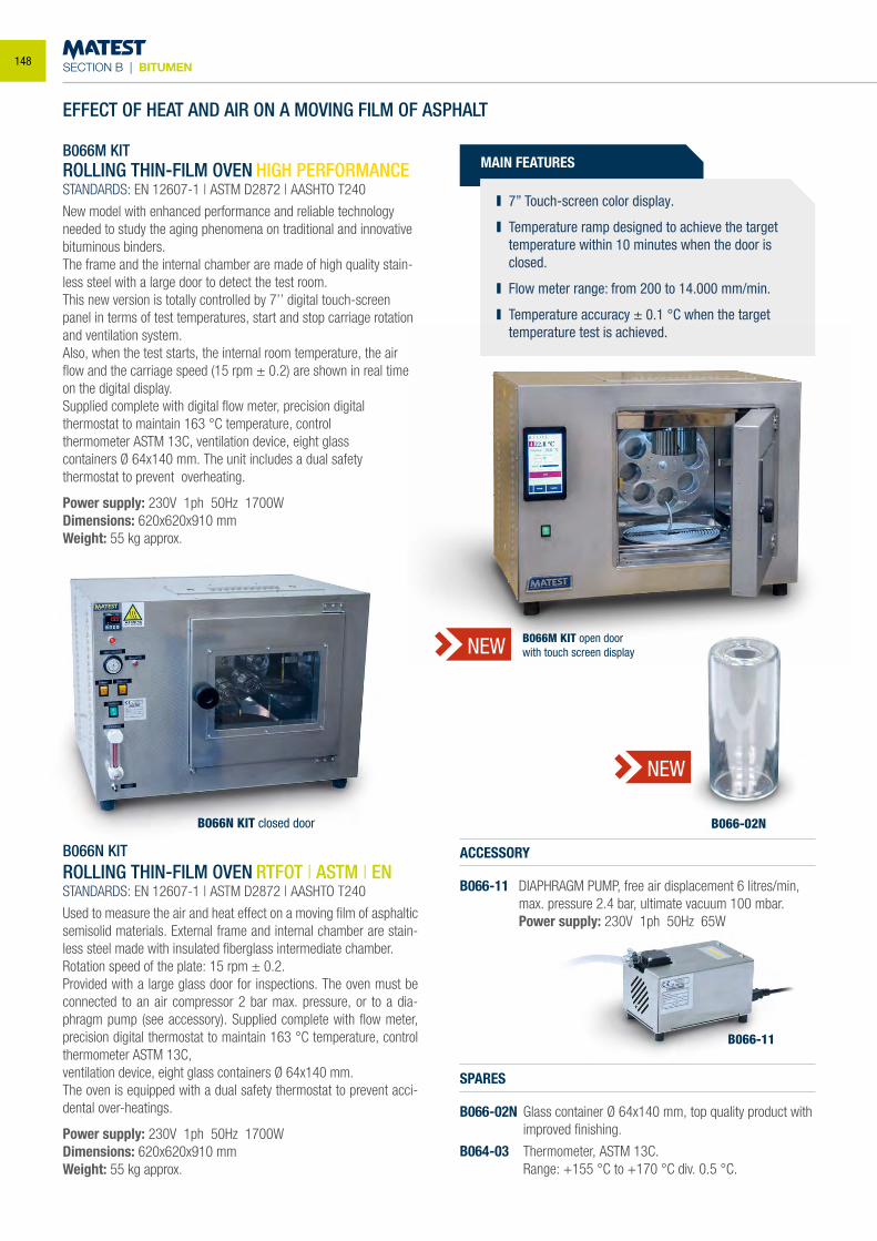
SECTION B | BITUMEN
B066N KITROLLING THIN-FILM OVEN RTFOT | ASTM | ENSTANDARDS: EN 12607-1 | ASTM D2872 | AASHTO T240
Used to measure the air and heat effect on a moving film of asphaltic semisolid materials. External frame and internal chamber are stain-less steel made with insulated fiberglass intermediate chamber.Rotation speed of the plate: 15 rpm ± 0.2.Provided with a large glass door for inspections. The oven must be connected to an air compressor 2 bar max. pressure, or to a dia-phragm pump (see accessory). Supplied complete with flow meter, precision digital thermostat to maintain 163 °C temperature, control thermometer ASTM 13C,ventilation device, eight glass containers Ø 64x140 mm.The oven is equipped with a dual safety thermostat to prevent acci-dental over-heatings.
Power supply: 230V 1ph 50Hz 1700WDimensions: 620x620x910 mmWeight: 55 kg approx.
B066M KITROLLING THIN-FILM OVEN HIGH PERFORMANCESTANDARDS: EN 12607-1 | ASTM D2872 | AASHTO T240
New model with enhanced performance and reliable technology needed to study the aging phenomena on traditional and innovative bituminous binders.The frame and the internal chamber are made of high quality stain-less steel with a large door to detect the test room.This new version is totally controlled by 7’’ digital touch-screen panel in terms of test temperatures, start and stop carriage rotation and ventilation system.Also, when the test starts, the internal room temperature, the air flow and the carriage speed (15 rpm ± 0.2) are shown in real time on the digital display.Supplied complete with digital flow meter, precision digital thermostat to maintain 163 °C temperature, control thermometer ASTM 13C, ventilation device, eight glass containers Ø 64x140 mm. The unit includes a dual safety thermostat to prevent overheating.
Power supply: 230V 1ph 50Hz 1700WDimensions: 620x620x910 mmWeight: 55 kg approx.
ACCESSORY
B066-11 DIAPHRAGM PUMP, free air displacement 6 litres/min, max. pressure 2.4 bar, ultimate vacuum 100 mbar.
Power supply: 230V 1ph 50Hz 65W
SPARES
B066-02N Glass container Ø 64x140 mm, top quality product with improved finishing.
B064-03 Thermometer, ASTM 13C. Range: +155 °C to +170 °C div. 0.5 °C.
B066M KIT open doorwith touch screen display
B066N KIT closed door
B066-11
B066-02N
NEW
NEW
EFFECT OF HEAT AND AIR ON A MOVING FILM OF ASPHALT
MAIN FEATURES
7’’ Touch-screen color display.
Temperature ramp designed to achieve the target temperature within 10 minutes when the door is closed.
Flow meter range: from 200 to 14.000 mm/min.
Temperature accuracy ± 0.1 °C when the target temperature test is achieved.
148
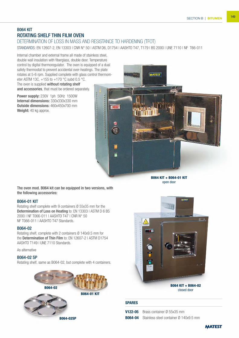
SECTION B | BITUMEN
B064 KITROTATING SHELF THIN FILM OVENDETERMINATION OF LOSS IN MASS AND RESISTANCE TO HARDENING (TFOT)STANDARDS: EN 12607-2, EN 13303 | CNR N° 50 | ASTM D6, D1754 | AASHTO T47, T179 | BS 2000 | UNE 7110 | NF T66-011
Internal chamber and external frame all made of stainless steel, double wall insulation with fiberglass, double door. Temperature control by digital thermoregulator. The oven is equipped of a dual safety thermostat to prevent accidental over-heatings. The plate rotates at 5-6 rpm. Supplied complete with glass control thermom-eter ASTM 13C, +155 to +170 °C subd 0.5 °C.The oven is supplied without rotating shelfand accessories, that must be ordered separately.
Power supply: 230V 1ph 50Hz 1500WInternal dimensions: 330x330x330 mmOutside dimensions: 460x450x700 mmWeight: 40 kg approx.
The oven mod. B064 kit can be equipped in two versions, with the following accessories:
B064-01 KITRotating shelf complete with 9 containers Ø 55x35 mm for the Determination of Loss on Heating to: EN 13303 | ASTM D 6 BS 2000 | NF T066-011 | AASHTO T47 | CNR N° 50NF T066-011 | AASHTO T47 Standards.
B064-02Rotating shelf, complete with 2 containers Ø 140x9.5 mm for the Determination of Thin Film to: EN 12607-2 | ASTM D1754 AASHTO T149 | UNE 7110 Standards.
As alternative
B064-02 SPRotating shelf, same as B064-02, but complete with 4 containers.
SPARES
V122-05 Brass container Ø 55x35 mm
B064-04 Stainless steel container Ø 140x9.5 mm
B064 KIT + B064-01 KITopen door
B064 KIT + B064-02 closed door
B064-02
B064-01 KIT
B064-02SP
149
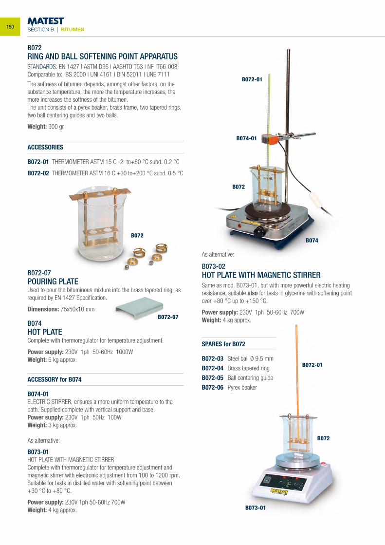
SECTION B | BITUMEN
B072
B072-07
B072RING AND BALL SOFTENING POINT APPARATUSSTANDARDS: EN 1427 | ASTM D36 | AASHTO T53 | NF T66-008Comparable to: BS 2000 | UNI 4161 | DIN 52011 | UNE 7111
The softness of bitumen depends, amongst other factors, on the substance temperature, the more the temperature increases, the more increases the softness of the bitumen.The unit consists of a pyrex beaker, brass frame, two tapered rings, two ball centering guides and two balls.
Weight: 900 gr
ACCESSORIES
B072-01 THERMOMETER ASTM 15 C -2 to+80 °C subd. 0.2 °C
B072-02 THERMOMETER ASTM 16 C +30 to+200 °C subd. 0.5 °C
B072-07POURING PLATEUsed to pour the bituminous mixture into the brass tapered ring, as required by EN 1427 Specification.
Dimensions: 75x50x10 mm
B074HOT PLATEComplete with thermoregulator for temperature adjustment.
Power supply: 230V 1ph 50-60Hz 1000WWeight: 6 kg approx.
ACCESSORY for B074
B074-01ELECTRIC STIRRER, ensures a more uniform temperature to the bath. Supplied complete with vertical support and base.Power supply: 230V 1ph 50Hz 100WWeight: 3 kg approx.
As alternative:
B073-02HOT PLATE WITH MAGNETIC STIRRERSame as mod. B073-01, but with more powerful electric heating resistance, suitable also for tests in glycerine with softening point over +80 °C up to +150 °C.
Power supply: 230V 1ph 50-60Hz 700WWeight: 4 kg approx.
As alternative:
B073-01HOT PLATE WITH MAGNETIC STIRRERComplete with thermoregulator for temperature adjustment and magnetic stirrer with electronic adjustment from 100 to 1200 rpm.Suitable for tests in distilled water with softening point between +30 °C to +80 °C.
Power supply: 230V 1ph 50-60Hz 700WWeight: 4 kg approx.
SPARES for B072
B072-03 Steel ball Ø 9.5 mm
B072-04 Brass tapered ring
B072-05 Ball centering guide
B072-06 Pyrex beaker
B074
B073-01
B072
B072-01
B072
B074-01
B072-01
150
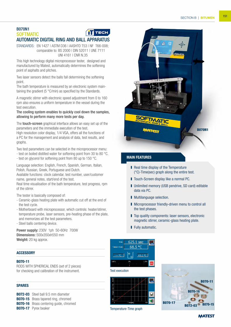
SECTION B | BITUMEN
B070N1SOFTMATIC AUTOMATIC DIGITAL RING AND BALL APPARATUS
STANDARDS: EN 1427 | ASTM D36 | AASHTO T53 | NF T66-008; comparable to: BS 2000 | DIN 52011 | UNE 7111 UNI 4161 | CNR N.35
This high technology digital microprocessor tester, designed and manufactured by Matest, automatically determines the softening point of asphalts and pitches.
Two laser sensors detect the balls fall determining the softening point. The bath temperature is measured by an electronic system main-taining the gradient (5 °C/min) as specified by the Standards.
A magnetic stirrer with electronic speed adjustment from 0 to 160 rpm also ensures a uniform temperature in the vessel during the test execution.The cooling system enables to quickly cool down the samples, allowing to perform many more tests per day.
The touch-screen graphical interface allows an easy set up of the parameters and the immediate execution of the test.High resolution color display, 1/4 VGA, offers all the functions of a PC for the management and analysis of data, test results, and graphs.
Two test parameters can be selected in the microprocessor menu: - test on boiled distilled water for softening point from 30 to 80 °C. - test on glycerol for softening point from 80 up to 150 °C.
Language selection: English, French, Spanish, German, Italian, Polish, Russian, Greek, Portuguese and Dutch. Available functions: clock calendar, test number, user/customer name, general notes, start/end of the test. Real time visualisation of the bath temperature, test progress, rpm of the stirrer.
The tester is basically composed of: - Ceramic-glass heating plate with automatic cut off at the end of
the test cycle. - Motherboard with microprocessor, which controls: heater/stirrer,
temperature probe, laser sensors, pre-heating phase of the plate, and memorizes all the test parameters.
- Steel balls centering device.
Power supply: 230V 1ph 50-60Hz 700W Dimensions: 500x350xh550 mm Weight: 20 kg approx.
MAIN FEATURES
Real time display of the Temperature (°C)-Time(sec) graph along the entire test.
Touch-Screen display like a normal PC.
Unlimited memory (USB pendrive, SD card) editable data via PC.
Multilanguage selection.
Microprocessor friendly-driven menu to control all the test phases.
Top quality components: laser sensors, electronic magnetic stirrer, ceramic-glass heating plate.
Fully automatic.
ACCESSORY
B070-11RODS WITH SPHERICAL ENDS (set of 2 pieces)for checking and calibration of the instrument.
SPARES
B072-03 Steel ball 9.5 mm diameterB070-15 Brass tapered ring, chromedB070-16 Brass centering guide, chromedB070-17 Pyrex beaker
Test execution
Temperature-Time graph
B070N1
B070-17
B070-11
B070-16
B070-15B072-03
151
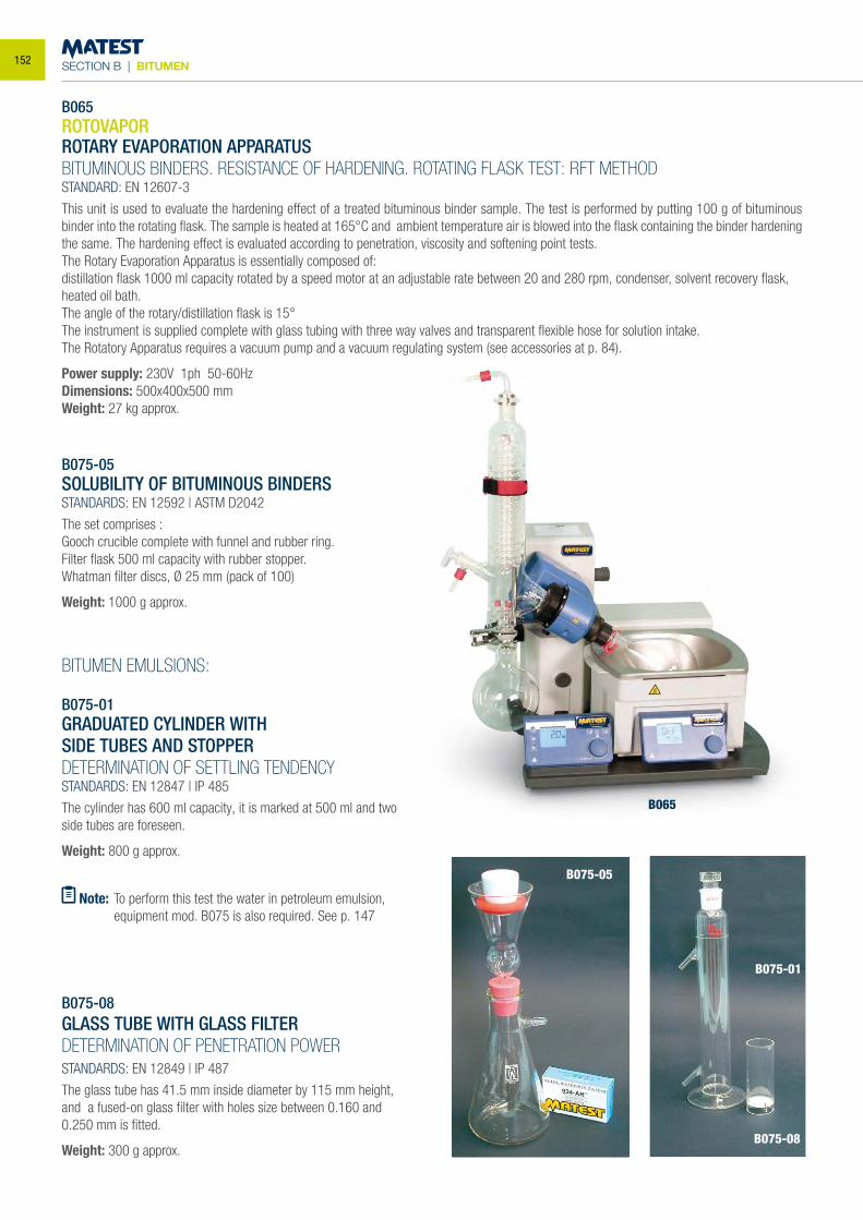
SECTION B | BITUMEN
B065ROTOVAPORROTARY EVAPORATION APPARATUSBITUMINOUS BINDERS. RESISTANCE OF HARDENING. ROTATING FLASK TEST: RFT METHODSTANDARD: EN 12607-3
This unit is used to evaluate the hardening effect of a treated bituminous binder sample. The test is performed by putting 100 g of bituminous binder into the rotating flask. The sample is heated at 165°C and ambient temperature air is blowed into the flask containing the binder hardening the same. The hardening effect is evaluated according to penetration, viscosity and softening point tests.The Rotary Evaporation Apparatus is essentially composed of:distillation flask 1000 ml capacity rotated by a speed motor at an adjustable rate between 20 and 280 rpm, condenser, solvent recovery flask, heated oil bath.The angle of the rotary/distillation flask is 15°The instrument is supplied complete with glass tubing with three way valves and transparent flexible hose for solution intake. The Rotatory Apparatus requires a vacuum pump and a vacuum regulating system (see accessories at p. 84).
Power supply: 230V 1ph 50-60HzDimensions: 500x400x500 mmWeight: 27 kg approx.
B075-05SOLUBILITY OF BITUMINOUS BINDERSSTANDARDS: EN 12592 | ASTM D2042
The set comprises :Gooch crucible complete with funnel and rubber ring.Filter flask 500 ml capacity with rubber stopper.Whatman filter discs, Ø 25 mm (pack of 100)
Weight: 1000 g approx.
BITUMEN EMULSIONS:
B075-01GRADUATED CYLINDER WITHSIDE TUBES AND STOPPERDETERMINATION OF SETTLING TENDENCYSTANDARDS: EN 12847 | IP 485
The cylinder has 600 ml capacity, it is marked at 500 ml and two side tubes are foreseen.
Weight: 800 g approx.
B075-08GLASS TUBE WITH GLASS FILTER DETERMINATION OF PENETRATION POWERSTANDARDS: EN 12849 | IP 487
The glass tube has 41.5 mm inside diameter by 115 mm height, and a fused-on glass filter with holes size between 0.160 and 0.250 mm is fitted.
Weight: 300 g approx.
B065
B075-05
B075-01
B075-08
Note: To perform this test the water in petroleum emulsion, equipment mod. B075 is also required. See p. 147
152
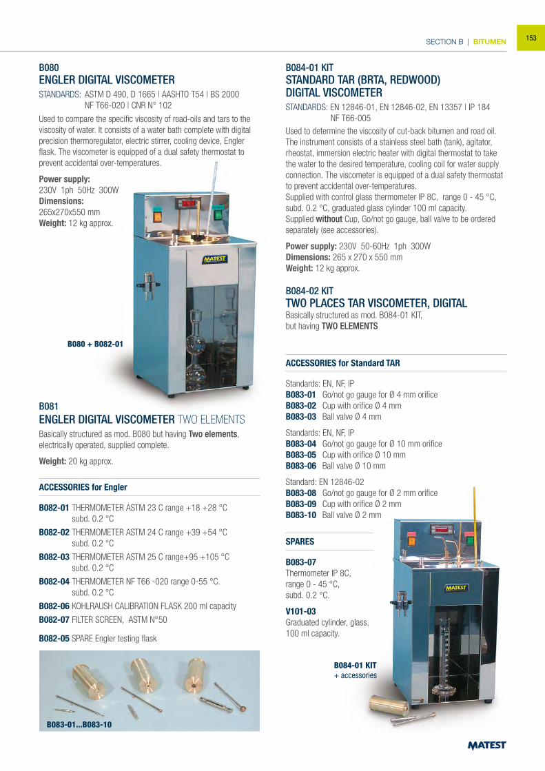
SECTION B | BITUMEN
B080 + B082-01
B084-01 KIT+ accessories
B080ENGLER DIGITAL VISCOMETERSTANDARDS: ASTM D 490, D 1665 | AASHTO T54 | BS 2000 NF T66-020 | CNR N° 102
Used to compare the specific viscosity of road-oils and tars to the viscosity of water. It consists of a water bath complete with digital precision thermoregulator, electric stirrer, cooling device, Engler flask. The viscometer is equipped of a dual safety thermostat to prevent accidental over-temperatures.
Power supply:230V 1ph 50Hz 300WDimensions:265x270x550 mm Weight: 12 kg approx.
B081ENGLER DIGITAL VISCOMETER TWO ELEMENTSBasically structured as mod. B080 but having Two elements, electrically operated, supplied complete.
Weight: 20 kg approx.
ACCESSORIES for Engler
B082-01 THERMOMETER ASTM 23 C range +18 +28 °C subd. 0.2 °C
B082-02 THERMOMETER ASTM 24 C range +39 +54 °C subd. 0.2 °C
B082-03 THERMOMETER ASTM 25 C range+95 +105 °C subd. 0.2 °C
B082-04 THERMOMETER NF T66 -020 range 0-55 °C. subd. 0.2 °C
B082-06 KOHLRAUSH CALIBRATION FLASK 200 ml capacity
B082-07 FILTER SCREEN, ASTM N°50
B082-05 SPARE Engler testing flask
B084-01 KITSTANDARD TAR (BRTA, REDWOOD)DIGITAL VISCOMETERSTANDARDS: EN 12846-01, EN 12846-02, EN 13357 | IP 184 NF T66-005 Used to determine the viscosity of cut-back bitumen and road oil. The instrument consists of a stainless steel bath (tank), agitator, rheostat, immersion electric heater with digital thermostat to take the water to the desired temperature, cooling coil for water supply connection. The viscometer is equipped of a dual safety thermostat to prevent accidental over-temperatures.Supplied with control glass thermometer IP 8C, range 0 - 45 °C, subd. 0.2 °C, graduated glass cylinder 100 ml capacity. Supplied without Cup, Go/not go gauge, ball valve to be ordered separately (see accessories).
Power supply: 230V 50-60Hz 1ph 300W Dimensions: 265 x 270 x 550 mmWeight: 12 kg approx.
B084-02 KIT TWO PLACES TAR VISCOMETER, DIGITAL Basically structured as mod. B084-01 KIT,but having TWO ELEMENTS
ACCESSORIES for Standard TAR
Standards: EN, NF, IP B083-01 Go/not go gauge for Ø 4 mm orifice B083-02 Cup with orifice Ø 4 mm B083-03 Ball valve Ø 4 mm
Standards: EN, NF, IP B083-04 Go/not go gauge for Ø 10 mm orifice B083-05 Cup with orifice Ø 10 mm B083-06 Ball valve Ø 10 mm
Standard: EN 12846-02B083-08 Go/not go gauge for Ø 2 mm orifice B083-09 Cup with orifice Ø 2 mm B083-10 Ball valve Ø 2 mm
SPARES
B083-07Thermometer IP 8C,range 0 - 45 °C,subd. 0.2 °C.
V101-03Graduated cylinder, glass,100 ml capacity.
B083-01...B083-10
153
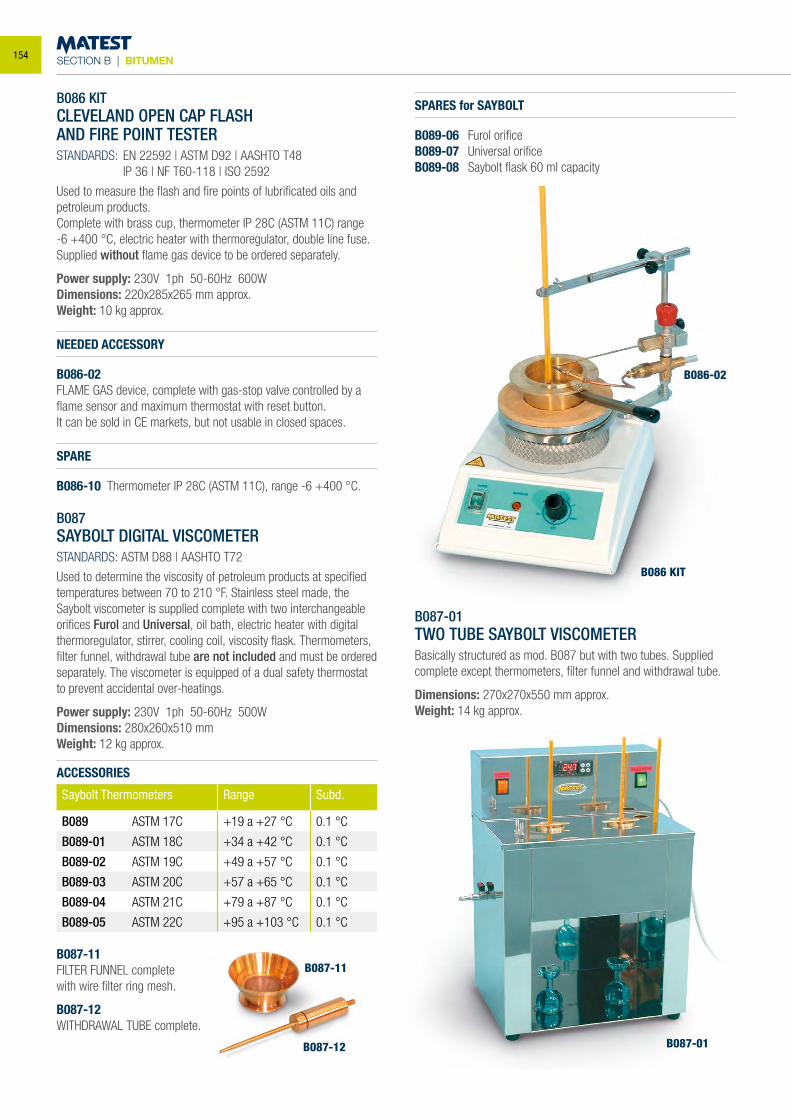
SECTION B | BITUMEN
B086 KITCLEVELAND OPEN CAP FLASHAND FIRE POINT TESTERSTANDARDS: EN 22592 | ASTM D92 | AASHTO T48 IP 36 | NF T60-118 | ISO 2592
Used to measure the flash and fire points of lubrificated oils and petroleum products.Complete with brass cup, thermometer IP 28C (ASTM 11C) range -6 +400 °C, electric heater with thermoregulator, double line fuse.Supplied without flame gas device to be ordered separately.
Power supply: 230V 1ph 50-60Hz 600WDimensions: 220x285x265 mm approx.Weight: 10 kg approx.
NEEDED ACCESSORY
B086-02 FLAME GAS device, complete with gas-stop valve controlled by a flame sensor and maximum thermostat with reset button.It can be sold in CE markets, but not usable in closed spaces.
SPARE
B086-10 Thermometer IP 28C (ASTM 11C), range -6 +400 °C.
B087SAYBOLT DIGITAL VISCOMETERSTANDARDS: ASTM D88 | AASHTO T72
Used to determine the viscosity of petroleum products at specified temperatures between 70 to 210 °F. Stainless steel made, the Saybolt viscometer is supplied complete with two interchangeable orifices Furol and Universal, oil bath, electric heater with digital thermoregulator, stirrer, cooling coil, viscosity flask. Thermometers, filter funnel, withdrawal tube are not included and must be ordered separately. The viscometer is equipped of a dual safety thermostat to prevent accidental over-heatings.
Power supply: 230V 1ph 50-60Hz 500WDimensions: 280x260x510 mmWeight: 12 kg approx.
ACCESSORIES
Saybolt Thermometers Range Subd.
B089 ASTM 17C +19 a +27 °C 0.1 °C
B089-01 ASTM 18C +34 a +42 °C 0.1 °C
B089-02 ASTM 19C +49 a +57 °C 0.1 °C
B089-03 ASTM 20C +57 a +65 °C 0.1 °C
B089-04 ASTM 21C +79 a +87 °C 0.1 °C
B089-05 ASTM 22C +95 a +103 °C 0.1 °C
B087-11FILTER FUNNEL completewith wire filter ring mesh.
B087-12WITHDRAWAL TUBE complete.
B087-01TWO TUBE SAYBOLT VISCOMETERBasically structured as mod. B087 but with two tubes. Supplied complete except thermometers, filter funnel and withdrawal tube.
Dimensions: 270x270x550 mm approx.Weight: 14 kg approx.
B086 KIT
B086-02
B087-01
B087-11
B087-12
SPARES for SAYBOLT
B089-06 Furol orificeB089-07 Universal orificeB089-08 Saybolt flask 60 ml capacity
154
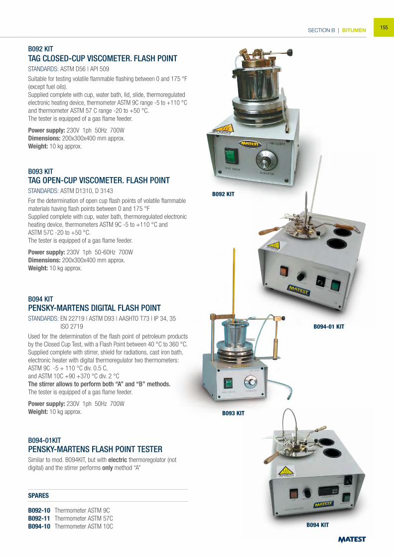
SECTION B | BITUMEN
B092 KIT
B093 KIT
B094 KIT
B092 KITTAG CLOSED-CUP VISCOMETER. FLASH POINTSTANDARDS: ASTM D56 | API 509
Suitable for testing volatile flammable flashing between 0 and 175 °F (except fuel oils).Supplied complete with cup, water bath, lid, slide, thermoregulated electronic heating device, thermometer ASTM 9C range -5 to +110 °C and thermometer ASTM 57 C range -20 to +50 °C.The tester is equipped of a gas flame feeder.
Power supply: 230V 1ph 50Hz 700WDimensions: 200x300x400 mm approx.Weight: 10 kg approx.
B093 KITTAG OPEN-CUP VISCOMETER. FLASH POINTSTANDARDS: ASTM D1310, D 3143
For the determination of open cup flash points of volatile flammable materials having flash points between 0 and 175 °FSupplied complete with cup, water bath, thermoregulated electronic heating device, thermometers ASTM 9C -5 to +110 °C andASTM 57C -20 to +50 °C.The tester is equipped of a gas flame feeder.
Power supply: 230V 1ph 50-60Hz 700WDimensions: 200x300x400 mm approx.Weight: 10 kg approx.
B094 KITPENSKY-MARTENS DIGITAL FLASH POINT STANDARDS: EN 22719 | ASTM D93 | AASHTO T73 | IP 34, 35 ISO 2719
Used for the determination of the flash point of petroleum products by the Closed Cup Test, with a Flash Point between 40 °C to 360 °C.Supplied complete with stirrer, shield for radiations, cast iron bath, electronic heater with digital thermoregulator two thermometers: ASTM 9C -5 + 110 °C div. 0.5 C,and ASTM 10C +90 +370 °C div. 2 °C The stirrer allows to perform both “A” and “B” methods.The tester is equipped of a gas flame feeder.
Power supply: 230V 1ph 50Hz 700W Weight: 10 kg approx.
SPARES
B092-10 Thermometer ASTM 9CB092-11 Thermometer ASTM 57CB094-10 Thermometer ASTM 10C
B094-01KITPENSKY-MARTENS FLASH POINT TESTERSimilar to mod. B094KIT, but with electric thermoregolator (not digital) and the stirrer performs only method “A”
B094-01 KIT
155
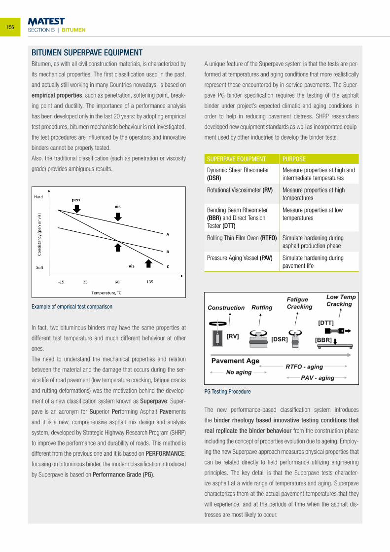
SECTION B | BITUMEN
BITUMEN SUPERPAVE EQUIPMENTBitumen, as with all civil construction materials, is characterized by
its mechanical properties. The first classification used in the past,
and actually still working in many Countries nowadays, is based on
empirical properties, such as penetration, softening point, break-
ing point and ductility. The importance of a performance analysis
has been developed only in the last 20 years: by adopting empirical
test procedures, bitumen mechanistic behaviour is not investigated,
the test procedures are influenced by the operators and innovative
binders cannot be properly tested.
Also, the traditional classification (such as penetration or viscosity
grade) provides ambiguous results.
In fact, two bituminous binders may have the same properties at
different test temperature and much different behaviour at other
ones.
The need to understand the mechanical properties and relation
between the material and the damage that occurs during the ser-
vice life of road pavement (low temperature cracking, fatigue cracks
and rutting deformations) was the motivation behind the develop-
ment of a new classification system known as Superpave: Super-
pave is an acronym for Superior Performing Asphalt Pavements
and it is a new, comprehensive asphalt mix design and analysis
system, developed by Strategic Highway Research Program (SHRP)
to improve the performance and durability of roads. This method is
different from the previous one and it is based on PERFORMANCE:
focusing on bituminous binder, the modern classification introduced
by Superpave is based on Performance Grade (PG).
A unique feature of the Superpave system is that the tests are per-
formed at temperatures and aging conditions that more realistically
represent those encountered by in-service pavements. The Super-
pave PG binder specification requires the testing of the asphalt
binder under project’s expected climatic and aging conditions in
order to help in reducing pavement distress. SHRP researchers
developed new equipment standards as well as incorporated equip-
ment used by other industries to develop the binder tests.
SUPERPAVE EQUIPMENT PURPOSE
Dynamic Shear Rheometer (DSR)
Measure properties at high and intermediate temperatures
Rotational Viscosimeter (RV) Measure properties at high temperatures
Bending Beam Rheometer (BBR) and Direct Tension Tester (DTT)
Measure properties at low temperatures
Rolling Thin Film Oven (RTFO) Simulate hardening during asphalt production phase
Pressure Aging Vessel (PAV) Simulate hardening during pavement life
The new performance-based classification system introduces
the binder rheology based innovative testing conditions that
real replicate the binder behaviour from the construction phase
including the concept of properties evolution due to ageing. Employ-
ing the new Superpave approach measures physical properties that
can be related directly to field performance utilizing engineering
principles. The key detail is that the Superpave tests character-
ize asphalt at a wide range of temperatures and aging. Superpave
characterizes them at the actual pavement temperatures that they
will experience, and at the periods of time when the asphalt dis-
tresses are most likely to occur.
Example of emprical test comparison
PG Testing Procedure
156
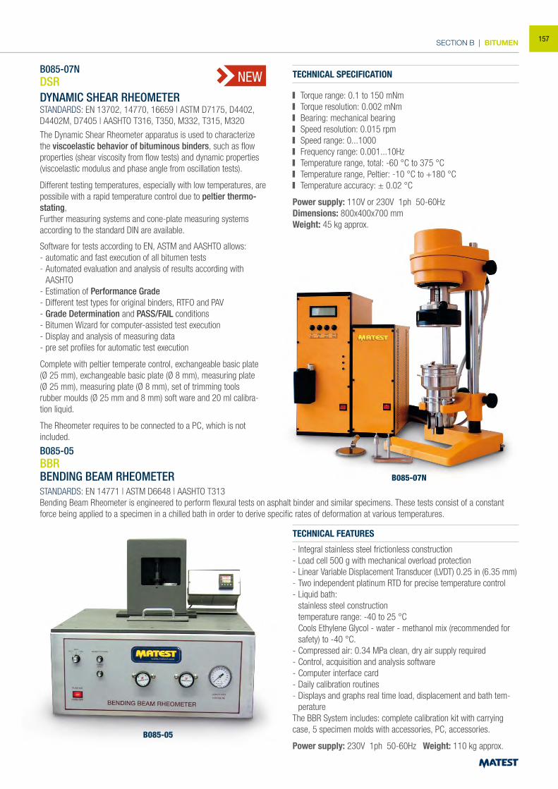
SECTION B | BITUMEN
B085-07NDSRDYNAMIC SHEAR RHEOMETERSTANDARDS: EN 13702, 14770, 16659 | ASTM D7175, D4402, D4402M, D7405 | AASHTO T316, T350, M332, T315, M320
The Dynamic Shear Rheometer apparatus is used to characterize the viscoelastic behavior of bituminous binders, such as flow properties (shear viscosity from flow tests) and dynamic properties (viscoelastic modulus and phase angle from oscillation tests).
Different testing temperatures, especially with low temperatures, are possibile with a rapid temperature control due to peltier thermo-stating,Further measuring systems and cone-plate measuring systems according to the standard DIN are available.
Software for tests according to EN, ASTM and AASHTO allows:- automatic and fast execution of all bitumen tests- Automated evaluation and analysis of results according with AASHTO- Estimation of Performance Grade- Different test types for original binders, RTFO and PAV- Grade Determination and PASS/FAIL conditions- Bitumen Wizard for computer-assisted test execution- Display and analysis of measuring data- pre set profiles for automatic test execution
Complete with peltier temperate control, exchangeable basic plate(Ø 25 mm), exchangeable basic plate (Ø 8 mm), measuring plate(Ø 25 mm), measuring plate (Ø 8 mm), set of trimming toolsrubber moulds (Ø 25 mm and 8 mm) soft ware and 20 ml calibra-tion liquid.
The Rheometer requires to be connected to a PC, which is not included.
TECHNICAL SPECIFICATION
Torque range: 0.1 to 150 mNm Torque resolution: 0.002 mNm Bearing: mechanical bearing Speed resolution: 0.015 rpm Speed range: 0...1000 Frequency range: 0.001...10Hz Temperature range, total: -60 °C to 375 °C Temperature range, Peltier: -10 °C to +180 °C Temperature accuracy: ± 0.02 °C
Power supply: 110V or 230V 1ph 50-60HzDimensions: 800x400x700 mmWeight: 45 kg approx.
NEW
B085-05BBRBENDING BEAM RHEOMETERSTANDARDS: EN 14771 | ASTM D6648 | AASHTO T313Bending Beam Rheometer is engineered to perform flexural tests on asphalt binder and similar specimens. These tests consist of a constant force being applied to a specimen in a chilled bath in order to derive specific rates of deformation at various temperatures.
B085-05
TECHNICAL FEATURES
- Integral stainless steel frictionless construction- Load cell 500 g with mechanical overload protection- Linear Variable Displacement Transducer (LVDT) 0.25 in (6.35 mm)- Two independent platinum RTD for precise temperature control- Liquid bath: stainless steel construction temperature range: -40 to 25 °C Cools Ethylene Glycol - water - methanol mix (recommended for
safety) to -40 °C.- Compressed air: 0.34 MPa clean, dry air supply required - Control, acquisition and analysis software- Computer interface card- Daily calibration routines- Displays and graphs real time load, displacement and bath tem-
peratureThe BBR System includes: complete calibration kit with carrying case, 5 specimen molds with accessories, PC, accessories.
Power supply: 230V 1ph 50-60Hz Weight: 110 kg approx.
B085-07N
157
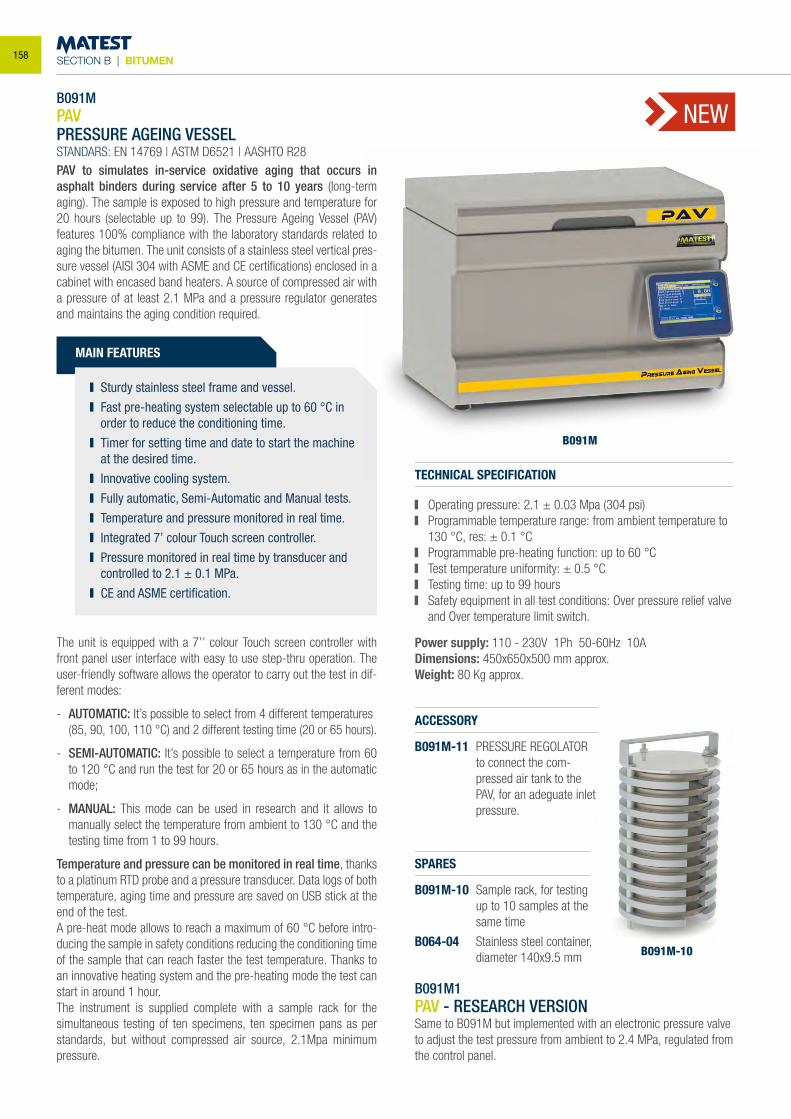
SECTION B | BITUMEN
B091MPAV PRESSURE AGEING VESSEL STANDARS: EN 14769 | ASTM D6521 | AASHTO R28
MAIN FEATURES
Sturdy stainless steel frame and vessel. Fast pre-heating system selectable up to 60 °C in
order to reduce the conditioning time. Timer for setting time and date to start the machine
at the desired time. Innovative cooling system. Fully automatic, Semi-Automatic and Manual tests. Temperature and pressure monitored in real time. Integrated 7’ colour Touch screen controller. Pressure monitored in real time by transducer and
controlled to 2.1 ± 0.1 MPa. CE and ASME certification.
The unit is equipped with a 7’’ colour Touch screen controller with front panel user interface with easy to use step-thru operation. The user-friendly software allows the operator to carry out the test in dif-ferent modes:
- AUTOMATIC: It’s possible to select from 4 different temperatures (85, 90, 100, 110 °C) and 2 different testing time (20 or 65 hours).
- SEMI-AUTOMATIC: It’s possible to select a temperature from 60 to 120 °C and run the test for 20 or 65 hours as in the automatic mode;
- MANUAL: This mode can be used in research and it allows to manually select the temperature from ambient to 130 °C and the testing time from 1 to 99 hours.
Temperature and pressure can be monitored in real time, thanks to a platinum RTD probe and a pressure transducer. Data logs of both temperature, aging time and pressure are saved on USB stick at the end of the test.A pre-heat mode allows to reach a maximum of 60 °C before intro-ducing the sample in safety conditions reducing the conditioning time of the sample that can reach faster the test temperature. Thanks to an innovative heating system and the pre-heating mode the test can start in around 1 hour.The instrument is supplied complete with a sample rack for the simultaneous testing of ten specimens, ten specimen pans as per standards, but without compressed air source, 2.1Mpa minimum pressure.
TECHNICAL SPECIFICATION
Operating pressure: 2.1 ± 0.03 Mpa (304 psi) Programmable temperature range: from ambient temperature to
130 °C, res: ± 0.1 °C Programmable pre-heating function: up to 60 °C Test temperature uniformity: ± 0.5 °C Testing time: up to 99 hours Safety equipment in all test conditions: Over pressure relief valve
and Over temperature limit switch.
Power supply: 110 - 230V 1Ph 50-60Hz 10ADimensions: 450x650x500 mm approx.Weight: 80 Kg approx.
SPARES
B091M-10 Sample rack, for testing up to 10 samples at the same time
B064-04 Stainless steel container, diameter 140x9.5 mm
ACCESSORY
B091M-11 PRESSURE REGOLATOR to connect the com-pressed air tank to the PAV, for an adeguate inlet pressure.
B091M
PAV to simulates in-service oxidative aging that occurs in asphalt binders during service after 5 to 10 years (long-term aging). The sample is exposed to high pressure and temperature for 20 hours (selectable up to 99). The Pressure Ageing Vessel (PAV) features 100% compliance with the laboratory standards related to aging the bitumen. The unit consists of a stainless steel vertical pres-sure vessel (AISI 304 with ASME and CE certifications) enclosed in a cabinet with encased band heaters. A source of compressed air with a pressure of at least 2.1 MPa and a pressure regulator generates and maintains the aging condition required.
B091M-10
B091M1PAV - RESEARCH VERSIONSame to B091M but implemented with an electronic pressure valve to adjust the test pressure from ambient to 2.4 MPa, regulated from the control panel.
NEW
158
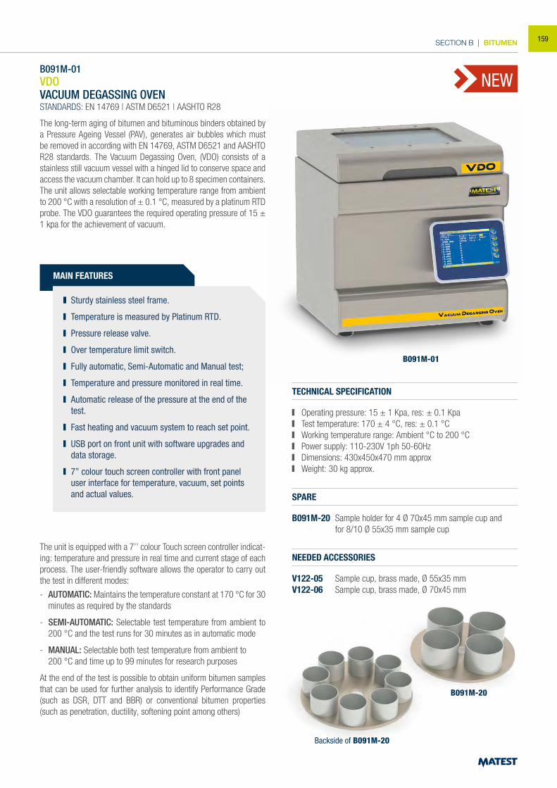
SECTION B | BITUMEN
B091M-01
B091M-01 VDOVACUUM DEGASSING OVEN STANDARDS: EN 14769 | ASTM D6521 | AASHTO R28
MAIN FEATURES
Sturdy stainless steel frame.
Temperature is measured by Platinum RTD.
Pressure release valve.
Over temperature limit switch.
Fully automatic, Semi-Automatic and Manual test;
Temperature and pressure monitored in real time.
Automatic release of the pressure at the end of the test.
Fast heating and vacuum system to reach set point.
USB port on front unit with software upgrades and data storage.
7’’ colour touch screen controller with front panel user interface for temperature, vacuum, set points and actual values.
The unit is equipped with a 7’’ colour Touch screen controller indicat-ing: temperature and pressure in real time and current stage of each process. The user-friendly software allows the operator to carry out the test in different modes:
- AUTOMATIC: Maintains the temperature constant at 170 °C for 30 minutes as required by the standards
- SEMI-AUTOMATIC: Selectable test temperature from ambient to 200 °C and the test runs for 30 minutes as in automatic mode
- MANUAL: Selectable both test temperature from ambient to 200 °C and time up to 99 minutes for research purposes
At the end of the test is possible to obtain uniform bitumen samples that can be used for further analysis to identify Performance Grade (such as DSR, DTT and BBR) or conventional bitumen properties (such as penetration, ductility, softening point among others)
TECHNICAL SPECIFICATION
Operating pressure: 15 ± 1 Kpa, res: ± 0.1 Kpa Test temperature: 170 ± 4 °C, res: ± 0.1 °C Working temperature range: Ambient °C to 200 °C Power supply: 110-230V 1ph 50-60Hz Dimensions: 430x450x470 mm approx Weight: 30 kg approx.
SPARE
B091M-20 Sample holder for 4 Ø 70x45 mm sample cup and for 8/10 Ø 55x35 mm sample cup
NEEDED ACCESSORIES
V122-05 Sample cup, brass made, Ø 55x35 mmV122-06 Sample cup, brass made, Ø 70x45 mm
B091M-20
Backside of B091M-20
The long-term aging of bitumen and bituminous binders obtained by a Pressure Ageing Vessel (PAV), generates air bubbles which must be removed in according with EN 14769, ASTM D6521 and AASHTO R28 standards. The Vacuum Degassing Oven, (VDO) consists of a stainless still vacuum vessel with a hinged lid to conserve space and access the vacuum chamber. It can hold up to 8 specimen containers. The unit allows selectable working temperature range from ambient to 200 °C with a resolution of ± 0.1 °C, measured by a platinum RTD probe. The VDO guarantees the required operating pressure of 15 ± 1 kpa for the achievement of vacuum.
NEW
159
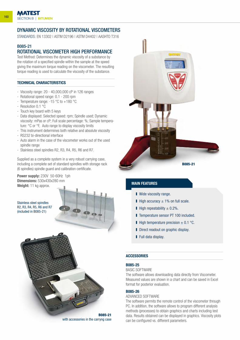
SECTION B | BITUMEN
B085-21
DYNAMIC VISCOSITY BY ROTATIONAL VISCOMETERSSTANDARDS: EN 13302 | ASTM D2196 | ASTM D4402 | AASHTO T316
B085-21ROTATIONAL VISCOMETER HIGH PERFORMANCETest Method: Determines the dynamic viscosity of a substance by the rotation of a specified spindle within the sample at the speed giving the maximum torque reading on the viscometer. The resulting torque reading is used to calculate the viscosity of the substance.
TECHNICAL CHARACTERISTICS
- Viscosity range: 20 - 40,000,000 cP in 126 ranges- Rotational speed range: 0.1 - 200 rpm- Temperature range: -15 °C to +180 °C- Resolution 0.1 °C- Touch key board with 5 keys- Data displayed: Selected speed: rpm; Spindle used; Dynamic viscosity: mPas or cP; Full scale percentage: %; Sample tempera-
ture: °C or °F, Auto range to display viscosity limits- This instrument determines both relative and absolute viscosity- RS232 bi-directional interface- Auto alarm in the case of the viscometer works out of the used
spindle range- Stainless steel spindles R2, R3, R4, R5, R6 and R7.
Supplied as a complete system in a very robust carrying case, including a complete set of standard spindles with storage rack(6 spindles) spindle guard and calibration certificate.
Power supply: 230V 50-60Hz 1phDimensions: 530x430x280 mmWeight: 11 kg approx. MAIN FEATURES
Wide viscosity range.
High accuracy ± 1% on full scale.
High repeatability ± 0.2%.
Temperature sensor PT 100 included.
High temperature precision ± 0.1 °C.
Direct readout on graphic display.
Full data display.
ACCESSORIES
B085-25BASIC SOFTWAREThe software allows downloading data directly from Viscometer. Measured values are shown in a chart and can be saved in Excel format for posterior evaluation.
B085-26ADVANCED SOFTWAREThe software permits the remote control of the viscometer through PC. In addition, the software allows to program different analysismethods (processes) to obtain graphics and charts including test data. Results obtained can be displayed in graphics. Viscosity plots can be configured vs. different parameters.
Stainless steel spindlesR2, R3, R4, R5, R6 and R7(included in B085-21)
B085-21with accessories in the carryng case
160
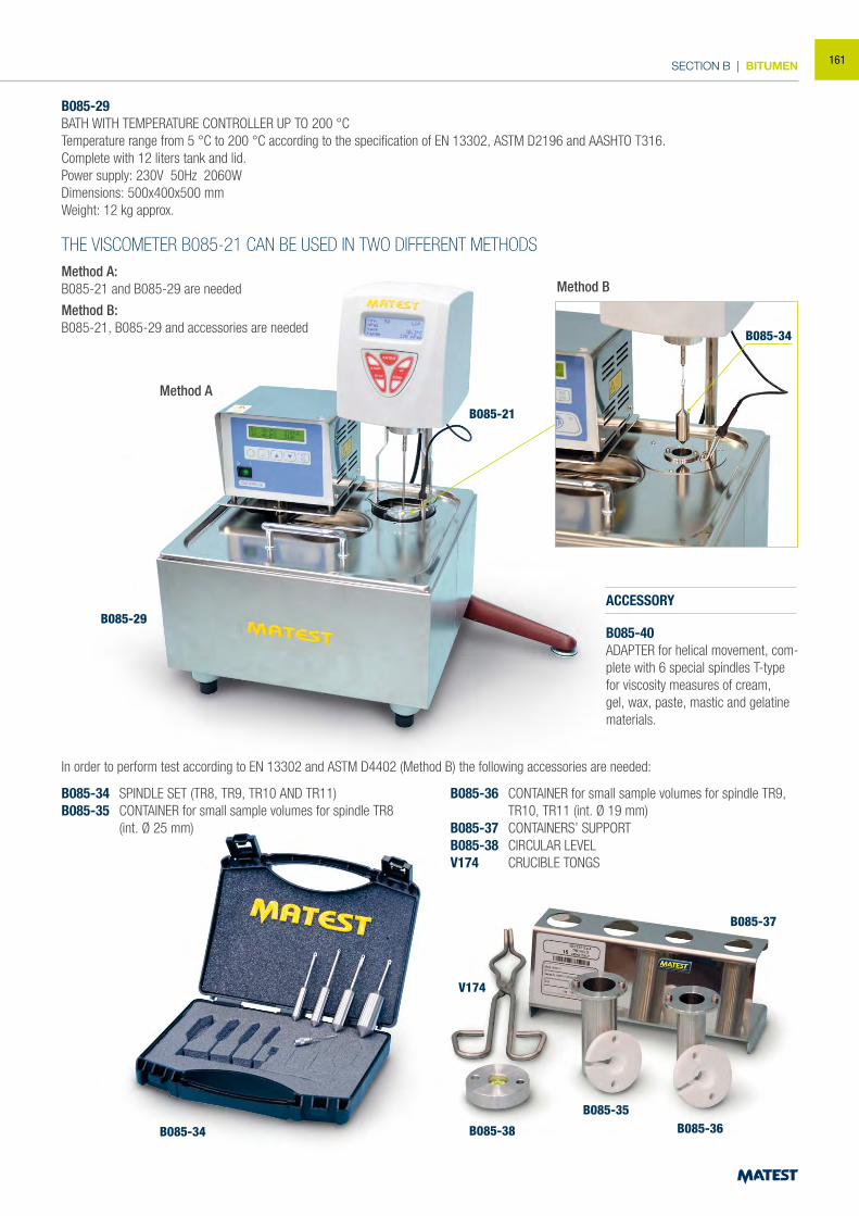
SECTION B | BITUMEN
B085-29BATH WITH TEMPERATURE CONTROLLER UP TO 200 °CTemperature range from 5 °C to 200 °C according to the specification of EN 13302, ASTM D2196 and AASHTO T316.Complete with 12 liters tank and lid.Power supply: 230V 50Hz 2060WDimensions: 500x400x500 mmWeight: 12 kg approx.
THE VISCOMETER B085-21 CAN BE USED IN TWO DIFFERENT METHODSMethod A:B085-21 and B085-29 are needed
Method B:B085-21, B085-29 and accessories are needed
In order to perform test according to EN 13302 and ASTM D4402 (Method B) the following accessories are needed:
B085-34 SPINDLE SET (TR8, TR9, TR10 AND TR11)B085-35 CONTAINER for small sample volumes for spindle TR8 (int. Ø 25 mm)
B085-36 CONTAINER for small sample volumes for spindle TR9, TR10, TR11 (int. Ø 19 mm)
B085-37 CONTAINERS’ SUPPORTB085-38 CIRCULAR LEVELV174 CRUCIBLE TONGS
B085-29
B085-34 B085-38
B085-35B085-36
B085-37
V174
Method A
Method B
B085-21
B085-34
ACCESSORY
B085-40ADAPTER for helical movement, com-plete with 6 special spindles T-type for viscosity measures of cream, gel, wax, paste, mastic and gelatine materials.
161
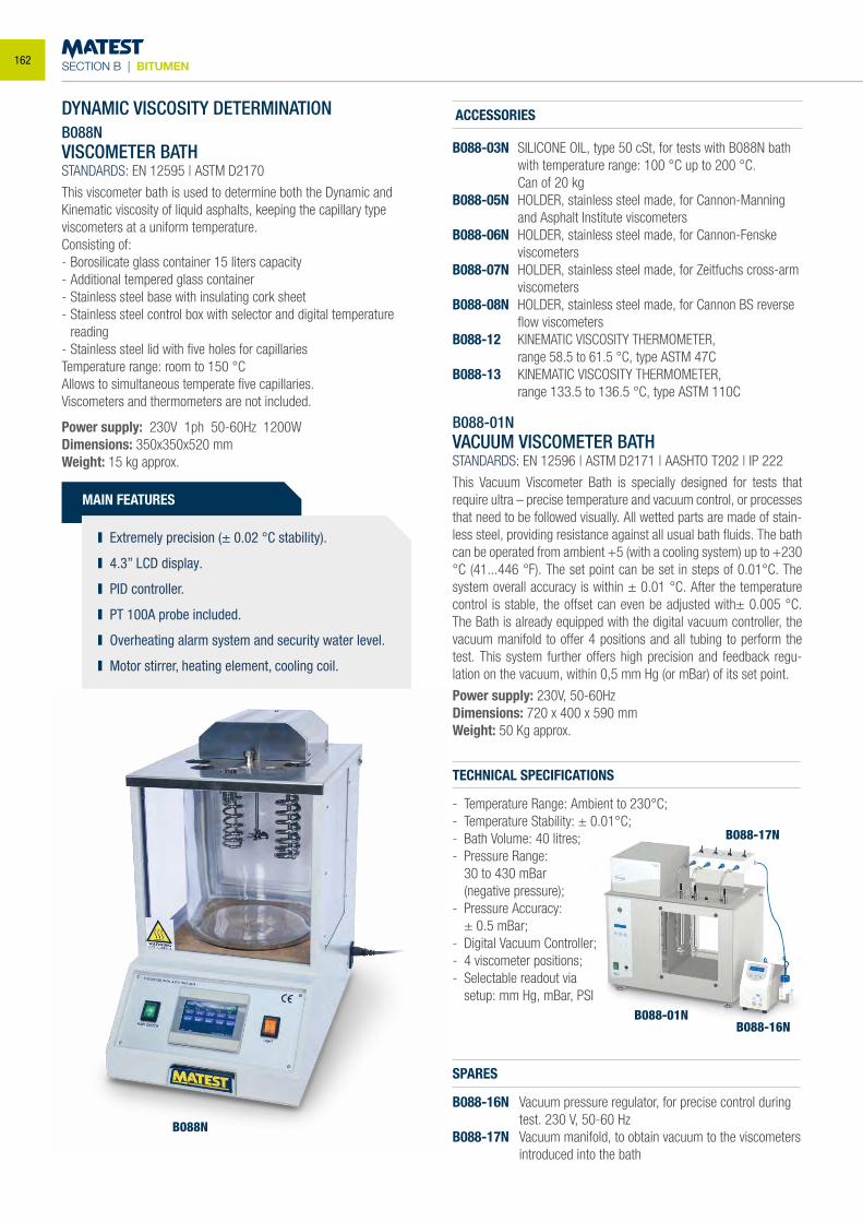
SECTION B | BITUMEN
B088N
B088-01N
B088-17N
B088-16N
DYNAMIC VISCOSITY DETERMINATIONB088NVISCOMETER BATHSTANDARDS: EN 12595 | ASTM D2170
This viscometer bath is used to determine both the Dynamic and Kinematic viscosity of liquid asphalts, keeping the capillary type viscometers at a uniform temperature.Consisting of:- Borosilicate glass container 15 liters capacity- Additional tempered glass container- Stainless steel base with insulating cork sheet- Stainless steel control box with selector and digital temperature
reading- Stainless steel lid with five holes for capillariesTemperature range: room to 150 °CAllows to simultaneous temperate five capillaries.Viscometers and thermometers are not included.
Power supply: 230V 1ph 50-60Hz 1200WDimensions: 350x350x520 mmWeight: 15 kg approx.
MAIN FEATURES
Extremely precision (± 0.02 °C stability).
4.3” LCD display.
PID controller.
PT 100A probe included.
Overheating alarm system and security water level.
Motor stirrer, heating element, cooling coil.
ACCESSORIES
B088-03N SILICONE OIL, type 50 cSt, for tests with B088N bath with temperature range: 100 °C up to 200 °C.
Can of 20 kgB088-05N HOLDER, stainless steel made, for Cannon-Manning
and Asphalt Institute viscometersB088-06N HOLDER, stainless steel made, for Cannon-Fenske
viscometersB088-07N HOLDER, stainless steel made, for Zeitfuchs cross-arm
viscometersB088-08N HOLDER, stainless steel made, for Cannon BS reverse
flow viscometersB088-12 KINEMATIC VISCOSITY THERMOMETER, range 58.5 to 61.5 °C, type ASTM 47CB088-13 KINEMATIC VISCOSITY THERMOMETER, range 133.5 to 136.5 °C, type ASTM 110C
B088-01N VACUUM VISCOMETER BATHSTANDARDS: EN 12596 | ASTM D2171 | AASHTO T202 | IP 222
This Vacuum Viscometer Bath is specially designed for tests that require ultra – precise temperature and vacuum control, or processes that need to be followed visually. All wetted parts are made of stain-less steel, providing resistance against all usual bath fluids. The bath can be operated from ambient +5 (with a cooling system) up to +230 °C (41...446 °F). The set point can be set in steps of 0.01°C. The system overall accuracy is within ± 0.01 °C. After the temperature control is stable, the offset can even be adjusted with± 0.005 °C. The Bath is already equipped with the digital vacuum controller, the vacuum manifold to offer 4 positions and all tubing to perform the test. This system further offers high precision and feedback regu-lation on the vacuum, within 0,5 mm Hg (or mBar) of its set point.
Power supply: 230V, 50-60Hz Dimensions: 720 x 400 x 590 mmWeight: 50 Kg approx.
TECHNICAL SPECIFICATIONS
- Temperature Range: Ambient to 230°C;- Temperature Stability: ± 0.01°C;- Bath Volume: 40 litres;- Pressure Range: 30 to 430 mBar (negative pressure);- Pressure Accuracy: ± 0.5 mBar;- Digital Vacuum Controller;- 4 viscometer positions;- Selectable readout via setup: mm Hg, mBar, PSI
SPARES
B088-16N Vacuum pressure regulator, for precise control during test. 230 V, 50-60 Hz
B088-17N Vacuum manifold, to obtain vacuum to the viscometers introduced into the bath
162
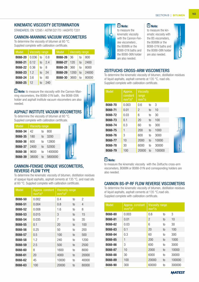
SECTION B | BITUMEN
CANNON-MANNING VACUUM VISCOMETERSTo determine the viscosity of bitumen at 60 °C.Supplied complete with calibration certificate.
Model Viscosity range
B088-20 0.036 to 0.8
B088-21 0.12 to 2.4
B088-22 0.36 to 8
B088-23 1.2 to 24
B088-24 3.6 to 80
B088-25 12 to 240
Model Viscosity range
B088-26 36 to 800
B088-27 120 to 2400
B088-28 360 to 8000
B088-29 1200 to 24000
B088-30 3600 to 80000
Note: to measure the viscosity with the Cannon-Man-ning viscometers, the B088-01N bath, the B088-05N holder and asphalt institute vacuum viscometers are also needed.
ASPHALT INSTITUTE VACUUM VISCOMETERSTo determine the viscosity of bitumen at 60 °C.Supplied complete with calibration certificate.
Model Viscosity range
B088-34 42 to 800
B088-35 180 to 3200
B088-36 600 to 12800
B088-37 2400 to 52000
B088-38 9600 to 1400000
B088-39 38000 to 5800000
CANNON-FENSKE OPAQUE VISCOMETERS, REVERSE-FLOW TYPETo determine the kinematic viscosity of bitumen, distillation residues of opaque liquid asphalts, asphalt cements at 135 °C, and road oils at 60 °C. Supplied complete with calibration certificate.
ZEITFUCHS CROSS-ARM VISCOMETERSTo determine the kinematic viscosity of bitumen, distillation residues of liquid asphalts, asphalt cements at 135 °C, road oils.Supplied complete with calibration certificate.
CANNON BS-IP-RF FLOW REVERSE VISCOMETERSTo determine the kinematic viscosity of bitumen, distillation residues of liquid asphalts, asphalt cements at 135 °C,road oils.Supplied complete with calibration certificate.
Model Approx. constantmm²/s²
Viscosity rangemm²/s²
B088-50 0.002 0.4 to 2
B088-51 0.004 0.8 to 4
B088-52 0.008 1.6 to 8
B088-53 0.015 3 to 15
B088-54 0.035 7 to 35
B088-55 0.1 20 to 100
B088-56 0.25 50 to 200
B088-57 0.5 100 to 500
B088-58 1.2 240 to 1200
B088-59 2.5 500 to 2500
B088-60 8 1600 to 8000
B088-61 20 4000 to 20000
B088-62 45 10000 to 40000
B088-63 100 20000 to 80000
Model Approx.constantmm²/s²
Viscosityrangemm²/s
B088-70 0.003 0.6 to 3
B088-71 0.01 2 to 10
B088-72 0.03 6 to 30
B088-73 0.1 20 to 100
B088-74 0.3 60 to 300
B088-75 1 200 to 1000
B088-76 3 600 to 3000
B088-77 10 2000 to 10000
B088-78 30 6000 to 30000
B088-79 100 20000 to 100000
Model Approx. constant mm²/s²
Viscosity rangemm²/s
B088-80 0.003 0.6 to 3
B088-81 0.01 2 to 10
B088-82 0.03 6 to 30
B088-83 0.1 20 to 100
B088-84 0.3 60 to 300
B088-85 1 200 to 1000
B088-86 3 600 to 3000
B088-87 10 2000 to 10000
B088-88 30 6000 to 30000
B088-89 100 20000 to 100000
B088-90 300 60000 to 300000
Note:to measure the kinematic viscosity with the Zeitfuchs cross-arm viscometers, B088N or B088-01N and corresponding holders are also needed.
Note:to measure the kinematic viscosity with the Cannon-Fen-ske viscometers , the B088N or the B088-01N baths and the B088-06N holder are also needed.
Note:to measure the kin-ematic viscosity with the BS viscometers, the B088N or the B088-01N baths and the B088-08N holder are also needed.
KINEMATIC VISCOSITY DETERMINATIONSTANDARDS: EN 12595 | ASTM D2170 | AASHTO T201
163
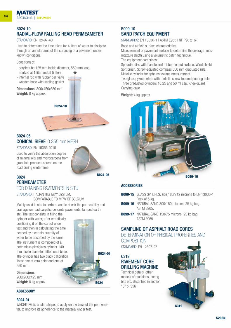
SECTION B | BITUMEN
B099-10SAND PATCH EQUIPMENTSTANDARDS: EN 13036-1 | ASTM E965 | NF P98 216-1
Road and airfield surface characteristics.Measurement of pavement surface to determine the average mac-rotexture depth using a volumetric patch technique.The equipment comprises:Spreader disc with handle and rubber coated surface. Wind shieldSoft brush. Screw-adjusted compass 500 mm graduated rule.Metallic cylinder for spheres volume measurement.Two glass pyknometers with metallic screw top and pouring holeThree graduated cylinders 10.25 and 50 ml cap. Knee-guardCarrying case
Weight: 4 kg approx.
ACCESSORIES
B099-15 GLASS SPHERES, size 180/212 microns to EN 13036-1 Pack of 5 kg.
B099-16 NATURAL SAND 300/150 microns, 25 kg bag. ASTM E965.
B099-17 NATURAL SAND 150/75 microns, 25 kg bag. ASTM E965
B099-10
S206N
B024-05
B024-10
B024
B024-01
B024-10 RADIAL-FLOW FALLING HEAD PERMEAMETER STANDARD: EN 12697-40
Used to determine the time taken for 4 liters of water to dissipate through an annular area of the surfacing of a pavement under known conditions.
Consisting of:
- acrylic tube 125 mm inside diameter, 560 mm long, marked at 1 liter and at 5 liters - internal rod with rubber ball valve - wooden base with sealing gasket
Dimensions: 800x450x680 mm Weight: 8 kg approx.
B024-05CONICAL SIEVE 0.355 mm MESHSTANDARD: EN 15366:2010
Used to verify the absorption degreeof mineral oils and hydrocarbons fromgranulate products spread on theroad during winter time.
B024PERMEAMETERFOR DRAINING PAVEMENTS IN SITUSTANDARD: ITALIAN HIGHWAY SYSTEM, COMPARABLE TO MPW OF BELGIUM
Mainly used in situ to perform and to check the permeability and drainage on road carpets, concrete pavements, tamped earth etc. The test consists in filling the cylinder with water, after ermetically positioning it on the carpet under test and then in calculating the time needed by a certain quantity of water to be absorbed by the same. The instrument is composed of a bottomless plexiglass cylinder 140 mm inside diameter, fitted on a base. The cylinder has two black calibration lines: one at zero point and one at 250 mm.
Dimensions: 260x260x425 mmWeight: 8 kg approx.
ACCESSORY
B024-01WEIGHT KG 5, anular shape, to apply on the base of the permeme-ter, to improve its adherence to the material under test.
C319PAVEMENT CORE DRILLING MACHINETechnical details, other models of machines, coring bits etc. described in section “C” p. 356
C319
SAMPLING OF ASPHALT ROAD CORESDETERMINATION OF PHISICAL PROPERTIES AND COMPOSITIONSTANDARD: EN 12697-27
164
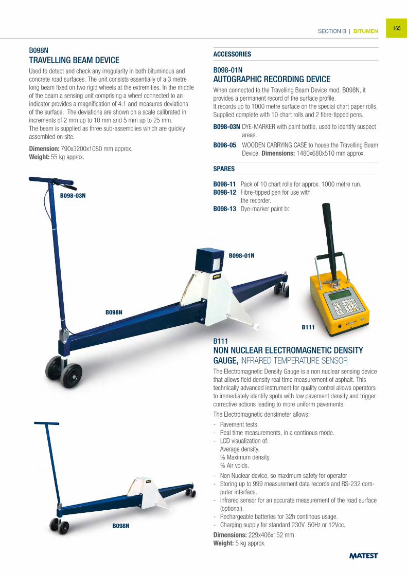
SECTION B | BITUMEN
S206N
B098N
TRAVELLING BEAM DEVICE Used to detect and check any irregularity in both bituminous and concrete road surfaces. The unit consists essentially of a 3 metre long beam fixed on two rigid wheels at the extremities. In the middle of the beam a sensing unit comprising a wheel connected to an indicator provides a magnification of 4:1 and measures deviations of the surface. The deviations are shown on a scale calibrated in increments of 2 mm up to 10 mm and 5 mm up to 25 mm. The beam is supplied as three sub-assemblies which are quickly assembled on site.
Dimension: 790x3200x1080 mm approx.Weight: 55 kg approx.
ACCESSORIES
B098-01NAUTOGRAPHIC RECORDING DEVICEWhen connected to the Travelling Beam Device mod. B098N, it provides a permanent record of the surface profile.It records up to 1000 metre surface on the special chart paper rolls.Supplied complete with 10 chart rolls and 2 fibre-tipped pens.
B098-03N DYE-MARKER with paint bottle, used to identify suspect areas.
B098-05 WOODEN CARRYING CASE to house the Travelling Beam Device. Dimensions: 1480x680x510 mm approx.
SPARES
B098-11 Pack of 10 chart rolls for approx. 1000 metre run.B098-12 Fibre-tipped pen for use with the recorder.B098-13 Dye-marker paint bottle.
B111NON NUCLEAR ELECTROMAGNETIC DENSITY GAUGE, INFRARED TEMPERATURE SENSORThe Electromagnetic Density Gauge is a non nuclear sensing device that allows field density real time measurement of asphalt. This technically advanced instrument for quality control allows operators to immediately identify spots with low pavement density and trigger corrective actions leading to more uniform pavements.
The Electromagnetic densimeter allows:
- Pavement tests.- Real time measurements, in a continous mode.- LCD visualization of:
Average density.% Maximum density.% Air voids.
- Non Nuclear device, so maximum safety for operator - Storing up to 999 measurement data records and RS-232 com-
puter interface.- Infrared sensor for an accurate measurement of the road surface
(optional).- Rechargeable batteries for 32h continous usage. - Charging supply for standard 230V 50Hz or 12Vcc.
Dimensions: 229x406x152 mmWeight: 5 kg approx.
B098-03N
B098N
B111
B098N
B098-01N
165
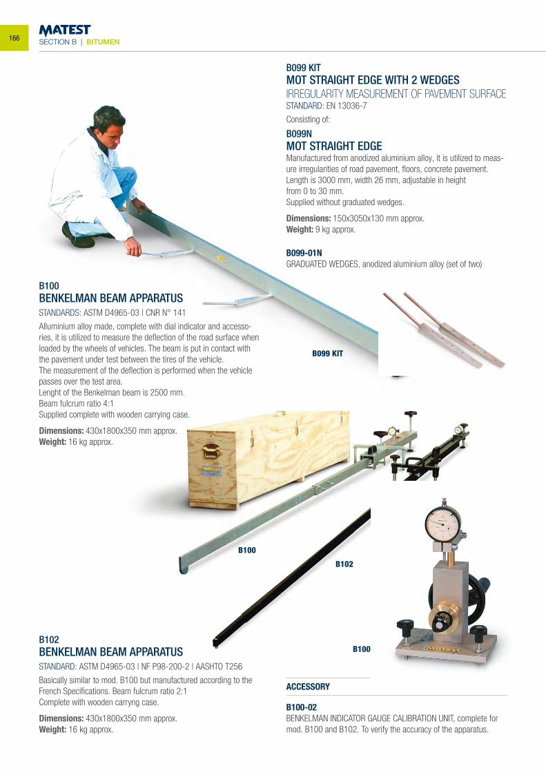
SECTION B | BITUMEN
B099 KIT
B100
B102
B100-02
B099-01N
B100BENKELMAN BEAM APPARATUSSTANDARDS: ASTM D4965-03 | CNR N° 141
Alluminium alloy made, complete with dial indicator and accesso-ries, it is utilized to measure the deflection of the road surface when loaded by the wheels of vehicles. The beam is put in contact with the pavement under test between the tires of the vehicle. The measurement of the deflection is performed when the vehicle passes over the test area.Lenght of the Benkelman beam is 2500 mm.Beam fulcrum ratio 4:1Supplied complete with wooden carrying case.
Dimensions: 430x1800x350 mm approx.Weight: 16 kg approx.
B099 KITMOT STRAIGHT EDGE WITH 2 WEDGESIRREGULARITY MEASUREMENT OF PAVEMENT SURFACESTANDARD: EN 13036-7
Consisting of:
B099NMOT STRAIGHT EDGEManufactured from anodized aluminium alloy, it is utilized to meas-ure irregularities of road pavement, floors, concrete pavement.Length is 3000 mm, width 26 mm, adjustable in heightfrom 0 to 30 mm.Supplied without graduated wedges.
Dimensions: 150x3050x130 mm approx.Weight: 9 kg approx.
B102BENKELMAN BEAM APPARATUSSTANDARD: ASTM D4965-03 | NF P98-200-2 | AASHTO T256
Basically similar to mod. B100 but manufactured according to the French Specifications. Beam fulcrum ratio 2:1Complete with wooden carryng case.
Dimensions: 430x1800x350 mm approx.Weight: 16 kg approx.
ACCESSORY
B100-02BENKELMAN INDICATOR GAUGE CALIBRATION UNIT, complete for mod. B100 and B102. To verify the accuracy of the apparatus.
B099-01NGRADUATED WEDGES, anodized aluminium alloy (set of two)
166
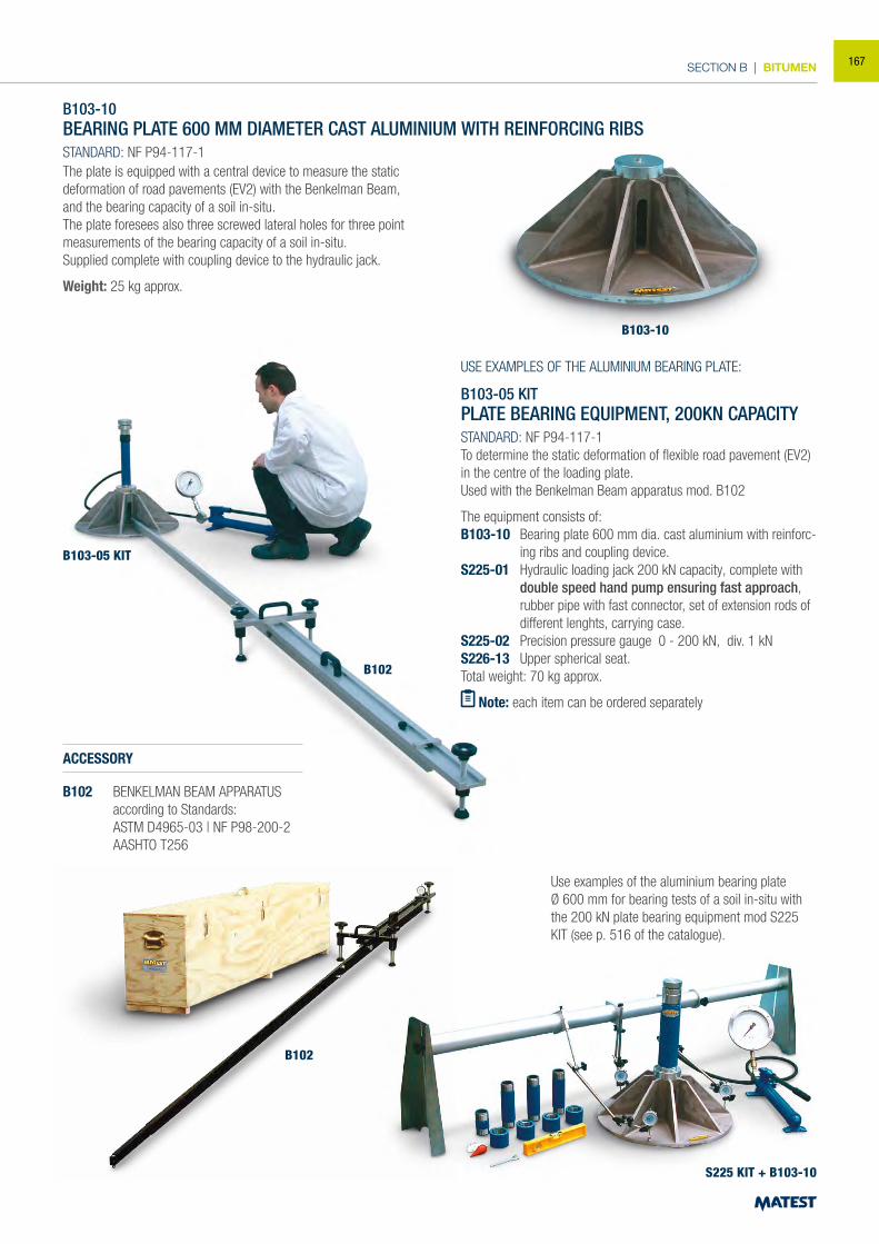
SECTION B | BITUMEN
B103-10BEARING PLATE 600 MM DIAMETER CAST ALUMINIUM WITH REINFORCING RIBSSTANDARD: NF P94-117-1
ACCESSORY
B102 BENKELMAN BEAM APPARATUS according to Standards:
ASTM D4965-03 | NF P98-200-2 AASHTO T256
USE EXAMPLES OF THE ALUMINIUM BEARING PLATE:
B103-05 KITPLATE BEARING EQUIPMENT, 200KN CAPACITYSTANDARD: NF P94-117-1To determine the static deformation of flexible road pavement (EV2) in the centre of the loading plate.Used with the Benkelman Beam apparatus mod. B102
The equipment consists of:B103-10 Bearing plate 600 mm dia. cast aluminium with reinforc-
ing ribs and coupling device.S225-01 Hydraulic loading jack 200 kN capacity, complete with
double speed hand pump ensuring fast approach, rubber pipe with fast connector, set of extension rods of different lenghts, carrying case.
S225-02 Precision pressure gauge 0 - 200 kN, div. 1 kNS226-13 Upper spherical seat.Total weight: 70 kg approx.
Note: each item can be ordered separately
Use examples of the aluminium bearing plateØ 600 mm for bearing tests of a soil in-situ with the 200 kN plate bearing equipment mod S225 KIT (see p. 516 of the catalogue).
B103-10
B103-05 KIT
B102
S225 KIT + B103-10
The plate is equipped with a central device to measure the static deformation of road pavements (EV2) with the Benkelman Beam, and the bearing capacity of a soil in-situ.The plate foresees also three screwed lateral holes for three point measurements of the bearing capacity of a soil in-situ.Supplied complete with coupling device to the hydraulic jack.
Weight: 25 kg approx.
B102
167
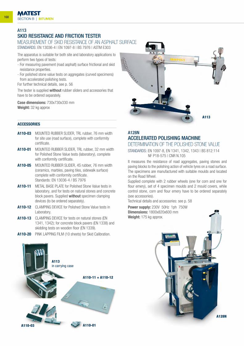
SECTION B | BITUMEN
A113SKID RESISTANCE AND FRICTION TESTERMEASUREMENT OF SKID RESISTANCE OF AN ASPHALT SURFACESTANDARDS: EN 13036-4 | EN 1097-8 | BS 7976 | ASTM E303
The apparatus is suitable for both site and laboratory applications to perform two types of tests:- For measuring pavement (road asphalt) surface frictional and skid
resistance properties.- For polished stone value tests on aggregates (curved specimens)
from accelerated polishing tests.For further technical details, see p. 56
The tester is supplied without rubber sliders and accessories that have to be ordered separately.
Case dimensions: 730x730x330 mmWeight: 32 kg approx
ACCESSORIES
A110-03 MOUNTED RUBBER SLIDER, TRL rubber, 76 mm width for site use (road surface), complete with conformity certificate.
A110-01 MOUNTED RUBBER SLIDER, TRL rubber, 32 mm width for Polished Stone Value tests (laboratory), complete with conformity certificate.
A110-05 MOUNTED RUBBER SLIDER, 4S rubber, 76 mm width (ceramics, marbles, paving tiles, sidewalk surface) complete with conformity certificate.
Standards: EN 13036-4 / BS 7976
A110-11 METAL BASE PLATE for Polished Stone Value tests in laboratory, and for tests on natural stones and concrete block pavers. Supplied without specimen clamping devices (to be ordered separately).
A110-12 CLAMPING DEVICE for Polished Stone Value tests in Laboratory.
A110-13 CLAMPING DEVICE for tests on natural stones (EN 1341, 1342); for concrete block pavers (EN 1338) and skidding tests on wooden floor (EN 1339).
A110-20 PINK LAPPING FILM (10 sheets) for Skid Calibration.
A113
A110-11 + A110-12
A110-01
A128N
A110-03
A113in carrying case
A128NACCELERATED POLISHING MACHINEDETERMINATION OF THE POLISHED STONE VALUE
STANDARDS: EN 1097-8, EN 1341, 1342, 1343 | BS 812:114 NF P18-575 | CNR N.105It measures the resistance of road aggregates, paving stones and paving blocks to the polishing action of vehicle tyres on a road surface.The specimens are manufactured with suitable moulds and located on the Road Wheel.Supplied complete with 2 rubber wheels (one for corn and one for flour emery), set of 4 specimen moulds and 2 mould covers, while control stone, corn and flour emery have to be ordered separately (see accessories).Technical details and accessories: see p. 58
Power supply: 230V 50Hz 1ph 750WDimensions: 1800x820x600 mmWeight: 175 kg approx.
168
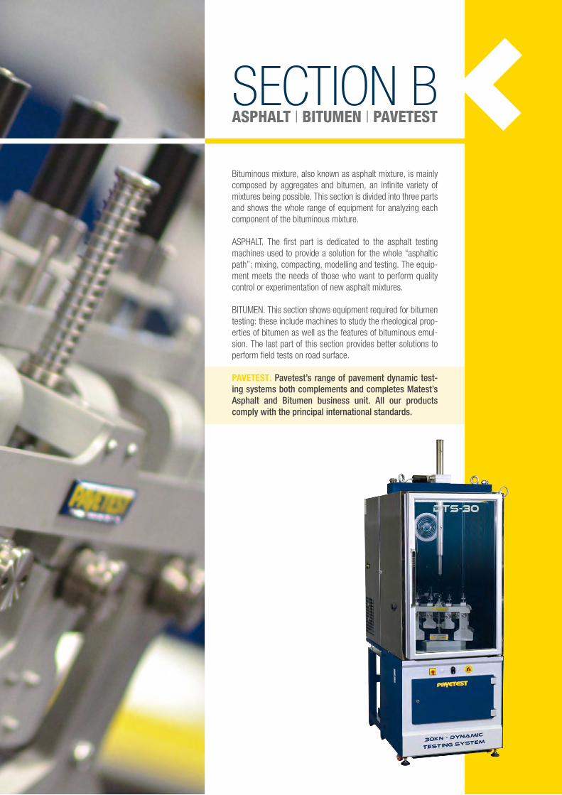
SECTION BASPHALT | BITUMEN | PAVETEST
Bituminous mixture, also known as asphalt mixture, is mainly composed by aggregates and bitumen, an infinite variety of mixtures being possible. This section is divided into three parts and shows the whole range of equipment for analyzing each component of the bituminous mixture.
ASPHALT. The first part is dedicated to the asphalt testing machines used to provide a solution for the whole “asphaltic path”: mixing, compacting, modelling and testing. The equip-ment meets the needs of those who want to perform quality control or experimentation of new asphalt mixtures.
BITUMEN. This section shows equipment required for bitumen testing: these include machines to study the rheological prop-erties of bitumen as well as the features of bituminous emul-sion. The last part of this section provides better solutions to perform field tests on road surface.
PAVETEST. Pavetest’s range of pavement dynamic test-ing systems both complements and completes Matest’s Asphalt and Bitumen business unit. All our products comply with the principal international standards.
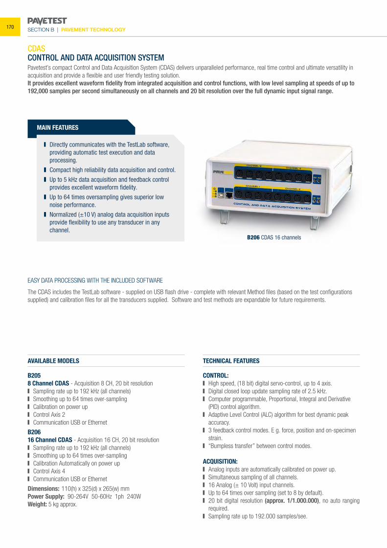
SECTION B | PAVEMENT TECHNOLOGY
CDASCONTROL AND DATA ACQUISITION SYSTEM Pavetest’s compact Control and Data Acquisition System (CDAS) delivers unparalleled performance, real time control and ultimate versatility in acquisition and provide a flexible and user friendly testing solution.It provides excellent waveform fidelity from integrated acquisition and control functions, with low level sampling at speeds of up to 192,000 samples per second simultaneously on all channels and 20 bit resolution over the full dynamic input signal range.
AVAILABLE MODELS
B2058 Channel CDAS - Acquisition 8 CH, 20 bit resolution Sampling rate up to 192 kHz (all channels) Smoothing up to 64 times over-sampling Calibration on power up Control Axis 2 Communication USB or Ethernet
B20616 Channel CDAS - Acquisition 16 CH, 20 bit resolution Sampling rate up to 192 kHz (all channels) Smoothing up to 64 times over-sampling Calibration Automatically on power up Control Axis 4 Communication USB or Ethernet
Dimensions: 110(h) x 325(d) x 265(w) mmPower Supply: 90-264V 50-60Hz 1ph 240WWeight: 5 kg approx.
TECHNICAL FEATURES
CONTROL: High speed, (18 bit) digital servo-control, up to 4 axis. Digital closed loop update sampling rate of 2.5 kHz. Computer programmable, Proportional, Integral and Derivative
(PID) control algorithm. Adaptive Level Control (ALC) algorithm for best dynamic peak
accuracy. 3 feedback control modes. E g. force, position and on-specimen
strain. “Bumpless transfer” between control modes.
ACQUISITION: Analog inputs are automatically calibrated on power up. Simultaneous sampling of all channels. 16 Analog (± 10 Volt) input channels. Up to 64 times over sampling (set to 8 by default). 20 bit digital resolution (approx. 1/1.000.000), no auto ranging
required. Sampling rate up to 192.000 samples/see.
MAIN FEATURES
Directly communicates with the TestLab software, providing automatic test execution and data processing.
Compact high reliability data acquisition and control. Up to 5 kHz data acquisition and feedback control
provides excellent waveform fidelity. Up to 64 times oversampling gives superior low
noise performance. Normalized (±10 V) analog data acquisition inputs
provide flexibility to use any transducer in any channel.
B206 CDAS 16 channels
EASY DATA PROCESSING WITH THE INCLUDED SOFTWARE
The CDAS includes the TestLab software - supplied on USB flash drive - complete with relevant Method files (based on the test configurations supplied) and calibration files for all the transducers supplied. Software and test methods are expandable for future requirements.
170
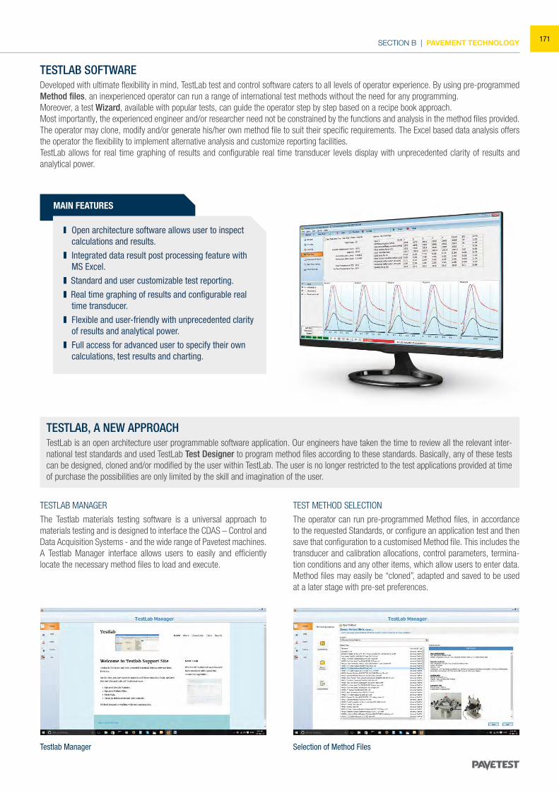
SECTION B | PAVEMENT TECHNOLOGY
MAIN FEATURES
Open architecture software allows user to inspect calculations and results.
Integrated data result post processing feature with MS Excel.
Standard and user customizable test reporting. Real time graphing of results and configurable real
time transducer. Flexible and user-friendly with unprecedented clarity
of results and analytical power. Full access for advanced user to specify their own
calculations, test results and charting.
TESTLAB SOFTWAREDeveloped with ultimate flexibility in mind, TestLab test and control software caters to all levels of operator experience. By using pre-programmed Method files, an inexperienced operator can run a range of international test methods without the need for any programming. Moreover, a test Wizard, available with popular tests, can guide the operator step by step based on a recipe book approach.Most importantly, the experienced engineer and/or researcher need not be constrained by the functions and analysis in the method files provided. The operator may clone, modify and/or generate his/her own method file to suit their specific requirements. The Excel based data analysis offers the operator the flexibility to implement alternative analysis and customize reporting facilities.TestLab allows for real time graphing of results and configurable real time transducer levels display with unprecedented clarity of results and analytical power.
Testlab Manager Selection of Method Files
TESTLAB, A NEW APPROACHTestLab is an open architecture user programmable software application. Our engineers have taken the time to review all the relevant inter-national test standards and used TestLab Test Designer to program method files according to these standards. Basically, any of these tests can be designed, cloned and/or modified by the user within TestLab. The user is no longer restricted to the test applications provided at time of purchase the possibilities are only limited by the skill and imagination of the user.
TESTLAB MANAGER
The Testlab materials testing software is a universal approach to materials testing and is designed to interface the CDAS – Control and Data Acquisition Systems - and the wide range of Pavetest machines. A Testlab Manager interface allows users to easily and efficiently locate the necessary method files to load and execute.
TEST METHOD SELECTION
The operator can run pre-programmed Method files, in accordance to the requested Standards, or configure an application test and then save that configuration to a customised Method file. This includes the transducer and calibration allocations, control parameters, termina-tion conditions and any other items, which allow users to enter data. Method files may easily be “cloned”, adapted and saved to be used at a later stage with pre-set preferences.
171
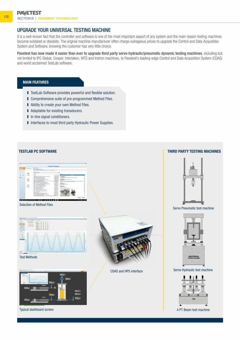
SECTION B | PAVEMENT TECHNOLOGY
UPGRADE YOUR UNIVERSAL TESTING MACHINE It is a well-known fact that the controller and software is one of the most important aspect of any system and the main reason testing machines become outdated or obsolete. The original machine manufacturer often charge outrageous prices to upgrade the Control and Data Acquisition System and Software, knowing the customer has very little choice.
Pavetest has now made it easier than ever to upgrade third party servo-hydraulic/pneumatic dynamic testing machines, including but not limited to IPC Global, Cooper, Interlaken, MTS and Instron machines, to Pavetest’s leading-edge Control and Data Acquisition System (CDAS) and world acclaimed TestLab software.
MAIN FEATURES
TestLab Software provides powerful and flexible solution. Comprehensive suite of pre-programmed Method Files. Ability to create your own Method Files. Adaptable for existing transducers. In-line signal conditioners. Interfaces to most third party Hydraulic Power Supplies.
CDAS and HPS interface Servo Hydraulic test machine
4 PT Beam test machine
Selection of Method Files
Test Methods
TESTLAB PC SOFTWARE THIRD PARTY TESTING MACHINES
Typical dashboard screen
Servo Pneumatic test machine
172
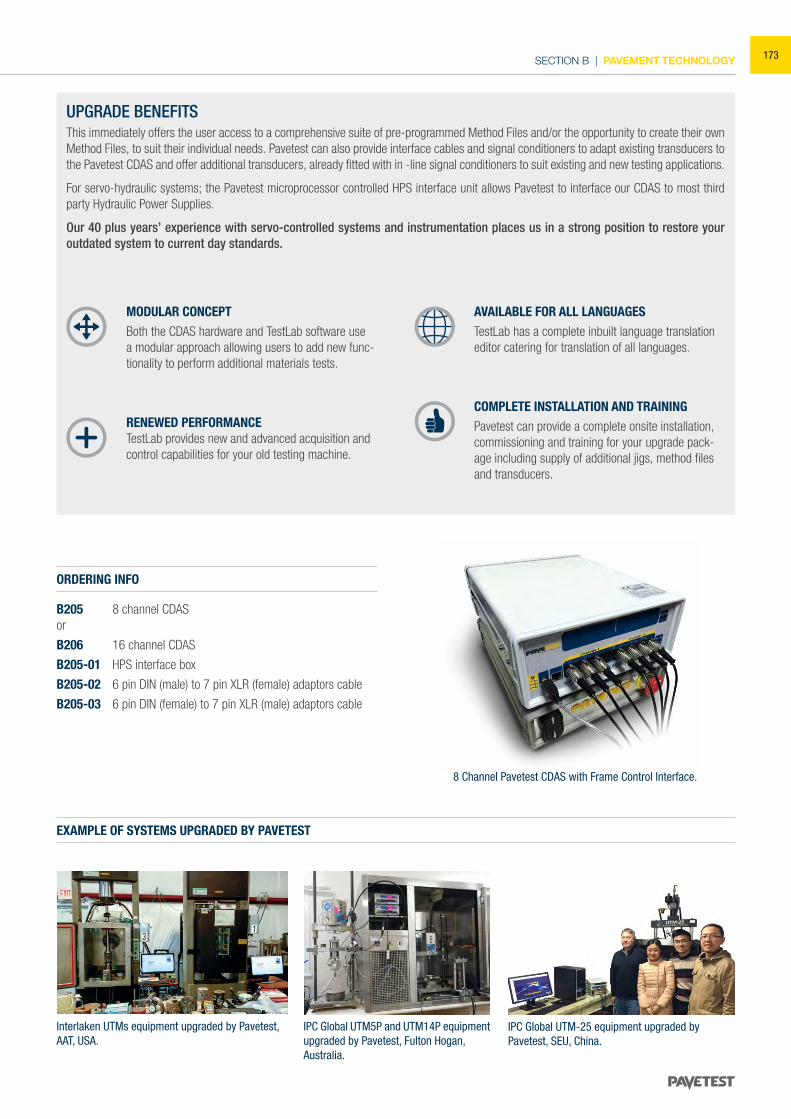
SECTION B | PAVEMENT TECHNOLOGY
IPC Global UTM5P and UTM14P equipment upgraded by Pavetest, Fulton Hogan,Australia.
UPGRADE BENEFITS This immediately offers the user access to a comprehensive suite of pre-programmed Method Files and/or the opportunity to create their own Method Files, to suit their individual needs. Pavetest can also provide interface cables and signal conditioners to adapt existing transducers to the Pavetest CDAS and offer additional transducers, already fitted with in -line signal conditioners to suit existing and new testing applications.
For servo-hydraulic systems; the Pavetest microprocessor controlled HPS interface unit allows Pavetest to interface our CDAS to most third party Hydraulic Power Supplies.
Our 40 plus years’ experience with servo-controlled systems and instrumentation places us in a strong position to restore your outdated system to current day standards.
MODULAR CONCEPTBoth the CDAS hardware and TestLab software use a modular approach allowing users to add new func-tionality to perform additional materials tests.
RENEWED PERFORMANCETestLab provides new and advanced acquisition and control capabilities for your old testing machine.
AVAILABLE FOR ALL LANGUAGESTestLab has a complete inbuilt language translation editor catering for translation of all languages.
COMPLETE INSTALLATION AND TRAININGPavetest can provide a complete onsite installation, commissioning and training for your upgrade pack-age including supply of additional jigs, method files and transducers.
Interlaken UTMs equipment upgraded by Pavetest,AAT, USA.
IPC Global UTM-25 equipment upgraded byPavetest, SEU, China.
ORDERING INFO
B205 8 channel CDASor
B206 16 channel CDAS
B205-01 HPS interface box
B205-02 6 pin DIN (male) to 7 pin XLR (female) adaptors cable
B205-03 6 pin DIN (female) to 7 pin XLR (male) adaptors cable
EXAMPLE OF SYSTEMS UPGRADED BY PAVETEST
8 Channel Pavetest CDAS with Frame Control Interface.
173
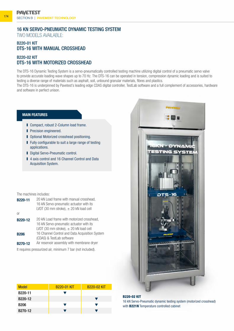
SECTION B | PAVEMENT TECHNOLOGY
MAIN FEATURES
16 KN SERVO-PNEUMATIC DYNAMIC TESTING SYSTEMTWO MODELS AVAILABLE:
B220-01 KITDTS-16 WITH MANUAL CROSSHEAD
B220-02 KITDTS-16 WITH MOTORIZED CROSSHEAD
The DTS-16 Dynamic Testing System is a servo-pneumatically controlled testing machine utilizing digital control of a pneumatic servo valve to provide accurate loading wave shapes up to 70 Hz. The DTS-16 can be operated in tension, compression dynamic loading and is suited to testing a diverse range of materials such as asphalt, soil, unbound granular materials, fibres and plastics. The DTS-16 is underpinned by Pavetest’s leading edge CDAS digital controller, TestLab software and a full complement of accessories, hardware and software in perfect unison.
The machines includes:
B220-11 20 kN Load frame with manual crosshead, 16 kN Servo-pneumatic actuator with its LVDT (30 mm stroke), ± 20 kN load cellor
B220-12 20 kN Load frame with motorized crosshead, 16 kN Servo-pneumatic actuator with its LVDT (30 mm stroke), ± 20 kN load cell B206 16 Channel Control and Data Acquisition System (CDAS) & TestLab softwareB270-12 Air reservoir assembly with membrane dryer
It requires pressurized air, minimum 7 bar (not included).
Model B220-01 KIT B220-02 KIT
B220-11
B220-12
B206
B270-12
Compact, robust 2-Column load frame. Precision engineered. Optional Motorized crosshead positioning. Fully configurable to suit a large range of testing
applications. Digital Servo-Pneumatic control. 4 axis control and 16 Channel Control and Data
Acquisition System.
B220-02 KIT16 kN Servo-Pneumatic dynamic testing system (motorized crosshead) with B221N Temperature controlled cabinet
174
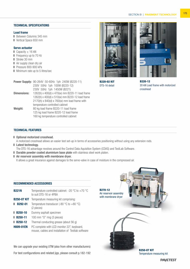
SECTION B | PAVEMENT TECHNOLOGY
TECHNICAL SPECIFICATIONS
Load frame Between Columns 345 mm Vertical Space 650 mm
Servo actuator Capacity ± 16 kN Frequency up to 70 Hz Stroke 30 mm Air supply clean dry air Pressure 800-900 kPa Minimum rate up to 5 litres/sec
Power Supply: 90-264V 50-60Hz 1ph 240W (B220-11) 230V 50Hz 1ph 100W (B220-12) 230V 50Hz 1ph 1450W (B221)Dimensions: 1262(h) x 400(d) x 470(w) mm B220-11 load frame 1262(h) x 400(d) x 510(w) mm B220-12 load frame 2170(h) x 840(d) x 760(w) mm load frame with temperature controlled cabinetWeight: 80 kg load frame B220-11 load frame 125 kg load frame B220-12 load frame 160 kg temperature controlled cabinet
For test configurations and related jigs, please consult p.182-192
RECOMMENDED ACCESSORIES
B221N Temperature controlled cabinet: -20 °C to +70 °C to suit DTS-16 or 4PBA
B250-07 KIT Temperature measuring kit comprising:
B292-01 Temperature transducer (-80 °C to +80 °C) (2 pieces)
B250-10 Dummy asphalt specimen
B250-11 100 mm “O” ring (3 pieces)
B250-12 Thermal conducting grease (about 56 g)
H009-01EN PC complete with LCD monitor 22”, keyboard, mouse, cables and installation of Testlab software
TECHNICAL FEATURES
Optional motorized crosshead. A motorized crosshead allows an easier test set-up in terms of accessories positioning without using any extension rods. Latest technology.
The DTS-16 advantage revolves around the Control Data Aquisition System (CDAS) and TestLab Software. Durable powder coated aluminium base plate with stainless steel work platen. Air reservoir assembly with membrane dryer.
It allows a great insurance against damages to the servo-valve in case of moisture in the compressed air.
We can upgrade your existing UTM (also from other manufacturers)
B220-02 KITDTS-16 detail
B220-1220 kN Load frame with motorized crosshead
B270-12Air reservoir assembly with membrane dryer
B250-07 KITTemperature measuring kit
175
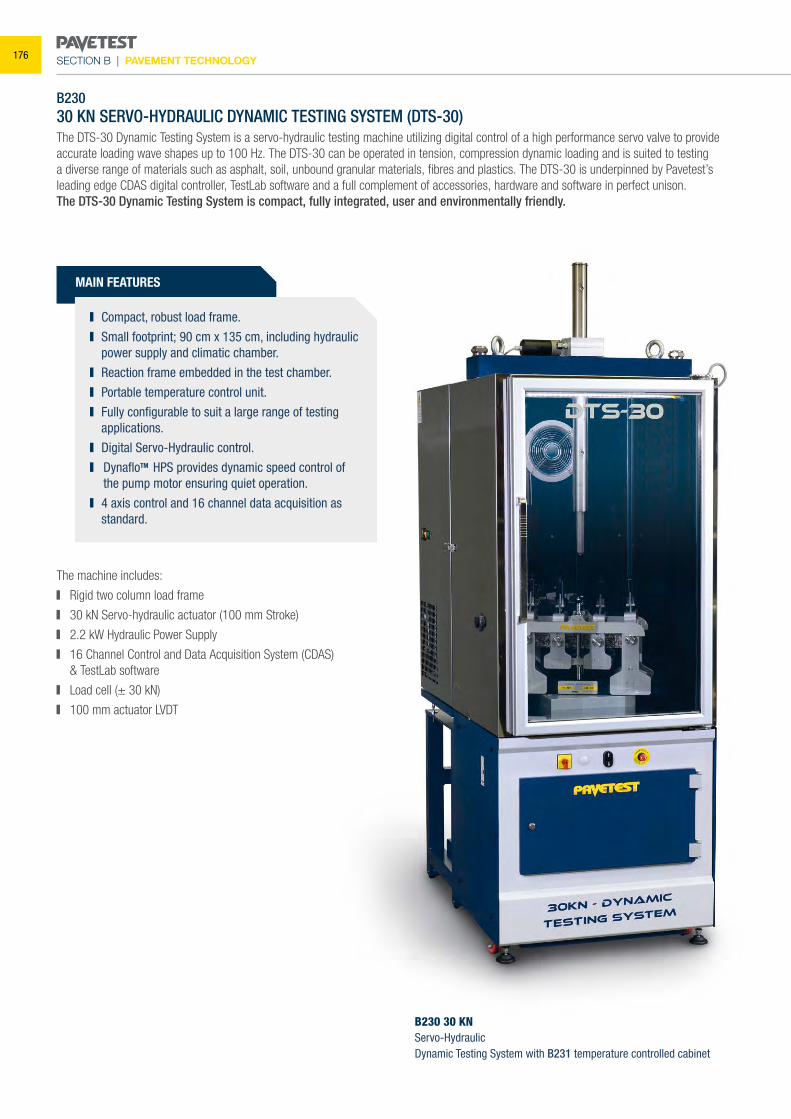
SECTION B | PAVEMENT TECHNOLOGY
B23030 KN SERVO-HYDRAULIC DYNAMIC TESTING SYSTEM (DTS-30) The DTS-30 Dynamic Testing System is a servo-hydraulic testing machine utilizing digital control of a high performance servo valve to provide accurate loading wave shapes up to 100 Hz. The DTS-30 can be operated in tension, compression dynamic loading and is suited to testing a diverse range of materials such as asphalt, soil, unbound granular materials, fibres and plastics. The DTS-30 is underpinned by Pavetest’s leading edge CDAS digital controller, TestLab software and a full complement of accessories, hardware and software in perfect unison.The DTS-30 Dynamic Testing System is compact, fully integrated, user and environmentally friendly.
The machine includes:
Rigid two column load frame
30 kN Servo-hydraulic actuator (100 mm Stroke)
2.2 kW Hydraulic Power Supply
16 Channel Control and Data Acquisition System (CDAS) & TestLab software
Load cell (± 30 kN)
100 mm actuator LVDT
B230 30 KNServo-HydraulicDynamic Testing System with B231 temperature controlled cabinet
MAIN FEATURES
Compact, robust load frame. Small footprint; 90 cm x 135 cm, including hydraulic
power supply and climatic chamber. Reaction frame embedded in the test chamber. Portable temperature control unit. Fully configurable to suit a large range of testing
applications. Digital Servo-Hydraulic control. DynafloTM HPS provides dynamic speed control of
the pump motor ensuring quiet operation. 4 axis control and 16 channel data acquisition as
standard.
176
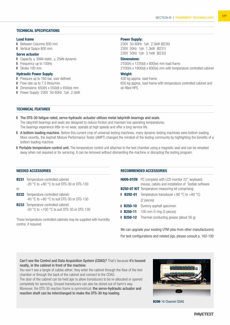
SECTION B | PAVEMENT TECHNOLOGY
NEEDED ACCESSORIES
B231 Temperature controlled cabinet: -20 °C to +80 °C to suit DTS-30 or DTS-130or
B232 Temperature controlled cabinet: -40 °C to +80 °C to suit DTS-30 or DTS-130
B233 Temperature controlled cabinet: -50 °C to +100 °C to suit DTS-30 or DTS-130
RECOMMENDED ACCESSORIES
H009-01EN PC complete with LCD monitor 22”, keyboard, mouse, cables and installation of Testlab software
B250-07 KIT Temperature measuring kit comprising:
B292-01 Temperature transducer (-80 °C to +80 °C)
(2 pieces)
B250-10 Dummy asphalt specimen
B250-11 100 mm O ring (3 pieces)
B250-12 Thermal conducting grease (about 56 g)
For test configurations and related jigs, please consult p. 182-192
We can upgrade your existing UTM (also from other manufacturers)
Can’t see the Control and Data Acquisition System (CDAS)? That’s because it’s housed neatly, in the cabinet in front of the machine.You won’t see a tangle of cables either; they enter the cabinet through the floor of the test chamber or through the back of the cabinet and connect to the CDAS.The door of the cabinet can be held ajar to allow transducers to be re-allocated or opened completely for servicing. Unused transducers can also be stored out of harm’s way.Moreover, the DTS-30 reaction frame is symmetrical; the servo-hydraulic actuator and reaction shaft can be interchanged to make the DTS-30 top loading.
B206 16 Channel CDAS
TECHNICAL SPECIFICATIONS
Load frame Between Columns 600 mm Vertical Space 800 mm
Servo actuator Capacity ± 30kN static, ± 25kN dynamic Frequency up to 100Hz Stroke 100 mm
Hydraulic Power Supply Pressure up to 160 bar, user defined Flow rate up to 7.5 litres/min Dimensions: 650(h) x 550(d) x 450(w) mm Power Supply: 230V 50-60Hz 1ph 2.5kW
Power Supply:230V 50-60Hz 1ph 2.5kW (B230)230V 50Hz 1ph 1.3kW (B231)230V 50Hz 1ph 3.1kW (B232)
Dimensions:2100(h) x 1220(d) x 800(w) mm load frame 2100(h) x 1800(d) x 800(w) mm with temperature controlled cabinet
Weight: 430 kg approx. load frame650 kg approx. load frame with temperature controlled cabinet andoil-filled HPS
TECHNICAL FEATURES
The DTS-30 fatigue rated, servo-hydraulic actuator utilizes metal labyrinth bearings and seals. The labyrinth bearings and seals are designed to reduce friction and maintain low operating temperatures. The bearings experience little-to-no wear, operate at high speeds and offer a long service life.
A bottom loading machine. Before this current crop of universal testing machines, many dynamic testing machines were bottom loading. More recently, the Asphalt Mixture Performance Tester (AMPT) changed the mindset of the testing community by highlighting the benefits of a bottom loading machine.
Portable temperature control unit. The temperature control unit attaches to the test chamber using a magnetic seal and can be wheeled away when not required or for servicing. It can be removed without dismantling the machine or disrupting the testing program.
These temperature controlled cabinets may be supplied with humidity control, if required.
177
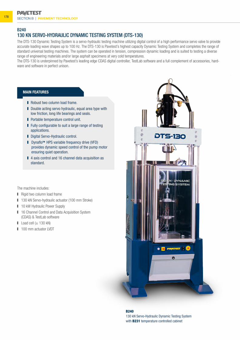
SECTION B | PAVEMENT TECHNOLOGY
B240130 KN SERVO-HYDRAULIC DYNAMIC TESTING SYSTEM (DTS-130)The DTS-130 Dynamic Testing System is a servo-hydraulic testing machine utilizing digital control of a high performance servo valve to provide accurate loading wave shapes up to 100 Hz. The DTS-130 is Pavetest’s highest capacity Dynamic Testing System and completes the range of standard universal testing machines. The system can be operated in tension, compression dynamic loading and is suited to testing a diverse range of engineering materials and/or large asphalt specimens at very cold temperatures.The DTS-130 is underpinned by Pavetest’s leading edge CDAS digital controller, TestLab software and a full complement of accessories, hard-ware and software in perfect unison.
The machine includes:
Rigid two column load frame
130 kN Servo-hydraulic actuator (100 mm Stroke)
10 kW Hydraulic Power Supply
16 Channel Control and Data Acquisition System (CDAS) & TestLab software
Load cell (± 130 kN)
100 mm actuator LVDT
B240130 kN Servo-Hydraulic Dynamic Testing Systemwith B231 temperature controlled cabinet
MAIN FEATURES
Robust two column load frame. Double acting servo hydraulic, equal area type with
low friction, long life bearings and seals. Portable temperature control unit. Fully configurable to suit a large range of testing
applications. Digital Servo-Hydraulic control. DynafloTM HPS variable frequency drive (VFD)
provides dynamic speed control of the pump motor ensuring quiet operation.
4 axis control and 16 channel data acquisition as standard.
178
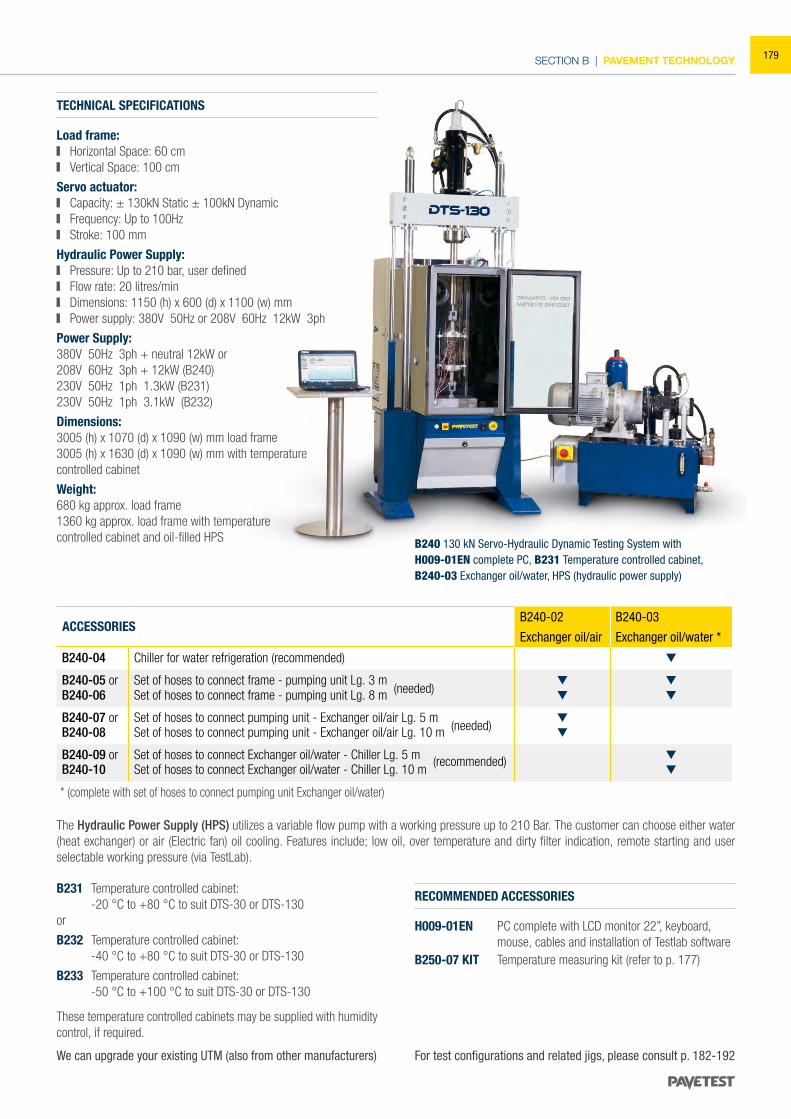
SECTION B | PAVEMENT TECHNOLOGY
* (complete with set of hoses to connect pumping unit Exchanger oil/water)
For test configurations and related jigs, please consult p. 182-192We can upgrade your existing UTM (also from other manufacturers)
RECOMMENDED ACCESSORIES
H009-01EN PC complete with LCD monitor 22”, keyboard, mouse, cables and installation of Testlab software
B250-07 KIT Temperature measuring kit (refer to p. 177)
B240 130 kN Servo-Hydraulic Dynamic Testing System withH009-01EN complete PC, B231 Temperature controlled cabinet, B240-03 Exchanger oil/water, HPS (hydraulic power supply)
B231 Temperature controlled cabinet: -20 °C to +80 °C to suit DTS-30 or DTS-130or
B232 Temperature controlled cabinet: -40 °C to +80 °C to suit DTS-30 or DTS-130
B233 Temperature controlled cabinet: -50 °C to +100 °C to suit DTS-30 or DTS-130
The Hydraulic Power Supply (HPS) utilizes a variable flow pump with a working pressure up to 210 Bar. The customer can choose either water (heat exchanger) or air (Electric fan) oil cooling. Features include; low oil, over temperature and dirty filter indication, remote starting and user selectable working pressure (via TestLab).
TECHNICAL SPECIFICATIONS
Load frame: Horizontal Space: 60 cm Vertical Space: 100 cm
Servo actuator: Capacity: ± 130kN Static ± 100kN Dynamic Frequency: Up to 100Hz Stroke: 100 mm
Hydraulic Power Supply: Pressure: Up to 210 bar, user defined Flow rate: 20 litres/min Dimensions: 1150 (h) x 600 (d) x 1100 (w) mm Power supply: 380V 50Hz or 208V 60Hz 12kW 3ph
Power Supply:380V 50Hz 3ph + neutral 12kW or208V 60Hz 3ph + 12kW (B240)230V 50Hz 1ph 1.3kW (B231)230V 50Hz 1ph 3.1kW (B232)
Dimensions: 3005 (h) x 1070 (d) x 1090 (w) mm load frame 3005 (h) x 1630 (d) x 1090 (w) mm with temperaturecontrolled cabinet
Weight: 680 kg approx. load frame1360 kg approx. load frame with temperaturecontrolled cabinet and oil-filled HPS
B240-02 B240-03
Exchanger oil/air Exchanger oil/water *
B240-04 Chiller for water refrigeration (recommended)
B240-05 or Set of hoses to connect frame - pumping unit Lg. 3 mB240-06 Set of hoses to connect frame - pumping unit Lg. 8 m (needed)
B240-07 or Set of hoses to connect pumping unit - Exchanger oil/air Lg. 5 mB240-08 Set of hoses to connect pumping unit - Exchanger oil/air Lg. 10 m (needed)
B240-09 or Set of hoses to connect Exchanger oil/water - Chiller Lg. 5 mB240-10 Set of hoses to connect Exchanger oil/water - Chiller Lg. 10 m
(recommended)
ACCESSORIES
These temperature controlled cabinets may be supplied with humidity control, if required.
179
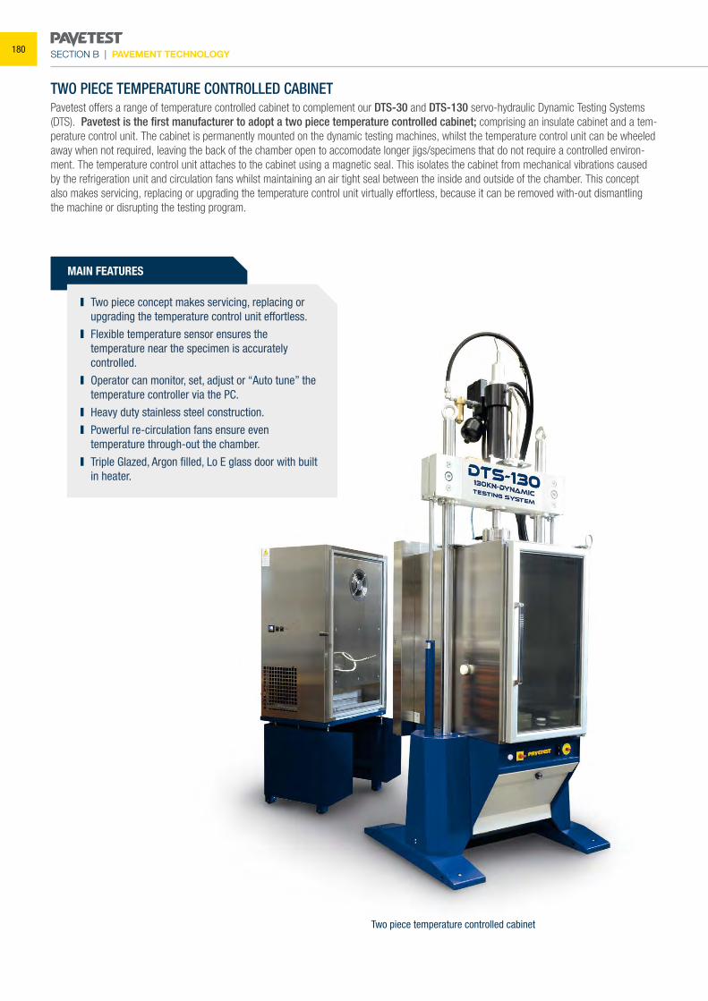
SECTION B | PAVEMENT TECHNOLOGY
MAIN FEATURES
TWO PIECE TEMPERATURE CONTROLLED CABINETPavetest offers a range of temperature controlled cabinet to complement our DTS-30 and DTS-130 servo-hydraulic Dynamic Testing Systems (DTS). Pavetest is the first manufacturer to adopt a two piece temperature controlled cabinet; comprising an insulate cabinet and a tem-perature control unit. The cabinet is permanently mounted on the dynamic testing machines, whilst the temperature control unit can be wheeled away when not required, leaving the back of the chamber open to accomodate longer jigs/specimens that do not require a controlled environ-ment. The temperature control unit attaches to the cabinet using a magnetic seal. This isolates the cabinet from mechanical vibrations caused by the refrigeration unit and circulation fans whilst maintaining an air tight seal between the inside and outside of the chamber. This concept also makes servicing, replacing or upgrading the temperature control unit virtually effortless, because it can be removed with-out dismantling the machine or disrupting the testing program.
Two piece concept makes servicing, replacing or upgrading the temperature control unit effortless.
Flexible temperature sensor ensures the temperature near the specimen is accurately controlled.
Operator can monitor, set, adjust or “Auto tune” the temperature controller via the PC.
Heavy duty stainless steel construction. Powerful re-circulation fans ensure even
temperature through-out the chamber. Triple Glazed, Argon filled, Lo E glass door with built
in heater.
Two piece temperature controlled cabinet
180
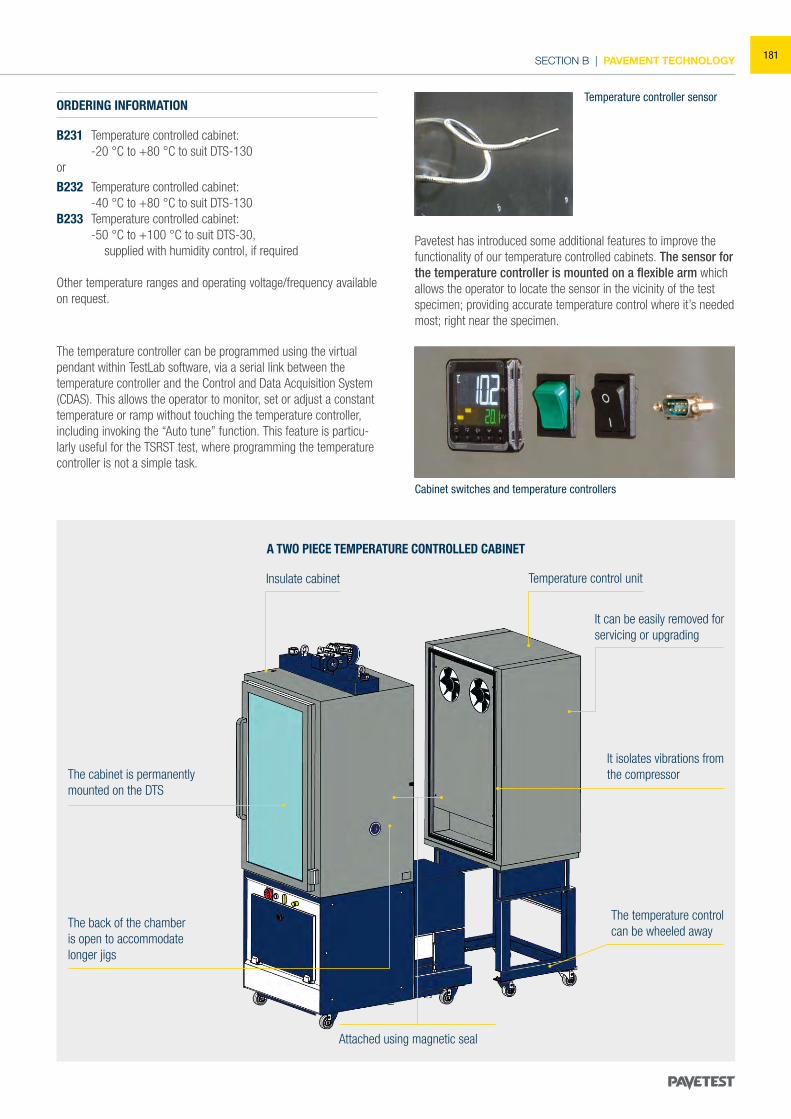
SECTION B | PAVEMENT TECHNOLOGY
ORDERING INFORMATION
B231 Temperature controlled cabinet: -20 °C to +80 °C to suit DTS-130or
B232 Temperature controlled cabinet: -40 °C to +80 °C to suit DTS-130B233 Temperature controlled cabinet: -50 °C to +100 °C to suit DTS-30, supplied with humidity control, if required
Other temperature ranges and operating voltage/frequency available on request.
Pavetest has introduced some additional features to improve the functionality of our temperature controlled cabinets. The sensor for the temperature controller is mounted on a flexible arm which allows the operator to locate the sensor in the vicinity of the test specimen; providing accurate temperature control where it’s needed most; right near the specimen.
The temperature controller can be programmed using the virtual pendant within TestLab software, via a serial link between the temperature controller and the Control and Data Acquisition System (CDAS). This allows the operator to monitor, set or adjust a constant temperature or ramp without touching the temperature controller, including invoking the “Auto tune” function. This feature is particu-larly useful for the TSRST test, where programming the temperature controller is not a simple task.
The back of the chamber is open to accommodate longer jigs
The cabinet is permanently mounted on the DTS
Insulate cabinet
It can be easily removed for servicing or upgrading
Temperature control unit
Attached using magnetic seal
It isolates vibrations fromthe compressor
The temperature controlcan be wheeled away
A TWO PIECE TEMPERATURE CONTROLLED CABINET
Temperature controller sensor
Cabinet switches and temperature controllers
181
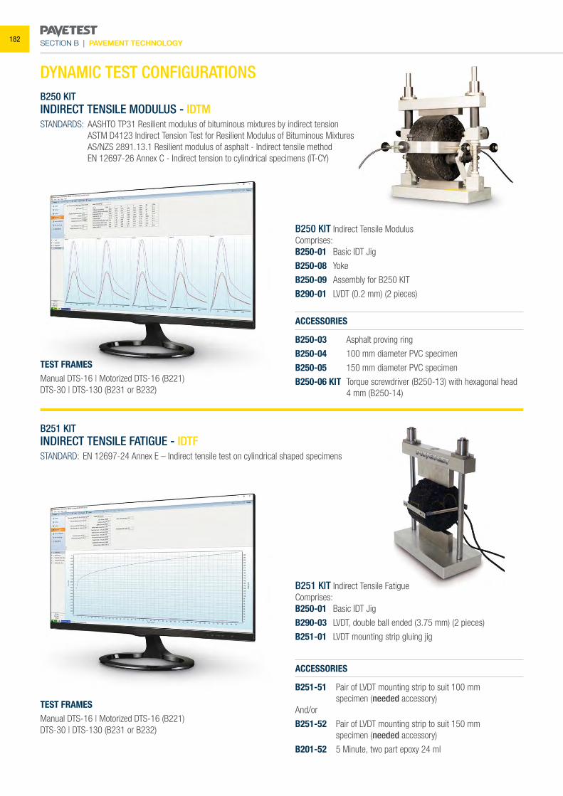
SECTION B | PAVEMENT TECHNOLOGY
B250 KITINDIRECT TENSILE MODULUS - IDTMSTANDARDS: AASHTO TP31 Resilient modulus of bituminous mixtures by indirect tension ASTM D4123 Indirect Tension Test for Resilient Modulus of Bituminous Mixtures AS/NZS 2891.13.1 Resilient modulus of asphalt - Indirect tensile method EN 12697-26 Annex C - Indirect tension to cylindrical specimens (IT-CY)
B251 KITINDIRECT TENSILE FATIGUE - IDTFSTANDARD: EN 12697-24 Annex E – Indirect tensile test on cylindrical shaped specimens
B250 KIT Indirect Tensile ModulusComprises:B250-01 Basic IDT Jig
B250-08 Yoke
B250-09 Assembly for B250 KIT
B290-01 LVDT (0.2 mm) (2 pieces)
B251 KIT Indirect Tensile FatigueComprises:B250-01 Basic IDT Jig
B290-03 LVDT, double ball ended (3.75 mm) (2 pieces)
B251-01 LVDT mounting strip gluing jig
ACCESSORIES
B250-03 Asphalt proving ring
B250-04 100 mm diameter PVC specimen
B250-05 150 mm diameter PVC specimen
B250-06 KIT Torque screwdriver (B250-13) with hexagonal head 4 mm (B250-14)
ACCESSORIES
B251-51 Pair of LVDT mounting strip to suit 100 mm specimen (needed accessory)And/or
B251-52 Pair of LVDT mounting strip to suit 150 mm specimen (needed accessory)
B201-52 5 Minute, two part epoxy 24 ml
TEST FRAMESManual DTS-16 | Motorized DTS-16 (B221)DTS-30 | DTS-130 (B231 or B232)
TEST FRAMESManual DTS-16 | Motorized DTS-16 (B221)DTS-30 | DTS-130 (B231 or B232)
DYNAMIC TEST CONFIGURATIONS
182
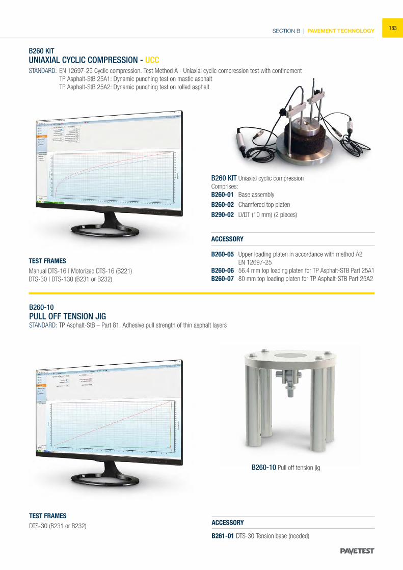
SECTION B | PAVEMENT TECHNOLOGY
ACCESSORY
B260-05 Upper loading platen in accordance with method A2 EN 12697-25B260-06 56.4 mm top loading platen for TP Asphalt-STB Part 25A1B260-07 80 mm top loading platen for TP Asphalt-STB Part 25A2
B260 KIT UNIAXIAL CYCLIC COMPRESSION - UCCSTANDARD: EN 12697-25 Cyclic compression. Test Method A - Uniaxial cyclic compression test with confinement TP Asphalt-StB 25A1: Dynamic punching test on mastic asphalt TP Asphalt-StB 25A2: Dynamic punching test on rolled asphalt
B260 KIT Uniaxial cyclic compressionComprises:B260-01 Base assembly
B260-02 Chamfered top platen
B290-02 LVDT (10 mm) (2 pieces)
TEST FRAMESManual DTS-16 | Motorized DTS-16 (B221)DTS-30 | DTS-130 (B231 or B232)
B260-10PULL OFF TENSION JIGSTANDARD: TP Asphalt-StB – Part 81, Adhesive pull strength of thin asphalt layers
ACCESSORY
B261-01 DTS-30 Tension base (needed)
TEST FRAMESDTS-30 (B231 or B232)
B260-10 Pull off tension jig
183
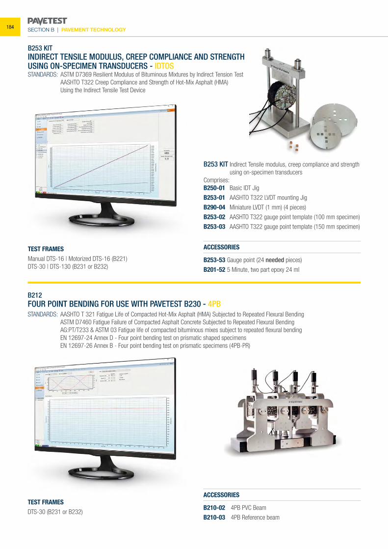
SECTION B | PAVEMENT TECHNOLOGY
B212FOUR POINT BENDING FOR USE WITH PAVETEST B230 - 4PBSTANDARDS: AASHTO T 321 Fatigue Life of Compacted Hot-Mix Asphalt (HMA) Subjected to Repeated Flexural Bending ASTM D7460 Fatigue Failure of Compacted Asphalt Concrete Subjected to Repeated Flexural Bending AG:PT/T233 & ASTM 03 Fatigue life of compacted bituminous mixes subject to repeated flexural bending EN 12697-24 Annex D - Four point bending test on prismatic shaped specimens EN 12697-26 Annex B - Four point bending test on prismatic specimens (4PB-PR)
ACCESSORIES
B210-02 4PB PVC Beam
B210-03 4PB Reference beam
TEST FRAMESDTS-30 (B231 or B232)
B253 KITINDIRECT TENSILE MODULUS, CREEP COMPLIANCE AND STRENGTHUSING ON-SPECIMEN TRANSDUCERS - IDTOSSTANDARDS: ASTM D7369 Resilient Modulus of Bituminous Mixtures by Indirect Tension Test AASHTO T322 Creep Compliance and Strength of Hot-Mix Asphalt (HMA) Using the Indirect Tensile Test Device
ACCESSORIES
B253-53 Gauge point (24 needed pieces)
B201-52 5 Minute, two part epoxy 24 ml
B253 KIT Indirect Tensile modulus, creep compliance and strength using on-specimen transducers
Comprises:B250-01 Basic IDT Jig
B253-01 AASHTO T322 LVDT mounting Jig
B290-04 Miniature LVDT (1 mm) (4 pieces)
B253-02 AASHTO T322 gauge point template (100 mm specimen)
B253-03 AASHTO T322 gauge point template (150 mm specimen)
TEST FRAMESManual DTS-16 | Motorized DTS-16 (B221)DTS-30 | DTS-130 (B231 or B232)
184
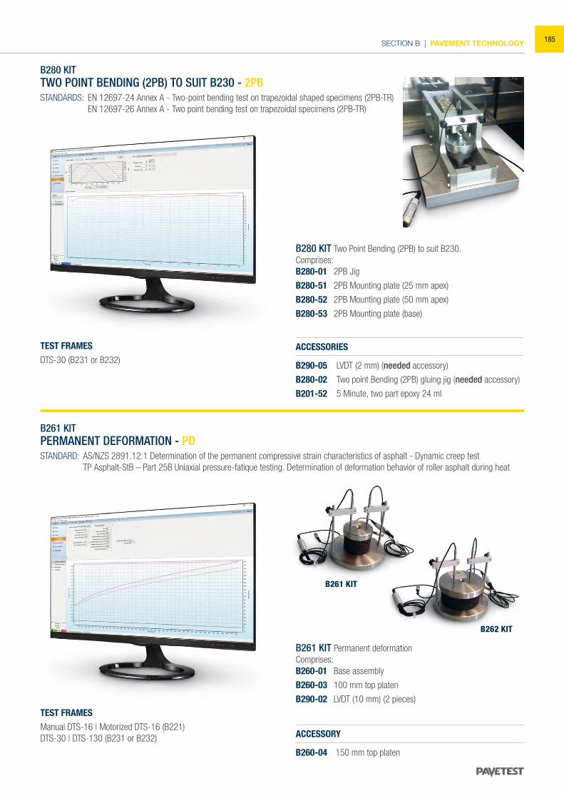
SECTION B | PAVEMENT TECHNOLOGY
B261 KIT
B262 KIT
B280 KIT TWO POINT BENDING (2PB) TO SUIT B230 - 2PBSTANDARDS: EN 12697-24 Annex A - Two-point bending test on trapezoidal shaped specimens (2PB-TR) EN 12697-26 Annex A - Two point bending test on trapezoidal specimens (2PB-TR)
B280 KIT Two Point Bending (2PB) to suit B230.Comprises:B280-01 2PB Jig
B280-51 2PB Mounting plate (25 mm apex)
B280-52 2PB Mounting plate (50 mm apex)
B280-53 2PB Mounting plate (base)
ACCESSORIES
B290-05 LVDT (2 mm) (needed accessory)
B280-02 Two point Bending (2PB) gluing jig (needed accessory)
B201-52 5 Minute, two part epoxy 24 ml
TEST FRAMESDTS-30 (B231 or B232)
B261 KIT PERMANENT DEFORMATION - PDSTANDARD: AS/NZS 2891.12.1 Determination of the permanent compressive strain characteristics of asphalt - Dynamic creep test TP Asphalt-StB – Part 25B Uniaxial pressure-fatique testing. Determination of deformation behavior of roller asphalt during heat
ACCESSORY
B260-04 150 mm top platen
B261 KIT Permanent deformationComprises:B260-01 Base assembly
B260-03 100 mm top platen
B290-02 LVDT (10 mm) (2 pieces)TEST FRAMESManual DTS-16 | Motorized DTS-16 (B221)DTS-30 | DTS-130 (B231 or B232)
185
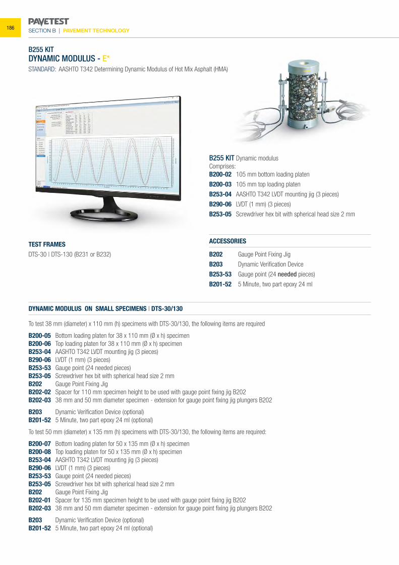
SECTION B | PAVEMENT TECHNOLOGY
B255 KIT DYNAMIC MODULUS - E*STANDARD: AASHTO T342 Determining Dynamic Modulus of Hot Mix Asphalt (HMA)
ACCESSORIES
B202 Gauge Point Fixing Jig
B203 Dynamic Verification Device
B253-53 Gauge point (24 needed pieces)
B201-52 5 Minute, two part epoxy 24 ml
B255 KIT Dynamic modulusComprises:B200-02 105 mm bottom loading platen
B200-03 105 mm top loading platen
B253-04 AASHTO T342 LVDT mounting jig (3 pieces)
B290-06 LVDT (1 mm) (3 pieces)
B253-05 Screwdriver hex bit with spherical head size 2 mm
TEST FRAMESDTS-30 | DTS-130 (B231 or B232)
DYNAMIC MODULUS ON SMALL SPECIMENS | DTS-30/130
To test 38 mm (diameter) x 110 mm (h) specimens with DTS-30/130, the following items are required
B200-05 Bottom loading platen for 38 x 110 mm (Ø x h) specimenB200-06 Top loading platen for 38 x 110 mm (Ø x h) specimenB253-04 AASHTO T342 LVDT mounting jig (3 pieces)B290-06 LVDT (1 mm) (3 pieces)B253-53 Gauge point (24 needed pieces)B253-05 Screwdriver hex bit with spherical head size 2 mmB202 Gauge Point Fixing JigB202-02 Spacer for 110 mm specimen height to be used with gauge point fixing jig B202B202-03 38 mm and 50 mm diameter specimen - extension for gauge point fixing jig plungers B202
B203 Dynamic Verification Device (optional)B201-52 5 Minute, two part epoxy 24 ml (optional)
To test 50 mm (diameter) x 135 mm (h) specimens with DTS-30/130, the following items are required:
B200-07 Bottom loading platen for 50 x 135 mm (Ø x h) specimenB200-08 Top loading platen for 50 x 135 mm (Ø x h) specimenB253-04 AASHTO T342 LVDT mounting jig (3 pieces)B290-06 LVDT (1 mm) (3 pieces)B253-53 Gauge point (24 needed pieces)B253-05 Screwdriver hex bit with spherical head size 2 mmB202 Gauge Point Fixing JigB202-01 Spacer for 135 mm specimen height to be used with gauge point fixing jig B202B202-03 38 mm and 50 mm diameter specimen - extension for gauge point fixing jig plungers B202
B203 Dynamic Verification Device (optional)B201-52 5 Minute, two part epoxy 24 ml (optional)
186
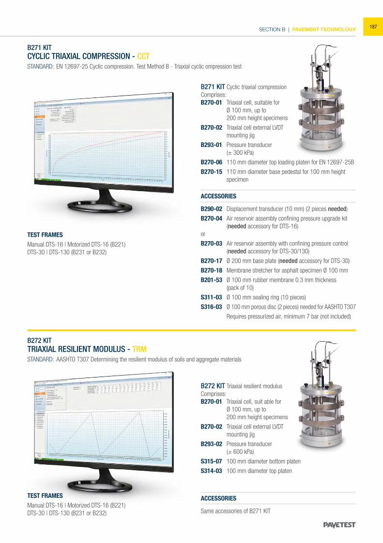
SECTION B | PAVEMENT TECHNOLOGY
B271 KIT CYCLIC TRIAXIAL COMPRESSION - CCTSTANDARD: EN 12697-25 Cyclic compression. Test Method B - Triaxial cyclic ompression test
B272 KITTRIAXIAL RESILIENT MODULUS - TRMSTANDARD: AASHTO T307 Determining the resilient modulus of soils and aggregate materials
ACCESSORIES
Same accessories of B271 KIT
B271 KIT Cyclic triaxial compressionComprises:B270-01 Triaxial cell, suitable for Ø 100 mm, up to 200 mm height specimens
B270-02 Triaxial cell external LVDT mounting jig
B293-01 Pressure transducer (± 300 kPa)
B270-06 110 mm diameter top loading platen for EN 12697-25B
B270-15 110 mm diameter base pedestal for 100 mm height specimen
B272 KIT Triaxial resilient modulusComprises:B270-01 Triaxial cell, suit able for Ø 100 mm, up to 200 mm height specimens
B270-02 Triaxial cell external LVDT mounting jig
B293-02 Pressure transducer (± 600 kPa)
S315-07 100 mm diameter bottom platen
S314-03 100 mm diameter top platen
TEST FRAMESManual DTS-16 | Motorized DTS-16 (B221)DTS-30 | DTS-130 (B231 or B232)
TEST FRAMESManual DTS-16 | Motorized DTS-16 (B221)DTS-30 | DTS-130 (B231 or B232)
ACCESSORIES
B290-02 Displacement transducer (10 mm) (2 pieces needed)
B270-04 Air reservoir assembly confining pressure upgrade kit (needed accessory for DTS-16)
or
B270-03 Air reservoir assembly with confining pressure control (needed accessory for DTS-30/130)
B270-17 Ø 200 mm base plate (needed accessory for DTS-30)
B270-18 Membrane stretcher for asphalt specimen Ø 100 mm
B201-53 Ø 100 mm rubber membrane 0.3 mm thickness (pack of 10)
S311-03 Ø 100 mm sealing ring (10 pieces)
S316-03 Ø 100 mm porous disc (2 pieces) needed for AASHTO T307
Requires pressurized air, minimum 7 bar (not included)
187
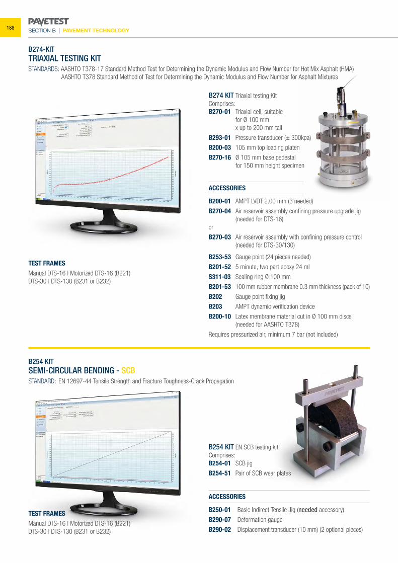
SECTION B | PAVEMENT TECHNOLOGY
B274-KIT TRIAXIAL TESTING KITSTANDARDS: AASHTO T378-17 Standard Method Test for Determining the Dynamic Modulus and Flow Number for Hot Mix Asphalt (HMA) AASHTO T378 Standard Method of Test for Determining the Dynamic Modulus and Flow Number for Asphalt Mixtures
ACCESSORIES
B250-01 Basic Indirect Tensile Jig (needed accessory)
B290-07 Deformation gauge
B290-02 Displacement transducer (10 mm) (2 optional pieces)
B274 KIT Triaxial testing KitComprises:B270-01 Triaxial cell, suitable for Ø 100 mm x up to 200 mm tall
B293-01 Pressure transducer (± 300kpa)
B200-03 105 mm top loading platen
B270-16 Ø 105 mm base pedestal for 150 mm height specimen
B254 KIT EN SCB testing kitComprises:B254-01 SCB jig
B254-51 Pair of SCB wear plates
TEST FRAMESManual DTS-16 | Motorized DTS-16 (B221)DTS-30 | DTS-130 (B231 or B232)
TEST FRAMESManual DTS-16 | Motorized DTS-16 (B221)DTS-30 | DTS-130 (B231 or B232)
ACCESSORIES
B200-01 AMPT LVDT 2.00 mm (3 needed)
B270-04 Air reservoir assembly confining pressure upgrade jig (needed for DTS-16)
or
B270-03 Air reservoir assembly with confining pressure control (needed for DTS-30/130)
B253-53 Gauge point (24 pieces needed)
B201-52 5 minute, two part epoxy 24 ml
S311-03 Sealing ring Ø 100 mm
B201-53 100 mm rubber membrane 0.3 mm thickness (pack of 10)
B202 Gauge point fixing jig
B203 AMPT dynamic verification device
B200-10 Latex membrane material cut in Ø 100 mm discs (needed for AASHTO T378)
Requires pressurized air, minimum 7 bar (not included)
B254 KIT SEMI-CIRCULAR BENDING - SCBSTANDARD: EN 12697-44 Tensile Strength and Fracture Toughness-Crack Propagation
188
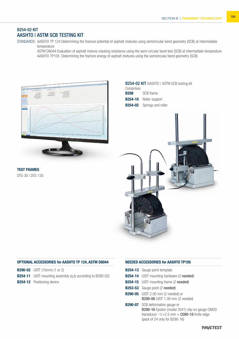
SECTION B | PAVEMENT TECHNOLOGY
B254-02 KIT AASHTO | ASTM SCB TESTING KITSTANDARDS: AASHTO TP 124 Determining the fracture potential of asphalt mixtures using semicircular bend geometry (SCB) at intermediate
temperature ASTM D8044 Evaluation of asphalt mixture cracking resistance using the semi-circular bend test (SCB) at intermediate temperature AASHTO TP105 Determining the fracture energy of asphalt mixtures using the semicircular bend geometry (SCB)
B254-02 KIT AASHTO | ASTM SCB testing kit Comprises:B208 SCB frame
B254-10 Roller support
B254-02 Springs and roller
TEST FRAMESDTS-30 | DTS-130
OPTIONAL ACCESSORIES for AASHTO TP 124, ASTM D8044
B290-02 LVDT (10mm) (1 or 2)
B254-11 LVDT mounting assembly (q,ty according to B290-02)
B254-12 Positioning device
NEEDED ACCESSORIES for AASHTO TP105
B254-13 Gauge point template
B254-14 LVDT mounting hardware (2 needed)
B254-15 LVDT mounting frame (2 needed)
B253-53 Gauge point (2 needed)
B290-05 LVDT 2.00 mm (2 needed) or B290-06 LVDT 1.00 mm (2 needed)
B290-07 SCB deformation gauge or B290-16 Epsilon (model 3541) clip-on gauge CMOD
transducer -1/+2.5 mm + C090-18 Knife edge (pack of 24 only for B290-16)
189
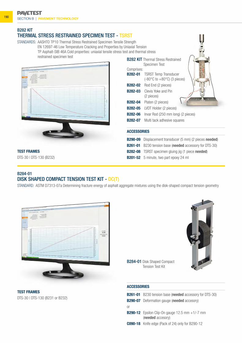
SECTION B | PAVEMENT TECHNOLOGY
B282 KITTHERMAL STRESS RESTRAINED SPECIMEN TEST - TSRSTSTANDARDS: AASHTO TP10 Thermal Stress Restrained Specimen Tensile Strength EN 12697-46 Low Temperature Cracking and Properties by Uniaxial Tension TP Asphalt-StB 46A Cold properties: uniaxial tensile stress test and thermal stress restrained specimen test
ACCESSORIES
B290-09 Displacement transducer (5 mm) (2 pieces needed)
B261-01 B230 tension base (needed accessory for DTS-30)
B282-08 TSRST specimen gluing jig (1 piece needed)
B201-52 5 minute, two part epoxy 24 ml
B282 KIT Thermal Stress Restrained Specimen Test Comprises:B282-01 TSRST Temp Transducer (-80°C to +80°C) (3 pieces)
B282-02 Rod End (2 pieces)
B282-03 Clevis Yoke and Pin (2 pieces)
B282-04 Platen (2 pieces)
B282-05 LVDT Holder (2 pieces)
B282-06 Invar Rod (250 mm long) (2 pieces)
B282-07 Multi tack adhesive squares
TEST FRAMESDTS-30 | DTS-130 (B232)
B284-01DISK SHAPED COMPACT TENSION TEST KIT - DC(T)STANDARD: ASTM D7313-07a Determining fracture energy of asphalt aggregate mixtures using the disk-shaped compact tension geometry
ACCESSORIES
B261-01 B230 tension base (needed accessory for DTS-30)
B290-07 Deformation gauge (needed accesory)
or
B290-12 Epsilon Clip-On gauge 12.5 mm +1/-7 mm (needed accesory)
C090-18 Knife edge (Pack of 24) only for B290-12
B284-01 Disk Shaped Compact Tension Test Kit
TEST FRAMESDTS-30 | DTS-130 (B231 or B232)
190
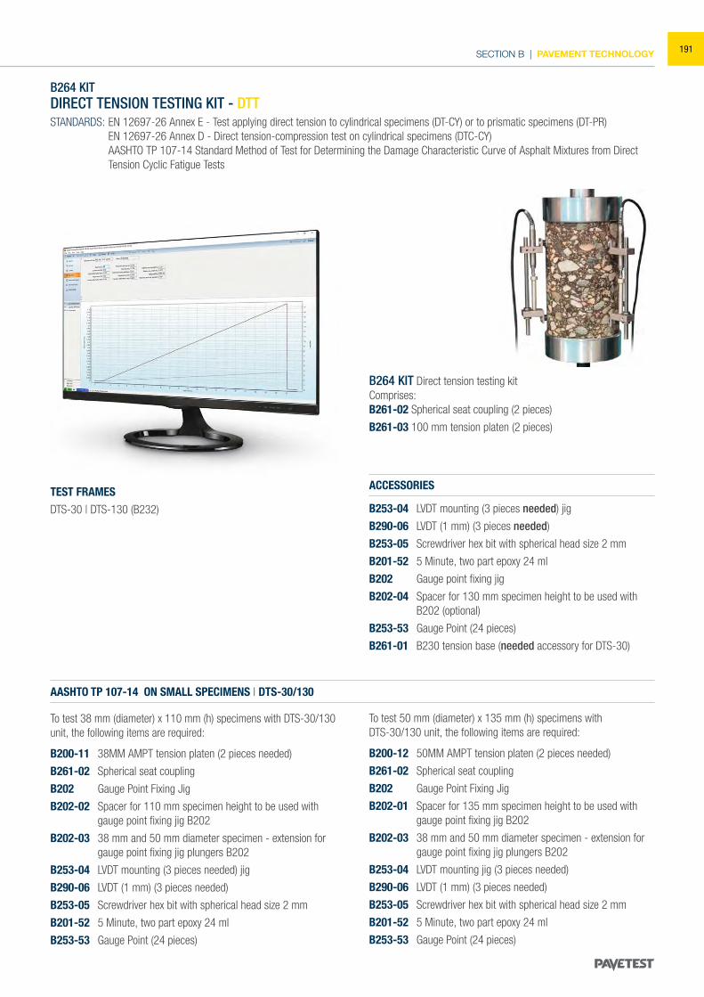
SECTION B | PAVEMENT TECHNOLOGY
B264 KIT DIRECT TENSION TESTING KIT - DTTSTANDARDS: EN 12697-26 Annex E - Test applying direct tension to cylindrical specimens (DT-CY) or to prismatic specimens (DT-PR) EN 12697-26 Annex D - Direct tension-compression test on cylindrical specimens (DTC-CY) AASHTO TP 107-14 Standard Method of Test for Determining the Damage Characteristic Curve of Asphalt Mixtures from Direct
Tension Cyclic Fatigue Tests
ACCESSORIES
B253-04 LVDT mounting (3 pieces needed) jig
B290-06 LVDT (1 mm) (3 pieces needed)
B253-05 Screwdriver hex bit with spherical head size 2 mm
B201-52 5 Minute, two part epoxy 24 ml
B202 Gauge point fixing jig
B202-04 Spacer for 130 mm specimen height to be used with B202 (optional)
B253-53 Gauge Point (24 pieces)
B261-01 B230 tension base (needed accessory for DTS-30)
B264 KIT Direct tension testing kit Comprises:B261-02 Spherical seat coupling (2 pieces)
B261-03 100 mm tension platen (2 pieces)
TEST FRAMESDTS-30 | DTS-130 (B232)
AASHTO TP 107-14 ON SMALL SPECIMENS | DTS-30/130
To test 38 mm (diameter) x 110 mm (h) specimens with DTS-30/130 unit, the following items are required:
B200-11 38MM AMPT tension platen (2 pieces needed)
B261-02 Spherical seat coupling
B202 Gauge Point Fixing Jig
B202-02 Spacer for 110 mm specimen height to be used with gauge point fixing jig B202
B202-03 38 mm and 50 mm diameter specimen - extension for gauge point fixing jig plungers B202
B253-04 LVDT mounting (3 pieces needed) jig
B290-06 LVDT (1 mm) (3 pieces needed)
B253-05 Screwdriver hex bit with spherical head size 2 mm
B201-52 5 Minute, two part epoxy 24 ml
B253-53 Gauge Point (24 pieces)
To test 50 mm (diameter) x 135 mm (h) specimens withDTS-30/130 unit, the following items are required:
B200-12 50MM AMPT tension platen (2 pieces needed)
B261-02 Spherical seat coupling
B202 Gauge Point Fixing Jig
B202-01 Spacer for 135 mm specimen height to be used with gauge point fixing jig B202
B202-03 38 mm and 50 mm diameter specimen - extension for gauge point fixing jig plungers B202
B253-04 LVDT mounting jig (3 pieces needed)
B290-06 LVDT (1 mm) (3 pieces needed)
B253-05 Screwdriver hex bit with spherical head size 2 mm
B201-52 5 Minute, two part epoxy 24 ml
B253-53 Gauge Point (24 pieces)
191
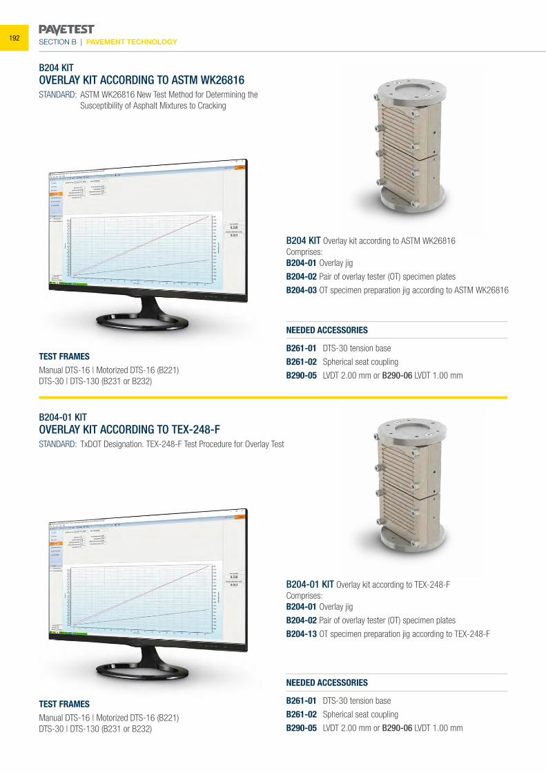
SECTION B | PAVEMENT TECHNOLOGY
B204 KIT OVERLAY KIT ACCORDING TO ASTM WK26816STANDARD: ASTM WK26816 New Test Method for Determining the
Susceptibility of Asphalt Mixtures to Cracking
B204-01 KIT OVERLAY KIT ACCORDING TO TEX-248-FSTANDARD: TxDOT Designation. TEX-248-F Test Procedure for Overlay Test
NEEDED ACCESSORIES
B261-01 DTS-30 tension base
B261-02 Spherical seat coupling
B290-05 LVDT 2.00 mm or B290-06 LVDT 1.00 mm
NEEDED ACCESSORIES
B261-01 DTS-30 tension base
B261-02 Spherical seat coupling
B290-05 LVDT 2.00 mm or B290-06 LVDT 1.00 mm
B204-01 KIT Overlay kit according to TEX-248-FComprises:B204-01 Overlay jig
B204-02 Pair of overlay tester (OT) specimen plates
B204-13 OT specimen preparation jig according to TEX-248-F
TEST FRAMESManual DTS-16 | Motorized DTS-16 (B221)DTS-30 | DTS-130 (B231 or B232)
TEST FRAMESManual DTS-16 | Motorized DTS-16 (B221)DTS-30 | DTS-130 (B231 or B232)
B204 KIT Overlay kit according to ASTM WK26816Comprises:B204-01 Overlay jig
B204-02 Pair of overlay tester (OT) specimen plates
B204-03 OT specimen preparation jig according to ASTM WK26816
192
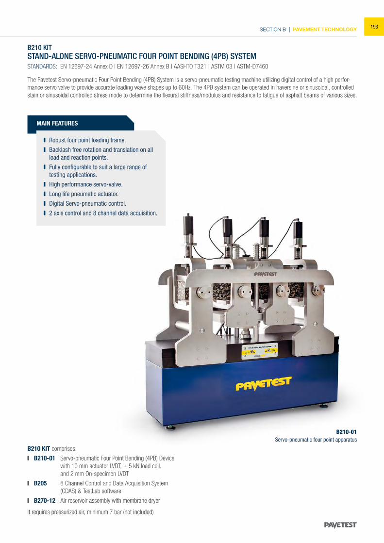
SECTION B | PAVEMENT TECHNOLOGY
B210 KITSTAND-ALONE SERVO-PNEUMATIC FOUR POINT BENDING (4PB) SYSTEMSTANDARDS: EN 12697-24 Annex D | EN 12697-26 Annex B | AASHTO T321 | ASTM 03 | ASTM-D7460
The Pavetest Servo-pneumatic Four Point Bending (4PB) System is a servo-pneumatic testing machine utilizing digital control of a high perfor-mance servo valve to provide accurate loading wave shapes up to 60Hz. The 4PB system can be operated in haversine or sinusoidal, controlled stain or sinusoidal controlled stress mode to determine the flexural stiffness/modulus and resistance to fatigue of asphalt beams of various sizes.
B210 KIT comprises:
B210-01 Servo-pneumatic Four Point Bending (4PB) Device with 10 mm actuator LVDT, ± 5 kN load cell.
and 2 mm On-specimen LVDT
B205 8 Channel Control and Data Acquisition System (CDAS) & TestLab software
B270-12 Air reservoir assembly with membrane dryer
It requires pressurized air, minimum 7 bar (not included)
MAIN FEATURES
Robust four point loading frame. Backlash free rotation and translation on all
load and reaction points. Fully configurable to suit a large range of
testing applications. High performance servo-valve. Long life pneumatic actuator. Digital Servo-pneumatic control. 2 axis control and 8 channel data acquisition.
B210-01Servo-pneumatic four point apparatus
193
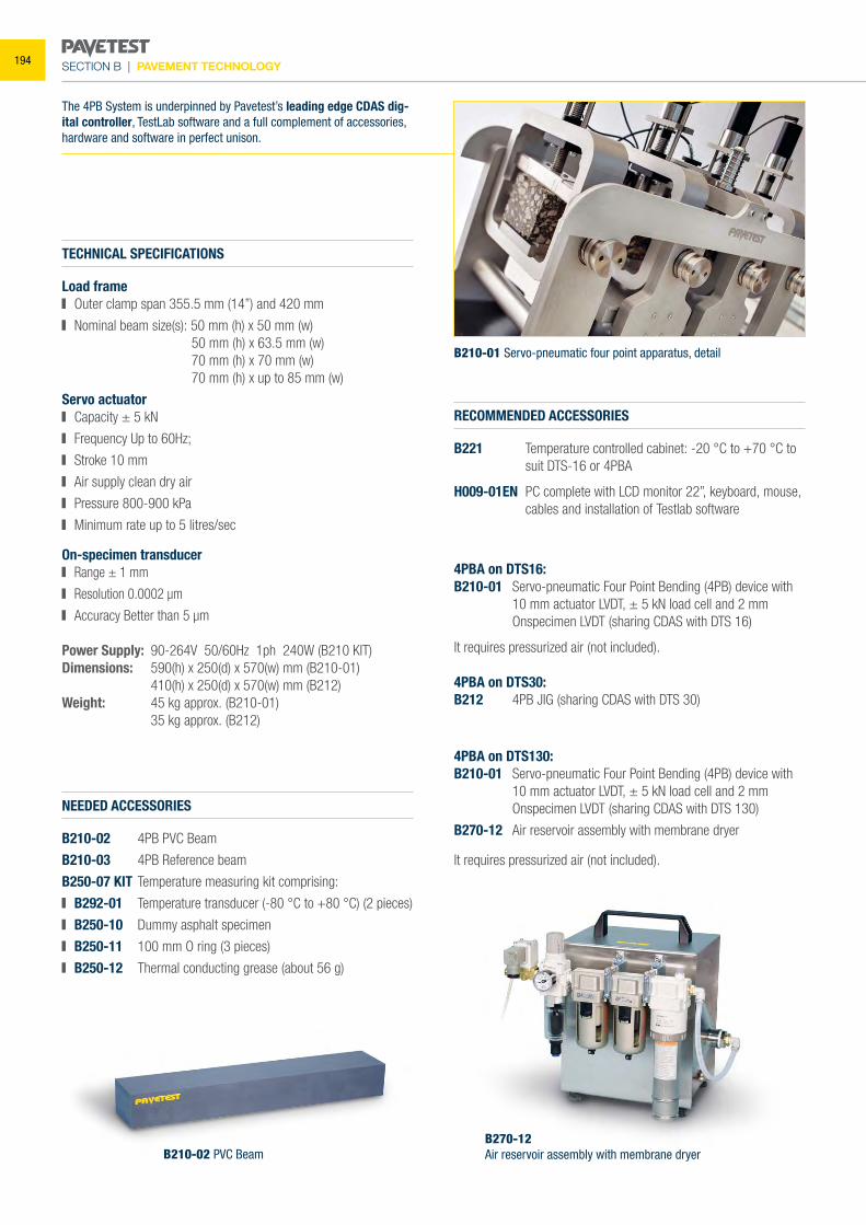
SECTION B | PAVEMENT TECHNOLOGY
TECHNICAL SPECIFICATIONS
Load frame Outer clamp span 355.5 mm (14”) and 420 mm
Nominal beam size(s): 50 mm (h) x 50 mm (w) 50 mm (h) x 63.5 mm (w) 70 mm (h) x 70 mm (w) 70 mm (h) x up to 85 mm (w)
Servo actuator Capacity ± 5 kN
Frequency Up to 60Hz;
Stroke 10 mm
Air supply clean dry air
Pressure 800-900 kPa
Minimum rate up to 5 litres/sec
On-specimen transducer Range ± 1 mm
Resolution 0.0002 μm
Accuracy Better than 5 μm
Power Supply: 90-264V 50/60Hz 1ph 240W (B210 KIT)Dimensions: 590(h) x 250(d) x 570(w) mm (B210-01) 410(h) x 250(d) x 570(w) mm (B212)Weight: 45 kg approx. (B210-01) 35 kg approx. (B212)
NEEDED ACCESSORIES
B210-02 4PB PVC Beam
B210-03 4PB Reference beam
B250-07 KIT Temperature measuring kit comprising:
B292-01 Temperature transducer (-80 °C to +80 °C) (2 pieces)
B250-10 Dummy asphalt specimen
B250-11 100 mm O ring (3 pieces)
B250-12 Thermal conducting grease (about 56 g)
RECOMMENDED ACCESSORIES
B221 Temperature controlled cabinet: -20 °C to +70 °C to suit DTS-16 or 4PBA
H009-01EN PC complete with LCD monitor 22”, keyboard, mouse, cables and installation of Testlab software
B270-12Air reservoir assembly with membrane dryerB210-02 PVC Beam
4PBA on DTS16:B210-01 Servo-pneumatic Four Point Bending (4PB) device with
10 mm actuator LVDT, ± 5 kN load cell and 2 mm Onspecimen LVDT (sharing CDAS with DTS 16)
It requires pressurized air (not included).
4PBA on DTS30:B212 4PB JIG (sharing CDAS with DTS 30)
4PBA on DTS130:B210-01 Servo-pneumatic Four Point Bending (4PB) device with 10 mm actuator LVDT, ± 5 kN load cell and 2 mm Onspecimen LVDT (sharing CDAS with DTS 130)
B270-12 Air reservoir assembly with membrane dryer
It requires pressurized air (not included).
The 4PB System is underpinned by Pavetest’s leading edge CDAS dig-ital controller, TestLab software and a full complement of accessories, hardware and software in perfect unison.
B210-01 Servo-pneumatic four point apparatus, detail
194
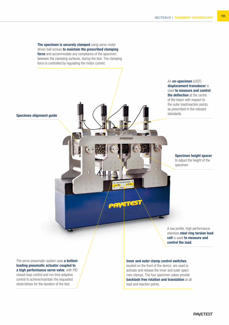
SECTION B | PAVEMENT TECHNOLOGY
Specimen alignment guide
The servo-pneumatic system uses a bottom loading pneumatic actuator coupled to a high performance servo valve, with PID closed-loop control and run time adaptive control to achieve/maintain the requested strain/stress for the duration of the test.
Inner and outer clamp control switches, located on the front of the device, are used to activate and release the inner and outer speci-men clamps. The four specimen yokes provide backlash free rotation and translation at all load and reaction points.
A low profile, high performance stainless steel ring torsion load cell is used to measure and control the load.
Specimen height spacerto adjust the height of thespecimen
An on-specimen (LVDT) displacement transducer is used to measure and control the deflection at the centre of the beam with respect to the outer load/reaction points, as prescribed in the relevant standards.
The specimen is securely clamped using servo-motor driven ball screws to maintain the prescribed clamping force and accommodate any compliance of the specimen between the clamping surfaces, during the test. The clamping force is controlled by regulating the motor current.
195
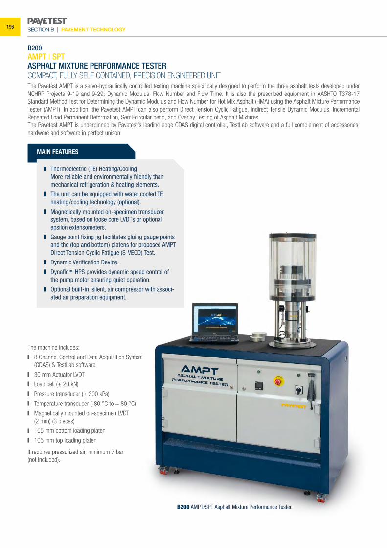
SECTION B | PAVEMENT TECHNOLOGY
B200AMPT | SPTASPHALT MIXTURE PERFORMANCE TESTERCOMPACT, FULLY SELF CONTAINED, PRECISION ENGINEERED UNITThe Pavetest AMPT is a servo-hydraulically controlled testing machine specifically designed to perform the three asphalt tests developed under NCHRP Projects 9-19 and 9-29; Dynamic Modulus, Flow Number and Flow Time. It is also the prescribed equipment in AASHTO T378-17 Standard Method Test for Determining the Dynamic Modulus and Flow Number for Hot Mix Asphalt (HMA) using the Asphalt Mixture Performance Tester (AMPT). In addition, the Pavetest AMPT can also perform Direct Tension Cyclic Fatigue, Indirect Tensile Dynamic Modulus, Incremental Repeated Load Permanent Deformation, Semi-circular bend, and Overlay Testing of Asphalt Mixtures. The Pavetest AMPT is underpinned by Pavetest’s leading edge CDAS digital controller, TestLab software and a full complement of accessories, hardware and software in perfect unison.
B200 AMPT/SPT Asphalt Mixture Performance Tester
MAIN FEATURES
Thermoelectric (TE) Heating/Cooling More reliable and environmentally friendly than
mechanical refrigeration & heating elements. The unit can be equipped with water cooled TE
heating/cooling technology (optional). Magnetically mounted on-specimen transducer
system, based on loose core LVDTs or optional epsilon extensometers.
Gauge point fixing jig facilitates gluing gauge points and the (top and bottom) platens for proposed AMPT Direct Tension Cyclic Fatigue (S-VECD) Test.
Dynamic Verification Device. DynafloTM HPS provides dynamic speed control of
the pump motor ensuring quiet operation. Optional built-in, silent, air compressor with associ-
ated air preparation equipment.
The machine includes:
8 Channel Control and Data Acquisition System (CDAS) & TestLab software
30 mm Actuator LVDT
Load cell (± 20 kN)
Pressure transducer (± 300 kPa)
Temperature transducer (-80 °C to + 80 °C)
Magnetically mounted on-specimen LVDT (2 mm) (3 pieces)
105 mm bottom loading platen
105 mm top loading platen
It requires pressurized air, minimum 7 bar(not included).
196
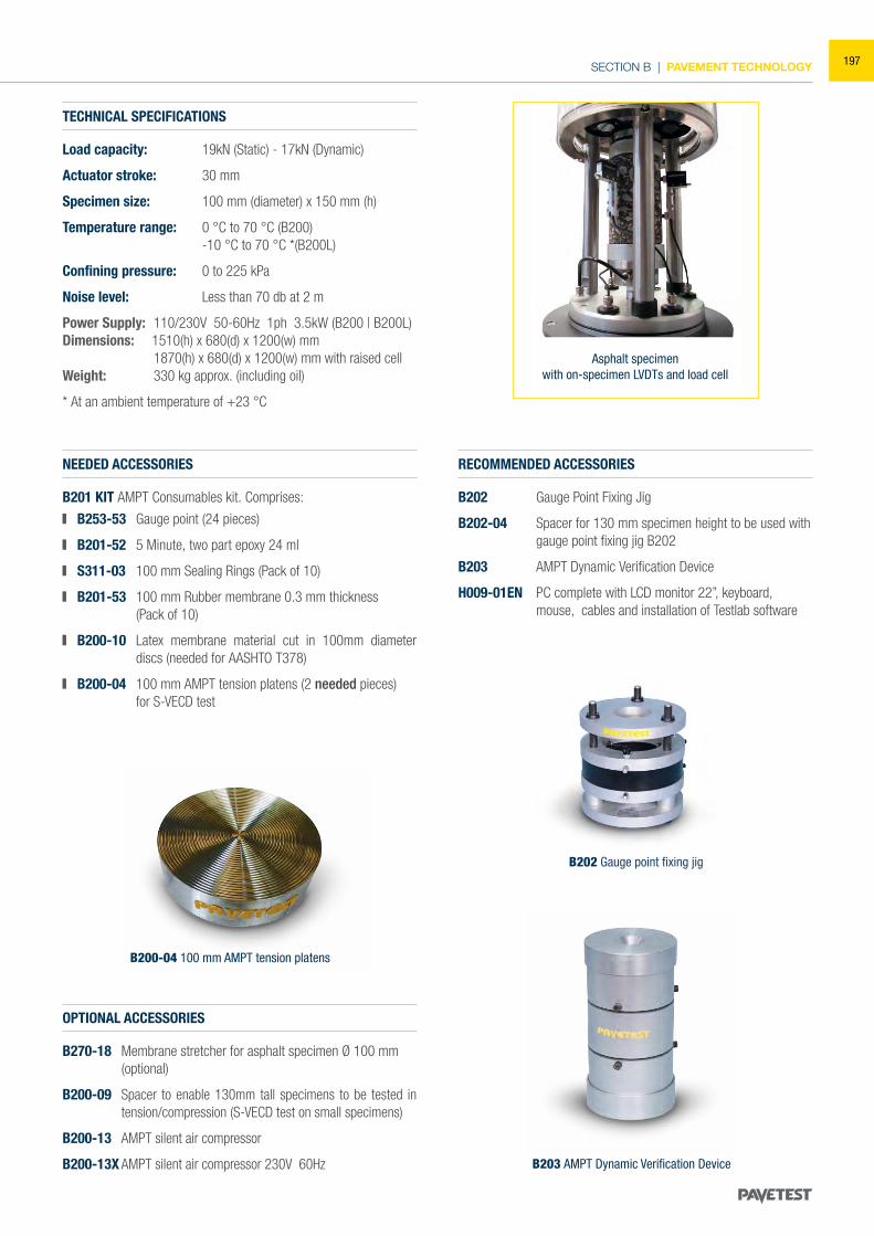
SECTION B | PAVEMENT TECHNOLOGY
TECHNICAL SPECIFICATIONS
Load capacity: 19kN (Static) - 17kN (Dynamic)
Actuator stroke: 30 mm
Specimen size: 100 mm (diameter) x 150 mm (h)
Temperature range: 0 °C to 70 °C (B200) -10 °C to 70 °C *(B200L)
Confining pressure: 0 to 225 kPa
Noise level: Less than 70 db at 2 m
Power Supply: 110/230V 50-60Hz 1ph 3.5kW (B200 | B200L)Dimensions: 1510(h) x 680(d) x 1200(w) mm 1870(h) x 680(d) x 1200(w) mm with raised cellWeight: 330 kg approx. (including oil)
* At an ambient temperature of +23 °C
NEEDED ACCESSORIES
B201 KIT AMPT Consumables kit. Comprises:
B253-53 Gauge point (24 pieces)
B201-52 5 Minute, two part epoxy 24 ml
S311-03 100 mm Sealing Rings (Pack of 10)
B201-53 100 mm Rubber membrane 0.3 mm thickness (Pack of 10)
B200-10 Latex membrane material cut in 100mm diameter discs (needed for AASHTO T378)
B200-04 100 mm AMPT tension platens (2 needed pieces) for S-VECD test
RECOMMENDED ACCESSORIES
B202 Gauge Point Fixing Jig
B202-04 Spacer for 130 mm specimen height to be used with gauge point fixing jig B202
B203 AMPT Dynamic Verification Device
H009-01EN PC complete with LCD monitor 22”, keyboard, mouse, cables and installation of Testlab software
Asphalt specimenwith on-specimen LVDTs and load cell
B202 Gauge point fixing jig
B200-04 100 mm AMPT tension platens
B203 AMPT Dynamic Verification Device
OPTIONAL ACCESSORIES
B270-18 Membrane stretcher for asphalt specimen Ø 100 mm (optional)
B200-09 Spacer to enable 130mm tall specimens to be tested in tension/compression (S-VECD test on small specimens)
B200-13 AMPT silent air compressor
B200-13X AMPT silent air compressor 230V 60Hz
197
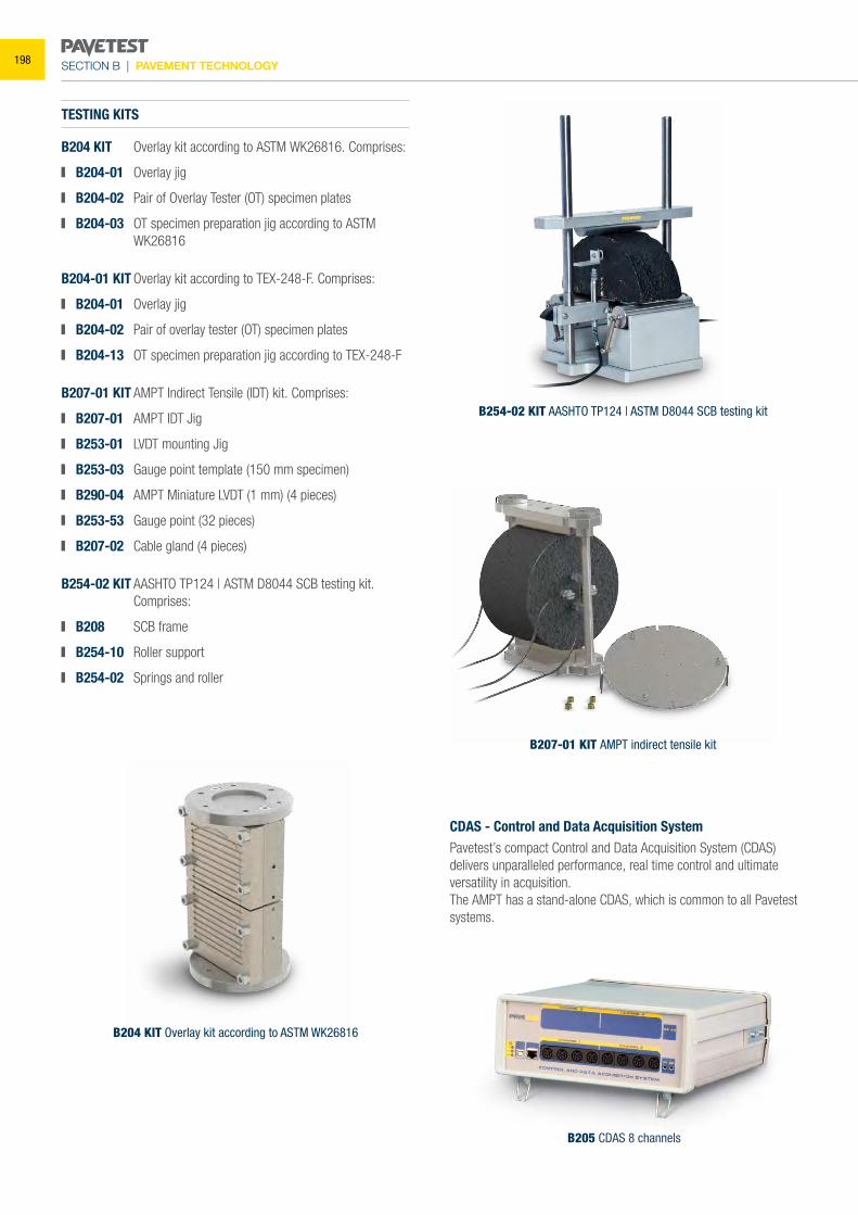
SECTION B | PAVEMENT TECHNOLOGY
B205 CDAS 8 channels
TESTING KITS
B204 KIT Overlay kit according to ASTM WK26816. Comprises:
B204-01 Overlay jig
B204-02 Pair of Overlay Tester (OT) specimen plates
B204-03 OT specimen preparation jig according to ASTM WK26816
B204-01 KIT Overlay kit according to TEX-248-F. Comprises:
B204-01 Overlay jig
B204-02 Pair of overlay tester (OT) specimen plates
B204-13 OT specimen preparation jig according to TEX-248-F
B207-01 KIT AMPT Indirect Tensile (IDT) kit. Comprises:
B207-01 AMPT IDT Jig
B253-01 LVDT mounting Jig
B253-03 Gauge point template (150 mm specimen)
B290-04 AMPT Miniature LVDT (1 mm) (4 pieces)
B253-53 Gauge point (32 pieces)
B207-02 Cable gland (4 pieces)
B254-02 KIT AASHTO TP124 | ASTM D8044 SCB testing kit. Comprises:
B208 SCB frame
B254-10 Roller support
B254-02 Springs and roller
CDAS - Control and Data Acquisition SystemPavetest’s compact Control and Data Acquisition System (CDAS)delivers unparalleled performance, real time control and ultimateversatility in acquisition.The AMPT has a stand-alone CDAS, which is common to all Pavetest systems.
B254-02 KIT AASHTO TP124 | ASTM D8044 SCB testing kit
B204 KIT Overlay kit according to ASTM WK26816
B207-01 KIT AMPT indirect tensile kit
198
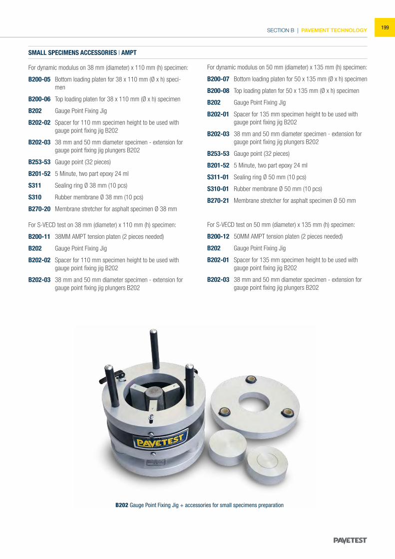
SECTION B | PAVEMENT TECHNOLOGY
B202 Gauge Point Fixing Jig + accessories for small specimens preparation
SMALL SPECIMENS ACCESSORIES | AMPT
For dynamic modulus on 38 mm (diameter) x 110 mm (h) specimen:
B200-05 Bottom loading platen for 38 x 110 mm (Ø x h) speci-men
B200-06 Top loading platen for 38 x 110 mm (Ø x h) specimen
B202 Gauge Point Fixing Jig
B202-02 Spacer for 110 mm specimen height to be used with gauge point fixing jig B202
B202-03 38 mm and 50 mm diameter specimen - extension for gauge point fixing jig plungers B202
B253-53 Gauge point (32 pieces)
B201-52 5 Minute, two part epoxy 24 ml
S311 Sealing ring Ø 38 mm (10 pcs)
S310 Rubber membrane Ø 38 mm (10 pcs)
B270-20 Membrane stretcher for asphalt specimen Ø 38 mm
For S-VECD test on 38 mm (diameter) x 110 mm (h) specimen:
B200-11 38MM AMPT tension platen (2 pieces needed)
B202 Gauge Point Fixing Jig
B202-02 Spacer for 110 mm specimen height to be used with gauge point fixing jig B202
B202-03 38 mm and 50 mm diameter specimen - extension for gauge point fixing jig plungers B202
For dynamic modulus on 50 mm (diameter) x 135 mm (h) specimen:
B200-07 Bottom loading platen for 50 x 135 mm (Ø x h) specimen
B200-08 Top loading platen for 50 x 135 mm (Ø x h) specimen
B202 Gauge Point Fixing Jig
B202-01 Spacer for 135 mm specimen height to be used with gauge point fixing jig B202
B202-03 38 mm and 50 mm diameter specimen - extension for gauge point fixing jig plungers B202
B253-53 Gauge point (32 pieces)
B201-52 5 Minute, two part epoxy 24 ml
S311-01 Sealing ring Ø 50 mm (10 pcs)
S310-01 Rubber membrane Ø 50 mm (10 pcs)
B270-21 Membrane stretcher for asphalt specimen Ø 50 mm
For S-VECD test on 50 mm (diameter) x 135 mm (h) specimen:
B200-12 50MM AMPT tension platen (2 pieces needed)
B202 Gauge Point Fixing Jig
B202-01 Spacer for 135 mm specimen height to be used with gauge point fixing jig B202
B202-03 38 mm and 50 mm diameter specimen - extension for gauge point fixing jig plungers B202
199
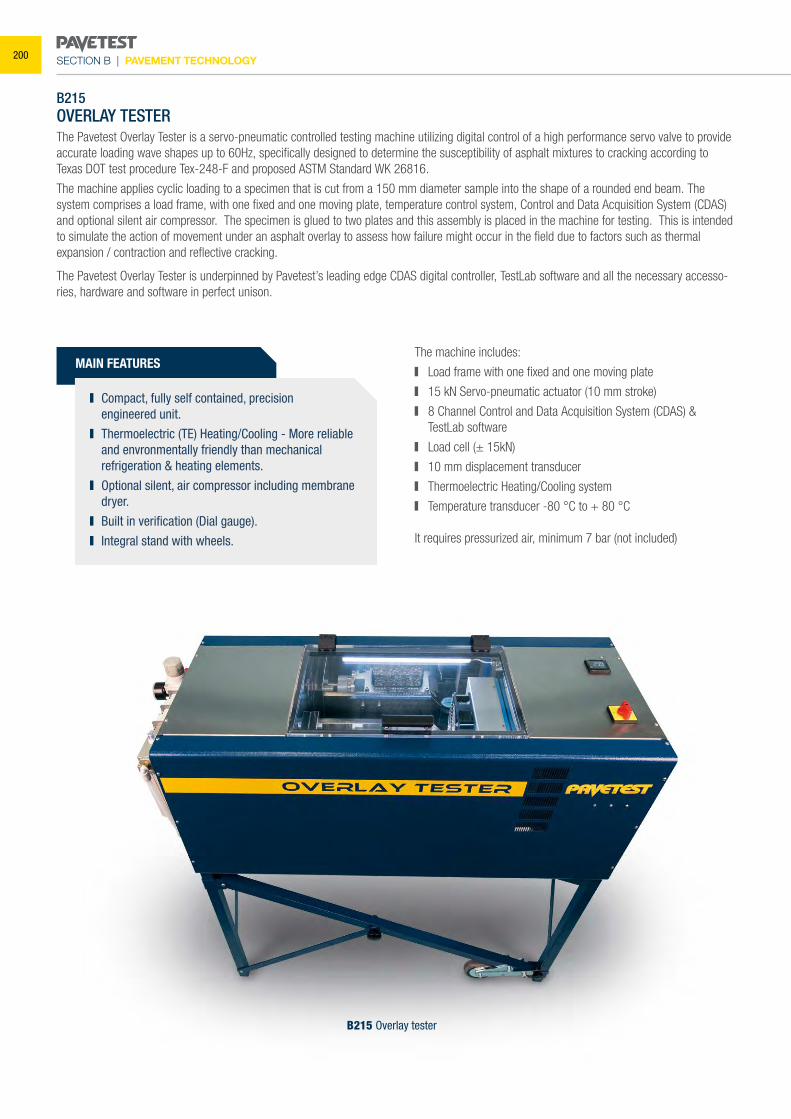
SECTION B | PAVEMENT TECHNOLOGY
MAIN FEATURES
Compact, fully self contained, precision engineered unit.
Thermoelectric (TE) Heating/Cooling - More reliable and envronmentally friendly than mechanical refrigeration & heating elements.
Optional silent, air compressor including membrane dryer.
Built in verification (Dial gauge). Integral stand with wheels.
B215OVERLAY TESTERThe Pavetest Overlay Tester is a servo-pneumatic controlled testing machine utilizing digital control of a high performance servo valve to provide accurate loading wave shapes up to 60Hz, specifically designed to determine the susceptibility of asphalt mixtures to cracking according to Texas DOT test procedure Tex-248-F and proposed ASTM Standard WK 26816.
The machine applies cyclic loading to a specimen that is cut from a 150 mm diameter sample into the shape of a rounded end beam. The system comprises a load frame, with one fixed and one moving plate, temperature control system, Control and Data Acquisition System (CDAS) and optional silent air compressor. The specimen is glued to two plates and this assembly is placed in the machine for testing. This is intended to simulate the action of movement under an asphalt overlay to assess how failure might occur in the field due to factors such as thermal expansion / contraction and reflective cracking.
The Pavetest Overlay Tester is underpinned by Pavetest’s leading edge CDAS digital controller, TestLab software and all the necessary accesso-ries, hardware and software in perfect unison.
B215 Overlay tester
The machine includes:
Load frame with one fixed and one moving plate
15 kN Servo-pneumatic actuator (10 mm stroke)
8 Channel Control and Data Acquisition System (CDAS) & TestLab software
Load cell (± 15kN)
10 mm displacement transducer
Thermoelectric Heating/Cooling system
Temperature transducer -80 °C to + 80 °C
It requires pressurized air, minimum 7 bar (not included)
200
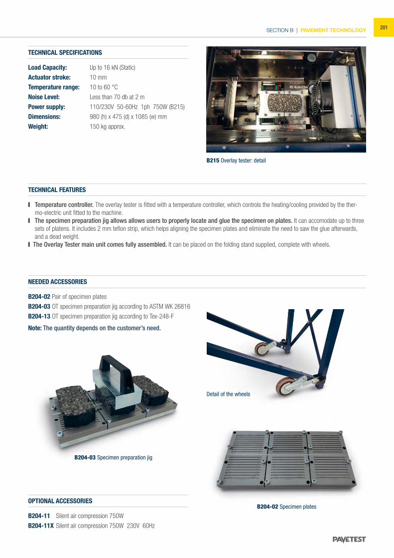
SECTION B | PAVEMENT TECHNOLOGY
TECHNICAL SPECIFICATIONS
Load Capacity: Up to 16 kN (Static)
Actuator stroke: 10 mm
Temperature range: 10 to 60 °C
Noise Level: Less than 70 db at 2 m
Power supply: 110/230V 50-60Hz 1ph 750W (B215)
Dimensions: 980 (h) x 475 (d) x 1085 (w) mm
Weight: 150 kg approx.
NEEDED ACCESSORIES
B204-02 Pair of specimen plates
B204-03 OT specimen preparation jig according to ASTM WK 26816
B204-13 OT specimen preparation jig according to Tex-248-F
Note: The quantity depends on the customer’s need.
TECHNICAL FEATURES
Temperature controller. The overlay tester is fitted with a temperature controller, which controls the heating/cooling provided by the ther-mo-electric unit fitted to the machine.
The specimen preparation jig allows allows users to properly locate and glue the specimen on plates. It can accomodate up to three sets of platens. It includes 2 mm teflon strip, which helps aligning the specimen plates and eliminate the need to saw the glue afterwards, and a dead weight.
The Overlay Tester main unit comes fully assembled. It can be placed on the folding stand supplied, complete with wheels.
Detail of the wheels
B215 Overlay tester: detail
OPTIONAL ACCESSORIES
B204-11 Silent air compression 750W
B204-11X Silent air compression 750W 230V 60Hz
B204-02 Specimen plates
B204-03 Specimen preparation jig
201
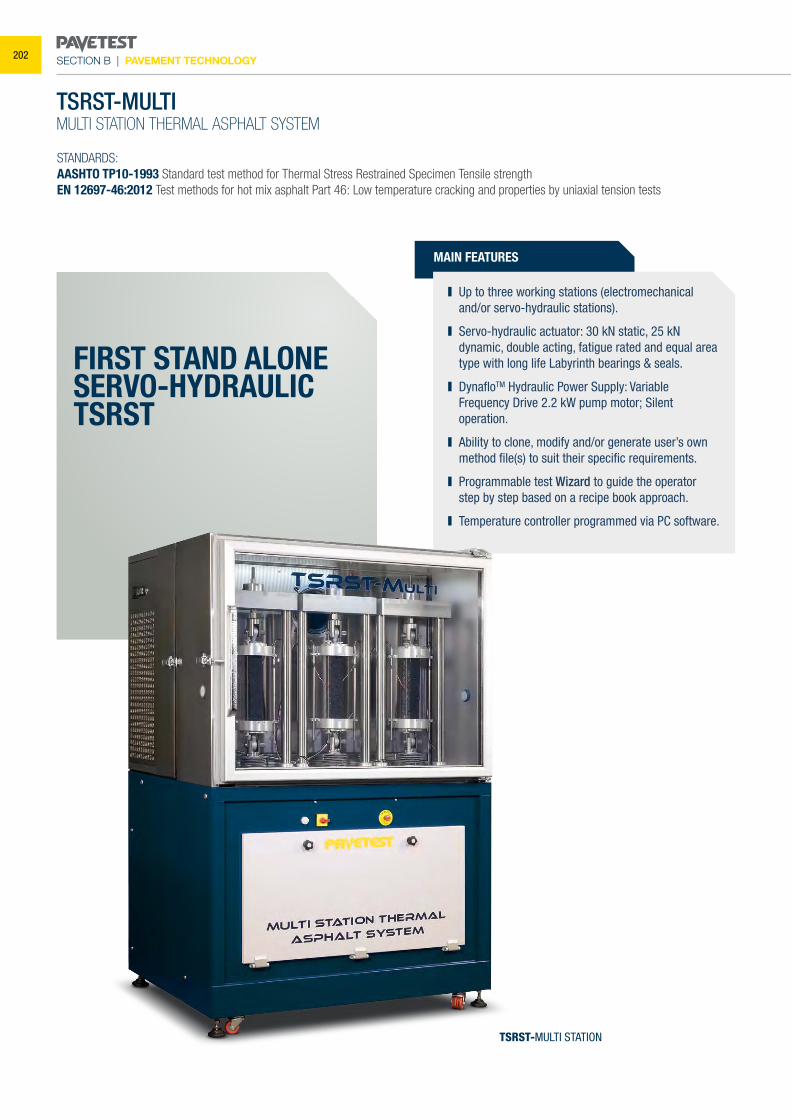
SECTION B | PAVEMENT TECHNOLOGY
TSRST-MULTIMULTI STATION THERMAL ASPHALT SYSTEM
STANDARDS:AASHTO TP10-1993 Standard test method for Thermal Stress Restrained Specimen Tensile strengthEN 12697-46:2012 Test methods for hot mix asphalt Part 46: Low temperature cracking and properties by uniaxial tension tests
MAIN FEATURES
Up to three working stations (electromechanical and/or servo-hydraulic stations).
Servo-hydraulic actuator: 30 kN static, 25 kN dynamic, double acting, fatigue rated and equal area type with long life Labyrinth bearings & seals.
DynafloTM Hydraulic Power Supply: Variable Frequency Drive 2.2 kW pump motor; Silent operation.
Ability to clone, modify and/or generate user’s own method file(s) to suit their specific requirements.
Programmable test Wizard to guide the operator step by step based on a recipe book approach.
Temperature controller programmed via PC software.
FIRST STAND ALONESERVO-HYDRAULICTSRST
TSRST-MULTI STATION
202
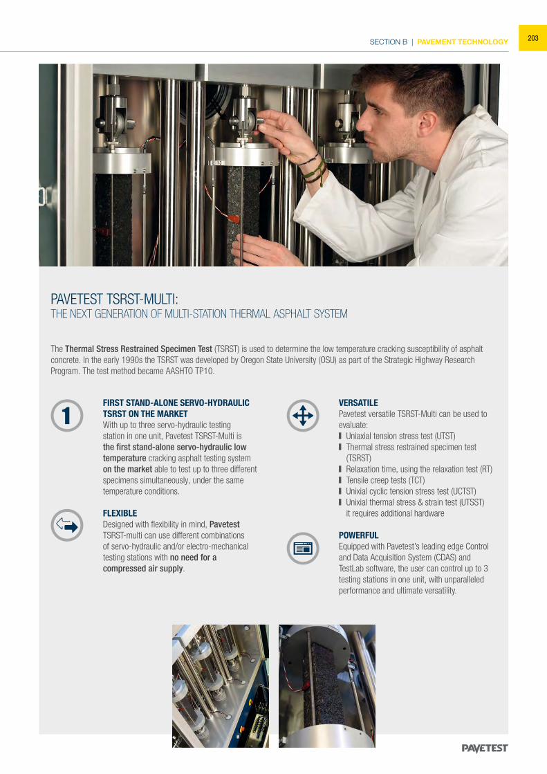
SECTION B | PAVEMENT TECHNOLOGY
The Thermal Stress Restrained Specimen Test (TSRST) is used to determine the low temperature cracking susceptibility of asphalt concrete. In the early 1990s the TSRST was developed by Oregon State University (OSU) as part of the Strategic Highway Research Program. The test method became AASHTO TP10.
FIRST STAND-ALONE SERVO-HYDRAULIC TSRST ON THE MARKET With up to three servo-hydraulic testing station in one unit, Pavetest TSRST-Multi is the first stand-alone servo-hydraulic low temperature cracking asphalt testing system on the market able to test up to three different specimens simultaneously, under the same temperature conditions.
FLEXIBLEDesigned with flexibility in mind, Pavetest TSRST-multi can use different combinations of servo-hydraulic and/or electro-mechanical testing stations with no need for a compressed air supply.
VERSATILEPavetest versatile TSRST-Multi can be used to evaluate: Uniaxial tension stress test (UTST) Thermal stress restrained specimen test
(TSRST) Relaxation time, using the relaxation test (RT) Tensile creep tests (TCT) Unixial cyclic tension stress test (UCTST) Unixial thermal stress & strain test (UTSST)
it requires additional hardware
POWERFUL Equipped with Pavetest’s leading edge Control and Data Acquisition System (CDAS) and TestLab software, the user can control up to 3 testing stations in one unit, with unparalleled performance and ultimate versatility.
PAVETEST TSRST-MULTI: THE NEXT GENERATION OF MULTI-STATION THERMAL ASPHALT SYSTEM
203
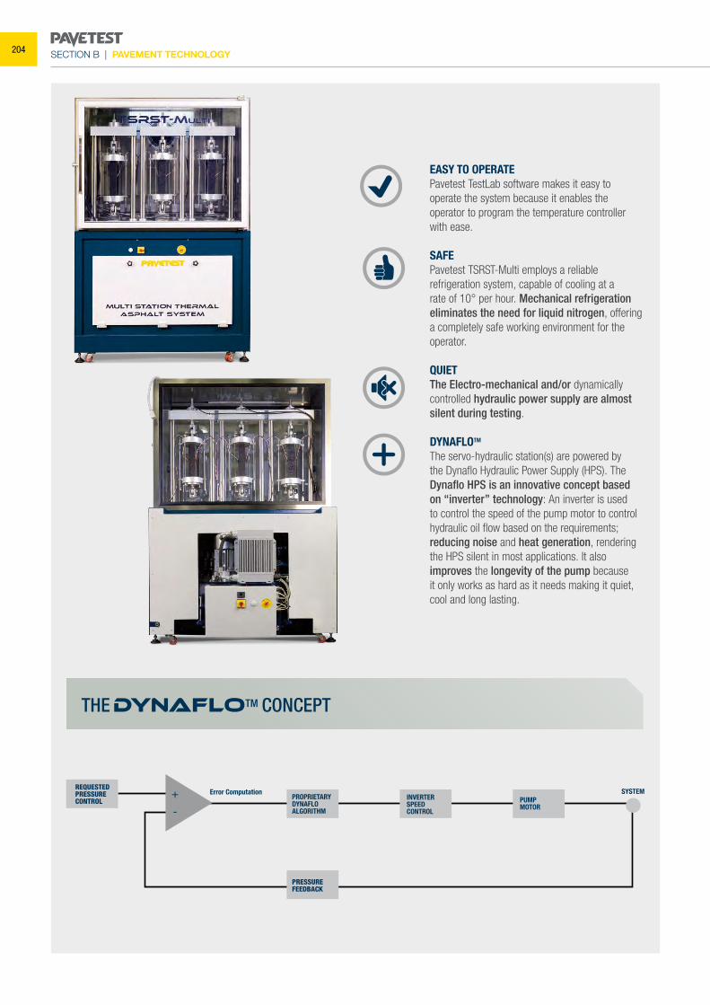
SECTION B | PAVEMENT TECHNOLOGY
EASY TO OPERATEPavetest TestLab software makes it easy to operate the system because it enables the operator to program the temperature controller with ease.
SAFEPavetest TSRST-Multi employs a reliable refrigeration system, capable of cooling at a rate of 10° per hour. Mechanical refrigeration eliminates the need for liquid nitrogen, offering a completely safe working environment for the operator.
QUIETThe Electro-mechanical and/or dynamically controlled hydraulic power supply are almost silent during testing.
DYNAFLOTM The servo-hydraulic station(s) are powered by the Dynaflo Hydraulic Power Supply (HPS). The Dynaflo HPS is an innovative concept based on “inverter” technology: An inverter is used to control the speed of the pump motor to control hydraulic oil flow based on the requirements; reducing noise and heat generation, rendering the HPS silent in most applications. It also improves the longevity of the pump because it only works as hard as it needs making it quiet, cool and long lasting.
PROPRIETARYDYNAFLOALGORITHM
PRESSUREFEEDBACK
INVERTERSPEEDCONTROL
PUMPMOTOR
Error Computation SYSTEM+
-
REQUESTED PRESSURE CONTROL
THE DYNAFLOTM CONCEPT
204
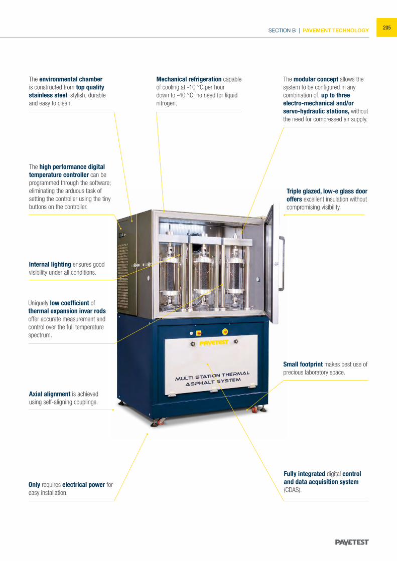
SECTION B | PAVEMENT TECHNOLOGY
The environmental chamber is constructed from top quality stainless steel; stylish, durable and easy to clean.
Mechanical refrigeration capable of cooling at -10 °C per hour down to -40 °C; no need for liquid nitrogen.
The high performance digital temperature controller can be programmed through the software; eliminating the arduous task of setting the controller using the tiny buttons on the controller.
The modular concept allows the system to be configured in any combination of, up to threeelectro-mechanical and/or servo-hydraulic stations, without the need for compressed air supply.
Internal lighting ensures good visibility under all conditions.
Uniquely low coefficient of thermal expansion invar rods offer accurate measurement and control over the full temperature spectrum.
Triple glazed, low-e glass door offers excellent insulation without compromising visibility.
Small footprint makes best use of precious laboratory space.
Only requires electrical power for easy installation.
Fully integrated digital control and data acquisition system (CDAS).
Axial alignment is achieved using self-aligning couplings.
205
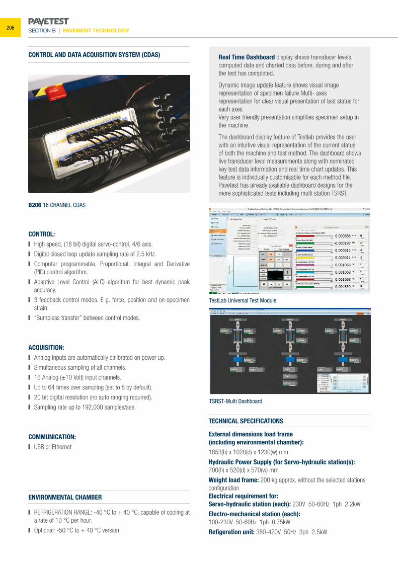
SECTION B | PAVEMENT TECHNOLOGY
TestLab Universal Test Module
TSRST-Multi Dashboard
Real Time Dashboard display shows transducer levels, computed data and charted data before, during and after the test has completed.
Dynamic image update feature shows visual image representation of specimen failure Multi- axes representation for clear visual presentation of test status for each axes.Very user friendly presentation simplifies specimen setup in the machine.
The dashboard display feature of Testlab provides the user with an intuitive visual representation of the current status of both the machine and test method. The dashboard shows live transducer level measurements along with nominated key test data information and real time chart updates. This feature is individually customisable for each method file. Pavetest has already available dashboard designs for the more sophisticated tests including multi station TSRST.
B206 16 CHANNEL CDAS
ENVIRONMENTAL CHAMBER
REFRIGERATION RANGE: -40 °C to + 40 °C, capable of cooling at a rate of 10 °C per hour.
Optional: -50 °C to + 40 °C version.
TECHNICAL SPECIFICATIONS
External dimensions load frame(including environmental chamber): 1853(h) x 1020(d) x 1230(w) mm
Hydraulic Power Supply (for Servo-hydraulic station(s): 700(h) x 520(d) x 570(w) mm
Weight load frame: 200 kg approx. without the selected stations configurationElectrical requirement for:Servo-hydraulic station (each): 230V 50-60Hz 1ph 2.2kW
Electro-mechanical station (each):100-230V 50-60Hz 1ph 0.75kW
Refigeration unit: 380-420V 50Hz 3ph 2.5kW
CONTROL AND DATA ACQUISITION SYSTEM (CDAS)
CONTROL: High speed, (18 bit) digital servo-control, 4/6 axis.
Digital closed loop update sampling rate of 2.5 kHz.
Computer programmable, Proportional, Integral and Derivative (PID) control algorithm.
Adaptive Level Control (ALC) algorithm for best dynamic peak accuracy.
3 feedback control modes. E g. force, position and on-specimen strain.
“Bumpless transfer” between control modes.
ACQUISITION: Analog inputs are automatically calibrated on power up.
Simultaneous sampling of all channels.
16 Analog (±10 Volt) input channels.
Up to 64 times over sampling (set to 8 by default).
20 bit digital resolution (no auto ranging required).
Sampling rate up to 192,000 samples/see.
COMMUNICATION: USB or Ethernet
206
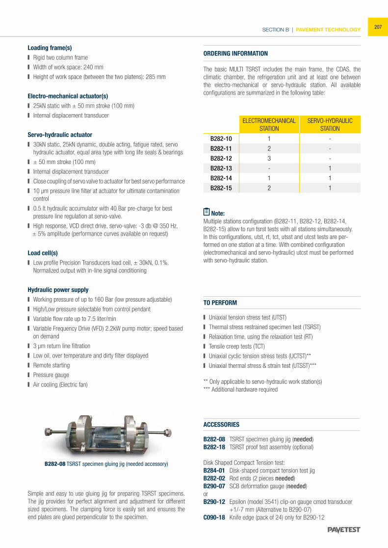
SECTION B | PAVEMENT TECHNOLOGY
ELECTROMECHANICAL STATION
SERVO-HYDRAULIC STATION
B282-10 1 -
B282-11 2 -
B282-12 3 -
B282-13 - 1
B282-14 1 1
B282-15 2 1
TO PERFORM
Uniaxial tension stress test (UTST)
Thermal stress restrained specimen test (TSRST)
Relaxation time, using the relaxation test (RT)
Tensile creep tests (TCT)
Uniaxial cyclic tension stress tests (UCTST)**
Uniaxial thermal stress & strain test (UTSST)***
ORDERING INFORMATION
The basic MULTI TSRST includes the main frame, the CDAS, the climatic chamber, the refrigeration unit and at least one between the electro-mechanical or servo-hydraulic station. All available configurations are summarized in the following table:
Loading frame(s) Rigid two column frame
Width of work space: 240 mm
Height of work space (between the two platens): 285 mm
Electro-mechanical actuator(s) 25kN static with ± 50 mm stroke (100 mm)
Internal displacement transducer
Servo-hydraulic actuator 30kN static, 25kN dynamic, double acting, fatigue rated, servo
hydraulic actuator, equal area type with long life seals & bearings
± 50 mm stroke (100 mm)
Internal displacement transducer
Close coupling of servo valve to actuator for best servo performance
10 μm pressure line filter at actuator for ultimate contamination control
0.5 lt hydraulic accumulator with 40 Bar pre-charge for best pressure line regulation at servo-valve.
High response, VCD direct drive, servo-valve: -3 db @ 350 Hz, ± 5% amplitude (performance curves available on request)
Load cell(s) Low profile Precision Transducers load cell, ± 30kN, 0.1%.
Normalized output with in-line signal conditioning
Hydraulic power supply Working pressure of up to 160 Bar (low pressure adjustable)
High/Low pressure selectable from control pendant
Variable flow rate up to 7.5 liter/min
Variable Frequency Drive (VFD) 2.2kW pump motor; speed based on demand
3 μm return line filtration
Low oil, over temperature and dirty filter displayed
Remote starting
Pressure gauge
Air cooling (Electric fan) ** Only applicable to servo-hydraulic work station(s)*** Additional hardware required
Simple and easy to use gluing jig for preparing TSRST specimens. The jig provides for perfect alignment and adjustment for different sized specimens. The clamping force is easily set and ensures the end plates are glued perpendicular to the specimen.
B282-08 TSRST specimen gluing jig (needed accessory)
ACCESSORIES
B282-08 TSRST specimen gluing jig (needed)B282-18 TSRST proof test assembly (optional)
Disk Shaped Compact Tension test:B284-01 Disk-shaped compact tension test jig B282-02 Rod ends (2 pieces needed)B290-07 SCB deformation gauge (needed)orB290-12 Epsilon (model 3541) clip-on gauge cmod transducer
+1/-7 mm (Alternative to B290-07)C090-18 Knife edge (pack of 24) only for B290-12
Note:Multiple stations configuration (B282-11, B282-12, B282-14,B282-15) allow to run tsrst tests with all stations simultaneously.In this configurations, utst, rt, tct, utsst and utcst tests are per-formed on one station at a time. With combined configuration (electromechanical and servo-hydraulic) utcst must be performed with servo-hydraulic station.
207
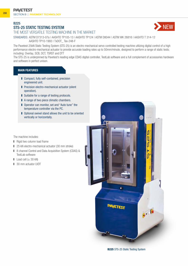
SECTION B | PAVEMENT TECHNOLOGY
B225 STS-25 Static Testing System
B225 STS-25 STATIC TESTING SYSTEMTHE MOST VERSATILE TESTING MACHINE IN THE MARKET STANDARDS: ASTM D7313-07a | AASHTO TP105-13 | AASHTO TP124 | ASTM D8044 | ASTM WK 26816 | AASHTO T 314-12 AASHTO TP10-1993 | TxDOT_ Tex-248-F
The Pavetest 25kN Static Testing System (STS-25) is an electro-mechanical servo-controlled testing machine utilizing digital control of a high performance electro-mechanical actuator to provide accurate loading rates up to 50mm/minute, designed to perform a range of static tests; including: Overlay, SCB, DCT, TSRST and DTTThe STS-25 is underpinned by Pavetest’s leading edge CDAS digital controller, TestLab software and a full complement of accessories hardware and software in perfect unison.
The machine includes:
Rigid two column load frame
25 kN electro-mechanical actuator (30 mm stroke)
8 channel Control and Data Acquisition System (CDAS) & TestLab software
Load cell (± 30 kN)
30 mm actuator LVDT
MAIN FEATURES
Compact, fully self-contained, precision engineered unit.
Precision electro-mechanical actuator (silent operation).
Suitable for a range of testing protocols. A range of two piece climatic chambers. Operator can monitor, set and “Auto tune” the
temperature controller via the PC. Optional swivel stand allows the unit to be oriented
vertically or horizontally.
NEW
208
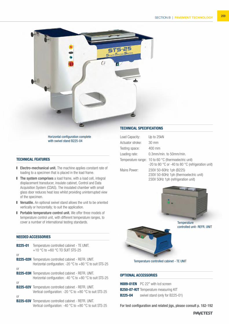
SECTION B | PAVEMENT TECHNOLOGY
Horizontal configuration completewith swivel stand B225-04
NEEDED ACCESSORIES
B225-01 Temperature controlled cabinet - TE UNIT. +10 °C to +60 °C TO SUIT STS-25orB225-02H Temperature controlled cabinet - REFR. UNIT. Horizontal configuration: -20 °C to +80 °C to suit STS-25orB225-03H Temperature controlled cabinet - REFR. UNIT. Horizontal configuration: -40 °C to +80 °C to suit STS-25orB225-02V Temperature controlled cabinet - REFR. UNIT. Vertical configuration: -20 °C to +80 °C to suit STS-25orB225-03V Temperature controlled cabinet - REFR. UNIT. Vertical configuration: -40 °C to +80 °C to suit STS-25
OPTIONAL ACCESSORIES
H009-01EN PC 22" with lcd screen
B250-07-KIT Temperature measuring KIT
B225-04 swivel stand (only for B225-01)
For test configuration and related jigs, please consult p. 182-192
TECHNICAL SPECIFICATIONS
Load Capacity: Up to 25kN
Actuator stroke: 30 mm
Testing space: 400 mm
Loading rate: 0.3mm/min. to 50mm/min.
Temperature range: 10 to 60 °C (thermoelectric unit) -20 to 80 °C or -40 to 80 °C (refrigeration unit)
Mains Power: 230V 50-60Hz 1ph (B225) 230V 50-60Hz 1ph (thermoelectric unit) 230V 50Hz 1ph (refrigeration unit)
TECHNICAL FEATURES
Electro-mechanical unit. The machine applies constant rate of loading to a specimen that is placed in the load frame.
The system comprises a load frame, with a load cell, integral displacement transducer, insulate cabinet, Control and Data Acquisition System (CDAS). The insulated chamber with small glass door reduces heat loss whilst providing uninterrupted view of the specimen.
Versatile. An optional swivel stand allows the unit to be oriented vertically or horizontally; to suit the application.
Portable temperature control unit. We offer three models of temperature control unit, with different temperature ranges, to cover a number of international testing standards. Temperature
controlled unit- REFR. UNIT
Temperature controlled cabinet - TE UNIT
209
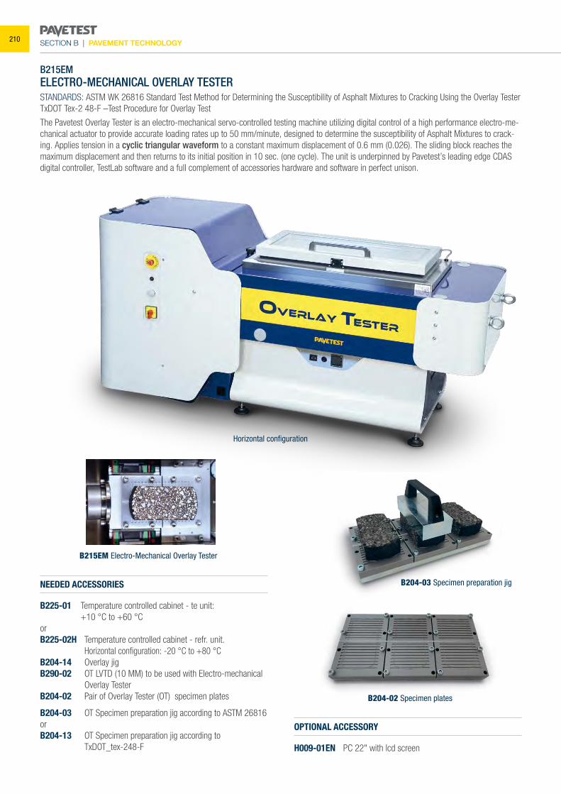
SECTION B | PAVEMENT TECHNOLOGY
B215EMELECTRO-MECHANICAL OVERLAY TESTER
STANDARDS: ASTM WK 26816 Standard Test Method for Determining the Susceptibility of Asphalt Mixtures to Cracking Using the Overlay Tester TxDOT Tex-2 48-F –Test Procedure for Overlay Test
The Pavetest Overlay Tester is an electro-mechanical servo-controlled testing machine utilizing digital control of a high performance electro-me-chanical actuator to provide accurate loading rates up to 50 mm/minute, designed to determine the susceptibility of Asphalt Mixtures to crack-ing. Applies tension in a cyclic triangular waveform to a constant maximum displacement of 0.6 mm (0.026). The sliding block reaches the maximum displacement and then returns to its initial position in 10 sec. (one cycle). The unit is underpinned by Pavetest’s leading edge CDAS digital controller, TestLab software and a full complement of accessories hardware and software in perfect unison.
B215EM Electro-Mechanical Overlay Tester
NEEDED ACCESSORIES
B225-01 Temperature controlled cabinet - te unit: +10 °C to +60 °CorB225-02H Temperature controlled cabinet - refr. unit. Horizontal configuration: -20 °C to +80 °CB204-14 Overlay jigB290-02 OT LVTD (10 MM) to be used with Electro-mechanical
Overlay TesterB204-02 Pair of Overlay Tester (OT) specimen plates
B204-03 OT Specimen preparation jig according to ASTM 26816orB204-13 OT Specimen preparation jig according to TxDOT_tex-248-F
OPTIONAL ACCESSORY
H009-01EN PC 22" with lcd screen
Horizontal configuration
B204-02 Specimen plates
B204-03 Specimen preparation jig
210
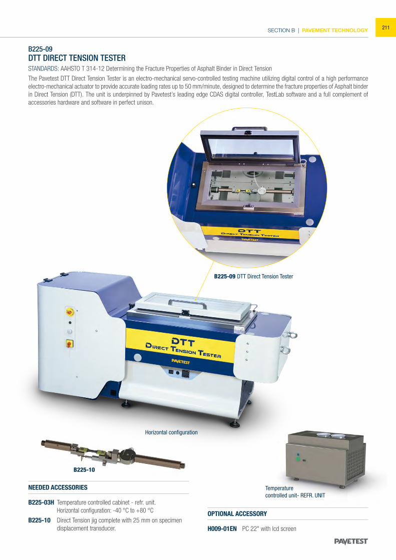
SECTION B | PAVEMENT TECHNOLOGY
B225-09DTT DIRECT TENSION TESTERSTANDARDS: AAHSTO T 314-12 Determining the Fracture Properties of Asphalt Binder in Direct Tension
The Pavetest DTT Direct Tension Tester is an electro-mechanical servo-controlled testing machine utilizing digital control of a high performance electro-mechanical actuator to provide accurate loading rates up to 50 mm/minute, designed to determine the fracture properties of Asphalt binder in Direct Tension (DTT). The unit is underpinned by Pavetest’s leading edge CDAS digital controller, TestLab software and a full complement of accessories hardware and software in perfect unison.
B225-09 DTT Direct Tension Tester
NEEDED ACCESSORIES
B225-03H Temperature controlled cabinet - refr. unit. Horizontal configuration: -40 °C to +80 °C
B225-10 Direct Tension jig complete with 25 mm on specimen displacement transducer.
OPTIONAL ACCESSORY
H009-01EN PC 22" with lcd screen
B225-10
Temperaturecontrolled unit- REFR. UNIT
Horizontal configuration
211
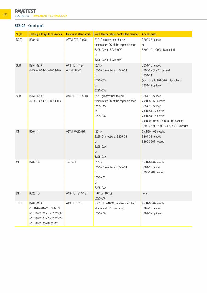
SECTION B | PAVEMENT TECHNOLOGY
Sigla Testing Kit/Jig/Accessories Relevant standard(s) With temperature controlled cabinet Accessories
DC(T) B284-01 ASTM D7313-07a "(10°C greater than the low B290-07 needed
temperature PG of the asphalt binder) or
B225-02H or B225-02V B290-12 + C090-18 needed
or
B225-03H or B225-03V
SCB B254-02-KIT AASHTO TP124 (25°c) B254-16 needed
(B208+B254-10+B254-02) ASTM D8044 B225-01+ optional B225-04 B290-02 (1or 2) optional
or B254-11
B225-02V (according to B290-02 q.ty) optional
or B254-12 optional
B225-03V
SCB B254-02-KIT AASHTO TP105-13 (22°C greater than the low B254-16 needed
(B208+B254-10+B254-02) temperature PG of the asphalt binder) 2 x B253-53 needed
B225-02V B254-13 needed
or 2 x B254-14 needed
B225-03V 2 x B254-15 needed
2 x B290-05 or 2 x B290-06 needed
B290-07 or B290-16 + C090-18 needed
OT B204-14 ASTM WK26816 (25°c) 3 x B204-02 needed
B225-01+ optional B225-04 B204-03 needed
or B290-02OT needed
B225-02H
or
B225-03H
OT B204-14 Tex 248F (25°c) 3 x B204-02 needed
B225-01+ optional B225-04 B204-13 needed
or B290-02OT needed
B225-02H
or
B225-03H
DTT B225-10 AASHTO T314-12 (+6° to -40 °C) none
B225-03H
TSRST B282-01-KIT AASHTO TP10 (-50°C to +10°C, capable of cooling 2 x B290-09 needed
(3 x B282-01+2 x B282-02 at a rate of 10°C per hour) B282-08 needed
+1 x B282-21+1 x B282-09 B225-03V B201-52 optional
+2 x B282-04+2 x B282-05
+2 x B282-06+B282-07)
STS-25 - Ordering info
212
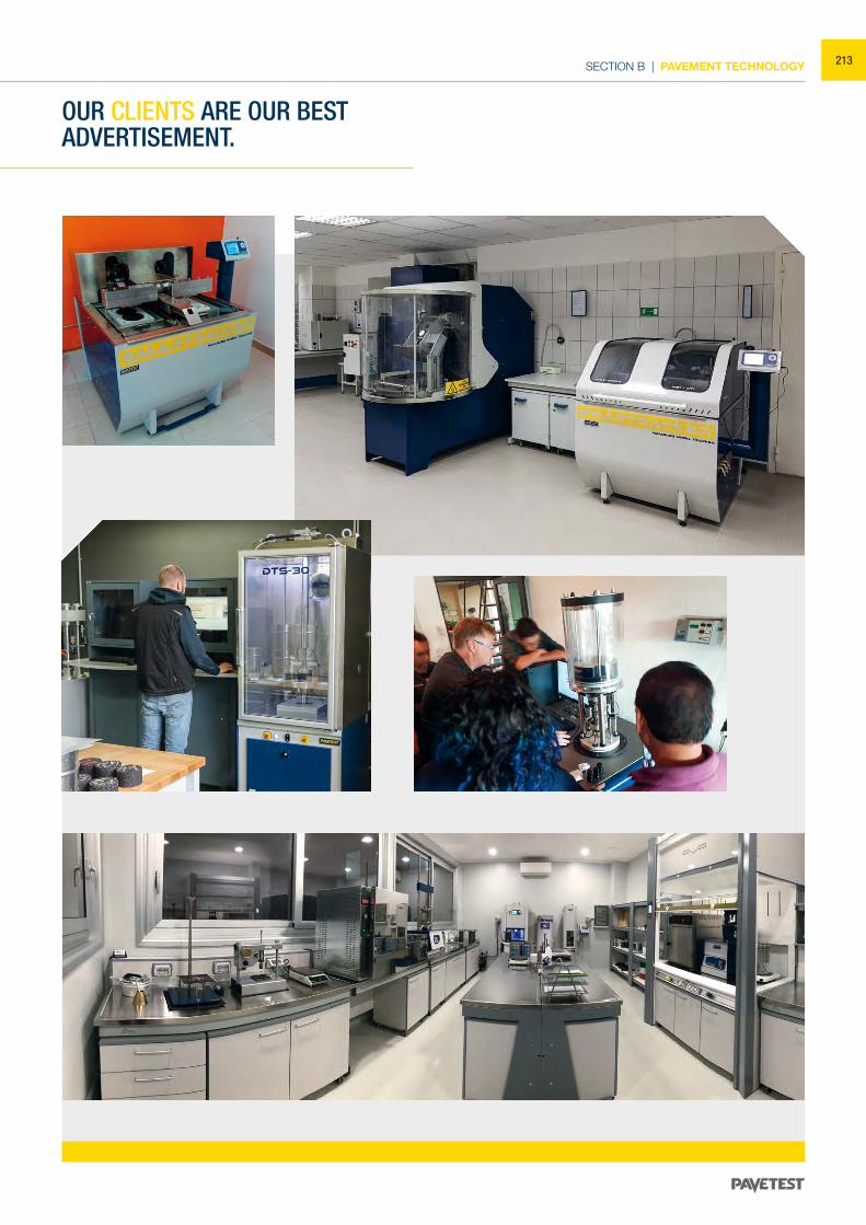
SECTION B | PAVEMENT TECHNOLOGY
OUR CLIENTS ARE OUR BEST ADVERTISEMENT.
213
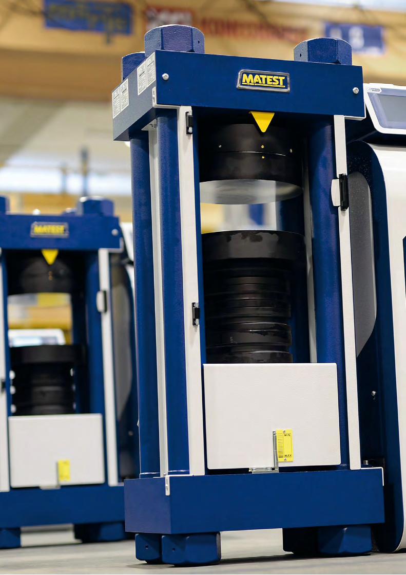
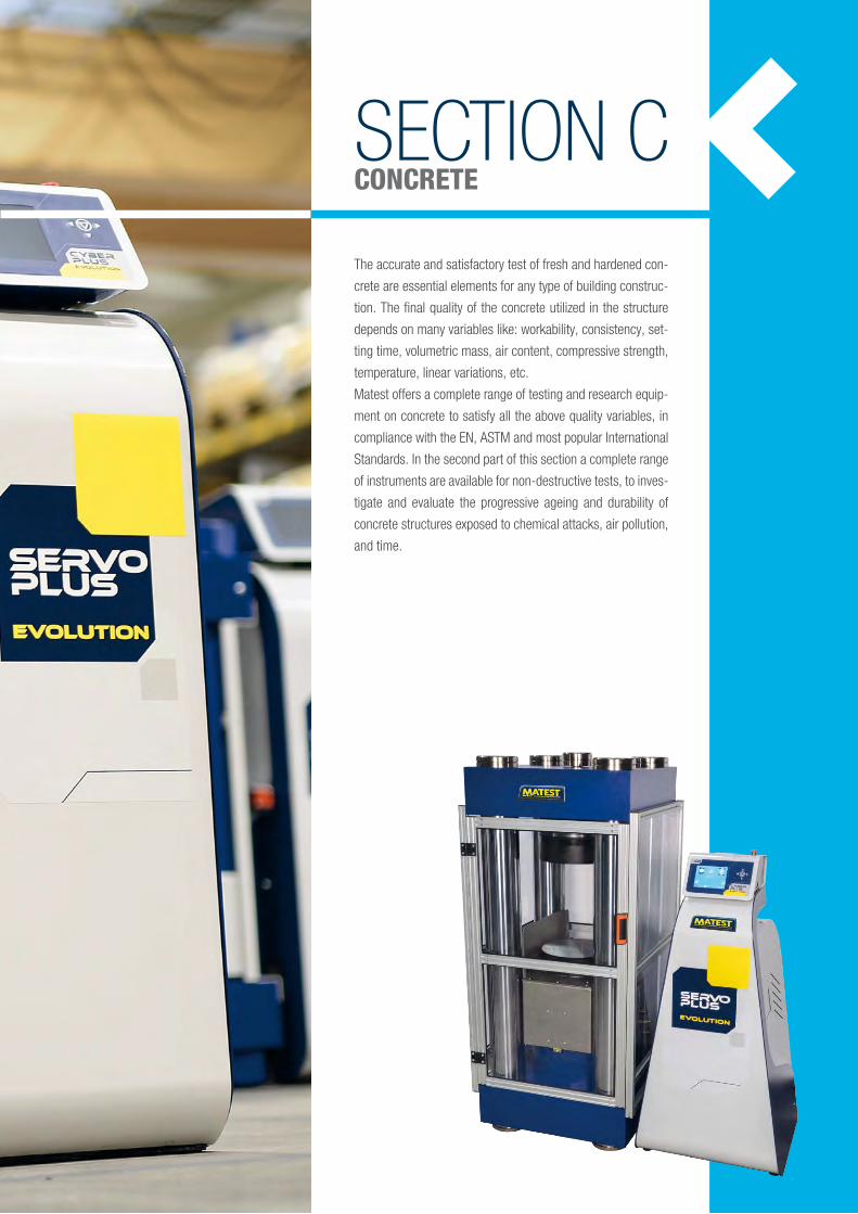
SECTION CCONCRETE
The accurate and satisfactory test of fresh and hardened con-
crete are essential elements for any type of building construc-
tion. The final quality of the concrete utilized in the structure
depends on many variables like: workability, consistency, set-
ting time, volumetric mass, air content, compressive strength,
temperature, linear variations, etc.
Matest offers a complete range of testing and research equip-
ment on concrete to satisfy all the above quality variables, in
compliance with the EN, ASTM and most popular International
Standards. In the second part of this section a complete range
of instruments are available for non-destructive tests, to inves-
tigate and evaluate the progressive ageing and durability of
concrete structures exposed to chemical attacks, air pollution,
and time.
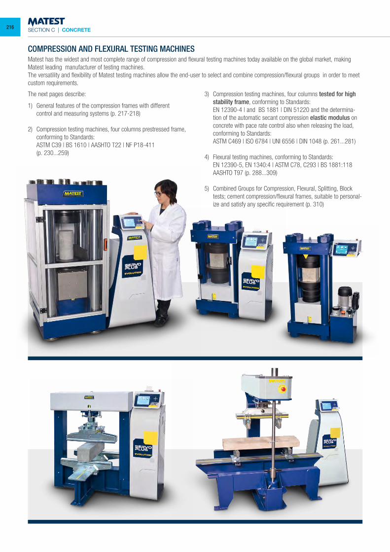
SECTION C | CONCRETE
COMPRESSION AND FLEXURAL TESTING MACHINESMatest has the widest and most complete range of compression and flexural testing machines today available on the global market, making Matest leading manufacturer of testing machines.The versatility and flexibility of Matest testing machines allow the end-user to select and combine compression/flexural groups in order to meet custom requirements.
The next pages describe:
1) General features of the compression frames with different control and measuring systems (p. 217-218)
2) Compression testing machines, four columns prestressed frame, conforming to Standards:
ASTM C39 | BS 1610 | AASHTO T22 | NF P18-411 (p. 230...259)
3) Compression testing machines, four columns tested for high stability frame, conforming to Standards:
EN 12390-4 | and BS 1881 | DIN 51220 and the determina-tion of the automatic secant compression elastic modulus on concrete with pace rate control also when releasing the load, conforming to Standards:
ASTM C469 | ISO 6784 | UNI 6556 | DIN 1048 (p. 261...281)
4) Flexural testing machines, conforming to Standards: EN 12390-5, EN 1340:4 | ASTM C78, C293 | BS 1881:118 AASHTO T97 (p. 288...309) 5) Combined Groups for Compression, Flexural, Splitting, Block
tests; cement compression/flexural frames, suitable to personal-ize and satisfy any specific requirement (p. 310)
216
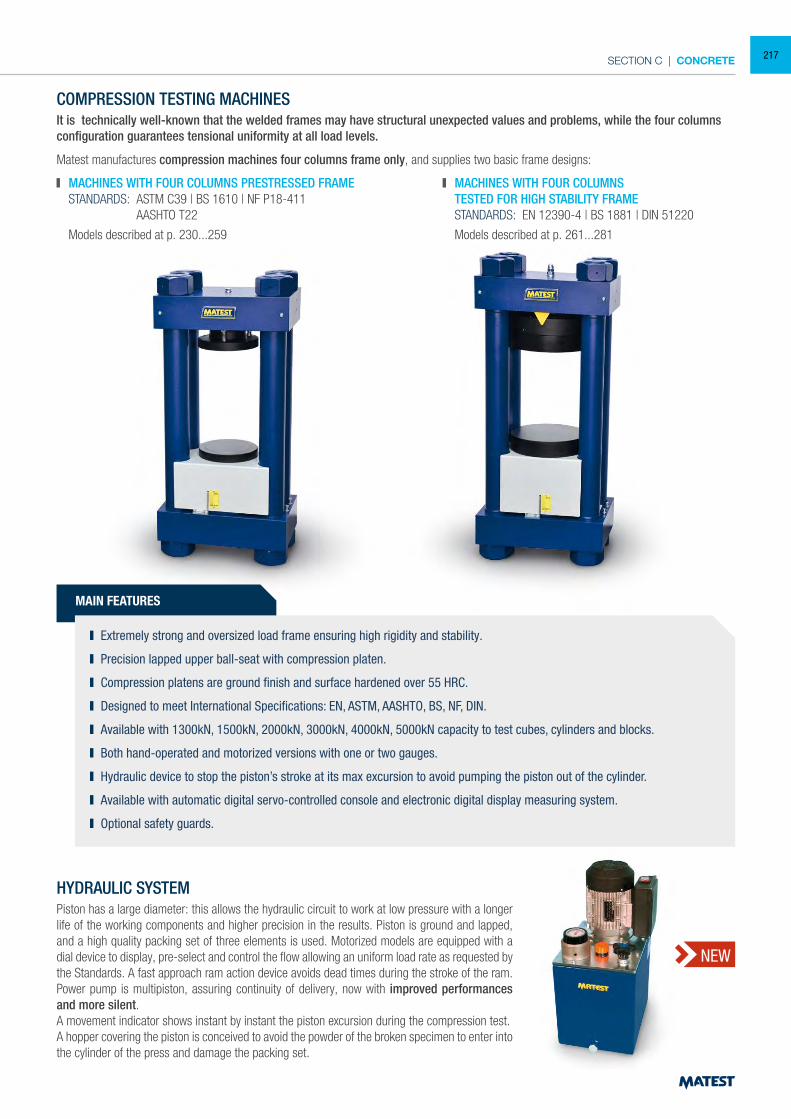
SECTION C | CONCRETE
NEW
COMPRESSION TESTING MACHINESIt is technically well-known that the welded frames may have structural unexpected values and problems, while the four columns configuration guarantees tensional uniformity at all load levels.
Matest manufactures compression machines four columns frame only, and supplies two basic frame designs:
MACHINES WITH FOUR COLUMNS PRESTRESSED FRAME STANDARDS: ASTM C39 | BS 1610 | NF P18-411 AASHTO T22
Models described at p. 230...259
MACHINES WITH FOUR COLUMNS TESTED FOR HIGH STABILITY FRAME STANDARDS: EN 12390-4 | BS 1881 | DIN 51220
Models described at p. 261...281
MAIN FEATURES
Extremely strong and oversized load frame ensuring high rigidity and stability.
Precision lapped upper ball-seat with compression platen.
Compression platens are ground finish and surface hardened over 55 HRC.
Designed to meet International Specifications: EN, ASTM, AASHTO, BS, NF, DIN.
Available with 1300kN, 1500kN, 2000kN, 3000kN, 4000kN, 5000kN capacity to test cubes, cylinders and blocks.
Both hand-operated and motorized versions with one or two gauges.
Hydraulic device to stop the piston’s stroke at its max excursion to avoid pumping the piston out of the cylinder.
Available with automatic digital servo-controlled console and electronic digital display measuring system.
Optional safety guards.
HYDRAULIC SYSTEMPiston has a large diameter: this allows the hydraulic circuit to work at low pressure with a longer life of the working components and higher precision in the results. Piston is ground and lapped, and a high quality packing set of three elements is used. Motorized models are equipped with a dial device to display, pre-select and control the flow allowing an uniform load rate as requested by the Standards. A fast approach ram action device avoids dead times during the stroke of the ram.Power pump is multipiston, assuring continuity of delivery, now with improved performances and more silent.A movement indicator shows instant by instant the piston excursion during the compression test.A hopper covering the piston is conceived to avoid the powder of the broken specimen to enter into the cylinder of the press and damage the packing set.
217
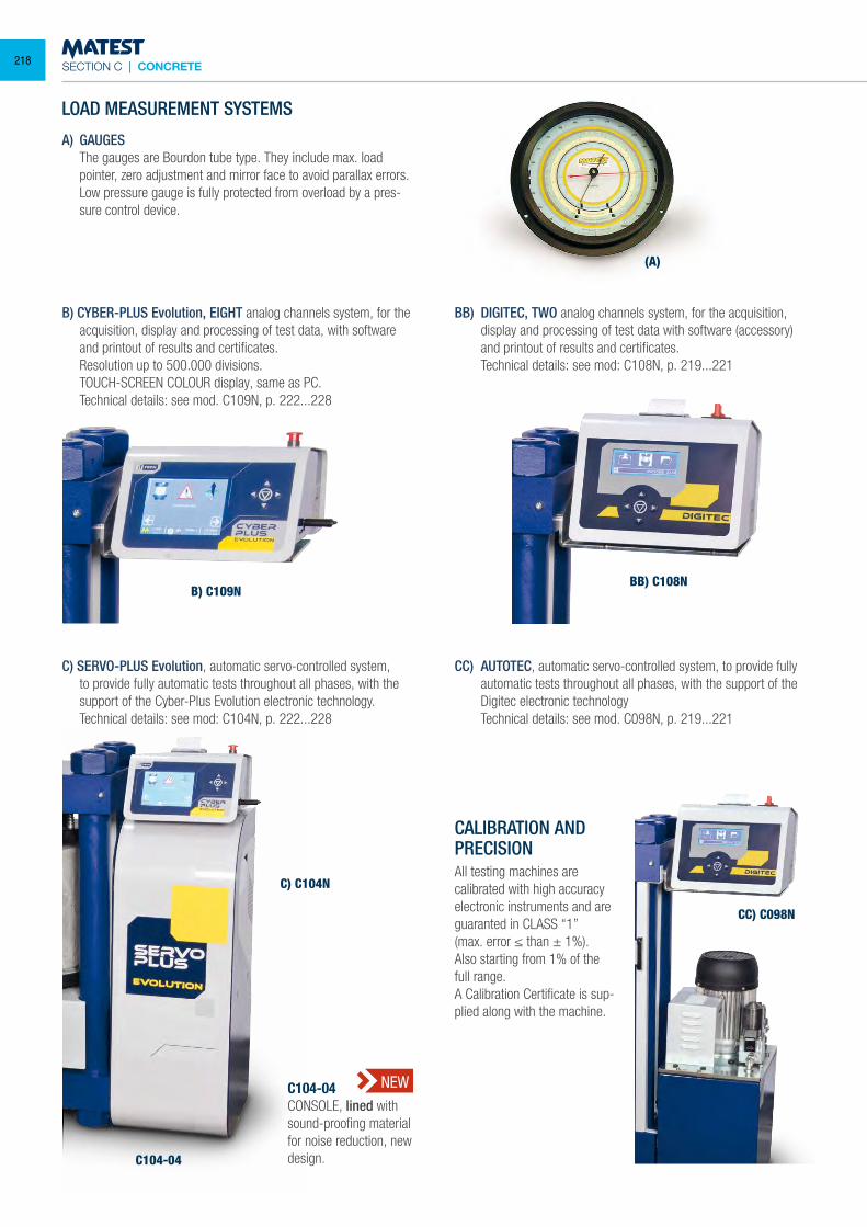
SECTION C | CONCRETE
LOAD MEASUREMENT SYSTEMS
A) GAUGES The gauges are Bourdon tube type. They include max. load
pointer, zero adjustment and mirror face to avoid parallax errors. Low pressure gauge is fully protected from overload by a pres-
sure control device.
B) CYBER-PLUS Evolution, EIGHT analog channels system, for the acquisition, display and processing of test data, with software and printout of results and certificates.
Resolution up to 500.000 divisions. TOUCH-SCREEN COLOUR display, same as PC. Technical details: see mod. C109N, p. 222...228
C) SERVO-PLUS Evolution, automatic servo-controlled system, to provide fully automatic tests throughout all phases, with the support of the Cyber-Plus Evolution electronic technology.
Technical details: see mod: C104N, p. 222...228
BB) DIGITEC, TWO analog channels system, for the acquisition, display and processing of test data with software (accessory) and printout of results and certificates.
Technical details: see mod: C108N, p. 219...221
CC) AUTOTEC, automatic servo-controlled system, to provide fully automatic tests throughout all phases, with the support of the Digitec electronic technology
Technical details: see mod. C098N, p. 219...221
CALIBRATION AND PRECISIONAll testing machines are calibrated with high accuracy electronic instruments and are guaranted in CLASS “1”(max. error ≤ than ± 1%).Also starting from 1% of the full range.A Calibration Certificate is sup-plied along with the machine.
B) C109N
(A)
C) C104N
BB) C108N
CC) C098N
C104-04CONSOLE, lined with sound-proofing material for noise reduction, new design.C104-04
NEW
218
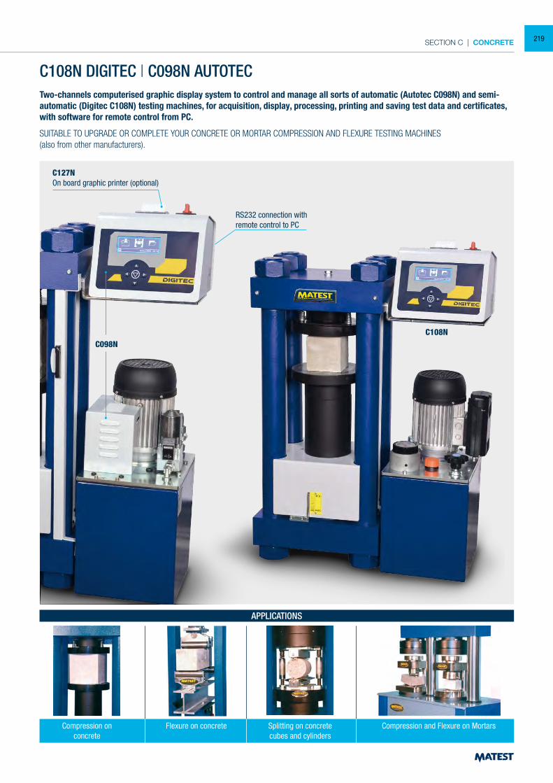
SECTION C | CONCRETE
Two-channels computerised graphic display system to control and manage all sorts of automatic (Autotec C098N) and semi-automatic (Digitec C108N) testing machines, for acquisition, display, processing, printing and saving test data and certificates, with software for remote control from PC.
SUITABLE TO UPGRADE OR COMPLETE YOUR CONCRETE OR MORTAR COMPRESSION AND FLEXURE TESTING MACHINES(also from other manufacturers).
C108N DIGITEC | C098N AUTOTEC
C127NOn board graphic printer (optional)
C108NC098N
Compression and Flexure on MortarsCompression onconcrete
APPLICATIONS
Splitting on concretecubes and cylinders
Flexure on concrete
RS232 connection with remote control to PC
219
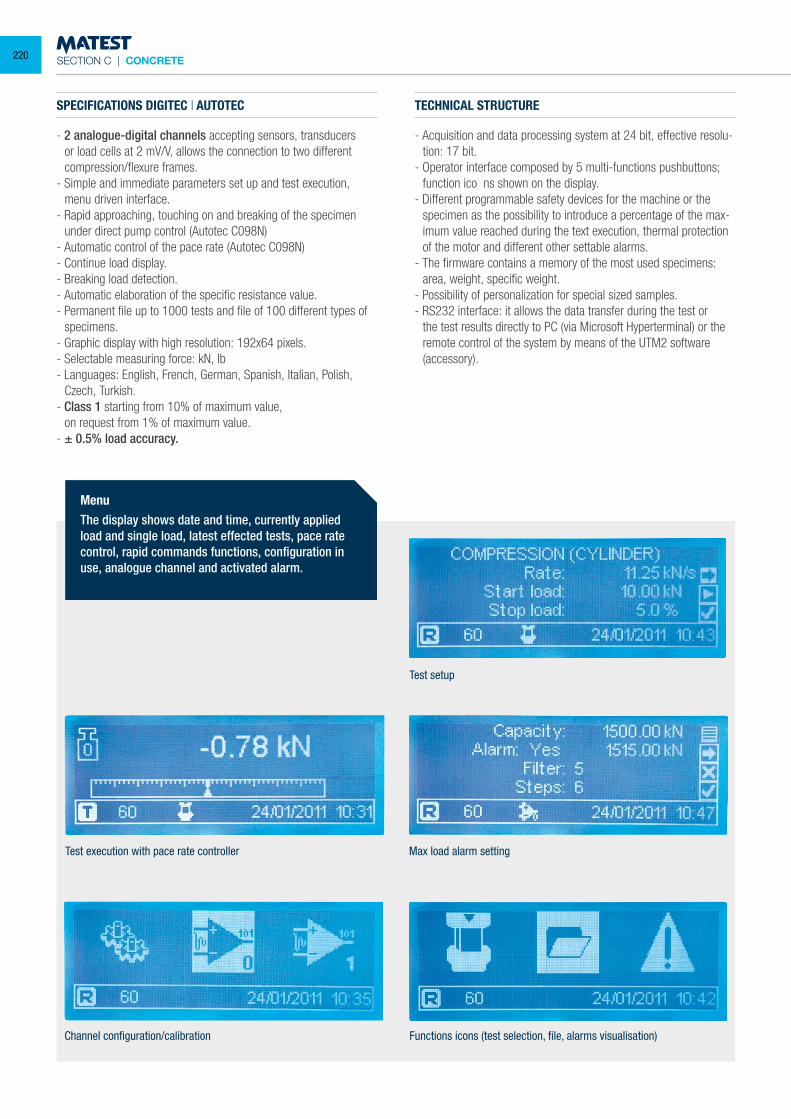
SECTION C | CONCRETE
SPECIFICATIONS DIGITEC | AUTOTEC
- 2 analogue-digital channels accepting sensors, transducers or load cells at 2 mV/V, allows the connection to two different compression/flexure frames.
- Simple and immediate parameters set up and test execution, menu driven interface.
- Rapid approaching, touching on and breaking of the specimen under direct pump control (Autotec C098N)
- Automatic control of the pace rate (Autotec C098N)- Continue load display.- Breaking load detection.- Automatic elaboration of the specific resistance value.- Permanent file up to 1000 tests and file of 100 different types of
specimens.- Graphic display with high resolution: 192x64 pixels.- Selectable measuring force: kN, lb- Languages: English, French, German, Spanish, Italian, Polish,
Czech, Turkish.- Class 1 starting from 10% of maximum value, on request from 1% of maximum value.- ± 0.5% load accuracy.
Test setup
Test execution with pace rate controller Max load alarm setting
Channel configuration/calibration Functions icons (test selection, file, alarms visualisation)
TECHNICAL STRUCTURE
- Acquisition and data processing system at 24 bit, effective resolu-tion: 17 bit.
- Operator interface composed by 5 multi-functions pushbuttons; function ico ns shown on the display.
- Different programmable safety devices for the machine or the specimen as the possibility to introduce a percentage of the max-imum value reached during the text execution, thermal protection of the motor and different other settable alarms.
- The firmware contains a memory of the most used specimens: area, weight, specific weight.
- Possibility of personalization for special sized samples.- RS232 interface: it allows the data transfer during the test or
the test results directly to PC (via Microsoft Hyperterminal) or the remote control of the system by means of the UTM2 software (accessory).
Menu The display shows date and time, currently applied load and single load, latest effected tests, pace rate control, rapid commands functions, configuration in use, analogue channel and activated alarm.
220
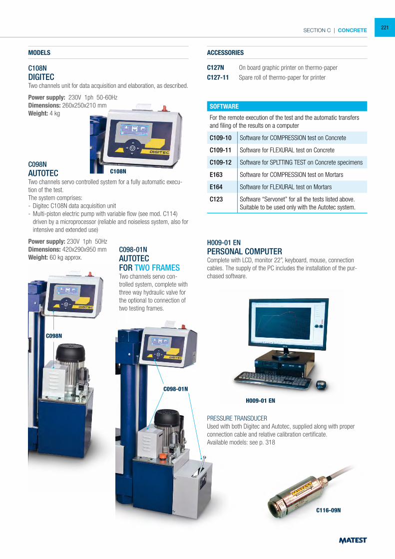
SECTION C | CONCRETE
MODELS
C108NDIGITECTwo channels unit for data acquisition and elaboration, as described.
Power supply: 230V 1ph 50-60HzDimensions: 260x250x210 mmWeight: 4 kg
ACCESSORIES
C127N On board graphic printer on thermo-paper
C127-11 Spare roll of thermo-paper for printer
SOFTWARE
For the remote execution of the test and the automatic transfers and filing of the results on a computer
C109-10 Software for COMPRESSION test on Concrete
C109-11 Software for FLEXURAL test on Concrete
C109-12 Software for SPLTTING TEST on Concrete specimens
E163 Software for COMPRESSION test on Mortars
E164 Software for FLEXURAL test on Mortars
C123 Software “Servonet” for all the tests listed above.Suitable to be used only with the Autotec system.
H009-01 ENPERSONAL COMPUTERComplete with LCD, monitor 22”, keyboard, mouse, connection cables. The supply of the PC includes the installation of the pur-chased software.
PRESSURE TRANSDUCERUsed with both Digitec and Autotec, supplied along with proper connection cable and relative calibration certificate.Available models: see p. 318
C098NAUTOTECTwo channels servo controlled system for a fully automatic execu-tion of the test.The system comprises:- Digitec C108N data acquisition unit- Multi-piston electric pump with variable flow (see mod. C114)
driven by a microprocessor (reliable and noiseless system, also for intensive and extended use)
Power supply: 230V 1ph 50HzDimensions: 420x290x950 mmWeight: 60 kg approx.
C098-01NAUTOTECFOR TWO FRAMESTwo channels servo con-trolled system, complete with three way hydraulic valve for the optional to connection of two testing frames.
C098N
C098-01N
H009-01 EN
C116-09N
C108N
221
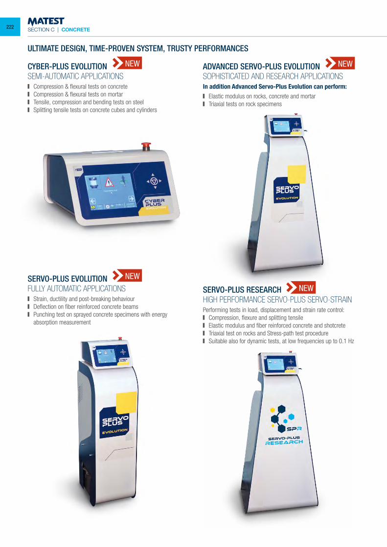
SECTION C | CONCRETE
NEW
ULTIMATE DESIGN, TIME-PROVEN SYSTEM, TRUSTY PERFORMANCES
CYBER-PLUS EVOLUTIONSEMI-AUTOMATIC APPLICATIONS Compression & flexural tests on concrete Compression & flexural tests on mortar Tensile, compression and bending tests on steel Splitting tensile tests on concrete cubes and cylinders
SERVO-PLUS EVOLUTIONFULLY AUTOMATIC APPLICATIONS Strain, ductility and post-breaking behaviour Deflection on fiber reinforced concrete beams Punching test on sprayed concrete specimens with energy
absorption measurement
ADVANCED SERVO-PLUS EVOLUTIONSOPHISTICATED AND RESEARCH APPLICATIONSIn addition Advanced Servo-Plus Evolution can perform: Elastic modulus on rocks, concrete and mortar Triaxial tests on rock specimens
NEW
NEW
NEW
SERVO-PLUS RESEARCH
HIGH PERFORMANCE SERVO-PLUS SERVO-STRAINPerforming tests in load, displacement and strain rate control: Compression, flexure and splitting tensile Elastic modulus and fiber reinforced concrete and shotcrete Triaxial test on rocks and Stress-path test procedure Suitable also for dynamic tests, at low frequencies up to 0.1 Hz
222
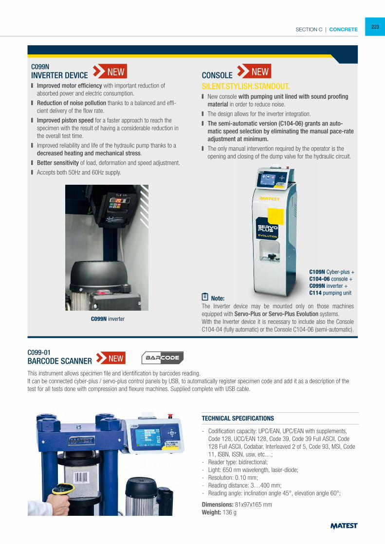
SECTION C | CONCRETE
C099NINVERTER DEVICE
Improved motor efficiency with important reduction of absorbed power and electric consumption.
Reduction of noise pollution thanks to a balanced and effi-cient delivery of the flow rate.
Improved piston speed for a faster approach to reach the specimen with the result of having a considerable reduction in the overall test time.
Improved reliability and life of the hydraulic pump thanks to a decreased heating and mechanical stress.
Better sensitivity of load, deformation and speed adjustment.
Accepts both 50Hz and 60Hz supply.
CONSOLE SILENT.STYLISH.STANDOUT. New console with pumping unit lined with sound proofing
material in order to reduce noise.
The design allows for the inverter integration.
The semi-automatic version (C104-06) grants an auto-matic speed selection by eliminating the manual pace-rate adjustment at minimum.
The only manual intervention required by the operator is the opening and closing of the dump valve for the hydraulic circuit.
Note:The Inverter device may be mounted only on those machines equipped with Servo-Plus or Servo-Plus Evolution systems.With the Inverter device it is necessary to include also the Console C104-04 (fully automatic) or the Console C104-06 (semi-automatic).
C109N Cyber-plus +C104-06 console +C099N inverter +C114 pumping unit
C099N inverter
NEW NEW
C099-01BARCODE SCANNER NEW
TECHNICAL SPECIFICATIONS
- Codification capacity: UPC/EAN, UPC/EAN with supplements, Code 128, UCC/EAN 128, Code 39, Code 39 Full ASCII, Code 128 Full ASCII, Codabar, Interleaved 2 of 5, Code 93, MSI, Code 11, ISBN, ISSN, usw, etc…;
- Reader type: bidirectional;- Light: 650 nm wavelength, laser-diode;- Resolution: 0.10 mm;- Reading distance: 3…400 mm;- Reading angle: inclination angle 45°, elevation angle 60°;
Dimensions: 81x97x165 mmWeight: 136 g
This instrument allows specimen file and identification by barcodes reading.It can be connected cyber-plus / servo-plus control panels by USB, to automatically register specimen code and add it as a description of the test for all tests done with compression and flexure machines. Supplied complete with USB cable.
223
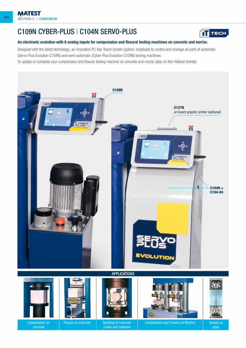
SECTION C | CONCRETE
An electronic evolution with 8 analog inputs for compression and flexural testing machines on concrete and mortar.
Designed with the latest technology, an innovative PC-like Touch Screen system, employed to control and manage all sorts of automatic
(Servo-Plus Evolution C104N) and semi-automatic (Cyber-Plus Evolution C109N) testing machines.
To update or complete your compression and flexural testing machine on concrete and mortar (also on Non-Matest brands)
C109N CYBER-PLUS | C104N SERVO-PLUS
Compression and Flexure on MortarsCompression onconcrete
APPLICATIONS
Splitting on concretecubes and cylinders
Flexure on concrete Tensile on steel
C109N
C104N +C104-04
C127Non board graphic printer (optional)
224
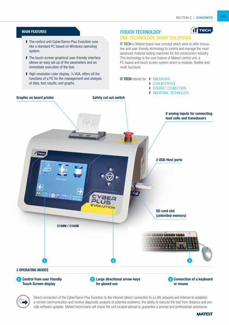
SECTION C | CONCRETE
MAIN FEATURES
The control unit Cyber/Servo-Plus Evolution runs like a standard PC based on Windows operating system.
The touch-screen graphical user-friendly interface allows an easy set up of the parameters and an immediate execution of the test.
High resolution color display, ¼ VGA, offers all the functions of a PC for the management and analysis of data, test results, and graphs.
3 OPERATING MODES
Control from user friendly Touch-Screen display
Large directional arrow-keys for gloved use
Connection of a keyboard or mouse
Direct connection of the Cyber/Servo Plus Evolution to the Intranet (direct connection to a LAN network) and Internet to establish a remote communication and receive diagnostic analysis of potential problems, the ability to execute the test from distance and pro-vide software updates. Matest technicians will check the unit located abroad to guarantee a prompt and professional assistance.
Graphic on board printer Safety cut out switch
8 analog inputs for connectingload cells and transducers
2 USB-Host ports
SD card slot(unlimited memory)
ONE TECHNOLOGY, MANY SOLUTIONSiT TECH is Matest brand-new concept which aims to offer innova-tive and user-friendly technology to control and manage the most advanced material testing machines for the construction industry.This technology is the core feature of Matest control unit, a PC-based and touch screen system which is modular, flexible and multi-functions.
iT TECH stands for: INNOVATION ICON INTERFACE INTERNET CONNECTION INDUSTRIAL TECHNOLOGY
1
1
2
2
3
3
C109N / C104N
ITOUCH TECHNOLOGY
225
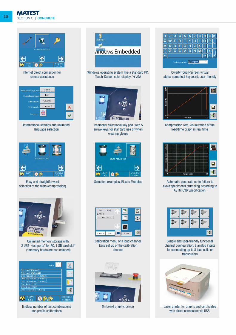
SECTION C | CONCRETE
Internet direct connection for remote assistance
Windows operating system like a standard PC.Touch-Screen color display, ¼ VGA
Qwerty Touch-Screen virtualalpha-numerical keyboard, user-friendly
International settings and unlimited language selection
Traditional directional key pad with 5arrow-keys for standard use or when
wearing gloves
Compression Test. Visualization of the load/time graph in real time
Easy and straightforwardselection of the tests (compression)
Selection examples, Elastic Modulus Automatic pace rate up to failure to avoid specimen’s crumbling according to
ASTM C39 Specification.
Laser printer for graphs and certificates with direct connection via USB.
Unlimited memory storage with:2 USB-Host ports* for PC, 1 SD card slot*
(*memory hardware not included)
On board graphic printer
Calibration menu of a load channel. Easy set up of the calibration
channel
Simple and user-friendly functional channel configuration. 8 analog inputs
for connecting up to 8 load cells or transducers
Endless number of test combinations and profile calibrations
226
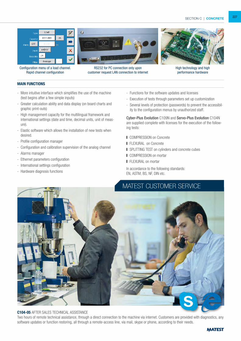
SECTION C | CONCRETE
Configuration menu of a load channel. Rapid channel configuration
RS232 for PC connection only uponcustomer request LAN connection to internet
High technology and highperformance hardware
MAIN FUNCTIONS
- More intuitive interface which simplifies the use of the machine (test begins after a few simple inputs)
- Greater calculation ability and data display (on board charts and graphic print-outs)
- High management capacity for the multilingual framework and international settings (date and time, decimal units, unit of meas-ure).
- Elastic software which allows the installation of new tests when desired.
- Profile configuration manager
- Configuration and calibration supervision of the analog channel
- Alarms manager
- Ethernet parameters configuration
- International settings configuration
- Hardware diagnosis functions
Cyber-Plus Evolution C109N and Servo-Plus Evolution C104N are supplied complete with licenses for the execution of the follow-ing tests:
COMPRESSION on Concrete
FLEXURAL on Concrete
SPLITTING TEST on cylinders and concrete cubes
COMPRESSION on mortar
FLEXURAL on mortar
In accordance to the following standards:EN, ASTM, BS, NF, DIN etc.
- Functions for the software updates and licenses
- Execution of tests through parameters set up customization
- Several levels of protection (passwords) to prevent the accessibil-ity to the configuration menus by unauthorized staff.
MATEST CUSTOMER SERVICE
C104-05 AFTER SALES TECHNICAL ASSISTANCETwo hours of remote technical assistance, through a direct connection to the machine via internet. Customers are provided with diagnostics, any software updates or function restoring, all through a remote-access line, via mail, skype or phone, according to their needs.
227
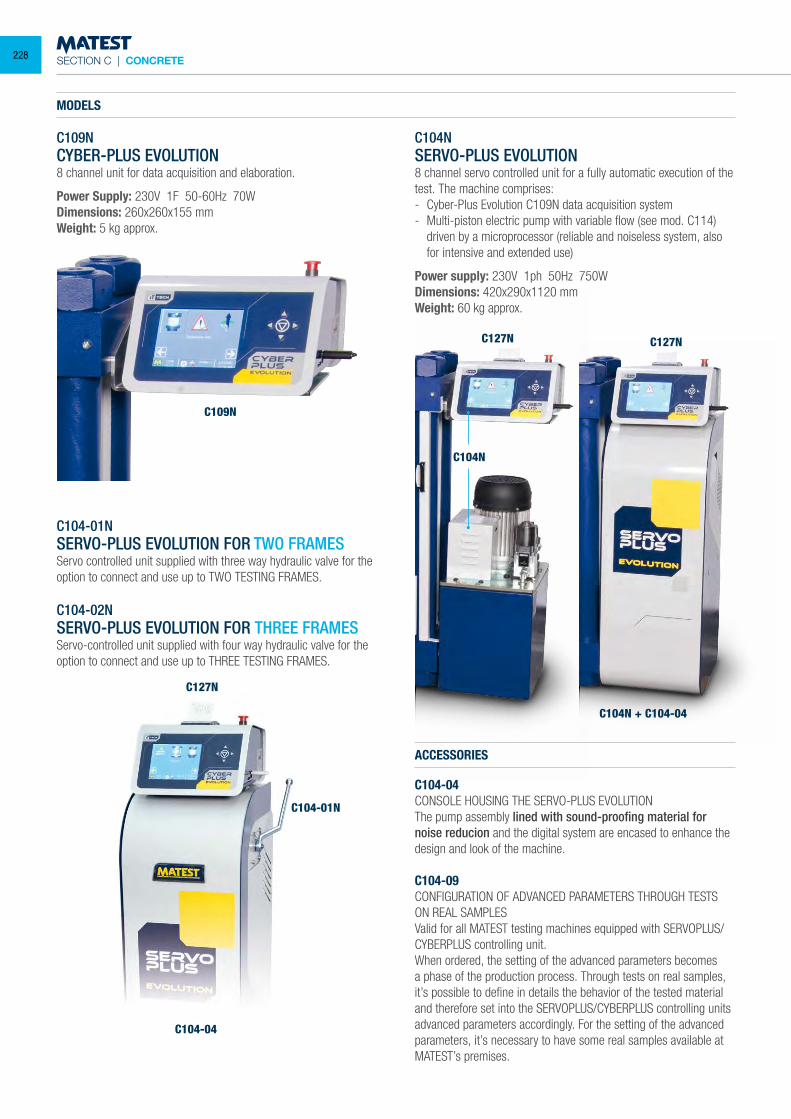
SECTION C | CONCRETE
C109N CYBER-PLUS EVOLUTION8 channel unit for data acquisition and elaboration.
Power Supply: 230V 1F 50-60Hz 70WDimensions: 260x260x155 mmWeight: 5 kg approx.
MODELS
C104-01NSERVO-PLUS EVOLUTION FOR TWO FRAMESServo controlled unit supplied with three way hydraulic valve for the option to connect and use up to TWO TESTING FRAMES.
C104-02NSERVO-PLUS EVOLUTION FOR THREE FRAMESServo-controlled unit supplied with four way hydraulic valve for the option to connect and use up to THREE TESTING FRAMES.
C104NSERVO-PLUS EVOLUTION8 channel servo controlled unit for a fully automatic execution of the test. The machine comprises:- Cyber-Plus Evolution C109N data acquisition system- Multi-piston electric pump with variable flow (see mod. C114)
driven by a microprocessor (reliable and noiseless system, also for intensive and extended use)
Power supply: 230V 1ph 50Hz 750WDimensions: 420x290x1120 mmWeight: 60 kg approx.
C127N
C104-01N
C104-04
C109N
C127N
C104N + C104-04
C104N
ACCESSORIES
C104-04CONSOLE HOUSING THE SERVO-PLUS EVOLUTIONThe pump assembly lined with sound-proofing material for noise reducion and the digital system are encased to enhance the design and look of the machine.
C104-09CONFIGURATION OF ADVANCED PARAMETERS THROUGH TESTS ON REAL SAMPLESValid for all MATEST testing machines equipped with SERVOPLUS/CYBERPLUS controlling unit.When ordered, the setting of the advanced parameters becomes a phase of the production process. Through tests on real samples, it’s possible to define in details the behavior of the tested material and therefore set into the SERVOPLUS/CYBERPLUS controlling units advanced parameters accordingly. For the setting of the advanced parameters, it’s necessary to have some real samples available at MATEST’s premises.
C127N
228
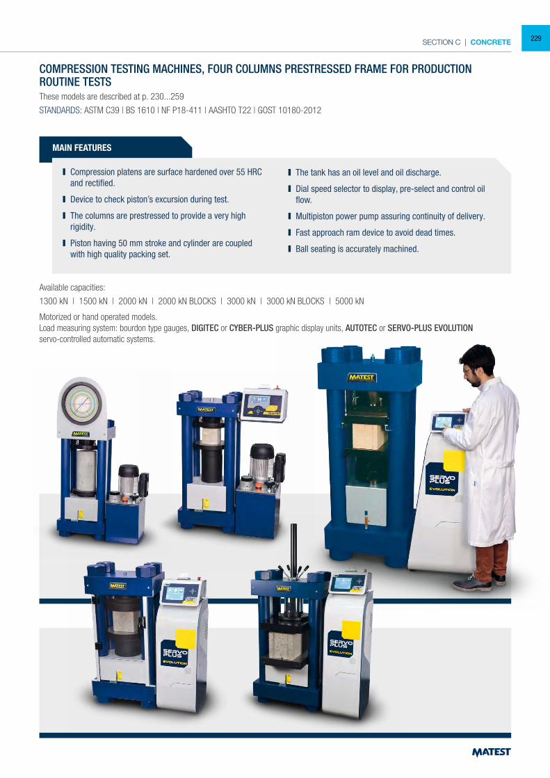
SECTION C | CONCRETE
COMPRESSION TESTING MACHINES, FOUR COLUMNS PRESTRESSED FRAME FOR PRODUCTIONROUTINE TESTSThese models are described at p. 230...259
STANDARDS: ASTM C39 | BS 1610 | NF P18-411 | AASHTO T22 | GOST 10180-2012
MAIN FEATURES
Compression platens are surface hardened over 55 HRC and rectified.
Device to check piston’s excursion during test.
The columns are prestressed to provide a very high rigidity.
Piston having 50 mm stroke and cylinder are coupled with high quality packing set.
The tank has an oil level and oil discharge.
Dial speed selector to display, pre-select and control oil flow.
Multipiston power pump assuring continuity of delivery.
Fast approach ram device to avoid dead times.
Ball seating is accurately machined.
Available capacities:
1300 kN | 1500 kN | 2000 kN | 2000 kN BLOCKS | 3000 kN | 3000 kN BLOCKS | 5000 kN
Motorized or hand operated models.Load measuring system: bourdon type gauges, DIGITEC or CYBER-PLUS graphic display units, AUTOTEC or SERVO-PLUS EVOLUTIONservo-controlled automatic systems.
229
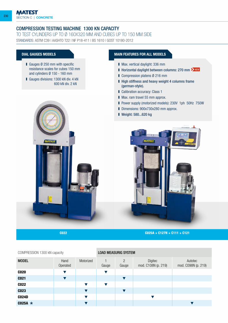
SECTION C | CONCRETE
DIAL GAUGES MODELS
Gauges Ø 250 mm with specific resistance scales for cubes 150 mm and cylinders Ø 150 - 160 mm
Gauges divisions: 1300 kN div. 4 kN 600 kN div. 2 kN
COMPRESSION 1300 kN capacity LOAD MEASURIG SYSTEM
MODEL HandOperated
Motorized 1 Gauge
2 Gauge
Digitecmod. C108N (p. 219)
Autotecmod. C098N (p. 219)
C020
C021
C022
C023
C024D
C025A
COMPRESSION TESTING MACHINE 1300 KN CAPACITYTO TEST CYLINDERS UP TO Ø 160X320 MM AND CUBES UP TO 150 MM SIDESTANDARDS: ASTM C39 | AASHTO T22 | NF P18-411 | BS 1610 | GOST 10180-2012
C025A + C127N + C111 + C121C022
MAIN FEATURES FOR ALL MODELS
Max. vertical daylight: 336 mm Horizontal daylight between columns: 270 mm Compression platens Ø 216 mm High stiffness and heavy weight 4 columns frame
(german-style). Calibration accuracy: Class 1 Max. ram travel 55 mm approx. Power supply (motorized models): 230V 1ph 50Hz 750W Dimensions: 900x730x280 mm approx. Weight: 580...620 kg
NEW
230
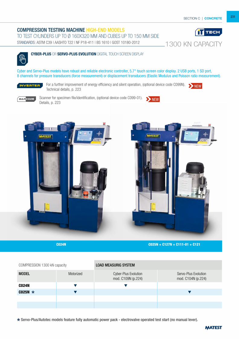
SECTION C | CONCRETE
COMPRESSION 1300 kN capacity LOAD MEASURIG SYSTEM
MODEL Motorized Cyber-Plus Evolutionmod. C109N (p.224)
Servo-Plus Evolutionmod. C104N (p.224)
C024N
C025N
COMPRESSION TESTING MACHINE HIGH-END MODELSTO TEST CYLINDERS UP TO Ø 160X320 MM AND CUBES UP TO 150 MM SIDESTANDARDS: ASTM C39 | AASHTO T22 | NF P18-411 | BS 1610 | GOST 10180-2012 1300 KN CAPACITY
C024N C025N + C127N + C111-01 + C121
Servo-Plus/Autotec models feature fully automatic power pack - electrovalve operated test start (no manual lever).
CYBER-PLUS OR SERVO-PLUS EVOLUTION DIGITAL TOUCH SCREEN DISPLAY
Cyber and Servo-Plus models have robust and reliable electronic controller, 5.7" touch screen color display. 2 USB ports, 1 SD port,8 channels for pressure transducers (force measurement) or displacement transducers (Elastic Modulus and Poisson ratio measurement).
For a further improvement of energy efficiency and silent operation, (optional device code C099N). Technical details, p. 223
Scanner for specimen file/identification, (optional device code C099-01).Details, p. 223
inverter NEW
NEWBARCODE
231
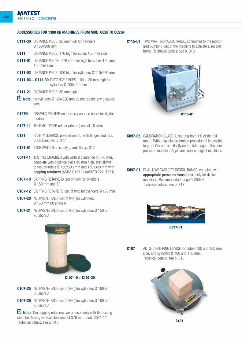
SECTION C | CONCRETE
ACCESSORIES FOR 1300 kN MACHINES FROM MOD. C020 TO C025N
C111-30 DISTANCE PIECE, 20 mm high for cylinders Ø 150x300 mm
C111 DISTANCE PIECE, 176 high for cubes 150 mm side
C111-01 DISTANCE PIECES, 176+50 mm high for cubes 150 and 100 mm side
C111-03 DISTANCE PIECE, 100 high for cylinders Ø 110x220 mm
C111-03 + C111-30 DISTANCE PIECES, 100 + 20 mm high for cylinders Ø 100x200 mm
C111-21 DISTANCE PIECE, 50 mm high
Note: the cylinders Ø 160x320 mm do not require any distance piece.
C127N GRAPHIC PRINTER on thermo-paper on board for digital models
C127-11 THERMO-PAPER roll for printer (pack of 10 rolls)
C121 SAFETY GUARDS, polycarbonate, with hinges and lock, to CE Directive. p. 317
C121-51 STOP SWITCH on safety guard. See p. 317
C041-11 TESTING CHAMBER with vertical clearance of 376 mm, complete with distance piece 40 mm high, that allows to test cylinders Ø 150x300 mm and 160x320 mm with capping retainers (ASTM C1231 | AASHTO T22, T851)
C107-10 CAPPING RETAINERS (set of two) for cylinders Ø 150 mm and 6”
C107-12 CAPPING RETAINERS (set of two) for cylinders Ø 160 mm
C107-20 NEOPRENE PADS (set of two) for cylinders Ø 150 mm 60 shore A
C107-21 NEOPRENE PADS (set of two) for cylinders Ø 150 mm 70 shore A
C107-25 NEOPRENE PADS (set of two) for cylinders Ø 160mm 60 shore A
C107-26 NEOPRENE PADS (set of two) for cylinders Ø 160 mm 70 shore A
Note: The capping retainers can be used only with the testing chamber having vertical clearance of 376 mm, mod. C041-11Technical details: see p. 316
C115-01 TWO WAY HYDRAULIC VALVE, connected to the motor-ized pumping unit of the machine to activate a second frame. Technical details: see p. 318
C097-05 CALIBRATION CLASS 1, starting from 1% of the full range. With a special calibration procedure it is possible to grant Class 1 practically on the full range of the com-pression machine. Applicable only on digital machines.
C097-01 DUAL LOW CAPACITY DIGITAL RANGE, complete with appropriate pressure transducer, only for digital machines. Recommended range 0-250kN.
Technical details: see p. 313
C107-10 + C107-20
C115-01
C097-01
C107
C107 AUTO-CENTERING DEVICE for cubes 100 and 150 mm side, and cylinders Ø 100 and 150 mm.
Technical details: see p. 316
232
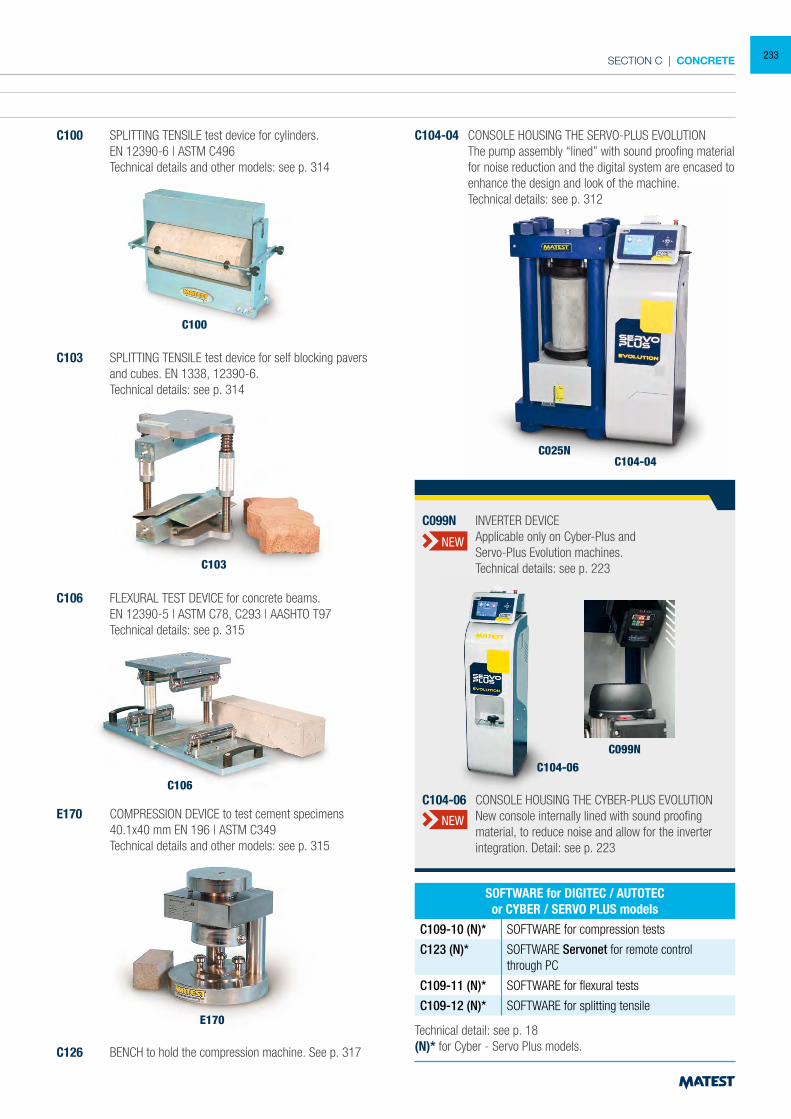
SECTION C | CONCRETE
ACCESSORIES FOR 1300 kN MACHINES FROM MOD. C020 TO C025N
C111-30 DISTANCE PIECE, 20 mm high for cylinders Ø 150x300 mm
C111 DISTANCE PIECE, 176 high for cubes 150 mm side
C111-01 DISTANCE PIECES, 176+50 mm high for cubes 150 and 100 mm side
C111-03 DISTANCE PIECE, 100 high for cylinders Ø 110x220 mm
C111-03 + C111-30 DISTANCE PIECES, 100 + 20 mm high for cylinders Ø 100x200 mm
C111-21 DISTANCE PIECE, 50 mm high
Note: the cylinders Ø 160x320 mm do not require any distance piece.
C127N GRAPHIC PRINTER on thermo-paper on board for digital models
C127-11 THERMO-PAPER roll for printer (pack of 10 rolls)
C121 SAFETY GUARDS, polycarbonate, with hinges and lock, to CE Directive. p. 317
C121-51 STOP SWITCH on safety guard. See p. 317
C041-11 TESTING CHAMBER with vertical clearance of 376 mm, complete with distance piece 40 mm high, that allows to test cylinders Ø 150x300 mm and 160x320 mm with capping retainers (ASTM C1231 | AASHTO T22, T851)
C107-10 CAPPING RETAINERS (set of two) for cylinders Ø 150 mm and 6”
C107-12 CAPPING RETAINERS (set of two) for cylinders Ø 160 mm
C107-20 NEOPRENE PADS (set of two) for cylinders Ø 150 mm 60 shore A
C107-21 NEOPRENE PADS (set of two) for cylinders Ø 150 mm 70 shore A
C100 SPLITTING TENSILE test device for cylinders. EN 12390-6 | ASTM C496 Technical details and other models: see p. 314
C100
C103 SPLITTING TENSILE test device for self blocking pavers and cubes. EN 1338, 12390-6.
Technical details: see p. 314
C106 FLEXURAL TEST DEVICE for concrete beams. EN 12390-5 | ASTM C78, C293 | AASHTO T97 Technical details: see p. 315
E170 COMPRESSION DEVICE to test cement specimens 40.1x40 mm EN 196 | ASTM C349 Technical details and other models: see p. 315
C126 BENCH to hold the compression machine. See p. 317
C104-04 CONSOLE HOUSING THE SERVO-PLUS EVOLUTION The pump assembly “lined” with sound proofing material
for noise reduction and the digital system are encased to enhance the design and look of the machine.
Technical details: see p. 312
E170
C106
C103
C104-04C025N
Technical detail: see p. 18(N)* for Cyber - Servo Plus models.
SOFTWARE for DIGITEC / AUTOTECor CYBER / SERVO PLUS models
C109-10 (N)* SOFTWARE for compression tests
C123 (N)* SOFTWARE Servonet for remote control through PC
C109-11 (N)* SOFTWARE for flexural tests
C109-12 (N)* SOFTWARE for splitting tensile
C104-06
C099N
C104-06 CONSOLE HOUSING THE CYBER-PLUS EVOLUTION New console internally lined with sound proofing
material, to reduce noise and allow for the inverter integration. Detail: see p. 223
C099N INVERTER DEVICE Applicable only on Cyber-Plus and Servo-Plus Evolution machines. Technical details: see p. 223
NEW
NEW
233
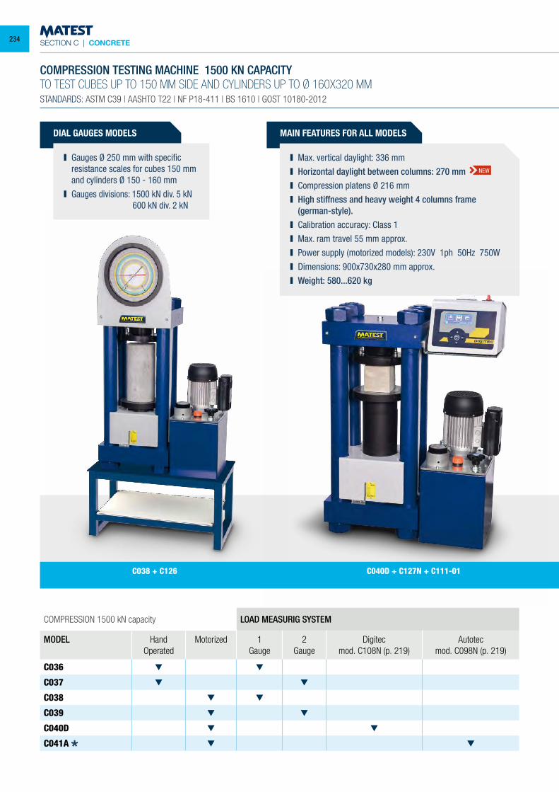
SECTION C | CONCRETE
DIAL GAUGES MODELS
Gauges Ø 250 mm with specific resistance scales for cubes 150 mm and cylinders Ø 150 - 160 mm
Gauges divisions: 1500 kN div. 5 kN 600 kN div. 2 kN
COMPRESSION 1500 kN capacity LOAD MEASURIG SYSTEM
MODEL HandOperated
Motorized 1 Gauge
2 Gauge
Digitecmod. C108N (p. 219)
Autotecmod. C098N (p. 219)
C036
C037
C038
C039
C040D
C041A
COMPRESSION TESTING MACHINE 1500 KN CAPACITYTO TEST CUBES UP TO 150 MM SIDE AND CYLINDERS UP TO Ø 160X320 MMSTANDARDS: ASTM C39 | AASHTO T22 | NF P18-411 | BS 1610 | GOST 10180-2012
MAIN FEATURES FOR ALL MODELS
Max. vertical daylight: 336 mm Horizontal daylight between columns: 270 mm Compression platens Ø 216 mm High stiffness and heavy weight 4 columns frame
(german-style). Calibration accuracy: Class 1 Max. ram travel 55 mm approx. Power supply (motorized models): 230V 1ph 50Hz 750W Dimensions: 900x730x280 mm approx. Weight: 580...620 kg
NEW
C040D + C127N + C111-01C038 + C126
234
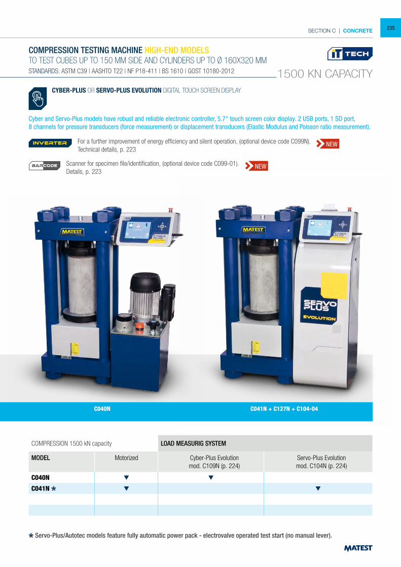
SECTION C | CONCRETE
COMPRESSION 1500 kN capacity LOAD MEASURIG SYSTEM
MODEL Motorized Cyber-Plus Evolutionmod. C109N (p. 224)
Servo-Plus Evolutionmod. C104N (p. 224)
C040N
C041N
COMPRESSION TESTING MACHINE HIGH-END MODELSTO TEST CUBES UP TO 150 MM SIDE AND CYLINDERS UP TO Ø 160X320 MMSTANDARDS: ASTM C39 | AASHTO T22 | NF P18-411 | BS 1610 | GOST 10180-2012 1500 KN CAPACITY
CYBER-PLUS OR SERVO-PLUS EVOLUTION DIGITAL TOUCH SCREEN DISPLAY
Cyber and Servo-Plus models have robust and reliable electronic controller, 5.7" touch screen color display. 2 USB ports, 1 SD port,8 channels for pressure transducers (force measurement) or displacement transducers (Elastic Modulus and Poisson ratio measurement).
Servo-Plus/Autotec models feature fully automatic power pack - electrovalve operated test start (no manual lever).
C040N C041N + C127N + C104-04
For a further improvement of energy efficiency and silent operation, (optional device code C099N). Technical details, p. 223
Scanner for specimen file/identification, (optional device code C099-01).Details, p. 223
inverter NEW
NEWBARCODE
235
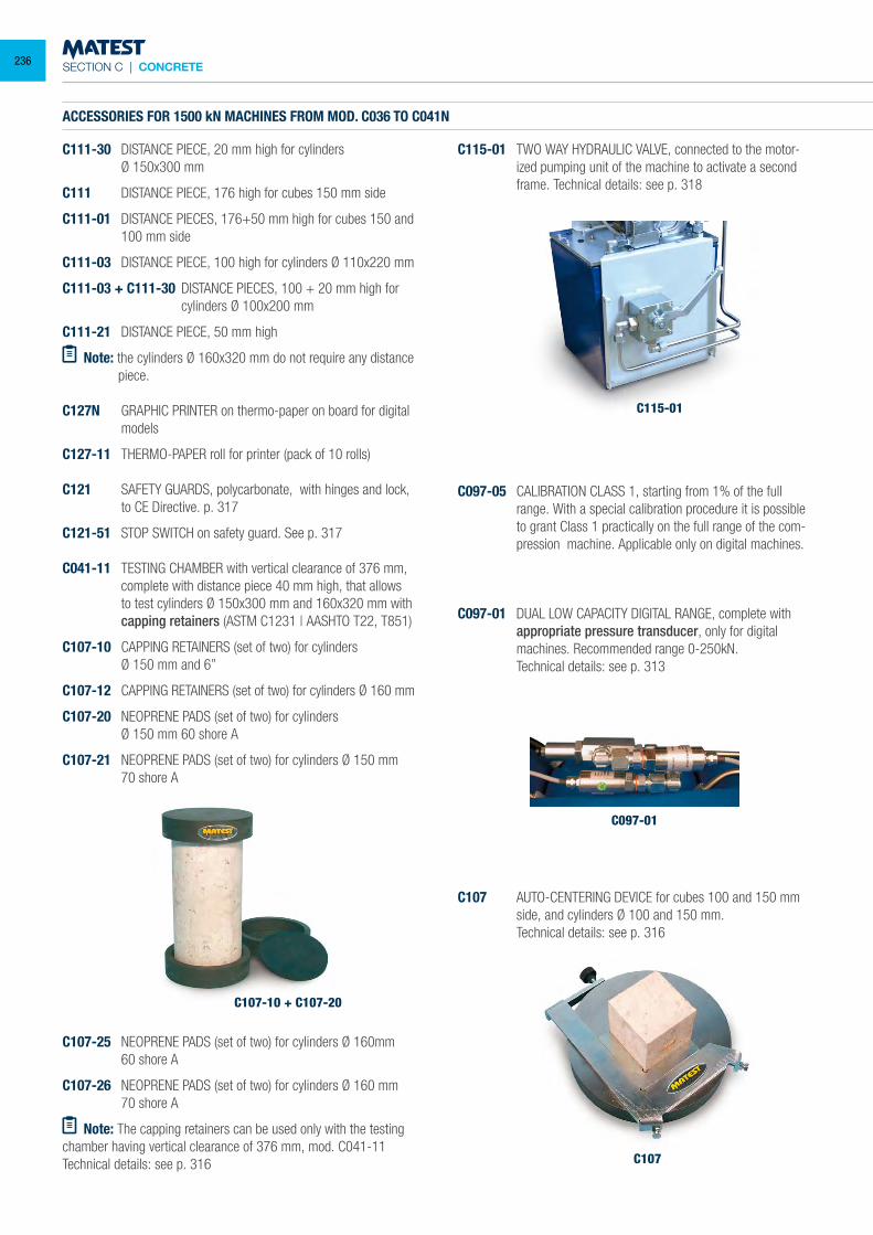
SECTION C | CONCRETE
ACCESSORIES FOR 1500 kN MACHINES FROM MOD. C036 TO C041N
C111-30 DISTANCE PIECE, 20 mm high for cylinders Ø 150x300 mm
C111 DISTANCE PIECE, 176 high for cubes 150 mm side
C111-01 DISTANCE PIECES, 176+50 mm high for cubes 150 and 100 mm side
C111-03 DISTANCE PIECE, 100 high for cylinders Ø 110x220 mm
C111-03 + C111-30 DISTANCE PIECES, 100 + 20 mm high for cylinders Ø 100x200 mm
C111-21 DISTANCE PIECE, 50 mm high
Note: the cylinders Ø 160x320 mm do not require any distance piece.
C127N GRAPHIC PRINTER on thermo-paper on board for digital models
C127-11 THERMO-PAPER roll for printer (pack of 10 rolls)
C121 SAFETY GUARDS, polycarbonate, with hinges and lock, to CE Directive. p. 317
C121-51 STOP SWITCH on safety guard. See p. 317
C041-11 TESTING CHAMBER with vertical clearance of 376 mm, complete with distance piece 40 mm high, that allows to test cylinders Ø 150x300 mm and 160x320 mm with capping retainers (ASTM C1231 | AASHTO T22, T851)
C107-10 CAPPING RETAINERS (set of two) for cylinders Ø 150 mm and 6”
C107-12 CAPPING RETAINERS (set of two) for cylinders Ø 160 mm
C107-20 NEOPRENE PADS (set of two) for cylinders Ø 150 mm 60 shore A
C107-21 NEOPRENE PADS (set of two) for cylinders Ø 150 mm 70 shore A
C107-25 NEOPRENE PADS (set of two) for cylinders Ø 160mm 60 shore A
C107-26 NEOPRENE PADS (set of two) for cylinders Ø 160 mm 70 shore A
Note: The capping retainers can be used only with the testing chamber having vertical clearance of 376 mm, mod. C041-11Technical details: see p. 316
C115-01 TWO WAY HYDRAULIC VALVE, connected to the motor-ized pumping unit of the machine to activate a second frame. Technical details: see p. 318
C097-05 CALIBRATION CLASS 1, starting from 1% of the full range. With a special calibration procedure it is possible to grant Class 1 practically on the full range of the com-pression machine. Applicable only on digital machines.
C097-01 DUAL LOW CAPACITY DIGITAL RANGE, complete with appropriate pressure transducer, only for digital machines. Recommended range 0-250kN.
Technical details: see p. 313
C107-10 + C107-20
C115-01
C097-01
C107
C107 AUTO-CENTERING DEVICE for cubes 100 and 150 mm side, and cylinders Ø 100 and 150 mm.
Technical details: see p. 316
236
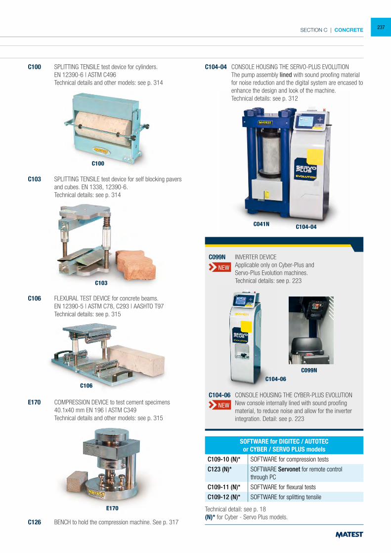
SECTION C | CONCRETE
ACCESSORIES FOR 1500 kN MACHINES FROM MOD. C036 TO C041N
C111-30 DISTANCE PIECE, 20 mm high for cylinders Ø 150x300 mm
C111 DISTANCE PIECE, 176 high for cubes 150 mm side
C111-01 DISTANCE PIECES, 176+50 mm high for cubes 150 and 100 mm side
C111-03 DISTANCE PIECE, 100 high for cylinders Ø 110x220 mm
C111-03 + C111-30 DISTANCE PIECES, 100 + 20 mm high for cylinders Ø 100x200 mm
C111-21 DISTANCE PIECE, 50 mm high
Note: the cylinders Ø 160x320 mm do not require any distance piece.
C127N GRAPHIC PRINTER on thermo-paper on board for digital models
C127-11 THERMO-PAPER roll for printer (pack of 10 rolls)
C121 SAFETY GUARDS, polycarbonate, with hinges and lock, to CE Directive. p. 317
C121-51 STOP SWITCH on safety guard. See p. 317
C041-11 TESTING CHAMBER with vertical clearance of 376 mm, complete with distance piece 40 mm high, that allows to test cylinders Ø 150x300 mm and 160x320 mm with capping retainers (ASTM C1231 | AASHTO T22, T851)
C107-10 CAPPING RETAINERS (set of two) for cylinders Ø 150 mm and 6”
C107-12 CAPPING RETAINERS (set of two) for cylinders Ø 160 mm
C107-20 NEOPRENE PADS (set of two) for cylinders Ø 150 mm 60 shore A
C107-21 NEOPRENE PADS (set of two) for cylinders Ø 150 mm 70 shore A
C100 SPLITTING TENSILE test device for cylinders. EN 12390-6 | ASTM C496 Technical details and other models: see p. 314
C100
C103 SPLITTING TENSILE test device for self blocking pavers and cubes. EN 1338, 12390-6.
Technical details: see p. 314
C106 FLEXURAL TEST DEVICE for concrete beams. EN 12390-5 | ASTM C78, C293 | AASHTO T97 Technical details: see p. 315
E170 COMPRESSION DEVICE to test cement specimens 40.1x40 mm EN 196 | ASTM C349 Technical details and other models: see p. 315
C126 BENCH to hold the compression machine. See p. 317
C104-04 CONSOLE HOUSING THE SERVO-PLUS EVOLUTION The pump assembly lined with sound proofing material
for noise reduction and the digital system are encased to enhance the design and look of the machine.
Technical details: see p. 312
E170
C106
C103
C104-04C041N
Technical detail: see p. 18(N)* for Cyber - Servo Plus models.
SOFTWARE for DIGITEC / AUTOTECor CYBER / SERVO PLUS models
C109-10 (N)* SOFTWARE for compression tests
C123 (N)* SOFTWARE Servonet for remote control through PC
C109-11 (N)* SOFTWARE for flexural tests
C109-12 (N)* SOFTWARE for splitting tensile
C104-06C099N
C104-06 CONSOLE HOUSING THE CYBER-PLUS EVOLUTION New console internally lined with sound proofing
material, to reduce noise and allow for the inverter integration. Detail: see p. 223
C099N INVERTER DEVICE Applicable only on Cyber-Plus and Servo-Plus Evolution machines. Technical details: see p. 223
NEW
NEW
237
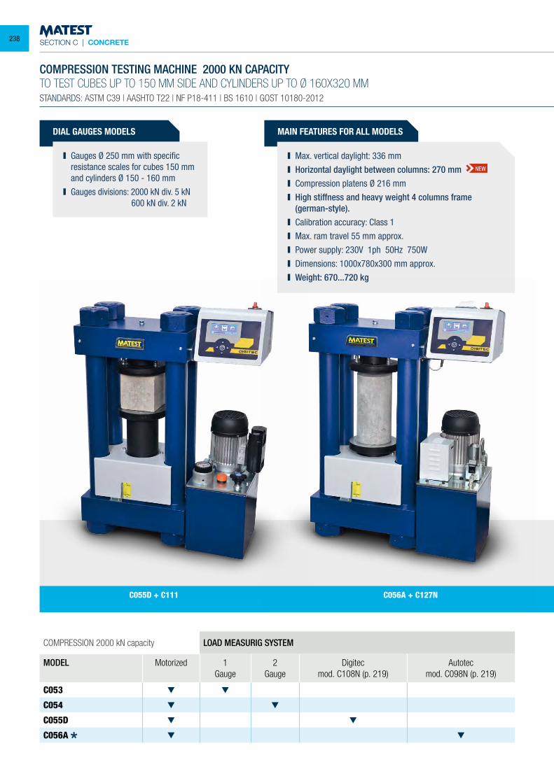
SECTION C | CONCRETE
DIAL GAUGES MODELS
Gauges Ø 250 mm with specific resistance scales for cubes 150 mm and cylinders Ø 150 - 160 mm
Gauges divisions: 2000 kN div. 5 kN 600 kN div. 2 kN
COMPRESSION 2000 kN capacity LOAD MEASURIG SYSTEM
MODEL Motorized 1 Gauge
2 Gauge
Digitecmod. C108N (p. 219)
Autotecmod. C098N (p. 219)
C053
C054
C055D
C056A
COMPRESSION TESTING MACHINE 2000 KN CAPACITYTO TEST CUBES UP TO 150 MM SIDE AND CYLINDERS UP TO Ø 160X320 MMSTANDARDS: ASTM C39 | AASHTO T22 | NF P18-411 | BS 1610 | GOST 10180-2012
MAIN FEATURES FOR ALL MODELS
Max. vertical daylight: 336 mm Horizontal daylight between columns: 270 mm Compression platens Ø 216 mm High stiffness and heavy weight 4 columns frame
(german-style). Calibration accuracy: Class 1 Max. ram travel 55 mm approx. Power supply: 230V 1ph 50Hz 750W Dimensions: 1000x780x300 mm approx. Weight: 670...720 kg
C056A + C127NC055D + C111
NEW
238
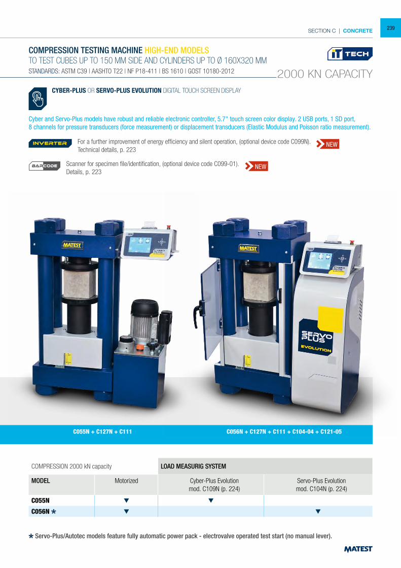
SECTION C | CONCRETE
COMPRESSION 2000 kN capacity LOAD MEASURIG SYSTEM
MODEL Motorized Cyber-Plus Evolutionmod. C109N (p. 224)
Servo-Plus Evolutionmod. C104N (p. 224)
C055N
C056N
COMPRESSION TESTING MACHINE HIGH-END MODELSTO TEST CUBES UP TO 150 MM SIDE AND CYLINDERS UP TO Ø 160X320 MMSTANDARDS: ASTM C39 | AASHTO T22 | NF P18-411 | BS 1610 | GOST 10180-2012 2000 KN CAPACITY
C055N + C127N + C111 C056N + C127N + C111 + C104-04 + C121-05
CYBER-PLUS OR SERVO-PLUS EVOLUTION DIGITAL TOUCH SCREEN DISPLAY
Cyber and Servo-Plus models have robust and reliable electronic controller, 5.7" touch screen color display. 2 USB ports, 1 SD port,8 channels for pressure transducers (force measurement) or displacement transducers (Elastic Modulus and Poisson ratio measurement).
Servo-Plus/Autotec models feature fully automatic power pack - electrovalve operated test start (no manual lever).
For a further improvement of energy efficiency and silent operation, (optional device code C099N). Technical details, p. 223
Scanner for specimen file/identification, (optional device code C099-01).Details, p. 223
inverter NEW
NEWBARCODE
239
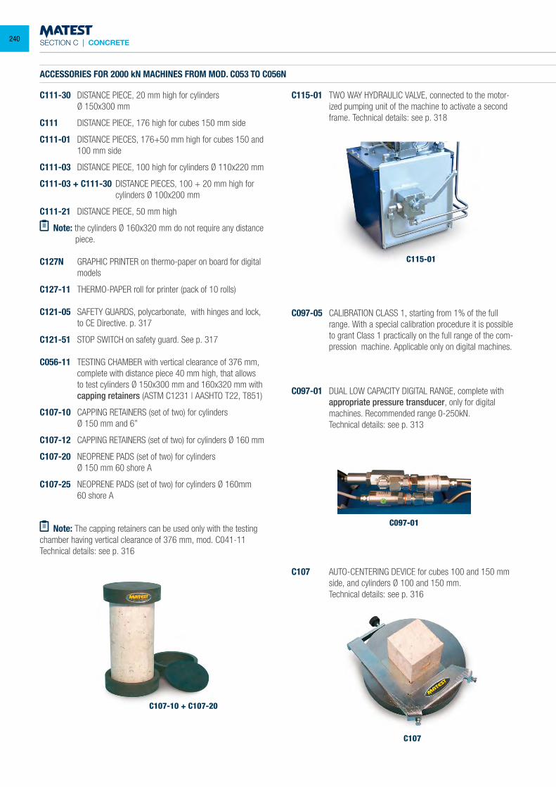
SECTION C | CONCRETE
ACCESSORIES FOR 2000 kN MACHINES FROM MOD. C053 TO C056N
C111-30 DISTANCE PIECE, 20 mm high for cylinders Ø 150x300 mm
C111 DISTANCE PIECE, 176 high for cubes 150 mm side
C111-01 DISTANCE PIECES, 176+50 mm high for cubes 150 and 100 mm side
C111-03 DISTANCE PIECE, 100 high for cylinders Ø 110x220 mm
C111-03 + C111-30 DISTANCE PIECES, 100 + 20 mm high for cylinders Ø 100x200 mm
C111-21 DISTANCE PIECE, 50 mm high
Note: the cylinders Ø 160x320 mm do not require any distance piece.
C127N GRAPHIC PRINTER on thermo-paper on board for digital models
C127-11 THERMO-PAPER roll for printer (pack of 10 rolls)
C121-05 SAFETY GUARDS, polycarbonate, with hinges and lock, to CE Directive. p. 317
C121-51 STOP SWITCH on safety guard. See p. 317
C056-11 TESTING CHAMBER with vertical clearance of 376 mm, complete with distance piece 40 mm high, that allows to test cylinders Ø 150x300 mm and 160x320 mm with capping retainers (ASTM C1231 | AASHTO T22, T851)
C107-10 CAPPING RETAINERS (set of two) for cylinders Ø 150 mm and 6”
C107-12 CAPPING RETAINERS (set of two) for cylinders Ø 160 mm
C107-20 NEOPRENE PADS (set of two) for cylinders Ø 150 mm 60 shore A
C107-25 NEOPRENE PADS (set of two) for cylinders Ø 160mm 60 shore A
Note: The capping retainers can be used only with the testing chamber having vertical clearance of 376 mm, mod. C041-11Technical details: see p. 316
C115-01 TWO WAY HYDRAULIC VALVE, connected to the motor-ized pumping unit of the machine to activate a second frame. Technical details: see p. 318
C097-05 CALIBRATION CLASS 1, starting from 1% of the full range. With a special calibration procedure it is possible to grant Class 1 practically on the full range of the com-pression machine. Applicable only on digital machines.
C097-01 DUAL LOW CAPACITY DIGITAL RANGE, complete with appropriate pressure transducer, only for digital machines. Recommended range 0-250kN.
Technical details: see p. 313
C107-10 + C107-20
C115-01
C097-01
C107
C107 AUTO-CENTERING DEVICE for cubes 100 and 150 mm side, and cylinders Ø 100 and 150 mm.
Technical details: see p. 316
240
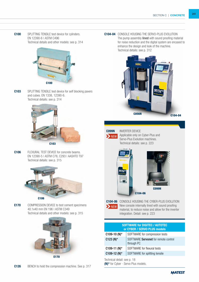
SECTION C | CONCRETE
ACCESSORIES FOR 2000 kN MACHINES FROM MOD. C053 TO C056N
C111-30 DISTANCE PIECE, 20 mm high for cylinders Ø 150x300 mm
C111 DISTANCE PIECE, 176 high for cubes 150 mm side
C111-01 DISTANCE PIECES, 176+50 mm high for cubes 150 and 100 mm side
C111-03 DISTANCE PIECE, 100 high for cylinders Ø 110x220 mm
C111-03 + C111-30 DISTANCE PIECES, 100 + 20 mm high for cylinders Ø 100x200 mm
C111-21 DISTANCE PIECE, 50 mm high
Note: the cylinders Ø 160x320 mm do not require any distance piece.
C127N GRAPHIC PRINTER on thermo-paper on board for digital models
C127-11 THERMO-PAPER roll for printer (pack of 10 rolls)
C121-05 SAFETY GUARDS, polycarbonate, with hinges and lock, to CE Directive. p. 317
C121-51 STOP SWITCH on safety guard. See p. 317
C056-11 TESTING CHAMBER with vertical clearance of 376 mm, complete with distance piece 40 mm high, that allows to test cylinders Ø 150x300 mm and 160x320 mm with capping retainers (ASTM C1231 | AASHTO T22, T851)
C107-10 CAPPING RETAINERS (set of two) for cylinders Ø 150 mm and 6”
C107-12 CAPPING RETAINERS (set of two) for cylinders Ø 160 mm
C107-20 NEOPRENE PADS (set of two) for cylinders Ø 150 mm 60 shore A
C107-25 NEOPRENE PADS (set of two) for cylinders Ø 160mm 60 shore A
Note: The capping retainers can be used only with the testing chamber having vertical clearance of 376 mm, mod. C041-11Technical details: see p. 316
C100 SPLITTING TENSILE test device for cylinders. EN 12390-6 | ASTM C496 Technical details and other models: see p. 314
C100
C103 SPLITTING TENSILE test device for self blocking pavers and cubes. EN 1338, 12390-6.
Technical details: see p. 314
C106 FLEXURAL TEST DEVICE for concrete beams. EN 12390-5 | ASTM C78, C293 | AASHTO T97 Technical details: see p. 315
E170 COMPRESSION DEVICE to test cement specimens 40.1x40 mm EN 196 | ASTM C349 Technical details and other models: see p. 315
C126 BENCH to hold the compression machine. See p. 317
C104-04 CONSOLE HOUSING THE SERVO-PLUS EVOLUTION The pump assembly lined with sound proofing material
for noise reduction and the digital system are encased to enhance the design and look of the machine.
Technical details: see p. 312
E170
C106
C103
C104-04C056N
Technical detail: see p. 18(N)* for Cyber - Servo Plus models.
SOFTWARE for DIGITEC / AUTOTECor CYBER / SERVO PLUS models
C109-10 (N)* SOFTWARE for compression tests
C123 (N)* SOFTWARE Servonet for remote control through PC
C109-11 (N)* SOFTWARE for flexural tests
C109-12 (N)* SOFTWARE for splitting tensile
C104-06
C099N
C104-06 CONSOLE HOUSING THE CYBER-PLUS EVOLUTION New console internally lined with sound proofing
material, to reduce noise and allow for the inverter integration. Detail: see p. 223
C099N INVERTER DEVICE Applicable only on Cyber-Plus and Servo-Plus Evolution machines. Technical details: see p. 223
NEW
NEW
241
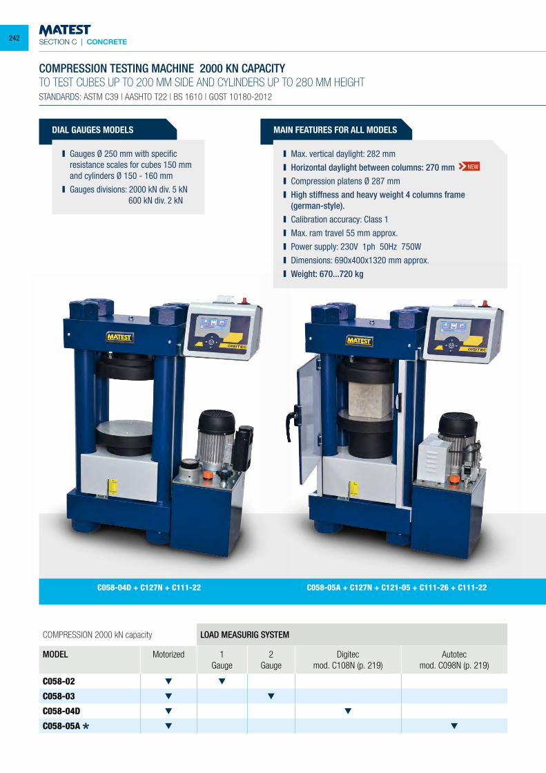
SECTION C | CONCRETE
DIAL GAUGES MODELS
Gauges Ø 250 mm with specific resistance scales for cubes 150 mm and cylinders Ø 150 - 160 mm
Gauges divisions: 2000 kN div. 5 kN 600 kN div. 2 kN
COMPRESSION 2000 kN capacity LOAD MEASURIG SYSTEM
MODEL Motorized 1 Gauge
2 Gauge
Digitecmod. C108N (p. 219)
Autotecmod. C098N (p. 219)
C058-02
C058-03
C058-04D
C058-05A
COMPRESSION TESTING MACHINE 2000 KN CAPACITYTO TEST CUBES UP TO 200 MM SIDE AND CYLINDERS UP TO 280 MM HEIGHTSTANDARDS: ASTM C39 | AASHTO T22 | BS 1610 | GOST 10180-2012
MAIN FEATURES FOR ALL MODELS
Max. vertical daylight: 282 mm Horizontal daylight between columns: 270 mm Compression platens Ø 287 mm High stiffness and heavy weight 4 columns frame
(german-style). Calibration accuracy: Class 1 Max. ram travel 55 mm approx. Power supply: 230V 1ph 50Hz 750W Dimensions: 690x400x1320 mm approx. Weight: 670...720 kg
C058-05A + C127N + C121-05 + C111-26 + C111-22C058-04D + C127N + C111-22
NEW
242
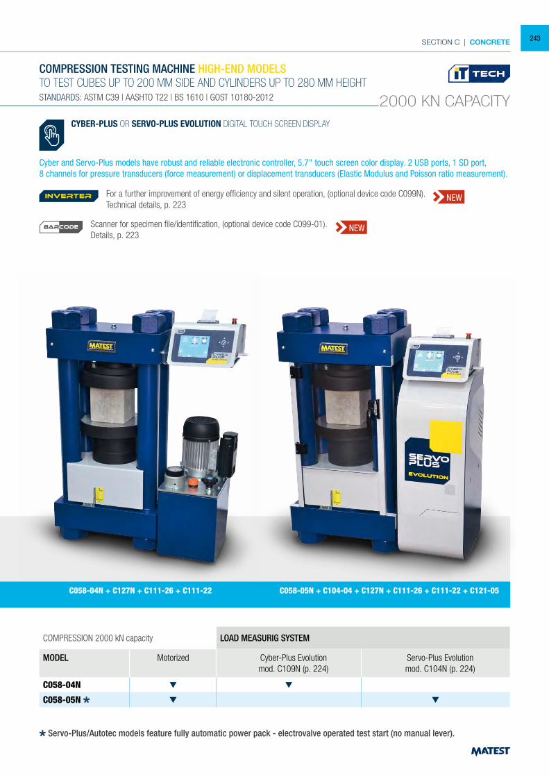
SECTION C | CONCRETE
COMPRESSION 2000 kN capacity LOAD MEASURIG SYSTEM
MODEL Motorized Cyber-Plus Evolutionmod. C109N (p. 224)
Servo-Plus Evolutionmod. C104N (p. 224)
C058-04N
C058-05N
COMPRESSION TESTING MACHINE HIGH-END MODELSTO TEST CUBES UP TO 200 MM SIDE AND CYLINDERS UP TO 280 MM HEIGHTSTANDARDS: ASTM C39 | AASHTO T22 | BS 1610 | GOST 10180-2012 2000 KN CAPACITY
C058-04N + C127N + C111-26 + C111-22 C058-05N + C104-04 + C127N + C111-26 + C111-22 + C121-05
CYBER-PLUS OR SERVO-PLUS EVOLUTION DIGITAL TOUCH SCREEN DISPLAY
Cyber and Servo-Plus models have robust and reliable electronic controller, 5.7" touch screen color display. 2 USB ports, 1 SD port,8 channels for pressure transducers (force measurement) or displacement transducers (Elastic Modulus and Poisson ratio measurement).
Servo-Plus/Autotec models feature fully automatic power pack - electrovalve operated test start (no manual lever).
For a further improvement of energy efficiency and silent operation, (optional device code C099N). Technical details, p. 223
Scanner for specimen file/identification, (optional device code C099-01).Details, p. 223
inverter NEW
NEWBARCODE
243
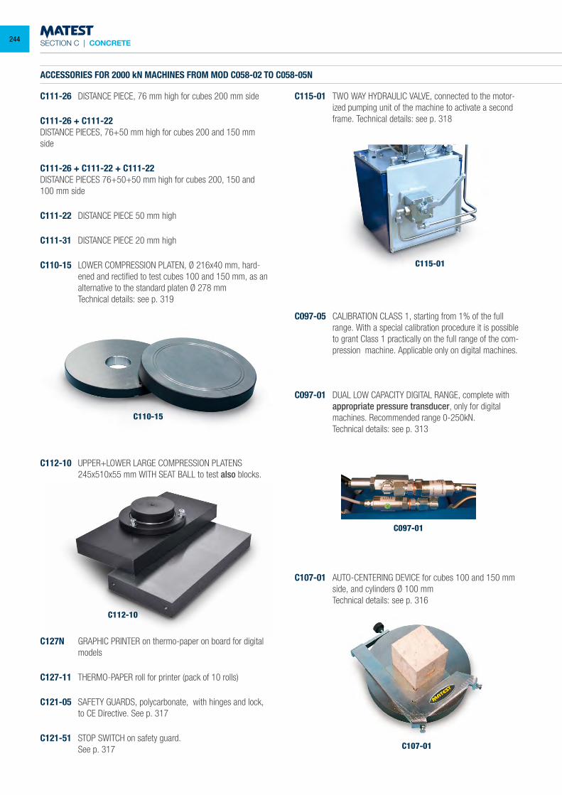
SECTION C | CONCRETE
ACCESSORIES FOR 2000 kN MACHINES FROM MOD C058-02 TO C058-05N
C111-26 DISTANCE PIECE, 76 mm high for cubes 200 mm side
C111-26 + C111-22DISTANCE PIECES, 76+50 mm high for cubes 200 and 150 mm side
C111-26 + C111-22 + C111-22DISTANCE PIECES 76+50+50 mm high for cubes 200, 150 and 100 mm side
C111-22 DISTANCE PIECE 50 mm high
C111-31 DISTANCE PIECE 20 mm high
C110-15 LOWER COMPRESSION PLATEN, Ø 216x40 mm, hard-ened and rectified to test cubes 100 and 150 mm, as an alternative to the standard platen Ø 278 mm
Technical details: see p. 319
C115-01 TWO WAY HYDRAULIC VALVE, connected to the motor-ized pumping unit of the machine to activate a second frame. Technical details: see p. 318
C097-05 CALIBRATION CLASS 1, starting from 1% of the full range. With a special calibration procedure it is possible to grant Class 1 practically on the full range of the com-pression machine. Applicable only on digital machines.
C097-01 DUAL LOW CAPACITY DIGITAL RANGE, complete with appropriate pressure transducer, only for digital machines. Recommended range 0-250kN.
Technical details: see p. 313
C115-01
C097-01
C107-01
C107-01 AUTO-CENTERING DEVICE for cubes 100 and 150 mm side, and cylinders Ø 100 mm
Technical details: see p. 316
C112-10 UPPER+LOWER LARGE COMPRESSION PLATENS 245x510x55 mm WITH SEAT BALL to test also blocks.
C110-15
C127N GRAPHIC PRINTER on thermo-paper on board for digital models
C127-11 THERMO-PAPER roll for printer (pack of 10 rolls)
C121-05 SAFETY GUARDS, polycarbonate, with hinges and lock, to CE Directive. See p. 317
C121-51 STOP SWITCH on safety guard. See p. 317
C112-10
244
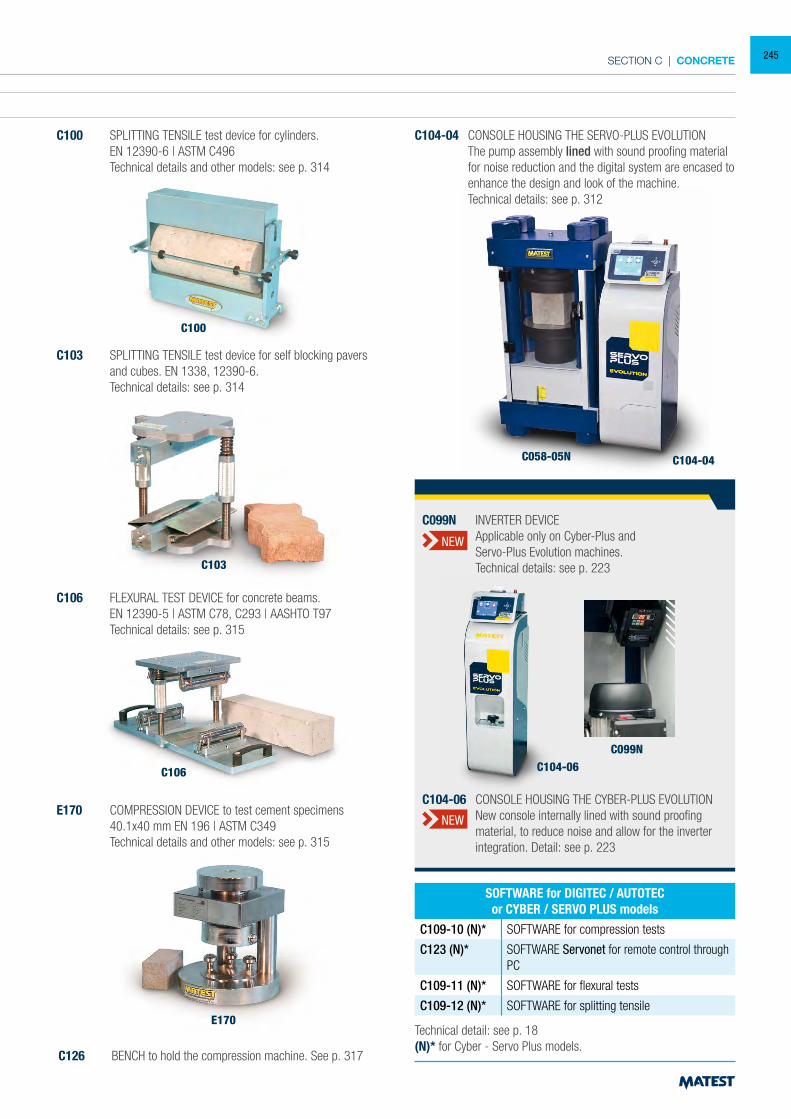
SECTION C | CONCRETE
ACCESSORIES FOR 2000 kN MACHINES FROM MOD C058-02 TO C058-05N
C111-26 DISTANCE PIECE, 76 mm high for cubes 200 mm side
C111-26 + C111-22DISTANCE PIECES, 76+50 mm high for cubes 200 and 150 mm side
C111-26 + C111-22 + C111-22DISTANCE PIECES 76+50+50 mm high for cubes 200, 150 and 100 mm side
C111-22 DISTANCE PIECE 50 mm high
C111-31 DISTANCE PIECE 20 mm high
C110-15 LOWER COMPRESSION PLATEN, Ø 216x40 mm, hard-ened and rectified to test cubes 100 and 150 mm, as an alternative to the standard platen Ø 278 mm
Technical details: see p. 319
C100 SPLITTING TENSILE test device for cylinders. EN 12390-6 | ASTM C496 Technical details and other models: see p. 314
C100
C103 SPLITTING TENSILE test device for self blocking pavers and cubes. EN 1338, 12390-6.
Technical details: see p. 314
C106 FLEXURAL TEST DEVICE for concrete beams. EN 12390-5 | ASTM C78, C293 | AASHTO T97 Technical details: see p. 315
E170 COMPRESSION DEVICE to test cement specimens 40.1x40 mm EN 196 | ASTM C349 Technical details and other models: see p. 315
C126 BENCH to hold the compression machine. See p. 317
C104-04 CONSOLE HOUSING THE SERVO-PLUS EVOLUTION The pump assembly lined with sound proofing material
for noise reduction and the digital system are encased to enhance the design and look of the machine.
Technical details: see p. 312
E170
C106
C103
C104-04C058-05N
Technical detail: see p. 18(N)* for Cyber - Servo Plus models.
SOFTWARE for DIGITEC / AUTOTECor CYBER / SERVO PLUS models
C109-10 (N)* SOFTWARE for compression tests
C123 (N)* SOFTWARE Servonet for remote control through PC
C109-11 (N)* SOFTWARE for flexural tests
C109-12 (N)* SOFTWARE for splitting tensile
C104-06C099N
C104-06 CONSOLE HOUSING THE CYBER-PLUS EVOLUTION New console internally lined with sound proofing
material, to reduce noise and allow for the inverter integration. Detail: see p. 223
C099N INVERTER DEVICE Applicable only on Cyber-Plus and Servo-Plus Evolution machines. Technical details: see p. 223
NEW
NEW
245
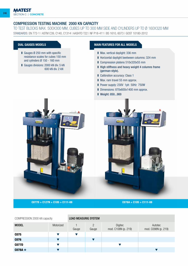
SECTION C | CONCRETE
DIAL GAUGES MODELS
Gauges Ø 250 mm with specific resistance scales for cubes 150 mm and cylinders Ø 150 - 160 mm
Gauges divisions: 2000 kN div. 5 kN 600 kN div. 2 kN
COMPRESSION 2000 kN capacity LOAD MEASURIG SYSTEM
MODEL Motorized 1 Gauge
2 Gauge
Digitecmod. C108N (p. 219)
Autotecmod. C098N (p. 219)
C075
C076
C077D
C078A
COMPRESSION TESTING MACHINE 2000 KN CAPACITYTO TEST BLOCKS MAX. 500X300 MM, CUBES UP TO 300 MM SIDE AND CYLINDERS UP TO Ø 160X320 MMSTANDARDS: EN 772-1 | ASTM C39, C140, C1314 | AASHTO T22 | NF P18-411 | BS 1610, 6073 | GOST 10180-2012
MAIN FEATURES FOR ALL MODELS
Max. vertical daylight: 336 mm Horizontal daylight beetween columns: 324 mm Compression platens 510x320x55 mm High stiffness and heavy weight 4 columns frame
(german-style). Calibration accuracy: Class 1 Max. ram travel 55 mm approx. Power supply: 230V 1ph 50Hz 750W Dimensions: 870x600x1400 mm approx. Weight: 850...900
C078A + C105 + C111-08 C077D + C127N + C105 + C111-08
246
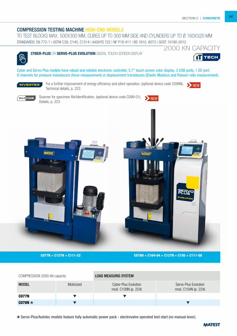
SECTION C | CONCRETE
COMPRESSION 2000 kN capacity LOAD MEASURIG SYSTEM
MODEL Motorized Cyber-Plus Evolutionmod. C109N (p. 224)
Servo-Plus Evolutionmod. C104N (p. 224)
C077N
C078N
COMPRESSION TESTING MACHINE HIGH-END MODELSTO TEST BLOCKS MAX. 500X300 MM, CUBES UP TO 300 MM SIDE AND CYLINDERS UP TO Ø 160X320 MMSTANDARDS: EN 772-1 | ASTM C39, C140, C1314 | AASHTO T22 | NF P18-411 | BS 1610, 6073 | GOST 10180-2012
2000 KN CAPACITY
C077N + C127N + C111-22 C078N + C104-04 + C127N + C105 + C111-08
CYBER-PLUS OR SERVO-PLUS EVOLUTION DIGITAL TOUCH SCREEN DISPLAY
Cyber and Servo-Plus models have robust and reliable electronic controller, 5.7" touch screen color display. 2 USB ports, 1 SD port,8 channels for pressure transducers (force measurement) or displacement transducers (Elastic Modulus and Poisson ratio measurement).
Servo-Plus/Autotec models feature fully automatic power pack - electrovalve operated test start (no manual lever).
For a further improvement of energy efficiency and silent operation, (optional device code C099N). Technical details, p. 223
Scanner for specimen file/identification, (optional device code C099-01).Details, p. 223
inverter NEW
NEWBARCODE
247
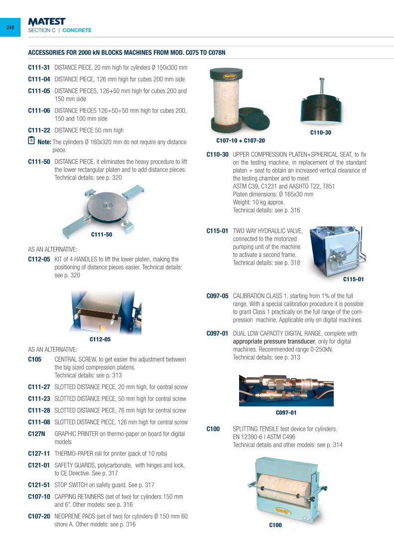
SECTION C | CONCRETE
C100
ACCESSORIES FOR 2000 kN BLOCKS MACHINES FROM MOD. C075 TO C078N
C111-31 DISTANCE PIECE, 20 mm high for cylinders Ø 150x300 mm
C111-04 DISTANCE PIECE, 126 mm high for cubes 200 mm side
C111-05 DISTANCE PIECES, 126+50 mm high for cubes 200 and 150 mm side
C111-06 DISTANCE PIECES 126+50+50 mm high for cubes 200, 150 and 100 mm side
C111-22 DISTANCE PIECE 50 mm high
Note: The cylinders Ø 160x320 mm do not require any distance piece.
C111-50 DISTANCE PIECE, it eliminates the heavy procedure to lift the lower rectangular platen and to add distance pieces.
Technical details: see p. 320
C107-10 + C107-20
C115-01
C110-30
C097-01
C115-01 TWO WAY HYDRAULIC VALVE, connected to the motorized pumping unit of the machine to activate a second frame. Technical details: see p. 318
C097-05 CALIBRATION CLASS 1, starting from 1% of the full range. With a special calibration procedure it is possible to grant Class 1 practically on the full range of the com-pression machine. Applicable only on digital machines.
C097-01 DUAL LOW CAPACITY DIGITAL RANGE, complete with appropriate pressure transducer, only for digital machines. Recommended range 0-250kN.
Technical details: see p. 313
C100 SPLITTING TENSILE test device for cylinders. EN 12390-6 | ASTM C496 Technical details and other models: see p. 314
AS AN ALTERNATIVE:
C112-05 KIT of 4 HANDLES to lift the lower platen, making the positioning of distance pieces easier. Technical details: see p. 320
AS AN ALTERNATIVE:
C105 CENTRAL SCREW, to get easier the adjustment between the big sized compression platens.
Technical details: see p. 313
C111-27 SLOTTED DISTANCE PIECE, 20 mm high, for central screw
C111-23 SLOTTED DISTANCE PIECE, 50 mm high for central screw
C111-28 SLOTTED DISTANCE PIECE, 76 mm high for central screw
C111-08 SLOTTED DISTANCE PIECE, 126 mm high for central screw
C127N GRAPHIC PRINTER on thermo-paper on board for digital models
C127-11 THERMO-PAPER roll for printer (pack of 10 rolls)
C121-01 SAFETY GUARDS, polycarbonate, with hinges and lock, to CE Directive. See p. 317
C121-51 STOP SWITCH on safety guard. See p. 317
C107-10 CAPPING RETAINERS (set of two) for cylinders 150 mm and 6”. Other models: see p. 316
C107-20 NEOPRENE PADS (set of two) for cylinders Ø 150 mm 60 shore A. Other models: see p. 316
C110-30 UPPER COMPRESSION PLATEN+SPHERICAL SEAT, to fix on the testing machine, in replacement of the standard platen + seat to obtain an increased vertical clearance of the testing chamber and to meet
ASTM C39, C1231 and AASHTO T22, T851 Platen dimensions: Ø 165x30 mm Weight: 10 kg approx. Technical details: see p. 316
C111-50
C112-05
248
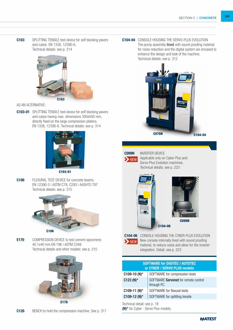
SECTION C | CONCRETE
ACCESSORIES FOR 2000 kN BLOCKS MACHINES FROM MOD. C075 TO C078N
C111-31 DISTANCE PIECE, 20 mm high for cylinders Ø 150x300 mm
C111-04 DISTANCE PIECE, 126 mm high for cubes 200 mm side
C111-05 DISTANCE PIECES, 126+50 mm high for cubes 200 and 150 mm side
C111-06 DISTANCE PIECES 126+50+50 mm high for cubes 200, 150 and 100 mm side
C111-22 DISTANCE PIECE 50 mm high
Note: The cylinders Ø 160x320 mm do not require any distance piece.
C111-50 DISTANCE PIECE, it eliminates the heavy procedure to lift the lower rectangular platen and to add distance pieces.
Technical details: see p. 320
C104-04 CONSOLE HOUSING THE SERVO-PLUS EVOLUTION The pump assembly lined with sound proofing material
for noise reduction and the digital system are encased to enhance the design and look of the machine.
Technical details: see p. 312
E170
C106
C103
C103-01
C104-04C078N
Technical detail: see p. 18(N)* for Cyber - Servo Plus models.
SOFTWARE for DIGITEC / AUTOTECor CYBER / SERVO PLUS models
C109-10 (N)* SOFTWARE for compression tests
C123 (N)* SOFTWARE Servonet for remote control through PC
C109-11 (N)* SOFTWARE for flexural tests
C109-12 (N)* SOFTWARE for splitting tensile
AS AN ALTERNATIVE:
C103-01 SPLITTING TENSILE test device for self blocking pavers and cubes having max. dimensions 300x500 mm, directly fixed on the large compression platens.
EN 1338, 12390-6. Technical details: see p. 314
C103 SPLITTING TENSILE test device for self blocking pavers and cubes. EN 1338, 12390-6.
Technical details: see p. 314
C106 FLEXURAL TEST DEVICE for concrete beams. EN 12390-5 | ASTM C78, C293 | AASHTO T97 Technical details: see p. 315
C126 BENCH to hold the compression machine. See p. 317
E170 COMPRESSION DEVICE to test cement specimens 40.1x40 mm EN 196 | ASTM C349 Technical details and other models: see p. 315
C104-06C099N
C104-06 CONSOLE HOUSING THE CYBER-PLUS EVOLUTION New console internally lined with sound proofing
material, to reduce noise and allow for the inverter integration. Detail: see p. 223
C099N INVERTER DEVICE Applicable only on Cyber-Plus and Servo-Plus Evolution machines. Technical details: see p. 223
NEW
NEW
249
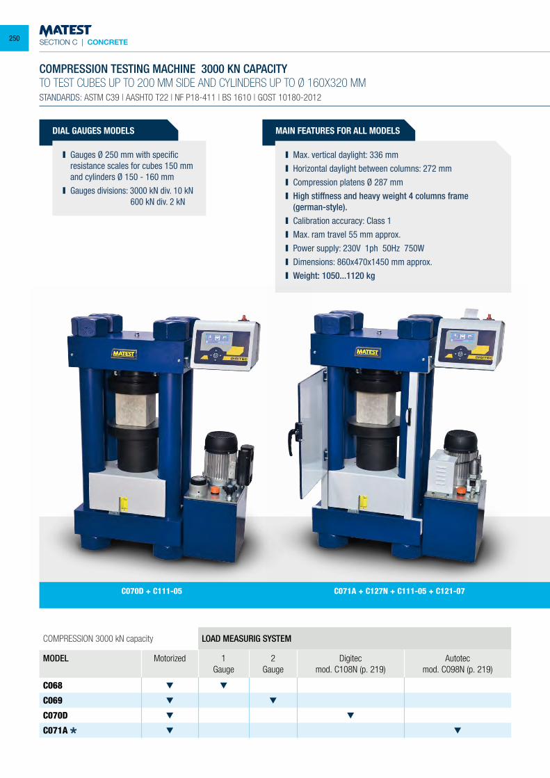
SECTION C | CONCRETE
DIAL GAUGES MODELS
Gauges Ø 250 mm with specific resistance scales for cubes 150 mm and cylinders Ø 150 - 160 mm
Gauges divisions: 3000 kN div. 10 kN 600 kN div. 2 kN
COMPRESSION 3000 kN capacity LOAD MEASURIG SYSTEM
MODEL Motorized 1 Gauge
2 Gauge
Digitecmod. C108N (p. 219)
Autotecmod. C098N (p. 219)
C068
C069
C070D
C071A
COMPRESSION TESTING MACHINE 3000 KN CAPACITYTO TEST CUBES UP TO 200 MM SIDE AND CYLINDERS UP TO Ø 160X320 MMSTANDARDS: ASTM C39 | AASHTO T22 | NF P18-411 | BS 1610 | GOST 10180-2012
MAIN FEATURES FOR ALL MODELS
Max. vertical daylight: 336 mm Horizontal daylight between columns: 272 mm Compression platens Ø 287 mm High stiffness and heavy weight 4 columns frame
(german-style). Calibration accuracy: Class 1 Max. ram travel 55 mm approx. Power supply: 230V 1ph 50Hz 750W Dimensions: 860x470x1450 mm approx. Weight: 1050...1120 kg
C071A + C127N + C111-05 + C121-07C070D + C111-05
250
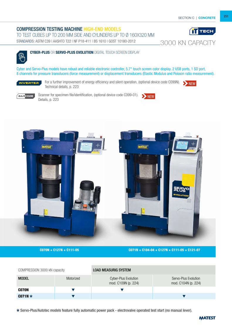
SECTION C | CONCRETE
COMPRESSION 3000 kN capacity LOAD MEASURIG SYSTEM
MODEL Motorized Cyber-Plus Evolutionmod. C109N (p. 224)
Servo-Plus Evolutionmod. C104N (p. 224)
C070N
C071N
COMPRESSION TESTING MACHINE HIGH-END MODELSTO TEST CUBES UP TO 200 MM SIDE AND CYLINDERS UP TO Ø 160X320 MMSTANDARDS: ASTM C39 | AASHTO T22 | NF P18-411 | BS 1610 | GOST 10180-2012 3000 KN CAPACITY
C070N + C127N + C111-05 C071N + C104-04 + C127N + C111-05 + C121-07
CYBER-PLUS OR SERVO-PLUS EVOLUTION DIGITAL TOUCH SCREEN DISPLAY
Cyber and Servo-Plus models have robust and reliable electronic controller, 5.7" touch screen color display. 2 USB ports, 1 SD port,8 channels for pressure transducers (force measurement) or displacement transducers (Elastic Modulus and Poisson ratio measurement).
Servo-Plus/Autotec models feature fully automatic power pack - electrovalve operated test start (no manual lever).
For a further improvement of energy efficiency and silent operation, (optional device code C099N). Technical details, p. 223
Scanner for specimen file/identification, (optional device code C099-01).Details, p. 223
inverter NEW
NEWBARCODE
251
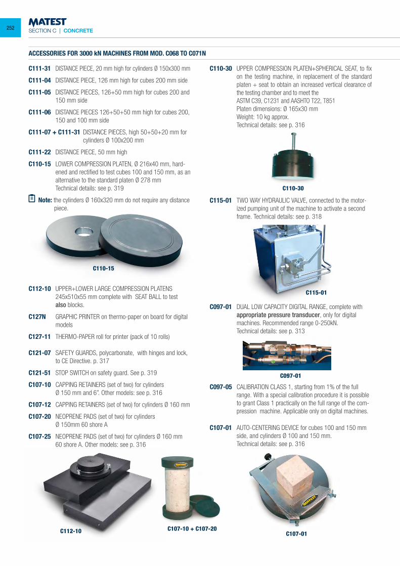
SECTION C | CONCRETE
C107-10 + C107-20
C115-01
C097-01
C107-01
C107-01 AUTO-CENTERING DEVICE for cubes 100 and 150 mm side, and cylinders Ø 100 and 150 mm.
Technical details: see p. 316
C110-15
ACCESSORIES FOR 3000 kN MACHINES FROM MOD. C068 TO C071N
C111-31 DISTANCE PIECE, 20 mm high for cylinders Ø 150x300 mm
C111-04 DISTANCE PIECE, 126 mm high for cubes 200 mm side
C111-05 DISTANCE PIECES, 126+50 mm high for cubes 200 and 150 mm side
C111-06 DISTANCE PIECES 126+50+50 mm high for cubes 200, 150 and 100 mm side
C111-07 + C111-31 DISTANCE PIECES, high 50+50+20 mm for cylinders Ø 100x200 mm
C111-22 DISTANCE PIECE, 50 mm high
C110-15 LOWER COMPRESSION PLATEN, Ø 216x40 mm, hard-ened and rectified to test cubes 100 and 150 mm, as an alternative to the standard platen Ø 278 mm
Technical details: see p. 319
Note: the cylinders Ø 160x320 mm do not require any distance piece.
C112-10 UPPER+LOWER LARGE COMPRESSION PLATENS 245x510x55 mm complete with SEAT BALL to test
also blocks.
C127N GRAPHIC PRINTER on thermo-paper on board for digital models
C127-11 THERMO-PAPER roll for printer (pack of 10 rolls)
C121-07 SAFETY GUARDS, polycarbonate, with hinges and lock, to CE Directive. p. 317
C121-51 STOP SWITCH on safety guard. See p. 319
C107-10 CAPPING RETAINERS (set of two) for cylinders Ø 150 mm and 6”. Other models: see p. 316
C107-12 CAPPING RETAINERS (set of two) for cylinders Ø 160 mm
C107-20 NEOPRENE PADS (set of two) for cylinders Ø 150mm 60 shore A
C107-25 NEOPRENE PADS (set of two) for cylinders Ø 160 mm 60 shore A. Other models: see p. 316
C110-30
C110-30 UPPER COMPRESSION PLATEN+SPHERICAL SEAT, to fix on the testing machine, in replacement of the standard platen + seat to obtain an increased vertical clearance of the testing chamber and to meet the
ASTM C39, C1231 and AASHTO T22, T851 Platen dimensions: Ø 165x30 mm Weight: 10 kg approx. Technical details: see p. 316
C115-01 TWO WAY HYDRAULIC VALVE, connected to the motor-ized pumping unit of the machine to activate a second frame. Technical details: see p. 318
C097-01 DUAL LOW CAPACITY DIGITAL RANGE, complete with appropriate pressure transducer, only for digital machines. Recommended range 0-250kN.
Technical details: see p. 313
C097-05 CALIBRATION CLASS 1, starting from 1% of the full range. With a special calibration procedure it is possible to grant Class 1 practically on the full range of the com-pression machine. Applicable only on digital machines.
C112-10
252
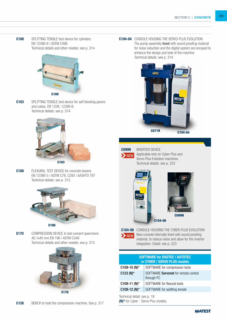
SECTION C | CONCRETE
ACCESSORIES FOR 3000 kN MACHINES FROM MOD. C068 TO C071N
C111-31 DISTANCE PIECE, 20 mm high for cylinders Ø 150x300 mm
C111-04 DISTANCE PIECE, 126 mm high for cubes 200 mm side
C111-05 DISTANCE PIECES, 126+50 mm high for cubes 200 and 150 mm side
C111-06 DISTANCE PIECES 126+50+50 mm high for cubes 200, 150 and 100 mm side
C111-07 + C111-31 DISTANCE PIECES, high 50+50+20 mm for cylinders Ø 100x200 mm
C111-22 DISTANCE PIECE, 50 mm high
C110-15 LOWER COMPRESSION PLATEN, Ø 216x40 mm, hard-ened and rectified to test cubes 100 and 150 mm, as an alternative to the standard platen Ø 278 mm
Technical details: see p. 319
Note: the cylinders Ø 160x320 mm do not require any distance piece.
C100 SPLITTING TENSILE test device for cylinders. EN 12390-6 | ASTM C496 Technical details and other models: see p. 314
C100
C103 SPLITTING TENSILE test device for self blocking pavers and cubes. EN 1338, 12390-6.
Technical details: see p. 314
C106 FLEXURAL TEST DEVICE for concrete beams. EN 12390-5 | ASTM C78, C293 | AASHTO T97 Technical details: see p. 315
E170 COMPRESSION DEVICE to test cement specimens 40.1x40 mm EN 196 | ASTM C349 Technical details and other models: see p. 315
C126 BENCH to hold the compression machine. See p. 317
C104-04 CONSOLE HOUSING THE SERVO-PLUS EVOLUTION The pump assembly lined with sound proofing material
for noise reduction and the digital system are encased to enhance the design and look of the machine.
Technical details: see p. 314
E170
C106
C103
C104-04C071N
Technical detail: see p. 18(N)* for Cyber - Servo Plus models.
SOFTWARE for DIGITEC / AUTOTECor CYBER / SERVO PLUS models
C109-10 (N)* SOFTWARE for compression tests
C123 (N)* SOFTWARE Servonet for remote control through PC
C109-11 (N)* SOFTWARE for flexural tests
C109-12 (N)* SOFTWARE for splitting tensile
C104-06
C099N
C104-06 CONSOLE HOUSING THE CYBER-PLUS EVOLUTION New console internally lined with sound proofing
material, to reduce noise and allow for the inverter integration. Detail: see p. 223
C099N INVERTER DEVICE Applicable only on Cyber-Plus and Servo-Plus Evolution machines. Technical details: see p. 223
NEW
NEW
253
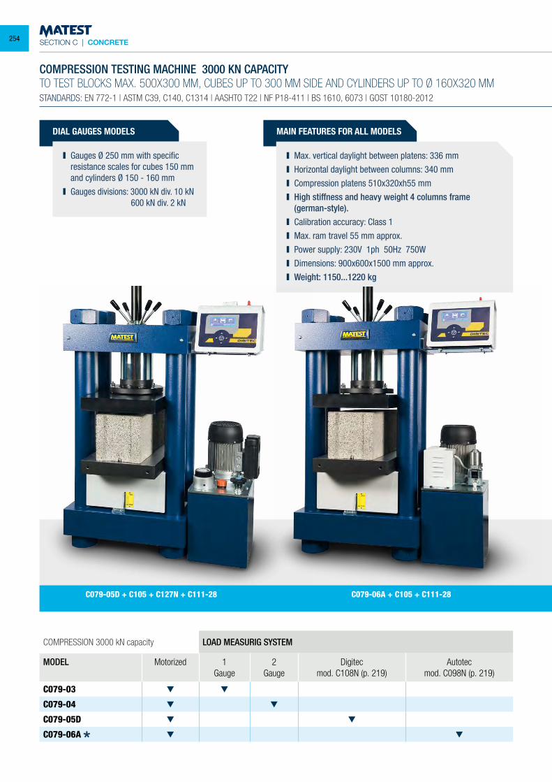
SECTION C | CONCRETE
DIAL GAUGES MODELS
Gauges Ø 250 mm with specific resistance scales for cubes 150 mm and cylinders Ø 150 - 160 mm
Gauges divisions: 3000 kN div. 10 kN 600 kN div. 2 kN
COMPRESSION 3000 kN capacity LOAD MEASURIG SYSTEM
MODEL Motorized 1 Gauge
2 Gauge
Digitecmod. C108N (p. 219)
Autotecmod. C098N (p. 219)
C079-03
C079-04
C079-05D
C079-06A
COMPRESSION TESTING MACHINE 3000 KN CAPACITYTO TEST BLOCKS MAX. 500X300 MM, CUBES UP TO 300 MM SIDE AND CYLINDERS UP TO Ø 160X320 MMSTANDARDS: EN 772-1 | ASTM C39, C140, C1314 | AASHTO T22 | NF P18-411 | BS 1610, 6073 | GOST 10180-2012
MAIN FEATURES FOR ALL MODELS
Max. vertical daylight between platens: 336 mm Horizontal daylight between columns: 340 mm Compression platens 510x320xh55 mm High stiffness and heavy weight 4 columns frame
(german-style). Calibration accuracy: Class 1 Max. ram travel 55 mm approx. Power supply: 230V 1ph 50Hz 750W Dimensions: 900x600x1500 mm approx. Weight: 1150...1220 kg
C079-06A + C105 + C111-28C079-05D + C105 + C127N + C111-28
254
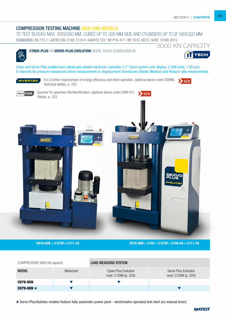
SECTION C | CONCRETE
COMPRESSION 3000 kN capacity LOAD MEASURIG SYSTEM
MODEL Motorized Cyber-Plus Evolutionmod. C109N (p. 224)
Servo-Plus Evolutionmod. C104N (p. 224)
C079-05N
C079-06N
COMPRESSION TESTING MACHINE HIGH-END MODELSTO TEST BLOCKS MAX. 500X300 MM, CUBES UP TO 300 MM SIDE AND CYLINDERS UP TO Ø 160X320 MMSTANDARDS: EN 772-1 | ASTM C39, C140, C1314 | AASHTO T22 | NF P18-411 | BS 1610, 6073 | GOST 10180-2012
3000 KN CAPACITY
C079-05N + C127N + C111-22 C079-06N + C105 + C127N + C104-04 + C111-28
CYBER-PLUS OR SERVO-PLUS EVOLUTION DIGITAL TOUCH SCREEN DISPLAY
Cyber and Servo-Plus models have robust and reliable electronic controller, 5.7" touch screen color display. 2 USB ports, 1 SD port,8 channels for pressure transducers (force measurement) or displacement transducers (Elastic Modulus and Poisson ratio measurement).
Servo-Plus/Autotec models feature fully automatic power pack - electrovalve operated test start (no manual lever).
For a further improvement of energy efficiency and silent operation, (optional device code C099N). Technical details, p. 223
Scanner for specimen file/identification, (optional device code C099-01).Details, p. 223
inverter NEW
NEWBARCODE
255
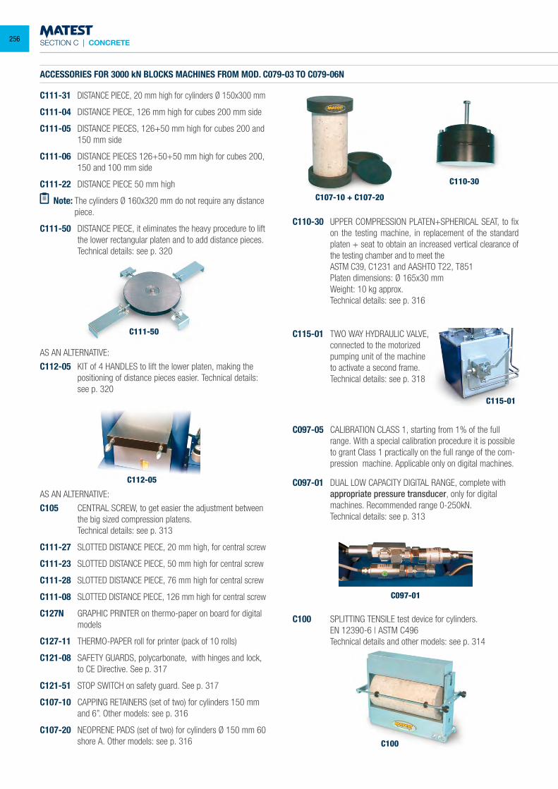
SECTION C | CONCRETE
C100
ACCESSORIES FOR 3000 kN BLOCKS MACHINES FROM MOD. C079-03 TO C079-06N
C111-31 DISTANCE PIECE, 20 mm high for cylinders Ø 150x300 mm
C111-04 DISTANCE PIECE, 126 mm high for cubes 200 mm side
C111-05 DISTANCE PIECES, 126+50 mm high for cubes 200 and 150 mm side
C111-06 DISTANCE PIECES 126+50+50 mm high for cubes 200, 150 and 100 mm side
C111-22 DISTANCE PIECE 50 mm high
Note: The cylinders Ø 160x320 mm do not require any distance piece.
C111-50 DISTANCE PIECE, it eliminates the heavy procedure to lift the lower rectangular platen and to add distance pieces.
Technical details: see p. 320
C107-10 + C107-20
C115-01
C110-30
C097-01
C115-01 TWO WAY HYDRAULIC VALVE, connected to the motorized pumping unit of the machine to activate a second frame. Technical details: see p. 318
C097-05 CALIBRATION CLASS 1, starting from 1% of the full range. With a special calibration procedure it is possible to grant Class 1 practically on the full range of the com-pression machine. Applicable only on digital machines.
C097-01 DUAL LOW CAPACITY DIGITAL RANGE, complete with appropriate pressure transducer, only for digital machines. Recommended range 0-250kN.
Technical details: see p. 313
C100 SPLITTING TENSILE test device for cylinders. EN 12390-6 | ASTM C496 Technical details and other models: see p. 314
AS AN ALTERNATIVE:
C112-05 KIT of 4 HANDLES to lift the lower platen, making the positioning of distance pieces easier. Technical details: see p. 320
AS AN ALTERNATIVE:
C105 CENTRAL SCREW, to get easier the adjustment between the big sized compression platens.
Technical details: see p. 313
C111-27 SLOTTED DISTANCE PIECE, 20 mm high, for central screw
C111-23 SLOTTED DISTANCE PIECE, 50 mm high for central screw
C111-28 SLOTTED DISTANCE PIECE, 76 mm high for central screw
C111-08 SLOTTED DISTANCE PIECE, 126 mm high for central screw
C127N GRAPHIC PRINTER on thermo-paper on board for digital models
C127-11 THERMO-PAPER roll for printer (pack of 10 rolls)
C121-08 SAFETY GUARDS, polycarbonate, with hinges and lock, to CE Directive. See p. 317
C121-51 STOP SWITCH on safety guard. See p. 317
C107-10 CAPPING RETAINERS (set of two) for cylinders 150 mm and 6”. Other models: see p. 316
C107-20 NEOPRENE PADS (set of two) for cylinders Ø 150 mm 60 shore A. Other models: see p. 316
C110-30 UPPER COMPRESSION PLATEN+SPHERICAL SEAT, to fix on the testing machine, in replacement of the standard platen + seat to obtain an increased vertical clearance of the testing chamber and to meet the
ASTM C39, C1231 and AASHTO T22, T851 Platen dimensions: Ø 165x30 mm Weight: 10 kg approx. Technical details: see p. 316
C111-50
C112-05
256
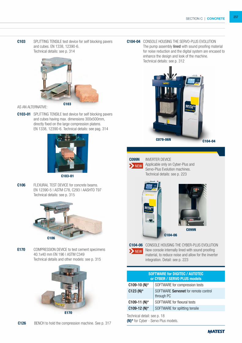
SECTION C | CONCRETE
ACCESSORIES FOR 3000 kN BLOCKS MACHINES FROM MOD. C079-03 TO C079-06N
C111-31 DISTANCE PIECE, 20 mm high for cylinders Ø 150x300 mm
C111-04 DISTANCE PIECE, 126 mm high for cubes 200 mm side
C111-05 DISTANCE PIECES, 126+50 mm high for cubes 200 and 150 mm side
C111-06 DISTANCE PIECES 126+50+50 mm high for cubes 200, 150 and 100 mm side
C111-22 DISTANCE PIECE 50 mm high
Note: The cylinders Ø 160x320 mm do not require any distance piece.
C111-50 DISTANCE PIECE, it eliminates the heavy procedure to lift the lower rectangular platen and to add distance pieces.
Technical details: see p. 320
C104-04 CONSOLE HOUSING THE SERVO-PLUS EVOLUTION The pump assembly lined with sound proofing material
for noise reduction and the digital system are encased to enhance the design and look of the machine.
Technical details: see p. 312
E170
C106
C103
C103-01
C104-04C079-06N
Technical detail: see p. 18(N)* for Cyber - Servo Plus models.
SOFTWARE for DIGITEC / AUTOTECor CYBER / SERVO PLUS models
C109-10 (N)* SOFTWARE for compression tests
C123 (N)* SOFTWARE Servonet for remote control through PC
C109-11 (N)* SOFTWARE for flexural tests
C109-12 (N)* SOFTWARE for splitting tensile
AS AN ALTERNATIVE:
C103-01 SPLITTING TENSILE test device for self blocking pavers and cubes having max. dimensions 300x500mm, directly fixed on the large compression platens.
EN 1338, 12390-6. Technical details: see pag. 314
C103 SPLITTING TENSILE test device for self blocking pavers and cubes. EN 1338, 12390-6.
Technical details: see p. 314
C106 FLEXURAL TEST DEVICE for concrete beams. EN 12390-5 | ASTM C78, C293 | AASHTO T97 Technical details: see p. 315
C126 BENCH to hold the compression machine. See p. 317
E170 COMPRESSION DEVICE to test cement specimens 40.1x40 mm EN 196 | ASTM C349 Technical details and other models: see p. 315
C104-06C099N
C104-06 CONSOLE HOUSING THE CYBER-PLUS EVOLUTION New console internally lined with sound proofing
material, to reduce noise and allow for the inverter integration. Detail: see p. 223
C099N INVERTER DEVICE Applicable only on Cyber-Plus and Servo-Plus Evolution machines. Technical details: see p. 223
NEW
NEW
257
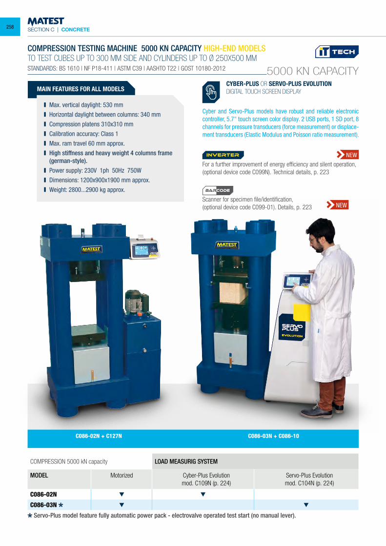
SECTION C | CONCRETE
5000 KN CAPACITY
COMPRESSION TESTING MACHINE 5000 KN CAPACITY HIGH-END MODELSTO TEST CUBES UP TO 300 MM SIDE AND CYLINDERS UP TO Ø 250X500 MMSTANDARDS: BS 1610 | NF P18-411 | ASTM C39 | AASHTO T22 | GOST 10180-2012
MAIN FEATURES FOR ALL MODELS
Max. vertical daylight: 530 mm Horizontal daylight between columns: 340 mm Compression platens 310x310 mm Calibration accuracy: Class 1 Max. ram travel 60 mm approx. High stiffness and heavy weight 4 columns frame
(german-style). Power supply: 230V 1ph 50Hz 750W Dimensions: 1200x900x1900 mm approx. Weight: 2800...2900 kg approx.
COMPRESSION 5000 kN capacity LOAD MEASURIG SYSTEM
MODEL Motorized Cyber-Plus Evolutionmod. C109N (p. 224)
Servo-Plus Evolutionmod. C104N (p. 224)
C086-02N
C086-03N
C086-02N + C127N C086-03N + C086-10
CYBER-PLUS OR SERVO-PLUS EVOLUTIONDIGITAL TOUCH SCREEN DISPLAY
Cyber and Servo-Plus models have robust and reliable electronic controller, 5.7" touch screen color display. 2 USB ports, 1 SD port, 8 channels for pressure transducers (force measurement) or displace-ment transducers (Elastic Modulus and Poisson ratio measurement).
Servo-Plus model feature fully automatic power pack - electrovalve operated test start (no manual lever).
For a further improvement of energy efficiency and silent operation, (optional device code C099N). Technical details, p. 223
Scanner for specimen file/identification,(optional device code C099-01). Details, p. 223
inverter NEW
NEW
BARCODE
258
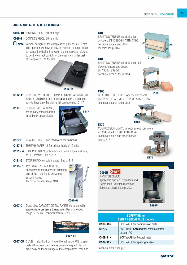
SECTION C | CONCRETE
CYBER-PLUS OR SERVO-PLUS EVOLUTIONDIGITAL TOUCH SCREEN DISPLAY
ACCESSORIES FOR 5000 kN MACHINES
C086-10 DISTANCE PIECE, 50 mm high
C086-11 DISTANCE PIECE, 25 mm high
Note: Vertical daylight of the compression platens is 530 mm. The operator will have to buy the needed distance pieces
to reduce the daylight between the compression platens to get the correct daylight of the specimen under test plus approx. 10 to 15 mm
C097-01
C112-11 UPPER+LOWER LARGE COMPRESSION PLATENS+SEAT BALL 310x510x55 mm to test also blocks. It is neces-sary to have also the sliding rail carriage mod. C117
C117 SLIDING RAIL CARRIAGE, for an easy removal of the large block upper platen
C127N GRAPHIC PRINTER on thermo-paper on board
C127-11 THERMO-PAPER roll for printer (pack of 10 rolls)
C121-04 SAFETY GUARDS, polycarbonate, with hinges and lock, to CE Directive. See p. 317
C121-51 STOP SWITCH on safety guard. See p. 317
C115-01 TWO WAY HYDRAULIC VALVE, connected to the motorized pumping unit of the machine to activate a second frame.
Technical details: see p. 318
C100
C100SPLITTING TENSILE test device for cylinders.EN 12390-6 | ASTM C496Technical details and othermodels: see p. 314
C103
C103SPLITTING TENSILE test device for selfblocking pavers and cubes.EN 1338, 12390-6.Technical details: see p. 314
E170
C106
C106FLEXURAL TEST DEVICE for concrete beams.EN 12390-5 | ASTM C78, C293 | AASHTO T97Technical details: see p. 315
E170COMPRESSION DEVICE to test cement specimens40.1x40 mm EN 196 | ASTM C349Technical details and other models:see p. 317
Technical detail: see p. 18
SOFTWARE for CYBER / SERVO PLUS models
C109-10N SOFTWARE for compression tests
C123N SOFTWARE Servonet for remote control through PC
C109-11N SOFTWARE for flexural tests
C109-12N SOFTWARE for splitting tensile
C097-01 DUAL LOW CAPACITY DIGITAL RANGE, complete with appropriate pressure transducer. Recommended range 0-250kN. Technical details: see p. 313
C097-01
C117
C097-05 CLASS 1, starting from 1% of the full range. With a spe-cial calibration procedure it is possible to grant Class 1 practically on the full range of the compression machine.
C099N
C099NINVERTER DEVICEApplicable only on Cyber-Plus andServo-Plus Evolution machines.Technical details: see p. 223
NEW
C112-11
259
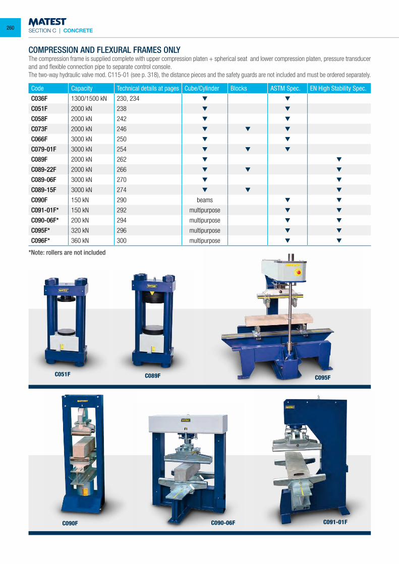
SECTION C | CONCRETE
Code Capacity Technical details at pages Cube/Cylinder Blocks ASTM Spec. EN High Stability Spec.
C036F 1300/1500 kN 230, 234
C051F 2000 kN 238
C058F 2000 kN 242
C073F 2000 kN 246
C066F 3000 kN 250
C079-01F 3000 kN 254
C089F 2000 kN 262
C089-22F 2000 kN 266
C089-06F 3000 kN 270
C089-15F 3000 kN 274
C090F 150 kN 290 beams
C091-01F* 150 kN 292 multipurpose
C090-06F* 200 kN 294 multipurpose
C095F* 320 kN 296 multipurpose
C096F* 360 kN 300 multipurpose
*Note: rollers are not included
COMPRESSION AND FLEXURAL FRAMES ONLYThe compression frame is supplied complete with upper compression platen + spherical seat and lower compression platen, pressure transducer and and flexible connection pipe to separate control console. The two-way hydraulic valve mod. C115-01 (see p. 318), the distance pieces and the safety guards are not included and must be ordered separately.
C091-01FC090-06F
C095FC051F C089F
C090F
260
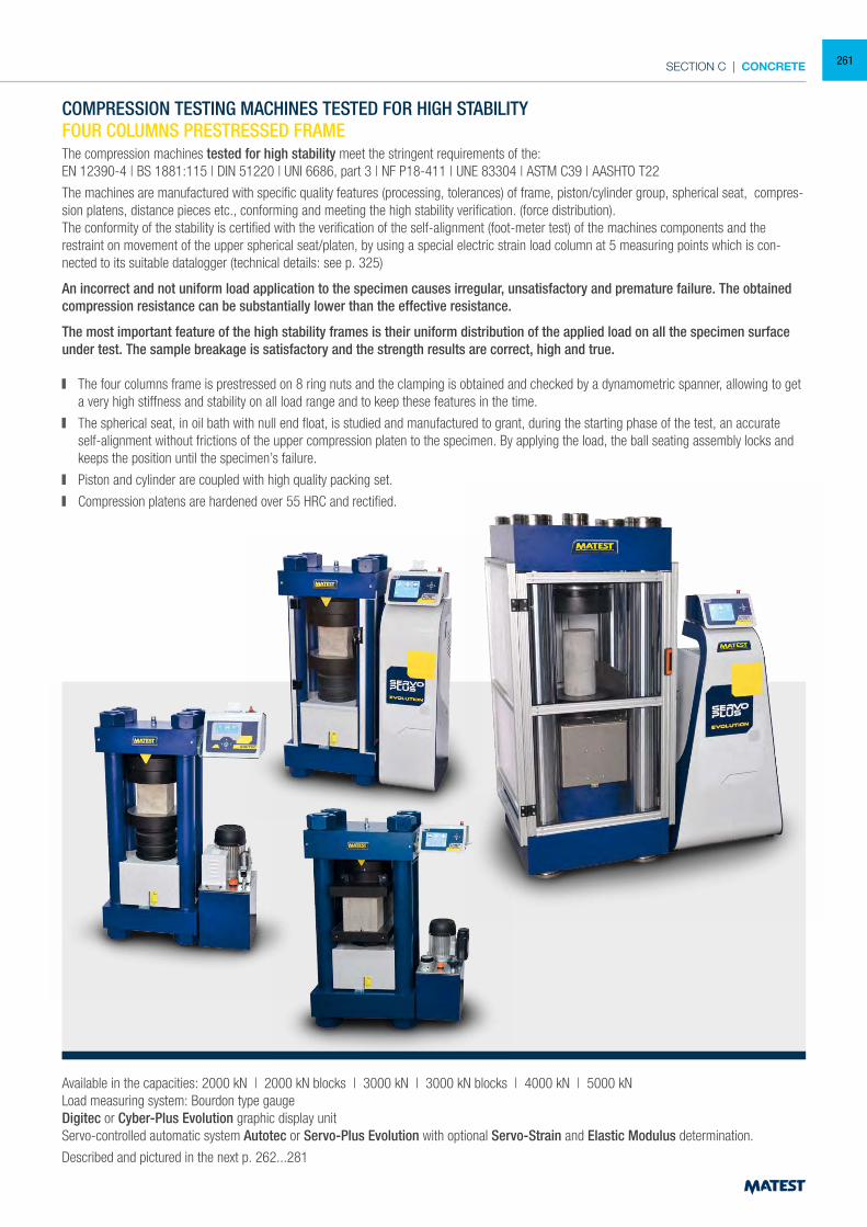
SECTION C | CONCRETE
COMPRESSION TESTING MACHINES TESTED FOR HIGH STABILITYFOUR COLUMNS PRESTRESSED FRAMEThe compression machines tested for high stability meet the stringent requirements of the:EN 12390-4 | BS 1881:115 | DIN 51220 | UNI 6686, part 3 | NF P18-411 | UNE 83304 | ASTM C39 | AASHTO T22
The machines are manufactured with specific quality features (processing, tolerances) of frame, piston/cylinder group, spherical seat, compres-sion platens, distance pieces etc., conforming and meeting the high stability verification. (force distribution).The conformity of the stability is certified with the verification of the self-alignment (foot-meter test) of the machines components and the restraint on movement of the upper spherical seat/platen, by using a special electric strain load column at 5 measuring points which is con-nected to its suitable datalogger (technical details: see p. 325)
An incorrect and not uniform load application to the specimen causes irregular, unsatisfactory and premature failure. The obtained compression resistance can be substantially lower than the effective resistance.
The most important feature of the high stability frames is their uniform distribution of the applied load on all the specimen surface under test. The sample breakage is satisfactory and the strength results are correct, high and true.
The four columns frame is prestressed on 8 ring nuts and the clamping is obtained and checked by a dynamometric spanner, allowing to get a very high stiffness and stability on all load range and to keep these features in the time.
The spherical seat, in oil bath with null end float, is studied and manufactured to grant, during the starting phase of the test, an accurate self-alignment without frictions of the upper compression platen to the specimen. By applying the load, the ball seating assembly locks and keeps the position until the specimen’s failure.
Piston and cylinder are coupled with high quality packing set.
Compression platens are hardened over 55 HRC and rectified.
Available in the capacities: 2000 kN | 2000 kN blocks | 3000 kN | 3000 kN blocks | 4000 kN | 5000 kNLoad measuring system: Bourdon type gaugeDigitec or Cyber-Plus Evolution graphic display unitServo-controlled automatic system Autotec or Servo-Plus Evolution with optional Servo-Strain and Elastic Modulus determination.
Described and pictured in the next p. 262...281
261
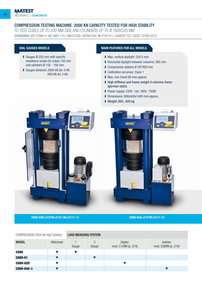
SECTION C | CONCRETE
DIAL GAUGES MODELS
Gauges Ø 250 mm with specific resistance scales for cubes 150 mm and cylinders Ø 150 - 160 mm
Gauges divisions: 2000 kN div. 5 kN 600 kN div. 2 kN
COMPRESSION 2000 kN High Stability LOAD MEASURIG SYSTEM
MODEL Motorized 1 Gauge
2 Gauge
Digitecmod. C108N (p. 219)
Autotecmod. C098N (p. 219)
C089
C089-01
C089-02D
C089-04A
COMPRESSION TESTING MACHINE 2000 KN CAPACITY TESTED FOR HIGH STABILITYTO TEST CUBES UP TO 200 MM SIDE AND CYLINDERS UP TO Ø 160X320 MMSTANDARDS: EN 12390-4 | BS 1881:115 | DIN 51220 | ASTM C39 | NF P18-411 | AASHTO T22 | GOST 10180-2012
MAIN FEATURES FOR ALL MODELS
Max. vertical daylight: 334.5 mm Horizontal daylight between columns: 260 mm Compression platens Ø 287X60 mm Calibration accuracy: Class 1 Max. ram travel 60 mm approx. High stiffness and heavy weight 4 columns frame
(german-style). Power supply: 230V 1ph 50Hz 750W Dimensions: 690x400x1400 mm approx. Weight: 850...920 kg
C089-04A+C127N+C111-13C089-02D+C127N+C121-06+C111-13
262
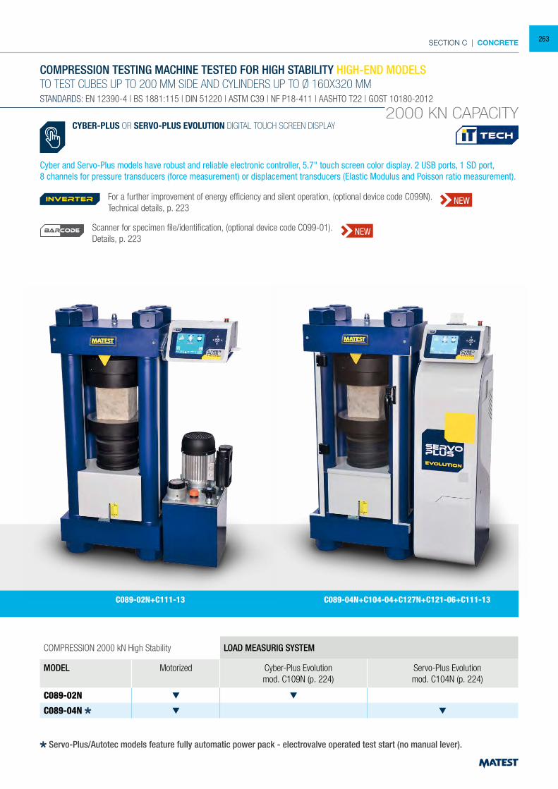
SECTION C | CONCRETE
COMPRESSION 2000 kN High Stability LOAD MEASURIG SYSTEM
MODEL Motorized Cyber-Plus Evolutionmod. C109N (p. 224)
Servo-Plus Evolutionmod. C104N (p. 224)
C089-02N
C089-04N
COMPRESSION TESTING MACHINE TESTED FOR HIGH STABILITY HIGH-END MODELSTO TEST CUBES UP TO 200 MM SIDE AND CYLINDERS UP TO Ø 160X320 MMSTANDARDS: EN 12390-4 | BS 1881:115 | DIN 51220 | ASTM C39 | NF P18-411 | AASHTO T22 | GOST 10180-2012
2000 KN CAPACITY
C089-02N+C111-13 C089-04N+C104-04+C127N+C121-06+C111-13
CYBER-PLUS OR SERVO-PLUS EVOLUTION DIGITAL TOUCH SCREEN DISPLAY
Cyber and Servo-Plus models have robust and reliable electronic controller, 5.7" touch screen color display. 2 USB ports, 1 SD port,8 channels for pressure transducers (force measurement) or displacement transducers (Elastic Modulus and Poisson ratio measurement).
Servo-Plus/Autotec models feature fully automatic power pack - electrovalve operated test start (no manual lever).
For a further improvement of energy efficiency and silent operation, (optional device code C099N). Technical details, p. 223
Scanner for specimen file/identification, (optional device code C099-01).Details, p. 223
inverter NEW
NEWBARCODE
263
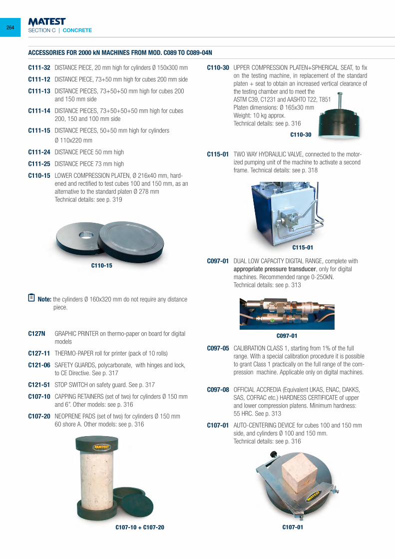
SECTION C | CONCRETE
C107-10 + C107-20
C115-01
C097-01
C107-01
C097-08 OFFICIAL ACCREDIA (Equivalent UKAS, ENAC, DAKKS, SAS, COFRAC etc.) HARDNESS CERTIFICATE of upper and lower compression platens. Minimum hardness:
55 HRC. See p. 313
C107-01 AUTO-CENTERING DEVICE for cubes 100 and 150 mm side, and cylinders Ø 100 and 150 mm.
Technical details: see p. 316
C110-15
ACCESSORIES FOR 2000 kN MACHINES FROM MOD. C089 TO C089-04N
C111-32 DISTANCE PIECE, 20 mm high for cylinders Ø 150x300 mm
C111-12 DISTANCE PIECE, 73+50 mm high for cubes 200 mm side
C111-13 DISTANCE PIECES, 73+50+50 mm high for cubes 200 and 150 mm side
C111-14 DISTANCE PIECES, 73+50+50+50 mm high for cubes 200, 150 and 100 mm side
C111-15 DISTANCE PIECES, 50+50 mm high for cylinders
Ø 110x220 mm
C111-24 DISTANCE PIECE 50 mm high
C111-25 DISTANCE PIECE 73 mm high
C110-15 LOWER COMPRESSION PLATEN, Ø 216x40 mm, hard-ened and rectified to test cubes 100 and 150 mm, as an alternative to the standard platen Ø 278 mm
Technical details: see p. 319
C127N GRAPHIC PRINTER on thermo-paper on board for digital models
C127-11 THERMO-PAPER roll for printer (pack of 10 rolls)
C121-06 SAFETY GUARDS, polycarbonate, with hinges and lock, to CE Directive. See p. 317
C121-51 STOP SWITCH on safety guard. See p. 317
C107-10 CAPPING RETAINERS (set of two) for cylinders Ø 150 mm and 6”. Other models: see p. 316
C107-20 NEOPRENE PADS (set of two) for cylinders Ø 150 mm 60 shore A. Other models: see p. 316
C110-30
C110-30 UPPER COMPRESSION PLATEN+SPHERICAL SEAT, to fix on the testing machine, in replacement of the standard platen + seat to obtain an increased vertical clearance of the testing chamber and to meet the
ASTM C39, C1231 and AASHTO T22, T851 Platen dimensions: Ø 165x30 mm Weight: 10 kg approx. Technical details: see p. 316
C115-01 TWO WAY HYDRAULIC VALVE, connected to the motor-ized pumping unit of the machine to activate a second frame. Technical details: see p. 318
C097-01 DUAL LOW CAPACITY DIGITAL RANGE, complete with appropriate pressure transducer, only for digital machines. Recommended range 0-250kN.
Technical details: see p. 313
Note: the cylinders Ø 160x320 mm do not require any distance piece.
C097-05 CALIBRATION CLASS 1, starting from 1% of the full range. With a special calibration procedure it is possible to grant Class 1 practically on the full range of the com-pression machine. Applicable only on digital machines.
264
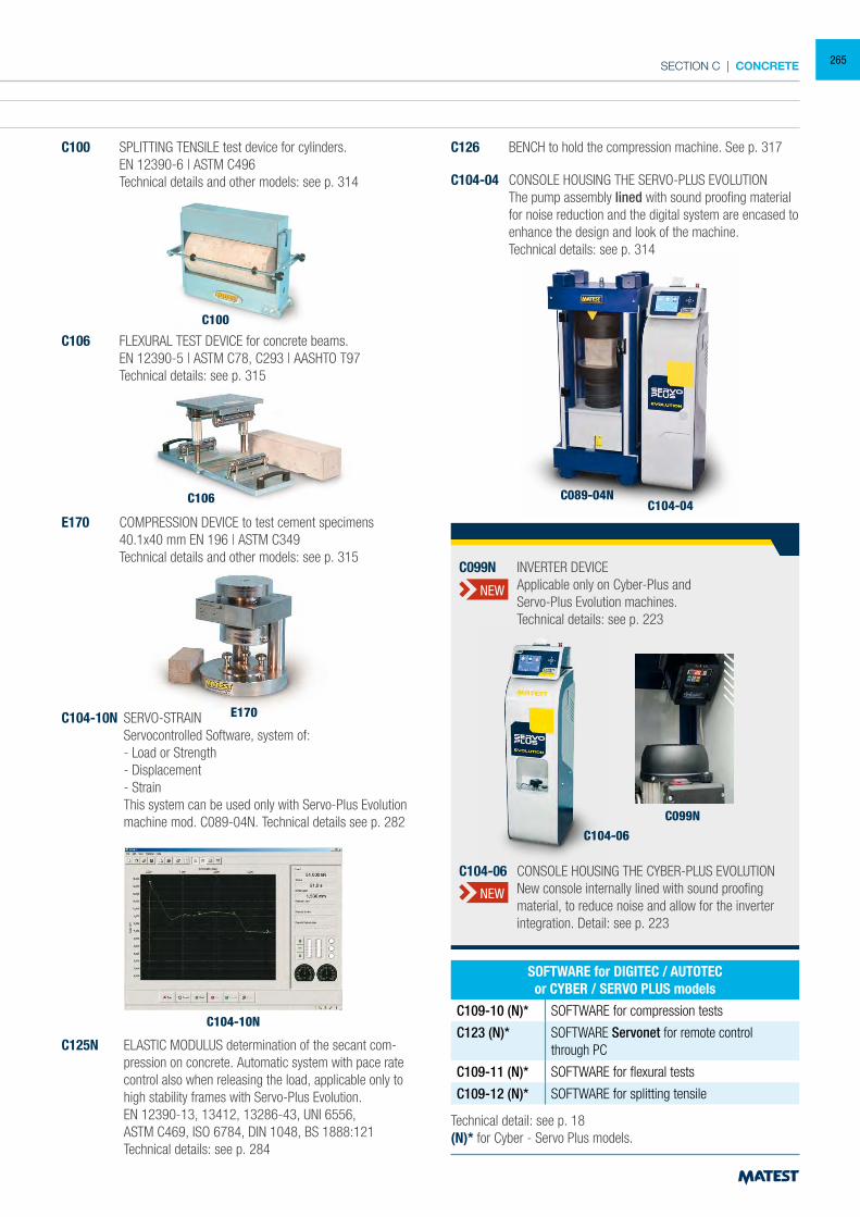
SECTION C | CONCRETE
ACCESSORIES FOR 2000 kN MACHINES FROM MOD. C089 TO C089-04N
C111-32 DISTANCE PIECE, 20 mm high for cylinders Ø 150x300 mm
C111-12 DISTANCE PIECE, 73+50 mm high for cubes 200 mm side
C111-13 DISTANCE PIECES, 73+50+50 mm high for cubes 200 and 150 mm side
C111-14 DISTANCE PIECES, 73+50+50+50 mm high for cubes 200, 150 and 100 mm side
C111-15 DISTANCE PIECES, 50+50 mm high for cylinders
Ø 110x220 mm
C111-24 DISTANCE PIECE 50 mm high
C111-25 DISTANCE PIECE 73 mm high
C110-15 LOWER COMPRESSION PLATEN, Ø 216x40 mm, hard-ened and rectified to test cubes 100 and 150 mm, as an alternative to the standard platen Ø 278 mm
Technical details: see p. 319
C100 SPLITTING TENSILE test device for cylinders. EN 12390-6 | ASTM C496 Technical details and other models: see p. 314
C100
C106 FLEXURAL TEST DEVICE for concrete beams. EN 12390-5 | ASTM C78, C293 | AASHTO T97 Technical details: see p. 315
E170 COMPRESSION DEVICE to test cement specimens 40.1x40 mm EN 196 | ASTM C349 Technical details and other models: see p. 315
C126 BENCH to hold the compression machine. See p. 317
C104-04 CONSOLE HOUSING THE SERVO-PLUS EVOLUTION The pump assembly lined with sound proofing material
for noise reduction and the digital system are encased to enhance the design and look of the machine.
Technical details: see p. 314
E170
C104-10N
C106 C104-04C089-04N
Technical detail: see p. 18(N)* for Cyber - Servo Plus models.
SOFTWARE for DIGITEC / AUTOTECor CYBER / SERVO PLUS models
C109-10 (N)* SOFTWARE for compression tests
C123 (N)* SOFTWARE Servonet for remote control through PC
C109-11 (N)* SOFTWARE for flexural tests
C109-12 (N)* SOFTWARE for splitting tensile
C104-10N SERVO-STRAIN Servocontrolled Software, system of: - Load or Strength - Displacement - Strain This system can be used only with Servo-Plus Evolution
machine mod. C089-04N. Technical details see p. 282
C125N ELASTIC MODULUS determination of the secant com-pression on concrete. Automatic system with pace rate control also when releasing the load, applicable only to high stability frames with Servo-Plus Evolution.
EN 12390-13, 13412, 13286-43, UNI 6556, ASTM C469, ISO 6784, DIN 1048, BS 1888:121 Technical details: see p. 284
C104-06
C099N
C104-06 CONSOLE HOUSING THE CYBER-PLUS EVOLUTION New console internally lined with sound proofing
material, to reduce noise and allow for the inverter integration. Detail: see p. 223
C099N INVERTER DEVICE Applicable only on Cyber-Plus and Servo-Plus Evolution machines. Technical details: see p. 223
NEW
NEW
265
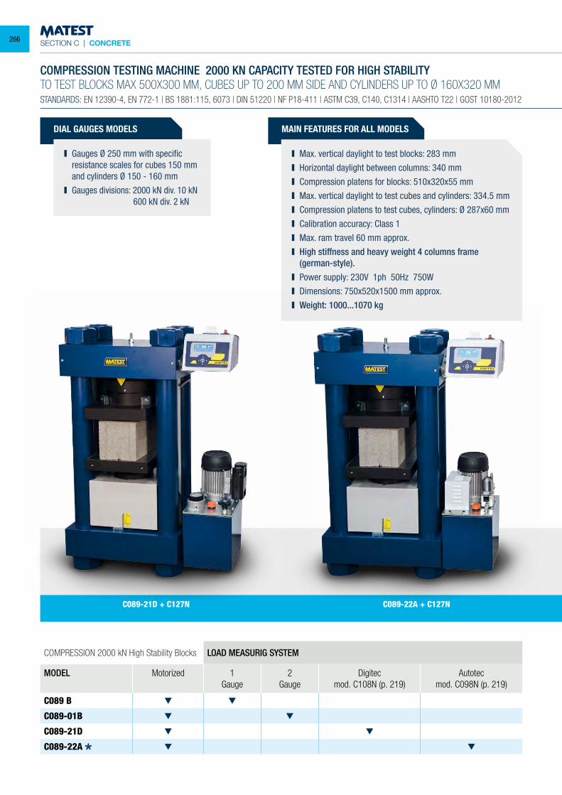
SECTION C | CONCRETE
DIAL GAUGES MODELS
Gauges Ø 250 mm with specific resistance scales for cubes 150 mm and cylinders Ø 150 - 160 mm
Gauges divisions: 2000 kN div. 10 kN 600 kN div. 2 kN
COMPRESSION 2000 kN High Stability Blocks LOAD MEASURIG SYSTEM
MODEL Motorized 1 Gauge
2 Gauge
Digitecmod. C108N (p. 219)
Autotecmod. C098N (p. 219)
C089 B
C089-01B
C089-21D
C089-22A
COMPRESSION TESTING MACHINE 2000 KN CAPACITY TESTED FOR HIGH STABILITYTO TEST BLOCKS MAX 500X300 MM, CUBES UP TO 200 MM SIDE AND CYLINDERS UP TO Ø 160X320 MMSTANDARDS: EN 12390-4, EN 772-1 | BS 1881:115, 6073 | DIN 51220 | NF P18-411 | ASTM C39, C140, C1314 | AASHTO T22 | GOST 10180-2012
MAIN FEATURES FOR ALL MODELS
Max. vertical daylight to test blocks: 283 mm Horizontal daylight between columns: 340 mm Compression platens for blocks: 510x320x55 mm Max. vertical daylight to test cubes and cylinders: 334.5 mm Compression platens to test cubes, cylinders: Ø 287x60 mm Calibration accuracy: Class 1 Max. ram travel 60 mm approx. High stiffness and heavy weight 4 columns frame
(german-style). Power supply: 230V 1ph 50Hz 750W Dimensions: 750x520x1500 mm approx. Weight: 1000...1070 kg
C089-21D + C127N C089-22A + C127N
266
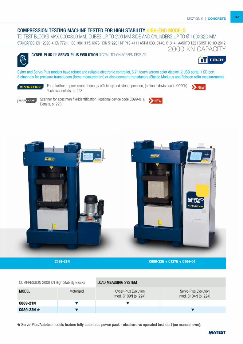
SECTION C | CONCRETE
COMPRESSION 2000 kN High Stability Blocks LOAD MEASURIG SYSTEM
MODEL Motorized Cyber-Plus Evolutionmod. C109N (p. 224)
Servo-Plus Evolutionmod. C104N (p. 224)
C089-21N
C089-22N
COMPRESSION TESTING MACHINE TESTED FOR HIGH STABILITY HIGH-END MODELSTO TEST BLOCKS MAX 500X300 MM, CUBES UP TO 200 MM SIDE AND CYLINDERS UP TO Ø 160X320 MMSTANDARDS: EN 12390-4, EN 772-1 | BS 1881:115, 6073 | DIN 51220 | NF P18-411 | ASTM C39, C140, C1314 | AASHTO T22 | GOST 10180-2012
2000 KN CAPACITY
C089-21N C089-22N + C127N + C104-04
CYBER-PLUS OR SERVO-PLUS EVOLUTION DIGITAL TOUCH SCREEN DISPLAY
Cyber and Servo-Plus models have robust and reliable electronic controller, 5.7" touch screen color display. 2 USB ports, 1 SD port,8 channels for pressure transducers (force measurement) or displacement transducers (Elastic Modulus and Poisson ratio measurement).
Servo-Plus/Autotec models feature fully automatic power pack - electrovalve operated test start (no manual lever).
For a further improvement of energy efficiency and silent operation, (optional device code C099N). Technical details, p. 223
Scanner for specimen file/identification, (optional device code C099-01).Details, p. 223
inverter NEW
NEWBARCODE
267

SECTION C | CONCRETE
C100
ACCESSORIES FOR 2000 kN BLOCKS MACHINES FROM MOD. C089B TO C089-22N
C111-32 DISTANCE PIECE, 20 mm high for cylinders Ø 150x300 mm
C111-12 DISTANCE PIECE, 73+50 mm high for cubes 200 mm side
C111-13 DISTANCE PIECES, 73+50+50 mm high for cubes 200 and 150 mm side
C111-14 DISTANCE PIECES 73+50+50+50 mm high for cubes 200, 150 and 100 mm side
C111-15 DISTANCE PIECES 50+50 mm high for cylinders Ø 110x220 mm
C111-24 DISTANCE PIECE 50 mm high
C111-25 DISTANCE PIECE 73 mm high
Note: The cylinders Ø 160x320 mm do not require any distance piece.
C111-50 DISTANCE PIECE, it eliminates the heavy procedure to lift the lower rectangular platen and to add distance pieces.
Technical details: see p. 320
C115-01
C097-01
C115-01 TWO WAY HYDRAULIC VALVE, connected to the motor-ized pumping unit of the machine to activate a second frame. Technical details: see p. 318
C097-05 CALIBRATION CLASS 1, starting from 1% of the full range. With a special calibration procedure it is possible to grant Class 1 practically on the full range of the com-pression machine. Applicable only on digital machines.
C097-08 OFFICIAL ACCREDIA (Equivalent UKAS, ENAC, DAKKS, SAS, COFRAC etc.) HARDNESS CERTIFICATE of upper and lower compression platens. Minimum hardness:
55 HRC. See p. 313
C097-01 DUAL LOW CAPACITY DIGITAL RANGE, complete with appropriate pressure transducer, only for digital machines. Recommended range 0-250kN.
Technical details: see p. 313
C100 SPLITTING TENSILE test device for cylinders. EN 12390-6 | ASTM C496 Technical details and other models: see p. 314
AS AN ALTERNATIVE:
C112-05 KIT of 4 HANDLES to lift the lower platen, making the positioning of distance pieces easier.
Technical details: see p. 320
C127N GRAPHIC PRINTER on thermo-paper on board for digital models
C127-11 THERMO-PAPER roll for printer (pack of 10 rolls)
C121-10 SAFETY GUARDS, polycarbonate, with hinges and lock, to CE Directive. See p. 317
C121-51 STOP SWITCH on safety guard. See p. 317
C111-50
C112-05
C117
C117 SLIDING RAIL CARRIAGE, for an easy removal of the upper block platen, to perform tests on blocks or on standard cubes and cylinders.
268
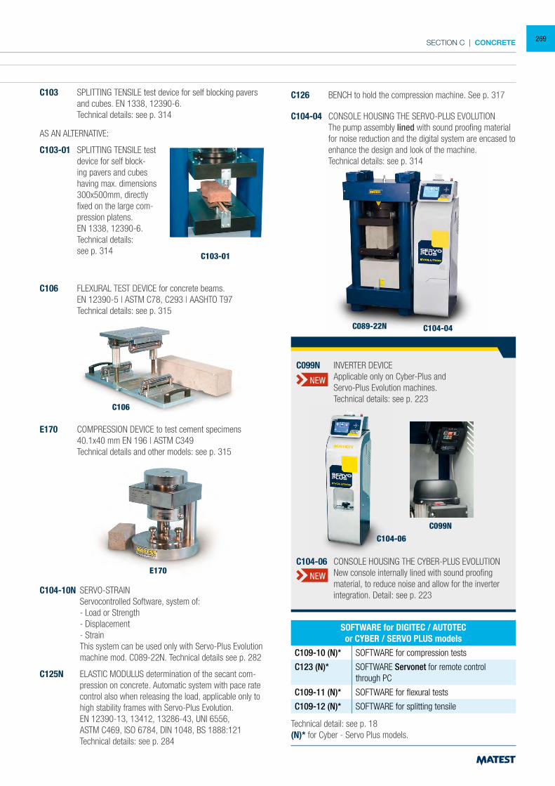
SECTION C | CONCRETE
ACCESSORIES FOR 2000 kN BLOCKS MACHINES FROM MOD. C089B TO C089-22N
C111-32 DISTANCE PIECE, 20 mm high for cylinders Ø 150x300 mm
C111-12 DISTANCE PIECE, 73+50 mm high for cubes 200 mm side
C111-13 DISTANCE PIECES, 73+50+50 mm high for cubes 200 and 150 mm side
C111-14 DISTANCE PIECES 73+50+50+50 mm high for cubes 200, 150 and 100 mm side
C111-15 DISTANCE PIECES 50+50 mm high for cylinders Ø 110x220 mm
C111-24 DISTANCE PIECE 50 mm high
C111-25 DISTANCE PIECE 73 mm high
Note: The cylinders Ø 160x320 mm do not require any distance piece.
C111-50 DISTANCE PIECE, it eliminates the heavy procedure to lift the lower rectangular platen and to add distance pieces.
Technical details: see p. 320
C104-04 CONSOLE HOUSING THE SERVO-PLUS EVOLUTION The pump assembly lined with sound proofing material
for noise reduction and the digital system are encased to enhance the design and look of the machine.
Technical details: see p. 314
E170
C106
C103-01
C104-04C089-22N
Technical detail: see p. 18(N)* for Cyber - Servo Plus models.
SOFTWARE for DIGITEC / AUTOTECor CYBER / SERVO PLUS models
C109-10 (N)* SOFTWARE for compression tests
C123 (N)* SOFTWARE Servonet for remote control through PC
C109-11 (N)* SOFTWARE for flexural tests
C109-12 (N)* SOFTWARE for splitting tensile
AS AN ALTERNATIVE:
C103-01 SPLITTING TENSILE test device for self block-ing pavers and cubes having max. dimensions 300x500mm, directly fixed on the large com-pression platens.
EN 1338, 12390-6. Technical details:
see p. 314
C103 SPLITTING TENSILE test device for self blocking pavers and cubes. EN 1338, 12390-6.
Technical details: see p. 314
C106 FLEXURAL TEST DEVICE for concrete beams. EN 12390-5 | ASTM C78, C293 | AASHTO T97 Technical details: see p. 315
C126 BENCH to hold the compression machine. See p. 317
E170 COMPRESSION DEVICE to test cement specimens 40.1x40 mm EN 196 | ASTM C349 Technical details and other models: see p. 315
C104-10N SERVO-STRAIN Servocontrolled Software, system of: - Load or Strength - Displacement - Strain This system can be used only with Servo-Plus Evolution
machine mod. C089-22N. Technical details see p. 282
C125N ELASTIC MODULUS determination of the secant com-pression on concrete. Automatic system with pace rate control also when releasing the load, applicable only to high stability frames with Servo-Plus Evolution.
EN 12390-13, 13412, 13286-43, UNI 6556, ASTM C469, ISO 6784, DIN 1048, BS 1888:121 Technical details: see p. 284
C104-06
C099N
C104-06 CONSOLE HOUSING THE CYBER-PLUS EVOLUTION New console internally lined with sound proofing
material, to reduce noise and allow for the inverter integration. Detail: see p. 223
C099N INVERTER DEVICE Applicable only on Cyber-Plus and Servo-Plus Evolution machines. Technical details: see p. 223
NEW
NEW
269
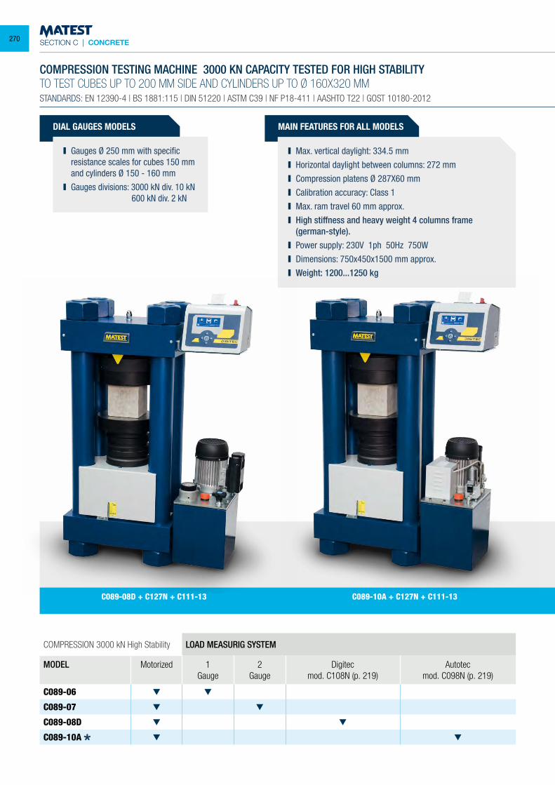
SECTION C | CONCRETE
DIAL GAUGES MODELS
Gauges Ø 250 mm with specific resistance scales for cubes 150 mm and cylinders Ø 150 - 160 mm
Gauges divisions: 3000 kN div. 10 kN 600 kN div. 2 kN
COMPRESSION 3000 kN High Stability LOAD MEASURIG SYSTEM
MODEL Motorized 1 Gauge
2 Gauge
Digitecmod. C108N (p. 219)
Autotecmod. C098N (p. 219)
C089-06
C089-07
C089-08D
C089-10A
COMPRESSION TESTING MACHINE 3000 KN CAPACITY TESTED FOR HIGH STABILITYTO TEST CUBES UP TO 200 MM SIDE AND CYLINDERS UP TO Ø 160X320 MMSTANDARDS: EN 12390-4 | BS 1881:115 | DIN 51220 | ASTM C39 | NF P18-411 | AASHTO T22 | GOST 10180-2012
MAIN FEATURES FOR ALL MODELS
Max. vertical daylight: 334.5 mm Horizontal daylight between columns: 272 mm Compression platens Ø 287X60 mm Calibration accuracy: Class 1 Max. ram travel 60 mm approx. High stiffness and heavy weight 4 columns frame
(german-style). Power supply: 230V 1ph 50Hz 750W Dimensions: 750x450x1500 mm approx. Weight: 1200...1250 kg
C089-10A + C127N + C111-13C089-08D + C127N + C111-13
270
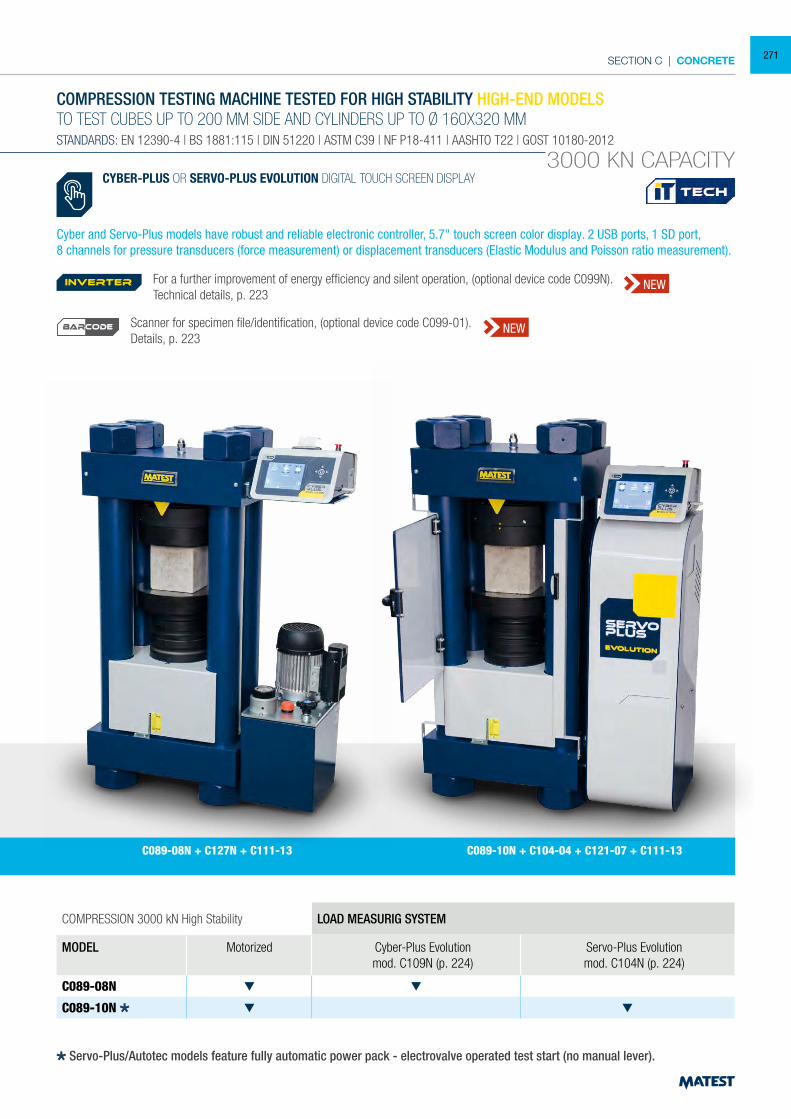
SECTION C | CONCRETE
COMPRESSION 3000 kN High Stability LOAD MEASURIG SYSTEM
MODEL Motorized Cyber-Plus Evolutionmod. C109N (p. 224)
Servo-Plus Evolutionmod. C104N (p. 224)
C089-08N
C089-10N
COMPRESSION TESTING MACHINE TESTED FOR HIGH STABILITY HIGH-END MODELSTO TEST CUBES UP TO 200 MM SIDE AND CYLINDERS UP TO Ø 160X320 MMSTANDARDS: EN 12390-4 | BS 1881:115 | DIN 51220 | ASTM C39 | NF P18-411 | AASHTO T22 | GOST 10180-2012
3000 KN CAPACITYCYBER-PLUS OR SERVO-PLUS EVOLUTION DIGITAL TOUCH SCREEN DISPLAY
Cyber and Servo-Plus models have robust and reliable electronic controller, 5.7" touch screen color display. 2 USB ports, 1 SD port,8 channels for pressure transducers (force measurement) or displacement transducers (Elastic Modulus and Poisson ratio measurement).
C089-08N + C127N + C111-13 C089-10N + C104-04 + C121-07 + C111-13
Servo-Plus/Autotec models feature fully automatic power pack - electrovalve operated test start (no manual lever).
For a further improvement of energy efficiency and silent operation, (optional device code C099N). Technical details, p. 223
Scanner for specimen file/identification, (optional device code C099-01).Details, p. 223
inverter NEW
NEWBARCODE
271
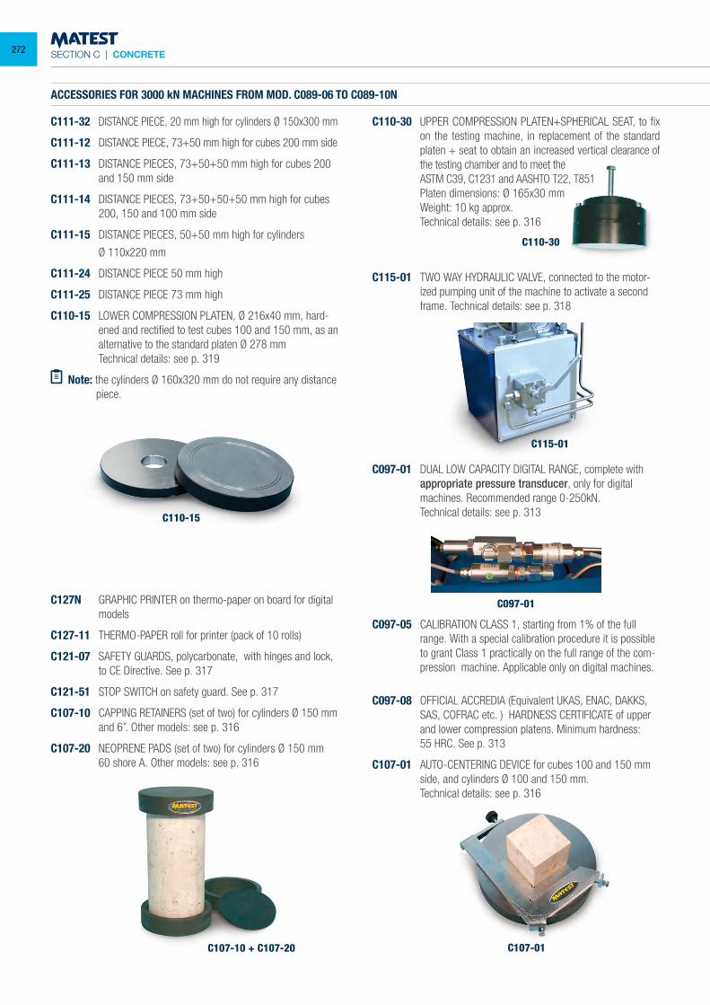
SECTION C | CONCRETE
C107-10 + C107-20
C115-01
C097-01
C107-01
C097-08 OFFICIAL ACCREDIA (Equivalent UKAS, ENAC, DAKKS, SAS, COFRAC etc. ) HARDNESS CERTIFICATE of upper and lower compression platens. Minimum hardness:
55 HRC. See p. 313
C107-01 AUTO-CENTERING DEVICE for cubes 100 and 150 mm side, and cylinders Ø 100 and 150 mm.
Technical details: see p. 316
C110-15
ACCESSORIES FOR 3000 kN MACHINES FROM MOD. C089-06 TO C089-10N
C111-32 DISTANCE PIECE, 20 mm high for cylinders Ø 150x300 mm
C111-12 DISTANCE PIECE, 73+50 mm high for cubes 200 mm side
C111-13 DISTANCE PIECES, 73+50+50 mm high for cubes 200 and 150 mm side
C111-14 DISTANCE PIECES, 73+50+50+50 mm high for cubes 200, 150 and 100 mm side
C111-15 DISTANCE PIECES, 50+50 mm high for cylinders
Ø 110x220 mm
C111-24 DISTANCE PIECE 50 mm high
C111-25 DISTANCE PIECE 73 mm high
C110-15 LOWER COMPRESSION PLATEN, Ø 216x40 mm, hard-ened and rectified to test cubes 100 and 150 mm, as an alternative to the standard platen Ø 278 mm
Technical details: see p. 319
Note: the cylinders Ø 160x320 mm do not require any distance piece.
C127N GRAPHIC PRINTER on thermo-paper on board for digital models
C127-11 THERMO-PAPER roll for printer (pack of 10 rolls)
C121-07 SAFETY GUARDS, polycarbonate, with hinges and lock, to CE Directive. See p. 317
C121-51 STOP SWITCH on safety guard. See p. 317
C107-10 CAPPING RETAINERS (set of two) for cylinders Ø 150 mm and 6”. Other models: see p. 316
C107-20 NEOPRENE PADS (set of two) for cylinders Ø 150 mm 60 shore A. Other models: see p. 316
C110-30
C110-30 UPPER COMPRESSION PLATEN+SPHERICAL SEAT, to fix on the testing machine, in replacement of the standard platen + seat to obtain an increased vertical clearance of the testing chamber and to meet the
ASTM C39, C1231 and AASHTO T22, T851 Platen dimensions: Ø 165x30 mm Weight: 10 kg approx. Technical details: see p. 316
C115-01 TWO WAY HYDRAULIC VALVE, connected to the motor-ized pumping unit of the machine to activate a second frame. Technical details: see p. 318
C097-01 DUAL LOW CAPACITY DIGITAL RANGE, complete with appropriate pressure transducer, only for digital machines. Recommended range 0-250kN.
Technical details: see p. 313
C097-05 CALIBRATION CLASS 1, starting from 1% of the full range. With a special calibration procedure it is possible to grant Class 1 practically on the full range of the com-pression machine. Applicable only on digital machines.
272
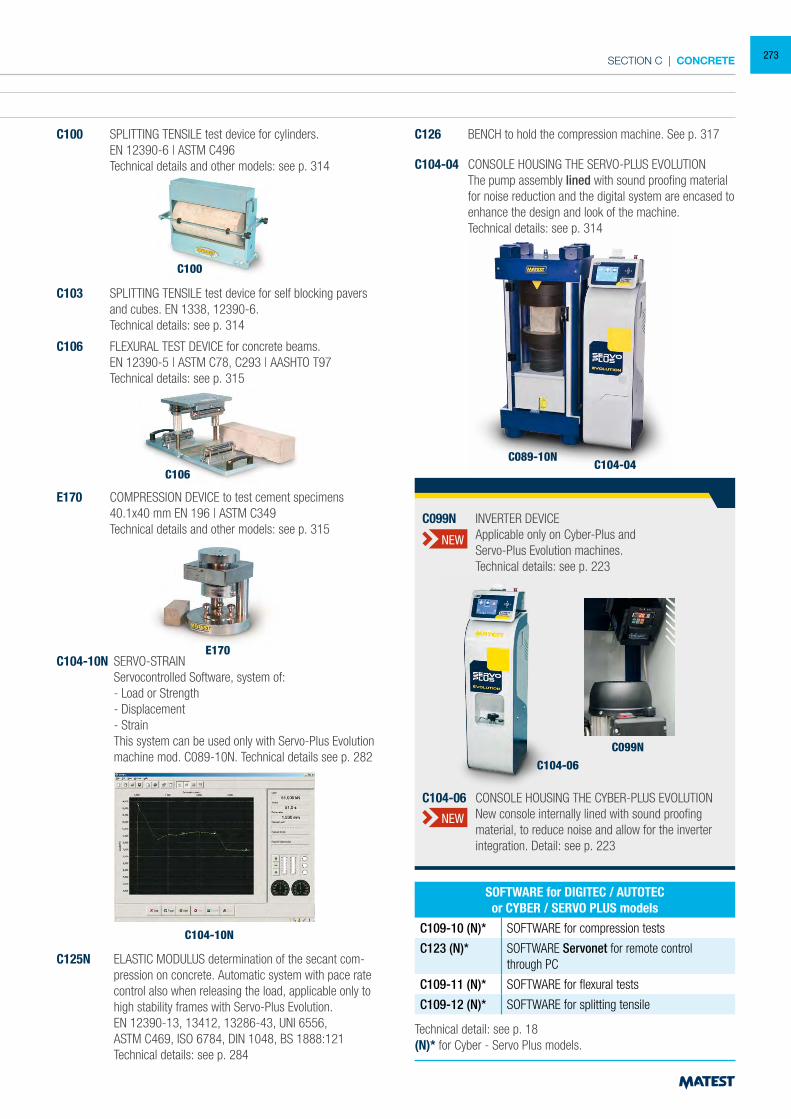
SECTION C | CONCRETE
ACCESSORIES FOR 3000 kN MACHINES FROM MOD. C089-06 TO C089-10N
C111-32 DISTANCE PIECE, 20 mm high for cylinders Ø 150x300 mm
C111-12 DISTANCE PIECE, 73+50 mm high for cubes 200 mm side
C111-13 DISTANCE PIECES, 73+50+50 mm high for cubes 200 and 150 mm side
C111-14 DISTANCE PIECES, 73+50+50+50 mm high for cubes 200, 150 and 100 mm side
C111-15 DISTANCE PIECES, 50+50 mm high for cylinders
Ø 110x220 mm
C111-24 DISTANCE PIECE 50 mm high
C111-25 DISTANCE PIECE 73 mm high
C110-15 LOWER COMPRESSION PLATEN, Ø 216x40 mm, hard-ened and rectified to test cubes 100 and 150 mm, as an alternative to the standard platen Ø 278 mm
Technical details: see p. 319
Note: the cylinders Ø 160x320 mm do not require any distance piece.
C100 SPLITTING TENSILE test device for cylinders. EN 12390-6 | ASTM C496 Technical details and other models: see p. 314
C100
C106 FLEXURAL TEST DEVICE for concrete beams. EN 12390-5 | ASTM C78, C293 | AASHTO T97 Technical details: see p. 315
E170 COMPRESSION DEVICE to test cement specimens 40.1x40 mm EN 196 | ASTM C349 Technical details and other models: see p. 315
C126 BENCH to hold the compression machine. See p. 317
C104-04 CONSOLE HOUSING THE SERVO-PLUS EVOLUTION The pump assembly lined with sound proofing material
for noise reduction and the digital system are encased to enhance the design and look of the machine.
Technical details: see p. 314
E170
C106C104-04
C089-10N
Technical detail: see p. 18(N)* for Cyber - Servo Plus models.
SOFTWARE for DIGITEC / AUTOTECor CYBER / SERVO PLUS models
C109-10 (N)* SOFTWARE for compression tests
C123 (N)* SOFTWARE Servonet for remote control through PC
C109-11 (N)* SOFTWARE for flexural tests
C109-12 (N)* SOFTWARE for splitting tensile
C104-10N SERVO-STRAIN Servocontrolled Software, system of: - Load or Strength - Displacement - Strain This system can be used only with Servo-Plus Evolution
machine mod. C089-10N. Technical details see p. 282
C103 SPLITTING TENSILE test device for self blocking pavers and cubes. EN 1338, 12390-6.
Technical details: see p. 314
C125N ELASTIC MODULUS determination of the secant com-pression on concrete. Automatic system with pace rate control also when releasing the load, applicable only to high stability frames with Servo-Plus Evolution.
EN 12390-13, 13412, 13286-43, UNI 6556, ASTM C469, ISO 6784, DIN 1048, BS 1888:121 Technical details: see p. 284
C104-10N
C104-06
C099N
C104-06 CONSOLE HOUSING THE CYBER-PLUS EVOLUTION New console internally lined with sound proofing
material, to reduce noise and allow for the inverter integration. Detail: see p. 223
C099N INVERTER DEVICE Applicable only on Cyber-Plus and Servo-Plus Evolution machines. Technical details: see p. 223
NEW
NEW
273
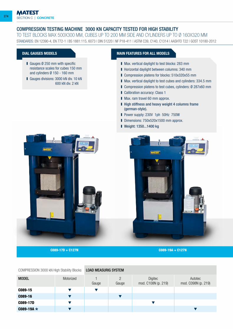
SECTION C | CONCRETE
DIAL GAUGES MODELS
Gauges Ø 250 mm with specific resistance scales for cubes 150 mm and cylinders Ø 150 - 160 mm
Gauges divisions: 3000 kN div. 10 kN 600 kN div. 2 kN
COMPRESSION 3000 kN High Stability Blocks LOAD MEASURIG SYSTEM
MODEL Motorized 1 Gauge
2 Gauge
Digitecmod. C108N (p. 219)
Autotecmod. C098N (p. 219)
C089-15
C089-16
C089-17D
C089-19A
COMPRESSION TESTING MACHINE 3000 KN CAPACITY TESTED FOR HIGH STABILITYTO TEST BLOCKS MAX 500X300 MM, CUBES UP TO 200 MM SIDE AND CYLINDERS UP TO Ø 160X320 MMSTANDARDS: EN 12390-4, EN 772-1 | BS 1881:115, 6073 | DIN 51220 | NF P18-411 | ASTM C39, C140, C1314 | AASHTO T22 | GOST 10180-2012
MAIN FEATURES FOR ALL MODELS
Max. vertical daylight to test blocks: 283 mm Horizontal daylight between columns: 340 mm Compression platens for blocks: 510x320x55 mm Max. vertical daylight to test cubes and cylinders: 334.5 mm Compression platens to test cubes, cylinders: Ø 287x60 mm Calibration accuracy: Class 1 Max. ram travel 60 mm approx. High stiffness and heavy weight 4 columns frame
(german-style). Power supply: 230V 1ph 50Hz 750W Dimensions: 750x520x1500 mm approx. Weight: 1350...1400 kg
C089-17D + C127N C089-19A + C127N
274
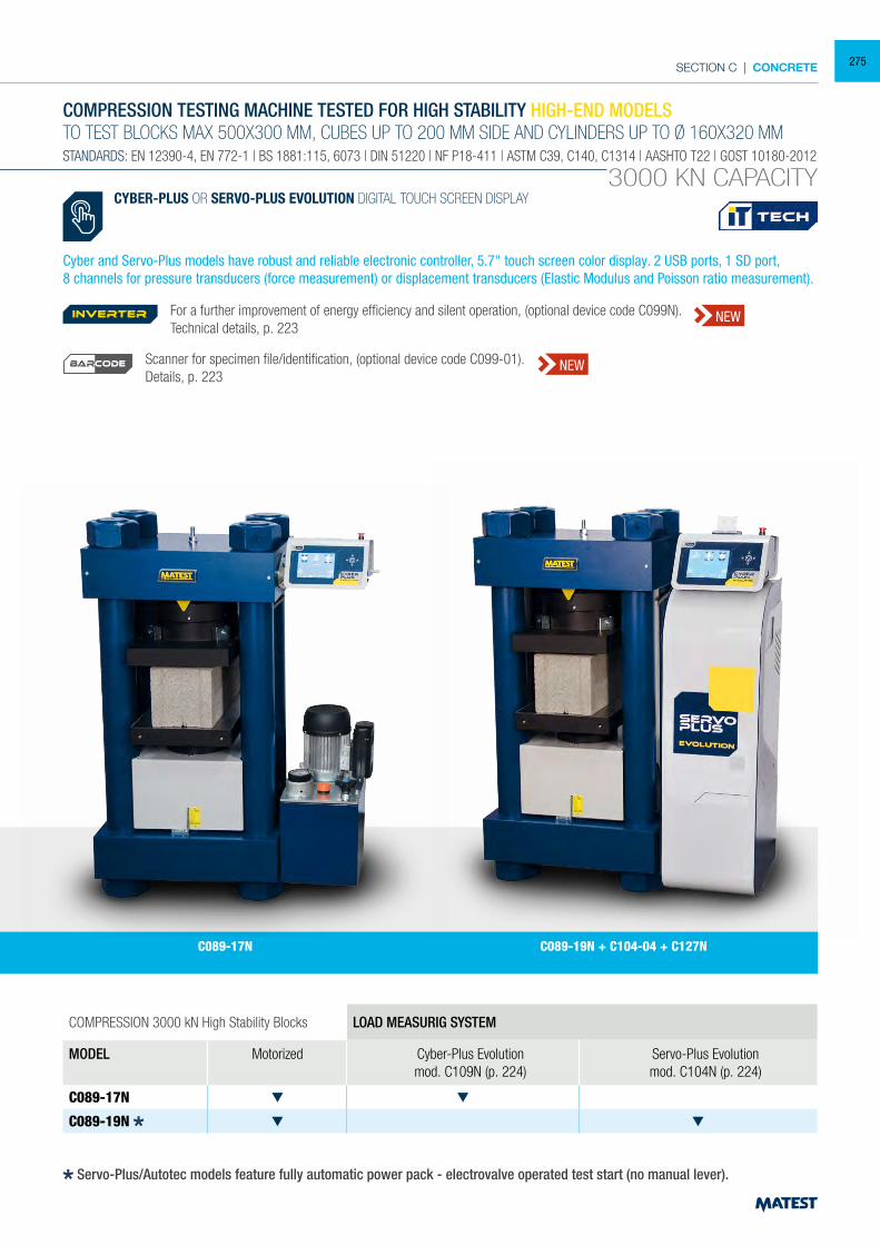
SECTION C | CONCRETE
COMPRESSION 3000 kN High Stability Blocks LOAD MEASURIG SYSTEM
MODEL Motorized Cyber-Plus Evolutionmod. C109N (p. 224)
Servo-Plus Evolutionmod. C104N (p. 224)
C089-17N
C089-19N
COMPRESSION TESTING MACHINE TESTED FOR HIGH STABILITY HIGH-END MODELSTO TEST BLOCKS MAX 500X300 MM, CUBES UP TO 200 MM SIDE AND CYLINDERS UP TO Ø 160X320 MMSTANDARDS: EN 12390-4, EN 772-1 | BS 1881:115, 6073 | DIN 51220 | NF P18-411 | ASTM C39, C140, C1314 | AASHTO T22 | GOST 10180-2012
3000 KN CAPACITY
C089-17N C089-19N + C104-04 + C127N
CYBER-PLUS OR SERVO-PLUS EVOLUTION DIGITAL TOUCH SCREEN DISPLAY
Cyber and Servo-Plus models have robust and reliable electronic controller, 5.7" touch screen color display. 2 USB ports, 1 SD port,8 channels for pressure transducers (force measurement) or displacement transducers (Elastic Modulus and Poisson ratio measurement).
Servo-Plus/Autotec models feature fully automatic power pack - electrovalve operated test start (no manual lever).
For a further improvement of energy efficiency and silent operation, (optional device code C099N). Technical details, p. 223
Scanner for specimen file/identification, (optional device code C099-01).Details, p. 223
inverter NEW
NEWBARCODE
275
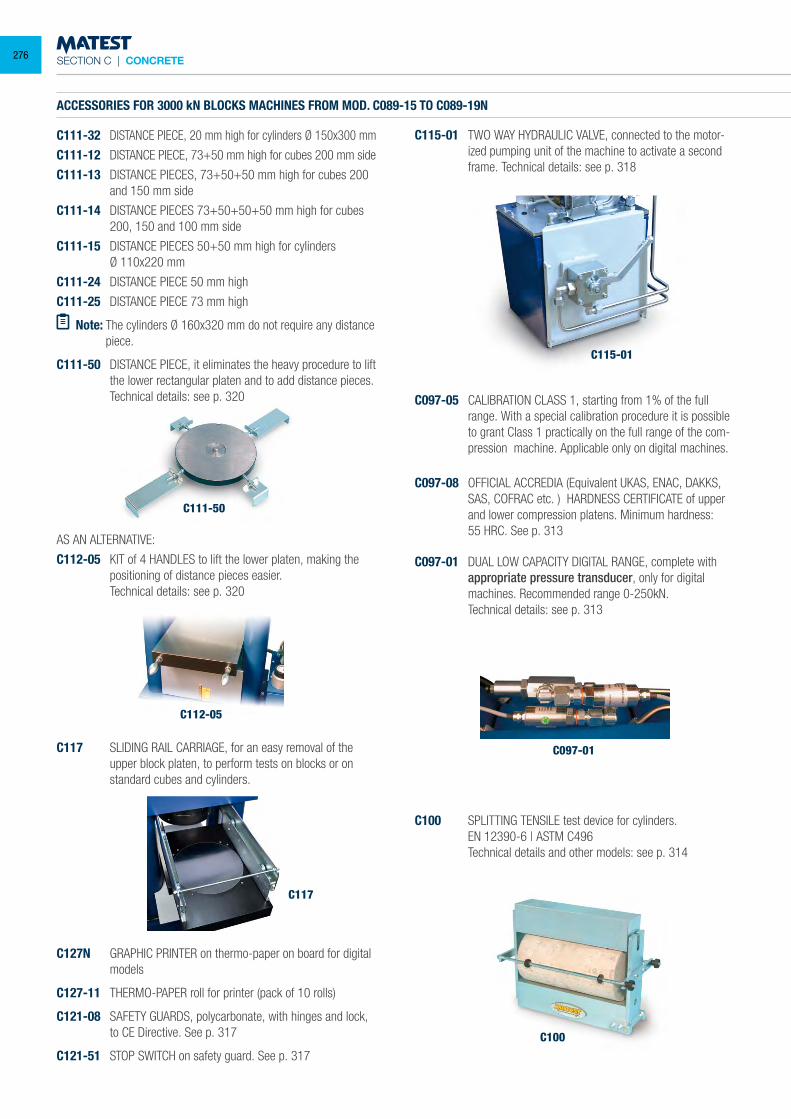
SECTION C | CONCRETE
C100
ACCESSORIES FOR 3000 kN BLOCKS MACHINES FROM MOD. C089-15 TO C089-19N
C111-32 DISTANCE PIECE, 20 mm high for cylinders Ø 150x300 mm
C111-12 DISTANCE PIECE, 73+50 mm high for cubes 200 mm side
C111-13 DISTANCE PIECES, 73+50+50 mm high for cubes 200 and 150 mm side
C111-14 DISTANCE PIECES 73+50+50+50 mm high for cubes 200, 150 and 100 mm side
C111-15 DISTANCE PIECES 50+50 mm high for cylinders Ø 110x220 mm
C111-24 DISTANCE PIECE 50 mm high
C111-25 DISTANCE PIECE 73 mm high
Note: The cylinders Ø 160x320 mm do not require any distance piece.
C111-50 DISTANCE PIECE, it eliminates the heavy procedure to lift the lower rectangular platen and to add distance pieces.
Technical details: see p. 320
C115-01
C097-01
C115-01 TWO WAY HYDRAULIC VALVE, connected to the motor-ized pumping unit of the machine to activate a second frame. Technical details: see p. 318
C097-05 CALIBRATION CLASS 1, starting from 1% of the full range. With a special calibration procedure it is possible to grant Class 1 practically on the full range of the com-pression machine. Applicable only on digital machines.
C097-08 OFFICIAL ACCREDIA (Equivalent UKAS, ENAC, DAKKS, SAS, COFRAC etc. ) HARDNESS CERTIFICATE of upper and lower compression platens. Minimum hardness:
55 HRC. See p. 313
C097-01 DUAL LOW CAPACITY DIGITAL RANGE, complete with appropriate pressure transducer, only for digital machines. Recommended range 0-250kN.
Technical details: see p. 313
C100 SPLITTING TENSILE test device for cylinders. EN 12390-6 | ASTM C496 Technical details and other models: see p. 314
AS AN ALTERNATIVE:
C112-05 KIT of 4 HANDLES to lift the lower platen, making the positioning of distance pieces easier.
Technical details: see p. 320
C127N GRAPHIC PRINTER on thermo-paper on board for digital models
C127-11 THERMO-PAPER roll for printer (pack of 10 rolls)
C121-08 SAFETY GUARDS, polycarbonate, with hinges and lock, to CE Directive. See p. 317
C121-51 STOP SWITCH on safety guard. See p. 317
C111-50
C112-05
C117
C117 SLIDING RAIL CARRIAGE, for an easy removal of the upper block platen, to perform tests on blocks or on standard cubes and cylinders.
276
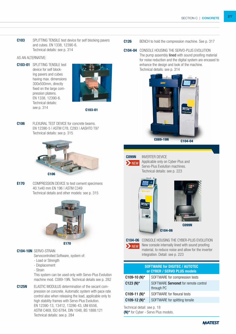
SECTION C | CONCRETE
ACCESSORIES FOR 3000 kN BLOCKS MACHINES FROM MOD. C089-15 TO C089-19N
C111-32 DISTANCE PIECE, 20 mm high for cylinders Ø 150x300 mm
C111-12 DISTANCE PIECE, 73+50 mm high for cubes 200 mm side
C111-13 DISTANCE PIECES, 73+50+50 mm high for cubes 200 and 150 mm side
C111-14 DISTANCE PIECES 73+50+50+50 mm high for cubes 200, 150 and 100 mm side
C111-15 DISTANCE PIECES 50+50 mm high for cylinders Ø 110x220 mm
C111-24 DISTANCE PIECE 50 mm high
C111-25 DISTANCE PIECE 73 mm high
Note: The cylinders Ø 160x320 mm do not require any distance piece.
C111-50 DISTANCE PIECE, it eliminates the heavy procedure to lift the lower rectangular platen and to add distance pieces.
Technical details: see p. 320
C104-04 CONSOLE HOUSING THE SERVO-PLUS EVOLUTION The pump assembly lined with sound proofing material
for noise reduction and the digital system are encased to enhance the design and look of the machine.
Technical details: see p. 314
E170
C106
C103-01
C104-04C089-19N
Technical detail: see p. 18(N)* for Cyber - Servo Plus models.
SOFTWARE for DIGITEC / AUTOTECor CYBER / SERVO PLUS models
C109-10 (N)* SOFTWARE for compression tests
C123 (N)* SOFTWARE Servonet for remote control through PC
C109-11 (N)* SOFTWARE for flexural tests
C109-12 (N)* SOFTWARE for splitting tensile
AS AN ALTERNATIVE:
C103-01 SPLITTING TENSILE test device for self block-ing pavers and cubes having max. dimensions 300x500mm, directly fixed on the large com-pression platens.
EN 1338, 12390-6. Technical details:
see p. 314
C103 SPLITTING TENSILE test device for self blocking pavers and cubes. EN 1338, 12390-6.
Technical details: see p. 314
C106 FLEXURAL TEST DEVICE for concrete beams. EN 12390-5 | ASTM C78, C293 | AASHTO T97 Technical details: see p. 315
C126 BENCH to hold the compression machine. See p. 317
E170 COMPRESSION DEVICE to test cement specimens 40.1x40 mm EN 196 | ASTM C349 Technical details and other models: see p. 315
C104-10N SERVO-STRAIN Servocontrolled Software, system of: - Load or Strength - Displacement - Strain This system can be used only with Servo-Plus Evolution
machine mod. C089-19N. Technical details see p. 282
C125N ELASTIC MODULUS determination of the secant com-pression on concrete. Automatic system with pace rate control also when releasing the load, applicable only to high stability frames with Servo-Plus Evolution.
EN 12390-13, 13412, 13286-43, UNI 6556, ASTM C469, ISO 6784, DIN 1048, BS 1888:121 Technical details: see p. 284
C104-06
C099N
C104-06 CONSOLE HOUSING THE CYBER-PLUS EVOLUTION New console internally lined with sound proofing
material, to reduce noise and allow for the inverter integration. Detail: see p. 223
C099N INVERTER DEVICE Applicable only on Cyber-Plus and Servo-Plus Evolution machines. Technical details: see p. 223
NEW
NEW
277
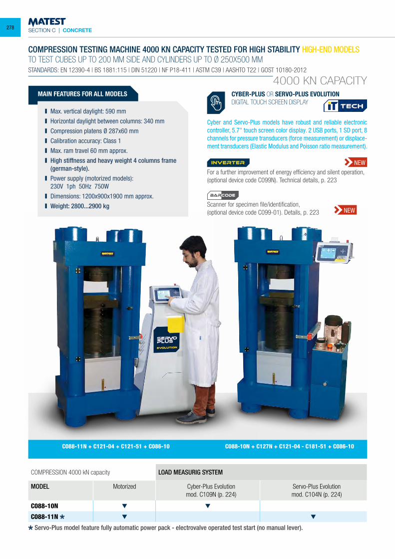
SECTION C | CONCRETE
4000 KN CAPACITY
COMPRESSION TESTING MACHINE 4000 KN CAPACITY TESTED FOR HIGH STABILITY HIGH-END MODELSTO TEST CUBES UP TO 200 MM SIDE AND CYLINDERS UP TO Ø 250X500 MMSTANDARDS: EN 12390-4 | BS 1881:115 | DIN 51220 | NF P18-411 | ASTM C39 | AASHTO T22 | GOST 10180-2012
MAIN FEATURES FOR ALL MODELS
Max. vertical daylight: 590 mm Horizontal daylight between columns: 340 mm Compression platens Ø 287x60 mm Calibration accuracy: Class 1 Max. ram travel 60 mm approx. High stiffness and heavy weight 4 columns frame
(german-style). Power supply (motorized models):
230V 1ph 50Hz 750W Dimensions: 1200x900x1900 mm approx. Weight: 2800...2900 kg
COMPRESSION 4000 kN capacity LOAD MEASURIG SYSTEM
MODEL Motorized Cyber-Plus Evolutionmod. C109N (p. 224)
Servo-Plus Evolutionmod. C104N (p. 224)
C088-10N
C088-11N
C088-11N + C121-04 + C121-51 + C086-10 C088-10N + C127N + C121-04 - C181-51 + C086-10
CYBER-PLUS OR SERVO-PLUS EVOLUTIONDIGITAL TOUCH SCREEN DISPLAY
Cyber and Servo-Plus models have robust and reliable electronic controller, 5.7" touch screen color display. 2 USB ports, 1 SD port, 8 channels for pressure transducers (force measurement) or displace-ment transducers (Elastic Modulus and Poisson ratio measurement).
Servo-Plus model feature fully automatic power pack - electrovalve operated test start (no manual lever).
For a further improvement of energy efficiency and silent operation, (optional device code C099N). Technical details, p. 223
Scanner for specimen file/identification,(optional device code C099-01). Details, p. 223
inverter NEW
NEW
BARCODE
278
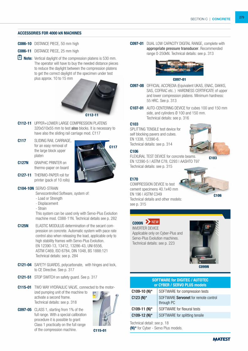
SECTION C | CONCRETE
ACCESSORIES FOR 4000 kN MACHINES
C086-10 DISTANCE PIECE, 50 mm high
C086-11 DISTANCE PIECE, 25 mm high
Note: Vertical daylight of the compression platens is 530 mm. The operator will have to buy the needed distance pieces
to reduce the daylight between the compression platens to get the correct daylight of the specimen under test plus approx. 10 to 15 mm
C112-11 UPPER+LOWER LARGE COMPRESSION PLATENS 320x510x55 mm to test also blocks. It is necessary to have also the sliding rail carriage mod. C117
C117 SLIDING RAIL CARRIAGE, for an easy removal of the large block upper platen
C127N GRAPHIC PRINTER on thermo-paper on board
C127-11 THERMO-PAPER roll for printer (pack of 10 rolls)
C103
C103SPLITTING TENSILE test device forself blocking pavers and cubes.EN 1338, 12390-6.Technical details: see p. 314
C106
C106FLEXURAL TEST DEVICE for concrete beams.EN 12390-5 | ASTM C78, C293 | AASHTO T97Technical details: see p. 315
E170COMPRESSION DEVICE to testcement specimens 40.1x40 mmEN 196 | ASTM C349Technical details and other models:see p. 315
Technical detail: see p. 18(N)* for Cyber - Servo Plus models.
SOFTWARE for DIGITEC / AUTOTECor CYBER / SERVO PLUS models
C109-10 (N)* SOFTWARE for compression tests
C123 (N)* SOFTWARE Servonet for remote control through PC
C109-11 (N)* SOFTWARE for flexural tests
C109-12 (N)* SOFTWARE for splitting tensile
C117
C097-01
C115-01
C104-10N SERVO-STRAIN Servocontrolled Software, system of: - Load or Strength - Displacement - Strain This system can be used only with Servo-Plus Evolution
machine mod. C088-11N. Technical details see p. 282
C125N ELASTIC MODULUS determination of the secant com-pression on concrete. Automatic system with pace rate control also when releasing the load, applicable only to high stability frames with Servo-Plus Evolution.
EN 12390-13, 13412, 13286-43, UNI 6556, ASTM C469, ISO 6784, DIN 1048, BS 1888:121 Technical details: see p. 284
C121-04 SAFETY GUARDS, polycarbonate, with hinges and lock, to CE Directive. See p. 317
C121-51 STOP SWITCH on safety guard. See p. 317
C115-01 TWO WAY HYDRAULIC VALVE, connected to the motor-ized pumping unit of the machine to activate a second frame.
Technical details: see p. 318
C097-05 CLASS 1, starting from 1% of the full range. With a special calibration procedure it is possible to grant
Class 1 practically on the full range of the compression machine.
C097-01 DUAL LOW CAPACITY DIGITAL RANGE, complete with appropriate pressure transducer. Recommended range 0-250kN. Technical details: see p. 313
C097-08 OFFICIAL ACCREDIA (Equivalent UKAS, ENAC, DAKKS, SAS, COFRAC etc. ) HARDNESS CERTIFICATE of upper and lower compression platens. Minimum hardness:
55 HRC. See p. 313
C107-01 AUTO-CENTERING DEVICE for cubes 100 and 150 mm side, and cylinders Ø 100 and 150 mm.
Technical details: see p. 316
C099N
C099NINVERTER DEVICEApplicable only on Cyber-Plus andServo-Plus Evolution machines.Technical details: see p. 223
NEW
C112-11
279
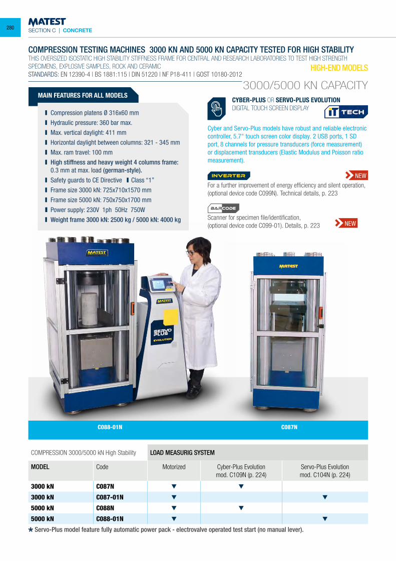
SECTION C | CONCRETE
COMPRESSION 3000/5000 kN High Stability LOAD MEASURIG SYSTEM
MODEL Code Motorized Cyber-Plus Evolutionmod. C109N (p. 224)
Servo-Plus Evolutionmod. C104N (p. 224)
3000 kN C087N
3000 kN C087-01N
5000 kN C088N
5000 kN C088-01N
COMPRESSION TESTING MACHINES 3000 KN AND 5000 KN CAPACITY TESTED FOR HIGH STABILITYTHIS OVERSIZED ISOSTATIC HIGH STABILITY STIFFNESS FRAME FOR CENTRAL AND RESEARCH LABORATORIES TO TEST HIGH STRENGTHSPECIMENS, EXPLOSIVE SAMPLES, ROCK AND CERAMICSTANDARDS: EN 12390-4 | BS 1881:115 | DIN 51220 | NF P18-411 | GOST 10180-2012
MAIN FEATURES FOR ALL MODELS
Compression platens Ø 316x60 mm Hydraulic pressure: 360 bar max. Max. vertical daylight: 411 mm Horizontal daylight between columns: 321 - 345 mm Max. ram travel: 100 mm High stiffness and heavy weight 4 columns frame:
0.3 mm at max. load (german-style). Safety guards to CE Directive Class “1” Frame size 3000 kN: 725x710x1570 mm Frame size 5000 kN: 750x750x1700 mm Power supply: 230V 1ph 50Hz 750W Weight frame 3000 kN: 2500 kg / 5000 kN: 4000 kg
HIGH-END MODELS
3000/5000 KN CAPACITYCYBER-PLUS OR SERVO-PLUS EVOLUTIONDIGITAL TOUCH SCREEN DISPLAY
Cyber and Servo-Plus models have robust and reliable electronic controller, 5.7" touch screen color display. 2 USB ports, 1 SD port, 8 channels for pressure transducers (force measurement) or displacement transducers (Elastic Modulus and Poisson ratio measurement).
C087NC088-01N
Servo-Plus model feature fully automatic power pack - electrovalve operated test start (no manual lever).
For a further improvement of energy efficiency and silent operation, (optional device code C099N). Technical details, p. 223
Scanner for specimen file/identification,(optional device code C099-01). Details, p. 223
inverter NEW
NEW
BARCODE
280
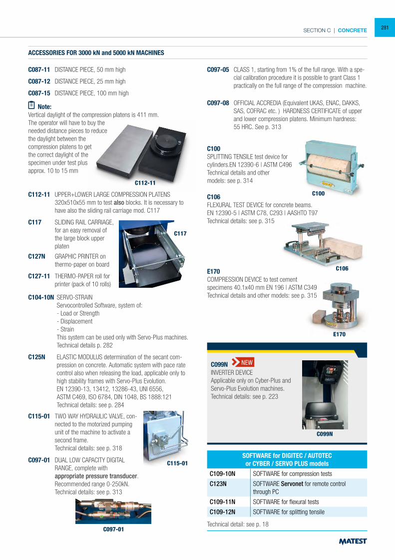
SECTION C | CONCRETE
ACCESSORIES FOR 3000 kN and 5000 kN MACHINES
C087-11 DISTANCE PIECE, 50 mm high
C087-12 DISTANCE PIECE, 25 mm high
C087-15 DISTANCE PIECE, 100 mm high
Note: Vertical daylight of the compression platens is 411 mm.The operator will have to buy the needed distance pieces to reduce the daylight between the compression platens to get the correct daylight of the specimen under test plus approx. 10 to 15 mm
C112-11 UPPER+LOWER LARGE COMPRESSION PLATENS 320x510x55 mm to test also blocks. It is necessary to have also the sliding rail carriage mod. C117
C117 SLIDING RAIL CARRIAGE, for an easy removal of the large block upper platen
C127N GRAPHIC PRINTER on thermo-paper on board
C127-11 THERMO-PAPER roll for printer (pack of 10 rolls)
E170
C106
C106FLEXURAL TEST DEVICE for concrete beams.EN 12390-5 | ASTM C78, C293 | AASHTO T97Technical details: see p. 315
E170COMPRESSION DEVICE to test cementspecimens 40.1x40 mm EN 196 | ASTM C349Technical details and other models: see p. 315
Technical detail: see p. 18
SOFTWARE for DIGITEC / AUTOTECor CYBER / SERVO PLUS models
C109-10N SOFTWARE for compression tests
C123N SOFTWARE Servonet for remote control through PC
C109-11N SOFTWARE for flexural tests
C109-12N SOFTWARE for splitting tensile
C117
C097-01
C104-10N SERVO-STRAIN Servocontrolled Software, system of: - Load or Strength - Displacement - Strain This system can be used only with Servo-Plus machines.
Technical details p. 282
C125N ELASTIC MODULUS determination of the secant com-pression on concrete. Automatic system with pace rate control also when releasing the load, applicable only to high stability frames with Servo-Plus Evolution.
EN 12390-13, 13412, 13286-43, UNI 6556, ASTM C469, ISO 6784, DIN 1048, BS 1888:121 Technical details: see p. 284
C115-01 TWO WAY HYDRAULIC VALVE, con-nected to the motorized pumping unit of the machine to activate a second frame.
Technical details: see p. 318
C097-05 CLASS 1, starting from 1% of the full range. With a spe-cial calibration procedure it is possible to grant Class 1 practically on the full range of the compression machine.
C097-08 OFFICIAL ACCREDIA (Equivalent UKAS, ENAC, DAKKS, SAS, COFRAC etc. ) HARDNESS CERTIFICATE of upper and lower compression platens. Minimum hardness:
55 HRC. See p. 313
C100
C100SPLITTING TENSILE test device for cylinders.EN 12390-6 | ASTM C496Technical details and othermodels: see p. 314
C097-01 DUAL LOW CAPACITY DIGITAL RANGE, complete with
appropriate pressure transducer. Recommended range 0-250kN. Technical details: see p. 313
C115-01
C099N
C099NINVERTER DEVICEApplicable only on Cyber-Plus andServo-Plus Evolution machines.Technical details: see p. 223
NEW
C112-11
281
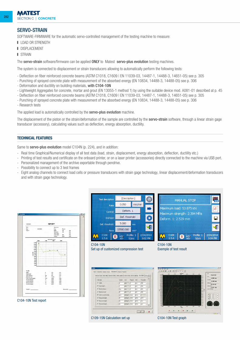
SECTION C | CONCRETE
SERVO-STRAINSOFTWARE-FIRMWARE for the automatic servo-controlled management of the testing machine to measure:
LOAD OR STRENGTH
DISPLACEMENT
STRAIN
The servo-strain software/firmware can be applied ONLY to Matest servo-plus evolution testing machines.
The system is connected to displacement or strain transducers allowing to automatically perform the following tests:
- Deflection on fiber reinforced concrete beams (ASTM C1018, C1609 | EN 11039-03, 14487-1, 14488-3, 14651-05) see p. 305- Punching of sprayed concrete plate with measurement of the absorbed energy (EN 10834, 14488-3, 14488-05) see p. 306- Deformation and ductility on building materials, with C104-10N- Lightweight Aggregates for concrete, mortar and grout (EN 13055-1 method 1) by using the suitable device mod. A081-01 described at p. 45- Deflection on fiber reinforced concrete beams (ASTM C1018, C1609 | EN 11039-03, 14487-1, 14488-3, 14651-05) see p. 305- Punching of sprayed concrete plate with measurement of the absorbed energy (EN 10834, 14488-3, 14488-05) see p. 306- Research tests
The applied load is automatically controlled by the servo-plus evolution machine.
The displacement of the piston or the strain/deformation of the sample are controlled by the servo-strain software, through a linear strain gage transducer (accessory), calculating values such as deflection, energy absorption, ductility.
C104-10NSet up of customized compression test
C104-10NExemple of test result
C104-10N Test report
C109-15N Calculation set up C104-10N Test graph
TECHNICAL FEATURES
Same to servo-plus evolution model C104N (p. 224), and in addition:
- Real time Graphical/Numerical display of all test data (load, strain, displacement, energy absorption, deflection, ductility etc.)- Printing of test results and certificate on the onboard printer, or on a laser printer (accessories) directly connected to the machine via USB port.- Personalized management of the archive exportable through pendrive.- Possibility to connect up to 3 test frames- Eight analog channels to connect load cells or pressure transducers with strain gage technology, linear displacement/deformation transducers
and with strain gage technology.
282
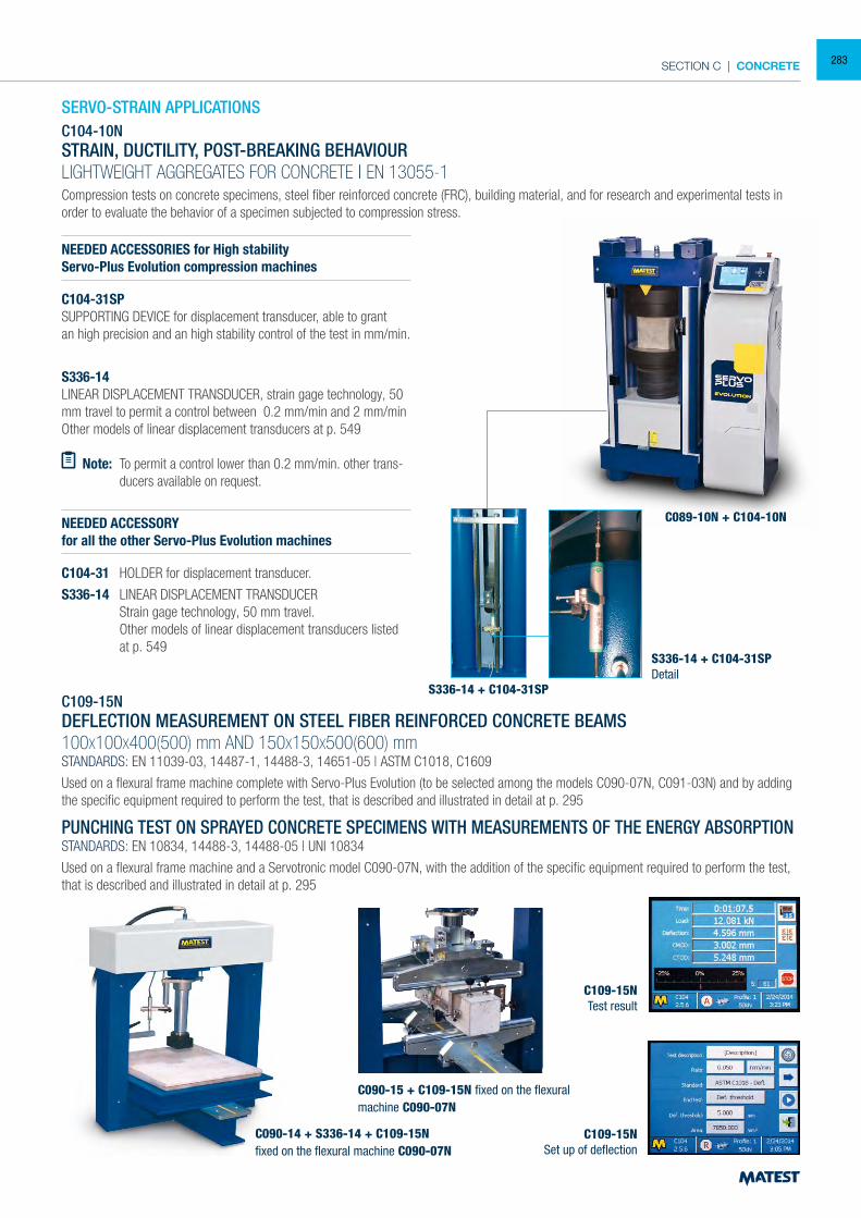
SECTION C | CONCRETE
SERVO-STRAIN APPLICATIONS C104-10NSTRAIN, DUCTILITY, POST-BREAKING BEHAVIOURLIGHTWEIGHT AGGREGATES FOR CONCRETE | EN 13055-1
Compression tests on concrete specimens, steel fiber reinforced concrete (FRC), building material, and for research and experimental tests in order to evaluate the behavior of a specimen subjected to compression stress.
NEEDED ACCESSORIES for High stabilityServo-Plus Evolution compression machines
C104-31SPSUPPORTING DEVICE for displacement transducer, able to grantan high precision and an high stability control of the test in mm/min.
S336-14LINEAR DISPLACEMENT TRANSDUCER, strain gage technology, 50 mm travel to permit a control between 0.2 mm/min and 2 mm/minOther models of linear displacement transducers at p. 549
Note: To permit a control lower than 0.2 mm/min. other trans-ducers available on request.
NEEDED ACCESSORYfor all the other Servo-Plus Evolution machines
C104-31 HOLDER for displacement transducer.
S336-14 LINEAR DISPLACEMENT TRANSDUCER Strain gage technology, 50 mm travel. Other models of linear displacement transducers listed
at p. 549
C109-15NDEFLECTION MEASUREMENT ON STEEL FIBER REINFORCED CONCRETE BEAMS100X100X400(500) mm AND 150X150X500(600) mmSTANDARDS: EN 11039-03, 14487-1, 14488-3, 14651-05 | ASTM C1018, C1609
Used on a flexural frame machine complete with Servo-Plus Evolution (to be selected among the models C090-07N, C091-03N) and by adding the specific equipment required to perform the test, that is described and illustrated in detail at p. 295
PUNCHING TEST ON SPRAYED CONCRETE SPECIMENS WITH MEASUREMENTS OF THE ENERGY ABSORPTIONSTANDARDS: EN 10834, 14488-3, 14488-05 | UNI 10834
Used on a flexural frame machine and a Servotronic model C090-07N, with the addition of the specific equipment required to perform the test, that is described and illustrated in detail at p. 295
C089-10N + C104-10N
S336-14 + C104-31SP
S336-14 + C104-31SPDetail
C090-14 + S336-14 + C109-15Nfixed on the flexural machine C090-07N
C090-15 + C109-15N fixed on the flexuralmachine C090-07N
C109-15NTest result
C109-15NSet up of deflection
283
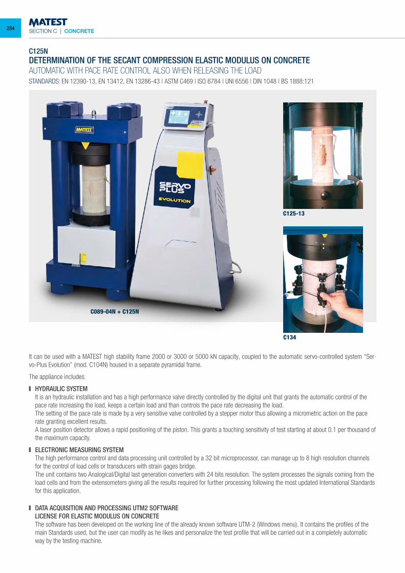
SECTION C | CONCRETE
C125NDETERMINATION OF THE SECANT COMPRESSION ELASTIC MODULUS ON CONCRETEAUTOMATIC WITH PACE RATE CONTROL ALSO WHEN RELEASING THE LOADSTANDARDS: EN 12390-13, EN 13412, EN 13286-43 | ASTM C469 | ISO 6784 | UNI 6556 | DIN 1048 | BS 1888:121
It can be used with a MATEST high stability frame 2000 or 3000 or 5000 kN capacity, coupled to the automatic servo-controlled system “Ser-vo-Plus Evolution” (mod. C104N) housed in a separate pyramidal frame.
The appliance includes:
HYDRAULIC SYSTEM It is an hydraulic installation and has a high performance valve directly controlled by the digital unit that grants the automatic control of the
pace rate increasing the load, keeps a certain load and than controls the pace rate decreasing the load. The setting of the pace rate is made by a very sensitive valve controlled by a stepper motor thus allowing a micrometric action on the pace
rate granting excellent results. A laser position detector allows a rapid positioning of the piston. This grants a touching sensitivity of test starting at about 0.1 per thousand of
the maximum capacity.
ELECTRONIC MEASURING SYSTEM The high performance control and data processing unit controlled by a 32 bit microprocessor, can manage up to 8 high resolution channels
for the control of load cells or transducers with strain gages bridge. The unit contains two Analogical/Digital last generation converters with 24 bits resolution. The system processes the signals coming from the
load cells and from the extensometers giving all the results required for further processing following the most updated International Standards for this application.
DATA ACQUISITION AND PROCESSING UTM2 SOFTWARE LICENSE FOR ELASTIC MODULUS ON CONCRETE The software has been developed on the working line of the already known software UTM-2 (Windows menu). It contains the profiles of the
main Standards used, but the user can modify as he likes and personalize the test profile that will be carried out in a completely automatic way by the testing machine.
C125-13
C134
C089-04N + C125N
284
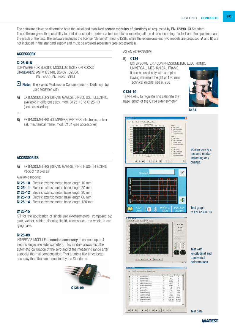
SECTION C | CONCRETE
Screen during a test and marker indicating any change.
C134
The software allows to determine both the initial and stabilized secant modulus of elasticity as requested by EN 12390-13 Standard.The software gives the possibility to print on a standard printer a test certificate reporting all the data concerning the test and the specimen and the graph of the test. The software includes the license “Servonet” mod. C123N, while the extensometers (two models are proposed: A and B) are not included in the standard supply and must be ordered separately (see accessories).
ACCESSORY
C125-01NSOFTWARE FOR ELASTIC MODULUS TESTS ON ROCKSSTANDARDS: ASTM D3148, D5407, D2664, EN 14580, EN 1926 | ISRM
Note: The Elastic Modulus on Concrete mod. C125N can be used together with:
A) EXTENSOMETERS (STRAIN GAGES), SINGLE USE, ELECTRIC, available in different sizes, mod. C125-10 to C125-13
(see accessories).
or:
B) EXTENSOMETERS /COMPRESSOMETERS, electronic, univer-sal, mechanical frame, mod. C134 (see accessories)
ACCESSORIES
A) EXTENSOMETERS (STRAIN GAGES), SINGLE USE, ELECTRIC Pack of 10 pieces
Available models:
C125-10 Electric extensometer, base length 10 mmC125-11 Electric extensometer, base length 20 mmC125-12 Electric extensometer, base length 30 mm C125-13 Electric extensometer, base length 60 mmC125-14 Electric extensometer, base length 120 mm
C125-15KIT for the application of single use extensometers composed by: glue, welder, solder, cleaning liquid, accessories, the whole in car-rying case.
C125-09INTERFACE MODULE, a needed accessory to connect up to 4 electric single use extensometers. This module allows also the automatic calibration of the zero and of the measuring range after a special thermal compensation. This grants a five times better accuracy than the one requested by the Standards.
AS AN ALTERNATIVE:
B) C134 EXTENSOMETER / COMPRESSOMETER, ELECTRONIC, UNIVERSAL, MECHANICAL FRAME. It can be used only with samples
having minimum height of 130 mm. Technical details: see p. 286
C134-10TEMPLATE, to regulate and calibrate the base length of the C134 extensometer.
Test graphto EN 12390-13
Test withlongitudinal and transversaldeformations
Test data
C125-09
285
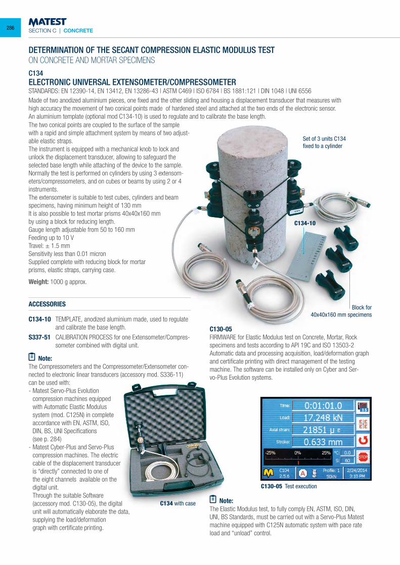
SECTION C | CONCRETE
DETERMINATION OF THE SECANT COMPRESSION ELASTIC MODULUS TESTON CONCRETE AND MORTAR SPECIMENS C134 ELECTRONIC UNIVERSAL EXTENSOMETER/COMPRESSOMETER STANDARDS: EN 12390-14, EN 13412, EN 13286-43 | ASTM C469 | ISO 6784 | BS 1881:121 | DIN 1048 | UNI 6556 Made of two anodized aluminium pieces, one fixed and the other sliding and housing a displacement transducer that measures withhigh accuracy the movement of two conical points made of hardened steel and attached at the two ends of the electronic sensor. An aluminium template (optional mod C134-10) is used to regulate and to calibrate the base length.
ACCESSORIES
C134-10 TEMPLATE, anodized aluminium made, used to regulate and calibrate the base length.
S337-51 CALIBRATION PROCESS for one Extensometer/Compres-someter combined with digital unit.
Note:The Compressometers and the Compressometer/Extensometer con-nected to electronic linear transducers (accessory mod. S336-11) can be used with:- Matest Servo-Plus Evolution
compression machines equipped with Automatic Elastic Modulus system (mod. C125N) in complete accordance with EN, ASTM, ISO, DIN, BS, UNI Specifications
(see p. 284)- Matest Cyber-Plus and Servo-Plus
compression machines. The electric cable of the displacement transducer is “directly” connected to one of the eight channels available on the digital unit.
Through the suitable Software (accessory mod. C130-05), the digital unit will automatically elaborate the data,
supplying the load/deformation graph with certificate printing.
C130-05FIRMWARE for Elastic Modulus test on Concrete, Mortar, Rockspecimens and tests according to API 19C and ISO 13503-2Automatic data and processing acquisition, load/deformation graph and certificate printing with direct management of the testing machine. The software can be installed only on Cyber and Ser-vo-Plus Evolution systems.
Note:The Elastic Modulus test, to fully comply EN, ASTM, ISO, DIN, UNI, BS Standards, must be carried out with a Servo-Plus Matest machine equipped with C125N automatic system with pace rate load and “unload” control.
The two conical points are coupled to the surface of the sample with a rapid and simple attachment system by means of two adjust-able elastic straps. The instrument is equipped with a mechanical knob to lock and unlock the displacement transducer, allowing to safeguard the selected base length while attaching of the device to the sample. Normally the test is performed on cylinders by using 3 extensom-eters/compressometers, and on cubes or beams by using 2 or 4 instruments. The extensometer is suitable to test cubes, cylinders and beam specimens, having minimum height of 130 mmIt is also possible to test mortar prisms 40x40x160 mmby using a block for reducing length. Gauge length adjustable from 50 to 160 mm Feeding up to 10 V Travel: ± 1.5 mm Sensitivity less than 0.01 micron Supplied complete with reducing block for mortarprisms, elastic straps, carrying case.
Weight: 1000 g approx.
C130-05 Test execution
C134 with case
C134-10
Block for40x40x160 mm specimens
Set of 3 units C134fixed to a cylinder
286
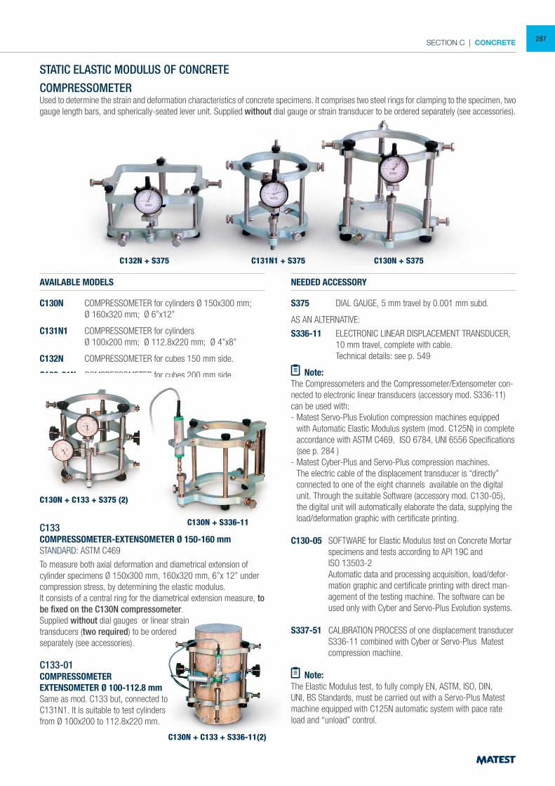
SECTION C | CONCRETE
STATIC ELASTIC MODULUS OF CONCRETE
COMPRESSOMETERUsed to determine the strain and deformation characteristics of concrete specimens. It comprises two steel rings for clamping to the specimen, two gauge length bars, and spherically-seated lever unit. Supplied without dial gauge or strain transducer to be ordered separately (see accessories).
AVAILABLE MODELS
C130N COMPRESSOMETER for cylinders Ø 150x300 mm; Ø 160x320 mm; Ø 6”x12”
C131N1 COMPRESSOMETER for cylinders Ø 100x200 mm; Ø 112.8x220 mm; Ø 4”x8”
C132N COMPRESSOMETER for cubes 150 mm side.
C132-01N COMPRESSOMETER for cubes 200 mm side.
C133COMPRESSOMETER-EXTENSOMETER Ø 150-160 mmSTANDARD: ASTM C469
To measure both axial deformation and diametrical extension of cylinder specimens Ø 150x300 mm, 160x320 mm, 6”x 12” under compression stress, by determining the elastic modulus.It consists of a central ring for the diametrical extension measure, to be fixed on the C130N compressometer.Supplied without dial gauges or linear straintransducers (two required) to be orderedseparately (see accessories).
C133-01COMPRESSOMETEREXTENSOMETER Ø 100-112.8 mm Same as mod. C133 but, connected to C131N1. It is suitable to test cylinders from Ø 100x200 to 112.8x220 mm.
NEEDED ACCESSORY
S375 DIAL GAUGE, 5 mm travel by 0.001 mm subd.
AS AN ALTERNATIVE:
S336-11 ELECTRONIC LINEAR DISPLACEMENT TRANSDUCER, 10 mm travel, complete with cable.
Technical details: see p. 549
Note:The Compressometers and the Compressometer/Extensometer con-nected to electronic linear transducers (accessory mod. S336-11) can be used with:- Matest Servo-Plus Evolution compression machines equipped
with Automatic Elastic Modulus system (mod. C125N) in complete accordance with ASTM C469, ISO 6784, UNI 6556 Specifications (see p. 284 )
- Matest Cyber-Plus and Servo-Plus compression machines. The electric cable of the displacement transducer is “directly” connected to one of the eight channels available on the digital unit. Through the suitable Software (accessory mod. C130-05), the digital unit will automatically elaborate the data, supplying the load/deformation graphic with certificate printing.
C130-05 SOFTWARE for Elastic Modulus test on Concrete Mortar
specimens and tests according to API 19C and ISO 13503-2 Automatic data and processing acquisition, load/defor-
mation graphic and certificate printing with direct man-agement of the testing machine. The software can be used only with Cyber and Servo-Plus Evolution systems.
S337-51 CALIBRATION PROCESS of one displacement transducer
S336-11 combined with Cyber or Servo-Plus Matest compression machine.
Note:
The Elastic Modulus test, to fully comply EN, ASTM, ISO, DIN, UNI, BS Standards, must be carried out with a Servo-Plus Matest machine equipped with C125N automatic system with pace rate load and “unload” control.
C130N + C133 + S375 (2)
C130N + S336-11
C132N + S375 C131N1 + S375 C130N + S375
C130N + C133 + S336-11(2)
287
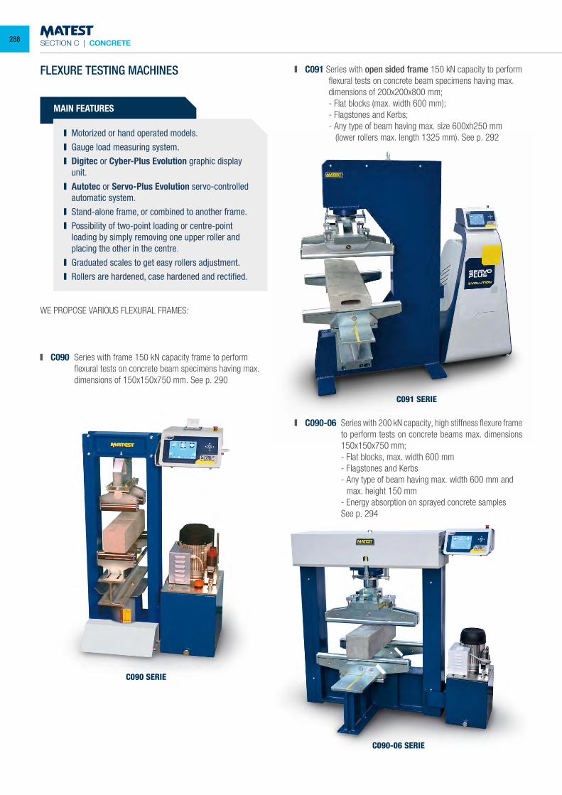
SECTION C | CONCRETE
FLEXURE TESTING MACHINES
MAIN FEATURES
Motorized or hand operated models. Gauge load measuring system. Digitec or Cyber-Plus Evolution graphic display
unit. Autotec or Servo-Plus Evolution servo-controlled
automatic system. Stand-alone frame, or combined to another frame. Possibility of two-point loading or centre-point
loading by simply removing one upper roller and placing the other in the centre.
Graduated scales to get easy rollers adjustment. Rollers are hardened, case hardened and rectified.
WE PROPOSE VARIOUS FLEXURAL FRAMES:
C090 Series with frame 150 kN capacity frame to perform flexural tests on concrete beam specimens having max. dimensions of 150x150x750 mm. See p. 290
C091 SERIE
C090-06 SERIE
C090 SERIE
C091 Series with open sided frame 150 kN capacity to perform flexural tests on concrete beam specimens having max. dimensions of 200x200x800 mm;
- Flat blocks (max. width 600 mm); - Flagstones and Kerbs; - Any type of beam having max. size 600xh250 mm
(lower rollers max. length 1325 mm). See p. 292
C090-06 Series with 200 kN capacity, high stiffness flexure frame to perform tests on concrete beams max. dimensions 150x150x750 mm;
- Flat blocks, max. width 600 mm - Flagstones and Kerbs - Any type of beam having max. width 600 mm and
max. height 150 mm - Energy absorption on sprayed concrete samples See p. 294
288
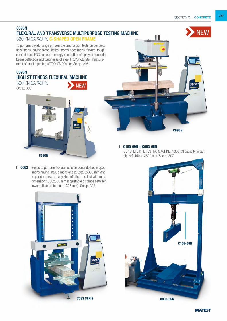
SECTION C | CONCRETE
C095NFLEXURAL AND TRANSVERSE MULTIPURPOSE TESTING MACHINE320 KN CAPACITY, C-SHAPED OPEN FRAME
C096NHIGH STIFFNESS FLEXURAL MACHINE 360 KN CAPACITY.See p. 300
To perform a wide range of flexural/compression tests on concrete specimens, paving slabs, kerbs, mortar specimens, flexural tough-ness of steel FRC concrete, energy absorption of sprayed concrete, beam deflection and toughness of steel FRC/Shotcrete, measure-ment of crack opening (CTOD-CMOD) etc. See p. 296
C093 SERIE
C095N
C096N
C093-05N
C109-09N
C109-09N + C093-05N CONCRETE PIPE TESTING MACHINE, 1000 kN capacity to test
pipes Ø 450 to 2600 mm. See p. 307
NEW
NEW
C093 Series to perform flexural tests on concrete beam spec-imens having max. dimensions 200x200x800 mm and to perform tests on any kind of other product with max. dimensions 550x550 mm (adjustable distance between lower rollers up to max. 1325 mm). See p. 308
289
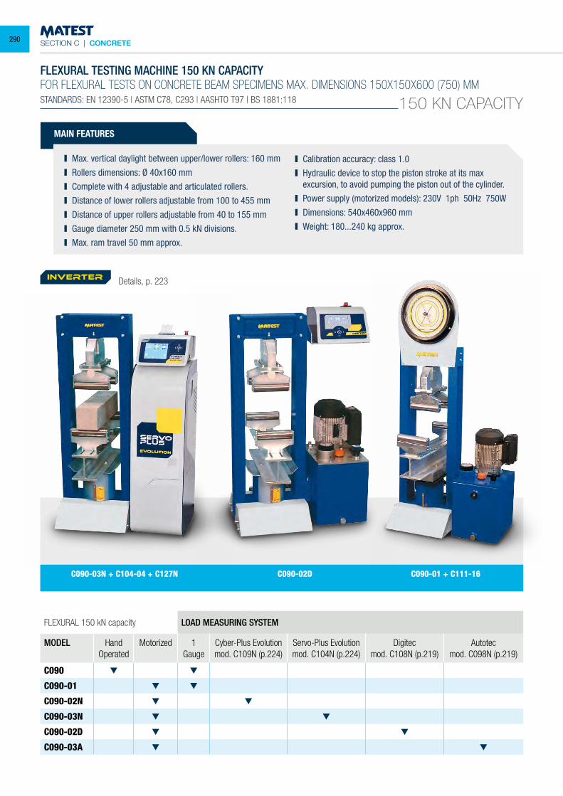
SECTION C | CONCRETE
C090-02D C090-01 + C111-16C090-03N + C104-04 + C127N
FLEXURAL TESTING MACHINE 150 KN CAPACITYFOR FLEXURAL TESTS ON CONCRETE BEAM SPECIMENS MAX. DIMENSIONS 150X150X600 (750) MMSTANDARDS: EN 12390-5 | ASTM C78, C293 | AASHTO T97 | BS 1881:118 150 KN CAPACITY
FLEXURAL 150 kN capacity LOAD MEASURING SYSTEM
MODEL HandOperated
Motorized 1 Gauge
Cyber-Plus Evolutionmod. C109N (p.224)
Servo-Plus Evolutionmod. C104N (p.224)
Digitecmod. C108N (p.219)
Autotecmod. C098N (p.219)
C090
C090-01
C090-02N
C090-03N
C090-02D
C090-03A
MAIN FEATURES
Max. vertical daylight between upper/lower rollers: 160 mm Rollers dimensions: Ø 40x160 mm Complete with 4 adjustable and articulated rollers. Distance of lower rollers adjustable from 100 to 455 mm Distance of upper rollers adjustable from 40 to 155 mm Gauge diameter 250 mm with 0.5 kN divisions. Max. ram travel 50 mm approx.
Calibration accuracy: class 1.0 Hydraulic device to stop the piston stroke at its max
excursion, to avoid pumping the piston out of the cylinder. Power supply (motorized models): 230V 1ph 50Hz 750W Dimensions: 540x460x960 mm Weight: 180...240 kg approx.
Details, p. 223inverter
290
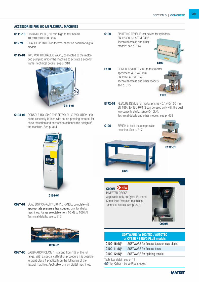
SECTION C | CONCRETE
C100
ACCESSORIES FOR 150 kN FLEXURAL MACHINES
C111-16 DISTANCE PIECE, 50 mm high to test beams 100x100x400/500 mm
C127N GRAPHIC PRINTER on thermo-paper on board for digital models
C115-01
C097-01
C115-01 TWO WAY HYDRAULIC VALVE, connected to the motor-ized pumping unit of the machine to activate a second frame. Technical details: see p. 318
C100 SPLITTING TENSILE test device for cylinders. EN 12390-6 | ASTM C496 Technical details and other models: see p. 314
C104-04 CONSOLE HOUSING THE SERVO-PLUS EVOLUTION, the pump assembly is lined with sound-proofing material for noise reduction and encased to enhance the design of the machine. See p. 314
C097-01 DUAL LOW CAPACITY DIGITAL RANGE, complete with appropriate pressure transducer, only for digital machines. Range selectable from 10 kN to 100 kN.
Technical details: see p. 313
C097-05 CALIBRATION CLASS 1, starting from 1% of the full range. With a special calibration procedure it is possible to grant Class 1 practically on the full range of the flexural machine. Applicable only on digital machines.
E170
E172-01
C126
E170 COMPRESSION DEVICE to test mortar specimens 40.1x40 mm EN 196 | ASTM C349 Technical details and other models: see p. 315
E172-01 FLEXURE DEVICE for mortar prisms 40.1x40x160 mm. EN 196 / EN ISO 679 (it can be used only with the dual
low capacity digital range 0-15kN). Technical details and other models: see p. 428
C126 BENCH to hold the compression machine. See p. 317
Technical detail: see p. 18(N)* for Cyber - Servo Plus models.
SOFTWARE for DIGITEC / AUTOTECor CYBER / SERVO PLUS models
C109-16 (N)* SOFTWARE for flexural tests on clay blocks
C109-11 (N)* SOFTWARE for flexural tests
C109-12 (N)* SOFTWARE for splitting tensile
C104-04
C099N
C099NINVERTER DEVICEApplicable only on Cyber-Plus andServo-Plus Evolution machines.Technical details: see p. 223
NEW
291
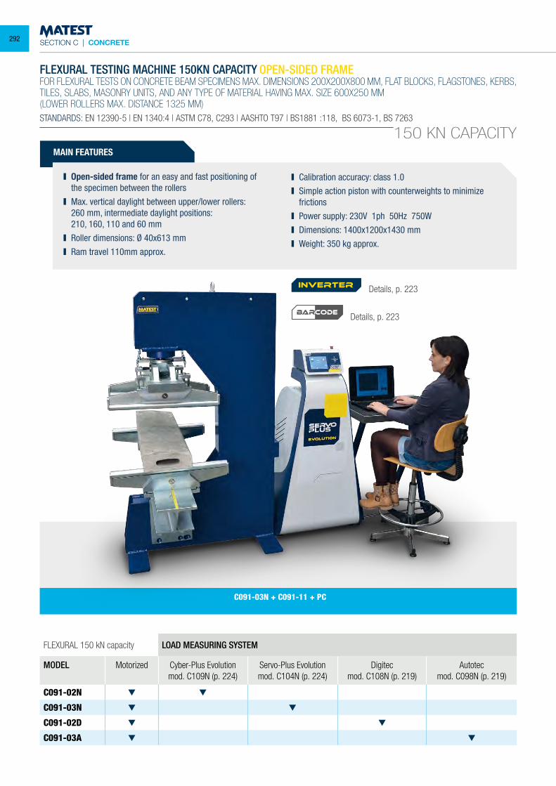
SECTION C | CONCRETE
C091-03N + C091-11 + PC
150 KN CAPACITY
FLEXURAL 150 kN capacity LOAD MEASURING SYSTEM
MODEL Motorized Cyber-Plus Evolutionmod. C109N (p. 224)
Servo-Plus Evolutionmod. C104N (p. 224)
Digitecmod. C108N (p. 219)
Autotecmod. C098N (p. 219)
C091-02N
C091-03N
C091-02D
C091-03A
FLEXURAL TESTING MACHINE 150KN CAPACITY OPEN-SIDED FRAMEFOR FLEXURAL TESTS ON CONCRETE BEAM SPECIMENS MAX. DIMENSIONS 200X200X800 MM, FLAT BLOCKS, FLAGSTONES, KERBS, TILES, SLABS, MASONRY UNITS, AND ANY TYPE OF MATERIAL HAVING MAX. SIZE 600X250 MM(LOWER ROLLERS MAX. DISTANCE 1325 MM)STANDARDS: EN 12390-5 | EN 1340:4 | ASTM C78, C293 | AASHTO T97 | BS1881 :118, BS 6073-1, BS 7263
MAIN FEATURES
Open-sided frame for an easy and fast positioning of the specimen between the rollers
Max. vertical daylight between upper/lower rollers: 260 mm, intermediate daylight positions: 210, 160, 110 and 60 mm Roller dimensions: Ø 40x613 mm Ram travel 110mm approx.
Calibration accuracy: class 1.0 Simple action piston with counterweights to minimize
frictions Power supply: 230V 1ph 50Hz 750W Dimensions: 1400x1200x1430 mm Weight: 350 kg approx.
Details, p. 223
Details, p. 223
inverter
BARCODE
292
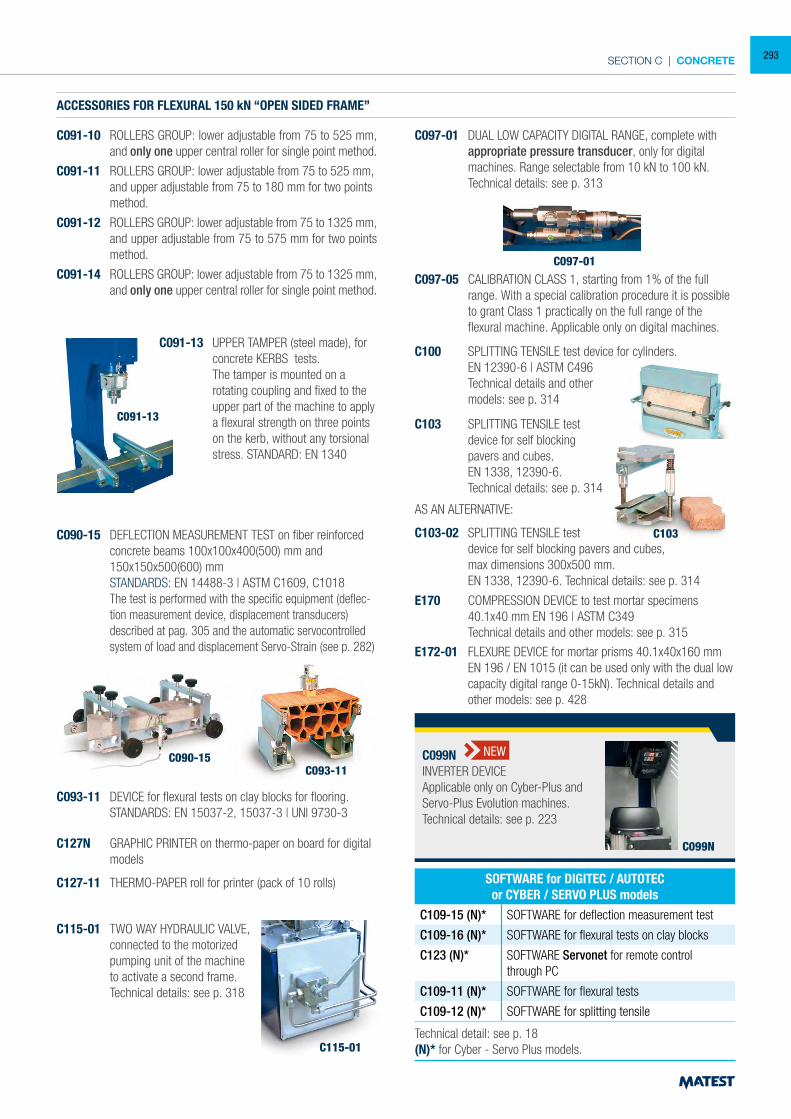
SECTION C | CONCRETE
ACCESSORIES FOR FLEXURAL 150 kN “OPEN SIDED FRAME”
C091-10 ROLLERS GROUP: lower adjustable from 75 to 525 mm, and only one upper central roller for single point method.
C091-11 ROLLERS GROUP: lower adjustable from 75 to 525 mm, and upper adjustable from 75 to 180 mm for two points method.
C091-12 ROLLERS GROUP: lower adjustable from 75 to 1325 mm, and upper adjustable from 75 to 575 mm for two points method.
C091-14 ROLLERS GROUP: lower adjustable from 75 to 1325 mm, and only one upper central roller for single point method.
C090-15 DEFLECTION MEASUREMENT TEST on fiber reinforced concrete beams 100x100x400(500) mm and 150x150x500(600) mm
STANDARDS: EN 14488-3 | ASTM C1609, C1018 The test is performed with the specific equipment (deflec-
tion measurement device, displacement transducers) described at pag. 305 and the automatic servocontrolled system of load and displacement Servo-Strain (see p. 282)
C093-11 DEVICE for flexural tests on clay blocks for flooring. STANDARDS: EN 15037-2, 15037-3 | UNI 9730-3
C093-11C090-15
C127N GRAPHIC PRINTER on thermo-paper on board for digital models
C127-11 THERMO-PAPER roll for printer (pack of 10 rolls)
C115-01
C115-01 TWO WAY HYDRAULIC VALVE, connected to the motorized pumping unit of the machine to activate a second frame. Technical details: see p. 318
C091-13 UPPER TAMPER (steel made), for concrete KERBS tests.
The tamper is mounted on a rotating coupling and fixed to the upper part of the machine to apply a flexural strength on three points on the kerb, without any torsional stress. STANDARD: EN 1340
C091-13
C097-01
C097-01 DUAL LOW CAPACITY DIGITAL RANGE, complete with appropriate pressure transducer, only for digital machines. Range selectable from 10 kN to 100 kN.
Technical details: see p. 313
C097-05 CALIBRATION CLASS 1, starting from 1% of the full range. With a special calibration procedure it is possible to grant Class 1 practically on the full range of the flexural machine. Applicable only on digital machines.
C100
C100 SPLITTING TENSILE test device for cylinders. EN 12390-6 | ASTM C496 Technical details and other models: see p. 314
C103
C103 SPLITTING TENSILE test device for self blocking pavers and cubes.
EN 1338, 12390-6. Technical details: see p. 314
AS AN ALTERNATIVE:
C103-02 SPLITTING TENSILE test device for self blocking pavers and cubes, max dimensions 300x500 mm. EN 1338, 12390-6. Technical details: see p. 314
E170 COMPRESSION DEVICE to test mortar specimens 40.1x40 mm EN 196 | ASTM C349 Technical details and other models: see p. 315E172-01 FLEXURE DEVICE for mortar prisms 40.1x40x160 mm EN 196 / EN 1015 (it can be used only with the dual low
capacity digital range 0-15kN). Technical details and other models: see p. 428
Technical detail: see p. 18(N)* for Cyber - Servo Plus models.
SOFTWARE for DIGITEC / AUTOTECor CYBER / SERVO PLUS models
C109-15 (N)* SOFTWARE for deflection measurement test
C109-16 (N)* SOFTWARE for flexural tests on clay blocks
C123 (N)* SOFTWARE Servonet for remote control through PC
C109-11 (N)* SOFTWARE for flexural tests
C109-12 (N)* SOFTWARE for splitting tensile
C099N
C099NINVERTER DEVICEApplicable only on Cyber-Plus andServo-Plus Evolution machines.Technical details: see p. 223
NEW
293
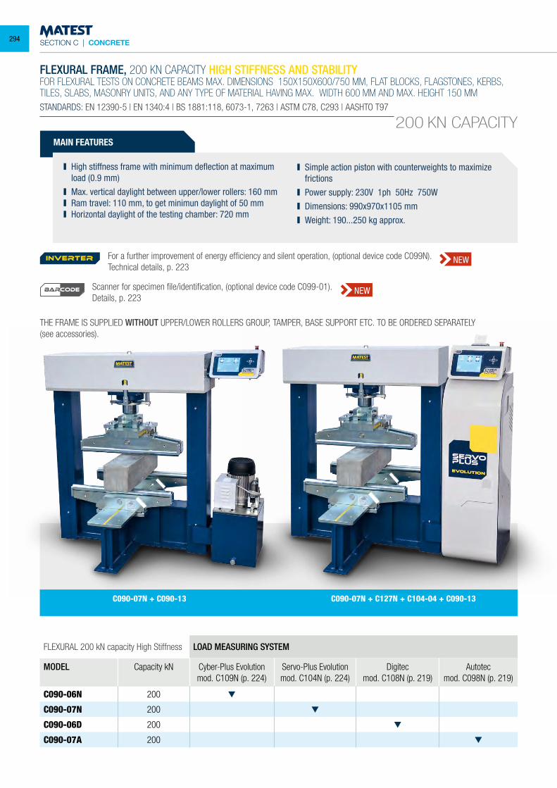
SECTION C | CONCRETE
C090-07N + C127N + C104-04 + C090-13C090-07N + C090-13
200 KN CAPACITY
FLEXURAL 200 kN capacity High Stiffness LOAD MEASURING SYSTEM
MODEL Capacity kN Cyber-Plus Evolutionmod. C109N (p. 224)
Servo-Plus Evolutionmod. C104N (p. 224)
Digitecmod. C108N (p. 219)
Autotecmod. C098N (p. 219)
C090-06N 200
C090-07N 200
C090-06D 200
C090-07A 200
FLEXURAL FRAME, 200 KN CAPACITY HIGH STIFFNESS AND STABILITYFOR FLEXURAL TESTS ON CONCRETE BEAMS MAX. DIMENSIONS 150X150X600/750 MM, FLAT BLOCKS, FLAGSTONES, KERBS, TILES, SLABS, MASONRY UNITS, AND ANY TYPE OF MATERIAL HAVING MAX. WIDTH 600 MM AND MAX. HEIGHT 150 MMSTANDARDS: EN 12390-5 | EN 1340:4 | BS 1881:118, 6073-1, 7263 | ASTM C78, C293 | AASHTO T97
MAIN FEATURES
High stiffness frame with minimum deflection at maximum load (0.9 mm)
Max. vertical daylight between upper/lower rollers: 160 mm Ram travel: 110 mm, to get minimun daylight of 50 mm Horizontal daylight of the testing chamber: 720 mm
Simple action piston with counterweights to maximize frictions
Power supply: 230V 1ph 50Hz 750W Dimensions: 990x970x1105 mm Weight: 190...250 kg approx.
THE FRAME IS SUPPLIED WITHOUT UPPER/LOWER ROLLERS GROUP, TAMPER, BASE SUPPORT ETC. TO BE ORDERED SEPARATELY(see accessories).
For a further improvement of energy efficiency and silent operation, (optional device code C099N). Technical details, p. 223
Scanner for specimen file/identification, (optional device code C099-01).Details, p. 223
inverter NEW
NEWBARCODE
294
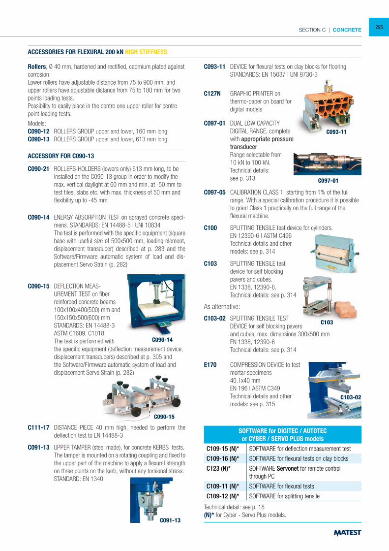
SECTION C | CONCRETE
ACCESSORIES FOR FLEXURAL 200 kN HIGH STIFFNESS
Rollers, Ø 40 mm, hardened and rectified, cadmium plated against corrosion.Lower rollers have adjustable distance from 75 to 900 mm, and upper rollers have adjustable distance from 75 to 180 mm for two points loading tests.Possibility to easily place in the centre one upper roller for centre point loading tests.
Models:C090-12 ROLLERS GROUP upper and lower, 160 mm long. C090-13 ROLLERS GROUP upper and lower, 613 mm long.
ACCESSORY FOR C090-13
C090-21 ROLLERS-HOLDERS (lowers only) 613 mm long, to be installed on the C090-13 group in order to modify the max. vertical daylight at 60 mm and min. at -50 mm to test tiles, slabs etc. with max. thickness of 50 mm and flexibility up to -45 mm
C090-14 ENERGY ABSORPTION TEST on sprayed concrete speci-mens. STANDARDS: EN 14488-5 | UNI 10834
The test is performed with the specific equipment (square base with useful size of 500x500 mm, loading element, displacement transducer) described at p. 283 and the Software/Firmware automatic system of load and dis-placement Servo Strain (p. 282)
C111-17 DISTANCE PIECE 40 mm high, needed to perform the deflection test to EN 14488-3
C090-15 DEFLECTION MEAS-UREMENT TEST on fiber reinforced concrete beams 100x100x400(500) mm and 150x150x500(600) mm
STANDARDS: EN 14488-3 ASTM C1609, C1018
The test is performed with the specific equipment (deflection measurement device, displacement transducers) described at p. 305 and the Software/Firmware automatic system of load and displacement Servo Strain (p. 282)
C090-15
C091-13 UPPER TAMPER (steel made), for concrete KERBS tests. The tamper is mounted on a rotating coupling and fixed to
the upper part of the machine to apply a flexural strength on three points on the kerb, without any torsional stress.
STANDARD: EN 1340
C091-13
C093-11 DEVICE for flexural tests on clay blocks for flooring. STANDARDS: EN 15037 | UNI 9730-3
C093-11
C127N GRAPHIC PRINTER on thermo-paper on board for digital models
C097-01
C097-01 DUAL LOW CAPACITY DIGITAL RANGE, complete with appropriate pressure transducer.
Range selectable from 10 kN to 100 kN. Technical details: see p. 313
C097-05 CALIBRATION CLASS 1, starting from 1% of the full range. With a special calibration procedure it is possible to grant Class 1 practically on the full range of the flexural machine.
C100
C100 SPLITTING TENSILE test device for cylinders. EN 12390-6 | ASTM C496 Technical details and other models: see p. 314
C103 SPLITTING TENSILE test device for self blocking pavers and cubes.
EN 1338, 12390-6. Technical details: see p. 314
C103
E170 COMPRESSION DEVICE to test mortar specimens
40.1x40 mm EN 196 | ASTM C349 Technical details and other
models: see p. 315
Technical detail: see p. 18(N)* for Cyber - Servo Plus models.
SOFTWARE for DIGITEC / AUTOTECor CYBER / SERVO PLUS models
C109-15 (N)* SOFTWARE for deflection measurement test
C109-16 (N)* SOFTWARE for flexural tests on clay blocks
C123 (N)* SOFTWARE Servonet for remote control through PC
C109-11 (N)* SOFTWARE for flexural tests
C109-12 (N)* SOFTWARE for splitting tensile
As alternative:
C103-02 SPLITTING TENSILE TEST DEVICE for self blocking pavers and cubes, max. dimensions 300x500 mm EN 1338, 12390-6 Technical details: see p. 314
C103-02
C090-14
295
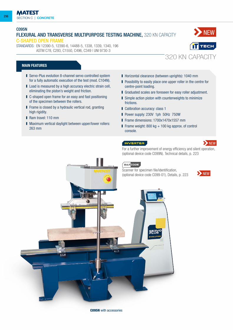
SECTION C | CONCRETE
C095NFLEXURAL AND TRANSVERSE MULTIPURPOSE TESTING MACHINE, 320 KN CAPACITYC-SHAPED OPEN FRAMESTANDARDS: EN 12390-5, 12390-6, 14488-5, 1338, 1339, 1340, 196 ASTM C78, C293, C1550, C496, C349 | UNI 9730-3
MAIN FEATURES
Servo-Plus evolution 8-channel servo controlled system for a fully automatic execution of the test (mod. C104N).
Load is measured by a high accuracy electric strain cell, eliminating the piston’s weight and friction.
C-shaped open frame for an easy and fast positioning of the specimen between the rollers.
Frame is closed by a hydraulic vertical rod, granting high rigidity.
Ram travel: 110 mm Maximum vertical daylight between upper/lower rollers:
263 mm
Horizontal clearance (between uprights): 1040 mm Possibility to easily place one upper roller in the centre for
centre-point loading. Graduated scales are foreseen for easy roller adjustment. Simple action piston with counterweights to minimize
frictions. Calibration accuracy: class 1 Power supply: 230V 1ph 50Hz 750W Frame dimensions: 1700x1470x1557 mm Frame weight: 800 kg + 100 kg approx. of control
console.
320 KN CAPACITY
C095N with accessories
NEW
For a further improvement of energy efficiency and silent operation, (optional device code C099N). Technical details, p. 223
Scanner for specimen file/identification,(optional device code C099-01). Details, p. 223
inverter NEW
NEW
BARCODE
296
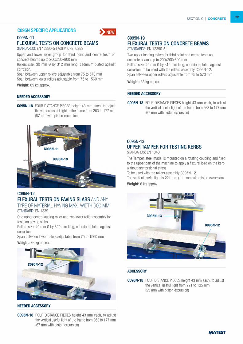
SECTION C | CONCRETE
NEWC095N-19FLEXURAL TESTS ON CONCRETE BEAMSSTANDARDS: EN 12390-5
Two upper loading rollers for third point and centre tests on concrete beams up to 200x200x800 mmRollers size: 40 mm Ø by 312 mm long, cadmium plated against corrosion, to be used with the rollers assembly C095N-12.Span between upper rollers adjustable from 75 to 570 mm
Weight: 65 kg approx.
NEEDED ACCESSORY
C095N-18 FOUR DISTANCE PIECES height 43 mm each, to adjust the vertical useful light of the frame from 263 to 177 mm (67 mm with piston excursion)
C095N-11FLEXURAL TESTS ON CONCRETE BEAMSSTANDARDS: EN 12390-5 | ASTM C78, C293
Upper and lower roller group for third point and centre tests on concrete beams up to 200x200x800 mmRollers size: 30 mm Ø by 312 mm long, cadmium plated against corrosion.Span between upper rollers adjustable from 75 to 570 mmSpan between lower rollers adjustable from 75 to 1560 mm
Weight: 65 kg approx.
NEEDED ACCESSORY
C095N-18 FOUR DISTANCE PIECES height 43 mm each, to adjust the vertical useful light of the frame from 263 to 177 mm (67 mm with piston excursion)
C095N-12FLEXURAL TESTS ON PAVING SLABS AND ANY TYPE OF MATERIAL HAVING MAX. WIDTH 600 MMSTANDARD: EN 1339
One upper centre loading roller and two lower roller assembly for tests on paving slabs.Rollers size: 40 mm Ø by 620 mm long, cadmium plated against corrosion.Span between lower rollers adjustable from 75 to 1560 mm
Weight: 76 kg approx.
NEEDED ACCESSORY
C095N-18 FOUR DISTANCE PIECES height 43 mm each, to adjust the vertical useful light of the frame from 263 to 177 mm (67 mm with piston excursion)
ACCESSORY
C095N-18 FOUR DISTANCE PIECES height 43 mm each, to adjust the vertical useful light from 221 to 135 mm
(25 mm with piston excursion)
C095N-13UPPER TAMPER FOR TESTING KERBSSTANDARDS: EN 1340
The Tamper, steel made, is mounted on a rotating coupling and fixed to the upper part of the machine to apply a flexural load on the kerb, without any torsional stress.To be used with the rollers assembly C095N-12.The vertical useful light is 221 mm (111 mm with piston excursion).
Weight: 6 kg approx.
C095N-11
C095N-19
C095N-12
C095N-13
C095N-12
C095N SPECIFIC APPLICATIONS
297
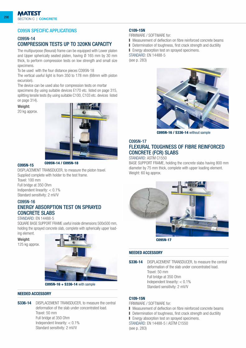
SECTION C | CONCRETE
C095N SPECIFIC APPLICATIONS
C095N-14COMPRESSION TESTS UP TO 320KN CAPACITYThe multipurpose (flexural) frame can be equipped with Lower platen and Upper spherically seated platen, having Ø 165 mm by 30 mm thick, to perform compression tests on low strength and small size specimens.To be used with the four distance pieces C095N-18The vertical useful light is from 350 to 178 mm (68mm with piston excursion).The device can be used also for compression tests on mortarspecimens (by using suitable devices E170 etc. listed on page 315, splitting tensile tests (by using suitable C100, C103 etc. devices listed on page 314).
Weight:20 kg approx.
C095N-15DISPLACEMENT TRANSDUCER, to measure the piston travel. Supplied complete with holder to the test frame.Travel: 100 mmFull bridge at 350 OhmIndipendent linearity: < 0.1%Standard sensitivity: 2 mV/V
C095N-16ENERGY ABSORPTION TEST ON SPRAYED CONCRETE SLABSSTANDARD: EN 14488-5SQUARE BASE SUPPORT FRAME useful inside dimensions 500x500 mm, holding the sprayed concrete slab, complete with spherically upper load-ing element.
Weight:125 kg approx.
NEEDED ACCESSORY
S336-14 DISPLACEMENT TRANSDUCER, to measure the central deformation of the slab under concentrated load.
Travel: 50 mm Full bridge at 350 Ohm Independent linearity: < 0.1% Standard sensitivity: 2 mV/V
NEEDED ACCESSORY
S336-14 DISPLACEMENT TRANSDUCER, to measure the central deformation of the slab under concentrated load.
Travel: 50 mm Full bridge at 350 Ohm Independent linearity: < 0.1% Standard sensitivity: 2 mV/V
C109-15NFIRMWARE / SOFTWARE for: Measurement of deflection on fibre reinforced concrete beams Determination of toughness, first crack strength and ductility Energy absorption test on sprayed specimens.
STANDARD: EN 14488-5(see p. 283)
C095N-17FLEXURAL TOUGHNESS OF FIBRE REINFORCED CONCRETE (FCR) SLABSSTANDARD: ASTM C1550BASE SUPPORT FRAME, holding the concrete slabs having 800 mm diameter by 75 mm thick, complete with upper loading element.Weight: 60 kg approx.
C109-15NFIRMWARE / SOFTWARE for: Measurement of deflection on fibre reinforced concrete beams Determination of toughness, first crack strength and ductility Energy absorption test on sprayed specimens.
STANDARD: EN 14488-5 | ASTM C1550(see p. 283)
C095N-14 / C095N-18
C095N-16 / S336-14 without sample
C095N-17
C095N-16 + S336-14 with sample
298
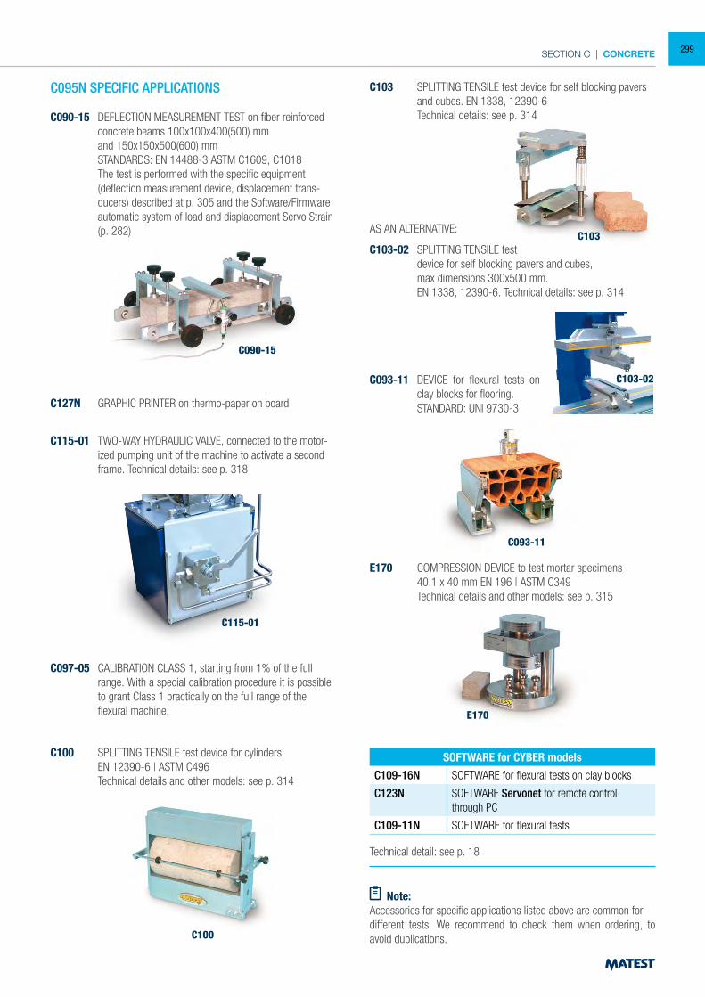
SECTION C | CONCRETE
C127N GRAPHIC PRINTER on thermo-paper on board
C095N SPECIFIC APPLICATIONS
C097-05 CALIBRATION CLASS 1, starting from 1% of the full range. With a special calibration procedure it is possible to grant Class 1 practically on the full range of the flexural machine.
C100
C100 SPLITTING TENSILE test device for cylinders. EN 12390-6 | ASTM C496 Technical details and other models: see p. 314
Technical detail: see p. 18
SOFTWARE for CYBER models
C109-16N SOFTWARE for flexural tests on clay blocks
C123N SOFTWARE Servonet for remote control through PC
C109-11N SOFTWARE for flexural tests
C093-11 DEVICE for flexural tests on clay blocks for flooring.
STANDARD: UNI 9730-3
C093-11
C115-01
C115-01 TWO-WAY HYDRAULIC VALVE, connected to the motor-ized pumping unit of the machine to activate a second frame. Technical details: see p. 318
E170
E170 COMPRESSION DEVICE to test mortar specimens 40.1 x 40 mm EN 196 | ASTM C349 Technical details and other models: see p. 315
C103 SPLITTING TENSILE test device for self blocking pavers and cubes. EN 1338, 12390-6
Technical details: see p. 314
C103AS AN ALTERNATIVE:
C103-02 SPLITTING TENSILE test device for self blocking pavers and cubes, max dimensions 300x500 mm. EN 1338, 12390-6. Technical details: see p. 314
C103-02
Note:Accessories for specific applications listed above are common fordifferent tests. We recommend to check them when ordering, to avoid duplications.
C090-15 DEFLECTION MEASUREMENT TEST on fiber reinforced concrete beams 100x100x400(500) mm
and 150x150x500(600) mm STANDARDS: EN 14488-3 ASTM C1609, C1018 The test is performed with the specific equipment
(deflection measurement device, displacement trans-ducers) described at p. 305 and the Software/Firmware automatic system of load and displacement Servo Strain (p. 282)
C090-15
299
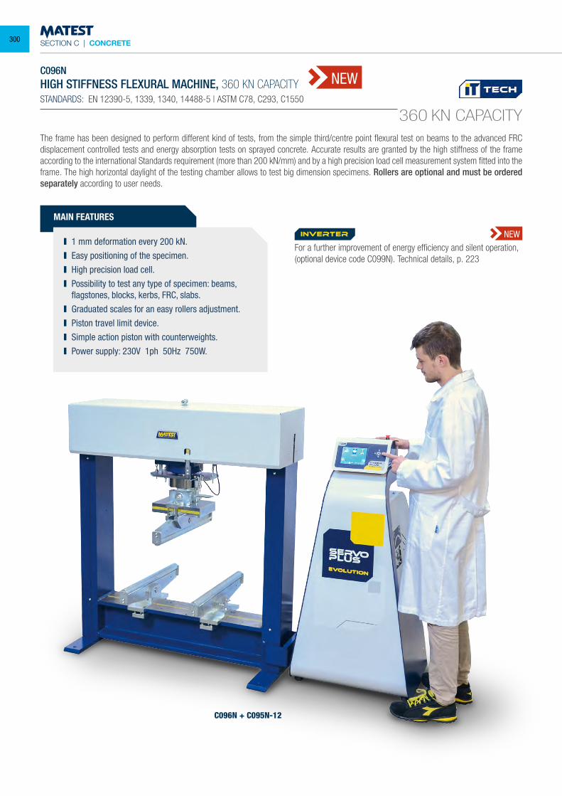
SECTION C | CONCRETE
C096NHIGH STIFFNESS FLEXURAL MACHINE, 360 KN CAPACITYSTANDARDS: EN 12390-5, 1339, 1340, 14488-5 | ASTM C78, C293, C1550
360 KN CAPACITY
NEW
The frame has been designed to perform different kind of tests, from the simple third/centre point flexural test on beams to the advanced FRC displacement controlled tests and energy absorption tests on sprayed concrete. Accurate results are granted by the high stiffness of the frame according to the international Standards requirement (more than 200 kN/mm) and by a high precision load cell measurement system fitted into the frame. The high horizontal daylight of the testing chamber allows to test big dimension specimens. Rollers are optional and must be ordered separately according to user needs.
MAIN FEATURES
1 mm deformation every 200 kN. Easy positioning of the specimen. High precision load cell. Possibility to test any type of specimen: beams,
flagstones, blocks, kerbs, FRC, slabs. Graduated scales for an easy rollers adjustment. Piston travel limit device. Simple action piston with counterweights. Power supply: 230V 1ph 50Hz 750W.
C096N + C095N-12
For a further improvement of energy efficiency and silent operation, (optional device code C099N). Technical details, p. 223
inverter NEW
300
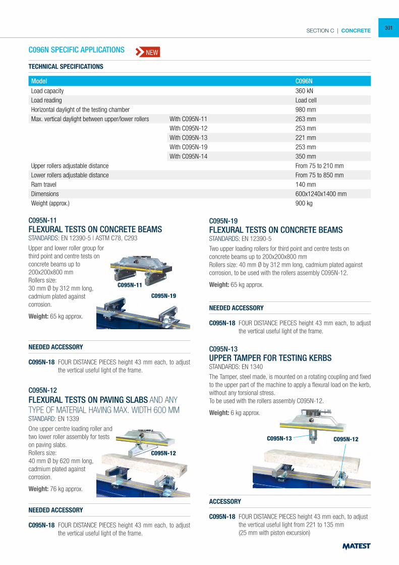
SECTION C | CONCRETE
TECHNICAL SPECIFICATIONS
Model C096NLoad capacity 360 kNLoad reading Load cellHorizontal daylight of the testing chamber 980 mmMax. vertical daylight between upper/lower rollers With C095N-11 263 mm
With C095N-12 253 mmWith C095N-13 221 mmWith C095N-19 253 mmWith C095N-14 350 mm
Upper rollers adjustable distance From 75 to 210 mmLower rollers adjustable distance From 75 to 850 mmRam travel 140 mmDimensions 600x1240x1400 mmWeight (approx.) 900 kg
NEW
C095N-19FLEXURAL TESTS ON CONCRETE BEAMSSTANDARDS: EN 12390-5
Two upper loading rollers for third point and centre tests on concrete beams up to 200x200x800 mmRollers size: 40 mm Ø by 312 mm long, cadmium plated against corrosion, to be used with the rollers assembly C095N-12.
Weight: 65 kg approx.
NEEDED ACCESSORY
C095N-18 FOUR DISTANCE PIECES height 43 mm each, to adjust the vertical useful light of the frame.
C095N-11FLEXURAL TESTS ON CONCRETE BEAMSSTANDARDS: EN 12390-5 | ASTM C78, C293
Upper and lower roller group forthird point and centre tests onconcrete beams up to200x200x800 mmRollers size:30 mm Ø by 312 mm long,cadmium plated againstcorrosion.
Weight: 65 kg approx.
C095N-12FLEXURAL TESTS ON PAVING SLABS AND ANY TYPE OF MATERIAL HAVING MAX. WIDTH 600 MMSTANDARD: EN 1339
One upper centre loading roller andtwo lower roller assembly for testson paving slabs.Rollers size:40 mm Ø by 620 mm long,cadmium plated againstcorrosion.
Weight: 76 kg approx.
NEEDED ACCESSORY
C095N-18 FOUR DISTANCE PIECES height 43 mm each, to adjust the vertical useful light of the frame.
ACCESSORY
C095N-18 FOUR DISTANCE PIECES height 43 mm each, to adjust the vertical useful light from 221 to 135 mm
(25 mm with piston excursion)
C095N-11
C095N-19
C095N-12
C095N-13 C095N-12
C096N SPECIFIC APPLICATIONS
C095N-13UPPER TAMPER FOR TESTING KERBSSTANDARDS: EN 1340
The Tamper, steel made, is mounted on a rotating coupling and fixed to the upper part of the machine to apply a flexural load on the kerb, without any torsional stress.To be used with the rollers assembly C095N-12.
Weight: 6 kg approx.
NEEDED ACCESSORY
C095N-18 FOUR DISTANCE PIECES height 43 mm each, to adjust the vertical useful light of the frame.
301
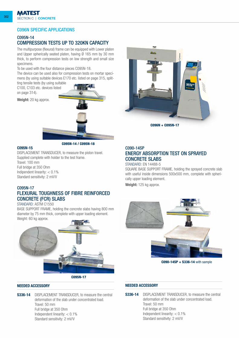
SECTION C | CONCRETE
C095N-14 / C095N-18
C096N + C095N-17
C096N SPECIFIC APPLICATIONS
C095N-14COMPRESSION TESTS UP TO 320KN CAPACITYThe multipurpose (flexural) frame can be equipped with Lower platen and Upper spherically seated platen, having Ø 165 mm by 30 mm thick, to perform compression tests on low strength and small size specimens.To be used with the four distance pieces C095N-18.The device can be used also for compression tests on mortar speci-mens (by using suitable devices E170 etc. listed on page 315, split-ting tensile tests (by using suitableC100, C103 etc. devices listedon page 314).
Weight: 20 kg approx.
C095N-15DISPLACEMENT TRANSDUCER, to measure the piston travel. Supplied complete with holder to the test frame.Travel: 100 mmFull bridge at 350 OhmIndipendent linearity: < 0.1%Standard sensitivity: 2 mV/V
C090-14SPENERGY ABSORPTION TEST ON SPRAYED CONCRETE SLABSSTANDARD: EN 14488-5SQUARE BASE SUPPORT FRAME, holding the sprayed concrete slab with useful inside dimensions 500x500 mm, complete with spheri-cally upper loading element.
Weight: 125 kg approx.
C090-14SP + S336-14 with sample
NEEDED ACCESSORY
S336-14 DISPLACEMENT TRANSDUCER, to measure the central deformation of the slab under concentrated load.
Travel: 50 mm Full bridge at 350 Ohm Independent linearity: < 0.1% Standard sensitivity: 2 mV/V
NEEDED ACCESSORY
S336-14 DISPLACEMENT TRANSDUCER, to measure the central deformation of the slab under concentrated load.
Travel: 50 mm Full bridge at 350 Ohm Independent linearity: < 0.1% Standard sensitivity: 2 mV/V
C095N-17
C095N-17FLEXURAL TOUGHNESS OF FIBRE REINFORCED CONCRETE (FCR) SLABSSTANDARD: ASTM C1550BASE SUPPORT FRAME, holding the concrete slabs having 800 mm diameter by 75 mm thick, complete with upper loading element.Weight: 60 kg approx.
302
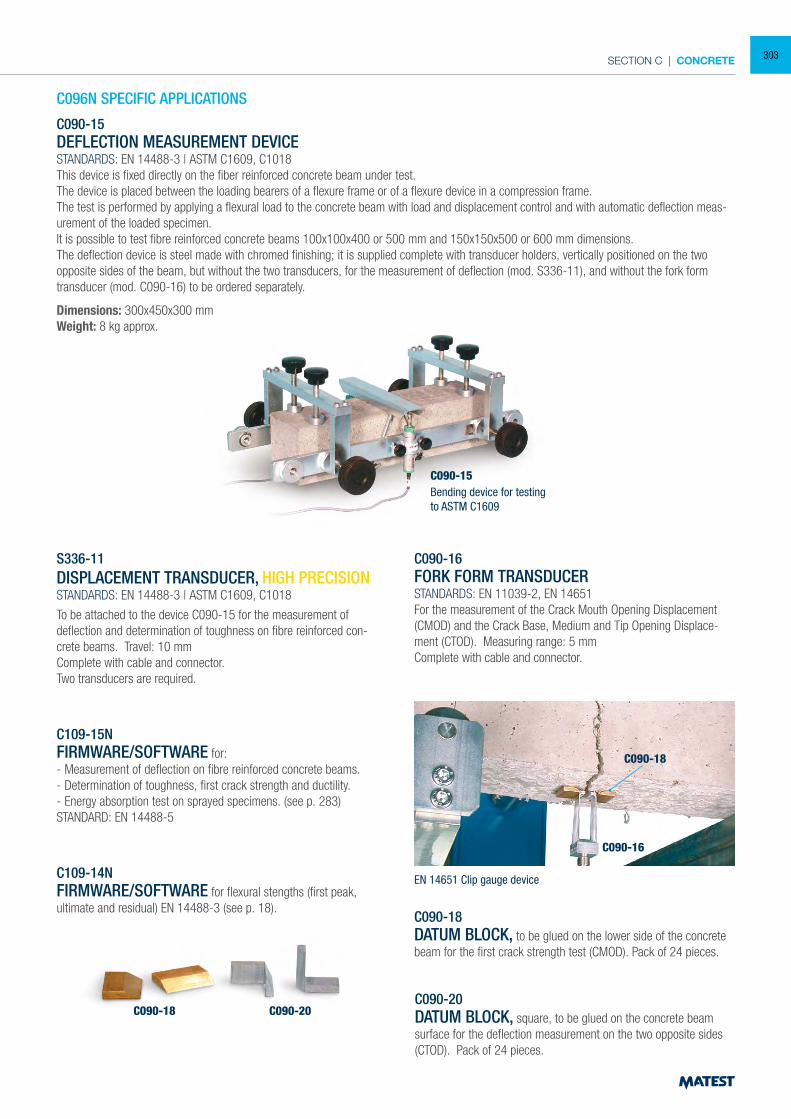
SECTION C | CONCRETE
C096N SPECIFIC APPLICATIONS
C090-15DEFLECTION MEASUREMENT DEVICESTANDARDS: EN 14488-3 | ASTM C1609, C1018This device is fixed directly on the fiber reinforced concrete beam under test.The device is placed between the loading bearers of a flexure frame or of a flexure device in a compression frame.The test is performed by applying a flexural load to the concrete beam with load and displacement control and with automatic deflection meas-urement of the loaded specimen.It is possible to test fibre reinforced concrete beams 100x100x400 or 500 mm and 150x150x500 or 600 mm dimensions.The deflection device is steel made with chromed finishing; it is supplied complete with transducer holders, vertically positioned on the two opposite sides of the beam, but without the two transducers, for the measurement of deflection (mod. S336-11), and without the fork form transducer (mod. C090-16) to be ordered separately.
Dimensions: 300x450x300 mmWeight: 8 kg approx.
C090-15Bending device for testingto ASTM C1609
S336-11
DISPLACEMENT TRANSDUCER, HIGH PRECISIONSTANDARDS: EN 14488-3 | ASTM C1609, C1018
To be attached to the device C090-15 for the measurement of deflection and determination of toughness on fibre reinforced con-crete beams. Travel: 10 mm Complete with cable and connector. Two transducers are required.
C109-15NFIRMWARE/SOFTWARE for:- Measurement of deflection on fibre reinforced concrete beams.- Determination of toughness, first crack strength and ductility.- Energy absorption test on sprayed specimens. (see p. 283)STANDARD: EN 14488-5
C109-14NFIRMWARE/SOFTWARE for flexural stengths (first peak, ultimate and residual) EN 14488-3 (see p. 18).
C090-18 C090-20
C090-16 FORK FORM TRANSDUCER STANDARDS: EN 11039-2, EN 14651 For the measurement of the Crack Mouth Opening Displacement (CMOD) and the Crack Base, Medium and Tip Opening Displace-ment (CTOD). Measuring range: 5 mm Complete with cable and connector.
C090-18DATUM BLOCK, to be glued on the lower side of the concrete beam for the first crack strength test (CMOD). Pack of 24 pieces.
C090-16
C090-18
EN 14651 Clip gauge device
C090-20 DATUM BLOCK, square, to be glued on the concrete beam surface for the deflection measurement on the two opposite sides (CTOD). Pack of 24 pieces.
303
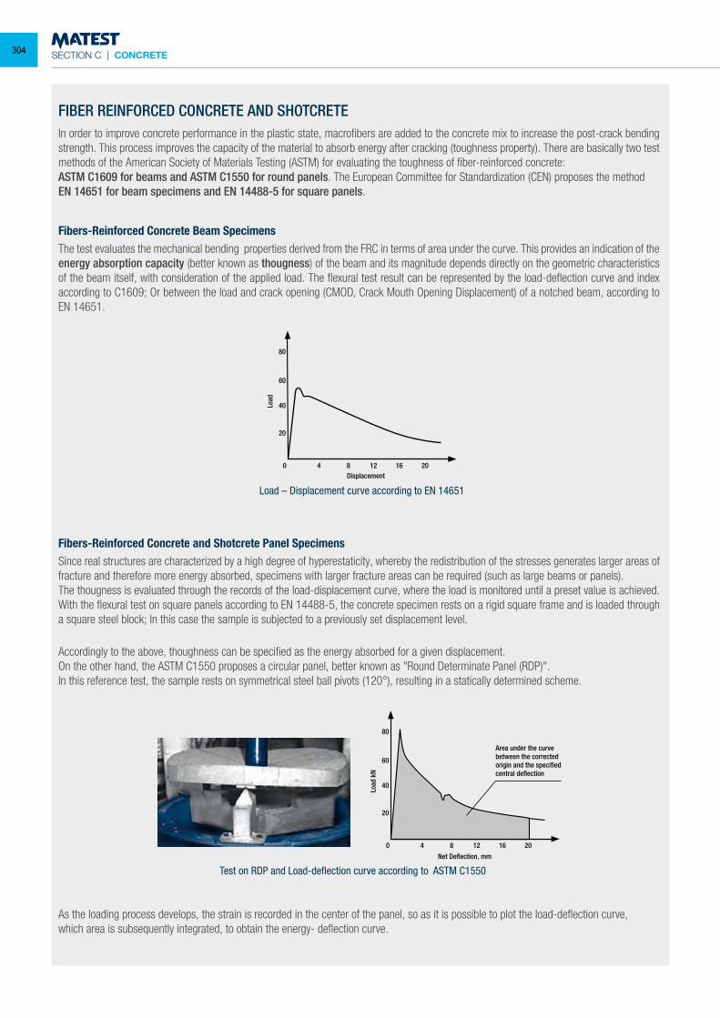
SECTION C | CONCRETE
Test on RDP and Load-deflection curve according to ASTM C1550
Load – Displacement curve according to EN 14651
FIBER REINFORCED CONCRETE AND SHOTCRETEIn order to improve concrete performance in the plastic state, macrofibers are added to the concrete mix to increase the post-crack bending strength. This process improves the capacity of the material to absorb energy after cracking (toughness property). There are basically two test methods of the American Society of Materials Testing (ASTM) for evaluating the toughness of fiber-reinforced concrete:ASTM C1609 for beams and ASTM C1550 for round panels. The European Committee for Standardization (CEN) proposes the methodEN 14651 for beam specimens and EN 14488-5 for square panels.
Fibers-Reinforced Concrete Beam SpecimensThe test evaluates the mechanical bending properties derived from the FRC in terms of area under the curve. This provides an indication of the energy absorption capacity (better known as thougness) of the beam and its magnitude depends directly on the geometric characteristics of the beam itself, with consideration of the applied load. The flexural test result can be represented by the load-deflection curve and index according to C1609; Or between the load and crack opening (CMOD, Crack Mouth Opening Displacement) of a notched beam, according to EN 14651.
Accordingly to the above, thoughness can be specified as the energy absorbed for a given displacement. On the other hand, the ASTM C1550 proposes a circular panel, better known as "Round Determinate Panel (RDP)".In this reference test, the sample rests on symmetrical steel ball pivots (120°), resulting in a statically determined scheme.
As the loading process develops, the strain is recorded in the center of the panel, so as it is possible to plot the load-deflection curve,which area is subsequently integrated, to obtain the energy- deflection curve.
80
60
40
20
0 4 8 12 16 20
Load
Displacement
80
60
40
20
0 4 8 12 16 20
Load
kN
Net Deflection, mm
Area under the curvebetween the correctedorigin and the specifiedcentral deflection
Fibers-Reinforced Concrete and Shotcrete Panel SpecimensSince real structures are characterized by a high degree of hyperestaticity, whereby the redistribution of the stresses generates larger areas of fracture and therefore more energy absorbed, specimens with larger fracture areas can be required (such as large beams or panels).The thougness is evaluated through the records of the load-displacement curve, where the load is monitored until a preset value is achieved. With the flexural test on square panels according to EN 14488-5, the concrete specimen rests on a rigid square frame and is loaded through a square steel block; In this case the sample is subjected to a previously set displacement level.
304
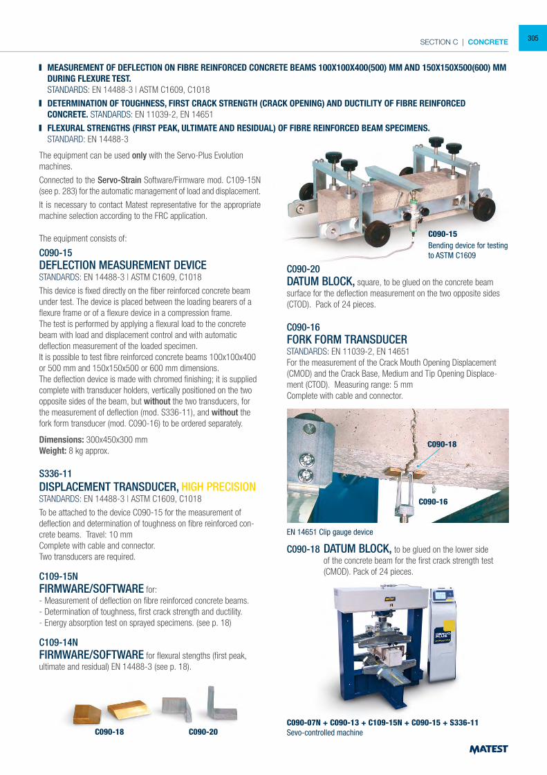
SECTION C | CONCRETE
MEASUREMENT OF DEFLECTION ON FIBRE REINFORCED CONCRETE BEAMS 100X100X400(500) MM AND 150X150X500(600) MM DURING FLEXURE TEST.
STANDARDS: EN 14488-3 | ASTM C1609, C1018
DETERMINATION OF TOUGHNESS, FIRST CRACK STRENGTH (CRACK OPENING) AND DUCTILITY OF FIBRE REINFORCED CONCRETE. STANDARDS: EN 11039-2, EN 14651
FLEXURAL STRENGTHS (FIRST PEAK, ULTIMATE AND RESIDUAL) OF FIBRE REINFORCED BEAM SPECIMENS. STANDARD: EN 14488-3
The equipment can be used only with the Servo-Plus Evolution machines.
Connected to the Servo-Strain Software/Firmware mod. C109-15N (see p. 283) for the automatic management of load and displacement.
It is necessary to contact Matest representative for the appropriate machine selection according to the FRC application.
The equipment consists of:
C090-15DEFLECTION MEASUREMENT DEVICESTANDARDS: EN 14488-3 | ASTM C1609, C1018
This device is fixed directly on the fiber reinforced concrete beam under test. The device is placed between the loading bearers of a flexure frame or of a flexure device in a compression frame.The test is performed by applying a flexural load to the concrete beam with load and displacement control and with automatic deflection measurement of the loaded specimen. It is possible to test fibre reinforced concrete beams 100x100x400 or 500 mm and 150x150x500 or 600 mm dimensions.The deflection device is made with chromed finishing; it is supplied complete with transducer holders, vertically positioned on the two opposite sides of the beam, but without the two transducers, for the measurement of deflection (mod. S336-11), and without the fork form transducer (mod. C090-16) to be ordered separately.
Dimensions: 300x450x300 mmWeight: 8 kg approx.
S336-11
DISPLACEMENT TRANSDUCER, HIGH PRECISIONSTANDARDS: EN 14488-3 | ASTM C1609, C1018
To be attached to the device C090-15 for the measurement of deflection and determination of toughness on fibre reinforced con-crete beams. Travel: 10 mm Complete with cable and connector. Two transducers are required.
C109-15NFIRMWARE/SOFTWARE for:- Measurement of deflection on fibre reinforced concrete beams.- Determination of toughness, first crack strength and ductility.- Energy absorption test on sprayed specimens. (see p. 18)
C109-14NFIRMWARE/SOFTWARE for flexural stengths (first peak, ultimate and residual) EN 14488-3 (see p. 18).
C090-18 C090-20
C090-15
C090-20 DATUM BLOCK, square, to be glued on the concrete beam surface for the deflection measurement on the two opposite sides (CTOD). Pack of 24 pieces.
C090-16 FORK FORM TRANSDUCER STANDARDS: EN 11039-2, EN 14651 For the measurement of the Crack Mouth Opening Displacement (CMOD) and the Crack Base, Medium and Tip Opening Displace-ment (CTOD). Measuring range: 5 mm Complete with cable and connector.
C090-18 DATUM BLOCK, to be glued on the lower side of the concrete beam for the first crack strength test (CMOD). Pack of 24 pieces.
C090-07N + C090-13 + C109-15N + C090-15 + S336-11Sevo-controlled machine
C090-16
C090-18
Bending device for testingto ASTM C1609
EN 14651 Clip gauge device
305
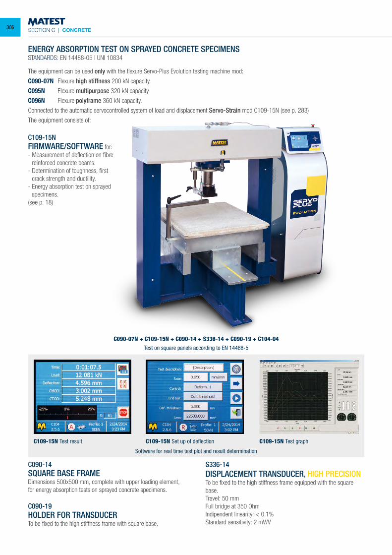
SECTION C | CONCRETE
C109-15NFIRMWARE/SOFTWARE for:- Measurement of deflection on fibre
reinforced concrete beams.- Determination of toughness, first
crack strength and ductility.- Energy absorption test on sprayed
specimens.(see p. 18)
C090-14SQUARE BASE FRAMEDimensions 500x500 mm, complete with upper loading element, for energy absorption tests on sprayed concrete specimens.
C090-19HOLDER FOR TRANSDUCERTo be fixed to the high stiffness frame with square base.
S336-14DISPLACEMENT TRANSDUCER, HIGH PRECISIONTo be fixed to the high stiffness frame equipped with the square base.Travel: 50 mmFull bridge at 350 OhmIndipendent linearity: < 0.1%Standard sensitivity: 2 mV/V
C090-07N + C109-15N + C090-14 + S336-14 + C090-19 + C104-04
C109-15N Set up of deflectionC109-15N Test result C109-15N Test graph
Software for real time test plot and result determination
Test on square panels according to EN 14488-5
ENERGY ABSORPTION TEST ON SPRAYED CONCRETE SPECIMENSSTANDARDS: EN 14488-05 | UNI 10834
The equipment can be used only with the flexure Servo-Plus Evolution testing machine mod:
C090-07N Flexure high stiffness 200 kN capacity
C095N Flexure multipurpose 320 kN capacity
C096N Flexure polyframe 360 kN capacity.
Connected to the automatic servocontrolled system of load and displacement Servo-Strain mod C109-15N (see p. 283)
The equipment consists of:
306
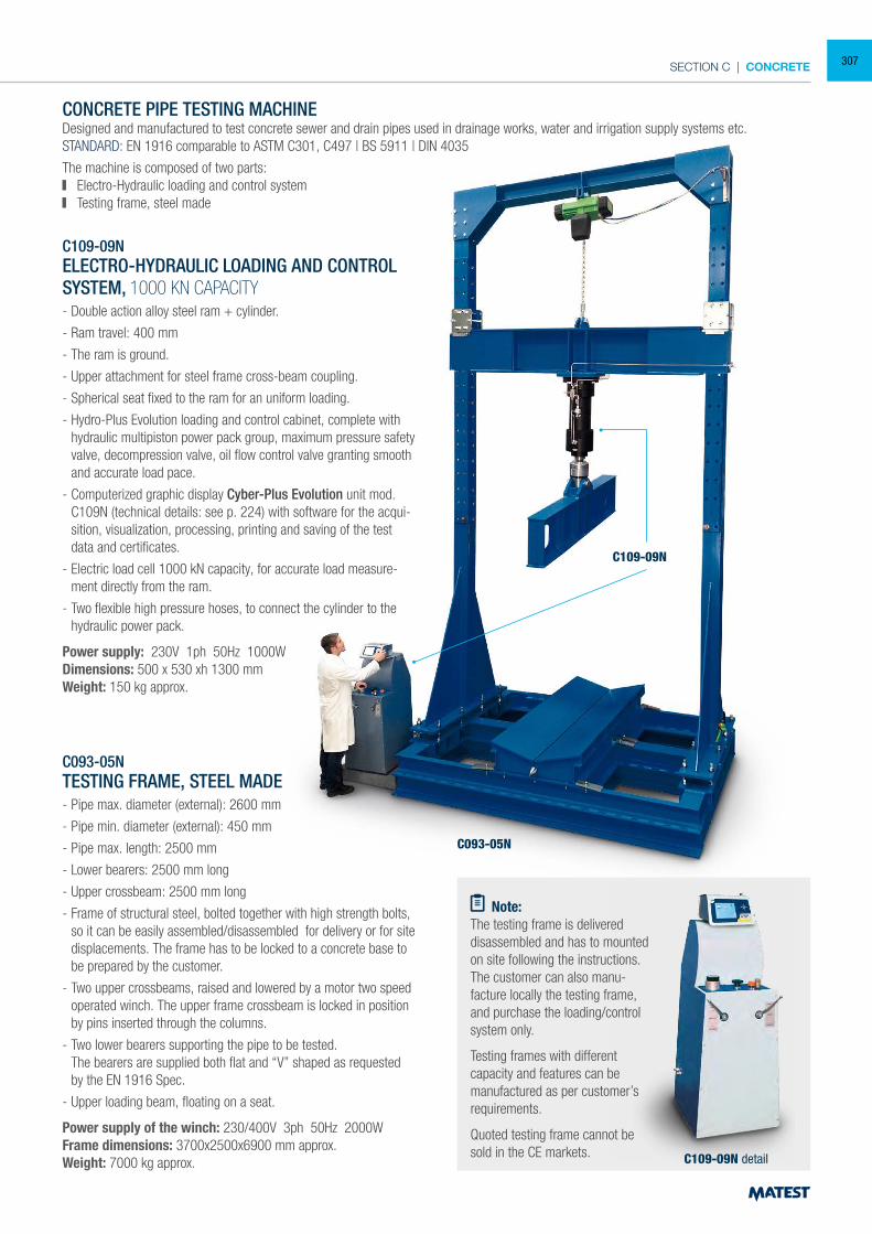
SECTION C | CONCRETE
C093-05N
C109-09N
CONCRETE PIPE TESTING MACHINEDesigned and manufactured to test concrete sewer and drain pipes used in drainage works, water and irrigation supply systems etc.STANDARD: EN 1916 comparable to ASTM C301, C497 | BS 5911 | DIN 4035
The machine is composed of two parts: Electro-Hydraulic loading and control system Testing frame, steel made
C109-09NELECTRO-HYDRAULIC LOADING AND CONTROL SYSTEM, 1000 KN CAPACITY- Double action alloy steel ram + cylinder.
- Ram travel: 400 mm
- The ram is ground.
- Upper attachment for steel frame cross-beam coupling.
- Spherical seat fixed to the ram for an uniform loading.
- Hydro-Plus Evolution loading and control cabinet, complete with hydraulic multipiston power pack group, maximum pressure safety valve, decompression valve, oil flow control valve granting smooth and accurate load pace.
- Computerized graphic display Cyber-Plus Evolution unit mod. C109N (technical details: see p. 224) with software for the acqui-sition, visualization, processing, printing and saving of the test data and certificates.
- Electric load cell 1000 kN capacity, for accurate load measure-ment directly from the ram.
- Two flexible high pressure hoses, to connect the cylinder to the hydraulic power pack.
Power supply: 230V 1ph 50Hz 1000WDimensions: 500 x 530 xh 1300 mmWeight: 150 kg approx.
C093-05NTESTING FRAME, STEEL MADE- Pipe max. diameter (external): 2600 mm
- Pipe min. diameter (external): 450 mm
- Pipe max. length: 2500 mm
- Lower bearers: 2500 mm long
- Upper crossbeam: 2500 mm long
- Frame of structural steel, bolted together with high strength bolts, so it can be easily assembled/disassembled for delivery or for site displacements. The frame has to be locked to a concrete base to be prepared by the customer.
- Two upper crossbeams, raised and lowered by a motor two speed operated winch. The upper frame crossbeam is locked in position by pins inserted through the columns.
- Two lower bearers supporting the pipe to be tested. The bearers are supplied both flat and “V” shaped as requested
by the EN 1916 Spec.
- Upper loading beam, floating on a seat.
Power supply of the winch: 230/400V 3ph 50Hz 2000WFrame dimensions: 3700x2500x6900 mm approx.Weight: 7000 kg approx.
Note:The testing frame is delivered disassembled and has to mounted on site following the instructions. The customer can also manu-facture locally the testing frame, and purchase the loading/control system only.
Testing frames with different capacity and features can be manufactured as per customer’s requirements.
Quoted testing frame cannot be sold in the CE markets. C109-09N detail
307
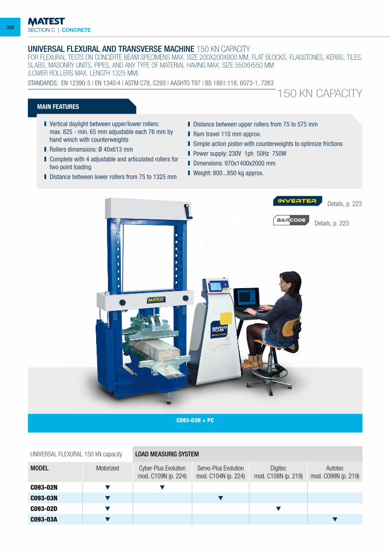
SECTION C | CONCRETE
UNIVERSAL FLEXURAL AND TRANSVERSE MACHINE 150 KN CAPACITYFOR FLEXURAL TESTS ON CONCERTE BEAM SPECIMENS MAX. SIZE 200X200X800 MM, FLAT BLOCKS, FLAGSTONES, KERBS, TILES, SLABS, MASONRY UNITS, PIPES, AND ANY TYPE OF MATERIAL HAVING MAX. SIZE 550XH550 MM(LOWER ROLLERS MAX. LENGTH 1325 MM)STANDARDS: EN 12390-5 | EN 1340:4 | ASTM C78, C293 | AASHTO T97 | BS 1881:118, 6073-1, 7263
150 KN CAPACITY
UNIVERSAL FLEXURAL 150 kN capacity LOAD MEASURIG SYSTEM
MODEL Motorized Cyber-Plus Evolutionmod. C109N (p. 224)
Servo-Plus Evolutionmod. C104N (p. 224)
Digitecmod. C108N (p. 219)
Autotecmod. C098N (p. 219)
C093-02N
C093-03N
C093-02D
C093-03A
MAIN FEATURES
Vertical daylight between upper/lower rollers: max. 825 - min. 65 mm adjustable each 76 mm by
hand winch with counterweights Rollers dimensions: Ø 40x613 mm Complete with 4 adjustable and articulated rollers for
two point loading Distance between lower rollers from 75 to 1325 mm
Distance between upper rollers from 75 to 575 mm Ram travel 110 mm approx. Simple action piston with counterweights to optimize frictions Power supply: 230V 1ph 50Hz 750W Dimensions: 970x1400x2000 mm Weight: 800...850 kg approx.
C093-03N + PC
Details, p. 223
Details, p. 223
inverter
BARCODE
308
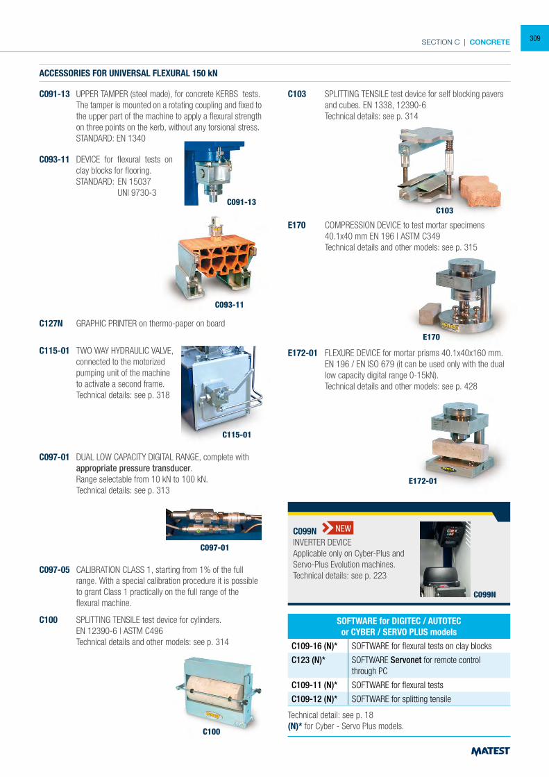
SECTION C | CONCRETE
ACCESSORIES FOR UNIVERSAL FLEXURAL 150 kN
C091-13 UPPER TAMPER (steel made), for concrete KERBS tests. The tamper is mounted on a rotating coupling and fixed to
the upper part of the machine to apply a flexural strength on three points on the kerb, without any torsional stress.
STANDARD: EN 1340
C097-01
C097-01 DUAL LOW CAPACITY DIGITAL RANGE, complete with appropriate pressure transducer.
Range selectable from 10 kN to 100 kN. Technical details: see p. 313
C097-05 CALIBRATION CLASS 1, starting from 1% of the full range. With a special calibration procedure it is possible to grant Class 1 practically on the full range of the flexural machine.
C100
C100 SPLITTING TENSILE test device for cylinders. EN 12390-6 | ASTM C496 Technical details and other models: see p. 314
C103 SPLITTING TENSILE test device for self blocking pavers and cubes. EN 1338, 12390-6
Technical details: see p. 314
C103
Technical detail: see p. 18(N)* for Cyber - Servo Plus models.
SOFTWARE for DIGITEC / AUTOTECor CYBER / SERVO PLUS models
C109-16 (N)* SOFTWARE for flexural tests on clay blocks
C123 (N)* SOFTWARE Servonet for remote control through PC
C109-11 (N)* SOFTWARE for flexural tests
C109-12 (N)* SOFTWARE for splitting tensile
C091-13
C093-11 DEVICE for flexural tests on clay blocks for flooring.
STANDARD: EN 15037 UNI 9730-3
C093-11
C115-01
C115-01 TWO WAY HYDRAULIC VALVE, connected to the motorized pumping unit of the machine to activate a second frame. Technical details: see p. 318
E170
E172-01
E170 COMPRESSION DEVICE to test mortar specimens 40.1x40 mm EN 196 | ASTM C349 Technical details and other models: see p. 315
E172-01 FLEXURE DEVICE for mortar prisms 40.1x40x160 mm. EN 196 / EN ISO 679 (it can be used only with the dual
low capacity digital range 0-15kN). Technical details and other models: see p. 428
C127N GRAPHIC PRINTER on thermo-paper on board
C099N
C099NINVERTER DEVICEApplicable only on Cyber-Plus andServo-Plus Evolution machines.Technical details: see p. 223
NEW
309
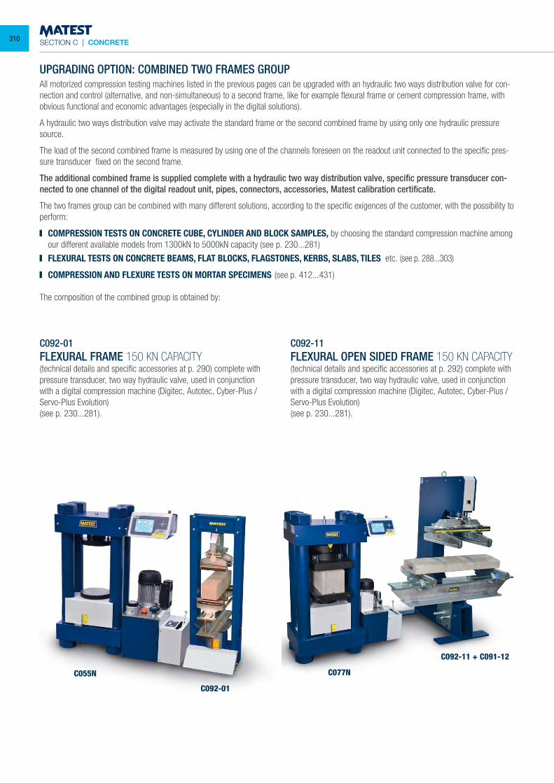
SECTION C | CONCRETE
UPGRADING OPTION: COMBINED TWO FRAMES GROUPAll motorized compression testing machines listed in the previous pages can be upgraded with an hydraulic two ways distribution valve for con-nection and control (alternative, and non-simultaneous) to a second frame, like for example flexural frame or cement compression frame, with obvious functional and economic advantages (especially in the digital solutions).
A hydraulic two ways distribution valve may activate the standard frame or the second combined frame by using only one hydraulic pressure source.
The load of the second combined frame is measured by using one of the channels foreseen on the readout unit connected to the specific pres-sure transducer fixed on the second frame.
The additional combined frame is supplied complete with a hydraulic two way distribution valve, specific pressure transducer con-nected to one channel of the digital readout unit, pipes, connectors, accessories, Matest calibration certificate.
The two frames group can be combined with many different solutions, according to the specific exigences of the customer, with the possibility to perform:
COMPRESSION TESTS ON CONCRETE CUBE, CYLINDER AND BLOCK SAMPLES, by choosing the standard compression machine among our different available models from 1300kN to 5000kN capacity (see p. 230...281)
FLEXURAL TESTS ON CONCRETE BEAMS, FLAT BLOCKS, FLAGSTONES, KERBS, SLABS, TILES etc. (see p. 288...303)
COMPRESSION AND FLEXURE TESTS ON MORTAR SPECIMENS (see p. 412...431)
The composition of the combined group is obtained by:
C092-01FLEXURAL FRAME 150 KN CAPACITY(technical details and specific accessories at p. 290) complete with pressure transducer, two way hydraulic valve, used in conjunction with a digital compression machine (Digitec, Autotec, Cyber-Plus / Servo-Plus Evolution)(see p. 230...281).
C092-11FLEXURAL OPEN SIDED FRAME 150 KN CAPACITY(technical details and specific accessories at p. 292) complete with pressure transducer, two way hydraulic valve, used in conjunction with a digital compression machine (Digitec, Autotec, Cyber-Plus / Servo-Plus Evolution)(see p. 230...281).
C077N
C092-11 + C091-12
C055N
C092-01
310
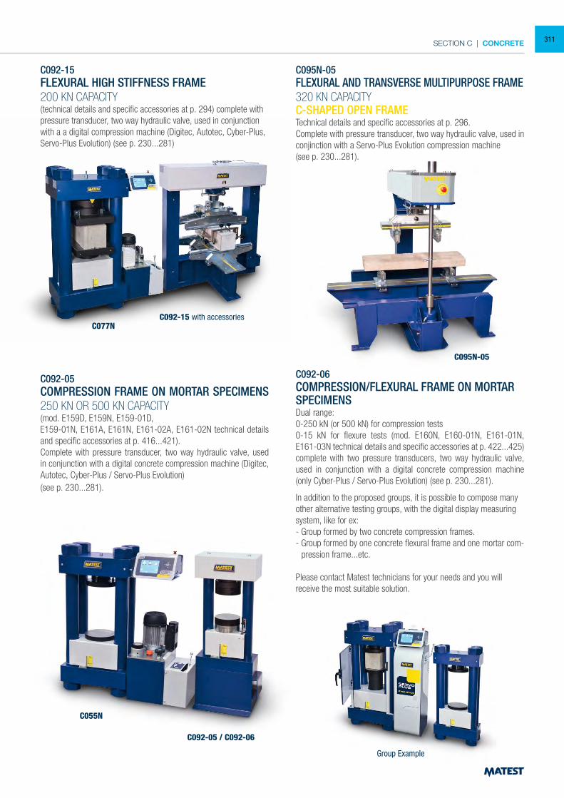
SECTION C | CONCRETE
C092-15FLEXURAL HIGH STIFFNESS FRAME200 KN CAPACITY(technical details and specific accessories at p. 294) complete with pressure transducer, two way hydraulic valve, used in conjunction with a a digital compression machine (Digitec, Autotec, Cyber-Plus, Servo-Plus Evolution) (see p. 230...281)
C095N-05FLEXURAL AND TRANSVERSE MULTIPURPOSE FRAME 320 KN CAPACITYC-SHAPED OPEN FRAMETechnical details and specific accessories at p. 296.Complete with pressure transducer, two way hydraulic valve, used in conjinction with a Servo-Plus Evolution compression machine(see p. 230...281).
C095N-05
C077N
C055N
C092-05 / C092-06
Group Example
C092-15 with accessories
C092-05COMPRESSION FRAME ON MORTAR SPECIMENS
250 KN OR 500 KN CAPACITY(mod. E159D, E159N, E159-01D,E159-01N, E161A, E161N, E161-02A, E161-02N technical details and specific accessories at p. 416...421).Complete with pressure transducer, two way hydraulic valve, used in conjunction with a digital concrete compression machine (Digitec, Autotec, Cyber-Plus / Servo-Plus Evolution)(see p. 230...281).
C092-06COMPRESSION/FLEXURAL FRAME ON MORTAR SPECIMENSDual range:0-250 kN (or 500 kN) for compression tests0-15 kN for flexure tests (mod. E160N, E160-01N, E161-01N, E161-03N technical details and specific accessories at p. 422...425) complete with two pressure transducers, two way hydraulic valve, used in conjunction with a digital concrete compression machine (only Cyber-Plus / Servo-Plus Evolution) (see p. 230...281).
In addition to the proposed groups, it is possible to compose many other alternative testing groups, with the digital display measuring system, like for ex:- Group formed by two concrete compression frames. - Group formed by one concrete flexural frame and one mortar com-
pression frame...etc.
Please contact Matest technicians for your needs and you will receive the most suitable solution.
311
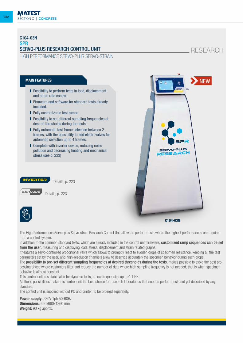
SECTION C | CONCRETE
C104-03NSPRSERVO-PLUS RESEARCH CONTROL UNITHIGH PERFORMANCE SERVO-PLUS SERVO-STRAIN
MAIN FEATURES
Possibility to perform tests in load, displacement and strain rate control.
Firmware and software for standard tests already included.
Fully customizable test ramps. Possibility to set different sampling frequencies at
desired thresholds during the tests. Fully automatic test frame selection between 2
frames, with the possibility to add electrovalves for automatic selection up to 4 frames.
Complete with inverter device, reducing noise pollution and decreasing heating and mechanical stress (see p. 223)
The High Performances Servo-plus Servo-strain Research Control Unit allows to perform tests where the highest performances are required from a control system. In addition to the common standard tests, which are already included in the control unit firmware, customized ramp sequences can be set from the user, measuring and displaying load, stress, displacement and strain related graphs.It features a servo-controlled proportional valve which allows to promptly react to sudden drops of specimen resistance, keeping all the test parameters set by the user, and high-resolution channels allow to describe accurately the specimen behavior during such drops.The possibility to pre-set different sampling frequencies at desired thresholds during the tests, makes possible to avoid the post pro-cessing phase where customers filter and reduce the number of data where high sampling frequency is not needed, that is when specimen behavior is almost constant.This control unit is suitable also for dynamic tests, at low frequencies up to 0.1 Hz.All these possibilities make this control unit the best choice for research laboratories that need to perform tests not yet described by any standard. The control unit is supplied without PC and printer, to be ordered separately.
Power supply: 230V 1ph 50-60HzDimensions: 650x660x1260 mmWeight: 90 kg approx.
NEW
C104-03N
Details, p. 223
Details, p. 223
inverter
BARCODE
RESEARCH
312
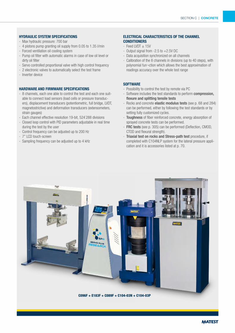
SECTION C | CONCRETE
HYDRAULIC SYSTEM SPECIFICATIONS- Max hydraulic pressure: 700 bar- 4 pistons pump granting oil supply from 0.05 to 1.35 l/min- Forced ventilation oil cooling system- Pump oil filter with automatic alarms in case of low oil level or
dirty oil filter- Servo controlled proportional valve with high control frequency- 2 electronic valves to automatically select the test frame - Inverter device
HARDWARE AND FIRMWARE SPECIFICATIONS- 8 channels, each one able to control the test and each one suit-
able to connect load sensors (load cells or pressure transduc-ers), displacement transducers (potentiometric, full bridge, LVDT, magnetostrictive) and deformation transducers (extensometers, strain gauges)
- Each channel effective resolution 19-bit, 524˙288 divisions- Closed loop control with PID parameters adjustable in real time
during the test by the user- Control frequency can be adjusted up to 200 Hz- 7” LCD touch-screen - Sampling frequency can be adjusted up to 4 kHz
ELECTRICAL CHARACTERISTICS OF THE CHANNELCONDITIONERS - Feed LVDT ± 15V - Output signal from -2.5 to +2.5V DC - Data acquisition synchronized on all channels - Calibration of the 8 channels in divisions (up to 40 steps), with
polynomial fun¬ction which allows the best approximation of readings accuracy over the whole test range
SOFTWARE- Possibility to control the test by remote via PC- Software includes the test standards to perform compression,
flexure and splitting tensile tests- Rocks and concrete elastic modulus tests (see p. 68 and 284)
can be performed, either by following the test standards or by setting fully customized cycles.
- Toughness of fiber reinforced concrete, energy absorption of sprayed concrete tests can be performed.
- FRC tests (see p. 305) can be performed (Deflection, CMOD, CTOD and flexural strength).
- Triaxial test on rocks and Stress-path test procedure, if completed with C104NLP system for the lateral pressure appli-cation and it is accessories listed at p. 70.
C096F + E183F + C089F + C104-03N + C104-03P
1
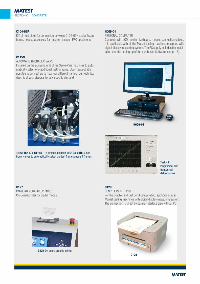
SECTION C | CONCRETE
C104-03PKIT of rigid pipes for connection between C104-03N and a flexure frame, needed accessory for research tests on FRC specimens.
C115NAUTOMATIC HYDRAULIC VALVEInstalled on the pumping unit of the Servo-Plus machines to auto-matically select one additional testing frame. Upon request, it is possible to connect up to max four different frames. Our technical dept. is at your disposal for any specific demand.
4 x C115N (2 x C115N + 2 already included in C104-03N) 4 elec-tronic valves to automatically select the test frame among 4 frames
H009-01PERSONAL COMPUTERComplete with LCD monitor, keyboard, mouse, connection cables, it is applicable with all the Matest testing machines equipped with digital display measuring system. The PC supply includes the instal-lation and the setting up of the purchased Software (see p. 18).
C128BENCH LASER PRINTERFor the graphic and test certificate printing, applicable on all Matest testing machines with digital display measuring system. The connection is direct by parallel interface also without PC.
C127ON-BOARD GRAPHIC PRINTEROn-Board printer for digital models.
H009-01
C128C127 On board graphic printer
Test withlongitudinal and transversaldeformations
2
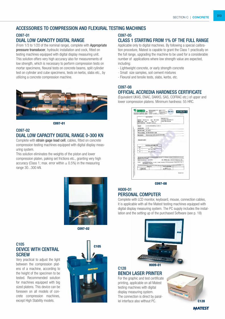
SECTION C | CONCRETE
ACCESSORIES TO COMPRESSION AND FLEXURAL TESTING MACHINESC097-01DUAL LOW CAPACITY DIGITAL RANGE(From 1/3 to 1/20 of the nominal range), complete with Appropriate pressure transducer, hydraulic installation and cock, fitted on testing machines equipped with digital display measuring unit.This solution offers very high accuracy also for measurements of low strength, which is necessary to perform compression tests on mortar specimens, flexural tests on concrete beams, split cylinder test on cylinder and cube specimens, tests on kerbs, slabs etc., by utilizing a concrete compression machine.
C097-02DUAL LOW CAPACITY DIGITAL RANGE 0-300 KN Complete with strain gage load cell, cables, fitted on concrete compression testing machines equipped with digital display meas-uring system.This solution eliminates the weights of the piston and lower compression platen, paking set frictions etc., granting very high accuracy (Class 1; max. error within ± 0.5%) in the measuring range 30...300 kN.
C097-01
C097-08
H009-01
C128
C097-02
C105C105DEVICE WITH CENTRAL SCREWVery practical to adjust the light between the compression plat-ens of a machine, according to the height of the specimen to be tested. Recommended solution for machines equipped with big sized platens. This device can be foreseen on all models of con-crete compression machines, except High Stability models.
C097-05CLASS 1 STARTING FROM 1% OF THE FULL RANGEApplicable only to digital machines. By following a special calibra-tion procedure, Matest is capable to grant the Class 1 practically on the full range, upgrading the machine to be used for a considerable number of applications where low strength value are expected, including:- Lightweight concrete, or early strength concrete- Small size samples, soil cement mixtures- Flexural and tensile tests, slabs, kerbs, etc.
C097-08OFFICIAL ACCREDIA HARDNESS CERTIFICATE(Equivalent UKAS, ENAC, DAKKS, SAS, COFRAC etc.) of upper and lower compression platens. Minimum hardness: 55 HRC.
H009-01PERSONAL COMPUTERComplete with LCD monitor, keyboard, mouse, connection cables, it is applicable with all the Matest testing machines equipped with digital display measuring system. The PC supply includes the instal-lation and the setting up of the purchased Software (see p. 18)
C128BENCH LASER PRINTER For the graphic and test certificate printing, applicable on all Matest testing machines with digital display measuring system.The connection is direct by paral-lel interface also without PC.
313
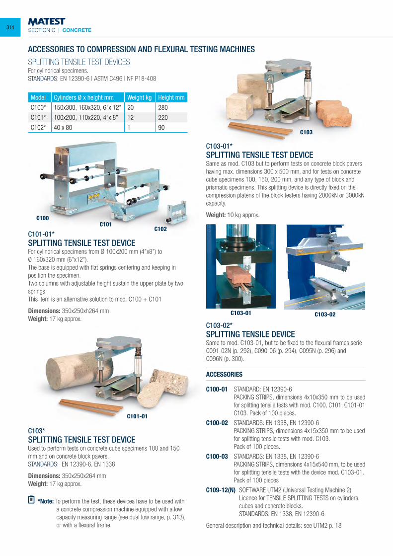
SECTION C | CONCRETE
SPLITTING TENSILE TEST DEVICESFor cylindrical specimens.STANDARDS: EN 12390-6 | ASTM C496 | NF P18-408
ACCESSORIES TO COMPRESSION AND FLEXURAL TESTING MACHINES
Model Cylinders Ø x height mm Weight kg Height mm
C100* 150x300, 160x320, 6”x 12” 20 280
C101* 100x200, 110x220, 4”x 8” 12 220
C102* 40 x 80 1 90
C101-01*SPLITTING TENSILE TEST DEVICEFor cylindrical specimens from Ø 100x200 mm (4”x8”) toØ 160x320 mm (6”x12”).The base is equipped with flat springs centering and keeping in position the specimen.Two columns with adjustable height sustain the upper plate by two springs.This item is an alternative solution to mod. C100 + C101
Dimensions: 350x250xh264 mmWeight: 17 kg approx.
C103*SPLITTING TENSILE TEST DEVICEUsed to perform tests on concrete cube specimens 100 and 150 mm and on concrete block pavers. STANDARDS: EN 12390-6, EN 1338
Dimensions: 350x250x264 mmWeight: 17 kg approx.
*Note: To perform the test, these devices have to be used with a concrete compression machine equipped with a low capacity measuring range (see dual low range, p. 313), or with a flexural frame.
C103-01*SPLITTING TENSILE TEST DEVICESame as mod. C103 but to perform tests on concrete block pavers having max. dimensions 300 x 500 mm, and for tests on concrete cube specimens 100, 150, 200 mm, and any type of block and prismatic specimens. This splitting device is directly fixed on the compression platens of the block testers having 2000kN or 3000kN capacity.
Weight: 10 kg approx.
C103-02*SPLITTING TENSILE DEVICESame to mod. C103-01, but to be fixed to the flexural frames serieC091-02N (p. 292), C090-06 (p. 294), C095N (p. 296) andC096N (p. 300).
ACCESSORIES
C100-01 STANDARD: EN 12390-6 PACKING STRIPS, dimensions 4x10x350 mm to be used
for splitting tensile tests with mod. C100, C101, C101-01 C103. Pack of 100 pieces.
C100-02 STANDARDS: EN 1338, EN 12390-6 PACKING STRIPS, dimensions 4x15x350 mm to be used
for splitting tensile tests with mod. C103. Pack of 100 pieces.
C100-03 STANDARDS: EN 1338, EN 12390-6 PACKING STRIPS, dimensions 4x15x540 mm, to be used
for splitting tensile tests with the device mod. C103-01. Pack of 100 pieces
C109-12(N) SOFTWARE UTM2 (Universal Testing Machine 2) Licence for TENSILE SPLITTING TESTS on cylinders,
cubes and concrete blocks. STANDARDS: EN 1338, EN 12390-6
General description and technical details: see UTM2 p. 18
C100C101
C101-01
C103
C103-01 C103-02
C102
314
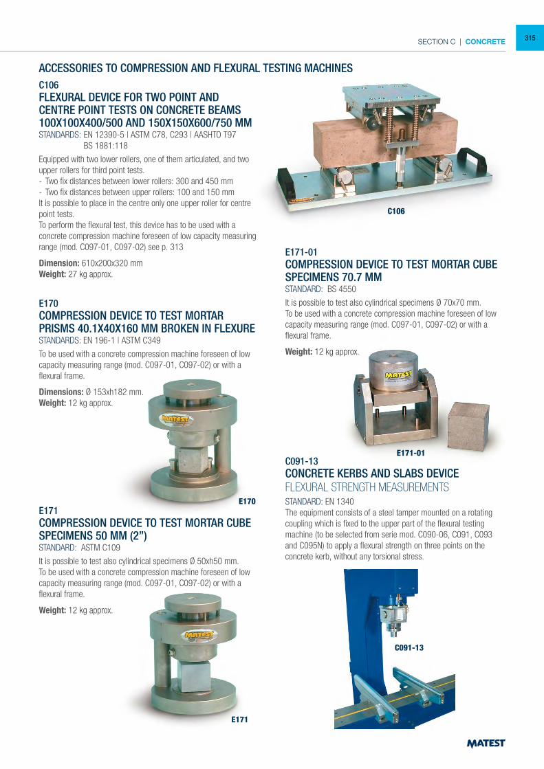
SECTION C | CONCRETE
ACCESSORIES TO COMPRESSION AND FLEXURAL TESTING MACHINESC106FLEXURAL DEVICE FOR TWO POINT AND CENTRE POINT TESTS ON CONCRETE BEAMS 100X100X400/500 AND 150X150X600/750 MMSTANDARDS: EN 12390-5 | ASTM C78, C293 | AASHTO T97 BS 1881:118
Equipped with two lower rollers, one of them articulated, and two upper rollers for third point tests.- Two fix distances between lower rollers: 300 and 450 mm- Two fix distances between upper rollers: 100 and 150 mmIt is possible to place in the centre only one upper roller for centre point tests.To perform the flexural test, this device has to be used with a concrete compression machine foreseen of low capacity measuring range (mod. C097-01, C097-02) see p. 313
Dimension: 610x200x320 mmWeight: 27 kg approx.
E170COMPRESSION DEVICE TO TEST MORTAR PRISMS 40.1X40X160 MM BROKEN IN FLEXURESTANDARDS: EN 196-1 | ASTM C349
To be used with a concrete compression machine foreseen of low capacity measuring range (mod. C097-01, C097-02) or with a flexural frame.
Dimensions: Ø 153xh182 mm. Weight: 12 kg approx.
E171COMPRESSION DEVICE TO TEST MORTAR CUBE SPECIMENS 50 MM (2”)STANDARD: ASTM C109
It is possible to test also cylindrical specimens Ø 50xh50 mm.To be used with a concrete compression machine foreseen of low capacity measuring range (mod. C097-01, C097-02) or with a flexural frame.
Weight: 12 kg approx.
E171-01COMPRESSION DEVICE TO TEST MORTAR CUBE SPECIMENS 70.7 MMSTANDARD: BS 4550
It is possible to test also cylindrical specimens Ø 70x70 mm.To be used with a concrete compression machine foreseen of low capacity measuring range (mod. C097-01, C097-02) or with a flexural frame.
Weight: 12 kg approx.
C091-13CONCRETE KERBS AND SLABS DEVICEFLEXURAL STRENGTH MEASUREMENTSSTANDARD: EN 1340The equipment consists of a steel tamper mounted on a rotating coupling which is fixed to the upper part of the flexural testing machine (to be selected from serie mod. C090-06, C091, C093 and C095N) to apply a flexural strength on three points on the concrete kerb, without any torsional stress.
E170
E171
C106
E171-01
C091-13
315
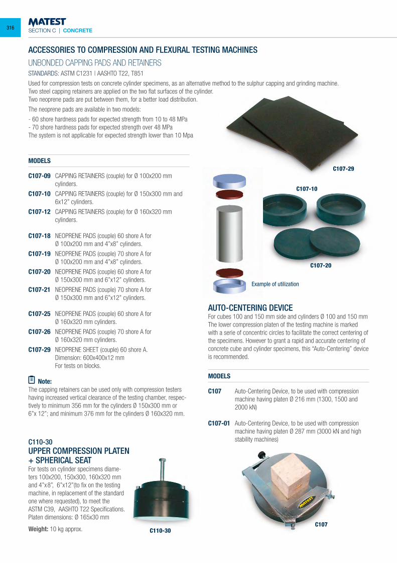
SECTION C | CONCRETE
ACCESSORIES TO COMPRESSION AND FLEXURAL TESTING MACHINESUNBONDED CAPPING PADS AND RETAINERSSTANDARDS: ASTM C1231 | AASHTO T22, T851
Used for compression tests on concrete cylinder specimens, as an alternative method to the sulphur capping and grinding machine.Two steel capping retainers are applied on the two flat surfaces of the cylinder. Two neoprene pads are put between them, for a better load distribution.
The neoprene pads are available in two models:
- 60 shore hardness pads for expected strength from 10 to 48 MPa- 70 shore hardness pads for expected strength over 48 MPaThe system is not applicable for expected strength lower than 10 Mpa
MODELS
C107-09 CAPPING RETAINERS (couple) for Ø 100x200 mm cylinders.
C107-10 CAPPING RETAINERS (couple) for Ø 150x300 mm and 6x12” cylinders.
C107-12 CAPPING RETAINERS (couple) for Ø 160x320 mm cylinders.
C107-18 NEOPRENE PADS (couple) 60 shore A for Ø 100x200 mm and 4”x8” cylinders.
C107-19 NEOPRENE PADS (couple) 70 shore A for Ø 100x200 mm and 4”x8” cylinders.
C107-20 NEOPRENE PADS (couple) 60 shore A for Ø 150x300 mm and 6”x12” cylinders.
C107-21 NEOPRENE PADS (couple) 70 shore A for Ø 150x300 mm and 6”x12” cylinders.
C107-25 NEOPRENE PADS (couple) 60 shore A for Ø 160x320 mm cylinders.
C107-26 NEOPRENE PADS (couple) 70 shore A for Ø 160x320 mm cylinders.
C107-29 NEOPRENE SHEET (couple) 60 shore A. Dimension: 600x400x12 mm For tests on blocks.
Note:The capping retainers can be used only with compression testers having increased vertical clearance of the testing chamber, respec-tively to minimum 356 mm for the cylinders Ø 150x300 mm or6”x 12”; and minimum 376 mm for the cylinders Ø 160x320 mm.
C110-30UPPER COMPRESSION PLATEN + SPHERICAL SEATFor tests on cylinder specimens diame-ters 100x200, 150x300, 160x320 mm and 4”x8”, 6”x12”(to fix on the testing machine, in replacement of the standard one where requested), to meet theASTM C39, AASHTO T22 Specifications.Platen dimensions: Ø 165x30 mm
Weight: 10 kg approx.
AUTO-CENTERING DEVICEFor cubes 100 and 150 mm side and cylinders Ø 100 and 150 mmThe lower compression platen of the testing machine is marked with a serie of concentric circles to facilitate the correct centering of the specimens. However to grant a rapid and accurate centering of concrete cube and cylinder specimens, this “Auto-Centering” device is recommended.
MODELS
C107 Auto-Centering Device, to be used with compression machine having platen Ø 216 mm (1300, 1500 and 2000 kN)
C107-01 Auto-Centering Device, to be used with compression machine having platen Ø 287 mm (3000 kN and high stability machines)
C107-29
C107-10
C107-20
C107C110-30
Example of utilization
316
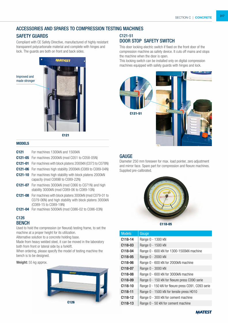
SECTION C | CONCRETE
C121
ACCESSORIES AND SPARES TO COMPRESSION TESTING MACHINES
C121-51
SAFETY GUARDSCompliant with CE Safety Directive, manufactured of highly resistant transparent polycarbonate material and complete with hinges and lock. The guards are both on front and back sides.
MODELS
C121 For machines 1300kN and 1500kN
C121-05 For machines 2000kN (mod C051 to C058-05N)
C121-01 For machines with block platens 2000kN (C073 to C078N)
C121-06 For machines high stability 2000kN (C089 to C089-04N)
C121-10 For machines high stability with block platens 2000kN capacity (mod C089B to C089-22N)
C121-07 For machines 3000kN (mod C066 to C071N) and high stability 3000kN (mod C089-06 to C089-10N)
C121-08 For machines with block platens 3000kN (mod C079-01 to C079-06N) and high stability with block platens 3000kN (C089-15 to C089-19N)
C121-04 For machines 5000kN (mod C086-02 to C086-03N)
C126BENCHUsed to hold the compression (or flexural) testing frame, to set the machine at a proper height for its utilization.Alternative solution to a concrete holding base.Made from heavy welded steel, it can be moved in the laboratory both from front or lateral side by a forklift.When ordering, please specify the model of testing machine the bench is to be designed.
Weight: 55 kg approx.
C121-51DOOR STOP SAFETY SWITCHThis door locking electric switch if fixed on the front door of the compression machine as safety device. It cuts off mains and stops the machine when the door is open.This locking switch can be installed only on digital compression machines equipped with safety guards with hinges and lock.
Models Gauge
C118-14 Range 0 - 1300 kN
C118-03 Range 0 - 1500 kN
C118-04 Range 0 - 600 kN for 1300-1500kN machine
C118-05 Range 0 - 2000 kN
C118-06 Range 0 - 600 kN for 2000kN machine
C118-07 Range 0 - 3000 kN
C118-08 Range 0 - 600 kN for 3000kN machine
C118-09 Range 0 - 150 kN for flexure press C090 serie
C118-10 Range 0 - 150 kN for flexure press C091, C093 serie
C118-11 Range 0 - 1500 kN for tensile press H010
C118-12 Range 0 - 300 kN for cement machine
C118-13 Range 0 - 50 kN for cement machine
GAUGE Diameter 250 mm foreseen for max. load pointer, zero adjustment and mirror face. Spare part for compression and flexure machines. Supplied pre-calibrated.
C118-05
C126
Improved andmade stronger
317
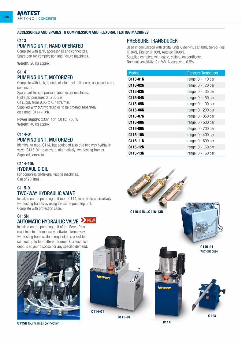
SECTION C | CONCRETE
C113PUMPING UNIT, HAND OPERATEDComplete with tank, accessories and connectors.Spare part for compression and flexure machines.
Weight: 20 kg approx.
C114PUMPING UNIT, MOTORIZEDComplete with tank, speed selector, hydraulic cock, accessories and connectors.Spare part for compression and flexure machines.Hydraulic pressure: 0...700 BarOil supply from 0.05 to 0.7 litre/min.Supplied without hydraulic oil to be ordered separately(see mod. C114-10N).
Power supply: 230V 1ph 50 Hz 750 WWeight: 40 kg approx.
C114-01PUMPING UNIT, MOTORIZEDIdentical to mod. C114, but equipped also of a two way hydraulic valve (C115-01) to activate, alternatively, two testing frames.Supplied complete.
C114-10NHYDRAULIC OILFor compression/flexural testing machines.Can of 20 litres.
C115-01TWO-WAY HYDRAULIC VALVEInstalled on the pumping unit mod. C114, to activate alternatively two testing frames by using the same pumping unit.Complete with protection case.
PRESSURE TRANSDUCERUsed in conjunction with digital units Cyber-Plus C109N, Servo-Plus C104N, Digitec C108N, Autotec C098N.Supplied complete with cable, calibration certificate.Nominal sensitivity: 2 mV/V. Accuracy: ± 0.5%
Models Pressure Transducer
C116-01N range: 0 - 10 bar
C116-02N range: 0 - 20 bar
C116-03N range: 0 - 35 bar
C116-04N range: 0 - 50 bar
C116-05N range: 0 - 100 bar
C116-06N range: 0 - 200 bar
C116-07N range: 0 - 350 bar
C116-08N range: 0 - 500 bar
C116-09N range: 0 - 700 bar
C116-10N range: 0 - 400 bar
C116-11N range: 0 - 600 bar
C116-12N range: 0 - 160 bar
C116-13N range: 0 - 60 bar
C116-01N...C116-13N
ACCESSORIES AND SPARES TO COMPRESSION AND FLEXURAL TESTING MACHINES
C114-01
C115N four frames connection
C115-01C114
C113
NEWC115NAUTOMATIC HYDRAULIC VALVEInstalled on the pumping unit of the Servo-Plus machines to automatically activate alternatively two testing frames. Upon request, it is possible to connect up to four different frames. Our technical dept. is at your disposal for any specific demand. C115-01
Without case
318
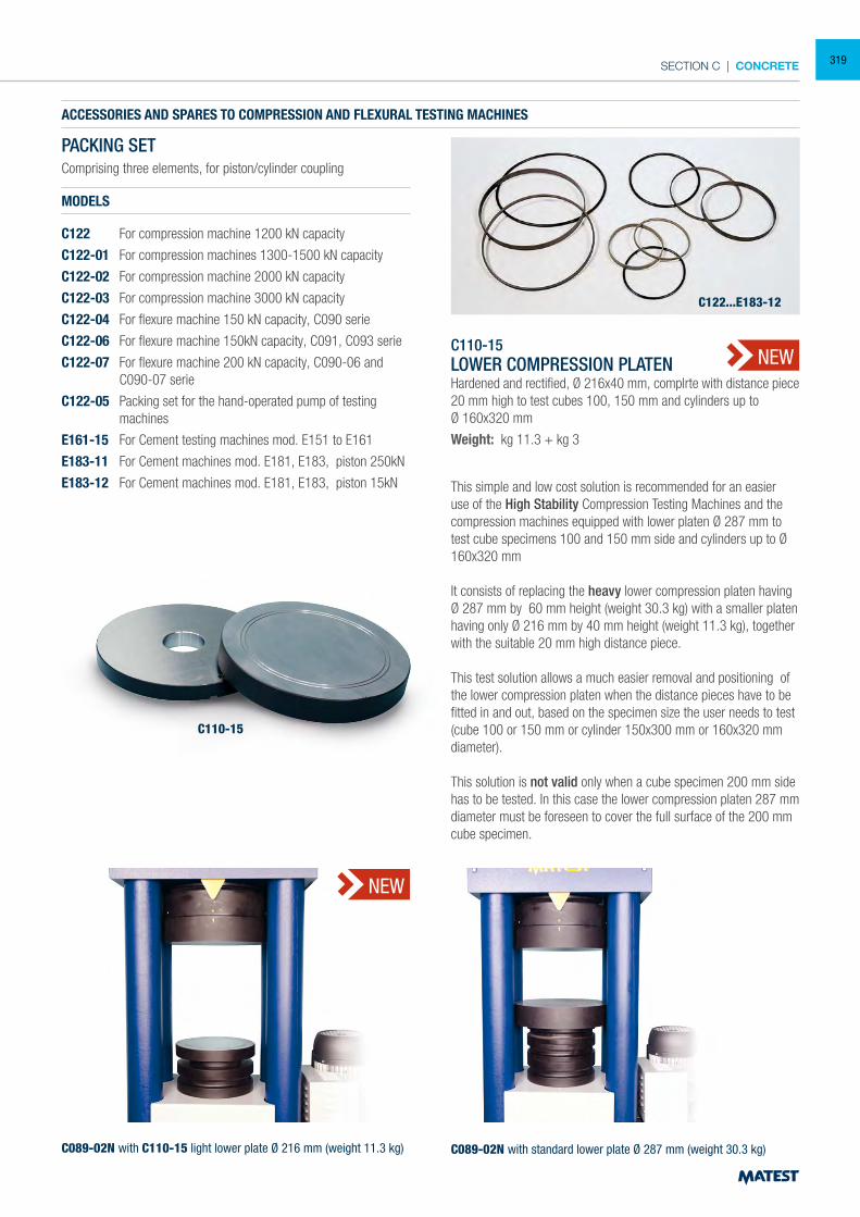
SECTION C | CONCRETE
ACCESSORIES AND SPARES TO COMPRESSION AND FLEXURAL TESTING MACHINES
PACKING SETComprising three elements, for piston/cylinder coupling
MODELS
C122 For compression machine 1200 kN capacity
C122-01 For compression machines 1300-1500 kN capacity
C122-02 For compression machine 2000 kN capacity
C122-03 For compression machine 3000 kN capacity
C122-04 For flexure machine 150 kN capacity, C090 serie
C122-06 For flexure machine 150kN capacity, C091, C093 serie
C122-07 For flexure machine 200 kN capacity, C090-06 and C090-07 serie
C122-05 Packing set for the hand-operated pump of testing machines
E161-15 For Cement testing machines mod. E151 to E161
E183-11 For Cement machines mod. E181, E183, piston 250kN
E183-12 For Cement machines mod. E181, E183, piston 15kN
C122...E183-12
C110-15LOWER COMPRESSION PLATENHardened and rectified, Ø 216x40 mm, complrte with distance piece 20 mm high to test cubes 100, 150 mm and cylinders up toØ 160x320 mm
Weight: kg 11.3 + kg 3
This simple and low cost solution is recommended for an easier use of the High Stability Compression Testing Machines and the compression machines equipped with lower platen Ø 287 mm to test cube specimens 100 and 150 mm side and cylinders up to Ø 160x320 mm It consists of replacing the heavy lower compression platen having Ø 287 mm by 60 mm height (weight 30.3 kg) with a smaller platen having only Ø 216 mm by 40 mm height (weight 11.3 kg), together with the suitable 20 mm high distance piece. This test solution allows a much easier removal and positioning of the lower compression platen when the distance pieces have to be fitted in and out, based on the specimen size the user needs to test (cube 100 or 150 mm or cylinder 150x300 mm or 160x320 mm diameter). This solution is not valid only when a cube specimen 200 mm side has to be tested. In this case the lower compression platen 287 mm diameter must be foreseen to cover the full surface of the 200 mm cube specimen.
C089-02N with C110-15 light lower plate Ø 216 mm (weight 11.3 kg) C089-02N with standard lower plate Ø 287 mm (weight 30.3 kg)
C110-15
NEW
NEW
319
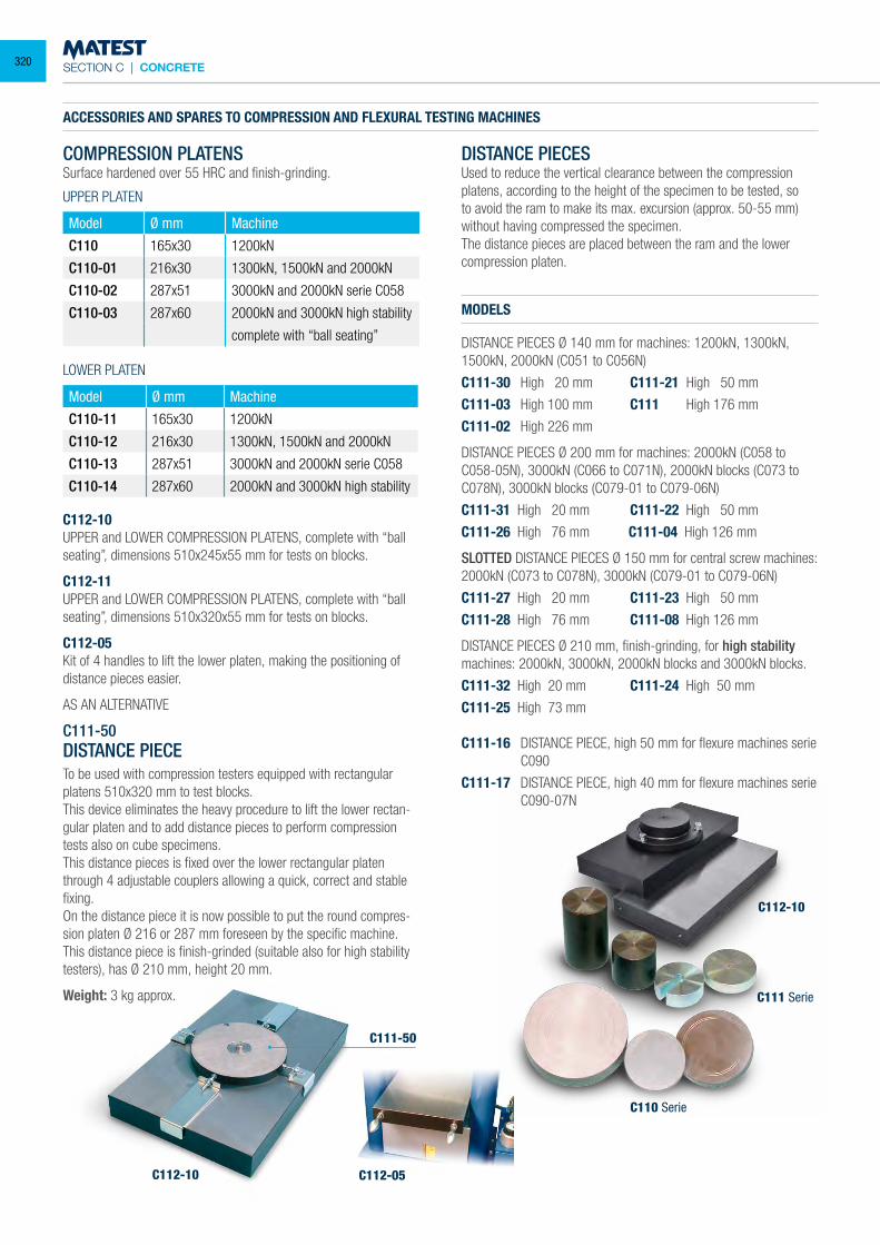
SECTION C | CONCRETE
COMPRESSION PLATENSSurface hardened over 55 HRC and finish-grinding.
UPPER PLATEN
Model Ø mm Machine
C110 165x30 1200kN
C110-01 216x30 1300kN, 1500kN and 2000kN
C110-02 287x51 3000kN and 2000kN serie C058
C110-03 287x60 2000kN and 3000kN high stability
complete with “ball seating”
LOWER PLATEN
Model Ø mm Machine
C110-11 165x30 1200kN
C110-12 216x30 1300kN, 1500kN and 2000kN
C110-13 287x51 3000kN and 2000kN serie C058
C110-14 287x60 2000kN and 3000kN high stability
C112-10UPPER and LOWER COMPRESSION PLATENS, complete with “ball seating”, dimensions 510x245x55 mm for tests on blocks.
C112-11UPPER and LOWER COMPRESSION PLATENS, complete with “ball seating”, dimensions 510x320x55 mm for tests on blocks.
C112-05Kit of 4 handles to lift the lower platen, making the positioning of distance pieces easier.
AS AN ALTERNATIVE
C111-50 DISTANCE PIECE To be used with compression testers equipped with rectangular platens 510x320 mm to test blocks. This device eliminates the heavy procedure to lift the lower rectan-gular platen and to add distance pieces to perform compression tests also on cube specimens. This distance pieces is fixed over the lower rectangular platen through 4 adjustable couplers allowing a quick, correct and stable fixing. On the distance piece it is now possible to put the round compres-sion platen Ø 216 or 287 mm foreseen by the specific machine. This distance piece is finish-grinded (suitable also for high stability testers), has Ø 210 mm, height 20 mm.
Weight: 3 kg approx.
MODELS
DISTANCE PIECES Ø 140 mm for machines: 1200kN, 1300kN, 1500kN, 2000kN (C051 to C056N)
C111-30 High 20 mm C111-21 High 50 mm
C111-03 High 100 mm C111 High 176 mm
C111-02 High 226 mm
DISTANCE PIECES Ø 200 mm for machines: 2000kN (C058 to C058-05N), 3000kN (C066 to C071N), 2000kN blocks (C073 to C078N), 3000kN blocks (C079-01 to C079-06N)
C111-31 High 20 mm C111-22 High 50 mm
C111-26 High 76 mm C111-04 High 126 mm
SLOTTED DISTANCE PIECES Ø 150 mm for central screw machines: 2000kN (C073 to C078N), 3000kN (C079-01 to C079-06N)
C111-27 High 20 mm C111-23 High 50 mm
C111-28 High 76 mm C111-08 High 126 mm
DISTANCE PIECES Ø 210 mm, finish-grinding, for high stability machines: 2000kN, 3000kN, 2000kN blocks and 3000kN blocks.
C111-32 High 20 mm C111-24 High 50 mm
C111-25 High 73 mm
C111-16 DISTANCE PIECE, high 50 mm for flexure machines serie C090
C111-17 DISTANCE PIECE, high 40 mm for flexure machines serie C090-07N
C112-10
C111 Serie
C110 Serie
C112-05
DISTANCE PIECESUsed to reduce the vertical clearance between the compression platens, according to the height of the specimen to be tested, so to avoid the ram to make its max. excursion (approx. 50-55 mm) without having compressed the specimen.The distance pieces are placed between the ram and the lower compression platen.
C112-10
C111-50
ACCESSORIES AND SPARES TO COMPRESSION AND FLEXURAL TESTING MACHINES
320
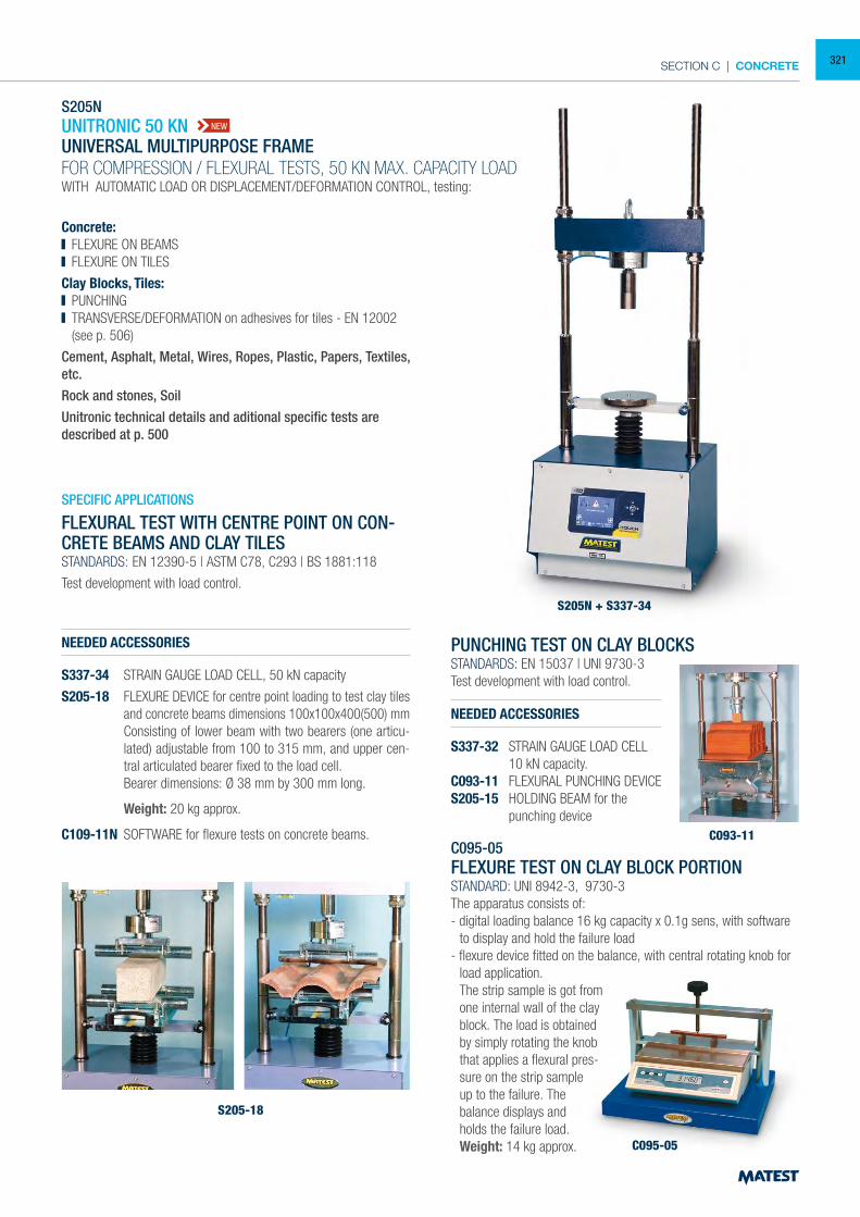
SECTION C | CONCRETE
S205N + S337-34
C093-11
S205-18
C095-05
S205NUNITRONIC 50 KNUNIVERSAL MULTIPURPOSE FRAME FOR COMPRESSION / FLEXURAL TESTS, 50 KN MAX. CAPACITY LOADWITH AUTOMATIC LOAD OR DISPLACEMENT/DEFORMATION CONTROL, testing:
Concrete: FLEXURE ON BEAMS FLEXURE ON TILES
Clay Blocks, Tiles: PUNCHING TRANSVERSE/DEFORMATION on adhesives for tiles - EN 12002 (see p. 506)
Cement, Asphalt, Metal, Wires, Ropes, Plastic, Papers, Textiles, etc.Rock and stones, SoilUnitronic technical details and aditional specific tests are described at p. 500
SPECIFIC APPLICATIONS
FLEXURAL TEST WITH CENTRE POINT ON CON-CRETE BEAMS AND CLAY TILESSTANDARDS: EN 12390-5 | ASTM C78, C293 | BS 1881:118
Test development with load control.
NEEDED ACCESSORIES
S337-34 STRAIN GAUGE LOAD CELL, 50 kN capacity
S205-18 FLEXURE DEVICE for centre point loading to test clay tiles and concrete beams dimensions 100x100x400(500) mm
Consisting of lower beam with two bearers (one articu-lated) adjustable from 100 to 315 mm, and upper cen-tral articulated bearer fixed to the load cell.
Bearer dimensions: Ø 38 mm by 300 mm long.
Weight: 20 kg approx.
C109-11N SOFTWARE for flexure tests on concrete beams.
PUNCHING TEST ON CLAY BLOCKSSTANDARDS: EN 15037 | UNI 9730-3Test development with load control.
NEEDED ACCESSORIES
S337-32 STRAIN GAUGE LOAD CELL 10 kN capacity.C093-11 FLEXURAL PUNCHING DEVICES205-15 HOLDING BEAM for the punching device
C095-05FLEXURE TEST ON CLAY BLOCK PORTIONSTANDARD: UNI 8942-3, 9730-3The apparatus consists of:- digital loading balance 16 kg capacity x 0.1g sens, with software
to display and hold the failure load - flexure device fitted on the balance, with central rotating knob for
load application. The strip sample is got from
one internal wall of the clay block. The load is obtained by simply rotating the knob that applies a flexural pres-sure on the strip sample up to the failure. The balance displays and holds the failure load.
Weight: 14 kg approx.
NEW
321
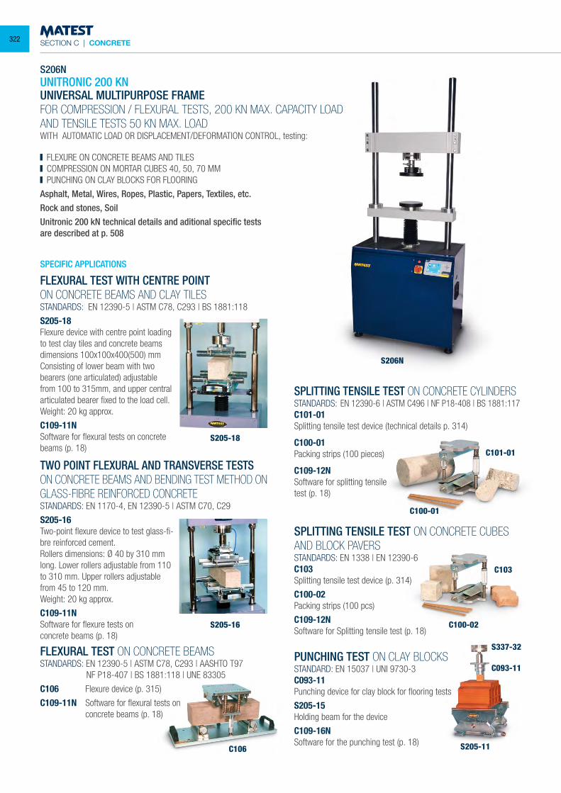
SECTION C | CONCRETE
S206NUNITRONIC 200 KNUNIVERSAL MULTIPURPOSE FRAME FOR COMPRESSION / FLEXURAL TESTS, 200 KN MAX. CAPACITY LOADAND TENSILE TESTS 50 KN MAX. LOADWITH AUTOMATIC LOAD OR DISPLACEMENT/DEFORMATION CONTROL, testing:
FLEXURE ON CONCRETE BEAMS AND TILES COMPRESSION ON MORTAR CUBES 40, 50, 70 MM PUNCHING ON CLAY BLOCKS FOR FLOORING
Asphalt, Metal, Wires, Ropes, Plastic, Papers, Textiles, etc.Rock and stones, SoilUnitronic 200 kN technical details and aditional specific tests are described at p. 508
FLEXURAL TEST WITH CENTRE POINTON CONCRETE BEAMS AND CLAY TILESSTANDARDS: EN 12390-5 | ASTM C78, C293 | BS 1881:118
S205-18Flexure device with centre point loading to test clay tiles and concrete beams dimensions 100x100x400(500) mmConsisting of lower beam with two bearers (one articulated) adjustable from 100 to 315mm, and upper central articulated bearer fixed to the load cell. Weight: 20 kg approx.
C109-11NSoftware for flexural tests on concrete beams (p. 18)
S205-18
S206N
S205-16
TWO POINT FLEXURAL AND TRANSVERSE TESTSON CONCRETE BEAMS AND BENDING TEST METHOD ON GLASS-FIBRE REINFORCED CONCRETESTANDARDS: EN 1170-4, EN 12390-5 | ASTM C70, C29
S205-16Two-point flexure device to test glass-fi-bre reinforced cement.Rollers dimensions: Ø 40 by 310 mm long. Lower rollers adjustable from 110 to 310 mm. Upper rollers adjustable from 45 to 120 mm.Weight: 20 kg approx.
C109-11NSoftware for flexure tests onconcrete beams (p. 18)
FLEXURAL TEST ON CONCRETE BEAMSSTANDARDS: EN 12390-5 | ASTM C78, C293 | AASHTO T97 NF P18-407 | BS 1881:118 | UNE 83305
C106 Flexure device (p. 315)
C109-11N Software for flexural tests on concrete beams (p. 18)
C106
SPLITTING TENSILE TEST ON CONCRETE CYLINDERSSTANDARDS: EN 12390-6 | ASTM C496 | NF P18-408 | BS 1881:117C101-01Splitting tensile test device (technical details p. 314)
C100-01Packing strips (100 pieces)
C109-12NSoftware for splitting tensiletest (p. 18)
SPLITTING TENSILE TEST ON CONCRETE CUBES AND BLOCK PAVERSSTANDARDS: EN 1338 | EN 12390-6C103Splitting tensile test device (p. 314)
C100-02Packing strips (100 pcs)
C109-12NSoftware for Splitting tensile test (p. 18)
PUNCHING TEST ON CLAY BLOCKSSTANDARD: EN 15037 | UNI 9730-3C093-11Punching device for clay block for flooring tests
S205-15Holding beam for the device
C109-16NSoftware for the punching test (p. 18)
C100-01
C100-02
C103
S337-32
C093-11
S205-11
C101-01
SPECIFIC APPLICATIONS
322
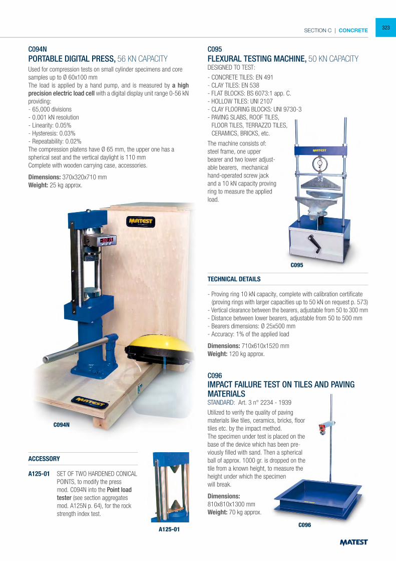
SECTION C | CONCRETE
C094NPORTABLE DIGITAL PRESS, 56 KN CAPACITYUsed for compression tests on small cylinder specimens and core samples up to Ø 60x100 mmThe load is applied by a hand pump, and is measured by a high precision electric load cell with a digital display unit range 0-56 kNproviding:- 65,000 divisions- 0.001 kN resolution- Linearity: 0.05%- Hysteresis: 0.03%- Repeatability: 0.02%The compression platens have Ø 65 mm, the upper one has a spherical seat and the vertical daylight is 110 mmComplete with wooden carrying case, accessories.
Dimensions: 370x320x710 mm Weight: 25 kg approx.
ACCESSORY
A125-01 SET OF TWO HARDENED CONICAL POINTS, to modify the press mod. C094N into the Point load tester (see section aggregates mod. A125N p. 64), for the rock strength index test.
C095FLEXURAL TESTING MACHINE, 50 KN CAPACITYDESIGNED TO TEST:
- CONCRETE TILES: EN 491- CLAY TILES: EN 538- FLAT BLOCKS: BS 6073:1 app. C.- HOLLOW TILES: UNI 2107- CLAY FLOORING BLOCKS: UNI 9730-3- PAVING SLABS, ROOF TILES, FLOOR TILES, TERRAZZO TILES, CERAMICS, BRICKS, etc.
TECHNICAL DETAILS
- Proving ring 10 kN capacity, complete with calibration certificate (proving rings with larger capacities up to 50 kN on request p. 573)- Vertical clearance between the bearers, adjustable from 50 to 300 mm- Distance between lower bearers, adjustable from 50 to 500 mm- Bearers dimensions: Ø 25x500 mm- Accuracy: 1% of the applied load
Dimensions: 710x610x1520 mmWeight: 120 kg approx.
C096IMPACT FAILURE TEST ON TILES AND PAVING MATERIALSSTANDARD: Art. 3 n° 2234 - 1939
Utilized to verify the quality of paving materials like tiles, ceramics, bricks, floor tiles etc. by the impact method.The specimen under test is placed on the base of the device which has been pre-viously filled with sand. Then a spherical ball of approx. 1000 gr. is dropped on the tile from a known height, to measure the height under which the specimen will break.
Dimensions: 810x810x1300 mmWeight: 70 kg approx.
A125-01
C094N
C095
C096
The machine consists of:steel frame, one upper bearer and two lower adjust-able bearers, mechanical hand-operated screw jack and a 10 kN capacity proving ring to measure the applied load.
323
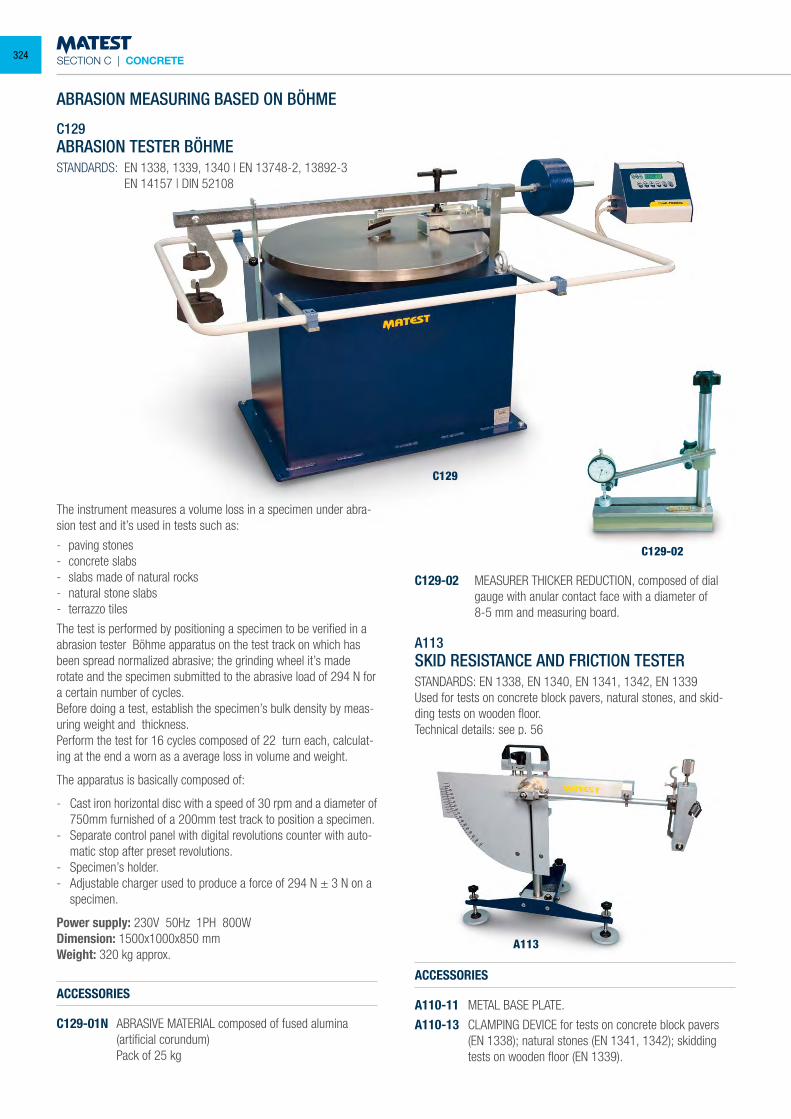
SECTION C | CONCRETE
C129
C129-02
ABRASION MEASURING BASED ON BÖHME
C129ABRASION TESTER BÖHMESTANDARDS: EN 1338, 1339, 1340 | EN 13748-2, 13892-3 EN 14157 | DIN 52108
The instrument measures a volume loss in a specimen under abra-sion test and it’s used in tests such as:
- paving stones - concrete slabs - slabs made of natural rocks - natural stone slabs- terrazzo tiles
The test is performed by positioning a specimen to be verified in a abrasion tester Böhme apparatus on the test track on which has been spread normalized abrasive; the grinding wheel it’s made rotate and the specimen submitted to the abrasive load of 294 N for a certain number of cycles. Before doing a test, establish the specimen’s bulk density by meas-uring weight and thickness. Perform the test for 16 cycles composed of 22 turn each, calculat-ing at the end a worn as a average loss in volume and weight.
The apparatus is basically composed of:
- Cast iron horizontal disc with a speed of 30 rpm and a diameter of 750mm furnished of a 200mm test track to position a specimen.
- Separate control panel with digital revolutions counter with auto-matic stop after preset revolutions.
- Specimen’s holder. - Adjustable charger used to produce a force of 294 N ± 3 N on a
specimen.
Power supply: 230V 50Hz 1PH 800W Dimension: 1500x1000x850 mmWeight: 320 kg approx.
A113SKID RESISTANCE AND FRICTION TESTERSTANDARDS: EN 1338, EN 1340, EN 1341, 1342, EN 1339Used for tests on concrete block pavers, natural stones, and skid-ding tests on wooden floor.Technical details: see p. 56
ACCESSORIES
A110-11 METAL BASE PLATE.
A110-13 CLAMPING DEVICE for tests on concrete block pavers (EN 1338); natural stones (EN 1341, 1342); skidding
tests on wooden floor (EN 1339).
ACCESSORIES
C129-01N ABRASIVE MATERIAL composed of fused alumina (artificial corundum)
Pack of 25 kg
C129-02 MEASURER THICKER REDUCTION, composed of dial gauge with anular contact face with a diameter of
8-5 mm and measuring board.
A113
324
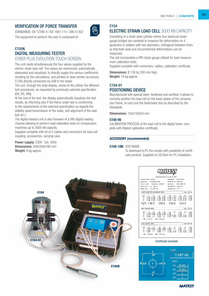
SECTION C | CONCRETE
VERIFICATION OF FORCE TRANSFERSTANDARDS: EN 12390-4 | BS 1881:115 | DIN 51302
The equipment to perform this test is composed of:
C155NDIGITAL MEASURING TESTERCYBER PLUS EVOLUTION TOUCH-SCREENThis unit reads simultaneously the four values supplied by the electric strain load cell. The values are memorized, automatically elaborated and visualized, to directly supply the various coefficients resulting by the calculations, and printed on laser printer (accessory C128) directly connected via USB to the tester.The unit, through the wide display, shows to the utilizer the different test procedures, as requested by previously selected specification (EN, BS, DIN).At the end of the test, the display automatically visualizes the test results, by informing also if the frame under test is conforming to the requirements of the selected specification as regards the stability (axial transmission of the loads, self-alignment of the seat ball etc.).The digital readout unit is also foreseen of a fifth digital reading channel allowing to perform load calibration tests on compression machines up to 3000 kN capacity.Supplied complete with kit of 5 cables and connectors for load cell coupling, accessories, carrying case.
Power supply: 230V 1ph 50HzDimensions: 450x350x160 mmWeight: 8 kg approx.
C154ELECTRIC STRAIN LOAD CELL 3000 KN CAPACITYConsisting of a strain steel cylinder where four balanced strain gauge bridges are centered to measure the deformation on 4 generatrix in relation with two diameters, orthogonal between them, so that both axial and circumferential deformations can be measured.The cell incorporates a fifth strain gauge utilized for load measure-ment calibration tests.Supplied complete with connectors, cables, calibration certificate.
Dimensions: Ø 130 by 200 mm high.Weight: 18 kg approx.
C154-01POSITIONING DEVICEManufactured with special steel, hardened and rectified, it allows to correclty position the load cell on the lower platen of the compres-sion frame, to carry out the footemeter test as described by the Standards.
Dimensions: 150x150x50 mm
C155-05CALIBRATION PROCESS of the load cell to the digital tester, com-plete with Matest calibration certificate.
ACCESSORY (recommended)
C155-10N SOFTWARE To download to PC the results with possibility of certifi-
cate printout. Supplied on CD Rom for PC installation.
Certificate example
C155N
C154-01
C154
325
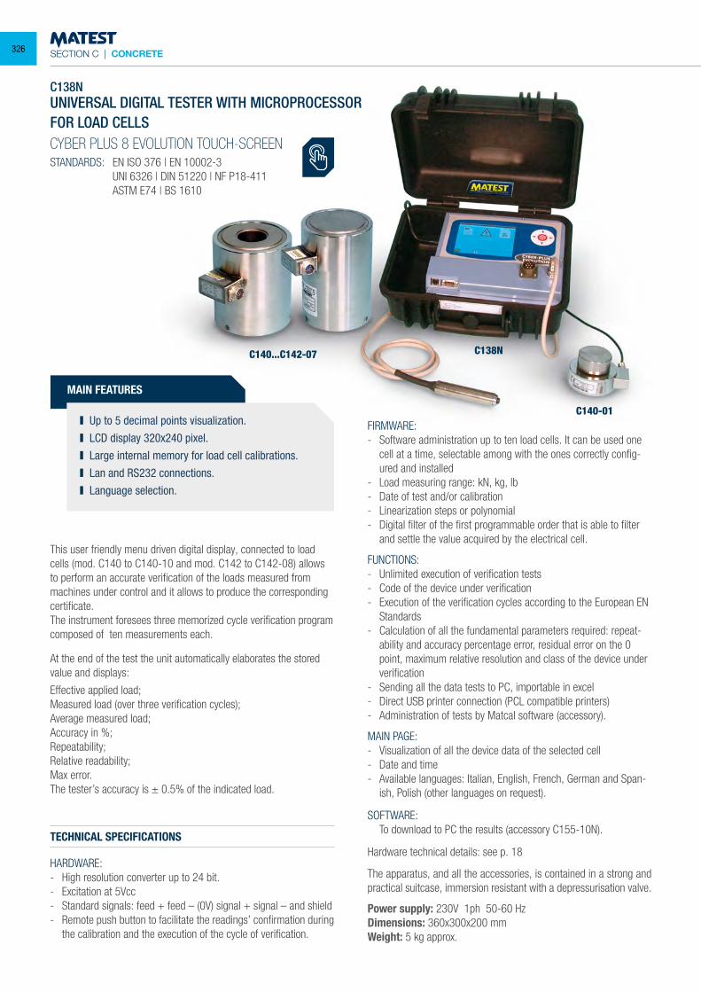
SECTION C | CONCRETE
C138NUNIVERSAL DIGITAL TESTER WITH MICROPROCESSORFOR LOAD CELLSCYBER PLUS 8 EVOLUTION TOUCH-SCREEN
STANDARDS: EN ISO 376 | EN 10002-3 UNI 6326 | DIN 51220 | NF P18-411 ASTM E74 | BS 1610
MAIN FEATURES
Up to 5 decimal points visualization. LCD display 320x240 pixel. Large internal memory for load cell calibrations. Lan and RS232 connections. Language selection.
This user friendly menu driven digital display, connected to load cells (mod. C140 to C140-10 and mod. C142 to C142-08) allows to perform an accurate verification of the loads measured from machines under control and it allows to produce the corresponding certificate.The instrument foresees three memorized cycle verification program composed of ten measurements each.
At the end of the test the unit automatically elaborates the stored value and displays:
Effective applied load;Measured load (over three verification cycles);Average measured load;Accuracy in %;Repeatability;Relative readability; Max error.The tester’s accuracy is ± 0.5% of the indicated load.
TECHNICAL SPECIFICATIONS
HARDWARE:- High resolution converter up to 24 bit.- Excitation at 5Vcc- Standard signals: feed + feed – (0V) signal + signal – and shield- Remote push button to facilitate the readings’ confirmation during
the calibration and the execution of the cycle of verification.
FIRMWARE:- Software administration up to ten load cells. It can be used one
cell at a time, selectable among with the ones correctly config-ured and installed
- Load measuring range: kN, kg, lb- Date of test and/or calibration- Linearization steps or polynomial- Digital filter of the first programmable order that is able to filter
and settle the value acquired by the electrical cell.
FUNCTIONS:- Unlimited execution of verification tests- Code of the device under verification- Execution of the verification cycles according to the European EN
Standards- Calculation of all the fundamental parameters required: repeat-
ability and accuracy percentage error, residual error on the 0 point, maximum relative resolution and class of the device under verification
- Sending all the data tests to PC, importable in excel- Direct USB printer connection (PCL compatible printers)- Administration of tests by Matcal software (accessory).
MAIN PAGE:- Visualization of all the device data of the selected cell- Date and time- Available languages: Italian, English, French, German and Span-
ish, Polish (other languages on request).
SOFTWARE: To download to PC the results (accessory C155-10N).
Hardware technical details: see p. 18
The apparatus, and all the accessories, is contained in a strong and practical suitcase, immersion resistant with a depressurisation valve.
Power supply: 230V 1ph 50-60 HzDimensions: 360x300x200 mmWeight: 5 kg approx.
C138NC140...C142-07
C140-01
326
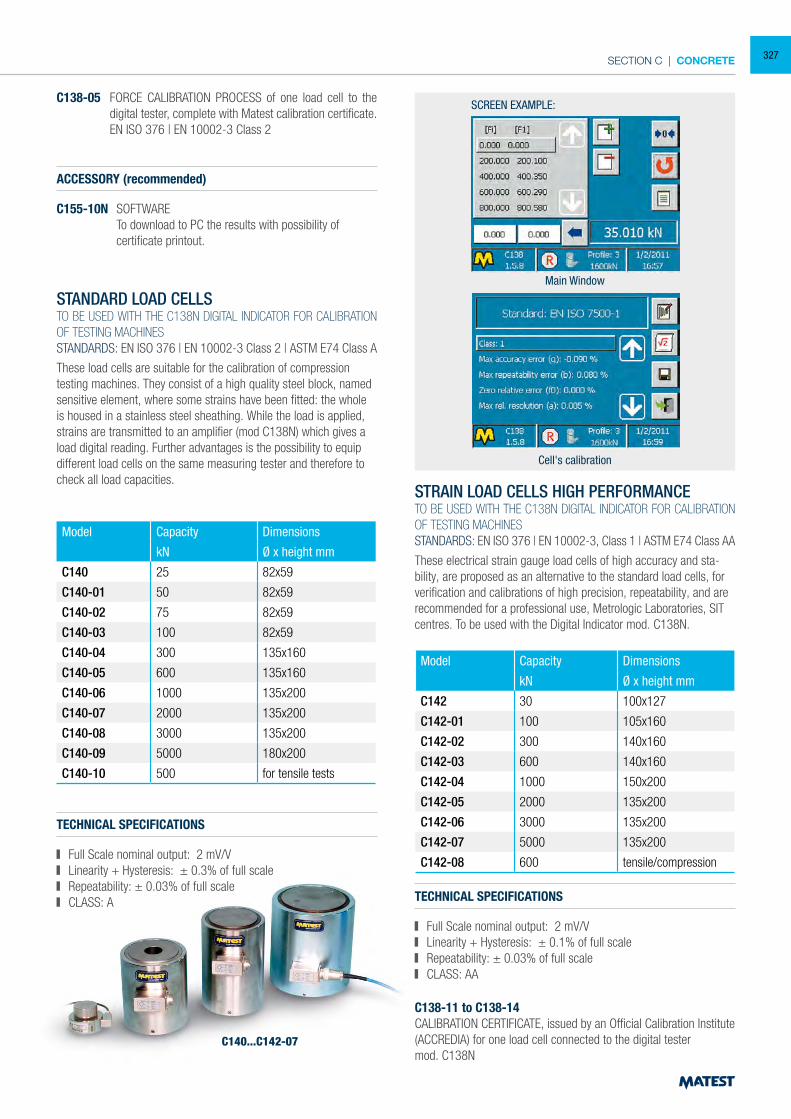
SECTION C | CONCRETE
C138-05 FORCE CALIBRATION PROCESS of one load cell to the digital tester, complete with Matest calibration certificate.
EN ISO 376 | EN 10002-3 Class 2
ACCESSORY (recommended)
C155-10N SOFTWARE To download to PC the results with possibility of certificate printout.
STANDARD LOAD CELLSTO BE USED WITH THE C138N DIGITAL INDICATOR FOR CALIBRATION OF TESTING MACHINESSTANDARDS: EN ISO 376 | EN 10002-3 Class 2 | ASTM E74 Class A
These load cells are suitable for the calibration of compression testing machines. They consist of a high quality steel block, named sensitive element, where some strains have been fitted: the whole is housed in a stainless steel sheathing. While the load is applied, strains are transmitted to an amplifier (mod C138N) which gives a load digital reading. Further advantages is the possibility to equip different load cells on the same measuring tester and therefore to check all load capacities.
STRAIN LOAD CELLS HIGH PERFORMANCETO BE USED WITH THE C138N DIGITAL INDICATOR FOR CALIBRATION OF TESTING MACHINESSTANDARDS: EN ISO 376 | EN 10002-3, Class 1 | ASTM E74 Class AA
These electrical strain gauge load cells of high accuracy and sta-bility, are proposed as an alternative to the standard load cells, for verification and calibrations of high precision, repeatability, and are recommended for a professional use, Metrologic Laboratories, SIT centres. To be used with the Digital Indicator mod. C138N.
TECHNICAL SPECIFICATIONS
Full Scale nominal output: 2 mV/V Linearity + Hysteresis: ± 0.3% of full scale Repeatability: ± 0.03% of full scale CLASS: A TECHNICAL SPECIFICATIONS
Full Scale nominal output: 2 mV/V Linearity + Hysteresis: ± 0.1% of full scale Repeatability: ± 0.03% of full scale CLASS: AA
C138-11 to C138-14CALIBRATION CERTIFICATE, issued by an Official Calibration Institute (ACCREDIA) for one load cell connected to the digital testermod. C138N
Model Capacity Dimensions
kN Ø x height mm
C140 25 82x59
C140-01 50 82x59
C140-02 75 82x59
C140-03 100 82x59
C140-04 300 135x160
C140-05 600 135x160
C140-06 1000 135x200
C140-07 2000 135x200
C140-08 3000 135x200
C140-09 5000 180x200
C140-10 500 for tensile tests
Model Capacity Dimensions
kN Ø x height mm
C142 30 100x127
C142-01 100 105x160
C142-02 300 140x160
C142-03 600 140x160
C142-04 1000 150x200
C142-05 2000 135x200
C142-06 3000 135x200
C142-07 5000 135x200
C142-08 600 tensile/compression
SCREEN EXAMPLE:
Main Window
Cell's calibration
C140...C142-07
327
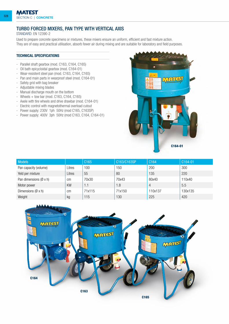
SECTION C | CONCRETE
TURBO FORCED MIXERS, PAN TYPE WITH VERTICAL AXISSTANDARD: EN 12390-2
Used to prepare concrete specimens or mixtures, these mixers ensure an uniform, efficient and fast mixture action.They are of easy and practical utilisation, absorb fewer air during mixing and are suitable for laboratory and field purposes.
TECHNICAL SPECIFICATIONS
- Parallel shaft gearbox (mod. C163, C164, C165)- Oil bath epicycloidal gearbox (mod. C164-01)- Wear-resistent steel pan (mod. C163, C164, C165)- Pan and main parts in wearproof steel (mod. C164-01)- Safety grid with bag breaker- Adjustable mixing blades- Manual discharge mouth on the bottom- Wheels + tow bar (mod. C163, C164, C165)- Axele with tire wheels and drive drawbar (mod. C164-01)- Electric control with magnetothermal overload cutout- Power supply: 230V 1ph 50Hz (mod C165, C163SP)- Power supply: 400V 3ph 50Hz (mod C163, C164, C164-01)
Models C165 C163/C163SP C164 C164-01
Pan capacity (volume) Litres 100 150 200 300
Yeld per mixture Litres 55 80 135 220
Pan dimensions (Ø x h) cm 70x30 70x43 80x40 110x40
Motor power KW 1.1 1.8 4 5.5
Dimensions (Ø x h) cm 71x115 71x150 110x137 130x135
Weight kg 115 130 225 420
C164-01
C163
C164
C165
328
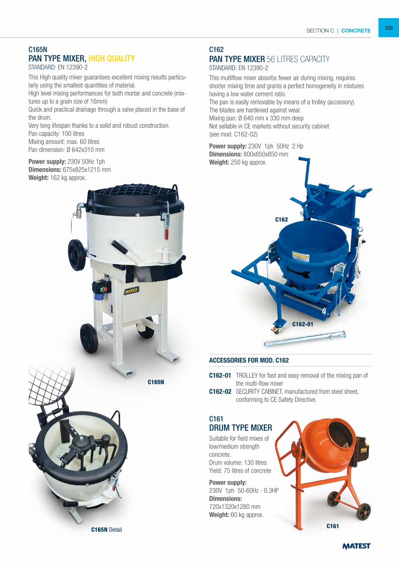
SECTION C | CONCRETE
C162PAN TYPE MIXER 56 LITRES CAPACITYSTANDARD: EN 12390-2
This multiflow mixer absorbs fewer air during mixing, requires shorter mixing time and grants a perfect homogeneity in mixtures having a low water cement ratio.The pan is easily removable by means of a trolley (accessory).The blades are hardened against wear.Mixing pan: Ø 640 mm x 330 mm deepNot sellable in CE markets without security cabinet(see mod. C162-02)
Power supply: 230V 1ph 50Hz 2 HpDimensions: 800x850x850 mmWeight: 250 kg approx.
ACCESSORIES FOR MOD. C162
C162-01 TROLLEY for fast and easy removal of the mixing pan of the multi-flow mixer
C162-02 SECURITY CABINET, manufactured from steel sheet, conforming to CE Safety Directive.
C162
C165N
C165N Detail C161
C162-01
C165NPAN TYPE MIXER, HIGH QUALITYSTANDARD: EN 12390-2
This High quality mixer guarantees excellent mixing results particu-larly using the smallest quantities of material.High level mixing performances for both mortar and concrete (mix-tures up to a grain size of 16mm)Quick and practical drainage through a valve placed in the base of the drum.Very long lifespan thanks to a solid and robust construction.Pan capacity: 100 litresMixing amount: max. 60 litresPan dimension: Ø 642x310 mm
Power supply: 230V 50Hz 1phDimensions: 675x825x1215 mmWeight: 162 kg approx.
C161DRUM TYPE MIXERSuitable for field mixes oflow/medium strengthconcrete.Drum volume: 130 litresYield: 75 litres of concrete
Power supply:230V 1ph 50-60Hz - 0.3HPDimensions:720x1320x1280 mmWeight: 60 kg approx.
329
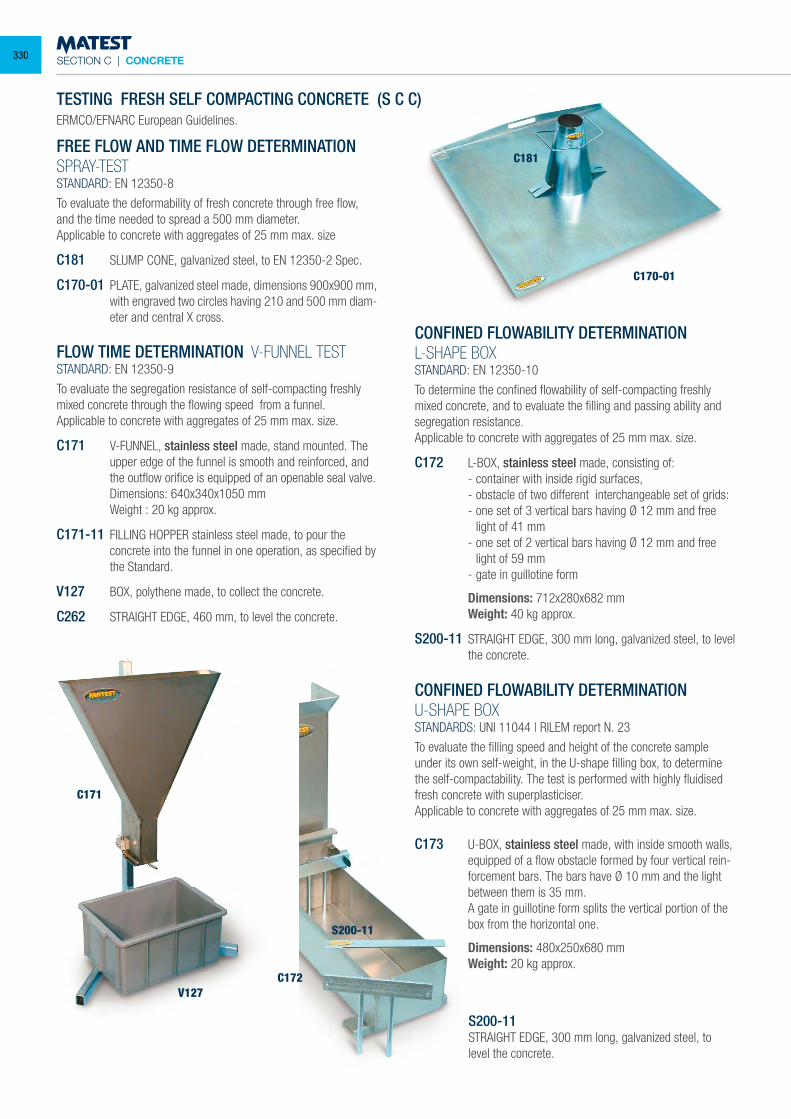
SECTION C | CONCRETE
C170-01
C181
TESTING FRESH SELF COMPACTING CONCRETE (S C C) ERMCO/EFNARC European Guidelines.
FREE FLOW AND TIME FLOW DETERMINATIONSPRAY-TESTSTANDARD: EN 12350-8
To evaluate the deformability of fresh concrete through free flow, and the time needed to spread a 500 mm diameter.Applicable to concrete with aggregates of 25 mm max. size
C181 SLUMP CONE, galvanized steel, to EN 12350-2 Spec.
C170-01 PLATE, galvanized steel made, dimensions 900x900 mm, with engraved two circles having 210 and 500 mm diam-eter and central X cross.
FLOW TIME DETERMINATION V-FUNNEL TESTSTANDARD: EN 12350-9
To evaluate the segregation resistance of self-compacting freshly mixed concrete through the flowing speed from a funnel.Applicable to concrete with aggregates of 25 mm max. size.
C171 V-FUNNEL, stainless steel made, stand mounted. The upper edge of the funnel is smooth and reinforced, and the outflow orifice is equipped of an openable seal valve.
Dimensions: 640x340x1050 mm Weight : 20 kg approx.
C171-11 FILLING HOPPER stainless steel made, to pour the concrete into the funnel in one operation, as specified by the Standard.
V127 BOX, polythene made, to collect the concrete.
C262 STRAIGHT EDGE, 460 mm, to level the concrete.
CONFINED FLOWABILITY DETERMINATION L-SHAPE BOXSTANDARD: EN 12350-10
To determine the confined flowability of self-compacting freshly mixed concrete, and to evaluate the filling and passing ability and segregation resistance.Applicable to concrete with aggregates of 25 mm max. size.
C172 L-BOX, stainless steel made, consisting of: - container with inside rigid surfaces, - obstacle of two different interchangeable set of grids: - one set of 3 vertical bars having Ø 12 mm and free
light of 41 mm - one set of 2 vertical bars having Ø 12 mm and free
light of 59 mm - gate in guillotine form
Dimensions: 712x280x682 mm Weight: 40 kg approx.
S200-11 STRAIGHT EDGE, 300 mm long, galvanized steel, to level the concrete.
CONFINED FLOWABILITY DETERMINATION
U-SHAPE BOXSTANDARDS: UNI 11044 | RILEM report N. 23
To evaluate the filling speed and height of the concrete sample under its own self-weight, in the U-shape filling box, to determine the self-compactability. The test is performed with highly fluidised fresh concrete with superplasticiser.Applicable to concrete with aggregates of 25 mm max. size.
C173 U-BOX, stainless steel made, with inside smooth walls, equipped of a flow obstacle formed by four vertical rein-forcement bars. The bars have Ø 10 mm and the light between them is 35 mm.
A gate in guillotine form splits the vertical portion of the box from the horizontal one.
Dimensions: 480x250x680 mm Weight: 20 kg approx.
S200-11STRAIGHT EDGE, 300 mm long, galvanized steel, to level the concrete.
C171
C172
S200-11
V127
330
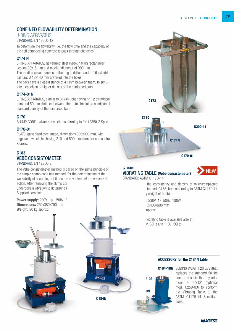
SECTION C | CONCRETE
CONFINED FLOWABILITY DETERMINATION
J-RING APPARATUSSTANDARD: EN 12350-12
To determine the flowability, i.e. the flow time and the capability of the self compacting concrete to pass through obstacles.
C174 NJ-RING APPARATUS, galvanized steel made, having rectangular section 30x15 mm and median diameter of 300 mm.The median circumference of the ring is drilled, and n. 16 cylindri-cal bars Ø 18x140 mm are fixed into the holes.The bars have a close distance of 41 mm between them, to simu-late a condition of higher density of the reinforced bars.
C174-01NJ-RING APPARATUS, similar to C174N, but having n° 12 cylindrical bars and 59 mm distance between them, to simulate a condition of standard density of the reinforced bars.
C170SLUMP CONE, galvanized steel, conforming to EN 12350-2 Spec.
C170-01 PLATE, galvanized steel made, dimensions 900x900 mm, with engraved two circles having 210 and 500 mm diameter and central X cross.
C183VEBÉ CONSISTOMETERSTANDARD: EN 12350-3
The Vebé consistometer method is based on the same principle of the simple slump cone test method, for the determination of the workability of concrete, but it has the advantage of a mechanized action. After removing the slump cone, the concreteundergoes a vibration to determine its slump.Supplied complete.
Power supply: 230V 1ph 50Hz 250WDimensions: 260x380x700 mm Weight: 90 kg approx.
C184NVIBRATING TABLE (Vebé consistometer)STANDARD: ASTM C1170-14
For determining the consistency and density of roller-compacted concrete. Similar to mod. C183, but conforming to ASTM C1170-14 Spec. with sliding weight of 50 lbs
* Power Supply: 230V 1F 50Hz 180WDimensions: 280x400x900 mmWeight: 110 kg approx.
*Note: The vibrating table is available also at: 230V 60Hz and 110V 60Hz
ACCESSORY for the C184N table
C184-10N SLIDING WEIGHT 20 LBS (that replaces the standard 50 lbs one) + base to fix a cylinder mould Ø 6”x12” (optional mod. C258-03) to conform the Vibrating Table to the ASTM C1176-14 Specifica-tions.
S200-11
C184-10N
C258-03
C173
C170
C174N
C170-01
NEW
C183
C184N
331
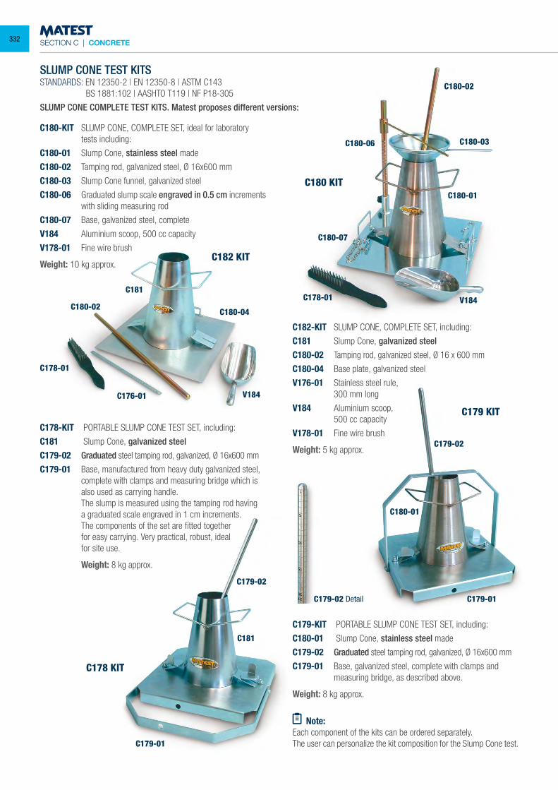
SECTION C | CONCRETE
SLUMP CONE TEST KITSSTANDARDS: EN 12350-2 | EN 12350-8 | ASTM C143 BS 1881:102 | AASHTO T119 | NF P18-305
SLUMP CONE COMPLETE TEST KITS. Matest proposes different versions:
C180-KIT SLUMP CONE, COMPLETE SET, ideal for laboratory tests including:
C180-01 Slump Cone, stainless steel made
C180-02 Tamping rod, galvanized steel, Ø 16x600 mm
C180-03 Slump Cone funnel, galvanized steel
C180-06 Graduated slump scale engraved in 0.5 cm increments with sliding measuring rod
C180-07 Base, galvanized steel, complete
V184 Aluminium scoop, 500 cc capacity
V178-01 Fine wire brush
Weight: 10 kg approx.
C178-KIT PORTABLE SLUMP CONE TEST SET, including:
C181 Slump Cone, galvanized steelC179-02 Graduated steel tamping rod, galvanized, Ø 16x600 mm
C179-01 Base, manufactured from heavy duty galvanized steel, complete with clamps and measuring bridge which is also used as carrying handle.
The slump is measured using the tamping rod having a graduated scale engraved in 1 cm increments. The components of the set are fitted together for easy carrying. Very practical, robust, ideal for site use.
Weight: 8 kg approx.
C182-KIT SLUMP CONE, COMPLETE SET, including:
C181 Slump Cone, galvanized steelC180-02 Tamping rod, galvanized steel, Ø 16 x 600 mm
C180-04 Base plate, galvanized steel
V176-01 Stainless steel rule, 300 mm long
V184 Aluminium scoop, 500 cc capacity
V178-01 Fine wire brush
Weight: 5 kg approx.
C179-KIT PORTABLE SLUMP CONE TEST SET, including:
C180-01 Slump Cone, stainless steel made
C179-02 Graduated steel tamping rod, galvanized, Ø 16x600 mm
C179-01 Base, galvanized steel, complete with clamps and measuring bridge, as described above.
Weight: 8 kg approx.
Note:Each component of the kits can be ordered separately.The user can personalize the kit composition for the Slump Cone test.
C182 KIT
C178 KIT
C179 KIT
C180 KIT
C180-02
C180-01
C178-01
C178-01
C176-01
C179-01
C179-01
C179-02
C179-02
C179-02 Detail
C180-04
C180-02
C180-03
C180-01
C180-07
C180-06
V184
V184C181
C181
332
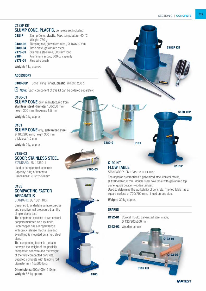
SECTION C | CONCRETE
C182P KITSLUMP CONE, PLASTIC, complete set including:
C181P Slump Cone, plastic. Max. temperature: 40 °C Weight: 750 gC180-02 Tamping rod, galvanized steel, Ø 16x600 mmC180-04 Base plate, galvanized steelV176-01 Stainless steel rule, 300 mm longV184 Aluminium scoop, 500 cc capacityV178-01 Fine wire brush
Weight: 5 kg approx.
ACCESSORY
C180-03P Cone Filling Funnel, plastic. Weight: 250 g
Note: Each component of this kit can be ordered separately.
C180-01SLUMP CONE only, manufactured fromstainless steel, diameter 100/200 mm,height 300 mm, thickness 1.5 mm
Weight: 2 kg approx.
C181SLUMP CONE only, galvanized steel,Ø 100/200 mm, height 300 mm,thickness 1.5 mm
Weight: 2 kg approx.
V185-03SCOOP, STAINLESS STEELSTANDARD: EN 12350-1
Used to sample fresh concreteCapacity: 5 kg of concreteDimensions: Ø 125x250 mm
C185COMPACTING FACTORAPPARATUSSTANDARD: BS 1881:103
Designed to undertake a more precise and sensitive test procedure than the simple slump test.The apparatus consists of two conical hoppers mounted on a cylinder.Each hopper has a hinged flange with quick release mechanism and everything is mounted on a rigid steel stand.The compacting factor is the ratio between the weight of the partially compacted concrete and the weight of the fully compacted concrete. Supplied complete with tamping rod diameter mm 16x600 long.
Dimensions: 500x400x1510 mmWeight: 55 kg approx.
C192 KITFLOW TABLESTANDARDS: EN 12350-5 | DIN 1048
The apparatus comprises a galvanized steel conical mould,Ø 130/200x200 mm, double steel flow table with galvanized top plane, guide device, wooden tamper.Used to determine the workability of concrete. The top table has a square surface of 700x700 mm, hinged on one side.
Weight: 30 kg approx.
SPARES
C192-01 Conical mould, galvanized steel made, Ø 130/200x200 mm
C192-02 Wooden tamper
C182P KIT
C180-03P
C181PV185-03
C185
C192-01
C192-02
C192 KIT
C181C180-01
333
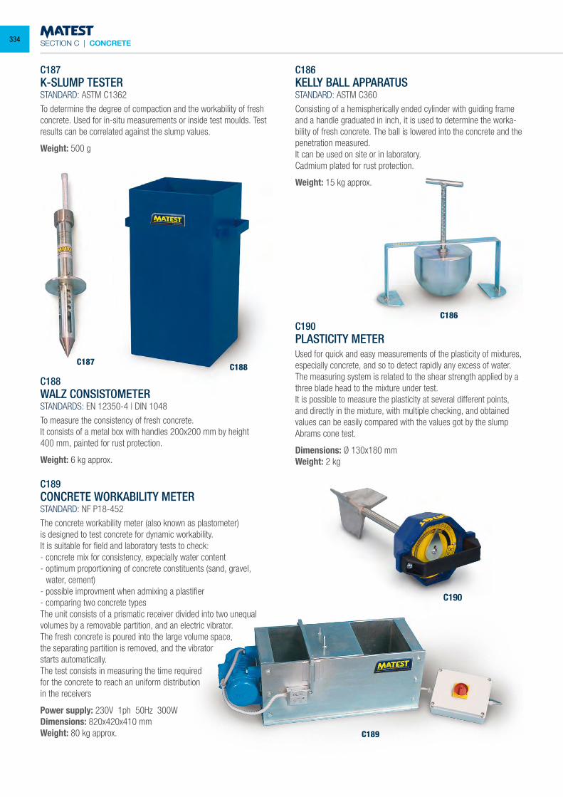
SECTION C | CONCRETE
C187K-SLUMP TESTERSTANDARD: ASTM C1362
To determine the degree of compaction and the workability of fresh concrete. Used for in-situ measurements or inside test moulds. Test results can be correlated against the slump values.
Weight: 500 g
C189CONCRETE WORKABILITY METERSTANDARD: NF P18-452
The concrete workability meter (also known as plastometer)is designed to test concrete for dynamic workability.It is suitable for field and laboratory tests to check:- concrete mix for consistency, expecially water content- optimum proportioning of concrete constituents (sand, gravel,
water, cement)- possible improvment when admixing a plastifier- comparing two concrete typesThe unit consists of a prismatic receiver divided into two unequal volumes by a removable partition, and an electric vibrator.The fresh concrete is poured into the large volume space, the separating partition is removed, and the vibrator starts automatically.The test consists in measuring the time required for the concrete to reach an uniform distribution in the receivers
Power supply: 230V 1ph 50Hz 300WDimensions: 820x420x410 mmWeight: 80 kg approx.
C186KELLY BALL APPARATUSSTANDARD: ASTM C360
Consisting of a hemispherically ended cylinder with guiding frame and a handle graduated in inch, it is used to determine the worka-bility of fresh concrete. The ball is lowered into the concrete and the penetration measured.It can be used on site or in laboratory.Cadmium plated for rust protection.
Weight: 15 kg approx.
C190PLASTICITY METERUsed for quick and easy measurements of the plasticity of mixtures, especially concrete, and so to detect rapidly any excess of water.The measuring system is related to the shear strength applied by a three blade head to the mixture under test.It is possible to measure the plasticity at several different points, and directly in the mixture, with multiple checking, and obtained values can be easily compared with the values got by the slump Abrams cone test.
Dimensions: Ø 130x180 mmWeight: 2 kg
C188WALZ CONSISTOMETERSTANDARDS: EN 12350-4 | DIN 1048
To measure the consistency of fresh concrete.It consists of a metal box with handles 200x200 mm by height400 mm, painted for rust protection.
Weight: 6 kg approx.
C187C188
C186
C189
C190
334
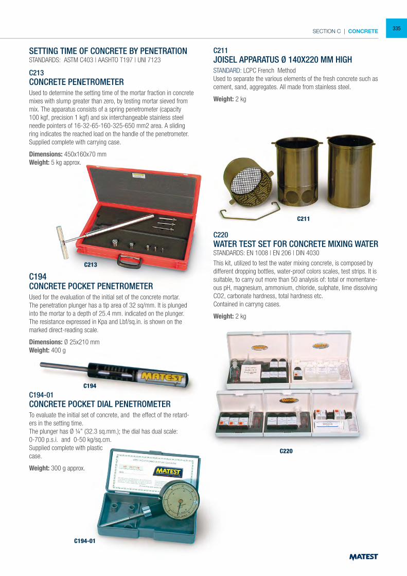
SECTION C | CONCRETE
SETTING TIME OF CONCRETE BY PENETRATIONSTANDARDS: ASTM C403 | AASHTO T197 | UNI 7123
C213CONCRETE PENETROMETERUsed to determine the setting time of the mortar fraction in concrete mixes with slump greater than zero, by testing mortar sieved from mix. The apparatus consists of a spring penetrometer (capacity100 kgf, precision 1 kgf) and six interchangeable stainless steel needle pointers of 16-32-65-160-325-650 mm2 area. A sliding ring indicates the reached load on the handle of the penetrometer. Supplied complete with carrying case.
Dimensions: 450x160x70 mmWeight: 5 kg approx.
C194CONCRETE POCKET PENETROMETERUsed for the evaluation of the initial set of the concrete mortar.The penetration plunger has a tip area of 32 sq/mm. It is plunged into the mortar to a depth of 25.4 mm. indicated on the plunger. The resistance expressed in Kpa and Lbf/sq.in. is shown on the marked direct-reading scale.
Dimensions: Ø 25x210 mmWeight: 400 g
C194-01CONCRETE POCKET DIAL PENETROMETERTo evaluate the initial set of concrete, and the effect of the retard-ers in the setting time.The plunger has Ø ¼” (32.3 sq.mm.); the dial has dual scale: 0-700 p.s.i. and 0-50 kg/sq.cm.Supplied complete with plasticcase.
Weight: 300 g approx.
C211JOISEL APPARATUS Ø 140X220 MM HIGHSTANDARD: LCPC French MethodUsed to separate the various elements of the fresh concrete such as cement, sand, aggregates. All made from stainless steel.
Weight: 2 kg
C220WATER TEST SET FOR CONCRETE MIXING WATERSTANDARDS: EN 1008 | EN 206 | DIN 4030
This kit, utilized to test the water mixing concrete, is composed by different dropping bottles, water-proof colors scales, test strips. It is suitable, to carry out more than 50 analysis of: total or momentane-ous pH, magnesium, ammonium, chloride, sulphate, lime dissolving CO2, carbonate hardness, total hardness etc.Contained in carryng cases.
Weight: 2 kg
C213
C194
C194-01
C220
C211
335
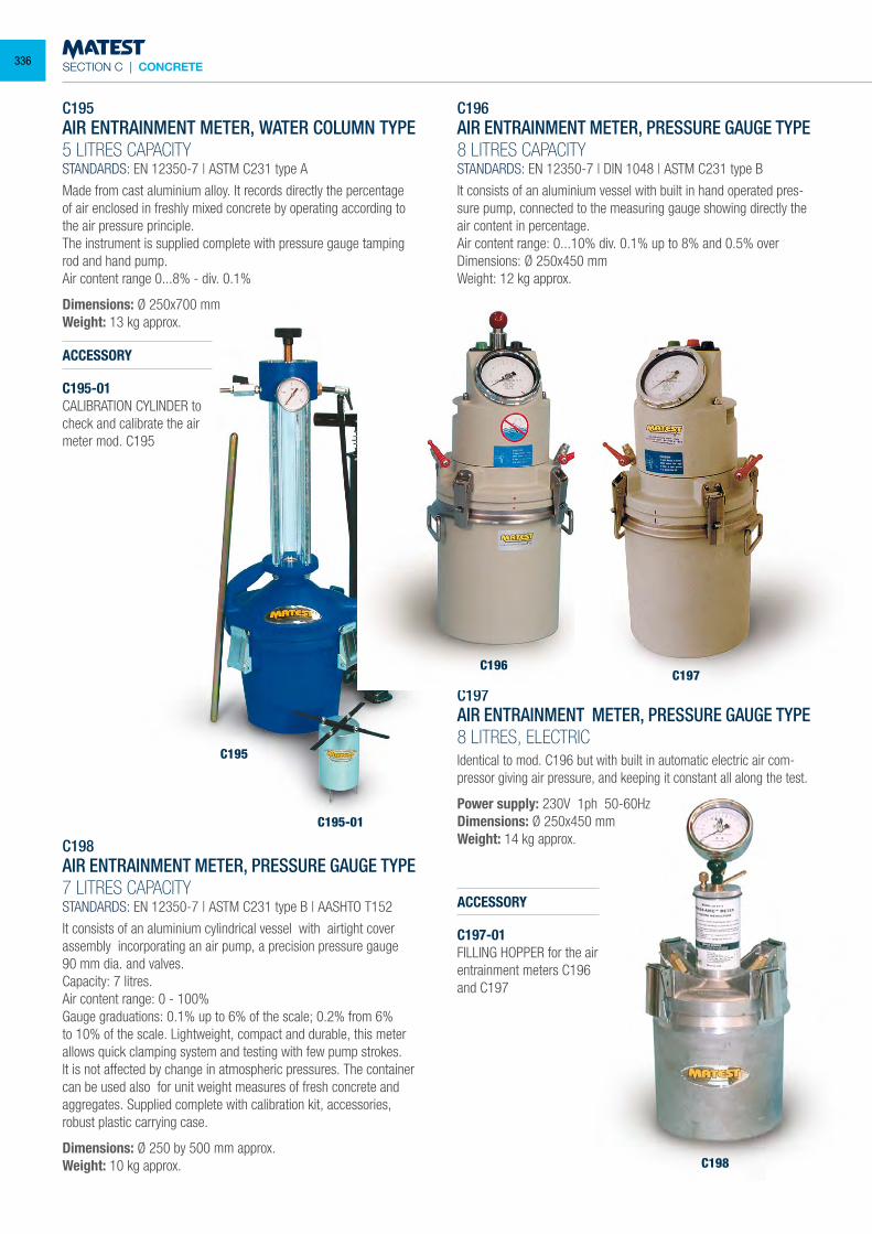
SECTION C | CONCRETE
C195
C195-01
C195AIR ENTRAINMENT METER, WATER COLUMN TYPE 5 LITRES CAPACITYSTANDARDS: EN 12350-7 | ASTM C231 type A
Made from cast aluminium alloy. It records directly the percentage of air enclosed in freshly mixed concrete by operating according to the air pressure principle.The instrument is supplied complete with pressure gauge tamping rod and hand pump.Air content range 0...8% - div. 0.1%
Dimensions: Ø 250x700 mmWeight: 13 kg approx.
ACCESSORY
C195-01CALIBRATION CYLINDER tocheck and calibrate the airmeter mod. C195
C198AIR ENTRAINMENT METER, PRESSURE GAUGE TYPE 7 LITRES CAPACITYSTANDARDS: EN 12350-7 | ASTM C231 type B | AASHTO T152
It consists of an aluminium cylindrical vessel with airtight cover assembly incorporating an air pump, a precision pressure gauge 90 mm dia. and valves.Capacity: 7 litres.Air content range: 0 - 100% Gauge graduations: 0.1% up to 6% of the scale; 0.2% from 6% to 10% of the scale. Lightweight, compact and durable, this meter allows quick clamping system and testing with few pump strokes.It is not affected by change in atmospheric pressures. The container can be used also for unit weight measures of fresh concrete and aggregates. Supplied complete with calibration kit, accessories, robust plastic carrying case.
Dimensions: Ø 250 by 500 mm approx.Weight: 10 kg approx.
C196AIR ENTRAINMENT METER, PRESSURE GAUGE TYPE 8 LITRES CAPACITYSTANDARDS: EN 12350-7 | DIN 1048 | ASTM C231 type B
It consists of an aluminium vessel with built in hand operated pres-sure pump, connected to the measuring gauge showing directly the air content in percentage.Air content range: 0...10% div. 0.1% up to 8% and 0.5% overDimensions: Ø 250x450 mmWeight: 12 kg approx.
C197AIR ENTRAINMENT METER, PRESSURE GAUGE TYPE 8 LITRES, ELECTRIC Identical to mod. C196 but with built in automatic electric air com-pressor giving air pressure, and keeping it constant all along the test.
Power supply: 230V 1ph 50-60HzDimensions: Ø 250x450 mmWeight: 14 kg approx.
ACCESSORY
C197-01FILLING HOPPER for the air entrainment meters C196 and C197
C196C197
C198
336
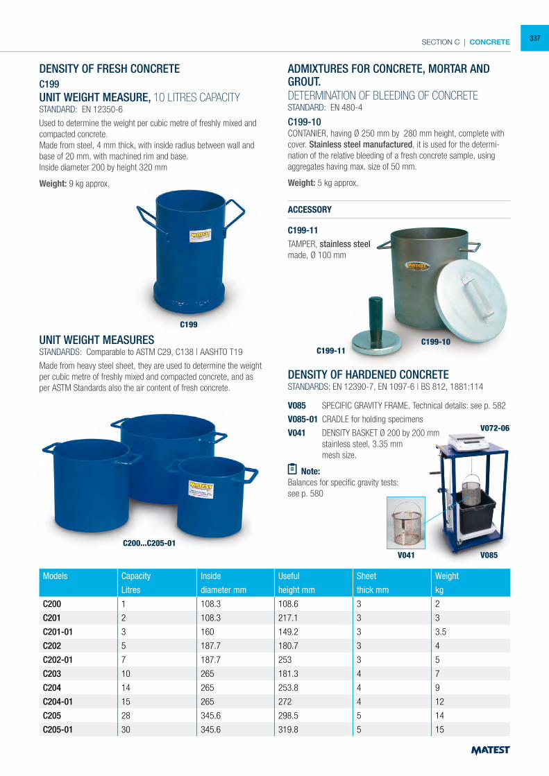
SECTION C | CONCRETE
DENSITY OF FRESH CONCRETEC199UNIT WEIGHT MEASURE, 10 LITRES CAPACITYSTANDARD: EN 12350-6
Used to determine the weight per cubic metre of freshly mixed and compacted concrete.Made from steel, 4 mm thick, with inside radius between wall and base of 20 mm, with machined rim and base.Inside diameter 200 by height 320 mm
Weight: 9 kg approx.
UNIT WEIGHT MEASURESSTANDARDS: Comparable to ASTM C29, C138 | AASHTO T19
Made from heavy steel sheet, they are used to determine the weight per cubic metre of freshly mixed and compacted concrete, and as per ASTM Standards also the air content of fresh concrete.
ADMIXTURES FOR CONCRETE, MORTAR AND GROUT.DETERMINATION OF BLEEDING OF CONCRETESTANDARD: EN 480-4
C199-10CONTANIER, having Ø 250 mm by 280 mm height, complete with cover. Stainless steel manufactured, it is used for the determi-nation of the relative bleeding of a fresh concrete sample, using aggregates having max. size of 50 mm.
Weight: 5 kg approx.
ACCESSORY
C199-11TAMPER, stainless steelmade, Ø 100 mm
DENSITY OF HARDENED CONCRETESTANDARDS: EN 12390-7, EN 1097-6 | BS 812, 1881:114
V085 SPECIFIC GRAVITY FRAME. Technical details: see p. 582
V085-01 CRADLE for holding specimens
V041 DENSITY BASKET Ø 200 by 200 mm stainless steel, 3.35 mm mesh size.
Note:Balances for specific gravity tests:see p. 580
Models Capacity Inside Useful Sheet Weight
Litres diameter mm height mm thick mm kg
C200 1 108.3 108.6 3 2
C201 2 108.3 217.1 3 3
C201-01 3 160 149.2 3 3.5
C202 5 187.7 180.7 3 4
C202-01 7 187.7 253 3 5
C203 10 265 181.3 4 7
C204 14 265 253.8 4 9
C204-01 15 265 272 4 12
C205 28 345.6 298.5 5 14
C205-01 30 345.6 319.8 5 15
C199
V085V041
V072-06
C199-11C199-10
C200...C205-01
337
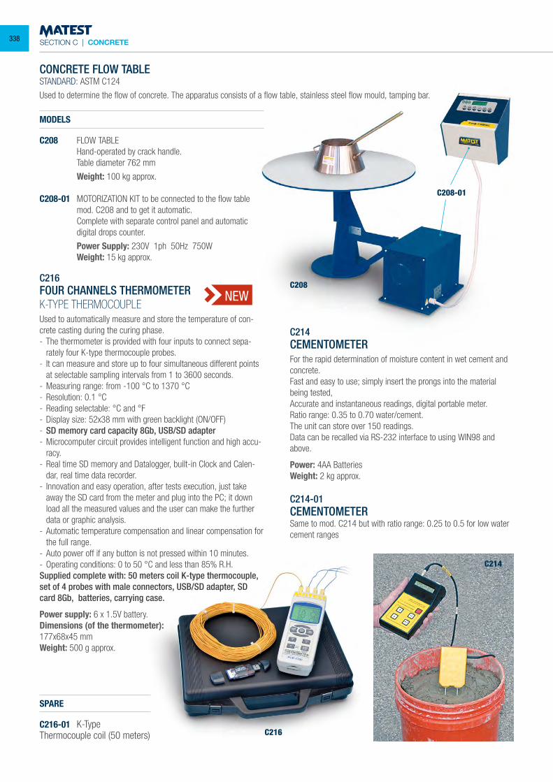
SECTION C | CONCRETE
C216
C208
C208-01
C214
CONCRETE FLOW TABLESTANDARD: ASTM C124
Used to determine the flow of concrete. The apparatus consists of a flow table, stainless steel flow mould, tamping bar.
MODELS
C208 FLOW TABLE Hand-operated by crack handle. Table diameter 762 mm
Weight: 100 kg approx.
C208-01 MOTORIZATION KIT to be connected to the flow table mod. C208 and to get it automatic.
Complete with separate control panel and automatic digital drops counter.
Power Supply: 230V 1ph 50Hz 750W Weight: 15 kg approx.
C214CEMENTOMETERFor the rapid determination of moisture content in wet cement and concrete.Fast and easy to use; simply insert the prongs into the material being tested,Accurate and instantaneous readings, digital portable meter.Ratio range: 0.35 to 0.70 water/cement.The unit can store over 150 readings.Data can be recalled via RS-232 interface to using WIN98 and above.
Power: 4AA BatteriesWeight: 2 kg approx.
C214-01CEMENTOMETERSame to mod. C214 but with ratio range: 0.25 to 0.5 for low water cement ranges
C216FOUR CHANNELS THERMOMETERK-TYPE THERMOCOUPLEUsed to automatically measure and store the temperature of con-crete casting during the curing phase.- The thermometer is provided with four inputs to connect sepa-
rately four K-type thermocouple probes.- It can measure and store up to four simultaneous different points
at selectable sampling intervals from 1 to 3600 seconds.- Measuring range: from -100 °C to 1370 °C- Resolution: 0.1 °C- Reading selectable: °C and °F- Display size: 52x38 mm with green backlight (ON/OFF)- SD memory card capacity 8Gb, USB/SD adapter- Microcomputer circuit provides intelligent function and high accu-
racy.- Real time SD memory and Datalogger, built-in Clock and Calen-
dar, real time data recorder.- Innovation and easy operation, after tests execution, just take
away the SD card from the meter and plug into the PC; it down load all the measured values and the user can make the further data or graphic analysis.
- Automatic temperature compensation and linear compensation for the full range.
- Auto power off if any button is not pressed within 10 minutes.- Operating conditions: 0 to 50 °C and less than 85% R.H.Supplied complete with: 50 meters coil K-type thermocouple, set of 4 probes with male connectors, USB/SD adapter, SD card 8Gb, batteries, carrying case.
Power supply: 6 x 1.5V battery.Dimensions (of the thermometer):177x68x45 mmWeight: 500 g approx.
NEW
SPARE
C216-01 K-TypeThermocouple coil (50 meters)
338
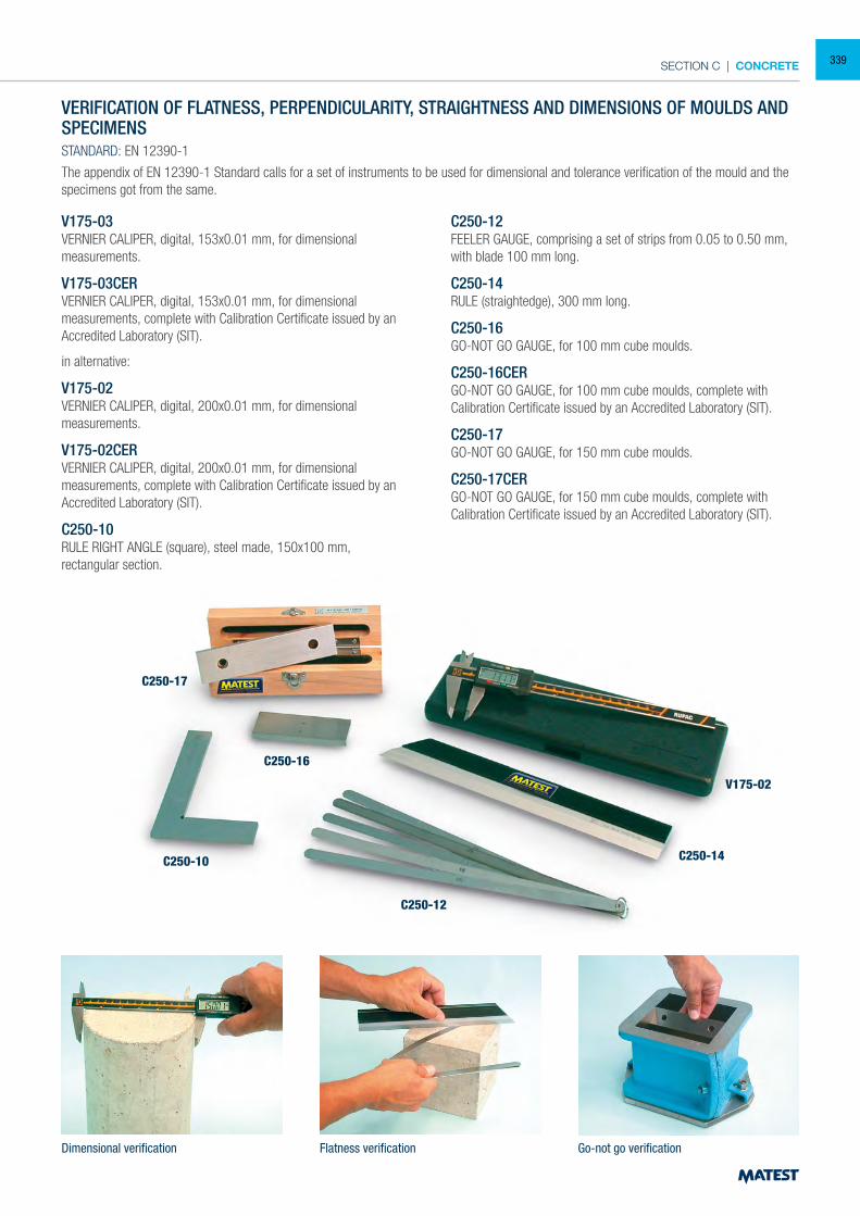
SECTION C | CONCRETE
VERIFICATION OF FLATNESS, PERPENDICULARITY, STRAIGHTNESS AND DIMENSIONS OF MOULDS AND SPECIMENSSTANDARD: EN 12390-1
The appendix of EN 12390-1 Standard calls for a set of instruments to be used for dimensional and tolerance verification of the mould and the specimens got from the same.
V175-03 VERNIER CALIPER, digital, 153x0.01 mm, for dimensional measurements.
V175-03CERVERNIER CALIPER, digital, 153x0.01 mm, for dimensional measurements, complete with Calibration Certificate issued by an Accredited Laboratory (SIT).
in alternative:
V175-02 VERNIER CALIPER, digital, 200x0.01 mm, for dimensional measurements.
V175-02CERVERNIER CALIPER, digital, 200x0.01 mm, for dimensional measurements, complete with Calibration Certificate issued by an Accredited Laboratory (SIT).
C250-10RULE RIGHT ANGLE (square), steel made, 150x100 mm, rectangular section.
C250-12FEELER GAUGE, comprising a set of strips from 0.05 to 0.50 mm, with blade 100 mm long.
C250-14RULE (straightedge), 300 mm long.
C250-16GO-NOT GO GAUGE, for 100 mm cube moulds.
C250-16CERGO-NOT GO GAUGE, for 100 mm cube moulds, complete with Calibration Certificate issued by an Accredited Laboratory (SIT).
C250-17GO-NOT GO GAUGE, for 150 mm cube moulds.
C250-17CERGO-NOT GO GAUGE, for 150 mm cube moulds, complete with Calibration Certificate issued by an Accredited Laboratory (SIT).
Dimensional verification Flatness verification Go-not go verification
C250-17
C250-16
C250-10
C250-12
C250-14
V175-02
339
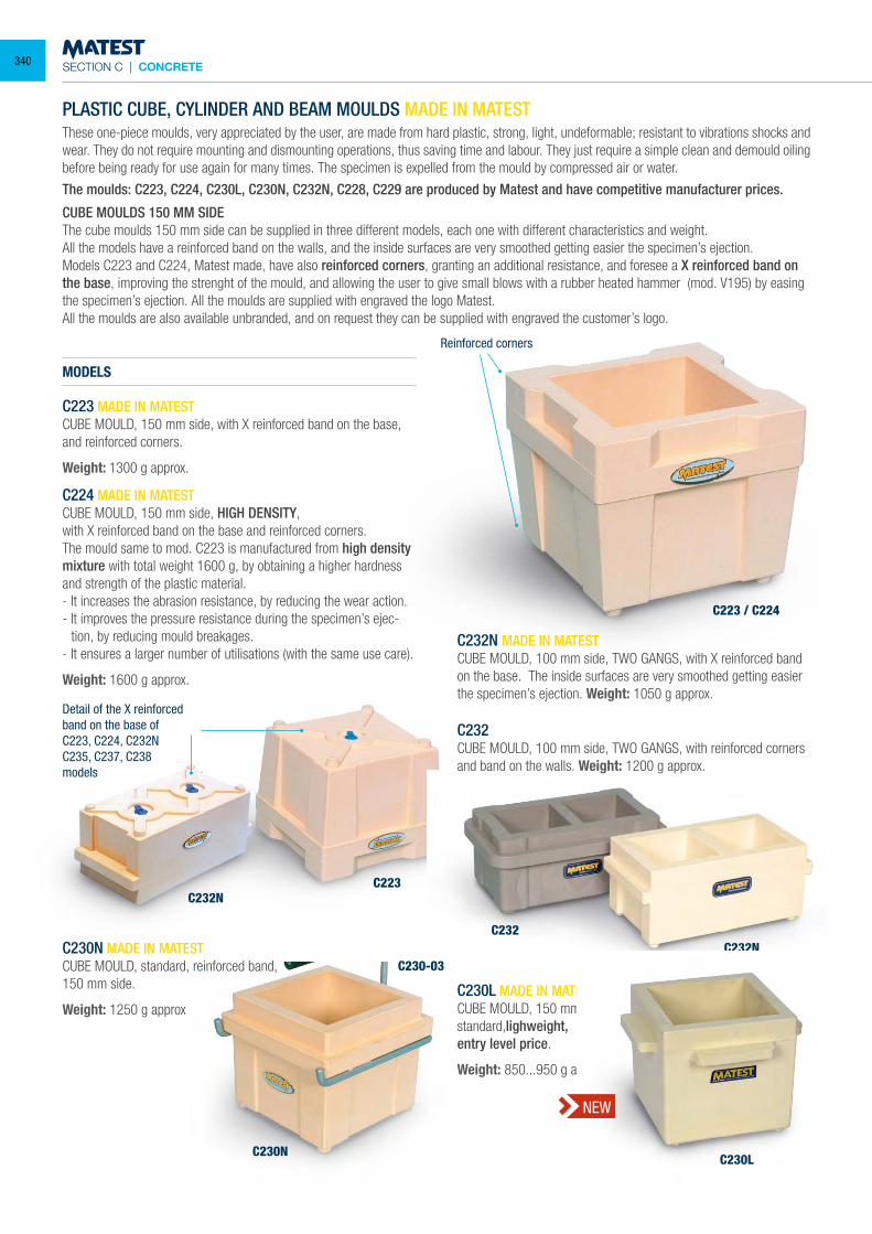
SECTION C | CONCRETE
PLASTIC CUBE, CYLINDER AND BEAM MOULDS MADE IN MATEST
These one-piece moulds, very appreciated by the user, are made from hard plastic, strong, light, undeformable; resistant to vibrations shocks and wear. They do not require mounting and dismounting operations, thus saving time and labour. They just require a simple clean and demould oiling before being ready for use again for many times. The specimen is expelled from the mould by compressed air or water.
The moulds: C223, C224, C230L, C230N, C232N, C228, C229 are produced by Matest and have competitive manufacturer prices.
CUBE MOULDS 150 MM SIDE The cube moulds 150 mm side can be supplied in three different models, each one with different characteristics and weight. All the models have a reinforced band on the walls, and the inside surfaces are very smoothed getting easier the specimen’s ejection. Models C223 and C224, Matest made, have also reinforced corners, granting an additional resistance, and foresee a X reinforced band on the base, improving the strenght of the mould, and allowing the user to give small blows with a rubber heated hammer (mod. V195) by easing the specimen’s ejection. All the moulds are supplied with engraved the logo Matest.All the moulds are also available unbranded, and on request they can be supplied with engraved the customer’s logo.
MODELS
C223 MADE IN MATEST CUBE MOULD, 150 mm side, with X reinforced band on the base, and reinforced corners.
Weight: 1300 g approx.
C224 MADE IN MATEST CUBE MOULD, 150 mm side, HIGH DENSITY,with X reinforced band on the base and reinforced corners. The mould same to mod. C223 is manufactured from high density mixture with total weight 1600 g, by obtaining a higher hardness and strength of the plastic material. - It increases the abrasion resistance, by reducing the wear action. - It improves the pressure resistance during the specimen’s ejec-
tion, by reducing mould breakages. - It ensures a larger number of utilisations (with the same use care).
Weight: 1600 g approx.
C232N MADE IN MATESTCUBE MOULD, 100 mm side, TWO GANGS, with X reinforced band on the base. The inside surfaces are very smoothed getting easier the specimen’s ejection. Weight: 1050 g approx.
C232CUBE MOULD, 100 mm side, TWO GANGS, with reinforced corners and band on the walls. Weight: 1200 g approx.
C230N MADE IN MATESTCUBE MOULD, standard, reinforced band,150 mm side.
Weight: 1250 g approxC230L MADE IN MATESTCUBE MOULD, 150 mm side,standard,lighweight,entry level price.
Weight: 850...950 g approx
Reinforced corners
Detail of the X reinforced band on the base ofC223, C224, C232NC235, C237, C238models
C223 / C224
C232NC223
C230N
C230-03
C232C232N
C230L
NEW
340
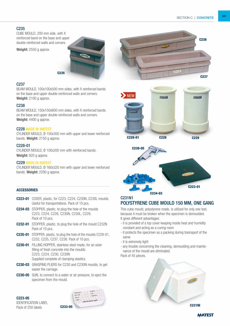
SECTION C | CONCRETE
C235 CUBE MOULD, 200 mm side, with X reinforced band on the base and upper double reinforced walls and corners.
Weight: 2550 g approx.
C237 BEAM MOULD, 100x100x500 mm sides, with X reinforced bands on the base and upper double reinforced walls and corners. Weight: 2100 g approx.
C238 BEAM MOULD, 150x150x600 mm sides, with X reinforced bands on the base and upper double reinforced walls and corners. Weight: 4400 g approx.
C228 MADE IN MATEST CYLINDER MOULD, Ø 150x300 mm with upper and lower reinforced bands. Weight: 2150 g approx.
C228-01 CYLINDER MOULD, Ø 100x200 mm with reinforced bands. Weight: 920 g approx.
C229 MADE IN MATEST CYLINDER MOULD, Ø 160x320 mm with upper and lower reinforced bands. Weight: 2200 g approx.
ACCESSORIES
C223-01 COVER, plastic, for C223, C224, C230N, C230L moulds. Useful for transportations. Pack of 10 pcs.
C234-03 STOPPER, plastic, to plug the hole of the moulds C223, C224, C228, C230N, C230L, C229. Pack of 10 pcs.
C232-01 STOPPER, plastic, to plug the hole of the mould C232N Pack of 10 pcs.
C235-01 STOPPER, plastic, to plug the hole of the moulds C228-01, C232, C235, C237, C238. Pack of 10 pcs.
C230-01 FILLING HOPPER, stainless steel made, for an esier filling of fresh concrete into the moulds:
C223, C224, C230, C230N Supplied complete of clamping elastics.
C230-03 GRASPING PLIERS for C230 and C230N moulds, to get easier the carriage.
C230-05 GUN, to connect to a water or air pressure, to eject the specimen from the mould.
C223-05 IDENTIFICATION LABEL Pack of 250 labels
C231N1POLYSTYRENE CUBE MOULD 150 MM, ONE GANGThis cube mould, polystyrene made, is utilized for only one test, because it must be broken when the specimen is demoulded.It gives different advantages:- it is provided of a top cover keeping inside heat and humidity
constant and acting as a curing room- it protects the specimen as a packing during trasnsport of the
same- it is extremely light- any trouble concerning the cleaning, demoulding and mainte-
nance of the mould are eliminated.Pack of 45 pieces.
C235C237
C230-05
C234-03
C233-05
C223-01
C231NI
C238
C228 C229C228-01
NEW
341
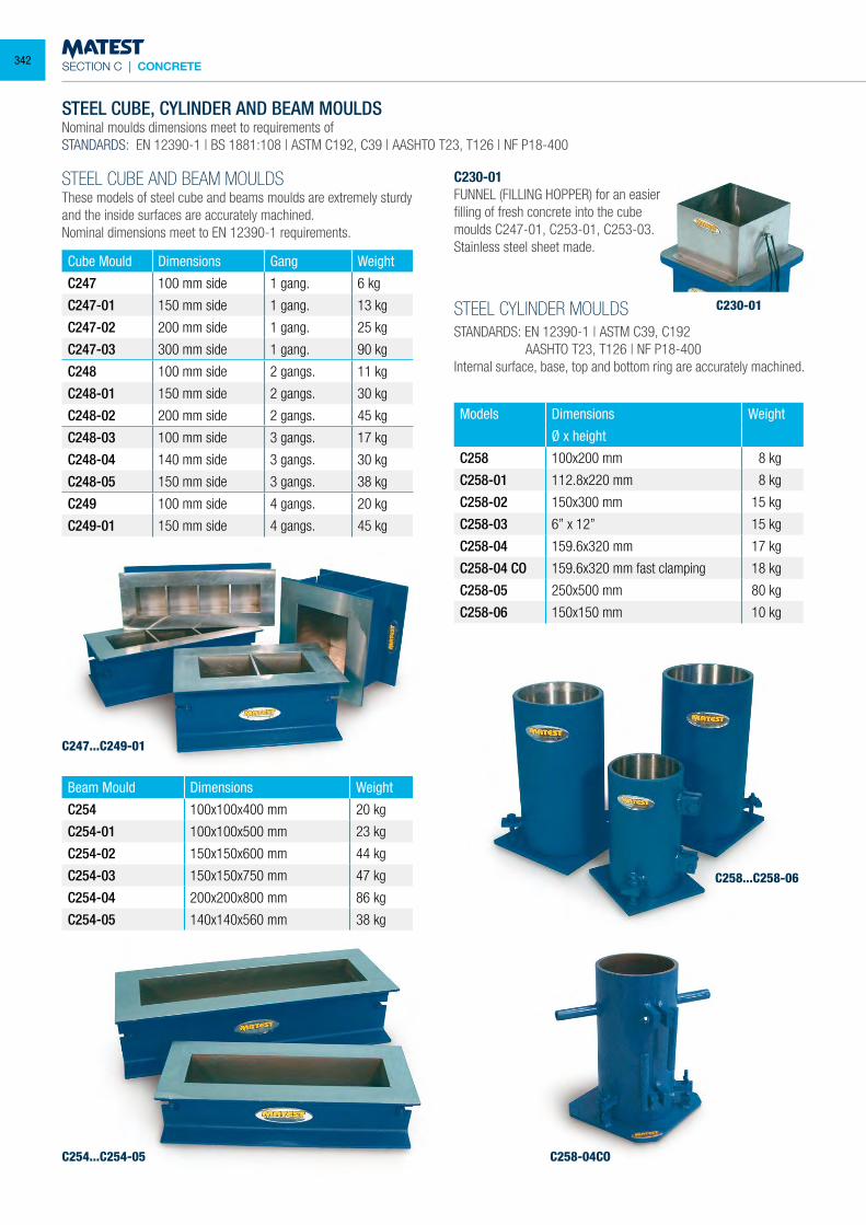
SECTION C | CONCRETE
STEEL CUBE, CYLINDER AND BEAM MOULDSNominal moulds dimensions meet to requirements ofSTANDARDS: EN 12390-1 | BS 1881:108 | ASTM C192, C39 | AASHTO T23, T126 | NF P18-400
STEEL CUBE AND BEAM MOULDSThese models of steel cube and beams moulds are extremely sturdy and the inside surfaces are accurately machined.Nominal dimensions meet to EN 12390-1 requirements.
C230-01FUNNEL (FILLING HOPPER) for an easierfilling of fresh concrete into the cubemoulds C247-01, C253-01, C253-03.Stainless steel sheet made.
STEEL CYLINDER MOULDSSTANDARDS: EN 12390-1 | ASTM C39, C192 AASHTO T23, T126 | NF P18-400Internal surface, base, top and bottom ring are accurately machined.
Models Dimensions Weight
Ø x height
C258 100x200 mm 8 kg
C258-01 112.8x220 mm 8 kg
C258-02 150x300 mm 15 kg
C258-03 6” x 12” 15 kg
C258-04 159.6x320 mm 17 kg
C258-04 CO 159.6x320 mm fast clamping 18 kg
C258-05 250x500 mm 80 kg
C258-06 150x150 mm 10 kg
Beam Mould Dimensions Weight
C254 100x100x400 mm 20 kg
C254-01 100x100x500 mm 23 kg
C254-02 150x150x600 mm 44 kg
C254-03 150x150x750 mm 47 kg
C254-04 200x200x800 mm 86 kg
C254-05 140x140x560 mm 38 kg
C230-01
C247...C249-01
C258...C258-06
C254...C254-05 C258-04CO
Cube Mould Dimensions Gang Weight
C247 100 mm side 1 gang. 6 kg
C247-01 150 mm side 1 gang. 13 kg
C247-02 200 mm side 1 gang. 25 kg
C247-03 300 mm side 1 gang. 90 kg
C248 100 mm side 2 gangs. 11 kg
C248-01 150 mm side 2 gangs. 30 kg
C248-02 200 mm side 2 gangs. 45 kg
C248-03 100 mm side 3 gangs. 17 kg
C248-04 140 mm side 3 gangs. 30 kg
C248-05 150 mm side 3 gangs. 38 kg
C249 100 mm side 4 gangs. 20 kg
C249-01 150 mm side 4 gangs. 45 kg
342
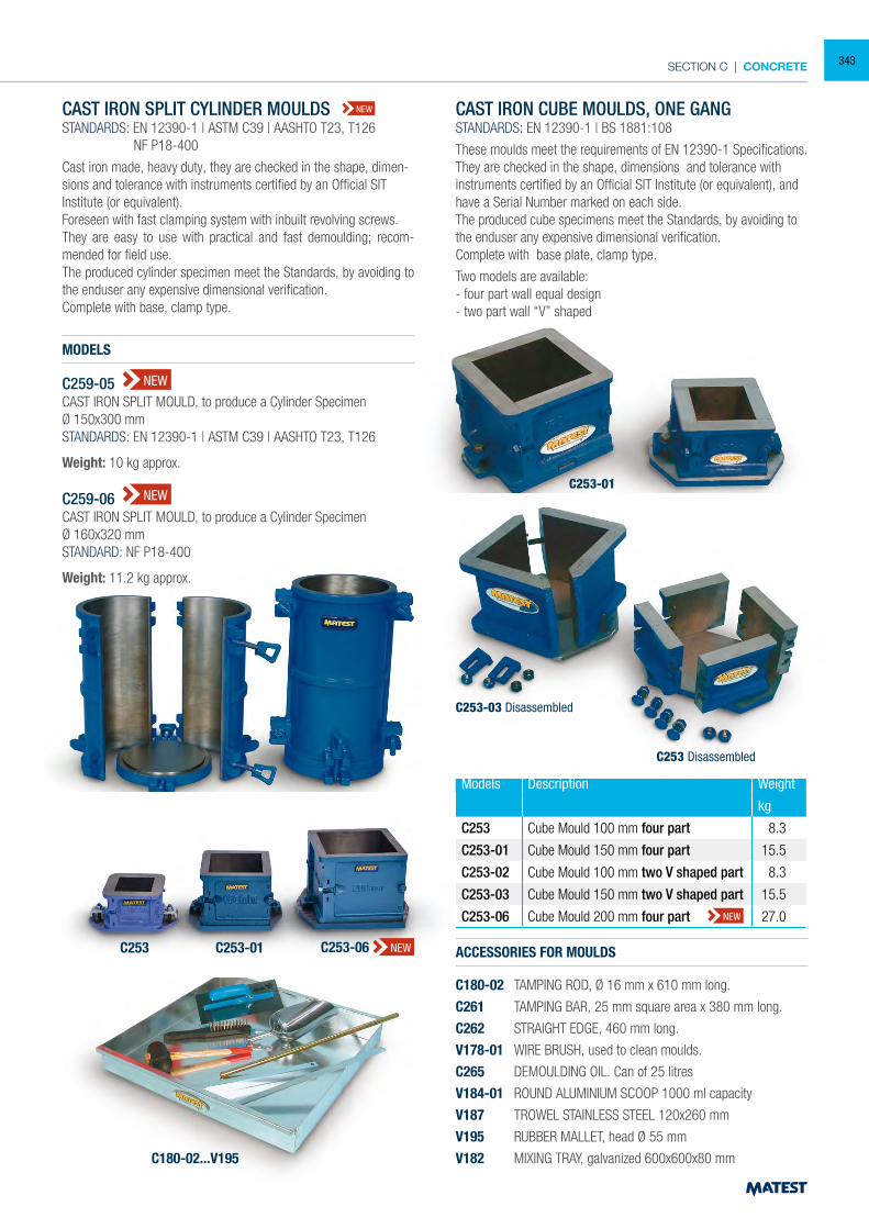
SECTION C | CONCRETE
Models Description Weight
kg
C253 Cube Mould 100 mm four part 8.3
C253-01 Cube Mould 150 mm four part 15.5
C253-02 Cube Mould 100 mm two V shaped part 8.3
C253-03 Cube Mould 150 mm two V shaped part 15.5
C253-06 Cube Mould 200 mm four part 27.0
C259-05
C253-01C253
C259-06
CAST IRON SPLIT CYLINDER MOULDSSTANDARDS: EN 12390-1 | ASTM C39 | AASHTO T23, T126 NF P18-400
Cast iron made, heavy duty, they are checked in the shape, dimen-sions and tolerance with instruments certified by an Official SIT Institute (or equivalent).Foreseen with fast clamping system with inbuilt revolving screws.They are easy to use with practical and fast demoulding; recom-mended for field use.The produced cylinder specimen meet the Standards, by avoiding to the enduser any expensive dimensional verification.Complete with base, clamp type.
MODELS
C259-05CAST IRON SPLIT MOULD, to produce a Cylinder SpecimenØ 150x300 mmSTANDARDS: EN 12390-1 | ASTM C39 | AASHTO T23, T126
Weight: 10 kg approx. C259-06CAST IRON SPLIT MOULD, to produce a Cylinder SpecimenØ 160x320 mmSTANDARD: NF P18-400
Weight: 11.2 kg approx.
CAST IRON CUBE MOULDS, ONE GANGSTANDARDS: EN 12390-1 | BS 1881:108
These moulds meet the requirements of EN 12390-1 Specifications.They are checked in the shape, dimensions and tolerance with instruments certified by an Official SIT Institute (or equivalent), and have a Serial Number marked on each side.The produced cube specimens meet the Standards, by avoiding to the enduser any expensive dimensional verification.Complete with base plate, clamp type.
Two models are available:- four part wall equal design- two part wall “V” shaped
ACCESSORIES FOR MOULDS
C180-02 TAMPING ROD, Ø 16 mm x 610 mm long.
C261 TAMPING BAR, 25 mm square area x 380 mm long.
C262 STRAIGHT EDGE, 460 mm long.
V178-01 WIRE BRUSH, used to clean moulds.
C265 DEMOULDING OIL. Can of 25 litres
V184-01 ROUND ALUMINIUM SCOOP 1000 ml capacity
V187 TROWEL STAINLESS STEEL 120x260 mm
V195 RUBBER MALLET, head Ø 55 mm
V182 MIXING TRAY, galvanized 600x600x80 mmC180-02...V195
C253-03 Disassembled
C253 Disassembled
NEW
NEW
NEW
NEW
C253-06C253-01C253 NEW
343
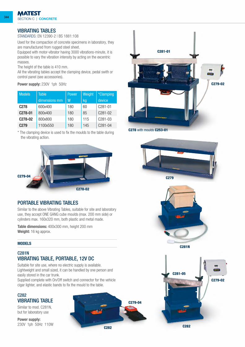
SECTION C | CONCRETE
VIBRATING TABLESSTANDARDS: EN 12390-2 | BS 1881:108
Used for the compaction of concrete specimens in laboratory, they are manufactured from rugged steel sheet.Equipped with motor-vibrator having 3000 vibrations-minute, it is possible to vary the vibration intensity by acting on the excentric masses.The height of the table is 410 mm.All the vibrating tables accept the clamping device, pedal swith or control panel (see accessories).
Power supply: 230V 1ph 50Hz
Models Table Power Weight *Clamping
dimensions mm W kg device
C278 600x400 180 60 C281-01
C278-01 800x400 180 85 C281-02
C278-02 800x800 180 115 C281-03
C279 1100x550 180 145 C281-04
* The clamping device is used to fix the moulds to the table during the vibrating action.
PORTABLE VIBRATING TABLESSimilar to the above Vibrating Tables, suitable for site and laboratory use, they accept ONE GANG cube moulds (max. 200 mm side) or cylinders max. 160x320 mm, both plastic and metal made.
Table dimensions: 400x300 mm, height 200 mmWeight: 16 kg approx.
MODELS
C281NVIBRATING TABLE, PORTABLE, 12V DCSuitable for site use, where no electric supply is available.Lightweight and small sized, it can be handled by one person and easily stored in the car trunk.Supplied complete with On/Off switch and connector for the vehicle cigar lighter, and elastic bands to fix the mould to the table.
C282VIBRATING TABLESimilar to mod. C281N,but for laboratory use
Power supply:230V 1ph 50Hz 110W
C281-01
C279C279-04
C278-02
C281N
C282
C281-05
C279-02
C279-02
C279-04
C282
C278 with moulds C253-01
344
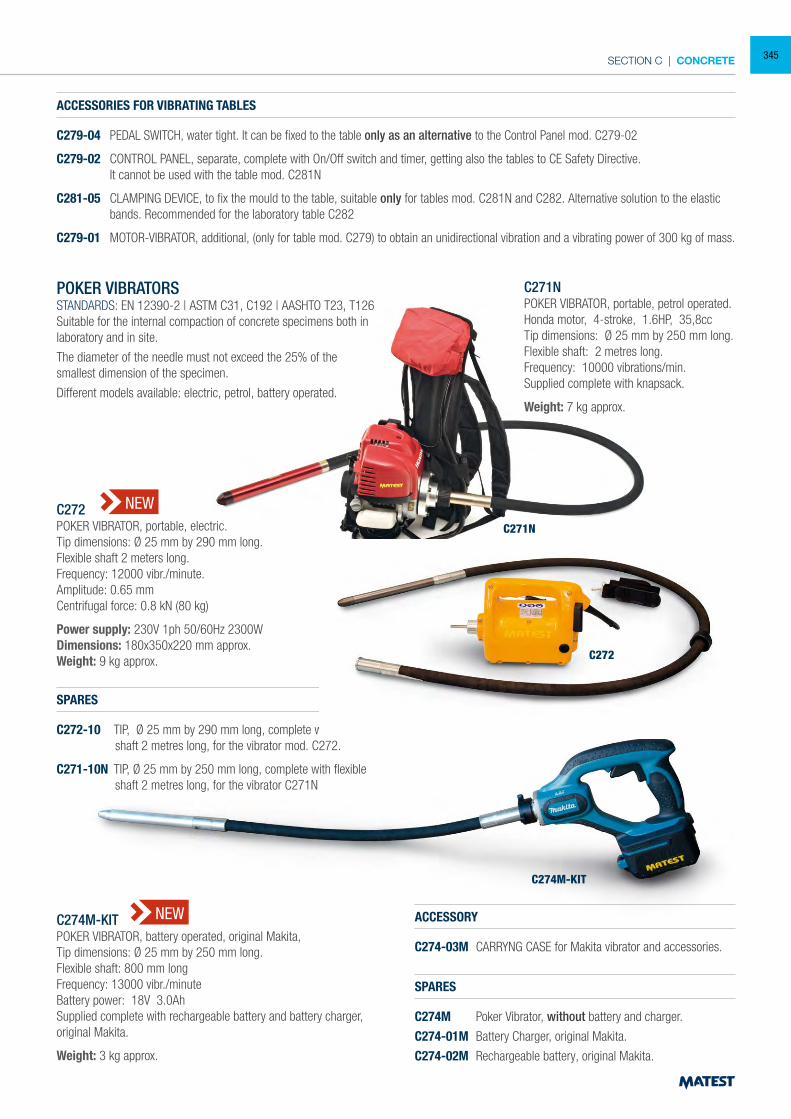
SECTION C | CONCRETE
ACCESSORIES FOR VIBRATING TABLES
C279-04 PEDAL SWITCH, water tight. It can be fixed to the table only as an alternative to the Control Panel mod. C279-02
C279-02 CONTROL PANEL, separate, complete with On/Off switch and timer, getting also the tables to CE Safety Directive. It cannot be used with the table mod. C281N
C281-05 CLAMPING DEVICE, to fix the mould to the table, suitable only for tables mod. C281N and C282. Alternative solution to the elastic bands. Recommended for the laboratory table C282
C279-01 MOTOR-VIBRATOR, additional, (only for table mod. C279) to obtain an unidirectional vibration and a vibrating power of 300 kg of mass.
POKER VIBRATORSSTANDARDS: EN 12390-2 | ASTM C31, C192 | AASHTO T23, T126Suitable for the internal compaction of concrete specimens both in laboratory and in site.
The diameter of the needle must not exceed the 25% of thesmallest dimension of the specimen.
Different models available: electric, petrol, battery operated.
C271NPOKER VIBRATOR, portable, petrol operated.Honda motor, 4-stroke, 1.6HP, 35,8ccTip dimensions: Ø 25 mm by 250 mm long.Flexible shaft: 2 metres long.Frequency: 10000 vibrations/min.Supplied complete with knapsack.
Weight: 7 kg approx.
C272POKER VIBRATOR, portable, electric.Tip dimensions: Ø 25 mm by 290 mm long.Flexible shaft 2 meters long.Frequency: 12000 vibr./minute.Amplitude: 0.65 mmCentrifugal force: 0.8 kN (80 kg)
Power supply: 230V 1ph 50/60Hz 2300WDimensions: 180x350x220 mm approx.Weight: 9 kg approx.
SPARES
C272-10 TIP, Ø 25 mm by 290 mm long, complete with flexible shaft 2 metres long, for the vibrator mod. C272.
C271-10N TIP, Ø 25 mm by 250 mm long, complete with flexible shaft 2 metres long, for the vibrator C271N
C274M-KITPOKER VIBRATOR, battery operated, original Makita,Tip dimensions: Ø 25 mm by 250 mm long.Flexible shaft: 800 mm longFrequency: 13000 vibr./minuteBattery power: 18V 3.0AhSupplied complete with rechargeable battery and battery charger, original Makita.
Weight: 3 kg approx.
SPARES
C274M Poker Vibrator, without battery and charger.
C274-01M Battery Charger, original Makita.
C274-02M Rechargeable battery, original Makita.
ACCESSORY
C274-03M CARRYNG CASE for Makita vibrator and accessories.
C271N
C272
C274M-KIT
NEW
NEW
345
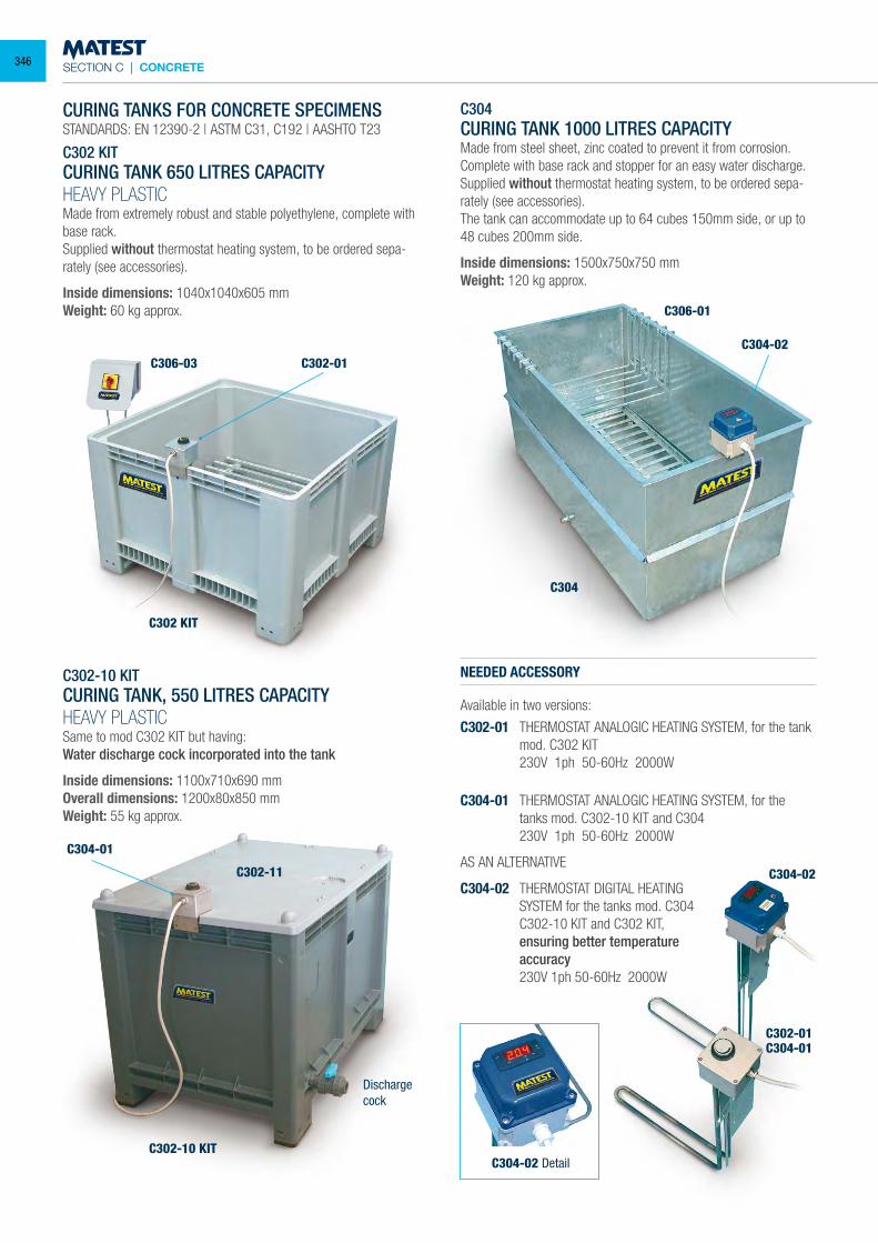
SECTION C | CONCRETE
CURING TANKS FOR CONCRETE SPECIMENSSTANDARDS: EN 12390-2 | ASTM C31, C192 | AASHTO T23
C302 KITCURING TANK 650 LITRES CAPACITYHEAVY PLASTICMade from extremely robust and stable polyethylene, complete with base rack.Supplied without thermostat heating system, to be ordered sepa-rately (see accessories).
Inside dimensions: 1040x1040x605 mmWeight: 60 kg approx.
C302-10 KIT CURING TANK, 550 LITRES CAPACITYHEAVY PLASTIC Same to mod C302 KIT but having: Water discharge cock incorporated into the tank
Inside dimensions: 1100x710x690 mm Overall dimensions: 1200x80x850 mm Weight: 55 kg approx.
C304CURING TANK 1000 LITRES CAPACITYMade from steel sheet, zinc coated to prevent it from corrosion. Complete with base rack and stopper for an easy water discharge.Supplied without thermostat heating system, to be ordered sepa-rately (see accessories).The tank can accommodate up to 64 cubes 150mm side, or up to 48 cubes 200mm side.
Inside dimensions: 1500x750x750 mmWeight: 120 kg approx.
NEEDED ACCESSORY
Available in two versions:
C302-01 THERMOSTAT ANALOGIC HEATING SYSTEM, for the tank mod. C302 KIT
230V 1ph 50-60Hz 2000W
C304-01 THERMOSTAT ANALOGIC HEATING SYSTEM, for the tanks mod. C302-10 KIT and C304
230V 1ph 50-60Hz 2000W
AS AN ALTERNATIVE
C304-02 THERMOSTAT DIGITAL HEATING SYSTEM for the tanks mod. C304
C302-10 KIT and C302 KIT, ensuring better temperature accuracy
230V 1ph 50-60Hz 2000W
C302 KIT
C302-11
C302-10 KIT
C304
C306-03
C306-01
C302-01
C302-01C304-01
C304-02
C304-01
C304-02
C304-02 Detail
Dischargecock
346
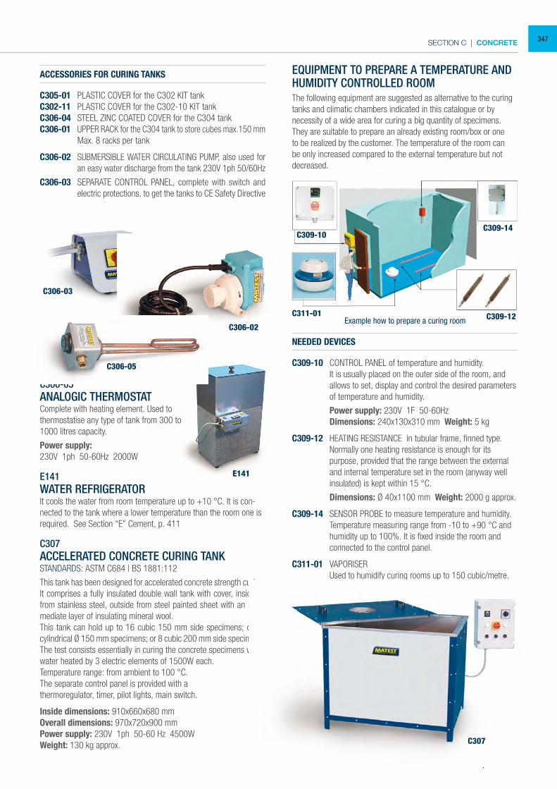
SECTION C | CONCRETE
C309-10C309-14
C309-12C311-01Example how to prepare a curing room
C306-05ANALOGIC THERMOSTAT Complete with heating element. Used to thermostatise any type of tank from 300 to 1000 litres capacity.
Power supply:230V 1ph 50-60Hz 2000W
E141WATER REFRIGERATORIt cools the water from room temperature up to +10 °C. It is con-nected to the tank where a lower temperature than the room one is required. See Section “E” Cement, p. 411
C307ACCELERATED CONCRETE CURING TANKSTANDARDS: ASTM C684 | BS 1881:112
This tank has been designed for accelerated concrete strength curing.It comprises a fully insulated double wall tank with cover, inside all from stainless steel, outside from steel painted sheet with an inter-mediate layer of insulating mineral wool.This tank can hold up to 16 cubic 150 mm side specimens; or 16 cylindrical Ø 150 mm specimens; or 8 cubic 200 mm side specimens.The test consists essentially in curing the concrete specimens with water heated by 3 electric elements of 1500W each.Temperature range: from ambient to 100 °C.The separate control panel is provided with athermoregulator, timer, pilot lights, main switch.
Inside dimensions: 910x660x680 mmOverall dimensions: 970x720x900 mmPower supply: 230V 1ph 50-60 Hz 4500WWeight: 130 kg approx.
EQUIPMENT TO PREPARE A TEMPERATURE AND HUMIDITY CONTROLLED ROOMThe following equipment are suggested as alternative to the curing tanks and climatic chambers indicated in this catalogue or by necessity of a wide area for curing a big quantity of specimens. They are suitable to prepare an already existing room/box or one to be realized by the customer. The temperature of the room can be only increased compared to the external temperature but not decreased.
NEEDED DEVICES
C309-10 CONTROL PANEL of temperature and humidity. It is usually placed on the outer side of the room, and
allows to set, display and control the desired parameters of temperature and humidity.
Power supply: 230V 1F 50-60Hz Dimensions: 240x130x310 mm Weight: 5 kg
C309-12 HEATING RESISTANCE in tubular frame, finned type. Normally one heating resistance is enough for its
purpose, provided that the range between the external and internal temperature set in the room (anyway well insulated) is kept within 15 °C.
Dimensions: Ø 40x1100 mm Weight: 2000 g approx.
C309-14 SENSOR PROBE to measure temperature and humidity. Temperature measuring range from -10 to +90 °C and
humidity up to 100%. It is fixed inside the room and connected to the control panel.
C311-01 VAPORISER Used to humidify curing rooms up to 150 cubic/metre. Technical data: see p. 350
C306-03
C306-05
E141
C306-02
C307
ACCESSORIES FOR CURING TANKS
C305-01 PLASTIC COVER for the C302 KIT tank C302-11 PLASTIC COVER for the C302-10 KIT tankC306-04 STEEL ZINC COATED COVER for the C304 tankC306-01 UPPER RACK for the C304 tank to store cubes max.150 mm Max. 8 racks per tank
C306-02 SUBMERSIBLE WATER CIRCULATING PUMP, also used for an easy water discharge from the tank 230V 1ph 50/60Hz
C306-03 SEPARATE CONTROL PANEL, complete with switch and electric protections, to get the tanks to CE Safety Directive
347
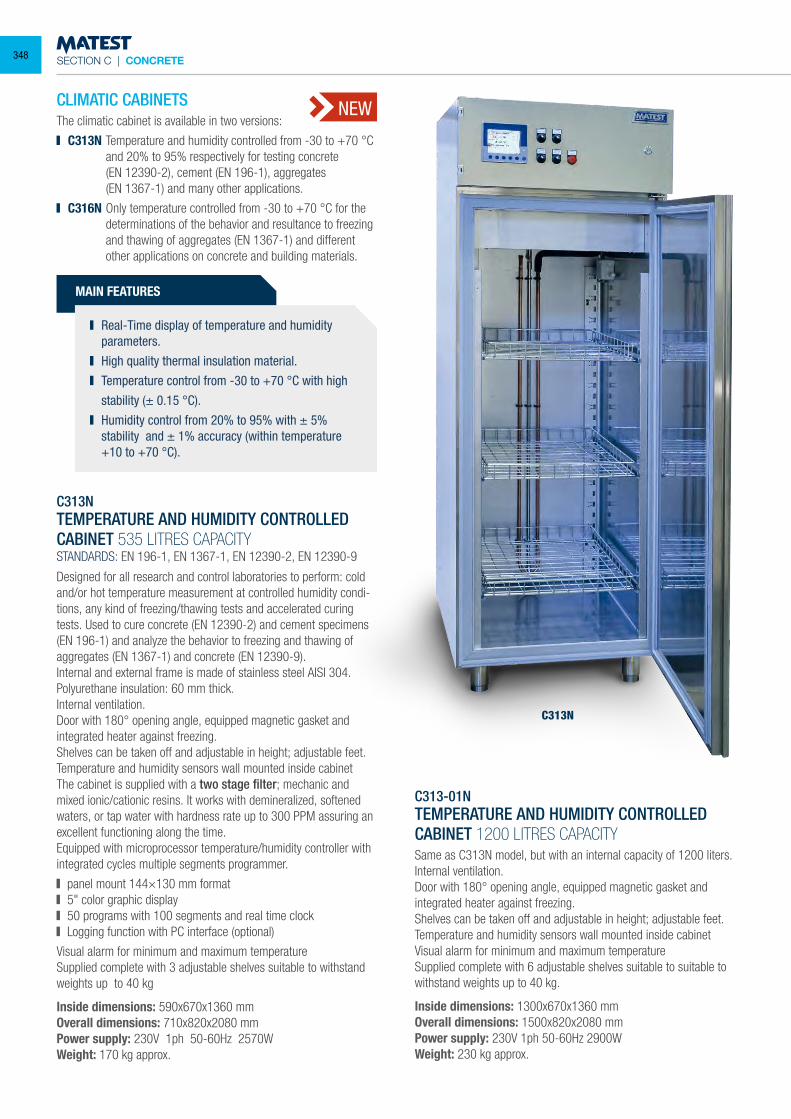
SECTION C | CONCRETE
C313NTEMPERATURE AND HUMIDITY CONTROLLEDCABINET 535 LITRES CAPACITYSTANDARDS: EN 196-1, EN 1367-1, EN 12390-2, EN 12390-9
Designed for all research and control laboratories to perform: coldand/or hot temperature measurement at controlled humidity condi-tions, any kind of freezing/thawing tests and accelerated curingtests. Used to cure concrete (EN 12390-2) and cement specimens(EN 196-1) and analyze the behavior to freezing and thawing ofaggregates (EN 1367-1) and concrete (EN 12390-9).Internal and external frame is made of stainless steel AISI 304.Polyurethane insulation: 60 mm thick.Internal ventilation.Door with 180° opening angle, equipped magnetic gasket and integrated heater against freezing.Shelves can be taken off and adjustable in height; adjustable feet.Temperature and humidity sensors wall mounted inside cabinetThe cabinet is supplied with a two stage filter; mechanic and mixed ionic/cationic resins. It works with demineralized, softened waters, or tap water with hardness rate up to 300 PPM assuring an excellent functioning along the time.Equipped with microprocessor temperature/humidity controller with integrated cycles multiple segments programmer.
panel mount 144×130 mm format 5" color graphic display 50 programs with 100 segments and real time clock Logging function with PC interface (optional)
Visual alarm for minimum and maximum temperatureSupplied complete with 3 adjustable shelves suitable to withstand weights up to 40 kg
Inside dimensions: 590x670x1360 mmOverall dimensions: 710x820x2080 mmPower supply: 230V 1ph 50-60Hz 2570WWeight: 170 kg approx.
C313-01NTEMPERATURE AND HUMIDITY CONTROLLED CABINET 1200 LITRES CAPACITYSame as C313N model, but with an internal capacity of 1200 liters.Internal ventilation.Door with 180° opening angle, equipped magnetic gasket and integrated heater against freezing.Shelves can be taken off and adjustable in height; adjustable feet.Temperature and humidity sensors wall mounted inside cabinetVisual alarm for minimum and maximum temperatureSupplied complete with 6 adjustable shelves suitable to suitable to withstand weights up to 40 kg.
Inside dimensions: 1300x670x1360 mmOverall dimensions: 1500x820x2080 mmPower supply: 230V 1ph 50-60Hz 2900WWeight: 230 kg approx.
MAIN FEATURES
Real-Time display of temperature and humidity parameters.
High quality thermal insulation material. Temperature control from -30 to +70 °C with high
stability (± 0.15 °C). Humidity control from 20% to 95% with ± 5%
stability and ± 1% accuracy (within temperature +10 to +70 °C).
CLIMATIC CABINETSThe climatic cabinet is available in two versions:
C313N Temperature and humidity controlled from -30 to +70 °C and 20% to 95% respectively for testing concrete
(EN 12390-2), cement (EN 196-1), aggregates (EN 1367-1) and many other applications.
C316N Only temperature controlled from -30 to +70 °C for the determinations of the behavior and resultance to freezing
and thawing of aggregates (EN 1367-1) and different other applications on concrete and building materials.
NEW
C313N
348
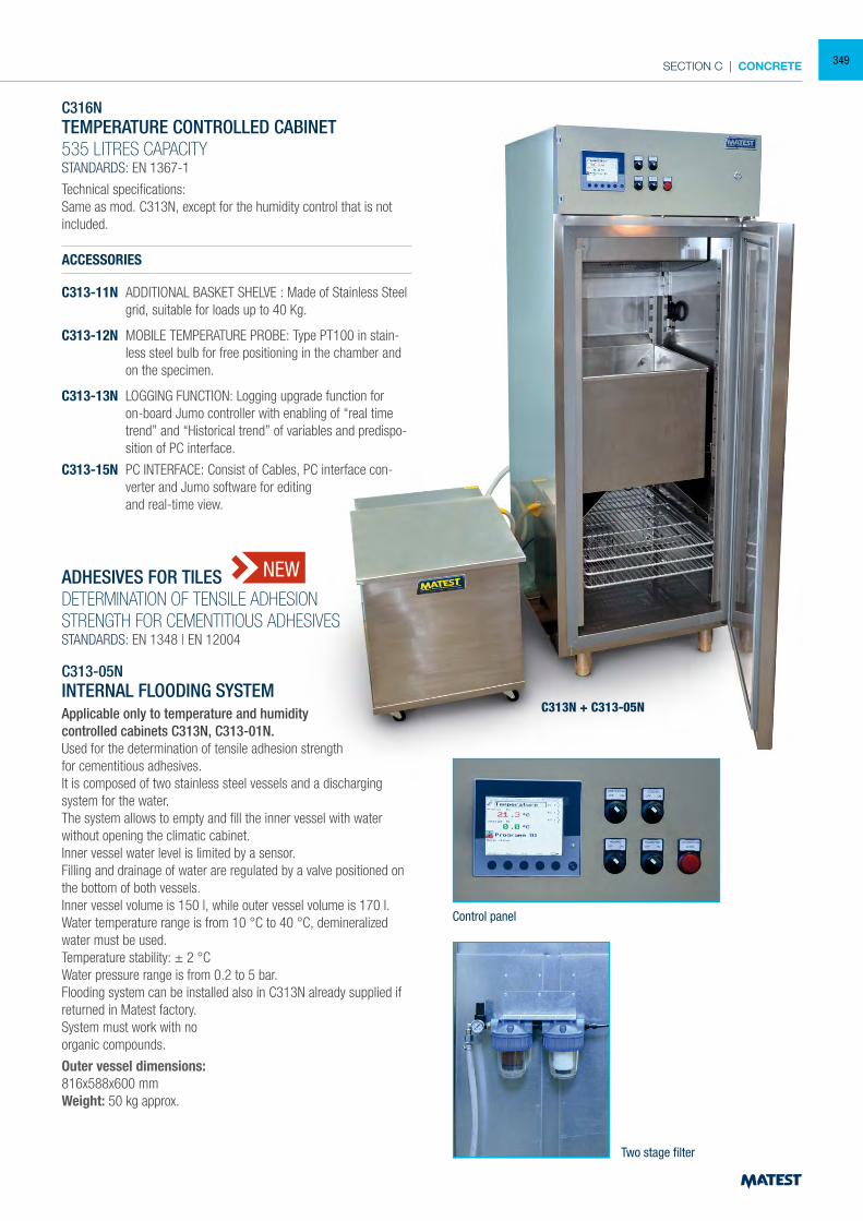
SECTION C | CONCRETE
C316NTEMPERATURE CONTROLLED CABINET535 LITRES CAPACITYSTANDARDS: EN 1367-1
Technical specifications:Same as mod. C313N, except for the humidity control that is not included.
ACCESSORIES
C313-11N ADDITIONAL BASKET SHELVE : Made of Stainless Steel grid, suitable for loads up to 40 Kg.
C313-12N MOBILE TEMPERATURE PROBE: Type PT100 in stain-less steel bulb for free positioning in the chamber and on the specimen.
C313-13N LOGGING FUNCTION: Logging upgrade function for on-board Jumo controller with enabling of “real time trend” and “Historical trend” of variables and predispo-sition of PC interface.
C313-15N PC INTERFACE: Consist of Cables, PC interface con-verter and Jumo software for editing
and real-time view.
ADHESIVES FOR TILESDETERMINATION OF TENSILE ADHESIONSTRENGTH FOR CEMENTITIOUS ADHESIVESSTANDARDS: EN 1348 | EN 12004
C313-05NINTERNAL FLOODING SYSTEMApplicable only to temperature and humiditycontrolled cabinets C313N, C313-01N.Used for the determination of tensile adhesion strength for cementitious adhesives.It is composed of two stainless steel vessels and a discharging system for the water.The system allows to empty and fill the inner vessel with water without opening the climatic cabinet.Inner vessel water level is limited by a sensor.Filling and drainage of water are regulated by a valve positioned on the bottom of both vessels.Inner vessel volume is 150 l, while outer vessel volume is 170 l.Water temperature range is from 10 °C to 40 °C, demineralized water must be used.Temperature stability: ± 2 °CWater pressure range is from 0.2 to 5 bar.Flooding system can be installed also in C313N already supplied if returned in Matest factory.System must work with noorganic compounds.
Outer vessel dimensions:816x588x600 mmWeight: 50 kg approx.
C313N + C313-05N
NEW
Two stage filter
Control panel
349

SECTION C | CONCRETE
C107-29
C107-10
C107-20
C107-12
Pads + Retainers+ Specimen configuration
UNBONDED CAPPING PADS AND RETAINERSSTANDARDS: ASTM C1231 | AASHTO T22, T851
Used for compression tests on concrete cylinder specimens, as an alternative method to the sulphur capping and grinding machine.Two steel capping retainers are applied on the two flat surfaces of the cylinder. Two neoprene pads are put between them, for a better load distri-bution.The neoprene pads are available in two models:- 60 shore hardness pads for expected strength from 10 to 48 MPa- 70 shore hardness pads for expected strength over 48 MPaThe system is not applicable for expected strength lower than 10 MpaThe couple of retainers + neoprene pads have a total thickness of 46 mm. Therefore the testing chamber of the press must have more vertical clearance than the height of the specimen + 46 mm.
MODELS
C107-09 CAPPING RETAINERS (couple) for Ø 100x200 mm cylinders.
C107-10 CAPPING RETAINERS (couple) for Ø 150x300 mm and 6x12” cylinders.
C107-12 CAPPING RETAINERS (couple) for Ø 160x320 mm cylinders
C107-18 NEOPRENE PADS (couple) 60 shore A for Ø 100x200 mm cylinders
C107-19 NEOPRENE PADS (couple) 70 shore A for Ø 100x200 mm cylinders
C107-20 NEOPRENE PADS (couple) 60 shore for Ø 150x300 mm and 6”x12” cylinders
C107-21 NEOPRENE PADS (couple) 70 shore for Ø 150x300 mm and 6”x12” cylinders
C107-25 NEOPRENE PADS (couple) 60 shore for Ø 160x320 mm cylinders
C107-26 NEOPRENE PADS (couple) 70 shore for Ø 160x320 mm cylinders
C107-29 NEOPRENE SHEET (couple) 60 shore A dimensions: 600x400x12 mm for test on blocks.
C311-01CURING ROOM VAPORISER UP TO 150 M³
Used to humidify curing rooms for concrete and mortar specimens.Max. room capacity: 150 cubic/metre.Supplied complete of level regulator with antioverflow, that allows the direct connection to the water net, for a continuous use of the vaporiser.
Power supply: 230V 1ph 50 HzDimensions: Ø 360x230 mmWeight: 3.5 kg approx.
C312-02CURING ROOM VAPORISER UP TO 500 M³
Same as mod. C311-01, but more powerful for rooms up to 500 cubic/metre capacity.Supplied complete of level regulator with antioverflow, that allows the direct connection to the water net, for a continuous use of the vaporiser.
Power supply: 230V 1ph 50 HzDimensions: Ø 420x350 mmWeight: 8 kg approx.
ACCESSORY FOR MOD. C311-01, C312-02
C312-10 HUMIDISTAT to automatically control the room humidity, range 30...100 %
SPARE
C312-11 Level regulator, complete of antioverflow.
C311-01 C312-10
C312-02
350
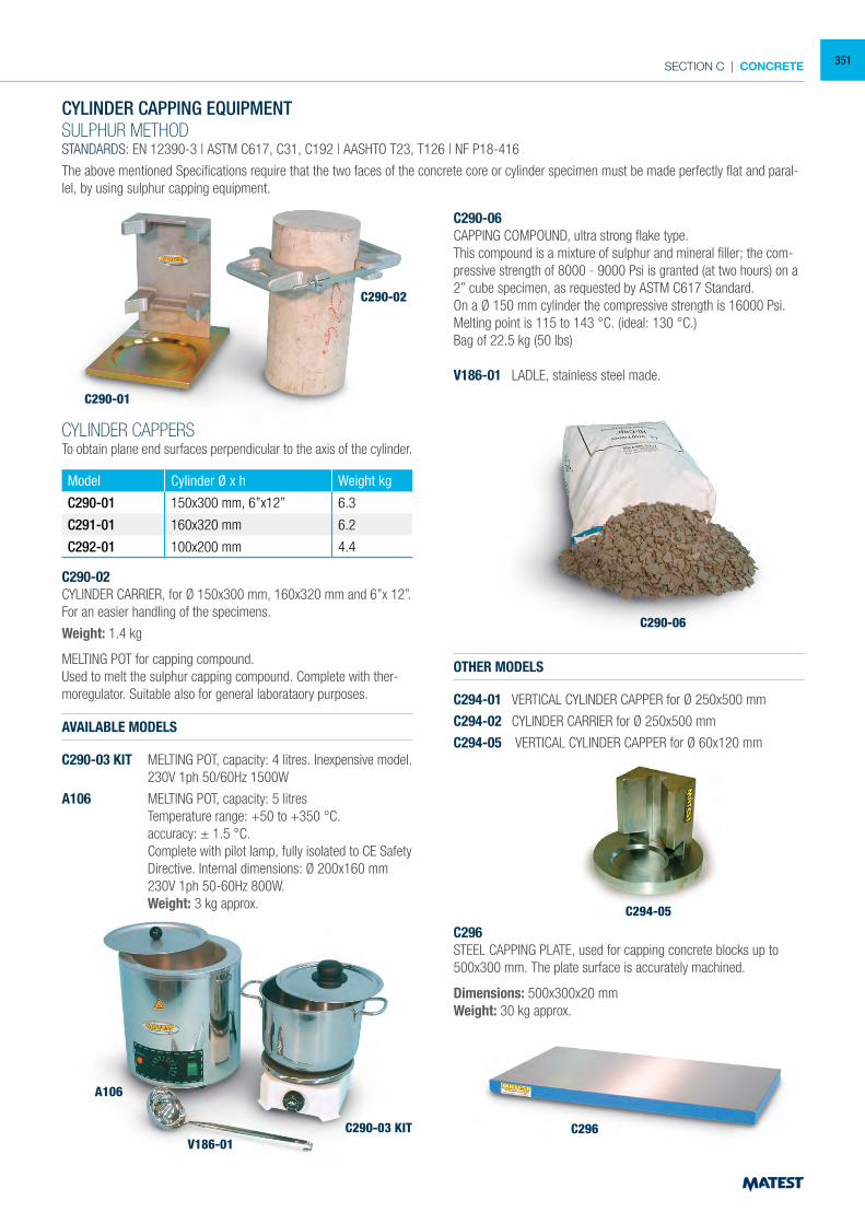
SECTION C | CONCRETE
CYLINDER CAPPING EQUIPMENTSULPHUR METHODSTANDARDS: EN 12390-3 | ASTM C617, C31, C192 | AASHTO T23, T126 | NF P18-416
The above mentioned Specifications require that the two faces of the concrete core or cylinder specimen must be made perfectly flat and paral-lel, by using sulphur capping equipment.
CYLINDER CAPPERSTo obtain plane end surfaces perpendicular to the axis of the cylinder.
Model Cylinder Ø x h Weight kg
C290-01 150x300 mm, 6”x12” 6.3
C291-01 160x320 mm 6.2
C292-01 100x200 mm 4.4
C290-02CYLINDER CARRIER, for Ø 150x300 mm, 160x320 mm and 6”x 12”.For an easier handling of the specimens.
Weight: 1.4 kg
MELTING POT for capping compound.Used to melt the sulphur capping compound. Complete with ther-moregulator. Suitable also for general laborataory purposes.
AVAILABLE MODELS
C290-03 KIT MELTING POT, capacity: 4 litres. Inexpensive model. 230V 1ph 50/60Hz 1500W
A106 MELTING POT, capacity: 5 litres Temperature range: +50 to +350 °C. accuracy: ± 1.5 °C. Complete with pilot lamp, fully isolated to CE Safety
Directive. Internal dimensions: Ø 200x160 mm 230V 1ph 50-60Hz 800W. Weight: 3 kg approx.
C290-06CAPPING COMPOUND, ultra strong flake type.This compound is a mixture of sulphur and mineral filler; the com-pressive strength of 8000 - 9000 Psi is granted (at two hours) on a 2” cube specimen, as requested by ASTM C617 Standard.On a Ø 150 mm cylinder the compressive strength is 16000 Psi.Melting point is 115 to 143 °C. (ideal: 130 °C.)Bag of 22.5 kg (50 lbs)
V186-01 LADLE, stainless steel made.
OTHER MODELS
C294-01 VERTICAL CYLINDER CAPPER for Ø 250x500 mm
C294-02 CYLINDER CARRIER for Ø 250x500 mm
C294-05 VERTICAL CYLINDER CAPPER for Ø 60x120 mm
C296STEEL CAPPING PLATE, used for capping concrete blocks up to 500x300 mm. The plate surface is accurately machined.
Dimensions: 500x300x20 mmWeight: 30 kg approx.
C290-01
A106
V186-01C290-03 KIT
C290-06
C294-05
C296
C290-02
351
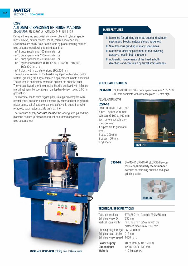
SECTION C | CONCRETE
C299 AUTOMATIC SPECIMEN GRINDING MACHINE STANDARDS: EN 12390-2 | ASTM D4543 | UNI 6132
Designed to grind and polish concrete cube and cylinder speci-mens, blocks, natural stones, rocks, ceramic materials etc. Specimens are easily fixed to the table by proper locking stirrups (see accessories) allowing to grind at a time: - n° 3 cube specimens 100 mm side, or - n° 3 cube specimens 150 mm side, or - n° 2 cube specimens 200 mm side, or - n° 2 cylinder specimens Ø 100x200, 110x220, 150x300,
160x320 mm, or - n° 1 block with max. dimensions 390x250 mm The radial mouvement of the head is equipped with end of stroke system, granting the fully automatic displacament in both directions. The column is completely protected against the abrasive dust. The vertical lowering of the grinding head is achieved with infinitesi-mal adjustments by operating on the top handwheel having 0.05 mm graduations. The machine, made from rugged plate, is supplied complete with control panel, coolant/decantation tank (by water and emulsifying oil), motor pump, set of abrasive sectors, safety chip guard that when removed, stops automatically the machine.
The standard supply does not include the locking stirrups and the diamond sectors (8 pieces) that must be ordered separately(see accessories).
TECHNICAL SPECIFICATIONS
Table dimensions: 775x280 mm (usefull: 750x235 mm) Grinding wheel Ø: 330 mm Vertical span width: min. 175 mm (95 mm with the distance piece) max. 380 mm Grinding height range: 95...380 mmGrinding head stroke: 215 mm Grinding wheel speed: 1400 rpm.
Power supply: 400V 3ph 50Hz 2700W Dimensions: 1220x1080x1730 mm Weight: 410 kg approx.
MAIN FEATURES
Designed for grinding concrete cube and cylinder specimens, blocks, natural stones, rocks etc.
Simultaneous grinding of many specimens. Motorized radial displacement of the revolving
abrasive head in both directions. Automatic mouvements of the head in both
directions and controlled by travel limit switches.
NEEDED ACCESSORIES
C300-06N LOCKING STIRRUPS for cube specimens side 100, 150, 200 mm complete with distance piece 85 mm high.
AS AN ALTERNATIVE
C299-10FAST LOCKING DEVICE, for:cubes 150 and 200 mm; cylinders Ø 100 to 160 mmEach device accepts only one specimen.It is possible to grind at a time:1 cube 200 mm;2 cubes 150 mm;2 cylinders.
C300-02 DIAMOND GRINDING SECTOR (8 pieces required) particularly recommended because of their long duration and good grinding action.
C299-10
C300-02
C299 with C300-06N holding one 150 mm cube
352
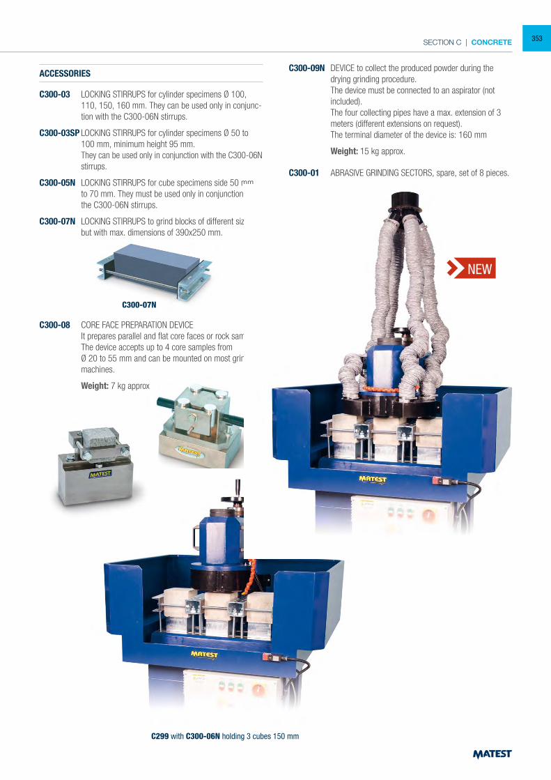
SECTION C | CONCRETE
C300-07N
C300-09N
C300-08
C300-05N
ACCESSORIES
C300-03 LOCKING STIRRUPS for cylinder specimens Ø 100, 110, 150, 160 mm. They can be used only in conjunc-tion with the C300-06N stirrups.
C300-03SP LOCKING STIRRUPS for cylinder specimens Ø 50 to 100 mm, minimum height 95 mm.
They can be used only in conjunction with the C300-06N stirrups.
C300-05N LOCKING STIRRUPS for cube specimens side 50 mm to 70 mm. They must be used only in conjunction with the C300-06N stirrups.
C300-07N LOCKING STIRRUPS to grind blocks of different sizes, but with max. dimensions of 390x250 mm.
C300-08 CORE FACE PREPARATION DEVICE It prepares parallel and flat core faces or rock samples. The device accepts up to 4 core samples from Ø 20 to 55 mm and can be mounted on most grinding
machines.
Weight: 7 kg approx
C300-09N DEVICE to collect the produced powder during the drying grinding procedure.
The device must be connected to an aspirator (not included).
The four collecting pipes have a max. extension of 3 meters (different extensions on request).
The terminal diameter of the device is: 160 mm
Weight: 15 kg approx.
C300-01 ABRASIVE GRINDING SECTORS, spare, set of 8 pieces.
C299 with C300-06N holding 3 cubes 150 mm
NEW
353
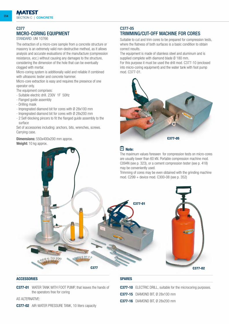
SECTION C | CONCRETE
C377MICRO-CORING EQUIPMENTSTANDARD: UNI 10766
The extraction of a micro-core sample from a concrete structure or masonry is an extremely valid non-destructive method, as it allows analysis and accurate evaluations of the manufacture (compression resistance, ecc.) without causing any damages to the structure, considering the dimension of the hole that can be eventually clogged with mortar.Micro-coring system is additionally valid and reliable if combined with ultrasonic tester and concrete hammer.Micro-core extraction is easy and requires the presence of one operator only.The equipment comprises:- Suitable electric drill. 230V 1F 50Hz- Flanged guide assembly- Drilling mask- Impregnated diamond bit for cores with Ø 28x100 mm- Impregnated diamond bit for cores with Ø 28x200 mm- 2 Self-blocking pincers to fit the flanged guide assembly to the
surfaceSet of accessories including: anchors, bits, wrenches, screws.Carrying case.
Dimensions: 550x400x200 mm approx.Weight: 10 kg approx.
ACCESSORIES
C377-01 WATER TANK WITH FOOT PUMP, that leaves the hands of the operators free for coring
AS ALTERNATIVE:
C377-02 AIR-WATER PRESSURE TANK, 10 liters capacity
C377-05TRIMMING/CUT-OFF MACHINE FOR CORESSuitable to cut and trim cores to be prepared for compression tests, where the flatness of both surfaces is a basic condition to obtain correct results.The equipment is made of stainless steel and aluminum and is supplied complete with diamond blade Ø 180 mm.For this purpose it must be used the drill mod. C377-10 (enclosed into micro-coring equipment) and the water tank with foot pump mod. C377-01.
Note:The maximum values foreseen for compression tests on micro-cores are usually lower than 60 kN. Portable compression machine mod. C094N (see p. 323), or a cement compression tester (see p. 418) may be conveniently used.Trimming of cores may be even obtained with the grinding machine mod. C299 + device mod. C300-08 (see p. 352)
SPARES
C377-10 ELECTRIC DRILL, suitable for the microcoring purposes.
C377-15 DIAMOND BIT, Ø 28x100 mm
C377-16 DIAMOND BIT, Ø 28x200 mm
C377-05
C377-01
C377-02C377
354
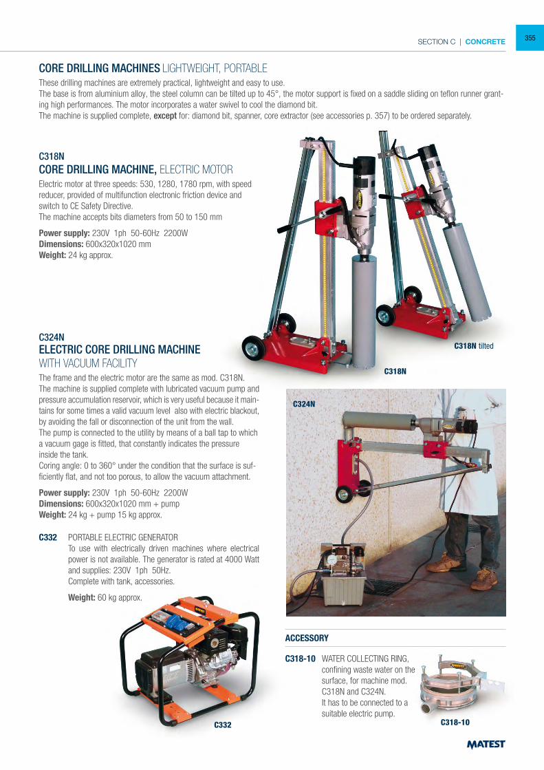
SECTION C | CONCRETE
CORE DRILLING MACHINES LIGHTWEIGHT, PORTABLEThese drilling machines are extremely practical, lightweight and easy to use.The base is from aluminium alloy, the steel column can be tilted up to 45°, the motor support is fixed on a saddle sliding on teflon runner grant-ing high performances. The motor incorporates a water swivel to cool the diamond bit.The machine is supplied complete, except for: diamond bit, spanner, core extractor (see accessories p. 357) to be ordered separately.
C318NCORE DRILLING MACHINE, ELECTRIC MOTORElectric motor at three speeds: 530, 1280, 1780 rpm, with speed reducer, provided of multifunction electronic friction device and switch to CE Safety Directive.The machine accepts bits diameters from 50 to 150 mm
Power supply: 230V 1ph 50-60Hz 2200WDimensions: 600x320x1020 mmWeight: 24 kg approx.
C324NELECTRIC CORE DRILLING MACHINEWITH VACUUM FACILITYThe frame and the electric motor are the same as mod. C318N.The machine is supplied complete with lubricated vacuum pump and pressure accumulation reservoir, which is very useful because it main-tains for some times a valid vacuum level also with electric blackout, by avoiding the fall or disconnection of the unit from the wall.The pump is connected to the utility by means of a ball tap to which a vacuum gage is fitted, that constantly indicates the pressure inside the tank.Coring angle: 0 to 360° under the condition that the surface is suf-ficiently flat, and not too porous, to allow the vacuum attachment.
Power supply: 230V 1ph 50-60Hz 2200WDimensions: 600x320x1020 mm + pumpWeight: 24 kg + pump 15 kg approx.
ACCESSORY
C318-10 WATER COLLECTING RING, confining waste water on the surface, for machine mod. C318N and C324N.
It has to be connected to a suitable electric pump.
C332 PORTABLE ELECTRIC GENERATOR To use with electrically driven machines where electrical
power is not available. The generator is rated at 4000 Watt and supplies: 230V 1ph 50Hz.
Complete with tank, accessories.
Weight: 60 kg approx.
C318N
C318-10C332
C324N
C318N tilted
355
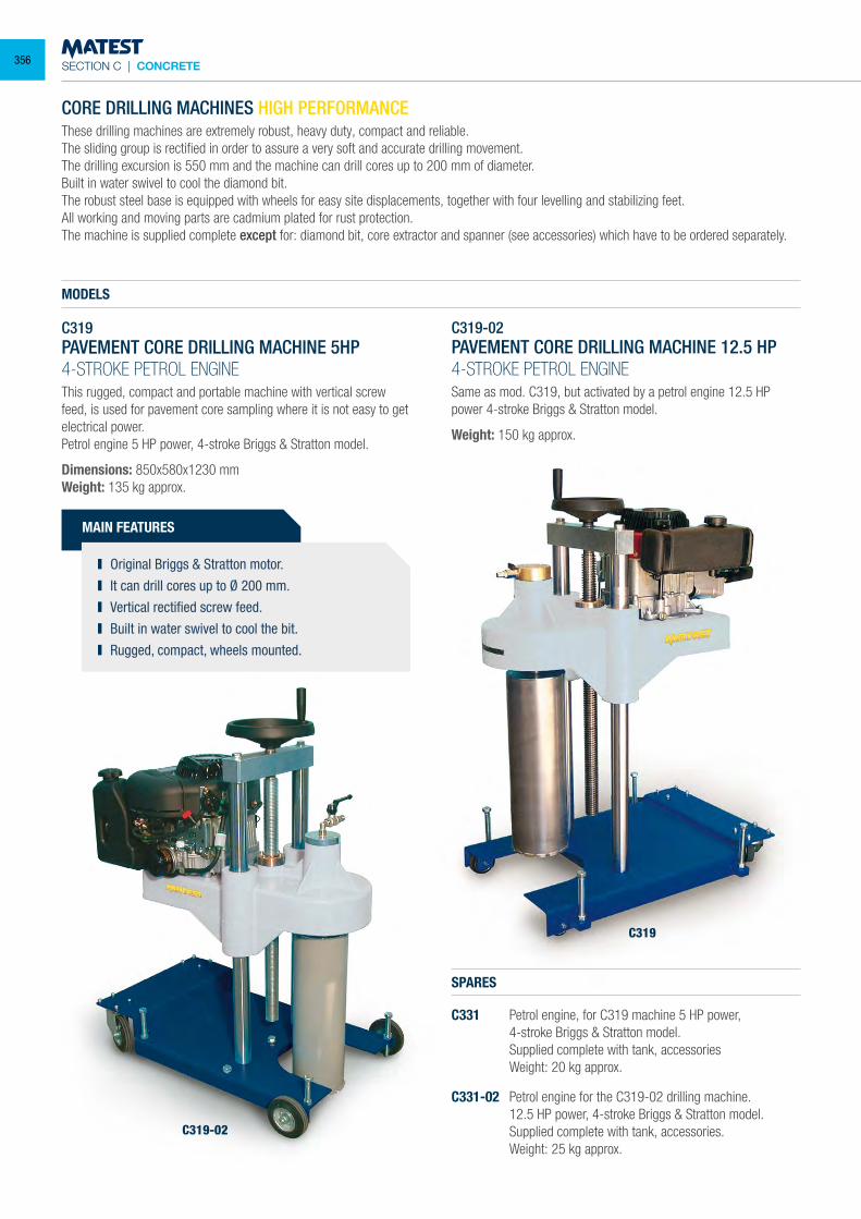
SECTION C | CONCRETE
CORE DRILLING MACHINES HIGH PERFORMANCEThese drilling machines are extremely robust, heavy duty, compact and reliable.The sliding group is rectified in order to assure a very soft and accurate drilling movement.The drilling excursion is 550 mm and the machine can drill cores up to 200 mm of diameter.Built in water swivel to cool the diamond bit.The robust steel base is equipped with wheels for easy site displacements, together with four levelling and stabilizing feet.All working and moving parts are cadmium plated for rust protection.The machine is supplied complete except for: diamond bit, core extractor and spanner (see accessories) which have to be ordered separately.
MAIN FEATURES
Original Briggs & Stratton motor. It can drill cores up to Ø 200 mm. Vertical rectified screw feed. Built in water swivel to cool the bit. Rugged, compact, wheels mounted.
MODELS
C319PAVEMENT CORE DRILLING MACHINE 5HP4-STROKE PETROL ENGINEThis rugged, compact and portable machine with vertical screw feed, is used for pavement core sampling where it is not easy to get electrical power.Petrol engine 5 HP power, 4-stroke Briggs & Stratton model.
Dimensions: 850x580x1230 mmWeight: 135 kg approx.
C319-02PAVEMENT CORE DRILLING MACHINE 12.5 HP4-STROKE PETROL ENGINESame as mod. C319, but activated by a petrol engine 12.5 HP power 4-stroke Briggs & Stratton model.
Weight: 150 kg approx.
SPARES
C331 Petrol engine, for C319 machine 5 HP power, 4-stroke Briggs & Stratton model. Supplied complete with tank, accessories Weight: 20 kg approx.
C331-02 Petrol engine for the C319-02 drilling machine. 12.5 HP power, 4-stroke Briggs & Stratton model. Supplied complete with tank, accessories. Weight: 25 kg approx.
C319-02
C319
356
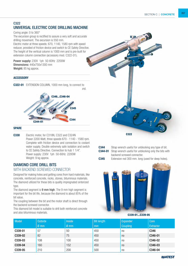
SECTION C | CONCRETE
C322UNIVERSAL ELECTRIC CORE DRILLING MACHINECoring angle: 0 to 360°The excursion group is rectified to assure a very soft and accurate drilling movement. The excursion is 550 mm.Electric motor at three speeds: 670, 1140, 1580 rpm with speed reducer, provided of friction device and switch to CE Safety Directive.The height of the vertical column is 1000 mm and is pre-built for extension column connection (accessory mod. C322-01).
Power supply: 230V 1ph 50-60Hz 2200WDimensions: 440x750x1300 mmWeight: 85 kg approx.
ACCESSORY
C322-01 EXTENSION COLUMN, 1000 mm long, to connect to mod. C322 for drillings over 1 metre from the ground.
DIAMOND CORE DRILL BITSWITH BACKEND SCREWED CONNECTORDesigned for making holes and getting cores from hard materials, like concrete, reinforced concrete, rocks, stones, bituminous materials.The diamond utilized for these bits is quality impregnated sinterized type.The diamond segment is 9 mm high. The 9 mm high segment is important for the bit life, because the diamond is about 85% of the bit value.The coupling between the bit and the motor shaft is direct through the backend screwed connector.This diamond bit model is suitable to drill both reinforced concrete and also bituminous materials.
C344 Strap wrench useful for unblocking any type of bit.C344-01 Strap wrench useful for unblocking only the bits with
backend screwed connector.C345 Extension rod 300 mm. long (used for deep holes).
Model Outside Inside Bit length Expander Core
Ø mm Ø mm mm Coupling Extractor
C339-01 57 50 450 no C346
C339-02 82 75 450 no C346-01
C339-03 108 100 450 no C346-02
C339-04 160 152 450 no C346-03
C339-05 210 200 500 no C346-04
C322
C345
C344C344-01
C346...C346-04
C339-01...C339-05
SPARE
C330 Electric motor, for C318N, C322 and C324N Power 2200 Watt, three speeds 670 - 1140 - 1580 rpm.
Complete with friction device and connection to coolant water supply. Double extremely safe isolation and switch to CE Safety Directive. Connection to hub 1 1/4”.
Power supply: 230V 1ph 50-60Hz 2200W Weight: 9 kg approx.
357
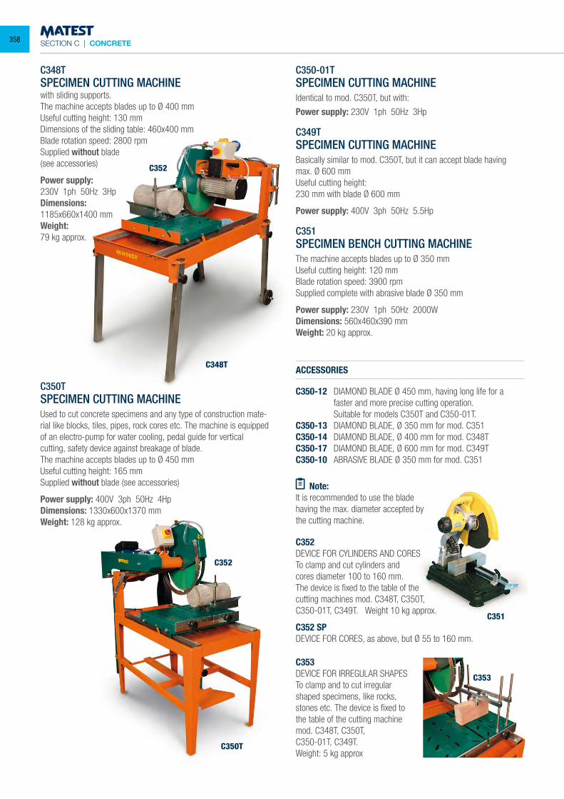
SECTION C | CONCRETE
C348T
C350T
C352
C352
C348TSPECIMEN CUTTING MACHINEwith sliding supports.The machine accepts blades up to Ø 400 mmUseful cutting height: 130 mmDimensions of the sliding table: 460x400 mmBlade rotation speed: 2800 rpmSupplied without blade(see accessories)
Power supply:230V 1ph 50Hz 3HpDimensions:1185x660x1400 mmWeight:79 kg approx.
C350TSPECIMEN CUTTING MACHINEUsed to cut concrete specimens and any type of construction mate-rial like blocks, tiles, pipes, rock cores etc. The machine is equipped of an electro-pump for water cooling, pedal guide for vertical cutting, safety device against breakage of blade.The machine accepts blades up to Ø 450 mmUseful cutting height: 165 mmSupplied without blade (see accessories)
Power supply: 400V 3ph 50Hz 4HpDimensions: 1330x600x1370 mmWeight: 128 kg approx.
C350-01TSPECIMEN CUTTING MACHINEIdentical to mod. C350T, but with:
Power supply: 230V 1ph 50Hz 3Hp
C349TSPECIMEN CUTTING MACHINEBasically similar to mod. C350T, but it can accept blade having max. Ø 600 mmUseful cutting height:230 mm with blade Ø 600 mm
Power supply: 400V 3ph 50Hz 5.5Hp
C351SPECIMEN BENCH CUTTING MACHINEThe machine accepts blades up to Ø 350 mmUseful cutting height: 120 mmBlade rotation speed: 3900 rpmSupplied complete with abrasive blade Ø 350 mm
Power supply: 230V 1ph 50Hz 2000WDimensions: 560x460x390 mmWeight: 20 kg approx.
ACCESSORIES
C350-12 DIAMOND BLADE Ø 450 mm, having long life for a faster and more precise cutting operation.
Suitable for models C350T and C350-01T.C350-13 DIAMOND BLADE, Ø 350 mm for mod. C351C350-14 DIAMOND BLADE, Ø 400 mm for mod. C348TC350-17 DIAMOND BLADE, Ø 600 mm for mod. C349TC350-10 ABRASIVE BLADE Ø 350 mm for mod. C351
Note:It is recommended to use the blade having the max. diameter accepted by the cutting machine.
C352DEVICE FOR CYLINDERS AND CORESTo clamp and cut cylinders and cores diameter 100 to 160 mm.The device is fixed to the table of the cutting machines mod. C348T, C350T, C350-01T, C349T. Weight 10 kg approx.
C352 SPDEVICE FOR CORES, as above, but Ø 55 to 160 mm.
C353DEVICE FOR IRREGULAR SHAPESTo clamp and to cut irregular shaped specimens, like rocks, stones etc. The device is fixed to the table of the cutting machinemod. C348T, C350T,C350-01T, C349T.Weight: 5 kg approx
C353
C351
358
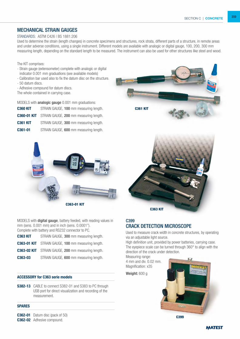
SECTION C | CONCRETE
C361 KIT
C363 KIT
C399
MECHANICAL STRAIN GAUGESSTANDARDS: ASTM C426 | BS 1881:206Used to determine the strain (length changes) in concrete specimens and structures, rock strata, different parts of a structure, in remote areas and under adverse conditions, using a single instrument. Different models are available with analogic or digital gauge, 100, 200, 300 mm measuring length, depending on the standard length to be measured. The instrument can also be used for other structures like steel and wood.
The KIT comprises:- Strain gauge (extensometer) complete with analogic or digital
indicator 0.001 mm graduations (see available models)- Calibration bar used also to fix the datum disc on the structure.- 50 datum discs.- Adhesive compound for datum discs. The whole contained in carrying case.
MODELS with analogic gauge 0.001 mm graduations:
C360 KIT STRAIN GAUGE, 100 mm measuring length.
C360-01 KIT STRAIN GAUGE, 200 mm measuring length.
C361 KIT STRAIN GAUGE, 300 mm measuring length.
C361-01 STRAIN GAUGE, 600 mm measuring length.
MODELS with digital gauge, battery feeded, with reading values in mm (sens. 0.001 mm) and in inch (sens. 0.0001”).Complete with battery and RS232 connector to PC.
C363 KIT STRAIN GAUGE, 300 mm measuring length.
C363-01 KIT STRAIN GAUGE, 100 mm measuring length.
C363-02 KIT STRAIN GAUGE, 200 mm measuring length.
C363-03 STRAIN GAUGE, 600 mm measuring length.
ACCESSORY for C363 serie models
S382-13 CABLE to connect S382-01 and S383 to PC through USB port for direct visualization and recording of the measurement.
SPARES
C362-01 Datum disc (pack of 50)C362-02 Adhesive compound.
C399CRACK DETECTION MICROSCOPEUsed to measure crack width in concrete structures, by operating via an adjustable light source.High definition unit, provided by power batteries, carrying case.The eyepiece scale can be turned through 360° to align with the direction of the crack under detection.Measuring range:4 mm and div. 0.02 mm.Magnification: x35
Weight: 600 g
C363-01 KIT
359
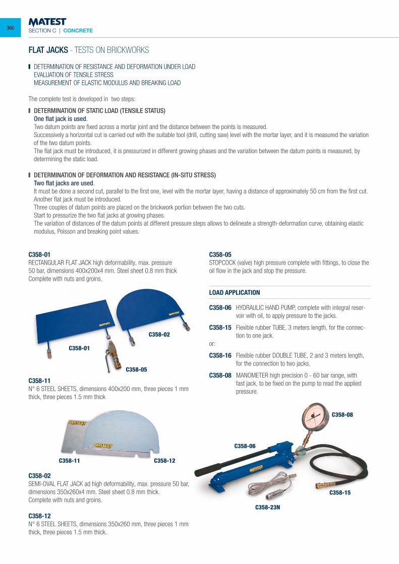
SECTION C | CONCRETE
C358-06
C358-08
C358-23N
C358-15
FLAT JACKS - TESTS ON BRICKWORKS DETERMINATION OF RESISTANCE AND DEFORMATION UNDER LOAD
EVALUATION OF TENSILE STRESS MEASUREMENT OF ELASTIC MODULUS AND BREAKING LOAD The complete test is developed in two steps:
DETERMINATION OF STATIC LOAD (TENSILE STATUS) One flat jack is used. Two datum points are fixed across a mortar joint and the distance between the points is measured. Successively a horizontal cut is carried out with the suitable tool (drill, cutting saw) level with the mortar layer, and it is measured the variation
of the two datum points. The flat jack must be introduced, it is pressurized in different growing phases and the variation between the datum points is measured, by
determining the static load.
DETERMINATION OF DEFORMATION AND RESISTANCE (IN-SITU STRESS) Two flat jacks are used. It must be done a second cut, parallel to the first one, level with the mortar layer, having a distance of approximately 50 cm from the first cut. Another flat jack must be introduced. Three couples of datum points are placed on the brickwork portion between the two cuts. Start to pressurize the two flat jacks at growing phases. The variation of distances of the datum points at different pressure steps allows to delineate a strength-deformation curve, obtaining elastic
modulus, Poisson and breaking point values.
C358-01RECTANGULAR FLAT JACK high deformability, max. pressure50 bar, dimensions 400x200x4 mm. Steel sheet 0.8 mm thickComplete with nuts and groins.
C358-11N° 6 STEEL SHEETS, dimensions 400x200 mm, three pieces 1 mm thick, three pieces 1.5 mm thick
C358-02SEMI-OVAL FLAT JACK ad high deformability, max. pressure 50 bar, dimensions 350x260x4 mm. Steel sheet 0.8 mm thick.Complete with nuts and groins. C358-12N° 6 STEEL SHEETS, dimensions 350x260 mm, three pieces 1 mm thick, three pieces 1.5 mm thick.
C358-05STOPCOCK (valve) high pressure complete with fittings, to close the oil flow in the jack and stop the pressure.
LOAD APPLICATION
C358-06 HYDRAULIC HAND PUMP, complete with integral reser-voir with oil, to apply pressure to the jacks.
C358-15 Flexible rubber TUBE, 3 meters length, for the connec-tion to one jack.
or:
C358-16 Flexible rubber DOUBLE TUBE, 2 and 3 meters length, for the connection to two jacks.
C358-08 MANOMETER high precision 0 - 60 bar range, with fast jack, to be fixed on the pump to read the applied pressure.
C358-01
C358-02
C358-05
C358-11 C358-12
360
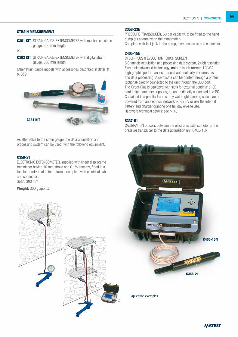
SECTION C | CONCRETE
C361 KIT
STRAIN MEASUREMENT
C361 KIT STRAIN GAUGE-EXTENSOMETER with mechanical strain gauge, 300 mm length
or:
C363 KIT STRAIN GAUGE-EXTENSOMETER with digital strain gauge, 300 mm length
Other strain gauge models with accessories described in detail at p. 359
As alternative to the strain gauge, the data acquisition andprocessing system can be used, with the following equipment:
C358-21ELECTRONIC EXTENSOMETER, supplied with linear displacement transducer having 10 mm stroke and 0.1% linearity, fitted in a tubular anodized aluminum frame, complete with electrical cable and connector .Span: 300 mm
Weight: 300 g approx.
C358-23NPRESSURE TRANSDUCER, 50 bar capacity, to be fitted to the hand pump (as alternative to the manometer).Complete with fast jack to the pump, electrical cable and connector.
C405-15NCYBER-PLUS 8 EVOLUTION TOUCH SCREEN8 Channels acquisition and processing data system, 24 bit resolution.Electronic advanced technology, colour touch screen 1/4VGA, high graphic performances, the unit automatically performs test and data processing. A certificate can be printed through a printer (optional) directly connected to the unit through the USB port.The Cyber-Plus is equipped with slots for external pendrive or SD card infinite memory supports, it can be directly connected to a PC. Contained in a practical and sturdy watertight carrying case, can be powered from an electrical network 90-270 V or use the internal battery and charger granting one full day on-site use.Hardware technical details: see p. 18
S337-51CALIBRATION process between the electronic extensometer or the pressure transducer to the data acquisition unit C405-15N
Aplication exemples
C358-21
C405-15N
361
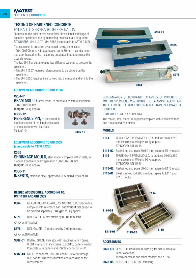
SECTION C | CONCRETE
TESTING OF HARDENED CONCRETEHYDRAULIC SHRINKAGE DETERMINATIONTo measure the axial and/or superficial dimensional shrinkage of concrete specimens during hardening process in a curing room.STANDARDS: UNI 11307 | UNI 6555 (comparable to ASTM C426)
The specimen is prepared by a mould having dimensions 100x100x500 mm, with aggregates up to 30 mm max. diameter, and after housed in the measuring apparatus that determines the axial shrinkage.The two UNI Standards require two different systems to prepare the specimen:- The UNI 11307 requires reference pins to be sticked on the
specimen.- The UNI 6555 requires inserts fixed into the mould and let into the
specimen.
EQUIPMENT ACCORDING TO UNI 11307:
C254-01BEAM MOULD, steel made, to prepare a concrete specimen 100x100x500 mmWeight: 23 kg approx.
C366-12REFERENCE PIN, to be sticked in the intersection of the longitudinal axis of the specimen with its bases.Pack of 10
EQUIPMENT ACCORDING TO UNI 6555(comparable to ASTM C426):
C365SHRINKAGE MOULD, steel made, complete with inserts, to prepare a concrete beam specimen 100x100x500 mmWeight: 23 kg approx.
C366-11INSERTS, stainless steel, spares to C365 mould. Pack of 10
NEEDED ACCESSORIES, ACCORDING TO:UNI 11307 AND UNI 6555
C364 MEASURING APPARATUS, for 100x100x500 specimens, complete with reference bar, but without dial gauge to be ordered separately. Weight: 23 kg approx.
S375 DIAL GAUGE, 5 mm stroke by 0.001 mm sens.
AS AN ALTERNATIVE:
S376 DIAL GAUGE, 10 mm stroke by 0.01 mm sens.
AS AN ALTERNATIVE:
S382-01 DIGITAL GAUGE indicator, with readings in mm (sens. 0.001 mm) and in inch (sens. 0.0001”), battery feeded.
Complete with battery and RS232 connector to PC.
S382-13 CABLE to connect S382-01 and S383 to PC through USB port for direct visualization and recording of the measurement.
DETERMINATION OF RESTRAINED EXPANSION OF CONCRETE OR MORTAR SPECIMENS CONTAINING THE EXPANSIVE AGENT, AND THE EFFECT OF THE AGGREGATES ON THE DRYING SHRINKAGE OF CONCRETE
STANDARDS: UNI 8147 | UNI 8148
The mould, steel made, is supplied complete with 3 screwed rods and 6 restrained end plates.
MODELS
E114 THREE GANG PRISM MOULD, to produce 80x80x240 mm specimens. Weight: 15 kg approx.
STANDARD: UNI 8148
E114-02 Restrained end plate 80x80 mm; spare to E114 mould.
E115 THREE GANG PRISM MOULD, to produce 50x50x250 mm specimens. Weight: 10 kg approx.
STANDARD: UNI 8147
E115-02 Restrained end plate 50x50 mm; spare to E115 mould.
E115-01 Steel screwed rod 280 mm long; spare to E114 and E115 moulds.
ACCESSORIES
E078 KIT LENGTH COMPARATOR, with digital dial to measure linear variations.
Technical details and other models: see p. 397
E078-05 REFERENCE ROD, 280 mm long
C366-12
E114-02
E115-01 E115-02E115
E114
C254-01
C365
S375
C364
362
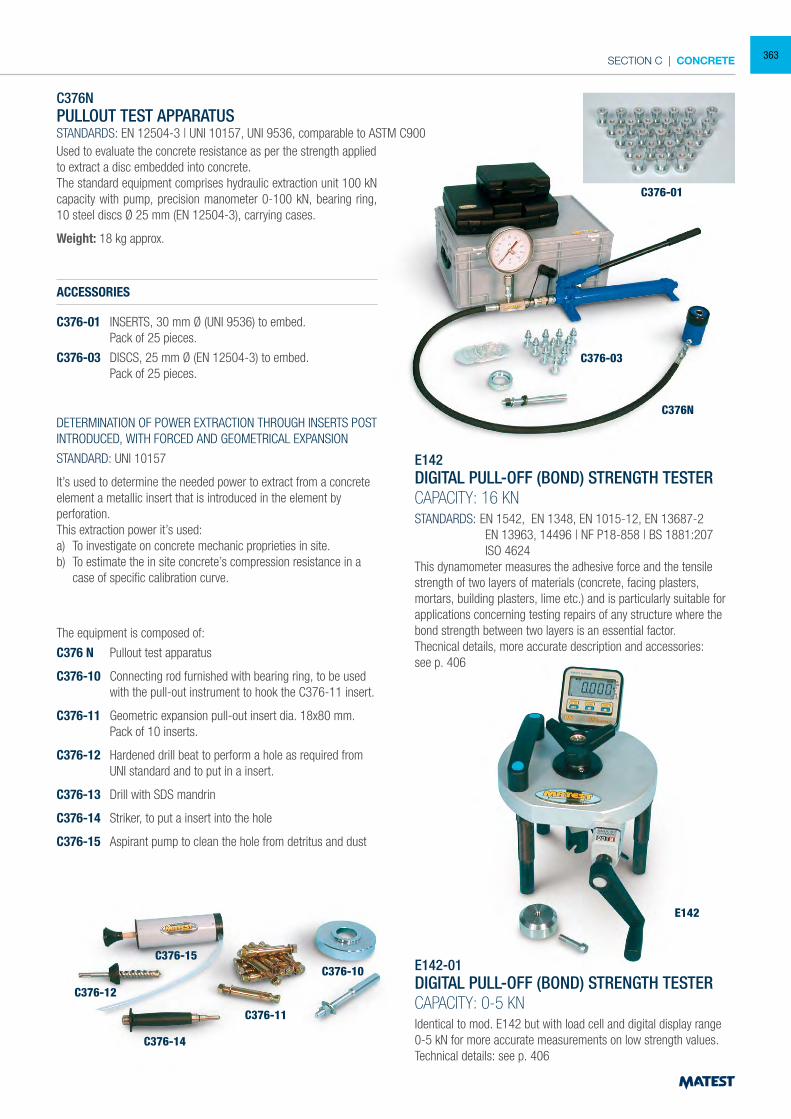
SECTION C | CONCRETE
C376N PULLOUT TEST APPARATUS STANDARDS: EN 12504-3 | UNI 10157, UNI 9536, comparable to ASTM C900Used to evaluate the concrete resistance as per the strength applied to extract a disc embedded into concrete. The standard equipment comprises hydraulic extraction unit 100 kN capacity with pump, precision manometer 0-100 kN, bearing ring, 10 steel discs Ø 25 mm (EN 12504-3), carrying cases.
Weight: 18 kg approx.
ACCESSORIES
C376-01 INSERTS, 30 mm Ø (UNI 9536) to embed. Pack of 25 pieces.
C376-03 DISCS, 25 mm Ø (EN 12504-3) to embed. Pack of 25 pieces.
E142DIGITAL PULL-OFF (BOND) STRENGTH TESTERCAPACITY: 16 KNSTANDARDS: EN 1542, EN 1348, EN 1015-12, EN 13687-2 EN 13963, 14496 | NF P18-858 | BS 1881:207 ISO 4624This dynamometer measures the adhesive force and the tensile strength of two layers of materials (concrete, facing plasters, mortars, building plasters, lime etc.) and is particularly suitable for applications concerning testing repairs of any structure where the bond strength between two layers is an essential factor.Thecnical details, more accurate description and accessories:see p. 406
E142-01DIGITAL PULL-OFF (BOND) STRENGTH TESTERCAPACITY: 0-5 KNIdentical to mod. E142 but with load cell and digital display range 0-5 kN for more accurate measurements on low strength values.Technical details: see p. 406
C376N
C376-03
C376-01
C376-15
C376-12
C376-14
C376-11
C376-10
E142
DETERMINATION OF POWER EXTRACTION THROUGH INSERTS POST INTRODUCED, WITH FORCED AND GEOMETRICAL EXPANSION
STANDARD: UNI 10157
It’s used to determine the needed power to extract from a concrete element a metallic insert that is introduced in the element by perforation.This extraction power it’s used:a) To investigate on concrete mechanic proprieties in site.b) To estimate the in site concrete’s compression resistance in a
case of specific calibration curve.
The equipment is composed of:
C376 N Pullout test apparatus
C376-10 Connecting rod furnished with bearing ring, to be used with the pull-out instrument to hook the C376-11 insert.
C376-11 Geometric expansion pull-out insert dia. 18x80 mm. Pack of 10 inserts.
C376-12 Hardened drill beat to perform a hole as required from UNI standard and to put in a insert.
C376-13 Drill with SDS mandrin
C376-14 Striker, to put a insert into the hole
C376-15 Aspirant pump to clean the hole from detritus and dust
363
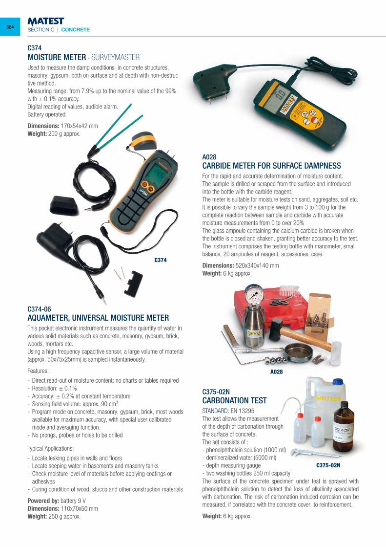
SECTION C | CONCRETE
C374
C374-06
A028
C375-02N
C374MOISTURE METER - SURVEYMASTERUsed to measure the damp conditions in concrete structures, masonry, gypsum, both on surface and at depth with non-destruc-tive method.Measuring range: from 7.9% up to the nominal value of the 99% with ± 0.1% accuracy.Digital reading of values, audible alarm.Battery operated.
Dimensions: 170x54x42 mm Weight: 200 g approx.
C374-06AQUAMETER, UNIVERSAL MOISTURE METERThis pocket electronic instrument measures the quantity of water in various solid materials such as concrete, masonry, gypsum, brick, woods, mortars etc. Using a high frequency capacitive sensor, a large volume of material (approx. 50x75x25mm) is sampled instantaneously.
Features:
- Direct read-out of moisture content; no charts or tables required- Resolution: ± 0.1%- Accuracy: ± 0.2% at constant temperature- Sensing field volume: approx. 90 cm³- Program mode on concrete, masonry, gypsum, brick, most woods
available for maximum accuracy, with special user calibrated mode and averaging function.
- No prongs, probes or holes to be drilled
Typical Applications:
- Locate leaking pipes in walls and floors- Locate seeping water in basements and masonry tanks- Check moisture level of materials before applying coatings or
adhesives- Curing condition of wood, stucco and other construction materials
Powered by: battery 9 VDimensions: 110x70x50 mmWeight: 250 g approx.
A028CARBIDE METER FOR SURFACE DAMPNESSFor the rapid and accurate determination of moisture content.The sample is drilled or scraped from the surface and introduced into the bottle with the carbide reagent.The meter is suitable for moisture tests on sand, aggregates, soil etc.It is possible to vary the sample weight from 3 to 100 g for the complete reaction between sample and carbide with accurate moisture measurements from 0 to over 20%The glass ampoule containing the calcium carbide is broken when the bottle is closed and shaken, granting better accuracy to the test.The instrument comprises the testing bottle with manometer, small balance, 20 ampoules of reagent, accessories, case.
Dimensions: 520x340x140 mmWeight: 6 kg approx.
C375-02NCARBONATION TESTSTANDARD: EN 13295The test allows the measurementof the depth of carbonation throughthe surface of concrete.The set consists of :- phenolphthalein solution (1000 ml)- demineralized water (5000 ml)- depth measuring gauge- two washing bottles 250 ml capacityThe surface of the concrete specimen under test is sprayed with phenolphthalein solution to detect the loss of alkalinity associated with carbonation. The risk of carbonation induced corrosion can be measured, if correlated with the concrete cover to reinforcement.
Weight: 6 kg approx.
364
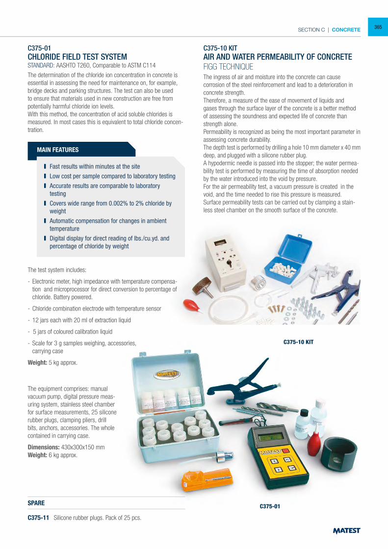
SECTION C | CONCRETE
C375-01CHLORIDE FIELD TEST SYSTEMSTANDARD: AASHTO T260, Comparable to ASTM C114
The determination of the chloride ion concentration in concrete is essential in assessing the need for maintenance on, for example, bridge decks and parking structures. The test can also be used to ensure that materials used in new construction are free from potentially harmful chloride ion levels.With this method, the concentration of acid soluble chlorides is measured. In most cases this is equivalent to total chloride concen-tration.
MAIN FEATURES
Fast results within minutes at the site Low cost per sample compared to laboratory testing Accurate results are comparable to laboratory
testing Covers wide range from 0.002% to 2% chloride by
weight Automatic compensation for changes in ambient
temperature Digital display for direct reading of lbs./cu.yd. and
percentage of chloride by weight
The test system includes:
- Electronic meter, high impedance with temperature compensa-tion and microprocessor for direct conversion to percentage of chloride. Battery powered.
- Chloride combination electrode with temperature sensor
- 12 jars each with 20 ml of extraction liquid
- 5 jars of coloured calibration liquid
- Scale for 3 g samples weighing, accessories, carrying case
Weight: 5 kg approx.
C375-10 KITAIR AND WATER PERMEABILITY OF CONCRETEFIGG TECHNIQUEThe ingress of air and moisture into the concrete can cause corrosion of the steel reinforcement and lead to a deterioration in concrete strength.Therefore, a measure of the ease of movement of liquids and gases through the surface layer of the concrete is a better method of assessing the soundness and expected life of concrete than strength alone.Permeability is recognized as being the most important parameter in assessing concrete durability.The depth test is performed by drilling a hole 10 mm diameter x 40 mm deep, and plugged with a silicone rubber plug.A hypodermic needle is passed into the stopper; the water permea-bility test is performed by measuring the time of absorption needed by the water introduced into the void by pressure.For the air permeability test, a vacuum pressure is created in the void, and the time needed to rise this pressure is measured.Surface permeability tests can be carried out by clamping a stain-less steel chamber on the smooth surface of the concrete.
The equipment comprises: manual vacuum pump, digital pressure meas-uring system, stainless steel chamber for surface measurements, 25 silicone rubber plugs, clamping pliers, drill bits, anchors, accessories. The whole contained in carrying case.
Dimensions: 430x300x150 mmWeight: 6 kg approx.
SPARE
C375-11 Silicone rubber plugs. Pack of 25 pcs.
C375-10 KIT
C375-01
365
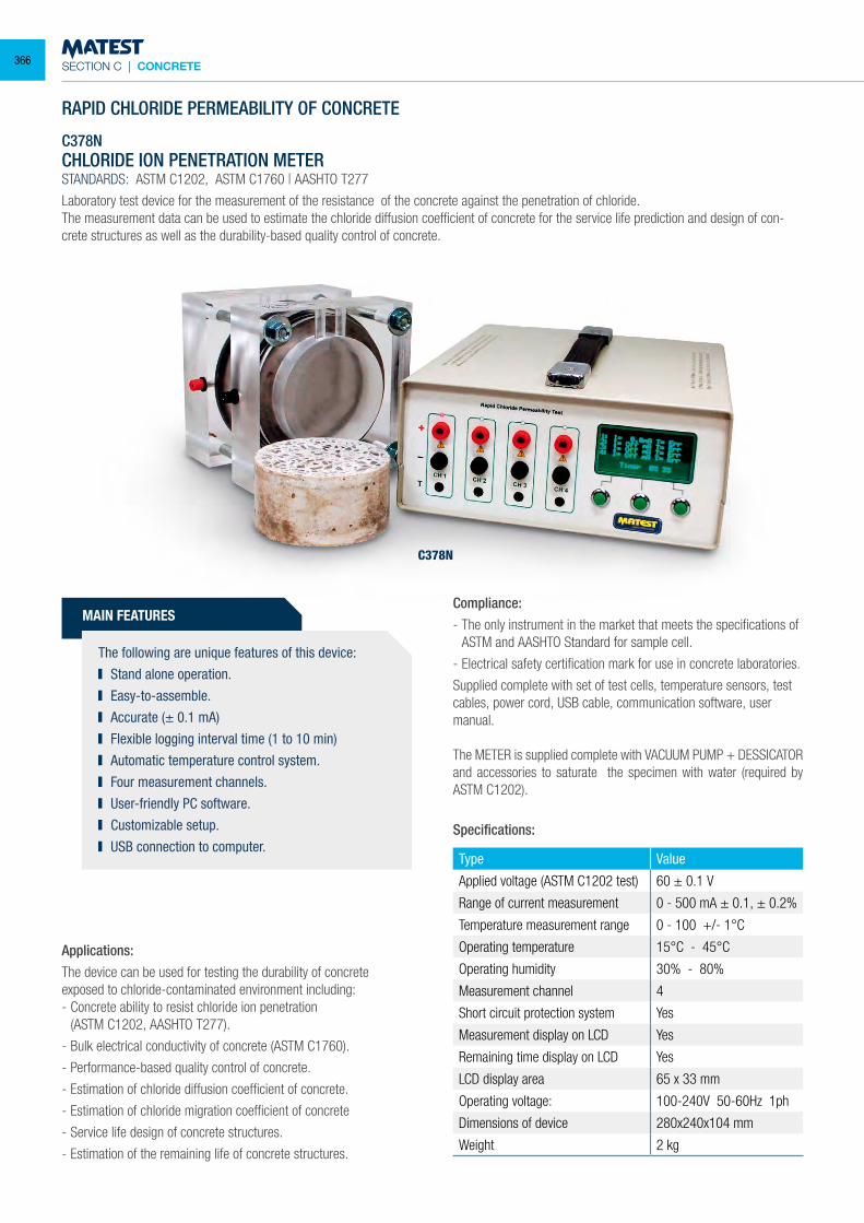
SECTION C | CONCRETE
MAIN FEATURES
The following are unique features of this device: Stand alone operation. Easy-to-assemble. Accurate (± 0.1 mA) Flexible logging interval time (1 to 10 min) Automatic temperature control system. Four measurement channels. User-friendly PC software. Customizable setup. USB connection to computer.
C378N
RAPID CHLORIDE PERMEABILITY OF CONCRETE
C378NCHLORIDE ION PENETRATION METERSTANDARDS: ASTM C1202, ASTM C1760 | AASHTO T277
Laboratory test device for the measurement of the resistance of the concrete against the penetration of chloride.The measurement data can be used to estimate the chloride diffusion coefficient of concrete for the service life prediction and design of con-crete structures as well as the durability-based quality control of concrete.
Applications:The device can be used for testing the durability of concrete exposed to chloride-contaminated environment including:- Concrete ability to resist chloride ion penetration (ASTM C1202, AASHTO T277).
- Bulk electrical conductivity of concrete (ASTM C1760).
- Performance-based quality control of concrete.
- Estimation of chloride diffusion coefficient of concrete.
- Estimation of chloride migration coefficient of concrete
- Service life design of concrete structures.
- Estimation of the remaining life of concrete structures.
Compliance:- The only instrument in the market that meets the specifications of
ASTM and AASHTO Standard for sample cell.
- Electrical safety certification mark for use in concrete laboratories.
Supplied complete with set of test cells, temperature sensors, test cables, power cord, USB cable, communication software, user manual.
The METER is supplied complete with VACUUM PUMP + DESSICATOR and accessories to saturate the specimen with water (required by ASTM C1202).
Type Value
Applied voltage (ASTM C1202 test) 60 ± 0.1 V
Range of current measurement 0 - 500 mA ± 0.1, ± 0.2%
Temperature measurement range 0 - 100 +/- 1°C
Operating temperature 15°C - 45°C
Operating humidity 30% - 80%
Measurement channel 4
Short circuit protection system Yes
Measurement display on LCD Yes
Remaining time display on LCD Yes
LCD display area 65 x 33 mm
Operating voltage: 100-240V 50-60Hz 1ph
Dimensions of device 280x240x104 mm
Weight 2 kg
Specifications:
366
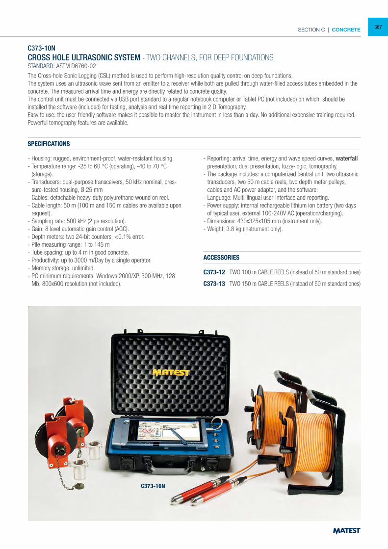
SECTION C | CONCRETE
C373-10NCROSS HOLE ULTRASONIC SYSTEM - TWO CHANNELS, FOR DEEP FOUNDATIONSSTANDARD: ASTM D6760-02
The Cross-hole Sonic Logging (CSL) method is used to perform high-resolution quality control on deep foundations. The system uses an ultrasonic wave sent from an emitter to a receiver while both are pulled through water-filled access tubes embedded in the concrete. The measured arrival time and energy are directly related to concrete quality.The control unit must be connected via USB port standard to a regular notebook computer or Tablet PC (not included) on which, should be installed the software (included) for testing, analysis and real time reporting in 2 D Tomography.Easy to use: the user-friendly software makes it possible to master the instrument in less than a day. No additional expensive training required.Powerful tomography features are available.
SPECIFICATIONS
- Housing: rugged, environment-proof, water-resistant housing.- Temperature range: -25 to 60 °C (operating), -40 to 70 °C (storage).- Transducers: dual-purpose transceivers, 50 kHz nominal, pres-
sure-tested housing, Ø 25 mm- Cables: detachable heavy-duty polyurethane wound on reel.- Cable length: 50 m (100 m and 150 m cables are available upon
request).- Sampling rate: 500 kHz (2 µs resolution).- Gain: 8 level automatic gain control (AGC).- Depth meters: two 24-bit counters, <0.1% error.- Pile measuring range: 1 to 145 m- Tube spacing: up to 4 m in good concrete.- Productivity: up to 3000 m/Day by a single operator.- Memory storage: unlimited.- PC minimum requirements: Windows 2000/XP, 300 MHz, 128
Mb, 800x600 resolution (not included).
ACCESSORIES
C373-12 TWO 100 m CABLE REELS (instead of 50 m standard ones)
C373-13 TWO 150 m CABLE REELS (instead of 50 m standard ones)
- Reporting: arrival time, energy and wave speed curves, waterfall presentation, dual presentation, fuzzy-logic, tomography.
- The package includes: a computerized central unit, two ultrasonic transducers, two 50 m cable reels, two depth meter pulleys, cables and AC power adapter, and the software.
- Language: Multi-lingual user-interface and reporting.- Power supply: internal rechargeable lithium ion battery (two days
of typical use), external 100-240V AC (operation/charging).- Dimensions: 430x325x105 mm (instrument only).- Weight: 3.8 kg (instrument only).
C373-10N
367
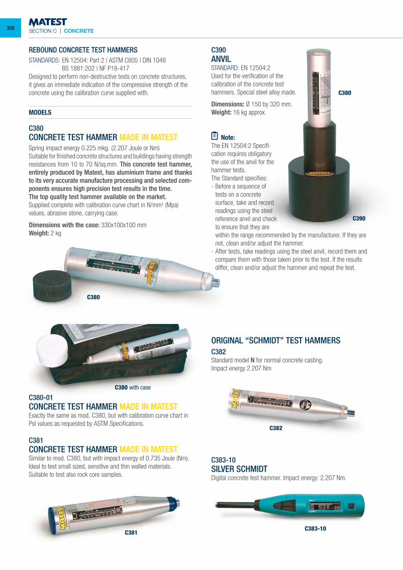
SECTION C | CONCRETE
REBOUND CONCRETE TEST HAMMERSSTANDARDS: EN 12504: Part 2 | ASTM C805 | DIN 1048 BS 1881:202 | NF P18-417Designed to perform non-destructive tests on concrete structures, it gives an immediate indication of the compressive strength of the concrete using the calibration curve supplied with.
MODELS
C380CONCRETE TEST HAMMER MADE IN MATESTSpring impact energy 0.225 mkg. (2.207 Joule or Nm)Suitable for finished concrete structures and buildings having strength resistances from 10 to 70 N/sq.mm. This concrete test hammer, entirely produced by Matest, has aluminium frame and thanks to its very accurate manufacture processing and selected com-ponents ensures high precision test results in the time.The top quality test hammer available on the market.Supplied complete with calibration curve chart in N/mm² (Mpa) values, abrasive stone, carrying case.
Dimensions with the case: 330x100x100 mmWeight: 2 kg
C380-01CONCRETE TEST HAMMER MADE IN MATESTExactly the same as mod. C380, but with calibration curve chart in PsI values as requested by ASTM Specifications.
C381CONCRETE TEST HAMMER MADE IN MATESTSimilar to mod. C380, but with impact energy of 0.735 Joule (Nm).Ideal to test small sized, sensitive and thin walled materials.Suitable to test also rock core samples.
C390ANVILSTANDARD: EN 12504:2Used for the verification of thecalibration of the concrete testhammers. Special steel alloy made.
Dimensions: Ø 150 by 320 mm.Weight: 16 kg approx.
Note:The EN 12504:2 Specifi-cation requires obligatory the use of the anvil for the hammer tests.The Standard specifies:- Before a sequence of
tests on a concrete surface, take and record readings using the steel reference anvil and check to ensure that they are within the range recommended by the manufacturer. If they are not, clean and/or adjust the hammer.
- After tests, take readings using the steel anvil, record them and compare them with those taken prior to the test. If the results differ, clean and/or adjust the hammer and repeat the test.
ORIGINAL “SCHMIDT” TEST HAMMERSC382Standard model N for normal concrete casting.Impact energy 2.207 Nm
C383-10SILVER SCHMIDTDigital concrete test hammer. Impact energy: 2.207 Nm.
C380
C381
C380
C390
C383-10
C382
C380 with case
368
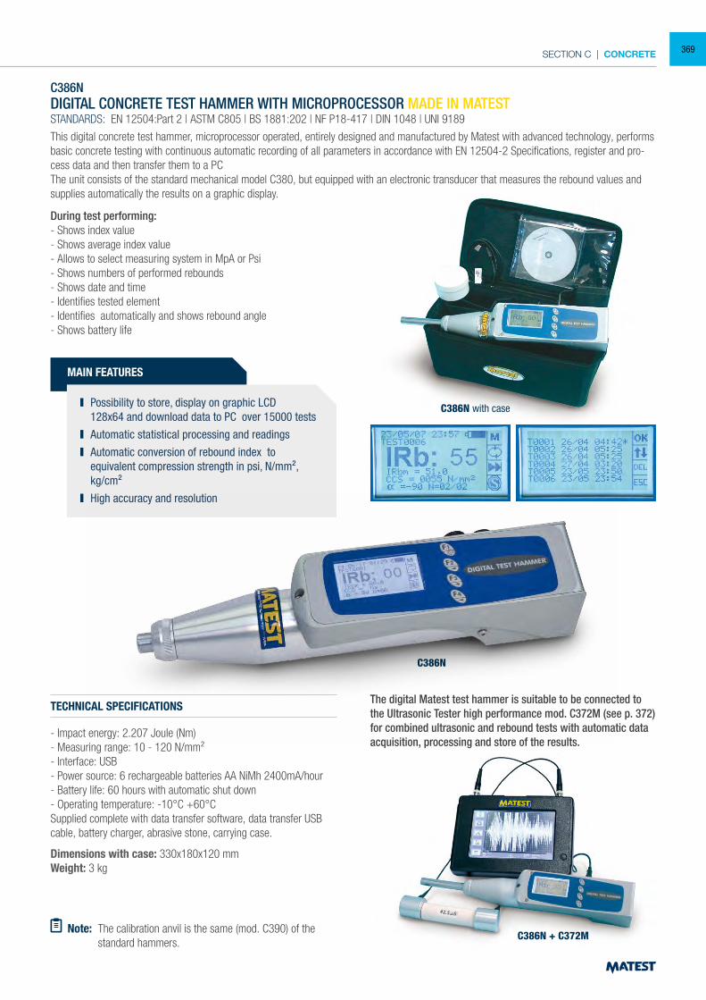
SECTION C | CONCRETE
C386N
C386N + C372M
C386N with case
C386NDIGITAL CONCRETE TEST HAMMER WITH MICROPROCESSOR MADE IN MATESTSTANDARDS: EN 12504:Part 2 | ASTM C805 | BS 1881:202 | NF P18-417 | DIN 1048 | UNI 9189
This digital concrete test hammer, microprocessor operated, entirely designed and manufactured by Matest with advanced technology, performs basic concrete testing with continuous automatic recording of all parameters in accordance with EN 12504-2 Specifications, register and pro-cess data and then transfer them to a PCThe unit consists of the standard mechanical model C380, but equipped with an electronic transducer that measures the rebound values and supplies automatically the results on a graphic display.
During test performing:- Shows index value- Shows average index value- Allows to select measuring system in MpA or Psi- Shows numbers of performed rebounds- Shows date and time- Identifies tested element- Identifies automatically and shows rebound angle- Shows battery life
MAIN FEATURES
Possibility to store, display on graphic LCD 128x64 and download data to PC over 15000 tests
Automatic statistical processing and readings Automatic conversion of rebound index to
equivalent compression strength in psi, N/mm², kg/cm² High accuracy and resolution
TECHNICAL SPECIFICATIONS
- Impact energy: 2.207 Joule (Nm)- Measuring range: 10 - 120 N/mm²- Interface: USB- Power source: 6 rechargeable batteries AA NiMh 2400mA/hour- Battery life: 60 hours with automatic shut down- Operating temperature: -10°C +60°CSupplied complete with data transfer software, data transfer USB cable, battery charger, abrasive stone, carrying case.
Dimensions with case: 330x180x120 mmWeight: 3 kg
Note: The calibration anvil is the same (mod. C390) of the standard hammers.
The digital Matest test hammer is suitable to be connected to the Ultrasonic Tester high performance mod. C372M (see p. 372) for combined ultrasonic and rebound tests with automatic data acquisition, processing and store of the results.
369
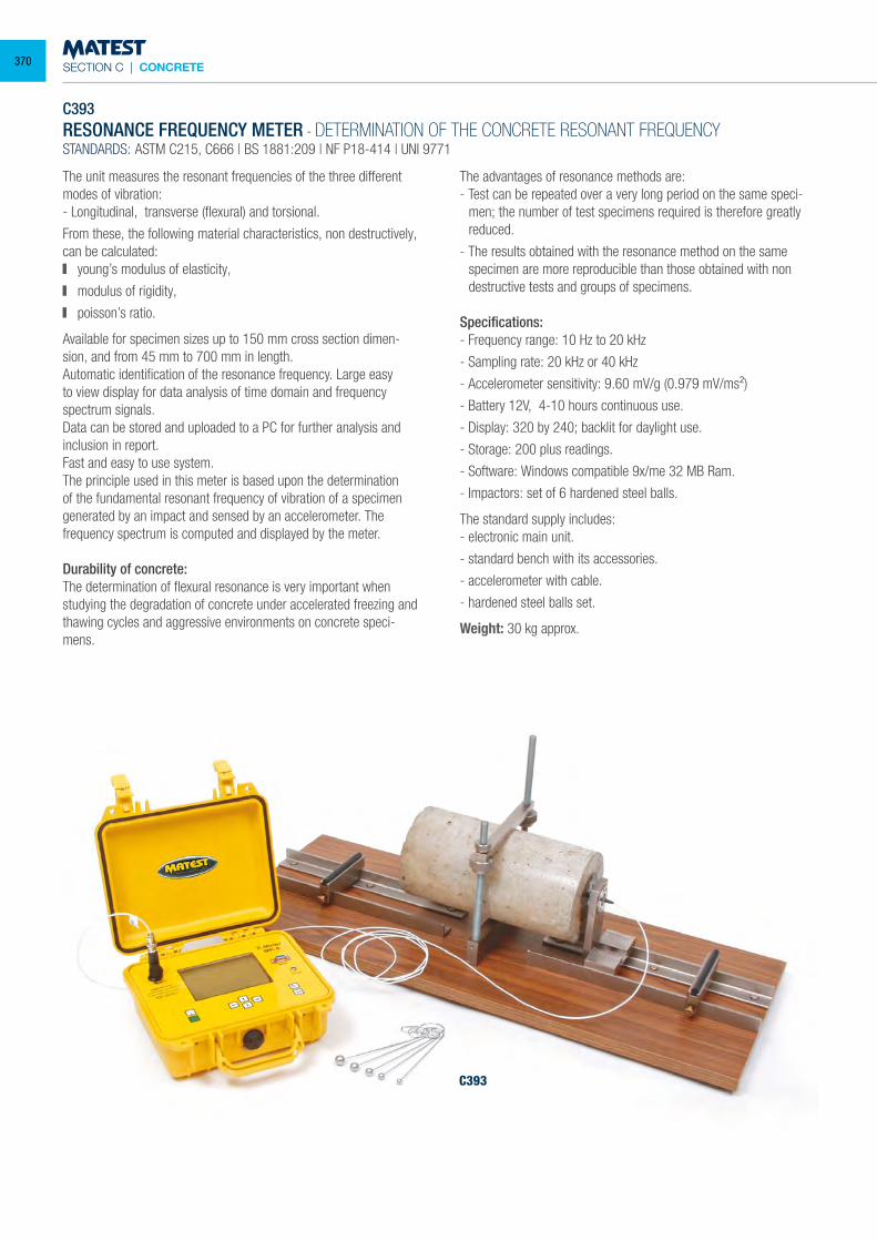
SECTION C | CONCRETE
C393RESONANCE FREQUENCY METER - DETERMINATION OF THE CONCRETE RESONANT FREQUENCYSTANDARDS: ASTM C215, C666 | BS 1881:209 | NF P18-414 | UNI 9771
The unit measures the resonant frequencies of the three different modes of vibration:- Longitudinal, transverse (flexural) and torsional.
From these, the following material characteristics, non destructively, can be calculated: young’s modulus of elasticity,
modulus of rigidity,
poisson’s ratio.
Available for specimen sizes up to 150 mm cross section dimen-sion, and from 45 mm to 700 mm in length.Automatic identification of the resonance frequency. Large easy to view display for data analysis of time domain and frequency spectrum signals.Data can be stored and uploaded to a PC for further analysis and inclusion in report.Fast and easy to use system.The principle used in this meter is based upon the determination of the fundamental resonant frequency of vibration of a specimen generated by an impact and sensed by an accelerometer. The frequency spectrum is computed and displayed by the meter.
Durability of concrete:The determination of flexural resonance is very important when studying the degradation of concrete under accelerated freezing and thawing cycles and aggressive environments on concrete speci-mens.
The advantages of resonance methods are:- Test can be repeated over a very long period on the same speci-
men; the number of test specimens required is therefore greatly reduced.
- The results obtained with the resonance method on the same specimen are more reproducible than those obtained with non destructive tests and groups of specimens.
Specifications:- Frequency range: 10 Hz to 20 kHz
- Sampling rate: 20 kHz or 40 kHz
- Accelerometer sensitivity: 9.60 mV/g (0.979 mV/ms²)
- Battery 12V, 4-10 hours continuous use.
- Display: 320 by 240; backlit for daylight use.
- Storage: 200 plus readings.
- Software: Windows compatible 9x/me 32 MB Ram.
- Impactors: set of 6 hardened steel balls.
The standard supply includes:- electronic main unit.
- standard bench with its accessories.
- accelerometer with cable.
- hardened steel balls set.
Weight: 30 kg approx.
C393
370
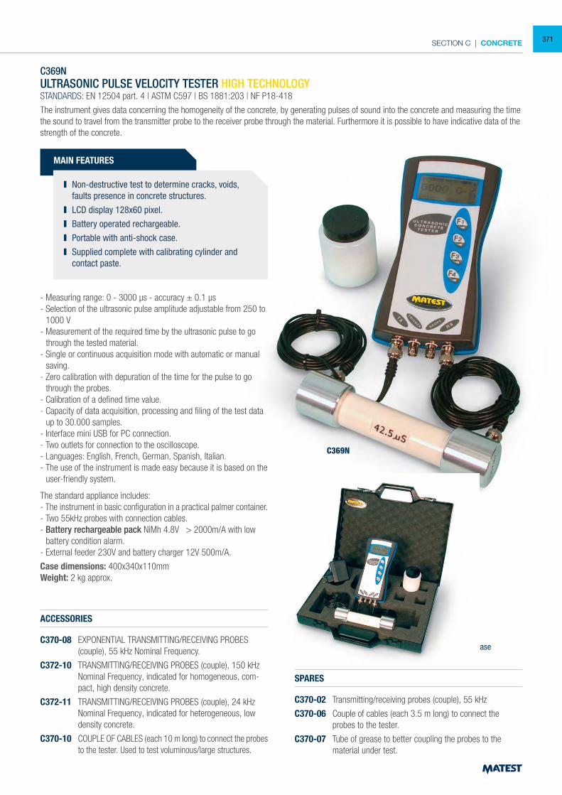
SECTION C | CONCRETE
C369N
C369N with case
C369NULTRASONIC PULSE VELOCITY TESTER HIGH TECHNOLOGYSTANDARDS: EN 12504 part. 4 | ASTM C597 | BS 1881:203 | NF P18-418
The instrument gives data concerning the homogeneity of the concrete, by generating pulses of sound into the concrete and measuring the time the sound to travel from the transmitter probe to the receiver probe through the material. Furthermore it is possible to have indicative data of the strength of the concrete.
- Measuring range: 0 - 3000 µs - accuracy ± 0.1 µs- Selection of the ultrasonic pulse amplitude adjustable from 250 to
1000 V- Measurement of the required time by the ultrasonic pulse to go
through the tested material.- Single or continuous acquisition mode with automatic or manual
saving.- Zero calibration with depuration of the time for the pulse to go
through the probes.- Calibration of a defined time value.- Capacity of data acquisition, processing and filing of the test data
up to 30.000 samples.- Interface mini USB for PC connection.- Two outlets for connection to the oscilloscope.- Languages: English, French, German, Spanish, Italian.- The use of the instrument is made easy because it is based on the
user-friendly system.
The standard appliance includes:- The instrument in basic configuration in a practical palmer container.- Two 55kHz probes with connection cables.- Battery rechargeable pack NiMh 4.8V > 2000m/A with low
battery condition alarm.- External feeder 230V and battery charger 12V 500m/A.
Case dimensions: 400x340x110mmWeight: 2 kg approx.
ACCESSORIES
C370-08 EXPONENTIAL TRANSMITTING/RECEIVING PROBES (couple), 55 kHz Nominal Frequency.
C372-10 TRANSMITTING/RECEIVING PROBES (couple), 150 kHz Nominal Frequency, indicated for homogeneous, com-pact, high density concrete.
C372-11 TRANSMITTING/RECEIVING PROBES (couple), 24 kHz Nominal Frequency, indicated for heterogeneous, low density concrete.
C370-10 COUPLE OF CABLES (each 10 m long) to connect the probes to the tester. Used to test voluminous/large structures.
SPARES
C370-02 Transmitting/receiving probes (couple), 55 kHz
C370-06 Couple of cables (each 3.5 m long) to connect the probes to the tester.
C370-07 Tube of grease to better coupling the probes to the material under test.
MAIN FEATURES
Non-destructive test to determine cracks, voids, faults presence in concrete structures.
LCD display 128x60 pixel. Battery operated rechargeable. Portable with anti-shock case. Supplied complete with calibrating cylinder and
contact paste.
371
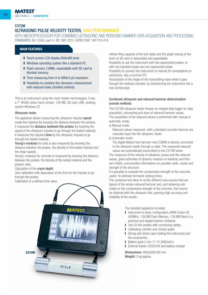
SECTION C | CONCRETE
C372MULTRASONIC PULSE VELOCITY TESTER, HIGH PERFORMANCEWITH MICROPROCESSOR FOR COMBINED ULTRASONIC AND REBOUND HAMMER DATA ACQUISITION AND PROCESSINGSTANDARDS: EN 12504: part 4 | BS 1881:203 | ASTM C597 | NF P18-418
This is an instrument using the most modern technologies; it has a 7" WVGA colour touch screen, 128 MB, SD card, USB, working system Windows CE.
Ultrasonic tests:The appliance allows measuring the ultrasonic impulse speed inside the material (by knowing the distance between the probes).It measures the distance between the probes (by knowing the speed of the ultrasonic impulse to go through the tested material).It measures the required time by the ultrasonic impulse to go through the tested material.Young’s modulus for soils is also measured (by knowing the distance between the probes, the density of the tested material and the shear-speed).Young's modulus for concrete is measured by knowing the distance between the probes, the density of the tested material and the poisson ratio.Calculation of the crack depth.Zero calibration with depuration of the time for the impulse to go through the probes.Calibration of a defined time value.
Infinite filing capacity of the test dates and the graph tracing of the tests on SD card or extractable and expandable.Possibility to use the instrument with two exponential probes, or with one standard probe and one exponential probe.Possibility to connect the instrument to internet for consultations or extractions, like a common PC.Visualization of the shape of the transmitting wave while it goes through the material checked, by transforming the instrument into a real oscilloscope.
Combined ultrasonic and rebound hammer determination(sonreb method):The C372M ultrasonic tester houses an integral data logger for data acquisition, processing and store of rebound hammer values.The acquisition of the rebound values is performed with manual or automatic mode.a) Manual mode: Rebound values measured with a standard concrete hammer are
manually input into the ultrasonic Tester.b) Automatic mode: The digital Matest test hammer mod C386N is directly connected
to the ultrasonic tester through a cable. The measured rebound values are automatically transmitted to the C372M tester.
The measures of the velocity of ultrasonic pulses and the rebound values, gives estimates of dynamic modulus of elasticity and Pois-son’s Ratio, and provides informations on possible voids, cracks and strength of the structure.It is possible to evaluate the compressive strength of the concrete, useful to estimate formwork striking times. The combined test allow to rectify different inaccuracies that are typical of the simple rebound hammer test, and obtaining esti-mates on the compressive strength of the concrete, that cannot be obtained with the ultrasonic test, granting high accuracy and reliability of the results.
The standard appliance includes: Instrument in basic configuration (ARM Cortex-AS
400MHz, 128 MB Flash Memory, 128 MB Ram) in a practical and elegant palmer container.
Two 55 kHz probes with connecting cables. Calibrating cylinder and contact paste Strong anti shock case holding the instrument and
the accessories. Battery pack Li-Ion 11.1V 3000mA.h External feeder 230V/24V and battery charger
Dimensions: 400x300x180 mm Weight: 3 kg approx.
MAIN FEATURES
Touch screen LCD display 800x480 pixel. Windows operating system like a standard PC. Flash memory 128Mb, expandable with SD card to
illimited memory. Time measuring from 0 to 9999,9 µS resolution. Possibility to combine the ultrasonic measurement
with rebound index (SonRed method).
C372M
372
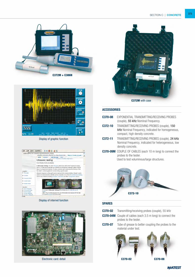
SECTION C | CONCRETE
ACCESSORIES
C370-08 EXPONENTIAL TRANSMITTING/RECEIVING PROBES (couple), 55 kHz Nominal Frequency.
C372-10 TRANSMITTING/RECEIVING PROBES (couple), 150 kHz Nominal Frequency, indicated for homogeneous, compact, high density concrete.
C372-11 TRANSMITTING/RECEIVING PROBES (couple), 24 kHz Nominal Frequency, indicated for heterogeneous, low density concrete.
C370-09M COUPLE OF CABLES (each 10 m long) to connect the probes to the tester.
Used to test voluminous/large structures.
SPARES
C370-02 Transmitting/receiving probes (couple), 55 kHz
C370-04M Couple of cables (each 3.5 m long) to connect the probes to the tester.
C370-07 Tube of grease to better coupling the probes to the material under test.
Display of graphic function
Display of internet function
Electronic card: detail
C372M with case
C372M + C386N
C372-10
C370-02 C370-08
373
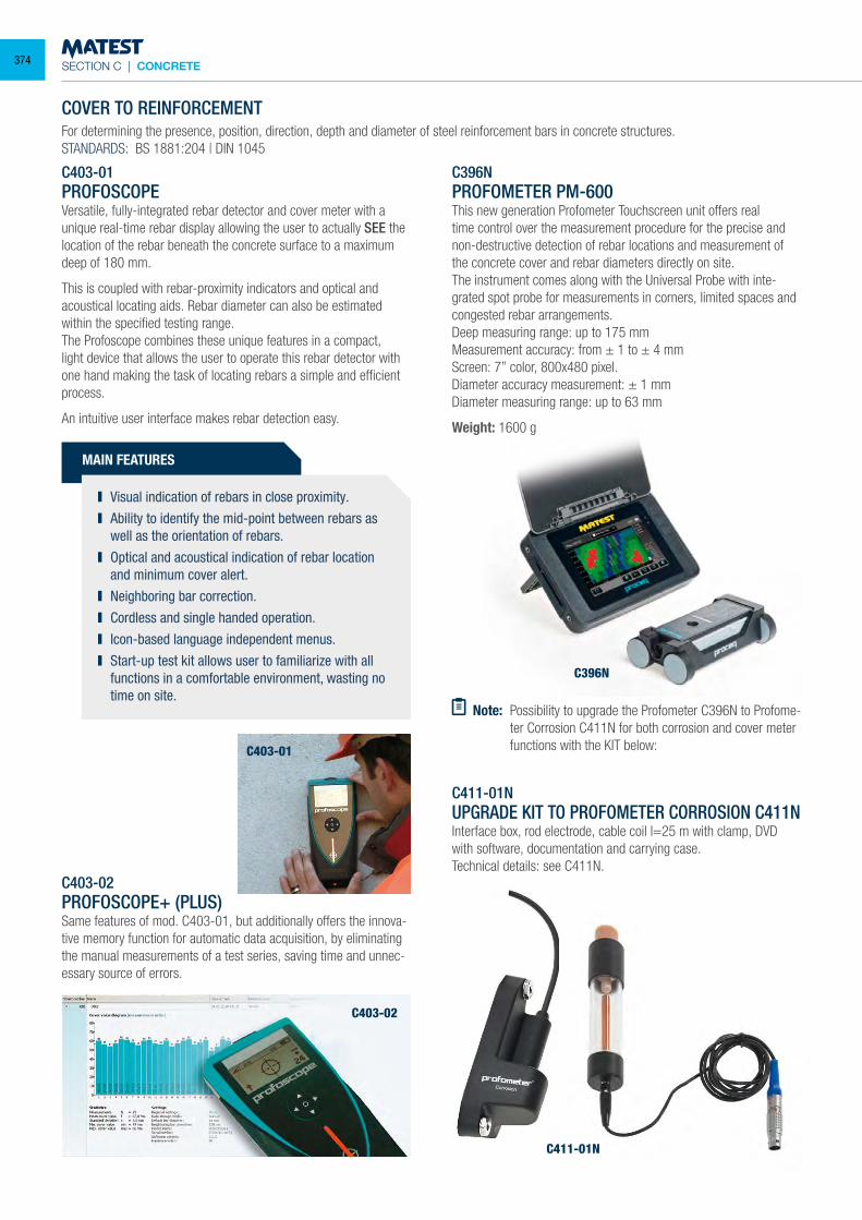
SECTION C | CONCRETE
COVER TO REINFORCEMENTFor determining the presence, position, direction, depth and diameter of steel reinforcement bars in concrete structures.STANDARDS: BS 1881:204 | DIN 1045
C403-01PROFOSCOPEVersatile, fully-integrated rebar detector and cover meter with a unique real-time rebar display allowing the user to actually SEE the location of the rebar beneath the concrete surface to a maximum deep of 180 mm.
This is coupled with rebar-proximity indicators and optical and acoustical locating aids. Rebar diameter can also be estimated within the specified testing range.The Profoscope combines these unique features in a compact, light device that allows the user to operate this rebar detector with one hand making the task of locating rebars a simple and efficient process.
An intuitive user interface makes rebar detection easy.
MAIN FEATURES
Visual indication of rebars in close proximity. Ability to identify the mid-point between rebars as
well as the orientation of rebars. Optical and acoustical indication of rebar location
and minimum cover alert. Neighboring bar correction. Cordless and single handed operation. Icon-based language independent menus. Start-up test kit allows user to familiarize with all
functions in a comfortable environment, wasting no time on site.
C403-02PROFOSCOPE+ (PLUS)Same features of mod. C403-01, but additionally offers the innova-tive memory function for automatic data acquisition, by eliminating the manual measurements of a test series, saving time and unnec-essary source of errors.
C396NPROFOMETER PM-600This new generation Profometer Touchscreen unit offers real time control over the measurement procedure for the precise and non-destructive detection of rebar locations and measurement of the concrete cover and rebar diameters directly on site.The instrument comes along with the Universal Probe with inte-grated spot probe for measurements in corners, limited spaces and congested rebar arrangements.Deep measuring range: up to 175 mmMeasurement accuracy: from ± 1 to ± 4 mmScreen: 7” color, 800x480 pixel.Diameter accuracy measurement: ± 1 mmDiameter measuring range: up to 63 mm
Weight: 1600 g
C403-01
C403-02
C396N
Note: Possibility to upgrade the Profometer C396N to Profome-ter Corrosion C411N for both corrosion and cover meter functions with the KIT below:
C411-01NUPGRADE KIT TO PROFOMETER CORROSION C411NInterface box, rod electrode, cable coil l=25 m with clamp, DVD with software, documentation and carrying case.Technical details: see C411N.
C411-01N
374
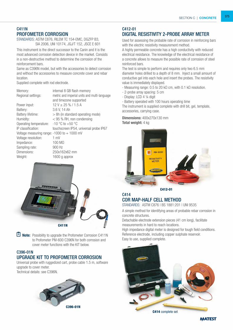
SECTION C | CONCRETE
C411N
C412-01DIGITAL RESISTIVITY 2-PROBE ARRAY METERUsed for assessing the probable rate of corrosion in reinforcing bars with the electric resistivity measurement method.A highly permeable concrete has a high conductivity with reduced electrical resistance. The knowledge of the electrical resistance of a concrete allows to measure the possible rate of corrosion of steel reinforced bars.The test is simple to perform and requires only two 6.5 mm diameter holes drilled to a depth of 8 mm. Inject a small amount of conductive gel into each hole and insert the probes. The resistivity value is immediately displayed.- Measuring range: 0.5 to 20 kΩ cm, with 0.1 kΩ resolution.- 2-probe array spacing: 5 cm- Display: LCD 4 ¼ digit- Battery operated with 100 hours operating timeThe instrument is supplied complete with drill bit, gel, template, accessories, carrying case.
Dimensions: 400x270x130 mmTotal weight: 4 kg
C414COR MAP-HALF CELL METHODSTANDARDS: ASTM C876 | BS 1881:201 | UNI 9535
A simple method for identifying areas of probable rebar corrosion in concrete structures.Detachable electrode extension pieces (41 cm long), facilitate measurements in hard to reach locations.High impedance digital meter is designed for tough field conditions.Reference electrode, including copper sulphate reservoir.Easy to use, supplied complete.
C412-01
C414 complete set
Note: Possibility to upgrade the Profometer Corrosion C411N to Profometer PM-600 C396N for both corrosion and cover meter functions with the KIT below.
C411NPROFOMETER CORROSIONSTANDARDS: ASTM C876, RILEM TC 154-EMC, DGZFP B3, SIA 2006, UNI 10174, JGJ/T 152, JSCE E 601
This instrument is the direct successor to the Canin and it is the most advanced corrosion detection device in the market. Consists in a non-destructive method to determine the corrosion of the reinforcement bars.Same as C396N model, but with the accessories to detect corrosion and without the accessories to measure concrete cover and rebar location.Supplied complete with rod electrode.
Memory: internal 8 GB flash memoryRegional settings: metric and imperial units and multi-language and timezone supportedPower input: 12 V ± 25 % / 1.5 ABattery: 3.6 V, 14 AhBattery lifetime: > 8h (in standard operating mode)Humidity: < 95 % RH, non condensingOperating temperature: -10 °C to +50 °CIP classification: touchscreen IP54, universal probe IP67Voltage measuring range: -1000 to + 1000 mVVoltage resolution: 1 mVImpedance: 100 MΩSampling rate: 900 HzDimensions: 250x162x62 mmWeight: 1600 g approx
C396-01NUPGRADE KIT TO PROFOMETER CORROSIONUniversal probe with ruggedized cart, probe cable 1.5 m, software upgrade to cover meter.Technical details: see C396N.
C396-01N
375
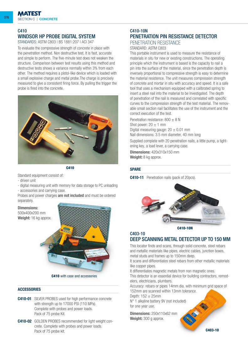
SECTION C | CONCRETE
C410
C410-10N
C403-10
C410 with case and accessories
C410WINDSOR HP PROBE DIGITAL SYSTEMSTANDARDS: ASTM C803 | BS 1881:207 | ACI 347
To evaluate the compressive strength of concrete in place with the penetration method. Non destructive test. It is fast, accurate and simple to perform. The five-minute test does not weaken the structure. Comparison between test results using this method and destructive tests shows a variance normally within 3% from each other. The method requires a pistol-like device which is loaded with a small explosive charge and metal probe.The charge is precisely measured to give a consistent firing force. By pulling the trigger the probe is fired into the concrete.
Standard equipment consist of:- driven unit- digital measuring unit with memory for data storage to PC unloading- accessories and carrying case.Probes and power charges are not included and must be ordered separately.
Dimensions:500x400x200 mm Weight: 16 kg approx.
ACCESSORIES
C410-01 SILVER PROBES used for high performance concrete with strength up to 17000 PSI (110 MPa).
Complete with probes and power loads. Pack of 75 probe Kit.
C410-02 GOLDEN PROBES recommended for light weight con-crete. Complete with probes and power loads.
Pack of 75 probe kit.
C403-10DEEP SCANNING METAL DETECTOR UP TO 150 MMThis locator finds and scans, through solid concrete, steel rebars and metallic materials like pipes, electric cables, junction boxes, metal studs and frames up to 150mm deep.It scans and differentiates steel rebars from other metallic materials like copper pipes.It differentiates magnetic metals from non magnetic ones.This detector is an essential device for building contractors, remod-elers, electricians, plumbers.Accuracy: rebars or pipes 14mm dia. with minimum grid space of 152mm are scanned within 13mm tolerance.Depth: 152 ± 25mmN° 1 alkaline battery 9V (not included)for one year use.
Dimensions: 250x110x62 mmWeight: 300 g approx.
C410-10N PENETRATION PIN RESISTANCE DETECTORPENETRATION RESISTANCESTANDARD: ASTM C803This portable instrument is used to measure the resistance of materials in situ for new or existing constructions. The operating principle which the instrument is based is the capacity to nail a pin into the surface of the material, since the penetration depth is inversely proportional to compressive strength is easy to determine the material resistence. The unit measures compression strength of concrete and mortar in situ with accuracy and speed. It is a safe tool that uses a mechanism equipped with a calibrated spring to insert a steel nail into the material to be investigated. The depth of penetration of the nail is measured and correlated with specific curves to the compression strength of the test material. The remov-able small section nail facilitates the use of the instrument and the correct execution of the test.
Penetration resistance: 800 ± 8 NShot power: 20 ± 1 mmDigital measuring gauge: 20 ± 0.01 mmNail dimensions: 3.5 mm diameter, 40 mm long
Supplied complete with 20 penetration nails, a little pump, a tight-ening key, a load lever, a carrying case.
Dimensions: 420x310x150 mmWeight: 8 kg approx.
SPARE
C410-11 Penetration nails (pack of 20pcs).
376
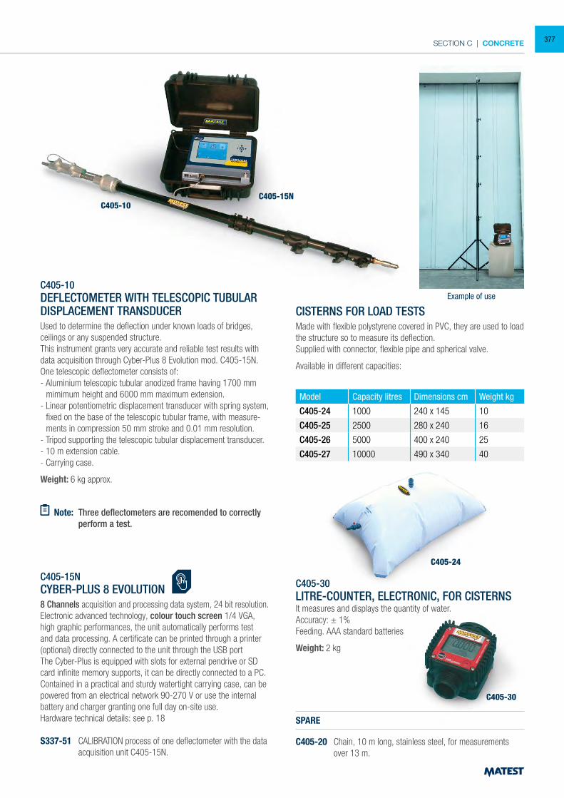
SECTION C | CONCRETE
C405-10DEFLECTOMETER WITH TELESCOPIC TUBULAR DISPLACEMENT TRANSDUCERUsed to determine the deflection under known loads of bridges, ceilings or any suspended structure. This instrument grants very accurate and reliable test results with data acquisition through Cyber-Plus 8 Evolution mod. C405-15N. One telescopic deflectometer consists of: - Aluminium telescopic tubular anodized frame having 1700 mm
mimimum height and 6000 mm maximum extension. - Linear potentiometric displacement transducer with spring system,
fixed on the base of the telescopic tubular frame, with measure-ments in compression 50 mm stroke and 0.01 mm resolution.
- Tripod supporting the telescopic tubular displacement transducer. - 10 m extension cable.- Carrying case.
Weight: 6 kg approx.
Note: Three deflectometers are recomended to correctly perform a test.
C405-15NCYBER-PLUS 8 EVOLUTION8 Channels acquisition and processing data system, 24 bit resolution.Electronic advanced technology, colour touch screen 1/4 VGA, high graphic performances, the unit automatically performs test and data processing. A certificate can be printed through a printer (optional) directly connected to the unit through the USB portThe Cyber-Plus is equipped with slots for external pendrive or SD card infinite memory supports, it can be directly connected to a PC. Contained in a practical and sturdy watertight carrying case, can be powered from an electrical network 90-270 V or use the internal battery and charger granting one full day on-site use.Hardware technical details: see p. 18
S337-51 CALIBRATION process of one deflectometer with the data acquisition unit C405-15N.
CISTERNS FOR LOAD TESTS Made with flexible polystyrene covered in PVC, they are used to load the structure so to measure its deflection. Supplied with connector, flexible pipe and spherical valve.
Available in different capacities:
Model Capacity litres Dimensions cm Weight kg
C405-24 1000 240 x 145 10
C405-25 2500 280 x 240 16
C405-26 5000 400 x 240 25
C405-27 10000 490 x 340 40
C405-30 LITRE-COUNTER, ELECTRONIC, FOR CISTERNSIt measures and displays the quantity of water. Accuracy: ± 1% Feeding. AAA standard batteries
Weight: 2 kg
SPARE
C405-20 Chain, 10 m long, stainless steel, for measurements over 13 m.
C405-15NC405-10
C405-24
C405-30
Example of use
377
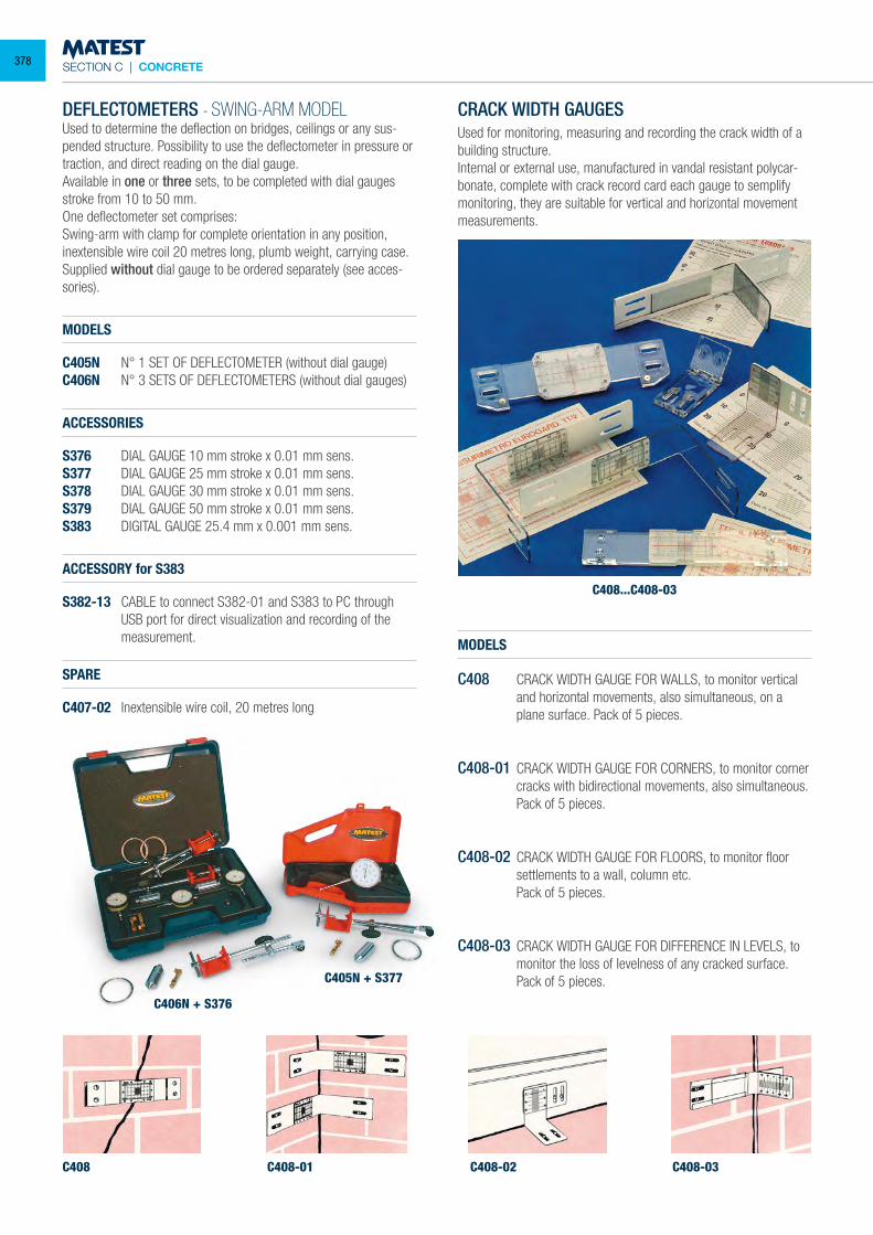
SECTION C | CONCRETE
C408
C406N + S376
C405N + S377
C408...C408-03
C408-01 C408-02 C408-03
DEFLECTOMETERS - SWING-ARM MODELUsed to determine the deflection on bridges, ceilings or any sus-pended structure. Possibility to use the deflectometer in pressure or traction, and direct reading on the dial gauge.Available in one or three sets, to be completed with dial gauges stroke from 10 to 50 mm.One deflectometer set comprises:Swing-arm with clamp for complete orientation in any position, inextensible wire coil 20 metres long, plumb weight, carrying case.Supplied without dial gauge to be ordered separately (see acces-sories).
MODELS
C405N N° 1 SET OF DEFLECTOMETER (without dial gauge)C406N N° 3 SETS OF DEFLECTOMETERS (without dial gauges)
ACCESSORIES
S376 DIAL GAUGE 10 mm stroke x 0.01 mm sens.S377 DIAL GAUGE 25 mm stroke x 0.01 mm sens.S378 DIAL GAUGE 30 mm stroke x 0.01 mm sens.S379 DIAL GAUGE 50 mm stroke x 0.01 mm sens.S383 DIGITAL GAUGE 25.4 mm x 0.001 mm sens.
ACCESSORY for S383
S382-13 CABLE to connect S382-01 and S383 to PC through USB port for direct visualization and recording of the measurement.
SPARE
C407-02 Inextensible wire coil, 20 metres long
CRACK WIDTH GAUGESUsed for monitoring, measuring and recording the crack width of a building structure.Internal or external use, manufactured in vandal resistant polycar-bonate, complete with crack record card each gauge to semplify monitoring, they are suitable for vertical and horizontal movement measurements.
MODELS
C408 CRACK WIDTH GAUGE FOR WALLS, to monitor vertical and horizontal movements, also simultaneous, on a plane surface. Pack of 5 pieces.
C408-01 CRACK WIDTH GAUGE FOR CORNERS, to monitor corner cracks with bidirectional movements, also simultaneous. Pack of 5 pieces.
C408-02 CRACK WIDTH GAUGE FOR FLOORS, to monitor floor settlements to a wall, column etc.
Pack of 5 pieces.
C408-03 CRACK WIDTH GAUGE FOR DIFFERENCE IN LEVELS, to monitor the loss of levelness of any cracked surface. Pack of 5 pieces.
378
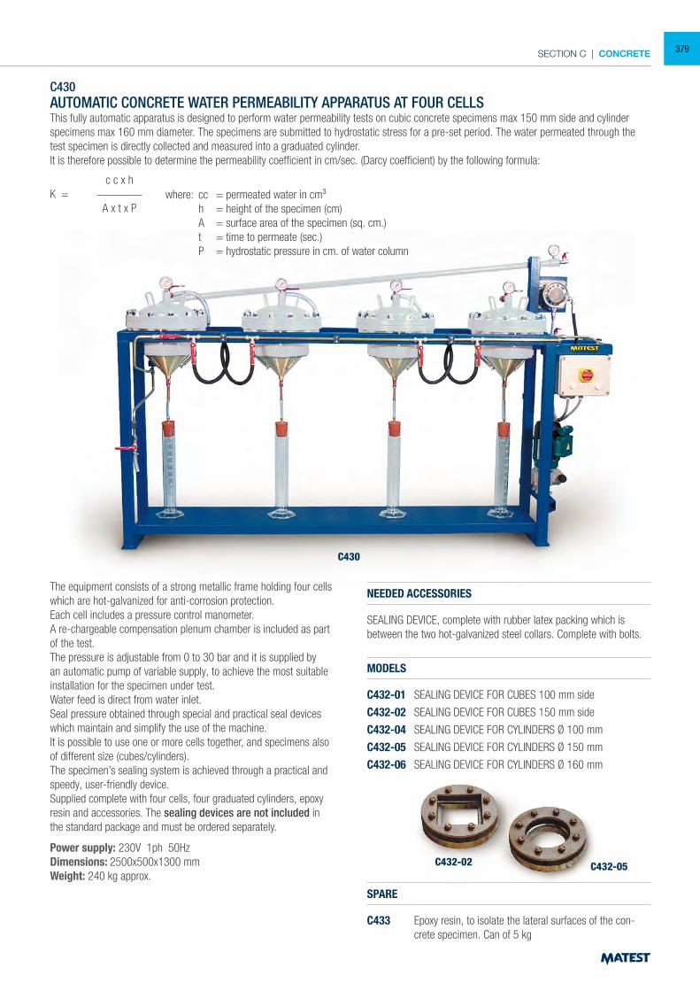
SECTION C | CONCRETE
C430AUTOMATIC CONCRETE WATER PERMEABILITY APPARATUS AT FOUR CELLSThis fully automatic apparatus is designed to perform water permeability tests on cubic concrete specimens max 150 mm side and cylinder specimens max 160 mm diameter. The specimens are submitted to hydrostatic stress for a pre-set period. The water permeated through the test specimen is directly collected and measured into a graduated cylinder.It is therefore possible to determine the permeability coefficient in cm/sec. (Darcy coefficient) by the following formula:
The equipment consists of a strong metallic frame holding four cells which are hot-galvanized for anti-corrosion protection.Each cell includes a pressure control manometer.A re-chargeable compensation plenum chamber is included as part of the test.The pressure is adjustable from 0 to 30 bar and it is supplied by an automatic pump of variable supply, to achieve the most suitable installation for the specimen under test.Water feed is direct from water inlet.Seal pressure obtained through special and practical seal devices which maintain and simplify the use of the machine.It is possible to use one or more cells together, and specimens also of different size (cubes/cylinders).The specimen’s sealing system is achieved through a practical and speedy, user-friendly device.Supplied complete with four cells, four graduated cylinders, epoxy resin and accessories. The sealing devices are not included in the standard package and must be ordered separately.
Power supply: 230V 1ph 50HzDimensions: 2500x500x1300 mmWeight: 240 kg approx.
NEEDED ACCESSORIES
SEALING DEVICE, complete with rubber latex packing which is between the two hot-galvanized steel collars. Complete with bolts.
MODELS
C432-01 SEALING DEVICE FOR CUBES 100 mm side
C432-02 SEALING DEVICE FOR CUBES 150 mm side
C432-04 SEALING DEVICE FOR CYLINDERS Ø 100 mm
C432-05 SEALING DEVICE FOR CYLINDERS Ø 150 mm
C432-06 SEALING DEVICE FOR CYLINDERS Ø 160 mm
SPARE
C433 Epoxy resin, to isolate the lateral surfaces of the con-crete specimen. Can of 5 kg
C430
C432-02 C432-05
c c x hK = A x t x P
where: cc = permeated water in cm³ h = height of the specimen (cm) A = surface area of the specimen (sq. cm.) t = time to permeate (sec.) P = hydrostatic pressure in cm. of water column
379
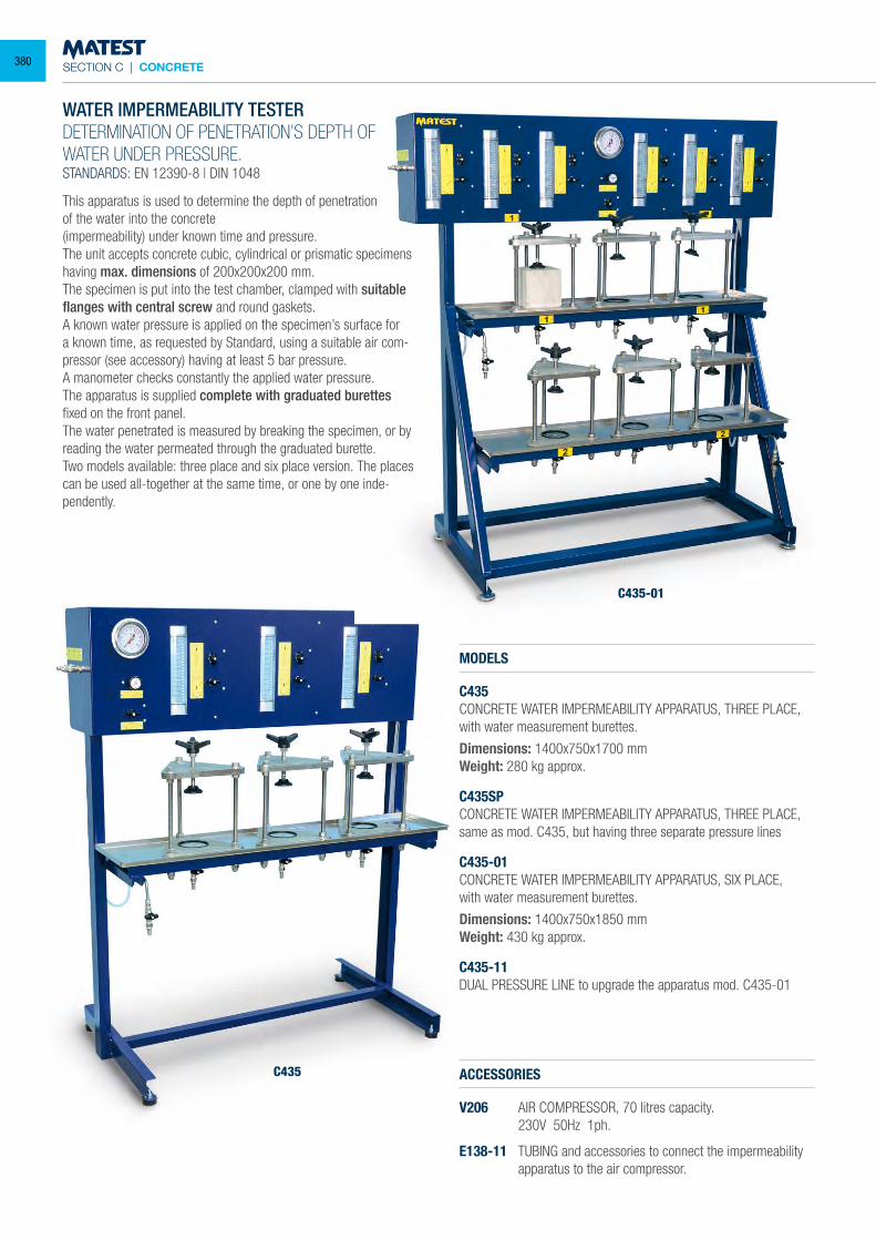
SECTION C | CONCRETE
WATER IMPERMEABILITY TESTERDETERMINATION OF PENETRATION’S DEPTH OF WATER UNDER PRESSURE.STANDARDS: EN 12390-8 | DIN 1048
This apparatus is used to determine the depth of penetrationof the water into the concrete(impermeability) under known time and pressure.The unit accepts concrete cubic, cylindrical or prismatic specimens having max. dimensions of 200x200x200 mm.The specimen is put into the test chamber, clamped with suitable flanges with central screw and round gaskets.A known water pressure is applied on the specimen’s surface for a known time, as requested by Standard, using a suitable air com-pressor (see accessory) having at least 5 bar pressure.A manometer checks constantly the applied water pressure.The apparatus is supplied complete with graduated burettes fixed on the front panel.The water penetrated is measured by breaking the specimen, or by reading the water permeated through the graduated burette.Two models available: three place and six place version. The places can be used all-together at the same time, or one by one inde-pendently.
MODELS
C435CONCRETE WATER IMPERMEABILITY APPARATUS, THREE PLACE, with water measurement burettes.
Dimensions: 1400x750x1700 mmWeight: 280 kg approx.
C435SPCONCRETE WATER IMPERMEABILITY APPARATUS, THREE PLACE, same as mod. C435, but having three separate pressure lines
C435-01CONCRETE WATER IMPERMEABILITY APPARATUS, SIX PLACE,with water measurement burettes.
Dimensions: 1400x750x1850 mmWeight: 430 kg approx.
C435-11DUAL PRESSURE LINE to upgrade the apparatus mod. C435-01
ACCESSORIES
V206 AIR COMPRESSOR, 70 litres capacity. 230V 50Hz 1ph.
E138-11 TUBING and accessories to connect the impermeability apparatus to the air compressor.
C435-01
C435
380
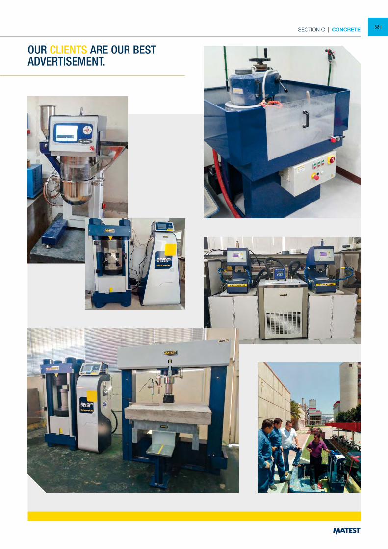
SECTION C | CONCRETE
OUR CLIENTS ARE OUR BEST ADVERTISEMENT.
381
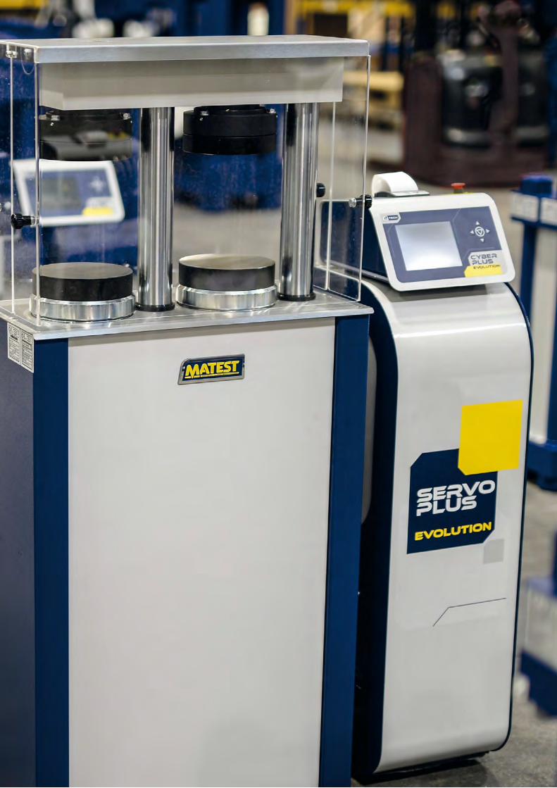
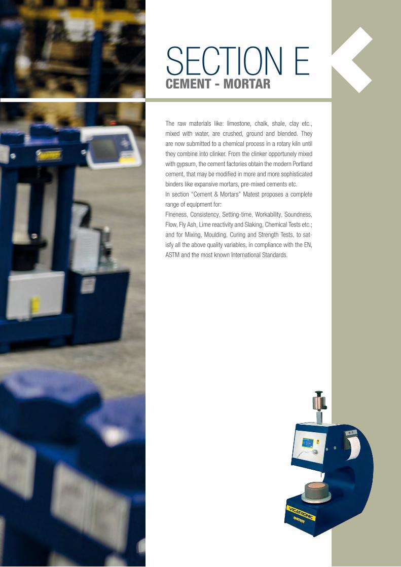
SECTION ECEMENT - MORTAR
The raw materials like: limestone, chalk, shale, clay etc.,
mixed with water, are crushed, ground and blended. They
are now submitted to a chemical process in a rotary kiln until
they combine into clinker. From the clinker opportunely mixed
with gypsum, the cement factories obtain the modern Portland
cement, that may be modified in more and more sophisticated
binders like expansive mortars, pre-mixed cements etc.
In section “Cement & Mortars” Matest proposes a complete
range of equipment for:
Fineness, Consistency, Setting-time, Workability, Soundness,
Flow, Fly Ash, Lime reactivity and Slaking, Chemical Tests etc.;
and for Mixing, Moulding, Curing and Strength Tests, to sat-
isfy all the above quality variables, in compliance with the EN,
ASTM and the most known International Standards.
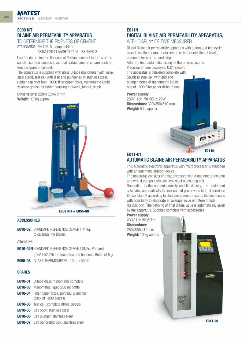
SECTION E | CEMENT - MORTAR
E009 KITBLAINE AIR PERMEABILITY APPARATUSTO DETERMINE THE FINENESS OF CEMENTSTANDARDS: EN 196-6, comparable to: ASTM C204 | AASHTO T153 | BS 4359:2
Used to determine the fineness of Portland cement in terms of the specific surface expressed as total surface area in square centime-ters per gram of cement.The apparatus is supplied with glass U-tube manometer with valve, steel stand, test cell with disk and plunger all in stainless steel, rubber aspirator bulb, 1000 filter paper disks, manometric liquid, vaseline grease for better coupling tube/cell, funnel, brush.
Dimensions: 220x180x470 mmWeight: 12 kg approx.
ACCESSORIES
E010-02 STANDARD REFERENCE CEMENT 114q. to calibrate the Blaine.
Alternative:
E010-02N STANDARD REFERENCE CEMENT SN2c. Portland
(CEM I 52,2N) turbinometric and fineness. Bottle of 5 g
E055-08 GLASS THERMOMETER -10 to +50 °C.
SPARES
E010-01 U-tube glass manometer complete
E010-03 Manometric liquid 250 ml bottle
E010-04 Filter paper discs, porosity: 2 micron (pack of 1000 pieces)
E010-08 Test cell, complete (three pieces)
E010-05 Cell body, stainless steel
E010-06 Cell plunger, stainless steel
E010-07 Cell perforated disk, stainless steel
E011NDIGITAL BLAINE AIR PERMEABILITY APPARATUS, WITH DISPLAY OF TIME MEASUREDDigital Blaine air permeability apparatus with automated test cycle, electric suction pump, photoelectric cells for detection of levels, chronometer start-up and stop.After the test, automatic display of the time measured.Precision of time displayed: 0.01 second.The apparatus is delivered complete with:Stainless steel cell with grid andplunger, bottle of manometric liquid,bag of 1000 filter paper disks, funnel.
Power supply: 230V 1ph 50-60Hz 20WDimensions: 300x250x510 mmWeight: 8 kg approx.
E011-01 AUTOMATIC BLAINE AIR PERMEABILITY APPARATUS
This automatic electronic apparatus with microprocessor is equipped with an automatic airproof device. The apparatus consists of a flat enclosure with a manometer column and with 4 components stainless steel measuring cell. Depending to the cement porosity and its density, the equipment calculates automatically the masse that you have to test, determines the constant K according to standard cement, records the test results with possibility to elaborate an average value of different tests.RS 232 port. The defining of final Blaine value is automatically given by the apparatus. Supplied complete with accessories Power supply: 230V 1ph 50-60Hz Dimensions:280x325x410 mm Weight: 10 kg approx.
E009 KIT + E055-08
E011N
E011-01
384
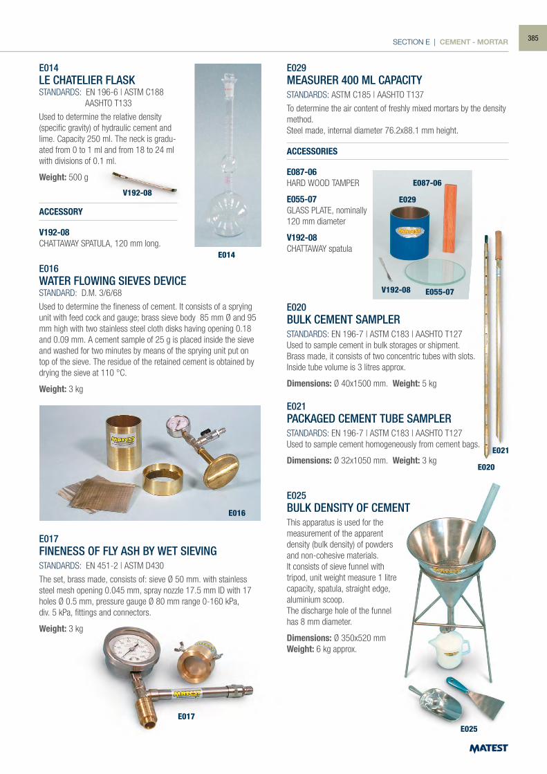
SECTION E | CEMENT - MORTAR
E014
E014LE CHATELIER FLASKSTANDARDS: EN 196-6 | ASTM C188 AASHTO T133
Used to determine the relative density (specific gravity) of hydraulic cement and lime. Capacity 250 ml. The neck is gradu-ated from 0 to 1 ml and from 18 to 24 ml with divisions of 0.1 ml.
Weight: 500 g
ACCESSORY
V192-08CHATTAWAY SPATULA, 120 mm long.
E016WATER FLOWING SIEVES DEVICESTANDARD: D.M. 3/6/68
Used to determine the fineness of cement. It consists of a sprying unit with feed cock and gauge; brass sieve body 85 mm Ø and 95 mm high with two stainless steel cloth disks having opening 0.18 and 0.09 mm. A cement sample of 25 g is placed inside the sieve and washed for two minutes by means of the sprying unit put on top of the sieve. The residue of the retained cement is obtained by drying the sieve at 110 °C.
Weight: 3 kg
E017FINENESS OF FLY ASH BY WET SIEVINGSTANDARDS: EN 451-2 | ASTM D430
The set, brass made, consists of: sieve Ø 50 mm. with stainless steel mesh opening 0.045 mm, spray nozzle 17.5 mm ID with 17 holes Ø 0.5 mm, pressure gauge Ø 80 mm range 0-160 kPa,div. 5 kPa, fittings and connectors.
Weight: 3 kg
E029MEASURER 400 ML CAPACITYSTANDARDS: ASTM C185 | AASHTO T137
To determine the air content of freshly mixed mortars by the density method.Steel made, internal diameter 76.2x88.1 mm height.
ACCESSORIES
E087-06HARD WOOD TAMPER
E055-07GLASS PLATE, nominally120 mm diameter
V192-08CHATTAWAY spatula
E020BULK CEMENT SAMPLERSTANDARDS: EN 196-7 | ASTM C183 | AASHTO T127Used to sample cement in bulk storages or shipment.Brass made, it consists of two concentric tubes with slots.Inside tube volume is 3 litres approx.
Dimensions: Ø 40x1500 mm. Weight: 5 kg
E021PACKAGED CEMENT TUBE SAMPLERSTANDARDS: EN 196-7 | ASTM C183 | AASHTO T127Used to sample cement homogeneously from cement bags.
Dimensions: Ø 32x1050 mm. Weight: 3 kg
E025BULK DENSITY OF CEMENTThis apparatus is used for the measurement of the apparent density (bulk density) of powders and non-cohesive materials. It consists of sieve funnel with tripod, unit weight measure 1 litre capacity, spatula, straight edge, aluminium scoop.The discharge hole of the funnel has 8 mm diameter.
Dimensions: Ø 350x520 mmWeight: 6 kg approx.
E016
E029
E087-06
E055-07
E025
V192-08
E020
E021
V192-08
E017
385
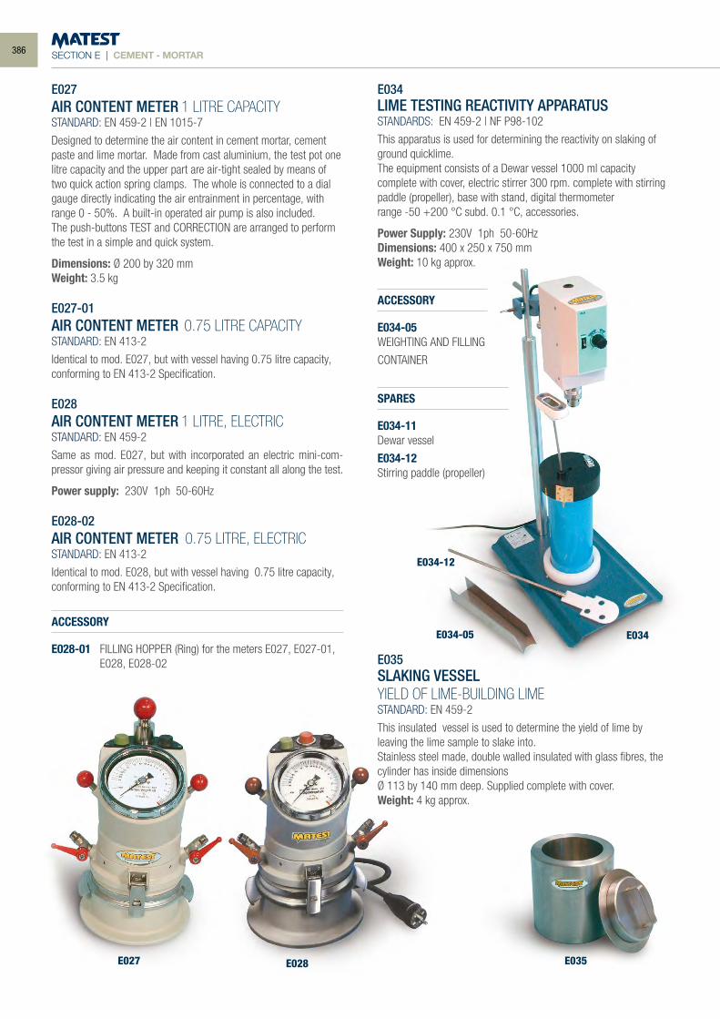
SECTION E | CEMENT - MORTAR
E027 E028 E035
E034-05
E034-12
E034
E027 AIR CONTENT METER 1 LITRE CAPACITY STANDARD: EN 459-2 | EN 1015-7
Designed to determine the air content in cement mortar, cement paste and lime mortar. Made from cast aluminium, the test pot one litre capacity and the upper part are air-tight sealed by means of two quick action spring clamps. The whole is connected to a dial gauge directly indicating the air entrainment in percentage, with range 0 - 50%. A built-in operated air pump is also included. The push-buttons TEST and CORRECTION are arranged to perform the test in a simple and quick system.
Dimensions: Ø 200 by 320 mm Weight: 3.5 kg
E027-01 AIR CONTENT METER 0.75 LITRE CAPACITYSTANDARD: EN 413-2
Identical to mod. E027, but with vessel having 0.75 litre capacity, conforming to EN 413-2 Specification.
E028
AIR CONTENT METER 1 LITRE, ELECTRICSTANDARD: EN 459-2
Same as mod. E027, but with incorporated an electric mini-com-pressor giving air pressure and keeping it constant all along the test.
Power supply: 230V 1ph 50-60Hz
E028-02 AIR CONTENT METER 0.75 LITRE, ELECTRICSTANDARD: EN 413-2
Identical to mod. E028, but with vessel having 0.75 litre capacity, conforming to EN 413-2 Specification.
ACCESSORY
E028-01 FILLING HOPPER (Ring) for the meters E027, E027-01, E028, E028-02
E034LIME TESTING REACTIVITY APPARATUSSTANDARDS: EN 459-2 | NF P98-102
This apparatus is used for determining the reactivity on slaking of ground quicklime.The equipment consists of a Dewar vessel 1000 ml capacity complete with cover, electric stirrer 300 rpm. complete with stirring paddle (propeller), base with stand, digital thermometerrange -50 +200 °C subd. 0.1 °C, accessories.
Power Supply: 230V 1ph 50-60HzDimensions: 400 x 250 x 750 mmWeight: 10 kg approx.
ACCESSORY
E034-05WEIGHTING AND FILLING
CONTAINER
SPARES
E034-11Dewar vessel
E034-12Stirring paddle (propeller)
E035SLAKING VESSELYIELD OF LIME-BUILDING LIMESTANDARD: EN 459-2
This insulated vessel is used to determine the yield of lime by leaving the lime sample to slake into.Stainless steel made, double walled insulated with glass fibres, the cylinder has inside dimensionsØ 113 by 140 mm deep. Supplied complete with cover.Weight: 4 kg approx.
386
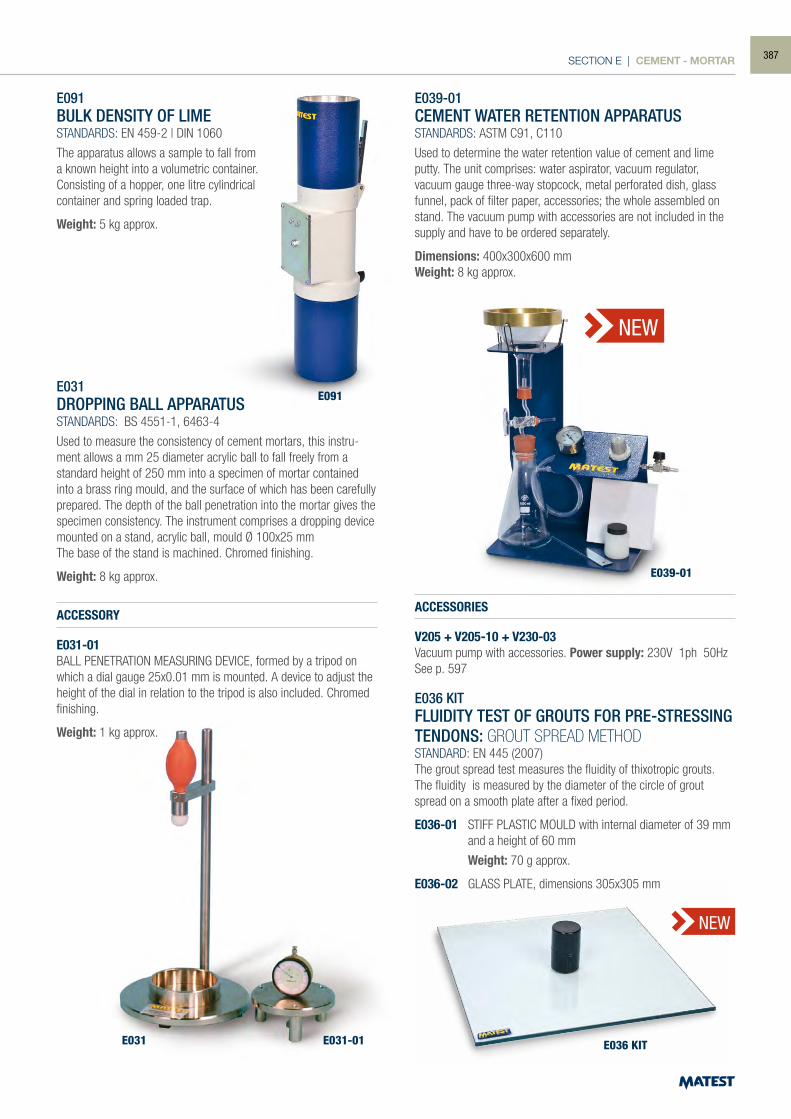
SECTION E | CEMENT - MORTAR
NEW
NEW
E091BULK DENSITY OF LIMESTANDARDS: EN 459-2 | DIN 1060
The apparatus allows a sample to fall from a known height into a volumetric container. Consisting of a hopper, one litre cylindrical container and spring loaded trap.
Weight: 5 kg approx.
E031DROPPING BALL APPARATUSSTANDARDS: BS 4551-1, 6463-4
Used to measure the consistency of cement mortars, this instru-ment allows a mm 25 diameter acrylic ball to fall freely from a standard height of 250 mm into a specimen of mortar contained into a brass ring mould, and the surface of which has been carefully prepared. The depth of the ball penetration into the mortar gives the specimen consistency. The instrument comprises a dropping device mounted on a stand, acrylic ball, mould Ø 100x25 mmThe base of the stand is machined. Chromed finishing.
Weight: 8 kg approx.
ACCESSORY
E031-01BALL PENETRATION MEASURING DEVICE, formed by a tripod on which a dial gauge 25x0.01 mm is mounted. A device to adjust the height of the dial in relation to the tripod is also included. Chromed finishing.
Weight: 1 kg approx.
E039-01CEMENT WATER RETENTION APPARATUSSTANDARDS: ASTM C91, C110
Used to determine the water retention value of cement and lime putty. The unit comprises: water aspirator, vacuum regulator, vacuum gauge three-way stopcock, metal perforated dish, glass funnel, pack of filter paper, accessories; the whole assembled on stand. The vacuum pump with accessories are not included in the supply and have to be ordered separately.
Dimensions: 400x300x600 mmWeight: 8 kg approx.
ACCESSORIES
V205 + V205-10 + V230-03Vacuum pump with accessories. Power supply: 230V 1ph 50HzSee p. 597
E036 KITFLUIDITY TEST OF GROUTS FOR PRE-STRESSING TENDONS: GROUT SPREAD METHODSTANDARD: EN 445 (2007)The grout spread test measures the fluidity of thixotropic grouts.The fluidity is measured by the diameter of the circle of grout spread on a smooth plate after a fixed period.
E036-01 STIFF PLASTIC MOULD with internal diameter of 39 mm and a height of 60 mm
Weight: 70 g approx.
E036-02 GLASS PLATE, dimensions 305x305 mm
E091
E031 E031-01
E039-01
E036 KIT
387
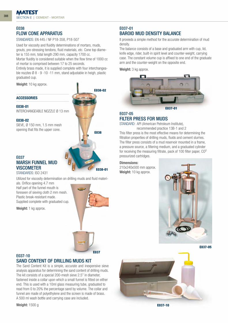
SECTION E | CEMENT - MORTAR
E038FLOW CONE APPARATUSSTANDARDS: EN 445 / NF P18-358, P18-507
Used for viscosity and fluidity determinations of mortars, muds, grouts, pre-stressing tendons, fluid materials, etc. Cone top diame-ter is 155 mm, total length 290 mm, capacity 1700 cc.Mortar fluidity is considered suitable when the flow time of 1000 cc of mortar is comprised between 17 to 25 seconds.Entirely brass made, it is supplied complete with four interchangea-ble nozzles Ø 8 - 9 -10 -11 mm, stand adjustable in heigh, plastic graduated cup.
Weight: 10 kg approx.
ACCESSORIES
E038-01INTERCHANGEABLE NOZZLE Ø 13 mm
E038-02SIEVE, Ø 150 mm, 1.5 mm mesh opening that fits the upper cone.
E037MARSH FUNNEL MUDVISCOMETERSTANDARDS: ISO 2431
Utilized for viscosity determination on drilling muds and fluid materi-als. Orifice opening 4.7 mmHalf part of the funnel mouth isforeseen of sieving cloth 2 mm mesh.Plastic break-resistant made.Supplied complete with graduated cup.
Weight: 1 kg approx.
E037-10SAND CONTENT OF DRILLING MUDS KITThe Sand Content Kit is a simple, accurate and inexpensive sieve analysis apparatus for determining the sand content of drilling muds.The kit consists of a special 200-mesh sieve 2.5” in diameter, fastened inside a collar upon which a small funnel is fitted on either end. This is used with a 10ml glass measuring tube, graduated to read from 0 to 20% the percentage sand by volume. The collar and funnel are made of polyethylene and the screen is made of brass.A 500 ml wash bottle and carrying case are included.
Weight: 1500 g
E037-01BAROID MUD DENSITY BALANCEIt provieds a simple method for the accurate determination of mud density.The balance consists of a base and graduated arm with cup, lid, knife edge, rider, built-in spirit level and counter-weight, carrying case. The constant volume cup is affixed to one end of the graduate arm and the counter-weight on the opposite end.
Weight: 3 kg approx.
E037-05FILTER PRESS FOR MUDSSTANDARD: API (American Petroleum Institute), recommended practice 13B-1 and 2This filter press is the most effective means for determining the filtration properties of drilling muds, fluids and cement slurries.The filter press consists of a mud reservoir mounted in a frame, a pressure source, a filtering medium, and a graduated cylinder for receiving the measuring filtrate, pack of 100 filter paper, CO² pressurized cartridges.
Dimensions:210x240x500 mm approx.Weight: 10 kg approx.
E038-01
E038-02
E038
E037
E037-01
E037-05
E037-10
388
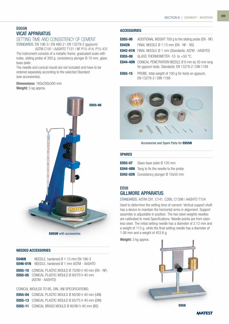
SECTION E | CEMENT - MORTAR
E055N with accessories
Accessories and Spare Parts for E055N
E055-06
E058
E055NVICAT APPARATUSSETTING TIME AND CONSISTENCY OF CEMENTSTANDARDS: EN 196-3 | EN 480-2 | EN 13279-2 (gypsum) ASTM C191 | AASHTO T131 | NF P15-414, P15-431The instrument consists of a metallic frame, graduated scale with index, sliding probe of 300 g, consistency plunger Ø 10 mm, glass base plate.The needle and conical mould are not included and have to be ordered separately according to the selected Standard(see accessories).
Dimensions: 160x200x300 mmWeight: 5 kg approx.
NEEDED ACCESSORIES
E046N NEEDLE, hardened Ø 1.13 mm EN 196-3E046-01N NEEDLE, hardened Ø 1 mm ASTM - AASHTO
E055-10 CONICAL PLASTIC MOULD Ø 70/80 h 40 mm (EN - NF)E055-05 CONICAL PLASTIC MOULD Ø 60/70 h 40 mm (ASTM - AASHTO)
CONICAL MOULDS TO BS, DIN, UNI SPECIFICATIONS:
E055-04 CONICAL PLASTIC MOULD Ø 80/90 h 40 mm (UNI)
E055-13 CONICAL PLASTIC MOULD Ø 65/75 h 40 mm (DIN)
E055-11 CONICAL BRASS MOULD Ø 80/90 h 40 mm (BS)
ACCESSORIES
E055-06 ADDITIONAL WEIGHT 700 g to the sliding probe (EN - NF)
E042N FINAL NEEDLE Ø 1.13 mm (EN - NF - BS)
E042-01N FINAL NEEDLE Ø 1 mm (Standards: ASTM - AASHTO)
E055-08 GLASS THERMOMETER -10 to +50 °C.
E044-40N CONICAL PENETRATION NEEDLE Ø 8 mm by 50 mm long for gypsum tests. Standards: EN 13279-2 | DIN 1168
E055-15 PROBE, total weight of 100 g for tests on gypsum, EN 13279-2 | DIN 1168
SPARES
E055-07 Glass base plate Ø 120 mm
E044-48N Tang to fix the needle to the probe
E042-02N Consistency plunger Ø 10x50 mm
E058GILLMORE APPARATUSSTANDARDS: ASTM C91, C141, C266, C1398 | AASHTO T154
Used to determine the setting time of cement. Vertical support shaft has a device to maintain the horizontal arms in alignment. Support assembly is adjustable in position. The two steel weights needles are calibrated to meet Specifications. Needle points are from stain-less steel. The initial setting needle has a diameter of 2.12 mm and a weight of 113 g, while the final setting needle has a diameter of 1.06 mm and a weight of 453.6 g.
Weight: 3 kg approx.
389
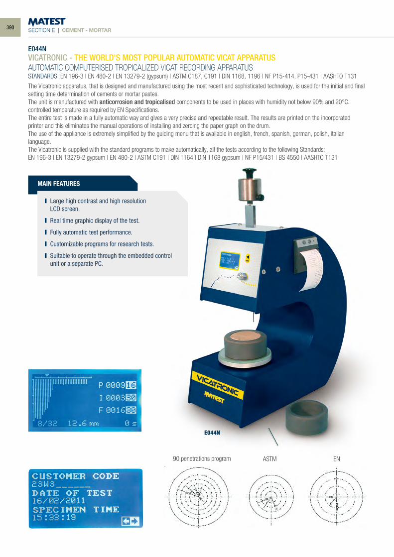
SECTION E | CEMENT - MORTAR
E044NVICATRONIC - THE WORLD'S MOST POPULAR AUTOMATIC VICAT APPARATUSAUTOMATIC COMPUTERISED TROPICALIZED VICAT RECORDING APPARATUSSTANDARDS: EN 196-3 | EN 480-2 | EN 13279-2 (gypsum) | ASTM C187, C191 | DIN 1168, 1196 | NF P15-414, P15-431 | AASHTO T131
The Vicatronic apparatus, that is designed and manufactured using the most recent and sophisticated technology, is used for the initial and final setting time determination of cements or mortar pastes.The unit is manufactured with anticorrosion and tropicalised components to be used in places with humidity not below 90% and 20°C. controlled temperature as required by EN Specifications.The entire test is made in a fully automatic way and gives a very precise and repeatable result. The results are printed on the incorporated printer and this eliminates the manual operations of installing and zeroing the paper graph on the drum.The use of the appliance is extremely simplified by the guiding menu that is available in english, french, spanish, german, polish, italian language.The Vicatronic is supplied with the standard programs to make automatically, all the tests according to the following Standards:EN 196-3 | EN 13279-2 gypsum | EN 480-2 | ASTM C191 | DIN 1164 | DIN 1168 gypsum | NF P15/431 | BS 4550 | AASHTO T131
90 penetrations program ASTM EN
E044N
MAIN FEATURES
Large high contrast and high resolution LCD screen.
Real time graphic display of the test.
Fully automatic test performance.
Customizable programs for research tests.
Suitable to operate through the embedded control unit or a separate PC.
390
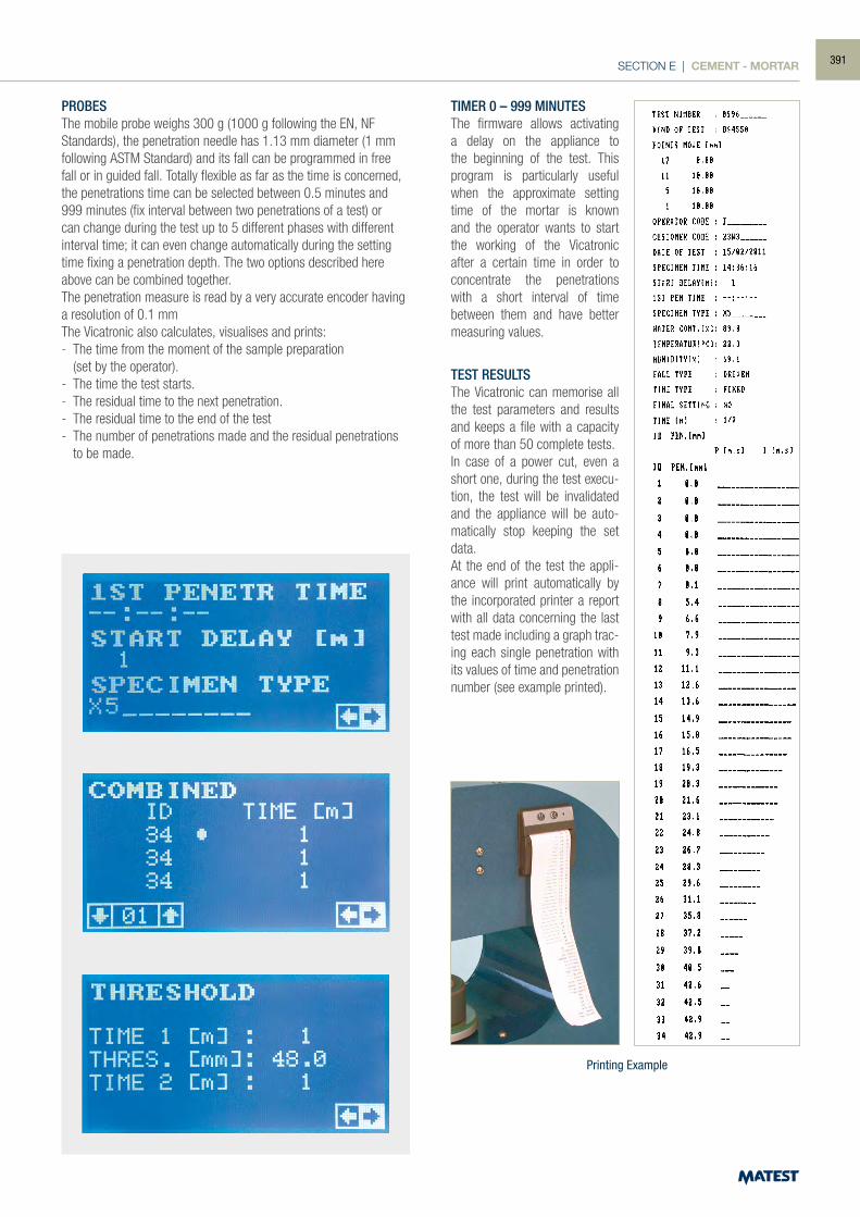
SECTION E | CEMENT - MORTAR
PROBESThe mobile probe weighs 300 g (1000 g following the EN, NF Standards), the penetration needle has 1.13 mm diameter (1 mm following ASTM Standard) and its fall can be programmed in free fall or in guided fall. Totally flexible as far as the time is concerned, the penetrations time can be selected between 0.5 minutes and 999 minutes (fix interval between two penetrations of a test) or can change during the test up to 5 different phases with different interval time; it can even change automatically during the setting time fixing a penetration depth. The two options described here above can be combined together.The penetration measure is read by a very accurate encoder having a resolution of 0.1 mmThe Vicatronic also calculates, visualises and prints:- The time from the moment of the sample preparation (set by the operator).- The time the test starts.- The residual time to the next penetration.- The residual time to the end of the test- The number of penetrations made and the residual penetrations
to be made.
TIMER 0 – 999 MINUTESThe firmware allows activating a delay on the appliance to the beginning of the test. This program is particularly useful when the approximate setting time of the mortar is known and the operator wants to start the working of the Vicatronic after a certain time in order to concentrate the penetrations with a short interval of time between them and have better measuring values.
TEST RESULTSThe Vicatronic can memorise all the test parameters and results and keeps a file with a capacity of more than 50 complete tests.In case of a power cut, even a short one, during the test execu-tion, the test will be invalidated and the appliance will be auto-matically stop keeping the set data.At the end of the test the appli-ance will print automatically by the incorporated printer a report with all data concerning the last test made including a graph trac-ing each single penetration with its values of time and penetration number (see example printed).
Printing Example
391
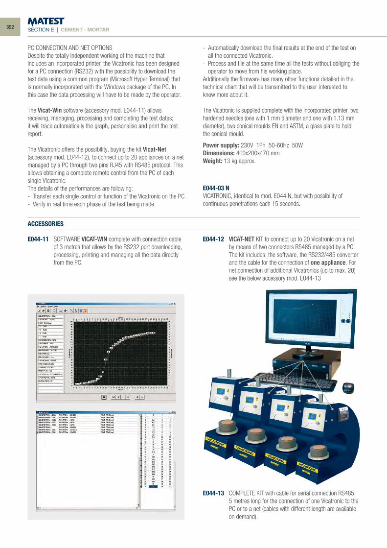
SECTION E | CEMENT - MORTAR
PC CONNECTION AND NET OPTIONSDespite the totally independent working of the machine that includes an incorporated printer, the Vicatronic has been designed for a PC connection (RS232) with the possibility to download the test data using a common program (Microsoft Hyper Terminal) that is normally incorporated with the Windows package of the PC. In this case the data processing will have to be made by the operator.
The Vicat-Win software (accessory mod. E044-11) allows receiving, managing, processing and completing the test dates;it will trace automatically the graph, personalise and print the test report.
The Vicatronic offers the possibility, buying the kit Vicat-Net (accessory mod. E044-12), to connect up to 20 appliances on a net managed by a PC through two pins RJ45 with RS485 protocol. This allows obtaining a complete remote control from the PC of each single Vicatronic.The details of the performances are following:- Transfer each single control or function of the Vicatronic on the PC- Verify in real time each phase of the test being made.
- Automatically download the final results at the end of the test on all the connected Vicatronic.
- Process and file at the same time all the tests without obliging the operator to move from his working place.
Additionally the firmware has many other functions detailed in the technical chart that will be transmitted to the user interested to know more about it.
The Vicatronic is supplied complete with the incorporated printer, two hardened needles (one with 1 mm diameter and one with 1.13 mm diameter), two conical moulds EN and ASTM, a glass plate to hold the conical mould.
Power supply: 230V 1Ph 50-60Hz 50WDimensions: 400x200x470 mmWeight: 13 kg approx.
E044-03 NVICATRONIC, identical to mod. E044 N, but with possibility of continuous penetrations each 15 seconds.
ACCESSORIES
E044-11 SOFTWARE VICAT-WIN complete with connection cable of 3 metres that allows by the RS232 port downloading, processing, printing and managing all the data directly from the PC.
E044-12 VICAT-NET KIT to connect up to 20 Vicatronic on a net by means of two connectors RS485 managed by a PC. The kit includes: the software, the RS232/485 converter and the cable for the connection of one appliance. For net connection of additional Vicatronics (up to max. 20) see the below accessory mod. E044-13
E044-13 COMPLETE KIT with cable for serial connection RS485, 5 metres long for the connection of one Vicatronic to the PC or to a net (cables with different length are available on demand).
392
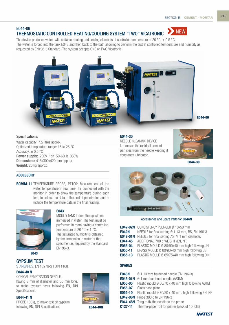
SECTION E | CEMENT - MORTAR
GYPSUM TESTSTANDARDS: EN 13279-2 | DIN 1168
E044-40 NCONICAL PENETRATION NEEDLE,having 8 mm of diameter and 50 mm long, to make gypsum tests following EN, DIN Specifications.
E044-41 NPROBE 100 g, to make test on gypsumfollowing EN, DIN Specifications.
SPARES
E046N Ø 1.13 mm hardened needle (EN 196-3) E046-01N Ø 1 mm hardened needle (ASTM)E055-05 Plastic mould Ø 60/70 x 40 mm high following ASTME055-07 Glass base plateE055-10 Plastic mould Ø 70/80 x 40 mm. high following EN, NFE042-06N Probe 300 g to EN 196-3E044-48N Tang to fix the needle to the probeC127-11 Thermo-paper roll for printer (pack of 10 rolls)
Accessories and Spare Parts for E044N
E043MOULD TANK to test the specimen immersed in water. The test must be performed in room having a controlled temperature of 20 °C ± 1 °C.The saturated humidity is obtained by the immersion in water of the specimen as required by the standard EN196-3.
E043
E044-30NEEDLE CLEANING DEVICEIt removes the residual cement particles from the needle keeping it constantly lubricated.
E044-30
E044-40N
E044-06THERMOSTATIC CONTROLLED HEATING/COOLING SYSTEM “TWO” VICATRONICThe device produces water with suitable heating and cooling elements at controlled temperature of 20 °C ± 0.5 °C.The water is forced into the tank E043 and then back to the bath allowing to perform the test at controlled temperature and humidity as requested by EN196-3 Standard. The system accepts ONE or TWO Vicatronic.
Specifications: Water capacity: 7.5 litres approx.Optimized temperature range: 15 to 25 °CAccuracy: ± 0.5 °CPower supply: 230V 1ph 50-60Hz 350WDimensions: 415x300x420 mm approx.Weight: 20 kg approx.
E044-06
E042-02N CONSISTENCY PLUNGER Ø 10x50 mmE042N NEEDLE for final setting Ø 1.13 mm, BS, EN 196-3E042-01N NEEDLE for final setting ASTM 1 mm diameter.E044-45 ADDITIONAL 700 g WEIGHT (EN, NF)E055-04 PLASTIC MOULD Ø 80/90x40 mm high following UNIE055-11 BRASS MOULD Ø 80/90x40 mm high following BSE055-13 PLASTIC MOULD Ø 65/75x40 mm high following DIN
NEW
ACCESSORY
B059M-11 TEMPERATURE PROBE, PT100: Measurement of the water temperature in real time. It’s connected with the monitor in order to show the temperature during each test, to collect the data at the end of penetration and to include the temperature data in the final reading.
393
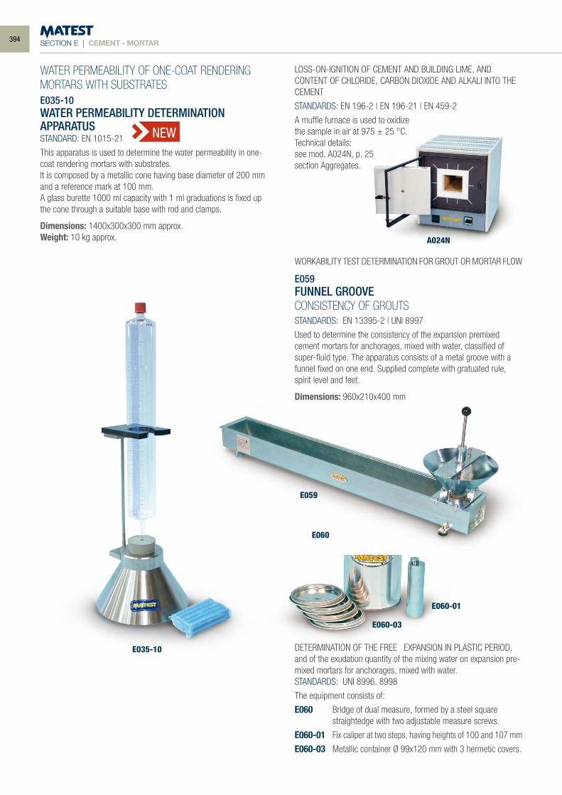
SECTION E | CEMENT - MORTAR
WATER PERMEABILITY OF ONE-COAT RENDERING MORTARS WITH SUBSTRATESE035-10WATER PERMEABILITY DETERMINATIONAPPARATUSSTANDARD: EN 1015-21
This apparatus is used to determine the water permeability in one-coat rendering mortars with substrates.It is composed by a metallic cone having base diameter of 200 mm and a reference mark at 100 mm.A glass burette 1000 ml capacity with 1 ml graduations is fixed up the cone through a suitable base with rod and clamps.
Dimensions: 1400x300x300 mm approx.Weight: 10 kg approx.
LOSS-ON-IGNITION OF CEMENT AND BUILDING LIME, AND CONTENT OF CHLORIDE, CARBON DIOXIDE AND ALKALI INTO THE CEMENT
STANDARDS: EN 196-2 | EN 196-21 | EN 459-2
A muffle furnace is used to oxidizethe sample in air at 975 ± 25 °C.Technical details:see mod. A024N, p. 25section Aggregates.
WORKABILITY TEST DETERMINATION FOR GROUT OR MORTAR FLOW
E059FUNNEL GROOVECONSISTENCY OF GROUTSSTANDARDS: EN 13395-2 | UNI 8997
Used to determine the consistency of the expansion premixed cement mortars for anchorages, mixed with water, classified of super-fluid type. The apparatus consists of a metal groove with a funnel fixed on one end. Supplied complete with gratuated rule, spirit level and feet.
Dimensions: 960x210x400 mmWeight: 10 kg approx.
DETERMINATION OF THE FREE EXPANSION IN PLASTIC PERIOD,and of the exudation quantity of the mixing water on expansion pre-mixed mortars for anchorages, mixed with water.STANDARDS: UNI 8996, 8998
The equipment consists of:
E060 Bridge of dual measure, formed by a steel square straightedge with two adjustable measure screws.
E060-01 Fix caliper at two steps, having heights of 100 and 107 mm
E060-03 Metallic container Ø 99x120 mm with 3 hermetic covers.
E035-10
A024N
E059
E060
E060-03
E060-01
NEW
394
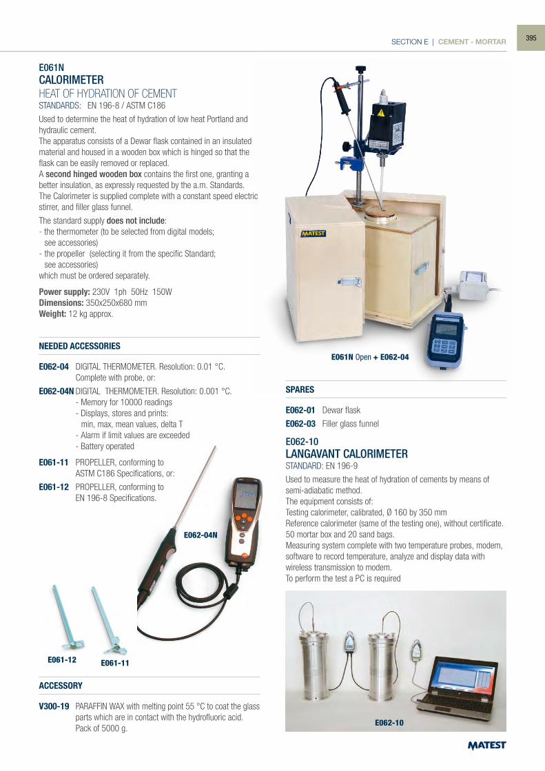
SECTION E | CEMENT - MORTAR
E061-12
E062-04N
E061-11
E061NCALORIMETERHEAT OF HYDRATION OF CEMENTSTANDARDS: EN 196-8 / ASTM C186
Used to determine the heat of hydration of low heat Portland and hydraulic cement.The apparatus consists of a Dewar flask contained in an insulated material and housed in a wooden box which is hinged so that the flask can be easily removed or replaced.A second hinged wooden box contains the first one, granting a better insulation, as expressly requested by the a.m. Standards.The Calorimeter is supplied complete with a constant speed electric stirrer, and filler glass funnel.
The standard supply does not include:- the thermometer (to be selected from digital models; see accessories)- the propeller (selecting it from the specific Standard; see accessories)which must be ordered separately.
Power supply: 230V 1ph 50Hz 150WDimensions: 350x250x680 mmWeight: 12 kg approx.
NEEDED ACCESSORIES
E062-04 DIGITAL THERMOMETER. Resolution: 0.01 °C. Complete with probe, or:
E062-04N DIGITAL THERMOMETER. Resolution: 0.001 °C. - Memory for 10000 readings - Displays, stores and prints: min, max, mean values, delta T - Alarm if limit values are exceeded - Battery operated
E061-11 PROPELLER, conforming to ASTM C186 Specifications, or:
E061-12 PROPELLER, conforming to EN 196-8 Specifications.
ACCESSORY
V300-19 PARAFFIN WAX with melting point 55 °C to coat the glass parts which are in contact with the hydrofluoric acid.
Pack of 5000 g.
SPARES
E062-01 Dewar flask
E062-03 Filler glass funnel
E062-10LANGAVANT CALORIMETERSTANDARD: EN 196-9
Used to measure the heat of hydration of cements by means of semi-adiabatic method.The equipment consists of:Testing calorimeter, calibrated, Ø 160 by 350 mmReference calorimeter (same of the testing one), without certificate.50 mortar box and 20 sand bags.Measuring system complete with two temperature probes, modem, software to record temperature, analyze and display data with wireless transmission to modem.To perform the test a PC is required
E062-10
E061N Open + E062-04
395
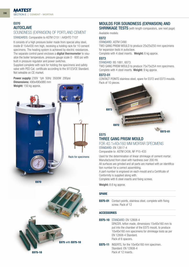
SECTION E | CEMENT - MORTAR
E070AUTOCLAVESOUNDNESS (EXPANSION) OF PORTLAND CEMENTSTANDARDS: Comparable to ASTM C151 | AASHTO T107
It consists of a high pressure boiler made from special alloy steel, inside Ø 154x430 mm high, receiving a holding rack for 10 cement specimens. The heating system is achieved by electric resistances.The separate control panel encloses a digital thermometer to visu-alize the boiler temperature, pressure gauge scale 0 - 600 psi with built in pressure regulator and power switches. Supplied complete with rack for holding the specimens and safety valve with PED Cat. certificate according to the 97/23/CE Standard. Not seleable on CE market.
Power supply: 230V 1ph 50Hz 3500W 295psiDimensions: 490x490x980 mmWeight: 150 kg approx.
MOULDS FOR SOUNDNESS (EXPANSION) AND SHRINKAGE TESTS (with length comparators, see next page)
Available models:
E072STANDARD: ASTM C490TWO GANG PRISM MOULD to produce 25x25x250 mm specimens for expansion tests in autoclave.Complete with 4 steel inserts. Weight: 6 kg approx.
E073STANDARD: BS 1881, 6073TWO GANG PRISM MOULD to produce 75x75x254 mm specimens. Complete with 4 steel inserts. Weight: 9 kg approx.
E072-01CONTACT POINTS stainless steel, spare for E072 and E073 moulds. Pack of 10 pieces.
E075THREE GANG PRISM MOULDFOR 40.1X40X160 MM MORTAR SPECIMENSSTANDARD: EN 12617-4Comparable to: ASTM C438, NF P15-433
Used for the determination of linear shrinkage of cement mortar.Manufactured from steel with hardness over 200 HV.All surfaces are grinded and all parts are marked with an identifica-tion number for a correct assembling.A part-number is engraved on each mould and a Certificate of Conformity is supplied along with.Complete with 6 steel inserts and fixing screws.
Weight: 8.6 kg approx.
SPARE
E075-01 Contact points, stainless steel, complete with fixing screw. Pack of 12
ACCESSORIES
E075-10 STANDARD: EN 12808-4 SPACER, teflon made, dimensions 15x40x160 mm to
put into the chamber of the E075 mould, to produce 10x40x160 mm specimens for shrinkage tests as per EN 12808-4 Standard.
Pack of 6 spacers.
E075-11 INSERTS, for the 10x40x160 mm specimen. Standard: EN 12808-4 Pack of 12 inserts.
E073
E072
E072-01
E075
E075-01
E075-10
E075 with E075-10
Rack for specimens
E070
396
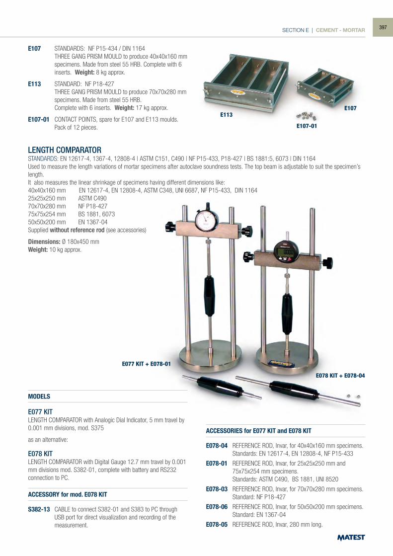
SECTION E | CEMENT - MORTAR
E107 STANDARDS: NF P15-434 / DIN 1164 THREE GANG PRISM MOULD to produce 40x40x160 mm specimens. Made from steel 55 HRB. Complete with 6
inserts. Weight: 8 kg approx.
E113 STANDARD: NF P18-427 THREE GANG PRISM MOULD to produce 70x70x280 mm
specimens. Made from steel 55 HRB. Complete with 6 inserts. Weight: 17 kg approx.
E107-01 CONTACT POINTS, spare for E107 and E113 moulds. Pack of 12 pieces.
LENGTH COMPARATOR STANDARDS: EN 12617-4, 1367-4, 12808-4 | ASTM C151, C490 | NF P15-433, P18-427 | BS 1881:5, 6073 | DIN 1164Used to measure the length variations of mortar specimens after autoclave soundness tests. The top beam is adjustable to suit the specimen’s length.It also measures the linear shrinkage of specimens having different dimensions like:40x40x160 mm EN 12617-4, EN 12808-4, ASTM C348, UNI 6687, NF P15-433, DIN 116425x25x250 mm ASTM C49070x70x280 mm NF P18-42775x75x254 mm BS 1881, 607350x50x200 mm EN 1367-04Supplied without reference rod (see accessories)
Dimensions: Ø 180x450 mmWeight: 10 kg approx.
MODELS
E077 KITLENGTH COMPARATOR with Analogic Dial Indicator, 5 mm travel by 0.001 mm divisions, mod. S375
as an alternative:
E078 KITLENGTH COMPARATOR with Digital Gauge 12.7 mm travel by 0.001 mm divisions mod. S382-01, complete with battery and RS232 connection to PC.
ACCESSORIES for E077 KIT and E078 KIT
E078-04 REFERENCE ROD, Invar, for 40x40x160 mm specimens. Standards: EN 12617-4, EN 12808-4, NF P15-433
E078-01 REFERENCE ROD, Invar, for 25x25x250 mm and 75x75x254 mm specimens.
Standards: ASTM C490, BS 1881, UNI 8520
E078-03 REFERENCE ROD, Invar, for 70x70x280 mm specimens. Standard: NF P18-427
E078-06 REFERENCE ROD, Invar, for 50x50x200 mm specimens. Standard: EN 1367-04
E078-05 REFERENCE ROD, Invar, 280 mm long.
ACCESSORY for mod. E078 KIT
S382-13 CABLE to connect S382-01 and S383 to PC through USB port for direct visualization and recording of the measurement.
E113E107
E107-01
E077 KIT + E078-01
E078 KIT + E078-04
397
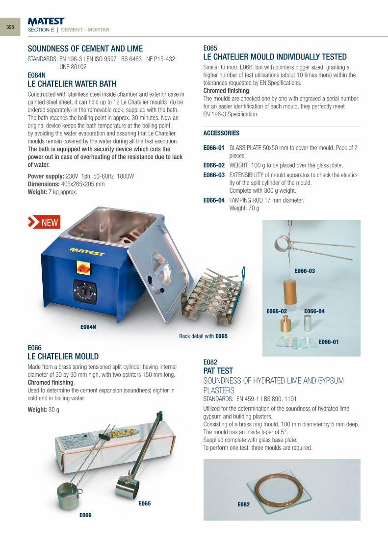
SECTION E | CEMENT - MORTAR
SOUNDNESS OF CEMENT AND LIMESTANDARDS: EN 196-3 | EN ISO 9597 | BS 6463 | NF P15-432 UNE 80102E064NLE CHATELIER WATER BATHConstructed with stainless steel inside chamber and exterior case in painted steel sheet, it can hold up to 12 Le Chatelier moulds (to be ordered separately) in the removable rack, supplied with the bath.The bath reaches the boiling point in approx. 30 minutes. Now an original device keeps the bath temperature at the boiling point, by avoiding the water evaporation and assuring that Le Chatelier moulds remain covered by the water during all the test execution. The bath is equipped with security device which cuts the power out in case of overheating of the resistance due to lack of water.
Power supply: 230V 1ph 50-60Hz 1800WDimensions: 405x265x205 mmWeight: 7 kg approx.
E066LE CHATELIER MOULDMade from a brass spring tensioned split cylinder having internal diameter of 30 by 30 mm high, with two pointers 150 mm long.Chromed finishing.Used to determine the cement expansion (soundness) eighter in cold and in boiling water.
Weight: 30 g
E065LE CHATELIER MOULD INDIVIDUALLY TESTEDSimilar to mod. E066, but with pointers bigger sized, granting a higher number of test utilisations (about 10 times more) within the tolerances requested by EN Specifications.Chromed finishing.The moulds are checked one by one with engraved a serial number for an easier identification of each mould, they perfectly meetEN 196-3 Specification.
ACCESSORIES
E066-01 GLASS PLATE 50x50 mm to cover the mould. Pack of 2 pieces.
E066-02 WEIGHT: 100 g to be placed over the glass plate.
E066-03 EXTENSIBILITY of mould apparatus to check the elastic-ity of the split cylinder of the mould.
Complete with 300 g weight.
E066-04 TAMPING ROD 17 mm diameter. Weight: 70 g
E082PAT TESTSOUNDNESS OF HYDRATED LIME AND GYPSUM PLASTERSSTANDARDS: EN 459-1 | BS 890, 1191
Utilized for the determination of the soundness of hydrated lime, gypsum and building plasters.Consisting of a brass ring mould, 100 mm diameter by 5 mm deep.The mould has an inside taper of 5°.Supplied complete with glass base plate.To perform one test, three moulds are required.
E064N
E066
E065 E082
E066-03
E066-02 E066-04
E066-01Rack detail with E065
NEW
398
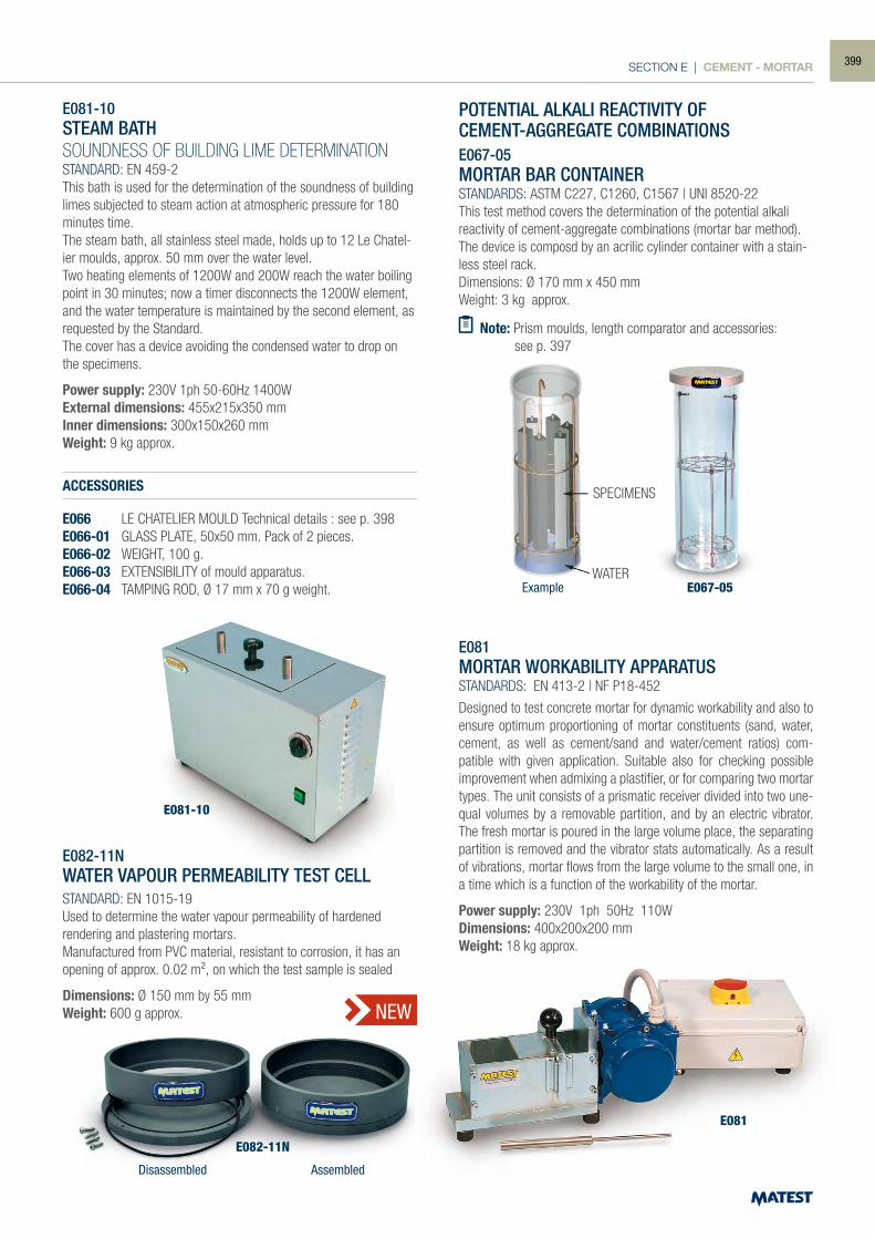
SECTION E | CEMENT - MORTAR
POTENTIAL ALKALI REACTIVITY OFCEMENT-AGGREGATE COMBINATIONSE067-05MORTAR BAR CONTAINERSTANDARDS: ASTM C227, C1260, C1567 | UNI 8520-22This test method covers the determination of the potential alkali reactivity of cement-aggregate combinations (mortar bar method).The device is composd by an acrilic cylinder container with a stain-less steel rack.Dimensions: Ø 170 mm x 450 mmWeight: 3 kg approx.
Note: Prism moulds, length comparator and accessories: see p. 397
E081-10STEAM BATHSOUNDNESS OF BUILDING LIME DETERMINATIONSTANDARD: EN 459-2This bath is used for the determination of the soundness of building limes subjected to steam action at atmospheric pressure for 180 minutes time.The steam bath, all stainless steel made, holds up to 12 Le Chatel-ier moulds, approx. 50 mm over the water level. Two heating elements of 1200W and 200W reach the water boiling point in 30 minutes; now a timer disconnects the 1200W element, and the water temperature is maintained by the second element, as requested by the Standard. The cover has a device avoiding the condensed water to drop on the specimens.
Power supply: 230V 1ph 50-60Hz 1400WExternal dimensions: 455x215x350 mmInner dimensions: 300x150x260 mmWeight: 9 kg approx.
ACCESSORIES
E066 LE CHATELIER MOULD Technical details : see p. 398E066-01 GLASS PLATE, 50x50 mm. Pack of 2 pieces.E066-02 WEIGHT, 100 g.E066-03 EXTENSIBILITY of mould apparatus.E066-04 TAMPING ROD, Ø 17 mm x 70 g weight.
E082-11N WATER VAPOUR PERMEABILITY TEST CELL STANDARD: EN 1015-19 Used to determine the water vapour permeability of hardened rendering and plastering mortars. Manufactured from PVC material, resistant to corrosion, it has an opening of approx. 0.02 m², on which the test sample is sealed
Dimensions: Ø 150 mm by 55 mm Weight: 600 g approx.
E081MORTAR WORKABILITY APPARATUSSTANDARDS: EN 413-2 | NF P18-452
Designed to test concrete mortar for dynamic workability and also to ensure optimum proportioning of mortar constituents (sand, water, cement, as well as cement/sand and water/cement ratios) com-patible with given application. Suitable also for checking possible improvement when admixing a plastifier, or for comparing two mortar types. The unit consists of a prismatic receiver divided into two une-qual volumes by a removable partition, and by an electric vibrator. The fresh mortar is poured in the large volume place, the separating partition is removed and the vibrator stats automatically. As a result of vibrations, mortar flows from the large volume to the small one, in a time which is a function of the workability of the mortar.
Power supply: 230V 1ph 50Hz 110WDimensions: 400x200x200 mmWeight: 18 kg approx.
SPECIMENS
WATERExample
Disassembled Assembled
E067-05
E081
E081-10
E082-11N
NEW
399
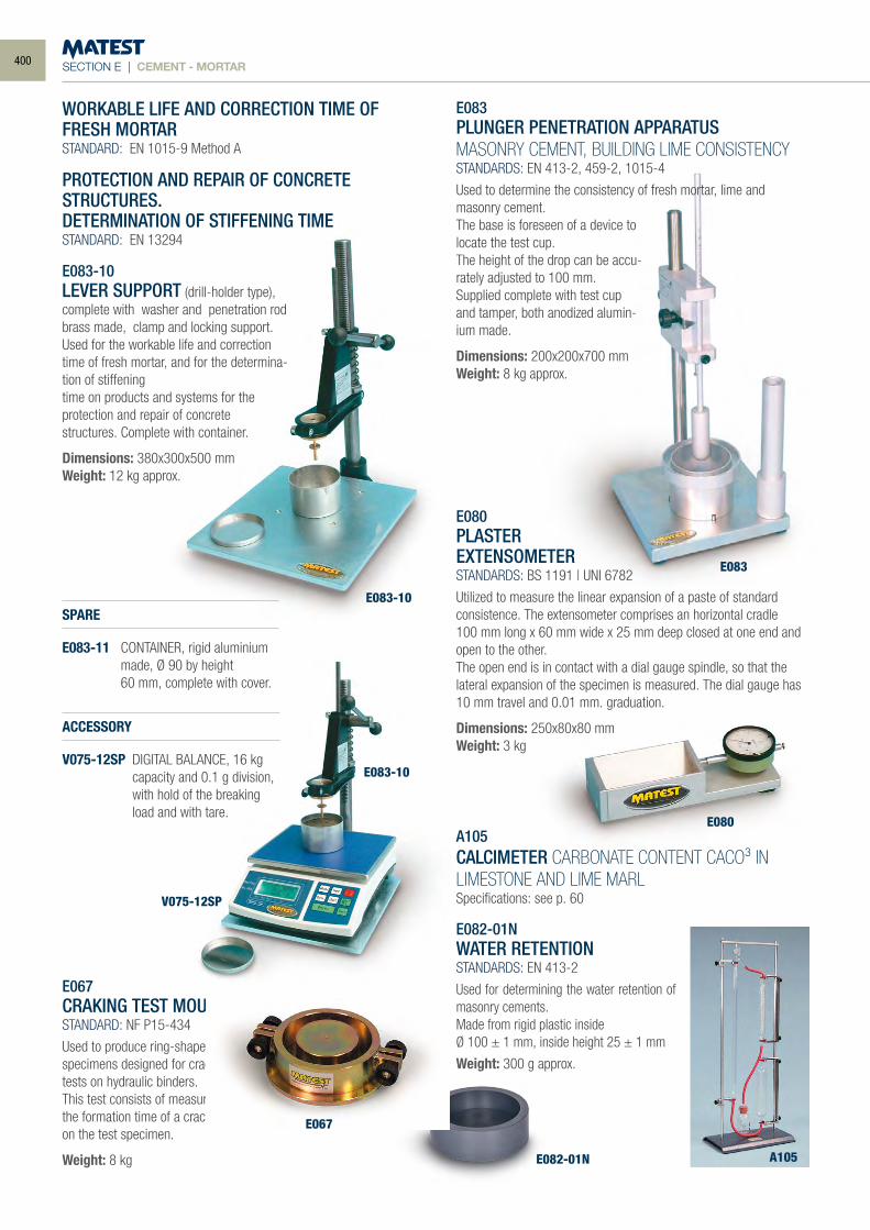
SECTION E | CEMENT - MORTAR
E083PLUNGER PENETRATION APPARATUSMASONRY CEMENT, BUILDING LIME CONSISTENCYSTANDARDS: EN 413-2, 459-2, 1015-4
Used to determine the consistency of fresh mortar, lime and masonry cement.The base is foreseen of a device to locate the test cup. The height of the drop can be accu-rately adjusted to 100 mm.Supplied complete with test cup and tamper, both anodized alumin-ium made.
Dimensions: 200x200x700 mmWeight: 8 kg approx.
WORKABLE LIFE AND CORRECTION TIME OF FRESH MORTARSTANDARD: EN 1015-9 Method A
PROTECTION AND REPAIR OF CONCRETESTRUCTURES.DETERMINATION OF STIFFENING TIMESTANDARD: EN 13294
E083-10LEVER SUPPORT (drill-holder type), complete with washer and penetration rod brass made, clamp and locking support.Used for the workable life and correction time of fresh mortar, and for the determina-tion of stiffeningtime on products and systems for theprotection and repair of concretestructures. Complete with container.
Dimensions: 380x300x500 mmWeight: 12 kg approx.
SPARE
E083-11 CONTAINER, rigid aluminium made, Ø 90 by height
60 mm, complete with cover.
ACCESSORY
V075-12SP DIGITAL BALANCE, 16 kg capacity and 0.1 g division, with hold of the breaking load and with tare.
E067CRAKING TEST MOULDSTANDARD: NF P15-434
Used to produce ring-shapedspecimens designed for crackingtests on hydraulic binders.This test consists of measuringthe formation time of a crackon the test specimen.
Weight: 8 kg
E080PLASTEREXTENSOMETERSTANDARDS: BS 1191 | UNI 6782
Utilized to measure the linear expansion of a paste of standard consistence. The extensometer comprises an horizontal cradle100 mm long x 60 mm wide x 25 mm deep closed at one end and open to the other.The open end is in contact with a dial gauge spindle, so that the lateral expansion of the specimen is measured. The dial gauge has 10 mm travel and 0.01 mm. graduation.
Dimensions: 250x80x80 mm Weight: 3 kg
A105CALCIMETER CARBONATE CONTENT CACO³ IN LIMESTONE AND LIME MARLSpecifications: see p. 60
E083-10
E083-10
E080
A105
E083
V075-12SP
E082-01N
E082-01NWATER RETENTIONSTANDARDS: EN 413-2
Used for determining the water retention of masonry cements.Made from rigid plastic insideØ 100 ± 1 mm, inside height 25 ± 1 mm
Weight: 300 g approx.
E067
400
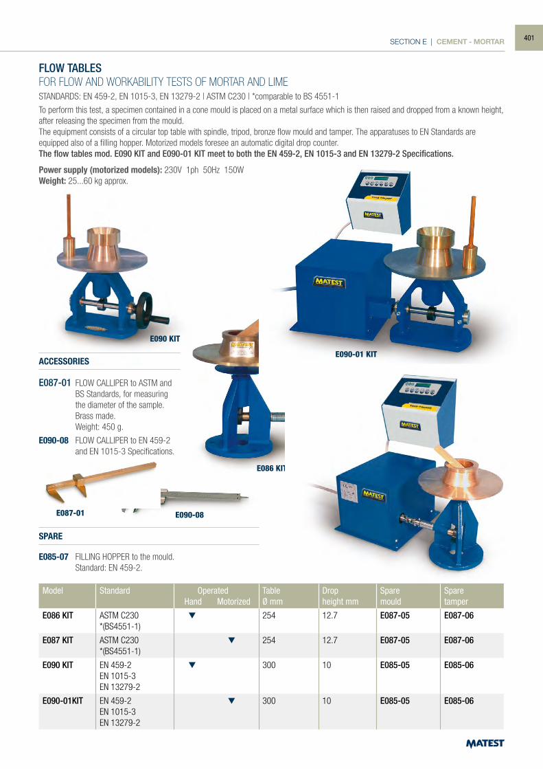
SECTION E | CEMENT - MORTAR
E090 KIT
E086 KIT
E087-01 E090-08
E090-01 KIT
E087 KIT
FLOW TABLESFOR FLOW AND WORKABILITY TESTS OF MORTAR AND LIMESTANDARDS: EN 459-2, EN 1015-3, EN 13279-2 | ASTM C230 | *comparable to BS 4551-1
To perform this test, a specimen contained in a cone mould is placed on a metal surface which is then raised and dropped from a known height, after releasing the specimen from the mould.The equipment consists of a circular top table with spindle, tripod, bronze flow mould and tamper. The apparatuses to EN Standards are equipped also of a filling hopper. Motorized models foresee an automatic digital drop counter.The flow tables mod. E090 KIT and E090-01 KIT meet to both the EN 459-2, EN 1015-3 and EN 13279-2 Specifications.
Power supply (motorized models): 230V 1ph 50Hz 150WWeight: 25...60 kg approx.
ACCESSORIES
E087-01 FLOW CALLIPER to ASTM and BS Standards, for measuring the diameter of the sample. Brass made.
Weight: 450 g.
E090-08 FLOW CALLIPER to EN 459-2 and EN 1015-3 Specifications.
SPARE
E085-07 FILLING HOPPER to the mould. Standard: EN 459-2.
Model Standard Operated Hand Motorized
TableØ mm
Dropheight mm
Sparemould
Sparetamper
E086 KIT ASTM C230*(BS4551-1)
254 12.7 E087-05 E087-06
E087 KIT ASTM C230*(BS4551-1)
254 12.7 E087-05 E087-06
E090 KIT EN 459-2EN 1015-3EN 13279-2
300 10 E085-05 E085-06
E090-01KIT EN 459-2EN 1015-3EN 13279-2
300 10 E085-05 E085-06
401
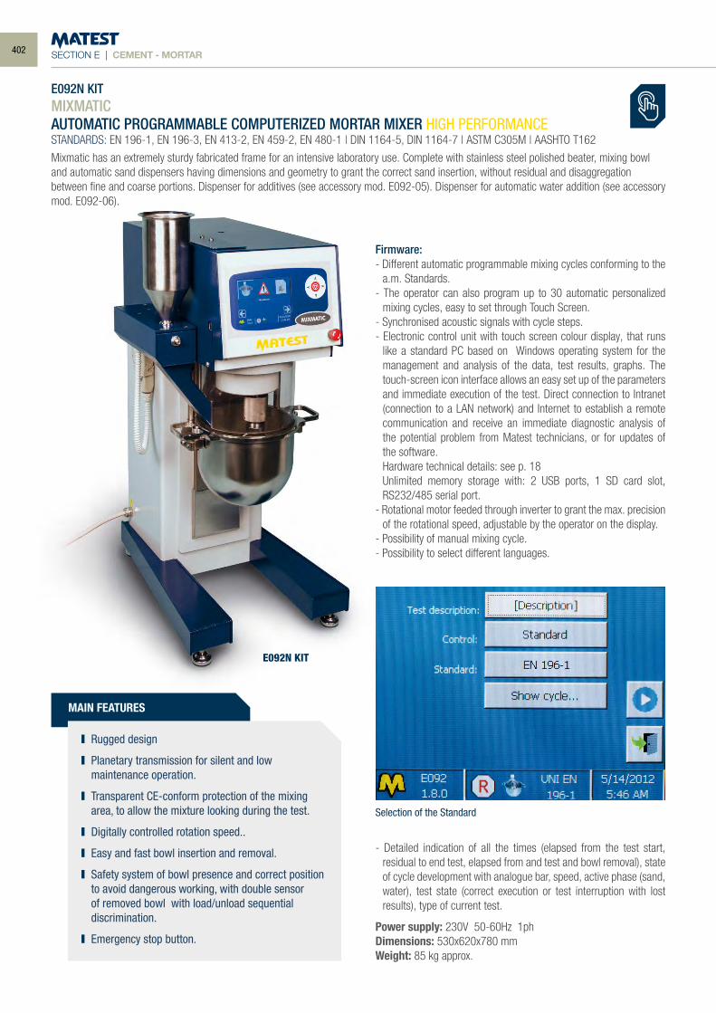
SECTION E | CEMENT - MORTAR
E092N KITMIXMATICAUTOMATIC PROGRAMMABLE COMPUTERIZED MORTAR MIXER HIGH PERFORMANCESTANDARDS: EN 196-1, EN 196-3, EN 413-2, EN 459-2, EN 480-1 | DIN 1164-5, DIN 1164-7 | ASTM C305M | AASHTO T162
Mixmatic has an extremely sturdy fabricated frame for an intensive laboratory use. Complete with stainless steel polished beater, mixing bowl and automatic sand dispensers having dimensions and geometry to grant the correct sand insertion, without residual and disaggregation between fine and coarse portions. Dispenser for additives (see accessory mod. E092-05). Dispenser for automatic water addition (see accessory mod. E092-06).
Firmware:- Different automatic programmable mixing cycles conforming to the
a.m. Standards.- The operator can also program up to 30 automatic personalized
mixing cycles, easy to set through Touch Screen. - Synchronised acoustic signals with cycle steps.- Electronic control unit with touch screen colour display, that runs
like a standard PC based on Windows operating system for the management and analysis of the data, test results, graphs. The touch-screen icon interface allows an easy set up of the parameters and immediate execution of the test. Direct connection to Intranet (connection to a LAN network) and Internet to establish a remote communication and receive an immediate diagnostic analysis of the potential problem from Matest technicians, or for updates of the software.
Hardware technical details: see p. 18 Unlimited memory storage with: 2 USB ports, 1 SD card slot,
RS232/485 serial port.- Rotational motor feeded through inverter to grant the max. precision
of the rotational speed, adjustable by the operator on the display.- Possibility of manual mixing cycle.- Possibility to select different languages.
- Detailed indication of all the times (elapsed from the test start, residual to end test, elapsed from and test and bowl removal), state of cycle development with analogue bar, speed, active phase (sand, water), test state (correct execution or test interruption with lost results), type of current test.
Power supply: 230V 50-60Hz 1phDimensions: 530x620x780 mmWeight: 85 kg approx.
Selection of the Standard
E092N KIT
MAIN FEATURES
Rugged design
Planetary transmission for silent and low maintenance operation.
Transparent CE-conform protection of the mixing area, to allow the mixture looking during the test.
Digitally controlled rotation speed..
Easy and fast bowl insertion and removal.
Safety system of bowl presence and correct position to avoid dangerous working, with double sensor of removed bowl with load/unload sequential discrimination.
Emergency stop button.
402
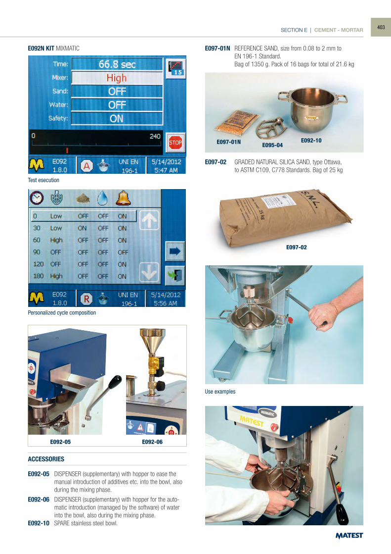
SECTION E | CEMENT - MORTAR
Test esecution
Personalized cycle composition
Use examples
E092N KIT MIXMATIC
ACCESSORIES
E092-05 DISPENSER (supplementary) with hopper to ease the manual introduction of additives etc. into the bowl, also during the mixing phase.
E092-06 DISPENSER (supplementary) with hopper for the auto-matic introduction (managed by the software) of water into the bowl, also during the mixing phase.
E092-10 SPARE stainless steel bowl.
E097-01N REFERENCE SAND, size from 0.08 to 2 mm to EN 196-1 Standard. Bag of 1350 g. Pack of 16 bags for total of 21.6 kg
E097-02 GRADED NATURAL SILICA SAND, type Ottawa, to ASTM C109, C778 Standards. Bag of 25 kg
E095-04E092-10E097-01N
E092-05 E092-06
E097-02
403
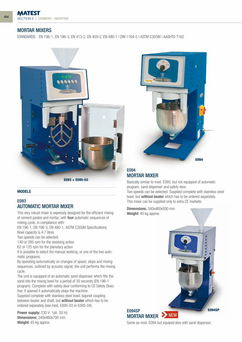
SECTION E | CEMENT - MORTAR
MORTAR MIXERSSTANDARDS: EN 196-1, EN 196-3, EN 413-2, EN 459-2, EN 480-1 | DIN 1164-5 | ASTM C305M | AASHTO T162
MODELS
E093AUTOMATIC MORTAR MIXERThis very robust mixer is expressly designed for the efficient mixing of cement pastes and mortar, with four automatic sequences of mixing cycle, in compliance with:EN 196-1, EN 196-3, EN 480-1, ASTM C305M Specifications.Bowl capacity is 4.7 litresTwo speeds can be selected:140 or 285 rpm for the revolving action62 or 125 rpm for the planetary actionIt is possible to select the manual working, or one of the two auto-matic programs.By operating automatically on changes of speed, stops and mixing sequences, outlined by acoustic signal, the unit performs the mixing cycle.The unit is equipped of an automatic sand dispenser which fills the sand into the mixing bowl for a period of 30 seconds (EN 196-1 program). Complete with safety door conforming to CE Safety Direc-tive; if opened it automatically stops the machine.Supplied complete with stainless steel bowl, bajonet coupling between beater and shaft, but without beater which has to be ordered separately (see mod. E095-03 or E095-04).
Power supply: 230 V 1ph 50 HzDimensions: 340x460x700 mm. Weight: 45 kg approx.
E093 + E095-03
E094
E094SP
E094MORTAR MIXERBasically similar to mod. E093, but not equipped of automatic program, sand dispenser and safety door. Two speeds can be selected. Supplied complete with stainless steel bowl, but without beater which has to be ordered separately.This mixer can be supplied only to extra CE markets.
Dimensions: 340x460x500 mmWeight: 40 kg approx.
E094SPMORTAR MIXERSame as mod. E094 but equiped also with sand dispenser.
NEW
404
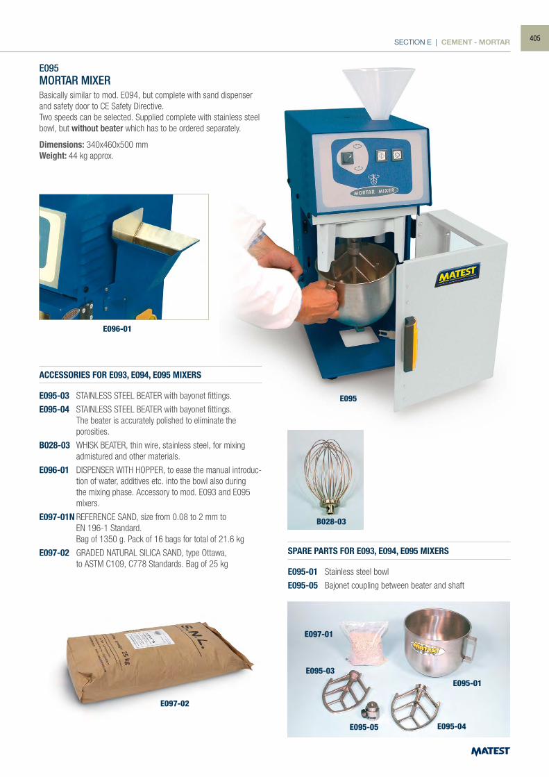
SECTION E | CEMENT - MORTAR
E095MORTAR MIXERBasically similar to mod. E094, but complete with sand dispenser and safety door to CE Safety Directive.Two speeds can be selected. Supplied complete with stainless steel bowl, but without beater which has to be ordered separately.
Dimensions: 340x460x500 mmWeight: 44 kg approx.
ACCESSORIES FOR E093, E094, E095 MIXERS
E095-03 STAINLESS STEEL BEATER with bayonet fittings.
E095-04 STAINLESS STEEL BEATER with bayonet fittings. The beater is accurately polished to eliminate the porosities.
B028-03 WHISK BEATER, thin wire, stainless steel, for mixing admistured and other materials.
E096-01 DISPENSER WITH HOPPER, to ease the manual introduc-tion of water, additives etc. into the bowl also during the mixing phase. Accessory to mod. E093 and E095 mixers.
E097-01N REFERENCE SAND, size from 0.08 to 2 mm to EN 196-1 Standard. Bag of 1350 g. Pack of 16 bags for total of 21.6 kg
E097-02 GRADED NATURAL SILICA SAND, type Ottawa, to ASTM C109, C778 Standards. Bag of 25 kg
SPARE PARTS FOR E093, E094, E095 MIXERS
E095-01 Stainless steel bowl
E095-05 Bajonet coupling between beater and shaft
E095
E096-01
E097-01
B028-03
E095-03
E095-05 E095-04
E095-01
E097-02
405
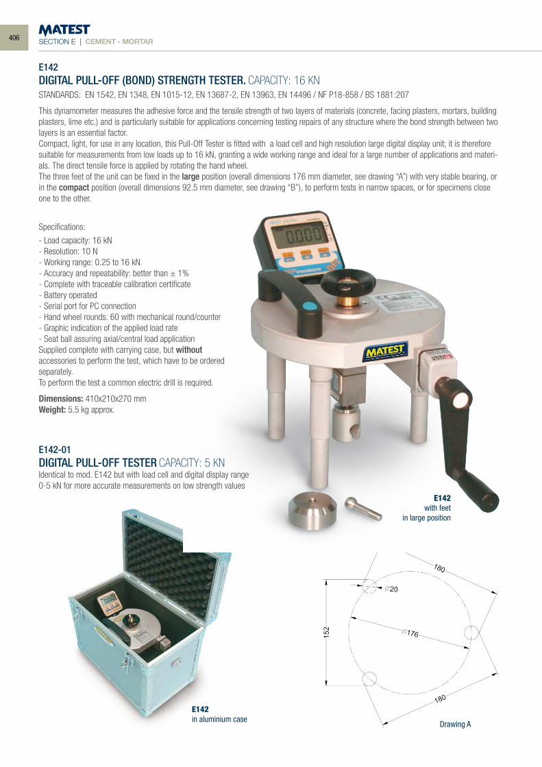
SECTION E | CEMENT - MORTAR
E142DIGITAL PULL-OFF (BOND) STRENGTH TESTER. CAPACITY: 16 KNSTANDARDS: EN 1542, EN 1348, EN 1015-12, EN 13687-2, EN 13963, EN 14496 / NF P18-858 / BS 1881:207
This dynamometer measures the adhesive force and the tensile strength of two layers of materials (concrete, facing plasters, mortars, building plasters, lime etc.) and is particularly suitable for applications concerning testing repairs of any structure where the bond strength between two layers is an essential factor.Compact, light, for use in any location, this Pull-Off Tester is fitted with a load cell and high resolution large digital display unit; it is therefore suitable for measurements from low loads up to 16 kN, granting a wide working range and ideal for a large number of applications and materi-als. The direct tensile force is applied by rotating the hand wheel.The three feet of the unit can be fixed in the large position (overall dimensions 176 mm diameter, see drawing “A”) with very stable bearing, or in the compact position (overall dimensions 92.5 mm diameter, see drawing “B”), to perform tests in narrow spaces, or for specimens close one to the other.
Specifications:
- Load capacity: 16 kN- Resolution: 10 N- Working range: 0.25 to 16 kN- Accuracy and repeatability: better than ± 1%- Complete with traceable calibration certificate- Battery operated- Serial port for PC connection- Hand wheel rounds: 60 with mechanical round/counter- Graphic indication of the applied load rate- Seat ball assuring axial/central load applicationSupplied complete with carrying case, but withoutaccessories to perform the test, which have to be orderedseparately.To perform the test a common electric drill is required.
Dimensions: 410x210x270 mmWeight: 5.5 kg approx.
E142-01DIGITAL PULL-OFF TESTER CAPACITY: 5 KNIdentical to mod. E142 but with load cell and digital display range 0-5 kN for more accurate measurements on low strength values
E142with feet
in large position
E142in aluminium case
Drawing A
406
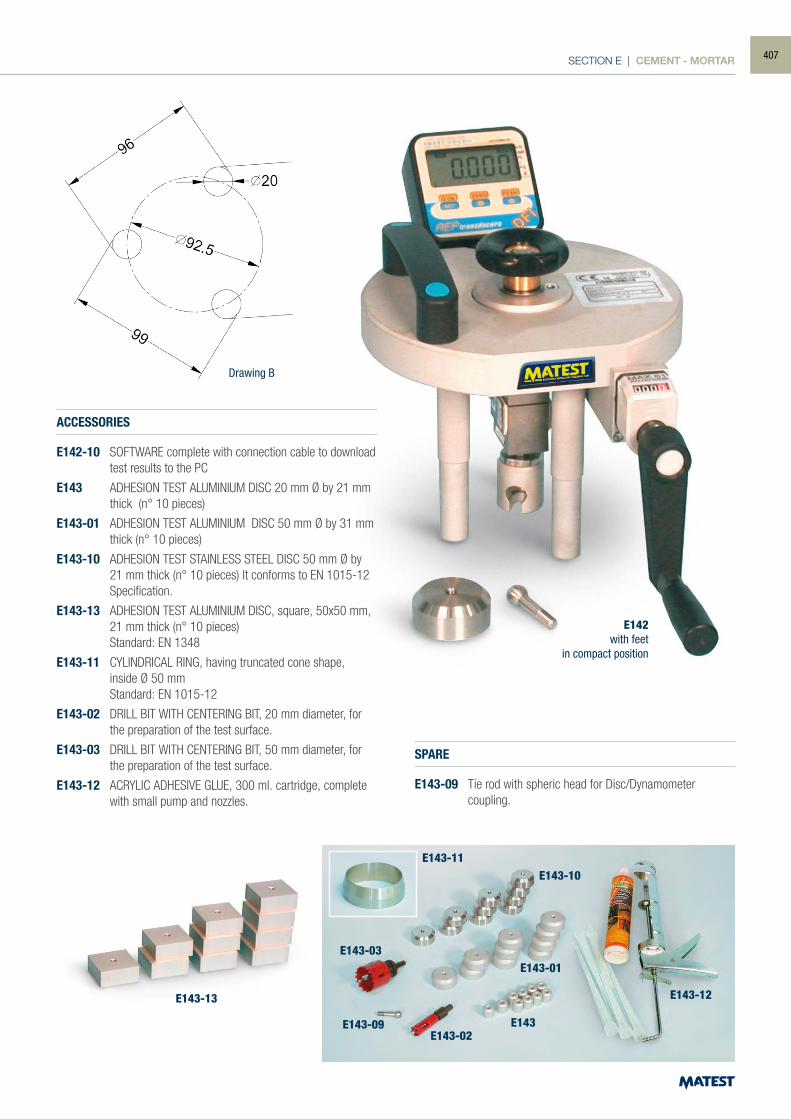
SECTION E | CEMENT - MORTAR
E142with feet
in compact position
Drawing B
ACCESSORIES
E142-10 SOFTWARE complete with connection cable to download test results to the PC
E143 ADHESION TEST ALUMINIUM DISC 20 mm Ø by 21 mm thick (n° 10 pieces)
E143-01 ADHESION TEST ALUMINIUM DISC 50 mm Ø by 31 mm thick (n° 10 pieces)
E143-10 ADHESION TEST STAINLESS STEEL DISC 50 mm Ø by 21 mm thick (n° 10 pieces) It conforms to EN 1015-12 Specification.
E143-13 ADHESION TEST ALUMINIUM DISC, square, 50x50 mm, 21 mm thick (n° 10 pieces) Standard: EN 1348
E143-11 CYLINDRICAL RING, having truncated cone shape, inside Ø 50 mm Standard: EN 1015-12
E143-02 DRILL BIT WITH CENTERING BIT, 20 mm diameter, for the preparation of the test surface.
E143-03 DRILL BIT WITH CENTERING BIT, 50 mm diameter, for the preparation of the test surface.
E143-12 ACRYLIC ADHESIVE GLUE, 300 ml. cartridge, complete with small pump and nozzles.
SPARE
E143-09 Tie rod with spheric head for Disc/Dynamometer coupling.
E143-13
E143-11
E143-03
E143-09E143-02
E143
E143-01
E143-10
E143-12
407
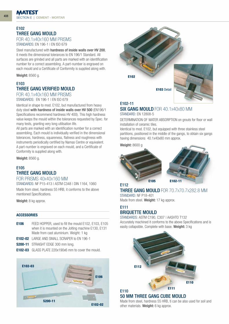
SECTION E | CEMENT - MORTAR
E102THREE GANG MOULDFOR 40.1X40X160 MM PRISMSSTANDARDS: EN 196-1 | EN ISO 679
Steel manufactured with hardness of inside walls over HV 200, it meets the dimensional tolerances to EN 196/1 Standard. All surfaces are grinded and all parts are marked with an identification number for a correct assembling. A part-number is engraved on each mould and a Certificate of Conformity is supplied along with.
Weight: 8560 g.
E103THREE GANG VERIFIED MOULDFOR 40.1X40X160 MM PRISMS STANDARDS: EN 196-1 | EN ISO 679
Identical in shape to mod. E102, but manufactured from heavy duty steel with hardness of inside walls over HV 500 (EN196/1 Specifications recommend hardness HV 400). This high hardness value keeps the mould within the tolerances requested by Spec. for many tests, granting very long utilisation life.All parts are marked with an identification number for a correct assembling. Each mould is individually verified in the dimensional tolerances, hardness, squareness, flatness and roughness with instruments periodically certified by Namas Centre or equivalent.A part-number is engraved on each mould, and a Certificate of Conformity is supplied along with.
Weight: 8560 g.
E105THREE GANG MOULDFOR PRISMS 40X40X160 MMSTANDARDS: NF P15-413 | ASTM C348 | DIN 1164, 1060
Made from steel, hardness 55 HRB, it conforms to the abovementioned Specifications.
Weight: 8 kg approx.
ACCESSORIES
E106 FEED HOPPER, used to fill the mould E102, E103, E105 when it is mounted on the Jolting machine E130, E131
Made from cast aluminium. Weight: 1 kg
E102-02 LARGE AND SMALL SCRAPER to EN 196-1
S200-11 STRAIGHT EDGE 300 mm long.
E102-03 GLASS PLATE 220x190x6 mm to cover the mould.
E102-11SIX GANG MOULD FOR 40.1X40X80 MMSTANDARD: EN 12808-5
DETERMINATION OF WATER ABSORPTION on grouts for floor or wall installation of ceramic tiles.Identical to mod. E102, but equipped with three stainless steel partitions, positioned in the middle of the gangs, to obtain six gangs having dimensions 40.1x40x80 mm approx.
Weight: 8600 g
E112THREE GANG MOULD FOR 70.7X70.7X282.8 MMSTANDARD: NF P18-401Made from steel. Weight: 17 kg approx.
E111BRIQUETTE MOULDSTANDARDS: ASTM C190, C307 | AASHTO T132Accurately machined it conforms to the above Specifications and is easily collapsible. Complete with base. Weight: 3 kg
E11050 MM THREE GANG CUBE MOULDMade from steel, hardness 55 HRB, ti can be also used for soil and other materials. Weight: 6 kg approx.
E102
E105
E112
E110
E111
E102-03
E102-02S200-11
E106
E102-11
E103 Detail
408
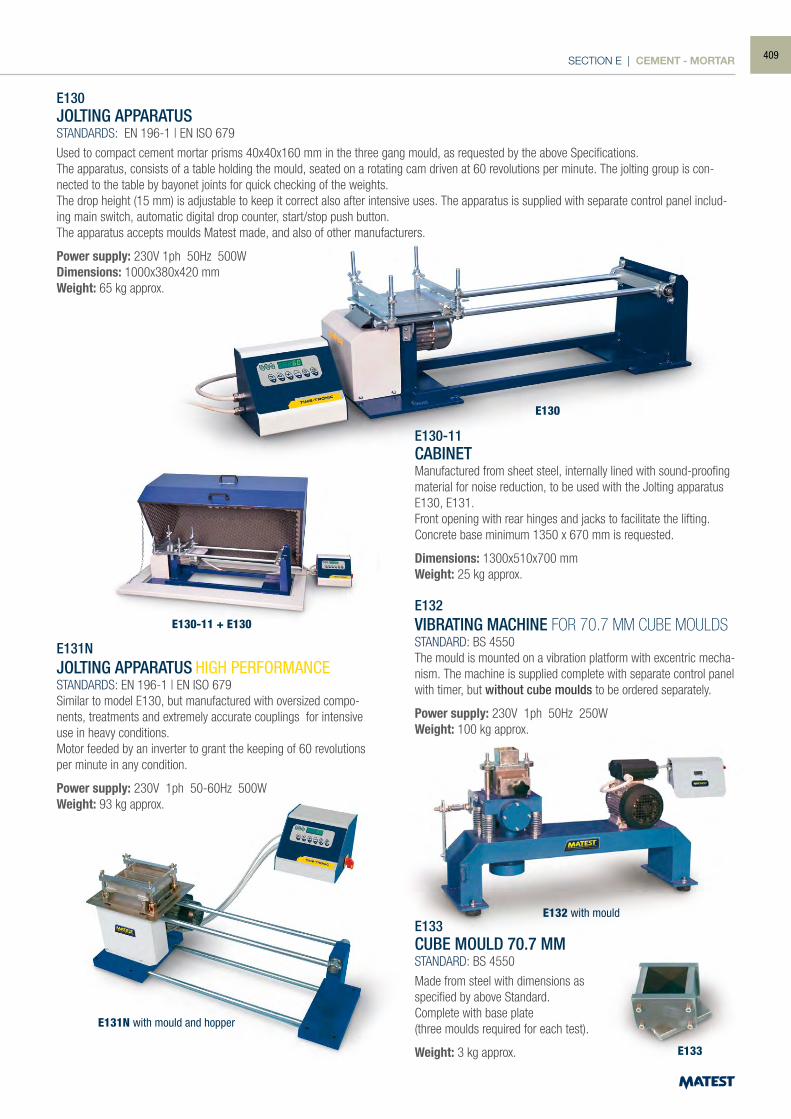
SECTION E | CEMENT - MORTAR
E130-11 + E130
E130
E131N with mould and hopper
E132 with mould
E130JOLTING APPARATUSSTANDARDS: EN 196-1 | EN ISO 679
Used to compact cement mortar prisms 40x40x160 mm in the three gang mould, as requested by the above Specifications.The apparatus, consists of a table holding the mould, seated on a rotating cam driven at 60 revolutions per minute. The jolting group is con-nected to the table by bayonet joints for quick checking of the weights.The drop height (15 mm) is adjustable to keep it correct also after intensive uses. The apparatus is supplied with separate control panel includ-ing main switch, automatic digital drop counter, start/stop push button.The apparatus accepts moulds Matest made, and also of other manufacturers.
Power supply: 230V 1ph 50Hz 500WDimensions: 1000x380x420 mmWeight: 65 kg approx.
E130-11CABINETManufactured from sheet steel, internally lined with sound-proofing material for noise reduction, to be used with the Jolting apparatus E130, E131.Front opening with rear hinges and jacks to facilitate the lifting.Concrete base minimum 1350 x 670 mm is requested.
Dimensions: 1300x510x700 mmWeight: 25 kg approx.
E131NJOLTING APPARATUS HIGH PERFORMANCESTANDARDS: EN 196-1 | EN ISO 679Similar to model E130, but manufactured with oversized compo-nents, treatments and extremely accurate couplings for intensive use in heavy conditions.Motor feeded by an inverter to grant the keeping of 60 revolutions per minute in any condition.
Power supply: 230V 1ph 50-60Hz 500WWeight: 93 kg approx.
E132VIBRATING MACHINE FOR 70.7 MM CUBE MOULDSSTANDARD: BS 4550The mould is mounted on a vibration platform with excentric mecha-nism. The machine is supplied complete with separate control panel with timer, but without cube moulds to be ordered separately.
Power supply: 230V 1ph 50Hz 250WWeight: 100 kg approx.
E133CUBE MOULD 70.7 MMSTANDARD: BS 4550
Made from steel with dimensions asspecified by above Standard.Complete with base plate(three moulds required for each test).
Weight: 3 kg approx. E133
409
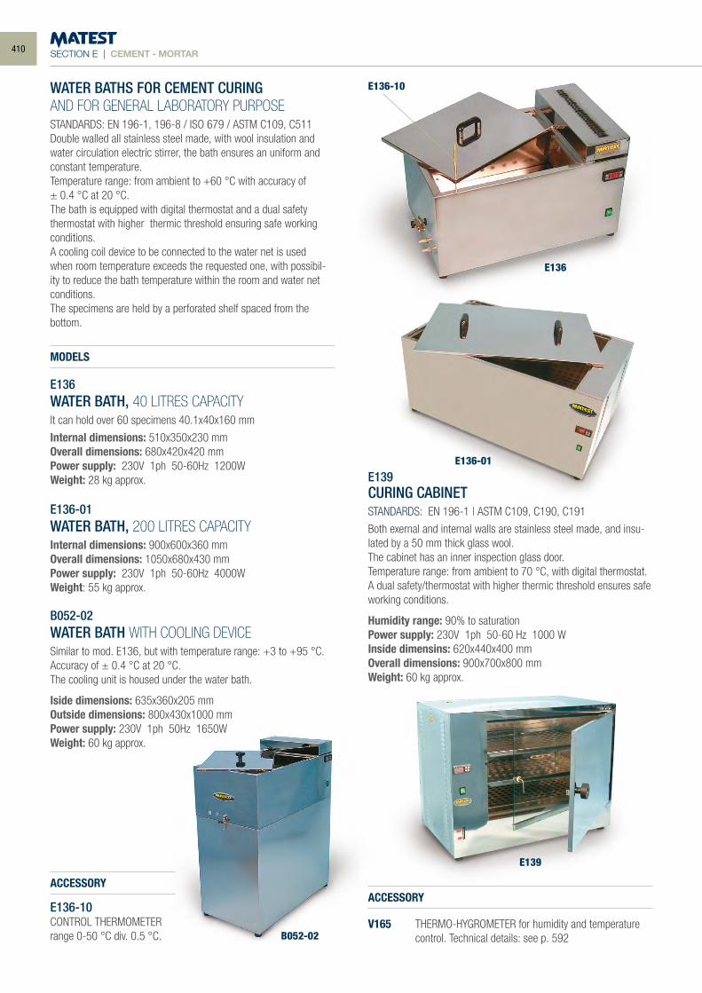
SECTION E | CEMENT - MORTAR
WATER BATHS FOR CEMENT CURINGAND FOR GENERAL LABORATORY PURPOSESTANDARDS: EN 196-1, 196-8 / ISO 679 / ASTM C109, C511Double walled all stainless steel made, with wool insulation and water circulation electric stirrer, the bath ensures an uniform and constant temperature.Temperature range: from ambient to +60 °C with accuracy of± 0.4 °C at 20 °C.The bath is equipped with digital thermostat and a dual safety thermostat with higher thermic threshold ensuring safe working conditions.A cooling coil device to be connected to the water net is used when room temperature exceeds the requested one, with possibil-ity to reduce the bath temperature within the room and water net conditions.The specimens are held by a perforated shelf spaced from the bottom.
MODELS
E136WATER BATH, 40 LITRES CAPACITYIt can hold over 60 specimens 40.1x40x160 mm
Internal dimensions: 510x350x230 mmOverall dimensions: 680x420x420 mmPower supply: 230V 1ph 50-60Hz 1200WWeight: 28 kg approx.
E136-01WATER BATH, 200 LITRES CAPACITYInternal dimensions: 900x600x360 mmOverall dimensions: 1050x680x430 mmPower supply: 230V 1ph 50-60Hz 4000WWeight: 55 kg approx.
B052-02WATER BATH WITH COOLING DEVICESimilar to mod. E136, but with temperature range: +3 to +95 °C. Accuracy of ± 0.4 °C at 20 °C.The cooling unit is housed under the water bath.
Iside dimensions: 635x360x205 mmOutside dimensions: 800x430x1000 mmPower supply: 230V 1ph 50Hz 1650WWeight: 60 kg approx.
ACCESSORY
E136-10CONTROL THERMOMETER range 0-50 °C div. 0.5 °C.
E139CURING CABINETSTANDARDS: EN 196-1 | ASTM C109, C190, C191
Both exernal and internal walls are stainless steel made, and insu-lated by a 50 mm thick glass wool.The cabinet has an inner inspection glass door.Temperature range: from ambient to 70 °C, with digital thermostat.A dual safety/thermostat with higher thermic threshold ensures safe working conditions.
Humidity range: 90% to saturationPower supply: 230V 1ph 50-60 Hz 1000 WInside dimensins: 620x440x400 mmOverall dimensions: 900x700x800 mmWeight: 60 kg approx.
ACCESSORY
V165 THERMO-HYGROMETER for humidity and temperature control. Technical details: see p. 592
E136-10
E136
E136-01
E139
B052-02
410
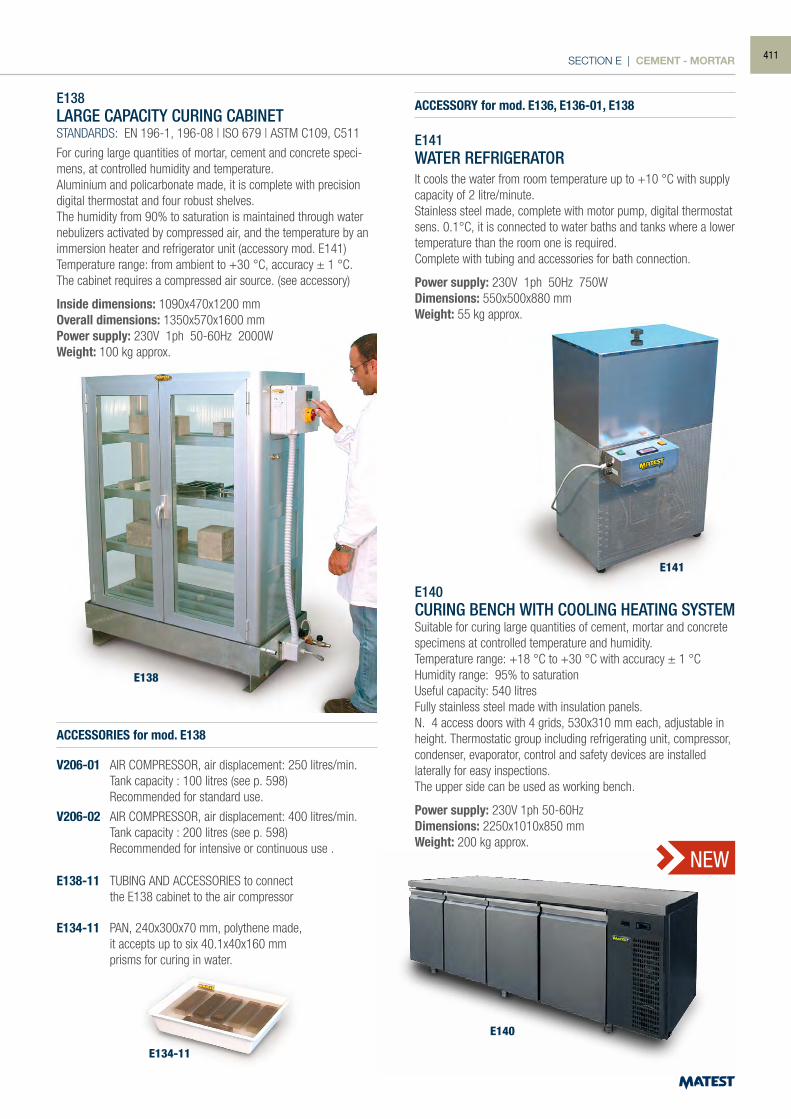
SECTION E | CEMENT - MORTAR
E138
E141
E134-11
E138LARGE CAPACITY CURING CABINETSTANDARDS: EN 196-1, 196-08 | ISO 679 | ASTM C109, C511
For curing large quantities of mortar, cement and concrete speci-mens, at controlled humidity and temperature.Aluminium and policarbonate made, it is complete with precision digital thermostat and four robust shelves.The humidity from 90% to saturation is maintained through water nebulizers activated by compressed air, and the temperature by an immersion heater and refrigerator unit (accessory mod. E141)Temperature range: from ambient to +30 °C, accuracy ± 1 °C.The cabinet requires a compressed air source. (see accessory)
Inside dimensions: 1090x470x1200 mmOverall dimensions: 1350x570x1600 mmPower supply: 230V 1ph 50-60Hz 2000WWeight: 100 kg approx.
ACCESSORIES for mod. E138
V206-01 AIR COMPRESSOR, air displacement: 250 litres/min. Tank capacity : 100 litres (see p. 598) Recommended for standard use.
V206-02 AIR COMPRESSOR, air displacement: 400 litres/min. Tank capacity : 200 litres (see p. 598) Recommended for intensive or continuous use .
E138-11 TUBING AND ACCESSORIES to connect the E138 cabinet to the air compressor
E134-11 PAN, 240x300x70 mm, polythene made, it accepts up to six 40.1x40x160 mm prisms for curing in water.
ACCESSORY for mod. E136, E136-01, E138
E141WATER REFRIGERATORIt cools the water from room temperature up to +10 °C with supply capacity of 2 litre/minute.Stainless steel made, complete with motor pump, digital thermostat sens. 0.1°C, it is connected to water baths and tanks where a lower temperature than the room one is required.Complete with tubing and accessories for bath connection.
Power supply: 230V 1ph 50Hz 750WDimensions: 550x500x880 mmWeight: 55 kg approx.
E140CURING BENCH WITH COOLING HEATING SYSTEMSuitable for curing large quantities of cement, mortar and concrete specimens at controlled temperature and humidity.Temperature range: +18 °C to +30 °C with accuracy ± 1 °CHumidity range: 95% to saturationUseful capacity: 540 litresFully stainless steel made with insulation panels.N. 4 access doors with 4 grids, 530x310 mm each, adjustable in height. Thermostatic group including refrigerating unit, compressor, condenser, evaporator, control and safety devices are installed laterally for easy inspections. The upper side can be used as working bench.
Power supply: 230V 1ph 50-60HzDimensions: 2250x1010x850 mmWeight: 200 kg approx.
E140
NEW
411
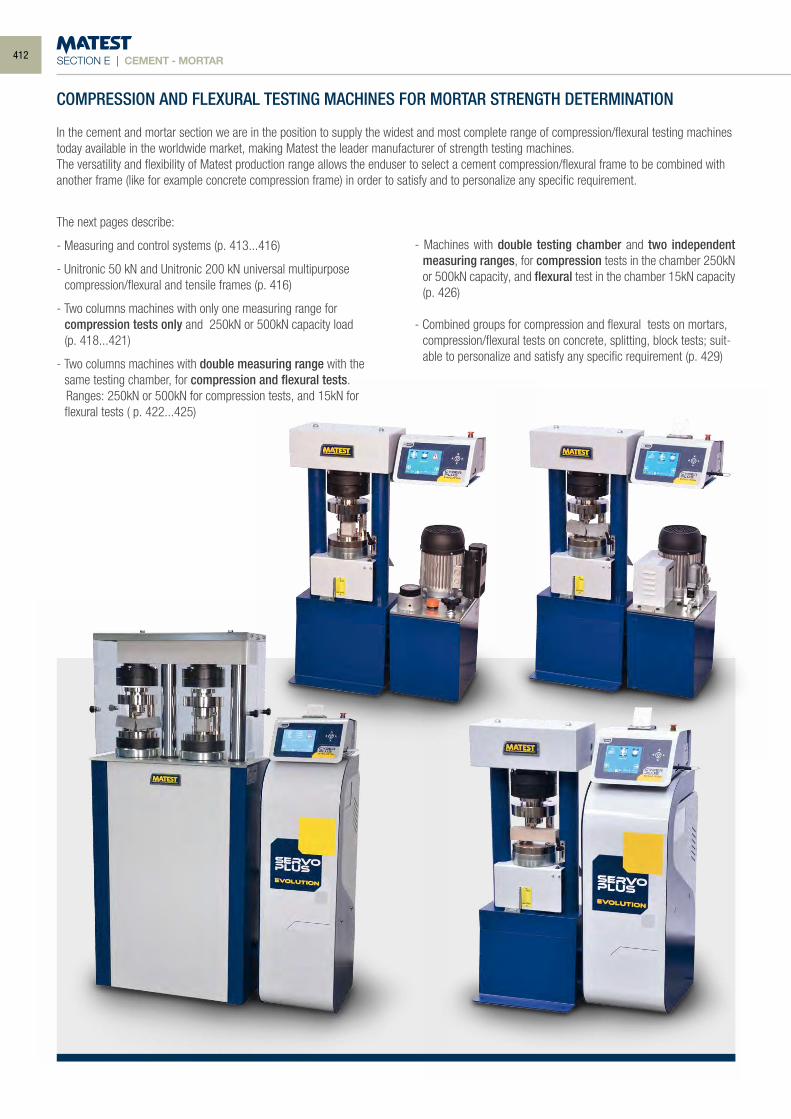
SECTION E | CEMENT - MORTAR
COMPRESSION AND FLEXURAL TESTING MACHINES FOR MORTAR STRENGTH DETERMINATION
In the cement and mortar section we are in the position to supply the widest and most complete range of compression/flexural testing machines today available in the worldwide market, making Matest the leader manufacturer of strength testing machines.The versatility and flexibility of Matest production range allows the enduser to select a cement compression/flexural frame to be combined with another frame (like for example concrete compression frame) in order to satisfy and to personalize any specific requirement.
The next pages describe:
- Measuring and control systems (p. 413...416)
- Unitronic 50 kN and Unitronic 200 kN universal multipurpose compression/flexural and tensile frames (p. 416)
- Two columns machines with only one measuring range for compression tests only and 250kN or 500kN capacity load (p. 418...421)
- Two columns machines with double measuring range with the same testing chamber, for compression and flexural tests.
Ranges: 250kN or 500kN for compression tests, and 15kN for flexural tests ( p. 422...425)
- Machines with double testing chamber and two independent measuring ranges, for compression tests in the chamber 250kN or 500kN capacity, and flexural test in the chamber 15kN capacity (p. 426)
- Combined groups for compression and flexural tests on mortars, compression/flexural tests on concrete, splitting, block tests; suit-able to personalize and satisfy any specific requirement (p. 429)
412
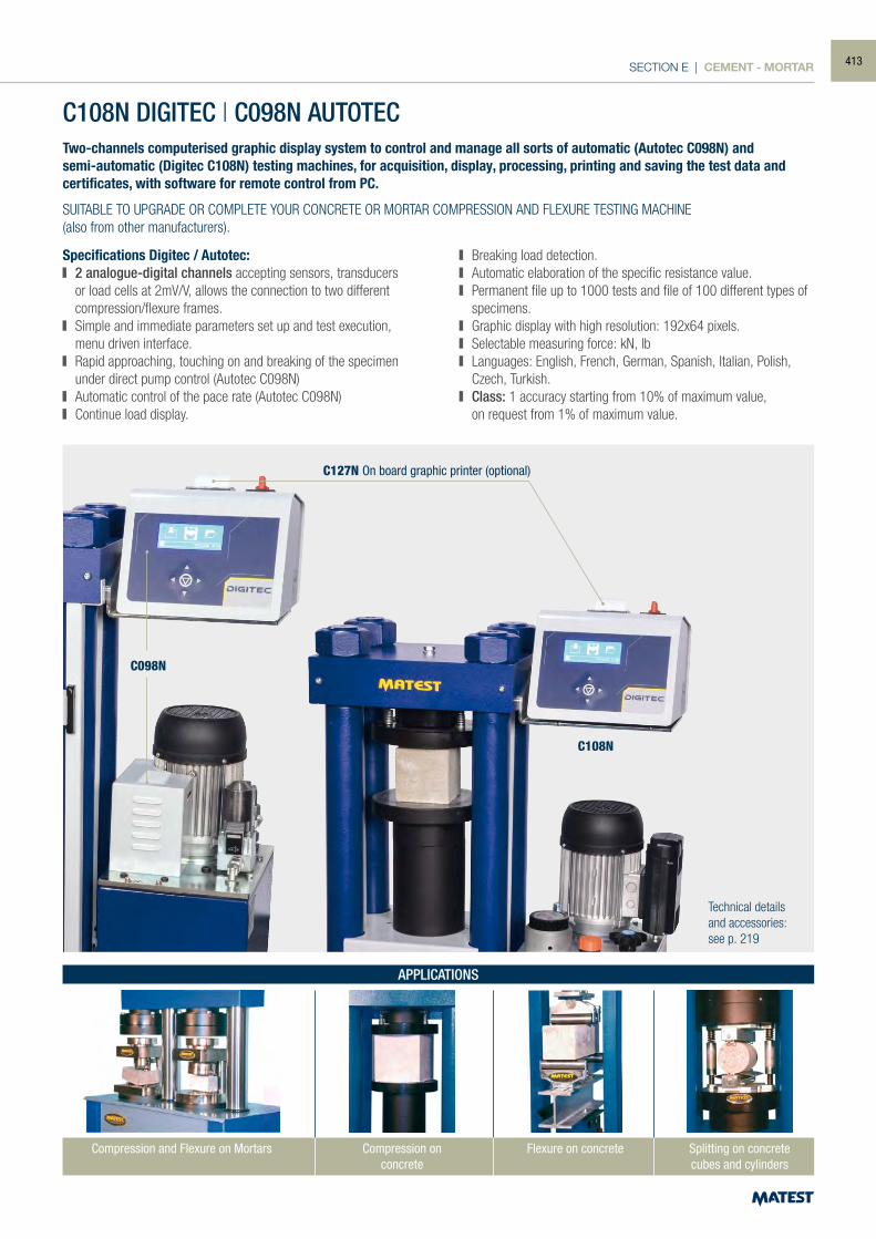
SECTION E | CEMENT - MORTAR
C108N DIGITEC | C098N AUTOTEC
C127N On board graphic printer (optional)
C108N
C098N
Two-channels computerised graphic display system to control and manage all sorts of automatic (Autotec C098N) and semi-automatic (Digitec C108N) testing machines, for acquisition, display, processing, printing and saving the test data and certificates, with software for remote control from PC.
SUITABLE TO UPGRADE OR COMPLETE YOUR CONCRETE OR MORTAR COMPRESSION AND FLEXURE TESTING MACHINE(also from other manufacturers).
Specifications Digitec / Autotec: 2 analogue-digital channels accepting sensors, transducers
or load cells at 2mV/V, allows the connection to two different compression/flexure frames.
Simple and immediate parameters set up and test execution, menu driven interface.
Rapid approaching, touching on and breaking of the specimen under direct pump control (Autotec C098N)
Automatic control of the pace rate (Autotec C098N) Continue load display.
Breaking load detection. Automatic elaboration of the specific resistance value. Permanent file up to 1000 tests and file of 100 different types of
specimens. Graphic display with high resolution: 192x64 pixels. Selectable measuring force: kN, lb Languages: English, French, German, Spanish, Italian, Polish,
Czech, Turkish. Class: 1 accuracy starting from 10% of maximum value,
on request from 1% of maximum value.
Technical detailsand accessories:see p. 219
Compression and Flexure on Mortars Compression onconcrete
APPLICATIONS
Splitting on concretecubes and cylinders
Flexure on concrete
413

SECTION E | CEMENT - MORTAR
An electronic evolution with 8 analog inputs for compression and flexural testing machines on concrete and mortar.
Designed with the latest technology, an innovative PC-like Touch Screen system, employed to control and manage all sorts of automatic
(Servo-Plus Evolution C104N) and semi-automatic (Cyber-Plus Evolution C109N) testing machines.
To update or complete your compression and flexural testing machine on concrete and mortar (also on Non-Matest brands)
C109N CYBER-PLUS | C104N SERVO-PLUS
Compression and Flexure on Mortars Compression onconcrete
APPLICATIONS
Splitting on concretecubes and cylinders
Flexure on concrete Tensile on steel
C109N
C104N
C127Non board graphic printer (optional)
414
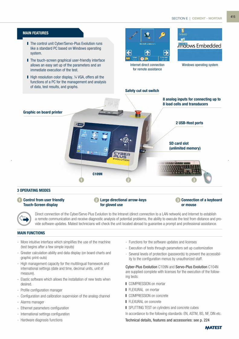
SECTION E | CEMENT - MORTAR
MAIN FEATURES
The control unit Cyber/Servo-Plus Evolution runs like a standard PC based on Windows operating system.
The touch-screen graphical user-friendly interface allows an easy set up of the parameters and an immediate execution of the test.
High resolution color display, ¼ VGA, offers all the functions of a PC for the management and analysis of data, test results, and graphs.
MAIN FUNCTIONS
- More intuitive interface which simplifies the use of the machine (test begins after a few simple inputs)
- Greater calculation ability and data display (on board charts and graphic print-outs)
- High management capacity for the multilingual framework and international settings (date and time, decimal units, unit of
measure).
- Elastic software which allows the installation of new tests when desired.
- Profile configuration manager
- Configuration and calibration supervision of the analog channel
- Alarms manager
- Ethernet parameters configuration
- International settings configuration
- Hardware diagnosis functions
Cyber-Plus Evolution C109N and Servo-Plus Evolution C104N are supplied complete with licenses for the execution of the follow-ing tests:
COMPRESSION on mortar
FLEXURAL on mortar
COMPRESSION on concrete
FLEXURAL on concrete
SPLITTING TEST on cylinders and concrete cubes
In accordance to the following standards: EN, ASTM, BS, NF, DIN etc.
- Functions for the software updates and licenses
- Execution of tests through parameters set up customization
- Several levels of protection (passwords) to prevent the accessibil-ity to the configuration menus by unauthorized staff.
Graphic on board printer
Safety cut out switch
8 analog inputs for connecting up to 8 load cells and transducers
2 USB-Host ports
SD card slot(unlimited memory)
1 2 3
Internet direct connectionfor remote assistance
Windows operating system
Technical details, features and accessories: see p. 224
C109N
3 OPERATING MODES
Control from user friendly Touch-Screen display
Large directional arrow-keys for gloved use
Connection of a keyboard or mouse
Direct connection of the Cyber/Servo Plus Evolution to the Intranet (direct connection to a LAN network) and Internet to establish a remote communication and receive diagnostic analysis of potential problems, the ability to execute the test from distance and pro-vide software updates. Matest technicians will check the unit located abroad to guarantee a prompt and professional assistance.
1 2 3
415
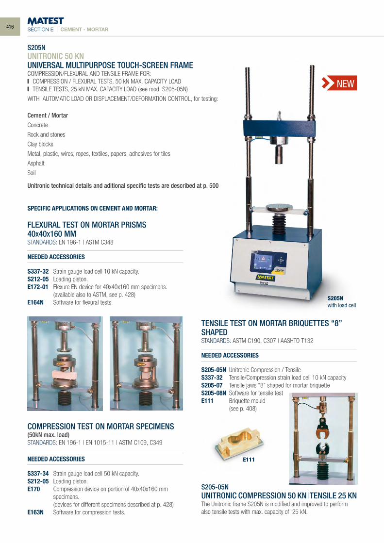
SECTION E | CEMENT - MORTAR
S205NUNITRONIC 50 KNUNIVERSAL MULTIPURPOSE TOUCH-SCREEN FRAMECOMPRESSION/FLEXURAL AND TENSILE FRAME FOR: COMPRESSION / FLEXURAL TESTS, 50 kN MAX. CAPACITY LOAD TENSILE TESTS, 25 kN MAX. CAPACITY LOAD (see mod. S205-05N)
WITH AUTOMATIC LOAD OR DISPLACEMENT/DEFORMATION CONTROL, for testing:
Cement / MortarConcrete
Rock and stones
Clay blocks
Metal, plastic, wires, ropes, textiles, papers, adhesives for tiles
Asphalt
Soil
Unitronic technical details and aditional specific tests are described at p. 500
S205Nwith load cell
NEW
SPECIFIC APPLICATIONS ON CEMENT AND MORTAR:
FLEXURAL TEST ON MORTAR PRISMS40X40X160 MMSTANDARDS: EN 196-1 | ASTM C348
NEEDED ACCESSORIES
S337-32 Strain gauge load cell 10 kN capacity.S212-05 Loading piston.E172-01 Flexure EN device for 40x40x160 mm specimens. (available also to ASTM, see p. 428)E164N Software for flexural tests.
COMPRESSION TEST ON MORTAR SPECIMENS(50kN max. load)STANDARDS: EN 196-1 | EN 1015-11 | ASTM C109, C349
NEEDED ACCESSORIES
S337-34 Strain gauge load cell 50 kN capacity.S212-05 Loading piston.E170 Compression device on portion of 40x40x160 mm
specimens. (devices for different specimens described at p. 428)E163N Software for compression tests.
TENSILE TEST ON MORTAR BRIQUETTES “8” SHAPED STANDARDS: ASTM C190, C307 | AASHTO T132
NEEDED ACCESSORIES
S205-05N Unitronic Compression / Tensile S337-32 Tensile/Compression strain load cell 10 kN capacity S205-07 Tensile jaws “8” shaped for mortar briquette S205-08N Software for tensile test E111 Briquette mould (see p. 408)
S205-05NUNITRONIC COMPRESSION 50 KN |TENSILE 25 KNThe Unitronic frame S205N is modified and improved to perform also tensile tests with max. capacity of 25 kN.
E111
416
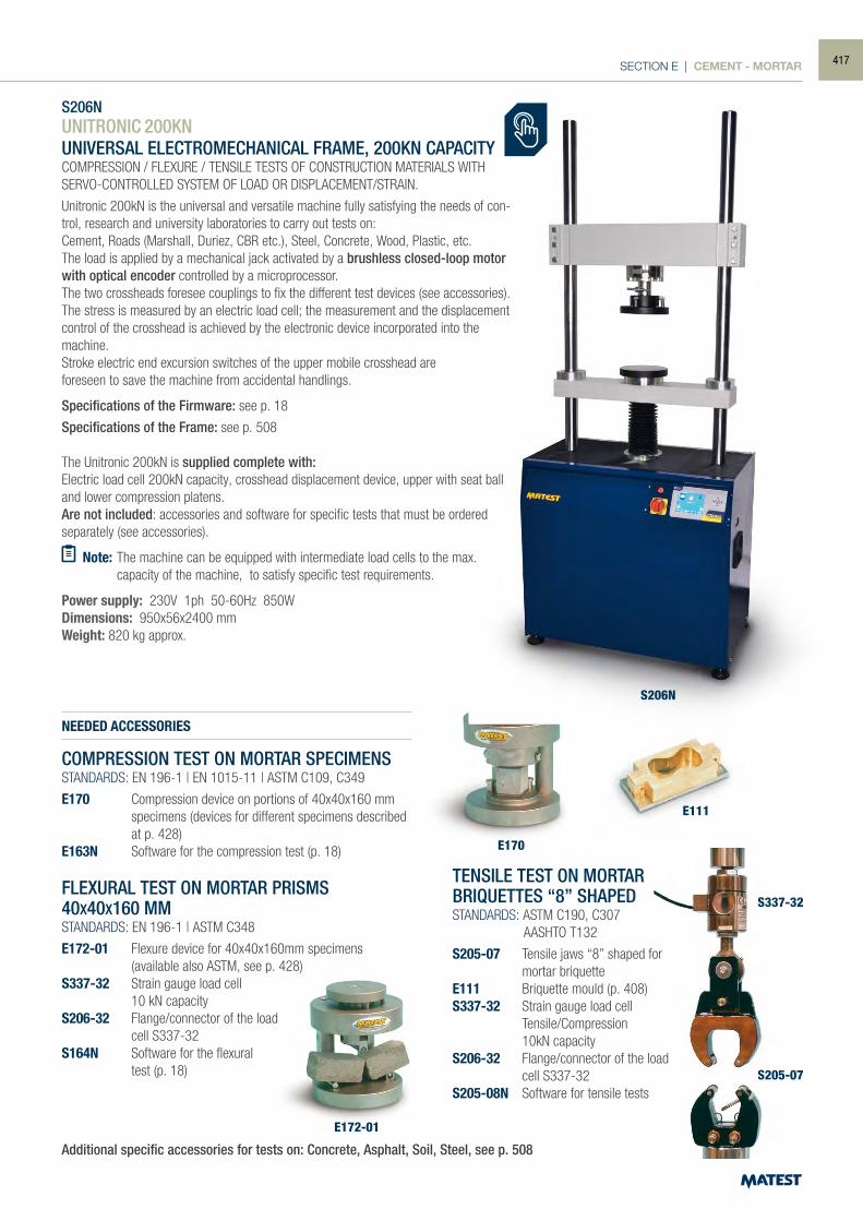
SECTION E | CEMENT - MORTAR
S206N
E170
E172-01
S337-32
S205-07
S206NUNITRONIC 200KNUNIVERSAL ELECTROMECHANICAL FRAME, 200KN CAPACITYCOMPRESSION / FLEXURE / TENSILE TESTS OF CONSTRUCTION MATERIALS WITH SERVO-CONTROLLED SYSTEM OF LOAD OR DISPLACEMENT/STRAIN.
Unitronic 200kN is the universal and versatile machine fully satisfying the needs of con-trol, research and university laboratories to carry out tests on:Cement, Roads (Marshall, Duriez, CBR etc.), Steel, Concrete, Wood, Plastic, etc.The load is applied by a mechanical jack activated by a brushless closed-loop motor with optical encoder controlled by a microprocessor.The two crossheads foresee couplings to fix the different test devices (see accessories).The stress is measured by an electric load cell; the measurement and the displacement control of the crosshead is achieved by the electronic device incorporated into the machine. Stroke electric end excursion switches of the upper mobile crosshead areforeseen to save the machine from accidental handlings.
Specifications of the Firmware: see p. 18
Specifications of the Frame: see p. 508
The Unitronic 200kN is supplied complete with:Electric load cell 200kN capacity, crosshead displacement device, upper with seat ball and lower compression platens.Are not included: accessories and software for specific tests that must be ordered separately (see accessories).
Note: The machine can be equipped with intermediate load cells to the max. capacity of the machine, to satisfy specific test requirements.
Power supply: 230V 1ph 50-60Hz 850WDimensions: 950x56x2400 mmWeight: 820 kg approx.
COMPRESSION TEST ON MORTAR SPECIMENSSTANDARDS: EN 196-1 | EN 1015-11 | ASTM C109, C349
E170 Compression device on portions of 40x40x160 mm specimens (devices for different specimens described at p. 428)
E163N Software for the compression test (p. 18)
FLEXURAL TEST ON MORTAR PRISMS40X40X160 MMSTANDARDS: EN 196-1 | ASTM C348
E172-01 Flexure device for 40x40x160mm specimens (available also ASTM, see p. 428)S337-32 Strain gauge load cell 10 kN capacityS206-32 Flange/connector of the load cell S337-32S164N Software for the flexural test (p. 18)
TENSILE TEST ON MORTARBRIQUETTES “8” SHAPEDSTANDARDS: ASTM C190, C307 AASHTO T132
S205-07 Tensile jaws “8” shaped for mortar briquetteE111 Briquette mould (p. 408)S337-32 Strain gauge load cell Tensile/Compression 10kN capacityS206-32 Flange/connector of the load cell S337-32S205-08N Software for tensile tests
Additional specific accessories for tests on: Concrete, Asphalt, Soil, Steel, see p. 508
NEEDED ACCESSORIES
E111
417
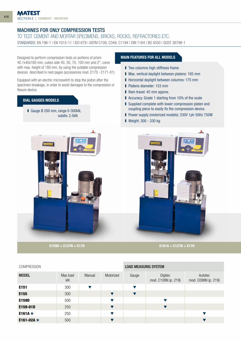
SECTION E | CEMENT - MORTAR
DIAL GAUGES MODELS
Gauge Ø 200 mm, range 0-300kN, subdiv. 2.5kN
COMPRESSION LOAD MEASURIG SYSTEM
MODEL Max loadkN
Manual Motorized Gauge Digitecmod. C108N (p. 219)
Autotecmod. C098N (p. 219)
E151 300
E155 300
E159D 500
E159-01D 250
E161A 250
E161-02A 500
MACHINES FOR ONLY COMPRESSION TESTSTO TEST CEMENT AND MORTAR SPECIMENS, BRICKS, ROCKS, REFRACTORIES ETC.STANDARDS: EN 196-1 | EN 1015-11 | ISO 679 | ASTM C109, C349, C1194 | DIN 1164 | BS 4550 | GOST 26798-1
MAIN FEATURES FOR ALL MODELS
Two columns high stiffness frame. Max. vertical daylight between platens: 185 mm Horizontal daylight between columns: 175 mm Platens diameter: 153 mm Ram travel: 45 mm approx. Accuracy: Grade 1 starting from 10% of the scale Supplied complete with lower compression platen and
coupling piece to easily fix the compression device. Power supply (motorized models): 230V 1ph 50Hz 750W Weight: 300 - 330 kg
E161A + C127N + E170E159D + C127N + E170
Designed to perform compression tests on portions of prism 40.1x40x160 mm, cubes side 40, 50, 70, 100 mm and 2”; cores with max. height of 180 mm, by using the suitable compression devices described in next pages (accessories mod. E170 - E171-01)
Equipped with an electric microswitch to stop the piston after the specimen breakage, in order to avoid damages to the compression or flexure device.
418
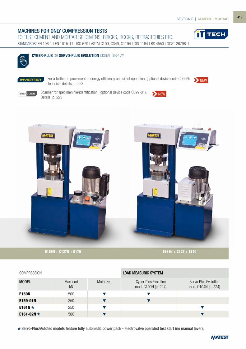
SECTION E | CEMENT - MORTAR
COMPRESSION LOAD MEASURIG SYSTEM
MODEL Max loadkN
Motorized Cyber-Plus Evolutionmod. C109N (p. 224)
Servo-Plus Evolutionmod. C104N (p. 224)
E159N 500
E159-01N 250
E161N 250
E161-02N 500
MACHINES FOR ONLY COMPRESSION TESTSTO TEST CEMENT AND MORTAR SPECIMENS, BRICKS, ROCKS, REFRACTORIES ETC.STANDARDS: EN 196-1 | EN 1015-11 | ISO 679 | ASTM C109, C349, C1194 | DIN 1164 | BS 4550 | GOST 26798-1
CYBER-PLUS OR SERVO-PLUS EVOLUTION DIGITAL DISPLAY
E159N + C127N + E170 E161N + C127 + E170
For a further improvement of energy efficiency and silent operation, (optional device code C099N). Technical details, p. 223
Scanner for specimen file/identification, (optional device code C099-01).Details, p. 223
inverter NEW
NEWBARCODE
Servo-Plus/Autotec models feature fully automatic power pack - electrovalve operated test start (no manual lever).
419
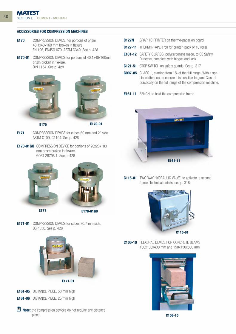
SECTION E | CEMENT - MORTAR
ACCESSORIES FOR COMPRESSION MACHINES
E170 COMPRESSION DEVICE for portions of prism 40.1x40x160 mm broken in flexure. EN 196, EN/ISO 679, ASTM C349. See p. 428
C115-01
C106-10
E171 COMPRESSION DEVICE for cubes 50 mm and 2” side. ASTM C109, C1194. See p. 428
E171-01 COMPRESSION DEVICE for cubes 70.7 mm side. BS 4550. See p. 428
E161-05 DISTANCE PIECE, 50 mm high
E161-06 DISTANCE PIECE, 25 mm high
Note: the compression devices do not require any distance piece.
C127N GRAPHIC PRINTER on thermo-paper on board
C127-11 THERMO-PAPER roll for printer (pack of 10 rolls)
E161-12 SAFETY GUARDS, polycarbonate made, to CE Safety Directive, complete with hinges and lock
C121-51 STOP SWITCH on safety guards. See p. 317
C097-05 CLASS 1, starting from 1% of the full range. With a spe-cial calibration procedure it is possible to grant Class 1 practically on the full range of the compression machine.
E161-11 BENCH, to hold the compression frame.
E170
E171 E170-01GO
E171-01
E161-11
C115-01 TWO WAY HYDRAULIC VALVE, to activate a second frame. Technical details: see p. 318
C106-10 FLEXURAL DEVICE FOR CONCRETE BEAMS 100x100x400 mm and 150x150x600 mm
E170-01 COMPRESSION DEVICE for portions of 40.1x40x160mm prism broken in flexure.
DIN 1164. See p. 428
E170-01
E170-01GO COMPRESSION DEVICE for portions of 20x20x100 mm prism broken in flexure
GOST 26798.1. See p. 428
420
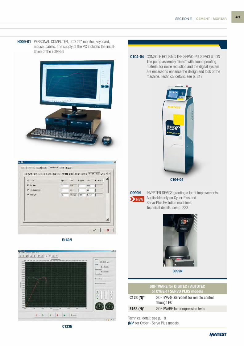
SECTION E | CEMENT - MORTAR
ACCESSORIES FOR COMPRESSION MACHINES
E170 COMPRESSION DEVICE for portions of prism 40.1x40x160 mm broken in flexure. EN 196, EN/ISO 679, ASTM C349. See p. 428
C104-04 CONSOLE HOUSING THE SERVO-PLUS EVOLUTION The pump assembly “lined” with sound proofing
material for noise reduction and the digital system are encased to enhance the design and look of the machine. Technical details: see p. 312
C099N
C099N INVERTER DEVICE granting a lot of improvements. Applicable only on Cyber-Plus and Servo-Plus Evolution machines. Technical details: see p. 223
NEW
Technical detail: see p. 18(N)* for Cyber - Servo Plus models.
SOFTWARE for DIGITEC / AUTOTECor CYBER / SERVO PLUS models
C123 (N)* SOFTWARE Servonet for remote control through PC
E163 (N)* SOFTWARE for compression tests
E163N
C123N
H009-01 PERSONAL COMPUTER, LCD 22” monitor, keyboard, mouse, cables. The supply of the PC includes the instal-lation of the software
C104-04
421
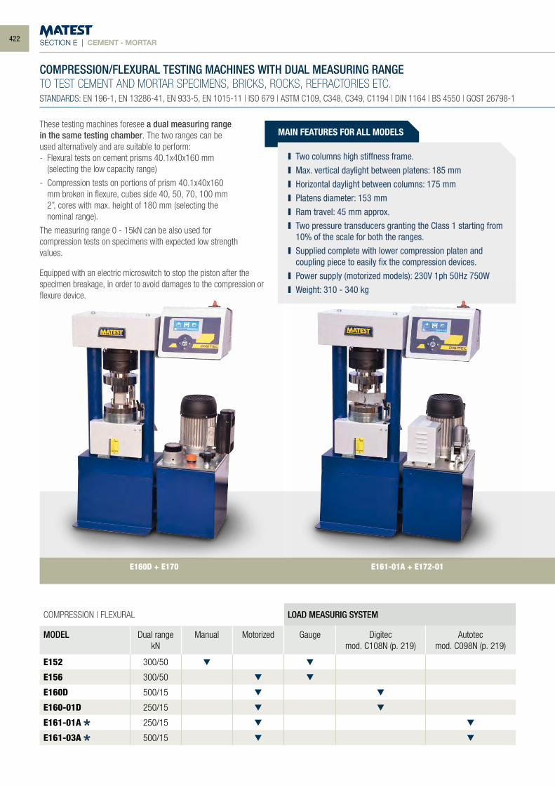
SECTION E | CEMENT - MORTAR
COMPRESSION | FLEXURAL LOAD MEASURIG SYSTEM
MODEL Dual rangekN
Manual Motorized Gauge Digitecmod. C108N (p. 219)
Autotecmod. C098N (p. 219)
E152 300/50
E156 300/50
E160D 500/15
E160-01D 250/15
E161-01A 250/15
E161-03A 500/15
COMPRESSION/FLEXURAL TESTING MACHINES WITH DUAL MEASURING RANGETO TEST CEMENT AND MORTAR SPECIMENS, BRICKS, ROCKS, REFRACTORIES ETC.STANDARDS: EN 196-1, EN 13286-41, EN 933-5, EN 1015-11 | ISO 679 | ASTM C109, C348, C349, C1194 | DIN 1164 | BS 4550 | GOST 26798-1
MAIN FEATURES FOR ALL MODELS
Two columns high stiffness frame. Max. vertical daylight between platens: 185 mm Horizontal daylight between columns: 175 mm Platens diameter: 153 mm Ram travel: 45 mm approx. Two pressure transducers granting the Class 1 starting from
10% of the scale for both the ranges. Supplied complete with lower compression platen and
coupling piece to easily fix the compression devices. Power supply (motorized models): 230V 1ph 50Hz 750W Weight: 310 - 340 kg
E161-01A + E172-01E160D + E170
These testing machines foresee a dual measuring range in the same testing chamber. The two ranges can be used alternatively and are suitable to perform:- Flexural tests on cement prisms 40.1x40x160 mm
(selecting the low capacity range)
- Compression tests on portions of prism 40.1x40x160 mm broken in flexure, cubes side 40, 50, 70, 100 mm 2”, cores with max. height of 180 mm (selecting the nominal range).
The measuring range 0 - 15kN can be also used for compression tests on specimens with expected low strength values.
Equipped with an electric microswitch to stop the piston after the specimen breakage, in order to avoid damages to the compression or flexure device.
422
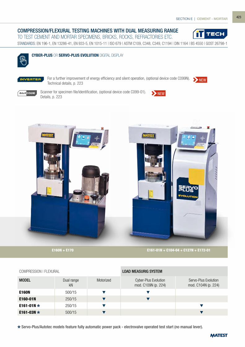
SECTION E | CEMENT - MORTAR
COMPRESSION | FLEXURAL LOAD MEASURIG SYSTEM
MODEL Dual rangekN
Motorized Cyber-Plus Evolutionmod. C109N (p. 224)
Servo-Plus Evolutionmod. C104N (p. 224)
E160N 500/15
E160-01N 250/15
E161-01N 250/15
E161-03N 500/15
COMPRESSION/FLEXURAL TESTING MACHINES WITH DUAL MEASURING RANGETO TEST CEMENT AND MORTAR SPECIMENS, BRICKS, ROCKS, REFRACTORIES ETC.STANDARDS: EN 196-1, EN 13286-41, EN 933-5, EN 1015-11 | ISO 679 | ASTM C109, C348, C349, C1194 | DIN 1164 | BS 4550 | GOST 26798-1
CYBER-PLUS OR SERVO-PLUS EVOLUTION DIGITAL DISPLAY
E160N + E170 E161-01N + C104-04 + C127N + E172-01
Servo-Plus/Autotec models feature fully automatic power pack - electrovalve operated test start (no manual lever).
For a further improvement of energy efficiency and silent operation, (optional device code C099N). Technical details, p. 223
Scanner for specimen file/identification, (optional device code C099-01).Details, p. 223
inverter NEW
NEWBARCODE
423
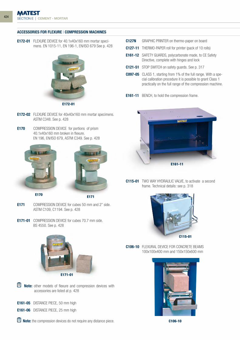
SECTION E | CEMENT - MORTAR
ACCESSORIES FOR FLEXURE | COMPRESSION MACHINES
E172-01 FLEXURE DEVICE for 40.1x40x160 mm mortar speci-mens. EN 1015-11, EN 196-1, EN/ISO 679 See p. 428
C115-01
C106-10
E171 COMPRESSION DEVICE for cubes 50 mm and 2” side. ASTM C109, C1194. See p. 428
E171-01 COMPRESSION DEVICE for cubes 70.7 mm side. BS 4550. See p. 428
E161-05 DISTANCE PIECE, 50 mm high
E161-06 DISTANCE PIECE, 25 mm high
Note: the compression devices do not require any distance piece.
C127N GRAPHIC PRINTER on thermo-paper on board
C127-11 THERMO-PAPER roll for printer (pack of 10 rolls)
E161-12 SAFETY GUARDS, polycarbonate made, to CE Safety Directive, complete with hinges and lock
C121-51 STOP SWITCH on safety guards. See p. 317
C097-05 CLASS 1, starting from 1% of the full range. With a spe-cial calibration procedure it is possible to grant Class 1 practically on the full range of the compression machine.
E161-11 BENCH, to hold the compression frame.
E170
E172-01
E171
E171-01
E161-11
C115-01 TWO WAY HYDRAULIC VALVE, to activate a second frame. Technical details: see p. 318
C106-10 FLEXURAL DEVICE FOR CONCRETE BEAMS 100x100x400 mm and 150x150x600 mm
E170 COMPRESSION DEVICE for portions of prism 40.1x40x160 mm broken in flexure. EN 196, EN/ISO 679, ASTM C349. See p. 428
E172-02 FLEXURE DEVICE for 40x40x160 mm mortar specimens. ASTM C348. See p. 428
Note: other models of flexure and compression devices with accessories are listed at p. 428
424
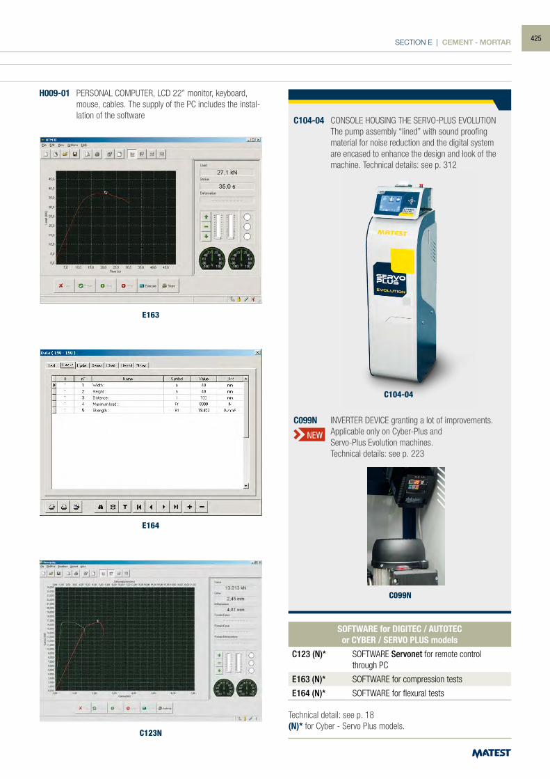
SECTION E | CEMENT - MORTAR
ACCESSORIES FOR FLEXURE | COMPRESSION MACHINES
E172-01 FLEXURE DEVICE for 40.1x40x160 mm mortar speci-mens. EN 1015-11, EN 196-1, EN/ISO 679 See p. 428
E163
E164
C123N
H009-01 PERSONAL COMPUTER, LCD 22” monitor, keyboard, mouse, cables. The supply of the PC includes the instal-lation of the software
Technical detail: see p. 18(N)* for Cyber - Servo Plus models.
SOFTWARE for DIGITEC / AUTOTECor CYBER / SERVO PLUS models
C123 (N)* SOFTWARE Servonet for remote control through PC
E163 (N)* SOFTWARE for compression tests
E164 (N)* SOFTWARE for flexural tests
C104-04 CONSOLE HOUSING THE SERVO-PLUS EVOLUTION The pump assembly “lined” with sound proofing
material for noise reduction and the digital system are encased to enhance the design and look of the machine. Technical details: see p. 312
C099N
C099N INVERTER DEVICE granting a lot of improvements. Applicable only on Cyber-Plus and Servo-Plus Evolution machines. Technical details: see p. 223
NEW
C104-04
425
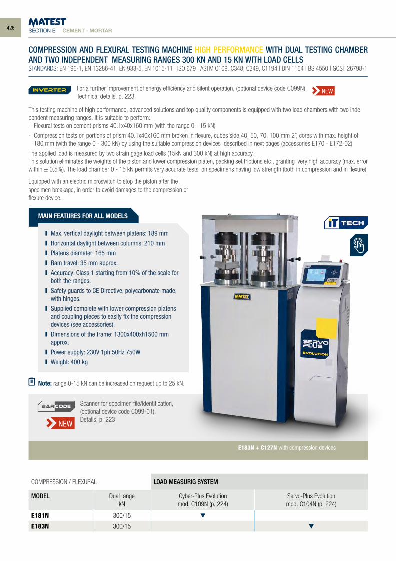
SECTION E | CEMENT - MORTAR
This testing machine of high performance, advanced solutions and top quality components is equipped with two load chambers with two inde-pendent measuring ranges. It is suitable to perform: - Flexural tests on cement prisms 40.1x40x160 mm (with the range 0 - 15 kN)
- Compression tests on portions of prism 40.1x40x160 mm broken in flexure, cubes side 40, 50, 70, 100 mm 2”, cores with max. height of 180 mm (with the range 0 - 300 kN) by using the suitable compression devices described in next pages (accessories E170 - E172-02)
The applied load is measured by two strain gage load cells (15kN and 300 kN) at high accuracy. This solution eliminates the weights of the piston and lower compression platen, packing set frictions etc., granting very high accuracy (max. error within ± 0,5%). The load chamber 0 - 15 kN permits very accurate tests on specimens having low strength (both in compression and in flexure).
COMPRESSION AND FLEXURAL TESTING MACHINE HIGH PERFORMANCE WITH DUAL TESTING CHAMBER AND TWO INDEPENDENT MEASURING RANGES 300 KN AND 15 KN WITH LOAD CELLSSTANDARDS: EN 196-1, EN 13286-41, EN 933-5, EN 1015-11 | ISO 679 | ASTM C109, C348, C349, C1194 | DIN 1164 | BS 4550 | GOST 26798-1
MAIN FEATURES FOR ALL MODELS
Max. vertical daylight between platens: 189 mm Horizontal daylight between columns: 210 mm Platens diameter: 165 mm Ram travel: 35 mm approx. Accuracy: Class 1 starting from 10% of the scale for
both the ranges. Safety guards to CE Directive, polycarbonate made,
with hinges. Supplied complete with lower compression platens
and coupling pieces to easily fix the compression devices (see accessories).
Dimensions of the frame: 1300x400xh1500 mm approx.
Power supply: 230V 1ph 50Hz 750W Weight: 400 kg
COMPRESSION / FLEXURAL LOAD MEASURIG SYSTEM
MODEL Dual rangekN
Cyber-Plus Evolutionmod. C109N (p. 224)
Servo-Plus Evolutionmod. C104N (p. 224)
E181N 300/15
E183N 300/15
E183N + C127N with compression devices
Note: range 0-15 kN can be increased on request up to 25 kN.
Scanner for specimen file/identification, (optional device code C099-01).Details, p. 223NEW
BARCODE
Equipped with an electric microswitch to stop the piston after the specimen breakage, in order to avoid damages to the compression or flexure device.
For a further improvement of energy efficiency and silent operation, (optional device code C099N). Technical details, p. 223
inverter NEW
426
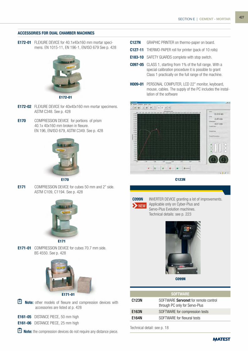
SECTION E | CEMENT - MORTAR
C099N
C099N INVERTER DEVICE granting a lot of improvements. Applicable only on Cyber-Plus and Servo-Plus Evolution machines. Technical details: see p. 223
NEW
ACCESSORIES FOR DUAL CHAMBER MACHINES
E172-01 FLEXURE DEVICE for 40.1x40x160 mm mortar speci-mens. EN 1015-11, EN 196-1, EN/ISO 679 See p. 428
E171 COMPRESSION DEVICE for cubes 50 mm and 2” side. ASTM C109, C1194. See p. 428
E171-01 COMPRESSION DEVICE for cubes 70.7 mm side. BS 4550. See p. 428
E161-05 DISTANCE PIECE, 50 mm high
E161-06 DISTANCE PIECE, 25 mm high
Note: the compression devices do not require any distance piece.
E170
E172-01
E171
E171-01
E170 COMPRESSION DEVICE for portions of prism 40.1x 40x160 mm broken in flexure. EN 196, EN/ISO 679, ASTM C349. See p. 428
E172-02 FLEXURE DEVICE for 40x40x160 mm mortar specimens. ASTM C348. See p. 428
Technical detail: see p. 18
SOFTWARE
C123N SOFTWARE Servonet for remote control through PC only for Servo-Plus
E163N SOFTWARE for compression tests
E164N SOFTWARE for flexural tests
C127N GRAPHIC PRINTER on thermo-paper on board.
C127-11 THERMO-PAPER roll for printer (pack of 10 rolls)
E183-10 SAFETY GUARDS complete with stop switch.
C097-05 CLASS 1, starting from 1% of the full range. With a special calibration procedure it is possible to grant
Class 1 practically on the full range of the machine.
H009-01 PERSONAL COMPUTER, LCD 22” monitor, keyboard, mouse, cables. The supply of the PC includes the instal-lation of the software
Note: other models of flexure and compression devices with accessories are listed at p. 428
C123N
427
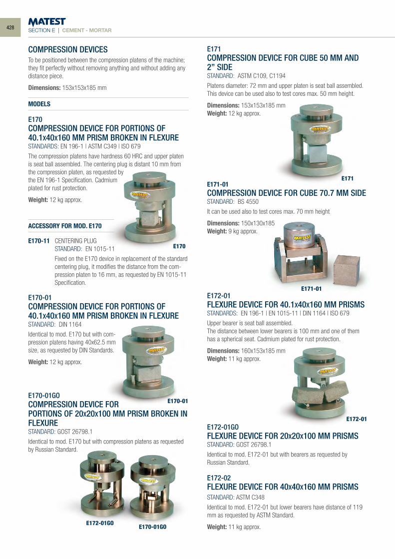
SECTION E | CEMENT - MORTAR
COMPRESSION DEVICESTo be positioned between the compression platens of the machine; they fit perfectly without removing anything and without adding any distance piece.
Dimensions: 153x153x185 mm
MODELS
E170COMPRESSION DEVICE FOR PORTIONS OF 40.1X40X160 MM PRISM BROKEN IN FLEXURESTANDARDS: EN 196-1 | ASTM C349 | ISO 679
The compression platens have hardness 60 HRC and upper platen is seat ball assembled. The centering plug is distant 10 mm from the compression platen, as requested by the EN 196-1 Specification. Cadmium plated for rust protection.
Weight: 12 kg approx.
ACCESSORY FOR MOD. E170
E170-11 CENTERING PLUG STANDARD: EN 1015-11
Fixed on the E170 device in replacement of the standard centering plug, it modifies the distance from the com-pression platen to 16 mm, as requested by EN 1015-11 Specification.
E170-01COMPRESSION DEVICE FOR PORTIONS OF 40.1X40X160 MM PRISM BROKEN IN FLEXURESTANDARD: DIN 1164
Identical to mod. E170 but with com-pression platens having 40x62.5 mm size, as requested by DIN Standards.
Weight: 12 kg approx.
E170-01GOCOMPRESSION DEVICE FOR PORTIONS OF 20X20X100 MM PRISM BROKEN IN FLEXURESTANDARD: GOST 26798.1
Identical to mod. E170 but with compression platens as requested by Russian Standard.
E171COMPRESSION DEVICE FOR CUBE 50 MM AND 2” SIDESTANDARD: ASTM C109, C1194
Platens diameter: 72 mm and upper platen is seat ball assembled.This device can be used also to test cores max. 50 mm height.
Dimensions: 153x153x185 mmWeight: 12 kg approx.
E171-01COMPRESSION DEVICE FOR CUBE 70.7 MM SIDESTANDARD: BS 4550
It can be used also to test cores max. 70 mm height
Dimensions: 150x130x185Weight: 9 kg approx.
E172-01FLEXURE DEVICE FOR 40.1X40X160 MM PRISMSSTANDARDS: EN 196-1 | EN 1015-11 | DIN 1164 | ISO 679
Upper bearer is seat ball assembled.The distance between lower bearers is 100 mm and one of them has a spherical seat. Cadmium plated for rust protection.
Dimensions: 160x153x185 mmWeight: 11 kg approx.
E172-01GOFLEXURE DEVICE FOR 20X20X100 MM PRISMSSTANDARD: GOST 26798.1
Identical to mod. E172-01 but with bearers as requested byRussian Standard.
E172-02FLEXURE DEVICE FOR 40X40X160 MM PRISMSSTANDARD: ASTM C348
Identical to mod. E172-01 but lower bearers have distance of 119 mm as requested by ASTM Standard.
Weight: 11 kg approx.
E171-01
E171
E170
E170-01
E172-01GOE170-01GO
E172-01
428
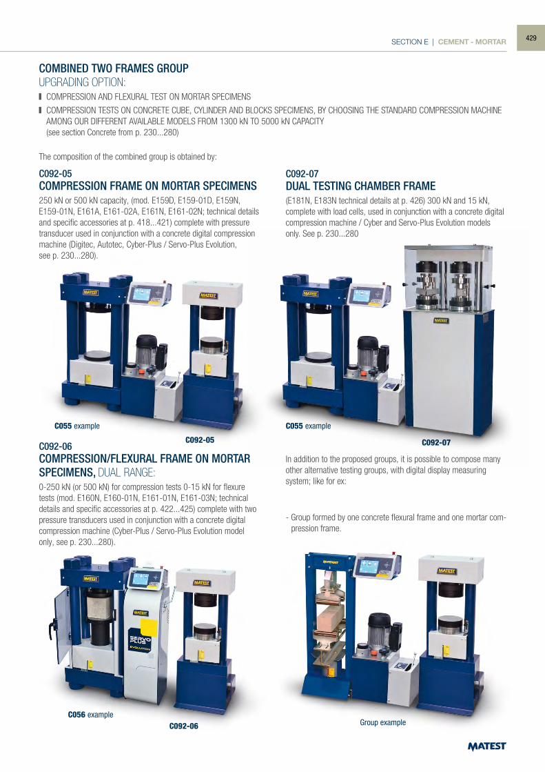
SECTION E | CEMENT - MORTAR
C055 example C055 example
C056 exampleGroup example
C092-05 C092-07
C092-06
COMBINED TWO FRAMES GROUPUPGRADING OPTION: COMPRESSION AND FLEXURAL TEST ON MORTAR SPECIMENS
COMPRESSION TESTS ON CONCRETE CUBE, CYLINDER AND BLOCKS SPECIMENS, BY CHOOSING THE STANDARD COMPRESSION MACHINE AMONG OUR DIFFERENT AVAILABLE MODELS FROM 1300 kN TO 5000 kN CAPACITY
(see section Concrete from p. 230...280)
The composition of the combined group is obtained by:
C092-05COMPRESSION FRAME ON MORTAR SPECIMENS250 kN or 500 kN capacity, (mod. E159D, E159-01D, E159N, E159-01N, E161A, E161-02A, E161N, E161-02N; technical details and specific accessories at p. 418...421) complete with pressure transducer used in conjunction with a concrete digital compression machine (Digitec, Autotec, Cyber-Plus / Servo-Plus Evolution,see p. 230...280).
C092-07DUAL TESTING CHAMBER FRAME(E181N, E183N technical details at p. 426) 300 kN and 15 kN, complete with load cells, used in conjunction with a concrete digital compression machine / Cyber and Servo-Plus Evolution models only. See p. 230...280
In addition to the proposed groups, it is possible to compose many other alternative testing groups, with digital display measuring system; like for ex:
- Group formed by one concrete flexural frame and one mortar com-pression frame.
C092-06COMPRESSION/FLEXURAL FRAME ON MORTAR SPECIMENS, DUAL RANGE:0-250 kN (or 500 kN) for compression tests 0-15 kN for flexure tests (mod. E160N, E160-01N, E161-01N, E161-03N; technical details and specific accessories at p. 422...425) complete with two pressure transducers used in conjunction with a concrete digital compression machine (Cyber-Plus / Servo-Plus Evolution model only, see p. 230...280).
429
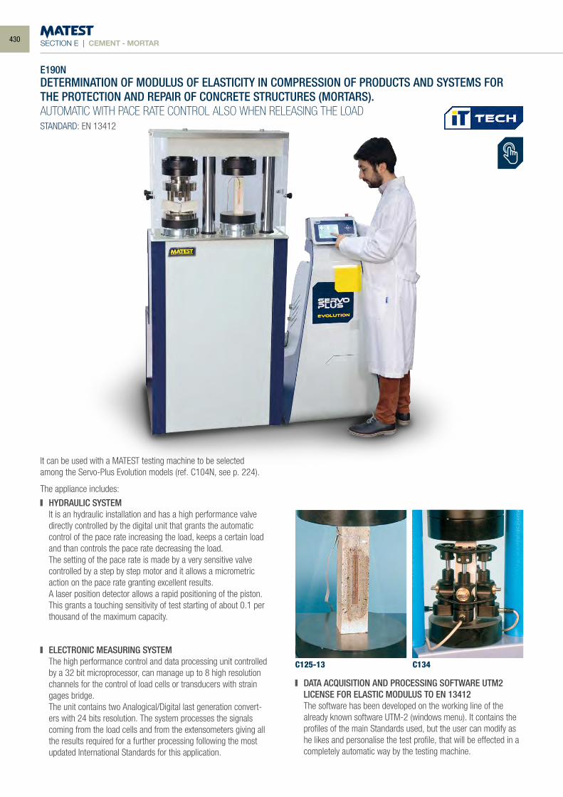
SECTION E | CEMENT - MORTAR
It can be used with a MATEST testing machine to be selected among the Servo-Plus Evolution models (ref. C104N, see p. 224).
The appliance includes:
HYDRAULIC SYSTEM It is an hydraulic installation and has a high performance valve
directly controlled by the digital unit that grants the automatic control of the pace rate increasing the load, keeps a certain load and than controls the pace rate decreasing the load.
The setting of the pace rate is made by a very sensitive valve controlled by a step by step motor and it allows a micrometric action on the pace rate granting excellent results.
A laser position detector allows a rapid positioning of the piston. This grants a touching sensitivity of test starting of about 0.1 per thousand of the maximum capacity.
ELECTRONIC MEASURING SYSTEM The high performance control and data processing unit controlled
by a 32 bit microprocessor, can manage up to 8 high resolution channels for the control of load cells or transducers with strain gages bridge.
The unit contains two Analogical/Digital last generation convert-ers with 24 bits resolution. The system processes the signals coming from the load cells and from the extensometers giving all the results required for a further processing following the most updated International Standards for this application.
DATA ACQUISITION AND PROCESSING SOFTWARE UTM2 LICENSE FOR ELASTIC MODULUS TO EN 13412 The software has been developed on the working line of the
already known software UTM-2 (windows menu). It contains the profiles of the main Standards used, but the user can modify as he likes and personalise the test profile, that will be effected in a completely automatic way by the testing machine.
C125-13 C134
E190NDETERMINATION OF MODULUS OF ELASTICITY IN COMPRESSION OF PRODUCTS AND SYSTEMS FOR THE PROTECTION AND REPAIR OF CONCRETE STRUCTURES (MORTARS).AUTOMATIC WITH PACE RATE CONTROL ALSO WHEN RELEASING THE LOADSTANDARD: EN 13412
430
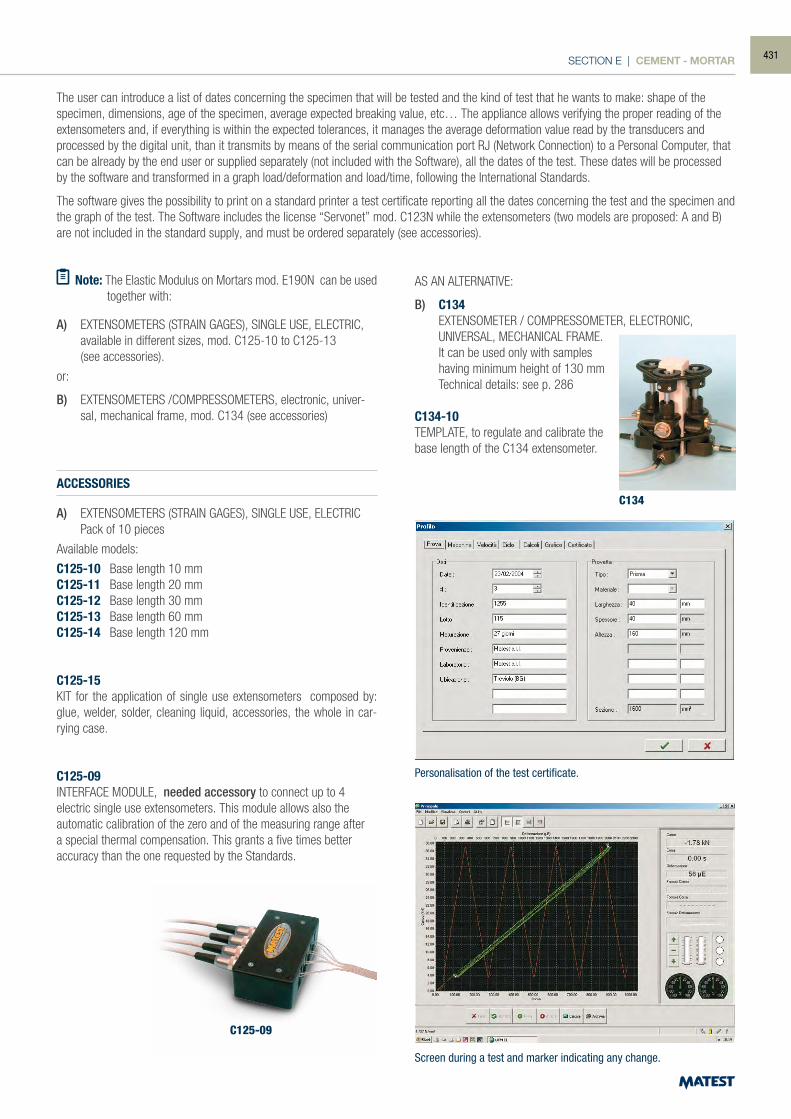
SECTION E | CEMENT - MORTAR
Screen during a test and marker indicating any change.
C134ACCESSORIES
A) EXTENSOMETERS (STRAIN GAGES), SINGLE USE, ELECTRIC Pack of 10 pieces
Available models:
C125-10 Base length 10 mmC125-11 Base length 20 mmC125-12 Base length 30 mm C125-13 Base length 60 mmC125-14 Base length 120 mm
C125-15KIT for the application of single use extensometers composed by: glue, welder, solder, cleaning liquid, accessories, the whole in car-rying case.
C125-09INTERFACE MODULE, needed accessory to connect up to 4 electric single use extensometers. This module allows also the automatic calibration of the zero and of the measuring range after a special thermal compensation. This grants a five times better accuracy than the one requested by the Standards.
AS AN ALTERNATIVE:
B) C134 EXTENSOMETER / COMPRESSOMETER, ELECTRONIC, UNIVERSAL, MECHANICAL FRAME. It can be used only with samples
having minimum height of 130 mm Technical details: see p. 286
C134-10TEMPLATE, to regulate and calibrate the base length of the C134 extensometer.
C125-09
The user can introduce a list of dates concerning the specimen that will be tested and the kind of test that he wants to make: shape of the specimen, dimensions, age of the specimen, average expected breaking value, etc… The appliance allows verifying the proper reading of the extensometers and, if everything is within the expected tolerances, it manages the average deformation value read by the transducers and processed by the digital unit, than it transmits by means of the serial communication port RJ (Network Connection) to a Personal Computer, that can be already by the end user or supplied separately (not included with the Software), all the dates of the test. These dates will be processed by the software and transformed in a graph load/deformation and load/time, following the International Standards.
The software gives the possibility to print on a standard printer a test certificate reporting all the dates concerning the test and the specimen and the graph of the test. The Software includes the license “Servonet” mod. C123N while the extensometers (two models are proposed: A and B) are not included in the standard supply, and must be ordered separately (see accessories).
Note: The Elastic Modulus on Mortars mod. E190N can be used together with:
A) EXTENSOMETERS (STRAIN GAGES), SINGLE USE, ELECTRIC, available in different sizes, mod. C125-10 to C125-13
(see accessories).
or:
B) EXTENSOMETERS /COMPRESSOMETERS, electronic, univer-sal, mechanical frame, mod. C134 (see accessories)
Personalisation of the test certificate.
431
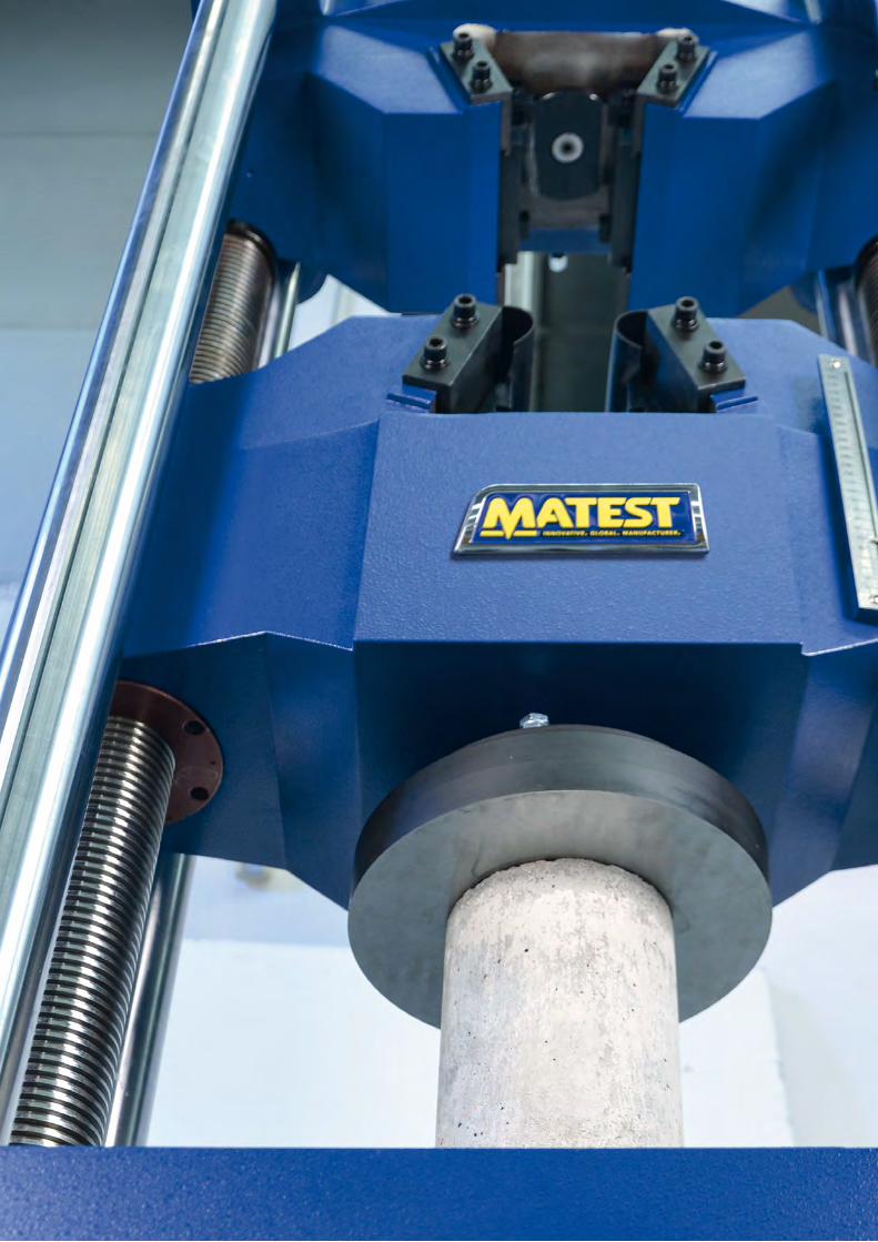
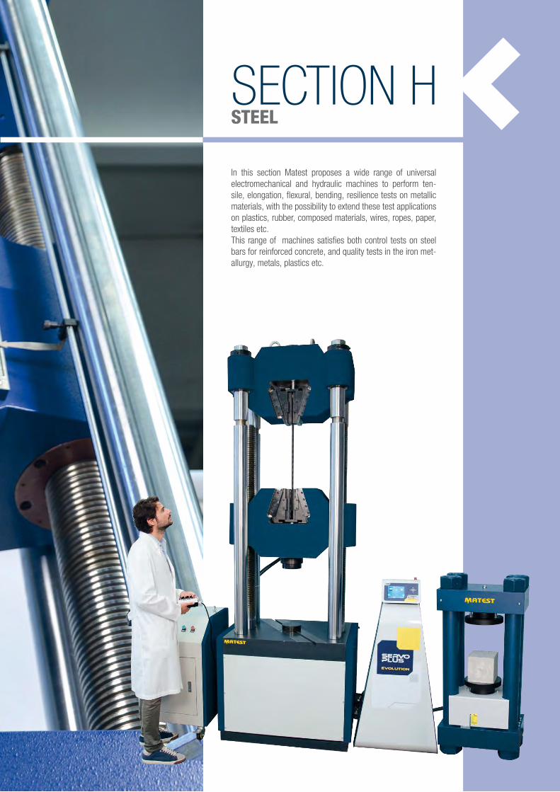
SECTION HSTEEL
In this section Matest proposes a wide range of universal electromechanical and hydraulic machines to perform ten-sile, elongation, flexural, bending, resilience tests on metallic materials, with the possibility to extend these test applications on plastics, rubber, composed materials, wires, ropes, paper, textiles etc.This range of machines satisfies both control tests on steel bars for reinforced concrete, and quality tests in the iron met-allurgy, metals, plastics etc.
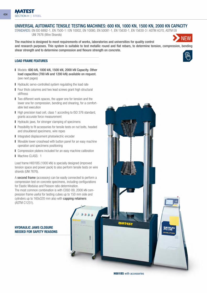
SECTION H | STEEL
NEW
H001BS with accessories
UNIVERSAL AUTOMATIC TENSILE TESTING MACHINES: 600 KN, 1000 KN, 1500 KN, 2000 KN CAPACITYSTANDARDS: EN ISO 6892-1, EN 7500-1 | EN 10002, EN 10080, EN 50081-1, EN 15630-1, EN 15630-3 | ASTM A370, ASTM E8 UNI 7676 (Wire Strands)
The machine is designed to meet requirements of works, laboratories and universities for quality controland research purposes. This system is suitable to test metallic round and flat rebars, to determine tension, compression, bending shear strength and to determine compression and flexure strength on concrete.
LOAD FRAME FEATURES
Models: 600 kN, 1000 kN, 1500 kN, 2000 kN Capacity. Other load capacities (700 kN and 1200 kN) available on request.
(see next pages)
Hydraulic servo-controlled system regulating the load rate
Four thick columns and two lead screws grant high structural stiffness
Two different work spaces, the upper one for tension and the lower one for compression, bending and shearing, for a comfort-able test execution
High precision load cell, class 1 according to ISO 376 standard, grants accurate force measurement
Hydraulic jaws, for stronger clamping of specimens
Possibility to fit accessories for tensile tests on nut bolts, headed and shouldered specimens, wire ropes
Integrated displacement photoelectric encoder
Movable lower crosshead with button panel for an easy machine operation and specimens positioning
Compression platens included for an easy machine calibration
Machine CLASS: 1
Load frame H001BS (1000 kN) is specially designed (improved tension space and power pack) to also perform tensile tests on wire strands (UNI 7676).
A second frame (accessory) can be easily connected to perform a compression test on concrete specimens, including configurations for Elastic Modulus and Poisson ratio determination.The most common combination is with C092-09, 2000 kN com-pression frame useful for testing cubes up to 150 mm side and cylinders up to 160x320 mm also with capping retainers(ASTM C1231).
HYDRAULIC JAWS CLOSURENEEDED FOR SAFETY REASONS
434
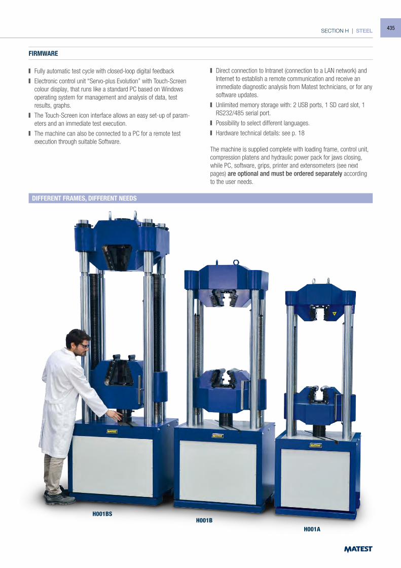
SECTION H | STEEL
FIRMWARE
Fully automatic test cycle with closed-loop digital feedback
Electronic control unit “Servo-plus Evolution” with Touch-Screen colour display, that runs like a standard PC based on Windows operating system for management and analysis of data, test results, graphs.
The Touch-Screen icon interface allows an easy set-up of param-eters and an immediate test execution.
The machine can also be connected to a PC for a remote test execution through suitable Software.
Direct connection to Intranet (connection to a LAN network) and Internet to establish a remote communication and receive an immediate diagnostic analysis from Matest technicians, or for any software updates.
Unlimited memory storage with: 2 USB ports, 1 SD card slot, 1 RS232/485 serial port.
Possibility to select different languages.
Hardware technical details: see p. 18
The machine is supplied complete with loading frame, control unit, compression platens and hydraulic power pack for jaws closing, while PC, software, grips, printer and extensometers (see next pages) are optional and must be ordered separately according to the user needs.
H001BSH001B
H001A
DIFFERENT FRAMES, DIFFERENT NEEDS
435
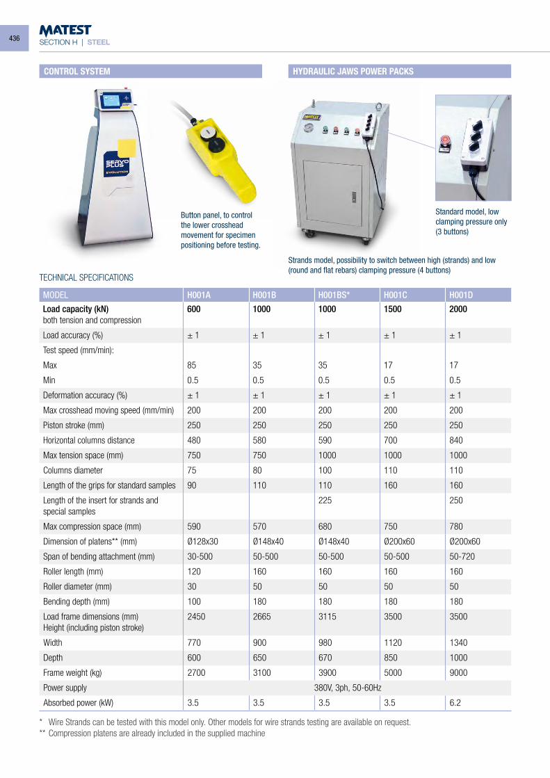
SECTION H | STEEL
TECHNICAL SPECIFICATIONS
* Wire Strands can be tested with this model only. Other models for wire strands testing are available on request.** Compression platens are already included in the supplied machine
MODEL H001A H001B H001BS* H001C H001D
Load capacity (kN)both tension and compression
600 1000 1000 1500 2000
Load accuracy (%) ± 1 ± 1 ± 1 ± 1 ± 1
Test speed (mm/min):
Max 85 35 35 17 17
Min 0.5 0.5 0.5 0.5 0.5
Deformation accuracy (%) ± 1 ± 1 ± 1 ± 1 ± 1
Max crosshead moving speed (mm/min) 200 200 200 200 200
Piston stroke (mm) 250 250 250 250 250
Horizontal columns distance 480 580 590 700 840
Max tension space (mm) 750 750 1000 1000 1000
Columns diameter 75 80 100 110 110
Length of the grips for standard samples 90 110 110 160 160
Length of the insert for strands and special samples
225 250
Max compression space (mm) 590 570 680 750 780
Dimension of platens** (mm) Ø128x30 Ø148x40 Ø148x40 Ø200x60 Ø200x60
Span of bending attachment (mm) 30-500 50-500 50-500 50-500 50-720
Roller length (mm) 120 160 160 160 160
Roller diameter (mm) 30 50 50 50 50
Bending depth (mm) 100 180 180 180 180
Load frame dimensions (mm)Height (including piston stroke)
2450 2665 3115 3500 3500
Width 770 900 980 1120 1340
Depth 600 650 670 850 1000
Frame weight (kg) 2700 3100 3900 5000 9000
Power supply 380V, 3ph, 50-60Hz
Absorbed power (kW) 3.5 3.5 3.5 3.5 6.2
CONTROL SYSTEM HYDRAULIC JAWS POWER PACKS
Button panel, to control the lower crosshead movement for specimen positioning before testing.
Standard model, low clamping pressure only (3 buttons)
Strands model, possibility to switch between high (strands) and low (round and flat rebars) clamping pressure (4 buttons)
436
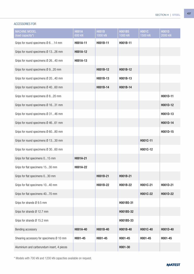
SECTION H | STEEL
ACCESSORIES FOR
MACHINE MODEL (load capacity*)
H001A600 kN
H001B1000 kN
H001BS1000 kN
H001C1500 kN
H001D2000 kN
Grips for round specimens Ø 6…14 mm H001A-11 H001B-11 H001B-11
Grips for round specimens Ø 13...26 mm H001A-12
Grips for round specimens Ø 26...40 mm H001A-13
Grips for round specimens Ø 9...20 mm H001B-12 H001B-12
Grips for round specimens Ø 20...40 mm H001B-13 H001B-13
Grips for round specimens Ø 40...60 mm H001B-14 H001B-14
Grips for round specimens Ø 8...20 mm H001D-11
Grips for round specimens Ø 16...31 mm H001D-12
Grips for round specimens Ø 31...46 mm H001D-13
Grips for round specimens Ø 46...61 mm H001D-14
Grips for round specimens Ø 60...80 mm H001D-15
Grips for round specimens Ø 13...30 mm H001C-11
Grips for round specimens Ø 30...60 mm H001C-12
Grips for flat specimens 0...15 mm H001A-21
Grips for flat specimens 15...30 mm H001A-22
Grips for flat specimens 0...30 mm H001B-21 H001B-21
Grips for flat specimens 10...40 mm H001B-22 H001B-22 H001C-21 H001D-21
Grips for flat specimens 40...70 mm H001C-22 H001D-22
Grips for strands Ø 9.5 mm H001BS-31
Grips for strands Ø 12.7 mm H001BS-32
Grips for strands Ø 15.2 mm H001BS-33
Bending accessory H001A-40 H001B-40 H001B-40 H001C-40 H001D-40
Shearing accessory for specimens Ø 10 mm H001-45 H001-45 H001-45 H001-45 H001-45
Aluminium and carborundum insert, 4 pieces H001-30
* Models with 700 kN and 1200 kN capacities available on request.
437
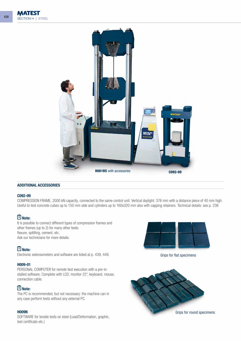
SECTION H | STEEL
H009-01PERSONAL COMPUTER for remote test execution with a pre-in-stalled software. Complete with LCD, monitor 22”, keyboard, mouse, connection cable.
Note:The PC is recommended, but not necessary: the machine can in any case perform tests without any external PC.
H001BS with accessories C092-09
Grips for round specimens
Grips for flat specimens Note:
Electronic extensometers and software are listed at p. 439, 449.
H009NSOFTWARE for tensile tests on steel (Load/Deformation, graphic, test certificate etc.)
ADDITIONAL ACCESSORIES
C092-09COMPRESSION FRAME, 2000 kN capacity, connected to the same control unit. Vertical daylight: 376 mm with a distance piece of 40 mm high.Useful to test concrete cubes up to 150 mm side and cylinders up to 160x320 mm also with capping retainers. Technical details: see p. 238
Note:It is possible to connect different types of compression frames and other frames (up to 2) for many other tests:flexure, splitting, cement, etc.Ask our technicians for more details.
438
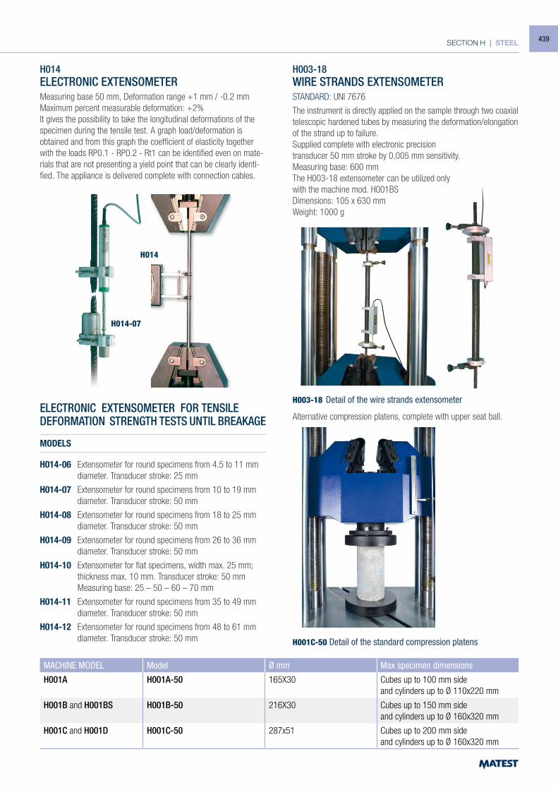
SECTION H | STEEL
H003-18 Detail of the wire strands extensometer
MACHINE MODEL Model Ø mm Max specimen dimensions
H001A H001A-50 165X30 Cubes up to 100 mm sideand cylinders up to Ø 110x220 mm
H001B and H001BS H001B-50 216X30 Cubes up to 150 mm sideand cylinders up to Ø 160x320 mm
H001C and H001D H001C-50 287x51 Cubes up to 200 mm sideand cylinders up to Ø 160x320 mm
H014ELECTRONIC EXTENSOMETERMeasuring base 50 mm, Deformation range +1 mm / -0.2 mmMaximum percent measurable deformation: +2%It gives the possibility to take the longitudinal deformations of the specimen during the tensile test. A graph load/deformation is obtained and from this graph the coefficient of elasticity together with the loads RP0.1 - RP0.2 - Rt1 can be identified even on mate-rials that are not presenting a yield point that can be clearly identi-fied. The appliance is delivered complete with connection cables.
ELECTRONIC EXTENSOMETER FOR TENSILEDEFORMATION STRENGTH TESTS UNTIL BREAKAGE
MODELS
H014-06 Extensometer for round specimens from 4.5 to 11 mm diameter. Transducer stroke: 25 mm
H014-07 Extensometer for round specimens from 10 to 19 mm diameter. Transducer stroke: 50 mm
H014-08 Extensometer for round specimens from 18 to 25 mm diameter. Transducer stroke: 50 mm
H014-09 Extensometer for round specimens from 26 to 36 mm diameter. Transducer stroke: 50 mm
H014-10 Extensometer for flat specimens, width max. 25 mm; thickness max. 10 mm. Transducer stroke: 50 mm
Measuring base: 25 – 50 – 60 – 70 mm
H014-11 Extensometer for round specimens from 35 to 49 mm diameter. Transducer stroke: 50 mm
H014-12 Extensometer for round specimens from 48 to 61 mm diameter. Transducer stroke: 50 mm
H014-07
H014
H003-18WIRE STRANDS EXTENSOMETERSTANDARD: UNI 7676
The instrument is directly applied on the sample through two coaxial telescopic hardened tubes by measuring the deformation/elongation of the strand up to failure. Supplied complete with electronic precisiontransducer 50 mm stroke by 0,005 mm sensitivity. Measuring base: 600 mmThe H003-18 extensometer can be utilized onlywith the machine mod. H001BSDimensions: 105 x 630 mm Weight: 1000 g
Alternative compression platens, complete with upper seat ball.
H001C-50 Detail of the standard compression platens
439
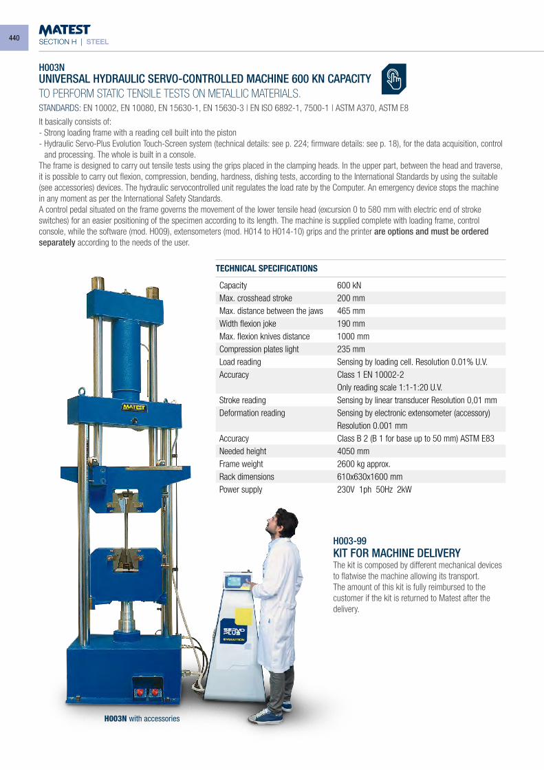
SECTION H | STEEL
H003NUNIVERSAL HYDRAULIC SERVO-CONTROLLED MACHINE 600 KN CAPACITY
TO PERFORM STATIC TENSILE TESTS ON METALLIC MATERIALS.STANDARDS: EN 10002, EN 10080, EN 15630-1, EN 15630-3 | EN ISO 6892-1, 7500-1 | ASTM A370, ASTM E8
It basically consists of:- Strong loading frame with a reading cell built into the piston- Hydraulic Servo-Plus Evolution Touch-Screen system (technical details: see p. 224; firmware details: see p. 18), for the data acquisition, control
and processing. The whole is built in a console.The frame is designed to carry out tensile tests using the grips placed in the clamping heads. In the upper part, between the head and traverse, it is possible to carry out flexion, compression, bending, hardness, dishing tests, according to the International Standards by using the suitable (see accessories) devices. The hydraulic servocontrolled unit regulates the load rate by the Computer. An emergency device stops the machine in any moment as per the International Safety Standards.A control pedal situated on the frame governs the movement of the lower tensile head (excursion 0 to 580 mm with electric end of stroke switches) for an easier positioning of the specimen according to its length. The machine is supplied complete with loading frame, control console, while the software (mod. H009), extensometers (mod. H014 to H014-10) grips and the printer are options and must be ordered separately according to the needs of the user.
TECHNICAL SPECIFICATIONS
H003-99KIT FOR MACHINE DELIVERYThe kit is composed by different mechanical devices to flatwise the machine allowing its transport.The amount of this kit is fully reimbursed to the customer if the kit is returned to Matest after the delivery.
H003N with accessories
Capacity 600 kNMax. crosshead stroke 200 mmMax. distance between the jaws 465 mmWidth flexion joke 190 mmMax. flexion knives distance 1000 mmCompression plates light 235 mmLoad reading Sensing by loading cell. Resolution 0.01% U.V.Accuracy Class 1 EN 10002-2
Only reading scale 1:1-1:20 U.V.Stroke reading Sensing by linear transducer Resolution 0,01 mmDeformation reading Sensing by electronic extensometer (accessory)
Resolution 0.001 mmAccuracy Class B 2 (B 1 for base up to 50 mm) ASTM E83Needed height 4050 mmFrame weight 2600 kg approx.Rack dimensions 610x630x1600 mmPower supply 230V 1ph 50Hz 2kW
440
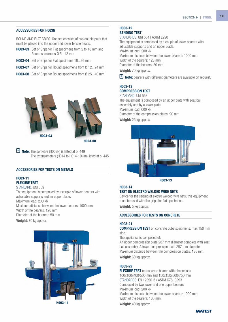
SECTION H | STEEL
H003-11
H003-13
ACCESSORIES FOR H003N
ROUND AND FLAT GRIPS. One set consists of two double pairs that must be placed into the upper and lower tensile heads.
H003-03 Set of Grips for Flat specimens from 2 to 18 mm and Round specimens Ø 5...12 mm
H003-04 Set of Grips for Flat specimens 18...36 mm
H003-07 Set of Grips for Round specimens from Ø 12...24 mm
H003-08 Set of Grips for Round specimens from Ø 25...40 mm
Note: The software (H009N) is listed at p. 449 The extensometers (H014 to H014-10) are listed at p. 445
ACCESSORIES FOR TESTS ON METALS
H003-11FLEXURE TESTSTANDARD: UNI 559The equipment is composed by a couple of lower bearers with adjustable supports and an upper blade.Maximum load: 200 kNMaximum distance between the lower bearers: 1000 mmWidth of the bearers: 120 mmDiameter of the bearers: 50 mm
Weight: 70 kg approx.
H003-12BENDING TESTSTANDARDS: UNI 564 | ASTM E290The equipment is composed by a couple of lower bearers with adjustable supports and an upper blade.Maximum load: 200 kNMaximum distance between the lower bearers: 1000 mmWidth of the bearers: 120 mmDiameter of the bearers: 50 mm
Weight: 70 kg approx.
Note: bearers with different diameters are available on request.
H003-13COMPRESSION TESTSTANDARD: UNI 558The equipment is composed by an upper plate with seat ball assembly and by a lower plate.Maximum load: 600 kNDiameter of the compression plates: 90 mm
Weight: 25 kg approx.
H003-14TEST ON ELECTRO WELDED WIRE NETSDevice for the seizing of electro welded wire nets; this equipment must be used with the grips for flat specimens.
Weight: 5 kg approx.
ACCESSORIES FOR TESTS ON CONCRETE
H003-21COMPRESSION TEST on concrete cube specimens, max 150 mm side.The appliance is composed of:An upper compression plate 287 mm diameter complete with seat ball assembly. A lower compression plate 287 mm diameterMaximum distance between the compression plates: 185 mm.
Weight: 60 kg approx.
H003-22FLEXURE TEST on concrete beams with dimensions 100x100x400/500 mm and 150x150x600/750 mmSTANDARDS: EN 12390-5 / ASTM C78, C293Composed by two lower and one upper bearersMaximum load: 200 kNMaximum distance between the lower bearers: 1000 mm.Width of the bearers: 160 mm.
Weight: 40 kg approx.
H003-03
H003-08
441
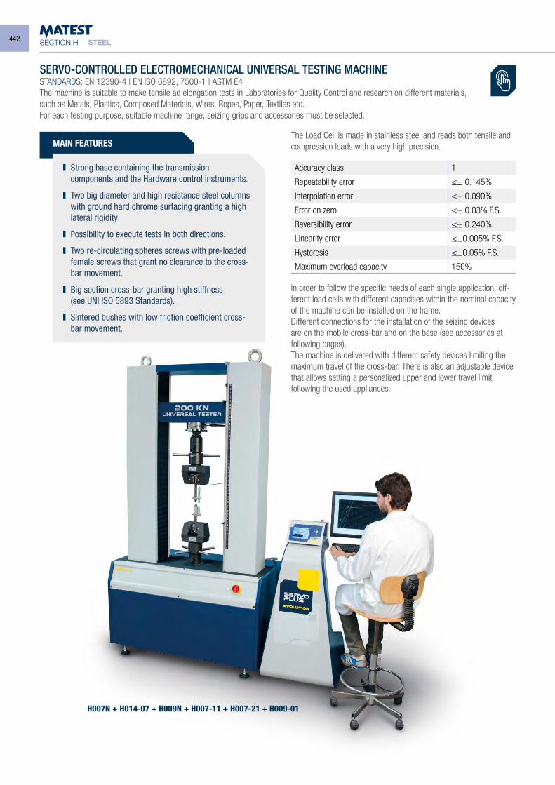
SECTION H | STEEL
SERVO-CONTROLLED ELECTROMECHANICAL UNIVERSAL TESTING MACHINESTANDARDS: EN 12390-4 | EN ISO 6892, 7500-1 | ASTM E4 The machine is suitable to make tensile ad elongation tests in Laboratories for Quality Control and research on different materials,such as Metals, Plastics, Composed Materials, Wires, Ropes, Paper, Textiles etc.For each testing purpose, suitable machine range, seizing grips and accessories must be selected.
MAIN FEATURES
Strong base containing the transmission components and the Hardware control instruments.
Two big diameter and high resistance steel columns with ground hard chrome surfacing granting a high lateral rigidity.
Possibility to execute tests in both directions.
Two re-circulating spheres screws with pre-loaded female screws that grant no clearance to the cross-bar movement.
Big section cross-bar granting high stiffness (see UNI ISO 5893 Standards).
Sintered bushes with low friction coefficient cross-bar movement.
The Load Cell is made in stainless steel and reads both tensile and compression loads with a very high precision.
Accuracy class 1
Repeatability error ≤± 0.145%
Interpolation error ≤± 0.090%
Error on zero ≤± 0.03% F.S.
Reversibility error ≤± 0.240%
Linearity error ≤±0.005% F.S.
Hysteresis ≤±0.05% F.S.
Maximum overload capacity 150%
In order to follow the specific needs of each single application, dif-ferent load cells with different capacities within the nominal capacity of the machine can be installed on the frame.Different connections for the installation of the seizing devices are on the mobile cross-bar and on the base (see accessories at following pages).The machine is delivered with different safety devices limiting the maximum travel of the cross-bar. There is also an adjustable device that allows setting a personalized upper and lower travel limit following the used appliances.
H007N + H014-07 + H009N + H007-11 + H007-21 + H009-01
442
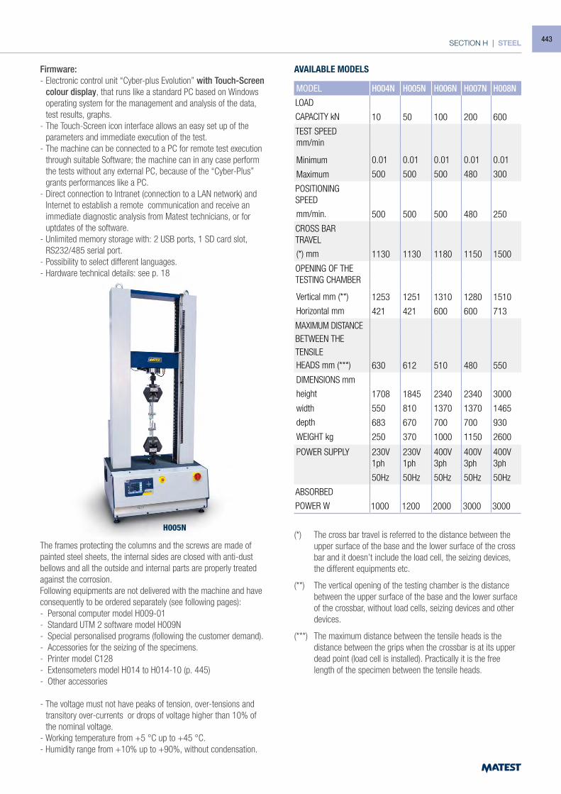
SECTION H | STEEL
H005N
Firmware:- Electronic control unit “Cyber-plus Evolution” with Touch-Screen
colour display, that runs like a standard PC based on Windows operating system for the management and analysis of the data, test results, graphs.
- The Touch-Screen icon interface allows an easy set up of the parameters and immediate execution of the test.
- The machine can be connected to a PC for remote test execution through suitable Software; the machine can in any case perform the tests without any external PC, because of the “Cyber-Plus” grants performances like a PC.
- Direct connection to Intranet (connection to a LAN network) and Internet to establish a remote communication and receive an immediate diagnostic analysis from Matest technicians, or for uptdates of the software.
- Unlimited memory storage with: 2 USB ports, 1 SD card slot, RS232/485 serial port.
- Possibility to select different languages.- Hardware technical details: see p. 18
The frames protecting the columns and the screws are made of painted steel sheets, the internal sides are closed with anti-dust bellows and all the outside and internal parts are properly treated against the corrosion. Following equipments are not delivered with the machine and have consequently to be ordered separately (see following pages):- Personal computer model H009-01- Standard UTM 2 software model H009N- Special personalised programs (following the customer demand).- Accessories for the seizing of the specimens.- Printer model C128- Extensometers model H014 to H014-10 (p. 445)- Other accessories
- The voltage must not have peaks of tension, over-tensions and transitory over-currents or drops of voltage higher than 10% of the nominal voltage.
- Working temperature from +5 °C up to +45 °C.- Humidity range from +10% up to +90%, without condensation.
(*) The cross bar travel is referred to the distance between the upper surface of the base and the lower surface of the cross bar and it doesn’t include the load cell, the seizing devices, the different equipments etc.
(**) The vertical opening of the testing chamber is the distance between the upper surface of the base and the lower surface of the crossbar, without load cells, seizing devices and other devices.
(***) The maximum distance between the tensile heads is the distance between the grips when the crossbar is at its upper dead point (load cell is installed). Practically it is the free length of the specimen between the tensile heads.
MODEL H004N H005N H006N H007N H008N
LOAD
CAPACITY kN 10 50 100 200 600
TEST SPEEDmm/min
Minimum
Maximum
0.01 0.01 0.01 0.01 0.01
500 500 500 480 300
POSITIONINGSPEED
mm/min. 500 500 500 480 250
CROSS BARTRAVEL
(*) mm 1130 1130 1180 1150 1500
OPENING OF THETESTING CHAMBER
Vertical mm (**)
Horizontal mm1253 1251 1310 1280 1510
421 421 600 600 713
MAXIMUM DISTANCEBETWEEN THETENSILEHEADS mm (***) 630 612 510 480 550
DIMENSIONS mm
height
width
depth
WEIGHT kg
1708 1845 2340 2340 3000
550 810 1370 1370 1465
683 670 700 700 930
250 370 1000 1150 2600
POWER SUPPLY 230V 1ph
230V 1ph
400V 3ph
400V 3ph
400V 3ph
50Hz 50Hz 50Hz 50Hz 50Hz
ABSORBED
POWER W 1000 1200 2000 3000 3000
AVAILABLE MODELS
443
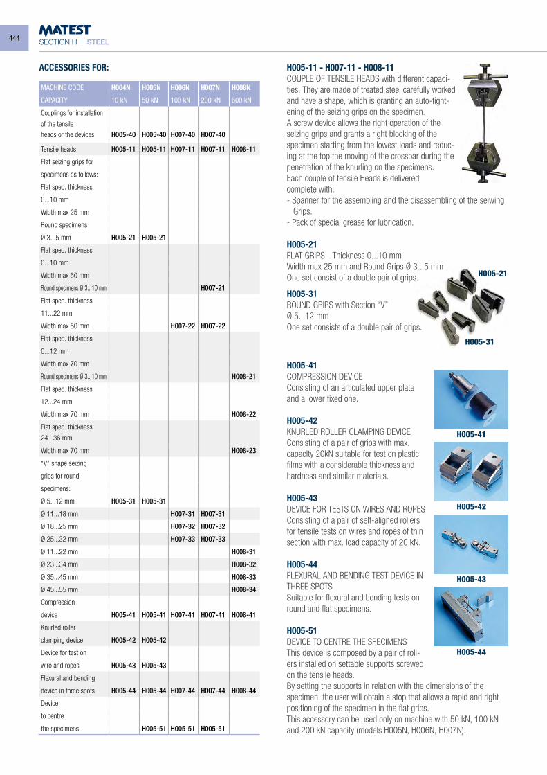
SECTION H | STEEL
MACHINE CODE H004N H005N H006N H007N H008N
CAPACITY 10 kN 50 kN 100 kN 200 kN 600 kN
Couplings for installation
of the tensileheads or the devices H005-40 H005-40 H007-40 H007-40
Tensile heads H005-11 H005-11 H007-11 H007-11 H008-11
Flat seizing grips for
specimens as follows:
Flat spec. thickness
0...10 mm
Width max 25 mm
Round specimens
Ø 3...5 mm H005-21 H005-21
Flat spec. thickness
0...10 mm
Width max 50 mm
Round specimens Ø 3...10 mm H007-21
Flat spec. thickness
11...22 mm
Width max 50 mm H007-22 H007-22
Flat spec. thickness
0...12 mm
Width max 70 mm
Round specimens Ø 3...10 mm H008-21
Flat spec. thickness
12...24 mm
Width max 70 mm H008-22
Flat spec. thickness
24...36 mm
Width max 70 mm H008-23
“V” shape seizing
grips for round
specimens:
Ø 5...12 mm H005-31 H005-31
Ø 11...18 mm H007-31 H007-31
Ø 18...25 mm H007-32 H007-32
Ø 25...32 mm H007-33 H007-33
Ø 11...22 mm H008-31
Ø 23...34 mm H008-32
Ø 35...45 mm H008-33
Ø 45...55 mm H008-34
Compression
device H005-41 H005-41 H007-41 H007-41 H008-41
Knurled roller
clamping device H005-42 H005-42
Device for test on
wire and ropes H005-43 H005-43
Flexural and bending
device in three spots H005-44 H005-44 H007-44 H007-44 H008-44
Device
to centre
the specimens H005-51 H005-51 H005-51
ACCESSORIES FOR: H005-11 - H007-11 - H008-11COUPLE OF TENSILE HEADS with different capaci-ties. They are made of treated steel carefully worked and have a shape, which is granting an auto-tight-ening of the seizing grips on the specimen.A screw device allows the right operation of the seizing grips and grants a right blocking of the specimen starting from the lowest loads and reduc-ing at the top the moving of the crossbar during the penetration of the knurling on the specimens.Each couple of tensile Heads is deliveredcomplete with:- Spanner for the assembling and the disassembling of the seiwing
Grips.- Pack of special grease for lubrication.
H005-21FLAT GRIPS - Thickness 0...10 mmWidth max 25 mm and Round Grips Ø 3...5 mmOne set consist of a double pair of grips.
H005-31ROUND GRIPS with Section “V”Ø 5...12 mmOne set consists of a double pair of grips.
H005-41COMPRESSION DEVICEConsisting of an articulated upper plate and a lower fixed one.
H005-42KNURLED ROLLER CLAMPING DEVICEConsisting of a pair of grips with max. capacity 20kN suitable for test on plastic films with a considerable thickness and hardness and similar materials.
H005-43DEVICE FOR TESTS ON WIRES AND ROPESConsisting of a pair of self-aligned rollers for tensile tests on wires and ropes of thin section with max. load capacity of 20 kN.
H005-44FLEXURAL AND BENDING TEST DEVICE IN THREE SPOTSSuitable for flexural and bending tests on round and flat specimens.
H005-51DEVICE TO CENTRE THE SPECIMENSThis device is composed by a pair of roll-ers installed on settable supports screwed on the tensile heads.By setting the supports in relation with the dimensions of the specimen, the user will obtain a stop that allows a rapid and right positioning of the specimen in the flat grips.This accessory can be used only on machine with 50 kN, 100 kN and 200 kN capacity (models H005N, H006N, H007N).
H005-21
H005-31
H005-41
H005-42
H005-43
H005-44
444
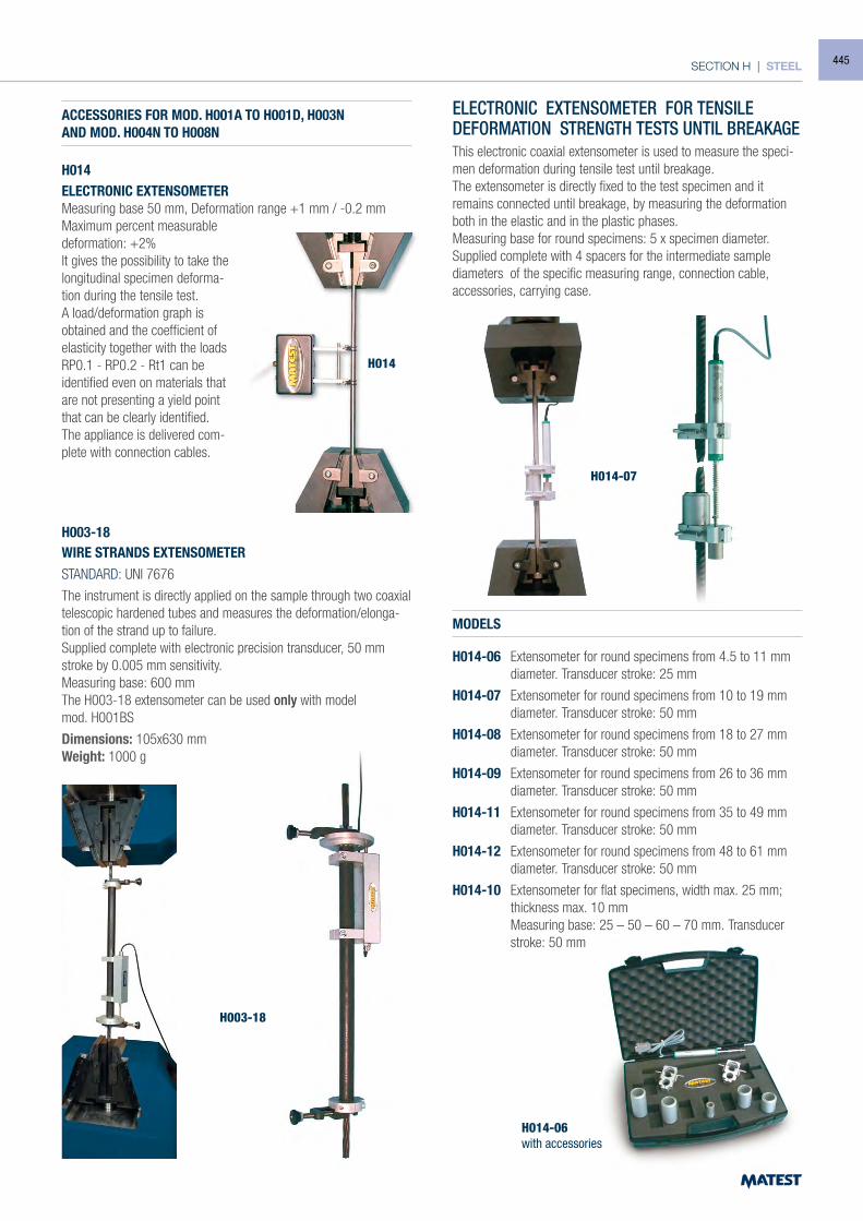
SECTION H | STEEL
ACCESSORIES FOR MOD. H001A TO H001D, H003NAND MOD. H004N TO H008N
H014ELECTRONIC EXTENSOMETERMeasuring base 50 mm, Deformation range +1 mm / -0.2 mmMaximum percent measurabledeformation: +2%It gives the possibility to take the longitudinal specimen deforma-tion during the tensile test.A load/deformation graph is obtained and the coefficient of elasticity together with the loads RP0.1 - RP0.2 - Rt1 can be identified even on materials that are not presenting a yield point that can be clearly identified.The appliance is delivered com-plete with connection cables.
H003-18 WIRE STRANDS EXTENSOMETER STANDARD: UNI 7676
The instrument is directly applied on the sample through two coaxial telescopic hardened tubes and measures the deformation/elonga-tion of the strand up to failure. Supplied complete with electronic precision transducer, 50 mm stroke by 0.005 mm sensitivity. Measuring base: 600 mmThe H003-18 extensometer can be used only with modelmod. H001BS
Dimensions: 105x630 mm Weight: 1000 g
ELECTRONIC EXTENSOMETER FOR TENSILEDEFORMATION STRENGTH TESTS UNTIL BREAKAGEThis electronic coaxial extensometer is used to measure the speci-men deformation during tensile test until breakage.The extensometer is directly fixed to the test specimen and it remains connected until breakage, by measuring the deformation both in the elastic and in the plastic phases.Measuring base for round specimens: 5 x specimen diameter.Supplied complete with 4 spacers for the intermediate sample diameters of the specific measuring range, connection cable, accessories, carrying case.
MODELS
H014-06 Extensometer for round specimens from 4.5 to 11 mm diameter. Transducer stroke: 25 mm
H014-07 Extensometer for round specimens from 10 to 19 mm diameter. Transducer stroke: 50 mm
H014-08 Extensometer for round specimens from 18 to 27 mm diameter. Transducer stroke: 50 mm
H014-09 Extensometer for round specimens from 26 to 36 mm diameter. Transducer stroke: 50 mm
H014-11 Extensometer for round specimens from 35 to 49 mm diameter. Transducer stroke: 50 mm
H014-12 Extensometer for round specimens from 48 to 61 mm diameter. Transducer stroke: 50 mm
H014-10 Extensometer for flat specimens, width max. 25 mm; thickness max. 10 mm
Measuring base: 25 – 50 – 60 – 70 mm. Transducer stroke: 50 mm
H014
H014-07
H003-18
H014-06with accessories
445
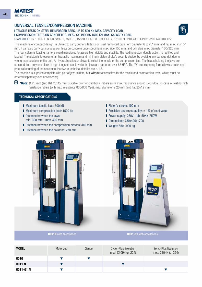
SECTION H | STEEL
UNIVERSAL TENSILE/COMPRESSION MACHINE TENSILE TESTS ON STEEL REINFORCED BARS, UP TO 500 KN MAX. CAPACITY LOAD. COMPRESSION TESTS ON CONCRETE CUBES / CYLINDERS 1500 KN MAX. CAPACITY LOAD.
STANDARDS: EN 10002 | EN ISO 6892-1, 7500-1, 15630-1 | ASTM C39, E4 | BS 1610 | NF P18-411 | DIN 51220 | AASHTO T22
This machine of compact design, is utilized to carry out tensile tests on steel reinforced bars from diameter 6 to 25* mm. and flat max. 25x15* mm. It can also carry out compression tests on concrete cube specimens max. side 150 mm. and cylinders max. diameter 160x320 mm.The four columns loading frame is overdimensioned to assure high rigidity and stability. The loading piston, double action, is rectified and lapped. The piston is foreseen of an hydraulic maximum and minimum piston stroke’s security device, by avoiding any damage risk due to wrong manipulations of the unit. An hydraulic selector allows to select the tensile or the compression test. The heads holding the jaws are obtained from only one block of high tungsten steel, while the jaws are hardened over 65 HRC. The “V” autoclamping form allows a quick and practical churking of the specimen. Hardware technical details: see p. 18.The machine is supplied complete with pair of jaw-holders, but without accessoires for the tensile and compression tests, which must be ordered separately (see accessories).
*Note: Ø 25 mm (and flat 25x15 mm) suitable only for traditional rebars (with max. resistance around 540 Mpa), in case of testing high resistance rebars (with max. resistance 800/850 Mpa), max. diameter is 20 mm (and flat 25x12 mm).
MODEL Motorized Gauge Cyber-Plus Evolutionmod. C109N (p. 224)
Servo-Plus Evolutionmod. C104N (p. 224)
H010
H011 N
H011-01 N
TECHNICAL SPECIFICATIONS
Maximum tensile load: 500 kN Maximum compression load: 1500 kN Distance between the jaws:
min. 300 mm - max. 400 mm Distance between the compression platens: 340 mm Distance between the columns: 270 mm
Piston’s stroke: 100 mm Precision and repeatability: ± 1% of read value Power supply: 230V 1ph 50Hz 750W Dimensions: 780x420x1700 Weight: 850...900 kg
H011-01 with accessoriesH011N with accessories
446
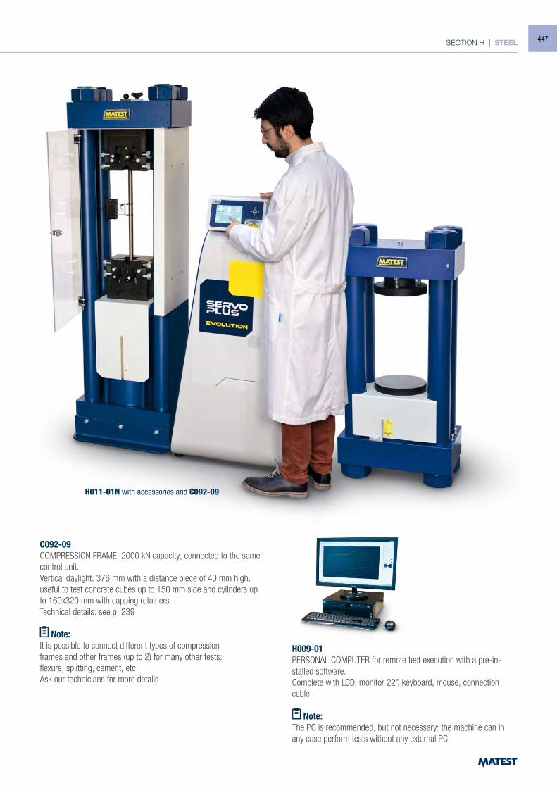
SECTION H | STEEL
C092-09COMPRESSION FRAME, 2000 kN capacity, connected to the same control unit.Vertical daylight: 376 mm with a distance piece of 40 mm high,useful to test concrete cubes up to 150 mm side and cylinders up to 160x320 mm with capping retainers.Technical details: see p. 239
Note:It is possible to connect different types of compressionframes and other frames (up to 2) for many other tests:flexure, splitting, cement, etc.Ask our technicians for more details
H009-01PERSONAL COMPUTER for remote test execution with a pre-in-stalled software.Complete with LCD, monitor 22”, keyboard, mouse, connection cable.
Note:The PC is recommended, but not necessary: the machine can in any case perform tests without any external PC.
H011-01N with accessories and C092-09
447
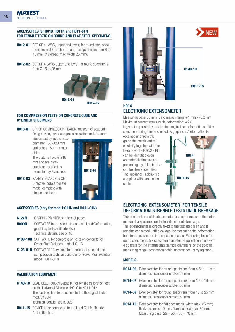
SECTION H | STEEL
ACCESSORIES for H010, H011N and H011-01NFOR TENSILE TESTS ON ROUND AND FLAT STEEL SPECIMENS
H012-01 SET OF 4 JAWS, upper and lower, for round steel speci-mens from Ø 6 to 15 mm, and flat specimens from 6 to 15 mm. thickness (max. width 25 mm).
H012-02 SET OF 4 JAWS upper and lower for round specimens from Ø 15 to 25 mm
FOR COMPRESSION TESTS ON CONCRETE CUBE ANDCYLINDER SPECIMENS
H013-01 UPPER COMPRESSION PLATEN foreseen of seat ball, fixing device, lower compression platen and distance pieces test cylinders max diameter 160x320 mm and cubes 150 mm max side.
The platens have Ø 216 mm and are hard-ened and rectified as requested by Standards.
H013-02 SAFETY GUARDS to CE Directive, polycarbonate made, complete with hinges and lock.
ACCESSORIES (only for mod. H011N and H011-01N)
C127N GRAPHIC PRINTER on thermal paper
H009N SOFTWARE for tensile tests on steel (Load/Deformation, graphics, test certificate etc.).
Technical details: see p. 18
C109-10N SOFTWARE for compression tests on concrete for Cyber-Plus Evolution model H011N
C123-01N SOFTWARE “Servonet” for tensile test on steel and compression tests on concrete for Servo-Plus Evolution model H011-01N
CALIBRATION EQUIPMENT
C140-10 LOAD CELL, 500kN Capacity, for tensile calibration test on the Universal Machines H010 to H011-01N
The load cell has to be connected to the digital tester mod. C138N.
Technical details: see p. 326
H011-15 DEVICE to be connected to the Load Cell for Tensile Calibration test.
C140-10
H011-15
H012-01
H013-01
H012-02
NEW
H014ELECTRONIC EXTENSOMETERMeasuring base 50 mm, Deformation range +1 mm / -0.2 mmMaximum percent measurable deformation: +2%It gives the possibility to take the longitudinal deformations of the specimen during the tensile test. A graph load/deformation is obtained and from this graph the coefficient of elasticity together with the loads RP0.1 - RP0.2 - Rt1 can be identified even on materials that are not presenting a yield point that can be clearly identified. The appliance is delivered complete with connection cables.
ELECTRONIC EXTENSOMETER FOR TENSILEDEFORMATION STRENGTH TESTS UNTIL BREAKAGEThis electronic coaxial extensometer is used to measure the defor-mation of a specimen under tensile test until breakage.The extensometer is directly fixed to the test specimen and it remains connected until breakage, by measuring the deformation both in the elastic and in the plastic phases. Measuring base for round specimens: 5 x specimen diameter. Supplied complete with 4 spacers for the intermediate sample diameters of the specific measuring range, connection cable, accessories, carrying case.
MODELS
H014-06 Extensometer for round specimens from 4.5 to 11 mm diameter. Transducer stroke: 25 mm
H014-07 Extensometer for round specimens from 10 to 19 mm diameter. Transducer stroke: 50 mm
H014-08 Extensometer for round specimens from 18 to 25 mm diameter. Transducer stroke: 50 mm
H014-10 Extensometer for flat specimens, width max. 25 mm; thickness max. 10 mm. Transducer stroke: 50 mm
Measuring base: 25 – 50 – 60 – 70 mm
H014-07
H014
448
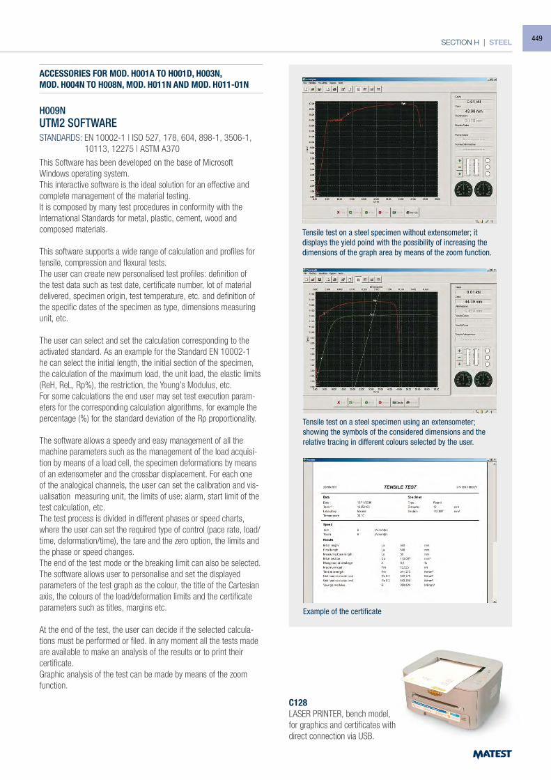
SECTION H | STEEL
ACCESSORIES FOR MOD. H001A TO H001D, H003N,MOD. H004N TO H008N, MOD. H011N AND MOD. H011-01N
H009NUTM2 SOFTWARESTANDARDS: EN 10002-1 | ISO 527, 178, 604, 898-1, 3506-1, 10113, 12275 | ASTM A370
This Software has been developed on the base of Microsoft Windows operating system.This interactive software is the ideal solution for an effective and complete management of the material testing.It is composed by many test procedures in conformity with the International Standards for metal, plastic, cement, wood and composed materials.
This software supports a wide range of calculation and profiles for tensile, compression and flexural tests.The user can create new personalised test profiles: definition of the test data such as test date, certificate number, lot of material delivered, specimen origin, test temperature, etc. and definition of the specific dates of the specimen as type, dimensions measuring unit, etc.
The user can select and set the calculation corresponding to the activated standard. As an example for the Standard EN 10002-1 he can select the initial length, the initial section of the specimen, the calculation of the maximum load, the unit load, the elastic limits (ReH, ReL, Rp%), the restriction, the Young’s Modulus, etc.For some calculations the end user may set test execution param-eters for the corresponding calculation algorithms, for example the percentage (%) for the standard deviation of the Rp proportionality.
The software allows a speedy and easy management of all the machine parameters such as the management of the load acquisi-tion by means of a load cell, the specimen deformations by means of an extensometer and the crossbar displacement. For each one of the analogical channels, the user can set the calibration and vis-ualisation measuring unit, the limits of use: alarm, start limit of the test calculation, etc.The test process is divided in different phases or speed charts, where the user can set the required type of control (pace rate, load/time, deformation/time), the tare and the zero option, the limits and the phase or speed changes.The end of the test mode or the breaking limit can also be selected.The software allows user to personalise and set the displayed parameters of the test graph as the colour, the title of the Cartesian axis, the colours of the load/deformation limits and the certificate parameters such as titles, margins etc.
At the end of the test, the user can decide if the selected calcula-tions must be performed or filed. In any moment all the tests made are available to make an analysis of the results or to print their certificate.Graphic analysis of the test can be made by means of the zoom function.
C128 LASER PRINTER, bench model, for graphics and certificates with direct connection via USB.
Tensile test on a steel specimen without extensometer; it displays the yield poind with the possibility of increasing the dimensions of the graph area by means of the zoom function.
Tensile test on a steel specimen using an extensometer;showing the symbols of the considered dimensions and the relative tracing in different colours selected by the user.
Example of the certificate
449
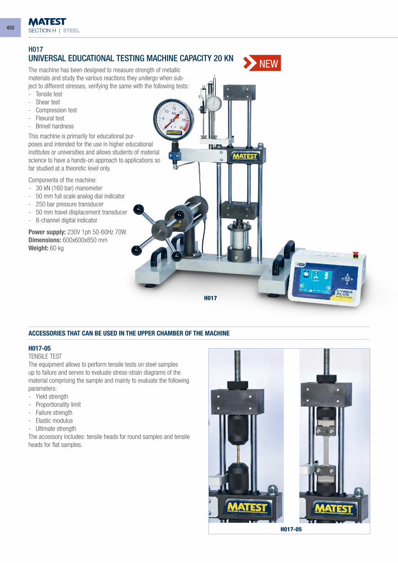
SECTION H | STEEL
H017UNIVERSAL EDUCATIONAL TESTING MACHINE CAPACITY 20 KNThe machine has been designed to measure strength of metallic materials and study the various reactions they undergo when sub-ject to different stresses, verifying the same with the following tests:- Tensile test- Shear test- Compression test- Flexural test- Brinell hardness
This machine is primarily for educational pur-poses and intended for the use in higher educational institutes or universities and allows students of material science to have a hands-on approach to applications so far studied at a theoretic level only.
Components of the machine:- 30 kN (160 bar) manometer- 50 mm full scale analog dial indicator- 250 bar pressure transducer- 50 mm travel displacement transducer- 8-channel digital indicator
Power supply: 230V 1ph 50-60Hz 70WDimensions: 600x600x850 mmWeight: 60 kg
ACCESSORIES THAT CAN BE USED IN THE UPPER CHAMBER OF THE MACHINE
H017-05TENSILE TESTThe equipment allows to perform tensile tests on steel samples up to failure and serves to evaluate stress-strain diagrams of the material comprising the sample and mainly to evaluate the following parameters:- Yield strength- Proportionality limit- Failure strength- Elastic modulus- Ultimate strengthThe accessory includes: tensile heads for round samples and tensile heads for flat samples.
H017
H017-05
NEW
450
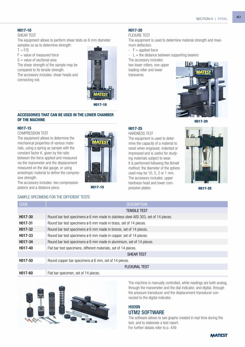
SECTION H | STEEL
ACCESSORIES THAT CAN BE USED IN THE LOWER CHAMBER OF THE MACHINE
H017-15COMPRESSION TESTThe equipment allows to determine the mechanical properties of various mate-rials, using a spring as sample with the constant factor K, given by the ratio between the force applied and measured via the manometer and the displacement measured on the dial gauge, or using anisotropic material to define the compres-sive strength.The accessory includes: two compression platens and a distance piece.
H017-20FLEXURE TESTThe equipment is used to determine material strength and maxi-mum deflection.- F = applied force- L = the distance between supporting bearersThe accessory includes: two lower rollers, one upper loading roller and lower transverse.
H017-25HARDNESS TESTThe equipment is used to deter-mine the capacity of a material to resist when engraved, indented or impressed and is useful for study-ing materials subject to wear.It is performed following the Brinell method: the diameter of the sphere used may be 10, 5, 2 or 1 mm.The accessory includes: upper hardness head and lower com-pression platen.
H017-10SHEAR TESTThe equipment allows to perform shear tests on 6 mm diameter samples so as to determine strength:T = F/SF = value of measured forceS = value of sectional areaThe shear strength of the sample may be compared to its tensile strength.The accessory includes: shear heads and connecting rod.
H017-10
H017-15
H017-20
H017-25
SAMPLE SPECIMENS FOR THE DIFFERENT TESTS
CODE DESCRIPTION
TENSILE TEST
H017-30 Round bar test specimens ø 6 mm made in stainless steel AISI 303, set of 14 pieces.
H017-31 Round bar test specimens ø 6 mm made in brass, set of 14 pieces.
H017-32 Round bar test specimens ø 6 mm made in bronze, set of 14 pieces.
H017-33 Round bar test specimens ø 6 mm made in copper, set of 14 pieces.
H017-34 Round bar test specimens ø 6 mm made in aluminium, set of 14 pieces.
H017-40 Flat bar test specimens, different materials, set of 14 pieces.
SHEAR TEST
H017-50 Round copper bar specimens ø 6 mm, set of 14 pieces.
FLEXURAL TEST
H017-60 Flat bar specimen, set of 14 pieces.
The machine is manually controlled, while readings are both analog, through the manometer and the dial indicator, and digital, through the pressure transducer and the displacement transducer con-nected to the digital indicator.
H009NUTM2 SOFTWAREThe software allows to see graphs created in real time during the test, and to elaborate a test report.For further details refer to p. 449
451
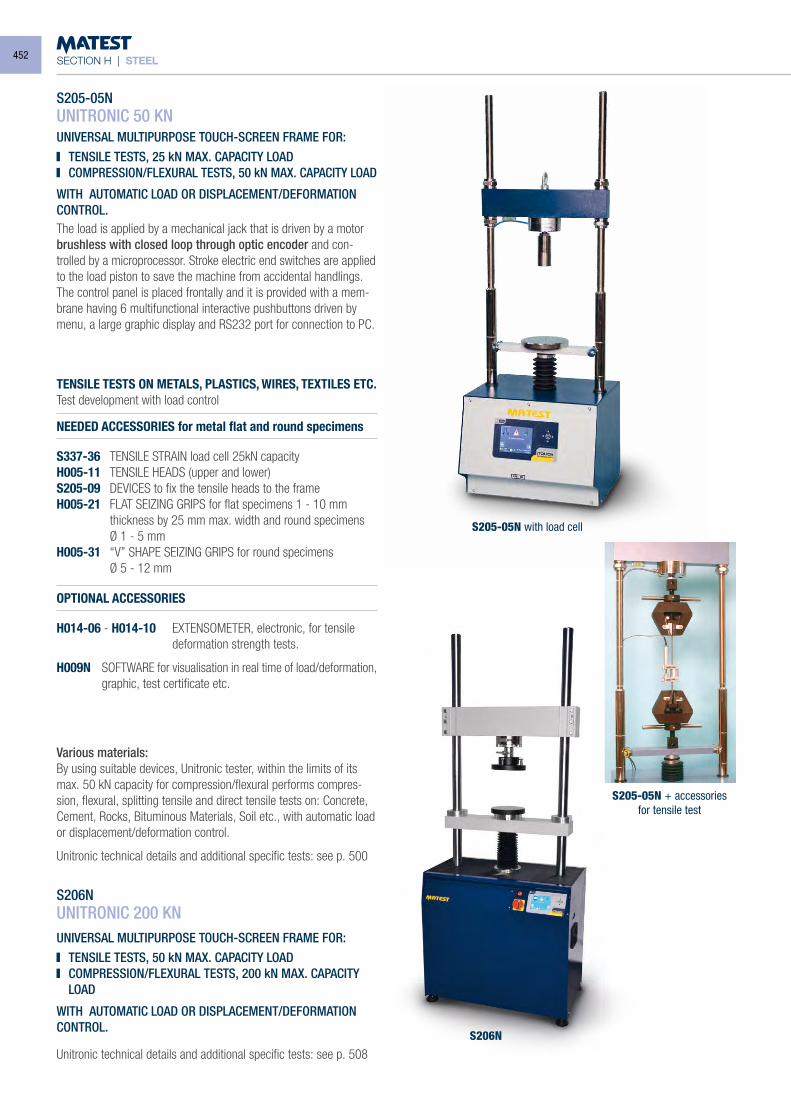
SECTION H | STEEL
S205-05NUNITRONIC 50 KNUNIVERSAL MULTIPURPOSE TOUCH-SCREEN FRAME FOR: TENSILE TESTS, 25 kN MAX. CAPACITY LOAD COMPRESSION/FLEXURAL TESTS, 50 kN MAX. CAPACITY LOAD
The load is applied by a mechanical jack that is driven by a motor brushless with closed loop through optic encoder and con-trolled by a microprocessor. Stroke electric end switches are applied to the load piston to save the machine from accidental handlings. The control panel is placed frontally and it is provided with a mem-brane having 6 multifunctional interactive pushbuttons driven by menu, a large graphic display and RS232 port for connection to PC.
TENSILE TESTS ON METALS, PLASTICS, WIRES, TEXTILES ETC. Test development with load control
NEEDED ACCESSORIES for metal flat and round specimens
S337-36 TENSILE STRAIN load cell 25kN capacity H005-11 TENSILE HEADS (upper and lower)S205-09 DEVICES to fix the tensile heads to the frameH005-21 FLAT SEIZING GRIPS for flat specimens 1 - 10 mm
thickness by 25 mm max. width and round specimens Ø 1 - 5 mm H005-31 “V” SHAPE SEIZING GRIPS for round specimens Ø 5 - 12 mm
OPTIONAL ACCESSORIES
H014-06 - H014-10 EXTENSOMETER, electronic, for tensile deformation strength tests.
H009N SOFTWARE for visualisation in real time of load/deformation, graphic, test certificate etc.
Various materials:By using suitable devices, Unitronic tester, within the limits of its max. 50 kN capacity for compression/flexural performs compres-sion, flexural, splitting tensile and direct tensile tests on: Concrete, Cement, Rocks, Bituminous Materials, Soil etc., with automatic load or displacement/deformation control.
Unitronic technical details and additional specific tests: see p. 500
S206NUNITRONIC 200 KN
UNIVERSAL MULTIPURPOSE TOUCH-SCREEN FRAME FOR: TENSILE TESTS, 50 kN MAX. CAPACITY LOAD COMPRESSION/FLEXURAL TESTS, 200 kN MAX. CAPACITY
LOAD
S205-05N with load cell
S206N
S205-05N + accessoriesfor tensile test
WITH AUTOMATIC LOAD OR DISPLACEMENT/DEFORMATIONCONTROL.
WITH AUTOMATIC LOAD OR DISPLACEMENT/DEFORMATIONCONTROL.
Unitronic technical details and additional specific tests: see p. 508
452
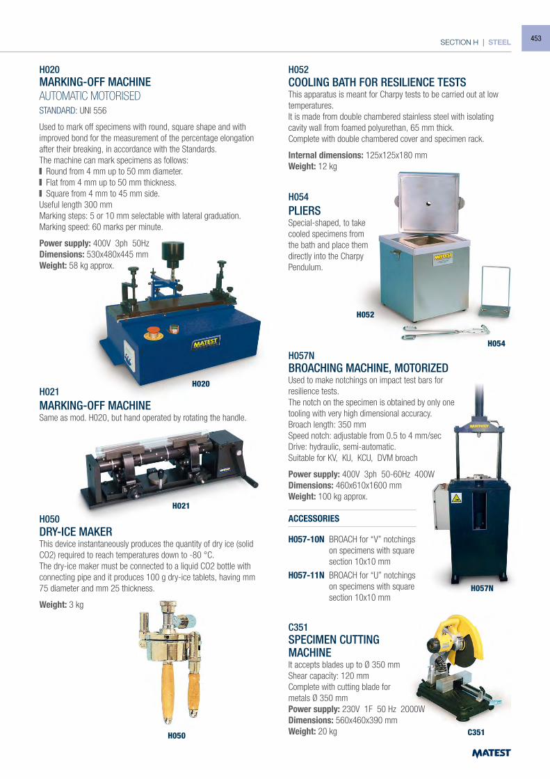
SECTION H | STEEL
H020
H052
H057N
C351
H054
H021
H050
H020MARKING-OFF MACHINEAUTOMATIC MOTORISEDSTANDARD: UNI 556
Used to mark off specimens with round, square shape and with improved bond for the measurement of the percentage elongation after their breaking, in accordance with the Standards.The machine can mark specimens as follows: Round from 4 mm up to 50 mm diameter. Flat from 4 mm up to 50 mm thickness. Square from 4 mm to 45 mm side.
Useful length 300 mmMarking steps: 5 or 10 mm selectable with lateral graduation.Marking speed: 60 marks per minute.
Power supply: 400V 3ph 50HzDimensions: 530x480x445 mmWeight: 58 kg approx.
H021MARKING-OFF MACHINESame as mod. H020, but hand operated by rotating the handle.
H050DRY-ICE MAKERThis device instantaneously produces the quantity of dry ice (solid CO2) required to reach temperatures down to -80 °C.The dry-ice maker must be connected to a liquid CO2 bottle with connecting pipe and it produces 100 g dry-ice tablets, having mm 75 diameter and mm 25 thickness.
Weight: 3 kg
H052COOLING BATH FOR RESILIENCE TESTSThis apparatus is meant for Charpy tests to be carried out at low temperatures.It is made from double chambered stainless steel with isolating cavity wall from foamed polyurethan, 65 mm thick.Complete with double chambered cover and specimen rack.
Internal dimensions: 125x125x180 mmWeight: 12 kg
H054PLIERSSpecial-shaped, to take cooled specimens from the bath and place them directly into the Charpy Pendulum.
H057NBROACHING MACHINE, MOTORIZEDUsed to make notchings on impact test bars for resilience tests.The notch on the specimen is obtained by only one tooling with very high dimensional accuracy.Broach length: 350 mmSpeed notch: adjustable from 0.5 to 4 mm/secDrive: hydraulic, semi-automatic.Suitable for KV, KU, KCU, DVM broach
Power supply: 400V 3ph 50-60Hz 400WDimensions: 460x610x1600 mmWeight: 100 kg approx.
ACCESSORIES
H057-10N BROACH for “V” notchings on specimens with square section 10x10 mm
H057-11N BROACH for “U” notchings on specimens with square section 10x10 mm
C351SPECIMEN CUTTINGMACHINEIt accepts blades up to Ø 350 mmShear capacity: 120 mmComplete with cutting blade formetals Ø 350 mmPower supply: 230V 1F 50 Hz 2000WDimensions: 560x460x390 mmWeight: 20 kg
453
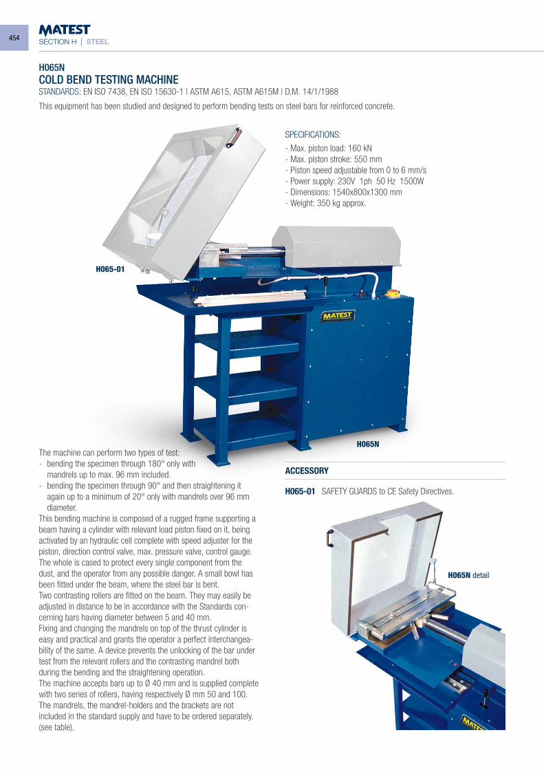
SECTION H | STEEL
H065NCOLD BEND TESTING MACHINESTANDARDS: EN ISO 7438, EN ISO 15630-1 | ASTM A615, ASTM A615M | D.M. 14/1/1988
SPECIFICATIONS:
- Max. piston load: 160 kN- Max. piston stroke: 550 mm- Piston speed adjustable from 0 to 6 mm/s- Power supply: 230V 1ph 50 Hz 1500W- Dimensions: 1540x800x1300 mm- Weight: 350 kg approx.
This equipment has been studied and designed to perform bending tests on steel bars for reinforced concrete.
The machine can perform two types of test:- bending the specimen through 180° only with mandrels up to max. 96 mm included.- bending the specimen through 90° and then straightening it
again up to a minimum of 20° only with mandrels over 96 mm diameter.
This bending machine is composed of a rugged frame supporting a beam having a cylinder with relevant load piston fixed on it, being activated by an hydraulic cell complete with speed adjuster for the piston, direction control valve, max. pressure valve, control gauge.The whole is cased to protect every single component from the dust, and the operator from any possible danger. A small bowl has been fitted under the beam, where the steel bar is bent.Two contrasting rollers are fitted on the beam. They may easily be adjusted in distance to be in accordance with the Standards con-cerning bars having diameter between 5 and 40 mm.Fixing and changing the mandrels on top of the thrust cylinder is easy and practical and grants the operator a perfect interchangea-bility of the same. A device prevents the unlocking of the bar under test from the relevant rollers and the contrasting mandrel both during the bending and the straightening operation.The machine accepts bars up to Ø 40 mm and is supplied complete with two series of rollers, having respectively Ø mm 50 and 100. The mandrels, the mandrel-holders and the brackets are not included in the standard supply and have to be ordered separately. (see table).
ACCESSORY
H065-01 SAFETY GUARDS to CE Safety Directives.
H065-01
H065N
H065N detail
454
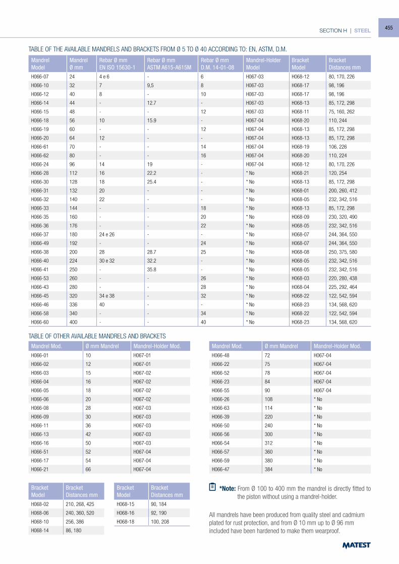
SECTION H | STEEL
MandrelModel
MandrelØ mm
Rebar Ø mmEN ISO 15630-1
Rebar Ø mmASTM A615-A615M
Rebar Ø mmD.M. 14-01-08
Mandrel-HolderModel
BracketModel
BracketDistances mm
H066-07 24 4 e 6 - 6 H067-03 H068-12 80, 170, 226
H066-10 32 7 9,5 8 H067-03 H068-17 98, 196
H066-12 40 8 - 10 H067-03 H068-17 98, 196
H066-14 44 - 12.7 - H067-03 H068-13 85, 172, 298
H066-15 48 - - 12 H067-03 H068-11 75, 160, 262
H066-18 56 10 15.9 - H067-04 H068-20 110, 244
H066-19 60 - - 12 H067-04 H068-13 85, 172, 298
H066-20 64 12 - - H067-04 H068-13 85, 172, 298
H066-61 70 - - 14 H067-04 H068-19 106, 226
H066-62 80 - - 16 H067-04 H068-20 110, 224
H066-24 96 14 19 - H067-04 H068-12 80, 170, 226
H066-28 112 16 22.2 - * No H068-21 120, 254
H066-30 128 18 25.4 - * No H068-13 85, 172, 298
H066-31 132 20 - - * No H068-01 200, 260, 412
H066-32 140 22 - - * No H068-05 232, 342, 516
H066-33 144 - - 18 * No H068-13 85, 172, 298
H066-35 160 - - 20 * No H068-09 230, 320, 490
H066-36 176 - - 22 * No H068-05 232, 342, 516
H066-37 180 24 e 26 - - * No H068-07 244, 364, 550
H066-49 192 - - 24 * No H068-07 244, 364, 550
H066-38 200 28 28.7 25 * No H068-08 250, 375, 580
H066-40 224 30 e 32 32.2 - * No H068-05 232, 342, 516
H066-41 250 - 35.8 - * No H068-05 232, 342, 516
H066-53 260 - - 26 * No H068-03 220, 280, 438
H066-43 280 - - 28 * No H068-04 225, 292, 464
H066-45 320 34 e 38 - 32 * No H068-22 122, 542, 594
H066-46 336 40 - - * No H068-23 134, 568, 620
H066-58 340 - - 34 * No H068-22 122, 542, 594
H066-60 400 - - 40 * No H068-23 134, 568, 620
Mandrel Mod. Ø mm Mandrel Mandrel-Holder Mod.H066-01 10 H067-01
H066-02 12 H067-01
H066-03 15 H067-02
H066-04 16 H067-02
H066-05 18 H067-02
H066-06 20 H067-02
H066-08 28 H067-03
H066-09 30 H067-03
H066-11 36 H067-03
H066-13 42 H067-03
H066-16 50 H067-03
H066-51 52 H067-04
H066-17 54 H067-04
H066-21 66 H067-04
Mandrel Mod. Ø mm Mandrel Mandrel-Holder Mod.H066-48 72 H067-04
H066-22 75 H067-04
H066-52 78 H067-04
H066-23 84 H067-04
H066-55 90 H067-04
H066-26 108 * No
H066-63 114 * No
H066-39 220 * No
H066-50 240 * No
H066-56 300 * No
H066-54 312 * No
H066-57 360 * No
H066-59 380 * No
H066-47 384 * No
BracketModel
BracketDistances mm
H068-02 210, 268, 425
H068-06 240, 360, 520
H068-10 256, 386
H068-14 86, 180
BracketModel
BracketDistances mm
H068-15 90, 184
H068-16 92, 190
H068-18 100, 208
TABLE OF THE AVAILABLE MANDRELS AND BRACKETS FROM Ø 5 TO Ø 40 ACCORDING TO: EN, ASTM, D.M.
TABLE OF OTHER AVAILABLE MANDRELS AND BRACKETS
*Note: From Ø 100 to 400 mm the mandrel is directly fitted to the piston without using a mandrel-holder.
All mandrels have been produced from quality steel and cadmium plated for rust protection, and from Ø 10 mm up to Ø 96 mm included have been hardened to make them wearproof.
455
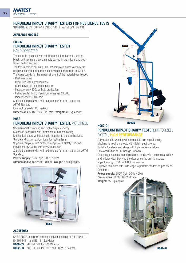
SECTION H | STEEL
PENDULUM IMPACT CHARPY TESTERS FOR RESILIENCE TESTSSTANDARDS: EN 10045-1 | EN ISO 148-1 | ASTM E23 | BS 131
AVAILABLE MODELS
H060NPENDULUM IMPACT CHARPY TESTERHAND OPERATEDThe tester is equipped with a falling pendulum hammer, able to break, with a single blow, a sample carved in the middle and posi-tioned on two supports.The test is carried out on a CHARPY sample in order to check the energy absorbed during the impact, which is measured in JOULE.The value stands for the impact strenght of the material (resilience).- Cast iron frame- Pendulum with hardened knife- Brake device to stop the pendulum- Impact energy 300J with 2J graduation- Falling angle: 140°, Pendulum mass kg. 21.300- Impact speed: 5.187 m/sSupplied complete with knife-edge to perform the test as perASTM StandardIt cannot be sold in CE marketsDimensions: 500x1000x1820 mm Weight: 400 kg approx.
H062PENDULUM IMPACT CHARPY TESTER, MOTORIZEDSemi-automatic working and high energy capacity.Motorized pendulum with immediate arm repositioning.Mechanical safety with automatic insertion to the arm hooking.Simple and fast utilization, ideal for routine tests.Supplied complete with protection cage to CE Safety Directive.Impact energy: 300J with 0.25J resolution.Supplied complete with knife-edge to perform the test as per ASTM Standard.Power supply: 230V 1ph 50Hz 180WDimensions: 800x578x1400 mm Weight: 450 kg approx.
ACCESSORY
KNIFE-EDGE to perform resilience tests according to EN 10045-1, EN ISO 148-1 and BS 131 StandardsH060-03 KNIFE-EDGE for H060N tester.H062-03 KNIFE-EDGE for H062 and H062-01 testers.
H062-01PENDULUM IMPACT CHARPY TESTER, MOTORIZED, DIGITAL, HIGH PERFORMANCEFully automatic working with immediate arm repositioning.Machine for resilience tests with high impact energy.Suitable for steels and alloys with high resilience values.Data acquisition to PC through Software.Safety cage aluminium and plexiglass made, with mechanical safety and microswitch blocking the door when the arm is inserted.Impact energy: 500J with 0.1J resolution.Supplied complete with knife-edge to perform the test as per ASTM Standard.Power supply: 380V 3ph 50Hz 400WDimensions: 2200x800x2300 mmWeight: 750 kg approx.
H060N
H062-01
H062
456
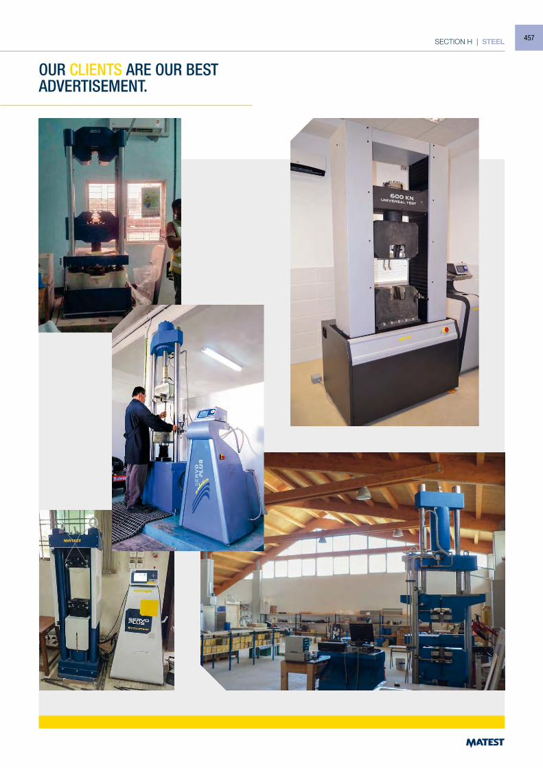
SECTION H | STEEL
OUR CLIENTS ARE OUR BEST ADVERTISEMENT.
457
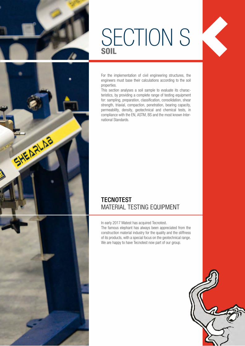
SECTION SSOIL
For the implementation of civil engineering structures, the engineers must base their calculations according to the soil properties.This section analyses a soil sample to evaluate its charac-teristics, by providing a complete range of testing equipment for: sampling, preparation, classification, consolidation, shear strength, triaxial, compaction, penetration, bearing capacity, permeability, density, geotechnical and chemical tests, in compliance with the EN, ASTM, BS and the most known Inter-national Standards.
In early 2017 Matest has acquired Tecnotest. The famous elephant has always been appreciated from the construction material industry for the quality and the stiffness of its products, with a special focus on the geotechnical range.We are happy to have Tecnotest now part of our group.
TECNOTESTMATERIAL TESTING EQUIPMENT
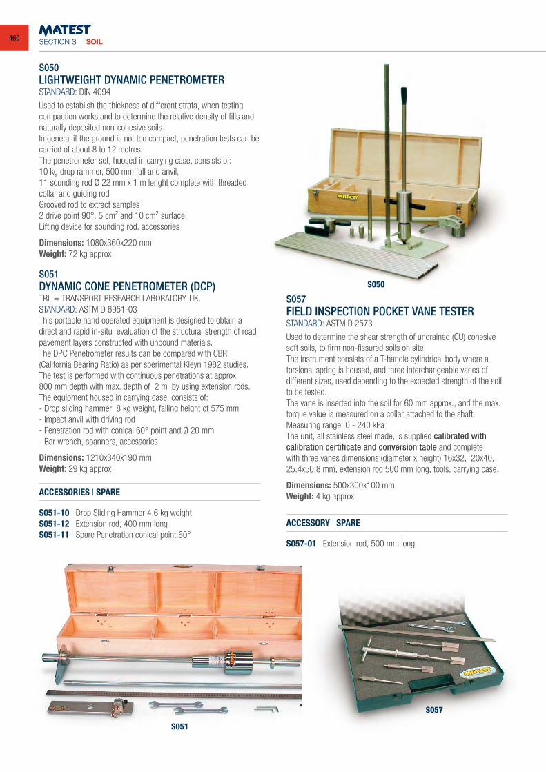
SECTION S | SOIL
S051
S050LIGHTWEIGHT DYNAMIC PENETROMETERSTANDARD: DIN 4094
Used to establish the thickness of different strata, when testing compaction works and to determine the relative density of fills and naturally deposited non-cohesive soils.In general if the ground is not too compact, penetration tests can be carried of about 8 to 12 metres.The penetrometer set, huosed in carrying case, consists of:10 kg drop rammer, 500 mm fall and anvil,11 sounding rod Ø 22 mm x 1 m lenght complete with threaded collar and guiding rodGrooved rod to extract samples2 drive point 90°, 5 cm² and 10 cm² surfaceLifting device for sounding rod, accessories
Dimensions: 1080x360x220 mmWeight: 72 kg approx
S051DYNAMIC CONE PENETROMETER (DCP)TRL = TRANSPORT RESEARCH LABORATORY, UK.STANDARD: ASTM D 6951-03This portable hand operated equipment is designed to obtain a direct and rapid in-situ evaluation of the structural strength of road pavement layers constructed with unbound materials.The DPC Penetrometer results can be compared with CBR(California Bearing Ratio) as per sperimental Kleyn 1982 studies.The test is performed with continuous penetrations at approx.800 mm depth with max. depth of 2 m by using extension rods.The equipment housed in carrying case, consists of:- Drop sliding hammer 8 kg weight, falling height of 575 mm- Impact anvil with driving rod- Penetration rod with conical 60° point and Ø 20 mm- Bar wrench, spanners, accessories.
Dimensions: 1210x340x190 mmWeight: 29 kg approx
ACCESSORIES | SPARE
S051-10 Drop Sliding Hammer 4.6 kg weight.S051-12 Extension rod, 400 mm longS051-11 Spare Penetration conical point 60°
S057FIELD INSPECTION POCKET VANE TESTERSTANDARD: ASTM D 2573
Used to determine the shear strength of undrained (CU) cohesive soft soils, to firm non-fissured soils on site.The instrument consists of a T-handle cylindrical body where a torsional spring is housed, and three interchangeable vanes of different sizes, used depending to the expected strength of the soil to be tested.The vane is inserted into the soil for 60 mm approx., and the max. torque value is measured on a collar attached to the shaft.Measuring range: 0 - 240 kPaThe unit, all stainless steel made, is supplied calibrated with calibration certificate and conversion table and complete with three vanes dimensions (diameter x height) 16x32, 20x40, 25.4x50.8 mm, extension rod 500 mm long, tools, carrying case.
Dimensions: 500x300x100 mmWeight: 4 kg approx.
ACCESSORY | SPARE
S057-01 Extension rod, 500 mm long
S057
S050
460

SECTION S | SOIL
S052KIT SOIL PROSPECTING KITSTANDARDS: ASTM D420, D1452 | AASHTO T86
This equipment, manufactured by Matest, comprises different augers, sampler and tools for soil investigations; the whole housed in a wooden carrying case.
The kit consists of: S092-01 Auger head Ø 80 mm S093-01 Auger head Ø 100 mm S094-01 Auger head Ø 150 mm S052-01 Dutch soil auger head, Edelman type, Ø 150 mm S052-02 Gravel auger head Ø 50 mm S092ASTA Extension rod 1 m long with “T” handle S095 n° 5 extension rods, 1 m long S053 Soil sampler Ø 38 mm complete with stainless steel
sample tube Ø 38x230 mm, jarring link, “T” handle. S053-04 n° 5 Stainless steel sample tubes Ø 38x230mm S052-03 Plastic cap ends for sample tubes Ø 38x230mm (12 pieces) S054 Hand extruder for sample tube Ø 38x230 mm S052-04 Stillson wrenches (2 pieces) S052-05 Wooden carrying case.
Dimensions: 1140x490x360 mmTotal weight: 50 kg approx.
S051-01MACKINTOSH PROSPECTING KITThis equipment, manufactured by Matest, is particularly useful for initial site investigation work in remote areas. The kit is capable boring to a depth 10 - 12 mtrs depending on ground conditions. The use of specially designed extension rod couplers reduces bore-hole friction to a minimum, permitting easy operation to considera-ble depth.Equipment consists of:- 12 boring rods 1 mtr long with 12 couplers- 2 pipe wrench and 1 tap wrench- Core tube adaptor and clay core tube- Driving head and clearing rod- Long and short driving point- Auger tool and standard core tube- Lifting/driving tool and hammer- Die nut and hand tapAll equipment supplied in a strong wooden box
Dimensions: 1050x260x120 mmWeight: 35 kg approx.
S052 KIT
S051-01
461
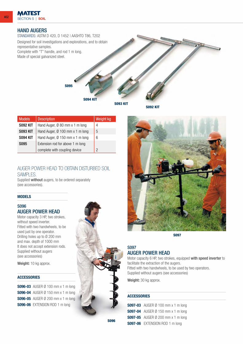
SECTION S | SOIL
HAND AUGERSSTANDARDS: ASTM D 420, D 1452 | AASHTO T86, T202
Designed for soil investigations and explorations, and to obtain representative samples.Complete with “T” handle, and rod 1 m long.Made of special galvanized steel.
Models Description Weight kg
S092 KIT Hand Auger, Ø 80 mm x 1 m long 4
S093 KIT Hand Auger, Ø 100 mm x 1 m long 5
S094 KIT Hand Auger, Ø 150 mm x 1 m long 6
S095 Extension rod for above 1 m long
complete with coupling device 2
AUGER POWER HEAD TO OBTAIN DISTURBED SOIL SAMPLES.Supplied without augers, to be ordered separately(see accessories).
S097AUGER POWER HEADMotor capacity 6 HP, two strokes, equipped with speed inverter to facilitate the extraction of the augers.Fitted with two handwheels, to be used by two operators.Supplied without augers (see accessories)
Weight: 30 kg approx.
ACCESSORIES
S097-03 AUGER Ø 100 mm x 1 m long
S097-04 AUGER Ø 150 mm x 1 m long
S097-05 AUGER Ø 200 mm x 1 m long
S097-06 EXTENSION ROD 1 m long
S095
S094 KITS093 KIT
S092 KIT
S097
S096
MODELS
S096AUGER POWER HEADMotor capacity 3 HP, two strokes, without speed inverter.Fitted with two handwheels, to be used just by one operator.Drilling holes up to Ø 200 mm and max. depth of 1000 mmIt does not accept extension rods.Supplied without augers(see accessories)
Weight: 10 kg approx.
ACCESSORIES
S096-03 AUGER Ø 100 mm x 1 m long
S096-04 AUGER Ø 150 mm x 1 m long
S096-05 AUGER Ø 200 mm x 1 m long
S096-06 EXTENSION ROD 1 m long
462
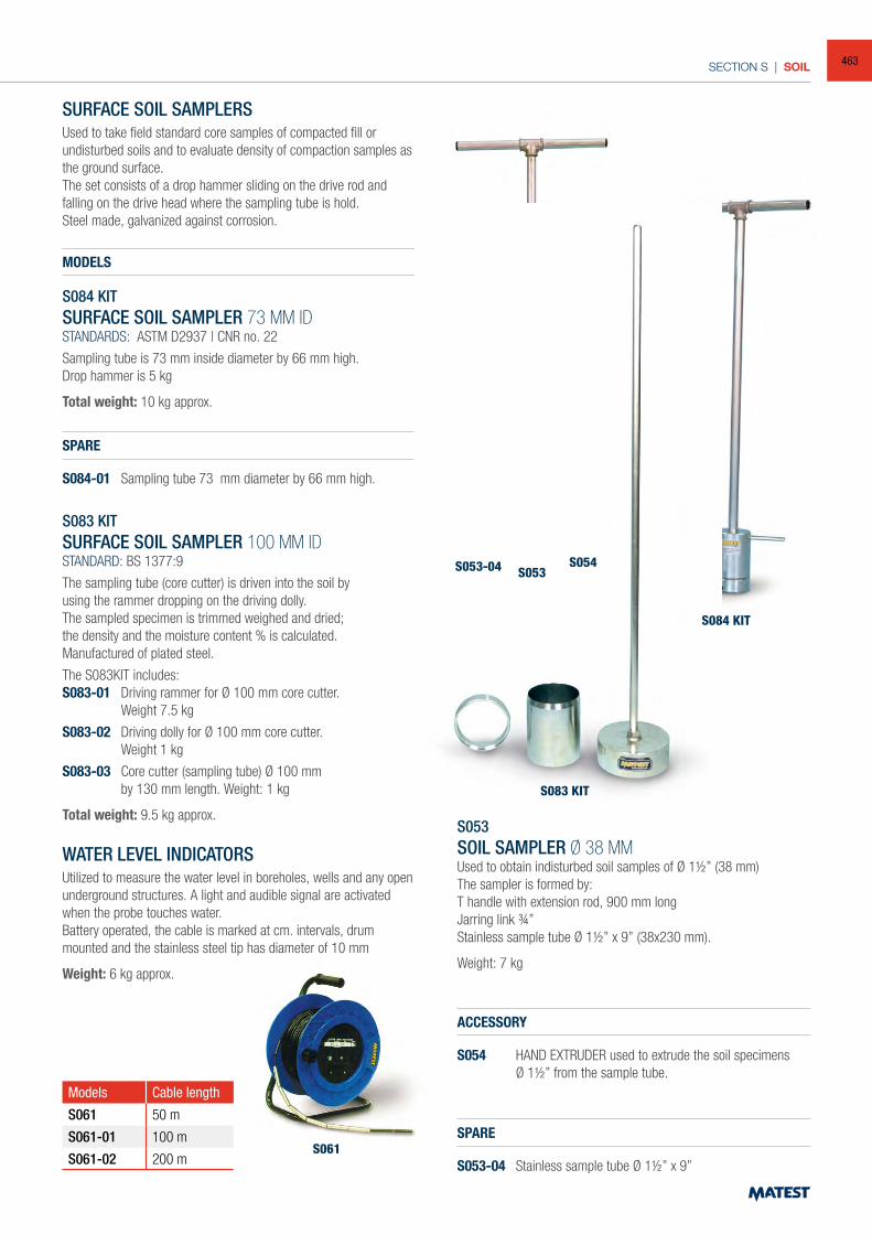
SECTION S | SOIL
SURFACE SOIL SAMPLERSUsed to take field standard core samples of compacted fill or undisturbed soils and to evaluate density of compaction samples as the ground surface.The set consists of a drop hammer sliding on the drive rod and falling on the drive head where the sampling tube is hold.Steel made, galvanized against corrosion.
MODELS
S084 KITSURFACE SOIL SAMPLER 73 MM IDSTANDARDS: ASTM D2937 | CNR no. 22
Sampling tube is 73 mm inside diameter by 66 mm high.Drop hammer is 5 kg
Total weight: 10 kg approx.
SPARE
S084-01 Sampling tube 73 mm diameter by 66 mm high.
S083 KITSURFACE SOIL SAMPLER 100 MM IDSTANDARD: BS 1377:9
The sampling tube (core cutter) is driven into the soil byusing the rammer dropping on the driving dolly.The sampled specimen is trimmed weighed and dried;the density and the moisture content % is calculated.Manufactured of plated steel.
The S083KIT includes:S083-01 Driving rammer for Ø 100 mm core cutter. Weight 7.5 kg
S083-02 Driving dolly for Ø 100 mm core cutter. Weight 1 kg
S083-03 Core cutter (sampling tube) Ø 100 mm by 130 mm length. Weight: 1 kg
Total weight: 9.5 kg approx.
WATER LEVEL INDICATORSUtilized to measure the water level in boreholes, wells and any open underground structures. A light and audible signal are activated when the probe touches water.Battery operated, the cable is marked at cm. intervals, drum mounted and the stainless steel tip has diameter of 10 mm
Weight: 6 kg approx.
Models Cable length
S061 50 m
S061-01 100 m
S061-02 200 mS061
S053SOIL SAMPLER Ø 38 MMUsed to obtain indisturbed soil samples of Ø 11/2” (38 mm)The sampler is formed by:T handle with extension rod, 900 mm longJarring link 3/4”Stainless sample tube Ø 11/2” x 9” (38x230 mm).
Weight: 7 kg
ACCESSORY
S054 HAND EXTRUDER used to extrude the soil specimens Ø 11/2” from the sample tube.
SPARE
S053-04 Stainless sample tube Ø 11/2” x 9”
S053S053-04
S084 KIT
S083 KIT
S054
463
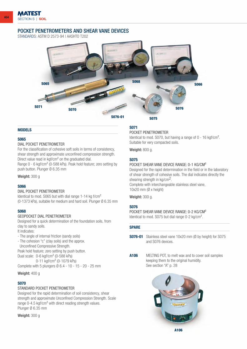
SECTION S | SOIL
MODELS
S065DIAL POCKET PENETROMETERFor the classification of cohesive soft soils in terms of consistency, shear strength and approximate unconfined compression strength.Direct value read in kgf/cm² on the graduated dial.Range 0 - 6 kgf/cm² (0-588 kPa). Peak hold feature; zero setting by push button. Plunger Ø 6.35 mm
Weight: 300 g
S066DIAL POCKET PENETROMETERIdentical to mod. S065 but with dial range 1-14 kg f/cm²(0-1373 kPa), suitable for medium and hard soil. Plunger Ø 6.35 mm
S068GEOPOCKET DIAL PENETROMETERDesigned for a quick determination of the foundation soils, from clay to sandy soils.It indicates:- The angle of internal friction (sandy soils)- The cohesion “c” (clay soils) and the approx. Unconfined Compressive Strength.Peak hold feature; zero setting by push button.Dual scale: 0-6 kgf/cm² (0-588 kPa) 0-11 kgf/cm² (0-1079 kPa)Complete with 5 plungers Ø 6.4 - 10 - 15 - 20 - 25 mm
Weight: 400 g
S070STANDARD POCKET PENETROMETERDesigned for the rapid determination of soil consistency, shear strength and approximate Unconfined Compression Strength. Scale range 0-4.5 kgf/cm² with direct reading strength values.Plunger Ø 6.35 mm
Weight: 300 g
S071POCKET PENETROMETERIdentical to mod. S070, but having a range of 0 - 16 kgf/cm². Suitable for very compacted soils.
Weight: 800 g.
S075POCKET SHEAR VANE DEVICE RANGE: 0-1 KG/CM²Designed for the rapid determination in the field or in the laboratory of shear strength of cohesive soils. The dial indicates directly the shearing strength in kg/cm2.Complete with interchangeable stainless steel vane,10x20 mm (Ø x height)
Weight: 300 g.
S076POCKET SHEAR VANE DEVICE RANGE: 0-2 KG/CM²Identical to mod. S075 but dial range 0-2 kg/cm².
SPARE
S076-01 Stainless steel vane 10x20 mm (Ø by height) for S075 and S076 devices.
A106 MELTING POT, to melt wax and to cover soil samples keeping them to the original humidity.
See section “A” p. 28
A106
S065
S071S070
S075
S076
S066S068
S076-01
POCKET PENETROMETERS AND SHEAR VANE DEVICESSTANDARDS: ASTM D 2573-94 | AASHTO T202
464
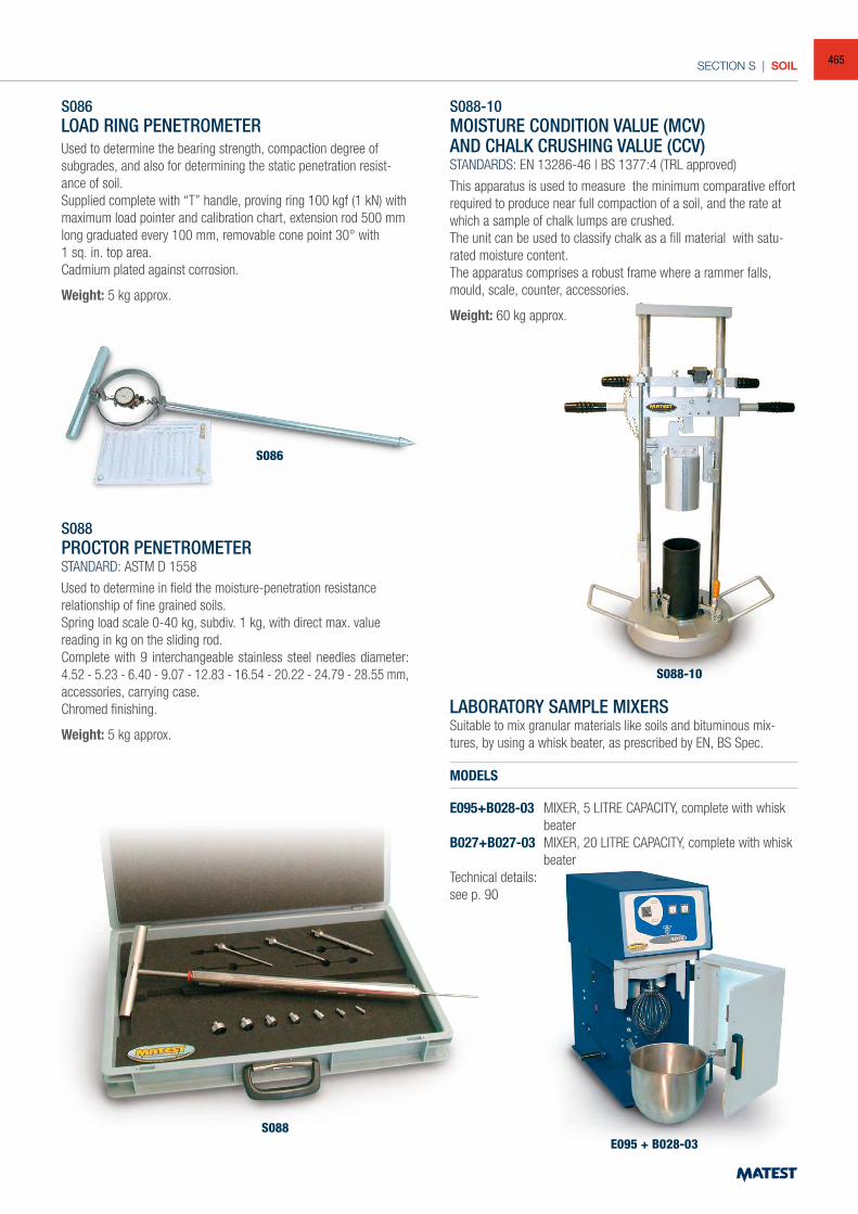
SECTION S | SOIL
LABORATORY SAMPLE MIXERSSuitable to mix granular materials like soils and bituminous mix-tures, by using a whisk beater, as prescribed by EN, BS Spec.
MODELS
E095+B028-03 MIXER, 5 LITRE CAPACITY, complete with whisk beater
B027+B027-03 MIXER, 20 LITRE CAPACITY, complete with whisk beater
Technical details:see p. 90
E095 + B028-03
S086LOAD RING PENETROMETERUsed to determine the bearing strength, compaction degree of subgrades, and also for determining the static penetration resist-ance of soil.Supplied complete with “T” handle, proving ring 100 kgf (1 kN) with maximum load pointer and calibration chart, extension rod 500 mm long graduated every 100 mm, removable cone point 30° with1 sq. in. top area.Cadmium plated against corrosion.
Weight: 5 kg approx.
S088PROCTOR PENETROMETERSTANDARD: ASTM D 1558
Used to determine in field the moisture-penetration resistance relationship of fine grained soils.Spring load scale 0-40 kg, subdiv. 1 kg, with direct max. value reading in kg on the sliding rod.Complete with 9 interchangeable stainless steel needles diameter: 4.52 - 5.23 - 6.40 - 9.07 - 12.83 - 16.54 - 20.22 - 24.79 - 28.55 mm, accessories, carrying case.Chromed finishing.
Weight: 5 kg approx.
S088-10MOISTURE CONDITION VALUE (MCV)AND CHALK CRUSHING VALUE (CCV)STANDARDS: EN 13286-46 | BS 1377:4 (TRL approved)
This apparatus is used to measure the minimum comparative effort required to produce near full compaction of a soil, and the rate at which a sample of chalk lumps are crushed.The unit can be used to classify chalk as a fill material with satu-rated moisture content.The apparatus comprises a robust frame where a rammer falls, mould, scale, counter, accessories.
Weight: 60 kg approx.
S086
S088
S088-10
465
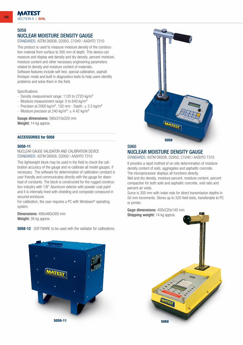
SECTION S | SOIL
S058NUCLEAR MOISTURE DENSITY GAUGESTANDARDS: ASTM D6938, D2950, C1040 | AASHTO T310
This product is used to measure moisture density of the construc-tion material from surface to 300 mm of depth. This device can measure and display wet density and dry density, percent moisture, moisture content and other necessary engineering parameters related to density and moisture content of materials. Software features include self-test, special calibration, asphalt thinlayer mode and built in diagnostics tests to help users identify problems and solve them in the field.
Specifications: - Density measurement range: 1120 to 2720 kg/m³- Moisture measurement range: 0 to 640 kg/m³- Precision at 2000 kg/m³, 150 mm - Depth: ± 3.5 kg/m³ - Moisture precision at 240 kg/m³: ± 4.42 kg/m³
Gauge dimensions: 580x310x220 mmWeight: 14 kg approx.
ACCESSORIES for S058
S058-11NUCLEAR GAUGE VALIDATOR AND CALIBRATION DEVICESTANDARDS: ASTM D6938, D2950 | AASHTO T310
This lightweight block may be used in the field to check the cali-bration accuracy of the gauge and re-calibrate all model gauges, if necessary. The software for determination of calibration constant is user friendly and communicates directly with the gauge for down-load of constants. The block is constructed for the rugged construc-tion industry with 1/8” Aluminum exterior with powder coat paint and it is internally lined with shielding and composite compound in secured enclosure. For calibration, the user requires a PC with Windows® operating system.
Dimensions: 480x460x300 mmWeight: 38 kg approx.
S058-12 SOFTWARE to be used with the validator for calibrations.
S060NUCLEAR MOISTURE DENSITY GAUGESTANDARDS: ASTM D6938, D2950, C1040 | AASHTO T310
It provides a rapid method of on-site determination of moisture density content of soils, aggregates and asphaltic concrete.The microprocessor displays all functions directly.Wet and dry density, moisture percent, moisture content, percent compaction for both soils and asphaltic concrete, void ratio and percent air voids.Surce is 300 mm with index rods for direct transmission depths in 50 mm increments. Stores up to 320 field tests, transferable to PC or printer.
Gage dimensions: 400x220x140 mmShipping weight: 14 kg approx.
S058
S058-11 S060
466
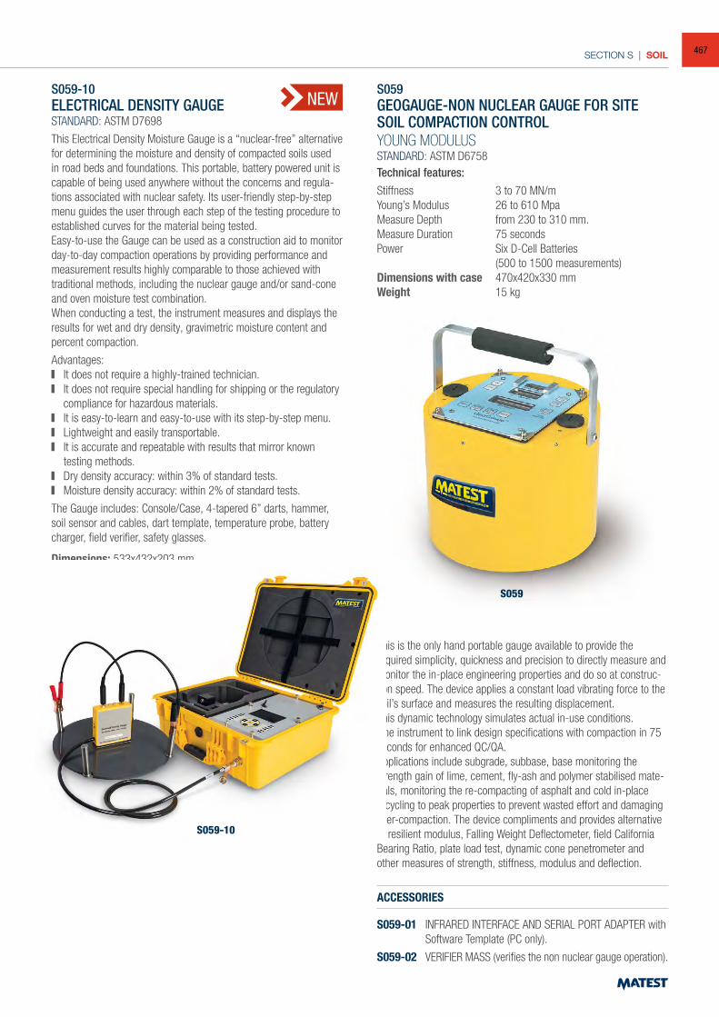
SECTION S | SOIL
S059
S059-10ELECTRICAL DENSITY GAUGESTANDARD: ASTM D7698
This Electrical Density Moisture Gauge is a “nuclear-free” alternative for determining the moisture and density of compacted soils used in road beds and foundations. This portable, battery powered unit is capable of being used anywhere without the concerns and regula-tions associated with nuclear safety. Its user-friendly step-by-step menu guides the user through each step of the testing procedure to established curves for the material being tested.Easy-to-use the Gauge can be used as a construction aid to monitor day-to-day compaction operations by providing performance and measurement results highly comparable to those achieved with traditional methods, including the nuclear gauge and/or sand-cone and oven moisture test combination.When conducting a test, the instrument measures and displays the results for wet and dry density, gravimetric moisture content and percent compaction.
Advantages: It does not require a highly-trained technician. It does not require special handling for shipping or the regulatory
compliance for hazardous materials. It is easy-to-learn and easy-to-use with its step-by-step menu. Lightweight and easily transportable. It is accurate and repeatable with results that mirror known
testing methods. Dry density accuracy: within 3% of standard tests. Moisture density accuracy: within 2% of standard tests.
The Gauge includes: Console/Case, 4-tapered 6” darts, hammer, soil sensor and cables, dart template, temperature probe, battery charger, field verifier, safety glasses.
Dimensions: 533x432x203 mmShipping Weight: 16 kg approx.
S059GEOGAUGE-NON NUCLEAR GAUGE FOR SITE SOIL COMPACTION CONTROLYOUNG MODULUSSTANDARD: ASTM D6758Technical features:Stiffness 3 to 70 MN/mYoung’s Modulus 26 to 610 Mpa Measure Depth from 230 to 310 mm.Measure Duration 75 secondsPower Six D-Cell Batteries (500 to 1500 measurements)Dimensions with case 470x420x330 mmWeight 15 kg
This is the only hand portable gauge available to provide the required simplicity, quickness and precision to directly measure and monitor the in-place engineering properties and do so at construc-tion speed. The device applies a constant load vibrating force to the soil’s surface and measures the resulting displacement.This dynamic technology simulates actual in-use conditions.One instrument to link design specifications with compaction in 75 seconds for enhanced QC/QA. Applications include subgrade, subbase, base monitoring the strength gain of lime, cement, fly-ash and polymer stabilised mate-rials, monitoring the re-compacting of asphalt and cold in-place recycling to peak properties to prevent wasted effort and damaging over-compaction. The device compliments and provides alternative to resilient modulus, Falling Weight Deflectometer, field California Bearing Ratio, plate load test, dynamic cone penetrometer and other measures of strength, stiffness, modulus and deflection.
ACCESSORIES
S059-01 INFRARED INTERFACE AND SERIAL PORT ADAPTER with Software Template (PC only).
S059-02 VERIFIER MASS (verifies the non nuclear gauge operation).
S059-10
NEW
467
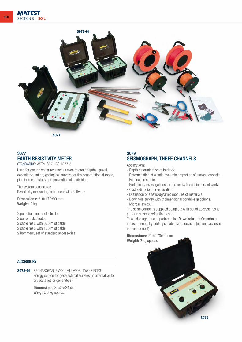
SECTION S | SOIL
S077EARTH RESISTIVITY METERSTANDARDS: ASTM G57 | BS 1377:3
Used for ground water researches even to great depths, gravel deposit evaluation, geological surveys for the construction of roads, pipelines etc., study and prevention of landslides.
The system consists of:Resisitivity measuring instrument with Software
Dimensions: 210x170x90 mmWeight: 2 kg
2 potential copper electrodes2 current electrodes2 cable reels with 300 m of cable2 cable reels with 100 m of cable2 hammers, set of standard accessories
ACCESSORY
S078-01 RECHARGEABLE ACCUMULATOR, TWO PIECES Energy source for geoelectrical surveys (in alternative to
dry batteries or generators).
Dimensions: 35x25x24 cm Weight: 6 kg approx.
S079SEISMOGRAPH, THREE CHANNELSApplications:- Depth determination of bedrock.- Determination of elastic-dynamic properties of surface deposits.- Foundation studies.- Preliminary investigations for the realization of important works.- Cost estimation for excavation.- Evaluation of elastic-dynamic modules of materials.- Downhole survey with tridimensional borehole geophone.- Microseismics.The seismograph is supplied complete with set of accessories to perform seismic refraction tests.This seismograph can perform also Downhole and Crosshole measurements by adding suitable kit of devices (optional accesso-ries on request).
Dimensions: 210x170x90 mmWeight: 2 kg approx.
S077
S079
S078-01
468
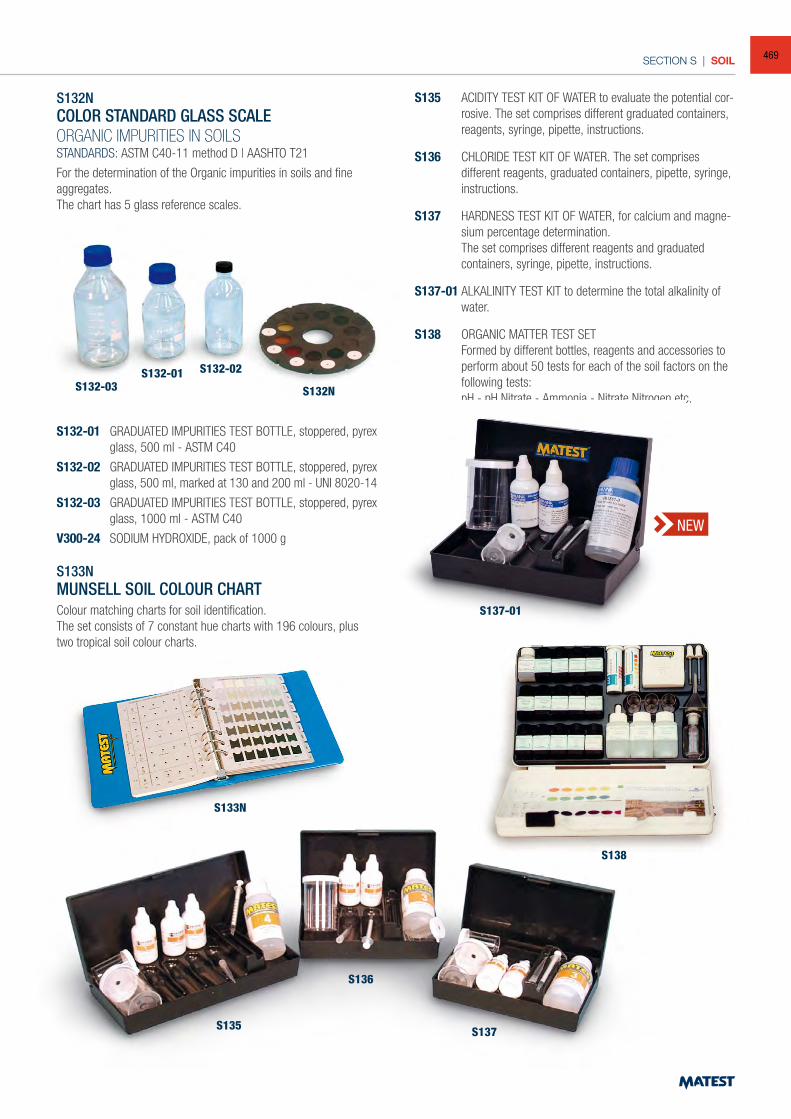
SECTION S | SOIL
S132-03S132-01 S132-02
S132N
S133N
S135
S136
S137
S132NCOLOR STANDARD GLASS SCALEORGANIC IMPURITIES IN SOILSSTANDARDS: ASTM C40-11 method D | AASHTO T21
For the determination of the Organic impurities in soils and fine aggregates.The chart has 5 glass reference scales.
S132-01 GRADUATED IMPURITIES TEST BOTTLE, stoppered, pyrex glass, 500 ml - ASTM C40
S132-02 GRADUATED IMPURITIES TEST BOTTLE, stoppered, pyrex glass, 500 ml, marked at 130 and 200 ml - UNI 8020-14
S132-03 GRADUATED IMPURITIES TEST BOTTLE, stoppered, pyrex glass, 1000 ml - ASTM C40
V300-24 SODIUM HYDROXIDE, pack of 1000 g
S133NMUNSELL SOIL COLOUR CHARTColour matching charts for soil identification.The set consists of 7 constant hue charts with 196 colours, plus two tropical soil colour charts.
S135 ACIDITY TEST KIT OF WATER to evaluate the potential cor-rosive. The set comprises different graduated containers, reagents, syringe, pipette, instructions.
S136 CHLORIDE TEST KIT OF WATER. The set comprises different reagents, graduated containers, pipette, syringe, instructions.
S137 HARDNESS TEST KIT OF WATER, for calcium and magne-sium percentage determination.
The set comprises different reagents and graduated containers, syringe, pipette, instructions.
S137-01 ALKALINITY TEST KIT to determine the total alkalinity of water.
S138 ORGANIC MATTER TEST SET Formed by different bottles, reagents and accessories to
perform about 50 tests for each of the soil factors on the following tests:
pH - pH Nitrate - Ammonia - Nitrate Nitrogen etc.
S138
S137-01
NEW
469
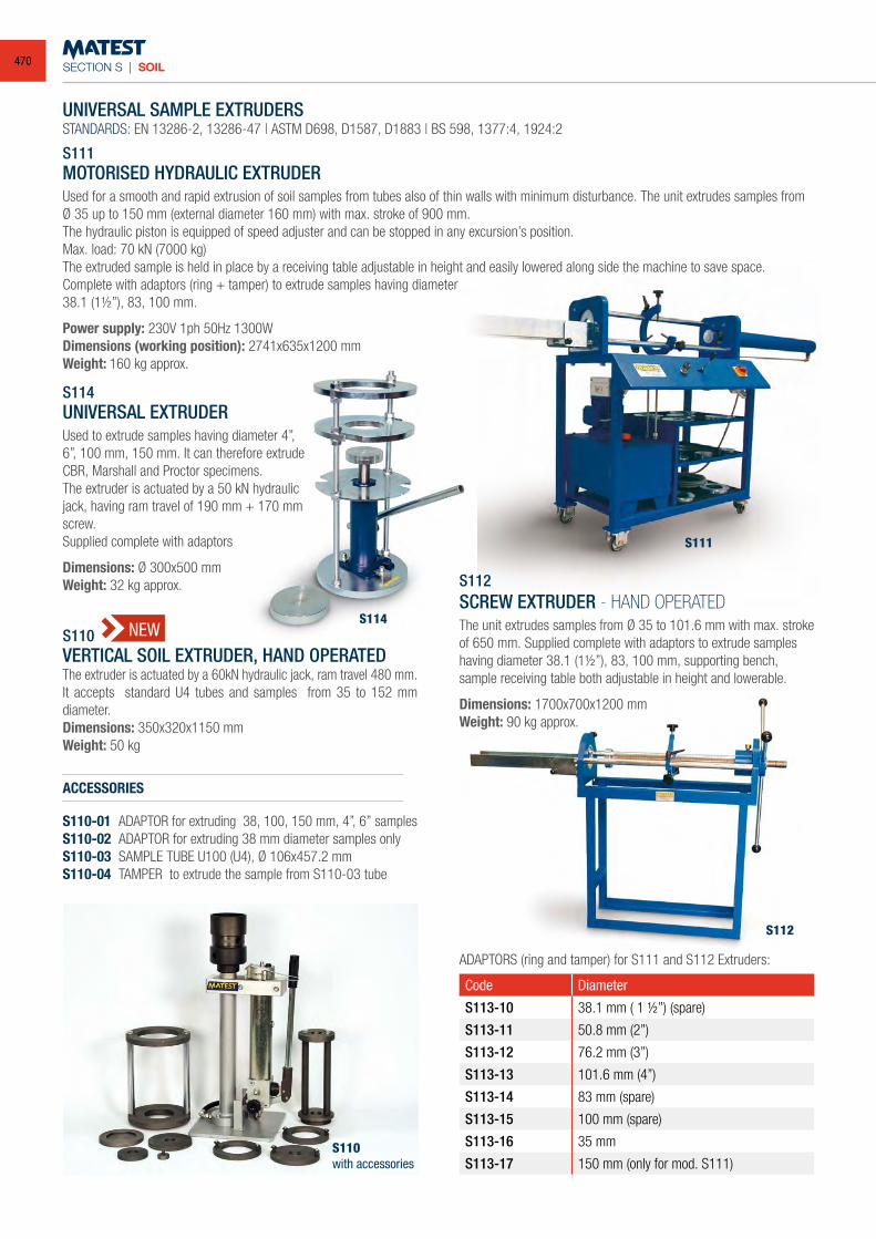
SECTION S | SOIL
UNIVERSAL SAMPLE EXTRUDERSSTANDARDS: EN 13286-2, 13286-47 | ASTM D698, D1587, D1883 | BS 598, 1377:4, 1924:2
S111MOTORISED HYDRAULIC EXTRUDERUsed for a smooth and rapid extrusion of soil samples from tubes also of thin walls with minimum disturbance. The unit extrudes samples from Ø 35 up to 150 mm (external diameter 160 mm) with max. stroke of 900 mm.The hydraulic piston is equipped of speed adjuster and can be stopped in any excursion’s position.Max. load: 70 kN (7000 kg)The extruded sample is held in place by a receiving table adjustable in height and easily lowered along side the machine to save space.Complete with adaptors (ring + tamper) to extrude samples having diameter38.1 (11/2”), 83, 100 mm.
Power supply: 230V 1ph 50Hz 1300WDimensions (working position): 2741x635x1200 mmWeight: 160 kg approx.
S114UNIVERSAL EXTRUDERUsed to extrude samples having diameter 4”, 6”, 100 mm, 150 mm. It can therefore extrude CBR, Marshall and Proctor specimens.The extruder is actuated by a 50 kN hydraulic jack, having ram travel of 190 mm + 170 mm screw.Supplied complete with adaptors
Dimensions: Ø 300x500 mmWeight: 32 kg approx. S112
SCREW EXTRUDER - HAND OPERATEDThe unit extrudes samples from Ø 35 to 101.6 mm with max. stroke of 650 mm. Supplied complete with adaptors to extrude samples having diameter 38.1 (11/2”), 83, 100 mm, supporting bench, sample receiving table both adjustable in height and lowerable.
Dimensions: 1700x700x1200 mmWeight: 90 kg approx.
Code Diameter
S113-10 38.1 mm ( 1 1/2”) (spare)
S113-11 50.8 mm (2”)
S113-12 76.2 mm (3”)
S113-13 101.6 mm (4”)
S113-14 83 mm (spare)
S113-15 100 mm (spare)
S113-16 35 mm
S113-17 150 mm (only for mod. S111)
ADAPTORS (ring and tamper) for S111 and S112 Extruders:
S111
S112
S114S110VERTICAL SOIL EXTRUDER, HAND OPERATEDThe extruder is actuated by a 60kN hydraulic jack, ram travel 480 mm. It accepts standard U4 tubes and samples from 35 to 152 mm diameter.Dimensions: 350x320x1150 mmWeight: 50 kg
ACCESSORIES
S110-01 ADAPTOR for extruding 38, 100, 150 mm, 4”, 6” samplesS110-02 ADAPTOR for extruding 38 mm diameter samples onlyS110-03 SAMPLE TUBE U100 (U4), Ø 106x457.2 mmS110-04 TAMPER to extrude the sample from S110-03 tube
S110with accessories
NEW
470
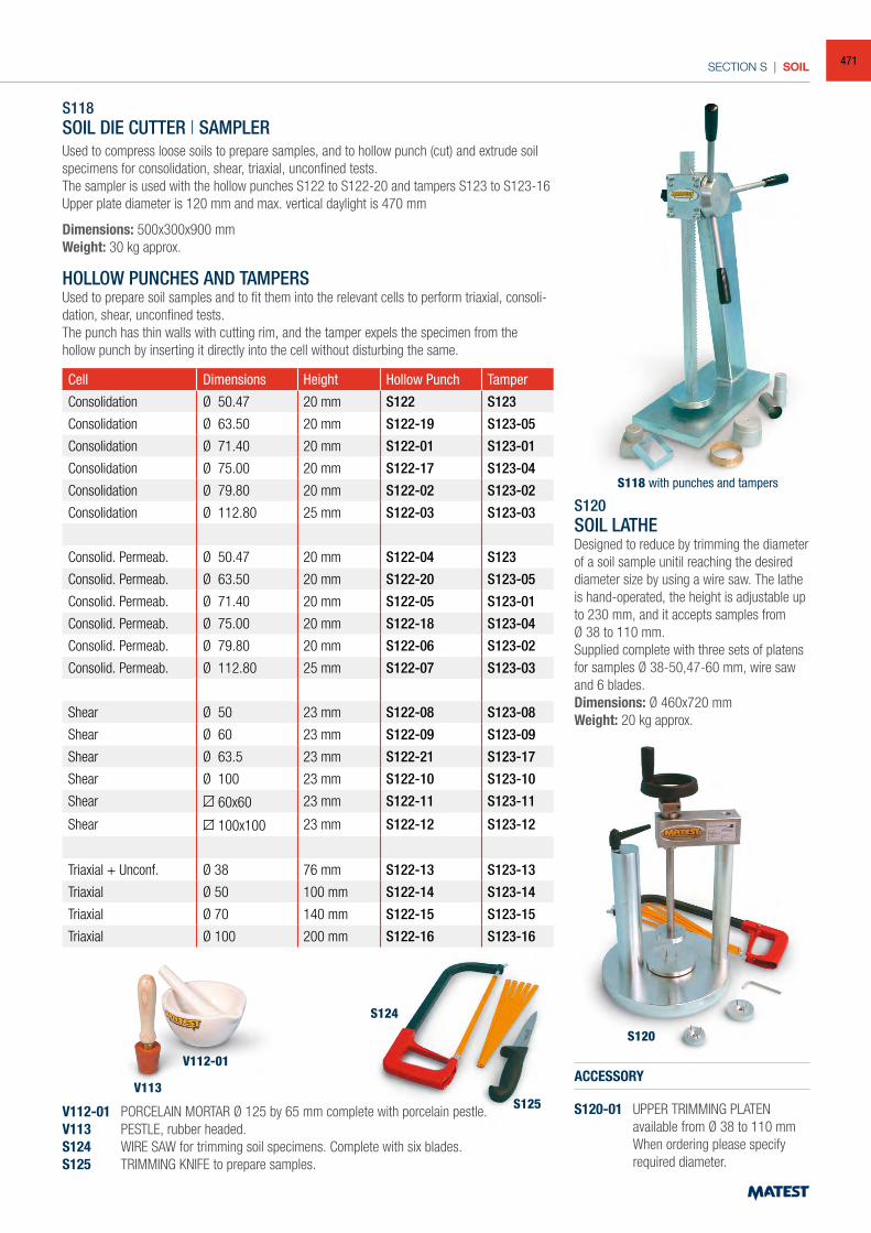
SECTION S | SOIL
S118SOIL DIE CUTTER | SAMPLERUsed to compress loose soils to prepare samples, and to hollow punch (cut) and extrude soil specimens for consolidation, shear, triaxial, unconfined tests.The sampler is used with the hollow punches S122 to S122-20 and tampers S123 to S123-16Upper plate diameter is 120 mm and max. vertical daylight is 470 mm
Dimensions: 500x300x900 mmWeight: 30 kg approx.
HOLLOW PUNCHES AND TAMPERSUsed to prepare soil samples and to fit them into the relevant cells to perform triaxial, consoli-dation, shear, unconfined tests.The punch has thin walls with cutting rim, and the tamper expels the specimen from the hollow punch by inserting it directly into the cell without disturbing the same.
S120SOIL LATHEDesigned to reduce by trimming the diameter of a soil sample unitil reaching the desired diameter size by using a wire saw. The lathe is hand-operated, the height is adjustable up to 230 mm, and it accepts samples fromØ 38 to 110 mm.Supplied complete with three sets of platens for samples Ø 38-50,47-60 mm, wire saw and 6 blades.Dimensions: Ø 460x720 mmWeight: 20 kg approx.
V112-01 PORCELAIN MORTAR Ø 125 by 65 mm complete with porcelain pestle.V113 PESTLE, rubber headed.S124 WIRE SAW for trimming soil specimens. Complete with six blades.S125 TRIMMING KNIFE to prepare samples.
ACCESSORY
S120-01 UPPER TRIMMING PLATEN available from Ø 38 to 110 mm When ordering please specify
required diameter.
Cell Dimensions Height Hollow Punch Tamper
Consolidation Ø 50.47 20 mm S122 S123
Consolidation Ø 63.50 20 mm S122-19 S123-05
Consolidation Ø 71.40 20 mm S122-01 S123-01
Consolidation Ø 75.00 20 mm S122-17 S123-04
Consolidation Ø 79.80 20 mm S122-02 S123-02
Consolidation Ø 112.80 25 mm S122-03 S123-03
Consolid. Permeab. Ø 50.47 20 mm S122-04 S123
Consolid. Permeab. Ø 63.50 20 mm S122-20 S123-05
Consolid. Permeab. Ø 71.40 20 mm S122-05 S123-01
Consolid. Permeab. Ø 75.00 20 mm S122-18 S123-04
Consolid. Permeab. Ø 79.80 20 mm S122-06 S123-02
Consolid. Permeab. Ø 112.80 25 mm S122-07 S123-03
Shear Ø 50 23 mm S122-08 S123-08
Shear Ø 60 23 mm S122-09 S123-09
Shear Ø 63.5 23 mm S122-21 S123-17
Shear Ø 100 23 mm S122-10 S123-10
Shear 60x60 23 mm S122-11 S123-11
Shear 100x100 23 mm S122-12 S123-12
Triaxial + Unconf. Ø 38 76 mm S122-13 S123-13
Triaxial Ø 50 100 mm S122-14 S123-14
Triaxial Ø 70 140 mm S122-15 S123-15
Triaxial Ø 100 200 mm S122-16 S123-16
S124
V112-01
V113S125
S120
S118 with punches and tampers
471
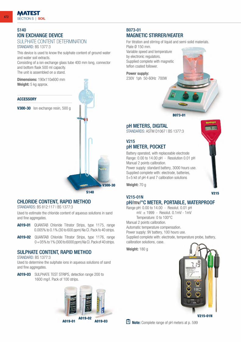
SECTION S | SOIL
S140ION EXCHANGE DEVICESULPHATE CONTENT DETERMINATIONSTANDARD: BS 1377:3
This device is used to know the sulphate content of ground water and water soil extracts.Consisting of a ion exchange glass tube 400 mm long, connector and bottom flask 500 ml capacity.The unit is assembled on a stand.
Dimensions: 190x110x600 mmWeight: 5 kg approx.
ACCESSORY
V300-30 Ion exchange resin, 500 g
CHLORIDE CONTENT, RAPID METHODSTANDARDS: BS 812:117 | BS 1377:3
Used to estimate the chloride content of aqueous solutions in sand and fine aggregates.
A019-01 QUANTAB Chloride Titrator Strips, type 1175, range 0.005% to 0.1% (30 to 600 ppm) Na Cl. Pack fo 40 strips.
A019-02 QUANTAB Chloride Titrator Strips, type 1176, range 0+05% to 1% (300 to 6000 ppm) Na Cl. Pack of 40 strips.
SULPHATE CONTENT, RAPID METHODSTANDARD: BS 1377:3Used to determine the sulphate ions in aqueous solutions of sand and fine aggregates.
A019-03 SULPHATE TEST STRIPS, detection range 200 to 1600 mg/l. Pack of 100 strips.
B073-01MAGNETIC STIRRER/HEATERFor titration and stirring of liquid and semi-solid materials.Plate Ø 150 mm.Variable speed and temperatureby electronic regulators.Supplied complete with magneticteflon coated follower.
Power supply:230V 1ph 50-60Hz 700W
pH METERS, DIGITALSTANDARDS: ASTM D1067 | BS 1377:3
V215pH METER, POCKETBattery operated, with replaceable electrodeRange: 0.00 to 14.00 pH - Resolution 0.01 pHManual 2 points calibration.Power supply: standard battery, 3000 hours use. Supplied complete with: electrode, batteries, 5+5 kit of pH 4 and 7 calibration solutions
Weight: 70 g
V215-01NpH/mv/°C METER, PORTABLE, WATERPROOF Range pH: 0.00 to 14.00 - Resolut. 0.01 pH mV: ± 1999 - Resolut. 0.1mV - 1mV Temperature: 0 to 100°C Manual 2 points calibration. Automatic temperature compensation.Power supply: 9V battery, 100 hours use.Supplied complete with: electrode, temperature probe, battery, calibration solutions, case.
Weight: 180 g
Note: Complete range of pH meters at p. 599
S140
A019-01A019-02
A019-03V215-01N
V215
B073-01
V300-30
472
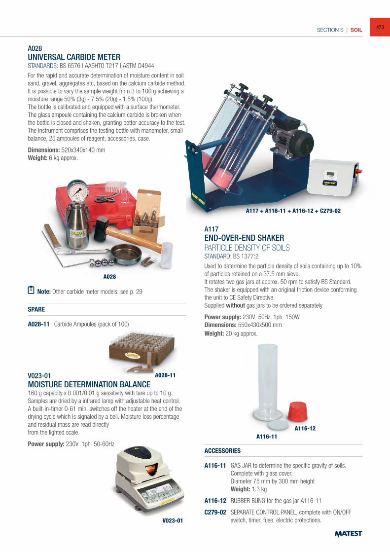
SECTION S | SOIL
Note: Other carbide meter models: see p. 29
A028
A117 + A116-11 + A116-12 + C279-02
A028-11
V023-01
A028UNIVERSAL CARBIDE METERSTANDARDS: BS 6576 | AASHTO T217 | ASTM D4944
For the rapid and accurate determination of moisture content in soil sand, gravel, aggregates etc, based on the calcium carbide method. It is possible to vary the sample weight from 3 to 100 g achieving a moisture range 50% (3g) - 7.5% (20g) - 1.5% (100g).The bottle is calibrated and equipped with a surface thermometer.The glass ampoule containing the calcium carbide is broken when the bottle is closed and shaken, granting better accuracy to the test.The instrument comprises the testing bottle with manometer, small balance, 25 ampoules of reagent, accessories, case.
Dimensions: 520x340x140 mmWeight: 6 kg approx.
SPARE
A028-11 Carbide Ampoules (pack of 100)
V023-01MOISTURE DETERMINATION BALANCE160 g capacity x 0.001/0.01 g sensitivity with tare up to 10 g.Samples are dried by a infrared lamp with adjustable heat control.A built-in-timer 0-61 min. switches off the heater at the end of the drying cycle which is signaled by a bell. Moisture loss percentage and residual mass are read directlyfrom the lighted scale.
Power supply: 230V 1ph 50-60Hz
A117END-OVER-END SHAKERPARTICLE DENSITY OF SOILSSTANDARD: BS 1377:2
Used to determine the particle density of soils containing up to 10% of particles retained on a 37.5 mm sieve.It rotates two gas jars at approx. 50 rpm to satisfy BS Standard.The shaker is equipped with an original friction device conforming the unit to CE Safety Directive.Supplied without gas jars to be ordered separately
Power supply: 230V 50Hz 1ph 150WDimensions: 550x430x500 mmWeight: 20 kg approx.
ACCESSORIES
A116-11 GAS JAR to determine the specific gravity of soils. Complete with glass cover. Diameter 75 mm by 300 mm height Weight: 1.3 kg
A116-12 RUBBER BUNG for the gas jar A116-11
C279-02 SEPARATE CONTROL PANEL, complete with ON/OFF switch, timer, fuse, electric protections.
A116-11A116-12
473
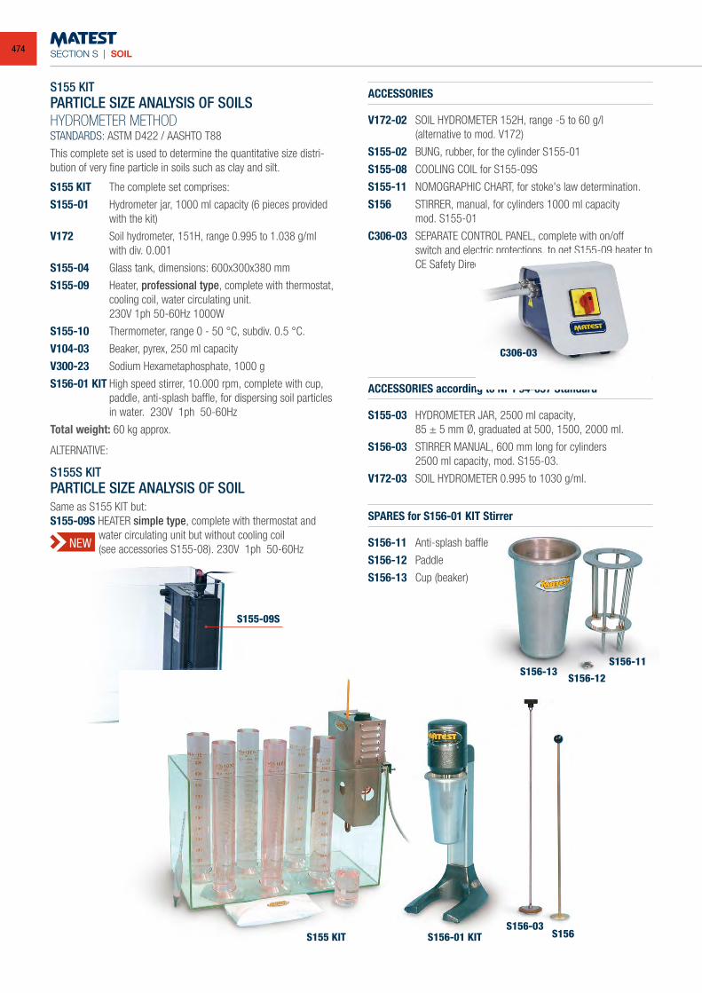
SECTION S | SOIL
S155 KITPARTICLE SIZE ANALYSIS OF SOILSHYDROMETER METHODSTANDARDS: ASTM D422 / AASHTO T88
This complete set is used to determine the quantitative size distri-bution of very fine particle in soils such as clay and silt.
S155 KIT The complete set comprises:
S155-01 Hydrometer jar, 1000 ml capacity (6 pieces provided with the kit)
V172 Soil hydrometer, 151H, range 0.995 to 1.038 g/ml with div. 0.001
S155-04 Glass tank, dimensions: 600x300x380 mm
S155-09 Heater, professional type, complete with thermostat, cooling coil, water circulating unit.
230V 1ph 50-60Hz 1000W
S155-10 Thermometer, range 0 - 50 °C, subdiv. 0.5 °C.
V104-03 Beaker, pyrex, 250 ml capacity
V300-23 Sodium Hexametaphosphate, 1000 g
S156-01 KIT High speed stirrer, 10.000 rpm, complete with cup, paddle, anti-splash baffle, for dispersing soil particles in water. 230V 1ph 50-60Hz
Total weight: 60 kg approx.
ALTERNATIVE:
S155S KITPARTICLE SIZE ANALYSIS OF SOILSame as S155 KIT but:S155-09S HEATER simple type, complete with thermostat and
water circulating unit but without cooling coil (see accessories S155-08). 230V 1ph 50-60Hz
ACCESSORIES
V172-02 SOIL HYDROMETER 152H, range -5 to 60 g/l (alternative to mod. V172)
S155-02 BUNG, rubber, for the cylinder S155-01
S155-08 COOLING COIL for S155-09S
S155-11 NOMOGRAPHIC CHART, for stoke's law determination.
S156 STIRRER, manual, for cylinders 1000 ml capacity mod. S155-01
C306-03 SEPARATE CONTROL PANEL, complete with on/off switch and electric protections, to get S155-09 heater to CE Safety Directive.
ACCESSORIES according to NF P94-057 Standard
S155-03 HYDROMETER JAR, 2500 ml capacity, 85 ± 5 mm Ø, graduated at 500, 1500, 2000 ml.
S156-03 STIRRER MANUAL, 600 mm long for cylinders 2500 ml capacity, mod. S155-03.
V172-03 SOIL HYDROMETER 0.995 to 1030 g/ml.
SPARES for S156-01 KIT Stirrer
S156-11 Anti-splash baffle
S156-12 Paddle
S156-13 Cup (beaker)
C306-03
S156-13S156-12
S156-11
S156S156-03
S156-01 KITS155 KIT
S155-09S
NEW
474
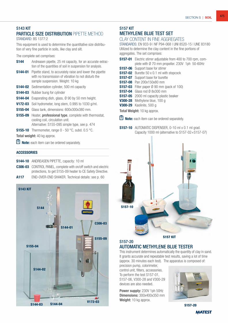
SECTION S | SOIL
S143 KITPARTICLE SIZE DISTRIBUTION PIPETTE METHODSTANDARD: BS 1377:2
This equipment is used to determine the quantitative size distribu-tion of very fine particle in soils, like clay and silt.
The complete set comprises:
S144 Andreasen pipette, 25 ml capacity, for an accurate extrac-tion of the quantities of soil in suspension for analysis.
S144-01 Pipette stand, to accurately raise and lower the pipette with no transmission of vibration to not disturb the sample suspension. Weight: 10 kg
S144-02 Sedimentation cylinder, 500 ml capacity
S144-03 Rubber bung for cylinder
S144-04 Evaporating dish, glass, Ø 90 by 50 mm height.
V172-03 Soil hydrometer, long stem, 0.995 to 1030 g/ml.
S155-04 Glass tank, dimensions: 600x300x380 mm.
S155-09 Heater, professional type, complete with thermostat, cooling coil, circulation unit.
Alternative: S155-09S simple type, see p. 474
S155-10 Thermometer, range 0 - 50 °C, subd. 0.5 °C.
Total weight: 40 kg approx.
Note: each item can be ordered separately.
ACCESSORIES
S144-10 ANDREASEN PIPETTE, capacity: 10 ml
C306-03 CONTROL PANEL, complete with on/off switch and electric protections, to get S155-09 heater to CE Safety Directive.
A117 END-OVER-END SHAKER. Technical details: see p. 60
S157 KITMETHYLENE BLUE TEST SETCLAY CONTENT IN FINE AGGREGATESSTANDARDS: EN 933-9 | NF P94-068 | UNI 8520-15 | UNE 83180Utilized to determine the clay content in the fine portions ofaggregates. The set comprises:
S157-01 Electric stirrer adjustable from 400 to 700 rpm, com-plete with Ø 70 mm propeller. 230V 1ph 50-60Hz
S157-06 Support base for stirrerS157-02 Burette 50 x 0.1 ml with stopcockS157-07 Support base for buretteS157-08 Pan 200x150x80 mmS157-03 Filter paper Ø 90 mm (pack of 100)S157-04 Glass rod Ø 8x300 mmS157-05 2000 ml capacity plastic beakerV300-28 Methylene blue, 100 gV300-29 Kaolinite, 500 g
Total Weight: 10 kg approx.
Note: each item can be ordered separately.
S157-10 AUTOMATIC DISPENSER, 0-10 ml x 0.1 ml grad. Capacity 1000 ml (alternative to S157-02+S157-07)
S157-20 AUTOMATIC METHYLENE BLUE TESTER This instrument determines automatically the quantity of clay in sand. It grants accurate and repeatable test results, saving a lot of time (approx. 30 minutes each test). The apparatus is composed of:precision pump, colorimeter, control unit, filters, accessories. To perform the test S157-01, S157-06, V300-28 and V300-29 devices are also needed.
Power supply: 230V 1ph 50Hz Dimensions: 300x400x350 mmWeight: 10 kg approx.
S144-03
S144-02
S144-01
S155-04
S144
S143 KIT
S157 KIT
S157-10
S155-09
C306-03
S144-04 V172-03
S157-20
475
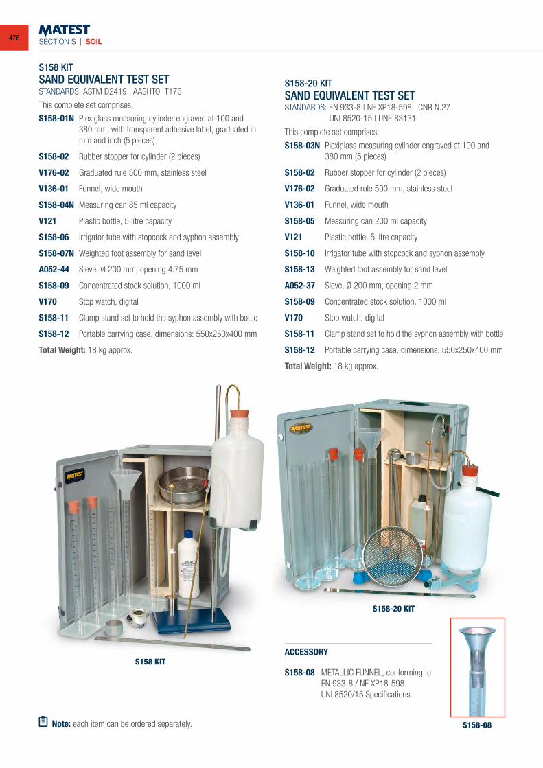
SECTION S | SOIL
S158 KITSAND EQUIVALENT TEST SETSTANDARDS: ASTM D2419 | AASHTO T176
This complete set comprises:
S158-01N Plexiglass measuring cylinder engraved at 100 and 380 mm, with transparent adhesive label, graduated in mm and inch (5 pieces)
S158-02 Rubber stopper for cylinder (2 pieces)
V176-02 Graduated rule 500 mm, stainless steel
V136-01 Funnel, wide mouth
S158-04N Measuring can 85 ml capacity
V121 Plastic bottle, 5 litre capacity
S158-06 Irrigator tube with stopcock and syphon assembly
S158-07N Weighted foot assembly for sand level
A052-44 Sieve, Ø 200 mm, opening 4.75 mm
S158-09 Concentrated stock solution, 1000 ml
V170 Stop watch, digital
S158-11 Clamp stand set to hold the syphon assembly with bottle
S158-12 Portable carrying case, dimensions: 550x250x400 mm
Total Weight: 18 kg approx.
S158-20 KITSAND EQUIVALENT TEST SETSTANDARDS: EN 933-8 | NF XP18-598 | CNR N.27 UNI 8520-15 | UNE 83131
This complete set comprises:
S158-03N Plexiglass measuring cylinder engraved at 100 and 380 mm (5 pieces)
S158-02 Rubber stopper for cylinder (2 pieces)
V176-02 Graduated rule 500 mm, stainless steel
V136-01 Funnel, wide mouth
S158-05 Measuring can 200 ml capacity
V121 Plastic bottle, 5 litre capacity
S158-10 Irrigator tube with stopcock and syphon assembly
S158-13 Weighted foot assembly for sand level
A052-37 Sieve, Ø 200 mm, opening 2 mm
S158-09 Concentrated stock solution, 1000 ml
V170 Stop watch, digital
S158-11 Clamp stand set to hold the syphon assembly with bottle
S158-12 Portable carrying case, dimensions: 550x250x400 mm
Total Weight: 18 kg approx.
ACCESSORY
S158-08 METALLIC FUNNEL, conforming to EN 933-8 / NF XP18-598 UNI 8520/15 Specifications.
Note: each item can be ordered separately.
S158 KIT
S158-20 KIT
S158-08
476
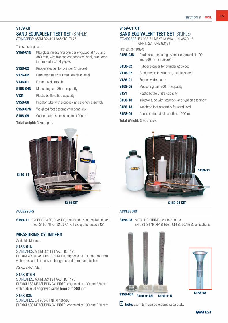
SECTION S | SOIL
Note: each item can be ordered separately.
S158-08
S159-01 KITS159 KIT
S159-11S159-11
S158-03N S158-01GN S158-01N
S159 KITSAND EQUIVALENT TEST SET (SIMPLE)STANDARDS: ASTM D2419 | AASHTO T176
The set comprises:
S158-01N Plexiglass measuring cylinder engraved at 100 and 380 mm, with transparent adhesive label, graduated in mm and inch (4 pieces)
S158-02 Rubber stopper for cylinder (2 pieces)
V176-02 Graduated rule 500 mm, stainless steel
V136-01 Funnel, wide mouth
S158-04N Measuring can 85 ml capacity
V121 Plastic bottle 5 litre capacity
S158-06 Irrigator tube with stopcock and syphon assembly
S158-07N Weighted foot assembly for sand level
S158-09 Concentrated stock solution, 1000 ml
Total Weight: 5 kg approx.
S159-01 KITSAND EQUIVALENT TEST SET (SIMPLE)STANDARDS: EN 933-8 | NF XP18-598 | UNI 8520-15 CNR N.27 | UNE 83131
The set comprises:
S158-03N Plexiglass measuring cylinder engraved at 100 and 380 mm (4 pieces)
S158-02 Rubber stopper for cylinder (2 pieces)
V176-02 Graduated rule 500 mm, stainless steel
V136-01 Funnel, wide mouth
S158-05 Measuring can 200 ml capacity
V121 Plastic bottle 5 litre capacity
S158-10 Irrigator tube with stopcock and syphon assembly
S158-13 Weighted foot assembly for sand level
S158-09 Concentrated stock solution, 1000 ml
Total Weight: 5 kg approx.
ACCESSORY
S159-11 CARRING CASE, PLASTIC, housing the sand equivalent set mod. S159 KIT or S159-01 KIT except the bottle V121
ACCESSORY
S158-08 METALLIC FUNNEL, conforming to EN 933-8 | NF XP18-598 | UNI 8520/15 Specifications.
MEASURING CYLINDERS Available Models :
S158-01NSTANDARDS: ASTM D2419 | AASHTO T176PLEXIGLASS MEASURING CYLINDER, engraved at 100 and 380 mm, with transparent adhesive label graduated in mm and inches.
AS ALTERNATIVE:
S158-01GNSTANDARDS: ASTM D2419 | AASHTO T176 PLEXIGLASS MEASURING CYLINDER, engraved at 100 and 380 mm with additional engraved scale from 0 to 380 mm
S158-03NSTANDARDS: EN 933-8 | NF XP18-598PLEXIGLASS MEASURING CYLINDER, engraved at 100 and 380 mm
477
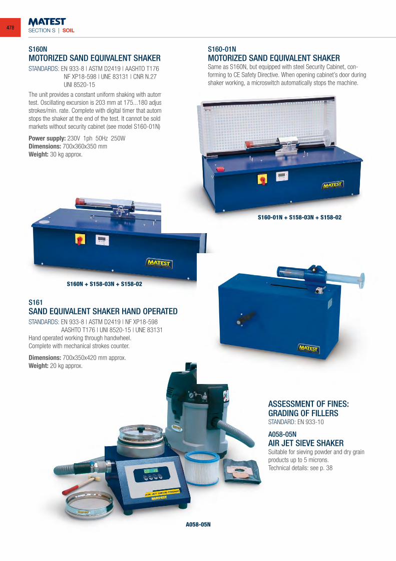
SECTION S | SOIL
S161
A058-05N
S160N + S158-03N + S158-02
S160NMOTORIZED SAND EQUIVALENT SHAKERSTANDARDS: EN 933-8 | ASTM D2419 | AASHTO T176 NF XP18-598 | UNE 83131 | CNR N.27 UNI 8520-15
The unit provides a constant uniform shaking with automatic cycle test. Oscillating excursion is 203 mm at 175...180 adjustable strokes/min. rate. Complete with digital timer that automatically stops the shaker at the end of the test. It cannot be sold in CE markets without security cabinet (see model S160-01N)
Power supply: 230V 1ph 50Hz 250WDimensions: 700x360x350 mm Weight: 30 kg approx.
S160-01NMOTORIZED SAND EQUIVALENT SHAKERSame as S160N, but equipped with steel Security Cabinet, con-forming to CE Safety Directive. When opening cabinet’s door during shaker working, a microswitch automatically stops the machine.
ASSESSMENT OF FINES:GRADING OF FILLERSSTANDARD: EN 933-10
A058-05NAIR JET SIEVE SHAKERSuitable for sieving powder and dry grainproducts up to 5 microns.Technical details: see p. 38
S161SAND EQUIVALENT SHAKER HAND OPERATEDSTANDARDS: EN 933-8 | ASTM D2419 | NF XP18-598 AASHTO T176 | UNI 8520-15 | UNE 83131Hand operated working through handwheel.Complete with mechanical strokes counter.
Dimensions: 700x350x420 mm approx.Weight: 20 kg approx.
S160-01N + S158-03N + S158-02
478
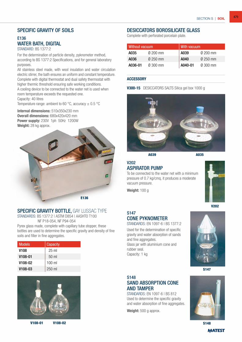
SECTION S | SOIL
SPECIFIC GRAVITY OF SOILSE136WATER BATH, DIGITALSTANDARD: BS 1377:2
For the determination of particle density, pyknometer method, according to BS 1377:2 Specifications, and for general laboratory purposes.All stainless steel made, with wool insulation and water circulation electric stirrer, the bath ensures an uniform and constant temperature.Complete with digital thermostat and dual safety thermostat with higher thermic threshold ensuring safe working conditions.A cooling device to be connected to the water net is used when room temperature exceeds the requested one.Capacity: 40 litresTemperature range: ambient to 60 °C, accuracy ± 0.5 °C
Internal dimensions: 510x350x230 mmOverall dimensions: 680x420x420 mmPower supply: 230V 1ph 50Hz 1200WWeight: 28 kg approx.
SPECIFIC GRAVITY BOTTLE, GAY LUSSAC TYPESTANDARDS: BS 1377:2 | ASTM D854 | AASHTO T100 NF P18-054, NF P94-054Pyrex glass made, complete with capillary tube stopper, these bottles are used to determine the specific gravity and density of fine soils and filler in fine aggregates.
Models Capacity
V108 25 ml
V108-01 50 ml
V108-02 100 ml
V108-03 250 ml
DESICCATORS BOROSILICATE GLASSComplete with perforated porcelain plate.
Without vacuum With vacuum
A035 Ø 200 mm A039 Ø 200 mm
A036 Ø 250 mm A040 Ø 250 mm
A036-01 Ø 300 mm A040-01 Ø 300 mm
ACCESSORY
V300-15 DESICCATORS SALTS Silica gel box 1000 g
S147CONE PYKNOMETERSTANDARDS: EN 1097-6 | BS 1377:2
Used for the determination of specific gravity and water absorption of sands and fine aggregates.Glass jar with aluminium cone and rubber seal.Capacity: 1 kg
S148SAND ABSORPTION CONE AND TAMPERSTANDARDS: EN 1097-6 | BS 812Used to determine the specific gravity and water absorption of fine aggregates.
Weight: 500 g approx.
V202ASPIRATOR PUMPTo be connected to the water net with a minimum pressure of 0.7 kg/cmq, it produces a moderate vacuum pressure.
Weight: 100 g
E136
V108-01
A039 A035
S147
S148
V202
V108-02
479
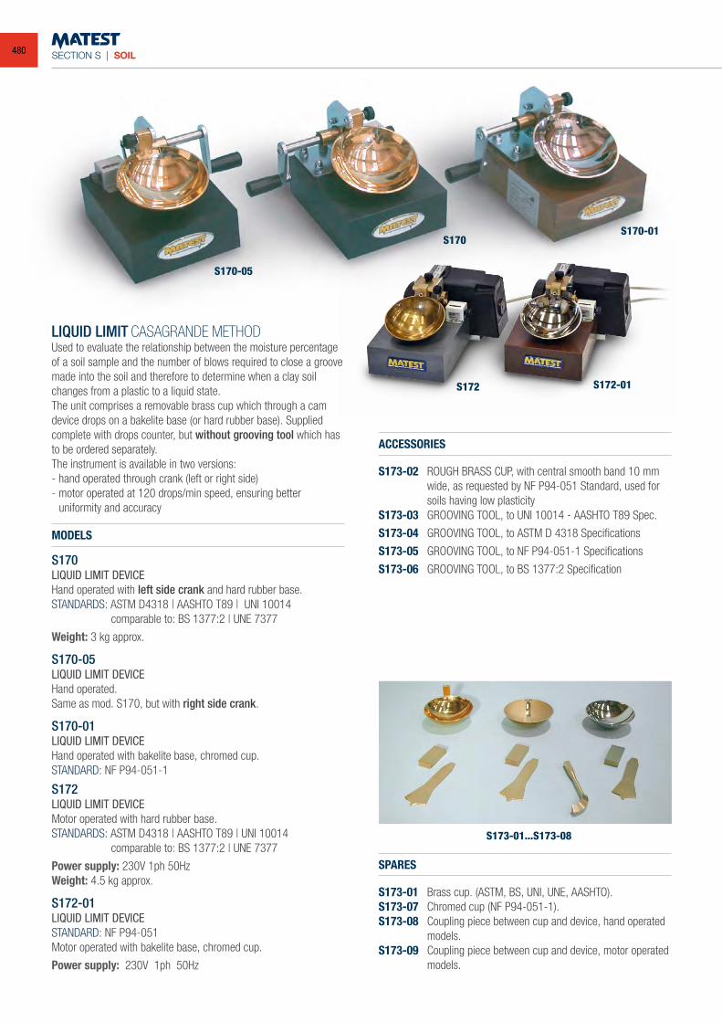
SECTION S | SOIL
LIQUID LIMIT CASAGRANDE METHODUsed to evaluate the relationship between the moisture percentage of a soil sample and the number of blows required to close a groove made into the soil and therefore to determine when a clay soil changes from a plastic to a liquid state.The unit comprises a removable brass cup which through a cam device drops on a bakelite base (or hard rubber base). Supplied complete with drops counter, but without grooving tool which has to be ordered separately.The instrument is available in two versions:- hand operated through crank (left or right side)- motor operated at 120 drops/min speed, ensuring better uniformity and accuracy
MODELS
S170LIQUID LIMIT DEVICEHand operated with left side crank and hard rubber base.STANDARDS: ASTM D4318 | AASHTO T89 | UNI 10014 comparable to: BS 1377:2 | UNE 7377
Weight: 3 kg approx.
S170-05LIQUID LIMIT DEVICEHand operated.Same as mod. S170, but with right side crank.
S170-01LIQUID LIMIT DEVICEHand operated with bakelite base, chromed cup.STANDARD: NF P94-051-1
S172LIQUID LIMIT DEVICEMotor operated with hard rubber base.STANDARDS: ASTM D4318 | AASHTO T89 | UNI 10014 comparable to: BS 1377:2 | UNE 7377
Power supply: 230V 1ph 50HzWeight: 4.5 kg approx.
S172-01LIQUID LIMIT DEVICESTANDARD: NF P94-051Motor operated with bakelite base, chromed cup.
Power supply: 230V 1ph 50Hz
ACCESSORIES
S173-02 ROUGH BRASS CUP, with central smooth band 10 mm wide, as requested by NF P94-051 Standard, used for soils having low plasticity
S173-03 GROOVING TOOL, to UNI 10014 - AASHTO T89 Spec.
S173-04 GROOVING TOOL, to ASTM D 4318 Specifications
S173-05 GROOVING TOOL, to NF P94-051-1 Specifications
S173-06 GROOVING TOOL, to BS 1377:2 Specification
SPARES
S173-01 Brass cup. (ASTM, BS, UNI, UNE, AASHTO).S173-07 Chromed cup (NF P94-051-1).S173-08 Coupling piece between cup and device, hand operated
models.S173-09 Coupling piece between cup and device, motor operated
models.
S170-05
S170S170-01
S172 S172-01
S173-01...S173-08
480
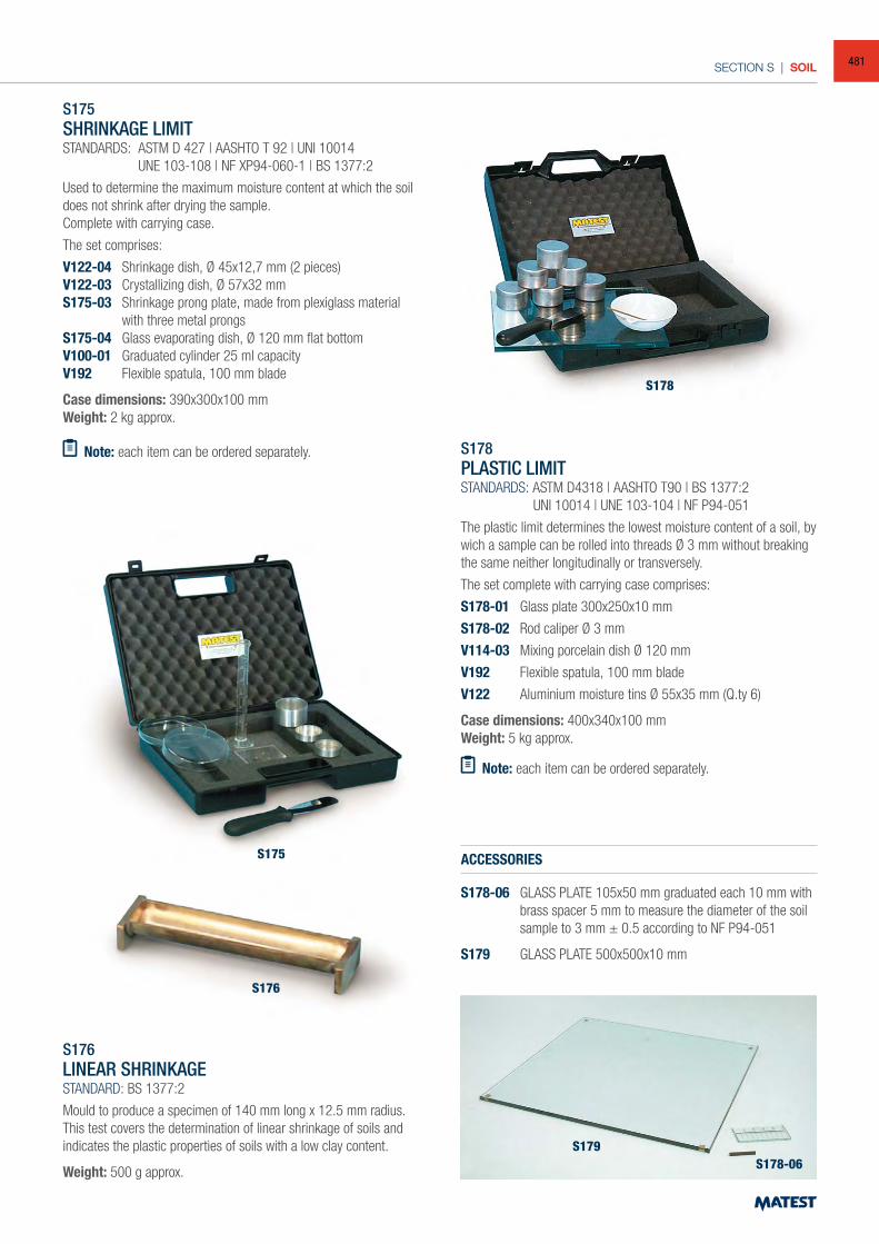
SECTION S | SOIL
S175SHRINKAGE LIMITSTANDARDS: ASTM D 427 | AASHTO T 92 | UNI 10014 UNE 103-108 | NF XP94-060-1 | BS 1377:2
Used to determine the maximum moisture content at which the soil does not shrink after drying the sample.Complete with carrying case.
The set comprises:
V122-04 Shrinkage dish, Ø 45x12,7 mm (2 pieces)V122-03 Crystallizing dish, Ø 57x32 mmS175-03 Shrinkage prong plate, made from plexiglass material
with three metal prongsS175-04 Glass evaporating dish, Ø 120 mm flat bottomV100-01 Graduated cylinder 25 ml capacityV192 Flexible spatula, 100 mm blade
Case dimensions: 390x300x100 mmWeight: 2 kg approx.
Note: each item can be ordered separately.
S176LINEAR SHRINKAGESTANDARD: BS 1377:2
Mould to produce a specimen of 140 mm long x 12.5 mm radius.This test covers the determination of linear shrinkage of soils and indicates the plastic properties of soils with a low clay content.
Weight: 500 g approx.
S178PLASTIC LIMITSTANDARDS: ASTM D4318 | AASHTO T90 | BS 1377:2 UNI 10014 | UNE 103-104 | NF P94-051
The plastic limit determines the lowest moisture content of a soil, by wich a sample can be rolled into threads Ø 3 mm without breaking the same neither longitudinally or transversely.
The set complete with carrying case comprises:
S178-01 Glass plate 300x250x10 mm
S178-02 Rod caliper Ø 3 mm
V114-03 Mixing porcelain dish Ø 120 mm
V192 Flexible spatula, 100 mm blade
V122 Aluminium moisture tins Ø 55x35 mm (Q.ty 6)
Case dimensions: 400x340x100 mmWeight: 5 kg approx.
Note: each item can be ordered separately.
ACCESSORIES
S178-06 GLASS PLATE 105x50 mm graduated each 10 mm with brass spacer 5 mm to measure the diameter of the soil sample to 3 mm ± 0.5 according to NF P94-051
S179 GLASS PLATE 500x500x10 mm
S175
S178
S179S178-06
S176
481
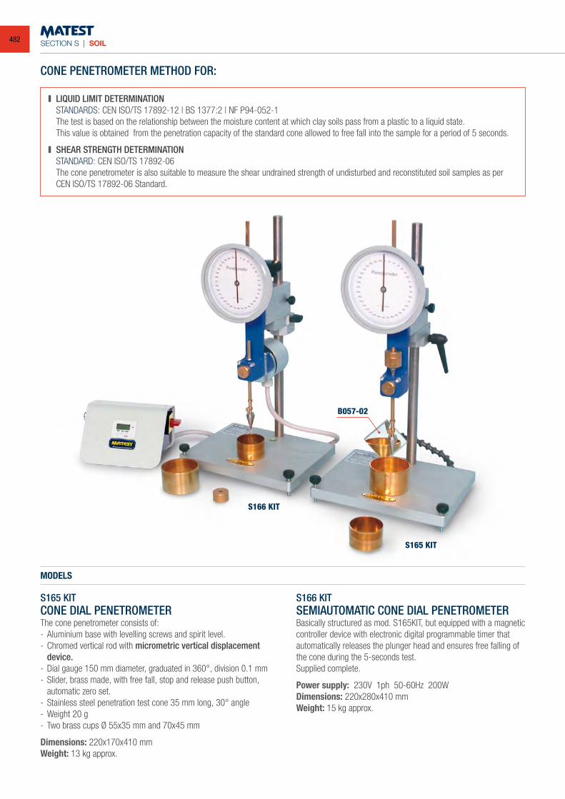
SECTION S | SOIL
CONE PENETROMETER METHOD FOR:
LIQUID LIMIT DETERMINATION STANDARDS: CEN ISO/TS 17892-12 | BS 1377:2 | NF P94-052-1 The test is based on the relationship between the moisture content at which clay soils pass from a plastic to a liquid state. This value is obtained from the penetration capacity of the standard cone allowed to free fall into the sample for a period of 5 seconds.
SHEAR STRENGTH DETERMINATION STANDARD: CEN ISO/TS 17892-06 The cone penetrometer is also suitable to measure the shear undrained strength of undisturbed and reconstituted soil samples as per CEN ISO/TS 17892-06 Standard.
S165 KITCONE DIAL PENETROMETERThe cone penetrometer consists of:- Aluminium base with levelling screws and spirit level.- Chromed vertical rod with micrometric vertical displacement
device.- Dial gauge 150 mm diameter, graduated in 360°, division 0.1 mm - Slider, brass made, with free fall, stop and release push button,
automatic zero set.- Stainless steel penetration test cone 35 mm long, 30° angle- Weight 20 g- Two brass cups Ø 55x35 mm and 70x45 mm
Dimensions: 220x170x410 mmWeight: 13 kg approx.
MODELS
S166 KITSEMIAUTOMATIC CONE DIAL PENETROMETERBasically structured as mod. S165KIT, but equipped with a magnetic controller device with electronic digital programmable timer that automatically releases the plunger head and ensures free falling of the cone during the 5-seconds test.Supplied complete.
Power supply: 230V 1ph 50-60Hz 200W Dimensions: 220x280x410 mmWeight: 15 kg approx.
S166 KIT
S165 KIT
B057-02
482
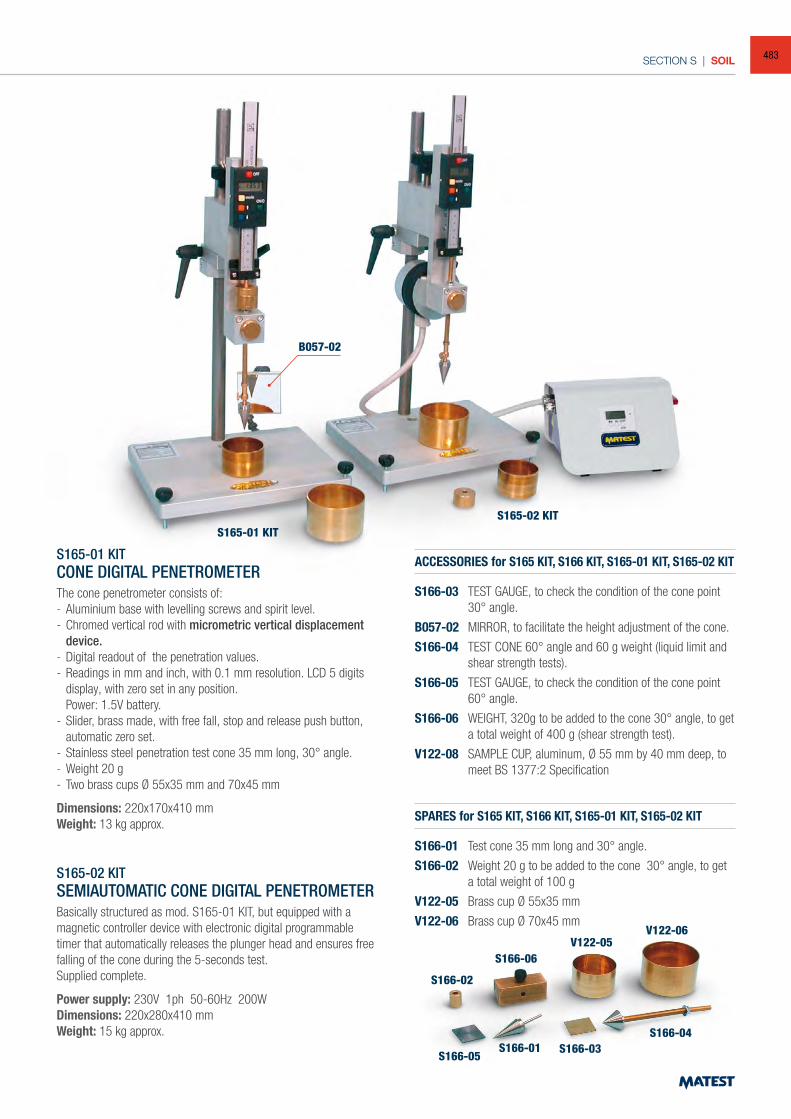
SECTION S | SOIL
S165-01 KIT
S166-05S166-03
S166-04S166-01
S166-02
S166-06V122-05
V122-06
S165-02 KIT
B057-02
S165-01 KITCONE DIGITAL PENETROMETERThe cone penetrometer consists of:- Aluminium base with levelling screws and spirit level.- Chromed vertical rod with micrometric vertical displacement
device.- Digital readout of the penetration values.- Readings in mm and inch, with 0.1 mm resolution. LCD 5 digits
display, with zero set in any position. Power: 1.5V battery. - Slider, brass made, with free fall, stop and release push button,
automatic zero set.- Stainless steel penetration test cone 35 mm long, 30° angle.- Weight 20 g- Two brass cups Ø 55x35 mm and 70x45 mm
Dimensions: 220x170x410 mmWeight: 13 kg approx.
S165-02 KITSEMIAUTOMATIC CONE DIGITAL PENETROMETERBasically structured as mod. S165-01 KIT, but equipped with a magnetic controller device with electronic digital programmable timer that automatically releases the plunger head and ensures free falling of the cone during the 5-seconds test.Supplied complete.
Power supply: 230V 1ph 50-60Hz 200W Dimensions: 220x280x410 mm Weight: 15 kg approx.
ACCESSORIES for S165 KIT, S166 KIT, S165-01 KIT, S165-02 KIT
S166-03 TEST GAUGE, to check the condition of the cone point 30° angle.
B057-02 MIRROR, to facilitate the height adjustment of the cone.
S166-04 TEST CONE 60° angle and 60 g weight (liquid limit and shear strength tests).
S166-05 TEST GAUGE, to check the condition of the cone point 60° angle.
S166-06 WEIGHT, 320g to be added to the cone 30° angle, to get a total weight of 400 g (shear strength test).
V122-08 SAMPLE CUP, aluminum, Ø 55 mm by 40 mm deep, to meet BS 1377:2 Specification
SPARES for S165 KIT, S166 KIT, S165-01 KIT, S165-02 KIT
S166-01 Test cone 35 mm long and 30° angle.
S166-02 Weight 20 g to be added to the cone 30° angle, to get a total weight of 100 g
V122-05 Brass cup Ø 55x35 mm
V122-06 Brass cup Ø 70x45 mm
483
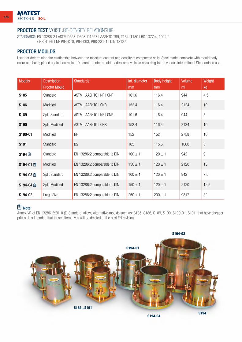
SECTION S | SOIL
PROCTOR TEST MOISTURE-DENSITY RELATIONSHIPSTANDARDS: EN 13286-2 | ASTM D558, D698, D1557 | AASHTO T99, T134, T180 | BS 1377:4, 1924:2 CNR N° 69 | NF P94-078, P94-093, P98-231-1 | DIN 18127
PROCTOR MOULDSUsed for determining the relationship between the moisture content and density of compacted soils. Steel made, complete with mould body, collar and base; plated against corrosion. Different proctor mould models are available according to the various international Standards in use.
Models Description Standards Int. diameter Body height Volume Weight
Proctor Mould mm mm ml kg
S185 Standard ASTM | AASHTO | NF | CNR 101.6 116.4 944 4.5
S186 Modified ASTM | AASHTO | CNR 152.4 116.4 2124 10
S189 Split Standard ASTM | AASHTO | NF | CNR 101.6 116.4 944 5
S190 Split Modified ASTM | AASHTO | CNR 152.4 116.4 2124 10
S190-01 Modified NF 152 152 2758 10
S191 Standard BS 105 115.5 1000 5
S194 Standard EN 13286:2 comparable to DIN 100 ± 1 120 ± 1 942 9
S194-01 Modified EN 13286:2 comparable to DIN 150 ± 1 120 ± 1 2120 13
S194-03 Split Standard EN 13286:2 comparable to DIN 100 ± 1 120 ± 1 942 7.5
S194-04 Split Modified EN 13286:2 comparable to DIN 150 ± 1 120 ± 1 2120 12.5
S194-02 Large Size EN 13286:2 comparable to DIN 250 ± 1 200 ± 1 9817 32
Note:Annex “A” of EN 13286-2:2010 (E) Standard, allows alternative moulds such as: S185, S186, S189, S190, S190-01, S191, that have cheaper prices. It is intended that these alternatives will be deleted at the next EN revision.
S185...S191
S194-04
S194-02
S194-01
S194
484
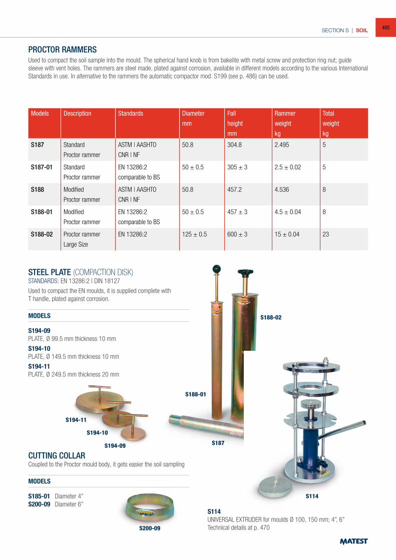
SECTION S | SOIL
S194-11
S194-10
S194-09
S200-09
PROCTOR RAMMERSUsed to compact the soil sample into the mould. The spherical hand knob is from bakelite with metal screw and protection ring nut; guide sleeve with vent holes. The rammers are steel made, plated against corrosion, available in different models according to the various International Standards in use. In alternative to the rammers the automatic compactor mod. S199 (see p. 486) can be used.
Models Description Standards Diameter Fall Rammer Total
mm height weight weight
mm kg kg
S187 Standard ASTM | AASHTO 50.8 304.8 2.495 5
Proctor rammer CNR | NF
S187-01 Standard EN 13286:2 50 ± 0.5 305 ± 3 2.5 ± 0.02 5
Proctor rammer comparable to BS
S188 Modified ASTM | AASHTO 50.8 457.2 4.536 8
Proctor rammer CNR | NF
S188-01 Modified EN 13286:2 50 ± 0.5 457 ± 3 4.5 ± 0.04 8
Proctor rammer comparable to BS
S188-02 Proctor rammer EN 13286:2 125 ± 0.5 600 ± 3 15 ± 0.04 23
Large Size
STEEL PLATE (COMPACTION DISK)STANDARDS: EN 13286:2 | DIN 18127
Used to compact the EN moulds, it is supplied complete withT handle, plated against corrosion.
MODELS
S194-09PLATE, Ø 99.5 mm thickness 10 mm
S194-10PLATE, Ø 149.5 mm thickness 10 mm
S194-11PLATE, Ø 249.5 mm thickness 20 mm
CUTTING COLLARCoupled to the Proctor mould body, it gets easier the soil sampling
MODELS
S185-01 Diameter 4”S200-09 Diameter 6”
S114UNIVERSAL EXTRUDER for moulds Ø 100, 150 mm; 4”, 6”Technical details at p. 470
S114
S187
S188-02
S188-01
485
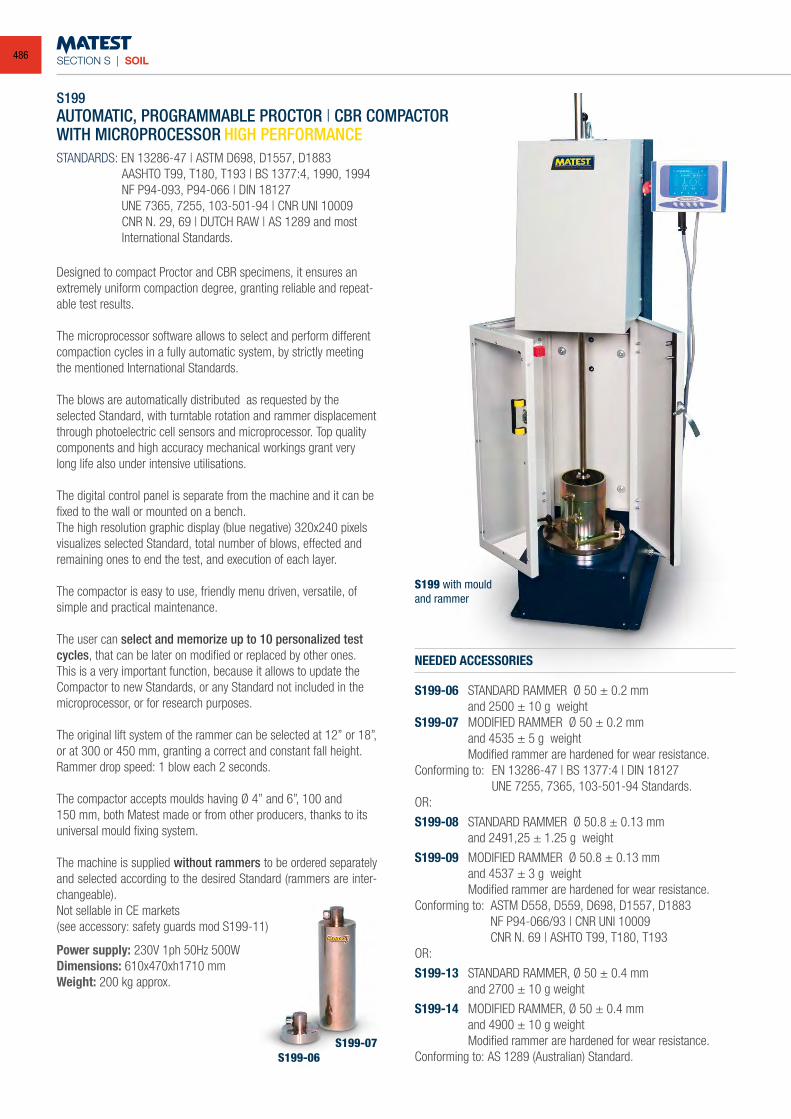
SECTION S | SOIL
S199-06S199-07
S199AUTOMATIC, PROGRAMMABLE PROCTOR | CBR COMPACTORWITH MICROPROCESSOR HIGH PERFORMANCE
Designed to compact Proctor and CBR specimens, it ensures an extremely uniform compaction degree, granting reliable and repeat-able test results.
The microprocessor software allows to select and perform different compaction cycles in a fully automatic system, by strictly meeting the mentioned International Standards. The blows are automatically distributed as requested by the selected Standard, with turntable rotation and rammer displacement through photoelectric cell sensors and microprocessor. Top quality components and high accuracy mechanical workings grant very long life also under intensive utilisations.
The digital control panel is separate from the machine and it can be fixed to the wall or mounted on a bench.The high resolution graphic display (blue negative) 320x240 pixels visualizes selected Standard, total number of blows, effected and remaining ones to end the test, and execution of each layer.
The compactor is easy to use, friendly menu driven, versatile, of simple and practical maintenance.
The user can select and memorize up to 10 personalized test cycles, that can be later on modified or replaced by other ones. This is a very important function, because it allows to update the Compactor to new Standards, or any Standard not included in the microprocessor, or for research purposes.
The original lift system of the rammer can be selected at 12” or 18”, or at 300 or 450 mm, granting a correct and constant fall height.Rammer drop speed: 1 blow each 2 seconds.
The compactor accepts moulds having Ø 4” and 6”, 100 and150 mm, both Matest made or from other producers, thanks to its universal mould fixing system.
The machine is supplied without rammers to be ordered separately and selected according to the desired Standard (rammers are inter-changeable).Not sellable in CE markets(see accessory: safety guards mod S199-11)
Power supply: 230V 1ph 50Hz 500WDimensions: 610x470xh1710 mmWeight: 200 kg approx.
S199 with mouldand rammer
NEEDED ACCESSORIES
S199-06 STANDARD RAMMER Ø 50 ± 0.2 mm and 2500 ± 10 g weightS199-07 MODIFIED RAMMER Ø 50 ± 0.2 mm and 4535 ± 5 g weight Modified rammer are hardened for wear resistance.Conforming to: EN 13286-47 | BS 1377:4 | DIN 18127 UNE 7255, 7365, 103-501-94 Standards.OR:
S199-08 STANDARD RAMMER Ø 50.8 ± 0.13 mm and 2491,25 ± 1.25 g weight
S199-09 MODIFIED RAMMER Ø 50.8 ± 0.13 mm and 4537 ± 3 g weight Modified rammer are hardened for wear resistance.Conforming to: ASTM D558, D559, D698, D1557, D1883 NF P94-066/93 | CNR UNI 10009 CNR N. 69 | ASHTO T99, T180, T193OR:
S199-13 STANDARD RAMMER, Ø 50 ± 0.4 mm and 2700 ± 10 g weight
S199-14 MODIFIED RAMMER, Ø 50 ± 0.4 mm and 4900 ± 10 g weight Modified rammer are hardened for wear resistance.Conforming to: AS 1289 (Australian) Standard.
STANDARDS: EN 13286-47 | ASTM D698, D1557, D1883 AASHTO T99, T180, T193 | BS 1377:4, 1990, 1994 NF P94-093, P94-066 | DIN 18127 UNE 7365, 7255, 103-501-94 | CNR UNI 10009 CNR N. 29, 69 | DUTCH RAW | AS 1289 and most International Standards.
486
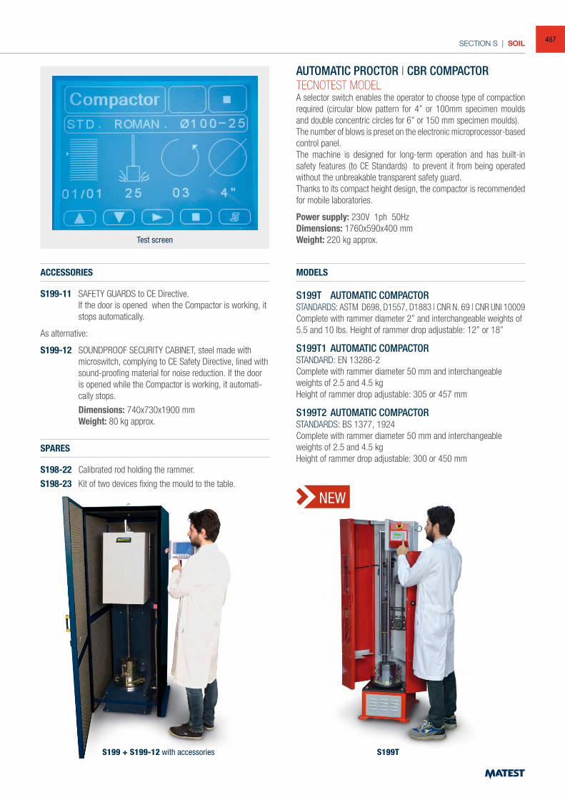
SECTION S | SOIL
ACCESSORIES
S199-11 SAFETY GUARDS to CE Directive. If the door is opened when the Compactor is working, it
stops automatically.
As alternative:
S199-12 SOUNDPROOF SECURITY CABINET, steel made with microswitch, complying to CE Safety Directive, lined with sound-proofing material for noise reduction. If the door is opened while the Compactor is working, it automati-cally stops.
Dimensions: 740x730x1900 mm Weight: 80 kg approx.
SPARES
S198-22 Calibrated rod holding the rammer.
S198-23 Kit of two devices fixing the mould to the table.
Test screen
S199 + S199-12 with accessories
AUTOMATIC PROCTOR | CBR COMPACTORTECNOTEST MODELA selector switch enables the operator to choose type of compaction required (circular blow pattern for 4” or 100mm specimen moulds and double concentric circles for 6” or 150 mm specimen moulds).The number of blows is preset on the electronic microprocessor-based control panel.The machine is designed for long-term operation and has built-in safety features (to CE Standards) to prevent it from being operated without the unbreakable transparent safety guard.Thanks to its compact height design, the compactor is recommended for mobile laboratories.
Power supply: 230V 1ph 50HzDimensions: 1760x590x400 mmWeight: 220 kg approx.
S199T
MODELS
S199T AUTOMATIC COMPACTORSTANDARDS: ASTM D698, D1557, D1883 | CNR N. 69 | CNR UNI 10009Complete with rammer diameter 2” and interchangeable weights of 5.5 and 10 lbs. Height of rammer drop adjustable: 12” or 18”
S199T1 AUTOMATIC COMPACTORSTANDARD: EN 13286-2Complete with rammer diameter 50 mm and interchangeable weights of 2.5 and 4.5 kgHeight of rammer drop adjustable: 305 or 457 mm
S199T2 AUTOMATIC COMPACTORSTANDARDS: BS 1377, 1924Complete with rammer diameter 50 mm and interchangeable weights of 2.5 and 4.5 kgHeight of rammer drop adjustable: 300 or 450 mm
NEW
487
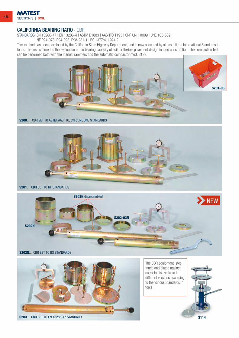
SECTION S | SOIL
CALIFORNIA BEARING RATIO - CBRSTANDARDS: EN 13286-47 | EN 13286-4 | ASTM D1883 | AASHTO T193 | CNR UNI 10009 | UNE 103-502 NF P94-078, P94-093, P98-231-1 | BS 1377:4, 1924:2This method has been developed by the California State Highway Department, and is now accepted by almost all the International Standards in force. The test is aimed to the evaluation of the bearing capacity of soil for flexible pavement design in road construction. The compaction test can be performed both with the manual rammers and the automatic compactor mod. S199.
The CBR equipment, steel made and plated against corrosion is available in different versions according to the various Standards in force.
S200... CBR SET TO ASTM, AASHTO, CNR/UNI, UNE STANDARDS
S201... CBR SET TO NF STANDARDS
S202N... CBR SET TO BS STANDARDS
S203... CBR SET TO EN 13286-47 STANDARD S114
S201-05
NEW
S202N
S202-03N
S202N disassembled
488
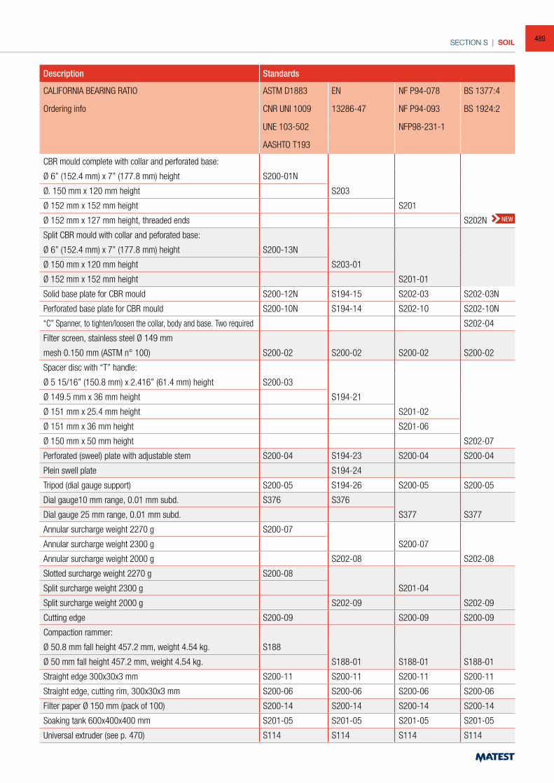
SECTION S | SOIL
Description Standards
CALIFORNIA BEARING RATIO ASTM D1883 EN NF P94-078 BS 1377:4
Ordering info CNR UNI 1009 13286-47 NF P94-093 BS 1924:2
UNE 103-502 NFP98-231-1
AASHTO T193
CBR mould complete with collar and perforated base:
Ø 6” (152.4 mm) x 7” (177.8 mm) height S200-01N
Ø. 150 mm x 120 mm height S203
Ø 152 mm x 152 mm height S201
Ø 152 mm x 127 mm height, threaded ends S202N
Split CBR mould with collar and peforated base:
Ø 6” (152.4 mm) x 7” (177.8 mm) height S200-13N
Ø 150 mm x 120 mm height S203-01
Ø 152 mm x 152 mm height S201-01
Solid base plate for CBR mould S200-12N S194-15 S202-03 S202-03N
Perforated base plate for CBR mould S200-10N S194-14 S202-10 S202-10N
“C” Spanner, to tighten/loosen the collar, body and base. Two required S202-04
Filter screen, stainless steel Ø 149 mm
mesh 0.150 mm (ASTM n° 100) S200-02 S200-02 S200-02 S200-02
Spacer disc with “T” handle:
Ø 5 15/16” (150.8 mm) x 2.416” (61.4 mm) height S200-03
Ø 149.5 mm x 36 mm height S194-21
Ø 151 mm x 25.4 mm height S201-02
Ø 151 mm x 36 mm height S201-06
Ø 150 mm x 50 mm height S202-07
Perforated (sweel) plate with adjustable stem S200-04 S194-23 S200-04 S200-04
Plein swell plate S194-24
Tripod (dial gauge support) S200-05 S194-26 S200-05 S200-05
Dial gauge10 mm range, 0.01 mm subd. S376 S376
Dial gauge 25 mm range, 0.01 mm subd. S377 S377
Annular surcharge weight 2270 g S200-07
Annular surcharge weight 2300 g S200-07
Annular surcharge weight 2000 g S202-08 S202-08
Slotted surcharge weight 2270 g S200-08
Split surcharge weight 2300 g S201-04
Split surcharge weight 2000 g S202-09 S202-09
Cutting edge S200-09 S200-09 S200-09
Compaction rammer:
Ø 50.8 mm fall height 457.2 mm, weight 4.54 kg. S188
Ø 50 mm fall height 457.2 mm, weight 4.54 kg. S188-01 S188-01 S188-01
Straight edge 300x30x3 mm S200-11 S200-11 S200-11 S200-11
Straight edge, cutting rim, 300x30x3 mm S200-06 S200-06 S200-06 S200-06
Filter paper Ø 150 mm (pack of 100) S200-14 S200-14 S200-14 S200-14
Soaking tank 600x400x400 mm S201-05 S201-05 S201-05 S201-05
Universal extruder (see p. 470) S114 S114 S114 S114
NEW
489
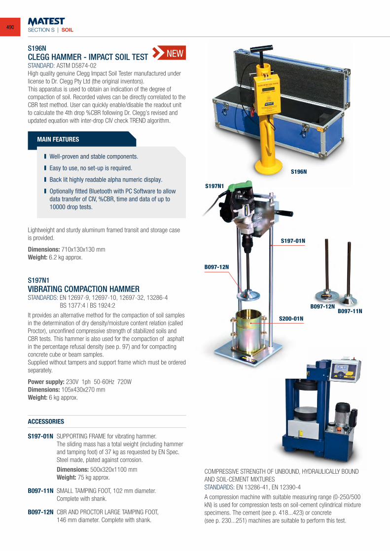
SECTION S | SOIL
B097-12NB097-11N
S197N1VIBRATING COMPACTION HAMMERSTANDARDS: EN 12697-9, 12697-10, 12697-32, 13286-4 BS 1377:4 | BS 1924:2
It provides an alternative method for the compaction of soil samples in the determination of dry density/moisture content relation (called Proctor), unconfined compressive strength of stabilized soils and CBR tests. This hammer is also used for the compaction of asphalt in the percentage refusal density (see p. 97) and for compacting concrete cube or beam samples.Supplied without tampers and support frame which must be ordered separately.
Power supply: 230V 1ph 50-60Hz 720WDimensions: 105x430x270 mmWeight: 6 kg approx.
ACCESSORIES
S197-01N SUPPORTING FRAME for vibrating hammer. The sliding mass has a total weight (including hammer
and tamping foot) of 37 kg as requested by EN Spec. Steel made, plated against corrosion.
Dimensions: 500x320x1100 mm Weight: 75 kg approx.
B097-11N SMALL TAMPING FOOT, 102 mm diameter. Complete with shank.
B097-12N CBR AND PROCTOR LARGE TAMPING FOOT, 146 mm diameter. Complete with shank.
COMPRESSIVE STRENGTH OF UNBOUND, HYDRAULICALLY BOUND AND SOIL-CEMENT MIXTURESSTANDARDS: EN 13286-41, EN 12390-4
A compression machine with suitable measuring range (0-250/500 kN) is used for compression tests on soil-cement cylindrical mixture specimens. The cement (see p. 418...423) or concrete(see p. 230...251) machines are suitable to perform this test.
B097-12N
S197N1
S197-01N
S200-01N
S196N
S196NCLEGG HAMMER - IMPACT SOIL TESTSTANDARD: ASTM D5874-02High quality genuine Clegg Impact Soil Tester manufactured under license to Dr. Clegg Pty Ltd (the original inventors).This apparatus is used to obtain an indication of the degree of compaction of soil. Recorded valves can be directly correlated to the CBR test method. User can quickly enable/disable the readout unit to calculate the 4th drop %CBR following Dr. Clegg’s revised and updated equation with inter-drop CIV check TREND algorithm.
MAIN FEATURES
Well-proven and stable components.
Easy to use, no set-up is required.
Back lit highly readable alpha numeric display.
Optionally fitted Bluetooth with PC Software to allow data transfer of CIV, %CBR, time and data of up to 10000 drop tests.
Lightweight and sturdy aluminum framed transit and storage case is provided.
Dimensions: 710x130x130 mm Weight: 6.2 kg approx.
NEW
490
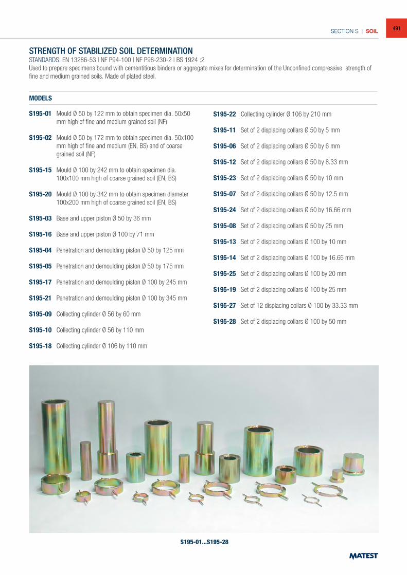
SECTION S | SOIL
S195-01...S195-28
STRENGTH OF STABILIZED SOIL DETERMINATIONSTANDARDS: EN 13286-53 | NF P94-100 | NF P98-230-2 | BS 1924 :2Used to prepare specimens bound with cementitious binders or aggregate mixes for determination of the Unconfined compressive strength of fine and medium grained soils. Made of plated steel.
MODELS
S195-01 Mould Ø 50 by 122 mm to obtain specimen dia. 50x50 mm high of fine and medium grained soil (NF)
S195-02 Mould Ø 50 by 172 mm to obtain specimen dia. 50x100 mm high of fine and medium (EN, BS) and of coarse grained soil (NF)
S195-15 Mould Ø 100 by 242 mm to obtain specimen dia. 100x100 mm high of coarse grained soil (EN, BS)
S195-20 Mould Ø 100 by 342 mm to obtain specimen diameter 100x200 mm high of coarse grained soil (EN, BS)
S195-03 Base and upper piston Ø 50 by 36 mm
S195-16 Base and upper piston Ø 100 by 71 mm
S195-04 Penetration and demoulding piston Ø 50 by 125 mm
S195-05 Penetration and demoulding piston Ø 50 by 175 mm
S195-17 Penetration and demoulding piston Ø 100 by 245 mm
S195-21 Penetration and demoulding piston Ø 100 by 345 mm
S195-09 Collecting cylinder Ø 56 by 60 mm
S195-10 Collecting cylinder Ø 56 by 110 mm
S195-18 Collecting cylinder Ø 106 by 110 mm
S195-22 Collecting cylinder Ø 106 by 210 mm
S195-11 Set of 2 displacing collars Ø 50 by 5 mm
S195-06 Set of 2 displacing collars Ø 50 by 6 mm
S195-12 Set of 2 displacing collars Ø 50 by 8.33 mm
S195-23 Set of 2 displacing collars Ø 50 by 10 mm
S195-07 Set of 2 displacing collars Ø 50 by 12.5 mm
S195-24 Set of 2 displacing collars Ø 50 by 16.66 mm
S195-08 Set of 2 displacing collars Ø 50 by 25 mm
S195-13 Set of 2 displacing collars Ø 100 by 10 mm
S195-14 Set of 2 displacing collars Ø 100 by 16.66 mm
S195-25 Set of 2 displacing collars Ø 100 by 20 mm
S195-19 Set of 2 displacing collars Ø 100 by 25 mm
S195-27 Set of 12 displacing collars Ø 100 by 33.33 mm
S195-28 Set of 2 displacing collars Ø 100 by 50 mm
491
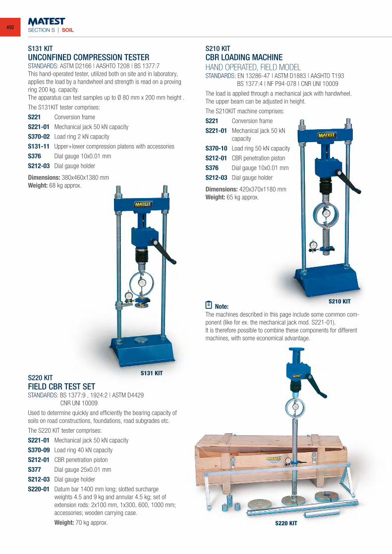
SECTION S | SOIL
S131 KITUNCONFINED COMPRESSION TESTERSTANDARDS: ASTM D2166 | AASHTO T208 | BS 1377:7This hand-operated tester, utilized both on site and in laboratory, applies the load by a handwheel and strength is read on a proving ring 200 kg. capacity.The apparatus can test samples up to Ø 80 mm x 200 mm height .
The S131KIT tester comprises:
S221 Conversion frame
S221-01 Mechanical jack 50 kN capacity
S370-02 Load ring 2 kN capacity
S131-11 Upper+lower compression platens with accessories
S376 Dial gauge 10x0.01 mm
S212-03 Dial gauge holder
Dimensions: 380x460x1380 mmWeight: 68 kg approx.
S220 KITFIELD CBR TEST SETSTANDARDS: BS 1377:9 , 1924:2 | ASTM D4429 CNR UNI 10009
Used to determine quickly and efficiently the bearing capacity of soils on road constructions, foundations, road subgrades etc.
The S220 KIT tester comprises:
S221-01 Mechanical jack 50 kN capacity
S370-09 Load ring 40 kN capacity
S212-01 CBR penetration piston
S377 Dial gauge 25x0.01 mm
S212-03 Dial gauge holder
S220-01 Datum bar 1400 mm long; slotted surcharge weights 4.5 and 9 kg and annular 4.5 kg; set of extension rods: 2x100 mm, 1x300, 600, 1000 mm; accessories; wooden carrying case.
Weight: 70 kg approx.
S210 KITCBR LOADING MACHINEHAND OPERATED, FIELD MODELSTANDARDS: EN 13286-47 | ASTM D1883 | AASHTO T193 BS 1377:4 | NF P94-078 | CNR UNI 10009
The load is applied through a mechanical jack with handwheel.The upper beam can be adjusted in height.
The S210KIT machine comprises:
S221 Conversion frame
S221-01 Mechanical jack 50 kN capacity
S370-10 Load ring 50 kN capacity
S212-01 CBR penetration piston
S376 Dial gauge 10x0.01 mm
S212-03 Dial gauge holder
Dimensions: 420x370x1180 mmWeight: 65 kg approx.
Note:The machines described in this page include some common com-ponent (like for ex. the mechanical jack mod. S221-01).It is therefore possible to combine these components for different machines, with some economical advantage.
S131 KIT
S210 KIT
S220 KIT
492
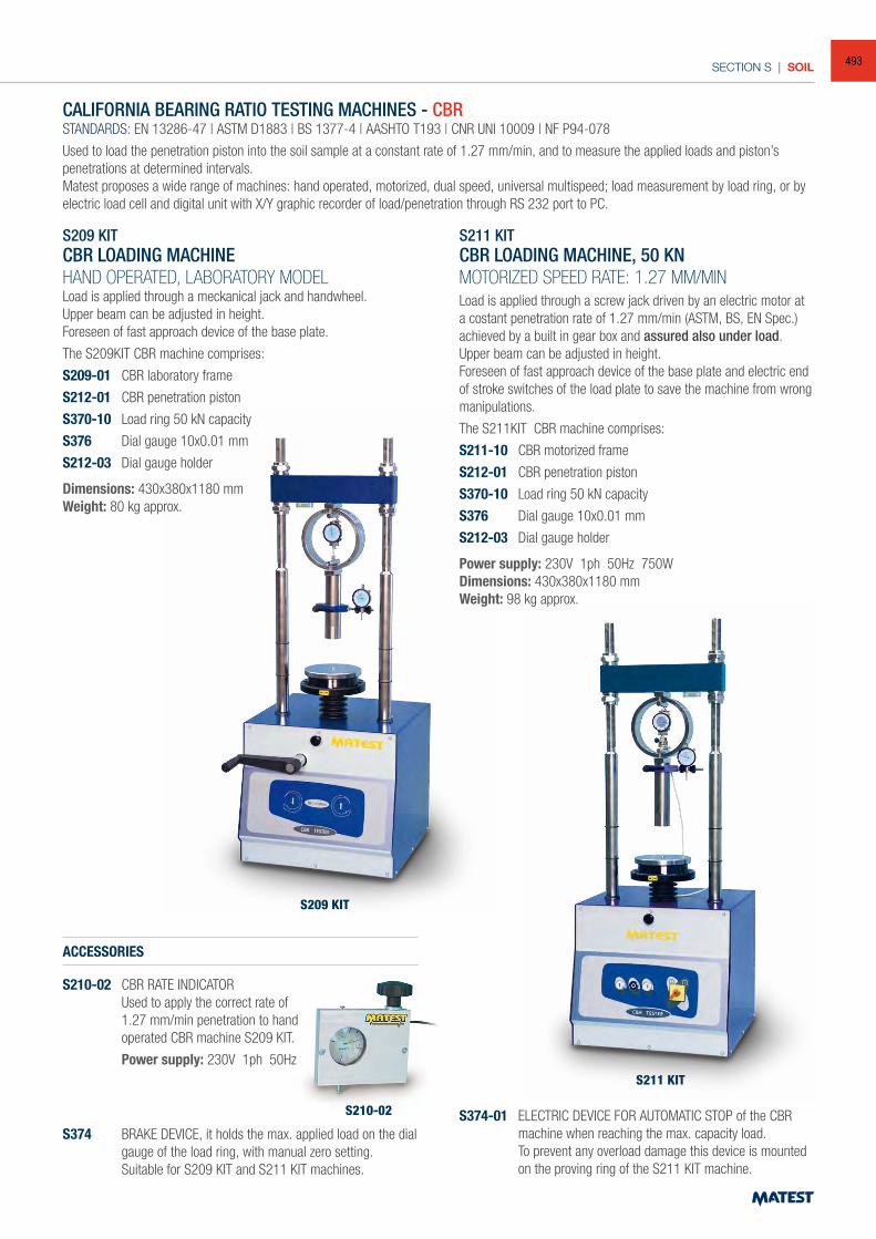
SECTION S | SOIL
S209 KIT
S210-02
S211 KIT
CALIFORNIA BEARING RATIO TESTING MACHINES - CBRSTANDARDS: EN 13286-47 | ASTM D1883 | BS 1377-4 | AASHTO T193 | CNR UNI 10009 | NF P94-078
Used to load the penetration piston into the soil sample at a constant rate of 1.27 mm/min, and to measure the applied loads and piston’s penetrations at determined intervals.Matest proposes a wide range of machines: hand operated, motorized, dual speed, universal multispeed; load measurement by load ring, or by electric load cell and digital unit with X/Y graphic recorder of load/penetration through RS 232 port to PC.
S209 KITCBR LOADING MACHINEHAND OPERATED, LABORATORY MODELLoad is applied through a meckanical jack and handwheel.Upper beam can be adjusted in height.Foreseen of fast approach device of the base plate.
The S209KIT CBR machine comprises:
S209-01 CBR laboratory frame
S212-01 CBR penetration piston
S370-10 Load ring 50 kN capacity
S376 Dial gauge 10x0.01 mm
S212-03 Dial gauge holder
Dimensions: 430x380x1180 mmWeight: 80 kg approx.
S211 KITCBR LOADING MACHINE, 50 KNMOTORIZED SPEED RATE: 1.27 MM/MINLoad is applied through a screw jack driven by an electric motor at a costant penetration rate of 1.27 mm/min (ASTM, BS, EN Spec.) achieved by a built in gear box and assured also under load.Upper beam can be adjusted in height.Foreseen of fast approach device of the base plate and electric end of stroke switches of the load plate to save the machine from wrong manipulations.
The S211KIT CBR machine comprises:
S211-10 CBR motorized frame
S212-01 CBR penetration piston
S370-10 Load ring 50 kN capacity
S376 Dial gauge 10x0.01 mm
S212-03 Dial gauge holder
Power supply: 230V 1ph 50Hz 750WDimensions: 430x380x1180 mmWeight: 98 kg approx.
ACCESSORIES
S210-02 CBR RATE INDICATOR Used to apply the correct rate of
1.27 mm/min penetration to hand operated CBR machine S209 KIT.
Power supply: 230V 1ph 50Hz
S374 BRAKE DEVICE, it holds the max. applied load on the dial gauge of the load ring, with manual zero setting.
Suitable for S209 KIT and S211 KIT machines.
S374-01 ELECTRIC DEVICE FOR AUTOMATIC STOP of the CBR machine when reaching the max. capacity load.
To prevent any overload damage this device is mounted on the proving ring of the S211 KIT machine.
493
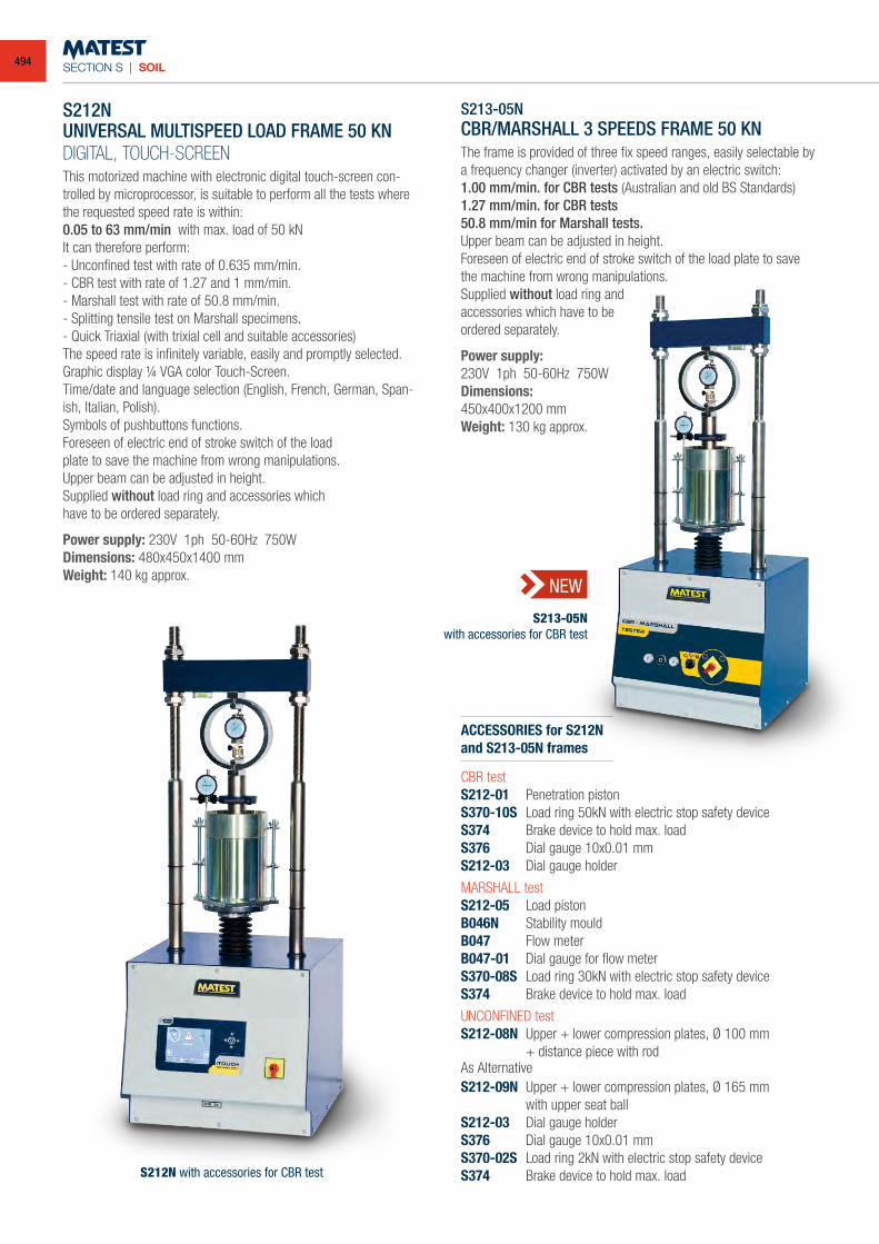
SECTION S | SOIL
S212N UNIVERSAL MULTISPEED LOAD FRAME 50 KN
DIGITAL, TOUCH-SCREENThis motorized machine with electronic digital touch-screen con-trolled by microprocessor, is suitable to perform all the tests where the requested speed rate is within:0.05 to 63 mm/min with max. load of 50 kNIt can therefore perform:- Unconfined test with rate of 0.635 mm/min.- CBR test with rate of 1.27 and 1 mm/min.- Marshall test with rate of 50.8 mm/min.- Splitting tensile test on Marshall specimens.- Quick Triaxial (with trixial cell and suitable accessories)The speed rate is infinitely variable, easily and promptly selected.Graphic display ¼ VGA color Touch-Screen.Time/date and language selection (English, French, German, Span-ish, Italian, Polish).Symbols of pushbuttons functions.Foreseen of electric end of stroke switch of the loadplate to save the machine from wrong manipulations.Upper beam can be adjusted in height.Supplied without load ring and accessories whichhave to be ordered separately.
Power supply: 230V 1ph 50-60Hz 750WDimensions: 480x450x1400 mmWeight: 140 kg approx.
S213-05NCBR/MARSHALL 3 SPEEDS FRAME 50 KNThe frame is provided of three fix speed ranges, easily selectable by a frequency changer (inverter) activated by an electric switch:1.00 mm/min. for CBR tests (Australian and old BS Standards)1.27 mm/min. for CBR tests50.8 mm/min for Marshall tests.Upper beam can be adjusted in height.Foreseen of electric end of stroke switch of the load plate to save the machine from wrong manipulations.Supplied without load ring andaccessories which have to beordered separately.
Power supply:230V 1ph 50-60Hz 750WDimensions:450x400x1200 mmWeight: 130 kg approx.
ACCESSORIES for S212Nand S213-05N frames
CBR testS212-01 Penetration pistonS370-10S Load ring 50kN with electric stop safety deviceS374 Brake device to hold max. load S376 Dial gauge 10x0.01 mmS212-03 Dial gauge holder
MARSHALL testS212-05 Load pistonB046N Stability mouldB047 Flow meterB047-01 Dial gauge for flow meterS370-08S Load ring 30kN with electric stop safety deviceS374 Brake device to hold max. load
UNCONFINED testS212-08N Upper + lower compression plates, Ø 100 mm + distance piece with rodAs AlternativeS212-09N Upper + lower compression plates, Ø 165 mm with upper seat ballS212-03 Dial gauge holderS376 Dial gauge 10x0.01 mm S370-02S Load ring 2kN with electric stop safety deviceS374 Brake device to hold max. load
S213-05Nwith accessories for CBR test
NEW
S212N with accessories for CBR test
494
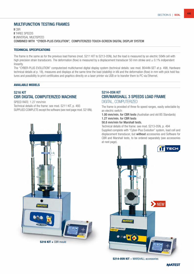
SECTION S | SOIL
MULTIFUNCTION TESTING FRAMES CBR THREE SPEEDS UNIVERSAL MULTISPEED
COMBINED WITH “CYBER-PLUS EVOLUTION”, COMPUTERIZED TOUCH-SCREEN DIGITAL DISPLAY SYSTEM
TECHNICAL SPECIFICATIONS
The frame is the same as for the previous load frames (mod. S211 KIT to S213-05N), but the load is measured by an electric 50kN cell with high precision strain transducers. The deformation (flow) is measured by a displacement transducer 50 mm stroke and ± 0.1% indipendent linearity.The “CYBER-PLUS EVOLUTION” computerized multichannel digital display system (technical details: see mod. B044N-SET at p. 498, Hardware technical details at p. 18), measures and displays at the same time the load (stability) in kN and the deformation (flow) in mm with pick hold fea-tures and possibility to print certificates and graphics directly on a laser printer via USB or to transfer them to PC via Ethernet.
AVAILABLE MODELS
S216 KITCBR DIGITAL COMPUTERIZED MACHINESPEED RATE: 1.27 mm/minTechnical details of the frame: see mod. S211 KIT, p. 493SUPPLIED COMPLETE except the software (see next page mod. S218N).
S214-05N KITCBR/MARSHALL 3 SPEEDS LOAD FRAMEDIGITAL, COMPUTERIZEDThe frame is provided of three fix speed ranges, easily selectable by an electric switch:1.00 mm/min. for CBR tests (Australian and old BS Standards)1.27 mm/min. for CBR tests50.8 mm/min for Marshall tests.Technical details of the frame: see mod. S213-05N, p. 494Supplied complete with “Cyber-Plus Evolution” system, load cell and displacement transducer, but without accessories and Software for CBR and Marshall tests, to be ordered separately (see accessories at next page).
S214-05N KIT + MARSHALL accessories
S216 KIT + CBR mould
NEW
495
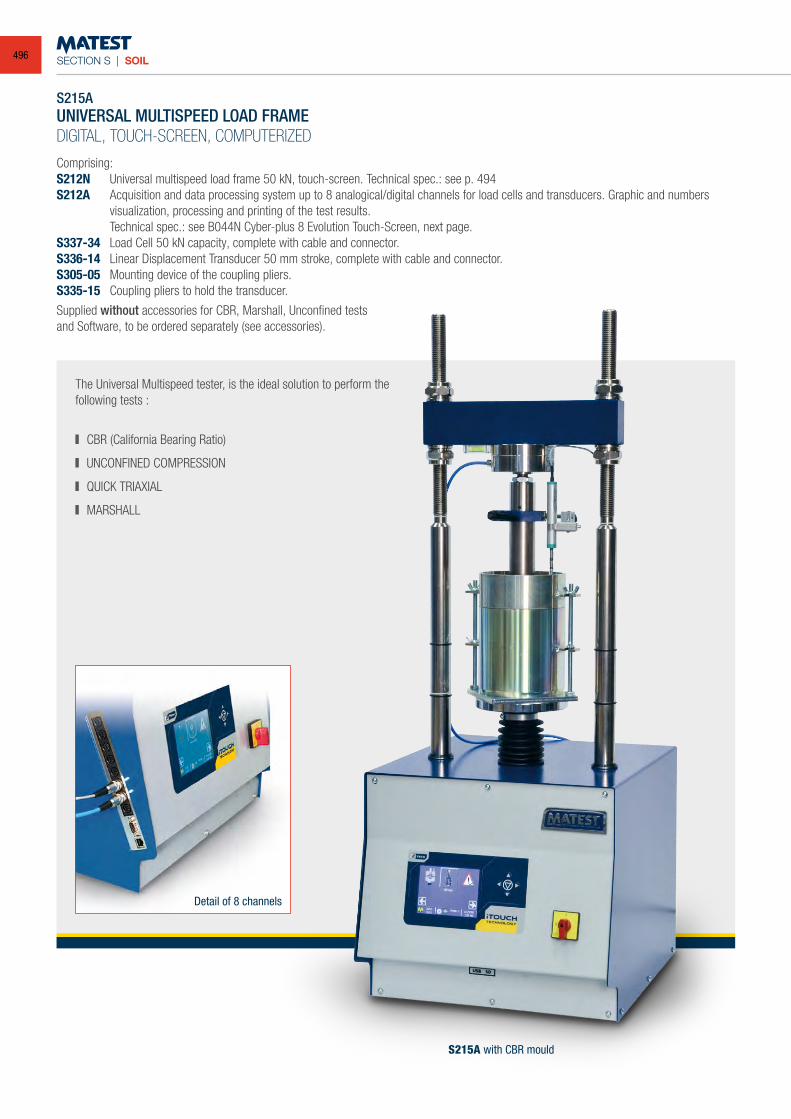
SECTION S | SOIL
Comprising:S212N Universal multispeed load frame 50 kN, touch-screen. Technical spec.: see p. 494S212A Acquisition and data processing system up to 8 analogical/digital channels for load cells and transducers. Graphic and numbers
visualization, processing and printing of the test results. Technical spec.: see B044N Cyber-plus 8 Evolution Touch-Screen, next page.S337-34 Load Cell 50 kN capacity, complete with cable and connector.S336-14 Linear Displacement Transducer 50 mm stroke, complete with cable and connector.S305-05 Mounting device of the coupling pliers.S335-15 Coupling pliers to hold the transducer.
Supplied without accessories for CBR, Marshall, Unconfined testsand Software, to be ordered separately (see accessories).
S215AUNIVERSAL MULTISPEED LOAD FRAMEDIGITAL, TOUCH-SCREEN, COMPUTERIZED
Detail of 8 channels
The Universal Multispeed tester, is the ideal solution to perform the following tests :
CBR (California Bearing Ratio)
UNCONFINED COMPRESSION
QUICK TRIAXIAL
MARSHALL
S215A with CBR mould
496
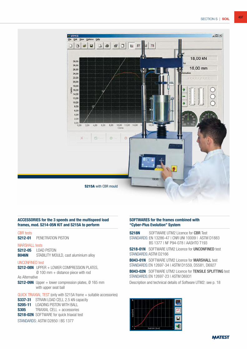
SECTION S | SOIL
ACCESSORIES for the 3 speeds and the multispeed load frames, mod. S214-05N KIT and S215A to perform
CBR testsS212-01 PENETRATION PISTON
MARSHALL testsS212-05 LOAD PISTONB046N STABILITY MOULD, cast aluminium alloy
UNCONFINED testS212-08N UPPER + LOWER COMPRESSION PLATES, Ø 100 mm + distance piece with rodAs AlternativeS212-09N Upper + lower compression plates, Ø 165 mm with upper seat ball
QUICK TRIAXIAL TEST (only with S215A frame + suitable accessories)S337-31 STRAIN LOAD CELL 2.5 kN capacityS205-11 LOADING PISTON WITH BALLS305 TRIAXIAL CELL + accessoriesS218-02N SOFTWARE for quick triaxial test
STANDARDS: ASTM D2850 | BS 1377
SOFTWARES for the frames combined with“Cyber-Plus Evolution” System
S218N SOFTWARE UTM2 Licence for CBR TestSTANDARDS: EN 13286-47 | CNR UNI 10009 | ASTM D1883 BS 1377 | NF P94-078 | AASHTO T193
S218-01N SOFTWARE UTM2 Licence for UNCONFINED testSTANDARDS: ASTM D2166
B043-01N SOFTWARE UTM2 Licence for MARSHALL testSTANDARDS: EN 12697-34 | ASTM D1559, D5581, D6927
B043-02N SOFTWARE UTM2 Licence for TENSILE SPLITTING testSTANDARDS: EN 12697-23 | ASTM D6931
Description and technical details of Software UTM2: see p. 18
S215A with CBR mould
497
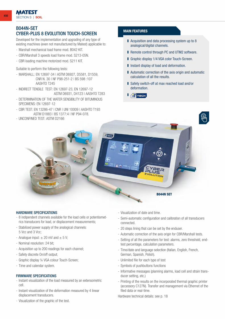
SECTION S | SOIL
B044N SET
B044N-SETCYBER-PLUS 8 EVOLUTION TOUCH-SCREENDeveloped for the implementation and upgrading of any type of existing machines (even not manufactured by Matest) applicable to:
- Marshall mechanical load frame mod. B042 KIT.
- CBR/Marshall 3 speeds load frame mod. S213-05N.
- CBR loading machine motorized mod. S211 KIT.
Suitable to perform the following tests:
- MARSHALL: EN 12697-34 | ASTM D6927, D5581, D1559, CNR N. 30 | NF P98-251-2 | BS 598 :107
AASHTO T245
- INDIRECT TENSILE TEST: EN 12697-23, EN 12697-12 ASTM D6931, D4123 | AASHTO T283
- DETERMINATION OF THE WATER SENSIBILITY OF BITUMINOUS SPECIMENS: EN 12697-12
- CBR TEST: EN 13286-47 | CNR | UNI 10009 | AASHTO T193 ASTM D1883 | BS 1377:4 | NF P94-078.- UNCONFINED TEST: ASTM D2166
MAIN FEATURES
Acquisition and data processing system up to 8 analogical/digital channels.
Remote control through PC and UTM2 software.
Graphic display 1/4 VGA color Touch-Screen.
Instant display of load and deformation.
Automatic correction of the axis origin and automatic calculation of all the results.
Safety switch-off at max reached load and/or deformation.
HARDWARE SPECIFICATIONS- 8 indipendent channels available for the load cells or potentiomet-
rics transducers for load, or displacement measurements;
- Stabilized power supply of the analogical channels: 5 Vcc and 3 Vcc;
- Analogue input: ± 20 mV and ± 5 V;
- Nominal resolution: 24 bit;
- Acquisition up to 200 readings for each channel;
- Safety discrete On/off output;
- Graphic display ¼ VGA colour Touch-Screen;
- Time and calendar system.
FIRMWARE SPECIFICATIONS- Instant visualization of the load measured by an extensometric
cell.
- Instant visualization of the deformation measured by 4 linear displacement transducers.
- Visualization of the graphic of the test.
- Visualization of date and time.
- Semi-automatic configuration and calibration of all transducers connected.
- 20 steps lining that can be set by the enduser.
- Automatic correction of the axis origin for CBR/Marshall tests.
- Setting of all the parameters for test: alarms, zero threshold, end-test percentage, calculation parameters.
- Time/date and language selection (Italian, English, French, German, Spanish, Polish).
- Unlimited file for each type of test
- Symbols of pushbuttons functions
- Informative messages (planning alarms, load cell and strain trans-ducer setting, etc.)
- Printing of the results on the incorporated thermal graphic printer (accessory C127N). Transfer and management via Ethernet of the filed data or real-time.
Hardware technical details: see p. 18
498
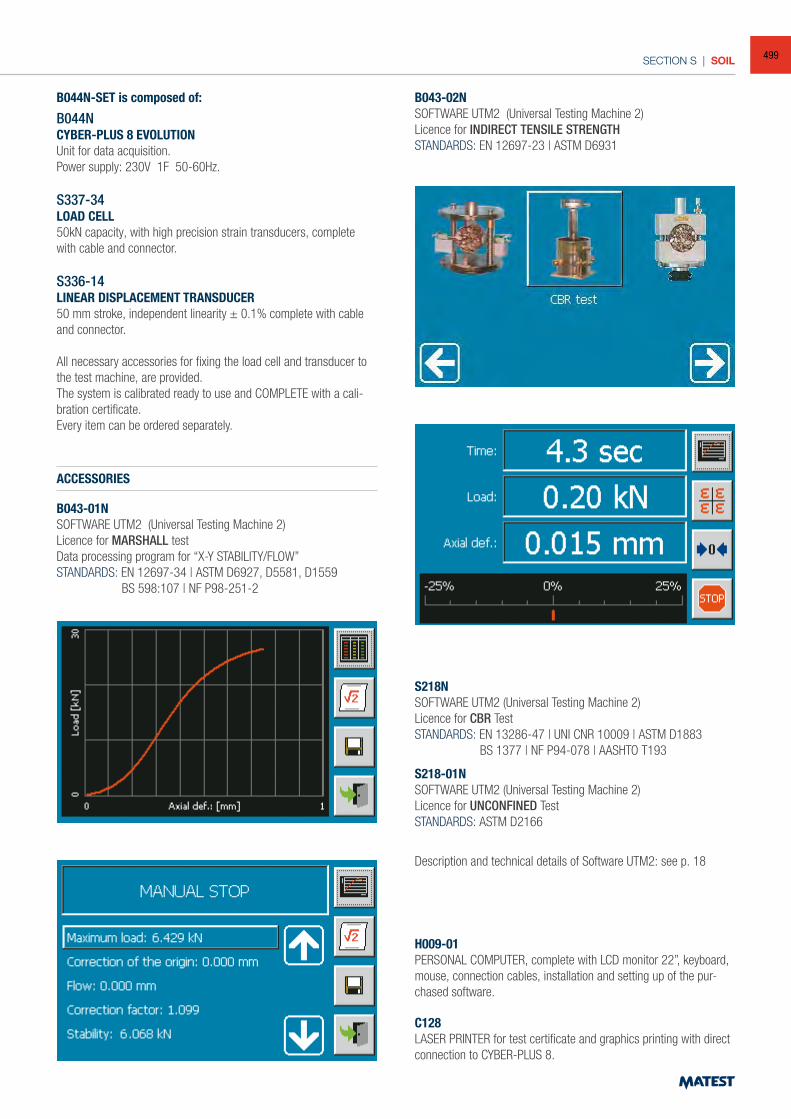
SECTION S | SOIL
B044N-SET is composed of:
B044NCYBER-PLUS 8 EVOLUTIONUnit for data acquisition.Power supply: 230V 1F 50-60Hz.
S337-34LOAD CELL50kN capacity, with high precision strain transducers, complete with cable and connector.
S336-14LINEAR DISPLACEMENT TRANSDUCER50 mm stroke, independent linearity ± 0.1% complete with cable and connector.
All necessary accessories for fixing the load cell and transducer to the test machine, are provided.The system is calibrated ready to use and COMPLETE with a cali-bration certificate.Every item can be ordered separately.
ACCESSORIES
B043-01NSOFTWARE UTM2 (Universal Testing Machine 2)Licence for MARSHALL testData processing program for “X-Y STABILITY/FLOW”STANDARDS: EN 12697-34 | ASTM D6927, D5581, D1559 BS 598:107 | NF P98-251-2
B043-02NSOFTWARE UTM2 (Universal Testing Machine 2)Licence for INDIRECT TENSILE STRENGTHSTANDARDS: EN 12697-23 | ASTM D6931
S218NSOFTWARE UTM2 (Universal Testing Machine 2)Licence for CBR TestSTANDARDS: EN 13286-47 | UNI CNR 10009 | ASTM D1883 BS 1377 | NF P94-078 | AASHTO T193
S218-01NSOFTWARE UTM2 (Universal Testing Machine 2)Licence for UNCONFINED TestSTANDARDS: ASTM D2166
Description and technical details of Software UTM2: see p. 18
H009-01PERSONAL COMPUTER, complete with LCD monitor 22”, keyboard, mouse, connection cables, installation and setting up of the pur-chased software.
C128LASER PRINTER for test certificate and graphics printing with direct connection to CYBER-PLUS 8.
499
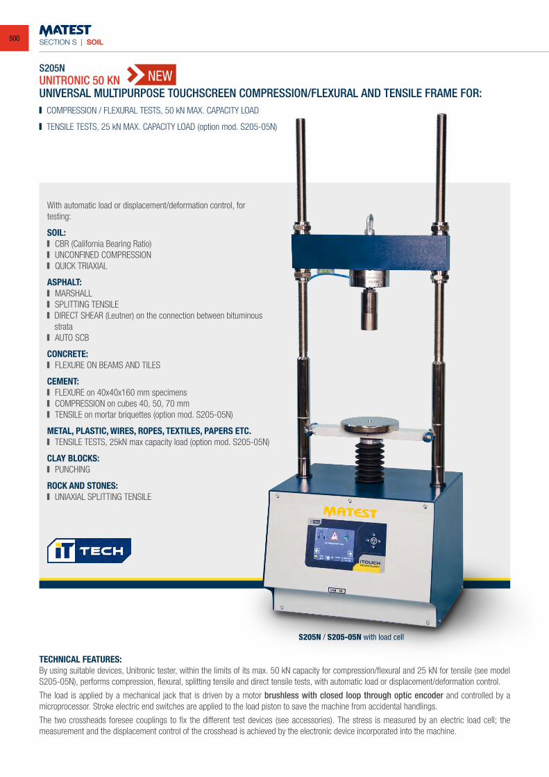
SECTION S | SOIL
S205NUNITRONIC 50 KN
With automatic load or displacement/deformation control, for testing:
SOIL: CBR (California Bearing Ratio) UNCONFINED COMPRESSION QUICK TRIAXIAL
ASPHALT: MARSHALL SPLITTING TENSILE DIRECT SHEAR (Leutner) on the connection between bituminous
strata AUTO SCB
CONCRETE: FLEXURE ON BEAMS AND TILES
CEMENT: FLEXURE on 40x40x160 mm specimens COMPRESSION on cubes 40, 50, 70 mm TENSILE on mortar briquettes (option mod. S205-05N)
METAL, PLASTIC, WIRES, ROPES, TEXTILES, PAPERS ETC. TENSILE TESTS, 25kN max capacity load (option mod. S205-05N)
CLAY BLOCKS: PUNCHING
ROCK AND STONES: UNIAXIAL SPLITTING TENSILE
UNIVERSAL MULTIPURPOSE TOUCHSCREEN COMPRESSION/FLEXURAL AND TENSILE FRAME FOR: COMPRESSION / FLEXURAL TESTS, 50 kN MAX. CAPACITY LOAD
TENSILE TESTS, 25 kN MAX. CAPACITY LOAD (option mod. S205-05N)
TECHNICAL FEATURES: By using suitable devices, Unitronic tester, within the limits of its max. 50 kN capacity for compression/flexural and 25 kN for tensile (see model S205-05N), performs compression, flexural, splitting tensile and direct tensile tests, with automatic load or displacement/deformation control.
The load is applied by a mechanical jack that is driven by a motor brushless with closed loop through optic encoder and controlled by a microprocessor. Stroke electric end switches are applied to the load piston to save the machine from accidental handlings.
The two crossheads foresee couplings to fix the different test devices (see accessories). The stress is measured by an electric load cell; the measurement and the displacement control of the crosshead is achieved by the electronic device incorporated into the machine.
S205N / S205-05N with load cell
NEW
500
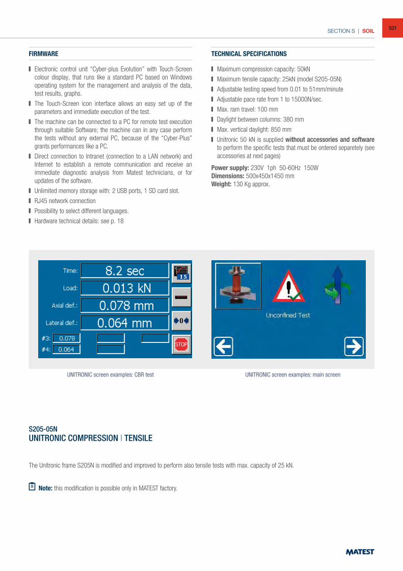
SECTION S | SOIL
FIRMWARE
Electronic control unit “Cyber-plus Evolution” with Touch-Screen colour display, that runs like a standard PC based on Windows operating system for the management and analysis of the data, test results, graphs.
The Touch-Screen icon interface allows an easy set up of the parameters and immediate execution of the test.
The machine can be connected to a PC for remote test execution through suitable Software; the machine can in any case perform the tests without any external PC, because of the “Cyber-Plus” grants performances like a PC.
Direct connection to Intranet (connection to a LAN network) and Internet to establish a remote communication and receive an immediate diagnostic analysis from Matest technicians, or for updates of the software.
Unlimited memory storage with: 2 USB ports, 1 SD card slot.
RJ45 network connection
Possibility to select different languages.
Hardware technical details: see p. 18
TECHNICAL SPECIFICATIONS
Maximum compression capacity: 50kN
Maximum tensile capacity: 25kN (model S205-05N)
Adjustable testing speed from 0.01 to 51mm/minute
Adjustable pace rate from 1 to 15000N/sec.
Max. ram travel: 100 mm
Daylight between columns: 380 mm
Max. vertical daylight: 850 mm
Unitronic 50 kN is supplied without accessories and software to perform the specific tests that must be ordered separetely (see accessories at next pages)
Power supply: 230V 1ph 50-60Hz 150WDimensions: 500x450x1450 mmWeight: 130 Kg approx.
UNITRONIC screen examples: CBR test UNITRONIC screen examples: main screen
S205-05NUNITRONIC COMPRESSION | TENSILE
The Unitronic frame S205N is modified and improved to perform also tensile tests with max. capacity of 25 kN.
Note: this modification is possible only in MATEST factory.
501
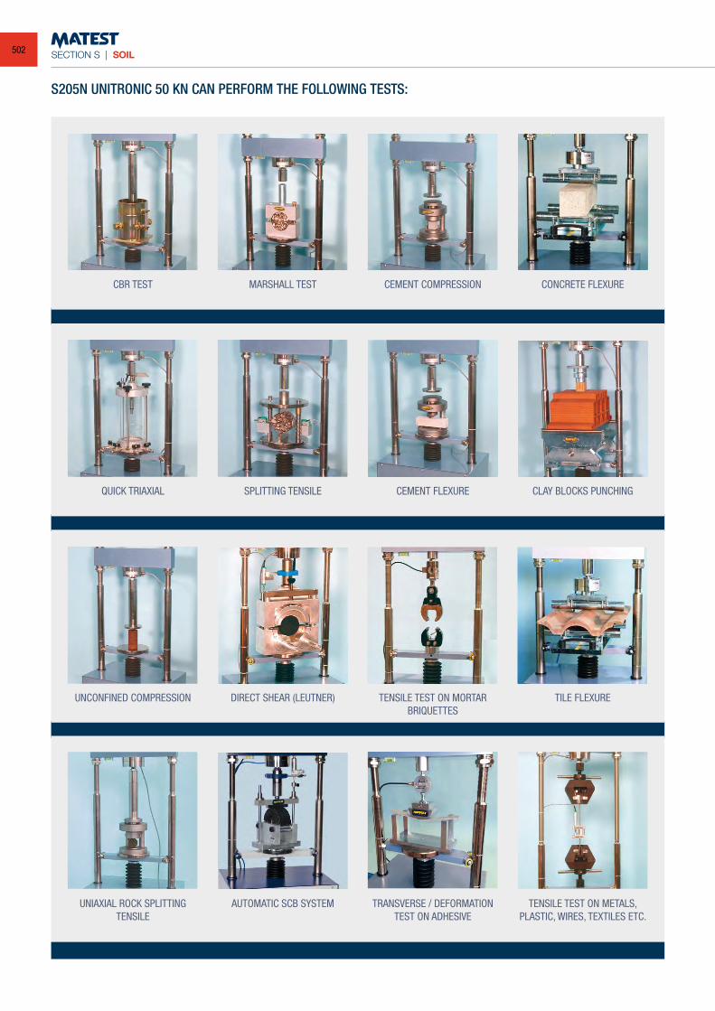
SECTION S | SOIL
S205N UNITRONIC 50 KN CAN PERFORM THE FOLLOWING TESTS:
CBR TEST
QUICK TRIAXIAL
UNCONFINED COMPRESSION
UNIAXIAL ROCK SPLITTINGTENSILE
MARSHALL TEST
SPLITTING TENSILE
DIRECT SHEAR (LEUTNER)
AUTOMATIC SCB SYSTEM
CEMENT COMPRESSION
CEMENT FLEXURE
TENSILE TEST ON MORTARBRIQUETTES
TRANSVERSE / DEFORMATIONTEST ON ADHESIVE
CONCRETE FLEXURE
CLAY BLOCKS PUNCHING
TILE FLEXURE
TENSILE TEST ON METALS,PLASTIC, WIRES, TEXTILES ETC.
502
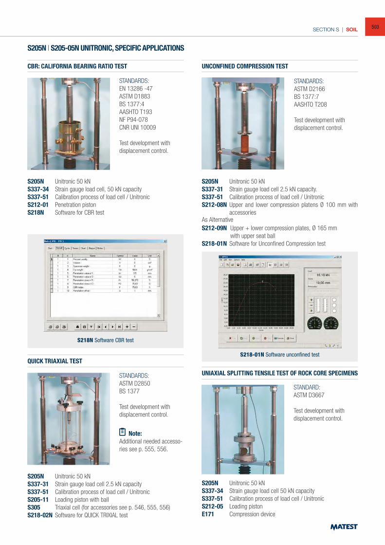
SECTION S | SOIL
S205N | S205-05N UNITRONIC, SPECIFIC APPLICATIONS
CBR: CALIFORNIA BEARING RATIO TEST
QUICK TRIAXIAL TEST
STANDARDS:EN 13286 -47ASTM D1883 BS 1377:4 AASHTO T193NF P94-078CNR UNI 10009
Test development with displacement control.
STANDARDS:ASTM D2166BS 1377:7AASHTO T208
Test development with displacement control.
STANDARDS:ASTM D2850BS 1377
Test development with displacement control.
S205N Unitronic 50 kNS337-34 Strain gauge load cell, 50 kN capacityS337-51 Calibration process of load cell / UnitronicS212-01 Penetration pistonS218N Software for CBR test
S205N Unitronic 50 kNS337-31 Strain gauge load cell 2.5 kN capacityS337-51 Calibration process of load cell / UnitronicS205-11 Loading piston with ballS305 Triaxial cell (for accessories see p. 546, 555, 556)S218-02N Software for QUICK TRIXIAL test
UNIAXIAL SPLITTING TENSILE TEST OF ROCK CORE SPECIMENS
STANDARD:ASTM D3667
Test development with displacement control.
S205N Unitronic 50 kNS337-34 Strain gauge load cell 50 kN capacityS337-51 Calibration process of load cell / UnitronicS212-05 Loading pistonE171 Compression device
UNCONFINED COMPRESSION TEST
S205N Unitronic 50 kNS337-31 Strain gauge load cell 2.5 kN capacity.S337-51 Calibration process of load cell / UnitronicS212-08N Upper and lower compression platens Ø 100 mm with
accessoriesAs AlternativeS212-09N Upper + lower compression plates, Ø 165 mm with upper seat ballS218-01N Software for Unconfined Compression test
S218-01N Software unconfined test
S218N Software CBR test
Note:Additional needed accesso-ries see p. 555, 556.
503
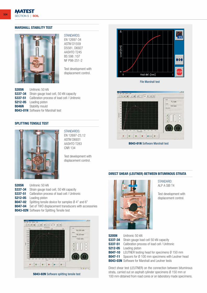
SECTION S | SOIL
SPLITTING TENSILE TEST
MARSHALL STABILITY TEST
DIRECT SHEAR (LEUTNER) BETWEEN BITUMINOUS STRATA
STANDARDS:EN 12697-23,12ASTM D6931AASHTO T283CNR 134
Test development with displacement control.
STANDARDS:EN 12697-34 ASTM D1559D5581, D6927AASHTO T245BS 598 :107 NF P98-251-2
Test development with displacement control.
STANDARD:ALP A StB T4
Test development with displacement control.
S205N Unitronic 50 kNS337-34 Strain gauge load cell, 50 kN capacityS337-51 Calibration process of load cell / UnitronicS212-05 Loading pistonB047-02 Splitting tensile device for samples Ø 4” and 6”B047-04 Set of TWO displacement transducers with accessoriesB043-02N Software for Splitting Tensile test
S205N Unitronic 50 kNS337-34 Strain gauge load cell, 50 kN capacityS337-51 Calibration process of load cell / UnitronicS212-05 Loading pistonB046N Stability mouldB043-01N Software for Marshall test
S205N Unitronic 50 kNS337-34 Strain gauge load cell 50 kN capacityS337-51 Calibration process of load cell / UnitronicS212-05 Loading pistonB047-10 LEUTNER testing head for specimens Ø 150 mm B047-11 Spacers for Ø 100 mm specimens with Leutner head B043-03N Software for Marshall and Leutner tests
S043-02N Software splitting tensile test
B043-01N Software Marshall test
File Marshall test
Direct shear test (LEUTNER) on the connection between bituminous strata, carried out on asphalt cylinder specimens Ø 150 mm or100 mm obtained from road cores or on laboratory made specimens.
504
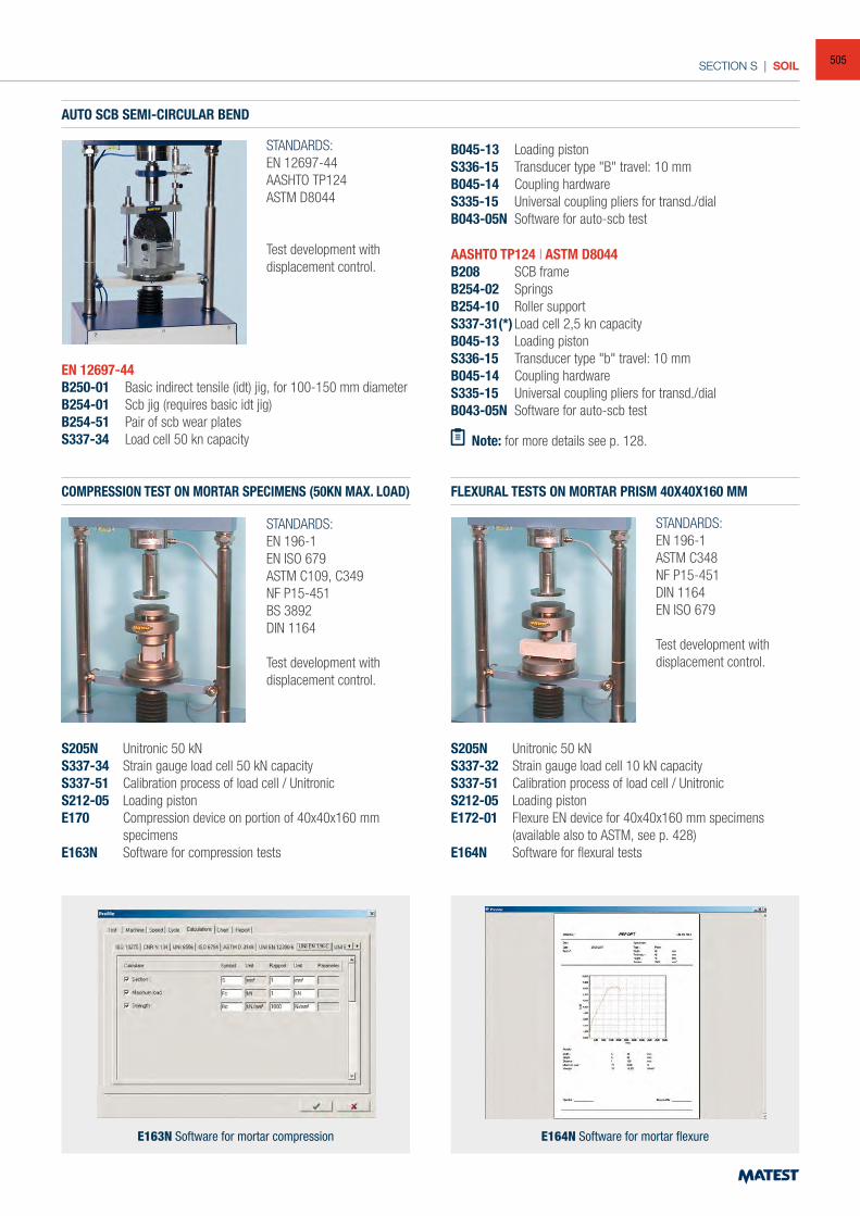
SECTION S | SOIL
COMPRESSION TEST ON MORTAR SPECIMENS (50KN MAX. LOAD)
AUTO SCB SEMI-CIRCULAR BEND
FLEXURAL TESTS ON MORTAR PRISM 40X40X160 MM
STANDARDS:EN 196-1EN ISO 679ASTM C109, C349 NF P15-451 BS 3892DIN 1164
Test development with displacement control.
STANDARDS:EN 12697-44AASHTO TP124ASTM D8044
Test development with displacement control.
STANDARDS:EN 196-1 ASTM C348 NF P15-451DIN 1164 EN ISO 679
Test development with displacement control.
S205N Unitronic 50 kNS337-34 Strain gauge load cell 50 kN capacityS337-51 Calibration process of load cell / UnitronicS212-05 Loading pistonE170 Compression device on portion of 40x40x160 mm
specimensE163N Software for compression tests
S205N Unitronic 50 kNS337-32 Strain gauge load cell 10 kN capacityS337-51 Calibration process of load cell / UnitronicS212-05 Loading pistonE172-01 Flexure EN device for 40x40x160 mm specimens
(available also to ASTM, see p. 428)E164N Software for flexural tests
E163N Software for mortar compression E164N Software for mortar flexure
EN 12697-44B250-01 Basic indirect tensile (idt) jig, for 100-150 mm diameterB254-01 Scb jig (requires basic idt jig)B254-51 Pair of scb wear plates S337-34 Load cell 50 kn capacity
AASHTO TP124 | ASTM D8044B208 SCB frameB254-02 SpringsB254-10 Roller supportS337-31(*) Load cell 2,5 kn capacity B045-13 Loading pistonS336-15 Transducer type "b" travel: 10 mmB045-14 Coupling hardware S335-15 Universal coupling pliers for transd./dialB043-05N Software for auto-scb test
B045-13 Loading pistonS336-15 Transducer type "B" travel: 10 mmB045-14 Coupling hardware S335-15 Universal coupling pliers for transd./dialB043-05N Software for auto-scb test
Note: for more details see p. 128.
505
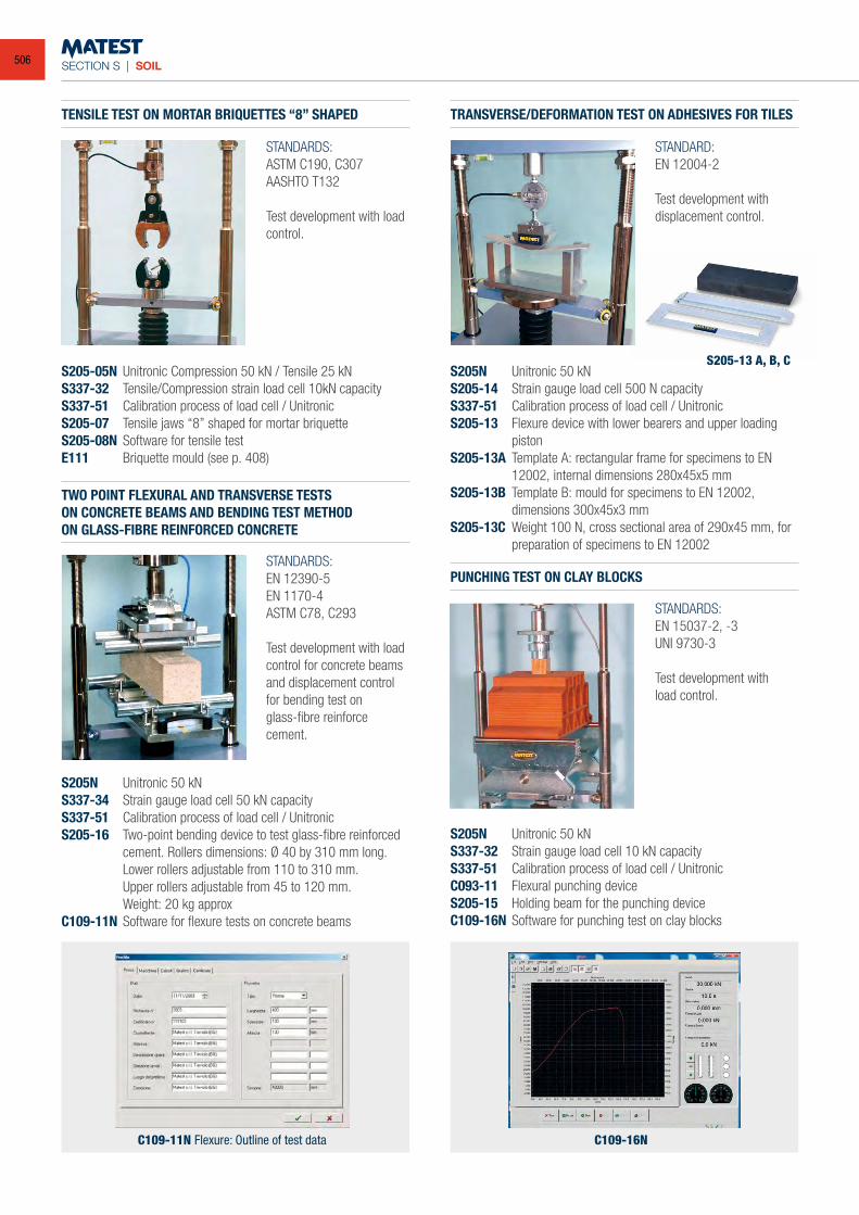
SECTION S | SOIL
TENSILE TEST ON MORTAR BRIQUETTES “8” SHAPED
TWO POINT FLEXURAL AND TRANSVERSE TESTS ON CONCRETE BEAMS AND BENDING TEST METHOD ON GLASS-FIBRE REINFORCED CONCRETE
TRANSVERSE/DEFORMATION TEST ON ADHESIVES FOR TILES
STANDARDS:ASTM C190, C307AASHTO T132
Test development with load control.
STANDARDS:EN 12390-5 EN 1170-4ASTM C78, C293
Test development with load control for concrete beams and displacement control for bending test onglass-fibre reinforce cement.
STANDARD:EN 12004-2
Test development with displacement control.
S205-05N Unitronic Compression 50 kN / Tensile 25 kNS337-32 Tensile/Compression strain load cell 10kN capacityS337-51 Calibration process of load cell / UnitronicS205-07 Tensile jaws “8” shaped for mortar briquetteS205-08N Software for tensile testE111 Briquette mould (see p. 408)
S205N Unitronic 50 kNS337-34 Strain gauge load cell 50 kN capacityS337-51 Calibration process of load cell / UnitronicS205-16 Two-point bending device to test glass-fibre reinforced
cement. Rollers dimensions: Ø 40 by 310 mm long. Lower rollers adjustable from 110 to 310 mm.
Upper rollers adjustable from 45 to 120 mm. Weight: 20 kg approxC109-11N Software for flexure tests on concrete beams
S205N Unitronic 50 kNS205-14 Strain gauge load cell 500 N capacityS337-51 Calibration process of load cell / UnitronicS205-13 Flexure device with lower bearers and upper loading
pistonS205-13A Template A: rectangular frame for specimens to EN
12002, internal dimensions 280x45x5 mmS205-13B Template B: mould for specimens to EN 12002,
dimensions 300x45x3 mmS205-13C Weight 100 N, cross sectional area of 290x45 mm, for
preparation of specimens to EN 12002
PUNCHING TEST ON CLAY BLOCKS
STANDARDS:EN 15037-2, -3 UNI 9730-3
Test development withload control.
S205N Unitronic 50 kNS337-32 Strain gauge load cell 10 kN capacityS337-51 Calibration process of load cell / UnitronicC093-11 Flexural punching deviceS205-15 Holding beam for the punching deviceC109-16N Software for punching test on clay blocks
S205-13 A, B, C
C109-11N Flexure: Outline of test data C109-16N
506
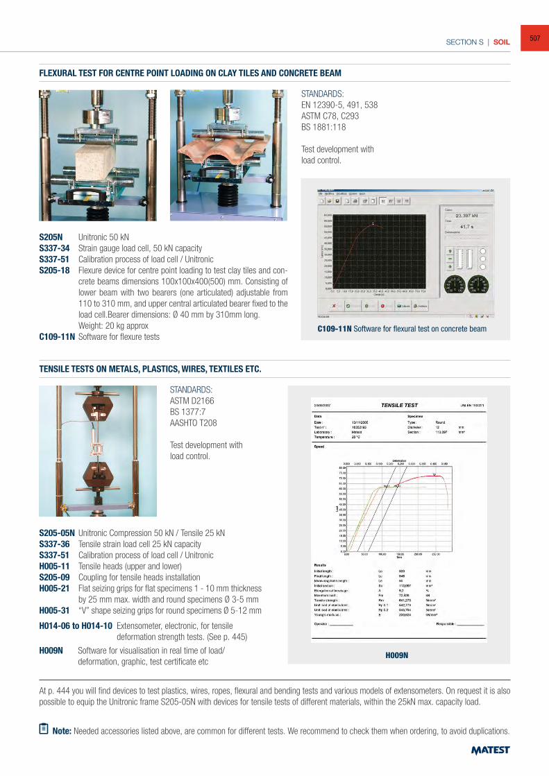
SECTION S | SOIL
TENSILE TESTS ON METALS, PLASTICS, WIRES, TEXTILES ETC.
FLEXURAL TEST FOR CENTRE POINT LOADING ON CLAY TILES AND CONCRETE BEAM
STANDARDS:ASTM D2166BS 1377:7AASHTO T208
Test development withload control.
STANDARDS:EN 12390-5, 491, 538 ASTM C78, C293BS 1881:118
Test development withload control.
S205-05N Unitronic Compression 50 kN / Tensile 25 kN S337-36 Tensile strain load cell 25 kN capacityS337-51 Calibration process of load cell / UnitronicH005-11 Tensile heads (upper and lower)S205-09 Coupling for tensile heads installationH005-21 Flat seizing grips for flat specimens 1 - 10 mm thickness
by 25 mm max. width and round specimens Ø 3-5 mmH005-31 “V” shape seizing grips for round specimens Ø 5-12 mm
S205N Unitronic 50 kNS337-34 Strain gauge load cell, 50 kN capacityS337-51 Calibration process of load cell / UnitronicS205-18 Flexure device for centre point loading to test clay tiles and con-
crete beams dimensions 100x100x400(500) mm. Consisting of lower beam with two bearers (one articulated) adjustable from 110 to 310 mm, and upper central articulated bearer fixed to the load cell.Bearer dimensions: Ø 40 mm by 310mm long.
Weight: 20 kg approxC109-11N Software for flexure tests
C109-11N Software for flexural test on concrete beam
At p. 444 you will find devices to test plastics, wires, ropes, flexural and bending tests and various models of extensometers. On request it is also possible to equip the Unitronic frame S205-05N with devices for tensile tests of different materials, within the 25kN max. capacity load.
Note: Needed accessories listed above, are common for different tests. We recommend to check them when ordering, to avoid duplications.
H014-06 to H014-10 Extensometer, electronic, for tensile deformation strength tests. (See p. 445)
H009N Software for visualisation in real time of load/deformation, graphic, test certificate etc
H009N
507
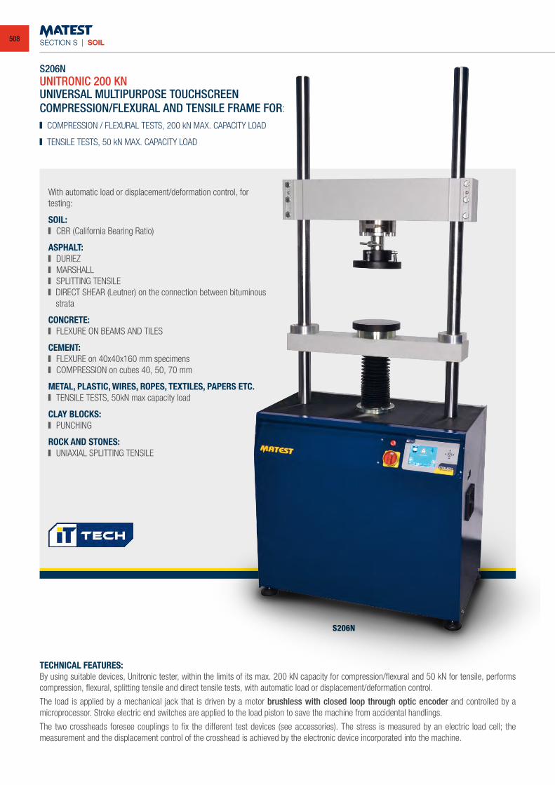
SECTION S | SOIL
S206NUNITRONIC 200 KN
With automatic load or displacement/deformation control, for testing:
SOIL: CBR (California Bearing Ratio)
ASPHALT: DURIEZ MARSHALL SPLITTING TENSILE DIRECT SHEAR (Leutner) on the connection between bituminous
strata
CONCRETE: FLEXURE ON BEAMS AND TILES
CEMENT: FLEXURE on 40x40x160 mm specimens COMPRESSION on cubes 40, 50, 70 mm
METAL, PLASTIC, WIRES, ROPES, TEXTILES, PAPERS ETC. TENSILE TESTS, 50kN max capacity load
CLAY BLOCKS: PUNCHING
ROCK AND STONES: UNIAXIAL SPLITTING TENSILE
UNIVERSAL MULTIPURPOSE TOUCHSCREENCOMPRESSION/FLEXURAL AND TENSILE FRAME FOR: COMPRESSION / FLEXURAL TESTS, 200 kN MAX. CAPACITY LOAD
TENSILE TESTS, 50 kN MAX. CAPACITY LOAD
TECHNICAL FEATURES: By using suitable devices, Unitronic tester, within the limits of its max. 200 kN capacity for compression/flexural and 50 kN for tensile, performs compression, flexural, splitting tensile and direct tensile tests, with automatic load or displacement/deformation control.
The load is applied by a mechanical jack that is driven by a motor brushless with closed loop through optic encoder and controlled by a microprocessor. Stroke electric end switches are applied to the load piston to save the machine from accidental handlings.
The two crossheads foresee couplings to fix the different test devices (see accessories). The stress is measured by an electric load cell; the measurement and the displacement control of the crosshead is achieved by the electronic device incorporated into the machine.
S206N
508
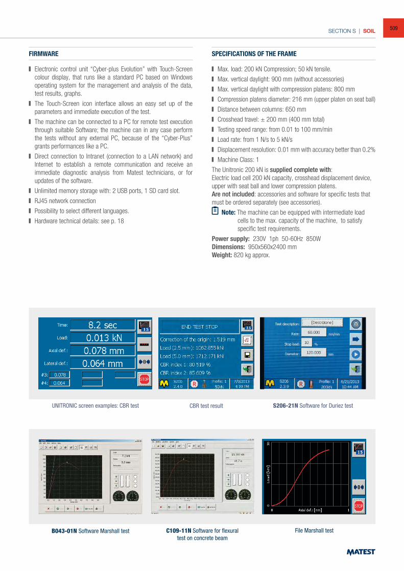
SECTION S | SOIL
FIRMWARE
Electronic control unit “Cyber-plus Evolution” with Touch-Screen colour display, that runs like a standard PC based on Windows operating system for the management and analysis of the data, test results, graphs.
The Touch-Screen icon interface allows an easy set up of the parameters and immediate execution of the test.
The machine can be connected to a PC for remote test execution through suitable Software; the machine can in any case perform the tests without any external PC, because of the “Cyber-Plus” grants performances like a PC.
Direct connection to Intranet (connection to a LAN network) and Internet to establish a remote communication and receive an immediate diagnostic analysis from Matest technicians, or for updates of the software.
Unlimited memory storage with: 2 USB ports, 1 SD card slot.
RJ45 network connection
Possibility to select different languages.
Hardware technical details: see p. 18
SPECIFICATIONS OF THE FRAME
Max. load: 200 kN Compression; 50 kN tensile.
Max. vertical daylight: 900 mm (without accessories)
Max. vertical daylight with compression platens: 800 mm
Compression platens diameter: 216 mm (upper platen on seat ball)
Distance between columns: 650 mm
Crosshead travel: ± 200 mm (400 mm total)
Testing speed range: from 0.01 to 100 mm/min
Load rate: from 1 N/s to 5 kN/s
Displacement resolution: 0.01 mm with accuracy better than 0.2%
Machine Class: 1
The Unitronic 200 kN is supplied complete with:Electric load cell 200 kN capacity, crosshead displacement device, upper with seat ball and lower compression platens.Are not included: accessories and software for specific tests that must be ordered separately (see accessories).
Note: The machine can be equipped with intermediate load cells to the max. capacity of the machine, to satisfy
specific test requirements.
Power supply: 230V 1ph 50-60Hz 850WDimensions: 950x560x2400 mmWeight: 820 kg approx.
UNITRONIC screen examples: CBR test
B043-01N Software Marshall test
CBR test result
C109-11N Software for flexural test on concrete beam
S206-21N Software for Duriez test
File Marshall test
509
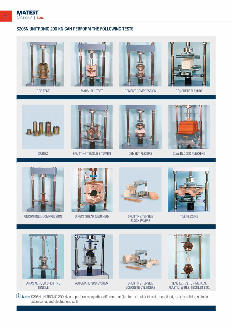
SECTION S | SOIL
S206N UNITRONIC 200 KN CAN PERFORM THE FOLLOWING TESTS:
CBR TEST
DURIEZ
UNCONFINED COMPRESSION
UNIAXIAL ROCK SPLITTINGTENSILE
MARSHALL TEST
SPLITTING TENSILE BITUMEN
DIRECT SHEAR (LEUTNER)
AUTOMATIC SCB SYSTEM
CEMENT COMPRESSION
CEMENT FLEXURE
SPLITTING TENSILEBLOCK PAVERS
SPLITTING TENSILECONCRETE CYLINDERS
CONCRETE FLEXURE
CLAY BLOCKS PUNCHING
TILE FLEXURE
TENSILE TEST ON METALS,PLASTIC, WIRES, TEXTILES ETC.
Note: S206N UNITRONIC 200 kN can perform many other different test (like for ex.: quick triaxial, unconfined, etc.) by utilizing suitable accessories and electric load cells.
510
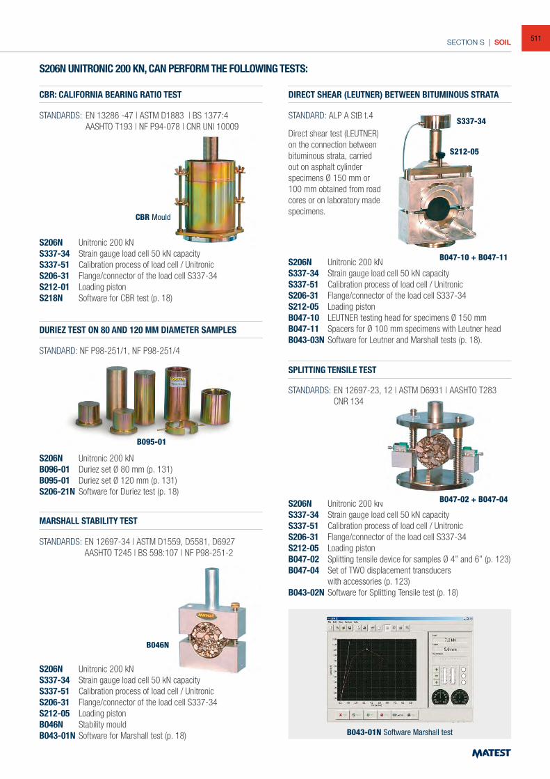
SECTION S | SOIL
S206N UNITRONIC 200 KN, CAN PERFORM THE FOLLOWING TESTS:
CBR: CALIFORNIA BEARING RATIO TEST
DURIEZ TEST ON 80 AND 120 MM DIAMETER SAMPLES
MARSHALL STABILITY TEST
DIRECT SHEAR (LEUTNER) BETWEEN BITUMINOUS STRATA
SPLITTING TENSILE TEST
STANDARDS: EN 13286 -47 | ASTM D1883 | BS 1377:4 AASHTO T193 | NF P94-078 | CNR UNI 10009
STANDARD: NF P98-251/1, NF P98-251/4
STANDARD: ALP A StB t.4
S206N Unitronic 200 kNS337-34 Strain gauge load cell 50 kN capacityS337-51 Calibration process of load cell / UnitronicS206-31 Flange/connector of the load cell S337-34S212-01 Loading pistonS218N Software for CBR test (p. 18)
S206N Unitronic 200 kNB096-01 Duriez set Ø 80 mm (p. 131)B095-01 Duriez set Ø 120 mm (p. 131)S206-21N Software for Duriez test (p. 18)
S206N Unitronic 200 kNS337-34 Strain gauge load cell 50 kN capacityS337-51 Calibration process of load cell / UnitronicS206-31 Flange/connector of the load cell S337-34S212-05 Loading pistonB046N Stability mouldB043-01N Software for Marshall test (p. 18)
S206N Unitronic 200 kNS337-34 Strain gauge load cell 50 kN capacityS337-51 Calibration process of load cell / UnitronicS206-31 Flange/connector of the load cell S337-34S212-05 Loading pistonB047-10 LEUTNER testing head for specimens Ø 150 mmB047-11 Spacers for Ø 100 mm specimens with Leutner headB043-03N Software for Leutner and Marshall tests (p. 18).
S206N Unitronic 200 kNS337-34 Strain gauge load cell 50 kN capacityS337-51 Calibration process of load cell / UnitronicS206-31 Flange/connector of the load cell S337-34S212-05 Loading pistonB047-02 Splitting tensile device for samples Ø 4” and 6” (p. 123)B047-04 Set of TWO displacement transducers with accessories (p. 123)B043-02N Software for Splitting Tensile test (p. 18)
B043-01N Software Marshall test
CBR Mould
B095-01
B046N
B047-02 + B047-04
B047-10 + B047-11
S212-05
S337-34
STANDARDS: EN 12697-34 | ASTM D1559, D5581, D6927 AASHTO T245 | BS 598:107 | NF P98-251-2
Direct shear test (LEUTNER) on the connection between bituminous strata, carried out on asphalt cylinder specimens Ø 150 mm or 100 mm obtained from road cores or on laboratory made specimens.
STANDARDS: EN 12697-23, 12 | ASTM D6931 | AASHTO T283 CNR 134
511
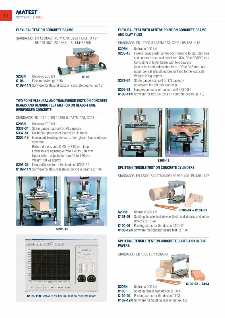
SECTION S | SOIL
FLEXURAL TEST ON CONCRETE BEAMS
SPLITTING TENSILE TEST ON CONCRETE CYLINDERS
SPLITTING TENSILE TEST ON CONCRETE CUBES AND BLOCK PAVERS
FLEXURAL TEST WITH CENTRE POINT ON CONCRETE BEAMS AND CLAY TILES
TWO POINT FLEXURAL AND TRANSVERSE TESTS ON CONCRETE BEAMS AND BENDING TEST METHOD ON GLASS-FIBREREINFORCED CONCRETE
STANDARDS: EN 12390-5 | ASTM C78, C293 | AASHTO T97 NF P18-407 | BS 1881:118 | UNE 83305
STANDARDS: EN 12390-6 | ASTM C496 | NF P18-408 | BS 1881:117
STANDARDS: EN 1338 | EN 12390-6
STANDARDS: EN 12390-5 | ASTM C78, C293 | BS 1881:118
STANDARDS: EN 1170-4, EN 12390-5 | ASTM C78, C293
S206N Unitronic 200 kNC106 Flexure device (p. 315)C109-11N Software for flexural tests on concrete beams. (p. 18)
S206N Unitronic 200 kNC101-01 Splitting tensile test device (technical details and other
devices: p. 314)C100-01 Packing strips for the device C101-01C109-12N Software for splitting tensile test. (p. 18)
S206N Unitronic 200 kNC103 Splitting tensile test device (p. 314)C100-02 Packing strips for the device C103C109-12N Software for Splitting tensile test (p. 18)
S206N Unitronic 200 kNS205-18 Flexure device with centre point loading to test clay tiles
and concrete beams dimensions 100x100x400(500) mm Consisting of lower beam with two bearers (one articulated) adjustable from 100 to 315 mm, and
upper central articulated bearer fixed to the load cell. Weight: 20kg approx.S337-34 Strain gauge load cell 50 kN capacity (to replace the 200 kN load cell)S206-31 Flange/connector of the load cell S337-34C109-11N Software for flexural tests on concrete beams (p. 18)
S206N Unitronic 200 kNS337-34 Strain gauge load cell 50kN capacityS337-51 Calibration process of load cell / UnitronicS205-16 Four-point bending device to test glass-fibre reinforced
concrete. Rollers dimensions: Ø 40 by 310 mm long Lower rollers adjustable from 110 to 310 mm Upper rollers adjustable from 45 to 120 mm Weight: 20 kg approx.S206-31 Flange/Connector of the load cell S337-34C109-11N Software for flexure tests on concrete beams (p. 18)
C109-11N Software for flexural test on concrete beam
C106
S205-16
C100-01 + C101-01
C100-02 + C103
S205-18
512
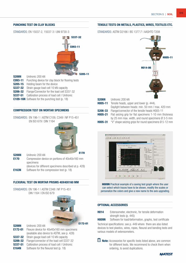
SECTION S | SOIL
PUNCHING TEST ON CLAY BLOCKS TENSILE TESTS ON METALS, PLASTICS, WIRES, TEXTILES ETC.
COMPRESSION TEST ON MORTAR SPECIMENS
FLEXURAL TEST ON MORTAR PRISMS 40X40X160 MM
STANDARDS: ASTM D2166 | BS 1377:7 | AASHTO T208
STANDARDS: EN 196-1 | ASTM C109, C349 | NF P15-451 EN ISO 679 | DIN 1164
STANDARDS: EN 196-1 | ASTM C348 | NF P15-451 DIN 1164 | EN ISO 679
S206N Unitronic 200 kNC093-11 Punching device for clay block for flooring testsS205-15 Holding beam for the deviceS337-32 Strain gauge load cell 10 kN capacityS206-32 Flange/Connector for the load cell S337-32S337-51 Calibration process of load cell / UnitronicC109-16N Software for the punching test (p. 18) S206N Unitronic 200 kN
H005-11 Tensile heads, upper and lower (p. 444). Daylight between heads: min. 50 mm / max. 420 mmS206-33 Flange/connector of the tensile heads H005-11H005-21 Flat seizing grip for flat specimens 1-10 mm thickness
by 25 mm max. width, and round specimens Ø 3-5 mmH005-31 “V” shape seizing grips for round specimens Ø 5-12 mm
S206N Unitronic 200 kNE170 Compression device on portions of 40x40x160 mm
specimens (devices for different specimens described at p. 428)E163N Software for the compression test (p. 18)
S206N Unitronic 200 kNE172-01 Flexure device for 40x40x160 mm specimens (available also device to ASTM, see p. 428)S337-32 Strain gauge load cell 10 kN capacityS206-32 Flange/connector of the load cell S337-32S337-51 Calibration process of load cell / UnitronicE164N Software for the flexural test (p. 18)
H009N Practical example of a saving test graph where the user can select which traces have to be shown, modify the scales or
personalize the colors and give a new name to the axis upgrading.
OPTIONAL ACCESSORIES
H014 Extensometer, electronic, for tensile deformation strength tests (p. 445)
H009N Software for load/deformation, graphs, test certificate
Technical specifications: see p. 449 where there are also listed devices to test plastics, wires, ropes, flexural and bending tests and various models of extensometers.
Note: Accessories for specific tests listed above, are common for different tests. We recommend to check them when ordering, to avoid duplications.
S205-11
H014-06
H005-11
E170
E172-01
C093-11
S337-32
STANDARDS: EN 15037-2, 15037-3 | UNI 9730-3
513
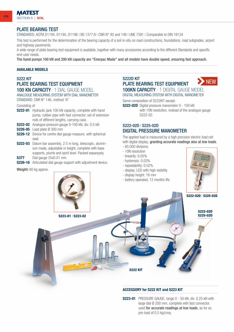
SECTION S | SOIL
PLATE BEARING TESTSTANDARDS: ASTM D1194, D1195, D1196 | BS 1377:9 | CNR N° 92 and 146 | UNE 7391 | Comparable to DIN 18134
This test is performed for the determination of the bearing capacity of a soil in-situ on road constructions, foundations, road subgrades, airport and highway pavements.A wide range of plate bearing test equipment is available, together with many accessories according to the different Standards and specificend-user needs.The hand pumps 100 kN and 200 kN capacity are “Enerpac Made” and all models have double speed, ensuring fast approach.
AVAILABLE MODELS
S222 KITPLATE BEARING TEST EQUIPMENT100 KN CAPACITY - 1 DIAL GAUGE MODELANALOGUE MEASURING SYSTEM WITH DIAL MANOMETERSTANDARD: CNR N° 146, method “A”
Consisting of:S222-01 Hydraulic jack 100 kN capacity, complete with hand
pump, rubber pipe with fast connector, set of extension rods of different lengths, carrying case.
S222-02 Analogue pressure gauge 0-100 kN, div. 0.5 kNS226-05 Load plate Ø 300 mmS226-12 Device for centre dial gauge measure, with spherical
seat.S222-03 Datum bar assembly, 2.5 m long, telescopic, alumin-
ium made, adjustable in height, complete with base supports, plumb and spirit level. Packed separayely.
S377 Dial gauge 25x0.01 mm S226-16 Articulated dial gauge support with adjustment device.
Weight: 60 kg approx.
S222D KITPLATE BEARING TEST EQUIPMENT100KN CAPACITY - 1 DIGITAL GAUGE MODELDIGITAL MEASURING SYSTEM WITH DIGITAL MANOMETER
Same composition of S222KIT except:S222-02D Digital pressure manometer 0 - 100 kN with 10N resolution, instead of the analogue gauge
S222-02.
S222-02D | S225-02DDIGITAL PRESSURE MANOMETERThe applied load is measured by a high precision electric load cell with digital display, granting accurate readings also at low loads.- 65.000 divisions- 10N resolution- linearity: 0.05%- hysteresis: 0.03%- repeatability: 0.02%- display: LCD with high visibility- display height: 16 mm- battery operated, 12 months life
ACCESSORY for S222 KIT and S223 KIT
S223-01 PRESSURE GAUGE, range 0 - 50 kN, div. 0.25 kN with large dial Ø 200 mm, complete with fast connector, used for accurate readings at low loads, as for ex. pre-load of 0.5 kg/cmq.
S222 KIT
S223-01 | S223-02S222-02DS225-02D
S222-02D | S225-02D
NEW
514
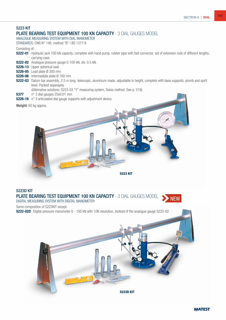
SECTION S | SOIL
S223D KITPLATE BEARING TEST EQUIPMENT 100 KN CAPACITY - 3 DIAL GAUGES MODELDIGITAL MEASURING SYSTEM WITH DIGITAL MANOMETER
Same composition of S223KIT except:S222-02D Digital pressure manometer 0 - 100 kN with 10N resolution, instead of the analogue gauge S222-02.
S223 KIT
S223D KIT
S223 KITPLATE BEARING TEST EQUIPMENT 100 KN CAPACITY - 3 DIAL GAUGES MODELANALOGUE MEASURING SYSTEM WITH DIAL MANOMETERSTANDARDS: CNR N° 146, method “B” | BS 1377:9
Consisting of:S222-01 Hydraulic jack 100 kN capacity, complete with hand pump, rubber pipe with fast connector, set of extension rods of different lengths,
carrying case.S222-02 Analogue pressure gauge 0-100 kN, div. 0.5 kN.S226-13 Upper spherical seat.S226-05 Load plate Ø 300 mmS226-06 Intermediate plate Ø 160 mmS222-03 Datum bar assembly, 2.5 m long, telescopic, aluminium made, adjustable in height, complete with base supports, plumb and spirit
level. Packed separayely. (Alternative solutions: S223-03 “Y” measuring system, Swiss method. See p. 519).S377 n° 3 dial gauges 25x0.01 mm S226-16 n° 3 articulated dial gauge supports with adjustment device.
Weight: 60 kg approx.
NEW
515
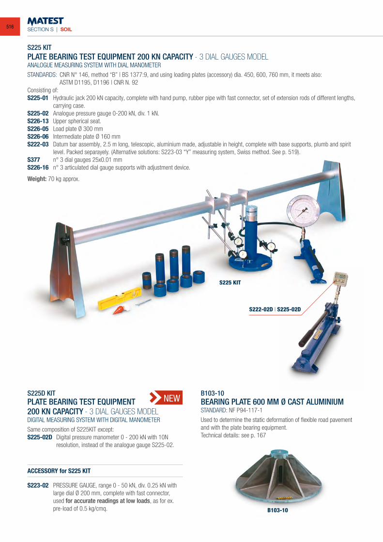
SECTION S | SOIL
S225 KITPLATE BEARING TEST EQUIPMENT 200 KN CAPACITY - 3 DIAL GAUGES MODELANALOGUE MEASURING SYSTEM WITH DIAL MANOMETER
STANDARDS: CNR N° 146, method “B” | BS 1377:9, and using loading plates (accessory) dia. 450, 600, 760 mm, it meets also: ASTM D1195, D1196 | CNR N. 92 Consisting of:S225-01 Hydraulic jack 200 kN capacity, complete with hand pump, rubber pipe with fast connector, set of extension rods of different lengths,
carrying case.S225-02 Analogue pressure gauge 0-200 kN, div. 1 kN.S226-13 Upper spherical seat.S226-05 Load plate Ø 300 mmS226-06 Intermediate plate Ø 160 mmS222-03 Datum bar assembly, 2.5 m long, telescopic, aluminium made, adjustable in height, complete with base supports, plumb and spirit
level. Packed separayely. (Alternative solutions: S223-03 “Y” measuring system, Swiss method. See p. 519).S377 n° 3 dial gauges 25x0.01 mm S226-16 n° 3 articulated dial gauge supports with adjustment device.
Weight: 70 kg approx.
S225D KITPLATE BEARING TEST EQUIPMENT200 KN CAPACITY - 3 DIAL GAUGES MODELDIGITAL MEASURING SYSTEM WITH DIGITAL MANOMETER
Same composition of S225KIT except:S225-02D Digital pressure manometer 0 - 200 kN with 10N
resolution, instead of the analogue gauge S225-02.
ACCESSORY for S225 KIT
S223-02 PRESSURE GAUGE, range 0 - 50 kN, div. 0.25 kN with large dial Ø 200 mm, complete with fast connector, used for accurate readings at low loads, as for ex. pre-load of 0.5 kg/cmq.
B103-10BEARING PLATE 600 MM Ø CAST ALUMINIUM STANDARD: NF P94-117-1
Used to determine the static deformation of flexible road pavement and with the plate bearing equipment.Technical details: see p. 167
B103-10
S225 KIT
S222-02D | S225-02D
NEW
516
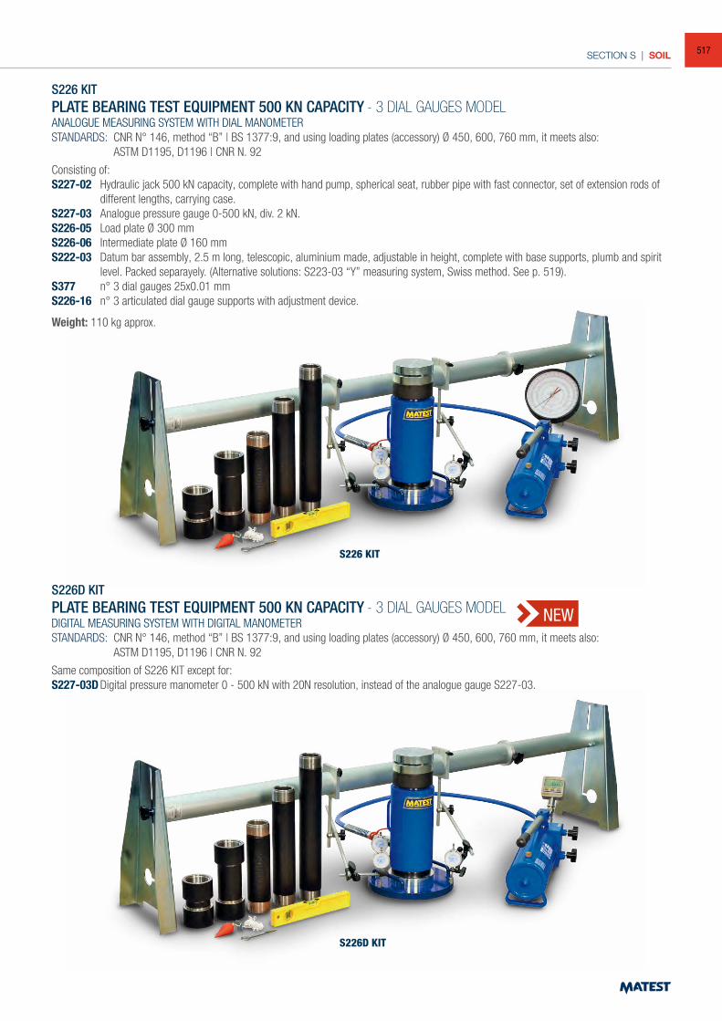
SECTION S | SOIL
S226 KIT
S226D KIT
S226 KITPLATE BEARING TEST EQUIPMENT 500 KN CAPACITY - 3 DIAL GAUGES MODELANALOGUE MEASURING SYSTEM WITH DIAL MANOMETERSTANDARDS: CNR N° 146, method “B” | BS 1377:9, and using loading plates (accessory) Ø 450, 600, 760 mm, it meets also: ASTM D1195, D1196 | CNR N. 92
Consisting of:S227-02 Hydraulic jack 500 kN capacity, complete with hand pump, spherical seat, rubber pipe with fast connector, set of extension rods of
different lengths, carrying case.S227-03 Analogue pressure gauge 0-500 kN, div. 2 kN.S226-05 Load plate Ø 300 mmS226-06 Intermediate plate Ø 160 mmS222-03 Datum bar assembly, 2.5 m long, telescopic, aluminium made, adjustable in height, complete with base supports, plumb and spirit
level. Packed separayely. (Alternative solutions: S223-03 “Y” measuring system, Swiss method. See p. 519).S377 n° 3 dial gauges 25x0.01 mm S226-16 n° 3 articulated dial gauge supports with adjustment device.
Weight: 110 kg approx.
S226D KITPLATE BEARING TEST EQUIPMENT 500 KN CAPACITY - 3 DIAL GAUGES MODELDIGITAL MEASURING SYSTEM WITH DIGITAL MANOMETERSTANDARDS: CNR N° 146, method “B” | BS 1377:9, and using loading plates (accessory) Ø 450, 600, 760 mm, it meets also: ASTM D1195, D1196 | CNR N. 92
Same composition of S226 KIT except for:S227-03D Digital pressure manometer 0 - 500 kN with 20N resolution, instead of the analogue gauge S227-03.
NEW
517
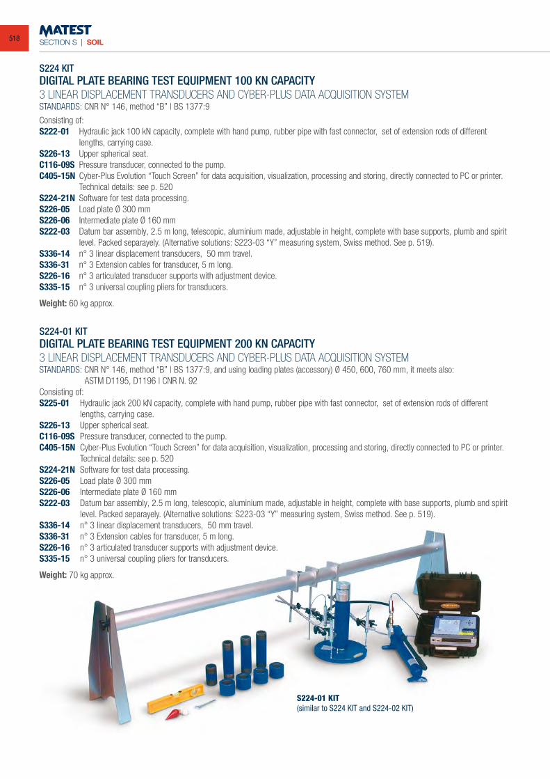
SECTION S | SOIL
S224-01 KIT(similar to S224 KIT and S224-02 KIT)
S224 KITDIGITAL PLATE BEARING TEST EQUIPMENT 100 KN CAPACITY 3 LINEAR DISPLACEMENT TRANSDUCERS AND CYBER-PLUS DATA ACQUISITION SYSTEMSTANDARDS: CNR N° 146, method “B” | BS 1377:9
Consisting of:S222-01 Hydraulic jack 100 kN capacity, complete with hand pump, rubber pipe with fast connector, set of extension rods of different
lengths, carrying case.S226-13 Upper spherical seat.C116-09S Pressure transducer, connected to the pump.C405-15N Cyber-Plus Evolution “Touch Screen” for data acquisition, visualization, processing and storing, directly connected to PC or printer.
Technical details: see p. 520S224-21N Software for test data processing.S226-05 Load plate Ø 300 mmS226-06 Intermediate plate Ø 160 mmS222-03 Datum bar assembly, 2.5 m long, telescopic, aluminium made, adjustable in height, complete with base supports, plumb and spirit
level. Packed separayely. (Alternative solutions: S223-03 “Y” measuring system, Swiss method. See p. 519).S336-14 n° 3 linear displacement transducers, 50 mm travel.S336-31 n° 3 Extension cables for transducer, 5 m long.S226-16 n° 3 articulated transducer supports with adjustment device.S335-15 n° 3 universal coupling pliers for transducers.
Weight: 60 kg approx.
S224-01 KITDIGITAL PLATE BEARING TEST EQUIPMENT 200 KN CAPACITY
3 LINEAR DISPLACEMENT TRANSDUCERS AND CYBER-PLUS DATA ACQUISITION SYSTEMSTANDARDS: CNR N° 146, method “B” | BS 1377:9, and using loading plates (accessory) Ø 450, 600, 760 mm, it meets also: ASTM D1195, D1196 | CNR N. 92 Consisting of:S225-01 Hydraulic jack 200 kN capacity, complete with hand pump, rubber pipe with fast connector, set of extension rods of different
lengths, carrying case.S226-13 Upper spherical seat.C116-09S Pressure transducer, connected to the pump.C405-15N Cyber-Plus Evolution “Touch Screen” for data acquisition, visualization, processing and storing, directly connected to PC or printer.
Technical details: see p. 520S224-21N Software for test data processing.S226-05 Load plate Ø 300 mmS226-06 Intermediate plate Ø 160 mmS222-03 Datum bar assembly, 2.5 m long, telescopic, aluminium made, adjustable in height, complete with base supports, plumb and spirit
level. Packed separayely. (Alternative solutions: S223-03 “Y” measuring system, Swiss method. See p. 519).S336-14 n° 3 linear displacement transducers, 50 mm travel.S336-31 n° 3 Extension cables for transducer, 5 m long.S226-16 n° 3 articulated transducer supports with adjustment device.S335-15 n° 3 universal coupling pliers for transducers.
Weight: 70 kg approx.
518
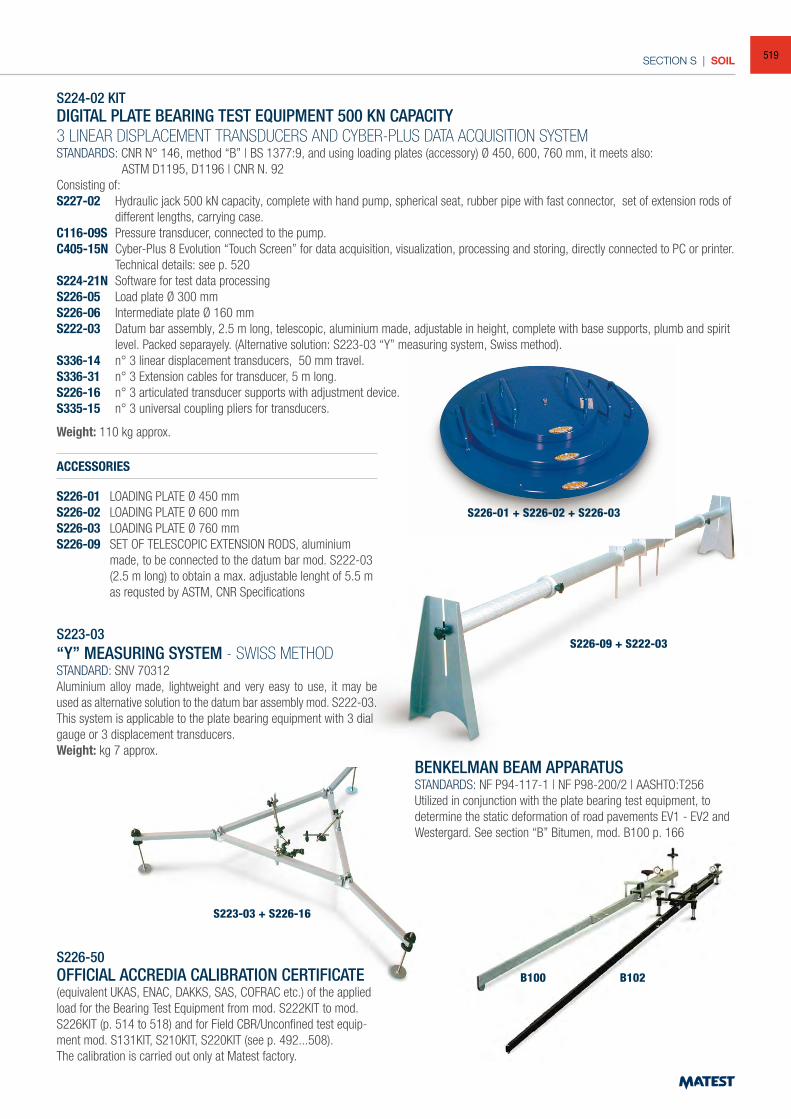
SECTION S | SOIL
S224-02 KITDIGITAL PLATE BEARING TEST EQUIPMENT 500 KN CAPACITY
3 LINEAR DISPLACEMENT TRANSDUCERS AND CYBER-PLUS DATA ACQUISITION SYSTEMSTANDARDS: CNR N° 146, method “B” | BS 1377:9, and using loading plates (accessory) Ø 450, 600, 760 mm, it meets also: ASTM D1195, D1196 | CNR N. 92Consisting of:S227-02 Hydraulic jack 500 kN capacity, complete with hand pump, spherical seat, rubber pipe with fast connector, set of extension rods of
different lengths, carrying case.C116-09S Pressure transducer, connected to the pump.C405-15N Cyber-Plus 8 Evolution “Touch Screen” for data acquisition, visualization, processing and storing, directly connected to PC or printer.
Technical details: see p. 520S224-21N Software for test data processingS226-05 Load plate Ø 300 mmS226-06 Intermediate plate Ø 160 mmS222-03 Datum bar assembly, 2.5 m long, telescopic, aluminium made, adjustable in height, complete with base supports, plumb and spirit
level. Packed separayely. (Alternative solution: S223-03 “Y” measuring system, Swiss method).S336-14 n° 3 linear displacement transducers, 50 mm travel.S336-31 n° 3 Extension cables for transducer, 5 m long.S226-16 n° 3 articulated transducer supports with adjustment device.S335-15 n° 3 universal coupling pliers for transducers.
Weight: 110 kg approx.
ACCESSORIES
S226-01 LOADING PLATE Ø 450 mmS226-02 LOADING PLATE Ø 600 mmS226-03 LOADING PLATE Ø 760 mmS226-09 SET OF TELESCOPIC EXTENSION RODS, aluminium
made, to be connected to the datum bar mod. S222-03 (2.5 m long) to obtain a max. adjustable lenght of 5.5 m
as requsted by ASTM, CNR Specifications
S223-03“Y” MEASURING SYSTEM - SWISS METHODSTANDARD: SNV 70312Aluminium alloy made, lightweight and very easy to use, it may be used as alternative solution to the datum bar assembly mod. S222-03.This system is applicable to the plate bearing equipment with 3 dial gauge or 3 displacement transducers. Weight: kg 7 approx.
S226-50OFFICIAL ACCREDIA CALIBRATION CERTIFICATE (equivalent UKAS, ENAC, DAKKS, SAS, COFRAC etc.) of the applied load for the Bearing Test Equipment from mod. S222KIT to mod. S226KIT (p. 514 to 518) and for Field CBR/Unconfined test equip-ment mod. S131KIT, S210KIT, S220KIT (see p. 492...508).The calibration is carried out only at Matest factory.
BENKELMAN BEAM APPARATUSSTANDARDS: NF P94-117-1 | NF P98-200/2 | AASHTO:T256Utilized in conjunction with the plate bearing test equipment, to determine the static deformation of road pavements EV1 - EV2 and Westergard. See section “B” Bitumen, mod. B100 p. 166
S226-01 + S226-02 + S226-03
S226-09 + S222-03
S223-03 + S226-16
B100 B102
519
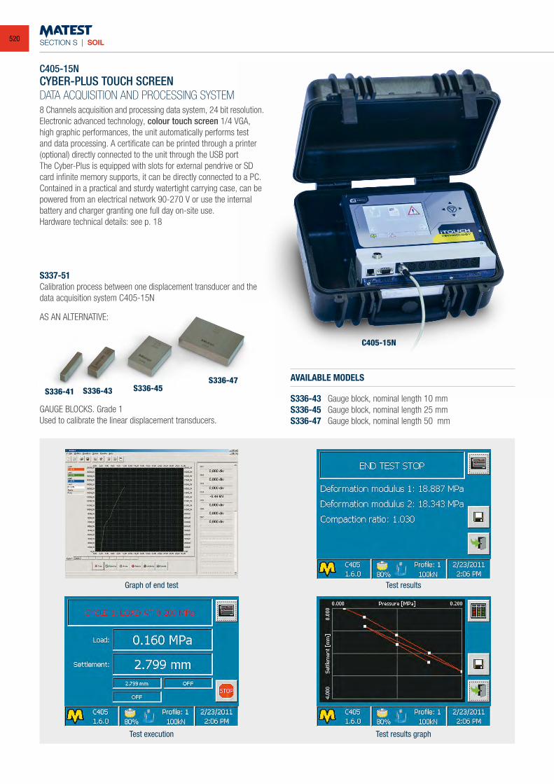
SECTION S | SOIL
C405-15NCYBER-PLUS TOUCH SCREENDATA ACQUISITION AND PROCESSING SYSTEM8 Channels acquisition and processing data system, 24 bit resolution.Electronic advanced technology, colour touch screen 1/4 VGA, high graphic performances, the unit automatically performs test and data processing. A certificate can be printed through a printer (optional) directly connected to the unit through the USB portThe Cyber-Plus is equipped with slots for external pendrive or SD card infinite memory supports, it can be directly connected to a PC. Contained in a practical and sturdy watertight carrying case, can be powered from an electrical network 90-270 V or use the internal battery and charger granting one full day on-site use.Hardware technical details: see p. 18
S337-51Calibration process between one displacement transducer and the data acquisition system C405-15N
AS AN ALTERNATIVE:
GAUGE BLOCKS. Grade 1Used to calibrate the linear displacement transducers.
AVAILABLE MODELS
S336-43 Gauge block, nominal length 10 mmS336-45 Gauge block, nominal length 25 mmS336-47 Gauge block, nominal length 50 mm
Graph of end test
Test execution
Test results
Test results graph
S336-41 S336-43 S336-45S336-47
C405-15N
520
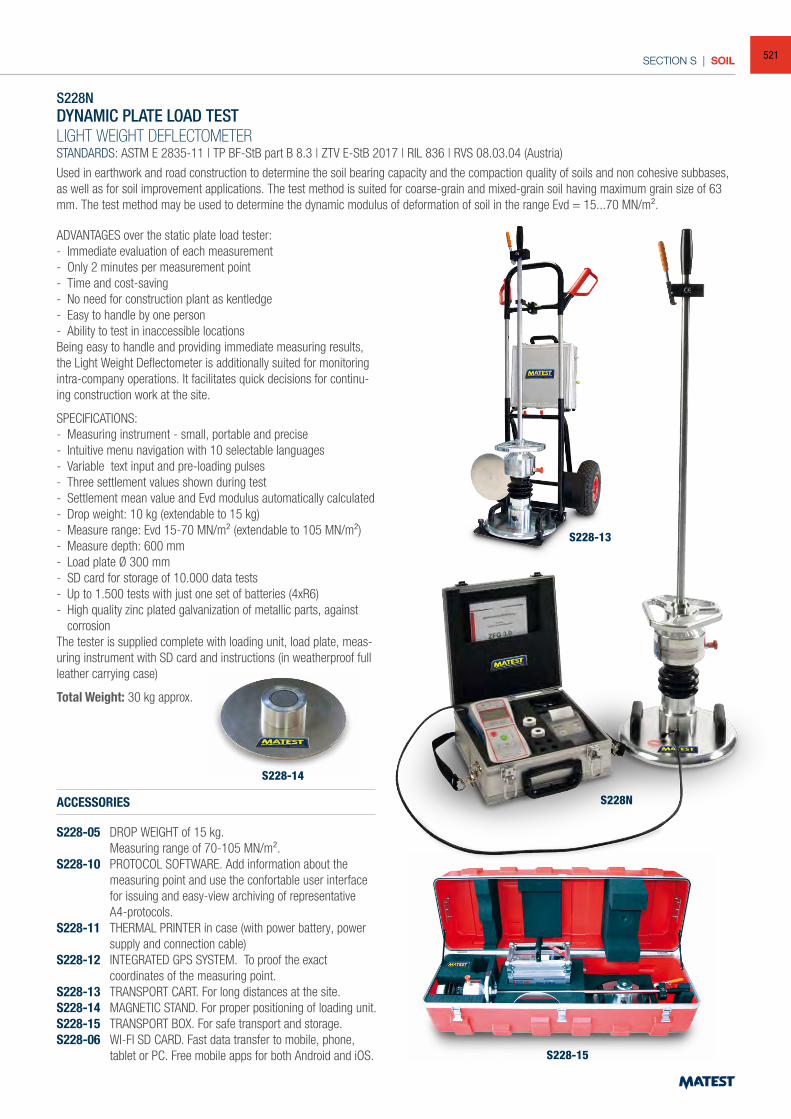
SECTION S | SOIL
S228N
S228-14
S228-15
S228NDYNAMIC PLATE LOAD TESTLIGHT WEIGHT DEFLECTOMETERSTANDARDS: ASTM E 2835-11 | TP BF-StB part B 8.3 | ZTV E-StB 2017 | RIL 836 | RVS 08.03.04 (Austria)
Used in earthwork and road construction to determine the soil bearing capacity and the compaction quality of soils and non cohesive subbases, as well as for soil improvement applications. The test method is suited for coarse-grain and mixed-grain soil having maximum grain size of 63 mm. The test method may be used to determine the dynamic modulus of deformation of soil in the range Evd = 15...70 MN/m².
ADVANTAGES over the static plate load tester:- Immediate evaluation of each measurement- Only 2 minutes per measurement point- Time and cost-saving- No need for construction plant as kentledge- Easy to handle by one person- Ability to test in inaccessible locationsBeing easy to handle and providing immediate measuring results, the Light Weight Deflectometer is additionally suited for monitoring intra-company operations. It facilitates quick decisions for continu-ing construction work at the site.
SPECIFICATIONS:- Measuring instrument - small, portable and precise- Intuitive menu navigation with 10 selectable languages- Variable text input and pre-loading pulses- Three settlement values shown during test- Settlement mean value and Evd modulus automatically calculated- Drop weight: 10 kg (extendable to 15 kg)- Measure range: Evd 15-70 MN/m² (extendable to 105 MN/m²)- Measure depth: 600 mm- Load plate Ø 300 mm- SD card for storage of 10.000 data tests- Up to 1.500 tests with just one set of batteries (4xR6)- High quality zinc plated galvanization of metallic parts, against
corrosionThe tester is supplied complete with loading unit, load plate, meas-uring instrument with SD card and instructions (in weatherproof full leather carrying case)
Total Weight: 30 kg approx.
ACCESSORIES
S228-05 DROP WEIGHT of 15 kg. Measuring range of 70-105 MN/m².S228-10 PROTOCOL SOFTWARE. Add information about the
measuring point and use the confortable user interface for issuing and easy-view archiving of representative A4-protocols.
S228-11 THERMAL PRINTER in case (with power battery, power supply and connection cable)
S228-12 INTEGRATED GPS SYSTEM. To proof the exact coordinates of the measuring point.
S228-13 TRANSPORT CART. For long distances at the site.S228-14 MAGNETIC STAND. For proper positioning of loading unit.S228-15 TRANSPORT BOX. For safe transport and storage.S228-06 WI-FI SD CARD. Fast data transfer to mobile, phone,
tablet or PC. Free mobile apps for both Android and iOS.
S228-13
521
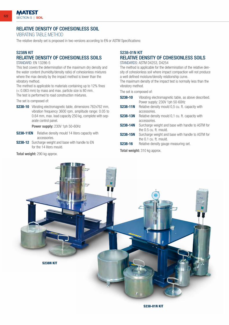
SECTION S | SOIL
RELATIVE DENSITY OF COHESIONLESS SOILVIBRATING TABLE METHOD
The relative density set is proposed in two versions according to EN or ASTM Specifications:
S238-01N KITRELATIVE DENSITY OF COHESIONLESS SOILSSTANDARDS: ASTM D4253, D4254The method is applicable for the determination of the relative den-sity of cohesionless soil where impact compaction will not produce a well defined moisture/density relationship curve.The maximum density of the impact test is normally less than the vibratory method.
The set is composed of:
S238-10 Vibrating electromagnetic table, as above described. Power supply: 230V 1ph 50-60HzS238-11N Relative density mould 0,5 cu. ft. capacity with accessories.S238-13N Relative density mould 0,1 cu. ft. capacity with accessories.S238-14N Surcharge weight and base with handle to ASTM for
the 0.5 cu. ft. mould.S238-15N Surcharge weight and base with handle to ASTM for
the 0.1 cu. ft. mould.S238-16 Relative density gauge measuring set.
Total weight: 310 kg approx.
S238N KITRELATIVE DENSITY OF COHESIONLESS SOILSSTANDARD: EN 13286-5This test covers the determination of the maximum dry density and the water content (humidity/density ratio) of cohesionless mixtures where the max density by the impact method is lower than the vibratory method.The method is applicable to materials containing up to 12% fines(< 0.063 mm) by mass and max. particle size is 80 mm.The test is performed to road construction mixtures.
The set is composed of:
S238-10 Vibrating electromagnetic table, dimensions 762x762 mm, vibration frequency 3600 rpm, amplitude range: 0.05 to 0.64 mm, max. load capacity 250 kg, complete with sep-arate control panel.
Power supply: 230V 1ph 50-60Hz
S238-11EN Relative density mould 14 liters capacity with accessories.S238-12 Surcharge weight and base with handle to EN for the 14 liters mould.
Total weight: 290 kg approx.
S238-01N KIT
S238N KIT
522
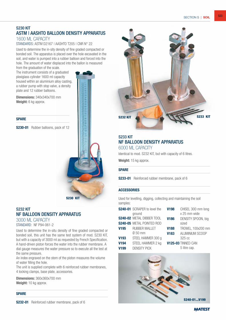
SECTION S | SOIL
S230 KITASTM | AASHTO BALLOON DENSITY APPARATUS1600 ML CAPACITYSTANDARDS: ASTM D2167 | AASHTO T205 | CNR N° 22
Used to determine the in-sity density of fine graded compacted or bonded soil. The apparatus is placed over the hole excavated in the soil, and water is pumped into a rubber balloon and forced into the hole. The amount of water displaced into the ballon is measured from the graduation of the scale.The instrument consists of a graduated plexiglass cylinder 1600 ml capacity housed within an aluminium alloy casting, a rubber pump with stop valve, a density plate and 12 rubber balloons.
Dimensions: 340x340x700 mmWeight: 6 kg approx.
SPARE
S230-01 Rubber balloons, pack of 12
S232 KITNF BALLOON DENSITY APPARATUS3000 ML CAPACITYSTANDARD: NF P94-061-2
Used to determine the in-situ density of fine graded compacted or bonded soil, this unit has the same test system of mod. S230 KIT, but with a capacity of 3000 ml as requested by French Specification.A hand-driven piston forces the water into the rubber membrane. A dial gauge measures the water pressure so to execute all the test at the same pressure.An index engraved on the stem of the piston measures the volume of water filling the hole.The unit is supplied complete with 6 reinforced rubber membranes, 4 locking clamps, base plate, accessories.
Dimensions: 360x360x700 mmWeight: 10 kg approx.
SPARE
S232-01 Reinforced rubber membrane, pack of 6
S233 KITNF BALLOON DENSITY APPARATUS6000 ML CAPACITYIdentical to mod. S232 KIT, but with capacity of 6 litres.
Weight: 15 kg approx.
SPARE
S233-01 Reinforced rubber membrane, pack of 6
ACCESSORIES
Used for levelling, digging, collecting and maintaining the soil samples:
S240-01 SCRAPER to level the ground
S240-02 METAL DIBBER TOOLS240-05 METAL POINTED ROD V195 RUBBER MALLET Ø 50 mm V193 STEEL HAMMER 300 gV194 STEEL HAMMER 2 kgV199 DENSITY PICK
V198 CHISEL 300 mm long x 25 mm wide
V186 DENSITY SPOON, big sized
V188 TROWEL, 100x200 mmV183 ALUMINIUM SCOOP
325 cc V125-03 TINNED CAN 5 litre cap.
S232 KIT S233 KIT
S230 KIT
S240-01...V199
523
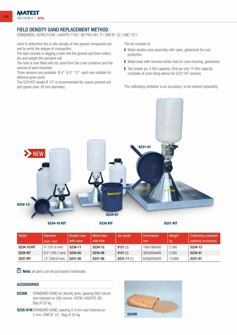
SECTION S | SOIL
FIELD DENSITY SAND REPLACEMENT METHODSTANDARDS: ASTM D1556 | AASHTO T191 | NF P94-061-3 | CNR N° 22 | UNE 7371
Used to determine the in-situ density of fine graned compacted soil and to verify the degree of compaction.The test consists in digging a hole into the ground and then collect, dry and weight the sampled soil.The hole is now filled with dry sand from the cone container and the volume of sand recorded.Three versions are available Ø 4” 6.5” 12” each one suitable for different grain sized. The S231KIT model Ø 12” is recommended for coarse grained soil and gravel (over 38 mm diameter).
The kit consists of:
Metal double cone assembly with valve, galvanized for rust protection.
Metal base with rimmed centre hole for cone housing, galvanized.
Two plastic jar, 5 litre capacity. (One jar only 15 litre capacity complete of cone fixing device for S231 KIT version)
Model Diameter Double cone Metal base Jar plastic Dimensions Weight Calibrating container
inch / mm with valve with hole mm kg (optional accessory)
S234-10 KIT 4” (101.6 mm) S234-11 S234-12 V121 (2) 190x190x500 2.300 S234-13
S234 KIT 6.5” (165.1 mm) S234-05 S234-06 V121 (2) 305x305x600 3.350 S234-01
S231 KIT 12” (304.8 mm) S231-05 S231-06 S231-11 (1) 620x620x920 13.600 S231-01
The calibrating container is an accessory, to be ordered separately.
Note: all parts can be purchased individually.
ACCESSORIES
S235N STANDARD SAND for density tests, passing 600 micron and retained on 300 micron. ASTM, AASHTO, BS.
Bag of 25 kg.
S235-01N STANDARD SAND, passing 0.4 mm and retained on 2 mm. CNR N° 22. Bag of 25 kg
S234-13
S234-10 KIT S234 KIT S231 KIT
S235N
S234-01
S231-01
NEW
524
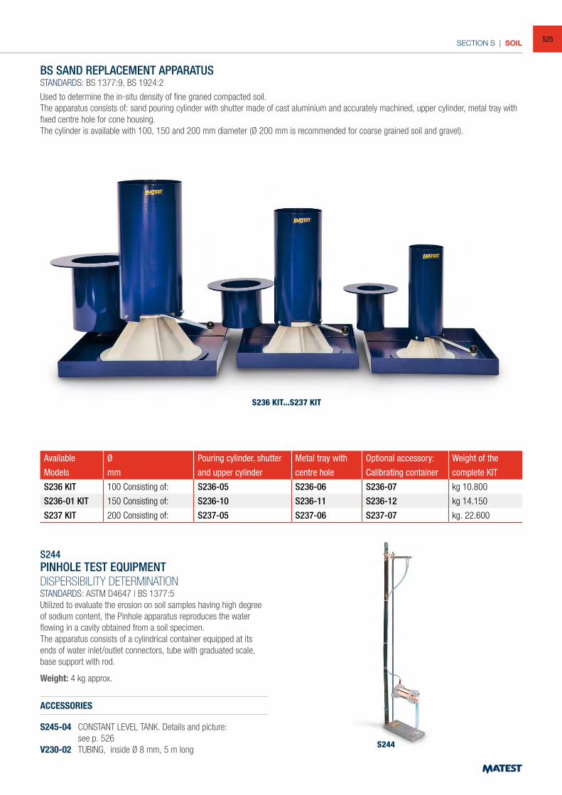
SECTION S | SOIL
BS SAND REPLACEMENT APPARATUSSTANDARDS: BS 1377:9, BS 1924:2
Used to determine the in-situ density of fine graned compacted soil.The apparatus consists of: sand pouring cylinder with shutter made of cast aluminium and accurately machined, upper cylinder, metal tray with fixed centre hole for cone housing.The cylinder is available with 100, 150 and 200 mm diameter (Ø 200 mm is recommended for coarse grained soil and gravel).
S244PINHOLE TEST EQUIPMENTDISPERSIBILITY DETERMINATIONSTANDARDS: ASTM D4647 | BS 1377:5Utilized to evaluate the erosion on soil samples having high degree of sodium content, the Pinhole apparatus reproduces the water flowing in a cavity obtained from a soil specimen.The apparatus consists of a cylindrical container equipped at its ends of water inlet/outlet connectors, tube with graduated scale, base support with rod.
Weight: 4 kg approx.
ACCESSORIES
S245-04 CONSTANT LEVEL TANK. Details and picture: see p. 526V230-02 TUBING, inside Ø 8 mm, 5 m long
Available Ø Pouring cylinder, shutter Metal tray with Optional accessory: Weight of the
Models mm and upper cylinder centre hole Calibrating container complete KIT
S236 KIT 100 Consisting of: S236-05 S236-06 S236-07 kg 10.800
S236-01 KIT 150 Consisting of: S236-10 S236-11 S236-12 kg 14.150
S237 KIT 200 Consisting of: S237-05 S237-06 S237-07 kg. 22.600
S244
S236 KIT...S237 KIT
525
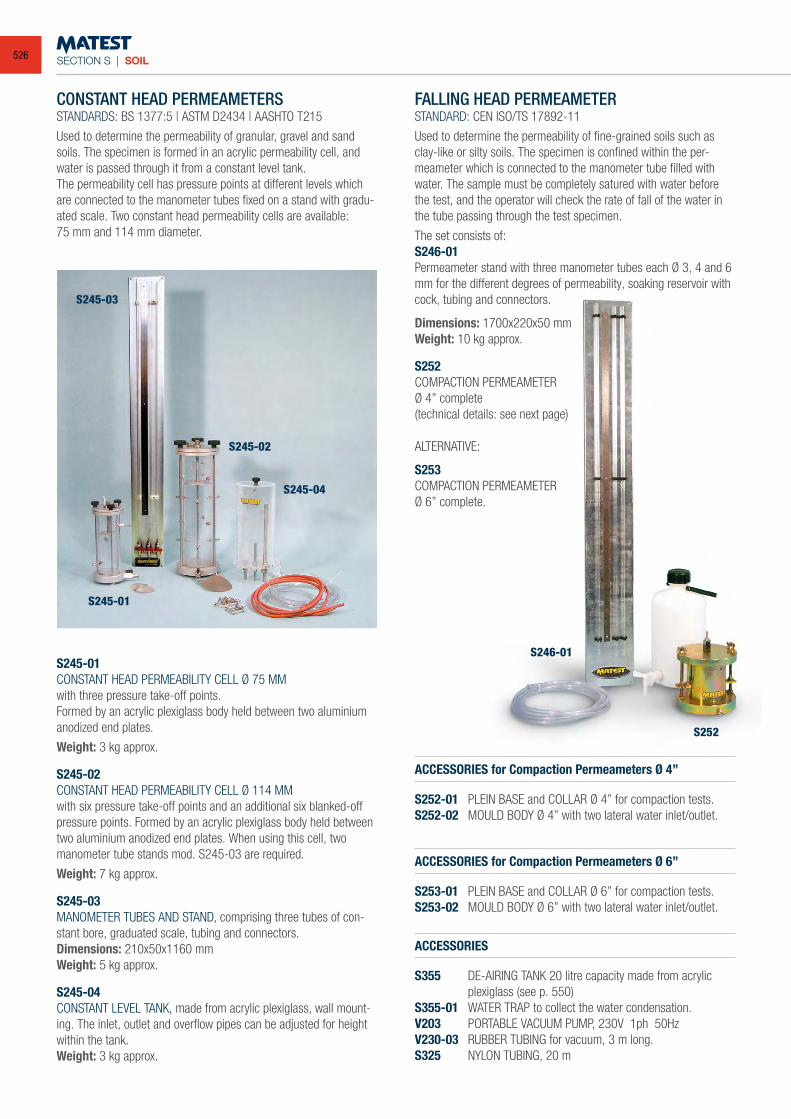
SECTION S | SOIL
CONSTANT HEAD PERMEAMETERSSTANDARDS: BS 1377:5 | ASTM D2434 | AASHTO T215
Used to determine the permeability of granular, gravel and sand soils. The specimen is formed in an acrylic permeability cell, and water is passed through it from a constant level tank.The permeability cell has pressure points at different levels which are connected to the manometer tubes fixed on a stand with gradu-ated scale. Two constant head permeability cells are available:75 mm and 114 mm diameter.
S245-01CONSTANT HEAD PERMEABILITY CELL Ø 75 MMwith three pressure take-off points.Formed by an acrylic plexiglass body held between two aluminium anodized end plates.
Weight: 3 kg approx.
S245-02CONSTANT HEAD PERMEABILITY CELL Ø 114 MMwith six pressure take-off points and an additional six blanked-off pressure points. Formed by an acrylic plexiglass body held between two aluminium anodized end plates. When using this cell, two manometer tube stands mod. S245-03 are required.
Weight: 7 kg approx.
S245-03MANOMETER TUBES AND STAND, comprising three tubes of con-stant bore, graduated scale, tubing and connectors.Dimensions: 210x50x1160 mmWeight: 5 kg approx.
S245-04CONSTANT LEVEL TANK, made from acrylic plexiglass, wall mount-ing. The inlet, outlet and overflow pipes can be adjusted for height within the tank.Weight: 3 kg approx.
FALLING HEAD PERMEAMETERSTANDARD: CEN ISO/TS 17892-11
Used to determine the permeability of fine-grained soils such as clay-like or silty soils. The specimen is confined within the per-meameter which is connected to the manometer tube filled with water. The sample must be completely satured with water before the test, and the operator will check the rate of fall of the water in the tube passing through the test specimen.
The set consists of:S246-01Permeameter stand with three manometer tubes each Ø 3, 4 and 6 mm for the different degrees of permeability, soaking reservoir with cock, tubing and connectors.
Dimensions: 1700x220x50 mmWeight: 10 kg approx.
S252COMPACTION PERMEAMETERØ 4” complete(technical details: see next page)
ACCESSORIES for Compaction Permeameters Ø 4”
S252-01 PLEIN BASE and COLLAR Ø 4” for compaction tests.S252-02 MOULD BODY Ø 4” with two lateral water inlet/outlet.
ACCESSORIES for Compaction Permeameters Ø 6”
S253-01 PLEIN BASE and COLLAR Ø 6” for compaction tests.S253-02 MOULD BODY Ø 6” with two lateral water inlet/outlet.
ACCESSORIES
S355 DE-AIRING TANK 20 litre capacity made from acrylic plexiglass (see p. 550)S355-01 WATER TRAP to collect the water condensation.V203 PORTABLE VACUUM PUMP, 230V 1ph 50HzV230-03 RUBBER TUBING for vacuum, 3 m long.S325 NYLON TUBING, 20 m
S245-01
S245-02
S245-03
S245-04
S246-01
S252
ALTERNATIVE:
S253COMPACTION PERMEAMETER Ø 6” complete.
526
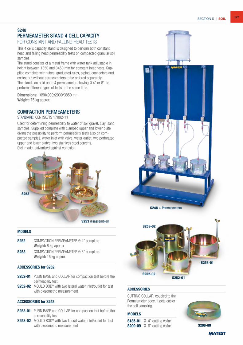
SECTION S | SOIL
S248PERMEAMETER STAND 4 CELL CAPACITYFOR CONSTANT AND FALLING HEAD TESTSThis 4 cells capacity stand is designed to perform both constant head and falling head permeability tests on compacted granular soil samples.The stand consists of a metal frame with water tank adjustable in height between 1350 and 3450 mm for constant head tests. Sup-plied complete with tubes, graduated rules, piping, connectors and cocks; but without permeameters to be ordered separately.The stand can hold up to 4 permeameters having Ø 4” or 6” to perform different types of tests at the same time.
Dimensions: 1050x900x2000/3850 mmWeight: 75 kg approx.
COMPACTION PERMEAMETERSSTANDARD: CEN ISO/TS 17892-11
Used for determining permeability to water of soil gravel, clay, sand samples. Supplied complete with clamped upper and lower plate giving the possibility to perform permeability tests also on com-pacted samples, water inlet with valve, water outlet, two perforated upper and lower plates, two stainless steel screens.Stell made, galvanized against corrosion.
MODELS
S252 COMPACTION PERMEAMETER Ø 4” complete. Weight: 8 kg approx.
S253 COMPACTION PERMEAMETER Ø 6” complete. Weight: 16 kg approx.
ACCESSORIES for S252
S252-01 PLEIN BASE and COLLAR for compaction test before the permeability test
S252-02 MOULD BODY with two lateral water inlet/outlet for test with piezometric measurement
ACCESSORIES for S253
S253-01 PLEIN BASE and COLLAR for compaction test before the permeability test
S253-02 MOULD BODY with two lateral water inlet/outlet for test with piezometric measurement
ACCESSORIES
CUTTING COLLAR, coupled to thePermeameter body, it gets easierthe soil sampling.
MODELS
S185-01 Ø 4” cutting collarS200-09 Ø 6” cutting collar
S253
S252-02
S200-09
S252-01
S253-01
S253-02S253 disassembled
S248 + Permeameters
527
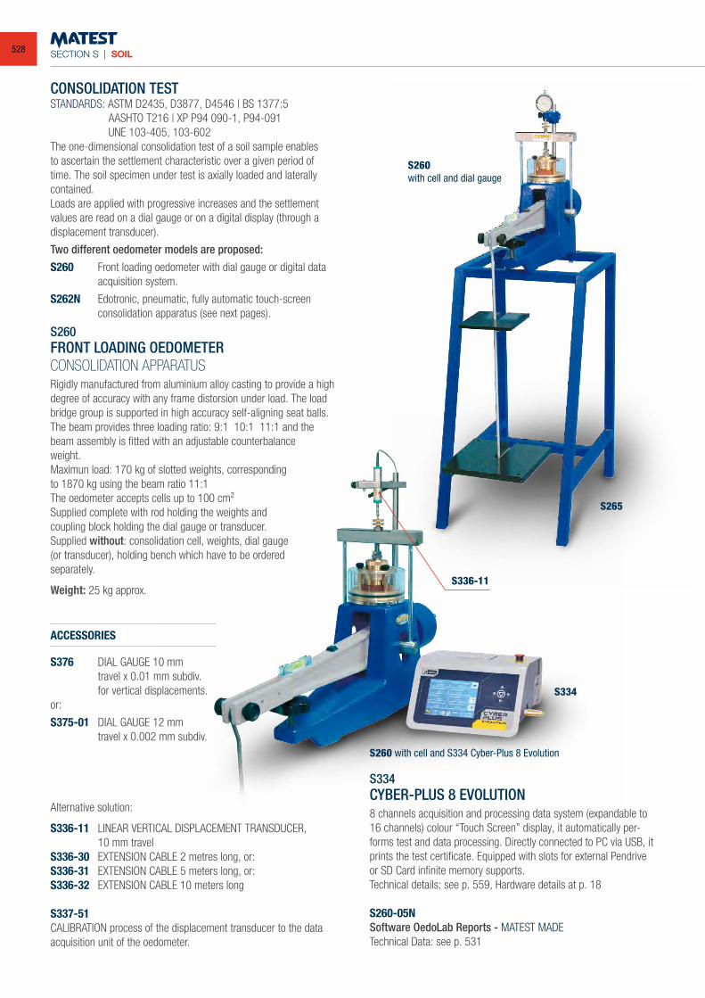
SECTION S | SOIL
CONSOLIDATION TESTSTANDARDS: ASTM D2435, D3877, D4546 | BS 1377:5 AASHTO T216 | XP P94 090-1, P94-091 UNE 103-405, 103-602The one-dimensional consolidation test of a soil sample enables to ascertain the settlement characteristic over a given period of time. The soil specimen under test is axially loaded and laterally contained.Loads are applied with progressive increases and the settlement values are read on a dial gauge or on a digital display (through a displacement transducer).
Two different oedometer models are proposed:S260 Front loading oedometer with dial gauge or digital data
acquisition system.
S262N Edotronic, pneumatic, fully automatic touch-screen consolidation apparatus (see next pages).
S260FRONT LOADING OEDOMETERCONSOLIDATION APPARATUSRigidly manufactured from aluminium alloy casting to provide a high degree of accuracy with any frame distorsion under load. The load bridge group is supported in high accuracy self-aligning seat balls.The beam provides three loading ratio: 9:1 10:1 11:1 and the beam assembly is fitted with an adjustable counterbalanceweight.Maximun load: 170 kg of slotted weights, correspondingto 1870 kg using the beam ratio 11:1The oedometer accepts cells up to 100 cm²Supplied complete with rod holding the weights andcoupling block holding the dial gauge or transducer.Supplied without: consolidation cell, weights, dial gauge(or transducer), holding bench which have to be orderedseparately.
Weight: 25 kg approx.
ACCESSORIES
S376 DIAL GAUGE 10 mm travel x 0.01 mm subdiv. for vertical displacements.or:
S375-01 DIAL GAUGE 12 mm travel x 0.002 mm subdiv.
Alternative solution:
S336-11 LINEAR VERTICAL DISPLACEMENT TRANSDUCER, 10 mm travelS336-30 EXTENSION CABLE 2 metres long, or:S336-31 EXTENSION CABLE 5 meters long, or:S336-32 EXTENSION CABLE 10 meters long
S337-51CALIBRATION process of the displacement transducer to the data acquisition unit of the oedometer.
S334CYBER-PLUS 8 EVOLUTION8 channels acquisition and processing data system (expandable to 16 channels) colour “Touch Screen” display, it automatically per-forms test and data processing. Directly connected to PC via USB, it prints the test certificate. Equipped with slots for external Pendrive or SD Card infinite memory supports.Technical details: see p. 559, Hardware details at p. 18
S260-05NSoftware OedoLab Reports - MATEST MADE Technical Data: see p. 531
S260with cell and dial gauge
S334
S265
S336-11
S260 with cell and S334 Cyber-Plus 8 Evolution
528
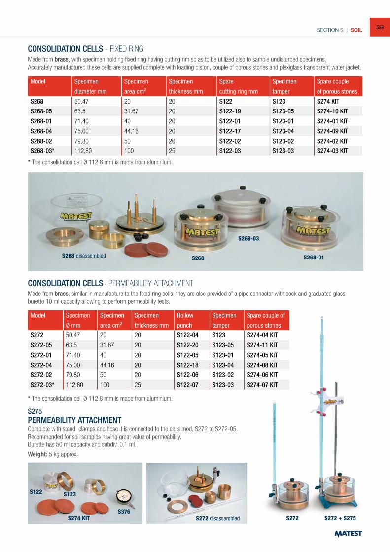
SECTION S | SOIL
CONSOLIDATION CELLS - FIXED RINGMade from brass, with specimen holding fixed ring having cutting rim so as to be utilized also to sample undisturbed specimens.Accurately manufactured these cells are supplied complete with loading piston, couple of porous stones and plexiglass transparent water jacket.
Model Specimen Specimen Specimen Spare Specimen Spare couple
diameter mm area cm² thickness mm cutting ring mm tamper of porous stones
S268 50.47 20 20 S122 S123 S274 KIT
S268-05 63.5 31.67 20 S122-19 S123-05 S274-10 KIT
S268-01 71.40 40 20 S122-01 S123-01 S274-01 KIT
S268-04 75.00 44.16 20 S122-17 S123-04 S274-09 KIT
S268-02 79.80 50 20 S122-02 S123-02 S274-02 KIT
S268-03* 112.80 100 25 S122-03 S123-03 S274-03 KIT
* The consolidation cell Ø 112.8 mm is made from aluminium.
CONSOLIDATION CELLS - PERMEABILITY ATTACHMENTMade from brass, similar in manufacture to the fixed ring cells, they are also provided of a pipe connector with cock and graduated glass burette 10 ml capacity allowing to perform permeability tests.
Model Specimen Specimen Specimen Hollow Specimen Spare couple of
Ø mm area cm² thickness mm punch tamper porous stones
S272 50.47 20 20 S122-04 S123 S274-04 KIT
S272-05 63.5 31.67 20 S122-20 S123-05 S274-11 KIT
S272-01 71.40 40 20 S122-05 S123-01 S274-05 KIT
S272-04 75.00 44.16 20 S122-18 S123-04 S274-08 KIT
S272-02 79.80 50 20 S122-06 S123-02 S274-06 KIT
S272-03* 112.80 100 25 S122-07 S123-03 S274-07 KIT
* The consolidation cell Ø 112.8 mm is made from aluminium.
S275PERMEABILITY ATTACHMENTComplete with stand, clamps and hose it is connected to the cells mod. S272 to S272-05.Recommended for soil samples having great value of permeability.Burette has 50 ml capacity and subdiv. 0.1 ml.
Weight: 5 kg approx.
S268
S122 S123
S376S272 S272 + S275S274 KIT
S268-03
S268-01S268 disassembled
S272 disassembled
529
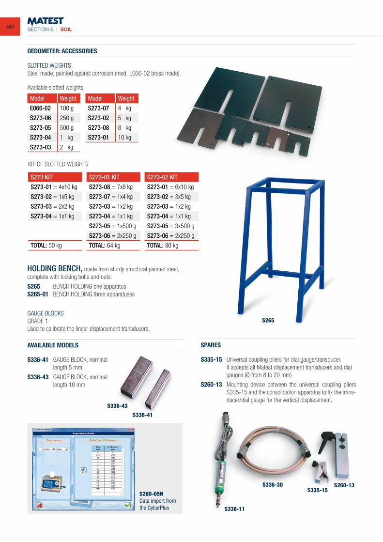
SECTION S | SOIL
OEDOMETER: ACCESSORIES
SLOTTED WEIGHTSSteel made, painted against corrosion (mod. E066-02 brass made).
Model Weight
E066-02 100 g
S273-06 250 g
S273-05 500 g
S273-04 1 kg
S273-03 2 kg
Model Weight
S273-07 4 kg
S273-02 5 kg
S273-08 8 kg
S273-01 10 kg
KIT OF SLOTTED WEIGHTS
S273 KIT
S273-01 = 4x10 kg
S273-02 = 1x5 kg
S273-03 = 2x2 kg
S273-04 = 1x1 kg
TOTAL: 50 kg
S273-01 KIT
S273-08 = 7x8 kg
S273-07 = 1x4 kg
S273-03 = 1x2 kg
S273-04 = 1x1 kg
S273-05 = 1x500 g
S273-06 = 2x250 g
TOTAL: 64 kg
S273-02 KIT
S273-01 = 6x10 kg
S273-02 = 3x5 kg
S273-03 = 1x2 kg
S273-04 = 1x1 kg
S273-05 = 3x500 g
S273-06 = 2x250 g
TOTAL: 80 kg
Available slotted weights:
HOLDING BENCH, made from sturdy structural painted steel, complete with locking bolts and nuts.
S265 BENCH HOLDING one apparatusS265-01 BENCH HOLDING three apparatuses
GAUGE BLOCKSGRADE 1Used to calibrate the linear displacement transducers.
AVAILABLE MODELS
S336-41 GAUGE BLOCK, nominal length 5 mm
S336-43 GAUGE BLOCK, nominal length 10 mm
SPARES
S335-15 Universal coupling pliers for dial gauge/transducer. It accepts all Matest displacement transducers and dial
gauges (Ø from 8 to 20 mm)
S260-13 Mounting device between the universal coupling pliers S335-15 and the consolidation apparatus to fix the trans-ducer/dial gauge for the vertical displacement.
S260-05NData import from the CyberPlus
S336-43
S336-41
S265
S336-11
S336-30S335-15
S260-13
530
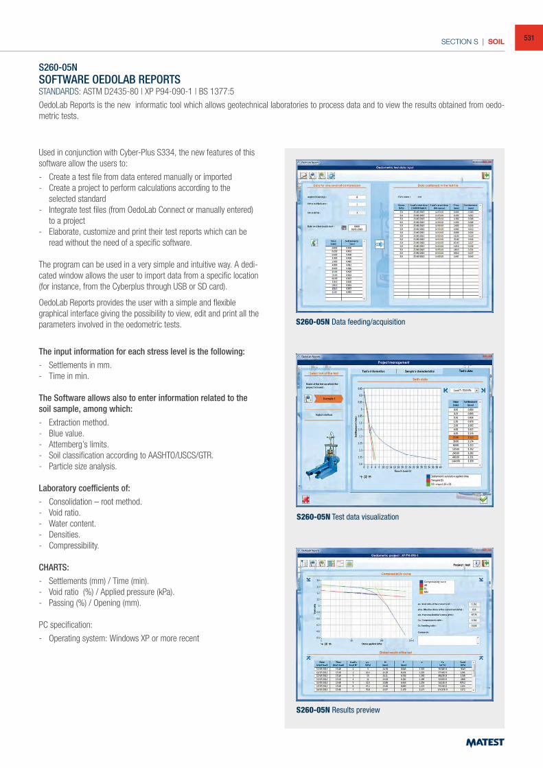
SECTION S | SOIL
S260-05NSOFTWARE OEDOLAB REPORTSSTANDARDS: ASTM D2435-80 | XP P94-090-1 | BS 1377:5
OedoLab Reports is the new informatic tool which allows geotechnical laboratories to process data and to view the results obtained from oedo-metric tests.
Used in conjunction with Cyber-Plus S334, the new features of this software allow the users to:
- Create a test file from data entered manually or imported- Create a project to perform calculations according to the
selected standard- Integrate test files (from OedoLab Connect or manually entered)
to a project- Elaborate, customize and print their test reports which can be
read without the need of a specific software.
The program can be used in a very simple and intuitive way. A dedi-cated window allows the user to import data from a specific location (for instance, from the Cyberplus through USB or SD card).
OedoLab Reports provides the user with a simple and flexible graphical interface giving the possibility to view, edit and print all the parameters involved in the oedometric tests.
The input information for each stress level is the following:- Settlements in mm.- Time in min. The Software allows also to enter information related to the soil sample, among which:- Extraction method.- Blue value.- Attemberg’s limits.- Soil classification according to AASHTO/USCS/GTR.- Particle size analysis.
Laboratory coefficients of: - Consolidation – root method.- Void ratio.- Water content.- Densities.- Compressibility.
CHARTS: - Settlements (mm) / Time (min).- Void ratio (%) / Applied pressure (kPa).- Passing (%) / Opening (mm).
PC specification:
- Operating system: Windows XP or more recent
S260-05N Data feeding/acquisition
S260-05N Test data visualization
S260-05N Results preview
531
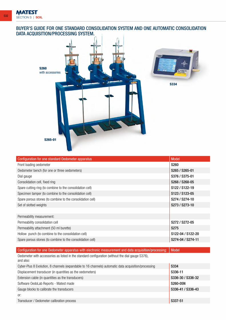
SECTION S | SOIL
BUYER’S GUIDE FOR ONE STANDARD CONSOLIDATION SYSTEM AND ONE AUTOMATIC CONSOLIDATION DATA ACQUISITION/PROCESSING SYSTEM.
Configuration for one standard Oedometer apparatus Model
Front loading oedometer S260
Oedometer bench (for one or three oedometers) S265 / S265-01
Dial gauge S376 / S375-01
Consolidation cell, fixed ring S268 / S268-05
Spare cutting ring (to combine to the consolidation cell) S122 / S122-19
Specimen tamper (to combine to the consolidation cell) S123 / S123-05
Spare porous stones (to combine to the consolidation cell) S274 / S274-10
Set of slotted weights S273 / S273-10
Permeability measurement:
Permeability consolidation cell S272 / S272-05
Permeability attachment (50 ml burette) S275
Hollow punch (to combine to the consolidation cell) S122-04 / S122-20
Spare porous stones (to combine to the consolidation cell) S274-04 / S274-11
Configuration for one Oedometer apparatus with electronic measurement and data acquisition/processing: Model
Oedometer with accessories as listed in the standard configuration (without the dial gauge S376),and also:
Cyber-Plus 8 Evolution, 8 channels (expandable to 16 channels) automatic data acquisition/processing S334
Displacement transducer (in quantities as the oedometers) S336-11
Extension cable (in quantities as the transducers) S336-30 / S336-32
Software OedoLab Reports - Matest made S260-05N
Gauge blocks to calibrate the transducers S336-41 / S336-43
or:
Transducer / 0edometer calibration process S337-51
S334
S265-01
S260with accessories
532
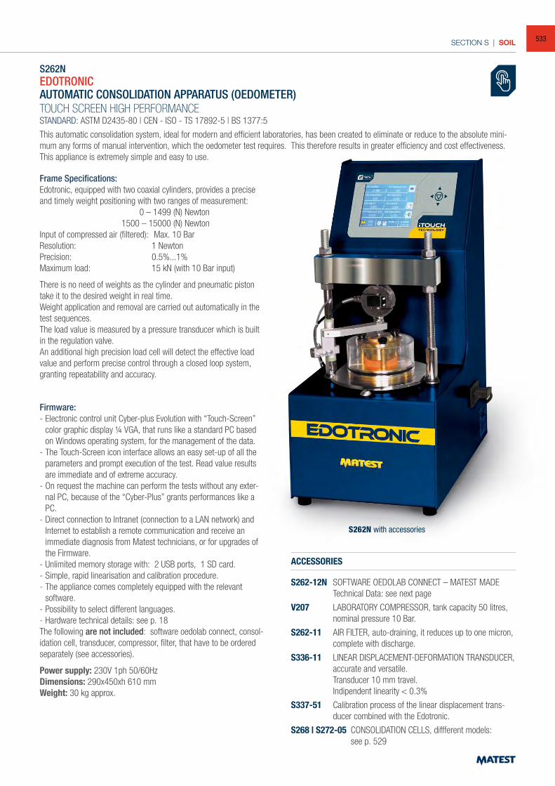
SECTION S | SOIL
S262NEDOTRONICAUTOMATIC CONSOLIDATION APPARATUS (OEDOMETER)TOUCH SCREEN HIGH PERFORMANCESTANDARD: ASTM D2435-80 | CEN - ISO - TS 17892-5 | BS 1377:5
This automatic consolidation system, ideal for modern and efficient laboratories, has been created to eliminate or reduce to the absolute mini-mum any forms of manual intervention, which the oedometer test requires. This therefore results in greater efficiency and cost effectiveness.This appliance is extremely simple and easy to use.
Frame Specifications:Edotronic, equipped with two coaxial cylinders, provides a precise and timely weight positioning with two ranges of measurement: 0 – 1499 (N) Newton 1500 – 15000 (N) NewtonInput of compressed air (filtered): Max. 10 BarResolution: 1 NewtonPrecision: 0.5%...1% Maximum load: 15 kN (with 10 Bar input)
There is no need of weights as the cylinder and pneumatic piston take it to the desired weight in real time.Weight application and removal are carried out automatically in the test sequences.The load value is measured by a pressure transducer which is built in the regulation valve.An additional high precision load cell will detect the effective load value and perform precise control through a closed loop system, granting repeatability and accuracy.
Firmware:- Electronic control unit Cyber-plus Evolution with “Touch-Screen”
color graphic display ¼ VGA, that runs like a standard PC based on Windows operating system, for the management of the data.
- The Touch-Screen icon interface allows an easy set-up of all the parameters and prompt execution of the test. Read value results are immediate and of extreme accuracy.
- On request the machine can perform the tests without any exter-nal PC, because of the “Cyber-Plus” grants performances like a PC.
- Direct connection to Intranet (connection to a LAN network) and Internet to establish a remote communication and receive an immediate diagnosis from Matest technicians, or for upgrades of the Firmware.
- Unlimited memory storage with: 2 USB ports, 1 SD card.- Simple, rapid linearisation and calibration procedure.- The appliance comes completely equipped with the relevant
software.- Possibility to select different languages.- Hardware technical details: see p. 18The following are not included: software oedolab connect, consol-idation cell, transducer, compressor, filter, that have to be ordered separately (see accessories).
Power supply: 230V 1ph 50/60HzDimensions: 290x450xh 610 mmWeight: 30 kg approx.
ACCESSORIES
S262-12N SOFTWARE OEDOLAB CONNECT – MATEST MADE Technical Data: see next page
V207 LABORATORY COMPRESSOR, tank capacity 50 litres, nominal pressure 10 Bar.
S262-11 AIR FILTER, auto-draining, it reduces up to one micron, complete with discharge.
S336-11 LINEAR DISPLACEMENT-DEFORMATION TRANSDUCER, accurate and versatile. Transducer 10 mm travel. Indipendent linearity < 0.3%
S337-51 Calibration process of the linear displacement trans-ducer combined with the Edotronic.
S268 | S272-05 CONSOLIDATION CELLS, diffferent models: see p. 529
S262N with accessories
533
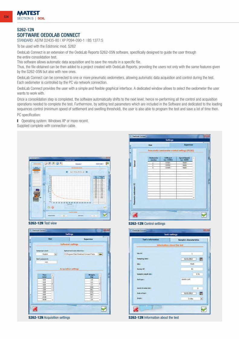
SECTION S | SOIL
S262-12NSOFTWARE OEDOLAB CONNECTSTANDARD: ASTM D2435-80 | XP P094-090-1 | BS 1377:5
To be used with the Edotronic mod. S262
OedoLab Connect is an extension of the OedoLab Reports S262-05N software, specifically designed to guide the user throughthe entire consolidation test.This software allows automatic data acquisition and to save the results in a specific file.Thus, the file obtained can be then added to a project created with OedoLab Reports, providing the users not only with the same features given by the S262-05N but also with new ones.
OedoLab Connect can be connected to one or more pneumatic oedometers, allowing automatic data acquistion and control during the test.Each oedometer is controlled by the PC via network connection.
OedoLab Connect provides the user with a simple and flexible graphical interface. A dedicated window allows to select the oedometer the user wants to work with.
Once a consolidation step is completed, the software automatically shifts to the next level; hence re-performing all the control and acquisition operations needed to complete the test. Furthermore, by setting test parameters which are included in the Software and dedicated to the loading sequences control (minimum speed of settlement and swelling threshold), the user is also able to program the test and save a lot of time then.
PC specification:
Operating system: Windows XP or more recent.Supplied complete with connection cable.
S262-12N Test view S262-12N Control settings
S262-12N Information about the testS262-12N Acquisition settings
534
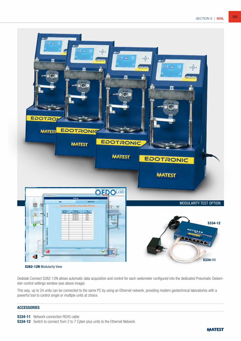
SECTION S | SOIL
Oedolab Connect S262-12N allows automatic data acquisition and control for each oedometer configured into the dedicated Pneumatic Oedom-eter control settings window (see above image).
This way, up to 24 units can be connected to the same PC by using an Ethernet network, providing modern geotechnical laboratories with a powerful tool to control single or multiple units at choice.
S262-12N Modularity View
MODULARITY TEST OPTION
ACCESSORIES
S334-11 Network connection RS45 cableS334-12 Switch to connect from 2 to 7 Cyber-plus units to the Ethernet Network
S334-11
S334-12
535
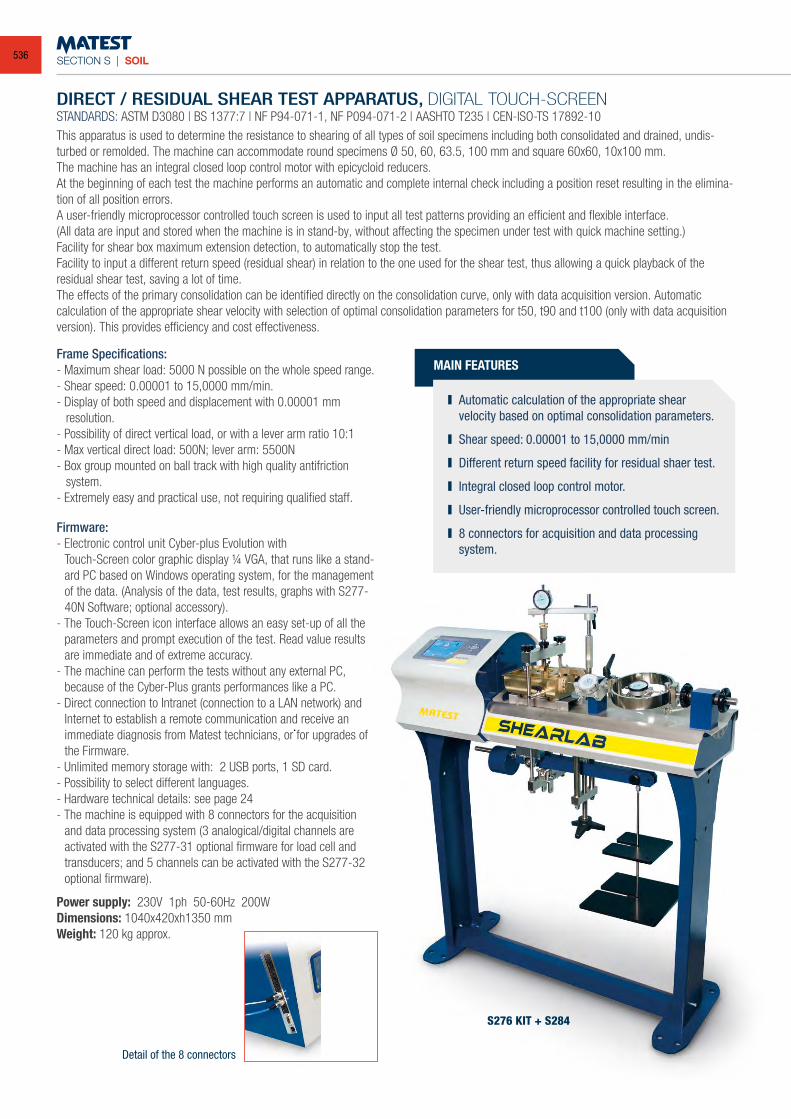
SECTION S | SOIL
DIRECT / RESIDUAL SHEAR TEST APPARATUS, DIGITAL TOUCH-SCREENSTANDARDS: ASTM D3080 | BS 1377:7 | NF P94-071-1, NF P094-071-2 | AASHTO T235 | CEN-ISO-TS 17892-10 This apparatus is used to determine the resistance to shearing of all types of soil specimens including both consolidated and drained, undis-turbed or remolded. The machine can accommodate round specimens Ø 50, 60, 63.5, 100 mm and square 60x60, 10x100 mm.The machine has an integral closed loop control motor with epicycloid reducers.At the beginning of each test the machine performs an automatic and complete internal check including a position reset resulting in the elimina-tion of all position errors.A user-friendly microprocessor controlled touch screen is used to input all test patterns providing an efficient and flexible interface.(All data are input and stored when the machine is in stand-by, without affecting the specimen under test with quick machine setting.)Facility for shear box maximum extension detection, to automatically stop the test.Facility to input a different return speed (residual shear) in relation to the one used for the shear test, thus allowing a quick playback of the residual shear test, saving a lot of time. The effects of the primary consolidation can be identified directly on the consolidation curve, only with data acquisition version. Automatic calculation of the appropriate shear velocity with selection of optimal consolidation parameters for t50, t90 and t100 (only with data acquisition version). This provides efficiency and cost effectiveness.
MAIN FEATURES
Automatic calculation of the appropriate shear velocity based on optimal consolidation parameters.
Shear speed: 0.00001 to 15,0000 mm/min
Different return speed facility for residual shaer test.
Integral closed loop control motor.
User-friendly microprocessor controlled touch screen.
8 connectors for acquisition and data processing system.
Firmware:- Electronic control unit Cyber-plus Evolution with Touch-Screen color graphic display ¼ VGA, that runs like a stand-
ard PC based on Windows operating system, for the management of the data. (Analysis of the data, test results, graphs with S277-40N Software; optional accessory).
- The Touch-Screen icon interface allows an easy set-up of all the parameters and prompt execution of the test. Read value results are immediate and of extreme accuracy.
- The machine can perform the tests without any external PC, because of the Cyber-Plus grants performances like a PC.
- Direct connection to Intranet (connection to a LAN network) and Internet to establish a remote communication and receive an immediate diagnosis from Matest technicians, or for upgrades of the Firmware.
- Unlimited memory storage with: 2 USB ports, 1 SD card.- Possibility to select different languages.- Hardware technical details: see page 24- The machine is equipped with 8 connectors for the acquisition
and data processing system (3 analogical/digital channels are activated with the S277-31 optional firmware for load cell and transducers; and 5 channels can be activated with the S277-32 optional firmware).
Power supply: 230V 1ph 50-60Hz 200WDimensions: 1040x420xh1350 mmWeight: 120 kg approx.
Frame Specifications:- Maximum shear load: 5000 N possible on the whole speed range.- Shear speed: 0.00001 to 15,0000 mm/min.- Display of both speed and displacement with 0.00001 mm
resolution.- Possibility of direct vertical load, or with a lever arm ratio 10:1- Max vertical direct load: 500N; lever arm: 5500N- Box group mounted on ball track with high quality antifriction
system.- Extremely easy and practical use, not requiring qualified staff.
S276 KIT + S284
Detail of the 8 connectors
536
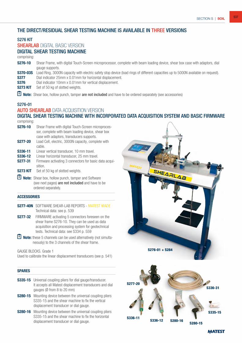
SECTION S | SOIL
THE DIRECT/RESIDUAL SHEAR TESTING MACHINE IS AVAILABLE IN THREE VERSIONS
S276 KITSHEARLAB DIGITAL BASIC VERSIONDIGITAL SHEAR TESTING MACHINEcomprising:
S276-10 Shear Frame, with digital Touch-Screen microprocessor, complete with beam loading device, shear box case with adaptors, dial gauge supports.
S370-03S Load Ring, 3000N capacity with electric safety stop device (load rings of different capacities up to 5000N available on request).S377 Dial indicator 25mm x 0.01mm for horizontal displacement.S376 Dial indicator 10mm x 0.01mm for vertical displacement.S273 KIT Set of 50 kg of slotted weights.
Note: Shear box, hollow punch, tamper are not included and have to be ordered separately (see accessories)
S276-01AUTO SHEARLAB DATA ACQUISITION VERSIONDIGITAL SHEAR TESTING MACHINE WITH INCORPORATED DATA ACQUISITION SYSTEM AND BASIC FIRMWARE comprising:
ACCESSORIES
S277-40N SOFTWARE SHEAR-LAB REPORTS - MATEST MADE Technical data: see p. 539
S277-32 FIRMWARE activating 5 connectors foreseen on the shear frame S276-10. They can be used as data acquisition and processing system for geotechnical tests. Technical data: see S334 p. 559
Note: these 5 channels can be used alternatively (not simulta-neously) to the 3 channels of the shear frame.
GAUGE BLOCKS. Grade 1Used to calibrate the linear displacement transducers (see p. 541)
SPARES
S335-15 Universal coupling pliers for dial gauge/transducer. It accepts all Matest displacement transducers and dial
gauges (Ø from 8 to 20 mm)
S280-15 Mounting device between the universal coupling pliers S335-15 and the shear machine to fix the vertical displacement transducer or dial gauge.
S280-16 Mounting device between the universal coupling pliers S335-15 and the shear machine to fix the horizontal displacement transducer or dial gauge.
S276-10 Shear Frame with digital Touch-Screen microproces-sor, complete with beam loading device, shear box case with adaptors, transducers supports.
S277-20 Load Cell, electric, 3000N capacity, complete with cable.
S336-11 Linear vertical transducer, 10 mm travel.S336-12 Linear horizontal transducer, 25 mm travel.S277-31 Firmware activating 3 connectors for basic data acqui-
sition.S273 KIT Set of 50 kg of slotted weights.
Note: Shear box, hollow punch, tamper and Software (see next pages) are not included and have to be
ordered separately.
S276-01 + S284
S277-20
S336-11
S336-31
S335-15
S336-12 S280-16S280-15
537
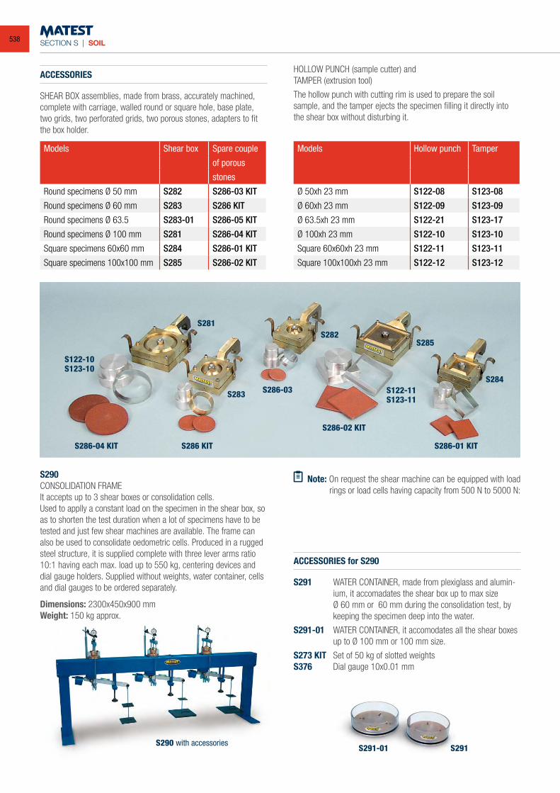
SECTION S | SOIL
ACCESSORIES
SHEAR BOX assemblies, made from brass, accurately machined, complete with carriage, walled round or square hole, base plate, two grids, two perforated grids, two porous stones, adapters to fit the box holder.
HOLLOW PUNCH (sample cutter) andTAMPER (extrusion tool)
The hollow punch with cutting rim is used to prepare the soil sample, and the tamper ejects the specimen filling it directly into the shear box without disturbing it.
Models Shear box Spare couple
of porous
stones
Round specimens Ø 50 mm S282 S286-03 KIT
Round specimens Ø 60 mm S283 S286 KIT
Round specimens Ø 63.5 S283-01 S286-05 KIT
Round specimens Ø 100 mm S281 S286-04 KIT
Square specimens 60x60 mm S284 S286-01 KIT
Square specimens 100x100 mm S285 S286-02 KIT
Models Hollow punch Tamper
Ø 50xh 23 mm S122-08 S123-08
Ø 60xh 23 mm S122-09 S123-09
Ø 63.5xh 23 mm S122-21 S123-17
Ø 100xh 23 mm S122-10 S123-10
Square 60x60xh 23 mm S122-11 S123-11
Square 100x100xh 23 mm S122-12 S123-12
ACCESSORIES for S290
S291 WATER CONTAINER, made from plexiglass and alumin-ium, it accomadates the shear box up to max size
Ø 60 mm or 60 mm during the consolidation test, by keeping the specimen deep into the water.
S291-01 WATER CONTAINER, it accomodates all the shear boxes up to Ø 100 mm or 100 mm size.
S273 KIT Set of 50 kg of slotted weightsS376 Dial gauge 10x0.01 mm
Note: On request the shear machine can be equipped with load rings or load cells having capacity from 500 N to 5000 N:
S290CONSOLIDATION FRAMEIt accepts up to 3 shear boxes or consolidation cells. Used to applly a constant load on the specimen in the shear box, so as to shorten the test duration when a lot of specimens have to be tested and just few shear machines are available. The frame can also be used to consolidate oedometric cells. Produced in a rugged steel structure, it is supplied complete with three lever arms ratio 10:1 having each max. load up to 550 kg, centering devices and dial gauge holders. Supplied without weights, water container, cells and dial gauges to be ordered separately.
Dimensions: 2300x450x900 mmWeight: 150 kg approx.
S286-04 KIT S286-01 KIT
S286-02 KIT
S284
S285S282
S283
S281
S122-11S123-11
S122-10S123-10
S286 KIT
S291-01 S291S290 with accessories
S286-03
538
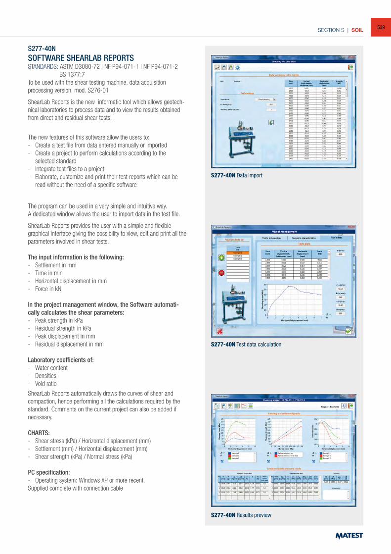
SECTION S | SOIL
S277-40NSOFTWARE SHEARLAB REPORTSSTANDARDS: ASTM D3080-72 | NF P94-071-1 | NF P94-071-2 BS 1377:7To be used with the shear testing machine, data acquisitionprocessing version, mod. S276-01
ShearLab Reports is the new informatic tool which allows geotech-nical laboratories to process data and to view the results obtained from direct and residual shear tests.
The new features of this software allow the users to:- Create a test file from data entered manually or imported- Create a project to perform calculations according to the
selected standard- Integrate test files to a project- Elaborate, customize and print their test reports which can be
read without the need of a specific software
The program can be used in a very simple and intuitive way.A dedicated window allows the user to import data in the test file.
ShearLab Reports provides the user with a simple and flexible graphical interface giving the possibility to view, edit and print all the parameters involved in shear tests.
The input information is the following:- Settlement in mm- Time in min- Horizontal displacement in mm- Force in kN
In the project management window, the Software automati-cally calculates the shear parameters: - Peak strength in kPa- Residual strength in kPa- Peak displacement in mm- Residual displacement in mm
Laboratory coefficients of:- Water content- Densities- Void ratio
ShearLab Reports automatically draws the curves of shear and compaction, hence performing all the calculations required by the standard. Comments on the current project can also be added if necessary.
CHARTS:- Shear stress (kPa) / Horizontal displacement (mm)- Settlement (mm) / Horizontal displacement (mm)- Shear strength (kPa) / Normal stress (kPa)
PC specification:- Operating system: Windows XP or more recent.Supplied complete with connection cable
S277-40N Data import
S277-40N Test data calculation
S277-40N Results preview
539
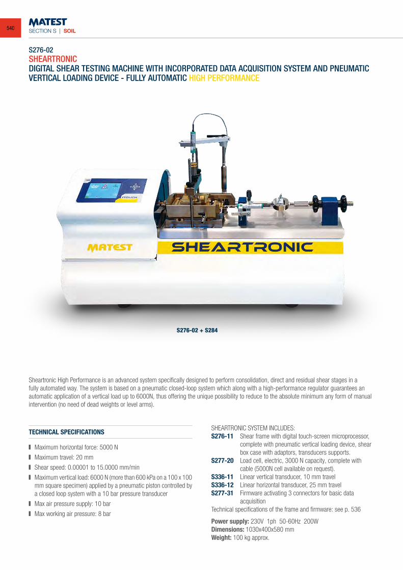
SECTION S | SOIL
S276-02SHEARTRONICDIGITAL SHEAR TESTING MACHINE WITH INCORPORATED DATA ACQUISITION SYSTEM AND PNEUMATIC VERTICAL LOADING DEVICE - FULLY AUTOMATIC HIGH PERFORMANCE
Sheartronic High Performance is an advanced system specifically designed to perform consolidation, direct and residual shear stages in a fully automated way. The system is based on a pneumatic closed-loop system which along with a high-performance regulator guarantees an automatic application of a vertical load up to 6000N, thus offering the unique possibility to reduce to the absolute minimum any form of manual intervention (no need of dead weights or level arms).
S276-02 + S284
TECHNICAL SPECIFICATIONS
Maximum horizontal force: 5000 N
Maximum travel: 20 mm
Shear speed: 0.00001 to 15.0000 mm/min
Maximum vertical load: 6000 N (more than 600 kPa on a 100 x 100 mm square specimen) applied by a pneumatic piston controlled by a closed loop system with a 10 bar pressure transducer
Max air pressure supply: 10 bar
Max working air pressure: 8 bar
SHEARTRONIC SYSTEM INCLUDES:S276-11 Shear frame with digital touch-screen microprocessor,
complete with pneumatic vertical loading device, shear box case with adaptors, transducers supports.
S277-20 Load cell, electric, 3000 N capacity, complete with cable (5000N cell available on request).
S336-11 Linear vertical transducer, 10 mm travelS336-12 Linear horizontal transducer, 25 mm travelS277-31 Firmware activating 3 connectors for basic data
acquisitionTechnical specifications of the frame and firmware: see p. 536
Power supply: 230V 1ph 50-60Hz 200WDimensions: 1030x400x580 mmWeight: 100 kg approx.
540
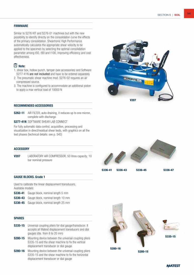
SECTION S | SOIL
FIRMWARE
Similar to S276 KIT and S276-01 machines but with the new possibility to identify directly on the consolidation curve the effects of the primary consolidation. Sheartronic High Performance automatically calculates the appropriate shear velocity to be applied to the specimen by selecting the optimal consolidation parameter among t50, t90 and t100, improving efficiency and cost effectiveness.
ACCESSORY
V207 LABORATORY AIR COMPRESSOR, 50 litres capacity, 10 bar nominal pressure
RECOMMENDED ACCESSORIES
S262-11 AIR FILTER, auto-draining, it reduces up to one micron, complete with discharge
S277-41N SOFTWARE SHEAR LAB CONNECT
For fully automatic data control, acquisition, processing and visualization in direct/residual shear tests, with graphics on all the test phases (technical details: see p. 542)
SPARES
S335-15 Universal coupling pliers for dial gauge/transducer. It accepts all Matest displacement transducers and dial gauges (dia. from 8 to 20 mm)
S280-15 Mounting device between the universal coupling pliers S335-15 and the shear machine to fix the vertical displacement transducer or dial gauge
S280-16 Mounting device between the universal coupling pliers S335-15 and the shear machine to fix the horizontal displacement transducer or dial gauge
GAUGE BLOCKS. Grade 1
Used to calibrate the linear displacement transducers. Available models:
S336-41 Gauge block, nominal length 5 mm
S336-43 Gauge block, nominal length 10 mm
S336-45 Gauge block, nominal length 25 mm
V207
S336-41
S280-16S280-15
S335-15
S336-43 S336-45 S336-47
Note: 1. shear box, hollow punch, tamper (see accessories) and Software
S277-41N are not included and have to be ordered separately2. The pneumatic shear machine mod. S276-02 requires an air
compressed source.3. The machine is configured to accommodate an additional piston
to apply a max vertical load of 10000 N
541
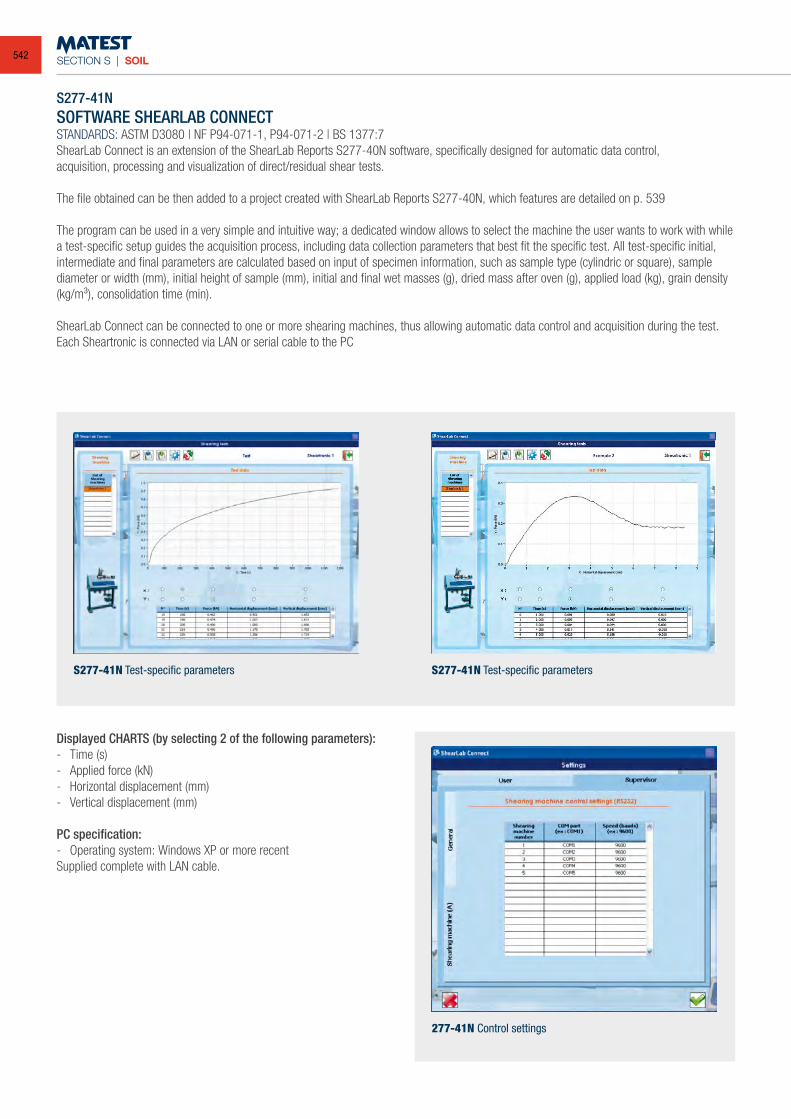
SECTION S | SOIL
S277-41NSOFTWARE SHEARLAB CONNECTSTANDARDS: ASTM D3080 | NF P94-071-1, P94-071-2 | BS 1377:7ShearLab Connect is an extension of the ShearLab Reports S277-40N software, specifically designed for automatic data control,acquisition, processing and visualization of direct/residual shear tests.
The file obtained can be then added to a project created with ShearLab Reports S277-40N, which features are detailed on p. 539
The program can be used in a very simple and intuitive way; a dedicated window allows to select the machine the user wants to work with while a test-specific setup guides the acquisition process, including data collection parameters that best fit the specific test. All test-specific initial, intermediate and final parameters are calculated based on input of specimen information, such as sample type (cylindric or square), sample diameter or width (mm), initial height of sample (mm), initial and final wet masses (g), dried mass after oven (g), applied load (kg), grain density (kg/m³), consolidation time (min).
ShearLab Connect can be connected to one or more shearing machines, thus allowing automatic data control and acquisition during the test. Each Sheartronic is connected via LAN or serial cable to the PC
Displayed CHARTS (by selecting 2 of the following parameters):- Time (s)- Applied force (kN)- Horizontal displacement (mm) - Vertical displacement (mm)
PC specification:- Operating system: Windows XP or more recentSupplied complete with LAN cable.
S277-41N Test-specific parameters S277-41N Test-specific parameters
277-41N Control settings
542
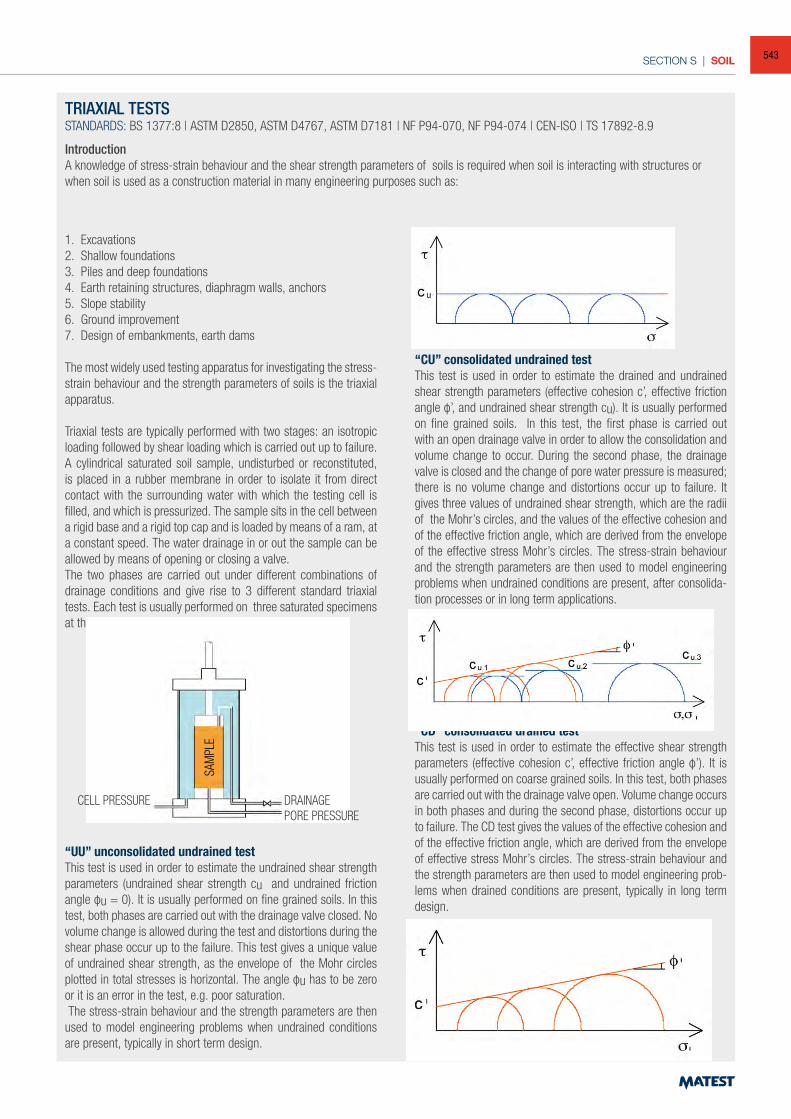
SECTION S | SOIL
TRIAXIAL TESTSSTANDARDS: BS 1377:8 | ASTM D2850, ASTM D4767, ASTM D7181 | NF P94-070, NF P94-074 | CEN-ISO | TS 17892-8.9
IntroductionA knowledge of stress-strain behaviour and the shear strength parameters of soils is required when soil is interacting with structures or when soil is used as a construction material in many engineering purposes such as:
1. Excavations 2. Shallow foundations 3. Piles and deep foundations4. Earth retaining structures, diaphragm walls, anchors5. Slope stability 6. Ground improvement7. Design of embankments, earth dams
The most widely used testing apparatus for investigating the stress-strain behaviour and the strength parameters of soils is the triaxial apparatus.
Triaxial tests are typically performed with two stages: an isotropic loading followed by shear loading which is carried out up to failure. A cylindrical saturated soil sample, undisturbed or reconstituted, is placed in a rubber membrane in order to isolate it from direct contact with the surrounding water with which the testing cell is filled, and which is pressurized. The sample sits in the cell between a rigid base and a rigid top cap and is loaded by means of a ram, at a constant speed. The water drainage in or out the sample can be allowed by means of opening or closing a valve. The two phases are carried out under different combinations of drainage conditions and give rise to 3 different standard triaxial tests. Each test is usually performed on three saturated specimens at three different confining pressures.
“UU” unconsolidated undrained testThis test is used in order to estimate the undrained shear strength parameters (undrained shear strength cu and undrained friction angle φu = 0). It is usually performed on fine grained soils. In this test, both phases are carried out with the drainage valve closed. No volume change is allowed during the test and distortions during the shear phase occur up to the failure. This test gives a unique value of undrained shear strength, as the envelope of the Mohr circles plotted in total stresses is horizontal. The angle φu has to be zero or it is an error in the test, e.g. poor saturation. The stress-strain behaviour and the strength parameters are then used to model engineering problems when undrained conditions are present, typically in short term design.
“CU” consolidated undrained testThis test is used in order to estimate the drained and undrained shear strength parameters (effective cohesion c’, effective friction angle φ’, and undrained shear strength cu). It is usually performed on fine grained soils. In this test, the first phase is carried out with an open drainage valve in order to allow the consolidation and volume change to occur. During the second phase, the drainage valve is closed and the change of pore water pressure is measured; there is no volume change and distortions occur up to failure. It gives three values of undrained shear strength, which are the radii of the Mohr’s circles, and the values of the effective cohesion and of the effective friction angle, which are derived from the envelope of the effective stress Mohr’s circles. The stress-strain behaviour and the strength parameters are then used to model engineering problems when undrained conditions are present, after consolida-tion processes or in long term applications.
“CD” consolidated drained testThis test is used in order to estimate the effective shear strength parameters (effective cohesion c’, effective friction angle φ’). It is usually performed on coarse grained soils. In this test, both phases are carried out with the drainage valve open. Volume change occurs in both phases and during the second phase, distortions occur up to failure. The CD test gives the values of the effective cohesion and of the effective friction angle, which are derived from the envelope of effective stress Mohr’s circles. The stress-strain behaviour and the strength parameters are then used to model engineering prob-lems when drained conditions are present, typically in long term design.
CELL PRESSURE
SAM
PLE
DRAINAGEPORE PRESSURE
543
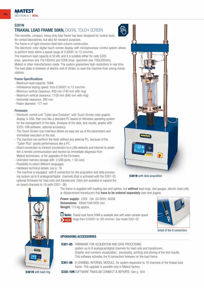
SECTION S | SOIL
S301NTRIAXIAL LOAD FRAME 50KN, DIGITAL TOUCH-SCREENThis versatile, compact, heavy duty load frame has been designed for routine tests,for central laboratories, but also for research purposes.The frame is of rigid chromed steel twin column construction.The electronic color digital touch-screen display with microprocessor control system allows to perform tests within a speed range of 0.00001 to 12 mm/min. The maximum load capacity is 50 kN, and it is suitable either for cells S305(max. specimen size 70x140mm) and S306 (max. specimen size 100x200mm),Matest or other manufacturers made. The system guarantees high resolutions in real time.The load plate is foreseen of electric end of stroke, to save the machine from wrong manip-ulations.
Detail of the 8 connectors
Frame Specifications:- Maximum load capacity: 50kN- Infinitesimal testing speed: from 0.00001 to 12 mm/min.- Minimum vertical clearance: 400 mm (140 mm with ring)- Maximum vertical clearance: 1100 mm (840 mm with ring)- Horizontal clearance: 380 mm- Platen diameter: 177 mm
Firmware:- Electronic control unit “Cyber-plus Evolution” with Touch-Screen color graphic display ¼ VGA, that runs like a standard PC based on Windows operating system
for the management of the data. (Analysis of the data, test results, graphs with S335-10N software; optional accessory).- The Touch-Screen icon interface allows an easy set-up of the parameters and immediate execution of the test.- The machine can perform the tests without any external PC, because of the
“Cyber-Plus” grants performances like a PC.- Direct connection to Intranet (connection to a LAN network) and Internet to estab-
lish a remote communication and receive an immediate diagnosis from Matest technicians, or for upgrades of the Firmware.- Unlimited memory storage with: 2 USB ports, 1 SD card.- Possibility to select different languages.- Hardware technical details: see p. 18- The machine is equipped with 8 connectors for the acquisition and data process-
ing system up to 8 analogical/digital channels (that is activated with the S301-05 optional firmware) for load cells and transducers. Extra slot available to expand the on-board channels to 16 (with S301- 06)
UPGRADING ACCESSORIES
S301-05 FIRMWARE FOR ACQUISITION AND DATA PROCESSING system up to 8 analogical/digital channels for load cells and transducers. Graphic and numbers visualization, processing, printing and storing of the test results. This software activates the 8 connectors foreseen on the load frame.
S301-06 8-CHANNEL INTERNAL MODULE, for system expansion to 16 channels of the triaxial load frame. This upgrade is possible only in Matest factory.
S335-10N SOFTWARE TRIAXLAB CONNECT & REPORTS See p. 554
The frame is supplied with loading ram and sphere, but without load rings, dial gauges, electric load cells or displacement transducers that have to be ordered separately (see next pages).
Power supply: 230V 1ph 50-60Hz 600WDimensions: 490x510xh1800 mm Weight: 115 kg approx.
S301N with data acquisition
S301N with load ring
Note: Triaxial load frame 50kN is available also with wider variable speed range from 0.00001 to 100 mm/min. See model S301-02NEW
544
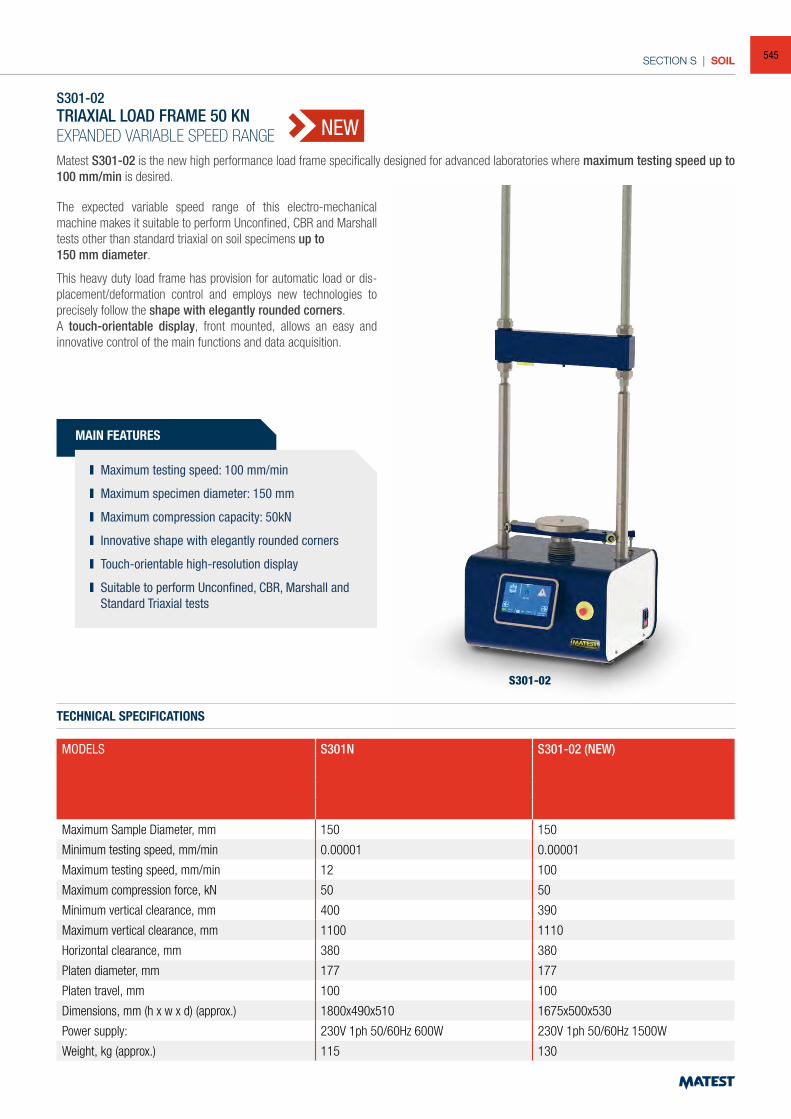
SECTION S | SOIL
S301-02
S301-02TRIAXIAL LOAD FRAME 50 KNEXPANDED VARIABLE SPEED RANGEMatest S301-02 is the new high performance load frame specifically designed for advanced laboratories where maximum testing speed up to 100 mm/min is desired.
MAIN FEATURES
Maximum testing speed: 100 mm/min
Maximum specimen diameter: 150 mm
Maximum compression capacity: 50kN
Innovative shape with elegantly rounded corners
Touch-orientable high-resolution display
Suitable to perform Unconfined, CBR, Marshall and Standard Triaxial tests
TECHNICAL SPECIFICATIONS
MODELS S301N S301-02 (NEW)
Maximum Sample Diameter, mm 150 150
Minimum testing speed, mm/min 0.00001 0.00001
Maximum testing speed, mm/min 12 100
Maximum compression force, kN 50 50
Minimum vertical clearance, mm 400 390
Maximum vertical clearance, mm 1100 1110
Horizontal clearance, mm 380 380
Platen diameter, mm 177 177
Platen travel, mm 100 100
Dimensions, mm (h x w x d) (approx.) 1800x490x510 1675x500x530
Power supply: 230V 1ph 50/60Hz 600W 230V 1ph 50/60Hz 1500W
Weight, kg (approx.) 115 130
The expected variable speed range of this electro-mechanical machine makes it suitable to perform Unconfined, CBR and Marshall tests other than standard triaxial on soil specimens up to150 mm diameter.
This heavy duty load frame has provision for automatic load or dis-placement/deformation control and employs new technologies to precisely follow the shape with elegantly rounded corners.A touch-orientable display, front mounted, allows an easy and innovative control of the main functions and data acquisition.
NEW
545
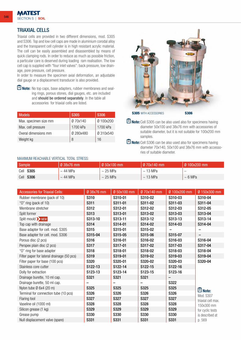
SECTION S | SOIL
TRIAXIAL CELLSTriaxial cells are provided in two different dimensions, mod. S305 and S306. Top and low cell caps are made in aluminium corodal alloy and the transparent cell cylinder is in high resistant acrylic material. The cell can be easily assembled and disassembled by means of quick clamping rods. In order to reduce as much as possible friction, a particular care is deserved during loading ram realisation. The low cell cap is supplied with “four inlet valves”: back pressure, low drain-age, pore pressure, cell pressure.In order to measure the specimen axial deformation, an adjustable dial gauge or a displacement transducer is also provided.
Note: No top caps, base adapters, rubber membranes and seal-ing rings, porous stones, dial gauges, etc. are included and should be ordered separately. In the table all accessories for triaxial cells are listed.
Models S305 S306
Max. specimen size mm Ø 70x140 Ø 100x200
Max. cell pressure 1700 kPa 1700 kPa
Overal dimensions mm Ø 280x480 Ø 310x540
Weight kg 8 16
MAXIMUM REACHABLE VERTICAL TOTAL STRESS:
Sample Ø 38x76 mm Ø 50x100 mm Ø 70x140 mm Ø 100x200 mm
Cell S305 ~ 44 MPa ~ 25 MPa ~ 13 MPa –
Cell S306 ~ 44 MPa ~ 25 MPa ~ 13 MPa ~ 6 MPa
Accessories for Triaxial Cells: Ø 38x76 mm Ø 50x100 mm Ø 70x140 mm Ø 100x200 mm Ø 150x300 mmRubber membrane (pack of 10) S310 S310-01 S310-02 S310-03 S310-04“O” ring (pack of 10) S311 S311-01 S311-02 S311-03 S311-04Membrane stretcher S312 S312-01 S312-02 S312-03 S312-05Split former S313 S313-01 S313-02 S313-03 S313-04Split mould S313-10 S313-11 S313-12 S313-13 S313-14Top cap with drainage S314 S314-01 S314-02 S314-03 S314-04Base adapter for cell. mod. S305 S315 S315-01 S315-02 – –Base adapter for cell. mod. S306 S315-04 S315-05 S315-06 S315-07 –Porous disc (2 pcs) S316 S316-01 S316-02 S316-03 S316-04Perspex plain disc (2 pcs) S317 S317-01 S317-02 S317-03 S317-04“O” ring for base adapter S318 S318-01 S318-02 S318-03 S318-04Filter paper for lateral drainage (50 pcs) S319 S319-01 S319-02 S319-03 S319-04Filter paper for base (100 pcs) S320 S320-01 S320-02 S320-03 S320-04Stainless core cutter S122-13 S122-14 S122-15 S122-16Dolly for extraction S123-13 S123-14 S123-15 S123-16Drainage burette, 10 ml cap. S321 S321 S321 –Drainage burette, 50 ml cap. – – – S322Nylon tube Ø 6x4 (20 m) S325 S325 S325 S325Terminal for connection tube (10 pcs) S326 S326 S326 S326Flaring tool S327 S327 S327 S327Vaseline oil (1000 ml) S328 S328 S328 S328Silicon grease (1 kg) S329 S329 S329 S329Grease pump S330 S330 S330 S330Null displacement valve (spare) S331 S331 S331 S331
Note: Cell S305 can be also used also for specimens having diameter 50x100 and 38x76 mm with accessories of suitable diameter, but it is not suitable for 100x200 mm samples.
Note: Cell S306 can be also used also for specimens having diameter 70x140, 50x100 and 38x76 mm with accesso-ries of suitable diameter.
S305 WITH ACCESSORIES S306
NEW
Note:Mod. S307 triaxial cell max. 150x300 mm for cyclic tests is described at p. 569
546
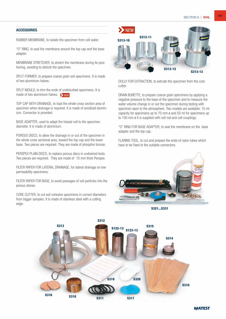
SECTION S | SOIL
ACCESSORIES
RUBBER MEMBRANE, to isolate the specimen from cell water.
“O” RING, to seal the membrane around the top cap and the base adapter.
MEMBRANE STRETCHER, to stretch the membrane during its posi-tioning, avoiding to disturb the specimen.
SPLIT FORMER, to prepare coarse grain soil specimens. It is made of two aluminium halves.
SPLIT MOULD, to trim the ends of undisturbed specimens. It is made of two aluminium halves.
TOP CAP WITH DRAINAGE, to load the whole cross section area of specimen when drainage is required. It is made of anodized alumin-ium. Connector is provided.
BASE ADAPTER, used to adapt the triaxial cell to the specimen diameter. It is made of aluminium.
POROUS DISCS, to allow the drainage in or out of the specimen in the whole cross sectional area, toward the top cap and the lower base. Two pieces are required. They are made of phosphor bronze.
PERSPEX PLAIN DISCS, to replace porous discs in undrained tests. Two pieces are required. They are made of 10 mm thick Perspex.
FILTER PAPER FOR LATERAL DRAINAGE, for lateral drainage on low permeability specimens.
FILTER PAPER FOR BASE, to avoid passages of soil particles into the porous stones.
CORE CUTTER, to cut soil cohesive specimens in correct diameters from bigger samples. It is made of stainless steel with a cutting edge.
S313-10S313-11
S313-12S313-13
S321...S331
S313
S312
S122-13 S123-13S315
S314
S310
S320
S317S311S318S316
S319
DOLLY FOR EXTRACTION, to extrude the specimen from the core cutter.
DRAIN BURETTE, to prepare coarse grain specimens by applying a negative pressure to the base of the specimen and to measure the water volume change in or out the specimen during testing with specimen open to the atmosphere. Two models are available: 10 ml capacity for specimens up to 70 mm ø and 50 ml for specimens up to 100 mm ø It is supplied with cell rod and cell couplings.
“O” RING FOR BASE ADAPTER, to seal the membrane on the base adapter and the top cap.
FLARING TOOL, to cut and prepare the ends of nylon tubes which have to be fixed to the suitable connectors.
NEW
NEW
547
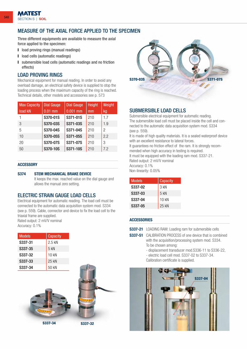
SECTION S | SOIL
S337-34 S337-32
S370-03S S371-07S
MEASURE OF THE AXIAL FORCE APPLIED TO THE SPECIMENThree different equipments are available to measure the axial force applied to the specimen: load proving rings (manual readings) load cells (automatic readings) submersible load cells (automatic readings and no friction
effects)
LOAD PROVING RINGSMechanical equipment for manual reading. In order to avoid any overload damage, an electrical safety device is supplied to stop the loading process when the maximum capacity of the ring is reached.Technical details, other models and accessories see p. 573
Max Capacity Dial Gauge Dial Gauge Height Weight
load kN 0.01 mm 0.001 mm mm kg
1 S370-01S S371-01S 210 1.7
3 S370-03S S371-03S 210 1.9
5 S370-04S S371-04S 210 2
10 S370-05S S371-05S 210 2.2
20 S370-07S S371-07S 210 3
50 S370-10S S371-10S 210 7.2
ACCESSORY
S374 STEM MECHANICAL BRAKE DEVICE It keeps the max. reached value on the dial gauge and
allows the manual zero setting.
ELECTRIC STRAIN GAUGE LOAD CELLSElectrical equipment for automatic reading. The load cell must be connected to the automatic data acquisition system mod. S334(see p. 559). Cable, connector and device to fix the load cell to the triaxial frame are supplied.Rated output: 2 mV/V nominalAccuracy: 0.1%
Models Capacity
S337-31 2.5 kN
S337-35 5 kN
S337-32 10 kN
S337-33 25 kN
S337-34 50 kN
Models Capacity
S337-02 3 kN
S337-03 5 kN
S337-04 10 kN
S337-05 25 kN
SUBMERSIBLE LOAD CELLSSubmersible electrical equipment for automatic reading.The submersible load cell must be placed inside the cell and con-nected to the automatic data acquisition system mod. S334(see p. 559).It is made of high quality materials. It is a sealed waterproof device with an excellent resistance to lateral forces. It guarantees no friction effect of the ram. It is strongly recom-mended when high accuracy in testing is required. It must be equipped with the loading ram mod. S337-21.Rated output: 2 mV/V nominalAccuracy: 0.1%Non-linearity: 0.05%
ACCESSORIES
S337-21 LOADING RAM: Loading ram for submersible cells
S337-51 CALIBRATION PROCESS of one device that is combined with the acquisition/processing system mod. S334.
To be chosen among: - displacement transducer mod.S336-11 to S336-22, - electric load cell mod. S337-02 to S337-34. Calibration certificate is supplied.
S337-04
548
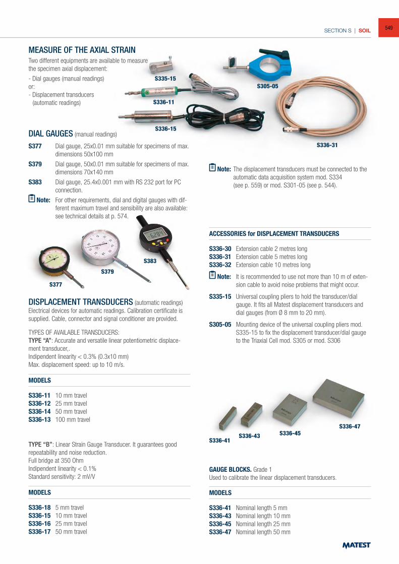
SECTION S | SOIL
MEASURE OF THE AXIAL STRAINTwo different equipments are available to measurethe specimen axial displacement:
- Dial gauges (manual readings)or:- Displacement transducers (automatic readings)
Note: The displacement transducers must be connected to the automatic data acquisition system mod. S334
(see p. 559) or mod. S301-05 (see p. 544).
DIAL GAUGES (manual readings)
S377 Dial gauge, 25x0.01 mm suitable for specimens of max. dimensions 50x100 mm
S379 Dial gauge, 50x0.01 mm suitable for specimens of max. dimensions 70x140 mm
S383 Dial gauge, 25.4x0.001 mm with RS 232 port for PC connection.
Note: For other requirements, dial and digital gauges with dif-ferent maximum travel and sensibility are also available: see technical details at p. 574.
DISPLACEMENT TRANSDUCERS (automatic readings)Electrical devices for automatic readings. Calibration certificate is supplied. Cable, connector and signal conditioner are provided.
TYPES OF AVAILABLE TRANSDUCERS:TYPE “A”: Accurate and versatile linear potentiometric displace-ment transducer,.Indipendent linearity < 0.3% (0.3x10 mm)Max. displacement speed: up to 10 m/s.
MODELS
S336-11 10 mm travelS336-12 25 mm travelS336-14 50 mm travelS336-13 100 mm travel
TYPE “B”: Linear Strain Gauge Transducer. It guarantees good repeatability and noise reduction. Full bridge at 350 OhmIndipendent linearity < 0.1%Standard sensitivity: 2 mV/V
MODELS
S336-18 5 mm travelS336-15 10 mm travelS336-16 25 mm travelS336-17 50 mm travel
ACCESSORIES for DISPLACEMENT TRANSDUCERS
S336-30 Extension cable 2 metres longS336-31 Extension cable 5 metres longS336-32 Extension cable 10 metres long
Note: It is recommended to use not more than 10 m of exten-sion cable to avoid noise problems that might occur.
S335-15 Universal coupling pliers to hold the transducer/dial gauge. It fits all Matest displacement transducers and dial gauges (from Ø 8 mm to 20 mm).
S305-05 Mounting device of the universal coupling pliers mod. S335-15 to fix the displacement transducer/dial gauge to the Triaxial Cell mod. S305 or mod. S306
GAUGE BLOCKS. Grade 1Used to calibrate the linear displacement transducers.
MODELS
S336-41 Nominal length 5 mmS336-43 Nominal length 10 mmS336-45 Nominal length 25 mmS336-47 Nominal length 50 mm
S336-31
S377
S336-41S336-43 S336-45
S336-47
S379
S383
S305-05S335-15
S336-11
S336-15
549
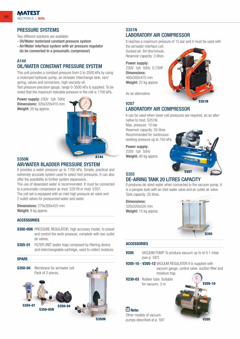
SECTION S | SOIL
PRESSURE SYSTEMSTwo different solutions are available:- Oil/Water motorized constant pressure system- Air/Water interface system with air pressure regulator (to be connected to a pneumatic compressor)
A144OIL/WATER CONSTANT PRESSURE SYSTEMThis unit provides a constant pressure from 0 to 3500 kPa by using a motorized hydraulic pump, an oil/water interchange tank, ram/spring, valves and connectors, high viscosity oil.Test pressure precision gauge, range 0-3500 kPa is supplied. To be noted that the maximum tolerable pressure in the cell is 1700 kPa.
Power supply: 230V 1ph 50HzDimensions: 320x320x410 mmWeight: 20 kg approx.
S350NAIR/WATER BLADDER PRESSURE SYSTEMIt provides a water pressure up to 1700 kPa. Simple, practical and extremely accurate system used to select test pressures, it can also offer the possibility to further system expansions.The use of deaerated water is recommended. It must be connected to a pneumatic compressor as mod. S351N or mod. V207.The cell set is equipped with an inlet high pressure air valve and2 outlet valves for pressurized water and water.
Dimensions: 270x300x425 mmWeight: 9 kg approx.
ACCESSORIES
S350-05N PRESSURE REGULATOR, high accuracy model, to preset and control the work pressure, complete with two outlet air valves.
S355-01 FILTER UNIT (water trap) composed by filtering device and interchangeable cartridge, used to collect moisture.
SPARE
S350-04 Membrane for air/water cell. Pack of 2 pieces.
S351NLABORATORY AIR COMPRESSORIt reaches a maximum pressure of 15 bar and it must be used with the air/water interface cell.Sucked air: 84 litre/minute.Reservoir capacity: 3 litres.
Power supply: 230V 1ph 50Hz 0.75HPDimensions:460x300x470 mmWeight: 22 kg approx.
As an alternative:
V207LABORATORY AIR COMPRESSORIt can be used when lower cell pressures are required, as an alter-native to mod. S351N.Max. pressure: 10 barReservoir capacity: 50 litresRecommended for continuousworking pressure up to 750 kPa
Power supply:230V 1ph 50HzWeight: 40 kg approx.
S355DE-AIRING TANK 20 LITRES CAPACITYIt produces de-aired water when connected to the vacuum pump. It is a perspex tank with an inlet water valve and an outlet air valve.Tank capacity: 20 litres.
Dimensions:320x320x520 mmWeight: 15 kg approx.
ACCESSORIES
V205 VACUUM PUMP To produce vacuum up to of 0.1 mbar (see p. 597)
V205-10 - V205-12 VACUUM REGULATOR It is supplied with vacuum gauge, control valve, suction filter and moisture trap.
V230-03 Rubber tube. Suitable for vacuum, 3 m
Note:Other models of vacuumpumps described at p. 597
A144
S350N
S355-01
S351N
V207
S355
V205
V205-10
S350-05NS350-04
550
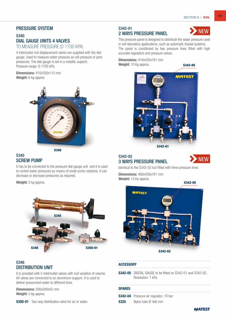
SECTION S | SOIL
PRESSURE SYSTEMS340DIAL GAUGE UNITS 4 VALVESTO MEASURE PRESSURE (0-1700 KPA)4 inlet/outlet null displacement valves are supplied with the dial gauge. Used to measure water pressure as cell pressure or pore pressures. The dial gauge is set in a metallic support.Pressure range: 0-1700 kPa.
Dimensions: 410x350x110 mmWeight: 6 kg approx.
S345SCREW PUMPIt has to be connected to the pressure dial gauge unit and it is used to control water pressures by means of small screw rotations. It can decrease or decrease pressures as required.
Weight: 3 kg approx.
S348DISTRIBUTION UNITIt is provided with 5 inlet/outlet valves with null variation of volume. All valves are connected to an aluminium support. It is used to deliver pressurized water to different lines.
Dimensions: 200x200x55 mmWeight: 3 kg approx.
S350-01 Two-way distribution valve for air or water.
S342-012 WAYS PRESSURE PANELThis pressure panel is designed to distribute the water pressure used in soil laboratory applications, such as automatic triaxial systems.The panel is constituted by two pressure lines fitted with high accurate regulators and pressure valves.
Dimensions: 416x430x181 mmWeight: 10 Kg approx.
S342-023 WAYS PRESSURE PANELIdentical to the S342-02 but fitted with three pressure lines.
Dimensions: 460x430x181 mmWeight: 13 Kg approx.
ACCESSORY
S342-05 DIGITAL GAUGE to be fitted on S342-01 and S342-02. Resolution: 1 kPa
SPARES
S342-04 Pressure air regulator, 10 bar
S325 Nylon tube Ø 4x6 mm
S340
S345
S348 S350-01
S342-01
S342-02
S342-05
S342-05
NEW
NEW
551
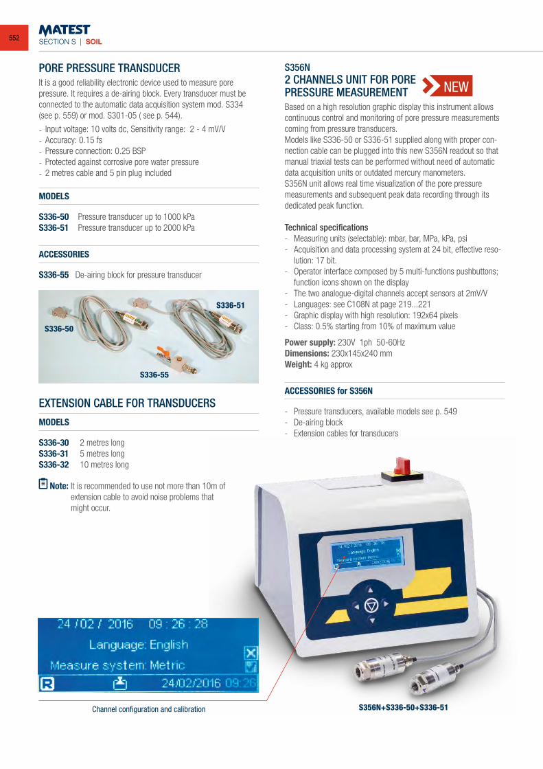
SECTION S | SOIL
S356N+S336-50+S336-51
EXTENSION CABLE FOR TRANSDUCERS
MODELS
S336-30 2 metres longS336-31 5 metres longS336-32 10 metres long
Note: It is recommended to use not more than 10m of extension cable to avoid noise problems that might occur.
S336-50
S336-51
S336-55
PORE PRESSURE TRANSDUCERIt is a good reliability electronic device used to measure pore pressure. It requires a de-airing block. Every transducer must be connected to the automatic data acquisition system mod. S334(see p. 559) or mod. S301-05 ( see p. 544).
- Input voltage: 10 volts dc, Sensitivity range: 2 - 4 mV/V- Accuracy: 0.15 fs- Pressure connection: 0.25 BSP- Protected against corrosive pore water pressure- 2 metres cable and 5 pin plug included
MODELS
S336-50 Pressure transducer up to 1000 kPaS336-51 Pressure transducer up to 2000 kPa
ACCESSORIES
S336-55 De-airing block for pressure transducer
S356N2 CHANNELS UNIT FOR POREPRESSURE MEASUREMENTBased on a high resolution graphic display this instrument allows continuous control and monitoring of pore pressure measurements coming from pressure transducers.Models like S336-50 or S336-51 supplied along with proper con-nection cable can be plugged into this new S356N readout so that manual triaxial tests can be performed without need of automatic data acquisition units or outdated mercury manometers.S356N unit allows real time visualization of the pore pressure measurements and subsequent peak data recording through its dedicated peak function. Technical specifications- Measuring units (selectable): mbar, bar, MPa, kPa, psi- Acquisition and data processing system at 24 bit, effective reso-
lution: 17 bit.- Operator interface composed by 5 multi-functions pushbuttons;
function icons shown on the display- The two analogue-digital channels accept sensors at 2mV/V- Languages: see C108N at page 219...221- Graphic display with high resolution: 192x64 pixels- Class: 0.5% starting from 10% of maximum value
Power supply: 230V 1ph 50-60HzDimensions: 230x145x240 mmWeight: 4 kg approx
ACCESSORIES for S356N
- Pressure transducers, available models see p. 549 - De-airing block - Extension cables for transducers
Channel configuration and calibration
NEW
552
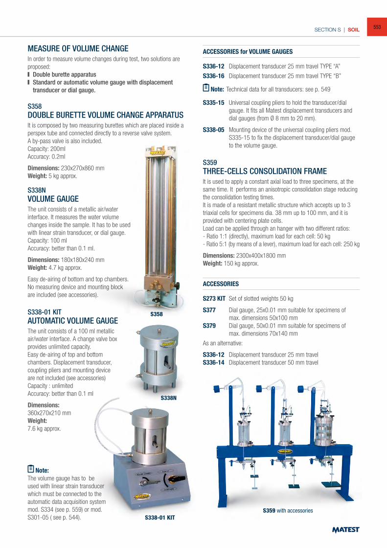
SECTION S | SOIL
MEASURE OF VOLUME CHANGE In order to measure volume changes during test, two solutions are proposed: Double burette apparatus Standard or automatic volume gauge with displacement
transducer or dial gauge.
S358DOUBLE BURETTE VOLUME CHANGE APPARATUSIt is composed by two measuring burettes which are placed inside a perspex tube and connected directly to a reverse valve system.A by-pass valve is also included.Capacity: 200mlAccuracy: 0.2ml
Dimensions: 230x270x860 mmWeight: 5 kg approx.
S338NVOLUME GAUGEThe unit consists of a metallic air/water interface. It measures the water volume changes inside the sample. It has to be used with linear strain transducer, or dial gauge.Capacity: 100 ml Accuracy: better than 0.1 ml.
Dimensions: 180x180x240 mmWeight: 4.7 kg approx.
Easy de-airing of bottom and top chambers. No measuring device and mounting block are included (see accessories).
S338-01 KITAUTOMATIC VOLUME GAUGEThe unit consists of a 100 ml metallic air/water interface. A change valve box provides unlimited capacity. Easy de-airing of top and bottom chambers. Displacement transducer, coupling pliers and mounting device are not included (see accessories)Capacity : unlimitedAccuracy: better than 0.1 ml
Dimensions:360x270x210 mmWeight:7.6 kg approx.
Note:The volume gauge has to be used with linear strain transducer which must be connected to the automatic data acquisition system mod. S334 (see p. 559) or mod. S301-05 ( see p. 544).
ACCESSORIES for VOLUME GAUGES
S336-12 Displacement transducer 25 mm travel TYPE “A”
S336-16 Displacement transducer 25 mm travel TYPE “B”
Note: Technical data for all transducers: see p. 549
S335-15 Universal coupling pliers to hold the transducer/dial gauge. It fits all Matest displacement transducers and dial gauges (from Ø 8 mm to 20 mm).
S338-05 Mounting device of the universal coupling pliers mod. S335-15 to fix the displacement transducer/dial gauge to the volume gauge.
S359THREE-CELLS CONSOLIDATION FRAMEIt is used to apply a constant axial load to three specimens, at the same time. It performs an anisotropic consolidation stage reducing the consolidation testing times. It is made of a resistant metallic structure which accepts up to 3 triaxial cells for specimens dia. 38 mm up to 100 mm, and it is provided with centering plate cells.Load can be applied through an hanger with two different ratios:- Ratio 1:1 (directly), maximum load for each cell: 50 kg - Ratio 5:1 (by means of a lever), maximum load for each cell: 250 kg
Dimensions: 2300x400x1800 mmWeight: 150 kg approx.
ACCESSORIES
S273 KIT Set of slotted weights 50 kg
S377 Dial gauge, 25x0.01 mm suitable for specimens of max. dimensions 50x100 mmS379 Dial gauge, 50x0.01 mm suitable for specimens of max. dimensions 70x140 mm
As an alternative:
S336-12 Displacement transducer 25 mm travelS336-14 Displacement transducer 50 mm travel
S358
S338N
S338-01 KITS359 with accessories
553
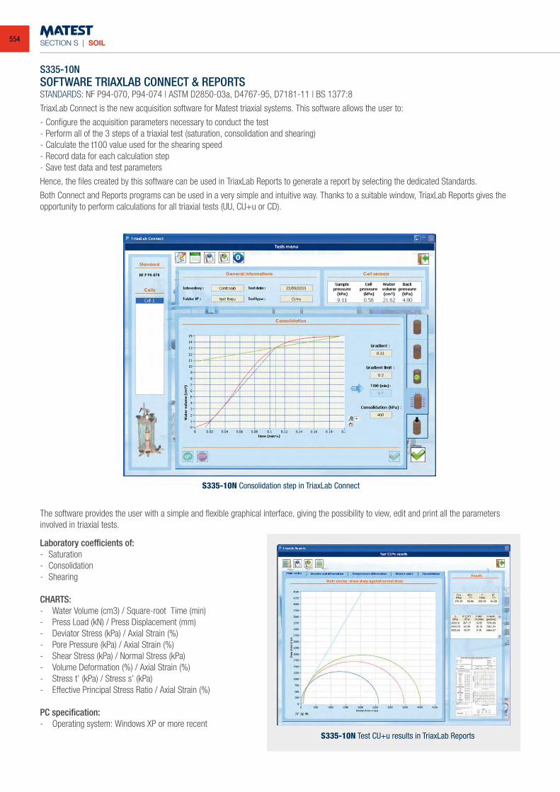
SECTION S | SOIL
S335-10NSOFTWARE TRIAXLAB CONNECT & REPORTSSTANDARDS: NF P94-070, P94-074 | ASTM D2850-03a, D4767-95, D7181-11 | BS 1377:8
TriaxLab Connect is the new acquisition software for Matest triaxial systems. This software allows the user to:
- Configure the acquisition parameters necessary to conduct the test - Perform all of the 3 steps of a triaxial test (saturation, consolidation and shearing)- Calculate the t100 value used for the shearing speed- Record data for each calculation step- Save test data and test parameters
Hence, the files created by this software can be used in TriaxLab Reports to generate a report by selecting the dedicated Standards.
Both Connect and Reports programs can be used in a very simple and intuitive way. Thanks to a suitable window, TriaxLab Reports gives the opportunity to perform calculations for all triaxial tests (UU, CU+u or CD).
The software provides the user with a simple and flexible graphical interface, giving the possibility to view, edit and print all the parameters involved in triaxial tests.
Laboratory coefficients of: - Saturation- Consolidation- Shearing
CHARTS: - Water Volume (cm3) / Square-root Time (min)- Press Load (kN) / Press Displacement (mm)- Deviator Stress (kPa) / Axial Strain (%)- Pore Pressure (kPa) / Axial Strain (%)- Shear Stress (kPa) / Normal Stress (kPa)- Volume Deformation (%) / Axial Strain (%)- Stress t’ (kPa) / Stress s’ (kPa)- Effective Principal Stress Ratio / Axial Strain (%)
PC specification:- Operating system: Windows XP or more recent
S335-10N Consolidation step in TriaxLab Connect
S335-10N Test CU+u results in TriaxLab Reports
554
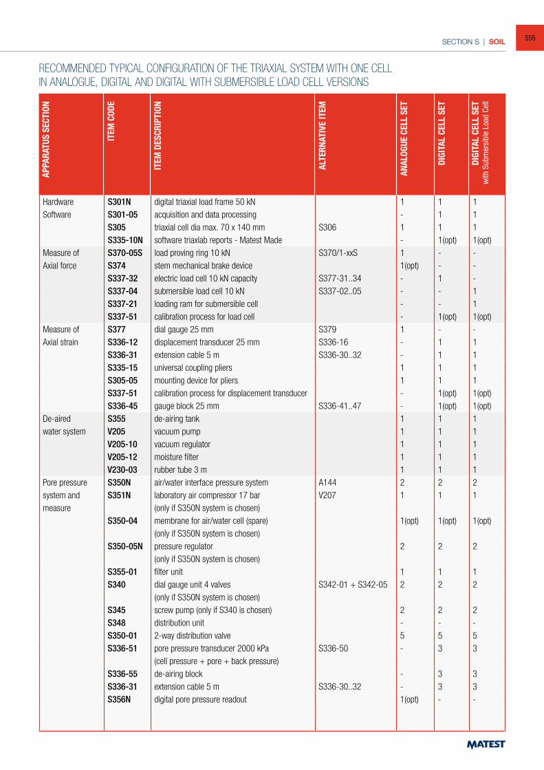
SECTION S | SOIL
Hardware S301N digital triaxial load frame 50 kN 1 1 1Software S301-05 acquisition and data processing - 1 1
S305 triaxial cell dia max. 70 x 140 mm S306 1 1 1S335-10N software triaxlab reports - Matest Made - 1(opt) 1(opt)
Measure of S370-05S load proving ring 10 kN S370/1-xxS 1 - -Axial force S374 stem mechanical brake device 1(opt) - -
S337-32 electric load cell 10 kN capacity S377-31..34 - 1 -S337-04 submersible load cell 10 kN S337-02..05 - - 1S337-21 loading ram for submersible cell - - 1S337-51 calibration process for load cell - 1(opt) 1(opt)
Measure of S377 dial gauge 25 mm S379 1 - -Axial strain S336-12 displacement transducer 25 mm S336-16 - 1 1
S336-31 extension cable 5 m S336-30..32 - 1 1S335-15 universal coupling pliers 1 1 1S305-05 mounting device for pliers 1 1 1S337-51 calibration process for displacement transducer - 1(opt) 1(opt)S336-45 gauge block 25 mm S336-41..47 - 1(opt) 1(opt)
De-aired S355 de-airing tank 1 1 1water system V205 vacuum pump 1 1 1
V205-10 vacuum regulator 1 1 1V205-12 moisture filter 1 1 1V230-03 rubber tube 3 m 1 1 1
Pore pressure S350N air/water interface pressure system A144 2 2 2system and S351N laboratory air compressor 17 bar V207 1 1 1measure (only if S350N system is chosen)
S350-04 membrane for air/water cell (spare) 1(opt) 1(opt) 1(opt)(only if S350N system is chosen)
S350-05N pressure regulator 2 2 2(only if S350N system is chosen)
S355-01 filter unit 1 1 1S340 dial gauge unit 4 valves S342-01 + S342-05 2 2 2
(only if S350N system is chosen)S345 screw pump (only if S340 is chosen) 2 2 2S348 distribution unit - - -S350-01 2-way distribution valve 5 5 5S336-51 pore pressure transducer 2000 kPa S336-50 - 3 3
(cell pressure + pore + back pressure)S336-55 de-airing block - 3 3S336-31 extension cable 5 m S336-30..32 - 3 3S356N digital pore pressure readout 1(opt) - -
RECOMMENDED TYPICAL CONFIGURATION OF THE TRIAXIAL SYSTEM WITH ONE CELLIN ANALOGUE, DIGITAL AND DIGITAL WITH SUBMERSIBLE LOAD CELL VERSIONS
APPA
RATU
S SE
CTIO
N
ITEM
COD
E
ITEM
DES
CRIP
TION
ALT
ERNA
TIVE
ITEM
ANAL
OGUE
CEL
L SE
T
DIGI
TAL
CELL
SET
DIGI
TAL
CELL
SET
with
Sub
mer
sibl
e Lo
ad C
ell
555
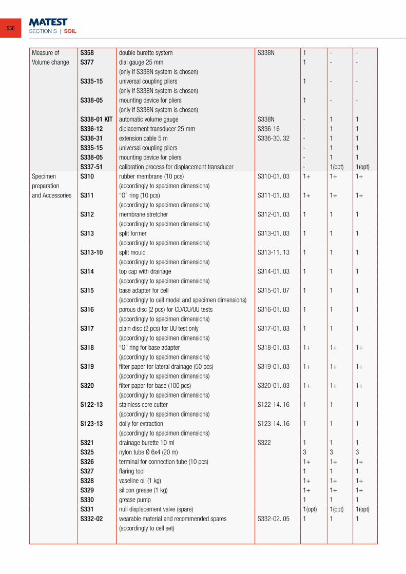
SECTION S | SOIL
Measure of S358 double burette system S338N 1 - -Volume change S377 dial gauge 25 mm 1 - -
(only if S338N system is chosen)S335-15 universal coupling pliers 1 - -
(only if S338N system is chosen)S338-05 mounting device for pliers 1 - -
(only if S338N system is chosen)S338-01 KIT automatic volume gauge S338N - 1 1S336-12 diplacement transducer 25 mm S336-16 - 1 1S336-31 extension cable 5 m S336-30..32 - 1 1S335-15 universal coupling pliers - 1 1S338-05 mounting device for pliers - 1 1S337-51 calibration process for displacement transducer - 1(opt) 1(opt)
Specimen S310 rubber membrane (10 pcs) S310-01..03 1+ 1+ 1+preparation (accordingly to specimen dimensions)and Accessories S311 “O” ring (10 pcs) S311-01..03 1+ 1+ 1+
(accordingly to specimen dimensions)S312 membrane stretcher S312-01..03 1 1 1
(accordingly to specimen dimensions)S313 split former S313-01..03 1 1 1
(accordingly to specimen dimensions)S313-10 split mould S313-11..13 1 1 1
(accordingly to specimen dimensions)S314 top cap with drainage S314-01..03 1 1 1
(accordingly to specimen dimensions)S315 base adapter for cell S315-01..07 1 1 1
(accordingly to cell model and specimen dimensions)S316 porous disc (2 pcs) for CD/CU/UU tests S316-01..03 1 1 1
(accordingly to specimen dimensions)S317 plain disc (2 pcs) for UU test only S317-01..03 1 1 1
(accordingly to specimen dimensions)S318 “O” ring for base adapter S318-01..03 1+ 1+ 1+
(accordingly to specimen dimensions)S319 filter paper for lateral drainage (50 pcs) S319-01..03 1+ 1+ 1+
(accordingly to specimen dimensions)S320 filter paper for base (100 pcs) S320-01..03 1+ 1+ 1+
(accordingly to specimen dimensions)S122-13 stainless core cutter S122-14..16 1 1 1
(accordingly to specimen dimensions)S123-13 dolly for extraction S123-14..16 1 1 1
(accordingly to specimen dimensions)S321 drainage burette 10 ml S322 1 1 1S325 nylon tube Ø 6x4 (20 m) 3 3 3S326 terminal for connection tube (10 pcs) 1+ 1+ 1+S327 flaring tool 1 1 1S328 vaseline oil (1 kg) 1+ 1+ 1+S329 silicon grease (1 kg) 1+ 1+ 1+S330 grease pump 1 1 1S331 null displacement valve (spare) 1(opt) 1(opt) 1(opt)S332-02 wearable material and recommended spares S332-02..05 1 1 1
(accordingly to cell set)
556
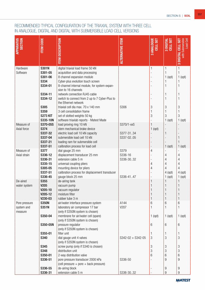
SECTION S | SOIL
RECOMMENDED TYPICAL CONFIGURATION OF THE TRIAXIAL SYSTEM WITH THREE CELLIN ANALOGUE, DIGITAL AND DIGITAL WITH SUBMERSIBLE LOAD CELL VERSIONS
APPA
RATU
SSE
CTIO
N
ITEM
COD
E
ITEM
DES
CRIP
TION
ALT
ERNA
TIVE
ITEM
3 AN
ALOG
UECE
LL S
ET
3 DI
GITA
LCE
LL S
ET
3 DI
GITA
L CE
LL S
ETw
ith S
ubm
ersi
ble
Load
Cel
l
Hardware S301N digital triaxial load frame 50 kN 1 1 1Software S301-05 acquisition and data processing - 1 1
S301-06 8 channel expansion module - 1 (opt) 1 (opt)S334 Cyber-plus evolution touch screen - 1 1S334-01 8-channel internal module, for system expan-
sion to 16 channels- 1 1
S334-11 network connection RJ45 cable - 1 1S334-12 switch to connect from 2 up to 7 Cyber-Plus to
the Ethernet network- 1 1
S305 triaxial cell dia max. 70 x 140 mm S306 3 3 3S359 3 cell consolidation frame 1 1 1S273 KIT set of slotted weights 50 kg 3 3 3S335-10N software triaxlab reports - Matest Made - 1 (opt) 1 (opt)
Measure of S370-05S load proving ring 10 kN S370/1-xxS 1 - -Axial force S374 stem mechanical brake device 1 (opt) - -
S337-32 electric load cell 10 kN capacity S377-31..34 - 1 -S337-04 submersible load cell 10 kN S337-02..05 - - 1S337-21 loading ram for submersible cell - - 1S337-51 calibration process for load cell - 1 (opt) 1 (opt)
Measure of S377 dial gauge 25 mm S379 4 - -Axial strain S336-12 displacement transducer 25 mm S336-16 - 4 4
S336-31 extension cable 5 m S336-30..32 - 4 4S335-15 universal coupling pliers 4 4 4S305-05 mounting device for pliers 4 4 4S337-51 calibration process for displacement transducer - 4 (opt) 4 (opt)S336-45 gauge block 25 mm S336-41..47 - 1 (opt) 1 (opt)
De-aired S355 de-airing tank 1 1 1water system V205 vacuum pump 1 1 1
V205-10 vacuum regulator 1 1 1V205-12 moisture filter 1 1 1V230-03 rubber tube 3 m 1 1 1
Pore pressure S350N air/water interface pressure system A144 6 6 6system and S351N laboratory air compressor 17 bar V207 1 1 1measure (only if S350N system is chosen)
S350-04 membrane for air/water cell (spare) 1 (opt) 1 (opt) 1 (opt)(only if S350N system is chosen)
S350-05N pressure regulator 6 6 6(only if S350N system is chosen)
S355-01 filter unit 1 1 1S340 dial gauge unit 4 valves S342-02 + S342-05 3 3 3
(only if S350N system is chosen)S345 screw pump (only if S340 is chosen) 3 3 3S348 distribution unit 3 3 3S350-01 2-way distribution valve 6 6 6S336-51 pore pressure transducer 2000 kPa S336-50 - 9 9
(cell pressure + pore + back pressure)S336-55 de-airing block - 9 9S336-31 extension cable 5 m S336-30..32 - 9 9
557
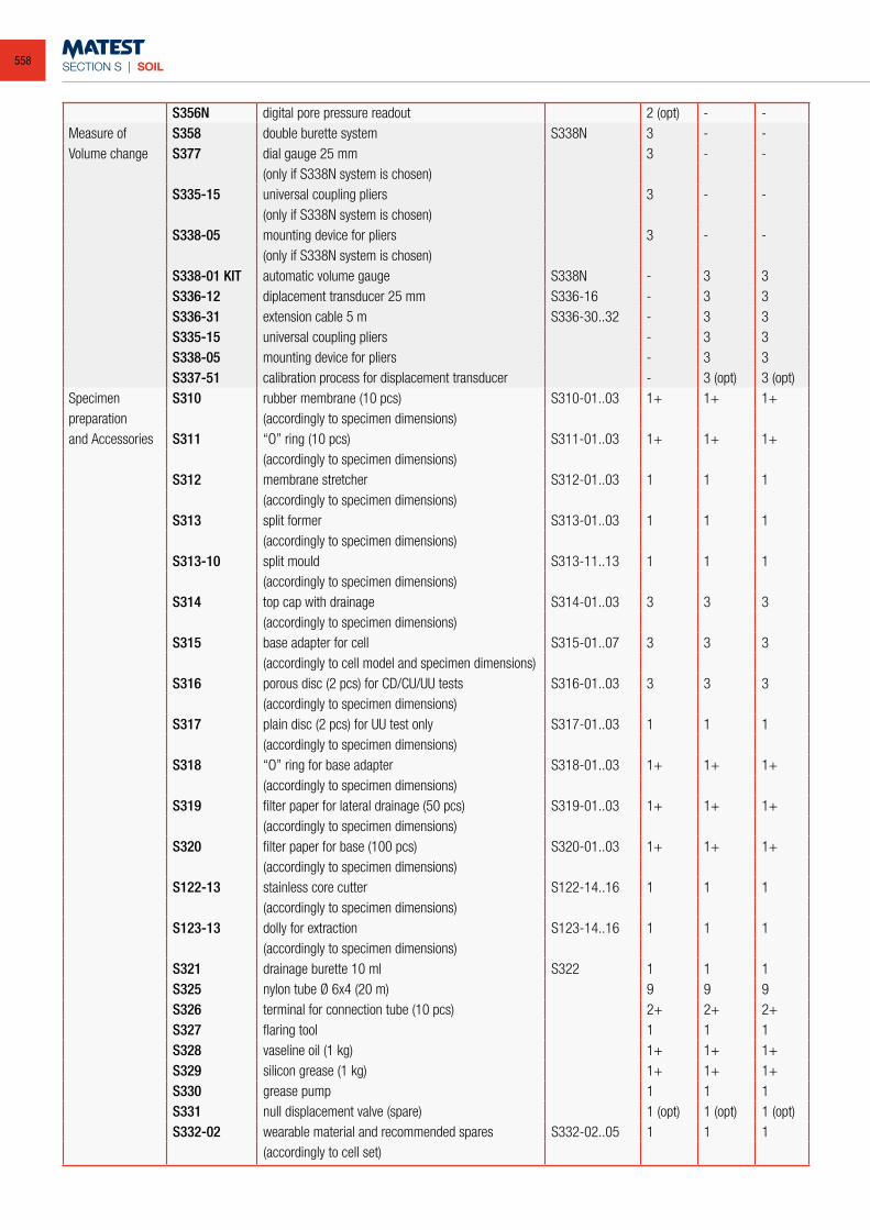
SECTION S | SOIL
S356N digital pore pressure readout 2 (opt) - -Measure of S358 double burette system S338N 3 - -Volume change S377 dial gauge 25 mm 3 - -
(only if S338N system is chosen)S335-15 universal coupling pliers 3 - -
(only if S338N system is chosen)S338-05 mounting device for pliers 3 - -
(only if S338N system is chosen)S338-01 KIT automatic volume gauge S338N - 3 3S336-12 diplacement transducer 25 mm S336-16 - 3 3S336-31 extension cable 5 m S336-30..32 - 3 3S335-15 universal coupling pliers - 3 3S338-05 mounting device for pliers - 3 3S337-51 calibration process for displacement transducer - 3 (opt) 3 (opt)
Specimen S310 rubber membrane (10 pcs) S310-01..03 1+ 1+ 1+preparation (accordingly to specimen dimensions)and Accessories S311 “O” ring (10 pcs) S311-01..03 1+ 1+ 1+
(accordingly to specimen dimensions)S312 membrane stretcher S312-01..03 1 1 1
(accordingly to specimen dimensions)S313 split former S313-01..03 1 1 1
(accordingly to specimen dimensions)S313-10 split mould S313-11..13 1 1 1
(accordingly to specimen dimensions)S314 top cap with drainage S314-01..03 3 3 3
(accordingly to specimen dimensions)S315 base adapter for cell S315-01..07 3 3 3
(accordingly to cell model and specimen dimensions)S316 porous disc (2 pcs) for CD/CU/UU tests S316-01..03 3 3 3
(accordingly to specimen dimensions)S317 plain disc (2 pcs) for UU test only S317-01..03 1 1 1
(accordingly to specimen dimensions)S318 “O” ring for base adapter S318-01..03 1+ 1+ 1+
(accordingly to specimen dimensions)S319 filter paper for lateral drainage (50 pcs) S319-01..03 1+ 1+ 1+
(accordingly to specimen dimensions)S320 filter paper for base (100 pcs) S320-01..03 1+ 1+ 1+
(accordingly to specimen dimensions)S122-13 stainless core cutter S122-14..16 1 1 1
(accordingly to specimen dimensions)S123-13 dolly for extraction S123-14..16 1 1 1
(accordingly to specimen dimensions)S321 drainage burette 10 ml S322 1 1 1S325 nylon tube Ø 6x4 (20 m) 9 9 9S326 terminal for connection tube (10 pcs) 2+ 2+ 2+S327 flaring tool 1 1 1S328 vaseline oil (1 kg) 1+ 1+ 1+S329 silicon grease (1 kg) 1+ 1+ 1+S330 grease pump 1 1 1S331 null displacement valve (spare) 1 (opt) 1 (opt) 1 (opt)S332-02 wearable material and recommended spares S332-02..05 1 1 1
(accordingly to cell set)
558
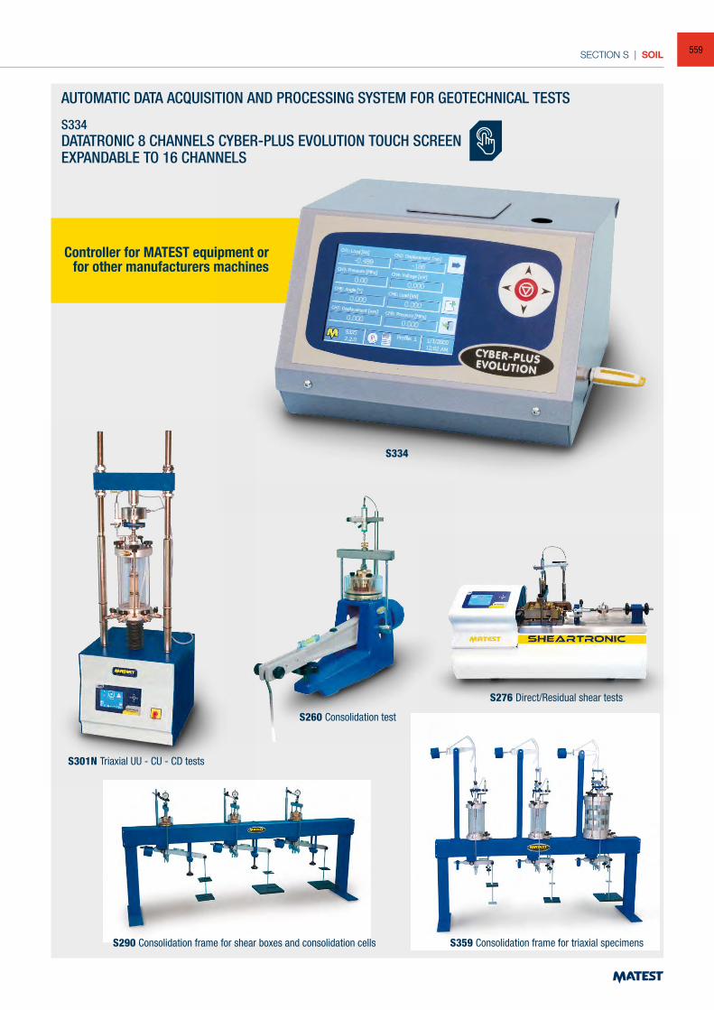
SECTION S | SOIL
AUTOMATIC DATA ACQUISITION AND PROCESSING SYSTEM FOR GEOTECHNICAL TESTS
S334DATATRONIC 8 CHANNELS CYBER-PLUS EVOLUTION TOUCH SCREENEXPANDABLE TO 16 CHANNELS
S260 Consolidation test
S359 Consolidation frame for triaxial specimensS290 Consolidation frame for shear boxes and consolidation cells
Controller for MATEST equipment orfor other manufacturers machines
S301N Triaxial UU - CU - CD tests
S276 Direct/Residual shear tests
S334
559
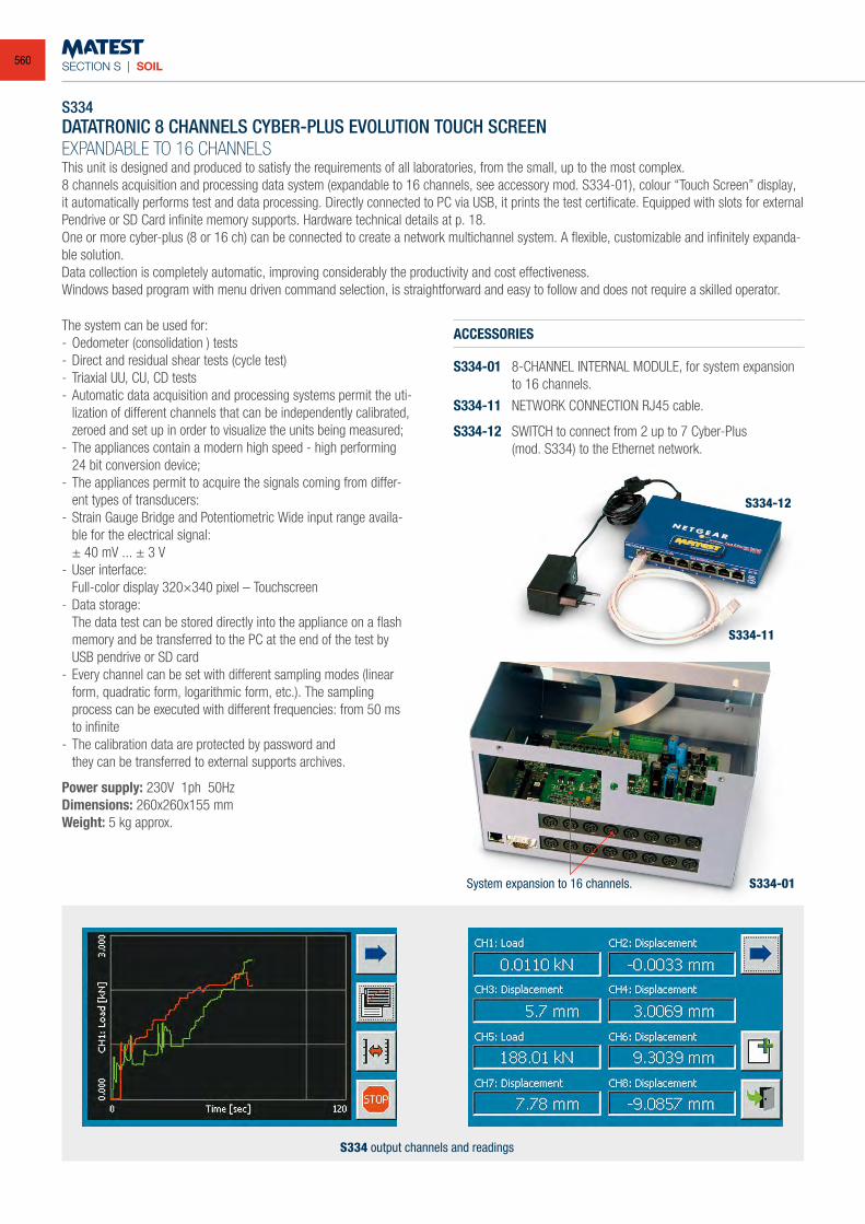
SECTION S | SOIL
S334DATATRONIC 8 CHANNELS CYBER-PLUS EVOLUTION TOUCH SCREENEXPANDABLE TO 16 CHANNELSThis unit is designed and produced to satisfy the requirements of all laboratories, from the small, up to the most complex. 8 channels acquisition and processing data system (expandable to 16 channels, see accessory mod. S334-01), colour “Touch Screen” display, it automatically performs test and data processing. Directly connected to PC via USB, it prints the test certificate. Equipped with slots for external Pendrive or SD Card infinite memory supports. Hardware technical details at p. 18.One or more cyber-plus (8 or 16 ch) can be connected to create a network multichannel system. A flexible, customizable and infinitely expanda-ble solution.Data collection is completely automatic, improving considerably the productivity and cost effectiveness.Windows based program with menu driven command selection, is straightforward and easy to follow and does not require a skilled operator.
The system can be used for:- Oedometer (consolidation ) tests- Direct and residual shear tests (cycle test)- Triaxial UU, CU, CD tests- Automatic data acquisition and processing systems permit the uti-
lization of different channels that can be independently calibrated, zeroed and set up in order to visualize the units being measured;
- The appliances contain a modern high speed - high performing 24 bit conversion device;
- The appliances permit to acquire the signals coming from differ-ent types of transducers:
- Strain Gauge Bridge and Potentiometric Wide input range availa-ble for the electrical signal:
± 40 mV ... ± 3 V- User interface: Full-color display 320×340 pixel – Touchscreen- Data storage: The data test can be stored directly into the appliance on a flash
memory and be transferred to the PC at the end of the test by USB pendrive or SD card
- Every channel can be set with different sampling modes (linear form, quadratic form, logarithmic form, etc.). The sampling process can be executed with different frequencies: from 50 ms to infinite
- The calibration data are protected by password and they can be transferred to external supports archives.
Power supply: 230V 1ph 50HzDimensions: 260x260x155 mmWeight: 5 kg approx.
ACCESSORIES
S334-01 8-CHANNEL INTERNAL MODULE, for system expansion to 16 channels.
S334-11 NETWORK CONNECTION RJ45 cable.
S334-12 SWITCH to connect from 2 up to 7 Cyber-Plus (mod. S334) to the Ethernet network.
System expansion to 16 channels.
S334 output channels and readings
S334-01
S334-11
S334-12
560
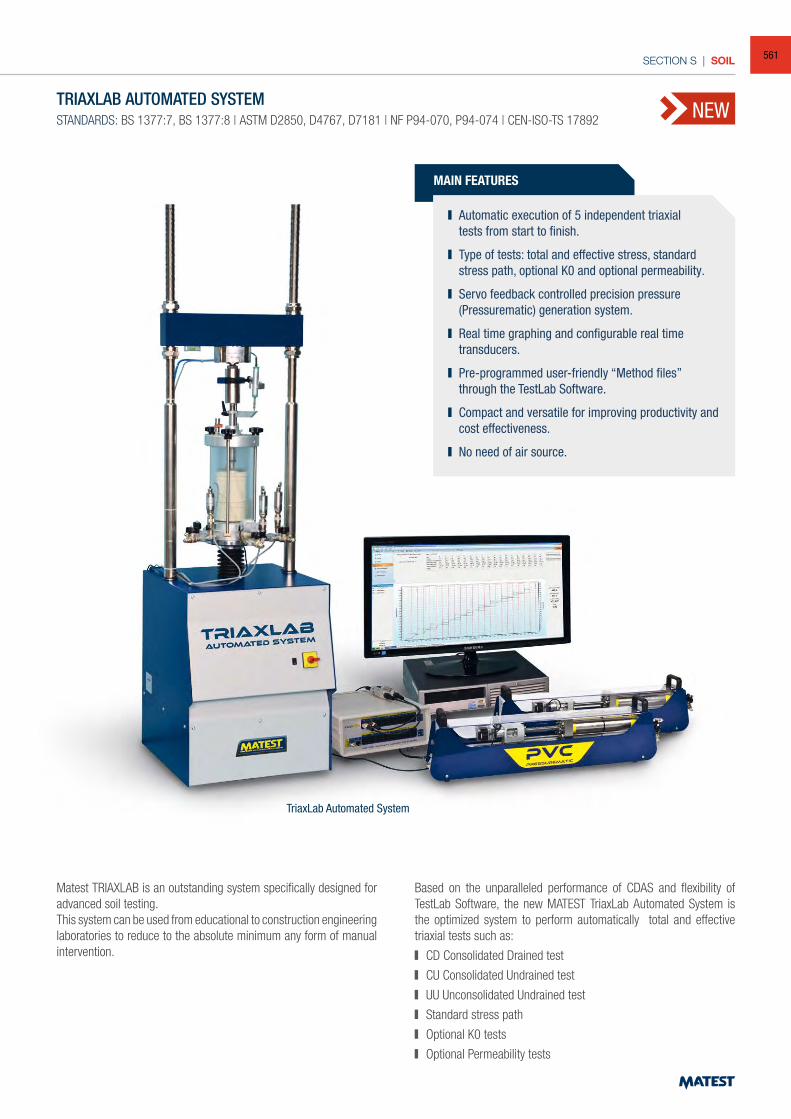
SECTION S | SOIL
NEWTRIAXLAB AUTOMATED SYSTEM
STANDARDS: BS 1377:7, BS 1377:8 | ASTM D2850, D4767, D7181 | NF P94-070, P94-074 | CEN-ISO-TS 17892
MAIN FEATURES
Automatic execution of 5 independent triaxial tests from start to finish.
Type of tests: total and effective stress, standard stress path, optional K0 and optional permeability.
Servo feedback controlled precision pressure (Pressurematic) generation system.
Real time graphing and configurable real time transducers.
Pre-programmed user-friendly “Method files” through the TestLab Software.
Compact and versatile for improving productivity and cost effectiveness.
No need of air source.
TriaxLab Automated System
Matest TRIAXLAB is an outstanding system specifically designed for advanced soil testing.This system can be used from educational to construction engineering laboratories to reduce to the absolute minimum any form of manual intervention.
Based on the unparalleled performance of CDAS and flexibility of TestLab Software, the new MATEST TriaxLab Automated System is the optimized system to perform automatically total and effective triaxial tests such as:
CD Consolidated Drained test
CU Consolidated Undrained test
UU Unconsolidated Undrained test
Standard stress path
Optional K0 tests
Optional Permeability tests
561
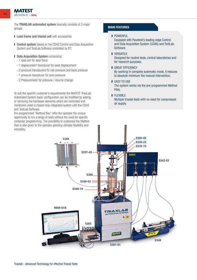
SECTION S | SOIL
S355
S305
S349-10
S337-43
S342-03
S305-05S336-23S335-15
H009-01N
S303
S336-53
MAIN FEATURES
POWERFUL Equipped with Pavetest’s leading edge Control
and Data Acquisition System (CDAS) and TestLab Software.
VERSATILE Designed for routine tests, central laboratories and
for research purposes.
GREAT EFFICIENCY By working in complete automatic mode, it reduces
to absolute minimum the manual intervention.
EASY TO USE The system works via the pre-programmed Method
Files.
FLEXIBLE Multiple triaxial tests with no need for compressed
air supply.
The TRIAXLAB automated system basically consists of 3 major groups:
Load frame and triaxial cell with accessories
Control system based on the CDAS Control and Data Acquisition System and TestLab Software controlled by PC
Data Acquisition System comprising: - 1 load cell for axial force
- 1 displacement transducer for axial displacement
- 2 pressure transducers for cell pressure and back pressure
- 1 pressure transducer for pore pressure
- 2 Pressurematic for pressure / volume change
Triaxlab – Advanced Technology for effective Triaxial Tests
To suit the specific customer’s requirements the MATEST TriaxLab Automated System basic configuration can be modified by adding or removing the hardware elements which are controlled and monitored under a closed-loop integrated system with the CDAS and TestLab Software.Pre-programmed “Method files” offer the operator the unique opportunity to run a range of tests without the need for specificcomputer programming. The possibility to customize the Method files is also given to the operator granting ultimate flexibility and versatility.
S301-01
S349
562
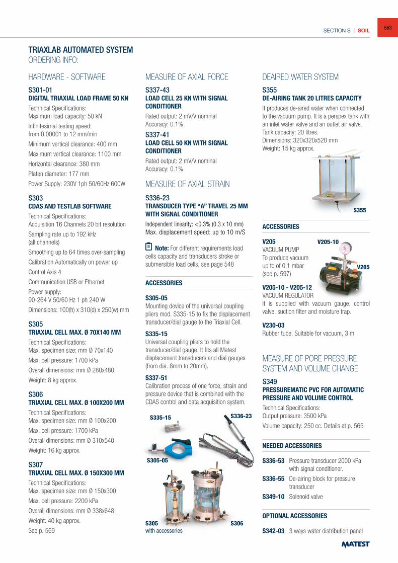
SECTION S | SOIL
TRIAXLAB AUTOMATED SYSTEMORDERING INFO:
HARDWARE - SOFTWARES301-01DIGITAL TRIAXIAL LOAD FRAME 50 KNTechnical Specifications:Maximum load capacity: 50 kN
Infinitesimal testing speed:from 0.00001 to 12 mm/min
Minimum vertical clearance: 400 mm
Maximum vertical clearance: 1100 mm
Horizontal clearance: 380 mm
Platen diameter: 177 mm
Power Supply: 230V 1ph 50/60Hz 600W
S303CDAS AND TESTLAB SOFTWARETechnical Specifications:Acquisition 16 Channels 20 bit resolution
Sampling rate up to 192 kHz(all channels)
Smoothing up to 64 times over-sampling
Calibration Automatically on power up
Control Axis 4
Communication USB or Ethernet
Power supply:90-264 V 50/60 Hz 1 ph 240 W
Dimensions: 100(h) x 310(d) x 250(w) mm
S305TRIAXIAL CELL MAX. Ø 70X140 MM
Technical Specifications:Max. specimen size: mm Ø 70x140
Max. cell pressure: 1700 kPa
Overall dimensions: mm Ø 280x480
Weight: 8 kg approx.
S306 TRIAXIAL CELL MAX. Ø 100X200 MMTechnical Specifications:Max. specimen size: mm Ø 100x200
Max. cell pressure: 1700 kPa
Overall dimensions: mm Ø 310x540
Weight: 16 kg approx.
S307 TRIAXIAL CELL MAX. Ø 150X300 MMTechnical Specifications:Max. specimen size: mm Ø 150x300
Max. cell pressure: 2200 kPa
Overall dimensions: mm Ø 338x648
Weight: 40 kg approx.
See p. 569
MEASURE OF AXIAL FORCES337-43LOAD CELL 25 KN WITH SIGNAL CONDITIONERRated output: 2 mV/V nominalAccuracy: 0.1%
S337-41LOAD CELL 50 KN WITH SIGNAL CONDITIONERRated output: 2 mV/V nominalAccuracy: 0.1%
MEASURE OF AXIAL STRAIN
S336-23 TRANSDUCER TYPE “A” TRAVEL 25 MM WITH SIGNAL CONDITIONERIndependent linearity: <0.3% (0.3 x 10 mm) Max. displacement speed: up to 10 m/S
MEASURE OF PORE PRESSURE SYSTEM AND VOLUME CHANGES349PRESSUREMATIC PVC FOR AUTOMATIC PRESSURE AND VOLUME CONTROLTechnical Specifications:Output pressure: 3500 kPa
Volume capacity: 250 cc. Details at p. 565
S305with accessories
S355
V205-10
V205
S306
S336-23S335-15
S305-05
Note: For different requirements load cells capacity and transducers stroke or submersible load cells, see page 548
ACCESSORIES
S305-05Mounting device of the universal coupling pliers mod. S335-15 to fix the displacement transducer/dial gauge to the Triaxial Cell.
S335-15 Universal coupling pliers to hold the transducer/dial gauge. It fits all Matest displacement transducers and dial gauges (from dia. 8mm to 20mm).
S337-51Calibration process of one force, strain and pressure device that is combined with the CDAS control and data acquisition system.
ACCESSORIES
V205 VACUUM PUMPTo produce vacuumup to of 0,1 mbar(see p. 597)
V205-10 - V205-12VACUUM REGULATORIt is supplied with vacuum gauge, control valve, suction filter and moisture trap.
V230-03Rubber tube. Suitable for vacuum, 3 m
NEEDED ACCESSORIES
S336-53 Pressure transducer 2000 kPa with signal conditioner.
S336-55 De-airing block for pressure transducer
S349-10 Solenoid valve
OPTIONAL ACCESSORIES
S342-03 3 ways water distribution panel
DEAIRED WATER SYSTEMS355 DE-AIRING TANK 20 LITRES CAPACITYIt produces de-aired water when connected to the vacuum pump. It is a perspex tank with an inlet water valve and an outlet air valve.Tank capacity: 20 litres.Dimensions: 320x320x520 mmWeight: 15 kg approx.
563
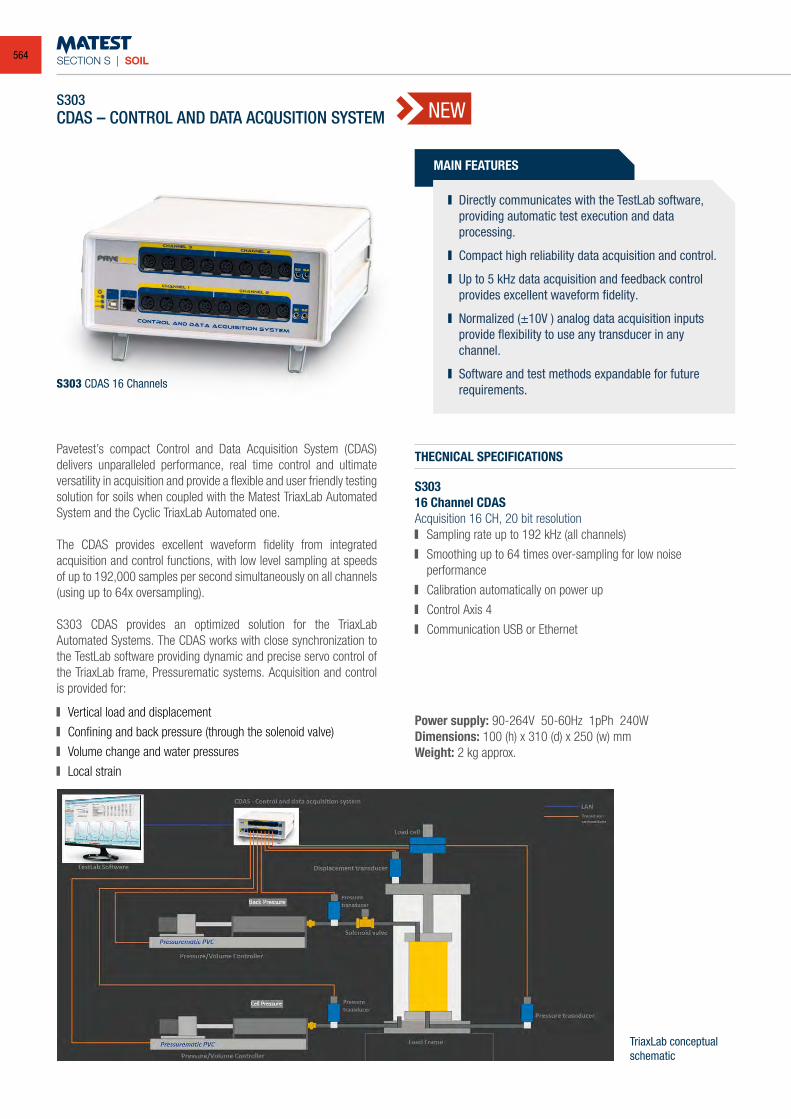
SECTION S | SOIL
THECNICAL SPECIFICATIONS
S303 16 Channel CDASAcquisition 16 CH, 20 bit resolution Sampling rate up to 192 kHz (all channels)
Smoothing up to 64 times over-sampling for low noise performance
Calibration automatically on power up
Control Axis 4
Communication USB or Ethernet
S303 CDAS 16 Channels
TriaxLab conceptualschematic
S303CDAS – CONTROL AND DATA ACQUSITION SYSTEM
Pavetest’s compact Control and Data Acquisition System (CDAS) delivers unparalleled performance, real time control and ultimate versatility in acquisition and provide a flexible and user friendly testing solution for soils when coupled with the Matest TriaxLab Automated System and the Cyclic TriaxLab Automated one.
The CDAS provides excellent waveform fidelity from integrated acquisition and control functions, with low level sampling at speeds of up to 192,000 samples per second simultaneously on all channels (using up to 64x oversampling).
S303 CDAS provides an optimized solution for the TriaxLab Automated Systems. The CDAS works with close synchronization to the TestLab software providing dynamic and precise servo control of the TriaxLab frame, Pressurematic systems. Acquisition and control is provided for:
Vertical load and displacement
Confining and back pressure (through the solenoid valve)
Volume change and water pressures
Local strain
Power supply: 90-264V 50-60Hz 1pPh 240WDimensions: 100 (h) x 310 (d) x 250 (w) mmWeight: 2 kg approx.
MAIN FEATURES
Directly communicates with the TestLab software, providing automatic test execution and data processing.
Compact high reliability data acquisition and control.
Up to 5 kHz data acquisition and feedback control provides excellent waveform fidelity.
Normalized (±10V ) analog data acquisition inputs provide flexibility to use any transducer in any channel.
Software and test methods expandable for future requirements.
NEW
564
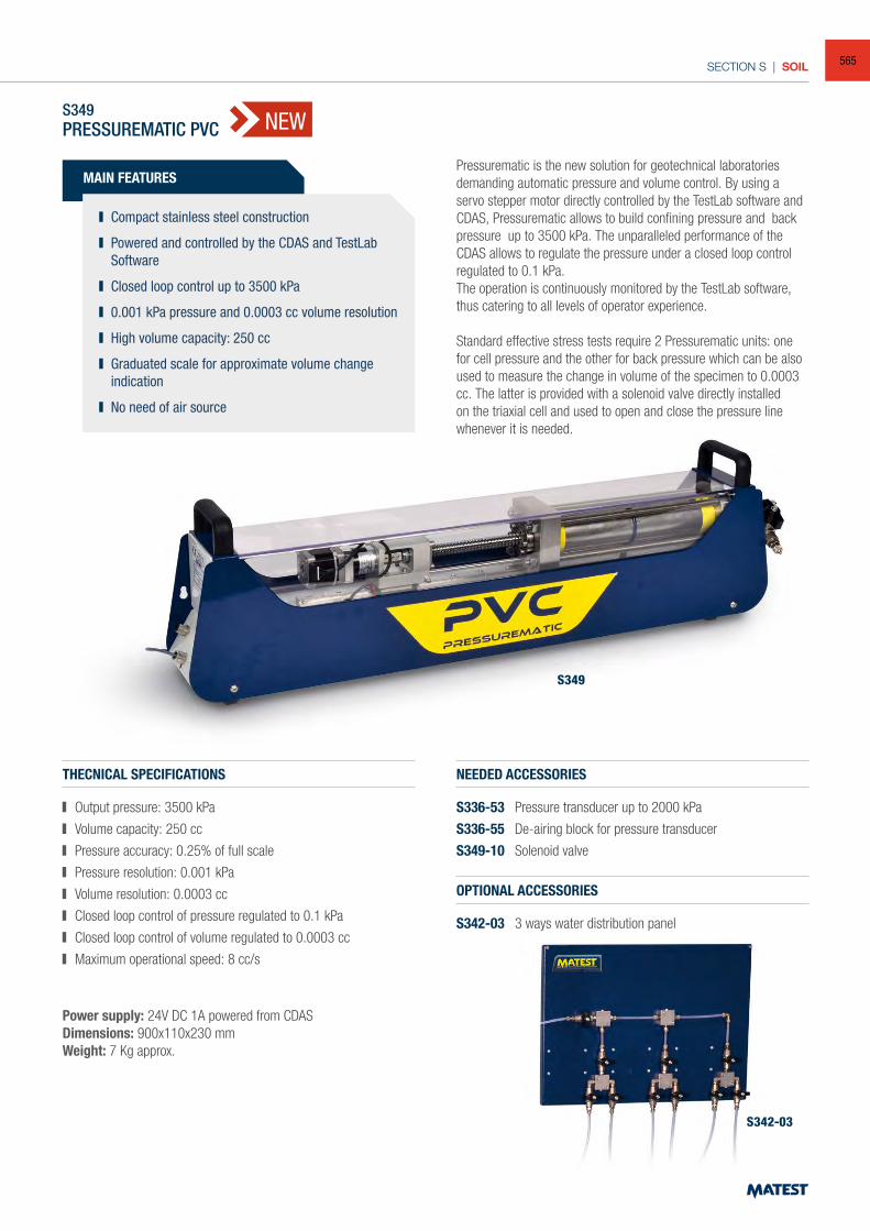
SECTION S | SOIL
S349PRESSUREMATIC PVC
MAIN FEATURES
Compact stainless steel construction
Powered and controlled by the CDAS and TestLab Software
Closed loop control up to 3500 kPa
0.001 kPa pressure and 0.0003 cc volume resolution
High volume capacity: 250 cc
Graduated scale for approximate volume change indication
No need of air source
Pressurematic is the new solution for geotechnical laboratories demanding automatic pressure and volume control. By using a servo stepper motor directly controlled by the TestLab software and CDAS, Pressurematic allows to build confining pressure and back pressure up to 3500 kPa. The unparalleled performance of the CDAS allows to regulate the pressure under a closed loop control regulated to 0.1 kPa.The operation is continuously monitored by the TestLab software, thus catering to all levels of operator experience.
Standard effective stress tests require 2 Pressurematic units: one for cell pressure and the other for back pressure which can be also used to measure the change in volume of the specimen to 0.0003 cc. The latter is provided with a solenoid valve directly installed on the triaxial cell and used to open and close the pressure line whenever it is needed.
THECNICAL SPECIFICATIONS
Output pressure: 3500 kPa
Volume capacity: 250 cc
Pressure accuracy: 0.25% of full scale
Pressure resolution: 0.001 kPa
Volume resolution: 0.0003 cc
Closed loop control of pressure regulated to 0.1 kPa
Closed loop control of volume regulated to 0.0003 cc
Maximum operational speed: 8 cc/s
NEEDED ACCESSORIES
S336-53 Pressure transducer up to 2000 kPa
S336-55 De-airing block for pressure transducer
S349-10 Solenoid valve
Power supply: 24V DC 1A powered from CDASDimensions: 900x110x230 mmWeight: 7 Kg approx.
S349
S342-03
OPTIONAL ACCESSORIES
S342-03 3 ways water distribution panel
NEW
565
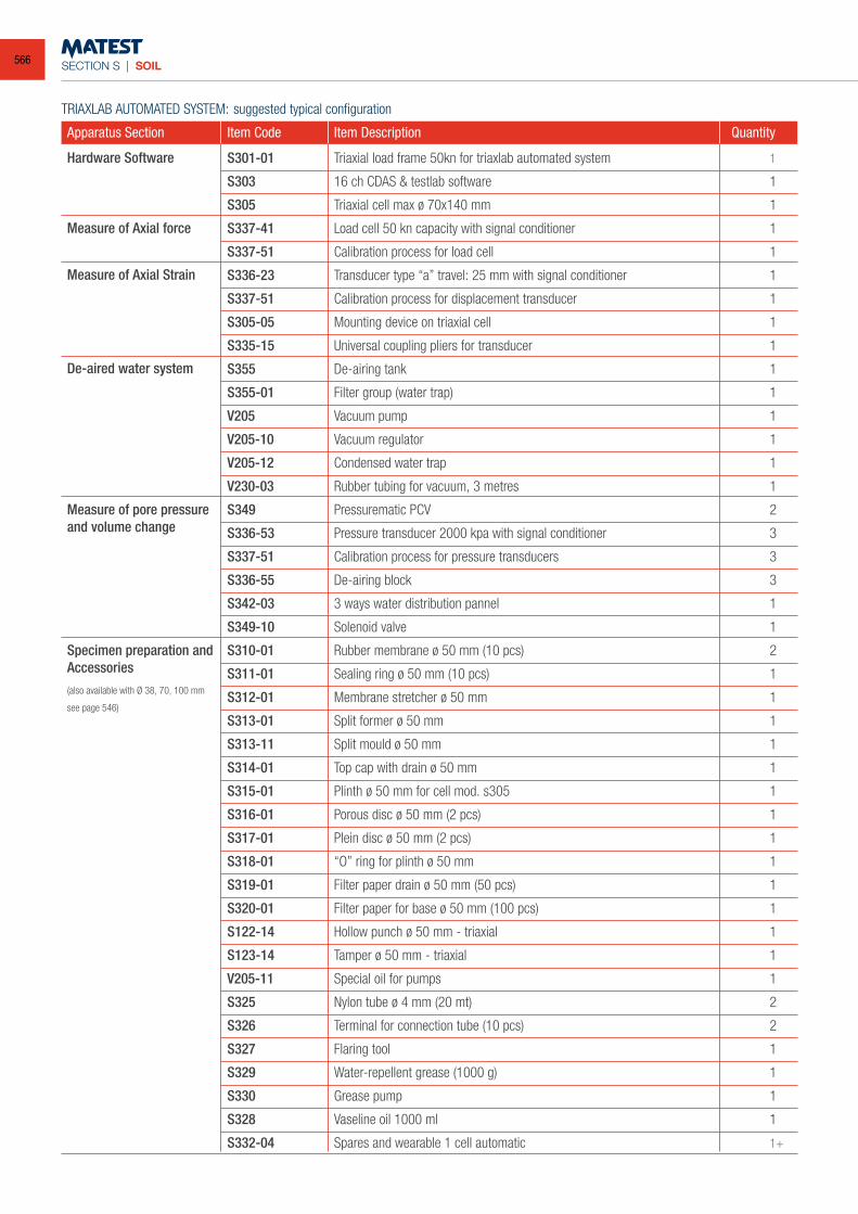
SECTION S | SOIL
TRIAXLAB AUTOMATED SYSTEM: suggested typical configuration
Apparatus Section Item Code Item Description Quantity
S301-01 Triaxial load frame 50kn for triaxlab automated system 1
S303 16 ch CDAS & testlab software 1
S305 Triaxial cell max ø 70x140 mm 1
S337-41 Load cell 50 kn capacity with signal conditioner 1
S337-51 Calibration process for load cell 1
S336-23 Transducer type “a” travel: 25 mm with signal conditioner 1
S337-51 Calibration process for displacement transducer 1
S305-05 Mounting device on triaxial cell 1
S335-15 Universal coupling pliers for transducer 1
S355 De-airing tank 1
S355-01 Filter group (water trap) 1
V205 Vacuum pump 1
V205-10 Vacuum regulator 1
V205-12 Condensed water trap 1
V230-03 Rubber tubing for vacuum, 3 metres 1
S349 Pressurematic PCV 2
S336-53 Pressure transducer 2000 kpa with signal conditioner 3
S337-51 Calibration process for pressure transducers 3
S336-55 De-airing block 3
S342-03 3 ways water distribution pannel 1
S349-10 Solenoid valve 1
S310-01 Rubber membrane ø 50 mm (10 pcs) 2
S311-01 Sealing ring ø 50 mm (10 pcs) 1
S312-01 Membrane stretcher ø 50 mm 1
S313-01 Split former ø 50 mm 1
S313-11 Split mould ø 50 mm 1
S314-01 Top cap with drain ø 50 mm 1
S315-01 Plinth ø 50 mm for cell mod. s305 1
S316-01 Porous disc ø 50 mm (2 pcs) 1
S317-01 Plein disc ø 50 mm (2 pcs) 1
S318-01 “O” ring for plinth ø 50 mm 1
S319-01 Filter paper drain ø 50 mm (50 pcs) 1
S320-01 Filter paper for base ø 50 mm (100 pcs) 1
S122-14 Hollow punch ø 50 mm - triaxial 1
S123-14 Tamper ø 50 mm - triaxial 1
V205-11 Special oil for pumps 1
S325 Nylon tube ø 4 mm (20 mt) 2
S326 Terminal for connection tube (10 pcs) 2
S327 Flaring tool 1
S329 Water-repellent grease (1000 g) 1
S330 Grease pump 1
S328 Vaseline oil 1000 ml 1
S332-04 Spares and wearable 1 cell automatic 1+
Specimen preparation andAccessories(also available with Ø 38, 70, 100 mm
see page 546)
Measure of pore pressureand volume change
Measure of Axial Strain
De-aired water system
Measure of Axial force
Hardware Software
566
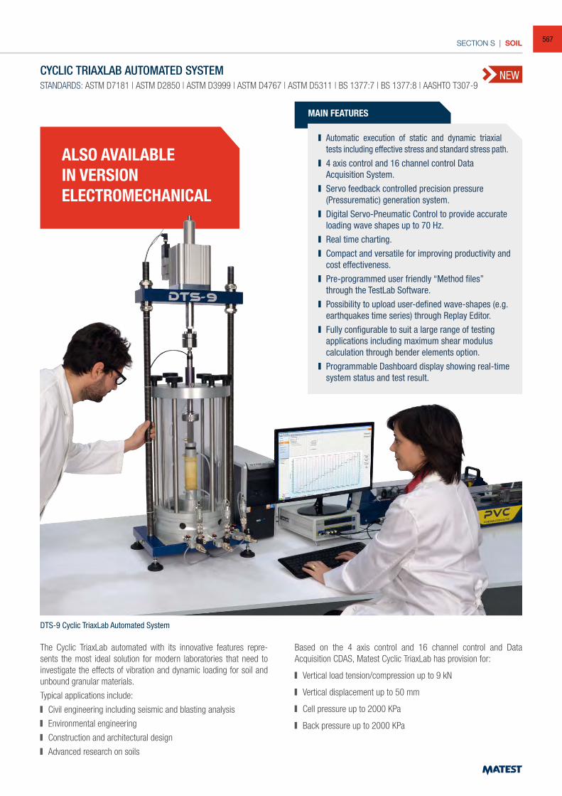
SECTION S | SOIL
NEWCYCLIC TRIAXLAB AUTOMATED SYSTEM
STANDARDS: ASTM D7181 | ASTM D2850 | ASTM D3999 | ASTM D4767 | ASTM D5311 | BS 1377:7 | BS 1377:8 | AASHTO T307-9
MAIN FEATURES
Automatic execution of static and dynamic triaxial tests including effective stress and standard stress path.
4 axis control and 16 channel control Data Acquisition System.
Servo feedback controlled precision pressure (Pressurematic) generation system.
Digital Servo-Pneumatic Control to provide accurate loading wave shapes up to 70 Hz.
Real time charting. Compact and versatile for improving productivity and
cost effectiveness. Pre-programmed user friendly “Method files”
through the TestLab Software. Possibility to upload user-defined wave-shapes (e.g.
earthquakes time series) through Replay Editor. Fully configurable to suit a large range of testing
applications including maximum shear modulus calculation through bender elements option.
Programmable Dashboard display showing real-time system status and test result.
The Cyclic TriaxLab automated with its innovative features repre-sents the most ideal solution for modern laboratories that need to investigate the effects of vibration and dynamic loading for soil and unbound granular materials.
Typical applications include:
Civil engineering including seismic and blasting analysis
Environmental engineering
Construction and architectural design
Advanced research on soils
DTS-9 Cyclic TriaxLab Automated System
Based on the 4 axis control and 16 channel control and Data Acquisition CDAS, Matest Cyclic TriaxLab has provision for:
Vertical load tension/compression up to 9 kN
Vertical displacement up to 50 mm
Cell pressure up to 2000 KPa
Back pressure up to 2000 KPa
ALSO AVAILABLEIN VERSIONELECTROMECHANICAL
567
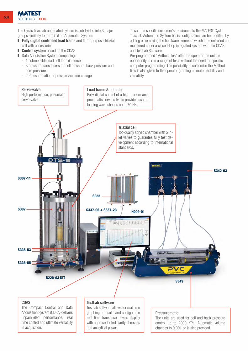
SECTION S | SOIL
S307-11
S307 S337-06 + S337-23
S355
S342-03
H009-01
S349B220-03 KIT
S336-53
S336-55
To suit the specific customer’s requirements the MATEST Cyclic TriaxLab Automated System basic configuration can be modified by adding or removing the hardware elements which are controlled and monitored under a closed-loop integrated system with the CDAS and TestLab Software.Pre-programmed “Method files” offer the operator the unique opportunity to run a range of tests without the need for specificcomputer programming. The possibility to customize the Method files is also given to the operator granting ultimate flexibility and versatility.
Triaxial cellTop quality acrylic chamber with 5 in-let valves to guarantee fully test de-velopment according to international standards.
Servo-valveHigh performance, pneumatic servo-valve
Load frame & actuatorFully digital control of a high performance pneumatic servo-valve to provide accurate loading wave shapes up to 70 Hz.
TestLab softwareTestLab software allows for real time graphing of results and configurable real time transducer levels display with unprecedented clarity of results and analytical power.
CDASThe Compact Control and Data Acquisition System (CDSA) delivers unparalleled performance, real time control and ultimate versatility in acquisition.
PressurematicThe units are used for cell and back pressure control up to 2000 KPa. Automatic volume changes to 0.001 cc is also provided.
The Cyclic TriaxLab automated system is subdivided into 3 major groups similarly to the TriaxLab Automated System: Fully digital controlled load frame and fit for purpose Triaxial
cell with accessories Control system based on the CDAS Data Acquisition System comprising:
- 1 submersible load cell for axial force - 3 pressure transducers for cell pressure, back pressure and
pore pressure - 2 Pressurematic for pressure/volume change
568
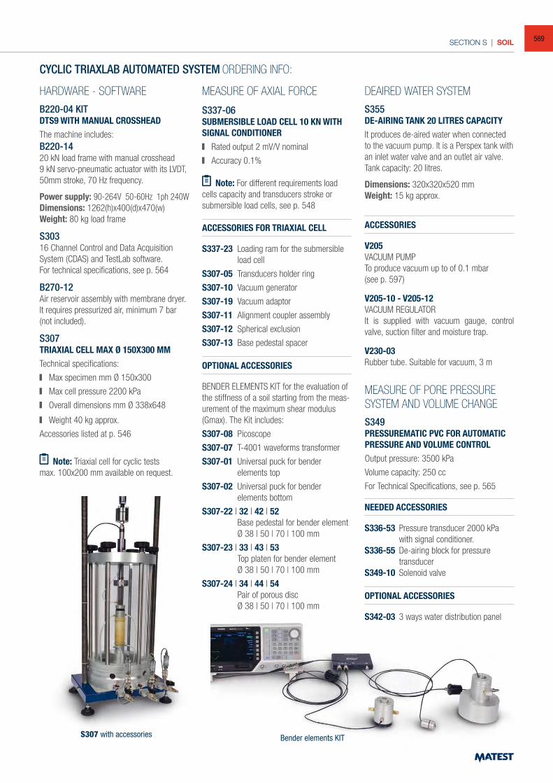
SECTION S | SOIL
CYCLIC TRIAXLAB AUTOMATED SYSTEM ORDERING INFO:
HARDWARE - SOFTWAREB220-04 KIT DTS9 WITH MANUAL CROSSHEAD The machine includes:B220-1420 kN load frame with manual crosshead9 kN servo-pneumatic actuator with its LVDT, 50mm stroke, 70 Hz frequency.
Power supply: 90-264V 50-60Hz 1ph 240WDimensions: 1262(h)x400(d)x470(w)Weight: 80 kg load frame
S30316 Channel Control and Data Acquisition System (CDAS) and TestLab software.For technical specifications, see p. 564
B270-12Air reservoir assembly with membrane dryer.It requires pressurized air, minimum 7 bar (not included).
S307TRIAXIAL CELL MAX Ø 150X300 MMTechnical specifications:
Max specimen mm Ø 150x300
Max cell pressure 2200 kPa
Overall dimensions mm Ø 338x648
Weight 40 kg approx.
Accessories listed at p. 546
Note: Triaxial cell for cyclic testsmax. 100x200 mm available on request.
MEASURE OF AXIAL FORCE
S337-06 SUBMERSIBLE LOAD CELL 10 KN WITH SIGNAL CONDITIONER Rated output 2 mV/V nominal
Accuracy 0.1%
MEASURE OF PORE PRESSURE SYSTEM AND VOLUME CHANGES349PRESSUREMATIC PVC FOR AUTOMATIC PRESSURE AND VOLUME CONTROLOutput pressure: 3500 kPa
Volume capacity: 250 cc
For Technical Specifications, see p. 565
S307 with accessories Bender elements KIT
Note: For different requirements load cells capacity and transducers stroke or submersible load cells, see p. 548
ACCESSORIES
V205 VACUUM PUMPTo produce vacuum up to of 0.1 mbar(see p. 597)
V205-10 - V205-12VACUUM REGULATORIt is supplied with vacuum gauge, control valve, suction filter and moisture trap.
V230-03Rubber tube. Suitable for vacuum, 3 m
NEEDED ACCESSORIES
S336-53 Pressure transducer 2000 kPa with signal conditioner.
S336-55 De-airing block for pressure transducer
S349-10 Solenoid valve
OPTIONAL ACCESSORIES
S342-03 3 ways water distribution panel
DEAIRED WATER SYSTEMS355 DE-AIRING TANK 20 LITRES CAPACITYIt produces de-aired water when connected to the vacuum pump. It is a Perspex tank with an inlet water valve and an outlet air valve.Tank capacity: 20 litres.
Dimensions: 320x320x520 mmWeight: 15 kg approx.
ACCESSORIES FOR TRIAXIAL CELL
S337-23 Loading ram for the submersible load cell
S307-05 Transducers holder ring
S307-10 Vacuum generator
S307-19 Vacuum adaptor
S307-11 Alignment coupler assembly
S307-12 Spherical exclusion
S307-13 Base pedestal spacer
OPTIONAL ACCESSORIES
BENDER ELEMENTS KIT for the evaluation of the stiffness of a soil starting from the meas-urement of the maximum shear modulus (Gmax). The Kit includes:
S307-08 Picoscope
S307-07 T-4001 waveforms transformer
S307-01 Universal puck for bender elements top
S307-02 Universal puck for bender elements bottom
S307-22 | 32 | 42 | 52 Base pedestal for bender element
Ø 38 | 50 | 70 | 100 mm
S307-23 | 33 | 43 | 53 Top platen for bender element Ø 38 | 50 | 70 | 100 mm
S307-24 | 34 | 44 | 54 Pair of porous disc Ø 38 | 50 | 70 | 100 mm
569
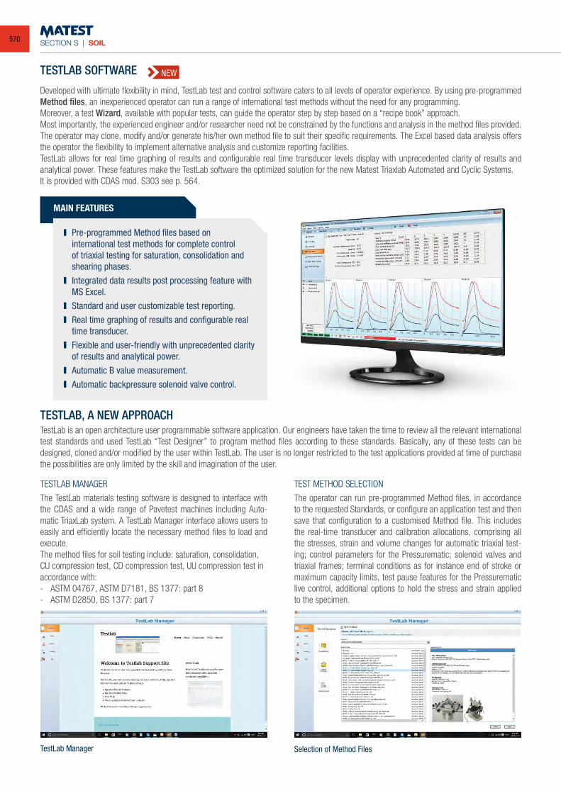
SECTION S | SOIL
TestLab Manager
TESTLAB SOFTWARE
Developed with ultimate flexibility in mind, TestLab test and control software caters to all levels of operator experience. By using pre-programmed Method files, an inexperienced operator can run a range of international test methods without the need for any programming. Moreover, a test Wizard, available with popular tests, can guide the operator step by step based on a “recipe book” approach.Most importantly, the experienced engineer and/or researcher need not be constrained by the functions and analysis in the method files provided. The operator may clone, modify and/or generate his/her own method file to suit their specific requirements. The Excel based data analysis offers the operator the flexibility to implement alternative analysis and customize reporting facilities.TestLab allows for real time graphing of results and configurable real time transducer levels display with unprecedented clarity of results and analytical power. These features make the TestLab software the optimized solution for the new Matest Triaxlab Automated and Cyclic Systems.It is provided with CDAS mod. S303 see p. 564.
Selection of Method Files
TESTLAB, A NEW APPROACHTestLab is an open architecture user programmable software application. Our engineers have taken the time to review all the relevant international test standards and used TestLab “Test Designer” to program method files according to these standards. Basically, any of these tests can be designed, cloned and/or modified by the user within TestLab. The user is no longer restricted to the test applications provided at time of purchase the possibilities are only limited by the skill and imagination of the user.
TESTLAB MANAGER
The TestLab materials testing software is designed to interface with the CDAS and a wide range of Pavetest machines including Auto-matic TriaxLab system. A TestLab Manager interface allows users to easily and efficiently locate the necessary method files to load and execute.The method files for soil testing include: saturation, consolidation, CU compression test, CD compression test, UU compression test in accordance with:- ASTM 04767, ASTM D7181, BS 1377: part 8- ASTM D2850, BS 1377: part 7
TEST METHOD SELECTION
The operator can run pre-programmed Method files, in accordance to the requested Standards, or configure an application test and then save that configuration to a customised Method file. This includes the real-time transducer and calibration allocations, comprising all the stresses, strain and volume changes for automatic triaxial test-ing; control parameters for the Pressurematic; solenoid valves and triaxial frames; terminal conditions as for instance end of stroke or maximum capacity limits, test pause features for the Pressurematic live control, additional options to hold the stress and strain applied to the specimen.
MAIN FEATURES
Pre-programmed Method files based on international test methods for complete control of triaxial testing for saturation, consolidation and shearing phases.
Integrated data results post processing feature with MS Excel.
Standard and user customizable test reporting. Real time graphing of results and configurable real
time transducer. Flexible and user-friendly with unprecedented clarity
of results and analytical power. Automatic B value measurement. Automatic backpressure solenoid valve control.
NEW
570
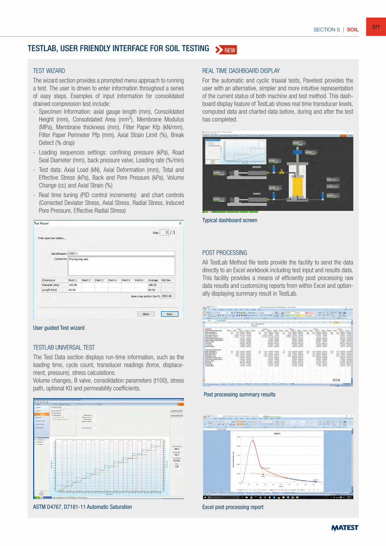
SECTION S | SOIL
TEST WIZARD
The wizard section provides a prompted menu approach to running a test. The user is driven to enter information throughout a series of easy steps. Examples of input information for consolidated drained compression test include:- Specimen Information: axial gauge length (mm), Consolidated
Height (mm), Consolidated Area (mm²), Membrane Modulus (MPa), Membrane thickness (mm), Filter Paper Kfp (kN/mm), Filter Paper Perimeter Pfp (mm), Axial Strain Limit (%), Break Detect (% drop)
- Loading sequences settings: confining pressure (kPa), Road Seal Diameter (mm), back pressure valve, Loading rate (%/min)
- Test data: Axial Load (kN), Axial Deformation (mm), Total and Effective Stress (kPa), Back and Pore Pressure (kPa), Volume Change (cc) and Axial Strain (%)
- Real time tuning (PID control increments) and chart controls (Corrected Deviator Stress, Axial Stress, Radial Stress, Induced Pore Pressure, Effective Radial Stress)
POST PROCESSING
All TestLab Method file tests provide the facility to send the data directly to an Excel workbook including test input and results data. This facility provides a means of efficiently post processing raw data results and customizing reports from within Excel and option-ally displaying summary result in TestLab.
ASTM D4767, D7181-11 Automatic Saturation
REAL TIME DASHBOARD DISPLAY
For the automatic and cyclic triaxial tests, Pavetest provides the user with an alternative, simpler and more intuitive representation of the current status of both machine and test method. This dash-board display feature of TestLab shows real time transducer levels, computed data and charted data before, during and after the test has completed.
TESTLAB, USER FRIENDLY INTERFACE FOR SOIL TESTING
Typical dashboard screen
TESTLAB UNIVERSAL TEST
The Test Data section displays run-time information, such as the loading time, cycle count, transducer readings (force, displace-ment, pressure), stress calculations.Volume changes, B valve, consolidation parameters (t100), stress path, optional K0 and permeability coefficients.
Excel post processing report
Post processing summary results
User guided Test wizard
NEW
571
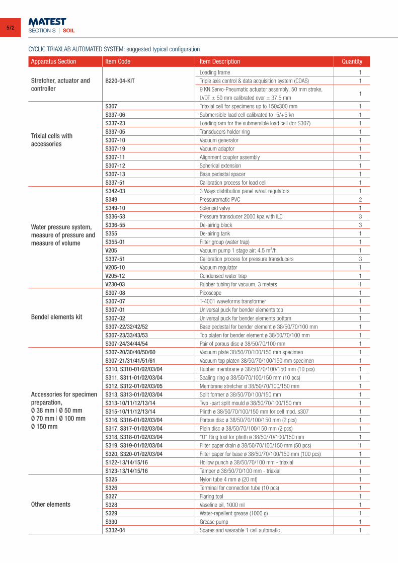
SECTION S | SOIL
Loading frame 1 B220-04-KIT Triple axis control & data acquisition system (CDAS) 1 9 KN Servo-Pneumatic actuator assembly, 50 mm stroke, LVDT ± 50 mm calibrated over ± 37.5 mm
1
S307 Triaxial cell for specimens up to 150x300 mm 1 S337-06 Submersible load cell calibrated to -5/+5 kn 1 S337-23 Loading ram for the submersible load cell (for S307) 1 S337-05 Transducers holder ring 1 S307-10 Vacuum generator 1 S307-19 Vacuum adaptor 1 S307-11 Alignment coupler assembly 1 S307-12 Spherical extension 1 S307-13 Base pedestal spacer 1 S337-51 Calibration process for load cell 1 S342-03 3 Ways distribution panel w/out regulators 1 S349 Pressurematic PVC 2 S349-10 Solenoid valve 1 S336-53 Pressure transducer 2000 kpa with ILC 3 S336-55 De-airing block 3 S355 De-airing tank 1 S355-01 Filter group (water trap) 1 V205 Vacuum pump 1 stage air: 4.5 m³/h 1 S337-51 Calibration process for pressure transducers 3 V205-10 Vacuum regulator 1 V205-12 Condensed water trap 1 V230-03 Rubber tubing for vacuum, 3 meters 1 S307-08 Picoscope 1 S307-07 T-4001 waveforms transformer 1 S307-01 Universal puck for bender elements top 1 S307-02 Universal puck for bender elements bottom 1 S307-22/32/42/52 Base pedestal for bender element ø 38/50/70/100 mm 1 S307-23/33/43/53 Top platen for bender element ø 38/50/70/100 mm 1 S307-24/34/44/54 Pair of porous disc ø 38/50/70/100 mm 1 S307-20/30/40/50/60 Vacuum plate 38/50/70/100/150 mm specimen 1 S307-21/31/41/51/61 Vacuum top platen 38/50/70/100/150 mm specimen 1 S310, S310-01/02/03/04 Rubber membrane ø 38/50/70/100/150 mm (10 pcs) 1 S311, S311-01/02/03/04 Sealing ring ø 38/50/70/100/150 mm (10 pcs) 1 S312, S312-01/02/03/05 Membrane stretcher ø 38/50/70/100/150 mm 1 S313, S313-01/02/03/04 Split former ø 38/50/70/100/150 mm 1 S313-10/11/12/13/14 Two -part split mould ø 38/50/70/100/150 mm 1 S315-10/11/12/13/14 Plinth ø 38/50/70/100/150 mm for cell mod. s307 1 S316, S316-01/02/03/04 Porous disc ø 38/50/70/100/150 mm (2 pcs) 1 S317, S317-01/02/03/04 Plein disc ø 38/50/70/100/150 mm (2 pcs) 1 S318, S318-01/02/03/04 "O" Ring tool for plinth ø 38/50/70/100/150 mm 1 S319, S319-01/02/03/04 Filter paper drain ø 38/50/70/100/150 mm (50 pcs) 1 S320, S320-01/02/03/04 Filter paper for base ø 38/50/70/100/150 mm (100 pcs) 1 S122-13/14/15/16 Hollow punch ø 38/50/70/100 mm - triaxial 1 S123-13/14/15/16 Tamper ø 38/50/70/100 mm - triaxial 1 S325 Nylon tube 4 mm ø (20 mt) 1 S326 Terminal for connection tube (10 pcs) 1 S327 Flaring tool 1 S328 Vaseline oil, 1000 ml 1 S329 Water-repellent grease (1000 g) 1 S330 Grease pump 1 S332-04 Spares and wearable 1 cell automatic 1
CYCLIC TRIAXLAB AUTOMATED SYSTEM: suggested typical configuration
Accessories for specimen preparation,Ø 38 mm | Ø 50 mmØ 70 mm | Ø 100 mmØ 150 mm
Other elements
Bendel elements kit
Water pressure system, measure of pressure and measure of volume
Trixial cells with accessories
Stretcher, actuator and controller
Apparatus Section Item Code Item Description Quantity
572
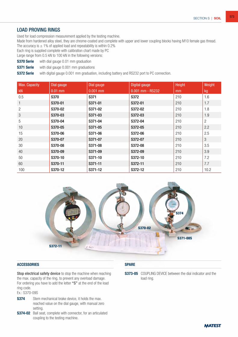
SECTION S | SOIL
LOAD PROVING RINGSUsed for load compression measurement applied by the testing machine.Made from hardened alloy steel, they are chrome-coated and complete with upper and lower coupling blocks having M10 female gas thread.The accuracy is ± 1% of applied load and repeatability is within 0.2%Each ring is supplied complete with calibration chart made by PCLarge range from 0.5 kN to 100 kN in the following versions:
S370 Serie with dial gauge 0.01 mm graduation
S371 Serie with dial gauge 0.001 mm graduations
S372 Serie with digital gauge 0.001 mm graduation, including battery and RS232 port to PC connection.
Max. Capacity Dial gauge Dial gauge Digital gauge Height Weight
kN 0.01 mm 0.001 mm 0.001 mm - RS232 mm kg
0.5 S370 S371 S372 210 1.6
1 S370-01 S371-01 S372-01 210 1.7
2 S370-02 S371-02 S372-02 210 1.8
3 S370-03 S371-03 S372-03 210 1.9
5 S370-04 S371-04 S372-04 210 2
10 S370-05 S371-05 S372-05 210 2.2
15 S370-06 S371-06 S372-06 210 2.5
20 S370-07 S371-07 S372-07 210 3
30 S370-08 S371-08 S372-08 210 3.5
40 S370-09 S371-09 S372-09 210 3.9
50 S370-10 S371-10 S372-10 210 7.2
60 S370-11 S371-11 S372-11 210 7.7
100 S370-12 S371-12 S372-12 210 10.2
ACCESSORIES
Stop electrical safety device to stop the machine when reaching the max. capacity of the ring, to prevent any overload damage.For ordering you have to add the letter “S” at the end of the load ring code.Ex.: S370-09S
S374 Stem mechanical brake device, it holds the max. reached value on the dial gauge, with manual zero setting.
S374-02 Ball seat, complete with connector, for an articulated coupling to the testing machine.
SPARE
S373-05 COUPLING DEVICE between the dial indicator and the load ring.
S372-11
S370-02
S371-08S
S374
573
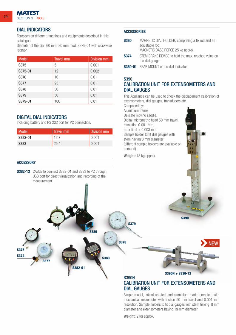
SECTION S | SOIL
S390
DIAL INDICATORSForeseen on different machines and equipments described in this catalogue.Diameter of the dial: 60 mm, 80 mm mod. S379-01 with clockwise rotation.
Model Travel mm Division mm
S375 5 0.001
S375-01 12 0.002
S376 10 0.01
S377 25 0.01
S378 30 0.01
S379 50 0.01
S379-01 100 0:01
DIGITAL DIAL INDICATORSIncluding battery and RS 232 port for PC connection.
Model Travel mm Division mm
S382-01 12.7 0.001
S383 25.4 0.001
ACCESSORIES
S380 MAGNETIC DIAL HOLDER, comprising a fix rod and an adjustable rod.
MAGNETIC BASE FORCE 25 kg approx.
S374 STEM BRAKE DEVICE to hold the max. reached value on the dial gauge.
S380-01 REAR MOUNT of the dial indicator.
S390CALIBRATION UNIT FOR EXTENSOMETERS AND DIAL GAUGES
This Appliance can be used to check the displacement calibration of extensometers, dial gauges, transducers etc.Composed by:Aluminium frame,Delicate moving saddle,Digital micrometric head 50 mm travel, resolution 0.001 mm,error limit ± 0.003 mmSample holder to fit dial gauges with stem having 8 mm diameter(different sample holders are available on demand).
Weight: 18 kg approx.
S375
S376
S380
S377
S382-01
S383
S378
S379
S374
S390NCALIBRATION UNIT FOR EXTENSOMETERS AND DIAL GAUGESSimple model, stainless steel and aluminium made, complete with mechanical micrometer with friction 50 mm travel and 0.001 mm resolution. Sample holders to fit dial gauges with stem having 8 mm diameter and extensometers having 19 mm diameter
Weight: 2 kg approx.
NEW
S390N + S336-12
ACCESSORY
S382-13 CABLE to connect S382-01 and S383 to PC through USB port for direct visualization and recording of the measurement.
574
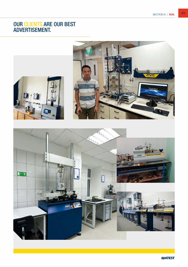
SECTION S | SOIL
OUR CLIENTS ARE OUR BEST ADVERTISEMENT.
575
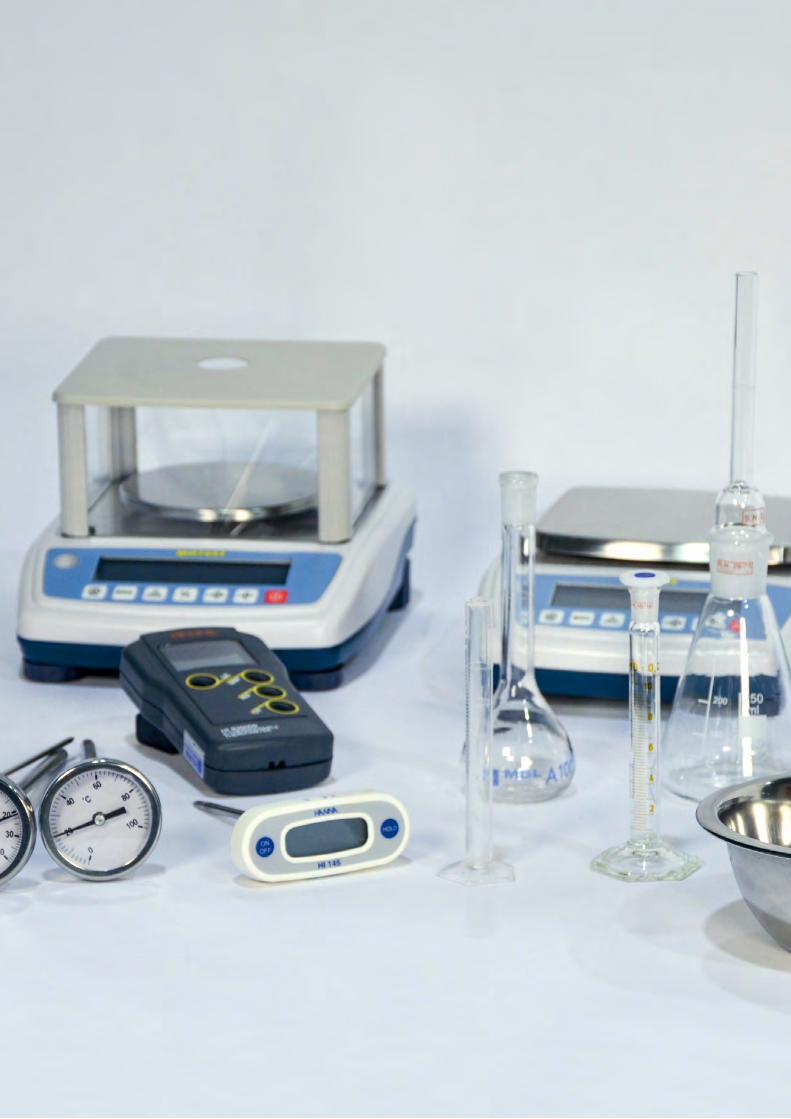
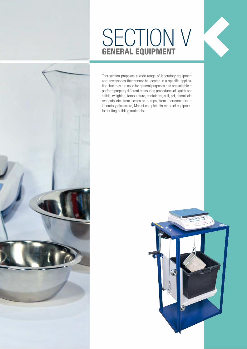
SECTION VGENERAL EQUIPMENT
This section proposes a wide range of laboratory equipment and accessories that cannot be located in a specific applica-tion, but they are used for general purposes and are suitable to perform properly different measuring procedures of liquids and solids, weighing, temperature, containers, still, pH, chemicals, reagents etc. from scales to pumps, from thermometers to laboratory glassware, Matest complete its range of equipment for testing building materials.
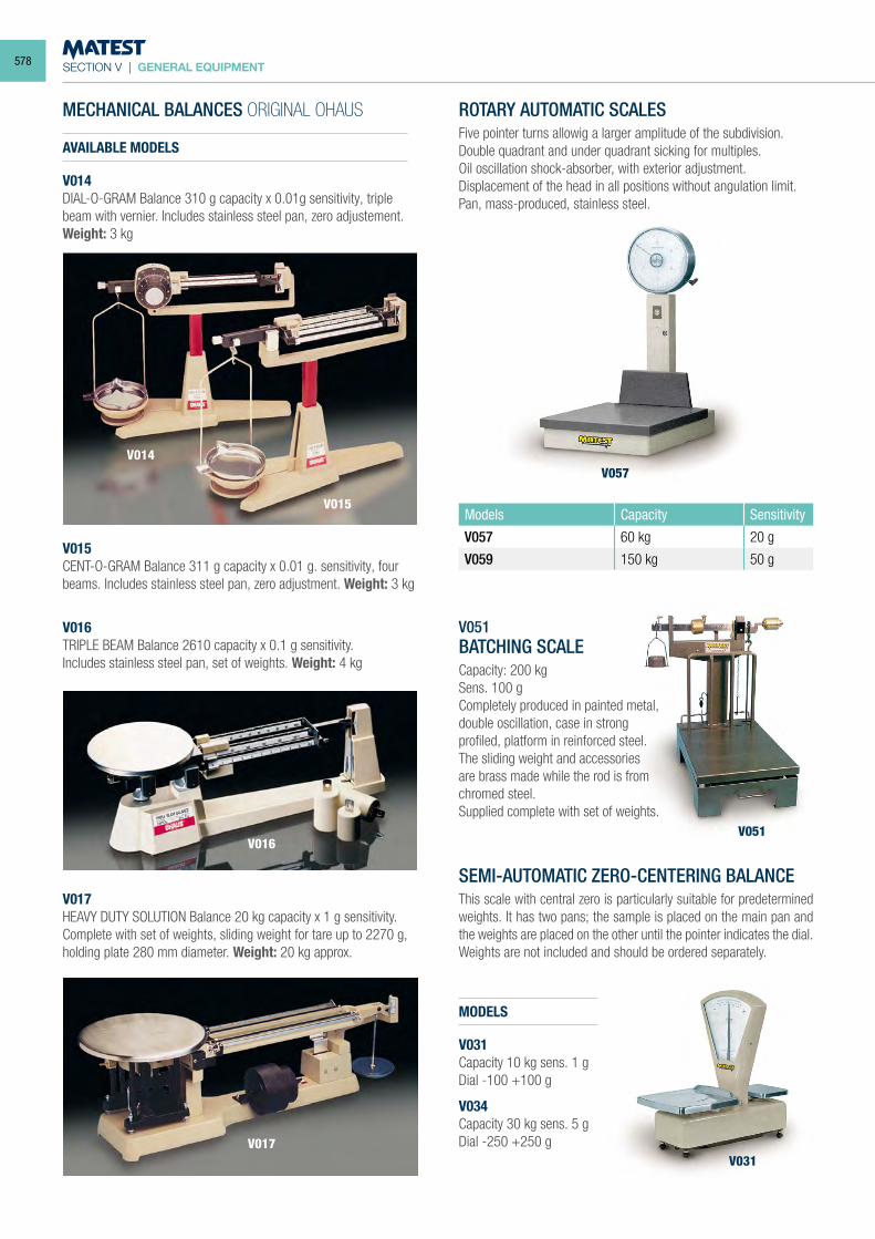
SECTION V | GENERAL EQUIPMENT
Models Capacity Sensitivity
V057 60 kg 20 g
V059 150 kg 50 g
MECHANICAL BALANCES ORIGINAL OHAUS
AVAILABLE MODELS
V014DIAL-O-GRAM Balance 310 g capacity x 0.01g sensitivity, triple beam with vernier. Includes stainless steel pan, zero adjustement. Weight: 3 kg
V015CENT-O-GRAM Balance 311 g capacity x 0.01 g. sensitivity, four beams. Includes stainless steel pan, zero adjustment. Weight: 3 kg
V016TRIPLE BEAM Balance 2610 capacity x 0.1 g sensitivity.Includes stainless steel pan, set of weights. Weight: 4 kg
V017HEAVY DUTY SOLUTION Balance 20 kg capacity x 1 g sensitivity. Complete with set of weights, sliding weight for tare up to 2270 g, holding plate 280 mm diameter. Weight: 20 kg approx.
ROTARY AUTOMATIC SCALESFive pointer turns allowig a larger amplitude of the subdivision. Double quadrant and under quadrant sicking for multiples.Oil oscillation shock-absorber, with exterior adjustment.Displacement of the head in all positions without angulation limit.Pan, mass-produced, stainless steel.
V051BATCHING SCALECapacity: 200 kgSens. 100 gCompletely produced in painted metal, double oscillation, case in strong profiled, platform in reinforced steel. The sliding weight and accessories are brass made while the rod is from chromed steel.Supplied complete with set of weights.
SEMI-AUTOMATIC ZERO-CENTERING BALANCEThis scale with central zero is particularly suitable for predetermined weights. It has two pans; the sample is placed on the main pan and the weights are placed on the other until the pointer indicates the dial.Weights are not included and should be ordered separately.
MODELS
V031Capacity 10 kg sens. 1 gDial -100 +100 g
V034Capacity 30 kg sens. 5 gDial -250 +250 g
V057
V031V017
V016
V015
V014
V051
578
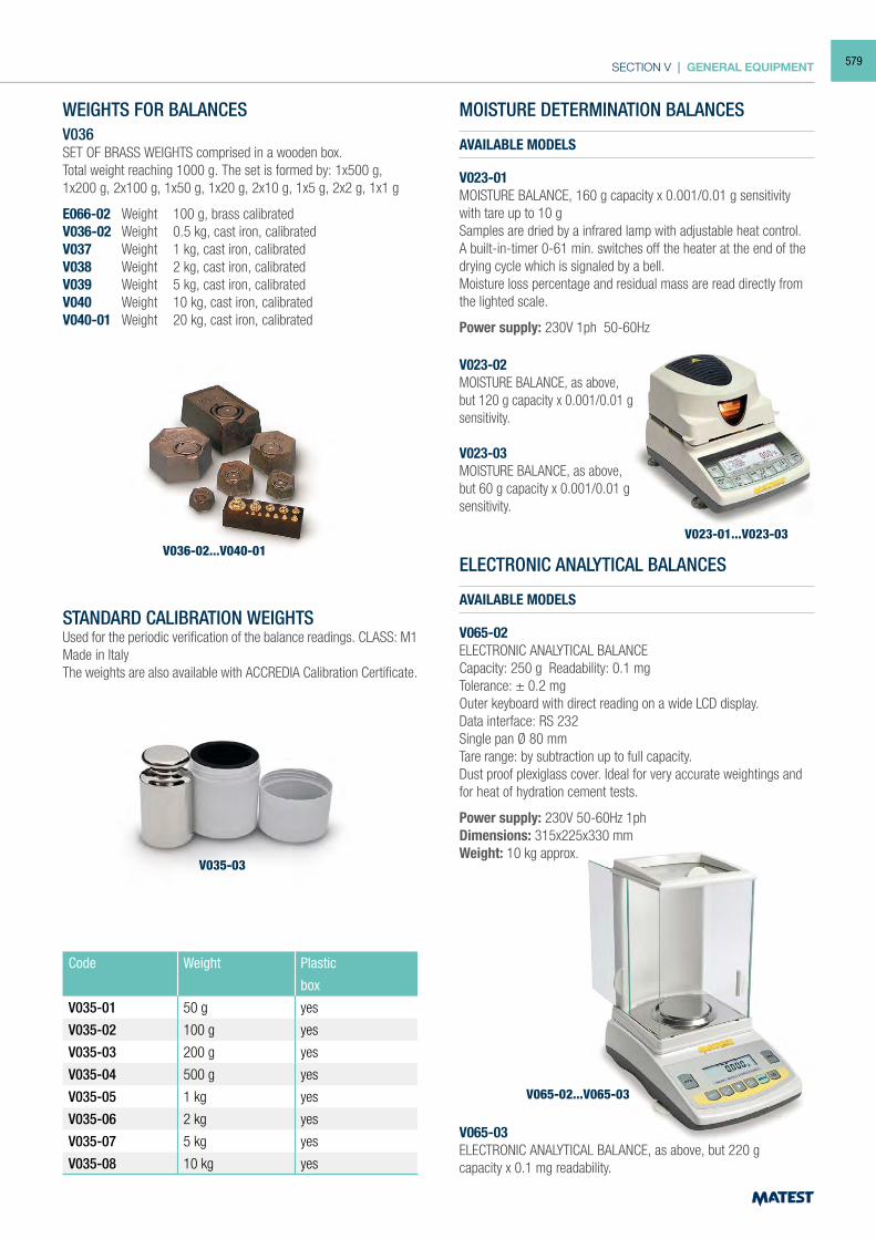
SECTION V | GENERAL EQUIPMENT
V035-03
V036-02...V040-01V023-01...V023-03
V065-02...V065-03
WEIGHTS FOR BALANCESV036SET OF BRASS WEIGHTS comprised in a wooden box.Total weight reaching 1000 g. The set is formed by: 1x500 g, 1x200 g, 2x100 g, 1x50 g, 1x20 g, 2x10 g, 1x5 g, 2x2 g, 1x1 g
E066-02 Weight 100 g, brass calibratedV036-02 Weight 0.5 kg, cast iron, calibratedV037 Weight 1 kg, cast iron, calibratedV038 Weight 2 kg, cast iron, calibratedV039 Weight 5 kg, cast iron, calibrated V040 Weight 10 kg, cast iron, calibratedV040-01 Weight 20 kg, cast iron, calibrated
STANDARD CALIBRATION WEIGHTSUsed for the periodic verification of the balance readings. CLASS: M1Made in ItalyThe weights are also available with ACCREDIA Calibration Certificate.
Code Weight Plastic
box
V035-01 50 g yes
V035-02 100 g yes
V035-03 200 g yes
V035-04 500 g yes
V035-05 1 kg yes
V035-06 2 kg yes
V035-07 5 kg yes
V035-08 10 kg yes
V023-02MOISTURE BALANCE, as above, but 120 g capacity x 0.001/0.01 g sensitivity.
V023-03MOISTURE BALANCE, as above, but 60 g capacity x 0.001/0.01 g sensitivity.
MOISTURE DETERMINATION BALANCES
AVAILABLE MODELS
V023-01MOISTURE BALANCE, 160 g capacity x 0.001/0.01 g sensitivity with tare up to 10 gSamples are dried by a infrared lamp with adjustable heat control.A built-in-timer 0-61 min. switches off the heater at the end of the drying cycle which is signaled by a bell.Moisture loss percentage and residual mass are read directly from the lighted scale.
Power supply: 230V 1ph 50-60Hz
ELECTRONIC ANALYTICAL BALANCES
AVAILABLE MODELS
V065-02ELECTRONIC ANALYTICAL BALANCECapacity: 250 g Readability: 0.1 mgTolerance: ± 0.2 mgOuter keyboard with direct reading on a wide LCD display.Data interface: RS 232Single pan Ø 80 mmTare range: by subtraction up to full capacity.Dust proof plexiglass cover. Ideal for very accurate weightings and for heat of hydration cement tests.
Power supply: 230V 50-60Hz 1phDimensions: 315x225x330 mmWeight: 10 kg approx.
V065-03ELECTRONIC ANALYTICAL BALANCE, as above, but 220 gcapacity x 0.1 mg readability.
579
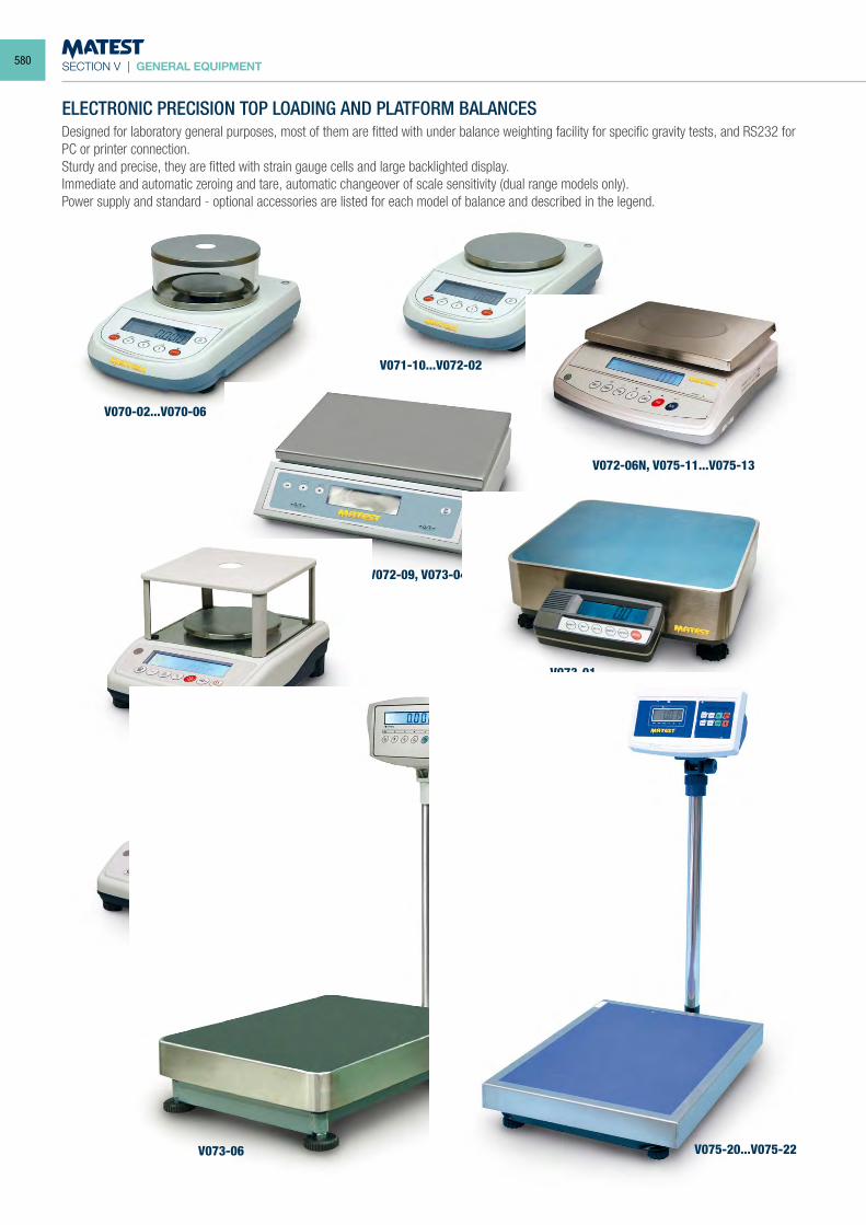
SECTION V | GENERAL EQUIPMENT
V070-02...V070-06
V071-10...V072-02
V072-06N, V075-11...V075-13
V072-09, V073-04
V073-01
V075-02...V075-04
V075-06
V075-20...V075-22V073-06
ELECTRONIC PRECISION TOP LOADING AND PLATFORM BALANCESDesigned for laboratory general purposes, most of them are fitted with under balance weighting facility for specific gravity tests, and RS232 for PC or printer connection.Sturdy and precise, they are fitted with strain gauge cells and large backlighted display.Immediate and automatic zeroing and tare, automatic changeover of scale sensitivity (dual range models only).Power supply and standard - optional accessories are listed for each model of balance and described in the legend.
580
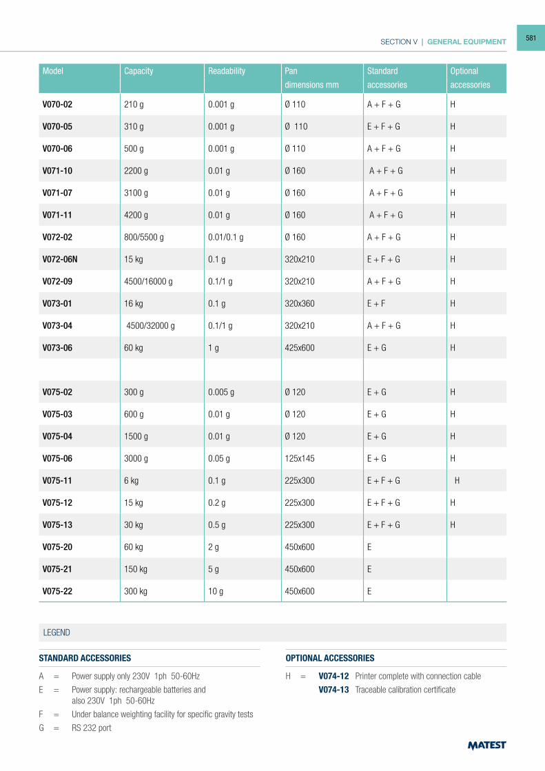
SECTION V | GENERAL EQUIPMENT
Model Capacity Readability Pan Standard Optional
dimensions mm accessories accessories
V070-02 210 g 0.001 g Ø 110 A + F + G H
V070-05 310 g 0.001 g Ø 110 E + F + G H
V070-06 500 g 0.001 g Ø 110 A + F + G H
V071-10 2200 g 0.01 g Ø 160 A + F + G H
V071-07 3100 g 0.01 g Ø 160 A + F + G H
V071-11 4200 g 0.01 g Ø 160 A + F + G H
V072-02 800/5500 g 0.01/0.1 g Ø 160 A + F + G H
V072-06N 15 kg 0.1 g 320x210 E + F + G H
V072-09 4500/16000 g 0.1/1 g 320x210 A + F + G H
V073-01 16 kg 0.1 g 320x360 E + F H
V073-04 4500/32000 g 0.1/1 g 320x210 A + F + G H
V073-06 60 kg 1 g 425x600 E + G H
V075-02 300 g 0.005 g Ø 120 E + G H
V075-03 600 g 0.01 g Ø 120 E + G H
V075-04 1500 g 0.01 g Ø 120 E + G H
V075-06 3000 g 0.05 g 125x145 E + G H
V075-11 6 kg 0.1 g 225x300 E + F + G H
V075-12 15 kg 0.2 g 225x300 E + F + G H
V075-13 30 kg 0.5 g 225x300 E + F + G H
V075-20 60 kg 2 g 450x600 E
V075-21 150 kg 5 g 450x600 E
V075-22 300 kg 10 g 450x600 E
STANDARD ACCESSORIES
A = Power supply only 230V 1ph 50-60Hz
E = Power supply: rechargeable batteries and also 230V 1ph 50-60Hz
F = Under balance weighting facility for specific gravity tests
G = RS 232 port
OPTIONAL ACCESSORIES
H = V074-12 Printer complete with connection cable
V074-13 Traceable calibration certificate
LEGEND
581
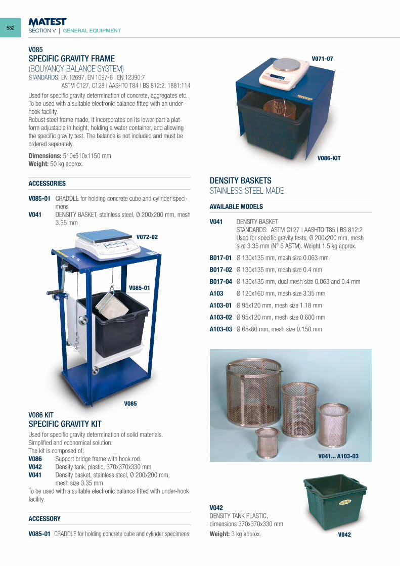
SECTION V | GENERAL EQUIPMENT
V085SPECIFIC GRAVITY FRAME(BOUYANCY BALANCE SYSTEM)STANDARDS: EN 12697, EN 1097-6 | EN 12390:7 ASTM C127, C128 | AASHTO T84 | BS 812:2, 1881:114
Used for specific gravity determination of concrete, aggregates etc.To be used with a suitable electronic balance fitted with an under - hook facility.Robust steel frame made, it incorporates on its lower part a plat-form adjustable in height, holding a water container, and allowing the specific gravity test. The balance is not included and must be ordered separately.
Dimensions: 510x510x1150 mmWeight: 50 kg approx.
ACCESSORIES
V085-01 CRADDLE for holding concrete cube and cylinder speci-mens
V041 DENSITY BASKET, stainless steel, Ø 200x200 mm, mesh 3.35 mm
V086 KITSPECIFIC GRAVITY KITUsed for specific gravity determination of solid materials. Simplified and economical solution.The kit is composed of:V086 Support bridge frame with hook rod.V042 Density tank, plastic, 370x370x330 mmV041 Density basket, stainless steel, Ø 200x200 mm, mesh size 3.35 mmTo be used with a suitable electronic balance fitted with under-hook facility.
ACCESSORY
V085-01 CRADDLE for holding concrete cube and cylinder specimens.
DENSITY BASKETSSTAINLESS STEEL MADE
AVAILABLE MODELS
V041 DENSITY BASKET STANDARDS: ASTM C127 | AASHTO T85 | BS 812:2 Used for specific gravity tests, Ø 200x200 mm, mesh size 3.35 mm (N° 6 ASTM). Weight 1.5 kg approx.
B017-01 Ø 130x135 mm, mesh size 0.063 mm
B017-02 Ø 130x135 mm, mesh size 0.4 mm
B017-04 Ø 130x135 mm, dual mesh size 0.063 and 0.4 mm
A103 Ø 120x160 mm, mesh size 3.35 mm
A103-01 Ø 95x120 mm, mesh size 1.18 mm
A103-02 Ø 95x120 mm, mesh size 0.600 mm
A103-03 Ø 65x80 mm, mesh size 0.150 mm
V042DENSITY TANK PLASTIC,dimensions 370x370x330 mm
Weight: 3 kg approx.
V041... A103-03
V042
V086-KIT
V071-07
V085-01
V085
V072-02
582
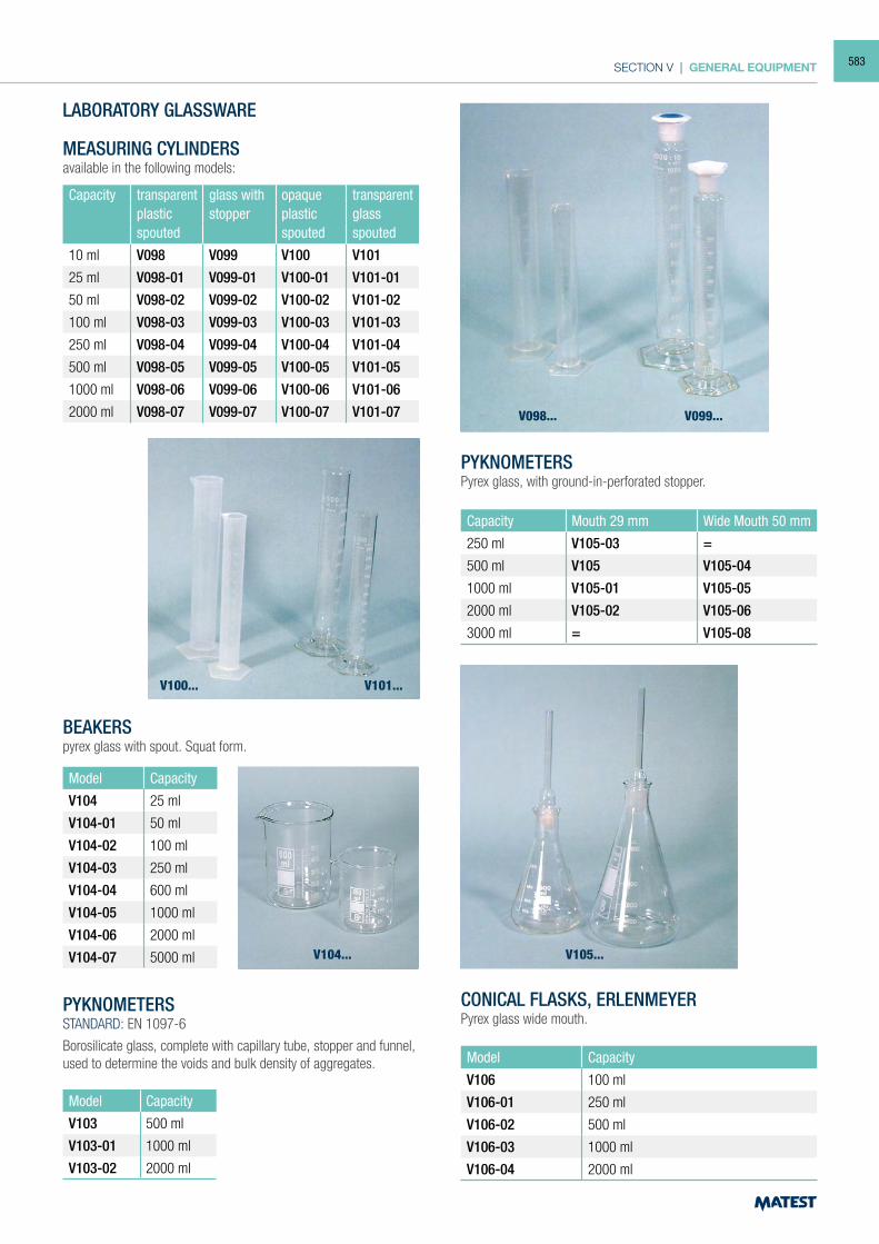
SECTION V | GENERAL EQUIPMENT
LABORATORY GLASSWARE
MEASURING CYLINDERSavailable in the following models:
Capacity transparent glass with opaque transparentplastic stopper plastic glassspouted spouted spouted
10 ml V098 V099 V100 V101
25 ml V098-01 V099-01 V100-01 V101-01
50 ml V098-02 V099-02 V100-02 V101-02
100 ml V098-03 V099-03 V100-03 V101-03
250 ml V098-04 V099-04 V100-04 V101-04
500 ml V098-05 V099-05 V100-05 V101-05
1000 ml V098-06 V099-06 V100-06 V101-06
2000 ml V098-07 V099-07 V100-07 V101-07
BEAKERSpyrex glass with spout. Squat form.
Model Capacity
V104 25 ml
V104-01 50 ml
V104-02 100 ml
V104-03 250 ml
V104-04 600 ml
V104-05 1000 ml
V104-06 2000 ml
V104-07 5000 ml
PYKNOMETERSSTANDARD: EN 1097-6
Borosilicate glass, complete with capillary tube, stopper and funnel, used to determine the voids and bulk density of aggregates.
Model Capacity
V103 500 ml
V103-01 1000 ml
V103-02 2000 ml
PYKNOMETERSPyrex glass, with ground-in-perforated stopper.
Capacity Mouth 29 mm Wide Mouth 50 mm
250 ml V105-03 =
500 ml V105 V105-04
1000 ml V105-01 V105-05
2000 ml V105-02 V105-06
3000 ml = V105-08
CONICAL FLASKS, ERLENMEYERPyrex glass wide mouth.
Model Capacity
V106 100 ml
V106-01 250 ml
V106-02 500 ml
V106-03 1000 ml
V106-04 2000 ml
V100... V101...
V104... V105...
V098... V099...
583
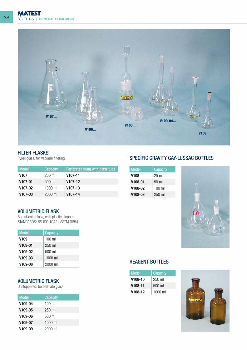
SECTION V | GENERAL EQUIPMENT
FILTER FLASKSPyrex glass, for Vacuum filtering.
Model Capacity Perforated bung with glass tube
V107 250 ml V107-11
V107-01 500 ml V107-12
V107-02 1000 ml V107-13
V107-03 2000 ml V107-14
SPECIFIC GRAVITY GAY-LUSSAC BOTTLES
Model Capacity
V108 25 ml
V108-01 50 ml
V108-02 100 ml
V108-03 250 ml
VOLUMETRIC FLASKBorosilicate glass, with plastic stopperSTANDARDS: BS-ISO 1042 | ASTM D854
Model Capacity
V109 100 ml
V109-01 250 ml
V109-02 500 ml
V109-03 1000 ml
V109-08 2000 ml
VOLUMETRIC FLASKUnstoppered, borosilicate glass.
Model Capacity
V109-04 100 ml
V109-05 250 ml
V109-06 500 ml
V109-07 1000 ml
V109-09 2000 ml
REAGENT BOTTLES
Model Capacity
V108-10 250 ml
V108-11 500 ml
V108-12 1000 ml
V107...
V106...V103...
V109-04...
V109
584
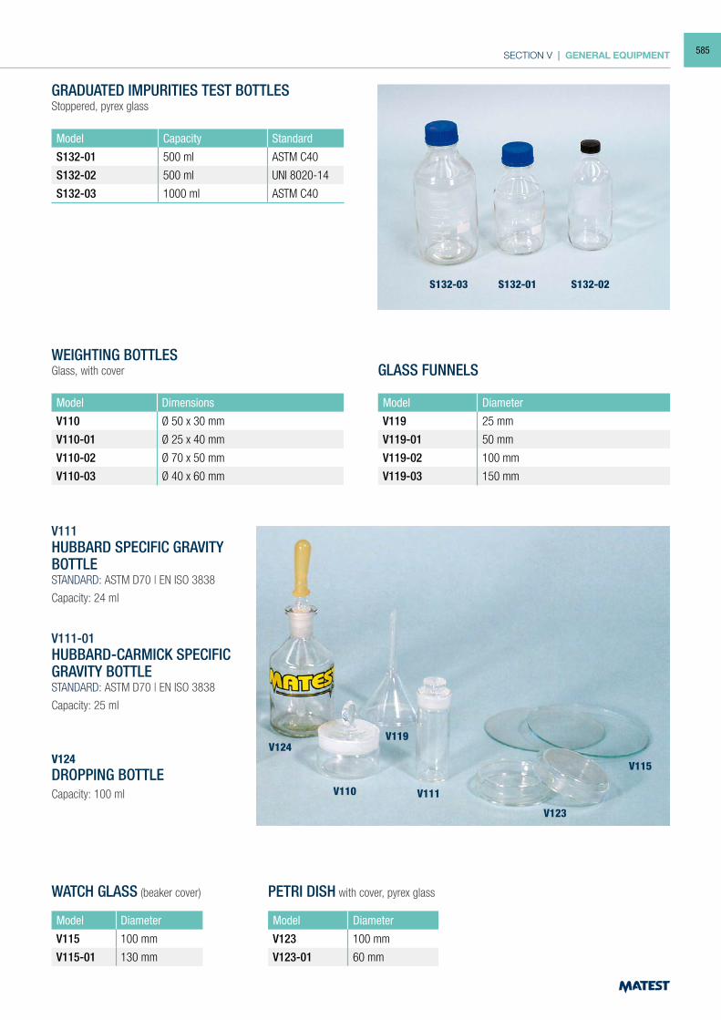
SECTION V | GENERAL EQUIPMENT
GRADUATED IMPURITIES TEST BOTTLESStoppered, pyrex glass
Model Capacity Standard
S132-01 500 ml ASTM C40
S132-02 500 ml UNI 8020-14
S132-03 1000 ml ASTM C40
WEIGHTING BOTTLESGlass, with cover
Model Dimensions
V110 Ø 50 x 30 mm
V110-01 Ø 25 x 40 mm
V110-02 Ø 70 x 50 mm
V110-03 Ø 40 x 60 mm
GLASS FUNNELS
Model Diameter
V119 25 mm
V119-01 50 mm
V119-02 100 mm
V119-03 150 mm
V111HUBBARD SPECIFIC GRAVITY BOTTLESTANDARD: ASTM D70 | EN ISO 3838
Capacity: 24 ml
V111-01HUBBARD-CARMICK SPECIFIC GRAVITY BOTTLESTANDARD: ASTM D70 | EN ISO 3838
Capacity: 25 ml
WATCH GLASS (beaker cover) PETRI DISH with cover, pyrex glass
Model Diameter
V115 100 mm
V115-01 130 mm
Model Diameter
V123 100 mm
V123-01 60 mm
V124DROPPING BOTTLECapacity: 100 ml
S132-03
V124
V110 V111
V115
V123
V119
S132-01 S132-02
585
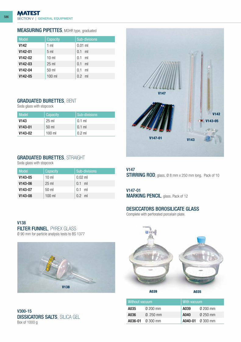
SECTION V | GENERAL EQUIPMENT
MEASURING PIPETTES, MOHR type, graduated
Model Capacity Sub-divisions
V142 1 ml 0.01 ml
V142-01 5 ml 0.1 ml
V142-02 10 ml 0.1 ml
V142-03 25 ml 0.1 ml
V142-04 50 ml 0.1 ml
V142-05 100 ml 0.2 ml
GRADUATED BURETTES, BENTSoda glass with stopcock
Model Capacity Sub-divisions
V143 25 ml 0.1 ml
V143-01 50 ml 0.1 ml
V143-02 100 ml 0.2 ml
GRADUATED BURETTES, STRAIGHTSoda glass with stopcock
Model Capacity Sub-divisions
V143-05 10 ml 0.02 ml
V143-06 25 ml 0.1 ml
V143-07 50 ml 0.1 ml
V143-08 100 ml 0.2 ml
V147STIRRING ROD, glass, Ø 8 mm x 250 mm long. Pack of 10
V147-01MARKING PENCIL, glass. Pack of 12
DESICCATORS BOROSILICATE GLASSComplete with perforated porcelain plate.
Without vacuum With vacuum
A035 Ø 200 mm A039 Ø 200 mm
A036 Ø. 250 mm A040 Ø 250 mm
A036-01 Ø 300 mm A040-01 Ø 300 mm
V300-15DISSICATORS SALTS, SILICA GELBox of 1000 g
V138FILTER FUNNEL, PYREX GLASSØ 90 mm for particle analysis tests to BS 1377
V147-01
A039V138
A035
V147
V143
V142
V143-05
586
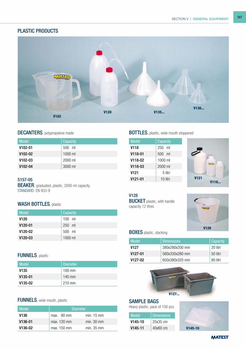
SECTION V | GENERAL EQUIPMENT
V102V120 V135...
V136...
DECANTERS, polypropylene made
Model Capacity
V102-01 500 ml
V102-02 1000 ml
V102-03 2000 ml
V102-04 3000 ml
S157-05BEAKER, graduated, plastic, 2000 ml capacity.STANDARD: EN 933-9
WASH BOTTLES, plastic
Model Capacity
V120 100 ml
V120-01 250 ml
V120-02 500 ml
V120-03 1000 ml
FUNNELS, plastic
Model Diameter
V135 100 mm
V135-01 140 mm
V135-02 210 mm
FUNNELS, wide mouth, plastic
Model Diameter
V136 max. 80 mm min. 15 mm
V136-01 max. 120 mm min. 30 mm
V136-02 max. 150 mm min. 35 mm
PLASTIC PRODUCTS
BOTTLES, plastic, wide mouth stoppered
Model Capacity
V118 250 ml
V118-01 500 ml
V118-02 1000 ml
V118-03 2000 ml
V121 5 litri
V121-01 10 litri
V128BUCKET plastic, with handlecapacity 12 litres
BOXES plastic, stacking
Model Dimensions Capacity
V127 380x280x200 mm 20 litri
V127-01 560x330x280 mm 50 litri
V127-02 650x380x320 mm 80 litri
SAMPLE BAGSHeavy plastic, pack of 100 pcs
Model Dimensions
V145-10 25x35 cm
V145-11 40x60 cm
V121
V128
V127...
V145-10
V118...
587
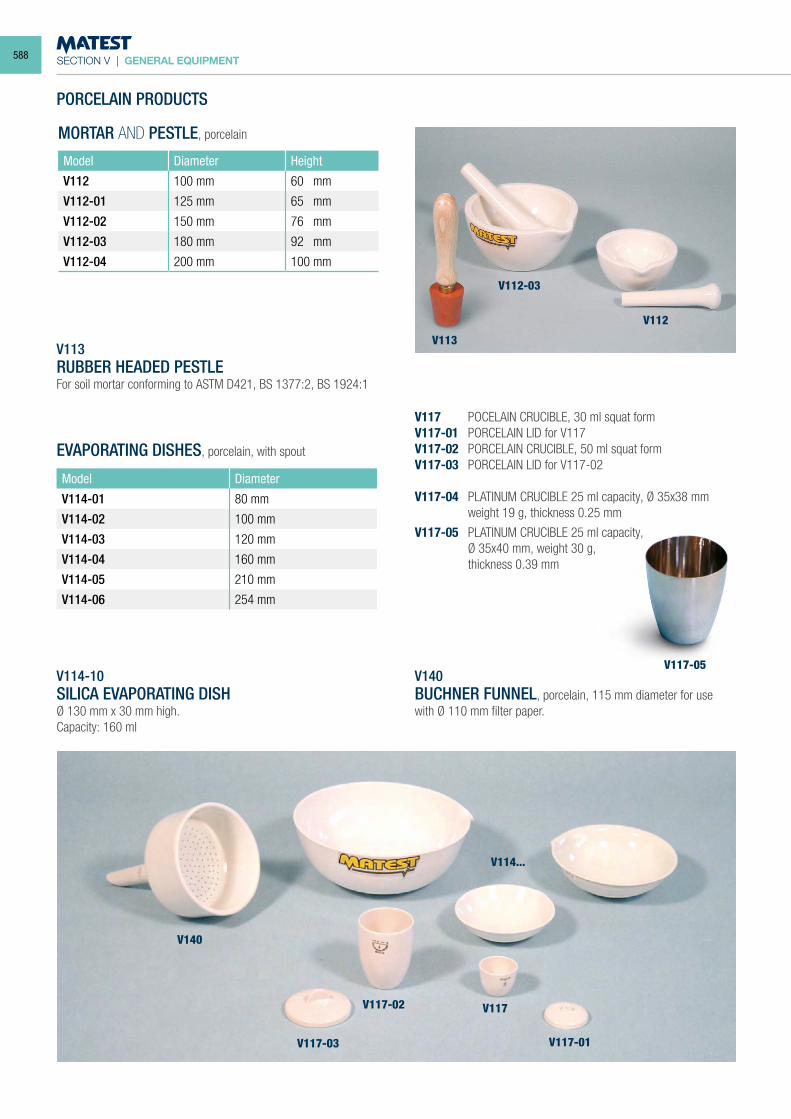
SECTION V | GENERAL EQUIPMENT
PORCELAIN PRODUCTS
MORTAR AND PESTLE, porcelain
Model Diameter Height
V112 100 mm 60 mm
V112-01 125 mm 65 mm
V112-02 150 mm 76 mm
V112-03 180 mm 92 mm
V112-04 200 mm 100 mm
V113RUBBER HEADED PESTLEFor soil mortar conforming to ASTM D421, BS 1377:2, BS 1924:1
EVAPORATING DISHES, porcelain, with spout
Model Diameter
V114-01 80 mm
V114-02 100 mm
V114-03 120 mm
V114-04 160 mm
V114-05 210 mm
V114-06 254 mm
V114-10SILICA EVAPORATING DISHØ 130 mm x 30 mm high.Capacity: 160 ml
V117 POCELAIN CRUCIBLE, 30 ml squat formV117-01 PORCELAIN LID for V117V117-02 PORCELAIN CRUCIBLE, 50 ml squat formV117-03 PORCELAIN LID for V117-02
V117-04 PLATINUM CRUCIBLE 25 ml capacity, Ø 35x38 mm weight 19 g, thickness 0.25 mm
V117-05 PLATINUM CRUCIBLE 25 ml capacity, Ø 35x40 mm, weight 30 g, thickness 0.39 mm
V140BUCHNER FUNNEL, porcelain, 115 mm diameter for use with Ø 110 mm filter paper.
V113
V112-03
V112
V117-05
V140
V117-03
V117-02
V117-01
V117
V114...
588
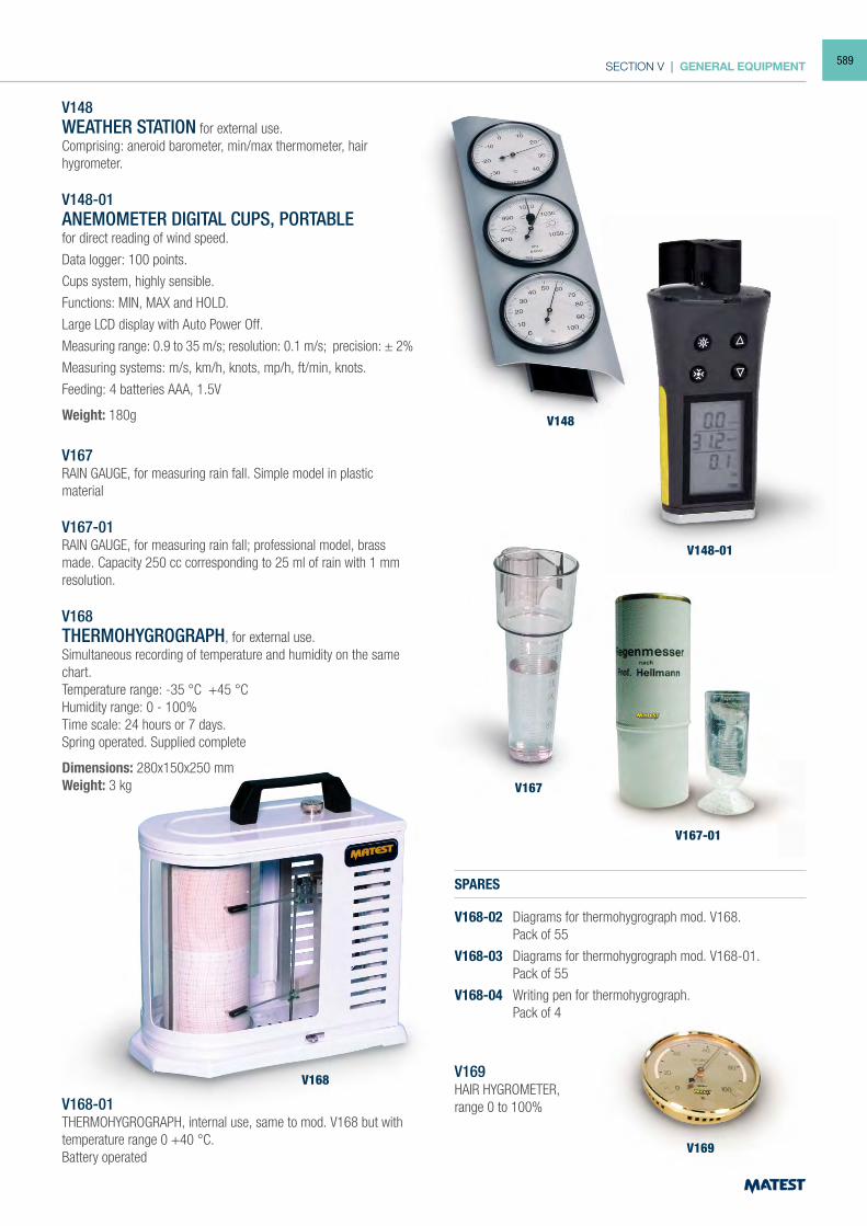
SECTION V | GENERAL EQUIPMENT
V148
V148-01
V148WEATHER STATION for external use.Comprising: aneroid barometer, min/max thermometer, hairhygrometer.
V148-01ANEMOMETER DIGITAL CUPS, PORTABLEfor direct reading of wind speed.
Data logger: 100 points.
Cups system, highly sensible.
Functions: MIN, MAX and HOLD.
Large LCD display with Auto Power Off.
Measuring range: 0.9 to 35 m/s; resolution: 0.1 m/s; precision: ± 2%
Measuring systems: m/s, km/h, knots, mp/h, ft/min, knots.
Feeding: 4 batteries AAA, 1.5V
Weight: 180g
V167RAIN GAUGE, for measuring rain fall. Simple model in plastic material
V167-01RAIN GAUGE, for measuring rain fall; professional model, brass made. Capacity 250 cc corresponding to 25 ml of rain with 1 mm resolution.
V168THERMOHYGROGRAPH, for external use.Simultaneous recording of temperature and humidity on the same chart.Temperature range: -35 °C +45 °CHumidity range: 0 - 100%Time scale: 24 hours or 7 days.Spring operated. Supplied complete
Dimensions: 280x150x250 mmWeight: 3 kg
V168-01THERMOHYGROGRAPH, internal use, same to mod. V168 but with temperature range 0 +40 °C.Battery operated
SPARES
V168-02 Diagrams for thermohygrograph mod. V168. Pack of 55
V168-03 Diagrams for thermohygrograph mod. V168-01. Pack of 55
V168-04 Writing pen for thermohygrograph. Pack of 4
V169HAIR HYGROMETER,range 0 to 100%
V167
V168
V169
V167-01
589
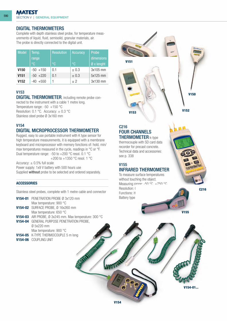
SECTION V | GENERAL EQUIPMENT
DIGITAL THERMOMETERSComplete with depth stainless steel probe, for temperature meas-urements of liquid, fluid, semisolid, granular materials, air.The probe is directly connected to the digital unit.
Model Temp. Resolution Accuracy Probe
range dimensions
°C °C °C Ø x lenght
V150 -50 +150 0.1 ± 0.3 3x105 mm
V151 -50 +220 0.1 ± 0.3 5x125 mm
V152 -40 +550 1 ± 2 3x130 mm
V153DIGITAL THERMOMETER, including remote probe con-nected to the instrument with a cable 1 metre long.Temperature range: -50 +150 °CResolution: 0.1 °C. Accuracy: ± 0.3 °CStainless steel probe Ø 3x160 mm
V154DIGITAL MICROPROCESSOR THERMOMETERRugged, easy to use portable instrument with K type sensor for high temperature measurements, it is equipped with a membrane keyboard and microprocessor with memory fonctions of: hold, min/max temperatures measured in the cycle, readings in °C or °F.Dual temperature range: -50 to +200 °C resol. 0.1 °C +200 to +1350 °C resol. 1 °CAccuracy: ± 0.5% full scalePower supply: 1x9 V battery with 500 hours useSupplied without probe to be selected and ordered separately.
ACCESSORIES
Stainless steel probes, complete with 1 metre cable and connector
V154-01 PENETRATION PROBE Ø 3x120 mm Max temperature: 900 °CV154-02 SURFACE PROBE, Ø 16x260 mm Max temperature: 650 °CV154-03 AIR PROBE, Ø 3x245 mm. Max temperature: 300 °CV154-04 GENERAL PURPOSE PENETRATION PROBE, Ø 5x220 mm Max temperature: 900 °CV154-05 K-TYPE THERMOCOUPLE 5 m longV154-06 COUPLING UNIT
C216FOUR CHANNELSTHERMOMETER k-type thermocouple with SD card data recorder for precast concrete.Technical data and accessories:see p. 338
V155 INFRARED THERMOMETER To measure surface temperatureswithout touching the object. Measuring range: -50 °C +750 °C Resolution: 0.1 °C up to 200 °C Functions: Hold and autoswitch-off. Battery type: 9V
V151
V153
V155
V154
V154-01...
V152
C216
V150
590
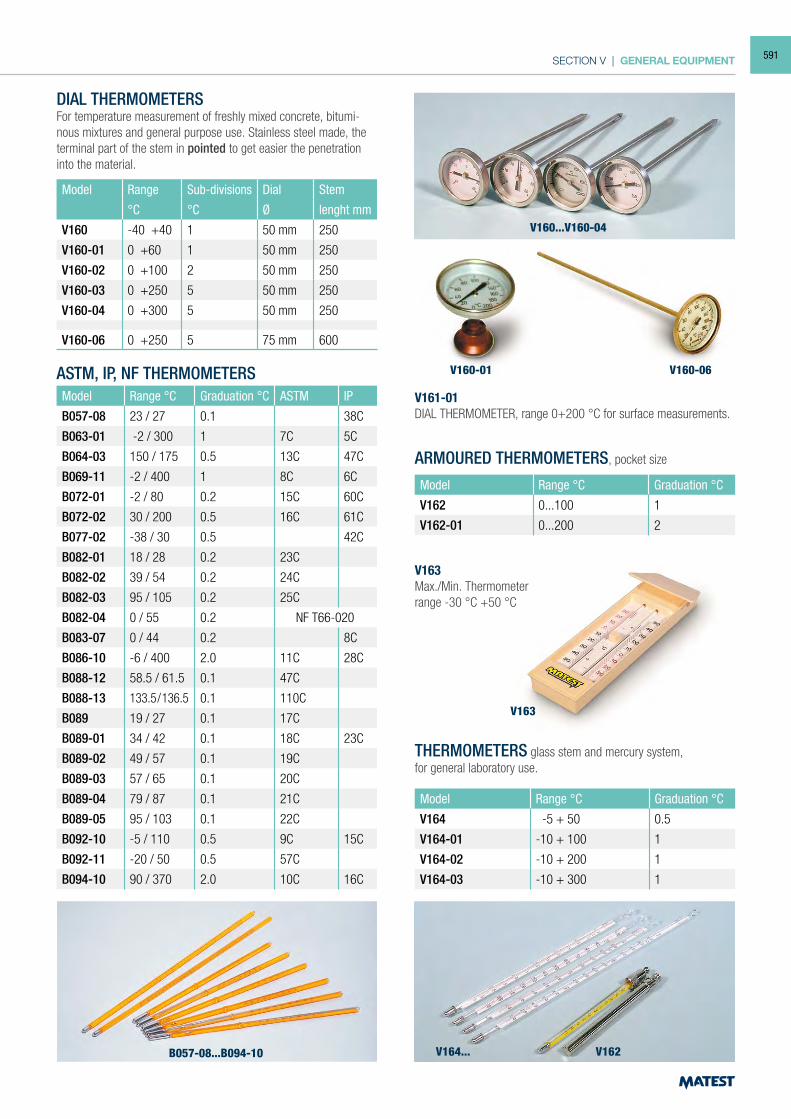
SECTION V | GENERAL EQUIPMENT
DIAL THERMOMETERSFor temperature measurement of freshly mixed concrete, bitumi-nous mixtures and general purpose use. Stainless steel made, the terminal part of the stem in pointed to get easier the penetration into the material.
Model Range Sub-divisions Dial Stem
°C °C Ø lenght mm
V160 -40 +40 1 50 mm 250
V160-01 0 +60 1 50 mm 250
V160-02 0 +100 2 50 mm 250
V160-03 0 +250 5 50 mm 250
V160-04 0 +300 5 50 mm 250
V160-06 0 +250 5 75 mm 600
ASTM, IP, NF THERMOMETERSModel Range °C Graduation °C ASTM IP
B057-08 23 / 27 0.1 38C
B063-01 -2 / 300 1 7C 5C
B064-03 150 / 175 0.5 13C 47C
B069-11 -2 / 400 1 8C 6C
B072-01 -2 / 80 0.2 15C 60C
B072-02 30 / 200 0.5 16C 61C
B077-02 -38 / 30 0.5 42C
B082-01 18 / 28 0.2 23C
B082-02 39 / 54 0.2 24C
B082-03 95 / 105 0.2 25C
B082-04 0 / 55 0.2 NF T66-020
B083-07 0 / 44 0.2 8C
B086-10 -6 / 400 2.0 11C 28C
B088-12 58.5 / 61.5 0.1 47C
B088-13 133.5/136.5 0.1 110C
B089 19 / 27 0.1 17C
B089-01 34 / 42 0.1 18C 23C
B089-02 49 / 57 0.1 19C
B089-03 57 / 65 0.1 20C
B089-04 79 / 87 0.1 21C
B089-05 95 / 103 0.1 22C
B092-10 -5 / 110 0.5 9C 15C
B092-11 -20 / 50 0.5 57C
B094-10 90 / 370 2.0 10C 16C
ARMOURED THERMOMETERS, pocket size
Model Range °C Graduation °C
V162 0...100 1
V162-01 0...200 2
V163Max./Min. Thermometerrange -30 °C +50 °C
THERMOMETERS glass stem and mercury system,for general laboratory use.
Model Range °C Graduation °C
V164 -5 + 50 0.5
V164-01 -10 + 100 1
V164-02 -10 + 200 1
V164-03 -10 + 300 1
V161-01DIAL THERMOMETER, range 0+200 °C for surface measurements.
V160...V160-04
V160-06V160-01
V163
B057-08...B094-10 V164... V162
591
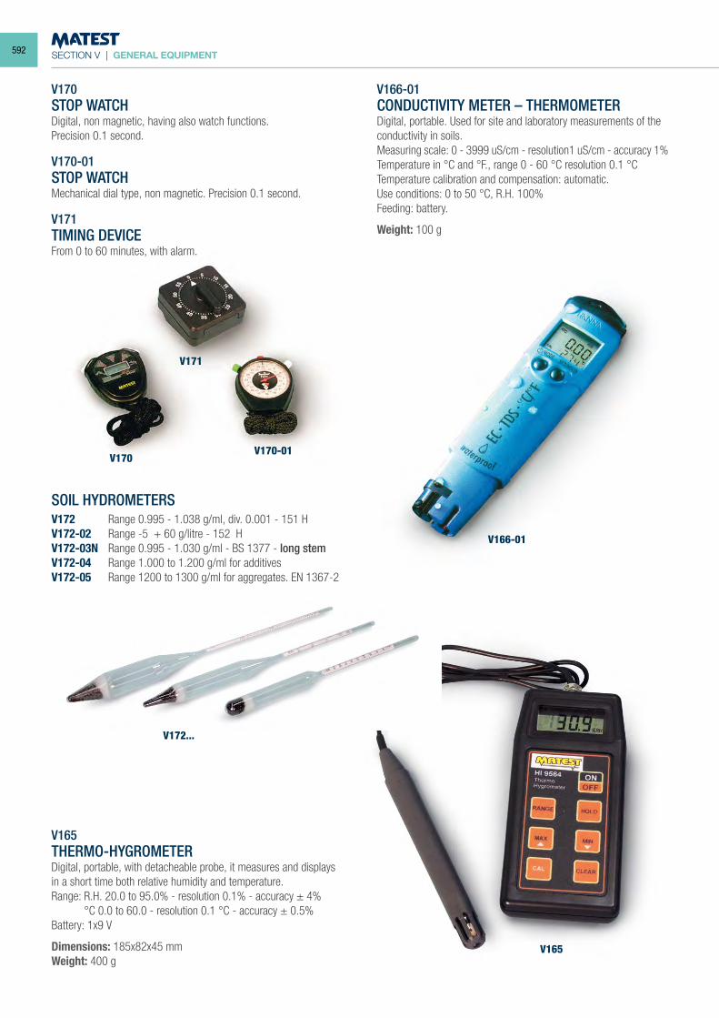
SECTION V | GENERAL EQUIPMENT
V170STOP WATCHDigital, non magnetic, having also watch functions.Precision 0.1 second.
V170-01STOP WATCHMechanical dial type, non magnetic. Precision 0.1 second.
V171TIMING DEVICEFrom 0 to 60 minutes, with alarm.
SOIL HYDROMETERSV172 Range 0.995 - 1.038 g/ml, div. 0.001 - 151 HV172-02 Range -5 + 60 g/litre - 152 HV172-03N Range 0.995 - 1.030 g/ml - BS 1377 - long stemV172-04 Range 1.000 to 1.200 g/ml for additivesV172-05 Range 1200 to 1300 g/ml for aggregates. EN 1367-2
V165THERMO-HYGROMETERDigital, portable, with detacheable probe, it measures and displays in a short time both relative humidity and temperature.Range: R.H. 20.0 to 95.0% - resolution 0.1% - accuracy ± 4% °C 0.0 to 60.0 - resolution 0.1 °C - accuracy ± 0.5%Battery: 1x9 V
Dimensions: 185x82x45 mmWeight: 400 g
V166-01CONDUCTIVITY METER – THERMOMETERDigital, portable. Used for site and laboratory measurements of the conductivity in soils.Measuring scale: 0 - 3999 uS/cm - resolution1 uS/cm - accuracy 1% Temperature in °C and °F., range 0 - 60 °C resolution 0.1 °CTemperature calibration and compensation: automatic.Use conditions: 0 to 50 °C, R.H. 100%Feeding: battery.
Weight: 100 g
V171
V170V170-01
V172...
V166-01
V165
592
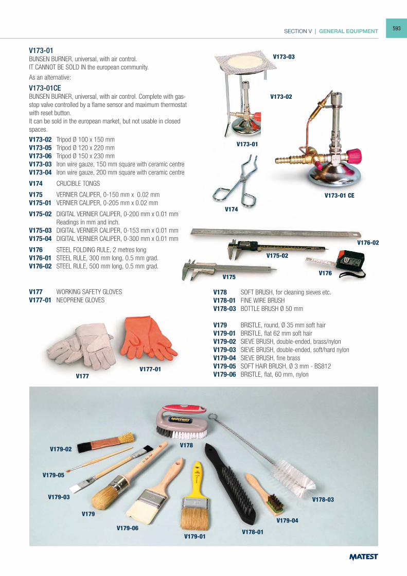
SECTION V | GENERAL EQUIPMENT
V173-01BUNSEN BURNER, universal, with air control.IT CANNOT BE SOLD IN the european community.
As an alternative:
V173-01CEBUNSEN BURNER, universal, with air control. Complete with gas-stop valve controlled by a flame sensor and maximum thermostat with reset button.It can be sold in the european market, but not usable in closed spaces.
V173-02 Tripod Ø 100 x 150 mmV173-05 Tripod Ø 120 x 220 mmV173-06 Tripod Ø 150 x 230 mmV173-03 Iron wire gauze, 150 mm square with ceramic centreV173-04 Iron wire gauze, 200 mm square with ceramic centre
V174 CRUCIBLE TONGS
V175 VERNIER CALIPER, 0-150 mm x 0.02 mmV175-01 VERNIER CALIPER, 0-205 mm x 0.02 mm
V175-02 DIGITAL VERNIER CALIPER, 0-200 mm x 0.01 mm Readings in mm and inch.
V175-03 DIGITAL VERNIER CALIPER, 0-153 mm x 0.01 mmV175-04 DIGITAL VERNIER CALIPER, 0-300 mm x 0.01 mm
V176 STEEL FOLDING RULE, 2 metres longV176-01 STEEL RULE, 300 mm long, 0.5 mm grad.V176-02 STEEL RULE, 500 mm long, 0.5 mm grad.
V177 WORKING SAFETY GLOVESV177-01 NEOPRENE GLOVES
V178 SOFT BRUSH, for cleaning sieves etc.V178-01 FINE WIRE BRUSHV178-03 BOTTLE BRUSH Ø 50 mm
V179 BRISTLE, round, Ø 35 mm soft hairV179-01 BRISTLE, flat 62 mm soft hairV179-02 SIEVE BRUSH, double-ended, brass/nylon V179-03 SIEVE BRUSH, double-ended, soft/hard nylonV179-04 SIEVE BRUSH, fine brassV179-05 SOFT HAIR BRUSH, Ø 3 mm - BS812V179-06 BRISTLE, flat, 60 mm, nylon
V173-01
V174
V175V176
V177
V178V179-02
V179-05
V179-03
V179
V179-06V179-01
V179-04
V178-01
V178-03
V177-01
V176-02
V175-02
V173-01 CE
V173-02
V173-03
593
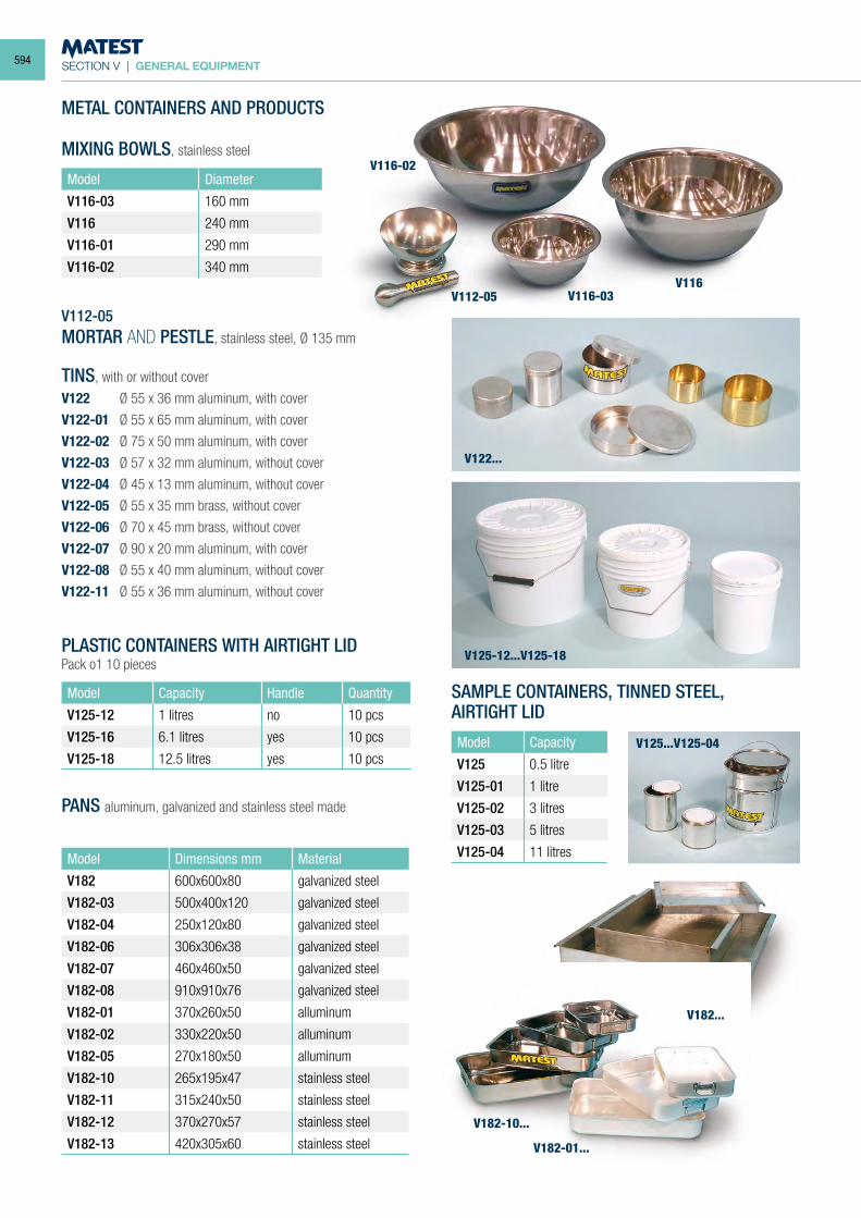
SECTION V | GENERAL EQUIPMENT
METAL CONTAINERS AND PRODUCTS
MIXING BOWLS, stainless steel
Model Diameter
V116-03 160 mm
V116 240 mm
V116-01 290 mm
V116-02 340 mm
V112-05MORTAR AND PESTLE, stainless steel, Ø 135 mm
TINS, with or without cover
V122 Ø 55 x 36 mm aluminum, with cover
V122-01 Ø 55 x 65 mm aluminum, with cover
V122-02 Ø 75 x 50 mm aluminum, with cover
V122-03 Ø 57 x 32 mm aluminum, without cover
V122-04 Ø 45 x 13 mm aluminum, without cover
V122-05 Ø 55 x 35 mm brass, without cover
V122-06 Ø 70 x 45 mm brass, without cover
V122-07 Ø 90 x 20 mm aluminum, with cover
V122-08 Ø 55 x 40 mm aluminum, without cover
V122-11 Ø 55 x 36 mm aluminum, without cover
PLASTIC CONTAINERS WITH AIRTIGHT LID Pack o1 10 pieces
Model Capacity Handle Quantity
V125-12 1 litres no 10 pcs
V125-16 6.1 litres yes 10 pcs
V125-18 12.5 litres yes 10 pcs
PANS aluminum, galvanized and stainless steel made
Model Dimensions mm Material
V182 600x600x80 galvanized steel
V182-03 500x400x120 galvanized steel
V182-04 250x120x80 galvanized steel
V182-06 306x306x38 galvanized steel
V182-07 460x460x50 galvanized steel
V182-08 910x910x76 galvanized steel
V182-01 370x260x50 alluminum
V182-02 330x220x50 alluminum
V182-05 270x180x50 alluminum
V182-10 265x195x47 stainless steel
V182-11 315x240x50 stainless steel
V182-12 370x270x57 stainless steel
V182-13 420x305x60 stainless steel
SAMPLE CONTAINERS, TINNED STEEL,AIRTIGHT LID
Model Capacity
V125 0.5 litre
V125-01 1 litre
V125-02 3 litres
V125-03 5 litres
V125-04 11 litres
V116
V122...
V182...
V182-10...
V182-01...
V125-12...V125-18
V125...V125-04
V116-03
V116-02
V112-05
594
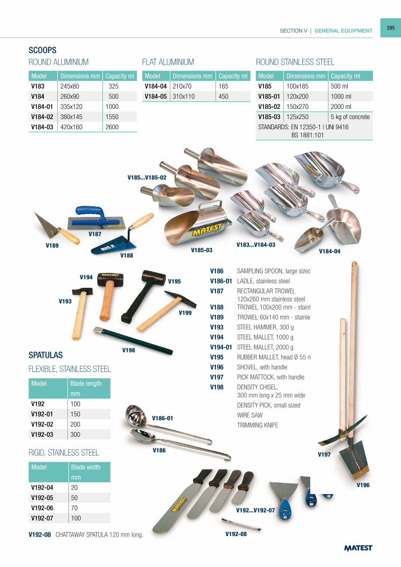
SECTION V | GENERAL EQUIPMENT
SCOOPS
Model Dimensions mm Capacity ml
V183 245x80 325
V184 260x90 500
V184-01 335x120 1000
V184-02 380x145 1550
V184-03 420x160 2600
Model Dimensions mm Capacity ml
V184-04 210x70 165
V184-05 310x110 450
Model Dimensions mm Capacity ml
V185 100x185 500 ml
V185-01 120x200 1000 ml
V185-02 150x270 2000 ml
V185-03 125x250 5 kg of concrete
STANDARDS: EN 12350-1 | UNI 9416 BS 1881:101
ROUND ALUMINIUM FLAT ALUMINIUM ROUND STAINLESS STEEL
SPATULAS
FLEXIBLE, STAINLESS STEEL
Model Blade length
mm
V192 100
V192-01 150
V192-02 200
V192-03 300
RIGID, STAINLESS STEEL
Model Blade width
mm
V192-04 20
V192-05 50
V192-06 70
V192-07 100
V192-08 CHATTAWAY SPATULA 120 mm long.
V186 SAMPLING SPOON, large sized
V186-01 LADLE, stainless steel
V187 RECTANGULAR TROWEL 120x260 mm stainless steelV188 TROWEL 100x200 mm - stainless steel
V189 TROWEL 60x140 mm - stainless steel
V193 STEEL HAMMER, 300 g
V194 STEEL MALLET, 1000 g
V194-01 STEEL MALLET, 2000 g
V195 RUBBER MALLET, head Ø 55 mm
V196 SHOVEL, with handle
V197 PICK MATTOCK, with handle
V198 DENSITY CHISEL, 300 mm long x 25 mm wide
V199 DENSITY PICK, small sized
S124 WIRE SAW
S125 TRIMMING KNIFE
V183...V184-03V185-03
V187
V189
V188
V199
V198
V186-01
V192-08
V192...V192-07
V186
V196
V197
V193
V194V195
V185...V185-02
V184-04
595
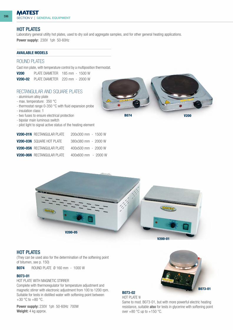
SECTION V | GENERAL EQUIPMENT
HOT PLATESLaboratory general utility hot plates, used to dry soil and aggregate samples, and for other general heating applications.
Power supply: 230V 1ph 50-60Hz
HOT PLATES(They can be used also for the determination of the softening point of bitumen, see p. 150)
B074 ROUND PLATE Ø 160 mm - 1000 W
B073-01HOT PLATE WITH MAGNETIC STIRRERComplete with thermoregulator for temperature adjustment and magnetic stirrer with electronic adjustment from 100 to 1200 rpm.Suitable for tests in distilled water with softening point between +30 °C to +80 °C.
Power supply: 230V 1ph 50-60Hz 700WWeight: 4 kg approx.
B073-02HOT PLATE WITH MAGNETIC STIRRERSame to mod. B073-01, but with more powerful electric heating resistance, suitable also for tests in glycerine with softening point over +80 °C up to +150 °C.
AVAILABLE MODELS
ROUND PLATESCast iron plate, with temperature control by a multiposition thermostat.
V200 PLATE DIAMETER 185 mm - 1500 W
V200-02 PLATE DIAMETER 220 mm - 2000 W
RECTANGULAR AND SQUARE PLATES- aluminium alloy plate- max. temperature: 350 °C- thermostat range 0-350 °C with fluid expansion probe- insulation class: 1- two fuses to ensure electrical protection- bipolar main luminous switch- pilot light to signal active status of the heating element
V200-01N RECTANGULAR PLATE 200x300 mm - 1500 W
V200-03N SQUARE HOT PLATE 380x380 mm - 2000 W
V200-05N RECTANGULAR PLATE 400x500 mm - 2000 W
V200-06N RECTANGULAR PLATE 400x600 mm - 2000 W
B074
V200-05
V200-01
B073-01
V200
596
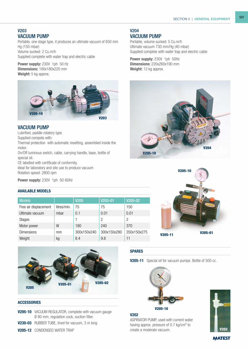
SECTION V | GENERAL EQUIPMENT
V203VACUUM PUMPPortable, one stage type, it produces an ultimate vacuum of 650 mm Hg (150 mbar)Volume sucked: 2 Cu.m/hSupplied complete with water trap and electric cable
Power supply: 230V 1ph 50 HzDimensions: 180x180x220 mmWeight: 5 kg approx.
VACUUM PUMPLubrified, paddle rotatory type.Supplied compete with:Thermal protection with automatic resetting, assembled inside the motor.On/Off luminous switch, cable, carrying handle, base, bottle of special oil.CE labelled with certificate of conformity.Ideal for laboratory and site use to produce vacuumRotation speed: 2800 rpm
Power supply: 230V 1ph 50-60Hz
AVAILABLE MODELS
Models V205 V205-01 V205-02
Free air displacement litres/min. 75 75 150
Ultimate vacuum mbar 0.1 0.01 0.01
Stages 1 2 2
Motor power W 180 240 370
Dimensions mm 300x150x240 300x150x280 350x150x275
Weight kg 8.4 9.8 11
ACCESSORIES
V205-10 VACUUM REGULATOR, complete with vacuum gauge Ø 80 mm, regulation cock, suction filter.
V230-03 RUBBER TUBE, lined for vacuum, 3 m long
V205-12 CONDENSED WATER TRAP
SPARES
V205-11 Special oil for vacuum pumps. Bottle of 500 cc.
V202ASPIRATOR PUMP, used with current water having approx. pressure of 0.7 kg/cm² to create a moderate vacuum.
V204VACUUM PUMPPortable, volume sucked: 5 Cu.m/hUltimate vacuum 730 mm/Hg (40 mbar)Supplied complete with water trap and electric cable
Power supply: 230V 1ph 50HzDimensions: 220x260x190 mmWeight: 12 kg approx.
V203
V204
V205-10
V205-10
V205-11
V205V205-01
V205-10
V202
V205-02
V205-01
V205-10
597
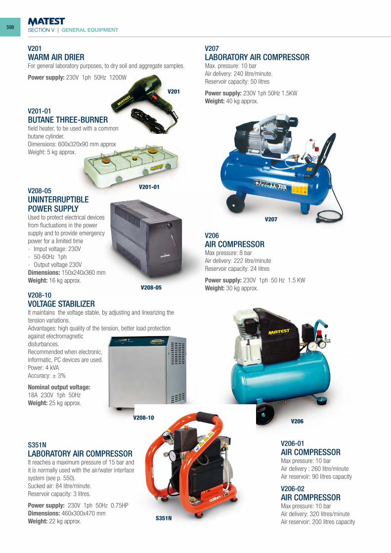
SECTION V | GENERAL EQUIPMENT
V201WARM AIR DRIERFor general laboratory purposes, to dry soil and aggregate samples.
Power supply: 230V 1ph 50Hz 1200W
V201-01BUTANE THREE-BURNERfield heater, to be used with a commonbutane cylinder.Dimensions: 600x320x90 mm approxWeight: 5 kg approx.
V208-10 VOLTAGE STABILIZER It maintains the voltage stable, by adjusting and linearizing the tension variations. Advantages: high quality of the tension, better load protection against electromagneticdisturbances. Recommended when electronic,informatic, PC devices are used. Power: 4 kVA Accuracy: ± 3%
Nominal output voltage:18A 230V 1ph 50Hz Weight: 25 kg approx.
S351NLABORATORY AIR COMPRESSORIt reaches a maximum pressure of 15 bar andit is normally used with the air/water interfacesystem (see p. 550).Sucked air: 84 litre/minute.Reservoir capacity: 3 litres.
Power supply: 230V 1ph 50Hz 0.75HPDimensions: 460x300x470 mmWeight: 22 kg approx.
V207LABORATORY AIR COMPRESSORMax. pressure: 10 barAir delivery: 240 litre/minute.Reservoir capacity: 50 litres
Power supply: 230V 1ph 50Hz 1.5KWWeight: 40 kg approx.
V206AIR COMPRESSORMax pressure: 8 barAir delivery: 222 litre/minuteReservoir capacity: 24 litres
Power supply: 230V 1ph 50 Hz 1.5 KWWeight: 30 kg approx.
V206-01AIR COMPRESSORMax pressure: 10 barAir delivery : 260 litre/minuteAir reservoir: 90 litres capacity
V206-02AIR COMPRESSORMax pressure: 10 barAir delivery: 320 litres/minuteAir reservoir: 200 litres capacity
V201
V201-01
V207
V206V208-10
S351N
V208-05
V208-05UNINTERRUPTIBLEPOWER SUPPLYUsed to protect electrical devices from fluctuations in the power supply and to provide emergency power for a limited time- Imput voltage: 230V- 50-60Hz 1ph- Output voltage 230VDimensions: 150x240x360 mmWeight: 16 kg approx.
598
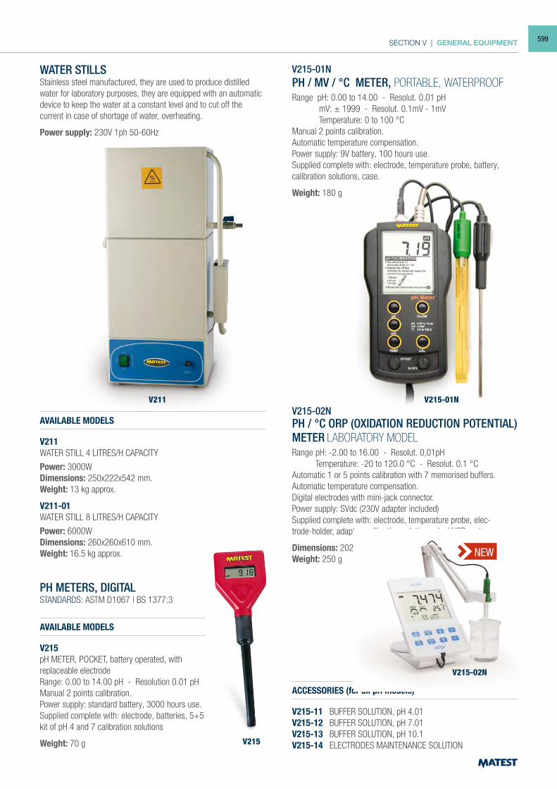
SECTION V | GENERAL EQUIPMENT
V211
V215
WATER STILLSStainless steel manufactured, they are used to produce distilled water for laboratory purposes, they are equipped with an automatic device to keep the water at a constant level and to cut off the current in case of shortage of water, overheating.
Power supply: 230V 1ph 50-60Hz
AVAILABLE MODELS
V211WATER STILL 4 LITRES/H CAPACITY
Power: 3000WDimensions: 250x222x542 mm.Weight: 13 kg approx.
V211-01WATER STILL 8 LITRES/H CAPACITY
Power: 6000WDimensions: 260x260x610 mm.Weight: 16.5 kg approx.
PH METERS, DIGITALSTANDARDS: ASTM D1067 | BS 1377:3
AVAILABLE MODELS
V215pH METER, POCKET, battery operated, with replaceable electrodeRange: 0.00 to 14.00 pH - Resolution 0.01 pHManual 2 points calibration.Power supply: standard battery, 3000 hours use. Supplied complete with: electrode, batteries, 5+5kit of pH 4 and 7 calibration solutions
Weight: 70 g
V215-01NPH / MV / °C METER, PORTABLE, WATERPROOF
Range pH: 0.00 to 14.00 - Resolut. 0.01 pH mV: ± 1999 - Resolut. 0.1mV - 1mV Temperature: 0 to 100 °C Manual 2 points calibration. Automatic temperature compensation.Power supply: 9V battery, 100 hours use.Supplied complete with: electrode, temperature probe, battery, calibration solutions, case.
Weight: 180 g
V215-02NPH / °C ORP (OXIDATION REDUCTION POTENTIAL) METER LABORATORY MODELRange pH: -2.00 to 16.00 - Resolut. 0,01pH Temperature: -20 to 120.0 °C - Resolut. 0.1 °CAutomatic 1 or 5 points calibration with 7 memorised buffers.Automatic temperature compensation.Digital electrodes with mini-jack connector.Power supply: SVdc (230V adapter included)Supplied complete with: electrode, temperature probe, elec-trode-holder, adaptor, calibration solutions, dual USB port
Dimensions: 202x140x13 mmWeight: 250 g
ACCESSORIES (for all pH models)
V215-11 BUFFER SOLUTION, pH 4.01V215-12 BUFFER SOLUTION, pH 7.01V215-13 BUFFER SOLUTION, pH 10.1V215-14 ELECTRODES MAINTENANCE SOLUTION
NEW
V215-02N
V215-01N
599
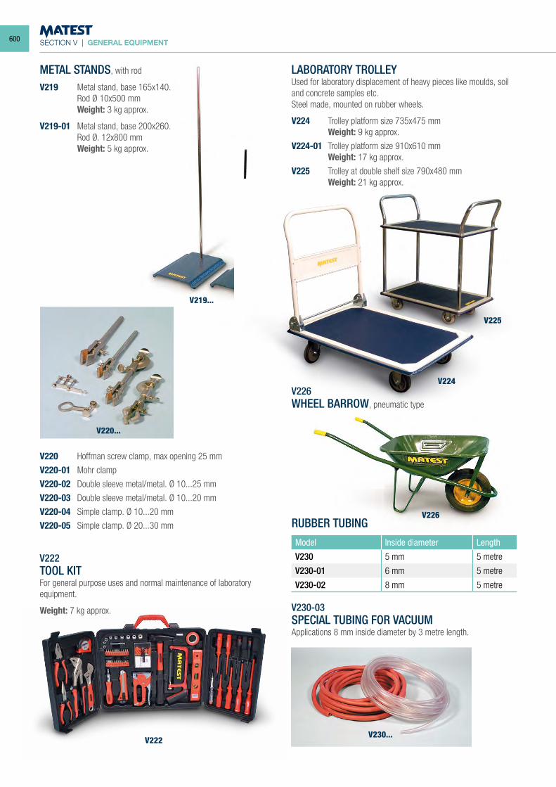
SECTION V | GENERAL EQUIPMENT
METAL STANDS, with rod
V219 Metal stand, base 165x140. Rod Ø 10x500 mm
Weight: 3 kg approx.
V219-01 Metal stand, base 200x260. Rod Ø. 12x800 mm
Weight: 5 kg approx.
V222TOOL KITFor general purpose uses and normal maintenance of laboratory equipment.
Weight: 7 kg approx.
LABORATORY TROLLEYUsed for laboratory displacement of heavy pieces like moulds, soil and concrete samples etc.Steel made, mounted on rubber wheels.
V224 Trolley platform size 735x475 mm Weight: 9 kg approx.
V224-01 Trolley platform size 910x610 mm Weight: 17 kg approx.
V225 Trolley at double shelf size 790x480 mm Weight: 21 kg approx.
V226WHEEL BARROW, pneumatic type
RUBBER TUBING
Model Inside diameter Length
V230 5 mm 5 metre
V230-01 6 mm 5 metre
V230-02 8 mm 5 metre
V230-03SPECIAL TUBING FOR VACUUMApplications 8 mm inside diameter by 3 metre length.
V220...
V225
V224
V226
V219...
V230...V222
V220 Hoffman screw clamp, max opening 25 mm
V220-01 Mohr clamp
V220-02 Double sleeve metal/metal. Ø 10...25 mm
V220-03 Double sleeve metal/metal. Ø 10...20 mm
V220-04 Simple clamp. Ø 10...20 mm
V220-05 Simple clamp. Ø 20...30 mm
600
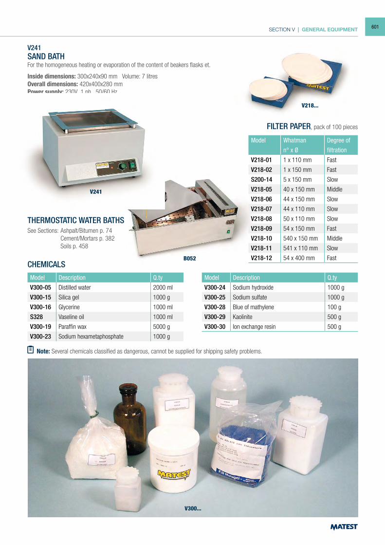
SECTION V | GENERAL EQUIPMENT
V241SAND BATHFor the homogeneous heating or evaporation of the content of beakers flasks et.
Inside dimensions: 300x240x90 mm Volume: 7 litresOverall dimensions: 420x400x280 mmPower supply: 230V 1 ph 50/60 HzWeight: 17 kg approx.
THERMOSTATIC WATER BATHSSee Sections: Ashpalt/Bitumen p. 74 Cement/Mortars p. 382 Soils p. 458
CHEMICALSModel Description Q.ty
V300-05 Distilled water 2000 ml
V300-15 Silica gel 1000 g
V300-16 Glycerine 1000 ml
S328 Vaseline oil 1000 ml
V300-19 Paraffin wax 5000 g
V300-23 Sodium hexametaphosphate 1000 g
Model Description Q.ty
V300-24 Sodium hydroxide 1000 g
V300-25 Sodium sulfate 1000 g
V300-28 Blue of mathylene 100 g
V300-29 Kaolinite 500 g
V300-30 Ion exchange resin 500 g
FILTER PAPER, pack of 100 pieces
Note: Several chemicals classified as dangerous, cannot be supplied for shipping safety problems.
V218...
B052
V300...
Model Whatman Degree of
n° x Ø filtration
V218-01 1 x 110 mm Fast
V218-02 1 x 150 mm Fast
S200-14 5 x 150 mm Slow
V218-05 40 x 150 mm Middle
V218-06 44 x 150 mm Slow
V218-07 44 x 110 mm Slow
V218-08 50 x 110 mm Slow
V218-09 54 x 150 mm Fast
V218-10 540 x 150 mm Middle
V218-11 541 x 110 mm Slow
V218-12 54 x 400 mm Fast
V241
601
INDEX | STANDARDS
INDEX
ANALYTICAL 603 - 614
STANDARDS 615 - 623
PRODUCT CODE 624 - 638
602
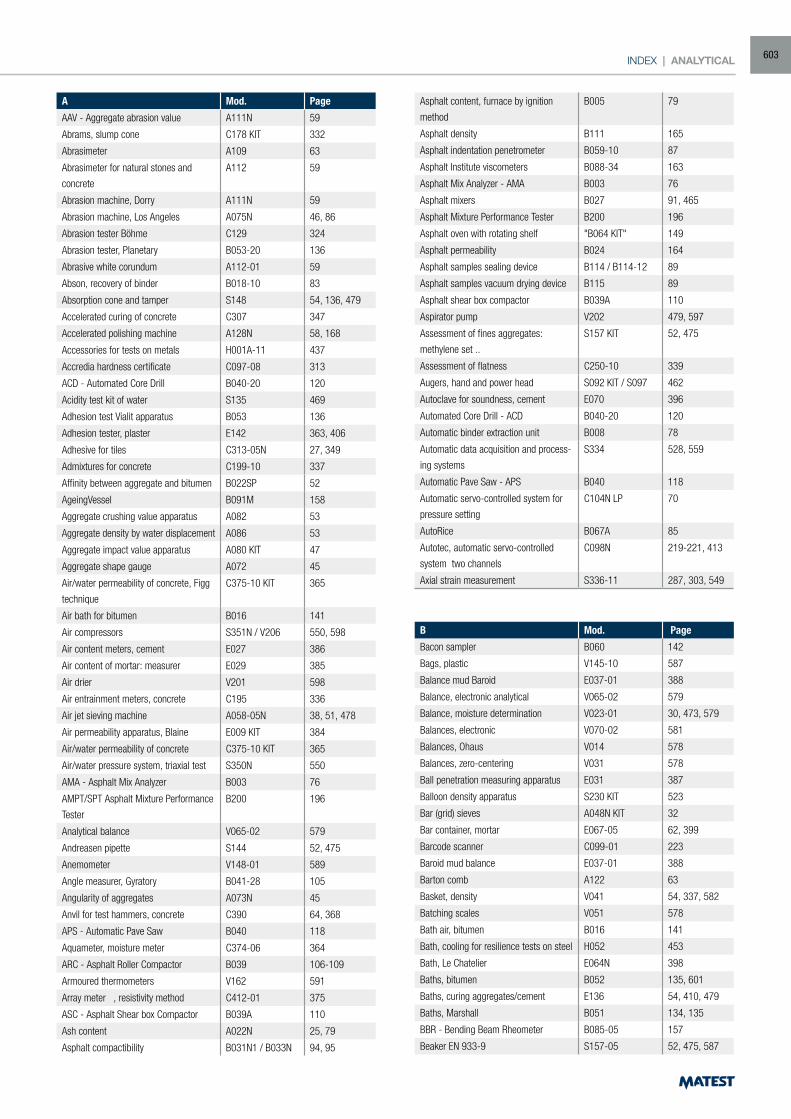
INDEX | ANALYTICAL
A Mod. Page
AAV - Aggregate abrasion value A111N 59
Abrams, slump cone C178 KIT 332
Abrasimeter A109 63
Abrasimeter for natural stones and
concrete
A112 59
Abrasion machine, Dorry A111N 59
Abrasion machine, Los Angeles A075N 46, 86
Abrasion tester Böhme C129 324
Abrasion tester, Planetary B053-20 136
Abrasive white corundum A112-01 59
Abson, recovery of binder B018-10 83
Absorption cone and tamper S148 54, 136, 479
Accelerated curing of concrete C307 347
Accelerated polishing machine A128N 58, 168
Accessories for tests on metals H001A-11 437
Accredia hardness certificate C097-08 313
ACD - Automated Core Drill B040-20 120
Acidity test kit of water S135 469
Adhesion test Vialit apparatus B053 136
Adhesion tester, plaster E142 363, 406
Adhesive for tiles C313-05N 27, 349
Admixtures for concrete C199-10 337
Affinity between aggregate and bitumen B022SP 52
AgeingVessel B091M 158
Aggregate crushing value apparatus A082 53
Aggregate density by water displacement A086 53
Aggregate impact value apparatus A080 KIT 47
Aggregate shape gauge A072 45
Air/water permeability of concrete, Figg
technique
C375-10 KIT 365
Air bath for bitumen B016 141
Air compressors S351N / V206 550, 598
Air content meters, cement E027 386
Air content of mortar: measurer E029 385
Air drier V201 598
Air entrainment meters, concrete C195 336
Air jet sieving machine A058-05N 38, 51, 478
Air permeability apparatus, Blaine E009 KIT 384
Air/water permeability of concrete C375-10 KIT 365
Air/water pressure system, triaxial test S350N 550
AMA - Asphalt Mix Analyzer B003 76
AMPT/SPT Asphalt Mixture Performance
Tester
B200 196
Analytical balance V065-02 579
Andreasen pipette S144 52, 475
Anemometer V148-01 589
Angle measurer, Gyratory B041-28 105
Angularity of aggregates A073N 45
Anvil for test hammers, concrete C390 64, 368
APS - Automatic Pave Saw B040 118
Aquameter, moisture meter C374-06 364
ARC - Asphalt Roller Compactor B039 106-109
Armoured thermometers V162 591
Array meter , resistivity method C412-01 375
ASC - Asphalt Shear box Compactor B039A 110
Ash content A022N 25, 79
Asphalt compactibility B031N1 / B033N 94, 95
Asphalt content, furnace by ignition
method
B005 79
Asphalt density B111 165
Asphalt indentation penetrometer B059-10 87
Asphalt Institute viscometers B088-34 163
Asphalt Mix Analyzer - AMA B003 76
Asphalt mixers B027 91, 465
Asphalt Mixture Performance Tester B200 196
Asphalt oven with rotating shelf "B064 KIT" 149
Asphalt permeability B024 164
Asphalt samples sealing device B114 / B114-12 89
Asphalt samples vacuum drying device B115 89
Asphalt shear box compactor B039A 110
Aspirator pump V202 479, 597
Assessment of fines aggregates:
methylene set ..
S157 KIT 52, 475
Assessment of flatness C250-10 339
Augers, hand and power head S092 KIT / S097 462
Autoclave for soundness, cement E070 396
Automated Core Drill - ACD B040-20 120
Automatic binder extraction unit B008 78
Automatic data acquisition and process-
ing systems
S334 528, 559
Automatic Pave Saw - APS B040 118
Automatic servo-controlled system for
pressure setting
C104N LP 70
AutoRice B067A 85
Autotec, automatic servo-controlled
system two channels
C098N 219-221, 413
Axial strain measurement S336-11 287, 303, 549
B Mod. Page
Bacon sampler B060 142
Bags, plastic V145-10 587
Balance mud Baroid E037-01 388
Balance, electronic analytical V065-02 579
Balance, moisture determination V023-01 30, 473, 579
Balances, electronic V070-02 581
Balances, Ohaus V014 578
Balances, zero-centering V031 578
Ball penetration measuring apparatus E031 387
Balloon density apparatus S230 KIT 523
Bar (grid) sieves A048N KIT 32
Bar container, mortar E067-05 62, 399
Barcode scanner C099-01 223
Baroid mud balance E037-01 388
Barton comb A122 63
Basket, density V041 54, 337, 582
Batching scales V051 578
Bath air, bitumen B016 141
Bath, cooling for resilience tests on steel H052 453
Bath, Le Chatelier E064N 398
Baths, bitumen B052 135, 601
Baths, curing aggregates/cement E136 54, 410, 479
Baths, Marshall B051 134, 135
BBR - Bending Beam Rheometer B085-05 157
Beaker EN 933-9 S157-05 52, 475, 587
603
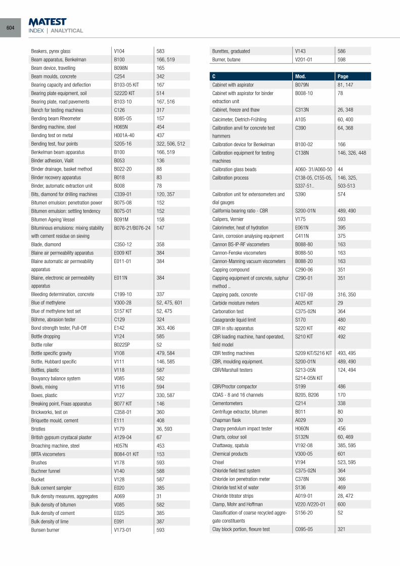
INDEX | ANALYTICAL
Beakers, pyrex glass V104 583
Beam apparatus, Benkelman B100 166, 519
Beam device, travelling B098N 165
Beam moulds, concrete C254 342
Bearing capacity and deflection B103-05 KIT 167
Bearing plate equipment, soil S222D KIT 514
Bearing plate, road pavements B103-10 167, 516
Bench for testing machines C126 317
Bending beam Rheometer B085-05 157
Bending machine, steel H065N 454
Bending test on metal H001A-40 437
Bending test, four points S205-16 322, 506, 512
Benkelman beam apparatus B100 166, 519
Binder adhesion, Vialit B053 136
Binder drainage, basket method B022-20 88
Binder recovery apparatus B018 83
Binder, automatic extraction unit B008 78
Bits, diamond for drilling machines C339-01 120, 357
Bitumen emulsion: penetration power B075-08 152
Bitumen emulsion: settling tendency B075-01 152
Bitumen Ageing Vessel B091M 158
Bituminous emulsions: mixing stability
with cement residue on sieving
B076-21/B076-24 147
Blade, diamond C350-12 358
Blaine air permeability apparatus E009 KIT 384
Blaine automatic air permeability
apparatus
E011-01 384
Blaine, electronic air permeability
apparatus
E011N 384
Bleeding determination, concrete C199-10 337
Blue of methylene V300-28 52, 475, 601
Blue of methylene test set S157 KIT 52, 475
Böhme, abrasion tester C129 324
Bond strength tester, Pull-Off E142 363, 406
Bottle dropping V124 585
Bottle roller B022SP 52
Bottle specific gravity V108 479, 584
Bottle, Hubbard specific V111 146, 585
Bottles, plastic V118 587
Bouyancy balance system V085 582
Bowls, mixing V116 594
Boxes, plastic V127 330, 587
Breaking point, Fraas apparatus B077 KIT 146
Brickworks, test on C358-01 360
Briquette mould, cement E111 408
Bristles V179 36, 593
British gypsum crystacal plaster A129-04 67
Broaching machine, steel H057N 453
BRTA viscometers B084-01 KIT 153
Brushes V178 593
Buchner funnel V140 588
Bucket V128 587
Bulk cement sampler E020 385
Bulk density measures, aggregates A069 31
Bulk density of bitumen V085 582
Bulk density of cement E025 385
Bulk density of lime E091 387
Bunsen burner V173-01 593
Burettes, graduated V143 586
Burner, butane V201-01 598
C Mod. Page
Cabinet with aspirator B079N 81, 147
Cabinet with aspirator for binder
extraction unit
B008-10 78
Cabinet, freeze and thaw C313N 26, 348
Calcimeter, Dietrich-Frühling A105 60, 400
Calibration anvil for concrete test
hammers
C390 64, 368
Calibration device for Benkelman B100-02 166
Calibration equipment for testing
machines
C138N 146, 326, 448
Calibration glass beads A060- 31/A060-50 44
Calibration process C138-05, C155-05,
S337-51..
146, 325,
503-513
Calibration unit for extensometers and
dial gauges
S390 574
California bearing ratio - CBR S200-01N 489, 490
Calipers, Vernier V175 593
Calorimeter, heat of hydration E061N 395
Canin, corrosion analysing equipment C411N 375
Cannon BS-IP-RF viscometers B088-80 163
Cannon-Fenske viscometers B088-50 163
Cannon-Manning vacuum viscometers B088-20 163
Capping compound C290-06 351
Capping equipment of concrete, sulphur
method ..
C290-01 351
Capping pads, concrete C107-09 316, 350
Carbide moisture meters A025 KIT 29
Carbonation test C375-02N 364
Casagrande liquid limit S170 480
CBR in situ apparatus S220 KIT 492
CBR loading machine, hand operated,
field model
S210 KIT 492
CBR testing machines S209 KIT/S216 KIT 493, 495
CBR, moulding equipment. S200-01N 489, 490
CBR/Marshall testers S213-05N
S214-05N KIT
124, 494
CBR/Proctor compactor S199 486
CDAS - 8 and 16 channels B205, B206 170
Cementometers C214 338
Centrifuge extractor, bitumen B011 80
Chapman flask A029 30
Charpy pendulum impact tester H060N 456
Charts, colour soil S132N 60, 469
Chattaway, spatula V192-08 385, 595
Chemical products V300-05 601
Chisel V194 523, 595
Chloride field test system C375-02N 364
Chloride ion penetration meter C378N 366
Chloride test kit of water S136 469
Chloride titrator strips A019-01 28, 472
Clamp, Mohr and Hoffman V220 /V220-01 600
Classification of coarse recycled aggre-
gate constituents
S156-20 52
Clay block portion, flexure test C095-05 321
604
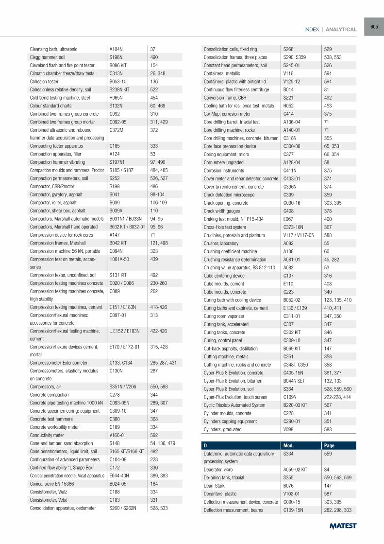
INDEX | ANALYTICAL
Cleansing bath, ultrasonic A104N 37
Clegg hammer, soil S196N 490
Cleveland flash and fire point tester B086 KIT 154
Climatic chamber freeze/thaw tests C313N 26, 348
Cohesion tester B053-10 136
Cohesionless relative density, soil S238N KIT 522
Cold bend testing machine, steel H065N 454
Colour standard charts S132N 60, 469
Combined two frames group concrete C092 310
Combined two frames group mortar C092-05 311, 429
Combined ultrasonic and rebound
hammer data acquisition and processing
C372M 372
Compacting factor apparatus C185 333
Compaction apparatus, filler A124 53
Compaction hammer vibrating S197N1 97, 490
Compaction moulds and rammers, Proctor S185 / S187 484, 485
Compaction permeameters, soil S252 526, 527
Compactor, CBR/Proctor S199 486
Compactor, gyratory, asphalt B041 98-104
Compactor, roller, asphalt B039 106-109
Compactor, shear box, asphalt B039A 110
Compactors, Marshall automatic models B031N1 / B033N 94, 95
Compactors, Marshall hand operated B032 KIT / B032-01 95, 96
Compression device for rock cores A147 71
Compression frames, Marshall B042 KIT 121, 498
Compression machine 56 kN, portable C094N 323
Compression test on metals, acces-
sories
H001A-50 439
Compression tester, unconfined, soil S131 KIT 492
Compression testing machines concrete C020 / C086 230-260
Compression testing machines concrete,
high stability
C089 262
Compression testing machines, cement E151 / E183N 418-426
Compression/flexural machines:
accessories for concrete
C097-01 313
Compression/flexural testing machine,
cement
...E152 / E183N 422-426
Compression/flexure devices cement,
mortar
E170 / E172-01 315, 428
Compressometer-Extensometer C133, C134 285-287, 431
Compressometers, elasticity modulus
on concrete
C130N 287
Compressors, air S351N / V206 550, 598
Concrete compaction C278 344
Concrete pipe testing machine 1000 kN C093-05N 289, 307
Concrete specimen curing: equipment C309-10 347
Concrete test hammers C380 368
Concrete workability meter C189 334
Conductivity meter V166-01 592
Cone and tamper, sand absorption S148 54, 136, 479
Cone penetrometers, liquid limit, soil S165 KIT/S166 KIT 482
Configuration of advanced parameters C104-09 228
Confined flow ability “L-Shape Box” C172 330
Conical penetration needle, Vicat apparatus E044-40N 389, 393
Conical sieve EN 15366 B024-05 164
Consistometer, Walz C188 334
Consistometer, Vebé C183 331
Consolidation apparatus, oedometer S260 / S262N 528, 533
Consolidation cells, fixed ring S268 529
Consolidation frames, three places S290, S359 538, 553
Constant head permeameters, soil S245-01 526
Containers, metallic V116 594
Containers, plastic with airtight lid V125-12 594
Continuous flow filterless centrifuge B014 81
Conversion frame, CBR S221 492
Cooling bath for resilience test, metals H052 453
Cor Map, corrosion meter C414 375
Core drilling barrel, triaxial test A136-04 71
Core drilling machine, rocks A140-01 71
Core drilling machines, concrete, bitumen C318N 355
Core face preparation device C300-08 65, 353
Coring equipment, micro C377 66, 354
Corn emery ungraded A128-04 58
Corrosion instruments C411N 375
Cover meter and rebar detector, concrete C403-01 374
Cover to reinforcement, concrete C396N 374
Crack detection microscope C399 359
Crack opening, concrete C090-16 303, 305
Crack width gauges C408 378
Craking test mould, NF P15-434 E067 400
Cross-Hole test system C373-10N 367
Crucibles, porcelain and platinum V117 / V117-05 588
Crusher, laboratory A092 55
Crushing coefficient machine A108 60
Crushing resistance determination A081-01 45, 282
Crushing value apparatus, BS 812:110 A082 53
Cube centering device C107 316
Cube moulds, cement E110 408
Cube moulds, concrete C223 340
Curing bath with cooling device B052-02 123, 135, 410
Curing baths and cabinets, cement E136 / E139 410, 411
Curing room vaporiser C311-01 347, 350
Curing tank, accelerated C307 347
Curing tanks, concrete C302 KIT 346
Curing, control panel C309-10 347
Cut-back asphalts, distillation B069 KIT 147
Cutting machine, metals C351 358
Cutting machine, rocks and concrete C348T, C350T 358
Cyber-Plus 8 Evolution, concrete C405-15N 361, 377
Cyber-Plus 8 Evolution, bitumen B044N SET 132, 133
Cyber-Plus 8 Evolution, soil S334 528, 559, 560
Cyber-Plus Evolution, touch screen C109N 222-228, 414
Cyclic Triaxlab Automated System B220-03 KIT 567
Cylinder moulds, concrete C228 341
Cylinders capping equipment C290-01 351
Cylinders, graduated V098 583
D Mod. Page
Datatronic, automatic data acquisition/
processing system
S334 559
Deaerator, vibro A059-02 KIT 84
De-airing tank, triaxial S355 550, 563, 569
Dean-Stark B076 147
Decanters, plastic V102-01 587
Deflection measurement device, concrete C090-15 303, 305
Deflection measurement, beams C109-15N 282, 298, 303
605
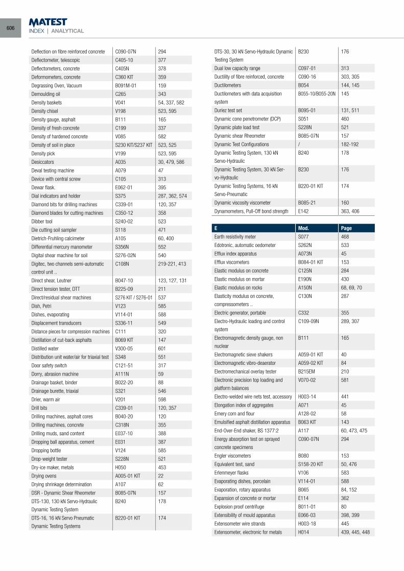
INDEX | ANALYTICAL
Deflection on fibre reinforced concrete C090-07N 294
Deflectometer, telescopic C405-10 377
Deflectometers, concrete C405N 378
Deformometers, concrete C360 KIT 359
Degrassing Oven, Vacuum B091M-01 159
Demoulding oil C265 343
Density baskets V041 54, 337, 582
Density chisel V198 523, 595
Density gauge, asphalt B111 165
Density of fresh concrete C199 337
Density of hardened concrete V085 582
Density of soil in place S230 KIT/S237 KIT 523, 525
Density pick V199 523, 595
Desiccators A035 30, 479, 586
Deval testing machine A079 47
Device with central screw C105 313
Dewar flask. E062-01 395
Dial indicators and holder S375 287, 362, 574
Diamond bits for drilling machines C339-01 120, 357
Diamond blades for cutting machines C350-12 358
Dibber tool S240-02 523
Die cutting soil sampler S118 471
Dietrich-Fruhling calcimeter A105 60, 400
Differential mercury manometer S356N 552
Digital shear machine for soil S276-02N 540
Digitec, two channels semi-automatic
control unit ..
C108N 219-221, 413
Direct shear, Leutner B047-10 123, 127, 131
Direct tension tester, DTT B225-09 211
Direct/residual shear machines S276 KIT / S276-01 537
Dish, Petri V123 585
Dishes, evaporating V114-01 588
Displacement transducers S336-11 549
Distance pieces for compression machines C111 320
Distillation of cut-back asphalts B069 KIT 147
Distilled water V300-05 601
Distribution unit water/air for triaxial test S348 551
Door safety switch C121-51 317
Dorry, abrasion machine A111N 59
Drainage basket, binder B022-20 88
Drainage burette, triaxial S321 546
Drier, warm air V201 598
Drill bits C339-01 120, 357
Drilling machines, asphalt cores B040-20 120
Drilling machines, concrete C318N 355
Drilling muds, sand content E037-10 388
Dropping ball apparatus, cement E031 387
Dropping bottle V124 585
Drop-weight tester S228N 521
Dry-ice maker, metals H050 453
Drying ovens A005-01 KIT 22
Drying shrinkage determination A107 62
DSR - Dynamic Shear Rheometer B085-07N 157
DTS-130, 130 kN Servo-Hydraulic
Dynamic Testing System
B240 178
DTS-16, 16 kN Servo Pneumatic
Dynamic Testing Systems
B220-01 KIT 174
DTS-30, 30 kN Servo-Hydraulic Dynamic
Testing System
B230 176
Dual low capacity range C097-01 313
Ductility of fibre reinforced, concrete C090-16 303, 305
Ductilometers B054 144, 145
Ductilometers with data acquisition
system
B055-10/B055-20N 145
Duriez test set B095-01 131, 511
Dynamic cone penetrometer (DCP) S051 460
Dynamic plate load test S228N 521
Dynamic shear Rheometer B085-07N 157
Dynamic Test Configurations / 182-192
Dynamic Testing System, 130 kN
Servo-Hydraulic
B240 178
Dynamic Testing System, 30 kN Ser-
vo-Hydraulic
B230 176
Dynamic Testing Systems, 16 kN
Servo-Pneumatic
B220-01 KIT 174
Dynamic viscosity viscometer B085-21 160
Dynamometers, Pull-Off bond strength E142 363, 406
E Mod. Page
Earth resistivity meter S077 468
Edotronic, automatic oedometer S262N 533
Efflux index apparatus A073N 45
Efflux viscometers B084-01 KIT 153
Elastic modulus on concrete C125N 284
Elastic modulus on mortar E190N 430
Elastic modulus on rocks A150N 68, 69, 70
Elasticity modulus on concrete,
compressometers ..
C130N 287
Electric generator, portable C332 355
Electro-Hydraulic loading and control
system
C109-09N 289, 307
Electromagnetic density gauge, non
nuclear
B111 165
Electromagnetic sieve shakers A059-01 KIT 40
Electromagnetic vibro-deaerator A059-02 KIT 84
Electromechanical overlay tester B215EM 210
Electronic precision top loading and
platform balances
V070-02 581
Electro-welded wire nets test, accessory H003-14 441
Elongation index of aggregates A071 45
Emery corn and flour A128-02 58
Emulsified asphalt distillation apparatus B063 KIT 143
End-Over-End shaker, BS 1377:2 A117 60, 473, 475
Energy absorption test on sprayed
concrete specimens
C090-07N 294
Engler viscometers B080 153
Equivalent test, sand S158-20 KIT 50, 476
Erlenmeyer flasks V106 583
Evaporating dishes, porcelain V114-01 588
Evaporation, rotary apparatus B065 84, 152
Expansion of concrete or mortar E114 362
Explosion proof centrifuge B011-01 80
Extensibility of mould apparatus E066-03 398, 399
Extensometer wire strands H003-18 445
Extensometer, electronic for metals H014 439, 445, 448
606
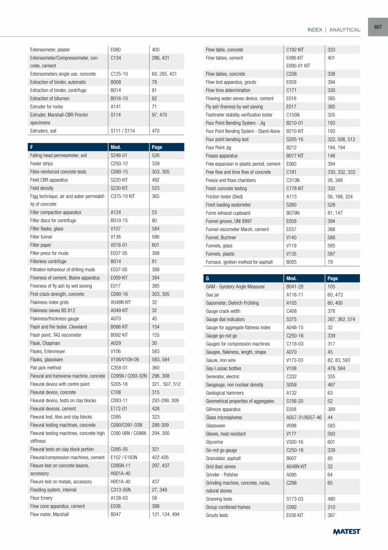
INDEX | ANALYTICAL
Extensometer, plaster E080 400
Extensometer/Compressometer, con-
crete, cement
C134 286, 431
Extensometers single use, concrete C125-10 69, 285, 431
Extraction of binder, automatic B008 78
Extraction of binder, centrifuge B014 81
Extraction of bitumen B016-10 82
Extruder for rocks A141 71
Extruder, Marshall-CBR-Proctor
specimens
S114 97, 470
Extruders, soil S111 / S114 470
F Mod. Page
Falling head permeameter, soil S246-01 526
Feeler strips C250-12 339
Fibre reinforced concrete tests C090-15 303, 305
Field CBR apparatus S220 KIT 492
Field density S230 KIT 523
Figg technique, air and water permeabil-
ity of concrete
C375-10 KIT 365
Filler compaction apparatus A124 53
Filter discs for centrifuge B010-15 80
Filter flasks, glass V107 584
Filter funnel V138 586
Filter paper V218-01 601
Filter press for muds E037-05 388
Filterless centrifuge B014 81
Filtration behaviour of drilling muds E037-05 388
Fineness of cement, Blaine apparatus E009 KIT 384
Fineness of fly ash by wet sieving E017 385
First crack strength, concrete C090-16 303, 305
Flakiness index grids A048N KIT 32
Flakiness sieves BS 812 A049 KIT 32
Flakiness/thickness gauge A070 45
Flash and fire tester, Cleveland B086 KIT 154
Flash point, TAG viscometer B092 KIT 155
Flask, Chapman A029 30
Flasks, Erlenmeyer V106 583
Flasks, glassware V106/V109-09 583, 584
Flat jack method C358-01 360
Flexural and transverse machine, concrete CO95N / C093-02N 296, 308
Flexural device with centre point S205-18 321, 507, 512
Flexural device, concrete C106 315
Flexural device, tests on clay blocks C093-11 293-299, 309
Flexural devices, cement E172-01 428
Flexural test, tiles and clay blocks C095 323
Flexural testing machines, concrete C090/C091-03N 288-309
Flexural testing machines, concrete high
stiffness
C090-06N / C096N 294, 300
Flexural tests on clay block portion C095-05 321
Flexural/compression machines, cement E152 / E183N 422-426
Flexure test on concrete beams,
accessory
C095N-11
H001A-40
297, 437
Flexure test on metals, accessory H001A-40 437
Flooding system, internal C313-05N 27, 349
Flour Emery A128-03 58
Flow cone apparatus, cement E038 388
Flow meter, Marshall B047 121, 124, 494
Flow table, concrete C192 KIT 333
Flow tables, cement E086 KIT
E090-01 KIT
401
Flow tables, concrete C208 338
Flow test apparatus, grouts E059 394
Flow time determination C171 330
Flowing water sieves device, cement E016 385
Fly ash fineness by wet sieving E017 385
Footmeter stability verification tester C155N 325
Four Point Bending System - Jig B210-01 193
Four Point Bending System - Stand-Alone B210 KIT 193
Four point bending test S205-16 322, 506, 512
Four Point Jig B212 184, 194
Fraass apparatus B077 KIT 146
Free expansion in plastic period, cement E060 394
Free flow and time flow of concrete C181 330, 332, 333
Freeze and thaw chambers C313N 26, 348
Fresh concrete testing C178 KIT 332
Friction tester (Skid) A113 56, 168, 324
Front loading oedometer S260 528
Fume exhaust cupboard B079N 81, 147
Funnel groove, UNI 8997 E059 394
Funnel viscometer Marsh, cement E037 388
Funnel, Buchner V140 588
Funnels, glass V119 585
Funnels, plastic V135 587
Furnace, ignition method for asphalt B005 79
G Mod. Page
GAM - Gyratory Angle Measurer B041-28 105
Gas jar A116-11 60, 473
Gasometer, Dietrich-Frühling A105 60, 400
Gauge crack width C408 378
Gauge dial indicators S375 287, 362, 574
Gauge for aggregate flatness index A048-15 32
Gauge go-not go C250-16 339
Gauges for compression machines C118-03 317
Gauges, flakiness, length, shape A070 45
Gauze, iron wire V173-03 82, 83, 593
Gay-Lussac bottles V108 479, 584
Generator, electric C332 355
Geogauge, non nuclear density S059 467
Geological hammers A132 63
Geometrical properties of aggregates S156-20 52
Gillmore apparatus E058 389
Glass microspheres A057-31/A057-46 44
Glassware V098 583
Gloves, heat resistant V177 593
Glycerine V300-16 601
Go-not go gauge C250-16 339
Granulator, asphalt B007 85
Grid (bar) sieves A048N KIT 32
Grinder - Polisher A095 64
Grinding machine, concrete, rocks,
natural stones
C298 65
Grooving tools S173-03 480
Group combined frames C092 310
Grouts tests E036 KIT 387
607
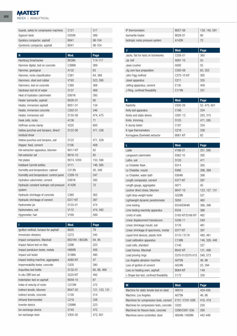
INDEX | ANALYTICAL
Guards, safety for compression machines C121 317
Gypsum tests E055N 389
Gyratory compactor, asphalt B041 98-104
Gyrotronic compactor, asphalt B041 98-104
H Mod. Page
Hamburg Smartracker B038A 114-117
Hammer digital, test on concrete C386N 369
Hammer, geological A132 63
Hammer, rocks classification C381 64, 368
Hammers, steel and rubber V193 523, 595
Hammers, test on concrete C380 368
Hardness test kit of water S137 469
Heat of hydration calorimeter E061N 395
Heater isomantle, asphalt B028-01 90
Heater, immersion asphalt B051-01 134
Heater, immersion concrete C302-01 346
Heater, immersion soil S155-09 474, 475
Hoek cells, rocks A136 71
Hoffman screw clamp V220 600
Hollow punches and tampers, direct/
residual shear
S122-08 471, 538
Hollow punches and tampers, soil S122 471, 529
Hopper, feed, cement E106 408
Hot extraction apparatus, bitumen B017 KIT 82
Hot extractor set B016-10 82
Hot plates B074, V200 150, 596
Hubbard-Carmik bottles V111 146, 585
Humidity and temperature: cabinet C313N 26, 348
Humidity and temperature: control panel C309-10 347
Hydration calorimeter, cement E061N 395
Hydraulic constant isotropic cell pressure
system
A142N 72
Hydraulic shrinkage of concrete C365 362
Hydraulic shrinkage of cement E077 KIT 397
Hydrometer jar S155-01 474
Hydrometers, soil V172 474, 592
Hygrometer, hair V169 589
I Mod. Page
Ignition method, furnace for asphalt B005 79
Immersion vibrators C272 345
Impact compactors, Marshall B031N1 / B033N 94, 95
Impact failure test on tiles C096 323
Impact pendulum tester, metals H060N 456
Impact soil tester S196N 490
Impact testing machine, aggregates A080 KIT 47
Impermeability tester, concrete C435 380
Impurities test bottle S132-01 60, 86, 469
In situ CBR test set S220 KIT 492
Indentation test on asphalt B059-10 87
Index of velocity of rocks C372M 372
Indirect tensile, bitumen B047-02 121, 123, 131
Indirect tensile, concrete C100 314
Infrared thermometer C216 338
Inverter device C099N 223
Ion exchange device S140 472
Ion exchange resin V300-30 472, 601
IP thermometers B057-08 139, 140, 591
Isomantle heater B028-01 90
Isotropic rocks pressure system A142N 72
J Mod. Page
Jacks, flat for tests on brickworks C358-01 360
Jar mill A091-10 55
Jaws crusher A092 55
Jig core face preparation C300-08 65, 353
John Figg method C375-10 KIT 365
Joisel apparatus C211 335
Jolting apparatus, cement E130 409
J-Ring, confined flowability C174N 331
K Mod. Page
Kaolinite V300-29 52, 475, 601
Kelly ball apparatus C186 334
Kerbs and slabs device C091-13 293, 315
Knife, trimming S125 471, 595
K-slump tester C187 334
K-type thermometers C216 338
Kumagawa (Soxhelet) extractor B061 KIT 82
L Mod. Page
Ladle V186-01 351, 595
Langavant calorimeter E062-10 395
Lathe, soil S120 471
Le Chatelier flask . E014 385
Le Chatelier, mould E066 398, 399
Le Chatelier, water bath E064N 398
Length comparator, cement E077 KIT 397
Length gauge, aggregates A071 45
Leutner direct shear, bitumen B047-10 123, 127, 131
Light drop-weight tester S228N 521
Lightweight dynamic penetrometer S050 460
Lime testing E034/E064N 386, 398
Lime testing reactivity apparatus E034 386
Limits of solis S165 KIT/S166 KIT 482
Linear displacement transducers S336-11 549
Linear shrinkage mould, soil S176 481
Linear shrinkage of specimens, mortar E077 KIT 397
Liquid limit devices, plastic limit S170 / S178 480, 481
Load calibration apparatus C138N 146, 326, 448
Load cells, standard C140 327
Load frames, Marshall B042 KIT 121, 498
Load proving rings S370-01/S370-01S 548, 573
Los Angeles abrasion machine A075N 46, 86
Loss of ignition of cement A024N 25, 394
Loss on heating oven, asphalt B064 KIT 149
L-Shape box test, confined flowability C172 330
M Mod. Page
Machine for static tensile test on steel H001A 434-439
Machine, Los Angeles A075N 46, 86
Machines for compression tests, cement E151 / E161-02N 418, 419
Machines for compression tests, concrete C020 230
Machines for flexure tests, concrete C090/C091-03A 290
Machines servo-controlled, steel H004N / H008N 442-449
608
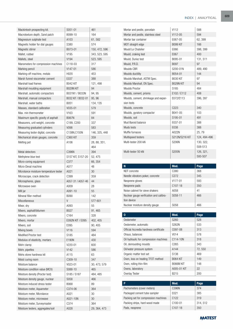
INDEX | ANALYTICAL
Mackintosh prospecting kit. S051-01 461
Macrotexture depth, Sand patch B099-10 164
Magnesium sulphate test A103 61, 582
Magnetic holder for dial gauges S380 574
Magnetic stirrer B073-01 150, 472, 596
Mallet, rubber V195 343, 523, 595
Mallets, steel V194 523, 595
Manometers for compression machines C118-03 317
Marking pencil V147-01 586
Marking-off machine, metals H020 453
Marsh funnel viscometer cement E037 388
Marshall load frames B042 KIT 121, 498
Marshall moulding equipment B029N KIT 94
Marshall, automatic compactors B031N1 / B033N 94, 95
Marshall, manual compactors B032 KIT / B032-01 95, 96
Marshall, water baths B051 134, 135
Masses, standard calibration V035-01 579
Max. min thermometer V163 591
Maximum specific gravity of asphalt B067N 84
Measurers, unit weight, concrete C199, C200 337
Measuring graduated cylinders V098 583
Measuring tester digital, concrete C138N,C155N 146, 325, 448
Mechanical strain gauges, concrete C360 KIT 359
Melting pot A106 28, 88, 351,
464
Metal detectors C396N 394
Methylene blue test S157 KIT, S157-20 52, 475
Micro-coring equipment C377 66, 354
Micro-Deval machine A077 48
Microlance moisture-temperature tester A021 30
Microscope, crack detection C399 359
Microspheres, glass A057-31 / A057-46 44
Microwave oven A009 28
Mill jar A091-10 55
Mineral filler method B090 142
Miscellaneous V 577-601
Mixer, dry A093 55
Mixers, asphalt/bitumen B027 91, 465
Mixers, concrete C164 328
Mixers, mortar E092N KIT / E095 402, 405
Mixers, soil E095 90, 405
Mixing bowls V116 594
Modified Proctor test S185 484
Modulus of elasticity, mortars E190N 430
Mohr clamp V220-01 600
Mohr, pipettes V142 586
Mohs stone hardness kit A115 63
Moist curing room C309-10 347
Moisture balance V023-01 30, 473, 579
Moisture condition value (MCV) S088-10 465
Moisture density (Proctor test) S185 / S187 484, 485
Moisture density gauge, nuclear S058 466
Moisture induced stress tester B068 89
Moisture meter, Aquameter C374-06 364
Moisture meter, Microlance A021 30
Moisture meter, microwave A021-10N 30
Moisture meter, Surveymaster C374 364
Moisture testers, aggregates/soil A028 29, 364, 473
Mortar and pestle, porcelain V112 588
Mortar and pestle, stainless steel V112-05 594
Mortar bar container E067-05 62, 399
MOT straight edge B099 KIT 166
Mould Le Chatelier E066 398, 399
Mould, craking test E067 400
Mould, Duriez test B095-01 131, 511
Mould, P.R.D. B097 97
Moulds CBR S200-01N 489, 490
Moulds ductility B054-01 144
Moulds Marshall, ASTM Spec. B030 KIT 97
Moulds Marshall, EN Spec. B029N KIT 94
Moulds Proctor S185 484
Moulds, cement, prisms E102 / E112 408
Moulds, cement, shrinkage and expan-
sion tests
E072/E113 396, 397
Moulds, concrete C223 340
Moulds, gyratory compactor B041-05 103
Moulds, soil S195-01 491
Mud Baroid balance E037-01 388
Muds tests E038 388
Muffle furnaces A022N 25, 79
Multispeed testers S212N/S216 KIT 124, 494-496
Multi-tester 200 kN S206N 130, 322,
508-513
Multi-tester 50 kN S205N 126, 321,
500-507
N Mod. Page
NDT concrete C380 368
Needle vibrators poker, concrete C272 345
Neoprene gloves V177-01 593
Neoprene pads C107-18 350
Noise cabinet for sieve shakers A058 41
Nuclear gauge verification and calibra-
tion device
S058-11 466
Nuclear moisture density gauge S058 466
O Mod. Page
Oedometer S260 528
Oedometer, automatic S262N 533
Official Accredia hardness certificate C097-08 313
Ohaus, balances V014 578
Oil hydraulic for compression machines C114-10N 318
Oil, demoulding moulds C265 343
Oil/water pressure system A144 72, 550
Organic matter test set S138 469
Oven, loss on heating TFOT method B064 KIT 149
Oven, rolling thin-film B066M KIT 148
Ovens, laboratory A005-01 KIT 22
Overlay Tester B215 200
P Mod. Page
Pachometers (cover meters) C396N 374
Packaged cement tube sampler E021 385
Packing set for compression machines C122 319
Packing strips, hard wood made C100-01 314, 512
Pads, neoprene C107-18 350
609
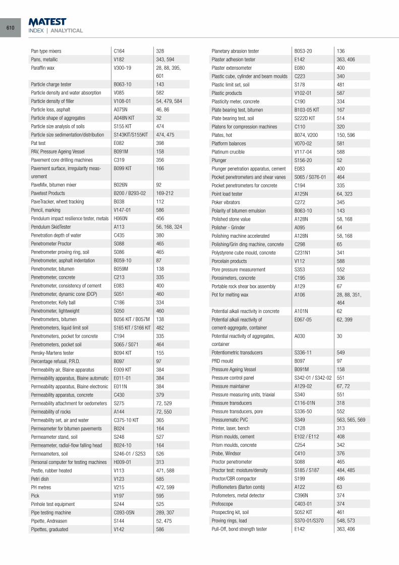
INDEX | ANALYTICAL
Pan type mixers C164 328
Pans, metallic V182 343, 594
Paraffin wax V300-19 28, 88, 395,
601
Particle charge tester B063-10 143
Particle density and water absorption V085 582
Particle density of filler V108-01 54, 479, 584
Particle loss, asphalt A075N 46, 86
Particle shape of aggregates A048N KIT 32
Particle size analysis of soils S155 KIT 474
Particle size sedimentation/distribution S143KIT/S155KIT 474, 475
Pat test E082 398
PAV, Pressure Ageing Vessel B091M 158
Pavement core drilling machines C319 356
Pavement surface, irregularity meas-
urement
B099 KIT 166
PaveMix, bitumen mixer B026N 92
Pavetest Products B200 / B293-02 169-212
PaveTracker, wheet tracking B038 112
Pencil, marking V147-01 586
Pendulum impact resilience tester, metals H060N 456
Pendulum SkidTester A113 56, 168, 324
Penetration depth of water C435 380
Penetrometer Proctor S088 465
Penetrometer proving ring, soil S086 465
Penetrometer, asphalt indentation B059-10 87
Penetrometer, bitumen B059M 138
Penetrometer, concrete C213 335
Penetrometer, consistency of cement E083 400
Penetrometer, dynamic cone (DCP) S051 460
Penetrometer, Kelly ball C186 334
Penetrometer, lightweight S050 460
Penetrometers, bitumen B056 KIT / B057M 138
Penetrometers, liquid limit soil S165 KIT / S166 KIT 482
Penetrometers, pocket for concrete C194 335
Penetrometers, pocket soil S065 / S071 464
Pensky-Martens tester B094 KIT 155
Percentage refusal, P.R.D. B097 97
Permeability air, Blaine apparatus E009 KIT 384
Permeability apparatus, Blaine automatic E011-01 384
Permeability apparatus, Blaine electronic E011N 384
Permeability apparatus, concrete C430 379
Permeability attachment for oedometers S275 72, 529
Permeability of rocks A144 72, 550
Permeability set, air and water C375-10 KIT 365
Permeameter for bitumen pavements B024 164
Permeameter stand, soil S248 527
Permeameter, radial-flow falling head B024-10 164
Permeameters, soil S246-01 / S253 526
Personal computer for testing machines H009-01 313
Pestle, rubber heated V113 471, 588
Petri dish V123 585
PH metres V215 472, 599
Pick V197 595
Pinhole test equipment S244 525
Pipe testing machine C093-05N 289, 307
Pipette, Andreasen S144 52, 475
Pipettes, graduated V142 586
Planetary abrasion tester B053-20 136
Plaster adhesion tester E142 363, 406
Plaster extensometer E080 400
Plastic cube, cylinder and beam moulds C223 340
Plastic limit set, soil S178 481
Plastic products V102-01 587
Plasticity meter, concrete C190 334
Plate bearing test, bitumen B103-05 KIT 167
Plate bearing test, soil S222D KIT 514
Platens for compression machines C110 320
Plates, hot B074, V200 150, 596
Platform balances V070-02 581
Platinum crucible V117-04 588
Plunger S156-20 52
Plunger penetration apparatus, cement E083 400
Pocket penetrometers and shear vanes S065 / S076-01 464
Pocket penetrometers for concrete C194 335
Point load tester A125N 64, 323
Poker vibrators C272 345
Polarity of bitumen emulsion B063-10 143
Polished stone value A128N 58, 168
Polisher - Grinder A095 64
Polishing machine accelerated A128N 58, 168
Polishing/Grin ding machine, concrete C298 65
Polystyrene cube mould, concrete C231N1 341
Porcelain products V112 588
Pore pressure measurement S353 552
Porosimeters, concrete C195 336
Portable rock shear box assembly A129 67
Pot for melting wax A106 28, 88, 351,
464
Potential alkali reactivity in concrete A101N 62
Potential alkali reactivity of
cement-aggregate, container
E067-05 62, 399
Potential reactivity of aggregates,
container
A030 30
Potentiometric transducers S336-11 549
PRD mould B097 97
Pressure Ageing Vessel B091M 158
Pressure control panel S342-01 / S342-02 551
Pressure maintainer A129-02 67, 72
Pressure measuring units, triaxial S340 551
Pressure transducers C116-01N 318
Pressure transducers, pore S336-50 552
Pressurematic PVC S349 563, 565, 569
Printer, laser, bench C128 313
Prism moulds, cement E102 / E112 408
Prism moulds, concrete C254 342
Probe, Windsor C410 376
Proctor penetrometer S088 465
Proctor test: moisture/density S185 / S187 484, 485
Proctor/CBR compactor S199 486
Profilometers (Barton comb) A122 63
Profometers, metal detector C396N 374
Profoscope C403-01 374
Prospecting kit, soil S052 KIT 461
Proving rings, load S370-01/S370 548, 573
Pull-Off, bond strength tester E142 363, 406
610
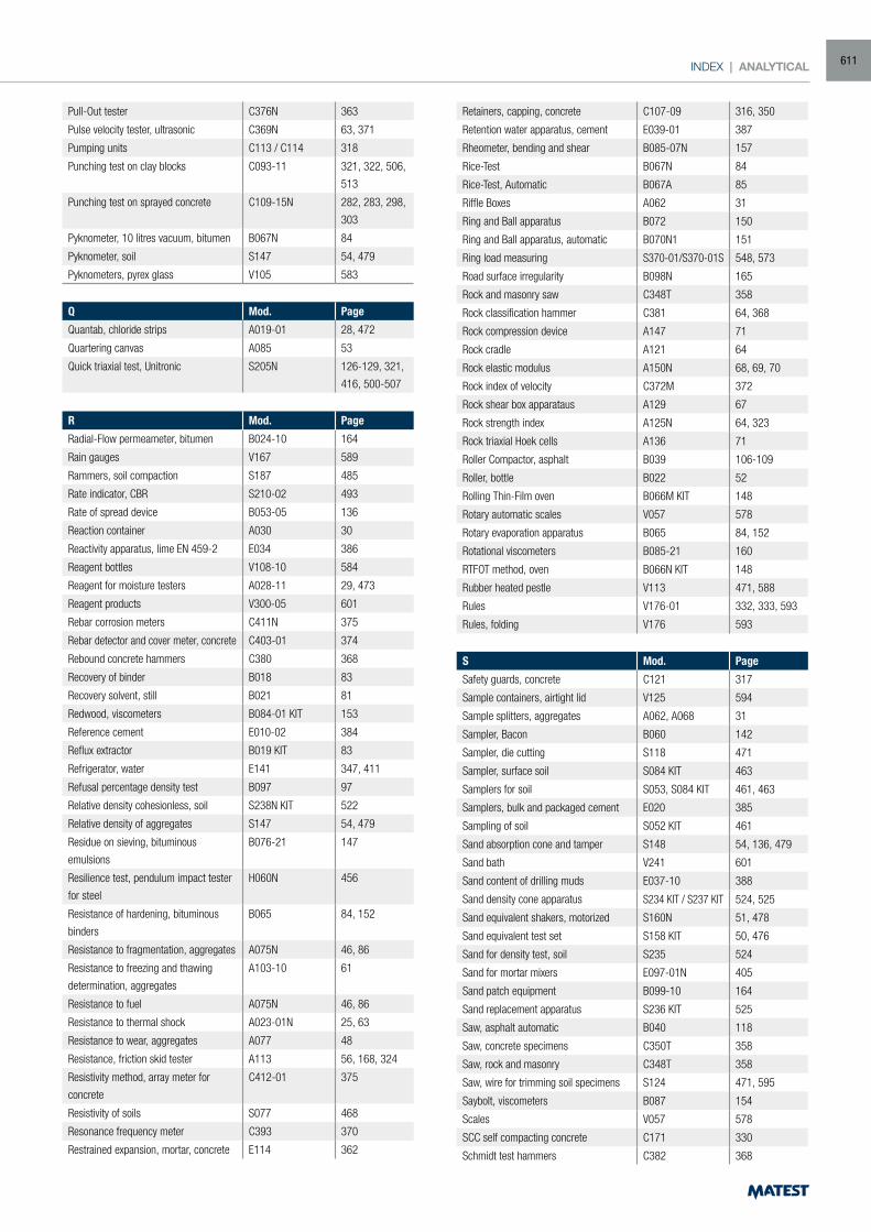
INDEX | ANALYTICAL
Pull-Out tester C376N 363
Pulse velocity tester, ultrasonic C369N 63, 371
Pumping units C113 / C114 318
Punching test on clay blocks C093-11 321, 322, 506,
513
Punching test on sprayed concrete C109-15N 282, 283, 298,
303
Pyknometer, 10 litres vacuum, bitumen B067N 84
Pyknometer, soil S147 54, 479
Pyknometers, pyrex glass V105 583
Q Mod. Page
Quantab, chloride strips A019-01 28, 472
Quartering canvas A085 53
Quick triaxial test, Unitronic S205N 126-129, 321,
416, 500-507
R Mod. Page
Radial-Flow permeameter, bitumen B024-10 164
Rain gauges V167 589
Rammers, soil compaction S187 485
Rate indicator, CBR S210-02 493
Rate of spread device B053-05 136
Reaction container A030 30
Reactivity apparatus, lime EN 459-2 E034 386
Reagent bottles V108-10 584
Reagent for moisture testers A028-11 29, 473
Reagent products V300-05 601
Rebar corrosion meters C411N 375
Rebar detector and cover meter, concrete C403-01 374
Rebound concrete hammers C380 368
Recovery of binder B018 83
Recovery solvent, still B021 81
Redwood, viscometers B084-01 KIT 153
Reference cement E010-02 384
Reflux extractor B019 KIT 83
Refrigerator, water E141 347, 411
Refusal percentage density test B097 97
Relative density cohesionless, soil S238N KIT 522
Relative density of aggregates S147 54, 479
Residue on sieving, bituminous
emulsions
B076-21 147
Resilience test, pendulum impact tester
for steel
H060N 456
Resistance of hardening, bituminous
binders
B065 84, 152
Resistance to fragmentation, aggregates A075N 46, 86
Resistance to freezing and thawing
determination, aggregates
A103-10 61
Resistance to fuel A075N 46, 86
Resistance to thermal shock A023-01N 25, 63
Resistance to wear, aggregates A077 48
Resistance, friction skid tester A113 56, 168, 324
Resistivity method, array meter for
concrete
C412-01 375
Resistivity of soils S077 468
Resonance frequency meter C393 370
Restrained expansion, mortar, concrete E114 362
Retainers, capping, concrete C107-09 316, 350
Retention water apparatus, cement E039-01 387
Rheometer, bending and shear B085-07N 157
Rice-Test B067N 84
Rice-Test, Automatic B067A 85
Riffle Boxes A062 31
Ring and Ball apparatus B072 150
Ring and Ball apparatus, automatic B070N1 151
Ring load measuring S370-01/S370-01S 548, 573
Road surface irregularity B098N 165
Rock and masonry saw C348T 358
Rock classification hammer C381 64, 368
Rock compression device A147 71
Rock cradle A121 64
Rock elastic modulus A150N 68, 69, 70
Rock index of velocity C372M 372
Rock shear box apparataus A129 67
Rock strength index A125N 64, 323
Rock triaxial Hoek cells A136 71
Roller Compactor, asphalt B039 106-109
Roller, bottle B022 52
Rolling Thin-Film oven B066M KIT 148
Rotary automatic scales V057 578
Rotary evaporation apparatus B065 84, 152
Rotational viscometers B085-21 160
RTFOT method, oven B066N KIT 148
Rubber heated pestle V113 471, 588
Rules V176-01 332, 333, 593
Rules, folding V176 593
S Mod. Page
Safety guards, concrete C121 317
Sample containers, airtight lid V125 594
Sample splitters, aggregates A062, A068 31
Sampler, Bacon B060 142
Sampler, die cutting S118 471
Sampler, surface soil S084 KIT 463
Samplers for soil S053, S084 KIT 461, 463
Samplers, bulk and packaged cement E020 385
Sampling of soil S052 KIT 461
Sand absorption cone and tamper S148 54, 136, 479
Sand bath V241 601
Sand content of drilling muds E037-10 388
Sand density cone apparatus S234 KIT / S237 KIT 524, 525
Sand equivalent shakers, motorized S160N 51, 478
Sand equivalent test set S158 KIT 50, 476
Sand for density test, soil S235 524
Sand for mortar mixers E097-01N 405
Sand patch equipment B099-10 164
Sand replacement apparatus S236 KIT 525
Saw, asphalt automatic B040 118
Saw, concrete specimens C350T 358
Saw, rock and masonry C348T 358
Saw, wire for trimming soil specimens S124 471, 595
Saybolt, viscometers B087 154
Scales V057 578
SCC self compacting concrete C171 330
Schmidt test hammers C382 368
611
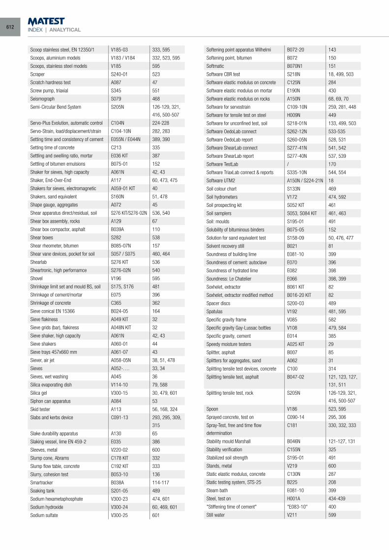
INDEX | ANALYTICAL
Scoop stainless steel, EN 12350/1 V185-03 333, 595
Scoops, aluminium models V183 / V184 332, 523, 595
Scoops, stainless steel models V185 595
Scraper S240-01 523
Scratch hardness test A087 47
Screw pump, triaxial S345 551
Seismograph S079 468
Semi-Circular Bend System S205N 126-129, 321,
416, 500-507
Servo-Plus Evolution, automatic control C104N 224-228
Servo-Strain, load/displacement/strain C104-10N 282, 283
Setting time and consistency of cement E055N / E044N 389, 390
Setting time of concrete C213 335
Settling and swelling ratio, mortar E036 KIT 387
Settling of bitumen emulsions B075-01 152
Shaker for sieves, high capacity A061N 42, 43
Shaker, End-Over-End A117 60, 473, 475
Shakers for sieves, electromagnetic A059-01 KIT 40
Shakers, sand equivalent S160N 51, 478
Shape gauge, aggregates A072 45
Shear apparatus direct/residual, soil S276 KIT/S276-02N 536, 540
Shear box assembly, rocks A129 67
Shear box compactor, asphalt B039A 110
Shear boxes S282 538
Shear rheometer, bitumen B085-07N 157
Shear vane devices, pocket for soil S057 / S075 460, 464
Shearlab S276 KIT 536
Sheartronic, high perfornamce S276-02N 540
Shovel V196 595
Shrinkage limit set and mould BS, soil S175, S176 481
Shrinkage of cement/mortar E075 396
Shrinkage of concrete C365 362
Sieve conical EN 15366 B024-05 164
Sieve flakiness A049 KIT 32
Sieve grids (bar), flakiness A048N KIT 32
Sieve shaker, high capacity A061N 42, 43
Sieve shakers A060-01 44
Sieve trays 457x660 mm A061-07 43
Siever, air jet A058-05N 38, 51, 478
Sieves A052-…. 33, 34
Sieves, wet washing A045 36
Silica evaporating dish V114-10 79, 588
Silica gel V300-15 30, 479, 601
Siphon can apparatus A084 53
Skid tester A113 56, 168, 324
Slabs and kerbs device C091-13 293, 295, 309,
315
Slake durability apparatus A130 65
Slaking vessel, lime EN 459-2 E035 386
Sleeves, metal V220-02 600
Slump cone, Abrams C178 KIT 332
Slump flow table, concrete C192 KIT 333
Slurry, cohesion test B053-10 136
Smartracker B038A 114-117
Soaking tank S201-05 489
Sodium hexametaphosphate V300-23 474, 601
Sodium hydroxide V300-24 60, 469, 601
Sodium sulfate V300-25 601
Softening point apparatus Wilhelmi B072-20 143
Softening point, bitumen B072 150
Softmatic B070N1 151
Software CBR test S218N 18, 499, 503
Software elastic modulus on concrete C125N 284
Software elastic modulus on mortar E190N 430
Software elastic modulus on rocks A150N 68, 69, 70
Software for servostrain C109-10N 259, 281, 448
Software for tensile test on steel H009N 449
Software for unconfined test, soil S218-01N 133, 499, 503
Software OedoLab connect S262-12N 533-535
Software OedoLab report S260-05N 528, 531
Software ShearLab connect S277-41N 541, 542
Software ShearLab report S277-40N 537, 539
Software TestLab / 170
Software TriaxLab connect & reports S335-10N 544, 554
Software UTM2 A150N / S224-21N 18
Soil colour chart S133N 469
Soil hydrometers V172 474, 592
Soil prospecting kit S052 KIT 461
Soil samplers S053, S084 KIT 461, 463
Soil: moulds S195-01 491
Solubility of bituminous binders B075-05 152
Solution for sand equivalent test S158-09 50, 476, 477
Solvent recovery still B021 81
Soundness of building lime E081-10 399
Soundness of cement: autoclave E070 396
Soundness of hydrated lime E082 398
Soundness: Le Chatelier E066 398, 399
Soxhelet, extractor B061 KIT 82
Soxhelet, extractor modified method B016-20 KIT 82
Spacer discs S200-03 489
Spatulas V192 481, 595
Specific gravity frame V085 582
Specific gravity Gay-Lussac bottles V108 479, 584
Specific gravity, cement E014 385
Speedy moisture testers A025 KIT 29
Splitter, asphalt B007 85
Splitters for aggregates, sand A062 31
Splitting tensile test devices, concrete C100 314
Splitting tensile test, asphalt B047-02 121, 123, 127,
131, 511
Splitting tensile test, rock S205N 126-129, 321,
416, 500-507
Spoon V186 523, 595
Sprayed concrete, test on C090-14 295, 306
Spray-Test, free and time flow
determination
C181 330, 332, 333
Stability mould Marshall B046N 121-127, 131
Stability verification C155N 325
Stabilized soil strength S195-01 491
Stands, metal V219 600
Static elastic modulus, concrete C130N 287
Static testing system, STS-25 B225 208
Steam bath E081-10 399
Steel, test on H001A 434-439
"Stiffening time of cement" "E083-10" 400
Still water V211 599
612
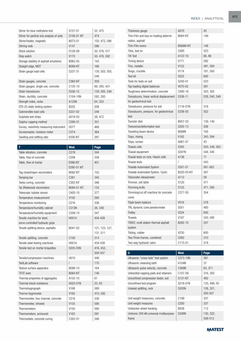
INDEX | ANALYTICAL
Stirrer for blue methylene test S157-01 52, 475
Stirrer for particle size analysis of soils S156-01 KIT 474
Stirrer/heater, magnetic B073-01 150, 472, 596
Stirring rods V147 586
Stock solution S158-09 50, 476, 477
Stop watch V170 50, 476, 592
Storage stability of asphalt emulsions B063-05 143
Straight edge, MOT B099 KIT 166
Strain gauge load cells S337-31 129, 503, 505,
548
Strain gauges, concrete C360 KIT 359
Strain gauges, single use, concrete C125-10 69, 285, 431
Strain transducers S336-15 129, 505, 549
Strain, ductility, concrete C104-10N 282, 283
Strength index, rocks A125N 64, 323
STS-25 static testing system B225 208
Submersible load cells S337-02 548
Sulphate test strips A019-03 28, 472
Sulphur capping method C290-01 351
Survey, resisitivity measuring instrument S077 468
Surveymaster, moisture meter C374 364
Swelling and settling ratio E036 KIT 387
T Mod. Page
Table vibrators, concrete C278 344
Table, flow of concrete C208 338
Table, flow of mortar E086 KIT
E090-01 KIT
401
Tag closed/open viscometers B092 KIT 155
Tamping bar C261 343
Tanks curing, concrete C302 KIT 346
Tar (Redwood) viscometers B084-01 KIT 153
Telescopic tubolar sensor C405-10 377
Temperature measurement V150 590
Temperature monitoring C216 338
Temperature/humidity cabinet C313N 26, 348
Temperature/humidity equipment C309-10 347
Tensile machine for steel,
servo-controlled hydraulic grips
H001A 434-439
Tensile splitting device, asphalts B047-02 121, 123, 127,
131, 511
Tensile splitting, concrete C100 314
Tensile steel testing machines H001A 434-439
Tensile test on mortar briquettes S205-05N 416, 452,
500-507
Tensile/compression machines H010 446
TestLab software / 170
Texture surface apparatus B099-10 164
TFOT oven B064 KIT 149
Thermal properties of aggregates A103-10 61
Thermal shock resistance A023-01N 25, 63
Thermohygrograph V168 589
Thermo-hygrometer V165 410, 592
Thermometer, four channel, concrete C216 338
Thermometer, infrared V155 590
Thermometers V150 590
Thermometers, armoured V162 591
Thermostats, concrete curing C302-01 346
Thickness gauge A070 45
Thin-Film and loss on heating determi-
nation, asphalt
B064 KIT 149
Thin-Film ovens B066M KIT 148
Tiles, test on C095 323
Tilt Test A122-10 66, 86
Timing device V171 592
Tins, metallic V122 481, 594
Tongs, crucible V174 161, 593
Tool kit V222 600
Tools for tests on soil S240-01 523
Top loading digital balances V070-02 581
Toughness determination, concrete C090-16 303, 305
Transducers, linear vertical displacement
for geotechnical test
S336-11 528, 540, 549
Transducers, pressure for soil C116-01N 318
Transducers, pressure, for geotechnical
test
S336-50 552
Transfer dish B057-03 139, 140
Transverse/deformation test S205-13 506
Travelling beam device B098N 165
Trays, mixing V182 343, 594
Trays, screen A061-07 43
Triaxial cells S305 503, 546, 563
Triaxial equipment S301N 544, 545
Triaxial tests on rock, Hoeck cells A136 71
Triaxial tests / 543
Triaxlab Automated System S301-01 561-563
Triaxlab Automated System, Cyclic B220-03 KIT 567
Tribometer-Abrasimeter A112 59
Trimmer, soil lathe S120 471
Trimming knife S125 471, 595
Trimming/cut off machine for concrete
cores
C377-05 354
Triple beam balance V016 578
TRL dynamic cone penetrometer S051 460
Trolley V224 600
Trowels V187 343, 595
TSRST, multi station thermal asphalt
system
B282-10 207
Tubing, rubber V230 600
Two-Three frames, combined C092 310
Two-way hydraulic valve C115-01 318
U Mod. Page
Ultrasonic “cross-hole” test system C373-10N 367
Ultrasonic cleansing bath A104N 37
Ultrasonic pulse velocity, concrete C369N 63, 371
Unbonded capping pads and retainers C107-09 316, 350
Unconfined compression tester, soil S131 KIT 492
Unconfined test program S218-01N 133, 499, 50
Uniaxial splitting, rock S205N 126, 321,
500-507
Unit weight measurers, concrete C199 337
Unit weight measures C200 337
Unitracker wheel tracking B038 112
Unitronic 200 kN universal multipurpose
frame
S206N 130, 322,
508-513
613
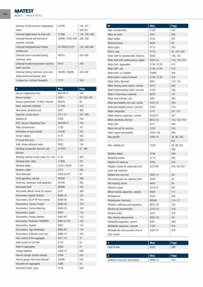
INDEX | ANALYTICAL
Unitronic 50 kN universal multipurpose
frame
S205N 126, 321,
500-507
Universal digital tester for load cells C138N 146, 326, 448
Universal flexural and transverse
machine, concrete
C095N / C093-02N 296, 308
Universal multispeed load frames,
soil/bitumen
S212N/S216 KIT 124, 494-496
Universal servo-controlled testing
machines, steel
H001A 434-439
Universal tensile/compression machine
steel/ concrete
H010 446
Universal testing machines, servo-con-
trolled electromechanical, steel
H004N / H008N 442-449
U-shape box, confined flowability C173 330
V Mod. Page
Vacuum degrassing Oven B091M-01 159
Vacuum pumps V203 83, 526, 597
Vacuum pyknometer 10 litres, bitumen B067N 84
Valve, automatic hydraulic C115N 318
Vane shear, pocket for soil S057 460
Vaporiser, curing rooms C311-01 347, 350
Vaseline oil S328 546
VDO, Vacuum Degassing Oven B091M-01 159
Vebé consistometer C183 331
Verification of force transfer C155N 325
Vernier calipers V175 593
V-Funnel flow time C171 330
Vialit, binder adhesion tester B053 136
Vibrating compaction hammer, soil,
bitumen
S197N1 97, 490
Vibrating machine mortar cubes 70,7 mm E132 409
Vibrating table, Vebé C184N 331
Vibrating tables C278, C281N 344
Vibrators, poker C272 345
Vibro-deaerator A059-02 KIT 84
Vicat apparatus, manual E055N 389
Vicatronic, automatic Vicat apparatus E044N 390
Viscometer bath B088N 162
Viscometer, Marsh funnel for cement E037 388
Viscometers Asphalt Institute B088-34 163
Viscometers, BS-IP-RF flow reverse B088-80 163
Viscometers, Cannon Fenske B088-50 163
Viscometers, Cannon Manning B088-20 163
Viscometers, Engler B080 153
Viscometers, Pensky-Martens B094 KIT 155
Viscometers, Redwood /TAR/BRTA B084-01 KIT 153
Viscometers, Saybolt B087 154
Viscometers, Tag closed/open B092 KIT 155
Viscometers, Zeitfuchs cross-arm B088-70 163
Void content of fine aggregate A071-10 37
Voids content of dry filler A124 53
Voids of aggregates A069 31
Voltage stabilizer V208-10 598
Volume change, burette (triaxial) S358 553
Volume gauge instrument (triaxial) S338N 553
Volumeter for aggregates A086 53
Volumetric flasks, glass V109 584
W Mod. Page
Walz consistometer C188 334
Warm air dryer V201 598
Wash bottles V120 587
Washing sieves A045 36
Watch glass V115 585
Watch, stop V170 50, 476, 592
Water bath for penetrometer, bitumen B058 139, 142
Water bath with cooling device, digital B052-02 123, 135, 410
Water bath, aggregates E136 / E139 410
Water bath, soil E136 / E139 410
Water bath: Le Chatelier E064N 398
Water baths, curing of cement E136 / E139 410
Water baths, Marshall B051 134, 135
Water flowing sieves device, cement E016 385
Water impermeability tester, concrete C435 380
Water in bituminous materials B076 147
Water level indicator, soil S061 463
Water permeability one-coat, mortar E035-10 394
Water permeability testers, concrete C430 379
Water refrigerator E141 347, 411
Water retention apparatus, cement E039-01 387
Water sensitivity, bitumen B052-02 123, 135, 410
Water stills V211 599
Water test set for concrete C220 335
Water vapour permeability E082-11N 399
Wax paraffin V300-19 28, 88, 395,
601
Wax, melting pot A106 28, 88, 351,
464
Weather station V148 589
Weighting bottles V110 585
Weights for balances V036 579
Weights, slotted for oedometer and
shear test machines
S273 KIT 530, 553 537
Welded wire nets test H003-14 441
Wet sieving pan+lid, stainless steel A046 36
Wet washing sieves A045 36
Whatman paper V218-01 601
Wheel tracking apparatus, asphalt B038 112
Wheelbarrow V226 600
Wheeltracker, Hamburg B038A 114-117
Wilhelmi, softening point apparatus B072-20 143
Windsor pin penetrometer C410-10 376
Windsor probe C410 376
Wire strands extensometer H003-18 441
Workability apparatus, cement E081 399
Workability apparatus, concrete C189 334
Workable life and correction time of
fresh mortar
E083-10 400
Y Mod. Page
Yield of lime E035 386
Z Mod. Page
Zeitfhchs cross-arm viscometers B088-70 163
614
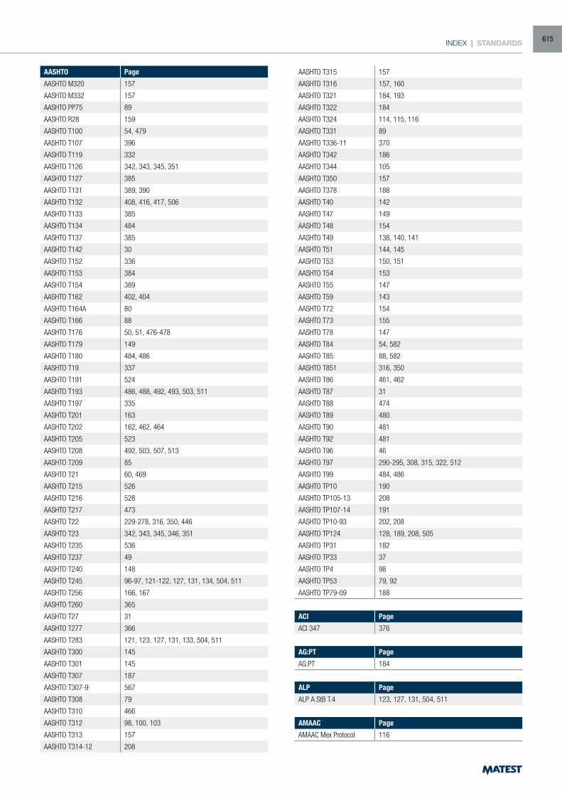
INDEX | STANDARDS
AASHTO Page
AASHTO M320 157
AASHTO M332 157
AASHTO PP75 89
AASHTO R28 159
AASHTO T100 54, 479
AASHTO T107 396
AASHTO T119 332
AASHTO T126 342, 343, 345, 351
AASHTO T127 385
AASHTO T131 389, 390
AASHTO T132 408, 416, 417, 506
AASHTO T133 385
AASHTO T134 484
AASHTO T137 385
AASHTO T142 30
AASHTO T152 336
AASHTO T153 384
AASHTO T154 389
AASHTO T162 402, 404
AASHTO T164A 80
AASHTO T166 88
AASHTO T176 50, 51, 476-478
AASHTO T179 149
AASHTO T180 484, 486
AASHTO T19 337
AASHTO T191 524
AASHTO T193 486, 488, 492, 493, 503, 511
AASHTO T197 335
AASHTO T201 163
AASHTO T202 162, 462, 464
AASHTO T205 523
AASHTO T208 492, 503, 507, 513
AASHTO T209 85
AASHTO T21 60, 469
AASHTO T215 526
AASHTO T216 528
AASHTO T217 473
AASHTO T22 229-278, 316, 350, 446
AASHTO T23 342, 343, 345, 346, 351
AASHTO T235 536
AASHTO T237 49
AASHTO T240 148
AASHTO T245 96-97, 121-122, 127, 131, 134, 504, 511
AASHTO T256 166, 167
AASHTO T260 365
AASHTO T27 31
AASHTO T277 366
AASHTO T283 121, 123, 127, 131, 133, 504, 511
AASHTO T300 145
AASHTO T301 145
AASHTO T307 187
AASHTO T307-9 567
AASHTO T308 79
AASHTO T310 466
AASHTO T312 98, 100, 103
AASHTO T313 157
AASHTO T314-12 208
AASHTO T315 157
AASHTO T316 157, 160
AASHTO T321 184, 193
AASHTO T322 184
AASHTO T324 114, 115, 116
AASHTO T331 89
AASHTO T336-11 370
AASHTO T342 186
AASHTO T344 105
AASHTO T350 157
AASHTO T378 188
AASHTO T40 142
AASHTO T47 149
AASHTO T48 154
AASHTO T49 138, 140, 141
AASHTO T51 144, 145
AASHTO T53 150, 151
AASHTO T54 153
AASHTO T55 147
AASHTO T59 143
AASHTO T72 154
AASHTO T73 155
AASHTO T78 147
AASHTO T84 54, 582
AASHTO T85 88, 582
AASHTO T851 316, 350
AASHTO T86 461, 462
AASHTO T87 31
AASHTO T88 474
AASHTO T89 480
AASHTO T90 481
AASHTO T92 481
AASHTO T96 46
AASHTO T97 290-295, 308, 315, 322, 512
AASHTO T99 484, 486
AASHTO TP10 190
AASHTO TP105-13 208
AASHTO TP107-14 191
AASHTO TP10-93 202, 208
AASHTO TP124 128, 189, 208, 505
AASHTO TP31 182
AASHTO TP33 37
AASHTO TP4 98
AASHTO TP53 79, 92
AASHTO TP79-09 188
ACI Page
ACI 347 376
AG:PT Page
AG:PT 184
ALP Page
ALP A StB T.4 123, 127, 131, 504, 511
AMAAC Page
AMAAC Mex Protocol 116
615
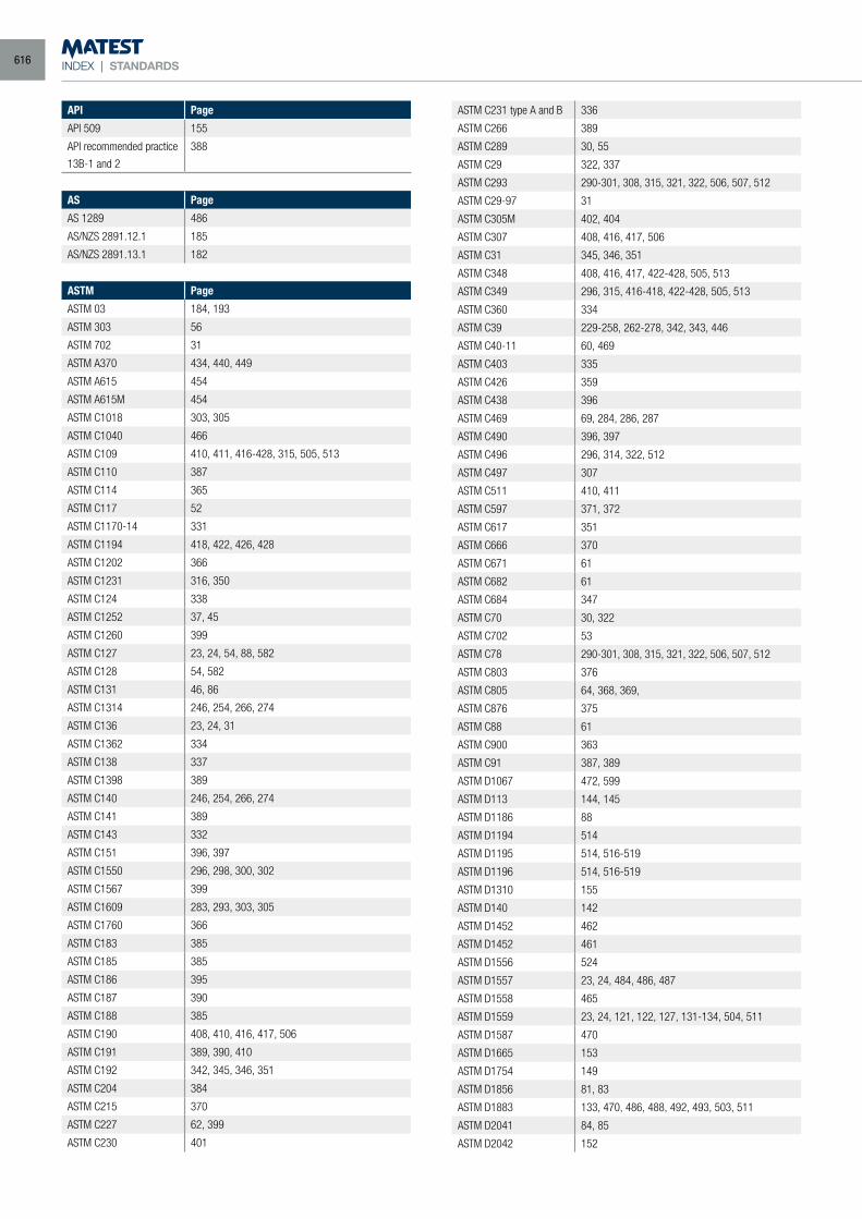
INDEX | STANDARDS
API Page
API 509 155
API recommended practice
13B-1 and 2
388
AS Page
AS 1289 486
AS/NZS 2891.12.1 185
AS/NZS 2891.13.1 182
ASTM Page
ASTM 03 184, 193
ASTM 303 56
ASTM 702 31
ASTM A370 434, 440, 449
ASTM A615 454
ASTM A615M 454
ASTM C1018 303, 305
ASTM C1040 466
ASTM C109 410, 411, 416-428, 315, 505, 513
ASTM C110 387
ASTM C114 365
ASTM C117 52
ASTM C1170-14 331
ASTM C1194 418, 422, 426, 428
ASTM C1202 366
ASTM C1231 316, 350
ASTM C124 338
ASTM C1252 37, 45
ASTM C1260 399
ASTM C127 23, 24, 54, 88, 582
ASTM C128 54, 582
ASTM C131 46, 86
ASTM C1314 246, 254, 266, 274
ASTM C136 23, 24, 31
ASTM C1362 334
ASTM C138 337
ASTM C1398 389
ASTM C140 246, 254, 266, 274
ASTM C141 389
ASTM C143 332
ASTM C151 396, 397
ASTM C1550 296, 298, 300, 302
ASTM C1567 399
ASTM C1609 283, 293, 303, 305
ASTM C1760 366
ASTM C183 385
ASTM C185 385
ASTM C186 395
ASTM C187 390
ASTM C188 385
ASTM C190 408, 410, 416, 417, 506
ASTM C191 389, 390, 410
ASTM C192 342, 345, 346, 351
ASTM C204 384
ASTM C215 370
ASTM C227 62, 399
ASTM C230 401
ASTM C231 type A and B 336
ASTM C266 389
ASTM C289 30, 55
ASTM C29 322, 337
ASTM C293 290-301, 308, 315, 321, 322, 506, 507, 512
ASTM C29-97 31
ASTM C305M 402, 404
ASTM C307 408, 416, 417, 506
ASTM C31 345, 346, 351
ASTM C348 408, 416, 417, 422-428, 505, 513
ASTM C349 296, 315, 416-418, 422-428, 505, 513
ASTM C360 334
ASTM C39 229-258, 262-278, 342, 343, 446
ASTM C40-11 60, 469
ASTM C403 335
ASTM C426 359
ASTM C438 396
ASTM C469 69, 284, 286, 287
ASTM C490 396, 397
ASTM C496 296, 314, 322, 512
ASTM C497 307
ASTM C511 410, 411
ASTM C597 371, 372
ASTM C617 351
ASTM C666 370
ASTM C671 61
ASTM C682 61
ASTM C684 347
ASTM C70 30, 322
ASTM C702 53
ASTM C78 290-301, 308, 315, 321, 322, 506, 507, 512
ASTM C803 376
ASTM C805 64, 368, 369,
ASTM C876 375
ASTM C88 61
ASTM C900 363
ASTM C91 387, 389
ASTM D1067 472, 599
ASTM D113 144, 145
ASTM D1186 88
ASTM D1194 514
ASTM D1195 514, 516-519
ASTM D1196 514, 516-519
ASTM D1310 155
ASTM D140 142
ASTM D1452 462
ASTM D1452 461
ASTM D1556 524
ASTM D1557 23, 24, 484, 486, 487
ASTM D1558 465
ASTM D1559 23, 24, 121, 122, 127, 131-134, 504, 511
ASTM D1587 470
ASTM D1665 153
ASTM D1754 149
ASTM D1856 81, 83
ASTM D1883 133, 470, 486, 488, 492, 493, 503, 511
ASTM D2041 84, 85
ASTM D2042 152
616
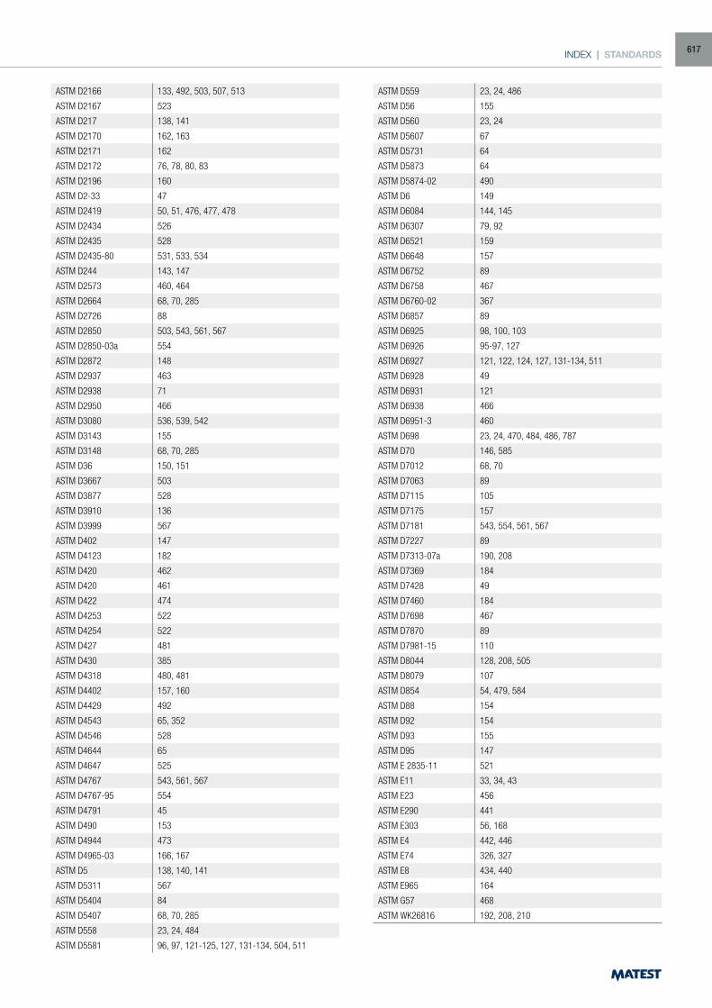
INDEX | STANDARDS
ASTM D2166 133, 492, 503, 507, 513
ASTM D2167 523
ASTM D217 138, 141
ASTM D2170 162, 163
ASTM D2171 162
ASTM D2172 76, 78, 80, 83
ASTM D2196 160
ASTM D2-33 47
ASTM D2419 50, 51, 476, 477, 478
ASTM D2434 526
ASTM D2435 528
ASTM D2435-80 531, 533, 534
ASTM D244 143, 147
ASTM D2573 460, 464
ASTM D2664 68, 70, 285
ASTM D2726 88
ASTM D2850 503, 543, 561, 567
ASTM D2850-03a 554
ASTM D2872 148
ASTM D2937 463
ASTM D2938 71
ASTM D2950 466
ASTM D3080 536, 539, 542
ASTM D3143 155
ASTM D3148 68, 70, 285
ASTM D36 150, 151
ASTM D3667 503
ASTM D3877 528
ASTM D3910 136
ASTM D3999 567
ASTM D402 147
ASTM D4123 182
ASTM D420 462
ASTM D420 461
ASTM D422 474
ASTM D4253 522
ASTM D4254 522
ASTM D427 481
ASTM D430 385
ASTM D4318 480, 481
ASTM D4402 157, 160
ASTM D4429 492
ASTM D4543 65, 352
ASTM D4546 528
ASTM D4644 65
ASTM D4647 525
ASTM D4767 543, 561, 567
ASTM D4767-95 554
ASTM D4791 45
ASTM D490 153
ASTM D4944 473
ASTM D4965-03 166, 167
ASTM D5 138, 140, 141
ASTM D5311 567
ASTM D5404 84
ASTM D5407 68, 70, 285
ASTM D558 23, 24, 484
ASTM D5581 96, 97, 121-125, 127, 131-134, 504, 511
ASTM D559 23, 24, 486
ASTM D56 155
ASTM D560 23, 24
ASTM D5607 67
ASTM D5731 64
ASTM D5873 64
ASTM D5874-02 490
ASTM D6 149
ASTM D6084 144, 145
ASTM D6307 79, 92
ASTM D6521 159
ASTM D6648 157
ASTM D6752 89
ASTM D6758 467
ASTM D6760-02 367
ASTM D6857 89
ASTM D6925 98, 100, 103
ASTM D6926 95-97, 127
ASTM D6927 121, 122, 124, 127, 131-134, 511
ASTM D6928 49
ASTM D6931 121
ASTM D6938 466
ASTM D6951-3 460
ASTM D698 23, 24, 470, 484, 486, 787
ASTM D70 146, 585
ASTM D7012 68, 70
ASTM D7063 89
ASTM D7115 105
ASTM D7175 157
ASTM D7181 543, 554, 561, 567
ASTM D7227 89
ASTM D7313-07a 190, 208
ASTM D7369 184
ASTM D7428 49
ASTM D7460 184
ASTM D7698 467
ASTM D7870 89
ASTM D7981-15 110
ASTM D8044 128, 208, 505
ASTM D8079 107
ASTM D854 54, 479, 584
ASTM D88 154
ASTM D92 154
ASTM D93 155
ASTM D95 147
ASTM E 2835-11 521
ASTM E11 33, 34, 43
ASTM E23 456
ASTM E290 441
ASTM E303 56, 168
ASTM E4 442, 446
ASTM E74 326, 327
ASTM E8 434, 440
ASTM E965 164
ASTM G57 468
ASTM WK26816 192, 208, 210
617
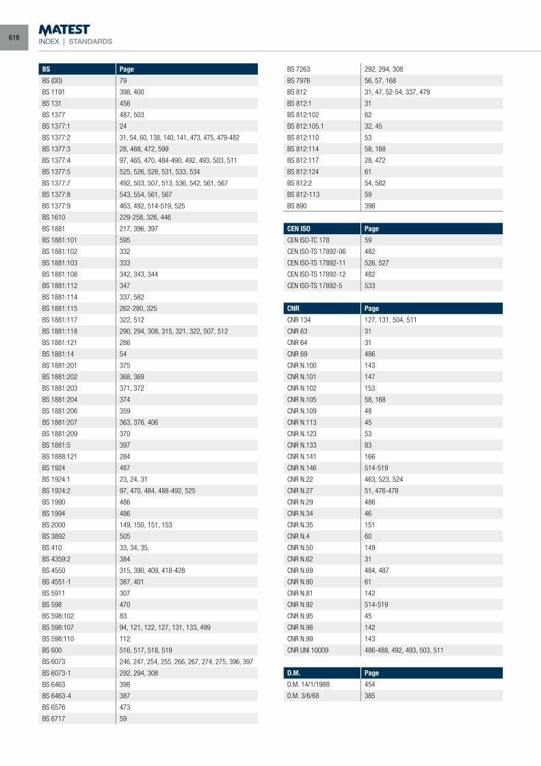
INDEX | STANDARDS
BS Page
BS (DD) 79
BS 1191 398, 400
BS 131 456
BS 1377 487, 503
BS 1377:1 24
BS 1377:2 31, 54, 60, 138, 140, 141, 473, 475, 479-482
BS 1377:3 28, 468, 472, 599
BS 1377:4 97, 465, 470, 484-490, 492, 493, 503, 511
BS 1377:5 525, 526, 528, 531, 533, 534
BS 1377:7 492, 503, 507, 513, 536, 542, 561, 567
BS 1377:8 543, 554, 561, 567
BS 1377:9 463, 492, 514-519, 525
BS 1610 229-258, 326, 446
BS 1881 217, 396, 397
BS 1881:101 595
BS 1881:102 332
BS 1881:103 333
BS 1881:108 342, 343, 344
BS 1881:112 347
BS 1881:114 337, 582
BS 1881:115 262-280, 325
BS 1881:117 322, 512
BS 1881:118 290, 294, 308, 315, 321, 322, 507, 512
BS 1881:121 286
BS 1881:14 54
BS 1881:201 375
BS 1881:202 368, 369
BS 1881:203 371, 372
BS 1881:204 374
BS 1881:206 359
BS 1881:207 363, 376, 406
BS 1881:209 370
BS 1881:5 397
BS 1888:121 284
BS 1924 487
BS 1924:1 23, 24, 31
BS 1924:2 97, 470, 484, 488-492, 525
BS 1990 486
BS 1994 486
BS 2000 149, 150, 151, 153
BS 3892 505
BS 410 33, 34, 35,
BS 4359:2 384
BS 4550 315, 390, 409, 418-428
BS 4551-1 387, 401
BS 5911 307
BS 598 470
BS 598:102 83
BS 598:107 94, 121, 122, 127, 131, 133, 499
BS 598:110 112
BS 600 516, 517, 518, 519
BS 6073 246, 247, 254, 255, 266, 267, 274, 275, 396, 397
BS 6073-1 292, 294, 308
BS 6463 398
BS 6463-4 387
BS 6576 473
BS 6717 59
BS 7263 292, 294, 308
BS 7976 56, 57, 168
BS 812 31, 47, 52-54, 337, 479
BS 812:1 31
BS 812:102 62
BS 812:105.1 32, 45
BS 812:110 53
BS 812:114 58, 168
BS 812:117 28, 472
BS 812:124 61
BS 812:2 54, 582
BS 812-113 59
BS 890 398
CEN ISO Page
CEN ISO-TC 178 59
CEN ISO-TS 17892-06 482
CEN ISO-TS 17892-11 526, 527
CEN ISO-TS 17892-12 482
CEN ISO-TS 17892-5 533
CNR Page
CNR 134 127, 131, 504, 511
CNR 63 31
CNR 64 31
CNR 69 486
CNR N.100 143
CNR N.101 147
CNR N.102 153
CNR N.105 58, 168
CNR N.109 48
CNR N.113 45
CNR N.123 53
CNR N.133 83
CNR N.141 166
CNR N.146 514-519
CNR N.22 463, 523, 524
CNR N.27 51, 476-478
CNR N.29 486
CNR N.34 46
CNR N.35 151
CNR N.4 60
CNR N.50 149
CNR N.62 31
CNR N.69 484, 487
CNR N.80 61
CNR N.81 142
CNR N.92 514-519
CNR N.95 45
CNR N.98 142
CNR N.99 143
CNR UNI 10009 486-488, 492, 493, 503, 511
D.M. Page
D.M. 14/1/1988 454
D.M. 3/6/68 385
618
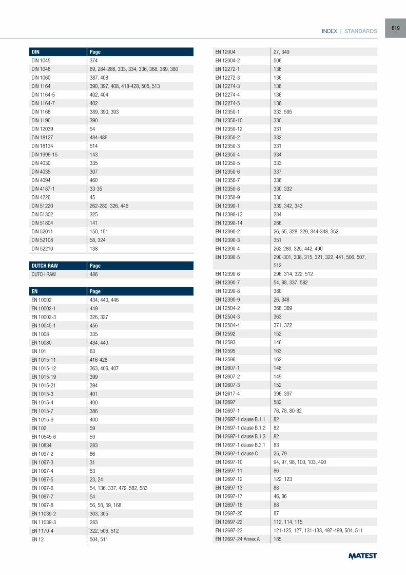
INDEX | STANDARDS
DIN Page
DIN 1045 374
DIN 1048 69, 284-286, 333, 334, 336, 368, 369, 380
DIN 1060 387, 408
DIN 1164 390, 397, 408, 418-428, 505, 513
DIN 1164-5 402, 404
DIN 1164-7 402
DIN 1168 389, 390, 393
DIN 1196 390
DIN 12039 54
DIN 18127 484-486
DIN 18134 514
DIN 1996-15 143
DIN 4030 335
DIN 4035 307
DIN 4094 460
DIN 4187-1 33-35
DIN 4226 45
DIN 51220 262-280, 326, 446
DIN 51302 325
DIN 51804 141
DIN 52011 150, 151
DIN 52108 58, 324
DIN 52210 138
DUTCH RAW Page
DUTCH RAW 486
EN Page
EN 10002 434, 440, 446
EN 10002-1 449
EN 10002-3 326, 327
EN 10045-1 456
EN 1008 335
EN 10080 434, 440
EN 101 63
EN 1015-11 416-428
EN 1015-12 363, 406, 407
EN 1015-19 399
EN 1015-21 394
EN 1015-3 401
EN 1015-4 400
EN 1015-7 386
EN 1015-9 400
EN 102 59
EN 10545-6 59
EN 10834 283
EN 1097-2 86
EN 1097-3 31
EN 1097-4 53
EN 1097-5 23, 24
EN 1097-6 54, 136, 337, 479, 582, 583
EN 1097-7 54
EN 1097-8 56, 58, 59, 168
EN 11039-2 303, 305
EN 11039-3 283
EN 1170-4 322, 506, 512
EN 12 504, 511
EN 12004 27, 349
EN 12004-2 506
EN 12272-1 136
EN 12272-3 136
EN 12274-3 136
EN 12274-4 136
EN 12274-5 136
EN 12350-1 333, 595
EN 12350-10 330
EN 12350-12 331
EN 12350-2 332
EN 12350-3 331
EN 12350-4 334
EN 12350-5 333
EN 12350-6 337
EN 12350-7 336
EN 12350-8 330, 332
EN 12350-9 330
EN 12390-1 339, 342, 343
EN 12390-13 284
EN 12390-14 286
EN 12390-2 26, 65, 328, 329, 344-348, 352
EN 12390-3 351
EN 12390-4 262-280, 325, 442, 490
EN 12390-5 290-301, 308, 315, 321, 322, 441, 506, 507,
512
EN 12390-6 296, 314, 322, 512
EN 12390-7 54, 88, 337, 582
EN 12390-8 380
EN 12390-9 26, 348
EN 12504-2 368, 369
EN 12504-3 363
EN 12504-4 371, 372
EN 12592 152
EN 12593 146
EN 12595 163
EN 12596 162
EN 12607-1 148
EN 12607-2 149
EN 12607-3 152
EN 12617-4 396, 397
EN 12697 582
EN 12697-1 76, 78, 80-82
EN 12697-1 clause B.1.1 82
EN 12697-1 clause B.1.2 82
EN 12697-1 clause B.1.3 82
EN 12697-1 clause B.3.1 83
EN 12697-1 clause C 25, 79
EN 12697-10 94, 97, 98, 100, 103, 490
EN 12697-11 86
EN 12697-12 122, 123
EN 12697-13 88
EN 12697-17 46, 86
EN 12697-18 88
EN 12697-20 87
EN 12697-22 112, 114, 115
EN 12697-23 121-125, 127, 131-133, 497-499, 504, 511
EN 12697-24 Annex A 185
619
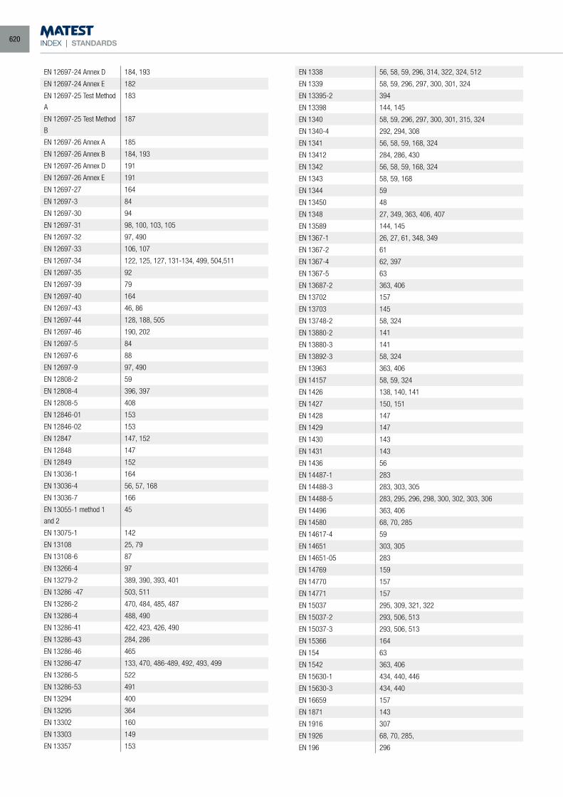
INDEX | STANDARDS
EN 12697-24 Annex D 184, 193
EN 12697-24 Annex E 182
EN 12697-25 Test Method
A
183
EN 12697-25 Test Method
B
187
EN 12697-26 Annex A 185
EN 12697-26 Annex B 184, 193
EN 12697-26 Annex D 191
EN 12697-26 Annex E 191
EN 12697-27 164
EN 12697-3 84
EN 12697-30 94
EN 12697-31 98, 100, 103, 105
EN 12697-32 97, 490
EN 12697-33 106, 107
EN 12697-34 122, 125, 127, 131-134, 499, 504,511
EN 12697-35 92
EN 12697-39 79
EN 12697-40 164
EN 12697-43 46, 86
EN 12697-44 128, 188, 505
EN 12697-46 190, 202
EN 12697-5 84
EN 12697-6 88
EN 12697-9 97, 490
EN 12808-2 59
EN 12808-4 396, 397
EN 12808-5 408
EN 12846-01 153
EN 12846-02 153
EN 12847 147, 152
EN 12848 147
EN 12849 152
EN 13036-1 164
EN 13036-4 56, 57, 168
EN 13036-7 166
EN 13055-1 method 1
and 2
45
EN 13075-1 142
EN 13108 25, 79
EN 13108-6 87
EN 13266-4 97
EN 13279-2 389, 390, 393, 401
EN 13286 -47 503, 511
EN 13286-2 470, 484, 485, 487
EN 13286-4 488, 490
EN 13286-41 422, 423, 426, 490
EN 13286-43 284, 286
EN 13286-46 465
EN 13286-47 133, 470, 486-489, 492, 493, 499
EN 13286-5 522
EN 13286-53 491
EN 13294 400
EN 13295 364
EN 13302 160
EN 13303 149
EN 13357 153
EN 1338 56, 58, 59, 296, 314, 322, 324, 512
EN 1339 58, 59, 296, 297, 300, 301, 324
EN 13395-2 394
EN 13398 144, 145
EN 1340 58, 59, 296, 297, 300, 301, 315, 324
EN 1340-4 292, 294, 308
EN 1341 56, 58, 59, 168, 324
EN 13412 284, 286, 430
EN 1342 56, 58, 59, 168, 324
EN 1343 58, 59, 168
EN 1344 59
EN 13450 48
EN 1348 27, 349, 363, 406, 407
EN 13589 144, 145
EN 1367-1 26, 27, 61, 348, 349
EN 1367-2 61
EN 1367-4 62, 397
EN 1367-5 63
EN 13687-2 363, 406
EN 13702 157
EN 13703 145
EN 13748-2 58, 324
EN 13880-2 141
EN 13880-3 141
EN 13892-3 58, 324
EN 13963 363, 406
EN 14157 58, 59, 324
EN 1426 138, 140, 141
EN 1427 150, 151
EN 1428 147
EN 1429 147
EN 1430 143
EN 1431 143
EN 1436 56
EN 14487-1 283
EN 14488-3 283, 303, 305
EN 14488-5 283, 295, 296, 298, 300, 302, 303, 306
EN 14496 363, 406
EN 14580 68, 70, 285
EN 14617-4 59
EN 14651 303, 305
EN 14651-05 283
EN 14769 159
EN 14770 157
EN 14771 157
EN 15037 295, 309, 321, 322
EN 15037-2 293, 506, 513
EN 15037-3 293, 506, 513
EN 15366 164
EN 154 63
EN 1542 363, 406
EN 15630-1 434, 440, 446
EN 15630-3 434, 440
EN 16659 157
EN 1871 143
EN 1916 307
EN 1926 68, 70, 285,
EN 196 296
620

INDEX | STANDARDS
EN 196-1 26, 315, 348, 402, 404, 408-411, 416-419, 422-
428, 505, 513
EN 196-2 25, 394
EN 196-21 25, 394
EN 196-3 389, 390, 398, 402, 404
EN 196-6 384, 385
EN 196-7 385
EN 196-8 395, 411
EN 196-9 395
EN 1997-2 60
EN 206 335
EN 22592 154
EN 22719 155
EN 413-2 386, 399, 400, 402, 404
EN 445 387, 388
EN 451-2 385
EN 459-1 398
EN 459-2 25, 386, 387, 394, 399-402, 404,
EN 480-1 402, 404
EN 480-2 389, 390
EN 480-4 337
EN 491 507
EN 50081-1 434
EN 538 507
EN 58 142
EN 7500-1 434, 440, 442, 446
EN 772-1 246, 247, 254, 255, 266, 267, 274, 275
EN 932-5 23, 24, 40, 42, 61
EN 933-10 38, 51, 478
EN 933-11 52
EN 933-2 33, 34, 35, 43
EN 933-3 31, 32, 55
EN 933-4 45
EN 933-5 45, 422, 423, 426
EN 933-6 45, 55
EN 933-7 45
EN 933-8 50, 51, 476-478
EN 933-9 52, 475, 587
EN ISO Page
EN ISO 10545-7 63
EN ISO 148-1 456
EN ISO 15630-1 454
EN ISO 376 326, 327
EN ISO 3838 146, 585
EN ISO 679 408-411, 418-428, 505, 513
EN ISO 6892 442
EN ISO 6892-1 434, 440, 446
EN ISO 7438 454
EN ISO 9597 398
ERMCO-EFNARC Page
ERMCO-EFNARC 330
GOST Page
GOST 11505-75 145
GOST 26798-1 418-428
GOST 33138-2014 145
GOST 10180-2012 229...280
IP Page
IP 179 141
IP 184 153
IP 222 162
IP 34 155
IP 35 155
IP 36 154
IP 485 152
IP 487 152
IP 49 138
IP 494 142
IP 74-77 147
ISO Page
ISO 1042 584
ISO 10545-6 59
ISO 178 449
ISO 2137 141
ISO 2431 388
ISO 2592 154
ISO 2719 155
ISO 3310-1 33, 34, 40-43
ISO 3310-2 33, 35, 43
ISO 3506-1 449
ISO 4624 363
ISO 527 449
ISO 565 33
ISO 604 449
ISO 6784 69, 284, 286
ISO 6872 31
ISO 898-1 449
ISRM Page
ISRM 64, 67, 68, 285
ITALIAN HIGHWAY SYSTEM
Page
ITALIAN HIGHWAY SYSTEM 164
LCPC Page
LCPC French Method 335
MPW BEGIUM Page
MPW BEGIUM 164
NCAT Page
NCAT (National Centre for
Asphalt Technology)
79
NF Page
NF P094-071-2 536
NF P15-413 408
NF P15-414 389, 390
NF P15-431 389, 390
NF P15-432 398
NF P15-433 396, 397
NF P15-434 397, 400
621
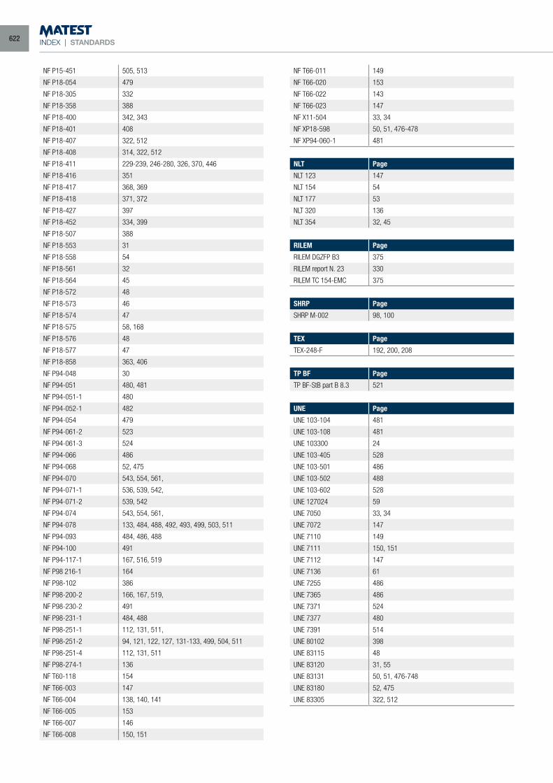
INDEX | STANDARDS
NF P15-451 505, 513
NF P18-054 479
NF P18-305 332
NF P18-358 388
NF P18-400 342, 343
NF P18-401 408
NF P18-407 322, 512
NF P18-408 314, 322, 512
NF P18-411 229-239, 246-280, 326, 370, 446
NF P18-416 351
NF P18-417 368, 369
NF P18-418 371, 372
NF P18-427 397
NF P18-452 334, 399
NF P18-507 388
NF P18-553 31
NF P18-558 54
NF P18-561 32
NF P18-564 45
NF P18-572 48
NF P18-573 46
NF P18-574 47
NF P18-575 58, 168
NF P18-576 48
NF P18-577 47
NF P18-858 363, 406
NF P94-048 30
NF P94-051 480, 481
NF P94-051-1 480
NF P94-052-1 482
NF P94-054 479
NF P94-061-2 523
NF P94-061-3 524
NF P94-066 486
NF P94-068 52, 475
NF P94-070 543, 554, 561,
NF P94-071-1 536, 539, 542,
NF P94-071-2 539, 542
NF P94-074 543, 554, 561,
NF P94-078 133, 484, 488, 492, 493, 499, 503, 511
NF P94-093 484, 486, 488
NF P94-100 491
NF P94-117-1 167, 516, 519
NF P98 216-1 164
NF P98-102 386
NF P98-200-2 166, 167, 519,
NF P98-230-2 491
NF P98-231-1 484, 488
NF P98-251-1 112, 131, 511,
NF P98-251-2 94, 121, 122, 127, 131-133, 499, 504, 511
NF P98-251-4 112, 131, 511
NF P98-274-1 136
NF T60-118 154
NF T66-003 147
NF T66-004 138, 140, 141
NF T66-005 153
NF T66-007 146
NF T66-008 150, 151
NF T66-011 149
NF T66-020 153
NF T66-022 143
NF T66-023 147
NF X11-504 33, 34
NF XP18-598 50, 51, 476-478
NF XP94-060-1 481
NLT Page
NLT 123 147
NLT 154 54
NLT 177 53
NLT 320 136
NLT 354 32, 45
RILEM Page
RILEM DGZFP B3 375
RILEM report N. 23 330
RILEM TC 154-EMC 375
SHRP Page
SHRP M-002 98, 100
TEX Page
TEX-248-F 192, 200, 208
TP BF Page
TP BF-StB part B 8.3 521
UNE Page
UNE 103-104 481
UNE 103-108 481
UNE 103300 24
UNE 103-405 528
UNE 103-501 486
UNE 103-502 488
UNE 103-602 528
UNE 127024 59
UNE 7050 33, 34
UNE 7072 147
UNE 7110 149
UNE 7111 150, 151
UNE 7112 147
UNE 7136 61
UNE 7255 486
UNE 7365 486
UNE 7371 524
UNE 7377 480
UNE 7391 514
UNE 80102 398
UNE 83115 48
UNE 83120 31, 55
UNE 83131 50, 51, 476-748
UNE 83180 52, 475
UNE 83305 322, 512
622
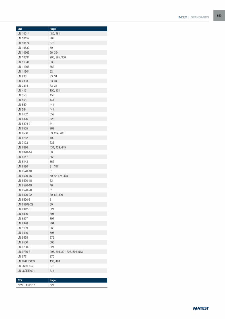
INDEX | STANDARDS
UNI Page
UNI 10014 480, 481
UNI 10157 363
UNI 10174 375
UNI 10532 59
UNI 10766 66, 354
UNI 10834 283, 295, 306,
UNI 11044 330
UNI 11307 362
UNI 11604 62
UNI 2331 33, 34
UNI 2333 33, 34
UNI 2334 33, 35
UNI 4161 150, 151
UNI 556 453
UNI 558 441
UNI 559 441
UNI 564 441
UNI 6132 352
UNI 6326 326
UNI 6394-2 54
UNI 6555 362
UNI 6556 69, 284, 286
UNI 6782 400
UNI 7123 335
UNI 7676 434, 439, 445
UNI 8020-14 60
UNI 8147 362
UNI 8148 362
UNI 8520 31, 397
UNI 8520-10 61
UNI 8520-15 50-52, 475-478
UNI 8520-18 32
UNI 8520-19 46
UNI 8520-20 61
UNI 8520-22 30, 62, 399
UNI 8520-6 31
UNI 85209-22 30
UNI 8942-3 321
UNI 8996 394
UNI 8997 394
UNI 8998 394
UNI 9189 369
UNI 9416 595
UNI 9535 375
UNI 9536 363
UNI 9730-3 321
UNI 9730-3 296, 309, 321-323, 506, 513
UNI 9771 370
UNI CNR 10009 133, 499
UNI JGJ/T 152 375
UNI JSCE E 601 375
ZTV Page
ZTV E-StB 2017 521
623
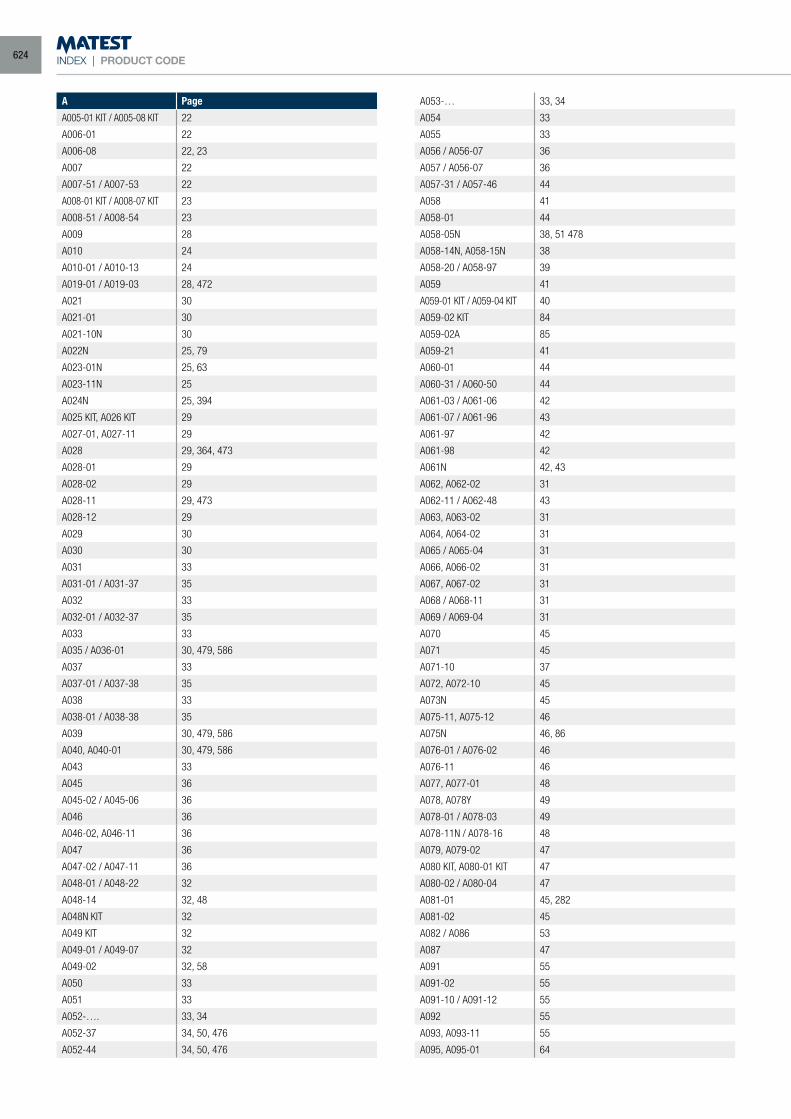
INDEX | PRODUCT CODE
A Page
A005-01 KIT / A005-08 KIT 22
A006-01 22
A006-08 22, 23
A007 22
A007-51 / A007-53 22
A008-01 KIT / A008-07 KIT 23
A008-51 / A008-54 23
A009 28
A010 24
A010-01 / A010-13 24
A019-01 / A019-03 28, 472
A021 30
A021-01 30
A021-10N 30
A022N 25, 79
A023-01N 25, 63
A023-11N 25
A024N 25, 394
A025 KIT, A026 KIT 29
A027-01, A027-11 29
A028 29, 364, 473
A028-01 29
A028-02 29
A028-11 29, 473
A028-12 29
A029 30
A030 30
A031 33
A031-01 / A031-37 35
A032 33
A032-01 / A032-37 35
A033 33
A035 / A036-01 30, 479, 586
A037 33
A037-01 / A037-38 35
A038 33
A038-01 / A038-38 35
A039 30, 479, 586
A040, A040-01 30, 479, 586
A043 33
A045 36
A045-02 / A045-06 36
A046 36
A046-02, A046-11 36
A047 36
A047-02 / A047-11 36
A048-01 / A048-22 32
A048-14 32, 48
A048N KIT 32
A049 KIT 32
A049-01 / A049-07 32
A049-02 32, 58
A050 33
A051 33
A052-…. 33, 34
A052-37 34, 50, 476
A052-44 34, 50, 476
A053-… 33, 34
A054 33
A055 33
A056 / A056-07 36
A057 / A056-07 36
A057-31 / A057-46 44
A058 41
A058-01 44
A058-05N 38, 51 478
A058-14N, A058-15N 38
A058-20 / A058-97 39
A059 41
A059-01 KIT / A059-04 KIT 40
A059-02 KIT 84
A059-02A 85
A059-21 41
A060-01 44
A060-31 / A060-50 44
A061-03 / A061-06 42
A061-07 / A061-96 43
A061-97 42
A061-98 42
A061N 42, 43
A062, A062-02 31
A062-11 / A062-48 43
A063, A063-02 31
A064, A064-02 31
A065 / A065-04 31
A066, A066-02 31
A067, A067-02 31
A068 / A068-11 31
A069 / A069-04 31
A070 45
A071 45
A071-10 37
A072, A072-10 45
A073N 45
A075-11, A075-12 46
A075N 46, 86
A076-01 / A076-02 46
A076-11 46
A077, A077-01 48
A078, A078Y 49
A078-01 / A078-03 49
A078-11N / A078-16 48
A079, A079-02 47
A080 KIT, A080-01 KIT 47
A080-02 / A080-04 47
A081-01 45, 282
A081-02 45
A082 / A086 53
A087 47
A091 55
A091-02 55
A091-10 / A091-12 55
A092 55
A093, A093-11 55
A095, A095-01 64
624
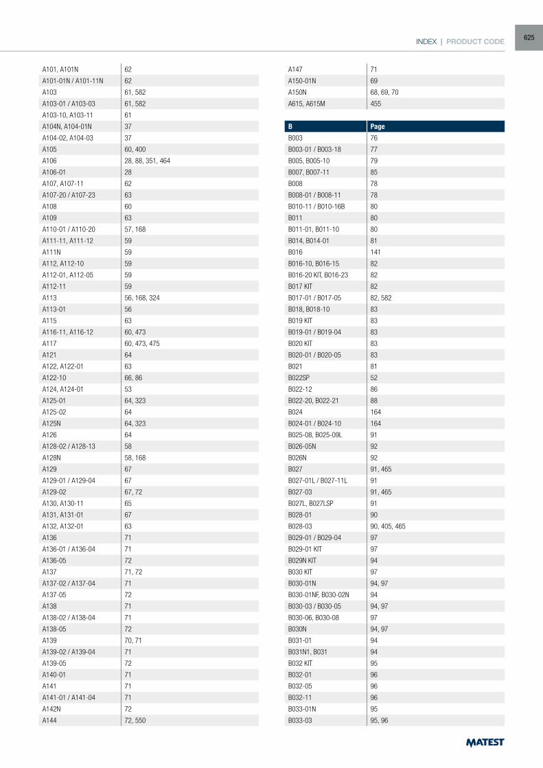
INDEX | PRODUCT CODE
A101, A101N 62
A101-01N / A101-11N 62
A103 61, 582
A103-01 / A103-03 61, 582
A103-10, A103-11 61
A104N, A104-01N 37
A104-02, A104-03 37
A105 60, 400
A106 28, 88, 351, 464
A106-01 28
A107, A107-11 62
A107-20 / A107-23 63
A108 60
A109 63
A110-01 / A110-20 57, 168
A111-11, A111-12 59
A111N 59
A112, A112-10 59
A112-01, A112-05 59
A112-11 59
A113 56, 168, 324
A113-01 56
A115 63
A116-11, A116-12 60, 473
A117 60, 473, 475
A121 64
A122, A122-01 63
A122-10 66, 86
A124, A124-01 53
A125-01 64, 323
A125-02 64
A125N 64, 323
A126 64
A128-02 / A128-13 58
A128N 58, 168
A129 67
A129-01 / A129-04 67
A129-02 67, 72
A130, A130-11 65
A131, A131-01 67
A132, A132-01 63
A136 71
A136-01 / A136-04 71
A136-05 72
A137 71, 72
A137-02 / A137-04 71
A137-05 72
A138 71
A138-02 / A138-04 71
A138-05 72
A139 70, 71
A139-02 / A139-04 71
A139-05 72
A140-01 71
A141 71
A141-01 / A141-04 71
A142N 72
A144 72, 550
A147 71
A150-01N 69
A150N 68, 69, 70
A615, A615M 455
B Page
B003 76
B003-01 / B003-18 77
B005, B005-10 79
B007, B007-11 85
B008 78
B008-01 / B008-11 78
B010-11 / B010-16B 80
B011 80
B011-01, B011-10 80
B014, B014-01 81
B016 141
B016-10, B016-15 82
B016-20 KIT, B016-23 82
B017 KIT 82
B017-01 / B017-05 82, 582
B018, B018-10 83
B019 KIT 83
B019-01 / B019-04 83
B020 KIT 83
B020-01 / B020-05 83
B021 81
B022SP 52
B022-12 86
B022-20, B022-21 88
B024 164
B024-01 / B024-10 164
B025-08, B025-09L 91
B026-05N 92
B026N 92
B027 91, 465
B027-01L / B027-11L 91
B027-03 91, 465
B027L, B027LSP 91
B028-01 90
B028-03 90, 405, 465
B029-01 / B029-04 97
B029-01 KIT 97
B029N KIT 94
B030 KIT 97
B030-01N 94, 97
B030-01NF, B030-02N 94
B030-03 / B030-05 94, 97
B030-06, B030-08 97
B030N 94, 97
B031-01 94
B031N1, B031 94
B032 KIT 95
B032-01 96
B032-05 96
B032-11 96
B033-01N 95
B033-03 95, 96
625
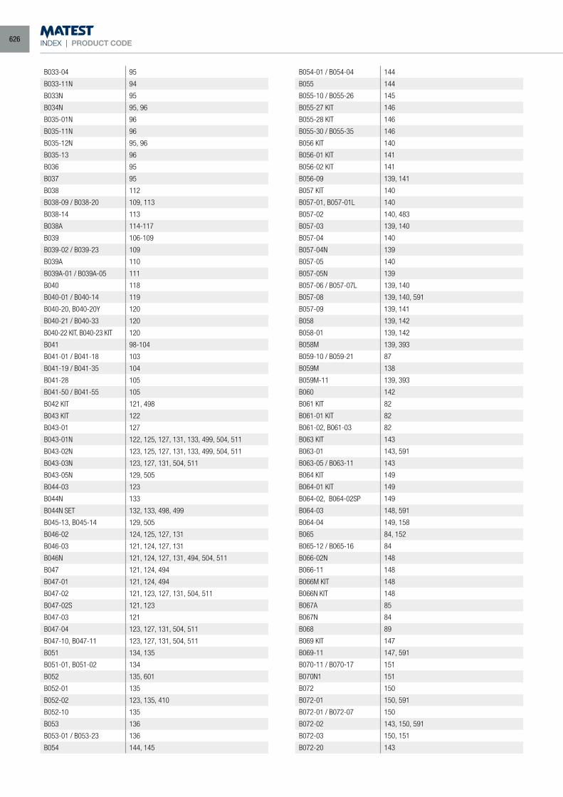
INDEX | PRODUCT CODE
B033-04 95
B033-11N 94
B033N 95
B034N 95, 96
B035-01N 96
B035-11N 96
B035-12N 95, 96
B035-13 96
B036 95
B037 95
B038 112
B038-09 / B038-20 109, 113
B038-14 113
B038A 114-117
B039 106-109
B039-02 / B039-23 109
B039A 110
B039A-01 / B039A-05 111
B040 118
B040-01 / B040-14 119
B040-20, B040-20Y 120
B040-21 / B040-33 120
B040-22 KIT, B040-23 KIT 120
B041 98-104
B041-01 / B041-18 103
B041-19 / B041-35 104
B041-28 105
B041-50 / B041-55 105
B042 KIT 121, 498
B043 KIT 122
B043-01 127
B043-01N 122, 125, 127, 131, 133, 499, 504, 511
B043-02N 123, 125, 127, 131, 133, 499, 504, 511
B043-03N 123, 127, 131, 504, 511
B043-05N 129, 505
B044-03 123
B044N 133
B044N SET 132, 133, 498, 499
B045-13, B045-14 129, 505
B046-02 124, 125, 127, 131
B046-03 121, 124, 127, 131
B046N 121, 124, 127, 131, 494, 504, 511
B047 121, 124, 494
B047-01 121, 124, 494
B047-02 121, 123, 127, 131, 504, 511
B047-02S 121, 123
B047-03 121
B047-04 123, 127, 131, 504, 511
B047-10, B047-11 123, 127, 131, 504, 511
B051 134, 135
B051-01, B051-02 134
B052 135, 601
B052-01 135
B052-02 123, 135, 410
B052-10 135
B053 136
B053-01 / B053-23 136
B054 144, 145
B054-01 / B054-04 144
B055 144
B055-10 / B055-26 145
B055-27 KIT 146
B055-28 KIT 146
B055-30 / B055-35 146
B056 KIT 140
B056-01 KIT 141
B056-02 KIT 141
B056-09 139, 141
B057 KIT 140
B057-01, B057-01L 140
B057-02 140, 483
B057-03 139, 140
B057-04 140
B057-04N 139
B057-05 140
B057-05N 139
B057-06 / B057-07L 139, 140
B057-08 139, 140, 591
B057-09 139, 141
B058 139, 142
B058-01 139, 142
B058M 139, 393
B059-10 / B059-21 87
B059M 138
B059M-11 139, 393
B060 142
B061 KIT 82
B061-01 KIT 82
B061-02, B061-03 82
B063 KIT 143
B063-01 143, 591
B063-05 / B063-11 143
B064 KIT 149
B064-01 KIT 149
B064-02, B064-02SP 149
B064-03 148, 591
B064-04 149, 158
B065 84, 152
B065-12 / B065-16 84
B066-02N 148
B066-11 148
B066M KIT 148
B066N KIT 148
B067A 85
B067N 84
B068 89
B069 KIT 147
B069-11 147, 591
B070-11 / B070-17 151
B070N1 151
B072 150
B072-01 150, 591
B072-01 / B072-07 150
B072-02 143, 150, 591
B072-03 150, 151
B072-20 143
626
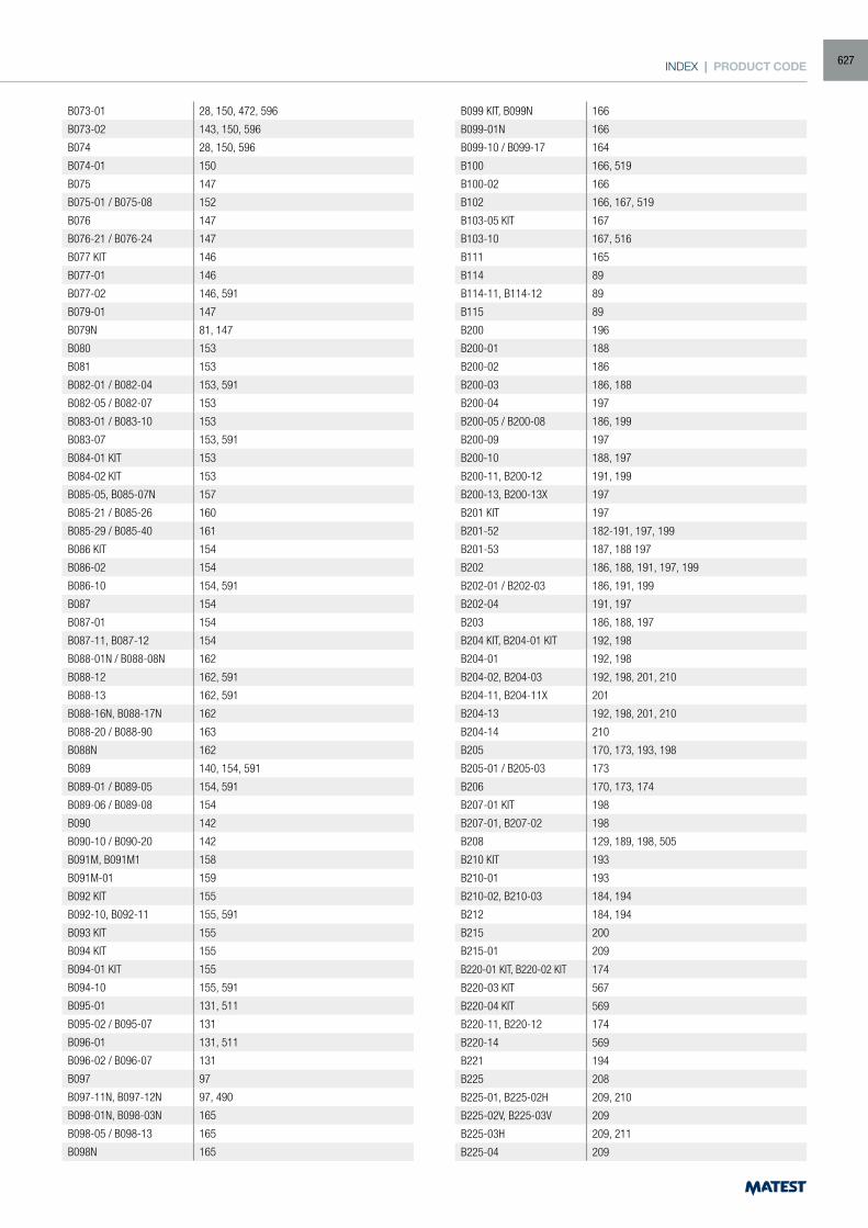
INDEX | PRODUCT CODE
B073-01 28, 150, 472, 596
B073-02 143, 150, 596
B074 28, 150, 596
B074-01 150
B075 147
B075-01 / B075-08 152
B076 147
B076-21 / B076-24 147
B077 KIT 146
B077-01 146
B077-02 146, 591
B079-01 147
B079N 81, 147
B080 153
B081 153
B082-01 / B082-04 153, 591
B082-05 / B082-07 153
B083-01 / B083-10 153
B083-07 153, 591
B084-01 KIT 153
B084-02 KIT 153
B085-05, B085-07N 157
B085-21 / B085-26 160
B085-29 / B085-40 161
B086 KIT 154
B086-02 154
B086-10 154, 591
B087 154
B087-01 154
B087-11, B087-12 154
B088-01N / B088-08N 162
B088-12 162, 591
B088-13 162, 591
B088-16N, B088-17N 162
B088-20 / B088-90 163
B088N 162
B089 140, 154, 591
B089-01 / B089-05 154, 591
B089-06 / B089-08 154
B090 142
B090-10 / B090-20 142
B091M, B091M1 158
B091M-01 159
B092 KIT 155
B092-10, B092-11 155, 591
B093 KIT 155
B094 KIT 155
B094-01 KIT 155
B094-10 155, 591
B095-01 131, 511
B095-02 / B095-07 131
B096-01 131, 511
B096-02 / B096-07 131
B097 97
B097-11N, B097-12N 97, 490
B098-01N, B098-03N 165
B098-05 / B098-13 165
B098N 165
B099 KIT, B099N 166
B099-01N 166
B099-10 / B099-17 164
B100 166, 519
B100-02 166
B102 166, 167, 519
B103-05 KIT 167
B103-10 167, 516
B111 165
B114 89
B114-11, B114-12 89
B115 89
B200 196
B200-01 188
B200-02 186
B200-03 186, 188
B200-04 197
B200-05 / B200-08 186, 199
B200-09 197
B200-10 188, 197
B200-11, B200-12 191, 199
B200-13, B200-13X 197
B201 KIT 197
B201-52 182-191, 197, 199
B201-53 187, 188 197
B202 186, 188, 191, 197, 199
B202-01 / B202-03 186, 191, 199
B202-04 191, 197
B203 186, 188, 197
B204 KIT, B204-01 KIT 192, 198
B204-01 192, 198
B204-02, B204-03 192, 198, 201, 210
B204-11, B204-11X 201
B204-13 192, 198, 201, 210
B204-14 210
B205 170, 173, 193, 198
B205-01 / B205-03 173
B206 170, 173, 174
B207-01 KIT 198
B207-01, B207-02 198
B208 129, 189, 198, 505
B210 KIT 193
B210-01 193
B210-02, B210-03 184, 194
B212 184, 194
B215 200
B215-01 209
B220-01 KIT, B220-02 KIT 174
B220-03 KIT 567
B220-04 KIT 569
B220-11, B220-12 174
B220-14 569
B221 194
B225 208
B225-01, B225-02H 209, 210
B225-02V, B225-03V 209
B225-03H 209, 211
B225-04 209
627
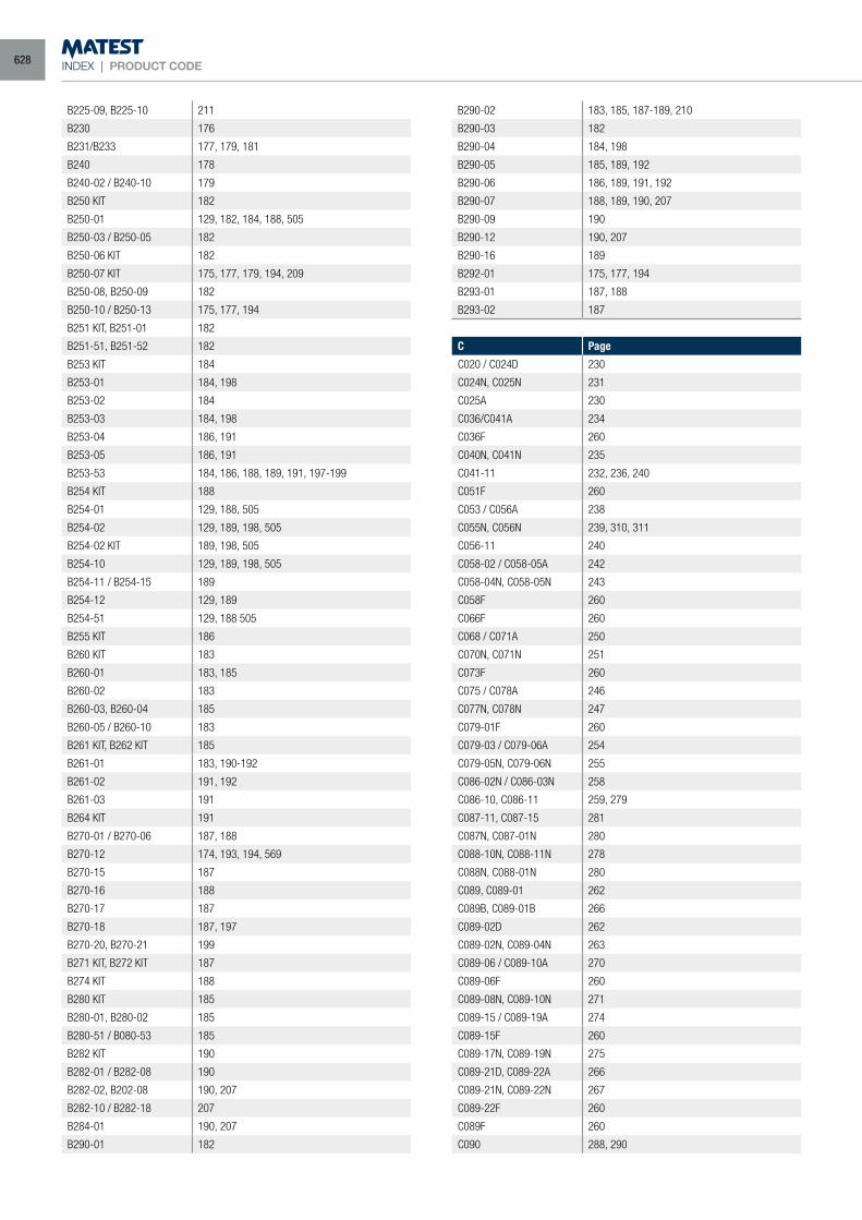
INDEX | PRODUCT CODE
B225-09, B225-10 211
B230 176
B231/B233 177, 179, 181
B240 178
B240-02 / B240-10 179
B250 KIT 182
B250-01 129, 182, 184, 188, 505
B250-03 / B250-05 182
B250-06 KIT 182
B250-07 KIT 175, 177, 179, 194, 209
B250-08, B250-09 182
B250-10 / B250-13 175, 177, 194
B251 KIT, B251-01 182
B251-51, B251-52 182
B253 KIT 184
B253-01 184, 198
B253-02 184
B253-03 184, 198
B253-04 186, 191
B253-05 186, 191
B253-53 184, 186, 188, 189, 191, 197-199
B254 KIT 188
B254-01 129, 188, 505
B254-02 129, 189, 198, 505
B254-02 KIT 189, 198, 505
B254-10 129, 189, 198, 505
B254-11 / B254-15 189
B254-12 129, 189
B254-51 129, 188 505
B255 KIT 186
B260 KIT 183
B260-01 183, 185
B260-02 183
B260-03, B260-04 185
B260-05 / B260-10 183
B261 KIT, B262 KIT 185
B261-01 183, 190-192
B261-02 191, 192
B261-03 191
B264 KIT 191
B270-01 / B270-06 187, 188
B270-12 174, 193, 194, 569
B270-15 187
B270-16 188
B270-17 187
B270-18 187, 197
B270-20, B270-21 199
B271 KIT, B272 KIT 187
B274 KIT 188
B280 KIT 185
B280-01, B280-02 185
B280-51 / B080-53 185
B282 KIT 190
B282-01 / B282-08 190
B282-02, B202-08 190, 207
B282-10 / B282-18 207
B284-01 190, 207
B290-01 182
B290-02 183, 185, 187-189, 210
B290-03 182
B290-04 184, 198
B290-05 185, 189, 192
B290-06 186, 189, 191, 192
B290-07 188, 189, 190, 207
B290-09 190
B290-12 190, 207
B290-16 189
B292-01 175, 177, 194
B293-01 187, 188
B293-02 187
C Page
C020 / C024D 230
C024N, C025N 231
C025A 230
C036/C041A 234
C036F 260
C040N, C041N 235
C041-11 232, 236, 240
C051F 260
C053 / C056A 238
C055N, C056N 239, 310, 311
C056-11 240
C058-02 / C058-05A 242
C058-04N, C058-05N 243
C058F 260
C066F 260
C068 / C071A 250
C070N, C071N 251
C073F 260
C075 / C078A 246
C077N, C078N 247
C079-01F 260
C079-03 / C079-06A 254
C079-05N, C079-06N 255
C086-02N / C086-03N 258
C086-10, C086-11 259, 279
C087-11, C087-15 281
C087N, C087-01N 280
C088-10N, C088-11N 278
C088N, C088-01N 280
C089, C089-01 262
C089B, C089-01B 266
C089-02D 262
C089-02N, C089-04N 263
C089-06 / C089-10A 270
C089-06F 260
C089-08N, C089-10N 271
C089-15 / C089-19A 274
C089-15F 260
C089-17N, C089-19N 275
C089-21D, C089-22A 266
C089-21N, C089-22N 267
C089-22F 260
C089F 260
C090 288, 290
628
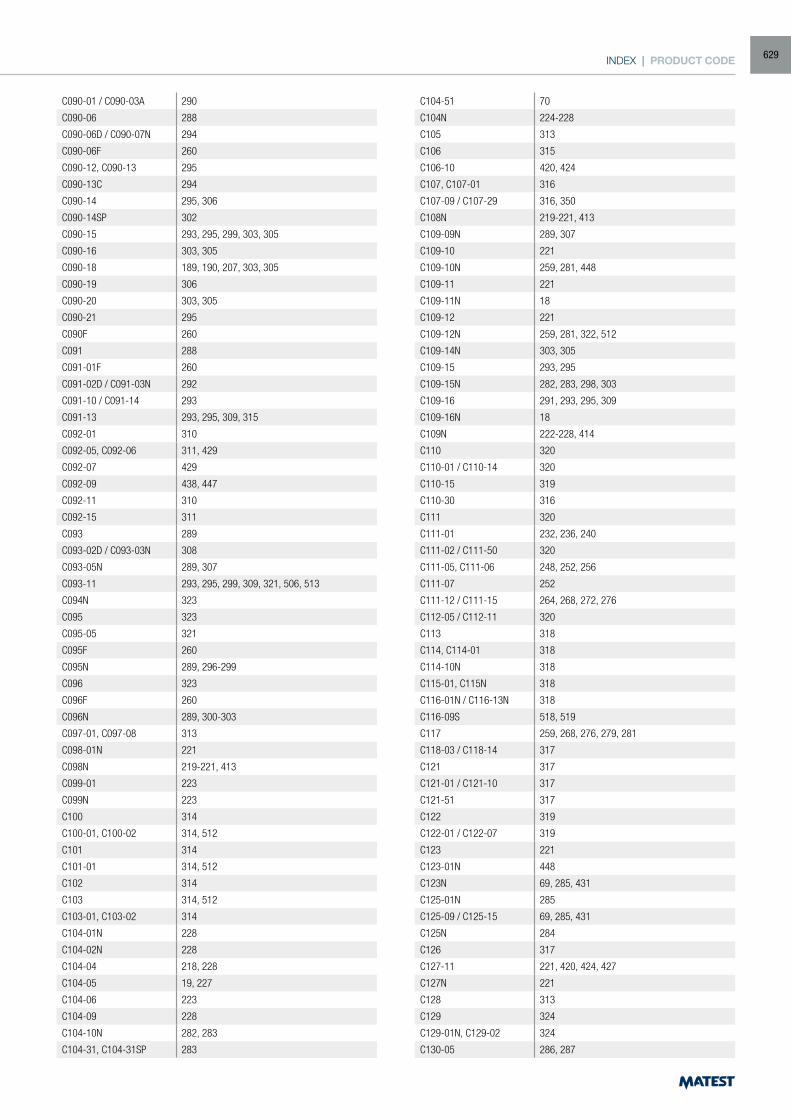
INDEX | PRODUCT CODE
C090-01 / C090-03A 290
C090-06 288
C090-06D / C090-07N 294
C090-06F 260
C090-12, C090-13 295
C090-13C 294
C090-14 295, 306
C090-14SP 302
C090-15 293, 295, 299, 303, 305
C090-16 303, 305
C090-18 189, 190, 207, 303, 305
C090-19 306
C090-20 303, 305
C090-21 295
C090F 260
C091 288
C091-01F 260
C091-02D / C091-03N 292
C091-10 / C091-14 293
C091-13 293, 295, 309, 315
C092-01 310
C092-05, C092-06 311, 429
C092-07 429
C092-09 438, 447
C092-11 310
C092-15 311
C093 289
C093-02D / C093-03N 308
C093-05N 289, 307
C093-11 293, 295, 299, 309, 321, 506, 513
C094N 323
C095 323
C095-05 321
C095F 260
C095N 289, 296-299
C096 323
C096F 260
C096N 289, 300-303
C097-01, C097-08 313
C098-01N 221
C098N 219-221, 413
C099-01 223
C099N 223
C100 314
C100-01, C100-02 314, 512
C101 314
C101-01 314, 512
C102 314
C103 314, 512
C103-01, C103-02 314
C104-01N 228
C104-02N 228
C104-04 218, 228
C104-05 19, 227
C104-06 223
C104-09 228
C104-10N 282, 283
C104-31, C104-31SP 283
C104-51 70
C104N 224-228
C105 313
C106 315
C106-10 420, 424
C107, C107-01 316
C107-09 / C107-29 316, 350
C108N 219-221, 413
C109-09N 289, 307
C109-10 221
C109-10N 259, 281, 448
C109-11 221
C109-11N 18
C109-12 221
C109-12N 259, 281, 322, 512
C109-14N 303, 305
C109-15 293, 295
C109-15N 282, 283, 298, 303
C109-16 291, 293, 295, 309
C109-16N 18
C109N 222-228, 414
C110 320
C110-01 / C110-14 320
C110-15 319
C110-30 316
C111 320
C111-01 232, 236, 240
C111-02 / C111-50 320
C111-05, C111-06 248, 252, 256
C111-07 252
C111-12 / C111-15 264, 268, 272, 276
C112-05 / C112-11 320
C113 318
C114, C114-01 318
C114-10N 318
C115-01, C115N 318
C116-01N / C116-13N 318
C116-09S 518, 519
C117 259, 268, 276, 279, 281
C118-03 / C118-14 317
C121 317
C121-01 / C121-10 317
C121-51 317
C122 319
C122-01 / C122-07 319
C123 221
C123-01N 448
C123N 69, 285, 431
C125-01N 285
C125-09 / C125-15 69, 285, 431
C125N 284
C126 317
C127-11 221, 420, 424, 427
C127N 221
C128 313
C129 324
C129-01N, C129-02 324
C130-05 286, 287
629
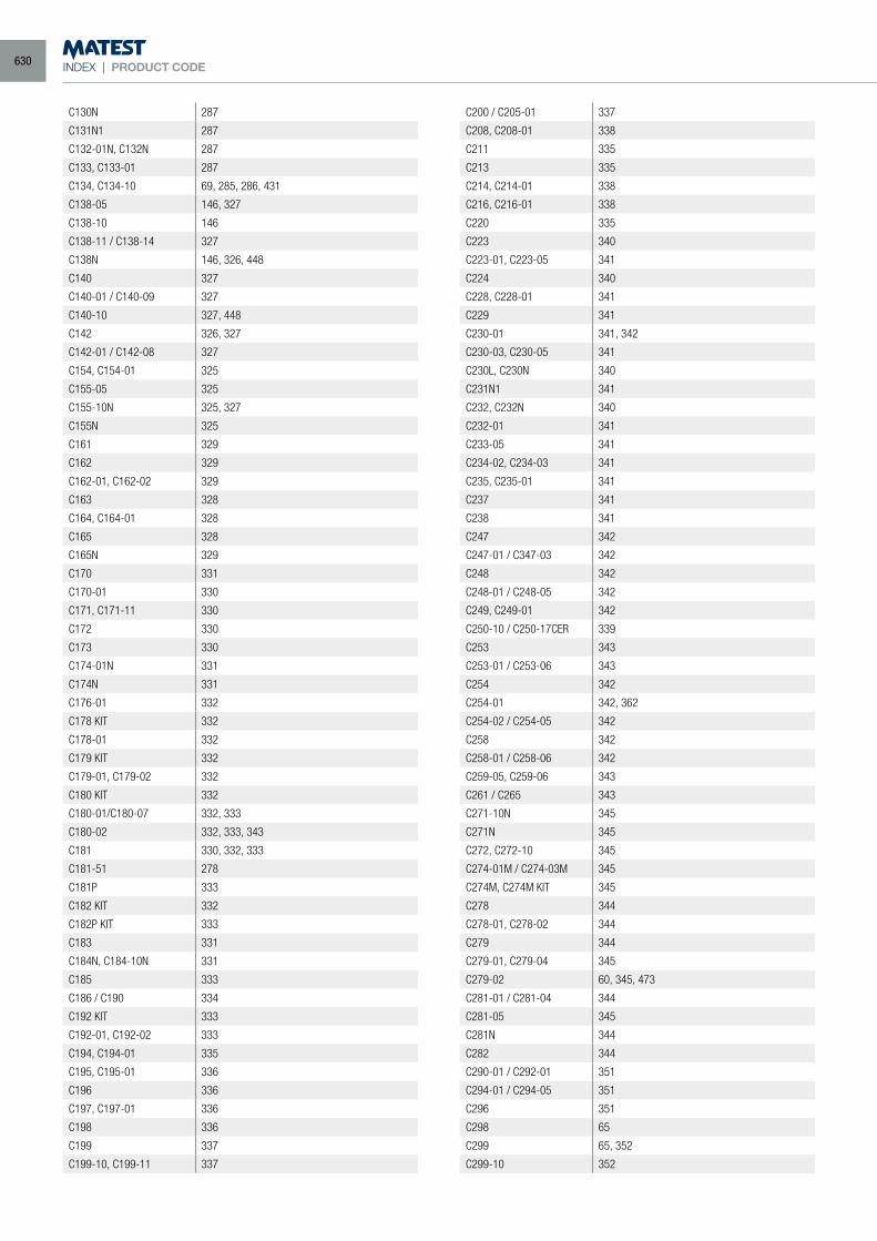
INDEX | PRODUCT CODE
C130N 287
C131N1 287
C132-01N, C132N 287
C133, C133-01 287
C134, C134-10 69, 285, 286, 431
C138-05 146, 327
C138-10 146
C138-11 / C138-14 327
C138N 146, 326, 448
C140 327
C140-01 / C140-09 327
C140-10 327, 448
C142 326, 327
C142-01 / C142-08 327
C154, C154-01 325
C155-05 325
C155-10N 325, 327
C155N 325
C161 329
C162 329
C162-01, C162-02 329
C163 328
C164, C164-01 328
C165 328
C165N 329
C170 331
C170-01 330
C171, C171-11 330
C172 330
C173 330
C174-01N 331
C174N 331
C176-01 332
C178 KIT 332
C178-01 332
C179 KIT 332
C179-01, C179-02 332
C180 KIT 332
C180-01/C180-07 332, 333
C180-02 332, 333, 343
C181 330, 332, 333
C181-51 278
C181P 333
C182 KIT 332
C182P KIT 333
C183 331
C184N, C184-10N 331
C185 333
C186 / C190 334
C192 KIT 333
C192-01, C192-02 333
C194, C194-01 335
C195, C195-01 336
C196 336
C197, C197-01 336
C198 336
C199 337
C199-10, C199-11 337
C200 / C205-01 337
C208, C208-01 338
C211 335
C213 335
C214, C214-01 338
C216, C216-01 338
C220 335
C223 340
C223-01, C223-05 341
C224 340
C228, C228-01 341
C229 341
C230-01 341, 342
C230-03, C230-05 341
C230L, C230N 340
C231N1 341
C232, C232N 340
C232-01 341
C233-05 341
C234-02, C234-03 341
C235, C235-01 341
C237 341
C238 341
C247 342
C247-01 / C347-03 342
C248 342
C248-01 / C248-05 342
C249, C249-01 342
C250-10 / C250-17CER 339
C253 343
C253-01 / C253-06 343
C254 342
C254-01 342, 362
C254-02 / C254-05 342
C258 342
C258-01 / C258-06 342
C259-05, C259-06 343
C261 / C265 343
C271-10N 345
C271N 345
C272, C272-10 345
C274-01M / C274-03M 345
C274M, C274M KIT 345
C278 344
C278-01, C278-02 344
C279 344
C279-01, C279-04 345
C279-02 60, 345, 473
C281-01 / C281-04 344
C281-05 345
C281N 344
C282 344
C290-01 / C292-01 351
C294-01 / C294-05 351
C296 351
C298 65
C299 65, 352
C299-10 352
630
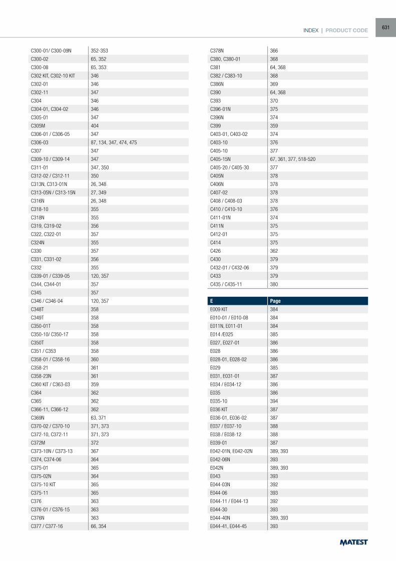
INDEX | PRODUCT CODE
C300-01/ C300-09N 352-353
C300-02 65, 352
C300-08 65, 353
C302 KIT, C302-10 KIT 346
C302-01 346
C302-11 347
C304 346
C304-01, C304-02 346
C305-01 347
C305M 404
C306-01 / C306-05 347
C306-03 87, 134, 347, 474, 475
C307 347
C309-10 / C309-14 347
C311-01 347, 350
C312-02 / C312-11 350
C313N, C313-01N 26, 348
C313-05N / C313-15N 27, 349
C316N 26, 348
C318-10 355
C318N 355
C319, C319-02 356
C322, C322-01 357
C324N 355
C330 357
C331, C331-02 356
C332 355
C339-01 / C339-05 120, 357
C344, C344-01 357
C345 357
C346 / C346-04 120, 357
C348T 358
C349T 358
C350-01T 358
C350-10/ C350-17 358
C350T 358
C351 / C353 358
C358-01 / C358-16 360
C358-21 361
C358-23N 361
C360 KIT / C363-03 359
C364 362
C365 362
C366-11, C366-12 362
C369N 63, 371
C370-02 / C370-10 371, 373
C372-10, C372-11 371, 373
C372M 372
C373-10N / C373-13 367
C374, C374-06 364
C375-01 365
C375-02N 364
C375-10 KIT 365
C375-11 365
C376 363
C376-01 / C376-15 363
C376N 363
C377 / C377-16 66, 354
C378N 366
C380, C380-01 368
C381 64, 368
C382 / C383-10 368
C386N 369
C390 64, 368
C393 370
C396-01N 375
C396N 374
C399 359
C403-01, C403-02 374
C403-10 376
C405-10 377
C405-15N 67, 361, 377, 518-520
C405-20 / C405-30 377
C405N 378
C406N 378
C407-02 378
C408 / C408-03 378
C410 / C410-10 376
C411-01N 374
C411N 375
C412-01 375
C414 375
C426 362
C430 379
C432-01 / C432-06 379
C433 379
C435 / C435-11 380
E Page
E009 KIT 384
E010-01 / E010-08 384
E011N, E011-01 384
E014 /E025 385
E027, E027-01 386
E028 386
E028-01, E028-02 386
E029 385
E031, E031-01 387
E034 / E034-12 386
E035 386
E035-10 394
E036 KIT 387
E036-01, E036-02 387
E037 / E037-10 388
E038 / E038-12 388
E039-01 387
E042-01N, E042-02N 389, 393
E042-06N 393
E042N 389, 393
E043 393
E044-03N 392
E044-06 393
E044-11 / E044-13 392
E044-30 393
E044-40N 389, 393
E044-41, E044-45 393
631
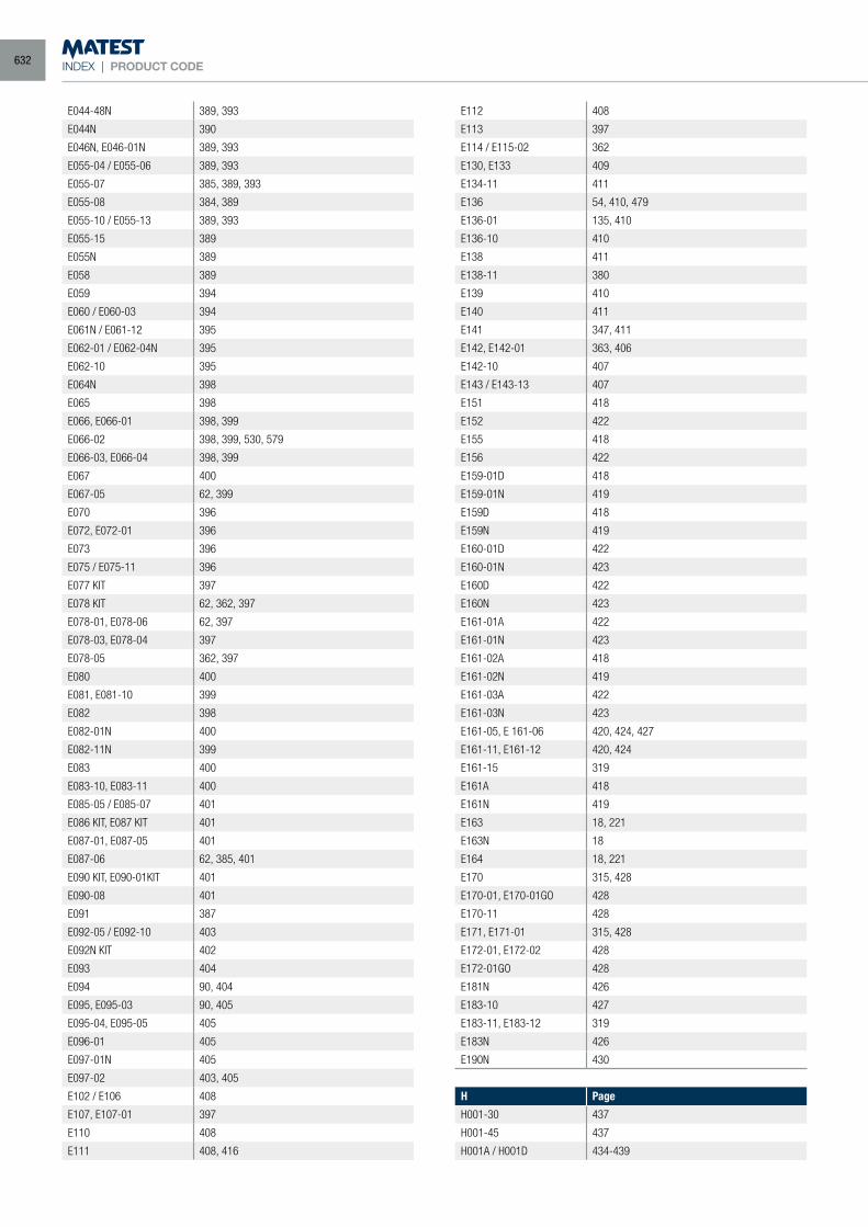
INDEX | PRODUCT CODE
E044-48N 389, 393
E044N 390
E046N, E046-01N 389, 393
E055-04 / E055-06 389, 393
E055-07 385, 389, 393
E055-08 384, 389
E055-10 / E055-13 389, 393
E055-15 389
E055N 389
E058 389
E059 394
E060 / E060-03 394
E061N / E061-12 395
E062-01 / E062-04N 395
E062-10 395
E064N 398
E065 398
E066, E066-01 398, 399
E066-02 398, 399, 530, 579
E066-03, E066-04 398, 399
E067 400
E067-05 62, 399
E070 396
E072, E072-01 396
E073 396
E075 / E075-11 396
E077 KIT 397
E078 KIT 62, 362, 397
E078-01, E078-06 62, 397
E078-03, E078-04 397
E078-05 362, 397
E080 400
E081, E081-10 399
E082 398
E082-01N 400
E082-11N 399
E083 400
E083-10, E083-11 400
E085-05 / E085-07 401
E086 KIT, E087 KIT 401
E087-01, E087-05 401
E087-06 62, 385, 401
E090 KIT, E090-01KIT 401
E090-08 401
E091 387
E092-05 / E092-10 403
E092N KIT 402
E093 404
E094 90, 404
E095, E095-03 90, 405
E095-04, E095-05 405
E096-01 405
E097-01N 405
E097-02 403, 405
E102 / E106 408
E107, E107-01 397
E110 408
E111 408, 416
E112 408
E113 397
E114 / E115-02 362
E130, E133 409
E134-11 411
E136 54, 410, 479
E136-01 135, 410
E136-10 410
E138 411
E138-11 380
E139 410
E140 411
E141 347, 411
E142, E142-01 363, 406
E142-10 407
E143 / E143-13 407
E151 418
E152 422
E155 418
E156 422
E159-01D 418
E159-01N 419
E159D 418
E159N 419
E160-01D 422
E160-01N 423
E160D 422
E160N 423
E161-01A 422
E161-01N 423
E161-02A 418
E161-02N 419
E161-03A 422
E161-03N 423
E161-05, E 161-06 420, 424, 427
E161-11, E161-12 420, 424
E161-15 319
E161A 418
E161N 419
E163 18, 221
E163N 18
E164 18, 221
E170 315, 428
E170-01, E170-01GO 428
E170-11 428
E171, E171-01 315, 428
E172-01, E172-02 428
E172-01GO 428
E181N 426
E183-10 427
E183-11, E183-12 319
E183N 426
E190N 430
H Page
H001-30 437
H001-45 437
H001A / H001D 434-439
632
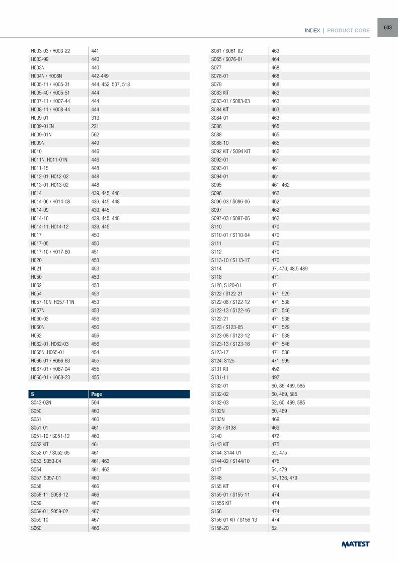
INDEX | PRODUCT CODE
H003-03 / H003-22 441
H003-99 440
H003N 440
H004N / H008N 442-449
H005-11 / H005-31 444, 452, 507, 513
H005-40 / H005-51 444
H007-11 / H007-44 444
H008-11 / H008-44 444
H009-01 313
H009-01EN 221
H009-01N 562
H009N 449
H010 446
H011N, H011-01N 446
H011-15 448
H012-01, H012-02 448
H013-01, H013-02 448
H014 439, 445, 448
H014-06 / H014-08 439, 445, 448
H014-09 439, 445
H014-10 439, 445, 448
H014-11, H014-12 439, 445
H017 450
H017-05 450
H017-10 / H017-60 451
H020 453
H021 453
H050 453
H052 453
H054 453
H057-10N, H057-11N 453
H057N 453
H060-03 456
H060N 456
H062 456
H062-01, H062-03 456
H065N, H065-01 454
H066-01 / H066-63 455
H067-01 / H067-04 455
H068-01 / H068-23 455
S Page
S043-02N 504
S050 460
S051 460
S051-01 461
S051-10 / S051-12 460
S052 KIT 461
S052-01 / S052-05 461
S053, S053-04 461, 463
S054 461, 463
S057, S057-01 460
S058 466
S058-11, S058-12 466
S059 467
S059-01, S059-02 467
S059-10 467
S060 466
S061 / S061-02 463
S065 / S076-01 464
S077 468
S078-01 468
S079 468
S083 KIT 463
S083-01 / S083-03 463
S084 KIT 463
S084-01 463
S086 465
S088 465
S088-10 465
S092 KIT / S094 KIT 462
S092-01 461
S093-01 461
S094-01 461
S095 461, 462
S096 462
S096-03 / S096-06 462
S097 462
S097-03 / S097-06 462
S110 470
S110-01 / S110-04 470
S111 470
S112 470
S113-10 / S113-17 470
S114 97, 470, 48,5 489
S118 471
S120, S120-01 471
S122 / S122-21 471, 529
S122-08 / S122-12 471, 538
S122-13 / S122-16 471, 546
S122-21 471, 538
S123 / S123-05 471, 529
S123-08 / S123-12 471, 538
S123-13 / S123-16 471, 546
S123-17 471, 538
S124, S125 471, 595
S131 KIT 492
S131-11 492
S132-01 60, 86, 469, 585
S132-02 60, 469, 585
S132-03 52, 60, 469, 585
S132N 60, 469
S133N 469
S135 / S138 469
S140 472
S143 KIT 475
S144, S144-01 52, 475
S144-02 / S144/10 475
S147 54, 479
S148 54, 136, 479
S155 KIT 474
S155-01 / S155-11 474
S155S KIT 474
S156 474
S156-01 KIT / S156-13 474
S156-20 52
633
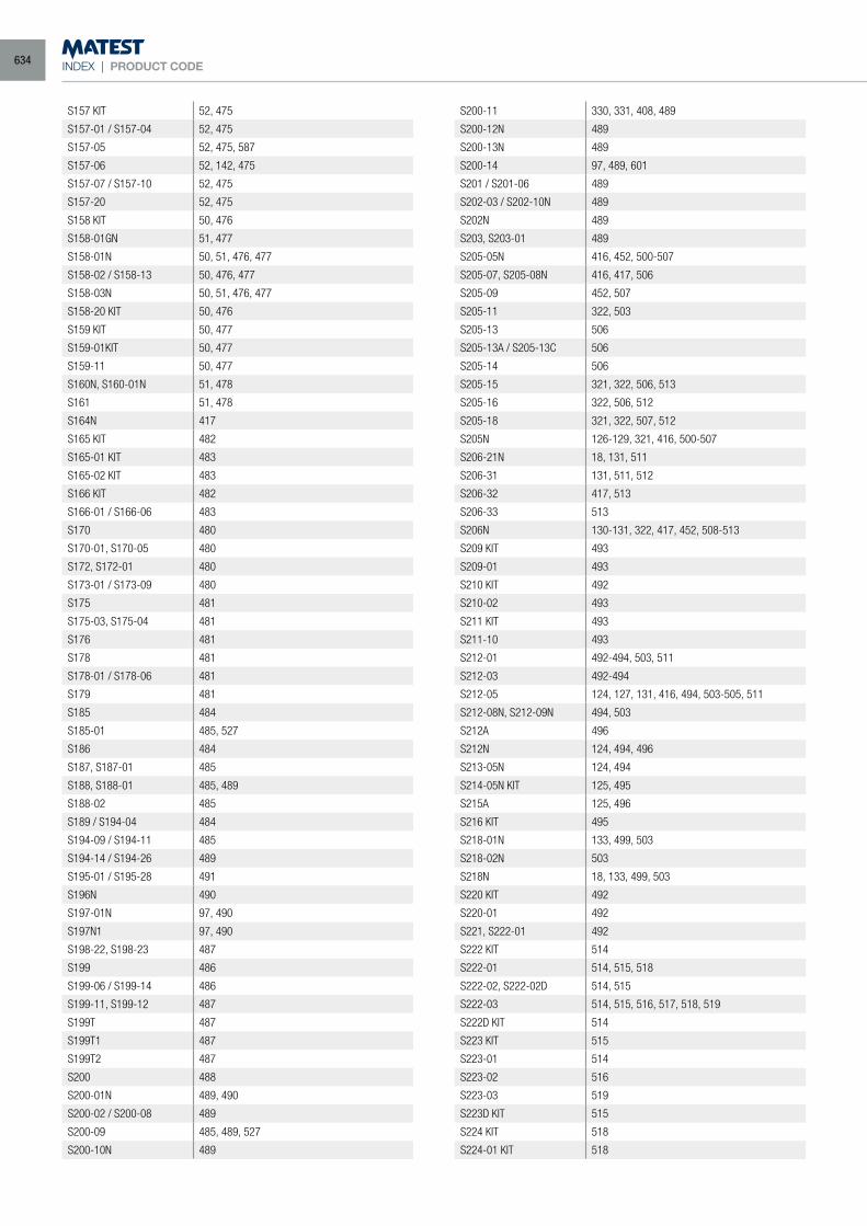
INDEX | PRODUCT CODE
S157 KIT 52, 475
S157-01 / S157-04 52, 475
S157-05 52, 475, 587
S157-06 52, 142, 475
S157-07 / S157-10 52, 475
S157-20 52, 475
S158 KIT 50, 476
S158-01GN 51, 477
S158-01N 50, 51, 476, 477
S158-02 / S158-13 50, 476, 477
S158-03N 50, 51, 476, 477
S158-20 KIT 50, 476
S159 KIT 50, 477
S159-01KIT 50, 477
S159-11 50, 477
S160N, S160-01N 51, 478
S161 51, 478
S164N 417
S165 KIT 482
S165-01 KIT 483
S165-02 KIT 483
S166 KIT 482
S166-01 / S166-06 483
S170 480
S170-01, S170-05 480
S172, S172-01 480
S173-01 / S173-09 480
S175 481
S175-03, S175-04 481
S176 481
S178 481
S178-01 / S178-06 481
S179 481
S185 484
S185-01 485, 527
S186 484
S187, S187-01 485
S188, S188-01 485, 489
S188-02 485
S189 / S194-04 484
S194-09 / S194-11 485
S194-14 / S194-26 489
S195-01 / S195-28 491
S196N 490
S197-01N 97, 490
S197N1 97, 490
S198-22, S198-23 487
S199 486
S199-06 / S199-14 486
S199-11, S199-12 487
S199T 487
S199T1 487
S199T2 487
S200 488
S200-01N 489, 490
S200-02 / S200-08 489
S200-09 485, 489, 527
S200-10N 489
S200-11 330, 331, 408, 489
S200-12N 489
S200-13N 489
S200-14 97, 489, 601
S201 / S201-06 489
S202-03 / S202-10N 489
S202N 489
S203, S203-01 489
S205-05N 416, 452, 500-507
S205-07, S205-08N 416, 417, 506
S205-09 452, 507
S205-11 322, 503
S205-13 506
S205-13A / S205-13C 506
S205-14 506
S205-15 321, 322, 506, 513
S205-16 322, 506, 512
S205-18 321, 322, 507, 512
S205N 126-129, 321, 416, 500-507
S206-21N 18, 131, 511
S206-31 131, 511, 512
S206-32 417, 513
S206-33 513
S206N 130-131, 322, 417, 452, 508-513
S209 KIT 493
S209-01 493
S210 KIT 492
S210-02 493
S211 KIT 493
S211-10 493
S212-01 492-494, 503, 511
S212-03 492-494
S212-05 124, 127, 131, 416, 494, 503-505, 511
S212-08N, S212-09N 494, 503
S212A 496
S212N 124, 494, 496
S213-05N 124, 494
S214-05N KIT 125, 495
S215A 125, 496
S216 KIT 495
S218-01N 133, 499, 503
S218-02N 503
S218N 18, 133, 499, 503
S220 KIT 492
S220-01 492
S221, S222-01 492
S222 KIT 514
S222-01 514, 515, 518
S222-02, S222-02D 514, 515
S222-03 514, 515, 516, 517, 518, 519
S222D KIT 514
S223 KIT 515
S223-01 514
S223-02 516
S223-03 519
S223D KIT 515
S224 KIT 518
S224-01 KIT 518
634
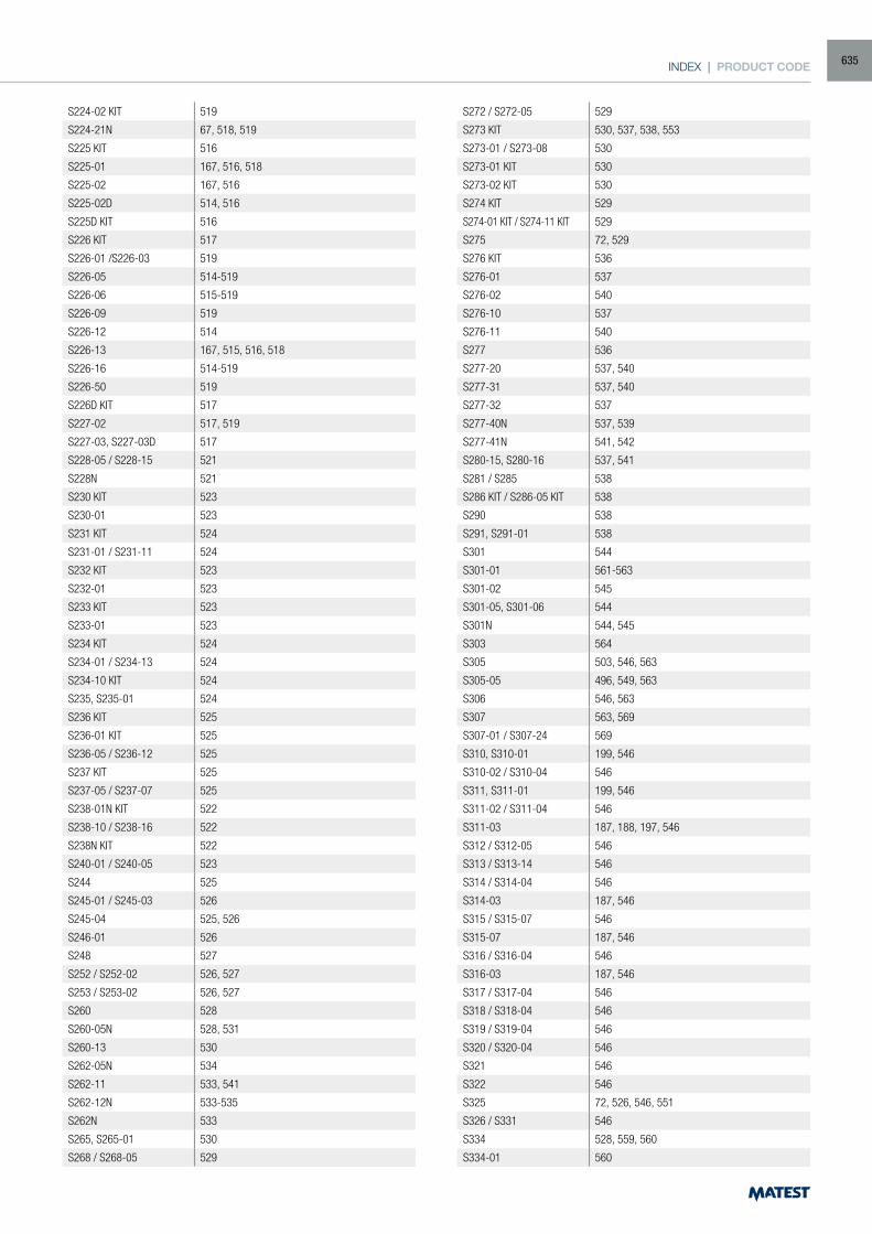
INDEX | PRODUCT CODE
S224-02 KIT 519
S224-21N 67, 518, 519
S225 KIT 516
S225-01 167, 516, 518
S225-02 167, 516
S225-02D 514, 516
S225D KIT 516
S226 KIT 517
S226-01 /S226-03 519
S226-05 514-519
S226-06 515-519
S226-09 519
S226-12 514
S226-13 167, 515, 516, 518
S226-16 514-519
S226-50 519
S226D KIT 517
S227-02 517, 519
S227-03, S227-03D 517
S228-05 / S228-15 521
S228N 521
S230 KIT 523
S230-01 523
S231 KIT 524
S231-01 / S231-11 524
S232 KIT 523
S232-01 523
S233 KIT 523
S233-01 523
S234 KIT 524
S234-01 / S234-13 524
S234-10 KIT 524
S235, S235-01 524
S236 KIT 525
S236-01 KIT 525
S236-05 / S236-12 525
S237 KIT 525
S237-05 / S237-07 525
S238-01N KIT 522
S238-10 / S238-16 522
S238N KIT 522
S240-01 / S240-05 523
S244 525
S245-01 / S245-03 526
S245-04 525, 526
S246-01 526
S248 527
S252 / S252-02 526, 527
S253 / S253-02 526, 527
S260 528
S260-05N 528, 531
S260-13 530
S262-05N 534
S262-11 533, 541
S262-12N 533-535
S262N 533
S265, S265-01 530
S268 / S268-05 529
S272 / S272-05 529
S273 KIT 530, 537, 538, 553
S273-01 / S273-08 530
S273-01 KIT 530
S273-02 KIT 530
S274 KIT 529
S274-01 KIT / S274-11 KIT 529
S275 72, 529
S276 KIT 536
S276-01 537
S276-02 540
S276-10 537
S276-11 540
S277 536
S277-20 537, 540
S277-31 537, 540
S277-32 537
S277-40N 537, 539
S277-41N 541, 542
S280-15, S280-16 537, 541
S281 / S285 538
S286 KIT / S286-05 KIT 538
S290 538
S291, S291-01 538
S301 544
S301-01 561-563
S301-02 545
S301-05, S301-06 544
S301N 544, 545
S303 564
S305 503, 546, 563
S305-05 496, 549, 563
S306 546, 563
S307 563, 569
S307-01 / S307-24 569
S310, S310-01 199, 546
S310-02 / S310-04 546
S311, S311-01 199, 546
S311-02 / S311-04 546
S311-03 187, 188, 197, 546
S312 / S312-05 546
S313 / S313-14 546
S314 / S314-04 546
S314-03 187, 546
S315 / S315-07 546
S315-07 187, 546
S316 / S316-04 546
S316-03 187, 546
S317 / S317-04 546
S318 / S318-04 546
S319 / S319-04 546
S320 / S320-04 546
S321 546
S322 546
S325 72, 526, 546, 551
S326 / S331 546
S334 528, 559, 560
S334-01 560
635
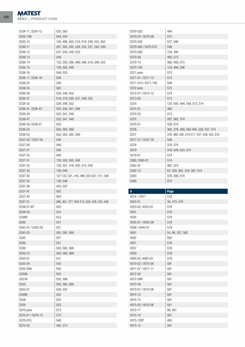
INDEX | PRODUCT CODE
S334-11, S334-12 535, 560
S335-10N 544, 554
S335-15 129, 496, 505, 518, 519, 549, 553, 563
S336-11 287, 303, 305, 528, 533, 537, 540, 549
S336-12 537, 540, 549, 553
S336-13 549
S336-14 133, 283, 306, 496, 499, 518, 549, 553
S336-15 129, 505, 549
S336-16 549, 553
S336-17, S336-18 549
S336-22 548
S336-23 563
S336-30 528, 549, 552
S336-31 518, 519, 528, 537, 549, 552
S336-32 528, 549, 552
S336-41, S336-43 520, 530, 541, 549
S336-45 520, 541, 549
S336-47 520, 541, 549
S336-50, S336-51 552
S336-53 563, 565, 569
S336-55 552, 563, 565, 569
S337-02 / S337-05 548
S337-06 569
S337-21 548
S337-23 569
S337-31 129, 503, 505, 548
S337-32 129, 321, 416, 505, 513, 548
S337-33 129, 548
S337-34 127-133, 321, 416, 496, 503-507, 511, 548
S337-35 129, 548
S337-36 452, 507
S337-41 563
S337-43 563
S337-51 286, 361, 377, 503-513, 520, 528, 533, 548
S338-01 KIT 553
S338-05 553
S338N 553
S340 551
S342-01 / S342-05 551
S342-03 563, 565, 569
S345 551
S348 551
S349 563, 565, 569
S349-10 563, 565, 569
S350-01 551
S350-04 550
S350-05N 550
S350N 550
S351N 550, 598
S355 550, 563, 569
S355-01 526, 550
S356N 552
S358 553
S359 553
S370 serie 573
S370-01 / S370-12 573
S370-01S 548
S370-02 492, 573
S370-02S 494
S370-03 / S370-08 573
S370-03S 537, 548
S370-04S / S370-07S 548
S370-08S 124, 494
S370-09 492, 573
S370-10 492, 493, 573
S370-10S 124, 494, 548
S371 serie 573
S371-01 / S371-12 573
S371-01S / S371-10S 548
S372 serie 573
S372-01 / S372-12 573
S373-05 573
S374 124, 493, 494, 548, 573, 574
S374-01 493
S374-02 573
S375 287, 362, 574
S375-01 528, 574
S376 362, 378, 489, 492-494, 528, 537, 574
S377 378, 489, 492, 514-517, 537, 549, 553, 574
S377-31 / S337-35 548
S378 378, 574
S379 378, 549, 553, 574
S379-01 574
S380, S380-01 574
S382-01 362, 574
S382-13 62, 359, 362, 378, 397, 574
S383 378, 549, 574
S390 574
V Page
V014 / V017 578
V023-01 30, 473, 579
V023-02, V023-03 579
V031 578
V034 578
V035-01 / V035-08 579
V036 / V040-01 579
V041 54, 88, 337, 582
V042 582
V051 578
V057 578
V059 578
V065-02, V065-03 579
V070-02 / V070-06 581
V071-07 / V071-11 581
V072-02 581
V072-06N 581
V072-09 581
V073-01 / V073-06 581
V074-12 581
V074-13 581
V075-02 / V075-06 581
V075-11 88, 581
V075-12 581
V075-12SP 400
V075-13 581
636
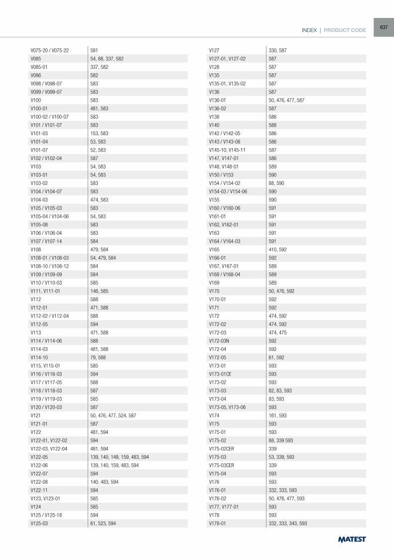
INDEX | PRODUCT CODE
V075-20 / V075-22 581
V085 54, 88, 337, 582
V085-01 337, 582
V086 582
V098 / V098-07 583
V099 / V099-07 583
V100 583
V100-01 481, 583
V100-02 / V100-07 583
V101 / V101-07 583
V101-03 153, 583
V101-04 53, 583
V101-07 52, 583
V102 / V102-04 587
V103 54, 583
V103-01 54, 583
V103-02 583
V104 / V104-07 583
V104-03 474, 583
V105 / V105-03 583
V105-04 / V104-06 54, 583
V105-08 583
V106 / V106-04 583
V107 / V107-14 584
V108 479, 584
V108-01 / V108-03 54, 479, 584
V108-10 / V108-12 584
V109 / V109-09 584
V110 / V110-03 585
V111, V111-01 146, 585
V112 588
V112-01 471, 588
V112-02 / V112-04 588
V112-05 594
V113 471, 588
V114 / V114-06 588
V114-03 481, 588
V114-10 79, 588
V115, V115-01 585
V116 / V116-03 594
V117 / V117-05 588
V118 / V118-03 587
V119 / V119-03 585
V120 / V120-03 587
V121 50, 476, 477, 524, 587
V121-01 587
V122 481, 594
V122-01, V122-02 594
V122-03, V122-04 481, 594
V122-05 139, 140, 149, 159, 483, 594
V122-06 139, 140, 159, 483, 594
V122-07 594
V122-08 140, 483, 594
V122-11 594
V123, V123-01 585
V124 585
V125 / V125-18 594
V125-03 61, 523, 594
V127 330, 587
V127-01, V127-02 587
V128 587
V135 587
V135-01, V135-02 587
V136 587
V136-01 50, 476, 477, 587
V136-02 587
V138 586
V140 588
V142 / V142-05 586
V143 / V143-08 586
V145-10, V145-11 587
V147, V147-01 586
V148, V148-01 589
V150 / V153 590
V154 / V154-02 88, 590
V154-03 / V154-06 590
V155 590
V160 / V160-06 591
V161-01 591
V162, V162-01 591
V163 591
V164 / V164-03 591
V165 410, 592
V166-01 592
V167, V167-01 589
V168 / V168-04 589
V169 589
V170 50, 476, 592
V170-01 592
V171 592
V172 474, 592
V172-02 474, 592
V172-03 474, 475
V172-03N 592
V172-04 592
V172-05 61, 592
V173-01 593
V173-01CE 593
V173-02 593
V173-03 82, 83, 593
V173-04 83, 593
V173-05, V173-06 593
V174 161, 593
V175 593
V175-01 593
V175-02 88, 339 593
V175-02CER 339
V175-03 53, 339, 593
V175-03CER 339
V175-04 593
V176 593
V176-01 332, 333, 593
V176-02 50, 476, 477, 593
V177, V177-01 593
V178 593
V178-01 332, 333, 343, 593
637
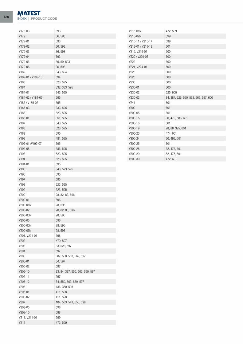
INDEX | PRODUCT CODE
V178-03 593
V179 36, 593
V179-01 593
V179-02 36, 593
V179-03 36, 593
V179-04 593
V179-05 36, 59, 593
V179-06 36, 593
V182 343, 594
V182-01 / V182-13 594
V183 523, 595
V184 332, 333, 595
V184-01 343, 595
V184-02 / V184-05 595
V185 / V185-02 595
V185-03 333, 595
V186 523, 595
V186-01 351, 595
V187 343, 595
V188 523, 595
V189 595
V192 481, 595
V192-01 /V192-07 595
V192-08 385, 595
V193 523, 595
V194 523, 595
V194-01 595
V195 343, 523, 595
V196 595
V197 595
V198 523, 595
V199 523, 595
V200 28, 82, 83, 596
V200-01 596
V200-01N 28, 596
V200-02 28, 82, 83, 596
V200-03N 28, 596
V200-05 596
V200-05N 28, 596
V200-06N 28, 596
V201, V201-01 598
V202 479, 597
V203 83, 526, 597
V204 597
V205 387, 550, 563, 569, 597
V205-01 84, 597
V205-02 597
V205-10 83, 84, 387, 550, 563, 569, 597
V205-11 597
V205-12 84, 550, 563, 569, 597
V206 136, 380, 598
V206-01 411, 598
V206-02 411, 598
V207 104, 533, 541, 550, 598
V208-05 598
V208-10 598
V211, V211-01 599
V215 472, 599
V215-01N 472, 599
V215-02N 599
V215-11 / V215-14 599
V218-01 / V218-12 601
V219, V219-01 600
V220 / V220-05 600
V222 600
V224, V224-01 600
V225 600
V226 600
V230 600
V230-01 600
V230-02 525, 600
V230-03 84, 387, 526, 550, 563, 569, 597, 600
V241 601
V300 601
V300-05 601
V300-15 30, 479, 586, 601
V300-16 601
V300-19 28, 88, 395, 601
V300-23 474, 601
V300-24 60, 469, 601
V300-25 601
V300-28 52, 475, 601
V300-29 52, 475, 601
V300-30 472, 601
638