signalling in 25kv ac electrified section - iriset
88
-
Upload
khangminh22 -
Category
Documents
-
view
3 -
download
0
Transcript of signalling in 25kv ac electrified section - iriset
S - 7 SIGNALLING IN 25KV AC
ELECTRIFIED SECTION
INDIAN RAILWAYS INSTITUTE OF
SIGNAL ENGINEERING & TELECOMMUNICATIONS
SECUNDERABAD - 500 017
Issued in March, 2013
VISION :
MISSION :
TO MAKE IRISET AN INSTITUTE OF INTERNATIONAL REPUTE, SETTING ITS OWN STANDARDS AND BENCHMARKS
TO ENHANCE QUALITY AND INCREASE PRODUCTIVITY OF SIGNALLING & TELECOMMUNICATION PERSONNEL THROUGH TRAINING
The Material Presented in this IRISET Notes is for guidance
only. It does not over rule or alter any of the Provisions
contained in Manuals or Railway Board’s directives.
S-7: SIGNALLING IN 25 KV AC ELECTRIFIED SECTION
CONTENTS
Sl.No.
Chapter
Page
No.
1. INTRODUCTION TO OHE SYSTEM 1
2. SIGNAL CLEARANCE AND VISIBILITY 11
3. PROTECTION OF OPERATING AND S&T STAFF 21
4. EARTHING ARRANGEMENTS IN RE AREA 23
5. LAYING OF SIGNALLING CABLES 25
6. BLOCK INSTRUMENTS AND CIRCUITS 29
7. STRAY CURRENTS 30
8. ALTERATIONS TO TRACK CIRCUITS 32
9. INDUCTION & IT’S EFFECTS ON SIGNALLING 42
10. PERSONNEL SAFETY IN 25KV RE AREA 63
11. EVALUATION AND UPGRADATION OF EXISTING SYSTEM DESIGN-VARIOUS PARAMETERS
65
12. INDUCED VOLTAGES DUE TO HIGHER CATENARY CURRENTS 71
13. REVISED DESIGN OF SIGNALLING SYSTEM TO SUIT HIGH CATENARY CURRENTS
72
14. REVIEW QUESTIONS 81
Checked By IES2,IOS3,SSE(D),LS2,PS2
No. of Pages 85
Date of Issue March, 2013
Version A3
In case of any suggestions please write to LS2/PS2 or mail to LS2/PS2 at email address
[email protected]/[email protected]
© IRISET
http://www.iriset.indianrailways.gov.in
“This is the Intellectual property for exclusive use of Indian Railways. No part of this publication may be stored in a retrieval system, transmitted or reproduced in any way, including but not limited to photo copy, photograph, magnetic, optical or other record without the prior agreement and written
permission of IRISET, Secunderabad, India”
INTRODUCTION TO OHE SYSTEM
Page 1 SIGNALLING IN 25KV AC
ELECTRIFIED SECTION
CHAPTER- 1: INTRODUCTION TO OHE (Overhead Equipment) SYSTEM
1.1 1500 Volt D.C. Electric Traction began in India in 1925 when the first section of 16 KM on Central Railway from Bombay VT to Kurla (Via Harbour Branch) was electrified. By 1930, the D.C. traction system was extended up to Pune and lgatpuri. The Southern Railway Metre Gauge line from Madras Beach to Tambaram was electrified in 1931. By 1936, about 388 RKM had been electrified serving mainly suburban sections of Bombay and Madras with the only exception of Bombay-Pune and Bombay-lgatpuri main line sections - where heavy gradients on the ghats favoured the introduction of electrification. After a lapse of nearly 20 years, 3000 Volt DC Electric Traction was introduced in 1958 in Calcutta Suburban Section over Howrah-Burdwan and Sheorapuli-Tarakeshwar sections. Work is going on at many of the locations to change DC traction into AC traction. In the year 1951, France first introduced 25 KV AC single phase 50 cycle traction system in French National Railways. This was followed by UK in 1956. In the late 1950s, Indian Railways also decided to adopt 25 KV AC 50 Hz Traction System. French National Railways SNCF had the maximum experience with 25 KV AC 50 Hz system of Electrification and was chosen as Technical Consultants for the Electrification Projects by Indian Railways.
The S&T System Design was based on the data already available with the Indian Railways and on the experience of M/s SNCF France.
25 KV AC Electrification was first carried out over 75 Route Kilometres (RKM) between Raj-Kharsawan - Dongaposi on South Eastern Railway in August 1960. Approximately 18145 RKM has been electrified by 25 KV AC traction system on Indian Railways. Advantages of Railway Electrification
(a) Increased power of locomotives and improved loco efficiency
(b) More productive – less man power
(c) Fuelling of locomotives is not necessary
(d) Low noise and environmental pollution
(e) Improved Acceleration and Deceleration is within short distance of time
(f) Less wear and tear of components
(g) Fuel efficient
Disadvantages of Railway Electrification
(a) Heavy capital investment
(b) Additional expenditure on remodelling of tunnel & bridges
(c) Need to re-train the crew.
(d) Additional expenditure towards maintenance of infrastructure
(e) Need to change the signalling system
INTRODUCTION TO OHE SYSTEM
IRISET Page 2
FEEDINGPOST
132
25KV
132 KV GRID
SECTIONINGPOST (SP)
SUB SECTIONINGPOSTS (SSP)
F.P SSP SP F.P F.PSSP SSP SSPSP
NEUTRALSECTION
R
Y
B
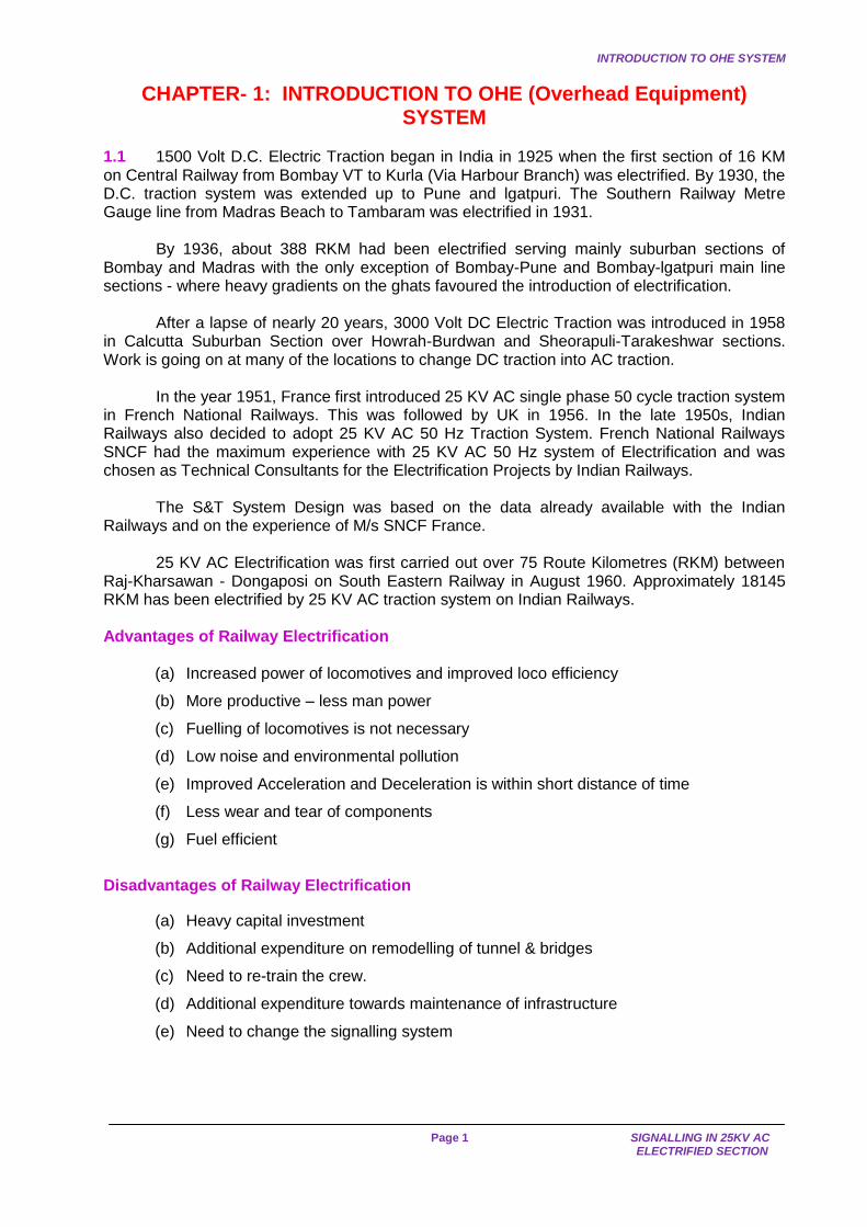
FIG.1.1 SKETCH SHOWING THE ARRANGEMENT OF POWER SUPPLY NEUTRAL SECTION
FEEDING POST SECTIONING & SUB SECTIONING POSTS
TRACTIONSUB
13225
KV (TSS)132
25KV(TSS)
STATION(TSS )
1.2 Power System
25 KV AC 50 Hz single phase power supply for electric traction is derived from the Grid Systems of State Electricity Boards through Traction Sub-Stations located along the route of the electrified sections at distances of 40 to 50 KM. Traction sub-stations receive 3 phase supply at higher voltages (220/132/110/66 KV). To ensure continuity of supply under all conditions, the high voltage feed to the traction sub stations is invariably arranged either from two sources of power or by a double circuit transmission line, so that even if one source fails, the other remains in service.
At each traction sub-station, normally two single phase transformers of 21.6/30.2 MVA capacity are installed, one of which is in service and the other functions as standby. These transformers step down the voltage to 25 KV for feeding the Overhead Equipment (OHE). In some earlier cases, Railways used to directly get 25 KV power supply from electricity boards to Feeding Posts located near the tracks.
Suitable protective arrangements in the form of circuit breakers, lightening arresters and isolators are provided to ensure quick isolation of fault in transmission line and substation equipment. The permissible variation of bus bar voltage is within +10% to –5% i.e. between 27.5 KV to 23.75 KV. Off-load tap changers are provided on the secondary side of the transformer. One end of the 25 KV winding of each 132/25 KV transformer is solidly earthed at the sub-station.
1.3 Communication Facilities
All aerial/over head telecommunication lines running by the side of the tracks are replaced with underground cables to overcome the interference caused by 25KV single-phase ac traction. The cables contain adequate number of conductors for various Railway telecom circuits.
Several independent circuits are provided to facilitate quick communication and to achieve necessary co-ordination in the interest of efficiency. In an emergency several communication circuits are available for required co-ordination etc. Some of the commonly available telephone circuits provided in electrified sections are
(a) Train Control/Section Control: This circuit is operated by Section Controller and is used for controlling train movements. It has connections with Signal Cabins, ASM Offices, Loco Sheds and Yard Masters' Offices.
COMMUNICATION FACILITIES
Page 3 SIGNALLING IN 25KV AC
ELECTRIFIED SECTION
(b) Dy.Control: This circuit is operated by the Deputy Controller and is used for directing traffic operations in general. It has connections with important SM offices, Yard Masters' Offices, Loco Sheds and Signal Cabins
(c) Traction Power Control (TPC): This is a special circuit and is used by TPC staff for all communications in connection with power supply, switching operations and for granting 'permit-to-work'. It has connections with SM offices, cabins, Traction Sub Station (TSS), SPs, SSPs, traction maintenance depots, important Signal Cabins, Divisional Officers such as Sr.DEE (TRD), Sr.DEE/OP and Traffic Control Offices.
(d) Traction Loco Control (TLC): This circuit is provided for ac traction and is operated by the Traction Loco Controller who is responsible for movements of electric locomotives and Electric Multiple Unit (EMU) stock. It has connections with Electric Loco Sheds, EMU Sheds, important SMs, Yard Masters, Divisional Officers such as Sr.DEE/DEE, AEE (RS), Sr.DEE/DEE/AEE (OP), Traffic Control Offices, Traction Foreman and important crew booking points.
(e) S&T Control
(f) Emergency Control: This circuit is provided to facilitate the traction maintenance gangs and electric train crew to get in touch with TPC with the least possible delay in emergencies. It is also used by train crew in times of accidents for communication with the Control Office. This circuit is operated by TPC and is located in the Remote Control centre (RCC). Emergency telephone socket boxes are provided along the track at an interval of 0.75 to 1 km and also near the signal cabins, SPs, SSPs, insulated overlaps and feeding posts etc. Portable emergency telephones are given to maintenance gangs, train crew and SMs. By plugging the portable telephone into an emergency socket it is possible to communicate with the TPC.
1.4 Feeding and Sectioning Arrangements
Since the Generation and Transmission Systems of the supply are 3 phase systems, the single-phase traction load causes imbalance in the supply system. This imbalance has undesirable effects on the generators and consumer equipments. To minimize this imbalance, power for traction is tapped from different phases at adjacent substations in cyclic order. Thus it becomes necessary to electrically separate the OHE systems fed by adjacent substations. This electrical separation is achieved by providing "Neutral Sections" which ensure that the two phases are not bridged by the pantographs of passing electric locomotives.
Interrupters at various switching stations and also the feeder circuit breakers at TSS are controlled from a RCC manned round the clock by TPCs (one or more-depending on workload). TPC (Traction Power Controller) is responsible for all switching operations for maintaining continuous power supply on all sections of OHE. He also maintains close liaison with Section Controllers of electrified sections.
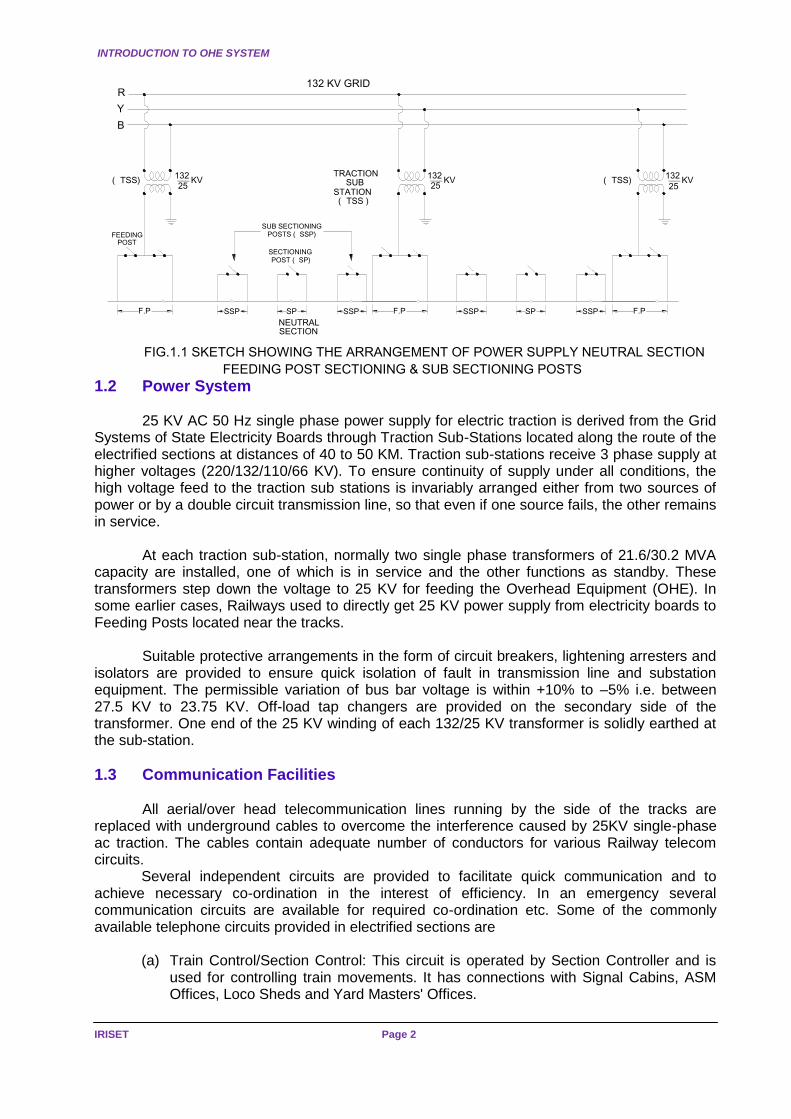
1.5 Sectioning and Paralleling Post (SP)
These are situated approximately midway between two TSS. At these posts, a neutral section is provided to avoid bridging of two different phases of 25 KV supply by the pantograph of a passing electric loco or EMU. Paralleling interrupters and bridging interrupters are also provided here.
Since the neutral sections remain dead (no electric supply), caution notices are provided well in advance to enable the drivers to coast through them. Special care is taken in fixing the location of neutral sections (on level gradients, away from signals, away from level crossing gates etc.) to ensure that the trains are able to coast through them and so that the possibility of a train stopping and getting stuck within the neutral sections are minimised.
INTRODUCTION TO OHE SYSTEM
IRISET Page 4
FIG.1.5(a) Sectioning and Paralleling Post (SP)
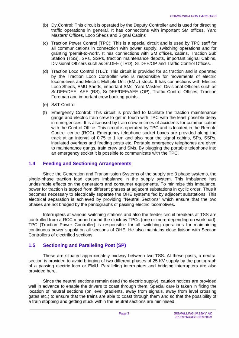
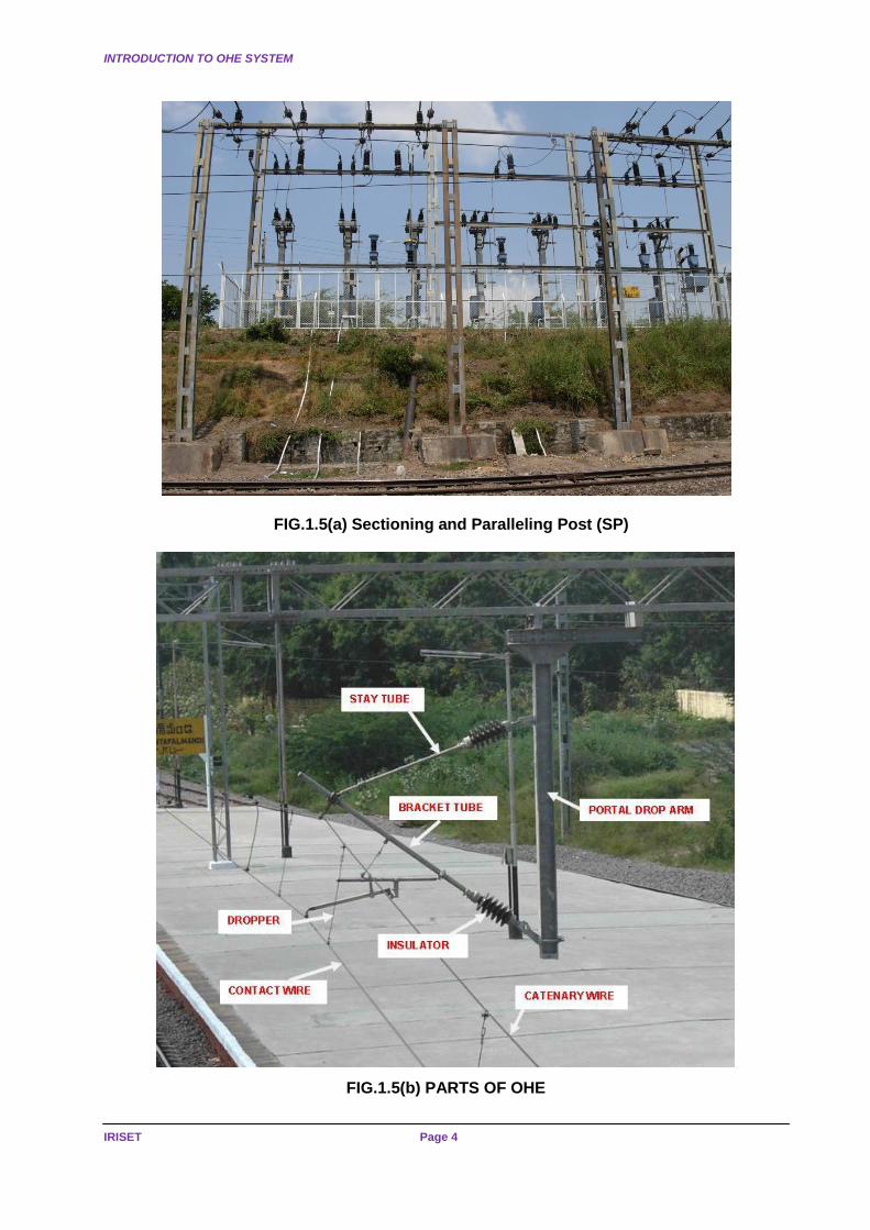
FIG.1.5(b) PARTS OF OHE
OVERHEAD EQUIPMENT
Page 5 SIGNALLING IN 25KV AC
ELECTRIFIED SECTION
1.6 Sub-Sectioning and Paralleling Post (SSP)
One or more SSPs are provided between each TSS & SP depending upon the distance between them. They facilitate maintenance and rapid isolation of OHE faults. In a double line section, normally 3 interrupters are provided at each SSP –Two (2) for connecting adjacent sub-sectors on Up and Down lines and one (1) for paralleling the Up and Down lines.
1.7 Sub-Sectioning Post
These are provided only occasionally. They are similar to SSP with provision for sectioning of OHE but not paralleling.
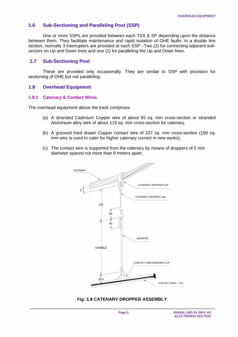
1.8 Overhead Equipment 1.8.1 Catenary & Contact Wires The overhead equipment above the track comprises
(a) A stranded Cadmium Copper wire of about 65 sq. mm cross-section or stranded Aluminium alloy wire of about 115 sq. mm cross-section for catenary.
(b) A grooved hard drawn Copper contact wire of 107 sq. mm cross-section (150 sq.
mm wire is used to cater for higher catenary current in new works). (c) The contact wire is supported from the catenary by means of droppers of 5 mm
diameter spaced not more than 9 meters apart.
CATENARY DROPPER CLIP
CATENARY DROPPER LINK
DROPPER
CONTACT WIRE DROPPER CLIP
CONTACT WIRE (107 )
21
50
50
105
VARIBLE
25.5
CATENARY
Fig: 1.8 CATENARY DROPPER ASSEMBLY

INTRODUCTION TO OHE SYSTEM
IRISET Page 6
1.8.2 Regulated and Unregulated OHE
OHE with automatic tensioning is called "Regulated" OHE. As a general rule at all mainlines and Block sections are to be provided with Regulated OHE. But at large isolated yards and unimportant lines, automatic tensioning is dispensed with in the interest of economy and only unregulated OHE is provided 1.8.3 Height of Contact Wire
The normal height of contact wire for regulated OHE is 5.55 m above rail level. For unregulated OHE in areas with a temperature range of 4 degree Celsius to 65 degree Celsius, the height is 5.75 m and in areas with a temperature range of 15 degree Celsius to 65 degree Celsius, the height is 5.65 m. In certain cases, such as under bridges, the height may be as low as 4.65 m on BG and 4.02 m on MG
Fig.1.8.2(a)TERMINATION OF REGULATED OHE (Pulley Block type)
Fig.1.8.2(b)OHE WITHOUT CATENARY WIRE
OVERHEAD EQUIPMENT
Page 7 SIGNALLING IN 25KV AC
ELECTRIFIED SECTION
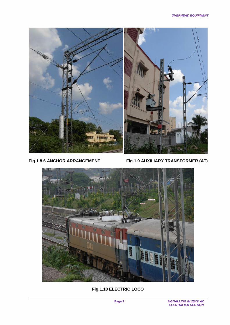
Fig.1.8.6 ANCHOR ARRANGEMENT Fig.1.9 AUXILIARY TRANSFORMER (AT)
Fig.1.10 ELECTRIC LOCO
INTRODUCTION TO OHE SYSTEM
IRISET Page 8
1.8.4 Span of Supporting Wires
On straight tracks, the catenary system is normally supported at maximum intervals of 72 m for BG and 63 m on MG. This interval is reduced in case of curvatures. 1.8.5 Stagger
The contact wire is "Staggered" so that as the pantograph glides along, the contact wire sweeps to and fro across the bearing surface of the pantograph up to a distance of 200 mm. on either side of centre line of straight track. In case of curved track, the stagger is 300 mm on the “inside” of the curve. This ensures a uniform wear & tear of the current collecting strips of the pantographs.
1.8.6 Anchor
The OHE conductors are terminated at intervals of about 1.5 KM to 2.0 KM and suitably anchored. An overlap span is provided & the conductor heights are so adjusted that the pantograph glides from one conductor to the other smoothly without struck. 1.8.7 Misc Equipment at Switching Stations Certain equipments are installed at various points to protect the lines, to monitor the availability of power supply and to provide other facilities. These are as under
(a) Lightning arresters are provided to protect sub-sections against voltage surges. (b) Auxiliary transformers are provided at all the SP/SSP and also at certain intermediate
points to supply ac at 240 V, 50 Hz required for signalling and operationally essential lighting installations. To ensure a fairly steady voltage, automatic voltage regulators are also provided where required.
(c) A small masonry cubicle is provided to accommodate remote control equipment,
control panel, telephone and batteries and battery chargers required for the control of interrupters and other similar equipments.
1.9 Power supply arrangements for Signals 1.9.1 Supply through 25 KV/240V auxiliary transformers (AT) is made available to ensure reliable supply of 240V AC at following places
(a) Each wayside station for CLS.
(b) Level crossings located at a distance of more than 2 km from Railway Station.
(c) At IBH/IBS
(d) At all the power supply installations.
1.9.2 In the event of power block being given on both the OHE sub-sections from which the signal supply is derived, electric traffic would necessarily have to be suspended on the line. During such periods, colour light signalling also need not be in operation. Such cases are likely to arise very rarely at any station and the duration of such block is also not likely to exceed an hour or so at a time. Therefore, no additional power supply arrangement is made by the Electrical Department at wayside stations. However, to cater for such situations, portable generating sets may be kept by the S&T Department to meet emergencies, if considered essential. Some railways provide DG sets of adequate capacities in bigger yards to cater to such eventualities.IPS has also being installed to overcome this problem.
SPECIAL WARNING SIGNALS
Page 9 SIGNALLING IN 25KV AC
ELECTRIFIED SECTION
1.9.3 Voltage Regulators The fluctuating nature of traction load causes perceptible fluctuation on the AC 240V supply affecting operation of signalling equipment. To overcome this, static type voltage regulators are provided by S&T Department to limit voltage fluctuations. These voltage regulators are installed either in separate kiosks inside the remote control cubicles, inside the equipment room or inside the cabins depending upon the position of various load centres.
1.10 Important Equipment of Electric Loco/EMU 1.10.1 Pantograph
For collecting power from 25 KV AC contact wire, pantographs are mounted on the roof of the traction vehicles. These pantographs are provided with steel strips for current collection. The raising and lowering of the pantograph is done by means of a pneumatically operated servo motor. In order to improve the life of the contact wire, use of carbon strips has also been tried. Use of carbon strips for current collection has already been adopted in European countries.
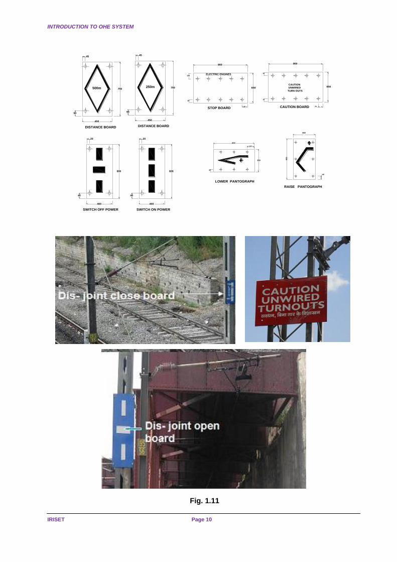
1.11 Special Warning Signals 1.11.1 Signal marking the end of Catenary Certain loops and sidings at a station may not be wired. An electric locomotive should not be taken into an unwired track as its pantographs and the OHE may get damaged and it will require a diesel engine to pull the electric locomotive out of the unwired track. Caution boards as per Fig. 1.11 are provided for warning the drivers about the unwired tracks taking off from wired tracks. In addition special indication boards are provided where the OHE ends on a track. Point levers controlling the movement of trains from the wired track to the unwired track are fitted with warning tablets painted yellow, to warn the cabin master not to admit electric locos on the unwired tracks. 1.11.2 Warning Signals for Neutral Sections To indicate to the driver that he is approaching a neutral section and should be in readiness to open Dis- joint DJ (main circuit breaker), two warning boards as per fig.1.11 below are fixed 500 m and 250 m in advance of the neutral section. The point where DJ is to be opened is indicated by the signal shown in Fig1.11 Indication that the neutral section has been passed and DJ may be closed again is given by another signal shown in the Fig.1.11
1.11.3 Temporary Signals Occasionally it becomes necessary to lower the pantograph on certain sections when OHE is not properly adjusted so as to avoid damage to the pantographs. In such cases temporary warning boards as shown in Fig.1.11 are placed ahead of the section, facing the direction from which locomotives normally approach. On reaching such a warning board, the Driver shall open DJ and lower pantograph/s of his electric locomotive/s. He may raise the pantographs after passing the section and reaching the signal provided for the purpose as per Fig.1.11
INTRODUCTION TO OHE SYSTEM
IRISET Page 10
Fig. 1.11
450
750
90
45
500m
DISTANCE BOARD DISTANCE BOARD
45
90
750
450
250m
STOP BOARD
900
ELECTRIC ENGINES
600
60
120
600UNWIRED
900
CAUTION BOARD
CAUTION
75
75
TURN OUTS
SWITCH OFF POWER
20
40
600
400 400
600
40
20
SWITCH ON POWER
60
350
600
LOWER PANTOGRAPH
120
60
0
400
90 75
RAISE PANTOGRAPH
FIG. 1.7
40
ELECTRICAL & SIGNAL CLEARANCE
Page 11 SIGNALLING IN 25KV AC
ELECTRIFIED SECTION
CHAPTER- 2: SIGNAL CLEARANCE AND VISIBILITY
The Signalling and Telecommunication Systems in AC Traction areas are affected in following aspects EFFECTS ON S&T
Electrical & Visibility Induction Return Current Signal clearance through Rails Electrostatic Electromagnetic Operating & Equipments Maintenance Staff
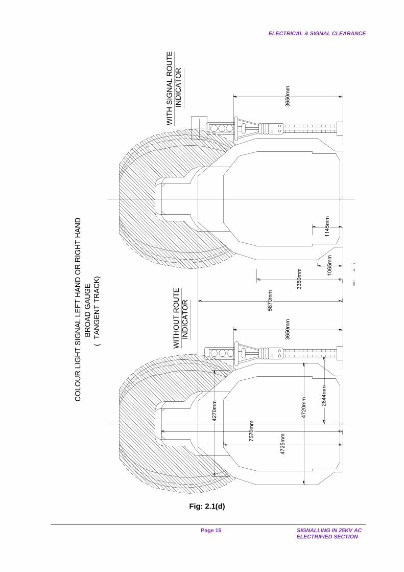
2.1 Electrical & Signal Clearance In the vicinity of high voltage conductors, a minimum electrical clearance is required to be provided to safeguard against flashing/arcing. ACTM (AC Traction Manual) details minimum vertical clearance and minimum lateral clearance between any live part of OHE or Pantograph and part of any fixed structure (earths or others) or moving load. Whenever a - high voltage conductor is provided, a minimum electrical clearance is required to be provided to safeguard against flashing/arcing. For 25 KV A.C. the electrical clearance is specified from the live conductor. As per ACTM min. vertical clearance between any live part of OHE or Pantograph and part of any fixed structure (earths or others) or moving load 320 mm. Stationary, 270 mm moving mini. Lateral clearance: 320 mm stationary, 220 mm moving. A signal clearance diagram is prepared in which an un-shaded portion is marked indicating the flashing/arching zone. Under no circumstances, a signal post or any of its fittings must be allowed to infringe in the un-shaded portion. The signal clearance diagrams may please be seen in [Figs 2.1(b), 2.1(c), 2.1(d), 2.1(e)].
Besides the above, in the matter of electrical clearances, the fundamental rule to be observed is that no one is allowed, under normal conditions, to approach closer than 2 metres from the extreme positions of the live parts of the OHE. This is shown as the shaded portion enclosed in the dotted lines of the signal clearance diagrams [Figs 2.1(b), 2.1(c), 2.1(d), 2.1(e)].
In other words, no one shall normally work within the shaded portion of the signal
clearance diagrams. When the signals have to be so located that they infringe, in to the shaded area, a
screen of wire mesh shall be provided between the signal post and the OHE to protect the staff who may have to work within the shaded area.

SIGNAL CLEARANCE AND VISIBILITY
IRISET Page 12
Where a signal post or its fittings have to be located within 2 m of live OHE, a screen of wire mesh of approved design solidly connected with the structural work shall be provided between the signal post and the OHE for protection of staff. Provision of such a screen is mandatory where any staffs are required to climb up the signal posts. The protection screen is not necessary when only the technical personnel, such as inspectors and maintainers of the S&T Dept. are authorised to work on the signals. When a screen is not provided for any reasons, a caution board is be provided on the signal post on the side facing the ladder at a height of 3 m above the rail level to caution staff. The technical personnel are expected to exercise special care while working and if there is any likelihood of any part of their equipment or tools coming within 2 m of live equipment, they will arrange for a power block before taking the work on hand. In case of signals (a) located above the contact wire and (b) provided with the iron screen it is necessary to connect them to the earth with earth resistance not exceeding 10 Ohms.
The screen shall be provided on the side adjacent to the catenary and for a signal post between two wired tracks, a screen on either side of the post will be required.
CLS IN 25 KV RE AREA CLS WITH WIRE MESH PROTECTION
FIG.2.1(a)

ELECTRICAL & SIGNAL CLEARANCE
Page 13 SIGNALLING IN 25KV AC
ELECTRIFIED SECTION
Note:
(1 ) All Dimensions given are in Millimetres.
(2 ) In applying the diagram to curves it should be inclined so that
the axis of the diagram is normal to the track plane.
(3 ) The diagram is not applicable to turnouts.
(4 ) This diagram is not applicable to the Anchor span where
the conductors are outside the track zone.
(5 ) The curves are drawn for the maximum can't applicable,
therefore, for lesser can't it may be economical to decide
the clearance at site jointly with the Electrical department.
(6 ) Curves in full line are for tangent track and those in dotted line
line for curves track with Super Elevation60.
5870
4420
1145 1065
305
3355
102
1676
2895
3505
3810
4720
PROFILE OF MAXIMUMMOVING DIMENSION 3660
4265
4725
3505
1830
420
FOR OVER LAP
LOCATION
PE
NT
O A
XIS
FOR NORMAL
LOCATION
1025
770
29002840
2920
420
5000
500R
500R
2000R2000R
2000
R
2000
R
2000R2000R
2000R
2000R
Fig. 2.2
SIGNAL CLEARANCE DIAGRAM TO SUIT 25 KV A.C. TRACTION
FOR TANGENT TRACKS AND CURVED TRACKS WITH SE 60
5500
5750
Fig: 2.1(b)
SIGNAL CLEARANCE DIAGRAM TO SUIT 25 KV A.C TRACTION FOR TANGENT TRACKS AND CURVED TRACKS WITH SE 60

SIGNAL CLEARANCE AND VISIBILITY
IRISET Page 14
Note:
(1 ) All Dimensions given are in Millimetres.
(3 ) The Diagram is not applicable to the Anchor span where
the Conductors are outside the track zone.
(2 ) This Diagram is not applicable to turnouts.
(4 ) The curves are drawn for the maximum can't applicable.
Therefore for lesser can't it may be economical to decide
the clearance at site jointly with the Electrical Department.
4420
1065
305
3355
102
1676
2895
3505
3810
4720
PROFILE OF MAXIMUMMOVING DIMENSION 3660
3505
1830
PENTO AXIS
5870
VERTICAL AXIS
750
5251000
1450
2000R
2000R
320R
320R
550R
500R
3015
2920
2000R2000R
1830
FOR NORMALLOCATION
FOR OVERLAPLOCATION
4550 4725
4265
5500
5750
Fig: 2.1(c) SIGNAL CLEARANCE DIAGRAM TO SUIT 25 KV A.C. TRACTION
FOR CURVED TRACKS 140 TO 185 SE(SUPER ELEVATION).
ELECTRICAL & SIGNAL CLEARANCE
Page 15 SIGNALLING IN 25KV AC
ELECTRIFIED SECTION
58
70
mm
BR
OA
D G
AU
GE
(T
AN
GE
NT
TR
AC
K)
CO
LO
UR
LIG
HT
SIG
NA
L L
EF
T H
AN
D O
R R
IGH
T H
AN
D
WIT
HO
UT
RO
UT
E
IND
ICA
TO
R
WIT
H S
IGN
AL R
OU
TE
IND
ICA
TO
R
Fig
. 2.4
33
50
mm
10
65
mm
11
45
mm
36
50
mm
36
50
mm
28
44
mm
47
20
mm
47
25
mm
75
70
mm
42
70
mm
Fig: 2.1(d)

SIGNAL CLEARANCE AND VISIBILITY
IRISET Page 16
1065mm1145mm
3355mm
2844mm
5670mm
4725mm
7570mm
6240mm
COLOUR LIGHT SIGNAL WITH JUNCTION ROUTE INDICATOR
Left hand or Right hand
BROAD GAUGE
(TANGENT TRACK)
Fig. 2.5
Fig: 2.1(e)
INSULATION OF ROD RUN
Page 17 SIGNALLING IN 25KV AC
ELECTRIFIED SECTION
2.2 Visibility of Signals
On non-electrified sections, signals are located so as to be clear of standard moving dimensions and to afford maximum continuous visibility to drivers of approaching trains. On electrified sections, OHE and associated equipments obstruct the visibility of signals. It is therefore preferable to erect the signals on the opposite side of the OHE masts. However, this may not be practicable in the case of signals on double line sections and in station yards.
2.3 Location of signals When signals have to be erected on the same side of the track as the OHE masts, the following steps may be taken
(a) A signal erected immediately behind an OHE mast will have its visibility severely affected by the mast. The distance between the signal and the mast in front of it must therefore be as great as possible. Under no circumstances this distance must be less than 30 metres.
(b) At the same time, it is not desirable to locate a signal closer than 10 metres from the
mast behind it. However, this distance may be reduced to 3 metres provided:
(i) The mast is not anchored and (ii) It is ensured that the contact wire is staggered away from the signal.
2.4 Implantation of Masts in Rear of the Colour Light Signals
The distance from centre line of track to the nearest part of the masts is normally 2.5 m. In case of MG this distance is 2.35mtrs. This is called normal implantation or normal setting distance.
For signals (especially the ones provided with route indicators) to be clear of the OHE (and pantograph) by 2 m, the nearest part of the signal post from the centre line of track shall be 2.844 metres. In such cases, the masts being between driver and the signal, the visibility of signal to the driver of the approaching trains will be affected. For unobstructed visibility, the signals are located between the OHE structure and the track.
As per Signal Engineering Manual, the visibilities of Multiple Aspect Signals are as under
First Permissive Signals: 400 m All other Signals: 200 m
Although minimum visibility of each signal has been prescribed as above, it is the usual
practice to cater for more visibility so that the driver can be confident to regulate the speeds of the trains based on the aspects of the signals.
RDSO have recommended the setting distances/extra implantation of the masts in front of the signal for the following cases
(a) MACLS without Route Indicator for a visibility of 600 m on a tangent track. (b) MACLS without Route Indicator for a visibility of 1000 m on a tangent track.

SIGNAL CLEARANCE AND VISIBILITY
IRISET Page 18
(c) MACLS with route indicator with horizontal arm for a visibility of 600 m. (d) MACLS with route indicator without horizontal arm for a visibility of 600 m.
The setting distances are given in Figs. 2.4(a), 2.4(b), 2.4(c) & 2.4(d).
SETTING OF OHE STRUCTURES SETTING OF OHE STRUCTURES
For Varying Distance from the CLS
Without Route indicator
For a Visibility of 600 M.
Where Approach Signal is provided other than Distant Signal
For Varying Distance from the CLS
Without Route indicator
For a Visibility of 1000 M. On a tangent track
Where No Approach Signal is provided.
FIG. 2.4(a) FIG 2.4(b)
Signal units are generally so fixed that the height of the centre line of the red signal is 3.65 metres (12 ft.) above rail level. No part of a signal without route indicator shall normally be higher than 5.2 metres above rail level.
INSULATION OF ROD RUN
Page 19 SIGNALLING IN 25KV AC
ELECTRIFIED SECTION
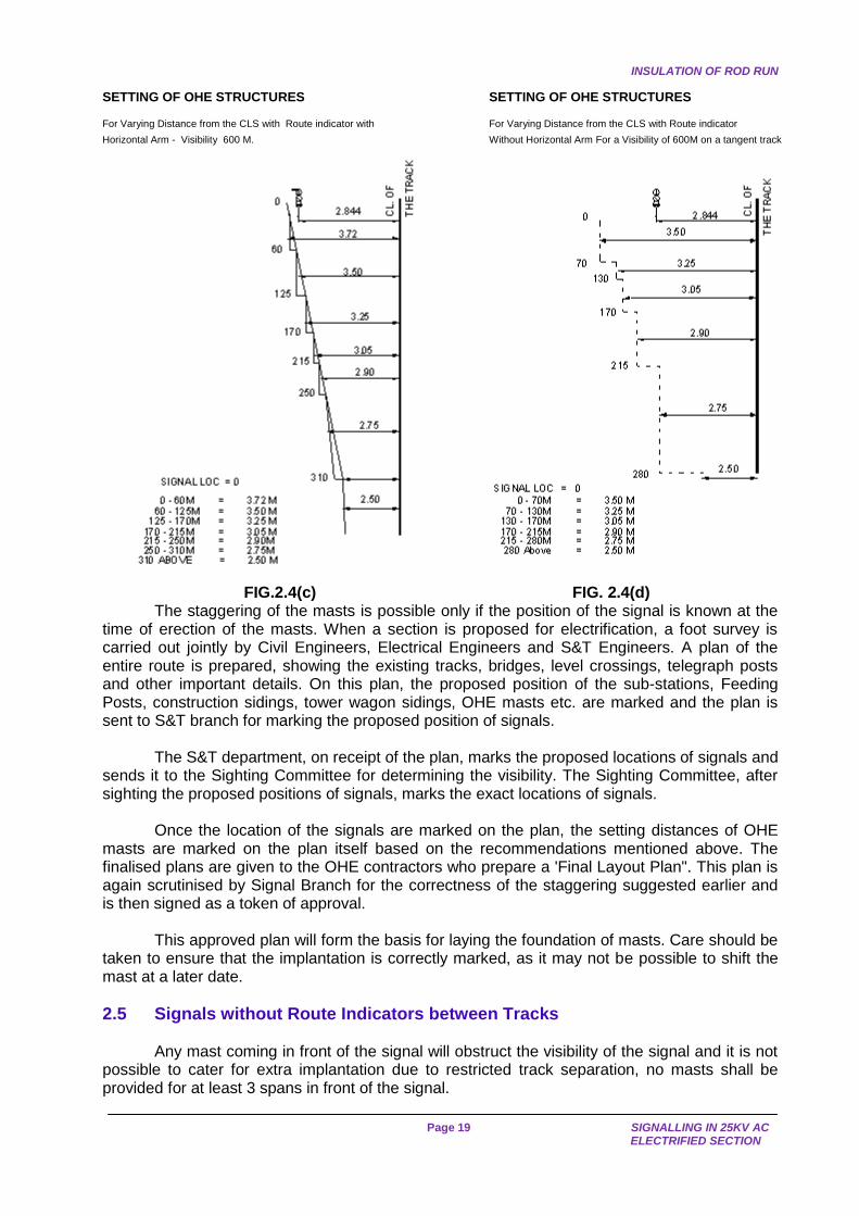
SETTING OF OHE STRUCTURES SETTING OF OHE STRUCTURES
For Varying Distance from the CLS with Route indicator with
Horizontal Arm - Visibility 600 M.
For Varying Distance from the CLS with Route indicator
Without Horizontal Arm For a Visibility of 600M on a tangent track
FIG.2.4(c) FIG. 2.4(d)
The staggering of the masts is possible only if the position of the signal is known at the time of erection of the masts. When a section is proposed for electrification, a foot survey is carried out jointly by Civil Engineers, Electrical Engineers and S&T Engineers. A plan of the entire route is prepared, showing the existing tracks, bridges, level crossings, telegraph posts and other important details. On this plan, the proposed position of the sub-stations, Feeding Posts, construction sidings, tower wagon sidings, OHE masts etc. are marked and the plan is sent to S&T branch for marking the proposed position of signals.
The S&T department, on receipt of the plan, marks the proposed locations of signals and sends it to the Sighting Committee for determining the visibility. The Sighting Committee, after sighting the proposed positions of signals, marks the exact locations of signals.
Once the location of the signals are marked on the plan, the setting distances of OHE masts are marked on the plan itself based on the recommendations mentioned above. The finalised plans are given to the OHE contractors who prepare a 'Final Layout Plan". This plan is again scrutinised by Signal Branch for the correctness of the staggering suggested earlier and is then signed as a token of approval.
This approved plan will form the basis for laying the foundation of masts. Care should be taken to ensure that the implantation is correctly marked, as it may not be possible to shift the mast at a later date.
2.5 Signals without Route Indicators between Tracks
Any mast coming in front of the signal will obstruct the visibility of the signal and it is not possible to cater for extra implantation due to restricted track separation, no masts shall be provided for at least 3 spans in front of the signal.

SIGNAL CLEARANCE AND VISIBILITY
IRISET Page 20
In station yards, the OHE wires are supported on portal drop arms fixed on gantries. Portal drop arms also should not normally be located in the track space where signals are located as they will obstruct the visibility.
In case portal drop arm has to be unavoidably located in front of the signal itself, the signal should be mounted on an offset bracket. In addition, a special study should be made in each such case to see whether the portal drop arm should also be offset from the centre line of the track space in the direction opposite to the offset of the signal. This study should be made for at least for 13 portal drop arms in front of the signal. Possibility of shortening the portal drop arm must also be examined in consultation with Electrical Dept.
2.6 Signals with Junction type Route Indicators between Tracks
Here also the same principle of avoiding the location of 3 masts in front of the signal should be followed. Portal drop arms should also be avoided in front of the signal. In case portal drop arms could not be avoided, off-setting the signal and the portal drop arm may be done.
The visibility of the signal shall be checked by day as well as by night by the official in charge of the work after each phase of OHE work, i.e. erection of masts, provision of brackets, wiring, etc. If at any stage the official feels that the visibility is not adequate, he shall impose suitable speed restrictions and take such steps as are required to improve the visibility.
The following drawings indicate the arrangement of portal drop arms for signals with and without route indicators. (Figs. 2.6(a), 2.6(b), 2.6(c), 2.(d), 2.6(e).
4.65
3.76
DN TRACKS UP TRACKS
SHIFTED
Fig. No. 2.6(a)
Fig. No. 2.6(b) Fig. No. 2.6(c)
Fig. No. 2.6(d) Fig. No. 2.6(e)
INSULATION OF ROD RUN
Page 21 SIGNALLING IN 25KV AC
ELECTRIFIED SECTION
CHAPTER-3: PROTECTION OF OPERATING AND S&T STAFF
Traction return currents pass through rails and since rods and wires (in case of Electro mechanical Signalling) are in contact with the rails at some point or other, the rail voltage, which can be quite large in case of faults, may get transmitted through them to the lever frame. Further, the rods and wires in AC Electrified areas do carry a certain amount of induced voltage.
Therefore, it is necessary to protect the Operating and S&T staff from the effects of the voltages mentioned above. For this purpose, the rod runs and wires are provided with insulations.
3.1 Insulation of Rod run
(a) Insulated Rod Joints are standardised. They are
(i) IRS-SA 3637 - Insulated Rod Joint - Butt End.
(ii) IRS-SA 3638 - Insulated Rod Joint - Coupling End.
The above rod joints can be used in the rod run.
(b) Each rod shall be provided with an insulator in the lead-out as close to the cabin as possible. This is provided immediately outside the cabin.
(c) While providing this insulator, it must be ensured that there is no possibility of a contact between the insulated portion of one rod (cabin end) and the un-insulated portion of another rod, signal wires or OHE mast.
(d) An additional insulator shall be provided between the last adjustable crank and the point/lock bar. The purpose of this insulator is to prevent the rail voltage being passed on to the run of rods.
(e) If the rod transmission is more than 300 metres, additional insulators shall be provided on each rod at every 300 metres, so that the distance between two consecutive insulators on the same rod remains lesser than 300 metres.
(f) The distance between the insulators and the adjacent rod roller guide shall be
adequate to permit the normal movement of the rod. Since the normal stroke is 200 mm, the insulation shall be at least 305 mm from the rod roller guide.
(g) In case there is a large number of rodding in the same alignment, the insulated joints
shall be provided on each rod run between the same sets of rod roller guides. If this is not done, any voltage appearing in one rod will be transmitted to another rod through the rod roller guide as can be seen from the Fig. 3.1
(h) The insulations shall be staggered so that the distance between the insulated joints of
the two neighbouring rods shall not be less than 305 mm (1ft.). (i) For rod running under the track, the top of the rod shall not be less than 40 mm below
the bottom of the rail to obviate the possibility of rail coming in contact with the rod during the passage of trains. (In non-RE stations the stipulated clearance is 25 mm)
(j) The distance between any OHE mast and the point rod shall not be less than 40 mm. (k) The rod joint insulation shall also be provided for rods of ground frames, point
indicators, shunting permit indicator, level crossing (if operated by rods) etc.

PROTECTION OF OPERATING AND S&T STAFF
IRISET Page 22
INSULATION JOINTS WRONGLY PROVIDED
HENCE VOLTAGE APPEARS ON ALL RODS
INSULATION
INSULATION
JOINT2200 MM
FIG: 3.1
AFFECTED
HIGH VOLTAGE
RODJOINT
TO CABIN
65 MM
GUIDE ASSEMBLY
ROD ROLLER
3.2 Insulation of Wires
The insulation of wires is obtained by provision of hard rubber wire insulators on the wire transmissions.
(a) The wire insulator shall conform to IRS Spec. No. S47-74. (b) The wire insulator shall be provided on each wire as close to the cabin as possible. It
is advisable to provide the insulator inside the cabin to ensure that the insulator is not exposed to sun and rain directly.
(c) An insulator shall be provided in each wire near the gear of operation e.g. LC gate. (d) All insulators shall be provided between two consecutive stakes or pulleys supporting
brackets i.e. within the same span. (e) An insulator to be provided at every 300 mts. (f) The horizontal distance between two wires shall not be less than 50 mm. (g) The vertical distance between two wires shall not be less than 200 mm. (h) Any contact between the wire transmission and the rails as well as the masts must be
avoided. A minimum distance of 40 mm shall be maintained between the wire and the nearest edge of the rail or mast.
(j) The insulator shall be provided with split links or disconnecting links on either side for
easy replacement. (k) Wire insulators shall be provided on wires of level crossing gate (lifting barriers.)
INSTALLATIONS TO BE EARTHED
Page 23 SIGNALLING IN 25KV AC
ELECTRIFIED SECTION
CHAPTER - 4: EARTHING ARRANGEMENTS IN RE AREA
4.1 Earthing of cables, equipment, buildings and structures is done for one or more of the following purposes
(a) To afford safety to the operating and maintenance personnel against electric shock. Any dangerous (voltage) potential appearing on the exposed parts with respect to earth or due to electromagnetic or electrostatic induction, are led to Earth protecting the staff against electrical shock. Battery charger earthing is an example.
(b) To ensure reliable and safe operation of the equipment by limiting or eliminating the
induced voltages in signal and Block circuits. (c) Block filter earthing and earthing of metallic cable sheath and armour are examples of
this type of earthing. (d) To protect the equipment against build up of unduly high, voltages this can cause
dielectric (Insulation) breakdown.
This can occur mostly due to physical contact of 25 KV overhead wire falling on the track and lightning. Protection through earthing given through surge discharger, lightning Dischargers etc., are some examples of this type.
4.2 Installations to be earthed
Separate earthing shall be provided for the following cases
(a) The lever frame and other metallic frames of the cabin shall be connected together to a separate earthing.
(b) The earthing shall be provided at every location box where cables terminate. (c) Metallic sheath wherever applicable and armouring of all underground cables. The
earthing of the sheath and armouring of main cables at either end is a matter of paramount importance because unless the cables are earthed properly at both ends it will not be possible to obtain the screening effect of the cable from induced voltages. It is not necessary to earth the sheath and armouring of screened cables or armouring of unscreened cables when they are used as a tail cables except in special cases where the length of the tail cable exceeds normal prescribed limits.
(d) The surge arrestors provided in block (e) In case of signals falling within 2 meters from the live parts of the OHE, the protection
screen shall be connected to an earth (f) All telecommunication equipment. (g) Lifting barrier
EARTHLING ARRANGEMENTS IN RE AREA
IRISET Page 24
The telecommunication equipment may be connected to the same earth as the lever
frames. Surge arrestors may be connected to the earth for the cable sheath. In all other cases separate earths shall be provided. The resistance of an earth shall not exceed 10 ohms. Where a number of cables are run together, it is advantageous to earth each cable separately.
4.3 Earth Resistance
The total resistance of an "Earth" is the sum of
(a) The resistance of the conductor joining the earth electrode to the installations; (b) The contact resistance between the surface of the earth electrode and the soil and (c) The resistance of the soil body surrounding the earth electrodes. Normally, the first two resistances are negligibly small compared to the third. So, the
resistance of “Earth" is primarily determined by the nature of the soil and not by the electrode itself. Limits of Earth Resistance: The maximum permissible value of earth resistance specified is
Earthing for lightening discharger 10 Ohms
Earth for equipment 10 Ohms
Axle counter cable (screened) in AC electrified area 1 Ohm
For Further Information, Please refer to IRISET notes S-9.
LAYING OF SIGNALLING CABLES
Page 25 SIGNALLING IN 25KV AC
ELECTRIFIED SECTION
CHAPTER -5: LAYING OF SIGNALLING CABLES
In the vicinity of 25KV AC OHE, no aerial lines are permitted to be used as they are subjected to induction. Hence, all the circuits are transferred to underground cables.
The main cables on AC electrified sections shall ordinarily be PVC insulated and armoured cable to IRS specification no S 63.
Paper insulated lead sheathed and armoured cables to IRS specification were earlier
used but have since been discontinued in view of special jointing and terminating requirements that were associated with them. Failures on account of ingress of moisture resulting in low insulation as well as special joining techniques required for paper insulated Lead Sheathed (PILC) cables led to their replacement by superior PVC insulated cables which can be directly terminated on terminal blocks.
Insulation resistance of each core shall not be less than 5.0 mega ohms/km at 500C as per IRS: S 63-89.
When 25 KV AC traction was introduced, it was decided to use only screened cables to reduce the effects of induction. However, as we will learn in next chapters, the use of screened cables was discontinued owing to practical reasons involving realisable screening effect. As per extant instructions, only PVC insulated PVC sheathed and armoured unscreened cable confirm to Specification IRS S-63-2007 shall be used for carrying signalling circuits.
Screened signalling cable may be used in cases of signalling installations where screened cable is already in use and site conditions demand its further use. The screened cable, if used, shall be PVC insulated, armoured and to IRS Specification No.S-35. However, any metallic sheathed armoured cable having a cable reduction factor of not more than 0.4 at field strength of 87.5 to 450 volts/kilometer may also be used.
5.1 Following principles are adopted in laying of signalling cables
(a) The cables laid parallel to the track shall normally be buried at a depth of 0.80 m, while those laid across the track must be at a depth of 1.0 m below the bottom of the rail.(However, in case of rocky soil, the depth of main cable may be reduced to 0.5 m)
(b) The depth of tail cables, which serve the track apparatus, shall not be less than 0.5m. (c) The cable shall be so laid that it is not less than one meter from the nearest edge of
the mast supporting the catenary or any other live conductor, provided the depth of the cable does not exceed 0.5 m. When the cable is laid at a depth greater than 0.5 m, a min distance of 3 m between the cable and the nearest edge of the OHE structure shall be maintained. If it is difficult to maintain these distances, the cable shall be laid in concrete/heavy duty HDPE/Ducts or any other approved means for a distance of 3 m on either side of the mast. When so laid, the distance between the cable and the mast may be reduced to 0.5 m. These precautions are necessary to avoid damage to the cable in the event of the failure of an overhead insulator.
(d) In the vicinity of TSS, the cables shall be laid at least 1 m away from any metallic
body of the substation that is fixed in the ground and at least 1 m away from the substation earth.
LAYING OF SIGNALLING CABLES
IRISET Page 26
Since all the traction return current returns to the transformer (132 KV/25KV) through the substation earth, it is necessary to provide a further protection to the cables. The cables shall therefore be laid in concrete pipes or enclosed brick channels for a length of 300 metres on either side of the sub-station. As far as possible, the cables shall be laid on the side of the track opposite to the sub-station side.
(e) In the vicinity of the switching stations viz. Feeding Posts, Sectioning Posts and Sub-sectioning Posts, the cables shall be laid at least 1 metre away from any metallic body of the station which is fixed in the ground.
(f) The, cables shall be laid at least 5 meters away from the switching station earthing.
This distance can be reduced to one metre, provided the cables are laid in concrete pipes.
(g) Where an independent earth is provided for an OHE structure, the cables shall be laid
at least one metre away from such earthing. (Normally all traction structures are bonded to a rail to provide a path for leakage current in case of leakage in the insulators provided on the OHE mast due to contamination or any other reason, as the concrete foundation of the mast does not provide earthing).
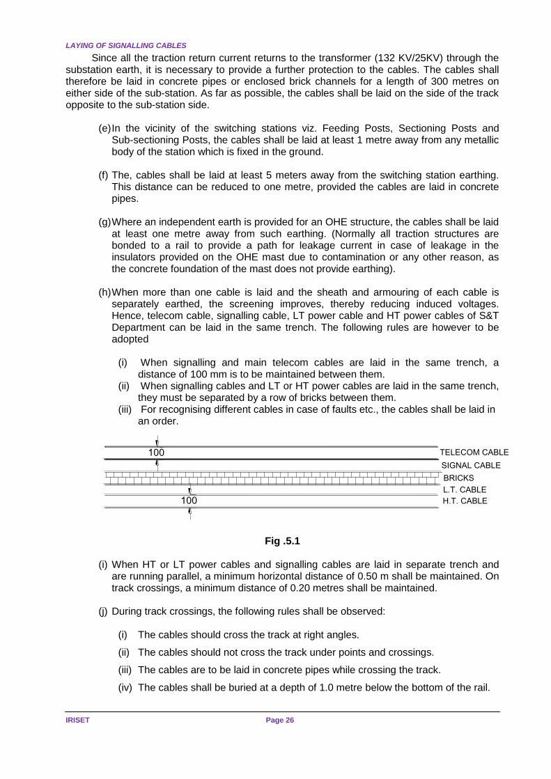
(h) When more than one cable is laid and the sheath and armouring of each cable is
separately earthed, the screening improves, thereby reducing induced voltages. Hence, telecom cable, signalling cable, LT power cable and HT power cables of S&T Department can be laid in the same trench. The following rules are however to be adopted
(i) When signalling and main telecom cables are laid in the same trench, a
distance of 100 mm is to be maintained between them. (ii) When signalling cables and LT or HT power cables are laid in the same trench,
they must be separated by a row of bricks between them. (iii) For recognising different cables in case of faults etc., the cables shall be laid in
an order.
Fig .5.1
(i) When HT or LT power cables and signalling cables are laid in separate trench and are running parallel, a minimum horizontal distance of 0.50 m shall be maintained. On track crossings, a minimum distance of 0.20 metres shall be maintained.
(j) During track crossings, the following rules shall be observed:
(i) The cables should cross the track at right angles.
(ii) The cables should not cross the track under points and crossings.
(iii) The cables are to be laid in concrete pipes while crossing the track.
(iv) The cables shall be buried at a depth of 1.0 metre below the bottom of the rail.
100
100
TELECOM CABLE
SIGNAL CABLE
BRICKS
L.T. CABLE
H.T. CABLE

LAYING OF SIGNALLING CABLES
Page 27 SIGNALLING IN 25KV AC
ELECTRIFIED SECTION
(k) The width of the cable trench shall be normally 0.46 metre (1'-6"). (l) The bottom of the cable trench shall be levelled and sharp materials, if any, shall be
got rid of. In case of soft ground, the cable shall be laid at the levelled bottom. In case, the ground is rocky, the cable shall be laid on a layer of sand of 50mm thickness deposited at the bottom of the trench.
In both the above cases, the cable shall be covered with a layer of sand or "Sifted" earth of 100 mm thickness as a protection.
(m) When cables have to cross culverts, they shall be suitably supported and protected.
The pipe used for taking the cable from the trench to the side of the culvert shall be deeply buried and rigidly fixed at either end. It is at these points that the cables are cut and stolen.
(n) When cables have to cross a metallic bridge, they shall be placed inside a GI trough
filled with sealing compound suitable to withstand 6000 V AC. The cable troughs shall be supported across the bridge, in such a manner that minimum vibrations occur to the cable. The supports shall be suitably fixed after consultation with the JE/SSE (Bridges).
(o) Earthing at the cable termination points in the cabins, relay room etc. and at the
locations shall be provided as indicated in Chapter-4. (p) The cable route shall be properly marked to allow easy indication in case of need.
The provision of cable markers is discontinued in some areas as this provides for easy identification of the location of cable and cables are subjected to theft. Instead, cable route plans are prepared indicating the location of cable with reference to either OHE mast or the track and these plans are handed over to the maintenance organisation for reference in case of need.
(q) Outside station limits, the cables shall be laid at a distance of 8 to 10 metres from the
centre of the nearest track. Care shall be taken to ensure that the route is selected within the railway boundary. If it is necessary to lay the cable outside the railway boundary, permission shall be obtained beforehand.
(r) Within station limits, where there are no OHE masts along the route of the cable, the
trenches shall preferably be dug at a distance of 3 metres (nearest edge of the trench) from the centre of track.
(s) Within station limits, when there are OHE masts along the route of the cable, the
trenches shall be dug at a distance of not less than 5.5 metres (nearest edge of the trench) from the centre of the track.
(t) In tunnels, it may not be possible to lay the underground cable. In such cases, a
chase (groove) is cut on the side of the tunnel and cable is taken inside the chase. Adequate numbers of brackets are to be provided outside the chase on the side of the tunnel to prevent cable from falling.
(u) Trenches shall be dug, cables laid and refilling done on the same day. This must be
ensured at least in the station yards, level crossings and other similar locations to avoid injury to passengers and public.
LAYING OF SIGNALLING CABLES
IRISET Page 28
(v) In case of laying of cables in embankments, slopes or where ashes or loose materials are encountered, shoring can be adopted. The shoring materials like planks, sheets shall be kept ready before digging.
(w) Back filling of the trenches shall be done properly, rammed and consolidated. (x) During excavation, the soil of the trenches shall not be thrown on the ballast but shall
be thrown away from the ballast. The cushioning effect of the track will be destroyed if dug earth is thrown on the ballast.
(y) In places where cables are to be laid between OHE foundation and track and also
between tracks, full excavation should be done only just before laying the cable in the presence of at least JE P Way though preliminary digging up to 0.4 - 0.45 metre may be done. In the case of track crossings, the work shall be done in the presence JE P.Way.
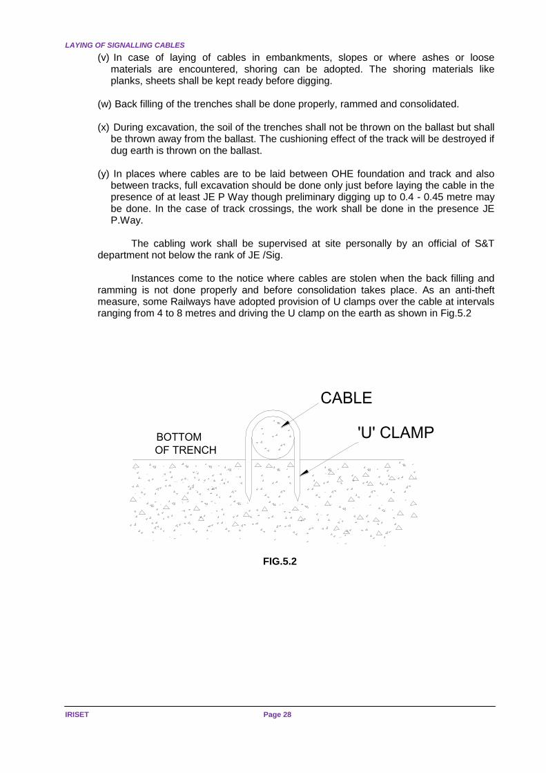
The cabling work shall be supervised at site personally by an official of S&T department not below the rank of JE /Sig. Instances come to the notice where cables are stolen when the back filling and ramming is not done properly and before consolidation takes place. As an anti-theft measure, some Railways have adopted provision of U clamps over the cable at intervals ranging from 4 to 8 metres and driving the U clamp on the earth as shown in Fig.5.2
BOTTOM
OF TRENCH
CABLE
'U' CLAMP
FIG.5.2

25KV AC ELECTRIFIED SECTIONS
Page 29 SIGNALLING IN 25KV AC
ELECTRIFIED SECTION
CHAPTER – 6: BLOCK INSTRUMENTS AND CIRCUITS
6.1 in 25KV AC electrified sections, the following block instruments shall only be used
Single Line Sections
(a) Neal's Token Instrument
(b) FM Token less Block Instrument (Handle type Token less Block instrument)
(c) Block Working with Axle Counter
Double Line Sections
(a) Double Line lock and Block Instrument.
(b) Axle Counter Block
If any other instruments are to be used, prior approval of Railway Board will have to be obtained.
The block circuits shall he transferred to long distance underground cables. Since block circuits are safety circuits, special P.V.C. insulated quads shall be provided for block circuits. A transformer is provided for each pair of block quad and the pairs are used through the transformers for block telephones and block bell circuits.
However, for block circuits, which work on DC, transformers cannot be used and so direct connection through the cables is necessary. To economise on cable conductors, the phantoms of each pair is used for the block circuit. Since the block circuits are very much longer than ordinary signal circuits, comparatively high voltages will be developed in the circuits even when aluminium sheathed cables with lower screening factor are used. Protective devices shall therefore be provided at either end of the block circuit for protection of the instruments as well as the staff operating them.
Various protective devices are to be provided depending on the type of instruments and also on the type of return circuit viz. earth return or metallic return. The principal protective device used is called “Block Filter". Additional protective devices are required for single line token instruments. The filter unit consists of four chokes with two condensers connected across the junction between the two chokes and earth.
When OFC, Radio or other communication means are used for block working, universal fail-safe block interface (UFSBI) of approved design shall be used. UFSBI is normally installed in communication room, which may not always be close to the place where block instruments are installed. In case the distance between UFSBI and block instrument is more than 500 metres, block filter shall be inserted in cable pairs connecting them. When a block section originates at a station in electrified area and terminates at a station in non-electrified area, filters shall be provided at both ends of such block section.
STRAY CURRENTS
IRISET Page 30
CHAPTER -7: STRAY CURRENTS
7.1 It is an observed fact that natural currents are found to be flowing in the soil in most
parts of the world especially in rocky soils. This may be due to partly electrolytic action and
partly to other causes which are not fully understood.
There have been instances when DC track relays of a DC track circuits operated due to stray currents. It is therefore necessary that stray current tests be carried out to ensure that DC track relays do not operate with stray currents. For measuring the stray currents, the following is to be kept in mind
(a) The test are to be carried out only on non-electrified lines i.e. the test should be carried out at the foot-by-foot survey stage itself at the time to preparation of the Project Report for electrification.
(b) If there are track circuits existing in the area, they shall be disconnected to safeguard
against false readings being recorded owing to leakage of block joints.
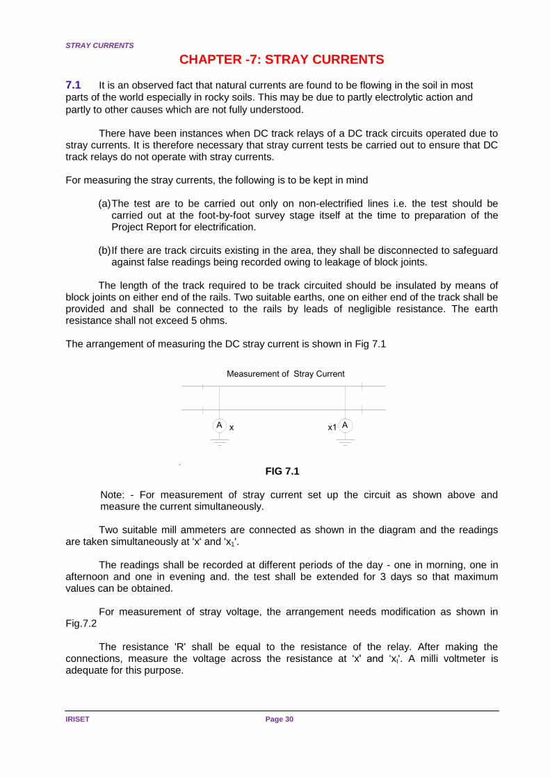
The length of the track required to be track circuited should be insulated by means of block joints on either end of the rails. Two suitable earths, one on either end of the track shall be provided and shall be connected to the rails by leads of negligible resistance. The earth resistance shall not exceed 5 ohms. The arrangement of measuring the DC stray current is shown in Fig 7.1
Measurement of Stray Current
A Ax x1
FIG 7.1
Note: - For measurement of stray current set up the circuit as shown above and measure the current simultaneously.
Two suitable mill ammeters are connected as shown in the diagram and the readings
are taken simultaneously at 'x' and 'x1'.
The readings shall be recorded at different periods of the day - one in morning, one in afternoon and one in evening and. the test shall be extended for 3 days so that maximum values can be obtained.
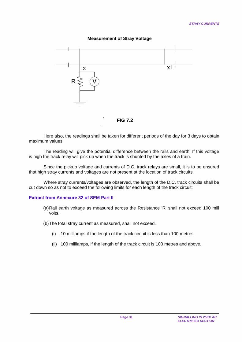
For measurement of stray voltage, the arrangement needs modification as shown in Fig.7.2
The resistance 'R' shall be equal to the resistance of the relay. After making the
connections, measure the voltage across the resistance at 'x' and ‘xI'. A milli voltmeter is adequate for this purpose.
STRAY CURRENTS
Page 31 SIGNALLING IN 25KV AC
ELECTRIFIED SECTION
Measurement of Stray Voltage
FIG 7.2
Here also, the readings shall be taken for different periods of the day for 3 days to obtain maximum values.
The reading will give the potential difference between the rails and earth. If this voltage is high the track relay will pick up when the track is shunted by the axles of a train.
Since the pickup voltage and currents of D.C. track relays are small, it is to be ensured that high stray currents and voltages are not present at the location of track circuits.
Where stray currents/voltages are observed, the length of the D.C. track circuits shall be cut down so as not to exceed the following limits for each length of the track circuit:
Extract from Annexure 32 of SEM Part II
(a) Rail earth voltage as measured across the Resistance 'R' shall not exceed 100 mill volts.
(b) The total stray current as measured, shall not exceed.
(i) 10 milliamps if the length of the track circuit is less than 100 metres. (ii) 100 milliamps, if the length of the track circuit is 100 metres and above.
ALTERATIONS TO TRACK CIRCUITS
IRISET Page 32
CHAPTER - 8: ALTERATIONS TO TRACK CIRCUITS
8.1 In an AC electrified section one of the following track Detections to be used
(a) DC Single Rail Track Circuits (b) AFTC (c) Axle Counters. Track circuit on AC-electrified section may use IRJs (Insulated Rail Joints) or ESJs
(Electrical Separation Joints) and may be configured as single rail or double rail track circuits. Track circuits, which use electric separation joints, shall be configured only as double rail track circuits.
8.2 DC Single Rail Track Circuit
The simplest track circuit is the single rail track circuit using DC supply from batteries with charging arrangements.
Normally, in non-track circuited areas, both rails are used for traction return current. In a DC single rail track circuit, only one rail is used for traction return current and the other rail is insulated to enable track circuiting. The rail, which is reserved for traction return current, is called the un insulated rail. Any connection from the OHE mast or any other structure shall be made to the un insulated rail only. Similarly, connections for the traction return currents at the feeding points as well as from Booster Transformers and return conductors shall be made only to the un-insulated rail (in track circuited areas).
As far as practicable, the rail adjacent to the OHE masts shall be treated as the un insulated rail. However, this may not always be possible, particularly in yards where there are a large number of points and crossings and where OHE masts are not on the same side of the track. 8.2.1 Relays
As traction return current flows through un insulated rails, there will be a voltage drop along the rail. This voltage will appear across the relay as well as the track feed battery.
VR = RAIL IMPEDANCE X TRACTION CURRENT.
IT = VR / (RAIL IMPEDANCE + RELAY IMPEDANCE.)
As rail impedance is very small compared to relay impedance, the equation can be modified as
IT = VR / RELAY IMPEDANCE
Since no traction current flows in the insulated rail, the voltage at Relay terminal R2 is zero. Hence an A.C. voltage Of VR on Relay terminal R1 forms a complete circuit for the relay through the axle of the loco.
The voltage is maximum when the track is shunted by a pair of wheels at the far end. In this condition a fairly large alternating current can flow through the relay.

TRACK CIRCUIT
Page 33 SIGNALLING IN 25KV AC
ELECTRIFIED SECTION
AXLE OF LOCO
V R
TRACK FEED TRACK RELAY
TRACTION RETURN CURRENT
R1 R2
INSULATED RAIL
FIG 8.2(a)
This gave a value producing a voltage drop of 10 volts per 90 metres (100 yds.) at 250 Amps. Ordinary 9 Ohms relays conform to BSS 1659 were found to chatter at A.C. voltages exceeding 35 volts.
It is therefore necessary that relays are made immune to alternating current to ensure that it will not operate falsely, in the presence of a superimposed A.C. voltage on the operating winding, i.e.
(a) It should not pick up when it should be in De-energised condition. (b) It should not remain held up when it should drop away.
There are two contemporary methods of A.C. immunisation, one employing a series
choke and the other inherently immunising the relay itself.
A choke has high A.C. impedance, and D.C. resistance of only few ohms which can easily be connected in series with the existing relay without modifying the relay. By the use of a series choke, the normal operation may not be seriously affected but the equipment will still function correctly with several hundred volts at 50 cycles applied.
However, it is undesirable to fit a single choke in series with a non-immunised track relay because if the choke becomes short-circuited, the relay would no longer be immune to A.C. voltages and might pick up, due to effects of traction current, with a train standing on the track circuit.
Hence, it is desirable to use relays which are inherently immunised.
(Note: - Details of A.C. immunised relays are explained in IRISET Notes S-19)
It has been found that a voltage drop of 10 volts per 90 metres (100yds) occurs at 250 amps. Using A.C. immunised relays, safe and reliable operation, could be maintained with max: 50 V A.C. potential across the relay and on this basis, a maximum length of 450 meters. was prescribed. This takes into account that there are 2 locos, each taking up to 120 amps. For a heavy train.

ALTERATIONS TO TRACK CIRCUITS
IRISET Page 34
8.2.2 Feed End
Let us see Fig. 8.2(a) again. If the feed end and relay ends happen to be interchanged, then the battery is required to be protected from the A.C. voltages. This is possible to be achieved by fitting a choke at the feed end of the track circuit in order to reduce the alternating current flowing through the battery.
If this choke becomes short circuited, no dangerous condition would arise.
At Feed end, transformer rectifier set alone should not be used, as it has been found on test that with 150 volts ' A.C. across the rails due to traction current and when the signalling supply is cut off from the A.C. side of the rectifier, a D.C. voltage of 5 volts was measured at the relay. This is because, the rectifier will appear as a half wave unit connected in parallel across the track circuit and consequently produces a D.C. potential across the relay when A.C. appears across the track.
This is a very dangerous condition and so a battery is a must. The transformer-rectifier can be used for charging the batteries but it must be ensured that the cells cannot get disconnected without the rectifier also being disconnected from the track. The battery, whose internal resistance is small, when connected across the rectifier set, provides a low resistance path for A.C. currents.
The A.C. immunised track relays as per IRS specification can withstand up to 50 V A.C. without any appreciable variation in their operating characteristics.
A typical D.C. single rail track circuit using an A.C. immunised relay is shown below:
R1 R2
BLOCK JOINT
INSULATED RAIL
UN-INSULATED RAIL
BATTERY
CHARGER
SHUNT BOND
SURGE ARRESTOR
9 OHMS AC IMMUNISED
TRACK RELAY
'B' TYPE CHOKE
Z= 120 OHMSR= 3 OHMS
REGULATINGRESISTANCE
TR
TYPICAL SINGLE RAIL DC TRACK CIRCUIT
FIG 8.2(b)
(a) For track circuits up to 100 m length only one surge arrestor at the relay end is necessary.
(b) If the track circuit is more than 100 m long, a surge arrestor to be provided at each
end. The track circuit arrangement shown in Fig. no 8.2(b) is for an isolated track circuit,
length of which should not exceed 450 metres. The maximum length of track circuit is 450 m, if wooden sleepers are provided with a train shunt resistance (TSR) value of 0.5 ohm. This is not true when concrete sleepers are provided.
TRACK CIRCUIT
Page 35 SIGNALLING IN 25KV AC
ELECTRIFIED SECTION
8.3 Track Circuit with Concrete Sleepers
The ballast resistance of a double rail track circuit provided with concrete sleepers is found to be 1 Ohm/KM. In 25 KV AC electrified section, only single rail D.C track circuit can be used.
With one rail earthed, the ballast resistance that is obtainable from the single rail track circuit will be 0.6 times that which will be obtainable in a double rail track. Hence, the minimum ballast resistance that will be available with the present design of concrete sleepers for single rail D.C. track circuit will be 0.6 ohm/km only.
The maximum length of track circuit that can be obtained is calculated as 350 metres, with the following parameters
(a) Ballast resistance of 0.6 ohms/km. (b) Train Shunt resistance of 0.25 ohms. (c) Over excitation of 250 % (d) Single lead acid cell (2.0 V to 2.6 volts) (e) Track Relay WSF type A.C. Immunised (4F/B, 2F, 2F/B) with pick up current of
value 66-72milliamps.
Hence the D.C. single rail track circuit length shall not exceed 350 metres when concrete sleepers are used. (This has the approval of Railway Board as per RDSO's letter No. STS/EANS/SLP dated 18.10.1978).
8.4 Bonding 8.4.1 The object of Track bonding are
(a) To provide a path for traction return current, which ensures that no component of the track/traction return network rises above 25V to remote earth, under normal traction load conditions and 430 V under traction short circuit conditions
(b) To ensure that protective equipment operates satisfactorily (c) To minimize damage to installations due to traction short circuit (d) To maintain correct operation of track circuits
TYPES OF TRACTION BONDS
(a) Transverse Bond
(b) Cross Bond.
(c) Structural Bond.
(d) Longitudinal Bonds: In Non-welded Negative rails i.e having fish plates, a metal strip is connected across fish plate for traction return current.
ALTERATIONS TO TRACK CIRCUITS
IRISET Page 36
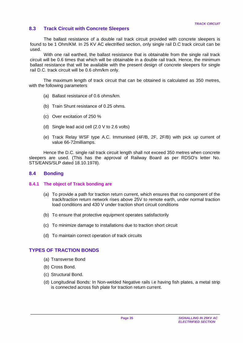
TRANSVERSE BOND
In case there are adjacent track circuits, the polarity of the track feed of adjacent track circuits, required to be reversed. In addition RDSO prescribes staggering of the return Rail.
If return rails are staggered, insulated joints are required to be provided on both rails and these will cause discontinuity of rail used for traction return current. A transverse Rail Bond is provided connecting all the non-insulated rails so that a continuous path is available for the return current.
Transverse -Bonding is provided by Electrical Department but the identification of the non-insulated rail is to be done S&T Department. A typical arrangement is shown in Fig.8.3.
Fig.No.8.3
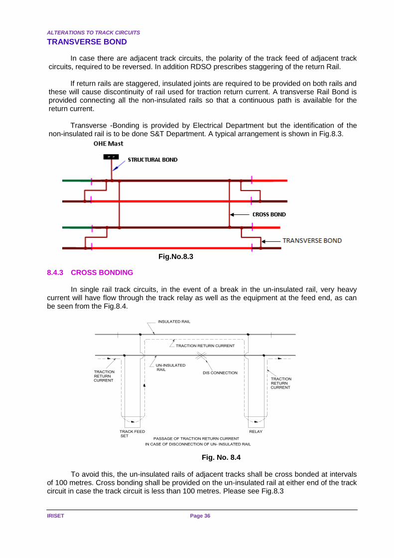
8.4.3 CROSS BONDING In single rail track circuits, in the event of a break in the un-insulated rail, very heavy
current will have flow through the track relay as well as the equipment at the feed end, as can be seen from the Fig.8.4.
Fig. No. 8.4
To avoid this, the un-insulated rails of adjacent tracks shall be cross bonded at intervals of 100 metres. Cross bonding shall be provided on the un-insulated rail at either end of the track circuit in case the track circuit is less than 100 metres. Please see Fig.8.3
INSULATED RAIL
UN-INSULATED
RAIL
TRACTION RETURN CURRENT
DIS CONNECTIONRETURN CURRENT
TRACK FEEDSET
RELAY
PASSAGE OF TRACTION RETURN CURRENT
IN CASE OF DISCONNECTION OF UN- INSULATED RAIL
TRACTION
RETURN CURRENT
TRACTION

TRACK CIRCUIT
Page 37 SIGNALLING IN 25KV AC
ELECTRIFIED SECTION
On single line sections, beyond top Points, other track may not be available.For cross bonding an extra rail (scrap rail) will be laid by Engineering Department along side of the un-insulated rail for the purpose of providing an alternate path for traction return current. The additional rail shall be longitudinally bonded in the same manner as the un-insulated rail and cross bonded to the un-insulated rail at the intervals prescribed above. Please see Fig.8.5
Fig.No.8.5
Alternately, in single rail track circuited sections, where a continuous earth wire is
provided on the traction mast capable of carrying full traction return current, the additional rail may not be required and the un-insulated rail shall be connected to each of the traction masts by a structure Bond which shall be riveted at both ends.
Structural Bond.
Structural Bonds provided to connect any metallic structure which is near by the side of track to un-insulated rail. Any un-due voltage developing due to induction voltages, or due to any other reasons, will be earthed by connecting to the negative rail.
INSULATED
RAIL
WOODEN/PSC
SLEEPERS
CROSS BONDING
SCRAP RAIL
UN INSULATED RAILCROSS BONDING
CROSS BONDING ON SINGLE RAIL TRACK
CROSS BONDS

ALTERATIONS TO TRACK CIRCUITS
IRISET Page 38
Cross Bond Structural Bond
Fig.8.6
CCROSS BOND
Longitudinal Bond
Transverse bond
OHE
Mast STRUCTURAL BOND
CSHUNT BOND
CTRANSVERSE
BBOND
LONGITUDINAL BOND

CENTRALISATION OF TRACK RELAY
Page 39 SIGNALLING IN 25KV AC
ELECTRIFIED SECTION
8.4.2 LONGITUDINAL BONDING
Longitudinal bonding on the insulated rails of single track circuits shall be provided by S&T department. Standard No.8 SWG, G.I. wire with channel bond pins may be used for this purpose. Longitudinal Bonds (Continuity) bonds are provided on un-insulated rails at fish plate joints for traction return current continuity.
The longitudinal bonding on a non-track-circuited track adjacent to track circuit shall be extended beyond the track circuit for a distance of 50 metres. In addition, the two rails of the non-track circuited track outside any track circuit or in between any two track circuits shall be bonded together immediately after the block joints.
The Cross Bonding, longitudinal bonding, transverse bonding, structural bonding and shunt bonding are done by Electrical Department.
It may be of interest to note that with the cross bonding provided, broken rail detection on the un-insulated rail will not be available.
8.5 Centralisation of Track Relay
In the case of 2 rail length D.C. track circuits, the most important factor is the, operating time of the track relay. The two-rail length track circuit is about 26 metres long and with a distance of 10 meters between the first wheel and the last wheel of a locomotive, the time required for a single locomotive to pass over the track circuit at 120 KMPH is of the order of 1 second.
So, the operating time of the track relays should not exceed one second to ensure that the track relay operates when the two rail length DC track circuit is passed through by a single locomotive at 120 kmph speed.
The operating time of the track relay depends on the supply voltage as well as the relay and feed end lead resistance.
Various tests have been conducted (RDSO's Report No.SST-7) and finally it was decided to adopt the supply voltages, feed end and relay end resistances for centralisation as given in Table on page 40
The table also give the requirements for other types of D.C. track circuits for centralisation in RE area. Audio Frequency Track circuits & Axle Counters are also in use in Electrified sections.
ALTERATIONS TO TRACK CIRCUITS
IRISET Page 40
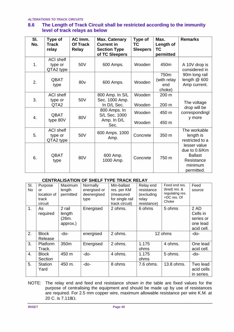
8.6 The Length of Track Circuit shall be restricted according to the immunity level of track relays as below
Sl. No.
Type of Track relay
AC Imm. Of Track Relay
Max. Catenary Current in Section Type of TC Sleepers
Type of TC Sleepers
Max. Length of TC permitted
Remarks
1. ACI shelf type or
QTA2 type 50V 600 Amps. Wooden 450m A 10V drop is
considered in 90m long rail length @ 600 Amp current.
2. QBAT type
80v 600 Amps. Wooden
750m (with relay
end choke)
3. ACI shelf type or QTA2
50V 800 Amp. In S/L Sec. 1000 Amp.
In D/L Sec.
Wooden
Wooden
200 m
200 m The voltage drop will be
correspondingly more 4.
QBAT type 80V
80V
800 Amps. In S/L Sec. 1000 Amp. In D/L
Sec.
Wooden
Wooden
450 m
450 m
5. ACI shelf type or
QTA2 type 50V
600 Amps. 1000 Amp.
Concrete 350 m The workable
length is restricted to a lesser value
due to 0.6/Km Ballast
Resistance minimum permitted.
6. QBAT type
80V 600 Amp.
1000 Amp. Concrete 750 m
CENTRALISATION OF SHELF TYPE TRACK RELAY
Sl. No
Purpose or location of track circuit
Maximum length permitted
Normally energised or deenergised type
Min-ballast res. per KM (measured for single rail track circuit)
Relay end resistance (excluding relay resistance)
Feed end res. (lead) res. & regulating res. +DC res. Of Choke
Feed source
1. As required
2 rail length (26m. approx.)
Energised 2 ohms. 6 ohms 5 ohms 2 AD Cells in series or one lead acid cell.
2. Block Release
-do- energised 2 ohms. 12 ohms -do-
3. Platform Track.
350m Energised 2 ohms. 1.175 ohms
4 ohms. One lead acid cell.
4. Block Section
450 m -do- 4 ohms. 1.175 ohms
5 ohms. -do-
5. Station Yard
450 m. -do- 8 ohms 7.6 ohms. 13.8 ohms. Two lead acid cells in series.
NOTE: The relay end and feed end resistance shown in the table are fixed values for the purpose of centralising the equipment and should be made up by use of resistances are required. For 2.5 mm copper wire, maximum allowable resistance per wire K.M. at
20 C. is 7.118.

CENTRALISATION OF TRACK RELAY
Page 41 SIGNALLING IN 25KV AC
ELECTRIFIED SECTION
(Note : TC length on concrete sleepers can be relaxed up to 450meters by CSTE if 4Ω /KM ballast resistance is consistently obtained at locations both in yard and the block sections( with 9Ω QTA2) ( RB Lr. NO. 2011/SIG/ SEM-II/Misc., dated Sept. 23. 2011)
8.8 AFTC Track Circuits
The use of audio frequencies permits the physical limits of an individual track circuit to be defined by tuned short circuits between the rails rather than the insulation in the rails themselves.
This track circuit has good immunity to 50Hz AC induced voltage or harmonics generated by thyristor controlled locos. It has a small over lap section of about 4m at the boundary between two track circuits.
Maximum length of Track Circuit under different track parameter conditions shall not exceed the limits as
given in this table
Sl.
N
o
RE
Sleeper
Secti
on
Yard /
Block
Min.
RB
in Ω
/Km
TSR
in Ω
Max.
Length of
Track
Circuit in
meters
Type of Track
Relay to be
used
Remarks
(L= Length of the Track circuit)
1 RE Wooden Block 4
0.5
450 QTA2 QSPA1 Relay shall be used as a
1st repeater relay for QTA2
Track Relay.
2 RE Wooden Yard 2
0.5
450 QTA2 QSPA1 Relay shall be used as a
1st repeater relay for QTA2
Track Relay.
3 RE PSC
Yard 2
0.5
350 QTA2 QSPA1 Relay shall be used as a
1st repeater relay for QTA2
Track Relay.
4 RE PSC
Yard/ Block sectio
n
4
0.5 450
(See Note
below)
QTA2 QSPA1 Relay shall be used as a
1st repeater relay for QTA2
Track Relay.
5 RE PSC
Yard
2
0.5
750 Mts. QBAT
(ACI level = 80V
AC, PU. 1.75 V,
175 mA ) in
conjunction with
QSPA1
With B-type
Choke at
R/end.
QSPA1 Relay shall be used as a
1st repeater relay for QBAT
Track Relay.

INDUCTION & IT’S EFFECTS ON SIGNALLING
IRISET Page 42
CHAPTER- 9: INDUCTION & IT ’S EFFECTS ON SIGNALLING
In the vicinity of an industrial frequency high voltage AC traction line i.e. Catenary there are two electrical phenomena which may affect S&T circuits. They are
(a) Electrostatic influence.
(b) Electromagnetic induction.
9.1 Electro-static Influence
When an uncharged body is brought near a charged body, it acquires some charge.
Around a conductor maintained at a high A.C. potential, there is an alternating electric field. The distance to which this field extends depends on the voltage, the condition of the surrounding atmosphere, the presence of earthed structures in the neighbourhood etc.
The electro-static field emanates from the positive charge and ends at the negative charge unlike magnetic lines of force, all of which form closed circuits.
Any conductor that exists within the field will get charged. In other words, the power conductor and the S&T conductor in the vicinity can be deemed to have small capacitance to earth and between themselves, the magnitude of these capacitances depends on the physical separation, atmospheric conditions etc.
The power developed in the S&T circuit by Electrostatic influence is proportional to the parallelism or the distance over which the catenary and S&T circuits are parallel. The power developed will be least when the signal is perpendicular to the catenary.
The magnitude of the voltage induced in the S&T conductor under the influence of the traction wire, depends on the relative position and not on its length. The energy transferred to the S&T conductor however depends on the length of parallelism.
The voltage induced electrostatic ally in an overhead line situated at a distance of 10 metres from the track was calculated to be about 3000V. If the parallelism of this line is 1 KM and if someone touch this line, a current of about 4 milliamps will flow through the body of the person. This would give a dangerous shock. If the value of the current is 15 milliamps, it would prove to be fatal to a person.
In a test conducted, the extent of electro-static induction has been found as follows:
Sl.No
Separation of Overhead wire alignment from the centre of track
Length of Parallelism of overhead alignment
Electro-static voltage measured
1. 9 metres 1 KM 950.00 V
2. 109 metres 1 KM 3.25 V
3. 209 metres 1 KM 0.9 V
It may be seen that as the distance of separation increases, the electrostatic voltage falls
steeply. It would therefore be desirable to shift the overhead alignments as far away as possible.
ELECTROMAGNETIC INDUCTION
Page 43 SIGNALLING IN 25KV AC
ELECTRIFIED SECTION
This is not possible in the signalling circuits. They have to be nearer to the track, to cater for making connections to signals, tracks, points, etc.
Electro-static voltage can be eliminated by providing an earthed metallic screen between the catenary and the signal and telecommunication lines. This is impracticable to provide metallic screen around long lengths of overhead lines.
The best method to eliminate the electrostatic induction is to transfer the circuits to underground cables and this is prescribed in the various Manuals. Hence, there shall be no aerial lines in the vicinity of A.C. Electrified track.
9.2 Electromagnetic Induction
When a conductor carries current, there is a magnetic field around the conductor. With an alternating current, the magnetic field is also alternating. Hence, the A.C. traction overhead system sets up an alternating magnetic field.
Any conductor linking with these magnetic lines of force, has a voltage induced in it according to the well known "Faraday's Law of Electromagnetic Induction" which states that "Whenever the, number of lines of force linking with a circuit changes, an e.m.f. is induced in the circuit which is proportional to the rate of change of flux".
The magnitude of the induced voltage is also dependent on the current, the distance of separation, the surrounding medium etc.
When the entire outward and return current is restricted to two conductors located physically close to each other, the induced voltage on a third conductor due to each one of these will cancel, leaving a resultant which is very nearly zero.
In the case of an A.C. traction system, the current drawn from the power sub-station by a locomotive is fed through the catenary and is returned through the, rail system. If all the" return current passes through the rails, the resultant induced voltage in a conductor in the vicinity will be negligible. However, in practice this is not the case.
The return current passes from the wheels of the locomotive and from the rails, a portion of the current passes through the ballast into the earth. Some of this portion penetrates deeply into the earth; some leaves 'the earth to find a path in other rails, cable sheaths, metal pipes and similar conductors parallel to the track.
Near the sub-station, the whole of the current must return to the secondary windings of supply transformers. When the rails are bonded to each other, some return current is shared between rails of adjacent tracks on the route from the nearest bonds, back to the sub-station.
9.3 Compensating Effects
The rails may carry both traction return and induced currents. The circuit for the traction return current includes the supply transformer windings, the catenary system and the electrical equipment in the locomotive.
The remaining portion of the circuit which contains the rails has a parallel path through the earth.
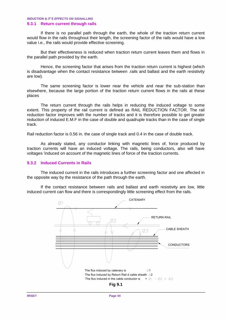
INDUCTION & IT’S EFFECTS ON SIGNALLING
IRISET Page 44
9.3.1 Return current through rails
If there is no parallel path through the earth, the whole of the traction return current would flow in the rails throughout their length, the screening factor of the rails would have a low value i.e., the rails would provide effective screening.
But their effectiveness is reduced when traction return current leaves them and flows in
the parallel path provided by the earth.
Hence, the screening factor that arises from the traction return current is highest (which is disadvantage when the contact resistance between .rails and ballast and the earth resistivity are low).
The same screening factor is lower near the vehicle and near the sub-station than elsewhere, because the large portion of the traction return current flows in the rails at these places
The return current through the rails helps in reducing the induced voltage to some extent. This property of the rail current is defined as RAIL REDUCTION FACTOR. The rail reduction factor improves with the number of tracks and it is therefore possible to get greater reduction of induced E.M.F in the case of double and quadruple tracks than in the case of single track. Rail reduction factor is 0.56 in. the case of single track and 0.4 in the case of double track.
As already stated, any conductor linking with magnetic lines of, force produced by traction currents will have an induced voltage. The rails, being conductors, also will have voltages 'induced on account of the magnetic lines of force of the traction currents. 9.3.2 Induced Currents in Rails
The induced current in the rails introduces a further screening factor and one affected in the opposite way by the resistance of the path through the earth.
If the contact resistance between rails and ballast and earth resistivity are low, little induced current can flow and there is correspondingly little screening effect from the rails.
CATENARY
RETURN RAIL
CABLE SHEATH
CONDUCTORS
The flux induced by catenary is 1
The flux induced by Return Rail d cable sheath 2
The flux induced in the cable conductor is =
Fig 9.1
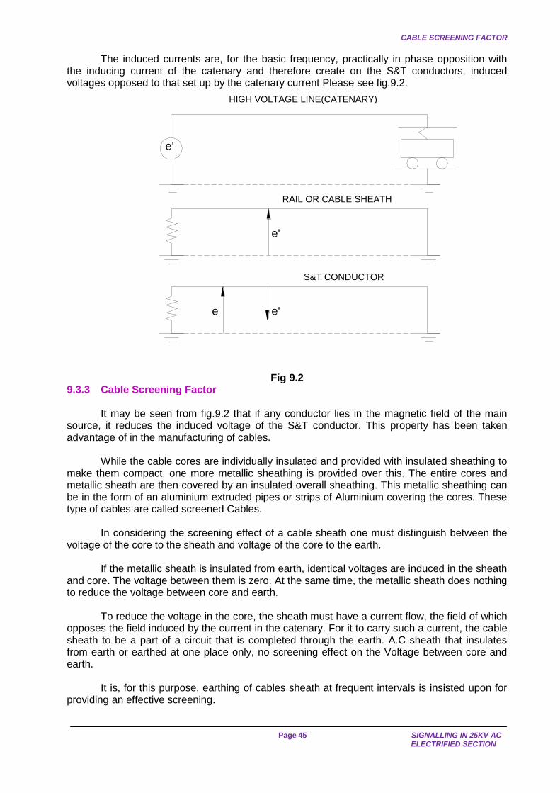
CABLE SCREENING FACTOR
Page 45 SIGNALLING IN 25KV AC
ELECTRIFIED SECTION
The induced currents are, for the basic frequency, practically in phase opposition with the inducing current of the catenary and therefore create on the S&T conductors, induced voltages opposed to that set up by the catenary current Please see fig.9.2.
HIGH VOLTAGE LINE(CATENARY)
e'
RAIL OR CABLE SHEATH
e'
e'
S&T CONDUCTOR
e
Fig 9.2 9.3.3 Cable Screening Factor
It may be seen from fig.9.2 that if any conductor lies in the magnetic field of the main source, it reduces the induced voltage of the S&T conductor. This property has been taken advantage of in the manufacturing of cables.
While the cable cores are individually insulated and provided with insulated sheathing to make them compact, one more metallic sheathing is provided over this. The entire cores and metallic sheath are then covered by an insulated overall sheathing. This metallic sheathing can be in the form of an aluminium extruded pipes or strips of Aluminium covering the cores. These type of cables are called screened Cables.
In considering the screening effect of a cable sheath one must distinguish between the voltage of the core to the sheath and voltage of the core to the earth.
If the metallic sheath is insulated from earth, identical voltages are induced in the sheath and core. The voltage between them is zero. At the same time, the metallic sheath does nothing to reduce the voltage between core and earth.
To reduce the voltage in the core, the sheath must have a current flow, the field of which opposes the field induced by the current in the catenary. For it to carry such a current, the cable sheath to be a part of a circuit that is completed through the earth. A.C sheath that insulates from earth or earthed at one place only, no screening effect on the Voltage between core and earth.
It is, for this purpose, earthing of cables sheath at frequent intervals is insisted upon for providing an effective screening.
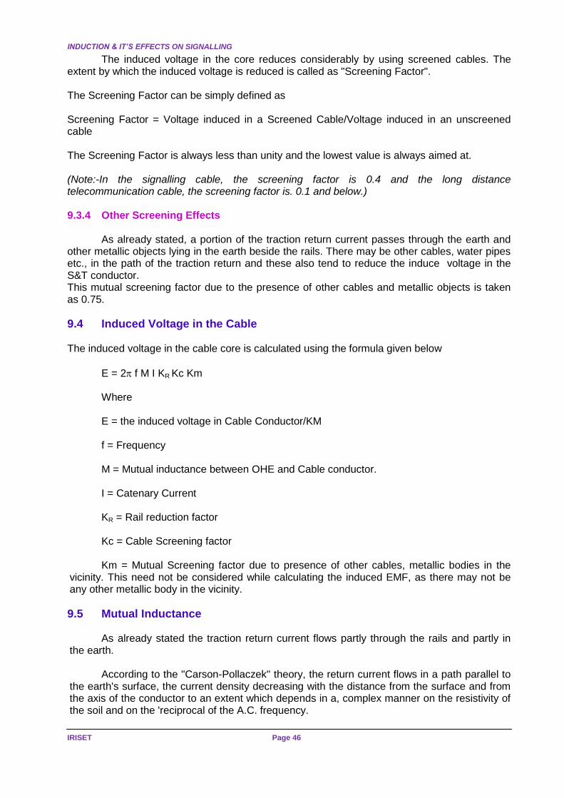
INDUCTION & IT’S EFFECTS ON SIGNALLING
IRISET Page 46
The induced voltage in the core reduces considerably by using screened cables. The extent by which the induced voltage is reduced is called as "Screening Factor". The Screening Factor can be simply defined as Screening Factor = Voltage induced in a Screened Cable/Voltage induced in an unscreened cable The Screening Factor is always less than unity and the lowest value is always aimed at. (Note:-In the signalling cable, the screening factor is 0.4 and the long distance telecommunication cable, the screening factor is. 0.1 and below.) 9.3.4 Other Screening Effects
As already stated, a portion of the traction return current passes through the earth and other metallic objects lying in the earth beside the rails. There may be other cables, water pipes etc., in the path of the traction return and these also tend to reduce the induce voltage in the S&T conductor. This mutual screening factor due to the presence of other cables and metallic objects is taken as 0.75.
9.4 Induced Voltage in the Cable The induced voltage in the cable core is calculated using the formula given below
E = 2 f M I KR Kc Km
Where
E = the induced voltage in Cable Conductor/KM
f = Frequency
M = Mutual inductance between OHE and Cable conductor.
I = Catenary Current
KR = Rail reduction factor
Kc = Cable Screening factor
Km = Mutual Screening factor due to presence of other cables, metallic bodies in the vicinity. This need not be considered while calculating the induced EMF, as there may not be any other metallic body in the vicinity.
9.5 Mutual Inductance
As already stated the traction return current flows partly through the rails and partly in the earth.
According to the "Carson-Pollaczek" theory, the return current flows in a path parallel to the earth's surface, the current density decreasing with the distance from the surface and from the axis of the conductor to an extent which depends in a, complex manner on the resistivity of the soil and on the 'reciprocal of the A.C. frequency.

MUTUAL INDUCTANCE
Page 47 SIGNALLING IN 25KV AC
ELECTRIFIED SECTION
A useful approximation to the impedance coefficients can be obtained by assuming that the earth is replaced by a perfect conductor.
d
2r
SURFACE OF EARTH
EQUIVALENT PERFECT CONDUCTOR
h
K21
Fig.No.9.3
The expression for the self-inductance of a conductor with return through a perfectly
conducting plane surface parallel to its axis is
L = [2 loge(2h/r) + 1/2] X 10 -4 henry per kilometre
Where h = distance of the conductor above the plane surface
And r = radius of the conductor in the same units as ‘h’
By equating this expression to that obtained from the Carson-Pollaczek theory with return through earth of finite conduct we obtain
Equation h = 330 p/f meters.
Where p = resistivity of the earth in Ohm-metres
And f = frequency in cycles.
The mutual inductance between two parallel conductors 1 return through a perfectly conducting plane parallel to their axes is given by
Equation: M = 2 loge (2h/d) X 10 -4 henry/kilometer.
Where d = distance between the conductors in the same unit as 'h'
This agrees closely with the "Carson - Pollaczek" formula small values of “d” which is the case for induction between the traction circuit and line-side cables, but becomes less accurate for larger values.
Taking as an example, a fairly common value for the earth resistivity of 250 Ohm metres, we see that at 50 cycles per second the depth of the equivalent plane is
h = 330 250/50 = 738 Metres.
The depths to which the currents penetrate are very large compared with the separation
between the catenary and the cables and with their height above earth. For an earth resistivity of 250 Ohm/ metres with catenary cable separation of 6 metres,
the Mutual inductance works out to 1100 Micro henrys per KM.
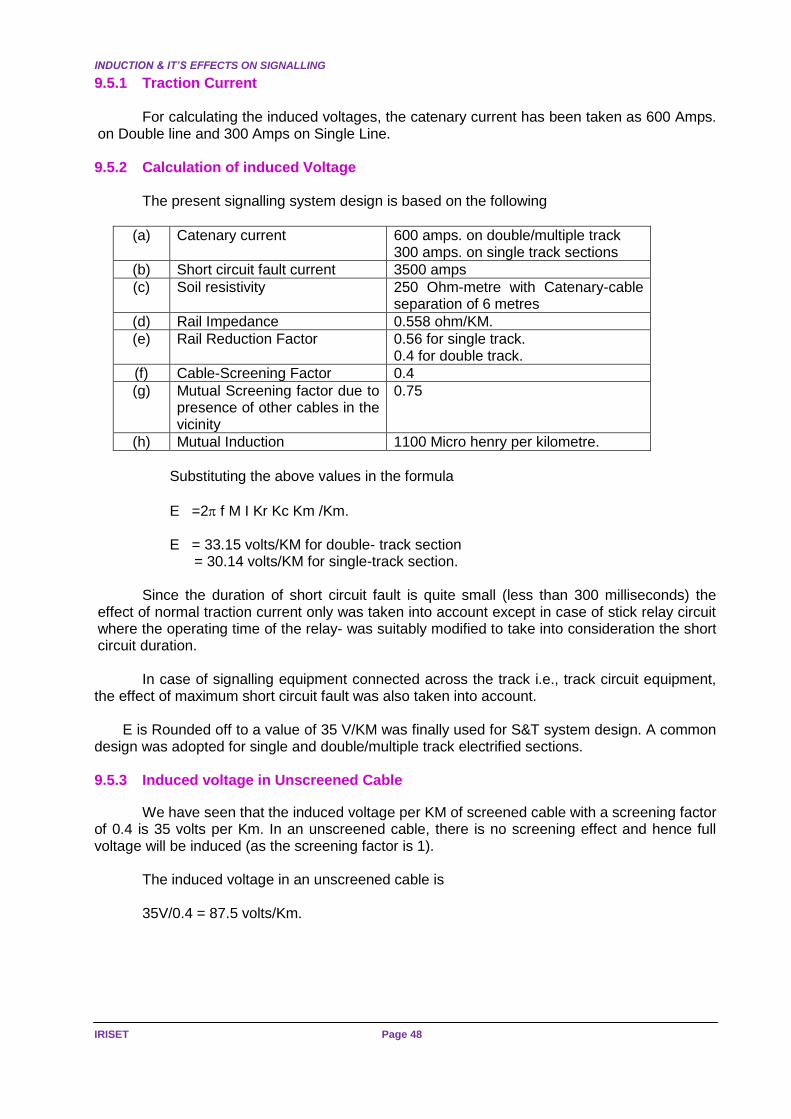
INDUCTION & IT’S EFFECTS ON SIGNALLING
IRISET Page 48
9.5.1 Traction Current
For calculating the induced voltages, the catenary current has been taken as 600 Amps. on Double line and 300 Amps on Single Line. 9.5.2 Calculation of induced Voltage
The present signalling system design is based on the following
(a) Catenary current 600 amps. on double/multiple track 300 amps. on single track sections
(b) Short circuit fault current 3500 amps
(c) Soil resistivity 250 Ohm-metre with Catenary-cable separation of 6 metres
(d) Rail Impedance 0.558 ohm/KM.
(e) Rail Reduction Factor 0.56 for single track. 0.4 for double track.
(f) Cable-Screening Factor 0.4
(g) Mutual Screening factor due to presence of other cables in the vicinity
0.75
(h) Mutual Induction 1100 Micro henry per kilometre.
Substituting the above values in the formula
E =2 f M I Kr Kc Km /Km.
E = 33.15 volts/KM for double- track section = 30.14 volts/KM for single-track section.
Since the duration of short circuit fault is quite small (less than 300 milliseconds) the
effect of normal traction current only was taken into account except in case of stick relay circuit where the operating time of the relay- was suitably modified to take into consideration the short circuit duration.
In case of signalling equipment connected across the track i.e., track circuit equipment, the effect of maximum short circuit fault was also taken into account. E is Rounded off to a value of 35 V/KM was finally used for S&T system design. A common design was adopted for single and double/multiple track electrified sections.
9.5.3 Induced voltage in Unscreened Cable
We have seen that the induced voltage per KM of screened cable with a screening factor of 0.4 is 35 volts per Km. In an unscreened cable, there is no screening effect and hence full voltage will be induced (as the screening factor is 1).
The induced voltage in an unscreened cable is
35V/0.4 = 87.5 volts/Km.
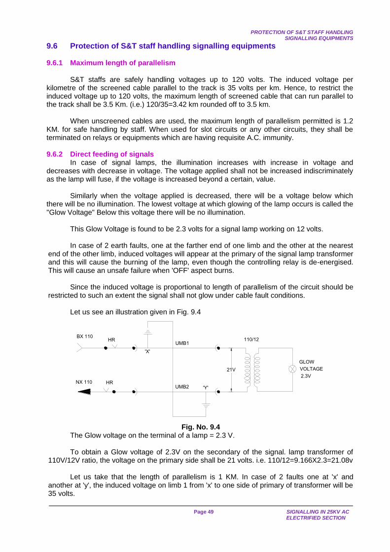
PROTECTION OF S&T STAFF HANDLING
SIGNALLING EQUIPMENTS
Page 49 SIGNALLING IN 25KV AC
ELECTRIFIED SECTION
9.6 Protection of S&T staff handling signalling equipments 9.6.1 Maximum length of parallelism
S&T staffs are safely handling voltages up to 120 volts. The induced voltage per kilometre of the screened cable parallel to the track is 35 volts per km. Hence, to restrict the induced voltage up to 120 volts, the maximum length of screened cable that can run parallel to the track shall be 3.5 Km. (i.e.) 120/35=3.42 km rounded off to 3.5 km.
When unscreened cables are used, the maximum length of parallelism permitted is 1.2 KM. for safe handling by staff. When used for slot circuits or any other circuits, they shall be terminated on relays or equipments which are having requisite A.C. immunity. 9.6.2 Direct feeding of signals
In case of signal lamps, the illumination increases with increase in voltage and decreases with decrease in voltage. The voltage applied shall not be increased indiscriminately as the lamp will fuse, if the voltage is increased beyond a certain, value.
Similarly when the voltage applied is decreased, there will be a voltage below which there will be no illumination. The lowest voltage at which glowing of the lamp occurs is called the "Glow Voltage" Below this voltage there will be no illumination.
This Glow Voltage is found to be 2.3 volts for a signal lamp working on 12 volts. In case of 2 earth faults, one at the farther end of one limb and the other at the nearest
end of the other limb, induced voltages will appear at the primary of the signal lamp transformer and this will cause the burning of the lamp, even though the controlling relay is de-energised. This will cause an unsafe failure when 'OFF' aspect burns.
Since the induced voltage is proportional to length of parallelism of the circuit should be
restricted to such an extent the signal shall not glow under cable fault conditions. Let us see an illustration given in Fig. 9.4
BX 110
NX 110
HRUMB1
110/12
GLOW
VOLTAGE
2.3V
HRUMB2
21V
'X'
'Y'
EQUIVALENT PERFECT CONDUCTOR
Fig. No. 9.4
The Glow voltage on the terminal of a lamp = 2.3 V.
To obtain a Glow voltage of 2.3V on the secondary of the signal. lamp transformer of 110V/12V ratio, the voltage on the primary side shall be 21 volts. i.e. 110/12=9.166X2.3=21.08v
Let us take that the length of parallelism is 1 KM. In case of 2 faults one at 'x' and another at 'y', the induced voltage on limb 1 from 'x' to one side of primary of transformer will be 35 volts.

INDUCTION & IT’S EFFECTS ON SIGNALLING
IRISET Page 50
The induced voltage on limb 2 from 'y' to the other side of the primary of transformer is
'zero' as there is no parallelism from Y to the transformer terminal.
The induced voltage will then appear across the primary of the transformer and will complete the circuit, - i.e., 35 volts will appear on the primary. This will produce 35x12/110 V = 3.82 volts on the secondary and will cause the lamp to be lit (with less intensity, of course) as it is above the glow voltage, even though the controlling relay is down. This will cause an unsafe condition if red lamp also fuses. To overcome this unsafe condition, the length of parallelism shall be restricted to such an extent that the voltage on the primary shall not exceed 21 volts when 2 cable faults occur at extreme ends.
Induced voltage is 35V for 1000 m. To restrict it to 21 volts, the length shall not exceed 21/35 x 1000 = 600 mtrs. Hence, the length of direct feeding of signals using a screened cable shall not exceed 600 metres.
When unscreened signalling cable is used, the induced voltage is 87.5V/Km. The maximum length of directly fed signalling circuit when unscreened cables are used, to prevent glowing of the signal under 2 earth fault conditions, shall not exceed 21/87.5 x 1000 = 240 mtrs.
In case there are 2 earth faults occurring on the two limbs within the stipulated length, the induced voltage will be superimposed along with the regular voltage and cause frequent fusing of lamps.
When frequent fusing of lamps occurs, the cable shall be tested for earth faults.
9.6.3 Common source of supply
If for any reason, the parallelism of a circuit exceeds 3.5 KM, a relay must be inserted in the circuit so that the physical continuity of the cable conductors is broken and the parallelism of each portion is kept below 3.5 KM.
If the parallelism in excess of 3.5 KM is due to the feeding two circuits from a common battery or power source, separate batteries or power source shall be provided to feed the circuit on each side to limit the parallelism to less than 3.5 KM.
9.7 Factor of Safety
The voltage which an S&T staff at field can handle safely has been stated as 120 volts. To limit the induced voltage, the length of parallelism of the cable has been limited so as the induced voltage does not exceed 120 V. So the equipments; connected to the cable should be capable of withstanding 120 V A.C. without any change in the characteristics of the equipment.
There may be occasions when the induced voltages may exceed 120V AC, though they may be rare, e.g. short circuit in the overhead system.
Since the equipments are permanently connected to the line side circuit, it is necessary
to safeguard the equipment against the above hazard. The equipment should, therefore, be capable of withstanding higher induced voltage. This' safety margin is called "Factor of Safety".
The factor of safety for signalling equipment used for line side circuit is prescribed as 2.5 times that of the induced voltage of 120 volts for a parallelism of 3.5 Km.
This means that the equipment shall be capable of withstanding 120 x 2.5 = 300V AC.
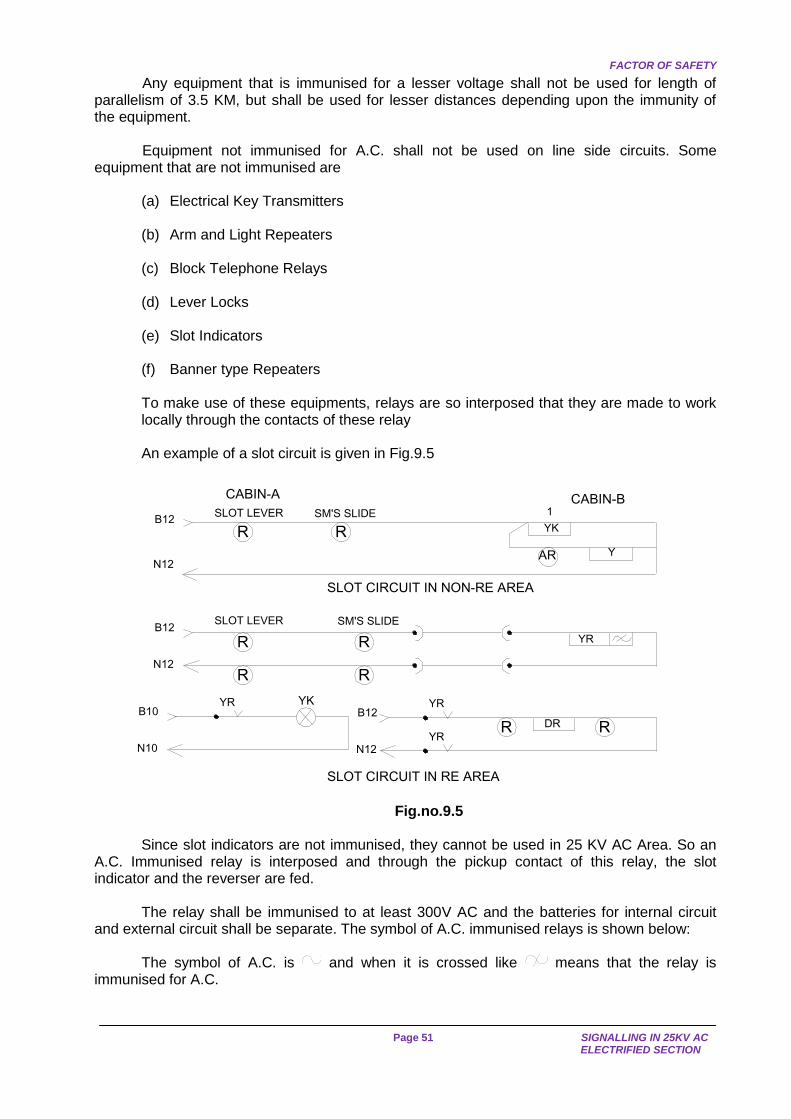
FACTOR OF SAFETY
Page 51 SIGNALLING IN 25KV AC
ELECTRIFIED SECTION
Any equipment that is immunised for a lesser voltage shall not be used for length of parallelism of 3.5 KM, but shall be used for lesser distances depending upon the immunity of the equipment.
Equipment not immunised for A.C. shall not be used on line side circuits. Some equipment that are not immunised are
(a) Electrical Key Transmitters (b) Arm and Light Repeaters (c) Block Telephone Relays (d) Lever Locks (e) Slot Indicators (f) Banner type Repeaters
To make use of these equipments, relays are so interposed that they are made to work locally through the contacts of these relay An example of a slot circuit is given in Fig.9.5
AR
SLOT LEVER SM'S SLIDE
N12
B12
Y
YK
CABIN-BSLOT LEVER
CABIN-A
SM'S SLIDE
R R
RR
SLOT CIRCUIT IN RE AREA
1
B10
N10
YKYR
YR
YR
RR DR
N12
B12
B12
N12
YR
SLOT CIRCUIT IN NON-RE AREA
RR
Fig.no.9.5
Since slot indicators are not immunised, they cannot be used in 25 KV AC Area. So an A.C. Immunised relay is interposed and through the pickup contact of this relay, the slot indicator and the reverser are fed.
The relay shall be immunised to at least 300V AC and the batteries for internal circuit and external circuit shall be separate. The symbol of A.C. immunised relays is shown below:
The symbol of A.C. is and when it is crossed like means that the relay is
immunised for A.C.
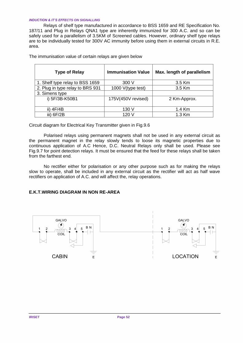
INDUCTION & IT’S EFFECTS ON SIGNALLING
IRISET Page 52
Relays of shelf type manufactured in accordance to BSS 1659 and RE Specification No. 187/11 and Plug in Relays QNA1 type are inherently immunized for 300 A.C. and so can be safely used for a parallelism of 3.5KM of Screened cables. However, ordinary shelf type relays are to be individually tested for 300V AC immunity before using them in external circuits in R.E. area. The immunisation value of certain relays are given below
Type of Relay
Immunisation Value
Max. length of parallelism
1. Shelf type relay to BSS 1659 300 V 3.5 Km
2. Plug in type relay to BRS 931 1000 V(type test) 3.5 Km
3. Simens type
i) 5F/3B-K50B1 175V(450V revised)
2 Km-Approx.
ii) 4F/4B 130 V 1.4 Km
iii) 6F/2B 120 V 1.3 Km
Circuit diagram for Electrical Key Transmitter given in Fig.9.6
Polarised relays using permanent magnets shall not be used in any external circuit as the permanent magnet in the relay slowly tends to loose its magnetic properties due to continuous application of A.C Hence, D.C. Neutral Relays only shall be used. Please see Fig.9.7 for point detection relays. It must be ensured that the feed for these relays shall be taken from the farthest end.
No rectifier either for polarisation or any other purpose such as for making the relays slow to operate, shall be included in any external circuit as the rectifier will act as half wave rectifiers on application of A.C. and will affect the, relay operations. E.K.T.WIRING DIAGRAM IN NON RE-AREA
1 2
GALVO
COIL
B N
ECABIN
1 2
GALVO
COIL
B N
ELOCATION
3 4 5 3 4 5

SIGNALS BEYOND 600M
Page 53 SIGNALLING IN 25KV AC
ELECTRIFIED SECTION
R1
LINE RELAYLINE RELAY
12.5 OPush Button
R3
12.5 OPush Button
Key is in.& Turned to RHS
Key Out
(All contact open)
1&2, 3&5 will make
Key is in.1&2, 3&4 will make
Position of Contacts
N24
B24
N24
B24
B24
N24
B24
N24
Fig.No.9.6
B 24V
N 24V
N
R
FOR DOUBLE ENDED POINTS
LEVER
CONTACTB 24V
N 24V
N
RWKRR
FOR SINGLE ENDED POINTS
'B' END'A' END
TYPICAL CIRCUIT FOR ELECTRICAL DETECTORS(ON A.C. ELCTRIFIED AREA)
LEVER
CONTACT
NWKR
NWKR
RWKR
N
N
R
R
LOCATION CABIN
ND
RD
ND
RD
RD
RD
RD
RD
ND
ND
ND
ND
Fig.No.9.7
Batteries or power source for feeding internal circuits having non-immunised equipments
shall not, be used in external circuits. The batteries for internal circuits and external circuits shall be separate. If common battery or power source is connected to both internal and external circuit, the characteristics of the non-immunised equipments used in the internal circuit shall be affected in case of faults in the cables connecting the external equipments.

INDUCTION & IT’S EFFECTS ON SIGNALLING
IRISET Page 54
9.8 Signals beyond 600 meters
It was earlier stated that the maximum length of direct feeding of signals shall not exceed 600 metres when screened cables are used and 240 metres when unscreened cables are used.
Many signals such as Advanced Starters, Home Signals and Distant Signals are located at distances of more than 600 metres from the controlling station. To feed these signals, two methods are in use.
They are
(a) Local Feed
(b) Remote Feed
9.9 Local Feed
For signals located beyond 600 metres, the controlling relays HR, DR, HHR etc, in relay room are repeated through A.C. immunised relays at the location and the signals are fed locally from these relay contacts.
Care should be taken to check the immunity of these relays to determine the length of parallelism, which however should not exceed 3.5 KM in any case.
All circuits, which pass through a main cable, must have individual returns and the controlling relay contacts must be included in both the conductors (i.e. double cutting of contacts is necessary). In case sufficient contacts are not available, the relays may be repeated and their contacts are used in the circuits.
No earth return circuit is permitted on any of the signal circuits as a single earth fault may affect the characteristics of the relays. Block circuit is an exception to this, as adequate protection has been provided to prevent unsafe conditions.
The circuit for a locally fed 3-aspect signal is given in Fig.9.8 In the local feed method, the following equipments are provided at the location box:
(a) 2 'OFF' aspect Controlling Relays (HPR,DPR) (b) 3 ECR Relays (DECR, HECR, RECR) (c) 3 Current Transformer Rectifier Sets to feed ECR Relays. (d) A Transformer rectifier set to feed D.C. voltage to repeat DECR, HECR, and RECR.
Besides the above, a power cable will be required to take power to the location to feed
the signals and repeat the ECRs.
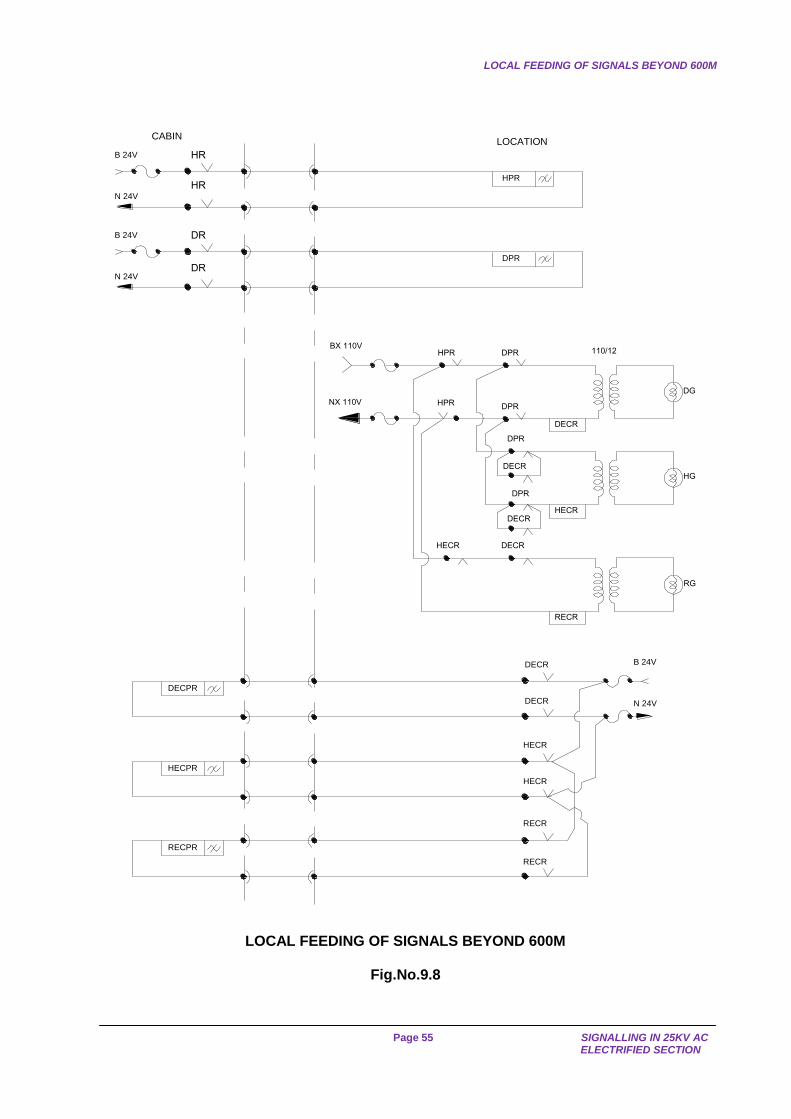
LOCAL FEEDING OF SIGNALS BEYOND 600M
Page 55 SIGNALLING IN 25KV AC
ELECTRIFIED SECTION
B 24V
HPR
CABIN
BX 110V
NX 110V
HPR 110/12
HPR
HR
N 24V
LOCATION
B 24V
DPR
DR
N 24V
DPR
DECR
DPR
DPR
DECR
DPR
DECRHECR
DECR
RECR
DECPR
HECPR
RECPR
DECR
HECR
RECR
B 24V
N 24V
HECR
HR
DR
DG
HG
RG
DECR
HECR
RECR
LOCAL FEEDING OF SIGNALS BEYOND 600M
Fig.No.9.8
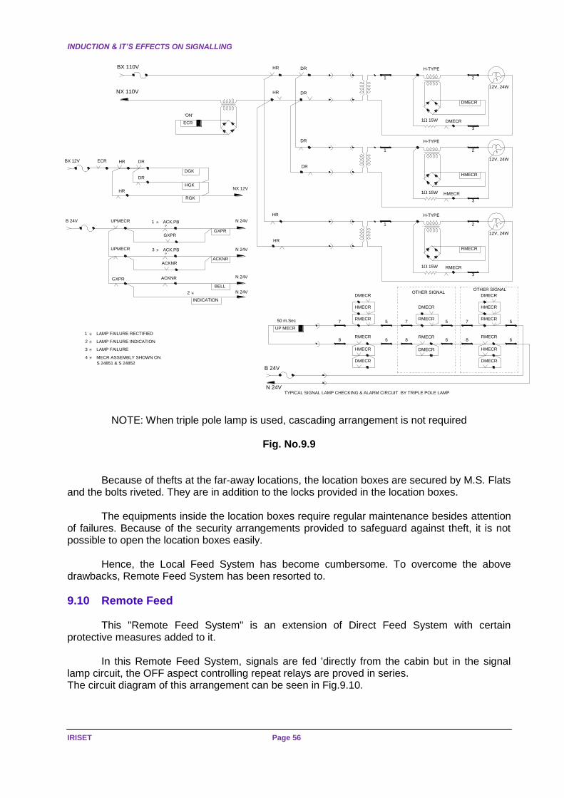
INDUCTION & IT’S EFFECTS ON SIGNALLING
IRISET Page 56
TYPICAL SIGNAL LAMP CHECKING & ALARM CIRCUIT BY TRIPLE POLE LAMP
OTHER SIGNALOTHER SIGNAL
868 86 6
7 5 7 5 5
DMECR
HMECR
RMECR
DMECR
RMECRRMECR
HMECR
DMECR
RMECR
HMECR
DMECR
7
DMECR
RMECR
DMECRHMECR
RMECR
UP MECR
50 m.Sec
N 24V
B 24V
12V, 24W
HR
1
3
2
115W RMECR
HR
RMECR
H-TYPE
H-TYPE
HMECR
DR
HMECR115W
2
3
1
DR
12V, 24W
'ON'
ECR
12V, 24W
HR DR
1
3
2
115W DMECR
DRHRBX 110V
NX 110V
DMECR
H-TYPE
S 24851 & S 24852
4 MECR ASSEMBLY SHOWN ON
3 LAMP FAILURE
2 LAMP FAILURE INDICATION
LAMP FAILURE RECTIFIED
2
INDICATION
ACKNRGXPR
BELL
ACK.PBUPMECR
ACKNRACKNR
P
3
1
1P
GXPRGXPR
N 24VB 24V UPMECR ACK.PB
HGK
DR
DR
RGK
DGK
NX 12V
BX 12V ECR
HR
HR
N 24V
N 24V
N 24V
NOTE: When triple pole lamp is used, cascading arrangement is not required
Fig. No.9.9
Because of thefts at the far-away locations, the location boxes are secured by M.S. Flats
and the bolts riveted. They are in addition to the locks provided in the location boxes.
The equipments inside the location boxes require regular maintenance besides attention of failures. Because of the security arrangements provided to safeguard against theft, it is not possible to open the location boxes easily.
Hence, the Local Feed System has become cumbersome. To overcome the above drawbacks, Remote Feed System has been resorted to.
9.10 Remote Feed
This "Remote Feed System" is an extension of Direct Feed System with certain protective measures added to it.
In this Remote Feed System, signals are fed 'directly from the cabin but in the signal lamp circuit, the OFF aspect controlling repeat relays are proved in series. The circuit diagram of this arrangement can be seen in Fig.9.10.

REMOTE FEEDING
Page 57 SIGNALLING IN 25KV AC
ELECTRIFIED SECTION
B 24V
HPR
CABIN
HR
N 24V
LOCATION
B 24V
DPR
DR
N 24V
BX 110V
NX 110V
HR 110/12DR
DECR
HECR
RECR
HPR DPR
HPR DPR
HPR
HPR
HR DR
DR
DR
HR
DR
HR
HR
DG
HG
RG
Remote feeding
Fig.No.9.10
No two earth faults as described in Fig.9.4 will cause an unsafe condition, as the OFF aspect lamps are proved by 'OFF' aspect controlling repeat relays (HPR, DPR) at the secondary side of the sign, transformer. Any two earth faults in the circuit of repeat relays of HR & DR will not pick up HPR or DPR as these relays are immunise for 300 V A.C. Hence, protection against false lighting of signals is assured.
No back contacts of HPR & DPR relays are proved in the ON aspect signal lamp circuit. In case of 2 earth faults in the ON aspect cores would only result in lighting of 'Red' lamp and this is, a safe side failure. For another reason, if back contacts of HPR & DPR are proved, the fault will remain dormant and continue to remain undetected. Hence, these contacts are not proved. If the induced voltage on the faulty cores of red aspect limbs is high ' the Red lamp will fuse very frequently and this provides a clue for checking the cable.
Another advantage in this arrangement is that the location box will contain only 2 relays and since no transformer-rectifier set is provided, no Maintenance is required at the location except for cleaning at intervals. Further, no power cable or additional cores for power supply will be required.
It may be argued as to why the HPR & DPR contacts should not be proved on the
primary side. Technically there is no objection except that when there is a single fault on one limb farther from the transformer the maintenance staff may inadvertently touch the relay terminal at the nearest end of the transformer and may receive a shock, when both normal voltage and induced voltage appear at the relay terminal. It is for this reason, the contacts are provided on the Secondary side.

INDUCTION & IT’S EFFECTS ON SIGNALLING
IRISET Page 58
Since RDSO's recommendations permit remote feed arrangements, Remote feed
arrangements up to 3 KM, the voltages at the supply points as well as at the signal transformers have to be suitably determined to obtain 10.5V at the lamp terminals, for which tapings are available at the supply and signal transformers. Advantages of Remote fed Signals.
Sl.No. Topic Local Fed Remote Fed
1. No. of cable conductors More Less
2. No. of Relays More Less
3. Power supply at location Box Required Not required
4. Time for Restoration of fault More Less
5. Chance for manipulation of Signals from Location
More Less
9.11 Route Indicator and Shunt Signal Circuits 9.11.1 Junction Type & Shunt Signals
The lamps used for Junction type Route Indicators and Shunt Signals have been standardised. They are 110 V- 25 Watts to SL 33 and are used in parallel.
Earlier lamps were used in series. This arrangement has resulted in increase of failures and caused detention to trains. Hence, Parallel arrangement has been resorted to.
In Junction Type Route Indicators, a new lamp proving transformer has been designed and is called as "U" type transformer. A lamp proving relay is connected on the secondary side of the U type transformer through a bridge rectifier. The design is so made that the relay will not drop even if 2 out of the 5 lamps in parallel fused. The relay will drop when 3 or more lamps fused.
The 110 V- 25 Watts lamp has a glow voltage of 30 volts. This can permit more than 600 metres of direct feed but for the sake of uniformity, 600 metres limit is maintained since route indicators are fixed on stop signals, for shunt signals also the same limit is retained, even though the length can be increased to 850 metres.
The circuitry arrangement for direct feeding of Route Indicators is similar to that of the
circuit for colour light signals as shown in Fig.9.11.

ROUTE INDICATOR AND SHUNT SIGNALT CIRCUITS
Page 59 SIGNALLING IN 25KV AC
ELECTRIFIED SECTION
BX 110V UR(1 ) UR(3 )
UR(3 )
UR(1 )
UR(1 )UR(3 )
NX 110V UR(1 )
UR(3 )UECR
ROAD - 1
ROAD - 2
ROAD - 3
LAMPS110V -25W
JUNCTION TYPE ROUTE INDICATOR CIRCUIT (WITHIN 600M) Fig.No.9.11
BX 110V HR
NX 110VHR
The circuit diagrams for shunt signals within 600 M
both for Post type & independent Shunt Signal.
OFF
POSITION LIGHT SHUNT SIGNAL CIRCUIT (WITHIN 600M) Fig.No.9.12
Route indicator circuit beyond 600 metres is similar to the circuit shown in Fig.9.11.
except that UR(I) and UR(3) are repeated at the location, designated as UPR(1) and UPR(2) and these contacts are proved in the lamp circuit through local feed. The UECR- is common at the location and repeated as UECPR, which will be proved in the signal and indication circuits.
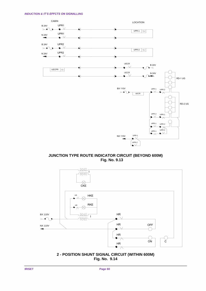
INDUCTION & IT’S EFFCTS ON SIGNALLING
IRISET Page 60
UPR-1
CABIN
UPR1
LOCATION
UPR-2
UPR2
UPR1
UPR2
UECPR
UECR
UECR
UPR-1 UPR-2
UECR
BX 110V
UPR-2 UPR-1
UPR-1 UPR-2
UPR-1UPR-2
NX 110V UPR-1
UPR-2
RD-1 UG
RD-2 UG
B 24V
N 24V
B 24V
N 24V
B 24V
N 24V
JUNCTION TYPE ROUTE INDICATOR CIRCUIT (BEYOND 600M)
Fig. No. 9.13
HRBX 110V
HR RKE
HR HKE
I
HR
HR
HR
OFF
ON C
CKE
I
NX 110V
2 - POSITION SHUNT SIGNAL CIRCUIT (WITHIN 600M)
Fig. No. 9.14

ROUTE INDICATOR AND SHUNT SIGNALT CIRCUITS
Page 61 SIGNALLING IN 25KV AC
ELECTRIFIED SECTION
In respect of shunt signals beyond 600 metres, the HR of the shunt signal is repeated at
the location. The circuit diagrams for single position and 2 position shunt signals are given in Figs.9.16 & 9.17
RDSO Manual of Instructions specify that the lamp proving units shall be connected on the secondary side of the transformer using U type lamp proving transformers. This arrangement requires that - the signal transformers are kept inside the location box. However, in practice many railways connect U type lamp proving transformer on the primary side, retaining the signal transformer in the signal unit itself.
HECR
HR
RECR
OFF
ON
PILOT
BX 110V
NX 110V
HR
SHUNT SIGNAL WITHIN 600M
Fig. No. 9.15
HPR
CABIN
HR
LOCATION
ECR1
ECPR
ECR2
NX 110V
BX 110V HPR
ECR1
ECR2ECPRBX 12V NX 12V
B 24V
N 24V
HR
B 24V
N 24V
HR
HR
ECR2ECR1
OFF-KE
POSITION SHUNT SIGNAL CIRCUIT (BEYOND 600M) Fig. no. 9.16
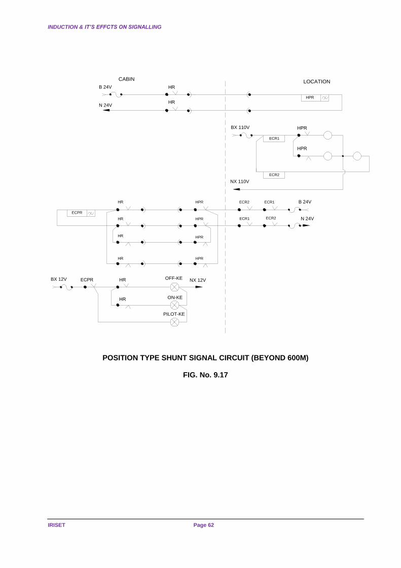
INDUCTION & IT’S EFFCTS ON SIGNALLING
IRISET Page 62
NX 110V
BX 110V
HPR
CABIN
HR
LOCATION
ECPR
ECR1HPR
ECPRBX 12V OFF-KE
ECR2HR
ECR1 ECR2HPRHR
HR
ON-KE
PILOT-KE
ECR1
HPR
HPR
ECR2
B 24V
N 24V
B 24V
N 24V
NX 12V
HR
HR
HR
HPR
HPR
HR
POSITION TYPE SHUNT SIGNAL CIRCUIT (BEYOND 600M)
FIG. No. 9.17

PRESENCE OF RETURN CURRENT IN RAIL
Page 63 SIGNALLING IN 25KV AC
ELECTRIFIED SECTION
CHAPTER -10: PERSONNEL SAFETY IN 25KV RE AREA 10.1 Proximity of Line Conductor
It was indicated in Chapter 2 that no part of signalling equipment shall fall within 2 metres of the live wire and screening shall be provided if any part fall within 2 metres of live conductor.
It was also warned that where screening was not provided either due to difficulty in provision of screen or due to only S&T staff working, a Caution Board shall be provided.
The size of the Caution Board shall be 225 mm X 200 mm indicating "Caution" in Hindi, English and regional language in white letters with a red back ground provided at a height of 3 metres (10 ft.) above Rail Level.
10.2 Presence of Return Current in Rail
10.2.1 The flow of return current in the rails will give rise to a potential difference
(a) Between adjacent rails at an insulated joint of a track circuit or at an ordinary joint in case the fish plates and bonding are broken.
(b) Between the ends of a fractured rail at the fracture.
(c) Between an insulated rail and the non-insulated rail used for the traction return current.
(d) Between the rail and the surrounding mass of earth.
10.2.2 Wherever staff have to work on installations which are in direct or indirect contact with the rails, they shall
(a) Use tools (insulated and non-insulated) in accordance with approved instructions, and
(b) Observe the provisions of Chapter XX of P.Way Manual supplemented by “Instructions for Railway Staff working on tracks equipped with 25 KV 50 Cycles A.C. Traction”
10.3 Induction in Metallic Bodies situated close to Overhead Electric Equipment
10.3.1 Induced voltage may appear in Signalling and Telecom cable when the length of parallelism to the track is appreciable. It is to be noted that even when there is no induced voltage at the time of starting a work precautionary measures listed below shall be taken, as induced voltages may develop at any time account of an increase in current in the traction lines. It is to be noted that in the case of equipment or circuits which earthed, a contact which may normally be without danger, give rise to an electric shock in the case of a break in circuit or in the earth connections. Consequently, when staff to work on Signal and Telecom circuits on 25 KV A.C. electric lines, they must take the following precautionary measures
(a) They shall, as a general rule, wear rubber gloves and use tools with insulated handles.
(b) When the work to be done is of such a nature that if rubber gloves cannot be used conveniently, special precautions shall be taken by splitting the circuits into sections or earthing them. In special cases both the steps shall be taken simultaneously. If these protective measures cannot be applied, staff must insulate them selves from the ground by using rubber mats, etc.

PERSONNEL SAFETY IN 25KV AC AREA
IRISET Page 64
(c) The cable conductors pertaining to the block instruments likely to develop heavy
induced voltages and every time the staff, handle the terminals of Block Circuits, they must rigidly observe the Provisions of paragraphs (a) and (b) above. These cables terminals shall be painted RED to remind the Maintenance staff of the danger. The Maintenance Inspectors shall explain meaning of this painting to the maintenance staff and ensure it is correctly understood by them.
10.3.2 Before any work is undertaken on Signalling or Rly. Telecom cable, the staff must
take the following precautionary measures
(a) Reduce the length of the circuit as much as possible. (b) Use rubber gloves as far as possible or alternatively use insulated rubber mats. (c) Before cutting the armour or the lead sheath of the cable or the wires in the cables,
an electrical connection of low resistance shall be established between the two parts of the armour, the sheathing and wires that are to be separated by cutting.
The following precautions should be taken while working in traction areas:–
(a) No work shall be done within a distance of two meters from the live parts of the
O.H.E.without a ‘permit-to-work. (See notes below) (b) For work adjacent to overhead equipment the SSE/JE(S) shall apply to the proper authority sufficiently in advance for sanctioning the traffic and power block required.
Note :- The Traction Power Controller through Traction Foreman will arrange to isolate and earth the section concerned on the date and at the time specified in consultation with the Traffic Controller. He shall then issue ‘permit-to-work’ to the SSE/JE(S). On completion of the work the ‘Permit-to work’ should be cancelled and Traction Power Controller advised who will then arrange to remove the earth and restore power supply.
Staff who has to work on electrical circuits must be equipped with insulated tools such as
box spanners, pliers, screw drivers, etc. They must in addition be supplied rubber mats and rubber gloves. In regard to staff who have to work on equipment directly connected to the rails, tools with the insulated handles may be supplied as far as possible and as far as practicable. A plastic sleeve on the handle will be sufficient in most cases.
Where a plastic sleeve cannot be provided as in the cases of tommy bars etc., the tools may be painted with insulating paint at regular intervals of 2 to 3 months. The insulators to be used are Jenson and Nicholson Grey Primer Surfacer and Jenson and Nicholson Black Insulating Lacquer. The portions of the tools to be painted should be cleaned thoroughly by wire brush and emery sheet and removed of all dirt and rust. One coat of the primer shall then be applied and the paint allowed to dry in air for 19 hours. After this, the coat of black lacquer shall be applied and after this is dry, the second coat of lacquer shall be applied. The tool shall not be used at least until 24 hours, after the second coat has been applied.
Staff must make themselves familiar with the instructions for treatment of persons suffering from electric shock. Instructions boards in English and in the Regional Language describing the methods to be adopted for treatment of electric shock must be clearly displayed in all Inspectors’ Offices.
DESIGN OF SIGNALLING SYSTEM
Page 65 SIGNALLING IN 25KV AC
ELECTRIFIED SECTION
CHAPTER-11: EVALUATION & UPGRADATION OF EXISTING SYSTEM DESIGN-VARIOUS PARAMETERS
11.1 The design of signalling system discussed in the earlier Chapters was formulated in the early sixties in consultation with SNCF.
Kottavalasa-Kirandul Section of E.Co.Rly.(a single line section handles iron-ore traffic
exclusively. This section was decided to be electrified and survey works were taken up in 1969-70. Based on the traffic projection for the section, it was found that the catenary current level for this section will be more than the level for which S&T designs exist and, so, special designs to suit higher catenary currents have to be evolved.
OHE wires of higher cross-section (150sq.mm. of Contac Wires), additional sub-stations, additional Block Stations, new type 0 wagons (Box-N) were some of the proposals covered in the optimisation of the capacity to handle the anticipated higher level of traffic.
Maximum traction current of 800 Amps on single track was expected to be reached on the Waltair-Kirandul Section. With the increase in traffic, the traction current on double line sections also was expected to reach 1000 Amps.
During the survey, the soil resistivity was measured and found to be as high as 1484 Ohm. metres. The designs available till the survey was undertaken were based on
(a) Catenary/ current 300 Amps on single line 600 Amps on double line
(b) Short circuit / current 3500 Amps
(c) Soil Resistivity 250 Ohm. Metre.
(d) Catenary Cable separation 6 metres
(e) Rail Impedance 0.558 Ohm/Km
(f) Rail Reduction Factor 0.56 for single line 0.40 for double line.
(g) Cable-Screening factor 0.4 (for lead sheathed and double steel tape armoured cable)
(h) Mutual screening factor due to presence of other cables in the vicinity
0.75.
The induced voltages calculated on the basis of the above values, using formula
E = 2 f M I Kr Kc Km
Was found to be - 33.15 V/ KM for double track section and 30.14 V/KM for single track section (Kr has been taken as 0.56 at 300 Amps).
However, for working out the designs, a uniform value 35 V/KM was assumed both for
single line and double, line sections.
EVALUATION AND UPGRADATION OF EXISTING SYSTEM DESIGN-VARIOUS PARAMETERS
IRISET Page 66
With increase in catenary currents and higher values of soil resistivity encountered, the
designs mentioned above become no longer valid, as the induced voltages would be higher.
Consultations with foreign railways did, not yield satisfactory results due to the complexity of the conditions, assumptions and calculations.
RDSO have therefore, conducted field trials, one in Panskura-Haldia section and the other in Kottavalasa - Kirandul section (both single line sections) of East Coast Railway.
The data collected at the field trials were analysed, evaluated and designs were upgraded to suit higher values of catenary currents.
The basis for the working out the revised designs was brought out in Report No.SST-33 (December 1982) by RDSO. The report, furnishes various tests details, the inferences from the readings and recommendations for the upgraded design.
11.2 Soil Resistivity
It is a known fact that the resistance of a uniform conductor increases with its length and decreases as the cross sectional area increases. Hence, R α l / A
Where 'R' is the Resistance, 'l' is the length of the conductor and ‘A’ is the cross sectional area of the conductor. The value of the Resistance can be given in the form of a formula: R = ρ (I/A)
Where 'ρ' (pronounced as 'rho') is a constant called the resistivity or the specific resistance of the conductor material. The resistivity or the specific resistance is defined as the resistance between opposite faces of a conductor of unit length and unit cross-sectional area and its unit is Ohm-metre.
The specific resistance of the earth or soil resistivity, sometimes called earth resistivity, is the main factor that determines the earth resistance and is the main factor contributing to the interference between power lines and Signalling and Telecom circuits. Most soils and rocks when completely dry are non-conductors of electricity, exceptions to this are certain mineral bodies, which are conductors because of their metallic content. When they contain water, the resistivity drops considerably. The type of soil, the amount of moisture content, dissolved salts, grain size and its distribution, temperature and pressure etc affect the soil resistivity and so the obtainable earth resistance is highly variable.
For measurements of Soil/Earth resistivity and Earth resistance, please refer to Chapter 5 of Instructions for Installation of S&T Equipment in 25 KV 50 Hz AC Electrified Section issued by RDSO.
The soil resistivity plays an important part in the Electromagnetic coupling effects. The
mutual coupling between the catenary and the cable core depends on soil resistivity.

SOIL RESISTIVITY
Page 67 SIGNALLING IN 25KV AC
ELECTRIFIED SECTION
11.2.1 It was also found that the rail impedance which depends upon the field strength produced by the current in the rail, is in turn dependant upon dimension, type of steel used, the frequency, the amplitude the current flowing through the rail, the rail joints and soil resistivity. As the soil resistivity increases, the rail impedance also increases. 11.2.2 The current dispersed by the load into the rail system at the load point changes into two components, while one component flows in the rails towards the feeding station, the other component flows in the rails away from the feeding station. These current ultimately leak into the earth due to attenuation offered by the rail system. Similarly, near the feeding points, the currents re-enter the rail and flow to the feeding point.
Return currents in the rails, flows in the opposite direction to that of the catenary. This current in turn causes an induced voltage in the cable conductor and reduces the induced voltages caused by catenary current. The rail reduction factor may be defined as the factor by which the induced voltage in the cable conductor is reduced due to the presence of the rails. The rail reduction factor decreases with the increase in soil resistivity (which is an advantage). 11.3 Max. Induced voltage on Cable Conductors
The induced voltage in trackside conductor attains maximum value only at a certain specified distance from the centre line of track. At all other distances, the induced voltage is less. Please See Fig.11.1 & 11.2 and Table - 1 given below
Fig. No. 11.1
5.64 m
'X' m
12RAILS
CONDUCTOR
CATENARY
1.676 m
1 m
SINGLE LINE SECTION TRACK CABLE GEOMETRY
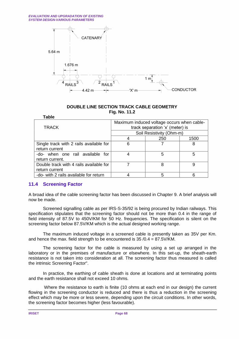
EVALUATION AND UPGRADATION OF EXISTING SYSTEM DESIGN-VARIOUS PARAMETERS
IRISET Page 68
'X' m
12RAILS
CONDUCTOR
5.64 m
34RAILS
CATENARY
1.676 m
1 m
4.42 m
DOUBLE LINE SECTION TRACK CABLE GEOMETRY Fig. No. 11.2
Table
TRACK
Maximum induced voltage occurs when cable-track separation ‘x’ (meter) is
Soil Resistivity (Ohm-m)
4 250 1500
Single track with 2 rails available for return current
6 7 8
-do- when one rail available for return current.
4 5 5
Double track with 4 rails available for return current
7 8 9
-do- with 2 rails available for return 4 5 6
11.4 Screening Factor A broad idea of the cable screening factor has been discussed in Chapter 9. A brief analysis will now be made.
Screened signalling cable as per IRS-S-35/92 is being procured by Indian railways. This specification stipulates that the screening factor should not be more than 0.4 in the range of field intensity of 87.5V to 450V/KM for 50 Hz. frequencies. The specification is silent on the screening factor below 87.5V/KM which is the actual designed working range.
The maximum induced voltage in a screened cable is presently taken as 35V per Km. and hence the max. field strength to be encountered is 35 /0.4 = 87.5V/KM.
The screening factor for the cable is measured by using a set up arranged in the laboratory or in the premises of manufacture or elsewhere. In this set-up, the sheath-earth resistance is not taken into consideration at all. The screening factor thus measured is called the intrinsic Screening Factor".
In practice, the earthing of cable sheath is done at locations and at terminating points and the earth resistance shall not exceed 10 ohms.
Where the resistance to earth is finite (10 ohms at each end in our design) the current flowing in the screening conductor is reduced and there is thus a reduction in the screening effect which may be more or less severe, depending upon the circuit conditions. In other words, the screening factor becomes higher (less favourable).
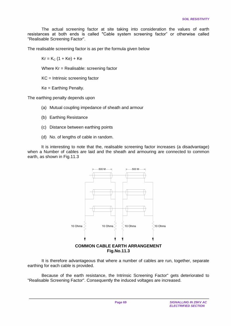
SOIL RESISTIVITY
Page 69 SIGNALLING IN 25KV AC
ELECTRIFIED SECTION
The actual screening factor at site taking into consideration the values of earth
resistances at both ends is called "Cable system screening factor” or otherwise called "Realisable Screening Factor". The realisable screening factor is as per the formula given below
Kr = KC (1 + Ke) + Ke
Where Kr = Realisable: screening factor
KC = Intrinsic screening factor
Ke = Earthing Penalty. The earthing penalty depends upon
(a) Mutual coupling impedance of sheath and armour (b) Earthing Resistance (c) Distance between earthing points (d) No. of lengths of cable in random.
It is interesting to note that the, realisable screening factor increases (a disadvantage)
when a Number of cables are laid and the sheath and armouring are connected to common earth, as shown in Fig.11.3
500 M 500 M
10 Ohms10 Ohms10 Ohms10 Ohms
COMMON CABLE EARTH ARRANGEMENT
Fig.No.11.3
It is therefore advantageous that where a number of cables are run, together, separate earthing for each cable is provided.
Because of the earth resistance, the Intrinsic Screening Factor" gets deteriorated to "Realisable Screening Factor". Consequently the induced voltages are increased.
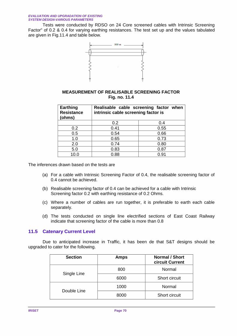
EVALUATION AND UPGRADATION OF EXISTING SYSTEM DESIGN-VARIOUS PARAMETERS
IRISET Page 70
Tests were conducted by RDSO on 24 Core screened cables with Intrinsic Screening Factor" of 0.2 & 0.4 for varying earthing resistances. The test set up and the values tabulated are given in Fig.11.4 and table below.
MEASUREMENT OF REALISABLE SCREENING FACTOR
Fig. no. 11.4
Earthing Resistance (ohms)
Realisable cable screening factor when intrinsic cable screening factor is
0.2 0.4
0.2 0.41 0.55
0.5 0.54 0.66
1.0 0.65 0.73
2.0 0.74 0.80
5.0 0.83 0.87
10.0 0.88 0.91
The inferences drawn based on the tests are
(a) For a cable with Intrinsic Screening Factor of 0.4, the realisable screening factor of 0.4 cannot be achieved.
(b) Realisable screening factor of 0.4 can be achieved for a cable with Intrinsic Screening factor 0.2 with earthing resistance of 0.2 Ohms.
(c) Where a number of cables are run together, it is preferable to earth each cable separately.
(d) The tests conducted on single line electrified sections of East Coast Railway indicate that screening factor of the cable is more than 0.8
11.5 Catenary Current Level
Due to anticipated increase in Traffic, it has been de that S&T designs should be upgraded to cater for the following.
Section Amps Normal / Short circuit Current
Single Line 800 Normal
6000 Short circuit
Double Line 1000 Normal
8000 Short circuit

USE OF UNSCRREENED SIGNALLING CABLE
Page 71 SIGNALLING IN 25KV AC
ELECTRIFIED SECTION
CHAPTER-12: INDUCED VOLTAGES DUE TO HIGHER CATENARY CURRENTS.
12.1 Use of Unscreened Signalling Cable
In the last Chapter, we have seen that realisable Screening factor of 0.4 cannot be achieved when the intrinsic screening factor is 0.4 and the cable sheath ends are connected to 10 ohms earthing. The realisable screening factor was calculated as 0.91.
Since resistance of Earthing determines the realisable screening factor and since
maintenance of low earth resistance is not always feasible, the Signal Standards Committee came to the conclusion that use of Screened cable may be discarded and to adopt Unscreened Cable for revised design.
The use of unscreened signalling cable for the Revised Designs has been approved by Railway Board.
12.2 Final Induced Voltages
The final Revised Design norms are given below
(a) Catenary Current 800 Amps on Single Line 1000 Amps on Double Line
(b) Soil Resistivity 1500 Ohm. metres.
(c) Rail Impedance 0.701 Single Line (when both lines are available for traction return current) 0.561 Double Line (when all the four lines are available for traction return current).
(d) Rail Reduction Factor 0.3926 Single Line (when both the rails are available for traction return current) 0.2666 Double Line (when all the four rails are available for traction return current)
(e) Track Cable Separation 8m - Single line (when both the rails an available for traction return current) 9m - Double line (when all the four rails are available for traction return current).
(f)
Unscreened Cable with -armouring earthed
The Induced Voltage under the above parameters, has been calculated as 95 V/KM for Double Line 116V/KM for Single Line
Note: It is at this separation distance, the maximum induced volt occurs. At other distances the induced voltages are less.
In the earlier design, even though the induced voltage was lesser in single line than in double line, the higher induced voltage of Double Line Section was taken as a standard for both Single a Double Lines for design of signalling system, as the difference between the two induced voltages was not appreciable.
In the Revised design separate designs for Single and Double Line sections are catered for. The reasons are
If higher induced voltage as obtained for single line is adopted for, double line, the cost of installation will be higher.
If separate design for single line sections (which are very few, is adopted, this design will be suitable even if the section is provided with double line.

REVISED DESIGN OF SIGNALLING SYSTEM TO SUIT HIGH CATENARY CURRENTS
IRISET Page 72
CHAPTER -13: REVISED DESIGN OF SIGNALLING SYSTEM TO SUIT HIGH CATENARY CURRENTS
13.1 In the previous chapter, it was mentioned that unscreened cables would be used and
that the induced voltages have been calculated as 95V/KM for double line and 116V/KM for single line.
With the higher values of induced voltages, let us review the original design and find out what modifications are required.
13.2 Human Safety
The maximum induced voltage which can safely be handled by maintenance staff has been limited to 120 V based on the practice of French Railways. The practice in British and American Railways is to consider 110 V as the maximum level of induced voltage.
As per Indian Electricity Rules, Voltages below 250 V are considered low voltage. On Indian Railways, S&T maintenance staffs are already maintaining systems with voltage far in excess of 120 V e.g. 500 V in some auto sections of S.E.Rly; 400 V and 300 V in many other Railways for feeding distant signals.
In automatic signalling section of Rajkharsawan-Sini-Tatanagar and Sini-Chandil Section of S.E.Rly. 3300 V 83 1/3 cycle power supply system was used.
In RRI Installations, 400 V, 3 Phase power supply is invariably used. Siemen's 380V 3phase Electric point machines are also in use in some Installation. All these high voltage installations are entirely maintained by S & T staff.
Retaining the existing limit of 120 V will give rise to reduction in the permissible lengths of various Signalling Circuits, for the higher induced Voltages of 95V on double line and 116 volts. on Single line and will necessitate introduction of additional relays. This will cause an increase in cost, additional maintenance and increase the vulnerability to theft.
If 120 V limit is increased to 400 V and is allowed be the maximum induced voltage that can be handled by S&T staff then there may be no much change from the earlier prescribed limit of parallelism. Of course, certain safety procedures and precautions have to be taken to handle high voltages.
13.3 Direct Feeding of Signals
We have seen in Chapter 9 that the maximum length (direct feeding of signals, using screened cables is 600 M and unscreened cables is 240 M. The above distances were based on
(a) Induced voltage is 35 V/KM on Screened cable and 87.5 V/KM on Unscreened cable.
(b) The Glow Voltage of Signal Lamp is 2.3 volts (c) Two Cable faults.

TRACK CIRCUITS
Page 73 SIGNALLING IN 25KV AC
ELECTRIFIED SECTION
Now that the induced voltage due to higher catenary currents and using unscreened cable has been determined as 95 V/KM on double line and 116 V on single line, the maximum length of direct feeding of signals gets changed.
With 110 V feed and a signal transformer of 110/12, the Maximum length is
On a Double line: 21/95 X 1000 = 221 metres = 220 m
On a Single Line: 21/116 X 1000 = 181 metres =180 m (Note: 21V is the voltage required on the primary of the signal transformer to produce a glow voltage of 2.3 V on the secondary).
So the maximum distance with 110 V feed is : 220 m on Double Line and 180 m on Single Line.
The above distances are too small for direct feeding of signal even in some end cabin system let alone on stations controlled from Central Cabins/Relay Rooms.
Hence, most of the signals especially with centralised operation will have the controlling relays repeated at the location. This could pose maintenance problem from the point of view of theft of relays from location boxes. This satisfies partly that the length on double line section is not reduced from the standards of original design. But on single line, the length is restricted to 495 m only.
It may be seen from Fig.13.1 that there are two transformers in the circuit between ECR and the signal lamp. Fresh designs of 110/300 V and 300 V/12 V have been prepared by RDSO, which when used will not cause ECR to pick up for "no load" currents of the 2 transformers in the circuit. The no load current of these transformers are specified as 5mA as against 15mA permitted for 110/12V CLS transformers.
13.4 Factor of Safety
The Factor of Safety as per original design of 2.5 was to cater for unforeseen conditions and for deterioration of equipment service.
If the same factor of safety of 2.5 is adopted for the revised design the line-side equipments will have to be immunised for 400 V X 2.5=1000 (assuming maximum induced voltage in a circuit to be 400V).
While there is no denying the fact that higher factor of safety would cater for worst conditions and eventualities, the cost fact very high, a luxury which we cannot afford always. Based on 25 years of experience, the factor of safety of 2.5 appears to be high though to a certain extent justified as we did not take into consideration the realisable screening factor (but considered the intrinsic screening only) and the line side equipments have been working with 300V AC immunisation and, therefore, with a lesser factor of safety.
This leads to speculation whether such a higher factor of safety is justified to cater for unknown factors or the equipments are immunised for more than what has been specified or there were no fault conditions of extreme nature.
In the calculations for induced E.M.F. due to higher catenary currents, care has been taken to determine the induced voltages under the following most unfavourable conditions
REVISED DESIGN OF SIGNALLING SYSTEM TO SUIT HIGH CATENARY CURRENTS
IRISET Page 74
(a) The catenary current is 800 A in single line and 1000A in double line sections (b) The load component -of rail return current does not flow in rail (c) The track is laid on steel sleepers (wooden sleepers in case rail voltage calculation) (d) The soil resistivity is 1500 Ohm metres at all places (e) The armour used in the screened cable does not give any protection (The armouring
in unscreened cable are to be earthed) (f) There are two earth faults on the conductor, one near and another far from the
function
Since all these conditions will never arise at the same instant, the factor of safety can be safely reduced from the existing figure of 2.5 to 1.5.
It has, therefore, been decided that the factor of safety for the designs of line-side equipments shall be 1.5.
The line-side equipments, shall, therefore, have an immunisation value of 400 V X 1.5 = 600V.This assures that 400V is the maximum permissible induced voltage on the cable conductor from the angle of human safety.
13.5 Signals beyond Range of Direct Feeding
With 300 volts feed the maximum distance of direct feeding of signals is 495 metres on single line and 605 metres on double line sections.
There are many signals, which are located at distances greater than the maximum permissible distance mentioned above. The maximum permissible circuit length depends upon
(a) AC immunity level of DC line relay and (b) Immunity level of power feed systems.
As per BSS 1659 and BRS 931, the AC immunity level of line relays has been prescribed separately for acceptance tests and type tests as given below
Relay AC Immunity Value
Shelf type BSS 1659 750 V (Type Test)
-do- 300 V (Acceptance Test)
Plug-in Relay BRS 931 1000 V (Type Test)
-do- 120 V (Acceptance Test)
This type test is a destructive test and hence the values given at type test, could not be
accepted for normal working. Since induced voltage experienced by relay will now be more than acceptance value, tests were conducted to find out whether the relay will be able to with stand the higher induced voltage now expected.
Shelf type relays and plug-in relays were therefore tested a subjected to 500V AC for one minute and the parameters were measured before and after subjecting them to 500V AC. It was found that the relay parameters do not change.

TRACK CIRCUITS
Page 75 SIGNALLING IN 25KV AC
ELECTRIFIED SECTION
The induced voltage is a phenomenon which will vary according to the current flowing in
the catenary and maximum values will last for more than a couple of minutes. Further, the maximum value of induced voltage as calculated will not materialise due to built safety factor. It has, therefore, been decided that the shelf type relays and plug-in type relays will be able to withstand the induced voltage now expected.
For a maximum length of parallelism of 3.5 KM, 600 AC immunity is required, but, since the maximum induced voltage in the circuit has to be restricted to 400V due to human safety consideration the maximum permissible length of line circuits for various types relays with a factor of safety of 1.5 is given below
Relay Maximum permissible length with factor of safety of 1.5
Single Track Double Track
Shelf Type AC Immunised 2.1 KM 2.8 KM
QNA1 2.1 KM 2.8 KM
K-50 (B-1) 1.0 KM 1.2 KM
QN1 2.1 KM 2.8 KM
K-50 750 m 900 m
Even though non-immunised relay like QNI and K-50 have got inherent AC immunity,
these relays should be avoided for use in the external circuits.
For signals, which are located beyond the maximum permissible distance of direct feeding the controlling relays, are repeated at the location.
For lighting these signals 2 methods are available. They are
(a) Local Feed (b) Remote Feed
Since 300 V feed for the signals and the corresponding type of transformers have now
been standardised, a separate 300 V power line should be run from the cabin to the location. Typical circuits for signals beyond the range of direct feed in figures mentioned against each.
Local Feed for Home Signal with Route Indicator Fig.13.1 Note: (1) Fig.13.3 Even though 300 V feed is standardised, RDSO's circuit caters for 110V feed
presumably to economise one transformer (as otherwise one 300/12 V transformer for Signal and one 300/110V for Route Indicator will be required).
(2) Fig.13.4: In S. Rly. Circuit, one additional ECR is provided for common shunt signal lamp
(Please see Fig.9.16).

REVISED DESIGN OF SIGNALLING SYSTEM TO SUIT HIGH CATENARY CURRENTS
IRISET Page 76
DE
CR
DG
HP
R
HO
ME
HO
ME
DP
RH
OM
E
HE
CR
HG
HO
ME
RE
CR
RG
HO
ME
HP
RH
OM
E
12
/110
RO
UT
E-1
UP
R
UG
(RO
UT
E-1
)
RO
UT
E
EC
R
BX
110V
NX
110V
UP
R
CG
(RO
UT
E-1
)U
PR
(RO
UT
E-2
)
UP
R(R
OU
TE
-1)
UP
R(R
OU
TE
-2)
RO
UT
E-2
UP
R
CG
(RO
UT
E-2
)
HP
R
HR
DP
R
DR
UP
R
UR
(RO
UT
E-1
)
UP
R
RO
UT
E-2
UR
(RO
UT
E-2
)
RO
UT
E-1
DE
CP
R
DE
CR
HE
CP
R
HE
CR
RE
CP
R
RE
CR
UE
CP
R
UE
CR
CA
BIN
L.H
OM
EH
OM
E S
IGN
AL
BX
110V
NX
110V
DP
RH
PR
DP
R
DP
R
HP
R
UP
R
UP
R(R
OU
TE
-1)
UP
R(R
OU
TE
-1)
UP
R(R
OU
TE
-2)
UP
R(R
OU
TE
-2)
UP
R(R
OU
TE
-2)
DE
CR
HE
CR
RE
CR
UE
CR
HR
DR
UR
(RO
UT
E-1
)
UR
(RO
UT
E-2
)B 2
4V
B 2
4V
B 2
4V
B 2
4V
B 2
4V
B 2
4V
B 2
4V
B 2
4V
N 2
4V
N 2
4V
N 2
4V
N 2
4V
N 2
4V
N 2
4V
N 2
4V
N 2
4V
Fig. No. 13.1 HOME SIGNAL – LOCAL FEED

TRACK CIRCUITS
Page 77 SIGNALLING IN 25KV AC
ELECTRIFIED SECTION
13.7 Track Circuits
With the increase in Catenary currents and increase in the values of Rail Impedance due to assumed increase in the value of soil resistivity, the A.C. voltage across the track relay of a single rail track circuit increases steeply as can be seen by the table given below
Single Track - 193.0V
Double track - 126.2V
Hence, the D.C. single rail track circuit of 450 m as per original design cannot be retained with the existing A.C. immunised D.C.track relay. A revised design has therefore become necessary. The maximum permissible length may be increased by
(a) Cross Bonding (b) Choke in series with relays (c) Cross Bonding and Choke in series with relay.
With the existing A.C. immunised relay and choke at feed end, the maximum lengths of
Track Circuits, which can be permitted to suit high catenary currents, are
(i) Single Line: 200 metres (ii) Double Line: 300 metres
The above lengths are valid only when cross bonding with other non-insulated rails on double line and bonding with another scrap rail on single line section are provided.
Again, these lengths are so small that a number of cut-section track circuits have to be provided for block section and platform track circuits and the cost of installation will go up with additional maintenance work.
The solutions are that we can go in for Frequency Modulated Audio Frequency Track Circuits or by increasing the immunisation of the existing track relay.
The next alternative is to have a suitable A.C. Immunised Track Relay. However, we do not have any suitable D.C. Track with higher A.C. immunity.
As an interim measure, tests were conducted using a in series with the A.C. immunised D.C. relay to increase the immunity of existing D.C. track relay.
It was found that with a 120 ohm. Impedance choke (3 ohm D.C. resistances) in series with the track relay, the length can be increased as detailed below:
(i) Single Line: 450 metres (ii) Double Line: 450 metres

REVISED DESIGN OF SIGNALLING SYSTEM TO SUIT HIGH CATENARY CURRENTS
IRISET Page 78
The above lengths are valid only when scrap rails are to carry the diverted return current from the rail used for track circuit purpose.
It, therefore, follows that the non-insulated rail of a circuit is bonded to the non-insulated
rails of other track circuits if there is no track adjacent to the track circuit, scrap rails shall provided for bonding purposes.
Recently QBAT relays have been developed and with chokes at feed and relay ends, these have been cleared for track circuits 750 metres (with 4 secondary cells at feed end).
In view of the increased AC immunity due to the presence of biased magnetic arrangement, QBAT relays can be used up to a maximum length of track circuit of 750 meters using one ‘B’ type choke at the relay end, under minimum ballast resistance of 2 ohms/km. Operation of track circuit with this type of relay will require four cells delivering 8.8V. QBAT relays shall be used in conjunction with QSPA1 relays conforming to BRS 933A. (Ref: 68th SSC Para 22.11.5.7)
Summarising, the following shall be the maximum length track circuit to suit higher catenary currents.
DC Single Rail Track Circuit Maximum permissible length
Single Line section Double Line Section
Without additional protection 200 m 300 m
With additional protection of 120 Ohm. Choke at relay end
450 m 450 m
A typical track circuit showing the additional protective arrangement is given in Fig.13.7
SURGE ARRESTORS
'B' TYPE CHOKEZ= 120 OHMS
R= 3 OHMS
CELL
R1 R2
9 OHMS AC IMMUNISED
TRACK RELAY
TR
REGULATINGRESISTANCE
'B' TYPE CHOKEZ= 120 OHMS
R= 3 OHMS
450 m
Fig. No.13.7 SINGLE RAIL D.C. TRACK CIRCUIT
13.8 Point Machines
It is a normal practice while preparing the circuits for Point Machine to cater for Point Controlling Relay, which controls the Point Contactor Relay having high current carrying contacts.
The feed to the electrical point machine is extended from the contacts of Point Contactor Relay. The detection contacts of the point machine extend D.C. feed to energise the relevant point detection relays in the cabin.
POINT MACHINES
Page 79 SIGNALLING IN 25KV AC
ELECTRIFIED SECTION
Point Controlling Relays may be housed in the cabin or at the location. If they are provided at the location, A.C. Immunised D.C. Relays shall be used. The point detection relays are also A.C. immunised. Their circuit length is governed by the type of relay used as given in the table earlier. The maximum permissible distance of electrical point depends on the A.C. immunity level of
(a) The Point Controlling Contactor Relay (b) The Point Motor
The existing design of point contactor relay is not immune up to the required level.
It is therefore desirable to use Point Contactor Relay close to the Point Controlling Relay or its repeater relay and have an A.C. immunised relay as point controlling relay or its repeater.
Point Contactor type PPWR 1 of WSF make, which is planned for manufacture in India, has an immunity value of 1000 V (Type Test).
The point machine requires considerable power for its operation. Due to induction, high voltages are obtained but it was not known whether sufficient power content will be available for the point machine to operate under faulty conditions.
The A.C. immunity values of various types of Point Machines were determined by experiments and based on the experiments, the maximum permissible length- for various types of Point machines, under a factor of safety of 1.5 will be as given below
RDSO recommends that marginal increase in the maximum permissible lengths may be obtained by using 'a choke in series with the point machine. Up to what margin, the increase is permitted is not specified. Since the factor of safety of 1.5 is catered for, it is presumed that the margin can be provided up to 33 1/3 %.
Type of Point Machine
AC Immunity Value (Volts)
Maximum permissible separation (metres) between Point Contractor and Point Machine on
Single Track Double Track
GRS – 5E 90 515 630
IRS.24 160 910 1100
Siemen’s IA 160 910 1100
Siemen’s IB 300 1650 2100
Siemen’s IC 400 2200 2800
RDSO specification No.S24/90 - for Electrical Point Machine non-trailable type, specifies
the A.C. immunity level of Electrical Point Machine shall not be less than 160V RMS at 50 Hz. With this the maximum permissible distance between the machine and the contactor would be 1.1 KM. Three phase point machines are having inherent immunisation to induction effects. Hence 3 phase point machines can be used where the point machines and their feed points are separated by large distances. M/s. CEERI - PILANI have developed Single Phase to 3 phase solid state conversion units which are extensively used for A.C. locos. This can be used for converting single phase to 3 phases, if 3 phase point machines are used, Rotary converters working from single phase traction AT supply, are also available.
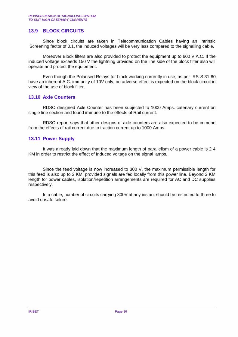
REVISED DESIGN OF SIGNALLING SYSTEM TO SUIT HIGH CATENARY CURRENTS
IRISET Page 80
13.9 BLOCK CIRCUITS
Since block circuits are taken in Telecommunication Cables having an Intrinsic Screening factor of 0.1, the induced voltages will be very less compared to the signalling cable.
Moreover Block filters are also provided to protect the equipment up to 600 V A.C. If the induced voltage exceeds 150 V the lightning provided on the line side of the block filter also will operate and protect the equipment.
Even though the Polarised Relays for block working currently in use, as per IRS-S.31-80 have an inherent A.C. immunity of 10V only, no adverse effect is expected on the block circuit in view of the use of block filter.
13.10 Axle Counters
RDSO designed Axle Counter has been subjected to 1000 Amps. catenary current on single line section and found immune to the effects of Rail current.
RDSO report says that other designs of axle counters are also expected to be immune from the effects of rail current due to traction current up to 1000 Amps.
13.11 Power Supply
It was already laid down that the maximum length of parallelism of a power cable is 2 4 KM in order to restrict the effect of Induced voltage on the signal lamps.
Since the feed voltage is now increased to 300 V, the maximum permissible length for this feed is also up to 2 KM, provided signals are fed locally from this power line. Beyond 2 KM length for power cables, isolation/repetition arrangements are required for AC and DC supplies respectively.
In a cable, number of circuits carrying 300V at any instant should be restricted to three to avoid unsafe failure.

REVIEW QUESTIONS
Page 81 SIGNALLING IN 25KV AC
ELECTRIFIED SECTION
REVIEW QUESTIONS SUBJECTIVE QUESTIONS
CHAPTER-1
1. What are advantages of 25 KV RE?
2. What is meant by regulated & un regulated OHE?
3. What is meant by normal implantation Of RE mast
4. Describe the different type of warning boards used 25 KV RE area.
CHAPTER-2
1. What are effects of 25 KV RE ON Signaling systems?
2. What is meant by signal clearance diagram, discus.
3. What are the precautions to be observed while fixing a signal in 25 KV RE.
CHAPTER-3
1. What are the precautions to be taken in case of wire & Rod trans mission in 25 KV RE?
CHAPTER-4
1. What are the equipments to be earthed in 25 KV RE? State values also.
CHAPTER-5
1. What the precaution to be taken while laying cable in 25 KV RE area.
CHAPTER-6
1. What are the pre cautions to be taken in case of Block-instruments in 25 KV RE area.
CHAPTER-7
1. Discus about the stray voltage of stray voltage & currents.
CHAPTER-8
1. What are the effects of 25 KV RE in case of Track circuit & what are the modifications required?
CHAPTER-9
1. What are effects of electro- static & electromagnetic induction in 25 KV RE? Discus.
2. What is meant by Glow voltage in case signal bulb & what are the methods are followed to over this kind of problems in case of signals beyond direct feeding range?
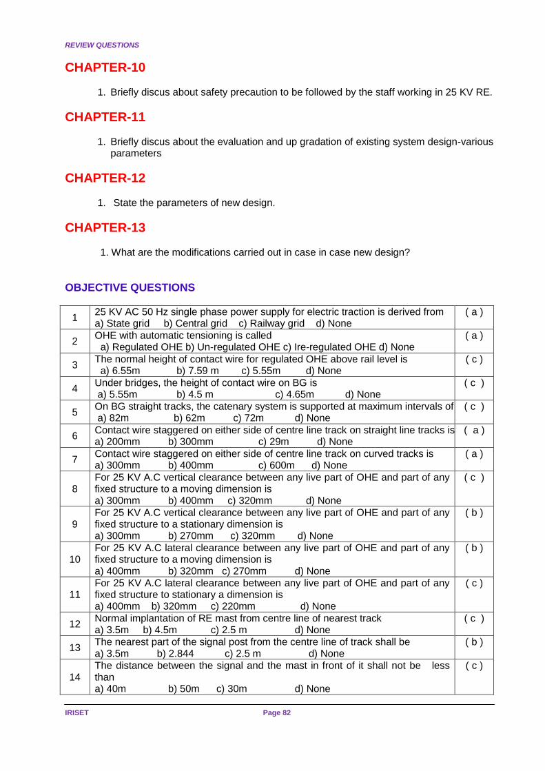
REVIEW QUESTIONS
IRISET Page 82
CHAPTER-10
1. Briefly discus about safety precaution to be followed by the staff working in 25 KV RE.
CHAPTER-11
1. Briefly discus about the evaluation and up gradation of existing system design-various parameters
CHAPTER-12
1. State the parameters of new design.
CHAPTER-13
1. What are the modifications carried out in case in case new design?
OBJECTIVE QUESTIONS
1 25 KV AC 50 Hz single phase power supply for electric traction is derived from a) State grid b) Central grid c) Railway grid d) None
( a )
2 OHE with automatic tensioning is called a) Regulated OHE b) Un-regulated OHE c) Ire-regulated OHE d) None
( a )
3 The normal height of contact wire for regulated OHE above rail level is a) 6.55m b) 7.59 m c) 5.55m d) None
( c )
4 Under bridges, the height of contact wire on BG is a) 5.55m b) 4.5 m c) 4.65m d) None
( c )
5 On BG straight tracks, the catenary system is supported at maximum intervals of a) 82m b) 62m c) 72m d) None
( c )
6 Contact wire staggered on either side of centre line track on straight line tracks is a) 200mm b) 300mm c) 29m d) None
( a )
7 Contact wire staggered on either side of centre line track on curved tracks is a) 300mm b) 400mm c) 600m d) None
( a )
8 For 25 KV A.C vertical clearance between any live part of OHE and part of any fixed structure to a moving dimension is a) 300mm b) 400mm c) 320mm d) None
( c )
9 For 25 KV A.C vertical clearance between any live part of OHE and part of any fixed structure to a stationary dimension is a) 300mm b) 270mm c) 320mm d) None
( b )
10 For 25 KV A.C lateral clearance between any live part of OHE and part of any fixed structure to a moving dimension is a) 400mm b) 320mm c) 270mm d) None
( b )
11 For 25 KV A.C lateral clearance between any live part of OHE and part of any fixed structure to stationary a dimension is a) 400mm b) 320mm c) 220mm d) None
( c )
12 Normal implantation of RE mast from centre line of nearest track a) 3.5m b) 4.5m c) 2.5 m d) None
( c )
13 The nearest part of the signal post from the centre line of track shall be a) 3.5m b) 2.844 c) 2.5 m d) None
( b )
14 The distance between the signal and the mast in front of it shall not be less than a) 40m b) 50m c) 30m d) None
( c )

REVIEW QUESTIONS
Page 83 SIGNALLING IN 25KV AC
ELECTRIFIED SECTION
15 The distance between the signal and the mast just in advance of signal normally a) 40m b) 50m c) 10m d) None
( c )
16 For rod running under the track, the top of the rod shall not be less Than 40 mm below the bottom of the rail.
( T )
17 The distance between any OHE mast and the point rod shall not be less than 40 mm.
( T )
18 Each rod shall be provided with an insulator immediately outside the cabin in the lead-out as close to the cabin as possible.
( T )
19 An additional insulator shall be provided between the last adjustable crank and the point/lock bar
( T )
20 If the rod transmission is more than 400 metres, additional insulators shall be provided on each rod at every 400metres
( F )
21 The distance between two consecutive insulators on the same rod should be lesser than 300 metres.
( T )
22 The wire insulator shall conform to IRS Spec. No. S47-74. ( T )
23 An insulator shall be provided in each wire near the gear of operation ( T )
24 A wire insulator to be provided at every 300mts of wire transmission ( T )
25 The horizontal distance between two wires shall not be less than 60 mm ( F )
26 The vertical distance between two wires shall not be less than 200 mm. ( T )
27 The lever frame and other metallic frames of the cabin shall be connected together to a separate earthing.
( T )
28 The earthing shall not be provided at every location box where cable terminate. ( F )
29 Earth connected for lightening discharger should not be more than 10 Ohms ( T )
30 Earth connected for equipment should not be less than 10 Ohms. ( F )
31 Earth connected Axle counter cable (screened) in ac electrified area should not be more than 1 Ohm.
( T )
32 Where more than one earthing arrangements are employed, the distance between earthing electrodes shall not be less than 6metres.
( F )
33 The clearance of equipment earths from system earths provided by the Electrical Dept. of Railways or any other administration shall not be less than 30 meters
( F )
34 The cables laid parallel to the track buried at a depth of 2 m minimum. ( F )
35 The depth of tail cables shall not be less than 1 m. ( F )
36 If cable is laid one meter from the RE mast its trench depth shall not be more than 0.5m.
( T )
37 If cable is laid in concrete/HDPE pipes up to 3 meters on either side of mast, the distance between the mast and trench can be reduced to 0.5 meters
( T )
38 If the cable is laid at more than 0.5 meters depth the distance between trench and mast shall not be less not be less than 3 meters.
( T )
39 In the vicinity of traction sub station the cables shall be laid on the side of the track opposite to the sub-station side
( T )
40 Cables shall be laid at least 10 meters away from the switching station earthing ( F )
41 During track crossings, the cables should cross the track at right angles ( T )
42 During track crossings, the cables can cross the track under points and crossings
( F )
43 During track crossings, the cables are to be laid in concrete pipes while crossing the track.
( T )
44 During track crossings, the cables shall be buried at a depth of 1.0 metre below the bottom of the rail.
( T )
45 At outside of station limits, the cable shall be laid 5 to 6 meters from the nearest centre line of the track.
( F )

REVIEW QUESTIONS
IRISET Page 84
46 At with in station limits, the cable shall be laid not less than 5.5 meters from the nearest centre line of the track
( T )
47 Stray voltage in a track circuit shall not be more than 100mV. ( T )
48 The total stray current shall not exceed 10mA for a track circuit length less than100m
( T )
49 The total stray current shall not exceed 10mA for a track circuit length more than100m
( T )
50 Only 09 ohms track relay should be used in AC RE area ( T )
51 Only single rail DC track circuit should be used in AC RE area. ( T )
52 In DC single rail track circuit feed end is protected by “B type” choke. ( T )
53 Maximum length of DC track circuit with wooden sleepers is 250m. ( F )
54 Maximum length of DC track circuit with PSC sleepers is 350m. ( T )
55 Maximum length of DC track circuit with QBAT relay and choke at feed-end is 450m
( F )
56 Electro static effects in signalling circuit can be nullified by transferring the circuits in to Underground cables.
( T )
57 Electro static effects in signalling circuit directly proportional to Length of parallelism.
( T )
58 Electro static effects in signalling cable inversely proportional to distance of separation between catenary and cable.
( T )
59 If whole of the return current passing the rails, then the voltage induced in a signaling cable which laid equal-distance from catenary & rail is 35v/km
( F )
60 In screened cable by earthing of metallic sheath voltage induced in cable is reduced.
( T )
61 Catenary current in old design is 600A D/L, 300A in single line. ( T )
62 Short circuit current in old design is 4500A. ( F )
63 Rail impedance in old design is 0.6 ohms. ( F )
64 Rail reduction factor in old design is 0.56 for S/L 0.4 for D/L. ( T )
65 Cable screening factor in old design is 9.6 ( F )
66 A common design was adopted for single and double/multiple track electrified sections in old design
( T )
67 Due to electro-magnetic induction the voltage induced in signalling screened cable in old design is 35V/KM.
( T )
68 Due to electro-magnetic induction the voltage induced in signaling un-screened cable in old design is 95V/KM.
( F )
69 Max. Length of a circuit parallelism with screened cable is 3.5 km in old design. ( T )
70 Max. Length of a circuit parallelism with un-screened cable is 1.9 km in old design.
( F )
71 Glow voltage of 12v signal bulb on primary of signal transformer (110/12) is 21V.
( T )
72 Glow voltage of 12v signal bulb on secondary of signal transformer (110/12) is 5V.
( F )
73 Direct feeding range of signals with screened cable is 600m. ( T )
74 Direct feeding range of signals with un- screened cable in old design is 330m ( F )
75 Shelf type line relays tested under BSS 1659, RE.Spec. 187/11, are only AC immunised
( T )
76 In case of track relays Copper slugs & a magnetic shunt is used to make the relay to AC immunised.
( T )
77 In case of Shelf type line relays no extra materials used to make relay AC immunised.
( T )
78 AC. immunized Shelf type track relay is immune to 65VAC ( F )
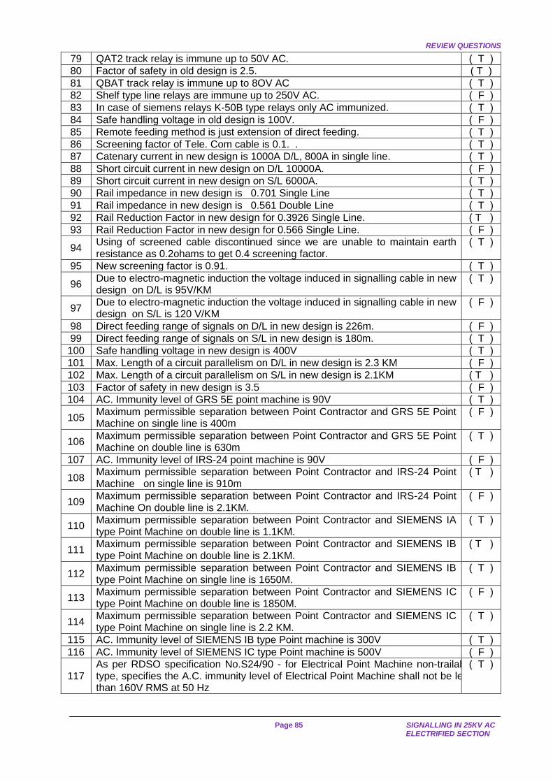
REVIEW QUESTIONS
Page 85 SIGNALLING IN 25KV AC
ELECTRIFIED SECTION
79 QAT2 track relay is immune up to 50V AC. ( T )
80 Factor of safety in old design is 2.5. ( T )
81 QBAT track relay is immune up to 8OV AC ( T )
82 Shelf type line relays are immune up to 250V AC. ( F )
83 In case of siemens relays K-50B type relays only AC immunized. ( T )
84 Safe handling voltage in old design is 100V. ( F )
85 Remote feeding method is just extension of direct feeding. ( T )
86 Screening factor of Tele. Com cable is 0.1. . ( T )
87 Catenary current in new design is 1000A D/L, 800A in single line. ( T )
88 Short circuit current in new design on D/L 10000A. ( F )
89 Short circuit current in new design on S/L 6000A. ( T )
90 Rail impedance in new design is 0.701 Single Line ( T )
91 Rail impedance in new design is 0.561 Double Line ( T )
92 Rail Reduction Factor in new design for 0.3926 Single Line. ( T )
93 Rail Reduction Factor in new design for 0.566 Single Line. ( F )
94 Using of screened cable discontinued since we are unable to maintain earth resistance as 0.2ohams to get 0.4 screening factor.
( T )
95 New screening factor is 0.91. ( T )
96 Due to electro-magnetic induction the voltage induced in signalling cable in new design on D/L is 95V/KM
( T )
97 Due to electro-magnetic induction the voltage induced in signalling cable in new design on S/L is 120 V/KM
( F )
98 Direct feeding range of signals on D/L in new design is 226m. ( F )
99 Direct feeding range of signals on S/L in new design is 180m. ( T )
100 Safe handling voltage in new design is 400V ( T )
101 Max. Length of a circuit parallelism on D/L in new design is 2.3 KM ( F )
102 Max. Length of a circuit parallelism on S/L in new design is 2.1KM ( T )
103 Factor of safety in new design is 3.5 ( F )
104 AC. Immunity level of GRS 5E point machine is 90V ( T )
105 Maximum permissible separation between Point Contractor and GRS 5E Point Machine on single line is 400m
( F )
106 Maximum permissible separation between Point Contractor and GRS 5E Point Machine on double line is 630m
( T )
107 AC. Immunity level of IRS-24 point machine is 90V ( F )
108 Maximum permissible separation between Point Contractor and IRS-24 Point Machine on single line is 910m
( T )
109 Maximum permissible separation between Point Contractor and IRS-24 Point Machine On double line is 2.1KM.
( F )
110 Maximum permissible separation between Point Contractor and SIEMENS IA type Point Machine on double line is 1.1KM.
( T )
111 Maximum permissible separation between Point Contractor and SIEMENS IB type Point Machine on double line is 2.1KM.
( T )
112 Maximum permissible separation between Point Contractor and SIEMENS IB type Point Machine on single line is 1650M.
( T )
113 Maximum permissible separation between Point Contractor and SIEMENS IC type Point Machine on double line is 1850M.
( F )
114 Maximum permissible separation between Point Contractor and SIEMENS IC type Point Machine on single line is 2.2 KM.
( T )
115 AC. Immunity level of SIEMENS IB type Point machine is 300V ( T )
116 AC. Immunity level of SIEMENS IC type Point machine is 500V ( F )
117 As per RDSO specification No.S24/90 - for Electrical Point Machine non-trailable type, specifies the A.C. immunity level of Electrical Point Machine shall not be less than 160V RMS at 50 Hz
( T )