POWER SUPPLY ARRANGEMENTS - iriset
326
TC- 4 POWER SUPPLY ARRANGEMENTS By B.L.V.PRASAD ILP 3 1 IRISET-SECUNDERABAD SUBJECT: TC 4
-
Upload
khangminh22 -
Category
Documents
-
view
1 -
download
0
Transcript of POWER SUPPLY ARRANGEMENTS - iriset

TC- 4
POWER SUPPLY ARRANGEMENTS
By
B.L.V.PRASAD
ILP 3
1IRISET-SECUNDERABADSUBJECT: TC 4

CHAPTER NO.1
CELLS AND BATTERIES
• 1. classification of cells
• 2. Primary Cells
• 3. Secondary Cells
• 4. Selecting the right battery (LA)
• 5. Types of loads
• 6. Electrical protection to the battery for SPV
• 7 Basic terminology
• 8 Battery care
2IRISET-SECUNDERABADSUBJECT: TC 4

• 9. Safety precautions
• 10. Standard tests on LA batteries
• 11. Troubleshooting
• 12.Indenting of LA cells
• 13.Comparison of different types of LA cells
• 14.Alkaline batteries
• 15.Comparison of various rechargeable batteries
3IRISET-SECUNDERABADSUBJECT: TC 4

Cell is an electrochemical device that converts chemical
energy into electricity by use of a galvanic cell or it can be
called a storage device that stores electrical energy in the
form chemical energy.
When more than one cell is connected together, it is called a
battery.
The cells which cannot be recharged after discharge are
known as “Primary cells”. Ex: Leclanche Dry Cell
4IRISET-SECUNDERABADSUBJECT: TC 4

• The cells in which the chemical condition as well as the
physical state of the electrodes after discharge are brought
back to the original condition by causing a current to flow in
the opposite direction (by charging ) are called Secondary
cells.
EX: a)Lead acid cell b) Alkaline cell
• Generally Lead acid secondary cells are widely used in
Indian Railways for telecom equipments as a Std/by power5IRISET-SECUNDERABADSUBJECT: TC 4

• (a) Lead Acid cell:
(b) Alkaline cell :
(i) Nickel Cadmium cell
(ii) Nickel-Metal Hydride cell (NiMh)
(iii) Nickel Iron cell
6IRISET-SECUNDERABADSUBJECT: TC 4

• Efficiency: The efficiency of a secondary cell is defined as the
ratio of output delivered by a cell to the input required to
restore its initial state of charge under specified conditions
of temperature, current rate and final voltage.
• Generally, the efficiency is expressed in three ways:-
a)Ampere-hour efficiency
b) Volt efficiency
c)Watt-hour efficiency7IRISET-SECUNDERABADSUBJECT: TC 4

• Ampere-hour efficiency: The ratio of the ampere-hours
output to the ampere-hours of recharge (Input).
% of Ah efficiency: Amp-hour discharge / Amp-hour charge
• Volt efficiency: The ratio of the average voltage during the
discharge to the average voltage during the recharge.
• Watt-hour efficiency: The efficiency is the ratio of the watt
hours output to the watt hours of the recharge.
• The capacity of Cell: The ability of a fully charged battery to8IRISET-SECUNDERABADSUBJECT: TC 4

deliver a specified quantity of electricity at a given rate
(amperes) over a definite period of time.
The unit for capacity is AH and it depends up on the
following factors.
a. Discharge Rate
b. Size of plates
c. Quantity and density of Electrolyte
d. Temperature
e. Age.9IRISET-SECUNDERABADSUBJECT: TC 4

• Depth of Discharge (DOD) of the cell: Secondary cell should
never be fully discharged (i.e. 100 %) due to Technical
considerations such as Increase in Internal Resistance with
increase in discharge, High Charging current for next
charging, Reduction in Life of cell etc.
Therefore, a limit is laid down on to extent of discharge
carried out on a cell is known as Depth of discharge (DOD)
and is stated as a percentage of the ampere-hour capacity.10IRISET-SECUNDERABADSUBJECT: TC 4

• Depth of Discharge permitted is as follows.
a.Flooded type of Lead Acid Cell - 70%
b.LMLA cell - 80%
c. VRLA cell - 50%.
• Self discharge of the cell: Self-discharge is a phenomenon
by which the charge of a stored cell is decreased due to
internal chemical reactions without any connection between
the electrodes (with out any load or open circuit).11IRISET-SECUNDERABADSUBJECT: TC 4

• Construction of Lead Acid Cell: The active material of the
lead acid cell is lead peroxide (Pb02) on the positive plate
and spongy lead (Pb) on the negative plate. Both the plates
are separated by an insulating material to prevent the
contact is called the separator. The plates are immersed in
an electrolyte of dilute sulphuric acid(H2SO4). The nominal
voltage of a LA cell is 2V.
• The cell is said to be discharging when it supplies current to
an external circuit or the load.12IRISET-SECUNDERABADSUBJECT: TC 4

The video below explains the construction and chemical
reactions that take place in a lead acid battery during
charging and discharging. To open the video, right click of
the mouse on the link and click the “open hyperlink”
https://www.youtube.com/watch?v=HhxtfULIO7c
13IRISET-SECUNDERABADSUBJECT: TC 4

• When current is forced through the cell from an external DC
source is called the charging.
• As the cell discharges, the density of electrolyte falls owing
to the conversion of some of the sulphuric acid (H2 So4) to
lead sulphate at the positive and negative plates and
increase in the production of water. So the specific gravity
of the electrolyte decreases which indicates the condition of
the cell.(2PbSO4 + 2 H2O). The voltage of the cell falls to 1.8 v14IRISET-SECUNDERABADSUBJECT: TC 4

and the specific gravity falls to 1.180
• During charging, the water and the sulphate on the plates
are reconverted into sulphuric acid and the specific gravity
gradually rises. (PbO2 + Pb + 2H2 SO4). If the charging current
is continued even after the plates are fully converted Pbo2
and Pb, electrolysis of water continues, the hydrogen and
oxygen are evolved freely and the cell is said to be gassing.
This condition of gassing indicates that the cell is fully
charged and further charging must be discontinued.15IRISET-SECUNDERABADSUBJECT: TC 4

• At this stage, the voltage of the cell reaches to 2.1V and the
specific gravity rises to 1.220 and gassing takes place. These
are the three indications of a fully charged LA flooded cell.
• There is a direct relationship between the state of charge of
the cell and the specific gravity of the electrolyte. In
practice, the standard way to test the condition of cell is to
measure the specific gravity of the electrolyte with a
hydrometer.
16IRISET-SECUNDERABADSUBJECT: TC 4

• The hydrometer is an instrument used to measure the
specific gravity (or relative density) of liquids i.e. the ratio of
the density of the liquid to the density of water.
• The routine checks to be carried out are :
1) Measurement of electrolyte level above plates.
2) Specific Gravity of electrolyte
3) Voltage.
• Types of Conventional Lead Acid Cells
17IRISET-SECUNDERABADSUBJECT: TC 4

• Basing on the manufacture process of the plates, the
conventional lead acid cells are broadly divided into three
categories
• Plante type or formed plates
• Tubular type
• Faure type or pasted plates
• Hence, Faure type plates are normally used as Negative
Plates and Plante or tubular type are used as Positive Plates
18IRISET-SECUNDERABADSUBJECT: TC 4

because of the inherent advantages and disadvantages they
possess.
• Plates:
The plates are actual electrodes holding the following active
materials.
Spongy Lead (-Ve)
Lead Peroxide (+Ve)
Electrolyte: H2 SO4 (Diluted)19IRISET-SECUNDERABADSUBJECT: TC 4

• Specific Gravity of Electrolyte:
• For a battery to work properly, it’s electrolyte (water plus
active ingredient) must contain a certain amount of active
ingredient. Since the active ingredient is dissolved in the
water, the amount of active ingredient cannot be measured
directly. An indirect way to determine whether or not the
electrolyte contains the proper amount of active ingredient
is to measure the specific gravity of electrolyte. Specific
gravity is the ratio of the weight of a certain amount of 20IRISET-SECUNDERABADSUBJECT: TC 4

Given substance compared to the weight of the same
amount of pure water.
• The SG of concentrated H2SO4 battery grade is 1.835
conforming to the specification IS:266 and added to distilled
water conforming to the specification IS: 1069. The SG of
electrolyte is measured with an instrument called
Hydrometer. The Sp. gravity of Electrolyte varies with
temperature. Any reading observed on the hydrometer
should be corrected to read at 27 deg.C.21IRISET-SECUNDERABADSUBJECT: TC 4

• Temperature Correction: Normally, if the temperature
increases, specific gravity decreases and vice versa by
0.0007 for each degree centigrade. Hence, the correction
should be made as follows-
• For every 1 deg C above 27 deg C add 0.0007 to the Sp.
gravity as read on the hydrometer.
• Similarly, for every 1 deg. C below 27 deg C, subtract 0.0007
from the Sp. Gr. as read on the Hydrometer22IRISET-SECUNDERABADSUBJECT: TC 4

• Initial charging of a new battery:
• Appliances required:
• 1.Voltmeter 2.Ammeter 3.hydrometer 4. Glass rod 5.Jar for
mixing the electrolyte 6.thermometer 7.Funnel 8.Mug 9.
Concentrated H2SO4 10. Distill water 11.battery grease
12. constant current battery charger 13. Constant voltage
charger
Tools: 1.Insulated spanners 2.Metel connector links23IRISET-SECUNDERABADSUBJECT: TC 4

• The personnel equipment: 1.gloves 2.Goggles 3.Apron
4.Gum shoes
• Stages of initial charging
• 1.Cleaning the battery
2.Preparatin of electrolyte
3.Filling of electrolyte
4. Initial Charging with a constant current battery charger
5.Discharging the battery to ascertain the capacity24IRISET-SECUNDERABADSUBJECT: TC 4

6. Recharging with constant voltage charger before
connecting to equipment.
• Initial Charging precautions:
• 1. This shall be done as per the instructions of the
Manufacturer.
• 2. For preparing electrolyte, only battery grade concentrated
Sulphuric acid (IS 266) and distilled water (IS 1069) should
be used.
25IRISET-SECUNDERABADSUBJECT: TC 4

• 3. Never add water to the acid as to prevent delivery
injurious fumes. During mixing, the temperature must
not be allowed to exceed 50 deg. C.
• 4. After preparation of electrolyte, allow it to cool to room
temperature before filling into the cell
• Maintenance precautions:
• 1. Keep open flames away from the battery. Smoking is
prohibited.
26IRISET-SECUNDERABADSUBJECT: TC 4

• A video on initial charging of LMLA batteries used in electric
locomotives in Hindi has been uploaded by camtech India
on you tube. To watch the video right click the mouse on
the below link and select “open hyperlink”.
• https://www.youtube.com/watch?v=leUkuod-v0s
27IRISET-SECUNDERABADSUBJECT: TC 4

• 2. Keep surroundings clean and top of the cells dry.
• 3. Electrical connections should be kept tight. Connecting
cables should be flexible and long.
• 4. Terminals should be smeared with Vaseline (Petroleum
Jelly) to prevent corrosion.
• 5. Vent plugs should be kept in position and tight to avoid
spilling of electrolyte.
• 6.Electrolyte lost due to spillage should be replaced with
28IRISET-SECUNDERABADSUBJECT: TC 4

that of the same specific gravity. Acid should never be
added.
• 7.Log sheets of charging and discharging to be maintained.
• 8.Avoid undercharging or overcharging
• 9. When idle, keep batteries on trickle charge.
• 10. Give batteries an equalizing charge monthly to bring the
SG of all the cells to the same value.
• 11. Insulated metal tools should be used to prevent short
29IRISET-SECUNDERABADSUBJECT: TC 4
• circuit. Wear protective clothing while handling batteries.
• 12. Ensure correct polarity between the cells.
• 13. Use calibrated meters for measuring current, voltage,
specific gravity and temperature.
• 14. In case of acid burns, apply Ammonia or Baking Soda.
• 15. Batteries showing irregularities, which cannot be
corrected, should be taken out of service and report made
to proper authority.
30IRISET-SECUNDERABADSUBJECT: TC 4

• The defects and faults in LA battery:
• 1. Sulphation 2. Buckling 3. Internal short circuit 4. Internal
discharge 5. Loss of capacity 6. Low density of electrolyte
• 7. High density of electrolyte 8. Reverse Voltage 9. Shedding
1 0. Sludge 11. Open Circuit 12. Temperature Troubles.
• 13. Battery does not charge 14. Stratification
31IRISET-SECUNDERABADSUBJECT: TC 4

• 1.Sulphation: This is a common phenomenon where in the
formation of lead sulphate takes place on the surface of
both the plates whenever the battery is discharged. If the
battery is left in discharged condition for a long time, the
Lead sulphate becomes hard and will not leave the plates
even after charging leading to loss of capacity. This is
indicated by no rise in the SG of battery even after charging
continuously at prescribed charging current.
• Cause: keeping the battery in discharged condition for 32
IRISET-SECUNDERABADSUBJECT: TC 4

a long tome or exposure of plates due to low level of
electrolyte.
• Treatment: Charge at 1/3rd of the normal rate, till the cell
delivers gases freely. Discharge at the same rate. Repeat the
cycle until the voltage of the cell reaches 2.35 on charge and
specific gravity is as per manufacturer's rating.
• 2.Buckling: The plates become saucer shaped and touch
with each other or with adjacent plates.33IRISET-SECUNDERABADSUBJECT: TC 4

• Cause: if the battery subjected to high rate of discharge or
charge, and heavy sulphation.
• Treatment: Plates to be replaced
• 3. Internal short circuit:
Indication: The cell will be warm even when idle, specific
gravity and voltage will be low immediately after charge.
There will be no gassing.
Cause: Buckled or sulphated plates or formation of sludge
34IRISET-SECUNDERABADSUBJECT: TC 4
• Treatment: If not very badly bent, the plates can be
removed, straightened in a vice or press. If very badly bent
they should be replaced. Fallen pieces and the sludge
should be removed.
• 4. Internal Discharge:
• Indication: The cell discharges faster, warm even in idle
condition, less capacity.
• Cause: Impurities inside the cell.
35IRISET-SECUNDERABADSUBJECT: TC 4

Treatment: Electrolyte is to be replaced
• 5. Loss of Capacity:
• Indication: Same as of internal discharge but it may not be
warm when idle.
• Cause: May be due to slight sulphation or slight buckling or
aging or impurities.
• Treatment: Attend as in case of sulphation and buckling and
internal discharge.
36IRISET-SECUNDERABADSUBJECT: TC 4

• 6.Low Density of Electrolyte:
• Indication: The SG readings are lower than the rated value
after charging and do not improve by continuous charging.
• Cause: May be due to short circuit or loss of electrolyte due
to excessive gassing, spillage or sulphation.
• Treatment: Withdraw the electrolyte and make up with
fresh acid to bring the value of the specific gravity to the
rated value, half an hour after stopping the charge and
37IRISET-SECUNDERABADSUBJECT: TC 4

continue the cycle till the readings are correct. If after 6
cycles the specific gravity does not come up to the correct
value, treat as is done for short circuit.
• 7. High Density of electrolyte:
• Indication: Maximum and minimum values of specific
gravities will be always higher than the specified values.
• Cause: Due to topping up with acid instead of water.
• Treatment: Charge at a current equal to 1/10th of AH
38IRISET-SECUNDERABADSUBJECT: TC 4

capacity till gassing is observed. Remove some of the
electrolyte, and replace with distilled water. Test specific
gravity after half-an-hour and if not correct, charge again till
gassing is observed. Remove electrolyte and water and
repeat cycle until correct specific gravity is obtained.
• 8.Reverse voltage of cells:
• Indication: The positive and negative terminals will show
opposite polarity.
39IRISET-SECUNDERABADSUBJECT: TC 4

• Cause: This is due to defective cell in a battery, which got
discharged already when the others are being discharged.
• As the discharge continues, the rundown cell gets charged
in the wrong direction by the main discharge current
passing through it. This results in the positive plate being
partially converted into spongy lead and the negative plate
into lead peroxide. This causes a reverse voltage and acts in
the opposite direction to the main battery Emf.
40IRISET-SECUNDERABADSUBJECT: TC 4

• Treatment: Remove the cause of the defect and give slight
charge. Remove the discharged cell.
• 9.Shedding:
• Indication: Slight loss in capacity or short circuit in the case
of very severe shedding.
• Cause: Due to excessive gassing or due to sulphation
peroxide paste gets dislodged from the grids.
• Treatment: Replace cell if severe or charge at low rate
41IRISET-SECUNDERABADSUBJECT: TC 4

• 10.Sludge: This is the name given to the peroxide or
sulphate sediments collected at the bottom of the jar.
• Indication: Loss of capacity or short circuit, visible in the
case of transparent container.
• Cause: Bad maintenance, excessive gassing, shock and
vibration, excessive sulphation.
• Treatment: Wash the plates and re-charge at low rate with
fresh electrolyte in the case of slight formation. In the case42IRISET-SECUNDERABADSUBJECT: TC 4

of severe formation replace the cell.
• 11.Open Circuit:
• Indication: No emf at the output terminal of the cell.
• Cause: Loose connections of connecting strap or corroded
terminals, or break in terminals.
• Treatment: Check all connections, examine for loose joints
at clamps and connecting bars. Clean terminals with sand
paper and smear Vaseline.43IRISET-SECUNDERABADSUBJECT: TC 4

• 12.Temperature Trouble:
• Indication: Temperature rises even for very slow rates of
charging.
• Cause: Due to bad location, proximity to any heated
element, shedding, buckling or defective separation.
• Treatment: Examine for the causes given and remove the
cause.
44IRISET-SECUNDERABADSUBJECT: TC 4

• 13.Battery does not charge:
• Indication: charging current is not shown by the charger
• Cause:
• (i) Disconnection in the charging circuit.
(ii) Loose connections or high resistance at terminals.
(iii) Defective charger, not feeding current.
(iv) Wrong connections.
• Treatment: above causes must be addressed
45IRISET-SECUNDERABADSUBJECT: TC 4

• 14.Stratification:
• Indication: on checking, SG is found to be less
• Cause: This happens to a fully charged battery when it is
kept in idle condition whenever disconnected from the load.
The electrolyte forms into two layers inside the battery i.e.
the acid being heavier settles at the bottom of the battery
and the water being lighter reaches to the top of battery
thus creating two strata or layers. As the SG of electrolyte
will be high at the bottom and low at the top of battery, the46IRISET-SECUNDERABADSUBJECT: TC 4

• bottom of the plates are eaten away by highly concentrated
acid thus leading to shedding.
• Treatment: This is prevented by giving freshening charge
every after 15 days for an idle battery for small duration.
47IRISET-SECUNDERABADSUBJECT: TC 4

• Sealed Lead Acid Batteries : The liquid electrolyte is
transformed into moistened separators and the enclosure is
sealed. Safety valves are added to allow venting of gas
during charge and discharge. They are the small sealed lead
acid (SLA), and the large valve regulated lead acid (VRLA).
Technically, both batteries are the same.
• Construction: These are designed to prevent electrolyte loss
through evaporation, spillage and gassing and this in turn
48IRISET-SECUNDERABADSUBJECT: TC 4

• prolongs the life of the battery and eases maintenance.
Instead of simple vent caps on the cells to let gas escape,
VRLA batteries have pressure valves that open only under
extreme conditions. Valve‐regulated batteries also need an
electrolyte design that reduces gassing by impeding the
release of oxygen and hydrogen into the atmosphere,
• generated by the galvanic action of the battery during
charging. This usually involves a catalyst that causes the
49IRISET-SECUNDERABADSUBJECT: TC 4

• hydrogen and oxygen to recombine into water and is called
gas recombinant system. Spillage of the acid electrolyte is
eliminated. Hence the SLA batteries are also safer.
• Unlike the flooded lead acid battery, both the SLA and VRLA
are designed with a low overvoltage potential to prohibit
the battery from reaching its gas-generating potential during
charge. Excess charging would cause gassing and water
depletion. Consequently , these batteries can never be50IRISET-SECUNDERABADSUBJECT: TC 4

• charged to their full potential.
• The Sealed Lead Acid batteries shall be charged with
Constant Voltage with voltage regulation. Leaving the
battery on float charge for a prolonged time does not cause
damage. The battery’s charge retention is best among
rechargeable batteries. The SLA must always be stored in a
charged state. Leaving the battery in a discharged condition
causes sulfation , a condition that makes the battery difficult
to charge.51IRISET-SECUNDERABADSUBJECT: TC 4
• Depending on the depth of discharge and operating
temperature, the SLA provides 200 to 300 discharge/ charge
cycles. The primary reason for its relatively short cycle life is
grid corrosion of the positive electrode, depletion of the
active material and expansion of the positive plates.
• These changes are most prevalent at higher operating
temperatures. The optimum operating temperature for the
SLA and VRLA battery is 27°C. As a rule of thumb, every 8°C
rise in temperature will cut the battery life to half.52IRISET-SECUNDERABADSUBJECT: TC 4

• These are also called as VRLA Batteries in the short form
because the pressure inside the cell/battery is regulated by
a special type of valve which can open and close
automatically. This is also comes under SMF LA (Sealed
Maintenance Free Lead Acid) battery because it is
completely sealed and does not require Maintenance during
its service life.
53IRISET-SECUNDERABADSUBJECT: TC 4

• The SLA is rated at 20 hour discharge. Longer discharge
times produce higher capacity readings.
• Valve Regulated Lead Acid batteries :
• (specification no: .IRS : S 93 / 96)
• These are also called as VRLA Batteries in the short form
because the pressure inside the cell/battery is regulated by
a special type of valve which can open and close
automatically. This is also comes under SMF LA (Sealed
Maintenance Free Lead Acid) battery because it is54IRISET-SECUNDERABADSUBJECT: TC 4

• completely sealed and does not require Maintenance during
its service life.
• VRLA batteries are two types :1.Gel type 2.AGM
• 1.GEL type : The electrolyte is suspended in either glass
fiber matting or in silica gel so makes it imobile. These
batteries can be discharged below 50% Depth of Discharge
(DOD) without danger of damaging the plates. a Gel
• battery can deliver typically 800 to 1100 cycles to 50%
Depth of Discharge (DOD)55IRISET-SECUNDERABADSUBJECT: TC 4

• Gel batteries are prone to damage if gassing is allowed to
occur. Hence, charging rates must be below 2.45 volts per
cell during boost charging and charge time is slower than
that of AGM batteries. They must be charged at a slower
rate (C/20) to prevent excess gas from damaging the cells.
They cannot be fast charged on a conventional charger as
they may be permanently damaged
56IRISET-SECUNDERABADSUBJECT: TC 4

• 2.AGM(Absorbed Glass Mat):Also known as Absorptive
Glass Micro‐Fiber
• In this Boron Silicate fiberglass mat acts as a separator
between the electrodes and absorbs the free electrolyte
acting like a sponge. The fiberglass matt absorbs and
immobilizes the acid in the matt but keeps it in a liquid
rather than a gel form. In this way the acid is more readily
available to the plates allowing faster reactions between the
acid and the plate material allowing higher charge/discharge57IRISET-SECUNDERABADSUBJECT: TC 4

rates as well as deep cycling. This construction is very robust
and able to withstand severe shocks and vibrations, the
cells will not leak even if the case is cracked.
• AGM's have a very low self‐discharge rate of from 1% to 3%
per month. These batteries should not be discharged below
50% Depth of Discharge (DOD) as there may be a possibility
of damaging the plates. Number of cycles is dependent on
the plate alloy used and is 300 to 500 cycles to 50% Depth
of Discharge (DOD).58IRISET-SECUNDERABADSUBJECT: TC 4

• Advantages of VRLA batteries in Railway Telecom:
1. No separate battery room is required due to compactness
and no emission of acid fumes So they can be installed by
the side of any electronic equipment.
2. Topping up with distilled water and measurement of
Specific gravity is notrequired.
3. Ideally suited for deep discharges and partial discharges
as well.59IRISET-SECUNDERABADSUBJECT: TC 4

4.Minimum grid growth for minimizing the possibility of
internal shorts.
5. Compact and light in weight
6. Very low self discharge of 0.5 to 1% of capacity per week
7. No spilling of electrolyte and can be installed in horizontal
direction without any leakage of electrolyte
8. No acid proof flooring is required as there no spillage
9. Very low self discharge of 0.5 to 1% of capacity per week.
60IRISET-SECUNDERABADSUBJECT: TC 4

• Specifications:
• 1. Nominal voltage: 2V/Cell
• 2. End point voltage: 1.75V/Cell
• 3. Capacities: 20 AH, 40 AH, 80 AH, 120 AH, 200 AH and
above etc
• 4. Type of separators: Glass mat
• 5. Mode of charging:
• i. Float mode-2.25V/Cell( For 16 Hours)
61IRISET-SECUNDERABADSUBJECT: TC 4

• ii. Boost mode- 3V/Cell and charging current should be
limited to 20 ٪of its AH capacity.
• 6. Material used for grids: Calcium alloy
• 7. Under normal operating conditions, equalizing charge is
not required. It is required when non-uniformity in voltage
has developed between the cells.
• 8. A.C. Ripple – should not exceed 3 ٪RMS
• 9. Operating temperature - -20˚C to +55˚C
62IRISET-SECUNDERABADSUBJECT: TC 4
• ii. Boost mode- 3V/Cell and charging current should be
limited to 20 ٪of its AH capacity.
• 6. Material used for grids: Calcium alloy
• 7. Under normal operating conditions, equalizing charge is
not required. It is required when non-uniformity in voltage
has developed between the cells.
• 8. A.C. Ripple – should not exceed 3 ٪RMS
• 9. Operating temperature - -20˚C to +55˚C
63IRISET-SECUNDERABADSUBJECT: TC 4

• The constructional details:
• Positive plates are of PbO2 pasted to the grid made of Lead-
calcium High Tin alloy to resist corrosion and log life
• Negative plates are of Pb pasted to the grid made of lead-
calcium alloy grid for maintenance free
• Separators : These are of Low resistance, high porosity and
highly absorbent type glass mat (AGM)
• Safety valve : This is of Self resealing, pressure regulated and
64IRISET-SECUNDERABADSUBJECT: TC 4

explosion proof. Regulation of pressure developed inside
the cell is done by a “valve” which opens and closes
automatically as per the preset pressure there by controlling
the pressure developed inside the battery eventually
prevents the explosion of battery due to pressure.
• Container: High impact Polypropylene co-polymer, ribbed
jar design for better heat dissipation and strength.
• Electrolyte: High purity Sulphuric acid to maximize shelf life.65IRISET-SECUNDERABADSUBJECT: TC 4

Selection of a battery for a given system:
The basis information required for selection of a battery is
1. Operating voltage of the system
2. Discharge currents: Constant current discharge for telecom
applications(continueos load)
3. Backup time: Duration to be supplied by the battery to load
4. ‘K’ factor: The ratio of rated capacity at 10hr. rate to the
amperes that can be supplied for ‘t’ minutes for a given
66IRISET-SECUNDERABADSUBJECT: TC 4
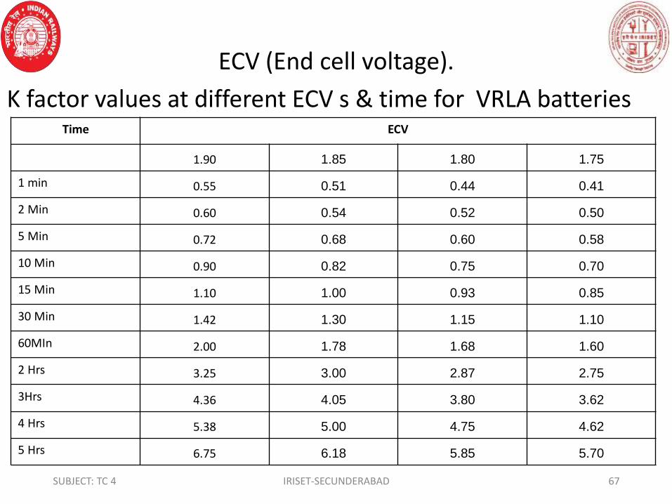
ECV (End cell voltage).
K factor values at different ECV s & time for VRLA batteriesTime ECV
1.90 1.85 1.80 1.75
1 min 0.55 0.51 0.44 0.41
2 Min 0.60 0.54 0.52 0.50
5 Min 0.72 0.68 0.60 0.58
10 Min 0.90 0.82 0.75 0.70
15 Min 1.10 1.00 0.93 0.85
30 Min 1.42 1.30 1.15 1.10
60MIn 2.00 1.78 1.68 1.60
2 Hrs 3.25 3.00 2.87 2.75
3Hrs 4.36 4.05 3.80 3.62
4 Hrs 5.38 5.00 4.75 4.62
5 Hrs 6.75 6.18 5.85 5.70
67IRISET-SECUNDERABADSUBJECT: TC 4

6 Hrs 7.70 7.32 6.25 6.12
7 Hrs 8.50 8.12 7.42 7.32
8 Hrs 9.76 9.00 8.35 8.20
9 Hrs 10.80 9.90 9.20 9.05
10 Hrs 12.00 10.50 10.20 10.00
Temperature correction factors:
Ambient temperature in Correction factor
-15 1.72
-10 1.49
-5 1.32
0 1.27
10 1.14
15 1.09
20 1.04
27 1.00
68IRISET-SECUNDERABADSUBJECT: TC 4
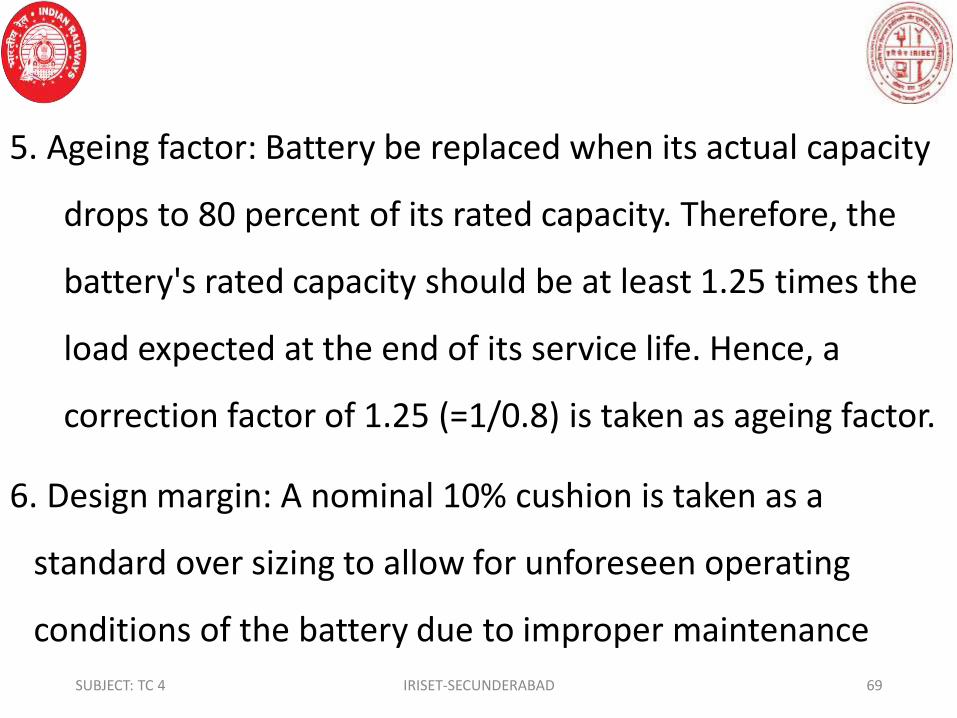
5. Ageing factor: Battery be replaced when its actual capacity
drops to 80 percent of its rated capacity. Therefore, the
battery's rated capacity should be at least 1.25 times the
load expected at the end of its service life. Hence, a
correction factor of 1.25 (=1/0.8) is taken as ageing factor.
6. Design margin: A nominal 10% cushion is taken as a
standard over sizing to allow for unforeseen operating
conditions of the battery due to improper maintenance
69IRISET-SECUNDERABADSUBJECT: TC 4

recent discharge or ambient temperature lower than
anticipated or both.
7.Over load factor: It is a pure reserve capacity that may be
installed to take care of any future additional load. Normally
10-15 ٪ overload factor is considered.
• a) Constant current discharge (E.g. Telecom)
• Example: Selection of a battery for supplying a load of 10
amps for 5 hours to an end cell voltage of 1.75V when the
system70IRISET-SECUNDERABADSUBJECT: TC 4

voltage is 48V at an ambient temperature of 27⁰C.
The information given for battery sizing is:
1. Load current : 10 amps
2. Backup time : 5 hrs
3. System voltage : 48 volts
4. End cell voltage : 1.75 volts
5. Temperature : 27⁰C.
• Step1: No.of cells = System voltage/nominal voltage of cell71IRISET-SECUNDERABADSUBJECT: TC 4

= 48/2 = 24 cells
• Step 2:Capacity required= load current x Back up time
• Since the battery is designed for 10 hour rate, for 5 hour
backup, K- factor need to be applied.
• Step 3 :From the K-factor table, for 1.75 ECV and discharge
time of 5 hrs, the K-factor is 5.70.
• Step 4: required battery capacity: 10x5.70=57AH
• Apply aging factor 0f 1.25 capacity becomes 57x1.25=71.2572IRISET-SECUNDERABADSUBJECT: TC 4

• DOD of cell is 50% = 71.25x 2=142.5AH
• Step 6: Nearest higher available battery capacity of 150 Ah is
chosen.
73IRISET-SECUNDERABADSUBJECT: TC 4

• b) Constant power discharge ( E.g. UPS System ) :
• Ex 2 : Selection of a battery for supplying 40 KVA load for 30
minutes to an ECV of 1.75 with a Power factor of 0.8 and an
inverter Efficiency of 85%. The voltage window is 205 - 285V
and ambient temperature is - 1 0 C
• The information required / given for battery sizing is :
• 1. KVA/KW rating: 40 KVA (Not required when KW rating is
given for UPS )
74IRISET-SECUNDERABADSUBJECT: TC 4

2. Minimum Voltage: 205 volt
3. Maximum voltage: 285 volt
4. Power factor: 0.8 ( Not required when KW rating is given
for UPS )
5. Efficiency of the Inverter : 85%
6. End Cell voltage : 1.75 volts
7. Operating temperature : - 0 10 C
8. Back up time : 30 minutes
75IRISET-SECUNDERABADSUBJECT: TC 4

• Step 1: Choice of number of cells
• Minimum number of cells = Minimum DC voltage / End cell
voltage
• = 205 / 1.75 = 117.14
• Round this to the next higher whole number i.e. 118
numbers of cells
• Maximum number of cells = Maximum DC voltage/Float or
Boost voltage
• = 285/ 2.3 = 123.9176IRISET-SECUNDERABADSUBJECT: TC 4

• Round this to the next lower whole number i.e. 123
numbers of cells. Ensure that the rounded minimum no. of
cells is less than the rounded maximum no. of cell.
• The number of cells selected should be in between the
maximum and minimum number of cells determined above.
Let us say we had chosen 120 nos. of cell.
• Battery’s Minimum Voltage = Chosen no. of cells x 1.75 Volts
• = 120 x 1.75 = 210 volts77IRISET-SECUNDERABADSUBJECT: TC 4

• Battery’s Maximum Voltage = Chosen no. of cells x 2.30 V
= 120 x 2.30 = 276 volts
Since both the above min and max voltages are within the
UPS voltage window, proceed as below:
• Step 2: Power required for UPS in kilowatts (KVA x PF = KW)
= 40 x 0.8 = 32 KW
• Step 3: Power required from the battery
(KW/Inverter efficiency) = 32 / 0.85
78IRISET-SECUNDERABADSUBJECT: TC 4

= 37.647 KW = 37647 Watts
• Step 4: Power required from each cell (watts per cell)
= 37647/120 = 313.73 watts per cell
• Step 5: Applying Ageing factor of 1.25 = 313.73 x 1.25
= 392.16 watts per cell
• Step 6: Applying Temp. Correction factor at 20 C (1.04 )
392.16 x 1.04 = 407.84watts per cell
79IRISET-SECUNDERABADSUBJECT: TC 4

• From the performance table, the Ah capacity of the cell
capable of giving 407.84 watts to an end cell voltage of 1.75,
as a backup time of 30 minutes is 233.05
• Design margin (Cushion) =10%
Therefore, 10% of 233.05=23.3
=233.05= 256.375
• Over load factor is normally 10% to 15%
• 233.05 of 15%=34.9
80IRISET-SECUNDERABADSUBJECT: TC 4
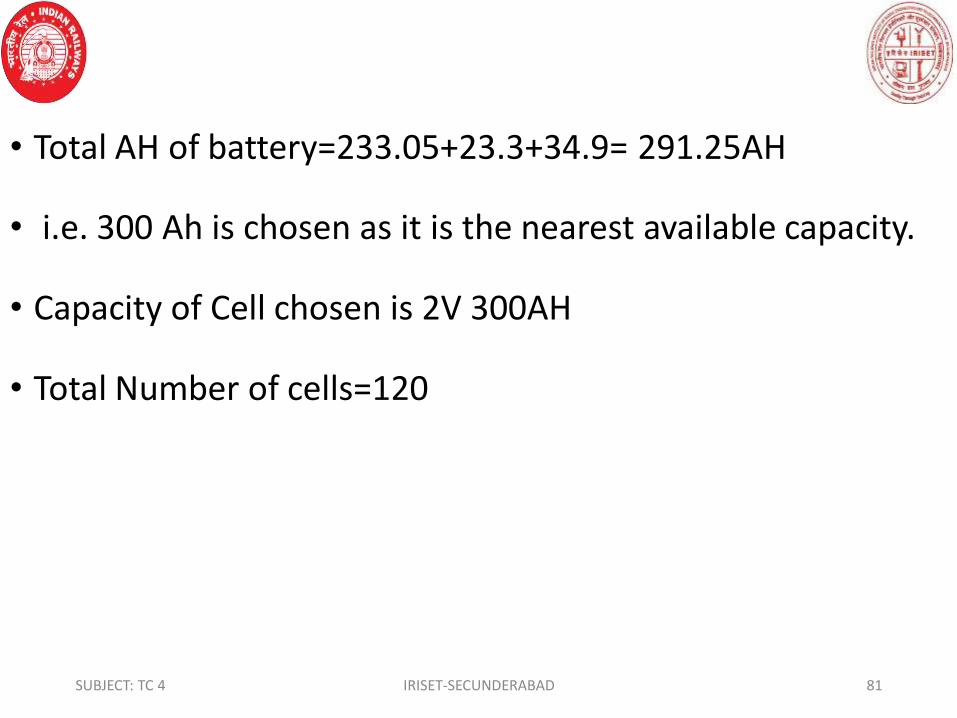
• Total AH of battery=233.05+23.3+34.9= 291.25AH
• i.e. 300 Ah is chosen as it is the nearest available capacity.
• Capacity of Cell chosen is 2V 300AH
• Total Number of cells=120
81IRISET-SECUNDERABADSUBJECT: TC 4

• Battery Care: . Do’s & Don’ts
• Do’s
• Unload the batteries carefully and place them upright on
the floor in single tier.
• Store the batteries in a cool and dry location.
• Charge the batteries within six months if they are under
storage.
• Unpack the batteries as per the unpacking instructions.82IRISET-SECUNDERABADSUBJECT: TC 4

• Install the batteries in a cool and dry location.
• Keep the battery area clean and dry.
• Monitor the charge and float voltages of the charger at
monthly intervals and adjust if required.
• Check the tightness of all the electrical connections at
monthly intervals.
• Check the compatibility of the charger before
commissioning the battery.83IRISET-SECUNDERABADSUBJECT: TC 4

• Maintain monthly service record as per enclosed format
• Provide adequate ventilation and illumination.
• Ensure the cell orientation & connections are as per the
General Arrangement Drawing.
Don’ts
• Do not expose the packed batteries to rain.
• Do not expose the packed batteries to sunlight
• Do not exceed the storage period without charging the84IRISET-SECUNDERABADSUBJECT: TC 4

batteries.
• Do not install the batteries in rooms with varying
temperature pockets due to sunlight or ventilation ducts.
• Do not short-circuit the battery or cells during assembly.
• Do not charge the batteries in sealed cubicles.
• Do not mix batteries of different types or makes.
• Do not make tap connections.
• Do not keep the batteries in discharged condition.85IRISET-SECUNDERABADSUBJECT: TC 4

• Safety Precautions:
• Do not touch un insulated battery connectors or terminals.
• Isolate the battery from the charger while working on the
battery.
• All tools used for installation should be insulated to avoid
accidental shorting of connections.
• Ensure that connections are made as per general
arrangement drawing enclosed.86IRISET-SECUNDERABADSUBJECT: TC 4
• Do not attempt to move the installed battery without
removing the connectors.
• Do not expose the battery to open flame or sparks.
• Keep the battery clean and dry.
• Incase of accidental contact with acid, wash the affected
area with a continuous flow of water for 15 minutes and
consult a doctor immediately.
• Do not install batteries in a sealed cabinet or enclosure since87IRISET-SECUNDERABADSUBJECT: TC 4
• explosive gases may be released under abnormal
conditions.
• Use a suitable lifting device in handling the battery to
prevent damage.
88IRISET-SECUNDERABADSUBJECT: TC 4

• Comparison of different types of Lead Acid cells:
Feature Flooded Lead Acid VRLA
1. Gassing/ fuming High gassing/ fuming,
separate battery
room with exhaust
system is essential.
No gassing/fuming,
can be installed
anywhere
2. Topping up of
electrolyte
Topping up required
frequently
No topping-up
required normally
3. Charging current
level
Lowest High
89IRISET-SECUNDERABADSUBJECT: TC 4

4. Space
requirement
Large cell size, Large space
required.
Small cell size, Low
space requirement.
5. Stacking Vertical stacking only. Tier
stacking not practical for
large size.
Horizontal or
vertical
6. Transporta-
tion in
charged
condition
Not possible.
Transportation in
uncharged (unfilled)
condition recommended.
Easy
90IRISET-SECUNDERABADSUBJECT: TC 4

7. Self-discharge
during storage,
at an average
temperature of
35°C.
Self-discharge is
very high. Long
storage not
recommended.
Recovery difficult.
50% self-discharge in
6 months. Recovery
easy.
8. Cyclic Life
(to 80% DoD).
Theoretically
maximum 2000
cycles at 27°C.
1400 cycles at an
average temperature
of 35°C in normal
environmental
condition 91IRISET-SECUNDERABADSUBJECT: TC 4
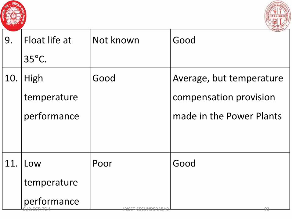
9. Float life at
35°C.
Not known Good
10. High
temperature
performance
Good Average, but temperature
compensation provision
made in the Power Plants
11. Low
temperature
performance
Poor Good
92IRISET-SECUNDERABADSUBJECT: TC 4
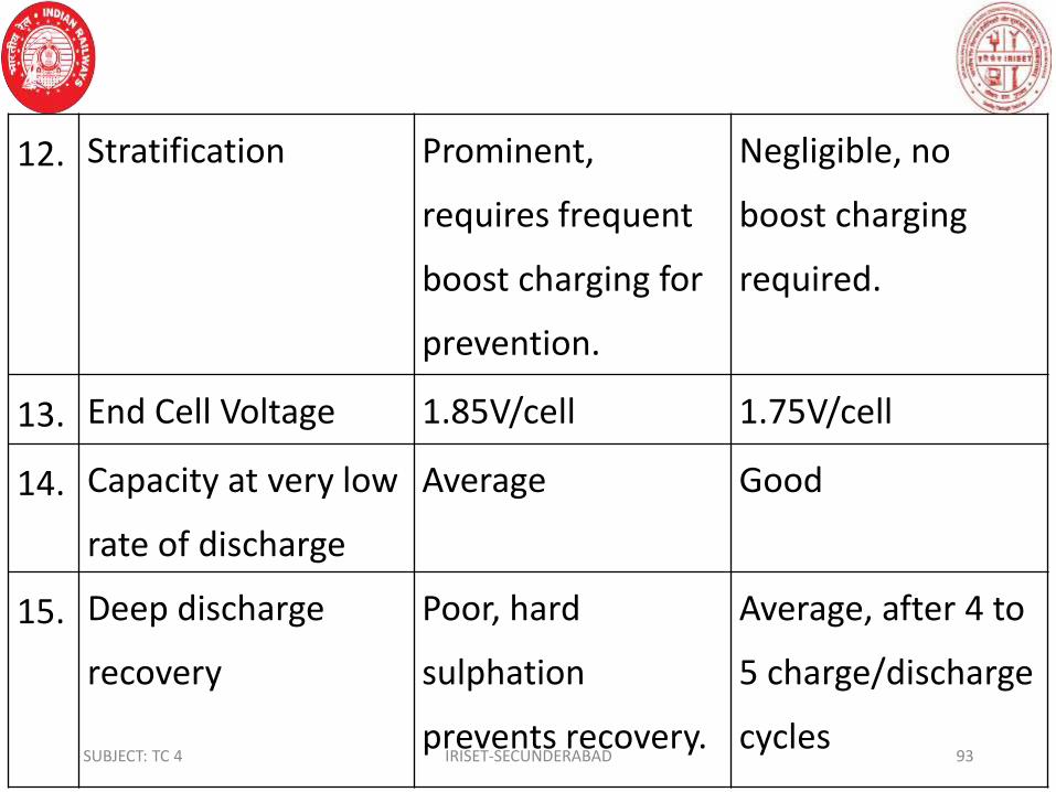
12. Stratification Prominent,
requires frequent
boost charging for
prevention.
Negligible, no
boost charging
required.
13. End Cell Voltage 1.85V/cell 1.75V/cell
14. Capacity at very low
rate of discharge
Average Good
15. Deep discharge
recovery
Poor, hard
sulphation
prevents recovery.
Average, after 4 to
5 charge/discharge
cycles 93IRISET-SECUNDERABADSUBJECT: TC 4

16. Charge efficiency Poor, 12 to 14
hours for 90%
recovery.
Excellent, 6 to 8
hours for 90%
recovery.
17
Float / Boost charging
voltage per cell
2.15 to 2.2 V /
2.4 V
2.25 V / 2.3 V
18 Aging factor 1.5 1.25
19 Depth of Discharge 80 % 50-80 %
20 Cost Low Cost 2 times costlier
than FLA
94IRISET-SECUNDERABADSUBJECT: TC 4

• Rechargeable Alkaline batteries: Depending on the
composition of the active materials of the plates, there are
many types of rechargeable batteries and typically their
output is 1.25 Volts/Cell.
• They are as follow: 1. Nickel iron(Ni Fe). (These cells are not
as popular as Ni-Cd Cells). 2. Nickel- cadmium (NiCd).
3. Nickel-Metal Hydride (NiMh).4. Silver zinc.5. Lithium-Ion
A single Ni Cd voltaic cell has an emf of 1.30 V. 95IRISET-SECUNDERABADSUBJECT: TC 4

• Ni Cd battery packs typically contain three or more cells in
series to produce the higher emfs needed by most
electronic devices. There are drawbacks to nickel-cadmium
batteries. Cadmium is a toxic heavy metal. Its use increases
the weight of batteries and provides an environmental
hazard. Some of these problems have been alleviated by the
development of nickel-metal-hydride (NiMH) batteries. The
cathode reaction of these batteries is the same as that for
for nickel-cadmium batteries. The anode reaction of NiMH96IRISET-SECUNDERABADSUBJECT: TC 4

batteries is very different, however. The anode consists of a
metal alloy, such as ZNi2, that has the ability to absorb
hydrogen atoms. During the oxidation at the anode, the
hydrogen atoms are released as H2O, during charging. The
newest rechargeable battery to receive large use in
consumer electronic devices is the lithium-ion (Li-ion)
battery. Because lithium is a very light element, Li-ion
batteries achieve a greater energy density—the amount of
of energy stored per unit mass-than nickel-based batteries.97IRISET-SECUNDERABADSUBJECT: TC 4

• The technology of Li-ion battery is very different from that
of the other batteries we have described here, and it is
based on the ability of Li+ ions to insert themselves into
certain layered solids. For example, Li+ ions can be inserted
into layers of graphite. During discharge lithium ions migrate
between two different layered materials that serve as the
anode and cathode of the cell. The specific reactions
involved are beyond the scope of our discussion. The end
point voltage of an Alkaline Cell is normally 1.0V/Cell. 98IRISET-SECUNDERABADSUBJECT: TC 4

• Nickel-Metal Hydride Batteries (Ni MH): The NiMH has been
replacing the NiCd in systems such as wireless
communications and mobile computing. The modern NiMH
offers up to 40 percent higher energy compared to NiCd.
Nickel-metal hydride batteries employ nickel hydroxide for
the positive electrode similar to Ni-Cd batteries. The
hydrogen is stored in a hydrogen-absorbing alloy for the
negative electrode, and an aqueous solution consisting
mainly of potassium hydroxide for the electrolyte.
99IRISET-SECUNDERABADSUBJECT: TC 4

• Advantages and Limitations of NiMH Batteries:
• 30 – 40 percent higher capacity over a standard NiCd. The
NiMH has potential for yet higher energy densities.
• Less prone to memory than the NiCd. Periodic exercise
cycles are required less often.
• Simple storage and transportation - transportation
conditions are not subject to regulatory control.
Environmentally friendly — contains only mild toxins;
profitable for recycling100IRISET-SECUNDERABADSUBJECT: TC 4

• Limitations: Limited service life
• Limited discharge current
• More complex charge algorithm needed
• High self-discharge
• Performance degrades if stored at elevated temperatures
• High maintenance — battery requires regular full discharge
to prevent crystalline formation.
• NiMH batteries are more expensive than NiCd.101IRISET-SECUNDERABADSUBJECT: TC 4

• In Indian Railways, these Batteries are used in Walkie-Talkie
sets, Digital Clocks and Cordless Telephones.
• The Lithium Ion battery:
• A rechargeable lithium-ion battery is made of one or more
power-generating compartments called cells. Each cell has
essentially three components. The positive electrode is
typically made from a chemical compound called lithium-
cobalt oxide (LiCoO2) or, in newer batteries,from lithium
iron phosphate (LiFePO4). The negative electrode is102IRISET-SECUNDERABADSUBJECT: TC 4

• generally made from carbon (graphite) and the electrolyte
varies from one type of battery to another.
• These Batteries will be used in Mobile phones, Computers
and Laptops.
• Advantages :
• High energy density potential for yet higher capacities.
• Relatively low self-discharge
• Low Maintenance103IRISET-SECUNDERABADSUBJECT: TC 4

• Limitations:1. Requires protection circuit 2.Subject to aging
even if not in use 3.Moderate discharge current.
Comparison of various rechargeable batteries:
Lead acid Ni cd NiMh Li- ion Li-poly
1 Gravimetric EnergyDensity(Wh/kg)
30-50 45-80 60-120 110-160 100-130
2 Internal Resistance in M ohms
<100 100-200 200-300 150-250 200-300
3 Overcharge Tolerance high moderate Low very low low
4 Self-discharge / Month 5% 20% 30% 10% 10%
5 Cell Voltage(nominal 2V 1.25V 1.25V 3.6V 3.6V
6 Load Current 5c 20C 5C >2C >2C
7 Fast Charge Time in hrs 8-16 1 2-4 2-4 2-4
8 Maintenance 3-6 months 30-60 days 60-90days Not req Not req
104IRISET-SECUNDERABADSUBJECT: TC 4

CHAPTER - 2
BATTERY CHARGING
• BATTERY CHARGING: This is an electrochemical process of
passing a direct current (D.C) through the battery in a
direction opposite that of discharge.
• METHODS OF CHARGING:
• There are two principal methods adopted for charging
batteries: 1. Constant current 2. Constant potentialSUBJECT : TC 4 IRISET- SECUNDERABAD 105

• There are two methods of constant current charging:-
• a. Series method of charging b. Parallel method of charging
• Constant current charging system: The charging current is
maintained constant till the end of charge irrespective of
rise in voltage of battery. This method is employed for initial
charging of lead acid cells. A higher charging rate is
permissible in the initial stages till the potential rises to 2.3
volts, after which it should be reduced to avoid loss of
SUBJECT TC 4 IRISET- SECUNDERABAD 106
• electrolyte due to excessive gassing and undue rise in
temperature of the plates. In this type of charging, there is a
possibility of battery getting over charged if not monitored
properly.
• There are two methods of constant method of charging
• 1. Series method of charging 2. Parallel method of charging
• Constant voltage charging: The charger is set at a fixed
voltage per cell and the charging current depends uponSUBJECT: TC 4 IRISET- SECUNDERABAD 107

difference of potential between the charger and the battery.
The initial charging current is very high, especially if the
battery is completely discharged. Hence, it is used only for
batteries which are not discharged to a very low value.
• Charging Systems: The following different types of charging
systems are adopted as per the requirement.
• 1. Initial Charging: Constant current method
• 2. Trickle Charging: Constant potential method
SUBJECT TC 4 IRISET- SECUNDERABAD 108

• 3. Float Charging: Constant potential method.
• 4. Float Trickle Charging: Constant potential method.
• 5. Equalizing Charging: Constant potential method.
• 6. Boost Charging: Constant Current Method
• 7. Normal Charging: Constant Potential Method
• 8. Freshening Charging: Constant potential method.
SUBJECT : TC 4 IRISET- SECUNDERABAD 109

• Initial Charging: constant current charger is used. This type
of charging is done to a new cell. The voltage supplied
should be at the rate of 2.7V per cell. If manufacturer
instruction card is not available the constant current of AH
Capacity/15 may be supplied.
• Trickle Charge : A system in which battery comes into
operation, only, during emergencies. At other times the
battery is idle and maintained in charged condition by trickle
SUBJECT :TC 4 IRISET- SECUNDERABAD 110

charging at 2.25 to 2.30 volts per cell. The trickle charge
current will be approximately 1 mA per A.H. at the rated 10
Hour capacity of the battery.
• Float Charge: is a system in which the battery is connected
in parallel to the charger or DC source and load. The float
charger current is automatically controlled by maintaining
the correct float voltage across the battery terminals. The
voltage of the system is set to 2.15V to 2.20 volts per cellSUBJECT: TC 4 IRISET- SECUNDERABAD 111

• Boost Charge: Given to a battery when it is neither possible
nor practicable to give it a regular charge. This is usually a
charge of higher rate and shorter duration in order to
prevent over-discharging of the battery. It is given at rate
2.4V Cell.
• Normal Charge: Done at two rates, the Start (high) rate
being maintained till the cells reach 2.4 volts per cell after
which at the finishing (low) rate till the end of charge.
SUBJECT : TC 4 IRISET- SECUNDERABAD 112

• Equalizing Charge: A periodical charge given to the battery
to correct any inequalities of Sp.Gr. among cells developed
during service. This also assures that the maximum capacity
is available when needed. The lower the floating voltage,
the more is the frequency of equalizing charge. An
equalizing charge is given at a rate of 10 Hr.Capacity/50.The
frequency of the refreshing charge is once in six months
only. This assures that the maximum capacity is available
when needed.SUBJECT: TC 4 IRISET- SECUNDERABAD 113

• Freshening Charge: Applicable to a charged battery when
kept idle at a rate of 4 ٪of the rated 10 hour capacity to
prevent stratification.
• CHARGING OF SMF (VRLA) BATTERIES:
• The battery system may require an initial charge if the
voltage per cell drops to 2.1 Volts while the battery is in
storage prior to installation. In order to give an initial charge
to the battery, the instructions below have to be observed
SUBJECT: TC 4 IRISET- SECUNDERABAD 114

• a) The battery must be kept in constant potential mode
• b) Set the voltage to 2.3 volts per cell with a current limit of
0.2C Amps max.
• c) After getting the required voltage for three consecutive
hours, (2.25V/cell) and then load is connected.
• EQUALISING CHARGE: This type of charging is to be done
for every after 6 months or if the variations in cell voltages is
more than 0.1V. SUBJECT: TC 4 IRISET- SECUNDERABAD 115
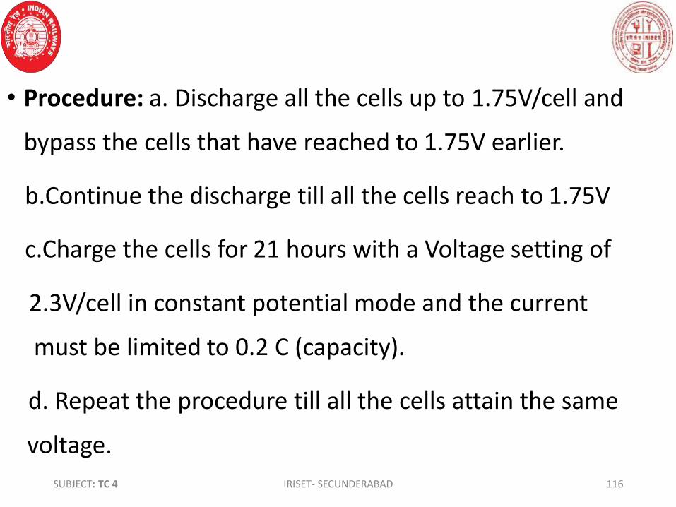
• Procedure: a. Discharge all the cells up to 1.75V/cell and
bypass the cells that have reached to 1.75V earlier.
b.Continue the discharge till all the cells reach to 1.75V
c.Charge the cells for 21 hours with a Voltage setting of
2.3V/cell in constant potential mode and the current
must be limited to 0.2 C (capacity).
d. Repeat the procedure till all the cells attain the same
voltage.
SUBJECT: TC 4 IRISET- SECUNDERABAD 116

• Procedure for keeping the batteries in unused condition:
Sometimes the batteries have to be laid up for an indefinite
period. If left without attention for more than 2 months, it
will deteriorate and a period of 6 months of no attention
will definitely ruin it. Periodic freshening charge is to be
given for the batteries in such a situation.
SUBJECT : TC 4 IRISET- SECUNDERABAD 117

• Various ways of connecting batteries as per requirement
1.Single battery of 12v 100ah
2. When 4 Nos. of 12V 100AH batteries are Connected in
series, the out put is 48V 100AH
SUBJECT: TC 4 IRISET- SECUNDERABAD 118
12V100ah
12V100ah 12V100ah 12V100ah 12V100ah
48V 100AH

3. When four nos of batteries are connected in parallel the
out put of the bank is12V 400AH. 12V 400AH
• When batteries are connected either
in series are in parallel fashion, it
must be ensured that they are of the
Same make , voltage ,capacity and
specs.
SUBJECT: TC 4 IRISET- SECUNDERABAD 119
12V100ah
12V100ah
12V100ah
12V100ah

• When 4 nos of batteries are connected in series Parallel fashion, the output will be 24V 200AH
SUBJEC: TC 4 IRISET- SECUNDERABAD 120
12V100ah
12V100ah 12V100ah
12V100ah
24V 200AH

• Do’s and Don’ts:
• 1. For normal charging constant voltage charger must be
used
• 2.Sealed maintenance free batteries must be charged with
SMPS battery chargers since these have temperature
compensating circuit s.
• 3.Do not make a battery bank with batteries of different
capacities and different makes though they are of the same
voltage.SUBJECT: TC 4 IRISET- SECUNDERABAD 121

Chapter-3
Battery chargers
The battery chargers adopt the following types of Power
Supplies:
1. Linear power supply
2. Switch mode power supply
• Battery charger: Is a system in which D.C. voltage is
dropped to the required value or AC is converted to the
required D.C. value to charge the secondary battery.SUBJECT: TC 4 IRISET- SECUNDERABAD 122

• Simple Battery charger (constant voltage):
• The charging current is determined by the excess of the DC
output of the charger over the voltage of the battery rather
the difference of voltage between charger and battery.
SUBJECT:TC 4 IRISET- SECUNDERABAD 123

• The charger consists of: Step down transformer: is to step
down the input mains voltage to the selected level.
• 2. Rectifier unit: To convert the stepped down AC to DC .
• 3. A smoothing filter: is a combination of inductors and
capacitors to suppress the ripple in the output for providing
a pure DC voltage for charging the battery.
• 4.R1 (trickle resistor): is inserted into the circuit when
charger is selected to trickle mode for low rate of charging.
SUBJECT: TC 4 IRISET- SECUNDERABAD 124

• R2 (ballast resistor):Introduced to reduce the change in the
charging current due to variations in input mains voltage or
variations in the load which cause fluctuations in charger
out put voltage which eventually causes change in current.
• It also provides regulation by acting as a preload there by
reducing the difference between the no load to full load.
• It provides safety to the personnel by providing a path for
stored energy of the filter capacitors to discharge through.
SUBJECT: TC 4 IRISET- SECUNDERABAD 125

• Linear power supply: (Conventional regulated power supply)
• The above regulated D.C. power supply consists of four
sections as shown in the above block diagram.
• The power transformer: This converts the AC line voltage
into a higher or lower AC voltage depending on the
application and isolates the connected control equipment SUBJECT: TC 4 IRISET- SECUNDERABAD 126
Power transformer Rectifier Filter Regulator DC O/PA.C I/P

from the main power source.
• Rectifier unit: This receives transformer output and
converts the AC voltage into DC voltage. The conversion
from AC to DC is not perfect and a certain amount of AC
residue or “ripple” remains in the output of the rectifier.
• Filter unit: This receives the pulsating DC from the rectifier
and converts into pure DC.
• Regulator unit: The unregulated filtered DC is applied to an SUBJECT: TC 4 IRISET- SECUNDERABAD 127

electronic feed back or control circuit of the regulator. The
regulator circuit maintains constant DC out put during
variations in the load or variations in the I/P line voltage.
The out put AC of the transformer is always higher than the
DC out put voltage (Ex: the o/p of the transformer
approximately 18V to 20V for an O/P of 12V DC). The
difference in voltage(6Vto 8V)is dissipated as heat in the
regulating transistor as it operates in linear mode and this
causes power lossSUBJECT: TC 4 IRISET- SECUNDERABAD 128

• Limitations of linear power supply: 1.The size of the unit is
bulky because of big size power transformer and power loss
is also high during regulation. 2. The regulation response
time is low. 3. These types of power plants do not have the
scope for modular expansion due to which frequent
changing of the power plants with each expansion of the
load. These are not suitable for VRLA batteries as
temperature compensation logic is not provided.
SUBJECT: TC 4 IRISET- SECUNDERABAD 129

• Switch mode power supply(SMPS): Switched-mode power
supplies (SMPS) are basically DC-to-DC converters, operating
at frequencies in the range of 20KHz to 100 KHZ.
• SMPS based power plants are compatible with conventional
flooded Lead acid as well as VRLA batteries.
• These types of power plants have the scope for modular
expansion due to which frequent changing of the power
plants is preventedSUBJECT: TC 4 IRISET- SECUNDERABAD 130

• The basic block diagram of SMPS is shown below
SUBJECT IRISET- SECUNDERABAD 131
High voltage low frequency input AC
Rectifier and filter
High frequency switch
High voltage DC
PWM oscillator
Error Amplifier
Rectifier and Filter
Out put DC
Step down
transformer
Output sensor
Feed back
Isolation
Reference

• The Ac input is fed to a high voltage rectifier and filter unit
and converted into high voltage DC. The high voltage DC is
chopped at a very high frequency in the range of 20Khz to
100Khz by the switching transistor.
• The output of the switching transistor which is a pulsating
DC is fed to the step down transformer . The stepped down
low pulsating DC is converted into pure DC by the rectifier
and filter unit and is supplied to the load.
SUBJECT: TC 4 IRISET- SECUNDERABAD 132

• The out put sensor senses the output voltage and sends it
to the isolation circuit which provides physical isolation
(through an optocoupler) between the output and
controlling circuit i.e. error amplifier.
• The error amplifier is also fed with a reference voltage apart
form the sensed voltage and both the voltages are
compared and the net error voltage is fed to the PWM
oscillator by the error amplifier.
SUBJECT: TC 4 IRISET- SECUNDERABAD 133

The PWM oscillator is designed to generate a very high fixed
frequency with variable pulse width. whenever there is a
change in output voltage due to input variations or load
variations, the output sensor senses it and feeds to the error
amplifier .
The error amplifier changes the width of the pulse as per
the resultant error and eventually regulates the output of
the system.
SUBJECT; TC 4 IRISET- SECUNDERABAD 134

• Since, the transistor is always in switching mode(ON or OFF),
this is called switch mode power supply system.
• The output voltage: Input voltage x D(Duty cycle)
• D =
• For example: Input voltage is 200 V and D=0.25 sec
Out put voltage= 200x0.25= 50V.
SUBJECT: TC 4 IRISET- SECUNDERABAD 135
ON0.25 sec
0.75 sec OFF
On Time
On time+ off time (one cycle Duration)

If Input voltage is 200 V and D=0.5 sec
Out put voltage= 200x0.5= 100V.
• If the output voltage tends to increase (due to decrease in
load or increase in input) the comparator produces a higher
output voltage which makes the pulse that drives the base
of the switching transistor narrower. That means, the duty
cycle is reduced. Since the duty cycle is lower the output
becomes less which tries to cancel almost all the originalSUBJECT: TC 4 IRISET- SECUNDERABAD 136
ON 0.5sec
OFF 0.5 sec

increase in output voltage. Conversely, if the regulated
output voltage tries to decrease, the output of the
comparator decreases. This makes the pulse wider and the
transistor conducts for longer time and the output
increases. Finally, the output regulation is achieved by
modifying the Duty cycle. Duty cycle depends on the “on”
time of transistor, which in turn depends on the width of
the pulse applied to the base of the transistor, which is
SUBJECT: TC 4 IRISET- SECUNDERABAD 137

controlled by ‘Pulse width modulator’ of the regulator
circuit.
• The power supply systems such as UPS, Computers, mobile
chargers, SMRs of battery chargers and IPS etc are all
working on the above principle.
• But different topologies areadopted as per the requirement
and design.
SUBJECT: TC 4 IRISET- SECUNDERABAD 138

• 12 V power supply unit at way stations:
• Power supply unit for Telecom Installations at way Side
Stations in 25 KV Electrified areas is designed for 12 Volts/ 2
Amps switch mode with advanced circuitry techniques as
per RDSO specification No.IRS: TC-72/97. In this unit the
output load can be taken for six way station equipments
through 6 way terminal strips, through 0.2 Amps Glass or
Cartridge fuses. One number of maintenance free
SUBJECT: TC 4 IRISET- SECUNDERABAD 139

Lead acid battery is fitted inside the unit having a rating of
12V/7AH. The PSU is protected against short circuit and
reverse polarity and suitable LED indications have been
provided. Protection arrangements for transients on the
input side is provided with MOVRs (320 volts rating) and
fuses with 2 ampere rating. Normally the LED on load
terminal will not glow. However, blowing of fuse on load
terminal shall be indicated by glowing of concerned 'Red'
LED. A suitable Earth terminal is provided in the PSU.SUBJECT: TC 4 IRISET- SECUNDERABAD 140

• 48 V DC SMPS POWER PLANT FOR INDIAN RAILWAYS
TELECOM EQUIPMENTS:(Rdso spec: rdso/spn/tl/23/99
version 4.0)
• This Power Plant is designed based on High Frequency
Switch Mode Techniques using switching frequencies of 20
KHz and above for the use by Indian Railways for Telecom
Equipments such as Exchanges, Multiplexing Equipments,
Microwave Radio Equips,GSM-R, TETRA and OFC equips etc.
SUBJECT: TC 4 IRISET- SECUNDERABAD 141
• General description:
• This power system designed on modular basis specially for
telecom equipment and is suitable for charging VRLA or
Conventional Lead Acid Batteries.
• Main features: Local and remote (via modem) monitoring of
any alarm condition of each of the rectifiers.
• Local and remote (via modem) monitoring of output current
of each rectifier.SUBJECT: TC 4 IRISET- SECUNDERABAD 142

• Enables setting of parameters of all the rectifiers using the
CSU front panel or an optional remote PC running WINCSU
software.
• Enables monitoring of DC load current and voltage.
• A typical system comprises number of rectifiers, a
monitoring and control subsystem comprising Control
Supervisory Unit (CSU) and a Master User Interface Board
(MUIB),Mains Monitoring Interface Board (MMIB), Battery
input circuit breaker and AC input distributionSUBJECT ; TC 4 IRISET- SECUNDERABAD 143

• The system with basic blocks of monitoring and control
functions is shown in figure given below:
• The rectifier (SMR) is designed to slide and plug into a
magazine and the DC output is connected to the load and to
the battery bank.
• Low voltage disconnect switch (LVDS) is included in series
with the batteries in order to prevent deep discharge of the
battery bank in the event of an unusually long AC power
outage.SUBJECT: TC 4 IRISET- SECUNDERABAD 144

SUBJECT IRISET- SECUNDERABAD 145
• 48 V DC SMPS POWER PLANT FOR TELECOM EQUIPMENT:
LPD : Lightning protective device
SMR: Switch mode rectifier
HVD: High voltage disconnect
CSU: Control supervisory unit
MUIB: Master user interface board
LVDS: Low Voltage disconnect switch
AC Distribu
tion
HVD
SMR Rack
LPD
CSU
MUIB
LVDS
BATTERY
DCDistribution
To loads
Remote voltage free contacts
To modem or pc

• HVD (High/Low voltage disconnect switch) is installed at the
input side to provide a galvanic isolation for the modules
from abnormal AC inputs. The magazine and rack can be
configured to build different ultimate capacities of 100
Ampere and 200 ampere.
• The monitoring and control signals, such as AC input
voltage, load current, battery current, temperature, battery
switch status, LVDS control and status, system voltage are
SUBJECT: TC 4 IRISET- SECUNDERABAD 146

connected to the monitoring and control module (CSU) via
master user interface board (MUIB) and mains monitoring
interface board (MMIB).
• A 4-wire cable, which carries the digital communication
signals that allow control and monitoring of the rectifier,
connects the CSU.
• A relay is provided to extend potential free contacts for
alarm condition in the MUIB. This relay operates when faultSUBJECT: TC 4 IRISET- SECUNDERABAD 147

arises. An analog AC voltmeter is provided at front panel to
monitor system AC input voltage.
• Main features of CSU as follow:
• Local and remote (via modem) monitoring of any alarm
condition of each of the rectifiers.
• Local and remote (via modem) monitoring of output current
of each rectifier.
• Enables setting of parameters of all the rectifiers using theSUBJECT: TC 4 IRISET- SECUNDERABAD 148

• CSU front panel or an optional remote PC running WINCSU
software.
• Enables monitoring of DC load current and voltage.
• The following functions are standard:
• Temperature compensation of the battery float and
equalization voltage (require temperature sensor).
• Programmable battery charging current limits (3 limits).
• Automatic equalization of the battery with selectable startSUBJECT: TC 4 IRISET- SECUNDERABAD 149

• (choose voltage/current level or discharge Ampere-hours)
and end (choose time duration or equalisation current)
parameters.
• Active current sharing.
• Installation :
• a.Initial Check up
• No damage should be observed during transportation
• Check the received material list as per the packing listSUBJECT IRISET- SECUNDERABAD 150

• All screws should be tightened once again at the site of the
rack.
• No damage should be observed in the CSU.
• Follow installation and commissioning procedure for SMR.
• Modules are individually packed and all packed modules are
supplied in one separate wooden box. Unpack the modules
and check for any transit damage Installation
SUBJECT: TC 4 IRISET- SECUNDERABAD 151

• Installation & Commissioning:
• The system should be installed with sufficient space at rear
and front for easy maintenance and servicing and should be
away from heat generating equipment.
• Lightening Protection Devices (LPD) and Surge Protection
Devices (SPD) are installed in the rack side by side as these
have been tested in coordination without the need of wire or
inductor between them.SUBJECT: TC 4 IRISET- SECUNDERABAD 152

ensure that the body of the cabinet is properly earthed
before applying power to the system.
• Initial battery connection & load connection shall be done
without energizing the system.
• A minimum clearance of approximately 1.0 meter is
recommended to be provided for the power plant.
• Check and ensure that the output voltage of power plant
shown on the name plate should correspond to battery
voltage.SUBJECT : TC 4 IRISET- SECUNDERABAD 153

• The cable installed between power plant and battery must
be sized to provide minimum voltage drop.
• Installing the lightening protection devices:
• Lightening protection devices (LPD) are provided in a
separate enclosure, which is intended to be installed at the
AC mains distribution level.
• Line, neutral and earth shall b connected to the terminal
block provided inside the enclosure.SUBJECT: TC 4 IRISET- SECUNDERABAD 154

• It is advised to maintain a distance of minimum 5 meters
between the main AC distribution point and power plant. If
this distance is not physically possible, use at least 5 meter
lengths of cables to connect AC to power plant. This is
required to establish a perfect co-ordination between
lightening protection device installed near the distribution
and the surge protection device (SPD) installed in the rack.
Cable length adds some inductance in the path, which is
SUBJECT: TC 4 IRISET- SECUNDERABAD 155

essential in transferring the surge energy between SPD and
LPD.
• AC input, DC output and communication cables are provided
at the rear side of the cabinet. Self locking type wago
connector is provided for AC and DC connections. Six wire
communication cable is used for communication. These
connectors have to be connected after inserting module
into the magazine.
SUBJECT: TC 4 IRISET- SECUNDERABAD 156

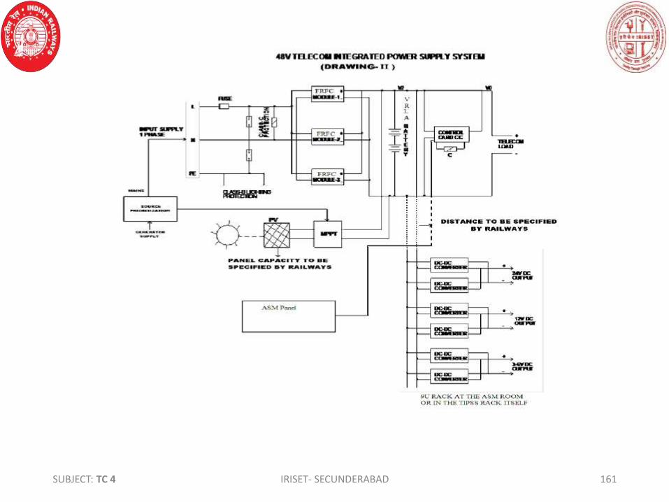
• Telecom Integrated Power Supply System:
• 1.Consists of a Distribution-Switching-Control-Alarm
Arrangement (DSCA) and Float Rectifier-Cum-chargers (FR-
FCs) or Float Rectifier cum Boost Chargers (FR-BCs) (in N+1
configuration in hot-standby and one module in cold
standby), DC-DC converter (in N+1 configuration in hot-
standby) for 24V, 12V, 3-6V, 48V
• MPPT Battery Charger (optional) , 48V battery set of
adequate capacitySUBJECT: TC 4 IRISET- SECUNDERABAD 157

2. The Telecom Integrated Power Supply System is capable of
meeting the load requirements (equipment and battery
bank) for various telecom equipments. The system shall be
expandable at rack level itself, using the basic modules of
the same rating.
3. To cater for higher load requirements, (for modules with
more than 50 watts) the same type of modules mounted in
the same rack are capable of working in parallel load sharing
arrangementSUBJECT: TC 4 IRISET- SECUNDERABAD 158

4. The Telecom Integrated Power Supply System is suitable
for operation from AC Mains, solar power supply or from a
DG Set.
5. The Telecom Integrated Power Supply System will work
satisfactorily either with VRLA maintenance free Battery as
per IRS;S 93/96(A) or Low Maintenance Lead Acid Battery as
per IRS;S 88/2004 with latest amendment. Battery as per
requirement will be integral part of he system.SUBJECT: TC 4 IRISET- SECUNDERABAD 159
6. In case, to provide solar power as an additional source of
power supply, Solar Panel Modules of adequate capacity
has to be provided.
7. One panel consisting of status indications and critical
alarms of TIPSS will be provided in ASM’s room. The
monitoring panel is of wall mounting type. 12 core, 1.5
sq.mm signalling cable as per IRS:S 63/2007 will be used for
connecting TIPSS to Status Monitoring Panel in Station
Master’s room.SUBJECT: TC 4 IRISET- SECUNDERABAD 160
SUBJECT: TC 4 IRISET- SECUNDERABAD 161

CHAPTER - 4
VOLTAGE STABILIZATION
• For telecom installations, the input supply must be
maintained reasonably constant in the face of varying load.
Since, it is not possible always with the inbuilt equipment, it
is necessary to incorporate a voltage stabilizing device as an
integral part of the equipment.
SUBJECT:TC 4 IRISET- SECUNDERABAD 162

• REQUIREMENTS FOR MAINS VOLTAGE STABILIZER:
• 1. To achieve accuracy of stabilization as per the specified
percentage of 1%
• 2. The second requirement for a stabilizing system is the fast
response to the sudden change in the mains voltage.
• 3. To prevent distortions in the original sinusoidal waveform
which is important for a good power supply
• 4. To achieve stabilized power with non moving elements
which is cheaper
SUBJECT:TC 4 IRISET- SECUNDERABAD 163

• Ferro resonant type automatic voltage regulator:
• It consists of a primary winding , secondary winding and a
third winding called a compensating winding.
• The compensating winding is connected in series with
primary winding and added to the primary side of the
transformer. This carries the load current and opposes the
primary flux to improve voltage regulation.
• A capacitor of proper value is connected across theSUBJECT:TC 4 IRISET- SECUNDERABAD 164

secondary winding to form a parallel resonance circuit.
• A magnetic shunt is provided between the two windings. It
provides a shunting path for the secondary flux.
• Description: Primary side: Mild Steel (Unsaturated Iron),
Secondary side: Silicon Steel (Saturated Iron)
• When the voltage is applied across primary winding is gradually
increased from zero to a particular voltage, called as KNEE
VOLTAGE or point of discontinuity, the secondary gets tuned to
SUBJECT:TC 4 IRISET- SECUNDERABAD165

SUBJECT:TC 4 IRISET- SECUNDERABAD 166

• parallel resonance at that point.
• Due to the resonance effect, the capacitor increases the
secondary voltage abruptly. This results in the increase of
secondary core magnetic flux due to induced current by the
capacitance in the secondary winding. This magnetic flux is
added to the flux flowing through secondary core due to the
primary voltage. Hence flux addition takes place in the
secondary core causing saturation of secondary winding.
SUBJECT:TC 4 IRISET- SECUNDERABAD167

• When the secondary magnetic circuit is saturated, much of
the secondary flux is decoupled from the primary winding
and passes through magnetic shunt.
• At primary knee voltage secondary core is saturated and
after knee voltage the increased amount of magnetic flux
passes through the magnetic shunt and does not increase
the flux in secondary. Hence secondary voltage remains
more or less constant.
SUBJECT:TC 4 IRISET- SECUNDERABAD 168
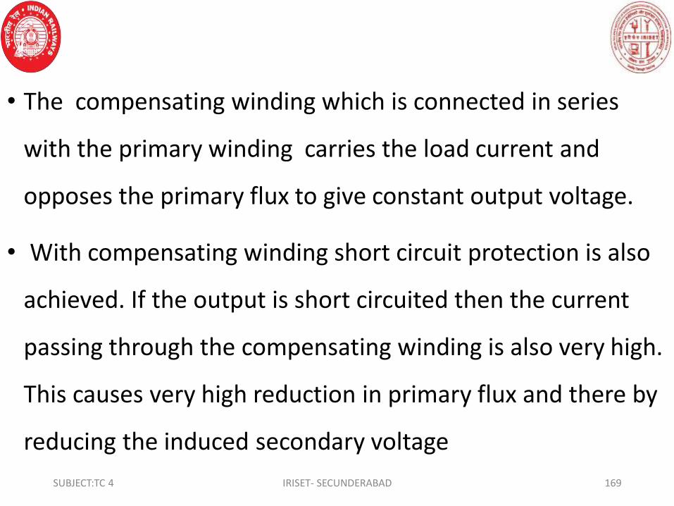
• The compensating winding which is connected in series
with the primary winding carries the load current and
opposes the primary flux to give constant output voltage.
• With compensating winding short circuit protection is also
achieved. If the output is short circuited then the current
passing through the compensating winding is also very high.
This causes very high reduction in primary flux and there by
reducing the induced secondary voltage
SUBJECT:TC 4 IRISET- SECUNDERABAD 169

• Features:
1. No moving parts.
2. Power handling capacity - 0.5 KVA to 10 KVA
3. It's output voltage= 230±1٪ for input voltage range of 160V
to 270 V at 50Hz,
4. Fast regulation. Response time is < 60 m.sec.
5. Complete automatic and continuous regulation
6. Watt efficiency not less than 80٪ in case of 0.5 KVA & not
less than 85٪ in case of 1 KVA to 10 KVA at full load.SUBJECT:TC 4 IRISET- SECUNDERABAD 170
7. Immune to input spikes and surges, because of high
isolation between I/P & O/P.
8. Self protection against overload
9. ‘No’ load current is not more than 30% of the rated input
current.
DRAWBACKS:
1. The harmonic distortion in the O/P voltage is maximum at
no load. Minimum 25٪ load of rated load must be provided
2. Output voltage is frequency dependentSUBJECT:TC 4 IRISET- SECUNDERABAD 171

• Servo Controlled Voltage Regulator (Stabilizer):
• Servo voltage regulator protects the appliances such as
CNC machines, electrical equipment, Battery Chargers,
motors, lab equipment etc. by correcting the voltage
fluctuations in the incoming AC voltage to the desired
voltage levels
• The principle of operating Servo Stabilizer
• It functions on comparing the output voltage with built-inSUBJECT:TC 4 IRISET- SECUNDERABAD 172

stable reference voltage source. The control circuit controls
the servo motor. The Control circuit operates the motor
whenever the output voltage falls or rises beyond the preset
SUBJECT:TC 4 IRISET- SECUNDERABAD 173

voltage. The motor is mechanically attached to the arm of a
continuously variable auto transformer which feeds to the
primary of a series control buck boost transformer. The
stabilizer output voltage is compared with the reference
voltage & resultant error signal controls the Servo Motor
which corrects the voltage by bringing it to the preset
voltage.
SUBJECT:TC 4 IRISET- SECUNDERABAD 174

Servo Stabilizer consists of following sub-assemblies:
a) Variable Transformers driven by the synchronous servo
motor
b) Series Transformer
c) Electronic Control
The Syn. Servo Motor driven variable Transformer feeds
the primary winding of the double wound series
Transformer secondary winding to add or subtract the
correcting voltage to the input Line voltageSUBJECT:TC 4 IRISET- SECUNDERABAD 175

The Electronic Control circuit monitors the O/P Voltage. In case
of voltage variations the control circuit drives the Servo Motor to
correct the O/P voltage within the rated limits
• Specifications & Features of 1 KVA single Phase Servo Stabilizer
• Input Voltage :: 160 – 260V, 50 Hz
• 2.Output: 230V + 1% (adjustable with + 10 V)
• 3.Capacity: 1 KVA, 1 phase
• 4.Voltage Correction Rate :20 volts/sec
• 5.Temperature Range: 0-55 CSUBJECT:TC 4 IRISET- SECUNDERABAD 176

• Mode of operation:
• The unit can be made to operate manually through the
• AUTO/MANUAL selector switch.
• Push switches INCREASE and DECREASE can increase/decrease
O/P voltage when AUTO/ MANUAL selector switch is in MANUAL
position
• Protections
• a) Output is automatically switched OFF if it is below 205 Volts or
above 245 Volts and automatically switches ON when safe
voltage returns.SUBJECT:TC 4 IRISET- SECUNDERABAD 177

• b) Built in Time-Delay for 5-6 minutes for re-start
• c) Overload protection provided through MCB
• d) Protection with auto switch off /fault signal against
single-phasing excessive input.
• Maintenance:
• The unit doesn’t require any regular maintenance, however
carbon brush of the variac should be checked occasionally.
SUBJECT:TC 4 IRISET- SECUNDERABAD 178

• The unit doesn’t require any regular maintenance However
carbon brush of the variac should be checked occasionally. If
required it should be replaced by a fresh one given as spare
in moveable arm of the variable transformer
• In case, carbon gets deposited on the conducting surface of
the variac it should be cleaned up after disconnecting the
main input supply
SUBJECT:TC 4 IRISET- SECUNDERABAD 179

SUBJECT:TC 4 IRISET- SECUNDERABAD 180
Block diagram of Servo Voltage Regulator

Chapter 5
UNINTERRUPTED POWER SUPPLY SYSTEM (UPS)
• An uninterrupted or uninterruptible power supply (UPS) is a
device that has an alternate source of energy (battery)
that can provide power when the primary power source is
temporarily disabled. The function of an UPS is to supply
uninterrupted power to the connected load. In railways, there
are utilized in places such as PRS, UTS, EDP centers etc.
where even a short/temporary power supply failure can
SUBJECT:TC 4 IRISET- SECUNDERABAD 181

cause a great inconvenience to public/ passengers and also
may lead to financial loss to the railways.
• RDSO, Lucknow has issued a technical specification for fault
tolerant Uninterrupted Power Supply (UPS) system for PRS,
EDP centers and other similar requirements of ON LINE UPS
system vide RDSO/ PE/ SPEC/ PS/ 0023-2001 (Rev. 0),
Amendment no.3 dtd.16.09.2011. As per above
specification, the UPS provided in Railways are single phase
or 3 phase system as indicated below for different ratings.SUBJECT:TC 4 IRISET- SECUNDERABAD 182

• Category A: 1 kVA to 7.5 kVA with single-phase input
and single phase output.
• Category B: 7.5 kVA to 30 kVA with three phase input
and Single phase output.
• Category C: 10 kVA and above with three phase input
and three phase output.
• Generally category ‘A’ UPS (1 kVA to 7.5 kVA with single
phase input and single phase output) are provided at
booking offices for Unreserved Ticketing System (UTS)SUBJECT:TC 4 IRISET- SECUNDERABAD 183

for continuous power backup.
UNINTERRUPTED POWER SUPPLY
In this, the rectifier accepts mains ac, converts it into dc to
feed it to the inverter as well as to charge the batteries. The
inverter converts dc power into clean, stable isolated ac
output which is given to the load connected at the output.
In the event of mains failure, the inverter works on the
battery supply and gives the uninterrupted output for a
period of backup time.SUBJECT:TC 4 IRISET- SECUNDERABAD 184

• Constant current / constant voltage (CCCV) is a combination
of the above two methods. The charger limits the amount
of current to a pre-set level until the battery reaches a pre-
set voltage level. The current then reduces as the battery
becomes fully charged. This system allows fast charging
without the risk of over-charging and is suitable for Li-ion
and other battery types.
SUBJECT:TC 4 IRISET- SECUNDERABAD 185
• TYPES OF UPS: The UPS can be divided into three types
depending on the construction and change over time.
They are: 1. Online 2. Off - Line 3. Line - interactive
• Online UPS: The inverter is always in ON condition even
when the mains power supply is available. During normal
condition, the input AC is converted to DC and then fed to
Inverter circuit which in turn converts DC into AC to supply
to the load. During mains supply failure, the DC voltage from
the battery is converted to AC voltage by the inverterSUBJECT:TC 4 IRISET- SECUNDERABAD 186

circuit and stepped up to the required output voltage level. The
battery is in float mode and gets charged by the charger cum
rectifier circuit. Two transformers are used one for the charger
and another for the inverter circuit. The battery capacity decides
the backup time of UPS. The shape of the output wave form is
pure Sine Wave. since, the inverter is always in ON condition ,
this called as online UPS.
ADVANTAGE: There is no changeover time from mains to battery
mode in the case of power failure.SUBJECT:TC 4 IRISET- SECUNDERABAD 187

SUBJECT:TC 4 IRISET- SECUNDERABAD 188
A C MAINS
INPUT
BATTERY
CHARGER &
RECTIFIER
B T 1
INVERTERA C OUT PUT
TO LOAD
NORMAL AND EMERGENCY POWER FLOW
T1T2
MAINS
TRANSFORMER
BATTERY
BLOCK DIAGRAM OF ON LINE UPS
USE: This type of system is mostly used supply power for
Medical and Surgical equipments, and big computer systems
where the data is most important like Banks and industries
etc.

SUBJECT:TC 4 IRISET- SECUNDERABAD 189
TRICKLE
CHARGE BATTERY
CHARGER
B T 1
INVERTER
A C SWITCH
EMERGENCY
POWER FLOW
T1
T2
A C INPUT
NORMAL
BATTERY
A C SWITCH
A C OUT PUT
TO LOAD
BLOCK DIAGRAM OF OFF LINE UPS
• Off-Line UPS: The AC power is directly supplied to the load
through an AC switch and the inverter is in off condition. On
the failure of mains, the line connected to AC switch opens

and the inverter AC switch will close allowing the battery to
provide back-up power through the inverter stage. The load
is starved during switch over time.
ADVANTAGES:
1. It is very much compact due to less number of components
compared to ON-Line UPS.
2. Inverter is “On” only when the AC input is off or out of
range.
3. It is economical.SUBJECT:TC 4 IRISET- SECUNDERABAD 190

SUBJECT:TC 4 IRISET- SECUNDERABAD 191
B T 1
RECTIFIER &
INVERTER
T1
A C INPUT
BATTERY
BANK
A C SWITCH
A C OUT PUT
TO LOAD
NORMAL POWER FLOW
TRICKLE
CHARGE
NORMAL
DIRECTION OF
EMERGENCY
POWER FLOW
BLOCK DIAGRAM OF LINE INTERACTIVE UPS
LINE INTERACTIVE UPS: During normal condition, the AC
power is directly supplied to the load through the AC switch
which is normally ON. Under the emergency conditions, the

AC switch opens the line and the battery comes into the circuit
to provide the backup power through the inverter stage. only
one transformer is used for charging circuit as well as for inverter
circuit. The transformer works in step down mode for charging
the battery and works in step up mode for inverter working.
• ADVANTAGES:
1. This is cheaper and less components are involved.
2. It is for only low power applications below 1KVA.
SUBJECT:TC 4 IRISET- SECUNDERABAD 192

S.no ON LINE UPS OFF LINE UPS LINE INTERACTIVE UPS
1 Inverter is ON always Inverter is ON only during mains failure
Inverter is ON only during mains failure
2 Switching time is zero Switching time is < 5m secs
Switching time is <5 m secs
3 Output is Sine wave Out put is Sine/square wave
Out put is Sine/square wave
4 Cost is high
5 sealed maintenance free batteries are used
sealed maintenance free / flooded batteries are used
sealed maintenance free / flooded batteries are used
6. Used in main frame computers /medical equipments where un-interrupted power supply is required
Used with PC’s or OtherApplications Where interruption upto 5 mS is permitted
Used with PC’s or OtherApplications Where interruption upto 5 mSis permitted
7 Float performance of charger has a wide influence on battery life
Battery charging iscontrolled automatically
Battery charging iscontrolled automatically
SUBJECT:TC 4 IRISET- SECUNDERABAD 193

CHAPTER 6
PHOTOVOLTAIC GENERATION OF ELECTRICITY -
SOLAR CELLS
• Electricity can be generated directly from Sunlight, by a
process called as Photovoltaic effect, which is defined as
the generation of an electromotive force as a result of the
absorption of ionizing radiation.
• Devices that use the PV effect to generate a voltage when
Sunlight is used as the source of ionizing radiation are called
Solar Cells.SUBJECT: TC4 IRISET- SECUNDERABAD 194

• Solar Cell:The heart of any PV Power System is the Solar
Cell. It is a transducer that converts the Sun's radiant energy
directly into electricity and is basically a semiconductor
diode capable of developing voltage.
• At present Silicon is the most important semiconductor
material for Photovoltaic Solar energy conversion.
• Solar Cell works on the principle of p-n semiconductor
junction. The holes in P-material and the electrons in
SUBJECT: TC4 IRISET- SECUNDERABAD 195
• N-material are are called majority carriers because they are
in excess and the majority of the current is carried by them.
Conversely the electrons in P-type material and the holes in
N-type material are called as minority carriers. The narrow
region is called as space charge region or depletion region.
• Silicon Solar Cell: In a Silicon Solar Cell layer of a typical
silicon cell is of a thickness such that light falling on the
surface penetrates far into the crystal to create electron-
hole pairs in the vicinity of the junction with the P-typeSUBJECT: TC4 IRISET- SECUNDERABAD 196

Silicon. The thickness is typically half a micron. Therefore,
when light falls on the cell electrons will collect in the N-
type layer and holes will collect in the P-type layer until
there is a voltage built up within the crystal sufficient to
push any other electron back into the P-type layer. In a
silicon Solar Cell that voltage is about 0.65 V.A current can
be drawn from the cell through a circuit that makes
electrical contact with both the front surface of the cell and
the back one. If the resistance of the external circuit is low,SUBJECT: TC4 IRISET- SECUNDERABAD 197

the current that flows through it is a measure of the rate at
which the electrons are separated from holes. That rate
depends on the intensity of the light falling on the surface of
the cell and on the rate at which electrons and holes are lost
through their recombination.
The efficiency of these Cells can be improved depending on
the fact that the output of Solar Cell of a given size is
proportional to the intensity of the radiation falling on that.
SUBJECT: TC4 IRISET- SECUNDERABAD 198

• This is achieved by concentrating sunlight onto a relatively
small area of Solar Cell, by focussing the light with a
parabolic mirror or trough shaped reflector known as
Wingston Collector.
• Solar Array Configuration: Solar Cell arrays usually consist
of Series-Parallel inter-connected Solar Cells bonded to
supporting substrate and encapsulated with transparent
materials to provide environmental protection and non-
corrosion. Most of the silicon Solar Cells employed for SUBJECT: TC4 IRISET- SECUNDERABAD 199

terrestrial applications are round wafers of 5 cm dia. and a
thickness of 0.3 to 0.5 mm. A 5 cm dia. cell with a surface
area of about 20 cm2 delivers in "Full Sun", a power about
0.3 W at less than 0.5 V, at room temperature.
• For higher power and higher voltage, a number of cells must
be assembled into Panel. If more voltage is required, the
cells should be connected in series and for more current in
parallel. By connecting a number of cells in series and
parallel, it is possible to provide any power at any voltageSUBJECT: TC4 IRISET- SECUNDERABAD 200

• The general practice is not to build a Solar Generator from
one panel but to divide the array into a number of modules
of equal voltage and power.
• The present standard values are 1.5 V, 6V, 12 V, 24 V, 48V,
which are multiples of each other. Any specific power
demand can be met by connecting a suitable number of
Modules in series and in parallel
• Precautions: Careful attention must be given to matching
the electrical characteristics of the cells which are to beSUBJECT: TC4 IRISET- SECUNDERABAD 201

assembled. As a general rule, all cells to be connected in
parallel should have the same Voc and even more
important, the same max power point voltage. Cells to be
operated in series have the same ISC and the same max.
power point current. The mismatching of Solar Cell
characteristics leads to 'bad' panels, because the cells of
higher photocurrent and photo voltage dissipate their
excess power in the cells of lower electrical performance
SUBJECT: TC4 IRISET- SECUNDERABAD 202

SUBJECT: TC4 IRISET- SECUNDERABAD 203
• The terminology of solar panel is given below.

• P-V array: A typical p-v array is shown below
16 Nos. of Solar Cell Modules are connected in series
Parallel to give a peak output of 64 V and 5.8 amps. EachSUBJECT: TC4 IRISET- SECUNDERABAD 204
solar module is assembled with 34 Solar Cells in series to
give a peak output of 1.45 amps and 16V.
Power System with Photovoltaic Conversion: a typical
arrangement is shown in figure below. As the Solar Power is
not available while it is dark, a normal storage arrangement
is needed in the form of battery. In Small Scale Units, a Solar
Conversion System and Storage is sufficient to meet day and
night power demand. Where as, in large Scale units another
SUBJECT: TC4 IRISET- SECUNDERABAD 205

• charger is also provided to charge batteries during periods
of darkness and also during periods while the peak power is
not obtained by P.V. conversion.
SUBJECT: TC4 IRISET- SECUNDERABAD 206

• Main Components of Solar Photovoltaic System in Indian
Railways:
• The solar power system consists of the following
components:
I) Solar array ii) Battery Bank iii) Solar Charge Controller
iv) Field Junction Box v) Solar Module Mounting Structure
v) Earthing kit vii) Cables. These arrangement of these
components is shown below.SUBJECT: TC4 IRISET- SECUNDERABAD 207

SUBJECT: TC4 IRISET- SECUNDERABAD 208

• a) Solar array : consists of series/parallel combination of
modules, which are mounted on the metallic structure in
sunny and shadow free area at a fixed angle as
recommended by designer. All the modules will face the
South in Northern hemisphere. Cables from the array area
will come to the control and battery room through junction
boxes from panels of modules.
• b) field junction box: FJB is the interface between Solar
panels and the Charge Controller. All the incoming/outgoing SUBJECT: TC4 IRISET- SECUNDERABAD 209

cables/wires from Solar panel to Charge Controller are
terminated at FJB.
• Solar Charge Controller: this is the interface between Array
and battery bank. It protects the battery from overcharging
and ensures moderate charging at finishing end of charge of
battery bank. Therefore it enhances the life of the battery
bank. It also indicates the charging status of batteries like
battery undercharged, overcharged or deep discharged
through LEDs indications. . Some switches and MCBs areSUBJECT: TC4IRISET- SECUNDERABAD
210

provided for manual or accidental cut-off of charging. . In
some charge controllers load terminals are also provided
through a low battery charge cut-off device so that it can
protect the battery bank from deep discharge. Solar Charge
Controller units for Indian Railways are manufactured as per
RDSO Specification No.RDSO/SPN/187/2004.
. First the controller is connected to the battery bank and
then it is connected to Solar Array/Solar module for sensing
the voltage from the module. When the system is put into
SUBJECT: TC4 IRISET- SECUNDERABAD 211

operation, the SPV modules start charging the battery bank.
Care should be taken that in no case the battery
connections are removed from the controller terminals
when the system is in operation, otherwise SPV voltage may
damage the Charge controller, since the Solar voltage is
always higher than the battery voltage.
Battery bank: The Sun is not always available and it is not
regular. However, loads are to be fed any time of the day.
Therefore power should be stored in a battery bank. SUBJECT: TC4 IRISET- SECUNDERABAD 212

Low maintenance Lead acid battery as per IRS: S 88/2004 or
latest of specified capacity will be provided. The capacity of
this battery bank is given in Ampere - Hour (AH) and bus bar
voltage. The bus-bar voltage is decided by the voltage
requirement of the load.
Earthing kit: Earthing kit is provided to earth the mounting
structure. The installation shall have proper earth terminals
and shall be properly earthed. Zonal Railways shall provide
earthing arrangement as per IS:S 3043 and directions issuedSUBJECT: TC4 IRISET- SECUNDERABAD 213

by RDSO for Lighting and Surge protection for signaling
equipment vide letter No.STS/E/SPD dated 22.06.2004. The
earth resistance shall not be more than 2 ohm. Earth
provided shall preferably be maintenance free using earth
resistance improvement material.
Cables: Different types of cables to connect module to
module, modules to charge controller, charge controller to
battery, or connect battery to load as required. The cable siz
SUBJECT: TC4 IRISET- SECUNDERABAD 214

size used for interconnection of SPV module, Charge
Controller and battery shall be minimum 2 X 2.5 sq. mm Cu.
Cable. As far as some hardware is concerned the screws and
bolts/nuts are of Chrome plated, stainless steel and brass so
that rusting does not take place.
Operation: Operation of the Solar power source is very
simple. Once the system is installed, CHG.ON (Green) LED
will glow during daytime and will indicate that the power is
available for charging Battery Bank from SPV panel.SUBJECT: TC4 IRISET- SECUNDERABAD 215

Connect the equipment to be operated on solar power
to the SPV Charge Control Unit at terminals marked
‘LOAD’ position.
• Types of Solar Panels:
Solar panels are classified on the basis of the following
points:
1) Crystalline Silicon (Mono/Poly/Amorphous)
2) Different Size or Area of cells
3) Type of cells & nos. (Rectangular/Circular/Square/SUBJECT: TC4 IRISET- SECUNDERABAD 216

Pseudo-square/Semi-circular etc.)
4) Power (High/Mid/Low range
• Advantages and Disadvantages of Solar Panel:
• Advantages
• Fuel source for Solar Panel is direct and endless so no
external fuels required.
• Sunlight - free of cost.
• Unlimited life of Solar Modules, fast response and high
reliability.SUBJECT: TC4 IRISET- SECUNDERABAD 217

• Can operate under high temperature and in open.
• Inherently short circuit protected and safe under any load
condition.
• Pollution free.
• Minimum Maintenance
• Independent working
• Operation is simple and no electrochemical reaction and no
liquid medium.SUBJECT: TC4 IRISET- SECUNDERABAD 218

• No AC to DC conversion losses as DC is produced directly.
• Noise-free as there are no moving parts.
• No transmission losses as installed in the vicinity of the load.
• Suitable for remote, isolated and hilly places.
• Suitable for moving loads/objects
• Since it is in modular form, provision of future expansion of
capacity is available.
• It can generate powers from milli-watts to several
megawatts.SUBJECT: TC4 IRISET- SECUNDERABAD 219

• It can be used almost everywhere from small electronic
devices to large scale MW power generation station.
• It can be installed and mounted easily with minimum cost.
• Disadvantages
• Initial cost is high
• Dependent on sunlight
• Additional cost for storage battery.
• Climatic conditions, location, latitude, longitude, altitude, SUBJECT: TC4 IRISET- SECUNDERABAD 220

• tilt angle, ageing, dent, bird droppings, etc. affect the output.
• It has no self-storage capacity.
• Manufacturing is a very complicated process.
• To install solar panel large area is required.
• Almost all Signalling and Telecommunication gears can be run by
solar power. In Indian Railway, Signalling and Telecom system are
Solar powered in phased manner. Priorities are given to those
locations where there is no conventional power or power
transmission through cables is cost effective.SUBJECT: TC4 IRISET- SECUNDERABAD 221

• Maintenance:
• Solar panels require virtually no maintenance. However the
associated equipment such as batteries and charge
controller are to be maintained. Oncein a fortnight the
surface of the panels should be wiped clean with a wet rag
to remove dust, fallen leaves, bird dropping etc. Only, water
to be used and no other cleaning agent. With Solar Panel
Secondary battery maintenance becomes minimum. Still
SUBJECT: TC4 IRISET- SECUNDERABAD 222

• general periodical maintenance of battery should be carried
out in the usual manner and as per maintenance manual.
• Precautions and Preventive Steps:
• Ensure that:
• a) SPV Modules are connected in parallel and SPV Panel
output voltage is less than 25 Volts under normal sunshine
condition (for 12V System/Module).
SUBJECT: TC4 IRISET- SECUNDERABAD 223

• b) All connections are properly made tight and neat using
the crimped Red (for +ve) and Black (for –ve) wires supplied
by the manufacturer in order to avoid reverse connection.
• c) The rating of the fuse in the charge controller is not
changed.
• d) The SPV Panel is installed facing SOUTH and with the
correct ‘Angle of tilt’.
• e) There is no shadow on any part of the SPV Panel at any
time of the day, to get maximum power.SUBJECT: TC4 IRISET- SECUNDERABAD 224

• f)If the SPV Panel is installed on ground, it must be fenced
properly to protect it from cattle and to prevent from any
damage/theft. Fencing should be made in such a way that
no shadow should fall on SPV Panel at any time of the day.
• g) Battery Bank is placed on a rack or platform insulated
from ground and located in a well-ventilated room and also
sufficient clearance is there over the battery.
• h) FIRST the Battery Bank, then SPV Panel and then Load is
SUBJECT: TC4 IRISET- SECUNDERABAD 225

• connected to SPV Charge Control Unit and for disconnection
reverse sequence is adopted.
• i) Battery terminals are never shorted even momentarily as
shorting will result in HEAVY SPARK AND FIRE. (To avoid the
same connect the cable at Charge Controller end ‘First’ and
then Battery end.)
• Never connect the Load directly to the SPV Panel as SPV
Panel may give higher/lower voltage than required by theSUBJECT: TC4 IRISET- SECUNDERABAD 226

• Load Equipment and hence the equipment may be
DAMAGED permanently.
• k) Blocking diode is provided at the array output for
protection against reverse polarity.
• l) Make sure that the Solar PV module gets direct sunlight
throughout the day where you install it.
• m) The Green indicator on Charge controller is only an
indication for charging. It will glow even at small amount of
charging. So to ensure efficient charging, the availability SUBJECT: TC4 IRISET- SECUNDERABAD 227

• of direct sunlight over the Solar PV module for the
maximum hours of the day should be ensured.
• n) It is NOT HEAT BUT LIGHT that produces energy. So let
direct sunlight to fall on the module surface without shades.
• Troubleshooting:
• SPV Power Source is not able to drive the connected
equipment.
• The diagnosis of the problem in such situations starts with
the battery.SUBJECT: TC4 IRISET- SECUNDERABAD 228

• If the voltage of the battery bank is correct as indicated in
Charge controller, there may be a problem in the inverter or
switch between load and inverter i.e. either inverter is
tripped or switch/load MCB is tripped or load fuse is blown
off. If none of the above fault is observed then Disconnect
the load (S & T Equipment) from Charge Controller and
connect it directly to Battery Bank. If the equipment
operates, the defect may be with the Charge Controller.
SUBJECT: TC4 IRISET- SECUNDERABAD 229

• Disconnect the Charge Controller and check as per
troubleshooting instructions given in the manual supplied
with it or inform the manufacturer/supplier.
• If any of the SPV modules gives low voltage/current output
during bright sunlight.
• Sun intensity 90 mW/Sq. cm)inform the manufacturer
/Supplier with module serial number along with the
measurements taken, for necessary investigations.
SUBJECT: TC4 IRISET- SECUNDERABAD 230
SUBJECT: TC 4 IRISET- SECUNDERABAD 231
CHAPTER – 7
SAFETY PRECAUTIONS, POWER SUPPLY ARRANGEMENTS
AND LOAD CALCULATIONS
Safety precautions for power supply systems:
• The fuses provided for power supply systems must be of
correct value. Rating of fuses shall be equal to 1.5 times the
current flowing through it.
• Do not bring naked flames into Battery room.
• Smoking should be prohibited inside the petrol storage

rooms and battery room.
• Dangerous growth of vegetation near the equipments or
feeder lines or masts must not be allowed.
• All power supply systems must be properly earthed.
• All electrical installations shall be provided with gas type
extinguishers. Water should not be used for extinguish
electrical fires.
• Fuses shall be removed or replaced only after the circuitSUBJECT: TC 4 IRISET- SECUNDERABAD 232

has been completely de-energized.
• Suitable protective guards and wire nets shall be provided
to prevent staff from making accidental contact at the
dangerous voltages and radio frequency high power
radiation.
• Where cables pass through metallic parts, insulating bushes
shall be provided.
• Tools which are used in S&T circuits and on any current
• carrying parts of S&T equipment are required to be
SUBJECT: TC 4 IRISET- SECUNDERABAD 233

insulated to protect the staff from AC induced voltages.
• Depth of Discharge permitted as follows:
• Flooded type Lead Acid Cell - 70%, LMLA cell - 80% , VRLA
cell - 50%.
• Recommended Capacity of the battery charger = C/10 X 2.5
(as per Battery charger Spec).
• Battery Charger Capacity (Ultimate System load) consists of
Equipment load plus battery charging current at 10 hour
SUBJECT: TC 4 IRISET- SECUNDERABAD 234

rate plus any other load which are to be fed from power
plant.
• Battery Charger Capacity (Ultimate System load) consists of
Equipment load plus battery charging current at 10 hour
rate plus any other load which are to be fed from power
plant.
• Ultimate load is the load of the system when it has grown to
its maximum capacity. Minimum five years growth
projection may be taken for the purpose of calculation. SUBJECT: TC 4 IRISET- SECUNDERABAD 235

• Here, the multiplying factor 2.5 is taken for SMPS chargers
on account of power factor, efficiency and future
requirement of load current.
• Total Load in VA = Voltage X Load Current/ Power Factor X
Efficiency
• = Voltage X (Charging current of battery+ Eqpt. Load)/Power
factor X Efficiency of charger.
SUBJECT: TC 4 IRISET- SECUNDERABAD 236

• Power supply system arrangement in Micro wave stations:
• Charge- discharge system working:
• In this system TWO battery banks are used. If one battery
bank is under charging and the other is connected to the
equipment. Connection and disconnection of the
equipment and batteries is done by the DPDT/DPST
switches as shown in the wiring diagram. TWO generators
are provided to supply AC during the AC mains power
failure. A suitable type of battery charger is to be providedSUBJECT: TC 4 IRISET- SECUNDERABAD 237

SUBJECT: TC 4 IRISET- SECUNDERABAD 238

SUBJECT: TC 4 IRISET- SECUNDERABAD 239
• to charge the battery banks.
• While changing over the batteries, precautions to be taken
to prevent switching off of the equipment. For that, put
both the DPDT switches to UP side and then put the
required switch to DOWN for charging battery.

SUBJECT: TC 4 IRISET- SECUNDERABAD 240
• Power supply arrangement for RE Repeater:
• RE repeater requires 24V DC for its working. It can be
provided by 12 numbers of Conventional type Lead Acid
cells connected in series to make 24V battery OF 120AH
capacity.
• The mains AC supply is given to the suitable type of battery
charger like Auto/Manual type of charger with efficient filter
circuit. The battery is connected in float fashion, so
whenever the AC mains supply goes OFF immediately

SUBJECT: TC 4 IRISET- SECUNDERABAD 241
Power supply arrangement for RE Repeater:

• the battery takes care and equipment will not be
interrupted .If the AC mains voltage is not restored shortly
the battery charger can be provided with the AT (traction)
supply which will be available all the time.
• POWER SUPPLY ARRANGEMENT AT OFC HUT: The power
supply arrangement at OFC hut is shown in the above block
diagram. Single battery is floated across the output of a float
charger of required current rating.
SUBJECT: TC 4 IRISET- SECUNDERABAD 242

SUBJECT: TC 4 IRISET- SECUNDERABAD 243

type battery charger associated with SMRs.
• SMRs works on switch mode technique and its output is a
stabilized DC supply of 48V ±2V. Each SMR current rating is
• 25 Amps. To get 50A of current, SMR modules each 25 Amps
are working in parallel operation and the third one is in
standby mode. The output of this is given to a battery bank
of 48V comprising 24 numbers of low maintenance /SMF
type Lead Acid cells (VRLA) each 2V 200Ah capacity,
SUBJECT: TC 4 IRISET- SECUNDERABAD 244

• connected in series to get 48 V 200 AH.
• Since the battery is connected in float fashion it is kept in
fully charged condition. The load current is taken from the
charger in a separate path. Whenever the AC mains supply
fails, automatically the battery takes over the load. After
resumption of AC supply, the charger gives current for
charging the battery and to the load.
• The positive of the battery shall be connected to below 1
Ohm earthing.SUBJECT: TC 4 IRISET- SECUNDERABAD 245

• SOLAR POWER SUPPLY ARRANGEMENT AT OFC HUT:
• While planning for Provision of Solar Power Supply system in
non RE area for a Telecom system load, the following
information shall be taken into consideration.
• 1. Load calculation
• 2. Sizing Solar Array
• 3. Battery capacity
• 4. Selection of Charge Controller
SUBJECT: TC 4 IRISET- SECUNDERABAD 246

• OFC HUT equipment power supply designed on solar power:
• For DC Loads: Load Amps X Operating Hours per Day = Amp
Hour Per Day (AHPD)
• Total OFC hut system load = 3750 VA ( from above load
calculation)
• DC Ampere Hours per Day = Total System Load/System
Nominal Voltage
• = 3750 Watt Hours per Day/48 Volts
• = 78 Ampere Hours per DaySUBJECT: TC 4 IRISET- SECUNDERABAD 247

• Total Ampere Hours per Day with Batteries :
• Total Ampere Hours per Day/(Battery efficiency X Module
derating)
• =78/(0.9 X 0.9) = 78/0.81 = 96.29 = 100 Ampere Hours per
Day
• Total PV Array Current = Total Daily Ampere Hour
requirement / Design Insolation*
• = 100 Amp-hrs / 5.0 peak solar hours= 20 Amps
• * Insolation Based on Optimum Tilt for SeasonSUBJECT: TC 4 IRISET- SECUNDERABAD 248

• PV Module selection: For ex:- Choose PV module of 75 W
• Max Power = 75 W (@STC), Max Current = 4.41 Amps
• Max Voltage = 17 Volts
• Number of Modules in Series = System Nominal Voltage /
Module Nominal Voltage = 48 Volts / (12 Volts/module) = 4
Modules
• Total Number of Modules = Number of modules in parallel X
Number of modules in SeriesSUBJECT: TC 4 IRISET- SECUNDERABAD 249

• = 15 X 4 = 60 modules of 75 Watt each i.e. 4500W
• Minimum Battery Capacity required = [Total Daily Amp-hour
per Day with Batteries (Step 5) X Desired Reserve Time
(Days)] / Percent of Usable Battery Capacity
• = (78 Amp-hrs/Day X 3 Days) / 0.80
• = 293 Amp-hrs = 300 Amp-hrs
• Choosing of Charge Controller = No. of Parallel Modules X
Isc X 1.25SUBJECT: TC 4 IRISET- SECUNDERABAD 250

• Charge Controller Capacity = 15 x 5 x 1.25 = 93.75
• = 94 Amps (Nearest higher available Value may be selected)
• e.g. 48 Volts 100 Amps may be chosen.
• Power supply arrangement at a LC gate with solar panel:
• Solar Panel output: 18V DC (without load) / 12 VDC nominal
(with load)
• Charger consists of 12V/7 Ah SMF battery
• DTMF selective calling telephone works on 12 VDC with
100mASUBJECT: TC 4 IRISET- SECUNDERABAD 251

Power consumption.Load Calculation can be carried out as mentioned in earlier systems.
SUBJECT: TC 4 IRISET- SECUNDERABAD 252

• Power supply arrangement at a LC gate with centralized
power supply at SM room:
• This Electronic LC gate Telephone system consists of a
centralized power supply unit at SM office only in a section.
This PSU consists of 2 no. of 7AH SMF batteries. This PSU
provides dual power supply of 12 & 24 V DC. Out of these,
24 V DC will be fed into line for operation of Electronic
Telephone system which is available in LC gates. Hence, the
LC gate telephone does not required at local power supplySUBJECT: TC 4 IRISET- SECUNDERABAD 253

for operation. Howe ever, the telephone available at Station
with SM works on 12V DC supply which is extended
SUBJECT: TC 4 IRISET- SECUNDERABAD 254

from PSU and telephone available at LC gate also works on
12V DC which derives from Line connection unit. his system
works on simple existing line (only one pair).
• Power supply arrangement for 25w VHF set:
• 25W VHF set used at stations, cabins and important
locations for safety communication shall be provided with
battery backup. For this backup power supply arrangement,
a separate 100 Ah battery connected with SMPS based
SUBJECT: TC 4 IRISET- SECUNDERABAD 255

12V/25 Amps charger shall be arranged in all the locations.
Proper earthing also has to be ensured.
SUBJECT: TC 4 IRISET- SECUNDERABAD 256

• Load Calculation:
• 25 W VHF set takes a load current of 3 Amps maximum, at
12 V D.C.
• Capacity of the battery required:3 Amps X10 Hours =30 Ah.
• As per RDSO instructions the battery should be discharged
up to 50% of its capacity to make it recharge quickly,
• Therefore Actual capacity of the battery required= 30 X 2 =
60 Ah.
• Hence 100 Ah capacity battery has chosen.SUBJECT: TC 4 IRISET- SECUNDERABAD 257

• Rating of the charger required to put the battery under
charging and to supply to set= C/10 x 2.5
• = 100/10 x 2.5 = 25 Amps.
• Total Load = Voltage X Load Current: 12 X 3 = 56.25 VA =
53VA
• Power Factor X Efficiency .8 X .8
SUBJECT: TC 4 IRISET- SECUNDERABAD 258

Power supply arrangement for gsm-r system at IRISET:
SUBJECT: TC 4 IRISET- SECUNDERABAD 259

Item Description of equipment
Power Load (W)
1 BTS - 2 TRX 550
2 BTS – 2 TRX 550
3 eBSC 1500
4 eTRAU 1500
Total load 4100
SUBJECT: TC 4 IRISET- SECUNDERABAD 260
Load Calculation as per TEC specification:

• Selection of a battery for supplying load of 4100 VA for 4
hours back up to an end point
• voltage of 1.75, when the system voltage is 48V at an
ambient temperature of 27 C.
• Total DC power consumption of all the GSM-R equipment:
4100 VA
• Operating Voltage of above GSM-R equipment: 48 V DC
• Load Current required for all the above equipment: 4100/48
= 85.42 ASUBJECT: TC 4 IRISET- SECUNDERABAD 261

• Back up time required: 4 hrs
• Capacity required = Load current x Backup time
• K-factor for 4 hours backup: 5
• Capacity of battery required: 85.42 A X 5 (K factor) = 427.1
Ah
• Applying Ageing Factor of 1.25, sized battery capacity =
427.1 x 1.25 = 533.85AH
• Hence, the nearest higher available capacity of battery:
=600 AhSUBJECT: TC 4 IRISET- SECUNDERABAD 262

• Selection of a Charger for a 600 Ah battery
• Load Current required for all the above equipment :
4100/48 = 85.42 A
• Capacity of VRLA battery: = 600 Ah
• Charging current required at 10%of 600 Ah = 60 Amps.
• Total Current (Load+ Charging Current) = 145.42 Amps
• Hence SMPS rating required = 150 Amps
• Number of SMR modules of 25 Amps required (n) = 6SUBJECT: TC 4 IRISET- SECUNDERABAD 263

• Charger with redundancy of SMR module (n+1) = 7
• Hence 600 Ah VRLA battery with 48V DC SMPS based
charger with ultimate capacity of 150 Amps consists of 7 no.
of SMRs has to be utilized.
SUBJECT: TC 4 IRISET- SECUNDERABAD 264
CHAPTER - 8
DIESEL GENERATOR SET
• In Indian Railways, mostly Diesel Generators are used as
standby power supply or as main power supply where
• electrification work is not completed or in remote areas like
microwave stations/level crossing gates/IBH etc.
• Diesel Generator shall be silent genset, Single Phase, 230 V
output. Diesel Engine is as per RDSO Specification
RDSO/SPN/193/2005 with acoustic proof enclosure, panel &
SUBJECT:TC 4 IRISET- SECUNDERABAD 265

• push button start assembly, remote operation panels and
anti vibration mounting of engine/ alternator along with low
maintenance battery of 12V as per IRS:S-88/93 Push button
starting arrangement is to be provided. For Railway S&T
applications based on load in RE/Non-RE area, generators of
7.5KVA, 10KVA, 12.5KVA and 15KVA are used.
SUBJECT:TC 4 IRISET- SECUNDERABAD 266

• Description of DG set Working:
• The diesel engine uses diesel as fuel and converts this fuel
(chemical energy) into motion (mechanical energy) required
to drive the AC generator (alternator). The main
characteristic of diesel engine which distinguishes them
from other combustion engines is the method of igniting
fuel. This works on the principle of “Compression ignition”.
• The air is taken into the cylinder and is compressed to very
SUBJECT:TC 4 IRISET- SECUNDERABAD 267

• high temperature of about 800°c. Then the diesel is injected
into it under high pressure in spray form which gets ignited
on coming into contact with hot air.
• Generally, Diesel engines ,now a days, adopt four stroke
cycle in place of 2 stroke cycle for delivering optimum power
because of inherent drawbacks in 2 stroke cycle such as
• 1. Atmospheric pollution 2. Limitation of power
• 3. Uneconomical 4. Waste of fuelSUBJECT:TC 4 IRISET- SECUNDERABAD 268

• Four- stroke cycle: A sequence of events which recur
regularly and in the same order is called a cycle. The
following events form the cycle in a diesel engine.
• 1. Filling the engine cylinder with fresh air. 2. Compression
of the fresh charge which raises its pressure and
temperature so that when the fuel is injected, it ignites
readily and burns efficiently. 3. Combustion of the fuel and
expansion of the hot gases. 4. Emptying the products of
combustion from the cylinder.SUBJECT:TC 4 IRISET- SECUNDERABAD 269
• When these four events are completed, the cycle is
repeated. When each of these four events requires a
separate stroke of the piston, the cycle is called a four stroke
cycle. Basically, a stroke is the movement of the piston in
the cylinder either from TDC (top dead center) to BDC
(bottom dead center) or from BDC to TDC. The dead center
is the maximum distance a piston can travel linearly in
either of the directions.
SUBJECT:TC 4 IRISET- SECUNDERABAD 270

• 1. Intake stroke: During the intake stroke the inlet valve is
opened and the outlet valve is closed .The piston moves
downward towards BDC. The pressure drops in the cylinder
and because of the low pressure the air from the
atmosphere is sucked into the cylinder.
• 2. Compression stroke: At the beginning of the stroke the
piston is at BDC and the cylinder is at its maximum volume.
The inlet valve closes and the cylinder is filled with air. The
SUBJECT:TC 4 IRISET- SECUNDERABAD 271

outlet valve remains in closed condition. Now the piston
moves upward to the TDC and compresses the air. The
pressure in the cylinder increases, the volume decreases
and the temperature increases. The temperature of
compressed air goes up to 400 °c to 700 °c .
• Power stroke: The diesel is injected or sprayed into the
cylinder in misty form under high pressure at the end of the
compression stroke. The temperature of the air inside the
cylinder is high enough to ignite the fuel and combustionSUBJECT:TC 4 IRISET- SECUNDERABAD 272

SUBJECT:TC 4 IRISET- SECUNDERABAD 273
due to combustion leads to the expansion of burnt gases
takes place . The heat energy developed inside the cylinder
due to combustion leads to the expansion of burnt gases

and increase in pressure. The high pressure of the burnt
gases forces the piston to BDC. In this stroke both valves
remain in closed condition.
• Exhaust stroke: The piston which is at BDC, after completion
of power stroke, starts moving to TDC and the exhaust valve
opens. The burnt gases discharged to the atmosphere under
the upward thrust of the piston through the exhaust valve.
The inlet valve remains in closed condition during this
stroke. The piston reaches TDC and will be ready for the
next cycle of operation.SUBJECT:TC 4 IRISET- SECUNDERABAD 274

SUBJECT:TC 4 IRISET- SECUNDERABAD 275
• These four strokes produce two revolutions of the
crankshaft. This process, continuously, repeats itself during
the operation of the engine.
• The diesel engine is mainly divided into four systems in
terms of regular maintenance. They are
• 1. Fuel system 2. Lubricating system.
• 3. Cooling system. 4. Starting system- hand and electric
• 1 Fuel system: The fuel system consists of the following
components.
• 1. Service tank
• 2. Fuel feed pump if fuel is not gravity fed
• 3. Fuel filter on the suction side of the fuel pump
• 4. Fuel injection pump
• 5. Injectors .
SUBJECT:TC 4 IRISET- SECUNDERABAD 276
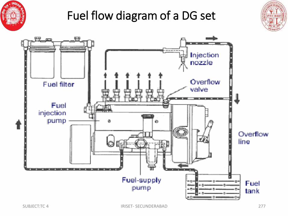
Fuel flow diagram of a DG set
SUBJECT:TC 4 IRISET- SECUNDERABAD 277

• Fuel oil (diesel) from the service tank enters into the diesel
filters. The diesel gets filtered from dirt and dust in the
filters and clean fuel is supplied to the injection Pump. As
each plunger of the pump lifted in the correct sequence,
fuel under high pressure is passed through a steel tube to
the injector. The injector is located in the cylinder head and
sprays the fuel in a misty form into the cylinder.
• Governor: Some form of governor is always fitted to control
the speed of the engine. For constant speed applications, SUBJECT:TC 4 IRISET- SECUNDERABAD 278

• the governor controls the speed automatically within
specified limits under changes of load between no load and
full load. The purpose of governor is to keep the engine
running at a desired speed (RPM)regardless of changes in
the load on the engine.
• Air lock in fuel system: Air lock is the most common
problem that occurs in diesel engines. It leads to starting
trouble and erratic running of the engine. Air lock is nothing
but entry of air into the fuel system whenever the fuel filters
are opened for cleaning and for replacement or whenever SUBJECT:TC 4 IRISET- SECUNDERABAD 279

• the fuel tank gets empty or due to lose fuel delivery pipe
connections. This air enters into the fuel injection pump
(FIP) and restricts the FIP to deliver the fuel under high
pressure in misty form through injectors. This causes the
nozzles to dribble (delivery of fuel in drops) and the
combustion does not take place, as the fuel is not in spray
form. Hence, the engine does not start.
• Procedure to remove air lock:
• a. First fill the diesel tank with diesel if fuel is found less.SUBJECT:TC 4 IRISET- SECUNDERABAD 280

• b. Unscrew the fuel feed pump and operate it until the
pressure is built up.
• c. Screw out the air bleeding screws and operate the pump
till the air from the filter bowls comes out. Then close the
fuel bleeding screws and tighten the fuel feed pumps knob.
• d. Crank the engine and make sure that the air is bled out of
FIP and tighten them when the air is totally bled out of the
fuel system. E) Clean diesel at all joints and on pipes before
starting. Start the DG set and run it for some time to ensureSUBJECT:TC 4 IRISET- SECUNDERABAD 281

• that the fuel system is free from air.
• Lubricating system: - The main function of lubrication
system is to reduce the heat caused by friction, enable the
metal parts slide easily over each other and prevents wear
of engine parts. All moving parts are lubricated and those
parts, which take a heavy load such as the crankshaft,
connecting rod bearings and camshaft bearings, are
pressure lubricated.
SUBJECT:TC 4 IRISET- SECUNDERABAD 282

SUBJECT:TC 4 IRISET- SECUNDERABAD 283
• The lubricating system consists of the following parts: -
• a) Oil sump b) Oil pump c) Relief valve. D) Oil filter
• E) Lubricating oil.

• a)Oil pump: - The pressure is provided by a pump, which has two
gears. The oil on entering the pump is carried through the pump
between the casing and the gear teeth and thus forced into the
system. The oil pump is gear driven from the crankshaft.
• b) Oil sump: The oil sump is located underneath the engine block
and contains lubricating oil. The oil is sent to all parts under
pressure and gets back to the sump after reaching to all the
parts. The dipstick is inserted into the sump through a hole to
check the level of the lubricating oil.
SUBJECT:TC 4 IRISET- SECUNDERABAD 284

• c) Relief valve: - The relief valve is provided for the
adjustment of the lubricating oil pressure delivered by
the pump within limits.
• d) Oil filter: - A coarse oil filter is fitted in front of the pump
to clean the oil before it enters the pump. A second, finer
filter cleans the oil again after it has left the pump and
before it enters the engine. The second filter to the side of
the engine and should be changed or cleaned as per
servicing schedule.SUBJECT:TC 4 IRISET- SECUNDERABAD 285

• e) Oil: Only recommended grades of oil must be used,
otherwise serious damage can be caused. Before starting
the engine, only a little oil in the bearings, but as soon as it
starts a film of oil is forced between the bearings and shafts.
If wrong grade is used the film may not be enough to stop
the shaft touching the bearings or the oil may not enter the
bearings at all. In each case rapid wear results and affects
the performance of the engine
SUBJECT:TC 4 IRISET- SECUNDERABAD 286

• COOLING SYSTEM: The main purpose of the cooling system
is not only to cool the engine, but also to ensure that the
working temperature of the engine is maintained within
limits. Overheating of the engine will result in
• a) loss of fuel due to evaporation.
• b) Distortion of cylinder wall and other working parts.
• c) Overheating of lubricating oil resulting in inefficient
lubrication.
SUBJECT:TC 4 IRISET- SECUNDERABAD 287

• D) If the lubrication between the piston and cylinder wall
breaks down, it will result in scuffing of the piston and
sticking of the piston rings. e) Burning of valves and valve
seats. Hence, the function of the cooling system is to
maintain the proper temperature of the engine under
varying operating conditions. The cooling system used in DG
sets is water cooling system. It consists of Radiator, Coolant,
Thermostat, water pump and a reservoir for coolant. The
coolant is a mixture of distill water and colored chemical.SUBJECT:TC 4 IRISET- SECUNDERABAD 288

Water cooling system in DG set
SUBJECT:TC 4 IRISET- SECUNDERABAD 289

• Let’s assume that the engine just started and is cold. Water
pump inlet and outlet is connected to the engine with help
of rubber hoses. We have thermostat mounted in path of
outlet to the engine. So Water is pumped by this radial
pump through thermostat into the engine water vents.
Thermostat does not allow the water to go into radiator
circuit until engine is at low temperature and water comes
back to pump through outlet hose. Coolant temperature
sensor is mounted just near the thermostat.SUBJECT:TC 4 IRISET- SECUNDERABAD 290

• As water keeps on circulating it extracts heat from the engine
and its temperature rises. As it reaches a temperature between
160 to 190 Fahrenheit, it melts the paraffin wax in thermostat
and opens it up. So now this hot water is circulated through
radiator circuit. Water enters the radiator through inlet port and
exchange it’s heat with air as it flows through number of small
radiator pipes and with help of fins attached to these pipes. But
as engine operates at higher rpm, engine’s temperature goes up,
so does the coolant’s temperature. This coolant gets heated up
SUBJECT:TC 4 IRISET- SECUNDERABAD 291
• to such a high temperature that it would create a high
pressure situation in radiator. If such a high pressure keeps
on increasing it would burst out the radiator pipes, which
we don’t want in any case. So to deal with this pressure we
have pressure cap and a radiator overflow tank. When
pressure in radiator reaches up-to 15 psi of pressure it lifts
up the spring in the pressure cap, thus opening a port for
coolant to be transfer to the radiator overflow tank, thus
keeping pressure in control.SUBJECT:TC 4 IRISET- SECUNDERABAD 292

• When coolant flowing into the overflow tank exceeds its
volume limits it flows out of tank through overflow hose.
When pressure drops in the radiator, it creates a vacuum in
the radiator, thus sucking coolant back to radiator from
overflow tank. That’s why we fill the radiator overflow tank
before going out for a ride. If the level of coolant falls below
minimum limit.
• In engine cooling system, radiator fan starts its operation
when temperature exceeds a particular temperature value.
It helps in lowering the coolant temperature by blowing airSUBJECT:TC 4 IRISET- SECUNDERABAD 293

• through radiator fins thus removing heat at a faster rate
from the coolant. It is regulated by the data from the
coolant temperature sensor.
• Coolant temperature sensor is a multi-purpose sensor as it’s
data is required in optimizing the performance of modern
ECU equipped engines.
SUBJECT:TC 4 IRISET- SECUNDERABAD 294

ELECTRICAL STARTING
• The engine is started by DC starter motor electrically. The
electrical starting system consists of a) Starter motor b) Battery
(usually of 12 V). c) 12v alternator.
• a) Starter motor: - The starter motor is mounted near the
flywheel and its shaft is provided with a small gear (pinion).
When the starter motor is operated, this small gear slides into
the teeth of the flywheel and turns it. When the flywheel turns,
the crankshaft, connecting rod and all operative parts of the
engine begin to move and the engine starts.SUBJECT:TC 4 IRISET- SECUNDERABAD 295

• b) Battery: - The purpose of the battery is to supply required
DC power to the starter motor for starting the engine. It also
supplies power to the control panel for to monitor the
engine parameters. This is usually a 12 volt lead acid battery.
The battery gets charged by the engine driven d.c.
alternator when the engine is running.
• 12v alternator: This is driven by the engine through a pulley
mechanism. It produces 12 V three phase AC and is rectified
and regulated for charging the battery.SUBJECT:TC 4 IRISET- SECUNDERABAD 296

• Main Alternator:
• An Alternator works on Faraday's law of Electromagnetic
Induction. Its main function is to convert the kinetic energy
into electrical energy. It has the following salient parts.
• a) Rotor b) Stator (c) Exciter
• ROTOR
• Rotors are of two types:
• a. Salient pole type
• b. Smooth cylindrical type.SUBJECT:TC 4 IRISET- SECUNDERABAD 297

• STATOR:
• The stator motor is equipped with seal type bearing and
requires no lubrication. stator is insulated on one side with
paper or varnish and house in a frame.
• EXCITER
• The exciter is generally a DC shunt motor or compound
generator whose voltage is 250V. In small alternator, the
exciter is mounted on the same shaft of the alternator.
SUBJECT:TC 4 IRISET- SECUNDERABAD 298

• INSTALLATION:
• The procedure for installation of DG set is recommended as
follows:
• (a) The foundation of Diesel Engine must perform three
functions:
• (i) Support the weight of the Engine.
• (ii) Maintain the Engine in proper alignment with the driven
machinery.
• (iii) Absorb vibrations produced by unbalanced forces.SUBJECT:TC 4 IRISET- SECUNDERABAD 299

• (b) DG sets shall be installed in a separate room of adequate
size with proper ventilation.
• (c) The diesel generator set shall be mounted on anti-
vibration pads.
• (d) The exhaust pipe shall be extended outside the
generator room and the silencer fixed away from the
premises. Exhaust pipe shall be appropriately insulated.
• (e) DG sets shall be installed in a separate room of
adequate size with proper ventilation.
SUBJECT:TC 4 IRISET- SECUNDERABAD 300
• (f) The diesel generator set shall be mounted on anti-vibration
pads.
• (g) The exhaust pipe shall be extended outside the generator
room and the silencer fixed away from the premises. Exhaust
pipe shall be appropriately insulated.
• (h)Where automatic start has been provided, the generator once
started should stop only with a time delay after Main supply is
resumed.
• (i) The connection between the battery and the DG Set shall
SUBJECT:TC 4 IRISET- SECUNDERABAD 301

• be through sufficiently thick wire to avoid drop in voltage.
• SPECIAL ATTENTION ON FOUNDATION:
• (a) DG set foundation should be separated from foundations
of adjoining structures.
• (b) Ground water level should be as low as possible and
should be deeper at least one fourth of foundation below
base plane. This reduces vibrations.
• (c) Any hot piping if embedded in the foundation should
be properly isolatedSUBJECT:TC 4 IRISET- SECUNDERABAD 302

• (d) Foundation must be protected from engine oil by
means of acid resisting coating
• To achieve the above object the engine should always be
installed on a good cement concrete foundation. The
composition for concrete is one part cement, two parts
clean sharp sand and four to five parts of washed ballast.
After pouring, the concrete should be allowed to set for at
least 48 hours. Before engine is bolted down, in very hot.
• and dry climate the block should be moistened with water
during this period.SUBJECT:TC 4 IRISET- SECUNDERABAD 303

• ERECTION:
• The Engine should be leveled up on the foundation block
where the Engine is mounted on superstructures, there
should be rigid construction leveled, before the engine is
bolted down. In case of a direct coupled set, the driven
unit must be lined up with the Engine and joined through a
flexible coupling. In case of a trolley mounted Engine, the
trolley should be parked on the horizontal ground.
SUBJECT:TC 4 IRISET- SECUNDERABAD 304

• MAINTENANCE:
• DAILY:
• (a) Check the lubricating oil level in the sump. Top up if
necessary.
• (b) Keep fuel tank full. The tank should be full completely
with clean fuel oil at the end of day’s work.
• (c) Clean the engine at the end of day’s work. If there are
any leakages, dust will collect at the leaky spots during the
SUBJECT:TC 4 IRISET- SECUNDERABAD 305

• next day’s work. Such leakages should be attended
promptly.
• (d) In case of tank or radiator cooled engines, check the
water level and top up if necessary, before starting the
Engine.
• (e) Run the Engine 5 minutes daily, check working properly
or not.
SUBJECT:TC 4 IRISET- SECUNDERABAD 306

• WEEKLY MAINTENANCE:
• (a)Clean the air cleaner completely
• (b) Clean fuel filter blows.
• (c) Check the electrolyte level in the battery. If required top up
with distilled water.
• (d) Check the cable connection at starter and dynamo.
• (e) Check the belt tension of dynamo/Alternator. It should be 8
to 10 mm, if required adjust it with the help of Tension adjusting
SUBJECT:TC 4 IRISET- SECUNDERABAD 307

• lever.
• (f) The brushes should be examined after every 100/150 hrs.
running to see that they are bedding properly.
• (g) Make sure that the vent hole in fuel tank cap is clear.
• (h) Check nut and bolts tighten if found loose.
• (i) Check the cooling system is perfect or not, if water
cooling, radiator should be full of water. If air cooling, check
belt it should not loose.SUBJECT:TC 4 IRISET- SECUNDERABAD 308

• MONTHLY MAINTENANCE
• (a) Drain the sump, flush out with approved brand or
flushing oil and refill with new oil.
• (b) Thoroughly clean out the fuel tank.
• (c) Clean filter oil bowl.
• (d) Change lubricating oil in the air cleaner after 250 hrs.
Operation.
• (e) Know out spot from the exhaust silencer.
• (f) Clean inlet and exhaust valves, grind valves - decarboniseSUBJECT:TC 4 IRISET- SECUNDERABAD 309

• Cylinder
• (g) After 200 hr. of operation examine bearing.
• (h) Wash out lubrication oil pipes.
• (i) Clean out water spaces in cylinder head and radiator.al
the servicing should be carried out as per periodicity
mentioned in service manual supplied with the DG set.
SUBJECT:TC 4 IRISET- SECUNDERABAD 310

• TROUBLESHOOTING:
• ENGINE FAIL TO START: Possible reason may be:
• a) Dirty clogged air cleaner – clean it.
• b) Check fuel tank, if empty – refill it.
• c) Check air in injection pump – Bleed (as procedure given).
• d) Check pressure valve spring – replace if broken.
• e) Check leakage of fuel in external and internal
connections.
• Check nozzle - if jammed clean or replace it.SUBJECT:TC 4 IRISET- SECUNDERABAD 311

SUBJECT:TC 4 IRISET- SECUNDERABAD 312
• Check fuel filter - clean or replace it.
• ENGINE STARTS BUT STOPS AFTER SOME TIME: Check
• (a) Air cleaner is clogged – clean it.
• (b) No fuel – refuel it.
• (c) Air in fuel line – bleed it.
• (d) Fuel line is choked – clean it.
• (e) Fuel filter is choked – clean it.

• (f) Faulty fuel pump – replace it.
• (g) Water mixed with fuel – change it.
• ENGINE NOT GAINING FULL SPEED
• Possible reasons may be:
• (a) Fuel tank may empty – refuel it.
• (b) Governor spring is broken – replace it
• (c) Dirty choked fuel filter – clean it.
SUBJECT:TC 4 IRISET- SECUNDERABAD 313

• ENGINE NOT GAINING FULL SPEED: Reasons may be:
• (a) Fuel tank may empty – refuel it.
• (b) Governor spring is broken – replace it
• (c) Dirty choked fuel filter – clean it.
ENGINE MISSES DURING OPERATION: Causes may be:
• (a) Air in fuel line – bleed.
• (b) Choked fuel injection holes – clean them.
• (c) Damaged or dribbling nozzle – replace it.
• (d) Faulty fuel pump-replace it.SUBJECT:TC 4 IRISET- SECUNDERABAD 314

• (e) Water mixed with fuel – change it.
• EXCESSIVE SMOKE AT NO LOAD:
• Possible reasons may be:
• (a) Dirty clogged air cleaner – clean it.
• (b) Choked fuel injection holes – clean it.
• (c) Faulty fuel pump – change it.
• EXCESSIVE SMOKE AT FULL LOAD:
• (a) Dirty clogged air cleaner – clean it.
• (b) Poor quality of fuel – use proper grade of fuel.SUBJECT:TC 4 IRISET- SECUNDERABAD 315
• d) Nozzle damaged – replace it.
• Choked fuel injector holes – clear it.
• (f) Faulty fuel pump– replace it.
• (g) Engine overloaded – adjust the load.
• (h) Broken seized/worn-out piston rings – replace them.
• (i) One or more cylinder not working – check and repair it.
• (j) Engine needs overhauling – send for overhauling.
• (k) Choke fuel injector holes – clear it
SUBJECT:TC 4 IRISET- SECUNDERABAD 316

• ENGINE GIVES OUT BLUE SMOKE:
• Possible reason may be:
• (a) Worn-out liner or piston – replace it.
• (b) Wrong grade lubricating oil used.
• (c) Engine used after a long time – ensure weekly starting.
• 8.9.9 ENGINE GIVES OUT WHITE SMOKE
• This is due to: (a) Water mixed with fuel.
SUBJECT:TC 4 IRISET- SECUNDERABAD 317
• ENGINE OVERHEATS:
• (a) Faulty fuel pump – replace it.
• (b) High exhaust back pressure – release the pressure.
• (c) Wrong grade of lubricating oil used. – use fresh.
• (d) Clogged oil passage – clear the passage.
• (e) Faulty relief valve setting – adjust it.
• (f) Loose fan belt – adjust it.
• (g) Air leakage through cowling – repair it.
• (h) Engine oil not changed – change oil.SUBJECT:TC 4 IRISET- SECUNDERABAD 318

• (i) Engine overloaded – adjust the load.
• (j) Broken/worn-out piston rings – replace them.
• (k) Damaged main or connecting bearings – replace them.
• 8.9.11 EXCESSIVE VIBRATIONS:
• (a) Engine needs overhauling – Manufacturer representative
or skilled mechanic should carry out O/H.
• Loose flywheel - tighten it
• (c) Battery run down – Battery to be charge in boost mode
or replace if defectiveSUBJECT:TC 4 IRISET- SECUNDERABAD 319

• EXCESSIVE FUEL CONSUMPTION Possible reasons may be:
• (a) Dirty clogged air cleaner – clean it.
• (b) Poor quality of fuel – use proper grade oil.
• (c) External/internal fuel leakage – checks it and prevent.
• (d) Faulty fuel pump – replace it.
• (e) Engine overloaded – adjust the load.
• (f) Broken worn-out piston rings – replace them.
• Damaged main or connecting bearing – replace them.
• Injector need adjustment – adjust it.SUBJECT:TC 4 IRISET- SECUNDERABAD 320

• VOLTAGE REGULATION IS UNSATISFACTORY
• Possible causes may be:
• (a) Incorrect speed of prime mover – Adjust the speed of
prime mover to correct Value on no load or full load. The
speed should be between 1560-1570 RPM on No Load and
1500 RPM at full load.
• OVERHEATING OF ALTERNATOR::
• Excessive room temp/Improper ventilation-Machine should
be installed in good ventilated room with exhaust fan.SUBJECT:TC 4 IRISET- SECUNDERABAD 321

• (a) Misalignment – Check alignment and adjust.
• (b) Faulty foundation – Reconstruct the foundations and
properly level it.
• (c) Overloading of machine – Check the load Current, if
more than reduce the load.
• (d) Block of ventilation holes – Clean the inlet and outlet
holes.
SUBJECT:TC 4 IRISET- SECUNDERABAD 322

• DO’S AND DON’TS
• DO’S:
• (a) Ensure proper cleaning of air cleaner and fuel filter.
• (b) Before starting ensure full tank of diesel in the tank.
• (c) Connect the load only when generator voltage regulation
is normal.
• (d) Before starting the DG open the door and windows for
proper ventilation.
• (e) Check that engine running without load for few minutes
before stopping.SUBJECT:TC 4 IRISET- SECUNDERABAD 323

• f) After every 100 hrs. running, check brush are bedding
properly and having correct
• pressure.
• (g) Change the lubricating oil periodically or after every 120
hours of running.
• (h) Check the load current is within limit as prescribed in the
machine plate.
• (i) Clean the inlets and outlets ventilation weekly.
SUBJECT:TC 4 IRISET- SECUNDERABAD 324

• DON’TS:
• (a) Don’t mix water into fuel.
• (b) Don’t mix different grades of grease.
• (c) Don’t pour diesel when engine is running.
• (d) Don’t start the engine without checking the level of
lubricating oil.
• (e) Don’t start the engine without opening fuel taps.
• (f) Don’t start the engine with load, first start the engine and
allow it to gain full speed then put the load.SUBJECT:TC 4 IRISET- SECUNDERABAD 325

• (g) Don’t smoke in the Generator room and also don’t keep
inflammable goods in Generator room.
• (h) Don’t forget to clean silencer after every three-six
months positively.
• DUTY CYCLE
• The generating sets should be run for a period of 18 to 20
hours maximum in 24 hours. Codal life of the DG set is 10
Years.
SUBJECT:TC 4 IRISET- SECUNDERABAD 326