Identifying risk issues and research advancements in supply ...
Upload
khangminh22Category
view
0download
0
इ रसेट IRISET
TCS 4
ISDN EXCHANGE AND ADVANCEMENTS

TCS 4
ISDN EXCHANGE AND ADVANCEMENTS
INDIAN RAILWAY INSTITUTE OF SIGNAL ENGINEERING & TELECOMMUNICATION,
SECUNDERABAD - 500017
April 2020
The Material Presented in this IRISET Notes is for guidance only. It does not over rule or alter any of the Provisions contained in Manuals or Railway Board’s directives

TCS 4
ISDN EXCHANGE AND ADVANCEMENTS
INDEX
S.No Chapter Page No 1. ISDN
1.1 Introduction 1.2 Objective 1.3 Advantages 1.4 Tools 1.5 Services 1.5.1 Bearer Services 1.5.2 Tele Services 1.5.3 Supplementary services 1.6 Basic structure of ISDN Architecture 1.7 ISDN Architecture-CPE 1.8 Subscribers equipment connected to the ISDN Line 1.9 ITU-T Standards of ISDN 1.10 ISDN Recommendations from ITU-T
1
2. Services offered by ISDN 2.1 Video Conferencing 2.1.1 Video Conferencing Equipment 2.1.2 Desktop Videoconferencing 2.2 Supplementary services 2.3 Other services 2.4 ISDN features
12
3. Coral Flexicom series and Coral IPx series Exchanges 3.1 Introduction 3.2 System General Description 3.3 Q-Sig Features 3.4 Coral Flexicom Series 3.4.1 Coral Flexicom 200 3.4.2 Coral Flexicom 300 3.4.3 Coral Flexicom 400 3.4.4 Coral Flexicom 5000 3.4.5 Coral Flexicom 6000 3.5 Coral IPx Series 3.5.1 Coral IPx Office 3.5.2 Coral IPx 500 3.5.3 Coral IPx 800 3.5.4 Coral IPx 3000 3.5.5 Coral IPx 4000
177
4. Tadiran Technology- ISDN Exchange Coral Flexicom 6000 4.1 Technology 4.2 Features 4.3 System general Description 4.4 Coral Flexicom 6000 cabinet Structure 4.5 The Control Shelf and control card assignments 4.5.1 Slot coded Keys 4.6 Common control cards and components 4.6.1 MCP-ATS 4.6.2 Group Controller Card 32GC 4.6.3 SAU
30

4.6.4 4/8XMM (optional) 4.6.5 CLA-ATS- Coral link Adapter 4.7 Peripheral Shelf control cards 4.7.1 PB-ATS (Peripheral Buffer) 4.7.2 PBD-ATS (Peripheral Buffer Driver) 4.7.3 PBD24S 4.8 Power Supply cards 4.8.1 PS-ATS 4.8.2 PPS 4.8.3 RPS 4.9 Shared Service and Auxiliary Interface Cards 4.9.1 DTMF Receiver card- DTR 4.9.2 Multi-party Conference Bridge Unit-CNF 4.9.3 iDSP 64 4.9.4 Multi Frequency Code receiver Card -MFR 4.9.5 Voice Storage Unit new -4VSN 4.9.6 Integrated Coral Message Center-iCMC 4.9.7 Auxiliary Card -8DRCF 4.10 Peripheral Cards 4.10.1Station cards 4.10.2Trunk Cards
5. Siemens Hipath 3800 Telephone Exchange 5.1 Introduction of Hipath 3800 and their series comparison 5.2 Siemens Hipath 3800 Exchange Features 5.3 Siemens Hipath 3800 Telephony Features 5.4 Hardware Description 5.5 DECT-Digital Enhanced Cordless Telephony 5.6 Programming
52
6. Questions Bank 58 7. Abbreviations / Acronyms 63 8. References / Websites 65 9. Glossary 66
Prepared by : K. Mohana Krishna, ICP1
Reviewed by : S. M. Hafeez Ali, APT
Approved by : C. Chandrasekhara Sastry, Sr. Prof. Tele
DTP and Drawings : K.Srinivas, JE (D)
Version No. : 1.0, April 2020
No. of Pages : 71
No. of Sheets : 36
© IRISET
“This is the intellectual property for exclusive use of Indian Railways. No part of this publication
may be stored in a retrieval system, transmitted or reproduced in any way, including but not
limited to photo copy, photograph, magnetic, optical or other record without the prior agreement
and written permission of IRISET, Secunderabad, India”
http://www.iriset.indianrailways.gov.in

IRISET 1 TCS4-ISDN Exchanges and Advancements
CHAPTER-1
I S D N
1.1 Introduction: ISDN – Integrated Services Digital Network was introduced in 1979, and is defined as per ITU (T) formerly known as CCITT Red Book. Volume III - Fascicle III.5, Page no.3 “An ISDN is a network, in general evolving from a telephony IDN, that provides end to end digital connectivity to support a wide range of services, including voice and non-voice services, to which users have access by a limited set of standard multipurpose user – network interfaces”. Network -Is a communication carrying system including medium, switching points and proper routing. Networks follow certain protocols for transmission. Digital -The communication is digital upto subscriber’s instrument. But it is also compatible to analog working instruments, though the transmission is in digital mode. Services - Services to subscriber like transmission of speech, image and data. Integrated - All the three services are transmitted simultaneously on a single pair of wires. Speech: 64 kbps. Image: 64 kbps (minimum.) Data: 16 kbps 144 kbps. For framing and other maintenance features = 48 kbps. Total: 144 + 48 = 192 kbps are transmitted and received. ISDN is intended to be a worldwide public telecommunications network to replace the existing telecommunications networks and deliver a wide variety of services. The ISDN is defined by the standardization of user interfaces and will be implemented as a set of digital switches and paths supporting a broad range of traffic types and providing value added processing services. In practice, there will be multiple networks, implemented within the national boundaries, but from the user’s point of view, there will be a single, uniformly accessible, worldwide network. ISDN has emerged as a powerful tool for provision of voice, data and image by means of the existing telephone network. ISDN is being viewed as a logical extension of the digitalization of the network, and most developing countries are in different stages of implementing ISDN. Even subscriber voice is sent in the digital form and so the phone is called a digital phone. An ISDN subscriber can establish at least two independent simultaneous calls on the existing pair of telephone line (basic rate ISDN), whereas only one call Is possible at present. The two simultaneous calls in ISDN can be of any type-speech, data, image or video. The call setup time for a call between two ISDN subscribers will be very short, of the order of 1 to 2 seconds. ISDN will also support a whole new set of additional facilities called supplementary services. The ISDN subscriber will have full connectivity, both nationally and internationally, to other telephone subscribers.

ISDN Exchange
IRISET 2 TCS4-ISDN Exchanges and Advancements
1.2 Objective The objective of the ISDN is to use existing infrastructure of telephone lines and networks and to be able to transmit
✓ Voice
✓ Digital data
✓ Other services like reservations, alarm etc. To provide the user with easy access to a multiplicity of services over a single connection and digitalization up to sub’s premises To form a wide area network that provides universal end-to-end connectivity over digital media, by integrating all transmission services into one without adding new links. 1.3 Advantages:
High speed up to2.048 Mbps High-quality communication. Reliability and security. Better use of existing facility. International standardization. Simplified wiring. Efficiency of network usage. Standard data transport rate.
1.4 Tools: The primary tools of ISDN systems are: Stored Program Control (SPC) Common Channel Signalling (CCS # 7) Digital Networks Open Systems Interconnection (OSI)
SPC was introduced into the telephone exchange with the introduction of the first electronically controlled switching system (in 1957 in Morris, Illionois, USA). In its present, fairly fully developed form SPC involves use of normally quite similar control machines (Computers) operating upon software programs that express diverse switching, signalling and administrative requirement. The software programs operate upon software data describing the configuration details of exchange to establish and control the network connections required. CCS is a method of signalling that concentrates all the management and connection signals relating to each of a multiplicity of communication channels onto a single “common channel”. The introduction of digital transmission and digital exchanges was complemented by the introduction of common channel message based signalling systems, where messages relating to different connections are statistically interleaved on a common channel. ITU-T signalling system No. 7 is the system defined for use between switching nodes.

ISDN Exchange
IRISET 3 TCS4-ISDN Exchanges and Advancements
ITU-T signalling system No. 7 is an extremely powerful common channel signalling (CCS) system, which is fast, reliable, economical and flexible. It is known variously as CCS7, C7 or SS7. It uses variable length messages for communicating signalling information between digital exchange and switching nodes. The CCS7 network architecture can be associated with the underlying voice / data network. The flexibility coupled with the large amount of signalling information that can be carried at 64 kbps, makes SS7 a sine qua non for most of the modern digital communication networks including ISDN, digital mobile systems. The provision of ISDN interface in the exchange presumes the availability of SS7 capability in the exchange for inter exchange signalling. CCS is essential to the ISDN, as it has already provided the communication capacity, speed and protocols to deal with much more complex requirements of ISDN connections or between diverse services. Standardization is an essential tool for the ISDN signalling. Digital Networks: Digitization of the telephone circuits is one of the tools for ISDN working, Which provides higher bandwidth, reliability, speed and flexibility. OSI is an attempt to rationalize and compartmentalize the conversation between the various communicating processors that may be involved in communication activities. The basic idea is to define the communications administrations and improve conditions for compatibility. The ISO’s seven layered OSI model is an important attempt in that direction. 1.5 Services: Telecommunication services are offered by a network operator or service provider and are accessed by users either at an ISDN interface or within a terminal connected to the ISDN. At a general level, ISDN services can be classified into following three categories.
Bearer Services Tele Services Supplementary Services
1.5.1 Bearer services: Bearer services are characterized by a set of low layer attributes. These attributes are classified into three categories:
Information transfer attributes;
1. Information transfer mode 2. Information transfer rate 3. Information transfer capability 4. Structure 5. Establishment of communication 6. Communication configuration 7. Symmetry
Access attributes;
1. Access channel and rate 2. Access protocol

ISDN Exchange
IRISET 4 TCS4-ISDN Exchanges and Advancements
General attributes, including operational and commercial attributes
1. Supplementary services provided 2. Quality of service 3. Interworking possibilities 4. Operational and commercial
Bearer services are capable for transportation of information between ISDN user/network interfaces, describe the transportation between locations. At present, 10 bearer services are fully or partially defined in ISDN. For example, the transportation of a 64-kbps bit stream between specified locations and without modification is a bearer service. The ISDN channel types are standardized as below:
A : Analogue Voice Channel at 4 KHz. B : Digital bearer channel at 64 kbps for voice or data transmission. C : 8 or 16 kbps digital channel. D : 16-bit digital channel for common channel out of band signaling. E : 64 kbps digital channel for internal ISDN signaling. H0 : 384 kbps digital channels. H1 : 1536 kbps digital channels (H11). H2 : 1920 kbps digital channels (H12).
ITU (T) has standardized the following combinations for ISDN working:
Basic Rate : 2 B + 1 D Primary Rate : 30 B + 1 D (E1 system) 23 B + 1D (T1 system) Hybrid : 1A + 1 C
Basic Rate Interface ( BRI): 2 B + 1 D
It is already seen that ISDN system transmits 144 kbps user information and 48 kbps maintenance information.
2B -Two bearer channels – 64 kbps + 64 kbps. 1D - One data channel – 16 kbps.
The 64-kbps transmission is normally known as basic rate transmission as it is the basic output from the telephone termination. The two bearer channels can be used as any of the combinations as given below:
Speech (64 kbps) + Image (64 kbps).
Speech (64 kbps) + Data (64 kbps)
Image (64 kbps) + Data (64 kbps)
Speech (64 kbps) + Speech (64 kbps)
Image (64 kbps) + Image (64 kbps)
Data (64 kbps) + Data (64 kbps) The figure 1.1 shows one twisted copper pair carrying two bearer channels each of 64 kbps and 1 D channel of 16 kbps.

ISDN Exchange
IRISET 5 TCS4-ISDN Exchanges and Advancements
Fig. 1.1 Basic Rate Interface As seen above the data transmitted by ‘B’ (bearer) channel is 64 kbps excluding that of 16 kbps transmitted by ‘D’ channel. So, at any given time 2 B + 1 D, 3 channels can be transmitted.
Speech (64) + Image (64) + Data (16) Speech (64) + Data (64) + Data (16) Image (64) + Data (64) + Data (16) Speech (64) + Speech (64) + Data (16) Image (64) + Image (64) + Data (16) Data (64) + Data (64) + Data (16) Line Coding – The data rate is 192 kbps for trans and 192 kbps for receive. This data rate is reduced to half by using 2B1Q line coding. Hence, the total bit rate on line is 192 kbps including trans & receive. The full duplex is achieved by using 2B1Q code and echo cancellation. There can be some incident that all the 3 channels are transmitting data at a time. D Channel – Data channel normally known as ‘D’ channel, is very powerful. It is normally stated as “ISDN is D Channel and D channel is ISDN”, which indicates the importance of ‘D’ channel for ISDN working. Without ‘D’ channel’s power ISDN can never function. The functions of ‘D’ channel are as below:
Controlling the bearer channels. Common Channel Signaling as per ITU (T)’s CCS #7. Data transmission by packet mode.
a) Controlling the bearer channels: The 1st priority function of ‘D’ channel is to control the transmission of two bearer channels simultaneous on a single copper pair. Again, the transmission is full duplex working.
b) Common channel signaling: ISDN signaling is by common channel as per ITU (T)’s
recommendation of CCS# 7. This gives a great advantage of bearer channel transmission without any disturbance while signal is transmitted. D channel is always alert, even when ‘B’ channels disconnect, keeps security and protocol authentication alive enabling the next call in sequence not to be delayed.
c) Data transmission by packet mode: The capacity of D channel is fully not utilized. Once call
is set up it doesn’t have much function other than call monitoring. It can be made available for user packet traffic when call control is needed it gets priority.

ISDN Exchange
IRISET 6 TCS4-ISDN Exchanges and Advancements
Primary rate interface (PRI):
Fig. 1.2 Primary Rate Interface E1: 30B+1D; T1: 23B+1D 30 B / 23B - Bearer channels. Each of 64 kbps.
To carry data, voice, image, video. 1D - Data (D) channel of 64 kbps.
To carry control information of 30 / 23 bearer channels. To carry common channel signal information of 30 / 23 bearer channels. To carry data in packet switching mode, when free.
1.5.2 Tele services:
It Corresponds to layers 4-7 of OSI model Network may change or process the data. Rely on the facilities of bearer services. Designed to accommodate complex user needs. Includes telephony, teletext, telefax, telex, and teleconferencing. Combine this transportation function with other information processing functions. These
additional information processing functions may be located within a network (public or private), or within user terminal equipment (such as PC).
Provide full capability for communication by means of terminals, network functions and possibly functions provided by dedicated centers.
Example: Telephony, Telex, videotext, message handling, etc., 1.5.3 Supplementary services:
Bearer service and Tele service are basic services of telecommunications, which the subscriber gets when he asks for a communication capability. The supplementary service can only supplement the basic service and consequently cannot be offered as a standalone service, can only be offered in association with a basic telecommunication service.
As an objective, Supplementary service is defined and implemented in a manner independent from the associated Bearer services and Tele services. This allows each Supplementary service to be used in combination with many Bearer services and Tele services, without requiring a special implementation of that Supplementary service in each case. An example would be the methods of requesting and authorizing Reverse charging, which are intended to be the same for an electronic message and a simple voice call.
Example: Calling number identity presentation, call transferring etc.
Some of the supplementary services are

ISDN Exchange
IRISET 7 TCS4-ISDN Exchanges and Advancements
Number identification services:
1. Calling Line Identification Presentation (CLIP) 2. Calling Line Identification Restriction (CLIR) 3. Connected Line Identification Presentation (COLP) 4. Connected Line Identification Restriction (COLR) 5. Malicious Call Identification (MCID) 6. Direct-Dialling IN (DDI) 7. Sub-Addressing (SUB) 8. Multiple Subscriber Number (MSN)
Call offering services:
1. Call Forwarding Unconditional (CFU) 2. Call Forwarding No Reply (CFNR) 3. Call Forwarding Busy (CFB) 4. Call Deflection (CD) 5. Explicit Call Transfer (ECT)
Call completion services:
1. Call Waiting (CW) 2. Hold (HOLD) 3. Call Completion to Busy Subscriber (CCBS)
Multiparty services:
1. Three Party (3PTY) 2. Add on Conference (CONF) 3. Meet me Conference (MMC)
New Supplementary services
1. User to user signalling (UUS) 2. Closed User Group (CUG) 3. Terminal Portability (TP) 4. Remote Control (RC) 5. Outgoing Call Barring -Fixed (OCB-F) 6. Outgoing Call Barring -User Controlled (OCB-UC) 7. Trunk Hunting (TH) 8. Line Hunting (LH) 9. Completion of calls on No Reply (CCNR) 10. Call Forwarding Unconditional to a service Centre (CFU-S) 11. Reverse charging at call setup time (REV(S)) 12. Advice on Charge on user request (AOC-R) 13. Virtual Card Calling (VCC) 14. Selective Call Forwarding (SCF) 15. Universal Access number (UAN) 16. Televoting (VOT) 17. Cordless Terminal Mobility (CTM)

ISDN Exchange
IRISET 8 TCS4-ISDN Exchanges and Advancements
1.6 Basic Structure of ISDN: ISDN standards of structure for user equipment have following three important aspects of the standard.
Functional groups - Functions that may be needed to support a user access arrangement. Reference Points – conceptual points driving functional groups and usually consist of
physical interface and connectors. Access Points – Establish which of the seven OSI layer entities are used at the functional
groups or reference points. 1.7 ISDN Architecture: (Customer Premises Equipment’s) (fig 1.3)
Fig. 1.3 ISDN Architecture
The various components of User Network Interface from the network side are shown in Fig. 1.3. Network Termination 1 (NT1) and Network Termination 2 (NT2) are the equipment’s connected. These equipment’s have definite distinct functions and also it is not essential that there should be both NT1 and NT2, i.e. all the functions of both the NT1 and NT2 can be provided by a single NT. The various functional groups of an ISDN are as given below Network Termination1 (NT1):
This is the group of functions that terminate the transmission line. As such, it is seen in the ITU-T’s recommendations as belong to the network provider, the owner of the transmission line.
A terminal equipment on the subscriber’s loop. Provided at each customer’s premises, connects the subscriber to the ISDN exchange using twisted pair or any other medium. NT1 has a connection on it into which a bus cable can be inserted. Functions of NT1:
Line termination Line maintenance and performance monitoring Timing Power transfer, i.e., Extracting power from line to drive at least the “wake-up” portion of the
terminal Parts of the multiplexing functions.

ISDN Exchange
IRISET 9 TCS4-ISDN Exchanges and Advancements
Network Termination2 (NT2): This is the group of functions that give the terminal its particular “character”. An NT2 is a functional block for switching and/or concentration of internal lines within the subscriber’s premises, could be a PABX if access is primary, a LAN or a terminal controller. As simultaneous several conversations are needed in large business organization, the device NT2 is used prior to NT1 at customer’s premises. Functions of the NT2:
Protocol handling or handling that part of the protocol associated with information transfer across a network
The higher-level parts of the multiplexing function Switching and concentration functions Maintenance functions Termination of the “S” interface, which may include multi drop termination and associated
contention resolution functions Interface functions Is a common termination box, provided in sub’ s premises. The below
given can be terminated in this box: The twisted pair from ISDN or NT1 Up to eight terminals of type TE1 or TE2 or combination of TE1 & TE2
Terminal Equipment – ISDN (TE1): This is the standard terminal of ISDN for digital telephone and G4 facsimile with ISDN function. An end user device that complies with ISDN recommendations.
a) ISDN telephones b) Video phone c) Video conferencing equipment d) Voice mail equipment e) Personal computer with PC add-on card for data Transfer at 64 kbps,
Terminal Equipment – Non ISDN (TE2): This is an ISDN non-standard terminal, uses current technology, and is used for the analog terminals such as
a) Decadic (dial, push button) telephones b) DTMF telephones c) Fax machines d) Modems e) Data port—any PC with RS 232C connection (serial port of the PC) can be connected.
Data up to 9.6 kbps can be transmitted without using modem.
Terminal Adapter (TA): This is used for the connectivity of non ISDN terminal to ISDN network. It converts a non ISDN interface to ISDN interface. To begin with, the existing terminals at the user end will be used for connecting it to the ISDN i.e. existing packet switching terminals which have X.25 protocol for signalling and not the D channel protocol as required for ISDN. The conversion of X.25 protocol to D channel protocol is done by the terminal Adapter (TA). Reference Points:
U Reference Point: The side on the network side, identified as “U” reference point, is owned, administered and maintained by the network operating company, and the premises side owned, administered and maintained by the user. Connection from ISDN exchange to NT1 is either on twisted pair or any other medium.2B/1Q Encoding is used.

ISDN Exchange
IRISET 10 TCS4-ISDN Exchanges and Advancements
T Reference Point: The point between NT1 and NT2 is known as “T” reference point and segregates the operator and user.
S Reference Point: The point between NT2 and TA or NT2 and TE1 is known as the “S” reference point. In case if the NT2 is not used i.e., functions like concentration are not needed. The S and T reference points coincide and is known as “S/T” reference point. Pseudo ternary Encoding is used
R Reference Point: The point between the TE2 and TA is called the “R” reference point.
1.8 Subscriber equipment that can be connected to the ISDN line:
The present-day user is already a subscriber. Telephone through connection to the PSTN, telex through the telex network, data through private and public packet switched data network. ISDN provides different services mainly voice, data and Image transmission over the same connection, the local telephone distribution network, to the subscriber. The concept of the ISDN is fundamentally a concept of integrated access In the ISDN, the telephone line is terminated on a common box, called the network termination, provided at the subscriber premises. Beyond this box, on the internal wiring in the subscriber’s premises, up to eight different types of ISDN / non ISDN terminals can be connected. ISDN terminal equipment’s like personal computer (PC) with add on ISDN card, video phone, video conferencing equipment etc., and non ISDN equipment’s like existing rotary and pushbutton telephones, fax machines, modems, PCs with RS 232 C connections can also be connected to the internal wiring with suitable adapters. Fig 1.4 shows the ISDN subscriber premises installation.
Fig. 1.4 ISDN Subscriber premises installation
The ISDN basic access can support up to 8 voice or data terminals so that the single ISDN access can perform the functions previously requiring a small PABX or key system and a small LAN. In many cases users will find this to be the most effective means to provide such facilities even without taking into account the facilities and service made available by the ISDN itself. 1.8 ITU-T standards for ISDN:
The initial series of ITU-T recommendations, the I –series, were first agreed and published at the end of the 1980-1984 plenary period. Further enhanced during 1984-88 plenary period. Full set of recommendations being published in the blue book. Further enhancements were made and published in 1992. The bulk of the information on the ISDN is contained in the Blue Books (1988 Recommendations) in three volumes, Volume III, Fascicles III.7, III.8 and III.9.

ISDN Exchange
IRISET 11 TCS4-ISDN Exchanges and Advancements
Fig. 1.5 ISDN ITU-T Standards
General Structure : I - 100 series. Service capabilities : I - 200 series Overall network aspects and functions : I - 300 series. ISDN user / Network interfaces : I - 400 series. Inter network interfaces : I - 500 series. Maintenance principles : I - 600 series. 1.10 ISDN RECOMMENDATIONS FROM ITU – T
Title Recommendation Reference Date Fascicle ISDN user – network interface data link layer – general aspects
1.440 [28] Q.920[33] 1993 VI.10
ISDN user – network interface, data link layer specification
1.441[29] Q.921[34] 1993 VI.10
ISDN user – network interface layer 3 – general aspects
1.450[30] Q.930[35] 1993 VI.11
ISDN user – network interface layer 3 specification for basic call control
1.451[31] Q.931[36] 1993 VI.11
Generic procedures for the control of ISDN supplementary services
1.452[32] Q.932[37] 1993 VI.11

Services & Features Offered by ISDN
IRISET 12 TCS4-ISDN Exchanges and Advancements
CHAPTER 2
SERVICES AND FEATURES OFFERED BY ISDN A wide range of services catering for the needs of residential and business subscribers will be offered. Data files between PCs will be transmitted at a high rate of 64 kbps. This is more than six times the typical speeds possible at present.
2.1 Video Conferencing An attractive service of ISDN being offered to customers is video conferencing, which has potential of curtailing travelling requirements of business executives. Videoconferencing can be achieved between any two ISDN customers on dial-up basis on existing telephone lines. Two types of videoconferencing are being offered. For high quality video (384 / 512 kbps), three / four ISDN lines will be required by the customer. In this case, in addition to video image of the participants, still pictures of documents and drawings can also be transmitted. For ordinary videoconferencing (128 kbps), a single ISDN line will be sufficient. 2.1.1 Video conferencing equipment: This equipment consists of a computer, TV monitor, camera and other control units. This equipment will be connected to the network using three ISDN lines. The equipment establishes connection to similar equipment on the other side by dialing through the network. Moving video images of the conference participants can be sent as well as received along with their conversation. It is possible to send diagrams and photographs by a still picture camera. Data transfer can also be done simultaneously. The equipment works at 384 / 512 kbps. In addition, video images can be sent or received on auxiliary equipment, like VCR. Using the control panel, the video camera can be moved or zoomed on the required participant of the conference. The transmitted picture can be viewed along with the received picture. 2.1.2 Desk-top videoconferencing: This is a compact version of the video conferencing equipment, usually PC based. The PC is upgraded by one or two add-on cards. A camera is provided which can be appropriately placed. Only 128 kbps of transmission capacity is required and, therefore, a single basic access ISDN line is sufficient. In any models, it is also possible to transfer files and jointly edit documents. 2.2 Supplementary Services: ISDN will also support a new set of additional facilities, called supplementary services, for speech calls. The following services will be available for calls made between ISDN subscribers. Calling line identification presentation (CLIP): When an ISDN subscriber receives a call, the calling subscriber number will be displayed on his ISDN telephone before the called subscriber answers the call. (The ISDN phone has a small LCD display resembling those available in calculators.) Thus, the subscriber knows the telephone number of the caller from the very beginning, even before answering the call. For example, when the subscriber is already in conversation, he may choose to attend the second incoming call depending on the caller’s number displayed. This service will be provided free of cost of all ISDN subscribers.

Services & Features Offered by ISDN
IRISET 13 TCS4-ISDN Exchanges and Advancements
Calling line identification restriction (CLIR): This service may be provided on subscription by onetime payment. By means of this service, the calling subscriber will be able to prevent the disclosure of his number to the called subscriber (prevention of CLIP). However, this service will be overridden by certain agencies such as police and fire services, since they may need to know the identity of the caller in all cases. Advice of charge (AOC): The amount charged for a call, in terms of call units, will be displayed on the calling subscriber’s ISDN phone. In case of long-distance calls, it is possible to see the count of metering pulses incremented for this call. This will be continuously updated as the call is in progress. Multiple subscriber number (MSN): As up to eight terminals can be connected in parallel on the subscriber premises wiring, to call a specific terminal (PC to call a PC, and phone to call a phone), separate number can be allotted to each terminal. This will be particularly useful when the call is received from a normal (analogue) subscriber. In case call is received from an ISDN subscriber, the terminal selection will be automatically made. Call forwarding services (CF): The call to a subscriber can be forwarded to another number under different criteria like, subscriber being busy or no answer. Calls can be forwarded unconditionally also (CFB, CFNR, CFU). Call forwarding busy (CFB): If the called subscriber is busy, the incoming calls to his number can be diverted to another number specified by him. Call forwarding no answer (CFNR): If the called subscriber is not available or does not answer the call, the incoming calls to his number can be diverted to another number specified by him after a few rings. Call forwarding unconditional (CFU): All the incoming calls to a subscriber can be diverted to another number specified by him. The ring directly goes to the diverted number in this case. Terminal portability (TP): In the subscriber premises up to eight terminals can be connected to a single ISDN line. These terminals can be in different rooms and also can be on different floors. The internal wiring in the subscriber premises is terminated on sockets. During conversation, it is possible to transfer the call from one terminal to another or even remove the terminal and connect it to another socket at a different location. This facility is available for calling as well as called subscriber. Call hold (CH): During conversation, it is possible to hold at least two more calls. The subscriber can switch between these calls. Closed user group (CUG): Companies with offices in different cities can have their ISDN number in a closed user group. The subscribers can call each other using short numbers as if they are connected to a PABX. This group enjoys certain calling privileges like selective call barring and additional level of security. ISDN phone: This terminal, in addition to having a handset and dialing key pad, also has an LCD display, additional key for storing frequently dialed numbers and other function keys.
Services & Features Offered by ISDN
IRISET 14 TCS4-ISDN Exchanges and Advancements
(i) Display: The ISDN phone has an LCD display resembling those available in calculators. The number dialed is displayed, so that the caller can leisurely enter the digits without mistake. This reduces wrong calling. In case of CLIP services, the calling number is displayed. In case of AOC, the number of call units charged is displayed. This is also used for programming of MSN, CF, etc. In addition to providing tones on the status of the call (dial tone, busy tone, ringing tone, routing tone, etc), status is also displayed. This combined with speaker phone facility provides true hands-free operation.
(ii) Logging: The logging facility provides for automatic storing of calling subscriber’s number, when the call could not be answered. The calling number can be recalled using the log.
Other facilities like redialing, memory dialing and speaker phone are also available. The phone is also called digital phone, since signals are transmitted and received in digital form. So the phone provides clear and noise-free conversation. In ISDN, the line condition is always checked continuously, so that any fault in the line is immediately detected. Terminal Adapter (TA): The existing analog terminals like rotary and push button telephones, modems, PCs, modems and fax machines can be connected to ISDN through terminal adapter. This is a quick solution to extend ISDN features to non-ISDN terminals. The TA provides ISDN line connectivity on one side and variety of connectors on the other side.
1. Analogue connector: Rotary & pushbutton telephones (pulse type or tone type), modems, fax, answering machines, cordless phones etc. can be connected.
2. Data port: Any PC with RS232C connection (serial port of the PC) can be connected to this port. Data transfer using standard software packages like X - talk or ProComm is possible up to 9.6 kbps. Modem is not required.
PC Add on ISDN card: This card can be fitted in standard PCs and can be used for data transfer at 64 kbps. This card fits into vacant slot of any standard 386 / 486 / Pentium PC. Software is also provided, which will be installed in the PC. The connector from the PC is connected to the ISDN line. Using the software, files from the PC can be transmitted or received at 64 kbps. Using both the B channels, it is possible to send data at 128 kbps. 2.3 Other services:
Negligible noise as digital working. Information of call in progress. Faster data rate. Full duplex working.
2.4 ISDN Features: CTI – computer telephony integration link: This provides open architecture interface to the call processing and management circuitry. CTI effectively merges telephone and computer systems in single environment. This system is useful for IVRS working. ACD – Automatic Call Distribution:
ACD applications effectively handle high volume of incoming calls by a variety of sophisticated and customized routing, queuing and management features.

Services & Features Offered by ISDN
IRISET 15 TCS4-ISDN Exchanges and Advancements
CAP – Computerized Attendant Position:
This permits efficient access to station, trunk and features of ISDN system. Cap effectively reduces the time needed to perform routine attendant functions, such as
transfer, hold etc. Cap incorporates universal directory which can contain both internal and external stations.
Additional PRI:
No need of extra D channel. It can cater for one and more PRI interfaces.
Additional PRI can accommodate 31 bearer channels Qsig:
Qsig private networking features. Qsig specifications for private network features signalling between PABX systems enables
two or more separate exchanges may be linked through ISDN facilities to form a single unified logic system.
VoIP- Voice Over IP
The telecommunications costs can be significantly reduced by rerouting interoffice traffic over your LAN/WAN with the VoIP. International conversations can be made for the cost of a local call - regardless of distance. Services and applications can also be enhanced by using IP network solutions in such areas as collaborative applications, conferencing, one number calling, unified messaging, call centers, web call centers, video applications, and network integration with the front office and back office databases and servers. The most important benefits IP networking provides are:
Reduced communication costs by sending voice, data, and fax over IP No need to maintain separate infrastructures for voice, data, and fax traffic Maximum transmission capacity by using one “pipe” for voice, data, and fax
Wireless Digital Station System
On-premise micro-cellular digital wireless system for full mobility of users within a building or campus environment, complete with handover and roaming. It should operate in several wireless bands and standards as the US ISM 2.4 GHz frequency band or DECT 1880-1900 MHz. Audio Conferencing
Efficient and effective conferencing is the key to fast decision making in a dynamic “face-to-face” environment without the need for costly and time-consuming meetings with their accompanying expenses of travel and accommodation. There are three kinds of Coral conferencing. These are usually referred to as:
Meet-Me Conference – a dial-in teleconference. All participants dial a single number at the appointed time in order to “meet,” and the conference begins.

Services & Features Offered by ISDN
IRISET 16 TCS4-ISDN Exchanges and Advancements
Add-On Conference – allows the conference initiator to call another person and add him as a participant. The initiator begins the conference by calling participants and transferring them to a designated conference bridge.
Group Call – enhanced features for full conference management. The initiator dials the “Enhanced Conference” feature, which generates a call to all preset conference members and automatically adds them to the conference bridge.
Voice mail Simple yet powerful unified messaging system that can greet callers and record internal user messages. ISDN should deliver all the messages, voice and e-mail into a universal mailbox, where the user can manage them from almost anywhere by phone or computer Remote shelf The remote shelf should be the integral part of the switching host system and should support for connecting at other end system. It should able to configured without impacting traffic on the host system. Remote locations should be connected via fiber optic cables, which is located up to 21 miles (35km) from the host system cabinet without intermediate regenerator equipment.

Coral FLEXICOM 6000
IRISET 17 TCS4-ISDN Exchanges and Advancements
CHAPTER-3
CORAL FLEXICOM SERIES & CORAL IPX SERIES 3.1 Introduction Tadiran make a range of products that suit customers of varying sizes from SME (Small Medium Enterprise) to large corporate customers. As a Global Multimedia Switching Platform, the Coral IPx and the Coral FlexiCom systems are built to meet the ever-changing demands of today’s enterprise. Built by a worldwide leader in advanced telecommunications solutions, Coral represents the cutting edge in state-of-the-art, software-controlled, digital voice, data, and video communications switching systems. The Coral is an IP converged communications platform and offers all the features and capabilities required in today’s business environment. Coral delivers a full complement of advanced call management features; powerful networking full range of IP based as well as legacy digital endpoints to take advantage of local and wide area converged services. The system includes robust support for: Features IP converged PBX (PUGW, MRC) VoIP (Voice over Internet Protocol) SIP/MGCP connectivity ISDN (Integrated Services Digital Network) gateway PSTN (Public Switched Telephone Network) gateway QSIG Networking (over ISDN and IP) CTI (Computer-Telephony Integration) ACD (Automatic Call Distribution) Composit Express/Pro Call Centers (Automatic Voice Call and Data Screen Distribution) Intelligent Call Routing Audio and Video Conferencing FlexLITE (remote peripheral switching) Digital Wireless telephones (DECT 1880-1900 MHz frequency band or in the US ISM 2.4 GHz) etc. 3.2 System general description: The Coral FlexiCom is a series of wall-mounted and free-standing systems available in various cabinet configurations. The cabinets range in size from the compact Coral FlexiCom 200, the mid-sized Coral FlexiCom 400, all wall-mounted; to the expandable Coral FlexiCom 5000 and Coral FlexiCom 6000, using free-standing cabinets. All of the Coral’s power and sophistication is available in each Coral FlexiCom system. The Coral Flexicom operation is supervised by highly efficient, stimuli-controlled call management Software with a 32-bit main processor INTEL 80386, hierarchical processor located in every peripheral card and in every digital telephone set. System of distributed processing is Utilized for efficient working. Operating software is stored in flash ROM, providing excellent long-term stability and flexibility to update. Database stored in battery protected SRAM. The system employs Universal Card Slot Concept, i.e., any peripheral interface card slot can accept any peripheral card without scarifying the system capacity. The slots are self-programmable by default as per the cord introduced. Even the ports are self-programmable by

Coral FLEXICOM 6000
IRISET 18 TCS4-ISDN Exchanges and Advancements
default, according to the type of card kept in the slot. Dual Linear Serial bus design is used to carry the control, voice, data signals throughout the system. Every signal is assured alternate route with in system. Fully digital key telephone sets using a single station pair are available with 12 or 28 programmable buttons, digital signal processor (DSP), audio system, built in speaker phone, optional 48- or 80-character alphanumeric display. Programmable button expansion modules add 40 buttons each for upto 144 buttons per telephone set. With simple 12 button DSP, voice announcement, back ground music, voice / data features are available. CoraLITE is a Fibre Optic Remote Shelf. Allows complete system integration with shelves of the system operating at distant places. The automatic call distribution (ACD) application effectively handles high volume of incoming calls by customized routing, queuing and management features. ACD automatically routes calls to all agents in a CTI - Linked ACD or call centre environment. The Computerized Attendant Position (CAP) permits fast, efficient access to stations, trunks and features of the coral Flexicom system. The CAP can efficiently reduce the time needed to perform the routine attendant functions. The standard generic features software provided with every coral Flexicom system is complete and self-contained, with an extensive feature complement. Coral Flexicom system design is based on a principle of open architecture. The examples are CoraLINK, third party CTI link over an ETHERNET bus. CORALINK complies with ECMA standards 179 and 180 and is compatible with the Novell TSAPI. The Coral IPx series includes the 500, 800, 3000 & 4000 models which roughly relate to the numbers of ports that can be used on the system. These systems, as opposed to the FlexiCom series, are all rack mountable. There is also the IPx Office which is an all-in-one box which includes an optional router and wireless LAN that enables a small business a complete solution. All these systems run the same software and include the same features across the entire range enabling customers to upgrade with minimal cost. The IPx line uses three different size cards, one for the Office, a second for the IPx 500 and third for the IPx 800/3000/4000. 3.3 Q-SIG Features:
Calling number indication CLIP / COLP Transmission of name NA Automatic call back CCBS / CCNR Call forwarding CFB / CFNR / CFU Transferring a connection CT Camp on busy A sub CO Transmission of tariff units AOC Path optimization PR Transparent forwarding to external protocol GF Private phone number plan PTNA (The number list should be matched)

Coral FLEXICOM 6000
IRISET 19 TCS4-ISDN Exchanges and Advancements
3.4 Coral Flexicom Series: 3.4.1 Coral Flexicom 200: The Coral FlexiCom 200 is a digital communication switching system based on Pulse Code Modulation (PCM) switching technology. The active circuitry of the system is contained on a mother board and removable cards. SPECIFICATIONS Installation Options : Wall mounted, Table-Top or Rack-Mounted. Microprocessor (Simplex) : 32-bit Microprocessor INTEL 80836 Capacity : 50,000 BHCA Storage : flash ROM Flash Memory : IMC 4MB Group Controller : SVC Main control processor : MCP-IPx2 Max Ports : 278+ including Stations and Trunks Traffic Capacity : 128 time slots Common control Set : Single Operating temperature : 00C to 400C Power Input : 115/230V AC, 60/50 Hz, 12V/24V DC-battery Plant Power Consumption : 150W (Base), 150W (Expansion) No. of Shelves : 1 Base Unit and 2 Expansion Unit.
Fig. 3.1 Coral Flexicom 200 Base Cabinet

Coral FLEXICOM 6000
IRISET 20 TCS4-ISDN Exchanges and Advancements
3.4.2 CORAL FLEXICOM 300: The Coral FlexiCom 300 offers outstanding value in a compact system. This configuration offers all of the sophisticated features of the 32-bit Coral FlexiCom system in a compact, low cost version that is suitable for systems of 20 to 96 stations. The Coral FlexiCom 300 may contain a total of up to ten Shared Service and Peripheral interface cards, with a maximum of 96 station and 56 trunk ports. A self-contained power supply allows the system to operate from any 115/230VAC power source. SPECIFICATIONS Installation Options : Wall mounted Microprocessor (Simplex) : 32-bit Microprocessor INTEL 80836 Capacity : 50,000 BHCA Storage : flash ROM Flash Memory : IMC 8MB Group Controller : SVC-24 Main control processor : MEX-IP2 Max Ports : 150+ including Stations and Trunks Traffic Capacity : 128 time slots Common control Set : Single Operating temperature : 00C to 400C Power Input : 115/230V AC, 60/50 Hz Plant Power Consumption : 275VA No. of Shelves : 1 Base Unit
Fig. 3.2 Coral Flexicom 300 Cabinet 3.4.3 CORAL FLEXICOM 400 The Coral FlexiCom 400 configuration offers greater capacity and flexibility than the Coral FlexiCom 300 cabinet, yet the wall-mount system remains compact and low-cost. The system is cost effective for applications of 40 to 300 stations. The system can be operated from a standard, –48VDC battery plant, or 115/230VAC. It may be used as remote peripheral card shelves when linked to a Coral IPx 4000 or Coral FlexiCom 6000 host cabinet.

Coral FLEXICOM 6000
IRISET 21 TCS4-ISDN Exchanges and Advancements
SPECIFICATIONS Installation Options : Wall mounted Microprocessor (Simplex) : 32-bit Microprocessor INTEL 80836 Capacity : 50,000 BHCA Storage : flash ROM Flash Memory : IMC 8MB Group Controller : HDC Main control processor : MEX-IP2 Max Ports : 384+ Stations and Trunks for 48VDC, 240+ for AC Traffic Capacity : 512 time slots non-blocking Common control Set : Single Operating temperature : 00C to 400C Power Input : 115/230V AC, 60/50 Hz Plant or -48V Power Consumption : 350W No. of Shelves : 1 Base Unit
Fig. 3.3 Coral Flexicom 400 Cabinet 3.4.4 Coral Flexicom – 5000 Coral FlexiCom 5000 supports configurations of up to 256 card slots, giving the system capacity for growth to 6,000 ports with a minimum traffic capacity of 100,000 BHCA. Coral FlexiCom 5000 systems in exceptional demands. It can be upgraded with call processing power in excess of 250,000 BHCA (Busy Hour Call Attempts), A 64-bit processor and ATS (Advanced Telecommunications System), provides speed and power. SPECIFICATIONS Installation Options : Floor Standing Microprocessor (Simplex) : 32-bit Microprocessor INTEL 80836 Capacity : 1, 00,000 BHCA Storage : flash ROM Flash Memory : IMC 16MB

Coral FLEXICOM 6000
IRISET 22 TCS4-ISDN Exchanges and Advancements
Group Controller : 4GC Main control processor : MEX-IP2 Max Ports : Single 3000, Dual 6000 Traffic Capacity : Single 512 time slots and Dual 1024 time slots Common control Set : Single/Dual Operating temperature : 00C to 400C Power Input : -48V DC Power Consumption : 710W (3 shelf), 1060W (4 shelf) No. of Shelves : 16 peripheral shelves including Remote shelves
Fig. 3.4 Coral Flexicom 5000 Main Cabinet

Coral FLEXICOM 6000
IRISET 23 TCS4-ISDN Exchanges and Advancements
3.4.5 Coral flexicom 6000 Refer chapter no.4 Coral FlexLITE Remote Control Systems: The FlexLITE remote peripheral shelf link is established via a pair of cards which contain the interface between the host Coral FlexiCom 6000 signal busses and the fiber optic cables as follows: FLMM (FlexLITE Motherboard Master) card with one or two FLMI or FLSI (optical fiber interface) baby-cards is installed at the Coral FlexiCom 6000 system. FLMS (FlexLITE Motherboard Slave) card with one or two FLMI or FLSI (optical fiber interface) baby-cards is installed in the remote Peripheral Shelf. Front panel connectors on each FLMI or FLSI baby-cards provide the mechanical and optical interface to the optical fibers which establish the digital link between the FLMM and FLMS cards. Each remote peripheral unit (Coral FlexiCom 400 cabinet, IPx 3000XE/XO pair cage or FlexiCom 5000 expansion shelf pair) requires its own FLMM and FLMS card pair. Optical fiber interface baby-cards, installed on the FLMM and FLMS cards, are available in two versions, covering two distance ranges, as follows: FLMI (FlexLITE Multi-mode Interface) cards for typical applications, use economical LED optical transmitters that can operate at distances of up to 1.24 miles (2km) over low-cost multi-mode fiber. FLSI (FlexLITE Single-mode Interface) cards for greater distances, use a high-power laser optical transmitter to span lengths up to 21 miles (35km) using high grade single-mode optical fiber. Two optical fibers are required for each FlexLITE remote unit. CORAL exchanges are marketed in India by BPL and HCL

Coral FLEXICOM 6000
IRISET 24 TCS4-ISDN Exchanges and Advancements
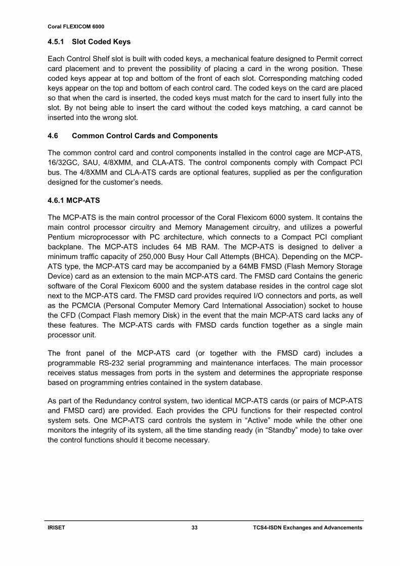
Fig. 3.5 FlexLITE Remote Shelf Interface Configurations for Coral FlexiCom 6000 3.5 Coral IPx series 3.5.1 Coral IPx Office The Coral IPX Office is the ultimate Communications Solution in One Box, the heart of the Coral IPx Office’s modular design, flexible architecture and 32-bit Intel processor. With a capacity of up to 50,000 BHCA (Busy Hour Call Attempts). It can be table or rack-mounted. The unit is completely self-contained and fan-cooled. The primary cabinet is known as the main unit (IPx Office). This unit houses the MCB Office card, MRC card, SAU unit, DBM-X card, NTU Office and WiFi cards, and five peripheral and shared service cards. IPx Office expansion units have four peripheral card slots that provide an additional 108 ports to the system. A maximum of two expansion cages can be included in each IPx Office system, bringing the total number of wired ports per system up to 294.

Coral FLEXICOM 6000
IRISET 25 TCS4-ISDN Exchanges and Advancements
SPECIFICATIONS
Installation Options : Table or Rack Mounted Microprocessor (Simplex) : 32-bit Microprocessor INTEL 80836 Capacity : 50,000 BHCA Storage : flash ROM Flash Memory : IMC 8/16MB Group Controller : Embedded GC Main control processor : MEX-IP2 Max Ports : 48 stations,60 dig. Trunks (main unit) and 48 stations,60 dig. Trunks (Expansion unit) Traffic Capacity : Non-blocking Common control Set : Single Operating temperature : 00C to 400C Power Input : -48V DC or 100-240V AC, 47-63Hz Power Consumption : 160W main unit, 160W (each expansion unit)
Fig. 3.6 Coral IPx Office Main Unit 3.5.2 Coral IPx 500
IPx 500 is a modular design, flexible architecture and 32-bit Intel processor. With a capacity of up to 50,000 BHCA (Busy Hour Call Attempts). These cabinets can be wall-mounted or rack-mounted. The cabinet is completely self-contained and convection cooled. The primary cabinet is known as the Main cabinet (IPx 500M). This cabinet houses the central processor, and some eight peripheral cards. The capacity can be extended through the addition of up to two Expansion cabinets (IPx 500X) to the main cabinet. SPECIFICATIONS
Installation Options : Wall or Rack Mounted Microprocessor (Simplex) : 32-bit Microprocessor INTEL 80836 Capacity : 50,000 BHCA Storage : flash ROM Flash Memory : IMC 8MB Group Controller : HDC Main control processor : MCP-IPx2 Max Ports : 192+ main, 240+ expansions, Total 672+ Traffic Capacity : 384 Common control Set : Single Operating temperature : 00C to 400C Power Input : -48V DC or 100-240V AC, 47-63Hz Power Consumption : 460W per cage No. of Shelves : 3 Cages

Coral FLEXICOM 6000
IRISET 26 TCS4-ISDN Exchanges and Advancements
Fig. 3.6 Coral IPx 500 Main Cage 3.5.3 The Coral IPx 800 The Coral IPx 800 configuration offers greater capacity and rack-mounted system. The system is cost effective for applications of 40 to 720+ stations. Coral IPx 800 can operate directly from a 48VDC power source Utilizing efficient, high-frequency, switch-mode power supplies. SPECIFICATIONS Installation Options : Rack Mounted Microprocessor (Simplex) : 32-bit Microprocessor INTEL 80836 Capacity : 50,000 BHCA Storage : flash ROM Flash Memory : IMC 8MB Group Controller : HDC Main control processor : MEX-IP2 Max Ports : 192+ main, 264+ expansion, Total 720+ Traffic Capacity : 384 Common control Set : Single Operating temperature : 00C to 400C Power Input : -48V DC or 100-240V AC, 47-63Hz Power Consumption : 575W per cage No. of Shelves : 3 Cages

Coral FLEXICOM 6000
IRISET 27 TCS4-ISDN Exchanges and Advancements
Fig. 3.6 Coral IPx 800 Main Cage 3.5.4 The Coral IPx 3000 Coral IPx 3000 supports configurations of up to 178 card slots, giving the system capacity for growth to 4,272 wired ports with a minimum traffic capacity of 100,000 BHCA (Busy Hour Call Attempts). The Coral IPx 3000 easily supports applications of up to 6,000 stations or 3,400 Coral FlexSets, including FlexAir wireless and IP ports. It can operate directly from a 48VDC power source.

Coral FLEXICOM 6000
IRISET 28 TCS4-ISDN Exchanges and Advancements
Fig. 3.6 Coral IPx 3000M Main Cage with Even and odd expansion cage SPECIFICATIONS
Installation Options : Rack Mounted Microprocessor (Simplex) : 32-bit Microprocessor INTEL 80836 Capacity : 1, 00,000 BHCA Storage : flash ROM Flash Memory : IMC 16MB Group Controller : 4GC Main control processor : MEX-IP2, duplicated Max Ports : single: 2136+, Dual: 4272+ Traffic Capacity : Single 512 time slots and Dual 1024 time slots Common control Set : Single/Dual Operating temperature : 00C to 400C Power Input : -48V DC or 100-240V AC, 47-63Hz Power Consumption : 575W per cage No. of Shelves : 16 Cages

Coral FLEXICOM 6000
IRISET 29 TCS4-ISDN Exchanges and Advancements
3.5.5 The Coral IPx 4000
The Coral IPx 4000 is a natural development of the advanced Coral IPx 3000 system. A free-standing, floor mounted Main cabinet. It is a 64-bit processor and ATS (Advanced Telecommunications System), provide speed and power. With call processing power in excess of 250,000 BHCA (Busy Hour Call Attempts), the High-Performance Coral IPx 4000 easily supports applications of up to 6,000 stations or 3,400 Coral FlexSets, including FlexAir wireless and IP ports. SPECIFICATIONS
Installation Options : Floor Standing Cabinet Microprocessor (Simplex) : 64-bit Microprocessor Capacity : 2,50,000 BHCA Storage : flash ROM Flash Memory : CFD 64MB+ Group Controller : 32GC Main control processor : MCP-ATS, Redundant Hot standby Max Ports : 4224+ Traffic Capacity : 3000 Time slots Common control Set : Single/Dual Operating temperature : 00C to 400C Power Input : -48V DC Power Consumption : 280W 4000C, 575W Each expansion. No. of Shelves : 16 Cages
Fig. 3.6 Coral IPx 4000 Main Cabinet

Coral FLEXICOM 6000
IRISET 30 TCS4-ISDN Exchanges and Advancements
CHAPTER-4
TADIRAN TECHNOLOGY ISDN EXCHANGE – CORAL FLEXICOM 6000
4.1 Technology: Coral Flexicom 6000 developed by Tadiran Telecom of ISRAEL with High traffic handling Processor (2,50,000 BHCA) for large businesses needing 6000 Ports. 4.2 Features: Q SIG (International networking Protocol standard) features transparent networking. ISDN applications, which includes BRI, PRI Computer Telephony Integration (CTI) Hospitality Industry Automatic Call distribution (ACD) Automatic route selection Wireless, cellular communications Computerized Attendant Position (CAP) Fibre optic remote shelf Networking ability Sophisticated Feature Transparencies Expansion into Broad band ISDN Coralink from external business center Voice mail Video conferencing Packet and DSO channelized data transport
4.3 System general description: The Coral FlexiCom 6000 is a digital, hot standby, redundant, communications switching system. The Coral system is based on Pulse Coded Modulation (PCM) switching technology. The active circuitry of the system is contained on removable printed circuit assemblies, or cards, nearly all of which may be used in any system in the family. The active circuitry of the Coral system is divided into two major functions: Common Control and Peripheral. The Common Control circuitry directs call traffic through the system, establishing audio connections between Peripheral ports. The Peripheral circuitry provides the hardware necessary to establish those connections. Instructions from the Common Control circuitry to the Peripheral circuitry, and status information from the Peripheral circuitry to the Common Control circuitry are passed through the Group Controller, which is considered neither Common Control nor Peripheral. The peripheral circuitry is further divided into Shared Service and Peripheral Interface functions. The Shared Service circuitry provides the equipment necessary to establish calls between Peripheral interfaces. The Peripheral Interface circuitry provides standardized electrical connections to external telephone station equipment and network facilities.

Coral FLEXICOM 6000
IRISET 31 TCS4-ISDN Exchanges and Advancements
The main elements in the Coral Flexicom 6000 system are as follows: Two sets of control cards providing two fully functional sets of control systems Proprietary Mirrored Memory and Switching Matrix technology built into the circuitry Programming software A motherboard supporting two sets of control systems Dual peripheral buffer units Dual power supply units The operating software stored in the CFD (Compact Flash memory Disk) of both control
system sets, provides complete long-term stability. Database program is stored in battery-protected SRAM in the appropriate components of
both control system sets. All generated data stored in the memory of the “Active” control system is automatically
recreated in the corresponding component in the “Standby” control system, ensuring rapid and seamless system changeover, fail-safe storage, and database dependability
In the event that the second or “Standby” control system must take over control, all communications activities continue unobstructed as if a single system has been in control all along.
4.4 Coral Flexicom 6000 Cabinet Structure The Coral Flexicom 6000 builds on a proven free-standing, floor mount main cabinet, serving as the system’s foundation. Each system consists of one Main cabinet, which houses the Coral Flexicom 6000 Control Shelf and Peripheral Shelves and one or more optional Expansion cabinets. The Coral Flexicom 6000 Control Shelf is easily accommodated into a standard Coral Flexicom 5000 main cabinet. Its size and dimensions are interchangeable with the Coral Flexicom 5000 Common Control Shelf. Figure 5.1 shows the Coral Flexicom 6000 system’s floor mounted structure and card slot assignments for a 4-shelf cabinet. 4.5 The Control Shelf and Control Card Assignments The Control Shelf is positioned at the bottom of the main cabinet. The Control Shelf is built to provide two sets of slots for the components required for the two common control systems. The Control Shelf is divided in half to provide corresponding slots on the Left and Right sides for each set of control system components to reside. A single motherboard, the MBC-ATS, serves both sets of common control systems. There are two sets of control cards standing side by side. Each set has seven slots. The control cards on the right side are duplicated on the left side in reverse and upside-down order. Each side consists of the following card slots placed in the order from the middle outward:
16GC or 32GC (+SAU) CLA-ATS (Optional) FMSD (for CLA-ATS Optional) MCP-ATS FMSD (for MCP-ATS Optional)

Coral FLEXICOM 6000
IRISET 32 TCS4-ISDN Exchanges and Advancements
Fig 4.1 Coral Flexicom 6000 system 4 shelf configuration
Card types are marked over each of the card slots. Upon first initializing the system, the control system set on the right side is designated as the “Active” operational control system, and the control system set on the left is designated as the “Standby” control system. Three slots are provided for Power Supply units, indicated in the figure as PS1, PS2 and PS3. Power Supply fuses are located in the upper left corner. The Fan tray and three fan fuses are located at the bottom of the Control Shelf.
Fig 4.2 Coral Flexicom 6000M/R Dual Control Shelf – Front View
Coral FLEXICOM 6000
IRISET 33 TCS4-ISDN Exchanges and Advancements
4.5.1 Slot Coded Keys Each Control Shelf slot is built with coded keys, a mechanical feature designed to Permit correct card placement and to prevent the possibility of placing a card in the wrong position. These coded keys appear at top and bottom of the front of each slot. Corresponding matching coded keys appear on the top and bottom of each control card. The coded keys on the card are placed so that when the card is inserted, the coded keys must match for the card to insert fully into the slot. By not being able to insert the card without the coded keys matching, a card cannot be inserted into the wrong slot. 4.6 Common Control Cards and Components The common control card and control components installed in the control cage are MCP-ATS, 16/32GC, SAU, 4/8XMM, and CLA-ATS. The control components comply with Compact PCI bus. The 4/8XMM and CLA-ATS cards are optional features, supplied as per the configuration designed for the customer’s needs. 4.6.1 MCP-ATS The MCP-ATS is the main control processor of the Coral Flexicom 6000 system. It contains the main control processor circuitry and Memory Management circuitry, and utilizes a powerful Pentium microprocessor with PC architecture, which connects to a Compact PCI compliant backplane. The MCP-ATS includes 64 MB RAM. The MCP-ATS is designed to deliver a minimum traffic capacity of 250,000 Busy Hour Call Attempts (BHCA). Depending on the MCP-ATS type, the MCP-ATS card may be accompanied by a 64MB FMSD (Flash Memory Storage Device) card as an extension to the main MCP-ATS card. The FMSD card Contains the generic software of the Coral Flexicom 6000 and the system database resides in the control cage slot next to the MCP-ATS card. The FMSD card provides required I/O connectors and ports, as well as the PCMCIA (Personal Computer Memory Card International Association) socket to house the CFD (Compact Flash memory Disk) in the event that the main MCP-ATS card lacks any of these features. The MCP-ATS cards with FMSD cards function together as a single main processor unit. The front panel of the MCP-ATS card (or together with the FMSD card) includes a programmable RS-232 serial programming and maintenance interfaces. The main processor receives status messages from ports in the system and determines the appropriate response based on programming entries contained in the system database. As part of the Redundancy control system, two identical MCP-ATS cards (or pairs of MCP-ATS and FMSD card) are provided. Each provides the CPU functions for their respected control system sets. One MCP-ATS card controls the system in “Active” mode while the other one monitors the integrity of its system, all the time standing ready (in “Standby” mode) to take over the control functions should it become necessary.

Coral FLEXICOM 6000
IRISET 34 TCS4-ISDN Exchanges and Advancements
Fig 4.3 Front View of Coral Flexicom MCP- ATS Card
4.6.2 Group Controller Card 32GC: The 32GC Group Controller card is the heart of the Coral FlexiCom 6000 system. It serves as a communication link in the Coral FlexiCom 6000 system, between the MCP-ATS and the PB-ATS cards located in peripheral shelves via the MPG-ATS located at the motherboard rear backplane. Each 32GC card includes innovative proprietary mirrored memory and switching matrix technology essential to the Hot Standby system. The 32GC card supports 4K time slots, eight HDLC highways and 32 PCM streams, and up to 16 peripheral shelves (See Figure 5.3.). It is capable of establishing calls between up to 2K ports on its maximum peripheral shelf capacity to any other 2K ports. Each PCM stream includes 128 Time Slots. Each shelf unit (even and odd numbered peripheral shelf pairs) receives 512 Time Slots, divided into four groups of 128 Time Slots. (See Figure 5.4) The 32GC card (32GC card) serves as a communication link, between the control cards and the PB-ATS cards located in peripheral shelves. The 32GC card contains:
SAU (Software Authorization Unit) 4/8XMM expansion piggyback (optional card) utilizes its shared memory Digital tone generators (DTMF, MFC, test, dial, busy, ringing, ringback, etc.)

Coral FLEXICOM 6000
IRISET 35 TCS4-ISDN Exchanges and Advancements
2 MB SRAM memory in which the system database is housed, incorporating 3 V back-up battery power protection.
Clock circuitry to synchronize the Coral peripheral clock to an external clock derived from one of two PRI30, 8TBR, 30T, digital trunk interface cards, designated the primary and secondary external clock source. This feature, called “slaved clock” or “loop-timed” operation, enables the system to integrate with any digital telephone network in the world. The 32GC monitors external clock signal integrity, and switches the system between the primary and secondary external clock sources, or internal 16/32GC clock, as necessary.
Mirrored Memory and Switching Matrix technology essential for the Hot Standby control system. Each of the dual control system sets contains one 32GC card. The “Standby” control system set “snoops” relevant information from the “Active” control system set.
With this information it readies its control card set for takeover of the control functions at any time it may become necessary.
The front panel of the 32GC card includes:
Diagnostic indicators RS-232 serial programming and maintenance interface SAU interface CLA Reset button
Fig 4.4 Front View of Coral Flexicom 32 GC Card

Coral FLEXICOM 6000
IRISET 36 TCS4-ISDN Exchanges and Advancements
Main - Red - lights during card initialization, is not lit when card is functioning properly. If this indicator is lit, the 32GC is faulty.
A - Flashing Green - lights when this system side is in Active mode, the flashing is slower when the system is most active.
S - Green - lights when this system side in Standby mode M - Red - lights when this system side is in Maintenance mode. F - Red - lights when this system side is in Faulty mode SAU - COM1 Port for the SAU unit, see Software Authorization Unit (SAU) Run (CLA) Indicator - green - lights when the CLA-ATS card is functioning. CLA Indicator - green - lights indicating which XMM is supporting the CLA-ATS on this side
of the control shelf (the left one lights when the lower XMM supports the CLA-ATS, the right one lights when the upper XMM supports the CLA-ATS).
RST CLA Button - used to reset the CLA-ATS card from the XMM mounted on the 32GC. The Reset button resets its XMM thus resetting the CLA card and drops all CTI calls during the process
4.6.3 SAU The Software Authorization Unit (SAU) plugs into the front panel connector of the 32GC card in each of the control card sets. Each SAU contains a unique system identification serial number. Each SAU unit contains a set of permissions and feature authorizations associated with its unique identification number. In order for the Coral FlexiCom 6000 system to function properly, the software detects and verifies the permission settings of each SAU unit on its corresponding 32GC card. Appropriately, both SAU units are set for the Hot Standby dual control system. The software detects the information embedded on both SAU units and verifies that both are matched and set for the Hot Standby dual control configuration. Loading unauthorized updates will cause the system to shut down after 14 days unless the proper authorization (SAU) is provided.
Fig 4.5 Software Authorization Unit of Coral Flexicom The Coral system automatically ceases call processing after 14 days for any of the following reasons:
The SAU serial number does not match the corresponding CFD SAU serial number. A SAU is removed from the 32GC front panel. The Coral generic version contained in the CFD is higher than is authorized by the SAU.
Relevant system messages appear on the PI, warning that the system will not operate without the proper SAU.

Coral FLEXICOM 6000
IRISET 37 TCS4-ISDN Exchanges and Advancements
4.6.4 4/8XMM (Optional)
The 4/8XMM piggyback card expands the memory capacity of the 32GC card and is mounted on the 32GC card. It is an expansion memory module containing either 4MB or 8MB. It provides added data storage capacity. It includes backup battery power protection. The required memory capacity on the XMM card is determined by the configuration and size of the system. The CLA-ATS card uses 2MB of the 4/XMM card.
4.6.5 CLA-ATS (CoraLINK Adapter) (Optional) The CLA-ATS card incorporates the application processor and Ethernet interface Circuitry for the computer-telephony integration link. This is an optional feature. CoraLINK uses TCP/IP protocol, complies with the ECMA 179 and 180 standards.
4.7 Peripheral shelf control cards
4.7.1 PB-ATS (Peripheral Buffer) card, for Coral FlexiCom 6000. Buffers PCM streams and HDLC highway, Clock and Sync signals to the Peripheral Shelves. Installed in even numbered Peripheral Shelf. It acts as a signal regenerator for the peripheral highways.
A single PB-ATS card provides the full range of exchanges between the 32GC card and the peripheral bus serving the peripheral shelves.
Dual System. Up to two PB-ATS cards may be installed side by side. The two PB-ATS cards occupy slots 1 and 2 of the even peripheral shelves. These two PB-ATS cards provide redundant peripheral buffer functions in which one of these PB-ATS cards is always functioning (“Active” LED on) while the second card stands by (“Active” LED off) ready to take over the PB functions at any time. In case of malfunction or maintenance need, the second PB-ATS card takes over and provides continuous operation.
Fig: 4.6 Coral Flexicom 6000, PCM Highway Distribution

Coral FLEXICOM 6000
IRISET 38 TCS4-ISDN Exchanges and Advancements
Single System. The peripheral shelves may be used in a single PB-ATS configuration to provide high traffic, high call throughout the system, without using the PB-ATS redundancy option. This configuration allows the same call handling, BHCA, and thorough output capacity of a full-fledged Coral FlexiCom 6000/R excluding the option of the concurrent sets of PB-ATS cards running side by side. The PB-ATS card occupies slot 1 of the even peripheral shelves, while slot 2 remains empty. 4.7.2. PBD-ATS PBD (Peripheral Bus Driver) piggyback card, for Coral FlexiCom 6000. Installed on the even numbered Peripheral Shelves’ backplane. Provides the HDLC, PCM, Clock and Sync signaling interface via the dual cables connecting to it from the MPG-ATS card. One set of cables function together with the “Active” control set while the second set “stands by” together with the “Standby” control system set. These connections are implemented via FC-19 cables hardwired between the 32GCs piggybacked backplane card (MPG-ATS) and PB-ATSs backplane card, the PBD-ATS 4.7.3 PBD24S the odd shelves make their connection to the MPG-ATS via a PBD24S (located on the backplane of the odd shelf) connected to their related PBD-ATSs on the even shelf via FC-18 cables is as shown in Fig 5.5
Fig 4.7 Back Plane wiring schematic for peripheral shelves to Control Shelf

Coral FLEXICOM 6000
IRISET 39 TCS4-ISDN Exchanges and Advancements
Fig 4.8 PBD24S to PBD-ATS cabling 4.8 Power Supply cards 4.8.1 PS-ATS PS (Power Supply) for Coral FlexiCom 6000 Common Control Shelf. Operating from -48VDC input and capable of providing the power of the entire control system shelf. Up to three PS units can be installed.
Fig 4.9 Front view of Control power Supply card

Coral FLEXICOM 6000
IRISET 40 TCS4-ISDN Exchanges and Advancements
Dual Power Supply. Supplying power is shared between two PS-ATS units. Either of the units is capable of providing the full power supply needs of the entire control system, in the event that one of the PS-ATS units malfunctions. Alarms indicate the fault and inform the administrator via the various alarm indication facilities. The faulty PS-ATS unit can be replaced while the system is live and operating (Hot Standby), without the need to shut down any part of the system. Circuit Description The PS-ATS includes two separate switch mode, DC-DC converters that convert the -48VDC input power to the +5V and +3.3V outputs. Another switch mode, DC-DC converter, along with two regulators provide the +12V and -12V output. Filtering circuitry minimizes ripple and noise on the -48 VDC feed to the Control cards. The PS-ATS also contains Hot Swap circuitry for redundancy purposes.
Fig 4.10 Circuit Diagram of Control Power Supply Card The Control and Alarm (monitoring) circuitry verifies that each voltage output (with the exception of the -48VDC output) is within specification. Should an output voltage deviate from specification, the monitoring circuitry produces an alarm signal to the system processor (displayed on the PI terminal), causing the red Fail indicator to illuminate. Additionally, the green Power indicator remains illuminated when power is supplied to the system. If the Voltage input drops below -40VDC, then the PS-ATS shuts down

Coral FLEXICOM 6000
IRISET 41 TCS4-ISDN Exchanges and Advancements
Fig 4.11 Power Cable Connectivity of Control Shelf 4.8.2 Peripheral Power Supply (PPS) The Peripheral Power Supply (PPS) provides internal operating voltages for the Coral FlexiCom 6000 peripheral shelves. The PPS contains three, pulse width modulated (PWM), switch-mode DC-DC converters which convert the 48VDC input power to +5VDC, –5VDC, +12VDC, and–12VDC operating voltages for the Coral internal circuitry. The PPS also further filters and current limits the 48VDC input to feed the peripheral card slots. All outputs except the –48VDC output are regulated. Voltage and current level monitoring circuitry check each output of the PPS and produce alarm signaling to the Coral system main processor in the event of abnormality. Each PPS is designed with the capacity to support two fully populated peripheral shelves (one Peripheral Shelf Unit) with an average mix of port types. The outputs of the PPS are designed to be paralleled with the outputs of a second PPS, offering load sharing of power supplies. Coral FlexiCom 6000 cabinets are factory wired to support load sharing. In cabinets with only 2 peripheral shelves, the power supply slots of both peripheral shelves are wired in parallel. In Main cabinets with 3 peripheral shelves, the lower two peripheral shelves are wired in parallel, while the top peripheral shelf stands alone. In cabinets with 4 peripheral shelves, the lower two peripheral shelves are wired in parallel, and the upper two peripheral shelves are wired in parallel, regardless of their even or odd numbering.

Coral FLEXICOM 6000
IRISET 42 TCS4-ISDN Exchanges and Advancements
Fig 4.12 Front view of Peripheral Supply card Circuit Description Three separate, switch-mode, DC-DC converters convert the 48VDC input power to +5VDC, +12VDC, and –5VDC and –12VDC outputs. One DC-DC converter provides both the –5VDC and –12VDC outputs. Filtering circuitry minimizes ripple and noise on the –48VDC feed to the peripheral cards.
Fig 4.13 Circuit Diagram of Peripheral Power Supply Card

Coral FLEXICOM 6000
IRISET 43 TCS4-ISDN Exchanges and Advancements
The filtering circuitry typically produces an output voltage about 1.5 volts lower than the input to the PPS. Monitoring circuitry verifies that each voltage output is within tolerance. Should any voltage fall out of tolerance, the monitoring circuitry produces an alarm signal to the system processor, and shuts the PPS down. The green power indicator of a PPS in shut down condition is still illuminated. 4.8.3 Ringer Power Supply (RPS) The Ringer Power Supply (RPS) provides high voltage ring generator current required by single-line telephone station ports of the 8SLS, 16SLS, 24SLS, 4SH/S, 8SH/S, 16SH/S, 4SH/S-LL, 8SH/S-LL, and 16SH/S-LL or 8SM cards. RPS is not required for New SA cards The RPS operates from a nominal input of 48 volts direct current (DC), typically supplied by an external 48VDC rectifier or stationary battery plant. The RPS contains a low frequency oscillator and power amplifier which convert the 48VDC input power to 75, 85, or 105 volts (16, 20 or 25Hz) alternating current (AC); for use as a ringing and message waiting signal on industry standard, single-line telephones (SLTs); and magneto telephone station ports.
Fig 4.14 Front view of Ringer Supply card The output voltage is selected by choosing a tap on the output transformer. The output voltage is regulated and adjustable from the front panel. Voltage monitoring circuitry checks the output of the RPS and produces alarm signaling to the Coral system main processor in the event of abnormality.

Coral FLEXICOM 6000
IRISET 44 TCS4-ISDN Exchanges and Advancements
Each RPS is designed with the capacity to support two fully populated peripheral shelves with average mix of port types. If extra capacity is required, an RPS may be installed in each peripheral shelf. The RPS employs automatic switching circuitry to share the output between two peripheral shelves. When two RPSs are installed in peripheral shelves wired for shared RPS operation, an operating RPS in either peripheral shelf supplies both shelves. If both RPSs are operational, each RPS supplies energy only to the shelf in which it is installed. Circuit Description The low frequency oscillator produces an AC waveform which is frequency-selectable via the front panel mounted selector switch. The frequency selection options are 16Hz, 20Hz and 25Hz. The output of the oscillator is fed to the power amplifier. A front panel mounted voltage adjust potentiometer varies the gain of the amplifier, increasing or decreasing the output voltage. The output of the power amplifier is fed to the output transformer. The output transformer has three taps to select the nominal output voltage. The monitoring circuit verifies that the RPS is producing ring voltage.
Fig 4.15 Circuit Diagram of Ringer Power Supply Card If the monitoring circuit is satisfied; relay K1 is operated, passing the RPS output to BRV OUT, the BRV bus of the first peripheral shelf. The RPS output also is passed through the released contacts of relay K2 to BRV IN, which is connected to the BRV bus of an adjacent peripheral shelf. If an RPS also is installed in the adjacent shelf, relay K2 is operated. However, the BRV bus of both shelves are still bridged together through the contacts of relay K1 in the second RPS. If both RPSs are functioning properly, relays K1 and K2 of both RPSs are operated, separating the peripheral shelf BRV busses and passing the RPS outputs only to their respective peripheral shelves. 4.9 Shared Service and Auxiliary Interface Cards: The system may be equipped with one or more shared service cards, which provide functions such as dial, call progress detection, DTMF, MFC tone dialling reception, multi party conference etc. These cards reside on the peripheral shelf; however they do not provide an interface to external devices.

Coral FLEXICOM 6000
IRISET 45 TCS4-ISDN Exchanges and Advancements
4.9.1 DTMF Receiver Card (DTR): The DTR provides up to 24 circuits, which receive and decode Dual Tone Multi-Frequency (DTMF) dialling tones. The DTR is required to support telephone station apparatus or trunks that send DTMF tones to the system to activate system features or select other ports. 8DTR card provides 8 circuits which receive and decode dual tone multi frequency dialling tones. 8 DTR card is required to support telephone station apparatus or trunks, which send DTMF tones to the exchange.
Number of DTMF Dialling ports Number of DTR receiver Circuits 100 8 500 16
1000 24 8DRCF cards Includes 8 DTR circuit DTMF receiver and decoder functions, among other functions. 4.9.2 Multi Party Conference Bridge Unit (CNF):
CNF card provides either multiparty conference or 3-way service but does not provide both. It provides,
8 circuits of 3-way conference 2 circuits of 15-way conference 1 circuit of 30-way conference The CNF card consists of 32 PCM input/output circuits which may be configured into two 15-party conference bridges or eight 3-party conference bridges. Configured as eight 3-party bridges, the CNF card allows digital conferences to be established between channels of a T1, 30T, 30T/x,4TBR, 8TBR, PRI23, or PRI30 digital trunk interface. This configuration also enables the Silent Monitor feature, allowing supervisors and administrators to continuously monitor any Peripheral Interface port in the system for service observation and training purposes. 4.9.3 iDSP 64
The iDSP is required for displaying CID (Caller ID) for SLT users. The card converts ASCII text information, received from the Coral main processor, into FSK tone: The FSK tones are supplied for direct injection onto the Coral PCM highways. The card provides up to 64 individual FSK tones simultaneously, each on a different PCM channel and call. The CID display feature for SLT requires an Authorization for SLT-CID, and an FSK compatible display unit installed on the SLT port. The following information:
Date, Time, Number (the last 10 digits), Name (the first 15 characters); enabled through programming in the configuration database.

Coral FLEXICOM 6000
IRISET 46 TCS4-ISDN Exchanges and Advancements
Modulated in FSK is sent to an 8/16/24SLS interface by the iDSP card, between the 1st and 2nd ring. The CID display unit detects this information and transforms it back into ASCII codes. Up to 64 SLT sets can receive CID information simultaneously from a single iDSP card. 4.9.4 Multi Frequency Code Receiver Card (MFR): MFR16 Multi-Frequency Code (MF or MFC tone) Receiver and decoder card. The MFR card provides 16 multi-frequency (MF or MFC) receiver circuits, which receive and decode MFC-R2 inter-office tone dial signaling. The card generally is used with 30T trunk cards, providing Direct Inward Dial (DID or DDI) service when connected to a central office or local exchange that delivers incoming call information via the MFC-R2 tone format. One MFC receiver circuit supports 20 ports of MFC dial signaling, thus one MFR card supports 320 MFC dialing Ports. 4.9.5 Voice Storage Unit New (4VSN): 4VSN card provides four ports used to deliver prerecorded announcement messages. The 4VSN is typically used to announce call intercept and ACD overflow conditions. Messages are stored digitally in ADPCM format, allowing 26 messages of up to 28 seconds in length, 2 messages of up to 55 seconds in length, and a total of 180 seconds of recording time. 4.9.6 iCMC (Integrated Coral Message Center) It supports up to 16 voice mail ports, iCMC (Integrated Coral Message Center), a simple yet powerful unified messaging system that can greet callers and record internal user messages. The iCMC delivers messages - voice, fax and e-mail to a universal mailbox, where the user can manage them from almost anywhere by phone or computer. The iCMC card provides all voice messaging system application functions and voice recording storage on its hard disk. The number of available voice mail ports (2 to 16, incriminated by 2) is determined by the operating system software and hardware authorization. Five concurrent ViewMail and ViewCall Plus licenses are provided. One language authorization is included, the required language can be chosen upon setup from an available list. 4.9.7 8DRCF-Auxiliary card Multi-Functional Resource Card is an auxiliary card for coral software version 14.1x or higher it provides the given following functionalities. One (1) Internal or external music interface for music-on-hold and Coral FlexSet
background music One (1) External/Internal music interface for music-on-hold and Coral FlexSet background
music One (1) External music interface for music-on-hold and Coral FlexSet background music One (1) External voice paging interface (Public Address) and relay contacts One (1) Auxiliary or Major/Minor Alarm relay contacts One (1) UNA (Universal Night Answer) or Central Bell relay contacts Three (3) RS-232E programming/maintenance interfaces, support any asynchronous serial
data terminal or printer, 7/8 data bits, all parity options, and data rates of 300 to 115,200 bps.

Coral FLEXICOM 6000
IRISET 47 TCS4-ISDN Exchanges and Advancements
One (1) ITU V.92, 56Kbps remote maintenance modem Six (6) 3-way conferences/Consultation/Broker service for digital trunks (3-way for stations
and analog lines is standard), support for Silent Monitoring and the Coral Message Center’s Silent Record feature
One (1) Meet me bridge conference for six parties 8DTD (Eight circuit Dial Tone Detector and call progress tone analyzer). General purpose
audio signal analysis circuits, use a self-contained table of call progress tone profiles to identify standard dial, busy, and ring back tone signals.
8DTR (Eight circuit DTMF signaling Receiver and decoders) The card is generally used to allow the use of tone dial single-line telephone sets, DTMF signaling over E&M and Direct Inward Dial (DID) trunks, and Direct Inward System Access (DISA) over central office trunks. 4.10 Peripheral Cards 4.10.1 Station cards Two Wire Standard Single Line Station Interface (24 SLS)- Analog Station:
8, 16, or 24 port 2-wire SLT (Single-Line Telephone) interface card. Supports message waiting indicator, and display CID (Caller ID) information. 48V loop, 1200Ω loop limit (including set). Each circuit provides bridged talk battery, DC biased high-voltage/low-frequency ring generator, and bridged –110VDC message lamp battery. Each circuit accepts Pulse or DTMF in dialing. Pulse dialing characteristics are fully programmable per card. The CID display feature requires iDSP shared service card, Authorization for SLT-CID, and FSK compatible CID display unit installed on the SLT port. Each SLT port can be individually enabled through programming in the configuration database. Each circuit consist of relay, Precision resistor network, the subscriber line interface circuit (SLIC) and a Digital-to-analog converter. The SLIC provides many of the “BORSCHT” functions of the station circuit, including DC battery feed, off-hook detection, ring-tip, audio gain, current limit and a 2-wire to 4-wirehybrid transmission network. Two Wire Standard Single Line Station Analog (24SA)- Analog Station:
The SA (8 SA and 24 SA) cards support the two-wire, loop-start, station circuit. The SA cards are functionally similar to the older SLS card with these following exceptions. It includes 1800 Ω extra-long loop resistance limit. Do not require an external Ring power supply. (a ring generator is embedded on the card)
Two Wire FlexSet Digital Station Interface (24 SFT)- Digital Station:
8, 16 or 24 port, 2-wire SFT (Station FlexSet Terminal) interface card. Each of the circuits support Coral FlexSet key telephone sets and CPA (Coral Paging Adapter), and APDL (Application Processor Data Links). Each digital station interface provides a data transmission path carrying control, signaling and voice information between the station terminal and the coral system ,as well as power to operate the station terminal over cable distances of up to 5250feet (1,600m).The data transmission rate of the 8 SFT/16SFT/24SFT interface supports two 64Kbps ISDN B channels and a 16Kbps D channel (2B+D).

Coral FLEXICOM 6000
IRISET 48 TCS4-ISDN Exchanges and Advancements
SKK - Wireless Station interface card
The 8SKK/16SKK is a peripheral I/O interface card that provides a number of digital ports for connection to RBS units which supports wireless stations.
Coral supports a single card cluster or a multi-card cluster.in multi-card cluster, SKK cards operate in SKK slave card or SKK master card. The SKK slave cards must be daisy -chained to the SKK-master. If there is only one SKK card in the cluster it configures as master. Coral supports 8 SKK master cards.
Fig 4.16 Connectivity Diagram of Wireless Cluster
A single SKK master card or a combination of one master card and its SKK slave cards is defined as on SKK cluster. Each cluster can consist of up to 8 SKK cards enabling a maximum of 128 radio base station. A coral system supports up to eight clusters. RBS Radio Base Station is a compact device that consist RF circuitry and transmit/receive antennas. The function of the RBS is to provide voice and data communication between the portable handsets and to the coral system via SKK card. Each RBS supports Four RF channels. Each cluster supports up to 256 RBS. Connection between RBS and SKK are made via one pair telephone cable supports maximum line length 1500m (4500feet). PUGW - Peripheral Universal Gate Way card-VoIP station/Trunk
PUGW is an interface card between the IP and Non-IP Circuits. It supports the IP end points and the MRC media channels necessary to supports calls between the IP and Non-IP ports. Each PUGW card supports up to 240 Coral IP ports. Ports can be Coral FlexSet -IP 280s, coral SIP and NET-IP trunks, Coral Gate ways for analog SLT and analog Trunks. MRC Media Resource Card are used to convert PCM calls to IP packets. Features:
It supports encoding standards G.711, G.729. Media channels 16, 32, and 64 (MRC). Supports up to 240 endpoints per card. Supports MGCP and SIP Signaling Protocol. Signaling and media Load Sharing up to 10 call agents. It requires 2 static IP addresses for signaling and media.
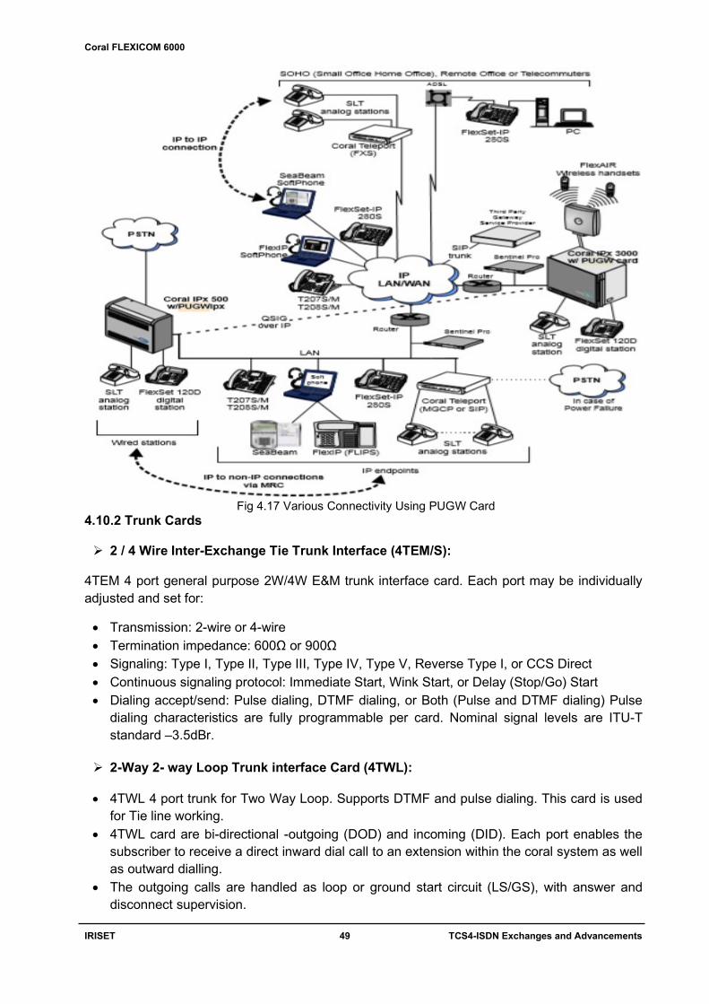
Coral FLEXICOM 6000
IRISET 49 TCS4-ISDN Exchanges and Advancements
Fig 4.17 Various Connectivity Using PUGW Card 4.10.2 Trunk Cards 2 / 4 Wire Inter-Exchange Tie Trunk Interface (4TEM/S):
4TEM 4 port general purpose 2W/4W E&M trunk interface card. Each port may be individually adjusted and set for:
Transmission: 2-wire or 4-wire Termination impedance: 600Ω or 900Ω Signaling: Type I, Type II, Type III, Type IV, Type V, Reverse Type I, or CCS Direct Continuous signaling protocol: Immediate Start, Wink Start, or Delay (Stop/Go) Start Dialing accept/send: Pulse dialing, DTMF dialing, or Both (Pulse and DTMF dialing) Pulse
dialing characteristics are fully programmable per card. Nominal signal levels are ITU-T standard –3.5dBr.
2-Way 2- way Loop Trunk interface Card (4TWL):
4TWL 4 port trunk for Two Way Loop. Supports DTMF and pulse dialing. This card is used
for Tie line working. 4TWL card are bi-directional -outgoing (DOD) and incoming (DID). Each port enables the
subscriber to receive a direct inward dial call to an extension within the coral system as well as outward dialling.
The outgoing calls are handled as loop or ground start circuit (LS/GS), with answer and disconnect supervision.

Coral FLEXICOM 6000
IRISET 50 TCS4-ISDN Exchanges and Advancements
2-wire Central Office Trunk Interface card(4T,8T,4TPF,8TPF) The 4T, 8T cards provide respectively four or eight general purpose, 2-wire, loop signalling central office trunk circuits. The circuits intended to connected to central office. Each port presents a 600Ω (or complex programmable) termination impedance, and may be individually configured and set for: Signaling operation: Loop Start, or Ground Start Dialing accept/send: Pulse dialing, DTMF dialing, or Both (Pulse and DTMF dialing)
Pulse dialing characteristics are fully programmable per card. The 4TPF and 8TPF cards, each provide four (4) ports with power failure (PF) transfer. Under normal powered-up conditions, the transfer circuits connect the central office loops to their respective 4TPF/8TPF card interfaces, and four (or two) pre-designated telephone sets to their respective Coral FlexiCom system station circuits. Should the system lose power, the transfer circuits switch the central office loops to their respective telephone sets. The 4TPF and 8TPFcan utilize standard single-line telephone sets as power failure stations. Monitoring circuitry in the transfer circuits prevents a call made during power failure from being disconnected when power is restored to the system. ISDN Basic Rate Digital Trunk Interface (4TBR, 8TBR):
4 or 8 port BRI (Basic Rate Interface) multiplexed, digital trunk card. ISDN compatible. Each
BRI port uses one pair of the four wires to transmit data and one pair to receive data. The bit rate of each pair of wires is 192 kbps. Each circuit provides a 144 Kbps 2B+D signal, consisting of two 64 Kbps B (voice) channels and a 16kbps D (data/control) channel. The rest of the bits are used for synchronization and maintenance purpose.
Fig 4.18 Connectivity of ISDN BRI ISDN require 4-wire connections, while PSTN provide 2-wire, u-interface connections. Therefore a 2 to 4 wire converter must be used as an interface.an external device, BRI NT1 is used for this purpose as shown above figure 5. ISDN Primary Rate Digital Trunk Interface Card (PRI-30):
PRI (Primary Rate Interface) digital trunk card. ISDN compatible digital interface, European ETSI standard (30B+D) at 2.048Mbps E1 rate. The PRI30 card provides a multiplexed, digital trunk interface with an integral control/data channel. The PRI30 card is designed to interconnect the Coral FlexiCom to a 4-wire primary rate interface (PRI) from a digital ISDN PSTN (Public Switched Telephone Network).
Coral FLEXICOM 6000
IRISET 51 TCS4-ISDN Exchanges and Advancements
The PRI30 complies with the ETSI specification for the European implementation of ISDN and combines 30 B channels at 64kbps and one D channel at 64kbps into a 30B+D signal of 2.048Mbps. The digital interface consists of two, balanced, twisted-wire pairs, one for transmitted data toward the network and the other for received data from the network. The characteristics transmission impedance of the two pairs may be configured to 75,100 or 120Ω, to match the specifications of the network trunk circuits. An interface adapter is available for coaxial interface connections for 75Ω and DA-15S Network Interface Connector 100Ω or 120 Ω. The front panel incorporates indicators for LOS (loss of signal), AIS (alarm indicator signal), RAI (remote alarm indicator), CRC (cyclic redundancy check error), DD (D channel error) and LBK (loopback test mode). PRI- 2DT are functionally identical to PRI-30, but provides two RJ-45 network interfaces of PRI-23, PRI-30, T1,30T and 30TM.That means each 2DT card can support the same number of digital trunks as any two combinations of PRI-23, PRI-30, T1,30T and 30TM. 30 Channel Digital Trunk Interface (30 T):
30 channel, E1 digital trunk interface card. Provides a 4-wire, digital multiplexed, CEPT compatible trunk interface at 2.048Mbps E1 rate. Each 30T channel may use E&M, DDI, or DDO signaling. 30T channels accept and use Pulse or DTMF dialing, or both. 30T/x cards also may use MFC-R2 signaling. Pulse dialing characteristics are fully programmable per card. Front panel indicators show red alarm (span fault), yellow alarm (network fault), bipolar violations, and test mode, and an ISO 4903, DA-15S interface connector is provided. An interface adapter is available for coaxial E1 interface connections. DDO Direct Dialling Outward. DDI Direct Dialling Inward. E & M Both ways.
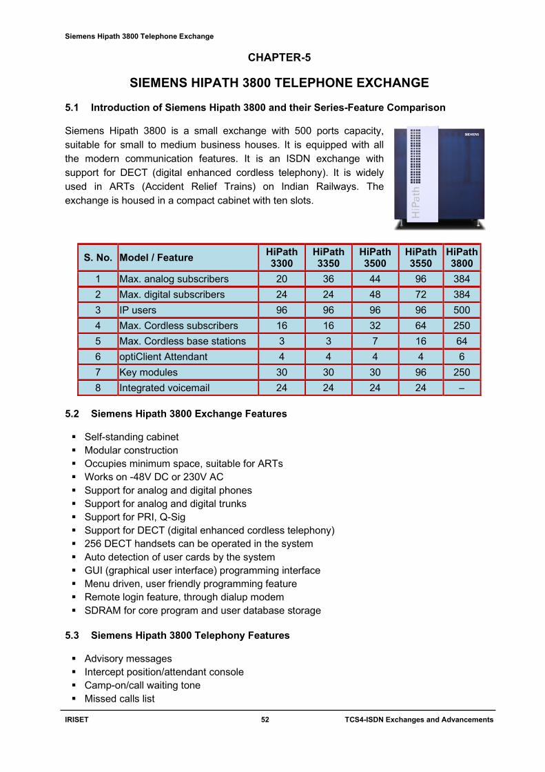
Siemens Hipath 3800 Telephone Exchange
IRISET 52 TCS4-ISDN Exchanges and Advancements
CHAPTER-5
SIEMENS HIPATH 3800 TELEPHONE EXCHANGE
5.1 Introduction of Siemens Hipath 3800 and their Series-Feature Comparison Siemens Hipath 3800 is a small exchange with 500 ports capacity, suitable for small to medium business houses. It is equipped with all the modern communication features. It is an ISDN exchange with support for DECT (digital enhanced cordless telephony). It is widely used in ARTs (Accident Relief Trains) on Indian Railways. The exchange is housed in a compact cabinet with ten slots.
S. No. Model / Feature HiPath 3300
HiPath 3350
HiPath 3500
HiPath 3550
HiPath 3800
1 Max. analog subscribers 20 36 44 96 384
2 Max. digital subscribers 24 24 48 72 384
3 IP users 96 96 96 96 500
4 Max. Cordless subscribers 16 16 32 64 250
5 Max. Cordless base stations 3 3 7 16 64
6 optiClient Attendant 4 4 4 4 6
7 Key modules 30 30 30 96 250
8 Integrated voicemail 24 24 24 24 –
5.2 Siemens Hipath 3800 Exchange Features Self-standing cabinet Modular construction Occupies minimum space, suitable for ARTs Works on -48V DC or 230V AC Support for analog and digital phones Support for analog and digital trunks Support for PRI, Q-Sig Support for DECT (digital enhanced cordless telephony) 256 DECT handsets can be operated in the system Auto detection of user cards by the system GUI (graphical user interface) programming interface Menu driven, user friendly programming feature Remote login feature, through dialup modem SDRAM for core program and user database storage
5.3 Siemens Hipath 3800 Telephony Features Advisory messages Intercept position/attendant console Camp-on/call waiting tone Missed calls list

Siemens Hipath 3800 Telephone Exchange
IRISET 53 TCS4-ISDN Exchanges and Advancements
Do Not Disturb/"ringer cutoff" Call pickup Call forwarding from extensions Call source and call destination display Call intrusion on call forwarding and call pickup Classes of service Executive/secretary function Display languages (can be specified individually) Paging (internal announcement) Call charge recording Group call Internal texts for feature handset Internal telephone directory Speed dialing (individual/central) Automatic line seizure Trunk keys Toggle Text messages Music-on-hold with system-driven announcements External music source (optional) Night service/day service Park Account code Relay (actuators/sensors) Consultation Callback on busy and no answer (automatic) Call number suppression Call signaling Call forwarding after timeout on RNA, immediately on busy Group ringing Hunt group (linear/cyclic) Changeover on (individual code lock) Telephone book, central Entrance telephone and door opener functions Transferring a call (internal/external) Number redial (enhanced) Automatic recall from public network carrier
5.4 Hardware Description Siemens Hipath 3800 Telephone Exchange is a free-standing cabinet with 10 slots. All slots are universal type except slot No. 6, which is nominated for main control card. Power supply is built into this unit. This exchange is operated from -48V DC or 230V AC. The various cards are explained below. Every slot is wired for 24 pairs. There are nine slots available in the basic cabinet BC (slots 1 to 5 and slots 7 to 10) and thirteen in the expansion cabinet EC (slots 1 to 6 and slots 8 to 14) for peripheral boards. The central control board CBSAP has a fixed slot (slot 6, only in the basic cabinet BC). Depending on your requirements, up to three LUNA2 power supply units can be used in the basic cabinet BC and up to four in the expansion cabinet EC.

Siemens Hipath 3800 Telephone Exchange
IRISET 54 TCS4-ISDN Exchanges and Advancements
CBSAP: Central Board Synergy Access Platform - This is the main control card in Hipath 3800 system, it is in the dedicated slot No. 6. This card facilitates in programming the exchange. A PC can be connected to the COM port of this card. Hipath Manager software is used for the programming. The core operating system, user database is stored on a SDRAM on this card. Core exchange requirements of switching, monitoring, programming and feature authorizations are designed on this card.
SLMO-8: Subscriber Line Module Optiset - This is a digital subscriber line card with 8 ports. Digital telephones are connected to this card.
SLMA-8: Subscriber Line Module Analog - This is an analog subscriber line card with 8 ports. Analog telephones are connected to this card.
TMEW-4: Trunk Module for E&M World - This is an analog trunk E&M card with 4 ports. Other exchanges can be connected through this card.
TMANI-8: Trunk Module Analog Network Interface - This is an analog trunk CO card with 8 ports. Other exchanges can be connected through this card.
DIUN2: Digital Interface Unit ISDN - This is a PRI digital trunk card with 2 number of 30 ports. Other exchanges can be connected through this card.
STMD: Subscriber and Trunk Module Digital - This is a BRI digital trunk card with 8 ports. Other exchanges can be connected through this card.
DIUT: Digital Interface Unit Trunk - This is a E1 digital trunk card with 30 ports. Other exchanges can be connected through this card.
STMI2: Subscriber Trunk Module IP is a VoIP gateway board (VoIP - Voice over IP) which provides the functionality of administered over Web-based Management (WBM) in HiPath 3800
SLCN: Single Line Cordless Network - This is a DECT card with 16 ports. Radio base stations are connected to this card with single pair. The power required for the base station is supplied on the connected pair. The base station works up to one km distance on 0.5mm dia copper pair from the exchange.
LUNA2: LUNA2 (Line-powered Unit for Network-based Architecture No. 2) is used as the central power supply in HiPath 3800. Depending on the system configuration up to three LUNA2 modules can be used in the basic cabinet and up to four LUNA2 modules can be used in the expansion cabinet. When expanding the HiPath 3800 to a two-cabinet system, two LUNA2 modules in the basic cabinet and three LUNA2 modules in the expansion cabinet are enough to supply the maximum configuration.
5.5 DECT - Digital Enhanced Cordless Telephony
This is an ITU standard radio communication system. This is well supported in this exchange. A radio base station is connected to SLCN card with a single copper pair. It works up to 1 km distance from the exchange. The power required to operated radio base station is drawn from the line itself. The DECT handsets look like mobile phones and communicate with radio base station. The DECT handsets work about 300 meters from base station in clear visibility. One SLCN card supports 16 radio base stations. In a Hipath 3800 system a maximum of four SLCN cards can be used. That is a total of 256 base stations can be connected in a system. One radio base station supports 16 simultaneous voice circuits. Smooth handing over from one radio base station to other radio base station takes place while a DECT handset is in motion.

Siemens Hipath 3800 Telephone Exchange
IRISET 55 TCS4-ISDN Exchanges and Advancements
SLM
O
1
TM
AN
I
3
DIU
T-2
5
ST
MD
7
DIU
N-2
9
SLM
A
2
TM
AN
I
4
CB
SA
P
6
SLC
N
8
SLM
O
10
DECT Handsets communicate with the base stations. The radius of operation is 300 meters from the nearby base station. Smooth handing over from one base station to other facilitates uninterrupted communication for DECT handsets while in motion. For the total cordless station mobility (roaming and seamless connection handover) within a system, the radio fields of these cordless boards are synchronized. The system views each mobile telephone (mobile station) as a corded telephone. During administration, a fixed port on the system’s “home cordless board” is assigned to the MT; this is used for addressing the MT. As soon as an MT moves into the area of a different radio switching location (“current-location cordless board”), an extension connection is switched using a DSS1 connection initiated by the cordless board.
Fig. 5.1 Siemens Hipath 3800 Exchange

Siemens Hipath 3800 Telephone Exchange
IRISET 56 TCS4-ISDN Exchanges and Advancements
5.6 Programming The various methods of accessing the Hipath 3800 system are Direct connection through COM port LAN interface Dialup modem
With Hipath Manager software the exchange is programmed. This software comes with the exchange. It is a GUI (graphical user interface) based software. This software is to be installed onto a PC. Through this Hipath Manager software, the user database from the exchange is downloaded onto the PC. The required modifications are to be applied in the program. The changes are to be saved accordingly. To effect the changes in the exchange, the user database from the PC is to be uploaded back to the exchange. The user database can be saved to a file for future backups. And this backup can be used to restore the system in case of any malfunction, erratic operation or crash of the exchange.
Fig. 5.2 Telephone no Configuration Window
Fig. 5.3 System Wide Window for Exchange Hardware

Siemens Hipath 3800 Telephone Exchange
IRISET 57 TCS4-ISDN Exchanges and Advancements
Fig. 5.4 Siemens Hipath 3800 Exchange Peripherals
Sie
me
ns
Hip
ath
3800
Exc
han
ge
Fixed Cellular Terminal
Radio Base Station
DECT Handset Cell phone
CO Trunk 2 wire Line
A/D Phones
SLCN 2 wire Line
COM Port Serial Cable

Question Bank
IRISET 58 TCS4-ISDN Exchanges and Advancements
QUESTIONS BANK OBJECTIVE
Chapter 1
1. What does the word 'N' stand for in ISDN? [ ]
A) Network B) North C) Note D) Net
2. What type of Signalling is used in ISDN Exchanges [ ]
A) E&M B) CCS7 C) CAS D) Loop
3. What is the D-channel data rate in ISDN BRI Interface? [ ]
A) 14Kbps B) 16Kbps C) 64Kbps D) 16KBPS
4. What is the D-channel data rate in ISDN PRI Interface [ ]
A) 14Kbps B) 16Kbps C) 64Kbps D) 64KBPS
5. Total PRI Transmission rate [ ]
A) 1.92 Mbps B)2.048MBPS C) 2.048Mbps D) 40Mbps
6. How many timeslots are present in European PRI interface rate? [ ]
A) 16 B) 32 C) 30 D) 31
7. What is the H0-channel date in ISDN [ ]
A) 1024 Kbps B) 384 Kbps C) 2048Kbps D) 192Kbps
8. What is the reference point between ISDN local exchange to Network termination 1 at
Customer premises? [ ]
A) U B) R C) S D) T
9. What is the reference point between Terminal Adapter and terminal equipment 2 at
Customer premises? [ ]
A) U B) R C) S D) T
10. What type of encoding is used in customer premises to ISDN Switch? [ ]
A) HDB3 B) CMI C) CAS D) 2B1Q Chapter 2 1. Services which provides Calling subscriber number will be displayed on his ISDN
telephone before the called subscriber answers the call [ ]
A) CLIR B) CLIP C) CID D) COD
2. Subscribers can call each other using short numbers as if they are connected to a
PABX, even if the Companies with offices in different cities. [ ]
A) CUG B) TP C) COS D) MSN
3. The feature which is useful for IVRS working and can be used for Call center [ ]
A) CAP B) CTI C) COS D) CFU
4. Service which provides unified messaging system that can greet callers and record
internal user messages [ ]
A) VoIP B) Conference C) Voicemail D) Wi-Fi access Chapter 3 1. Coral FlexiCom 200 will have flash memory of
A) 8MB B) 14MB C) 4MB D) 6MB
2. Coral FlexiCom 300 main control processor is

Question Bank
IRISET 59 TCS4-ISDN Exchanges and Advancements
A) MEX-IP2 B) MCP-IPx2 C) MPC D) MCP-ATS
3. Coral FlexiCom 400 configuration supports traffic capacity ____ time slots
A) 128 B) 512 C) 1024 D) 4096
4. Coral FlexiCom 5000 systems minimum traffic capacity ______ BHCA
A) 50,000 B) 2,50,000 C) 1,00,000 D) 4096
5. Coral IPx system in which Wi-Fi can be inbuilt with the system
A) IPx Office B) IPx500 C) IPx3000 D) IPx800
6. Coral IPx system which supports 64-bit processor is
A) IPx Office B) IPx500 C) IPx3000 D) IPx4000
7. Coral IPx4000 system supports _______ Cages
A) 8 B) 32 C) 16 D) 4
8. Coral IPx3000 system supports _______ Group controller
A) 8 B) 4 C) 16 D) 32
9. The Coral IPx 800 supports traffic capacity of ____ time slots
A) 128 B) 384 C) 1024 D) 4096
10. Coral IPx4000 system is a
A) floor standing B) rack mounted C) wall mountable D) Table mounted Chapter 4
1. Which is the control card in coral flexicom 6000? [ ]
A) UGW B) iDSP C) DTR D) MCP
2. Which is the switching card in coral flexicom 6000? [ ]
A) DTR B) IDSP C) MCP D) GC
3. Which is the peripheral card in coral flexicom 6000? [ ]
A) MCP B) CNF C) DTR D) SFT
4. Which is the service card in coral flexicom 6000? [ ]
A) TEM B) SFT C) SA D) DTR
5. Which is the analog subscriber card in coral flexicom 6000? [ ]
A) TBR B) TWL C) SFT D) SA
6. Which is the digital subscriber card in coral flexicom 6000? [ ]
A) TBR B) TEM C) SA D) SFT
7. Which is the analog trunk card in coral flexicom 6000? [ ]
A) SFT B) PRI C) TBR D) TEM
8. Which is the digital trunk card in coral flexicom 6000? [ ]
A) TC B) TWL C) TEM D) PRI
9. Which is the BRI card in coral flexicom 6000? [ ]
A) TWL B) TC C) TEM D) TBR
10. Which is the VoIP card in coral flexicom 6000? [ ]
A) MCP B) SFT C) IDSP D) UGW
11. Which is the DTMF tone dialing support card in coral flexicom 6000? [ ]
A) GC B) MCP C) IDSP D) DTR
12. Which is the caller ID card in coral flexicom 6000? [ ]
A) GC B) MCP C) DTR D) IDSP
13. Which is the multifunction resource card in coral flexicom 6000? [ ]
A) DTR B) IDSP C) MCP D) DRCF

Question Bank
IRISET 60 TCS4-ISDN Exchanges and Advancements
14 Which card contains serial ports in coral flexicom 6000? [ ]
A) MCP B) UGW C) IDSP D) DRCF
15. Which card contains internal modem in coral flexicom 6000? [ ]
A) UGW B) GC C) MCP D) DRCF
16. Which card contains COM 0 port in coral flexicom 6000? [ ]
A) IDSP B) DTR C) GC D) MCP
17. Which card contains COM2 port in coral flexicom 6000? [ ]
A) UGW B) GC C) MCP D) DRCF
18. Which card contains SAU in coral flexicom 6000? [ ]
A) IDSP B) UGW C) MCP D) GC
19. How many peripheral shelves are supported in coral flexicom 6000? [ ]
A) 12 B) 14 C) 16 D) 18
20. How many slots are there in a peripheral shelf in coral flexicom 6000? [ ]
A) 14 B) 16 C) 18 D) 20
21. In which slot PB card is available in coral flexicom 6000? [ ]
A) 5 B) 4 C) 3 D) 1&2
22. How many shelves are controlled by one PB card in coral flexicom 6000? [ ]
A) 1 B)2 C) 3 D) 4
23. How many time slots are allotted for one peripheral shelf in coral flexicom 6000? [ ]
A)128 B) 256 C) 512 D) 1024
24. How many time slots are allotted for a PB card in coral flexicom 6000? [ ]
A) 128 B) 256 C) 512 D) 1024
25. What is the time slot switching capacity of 32GC card in coral flexicom 6000? [ ]
A) 1024 B) 2048 C) 4096 D) 8192
26. How many inputs are there in 32GC card in coral flexicom 6000? [ ]
A) 4 B) 6 C) 8 D) 10
27. Which COM port supports backup/restore in coral flexicom 6000? [ ]
A) COM 3 B) COM 2 C) COM 1 D) COM 0
28. How many IP ports are supported by a UGW card in coral flexicom 6000? [ ]
A) 254 B) 252 C) 250 D) 248
29. How many pairs are required to connect a digital telephone in coral flexicom 6000?[ ]
A) 4 B) 3 C) 2 D) 1
30. What is the ringing voltage for analog phones in ISDN exchanges? [ ]
A) 75V@40 Hz B) 75V@35 Hz C) 75V@30 Hz D) 75V@25 Hz
31. What is the nominal working voltage for isdn exchanges? [ ]
A) 54v dc B) 52v dc C)50v dc D) 48v dc
32. How many pairs are required to connect PRI trunk? [ ]
A) 1 B) 2 C) 3 D) 4
33. What is the data rate of BRI? [ ]
A) 192 kbps B) 194 kbps C) 196 kbps D) 198 kbps
34. How many voice channels are there in BRI? [ ]
A) 1 B) 2 C) 3 D) 4
35. How many voice channels are there in PRI? [ ]
A) 26 B) 28 C) 30 D) 32
36. What is the data rate of a voice channel? [ ]

Question Bank
IRISET 61 TCS4-ISDN Exchanges and Advancements
A) 64 bps B) 64 kbps C) 64 Mbps D) 64 Gbps
37. What is the data rate of channel 'D' in PRI? [ ]
A) 60 kbps B) 62 kbps C) 64 kbps D) 66 kbps
38. Up to what length a digital telephone works on 0.5mm dia copper pair? [ ]
A) 1 km B) 2 km C) 3 km D) 4 km Chapter 5 1. How many slots are there in siemens hipath 3800 exchange? [ ]
A) 14 B) 8 C) 10 D) 12
2. Which slot contains main control card in siemens hipath 3800 exchange? [ ]
A) 5 B) 6 C) 7 D) 8
3. How many pairs are wired for each slot to MDF in siemens hipath 3800 exchange? [ ]
A) 22 B) 24 C) 26 D) 28
4. How many DECT cards are supported in siemens hipath 3800 exchange? [ ]
A) 1 B) 2 C) 3 D) 4
5. How many ports are there in a DECT card in siemens hipath 3800 exchange? [ ]
A) 14 B) 16 C) 18 D) 20
6. How many radio base stations are supported in siemens hipath 3800 exchange? [ ]
A)32 B) 64 C) 256 D) 128
7. How many pairs are required to connect a base station in hipath 3800 exchange? [ ]
A) 1 B) 2 C) 3 D) 4
8. How many simultaneous calls are supported by one base station in hipath 3800? [ ]
A) 5 B) 10 C) 16 D) 20
9. How many DECT handsets are supported in siemens hipath 3800 exchange? [ ]
A) 250 B) 256 C) 254 D) 252
10. What is the radius of operation of a base station in siemens hipath 3800 exchange? [ ]
A) 100 mts B) 200 mts C) 300 mts D) 400 mts
SUBJECTIVE Chapter 1:
1. What are the advantages of ISDN exchange? 2. Explain BRI and PRI? 3. Draw BRI customer premises connectivity diagram? 4. What is the function of NT1? 5. What is the function of NT2? 6. What is meant by TE1, TE2, and TA?
Chapter 2:
1. What are the services offered by ISDN exchange? 2. What are the features offered by ISDN exchange?
Chapter 3:
1. Breifly explain various coral flexicom series exchanges? 2. Breifly explain various coral IPx series exchanges?

Question Bank
IRISET 62 TCS4-ISDN Exchanges and Advancements
Chapter 4:
1. Draw the Coral Flexicom 6000 Dual Control Highway Structure?
2. Explain with neat diagram the circuitry of PPS in Coral flexicom 6000? Chapter 5:
1. What are the cards available in Hipath 3800? 2. Write short notes on Siemens Hipath 3800 DECT interface? 3. What are the various methods of access to Hipath 3800? 4. Draw and explain the connectivity for establishing the Communication using HiPath 3800
at the accident site. Key to Objective:
Chapter1
1.a, 2.b, 3.b, 4.c, 5.c, 6.b, 7.b, 8.a, 9.b, 10.d
Chapter 2 1.b, 2.a, 3.b, 4.c
Chapter 3 1.c, 2.a, 3.b, 4.c, 5.a, 6.d, 7.c, 8.b, 9.b, 10.a
Chapter 4 1.d, 2.d, 3.d, 4.d, 5.d, 6.d, 7.d, 8.d, 9.d, 10.d, 11.d, 12.d, 13.d, 14.d, 15.d, 16.d, 17.d, 18.d, 19.c, 20.c, 21.d, 22.b, 23.b, 24.c, 25.c, 26.c, 27.d, 28.d, 29.d, 30.d, 31.d, 32.b, 33.a, 34.b, 35.c, 36.b, 37.c, 38.a
Chapter 5 1.c, 2.b, 3.b, 4.d, 5.b, 6.b, 7.a, 8.c, 9.b, 10.c

Abbreviations/Acronyms
IRISET 63 TCS4-ISDN Exchanges and Advancements
ABBREVIATIONS / ACRONYMS
ACD Automatic Call Distribution
AOC Advice on Charge
APDL Application Processor Data Links
ART Accident Relief Train
ASCII American Standard Connection for Information Interchange
ATS Advanced Telecommunication System
BHCA Busy Hour Call Attempts
BRI Basic Rate Interface
CAP Computerised Attendant Position
CBSAP Central Board Synergy Access Platform
CCITT Consultative Committee for International Telephony and Telegraph
CCS7 Common Channel Signaling no.7
CF Call Forward
CFD Compact Flash Memory Disk
CLA Coral Link Adapter
CLIP Calling Line Identification Presentation
CPA Coral Paging Adapter
CRC Cyclic redundancy check
CTI Computer Telephony Integration
CUG Closed User Group
DECT Digital Enhanced Cordless Telephony
DID Direct inward dialling
DISA Direct Inward System Access
DOD Direct Outward Dialling
DSP Digital Signal Processor
DTMF Dual Tone Multi Frequency
ECMA European Computer Manufacturers Association
ETSI European Telecommunication’s Standards Institute
FLMM FlexLITE Motherboard Master
FLMS FlexLITE Motherboard Slave
FMSD Flash Memory Storage Device
GC Group Controller
HDLC High-Level Data Link Control
ICMC Integrated coral message centre
IMC Integrated Memory Card
ISDN Integrated Services Digital Network
ITU-T International Telecom Union -Telecommunications
LAN Local Area Network
LCD Liquid crystal display
MCP Main Control Processor Card
MFR Multi Frequency code Receiver card
MGCP Media Gateway Control Protocol
MRC Media Resource Card
MSN Multiple Subscriber Number
NT1 Network Termination1

Abbreviations/Acronyms
IRISET 64 TCS4-ISDN Exchanges and Advancements
OSI Open Standard Interconnection
PBD Peripheral Bus Driver
PBX Private Branch Exchange
PCI Peripheral Component Interconnect
PCM Pulse Code Modulation
PCMCIA Personal Computer Memory Card International Association
PPS Peripheral Power Supply
PRI Primary Rate Interface
PS Power Supply
PSTN Public Switched Telephone Network
PUGW Peripheral Universal Gateway
ROM Read Only Memory
RPS Ringer Power Supply
SAU Software Authorization Unit
SFT Station Flexiset Terminal
SLCN Single Line Cordless Network
SLIC Subscriber line Interface Circuit
SLMO Subscriber Line Module Optiset
SME Small Medium Enterprise
SPC Stored Program Control
SRAM Static Random-Access Memory
TA Terminal Adapter
TE1 Terminal Equipment 1
TSAPI Telephony Server Application Programming Interface
VCC Virtual Card Calling
VCR Video Cassette Recorder
VoIP Voice Over Internet Protocol
VSN Voice Storage Network
Wi-Fi Wireless Fidelity

References/Websites
IRISET 65 TCS4-ISDN Exchanges and Advancements
References / Websites
1. Voice over Ip fundamentals by Jonathan Davidson, James Peters
2. ISDN EXPLAINED, World wide Network and Applications Technology by John M.
Griffiths.
3. Manuals of Coral Flexicom & IPx Product Description.
4. Manual of Coral Flexicom 6000 ISDN Exchange.
5. Manual of Siemens Hi-path 3000 series

Glossary
IRISET 66 TCS4-ISDN Exchanges and Advancements
GLOSSARY A access, 1, 2, 8, 9, 10, 12, 15, 18 accommodate, 6, 15 actuators, 53 adapter, 14, 51 addresses, 48 alive, 5 alphanumeric, 18 amplifier, 43, 44 analyzer, 47 antennas, 48 apparatus, 45 architecture, 3, 14, 18, 24, 25, 33 asynchronous, 46 attributes, 3, 4 auxiliary, 12, 46 B backplane, 33, 34, 38 balanced, 51 bandwidth, 3 barring, 13 bearer, 4, 5, 6, 15 biased, 47 bipolar, 51 C cabinet, 16, 17, 20, 23, 24, 25, 29, 31, 52,
53, 54 cage, 23, 26, 28, 33 camera, 12 cancellation, 5 capability, 3, 6 cases, 10, 13 chained, 48 channelized, 30 cluster, 48 coaxial, 51 coincide, 10 collaborative, 15 compartmentalize, 3 compatible, 1, 18, 45, 47, 50, 51 compliant, 33 concentration, 9, 10 control, 2, 5, 6, 12, 18, 19, 20, 21, 22, 25,
26, 28, 29, 30, 31, 32, 33, 34, 35, 36, 37, 38, 39, 40, 47, 50, 53, 54
convection, 25 converged, 17 conversation, 3, 12, 13, 14 cooled, 24, 25 copper, 5, 54 core, 54 coupled, 3 crash, 56
criteria, 13 cyclic, 51, 53 D daisy, 48 decode, 45, 46 delayed, 5 derived, 35 design, 18, 24, 25 detected, 14 deviate, 40 digitalization, 1, 2 digitally, 46 dimensions, 31 distinct, 8 dual, 35, 36, 38, 45 duplex, 5, 14 duplicated, 28, 31 E echo, 5 economical, 3, 23 edge, 17 efficiently, 18 embedded, 36, 47 emerged, 1 encoding, 48 enhanced, 10, 15, 16, 52, 53 enterprise, 17 entities, 8 erratic, 56 error, 51 extremely, 3 F facsimile, 9 fax, 10, 14, 15, 46 features, 1, 14, 15, 16, 17, 18, 20, 30, 33,
45, 52 filtering, 43 flashing, 36 fledged, 38 flexibility, 3, 17, 20 flexible, 3, 24, 25 foundation, 31 framing, 1 fuses, 32 G gain, 44, 47 gateway, 17, 54 generic, 18, 33, 36 green, 36, 40, 43 greet, 16, 46

Glossary
IRISET 67 TCS4-ISDN Exchanges and Advancements
H handover, 15, 55 hardwired, 38 hierarchical, 17 I illuminate, 40 initiator, 16 injection, 45 innovative, 34 interleaved, 2 intrusion, 53 L layered, 3 layers, 6 leader, 17 legacy, 17 leisurely, 14 linear, 53 M magneto, 43 malfunction, 37, 56 marked, 32 matrix, 34 metering, 13 mirrored, 34 N national, 1 nearby, 55 O objective, 2, 7 operational, 4, 32, 44 optical, 23 optimization, 18 oscillator, 43, 44 overflow, 46 overridden, 13 P paging, 46 parity, 46 peripheral, 17, 20, 22, 23, 24, 25, 30, 31,
34, 35, 37, 38, 41, 42, 44, 45, 47, 48, 53 photographs, 12 piggyback, 34, 37, 38 plenary, 11 positioned, 31 potentiometer, 44 prerecorded, 46 primary, 2, 9, 24, 25, 35, 50 priority, 5, 6 privileges, 13
processor, 17, 18, 19, 20, 21, 22, 24, 25, 26, 28, 29, 33, 37, 40, 41, 43, 45
proprietary, 31, 34 Q queuing, 15, 18 R radius, 55 rationalize, 3 rectifier, 43 redundancy, 38, 40, 51 redundant, 30, 37 regenerator, 16, 37 relay, 44, 46 reliability, 3 reservations, 2 residential, 12 resolution, 9 restriction, 13 ringback, 34 ripple, 40, 42 roaming, 15, 55 robust, 17 rotary, 10, 14 routine, 15, 18 S safe, 31 same, 7, 10, 18, 38, 51 seamless, 31, 55 segregates, 10 seizure, 53 sensors, 53 serial, 9, 14, 33, 35, 36, 46 simultaneously, 1, 12, 45, 46 sophisticated, 14, 20 static, 48 stimuli, 17 supervised, 17 suppression, 53 T tariff, 18 technology, 9, 19, 30, 31, 34, 35 teleconferencing, 6 telefax, 6 teletext, 6 telex, 6, 10 ternary, 10 tolerance, 43 transmit, 2, 48, 50 transparent, 18, 30 twisted, 4, 8, 9, 51 U unified, 15, 16, 46

Glossary
IRISET 68 TCS4-ISDN Exchanges and Advancements
uniformly, 1 V video, 1, 6, 10, 12, 15, 17 videoconferencing, 12 violations, 51 voicemail, 52 W wake, 8
wall, 17, 20, 25 waveform, 44 wirehybrid, 47 wireless, 15, 18, 27, 29, 48 worldwide, 1, 17 wrong, 14, 33 Y yellow, 51

For any suggestions mail to [email protected]/[email protected]
www.iriset.indianrailways.gov.in
भारतीय रेल सगनल इंिज नयर व दरूसंचार सं थान तारनाका रोड, सकंदराबाद – 500 017
FAX: 070-89888(Rly), 040-27823922(BSNL), Ph: 040-27820315
VISION: TO MAKE IRISET AN INSTITUTE OF INTERNATIONAL REPUTE, SETTING ITS OWN STANDARDS AND BENCHMARKS. MISSION: TO ENHANCE QUALITY AND INCREASE PRODUCTIVITY OF SIGNALLING & TELECOMMUNICATION PERSONNEL THROUGH TRAINING
IRISET QUALITY THROUGH TRAINING श ण वारा गुणव ा
Copyright © 2022 FDOKUMEN