Gyandeep - 2021 - iriset
157
Visit Our Website: www.reallygreatsite.com Indian Railways Institute of Signal Engineering and Telecommunications Tarnaka Road, Secunderabad 2021 ANNIVERSARY ISSUE GYANDEEP GYANDEEP 2021 More Info: +123-456-7890 Social Media: @reallygreatsite TECHNICAL MAGAZINE 2021
-
Upload
khangminh22 -
Category
Documents
-
view
1 -
download
0
Transcript of Gyandeep - 2021 - iriset

Visit Our Website:www.reallygreatsite.com
Indian Railways Institute of Signal
Engineering and Telecommunications
Tarnaka Road, Secunderabad
2021
ANNIVERSARY ISSUE
GYANDEEPGYANDEEP
2021
More Info: +123-456-7890
Social Media:@reallygreatsite
TECHNICAL MAGAZINE
2021

Team Towers

GAUTHAM
Text Box


Gyandeep - 2021
Contents
S.N Article Author Page
1. Capacity Enhancement in Training Amid Pandemic Challenges
C. Neelakanta Reddy,
Senior Professor (Training)/IRISET
1
2. Implementation strategy for Train Collision Avoidance System (TCAS) On Mumbai Central- Ahmedabad section of Western Railway
Rahul A Hande, CSE-II/WR 8
3. Planning of Implementation of TCAS over NDLS-GZB-CYZ Section (New Delhi-Howrah Route) of Northern Railway
Jai Prakash Sindhu, CSTE/Proj/Planning,NR
23
4. Comprehensive Planning of TCAS (KAVACH) Towers
V N M Rao, CSTE/Projects/SC/SCR , Manoj Kumar Gupta, CSE/SCR &
C. Sivakumar Kashyap, DSTE/TCAS/SCR
28
5. Implementation of TCAS (KAVACH) in Automatic Block Signalling Territory
V N M Rao, CSTE/Projects/SCR & M. Muni Kumar,CSTE/Projects/Tele/SCR
40
6. Data Logger Management Information System (MIS) on WCR
Sanjeev Tiwari, CVO (S&T), WCR
49
7. Railnet Network Extension using 4 G LTE Router at Remote Location
Pramod Kumar , CCE/ECR/HJP &
Ravi Prakash, SSE/Tele/HJP
52
8. Multi Protocol Label Switching (MPLS) Implementation Over South Western Railway
Kuldeep
Dy.CSTE Proj./SWR
58
9. Project on Automatic Signaling in Kanpur - Prayagraj - Pt. Deen Dayal Upadhaya section of NCR and constrains in Commissioning and lesson learnt to complete the work
Yaswant Singh, CSTE/HQ/NCR 63
10. Realising the Data Potential: Role of IRISET
Yashpal Singh Tomar
RailTel, GGM/Proj./O&M,Secunderabad.
70
11. Study of Lightning, Surge Protection, Earthing for S&T Installations
Bhuvnesh Kumar Agrawal, CSE-II/SCR
72
12. Study of Interface circuits of EI and optimization /reduction of Relays used in NWR.
Anurag Goyal, CSTE/Proj./NER 83

Gyandeep - 2021
13. Novelty in S&T workshop, Mettuguda, Secunderabad
M K Rao, CWM, S&T Workshop, SCR
89
14. Remote monitoring of Track battery charging through Battery charging monitoring unit (BCMU)
Naveen Bhushan Sharma, ADSTE/BAZ/Kota/WCR &
Aashish Kumar Agrawal,
SSE/Sig./Kota, WCR
92
15. SPADs of Indian Railways: Analysis & Recommendations
Vijaylaxmi Kaushik, CSTE/Proj./NWR
96
16. Small Things - Big Impact: Mumbai Suburban Section (Churchgate to Virar)
Ankit Lodha, Sr.DSTE/S/MMCT &
Mahtab Alam, ADSTE/S/MMCT
102
17. Integrated Communication System for Tunnels
J Vijay Kumar, ITX4/IRISET 111
18. Creating VLAN Services in TJ1400 OLT
Shine B Joseph , SSE/Tele/TVC Div. /SR
116
19. Approaching towards A Unified Signal and Telecommunication Asset Maintenance in Indian Railway
T Neela Pavani, Sr. DSTE/HYB/SCR
120
20. Preparation of S&T Schedule of Rates (SOR) for North Central Railway
Prafull Chandra Pandey
CSTE/Proj.-IV/NCR
122
21. HASSDAC Vs MSDAC comparison in implementing the IBS scheme
Suryanarayana D, Dy.CSTE/C/GTL/SCR
125
22. Power Reduction Techniques Implemented using Linear Feedback Shift Registers
Dr.P. Koti Lakshmi, Associate Professor & Mani venkata kumar. K, GM(S&T), KMRL
128
23. Communication Based Train Control (CBTC) Systems – Grade of Operations (GoA) Moving towards Unattended Train Operations (UTO) (Importance of Rolling Stock – Onboard Signaling Interface)
Yog Raj Bhardwaj,
CSTE/P1, DMRC
133

Capacity Enhancement in Training Amid Pandemic
Challenges
C. Neelakanta ReddySenior Professor (Training), IRISET
Abstract
This article enumerates innovative solutions adoptedby IRISET in Training of S&T manpower during theunforeseen pandemic times. It brings out special fea-tures of each training course customized to hybridlearning model and consequent improvement in pa-tronage for the training courses conducted. The ar-ticle also mentions few challenges to be addressed tomake the learning process more fruitful.
Introduction
This article primarily deals with the enhancement ofcapacity to train manpower in IRISET. It is believedthat the enhancement of training capacity leads toimprovement in upkeep of the assets and the pacewith which the assets are created for the expansionof network, so the capacity enhancement in trainingleads to all round development in the organization.The unforeseen pandemic in 2020 & 2021 has thrownseveral challenges to IRISET. The institute was ableto find innovative solutions which are sustainable ona long term basis. Highlights of innovations in capac-ity enhancement of the institute are outlined below.
1 Commencement of On-lineClasses
Though the institute had the experience of conduct-ing virtual classes with the trainees at Zonal S&TTraining Schools, the institute had never conductedon-line classes for the trainees staying in the Hostelsor individual locations in the past. The institutewas closed for physical classes from 20.03.2020 whena section of probationers had stayed in the OfficersRest House (ORH) in Bengaluru during their visit toIndian Railways Institute of Disaster Management(IRIDM), where a Covid positive suspect also stayedin the ORH during the same time. The instituteweighed various options to conduct on-line classes
till a beginning was made on 01.04.2020 to conductfirst ever on-line class on Zoom Platform for IRSSEProbationers stranded in the Institute. Severalplatforms like Zoom, WebEx, Microsoft Teams,Google Meet etc. were tried out in the initial phase.Good number of experiments were conducted amongthe faculty to acquaint themselves with variousfeatures of virtual platform. The institute wassuccessful in ensuring the participation of seniorexecutives working on Railways who were techsavvy and eager to experience the virtual platform,in delivering guest lectures. The days of nationalimportance like 16th April when the first railwaytrain was run on Indian Soil from Boribunder (nowChhatrapati Shivaji Maharaj Terminus Mumbai)to Tannah (Thane), were selected to deliver guestlectures by eminent personalities to instill sense ofpride among the dignitaries and trainees.
A committee was formed under the chairmanshipof Dean with Senior Professor (Training) and Se-nior Professor (Telecom) as members to formulatethe modalities for conduct of on-line classes in theinstitute in regular fashion. The committee maderecommendations on the responsibilities of differentagencies to organize on-line classes, management ofthe group of trainees during the conduct of classesand exploring various features available on virtualplatforms like polling, white board, chart featuresetc. to make on-line learning more attractive. Theexperience gained during the initial phase helpedthe faculty to deliver on-line classes from residenceswhen the institute was closed during lockdown. Thesame on-line class environment was also replicatedfor transmission of physical classes to the trainees inisolation in hostels in subsequent stages of operatingthe institute. The institute supplied 51 hearing aidswith built in microphone to the faculty to help themdeliver quality content. With the strong foundationslaid for on-line classes coupled with reskilling of thefaculty, the institute had taken many initiatives inattracting large number of trainees for the trainingprogrammes conducted during the pandemic times.
____________________________________________ Gyandeep - 2021 _____________________________________________ Page 1 of 141

2 Introduction of BlendedLearning for MandatoryTraining Courses
Even though the institute was closed for physicalclass room sessions, the institute could not afford tostop training process as there was large demand fortraining of in-service supervisors in Signal & Tele-com streams performing the safety duties to com-plete their Refresher Courses at the periodicity ofonce in four years. Sensing the need to continue thetraining process, two committees were nominated tofinalize the modalities of blended learning for a spec-trum of trainees ranging from Technicians to Officers.The committee consisting of Senior Professor (Sig-nal), Senior Professor (Telecom) & Senior Professor(Training) had made recommendations on blendedmodel of learning for training courses of supervisorsand officers. Another committee consisting of Train-ing Managers of Central, South Central and West-ern Railways along with Senior Professor (Training)finalized the modalities of blended model of train-ing for Technicians. The on-line classes are aimedfor imparting inputs on basics of signaling & Tele-com subjects to the trainees who are in service orthose under close monitoring of Officers / Supervi-sors in the field units. The on-campus training is pro-posed for all other categories of trainees who have nothad opportunity for exposure on working systems fortraining on fault diagnostics, deeper analysis, designand evaluation etc. The reports of the committeeswere approved by Railway Board in December, 2020.Every training course covered under blended learningalso has special features enumerated in the successiveparagraphs.
3 Issue of E-Refresher Certifi-cates after Completion of on-line Component of RefresherCourses
It was decided to conduct 03 weeks of RefresherCourse training for Signal & Telecom Supervisors(out of total duration of 04 weeks) through on-linemeans, evaluate them through one to one viva-vocesessions arranged on virtual platforms and issue pro-visional E-Refresher Certificates valid for one year af-ter successful evaluation. This measure helped to liq-uidate large number of arrears of Refresher Coursesduring the year 2020. The institute had subsequentlyused Moodle platform for objective evaluation of the
trainees in place of viva-voce. The provisional E-Refresher Certificates are made available on IRISETTrainee Management System (ITMS) portal to en-able the trainees to download them sitting at theirlocations. An event on virtual platform was orga-nized on 04.07.2020 to present the first E-RefresherCertificate to Ms Sangeetha M Justin, Jr. Engi-neer (Signal), Allepy in Thiruvananthapuram Di-vision of Southern Railway attended by Member(S&T), Railway Board; General Managers / South-ern & South Central Railway; Director Generals /NAIR & IRISET and Principal Executive Director(T & MPP), Railway Board. The same concept isapplied to Refresher Courses of Technicians also byrespective Zonal S&T Training Schools.
Figure 1: News coverage on issue of E-Refresher Cer-tificate
4 Flexi Timings of On-line In-tegration Courses
In general, it is difficult to get Group B Officersfor Integration Courses in Signal to Telecom andTelecom to Signal streams due to the engagementof these officers in important duties in Zonal Rail-ways. The institute organized on-line classes dur-ing the Forenoon Sessions of the day leaving thetrainee officers free from training in the Afternoons.This enabled the Zonal Railways to utilize their ser-vices effectively. As a result, good number of officer
____________________________________________ Gyandeep - 2021 _____________________________________________ Page 2 of 141

trainees was imparted Integration Courses trainingin the years 2020 and 2021.
5 Group Facilities for Trainingof Apprentice JEs
The organization has seen large scale recruitment ofApp. JEs/SSEs (Signal, Design & Telecom) throughRRBs and these trainees reported to Zonal Railwaysfor commencement of training. The innovative ideaconceived to conduct the training of large numberof App. JEs/SSEs is the introduction of the conceptof group facilities (skill centre) and mentorship ofnodal SSE. The group facilities are located in thepremises of Railways like Zonal/ Divisional TrainingCentre, Divisional Office, Sub-Divisional office,Depot of SSE etc where audio visual systems aremade available by Zonal Railways to enable smallgroups of trainees participate in the on-line classesconducted by IRISET.
These locations are expected to have reliable powersupply and robust network bandwidth. Each traineeis allotted a mentor who is nodal SSE of the ZonalRailway. He will take care of the logistics, audiovisual aids of the group facility, clear the primarydoubts of the trainees, ensure exposure of traineesto field working after the classes and oversee Covidappropriate behavior among the trainees at hislocation.
The institute had arranged day-long continuoussessions two days prior to commencement of actualtraining to get the nodal SSEs acquainted withthe virtual platform practices in on-line learning.The top management of training institute had alsointeracted with the nodal SSEs (mentors) to identify“Way ahead” to ensure hassle free training throughgroup facility locations. The nodal SSEs are allottedfolders in Google Drive to upload weekly attendanceof their trainees.Since the same group facility is re-quired to be used by different target group trainees,such as JE / Signal, JE/Telecom, JE/ Design,Promoted JE/Signal, Promoted JE/Telecom etc.the institute had resorted to staggered time-tables toensure utilization of same facility by different groups.
As a result, the faculty of the institute had to takeadditional work load to work in extended hours be-yond regular office working. The institute had alsotaken the responsibility of dispatch of hard copies ofIRISET notes to around 1100 trainees spread overdifferent divisions of Zonal Railways through train
parcel services, coordinating with individual Rail-ways effectively.
Figure 2: Group Facility at Bilaspur on South EastCentral Railway
6 Commencement of PhysicalClasses in the month of De-cember, 2020
Government of India had laid down several proto-cols for functioning of training institutes from timeto time. The institute had followed all the stipu-lations of these protocols in letter and spirit. Thetrainees reporting to the institute were asked to bringRTPCR test certificate showing negative result forCovid 19. The trainees were isolated during the ini-tial two weeks of their reporting at the institute inindividual rooms. The hostel authorities had madearrangements to supply food to the trainees in theirrooms throughout the duration of isolation. Thetrainees were given thermometers and pulse oxime-ters for monitoring their parameters. Medical Ad-vice from doctors of South Central Railway was ar-ranged for the symptomatic trainees. The institutehad mandated recording of the status of the individ-ual on Arogya Setu app in the CCTV cameras kept atthe entry locations of the buildings in the institute.The Audio Visual systems available in the Institutewere predominantly used for sensitization of the in-mates of the institute on the precautions to be takento prevent spread of Covid 19. Sports & Culturalfacilities were restricted during this period, to avoidtrainees moving in large groups. Restrictions wereimposed on the movement of trainees outside thecampus. Screening of temperature of all trainees,faculty and staff was made compulsory while theyenter the institute. Entry of visitors was restricted.Sensor based sanitizer dispensers were provided atconspicuous locations in the institute as well as hos-tels. Sensor based taps were provided in the hostelmess and wash rooms. Dish warmers were procuredto sanitize the cutlery before use by trainees.
The institute had taken swift action to make ar-
____________________________________________ Gyandeep - 2021 _____________________________________________ Page 3 of 141

Figure 3: Recording status on Arogya Setu throughsurveillance camera
rangements of spacious class rooms with adequatephysical distance, in the class room environment.Laboratory spaces were re-organised to make ar-rangements for such spacious class rooms. The class-rooms are equipped with multiple displays and inter-active writing panels so that the faculty’s work on thewriting panel is available to all the trainees throughmultiple displays. The public address system in theclass rooms is suitably augmented. The timings ofmess and time-table for physical classes are staggeredto prevent congregation of large number of trainees.This warranted the faculty to work in extended hoursbeyond the normal duty hours. The faculty & staffin the institute were also re-located to alternate lo-cations to ensure adequate physical distance, withthe work stations shifted to the new locations. Theinstitute had used 20 VPN connections to enable theofficers and staff work from home during the severepandemic scenario. A close watch was kept on theCovid positive cases in the campus and immediateaction was taken for sanitization of the premises asper the extant instructions. The trainees were sen-sitized in every class on precautions to be taken tocontain the spread of pandemic.
Figure 4: New spacious classroom with physical dis-tancing
7 Close Liaison with MedicalAuthorities
Protocol decided by Medical authorities of SouthCentral Railway mandated visits of medical teamheaded by a Doctor on the first day of arrival oftrainees to test them physically for any symptoms.The trainees with symptoms were sent for medicalexamination to the Railway Hospital. A vehicle wasmade available 24/7 at the disposal of trainees for en-abling them reach hospital in shortest possible time.The close proximity of Central Hospital, Lallagudawithin a distance of 2 km is an added advantage forthe Institute to handle the pandemic scenario effec-tively. The pandemic period has seen hospitalizationof three trainees in Central Hospital, Lallaguda forCovid-19 complications. The active support of med-ical authorities of South Central Railway has alsohelped the institute to vaccinate its employees andtrainees extensively. In addition to getting vacci-nated in the community facilities arranged by SouthCentral Railway in the vicinity of the institute, theinstitute also arranged vaccination camps within theinstitute’s campus on 04 occasions exclusively forthe faculty, staff and trainees. Approximately 500trainees were vaccinated in these camps. The vacci-nation facility was also extended to the outsourcedstaff working in the Institute.
8 Digital Initiatives in Training
The institute shifted its working to E-office com-pletely during the pandemic. Initiatives like issueof e-passes were undertaken in proactive way. Vari-ous features of ITMS portal are explored to minimizethe physical transfer of files and enhance interactionwith the trainees. Features like Trainee registration,placing of request for hostel, transport, availability ofcertificate in the website etc were extensively used.Learning resources were upgraded and made avail-able on the ITMS portal for access by trainees. Oneterra byte capacity server space was hired from RCILand common shared digital repository was created toenable all Zonal S&T training schools and TrainingManagers upload their learning resources to ensureoptimum utilization of such resources by all stakeholders. The resources included Power Point Presen-tations, Demonstration Videos, Question Banks andother reading material. Java based web applicationsfor on-line monitoring of Field Training diaries ofIRSSE Probationers and monitoring of action takenon the feedback received from on-campus traineeswere put in place to improve the accountability.
____________________________________________ Gyandeep - 2021 _____________________________________________ Page 4 of 141

9 Overcoming the ChallengesPosed during 2nd Wave ofthe Pandemic
The 2nd wave of the pandemic was quite severe andthe number of covid 19 positive cases across the coun-try was on a rise. During this time, the institute wasexpected to call the trainees of Refresher Courses andPromoted JEs (selected under 20% LDCE quota) tothe campus to complete their on-campus training.Since the situation is not conducive, new modalitieswere decided for these training courses. In respect ofRefresher Courses, it was decided to make the litera-ture and demonstration videos of practicals availableon the website for access by all trainees. The facultyof the institute could develop 57 videos demonstrat-ing practical sessions. Also practical doubt clearancesessions were arranged for 4 weeks through virtualplatform to enable the trainees to clear their doubtspertaining to a particular laboratory on a nominatedday of the week from the faculty of IRISET. This fa-cility was used by trainees of Refresher courses, pro-moted JE courses (Intermediate courses) and facultyof Zonal S&T training schools. Subsequently, thesubjective examinations for Refresher Courses andPromoted JE courses were conducted in the premisesof Zonal Railways in association with the nodal ex-amination officers nominated in each division. Thequestion papers were sent one hour before the com-mencement of examination through electronic meansto the nominated nodal officer. After the conductof examination duly ensuring Covid protocols, theDivision sent the answer sheets in sealed covers toIRISET through speed post or courier. The evalua-tion was done and results were declared by IRISET.Supplementary examinations were also conducted forRefresher Courses to benefit the trainees who couldnot write examinations in the first instance. Re-fresher Course examinations were conducted for 1115Signal supervisors and 690 Telecom supervisors atone go in this fashion. In case of Promoted JEs,training of theory portion through on-line means istaken care by IRISET leaving the responsibility ofpractical exposure of trainees to the Zonal Railwaysin their training schools. Zonal Railways were alsoadvised to take up the responsibility of guiding thepromoted JE trainees in carrying out the projectworks.
There was flexibility and dynamism in taking variousdecisions in conducting the training courses duringthe pandemic in order to maintain the momentumin spite of the adverse circumstances. The decisionslike enhancement of on-line component of training,
Figure 5: Conduct of Examinations at Deen DayalUpadhyaya Jn on East Central Railway
pre-ponement of on-line training courses, postpone-ment of on campus courses and increased coverageof general subjects in on-line component have gone along way in managing the situation during 2nd waveof pandemic. The trainees of the institute had strongfaith in the management of the Institute and obeyedthe discipline meticulously. Greater flexibility is ex-ercised to plan training courses with an aim to com-plete mandatory training of large number of new re-cruits in shortest possible time.
10 Statistics Showing En-hanced Capacity
The comparative figures indicating the enhancementof training capacity in 2020 and 2021 is evident fromthe figures below.
Figure 6: Table
(* The figures up to October 2021 are consideredin 2021 calendar year.) The figures in parenthesisindicate relative improvement over the previousperiod.
The Institute had several important achievementsduring the period in spite of the challenges posedby the pandemic. The institute had trained highestnumber of trainees with an all-time high of 18,587trainee days during the month of September, 2020in the history of the Institute when the Institute hadtrained large number of Apprentice trainees. The in-stitute had trained highest number of trainees in a
____________________________________________ Gyandeep - 2021 _____________________________________________ Page 5 of 141

year- 6517 in 2020 and had completed the year 2020with 82,742 (+ 38.51%) training man days (or traineedays), which is the highest in the history of the In-stitute. IRISET has become the first CTI (Central-ized Training Institute) on Indian Railways to com-plete one Lakh trainee days in a calendar year on03.09.2021 with around four months left over in theyear. As on 31.10.2021, the institute has registered1,24,832 trainee days in the current year. Inciden-tally, this institute operates with lowest expenditureamong all CTIs on Indian Railways. The Institute
Figure 7: Newspaper clipping on achieving one lakhtrainee days
had also imparted online training to the executives ofDFCCIL and RVNL in these difficult times. The In-stitute had played the role of aggregator in impartingtraining to executives of Kochi Metro Rail Limited(KMRL) and Chennai Metro Rail Limited (CMRL)on RAMS (Reliability, Availability, Maintainabilityand Safety) courses by liaisoning with the subjectexperts in the industry. The institute has earnedRs. 1.2 Cr and Rs. 1.4 Cr through this training inthe year 2020 and 2021 respectively. The efforts ofthe institute accounted for saving to the tune of Rs.15.4 Cr towards TA expenses alone in respect of thetrainees.
11 Challenges Ahead
The institute had under taken on-line training in abig manner, but the quality of training as perceivedby a section of trainees in online classes is a matterof concern. There is an urgent need to address theissues to improve the quality of on-line learning. TheInstitute would be working on the ways and meansto engage the trainees in intensive manner during on-line courses. At the same time, it is expected that thetrainees join on-line classes through suitable systemsavoiding mobile phones. The trainees nominated foron-line training are expected to be left exclusivelyreserved for the learning process without distractingthem for day to day routine activities of the ZonalRailways during the training period. The group fa-cility locations as a skill center is a workable idea totake learning to various corners of the country bridg-ing the digital divide effectively. There is a need tostrengthen the facilities available at such locationsand proliferate these facilities to other work centersas well. The learning resources are presently limitedto power point presentations and primitive videos.Enhancement of the quality of audio visual contentwith interactive features may go a long way in en-abling the trainee to experience improved quality oflearning. There is a need to work on quality ques-tion banks and self learning courses in future. Sincethe organization has envisaged large scale modern-ization of Signaling & Telecom systems, there is anurgent need to commence training courses in this di-rection to bring synergy among all stakeholders andto disseminate the knowledge. The limitations expe-rienced by the institute in accommodation, labora-tory facilities, classrooms and non-availability of lat-est modern technology systems in the Institute needto be addressed in the right earnest to equip ourselvesbetter for future challenges in training.
____________________________________________ Gyandeep - 2021 _____________________________________________ Page 6 of 141
Shri C. Neelakanta Reddy,is a IRSSE Officer of 1996ESE Batch, currentlyworking as Senior Profes-sor (Training). IRISETsince 19th February, 2020.He has completed hisgraduation and post grad-uation in Engineeringfrom Sri VenkateswaraUniversity, Tirupati. Important assignments hehandled in S&T Department are Sr. DSTE andDy. CSTE (Projects), Secunderabad, lookingafter the maintenance of S&T assets on busyroutes and creation of assets for enhancement ofsafety and capacity. He also has rich experiencein General Administration wing as Dy. GeneralManager (General) and Secretary to GeneralManager in South Central Railway with firsthand exposure to people centric issues and largegroup dynamics in management of the organization.
____________________________________________ Gyandeep - 2021 _____________________________________________ Page 7 of 141
Implementation strategy for Train Collision Avoidance
System (TCAS) On Mumbai Central- Ahmedabad
section of Western Railway
Rahul A HandeChief Signal Engineer (II), Western Railway
Abstract
Present Train Operations on Indian Railways arebased on Trackside Signalling and Manual Controlof Operations. Though modern technology is beingadopted for interlocking components, Signalling sys-tems on IR have relied on the Loco Pilot to react toindication displayed to them by the line side Signals.World over, to reduce the risks created by LocoPilot failure to respond to signal instruction, variousforms of warning devices and signal command en-forcement systems have been developed, referred as,Automatic Train Protection (ATP) Systems. Thesesystems continuously monitor the actual Train speedand enforce adherence to the maximum allowablesafe distance available (Movement Authority) to theTrains.
In a significant move, IR have decided to implementindigenously developed and RDSO approved TCASacross Indian Railways in line with the strategyof adopting National Automatic Train Protection(ATP) system for Hon’ble PM’s vision of Atmanir-bar Bharat and go ahead with provision of TCASin lieu of earlier sanctioned ETCS (European TrainControl System).
Train Collision Avoidance System (TCAS) is anindigenous Automatic Train Protection Systembeing developed by RDSO involving three Indianvendors. The system alerts the Loco Pilot that thetrain is approaching a signal or PSRs and requireshim to acknowledge the warning in case of overspeeding. Otherwise, the system would initiate abrake application after a pre-defined short delay.
According to the decision, provisions of TPWS &ETCS Level-2, which were initially included in thesanctioned work ”Mumbai Central-Virar-Vadodara-Ahmedabad - Train protection system (500 rkm)”,approved under PH-33 in PB2010-11 at the cost
of Rs. 530.5 Cr, are being replaced by indigenousTCAS.
The overall scheme and implementation strategy forindigenous TCAS in Mumbai Central – Ahmedabadsection (about 494 km) are discussed in this paper.The constraints foreseen in the project and amicablesolutions to mitigate the issues are covered. Effortsare made to make the paper a guiding document,that can be referred for planning and execution ofthis ambitious project of IR targeted for commis-sioning by Dec’2022.
1 Objective
The work TPWS was sanctioned in 2010-11 onMumbai Central- Vadodara-Ahmedabad sectionand was subsequently frozen in view of advent ofETCS Level-2. IR have now decided to implementindigenously developed and RDSO approved TCASunder National Automatic Train Protection (ATP)system and go ahead with provision of TCAS in lieuof earlier sanctioned ETCS (European Train ControlSystem). Accordingly, provisions of TPWS / ETCSL2, are being replaced by indigenous TCAS. Theestimated cost is about Rs. 211 Cr. TCAS worksare also sanctioned over other routes of WesternRailway, which constitutes about 2363 km.
Automatic Block Signalling is already functional inMumbai Central-Ahmedabad section. Commission-ing this major project by Dec’2022, is a great chal-lenge and it is necessary to carefully plan a de-tailed strategy. With the experience gained from theonly commissioned project in South Central Railway(which is mostly in Absolute Block System), an at-tempt is made in this paper, to cover overall TCASscheme and implementation strategy considering var-ious factors of the Mumbai Central – Ahmedabadsection. The constraints foreseen in the project and
____________________________________________ Gyandeep - 2021 _____________________________________________ Page 8 of 141

amicable solutions to mitigate the issues are covered.
2 Scope
The study & the paper touches the basics of theTCAS system, principle of operation, features etc.Various components and functionalities are coveredand explained with illustrations. Important param-eters of the system as detailed in the Specificationsand OEM manuals are reproduced for ready refer-ences. A broad overview of planning of the TCAS inMumbai Central – Ahmedabad section, implemen-tation challenges, various constraints and mitigationmeasures have been studied & presented in the pa-per. A focus is also kept on drawings & documen-tation required for this work. Important technicalaspects required during the installation of StationTCAS are specially indicated.
3 Overview of IndigenousTCAS
TCAS will be provided on sections equipped withMulti Aspect Colour Light Signalling and loco pilotwill follow line-side signals as per prevalent operat-ing rules. Provision of TCAS will be an additionalsafety aid to the loco pilot to prevent consequencesarising out of Signal Passing At Danger (SPAD),to control train speed within specified limits, todisplay Signal Aspect in Loco pilot’s cab and tofurther reduce the probability of train collisionsin block sections and on running lines at stationsthrough certain non-signalling based protections.The operation of TCAS shall, in no way, infringe/ overrule the rules of normal train operations onIndian Railways.
TCAS is required to be functional up to a maximumtrain speed of 200 kmph. The Loco TCAS unit,Stationary TCAS Unit, Network ManagementSystem, Key Management System and RFID tagsshall adhere to the requirement of interoperability.
It comprises of trackside equipment including Sta-tionary TCAS Unit and On-board equipment calledLoco TCAS. It conforms to Safety Integrity LevelSIL-4 as per CENELEC or equivalent standards.
Each Loco TCAS in the vicinity of the stationaryTCAS, will communicate its position, speed, direc-tion of movement with the stationary TCAS unitson radio. The stationary TCAS systems will acquire
the status of all signal aspects, berthing track cir-cuits & points of its yard, calculates the movementauthority of the locos and transmits the data over ra-dio to the loco TCAS. The Loco TCAS upon recep-tion of the data from the Stationary TCAS, analysesthe data received and supervises the train movementin accordance with the data analysed. In the eventof emergency situations, the system applies brakesthereby preventing collisions. The on-board LocoTCAS equipment also shows the speed, movementauthority, target distances, approaching signal as-pects etc to the Loco Pilot.
3.1 Principle of Operation
The TCAS sub-systems are installed in stationsknown as Stationary TCAS and in locos knownas Loco TCAS. Stationary TCAS unit comprisesof STCAS Vital Computer, Field Interface Unit(FIU), GPS/GNSS receiver, GSM, SM-OCIP, Radiomodems and Radio antennae. The Loco TCAS unitcomprises of LTCAS Vital Computer, GPS/GNSSreceiver, speedometer unit, RFID Reader, LP-OCIP,Brake interface unit (BIU), CAB-Input unit, Radiomodems and Radio antennae. The Radio modemsestablishes communication between the Station& Loco TCAS systems. GPS/GNSS is used toprovide time reference to Loco and StationaryTCAS systems to perform Radio communication.
Field inputs like all signals, Points, track circuits,berthing tracks from the RRI panel are wired to theFIU. RFID tags with tag data are fixed on the sleep-ers in station and block sections. The RFID Readerfixed underneath the loco, reads the RFID data whenit comes in proximity.
The Loco TCAS frames the information contain-ing its operating mode, absolute position, lastRFID tag, movement direction, train length, trackidentification number as a single communicationpacket and sends it to the Stationary TCAS uniton Radio. Based on the status of the field inputsand the Loco TCAS location, the Stationary TCAScalculates the Movement Authority for the Loco.The Stationary TCAS also provides the necessaryinformation required to compute the Train lengthby checking the sequence of the AT and BT trackcircuits. Stationary TCAS communicates all thisinformation to the Loco TCAS using the StationRadio Modem. The Loco TCAS receives the datatransmitted by the Stationary TCAS on Radio andtravels in accordance with the received MovementAuthority, Current Signal aspect and other infor-mation received from the station. In the event of
____________________________________________ Gyandeep - 2021 _____________________________________________ Page 9 of 141

Figure 1: Train Collission Avoidance System (TCAS)
emergency situations, SOS signals are generated andthe Loco TCAS applies emergency brake automat-ically through BIU thereby preventing occurrenceof catastrophic events. LTCAS also displaysthe speed, movement authority, target distances,approaching signal aspects etc on DMI for the pilots.
Loco unit calculates the location of the train betweentwo RFID tags dynamically based on the distancetravelled from last RFID tag through speed sensingarrangement on Locomotive. Loco unit acts on datafrom even one RFID tag out of duplicated tags, logsthe missing RFID tag & transmit the same to NMS.On not receiving any information from any one Nor-mal RFID tag 50 m beyond the expected location,Tag missing indication shall be displayed on DMI.If two consecutive Normal RFID tags are not read,Loco TCAS shall switch from Full supervision modeto Limited supervision mode.
3.2 Operational Modes
The TCAS loco equipment are capable of supervisingthe following operational modes:
1. Stand By(SB)
2. Staff Responsible(SR)
3. Limited Supervision(LS)
4. Full Supervision(FS)
5. Override(OV)
6. On Sight(OS)
7. Trip(TR)
8. Post Trip(PT)
9. Non Leading(NL)
10. Reverse(RV)
____________________________________________ Gyandeep - 2021 _____________________________________________ Page 10 of 141

11. Shunt(SH)
12. System Failure(SF)
13. Isolation(IS)
3.3 Features of TCAS
Loco TCAS unit and Stationary TCAS unitSelf-Test - perform an automatic self-test when theequipment is switched ON.
Operation modes - capable of supervising the 13operational modes.Display of Signal Aspect - on DMI.
Train Length Assignment - automatically calcu-late train length by the loco TCAS unit on receivingthe required information from Stationary TCASunit.Train location - determine the location of the trainwith the help of RFID tag data and Speed sensoroutput.
Speed calculation and indication - Loco makesspeed profile/ brake curve for different situationsbased on movement authority, speed restrictionand other information as received from Tracksidesub-system.
Prevention of Signal Passing at Danger(SPAD) - supervise the movement authority basedon the signal aspect, point position and the statusof the berthing track circuit.
Supervision of speed limits - supervise to staticand dynamic train speed profiles.
Prevention of Head on & Rear end Collisions- preventing Head on & Rear end collisions inStation as well as Block section.
Prevention of Side Collision (infringement toadjacent lines) in Block Section - automaticallygenerating SoS from a loco TCAS unit if it stops fora specific amount of time (Default: 10s) in the blocksection.
Protection of Roll Back - detecting Roll Back ofthe train through train interface.
Manual SoS generation/Cancellation - man-ually generating and cancelling SoS from bothStationary and Loco TCAS unit.
Auto whistling on approach of Level CrossingGate - optional auto whistling to alert the roadusers of approaching train.
3.4 Components of TCAS
Trackside subsystem comprised of RFID tag,Stationary TCAS Unit, Tower and Antennae.
RFID Tags are fitted on sleepers between the rails,in station section, point zones, near Signals & trackin block section for giving Trackside informationto Loco TCAS unit. It shall be duplicated withidentical information.
Frequency of operation :865-867 MHzProgrammable with minimum 128 bits (includingCRC) of user data.Shall have minimum IP 68 protection
RFID tags are categorized as follows:
(a) Normal tag - provided in the block section &station section. The maximum distance betweenthe two normal tags shall not be more than 1000m. Each Normal tag shall be linked to next twonormal tags in both the directions (Nominal &Reverse).
(b) Signal foot tag - provided at foot of every signalpost
(c) Signal approach tag - provided before the ap-proach of (typically 150 250m) every signal postto correct the odometry error
(d) TIN Discrimination tag - used to indicate changein the TIN of track section. Normally it will beplaced at turnouts.
(e) LC gate tag (optional)
(f) Tunnel tag (for future use)
(g) TCAS Exit tag - territory exit point
(h) Adjustment/Junction tag - to adjust the abso-lute location in the block section. Junction tagshall be provided, at the junction stations to cor-rect the absolute location.
(i) Banner/Caution Indicator Tag at TemporarySpeed Restrictions (for future use)
Stationary TCAS Unit is comprised of Sta-tion/LC/IB TCAS Vital Computer including FIU,Stationary TCAS Radio Unit, Remote Interface Unit
____________________________________________ Gyandeep - 2021 _____________________________________________ Page 11 of 141

Figure 2:
(RIU) & Station Master Operation and IndicationPanel (SM-OCIP)
Station/LC/IB TCAS Vital Computer gener-ates messages to be sent to the train on basis of in-formation received from interlocking inputs and onbasis of information exchanged with the Loco TCASunits. Vital Computer architecture is minimum 2out of 2. Real Time Clock synchronization facilitywith GNSS clock to synchronize with other TCASsystems in hot standby manner is provided. Ether-net/E1port and two GSM interfaces are for connec-tivity with Network Management System (NMS) andKey Management System.
Stationary TCAS Radio Unit is used for thebi-directional exchange of messages between LocoTCAS unit and Stationary TCAS units. The UHF(406MHz to 470MHz) full-duplex radio communi-cation unit have hot standby provision with sepa-rate cable & antenna for each radio. The StationaryTCAS unit shall allocate a Timeslot and FrequencyChannel pair for Communication with a particularLoco unit. Typical arrangement is depicted in thefollowing figure. Antenna is a combination of ver-tically polarized omni and/ or directional antennae.The antenna cable & antenna tower is suitable toprovide a minimum range of 4.5 kms. Coaxial cablesuitable for UHF applications with 50W characteris-tic impedance and losses within 1dB / 10m is used.
The received signal strength should be better than-85 dBm and packet error rate shall not exceed 5%throughout the Communication Mandatory Zones.Remote Interface Unit (RIU) is used where re-mote signalling functions are required to be fetchedto a nearby Stationary TCAS unit. It utilises linemodems for communicating with stationary TCASunit over OFC/Quad cable in ring network. A sin-gle RIU shall be capable of handling at least 32 fieldinputs. The ring topology arrangement for RIUs isshown in the following figure.
Figure 3:
____________________________________________ Gyandeep - 2021 _____________________________________________ Page 12 of 141

Figure 4:
Station Master Operation and IndicationPanel consists of following indications/ buttons/buzzers : a) Station Master’s Key b) LCD display(4Linex20 char) c) SoS indication d) Health indica-tion e) Audio Buzzer f) Three Push Buttons (Com-mon, Generation and Cancellation) to generate andcancel the SoS g) Electromechanical non-resettable6 digit counter for recording SoS operation.
Figure 5:
On-board Sub-system (Loco TCAS Unit) iscomprised of Loco TCAS Vital Computer, RFIDreaders, Loco TCAS Radio Unit, Driver MachineInterface (DMI), Brake Interface Unit (BIU)
Loco TCAS Vital Computer supervises themovement of the train on basis of informationexchanged with Stationary TCAS units and otherLoco TCAS units. Vital Computer architectureis minimum 2 out of 2. It has Real Time Clocksynchronization with GNSS clock to synchronizewith other TCAS systems in hot standby mannerand two GSM interfaces for connectivity with NMS& KMS.
Loco TCAS Radio Unit consisting of two RadioModems in hot standby with separate cables andantennae for each radio. The specifications is similarto Stationary TCAS unit. It has provision to switchto other frequency channel. Loco unit Antenna isOmni-directional & have vertical polarization witha gain of 3 dBi.
RFID Reader consisting of two RFID Reader& Antenna in hot standby for getting the in-formation from RFID tags fitted on the track.It is reliable for working at Locomotive speedup to 200 KMPH. RFID reader antenna is ableto read RFID tag from a vertical distance of 700 mm.
Driver Machine Interface (DMI) consist ofsuitable display arrangement and buttons/ switchesfor operation. The software of DMI is verified& validated to Safety Integrity Level (SIL) -2 ofCENELEC or equivalent international standards.
Brake Interface Unit (BIU) shall apply normal,service & emergency brakes of locomotives respec-tively based on the type of brake command receivedfrom Loco TCAS unit.
Network Management System is provided forCentralized monitoring of TCAS station and Locoequipment. It is to be built on E1 interface availableon Railtel OFC system. Using E1 interface, eachStationary TCAS unit is connected to adjacent sta-tionary TCAS unit/Network Management System
____________________________________________ Gyandeep - 2021 _____________________________________________ Page 13 of 141

Figure 6:
to form a network. Centralized monitoring of agroup of stations is achieved by collecting signalaspects, track occupancy, loco absolute positionetc., from each of the Stationary TCAS. All relayinformation and radio packets exchanged betweenStation and Loco are logged in Central Server andaccessed through NMS. Stationary TCAS units shallcommunicate with NMS unit using the StationaryTCAS NMS Packet Structure defined in RDSOSpecification using Ethernet protocol over thisnetwork.
3.5 Radio Communication
Radio Communication Security and Key Manage-ment System (KMS) is built on AES (Advanced En-cryption Standard)-128 security coding to ensure se-cured communication between Stationary and LocoTCAS Units. Radio Communication uses crypto-graphic techniques with security keys. Key is a se-quence of 128 bits. Authentication key, used to es-tablish a safe connection between Stationary & LocoTCAS units, will be communicated by KMS to allLoco and Stationary TCAS units and it will havevalid time period for its usage. Key ManagementSystem would be centralized for Indian Railways.Session key, used for protection of data transfer be-tween Stationary & Loco TCAS units, will be com-puted by Loco TCAS and Stationary TCAS unitsat the time of establishment of communication ses-sion. KMS shall maintain 30 sets of AuthenticationKeys having validity period of not be less than 120days. All the TCAS systems use GPRS to communi-cate with KMS. Process flow for authentication keystransmission is depicted in following diagram.
Process Flow: On entering into CommunicationZone of Stationary TCAS, Loco TCAS unit sendsthe Access Request packet to Stationary TCASsystem in “f0” frequency. On receiving the packet,Stationary TCAS unit generates its own Random
Figure 7:
Number (Rs) and computes the session key Ksand transmits the Access Authority message withCBC-MAC code (Cipher Block Chaining MessageAuthentication Code). Access Authority messagecontains frequency pair and Random Number Rs.Loco TCAS unit then compute the session key Ks. IfCBC-MAC is successful, Loco starts communicatingthe regular packet and stops sending the AccessRequest Packet. When Stationary TCAS receivesthe Loco regular packet, it stops communicatingthe Access Authority message and initiates theStationary regular packet and static speed profilepacket transmission.
Multiple Access scheme and Radio com-munication protocol - Communication shall beOver-The-Air using Multiple Access having framecycle 2000 milli seconds. Full duplex communicationin frequency range of 406MHz to 470MHz is used.TCAS shall use transmit frequency (f0) in blocksection and at the times of emergency situations.Stationary TCAS and Loco TCAS use their respec-tive timeslot(s) in the Multiple Access.
The TDMA frame cycle is divided into basic 78 timeslot position markers (position nos. 1 to 78) eachof width 352 bits (18.33 m-sec). These are spaced96 bits (5 m-sec) apart except for the four widertime slots to ensure proper frequency stabilizationon change.
4 Challenges & Strategy for In-stallation of TCAS in Mum-bai Central – Ahmedabadsection
Mumbai Central - Ahmedabad section passesthrough three divisions namely Mumbai Central,Vadodara and Ahmedabad. The entire section
____________________________________________ Gyandeep - 2021 _____________________________________________ Page 14 of 141

Figure 8:
Figure 9:
is equipped with Automatic Signalling. Thereare 104 interlocked stations provided with RouteRelay Interlocking, Panel Interlocking & electronicInterlocking of various make. Track detectiontechnology used is DC Track circuit (DCTC), AudioFrequency Track Circuit (AFTC) and Digital AxleCounters (MSDAC / HASSDAC / SSDAC). Total176 interlocked LC gates are protecting the Roadtraffic. Division-wise details are depicted in thefollowing table.
4.1 Station TCAS, RIUs, Cable &Power Supply Requirement
Since there are 104 stations in the Mumbai Central– Ahmedabad section, total 104 STCAS will be re-quired for the stations. In addition, 34 additionalSTCAS need to be provided in mid section to cater
Figure 10:
for the requirement of coverage of 3 signals in com-munication mandatory zone of the STCAS on eitherside (explained in the following paragraph).
Figure 11:
____________________________________________ Gyandeep - 2021 _____________________________________________ Page 15 of 141

A typical STCAS 19” rack is depicted in abovefigure. It is to be installed in the Relay room andto be interfaced with interlocking circuits. 600 mmspace need to be left vacant around the rack forinstallation & maintenance movement area. Thus,about a space of 6 ft x 6 ft is recommended forthe STCAS rack. Relay contacts being connectedto TCAS shall have parallel contact to minimisefailures due to Relay contact resistance. For this,there shall be additional requirement of relays andracks. Most of the stations on Mumbai Central– Ahmedabad route are old installations and apreliminary survey revealed that adequate spacemay not be available at all the stations. A provisionfor additional room adjacent to the existing relayroom shall be planned at such stations after adetailed survey.
Vide RDSO TAN STS/E/TAN/5001dt 20.2.2019,numbering scheme for STCAS zone wise has beenreleased. First two digits for Western Railway are24 - 26. The last three digits shall be decided byWR. Following format is proposed for the number-ing scheme for STCAS on WR.
Figure 12:
Thus, Mumbai Central will have number : 24-1-01,Ahmedabad : 24-3-03 etc.
The Station TCAS system requires 110V DC inputat two locations, namely, TCAS sub-system inRelay Room and the Radio sub-system at locationbox near Radio tower. The Power supply for theStationary TCAS may be taken from the 110V DCof existing IPS system of the station dependingupon the load requirement specified by the OEM.Normally, the existing IPS will be able to caterthe additional load of the STCAS. 110V DC ofexisting IPS system available at all Stations & AutoRelay huts except at Mumbai – Virar Suburban& Vadodara – Ahmedabad. Replacement work inprogress in Vadodara – Ahmedabad includes IPS.
Both the power inputs are to be taken from Sta-tion IPS through two separate Fuses of 10 Amp
each. Both should be provided with OEM specified& RDSO approved 10A DC MCB and surge protec-tion along with EMI filter at the input. The powersupply shall be extended on duplicated cable of min-imum 10 sq mm on diverse path. The voltage dropon the cable should not exceed 1.0 volt.
There are 88, 48 & 3 Auto Relay Huts in MumbaiCentral, Vadodara & Ahmedabad divisions respec-tively in the section under consideration. It totals139 Auto relay huts. All these will be equipped withRelay interface Units (RIUs). The Stationary TCASunits shall be connected with neighbouring stationsand Auto huts RIUs over redundant OFC to belaid, on diverse paths to ensure high availability.Tapping the existing Railtel OFC at the mid-sectionwith provision of STM and associated power supplyarrangement may not be a viable option from main-tenance point of view. Laying of separate OFC forsuch locations on redundant path will be preferable.Thus about 1000+ km OFC laying is involved alongthe tack on either side to ensure high availability onthis 494 km section which is a very challenging task.Short haul Radios may be explored.
Similarly, the communication with Radio Towershall be through redundant OFC and redundantpower cable for power supply on diverse paths.
1x12C signalling cable and 1x10p telecom cable shallbe laid from the STCAS equipment to SM-OCIPto be installed in the panel room. 1 x 10p cablefrom STCAS to OFC room will be laid for NMSconnectivity.
The Earth Electrode and its details of in-stallation shall be as per clause no 8.1 ofRDSO/SPN/197/2008. The TCAS rack should beconnected with shortest path with common earth busbar in the relay room. Also, doors of the rack shouldbe earthed using copper braids. One of the OEM hasspecified earthing value limits as follows.
Stationary TCAS Equipment less than or equal to 1Ohms 3 legs of RF Tower, Location Box, All cablesfrom TCAS unit less than or equal to 2 Ohms
In terms of RDSO SpecificationRDSO/SPN/196/2012 Ver 3.2 Para 5.4.1.3.3.6,5.4.1.4.2 & 5.4.1.4.3 - The communication manda-tory zone for a stationary TCAS unit shall includeat least two RFID tags prior to a distance of 1km from first approaching signal of the respectivestationary TCAS unit.
A minimum range of communication approximately
____________________________________________ Gyandeep - 2021 _____________________________________________ Page 16 of 141

Figure 13:
Figure 14:
1.5 km on approach of first signal of the Station-ary TCAS unit (typically 4.5 kms in case of Double-Distant territory) is required. Further in case of Au-tomatic Signal territory, at least 3 signals shall becommon to both the adjacent STCAS as depictedin the following figure, to ensure continuous updat-ing of Movement Authority & to avoid unnecessarybreaking.
In view of this requirement, additional StationTCAS with Tower & Antenna shall be required, ifthe distance between two STCAS is more than 6 kmand one more if it exceeds 12 km. In Mumbai Cen-tral – Ahmedabad section, there are 34 such blocksections where station to station distance is morethan 6 km and less than 12 km for which additionalSTCAS with Tower & Antenna arrangement need
to be provided at suitable mid-section approachablelocations preferably at LC Gate relay huts. Thelongest block section is 12.2 km, hence there willnot be need of two mid-section TCAS in one blocksection.
To bring these mid-section STCAS on the network,OFC communication is required. OFC laid for RIUslocated at each Auto Relay Hut shall be extendedfor the mid-section TCAS.
4.2 Tower & Antenna for STCAS
138 towers are required in the section as per pre-liminary assessment. As per the RDSO Specifica-tion, minimum height of self-supported tower recom-
____________________________________________ Gyandeep - 2021 _____________________________________________ Page 17 of 141

Figure 15:
mended is 40m. Mumbai suburban area is full of highrise buildings that obstruct the radio signals. Alsocurvatures and terrain will be important aspects. Acareful Radio signal survey will be necessary. De-signing of towers is a specialised subject. The designshall be validated by designated IIT/NIT or equiva-lent Government department and approval of ChiefBridge Engineer is necessary for safety. The designof tower and foundation shall consider Wind velocity,soil bearing capacity, tower site, Ladder, Platform,Staging, Aviation Lamp and Earthing arrangement.WPC, SACFA clearances shall be obtained.
5 Loco TCAS & BIU
Over Western Railway, the total loco holding is 934out of which diesel loco holding is 460 (including 33shunting locos) and electric loco holding is 474.Diesel Loco holding on WRThere are total five Diesel Loco Sheds located atVatva, Ratlam, Sabarmati, Bandra & GandhidhamElectric Loco holding on WR
There are total four Electric Loco Sheds locatedat Valsad, Vadodara, Vatva & Ratlam.There are total 16 different types of loco on WR(9 diesel + 7 electric). Diesel loco sheds at Vatva,Ratlam & Sabarmati handle most of the diesel locotypes and similarly, Electric loco sheds at Valsad& Vadodara handle most types of the locos. Thus,these sheds need to be equipped with Installationkit & Test bench for testing Loco TCAS unit while
Figure 16:
Figure 17:
____________________________________________ Gyandeep - 2021 _____________________________________________ Page 18 of 141

leaving the loco shed to ensure the functioning ofLoco TCAS components such as brake interfaceunit, RFID Reading and communication capability.
At present, provision of only 90 locos is being madein the estimate based on the requirement given bythe Electrical department. This need to be enhancedappropriately with a proper review to derive themaximum benefits of the system. Suburban systemis not included and shall work on the existingAuxiliary Waring System (AWS). Decision needto be taken to go ahead with TCAS in suburbanalso as AWS is overaged and spares are not available.
5.1 RFIDs
About 22830 RFID Tags are estimated for the Mum-bai Central – Ahmedabad section after a preliminaryassessment. Kit for configuring, programming anddownloading RFID Tag data shall be provided at 7locations viz 3 for Mumbai Central & Vadodara di-visions each and 1 for Ahmedabad division for fasterexecution and future maintenance activities. Utmostcare needs to be taken while placing the RFID tags.Errors shall be eliminated by multiple level checks.
5.2 NMS & KMS
Network Management System for Centralized moni-toring of TCAS station and Loco equipment shallbe provided at divisional headquarters preferably incontrol office. E1 interface available in the sectionon Railtel OFC system shall be used. To housethe NMS adequate space shall be required in theDivisional Control office where all concerned con-trollers can access the real time movement of TCASequipped trains and location of non TCAS trainsas per the track occupancy. Also, this centralisedsystem will be a great assistance for diagnostics,maintenance as well as initial testing of the system.Key Management System (KMS) shall be hostedby RCIL as a centralised system for IR. Necessarycharges shall be borne by WR for their portion.
5.3 Drawings, Documentation &Clearances
RFID tag-TIN layouts for Station/IB/LC orblock sections shall be prepared with Station yardlayout as reference, the actual site considerations,site survey to mark the locations for tags. RFIDtag-TIN layout need not be up to scale. Absolute
locations of Station centre line, tags, LC gates, sig-nals and turnout switches shall be mentioned on theRFID layout. The centre of Station Master’s panelshall be taken as station’s Centre Line for referencepurpose. RDSO Specification RDSO/SPN/196/2012Ver 3.2 shall be followed for placement of RFID tags.A single TIN section shall be represented using asingle colour. The TINS in vicinity shall be repre-sented in different colours. Non-TCAS territory shallbe represented through white colour. Tag numbers(values in the range of 1 –1023) and TIN numbers(values in the range of 1-127) shall be allotted. Suffi-cient spares for future needs shall be taken into con-sideration while allotting the numbers. The allottednumbers shall also be mentioned on the RFID tag-TIN layout.
A typical Station & Auto section RFID tag-TIN lay-out are shown below.
TCAS control tables are very important docu-ment. It shall be based on the SIP and ap-proved RFID tag-TIN layout. RDSO Specifica-tion RDSO/SPN/196/2012 Ver 3.2 shall be followed.TCAS control table shall include all signals whichwill be monitored by a specific stationary TCAS unit.In case of permissive signals, where the inputs for sig-nal indications are available, the ECR shall be usedfor the purpose of displaying signal aspect. How-ever, movement authority shall be decided based onthe signal aspect of the approaching Stop Signal. Ex-ample of TCAS TOC is given below.
TCAS Wiring diagram, Configuration details, RFIDTag TIN Layout, TCAS TOC etc shall be part ofthe Circuit diagram of the station. It shall be keptat all the designated locations i.e. HQ & DivisionalDrawing office, SSE’s Office, Station relay Roometc. The approved Original Tracings and soft copiesPDFs etc shall also be preserved in HQ Drawingoffice.
Clearance / licences for the Radio frequency spec-trum (Full duplex 406MHz to 470MHz) & Towerneed to be obtained from Wireless Planning and Co-ordination (WPC) & Standing Advisory Committeeon Radio Frequency Allocation (SACFA) wing ofthe Ministry of Communications. The detailedprocedure is available on the “dot.gov.in” website.
5.4 Testing
Factory Acceptance test Station TCAS Appli-cation Logics shall be carried ou at the OEM’ssetup. The OEM shall provide arrangements forsimulation of the field conditions and the response
____________________________________________ Gyandeep - 2021 _____________________________________________ Page 19 of 141

Figure 18:
Figure 19:
output to be documented in reference to TCASTOC. The FAT shall be verified by Railway Officials.
In Site Acceptance Test, the functional tests shallbe carried out to demonstrate that the completeTCAS system operates correctly in accordance withthe specification, in actual field conditions and thatthe local configuration of data is correct. Wherenecessary, input conditions shall be simulated.The SAT is more challenging due to coordinationrequired with various departments especially Opera-tions, for movement of TCAS equipped Loco undervarious required conditions in the entire sectionto test each aspect of every signal and RFID Tagcorrespondence. This necessitates affecting thepunctuality. To mitigate this issue, TCAS locosmay be allowed to run and the LP/ALP feedback
as well as corresponding data may be analysed fora substantial duration before commissioning thesystem. A detailed testing procedure need to bedrafted in consultation with OEM & RDSO toensure full proof testing.
6 Conclusion
Implementing indigenously developed and RDSOapproved TCAS across Indian Railways in linewith the strategy of adopting National AutomaticTrain Protection (ATP) is the need of the hour, forsafety of train operations. TCAS has all essentialsafety features for ATP functionalities. It has alsobeen tested and safety approved for speed up to
____________________________________________ Gyandeep - 2021 _____________________________________________ Page 20 of 141

Figure 20:
160 Kmph. Performance of the system has beensatisfactory over the South Central Railway. TCAScan be further developed to make it a PremiumExport product in the field of Modern RailwaySignalling for exporting to both developing anddeveloped countries.
Production capacity (presently there are 3 vendors)will have to be increased through vendor devel-opment. Additional space for STCAS, Design &Installation of towers & Additional space for NMSin control office can be entrusted to Engineering de-partment to expedite execution process. 1000+ kmOFC laying on redundant path is a critical activity.Clearances for frequency spectrum & towers can bepiloted at higher hierarchy. Additional drawings /documentation approvals need to be carefully donefor error free installation. Extensive testing & trialswill be very important for reliable working of thesystem. Detailed procedure is necessary for errorfree testing & trials.
Expanding TCAS loco base need to be taken up onpriority for maximum benefit from the system. Also,TCAS for suburban system is needed.
7 References
1. Specification of Train Collision Avoid-ance System (TCAS) Specification No.RDSO/SPN/196/2012 Version 3.2 issued
by Signal Directorate, Research, Designs &Standards Organisation, Ministry of Railways,Manak Nagar, Lucknow – 226 011
2. Technical Advisory Note for System Improve-ments regarding installation of Stationary TrainCollision Avoidance System (TCAS), DocumentNo. STS/E/TAN/5001, Ver 1.0, Date 20.2.2019
3. Presentation document of Signal Directorate,Research, Designs & Standards Organisation,Ministry of Railways, Manak Nagar, Lucknow– 226 011
4. Minutes of Meeting with Honb’le MR held on04th July, 2020 to discuss issues related to Sig-nal & Telecom Directorate, issued vide RB No.2020/Sig/25/MR Meeting/1 dated 24.7.2020
5. Detailed Project Report For “Provision Of In-digenous Train Collision Avoidance System OnLow Density Railway Network Of Western Rail-way. (Umbrella Work 2020-21) DPR No.CSTE/Plg./WR/01/2020
6. Overview Of Train Collision Avoidance System(MCA110) Ver 1.1 of M/s Medha
7. Revised Estimate for Provision of IndigenousTrain Collision Avoidance System (TCAS) inlieu of ETCS Level-2 to achieve Automatic TrainProtection in MMCT-BRC-ADI section.
8. Stationary TCAS Installation Manual, Docu-ment Number: 5 16 75 0021 Version: 1.1 Date
____________________________________________ Gyandeep - 2021 _____________________________________________ Page 21 of 141

Published: 31-05-2017 Prepared by HBL PowerSystems Ltd Hyderabad
9. Train Collision Avoidance System (ManualSuite) Document #: 5 16 76 0004 V1.0 by HBLPower Systems Ltd Hyderabad
10. Volume V Maintenance & Trouble ShootingManual of Station TCAS, Document No. KMIL:TCAS: MM-S Version. 1.1, by M/s Kernex Mi-crosystems (India) Ltd. Hyderabad
11. Volume IV Station TCAS Installation Manual,Document No. KMIL: TCAS: IM-S Version.1.1, by M/s Kernex Microsystems (India) Ltd.Hyderabad
Shri. Rahul A. Hande isan officer of Indian RailwayService of Signal Engineer,1998 batch. He studiedBachelor of Engineering(Electronics Engineer-ing) from VisveswarayaRegional College of Engi-neering, Nagpur (renamedas Visveswaraya NationalInstitute of Technology). He worked at HCL Infos-ystems Ltd before joining the IR. He has 20 years ofexperience of working on Indian Railways. He hadheld various positions in open line, construction,drawing & design and headquarters at various placeson Central, North Central, South East Central andWestern Railway.
He has considerable experience of execution & com-missioning of Automatic Signalling, Gauge Conver-sion, Yard remodelling, Railway Electrification worksapart from maintenance of signalling & telecom as-sets. His prominent contributions are setting up ofSignal & Telecom Training Centre at Nainpur, Bi-laspur RRI Yard remodelling and 100+ km Auto-matic Signalling work. Presently he is working asChief Signal Engineer (II) at Western Railway
____________________________________________ Gyandeep - 2021 _____________________________________________ Page 22 of 141

Planning of Implementation of TCAS over
NDLS-GZB-CYZ Section (New Delhi-Howrah Route)
of Northern Railway
Jai Prakash SindhuCSTE/Proj/Planning, Northern Railway
Abstract
In order to meet the requirements of safe opera-tions of Trains, Railway Board has decided to im-plement Train Collision Avoidance System (TCAS),an indigenously developed and RDSO approved Au-tomatic Train Protection (ATP) system, over IndianRailways. This paper will cover in brief features ofTCAS, its main sub systems, its working, Planningof Implementation of TCAS over NDLS-GZB-CYZ(New Delhi-Howrah Route) Section of Northern Rail-way and guidelines for execution.
Objective
The objective of this project repost is to give in brief:
� Planning of Implementation of TCAS overNDLS-GZB-CYZ Section (New Delhi-HowrahRoute) of Northern Railway
� Guidelines for execution of TCAS works
1 Sanctioned TCAS/TPWSworks over NR
Following TCAS works are sanctioned over NorthernRailway:
1 Raising of Speed upto 160 kmph on :
a. New Delhi – Howrah (including Kanpur-Lucknow) Route. This includes New Delhi-Ghaziabad-Chipyana Buzurg and Kanpur(Ex)-Lucknow Sections of Northern Railway.
b. New Delhi - Mumbai Route. This includes NewDelhi-Palwal Sections of Northern Railway.
2 Provision of TPWS over:
a. Delhi Area upto Ghaziabad and Nizamuddin(118 Kms)
b. Delhi-Ambala-Amritsar section (424 Rkm).
c. Provision of indigenous train collision avoidancesystem on Low density Railway Network of NR(Umbrella work 2020-21) and on remaining sec-tions of HDN routes (Umbrella work 2021-22)
As per guidelines issued by RB, indigenouslydeveloped and RDSO approved TCAS is to beimplemented over IR. Hence, wherever TPWS issanctioned, Estimate has been/will be revised andTCAS will be provided.
2 EPC Tender
RB vide their letter no. 2013/Sig/TCAS/Statusdated 18.01.2021 issued policy guidelines to executeTCAS works through EPC Tender.
Accordingly the tender document for the workof “Provision of Indian Railway Train CollisonAvoidance System (IR TCAS) over NDLS-PWL,Ex.TKJ-CPYZ & LKO-Ex.CNB Sections of North-ern Railway including Provision for Double distantalong with Interlocking of required Block section LCsin LKO-Ex.CNB Section & Provision of STM4 /New towers at Stations wherever not available inNDLS-PWL & Ex.TKJ-CPYZ Sections along withLoco TCAS fitment works in 122 nos. of 160kmphElectric Locos in connection with achieving speedsup to 160kmph over New delhi – Mumbai and NewDelhi – Howrah (including Lucknow – Kanpur)Routes of Indian Railways”, has been prepared onEPC mode of tendering system. Appx cost 147. 2 cr.
EPC (Engineering, procurement and construction)Tender Document issued by RB is basically forEngineering works. It has been suitably customizedfor S&T work and is under advanced stage of financevetting.
____________________________________________ Gyandeep - 2021 _____________________________________________ Page 23 of 141

3 Estimates used For EPCTender
Following Estimates have been used For EPC Ten-der:
1. S&T Sub Estimate in connection with raising ofspeed upto 160 kmph in NDLS-GZB-CYZ sec-tion and CNB(Ex)-LKO section of NDLS-HWHroute.
2. S&T Sub Estimate in connection with raising ofspeed upto 160 kmph, in NDLS-PWL Section ofNDLS-BCT.
3. Provision of TPWS over Delhi area up to GGBand HNZM (118 rkm)
4. Provision of MTRC over New Delhi-Ghaziabadsection including Delhi-Sahibabad
5. Provision of Train Management System coveringto 32 station of DLI area.
4 Tentative Targets
Following are the tentative targets for various activi-ties for Implementation of TCAS(given in Table:1)
5 Approximate Cost of EPCTender
Approximate cost of various activities includedin the scope of work of EPC Tender are given inTable:2
Details of Stations in NDLS-GZB-CYZ Sec-tion: New Delhi (NDLS), Tilak Bridge (TKJ),Anand Vihar Terminal (ANVT), B panel (BPNL),Sahibabad (SBB), Ghaziabad (GZB), ChipiyanaBujurg (CPYZ) ( Total 7 Stations)
Details of LC Gates/ Auto Sigg Huts in NDLS-GZB-CYZ SectionTable:3:
Details of NDLS-GZB-CYZ SectionTable:4
6 Scope of work of EPC Tender
The scope of work of EPC Tender Includes :
� The scope of work of the EPC Tender includesall Civil, Electrical and Signalling & Telecomworks required for completion of the Project.
� The scope of work includes complete Survey, De-sign, Supply, Installation of:
� All Materials, Skilled/Unskilled Labour orientedJobs/Activities whatsoever as required includ-ing Supervision, Testing, Commissioning, Certi-fication & Documentation to complete the work.
� Service Buildings wherever required, CompleteTCAS systems, Power Supply arrangement.
� OFC and Copper cables with all associatedmaterials, Networking arrangement for S&Tequipments, STM-4, extending and connectingthrough E1s or Dark fibre.
� RSS survey, Towers and antennas, WPC andSACFA clearance including Payment of variouscharges and fees towards License, Royalty, etc.
� Defect liability of 2 years, 5 years AMC afterexpiry of Defect liability of 2 years.
7 Inputs to be given by Rail-way
Inputs from Railway will be limited to the following:
� Approval of designs, schemes, plans, specifica-tions, Cable Route plans, GAD of Service Build-ing, etc
� Existing SIPs of all Stations, Auto Sections andInterlocked LC Gates.
� Approval of Revised plans before commission-ing, if any
� Approval of Phasing of work, if any
� Arrangement of one Main Local power supplyconnection at each Station
� Signing of AMC for maintenance for 5 years af-ter defect liability period
� Releasing proportionate payments as per TenderConditions
____________________________________________ Gyandeep - 2021 _____________________________________________ Page 24 of 141
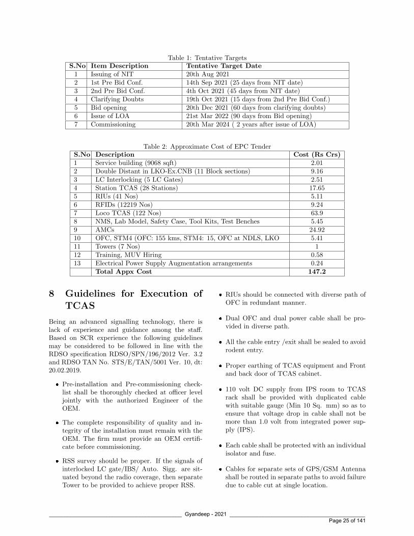
Table 1: Tentative TargetsS.No Item Description Tentative Target Date
1 Issuing of NIT 20th Aug 20212 1st Pre Bid Conf. 14th Sep 2021 (25 days from NIT date)3 2nd Pre Bid Conf. 4th Oct 2021 (45 days from NIT date)4 Clarifying Doubts 19th Oct 2021 (15 days from 2nd Pre Bid Conf.)5 Bid opening 20th Dec 2021 (60 days from clarifying doubts)6 Issue of LOA 21st Mar 2022 (90 days from Bid opening)7 Commissioning 20th Mar 2024 ( 2 years after issue of LOA)
Table 2: Approximate Cost of EPC TenderS.No Description Cost (Rs Crs)1 Service building (9068 sqft) 2.012 Double Distant in LKO-Ex.CNB (11 Block sections) 9.163 LC Interlocking (5 LC Gates) 2.514 Station TCAS (28 Stations) 17.655 RIUs (41 Nos) 5.116 RFIDs (12219 Nos) 9.247 Loco TCAS (122 Nos) 63.98 NMS, Lab Model, Safety Case, Tool Kits, Test Benches 5.459 AMCs 24.9210 OFC, STM4 (OFC: 155 kms, STM4: 15, OFC at NDLS, LKO 5.4111 Towers (7 Nos) 112 Training, MUV Hiring 0.5813 Electrical Power Supply Augmentation arrangements 0.24
Total Appx Cost 147.2
8 Guidelines for Execution ofTCAS
Being an advanced signalling technology, there islack of experience and guidance among the staff.Based on SCR experience the following guidelinesmay be considered to be followed in line with theRDSO specification RDSO/SPN/196/2012 Ver. 3.2and RDSO TAN No. STS/E/TAN/5001 Ver. 10, dt:20.02.2019.
� Pre-installation and Pre-commissioning check-list shall be thoroughly checked at officer leveljointly with the authorized Engineer of theOEM.
� The complete responsibility of quality and in-tegrity of the installation must remain with theOEM. The firm must provide an OEM certifi-cate before commissioning.
� RSS survey should be proper. If the signals ofinterlocked LC gate/IBS/ Auto. Sigg. are sit-uated beyond the radio coverage, then separateTower to be provided to achieve proper RSS.
� RIUs should be connected with diverse path ofOFC in redundant manner.
� Dual OFC and dual power cable shall be pro-vided in diverse path.
� All the cable entry /exit shall be sealed to avoidrodent entry.
� Proper earthing of TCAS equipment and Frontand back door of TCAS cabinet.
� 110 volt DC supply from IPS room to TCASrack shall be provided with duplicated cablewith suitable gauge (Min 10 Sq. mm) so as toensure that voltage drop in cable shall not bemore than 1.0 volt from integrated power sup-ply (IPS).
� Each cable shall be protected with an individualisolator and fuse.
� Cables for separate sets of GPS/GSM Antennashall be routed in separate paths to avoid failuredue to cable cut at single location.
____________________________________________ Gyandeep - 2021 _____________________________________________ Page 25 of 141

Table 3: Details of LC Gates/ Auto Sigg Huts in NDLS-GZB-CYZ SectionS.No Controlling Station LC/Auto Hut No. Chainage Type of Interlocking
1 NDLS/TKJ ARH Relay based2 TKJ/BPNL ARH1 2/14 Relay based3 TKJ/BPNL ARH2 3/19 Relay based4 TKJ/BPNL ARH3 7/02 Relay based5 SBB/GZB ARH1 15/7-9 Relay based6 SBB/GZB ARH2 16/7-9 Relay based7 SBB/GZB ARH3 17/7-9 Relay based8 SBB/GZB ARH4 18/7-9 Relay based t
Table 4: Details of NDLS-GZB-CYZ SectionSection Length 26 RKMMax. Permissible Speed 160 KMPHNumber of Lines 1. 6 lines from New Delhi to Tilak Bridge
2. 2 lines from Tilak Bridge to B-Panel3. 2 lines from Anand Vihar terminal to Sahibabad4. 4 lines from Sahibabad to Ghaziabad5. 3 lines from Ghaziabad to Chipiyana6. 3 lines from Chipiyana till auto section boundary of CYZ-MIU section.
System of Block working Automatic
� Tower location drawing should be Jointly ap-proved by S&T, Civil, Electrical departments.
� Soil Test for tower Foundation to be done by aGovernment/ reputed approved institute.
� Foundation & Tower installation to be donein coordination with Civil Engineering depart-ment.
� Tower foundation & structure design and draw-ing should be proof checked by independent 3rdparty (e.g. CPRI).
� Approval of Bridge department of Zonal Railwayshould be obtained for Tower foundation andstructure design & drawing.
� After erection of tower, activities like Towerpainting, fencing, earthing, Lightening arrestor,Aviation lamp fitting to be ensured.
� The RFID tags shall be fitted on the sleepers be-tween the rails as per guidelines given for IndianRailways .
� No holes shall be drilled in the Sleepers and theRFID Tags shall be fixed through clamps only.Due care shall be taken that damage/ punctur-ing to PSC sleepers is not caused.
� RFID tags fixing shall be avoided in turnoutportion. In any case, these shall not be locatedin switch portion of turnout.
� The performance of RFID tag may get degradedduring RFID Fixture getting submerged in wa-ter. Therefore, installation should be done con-sidering this fact.
� The installation of RFID tag and fixture shouldbe avoided at locations susceptible to ballast ac-cumulation at the center of sleeper such as levelcrossing etc.
� RFID Tags in Block Section shall be placed withconsideration to the ease of maintenance andvandalism. These should be placed, if feasible,in vicinity of EC sockets, LC gate or any otherplace where a maintainer is usually required tovisit.
9 OFC and Power Cable Lay-ing
Cable laying: 48F TCAS OFC shall be laid onopposite side of the Track as for the existing 24FTelecom OFC as far as possible. In case SignallingPower cable is also required to be laid, the possi-bility of laying it with the 48F TCAS OFC may
____________________________________________ Gyandeep - 2021 _____________________________________________ Page 26 of 141

be examined and executed with the approval ofthe Competent authority. Second Signalling Powercable for ring Protection can be laid on other side ofthe Track.
OFC Cable Policy: As per Railway Board letterNo. 2013/Sig/TCAS/Status Dt. 18.01.2021, Re-mote Interface Units (RIUs) shall be connected inring fashion and they shall be able to connect to sta-tion TCAS in case of failure of main path. For thispurpose one new 48 fibre OFC shall be laid. Out ofthese 48 fibres, 6 fibres shall be used for signallingpurpose (4 working + 2 spares). In addition to that,4 fibres in existing OFC cable shall also be used forring protection. The circuits on these 4 fibres of ex-isting OFC cable shall be transferred to new OFCcable. Separate OFC shall be laid from the nearestjoint in existing OFC to extend to RIU Hut. Thenewly laid OFC shall be maintained by Telecom oras decided later on.
10 References
1. Specification of Train Collision Avoid-ance System (TCAS) Specification No.RDSO/SPN/196/2012 Version 3.2 issuedby Signal Directorate, Research Designs &Standards Organisation, Ministry of Railways,Manak Nagar, Lucknow – 226011.
2. Handbook on Train Collision Avoidance Sys-tem (TCAS) - An Indigenous ATP System,CAMTECH/S/PROJ/2020-21/SP10/1.0 April2021, by Indian Railways Centre for AdvancedMaintenance Technology Maharajpur, Gwalior(M.P.) Pin Code – 474 005
3. A Paper on ‘Train Collision Avoidance System(TCAS) Implementation - Way Forward’ byV N M Rao, IRSSE CSTE/Projects/SC/SCRand M. Muni Kumar, IRSSE, DyC-STE/Projects/Tele/SC/SCR
4. Project report on Execution Strategy for Im-plementation of TCAS on Northern Railway– Dt 09.07.21 by Sh Rajendra Kumar Yadav,CSE/II/Northern Railway.
5. Inputs from Sh. K V Reddy, DRM/Guntkal(Ex SPS/IRISET), Sh D K Singh,DRM/Alipurduar (Ex ED/Tele/RDSO), Sh DB Singh, ED/Sig/RDSO, Sh Neeraj Gupta,CSTE/Proj/East, Northern Railway, Sh Ra-jendra Kumar Yadav, CSTE/Proj./Planning,
Northern Railway. and Sh Prabhakar SharanDy CSTE/TW/NDLS, Northern Railway.
Shri Jai Prakash Sindhuis an officer of the 1990batch of Indian RailwayService of Signal Engineers.He did his B.Tech. (Electri-cal Engineering) from IITDelhi in 1989 and M. Tech.(Communication & RadarEngineering) in 1991 fromIIT Delhi. Prior to joining Indian Railways as IRSSEprobationer, he worked as Research and Develop-ment Engineer in ITI Naini. He has about 30 yearsof experience of working in various capacies in IndianRailways. He has held various positions in Railwaysin Open line, Microwave maintenance, Project Units& Construcon units. He has worked on NorthernRailway, East Central Railway, IRCOT, IRCON andRailway Board. He is presently working as Chief Sig-nal & Telecom Engineer/Project in Northern Rail-way.
____________________________________________ Gyandeep - 2021 _____________________________________________ Page 27 of 141

Comprehensive Planning of TCAS (KAVACH) Towers
V N M Rao, IRSSE, CSTE/Projects/SC/SCRManoj Kumar Gupta, IRSSE, CSE/SCR
C. Sivakumar Kashyap, IRSSE, DSTE/TCAS/SC/SCR
Abstract
With the advent of high speed and high densityRail Networks over IR, implementation of AutomaticTrain Protection (ATP) systems has become a sinequa non for ensuring safety of trains. Most ATP sys-tems provide an additional layer of safety over theexisting interlocking systems so as to aid the locopilots. All the ATP systems need radio communica-tion towers for functioning. This paper discusses therationale behind the decision making learnt duringthe course of TCAS implementation in South Cen-tral Railway.
1 Need for CommunicationTowers
Communication between locomotive TCAS andstationary TCAS is exclusively through radio waves.At present, TCAS uses spot frequencies in 400MHz to 450 MHz band (f0 – 441.8 MHz, f1 –456.8 MHz, f2 – 416.8 MHz, f3 – 466.8 MHz, f4– 426.8 MHz). Considering the scenario wherea loco is moving from block station A to blockstation B, it should communicate with stationsA and B for approximately half the distance ofblock section each. Without loss of generality, ablock section can safely be assumed to be around10 km. This means that one stationary TCASequipment should cater to around 5 km communi-cation. An antenna at ground level can simply notperform the job. Here arises the need for communi-cation towers to increase the range of radio coverage.
2 Initial Reconnaissance Sur-vey for Towers and their Fea-sibility
The most important initial step in taking up towerworks is to carry out initial survey studying the feasi-bility of towers keeping in mind factors such as heightof tower, signal strength, ease of construction andmaintenance of sites. During this survey, sites couldbe classified into Green, Amber and Red based onthe difficulty of implementation
A typical survey format detailing various geograph-ical and technical factors for identifying tower plotlocation is given below. Name of the Station /IBS / LC Gates for the proposed Tower loca-tion :
3 Selection of Tower
3.1 Selection of Type of Tower
Based on the initial planning, drone survey, RadioSignal Strength Indicator (RSSI), site reconnaissancesurvey, tower types are chosen. The types of towersare discussed below.
(a) Self Supporting Lattice Towers – They can beangular, tubular or a hybrid of both angular andtubular. Similarly, self supporting towers are ei-ther 3 or 4 legged.
(b) Self Supporting Monopole – It is a single selfsupporting pole. This design is generally usedto minimise foot print at the site which is easilyaccessible.
(c) Narrow Based Self Supporting Lattice Tower –It is generally a 4 legged tubular tower upto 40m height with very low foot print. It is usedas a substitute to monopole when there are noaesthetic constraints.
____________________________________________ Gyandeep - 2021 _____________________________________________ Page 28 of 141

Classification Green Amber RedPlot Size No limitation Poses limitation in Tower
Height / Design SelectionSerious Constraints
Plot Access No limitation Poses possibility of HeadLoad
Serious Constraints
Ground Water No limitation Moderate saturation pos-ing limitation in selectionof tower
Extreme saturation
Soil / Rock Condi-tions
Good soil and non-rocky conditions
Moderately good soil Extreme limitation in soilstrength
Summary Action None Tackling with DesignModifications
Find alternatives beforecontract is awarded.
Table 1:
S.No Survey Item Description Remarksa Any High Rise Buildings/trees available near proposed tower location Yes/Nob Type of Soil-Rocky/Clay/Black Cotton/Sand etcc Soil is natural mother earth or filled soild Nearest Airport available to the station/LC gate/IB& Distance in Kmse Is Station/LC gate/IB situated in Forest area Yes/Nof Is Station/LC gate/IB situated in Coastal area(with in 15 Kms from
Coast)Yes/No
g Tower shall be placed 46 m (Horizontal Distance) away from the Nearesttrack as far as possible. Is 46 m Horizontal Railway Boundary clearanceavailable
Available/NotAvailable Distancebetween tower andnearest track centre-
h Availability of high tension wires in near vicinity Yes / Noi Any water pipelines in near vicinity of tower location Yes / Noj Availability of staff quarters/houses nearby Yes / Nok Availability of underground Signalling / Telecom, / Power cables / OFC Yes / Nol Interdistance Distance between proposed tower and Relay roomm Interdistance Distance between nearest track centre to railway boundaryn Quad cable, OFC, signalling cable paths (same side/other side of tower
location)Quad - OFC - Sig-nalling -
o Longitude & Lattitude coordinates of proposed tower site for Ligowavesoftware / WPC / MSL
Longitude - Lati-tude - MSL - Pin-code -
p Attachment of site photos Yes / Noq Motorable access to the proposed site for transportation of fabricated
tower materialsYes / No
r Any future plans by other departments for utilisation of proposed towerplot area
s Any sanction of ROB / RUB in lieu of LC gate Yes / Not Sanction of new interlocked LC gateu Other information if any
Table 2:
____________________________________________ Gyandeep - 2021 _____________________________________________ Page 29 of 141

Characteristic 4 LeggedAngular
3 LeggedAngular
NarrowBased
Monopole
Foot Print 4 3 2 1Visual Appeal 4 3 2 1Ease of Fabrication 1 2 3 4Ease of Erection 3 1 2 4Overall Cost 2 1 3 4Remarks (1 denotes lowest / cheapest / easiest) (4 denotes highest / costliest / difficult)
Table 3:
Figure 1: Three Legged Angular Tower
Figure 2: Four Legged Angular Tower
Figure 3: Tubular Tower
Figure 4: Monopole Tower
____________________________________________ Gyandeep - 2021 _____________________________________________ Page 30 of 141

Figure 5: Narrow Based Tower
Monopole tower requires motorable road access tosite, long boom cranes, space for horizontal assem-bly of monopole at site and lifting of monopole usingcrane. This means that monopole is not a recom-mended option over lattice tower at constrained sitelocations. At such locations, narrow based latticetowers are preferable. As such, it is opined that threelegged tubular tower of 40 m height is preferable inline with RDSO guidelines to have uniformity andstandardisation.
3.2 Selection of Height of Tower andNumber of Towers
The height of tower and number of towers can bedecided based on the following inputs.
(a) Geological conditions of site – Soil Bearing Ca-pacity, Water Table, Drainage etc
(b) Accessibility of site for carrying material
(c) Radio network link calculations. The receivedsignal strength should not be poorer than (-)85dBm throughout the communication mandatoryzones. It may be ensured that there are no ob-structions in 60% of the First Fresnel Zone asshown in Figure 6.
(d) The antennae for communication system of sta-tionary TCAS system shall be able to providea minimum range of communication upto 1.5km beyond the the first signal of the station-ary TCAS unit. This is typically 4.5 km in caseof double distant territory. In the case of IBS /Mid-section Interlocked LC Gates, this is muchsmaller and hence, 15 m / 20 m tower could alsobe explored based on survey details.
(e) Design Basis Report of complete route contain-ing the following
(i) Confirmation of tower (3 legged, angular /Tubular, Monopole, etc.,)
(ii) Elevation of antenna on the tower structure
(iii) Wind speed
(iv) Terrain condition
(v) Seismic conditions
(vi) IR Code of Practice issued by RDSO tobe followed for structural designs, fabri-cation and erection of towers. Referenceto RDSO’s B&S Directorate checklist onDesign of Super-structure for TCAS towervide document dated RDSO-BnS0EBS(SB-2)/16/2020-O/o ED/BnS/RDSO dated11/01/2021.
(vii) Material specification
(f) Above details can be finalized by
(i) Reconnaissance (Walk over survey)
(ii) Ligowave software to decide the antennaheight
(iii) Drone survey to have the exact locationsof stations, Signal structure, IBS and Autogoomties, kilometer stones, traction mastsetc.
(g) RSSI (Received Signal Strength Indicator) Sur-vey is required to fine tune the antennas light,which is already available with the help ofLigowave software using the longitude and lati-tude of tower location at stations, IBS and Auto-goomties, LC gates, etc.
(h) If we fine tune the antennas height also in thebeginning, then only RSSI survey in advance ofinviting EPC tender is required.
____________________________________________ Gyandeep - 2021 _____________________________________________ Page 31 of 141
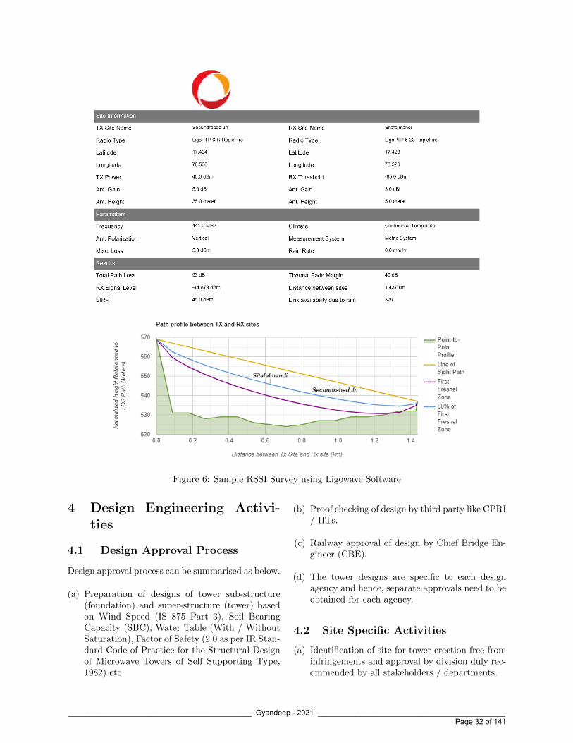
Figure 6: Sample RSSI Survey using Ligowave Software
4 Design Engineering Activi-ties
4.1 Design Approval Process
Design approval process can be summarised as below.
(a) Preparation of designs of tower sub-structure(foundation) and super-structure (tower) basedon Wind Speed (IS 875 Part 3), Soil BearingCapacity (SBC), Water Table (With / WithoutSaturation), Factor of Safety (2.0 as per IR Stan-dard Code of Practice for the Structural Designof Microwave Towers of Self Supporting Type,1982) etc.
(b) Proof checking of design by third party like CPRI/ IITs.
(c) Railway approval of design by Chief Bridge En-gineer (CBE).
(d) The tower designs are specific to each designagency and hence, separate approvals need to beobtained for each agency.
4.2 Site Specific Activities
(a) Identification of site for tower erection free frominfringements and approval by division duly rec-ommended by all stakeholders / departments.
____________________________________________ Gyandeep - 2021 _____________________________________________ Page 32 of 141

(b) Collection of soil samples at the identified loca-tions and their lab testing
(c) Submission of Soil Investigation Report statingSBC to railways along with relevant foundationdrawing for review and approval.
(d) Final approval for “Fit for Construction” byproject executing unit.
4.3 Site Execution Activities andTimelines
Note : Tower construction would take approximately45 days per tower. By engaging four teams each ofCivil, Tower and Site supervision, approximately 12towers sites can be completed in a month with con-current management. However, the above parallelactivities will become effective after initial period of6 to 8 weeks from the commencement of the projectactivities.
5 Inspections and Testing ofTower
5.1 Inspection and Tests for Founda-tion and Tower
5.2 Tower Super-structure MaterialInspection by RITES – QualityAssurance Plan (QAP)
Tower super-structure material inspection is done byRITES at two stages.
1. Raw material inspection for super-structure oftower
2. Inspection of finished goods (members) of towersuper-structure
RITES inspection shall be carried out in accordancewith Quality Assurance Plan (QAP) that has beenprepared and agreed by all the stakeholders – Rail-way, Tower Designer, Contractor Agency and TowerFabricator. Necessary approvals shall be obtainedfrom CBE. The broad guidelines of QAP and manu-facturing process right from raw material to finishedproduct are elaborated below.
table
6 Cable Connectivity forTower at Stationary TCASLocations
Cable shall be provided at stationary TCAS loca-tions for tower catering to the power supply radiomodems, aviation lamp and RF transmission of data.Cable connectivity diagram is shown below.Notes for Figure 8
1. Two diversified cable paths shall be providedas far as possible, from STCAS to the tower toavoid common mode failures.
2. 6/24 OFC cable in diverse path shall be pro-vided from STCAS to the tower to avoid com-mon mode failures.
3. 12 Core Signalling cable or Power cable for op-erating Radio of aviation lamp.
4. 12 Core Signalling cable between SMOCIP toStationary TCAS.
5. OFC cable for NMS purpose
6. LMR-600 RF coaxial cable from the two radiomodems to antennae shall be routed in the dif-ferent paths.
7 WPC / SACFA ClearanceProcess
Wireless Planning and Coordination (WPC) clear-ance is necessary for the operation of radios in India.This clearance is for the operation of radio. Site spe-cific clearances such as defence areas, airport areaetc., are given through SACFA clearance. Revisedprocess for the application is given below.
(a) SARALSANCHAR (Simplified Application ForRegistration and Licenses) a Web based Portal,for Issuing of various types of Licenses and Reg-istration certificates is part of various Digital ini-tiatives being taken by Department of Telecom-munications.
(b) Applications to be processed in SARALSAN-CHAR online portal through sub-user creation
(c) A Master User has been created for Ministry ofRailways for creation of Sub-Users on Saral Plat-form of WPC (SACFA), who can then apply fur-ther for allotment of frequencies
____________________________________________ Gyandeep - 2021 _____________________________________________ Page 33 of 141

____________________________________________ Gyandeep - 2021 _____________________________________________ Page 34 of 141

____________________________________________ Gyandeep - 2021 _____________________________________________ Page 35 of 141

Figure 7: Typical Tower Site Photographs
Figure 8: Cable Connectivity Diagram for TCAS at Stationary TCAS Locations
____________________________________________ Gyandeep - 2021 _____________________________________________ Page 36 of 141

(d) TCAS uses FIVE frequency spots in 400 MHzto 450 MHz band. (f0 - 441.8 MHz, f1 - 456.8MHz, f2 - 416.8 MHz, f3 - 466.8 MHz and f4 -426.8MHz).
(e) SCR has initially processed applications for theWPC clearance for TCAS frequencies during De-cember 2020 after introduction of Portal.
(f) Two Radios for each STCAS/LC TCAS and Tworadios for each Loco TCAS and 10
(g) There is a restriction of maximum 99 nos. ofradios per application in the portal, hence pro-cessed with multiple applications (Six) to caterthe entire 1200km on-going TCAS project.
(h) Approval process takes 6 to 8 months and henceRailways shall initiate the process well in ad-vance
(i) With Dealer Possession License (DPL), OEMscan import TCAS Radios, but for supply andoperation WPC license is required.
(j) Main aim of Standing Advisory Committee onRadio Frequency Allocation (SACFA) is to en-sure aviation safety and security and addressedby clearance for a tower/ antenna / site ( Heights¿ 30 Meters)
(k) Initiation of SACFA clearance after obtainingthe Decision letter from WPC which is a pre-requisite to fill the online application for SACFAclearance in the portal.
8 Maintenance of Towers
Once TCAS towers are erected, it is essential thatthey are kept in “fit” condition through regular main-tenance. It generally consists of general inspection,fault tracing, checking of tower aviation lights, quar-terly checking of condition of foundation, corrosion,tilt, nut and bolt tightness, distortion of members,cabling intactness, earthing, half yearly verticalitycheck and other need based maintenance. Painting oftower is also needed every three years. SCR has ad-dressed the issue by entering into a Memorandum ofUnderstanding (MoU) with RailTel for maintenanceof towers.
9 Experience of SCR inKAVACH Deployment
SCR has faced many challenges in KAVACH towerinstallation. Some of them are summarised below.
10 Conclusion
Successful deployment of TCAS needs timely erec-tion of communication tower for establishing connec-tivity between Stationary TCAS and Loco TCAS.One of the critical activities of KAVACH deploymentis construction of towers and none of the testing ac-tivities could be initiated without the erection of tow-ers. South Central Railway has successfully erectedmore than 100 Lattice towers within a year overcom-ing the above challenges and paved the way for im-plementation of TCAS in 1200 RKM in SCR. Initialreconnaissance survey for towers and their feasibility,meticulous planning, regular progress reviews withtower contractors, resolving site issues, concurrentmanagement of tower activities are some of the keyareas for meeting the targets. ADEN or SSE/Workspossessing adequate competency in Civil foundationsand steel structures shall be deputed under the ad-ministrative control of S&T department for autho-rised working.
____________________________________________ Gyandeep - 2021 _____________________________________________ Page 37 of 141

Figure 9:
____________________________________________ Gyandeep - 2021 _____________________________________________ Page 38 of 141

Shri V.N.M. Rao is anIRSSE 1996 Batch officerjoined Indian Railways in1998 after completing hisMasters Degree from IIT,Roorkee. He has 23 Yearsof experience in RailwaySignalling field. He hasworked in the southern partof Indian Railways as In-charge Maintenance En-gineer as well as Project Executing Officer. Hehas handled various modern signalling projects likeTPWS(ETCS-L1),EI, AFTC, and MSDAC in South-ern Railway as CSTE/Projects, Chennai. He hassuccessfully commissioned TPWS projects of M/sAnsaldo make at Chennai Beach Gummidipundi Sec-tion and M/s Thales make TPWS system at BasinBridge Junction-Arakkonam Section with interop-erability between the vendors. He has four yearsSignalling Design experience in UK Signalling whileworking for UK Railways under M/s Atkins, Shar-jah. He possesed an IRSE (UK) license for Sig-nalling Scheme Designer, Signalling Principles De-signer and Signalling Design Verifier. He was in-strumental in successful commissioning of importantGlobal projects such as Rugby and Nuneaton (RuN)SSI Project with Centralized Traffic Control etc,while on deputation. He is an Executive CouncilMember for IRSTELO which is responsible to oper-ate Licensing Scheme for Competence assessment inS&T field of Indian Railways. He is currently work-ing as CSTE/Projects/South Central Railway, look-ing after TCAS & other modern S&T projects inSCR and spearheaded for successful deployment ofKAVACH in 600Kms in the current year in SC Rail-way.
Shri Manoj Kumar Guptais an officer of IndianRailway Service of Sig-nal Engineers 1998 batch.He completed his Masterof Engineering (Electronicsand Communication) fromMalviya Regional Engineer-ing College, Jaipur (re-named as Malviya NationalInstitute of Technology) in 1998. He has 21 yearsof experience of working on Indian Railways. He
has held various positions in open line, construc-tion, drawing and design and headquarters at variousplaces in Western, North Western and South Cen-tral Railway. He has considerable experience of exe-cution and commissioning of various targeted workslike traffic facilities, gauge conversion, new lines andyard remodelling works apart from the maintenanceof signal and telecommunication assets. He has lastworked as Chief Signal Engineer - II, South CentralRailway.
Shri C Sivakumar Kashyapis an IRSSE 2013 Batchofficer joined Indian Rail-ways in 2014 after complet-ing his Bachelor’s Degreefrom IIT Kharagpur. Hehas 7 years of experiencein Railway Signalling field.He is handling Train Colli-sion Avoidance System deployment in South CentralRailway as a Divisional Signal and Telecom Engi-neer. He was the engineer-in-charge for maintenanceactivities of Signal and Telecom department in Se-cunderabad and Guntakal Divisions at Kazipet andRaichur.
____________________________________________ Gyandeep - 2021 _____________________________________________ Page 39 of 141

Implementation of TCAS (KAVACH) in Automatic
Block Signalling Territory
V N M Rao, IRSSE, CSTE/Projects/SC/SCRM. Muni Kumar, IRSSE, Dy.CSTE/Projects/Tele/SC/SCR
Abstract
With the advent of high speed and high density RailNetworks over IR, in order to ensure safety, it ismandatory to implement Automatic Train Protec-tions (ATP) Systems such as TCAS, ETCS-L1, L2etc. As per the extant guidelines issued by Rail-way Board, indigenously developed and RDSO ap-proved TCAS should be implemented across IndianRailways in line with the strategy of adapting Na-tional ATP system for Hon’ble PM’s vision of AtmaNirbhar Bharat. In order to achieve line capacityenhancement TCAS and Automatic Block Signalling(ABS) systems are to be provided. At present worksover 35,000 RKms have been sanctioned for provi-sion of TCAS along with Automatic block signalling(ABS) and CTC. Ministry of Railways has given anambitious target of completion of TCAS (KAVACH)works by 2024. Fitness of TCAS to work in ABS sec-tions has been tested and approved by RDSO.Thisdocument summarizes as how TCAS would be im-plemented successfully in Automatic Block Sectionterritory based on the experience gained in SouthCentral Railway.
1 Introduction of ABS andTCAS (KAVACH)
Automatic block signalling (ABS) is a method ofrailway signalling where a railway line is dividedinto a succession of track sections or blocks. Trackcircuits/Axle Counters are installed to enablecontinuous train detection along the rail line. TheseTrack circuits/Axle Counters then control the stopsignals, governing train entry into an automaticblock section.
Indian Railways have taken up indigenous de-velopment of an ATP system - called as TrainCollision Avoidance System (TCAS) through itsResearch & Design wing RDSO to prevent dan-gerous train collisions caused due to human errors
or limitations and equipment failures by providingadditional layer of enhanced safety in the operations.
TCAS (KAVACH) is meant to provide protection bypreventing trains passing Signal at Danger (SPAD),excessive speed over turnouts / speed restrictionsand to avoid the situation where more than onetrain are on the same track leading to imminentcollision even in non-signaled territory if operationsare not able to control so.
It acts as a safety aid to provide assistance to LocoPilots by means of real-time display of signalling re-lated information such as Movement Authority, Tar-get Speed, Target Distance, Signal Aspects, overspeed alerts & beeps etc. in Loco Pilot’s cab.
2 Implementation of TCAS inAuto section
2.1 Centralization of Signalling In-formation
Depending upon Zonal Railway practices, Cen-tralized or Distributed Signalling Interlocking isadopted for Automatic signalling. In DistributedAuto signalling, the Interlocking and Relay func-tions are available at particular Signal LocationBox, this envisages provision of RIU/STCAS atSignal Location boxes. The disadvantages of thisDistributed Interlocking are Poor Maintainability,Poor accessibility and EMI/EMC issues. To meetthe future/modern Signalling demands such asEI/CTC/TMS/TCAS etc., working over OFCbackbone, it is required to convert the existing Dis-tributed Auto-signalling to Centralized Architecture.
Therefore, the primary requirement of ModernSignalling System is CENTRALIZATION i.e tomake signalling Information of Auto sections readilyavailable at centrally located Interlocking system at
____________________________________________ Gyandeep - 2021 _____________________________________________ Page 40 of 141

Centralized Hut using redundant OFC Network.
For this purpose, in Automatic signalling Territory,masonry Auto Location Huts (ALH) are to beconstructed and strategically located at every 3-3.5Kms to bring Signal, Track detection and LC gateinformation. Each ALH will cover 3-4 signals oneach line, i.e., for Double Line Section approximately6-8 Signals are catered. Based on the length of blocksection, the number of ALHs to be decided to caterboth Up and Down signalling.
The ALH shall be spacious enough for accommo-dating Track Detection Devices (MSDAC Evalu-ators/ AFTC / DC Track circuits), Relay racks,Data Logging equipment (Data logger/RTUs),Remote Diagnostic system, I/O Gatherers (OC/FNMUX/UFSBI, STCAS/RIU), CTC/TMSInterface equipment etc. Further, IPMPLS and LTEinterface equipment may also need to be locatedin ALHs. The equipment provided at ALH shallbe powered by IPS with LMLA/VRLA batterybank. For effective communication between Stationto ALH and ALH to ALH, 48 Fibre OFC shall belaid on UP & DN Lines to facilitate path diversity.Fire detection and suppression systems also to beconsidered for safety.
ALH eliminates problems like fatigue of electroniccomponents due to high temperatures, dry solderingdue to dust & humidity, EMI / EMC effects in REarea. Centralized IPS connected to UP/Down ATensures high Availability of redundant & uninter-rupted power supply to the equipment.
There are different means available for transfer ofSignalling functions between Station to ALH andALH to ALH and are detailed below :
(a) Failsafe Multiplexer (FNMUX): This SIL4equipment does multiplexing of signalling relayinformation wired inside the ALH and transmitsto station through OFC network. At the otherend of the station, demultiplexing takes placeand generates Relay I/Os to be wired to the In-terlocking system, thus ensuring the entire blocksection between stations can be made availablecentrally for further processing. However, RDSOspecifications for FN-MUX equipment are underissue. Nowadays, internal FNMUX is a part ofRDSO approved MSDAC system being used fortrack detection in Auto sections and hence thesame can be used for transfer of signalling datato central interlocking.
(b) Object Controller (OC): Object Controller to bekept in ALH is a slave unit of EI placed at stationand transfers signalling I/Os to EI. However, incase of brown field projects, EI at stations shallbe with Distributed architecture and the samemake OCs shall be ensured at ALH. At times,this may warrant premature replacement of non-distributed type EIs/RRI/PI at stations in orderto match with the proposed OCs to be kept atALHs. Modification of Application Logic datahas to be taken care at stations. Keeping OCs atALH is robust and give best response times be-ing common hardware platform. However, thisarrangement is costlier and invites high main-tainability similar to Station EI system and highMTTR. By and large, this is an ideal solution forgreen field projects to have uniform EI with OCsthroughout the section connected via redundantOFC network and fed by uninterrupted IPS.
(c) Universal Failsafe Block Interface (UFSBI): Thisis an another RDSO approved legacy equipment,works on point-to-point basis unlike FNMUXwhich works on point to multi point. A pair ofUFSBI for either side demands large space insideALH and to be connected through redundantOFC communication media to transmit/receivethe signalling data from ALH to ALH and ALHto station.
(d) Remote Interface Unit (RIU): Remote InterfaceUnit (RIU) of TCAS, which captures the relayinputs wired to it, multiplexes and exchangesthe data with master STCAS through dark fi-bre. RIU does not demultiplex to generate RelayI/Os at station and always works in conjunctionwith STCAS. As such it is a proprietary deviceof TCAS OEMs and hence cannot be used forgeneric applications like any other I/O gatherer.
As such, Centralization in Automatic Signallingsection needs the following basic infra for implemen-tation of TCAS and CTC along with ABS:
(a) Construction of Masonry Huts at every 3-3.5Kms.
(b) Centralization of Signal, Track Circuit & LCgate information wired at ALH covering 6 to 8Up & Down signals spread within 3-3.5 Kms.This needs laying of continuous 30 Core sig-nalling cables, Up & down Power cables (wher-ever AT supply is not available), 6 Quad cablesfor MSDAC/AFTC between stations.
____________________________________________ Gyandeep - 2021 _____________________________________________ Page 41 of 141

(c) Continuous OFC (2 X 48 fibre) on either side oftrack with path diversity to ensure high avail-ability besides double ring protection.
(d) UP/Down AT supply source at each ALH
(e) Centralized IPS connected to UP/Down ATs toensure high availability of redundant & uninter-rupted power supply.
2.2 Criteria for Placement of RemoteInterface Unit (RIU) and Com-munication Network
(a) Placement of RIUs in Auto section : RIUis a miniature version of STCAS without radiocommunication unit, which captures the relayinputs wired to it, multiplexes and exchangesthe data with master STCAS through darkfibre. In a Ring network, each RIU is connectedto two adjacent RIUs in primary and secondarychannels and capable of handling at least 32field inputs.
RIU shall be used where remote signallingfunctions are required to be fetched to a nearbyStationary TCAS unit, for example from endcabin of distributed interlocking, a nearby LCGate, Intermediate Block Section or AutomaticSignalling section.As such RIU is an extendedsignal condition card kept at remote place (e.g.LC gate) and wired through OFC to senddata to STCAS kept at adjacant station.
RIU shall be installed only if they are comingwithin the RF communication coverage of sta-tion tower to maintain continuous connectivitybetween STACS and Loco TCAS. RIU shall notbe used when there is no radio coverage andhence an independent tower to be provided alongwith LC TCAS/STCAS instead of RIU.
(b) Connectivity of RIUs:Fig.1 depicts the typ-ical scheme for TCAS RIU connectivity in Au-tomatic signal territory. Minimum Four dark fi-bres are needed for connecting the RIUs to theirrespective STCAS with double ring protectionarrangement. If fibres are available same maybe used otherwise one new 48 fibre OFC shall belaid. Out of these 48 fibres, 6 fibres shall be usedfor Signalling purpose (4 working + 2 spare). Inaddition to that, 4 fibres in existing OFC ca-ble shall also be used for ring protection. Thecircuits on these 4 fibres of existing OFC cable
shall be transferred to new OFC cable. SeparateOFC shall be laid from the nearest joint(OFCcahmbers) in existing OFC to extend to RIUhut. The signal information of at least two/threesignals in overlap zone has to be wired to ei-ther side of stations for relaying the MovementAuthority (MA) information for seamless TCASfunctionality with smooth handing over of LocoTCAS from one STCAS to another during com-munication change over between stations. Thisavoids abrupt braking by Loco TCAS due to con-tinuous availability of MA in Auto section. Toachieve this, additional/duplicated RIUs need tobe wired in the overlap communication zone topump the data to adjacent station TCAS units.Alternatively, if the provision of direct STCASto STCAS communication is available, which isunder development by RDSO, the requirement ofthese additional RIUs can be dispensed with fig.2depicts the radiocommunication arrangement inoverlap zone in Automatic block territory forTCAS.
Note for Fig.1:
(a) RIU1 and RIU2A are wired with STCAS-1at Station A. RIU2B and RIU3 are wiredwith STCAS-2 at Station B. AUTO HUT 2data in overlap zone is required to be avail-able at both Station A and Station B toensure continuous availability of MovementAuthority, hence duplicate RIUs 2A and 2Bare used at AUTO HUT 2.
(b) RIUs are connected with the concernedSTCAS unit and with adjacent RIUsthrough dark fibre.
(c) Double ring protection is to be made avail-able with two 48 fibre OFCs laid with pathdiversity. Alternatively, it can be achievedby swapping between the existing RailtelOFC and newly laid 48 fibre OFC on theother side of the track w.r.t Railtel OFC.
(d) Single fibre is used for both Tx & Rx ineach communication link.
(e) otal 4 fibres (2 fibres from each of the twoOFCs) are required from Station A to Sta-tion B to achieve double ring protection(i.e., Channel-A and Channel-B).
(c) Communication Requirements: Unlike ab-solute block section, Radio communication ismandatory for the entire automatic block sec-tion. RF overlap of 1Km in Auto section is re-quired depending on Design speed, Emergency
____________________________________________ Gyandeep - 2021 _____________________________________________ Page 42 of 141

Figure 1: Typical scheme for TCAS RIU connectivity in Automatic Signal Territory
Braking Distance, communication handing overtime etc. It is generally considered that a 40mhigh TCAS tower will have 4.5km radio rangeon either side, so additional towers with LCTCAS at midsection is required wherever inter-distance between stations is greater than 7 to8 km depending on the geographical conditions,vegetation, water bodies and high rise buildingswhich are impediments to Line of Sight (LoS)and received signal strength. Adaption of lowerheight towers of 15m/20m may be planned inthese sections as per the required coverage areato overcome the geographical limitations or ifthe auto section length is more than 7 to 8Kms.Altrnatively, towers with height of 30m orsuitable may be considered at station/ALH keep-ing in view of future LTE migration for decidingheight of the tower, RSSI survey may be carriedout using Ligowave or any other software andfirst survey.
3 Survey for TCAS in AutoSection
A detailed feasibility survey as per the standard for-mat is required to ensure the availability of space foraccommodating the RIUs inside ALH or distributedlocation box, availability of reliable & uninterruptedpower supply, fetching signalling information and es-tablishing OFC connectivity. In SC Railway, TCASWorks are completed for about 56 Kms of AutomaticSection and ready for deployment. A sample survey
analysis conducted before taking up TCAS works isdiscussed below:Based on the survey, the following three schemes areadopted:
(i) Scheme 1: Centralized IPS available at powerhuts, but signalling information (ECR, TR etc.)is available at distributed signal locations.
(ii) Scheme 2: Centralization of signalling andpower at ALH at every 3-3.5 Kms.
(iii) Scheme 3: Distributed signalling at locationboxes and 110V AC power fed from UP/DNATs through power cables.
In case centralization of signalling information inauto huts is not available, efforts shall be made tolay the signalling and Quad cables to bring signallingand track detection inputs in auto huts to feed RIUs.Based on the survey in the existing Auto section, thefollowing schemes are adapted:Scheme 1 (Power hut is available with central-ized IPS but without centralization of signals& track detection information): This scheme isadapted in Bolarum to Falaknuma section.
(A) Existing Signalling Arrangements:
� Signals generally are spaced 1km apart andhave 4 aspects.
� Track occupancy is detected by continuousDC track circuits. The section between twosignals is divided into 03 to 04 track cir-cuits.
____________________________________________ Gyandeep - 2021 _____________________________________________ Page 43 of 141
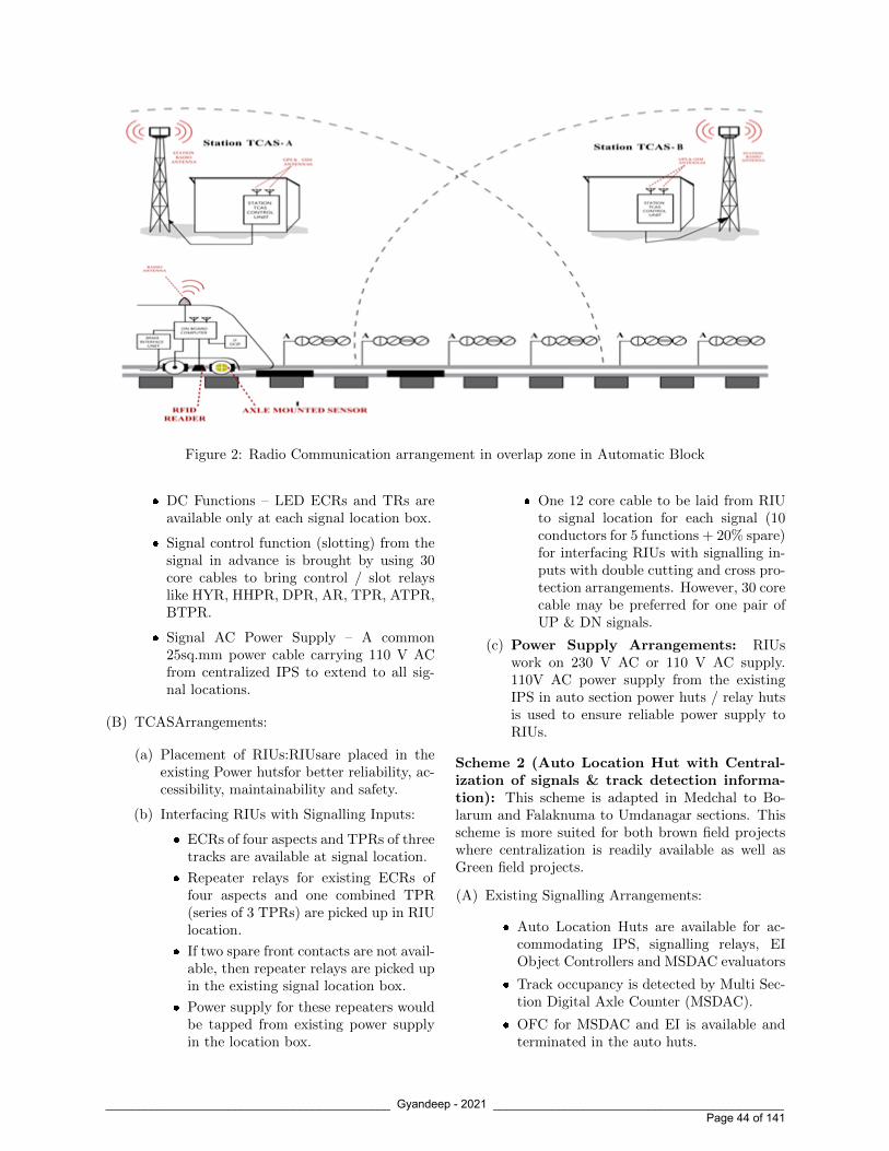
Figure 2: Radio Communication arrangement in overlap zone in Automatic Block
� DC Functions – LED ECRs and TRs areavailable only at each signal location box.
� Signal control function (slotting) from thesignal in advance is brought by using 30core cables to bring control / slot relayslike HYR, HHPR, DPR, AR, TPR, ATPR,BTPR.
� Signal AC Power Supply – A common25sq.mm power cable carrying 110 V ACfrom centralized IPS to extend to all sig-nal locations.
(B) TCASArrangements:
(a) Placement of RIUs:RIUsare placed in theexisting Power hutsfor better reliability, ac-cessibility, maintainability and safety.
(b) Interfacing RIUs with Signalling Inputs:
� ECRs of four aspects and TPRs of threetracks are available at signal location.
� Repeater relays for existing ECRs offour aspects and one combined TPR(series of 3 TPRs) are picked up in RIUlocation.
� If two spare front contacts are not avail-able, then repeater relays are picked upin the existing signal location box.
� Power supply for these repeaters wouldbe tapped from existing power supplyin the location box.
� One 12 core cable to be laid from RIUto signal location for each signal (10conductors for 5 functions + 20% spare)for interfacing RIUs with signalling in-puts with double cutting and cross pro-tection arrangements. However, 30 corecable may be preferred for one pair ofUP & DN signals.
(c) Power Supply Arrangements: RIUswork on 230 V AC or 110 V AC supply.110V AC power supply from the existingIPS in auto section power huts / relay hutsis used to ensure reliable power supply toRIUs.
Scheme 2 (Auto Location Hut with Central-ization of signals & track detection informa-tion): This scheme is adapted in Medchal to Bo-larum and Falaknuma to Umdanagar sections. Thisscheme is more suited for both brown field projectswhere centralization is readily available as well asGreen field projects.
(A) Existing Signalling Arrangements:
� Auto Location Huts are available for ac-commodating IPS, signalling relays, EIObject Controllers and MSDAC evaluators
� Track occupancy is detected by Multi Sec-tion Digital Axle Counter (MSDAC).
� OFC for MSDAC and EI is available andterminated in the auto huts.
____________________________________________ Gyandeep - 2021 _____________________________________________ Page 44 of 141

S.No Section Length(km)
AutoSignalHutAvail-able
Availabilityof PowerHut
Availabilityof SignalInputs inHut
Availabilityof Sig-nallingOFC
Action Required
1. MED-GDPL 8.33 2 Nos NA Yes Yes No action needed as allsignal inputs available inhut and OFC spares fibresavailable.
2. BMO-CVB 4.41 NO 1 No No NO Only IPS available inPower hut, space is avail-able for installation ofRIU and relays a) Central-isation of signal inputs tobe done in power hut b)OFC to be laid on bothsides
3. MJF-STPD B 1.6 NA NA NA No Only one auto signal avail-able in section. a) Sig-nalling inputs to be ex-tended to STPD B Cabin.b) OFC to be laid on bothsides
4. STPD B - SC 1.5 NA NA NA NA OFC to be laid on bothsides
Table 1:
� DC Functions – LED ECRs and axlecounter VPRs are available at Auto huts.
� Communication Protocol between EI &TCAS is under development by RDSO,hence RIUs are to be provided at ALHthrough OCs are available.
� In case internal FN-MUX facility is avail-able with MSDAC system, then provisionof RIUs are redundant.
(B) TCAS Arrangements:
(a) Placement of RIUs: RIUs are placed inthe existing Auto Location Huts for betterreliability, accessibility, maintainability andsecurity.
(b) Interfacing RIUs with Signalling In-puts: Repeater relays for existing ECRsof signal aspects and axle counter VPRavailable in huts are picked up to interfacewith RIU. Power supply for these repeaterswould be tapped from existing power sup-ply.
(c) Power Supply Arrangements: RIUswork on 230 V AC or 110 V AC supply.
110V AC power supply from the existingIPS in auto section derived from UP/Downis used to ensure reliable power supply toRIUs.
Scheme 3 (Masonry Huts are not availablei.e,ECRs at signal posts with minimum signallingcable): (DISTRIBUTED SIGNALLING INAUTO SECTION)This scheme is adapted in Sanathnagar to Lingam-palli section.
(A) Existing Signalling Arrangements:
� Signals generally are spaced 1km apart andhave 4 aspects.
� Track occupancy is detected by continuousDC track circuiting. The section betweentwo signals is divided into 03 or 04 trackcircuits.
� DC Functions – LED ECRs and TRs areavailable at each signal location box.
� Signal control function (slotting) from thesignal in advance is brought by using 24/30core cables to bring control / slot relays
____________________________________________ Gyandeep - 2021 _____________________________________________ Page 45 of 141

like HYR, HHPR, DPR, AR, TPR, ATPR,BTPR.
� Signal AC Power Supply – Two common25sq.mm power cable carrying 230 V ACfrom both end CLS panels to all signal lo-cations & with 230/110V step down trans-former
� DC Relay Power Supply –110V AC/24VDC Battery Charger at all signal locations.
(B) TCAS Arrangements:
(a) Placement of RIUs: RIUs are placed inthe specially designed RTU Location boxes(67% higher voluminous than regular loca-tion box)next to the Signal Location Boxat each signal post. This will reduce theusage of signalling cable to the barest mini-mum but requires termination of OFC andinterface equipment at each signalling lo-cation. RIUs are having 24V monoblocksealed battery for backup arrangement andshould withstand higher temperatures.
(b) Interfacing RIUs with Signalling In-puts:
� ECRs of four aspects and TPRs ofthree tracks are available at signal lo-cation.
� Repeater relays for existing ECRs offour aspects and one combined TPR(series of 3 TPRs) are picked up forinterfacing with RIUs.
� Power supply for these repeaters wouldbe tapped from existing power supplyin the location box.
� To strengthen the existing power sup-ply, separate power cable/ 12C may belaid to cater for additional load.
(c) Power Supply Arrangements: RIUswork on 230V AC or 110 V AC supply. Ex-isting power supply in the location box tobe tapped for RIUs.
4 Challenges faced during im-plementation of TCAS inAuto-section:
(a) Trenching and laying of OFC, Signalling &Power cables:
Meticulous cable core survey of all types of cablesfor its spare capacity shall be taken to avoid themost critical activity of cable trenching, more soin suburban section filled with drainage canalsand slum dwellings along the track. Damagingthe existing cables shall be avoided by survey-ing existing cable paths (which are often notmatching in terms of path/route and depth be-low ground level) and quick restorations in caseof cable cuts. Cable meggering of spare cablesand OTDR test for OFC cable loss measure-ments shall be done before utilising them forTCAS. Blowing of OFC in existing ducts shallalso be considered duly ensuring OFC duct in-tegrity. Swapping of OFC fibres from RCIL orleasing out additional fibres may be resorted toavoid laying of OFC on either side of the trackfor path diversity and high availability. As such,brown field projects demand centralisation andinvite lot of time overruns in cable trenching, lay-ing of various cables between stations and con-struction of masonry huts. However, in greenfield projects, 2 x 48 fibre OFC shall be laid totake care of CTC / LTE backbone requirementsapart from TCAS and ABS.
(b) Mapping Scheme of PSR/TSR, GradientData Using Drone Survey
Loco pilot regulates the train speed as per thePermanent Speed Restriction (PSR) and Tem-porary Speed Restriction (TSR) in the sectionby referencing with Kilometer Stones / TractionMasts located along the track. During the sur-vey, it was noted that the existing KilometerStones are not uniformly placed in the Medchalto Bolarum section; hence these locations arenot matching with absolute location measure-ments carried out through Drone survey.Propermapping of physical Kilometer Stones / Trac-tion Masts to absolute locations shall be derivedfrom Drone survey to ensure initiation of speedcontroland actuation of brake application at thecorrect location in the true spirit of implemen-tation of KAVACH. As per the RDSO TechnicalAdvisory Note, Adjustment tag shall be placedbeyond 350 meter of Communication MandatoryZone, hence adjustment tags are avoided in Au-tomatic signalling territory being the continuouscommunication zone. Following measures aretaken to properly map the PSR/TSR and gra-dient data to overcome the offset problem.
(a) Centre line of the first station building
____________________________________________ Gyandeep - 2021 _____________________________________________ Page 46 of 141

Figure 3: OFFSET error in MED-GDPL-BMD Autosection(14km)
shall be the reference point for the mappingscheme.
(b) All the locations of KM Stones / TractionMasts are to be mapped to the absolute lo-cations by carrying out survey using Drone/ Loco mounted camera / foot survey withodometer / surveyor wheel
(c) Similarly, gradient data is also providedwith reference to Kilometer Stones . Here,the mapping is to be done as mentionedabove. However, fractional distances (dis-tances below 100m) are to be mapped toDrone survey absolute locations by usingthe principle of proportionality consideringdistance between the two adjacent Kilome-ter stones.
A sample OFFSET error in MED – GDPL –BMO Auto section of 14 kms is furnished below:It can be seen that in a stretch of 14 Kms autosection, an offset error ranging from (+)180mto(-)100m was found due to mapping errorsbased on SIP/ESP and km location marked onphysical Kilometer stones / Traction masts .Assuch mapping is very important activity whileimplementing KAVACH in Auto section to avoidrepeated FAT/SAT and dynamic trials causingtime over runs in commissioning of TCAS .
5 Conclusion:
TCAS being an indigenously developed technologywith IP rights with RDSO and approved for speedsupto 160 KMPH shall be rolled out on sections ofGQ/GD routes identified for running trains at 160
KMPH. As the TCAS (KAVACH) works are sanc-tioned along with ABS and CTC, planning shall bemade for centralization of signalling at Auto Loca-tion Huts and laying of OFC (2X48 fibre) to form ba-sic signaling and networking backbone for ABS worksand to be useful for TCAS as well as CTC implemen-tation. In foggy weather conditions and winter sea-son modified automatic signalling system is being in-troduced in NCR & NR and TCAS shall be designedand operated to suit this temporary working on mod-ified automatic signalling. Roll out of TCAS in 56kms of Automatic Block section posed many chal-lenges due to extensive trench work requirements.Survey, mapping and preparation of Roll diagramsshall be made readily available before taking up fieldworks.
____________________________________________ Gyandeep - 2021 _____________________________________________ Page 47 of 141

Shri V.N.M. Rao is anIRSSE 1996 Batch officerjoined Indian Railways in1998 after completing hisMasters Degree from IIT,Roorkee. He has 23 Yearsof experience in RailwaySignalling field. He hasworked in the southern partof Indian Railways as In-charge Maintenance En-gineer as well as Project Executing Officer. Hehas handled various modern signalling projects likeTPWS(ETCS-L1),EI, AFTC, and MSDAC in South-ern Railway as CSTE/Projects, Chennai. He hassuccessfully commissioned TPWS projects of M/sAnsaldo make at Chennai Beach Gummidipundi Sec-tion and M/s Thales make TPWS system at BasinBridge Junction-Arakkonam Section with interop-erability between the vendors. He has four yearsSignalling Design experience in UK Signalling whileworking for UK Railways under M/s Atkins, Shar-jah. He possesed an IRSE (UK) license for Sig-nalling Scheme Designer, Signalling Principles De-signer and Signalling Design Verifier. He was in-strumental in successful commissioning of importantGlobal projects such as Rugby and Nuneaton (RuN)SSI Project with Centralized Traffic Control etc,while on deputation. He is an Executive CouncilMember for IRSTELO which is responsible to oper-ate Licensing Scheme for Competence assessment inS&T field of Indian Railways. He is currently work-ing as CSTE/Projects/South Central Railway, look-ing after TCAS & other modern S&T projects inSCR and spearheaded for successful deployment ofKAVACH in 600Kms in the current year in SC Rail-way.
Shri M. Muni Kumar is anIRSSE 2006 batch officerjoined Indian Railways in2008 after completing hisM.Tech from IIT Bombay.Presently he is working as aProject in-charge officer ofthe Projects Tele unit, pri-marily handling implemen-tation of TCAS works of South Central Railwayand other modern signalling and telecom works. Healso worked as a coordinating officer from SCR forRDSO’s in¬digenous developmental project of TrainCollision Avoidance System (TCAS) right from itsinception and delivered the project successfully. Hehas 13 years of experience in varied Railway Sig-nalling & telecommunication fields and worked inmaintenance wing of SCR as a sub-divisional and di-visional officer at Secunderabad & Nanded divisions.He worked as an In-Charge Maintenance officer ofGuntur division.He spearheaded various Modern sig-nalling technologies including UFSBIs, Digital axlecounters, Electronic interlocking, Automatic TrainProtection (ATP) Systems etc. He has successfullydeployed KAVACH in 600 Kms in the current yearin SC Railway.
____________________________________________ Gyandeep - 2021 _____________________________________________ Page 48 of 141

Data Logger Management Information System (MIS)
on WCR
Sanjeev TiwariCVO (S&T), West Central Railway
An innovation of Data Logger - MIS (ManagementInformation System) on WCR was commissioned inMay/ June 2015 covering all the divisions, viz, Ja-balpur, Bhopal and Kota.
The initial innovation was reported in the monthlyPCDO of February, 2015 to Railway Board. Withgradual involvement of other departments and withelimination of teething troubles, the MIS becamefunctional in May/ June 2015.
1 MIS initiative
At the time of this innovation in year 2015, thesystem of datalogger enabled preparation of variousreports, like daily / weekly / monthly etc. excep-tional reports, with manual intervention only. Thiswas a highly time consuming exercise and may causeseveral errors due to manual compilation. Complexbut user friendly reports were simply not possibleto be made manually, hence they were never tried,though data logger had the required information.
To overcome this problem and also to generatelarge number of other user friendly reports, anMIS (Management Information System) hasbeen developed by WCR and is operational now on“24X7” basis. This MIS is able to create automaticsummary reports of various types which can be usedby the management at divisional and zonal levelsvery effectively and gainfully for preventive, cor-rective & predictive maintenance, thereby bringingabout improvements in operations and in enhancingsafety. Thus MIS has facilitated the “USE” ofthe hidden treasure of train operations datain the data logger.
This innovative work in the field of Data Loggers,which is first of its kind on Indian Railways, hasproved to be an important milestone in the evolu-tion of data loggers. This innovation has witnessedseveral teething troubles and lack of desired out-puts during initial stages before becoming functional.
Before the commissioning of Data Logger basedMIS, there have been several cases of overspeedingof trains in loop lines to the extent of 60 to 70Kmph. After commissioning of Data logger basedMIS and continuous monitoring, the overspeedingcases have reduced drastically, thereby, improvingsafety. The system is already being used extensivelyat divisional level for monitoring of late start oftrains, late operation of home signal, late closureof level crossing gates, premature release of panelbuttons by Dy SS, point loose packing, relay roomsopening etcetera. Besides these, there are manymore reports which are being used for preventive andpredictive maintenance of signalling systems. Thesereports include identification of weak condensers,monitoring of health of cables, monitoring of regularpoint testing, monitoring of current regulators ofLED signals and many more.
The webpage and some reports of this MIScan be seen by logging in to 10.157.16.40with username as “guest”and password as“12345678”.
Figure 1: Shri Ramesh Chandra, (then) GeneralManager, WCR inaugurating the MIS in year 2015
Name/ Designation of group leader whoeffected innovation:- Shri R. K. Jain, (then)CSE/ WCR. [The idea and motivation was providedby the then GM WCR Shri S. V. Arya]
Name/ Designation of group members who
____________________________________________ Gyandeep - 2021 _____________________________________________ Page 49 of 141

effected innovation:- i) Shri Susheel Namdeo,(then) Sr DSTE/Co/ Jabalpur division [now Sr Pro-fessor, IRISET, Secunderabad], ii) Shri Sanjeev Ti-wari, (then) Dy CSTE/Signal/ Jabalpur (HQ) [nowCVO(S&T), WCR – Jabalpur (HQ)], iii) Shri AtulTripathi, (then) SSE/Signal/ Jabalpur division [nowADSTE/ Satna, Jabalpur division], iv) Shri RajulSaxena, SSE/Signal/ Jabalpur (HQ), v) Shri Ra-jeev Saxena, SSE/Data Logger/ Kota division, vi)Shri Yashwant Gaur, SSE/ Signal, Bhopal division,vii) Shri Ramesh Gupta, SSE/Signal/ Jabalpur di-vision, viii) Shri Shailendra Chaturvedi, SSE/ Sig-nal, Jabalpur division, ix) Shri Vijay Kumar Singh,MCM/Signal/ Kota division, x) Shri Praveen Shri-vastava, JE/Data Logger/ Bhopal division.
2 System Improvements af-fected by MIS
1. The most wonderful thing about the system isthat it became instantly applicable for the entireWCR (all the stations of WCR), and has startedgiving benefits to the railways operations andsafety.
2. Another amazing feature is that the whole MISwith a large number of reports and sub-reportsand sub-sub reports is made available on RailnetPlatform. All the departments in the divisionand HQ have been given access to the system bycreating user groups in each department. Thusall departments in Division and in HQ are al-lowed to see whichever report they want to see,and take action. Nobody need to depend uponthe Data Logger Management Centre to makethe reports available.
3. This data logger MIS is a result of the realizationof a need of user friendly MIS making use ofthe accurate and authentic information providedby the data loggers. Various departments areusing the appropriate reports as applicable foranalyzing the failures attributable to them aswell as for bringing further improvement in theiroverall working. Thus MIS has facilitated the“USE” of the hidden treasure of train operationsdata in the data logger.
3 Effectiveness of innovation
At the time of commissioning in May/ June 2015,MIS generated a total of 37 main reports, eachof which includes nearly 5-6 sub reports (i.e.,
Daily detailed report, weekly summary, monthlysummary, periodical summary and specific datereport etc) so that corrective and preventive actionsmay be taken timely by the concerned depart-ments, thereby, enhancing safety and preventingundesired loss of punctuality of Mail/ Express trains.
The selection of reports is available division-wise,section-wise, station-wise, month-wise and period-wise etc. The schematic of Reports generated byMIS is shown below:-
Figure 2:
This MIS is also available on Rail Net platform foruniversal access at divisional/ Zonal level.
4 Conclusion
This Innovation is going to be the key for success inany field of railway operations and maintenance inthe coming years. One may correlate ‘Innovation’to ‘Modern Signalling Equipment’ what ‘Efficiency’was to ‘Industrial age’ period. While ‘Invention’requires greater degree of ‘Free-wheeling’, ‘Innova-tion’ requires ‘Disciplined Professionalisation’. Theneed is to be innovative on the right things in theright areas at the right time, to mix the proven andthe novel so as to attain an optimum, harmoniousensemble. Innovation in design/ application of anymodern signalling equipment must be combinedwith wisdom stemming from experience and withnew creative, logical and economic ideas to reapmaximum benefits. The above-mentioned innova-tion has emerged as cost-effective tool in preventiveand predictive maintenance besides ensuring safetyand efficiency by channelising the flow of creativethoughts.
The MIS has facilitated the “USE” of thehidden treasure of train-operations data inthe data logger. In other words, this MIS has
____________________________________________ Gyandeep - 2021 _____________________________________________ Page 50 of 141

provided a bucket for taking out the treasureof the “train-operations data” from the wellof the data logger.
This innovative work of MIS (Management Informa-tion System) in the field of Data Loggers, which wasthe “first of its kind on Indian Railways”, is likely toprove an ‘important milestone’ in the evolution ofData Loggers and “Train Operations” and “Safety”on Indian Railways will immensely improve fromthis innovation.
Shri Mahatma Gandhi has rightly said: “Thedifference between what we do and what weare capable of doing would suffice to solvemost of the problems”.
Shri Sanjeev Tiwari is anofficer of the 2000 Batchof Indian railway Service ofSignal Engineers. He has 17years of experience workingin various capacities in In-dian Railways. He did hisgraduation from IIT Kan-pur. In Indian Railways,he has held various positions in open line. He hasworked as ADSTE, Jabalpur division, DSTE and SrDSTE, Signal in Kota division, Dy CSTE/ Signal inHQ, Sr DSTE, Signal and Sr DSTE, Co in Bhopaldivision. He has commissioned various Signallingsystems like yard remodelling, RRI, Automatic Sig-nalling, Panels Interlocking, LC gates interlocking,IBSs, Digital Axle Counters and telecom systems likeQuad and OFC based communication systems, Ex-changes etc. Presently, he is working as Chief Vigi-lance Officer (S&T) in West Central Railway.
____________________________________________ Gyandeep - 2021 _____________________________________________ Page 51 of 141

Railnet Network Extension using 4 G LTE Router at
Remote Location
Pramod Kumar, CCE, HJP, East Coast RailwayRavi Prakash, SSE(Tele), HJP, East Coast Railway
Abstract
Introduction of various e services on Railnet like eof-fice, eDAS, IP-telephony, Video Conferencing, cre-ation of our own Cloud for sharing of informationfrom Any where/Any time etc. and much more em-phasis on digitalization/paperless working in day today Railway office working has given Railnet vitalimportance and its availability anywhere and every-where has becomes paramount.This article discussesa scheme to extend the Railnet to remote locationon readily available LTE network of various telecomservice providers with 4G LTE Router. It also doc-uments the trials done in ECR and the learning de-rived from this trial.
1 Intruduction
On Indian Railway, Railnet is a pan india networkand has been provided in Railway Board, Zonal Hq,Divisional Hq, and other important premises andstations over the Railway jurisdiction. Railnet isvital for running applications such as eoffice, eDas,HMIS etc. Therefore, 100 % availability of Railnetat desired locations is the foremost priority of S&Tdepartment. Now people are working from home dueto COVID-19. Railway officials can work throughe office from home with the expansion of Railnet,.The physical and geographical line has been blurrednow. The Railnet Network can easily be extendedto the remote locations by using 4G LTE SIM basedrouter for seamless work from any remote locations.
2 Basic Building blocks for theset up of Railnet extension
(i) VPN system in Railnet network atZonal/Divisional Headquarter.
(ii) 01 No of 4G LTE Router at remote locations.
(iii) 01 No SIM cards (CUG).
(iv) 230 stable AC power supply at remote location.
3 VPN system Set up at Divi-sional/Zonal HQ
(i) A VPN (virtual private network) is a servicethat creates a safe, encrypted online connec-tion. VPNs essentially extend a private net-work across a public network, which should al-low a user to securely send and receive dataacross the internet. VPN tunneling creates apoint-to-point connection that cannot be ac-cessed by unauthorized users. To create thetunnel, a tunneling protocol is used over ex-isting networks. Different VPNs will use dif-ferent tunneling protocols, such as OpenVPNor Secure Socket Tunneling Protocol (SSTP).The tunneling protocol used may depend onthe platform the VPN is being used on, suchas SSTP being used on Windows OS, and willprovide data encryption at varying strengths.The endpoint device needs to be running a VPNclient (software application) locally or in thecloud.
(ii) For VPN setup a VPN router should be in-stalled and a public IP will be configured toits one of the ethernet port and other Ether-net port will be connected to our local RailnetLAN. The client software or configuration maybe done in the local PC/Laptop. The setupblock Diagram is give below(Figure 1):
At Divisional/Zonal Office, VPN system with L2TP/Open VPN Protocol should be configured andintegrated and with Railnet network.
____________________________________________ Gyandeep - 2021 _____________________________________________ Page 52 of 141

Figure 1: VPN system Set up at Divisional/ZonalHQ
4 VPN system Set up at Re-mote location
ECR HQ Hajipur is already having a VPN Routerwith L2TP Protocol configured on it . Public IPwhich has been taken from RCIL is configured onL2TP server application on VPN router . D-LinkDWR-921 4G Router in Remote location is used forestablishing the internet connectivity using a Airtel4 G SIM card on its 1st WAN port interface. Thenwe have configured 1 more WAN interface as L2TPover IPSec using L2TP server details configured onVPN router at Divisional/Zonal office. After thatL2TP WAN interface of 4G Router will receive IPaddress, subnet mask, Gateway & DNS server formL2TP server of VPN router at Divisional/Zonal of-fice. After this we have added static Route in D-LinkDWR-921 4G Router for accessing Railnet LAN net-work (10.0.0.0/8). After configuring this static routein remote end router, PC connected with 4G routerLAN can directly access the remote Railnet networkand Applications.
Figure 2: Schematic Plan of the entire set up
5 Step by Step configuration isas follows:
(i) Router LAN configuration: First the routerwill be accessed through web browser using theLocal IP address of the LTE router.
Figure 3: Schematic Plan of the entire set up
(ii) IP details of Laptop connected to LAN port ofthe Router:
Figure 4: Schematic Plan of the entire set up
____________________________________________ Gyandeep - 2021 _____________________________________________ Page 53 of 141

(iii) Router WAN configuration with LTE forInternet: The WAN port of the LTE routershould be configured for APN as per SIM con-figuration for internet.
Figure 5:
Figure 6:
Figure 7:
(iv) One more WAN interface configurationfor L2TP over IPSec: After configuratingthe remote router for internet on one of itsWAN interface.We added one more WAN inter-face of the LTE router for L2TP protocol. Weselect connection type as L2TP over IPSec andthe put the details received from VPN routerat divisional/Zonal.
Figure 8:
Figure 9:
Figure 10:
Figure 11:
(v) Device WAN Status:
____________________________________________ Gyandeep - 2021 _____________________________________________ Page 54 of 141

Figure 12:
Figure 13:
Figure 14:
(vi) Routing Settings: To reach the remote net-work of Railway (10.0.0.0/8) from the Router’sLAN network (192.168.0.0/24) we need to addthe static route with L2TP WAN interface &its IP address as gateway.
Figure 15:
Figure 16:
(vii) Reachability Status for the Remote LANnetwork.
Ping & Trace Route to 10.169.250.150
Figure 17:
____________________________________________ Gyandeep - 2021 _____________________________________________ Page 55 of 141

(viii) Ping & Trace Route to 10.0.224.5
Figure 18:
(ix) Local breakout for internet traffic and itpasses via local gateway and do not goover L2TP Tunnel
Ping & Trace route to global DNS 8.8.8.8
Figure 19:
(x) Railway’s Application access for RemoteLAN network PC:
Figure 20:
Figure 21:
6 Trail Result
By using the 4g LTE SIM based router the Rail-net is successfully extended at the remote loca-tion. The speed was dependent on the band-width of the service provider network. But it isgood enough for normal application like eoffice,e Das, voice telephony, HMIS etc.
7 Conclusion & Way Ahead
From the trials the following conclusions can bedrawn.
(i) The scheme of extending the Railnet Net-work through 4G LTE SIM based routeris technically feasible.
(ii) Stable power supply (may be using UPS)at remote location is required to powerthe 4G Router.
(iii) Once the system stabilizes, it can be usedto extend the UTS/PRS/FOIS Networkat remote locations with proper VPN in-stallation with UTS/PRS/FOIS system.
(iv) The system may be used in ART for pro-viding the Railway Telephone and Railnetat the site.
(v) Multisim based 4G router can be exploredwhere bandwidth of various sims can becombined for higher bandwidth applica-tion.
____________________________________________ Gyandeep - 2021 _____________________________________________ Page 56 of 141

Shri Pramod Kumar isan IRSSE officer of 2001batch. He started his careeras ASTE Mumbai subur-ban and has worked exten-sively in Operation &Main-tenance under open line invarious capacities as ASTE,DSTE and Sr DSTE onWRand ECR. He also has a vastexperience of design, development, execution andmanagement of projects under new line, doubling,gauge conversion and railway electrification whileworking as Dy CSTE on ECR and CORE. Presently,he is working as CCE /ECR and is closely associatedwith faster roll out of IP based VSS, VOIP basedTCCS, IP MPLS and LTE on ECR.
Shri Ravi Prakash is aMaster of Science with In-formation technology as thespecialization. He has ex-perience of 21 years in In-dian Railways. He is expe-rienced in the field of Mi-crowave, Quad, OFC in-stallation, Wireless System,CCTV and Data network ofIndian Railways. He has commissioned Exchanges atECR. He is instrumental in implementation of HMISover ECR He is also experience in radio planningto protect control and other E1’s required for en-hancing the control communication uptime. He alsoholds good knowledge of TDM and Asterisk VoIPexchange, VoIP based TCCS, IP-MPLS System, IPbased CCTV system. Presently he is working asSSE/Tele at headquarter Hajipur/East Central Rail-way.
____________________________________________ Gyandeep - 2021 _____________________________________________ Page 57 of 141

Multi Protocol Label Switching (MPLS)
Implementation over South Western Railway(SWR)
Kuldeep,Dy. CSTE(Proj.), Hubballi, South Western Railway
1 Introduction
Indian Railways has its own communication system.6 Quad copper cable and OFC is being used asmedia for communication. The 6 Quad cable is laidalong the track and is terminated at all the station& LC gates and it is maintained departmently. 6Quad is used for connecting the Block instruments,LC gates, Emergency communication sockets,BPAC and in SP/SSPs for extending SCADA in REterritories.
Railway has laid 24 fibre OFC along the track andterminated only at stations and is maintained byRCIL. Out of the 24 fibres, only 4 fibres are beingused by Railways. These 4 fibres are terminatedat all the stations to serve for short-haul systemsusing STM-1 on 2 fibres and remaining two fibresare spare. The NMS for STM - 1 equipment areprovided at the Test room of the respective divisionsand are manned by Railway staff. The rest 20fibres are used by RailTel and are terminated at thelong-haul PoPs of RailTel. These POPs are alsothe locations where STM - 4 bandwidth is extendedfor Railway use. RailTel is using STM-16, DWDM,OTN etc. for their long-haul communication.RailTel also has an MPLS -IP/ TP network that isused to deliver Internet Bandwidth to Railways andalso bandwidth for interconnecting the Railway.
SDH backbone is used for Railway communicationlike Control communications, UTS/PRS circuits,FOIS/COIS/CMS circuits, IPIS, Data Logger,BPAC, UFSBI/SSBPAC(D), SCADA/RC circuits,Video conference, Exchanges etc. It is used toextend RAILNET through redundant paths on OFCto all sub divisional officers and supervisors in wayside units. It is used to provide connectivity tosubordinate and sub divisional officers for adoptionof mission critical applications like E-Office, E-DAS,IPAS, IMMS, UMID, HRMS, etc. It is used toextend Video Surveillance System (VSS) traffic
from wayside stations to the Security Controlcommand centre.There is an exponential growthin the Voice, Video and Data traffic which willrequire high bandwidth and low latency backbone torun traffic intensive and mission critical applications.
2 SDH Technology and itsDrawings
STM-1 equipment is provided at all the stations inwhich 21 E1s for drop/insert of required E1 circuitsand 4 Fast Ethernet (IEEE 10 BASE-T) circuits tocater to Ethernet end users are provided. STM-4/16/64 equipment is provided for RailTel’s longhaul network. STM-1 supports a maximum of 155.52Mbps. It has only Two Redundant Paths i.e., Work-ing path and protection path with automatic Switch-ing. The limited bandwidth and alternate paths re-duce its scalability. Also, World is adopting Packetswitching technology which is driven by exponentialgrowth in data traffic. Large scale adoption of VoIP/IP telephony has further pushed this adoption. Thebandwidth usage efficiency is low in SDH, as the VCpipes of SDH use exclusive bandwidth while in packetswitching it can be dynamically varied.
3 Multi Protocol Label Switch-ing (MPLS) and its Ad-vances
IP MPLS is a routing technique in telecommuni-cations networks that directs data from one nodeto the next based on short path labels rather thanlong network addresses, thus avoiding complexlookups in a routing table and speeding traffic flows.MPLS can encapsulate packets of various networkprotocols, hence the ”multiprotocol” reference onits name. In an MPLS network, labels are assigned
____________________________________________ Gyandeep - 2021 _____________________________________________ Page 58 of 141

to data packets. Packet-forwarding decisions aremade solely on the contents of this label, withoutthe need to examine the packet itself. This allowsone to create end-to-end circuits across any type oftransport medium, using any protocol.
MPLS routers establish a label-switched path(LSP), a predetermined path to route traffic in anMPLS network. It is only after an LSP has beenestablished that MPLS forwarding can occur. LSPsare unidirectional which means that return trafficis sent over a different LSP and hence is muchfaster than normal routing. An MPLS router thatperforms routing based only on the label is called alabel switch router (LSR). When an LSR receivesa packet, it uses the label included in the packetheader as an index to determine the next hop on thelabel-switched path (LSP) and a corresponding labelfor the packet from a lookup table. The old labelis then removed from the header and replaced withthe new label before the packet is routed forward.A label edge router (LER) is a router that operatesat the edge of an MPLS network and acts as theentry and exit points for the network. LERs pushan MPLS label onto an incoming packet and pop itoff an outgoing packet.
4 Implementation of MPLS
IP-MPLS Network is based on a converged, serviceoriented architecture to support all applications.It provides high redundancy, assured Quality ofService (QoS) and robust agility in the network.IP-MPLS work is sanctioned over South WesternRailway and will become the telecommunicationbackbone for railway applications like Control com-munication, PRS/UTS, FOIS/COIS/CMS, Datalogger, SCADA, Exchange Trunk/PRI and networkfor Wi-Fi, VSS and RAILNET regardless of theircriticality over a common network infrastructure,with no compromise in performance and security.MPLS network will support 10G bandwidth. Thenetwork’s flexible IP/MPLS VPN service capabilitysupports IP Ethernet and SDH communicationsin both point-to-point and multipoint manner tomeet the communications requirements of differentapplications. Each application is carried over adedicated VPN, segregated from all other VPNs.Through NMS/EMS, monitoring and managementof end network devices can converge at a centralizedlocation.
5 IP MPLS Network Imple-mentation Scheme and Mi-gration Plan
(a) It is planned to implement the MPLS network inparallel with the existing SDH network. For this,additional 2 fibres will be hired from RCIL. Bothnetwork will work simultaneously. SDH protec-tion is planned on the LER router through STM-1 port at junction stations. Considering the var-ious services and applications used by the divi-sion, servers for running the various services andapplications relevant to the Division are locatedin the Divisional HQs in suitable Data Centers ieat Hubballi and Gadag in Hubballi division, Ban-galore and Bangarpet in Bangalore division andMysuru and Hassan in Mysuru division. Thiswill also serve to address latency and responsetime issues besides optimizing bandwidth utiliza-tion. After complete implementation and migra-tion, STM equipment will be phased out.
(b) Since most circuits originate from Divisional HQand terminate at each of the stations in the Di-vision, adjacent divisional HQ, Zonal HQ andthe internet gateway, first a Divisional NOC willbe created at Hubballi, Bengaluru, Mysuru andZonal NOC at SWR HQ for NMS of the unifiedtelecom network and make it operational.
(c) Stations are provided with STM-1 of Tejas-100or 1400 or Fibcom make connected with PDMux on 2Mbps of Webfil/ PunCom/ Coral makeetc. The SDH equipment at all the waysideSDH equipment rooms and other divisional andzonal locations will be replaced with IP-MPLSrouters. A section wise availability of E1 Detailsof SDH networks is prepared specifically cover-ing services being offered by the existing SDHnetwork. Each of these services will be mappedto the MPLS network as an E1 circuit, MPLSVPN (L3/L2) and at MPLS boundary locationsSTM-1 interface with SDH network dependingupon the application. LSRs shall be connectedwith existing Railway’s/Railtel/BSNL SDH net-work through STM/Ethernet interface.
6 Survey (LER AND LSR Re-quirement)
Survey has been carried out in all three divisions i.e.Hubballi, Bangalore and Mysuru of SWR to identify
____________________________________________ Gyandeep - 2021 _____________________________________________ Page 59 of 141

S.N
Stn.Code
Pd MUX UTS/ PRS FOISDataLogger
BPAC SCADA UFSBI RAILNET Total
1 TGT 2 1 2 2 2 2 112 LD 3 2 1 3 3 3 3 10 283 SVTN 2 2 2 2 2 104 DEV 2 2 2 2 2 2 125 NAG 2 2 2 2 2 10
Table 1: This is a sample of E1 details of stations in Hubli Division
the locations to provide Label Edge Routers (LERs)and Label Switch Routers (LSRs). Total 327 lo-cations are identified to provide LERs. These 327locations include all stations (wayside and junctionstations) of SWR, stations of adjacent Railway likeMRJ (CR), HG( CR), MAQ (SR), OML (SR), MJO(KRCL) and MAO (KRCL) and Control Rooms ofall divisions. It is also planned to provide LERs atData Center (DC) at Hubballi, Bangalore and My-suru and Disaster Recovery (DR) at Gadag, Bangar-pet and Hassan.
(a) LER and LSR Locations in Hubli Division
Sl. No Station Stn Code LER LSR1 Miraj (CR) MRJ 12 Vijayanagar VJR 13 Shedbal SED 14 Sambre SXB 15 Belagavi BGM 1 16 Desur DUR 17 Khanapur KNP 18 Gunji GNJ 19 Londa LD 1 110 Tinaighat TGT 1
Table 2: This is a sample of LSR and LER locationdetails
Out of 327 locations, 289 locations are identifiedto provide LER with minimum configuration. LERminimum configuration equipped with interfaces: 2x 10G (optical) SFP+ Ports, 4 x 1GbE (Optical)interface, 4 x 1GbE (Copper) interfaces and 16 xE1 (G. 703) interfaces. Existing E1 dropped at allstations and requirement of number of E1 at eachstation after implementation of MPLS is calculated.Final number of E1 required after implementationof MPLS are 10-12 numbers at all wayside stations.Therefore, no LER maximum configuration I isplanned. Remaining 38 locations are identified toprovide LER Max configuration II equipped withinterfaces: 2 x 10G (optical) SFP+ Ports, 4 x 1GbE
Brand LER LSRCisco ASR 902 ASR 903Juniper ACX 4000 MX 104Nokia SAR 7705 IXR 7250
Table 3: Models of LER and LSR offered by differentcompanies
(Optical) interface, 4 x 1GbE (Copper) interfaces,16 x E1 (G. 703) interfaces and 2 x STM-1 opticalports. LER max configurations are at all junctionstations and planned to access the benefit of existingSDH network till these are phased out from SWR.
Total 38 locations are identified to provide LSRs.LSRs are equipped with interfaces: 8 x 10G (optical)SFP+ Ports. LSR is planned at all junction stationswhere more than 2 OFC direction / path areavailable at a station. Layer3 switch is planned atall the stations for extending circuits through VLAN.
7 Protection Paths
The communication network shall consist of MPLSrings of smaller and larger sections connected to ev-ery station in the section terminating at a junctionstation. The station to station MPLS connectivityshall be on 10G optical interface. Suitable VPNsshall be defined for segregation of the network. Divi-sional MPLS network will form an MPLS domain initself and will be connected with RCIL’s MPLS net-work using 1G interface at various stations in the di-vision. Also MPLS network will be connected at theborder stations of SWR i.e. MRJ, HG, BAY, MAO,MAQ, OML, SA, DMM, JTJ, and OML station inother Zonal railways with RCIL’s MPLS network us-ing 1G interface. Wherever there is no feasibilityof RailTel Network, BSNL Network will be used .Itis planned to make rings within divisions and withinzones for multiple protection paths to reduce networklink down time.
____________________________________________ Gyandeep - 2021 _____________________________________________ Page 60 of 141

Figure 1: Tentative diagram of LSR and LER con-nections over SWR including protection circuits
Data networks such as PRS/UTS/FOIS etc arecurrently using IP routers at each station, withat least 2 active WAN interfaces using E1 cir-cuits, to provide route redundancy. Railway Boardhas issued Guidelines regarding use of Ethernetinterfaces for PRS/UTS and other data commu-nication circuits (FOIS, COIS, CMS) vide letterNo. 2021/Tele Dev/Unified Communications dated29/07/2021. After the introduction of MPLS LERsat all stations, route redundancy function will nolonger be required to be provided by these IProuters as that job will then be vested to the MPLSLERs/LSRs itself for all the VPNs at that station.Hence these PRS/UTS routers will need only 2 Eth-ernet ports, one to connect the MPLS node for up-stream connectivity and other for the LAN connec-tivity for the L2 switch already available there forthe end points, terminals etc. The scheme is shownin the diagram below in which.
8 Circuits on E1 and Ethernet
After implementation of MPLS, it is planned to shiftFOIS, Railnet, UTS/PRS, VOIP (Control and Autophone) phones, Analog phones through gateway, ECthrough gateway and VSS on Ethernet and BPAC,SSBPAC, UFSBI, SCADA, Data Logger will workon E1.
Figure 2: Tentitive architucture of PRS/UTS Net-work through MPLS
Total 8 x 1G downlink port is available at all sta-tions in LER. Dedicated 1G port is planned forVSS. FOIS, Railnet, UTS/PRS, VOIP based Controlphones and SIP based Auto phones, Analog phonesthrough gateway, EC through gateway will be pro-vided in dedicated 1G port by creating VLANs andVRF in LER & Switch. Virtual routing and forward-ing (VRF) is an IP-based computer network tech-nology that enables the simultaneous co-existence ofmultiple virtual routers (VRs) as instances or vir-tual router instances (VRIs) within the same router.Packets are forwarded only between interfaces on thesame VRF which is used to carry different circuitsover same interface like, Railnet, FOIS, VOIP (Con-trol and Auto phone) phones, Analog phones throughgateway, EC through gateway. One dedicated portis planned to extended circuit for UTS/PRS.
Figure 3: The different E1 and Ethernet circuits onMPLS
Network Management Software is planned infederated and multi-tenant architecture. One NMSservers will be installed at SWR HQ and one serverwill be installed at Hubballi, Bangalore and Mysuru
____________________________________________ Gyandeep - 2021 _____________________________________________ Page 61 of 141

each. NMS server will be in 1+1 configurationto provide hardware redundancy. It is plannedto manage, monitor and configure 6000 networknodes including MPLS routers, Layer 3 switches,Layer 2 switches, UPS with SNMP ports, servers,Phones, gateways, etc. over SWR. The exist-ing IP addressing working for various applicationswill be integrated with IP MPLS Network IP scheme.
Training of telecom staff is the most important partin the implementation of IP MPLS. All the main-tenance staff has to be trained in the operation,maintenance and troubleshooting. IP/MPLS is wellsuited to fulfil present and future requirements of In-dian Railways as its implementation offers numerousbenefits in terms of ease of adoption, future band-width requirement, Quality of Service, better net-work security, supports any to any type connectivity,improves packet performance and controls traffic.
Shri Kuldeep is an IRSSEOfficer of 2007 batch.He has started his careeras ASTE Ongole in Vi-jayawada Division of SCR.He has worked as DSTEGuntakal and Sr. DSTEHubli and has vast expe-rience in maintenance andoperations in open line. Heis also expertise in design, development and execu-tion of various projects as Sr. DSTE and Dy. CSTE.
At present he is working as Dy. CSTE/Project Hubliand carrying out various projects like IP MPLS,VoIP based TCCS, SIP based exchange and VSS atA & B and D & E category stations in all three di-visions of SWR.
____________________________________________ Gyandeep - 2021 _____________________________________________ Page 62 of 141

Project on Automatic Signaling in Kanpur -
Prayagraj – Pt. Deen Dayal Upadhaya section of
NCR and constrains in Commissioning and lesson
learnt to complete the work
Yashwant SinghCSTE/HQ, North Central Railway
Abstract
The GZB-PRYJ-DDU section of Pryagraj Di-vision of North Central Railway is one of thebusiest routes of Indian Railways. As a part ofup-gradation of infrastructure of Indian Railways(IR), Automatic Signaling System has beenplanned for reducing the headway in block sec-tion to enhance the line capacity of the section.While answering the un-stared question raised on18/07/2018 by Hon’ble Member of Parliamentof LokSabha Shri R.Gopal Krishanan, Hon’bleRailway Minister announced that to increase thecapacity of train and other services in identified7 HDN routes, additional infrastructures require-ments like bypass / flyovers, doubling / tripling,provision of automatic signaling etc are planned.Automatic Signaling plays a very vital role inenhancing much needed line capacity of existingIR track. In fact, this is the very cost effectivesolution and has very less gestation period whencompared to new line project as it does not requireacquisition of land and construction of additionallines.
Under Mission Rafter, MOR has decided toupgrade the speed of GQ Route (Golden Quadri-lateral) along with Diagonal routes to 160 KMPHby March 2024. NDLS –CNB-PRYJ-DDU-Hawrahroute is the busiest HDN route of Indian Rail-ways (07 HDN Route), IR has assigned highestpriority to give input to enhance line capacity andthroughput of this section.
Accordingly automatic Signaling (ABS) wassanctioned in CNB-PRYJ-DDU section of NCRin year 2003-04. Automatic Block Working is asystem of train working in which movement of thetrains is controlled by the automatic stop signals.These signals are operated automatically by thepassage of trains. ABS operation is designed toallow trains operating in the same direction tofollow each other in a safe manner without risk of
rear-end collision. It reduces railways costs andincreases their capacity. In automatic Signaling,reliability and availability of track detection is themost important. In the past 15 years, it has addedabout 100-120 Kms of new automatic signalingevery year which is far from satisfactory. Tilldate, only 3134 RKM sections are commissionedwith ABS over the entire IR. Further, ABS worksfor 1200 RKM only are sanctioned in differentRailways. ABS works on 560 out of 1200 RKMsanctioned are frozen. Past performance of AFTCon IR is not very encouraging to further prolifera-tion on Automatic Signaling on IR. Performanceof Track circuits with detection by means ofMSDAC has been reported good.
1 Objective: Scope and rele-vance of this project
A Work for continuous track circuiting (ABS) onKanpur - Prayagraj – Pt Deen Dayal Upadhayasection of NCR (47 Block sections) was sanctionedin FY 2003-04, but till now only 23 Block sectionare completed. There were some challenge facedduring execution and project could not be com-pleted till now. This route is the busiest routeof HDN network of IR. Therefore, this is a highpriority project for enhancing line capacity.
GZB - CNB - PRYJ - DDU section of NCR railway(PRYJ Division) is come under the identified HighDensity Network Route (HDN 1:- DLI - HWH)and this is one of the busiest route of IR. Auto-matic signaling is the one of the most importantmethod to reduce the headways in section thusenhancing line capacity of section.
The challenges faced in the project and lessonlearnt to mitigate the issues are covered tocomplete the automatic signaling in balanced 23sections of CNB-PRYJ section of NCR. Efforts
____________________________________________ Gyandeep - 2021 _____________________________________________ Page 63 of 141

are made to make the paper a guiding document,that can be referred for planning and execution ofthis ambitious project of IR targeted for commis-sioning. This paper is planned to attempt to coverscheme and implementation strategy for ABS inbalanced section (in CNB-PRYJ section). Kanpur- Prayagraj section is sandwiched between longautomatic section on either side (GZB-CNB andPRYJ-DDU sections, Fig-1). This has becomeoperational constraint leading to detention oftrains. In order to achieve full benefit of lineenhancement of the route on NCR, it is necessarythat bottleneck may be removed as early aspossible.
IR has assigned highest priority to give input to en-hance line capacity and throughput of this section.ABS had already commissioned in 23 out of 47B/ sections in CNB-PRYJ-DDU section (i.e. 165out 326 RKM sections have been commissioned).Automatic signaling in remaining 24 B/sectionsof 181 km in Prayagraj – Kanpur is to be provided.
I have chosen this project i.e. Project on Au-tomatic Signalling in CNB-PRYJ-DDU sec-tions of NCR and constrains in Commis-sioning and lesson learnt to complete thisproject.The challenges faced in this project and lessonlearnt to mitigate the issues are covered to com-plete the automatic signaling in balanced 23 sec-tions of Kanpur-Pyragraj section of NCR
2 Brief history of ABSProject in CNB-PRYJ-DDU Section
The work of ABS in 47 block section (of 324RKM) in CNB – PRYJ - DDU section (Fig-2)was sanctioned in 2003-04 with abstract cost ofRs.73.7 Cr only. This work was frozen on 2003itself. In the Blue print of 2007- 08, GZB toDDU section of NCR was identified as criticalsection of HDN 1 and it was mentioned in BluePrint that in CNB – PRYJ - DDU section, ABSwork is sanctioned but frozen. No valid reason/ justification has been given before taking suchdecision to frozen the work. In the action plan inthe Blue Print, it was directed to de-frozen thisABS work. As per direction given in the BluePrint of 2007- 08. Railway Board de-frozen thiswork in Nov-2009. Meanwhile, detailed estimate ofRs.93.7 Cr incorporating track detection by meansof AFTC was vetted and sanctioned in Feb-2007.After De-frozen of this work , a committee wasformed by GM/NCR for finalization of schemefor example how much spacing of Signal, Relay
Hut , AFTC plan etc and simultaneously indentswere prepared , vetted and sent for procurementof store (like Cables and Relays etc) for theprovisioned Qty in DE . Committee submitted itreport in March-2010. It was planned to split thework of ABS from CNB – PRYJ - DDU section intwo sections (PRYJ - DDU and PRYJ - CNB).
The Qty of Cables and Relays were not adequatein the D.E sanctioned on Feb-2007. Therefore,field execute prepared 1st Revised Estimate (1stRE) of Rs.151 Cr and this 1st RE was sanctionedin Oct -2011 by GM. For early completion of work,following 3 tenders were awarded incorporatingAFTC for track detection as per details below:-
a) PRYJ - DDU (19 Block Sections):- ABS on19 blocks section in PRYJ-DDU to be provided.Field executive awarded two tender for these 19block sections of 141 RKM as per details below:-
1) NAINI - UNCHIDIH (5 B/Sec):- Ten-der was opened on 10/08/2011 and awardedon Oct-2011 for 5 block section. ABS havebeen commissioned in all the 5 block sectionin Nov-2013
2) UNCHIDIH - DDU (14 B/Section):-Tender was opened on 20/09/2011 awardedon Feb-2012. ABS have been commissionedin all the 14 block section in Sep-2015.
b) PRYJ - CNB (27 Block /Sections of 181RKM):- Only one tender was awarded for 27block sections. Tender was opened in Feb-2012and awarded in Feb-2013.
Meanwhile in March-2013 ( till then ABS in 4B/Sections had been commissioned in PRYJ -DDU section) ,HQ directed that IRPMU firstexecute and complete the ABS work in PRYJ -DDU sections , then ABS work shall be started inPRYJ - CNB sections. Hence this ABS workwas once again frozen in March 2013, butnow on CNB - PRYJ sections only. The workof ABS in the PRYJ – CNB section could not bestarted in spite of tender was already awarded forthe PRYJ-CNB sections. During execution of ABSwork in PRYJ - DDU sections, field executive didreassessment of materials and found that quantityof quad cables and signaling cables in the 1stRE are also not sufficient to complete the workin CNB – PRYJ - DDU. Therefore, 2nd RevisedEstimate was prepared and sent to railway Boardfor sanction on Feb-2014. Meanwhile, the firm hadalready supplied some part of materials (40-45%)like AFTC, data loggers etc. ABS Work in all19 B/Sec of PRYJ - DDU section (of 141 RKM)completed on Sep-2015. All cables procured as per
____________________________________________ Gyandeep - 2021 _____________________________________________ Page 64 of 141

1st RE had been consumed in PRYJ-DDU sectionitself. Meanwhile, the GM/NCR wrote a letter toRB in 2014 stating that there is no need of ABS inPRYJ-CNB section and no need to sanction 2ndRE. On 05/10/2015, GM/NCR took decision onceagain that ABS on balanced 27 B/Sections i.e.in PRYJ-CNB section shall be provided as workis already sanctioned. And field executive wasdirected to start work from CNB side. Further,GM/NCR wrote a DO letter on 09/12/2015to RB for sanctioning of 2nd RE as early aspossible so that this ABS work may be completedfor achievement of full benefit of enhanced linecapacity. Tender for this PRYJ - CNB (27 B/S)was already awarded in FEB-2013 with DOC upto Oct-2014. Firm wrote several letters to fieldofficer for issuing the cables for execution of workin CNB - PRYJ section. But Railway did notissue cables to firm for the CNB-PRYJ sectionsince this work was frozen by HQ for this section.All cables as per 1st RE were consumed in PRYJ -DDU sections only. Railway arranged cables fromother unit in Oct-2016. But firm started requestfor short closer of this work on account Railwaysince the DOC expired in Oct-2014.
Several meetings were held between Railways andfirm. It was decided mutually on Aug-2017 thatfirm will complete the work in those sections forwhich firm had already supplied materials (AFTC,Data-loggers, and Relay Rack etc). Therefore, itis decided that the firm will have to commissionABS on 11 out of 27 block sections only. Finally,2nd RE was sanctioned on Feb-2017. Indentshad been sent to Store department in Aug-2017.Supply of cables started in Sep-2019. Some POswere cancelled and retendering is under progressfor balanced Qty.
As per decision , negative variation of tender Qtyhad been vetted in Feb- 2019 and CompetentAuthority had sanctioned negative variation on24/10/2019 and accord approval for revision of es-timate incorporating MSDAC for track detectionfor balanced 16 B/Sec on CNB-PRYJ sections sinceperformance of AFTC is poor. Now as per direc-tion, 3rd revised estimate incorporating MSDACfor track detection and EI at each relay hut in eachblock section has been vetted and under process ofsanction. The firm commissioned first auto sig-nal in Chekeri-Chandari section of CNB-PRYJ onApril-2018. Till date, only 4 block sections arecommissioned.
Figure 1:
Figure 2:
3 Constraints in execution ofABS projects and Lessonlearnt
Generally, Projects have been proposed by theplanning cell at different levels with abstract costof execution. Once it is approved, the survey isbeing conducted and a detailed project report isbeing made. In the case of signaling work, S&Tdepartment finalized the signaling systems follow-ing the codal provision of IRSEM, G&SR, safetyplan, recommendations of standing committeesof RB & RDSO as well as various guidelines &instruction issued by RB and RDSO prevailing atthat time.
As per Draft Para on “Constraint/Bottlenecksfor enhancing Line Capacity on HDN in theIndian Railway”, audit mentioned that frequentchange in executing agency, improper panning andunrealistic assessment of quantity of materials,delay in finalization of scheme and unnecessaryFrozen of this work are main cause of delay of thiswork. In the instant case of Automatic Signalingon Kanpur-Prayagraj-Pt Deen Dayal Upadhayasections of NCR, I have gone through the tenderfiles, estimate file, correspondence file of thiswork to identify the constraints / challenges
____________________________________________ Gyandeep - 2021 _____________________________________________ Page 65 of 141

faced which has caused delay in execution of theproject. Further, I have gone through variouspolicy /guidelines/instructions issued by RailwayBoard and RDSO for the matter of laying ofsignaling cables.
There have been several factors that cause delayin commissioning of automatic signaling in CNB-PRYJ-DDU sections. Some of the important fac-tors are as under:-
1. Frequent frozen /de-frozen of work: - TheABS work was frozen and de-frozen two times.No valid reason / justification has been givenbefore taking such decision to frozen the work.Work was sanctioned in FY-2003-04 and frozenin 2003 itself. The work was de-frozen in Nov-2009. Hence there is a delay of 5-6 years intaking decision for providing automatic signalfor enhancing line capacity of section. Secondtime it was frozen by HQ on March-2013 statingthat IRPMU should execute this work in PRYJ-DDU section then work shall be started in CNB-PRYJ. Hence frequent frozen of this work de-layed this ABS project.
Lesson learnt: - If any work is sanctioned,then work should not be frozen. If administra-tion feels that the work is no more required afterappearing in PB then it should be decided anddropped from Pink Book instead of frozen. Itis not good for any project to frozen andthen de-frozen as it leads to cost over-run and execution becomes extremely dif-ficult specially when there is PVC clausein the tender.
2. Improper planning and survey for prepa-ration of Abstract Estimate and DE: -
Realistic Quantity of cables and Relays forthis project were not assessed neither at thestage of Abstract estimate nor at the time ofDetailed Estimate and 1st Revised Estimates.Assessment of quantity was not done properlyin DE and 1st RE, therefore the 2nd revisionof estimate was sent to Railway Board forsanction. Quad cables provisioned in 1st REhad already been consumed in ALD- MGSsections of 141 Route KM section. As soon asGM took decision in Oct-2015 for de-frozen thiswork, work could have started in CNB-ALD ifrealistic qty were taken in 1st RE.
Therefore, due to improper planning ofwork and improper assessment of quan-tity from Abstract estimate to 1st Re-vised Estimate caused this project de-layed.
Lesson learnt: - In case of all project of na-tional importance like ABS, ATP, MTRS etc.A detailed Project Report should be preparedwith proper planning.
3. Increase of Cable requirement due to im-plement of RDSO’ guidelines and RB’sInstruction
The cable requirement was also increased dueto new policy and guidelines issued by RB andRDSO in addition to improper assessment ofQty in 1st RE. RDSO/LKO issued guidelinesfor “Signaling Cable Laying” in Sep-2011and Railway Board also issued a letter videNo. 2011/SIG/SF-1 dated 23/09/2011 on thesubject “Cable Laying Practice”. To implementthe above RDSO’s guidelines and RB’s instruc-tion, executing agency has to change cablecore plan and cables were laid accordingly.The cables already procured as per sanctionedestimate had been exhausted in PRYJ-DDUsections only. Therefore, estimate had to berevised accordingly to cater the requirement ofcables in remaining 27 Block sections. This wasthe reason the executing agency has to prepare2nd revised estimate incorporating realisticquantity of cables and relays etc. This aspectadversely affected this project.
Lesson learnt:-. Finalizing scheme for execu-tion of any signaling and telecom work is mostimportant aspect. This activity should be donecarefully and before preparation of detailed esti-mate as per railway policy and according to in-struction/guidelines issued by Railway, RDSOand Railway board.
4. Delay in sanctioning revised estimates: -As already explained above, to implement RB’sInstructions and RDSO guideline for the mat-ter of laying of cables, the cables procured asper sanctioned estimate had already been ex-hausted in PRYJ-DDU sections only. This wasunavoidable situation and therefore, there wasurgent need to revise the estimate to cater therequirement of cables. Therefore, the 2nd Re-vised Estimate (RE) was prepared sent to Rail-way Board for sanction duly vetted by associatefinance and approval of GM on Feb 2014. 2ndRE was sanctioned on Feb 2017. Delay in sanc-tioning of 2nd RE delayed this project further.
Lesson learnt: - It is a need to strengthen filedunit further. More power should be delegatedto Zonal Railway in case of sanctioning of esti-mate wherein increase of cost due to other thanescalation.
5. Store Department could not procureCables and Shortage of cables, Relays
____________________________________________ Gyandeep - 2021 _____________________________________________ Page 66 of 141

etc: - Vetted indents for 6 Quad cables andSignaling cables were sent in Aug-2017. Supplyof cables started in Sep-2019. Some PO werecancelled and retendering is under progress forbalanced Qty Hence not procurement of addi-tional cables at time further delayed the project.
Lesson learnt: - 50 to 80% of All ca-bles/Relays and other critical items should inincluded in work tenders in future work, as be-ing done in WR/CR with approval of GM.
6. Demand of Additional Facility in ABSWork: - Operating Department desire that allK-points whenever at station should be replacedby Motor Operated point. Therefore delay inapproving SIP, SWR and SWRD resulted fur-ther delay.
Lesson learnt: - Automatic Signaling workshould not linked with yard remodeling, addi-tional facilities at stations etc
7.
8. Unwillingness of firm to execute the work: -The tender for ABS in CNB-PRYJ was awardedin Feb-2013 with DOC up to Oct-2014. Thereis no PVC Clause in this work tender. Tenderfile reveals that as soon as tender was awarded,the firm had made several request letters toexecuting agency for issuing cables for ABSwork in CNB-PRYJ section but Railway did notissue cables because this work was once againfrozen by HQ in March-2013. Store departmentRailway could not procure cables. After expiryof DOC, the firm started requesting for shortclosure of tender because contractor was notready to execute the work which was awardedin Feb-2013 stating that there is huge loss tofirm to execute this work.
After several meeting held between Rly andfirm, It was decided in Aug-2017 that the firmwill execute the work in those sections onlyfor firm had already supplied the materials(11B/secs) and negative variation will be made.
Now, as decided mutually that Running Con-tractor will have to execute only 11 out of 27Block sections. The contractor had alreadycommissioned 4 blocks sections. Accordingly,negative variation of tender Qty had been vet-ted in Feb- 2019 and Competent Authority hadsanctioned negative variation on 24/10/2019For the remaining 16 block sections 3rd Re-vised estimate had been prepared and vetted isunder sanction incorporating MSDAC for track
detection.
Lesson learnt to complete the remaining section:- Speeding execution should be ensured to avoidchange of plan & scheme. Work should not befrozen once sanctioned because this lead to costoverrun and project become very difficult.
4 Way forward to completethe ABS project of remain-ing section:-
Cables are vital store required for ABS signaling.As conventional scheme planned, huge coppercables were required for ICC to repeat signalaspect and track relay for indication and controlfrom RH to stations and vice versa, Because , firmwill have to execute ABS work in only 11 out of27 block sections therefore for the remaining 16block sections estimate may be revised incorpo-rating of MSDAC for track detection along withprovision of EI at each relay hut. OFC shouldbe planned for communication of EIs installedat RH and stations. Therefore OFC cable be-tween RH to stations & RH to RH (Fig-3 & 4)should be incorporated for communication amongMLK since all stations are Electronic Interlockedstation. RB already revised interlocking planat station and block sections in 2016. By thisscheme requirement of quad cables will be reduced.
Figure 3:
Figure 4:
Benefit of ABS with MSDAC for track de-tection and EI at RH:-
____________________________________________ Gyandeep - 2021 _____________________________________________ Page 67 of 141

� Track detection by means of MSDAC for ABSwill reduce requirement of 6 Quad Cables. InAFTC, separate Quad cable is required for TXand Rx.
� AFTC is outdated technology. In future, theremay be problem for maintenance also.
� Track circuit by means of MSDAC is more reli-able because it is immune to drainage, Ballastcondition and insulation of rail.
� Provision of auto resetting using SupervisoryTrack Section (STS)
� Separate evaluators of MSDAC for UP andDN direction: Reliability of Track Circuit isimproved.
� A single track section includes route as wellas overlap of signal. Therefore no separateoverlap is required.
� Direction of movement is ensured through cir-cuit by MSDAC.
� Communication of aspect of tracks and signalsfrom RH to stations and vice versa on OFCusing EI at RH.
� Requirement of copper cable for ICC is elim-inated: - Earlier, copper cables are being laidfor ICC to repeat the relays of track and sig-nal aspect for indication and control from RHto stations and vice versa.
� Easy to install:- For one track section , only2 DP between two Auto Signal are requiredirrespective of length of track section. Qty ofAFTC is dependent of inter distance of autosignals.
� Requirement of Relays will reduced:-
� All interlocking will be through MLK andtherefore jumper wiring will be less.
5 Reference
1. Guidelines on signaling cables laying issued byRDSO vide No. RDSO/Sig/2010 Ver-1.0 inSep 2011.
2. RB’s letter No 2010/SIG/SF-1 dated23/09/2011 on the subject “Cable Lay-ing Practice”
3. Audit’s Draft Para of on “Con-straint/Bottlenecks for enhancing LineCapacity on HDN in the Indian Railway”.
4. Tender file no. IRPMU/S&T/P/CNB-PRYJ/Tender/18.
5. Estimates file of this project
6. RDSO letter No. STS/E/AC/ABS dated27/06/2008 on “Guidelines for Automatic sig-naling using MSDAC”.
7. Minutes of meeting of VC held on 13/12/2019issued vide RB’s letter No.2012/Sig/M/7/Gen(DAC) dated 03/01/2020 on the subject “Im-proving performance of Track- Avoiding re-quirement of GJ and drilling of holes in Railfor Signaling. Discussion with field officers”
8. Discussion with field officers”
____________________________________________ Gyandeep - 2021 _____________________________________________ Page 68 of 141

Shri Yashwant Singh is anofficer of the 1998 batchof Indian Railway Serviceof Signal Engineers. Hedid his B.E in Electronics& Telecommunication En-gineering from Universityof Roorkee (IIT-Roorkee).He has 19 years of experi-ence working in various ca-pacities in India Railways.In Indian Railways he heldvarious positions in the Open line , Project Unit& Construction units. He has an experience of 19-years experience of Railway working. He worked inNWR Railway. He worked as SrDSTE in Morad-abad division of Northern railway for 7 years. Hehad commissioned various signaling & telecommu-nication related works for yard remodeling, RRI,Auto signaling, IBS,. During the course he com-missioned signaling systems like EI (Electronic In-terlocking), MSDAC (Multi Section Digital AxleCounter), AFTC (Audio Frequency Track Circuit)etc and in telecom system MTRC. He is presentlyworking as Chief Signal& Telecom Engineer/HQ inNorth Central Railway.
____________________________________________ Gyandeep - 2021 _____________________________________________ Page 69 of 141

Realising the Data Potential: Role of IRISET
Yashpal Singh TomarGroup GM Project and O&M, Secunderabad
Abstract
This article discusses the need for training ourofficers and staff on basics of data science andmachine learning. Methods to achieve this arealso discussed.
1 Background
“Data is the new oil” it is said. Hence it needsto be refined and converted to a format to cre-ate value out of it.
What are we doing with our data? Are wetapping its potential? Are we equipped forthat? Do we have that awareness, and can wesee that potential?
The answer in my opinion is, “lot more to bedone on this front”.
We need to train our officers and staff to maketheir approach data driven and thus to use fullpotential of data.
2 Benefits
We see that there are companies which arerunning in losses but seeing evaluations ofbillions of dollars. The reason is obviousthat they have potential to become big. Butthe question is, “Why investor see potentialin them?” The answer lies in the fact thatthese are new age companies and involveuse of internet by customer. They have alltheir operations digitised. This is resultinginto ready availability of customer data anddata on all aspects of company’s operations.This data is being leveraged using AI andmachine learning techniques for optimisingand improving efficiency, solving the problemsand creating an edge over competition. This isthe common factor in all these companies, andthis is one of the factors as to why investors
see enormous potential in these companied.
One case in point is that of Ola. Ola hasrecently started new company that sellsused cars. Ola may be using the data oncustomer generated through cab aggregationplatform to identify potential buyers in dif-ferent customer segment and to do targetedmarketing. They can also find customers fortheir e-scooters.
Railways can also use data for its benefit. Todo so, we must have inhouse capability tounderstand data science field. Once we haveit, coupled with domain knowledge, we willbe able to see the potential and would be ableto identify problems which could be solvedusing AI. Trained workforce in this field canbe a change agent for easy adaptation of suchtechnology like introduction of new MIS, ERPetc
3 Where are We Today
We in Railway have started using automationand digitisation. The examples are data log-ger, FOIS, UTS, IRPMS, HMIS, IoT, e-office,e-DAS etc. MIS systems are also being usedor being developed. In addition, IRCTC isalso gathering lot of data on passengers. Asfar as S&T is concerned, each division andZonal railway is keeping data in excel sheets.We are also doing failure analysis. We aresupposed to do predictive maintenance basedon alerts generated by data logger.
However, there is need to do more effectivehandling of data to get better insight and toimprove our efficiency and to solve our prob-lems. The data collection must also be clean.Multiple entries of the same data need to be
____________________________________________ Gyandeep - 2021 _____________________________________________ Page 70 of 141

avoided. Going forward we should be able tosee as to how full potential of this data can berealised.
4 What should be Done
It is now essential that our workforce istrained in the data and Machine learningfields. Interested serving officers and staffwho have knack for technology are givenintroductory training on data science andmachine learning. They should be encouragedto join online course for which fee to bere-imbursed. They can do the training whilecontinue to work.
IRISET should provide introductory trainingon data science and machine learning to newlyrecruited staff and officers. IRISET can tie upwith any online training platform for this pur-pose. There are number of such platforms, likeCoursera, Edx, Great learning, Unacademy,Intelipaat, Analytic Vidya etc. Both introduc-tory and advance level courses are available. Iflong term tie-up is done, they may customisethe courses, though not much customisationis needed. In addition to general introductorycourses, there are two tools which should betaught. These tools are Advance MS Exceland Python. MS Excel must be mandatoryfor all while Python must be mandatory forofficers and Telecom staff and optional for Sig-nalling staff.
5 Why Learn MS Excel (Ad-vance)
It is ubiquitous. Everyone uses it sometimeor other. Learning Advance excel can increaseproductivity and quality of work. It can beused for data visualisation and dashboards.Advance excel features like pivot table, powerquery and power pivot are immensely powerfultools for data pre-processing, analytics and vi-sualisations. Microsoft is continuously addingnew features including AI based features in ex-cel where complex analysis can be done withfew clicks of mouse. Once advance features ofExcel are learnt, “Power BI” which is anothermore powerful application from Microsoft for
data analysis and visualisation, can be learnteasily.
6 Why Learn Python
Python is open-source programming lan-guage. Python is most widely used for datascience and machine learning. There-arevarious modules and libraries available whichmake Python quite easy to use. It is alsovery widely used for scripting and automation.
At the end of the training, the trainees mustbe asked to complete a project.
7 Impact of Training
All the trained workforces will be more sensi-tive to storing clean data. They will developbetter understanding of IT projects. Theywill be able to appreciate data science andmachine learning projects and will be able totake informed decision on their implementa-tion. Some of them will develop interest inthe subject and will develop next level of abil-ity. They will be leading the innovation, iden-tifying areas where data science and machinelearning could be used. In any case, IndianRailways will make attempt in this directionand S&T department should not be found leftbehind and wanting. Instead, it should be ableto provide leadership.
8 Conclusion
It is high time that we start giving intro-ductory training in Data science and machinelearning. We can not afford to be left behindand IRISET must play a key role in this.
Shri Yashpal Singh Tomaris an IRSSE officer of 1991batch. He is presentlyon deputation to RailTeland working as Group GMProject and O&M at Secun-derabad.
____________________________________________ Gyandeep - 2021 _____________________________________________ Page 71 of 141

Study of Lightning, Surge Protection, Earthing for
S&T Installations
Bhuvnesh Kumar Agrawal,CSE-II, Secunderabad, S C Railway
1 Objective
Study the Specifications, Instructions already avail-able on the subject of Lightening and SurgeProtections on Indian Railways, Study of thenon-compliance/deviations from critical instruc-tions/specifications leading to failures. Study andsuggest further improvements in consultation withOEMs. Case study of HASANPARTY station of SCdivision of SC Railway for possible reasons for recentfailures due to Bad Weather and Lightning.
2 Scope
� Need for Lightning and Surge Protections
� Sources of Transients and Surges
� Components of Protection Systems
� RDSO and Railway Instructions and Technical
� Effective Protection Plan and Components. Ad-visory Notes
� Provisions in RDSO Specifications
� Maintenance Hand books issued by CAM Tech
� Typical and Integrated Earthing and BondingPlan
� Common Deficiencies in S&T Installations
� Case Study of Hasanparty Station.
3 Need for Lightning andSurge Protection Systems
� To Protect Equipment’s against build up of HighVoltages and subsequent Damage.
� To ensure Safe and Reliable working of equip-ment’s by eliminating induced voltages
� To protect the Staff/Personnel working on theequipment’s against shock
4 Effective Protection Planand Components
Any Protection Plan should be wholistic and shouldcover the following components. There should not beany differentiation between Signalling and Telecomsystems installed at a station and both should beintegrated.
� The lightening strike should be captured at apreferred point referred to as A Class ProtectionAir Terminal on Top of the Building.
� Effective Down Conductor for diverting theLightning Energy(High Built up of Voltage) tothe Ground ( Earth).
� Effective Earthing Arrangement for dissipatingthe energy so received.
� Surge Protection Devices further referred asSPDs of Class B, C, D as per RDSO specifi-cations.
� Ensure an Equipotential Earth Plane for allEquipment’s and Sub Systems.
� Bonding of individual Equipment’s to the Eq-uity Potential Earth Plane
� Protect Equipment’s from Surges and Tran-sients coming from Incoming Power Lines
� Provisions for eliminating/limiting induced volt-ages to ensure Safe and Reliable working ofequipment’s by Armoring/Screening of Cablescarrying low voltage data and Telecom circuitsand their bonding to Equipotential earth.
� The laying and drawing of wires/cables with ad-equate spacing between Clean and Dirty wiresto reduce possibility of induced voltages in cleanwires carrying vital circuits due to transients inDirty wires.
� To minimize the effect of circulating EarthLoops
____________________________________________ Gyandeep - 2021 _____________________________________________ Page 72 of 141

5 A Class Protection Systems
As per extant instructions from Railway Boardand RDSO A class LPS are to be provided for allElectronic Interlocking Installations of the type ofFranklin Rod of 3 meters height (TAN 3006) forprotection against direct lightning strikes.
There are three primary components of the A Classsystems shown in Figure 1.
� Air Terminal
� Down Conductor
� Earth Grounding System
Figure 1:
The Air terminal captures the lightning dischargecurrent which is dissipated to Earth through Downconductor.
The Protection area is normally calculated basedon Rolling Sphere Method as seen in Figure 2 As perIEC standards an angle of 45 degrees is considered asstandard zone of protection. Accordingly, the num-ber of Air Terminals shall be planned.
Figure 2:
The Down conductor is a copper cable of adequatesize. 50% of the lightning energy is transferred tothe ground.
It is seen that there are no standards specified fordesign, type of Air Terminals and Down Conductorby RDSO. Railways are using the practices assuggested by OEMs.
It is recommended that RDSO shall clearlyspecify the complete Design, Types, Material,Protection Coverage for Air Terminals andDown Conductor through separate Specifi-cations to have uniformity and control overquality in installations.
The Earth and Grounding Systems are well cov-ered in RDSO Specifications 197/2008. The impor-tant considerations are covered in para 7 of this re-port.
6 Class B & C Stage 1 andStage 2 Protection SystemsSPDs
As per RDSO/SPN/165/2012 Class B& C SPDsStage 1 are required to be provided at the 230 Inputlevel in TT Configuration. The class B are of SparkGap type Voltage Switching Device tested as perIEC 61643. Similarly, Class C SPD to be providedbetween Line and Neutral which is a single compactvaristor, a voltage clamping device and thermaldisconnection type. Also, Class C SPDs Stage 2 areprovided on the output side for external circuits.
AS per specs the provisions of End-of-Life Indi-cation and Potential Free Contacts are cateredas below.
For SPD Class B between Line and Neutral
� End of Life Indication: Mandatory
� Potential Free Contact: Optional
For SPD Class B between Neutral and Earth
� End of Life Indication: Optional
� Potential Free Contact: Optional
For SPD Class C between Line and Neutral
� End of Life Indication: Mandatory
____________________________________________ Gyandeep - 2021 _____________________________________________ Page 73 of 141

� Potential Free Contact: Mandatory
It is seen that recently approved specifications byRDSO/SPN/215/2018 issue Date 11.02.2018 forIPS under the title “Power Supply ArrangementLevel Crossing Gates/Intermediate Block Work-ing/Intermediate Relay Hut” above features havebeen made Mandatory for both Class B & C.
It is suggested that the same should bemade Mandatory for IPS SpecificationsRDSO/SPN/165/2012. This will provideopportunity of Prewarning for replacementof a failed SPD.
It was seen at MLYC station that the poten-tial free contacts provided are not accessiblefor further wiring due to very close interspac-ing of SPDs Fig 3. It is recommended thatthe PF contacts should be prewired and madeavailable on a row of terminals which can beeasily accessed and wired to Data loggers.
Figure 3:
Another common deficiency/non-compliance of avery important provision of these specs, which isalso covered under Earthing specs, TANs, Boardletters is normally seen at installations i.e. “MEEB(Main Earth Equipotential Busbar) shall beinstalled at 20 Cms to SPD with Connectingcable length being less than 0.5 Meters with-out any Bends.”
Location of SPD Box: It is also recommendedthat the SPD box should be so located on thewall such that there is no cable ladder aboveit to avoid any incidence of cables on ladderburning due to any malfunctioning of SPDscausing fire. The author has been witness toone such incidence at Mantralayam station ofGTL division causing total shutdown of thePanel.
7 Earthing and EquipotentialEarthing and Bonding Plan
I would like to give a substantial weightage to thisMOST VITAL part of the entire Eco System ofLightening, Surge and Transients Protection Plan asmost of the issues here pertain to installation de-ficiencies due to unawareness of executing agenciesand maintenance officials coupled with use of poorquality of materials/workmanship.
7.1 Location of Earth Electrodes
� The earth electrodes should be preferably lo-cated in mother soil and not high banks, made-up soil. The distance between two earth elec-trodes shall be maintained at 3 to 6 meters.
� Normally it is desired that the earth electrodesshould be provided on either side of the build-ing for Perimetric Earth. To achieve this careand coordination should happen at the stageof building construction for providing GI Pipesacross the building at specified locations (samewill be explained more clearly in a TypicalEarthing Plan). In case it is not possible to havea Perimetric Earthing a Ring Earth should beprovided on one side of the building for whichadequate non-Concrete surface should be en-sured to achieve 3 to 6 meters spacing betweenearth electrodes.
� It should be insisted upon and provided for whileapproving the Building Drawing that a provisionof Plinth area of 1.5 Meters on both sides ofthe building shall not be concreted to cater forprovision of earth electrodes.
7.2 Choice of Type of Earth Elec-trodes
� Conventional Electrode of GI Pipe
� MF Earth Electrode made up of high tensile lowcarbon steel rod with copper coating on outersurface.
Irrespective above choices, the earth values realizedwill normally be function of soil resistivity, howeverit is preferred that for all Earths in station areashould be of MF type simply because of beingalmost maintenance free and providing lastingconnections through exothermic welding. Theconventional GI Pipe electrodes are prone to rusting
____________________________________________ Gyandeep - 2021 _____________________________________________ Page 74 of 141

and deterioration over a period of time.
For outdoor application MF earths are preferredfor DAC application since required earth values are¡1 ohms, for others in outdoor Conventional elec-trodes can be used, however it needs regular mainte-nance/replacement.
7.3 Provision of Loop earths andRing/Perimetric Earth arrange-ments
� Additional Earth electrodes should be providedat 3 to 6 meters spacing and looped/interlinkedwith copper tapes and exothermically welded
� The copper tapes shall be laid at a depth of 0.5meters
� This copper tape should also be covered withearth enhancing compound
� Whenever the distance between an EquipmentRoom in the same building or a separate build-ing is more than 25 Meters, there should be aseparate Earthing System.
7.4 Concept of MEEB (Main Equipo-tential Earth Busbar) and SEEB(Sub Equipotential Earth Bus-bar) and BRC (Bonding RingPerimetric)
� As can be seen in Figure 4 Typical Earthingand Bonding Plan There is a Perimetric RingEarth with six Electrodes covering the Equip-ment (IPS) Room and Relay Room of which Oneelectrode is termed a main electrode.
� It can be seen that two Perimetric earthing sys-tems are considered for Signalling and Telecominstallations with interconnection for achievingEquipotential Earth
� The number of Earth electrodes can be decidedbased on-site conditions to achieve ¡1-ohm val-ues.
� Separate Earths are catered for Lightning Ar-restors, VHF Sets, Quad Cables which arefurther interlinked with Perimetric Earth toachieve equipotential Earth.
� The Main Electrode alone is connected toMEEB Copper strip in Equipment Room Justbelow the SPD Box of the IPS. As per recent
TAN, it is to be connected with 4 numbers of 35Sq mm Copper cables.
� SEEBs are provided in Each Room directlyconnected to MEEB through suitable multicorecopper cables.
� Each Equipment should be directly connected tothe SEEB/BRC in Star bonding configurationFig 5 to avoid circulating Earth loops.
� The objective of BRC is to have a low induc-tance Common Bonding Network. It is not nec-essary that BRC has to be a closed loop. BRCcan be terminated short of Doors and windows.
� Separate SEEB with BRC has been provided inIPS Room, Relay Room.
� SEEBs without BRC has been provided inMaintainer and Station Master Room
7.5 Other Important Considerationsof Earthing and Bonding Ar-rangements
� It is preferred that connection to EEBs/BRCsshall be exothermically welded, if not Copperlugs with Spring Washers shall be used.
� Copper cables and Tapes of standard sizes shallbe used as given in Fig 6
� Routing of all bonding conductors from Equip-ment’s to SEEB/BRC and SEEB to MEEBshall be as short as possible and separated fromother wiring’. Preferably all bonding connec-tions should be routed through floors except forearthing ladders which should be taken fromBRC in a separate PVC pipe and connected tobottom of ladder.
8 Separation of Wires Carry-ing Data with Wires Carry-ing Power and Earth Wires
Railway Board vide their instructions and RDSOthrough Technical Advisory Notes (TANs) haverepeatedly advised for various protective meth-ods/practices which need to be ensuring at the timeof system installation.
� All Earth wires/bonds/cables are classified andshould be treated as “DIRTY” and shouldnot be mixed/laid/run with cables carrying“CLEAN” Signalling and Power circuits.
____________________________________________ Gyandeep - 2021 _____________________________________________ Page 75 of 141
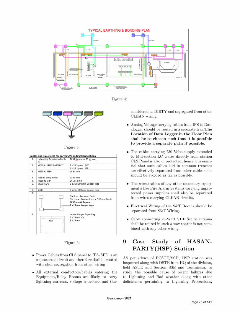
Figure 4:
Figure 5:
Figure 6:
� Power Cables from CLS panel to IPS/SPD is anunprotected circuit and therefore shall be routedwith clear segregation from other wiring
� All external conductors/cables entering theEquipment/Relay Rooms are likely to carrylightning currents, voltage transients and thus
considered as DIRTY and segregated from otherCLEAN wiring
� Analog Voltage carrying cables from IPS to Dat-alogger should be routed in a separate tray.TheLocation of Data Logger in the Floor Planshall be so chosen such that it is possibleto provide a separate path if possible.
� The cables carrying 230 Volts supply extendedto Mid-section LC Gates directly from stationCLS Panel is also unprotected, hence it is essen-tial that such cables laid in common trenchesare effectively separated from other cables or itshould be avoided as far as possible.
� The wires/cables of any other secondary equip-ment’s like Fire Alarm Systems carrying unpro-tected power supplies shall also be separatedfrom wires carrying CLEAN circuits.
� Electrical Wiring of the S&T Rooms should beseparated from S&T Wiring.
� Cable connecting 25-Watt VHF Set to antennashall be routed in such a way that it is not com-bined with any other wiring.
9 Case Study of HASAN-PARTY(HSP) Station
AS per advice of PCSTE/SCR, HSP station wasinspected along with DSTE from HQ of the division,field ASTE and Section SSE and Technician, tostudy the possible cause of recent failures dueto Lightning and Bad weather along with otherdeficiencies pertaining to Lightning Protections,
____________________________________________ Gyandeep - 2021 _____________________________________________ Page 76 of 141

SPDs, Earthing arrangements.
It was seen that the following failures had occurredin recent past
� Outgoing TPR 24 V DC fuses at same locationbox were fused for Track Circuits 29T, 11T, 39T
� DN East Line HASSDAC failed and Mother-board burnt
� RE Cutting 24 Volts DC Signal circuit Fuseblown at Relay Rack. It is a mid-section LCGate with IPS. Same also used for RE cuttingpurpose.
9.1 Track Circuits failure
� The power cable carrying 24 V DC from Cabinto Location box was checked and properlyearthed
� Signalling cable carrying TPR circuits was prop-erly earthed at Cabin end and cable was meg-gered and values above 100 M ohms.
� The 24 V DC output at IPS was protected withSPD found in working condition
� At the Location box, it was seen that the powercable 24V DC armour earthing at GI wire wasloose and not soldered. Further GI wire was alsorusted Fig 7
Figure 7:
The probable cause of fuse blowing is due toineffective earthing of the power cable armourat location end.
9.2 HASSDAC failure
� � It was seen that the 24 V DC to HASSDACwas extended from an External DC-DC conver-tor unit (Not from the IPS Modules) which wasnot protected by SPD Fig 8.
Figure 8:
� The location end Earthing and armour connec-tivity was found intact.
� The possibility of surge coming through Quadcable could not be checked as the system waschanged to new quad cable laid by constructiontwo days before our visit.
� It was seen that the HASSDAC motherboardwas burnt at the power supply cards area
It was also seen that the West Line HASS-DAC supply was extended from DC-DC con-vertor modules of IPS protected with SPDshence it was not failing, Only East Line HAS-SDAC was regularly failing. The probablecause was non protection of external supplywith SPD.
9.3 RE Cutting Failure
� The RE Cutting for Distant Signal is providedat the Relay Room of a Mid-section LC gate
____________________________________________ Gyandeep - 2021 _____________________________________________ Page 77 of 141

having its own mini IPS.
� The IPS provided is as per 2004 specificationswith external supplies protected by MOVs andnot SPDs.
� RDSO vide its letter No STS/E/IPS. GenlDated 02.12.2011 had advised Railways for mod-ification by OEMs for provision of SPDs for allexternal supplies at pre-specified Rates. It is no-ticed that the required modifications were notcarried out in this IPS.
� The Earth Value at IPS MEEB was found 3Ohms which is on higher side.
The probable cause of failure was non-protection of 24 V DC external supply by SPDand high earth resistance.
9.4 Other deficiencies noticed at HSPstation
� In both Cabins the MEEB at IPS Room and Re-lay Room were two separate earths without anyinterconnection i.e. not having an equipotentialearth.
� The MEEB for IPS was located in BatteryRoom and connected to SPD of IPS with a ca-ble length of 10 to 15 Meters and size 10 sq mmand mixed on ladder with other wiring
� The 230 Supply Power cable from CLS panel toIPS was mixed with other wiring and laid on acommon ladder.
� A single Earth was provided for both side Quadcables without interconnection to Ring Earth
� The BPAC and Block circuits were changed overto new quad cable without any earthing of quadarmour at other end station KMPT resulting inhigh induced voltage of 54 Volts.
� The quad pairs were not twisted before termi-nations at either ends.
� Many of the outdoor Earths to location Boxesand Signals were hugely rusted and connectedwith GI wires.
10 Recommendations for Im-provement
10.1 The Conventional Earth Elec-trode
� It is normally seen that the conventional earthelectrodes, though supplied with RITES inspec-tion, over a short period of time gets rusted.Specially the bracket to which earth Cable/GIWire/MS Flat are connected. Same can be seenin figures 9 to 10. Stricter quality checks are re-quired at Inspection Points such that the poorquality materials are rejected.
Figure 9:
Figure 10:
� It is recommended to change the design ofbracket to double brackets as shown in Fig 12
____________________________________________ Gyandeep - 2021 _____________________________________________ Page 78 of 141
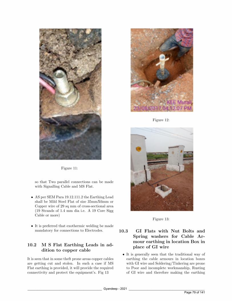
Figure 11:
so that Two parallel connections can be madewith Signalling Cable and MS Flat.
� AS per SEM Para 19.12.111.2 the Earthing Leadshall be Mild Steel Flat of size 35mmX6mm orCopper wire of 29 sq mm of cross-sectional area(19 Strands of 1.4 mm dia i.e. A 19 Core SiggCable or more)
� It is preferred that exothermic welding be mademandatory for connections to Electrodes.
10.2 M S Flat Earthing Leads in ad-dition to copper cable
It is seen that in some theft prone areas copper cablesare getting cut and stolen. In such a case if MSFlat earthing is provided, it will provide the requiredconnectivity and protect the equipment’s. Fig 13
Figure 12:
Figure 13:
10.3 GI Flats with Nut Bolts andSpring washers for Cable Ar-mour earthing in location Box inplace of GI wire
� It is generally seen that the traditional way ofearthing the cable armours in location boxeswith GI wire and Soldering/Tinkering are proneto Poor and incomplete workmanship, Rustingof GI wire and therefore making the earthing
____________________________________________ Gyandeep - 2021 _____________________________________________ Page 79 of 141

ineffective inspite of the earth electrode havinggood earth value. The same was witnessed atHSP station causing fuse blowing.
� AS can be seen in the figure 14 The GI flats aredrilled with adequate holes for connecting thearmours of all possible cables in the location boxbesides having a cushion for future connections.The use of sring washers ensures firm and lastingconnection.
Figure 14:
11 Use of advanced SPDs andA Class Protection Systems
With Constant research and innovation, companiesare coming up with innovative solutions and con-stantly improving on their products. However, theefficiency and effectiveness of such advanced SPDscan only be ascertained over a period of reasonableservice and availability of empirical data. Consider-ing the Cost implications, it is suggested to use themat few Most Lighting Prone Zones. As per IEC thereare different classes of environment.
11.1 Transient Discriminating Tech-nology SPDs by ERICO
In a conventional SPD using MOVs or SiliconAvalanche Diodes are not able to differentiatebetween a sustained Temporary Over Voltage and atrue Transient or Surge event thus tend to suppresspeak of each Half Cycle of the TOV, causing heatingup of device which can potentially lead to fire hazardas shown in Fig. . .
While TD technology SPDs have a patented QuickSwitch with frequency discrimination circuit whichcan differentiate between TOVs and fast transientsassociated with Lightnings Strikes/Surges. The de-vice has two clamping levels, one above peak of TOVwhich normally is twice the nominal voltage and
Figure 15:
other much lower for transients. It therefore en-hances operational life of the SPD. Fig 16
Figure 16:
11.2 A Class Protection Systems
Currently we are using two types of A class systemson Indian Railways
� Conventions Franklin Rod air terminal Fig 17
� Advanced Controlled Streamer Emission (CSE)Based air terminal Fig 18
There are three primary components of the A Classsystems
� Air Terminal
� Down Conductor
____________________________________________ Gyandeep - 2021 _____________________________________________ Page 80 of 141

Figure 17:
Figure 18:
� Earth Grounding System
It can be seen that in both type of systems Only AirTerminal and Down conductor designs are different,whereas Earth Grounding System is common andremains same.
The Air terminal captures the lightning dischargecurrent which is dissipated to Earth through Downconductor
As per IEC 62305 the zone of protection providedby different air terminals should be considered onlybased on their real physical dimensions and class ofLightning Protection System. AS per the empiricaldata it is seen that the lightning strikes takes placemore often at pointed objects, corners, sharp edges.
The functioning of CSE based air terminal is shownin fig 19 & 20
Figure 19:
Figure 20:
It has an added feature of Lightning Event Counter.The conventional LPS adopts Copper cables as Downconductors, whereas CSE Systems have patented de-signed down conductors with features of Low Induc-tance per unit length, low surge impedances, mini-mizes danger of side flashing with metallic parts ofthe building. Fig 21
12 Conclusion
� The important guidelines/TANS/Instructions/Specifications issued by RDSO and RailwayBoard need to be audited at existing stationsand same need to be meticulously followed innew installations by construction agencies
� Awareness and knowledge of S&T officials needto be increased by special counselling sessionsthrough site visits, Video Conferencing sessions
� Strict quality discipline is required by materialinspecting agencies before clearing supplies
� Clear specifications for Air Terminals and Down
____________________________________________ Gyandeep - 2021 _____________________________________________ Page 81 of 141

Figure 21:
Conductors should be issued by RDSO for uni-formity
� Recommendations for change in design of con-ventional electrodes, MS Flat earthing and GIFlat earthing in Location boxes may be con-sidered for standard adoption by competent au-thorities
� End of Life Indication and Potential Free Con-tacts may be made mandatory in all SPDs irre-spective of its usage.
13 References
1. RDSO Specifications 197/2008 for Earthing andBonding
2. ERICO Guide on Surge Protection Solutions
3. RDSO Specification 165/2012 for IntegratedPower Supply
4. RDSO Specification 215/2018 for IPS forLC/IB/RE Cutting
5. Maintenance handbook on Earthing & Surgeprotection CAMTECH
6. Pocket book on Ring Earth & Maintenance FreeEarth CAMTECH
7. RDSO Lr STS L SSI dated 28-06-2016
8. RDSO Lr STS/E/IPS. Genl Dated 02.12.2011
9. Rly. Bd. action plan for Lightning failuresdt.19.08.11
10. System 3000 Manual ERICO
11. RDSO TAN 3006
12. bRDSO TAN-STS-E-TAN-3012 TSAA Guide-lines
13. Guide to BS EN IEC 62305 standard
14. IEC Protection Against Lightning by M L Hen-shaw
15. LIGHTNING PROTECTION GUIDE DEHN
Shri Bhuvnesh KumarAgrawal is an officer of IndianRailway service of Signal Engi-neers 1989 Batch. He completedhis Bachelor of Engineering(Electronics & Communication)from Regional Engineering Col-lege Srinagar Kashmir (Renamedas National Institute of Technol-ogy Srinagar) in 1988. He has 30years of experience of workingon Indian Railways He has heldvarious positions in Openline,Construction, Railway Electrification, IRISETand RVNL. He has a considerable experience inmaintenance of Signalling and Telecommunicationassets in two divisions as a SrDSTE, execution ofRailway Projects of Doubling, New Line, Third Lineworks, New Crossing Stations, Yard Remodeling’s,IBS, Automatic Sigg, Interlocking of Gates, RailwayElectrification. He has also served at IRISET asProfessor.
____________________________________________ Gyandeep - 2021 _____________________________________________ Page 82 of 141

Study of Interface Circuits of EI and
Optimization/Reduction of Relays Used in NWR
Anurag Goyal,CSTE(Project), North Western Railway
1 Preface
The era of Interlocking started with mechanical leverframes. As the size of yards and train movementsincreased the size of lever frames also increased.These lever frames not only increased in sizeoccupying more space but also required intensivemaintenance. With the advent of electromagneticrelays, these lever frames gave way to relay in-terlocking based installations. This developmentresulted in relatively faster operations, fail-safetyin operation and reduced size of building requiredfor housing of interlocking installations. Withfurther increase in traffic and expansion of railwaynetwork, large number of route relay interlockingand panel interlocking stations were commissioned.In case of RRI and Central Panel Interlocking, allthe operations have become centralized, reducingmanpower and confusion in operations.
Presently, Indian Railways with network of 63,000route Kms, have approximately 5500 Route Relayinterlocking or Panel Interlocking installations. Thedrawbacks of these installations are as follows:
(a) The wiring diagrams for such installations runinto hundreds of sheets.
(b) These installations require lot of pre-commissioning work as individual relays,wiring and interconnections along with thou-sands of soldered joints are required to bephysically examined and certified.
(c) The pre-commissioning and commissioning exer-cise for indoor equipment takes longer time andeven for small yard remodelling like addition ofa loop line, all the above activities are requiredto be redone.
(d) The failures of Relays are large in number due toHigh contact resistance, heat and dust. Nowa-
days, the availability of Relays has also becomea concern.
(e) The power requirement of these installations ismuch higher.
(f) The maintenance, testing and failure diagnosisand thereafter failure rectification takes lot oftime.
With development of modern fault tolerant andfail-safety techniques, electronics and particularlymicroprocessors have found acceptance in the area ofrailway signalling world over. Railways in advancecountries of Europe, North America, Australia,Japan etc. have gone for large scale introduction ofmicroprocessor based Electronic Interlocking.
Advantages of Electronic interlocking:
There are following advantages of Electronic Inter-locking over Relay based Interlocking:
(a) The interlocking logic is based on software re-quiring no wiring in the system for individualroute/signal.
(b) The electronic interlocking has two levels of soft-ware i.e. Executive software and Applicationsoftware. The Executive software contains fixedsystem functions, which are universal and ap-plicable to all type of signalling installations,whereas, the Application software contains vari-able signalling functions pertaining to specificrailway or stations primarily based on selectiontable. Therefore, with slight modification in ap-plication software the interlocking Software of aparticular station can be designed.
(c) Alteration/Modificationiseasier; yard remod-elling does not require large scale wiringalterations and testing, obviating, the need forlong duration traffic blocks.
____________________________________________ Gyandeep - 2021 _____________________________________________ Page 83 of 141

(d) Except interface relays, no internal relays are re-quired; therefore power supply, relay racks & ac-cessories and indoor wiring are reduced propor-tionally. The space requirement is also reducedsubstantially.
(e) Interlocking has got extensive self-diagnostic fea-tures& duplication of CPU/System increasingavailability.
(f) Due to in built-in internal data logger the elec-tronic interlocking has the facility of automaticdata logging.
(g) The remote operation is also possible in elec-tronic interlocking& EI is able to interface withModern Signalling systems like ETCS, TCAS,CTC etc.
(h) No manipulation like spurious feed or forcedpickup of Relay is possible in EI.
In Indian Railways, we have also provided EI almostat 30% of total stations. We are using interface (forvital output/input functions) relays with EI to runthe signalling gears.
2 Reasons for taking thisProject
Although the EI with reduced number of relays isfunctioning fine but availability of relays and theirfailures are still a big challenge to tackle with. Nor-mally, on an average, the numbers of relays are re-duced to 30% of no. of relays used in PI/RRI for aparticular station. It has been noticed that in NWR,still more than 30relays are used with EI reducingthe advantage of using EI& facing inherent disad-vantages of Relays as mentioned earlier.
3 Scope of Project
In order to facilitate introduction of EI on IndianRailways, specifications have been issued by RDSOand at present, following two specifications are invogue:
1. RDSO/SPN/192: Electronic Interlocking
2. RDSO/SPN/203: Electronic Interlocking forBig Yards
As stated above, In Indian Railways, we are using EIwith relay interfaces i.e. for driving any gear inthefield and for taking signaling inputs into EI from
field; the relays are used as interfaces. It results intothe use of still 1/3rd number of relays used in relayinterlocking. In world railways, they have stoppedusing these relay interfaces, the vital input/outputmodules are designed in a manner that the fieldgears are directly driven from EI and inputs fromthe field are taken directly into EI. The use of relaysis at the bare minimum level and only at the placeswhere essential.
For last 20 years over Indian Railways, approxi-mately 2000 numbers of EIs have been commissionedand we have gained sufficient confidence regardingsafe and reliable working of EI. To tap the fullpotential of EI, the time has come that we shouldalso go for solid state input/output modules anduse of relay should be minimized to the maximumextent as being done in world railways.
As a step towards this direction, our specificationshave provision of Solid state modules. In SSCsheld earlier, decision has been taken to use objectcontroller solid state point and signal modules onlyin place of relay modules in case of El for big yards.One indigenous vendor is also developing these solidstate modules and they are under testing by RDSO.
The use of Relays can be reduced substantially onlyby using these Solid state modules but it would taketime. In the meantime, efforts shall be made toreduce the use of relays to the maximum possibleextent.
Therefore, the purpose of this project is to study theexisting relay circuits of PI/RRI and EI and to sug-gest measures so that number of relays used with EImay be reduced to the maximum extent in NWR.Since Railway board has also issued RDSO genericinterface circuits for EI vide report No. SS/155/2019(Enclosed at Annexure-D) and which are undertesting/observations with zonal railways, therefore,the outcome of this project would also be comparedwith RDSO circuits. RDSO standardized only inter-face circuits and did not mention outdoor circuits,rightly so, as they are similar to circuits used in Re-lay interlocking.
4 Study of Measures for reduc-tion of Relays
On commissioningof UMRA station of Ajmer (AII)division of NWR by construction, it was noticed bySr.DSTE/AII that no. of relays used with KYOSAN
____________________________________________ Gyandeep - 2021 _____________________________________________ Page 84 of 141

EI are more than the relays normally used withEI. The same was conveyed to PCSTE. Since ithappened at the same time when the undersignedwas nominated for SAG training, therefore PCSTEasked undersigned to study the circuits and instal-lation of UMRA station and suggest measures toreduce the no. of relays in EI.
The undersigned studied the logic and interface cir-cuits of UMRA station of which SIP is enclosed atAnnexure- A. After studying the same and discus-sion with drawing cell of NWR HQ and RDSO, thefollowing measures are suggested for reduction of re-lays:
4.1 Local issues of NWR
The UMRA station has 46 routes, having 4 linesand located on single line section. The total no. ofinterface relays used is 223 (Indoor), total relaysused including outdoor relays are 284.The studyis restricted to Indoor interface circuits as there isno scope of reducing outdoor Relays. The types ofindoor relays used primarily are QNN1, QECX-61,QNA1, QBCA1, QL1 and QSPA1. The detailsof all the relays used in 3 relay racks is placed atAnnexure-B.
It was observed that for all internal interface relays,only QNN1 relays are used and for functions comingfrom the field, only QNA1 relays are used. Thoughthe relays of QN1 and QNNA1 types were availablewith the construction organization, but the sameare not used in installation. The judicious and op-timum use of relays depending upon requirement offront and back contacts of particular function/circuitcould have reduced the no. of relays to a large extent.
Relay disposition charts and their contact analy-sis of other stations have also been studied andit was observed that similar problems exist inother stations of NWR also. For example, onemore station of 3 lines, MandiAdampur of BKNdivision of NWR which was commissioned byProject unit in year 2019-20 was studied and foundthat QNN1 relays were not used at all & onlyQN1 relays were used. The station is having 34routes and the no. of indoor interface relays usedwith MLK II EIare 221 which is again on higher side.
The judicious use of combination of QN1, QNA1,QNN1 and QNNA1 relays can reduce no. of relays.The interface circuits and the requirements of frontand back contacts were studied by undersigned for
each function and its circuit and following is con-cluded:
(a) For following functions, QN1(8F/8B or 12F/4B)relay shall be used.
(i) DR, HR, HHR and UHRcircuits of all mainand subsidiary signals.
(b) For following Non-AC immunised functions,QNN1(4F/4B) relay shall be used.
(i) Crank Handle and LC gate Normal controlfunction(CHZYR, LCYR).
(ii) Up and Down false feed cut off re-lay(FCOR)
(iii) Home signal relays required for UFSBIfunctioning(HGNCR, HSRR, HSATPRand HSBTPR)
(iv) Advance Starter relays required for UFSBIfunctioning(ASCR, ASGNCR, LSS.GNand LSS.R)
(v) Point interlocking latchrelay(NWR, RWR)
(vi) For all types of counter actuating re-lays(COGGN, ERRB, COCYN, EBPU,RRBU, ECH, OYN)
(vii) UP and DOWN all signals HR/DR downproving relays for emergency crank handleoperations.
(viii) Relay room door closing relay.
(c) For following AC immunised functions,QNNA1(4F/4B) relay shall be used.
(i) Level crossing closure proving relay(LC-KLCPR)
(ii) Point detection relays(NWKR,RWKR)
(iii) Crank handle IN proving relay(CHZPR)
(iv) DAC: clearance relay(VPR) & preparatoryreset relay(PPR)
The above principle was applied in UMRAstation as a sample case and by using relay ofrequired configuration, 24 relays got reduced.The proposed use of relay is placed at Annexure-C.If relays are available, it is suggested to use them inthe circuits, as stated above for optimum utilization.
For indent purpose, 20% relays shall be QN1& 80% Relays shall be QNN1 (45% QNN1& 35% QNNA1) taking indoor/outdoor Linerelays.
____________________________________________ Gyandeep - 2021 _____________________________________________ Page 85 of 141

4.2 Identification of redundant relayin NWR circuits and its compar-ison With RDSO standard cir-cuits.
(a) In NWR, for emergency slide barrier (ESB)operation, non-rigid locking through chain wasprovided earlier and two relays were provided toprove its normal and reverse condition. Whileusing ESB, only yellow aspect was displayed byits controlling signal.
PCSTE/NWR instructed and later reiteratedby Railway Board also, now rigid locking isprovided in ESB and Green aspect is displayedby controlling signal. Since ESB’s safety and itsfunction have become similar to normal ELB,above mentioned 02 relays are now not required.This would reduce 02 nos. of relays perLC gate.
(b) As per standard circuit issued by RDSO vide re-port No. SS/155/2019 (Enclosed at Annexure-D), for Shunt and Calling On signal, only 01lamp checking relay is used for ON/OFF func-tions(refer page no. 118 of RDSO report atAnnexure-D). In NWR, same practice is fol-lowed for dependent shunt and calling on signalbut for independent shunt signal separate lampchecking relays are used for ON/OFF aspects.Following RDSO circuit, only 01 lamp checkingrelay may be used. As suggested by RDSO, ECRrelay should be wired in negative path. Thiswould reduce 01 no. of ECR relay per indepen-dent shunt signal.
(c) As per standard circuit issued by RDSOvide report No. SS/155/2019,for point op-eration, NWR, RWR, NWCR and RWCRhave been taken as virtual relay and usingtheir bit, the contractor relay(NWZR/RWZRor WCZR/NWCZR or WCZR/RWCZR) getspicked up(refer page no. 68 to 71 of RDSOreport at Annexure-D). In NWR, we are notusing WCZR as physical relay.
In NWR, we are using NWR/RWR &NWCR/RWCR relays as physical relayswhich seem redundant. If RDSO circuit isfollowed, these 4 relays can be used as internalvirtual relay.
This would reduce 03 no. of relays percrossover(double ended/single ended).
(d) In NWR, one crank handle is taken for eachcrossover (same as mentioned in RDSO Stan-dard circuits), the same can be minimised byputting 2 crossovers of same side of yard in onecrank handle group by studying Yard flexibility.For instance, in single line, 3 lines station, oneend of both the crossovers is connected to Mainline on either side of yard, on failure of any pointof these 2 crossovers will affect all movements ofthat side of yard. If accepted, minimum 4Relays can be reduced i.e. 02 relays pergroup.
The above can further reduce minimum 15-20relays in a 3/4 line station.
Taking our sample UMRA yard, which has3 independent shunt signals, 07 crossoversbut no LC gate, minimum24 Relays canbe reduced (without taking d above in accountas it is still debatable).
4.3 Problems Identified in RDSOCircuit:
While studying the RDSO vis-a-vis NWR circuits,following few problems have been identified in RDSOcircuit requiring review of same(the problems havebeen rechecked by simulating the conditions wher-ever possible in FAT setup of drawing section ofNWR HQ):
(i) At page no. 101/102 of RDSO circuit, inEUUYZ/ESUYZ counter logic, pick up contactof JSLR is taken in place of JR. This would re-sult the counter to keep on increasing for 120seconds till JSLR gets dropped. JR relay getspicked up after 120 seconds of picking up ofJSLR(refer page no. 100 of RDSO reportatAnnexure-D).
(ii) Signal failure, point failure indication andbuzzer circuits are not provided in RDSO cir-cuit. Similarly, ECH counter for emergencycrank handle operation is not mentioned inRDSO circuit.
(iii) In RDSO circuit, at Point no. 12 at pageno. 112at Annexure-D, it is mentioned that“HR of starter signals will be slow to release3 to 5 seconds for only train movement toprevent the raising of signal in face of loco pi-lot while shunting. It is achieved through firstcontrolling track TP1R and their TSR”. If
____________________________________________ Gyandeep - 2021 _____________________________________________ Page 86 of 141

we go by the circuit given at page no. 126at Annexure-D, then even there is no trainmovement and berthing track is not occupied,if starter signal is taken OFF, it will be replacedonly after time delay of 3-5 seconds on shunt-ing of controlling track circuits.This shortcom-ing is debatable and either circuits required tobe changed or if the circuit seems fine then thewords “Only train movement” may be re-quired to be deleted from point no. 12 of pageno. 112 at Annexure-D.
(iv) At page no. 77 of RDSO circuitat Annexure-D, the contacts of advance starter S12 ASR istaken in S17 UCR but logic/picking up of S12ASR relay is not shown anywhere.
(v) At page no. 98 to 100 of RDSO cir-cuitsat Annexure-D, emergency route re-lease(EUUYR)and emergency sub route can-cellation(ESUYR) circuits are given. Inboth the circuits, the conflicting ASR ofmain/subsidiary signal on the same post(in thiscase for routing home S17 is shown). Same sig-nal is taken in both the circuits. In case of fail-ure/drop of any back lock track circuit wouldresult into drop of all ASRs and it will not bepossible to release sub route also by emergencyoperation after physical examination. The cir-cuit is designed based on Railway Board’s letterof eliminating S&T cooperation and by intro-ducing a time delay of 120 seconds. In opinionof NWR, RDSO circuit is fine for EUUYR butneeds review for ESUYR.
(vi) At page no. 124 of RDSO circuitsatAnnexure-D, for putting back signal to dan-ger counter circuit, pick up contact of con-cerned HR, signal button and cancellation but-ton are taken but the counter can not beincreased as after cancelling the signal HRrelay immediately drops breaking the circuitfor EGGNZ(EGGN counter). In NWR, thiscounter is not used as it is a repetition of routecancellation counter.
(vii) In page no. 161 of RDSO circuitsatAnnexure-D, flashing indication shall appearas and when overlap cancellation timer is inprogress, to ensure the same the pickup con-tact of JSLR should have been taken in placeof JR in 25 OV FLASH circuit.
(viii) At page no. 135 of RDSO circuits, for takingout Crank handle in Emergency, in circuit ofECH CZR, pickup contact of JSLR & JR are
taken resulting into chattering of relays andnot able to take out crank handle. In field, weremoved the pickup contact of JSLR.
For the above, a letter from NWR to RDSO is writ-ten on 03.02.2021 to review the problems mentionedabove.
5 Recommendations
1. By judicious deployment of Relays of requiredconfiguration, more than 10% of relays used to-day may be reduced as given in para 4.1.
2. By following RDSO circuits and removing re-dundant relays, further 15- 20 or more relayscan be reduced for a typical ¾ lines stations asgiven in para 4.2.
3. The review of few RDSO circuits required asproblems identified by simulating circuits inFAT setup of NWR HQ as given in para 4.3.
6 Conclusions
If recommendations given at para 5.1 & 5.2 are ap-plied on our sample station UMRA, then total 24 +24 = 48 indoor relays can be reduced. In placeof existing 223 indoor Relays, only 175 indoorrelays would be needed i.e. 22% reduction ofIndoor Relays.
7 Reference and Acknowledge-ment
1. Shri Mohan Dudeja, PCSTE/NWR for givingthe project of practical nature to improve thefunctioning of signalling installations.
2. Shri K. V. Reddy, SPS/IRISET & Course Direc-tor: For guiding and encouraging undersignedfor timely completion of Project.
3. Shri Anoop Kumar Sharma,CSTE/P&D/NWR, ShriPradeepPunia,Dy.CSTE/D&D/NWR, ShriOmprakashMeena,SSE/D&D for making available all circuits anddrawings and having in depth discussion oncircuits and for simulation in their FAT setup.
4. Shri Ajay Kumar Verma, ED/Signal/RDSO forgiving valuable suggestions from time to time.
____________________________________________ Gyandeep - 2021 _____________________________________________ Page 87 of 141

5. Shri Deepak Verma, Sr.DSTE/AII & Shri Dalc-hand, ADSTE/Aburoad: For providing the de-tails of UMRA station & valuable suggestions.
6. RDSO generic interface circuits for EI vide re-port No. SS/155/2019 & NWR circuits.
Shri Anurag Goyalis an IRSSE officer of1991 exam batch and isCSTE/Project/NWR since05.11.2019. Earlier he hasworked in various capaci-ties in Open line, Project,RDSO, RVNL on IndianRailway. He has beeninvolved in developmentof Electronic Interlocking and TCAS while postedin Signal Directorate of RDSO. He has got manyPI/EI commissioned in NR/NWR while postedin Project organisation. He has experience ofworking in SER, NR, NCR, RDSO and PSU. Hehad been on foreign deputation twice in Japanand Australia in connection with development ofElectronic Interlocking.
____________________________________________ Gyandeep - 2021 _____________________________________________ Page 88 of 141

Novelty in S&T Workshop, Mettuguda
M K Rao, CWM,Mettuguda, Secunderabad
S&T workshop Mettuguda, Secunderabad a unit ofSouth Central Railway brings in a new thought ofutilising the energy resources available from scrap,inducing high demand products into workshop, sav-ings of expenditure by effective planning, duly con-sidering staff welfare and having a better workingatmosphere. The detailed action taken is indicatedas under.
I. If innovations can bring new technology into thesystem, then newness of thoughts in generatingrevenue is also an innovation. This workshophas been facing lot of hardship in clearing thescrap generated mainly Aluminium Bore, CastIron & Mild steel. The availability of transportfacility to send the scrap to Scrap depot wasvery scary.
In view of this scary situation, a simple thoughtof Scrapping was thought on in the year 2020on as is where is basis along with the Storesdepartment is. The success of the story is asper the table indicated below.
Apart from the above, the scrap was utilised indesign and manufacture of Portable Cranes – 1Tonne and hand trolley’s for movement of pointmachines.
S. No Year Scrap Generated in MTs1. 2019 - 2020 108.202. 2020 - 2021 113.43. 2021 till date 66.27
Total 260.17
As a result of the above, workshop was declaredtwice as “Scarp free workshop” and has evenresulted in generating revenue. The usage ofMan power for loading/unloading of scrap isalso eliminated.
II. In view of a fast growing “Athmanirbhar”country, it was felt that a need for introduc-tion of new products which are approved byRDSO/LKO shall be introduced in workshop.Workshop has taken initiative in manufacturing
and supply of Point machine 143mm & 220mm.The DC to DC converters designed by this unitwere used as field trial during the life test andhave proven to be design worthy. The long pro-cessed list of events is placed as under.
As always stated behind all the success sto-ries lies Patience, Focus and Quality of work-ing have resulted in achieving Initial Type Ap-proval of Point machine 143mm & High thrustPoint machine-220mm along with Clamp lock.
III. A step towards controlling the expendi-ture:
(a) Towards befitting the saving of ElectricalPower consumption and as the saying goes“Energy saved is energy produced”.
The in house design of LDR dependent cir-cuits were designed with unused materiallying in the shop floor as scrap, is beingutilised for auto control of street lightsduring day and night.
All the ceiling fans were replaced withBLDC fans - 206 No.s and Inverter typesplit air conditioner in meeting hall- 2No.s, one in each in Jig boring machineof Tool Room and in Modernisation section.
VVVF drive has been installed for Powerhammers – 02 No.s.
These has yielded in a saving ofRs.22,400/month and will recur aslong as the workshop performs.
(b) As a result of combining different parts ofElectric lifting barrier and Track feed bat-tery charger as a single indent for eachproduct, during indenting for this financialyear has resulted in not only reduced priceto tune of Rs.8,32,000.00 and as well theproduct will not have wait for one particu-lar supply of component and the productscan be manufactured as per the schedule.
____________________________________________ Gyandeep - 2021 _____________________________________________ Page 89 of 141

(c) Revision of rates for the items manufac-tured in S&T/Workshop/MFT. Initiallythe Rates were reviewed in the month ofJanuary 2020 after CWM/S&T/MFT hastaken up and as has yielded in a saving ofRs.6.00 Cr. The process of review has beenkept in continuation and after introductionof New Jigs, Fixtures and Punches & mod-ifications in the process of items/productsmanufactured in this unit, the rates havebeen again fine tuned in the month ofSeptember’2021, which has resulted to asaving of Rs.27.86 Lakhs and the reviewprocess is made mandatory as a part of
duty list.
The overall cost of products is less whencompared to other S&T workshops of In-dian Railways in spite of increase in cost ofraw material.
(d) A Fork lift and two lister trucks were re-paired in house to the best possible and arebeing utilised for transportation.
IV. Staff welfare side:
� A COVID vaccination drive has been con-ducted in workshop with the help of Med-ical department in the premises of this
____________________________________________ Gyandeep - 2021 _____________________________________________ Page 90 of 141

Figure 1:
Figure 2:
unit. First dose of Jabs have been com-pleted for all staff including RPF, Appren-tices and contract labour for maintenanceof workshop. The second dose for the rea-son of staff being infected and recoupedfrom COVID is pending for 48 staff.
� An atmospheric water generator with500Ltrs capacity – 2 No.s have been pro-vided for pure drinking water facility forthe staff of workshop to avoid perennialwater problem.
� Canteen has been renovated with newequipment.
V. Better working atmosphere:
� In view of provision of computers for theimplementation of UDM and e-office, thisworkshop has collected the old systems ly-ing in the department, repaired and havebeen put in use along with VPN in all the
Figure 3:
sections of this unit, due to the procure-ment of computers have been restricted.
� First e- pass was issued in SCR by thisunit.
� All the sections have been provided withPublic address system for better commu-nication between staff and SSE of the shopfloor.
Finally The TEAM (Together EveryoneAchieves/Accomplishes More) of S&T hasproved again, that anything can be achievedwith the proper planning, focus and deter-mination in the staff of this unit and thecooperation of all the divisions and massivesupport of headquarters.
Shri M.Koteswara Rao, isan IRSSE of 1998 batch.He worked in NF Rly. For10 years and also workedas Professor(Signal) for 8years. He worked asSr.DSTE/SC div for 2 years9 months. Presently heis working as CWM, S&T,MFT, SC Railway. He has received various awardsfrom various levels apart from his contribution to-wards innovation
____________________________________________ Gyandeep - 2021 _____________________________________________ Page 91 of 141

Remote Monitoring of Track Battery Charging
through Battery Charging Monitoring Unit (BCMU)
Naveen Bhushan Sharma, ADSTE, BAZ, Kota, WCRAashish Kumar Agrawal, SSE(Sig), Kota, WCR
Abstract
Track Circuits Battery charging monitoring unit(BCMU) used as a remote monitoring device totrack the charging process of track batteries. Thisunit generates the audio/visual alarm at locationbox as well as message on the mobile of main-tainer/supervisors through Datalogger/RTU connec-tivity whenever the charging process interrupted.This article explains the working of the BCMUin detail, comparative analysis with existing sys-tems to identify its advantage and disadvantagesand field performance analysis of BCMU installed atSALPURA station of Kota Division of West CentralRailway.
1 Introduction
Track circuits play an important role in the sig-naling systems by detecting the presence of vehicleon that particular portion/section of the track toavoid conflicting movements and prevent the colli-sion. Rechargeable Batteries are used as source ofsupply to feed DC track circuits. These batteriesrequire almost continuous charging, for this trackcharger is provided at site and they are continu-ously charging the batteries on trickle mode. When-ever the charging of battery is interrupt, battery willdrain out and it result in failure of track circuitand adversely impacts smooth and timely runningof trains. Ensuring continuous charging of batteriesis essential for uninterrupted healthy functioning oftrack circuits.
2 Existing Provision
Currently as per IRS specifications S89/2013 Ver-sion 1.0 there is system of identification of batterycharger failure by indicating charger fails LED in-dication with AC input being available on batterycharger at location box. This system also extends
audio/visual alarm at remote place whenever chargeroutput fails with AC input being available throughPFC if proved in Datalogger/RTU.
2.1 Limitation of Existing System
However there is no specification/system to identifywhether actual battery charging is taking place ornot.
3 Proposed System
The proposed Battery Charging Monitoring Unit(BCMU) monitors the charging current of the bat-teries to track the battery charging process. Thissystem generates audio/visual alarm in the locationbox also which can be relayed to Datalogger/RTUthrough PFC provided in the unit. This BatteryCharging Monitoring Unit (BCMU) has been in-stalled at SALPURA (SYL) station of Kota divi-sion of West Central Railways on experimental ba-sis. The BCMU are analyzed for two yearsand the results are very promising and satis-factory.
4 Technical Details and Work-ing
The output of charger has to be connect on chargerterminals and battery side has to be connect onbattery terminals. Standard colour code is used forseparation of positive and negative terminals. Redcolour terminal is for positive (+) and black colourterminal is for negative (-).
Yellow colour terminal is used for potential freecontact. Common terminal is input for the contactand NC (Normal close contact) terminal is outputof the potential free contact.
____________________________________________ Gyandeep - 2021 _____________________________________________ Page 92 of 141

S,No Features Specifications1. Overall Size 105mm X 81mm X
78mm2. Body(MOC) Powdered Coated
(Galvanized CRSheet)
3. Weight 570 Gms
4.
Terminals1. ChargerOutput
02 Nos
2. BatteryOutput
02 Nos
Potential freecontact
02 Nos
Table 1:
LEDFunction
LEDColor
HealthyStatus
FaultStatus
ChargerOutput
Green On Off
BatteryCharging
Yellow On Off
Fault RED Off OnInput/Output of Chargers Fails/Battery Charging Fails - BuzzerSounds continuous
Table 2: Indication
Potential free contact is normally make contactwhenever any charger fails or battery disconnectedthe contact opens.
By using this contact in series a relay can beenergized at station. Whenever any charger fails,this contact opens causes the relay to drop andan indication audible & visible indication can beavailable at location box and at stations/maintainer’room.
Also continuous buzzer starts sounding in the loca-tion boxes. It indicates that charger of this locationbox is defective maintainer/supervisors immediatelyattend the problem, and battery can be prevent fromdraining out. As & when charger is restored contactmakes and all are normal again. The system canbe monitored remotely by using data logger, Faultmessages can also generate.
Figure 1:
Figure 2: Connection Diagram Battery ChargingMonitoring Unit
5 Advantages
� It has novel capabilities to monitor the Charg-ing of battery, Continuous health of battery andDisconnection/Loose connection at battery ter-minals.
� It generates alarm when charger remains OFFdue to the negligence of maintainer during main-tenance activities of track circuit.
� It also generates alarm when 110 Volt AC inputfor charger fails.
� It has nominal power consumption and low costfeature.
� The remote monitoring feature, throughData logger will send alarm massage onthe maintainers mobile, will serve as a pre-ventive maintenance to1ol and prevents failures.
6 Field performance analysis
The Battery Charging Monitoring Unit (BCMU) hasbeen installed at SALPURA station of Kota Divisionof West Central Railway since April 2019. Total 12No. of Units have been installed and field perfor-mance of BCMU has been analyzed over the period
____________________________________________ Gyandeep - 2021 _____________________________________________ Page 93 of 141

S.No Features/Facility BCMUTrack Feed
Battery Charger1. Monitor Output of Charger Yes Yes2. Monitor Battery Connected to Terminal Yes No
3. Monitoring Input 110V AC for Charger YesYes - Gen. Electric make,
No-Epsilon make
4.Checks Dry Solder or Loose connection/Disconnection (High Resistance in Path)
Yes No
5.Disconnection/Loose ConnectionBattery to Battery Terminal
Yes No
6. Buzzer Sound Yes No7. Current Consuption 15 to 20 mA -
8. Power ConsuptionVery Less(Normal)
-
9. Effect of MoistureNo Effect
(As Unit is sealed)-
10. Internal Circuit Easy -
Table 3: Comparison with existing system
from Apr 2019 to Sep 2021 and there is no failure ofthese track circuits on charger faulty account.
Figure 3:
The remote monitoring feature, through Data loggerwill send alarm massage on the maintainers mobile.The field data shows that there is no failure on ac-count of Track feed charger defective/Battery run-down on the Track circuits where BCMU has beeninstalled. At times the failure alarm has been gen-erated and promptly attended by the maintainers.This proves the utility of the BCMU as an effectivesystem for preventive maintenance.
7 Conclusion
The Battery Charging Monitoring Unit (BCMU) dis-cussed in this article can be utilized for remote mon-itoring of battery charging process. It has novel ca-pabilities to monitor the charging of battery, Contin-uous health of battery and disconnection/loose con-nection at battery terminals. The analysis of field
Figure 4:
data proves the effectiveness of BCMU as a preven-tive maintenance tool. This system may be devel-oped by using current state of the art technology asa stand alone unit or may be integrated with bat-tery feed chargers. RDSO specifications may be de-veloped to include BCMU specifications as standardfor Track circuits.
8 References
1. RDSO specification : IRS specificationsS89/2013 Version 1.0
2. Concept Paper developed by Kota Division :Battery Charging Monitoring Unit (BCMU)Briefly About the Author
____________________________________________ Gyandeep - 2021 _____________________________________________ Page 94 of 141

Shri Naveen Bhushan Sharmabelongs to IRSSE 2016 Batch.After completing B.E. in Elec-tronics & Communication fromMBM Engineering College Jodh-pur in 2013, he has joined as Sci-entist/Engineer in Space Appli-cation Centre, ISRO at Ahmed-abad and continued in ISRO tilljuly 2017. Thereafter, he hasjoined S&T department of Indian Railways in July2017. He was allotted West Central Railway zoneand joined as ASTE in Kota division of West Cen-tral Railway in 2019. He has working experience inSolid State Power Amplifier(SSPA) and DC-DC con-verter design for space applications and publishedfour IEEE Conference papers in these areas. AsASTE/tele he plays major role in commissioning ofWi-Fi work at stations and installation of CCTVcameras at vulnerable LC gates. As ASTE/Baran,he plays pivotal role in the doubling work in KOTA-RTA section, 7 stations has been successfully com-missioned with EI. Two stations EI logic alterationshas been done under his guidance departmentally.He is keen in learning about current state of the arttechnologies in railway signalling and telecommuni-cations.
Shri Aashish Kumar Agrawalis currently holding post ofSSE/SIG/KOTA. He has grad-uated Electronics & Telecom-munications Engineering. Heholds experience about 10 Yearsin S&T department at variousplaces in Jabalpur and Kota Di-vision.
____________________________________________ Gyandeep - 2021 _____________________________________________ Page 95 of 141

SPADs of Indian Railways:
Analysis & Recommendations
Vijaylaxmi KaushikCSTE(Projects), North Western Railway
1 Introduction
Safety in train operations depends upon skill, performance and alertness of the loco pilots who have beengiven the responsibility of driving a train duly following certain set of safety rules.
Though ‘Signal passing at Danger (SPAD)’ is classified as an Indicative accident, it has the potential ofgetting converted into a consequential accident like collision or derailment resulting in loss of lives.
Through this project, analysis of SPAD cases for last five years w.e.f . 01/04/2015 to 31/03/2020 has beendone based on various parameters like railway, time of the day, rest availed by crew, duty completed at thetime of SPAD, channel of recruitment of Loco Pilot, type of train , type of traction, distance travelled afterSPAD etc. to find if any pattern emerges from this analysis and to suggest recommendations with a view tofurther reduce these accidents.
2 Statistics and Trend of SPAD Cases
2.1 Consequential SPAD cases result into a collision or derailment of the train.The share of the consequential SPAD compare to total SPAD cases is in-dicated below:
Type of Accident2015-16 2016-17 2017-18 2018-19 2019-20 Total Total%
Consequential/Other train acci-dents
3 9 4 3 3 22 7.75
Indi-cative 42 42 55 65 58 262 92.25Total 45 51 59 68 61 284
2.2 The traction wise break up of SPAD cases is indicated below:
Traction wise Analysis2015-16 2016-17 2017-18 2018-19 2019-20 Total Total%
Diesel 18 22 24 31 19 114 40.14Electrical 26 27 34 36 42 165 58.10Engg 0 1 1 0 0 2 0.70TRD 1 1 0 1 0 3 1.06Total 45 51 59 68 61 284
____________________________________________ Gyandeep - 2021 _____________________________________________ Page 96 of 141

2.3 Service wise Analysis
Service wise Analysis2015-16 2016-17 2017-18 2018-19 2019-20 Total Total%
Suburban 7 4 1 16 13 41 414.44Other Passenger 20 28 36 31 26 141 49.65Goods 18 19 22 21 22 102 35.91Total 45 51 59 68 61 284
2.4 Railway wise, Year wise Breakup of the SPAD Cases is Indicated Below:
Railway-wise SPAD casesRailways 2015-16 2016-17 2017-18 2018-19 2019-20 TotalCR 11 8 3 12 6 40ECoR 1 2 0 1 2 6ECR 1 3 1 6 8 19ER 0 0 1 4 1 6NCR 4 9 1 5 5 24NER 0 2 1 0 0 3NFR 2 3 2 5 1 13NR 4 4 6 5 4 23NWR 1 0 3 0 3 7SCR 5 7 6 10 8 36SECR 1 2 9 3 3 18SER 0 1 1 5 5 12SR 6 4 3 4 5 22SWR 1 1 1 2 1 6WCR 1 1 7 0 4 13WR 7 3 14 6 4 34KRCL 0 1 0 0 0 1Metro 1 1Total 45 51 59 68 61 284
2.5 Data based on Rest Availed
Loco Pilot Last Rest availed (HQ/Outstation)Rest availed 2015-16 2016-17 2017-18 2018-19 2019-20 Total Total%HQ Rest/ Other train ac-cidents
28 33 33 37 39 170 61.0
Outstation Rest 16 16 25 29 22 108 39.0Total 44 49 58 66 61 278
2.6 Data of Duty Hours Completed at the Time of SPAD
Duty Completed at the time of SPADDuty Done (Hrs.) 2015-16 2016-17 2017-18 2018-19 2019-20 Total
P G P G P G P G P G¡ 2 Hrs. 9 0 10 3 9 4 10 2 9 2 582 - 4 Hrs. 9 4 7 2 19 3 21 4 10 5 844 - 6 Hrs. 5 6 9 7 7 4 8 7 9 3 656 - 8 Hrs. 3 3 5 3 1 2 5 4 4 2 328 - 10 Hrs. 0 3 1 1 0 3 3 2 1 6 20¿ 10 Hrs. 0 1 0 1 0 2 0 0 1 4 9Total 26 17 32 17 36 18 47 19 34 22 268
____________________________________________ Gyandeep - 2021 _____________________________________________ Page 97 of 141

2.7 Time of Occurrence of SPAD
Time of occurrence of SPADTime 2015-16 2016-17 2017-18 2018-19 2019-20 Total
P G P G P G P G P G00.00 - 02.00 0 3 3 1 1 4 3 1 2 1 1902.00 - 04.00 3 0 3 2 1 1 5 2 2 4 2304.00 - 06.00 2 0 5 3 1 1 1 3 2 3 2106.00 - 08.00 3 3 2 3 4 2 8 1 5 3 3408.00 - 10.00 5 2 0 1 6 1 3 5 5 1 2910.00 - 12.00 2 2 1 1 6 0 5 2 6 1 2612.00 - 14.00 2 3 1 1 1 3 5 2 4 4 2614.00 - 16.00 4 2 1 0 5 4 6 1 1 2 2616.00 - 18.00 1 2 3 0 1 2 2 2 1 0 1418.00 - 20.00 0 0 6 3 4 2 4 0 4 1 2420.00 - 22.00 1 0 5 2 3 1 3 1 4 1 2122.00 - 24.00 4 0 2 0 4 0 2 1 3 1 17Total 27 17 32 17 37 21 47 21 39 22 280
2.8 Distance traveled after SPAD
Distance travelled after SPADSignal Passed byDistance (m)
2015-16 2016-17 2017-18 2018-19 2019-20 Total Total%
Upto 10 2 2 3 9 5 21 8.310 - 20 5 10 3 6 7 31 12.3020 - 50 5 1 12 18 13 49 18.350 - 100 9 11 7 8 10 45 17.1100 - 200 7 7 13 4 7 38 15.1200 - 1000 8 12 13 11 9 53 20.0¿ 1000 5 3 3 4 4 19 7.6Total 41 46 54 60 55 256
2.9 Direction of Working of Engine
Direction of working of engineDirection of Working 2015-16 2016-17 2017-18 2018-19 2019-20 Total Total%Short Hood 40 44 51 61 59 255 89.50Long Hood 4 5 7 7 2 25 10.50Total 44 49 58 68 61 280
2.10 Age of Loco Pilot
Age of Loco PilotAge group 2015-16 2016-17 2017-18 2018-19 2019-20 Total Total%Upto 35 7 0 1 6 11 25 9.135 - 40 2 5 7 8 5 27 9.840 - 45 8 6 12 14 8 48 17.445 - 50 12 15 7 12 17 63 22.950 - 55 9 14 11 12 8 54 19.655 - 60 6 9 17 14 12 58 21.1Total 44 49 55 66 61 275
____________________________________________ Gyandeep - 2021 _____________________________________________ Page 98 of 141

2.11 SPAD per thousand Crew
SPAD per 1000 RRB/Departmental CrewType of traction RRB Deptt RRB Crew Deptt Crew Total SPAD per 1000 crew
RRB DepttDiesel 58 53 10194 6348 5.69 8.35Electrical 119 36 16269 3839 7.31 9.38Total 177 89 26463 10187 6.69 8.74
2.12 Mode of Recruitment of Loco Pilot
Mode of Recruitment of Loco Pilot2015 -16
2016-17
2017-18
2018-19
2019-20
Total Total%
DSL Elect DSL Elect DSL Elect DSL Elect DSL ElectRRB 7 21 10 17 11 22 18 28 12 31 177 66.5Deptt 11 4 11 9 11 7 13 7 7 9 89 33.5Total 18 25 21 26 22 29 31 35 19 40 266
2.13 Month wise SPAD Data 2015-2020
April May June July Aug Sep Oct Nov Dec Jan Feb Mar Total24 37 18 26 25 27 15 30 24 19 20 19 284
2.14 Details of Signals Passed at Danger
Details of signals passedType of signal passed 2015-16 2016-17 2017-18 2018-19 2019-20 Total Total%Starter 16 24 24 34 31 129 45.9Home/Automatic 24 23 28 21 23 119 42.3Intermediate Starter 0 0 0 4 2 6 2.1Only Advance Starter 0 1 2 4 2 9 3.2Gate Signal 0 1 1 1 0 3 1.0Outer 0 0 1 0 0 1 0.40IBH/IBS 2 2 3 4 3 14 5.0Total 42 51 59 68 61 281
2.15 Reasons of SPAD
Reasons for SPADReason for SPAD as iden-tified by Enquiry Commit-tee
01.4.2011 to 31.3.2016 16-17 17-18 18-19 19-20 Total Total %
Lack of brake power ontrain / Defective Brakes
11 1 2 1 1 16 3.0
Visibility impaired by fog 10 4 1 0 0 15 3.0Delayed application ofbrakes
58 11 13 13 11 106 19.1
Lack of alertness and neg-ligence of Crew
239 35 43 54 47 418 74.8
Miscellaneous 0 0 0 0 2 2 0.0Total 318 51 59 68 61 557
____________________________________________ Gyandeep - 2021 _____________________________________________ Page 99 of 141

3 Analysis of the SPAD Cases
1. 7.75% of the SPAD cases result into consequentialaccidents.
2. 1.76% of SPADs were caused by Track ma-chine/Tower wagon drivers. 40.14% and 58.10%are attributed to Diesel and Electric loco pilotsrespectively.
3. 36% cases are attributed to Goods trains. Restare passenger trains including Suburban trains.
4. Out of 16 major Railways, six Railways namely,CR, SCR, WR, NCR, NR and SR have con-tributed to almost 63.5% of SPADs.
5. 61% of SPAD cases are happening after HQs rest.
6. A whopping 77.24% of SPAD cases occurredwithin six hours of duty time. In only 3.4 % ofSPAD cases crew had worked beyond 10 hours.
7. Cases are spread over all hours round the clock.No specific pattern of occurrence of SPADs withrespect to any particular time zone could be es-tablished.
8. In 57% cases, the train could be stopped within100m of passing the signal at danger i.e. withinthe signal overlap. However, in 28% cases, thetrain travelled beyond 200m and in 7.6% of cases,the train travelled for more than a kilometre afterSPAD. These 28% cases have a potential of gettingconverted into consequential accidents.
9. In 10.5% cases, the engine was in long hood posi-tion.
10. 63.6% of cases are attributed to loco pilots beyondthe age of 45 yrs.
11. Although 66.5% SPADs have been caused by LPsrecruited through RRB as compared to 33.5% de-partmental LPs, this data when normalised perthousand crew indicates that total SPADs perthousand crew is 8.74 for departmental LPs asagainst 6.69 for RRB recruited LPs.
12. Maximum numbers of SPAD cases occurred in themonth of May followed by November.
13. Starter/Home/Automatic signals constitute 88%of signals passed at danger.
14. Almost 75% of SPAD cases occurred due to lackof alertness/negligence of the crew.
4 Conclusions
It is clear from the above analysis that the majorcause of SPADs is lack of alertness/negligence of thecrew. Majority of SPADs are occurring within firstsix hours of duty and after HQ rest. Some of thereasons for this may be any or combination of thefollowing:
1. Lack of proper rest before duty
2. Stress related to personal/family problems
3. Physical/mental condition of LP
4. Stress due to long pre departure detentions
5. Age and experience of the Loco pilot
6. Training and competence
7. Organisational pressure
8. Physical characteristics of signal and their loca-tion
9. General expectations of the aspect of the signalbased on prior experience etc.
5 Recommendations
1. All vacancies of ALPs be filled on priority whichwould enable the LPs to get leave when requiredto carry out their family responsibilities.
2. Regular interaction with the families of the LPs bedone to explain to them the importance of theirjobs with a view to provide a relaxed atmosphereat home.
3. Railway Board’s instructions with respect to Ap-titude test be followed strictly. Operators deputedfor working tower cars and track machines shouldalso be subjected to aptitude test.
4. Working of Vigilance control devices (VCD) pro-vided in locos should be strictly adhered to forensuring alertness of the crew on the run.
5. Signal sighting committees should be activatedand deficiencies noticed with regard to visibilityof signals be attended on priority.
6. Efforts should be made to reduce Pre departuredetentions by better planning and arrangementsbe made to bring the LPs to the running room/HQat the earliest in cases of DCR to enable them toavail desired rest.
____________________________________________ Gyandeep - 2021 _____________________________________________ Page 100 of 141

7. As the reflexes of LPs slow down with age, ALPsmust be counselled to use emergency brakes whenthey face a situation of SPAD without waiting tobe told by LP.
8. As per present system, aptitude test is done onceat the time of induction as ALP and again asLP for high speed trains like Rajdhani/Shatabdi.As the majority of accidents have been done byLPs aged beyond 45yrs, there is a necessity to in-troduce psycho-intervention and training/ coun-selling for loco pilots at other stages of their ca-reer as well. The age at which this intervention isrequired needs to be studied separately.
9. Present medical examination does not cover psy-chological aspects and depends on voluntary dis-closure of problems by the examinee. In manycases running staff does not disclose the ailmentsand tend to conceal in fear of de-categorisation.Moreover, it is a fact that running staff do consultprivate practitioners. So, the elements of Periodicmedical examination should be reviewed duly in-corporating problems related to sleep deprivation,fatigue, stress, health profile and other related as-pects.
10. Specific training needs of departmentally pro-moted candidates in the ALP cadre needs to bestudied a fresh.
11. With execution of Automatic signalling/IBS works, the number of signals encountered by LPs on atrip have greatly increased. A trial may be doneby providing fogsafe devices during all seasons toalert the driver of an approaching signal. Feedbackfrom drivers may be analysed for further decisionin this regard.
12. A suitable automatic train protection system maybe planned to be provided in mission mode on highdensity routes to mitigate SPADs resulting in con-sequential accidents.
13. Following remedial measures suggested by RDSOfor increasing mental alertness of the crew may beimplemented in the right earnest:
1. Mental exercises on regular basis will enhancecognitive abilities and in turn increase level ofalertness.
2. Physical exercise keeps physiological activitiesactivated thus helping in sound sleep and elim-inates the risk of fatigue at work.
3. Good food habits and balanced nutrition willhelp in mental health which keeps the toxins
away from body thus making a person moreagile and active.
4. Proper rest and sound sleep will restore thebody to work again with physical and mentalvigour.
5. Yoga and pranayama increase alertness by mit-igating the factors responsible for stress.
6 Reference and Acknowledg-ment
1. Accident data available on SIMS website
2. Mr.T.P.Agrawal ED/Safety/RB for sharing thedata
3. Mr. Mukesh Inspector/Safety/RB for helpingwith data analysis
4. Mr. P. Srinivas GGM/CONCOR and Ex Direc-tor/Safety/RB for helping with analysis and giv-ing inputs on Aptitude tests
Smt.Vijaylaxmi Kaushikis an IRSSE officer of1987 exam batch. Shehas worked in variouscapacities in construc-tion, open line, computerreservation on NorthernRailway, as ED/Safety/RB,GM/S&T/CRIS and asDRM/Lucknow/NER.
On NR , she was instrumen-tal in commissioning of various signalling, telecomand PRS/UTS projects and in streamlining of main-tenance procedures. As ED/Safety/RB, she achievedsuccessful execution and implementation of Safety In-formation Management System(SIMS) and setting upof Disaster management control centre in RailwayBoard. In CRIS, she initiated the pilot project of Sig-nal maintenance management system(SMMS). Dur-ing her tenure as DRM/LJN, she achieved comple-tion of Gauge Conversion works on 250km and open-ing of 190km of section to public, electrification on38 km, apart from completion of numerous passengeramenity works.
____________________________________________ Gyandeep - 2021 _____________________________________________ Page 101 of 141

Small Things - Big Impact: Mumbai Suburban Section
(Churchgate to Virar)
Ankit Lodha, Sr.DSTE/S/MMCT)Mahtab Alam, ADSTE/S/MMCT)
Abstract
Churchgate-Virar Suburban Section in WesternRailways is a High Traffic Density Route wheretrains run at headway of just 3 minutes in peakhours.Mumbai suburban section of CCG-VR isautomatic signalling section mostly based on con-ventional relay-based interlocking (M-M of SiemensRRIs) and capable to run around 1.5 thousandServices per day which includes both EMU and MailExpress services with the punctuality of around 98%.
With huge traffic, time required for maintenance ac-tivities is always a challenge which gets bigger whenit comes to fault rectification or coming with newideas to deal with the fresh needs. Over a periodhave time, some problems were observed and reme-dial solutions with practical approach were soughtwhich are making big impact now in terms of easyfault finding, faster rectifications, reliability improve-ment and reduction of failures. The same are beingshared here which may be useful in other areas toowith needs-based customization.
1. “OP-SFR (One Page Signal Fault RectificationKey” and “Maintainer handout” for quick faultrectification.
2. Derivate supplies Auto changeover modifica-tions to prevent hunting issue.
3. Introduction of customized IPS with existingconventional dual power panel system.
4. Single-phase IPS compatibility issue with 3-phase input supply.
5. Standardization of cable testing & record keep-ing – A practical approach.
6. Signalling Cable redundancy for ICC functionsby using fail safe Mux (UFSBI).
7. Issue of TWS and far feed Points Motor stoppingon obstructions.
8. TWS Maintenance issues due to switch de-sign/Lying defects (Engg. side).
9. Quick Checks during TWS point failures byS&T staff at site.
1 “One Page Signal Fault Rec-tification Key-OPSFR” and“Maintainer Handout” forQuick Fault Rectification
(a) For quick rectification of Indoor faults, it is al-ways required to have a quicker check on circuitprogression in right sequence. To suit this pur-pose, one-page fault Rectification key is preparedfor each main signal of a station known as OP-SFR Key. It is maintained in loose folder. At thetime of any indoor signal failures, concern Keypage of the signal is taken out and circuit pro-gression is checked quickly through physical posi-tion of Relays. Since concerned wiring diagramsnumber and with tag block particulars are alsomentioned in the sheet, further diagnosis is alsopossible through test probe using this One Page.This OP-SFR Key enables JE/SSE to diagnoseand rectify the failures single handed withoutpuzzling in thousands of wiring diagrams.
(b) A Maintainer’s Handout is prepared and keptat each installation/station for speedy faultrectifications, which includes all references withregard to Voltage Ranges/ Drawings/ FlowCharts etc. It acts as a readily available sourceto refer during the course failure of any gears insuburban section like- RRIs, MSDACs, AFTCs,and AWS etc.
____________________________________________ Gyandeep - 2021 _____________________________________________ Page 102 of 141

Figure 1:
Figure 2:
(Google drive link is being given below for its PDFCopy)
https://drive.google.com/file/d/1rgnkVmx0GC1Gvmf6LEVNia4HjA8e7nIX/view?usp=sharing
2 Derivate supplies Autochangeover circuit modifi-cation to prevent huntingissue
Continuous hunting of Auto-changeover unit wasnoticed when supply of default source resumes aftermomentary interruption. This issue occurred dueto voltage difference between on load and no-loadsupply, non-reliability of Voltage Sensing Relay
(VSR) & momentary sensing of supply mixingby IPS. Hence, modification in existing Autochangeover circuit of CCG-VR section was done toprevent chattering of power supply & power failuresdue to mixing of conventional power supply with IPS.
In existing Auto changeover circuit, there were 2 is-sues as under:
Figure 3:
Figure 4:
(a) Priority of main supply is fixed by a knob typeRotary switch, so whenever priority supply fluc-tuates or it’s voltage sensing relay malfunctions,main supply chatters even though the stand bysupply is available. This finally turns into powersupply failure. Also, power supply failures oc-cur whenever main supply is at threshold limit& voltage sensing relay pick up & drops at noload & on load condition.
(b) Present Auto changeover is designed basically forconventional type power supplies and momentar-
____________________________________________ Gyandeep - 2021 _____________________________________________ Page 103 of 141

Figure 5:
ily mixing of supplies is due to forced pick up ofpriority supply not affecting the system but withthe introduction of IPS as priority supply, IPS in-verters treats its momentarily mixing of supplyas short circuit and goes to short circuit mode,resulting into chattering of supply even thoughboth I/P supplies are intact.
To overcome above these problems following alter-ations were carried out:
1. Priority switch replaced with push buttons &one additional dummy relay inserted in non-priority supply to ensure priority supply comesin load during initial boot up.
2. To avoid supply mixing, forced pick up ofpriority supply is changed to forced drop ofanother supply & picking up of concernedsupply pick with other already dropped relay.This modification is done on entire MumbaiSuburban section and now the circuits areworking properly. Both the problems associatedwith old arrangement of Auto Change Overhave been eliminated.
During the course of above alteration, changeover time also reduced to millisecond as it doesnot depend on knob turning speed of 3 positionswitch (Now it is equal to drop and pickup timeof contractor relay), this has further eliminatedthe possibility of signal going to danger duringauto or forced changeovers.
3 IPS insertion schematicswith existing conventionaldual power panel system
In this section, most of the installations are metal tometal RRIs equipped with robust dual power panelwith auto change over switches but further enhance-ment of reliability of power supply is done by theinsertion of IPS as a main supply as it gives ripplefree supply which is a must for smooth working ofMSDACs and Battery back up to safeguard non sig-nal blanking of signals at site at any circumstances,keeping (PP2) as it is for standby supply in case anyissue occurs with IPS. A schematic diagram is shownabove depicting introduction of IPS in the existingconventional system.
Figure 6:
4 Single-phase IPS compatibil-ity issue with 3-phase inputsupply in terms of load bal-ancing
Normally IPS is designed and approved by RDSOfor single phase supply derived from OHE throughauxiliary supply transformers. In Mumbai suburban section there is dedicated 3-Phase signallingsupply already available which is very reliable andfluctuation free compared to the OHE driven supply,hence it has been retained. But there is a challengeto provide single phase IPS in 3 phase feeds, as itcreates unbalance loading on R-Y-B phases.
____________________________________________ Gyandeep - 2021 _____________________________________________ Page 104 of 141

In order to make, single phase IPS compatible with 3phase input supply, SMRs of the IPS are regroupedsuitably for each phase with the help of OEM M/sSTATCON by adding one additional box to accom-modate separate protection Equipment’s for all threeinput phases in lieu of the existing one. This arrange-ment is working satisfactorily at Bandra station since2018.
Figure 7:
5 Standardization of cabletesting & record keeping – Apractical approach
Cable is the backbone of present day signalling sys-tems and cable defects/damages affect the punctual-ity and safety of trains, hence to ensure the practi-cally feasible testing/recordkeeping in useful manner,followings are being practiced in Mumbai Sub-urbansection:
(a) Only 2 bunches of main cable core charts & 2bunches of location details of A-3 size in rigidbinding is being maintained including all sig-nalling & quad cable. Bifurcation is as following:
Cable core Chart:
(1) Cable core chart– (Station code)/South
(2) Cable core chart– (Station code)/North
Location Details:
(1) Location details- (Station code)/South
(2) Location details-(Station code)/North
These charts contain all work-ing/Spare/Terminated or to be terminatedcables with function names.
(b) Temporary transferred cables strands/defectivecables patches or Defective cable strandsare marked with pencil on these cable corecharts/Loc Details for ready reference as sameare subject to changes after corrective actionsare taken.
(c) Entire cable length starting from ‘K’ rack to endlocation is given one unique no. and patches inbetween junction locations are given A, B, C,D... as prefix to the respective cable no. as perillustration given below & in the cable testingregisters entries are done as a single cable only.(Patches details are drawn on the top portionof fixed information & any specific defects of apatch portion is be specified in remark/Sign. col-umn)
(d) Cable testing is done end to end (without open-ing in between junction terminals) and accord-ingly cable insulation/loop resistance entry isdone in respective register. (Any specific defectsof a patch portion is specified in remark/Signcolumn)
(e) If during end-to-end cable testing any cablestrand is found defective then all patches aretested to find out the particular defective patch& all details w. r.t. the defective patch is writtenin remark/Sign column of cable testing register.
(f) Restoration of above defective patch & normal-ization of ‘K’ Rack-
If any function transferred in emergency, lateron in the first opportunity, it is restored afterpinpointing the fault in following manner:-
Figure 8:
If the strand is found healthy while attending de-fective termination at concern location, the sameis restored as the original one.
____________________________________________ Gyandeep - 2021 _____________________________________________ Page 105 of 141

If any cable is actually found defective, then de-fective patch is identified and a consolidated re-port in this regard for entire yard is sent to SICable through CSI/Depot In-charge for correc-tive action on his behalf.
If complete spare cable is available in betweenLocations of faulty cable, then terminations areinterchanged and details are filled in the respec-tive cable register.
If spare in between defective patch locations isnot available, then cable laying planned. Afterabove corrective actions are taken, transferredfunctions at ‘K’ rack are normalized.
(g) During cable testing, health of the cable may bedirectly written on cable core chart with pencil(Insulation Value/Loop resistance) as subject tochange for quick reference in following manner.Entire cable health i.e. From ‘k’ rack to last
Figure 9:
location. To be written near ‘k’ rack terminationdetails as per below illustration-
(i) All defective cables/Transferred functionsmust reflect in cable core charts & locationdetails (Preferably with pencil as subjectthese are subject to change after correctiveaction) for quick reference besides properentry in respective cable testing registers.
6 Signaling Cable redundancyfor ICC functions by usingfail safe Mux (UFSBI)
In automatic signalling sections, ICC functions aretransmitted by the signalling Cu cables but due tolonger feed lengths, it is prone to frequent failures.To avoid this, parallel transmission may be done bythe use of UFSBI Mux or any fail-safe Mux as per be-low scheme- Such 19 pairs of UFSBI have been used
Figure 10:
in CCG-VR section & working satisfactorily since2018. It helps greatly in case of failure of Conven-tional ICC which used to take time in restoration inearlier times.
7 TWS and far fed Point Mo-tor stopping issue on ob-structions in lieu of declutch-ing – Long-time & Short timesolutions:
Pt. Motors which are fed from long distance usuallyget stopped dead during obstruction test due tohigh voltage drop-in feeder line, hence less voltageacross point motor terminals.
Voltage supplied = Voltage drops in line + Voltageat motor terminals
If voltage across motor is ¡65V motor it may notrotate, hence no back EMF. (Motor acts only asresistive load which is very low) resulting heavycurrent flow in the circuit in the range of 6-10Amps. In this condition, most of the voltage dropsin feeding line & almost NIL or very low comesvoltage across the motor terminals, but mostly fusedoesn’t blow as feeder line is already offering highresistance and also the current flows only for a shortduration i.e., for max 15-17 seconds as limited byWJR condenser.
____________________________________________ Gyandeep - 2021 _____________________________________________ Page 106 of 141

To overcome the above situation following my bedone-
1. Additional parallel conductor to be added i.e.one additional 12C cable to be added leading toachieve finally 3+3, 3+3, 2+2 & 4+4 conductorsfor W1, W2, W3 and W4 respectively as perschematics attached.
Figure 11:
2. Rectifier supply to be increased if above (1) isnot possible immediately due to want of sparecables. Point Rectifier voltage to be increasedto around 155-160V (Normally it is kept near140V). Rectifier transformer tapping may be ad-justed from both primary and secondary sidesand bleeder resistance also needs to be correctedas per high output voltage. (OEM M/s GEACdone it free of cost for BVI-VR section rectifiers.
Figure 12:
Figure 13:
8 TWS Maintenance issuesdue to switch laying defects
Reasons for frequent TWS point failures after trainmovement in normal or reverse- Tongue rail housingdisturbances due to laying practices from Engg. side.
(a) Tongue Rail Housing Issue - There is notolerance between tongue rail and stock rail(Image-1), Hence Groove on Tounge rail isrequired for proper housing with Stock Rail.For achieving proper housing of the tonguerail, entire point layout must be in perfect levelwhich is neither provided by the Engg. deptnor tried at site by Engineering counterparts inmost of the cases. Train operations in N-R andvice versa causes variation in level and gaps arevisible alongside the housing. Prime cause forthis situation is lack of tolerance in the designof Stock and Tounge rail that leads to createhousing issue during train movements.
. Issue of Tongue Rail going Out Of Squarefrequently: As tongue rail is completely floatingup to 20th sleeper (There is no stretcher bar) and itis bolted with stock rails at 21st and 22nd sleepersonly, hence it is highly prone to creep specially atthe places where uni-directional movements takeplace. Due to shearing of these stock bolts, groundconnections become out of the square, resulting inobstruction in clamp lock. Since, the clamp lockworks inside a tight channel, any creep will affectits functioning adversely due to disturbed alignment.
Random Gauge Variations – Due to absence ofstock bolting unlike in conventional point, here Pe-drol clip with steel liners in one side and chair lock
____________________________________________ Gyandeep - 2021 _____________________________________________ Page 107 of 141

Figure 14: (Grooved portion house inside stock railweb up to 12th sleeper)
Figure 15: (Horizontal & Vertical Gap which leadthe level change Gap)
Loose Packing Issue: Point zone packing must notbe loose as there is almost negligible tolerance forhousing of tongue rail inside the web of stock rail.Proper packing can be done by TTM machinesonly. Manual packing is not long-lasting & maybe disturbed with train movements but there is amajor issue with special distances for placing ofsleepers in point zone for thick web points. TTMhas no adjustment for this specific sleeper distancesand even if it is tried in point zone also, it shiftsthe sleepers as per standard pre-fixed distanceswhich again are needed to be corrected manually.This leads to a situation where packing achieved byTTM remains as good as manual packing. (Due toabsence of stock bolting, sleepers are free to move
Figure 16: (Blotting with stock rails only at 21st &22nd Sleeper
Figure 17: Complete floating tongue rail up to 21sleeper
either side, when pulled by TTM machine.)
These special distances for TWS are as following:
Normal sleeper to sleeper distance = 600mmBetween 3rd and 4th sleepers of TWS = 745mmOther point zone sleepers’ distances graduallydecrease up to JOH from 745mm to 600mm
Opening of Tongue rail:
In TWS point, opening of tongue rail is desired as160mm. As seen in operation of TWS point, even ifopening of point is increased it does not affect safetyor operation of points. To adjust opening of points,packing shims are provided between tongue rail
____________________________________________ Gyandeep - 2021 _____________________________________________ Page 108 of 141

Figure 18:
Figure 19:
switch bracket which later lead to failure of clamplock assembly. Hence in order to reduce clamp lockassembly failures, it is better not to provide shimsfor opening adjustment and opening from 157mm to170mm should be treated as tolerable.
Quick Checks during TWS point failures byS&T staff:
Whenever panel point current meter shows deflec-tions and point is not setting in desired position,failure is to be attended at site and following to beobserved:
Case 1: If No movement at all (Point motor beingdeclutch): First 60 mm unlocking stroke has obstruc-tion. Close tongue clamp to be examined for anyjamming due to excessive spring of tongue rails, lu-
brication issue etc.
Figure 20:
Case2: Point tongue almost reached at desired po-sition but open tongue moves only 100 mm (Pointmotor being declutches): There is a obstructionat 60+100 =160 mm movements. It may be dueto there is a obstruction between tongue rail andstock rail and due to this locking of new positionnot taking place (Clamp fish tail not disengaging) –Check for any physical obstructions between tonguerail and stock rail, if not tongue rail housing tobe checked/got corrected from engineering counterparts. (Clamp lock to be examined only when tonguerail properly houses against stock rail and point ma-chine rotary locking need not to be touched as at 160mm stroke locking is not taking place, rotary lockingis effective only near close to completon of the strokei.e. 220mm)
Figure 21:
Case 3: Point tongue almost reached at desired po-sition and also open tongue opened completely i.e.around 160 mm (Point motor being declutches): –
____________________________________________ Gyandeep - 2021 _____________________________________________ Page 109 of 141

There is a obstruction at 60+100+60 =220 mmmovement. It may be due to obstruction betweentongue rail and stock rail and due to this point ma-chine rotary locking at new position is not takingplace. Point housing to be checked/got correctedfrom Engineering Counter parts. Rotary locking tobe examined/ adjusted only when tongue rail prop-erly houses against stock rail.
Figure 22:
Shri Ankit Lodha is an IRSSEOfficer of 2011 Batch. Hestarted is career as ASTE-BRCand worked extensively in Op-eration & Maintenance underopen line in various capacitiesas ASTE, DSTE and Sr.DSTEon WR. He also has a vast ex-perience of operation, executionand management of projects under Project unit.Presently, He is working as Sr. DSTE(S)/Mumbai.
Shri Mahtab Alam is aB.Sc & DEE in ECE.He has experience in thefield of signalling in Oper-ation & Maintenance underMumbai Suburban Section.Presently he is working asADSTE/Borivali in Mum-bai Central Division of WR.
____________________________________________ Gyandeep - 2021 _____________________________________________ Page 110 of 141

Integrated Communication System for Tunnels
J.Vijay KumarInstructor, IRISET
Abstract
The technical requirements of Integrated Communi-cation System for Tunnels on Indian Railway net-work of varying lengths:Railway Requirement for Tunnel communication
� During maintenance and constructional blocks,
� Communication in the train between Guard &Driver,
� Emergency radio communication betweendriver, guard, station master & Cabin, TrainControl etc.
1 Introduction
General requirements of tunnel radio systems are:
� Continuous coverage over the entire length ofthe tunnel i.e. no dead spots
� Clear audio throughout with little or no inter-ference
� Reliable system operation under harsh tunnelenvironmental conditions
� Trunked radio channels across many bands
� Ease of system operation and maintenance
Using this tunnel communication, we can providecommunication by various means like VHF, GSM-R/LTE-R, TCAS and LocoTrol etc.
Tunnels can broadly be categorized in three cate-gories i.e.
� Tunnels less than 500 meters,
� Tunnels more than 500 meters to 5000 meters
� Tunnel more than 5000 meters length.
Systems required for providing communication at thetunnels less than 500 meters
� Antenna
� Radio Tower & RF Cable
� Off-Air Channelized Repeater
� Leaky co-axial cable
1.1 Antenna arrangement
For Tunnels less than 500 meters, Antenna to beinstalled at tunnel site for VHF, LocoTrol, GSM-R/LTE, TCAS etc. This antenna arrangement con-sists of:
� RG217 Coaxial cable with proper connectors
� RF Lightning & Surge Protector
� Tower at Tunnel for fixing antenna.
1.2 Radio Tower & RF Cable
� Galvanized steel structure of tubular triangular
� Self-supported/ guyed mast.
� Maximum height – 10m on single foundation.
� Lightening arrestor of copper rod connectedfrom tower top to ground.
� Aviation lamp on the top for identification.
� GP antennas (Tx & Rx) installed on the radiotower
1.3 Off-Air Channelized Repeater
For less than 500 meters Tunnels are to be coveredwith High Gain Off-Air Channelized Repeaters feed-ing Dual Radiating Cable Systems. The Repeaterscover VHF /LocoTrol, GSM-R/LTE and TCAS com-munication.
____________________________________________ Gyandeep - 2021 _____________________________________________ Page 111 of 141

Figure 1: Tunnel communication for less than 500 meters
Figure 2: Tunnel communication for less than 500 meters
1.4 Leaky Co-axial Cable
Leaky Cable is a type of RF coaxial cable whichhas gaps or slots in its outer conductor to allow theradio signal to leak into or out of the cable along itsentire length so the cable functioning as extendedantennas. It is suitable for wireless communicationin narrow or long, curvy surroundings, in buildings,tunnels, subways, high-speed trains, etc.
Leaky Cable is a type of RF coaxial cable which hasgaps or slots in its outer conductor to allow the radiosignal to leak into or out of the cable along its entire
Figure 3: Tunnel communication for less than 500meters
____________________________________________ Gyandeep - 2021 _____________________________________________ Page 112 of 141

length so the cable functioning as extended antennas.
It is suitable for wireless communication in narrowor long, curvy surroundings, in buildings, tunnels,subways, high-speed trains, etc.
1.5 Leaky Cable installation position-ing options
� Ceiling installation
� Wall installation above train height
� Wall installation at window height
Systems required for providing communication at thetunnels more than 500 meters to 5000 meters.
� Master Unit with Power supply unit
� Fibre Junction Box
� Off-Air Channelized Repeater
� Leaky Coaxial Cable (Two sets)
� Antenna for each system
� Optic Fibre cable
� Optical Remote Unit
� Power supply unit for Optical Remoteunit/Repeater in Tunnels
1.6 Master Unit
The Master Unit is used to convert signals from RFto light when fibre fed repeaters is used at the remoteend of the optical link. Master Unit will be used inmore than 500 meters lengths tunnels. Master Unitsystem may consist of following sub-system:
� Channelized VHF /LocoTrol Off-Air Repeaterand VHF /LocoTrol Optical Master Unit.
� Channelized GSM-R/LTE Off-Air Repeater andGSM-R/LTE Optical Master Unit.
� Channelized TCAS Off-Air Repeater and TCASOptical Master Unit
1.7 Optical Master Unit (OMU)
This Optical Master Unit (OMU) enhances RFcoverage in confined areas, such as tunnels.OMU consists of a Master station distributing theRF signals to remote units (ORU) with opticaltransmitters and optical receivers, by optical fibers.
These Optical Remote Units (ORU’s) transform theoptical signal into RF, amplify it and then deliver itto the infrastructure at the appropriate power level.
1.8 Optical Remote Unit
Optical Remote unit is used at the remote end toconvert Optical Signal to RF Signal and then trans-mit it into Leaky cable in the particular area to coverthe tunnel for the wireless communication.
� It is connected to Master Unit.
� Optical Remote Units to accept for VHF Sim-plex, LocoTrol, GSM-R/LTE and TCAS.
� Optical Remote unit shall be used to providecoverage in more than 500 meters lengths tun-nels.
Systems required for providing communication atthe tunnels more than 5000 meters, is similar tothat of 5000 meters with redundancy arrangementat other end of the tunnel.
1.9 PA system
A Public address system shall be provided toinform/warn maintenance and service staff and giveinstructions to people in abnormal conditions duringincident. Therefore loudspeakers shall be installedevery 100 m in the tunnel.
1.10 IP Based Video SurveillanceSystem
IP based Video Surveillance System shall be pro-vided inside tunnels to ensure that there are noblank spots over the tunnels.
All the camera feed will be transferred to TunnelControl Centre/Divisional Control Room for view-ing, recording and monitoring of tunnels throughcameras.
____________________________________________ Gyandeep - 2021 _____________________________________________ Page 113 of 141

Figure 4: Tunnel communication for more than 500 meters to 5000 meters with loop redundancy
Figure 5: Tunnel communication system for more than 5000 meters with head end redundancy
2 Conclusion
In near future Railways are planning to provid-ing new rail connectivity to remote areas in North-Eastern states, Uttarakhand, J&K etc. All theseplaces are most of them hill areas and large num-ber of tunnels are going to come en-route, providing
the communication in these tunnels is a big challeng-ing task for Railways, now it is a time for us to knowthe implications and importance of tunnel communi-cation.
____________________________________________ Gyandeep - 2021 _____________________________________________ Page 114 of 141

Figure 6: Services can be offered using Tunnel Com-munication System
Figure 7: Modules are required for Tunnel Commu-nication System
Shri J. Vijay kumar joinedas JE(Tele), ECoR. He workedas section in charge and main-tained Analog Microwave linkin Waltair div., as incharge ofComputer lab & Networking laband maintained IT infrastruc-ture & E-learning in IRISET/SC.Presently working as Instructor.
____________________________________________ Gyandeep - 2021 _____________________________________________ Page 115 of 141

Creating VLAN services in TJ1400 OLT
Shine B Joseph, SSE(Tele)TVC Division, Southern Railway
Optical Line Transmission Equipment (OLTE ofmake: TEJAS TJ1400-1) was installed by TATAEducation and Development Trust (TEDT) jointlywith RailTel Corporation of India Limited(RCIL)for WiFi based Internet Access Service at 4791 ClassB, C, D & E Railway stations across PAN Indiausing one spare Fiber of Railways in the year 2019.
TEJAS TJ1400-1 OLTE is equipped with 8 numberof GPON ports and 6 number of Optical EthernetService ports. Amongst the 8 number of GPONports, one port is connected to the Optical NetworkTerminal (ONT of make: TEJAS 2100N) GPONEquipment for APs (Access Points) installed atPlatforms. The 6 number of Optical Ethernet portscan be either configured to 2 X 10G ports + 4 X 1Gports or 2 X 1G ports + 4 X 10G ports, Of which bydefault, two number of 10G ports are used to con-nect both end fibers and remaining ports are left idle.
Among the remaining four 1G ports each port canbe connected between two stations and can be pro-grammed as E-Line for transporting the any Ether-net based circuits between stations via OLTE.
Figure 1:
Possibilities of TJ1400 OLT
� 1400-1 OLT is having 6 SFP network uplinkports
� Configured as 2x10G + 4x1GE ports
� Port P2 & P4 configured as 10GE port
� Port P1, P3, P5 & P6 configured as 1GE portby default
� Port P2 and P4 used for Network Uplink
� Ports P1, P3, P5 & P6 can be utilized for Pointto Point/Multipoint services within TJ1400-1network to a maximum of 1GE capacity withadditional SFP’s and media converters
� Media level protection can be planned for exist-ing Ethernet circuits
Testing and implementation
� In Trivandrum Division of Southern Railway,Ambalappuzha (AMPA) and Cheppad(CHPD)was identified and assigned for program-ming/testing/configuration of TJ1400-1 OLT
� An ELAN point to point service was cre-ated between AMPA and CHPD carryingDTES(Division Train Enquiry System) Ether-net circuit
� DTES circuit was tested from CHPD station upto TVC Division HQ office server via TJ1400-1OLT
� Port P3 was used at both stations for the pro-gramming of ELAN
� Dual fiber SFP and media converters were usedat AMPA and CHPD for achieving the connec-tivity.
� Port P2 at AMPA and CHPD was configuredas Uplink for network connectivity with 10GEBandwidth
Programming of TJ1400-1 OLT
Programming of TJ1400-1 OLT at AMPA sta-tion
� After logging into TJ1400-1 OLT select L2 ser-vice¿ Service Switch-1¿ Port Configuration
� Configure Port P3 (ETH 1-1-3) as local connec-tivity to media converter
� Edit physical parameter of P3 to
– Admin Status “Up”
____________________________________________ Gyandeep - 2021 _____________________________________________ Page 116 of 141

Figure 2:
– Manual Speed Settings (Mbps) to “100”(same as media converter speed)
– LAN Circuit Identifier “AMPA-CHPDDTES Test”
Figure 3:
� Edit Switching parameter of P3 to
– Port Type “802.1q port dot1q port”
– Port Mode “Regular mode”
– Port VLAN ID “200”
– Acceptable Frame Policy “Accept All”
Figure 4:
� Go to L2 service¿ Service Switch-1¿ Service pro-visioning to set Flow Point Template and ELANservice
� Create new Flow Point Template with
– Flow Point Template Description “ AMPA-CHPD DTES”
– FP Template Type “CVLAN”
____________________________________________ Gyandeep - 2021 _____________________________________________ Page 117 of 141

– CVLAN Range “200”
Figure 5:
� Create new ELAN services with
– Service name “ AMPA-CHPD DTES”
– Forwarding Type “CVLAN Forwarding”
– CVLAN Range “200”
Figure 6:
� Select “AMPA-CHPD DTES” ELAN services
� Add new Flow point
– FlowPoint Type “dot1q Interface”
– Type of Traffic flowing through this Flow-Point “Data Traffic”
– Interface “ETH 1-1-3” (port P3 withVLAN ID 200 added to FP Template)
– FlowPoint Template “AMPA-CHPDDTES”
� Select “AMPA-CHPD DTES” ELAN services
� Add new Flow point
– FlowPoint Type “dot1q Interface”
– Type of Traffic flowing through this Flow-Point “Data Traffic”
– Interface “ETH 1-1-2” (port P2 with net-work Uplink towards CHPD side is addedto FP Template)
Figure 7:
Figure 8:
– FlowPoint Template “AMPA-CHPDDTES”
� Select “AMPA-CHPD DTES” ELAN services
� ETH 1-1-3 (Port P3) and ETH 1-1-2 (Port P2)are added to “AMPA-CHPD DTES” ELAN ser-vices
Figure 9:
� The same programming has to be configured atCHPD station with Port P2 as network Uplinkto AMPA side and Port P3 as local connectivityto media converter
� @ AMPA:
– DTES circuit was extended to TJ1400-1OLT port P3 from STM16 Tejas equipment
____________________________________________ Gyandeep - 2021 _____________________________________________ Page 118 of 141

CEF card and connected to CHPD via PortP2.
� @ CHPD:
– CHPD network Uplink is connected viaPort P2 of TJ1400-1 OLT towards AMPAside. DTES network was dropped at PortP3 in TJ1400-1 OLT and connected to Lap-top
� DTES server (IP address: 172.31.0.18) installedat Trivandrum Divisional Office was pingedsuccessfully from CHPD Laptop (IP address:172.31.6.51)
Shri Shine B Joseph ,Senior Section Engineer,Ernakulam, , TVC Di-vision Southern Railway.Presently working as Se-nior Section Engineer atErnakulam, TrivadrumDivision, Southern Railwaywith qualification of B-Techin Electronics and Commu-nication from Cochin University. I worked as JuniorEngineer at Chennai Division from 2006-2012 as incharge at Arakkonam-Renigunta section, worked asJE at Ernakulam section for 4 years and as SSEIncharge at Alleppey section of TVC Division for 4years.
I have done the testing, Programming & Configu-ration for the transport of Ethernet circuits upto10Gbps bandwidth in ALLP section via OLTEs pro-vided for WiFi purpose at stations, the same can bedone between any two locations in Indian Railwaywhere the 4000+ OLT equipment’s are installed forWiFi-based Internet Access Service using one spareFibre of Railways in 2019. Efficient 10Gbps band-width utilization can be accomplished for own cir-cuits of Railways without any additional hardwareand financial consequences, as many as 4000+ (Te-jas TJ1400) OLTEs are installed through the IndianRailways as part of the CSR scheme of TATA Edu-cation and Development Trust (TEDT) jointly withRailTel Corporation of India Limited (RCIL).
____________________________________________ Gyandeep - 2021 _____________________________________________ Page 119 of 141

Approaching towards A Unified Signal and
Telecommunication Asset Maintenance in Indian
Railway
T Neela PavaniSr.DSTE, HYB Division, South Central Railway
Are we moving towards a unified signal and telecommaintenance? With a rapid progression towardsinstallation of modern signalling equipment, theboundaries between signal and telecommunicationis ever thinning. An attempt in this directionis conducting migration courses from signal totelecom and vice-versa at officer level. However, it ispertinent to note that a supervisor is the foreman toRailway maintenance, he/she plays a vital and directrole in maintenance and troubleshooting. Hence,availability of an S&T supervisor will effectivelyinfluence towards a holistic and better upkeep ofequipment.
Figure 1: UFSBI & Relay rack
For instance, in the maintenance of the latest Uni-versal Fail Safe Block Interface (UFSBI) equipment,while the digital multiplexer, operating panel, re-lays along with power supply & wiring is maintainedby signal staff, the communication interface, me-dia health and parameters are telecom counterpart’sresponsibility. There is one major lacuna in thismethod, single supervisor is failing to have a com-plete picture of essentials for UFSBI’s upkeep. Asa result more staff is required to mobilised and sub-jected to blame game especially during incidences –
Figure 2: UFSBI Block Panel
a manpower and time wastage. Not just with mod-ern devices, dependence on telecom staff for blockequipment upkeep has been a norm since the begin-ning. And with the migration of backbone media topreferably fiber based available in redundancy, theresponsibility of upkeep of media integrity is gradu-ally shifting to signal supervisor. Another way to saythat trend is shifting towards requirement of singlesupervisor to look after signal & telecom asset.
Figure 3: SMOCIP equipment at SM panel
It shall not be a surprise if there comes a timewhen requirement of “railway engineer” will be apossibility! Kavach a.k.a Train Collision AvoidanceSystem project is one step closer to this possibility
____________________________________________ Gyandeep - 2021 _____________________________________________ Page 120 of 141

Figure 4: Driver Machine Interface view On Board
making it a reality. The assets of Kavach are sovariedly distributed and mushroomed practicallyeverywhere at track side and on-board, right fromstationary TCAS equipment at relay room, tolocomotive TCAS, Brake interface Unit & RFIDreader on board, RFID tags on provided on tracks,operation cum indication panel at SM room andcommunication tower with radio equipment atstation/IB/LC location. Each of these equipmentrequires an expertise in different subject, for instancewhile stationary TCAS and RFID planning can bedone by signal supervisor, erection of towers is acivil engineering subject, Installation of Loco TCASand brake interface along with pneumatic controland tapping is electrical or mechanical subjectdepending on whether it is electrical or diesel loco,radio equipment and media interface between TCASand remote units comes under telecom supervisor.However to answer a bigger question of merger oftechnicians, it might be useful to retain them as perthe expertise gained in their specialisation.
Therefore to conclude, Asset maintenance especiallyin S&T requires a unified supervision- under singlesupervisor for holistic approach & efficient manage-ment!
Ms. Neela Pavani T, IRSSE2011 is presently workingas SrDSTE/HYB in SouthCentral Railway. With 8+yrs of experience in Sig-nal and Telecommunicationfield of Indian Railway, sheserved in different capaci-ties in construction, main-tenance and projects. Shewas associated with projects like first tripling work inKazipet-Balharshah section of SCR, Kavach (TrainCollision Avoidance System) etc. She has M.Techin Electronic Design and Technology from IISc Ben-galuru, and B.Tech in Electronics and Communica-tion from Jawaharlal Technological University, Hy-derabad.
____________________________________________ Gyandeep - 2021 _____________________________________________ Page 121 of 141

Preparation of S&T Schedule of Rates (SOR) for
North Central Railway
Prafull Chandra PandeyCSTE/Project-IV, NCR
Abstract
As per the extant policies of Railway board andinstructions laid down in Signal Engineering Manual(SEM), all the Railways are to adopt and implementa standard schedule of rates (SOR) for the signallingand telecommunication items.
In the last 8-10 years, various railways viz. NWR,SCR, ECoR etc. and CORE organisation havealready implemented the SOR and few of them haveeven revised or in the process of revision of SOR.
North Central Railway has yet to adopt and imple-ment the SOR.
The report starts by highlighting the various Rail-way board letter and paras of SEM which authoriseand guide the railways for adoption of SOR. The ne-cessity and importance of an SOR and the variouspitfalls faced by the executive units in the absenceof an SOR is also dealt with. The report then delvesinto the detailed methodology adopted by the NorthCentral Railway for the evaluation of the rates forvarious items covered under SOR. The report alsohighlights the practical problem faced during the ex-ercise of evaluation of SOR.
1 Objective
The objective of this project is to evaluate andfinalise the standard Schedule of rates for S&Titems for North Central Railway.
The necessity/advantages for the adoption of SORcan be highlighted as follows:
1.1 From Administrative (Railway)Point of View
� The non uniformity and ambiguity in technicaldescription/specification of S&T items shall be
removed
� The adoption of Non uniform/localized/nonstandard rates while finalising estimates, sched-ules etc. shall be regularised
� The dependence on OEMs in absence of unifor-mity in description of items and rates shall notbe necessary
� The problem in finalising/accepting TC minutesshall be removed 5) The ambiguity in descrip-tion/specification leads to shortfalls in executionat site shall be removed
1.2 From Works (Contrac-tor/Tenderer) Point of View
� The ambiguity in description leading to non uni-form/arbitrary/non standard quoting of ratesby tenderers/contractors shall be removed
1.3 From Vigilance Point of View
� All the above ambiguities giving rise to potentialvigilance angles shall be taken care of therebyeasing and expediting the progress of works.
2 Authority/Letters for Adop-tion of Standard SOR
The various Railway Board letters and SEM paraswhich emphasise upon the adoption and implemen-tation of a standard SOR are as follows:
(1.) Para 5.2.2(e) of the SEM, Part-I (At-tached at Annexure-A)Para Para 5.2.2(e)of the SEM, Part-I clearlylays down the stipulation for maintaining thestandard SOR which is to be issued underthe authority of PCSTE/CSTE(Con.). TheSOR may be reviewed and revised by the PC-STE/CSTE(Con.)once every five years or atshorter intervals if considered necessary.
1____________________________________________ Gyandeep - 2021 _____________________________________________
Page 122 of 141

(2.) RB letter no.200/CE-I(Spl)/IRUSSOR/W&M/1 dtd 25.4.2011 (Attached asAnnexure-B)The above Railway board letter clearly directsthe Zonal Railways to finalise the USSOR “Uni-fied Standard Schedule of rates” nd practice itin all tenders/contracts of open line or construc-tion.
(3.) Para 2.2.2 of Indian Railways unifiedStandard schedule of rates and Stan-dard specifications 2010 (Attached asAnnexure-C)Para 2.2.2 of the Indian Railways unified Stan-dard schedule of rates and Standard specifica-tions 2010 directs the appointment of a threemember committee, with one accounts member, to finalise the standard SOR.
(4.) Para 4 of the RB letter no. 2013/Sig/01/(pt) Dup dated 19.11.2020 (Attached asAnnexure-D)Para 4 of the above Railway board letter clearlyinstructs the Zonal Railways to urgently publishthe standard SOR for major S&T items.
3 Methodology adopted in NCRailway for implementingthe SOR
Based on the directives issued in various Railwayboard letters and manuals as already discussed inChapter-2 above and discussions with other railwayssuch as NWR, ECoR, CORE etc, a comprehensivestrategy was formulated which is briefly discussed asfollows:
� Appointment of a 3 member JAG com-mitteeA three member JAG officers committee, includ-ing an accounts member, was nominated.
� Adoption of most recent Last Acceptedrates (LARs)As per the para 6 of the Railway board letteravailable at Annexure-D, the Railways havebeen advised to consider rates available in thepurchase orders of stores.
Hence, most recent POs (but not older thanDec’ 2017 i.e. not older than three years),issued from the stores department of NCrailway, for critical and high value items likeSignalling cable, Relays, LEDs, Integrated
Power supply, Axle counter, Point machinesetc. were considered.
With an aim of having a broad based uni-form strategy, taking care of different localconditions over NC Railway, about 5-6 LARsfrom year 2020 were chosen from Agra, Jhansi,Prayagraj and NCR PU units, while evaluat-ing the rates for items primarily coming underthe purview of contractual supply and instal-lation/commissioning . Care was also taken tochoose such LARs which have no barring or min-imum barring of rates.
� Updation of the LARsThe chosen PO/contractual LARS have beenupdated with the Wholesale price index (WPI)for “All Commodities” issued by Govt. of In-dia. The WPI has been taken from the officialwebpage of Ministry of Commerce and industry(eaindustry.nic.in).
� Correction/Updation in the item descrip-tion as per the latest specificationsThe technical details of the items being includedin the SOR is being cross checked from theRDSO specifications and description in POs soas to incorporate the latest/updated and cor-rected details.
� Breakup of S&T items The total S&T itemshave been incorporated in 15 chapters e.g. Re-lays, Power supply, Data logger etc. Each chap-ter has both supply and installation items. Ef-forts have been undertaken to arrive at SORrates for the supply and installation separatelyso as to ease the framing of estimates, schedulesetc. from the executive point of view.
� Numbering scheme The items have beennumbered in the format ‘abcde’, where ‘ab’stands for Chapter no. from 01 to 99 and ‘cde’stands for item no. from 001 to 999. It is on thesame lines as adopted in the SOR of Engineeringdepartment.
� Acessibility/Availability after finalisationThe SOR once finalised and approved shall bemade available on the NCR intranet website:http://10.102.2.19/ncr/index.html
� Future review/updation/revision of SORAs already discussed in para 5.2.2(e) of SEMpart-I, the proposed frequency of review and re-vision of SOR is every five years, or lesser if thecompetent authority decides so. Based on the
2____________________________________________ Gyandeep - 2021 _____________________________________________
Page 123 of 141

experience of other Railways like NWR, ECoR,CORE etc. where revision has take time from 3to 8 years, the NCR recommends to adopt thepolicy of review after every 5 years through thesame 3 member committee method as adoptedin formulating the new SOR.
4 Problems faced
The actual problems faced while evaluating the SORare as follows:
� Choosing of properly detailed and latest LARswithout any rates being barred.
� POs not being available for an item in the last3 years. In that case a latest contractual LARhas been taken
� Mismatch in the technical specifica-tion/detail/drawing no. for an item. Cor-rection/updation is being done based on RDSOspecifications/drawings,PO descriptions andNCR HQ approved drawings.
� Items available in LARs as combined one itemof supply and installation whereas the rates ofsupply and installation are being tried to be sep-arated.
� Huge variation in the rate of any particular itemamong the adopted LARs. However the averag-ing will moderate these variations.
5 Conclusion
As discussed above, the standard SORs have beenadopted by many Railways and the same are beingexpedited for the NC Railway. The adoption ofSOR is imperative as discussed in item 1 above.Efforts are being done to adopt a similar strategyas adopted by other Railways with the emphasis onlocal conditions while choosing the LARs and POs.
The SOR will definitely standardise and simplify thework of S&T department.
6 References
� UBR (Uniform basic rate) of ECoR issued in2018
� SOR of NWR issued in 2020
� SOR of CORE issued in 2013
Shri Prafull ChandraPandey is an officer of 2000batch of Indian RailwayService of Signal Engi-neers. Prior to joiningthe Railways, he wasworking as Assistant Direc-tor(Research) in All Indiaradio and Doordarshan asan officer of 1994 batchof Indian Broadcasting Services. He completedhis B.Tech. from Harcourt Butler Technologi-cal Institute (now Harcourt Butler TechnologicalUniversity), Kanpur and M.E. from University ofRoorkee (now IIT/Roorkee). He has more than24 years of working experience in AIR & DD andRailways. He has worked in Open line, Works andConstruction units in Railways. He was deputed tointernational UIC seminar on ETCS at Milan, Italy.He has been instrumental in the commissioning ofElectronic Interlocking at 24 stations and automaticsignalling over 25 block sections using AFTC, allon the NCR trunk route of New Delhi-Mughalsarai.He is presently working as Chief Signalling andTelecomm. Engineer/Project-IV in North CentralRailway.
3____________________________________________ Gyandeep - 2021 _____________________________________________
Page 124 of 141

HASSDAC Vs MSDAC Comparison in
Implementing the IBS Scheme
Suryanarayana DDy.CSTE/C/GTL, South Central Railway
1 Introduction
Of the different schemes possible for implementingIBS scheme, two schemes are preferred, in practise,owing to the benefits they offer:
1. IBS scheme by using HASSDACs and MUXes
2. IBS scheme by using MSDAC dual
In GTL division both the schemes are in working.HASSDACs and MUXes were used in PDL-DHNEsection and MSDAC dual in NW-WADI section.Each scheme has its own advantages and disad-vantages and the two systems are compared here.
2 Brief requirements for IBSworking
Typical IBS scheme consists of three track sectionsin each direction:
(i.) AC section from foot of the LSS upto400mtrs ahead of the IB signal.
(ii.) IB track circuit section from the foot of theIB signal upto 400mtrs ahead of the IB sig-nal.
(iii.) BPAC section from the foot of the IB signalupto 180mtrs ahead of the home signal ofthe ahead station. The usage of MSDACor HASSDAC is required to sense theoccupancy/vacancy of these three sections.
The usage of MSDAC or HASSDAC is requiredto sense the occupancy/vacancy of these threesections. Along with the details about the occu-pancy/vacancy of these track sections, status ofIB signal controlling relays and ECRs have to beexchanged between the stations and the IB hut.
For this Purpose
(1.) For proving the occupancy/vacancy of thetrack sections:
(a.) SSDAC Single or Dual
(b.) HASSDAC OR
(c.) MSDAC Single or Dual
(2.) In case of (i) and (ii) for proving IB track cir-cuit section, Track Circuit with feed end andrelay end has to be deployed along with thenecessary Glued Joints
(3.) For exchanging the status of different relaysbetween Stations and IB hut:
(a.) Directly relays can be repeated using REcut boxes
(b.) Status of relays can be converted intoa data stream and sent using Copperchannel or OFC channel. For this pur-pose UFSBI MUX is being used whichtakes the Relays status as input and con-verts that information into digital datathat can be sent via voice channel (Ei-ther Copper media or OFC)
3 IBS Implementation by us-ing HASSDACs
1. IBS using HASSDAC can be implemented,asshown in the Fig.1 below, by installing HAS-SDAC coils as shown in the figure. Totalfour pairs of HASSDAC would be required forproving the track vacancy of AC and BPACsections for both the directions. For provingthe track vacancy of IB track circuit section aseparate 400mtrs length track circuit arrange-ment needs to be done
2. In addition to this, for exchanging the sig-nalling information two pairs of MUXes wouldbe required: one pair for exchanging the sig-nalling information between the first stationand IB hut and the second pair for the IB hutand the second station
3. Generally, HASSDAC one channel will bewired to work on 6quad and the other channelwill be working on OFC. And, MUXes will be
____________________________________________ Gyandeep - 2021 _____________________________________________ Page 125 of 141

working on either 6quad or OFC. For interfac-ing the HASSDAC and MUX with the OFC,MAPLE4CS/FABIO4CS or similar equipmentneeds to be provided at the stations and at theIB hut
4 Brief details about the IBSimplementation using HAS-SDACs:
I. Power supply requirement: Power Sup-ply modules have to be provided forall DPs of HASSDACs, MUXes and forMAPLE4CS/FABIO4CS. Power supply ca-bles have to be laid from power rack to thelocations
II. Communication Channel requirement:As shown in the Fig.2, minimum 3 quadswould be required for HASSDACs andMUXes
III. IB Track circuit requirement: 400mtrlength track circuit has to be implemented.
IV. Installation and Maintenance: Electron-ics has to be installed and the wiring hasto be done in the location boxes. 6quad,Signal cables and power cables have to belaid up to the location of the DP. To fix thecoils, holes to be drilled in the rails. MUXesand MAPLE4CS/FABIO4CS have also to beerected and wired.
V. Cost of procurement and installation:
(i.) For HASSDACs = 4X7.5 lacs = 30lacs(Approx.)
(ii.) For MUXes = 2X8.75lacs = 17.5lacs(Approx.)
(iii.) For MAPLE4CS = 4X1.75lacs = 7lacs(Approx.)
Total = 55 lacs.(Approx)
In addition to the above, the cost of power cables,signal cables, 6quad and IPS modules has to beincurred.
5 IBS implementation by us-ing MSDAC:
1. IBS using MSDAC can be implemented by in-stalling MSDAC coils as shown in the figure.3.Total 16 coils would be required, for both UP
Figure 1: IBS with HASSDAC
Figure 2: HASSDAC Communication
and DOWN tracks, for proving the track va-cancy of AC & BPAC sections and for prov-ing the track vacancy of IB track circuit por-tion(400mtrs length). For exchanging the sig-nalling information between stations and IBhut, no extra MUXes would be required, MS-DAC can serve the purpose.
2. For communication between the station and theIB hut, one pair of copper conductors and onepair of dark fibers would be sufficient.
3. Brief details about the IBS implementa-tion using MSDAC:
(I.) Power supply requirement: Single powerSupply of 24V for the MSDAC unit issufficient.
(II.) Communication Channel requirement:A pair of copper cables is sufficient be-tween the stations and the IB hut. ForOFC path, as MSDAC needs only darkfibers, separate MAPLE4CS/FABIO4CSare not required.
(III.) IB Track circuit requirement: As MS-DAC can prove the track vacancy of IBtrack circuit portion, separate track cir-cuit is not required.
(IV.) Installation and Maintenance: Electron-ics have to be installed and the wiringhas to be done in the stations and IB hutonly. Signal and power cables need notbe laid up to the DPs. Single 6quad canbe used to power the DPs and carry theDP information as well. To fix the coils,holes need not be drilled in the rails. AsMSDAC can take care of the exchange ofinformation between the stations and the
____________________________________________ Gyandeep - 2021 _____________________________________________ Page 126 of 141

Figure 3: IBS with MSDAC
Figure 4: MSSDAC COmmunication
IB hut, no need for MUXes. Hence, In-stallation and maintenance are relativelyeasy.
(V.) Cost of procurement and installation:
(a.) For Single DP= 5.4lacs
(b.) For MSDAC dual configuration, to-tal 16 DPs. Hence, total cost willbe 16X5.4 =86 lacs.(approx)
Figure 5:
Sri Suryanarayana D is ,of-ficer of IRSSE 2010 exambatch,presently working asDyCSTE/C/GTL/SCR.He worked in SCR invarious capacities inmaintenance and con-struction as ASTE, DSTEand DyCSTE. He workedin Newline and Doubleline projects in construc-tion. He has experiencein installation and com-missioning of EIs of HITACHI and MEDHAmake.
____________________________________________ Gyandeep - 2021 _____________________________________________ Page 127 of 141

Power Reduction Techniques Implemented using
Linear Feedback Shift Registers
Dr.P. Koti Lakshmi, Associate Professor, Osmania UniversityMani Venkata Kumar. K, GM(S&T), KMRL, Kochi
Abstract
Built-in Self-Test, or BIST, is the technique of incor-porating additional hardware and software into inte-grated circuits to allow them to carryout self-testing,using in-built circuits, thereby reducing dependenceon an external test equipment. The process involvescreation of test vectors, apply them to the circuit andafterward verify the required functionality. Beinga mechanized testing, BIST improves testing withhigh flaw inclusion. BIST circuit not only helps toverify and validate CUT, but also helps in reducethe IC cost by decreasing the no of I/O pins. Toreduce the power, the test pattern also need to beoptimized. The one of the optimization techniquesdetailed in this paper. The ISE simulator is used toverify the functionality and the synthesis was per-formed by using XILINX ISE 14.7 EDA(VIVADO)tool along with VERILOG HDL coding Language.
1 Introduction
Conventional Linear Feedback Shift Registers(LFSR’s) are used to carried out Test Pattern Gen-eration (TPG). In LP LFSR’s circuit the flip flopsare connected in series and each flip flop stores 1-bitdata. To generate the random number an externalclock pulse, need to be given to the circuit. The cir-cuit is initialized with seed count. Each clock pulsecan produce a single pattern at the output of the flip-flops. The test patterns had to be applied to obtainthe fault coverage of circuit for testing.
The power consumption of the circuit depends onthe chip switching activity. If the successive patternshad correlation, then the consumption power willdecrease otherwise power consumption will increase.To reduce the power consumption, a new algorithmis proposed. This algorithm increases the correlationbetween the two successive vectors by introducingintermediate vectors in order to reduce the powerconsumption.
Figure 1: Block diagram for BIST
Power consumption is the major concern for today’sSystem-on-Chip (SoC). The power dissipation inCMOS technology is either static or dynamic.The current leakage is the primary cause of Staticpower dissipation, which is very small. Dynamicpower dissipation is the major factor in the powerdissipation, Node switching is the major contributorin dynamic power dissipation.
High correlation between consequtive test vectorsreduces switching activity and eventually powerdissipation in the circuit. More power may result incircuit damage due to instantaneous power surges,formation of hot spots.
Testing takes considerable amount of time after man-ufacturing of any product. BIST is used to save thetesting time. BIST generates all possible test pat-terns, of N bit length. The BIST mainly comprises ofvector generator, Device and analyzer. The responsegenerated by the device on application of test vectorsis analyzed by the the signature analyzer. The sig-nature analyzer in response generates output. Theoutput of the signature analyzer is compared withideal signature The comparator compares the same
____________________________________________ Gyandeep - 2021 _____________________________________________ Page 128 of 141

and declares whether the device is fault free or not.
A. Advantages of the BIST
(a) the cost for testing is reduced greatly usingBIST as it will not need any external hard-ware
B. Limitations of BIST
(a) The overall chip area gets increased as BISTalso needs chip area.
2 Existing System
BIST consists of fault vector generator, analyzerand control unit. The generation of test patternalso be applied to CUT. This may be processor orcommitted circuit. This test pattern generator iseither a random one or it may be deterministic. Inthis paper an LFSR was using as a random numbergenerator.
It is a conventional counter and the correlation be-tween two successive counts is high as a result thepower consumption is also high.
Figure 2: The Architecture for LFSR
3 Proposed System
LFSR design is modified to increase correlationbetween two successive test vectors. The highcorrelation will result in reduced switching activityinside Device.
Let’s assume that
Si = { bi 1 , bi 2 , . . . . ,bi i , . . bi n } and
Si+1 ={b i+1 1 , b i+1 2 ,. ,bi+1 i , . . .bi+1 n }are the consecutive test vectors,
Where
Si1 = { bi1 1 , bi1 2 , . .. ,bi i , . . . . ..bi1 n },
Si2 = { b i2 1 , b i2 2 , ,bi i ,. . . . . .b i2n } and
Si3 = { b i3 1 , b i3 2 , . . . ,bi i , . .b i3 n }
are intermediate test vectors to be introduced be-tween Si and Si+1. These new vectors are generatedfrom the main vectors Si and Si+1. The generationof vector Si2 in between Si and Si+1 is created bycombining first half of Si and the second half Si2.
The Si1 is created between Si and Si2. It is producedby placing first half of Si at same place of Si1 andsecond part is by comparing second half part Si withSi2, if bits are similar then same bits will be retainedotherwise last bit of Si (bi n ) is positioned.
Figure 3: Test Pattern
Similarly, Si3 is created between Si2 and Si+1, firsthalf is deduced on comparing first half of Si2 withfirst half of Si+1 and the second half of Si+1. Theabove fig. 3 shows 16-bit test patterns created whichclearly show that have not more than four transitionsbetween any two successive patterns.
____________________________________________ Gyandeep - 2021 _____________________________________________ Page 129 of 141

Figure 4: LFSR based on combination and sequentialarchitecture
4 Results
Figure 5: RTL Schematic
Figure 6: RTL Technology
Figure 7: View technology Schematic
Figure 8: Simulation
Simulation
The simulation shows the proposed LFSR has thefault coverage in 1026 test vectors against proposed1254.
____________________________________________ Gyandeep - 2021 _____________________________________________ Page 130 of 141

Comparision Results
Figure 9: Data graph for frequency
Figure 10: Power Consumption of LFSR
5 Conclusion & Future Scope
The proposed method significantly reduces the powerconsumption during testing mode with reducedswitching activities against conventional LFSR.From the implementation results, it is verified thatthe
1. This provides significant power reductions withslight increasing in chip area with additional re-quirement of one flip-flop.
6 References
1. A Afzali, M Alisaface, E Atoofian, S Hatami, ZNavabi, ”A New Low-Power Scan-Path Architec-ture”, IEEE International Symposium, vol. 5,pp.5278-5281, May 2005.
2. N. Basturkmen, S. Reddy, I. Pomeranz, ”A Lowpower Pseudo-Random BIST Technique”, Proc.Int. Conf. on Computer Design (ICCD’02), pp.468-473, 2002.
3. M.L. Bushnell, V.D. Agrawal Essentials of elec-tronic testing for digital, memory, and mixed-signal VLSI circuits kluwer Academic Publishers,2000, pp. 463-614.
4. Shikha Kakar, Balwinder Singh and Arun Khosla:Implementation of BIST Capability using LFSRTechniques in UART. International Journal of Re-cent Trends in Engineering, vol. 1, No. 3, pp.301- 304, May 2009.
5. Chien-In Henry Chen, Kiran George: Config-urable twodimensional linear feedback shifter reg-isters for parallel and serial built-in self-test.IEEEtransactions on Instrumentation and Measure-ment, vol. 53, no. 4, pp. 1005–1014, Aug. 2004.
6. Balwinder Singh, Arun Khosla, Sukhleen Bindra,”Power Optimization of Linear Feedback ShiftRegister (LFSR) for Low Power BIST”, AdvanceComputing Conference 2009. IACC 2009. IEEEInternational, pp. 311-314, 2009.
7. S. Wang S. Gupta ”DS-LFSR: A New BIST TPGfor Low Heat Dissipation” IEEE Int. Test Confpp. 848-857 1997.
____________________________________________ Gyandeep - 2021 _____________________________________________ Page 131 of 141
Prof.P. Koti Lakshmi isProfessor in the depart-ment of ECE, Univer-sity college of Engineer-ing, Osmania University,Hyderabad. She has 21years of teaching experi-ence. She obtained herAMIETE Degree fromIETE, New Delhi in 1999, her M.E in Digital systemsin 2004 and Ph.D in VLSI Design in 2019 from Osma-nia University, Hyderabad, Telangana. Her areas ofinterest include VLSI Design and Wireless Commu-nications, Design for testability, VLSI testing, Hard-ware description languages.
Shri K Mani Venkata Kumar isan IRSSE officer of 2001 batchHe graduated from JNTU, Kak-inada in Electronics and Com-munication Engineering in theyear 2002. He started his careerin Railways in Chennai Divisionas ADSTE/Sullurupeta in theyear 2004. He worked in variouscapacities in Open line in South-ern Railway. He also worked as Project head for Re-construction of Northern lines Signalling in NorthernProvince of Sri Lanka from 2012-2015. He worked asProfessor(Signalling) at IRISET. Presently workingas GM(S&T), KMRL, Kochi.
____________________________________________ Gyandeep - 2021 _____________________________________________ Page 132 of 141
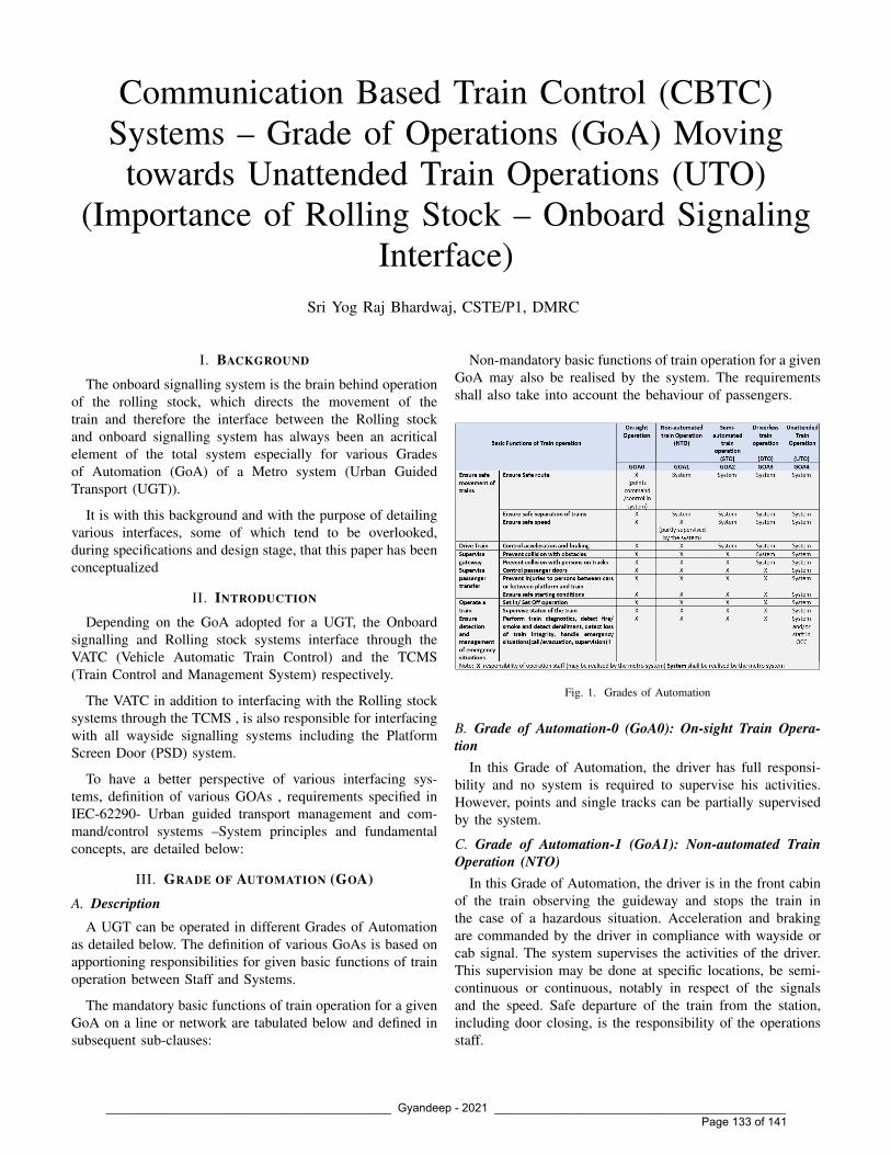
Communication Based Train Control (CBTC)Systems – Grade of Operations (GoA) Movingtowards Unattended Train Operations (UTO)
(Importance of Rolling Stock – Onboard SignalingInterface)
Sri Yog Raj Bhardwaj, CSTE/P1, DMRC
I. BACKGROUND
The onboard signalling system is the brain behind operationof the rolling stock, which directs the movement of thetrain and therefore the interface between the Rolling stockand onboard signalling system has always been an acriticalelement of the total system especially for various Gradesof Automation (GoA) of a Metro system (Urban GuidedTransport (UGT)).
It is with this background and with the purpose of detailingvarious interfaces, some of which tend to be overlooked,during specifications and design stage, that this paper has beenconceptualized
II. INTRODUCTION
Depending on the GoA adopted for a UGT, the Onboardsignalling and Rolling stock systems interface through theVATC (Vehicle Automatic Train Control) and the TCMS(Train Control and Management System) respectively.
The VATC in addition to interfacing with the Rolling stocksystems through the TCMS , is also responsible for interfacingwith all wayside signalling systems including the PlatformScreen Door (PSD) system.
To have a better perspective of various interfacing sys-tems, definition of various GOAs , requirements specified inIEC-62290- Urban guided transport management and com-mand/control systems –System principles and fundamentalconcepts, are detailed below:
III. GRADE OF AUTOMATION (GOA)
A. DescriptionA UGT can be operated in different Grades of Automation
as detailed below. The definition of various GoAs is based onapportioning responsibilities for given basic functions of trainoperation between Staff and Systems.
The mandatory basic functions of train operation for a givenGoA on a line or network are tabulated below and defined insubsequent sub-clauses:
Non-mandatory basic functions of train operation for a givenGoA may also be realised by the system. The requirementsshall also take into account the behaviour of passengers.
Fig. 1. Grades of Automation
B. Grade of Automation-0 (GoA0): On-sight Train Opera-tion
In this Grade of Automation, the driver has full responsi-bility and no system is required to supervise his activities.However, points and single tracks can be partially supervisedby the system.
C. Grade of Automation-1 (GoA1): Non-automated TrainOperation (NTO)
In this Grade of Automation, the driver is in the front cabinof the train observing the guideway and stops the train inthe case of a hazardous situation. Acceleration and brakingare commanded by the driver in compliance with wayside orcab signal. The system supervises the activities of the driver.This supervision may be done at specific locations, be semi-continuous or continuous, notably in respect of the signalsand the speed. Safe departure of the train from the station,including door closing, is the responsibility of the operationsstaff.
____________________________________________ Gyandeep - 2021 _____________________________________________ Page 133 of 141

D. Grade of Automation-2 (GoA2): Semi-automated TrainOperation (STO)
In this Grade of Automation, the driver is in the front cabinof the train observing the guideway and stops the train inthe case of a hazardous situation. Acceleration and braking isautomated and the speed is supervised continuously by thesystem. Safe departure of the train from the station is theresponsibility of the operations staff (door opening and closingmay be done automatically).
E. Grade of Automation-3 (GoA3): Driverless Train Opera-tion (DTO)
In this Grade of Automation, additional measures are neededcompared to GoA2 because there is no driver in the front cabinof the train to observe the guideway and stop the train in caseof a hazardous situation.
In this Grade of Automation, a member of staff , namelyRoving Attendant (RA) , is necessary on-board. Safe departureof the train from the station, including door closing, canbe the responsibility of the operations staff or may be doneautomatically.
F. Grade of Automation-4 (GoA 4): Unattended Train Op-eration (UTO)
In this Grade of Automation, additional measures are neededas compared to GoA3 because there is no onboard staff. Safedeparture of the train from the station, including door closing,has to be done automatically by the system.
More specifically, the GoA4 system supports detection andmanagement of hazardous conditions and emergency situationssuch as evacuation of passengers. Some hazardous conditionsor emergency situations, such as derailment or the detectionof smoke or fire, may require staff intervention.
IV. IMPLEMENTATION OF GRADES OF AUTOMATION
Different Grade of Automations may be used with the sametrain at different locations on the same line. The functions fordifferent Grades of Automation must be realised by up-gradingthe technical sub-systems , implemented on a common corearchitecture. The metro command and control systems shalladdress the basic functions , including associated interfacesidentified in the above fig.1 for implementation
V. PURPOSE AND TYPE OF INTERFACES
The interface requirements between on-board signalling(VATC) and Rolling Stock (TCMS) have been specified,herein, considering requirements for various Grade of Automa-tions detailed above.
The purpose of Interface is the exchange of status informa-tion between the Signalling and Rolling Stock systems thro’the VATC and TCMS, primarily for following functionalities:
- Control- Indication- Logging
To implement the above interfaces, signals from, both VATCand TCMS, typically interface with each other as diagrammat-ically represented below.
Fig. 2. Rolling Stock – On-board Signalling (VATC) Interface (Typical)
VI. RS (TCMS) - ON-BOARD SIGNALLING (VATC)INTERFACE:
The TCMS-VATC interface provides following functionali-ties:
- providing TCMS alarm messages to VATC- informing VATC when Emergency Brake (EB) is trig-
gered- providing status of EB to VATC.- informing VATC when Start button is pressed- informing VATC the status of door open and door close
buttons- informing VATC when all train doors are closed- informing VATC which mode is selected- informing VATC when holding brake is applied- informing VATC position of SCOS (safety cut out switch)- informing VATC of selection of automatic/ manual train
door open operation.- confirming Train Integrity to the VATC
VII. ON-BOARD SIGNALLING (VATC) – RS (TCMS)INTERFACE:
The VATC – TCMS interface provides following function-alities:
- To output the Pulse Width Modulation (PWM) signal tocontrol the train speed.
- To provide VATC information and alarms to TCMS- To provide “Train speed is below 0.5 km/hour” signal- To output the correct door side for opening- To trigger RS equipment when EB is required by VATC- To output the motor / brake command for speed control- To output a signal when over speed or signal passed at
danger is detected.- To detect the Neutral Section and intimate TCMS for
staggered opening / closing of VCB (Vacuum CircuitBreaker)
____________________________________________ Gyandeep - 2021 _____________________________________________ Page 134 of 141

The Interface Control Document (ICD) prepared jointly byboth Rolling stock (RS) and Signalling system vendors shouldclearly and unambiguously define the type of interface for eachfor each and every interfacing signal.
VIII. SPECIAL / ADDITIONAL FUNCTIONALITIES/INTERFACES:
In addition to the above interfaces, additional systems asdetailed below are also required to be provided in the trainand interfaced with on-board signalling, so as to comply withoperational and safety provisions for the train, as defined inIEC-62267:
i) Rolling stock (RS) control - Remote control commandsii) Onboard Public Address (PA) system
iii) Onboard Fire detection systemiv) Onboard Passenger Alarm Device (PAD) system – Com-
munication with OCC.v) Onboard Closed Circuit TV (CCTV) system - Surveil-
lance - Monitoring of fire, passenger alarm device fromOCC
vi) Rolling stock monitoring - Remote monitoring of RSParameters (Alarms and Events)
vii) Onboard Obstruction or Derailment Detection Device(ODD)
viii) Onboard Rail check systemix) Onboard monitoring of Overhead Catenary System (OCS)
(Auxiliary Drop Device (ADD) and Pantograph FailureDetection)
Relevance of the above Commands / Indications for eachGrade of Automation is detailed as Under:
i) S.No. (i)- While provision pertaining to remote control com-
mands for RS is not applicable for ATP/ATO (GOA1 & 2) modes, it is mandatory for DTO/UTO (GOA 3& 4) modes.
ii) S. Nos. (ii) - (iii)- These functionalities are mandatory for GOA 1 &
GOA-2 mode of operationiii) S. Nos. (iv) - (v)
- These functionalities are mandatory for GOA 3 & GOA4 mode of operations
iv) S. Nos. (vi) - (ix)- While these functionalities are mandatory for
DTO/UTO (GOA 3 & 4) mode(s), they can beconsidered desirable for ATP/ATO (GOA 1 & 2)mode projects on financial viability considerations
Details for each of the above provisions are elucidated asunder:
i) Remote Control Commands for Rolling Stock
The Traffic Controller (TC) in the Operation ControlCentre (OCC) shall be provided with remote controlof various RS functionalities from the Signalling (ATS)
Work Station in the OCC. This functionality shall enablethe TC to take remote control of any specific functionalityof the Rolling Stock required to rescue or operate thetrain.
Fig. 3. Typical communication schematic - Remote Command of RS fromOCC
Fig. 4. Execution of Remote Commands for Rolling Stock by TrafficController
Remote control of Rolling Stock functionalities shall beapplicable only for DTO/UTO (GoA 3 & 4) modes andshall be inhibited for ATP/ATO (GoA 1 & 2) modes ofoperation.
ii) Remote Monitoring of RS Parameters (Alarms &Events) - Rolling Stock Controller (RSC)
The RS parameters including alarms & events shall bemonitored by the RSC in the OCC. Monitoring of theRS parameters would also include monitoring of asso-ciated alarms & events. The RSC shall work in closecoordination with the Traffic Controller (TC) and assisthim in remote control of various Rolling Stock (Train)functionalities under DTO/UTO mode of operations as& when the need arises.
____________________________________________ Gyandeep - 2021 _____________________________________________ Page 135 of 141

Fig. 5. Typical communication schematic - Remote Monitoring of RollingStock
Fig. 6. Typical RSC Screen for monitoring RS Parameters
While provision of RSC functionality shall be mandatoryfor GOA 3 & 4 mode of operation, for GOA 1 & 2modes, it shall be optional, considering the fact that theTrain Operator (TO) is available for monitoring the RSparameters on the Train
Provision of RSC shall also enable centralized monitoringof parameters of all Rolling Stock (Trains) operating inthe metro system, resulting in better monitoring and co-ordination of the Rolling Stock , thus avoiding any failureof the Rolling stock even in GoA 1 & 2 projects, byinitiating preventive action based on information availablewith the RSC.
A considered view, based on financial viability, is there-fore required to be taken to include this feature for GoA-2projects.
iii) Onboard CCTV Surveillance - Monitoring of Fire,Passenger Alarm Device from OCC
While CCTV surveillance is provided as a default system
in the train for GoA 1 & 2 projects, but extending thesame (CCTV surveillance ) to the OCC is mandatory forGoA-3 & 4 projects.
The CCTV system shall provide cameras with videoanalytic functionality for surveillance of the following:- Saloon area- Platform- Front track- Over Head Catenary- Detrainment process
Fig. 7. Graphical representation - Location of various surveillance camerason Train
Fig. 8. Saloon camera view
Fig. 9. Detrainment camera view
Nominated CCTV cameras shall also be linked to variousevents or alarms (fire etc.) in the Rolling Stock forautomatic PoP up and generation of an event file (1 min.before & 5 min. after ) . The automatic PoP up happenson the CCTV MMI in the Driver’s cab in GoA1 & GoA2modes and on the CCTV MMI in the OCC in GoA3 &GoA4 mode of operations. Events are generated in the on-board NVR (Network Video Recorder) and forwarded tothe CCTV MMI in OCC. These events can be accessed
____________________________________________ Gyandeep - 2021 _____________________________________________ Page 136 of 141

Fig. 10. location of cameras
Fig. 11. Side camera – view
Fig. 12. Track camera – view
Fig. 13. OH Catenary camera – view
manually from the NVR in GOA 1 & 2 modes and fromthe CCTV MMI in OCC for GOA 3 & 4 modes.
Extension of CCTV surveillance to a dedicated work-station in the OCC shall be mandatory and include displayof following from the train for GoA-3 &4 mode ofoperations:- Live CCTV cameras (selected)- PoP up of cameras linked/associated to an event /
alarm.- Video from the train NVR (selected camera / time)- Videos of various events and alarms including the Rail
check system & Automatic Drop Device (ADD).
iv) Onboard Passenger Alarm Device(PAD)
All trains are equipped with onboard PAD system consist-ing of a Push Button, Speaker & Microphone for alerting& communication of passengers with the TO in GOA 1& 2 mode and with the OCC for GOA 3 & 4 mode ofoperations.
Fig. 14. Passenger Alarm Device (PAD)
The PAD is activated when passenger presses the buttonon interior covering panel. PAD has a built-in microphoneand speaker. Normally the PAD is connected to the Trainoperator , but during GoA3 & GoA4 modes , the callwill automatically be forwarded to the TC in the OCCby the Train radio system. The PAD provides full-duplexcommunication
v) Public Address (PA) system
All trains shall be equipped with an integrated publicaddress system for assistance of the TO in GoA 1 & 2modes and to the TC in the OCC for GoA 3 & 4 modeof operations.
The onboard PA system shall be used for announcing thefollowing operational and traffic related information bythe TO in GoA 1 & 2 modes & by TC in OCC in GoA3 &4 mode:- Instructions to passengers as to how to behave in an
emergency- Train dispatching announcements, when dispatched
directly by the OCC- Information on train delays, connecting trains etc. by
the OCC.
____________________________________________ Gyandeep - 2021 _____________________________________________ Page 137 of 141

Fig. 15. Passenger Announcement System
- Automatic announcements e.g. “next station”- Other announcements
Urgent announcements given by OCC shall automaticallyinterrupt system-initiated announcements having lowerpriority.
vi) Onboard - Fire and smoke detection (train)
All trains shall be equipped with Fire and smoke detectionsystem with alarms extended to the TO in GoA 1 & 2systems and same shall be connected, directly to the OCCfor GoA 3 & 4 systems.
Fig. 16. Fire & Smoke Detection System
Trains , under fire conditions and / or activation of smokedetection system alarm , shall continue to the next stationand shall be stopped there i.e. continuation of the journeyshall be inhibited with doors remaining open. If the trainis in a station when the fire or smoke is detected, the traindoors shall remain open and the train shall be preventedfrom leaving the station.
vii) Onboard Obstruction / Derailment Detection Device(ODD)
An onboard obstacle/derailment detection device can re-duce detrimental consequences to passengers and prop-erty from collisions with obstacles on the track.
The obstacle detection device shall detect when an ob-stacle is in contact with the device. Specification of
Fig. 17. Obstruction / Derailment Detection Device (ODD)
obstacles to be detected shall be defined in the technicalspecifications. If an obstacle is detected, the train shallapply the emergency brake in all modes of operation.
Detection of an obstacle shall be reported to the OCCas an emergency message. Normal operation shall onlybe resumed after it has been verified that all hazardousconditions have been resolved.
viii) Onboard Rail Check System
An onboard rail check system can enable automaticinspection/monitoring of rail head, fasteners, sleepers &ballast.
Fig. 18. Rail Check System
Rail Check Sensor System- Field of view 1500 mm- camera in housing- illuminationThe onboard rail check system works on the principle ofrecording using high resolution cameras. The rail checksystem is able to detect broken rails, defects in rail head,missing material, cracks in rail etc.
The rail check system shall continuously record the trackparameters and also automatically detect any defect &record the same as an event and report it to OCC.Provision shall be made to enable staff in the OCC toassess the situation, and Initiate relevant measures definedby rules and procedures in order to ensure a safe trainoperations.
____________________________________________ Gyandeep - 2021 _____________________________________________ Page 138 of 141

ix) Onboard Overhead Catenary (OCS) monitoring Sys-tem– ADD & Pantograph Failure
The OCS monitoring system shall continuously monitorthe overhead catenary including the pantograph throughdedicated CCTV cameras with video analytic & artifi-ial intelligence functionality. The CCTV footages bothcontinuous & events shall be recorded in the train-borneNVR.
The events for the OCS monitoring system shall betriggered by:- Auto Drop Detection (ADD) system- Pantograph Failure
Fig. 19. OCS monitoring system
Fig. 20. Functioning of the ADD System
The ADD and pantograph failure detection system worksin conjunction with the OCS monitoring system with anyevent recorded in the NVR as a 6 min. event file (1 min.before the incident & 5 min. post incident)
IX. ADDITIONAL FUNCTIONALITIES:In addition to the above, following features, involving
signalling & rolling stock interface, which generally tend tobe overlooked should also be catered for:
i) Passenger exchange time of 20 secs.in a station dwelltime of 30 secs. should be ensured. (after considering alltrain door, platform screen door opening & closing times)
ii) So as to reduce the processing time for door openingand closing, the VATC should directly interface with theway-side PSD system rather than through the way-sideATS/ATP system.
iii) The open and closing cycle of doors including PSDsshould be proved by the system to possibility of departureof train without passenger servicing.
iv) All cut-out / bypass switches / push buttons should beassociated with a digital counter.
v) While cut out switches should be sealed, push buttonsshould have dual (two hand) operation to avoid inadver-tent issue of commands.
vi) All signals exchanged between the VATC, PSD & TCMSshould be logged in each individual system, for fault androot cause analysis.
vii) All rolling stock equipment including the TCMS shouldbe synchronized with signalling clock of the VATC.
viii) The Door Proving Lock bypass (DPLCoS) functionalityshould be achieved using a transitory latched commandwhich resets on arrival at the station. This will compeloperation of the DPLCoS push button at every station.
ix) System timings (delay) of various design functionalitiesconfigured by either Rolling Stock or signalling system(s)shall be implemented only after mutual agreement of bothRS & Signalling.
x) Suitable arrangements should be made both in the RollingStock & signalling systems, so as to ensure rescue of thetrain, in UTO mode to the next station, under failure ofAll Doors Close Relay (ADCR) in mid-section. Associ-ated Standard Operating Procedures (SoP) & hazard logalong with suitable mitigation shall be jointly proposedby RS & signalling vendors.
xi) Isolation of any train door should be suitably indicated inthe train , for information of the passenger.. Use of REDindication for isolation status along with other indicationsof the Train door , using dual colour LEDs , can beprovisioned in the design.
xii) The Signalling system shall ensure the train moves underATP protection within the speed limit specified by RS(under various conditions viz. suspension failure etc.).Indications on the DMI shall reflect the speed restrictionspecified by RS & under which the train is being operatedby the Signalling system.
xiii) For UTO system, if a train is in sleep mode for morethan 24 hrs. , an alarm should be provided to the depotcontroller to avoid discharge of battery.
xiv) For UTO system, the sleep and wake Up process shallbe jointly finalized by RS & signalling so as to cater forall operational conditions including :- Stabling of trains at designated points on the main line- Simultaneous waking up of trains from stabling lines
as per timetable- Handling of trains under failure of wake-up process of
a particular train etc.xv) Wash mode functionality should be available under UTO
mode of operationxvi) For UTO systems, jog & creep functionality should be
available to cater of under/over shoot of trains.xvii) Provision should be available for transmitting both Train
____________________________________________ Gyandeep - 2021 _____________________________________________ Page 139 of 141

Operation Data (TOD) and the VATC data on-line todesignated wayside systems provided by Rolling stock& signalling systems respectively. This data shall beused for alarm monitoring, maintenance & generation ofManagement Information System (MIS ) reports for theTCMS & train borne signalling systems. The CCTV radiosystem shall be utilized for transmission of these data.
xviii) Both RS & signalling systems shall provide a networksecurity plan for their respective onboard networks.
xix) Feasibility of providing monitoring & control functional-ity both to the OCC & Rolling Stock and vice versa overthe CCTV radio network.
xx) Data down load facility of selected train on the RovingAttendant’s (RA) maintenance terminal.
xxi) RA to have announcement facility to passengers of a trainfrom his Radio handset.
X. ADVANCEMENTS IN INTERFACE CONNECTIVITY (IPINTERFACE):
Earlier when RS (TCMS) – signalling (VATC) were inter-faced using Input / Output (I/O) cards or serial interface it wasa normal practice to use hardwired signals with monitoringof both front & back contacts. This conventional interfaceensured traditionally reliability and compatibility of SIL levelsi.e. SIL4 for interface between TCMS – VATC.
With improvement & proliferation of IP technology, theseinterfaces are increasingly migrating to IP (Ethernet) basedinterface (IF.IP) using TRCP (Real Time Control Protocol) ,TRDP (Train Real Time Data Protocols) resulting in reductionin train wires and higher interfacing speed.
Functionality of signals which are agreed to be exchangedusing this interface mode should be clearly identified as vitalor non-vital. While vital signals which shall normally be usedfor control applications by the VATC , shall be configuredin the Safety (SIL-2) packet, non-vital signals normally usedfor indication or logging purposes, shall be configured in thenon-safety (SIL-0) packet of the TCMS interface.
To increase reliability of the interface, it should be ensuredthat the TCMS – VATC interface should:
- be direct i.e. TCMS – VATC, rather than cascadedthrough the event recorder or any other device viz. TCMS– Event recorder – VATC etc.
- use of redundant signals in OR logic to attain the desiredfunctionality to the extent possible
The signalling vendor shall include use of SIL-2/SIL-0signals of the TCMS by VATC, in its safety case submittedfor safety certification of the VATC.
All signals exchanged between Rolling stock & Signallingsystem(s) , should be clearly and unambiguously defined tobe interfaced either through hardwired or ethernet connectivitybetween both the systems.
XI. RADIO SYSTEMS
The CBTC system shall be provided with two indepen-dent (standalone) Radio Systems namely:
- CBTC Radio System- CCTV Radio System
Fig. 21. Connectivity of CCTV & CBTC Radio Systems
A. CBTC Radio System
The CBTC radio system in addition to catering for trans-mission of the train borne signalling functionalities (vital andnon-vital) between the wayside signalling system shall alsocater for transmission of commands and associated indications, key alarms required for remote control functionality of rollingstock from the ATS work station in the OCC ( for GOA 3 & 4).The capacity of the CBTC Radio should be of min. 50 MBPSwith associated networks configured for 1 GBPS, so as to caterfor all the above functionalities including 25% spare capacitywith minimum latency.
B. CCTV Radio System
The CCTV radio system in addition to catering for require-ment of transmission of live CCTV cameras from the train tothe CCTV workstation in OCC shall also cater for transmissionof the following:
- Live videos of all cameras configured in the CCTVsurveillance system.
- PoP up of various live feed linked to an event / alarmincluding Rail check & ADD system.
- Recorded video from the train NVR- Recorded videos of various events/alarms including the
rail check system & ADD system.
In addition to the above, the CCTV radio system shallalso be used for transmitting the following:
Rolling Stock- Train Status & Operation Data (TOD)- TCMS screen shot- Train alarms- TCMS log data
____________________________________________ Gyandeep - 2021 _____________________________________________ Page 140 of 141

Signalling System- VATC alarms- VATC log data
On Board entertainment services- Wi-Fi services- Advertisements from OCC- Live media (news, movies etc.) transmission from OCC
To cater for the above requirements, while the CCTV radionetwork should be min. of 250 MBPS capacity, the associatedtrain borne & way side CCTV network should be configuredon a 10 G backbone which shall cater to 25% spare capacitywith minimum latency.
Considering, the CBTC radio network caters to vital controlfunctionality of the Signalling & Rolling Stock systems, theCBTC & CCTV radio systems, both train borne & wayside,should be independent & isolated from each other, to preventany interference including capacity constraints & traffic lop-ping between these (CBTC & CCTV) systems.
Mr. Yog Raj Bhardwaj, presently positioned asCSTE/P1 in DMRC, is a Graduate in Electrical(Electronics) Engineering from Delhi College ofEngineering of Class -1981. Immediately after grad-uation, in 1981, he joined BHEL, Control EquipmentDivision, Bangalore as a Design Engineer (BoilerControls). Thereafter, in 1984, he joined the IndianRailway Service for Signal Engineers (IRSSE-1982)on Western Railway.
He has over 37 years of experience in field ofRailway & Metro Signalling & Telecommunication
systems. He successfully commissioned ODA funded project of RemoteControl & Train Describer System (GEC-GS, UK) covering 23 stations ofDelhi Area, Northern Railway. He was also posted as Director / Telecomm.,Railway Board, Ministry of Railways from 1999 – 2004. During his stintin RailTel (RCIL), a PSU under Ministry of Railways, he was instrumentalin commissioning over 10000 Kms of OFC network using STM-16 networkcomprising of Alcatel & WRI SDH equipment
He took voluntary retirement from Railway Service in 2008 and joinedDelhi Airport Metro Express Pvt. Ltd (DAMEPL) where he was responsiblefor Design, installation and commissioning of Telecommunication Systems forDelhi Airport Metro Express Project. Subsequently , in 2011, he joined L&T,as General Manager and was responsible for Signalling, Telecommunication& AFC Systems for Hyderabad Metro Rail Project after which he again joinedDAMEPL as Head - Operations.
After tenure with Delhi Airport Metro Express Line, in 2014, he joinedRITES Ltd. as General Manager (S&T) and was deputed as S&T / AFCexpert with GC/ DMRC (Phase III) unit, responsible for assisting DMRCin technical evaluation & review of documents received from vendors ofSignalling, Telecommunication & AFC systems
After completion of contract tenure in RITES, in 2015 , he joined RailTel asGeneral Manager /NTP, responsible for Network & Technology Planning inRailTel Corporation of India Ltd. including the Wi-Fi project on RailwayStations being executed in collaboration with M/s Google Inc. Also wasresponsible for HR functionalities as additional charge of GGM/HRD.
Before joining DMRC, in 2019 , he was positioned as Interface (UTO))Expert with Delhi Metro Rail Corporation for commissioning their UTOoperations of Phase -3 (Line 7 ]& Line-8) through Louis Berger ConsultingPvt. Ltd.
As CSTE/P! in DMRC, he is presently responsible for Signaling workson Line-8 (Magenta Line) , Telecomm. Works for all Lines, S&T work onNoida-Greater Noida Metro Corridor, Central Vista Metro Project and otherConsultancy projects of DMRC.
____________________________________________ Gyandeep - 2021 _____________________________________________ Page 141 of 141

CMMI®V2.0 / Exp. 20 23-0 1-29 / Appraisal # 5 10 62
99.999 $
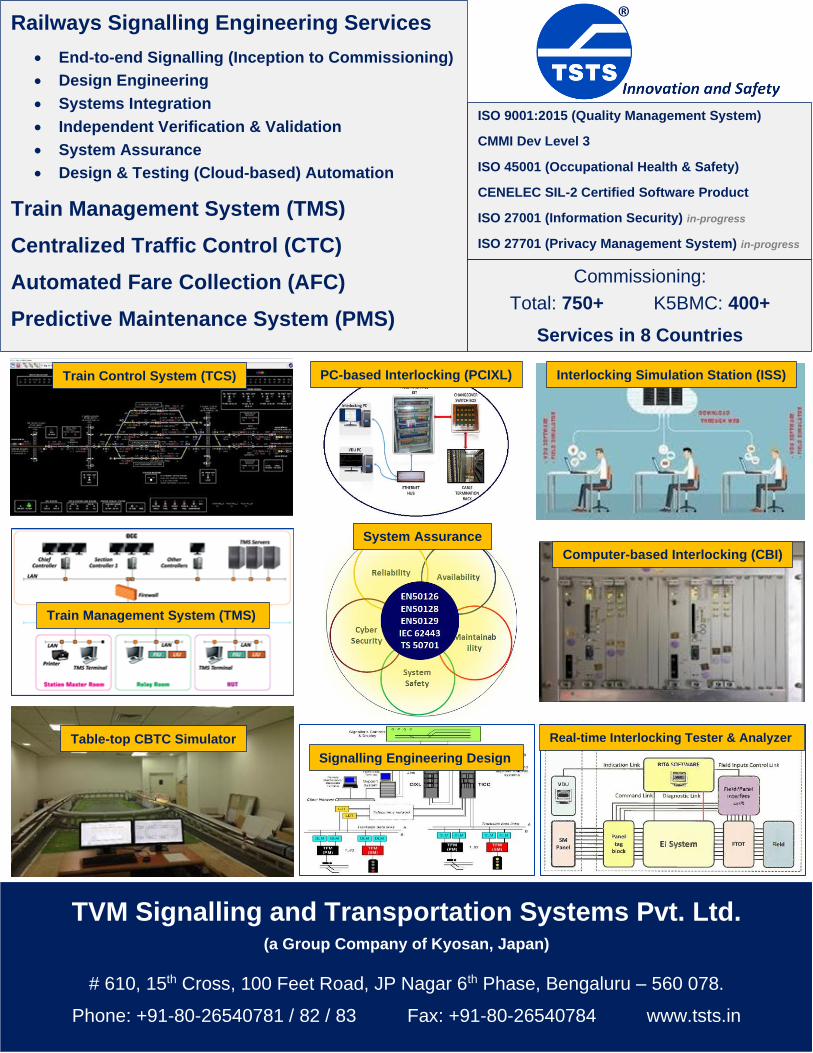
Railways Signalling Engineering Services
• End-to-end Signalling (Inception to Commissioning)
• Design Engineering
• Systems Integration
• Independent Verification & Validation
• System Assurance
• Design & Testing (Cloud-based) Automation
Train Management System (TMS)
Centralized Traffic Control (CTC)
Automated Fare Collection (AFC)
Predictive Maintenance System (PMS)
ISO 9001:2015 (Quality Management System)
CMMI Dev Level 3
ISO 45001 (Occupational Health & Safety)
CENELEC SIL-2 Certified Software Product
ISO 27001 (Information Security) in-progress
ISO 27701 (Privacy Management System) in-progress
Commissioning:
Total: 750+ K5BMC: 400+
Services in 8 Countries
TVM Signalling and Transportation Systems Pvt. Ltd. (a Group Company of Kyosan, Japan)
# 610, 15th Cross, 100 Feet Road, JP Nagar 6th Phase, Bengaluru – 560 078.
Phone: +91-80-26540781 / 82 / 83 Fax: +91-80-26540784 www.tsts.in
Train Control System (TCS) Interlocking Simulation Station (ISS)
System Assurance
Train Management System (TMS)
PC-based Interlocking (PCIXL)
Computer-based Interlocking (CBI)
Table-top CBTC Simulator
Signalling Engineering Design
Real-time Interlocking Tester & Analyzer


MEDHA, an R&D focused company with more than 30 years of experience of design, development and manufacturing of leading technology Power Electronics products for Railway applications. Medha is the largest supplier of Propulsion control systems which includes vehicle control systems, traction converters, traction motors, auxiliary power converters and other control and power electronic systems to Indian Railways and to several other countries. Medha's Propulsion control system and Train Control Management System power the reputed 'Vande Bharat Express' – the first train in India to travel at 160 km/h.
Design Manufacturing Maintenance
ISO 9001 4
www.medha.com
Medha Servo Drives Pvt. Ltd.2-3-2/A, Cherlapally, Medchal District,.
Hyderabad - 500 051 Telangana, India [email protected]+91-40-6723 7000
Integrated Solutions for Locomotives and Trainsets
IGBT based traction (propulsion) converters ranging from 1.1 MW upto 4.5 MW and higher power ratings for installation on AC-AC traction vehicles including Locomotives, DMUs, EMUs and Metros.
Microprocessor based vehicle control and fault diagnostic systems for Locomotives, DMUs, EMUs, and Metros. Additional features include remote monitoring system, in-built speedometer, vigilance control and more.
Vehicle Control SystemsTraction Converters
Signaling Systems
Single and Multi Section Axle Counter
Electronic Interlocking SystemMedha's Electronic Interlocking System is a modular, fail safe and configurable signaling system which meets CENELEC SIL4 safety standards.
Reliable wheel counting with fail-safe occupancy detection.
Wheel diameter range380mm to 1092mm
Wheel speedupto 300kmph
Sleepers:wood, steel,concrete, composite
Wheel sensorsIP68 protection
Two sensors working onelectromagnetic fielddetection principle
Rail profile
60kgs / 52kgs / 90R
Digital Axle Counter Reset BoxWheel counter with 4x20 dot matrix display
Supports hot swapping of cards
Digital Axle Counter Unit
RADIO STATIONANTENNA
RFID TAG READER RFID TAGS
GPS & GSMANTENNA
STATIONTCS
CONTROLUNIT
SIMOCP
VDU
SIGNALASPECT RELAYS
BRAKEINTERFACE UNIT
ONBOARDCOMPUTER
LPOCIP SIGNAL POST
RADIO ANTENNA GPS & GSMANTENNA
Track occupancy status
Point/Switch status
(KAVACH - Train Collision Avoidance System)Medha's Train Collision Avoidance System (TCAS) allows safe movement of trains within the Station vicinity and in Block Sections and prevents any train collision which can be caused due to overshooting of traffic signal (Signal Passing at Danger)

Taashee Linux Services Pvt Ltd (CMMI-SVC v1.3 Maturity Level 3 Appraised and ISO 27001:2013 & ISO 9001:2015 Certified) is a leading open-source technology company with a global footprint specializing in Technology Integration, Application Transforma-tion, Hardware Provisioning, Database Management, Cybersecurity, Networking, Works-pace Solutions, RPA and more. We have formed strategic worldwide partnerships with Red Hat, JBoss, Ansible, Liferay, Alfresco, VMware, Veeam, EDB, Qlik, Amazon, Ubuntu, Nagios and Crafter among others.
www.taashee.com
Corporate Office:Taashee Linux Services Pvt Ltd,Western Aqua, 12th FloorWorkafella, 101,Whitefields, HITEC City, Kondapur,Hyderabad-500081,Telangana.
Contact Details:
Phone: +91-9154910504Email: [email protected]
Hyderabad | Mumbai | New Delhi | Bengaluru | Chennai | Vishakhapatnam | Singapore
Our Services & CAPABILITIES
01
02
03
04
05
06
Advanced Red Hat Solutions on Openshift and & Openstack
Application Transformation from monolithic to Microservices
Advanced implementation of VMware and Veeam Projects
Architecture designing of complex Data fabric using Open Source DBs like PostgreSQL, Cassandra, Redis and Hazelcast
Implementation and commissioning of private cloud oriented Data Center on new age hyper converged platforms from HP, Dell and Nutanix
Advanced cloud management projects in AWS, Azure & GCP


CREATING TELECOM AND ICT INFRASTRUCTURE
FOR YOUR DIGITAL GROWTH
RailTel Corporation of India Limited(A Government of India Undertaking)
RailTel - Delivering Strategic and Critical Network Infrastructure Services
SERVICESHD Video Conferencing • Data Center and Cloud Services • Retail broadband service – RailWireLeased Line • Virtual Private Network • NLD for Voice Carriage Network • Internet Leased Line
Consultancy Service • Signalling Services • Tower Collocation • State Wide Area Network Management
PROJECTSPM WANI • Video Surveillance System • Wi-Fi
Hospital Management Information System (HMIS) • Implementation of NIC e- office
Corporate Office:
Plate-A, 6th Floor, Office Block Tower-2, East Kidwai Nagar, New Delhi-110023Tel.: +91 11 22900600 | Fax: +91 11 22900699
www.railtelindia.com
Mini Ratna (Category-I) CPSE
ISO 9001:2015ISO/IEC 20000-1: 2018ISO/IEC 27001:2013CMMI Maturity Level -4@RailTel railtel-corporation-of-india-ltd railtelcorporationJoin us:
Boradband
Wi-Fi HotspotCreationn
e-office
Tower Collocation
Telepresence asa Service
ICT Project &Consultancy
Services
Railway SignallingProjects
Leased Line
MPLS-VPN
Data CenterServices
Security OperationCentre Service