
Flow State Aware Management Without User Signalling
58
Attorney Docket No.: CP1742 1 FLOW STATE AWARE QoS MANAGEMENT WITHOUT USER SIGNALLING 5 Inventor: John Leonard Adams BACKGROUND OF THE INVENTION The present invention relates to a communications network and a method of 10 operating a communications network. Recently, the demand for streaming video to a computer via the Internet has grown strongly. This has led to a need to supply increasing amounts of video material over local communication networks (whether the copper pairs used 15 by telephone network operators or the coaxial cables used by cable television network operators). In telephony networks this additional demand is being met by the introduction of Digital Subscriber Loop (DSL) technology. As its name suggests, this 20 technology carries digital signals over the local copper loop between a user’s home and a local telephone exchange. Data-rates of several megabits per second to the user’s home are achievable. The digital signal is conveyed
Transcript of Flow State Aware Management Without User Signalling
Attorney Docket No.: CP1742
1
FLOW STATE AWARE QoS MANAGEMENT WITHOUT USER SIGNALLING
5
Inventor: John Leonard Adams
BACKGROUND OF THE INVENTION
The present invention relates to a communications network and a method of10
operating a communications network.
Recently, the demand for streaming video to a computer via the Internet has
grown strongly. This has led to a need to supply increasing amounts of video
material over local communication networks (whether the copper pairs used15
by telephone network operators or the coaxial cables used by cable
television network operators).
In telephony networks this additional demand is being met by the introduction
of Digital Subscriber Loop (DSL) technology. As its name suggests, this20
technology carries digital signals over the local copper loop between a user’s
home and a local telephone exchange. Data-rates of several megabits per
second to the user’s home are achievable. The digital signal is conveyed

Attorney Docket No.: CP1742
2
between modems placed at either end of the copper loop – the modem in the
user’s home usually being incorporated in a set-top box. The advantages of
statistical multiplexing have led to the digital signals being organised into
packets (whether they be Asynchronous Transfer Mode (ATM) packets or
Internet Protocol (IP) packets).5
Many cable networks are being upgraded to carry digital signals to user’s
homes. At least where the signals have been carried over the Internet, those
digital signals are again arranged into packets.
10
Video material requires a data rate which varies between 1.5Mbps (for a
quality comparable to that offered by a video cassette recording) to 20Mbps
(High-Definition Television). In DSL networks, this means that a mechanism
is needed to manage contention for the capacity offered over the copper loop
leading to the user’s home. Although cable networks can carry around sixty15
video streams simultaneously, their capacity is normally shared by several
hundred users, meaning that contention for the capacity on the cable will also
need to be managed as cable network users demand more choice in the
material they view.
20
In a conventional telephone network, the problem of contention for scarce
telecommunication resources is dealt with by simply preventing a user from
receiving (or sending) any traffic unless the necessary capacity to carry that

Attorney Docket No.: CP1742
3
traffic can be reserved beforehand. There are numerous connection
admission control schemes of this sort for packet networks too – examples
include the Resource Reservation Protocol (RSVP). Although such schemes
prevent congestion, QoS management must also manage so-called “elastic”
traffic where there is potentially a need for a minimum guaranteed rate but5
frequently a desire to transmit the flow as fast as possible, subject to network
congestion constraints and constraints on maximum sending rates.
An alternative to the use of connection admission control in packet networks
is to use reactive flow control. These schemes allow users access to10
communications resources but attempt to cause senders to decrease their
sending rate on the onset of congestion. The scheme used for reliable
transmission across the Internet (Transmission Control Protocol) is the most
common example. This is unsuitable for video flows however, since real-time
video servers cannot reduce their sending rate.15
In most flow control schemes, all users are adversely affected by the onset of
congestion. Some flow control schemes are more sophisticated, classifying
traffic into different classes, with some classes being more likely to suffer
packet delay or discard than others. In situations where such classification is20
not available or where most traffic is within one class, alternative solutions
must be provided. One such alternative solution which concentrates the
adverse effects of ATM cell discard on one IP packet at a time is described in

Attorney Docket No.: CP1742
4
[23].
A discussion toward the Internet based Next Generation Network (NGN) is
actively progressed around the standards bodies including the ITU-T
(International Telecommunication Union - Telecommunication Standardization5
Sector) and ETSI (European Telecommunications Standards Institute), IEEE
(Institute of Electrical and Electronics Engineers), IETF (Internet Engineering
Task Force), and etc. The roles of the standard bodies are different. The IEEE
and IETF develop the core technology for specific problems in layer 2 and layer 3,
respectively. ITU-T and ETSI develop the network architecture and control10
procedure.
The QoS control or resource control architecture has been developed in the
several standard bodies. To name a few, they are ITU-T, ETSI, Cable Lab, 3GPP,
MSF, and the DSL forum. Among those organization, CableLab, and DSL forum,15
3GPP, and ETSI define the QoS control architecture in a particular case while
ITU-T defines the generic architecture that can cover the outcomes of other
standard bodies.
CableLab defines the dynamic QoS (DQoS) control architecture [3] for the Hybrid20
Fiber and Coaxial (HFC) network. The control architecture is designed for the
uniqueness of the HFC network. In the HFC network, multiple CMs (Cable
Modems) share an upstream channel to CMTS (Cable Modem Termination

Attorney Docket No.: CP1742
5
System). The bandwidth is controlled based on layer 2 MAC protocol called
DOCSIS (Data Over Cable System Interface Specification) [4]. The layer 2 level
QoS guarantee mechanism is defined from the DOCSIS version 1.1. The goal of
the DQoS is supporting the QoS guaranteed service through HFC network.
5
DQoS defines the procedure of the call setup signalling and the dynamic QoS
control on DOCSIS interface. In the architecture, the CMS (Call Management
Server) / Gate controller controls the call establishment. The guaranteed
bandwidth between CM and CMTS is reserved dynamically during the call setup
signalling. The CMS/Gate Controller triggers the layer 2 or layer 3 QoS signalling10
to reserve the bandwidth in the HFC network by sending commands to CM,
CMS, or MTA (Multimedia Terminal Adapter).
DQoS has been refined through version 1.0, 1.5, and 2.0. Version 1.0 defines the
basic call setup signalling procedure for both embedded MTA and standalone15
MTA. The embedded MTA can initiate the dynamic layer 2 QoS signalling while a
standalone MTA initiates IP level QoS signalling. Version 1.5 and 2.0 defines the
QoS control architecture when SIP (Session Initiation Protocol) based call setup
signalling is used. DQoS 2.0 is defined especially for interoperability with IP
Multimedia Subsystem (IMS) which is the SIP based call setup architecture20
developed in 3rd Generation Partnership Project (3GPP). PacketCable
Multimedia [5] has been developed for simple and reliable control for the
multimedia service over cable network. It defines the service delivery framework

Attorney Docket No.: CP1742
6
for the policy based control on multimedia service. The simple procedure for time
or volume based resource authorization, resource auditing mechanism, and
security of the infrastructure are defined in PacketCable Multimedia.
Such developments as this strongly suggest that new QoS mechanisms should5
take account of, and build on top of, the underlying deployment of QoS controls.
Again, the DSL forum defines the resource control at the DSL (Digital Subscriber
Line) access network [6]. Unlike Cable network, DSL modem is connected to the
subscriber through the dedicated line. Layer 2 level dynamic QoS control10
between DSL modem and Digital Subscriber Line Access Multiplexer (DSLAM) is
not required. The DSL forum focuses more on resource control in the home
network especially resource control of multiple terminals behind the home
gateway.
15
The resource control architectures defined in the above mentioned two standard
bodies - PacketCable and DSL Forum focus on a specific transport technology
(i.e., HFC network and DSL network). The scope of DQoS and DSL forum is
mainly within network operator’s view. Unlike these, RACF (Resource and
Admission Control Functions) [7] of ITU-T and RACS (Resource and Admission20
Control Sub-system) [8] of ETSI define the resource control architecture in more
general aspect.

Attorney Docket No.: CP1742
7
The QoS control architecture in both RACF and RACS are closely related with
3GPP (3rd Generation Partnership Project) effort. The 3GPP is originally founded
for developing new service architecture over cellular network, especially for GSM
(Global System for Mobile communication) network. During this effort, 3GPP
developed the IMS (IP Multimedia Subsystem) for controlling the IP multimedia5
services in the areas of session control, service control, and management of
database of the subscribers. Even though IMS is initially developed for the
evolution of GSM cellular network, its framework can be applicable for any types
of transport technologies. The IMS architecture has been adopted to the other
QoS control architectures such as 3GPP2 MMD (Multimedia Domain), ETSI10
TISPAN (Telecoms & Internet converged Services & Protocols for Advanced
Networks), and ITU-T NGN. Thus, both RACS and RACF are interoperable with
IMS.
In general, RACF and RACS are very similar with each other. The two standards15
bodies are closely interacted in developing their architecture. There is no
significant conflict between the two, but there are still differences [9]. One of
differences is the range of the control region. The control region of RACS covers
the access network and the edge of the core network. The access network is
defined as the region where the traffic is aggregated or distributed without20
dynamic routing. The resource control in the access network is done in layer 2
level. The core network is the region that the IP routing starts. The core network
is out of scope in the RACS. RACF, however, covers both core and access

Attorney Docket No.: CP1742
8
network. RACF covers both fixed and mobile networks while RACS is defined for
the fixed network. For the control mechanism, the RACF defines more control
scenarios than RACS. Therefore, RACS is considered as a subset of RACF.
ITU-T defines the QoS control functions based on its NGN architecture. One of5
the important concepts in the ITU-T NGN architecture is the independence of the
transport and the service [10]. The transport is concerning about the delivery of
packets of any kind generically, while the services are concerns about the packet
payloads, which may be part of the user, control, or management plane. In this
design principle, the NGN architecture is divided into two stratums - Service10
Stratum and Transport Stratum. Under the concept of the independence of a
service and transport functions, the network resource and reliability are
guaranteed by the network side upon request from the service stratum. Service
Stratum is responsible for the application signalling and Transport Stratum is
responsible for reliable data packet forwarding and traffic control. The service15
stratum can be a simple application server or a full-blown system such as IMS
(IP Multimedia Sub-system).
Transport control function is located in Transport stratum interfacing with the
Service stratum. It determines the admission of the requested service based on20
the network policy and the resource availability. It also controls the network
element to allocate the resource once it is accepted. Resource and Admission
Control Functions (RACF) is responsible for the major part of the admission
Attorney Docket No.: CP1742
9
decision and resource control of the transport function. Details of RACF
mechanism can be found in [11][7].
Once again, this developing infrastructure needs to be taken account of when
considering new QoS mechanisms.5
Review of current per-flow QoS controls The flow level transport technology is
not a new concept. The core technologies for the traffic management schemes
such as in flow level scheduling, policing, and sharing are already available in the
commercial product [12]. The current deployment of flow base control, however,10
is limited only at the edge of the network. Typical examples of flow base control
are traffic monitoring, packet inspection, PacketCable access, session border
controller, edge router, and interworking between two networks. They are mostly
stand alone solution at the edge of the network.
15
However, flow level traffic control only at the edge cannot guarantee the flow
level QoS. Furthermore, DiffServ guarantees the QoS only if the premium traffic
load is very low (~ under 10%) [13]. On the other hand, having scalable control
architecture for flow level traffic control along the data path is a challenging issue,
because the number of flows in a network is huge.20
There are several schemes proposed for the scalable control of traffic using flow
level mechanisms. These are listed below.

Attorney Docket No.: CP1742
10
(1). Flow Aware Network (FAN) France Telecom proposed a Flow Aware
Network (FAN) [14]. FAN applies three different regimes based on the
network status. They are the “transparent regime”, “elastic regime”, and
“overload regime”. The transparent regime is applied when the network has5
no congestion at all. The elastic regime is applied when the network
experiences the occasional traffic congestion because of a few high rate data
flows. The overload regime is applied when the traffic overloads the link
capacity in the network.
No traffic control is required in the transparent regime. The traffic control is10
effective only in the overload or elastic regime. In the elastic regime, the network
enforces the bandwidth limit for every flow. Every flow is assigned the same
amount of bandwidth. In the overload regime, new flows are blocked to protect
existing flows. To reduce the control complexity, an implicit approach is preferred
where no signalling is required for controlling the network. Each node makes15
locally optimal decision based on local observation.
The main focus of FAN is the simplicity. It requires no signalling. Only implicit
admission control is required upon congestion. Although the control mechanism
is very simple, it is shown that the network is stabilized remarkably in FAN.20
However, this architecture is designed mainly for network stabilization aspect.
Every flow is treated equally. In order to support various of QoS requirement for
individual flow, this architecture should be improved.

Attorney Docket No.: CP1742
11
(2). Flow Sate Aware (FSA) technologies FSA is developed to provide
different QoS for the individual flow. FSA defines the service types based on
typical example of Internet services [15][16]. They are Maximum Rate (MR),
Guaranteed Rate (GR), Variable Rate (VR), and Available Rate (AR). GR is5
designed for applications requiring guaranteed bandwidth for the entire
duration of the flow. MR is designed for streaming media such as video and
voice. AR is designed for data traffic flow where the application can setup the
flow rate at the maximum rate that the network can currently support. VR is
the combination of AR and MR. VR could be used for obtaining a maximum10
response time for a transaction (e.g., a stock trade with maximum transaction
time). The MR portion guarantees the minimum guaranteed bandwidth and
AR portion is for use available network resource. FSA divides the network
resource into two portions. One is Fixed Rate (FR) and the other is Network
Rate (NR). FR is requested when flow needs a fixed rate available during the15
service. NR is requested when flow sends buffered data using network
available bandwidth. Service type GR and MR request FR, AR requests NR,
and VR requests both NR and FR. The detail requirement is defined in [15].
20
FR and NR are requested by the signalling [24] and every node along the path
configures its resource based on the requested FR and NR. For the call setup
signalling, the source node and destination node exchanges the control

Attorney Docket No.: CP1742
12
messages. [Figure 1] describes the signalling procedure for the service type
MR, GR, and AR. In the ingress FSA (iFSA) and egress FSA (eFSA)
exchanges the request, response, confirm, renegotiate, and confirm message
for request the transport resource. For MR, iFSA sends the data traffic before
receiving the response from eFSA. MR is designed based on the concept of5
the conditional guaranteed bandwidth [16][17]. For GR, it needs to know the
explicit start and ending time of the flow. Therefore, it sends confirm and close
messages for acknowledging every transit node reserves and release the
requested bandwidth. The service type AR is designed to use network
available resource. iFSA and other FSA nodes continuously monitor the10
network available resource and adjust the NR accordingly.
Both approaches, FAN and FAS, give an insight for flow based traffic control.
FAN shows that even very simple flow level traffic control can stabilize the
network efficiently. FSA shows that the network resource can be divided into15
FR and NR. It also indicates that the transit nodes should be controlled for
end-to-end flow level QoS.
However, the two approaches have outstanding issues. As mentioned earlier,
FAN is not designed for supporting various QoS requirement of the service. Its20
main objective is stabilizing the overall network performance. In this viewpoint,
FAN treats every flow equally. This may stabilize the transport network in
general, but the network provider cannot generate additional profit, because
Attorney Docket No.: CP1742
13
FAN cannot support the service that has special QoS treatment. Good
business model is hardly found in this case.
FSA is designed for supporting various QoS requirement. Its implementation
can be done in both the in-band signalling [24] and out-of-band signalling. The5
in-band signalling procedure requires the every node exchanges the request
and response. The request need to be examined by the all the transit node.
The destination node generates the response message, and source node finds
the agreed rate from the response message. In this approach every FSA node
should maintain the flow state.10
Requiring FSA signalling feature in every user terminal is possible. However,
by making the terminal independent of FSA, we can have several benefits.
First, the terminal usually has different capability. The network architecture
should be flexible enough to support multiple types of terminal in a network.15
The terminal can support transport QoS signalling but also has application
signalling. The application signalling is common for all terminal types. In order
to support more terminal types, the QoS signalling of terminal should be
designed in application level. Second, the network security is important in
managed network. Enabling the signalling function in the terminal may cause20
the security hole in the network. For resolving this problem, [15] specifies the
mechanism to authorize the in-band signalling in the application signalling
phase. FSA signalling initiated in the network side from the network edge can
Attorney Docket No.: CP1742
14
be another option to avoid the security problem.
In both FAN and FSA approaches, focus is mainly in the transport control. In
order to take account of the existing deployment of QoS functions, the concept
of RACF function needs to be considered.5
(3).FSA with out-band signalling In this proposal, the FSA signalling is
combined with RACF. CPE (Customer Premises Equipment) or user terminal
should be able to request the flow level resource in any kind of application
signalling. In this aspect, the CPE and user terminal should be protocol
independent.10
Second, this proposal focuses flow-based control in the access network, not
the core. In the access network, user data traffic is statically routed to the edge
of the core network, and the downstream data traffic is statically forwarded
from the edge of the core network to the end user. Core supports both IP15
based dynamic routing and layer 2 based static forwarding. The traffic volume,
number of flows, and dynamicity of traffic are different in the core and access.
Traditional access network controls the bandwidth based on subscribed
bandwidth per user in L2 level. For flow level traffic control, however, the
bandwidth should be controlled by individual flow. Flow awareness capability is20
required in the access nodes. The static packet forwarding and scheduling in
the flow level granularity is required in the access network. The call by call
traffic control and policy enforcement from control plane (e.g., RACF) should

Attorney Docket No.: CP1742
15
be done in micro flow level. In the core, the number of flows is high and call by
call flow level control in RACF is difficult to achieve. In the core side network,
therefore, the traffic should be controlled in aggregate level rather than micro
flow level. The reliability and monitoring capability will be more important in the
core. The flow based traffic control and the aggregated traffic control should be5
translated at the edge of the core network.
These design principles are further illustrated in Figure 2.
However, none of the above proposals provides a method of managing
contention in a packet network which allows flow-based QoS mechanisms to10
offer:
Preference priority control of some flows in the event of congestion or
sudden re-routing of traffic in the event of a network link failure.
Admission of variable rate, delay-sensitive flows requiring some
minimum guaranteed bandwidth.15
Management of the fastest transfer time (highest available transfer
rate).
All of these features need to be realized in an environment where CPE’s are not
capable of FSA signalling (and therefore they are protocol independent) and
where RACF may be deployed and is deciding how much guaranteed bandwidth20
has been allocated.

Attorney Docket No.: CP1742
16
SUMMARY OF THE INVENTION
According to the present invention, there is provided a method of operating a5
packet subnet that aims to solve the problem of managing contention in a packet
network allowing:
Preference priority control of some flows in the event of congestion or
sudden re-routing of traffic in the event of a network link failure.
Admission of variable rate, delay-sensitive flows requiring some10
minimum guaranteed bandwidth.
Management of the fastest transfer time (highest available transfer
rate).
these features to be realized in an environment where there is no FSA
signalling and where RACF may be deployed and is deciding how15
much guaranteed bandwidth has been allocated.
The said method of operating the subnet comprises:
Receiving one or more communication packets indicative of the
commencement of a packet communication through said subnet, said20
packet communication comprising a plurality of packets.
Responsive to receipt of said one or more communication

Attorney Docket No.: CP1742
17
commencement packets, storing a set of communication identifiers,
each communication identifier enabling identification of packets
belonging to one of said commenced packet communications.
Responsive to receipt of said one or more communication
commencement packets, retrieving policy information relating to any5
initial or sustained QoS treatment of the flow, where such policy
information is derived from packet header information at any level of
encapsulation or is derived from policy attributes associated with the
physical link on which the packet arrived or will depart.
Responsive to receipt of said one or more communication10
commencement packets, and to retrieved policy information, and
where the retrieved policy information indicates a delay-sensitive QoS
treatment with unknown flow rate, assigning:
o an initial minimum guaranteed rate
o an initial additional rate assigned from a pool of capacity divided15
among flows which have this QoS policy
o allowing immediate transfer of the flow at a rate equal to or less
than the minimum plus additional rate allowance.
o assigning a preference priority, or protected communication
indication, based on the retrieved policy information20
o assigning an initial discard probability to the flow that will
determine if it is included in the list of flows that are treated as

Attorney Docket No.: CP1742
18
vulnerable to discard in the event of congestion.
Responsive to receipt of said one or more communication
commencement packets, initiating an initial measurement period,
during which the actual sending rate of the flow is measured.5
Responsive to the termination of the measurement period, retrieving
any changes of policy that derive from the measured rate.
Responsive to any changes of policy based upon measured rate,
updating the flow state and policer/ shaper parameters according to
these said changes in policy.10
Responsive to receipt of said one or more communication
commencement packets, and to retrieved policy information, and
where the retrieved policy information indicates a delay-sensitive QoS
treatment with a pre-determined guaranteed rate, assigning:
o a preference priority, or protected communication indication,15
based on retrieved policy information
o assigning an initial discard probability to the flow that will
determine if it is included in the list of flows that are treated as
vulnerable to discard in the event of congestion.
o assigning the pre-determined guaranteed rate20
o allowing immediate transfer of the flow at a rate equal to or less
than the pre-determined rate.

Attorney Docket No.: CP1742
19
Responsive to a predetermined condition being met, removing an
identifier from said set of stored identifiers associated with flows
vulnerable to discard prior to the cessation of the associated
communication.
Responsive to receipt of said one or more communication packets,5
causing each said packet to be delayed prior to transmission towards
its destination.
Responsive to the receipt of a said communication packet that causes
a threshold of burst tolerance or packet jitter to be reached or
exceeded on a flow or group of flows:10
o Identifying among the said delayed packets belonging to the
flow or group of flows and the said newly received packet, which,
if any of the packets, has an associated vulnerable to discard
state or has the lowest preference priority compared to the
others.15
o Selecting, if two or more such packets be so identified, a single
packet randomly chosen among any that are vulnerable to
discard or, if none, randomly among any that have the common
lowest preference priority.
o Responsive to the said packet selection, changing the flow state20
of the flow to which it belongs so that it is vulnerable to discard
and discarding the said packet.

Attorney Docket No.: CP1742
20
On a threshold level of congestion being reached in said packet
subnet:
identifying packets belonging to a communication associated with
one of said set of stored identifiers corresponding to one of the said
flows vulnerable to discard; and5
degrading the forwarding of packets so identified, relative to
packets belonging to other communications.
By operating a packet subnet to introduce, into a stored set of communication
identifiers, on or before the commencement of a new communication, a10
communication identifier which enables the identification of packets
belonging to the new packet communication, and discriminating against
packets containing a communication identifier belonging to said set when
forwarding packets during a period of congestion, a packet subnet operator is
able to concentrate the adverse effects of that congestion of selected15
communications. By additionally removing communication identifiers from
said set prior to the cessation of the associated communication,
communications that have been in existence for a period of time are treated
preferentially to communications that have been in existence for a shorter
period of time. This has the advantage that quality of service afforded to a20
communication increases as the age of the communication increases. This
in turn has the advantage of being less annoying to users receiving
communications than the random nature of packet discard applied in

Attorney Docket No.: CP1742
21
conventional congestion alleviation mechanisms which might result in a
communication a user has been receiving for some time being degraded
whilst a newly started communication is allowed to continue.
In some embodiments, said predetermined condition comprises the elapse of a5
period of time after the commencement of said flow.
In preferred embodiments, said predetermined condition comprises the
addition of an identifier to said set of stored identifiers. In this way, the age of
a communication relative to other flows determines how packets of the flow10
are treated on the onset of congestion.
In a preferred embodiment, an increase in minimum rate after measurement
is subject to the sum of such minimum rates being less than some threshold
value. Some flows may therefore not have their minimum guaranteed rate15
increased to match the current sending rate. Typically flows of lower
preference priority are the least likely to have their minimum rates increased
to match their measured rates.
In a preferred embodiment the method of operating the packet subnet is such20
that, when new flow arrivals when congestion has started or where traffic
levels are close to some threshold indicative of the onset of congestion, such
flows, are no longer assigned any additional capacity from the available pool

Attorney Docket No.: CP1742
22
and will be placed in the flows vulnerable to discard list.
In a preferred embodiment, the number of flows included in the flows
vulnerable to discard list will be divided into groups that are each associated
with a specific output link, and a new flow is added to one such group if the5
current aggregate rate of that group is less than a pre-determined threshold.
In a preferred embodiment, a flow identifier is not removed from the list of
flows vulnerable to discard if it would cause the group of common flows of
which it is a member that are output on the same output link to have an10
aggregate rate that is less than a pre-determined threshold.
In this way, it is ensured that sufficient traffic is represented by the
communications identified by communication identifiers in said set of flows
vulnerable to discard to allow said node to alleviate said congestion.15
Preferably, said forwarding step involves discarding said identified packets
whilst forwarding said packets belonging to other communications.
Preferably, each packet of a communication contains the communication20
identifier associated with said communication. This provides a convenient
method for determining to which communication a packet belongs.

Attorney Docket No.: CP1742
23
In preferred embodiments, said method further comprises, on a high level of
congestion being reached in said subnet, reading said communication
identifier from any one packet or any pre-determined number of packets
corresponding to different flows, received at a network node; and adding said5
communication identifier, or set of identifiers, to said set of flows vulnerable to
discard. This provides a mechanism for increasing the number of packets
discarded on the advent of a higher level of congestion, and thereby reacting
more strongly to higher levels of congestion. Furthermore, by reading a
communication identifier from packet(s) received at the subnet at a given10
time, the probability of selecting a communication which is contributing to the
higher level of congestion is increased.
Preferably, said set of communication identifiers comprises a plurality of
subsets of communication identifiers, all associated with the same output link15
on which packets associated with such identifiers will be forwarded a
communication identifier first being placed in a first subset that is vulnerable
to discard and moving to a second subset that is less vulnerable to discard
on the occurrence of a subset removal condition being met, wherein, on the
onset of congestion, packets in said second subset are forwarded in20
preference to packets in said first subset.
This has the advantage of providing another gradation in the increase of

Attorney Docket No.: CP1742
24
quality of service offered to a communication with the age of the
communication.
A communication may comprise one or more packet flows.
5
According to a second aspect of the present invention there is provided a
packet network node comprising:
an input for receiving one or more packets;
means arranged in operation to detect congestion in said packet10
network node, relating to any flow or group of flows and associated
limits of network capacity assigned to such a flow or group of flows;
means arranged in operation to detect excessive packet bursts or jitter
in said packet network node relating to any flow or group of flows and
associated limits of burstiness or jitter assigned to such a flow or group15
of flows;
a communication identifier store for storing a set of communication
identifiers;
means arranged in operation to detect communication announcement
packets received at said input, and responsive to said detection to20
store, in said communication identifier store, a communication identifier
included in said communication announcement packet;
Attorney Docket No.: CP1742
25
means arranged in operation to detect new flows that have
commenced without a communication announcement packet received
at said input, and responsive to said detection to store, in said
communication identifier store, a communication identifier.
means arranged in operation to remove, on a predetermined condition5
being met, the “vulnerable to discard” status associated with a
communication identifier from said communication identifier store prior
to the cessation of the communication;
means arranged in operation to delay said arriving packets.
means arranged in operation to identify either a delayed packet or10
latest received packet that should be discarded when burstiness or
jitter detection means determine that such a deletion is required on any
flow or group of flows.
means arranged in operation that will automatically select for discard a
packet of a flow that is vulnerable to discard or, if none, then any15
packet that has the lowest preference priority within the delayed or
latest arriving set of packets associated with the said flow or group of
flows.
means arranged in operation, on the detection of congestion caused
by any flow or group of flows as determined by said congestion20
detection means, to identify packets received at said input belonging to
a communication associated with one of said communication identifiers

Attorney Docket No.: CP1742
26
stored in said communication identifier store; and forward packets so
that those not in “vulnerable to discard” status within said group of
flows associated with the said congestion are forwarded in preference
to packets belonging to flows of the same group that are in “vulnerable
to discard” status.5
Means arranged in operation to classify a new flow that has
commenced without a communication announcement packet,
including:
o Means to determine any policy associated with the new flow,
based upon header information carried in the packet at any layer10
of encapsulation, or information associated the physical link on
which the packet arrived.
o Means to assign both an initial minimum guaranteed rate and an
additional rate whose value is not guaranteed to be sustained
but allows the use of additional spare capacity.15
o Means to frequently review the amount of additional spare
capacity that can be assigned to any said flow that has
commenced without a communication announcement packet,
and means to assign and police any revised additional spare
capacity plus minimum guaranteed capacity against the rate of20
forwarding of bytes along said flow.
o Means to measure the forwarding rates of any flow including
means to commence such a measurement for a fixed interval

Attorney Docket No.: CP1742
27
when and if required, as determined through said policy
information.
o Means to update for any flow or group of flows the assigned rate
limits or preference priorities or vulnerability to discard based on
the result of one or more measurements of the forwarding rate5
of any said flow or group of flows, including means to revise the
policed rate(s) of the flow or group of flows based on both
current minimum guaranteed rate(s) and current additional
available rate(s), where either of these components of assigned
capacity may be zero.10
According to a third aspect of the present invention, there is provided
a packet communication source comprising means arranged in
operation to generate one or more communication announcement
packets according to:15
o Means that determine any policy information that can be derived
for a new flow that has commenced without a communication
announcement packet.
o Means that include flow identifier information in the header of
said generated communication announcement packet which is20
the same flow identifier that is found in the arriving packet of a
new flow that had started without a communication
announcement packet
Attorney Docket No.: CP1742
28
means arranged in operation to send said generated communication
announcement packets from said output; means along any output link
either being the same output link that will be chosen for the other
packets of the corresponding flow, or any other link depending on
policy information..5
BRIEF DESCRIPTION OF THE DRAWINGS
In order to more fully describe embodiments of the present invention,
reference is made to the accompanying drawings. These drawings are not to be10
considered limitations in the scope of the invention, but are merely illustrative.
Figure 1 illustrates the prior art relating to in-band only FSA signalling.
Figure 2 illustrates alternative prior art relating to a combination of in-band
FSA signalling and out-of-band signalling.15
Figure 3 illustrates the high-level network configuration for the realization of
flow-based services
Figure 4 illustrates the high-level functions of the flow-based QoS
management function, according to one embodiment of the present invention.
Figure 5 illustrates buffer alarm indications within the flow-based QoS20
manager, according to one embodiment of the present invention.
Figure 6 illustrates an expansion of the functions of the packet handler 6.2,

Attorney Docket No.: CP1742
29
according to one embodiment of the present invention.
Figure 7 illustrates an expansion of the functions of the controller 6.3.
according to one embodiment of the present invention.
Figure 8 illustrates an alternative network configuration involving a bit-stream
connection product connecting content towards DSLAMS and beyond to the5
end users, where the connection product is managed by a flow-based QoS
manager
Figure 9 is an expansion of function 6 for the second preferred embodiment.
Figure 10 is an expansion of the shaper function 6.5 for the second preferred
embodiment.10
Attorney Docket No.: CP1742
30
DETAILED DESCRIPTION OF THE INVENTION
An internetwork (Figure 3) comprises a user’s home network 3, whereas
component 2 of Figure 3 is either an IP routed network or an ATM network or5
an Ethernet network or layer 1 cross-connection, such as SDH. In Figure 3 is
also a pair of copper wires 19 connecting the user’s home network 3 to
network 2, an Internet Service Provider’s (ISP’s) local area network 4, a flow-
based QoS manager 6, a network link 5 that represents capacity that the ISP
uses to deliver multiple flows to (or receive from) multiple end user networks10
3. The ISP network link 7 would represent the input packets into the flow-
based QoS manager 6 for flows travelling downstream from the ISP’s
network 4. The ISP’s local area network 4 is connected to the Internet 8 via
an Internet link 9.
15
The network 2 comprises exchange-housed equipment (17,18) housed in the
local telephone exchange building 20 and a wide-area network 22 which
connects a plurality of such DSLAMs 18 (there is normally one or more
DSLAMs per exchange building, only one exchange building is shown in the
drawing) towards the flow-based QoS manager 6. As will be understood by20
those skilled in the art, the exchange-housed equipment includes a Digital
Subscriber Line Access Multiplexer (DSLAM) 18 shared between many users
and, for each pair of copper wires 19, a splitter unit 17 which terminates the

Attorney Docket No.: CP1742
31
pairs of copper wires 19. The splitter unit 17 is effective to send signals
within the frequency range used for normal telephony to the Public Switched
Telephone Network (not shown) and to send signals in higher frequency
bands to the DSLAM 18.
5
The user’s home network may comprise a PC 10, a digital television 15, a
splitter unit 14, a router / set-top box 16 which incorporates an Asymmetric
Digital Subscriber Line (ADSL) modem 13, a cable 12 interconnecting the
modem 13 and the splitter unit 14, and cables connecting the router 16 to the
PC 10 and the digital television 15. The splitter unit 14 is effective to send10
signals within the frequency range used for normal telephony to the user’s
telephone 11 and to send signals in higher frequency bands to the ADSL
modem 13. The ADSL modem 13 represents the network termination point of
network 2.
15
The ISP’s network 4 comprises an IP router 24, a content provider’s video
server 27, and a Local Area Network 30 which interconnects them. The
previously mentioned Internet link 9 is connected to the IP router 24.
Broadband services typically utilize Ethernet as the layer 2 protocol. Again,20
typically in such a case, the DSLAM terminates the ATM if PPoA is used over
the copper pair, and the DSLAM encapsulates the PPP payload in Ethernet

Attorney Docket No.: CP1742
32
for forwarding to the function 6. Link 5 is the aggregate capacity between
function 6 and the DSLAMs and it is further subdivided into separate VLANs
with either dedicated capacity per DSLAM or capacity that can be borrowed
but is preemptively available when traffic conditions require the full capacity
that can be available towards or from any one DSLAM.5
Two other connection products 5 are based on the IP layer and routing
across an MPLS platform.
In these cases, the PPPoE connections will terminate on a BRAS function
within network 22. The two options are:10
Using L2TP between the BRAS (acting as the LAC) and the ISP LNS
router or direct to the service provider for them to provide the HG
functions L2TP LNS (L2TP pass through) etc.
Create per service provider IP VPN’s
15
Figure 4 relates to the first preferred embodiment and shows an expansion of
the function 6, containing sub-function 6.1 to 6.4. The size of buffer 6.1 is
based on the following considerations. Firstly, as all flows are being policed at
input 6.2 against their individual capacity allocations, it is possible to arrange
the operation to be such that the sum of all capacity allocations is never20
larger than the output link capacity. In such a case, only the simultaneous
and independent forwarding of packets from two or more input links to the
Attorney Docket No.: CP1742
33
same output link would cause the need for buffering at the output. But two
other conditions are considered within the scope of this present first
embodiment of the invention:
Sudden surges of traffic on to a specific output link, for example due to
traffic being re-routed following a link failure. This may happen, for5
example, in some applications where alternative paths are established
between the content source and a group of receiving end-systems and
where both paths are carrying some traffic, possibly for cost-reduction
reasons.
Over-booking of the output link capacity This is the deliberate10
assignment of guaranteed capacity, or minimum guaranteed capacity
that anticipates that not all sources will use their current guaranteed
capacity assignment. In that case, extra flows can be added on the
basis that some are the most vulnerable to discard, should the actual
use of assigned capacity be higher than was anticipated.15
The elements of Figure 4 comprise a buffer 6.1, a packet handler 6.2, a
controller 6.3 and a flow parameter store 6.4. As will be understood by those
skilled in the art buffer 6.1 operates as a store for packets which are to be
sent along connection 5. The buffer comprises an area within an electronic20
memory (that memory might be partitioned between buffers for all customers
connected to a given DSLAM (18)). Similarly, the processing carried out in
relation to each customer may comprise a virtual process running on a

Attorney Docket No.: CP1742
34
processor shared between those customers. The buffer 6.1 is operable to
monitor the degree to which it filled and to send threshold crossing signals to
the controller 6.3 on predetermined buffer-fill thresholds being reached. The
controller 6.3 monitors these messages and maintains a state machine which
indicates the current state of the buffer. Packet handler 6.2 is operable to5
detect the arrival of new flows and to inform the controller 6.3 of that arrival,
including any relevant parameters such as packet header information at any
level of encapsulation and link and virtual link identities. The controller 6.3 in
turn updates the flow parameter store 6.4 with details of the newly arrived
flow after checking for relevant policy information. Broadly speaking, the10
present embodiment operates by having the controller 6.3 send a packet
deletion signal to the packet handler 6.2 on the buffer state moving to “delete”.
The packet handler 6.2 then begins to delete packets which belong to the
flows whose characteristics are currently recorded within the flow parameter
store 6.4. By arranging the flow parameter store to delete the vulnerable to15
discard status of the oldest flow in the store that is still vulnerable to discard
on accepting the details of the newly arrived flow from the controller 6.3, the
deletion operation of the packet handler is concentrated on newly arrived
flows.
20
Figure 5 shows the three possible states of the buffer 6.1 as monitored by the
controller 6.3. The buffer is initially in a state “pass” which the controller 6.3
updates to state “delete” on receiving a lower threshold buffer alarm from the

Attorney Docket No.: CP1742
35
buffer 6.1. If an upper threshold buffer alarm is received from the buffer 6.1
by the controller 6.3 when the buffer 6.1 is in the state “delete”, then the
buffer state is changed further to “emergency delete”. If the buffer state is
either “delete” or “emergency delete” then the arrival of a buffer alarm off
message from the buffer 6.1 causes the controller 6.3 to change the recorded5
buffer state to “pass”.
Related to these buffer states, the controller signals to the packet handler 6.2
to behave as follow:10
If the state is “pass” then 6.3 indicates to 6.2 that no packet deletions
should be performed
If the state is “delete” then 6.3 indicates to 6.2 that it should perform
deletion of any packet belonging to a particular group of flows whose
status is “vulnerable to discard”. The particular group which 6.3 points15
function 6.2 towards, is the group of flows that are all aggregated on
the same output VLAN or virtual link. In a simplified embodiment,
function 6 acts only as a shaper and flow-based QoS manager for
flows whose input VLAN are all transferred to the same output VLAN
and there is no switching. In this case, 6.3 needs only to indicate the20
appropriate input VLAN value.
If the state is “emergency delete” then 6.3 instructs 6.2 to add one
Attorney Docket No.: CP1742
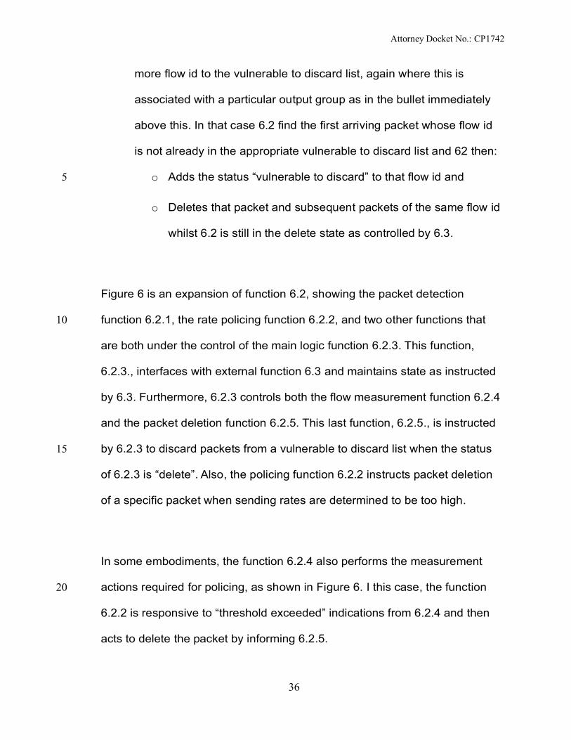
36
more flow id to the vulnerable to discard list, again where this is
associated with a particular output group as in the bullet immediately
above this. In that case 6.2 find the first arriving packet whose flow id
is not already in the appropriate vulnerable to discard list and 62 then:
o Adds the status “vulnerable to discard” to that flow id and5
o Deletes that packet and subsequent packets of the same flow id
whilst 6.2 is still in the delete state as controlled by 6.3.
Figure 6 is an expansion of function 6.2, showing the packet detection
function 6.2.1, the rate policing function 6.2.2, and two other functions that10
are both under the control of the main logic function 6.2.3. This function,
6.2.3., interfaces with external function 6.3 and maintains state as instructed
by 6.3. Furthermore, 6.2.3 controls both the flow measurement function 6.2.4
and the packet deletion function 6.2.5. This last function, 6.2.5., is instructed
by 6.2.3 to discard packets from a vulnerable to discard list when the status15
of 6.2.3 is “delete”. Also, the policing function 6.2.2 instructs packet deletion
of a specific packet when sending rates are determined to be too high.
In some embodiments, the function 6.2.4 also performs the measurement
actions required for policing, as shown in Figure 6. I this case, the function20
6.2.2 is responsive to “threshold exceeded” indications from 6.2.4 and then
acts to delete the packet by informing 6.2.5.

Attorney Docket No.: CP1742
37
Figure 7 is an expansion of function 6.3, showing its signal generation
function 6.3.1, its main logic function 6.3.2., and a fast memory store for
policy information. The function 6.3.2 is responsive to inputs from the buffer
6.1 and from the packet handler 6.2 and is responsible for maintaining the5
correct state of both of those two functions. Function 6.3.2 also initiates policy
look-ups from 6.3.3 and determines an appropriate rate allocation for each
flow. The function 6.3.3 contains both “default” policies” and “updated”
policies. A default policy is typically an assigned medium preference priority
and a small minimum guaranteed bandwidth, allowing a “top up” of capacity10
through the available rate pool. In many cases, it may be acceptable for a
flow to start with a default policy whilst 6.3.2 retrieves from an external source
a more appropriate policy and then downloads that into 6.3.3 for future
reference. In this way, the policies of 6.3.3 are faster to retrieve and are
adjusted (including the appropriate update to rate allocation and policing15
actions in 6.2) as soon as more information is available.
Function 6.2 detects that an arriving packet is a signalling packet, conforming
with [24], and passes the flow id and signalling information to 6.3.2. These
signals may be response signals from another flow-aware QoS manager20
function, if a tandem arrangement of such functions is deployed. It may also
be from flow-aware source or destination end-systems.

Attorney Docket No.: CP1742
38
Note that function 6.3.1 sends signals direct to an appropriate buffer 6.1,
bypassing any packet deletion logic. The appropriate buffer, together with the
relevant signalling parameters are passed from 6.3.2 to 6.3.1.
Function 6.3.2 also informs function 6.2.3 to commence a measurement for a5
flow in preparation for updating default rate parameters. The results of that
measurement are sent back from 6.2.3 to 6.3.2 and then 6.3.2 updates 6.2.3
with changes to the policing (if any) for that flow.
Figure 8 relates to the second preferred embodiment of the invention, where10
there are no switching functions to be performed. In this configuration, the
flow-based QoS manager is an edge FSA shaper function managing an
Ethernet VLAN-structured fibre bandwidth connection from the Network
Provider, enabling the Service Provider to maintain their own FSA QoS
services and Intelligent Packet services towards or from a DSLAM (or base15
station) and, ultimately via copper (or wireless) to a number of end-users.
Alternatively, in this configuration, the function 6 is a Network Provider
function enabling QoS services and Intelligent Packet Services that can be
offered to Service Providers.
Function 6 shapes the aggregate traffic of a specific VLAN according to the20
given maximum rate allowable, and given burst tolerance allowable. It also
shapes the aggregate traffic towards each end user, again according to the

Attorney Docket No.: CP1742
39
maximum rate allowable and given burst tolerance allowable. In each case, it
applies FSA QoS principles to incidents of congestion or incidents of
excessive burstiness with respect to the individual flows that make up any
particular aggregate traffic.
5
Figure 9 shows the combination of functions that are used to assign a FSA
flow treatment to flows that have no associated FSA signalling.
Function 6.1 (Fast Packet Analyser) – identifies a packet arrival which
has no corresponding flow state entry (i.e. no prior signalling packet
detected).10
Function 6.2 (Policy Cache) is used to determine what rate or
preference may be an appropriate initial setting.
Function 6.3 (Measurements) initiates a byte-count measurement
within a defined interval.
Function 6.4 (Deeper Packet Analyser and Policy look-up).15
Function 6.5 (Shaper)
Function 6.6 (Network-generated FSA signalling)
For most flows, the initial assignment of flow state and flow treatment will be
one that provides the greatest ability to “flex” as the actual packet load
arrives and prior to the next measurement-based update. The principles of20
this are:

Attorney Docket No.: CP1742
40
The initial assignment is a VR assignment with either a default
minimum MR rate, or a minimum rate that the Policy Cache function
6.2 derives from the Fast Packet Analyser (function 6.1) inputs.
As with all VR flows, an available rate (AR) top-up is also added to the
flow treatment, allowing the possibility of flexing beyond the minimum5
MR rate and prior to a measurement-based update.
Via a command from function 6.4, the first measurement interval commences
in function 6.3 and, for a short period (typically a few hundred milliseconds),
the actual arrival rate is observed in terms of bytes per time unit.
At the termination of the measurement interval in function 6.3, the function10
6.4 is informed of the measured rate. Function 6.4 then performs further
policy look-ups relating to this new information about the flow.
Whenever function 6.4 recovers additional data about a flow, either from
measurements or from a deeper analysis of the packet, it initiates the15
following actions:
Updating or initialising flow state values (held within function 6.4) and
policing/ shaping parameters (within function 6.5).
If required, informing function 6.6 to send a FSA signal towards further
downstream FSA functions, to update them about flow state and flow20
treatment.

Attorney Docket No.: CP1742
41
Figure 10 shows an expansion of the shaper function in this preferred embodiment.
Function 6.5.1 performs several tasks:
It maintains a token bucket for each end-user aggregate, and a further one for
the aggregate of all end user traffic on the link towards the DSMAM.
It maintains Virtual Queues. Each virtual queue monitors the packet arrival/5
departure process over a relatively long rolling interval, taking account of
deletions triggered by “vulnerable discard” actions to build up a picture of
whether packet arrivals are reaching a point of overload.
It performs packet deletion
For any packet of any preference priority, when the token bucket in 6.5.110
determines that immediate forwarding would exceed shaper limits, the packet is
forwarded to the Delay/ Deletion function 6.5.2, marked as “delay”. A separate
instruction is also sent to the control function 6.5.4, noting that the packet
identity plus its aggregate identity (e.g. one of the packets for a given end-user),
and its preference priority and (via function 6.5.3) the vulnerability to discard15
status of the associated flow state of that packet.
Packets marked as delayed within function 6.5.2 are delayed only for a short
interval. In one embodiment, this interval may be determined to be the
equivalent of the time interval of draining tokens such that:20
The drain rate corresponds to a policed rate for that flow or flow aggregate
(e.g. the policed rate for the all flows towards a given end-user)
The token count corresponds to a maximum sized packet.

Attorney Docket No.: CP1742
42
In another embodiment, this delay interval may be a pre-determined fixed short
interval. In a third embodiment, every packet is automatically delayed for a pre-
determined fixed short interval, but function 6.5.4 is informed only of those that
are to be examined for possible deletion as described next.
5
If the Control Function 6.5.4 detects there is already a delayed packet for the
same aggregate identity (e.g. there is already a delayed packet waiting to go to
the same given end-user), then function 6.5.4 proceeds as follows:
If any delayed packet of this same aggregate identity belongs to a flow
with flow status “vulnerable to discard”, function 6.5.4 instructs function10
6.5.2 to delete that packet
If there are no such packets that can be deleted because of the
“vulnerable to discard” status, the lowest preference priority packet is
deleted from the Delay/ Deletion function 6.5.2
The state of the flow id of this deleted packet is changed to “vulnerable to15
discard” and added to the list of such flows in 6.5.3.
Meanwhile, the virtual queue in 6.5.1 for that same aggregate contains trigger points
that force discard of all further arriving packets towards 6.5.1 whenever any belong
to a flow marked “vulnerable to discard”. In 6.5.1, there is one virtual queue per end-
user aggregate and one for the aggregate of all traffic towards the DSLAM (i.e. an20
identical set to the shaper token buckets).

Attorney Docket No.: CP1742
43
A rolling virtual queue considers an arriving packet as the latest end-point of a pre-
defined maximum interval, the oldest event of which (a previous packet arrival) rolls
forward so as to keep the event interval always within this pre-defined maximum.
Within that interval the average load is calculated, taking account of all vulnerable
discards. If the average load rises to a threshold level, then the “vulnerable discard5
alarm” is triggered in 6.5.1 and all subsequent packets that arrive will be deleted if
they are associated with flows marked “vulnerable to discard”. This action will
continue until a lower threshold is reached in the virtual queue when the alarm is
switched off.
10
Alarm threshold settings are set so as to minimise the further selection of an
additional flow through actions of the Control Function 6.5.4 and Delay/ Deletion
Function 6.5.2 in response to “delay packet” decisions within 6.5.1. In other words,
the thresholds are set below the maximum average rate that can be sustained
towards an end-user (or towards the DSLAM). The margin may only be small and15
take account of:
The need to begin discard actions BEFORE leaving the only remaining
choice being those packets marked for possible deletion by 6.5.1 through
notification to 6.5.4 when a burstiness or jitter threshold is reached or
exceeded. So load reduction should already be happening via discard of20
vulnerable flows, making the likelihood far more rare that there will be a
random further selection of another flow id for discard.

Attorney Docket No.: CP1742
44
short-term variations of load within the virtual queue measurement interval,
where such variations imply short overload events that are undetected by
the virtual queue mechanism.
Note that:5
if the virtual queue measurement interval is very short then it could trigger
alarms frequently whenever there is some degree of packet clustering.
If the virtual queue length is too long, there may be undetected intervals of
packet overload within that time period. This effect can be compensated
by setting the threshold (to begin deletion of packets associated with10
vulnerable to discard flows) below the absolute maximum allowed rate for
that flow aggregate.
Function 6.5.3 is updates on its list of flows vulnerable to discard from
functions 6.2 and 6.4. This occurs, as necessary, with each new packet15
arrival.

Attorney Docket No.: CP1742
45
WHAT IS CLAIMED IS:
1. A method of operating a packet subnetwork comprising:
5
Receiving one or more communication packets indicative of the commencement
of a packet communication through said subnet, said packet communication
comprising a plurality of packets.
Responsive to receipt of said one or more communication commencement
packets, storing a set of communication identifiers, each communication identifier10
enabling identification of packets belonging to one of said commenced packet
communications.
Responsive to receipt of said one or more communication commencement
packets, retrieving policy information relating to any initial or sustained QoS
treatment of the flow, where such policy information is derived from packet15
header information at any levelof encapsulation or is derived from policy
attributes associated with the physical link on which the packet arrived or will
depart..
Responsive to receipt of said one or more communication commencement
packets, and to retrieved policy information, and where the retrieved policy20
information indicates a delay-sensitive QoS treatment with unknown flow rate,
assigning:
an initial minimum guaranteed rate
Attorney Docket No.: CP1742
46
an initial additional rate assigned from a pool of capacity divided
among flows which have this QoS policy
allowing immediate transfer of the flow at a rate equal to or less than
the minimum plus additional rate allowance.
assigning a preference priority, or protected communication indication,5
based on the retrieved policy information
assigning an initial discard probability to the flow that will determine if it
is included in the list of flows that are treated as vulnerable to discard
in the event of congestion.
10
Responsive to receipt of said one or more communication commencement
packets, initiating an initial measurement period, during which the actual sending
rate of the flow is measured.
Responsive to the termination of the measurement period, retrieving any
changes of policy that derive from the measured rate.15
Responsive to any changes of policy based upon measured rate, updating
the flow state and policer/ shaper parameters according to these said
changes in policy.
Responsive to receipt of said one or more communication commencement20
packets, and to retrieved policy information, and where the retrieved policy

Attorney Docket No.: CP1742
47
information indicates a delay-sensitive QoS treatment with a pre-determined
guaranteed rate, assigning:
a preference priority, or protected communication indication, based on
retrieved policy information
assigning an initial discard probability to the flow that will determine if it5
is included in the list of flows that are treated as vulnerable to discard
in the event of congestion.
assigning the pre-determined guaranteed rate
allowing immediate transfer of the flow at a rate equal to or less than
the pre-determined rate.10
Responsive to a predetermined condition being met, removing an identifier from
said set of stored identifiers associated with flows vulnerable to discard prior to
the cessation of the associated communication.
Responsive to receipt of said one or more communication packets, causing
each said packet to be delayed prior to transmission towards its destination.15
Responsive to the receipt of a said communication packet that causes a
threshold of burst tolerance or packet jitter to be reached or exceeded on a
flow or group of flows:
Identifying among the said delayed packets belonging to the flow or20
group of flows and the said newly received packet, which, if any of the
packets, has an associated vulnerable to discard state or has the

Attorney Docket No.: CP1742
48
lowest preference priority compared to the others.
Selecting, if two or more such packets be so identified, a single packet
randomly chosen among any that are vulnerable to discard or, if none,
randomly among any that have the common lowest preference priority.
Responsive to the said packet selection, changing the flow state of the5
flow to which it belongs so that it is vulnerable to discard and
discarding the said packet.
On a threshold level of congestion being reached in said packet subnet:
identifying packets belonging to a communication associated with one
of said set of stored identifiers corresponding to one of the said flows10
vulnerable to discard; and
degrading the forwarding of packets so identified, relative to packets
belonging to other communications.
15
2. A method according to claim 1 where the number of flows included in the flows
vulnerable to discard list will be divided into groups that are each associated with a
specific output link, and a new flow is added to one such group if the current
aggregate rate of that group is less than a pre-determined threshold.
20
3 A method according to claim 1 where a flow identifier is not removed from
the list of flows vulnerable to discard if it would cause the group of common

Attorney Docket No.: CP1742
49
flows of which it is a member that are output on the same output link to have an
aggregate rate that is less than a pre-determined threshold.
4. A method according to claim 1 where said set of communication identifiers
comprises a plurality of subsets of communication identifiers, all associated with the5
same output link on which packets associated with such identifiers will be forwarded,
a communication identifier first being placed in a first subset that is vulnerable to
discard and moving to a second subset that is less vulnerable to discard on the
occurrence of a subset removal condition being met, wherein, on the onset of
congestion, packets in said second subset are forwarded in preference to packets in10
said first subset.
5. A method according to claim 1 where an increase in minimum rate after
measurement is subject to the sum of such minimum rates being less than some
threshold value. Some flows may therefore not have their minimum guaranteed rate
increased to match the current sending rate. Typically flows of lower preference15
priority are the least likely to have their minimum rates increased to match their
measured rates.
6. A method according to claim 1 where, when new flow arrivals when congestion
has started or where traffic levels are close to some threshold indicative of the onset
of congestion, such flows, are no longer assigned any additional capacity from the20
available pool and will be placed in the flows vulnerable to discard list.
7. A packet network node comprising:

Attorney Docket No.: CP1742
50
an input for receiving one or more packets;
means arranged in operation to detect congestion in said packet
network node, relating to any flow or group of flows and associated
limits of network capacity assigned to such a flow or group of flows;
means arranged in operation to detect excessive packet bursts or jitter5
in said packet network node relating to any flow or group of flows and
associated limits of burstiness or jitter assigned to such a flow or group
of flows;
a communication identifier store for storing a set of communication
identifiers;10
means arranged in operation to detect communication announcement
packets received at said input, and responsive to said detection to
store, in said communication identifier store, a communication identifier
included in said communication announcement packet;
means arranged in operation to detect new flows that have15
commenced without a communication announcement packet received
at said input, and responsive to said detection to store, in said
communication identifier store, a communication identifier.
means arranged in operation to remove, on a predetermined condition
being met, the “vulnerable to discard” status associated with a20
communication identifier from said communication identifier store prior
to the cessation of the communication.

Attorney Docket No.: CP1742
51
means arranged in operation to delay said arriving packets.
means arranged in operation to identify either a delayed packet or
latest received packet that should be discarded when burstiness or
jitter detection means determine that such a deletion is required on any
flow or group of flows.5
means arranged in operation that will automatically select for discard a
packet of a flow that is vulnerable to discard or, if none, then any
packet that has the lowest preference priority within the delayed or
latest arriving set of packets associated with the said flow or group of
flows.10
means arranged in operation, on the detection of congestion caused
by any flow or group of flows as determined by said congestion
detection means, to identify packets received at said input belonging to
a communication associated with one of said communication identifiers
stored in said communication identifier store; and forward packets so15
that those not in “vulnerable to discard” status within said group of
flows associated with the said congestion are forwarded in preference
to packets belonging to flows of the same group that are in “vulnerable
to discard” status.
means arranged in operation to classify a new flow that has20
commenced without a communication announcement packet,
including:

Attorney Docket No.: CP1742
52
o Means to determine any policy associated with the new flow,
based upon header information carried in the packet at any layer
of encapsulation, or information associated the physical link on
which the packet arrived.
o Means to assign both an initial minimum guaranteed rate and an5
additional rate whose value is not guaranteed to be sustained
but allows the use of additional spare capacity.
o Means to frequently review the amount of additional spare
capacity that can be assigned to any said flow that has
commenced without a communication announcement packet,10
and means to assign and police any revised additional spare
capacity plus minimum guaranteed capacity against the rate of
forwarding of bytes along said flow.
o Means to measure the forwarding rates of any flow including
means to commence such a measurement for a fixed interval15
when and if required, as determined through said policy
information.
o Means to update for any flow or group of flows the assigned rate
limits or preference priorities or vulnerability to discard based on
the result of one or more measurements of the forwarding rate20
of any said flow or group of flows, including means to revise the
policed rate(s) of the flow or group of flows based on both
current minimum guaranteed rate(s) and current additional

Attorney Docket No.: CP1742
53
available rate(s), where either of these components of assigned
capacity may be zero.
8. A packet network node including a packet communications source comprising:
means arranged in operation to generate one or more communication5
announcement packets according to:
o Means that determine any policy information that can be derived
for a new flow that has commenced without a communication
announcement packet.
o Means that include flow identifier information in the header of10
said generated communication announcement packet which is
the same flow identifier that is found in the arriving packet of a
new flow that had started without a communication
announcement packet
means arranged in operation to send said generated communication15
announcement packets along any output link either being the same output
link that will be chosen for the other packets of the corresponding flow, or
any other link depending on policy information.
20

Attorney Docket No.: CP1742
54
ABSTRACT
FLOW STATE AWARE QoS MANAGEMENT WITHOUT USER SIGNALLING
5
A packet network node and method of operating a packet network node are
disclosed. Conventional packet network nodes react to congestion in the packet
network by dropping packets in a manner which is perceived by users to be
indiscriminate. In embodiments of the present invention, indiscriminate packet
discards are prevented by causing packets to be discarded according to bandwidth10
allocations that, intelligently track flow sending rates. Flows are allocated bandwidth
based on policy information. Where such policy information indicates that the flow
should be treated as delay-sensitive, the present invention includes means to
allocate an initial minimum rate that will be guaranteed and such flows will also have
the use of an additional capacity that varies depending on the number of such flows15
that currently share an available pool of capacity. Furthermore, this minimum rate
guarantee is modified following a measurement interval that allows a more accurate
assignment of an appropriate minimum rate even though no signalling has been
initiated by the communications source that would indicate the source sending rate.
In a preferred embodiment, an increase in minimum rate after measurement is20
subject to the sum of such minimum rates being less than some threshold value.
Some flows may therefore not have their minimum guaranteed rate increased to
match the current sending rate. Typically flows of lower preference priority (as

Attorney Docket No.: CP1742
55
determined by policy information) are the least likely to have their minimum rates
increased to match their measured rates. Some flows are therefore more likely to be
subject to packet discard through the policing of individual flows against their current
rate allocation. Congestion may still be anticipated even with these measures. For
example it may happen in the event of re-routing flows around a failed link. Another5
factor is that new flow arrivals may occur when congestion has started or where
traffic levels are close to some threshold indicative of the onset of congestion. In
such cases, the preferred embodiment no longer assigns to such new flows any
additional capacity from the available pool. Furthermore, the packet network node
makes an entry in a vulnerable communications table on receipt of a new flow10
commencement packet. After an amount of time, and often before the cessation of
a communication, such entries are removed from the vulnerable communications
table. On the onset of congestion, the packet network node disclosed herein deletes
packets in communications identified in the vulnerable communications table. This
provides a congestion alleviation method which is less annoying to users since15
communications that have been in existence for longer are less susceptible to
component packets being deleted.

Attorney Docket No.: CP1742
56
References
[1] Seong Wook Kang and Jae Yoon Kim, “Coming u-Health era”(in Korean), CEO
information, Samsung Economic Research Institute(SERI), no. 602, May 20075
[2] World Economic Forum, “Shaping the Global Agenda: The Shifting Power
Equation”, Annual Meeting Report, Jan. 2007
[3] PacketCable specification PKT-SP-DQOS-I10-040721 “PacketCable Dynamic
Quality-of-Service”
[4] Cable Television Laboratories, Inc, “Data-Over-Cable Service Interface10
Specifications, Radio Frequency Interface Specification”, SPRFIv1.1-I10-030730,
July 30, 2003
[5] PacketCable Specification PKT-SP-MM-I03-051221, “ Multimedia Specification”,
Dec. 21, 2005
[6] Technical Report 59 DSL Forum “DSL Evolution – Architecture Requirements for15
the Support of QoS-Enabled IP Services”
[7] ITU-T recommendation Y.2111 “Resource and Admission Control Functions in
NGN”
[8] ETSI ES 282 003 V1.1.1 (2006-03), “Resource and Admission Control Sub-
system (RACS); Functional Architecture.”20
[9] ITU-T NGN-GSI contribution, Kobe-Q04-13-014, "Comparison of TISPAN RACS
and ITU-T RACF"
[10] ITU-T recommendation Y.2012 “Functional Requirements and Architecture of

Attorney Docket No.: CP1742
57
the NGN”
[11] Jongtae Song, Mi Young Chang, Soon Seok Lee, and Jinoo Joung,
“Overview of ITU-T NGN QoS control”, IEEE Communication Magazine, vol. 45,
no. 9, Sept. 2007.
[12] Jongtae Song, “Flow based control for Future Internet” Presented in Future5
Internet Forum (FIW) 2007, July 200. available at
http://mmlab.snu.ac.kr/fiw2007/presentations/architecture_jtsong.pdf
[13] I. Stoika and H. Zhang, “Providing guaranteed services without per flow
management”, in CM SIGCOMM, Sept, 1999, pp. 91-94
[14] S. Oueslati and J. Roberts, “A new direction for quality of service: Flow-aware10
networking”, in Proc. Conference on Next Generation Internet Network (NGI),
April 2005
[15] ITU-T Recommendation Y.2121, “Requirements for the support of stateful
flow-aware transport technology in an NGN”
[16] J. L. Adams, L. G. Roberts, and A. IJsselmuiden “Changing the internet to15
support real-time content supply from a large fraction of broadband residential
users”, BT Technology Journal, Vol. 23, No. 2, pp 217-231, April 2005
[17] ITU-T Recommendation Y.1221 Amendment 2 (2005), Traffic control and
congestion control in IP-based networks
[18] ITU-T recommendation Y.1372/G.8113, “Requirements for OAM functions in20
T-MPLS based networks “, April 2007
[19] ITU-T recommendation Y.1373/G.8114, “Operation and maintenance
mechanism for T-MPLS layer networks ”, April 2007

Attorney Docket No.: CP1742
58
[20] Jongtae Song, et. al, “DiffProbe: One way Delay Measurement for
Asynchronous Network and Control Mechanism in BcN Architecture”,
Proceeding of the 8th International Conference On Advanced Communication
Technology, Feb. 2006
[21] Inbong Joo, et al, “Performance Monitoring for Multimedia Traffic using5
Differentiated Probe (DiffProbe)”, Proceeding of the ICME ’07, July 2007.
[22] D.W. Hong et al., "M_CSPF: A Scalable CSPF Routing Scheme with Multiple
QoS Constraints for MPLS Traffic Engineering," ETRI Journal, vol.27, no.6, Dec.
2005, pp.733-746.
[23] ‘Early Selective Packet Discard for Alternating Resource Access of TCP over10
ATM-UBR’ by Kangsik Cheon and Shivendra S. Panwar, in the Proceedings of
IEEE Conference on Local Computer Networks LCN 97, Minneapolis, Minnesota,
Nov. 2-5, 1997.
[24] ITU-T Study Group 11, Draft Recommendation Q.flowstatesig on signalling
protocols and procedures relating to Flow State Aware access QoS control in an15
NGN. Editor J.L.Adams.
[25]