Optical Accelerometers for Detecting Low-Frequency Micro ...
21
Citation: Lei, Y.-J.; Li, R.-J.; Zhang, L.-S.; Hu, P.-H.; Huang, Q.-X. Optical Accelerometers for Detecting Low-Frequency Micro-Vibrations. Appl. Sci. 2022, 12, 3994. https:// doi.org/10.3390/app12083994 Academic Editors: Guanhao Wu, Xiuguo Chen and Yuki Shimizu Received: 22 March 2022 Accepted: 13 April 2022 Published: 14 April 2022 Publisher’s Note: MDPI stays neutral with regard to jurisdictional claims in published maps and institutional affil- iations. Copyright: © 2022 by the authors. Licensee MDPI, Basel, Switzerland. This article is an open access article distributed under the terms and conditions of the Creative Commons Attribution (CC BY) license (https:// creativecommons.org/licenses/by/ 4.0/). applied sciences Review Optical Accelerometers for Detecting Low-Frequency Micro-Vibrations Ying-Jun Lei 1,2 , Rui-Jun Li 1,2, * , Lian-Sheng Zhang 1,2, * , Peng-Hao Hu 1,2 and Qiang-Xian Huang 1,2 1 School of Instrument Science and Opto-Electronics Engineering, Hefei University of Technology, Hefei 230009, China; [email protected] (Y.-J.L.); [email protected] (P.-H.H.); [email protected] (Q.-X.H.) 2 Anhui Province Key Laboratory of Measuring Theory and Precision Instrument, Hefei University of Technology, Hefei 230009, China * Correspondence: [email protected] (R.-J.L.); [email protected] (L.-S.Z.) Abstract: Optical accelerometers are high-precision inertial sensors that use optical measurement technology to achieve high-precision and electromagnetic interference-resistant acceleration mea- surements. With the intensive research and development of optical accelerometers in recent years, their applications in inertial navigation, structural health monitoring, precision vibration isolation systems, wind turbine fault monitoring, earthquake monitoring, and other low-frequency vibration detection have flourished. Optical accelerometers have various schemes; however, their characteris- tics vary considerably due to different optical modulation schemes. This study aims to address the lack of systematic evaluation of currently available low-frequency optical accelerometers. Optical accelerometers can be classified into four categories in accordance with their optical modulation schemes: optical path-, optical intensity-, optical phase-, and optical wave-length-modulated ac- celerometers. The typical performance, advantages and disadvantages, and possible application scenarios of various optical accelerometers are summarized. This study also presents the current status and trends of low-frequency optical accelerometers in consideration of the growing demand for high-precision, low-frequency acceleration measurements. Keywords: accelerometer; optical sensing systems; optical modulation; accelerometer review 1. Introduction Vibration is closely related to people’s daily life and production, and thus, vibration detection is highly significant. The parameters of vibration signals include displacement, velocity, and acceleration. Vibration detection can be achieved by measuring the values of these parameter quantities. Accelerometers are efficient instruments for vibration detection. Accelerometers can be categorized into electronic and optical accelerometers in ac- cordance with their operating principles. Electronic accelerometers include piezoelectric, capacitive, and piezoresistive types. Piezoelectric accelerometers have many advantages, such as low cost, availability in many forms, and simplicity in handling and implementa- tion; however, they exhibit the problems of low linearity and accuracy caused by external excitation and the piezoelectric material [1,2]. Capacitive accelerometers present the ad- vantages of high sensitivity, low frequency response, and wide dynamic range. However, they can be easily interfered with by the external environment and are only suitable for low-frequency field applications, such as seismic detection and geological exploration [3,4]. Piezoresistive acceleration sensors demonstrate the advantages of small volume, low out- put impedance, and high measurement accuracy; however, they are easily affected by temperature [5,6]. In addition to the above factors, piezoelectric, piezoresistive, and capaci- tive accelerometers are vulnerable to electromagnetic interference due to the limitations of their sensing principles, making it difficult to detect micro-vibrations. Appl. Sci. 2022, 12, 3994. https://doi.org/10.3390/app12083994 https://www.mdpi.com/journal/applsci
-
Upload
khangminh22 -
Category
Documents
-
view
0 -
download
0
Transcript of Optical Accelerometers for Detecting Low-Frequency Micro ...

�����������������
Citation: Lei, Y.-J.; Li, R.-J.; Zhang,
L.-S.; Hu, P.-H.; Huang, Q.-X. Optical
Accelerometers for Detecting
Low-Frequency Micro-Vibrations.
Appl. Sci. 2022, 12, 3994. https://
doi.org/10.3390/app12083994
Academic Editors: Guanhao Wu,
Xiuguo Chen and Yuki Shimizu
Received: 22 March 2022
Accepted: 13 April 2022
Published: 14 April 2022
Publisher’s Note: MDPI stays neutral
with regard to jurisdictional claims in
published maps and institutional affil-
iations.
Copyright: © 2022 by the authors.
Licensee MDPI, Basel, Switzerland.
This article is an open access article
distributed under the terms and
conditions of the Creative Commons
Attribution (CC BY) license (https://
creativecommons.org/licenses/by/
4.0/).
applied sciences
Review
Optical Accelerometers for Detecting Low-FrequencyMicro-VibrationsYing-Jun Lei 1,2 , Rui-Jun Li 1,2,* , Lian-Sheng Zhang 1,2,* , Peng-Hao Hu 1,2 and Qiang-Xian Huang 1,2
1 School of Instrument Science and Opto-Electronics Engineering, Hefei University of Technology,Hefei 230009, China; [email protected] (Y.-J.L.); [email protected] (P.-H.H.);[email protected] (Q.-X.H.)
2 Anhui Province Key Laboratory of Measuring Theory and Precision Instrument,Hefei University of Technology, Hefei 230009, China
* Correspondence: [email protected] (R.-J.L.); [email protected] (L.-S.Z.)
Abstract: Optical accelerometers are high-precision inertial sensors that use optical measurementtechnology to achieve high-precision and electromagnetic interference-resistant acceleration mea-surements. With the intensive research and development of optical accelerometers in recent years,their applications in inertial navigation, structural health monitoring, precision vibration isolationsystems, wind turbine fault monitoring, earthquake monitoring, and other low-frequency vibrationdetection have flourished. Optical accelerometers have various schemes; however, their characteris-tics vary considerably due to different optical modulation schemes. This study aims to address thelack of systematic evaluation of currently available low-frequency optical accelerometers. Opticalaccelerometers can be classified into four categories in accordance with their optical modulationschemes: optical path-, optical intensity-, optical phase-, and optical wave-length-modulated ac-celerometers. The typical performance, advantages and disadvantages, and possible applicationscenarios of various optical accelerometers are summarized. This study also presents the currentstatus and trends of low-frequency optical accelerometers in consideration of the growing demandfor high-precision, low-frequency acceleration measurements.
Keywords: accelerometer; optical sensing systems; optical modulation; accelerometer review
1. Introduction
Vibration is closely related to people’s daily life and production, and thus, vibrationdetection is highly significant. The parameters of vibration signals include displacement,velocity, and acceleration. Vibration detection can be achieved by measuring the values ofthese parameter quantities. Accelerometers are efficient instruments for vibration detection.
Accelerometers can be categorized into electronic and optical accelerometers in ac-cordance with their operating principles. Electronic accelerometers include piezoelectric,capacitive, and piezoresistive types. Piezoelectric accelerometers have many advantages,such as low cost, availability in many forms, and simplicity in handling and implementa-tion; however, they exhibit the problems of low linearity and accuracy caused by externalexcitation and the piezoelectric material [1,2]. Capacitive accelerometers present the ad-vantages of high sensitivity, low frequency response, and wide dynamic range. However,they can be easily interfered with by the external environment and are only suitable forlow-frequency field applications, such as seismic detection and geological exploration [3,4].Piezoresistive acceleration sensors demonstrate the advantages of small volume, low out-put impedance, and high measurement accuracy; however, they are easily affected bytemperature [5,6]. In addition to the above factors, piezoelectric, piezoresistive, and capaci-tive accelerometers are vulnerable to electromagnetic interference due to the limitations oftheir sensing principles, making it difficult to detect micro-vibrations.
Appl. Sci. 2022, 12, 3994. https://doi.org/10.3390/app12083994 https://www.mdpi.com/journal/applsci

Appl. Sci. 2022, 12, 3994 2 of 21
Compared with electrical sensing, optical sensing improves the sensitivity of ac-celerometers by an order of magnitude and enables accurate detection of micro-vibrations [7].Various optical accelerometers have been reported in the past decades, yet a systematic re-view of low-frequency optical accelerometers has remained elusive. In this review, we focuson the measurement principle and performance of state-of-the-art optical accelerometersand divide them into several categories in accordance with their optical modulation scheme.By using typical demonstrations as examples, merits and disadvantages are presented here,providing a big picture of optical accelerometers, along with their application prospectsand development tendencies.
2. Principle and Requirements2.1. Principle of Accelerometer
A common accelerometer comprises a spring, a damper, a seismic mass, and a dis-placement sensor arranged within a housing attached to a base [8], as shown in Figure 1. Inoperation, the base is mounted on the vibrating structure to be measured, and the relativedisplacement between the seismic mass and the base is recorded by the displacement sensor.
Appl. Sci. 2022, 12, x FOR PEER REVIEW 2 of 21
Compared with electrical sensing, optical sensing improves the sensitivity of accelerom-eters by an order of magnitude and enables accurate detection of micro-vibrations [7]. Various optical accelerometers have been reported in the past decades, yet a systematic review of low-frequency optical accelerometers has remained elusive. In this review, we focus on the meas-urement principle and performance of state-of-the-art optical accelerometers and divide them into several categories in accordance with their optical modulation scheme. By using typical demonstrations as examples, merits and disadvantages are presented here, provid-ing a big picture of optical accelerometers, along with their application prospects and de-velopment tendencies.
2. Principle and Requirements 2.1. Principle of Accelerometer
A common accelerometer comprises a spring, a damper, a seismic mass, and a displace-ment sensor arranged within a housing attached to a base [8], as shown in Figure 1. In op-eration, the base is mounted on the vibrating structure to be measured, and the relative dis-placement between the seismic mass and the base is recorded by the displacement sensor.
Figure 1. Typical accelerometer structure diagram.
Following Newton’s second law, the force acting on the seismic mass m can be ex-pressed as
= − − − − ( ) ( )m b m bma k x x c x x , (1)
where xm is the displacement of the seismic mass, xb is the displacement of the base, a is the acceleration to be detected, k is the elastic coefficient of spring, and c is the damper coeffi-cient of the accelerometer. The relative displacement z between the seismic mass and the base can be expressed as
= −( ) ( ) ( )m bz t x t x t . (2)
Assuming the detected vibration is a simple harmonic vibration, we have xb(t) = Xb cos(ωbt), where ωb is the frequency of vibration. Bring xb(t) and z(t) into Equation (1):
2ω ω+ + = cosb b bmz cz kz m X t . (3)
Solve Equation (3) and obtain:
( )2 2 2 2 21 2 = − + ∗ − ( ) ( ) ( ) cos( )n b n b b b bz t ω ω ξω ω ω X ω t φ , (4)
where ωn = (k/m)1/2 is the resonant frequency of the accelerometer, ξ = c/2(mωn) is the damp-ing ratio of the accelerometer, and φ can be expressed as
( )( ) ( )( )21 2 1− = − tan b n b nφ ξ ω ω ω ω . (5)
Additionally, the acceleration caused by vibration is
Displacement sensor
k Spring
House
Seismicmass m
Base
xm(t)
xb(t)Damperc
Figure 1. Typical accelerometer structure diagram.
Following Newton’s second law, the force acting on the seismic mass m can be ex-pressed as
ma = −k(xm − xb)− c(.xm − .
xb), (1)
where xm is the displacement of the seismic mass, xb is the displacement of the base, a isthe acceleration to be detected, k is the elastic coefficient of spring, and c is the dampercoefficient of the accelerometer. The relative displacement z between the seismic mass andthe base can be expressed as
z(t) = xm(t)− xb(t). (2)
Assuming the detected vibration is a simple harmonic vibration, we have xb(t) = Xbcos(ωbt), where ωb is the frequency of vibration. Bring xb(t) and z(t) into Equation (1):
m..z + c
.z + kz = mω2
b Xb cos ωbt. (3)
Solve Equation (3) and obtain:
z(t) =[
1/(√
(ω2n − ω2
b)2+ (2ξωnωb)
2)]
∗[ω2
b Xb cos(ωbt − ϕ)], (4)
where ωn = (k/m)1/2 is the resonant frequency of the accelerometer, ξ = c/2(mωn) is thedamping ratio of the accelerometer, and ϕ can be expressed as
ϕ = tan−1[(2ξ(ωb/ωn))
/(1 − (ωb/ωn)
2)]
. (5)

Appl. Sci. 2022, 12, 3994 3 of 21
Additionally, the acceleration caused by vibration is
..xb(t) = −ω2
b Xb cos(ωbt). (6)
Equation (4) can be rewritten as
ω2nz(t) =
[1/(√
(1 − (ω2b/ω2
n)2+ (2ξωb/ωn)
2)]
∗[ω2
b Xb cos(ωbt − ϕ)]
(7)
Order
H(ωb/ωn) = 1/(√
(1 − (ω2b/ω2
n)2+ (2ξωb/ωn)
2)
. (8)
When ωb � ωn, the H(ωb/ωn) ≈ 1 and ϕ ≈ 0. Then the acceleration value..xb can be
calculated as..xb ≈ ω2
nz(t). (9)
As can be seen from Equation (9), the mechanical sensitivity of the accelerometer canbe approximated as the inverse of the square of its resonant frequency, so the higher theresonant frequency, the lower the mechanical sensitivity. Therefore, the low frequencyaccelerometer needs to have a lower resonant frequency. Additionally, the use of high-sensitivity displacement sensors can also improve the sensitivity of accelerometers.
2.2. Requirements of Low Frequency Accelerometers
Low-frequency, high-sensitivity accelerometers have a wide range of applications,and they play an important role in industries and daily life, including inertial navigation,structural health monitoring, active vibration isolation systems, fault detection of windturbine, and earthquake detection.
2.2.1. Inertial Navigation
Navigation techniques are divided into two categories: positioning and trajectoryextrapolation [9]. One representative of positioning technology is a global navigationsatellite system. The trajectory extrapolation method recursively measures the amountof variation in the real-time motion state of a moving object relative to the initial motionstate. Then, the real-time position of the moving object based on that amount of change isdetermined. Inertial navigation is an example of the trajectory extrapolation method usedas a navigation technique. An accelerometer in an inertial navigation system can measurethe acceleration and angular acceleration of the carrier. In accordance with Newton’ssecond law of motion, time integrates acceleration and angular acceleration to obtain thevelocity, angular velocity, and position information of a moving object. The operation oftime integration will amplify the error of the accelerometer, and thus, an accelerometer usedin an inertial navigation system must meet high accuracy, stability, and anti-interferencecapability requirements. Optical accelerometers exhibit advantages in terms of accuracy,stability, and immunity to electromagnetic interference by utilizing optical sensing. Theydemonstrate good prospects in inertial navigation.
2.2.2. Structural Health Monitoring
Bridges vibrate when vehicles pass over them, and high buildings sway when strongwinds blow around them. If the vibration of large buildings exceeds the threshold value,catastrophic losses may occur. Accelerometers can measure the structural vibration ofthese buildings to determine their structural health and provide early warning for potentialdamage. Structural vibrations in large buildings are typically low-frequency vibrationsbelow 100 Hz, and they require a multipoint arrangement for monitoring. Therefore,accelerometers must achieve high accuracy with a small size and meet the requirementsfor long-distance measurement [10]. An optical sensor-based accelerometer has high

Appl. Sci. 2022, 12, 3994 4 of 21
measurement accuracy while enabling long-distance and distributed measurements; thus,it can meet the structural health monitoring needs of large buildings [11].
2.2.3. Vibration Isolation Systems
In microscale and nanoscale precision measurement systems and ultra-precision ma-chining systems, the effects of vibration on measurement precision and machining accuracyis devastating, and the vibration is a major factor that limits the improvement of mea-surement and machining accuracy [12,13]. Vibration isolation is divided into active andpassive vibration isolations; passive vibration isolation techniques experience difficultyin isolating low-frequency vibrations of 0.5–5 Hz [14], while active vibration isolation cansuppress low-frequency vibrations more efficiently. In an active vibration control system,accurate access to real-time vibration information is the key. Therefore, high-precisionreal-time detection of low-frequency micro-vibrations must be inevitably achieved. Opticalaccelerometers demonstrate advantages in measurement accuracy and response speed.They have potential applications in the field of precision active vibration isolation.
2.2.4. Fault Detection of Wind Turbine
Wind energy has grown rapidly in the last decade due to its clean and renewablenature. By the end of 2021, more than 650 GW of installed wind energy capacity hasbeen put into operation worldwide. Mechanical drive components (gears and bearings)of wind turbines are prone to failure due to exposure to harsh environments, such asrandom winds, temperature differences, and alternating loads [15–17]. Mechanical failuresof wind turbines may lead to their shutdown and have adverse social impacts. Therefore,the study of mechanical failure detection of wind turbine units has received increasingattention develop a reasonable operation and maintenance plan and to avoid catastrophicconsequences. The lowest rotational frequency of the internal rotating mechanism of a windturbine can be as low as 0.33 Hz [18], so the fault detection accelerometer of a wind turbineneeds to have good low-frequency response characteristics, as well as high sensitivity.
2.2.5. Earthquake Monitoring
Advances in seismology have relied closely on the development of instruments. Froma scientific point of view, accuracy is crucial: the more accurate the detection of seismicproperties, the more reliable the understanding of earthquake hazards, which in turnis of guiding importance for the study of seismic prevention techniques. In addition toseismic research, monitoring of earthquakes is also used in resource exploration, gravity-assisted navigation, and monitoring of volcanic activity. According to previous studies, thefrequency range of the Earth’s near-source strong ground motions is 0.3–3.0 Hz [19]; there-fore, earthquake monitoring accelerometers need to have good low-frequency responsecharacteristics.
3. Optical Path Modulation
An optical accelerometer based on the optical path modulation principle senses ac-celeration by directly modulating the optical path. When external acceleration acts on theaccelerometer, seismic mass in the accelerometer is inertially displaced, directly altering thelaser optical path. This type of accelerometer exhibits the advantages of a simple structureand low cost.
A focus error sensor (FES) based on a DVD pickup head is a high-precision opticalpath modulation sensing system. Figure 2 shows a focus sensor modified from a red-rayDVD pickup head by removing the voice coil motor and using a rectangular prism to turnthe optical path. It exhibits the advantages of high resolution and high accuracy. Thismodified sensor can be used in nanoscale measurement after calibration. As shown inFigure 3a, Chu et al. designed a cantilevered high-sensitivity optical accelerometer witha sensitivity of 12.3 V/g on the basis of focus error sensing [20]. As shown in Figure 3b,Liu et al. improved the design of Chu et al. by using the moving part of the voice coil

Appl. Sci. 2022, 12, 3994 5 of 21
motor inside a DVD pickup head as the elastic mechanism; they reduced the size of theaccelerometer while improving its sensitivity to 24.4 V/g [21]. The resonant frequency inthe x and y directions of a cantilevered beam is not significantly greater than the resonantfrequency in the z-direction, and vibrations in the x and y directions exert a greater effecton the output of the accelerometer. Therefore, Li et al. designed an accelerometer witha fully symmetric leaf spring (as shown in Figure 4); it has a resolution of 0.3 mg andmeasurement uncertainty as low as 0.07 mg (K = 2) [22]. To improve the sensitivity ofoptical accelerometers, Cheng et al. modeled an optical accelerometer by using sensitivityanalysis and improved its sensing optical path to achieve a resolution as low as 4 µg [23].
The FES is based on a modified DVD pickup head, and its internal optical componentsare irreplaceable and exhibit poor maintainability. Laser triangulation (LTG) is a methodfor achieving position detection on the basis of the change in optical path. As depictedin Figure 5, when the position of the reflector changes ∆h, the position of the spot on thephotodetector will also change ∆l. The relationship between ∆h and ∆l is
∆l =∆h
sin α, (10)
where α is the angle between the incident laser beam and the reflector. Therefore, theLTG method can amplify the displacement 1/sin α times. This method is widely used inmicro/nano measurement instruments, such as micro/nano contact probes [24], scanningprobe microscopes [25], and optical accelerometers (Figure 6) [7]. With the development oftechnology, the resolution of photodetectors has reached the submicron order. For example,the photodetector (SPOT-4, OSI Optoelectronics Co., Ltd., Hawthorne, CA, USA) used inthe literature [7] has a position resolution of 0.1 µm, and with optical lever amplification;this displacement sensor has a resolution of 70 nm. An optical accelerometer based onthe LTG method and a fully symmetrical leaf spring-type elastic mechanism can achieve alow-frequency response down to 0.4 Hz and a high resolution of 0.3 mg.
Appl. Sci. 2022, 12, x FOR PEER REVIEW 5 of 21
design of Chu et al. by using the moving part of the voice coil motor inside a DVD pickup head as the elastic mechanism; they reduced the size of the accelerometer while improving its sensitivity to 24.4 V/g [21]. The resonant frequency in the x and y directions of a cantile-vered beam is not significantly greater than the resonant frequency in the z-direction, and vibrations in the x and y directions exert a greater effect on the output of the accelerometer. Therefore, Li et al. designed an accelerometer with a fully symmetric leaf spring (as shown in Figure 4); it has a resolution of 0.3 mg and measurement uncertainty as low as 0.07 mg (K = 2) [22]. To improve the sensitivity of optical accelerometers, Cheng et al. modeled an opti-cal accelerometer by using sensitivity analysis and improved its sensing optical path to achieve a resolution as low as 4 µg [23].
The FES is based on a modified DVD pickup head, and its internal optical components are irreplaceable and exhibit poor maintainability. Laser triangulation (LTG) is a method for achieving position detection on the basis of the change in optical path. As depicted in Figure 5, when the position of the reflector changes Δh, the position of the spot on the photode-tector will also change Δl. The relationship between Δh and Δl is
ΔΔsin
hlα
= , (10)
where α is the angle between the incident laser beam and the reflector. Therefore, the LTG method can amplify the displacement 1/sin α times. This method is widely used in micro/nano measurement instruments, such as micro/nano contact probes [24], scanning probe micro-scopes [25], and optical accelerometers (Figure 6) [7]. With the development of technology, the resolution of photodetectors has reached the submicron order. For example, the photo-detector (SPOT-4, OSI Optoelectronics Co., Ltd., Hawthorne, CA, USA) used in the literature [7] has a position resolution of 0.1 µm, and with optical lever amplification; this displace-ment sensor has a resolution of 70 nm. An optical accelerometer based on the LTG method and a fully symmetrical leaf spring-type elastic mechanism can achieve a low-frequency response down to 0.4 Hz and a high resolution of 0.3 mg.
Figure 2. FES: (a) structure schematic and (b) sensing principle. Reprinted with permission from Ref. [26]. Copyright 2019 Springer Nature.
Figure 3. Cantilevered accelerometers: (a) leaf spring and (b) voice coil. Reprinted with permission from Ref. [21]. Copyright 2008 IOP.
Figure 2. FES: (a) structure schematic and (b) sensing principle. Reprinted with permission fromRef. [26]. Copyright 2019 Springer Nature.
Appl. Sci. 2022, 12, x FOR PEER REVIEW 5 of 21
design of Chu et al. by using the moving part of the voice coil motor inside a DVD pickup head as the elastic mechanism; they reduced the size of the accelerometer while improving its sensitivity to 24.4 V/g [21]. The resonant frequency in the x and y directions of a cantile-vered beam is not significantly greater than the resonant frequency in the z-direction, and vibrations in the x and y directions exert a greater effect on the output of the accelerometer. Therefore, Li et al. designed an accelerometer with a fully symmetric leaf spring (as shown in Figure 4); it has a resolution of 0.3 mg and measurement uncertainty as low as 0.07 mg (K = 2) [22]. To improve the sensitivity of optical accelerometers, Cheng et al. modeled an opti-cal accelerometer by using sensitivity analysis and improved its sensing optical path to achieve a resolution as low as 4 µg [23].
The FES is based on a modified DVD pickup head, and its internal optical components are irreplaceable and exhibit poor maintainability. Laser triangulation (LTG) is a method for achieving position detection on the basis of the change in optical path. As depicted in Figure 5, when the position of the reflector changes Δh, the position of the spot on the photode-tector will also change Δl. The relationship between Δh and Δl is
ΔΔsin
hlα
= , (10)
where α is the angle between the incident laser beam and the reflector. Therefore, the LTG method can amplify the displacement 1/sin α times. This method is widely used in micro/nano measurement instruments, such as micro/nano contact probes [24], scanning probe micro-scopes [25], and optical accelerometers (Figure 6) [7]. With the development of technology, the resolution of photodetectors has reached the submicron order. For example, the photo-detector (SPOT-4, OSI Optoelectronics Co., Ltd., Hawthorne, CA, USA) used in the literature [7] has a position resolution of 0.1 µm, and with optical lever amplification; this displace-ment sensor has a resolution of 70 nm. An optical accelerometer based on the LTG method and a fully symmetrical leaf spring-type elastic mechanism can achieve a low-frequency response down to 0.4 Hz and a high resolution of 0.3 mg.
Figure 2. FES: (a) structure schematic and (b) sensing principle. Reprinted with permission from Ref. [26]. Copyright 2019 Springer Nature.
Figure 3. Cantilevered accelerometers: (a) leaf spring and (b) voice coil. Reprinted with permission from Ref. [21]. Copyright 2008 IOP. Figure 3. Cantilevered accelerometers: (a) leaf spring and (b) voice coil. Reprinted with permissionfrom Ref. [21]. Copyright 2008 IOP.

Appl. Sci. 2022, 12, 3994 6 of 21Appl. Sci. 2022, 12, x FOR PEER REVIEW 6 of 21
Figure 4. Accelerometer with a fully symmetric leaf spring: (a) structure schematic and (b) photo-graph. Reprinted with permission from Ref. [22]. Copyright 2019 IEEE.
Figure 5. Principle of LTG: (a) optical path and (b) output signal.
Figure 6. Accelerometer based on the LTG [7]: (a) principle, (b) structure schematic, and (c) photo-graph.
Common 1D accelerometers cannot meet the requirements of the aerospace, robotics, and other multidimensional measurement fields due to the complexity and multidimen-sionality of vibration. Therefore, research on 2D accelerometers has been increasing gradu-ally. The key to 2D optical accelerometers is 2D angle sensing. Figure 7a presents the sche-matic of a 2D angle sensor modified from a DVD pickup head [26]. As shown in Figure 7b, Chu et al. designed a highly sensitive 2D optical accelerometer based on a modified DVD pickup head with x- and y-axis sensitivities of 22.9 V/g and 21.3 V/g, respectively [27].
Although the use of a DVD pickup head is convenient; this part is extremely compact, such that any component change is impossible. Following the optical configuration of a DVD pickup head, a compact 2D angle sensor based on the laser autocollimator (LAC) prin-ciple was developed to expand the measurement range [28]. Lei et al. designed a 2D optical accelerometer based on this modified 2D angle sensor [29] (Figure 8). The accelerometer uses a hollow cylindrical arc-cut 2D flexure hinge, which references its stability, and is based on an optical sensing method, which imbues it with high sensitivity and resolution. Its x-
Laser diode
Reflect
∆𝒍 ∆𝒉𝜶Optical sensor
1
2
A B
CD1:
2:
—
+ (A+B)-(C+D)=0
A B
CD —
+ (A+B)-(C+D)<0
(a) (b)
Figure 4. Accelerometer with a fully symmetric leaf spring: (a) structure schematic and (b) photo-graph. Reprinted with permission from Ref. [22]. Copyright 2019 IEEE.
Appl. Sci. 2022, 12, x FOR PEER REVIEW 6 of 21
Figure 4. Accelerometer with a fully symmetric leaf spring: (a) structure schematic and (b) photo-graph. Reprinted with permission from Ref. [22]. Copyright 2019 IEEE.
Figure 5. Principle of LTG: (a) optical path and (b) output signal.
Figure 6. Accelerometer based on the LTG [7]: (a) principle, (b) structure schematic, and (c) photo-graph.
Common 1D accelerometers cannot meet the requirements of the aerospace, robotics, and other multidimensional measurement fields due to the complexity and multidimen-sionality of vibration. Therefore, research on 2D accelerometers has been increasing gradu-ally. The key to 2D optical accelerometers is 2D angle sensing. Figure 7a presents the sche-matic of a 2D angle sensor modified from a DVD pickup head [26]. As shown in Figure 7b, Chu et al. designed a highly sensitive 2D optical accelerometer based on a modified DVD pickup head with x- and y-axis sensitivities of 22.9 V/g and 21.3 V/g, respectively [27].
Although the use of a DVD pickup head is convenient; this part is extremely compact, such that any component change is impossible. Following the optical configuration of a DVD pickup head, a compact 2D angle sensor based on the laser autocollimator (LAC) prin-ciple was developed to expand the measurement range [28]. Lei et al. designed a 2D optical accelerometer based on this modified 2D angle sensor [29] (Figure 8). The accelerometer uses a hollow cylindrical arc-cut 2D flexure hinge, which references its stability, and is based on an optical sensing method, which imbues it with high sensitivity and resolution. Its x-
Laser diode
Reflect
∆𝒍 ∆𝒉𝜶Optical sensor
1
2
A B
CD1:
2:
—
+ (A+B)-(C+D)=0
A B
CD —
+ (A+B)-(C+D)<0
(a) (b)
Figure 5. Principle of LTG: (a) optical path and (b) output signal.
Appl. Sci. 2022, 12, x FOR PEER REVIEW 6 of 21
Figure 4. Accelerometer with a fully symmetric leaf spring: (a) structure schematic and (b) photo-graph. Reprinted with permission from Ref. [22]. Copyright 2019 IEEE.
Figure 5. Principle of LTG: (a) optical path and (b) output signal.
Figure 6. Accelerometer based on the LTG [7]: (a) principle, (b) structure schematic, and (c) photo-graph.
Common 1D accelerometers cannot meet the requirements of the aerospace, robotics, and other multidimensional measurement fields due to the complexity and multidimen-sionality of vibration. Therefore, research on 2D accelerometers has been increasing gradu-ally. The key to 2D optical accelerometers is 2D angle sensing. Figure 7a presents the sche-matic of a 2D angle sensor modified from a DVD pickup head [26]. As shown in Figure 7b, Chu et al. designed a highly sensitive 2D optical accelerometer based on a modified DVD pickup head with x- and y-axis sensitivities of 22.9 V/g and 21.3 V/g, respectively [27].
Although the use of a DVD pickup head is convenient; this part is extremely compact, such that any component change is impossible. Following the optical configuration of a DVD pickup head, a compact 2D angle sensor based on the laser autocollimator (LAC) prin-ciple was developed to expand the measurement range [28]. Lei et al. designed a 2D optical accelerometer based on this modified 2D angle sensor [29] (Figure 8). The accelerometer uses a hollow cylindrical arc-cut 2D flexure hinge, which references its stability, and is based on an optical sensing method, which imbues it with high sensitivity and resolution. Its x-
Laser diode
Reflect
∆𝒍 ∆𝒉𝜶Optical sensor
1
2
A B
CD1:
2:
—
+ (A+B)-(C+D)=0
A B
CD —
+ (A+B)-(C+D)<0
(a) (b)
Figure 6. Accelerometer based on the LTG [7]: (a) principle, (b) structure schematic, and (c) photograph.
Common 1D accelerometers cannot meet the requirements of the aerospace, robotics,and other multidimensional measurement fields due to the complexity and multidimension-ality of vibration. Therefore, research on 2D accelerometers has been increasing gradually.The key to 2D optical accelerometers is 2D angle sensing. Figure 7a presents the schematic ofa 2D angle sensor modified from a DVD pickup head [26]. As shown in Figure 7b, Chu et al.designed a highly sensitive 2D optical accelerometer based on a modified DVD pickuphead with x- and y-axis sensitivities of 22.9 V/g and 21.3 V/g, respectively [27].

Appl. Sci. 2022, 12, 3994 7 of 21
Appl. Sci. 2022, 12, x FOR PEER REVIEW 7 of 21
and y-axis sensitivities are 25.2 V/g and 25.6 V/g, respectively, and its test resolution is down to 60 µg. Compared with that in Chu et al., the performance and serviceability of this optical accelerometer are improved, enhancing its application value.
Figure 7. Accelerometer based on the LAC: (a) 2D angle sensor and (b) 2D accelerometer based on a DVD pickup head. Figure (a) is reprinted with permission from Ref. [26]. Copyright 2019 Springer Nature.
Figure 8. 2D accelerometer based on a modified 2D angle sensor. Reprinted with permission from Ref. [26]. Copyright 2021 Elsevier.
In addition to 2D angle sensors based on the LAC principle, 2D angle measurement based on the laser interference (LI) principle was proposed by Fang et al. This method uti-lizes the spectral separation properties of angular cone prisms and gratings with directional reflection characteristics to achieve a coherent beam with an error of less than ±0.01° for 2D angle measurement. On the basis of this principle, Fang et al. designed a 2D optical accel-erometer that can reach a measurement range of 177 g with a measurement error of less than 0.1 g [30]. This study achieved a large range but sacrificed measurement accuracy.
In summary, optical accelerometers based on optical path modulation are character-ized by a simple structure and convenient signal processing; high sensitivity can be achieved by optimizing the mechanical [22] or optical sensing units [23]. However, the measurement accuracy of this type of optical accelerometer is directly related to the structure of the optical path and the performance of the photodetector. To increase the sensitivity of the accelerom-eter, the optical range of the optical lever should be widened, and a high-sensitivity photo-detector should be used, increasing the size and cost of the accelerometer. The parameters of the structures and the optical accelerometer based on optical path modulation (i.e., reso-nant frequency, working frequency band, and sensitivity) are provided in Table 1.
Figure 7. Accelerometer based on the LAC: (a) 2D angle sensor and (b) 2D accelerometer basedon a DVD pickup head. Figure (a) is reprinted with permission from Ref. [26]. Copyright 2019Springer Nature.
Although the use of a DVD pickup head is convenient; this part is extremely compact,such that any component change is impossible. Following the optical configuration of aDVD pickup head, a compact 2D angle sensor based on the laser autocollimator (LAC)principle was developed to expand the measurement range [28]. Lei et al. designed a2D optical accelerometer based on this modified 2D angle sensor [29] (Figure 8). Theaccelerometer uses a hollow cylindrical arc-cut 2D flexure hinge, which references itsstability, and is based on an optical sensing method, which imbues it with high sensitivityand resolution. Its x- and y-axis sensitivities are 25.2 V/g and 25.6 V/g, respectively, andits test resolution is down to 60 µg. Compared with that in Chu et al., the performance andserviceability of this optical accelerometer are improved, enhancing its application value.
Appl. Sci. 2022, 12, x FOR PEER REVIEW 7 of 21
and y-axis sensitivities are 25.2 V/g and 25.6 V/g, respectively, and its test resolution is down to 60 µg. Compared with that in Chu et al., the performance and serviceability of this optical accelerometer are improved, enhancing its application value.
Figure 7. Accelerometer based on the LAC: (a) 2D angle sensor and (b) 2D accelerometer based on a DVD pickup head. Figure (a) is reprinted with permission from Ref. [26]. Copyright 2019 Springer Nature.
Figure 8. 2D accelerometer based on a modified 2D angle sensor. Reprinted with permission from Ref. [26]. Copyright 2021 Elsevier.
In addition to 2D angle sensors based on the LAC principle, 2D angle measurement based on the laser interference (LI) principle was proposed by Fang et al. This method uti-lizes the spectral separation properties of angular cone prisms and gratings with directional reflection characteristics to achieve a coherent beam with an error of less than ±0.01° for 2D angle measurement. On the basis of this principle, Fang et al. designed a 2D optical accel-erometer that can reach a measurement range of 177 g with a measurement error of less than 0.1 g [30]. This study achieved a large range but sacrificed measurement accuracy.
In summary, optical accelerometers based on optical path modulation are character-ized by a simple structure and convenient signal processing; high sensitivity can be achieved by optimizing the mechanical [22] or optical sensing units [23]. However, the measurement accuracy of this type of optical accelerometer is directly related to the structure of the optical path and the performance of the photodetector. To increase the sensitivity of the accelerom-eter, the optical range of the optical lever should be widened, and a high-sensitivity photo-detector should be used, increasing the size and cost of the accelerometer. The parameters of the structures and the optical accelerometer based on optical path modulation (i.e., reso-nant frequency, working frequency band, and sensitivity) are provided in Table 1.
Figure 8. 2D accelerometer based on a modified 2D angle sensor. Reprinted with permission fromRef. [26]. Copyright 2021 Elsevier.
In addition to 2D angle sensors based on the LAC principle, 2D angle measurementbased on the laser interference (LI) principle was proposed by Fang et al. This methodutilizes the spectral separation properties of angular cone prisms and gratings with direc-tional reflection characteristics to achieve a coherent beam with an error of less than ±0.01◦
Appl. Sci. 2022, 12, 3994 8 of 21
for 2D angle measurement. On the basis of this principle, Fang et al. designed a 2D opticalaccelerometer that can reach a measurement range of 177 g with a measurement error ofless than 0.1 g [30]. This study achieved a large range but sacrificed measurement accuracy.
In summary, optical accelerometers based on optical path modulation are characterizedby a simple structure and convenient signal processing; high sensitivity can be achieved byoptimizing the mechanical [22] or optical sensing units [23]. However, the measurementaccuracy of this type of optical accelerometer is directly related to the structure of theoptical path and the performance of the photodetector. To increase the sensitivity ofthe accelerometer, the optical range of the optical lever should be widened, and a high-sensitivity photodetector should be used, increasing the size and cost of the accelerometer.The parameters of the structures and the optical accelerometer based on optical pathmodulation (i.e., resonant frequency, working frequency band, and sensitivity) are providedin Table 1.
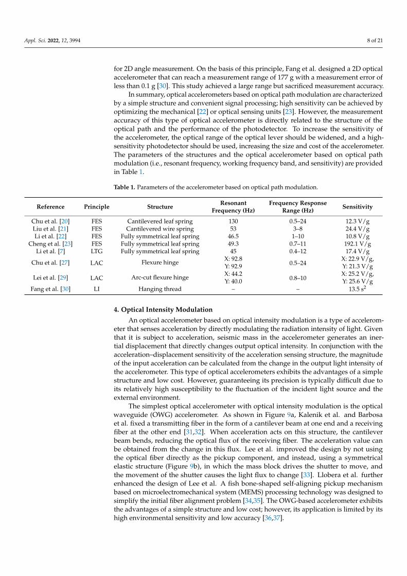
Table 1. Parameters of the accelerometer based on optical path modulation.
Reference Principle Structure ResonantFrequency (Hz)
Frequency ResponseRange (Hz) Sensitivity
Chu et al. [20] FES Cantilevered leaf spring 130 0.5–24 12.3 V/gLiu et al. [21] FES Cantilevered wire spring 53 3–8 24.4 V/gLi et al. [22] FES Fully symmetrical leaf spring 46.5 1–10 10.8 V/g
Cheng et al. [23] FES Fully symmetrical leaf spring 49.3 0.7–11 192.1 V/gLi et al. [7] LTG Fully symmetrical leaf spring 45 0.4–12 17.4 V/g
Chu et al. [27] LAC Flexure hinge X: 92.80.5–24
X: 22.9 V/g,Y: 92.9 Y: 21.3 V/g
Lei et al. [29] LAC Arc-cut flexure hinge X: 44.20.8–10
X: 25.2 V/g,Y: 40.0 Y: 25.6 V/g
Fang et al. [30] LI Hanging thread – – 13.5 s2
4. Optical Intensity Modulation
An optical accelerometer based on optical intensity modulation is a type of accelerom-eter that senses acceleration by directly modulating the radiation intensity of light. Giventhat it is subject to acceleration, seismic mass in the accelerometer generates an iner-tial displacement that directly changes output optical intensity. In conjunction with theacceleration–displacement sensitivity of the acceleration sensing structure, the magnitudeof the input acceleration can be calculated from the change in the output light intensity ofthe accelerometer. This type of optical accelerometers exhibits the advantages of a simplestructure and low cost. However, guaranteeing its precision is typically difficult due toits relatively high susceptibility to the fluctuation of the incident light source and theexternal environment.
The simplest optical accelerometer with optical intensity modulation is the opticalwaveguide (OWG) accelerometer. As shown in Figure 9a, Kalenik et al. and Barbosaet al. fixed a transmitting fiber in the form of a cantilever beam at one end and a receivingfiber at the other end [31,32]. When acceleration acts on this structure, the cantileverbeam bends, reducing the optical flux of the receiving fiber. The acceleration value canbe obtained from the change in this flux. Lee et al. improved the design by not usingthe optical fiber directly as the pickup component, and instead, using a symmetricalelastic structure (Figure 9b), in which the mass block drives the shutter to move, andthe movement of the shutter causes the light flux to change [33]. Llobera et al. furtherenhanced the design of Lee et al. A fish bone-shaped self-aligning pickup mechanismbased on microelectromechanical system (MEMS) processing technology was designed tosimplify the initial fiber alignment problem [34,35]. The OWG-based accelerometer exhibitsthe advantages of a simple structure and low cost; however, its application is limited by itshigh environmental sensitivity and low accuracy [36,37].

Appl. Sci. 2022, 12, 3994 9 of 21
Appl. Sci. 2022, 12, x FOR PEER REVIEW 8 of 21
Table 1. Parameters of the accelerometer based on optical path modulation.
Reference Principle Structure Resonant Frequency (Hz) Frequency Response Range (Hz) Sensitivity Chu et al. [20] FES Cantilevered leaf spring 130 0.5–24 12.3 V/g Liu et al. [21] FES Cantilevered wire spring 53 3–8 24.4 V/g Li et al. [22] FES Fully symmetrical leaf spring 46.5 1–10 10.8 V/g
Cheng et al. [23] FES Fully symmetrical leaf spring 49.3 0.7–11 192.1 V/g Li et al. [7] LTG Fully symmetrical leaf spring 45 0.4–12 17.4 V/g
Chu et al. [27] LAC Flexure hinge X: 92.8
0.5–24 X: 22.9 V/g,
Y: 92.9 Y: 21.3 V/g
Lei et al. [29] LAC Arc-cut flexure hinge X: 44.2
0.8–10 X: 25.2 V/g,
Y: 40.0 Y: 25.6 V/g Fang et al. [30] LI Hanging thread – – 13.5 s2
4. Optical Intensity Modulation An optical accelerometer based on optical intensity modulation is a type of accelerometer
that senses acceleration by directly modulating the radiation intensity of light. Given that it is subject to acceleration, seismic mass in the accelerometer generates an inertial displacement that directly changes output optical intensity. In conjunction with the acceleration–displace-ment sensitivity of the acceleration sensing structure, the magnitude of the input acceleration can be calculated from the change in the output light intensity of the accelerometer. This type of optical accelerometers exhibits the advantages of a simple structure and low cost. However, guaranteeing its precision is typically difficult due to its relatively high susceptibility to the fluctuation of the incident light source and the external environment.
The simplest optical accelerometer with optical intensity modulation is the optical waveguide (OWG) accelerometer. As shown in Figure 9a, Kalenik et al. and Barbosa et al. fixed a transmitting fiber in the form of a cantilever beam at one end and a receiving fiber at the other end [31,32]. When acceleration acts on this structure, the cantilever beam bends, reducing the optical flux of the receiving fiber. The acceleration value can be obtained from the change in this flux. Lee et al. improved the design by not using the optical fiber directly as the pickup component, and instead, using a symmetrical elastic structure (Figure 9b), in which the mass block drives the shutter to move, and the movement of the shutter causes the light flux to change [33]. Llobera et al. further enhanced the design of Lee et al. A fish bone-shaped self-aligning pickup mechanism based on microelectromechanical system (MEMS) processing technology was designed to simplify the initial fiber alignment prob-lem [34,35]. The OWG-based accelerometer exhibits the advantages of a simple structure and low cost; however, its application is limited by its high environmental sensitivity and low accuracy [36,37].
Figure 9. OWG accelerometer: (a) cantilever type and (b) shutter type.
In addition to OWG, grating shutters (GSs) can also be used as optical intensity modu-lation elements for accelerometers. Abbaspour et al. proposed a GS-based accelerometer, the light source emits light vertically downward, with a GS-shaped sensing structure in the
Cantilever input fiber Output fiber Laser
(a) (b)
Mass
Input fiber
Output fiber Shutter
Elastic beam
Laser
Figure 9. OWG accelerometer: (a) cantilever type and (b) shutter type.
In addition to OWG, grating shutters (GSs) can also be used as optical intensity modu-lation elements for accelerometers. Abbaspour et al. proposed a GS-based accelerometer,the light source emits light vertically downward, with a GS-shaped sensing structure in themiddle and a grating-type detector below, along with a detector for sensing ambient light,achieving common-mode rejection. The linear range of this accelerometer reaches ±84 g,but its sensitivity is less than 0.1 V/g [38]. Wu et al. fabricated an optical accelerometerwith a wide band of 10 Hz–1.5 kHz on the basis of MEMS technology with an array ofgratings with square holes, an array of organic light-emitting diodes as the light source,and an array of organic photodetectors as the detector [39]. Similarly, Carr et al. fabricateda high-precision sub-wavelength nano-grating based on photolithography and designeda wide-band high-sensitivity displacement sensor based on this grating and an arrayedvertical cavity surface laser [40,41]. Krishnamoorthy et al. applied the grating to a high-sensitivity optical accelerometer, as shown in Figure 10. This optical accelerometer achievesa resonant frequency of 36 Hz and a sensitivity of 590 V/g [42].
Appl. Sci. 2022, 12, x FOR PEER REVIEW 9 of 21
middle and a grating-type detector below, along with a detector for sensing ambient light, achieving common-mode rejection. The linear range of this accelerometer reaches ±84 g, but its sensitivity is less than 0.1 V/g [38]. Wu et al. fabricated an optical accelerometer with a wide band of 10 Hz–1.5 kHz on the basis of MEMS technology with an array of gratings with square holes, an array of organic light-emitting diodes as the light source, and an array of organic photodetectors as the detector [39]. Similarly, Carr et al. fabricated a high-preci-sion sub-wavelength nano-grating based on photolithography and designed a wide-band high-sensitivity displacement sensor based on this grating and an arrayed vertical cavity surface laser [40,41]. Krishnamoorthy et al. applied the grating to a high-sensitivity optical accelerometer, as shown in Figure 10. This optical accelerometer achieves a resonant fre-quency of 36 Hz and a sensitivity of 590 V/g [42].
Figure 10. GS-based accelerometer. Reprinted with permission from Ref. [42]. Copyright 2008 Else-vier.
Similar to the principle of GS, an optical shadow sensor (OSS) realizes sensing by detect-ing changes in shadows projected onto the photosensitive surface of a photodetector [43]. Bochobza et al. used an OSS to measure the motion of seismic mass, as shown in Figure 11a [44,45]. The system consists of a suspended seismic mass and a complementary metal–oxide–semiconductor (CMOS) chip with a detection photodiode and a readout circuit. When accel-eration acts on the system, the seismic mass moves, causing a change in the shaded portion of the CMOS chip’s photosensitive surface, which, in turn, causes a change in the chip’s output signal, from which the acceleration value can be calculated. The performance of the accel-erometer is affected by the resolving power of the CMOS chip at the micron level. Ham-mond et al. used high-sensitivity photodetectors instead of CMOS chips to improve the ac-curacy of OSS [46]. This photodetector is produced by Siemens, model BPX-65, and has a sensitivity of 0.55 A/W, a quantum efficiency of 80%, and a NEP of 3.3 × 10⁻¹⁴ W/Hz1/2. The accelerometer designed by Hammond et al. also uses an inverse spring with a very low reso-nance frequency (2.3 Hz) with an accelerometer sensitivity as low as 41 ng/Hz1/2. Tang et al. and Duan et al. also designed accelerometers with very low resonant frequencies [47,48]. Tang et al. used an asymmetric spring structure that consisted of two curved and two folded beams, as shown in Figure 11b, to significantly improve the sensitivity of the optical accelerometer to 8.1 ng/Hz1/2.
Figure 11. OSS-based accelerometer: (a) cantilevered and (b) asymmetric spring. Figures are re-printed with permission from: (a) Ref. [44]. Copyright 2000 Elsevier; (b) Ref. [47]. Copyright 2019 Springer Nature.
Figure 10. GS-based accelerometer. Reprinted with permission from Ref. [42]. Copyright 2008 Elsevier.
Similar to the principle of GS, an optical shadow sensor (OSS) realizes sensing bydetecting changes in shadows projected onto the photosensitive surface of a photodetec-tor [43]. Bochobza et al. used an OSS to measure the motion of seismic mass, as shown inFigure 11a [44,45]. The system consists of a suspended seismic mass and a complemen-tary metal–oxide–semiconductor (CMOS) chip with a detection photodiode and a readoutcircuit. When acceleration acts on the system, the seismic mass moves, causing a changein the shaded portion of the CMOS chip’s photosensitive surface, which, in turn, causesa change in the chip’s output signal, from which the acceleration value can be calculated.The performance of the accelerometer is affected by the resolving power of the CMOSchip at the micron level. Hammond et al. used high-sensitivity photodetectors insteadof CMOS chips to improve the accuracy of OSS [46]. This photodetector is produced bySiemens, model BPX-65, and has a sensitivity of 0.55 A/W, a quantum efficiency of 80%,and a NEP of 3.3 × 10⁻¹⁴ W/Hz1/2. The accelerometer designed by Hammond et al. alsouses an inverse spring with a very low resonance frequency (2.3 Hz) with an accelerometersensitivity as low as 41 ng/Hz1/2. Tang et al. and Duan et al. also designed accelerometerswith very low resonant frequencies [47,48]. Tang et al. used an asymmetric spring structurethat consisted of two curved and two folded beams, as shown in Figure 11b, to significantlyimprove the sensitivity of the optical accelerometer to 8.1 ng/Hz1/2.

Appl. Sci. 2022, 12, 3994 10 of 21
Appl. Sci. 2022, 12, x FOR PEER REVIEW 9 of 21
middle and a grating-type detector below, along with a detector for sensing ambient light, achieving common-mode rejection. The linear range of this accelerometer reaches ±84 g, but its sensitivity is less than 0.1 V/g [38]. Wu et al. fabricated an optical accelerometer with a wide band of 10 Hz–1.5 kHz on the basis of MEMS technology with an array of gratings with square holes, an array of organic light-emitting diodes as the light source, and an array of organic photodetectors as the detector [39]. Similarly, Carr et al. fabricated a high-preci-sion sub-wavelength nano-grating based on photolithography and designed a wide-band high-sensitivity displacement sensor based on this grating and an arrayed vertical cavity surface laser [40,41]. Krishnamoorthy et al. applied the grating to a high-sensitivity optical accelerometer, as shown in Figure 10. This optical accelerometer achieves a resonant fre-quency of 36 Hz and a sensitivity of 590 V/g [42].
Figure 10. GS-based accelerometer. Reprinted with permission from Ref. [42]. Copyright 2008 Else-vier.
Similar to the principle of GS, an optical shadow sensor (OSS) realizes sensing by detect-ing changes in shadows projected onto the photosensitive surface of a photodetector [43]. Bochobza et al. used an OSS to measure the motion of seismic mass, as shown in Figure 11a [44,45]. The system consists of a suspended seismic mass and a complementary metal–oxide–semiconductor (CMOS) chip with a detection photodiode and a readout circuit. When accel-eration acts on the system, the seismic mass moves, causing a change in the shaded portion of the CMOS chip’s photosensitive surface, which, in turn, causes a change in the chip’s output signal, from which the acceleration value can be calculated. The performance of the accel-erometer is affected by the resolving power of the CMOS chip at the micron level. Ham-mond et al. used high-sensitivity photodetectors instead of CMOS chips to improve the ac-curacy of OSS [46]. This photodetector is produced by Siemens, model BPX-65, and has a sensitivity of 0.55 A/W, a quantum efficiency of 80%, and a NEP of 3.3 × 10⁻¹⁴ W/Hz1/2. The accelerometer designed by Hammond et al. also uses an inverse spring with a very low reso-nance frequency (2.3 Hz) with an accelerometer sensitivity as low as 41 ng/Hz1/2. Tang et al. and Duan et al. also designed accelerometers with very low resonant frequencies [47,48]. Tang et al. used an asymmetric spring structure that consisted of two curved and two folded beams, as shown in Figure 11b, to significantly improve the sensitivity of the optical accelerometer to 8.1 ng/Hz1/2.
Figure 11. OSS-based accelerometer: (a) cantilevered and (b) asymmetric spring. Figures are re-printed with permission from: (a) Ref. [44]. Copyright 2000 Elsevier; (b) Ref. [47]. Copyright 2019 Springer Nature.
Figure 11. OSS-based accelerometer: (a) cantilevered and (b) asymmetric spring. Figures are reprintedwith permission from: (a) Ref. [44]. Copyright 2000 Elsevier; (b) Ref. [47]. Copyright 2019 Springer Nature.
In summary, optical accelerometers based on optical intensity modulation are similarto those based on optical path modulation, with a simple structure and lower cost. Thistype of optical accelerometers can achieve extremely high sensitivity by using a highlysensitive mechanical sensing unit [46–48]. However, the measurement accuracy of lightintensity-modulated accelerometers is directly dependent on the stability of light intensityand has high requirements for the light source and its driver. Therefore, the cost of highlysensitive optical intensity-modulated optical accelerometers is high. The parameters of thestructures and the optical accelerometer based on optical intensity modulation (i.e., resonantfrequency, working frequency band, and sensitivity) are provided in Table 2.
Table 2. Parameters of the accelerometer based on optical intensity modulation.
Reference Principle Structure ResonantFrequency (Hz)
Frequency ResponseRange (Hz) Sensitivity
Kalenik et al. [31] OWG Cantilevered fiber optics 125 – 6%/gBarbosa et al. [32] OWG Cantilevered fiber optics 3.3 k 20–2000 3.3 mV/g
Lee et al. [33] OWG Symmetrical flexure hinge 5.5 k <1000 2.46 mV/gLlobera et al. [34,35] OWG Symmetrical flexure hinge 51 – 32.14 dB/gSchröpfer et al. [36] OWG Symmetrical flexure hinge – – 1.8 V/gCadarso et al. [37] OWG Symmetrical flexure hinge – – 13.1 dB/g
Abbaspour et al. [38] GS Flexure hinge – – 0.04 V/gWu et al. [39] GS Flexure hinge 60 10–1.5 k –
Krishnamoorthy et al. [40] GS Flexure hinge 36 – 590 V/gBochobza et al. [44,45] OSS Cantilevered flexure hinge 550 <400 0.6 V/gHammond et al. [46] OSS Inverse spring 2.3 <0.02 41 ng/Hz1/2
Tang et al. [47] OSS Asymmetric spring 3 <0.1 8.1 ng/Hz1/2
Duan et al. [48] OSS V-shape elastic beam 8.24 <1 3800 µm/g
5. Optical Phase Modulation
Optical phase-modulated accelerometers use the phase change of an optical wave in anoptical fiber caused by external vibrations to detect vibrations. Optical accelerometers basedon optical phase modulation generally consist of two parts: an optical fiber interferometerand a vibration-sensitive elastic mechanism. Fiber optic interferometers can be classifiedinto Michelson interferometers (MSIs), Mach–Zehnder interferometers (MZIs), and Fabry–Perot interferometers (FPIs) in accordance with the interference principle.
An MSI is a dual-beam interferometer in which coherent light from a laser is incidenton two single-mode fibers, one of which is the detection fiber while the other is thereference fiber, as shown in Figure 12. Pechstedt et al. proposed an optical accelerometerby winding optical fibers on the top and bottom of an elastic cylinder with a mass blockin the middle [49]. This accelerometer achieves differential vibration measurements andimproved sensitivity, as shown in Figure 13a. Chen et al. fixed the detection fiber of

Appl. Sci. 2022, 12, 3994 11 of 21
an MSI to the seismic mass of an optical accelerometer. The mass is fixed onto the baseof the accelerometer by elastic beams, as shown in Figure 13b. The frequency responserange of this accelerometer is 5–500 Hz, which is a wide spectral response range [50,51].In addition to elastic cylinders and elastic beams, elastic diaphragms with low resonancefrequencies are also used as vibration-sensitive structures for optical accelerometers. Chenet al. achieved vibration measurement by fixing the detection fiber of an MSI onto adifferent elastic structure and using the bending stress of the diaphragm vibration to loadonto the detection fiber and change its phase [52–54].
Appl. Sci. 2022, 12, x FOR PEER REVIEW 10 of 21
In summary, optical accelerometers based on optical intensity modulation are similar to those based on optical path modulation, with a simple structure and lower cost. This type of optical accelerometers can achieve extremely high sensitivity by using a highly sensitive mechanical sensing unit [46–48]. However, the measurement accuracy of light intensity-modulated accelerometers is directly dependent on the stability of light intensity and has high requirements for the light source and its driver. Therefore, the cost of highly sensitive optical intensity-modulated optical accelerometers is high. The parameters of the structures and the optical accelerometer based on optical intensity modulation (i.e., reso-nant frequency, working frequency band, and sensitivity) are provided in Table 2.
Table 2. Parameters of the accelerometer based on optical intensity modulation.
Reference Principle Structure Resonant Frequency (Hz) Frequency Response Range (Hz) Sensitivity Kalenik et al. [31] OWG Cantilevered fiber optics 125 – 6%/g Barbosa et al. [32] OWG Cantilevered fiber optics 3.3 k 20–2000 3.3 mV/g
Lee et al. [33] OWG Symmetrical flexure hinge 5.5 k <1000 2.46 mV/g Llobera et al. [34,35] OWG Symmetrical flexure hinge 51 – 32.14 dB/g Schröpfer et al. [36] OWG Symmetrical flexure hinge – – 1.8 V/g Cadarso et al. [37] OWG Symmetrical flexure hinge – – 13.1 dB/g
Abbaspour et al. [38] GS Flexure hinge – – 0.04 V/g Wu et al. [39] GS Flexure hinge 60 10–1.5 k –
Krishnamoorthy et al. [40] GS Flexure hinge 36 – 590 V/g Bochobza et al. [44,45] OSS Cantilevered flexure hinge 550 <400 0.6 V/g Hammond et al. [46] OSS Inverse spring 2.3 <0.02 41 ng/Hz1/2
Tang et al. [47] OSS Asymmetric spring 3 <0.1 8.1 ng/Hz1/2 Duan et al. [48] OSS V-shape elastic beam 8.24 <1 3800 µm/g
5. Optical Phase Modulation Optical phase-modulated accelerometers use the phase change of an optical wave in
an optical fiber caused by external vibrations to detect vibrations. Optical accelerometers based on optical phase modulation generally consist of two parts: an optical fiber interfer-ometer and a vibration-sensitive elastic mechanism. Fiber optic interferometers can be clas-sified into Michelson interferometers (MSIs), Mach–Zehnder interferometers (MZIs), and Fabry–Perot interferometers (FPIs) in accordance with the interference principle.
An MSI is a dual-beam interferometer in which coherent light from a laser is incident on two single-mode fibers, one of which is the detection fiber while the other is the reference fiber, as shown in Figure 12. Pechstedt et al. proposed an optical accelerometer by winding optical fibers on the top and bottom of an elastic cylinder with a mass block in the middle [49]. This accelerometer achieves differential vibration measurements and improved sensi-tivity, as shown in Figure 13a. Chen et al. fixed the detection fiber of an MSI to the seismic mass of an optical accelerometer. The mass is fixed onto the base of the accelerometer by elastic beams, as shown in Figure 13b. The frequency response range of this accelerometer is 5–500 Hz, which is a wide spectral response range [50,51]. In addition to elastic cylinders and elastic beams, elastic diaphragms with low resonance frequencies are also used as vi-bration-sensitive structures for optical accelerometers. Chen et al. achieved vibration meas-urement by fixing the detection fiber of an MSI onto a different elastic structure and using the bending stress of the diaphragm vibration to load onto the detection fiber and change its phase [52–54].
Figure 12. Schematic of the MSI. Figure 12. Schematic of the MSI.
Appl. Sci. 2022, 12, x FOR PEER REVIEW 11 of 21
Figure 13. MSI-based accelerometer: (a) elastic cylinder and (b) elastic beam.
MZI is similar to MSI. Although both are two-beam interferometers, the difference is that MZI does not use end-face reflection, but instead, couples two beams to interfere for a transmission interferometer, as shown in Figure 14. The phase shift Δφ from the strain caused by the acceleration a is
0
2( ) Δ ( )fπφ a n L aλ
= , (11)
where λ0 is the wavelength of incident light, nf is the effective refractive index of the optical fiber, and ΔL(a) is the amount of change in the detection fiber caused by the acceleration. The MZI optical accelerometer structure is also similar to that of MSI. Rivera et al. wrapped an optical fiber of MZI around the transformer core, and an acceleration value can be ob-tained by demodulating the change in the optical phase inside the fiber [55]. To improve the sensitivity of the MZI accelerometer, Rochus et al. fixed the detection fiber of the MZI inter-ferometer in the form of a spiral on a diaphragm with a mass block to maximize the me-chanical sensitivity of the MZI accelerometer, but the measurement range is small [56]. Zeng et al. proposed a 3D MZI optical accelerometer by mounting three-component optical accel-erometers in orthogonal orientation [57]. Each single-component optical accelerometer is constructed by wrapping MZI detection fiber around an elastic cylinder, similar to the de-sign of Pechstedt et al. [49]. The frequency response of this 3D optical accelerometer is within the range of 10–800 Hz. MZI and MSI exhibit similarities in measurement, sensor structure design, and signal demodulation. However, MSI exhibits two times the sensitivity of MZI when light wave makes one round trip in fiber with the same fiber length. In addition, MSI does not have a closed fiber loop and the fiber winding process is simpler. Therefore, MSI is more widely used than MZI.
Figure 14. Schematic of the MZI.
In addition to MSI and MZI, which are two-optical interferometric sensing systems, the single-optical interferometric-based FPI is also widely used in optical accelerometers. The structure of FPI is shown in Figure 15. Its resonant cavity consists of two optical fiber end faces, wherein the incident light is reflected several times between the two end faces. The phase difference between two adjacent emitted lights is the same, and all reflected lights enter the detection system to produce multi-beam interference. The relationship between the end-face displacement ΔL and the phase shift Δφ is
Figure 13. MSI-based accelerometer: (a) elastic cylinder and (b) elastic beam.
MZI is similar to MSI. Although both are two-beam interferometers, the difference isthat MZI does not use end-face reflection, but instead, couples two beams to interfere fora transmission interferometer, as shown in Figure 14. The phase shift ∆ϕ from the straincaused by the acceleration a is
ϕ(a) =2π
λ0n f ∆L(a), (11)
where λ0 is the wavelength of incident light, nf is the effective refractive index of the opticalfiber, and ∆L(a) is the amount of change in the detection fiber caused by the acceleration.The MZI optical accelerometer structure is also similar to that of MSI. Rivera et al. wrappedan optical fiber of MZI around the transformer core, and an acceleration value can beobtained by demodulating the change in the optical phase inside the fiber [55]. To improvethe sensitivity of the MZI accelerometer, Rochus et al. fixed the detection fiber of the MZIinterferometer in the form of a spiral on a diaphragm with a mass block to maximize themechanical sensitivity of the MZI accelerometer, but the measurement range is small [56].Zeng et al. proposed a 3D MZI optical accelerometer by mounting three-component opticalaccelerometers in orthogonal orientation [57]. Each single-component optical accelerometeris constructed by wrapping MZI detection fiber around an elastic cylinder, similar to the

Appl. Sci. 2022, 12, 3994 12 of 21
design of Pechstedt et al. [49]. The frequency response of this 3D optical accelerometer iswithin the range of 10–800 Hz. MZI and MSI exhibit similarities in measurement, sensorstructure design, and signal demodulation. However, MSI exhibits two times the sensitivityof MZI when light wave makes one round trip in fiber with the same fiber length. Inaddition, MSI does not have a closed fiber loop and the fiber winding process is simpler.Therefore, MSI is more widely used than MZI.
Appl. Sci. 2022, 12, x FOR PEER REVIEW 11 of 21
Figure 13. MSI-based accelerometer: (a) elastic cylinder and (b) elastic beam.
MZI is similar to MSI. Although both are two-beam interferometers, the difference is that MZI does not use end-face reflection, but instead, couples two beams to interfere for a transmission interferometer, as shown in Figure 14. The phase shift Δφ from the strain caused by the acceleration a is
0
2( ) Δ ( )fπφ a n L aλ
= , (11)
where λ0 is the wavelength of incident light, nf is the effective refractive index of the optical fiber, and ΔL(a) is the amount of change in the detection fiber caused by the acceleration. The MZI optical accelerometer structure is also similar to that of MSI. Rivera et al. wrapped an optical fiber of MZI around the transformer core, and an acceleration value can be ob-tained by demodulating the change in the optical phase inside the fiber [55]. To improve the sensitivity of the MZI accelerometer, Rochus et al. fixed the detection fiber of the MZI inter-ferometer in the form of a spiral on a diaphragm with a mass block to maximize the me-chanical sensitivity of the MZI accelerometer, but the measurement range is small [56]. Zeng et al. proposed a 3D MZI optical accelerometer by mounting three-component optical accel-erometers in orthogonal orientation [57]. Each single-component optical accelerometer is constructed by wrapping MZI detection fiber around an elastic cylinder, similar to the de-sign of Pechstedt et al. [49]. The frequency response of this 3D optical accelerometer is within the range of 10–800 Hz. MZI and MSI exhibit similarities in measurement, sensor structure design, and signal demodulation. However, MSI exhibits two times the sensitivity of MZI when light wave makes one round trip in fiber with the same fiber length. In addition, MSI does not have a closed fiber loop and the fiber winding process is simpler. Therefore, MSI is more widely used than MZI.
Figure 14. Schematic of the MZI.
In addition to MSI and MZI, which are two-optical interferometric sensing systems, the single-optical interferometric-based FPI is also widely used in optical accelerometers. The structure of FPI is shown in Figure 15. Its resonant cavity consists of two optical fiber end faces, wherein the incident light is reflected several times between the two end faces. The phase difference between two adjacent emitted lights is the same, and all reflected lights enter the detection system to produce multi-beam interference. The relationship between the end-face displacement ΔL and the phase shift Δφ is
Figure 14. Schematic of the MZI.
In addition to MSI and MZI, which are two-optical interferometric sensing systems,the single-optical interferometric-based FPI is also widely used in optical accelerometers.The structure of FPI is shown in Figure 15. Its resonant cavity consists of two optical fiberend faces, wherein the incident light is reflected several times between the two end faces.The phase difference between two adjacent emitted lights is the same, and all reflectedlights enter the detection system to produce multi-beam interference. The relationshipbetween the end-face displacement ∆L and the phase shift ∆ϕ is
∆ϕ =4πn f ∆L
λ0, (12)
where λ0 is the wavelength of the incident light, and nf is the effective refractive index ofthe optical fiber.
Appl. Sci. 2022, 12, x FOR PEER REVIEW 12 of 21
0
4=
ΔΔ fπn Lφ
λ, (12)
where λ0 is the wavelength of the incident light, and nf is the effective refractive index of the optical fiber.
Figure 15. Schematic of the FPI.
Given that it is subject to acceleration, the inertial force of the seismic mass drives the end face of FPI, changing the reflection or transmission spectrum. The magnitude of input acceleration can be obtained by analyzing the spectrum. Gerges et al. proposed an optical accelerometer that consists of two identical hemispherical FPIs [58]. Two identical spherical metal mirrors are attached onto the central diaphragm (one on each side), forming the outer mirror of FPI, while the distal end of the fiber is used as the inner mirror. This optical accel-erometer has a sensitivity of 2.2 × 10⁻⁷ g/Hz1/2 and a resonant frequency of 450 Hz. Early FPI optical accelerometers exhibited high performance. In recent years, many researchers have started improving the mechanical design of optical accelerometers to increase their sensitiv-ity. For example, Davies et al. introduced a V-beam displacement amplification structure into the accelerometer structure, as shown in Figure 16 [59]. The inertial displacement of the mass causes the V-shaped structure to compress in the x-direction and expand in the y-di-rection, modulating the Fabry–Perot cavity length and changing the wavelength of the out-put light. The bandwidth of this accelerometer is about 10 kHz, and the maximum me-chanical amplification is 18.6.
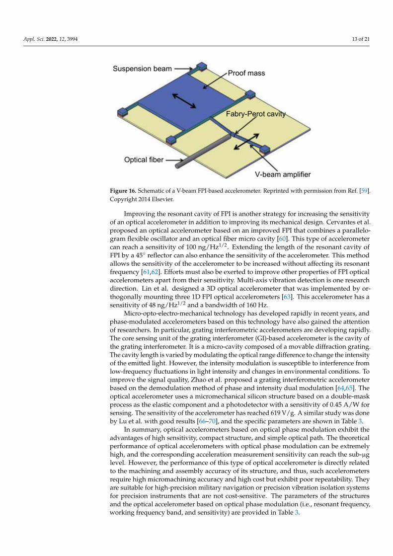
Figure 16. Schematic of a V-beam FPI-based accelerometer. Reprinted with permission from Ref. [59]. Copyright 2014 Elsevier.
Improving the resonant cavity of FPI is another strategy for increasing the sensitivity of an optical accelerometer in addition to improving its mechanical design. Cervantes et al. proposed an optical accelerometer based on an improved FPI that combines a parallelogram flexible oscillator and an optical fiber micro cavity [60]. This type of accelerometer can reach a sensitivity of 100 ng/Hz1/2. Extending the length of the resonant cavity of FPI by a 45° re-flector can also enhance the sensitivity of the accelerometer. This method allows the sensi-tivity of the accelerometer to be increased without affecting its resonant frequency [61,62]. Efforts must also be exerted to improve other properties of FPI optical accelerometers apart from their sensitivity. Multi-axis vibration detection is one research direction. Lin et al. de-signed a 3D optical accelerometer that was implemented by orthogonally mounting three 1D FPI optical accelerometers [63]. This accelerometer has a sensitivity of 48 ng/Hz1/2 and a bandwidth of 160 Hz.
Figure 15. Schematic of the FPI.
Given that it is subject to acceleration, the inertial force of the seismic mass drivesthe end face of FPI, changing the reflection or transmission spectrum. The magnitude ofinput acceleration can be obtained by analyzing the spectrum. Gerges et al. proposed anoptical accelerometer that consists of two identical hemispherical FPIs [58]. Two identicalspherical metal mirrors are attached onto the central diaphragm (one on each side), formingthe outer mirror of FPI, while the distal end of the fiber is used as the inner mirror. Thisoptical accelerometer has a sensitivity of 2.2 × 10⁻⁷ g/Hz1/2 and a resonant frequencyof 450 Hz. Early FPI optical accelerometers exhibited high performance. In recent years,many researchers have started improving the mechanical design of optical accelerometersto increase their sensitivity. For example, Davies et al. introduced a V-beam displacementamplification structure into the accelerometer structure, as shown in Figure 16 [59]. The in-ertial displacement of the mass causes the V-shaped structure to compress in the x-directionand expand in the y-direction, modulating the Fabry–Perot cavity length and changing thewavelength of the output light. The bandwidth of this accelerometer is about 10 kHz, andthe maximum mechanical amplification is 18.6.
Appl. Sci. 2022, 12, 3994 13 of 21
Appl. Sci. 2022, 12, x FOR PEER REVIEW 12 of 21
0
4=
ΔΔ fπn Lφ
λ, (12)
where λ0 is the wavelength of the incident light, and nf is the effective refractive index of the optical fiber.
Figure 15. Schematic of the FPI.
Given that it is subject to acceleration, the inertial force of the seismic mass drives the end face of FPI, changing the reflection or transmission spectrum. The magnitude of input acceleration can be obtained by analyzing the spectrum. Gerges et al. proposed an optical accelerometer that consists of two identical hemispherical FPIs [58]. Two identical spherical metal mirrors are attached onto the central diaphragm (one on each side), forming the outer mirror of FPI, while the distal end of the fiber is used as the inner mirror. This optical accel-erometer has a sensitivity of 2.2 × 10⁻⁷ g/Hz1/2 and a resonant frequency of 450 Hz. Early FPI optical accelerometers exhibited high performance. In recent years, many researchers have started improving the mechanical design of optical accelerometers to increase their sensitiv-ity. For example, Davies et al. introduced a V-beam displacement amplification structure into the accelerometer structure, as shown in Figure 16 [59]. The inertial displacement of the mass causes the V-shaped structure to compress in the x-direction and expand in the y-di-rection, modulating the Fabry–Perot cavity length and changing the wavelength of the out-put light. The bandwidth of this accelerometer is about 10 kHz, and the maximum me-chanical amplification is 18.6.
Figure 16. Schematic of a V-beam FPI-based accelerometer. Reprinted with permission from Ref. [59]. Copyright 2014 Elsevier.
Improving the resonant cavity of FPI is another strategy for increasing the sensitivity of an optical accelerometer in addition to improving its mechanical design. Cervantes et al. proposed an optical accelerometer based on an improved FPI that combines a parallelogram flexible oscillator and an optical fiber micro cavity [60]. This type of accelerometer can reach a sensitivity of 100 ng/Hz1/2. Extending the length of the resonant cavity of FPI by a 45° re-flector can also enhance the sensitivity of the accelerometer. This method allows the sensi-tivity of the accelerometer to be increased without affecting its resonant frequency [61,62]. Efforts must also be exerted to improve other properties of FPI optical accelerometers apart from their sensitivity. Multi-axis vibration detection is one research direction. Lin et al. de-signed a 3D optical accelerometer that was implemented by orthogonally mounting three 1D FPI optical accelerometers [63]. This accelerometer has a sensitivity of 48 ng/Hz1/2 and a bandwidth of 160 Hz.
Figure 16. Schematic of a V-beam FPI-based accelerometer. Reprinted with permission from Ref. [59].Copyright 2014 Elsevier.
Improving the resonant cavity of FPI is another strategy for increasing the sensitivityof an optical accelerometer in addition to improving its mechanical design. Cervantes et al.proposed an optical accelerometer based on an improved FPI that combines a parallelo-gram flexible oscillator and an optical fiber micro cavity [60]. This type of accelerometercan reach a sensitivity of 100 ng/Hz1/2. Extending the length of the resonant cavity ofFPI by a 45◦ reflector can also enhance the sensitivity of the accelerometer. This methodallows the sensitivity of the accelerometer to be increased without affecting its resonantfrequency [61,62]. Efforts must also be exerted to improve other properties of FPI opticalaccelerometers apart from their sensitivity. Multi-axis vibration detection is one researchdirection. Lin et al. designed a 3D optical accelerometer that was implemented by or-thogonally mounting three 1D FPI optical accelerometers [63]. This accelerometer has asensitivity of 48 ng/Hz1/2 and a bandwidth of 160 Hz.
Micro-opto-electro-mechanical technology has developed rapidly in recent years, andphase-modulated accelerometers based on this technology have also gained the attentionof researchers. In particular, grating interferometric accelerometers are developing rapidly.The core sensing unit of the grating interferometer (GI)-based accelerometer is the cavity ofthe grating interferometer. It is a micro-cavity composed of a movable diffraction grating.The cavity length is varied by modulating the optical range difference to change the intensityof the emitted light. However, the intensity modulation is susceptible to interference fromlow-frequency fluctuations in light intensity and changes in environmental conditions. Toimprove the signal quality, Zhao et al. proposed a grating interferometric accelerometerbased on the demodulation method of phase and intensity dual modulation [64,65]. Theoptical accelerometer uses a micromechanical silicon structure based on a double-maskprocess as the elastic component and a photodetector with a sensitivity of 0.45 A/W forsensing. The sensitivity of the accelerometer has reached 619 V/g. A similar study was doneby Lu et al. with good results [66–70], and the specific parameters are shown in Table 3.
In summary, optical accelerometers based on optical phase modulation exhibit theadvantages of high sensitivity, compact structure, and simple optical path. The theoreticalperformance of optical accelerometers with optical phase modulation can be extremelyhigh, and the corresponding acceleration measurement sensitivity can reach the sub-µglevel. However, the performance of this type of optical accelerometer is directly relatedto the machining and assembly accuracy of its structure, and thus, such accelerometersrequire high micromachining accuracy and high cost but exhibit poor repeatability. Theyare suitable for high-precision military navigation or precision vibration isolation systemsfor precision instruments that are not cost-sensitive. The parameters of the structuresand the optical accelerometer based on optical phase modulation (i.e., resonant frequency,working frequency band, and sensitivity) are provided in Table 3.

Appl. Sci. 2022, 12, 3994 14 of 21
Table 3. Parameters of the accelerometer based on optical phase modulation.
Reference Principle Structure ResonantFrequency (Hz)
Frequency ResponseRange (Hz) Sensitivity
Pechstedt et al. [49] MSI Elastic cylinder 300 <100 –Chen et al. [50,51] MSI Elastic beams 400 10–150 0.66 V/g
Chen et al. [52] MSI Elastic diaphragm 1.6 k 100–800 2.2 rad/gCranch et al. [59] MSI Elastic diaphragm 3.8 k <1 k 35.9 dB re rad/g
Wu et al. [54] MSI Cantilever beam 490 10–300 1.13 V/gRochus et al. [56] MZI Elastic diaphragm – <25 k –Zeng et al. [57] MZI Elastic cylinder 1 k 10–800 38 dB re rad/g
Gerges et al. [58] FPI Elastic beams 450 <47.7 220 ng/Hz1/2
Davies et al. [59] FPI Combined elastic beams 11.75 k <5 k 0.3 mV/g
Cervantes et al. [60] FPI Parallelogram flexibleoscillator 11 k 1.5–12 k 100 ng/Hz1/2
Liu et al. [61,62] FPI Cantilever beam 520 20–160 20 V/gLin et al. [63] FPI Symmetrical leaf spring 144 20–120 36 dB re rad/g
Zhao et al. [64,65] GI Four cantilever beams 1 k <200 619 V/g
Lu et al. [66] GI Four serpentine-shapedflexure beams 34.5 <5 2485 V/g
Zhang et al. [69] GI Eight cantilever beams 7553 100–2000 –
Yao et al. [70] GI Six serpentine-shapedflexure beams 24.8 <3 60 V/g
6. Optical Wavelength Modulation
Accelerometers based on optical wavelength modulation detect acceleration by mea-suring the wavelength drift of the output light under the effect of acceleration. The twomain types of optical wavelength modulated accelerometers include fiber optic Bragggrating (FBG) accelerometers and photonic crystal (PHC) accelerometers.
Research on FBG started as early as 1978 [71,72]. FBG is a periodic modulation of therefractive index in the fiber core. When a broadband light is transmitted along with thefiber core, the FBG reflects the narrowband part of a specific wavelength while the rest ofthe broadband light passes through. The central wavelength of the reflected spectrum isdefined as λb and can be expressed in terms of two parameters [73,74]:
λb = 2 ∗ n f ∗ Λ, (13)
where nf is the effective refractive index of the optical fiber, and Λ is the periodicity of thegrating. The wavelength shift of λb is decided by the changes of nf and Λ, which are mainlyinfluenced by the axial strain ∆ε and environment temperature ∆T. In this case, the Braggwavelength dependency on the strain and temperature could be described by [75]
∆λbλb
= (1 − Pe) ∗ ∆ε + (α f + ξ) ∗ ∆T, (14)
where αf is the thermal expansion coefficient, ξ is the thermal optic coefficient, and Pe is theelastic optical coefficient.
Berkoff et al. designed an original FBG-based optical accelerometer, shown in Figure 17a,wherein the FBG is arranged in an elastic material [76]. The measurement of vibration isachieved by measuring the central wavelength drift of the FBG. This accelerometer has asensitivity of 1 ng/Hz1/2 and a bandwidth of 2 kHz. In addition to placing FBG inside anelastic material, fixing FBG onto an elastic beam has also been used in the design of opticalaccelerometers. The optical accelerometer designed by Todd et al. placed a seismic mass inthe middle of two simply supported beams and fixed the FBG onto the lower surface ofthe lower simply supported beam, as shown in Figure 17b [77]. When external vibrationis loaded onto the sensor, the deformation of the beam causes the center wavelength ofthe FBG to drift, and the amplitude and frequency information of the external vibration

Appl. Sci. 2022, 12, 3994 15 of 21
can be obtained on the basis of drift value. Mita et al. proposed an accelerometer with acantilever FBG [78]. This accelerometer consists of an L-shaped rigid cantilever beam, aseismic mass, a spring, and FBG. In the design of Mita et al., FBG is not directly fixed ontothe L-shaped cantilever beam, but instead, a point contact is used with the cantilever beamto ensure the consistency of the strain applied to the entire FBG. A similar design was madeby Weng et al. [79,80].
Appl. Sci. 2022, 12, x FOR PEER REVIEW 14 of 21
2 * *b fλ n= Λ , (13)
where nf is the effective refractive index of the optical fiber, and Λ is the periodicity of the grating. The wavelength shift of λb is decided by the changes of nf and Λ, which are mainly influenced by the axial strain Δε and environment temperature ΔT. In this case, the Bragg wavelength dependency on the strain and temperature could be described by [75]
1( ) * ( ) *be f
b
λP ε α ξ T
λΔ
= − Δ + + Δ , (14)
where αf is the thermal expansion coefficient, ξ is the thermal optic coefficient, and Pe is the elastic optical coefficient.
Berkoff et al. designed an original FBG-based optical accelerometer, shown in Figure 17a, wherein the FBG is arranged in an elastic material [76]. The measurement of vibration is achieved by measuring the central wavelength drift of the FBG. This accelerometer has a sen-sitivity of 1 ng/Hz1/2 and a bandwidth of 2 kHz. In addition to placing FBG inside an elastic material, fixing FBG onto an elastic beam has also been used in the design of optical accel-erometers. The optical accelerometer designed by Todd et al. placed a seismic mass in the middle of two simply supported beams and fixed the FBG onto the lower surface of the lower simply supported beam, as shown in Figure 17b [77]. When external vibration is loaded onto the sensor, the deformation of the beam causes the center wavelength of the FBG to drift, and the amplitude and frequency information of the external vibration can be obtained on the basis of drift value. Mita et al. proposed an accelerometer with a cantilever FBG [78]. This accel-erometer consists of an L-shaped rigid cantilever beam, a seismic mass, a spring, and FBG. In the design of Mita et al., FBG is not directly fixed onto the L-shaped cantilever beam, but instead, a point contact is used with the cantilever beam to ensure the consistency of the strain applied to the entire FBG. A similar design was made by Weng et al. [79,80].
Figure 17. FBG-based accelerometer: (a) elastic material and (b) two simply supported beams.
FBG has good multipoint measurement capability. Linze et al. designed a distributed optical accelerometer based on FBG [81,82]. This distributed optical accelerometer is real-ized by using pairs of vibration-sensitive mechanical structures and paired FBGs with dif-ferent Bragg wavelengths. In the design of Linze et al., up to six optical accelerometers can be combined for measurement.
In recent years, many researchers have started to focus on improving the performance of FBG optical accelerometers. In their research, they have exerted effort on two perspectives: the design of FBG and the design of a vibration-sensitive mechanical structure. Guo et al. used a tilted FBG (TFBG), as shown in Figure 18, to produce a biconical accelerometer, avoiding the difficulty of demodulation of the output optical wavelength signal when the traditional FBG accelerometer is used, and its reflected optical power is proportional to the acceleration [11]. A similar design was developed by Huang et al. [83]. The advantage of TFBG over FBG is that the optical fiber does not require stretching and can be embedded directly into the solid base, improving the reliability of the optical accelerometer and reducing its size.
FBGFiber
Mass
Elastic material
Mass
Elastic beam 1
Elastic beam 2
FBG
(a) (b)
Figure 17. FBG-based accelerometer: (a) elastic material and (b) two simply supported beams.
FBG has good multipoint measurement capability. Linze et al. designed a distributedoptical accelerometer based on FBG [81,82]. This distributed optical accelerometer isrealized by using pairs of vibration-sensitive mechanical structures and paired FBGs withdifferent Bragg wavelengths. In the design of Linze et al., up to six optical accelerometerscan be combined for measurement.
In recent years, many researchers have started to focus on improving the perfor-mance of FBG optical accelerometers. In their research, they have exerted effort on twoperspectives: the design of FBG and the design of a vibration-sensitive mechanical struc-ture. Guo et al. used a tilted FBG (TFBG), as shown in Figure 18, to produce a biconicalaccelerometer, avoiding the difficulty of demodulation of the output optical wavelengthsignal when the traditional FBG accelerometer is used, and its reflected optical power is pro-portional to the acceleration [11]. A similar design was developed by Huang et al. [83]. Theadvantage of TFBG over FBG is that the optical fiber does not require stretching and can beembedded directly into the solid base, improving the reliability of the optical accelerometerand reducing its size.
Appl. Sci. 2022, 12, x FOR PEER REVIEW 15 of 21
Figure 18. TFBG-based accelerometer [11]: (a) schematic and (b) photograph.
Other researchers have increased the sensitivity of FBG accelerometers by improving their mechanical design. As shown in Figure 19a, Basumallick et al. increased the sensitivity of a cantilever FBG accelerometer by using a simple method, i.e., adding a polyimide patch to the cantilever beam that does not affect its resonant frequency [84,85]. This polyimide patch increased the distance between the central axis of the cantilever beam and FBG, improving the sensitivity of the accelerometer. The design is simple in structure, but it improves sensitivity without affecting bandwidth and other characteristics. Shi et al. and Yu et al. designed an FBG accelerometer based on an isosceles triangular cantilever beam [86,87]. Zhang et al. designed a compact accelerometer based on an organic double semicircular cantilever beam and double FBGs [88], as illustrated in Figure 19b. These studies were conducted to suppress the FBG chirp effect and improve the sensitivity of FBG optical accelerometers. Elastic diaphragms with high mechanical sensitivity have also been applied to FBG accelerometers. Liu et al. de-signed a double diaphragm-based FBG accelerometer with FBGs mounted on the upper sur-face of the diaphragm along the circumferential direction; this design can effectively prevent the FBG chirp effect [89]. When acceleration acts on the sensor, a uniform strain is gener-ated, leading to an FBG wavelength shift.
Figure 19. Improved cantilever FBG accelerometer: (a) polyimide patch and (b) double semicircular flexible hinge. Figures are reprinted with permission from: (a) Ref. [84]. Copyright 2012 Elsevier; (b) Ref. [88]. Copyright 2014 Elsevier.
The photonic crystal (PHC) accelerometer is also an optical wavelength modulated ac-celerometer. The displacement sensing unit of a PHC accelerometer is usually a one- or two-dimensional PHC waveguide. PHC waveguides have a photonic bandgap that is selective for the wavelength of the passing light [90]. Acceleration deforms the periodic photonic structure, thereby destroying and altering the selectivity. Thus, PHC accelerometers obtain acceleration values by detecting changes in wavelength.
PHCs can be classified into one-dimensional and two-dimensional forms depending on the form of lattice composition. One-dimensional PHCs are periodic stacks of materials with different refractive indices. When the periodicity or material properties of the bandgap material will be changed, the central wavelength of its output light will be changed. Sheikhaleh et al. used alternating silicon and air to form a bandgap PHC accelerometer with a mass connected to a silicon finger in the middle. When acceleration is applied to the accelerometer, the silicon finger in the middle moves in the sensing direction, thus chang-ing the periodic condition of the bandgap, and the acceleration value can be obtained from
Figure 18. TFBG-based accelerometer [11]: (a) schematic and (b) photograph.
Other researchers have increased the sensitivity of FBG accelerometers by improvingtheir mechanical design. As shown in Figure 19a, Basumallick et al. increased the sensitivityof a cantilever FBG accelerometer by using a simple method, i.e., adding a polyimide patchto the cantilever beam that does not affect its resonant frequency [84,85]. This polyimidepatch increased the distance between the central axis of the cantilever beam and FBG,improving the sensitivity of the accelerometer. The design is simple in structure, butit improves sensitivity without affecting bandwidth and other characteristics. Shi et al.

Appl. Sci. 2022, 12, 3994 16 of 21
and Yu et al. designed an FBG accelerometer based on an isosceles triangular cantileverbeam [86,87]. Zhang et al. designed a compact accelerometer based on an organic doublesemicircular cantilever beam and double FBGs [88], as illustrated in Figure 19b. Thesestudies were conducted to suppress the FBG chirp effect and improve the sensitivity ofFBG optical accelerometers. Elastic diaphragms with high mechanical sensitivity havealso been applied to FBG accelerometers. Liu et al. designed a double diaphragm-basedFBG accelerometer with FBGs mounted on the upper surface of the diaphragm alongthe circumferential direction; this design can effectively prevent the FBG chirp effect [89].When acceleration acts on the sensor, a uniform strain is generated, leading to an FBGwavelength shift.
Appl. Sci. 2022, 12, x FOR PEER REVIEW 15 of 21
Figure 18. TFBG-based accelerometer [11]: (a) schematic and (b) photograph.
Other researchers have increased the sensitivity of FBG accelerometers by improving their mechanical design. As shown in Figure 19a, Basumallick et al. increased the sensitivity of a cantilever FBG accelerometer by using a simple method, i.e., adding a polyimide patch to the cantilever beam that does not affect its resonant frequency [84,85]. This polyimide patch increased the distance between the central axis of the cantilever beam and FBG, improving the sensitivity of the accelerometer. The design is simple in structure, but it improves sensitivity without affecting bandwidth and other characteristics. Shi et al. and Yu et al. designed an FBG accelerometer based on an isosceles triangular cantilever beam [86,87]. Zhang et al. designed a compact accelerometer based on an organic double semicircular cantilever beam and double FBGs [88], as illustrated in Figure 19b. These studies were conducted to suppress the FBG chirp effect and improve the sensitivity of FBG optical accelerometers. Elastic diaphragms with high mechanical sensitivity have also been applied to FBG accelerometers. Liu et al. de-signed a double diaphragm-based FBG accelerometer with FBGs mounted on the upper sur-face of the diaphragm along the circumferential direction; this design can effectively prevent the FBG chirp effect [89]. When acceleration acts on the sensor, a uniform strain is gener-ated, leading to an FBG wavelength shift.
Figure 19. Improved cantilever FBG accelerometer: (a) polyimide patch and (b) double semicircular flexible hinge. Figures are reprinted with permission from: (a) Ref. [84]. Copyright 2012 Elsevier; (b) Ref. [88]. Copyright 2014 Elsevier.
The photonic crystal (PHC) accelerometer is also an optical wavelength modulated ac-celerometer. The displacement sensing unit of a PHC accelerometer is usually a one- or two-dimensional PHC waveguide. PHC waveguides have a photonic bandgap that is selective for the wavelength of the passing light [90]. Acceleration deforms the periodic photonic structure, thereby destroying and altering the selectivity. Thus, PHC accelerometers obtain acceleration values by detecting changes in wavelength.
PHCs can be classified into one-dimensional and two-dimensional forms depending on the form of lattice composition. One-dimensional PHCs are periodic stacks of materials with different refractive indices. When the periodicity or material properties of the bandgap material will be changed, the central wavelength of its output light will be changed. Sheikhaleh et al. used alternating silicon and air to form a bandgap PHC accelerometer with a mass connected to a silicon finger in the middle. When acceleration is applied to the accelerometer, the silicon finger in the middle moves in the sensing direction, thus chang-ing the periodic condition of the bandgap, and the acceleration value can be obtained from
Figure 19. Improved cantilever FBG accelerometer: (a) polyimide patch and (b) double semicircularflexible hinge. Figures are reprinted with permission from: (a) Ref. [84]. Copyright 2012 Elsevier;(b) Ref. [88]. Copyright 2014 Elsevier.
The photonic crystal (PHC) accelerometer is also an optical wavelength modulatedaccelerometer. The displacement sensing unit of a PHC accelerometer is usually a one- ortwo-dimensional PHC waveguide. PHC waveguides have a photonic bandgap that is selec-tive for the wavelength of the passing light [90]. Acceleration deforms the periodic photonicstructure, thereby destroying and altering the selectivity. Thus, PHC accelerometers obtainacceleration values by detecting changes in wavelength.
PHCs can be classified into one-dimensional and two-dimensional forms dependingon the form of lattice composition. One-dimensional PHCs are periodic stacks of materialswith different refractive indices. When the periodicity or material properties of the bandgapmaterial will be changed, the central wavelength of its output light will be changed.Sheikhaleh et al. used alternating silicon and air to form a bandgap PHC accelerometerwith a mass connected to a silicon finger in the middle. When acceleration is applied tothe accelerometer, the silicon finger in the middle moves in the sensing direction, thuschanging the periodic condition of the bandgap, and the acceleration value can be obtainedfrom the amount of change in the central wavelength of the output light [91]. A similarstudy was conducted by Huang et al. [92].
Mojtaba et al. proposed a two-dimensional PHC-based accelerometer consisting oftwo waveguides and a ring resonator with a two-dimensional rod-like PHC microstructure,and a holder connecting the central rod and mass of the nanocavity. When there is anacceleration acting on this accelerometer, the displacement of the mass causes the radius ofthe ring resonator to become larger, which results in a wavelength red-shift of the outputresonant mode. By detecting the wavelength shift in the readout system, the magnitudeand direction of the acceleration can be interpreted [93]. A similar study was conducted bySheikhaleh et al. [94].
FBG accelerometers exhibit the advantages of anti-electromagnetic interference, lowloss, good scalability, small size, and light weight. They can be applied in complex en-vironments. In addition, FBG-based optical accelerometers provide an effective solutionfor realizing the multipoint monitoring of the health of the large infrastructure. However,as can be seen from Equation (14), the output signal of the FBG can be modulated bytemperature compared to other types of optical modulation methods. Therefore, comparedto other types of optically modulated accelerometers, FBG accelerometers have the highestsensitivity to ambient temperature and require temperature compensation when used. PHCaccelerometers have the advantage of large bandwidth and compact size. However, their
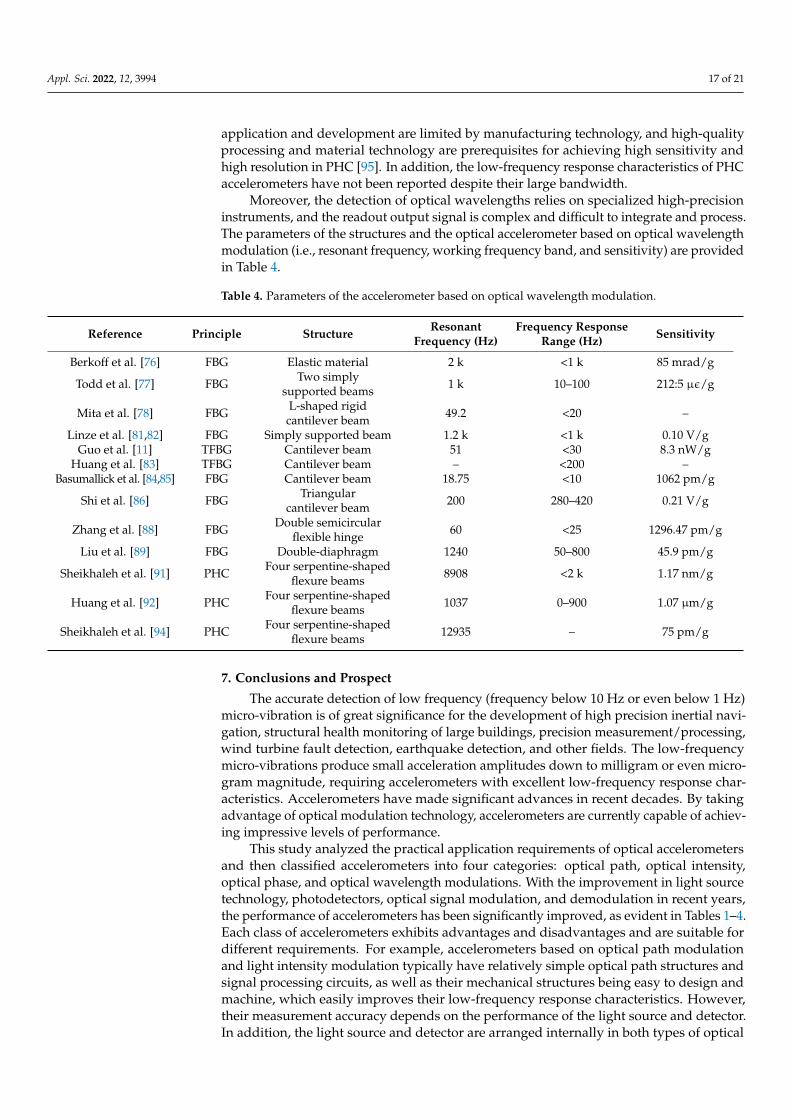
Appl. Sci. 2022, 12, 3994 17 of 21
application and development are limited by manufacturing technology, and high-qualityprocessing and material technology are prerequisites for achieving high sensitivity andhigh resolution in PHC [95]. In addition, the low-frequency response characteristics of PHCaccelerometers have not been reported despite their large bandwidth.
Moreover, the detection of optical wavelengths relies on specialized high-precisioninstruments, and the readout output signal is complex and difficult to integrate and process.The parameters of the structures and the optical accelerometer based on optical wavelengthmodulation (i.e., resonant frequency, working frequency band, and sensitivity) are providedin Table 4.
Table 4. Parameters of the accelerometer based on optical wavelength modulation.
Reference Principle Structure ResonantFrequency (Hz)
Frequency ResponseRange (Hz) Sensitivity
Berkoff et al. [76] FBG Elastic material 2 k <1 k 85 mrad/g
Todd et al. [77] FBG Two simplysupported beams 1 k 10–100 212:5 µε/g
Mita et al. [78] FBG L-shaped rigidcantilever beam 49.2 <20 –
Linze et al. [81,82] FBG Simply supported beam 1.2 k <1 k 0.10 V/gGuo et al. [11] TFBG Cantilever beam 51 <30 8.3 nW/g
Huang et al. [83] TFBG Cantilever beam – <200 –Basumallick et al. [84,85] FBG Cantilever beam 18.75 <10 1062 pm/g
Shi et al. [86] FBG Triangularcantilever beam 200 280–420 0.21 V/g
Zhang et al. [88] FBG Double semicircularflexible hinge 60 <25 1296.47 pm/g
Liu et al. [89] FBG Double-diaphragm 1240 50–800 45.9 pm/g
Sheikhaleh et al. [91] PHC Four serpentine-shapedflexure beams 8908 <2 k 1.17 nm/g
Huang et al. [92] PHC Four serpentine-shapedflexure beams 1037 0–900 1.07 µm/g
Sheikhaleh et al. [94] PHC Four serpentine-shapedflexure beams 12935 – 75 pm/g
7. Conclusions and Prospect
The accurate detection of low frequency (frequency below 10 Hz or even below 1 Hz)micro-vibration is of great significance for the development of high precision inertial navi-gation, structural health monitoring of large buildings, precision measurement/processing,wind turbine fault detection, earthquake detection, and other fields. The low-frequencymicro-vibrations produce small acceleration amplitudes down to milligram or even micro-gram magnitude, requiring accelerometers with excellent low-frequency response char-acteristics. Accelerometers have made significant advances in recent decades. By takingadvantage of optical modulation technology, accelerometers are currently capable of achiev-ing impressive levels of performance.
This study analyzed the practical application requirements of optical accelerometersand then classified accelerometers into four categories: optical path, optical intensity,optical phase, and optical wavelength modulations. With the improvement in light sourcetechnology, photodetectors, optical signal modulation, and demodulation in recent years,the performance of accelerometers has been significantly improved, as evident in Tables 1–4.Each class of accelerometers exhibits advantages and disadvantages and are suitable fordifferent requirements. For example, accelerometers based on optical path modulationand light intensity modulation typically have relatively simple optical path structures andsignal processing circuits, as well as their mechanical structures being easy to design andmachine, which easily improves their low-frequency response characteristics. However,their measurement accuracy depends on the performance of the light source and detector.In addition, the light source and detector are arranged internally in both types of optical

Appl. Sci. 2022, 12, 3994 18 of 21
accelerometers, making them complex, large, and heavy. The use of both types of opticalaccelerometers is suitable for applications wherein the size and mass requirements ofthe accelerometer are insensitive, such as precision active vibration isolation systems,structural health monitoring, and earthquake monitoring. Accelerometers based on opticalphase and wavelength modulations have also been extensively investigated in recentyears. The optical paths of these types of optical accelerometers are mostly arranged inoptical fibers, while the light source and detector are placed outside. In addition, themechanical structures of these two types of accelerometers are also mostly designed andprocessed using microelectromechanical techniques, with an overall compact structure andsmall size. However, these two types of accelerometers also have the problems of highcost and complicated output signal modulation and demodulation technology, and theconvenience of using them is different from the first two types. Therefore, these types ofaccelerometers can measure micron-level acceleration with high accuracy in mass- andsize-sensitive application scenarios, such as inertial navigation and wind turbine faultmonitoring. A summary of the performance of the four types of optical accelerometers isprovided in Table 5.
Table 5. Parameters of the four types of optical accelerometers.
Parameter Optical PathModulation
Optical IntensityModulation
Optical PhaseModulation
Optical WavelengthModulation
Optical displacementresolution µm–nm scale µm–nm scale nm scale nm scale
Characteristics Simple optical path structure, signal processingcircuits, and good low-frequency response
Compact structure, small size, and wide frequencyresponse range
Applications Active vibration isolation systems, structuralhealth monitoring, and earthquake monitoring
Inertial navigation and wind turbine faultmonitoring
Research on high-precision optical accelerometers will continue to flourish in the com-ing decades, focusing on the collaborative design of optical and mechanical components,the application of precision micromachining techniques, and the study of new opticalmeasurement technologies. The development of high-precision optical accelerometersshould be promoted toward high sensitivity, stability, integration, and anti-interferencecapability. Moreover, the application range of optical accelerometers should be broadenedto make them convenient and easy-to-use precision instruments instead of being limited tolaboratory application scenarios.
Author Contributions: Conceptualization, Y.-J.L. and R.-J.L.; methodology, L.-S.Z.; writing—originaldraft preparation, Y.-J.L.; writing—review and editing, R.-J.L., L.-S.Z. and P.-H.H.; funding acquisition,R.-J.L. and Q.-X.H. All authors have read and agreed to the published version of the manuscript.
Funding: This research was funded by the National Key R&D Program of China (2019YFB2004900)and the National Natural Science Foundation of China (52175506).
Institutional Review Board Statement: Not applicable.
Informed Consent Statement: Not applicable.
Data Availability Statement: Not applicable.
Conflicts of Interest: The authors declare no conflict of interest.
References1. Shivashankar, P.; Gopalakrishnan, S. Review on the use of piezoelectric materials for active vibration, noise, and flow control.
Smart Mater. Struct. 2020, 29, 053001. [CrossRef]2. Pramanik, R.; Arockiarajan, A. Effective properties and nonlinearities in 1-3 piezocomposites: A comprehensive review. Smart
Mater. Struct. 2019, 28, 103001. [CrossRef]3. D’Alessandro, A.; Scudero, S.; Vitale, G. A review of the capacitive MEMS for seismology. Sensors 2019, 19, 3093. [CrossRef] [PubMed]

Appl. Sci. 2022, 12, 3994 19 of 21
4. Giacci, F.; Dellea, S.; Langfelder, G. Signal integrity in capacitive and piezoresistive single-and multi-axis MEMS gyroscopesunder vibrations. Microelectron. Reliab. 2017, 75, 59–68. [CrossRef]
5. Kordas, K.; Pitkänen, O. Piezoresistive carbon foams in sensing applications. Front. Mater. 2019, 6, 93. [CrossRef]6. Liu, F.; Gao, S.; Niu, S.; Zhang, Y.; Guan, Y.; Gao, C.; Li, P. Optimal design of high-g MEMS piezoresistive accelerometer based on
Timoshenko beam theory. Microsyst. Technol. 2018, 24, 855–867. [CrossRef]7. Li, R.; Lei, Y.; Chang, Z.; Zhang, L.; Fan, K. Development of a high-sensitivity optical accelerometer for low-frequency vibration
measurement. Sensors 2018, 18, 2910. [CrossRef]8. Venkateshan, S.P. Mechanical Measurements; Springer: New York, NY, USA, 2015. [CrossRef]9. Noureldin, A.; Karamat, T.; Georgy, J. Fundamentals of Inertial Navigation, Satellite-Based Positioning and Their Integration, 1st ed.;
Springer: Berlin/Heidelberg, Germany, 2013. [CrossRef]10. Antunes, P.; Lima, H.; Alberto, N.; Rodrigues, H.; Pinto, P.; Pinto, J.; Nogueira, R.; Varum, H.; Costa, A.; Andre, P. Optical fiber
accelerometer system for structural dynamic monitoring. IEEE Sens. J. 2009, 9, 1347–1354. [CrossRef]11. Guo, T.; Shao, L.; Tam, H.; Krug, P.; Albert, J. Tilted fiber grating accelerometer incorporating an abrupt biconical taper for
cladding to core recoupling. Opt. Express 2009, 17, 20651–20660. [CrossRef]12. Rivin, E. Vibration isolation of precision equipment. Precis. Eng. 1995, 17, 41–56. [CrossRef]13. DeBra, D. Vibration isolation of precision machine tools and instruments. CIRP Ann. 1992, 41, 711–718. [CrossRef]14. Liu, J.; He, J. Research on measurement of low-frequency and micro-amplitude of vibration in active damping of platform. J. Univ.
Shanghai Sci. Technol. 2005, 27, 185–188. (In Chinese) [CrossRef]15. Salameh, J.; Cauet, S.; Etien, E.; Sakout, A.; Rambault, L. Gearbox condition monitoring in wind turbines: A review. Mech. Syst.
Signal Processing 2018, 111, 251–264. [CrossRef]16. Amirat, Y.; Benbouzid, M.; Al-Ahmar, E.; Bensaker, B.; Turri, S. A brief status on condition monitoring and fault diagnosis in
wind energy conversion systems. Renew. Sustain. Energy Rev. 2009, 13, 2629–2636. [CrossRef]17. Igba, J.; Alemzadeh, K.; Durugbo, C.; Henningsen, K. Performance assessment of wind turbine gearboxes using in-service data:
Current approaches and future trends. Renew. Sustain. Energy Rev. 2015, 50, 144–159. [CrossRef]18. Teng, W.; Ding, X.; Tang, S.; Xu, J.; Shi, B.; Liu, Y. Vibration analysis for fault detection of wind turbine drivetrains—A
comprehensive investigation. Sensors 2021, 21, 1686. [CrossRef]19. Clinton, J.; Heaton, T. Potential advantages of a strong-motion velocity meter over a strong-motion accelerometer. Seismol. Res.
Lett. 2002, 73, 332–342. [CrossRef]20. Chu, C.; Lin, C. Development of an optical accelerometer with a DVD pick-up head. Meas. Sci. Technol. 2005, 16, 2498. [CrossRef]21. Liu, Y.; Fan, K.; Chu, C.; Werner, A.; Gerd, J. Development of an optical accelerometer for low-frequency vibration using the voice
coil on a DVD pickup head. Meas. Sci. Technol. 2008, 19, 084012. [CrossRef]22. Li, R.; Chang, Z.; Lei, Y.; Cheng, Z.; Liu, X.; Fan, K.; Lv, J. A low-frequency micro accelerometer based on three-lobed leaf spring
and a focus probe. IEEE Photonics J. 2019, 11, 6800712. [CrossRef]23. Cheng, Z.; Liu, L.; Lei, Y.; Li, H.; Zhang, L.; Li, R.; Huang, Q. Modeling and improvement of a low-frequency micro-accelerometer.
Rev. Sci. Instrum. 2021, 92, 025002. [CrossRef] [PubMed]24. Li, R.; Xiang, M.; He, Y.; Fan, K.; Cheng, Z.; Huang, Q.; Zhou, B. Development of a high-precision touch-trigger probe using a
single sensor. Appl. Sci. 2016, 6, 86. [CrossRef]25. Zhang, L.; Long, Q.; Liu, Y.; Zhang, J.; Feng, Z. Correlation-steered scanning for scanning probe microscopes to overcome thermal
drift for ultra-long time scanning. Ultramicroscopy 2016, 166, 16–26. [CrossRef] [PubMed]26. Fan, K.; Li, R.; Xu, P. Design and verification of micro/nano-probes for coordinate measuring machines. Nanomanufacturing
Metrol. 2019, 2, 1–15. [CrossRef]27. Chu, C.L.; Lin, C.H.; Fan, K.C. Two-dimensional optical accelerometer based on commercial DVD pick-up head. Meas. Sci.
Technol. 2006, 18, 265–274. [CrossRef]28. Cheng, Z.; Liu, L.; Xu, P.; Li, R.; Fan, K.; Li, H.; Wei, Y. Modeling and Optimal Design for a High Stability 2D Optoelectronic
Angle Sensor. Sensors 2019, 19, 4409. [CrossRef]29. Lei, Y.; Li, R.; Chen, R.; Zhang, L.; Hu, P.; Huang, Q.; Fan, K. A high-precision two-dimensional micro-accelerometer for
low-frequency and micro-vibrations. Precis. Eng. 2021, 67, 419–427. [CrossRef]30. Fang, X.; Cao, M. Theoretical analysis of 2D acceleration laser sensor and several design parameters. Opt. Laser Technol. 2003, 35,
345–348. [CrossRef]31. Kalenik, J.; Pajak, R. A cantilever optical-fiber accelerometer. Sens. Actuators A 1998, 68, 350–355. [CrossRef]32. Barbosa, F.; Borin, F.; Arakaki, A.; Aguiar, J.; Chaves, C. A novel optical accelerometer. SBMO/IEEE MTT-S. In Proceedings of the
International Conference on Microwave and Optoelectronics, Brasilia, Brazil, 25 July 2005. [CrossRef]33. Lee, S.; Cho, D. Development of a micro-opto-mechanical accelerometer based on intensity modulation. Microsyst. Technol. 2004,
10, 147–154. [CrossRef]34. Llobera, A.; Seidemann, V.; Plaza, J.; Cadarso, V.; Buttgenbach, S. Integrated polymer optical accelerometer. IEEE Photonics Technol.
Lett. 2005, 17, 1262–1264. [CrossRef]35. Llobera, A.; Seidemann, V.; Plaza, J.; Cadarso, V.; Buttgenbach, S. SU-8 optical accelerometers. J. Microelectromech. Syst. 2007, 16,
111–121. [CrossRef]

Appl. Sci. 2022, 12, 3994 20 of 21
36. Schröpfer, G.; Elflein, W.; de Labachelerie, M.; Porte, H.; Ballandras, S. Lateral optical accelerometer micromachined in (100) siliconwith remote readout based on coherence modulation. Sens. Actuators A 1998, 68, 344–349. [CrossRef]
37. Cadarso, V.; Llobera, A.; Villanueva, G.; Seidemann, V.; Buttgenbach, S.; Plaza, J. Polymer microoptoelectromechanical systems:Accelerometers and variable optical attenuators. Sens. Actuators A 2008, 145, 147–153. [CrossRef]
38. Abbaspour-Sani, E.; Huang, R.; Kwok, C. A novel optical accelerometer. IEEE Electron Device Lett. 1995, 16, 166–168. [CrossRef]39. Wu, Y.; Kao, Y.; Chao, P.; Wey, C.; Sauter, T.; Eka, F.; Pandey, R. Design and Implementation of OLED Driving and OPD Readout
Circuitry for an Optical Vibration Sensor. IEEE Sens. 2018, 1–4. [CrossRef]40. Carr, D.; Sullivan, J.; Friedmann, T. Femtophotonics: Optical transducers utilizing novel subwavelength dual layer grating structure.
In Proceedings of the Solid-State Sensors, Actuators, and Microsystems Workshop, Hilton Head Island, SC, USA, 6–10 June 2004.[CrossRef]
41. Carr, D.; Sullivan, J.; Friedmann, T. Laterally deformable nanomechanical zeroth-order gratings: Anomalous diffraction studiedby rigorous coupled-wave analysis. Opt. Lett. 2003, 28, 1636–1638. [CrossRef]
42. Krishnamoorthy, U.; Olsson Iii, R.H.; Bogart, G.R.; Baker, M.; Carr, D.; Swiler, T.; Clews, P. In-plane MEMS-based nano-gaccelerometer with sub-wavelength optical resonant sensor. Sens. Actuators A 2008, 145, 283–290. [CrossRef]
43. Bramsiepe, S.; Loomes, D.; Middlemiss, R.; Paul, D.; Hammond, G. A high stability optical shadow sensor with applications forprecision accelerometers. IEEE Sens. J. 2018, 18, 4108–4116. [CrossRef]
44. Bochobza-Degani, O.; Seter, D.; Socher, E.; Nemirovsky, Y. Comparative study of novel micromachined accelerometers employingMIDOS. Sens. Actuators A 2000, 80, 91–99. [CrossRef]
45. Bochobza-Degani, O.; Seter, D.; Socher, E.; Nemirovsky, Y. Design and noise consideration of an accelerometer employingmodulated integrative differential optical sensing. Sens. Actuators A 2000, 84, 53–64. [CrossRef]
46. Middlemiss, R.; Samarelli, A.; Paul, D.; Hough, J.; Rowan, S.; Hammond, G. Measurement of the Earth tides with a MEMSgravimeter. Nature 2016, 531, 614–617. [CrossRef] [PubMed]
47. Tang, S.; Liu, H.; Yan, S.; Xu, X.; Wu, W.; Fan, J.; Liu, J.; Hu, C.; Tu, L. A high-sensitivity MEMS gravimeter with a large dynamicrange. Microsyst. Nanoeng. 2019, 5, 1–11. [CrossRef] [PubMed]
48. Duan, Y.; Wei, X.; Wang, H.; Zhao, M.; Ren, Z.; Zhao, H.; Ren, J. Design and numerical performance analysis of a microgravityaccelerometer with quasi-zero stiffness. Smart Mater. Struct. 2020, 29, 075018. [CrossRef]
49. Pechstedt, R.; Jackson, D. Design of a compliant-cylinder-type fiber-optic accelerometer: Theory and experiment. Appl. Opt. 1995,34, 3009–3017. [CrossRef]
50. Chen, C.; Ding, G.; Zhang, D.; Cui, Y.; Li, S. Michelson fiberoptic accelerometer. Rev. Sci. Instrum. 1998, 69, 3123–3126. [CrossRef]51. Chen, C.; Zhang, D.; Ding, G.; Cui, Y. Broadband Michelson fiber-optic accelerometer. Appl. Opt. 1999, 38, 628–630. [CrossRef]52. Chen, G.; Zhang, X.; Brambilla, G.; Newson, T. Theoretical and experimental demonstrations of a microfiber-based flexural disc
accelerometer. Opt. Lett. 2011, 36, 3669–3671. [CrossRef]53. Cranch, G.; Nash, P. High-responsivity fiber-optic flexural disk accelerometers. J. Lightwave Technol. 2000, 18, 1233. [CrossRef]54. Wu, X.; Wang, X.; Li, S.; Huang, S.; Ge, Q.; Yu, B. Cantilever fiber-optic accelerometer based on modal interferometer. IEEE
Photonics Technol. Lett. 2015, 27, 1632–1635. [CrossRef]55. Rivera, H.; García-Souto, J.; Sanz, J. Measurements of mechanical vibrations at magnetic cores of power transformers with
fiber-optic interferometric intrinsic sensor. IEEE J. Sel. Top. Quantum Electron. 2000, 6, 788–797. [CrossRef]56. Rochus, V.; Westerveld, W.J.; Figeys, B.; Figeys, B.; Rottenberg, X.; Jansen, R. Simulation and Design of an Optical Accelerometer.
In Proceedings of the 20th International Conference on Thermal, Mechanical and Multi-Physics Simulation and Experiments inMicroelectronics and Microsystems (EuroSimE), Hannover, Germany, 24–27 March 2019. [CrossRef]
57. Zeng, N.; Shi, C.; Zhang, M.; Wang, L.; Liao, Y.; Lai, S. A 3-component fiber-optic accelerometer for well logging. Opt. Commun.2004, 234, 153–162. [CrossRef]
58. Gerges, A.; Newson, T.; Jackson, D. Practical fiber-optic-based submicro-g accelerometer free from source and environmentalperturbations. Opt. Lett. 1989, 14, 1155–1157. [CrossRef]
59. Davies, E.; George, D.; Gower, M.; Holmes, A. MEMS Fabry–Pérot optical accelerometer employing mechanical amplification viaa V-beam structure. Sens. Actuators A 2014, 215, 22–29. [CrossRef]
60. Guzmán Cervantes, F.; Kumanchik, L.; Pratt, J.; Taylor, J. High sensitivity optomechanical reference accelerometer over 10 kHz.Appl. Phys. Lett. 2014, 104, 221111. [CrossRef]
61. Liu, B.; Zhong, Z.; Lin, J.; Wang, X.; Liu, L.; Shan, M.; Jin, P. Extrinsic Fabry–Pérot cantilever accelerometer based on micromachined45◦ angled fiber. J. Lightwave Technol. 2018, 36, 2196–2203. [CrossRef]
62. Han, J.; Zhang, W.; Wang, Z.; Sun, B.; Xu, B.; Li, F. Fiber optical accelerometer based on 45 degrees Fabry-Perot cavity. Adv. Sens.Syst. Appl. 2014, 9274, 927418. [CrossRef]
63. Lin, Q.; Chen, L.; Li, S.; Wu, X. A high-resolution fiber optic accelerometer based on intracavity phase-generated carrier (PGC)modulation. Meas. Sci. Technol. 2010, 22, 015303. [CrossRef]
64. Zhao, S.; Zhang, J.; Hou, C.; Bai, J.; Yang, G. Optical accelerometer based on grating interferometer with phase modulationtechnique. Appl. Opt. 2012, 51, 7005–7010. [CrossRef]
65. Zhao, S.; Hou, C.; Bai, J.; Yang, G.; Tian, F. Nanometer-scale displacement sensor based on phase-sensitive diffraction grating.Appl. Opt. 2011, 50, 1413–1416. [CrossRef]

Appl. Sci. 2022, 12, 3994 21 of 21
66. Lu, Q.; Bai, J.; Wang, K.; He, S. Design, optimization, and realization of a high-performance MOEMS accelerometer from adouble-device-layer SOI wafer. J. Microelectromech. Syst. 2017, 26, 859–869. [CrossRef]
67. Lu, Q.; Wang, C.; Bai, J.; Wang, K.; Lian, W.; Lou, S.; Jiao, X.; Yang, G. Subnanometer resolution displacement sensor based on agrating interferometric cavity with intensity compensation and phase modulation. Appl. Opt. 2015, 54, 4188–4196. [CrossRef]
68. Lu, Q.; Bai, J.; Wang, K.; Chen, P.; Fang, W.; Wang, C. Single Chip-based nano-optomechanical accelerometer based on subwave-length grating pair and rotated serpentine springs. Sensors 2018, 18, 2036. [CrossRef] [PubMed]
69. Zhang, T.; Liu, H.; Feng, L.; Wang, X.; Zhang, Y. Noise suppression of a micro-grating accelerometer based on the dual modulationmethod. Appl. Opt. 2017, 56, 10003–10008. [CrossRef]
70. Yao, Y.; Pan, D.; Wang, J.; Dong, T.; Guo, J.; Wang, C.; Geng, A.; Fang, W.; Lu, Q. Design and Modification of a High-ResolutionOptical Interferometer Accelerometer. Sensors 2021, 21, 2070. [CrossRef] [PubMed]
71. Hill, K.; Fujii, Y.; Johnson, D.; Kawasaki, B. Photosensitivity in optical fiber waveguides: Application to reflection filter fabrication.Appl. Phys. Lett. 1978, 32, 647–649. [CrossRef]
72. Kawasaki, B.; Hill, K.; Johnson, D.; Fujii, Y. Narrow-band Bragg reflectors in optical fibers. Opt. Lett. 1978, 3, 66–68. [CrossRef]73. Wang, X.; Guo, Y.; Xiong, L. Hybrid fiber Bragg grating sensor for vibration and temperature monitoring of a train bearing. Chin.
Opt. Lett. 2018, 16, 070604. [CrossRef]74. Wang, X.; Guo, Y.; Xiong, L.; Wu, H. High-frequency optical fiber Bragg grating accelerometer. IEEE Sens. J. 2018, 18, 4954–4960. [CrossRef]75. Guo, T.; Zhang, T.; Li, Y.; Qiao, X. Highly sensitive FBG seismometer with a 3D-printed hexagonal configuration. J. Lightwave
Technol. 2020, 38, 4588–4595. [CrossRef]76. Berkoff, T.; Kersey, A. Experimental demonstration of a fiber Bragg grating accelerometer. IEEE Photonics Technol. Lett. 1996, 8,
1677–1679. [CrossRef]77. Todd, M.; Johnson, G.; Althouse, B.; Vohra, S. Flexural beam-based fiber Bragg grating accelerometers. IEEE Photonics Technol.
Lett. 1998, 10, 1605–1607. [CrossRef]78. Mita, A.; Yokoi, I. Fiber Bragg grating accelerometer for buildings and civil infrastructures. Smart Structures and Materials 2001:
Smart Systems for Bridges, Structures, and Highways. Int. Soc. Opt. Photonics 2001, 4330, 479–486. [CrossRef]79. Weng, Y.; Qiao, X.; Guo, T.; Hu, M.; Feng, Z.; Wang, R.; Zhang, J. A robust and compact fiber Bragg grating vibration sensor for
seismic measurement. IEEE Sens. J. 2011, 12, 800–804. [CrossRef]80. Zeng, Y.; Wang, J.; Yang, H.; Ma, L. Fiber Bragg grating accelerometer based on L-shaped rigid beam and elastic diaphragm for
low-frequency vibration measurement. Acta Opt. Sin. 2015, 35, 1206005. [CrossRef]81. Linze, N.; Tihon, P.; Verlinden, O.; Mégret, P.; Wuilpart, M. Development of a multi-point polarization-based vibration sensor.
Opt. Express 2013, 21, 5606–5624. [CrossRef]82. Linze, N.; Tihon, P.; Verlinden, O.; Mégret, P.; Wuilpart, M. Linearity considerations in polarization-based vibration sensors. Appl.
Opt. 2012, 51, 6997–7004. [CrossRef]83. Huang, Y.; Guo, T.; Lu, C.; Tam, H. VCSEL-based tilted fiber grating vibration sensing system. IEEE Photonics Technol. Lett. 2010,
22, 1235–1237. [CrossRef]84. Basumallick, N.; Chatterjee, I.; Biswas, P.; Dasgupta, K.; Bandyopadhyay, S. Fiber Bragg grating accelerometer with enhanced
sensitivity. Sens. Actuators A 2012, 173, 108–115. [CrossRef]85. Basumallick, N.; Biswas, P.; Dasgupta, K.; Bandyopadhyay, S. Design optimization of fiber Bragg grating accelerometer for
maximum sensitivity. Sens. Actuators A 2013, 194, 31–39. [CrossRef]86. Shi, C.; Zeng, N.; Ho, H.; Chan, C.; Zhang, M.; Jin, W.; Liao, Y. Cantilever optical vibrometer using fiber Bragg grating. Opt. Eng.
2003, 42, 3179–3181. [CrossRef]87. Yu, Y.; Tam, H.; Chung, W.; Demokan, M. Fiber Bragg grating sensor for simultaneous measurement of displacement and
temperature. Opt. Lett. 2000, 25, 1141–1143. [CrossRef] [PubMed]88. Zhang, X.; Rong, Q.; Sun, H.; Yang, S.; Yuan, L.; Hu, M. Low-frequency fiber Bragg grating accelerometer based on a double-
semicircle cantilever. Opt. Fiber Technol. 2014, 20, 190–193. [CrossRef]89. Liu, Q.; Qiao, X.; Fu, H.; Gao, H.; Yu, D. Large frequency range and high sensitivity fiber Bragg grating accelerometer based on
double diaphragms. IEEE Sens. J. 2014, 14, 1499–1504. [CrossRef]90. Joannopoulos, J.; Villeneuve, P.; Fan, S. Photonic crystals: Putting a new twist on light. Nature 1997, 386, 143–149. [CrossRef]91. Sheikhaleh, A.; Abedi, K.; Jafari, K. A proposal for an optical MEMS accelerometer relied on wavelength modulation with one
dimensional photonic crystal. J. Lightwave Technol. 2016, 34, 5244–5249. [CrossRef]92. Huang, K.; Nie, Y.; Liu, Y.; Liu, P.; Cao, L.; Wang, Q.; Li, J. A proposal for a high-sensitivity optical MEMS accelerometer with a
double-mode modulation system. J. Lightwave Technol. 2021, 39, 303–309. [CrossRef]93. Hosseinzadeh Sani, M.; Saghaei, H.; Mehranpour, M.; Asgariyan Tabrizi, A. A novel all-optical sensor design based on a tunable
resonant nanocavity in photonic crystal microstructure applicable in MEMS accelerometers. Photonic Sens. 2021, 11, 457–471. [CrossRef]94. Sheikhaleh, A.; Abedi, K.; Jafari, K. An optical MEMS accelerometer based on a two-dimensional photonic crystal add-drop filter.
J. Lightwave Technol. 2017, 35, 3029–3034. [CrossRef]95. Malayappan, B.; Lakshmi, U.; Rao, B.; Ramaswamy, K.; Pattnaik, P. Sensing Techniques and Interrogation Methods in Optical
MEMS Accelerometers: A Review. IEEE Sens. J. 2022, 22, 6232–6246. [CrossRef]