MOCA: A Low-Power, Low-Cost Motion Capture System Based on Integrated Accelerometers
11
Hindawi Publishing Corporation Advances in Multimedia Volume 2007, Article ID 82638, 11 pages doi:10.1155/2007/82638 Research Article MOCA: A Low-Power, Low-Cost Motion Capture System Based on Integrated Accelerometers Elisabetta Farella, 1 Luca Benini, 1 Bruno Ricc ` o, 1 and Andrea Acquaviva 2 1 Dipartimento di Elettronica, Informatica e Sistemistica (DEIS), Universit´ a di Bologna, Viale Risorgimento 2, 40136 Bologna, Italy 2 Information Science and Technology Institute (ISTI), University of Urbino, Piazza Repubblica 13, 61029 Urbino, Italy Received 5 September 2006; Revised 18 January 2007; Accepted 8 March 2007 Recommended by Yong Pei Human-computer interaction (HCI) and virtual reality applications pose the challenge of enabling real-time interfaces for natu- ral interaction. Gesture recognition based on body-mounted accelerometers has been proposed as a viable solution to translate patterns of movements that are associated with user commands, thus substituting point-and-click methods or other cumbersome input devices. On the other hand, cost and power constraints make the implementation of a natural and efficient interface suitable for consumer applications a critical task. Even though several gesture recognition solutions exist, their use in HCI context has been poorly characterized. For this reason, in this paper, we consider a low-cost/low-power wearable motion tracking system based on integrated accelerometers called motion capture with accelerometers (MOCA) that we evaluated for navigation in virtual spaces. Recognition is based on a geometric algorithm that enables efficient and robust detection of rotational movements. Our objective is to demonstrate that such a low-cost and a low-power implementation is suitable for HCI applications. To this purpose, we characterized the system from both a quantitative point of view and a qualitative point of view. First, we performed static and dynamic assessment of movement recognition accuracy. Second, we evaluated the effectiveness of user experience using a 3D game application as a test bed. Copyright © 2007 Elisabetta Farella et al. This is an open access article distributed under the Creative Commons Attribution License, which permits unrestricted use, distribution, and reproduction in any medium, provided the original work is properly cited. 1. INTRODUCTION Motion tracking is a key enabling technology that is nowa- days widely applied into research and commercial fields ranging from human-computer interaction to robot navi- gation, virtual and augmented reality. Tracking systems are now a mature technology [1] for being used in ambient in- telligence applications to provide users with personalized ser- vices depending on their location or position. They are also used in augmented reality applications to generate virtual scenes depending on the user point of view. Recently, tracking of human gestures has been extensively studied to promote human-like input interfaces to machines. In particular, virtual reality (VR) applications and immer- sive games critically require natural human-computer inter- faces (HCIs), which reduce the gap between virtual-world and real-world interactions. For instance, in learning or gam- ing applications where navigation in virtual environments is needed, the effectiveness of the user experience depends not only on the rendering quality but also on the interac- tion with the system. A successful HCI system must guaran- tee real-time feedback to the user and be neither intrusive nor cumbersome [2]. Furthermore, to allow deployment on commercial-off-the-shelf computer systems, it must be de- signed with commodity components. Most of the research on motion tracking is concerned with the design of highly accurate and expensive systems for absolute positioning in space. Some specific tracking tasks, such as gesture recognition, do not require high precision in absolute positioning, and currently available commercial systems based on electromagnetic and optical sensors are too expensive for consumer products. Accelerometer-based sensing methods are a promising technology for low-cost motion capture systems [2, 3], since they can be implemented with low-power integrated com- ponents. Furthermore, unlike more accurate tracking tech- niques based on optical or movement sensors [4–6], they do not require video cameras, making them more suitable for mobile interaction. In fact, in a virtual or augmented real- ity environment, the user may want to move around without bounds to interact with virtual objects.
Transcript of MOCA: A Low-Power, Low-Cost Motion Capture System Based on Integrated Accelerometers
Hindawi Publishing CorporationAdvances in MultimediaVolume 2007, Article ID 82638, 11 pagesdoi:10.1155/2007/82638
Research ArticleMOCA: A Low-Power, Low-Cost Motion Capture SystemBased on Integrated Accelerometers
Elisabetta Farella,1 Luca Benini,1 Bruno Ricco,1 and Andrea Acquaviva2
1 Dipartimento di Elettronica, Informatica e Sistemistica (DEIS), Universita di Bologna, Viale Risorgimento 2, 40136 Bologna, Italy2 Information Science and Technology Institute (ISTI), University of Urbino, Piazza Repubblica 13, 61029 Urbino, Italy
Received 5 September 2006; Revised 18 January 2007; Accepted 8 March 2007
Recommended by Yong Pei
Human-computer interaction (HCI) and virtual reality applications pose the challenge of enabling real-time interfaces for natu-ral interaction. Gesture recognition based on body-mounted accelerometers has been proposed as a viable solution to translatepatterns of movements that are associated with user commands, thus substituting point-and-click methods or other cumbersomeinput devices. On the other hand, cost and power constraints make the implementation of a natural and efficient interface suitablefor consumer applications a critical task. Even though several gesture recognition solutions exist, their use in HCI context has beenpoorly characterized. For this reason, in this paper, we consider a low-cost/low-power wearable motion tracking system based onintegrated accelerometers called motion capture with accelerometers (MOCA) that we evaluated for navigation in virtual spaces.Recognition is based on a geometric algorithm that enables efficient and robust detection of rotational movements. Our objectiveis to demonstrate that such a low-cost and a low-power implementation is suitable for HCI applications. To this purpose, wecharacterized the system from both a quantitative point of view and a qualitative point of view. First, we performed static anddynamic assessment of movement recognition accuracy. Second, we evaluated the effectiveness of user experience using a 3D gameapplication as a test bed.
Copyright © 2007 Elisabetta Farella et al. This is an open access article distributed under the Creative Commons AttributionLicense, which permits unrestricted use, distribution, and reproduction in any medium, provided the original work is properlycited.
1. INTRODUCTION
Motion tracking is a key enabling technology that is nowa-days widely applied into research and commercial fieldsranging from human-computer interaction to robot navi-gation, virtual and augmented reality. Tracking systems arenow a mature technology [1] for being used in ambient in-telligence applications to provide users with personalized ser-vices depending on their location or position. They are alsoused in augmented reality applications to generate virtualscenes depending on the user point of view.
Recently, tracking of human gestures has been extensivelystudied to promote human-like input interfaces to machines.In particular, virtual reality (VR) applications and immer-sive games critically require natural human-computer inter-faces (HCIs), which reduce the gap between virtual-worldand real-world interactions. For instance, in learning or gam-ing applications where navigation in virtual environmentsis needed, the effectiveness of the user experience dependsnot only on the rendering quality but also on the interac-tion with the system. A successful HCI system must guaran-
tee real-time feedback to the user and be neither intrusivenor cumbersome [2]. Furthermore, to allow deployment oncommercial-off-the-shelf computer systems, it must be de-signed with commodity components.
Most of the research on motion tracking is concernedwith the design of highly accurate and expensive systems forabsolute positioning in space. Some specific tracking tasks,such as gesture recognition, do not require high precisionin absolute positioning, and currently available commercialsystems based on electromagnetic and optical sensors are tooexpensive for consumer products.
Accelerometer-based sensing methods are a promisingtechnology for low-cost motion capture systems [2, 3], sincethey can be implemented with low-power integrated com-ponents. Furthermore, unlike more accurate tracking tech-niques based on optical or movement sensors [4–6], they donot require video cameras, making them more suitable formobile interaction. In fact, in a virtual or augmented real-ity environment, the user may want to move around withoutbounds to interact with virtual objects.
2 Advances in Multimedia
In this work, we focus on a low-cost motion capture in-terface system targeted to the navigation in virtual interac-tive environment called motion capture with accelerometers(MOCA) [7]. This recognition technology has been used toimplement a body sensor network targeted to human posturerecognition [1]. In this paper, the objective is to demonstrate,through extensive user experience characterization, that ourlow-cost, low-power while robust motion recognition systemis valuable to implement human-like interaction. We selecteda subset of the possible recognizable postures using a singlenode to test the effectiveness of the recognition algorithm.This choice has been made to characterize the recognitionperformance independently from network and synchroniza-tion issues.
The system is based on commodity components such asintegrated accelerometers and completed by many softwareparts. The main features of the system are (i) a low-cost andlow-power implementation providing easy deployment andwearability; (ii) an optimized data acquisition process; (iii)a lightweight and efficient position and motion recognitionsoftware. It is driven by a geometrical tracking algorithm,that guarantees robustness with respect to drift problemstypical of solutions based on integration of acceleration data[2, 8, 9]. All these characteristics make the MOCA systemsuitable to interactive environments and allow its implemen-tation on resource-constrained devices such as PDAs.
The recognition process works as follows. Data transmit-ted by sensing units are sampled and collected by an acqui-sition/control board that communicates to the machine run-ning the virtual world by means of a serial link. The limitedsize and weight of the acquisition board make it suitable tobe installed on a palmtop computer or PDA, providing un-constrained mobility. Communication between sensing unitsand the acquisition board takes place by means of a ded-icated wired link. However, a fully wireless solution whereboth sensing unit and acquisition board are provided withRF interface has also been developed [10]. In both cases, thecost of the interface hardware is around $100 (even in smallvolume prototyping). In this scenario, the palmtop computermay represent a preprocessing stage for final interaction toa remote sensor fusion system for ambient intelligence orlocation-aware applications. On the other hand, it may rep-resent the target system if low-end interactive applicationsare running on it (e.g., games).
We performed a number of tests to verify accuracy, powerconsumption, and performance of our system. Even if ac-celeration sensors can be placed anywhere on the body, weperformed tests using representative rotational movementsof the hand. We obtained a static accuracy of 3 degreesfor different contiguous orientations. With regard to dy-namic characteristics, our system is suitable to detect hu-man body movements for HCI applications, that are typicallycharacterized by an angular velocity of around 3 radians/s.Power consumption measurements show that the systemcan operate continuously at least for 12 hours with 100 g,750 mAh batteries. For the wireless prototype we followedthe same low-cost/low-power design guide, additional powerconsumption being only 15% [1]. Our system has been also
extensively tested in the field. First, the performance of theinterface in terms of response time and movement loss hasbeen analyzed. Then, a 3D game was used as a test bed toevaluate usability and user experiences.
The contribution of this work is thus twofold. First,we demonstrate that a low-cost, low-power motion track-ing solution based on integrated accelerometers and onlightweight, efficient, and robust motion tracking algorithmprovides an accuracy suitable for HCI applications. Second,we present the results of extensive characterization on thefield through the evaluation of human experience with realapplications.
2. RELATED WORK
Motion tracking has been studied in many fields and a varietyof solutions have been proposed depending on the targetedapplication requirements [10].
2.1. Motion tracking solutions
For human-computer interaction (HCI), which aims at build-ing natural perceptual user interfaces, human motion track-ing is used to ease the interactions with machines and toenhance the mobility of portable devices. The design of in-terfaces for natural human-computer interaction is a criticalresearch problem that has been addressed in different waysdepending on the targeted systems and applications [11].Several studies have been performed to design unobtrusiveinput interfaces for wearable computers [2, 3, 12, 13]. Infact, these devices cannot be equipped with traditional inputdevices like keyboards and mice for mobility reasons. In thisfield various modalities are investigated: gesture, gaze, facialexpressions as they occur in human-human communication.Gesture recognition systems have lower accuracy and jitterrequirements compared to other applications where motiontracking is applied such as robotic and augmented reality[14–25]. Instead power consumption and cost are the mostcritical factors. For these reasons, previous solutions are notwell suited to these kinds of applications. The purpose oftracking in this context is to recognize a set of movementsindicating commands. Thus, the accuracy affects just thenumber of different commands that can be distinguished.
Both vision-based and accelerometer-based techniqueshave been proposed for gesture recognition [14, 17, 26]. Onegeneral weakness of optical tracking systems is that theremust be line of sight between the camera and the tracked ob-ject. Another drawback of the optical method is its strongdependency on environmental luminance. In addition, it isdifficult to use this tracking system for real-time applica-tions since the system needs postprocessing of the data to ex-tract motion information. Moreover, commercially availableproducts adopting these kinds of techniques are currently tooexpensive for consumer applications [27]. The motes pre-sented in [28] are a very interesting solution in terms of wear-ability, since they are tiny and modular. However, at presentthey are not optimized for a particular application scenario,such as movement tracking and gesture recognition.
Elisabetta Farella et al. 3
Accelerometer-based solutions, even though less accuratethan optical tracking, are a promising alternative for gesturerecognition in mobile environments. Commercial systemsbased on inertial sensors [29, 30] are in many cases accurateenough for HCI domain, but still expensive (also because be-ing sold in pair with dedicated software), even if the cost isgenerally lower compared with multicamera-based motiontrackers. For these commercial solutions, the bridge betweensensors on body and the gateway is wireless, but cables arestill present among the units worn by the user, limiting us-ability.
Several academic projects propose various types of inputhardware [3, 9, 12]. The work of Bang et al. [27] is a dedicatedsolution consisting of a pen system based on accelerometersand gyroscopes. The system is used for recognizing hand-writing motion in 2D and 3D spaces. One major problemfaced in [9] is the compensation for inaccuracies in positionand orientation detection due to the integration process. Thisproblem is common to most of the accelerometer-based so-lutions we analyzed. Different approaches have been evalu-ated to face it, ranging from Kalman filtering [2], usage ofsecondary sensors [8] to compensation techniques exploitingexternal measurements or introducing reinitialization, as ithappens in [9] where the zero-velocity compensation (ZVC)technique is exploited. This technique is not tailored to theinteraction with virtual environments.
A microaccelerometer-based interface for interaction withmixed reality in wearable computers has been presented byCheok et al. [2]. Accelerometers are mounted on variouskinds of input devices: a pen and a tilt and gesture pad. Theyprovide 3D information about motion of the body part onwhich they are worn. Authors present a detailed testing ofthe filtering approach they exploited to reduce position andvelocity measurement errors caused by the integration step.Results obtained show that filtering helps reducing eventhough not eliminating the measurement error. Moreover,the application of a complex filtering step may consistentlydegrade the dynamic performance of the recognition. Forthis reason, the applicability of this approach to interactiveinput systems is still not proven.
Motion tracking with accelerometers can be used also forinteraction with intelligent environments, as shown in a re-cent work by Wilson and Shafer [8]. This approach envi-sions the collaboration between a hand-held sensor (a wandcalled XWand) system with the external environment (e.g., aliving room) to let the user control intelligent devices. Thepresented system exploits an infrared link to point the de-vice to be controlled, then uses gesture recognition to con-trol it. Position information is computed using integrationof sensor data and gesture mapping is performed exploitingthe knowledge of interaction context. A set of gestures maybe significant only for that particular device pointed by thewand.
Gesture processing systems have been designed for inter-action with VR systems using immersive 3D displays (suchas for navigation in virtual theaters) [5, 33]. They are mainlytargeted to particular movement, such as the sentient floor[31] and the SenToy doll [6].
Sensing unit Acquisition unit
Lab prototypes
RS232 · · ·
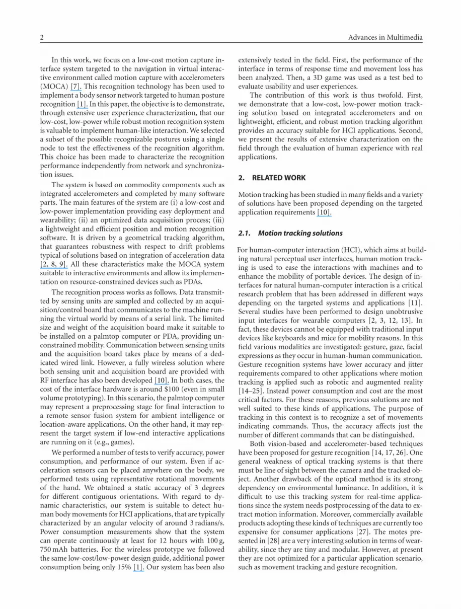
Figure 1: The gesture recognition interface can interact with vari-ous hardware targets.
2.2. The MOCA solution
The motion tracking system described in this paper targetsgesture recognition for interaction with a virtual environ-ment. The main characteristics of the motion capture systemare the following: consumer, low-power and wearable hard-ware; low-complexity position recognition algorithm (tilt-based) with high dynamic performance suitable for interac-tive systems. In our system, accelerometers are used to rec-ognize inclinations of human body. In our example applica-tion we used two accelerometers to recognize the arm posi-tion and movements.
Main contribution of this work with respect to the stateof the art is the followings. First, we do not perform integra-tion on the accelerometer data, instead we rely on a geomet-rical approach based on tilt. We use this approach to computeinclination with respect to gravity since we do not need infor-mation on absolute position, which can be obtained throughdouble integration. Our approach eliminates the need forcompensating for the error introduced by the integrationstep common to the techniques described before [2, 8, 9].This is a critical advantage since noise cancellation from dou-ble integration is an extremely challenging task, for whichno general solution is known. In addition, the reduced com-putational complexity makes our system more suitable formobile devices with limited computational resources such aspalmtop computers.
The second distinction concerns the qualitative assess-ment. In our work, we targeted the evaluation of gesturerecognition effectiveness for interaction with VR applica-tions like 3D games. Instead of just focusing on accelerom-eter accuracy, we provide a full evaluation of user experienceby measuring the number of recognized movements for dif-ferent user behaviors.
3. GENERAL SYSTEM ARCHITECTURE
The general system architecture is composed of a fixed sys-tem back end and a flexible and reconfigurable front end(Figure 1).
The system back end consists of (i) the MOCA prototype(one acquisition board and up to four sensing units) (ii) theMOCA interface, and (iii) the implementation of the track-ing algorithm. It is responsible for collecting and interpretingdata (from basic driver operation, to position recognition or
4 Advances in Multimedia
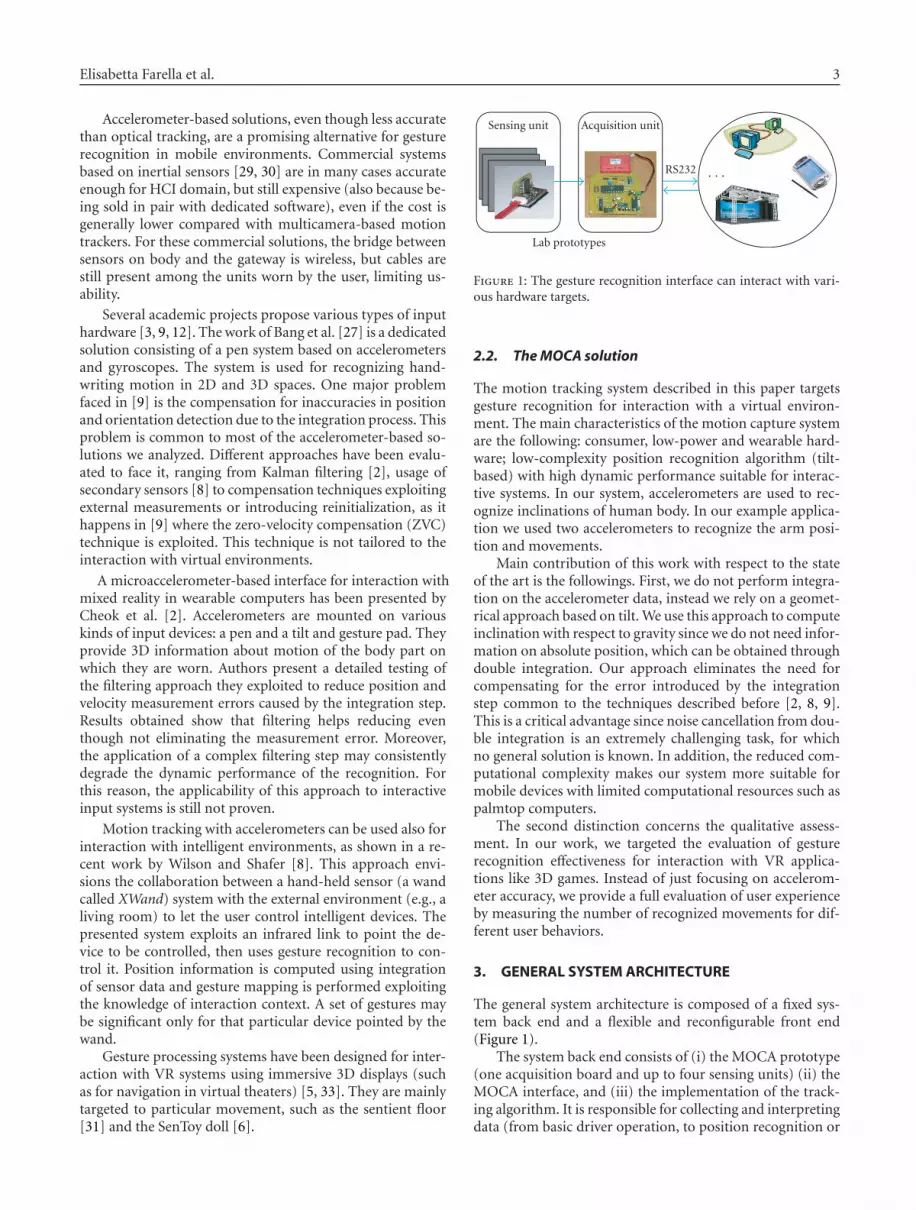
z
x
y
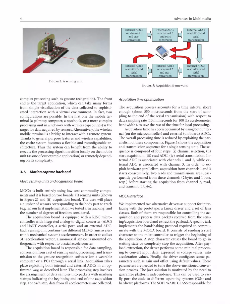
Figure 2: A sensing unit.
complex processing such as gesture recognition). The frontend is the target application, which can take many formsfrom simple visualization of the data collected to sophisti-cated interaction with a virtual environment. In fact, twoconfigurations are possible. In the first one the mobile ter-minal (a palmtop computer, a notebook, or a more complexprocessing unit in a network with wireless capabilities) is thetarget for data acquired by sensors. Alternatively, the wirelessmobile terminal is a bridge to interact with a remote system.Thanks to general purpose features and wireless capabilities,the entire system becomes a flexible and reconfigurable ar-chitecture. Thus the system can benefit from the ability toexecute the processing algorithm either locally on the mobileunit (as one of our example application) or remotely depend-ing on its complexity.
3.1. Motion capture back end
Moca sensing units and acquisition board
MOCA is built entirely using low-cost commodity compo-nents and it is based on two boards: (i) sensing units (shownin Figure 2) and (ii) acquisition board. The user will placea number of sensors corresponding to the body part to track(e.g., in our first implementation we tested arm tracking) andthe number of degrees of freedom considered.
The acquisition board is equipped with a RISC micro-controller with integrated analog-to-digital converter (ADC)and UART controller, a serial port, and an external ADC.Each sensing unit contains two different MEMS (micro elec-tronic mechanical system) accelerometers. In order to collect3D acceleration vector, a monoaxial sensor is mounted or-thogonally with respect to biaxial accelerometer.
The acquisition board is responsible for data sampling,conversion from a set of sensing units, processing, and trans-mission to the gesture recognition software (on a wearablecomputer or a PC) through a serial link. Acquisition takesplace exploiting both internal and external ADCs in an op-timized way, as described later. The processing step involvesthe arrangement of data samples into packets with markingstamps indicating the beginning and end of one acquisitionstep. For each step, data from all accelerometers are collected.
Internal ADC:set channel 1
and startconversion
External ADC:set channel 3
and startconversion
External ADC:read ADC and
serialtransmission
Internal ADC:read ADC and
serialtransmission
Internal ADC:set channel 2
and startconversion
Internal ADC:read ADC and
serialtransmission
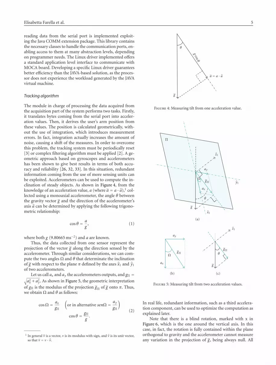
Figure 3: Acquisition framework.
Acquisition time optimization
The acquisition process accounts for a time interval shortenough (about 350 microseconds from the start of sam-pling to the end of the serial transmission) with respect todata sampling rate (10 milliseconds for 100 Hz accelerometerbandwidth), to save the rest of the time for local processing.
Acquisition time has been optimized by using both inter-nal (on the microcontroller) and external (on board) ADCs.The overall processing time is reduced by exploiting the par-allelism of these components. Figure 3 shows the acquisitionand transmission sequence for a single sensing unit. The se-quence is composed of four steps: (i) channel selection, (ii)start acquisition, (iii) read ADC, (iv) serial transmission. In-ternal ADC is associated with channels 1 and 2, while ex-ternal ADC is associated with channel 3. In order to ex-ploit hardware parallelism, acquisition from channels 1 and 3starts consecutively. Two reads and transmissions are subse-quently performed from these channels (2 bytes and 1 byte,resp.) before starting the acquisition from channel 2, read,and transmit (1 byte).
MOCA interface
We implemented two alternative drivers as support for inter-facing with the prototype: a Linux driver and a set of Javaclasses. Both of them are responsible for controlling the ac-quisition and process data packets received from the sens-ing/acquisition board and extract the payload. A specific taskimplements the handshaking protocol required to commu-nicate with the MOCA board. It consists of sending a startcharacter to the microcontroller to trigger the beginning ofthe acquisition. A stop character causes the board to go inwaiting state or completely stop the acquisition. After pay-load extraction, the driver performs some minimal process-ing to convert input data, expressed as voltage values, intoacceleration values. Finally, the driver configures some pa-rameters such as gain and offset using default values. Theseparameters are needed to tune the above-mentioned conver-sion process. The Java solution is motivated by the need toguarantee platform independence. This can be used to eas-ily port the code to different operating systems (OSs) andhardware platforms. The SOFTWARE CLASS responsible for
Elisabetta Farella et al. 5
reading data from the serial port is implemented exploit-ing the Java COMM extension package. This library containsthe necessary classes to handle the communication ports, en-abling access to them at many abstraction levels, dependingon programmer needs. The Linux driver implemented offersa standard application level interface to communicate withMOCA board. Developing a specific Linux driver guaranteesbetter efficiency than the JAVA-based solution, as the proces-sor does not experience the workload generated by the JAVAvirtual machine.
Tracking algorithm
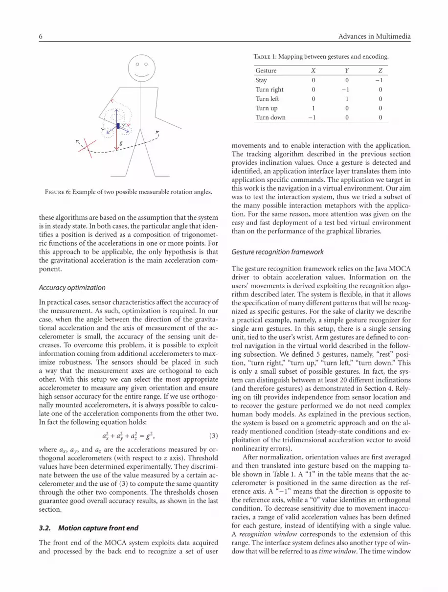
The module in charge of processing the data acquired fromthe acquisition part of the system performs two tasks. Firstly,it translates bytes coming from the serial port into acceler-ation values. Then, it derives the user’s arm position fromthese values. The position is calculated geometrically, with-out the use of integration, which introduces measurementerrors. In fact, integration actually increases the amount ofnoise, causing a shift of the measures. In order to overcomethis problem, the tracking system must be periodically reset[3] or complex filtering algorithm must be applied [2]. A ge-ometric approach based on gyroscopes and accelerometershas been shown to give best results in terms of both accu-racy and reliability [26, 32, 33]. In this situation, redundantinformation coming from the use of more sensing units canbe exploited. Accelerometers can be used to compute the in-clination of steady objects. As shown in Figure 4, from theknowledge of an acceleration value, a (where a = a · a),1 col-lected using a monoaxial accelerometer, the angle θ betweenthe gravity vector g and the direction of the accelerometer’saxis a can be determined by applying the following trigono-metric relationship:
cos θ = a
g, (1)
where both g (9.80665 ms−2) and a are known.Thus, the data collected from one sensor represent the
projection of the vector g along the direction sensed by theaccelerometer. Through similar considerations, we can com-pute the two angles Ω and θ that determinate the inclinationof g with respect to the plane π defined by the axes x1 and y1
of two accelerometers.Let us call ax and ay the accelerometers outputs, and gΠ =
√
a2x + a2
y . As shown in Figure 5, the geometric interpretation
of gΠ is the modulus of the projection gΠ of g onto π. Thus,we obtain Ω and θ as follows:
cosΩ = axgΠ
(
or in alternative senΩ = aygΠ
)
cos θ = gΠg.
(2)
1 In general v is a vector, v is its modulus with sign, and v is its unit vector,so that v = v · v.
g
a = a · a
θ
gcos θ
Figure 4: Measuring tilt from one acceleration value.
Π
g
Ω
ax
gΠ
θ
x1
z1
y1
ay
(a)
ΩgΠ
ay
ax
(b)
θ
g
gΠ
z1
(c)
Figure 5: Measuring tilt from two acceleration values.
In real life, redundant information, such as a third accelera-tion component, can be used to optimize the computation asexplained later.
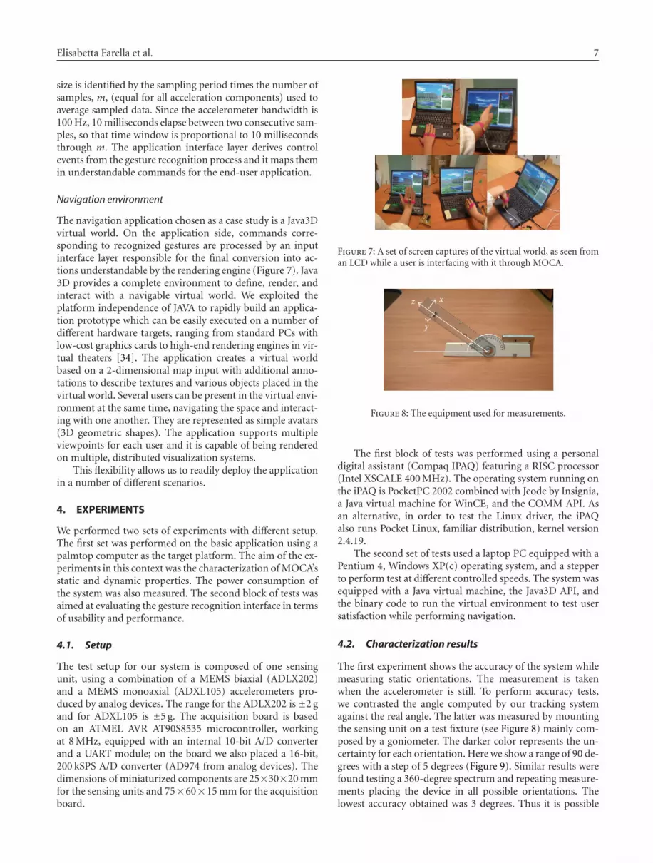
Note that there is a blind rotation, marked with x inFigure 6, which is the one around the vertical axis. In thiscase, in fact, the rotation is fully contained within the planeorthogonal to gravity and the accelerometer cannot measureany variation in the projection of g, being always null. All
6 Advances in Multimedia
g
Figure 6: Example of two possible measurable rotation angles.
these algorithms are based on the assumption that the systemis in steady state. In both cases, the particular angle that iden-tifies a position is derived as a composition of trigonomet-ric functions of the accelerations in one or more points. Forthis approach to be applicable, the only hypothesis is thatthe gravitational acceleration is the main acceleration com-ponent.
Accuracy optimization
In practical cases, sensor characteristics affect the accuracy ofthe measurement. As such, optimization is required. In ourcase, when the angle between the direction of the gravita-tional acceleration and the axis of measurement of the ac-celerometer is small, the accuracy of the sensing unit de-creases. To overcome this problem, it is possible to exploitinformation coming from additional accelerometers to max-imize robustness. The sensors should be placed in sucha way that the measurement axes are orthogonal to eachother. With this setup we can select the most appropriateaccelerometer to measure any given orientation and ensurehigh sensor accuracy for the entire range. If we use orthogo-nally mounted accelerometers, it is always possible to calcu-late one of the acceleration components from the other two.In fact the following equation holds:
a2x + a2
y + a2z = g2, (3)
where ax, ay , and az are the accelerations measured by or-thogonal accelerometers (with respect to z axis). Thresholdvalues have been determined experimentally. They discrimi-nate between the use of the value measured by a certain ac-celerometer and the use of (3) to compute the same quantitythrough the other two components. The thresholds chosenguarantee good overall accuracy results, as shown in the lastsection.
3.2. Motion capture front end
The front end of the MOCA system exploits data acquiredand processed by the back end to recognize a set of user
Table 1: Mapping between gestures and encoding.
Gesture X Y Z
Stay 0 0 −1
Turn right 0 −1 0
Turn left 0 1 0
Turn up 1 0 0
Turn down −1 0 0
movements and to enable interaction with the application.The tracking algorithm described in the previous sectionprovides inclination values. Once a gesture is detected andidentified, an application interface layer translates them intoapplication specific commands. The application we target inthis work is the navigation in a virtual environment. Our aimwas to test the interaction system, thus we tried a subset ofthe many possible interaction metaphors with the applica-tion. For the same reason, more attention was given on theeasy and fast deployment of a test bed virtual environmentthan on the performance of the graphical libraries.
Gesture recognition framework
The gesture recognition framework relies on the Java MOCAdriver to obtain acceleration values. Information on theusers’ movements is derived exploiting the recognition algo-rithm described later. The system is flexible, in that it allowsthe specification of many different patterns that will be recog-nized as specific gestures. For the sake of clarity we describea practical example, namely, a simple gesture recognizer forsingle arm gestures. In this setup, there is a single sensingunit, tied to the user’s wrist. Arm gestures are defined to con-trol navigation in the virtual world described in the follow-ing subsection. We defined 5 gestures, namely, “rest” posi-tion, “turn right,” “turn up,” “turn left,” “turn down.” Thisis only a small subset of possible gestures. In fact, the sys-tem can distinguish between at least 20 different inclinations(and therefore gestures) as demonstrated in Section 4. Rely-ing on tilt provides independence from sensor location andto recover the gesture performed we do not need complexhuman body models. As explained in the previous section,the system is based on a geometric approach and on the al-ready mentioned condition (steady-state conditions and ex-ploitation of the tridimensional acceleration vector to avoidnonlinearity errors).
After normalization, orientation values are first averagedand then translated into gesture based on the mapping ta-ble shown in Table 1. A “1” in the table means that the ac-celerometer is positioned in the same direction as the ref-erence axis. A “−1” means that the direction is opposite tothe reference axis, while a “0” value identifies an orthogonalcondition. To decrease sensitivity due to movement inaccu-racies, a range of valid acceleration values has been definedfor each gesture, instead of identifying with a single value.A recognition window corresponds to the extension of thisrange. The interface system defines also another type of win-dow that will be referred to as time window. The time window
Elisabetta Farella et al. 7
size is identified by the sampling period times the number ofsamples, m, (equal for all acceleration components) used toaverage sampled data. Since the accelerometer bandwidth is100 Hz, 10 milliseconds elapse between two consecutive sam-ples, so that time window is proportional to 10 millisecondsthrough m. The application interface layer derives controlevents from the gesture recognition process and it maps themin understandable commands for the end-user application.
Navigation environment
The navigation application chosen as a case study is a Java3Dvirtual world. On the application side, commands corre-sponding to recognized gestures are processed by an inputinterface layer responsible for the final conversion into ac-tions understandable by the rendering engine (Figure 7). Java3D provides a complete environment to define, render, andinteract with a navigable virtual world. We exploited theplatform independence of JAVA to rapidly build an applica-tion prototype which can be easily executed on a number ofdifferent hardware targets, ranging from standard PCs withlow-cost graphics cards to high-end rendering engines in vir-tual theaters [34]. The application creates a virtual worldbased on a 2-dimensional map input with additional anno-tations to describe textures and various objects placed in thevirtual world. Several users can be present in the virtual envi-ronment at the same time, navigating the space and interact-ing with one another. They are represented as simple avatars(3D geometric shapes). The application supports multipleviewpoints for each user and it is capable of being renderedon multiple, distributed visualization systems.
This flexibility allows us to readily deploy the applicationin a number of different scenarios.
4. EXPERIMENTS
We performed two sets of experiments with different setup.The first set was performed on the basic application using apalmtop computer as the target platform. The aim of the ex-periments in this context was the characterization of MOCA’sstatic and dynamic properties. The power consumption ofthe system was also measured. The second block of tests wasaimed at evaluating the gesture recognition interface in termsof usability and performance.
4.1. Setup
The test setup for our system is composed of one sensingunit, using a combination of a MEMS biaxial (ADLX202)and a MEMS monoaxial (ADXL105) accelerometers pro-duced by analog devices. The range for the ADLX202 is ±2 gand for ADXL105 is ±5 g. The acquisition board is basedon an ATMEL AVR AT90S8535 microcontroller, workingat 8 MHz, equipped with an internal 10-bit A/D converterand a UART module; on the board we also placed a 16-bit,200 kSPS A/D converter (AD974 from analog devices). Thedimensions of miniaturized components are 25×30×20 mmfor the sensing units and 75×60×15 mm for the acquisitionboard.
Figure 7: A set of screen captures of the virtual world, as seen froman LCD while a user is interfacing with it through MOCA.
z x
y
Figure 8: The equipment used for measurements.
The first block of tests was performed using a personaldigital assistant (Compaq IPAQ) featuring a RISC processor(Intel XSCALE 400 MHz). The operating system running onthe iPAQ is PocketPC 2002 combined with Jeode by Insignia,a Java virtual machine for WinCE, and the COMM API. Asan alternative, in order to test the Linux driver, the iPAQalso runs Pocket Linux, familiar distribution, kernel version2.4.19.
The second set of tests used a laptop PC equipped with aPentium 4, Windows XP(c) operating system, and a stepperto perform test at different controlled speeds. The system wasequipped with a Java virtual machine, the Java3D API, andthe binary code to run the virtual environment to test usersatisfaction while performing navigation.
4.2. Characterization results
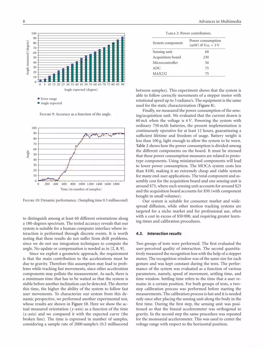
The first experiment shows the accuracy of the system whilemeasuring static orientations. The measurement is takenwhen the accelerometer is still. To perform accuracy tests,we contrasted the angle computed by our tracking systemagainst the real angle. The latter was measured by mountingthe sensing unit on a test fixture (see Figure 8) mainly com-posed by a goniometer. The darker color represents the un-certainty for each orientation. Here we show a range of 90 de-grees with a step of 5 degrees (Figure 9). Similar results werefound testing a 360-degree spectrum and repeating measure-ments placing the device in all possible orientations. Thelowest accuracy obtained was 3 degrees. Thus it is possible
8 Advances in Multimedia
0
10
20
30
40
50
60
70
80
90
100
An
gle
mea
sure
d(d
egre
e)
Angle expected (degree)
0 5 10 15 20 25 30 35 40 45 50 55 60 65 70 75 80 85 90
Error rangeAngle expected
Figure 9: Accuracy as a function of the angle.
0
10
20
30
40
50
60
70
80
90
100
An
gle
0 200 400 600 800 1000 1200 1400 1600 1800
Time (in number of samples)
Figure 10: Dynamic performance. (Sampling time 0.5 millisecond)
to distinguish among at least 60 different orientations alonga 180-degrees spectrum. The tested accuracy reveals that oursystem is suitable for a human-computer interface where in-teraction is performed through discrete events. It is worthnoting that these results do not suffer from drift problems,since we do not use integration techniques to compute theangle. No update or compensation is needed as in [2, 8, 9].
Since we exploit a geometric approach, the requirementis that the main contribution to the accelerations must bedue to gravity. Therefore this assumption may lead to prob-lems while tracking fast movements, since other accelerationcomponents may pollute the measurement. As such, there isa minimum time that has to be waited so that the system isstable before another inclination can be detected. The shorterthis time, the higher the ability of the system to follow fastuser movements. To characterize our system from this dy-namic perspective, we performed another experimental test,whose results are shown in Figure 10. Here we show the ac-tual measured orientation (y-axis) as a function of the time(x-axis) and we compared it with the expected curve (thebroken line). The time is expressed in number of samples,considering a sample rate of 2000 sample/s (0.5 millisecond
Table 2: Power contributors.
System componentPower consumption(mW) @ Vcc = 5 V
Sensing unit 60
Acquisition board 230
Microcontroller 50
ADC 75
MAX232 75
between samples). This experiment shows that the system isable to follow correctly movements of a stepper motor withrotational speed up to 3 radians/s. The equipment is the sameused for the static characterization (Figure 8).
Finally, we measured the power consumption of the sens-ing/acquisition unit. We evaluated that the current drawn is60 mA when the voltage is 6 V. Powering the system withordinary 750 mAh batteries, the present implementation iscontinuously operative for at least 12 hours, guaranteeing asufficient lifetime and freedom of usage. Battery weight isless than 100 g, light enough to allow the system to be worn.Table 2 shows how the power consumption is divided amongthe different components on the board. It must be stressedthat these power consumption measures are related to proto-type components. Using miniaturized components will leadto lower power consumption. The MOCA system costs lessthan $100, making it an extremely cheap and viable systemfor many end-user applications. The total component and as-sembly cost for the acquisition board and one sensing unit isaround $75, where each sensing unit accounts for around $25and the acquisition board accounts for $50 (with componentbought in small volumes).
Our system is suitable for consumer market and wide-spread diffusion, while other motion tracking systems aretargeted for a niche market and for professional use, oftenwith a cost in excess of $50 000, and requiring greater learn-ing times and calibration procedures.
4.3. Interaction results
Two groups of tests were performed. The first evaluated theuser-perceived quality of interaction. The second quantita-tively measured the recognition loss with the help of a steppermotor. The recognition window was of the same size for eachgesture and was kept constant during the tests. The perfor-mance of the system was evaluated as a function of variousparameters, namely, speed of movement, settling time, andtime window. Settling time refers to the time that a user re-mains in a certain position. For both groups of tests, a two-step calibration process was performed before starting themeasurements. The calibration process is fast and it is neededonly once after placing the sensing unit along the body in thefirst time. During the first step, the sensing unit was posi-tioned so that the biaxial accelerometer was orthogonal togravity. In the second step the same procedure was repeatedfor the monoaxial accelerometer. This was used to center thevoltage range with respect to the horizontal position.
Elisabetta Farella et al. 9
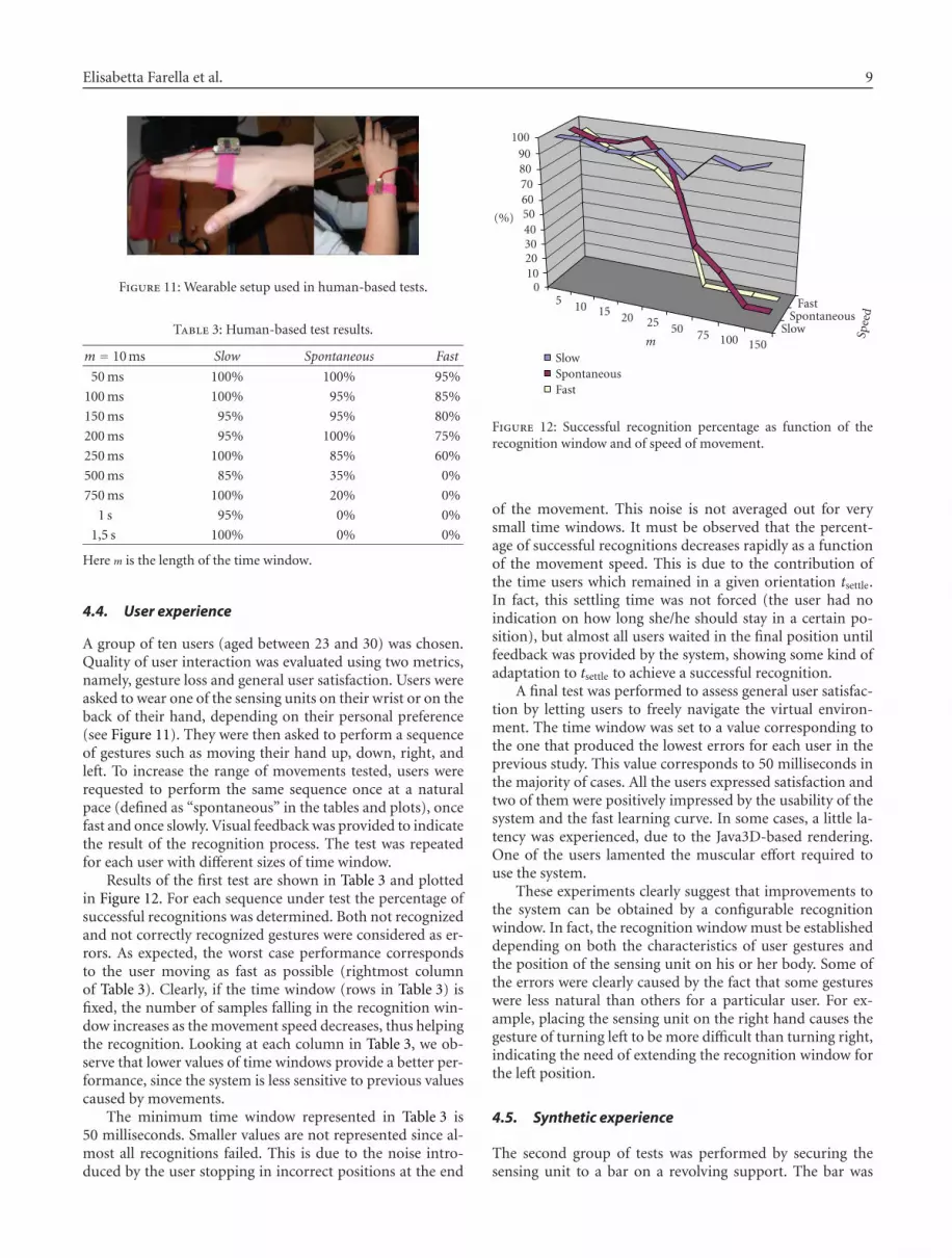
Figure 11: Wearable setup used in human-based tests.
Table 3: Human-based test results.
m = 10 ms Slow Spontaneous Fast
50 ms 100% 100% 95%
100 ms 100% 95% 85%
150 ms 95% 95% 80%
200 ms 95% 100% 75%
250 ms 100% 85% 60%
500 ms 85% 35% 0%
750 ms 100% 20% 0%
1 s 95% 0% 0%
1,5 s 100% 0% 0%
Here m is the length of the time window.
4.4. User experience
A group of ten users (aged between 23 and 30) was chosen.Quality of user interaction was evaluated using two metrics,namely, gesture loss and general user satisfaction. Users wereasked to wear one of the sensing units on their wrist or on theback of their hand, depending on their personal preference(see Figure 11). They were then asked to perform a sequenceof gestures such as moving their hand up, down, right, andleft. To increase the range of movements tested, users wererequested to perform the same sequence once at a naturalpace (defined as “spontaneous” in the tables and plots), oncefast and once slowly. Visual feedback was provided to indicatethe result of the recognition process. The test was repeatedfor each user with different sizes of time window.
Results of the first test are shown in Table 3 and plottedin Figure 12. For each sequence under test the percentage ofsuccessful recognitions was determined. Both not recognizedand not correctly recognized gestures were considered as er-rors. As expected, the worst case performance correspondsto the user moving as fast as possible (rightmost columnof Table 3). Clearly, if the time window (rows in Table 3) isfixed, the number of samples falling in the recognition win-dow increases as the movement speed decreases, thus helpingthe recognition. Looking at each column in Table 3, we ob-serve that lower values of time windows provide a better per-formance, since the system is less sensitive to previous valuescaused by movements.
The minimum time window represented in Table 3 is50 milliseconds. Smaller values are not represented since al-most all recognitions failed. This is due to the noise intro-duced by the user stopping in incorrect positions at the end
0102030405060708090
100
5 10 15 20 25 50 75 100 150Slow
SpontaneousFast
SlowSpontaneousFast
Spee
d
m
(%)
Figure 12: Successful recognition percentage as function of therecognition window and of speed of movement.
of the movement. This noise is not averaged out for verysmall time windows. It must be observed that the percent-age of successful recognitions decreases rapidly as a functionof the movement speed. This is due to the contribution ofthe time users which remained in a given orientation tsettle.In fact, this settling time was not forced (the user had noindication on how long she/he should stay in a certain po-sition), but almost all users waited in the final position untilfeedback was provided by the system, showing some kind ofadaptation to tsettle to achieve a successful recognition.
A final test was performed to assess general user satisfac-tion by letting users to freely navigate the virtual environ-ment. The time window was set to a value corresponding tothe one that produced the lowest errors for each user in theprevious study. This value corresponds to 50 milliseconds inthe majority of cases. All the users expressed satisfaction andtwo of them were positively impressed by the usability of thesystem and the fast learning curve. In some cases, a little la-tency was experienced, due to the Java3D-based rendering.One of the users lamented the muscular effort required touse the system.
These experiments clearly suggest that improvements tothe system can be obtained by a configurable recognitionwindow. In fact, the recognition window must be establisheddepending on both the characteristics of user gestures andthe position of the sensing unit on his or her body. Some ofthe errors were clearly caused by the fact that some gestureswere less natural than others for a particular user. For ex-ample, placing the sensing unit on the right hand causes thegesture of turning left to be more difficult than turning right,indicating the need of extending the recognition window forthe left position.
4.5. Synthetic experience
The second group of tests was performed by securing thesensing unit to a bar on a revolving support. The bar was
10 Advances in Multimedia
0
10
20
30
40
50
60
70
80
90
100
(%)
m
0.95 1.
55 1.9
2.62 3.
81 7.48
Rotation speed (radian/s)
323
4363
83
0.951.551.9
2.623.817.48
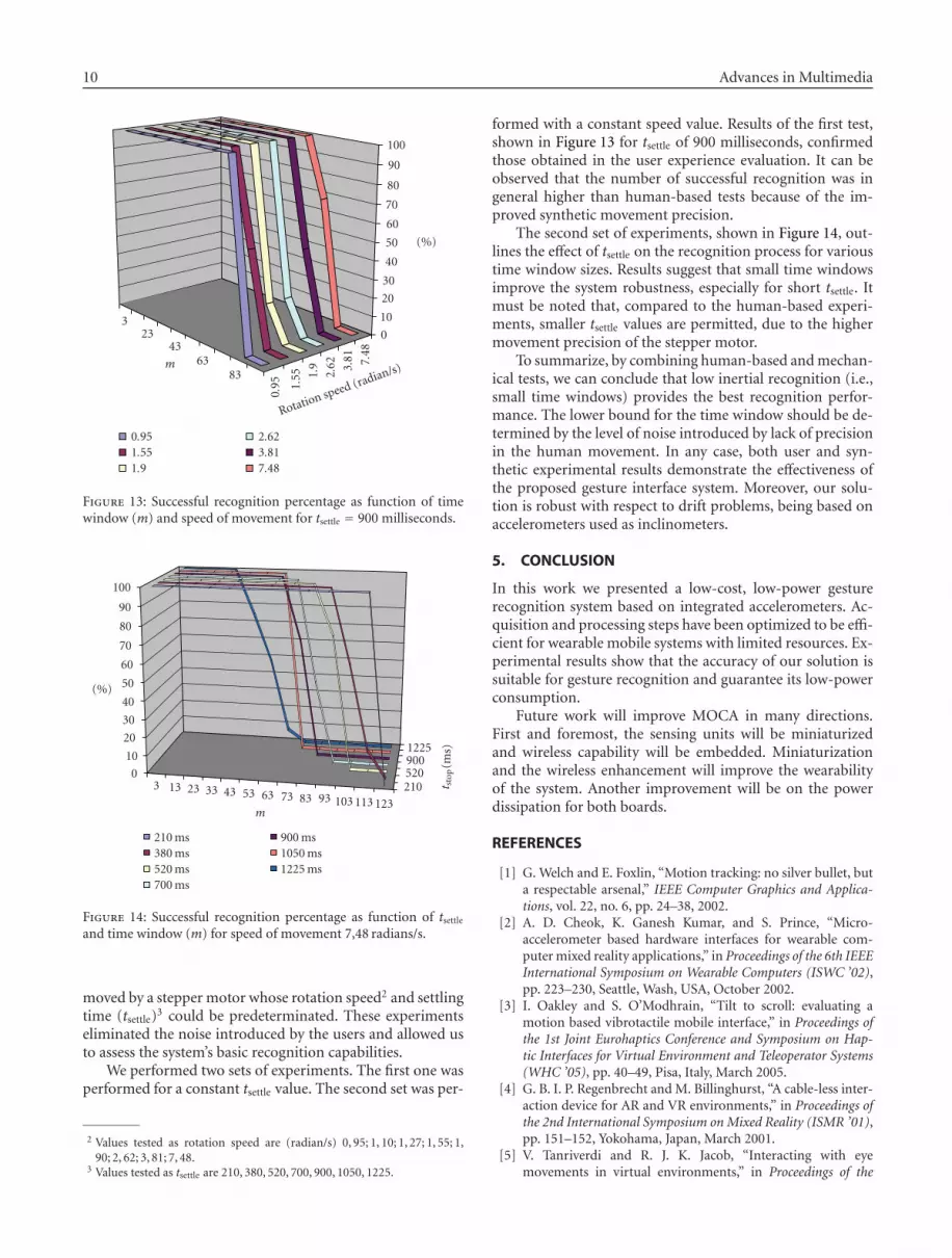
Figure 13: Successful recognition percentage as function of timewindow (m) and speed of movement for tsettle = 900 milliseconds.
3 13 23 33 43 53 63 73 83 93 103 113 123
2105209001225
t sto
p(m
s)
0
10
20
30
40
50
60
70
80
90
100
210 ms380 ms520 ms700 ms
900 ms1050 ms1225 ms
m
(%)
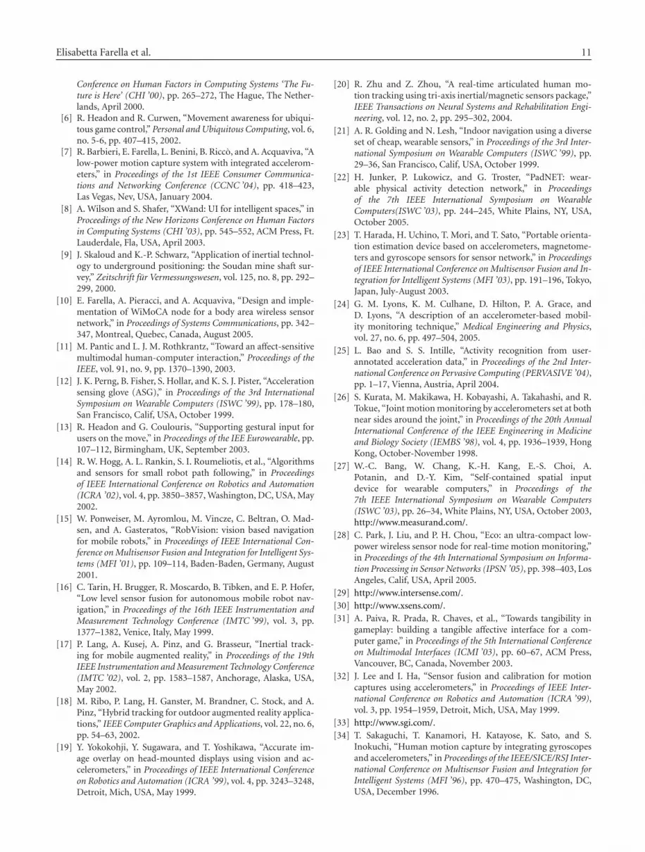
Figure 14: Successful recognition percentage as function of tsettle
and time window (m) for speed of movement 7,48 radians/s.
moved by a stepper motor whose rotation speed2 and settlingtime (tsettle)3 could be predeterminated. These experimentseliminated the noise introduced by the users and allowed usto assess the system’s basic recognition capabilities.
We performed two sets of experiments. The first one wasperformed for a constant tsettle value. The second set was per-
2 Values tested as rotation speed are (radian/s) 0, 95; 1, 10; 1, 27; 1, 55; 1,90; 2, 62; 3, 81; 7, 48.
3 Values tested as tsettle are 210, 380, 520, 700, 900, 1050, 1225.
formed with a constant speed value. Results of the first test,shown in Figure 13 for tsettle of 900 milliseconds, confirmedthose obtained in the user experience evaluation. It can beobserved that the number of successful recognition was ingeneral higher than human-based tests because of the im-proved synthetic movement precision.
The second set of experiments, shown in Figure 14, out-lines the effect of tsettle on the recognition process for varioustime window sizes. Results suggest that small time windowsimprove the system robustness, especially for short tsettle. Itmust be noted that, compared to the human-based experi-ments, smaller tsettle values are permitted, due to the highermovement precision of the stepper motor.
To summarize, by combining human-based and mechan-ical tests, we can conclude that low inertial recognition (i.e.,small time windows) provides the best recognition perfor-mance. The lower bound for the time window should be de-termined by the level of noise introduced by lack of precisionin the human movement. In any case, both user and syn-thetic experimental results demonstrate the effectiveness ofthe proposed gesture interface system. Moreover, our solu-tion is robust with respect to drift problems, being based onaccelerometers used as inclinometers.
5. CONCLUSION
In this work we presented a low-cost, low-power gesturerecognition system based on integrated accelerometers. Ac-quisition and processing steps have been optimized to be effi-cient for wearable mobile systems with limited resources. Ex-perimental results show that the accuracy of our solution issuitable for gesture recognition and guarantee its low-powerconsumption.
Future work will improve MOCA in many directions.First and foremost, the sensing units will be miniaturizedand wireless capability will be embedded. Miniaturizationand the wireless enhancement will improve the wearabilityof the system. Another improvement will be on the powerdissipation for both boards.
REFERENCES
[1] G. Welch and E. Foxlin, “Motion tracking: no silver bullet, buta respectable arsenal,” IEEE Computer Graphics and Applica-tions, vol. 22, no. 6, pp. 24–38, 2002.
[2] A. D. Cheok, K. Ganesh Kumar, and S. Prince, “Micro-accelerometer based hardware interfaces for wearable com-puter mixed reality applications,” in Proceedings of the 6th IEEEInternational Symposium on Wearable Computers (ISWC ’02),pp. 223–230, Seattle, Wash, USA, October 2002.
[3] I. Oakley and S. O’Modhrain, “Tilt to scroll: evaluating amotion based vibrotactile mobile interface,” in Proceedings ofthe 1st Joint Eurohaptics Conference and Symposium on Hap-tic Interfaces for Virtual Environment and Teleoperator Systems(WHC ’05), pp. 40–49, Pisa, Italy, March 2005.
[4] G. B. I. P. Regenbrecht and M. Billinghurst, “A cable-less inter-action device for AR and VR environments,” in Proceedings ofthe 2nd International Symposium on Mixed Reality (ISMR ’01),pp. 151–152, Yokohama, Japan, March 2001.
[5] V. Tanriverdi and R. J. K. Jacob, “Interacting with eyemovements in virtual environments,” in Proceedings of the
Elisabetta Farella et al. 11
Conference on Human Factors in Computing Systems ‘The Fu-ture is Here’ (CHI ’00), pp. 265–272, The Hague, The Nether-lands, April 2000.
[6] R. Headon and R. Curwen, “Movement awareness for ubiqui-tous game control,” Personal and Ubiquitous Computing, vol. 6,no. 5-6, pp. 407–415, 2002.
[7] R. Barbieri, E. Farella, L. Benini, B. Ricco, and A. Acquaviva, “Alow-power motion capture system with integrated accelerom-eters,” in Proceedings of the 1st IEEE Consumer Communica-tions and Networking Conference (CCNC ’04), pp. 418–423,Las Vegas, Nev, USA, January 2004.
[8] A. Wilson and S. Shafer, “XWand: UI for intelligent spaces,” inProceedings of the New Horizons Conference on Human Factorsin Computing Systems (CHI ’03), pp. 545–552, ACM Press, Ft.Lauderdale, Fla, USA, April 2003.
[9] J. Skaloud and K.-P. Schwarz, “Application of inertial technol-ogy to underground positioning: the Soudan mine shaft sur-vey,” Zeitschrift fur Vermessungswesen, vol. 125, no. 8, pp. 292–299, 2000.
[10] E. Farella, A. Pieracci, and A. Acquaviva, “Design and imple-mentation of WiMoCA node for a body area wireless sensornetwork,” in Proceedings of Systems Communications, pp. 342–347, Montreal, Quebec, Canada, August 2005.
[11] M. Pantic and L. J. M. Rothkrantz, “Toward an affect-sensitivemultimodal human-computer interaction,” Proceedings of theIEEE, vol. 91, no. 9, pp. 1370–1390, 2003.
[12] J. K. Perng, B. Fisher, S. Hollar, and K. S. J. Pister, “Accelerationsensing glove (ASG),” in Proceedings of the 3rd InternationalSymposium on Wearable Computers (ISWC ’99), pp. 178–180,San Francisco, Calif, USA, October 1999.
[13] R. Headon and G. Coulouris, “Supporting gestural input forusers on the move,” in Proceedings of the IEE Eurowearable, pp.107–112, Birmingham, UK, September 2003.
[14] R. W. Hogg, A. L. Rankin, S. I. Roumeliotis, et al., “Algorithmsand sensors for small robot path following,” in Proceedingsof IEEE International Conference on Robotics and Automation(ICRA ’02), vol. 4, pp. 3850–3857, Washington, DC, USA, May2002.
[15] W. Ponweiser, M. Ayromlou, M. Vincze, C. Beltran, O. Mad-sen, and A. Gasteratos, “RobVision: vision based navigationfor mobile robots,” in Proceedings of IEEE International Con-ference on Multisensor Fusion and Integration for Intelligent Sys-tems (MFI ’01), pp. 109–114, Baden-Baden, Germany, August2001.
[16] C. Tarin, H. Brugger, R. Moscardo, B. Tibken, and E. P. Hofer,“Low level sensor fusion for autonomous mobile robot nav-igation,” in Proceedings of the 16th IEEE Instrumentation andMeasurement Technology Conference (IMTC ’99), vol. 3, pp.1377–1382, Venice, Italy, May 1999.
[17] P. Lang, A. Kusej, A. Pinz, and G. Brasseur, “Inertial track-ing for mobile augmented reality,” in Proceedings of the 19thIEEE Instrumentation and Measurement Technology Conference(IMTC ’02), vol. 2, pp. 1583–1587, Anchorage, Alaska, USA,May 2002.
[18] M. Ribo, P. Lang, H. Ganster, M. Brandner, C. Stock, and A.Pinz, “Hybrid tracking for outdoor augmented reality applica-tions,” IEEE Computer Graphics and Applications, vol. 22, no. 6,pp. 54–63, 2002.
[19] Y. Yokokohji, Y. Sugawara, and T. Yoshikawa, “Accurate im-age overlay on head-mounted displays using vision and ac-celerometers,” in Proceedings of IEEE International Conferenceon Robotics and Automation (ICRA ’99), vol. 4, pp. 3243–3248,Detroit, Mich, USA, May 1999.
[20] R. Zhu and Z. Zhou, “A real-time articulated human mo-tion tracking using tri-axis inertial/magnetic sensors package,”IEEE Transactions on Neural Systems and Rehabilitation Engi-neering, vol. 12, no. 2, pp. 295–302, 2004.
[21] A. R. Golding and N. Lesh, “Indoor navigation using a diverseset of cheap, wearable sensors,” in Proceedings of the 3rd Inter-national Symposium on Wearable Computers (ISWC ’99), pp.29–36, San Francisco, Calif, USA, October 1999.
[22] H. Junker, P. Lukowicz, and G. Troster, “PadNET: wear-able physical activity detection network,” in Proceedingsof the 7th IEEE International Symposium on WearableComputers(ISWC ’03), pp. 244–245, White Plains, NY, USA,October 2005.
[23] T. Harada, H. Uchino, T. Mori, and T. Sato, “Portable orienta-tion estimation device based on accelerometers, magnetome-ters and gyroscope sensors for sensor network,” in Proceedingsof IEEE International Conference on Multisensor Fusion and In-tegration for Intelligent Systems (MFI ’03), pp. 191–196, Tokyo,Japan, July-August 2003.
[24] G. M. Lyons, K. M. Culhane, D. Hilton, P. A. Grace, andD. Lyons, “A description of an accelerometer-based mobil-ity monitoring technique,” Medical Engineering and Physics,vol. 27, no. 6, pp. 497–504, 2005.
[25] L. Bao and S. S. Intille, “Activity recognition from user-annotated acceleration data,” in Proceedings of the 2nd Inter-national Conference on Pervasive Computing (PERVASIVE ’04),pp. 1–17, Vienna, Austria, April 2004.
[26] S. Kurata, M. Makikawa, H. Kobayashi, A. Takahashi, and R.Tokue, “Joint motion monitoring by accelerometers set at bothnear sides around the joint,” in Proceedings of the 20th AnnualInternational Conference of the IEEE Engineering in Medicineand Biology Society (IEMBS ’98), vol. 4, pp. 1936–1939, HongKong, October-November 1998.
[27] W.-C. Bang, W. Chang, K.-H. Kang, E.-S. Choi, A.Potanin, and D.-Y. Kim, “Self-contained spatial inputdevice for wearable computers,” in Proceedings of the7th IEEE International Symposium on Wearable Computers(ISWC ’03), pp. 26–34, White Plains, NY, USA, October 2003,http://www.measurand.com/.
[28] C. Park, J. Liu, and P. H. Chou, “Eco: an ultra-compact low-power wireless sensor node for real-time motion monitoring,”in Proceedings of the 4th International Symposium on Informa-tion Processing in Sensor Networks (IPSN ’05), pp. 398–403, LosAngeles, Calif, USA, April 2005.
[29] http://www.intersense.com/.[30] http://www.xsens.com/.[31] A. Paiva, R. Prada, R. Chaves, et al., “Towards tangibility in
gameplay: building a tangible affective interface for a com-puter game,” in Proceedings of the 5th International Conferenceon Multimodal Interfaces (ICMI ’03), pp. 60–67, ACM Press,Vancouver, BC, Canada, November 2003.
[32] J. Lee and I. Ha, “Sensor fusion and calibration for motioncaptures using accelerometers,” in Proceedings of IEEE Inter-national Conference on Robotics and Automation (ICRA ’99),vol. 3, pp. 1954–1959, Detroit, Mich, USA, May 1999.
[33] http://www.sgi.com/.[34] T. Sakaguchi, T. Kanamori, H. Katayose, K. Sato, and S.
Inokuchi, “Human motion capture by integrating gyroscopesand accelerometers,” in Proceedings of the IEEE/SICE/RSJ Inter-national Conference on Multisensor Fusion and Integration forIntelligent Systems (MFI ’96), pp. 470–475, Washington, DC,USA, December 1996.