Alaris Capture Pro Software - DTIC
283
DE92002388 ims Information Is our business. MOISTURE CONTROL HANDBOOK: NEW, LOW-RISE, RESIDENTIAL CONSTRUCTION OAK RIDGE NATIONAL LAB., IN OCT 1991 U.S. DEPARTMENT OF COMMERCE National Technical Information Service
-
Upload
khangminh22 -
Category
Documents
-
view
3 -
download
0
Transcript of Alaris Capture Pro Software - DTIC
DE92002388 ims Information Is our business.
MOISTURE CONTROL HANDBOOK: NEW, LOW-RISE, RESIDENTIAL CONSTRUCTION
OAK RIDGE NATIONAL LAB., IN
OCT 1991
U.S. DEPARTMENT OF COMMERCE National Technical Information Service

Tailored to Your Needs!
Selected Research In
SRIM® is a tailored information service that delivers complete microfiche copies of government publications based on your needs, automatically, within a few weeks of announcement by NTIS.
SRIM Saves You Time, Money, and Space! Automatically, every two weeks, your SRIM3 profile is run against all new publications received by NTIS and the publications microfiched for your order. Instead of paying approximately $15-30 for each publication, you pay only $2.50 for the microfiche version. Corporate and special libraries love the space-saving convenience of microfiche.
IMTIS offers two options for SRIM® selection criteria:
Standard SRIIVT-Choose from among 350 pre-chosen subject topics.
Custom SRIM®-For a one-time additional fee, an NTIS analyst can help you develop a keyword strategy to design your Custom SRIM® requirements. Custom SRIM® allows your SRIM' selection to be based upon specific subject keywords, not just broad subject topics. Call an NTIS subject specialist at (703) 605-6655 to help you create a profile that will retrieve only those technical reports of interest to you.
SRIM® requires an NTIS Deposit Account. The NTIS employee you speak to will help you set up this account if you don't already have one.
For additional information, call the NTIS Subscriptions Department at 1-800-363-2068 or (703) 605-6060. Or visit the NTIS Web site at http://www.ntis.gov and select SRIM® from the pull-down menu.
U.S. DEPARTMENT OF COMMERCE Technology Administration
National Technical information Service Springfield, VA 22161 (703) 605-6000
http://www.ntis.gov
ORNL/Sub/89-SD350/1
OAK RIDGE I NATIONAL LABORATORY
tvfsxrrTnv mafuetta
Moisture Control Handbook New, Low-rise, Residential
Construction
Joseph Lstiburek
John Carmody
MANAGED BY MAHTIN MARIETTA ENERGY SYSTEMS, INC.
FOR THE UNITED STATES
DEPARTMENT OF ENERGY OiSTRiBUTION OF THIS DOCUMENT \S UNLIMITED
.I'
This report has been reproduced directly from the best available copy.
Available to DOE and DOE contractors from the Office of Scientific and Techni¬ cal Information, P.O. Box 62, Oak Ridge, TN 37831; prices available from (615) 576-8401, FTS 626-8401.
Available to the public from the National Technical Information Service, U.S.
Department of Commerce, 5285 Port Royal Rd., Springfield, VA 22161.
This report was prepared as an account of work sponsored by an agency of the United States Government. Neither the United States Government nor any agency thereof, nor any of their employees, makes any warranty, express or implied, or assumes any legal liability or responsibility for the accuracy, com¬ pleteness, or usefulness of any information, apparatus, product, or process dis¬ closed, or represents that its use would not infringe privately owned rights. Reference herein to any specific commercial product, process, or service by trade name, trademark, manufacturer, or otherwise, does not necessarily consti¬ tute or imply its endorsement, recommendation, or favoring by the United Slates Government or any agency thereof. The views and opinions of authors expressed herein do not necessarily state or reflect those of the United States Government or any agency thereof.
ORNL/Sub—89-SD350/1
DE92 002388
Energy Division
MOISTURE CONTROL HANDBOOK New, Low-rise, Residential Construction
Joseph Lsliburek: Building Scienu; Corporation Chestnut Hill, Massachusetts
John Carmody Underground Space Center
University of Minnesota Minneapolis, Minnesota
Dames and Moore, Tiuw, Inc.
October 1991
*Tbo subrtvrced rwietsript has baon try b controctor of tK« U.S
Govammeot undot conosct No. 0€- AC05-B40«21400. AccOrtSnglv. rho U.S. Govemmam retains a riooaxckisrvti, (oyaJ^-froo Soonse to pubkali or roproduco the putoishod form ol iha contribution, or Blow others to do ». h* U.S, Gowemnwit
putoesaj.'
Research sponsored by the Office of Buildings and Community Systems, Building Systems Division, U.S. Department of Energy, under Contract DE-ACG5-840R21400 with the Martin Marietta Energy Systems, Inc.
DISTRIBUTION OF THIS DOCUMENT IS UNLIMITED*'-'
DISCLAIMER
Portions of this document may be illegible electronic image products. Images are produced from the best available original document.
Moisture Control Handbook
New, Low-rise, Residential Construction
by Joseph Lstiburek with John Carmody
Date of Publication: October, 1991
Part of the National Program for Building Thermal Envelope Systems and Materials
Prepared for the U.S. Department of Energy Conservation and Renewable Energy
Office of Buildings and Community Systems Building Systems Division
Moisture Control Handbook
New, Low-rise, Residential Construction
by Joseph Lstiburek B,A.Sc., M.Eng., P.Eng.
Building Scietice Corporation
Chestnut Hill, Massachusetts
with John Cannody Underground Space Center
University of Minnesota
Minneapolis, Minnesota
Dames and Moore, Trow Inc.
Designed and Illustrated by John Cannody
Technical Advisors:
Professor John Timusk, Center for Building Science, University of Toronto Gustav Handegord, Formerly of the Division of Building Research, National Research
Council of Canada Professor George Tsongas, Department of Mechanical Engineering, Portland State University
Steering Committee:
Reece Achenbach Doug Burch, National Institute of Standards and Technology Jeffrey Christian, Oak Ridge National Laboratory George Courville, Oak Ridge National Laboratory William Freebome, U.S. Dept, of Housing and Urban Development John Goldsmith, U-S. Dept, of Energy Kenneth Labs, Progressive Architecture Dave Lovich, Owens-Coming Fiberglas Paul Shipp, USG Corporation Research Center Sam Taylor, U.S. Dept, of Energy Anton Tenwolde, U.S. Dept, of Agriculture, Forest Products Laboratory Martha Van Geem, Construction Technology Labs, Portland Cement Association
Date of Publication: October, 1991
Managed by: Martin Marietta Energy Systems, Inc.
for the U.S. Department of Energy under Contract DE-AC05-840R21400
Prepared for: Oak Ridge National Laboratory
Oak Ridge, Tennessee 37831
'
— — —
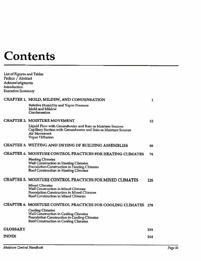
Contents List of Figures and Tables Preface / Abstract Acknowledgments Introduction Executive Summary
CHAPTER 1. MOLD, MILDEW, AND CONDENSATION 1
Relative Humidity and Vapor Pressure Mold and Mildew Condensation
CHAPTER 2. MOISTURE MOVEMENT 12
Liquid Flow with Groundwater and Rain as Moisture Sources Capillary Suction with Groundwater and Rain as Moisture Sources Air Movement Vapor Diffusion
CHAPTER 3. WETTING AND DRYING OF BUILDING ASSEMBLIES 46
CHAPTER 4. MOISTURE CONTROL PRACTICES FOR HEATING CLIMATES 74
Heating Climates Wall Construction in Heating Climates Foundation Construction in Heating Climates Roof Construction in Heating Climates
CHAPTER 5. MOISTURE CONTROL PRACTICES FOR MIXED CLIMATES 126 Mixed Climates Wall Construction in Mixed Climates Foundation Construction in Mixed Climates Roof Construction in Mixed Climates
CHAPTER 6. MOISTURE CONTROL PRACTICES FOR COOLING CLIMATES 178
Cooling Climates Wall Construction in Cooling Climates Foundation Construction in Cooling Climates Roof Construction in Cooling Climates
GLOSSARY 235
INDEX 244
Moisture Control Handbook Page Hi
Summary of Figures and Tables Chapter 1 Figures
Figure 1-1: Figure 1-2:
Figure 1-3: Figure 1-4: Figure 1-5: Figure 1-6: Figure 1-7:
Figure 1-8:
Relative Humidity Increases as Temperature Decreases Relative Humidity Increases as Vapor Pressure or Moisture Content of Air
Increases Psychrometric Chart Partial Plan of House Heat Loss Effects at Building Comers Heat Loss Effects at Ceiling Edge Thermal Bridge at Wall/Floor Intersection Thermal Bridge Through Framing Members
Chapter 2 Figures
Figure 2-1A: Figure 2-1B: Figure 2-2: Figure 2-3: Figure 2-4: Figure 2-5: Figure 2-6: Figure 2-7: Figure 2-8: Figure 2-9: Figure 2-10: Figure 2-11: Figure 2-12: Figure 2-13: Figure 2-14: Figure 2-15: Figure 2-16: Figure 2-17: Figure 2-18: Figure 2-19: Figure 2-20 A: Figure 2-20B: Figure 2-21: Figure 2-22:
Figure 2-23:
Figure 2-24: Figure 2-25: Figure 2-26A: Figure 2-26B:
Potential Surface Drainage Problems Effective Surface Drainage Techniques Drain Screen Concept Using Porous Backfill Drain Screen Concept Using a Free-Draining Board or Membrane Barrier / Membrane Approach Control joints in Concrete Walls Brick Veneer Wall Designed as a Rain Screen Wall Using Vinyl or Aluminum Siding Designed as a Rain Screen Wood Frame Wall Designed as a Rain Screen Effects of Wind Around the Corner of a Brick Veneer Wall Metal Building Wall Designed as a Drain Screen Rain Screen Concept Applied to Precast Concrete Joint Design Flashing Directing Water Out of a Cladding Joint Flashing Directing Water Out of a Building Assembly Capillary Rise Through a Concrete Footing Capillary Rise in Wood Siding Techniques to Control Capillary Moisture Below Grade Techniques to Control Capillary Moisture Above Grade Capillary Break in a Brick Veneer Wall Capillary Break in a Wood Shake Roof Interior Air Retarder Using the Air Drywall Approach (ADA) Interior Air Retarder Using the Poly-Wrap Approach Interior Air Retarder Details at Window jamb Interior Air Retarder Details at Intersection of Exterior and Interior Partition
Walls Interior Ait Retarder Details at Intersection of Roof and Interior Partition
Walls Interior Air Retarder Details at Electric Outlet Boxes in Exterior Walls Interstitial Air Retarder in Composite Wall Exterior Air Retarder Using the Air Sheathing Approach (ASA) Exterior Air Retarder Using the House-Wrap Approach
Moisture Control Handbook Page v
Figure 2-27: Figure 2-28: Figure 2-29:
Figure 2-30A: Figure 2-30B:
Figure 2-30C:
Figure 2-31:
Figure 2-32: Figure 2-33:
Figure 2-34:
Figure 2-35:
Figure 2-36:
Air Pressure Patterns Caused by the Stack Effect Change in the Neutral Pressure Plane Caused by the Chimney Effect Air Pressurization Patterns in a House with the Mechanical System in the
Basement Air Pressurization Pattern with Mechanical System Ducts in the Attic Air Pressurization Pattern with Mechanical System Ducts in the Craw!
Space Air Pressurization Pattern with Mechanical System Ducts in the Attic and
the Crawl Space Warm, Humid Air Drawn from Attic through Opening Around Supply
Duct Pressurization of Flat Roof Assembly to Control Exfiltration Vapor Diffusion Retarder on the Exterior of a Concrete or Masonry
Foundation Wall and Beneath the Concrete Slab Vapor Diffusion Retarder on the Interior of a Wood Frame Wall Inside of
the Foundation Wall Vapor Diffusion Retarder on the Interior of a Concrete or Masonry
Foundation Wall Effect of Exterior Insulation on Basement Wall Temperature and Humidity
Levels
Chapter 3 Figures
Figure 3-1; Figure 3-2A: Figure 3-2 B: Figure 3-3:
Figure 3-4:
Figure 3-5:
Figure 3-6:
Figure 3-7:
Figure 3-8: Figure 3-9: Figure 3-10:
Figure 3-11: Figure 3-12; Figure 3-13:
Figure 3-14:
Moisture Movement in a Wood Frame Wall in a Heating Climate Condensation Pattern with Fiberglass Cavity Insulation Condensation Pattern with Cellulose Cavity Insulation Schematic of Moisture Transport Welting Mechanisms in a Wall with Wood
Siding Schematic of Moisture Transport Wetting Mechanisms in a Wall with Vinyl
or Aluminum Siding Moisture Transport Wetting Mechanisms in a Wall with an Electrical Outlet
Box Potential for Condensation in Wood Frame Walls in a Heating Climate
(Chicago, Illinois) [3.6] Potential for Condensation in Wood Frame Walls in a Heating Climate
(Chicago, Illinois) [3.6] Removal of Moisture by Ventilation of a Wall with Wood Siding Removal of Moisture with Ventilation Conceptual Illustration of the Drain Screen Technique Applied to a Wood
Frame Wall Moisture Transport Wetting Mechanisms in a Roof Assembly Inverted Roof Membrane Unvented Cathedral Ceiling with R-20 Rigid Insulation Above K-19 Balt
Insulation Unvented Cathedral Ceiling with R-12 Rigid Insulation Above R-28 Batt
Insulation
Chapter 4 Figures
Figure 4-1: Figure 4-2: Figure 4-3: Figure 4-4: Figure 4-5; Figure 4-6: Figure 4-7: Figure 4-8: Figure 4-9:
Map of Heating Climate Zone in the United States Whole House Concepts for Heating Climates Wall 1—Heating Climate (Impermeable Noninsulating Sheathing) Wall 2—Heating Climate (Impermeable Insulating Sheathing) Wall 3—Heating Climate (Permeable Insulating Sheathing) Wall 4—Heating Climate (Impermeable Insulating Sheathing) Wall 5—Heating Climate (Permeable Noninsulating Sheathing) Wall 6—Heating Climate (Masonry Wall with Exterior Insulation) Basement 1—Heating Climate (Interior Insulation)
Figure 4-10: Figure 4-11: Figure 4-12: Figure 4-13: Figure 4-14:
Figure 4-15:
Figure 4-16: Figure 4-17: Figure 4-18: Figure 4-19: Figure 4-20: Figure 4-21:
Basement 2—Heating Climate (Exterior Insulation) Basement 3—Heating Climate (Interior Insulation) Basement 4—Heating Climate (Exterior Insulation) Basement 5—Heating Climate (Interior Insulation) Basement 6—Heating Climate (Wood Foundation Wall with Exterior
Insulation) Basement 7—Heating Climate (Wood Foundation Wall with Exterior
Insulation) Slab 1—Heating Climate (Exterior Insulation) Roof 1—Heating Climate (Vented Attic) Roof 2—Heating Climate (Vented Cathedral Ceiling) Roof 3—Heating Climate (Vented Cathedral Ceiling) Roof 4—Heating Climate (Unvented Cathedral Ceiling) Roof 5—Heating Climate (Unvented Cathedral Ceiling)
Chapter 5 Figures
Figure 5-1: Figure 5-2: Figure 5-3: Figure 5-4: Figure 5-5: Figure 5-6: Figure 5-7: Figure 5-8: Figure 5-9: Figure 5-10: Figure 5-11:
Figure 5-12: Figure 5-13: Figure 5-14:
Figure 5-15:
Figure 5-16: Figure 5-17: Figure 5-18: Figure 5-19:
Map of Mixed Climate Zone in the United States Whole House Concepts for Mixed Climates Wall 1—Mixed Climate (Impermeable Noninsulating Sheathing) Wall 2—Mixed Climate (Permeable Noninsulating Sheathing) Wail 3—Mixed Climate (Permeable Noninsulating Sheathing) Wall 4—Mixed Climate (Impermeable Insulating Sheathing) Wall 5—Mixed Climate (Impermeable Insulating Sheathing) Basement 1—Mixed Climate (Exterior Insulation) Basement 2—Mixed Climate (Interior Insulation) Basement 3—Mixed Climate (Interior Insulation) Basement 4—Mixed Climate (Wood Foundation Wall with Exterior
Insulation) Crawl Space 1—Mixed Climate (Unvented with Exterior Insulation) Crawl Space 2—-Mixed Climate (Unvented with Interior Insulation) Crawl Space 3—Mixed Climate (Unvented Wood Foundation Wall with
Exterior Insulation) Crawl Space 4—Mixed Climate (Unvented Wood Foundation Wall with
Exterior Insulation) Roof 1—Mixed Climate (Vented Attic) Roof 2—Mixed Climate (Vented Attic) Roof3—Mixed Climate (Vented Cathedral Ceiling) Roof 4—Mixed Climate (Unvented Cathedral Ceiling)
Chapter 6 Figures
Figure 6-1: Figure 6-2: Figure 6-3: Figure 6-4: Figure 6-5: Figure 6-6: Figure 6-7: Figure 6-8: Figure 6-9: Figure 6-10: Figure 6-11: Figure 6-12: Figure 6-13: Figure 6-14: Figure 6-15: Figure 6-16:
Map of Cooling Climate Zone in the United States Whole House Concepts for Cooling Climates Wall 1—Cooling Climate (Impermeable Noninsulating Sheathing) Wall 2—Cooling Climate (Impermeable Insulating Sheathing) Wall 3—Cooling Climate (Impermeable Noninsulating Sheathing) Wall 4—Cooling Climate (Permeable Noninsulating Sheathing) Wall 5—Cooling Climate (Impermeable Noninsulating Sheathing) Wall 6—Cooling Climate (Masonry Wall with Interior Insulation) Wall 7—Cooling Climate (Masonry Wall with Interior Insulation) Wall 8—Cooling Climate (Masonry Wall with Interior Insulation) Wall 9—Cooling Climate (Masonry Wall with Exterior Insulation) Wall 10—Cooling Climate (Masonry Wall with Interior Insulation) Crawl Space 1—Cooling Climate (Vented with Ceiling Insulation) Crawl Space 2—Cooling Climate (Vented with Ceiling Insulation) Crawl Space 3—Cooling Climate (Unvented with Exterior Insulation) Crawl Space 4—Cooling Climate (Unvented with Interior Insulation)
Moisture Control Handbook Page vii

Figure 6-17 Figure 6-18 Figure 6-19 Figure 6-20 Figure 6-21 Figure 6-22 Figure 6-23 Figure 6-24 Figure 6-25
Tables
Table 2-1: Table 4-1: Table 4-2: Table 4-3: Table 5-1: Table 5-2: Table 5-3: Table 6-1: Table 6-2: Table 6-3:
Slab 1—Cooling Climate (Exterior Insulation) Slab 2—Cooling Climate (Interior Insulation) Slab 3—Cooling Climate (Exterior Insulation) Roof 1—Cooling Climate (Vented Attic) Roof 2—Cooling Climate (Vented Attic) Roof 3—Cooling Climate (Vented Attic) Roof 4—Cooling Climate (Vented Attic) Roof 5—Cooling Climate (Vented Attic) Roof 6—Cooling Climate (Vented Attic)
Household Moisture Sources Characteristics of Wall Assemblies for Heating Climates Characteristics of Foundation Assemblies for Heating Climates Characteristics of Roof Assemblies for Heating Climates Characteristics of Wall Assemblies for Mixed Climates Characteristics of Foundation Assemblies for Mixed Climates Characteristics of Roof Assemblies for Mixed Climates Characteristics of Wall Assemblies for Cooling Climates Characteristics of Foundation Assemblies for Cooling Climates Characteristics of Roof Assemblies for Cooling Climates
Preface This handbook is a product of the U.S.
Department of Energy Building Envelope Systems and Materials (BTESM) Research Program centered at Oak Ridge National Laboratory. The major objective of the research effort in building moisture control is to provide information to designers, builders, and building owners that will lead to the construction of energy-efficient walls, roofs, and foundations. This handbook is another in a series of design tools produced through the BTESM Program aimed at providing the most current design information.
Moisture control is a key component in designing energy-efficient, healthy buildings. The presence of uncontrolled moisture in a building envelope will rapidly degrade structural materials and insulation. Moreover, it can lead to mold, mildew, odors, and pathogens. While the energy use impact of uncontrolled building moisture is not easy to quantify, it is obvious that the overall impact in terms of lost time, productivity, and expensive reconstruction is quite large. By analyzing moisture transport mechanisms in building envelopes and systematically describing control strategies for each, the building designer is provided with information needed to minimize the risk of moisture problems in energy-efficient buildings. This handbook also illustrates that energy-efficient, tight envelope design is clearly part of the solution to healthy buildings when interior relative humidity, temperature, and pressure are controlled simultaneously.
DOE formed a review panel of moisture experts to provide guidance for this effort (listed on the title page). This group reviewed the outline as well as several drafts of the handbook, and through this process strengthened the document. Although most of the committee supports the major underlying concepts, it was clear that there are many unresolved issues in this emerging
field. There are two schools of thought among building designers. Historically, the predominant envelope design strategy used in low-rise residential buildings was to keep out all moisture at all times. The concept of acceptable moisture levels discussed in the handbook, however, recognizes envelopes can get wet or occasionally start out wet. Therefore, a design could recognize this and encourage periodic drying.
The construction details shown for heating, mixed, and cooling climates are based on moisture transport principles. However, much work remains to be performed in order to determine the wetting and drying patterns of both conventional and novel envelope systems. Some building researchers believe no moisture, internal to the envelope, is acceptable at any time and that once wet, envelopes are unlikely to dry out. On the other hand, some designers believe it is too costly or too risky to completely control moisture entry. In fact, some believe that building envelope materials will frequently have high initial moisture levels, and that degradation of siding, sheathing, sealants, caulking, and flashings can all contribute significantly to the moisture load. Thus, their approach is to keep moisture levels low by providing a path for moisture to escape. A design strategy that assumes building envelopes may get wet and permits them to dry, presents a more forgiving and perhaps less costly alternative. Reliably quantifying the impact of these approaches, particularly wetting and drying within construction assemblies, remains to be accomplished in future editions of the Moisture Control Handbook. This handbook is a first step in helping designers and builders to understand and utilize moisture control strategies.
DOE and the BTESM staff at ORNL hope this material will serve as a starting point for an international focus on how to build even
Moisture Control Handbook Page ix
more energy-efficient, moisture controlling building envelopes. Vv’e welcome your response to this handbook, particularly builders, designers, researchers, and building owners. Please send your suggestions for improving future editions.
Jeffrey Christian R&D Manager, Building Envelope
Systems and Materials Program Oak Ridge National Laboratory P.O.Box 2008 Building 3147 MS 6070 Oak Ridge, TN 37831-6070
John Goldsmith Walls and Foundations, Program
Manager U.S. Department of Energy

Abstract Moisture problems are prevalent all over
North America, almost independent of climate. They are viewed as one of the single largest factors limiting the useful service life of a building. Elevated levels of moisture in buildings also can lead to serious health effects for occupants. Until recently, very little consensus on moisture control existed in the building community. The information available was typically incomplete, contradictory, usually limited to specific regions, and in many cases misleading. A need to develop a document which presented the issues relating to moisture from a building science or "systems" approach existed. This handbook attempts to fill that need and illustrates that energy-efficient, tight envelope design is clearly part of the solution to healthy buildings when interior relative humidity, temperature, and pressure
are controlled simultaneously. The first three chapters of the handbook
present the basic principles of moisture problems and solutions in buildings. Chapter 1—Mold, Mildew, and Condensation, examines surface moisture problems- Chapter 2—Moisture Movement, examines how building assemblies get wet from both the exterior and interior. Chapter 3—Wetting and Drying of Building Assemblies, introduces the concepts of acceptable performance, moisture balance, and the redistribution of moisture within building assemblies. Chapters 4 through 6 apply the concepts outlined in the previous chapters and present specific moisture control practices for three basic U.S. climate zones. The advantages and disadvantages of several wall, foundation, and roof assemblies are discussed for each climate zone.
Moisture Control Handbook Page xi
Acknowledgments The steering committee for this project
provided valuable review and comment during the development of the book- Steering committee members included:
Reece Achenbach Doug Burch, National Institute of
Standards and Technology Jeffrey Christian, Oak Ridge National
Laboratory George Courville, Oak Ridge National
Laboratory William Freebome, U.S. Dept of Housing
and Urban Development John Goldsmith, U.S. Dept, of Energy Kenneth Labs, Progressive Architecture Dave Lovich, Owens-Coming Fiberglas Paul Shipp, USG Corporation Research
Center Sam Taylor, U.S. Dept, of Energy Anton Tenwolde, U.S. Dept, of
Agriculture, Forest Products Laboratory
Martha Van Geem, Construction Technology Labs, Portland Cement Association
Technical advisors to the project were: Professor John Tinrusk, University of Toronto; Gustav Handegord, formerly of the National Research Council of Canada; and Professor George Tsongas, Portland State University.
Guidance and advice were provided by; John Tooley, Florida Natural Retrofit; Philip Farey, FSEC; Gary Nelson, The Energy Conservatory; Phil Hendrickson, Dow Chemical; Jim White, Canada Mortgage and Housing Corporation; and Axel Carlson, University of Alaska. Finally, the manuscript was improved considerably by the editing of Pam Snopl.
Joseph Lstiburek Building Science Corporation Chestnut Hill, Massachusetts
John Carmody Underground Space Center University of Minnesota
Page xii
Introduction The Need For A Moisture Control Handbook
Moisture problems are prevalent all over North America, almost independent of climate. They are viewed as one of the single largest factors limiting the useful service life of a building. Elevated levels of moisture in buildings also can lead to serious health effects for occupants. Until recently, very little consensus on moisture control existed in the building community. The information available was typically incomplete, contradictory, usually limited to specific regions, and in many cases misleading. A need to develop a document which presented the issues relating to moisture from a building science or "systems" approach existed. This document attempts to fill that need.
How To Use This Handbook
This handbook approaches the moisture problem from several perspectives. Chapter 1—Mold, Mildew, and Condensation, examines surface moisture problems. Chapter 2—Moisture Movement, examines how building assemblies get wet from both the exterior and interior. Chapter 3—Wetting and Drying of Building Assemblies, introduces the concepts of acceptable performance, moisture balance, and the redistribution of moisture within building assemblies. Chapters 4 through 6 apply the concepts outlined in the previous chapters and present specific moisture control practices for three basic U.S. climate zones. Each chapter is designed to stand on its own. As such, reading of this document from front to back and in sequence will likely not be
necessary for some readers. Of course, reading of the document in its entirety is recommended.
Some readers may wish to skip over the first few chapters and go directly to the chapters presenting specific moisture control practices and construction details for their particular climate. The commentary relating to each detail will likely provide much of the information required by many readers. More detailed explanations of the principles utilized in the development of the details can be found in the early chapters.
This handbook attempts to provide the rationale for successfully designing and constructing building assembly details without getting mired in theory and equations. Those readers desiring further information and depth are directed to the bibliography at the end of each chapter. References are provided where the specific issues raised may require further explanation, or where it was felt necessary to direct readers to particularly relevant research findings.
Whenever a specific construction practice in a particular climate presented in this handbook deviates from a practice with which the reader is familiar, the reader is urged to consult authorities having jurisdiction to determine local code compliance prior to utilization.
Insulation levels in wall, roof, and foundation assemblies, except where specifically noted to control moisture accumulation on condensing surfaces, are left to the judgement of the reader. Guidance regarding optimum insulation levels for foundation assemblies can be found in the Builder's Foundation Handbook (Carmody, Christian, Labs, 1991).
Moisture Control Handbook Page xiii
Executive Summary Moisture problems are viewed as one of
the single Largest factors limiting the useful service life of a building. They are prevalent all over North America to some degree. Also, serious health effects for occupants can result from elevated levels of moisture in buildings.
The handbook is divided into six chapters, with each chapter designed to stand on its own. Chapter 1. Mold, Mildew, and Condensation examines surface moisture problems- Chapter 2. Moisture Movement examines how building assemblies get wet from both the exterior and interior. Chapter 3 Wetting and Drying of Building Assemblies introduces the concepts of acceptable performance, moisture balance, and the redistribution of moisture within building assemblies. The remaining chapters apply the concepts outlined in the previous chapters and present specific moisture control practices for various climates.
Chapter 1: Mold, Mildew, and Condensation
The most common surface moisture- related problems, regardless of climate, are mold, mildew, and condensation. The single most important factor influencing these problems is relative humidity near surfaces. Relative humidity is the amount of moisture contained in a unit of air relative to the maximum amount of moisture the unit of air can hold at a specific temperature- Relative humidity can be increased two ways - by increasing moisture levels (vapor pressure) and by decreasing temperature. Where relative humidities near surfaces are maintained below 70 percent, mold and mildew growth can be controlled. Since relative humidities are dependent on both temperature and vapor pressure, mold and mildew control will be dependent on
controlling both the temperature and vapor pressure near surfaces. When the relative humidity reaches 100 percent, moisture can condense. The same strategies that control mold and mildew growth also control condensation on surfaces - increasing surface temperatures and reducing vapor pressures (moisture Levels) near surfaces
Chapter 2: Moisture Movement
The four moisture transport mechanisms predominant in building science are:
1. Liquid flow due to gravity and/or an air pressure difference
2. Moisture transport due to capillary suction
3. Air movement
4 Vapor diffusion
All moisture movement, and therefore any moisture-related problem is a result of one or a combination uf these mechanisms. Each of these mechanisms can act independently and must be dealt with during design and construction.
The first mechanism, liquid flow, is primarily responsible for moving moisture into the building envelope from the exterior. Capillary suction typically moves moisture into the building envelope from the exterior and also redistributes condensed moisture within building envelopes. The tatter two mechanisms, air movement and vapor diffusion, can move moisture both from the exterior as well as from within the conditioned space into the building envelope depending on exterior and interior conditions. For example, when a building in a cold climate is being heated, air movement and vapor diffusion typically result in a net movement from within the conditioned space into the building envelope. When a building
Page xiv
is in a warm climate and is being cooled, air movement and vapor diffusion may result in a net movement of moisture from the exterior into the conditioned space.
This duality of movement is dependent on both climactic and interior conditions and is often overlooked by designers and builders. It is not unusual to find cold climate building envelope designs employed in warm climate regions. Even more confusing to the builder and designer are conditions where both heating and cooling occur for extended periods of time.
Of the four mechanisms, the most significant are liquid flow and capillary suction where ground water and rain are the moisture sources. Controlling ground water entry below grade and rain entry above grade have traditionally been the preoccupation of generations of builders and designers and it is no different today. Liquid flow and capillarity are also recognized as the primary factors in the wetting of materials. Air transport and vapor diffusion are less obvious contributions.
Chapter 3: Wetting and Drying of Building Assemblies
Ideally, building assemblies would always be built with dry materials under dry conditions, and would never get wet from imperfect design, poor workmanship or occupants. Unfortunately, these conditions do not exist.
It has been accepted by the building industry that many building assemblies become wet during service, and in many cases start out wet. Furthermore, the industry has recognized that in many circumstances it may be impractical to design and build building assemblies which never get wet. This has given rise to the concept of acceptable performance. Acceptable performance implies the design and construction of building assemblies which may periodically get wet, or start out wet initially, but yet are still durable and provide a long, useful service life. Repeated wetting followed by repeated drying can provide acceptable performance if during the wet period, materials do not stay wet long enough under adverse conditions to deteriorate.
Good design and practice involve controlling the wetting of building assemblies from the exterior and interior. They may also involve drying building
assemblies should they become wet during service or start out wet as a result of building with wet materials or under wet conditions.
Moisture accumulates when the rate of moisture entry into an assembly exceeds the rate of moisture removal. When moisture accumulation exceeds the ability of the assembly materials to store the moisture without significantly degrading performance or long term service life, moisture problems result.
Numerous strategies can be implemented to minimize the risk of moisture damage. The strategies fall into following three groups:
1. Control of moisture entry
2. Control of moisture accumulation
3. Removal of moisture
Strategies in the three groupings can be utilized in combination and have been proven to be most effective in that manner. Strategies effective in the control of moisture entry, however, are often not effective if building assemblies start out wet, and in fact can be detrimental. If a technique is effective at preventing moisture from entering an assembly, it is also likely to be effective at preventing moisture from leaving an assembly. Conversely, a technique effective at removing moisture may also allow moisture to enter. Balance between entry and removal is the key.
Building assemblies can get wet from the interior or exterior, or they can start out wet as a result of the construction process due to wet building materials or construction under wet conditions. Moisture can enter from the interior in two ways: air movement and vapor diffusion. Moisture entering from the exterior can be from four sources:
L Liquid flow (rain & groundwater as moisture sources)
2. Capillary suction (rain & ground water as moisture sources)
3. Air movement
4. Vapor diffusion
Moisture can be redistributed within an assembly by four processes:
1. Liquid flow due to gravity
2. Capillary suction
3. Air movement
4 Vapor diffusion
Moisture Control Handbook Page xv
Finally, moisture can be removed (dried) to the exterior or to the interior in three ways:
L Liquid flow due to gravity (drainage)
2. Air movement (ventilation)
3. Vapor diffusion (vapor pressure differences)
The above mechanisms can act singly or in combination.
Chapter 4: Moisture Control Practices for Heating Climates
Heating climates are defined as regions with 4000 heating degree days or greater. Intermittent cooling (air conditioning) typically is necessary.
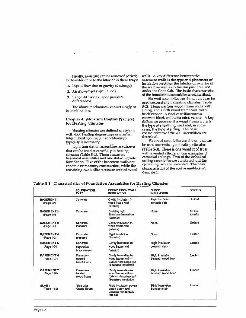
Eight foundation assemblies are shown that can be used successfully in healing climates (Table S-l). There are seven basement assemblies and one slab-on-grade foundation. Five of the basement walls are concrete or masonry construction, while the remaining two utilize pressure-treated wood
walls. A key difference between the basement walls is the type and placement of insulation on either the interior or exterior of the wall, as well as in the rim joist area and under the floor slab. The basic characteristics of the foundation assemblies are described.
Six wall assemblies are shown that can be used successfully in heating climates (Table S-2). There are four wood frame walls with siding, and a fifth wood frame wall with brick veneer. A final case illustrates a concrete block wall with brick veneer. A key difference between the wood frame walls is the type of sheathing used and, in some cases, the type of siding. The basic characteristics of the wall assemblies are described.
Five roof assemblies are shown that can be used successfully in heating climates (Table S-3). There is one wood roof truss with a vented attic, and four examples of cathedral ceilings. Two of the cathedral ceiling assemblies are ventilated and the remaining two are unvented. The basic characteristics of the roof assemblies are described.
Table S-l: Characteristics of Foundation Assemblies for Heating Climates
BASEMENT 1 (Page 92)
BASEMENT2 (Page 95)
BASEMENTS (Page 9S)
BASEMENT4 (Page 101)
BASEMENT 5 (Page 104)
BASEMENT B (Page 107)
BASEMENT 7 (Page 110)
SLAB 1 page 113)
FOUNDATION FOUNDATION WALL FLOOR DRYING TYPE INSULATION INSULATION
Concrete
Concrete
Concrete masonry
Concrete masonry
Concrela supporting biicl< veneer
Pressure- treated wood frame
Pressure- treated wood frame
Slab with Grade Beam
Cavity Insulation In wood frame wait (Interior)
Draining rigid fiberglass insulation (Exterior)
Cavity Insulation in wood frame wall (interior)
Rigid insulation (Exterior)
Cavity insulation in wood frame wall (Interior)
Cavity insulation in wood frame wall— Exterior draining rigid fib or ■-Lars insulation
Cavity insulation in wood frame wall— Exterior draining rigid fiberglass, insulation
Rigid Insulation covers grade beam and extends horizontally into soil
Rigid insulation beneath slab
None
None
None
Rigid insulation beneath slab
Rigid insulation beneath wood floor
Rigid insulation beneath wood floor
Rigid Insulation boneath slab
Limited
To lire exterior
Limited
Umitod
Limited
Limited
limited
Limited
Page xvi
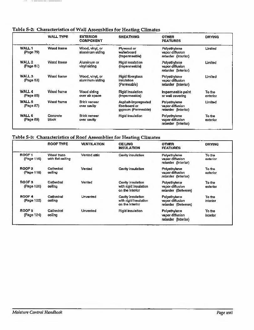
Table S-2: Characteristics of Wall Assemblies for Heating Climates WALL TYPE EXTERIOR
COMPONENT SHEATHING OTHER
FEATURES DRYING
WALL 1 (Page 79)
WALL 2 (Page 81)
WALL 3 (Page 83)
WALL 4 (Page 85)
WALLS (Page 87)
WALL 6 (Page 89)
Wood frame
Wood frame
Wood frame
Wood frame
Wood frame
Concrete block
Wood, vinyl, or aluminum siding
Aluminum or vinyl siding
Wood, vinyl, or aluminum siding
Wood siding over airspace
Brick veneer over cavity
Brick veneer over cavity
Piywood or waferboard (Impermeable)
Rigid insulation (Impermeable)
Rigid fiberglass insulation (Permeable)
Rigid insulation (impermeable)
Asphaft-impregnated fiberboard or gypsum (Permeabie)
Rigid insulation
Polyethylene vapor diffusion retarder (Interior)
Polyethylene vapor diffusion retarder (Interior)
Polyethylene vapor diffusion retarder (Interior)
Impermeable paint or wall covering
Polyethylene vapor diffusion retarder (Interior)
Polyethyiene vapor diffusion retarder (Interior)
Limited
Limited
Limited
To the exterior
Limited
To the exterior
ROOF TYPE VENTILATION CHUNG OTHER DRYING INSULATION FEATURES
ROOF 1 (Page 116)
ROOF 2 (Page 118)
ROOF 3 (Page 120)
HOOF 4 (Page 122)
ROOFS (Page 124)
Wood truss with flat ceiling
Cathedral ceiling
Cathedral ceiling
Cathedral ceiling
Cathedra! ceiling
Vented attic
Vented
Vented
Unvented
Unvented
Cavity insulation
Cavity insulation
Cavity insulation with rigid Insulation on the interior
Polyethylene To the vapor diffusion exterior retarder (Interior)
Polyethylene To the vapor diffusion exterior retarder (Interior)
Polyethylene To the vapor diffusion exterior retarder (Between)
Cavity insulation with rigid insulation on the interior
Polyethylene To the vapor diffusion interior retarder (Between)
Rigid insulation Polyethylene To the vapor diffusion interior retarder (Interior)
Moisture Control Handbook Page xvii

Chapter 5: Moisture Control Practices for Mixed Climates
Mixed climates are defined as regions with up to 4000 heating degree days combined with a significant number of cooling (air conditioning) hours. Heating and cooling are needed for significant periods of time.
Eight foundation assemblies are shown that can be used successfully in mixed climates (Table S-4). There are four basement assemblies and four crawl spaces. Three of the basement walls are concrete or masonry construction, while the other utilizes pressure-treated wood walls. All four crawl spaces fire unvented - two utilize concrete or masonry walls, and two are pressure treated wood construction. A key difference between tbe foundation assemblies is the type and placement of insulation on either the interior or exterior of the wail, as well as
in the rim joist area and the floor. The basic characteristics of the foundation assemblies are described.
Five wall assemblies are shown that can be used successfully in mixed climates (Table S-5). All five examples are wood frame walls - three with siding, one with brick veneer, and one with stucco cladding. -Other differences between the wood frame wails include the type of sheathing and whether an interior vapor diffusion retarder is used. The basic characteristics of the wall assemblies are described.
Four root assemblies are shown that can be used successfully in mixed climates (Table P-6)- There are two assemblies with wood roof trusses and vented attics, and two examples of cathedral ceilings. One of the cathedral ceiling assemblies is ventilated and th e o ther one i sun vented. The basic characteristics of the roof assemblies are described.
Table S-4: Characteristics of Foundation Assemblies for Mixed Climates FOUNDATION TYPE
FOUNDATION WALL
INSULATION FLOOR
INSULATION DRYING
BASEMENT 1 {Page 144)
BASEMENT 2 (Pago 147)
BASEMENT 3 (Page 150)
BASEMENT4 (Page 153)
CRAWL SPACE 1 (Page 15S)
CRAWL SPACE 2 (Page 159)
CRAWL SPACE 3 (Page 162)
CRAWL SPACE 4 (Page 165)
Con,TretB
Corraete
Concrete masonry supporting brick
Pressure- treated wood frame
Concrete
Concrete masonry
Pressure- treated wood frame
Pressure- treated ■wood frame
Rigid insulation (Exterior)
Cavity insulation in wood frame Wat! (Interior)
Cavity insulation in wood frame wall (Interior)
Cavity Insulation In wood frame wall— Rigid insulation (Exterior)
Rigid insulation (Exterior)
Faced batt insulation over wail (interior)
Cavity insulation in wood frame wall— Rigid insulation (Exterior)
Cavity insulation in wood frame wall— Rigid insulation (Exterior)
None
None
None
Rigid insulation beneath wood floor
None
Faced batt insulation extends onto floor perimeter
None
Faced batt insulation extends onto floor perimeter
Limited
Limited
limited
Limited
To the interior
To the interior
To the interior
To the Interior
Page xoiii

Table S-5: Characteristics of Wall Assemblies for Mixed Climates WALL TYPE EXTERIOR
COMPONENT
WALL 1 (Page 132)
WALL 2 (Page 134)
WA LL 3 (Page 136)
Wood frame
Wood frame
Wood frame
Wood, vinyl, or aluminum siding
Aluminum or vinyl siding
Brick veneer over cavity
Aluminum or vinyl siding
WALL 4 Wood frame (Page 138)
SHEATHING OTHER DRYING FEATURES
Plywood or Polyethylene Limited waferboard vapor diffusion (Impermeable) retarder (Interior)
Asphalt-impregnated Polyethylene Limited fiberboard or vapor diffusion gypsum (Permeable) retarder (Interior)
Asphalt-impregnated Polyethylene Limited fiberboard or vapor diffusion gypsum (Permeable) retarder (Interior)
Rigid insulation Permeable latex paint To the (Impermeable) permits drying to Ihe interior
interior
WALL 5 Wood frame (Page 140)
Stucco cladding Rigid insulation (Impermeable)
Permeable latex paint To the permits drying to the exterior interior
Table S-6: Characteristics of Roof Assemblies for Mixed Climates ROOF TYPE VENTILATION CEIUNG OTHER
INSULATION FEATURES
ROOF 1 (Page 169)
ROOF 2 (Page 171)
ROOF 3 (Page 173)
ROOF 4 (Page 175)
Wood truss with fiat ceiling
Wood truss with fiat ceiling
Cathedral ceiling
Cathedral ceiling
Vented attic
Vented attic
Vented
Unvented
Cavity insulation
Cavity Insulation
Cavity insulation
Cavity insulation with rigid insulation on the exterior
Polyethylene vapor diffusion retarder (Interior)
Gypsum board sealed to framing acts as air retarder
Polyethylene vapor diffusion retarder (Interior)
Polyethylene vapor diffusion retarder (Between)
DRYING
To the exterior
To the exterior
To the exterior
To Ihe interior
Moisture Control Handbook Page xix
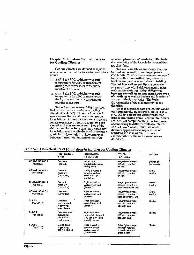
Chapter 6: Moisture Control Practices for Cooling Climates
Cooling climates are defined as regions where one or both of the following conditions occur:
1. A 67 °F {19.4 “C) or higher wet bulb temperature for 3000 or more hours during the warmest six consecutive months of tile year,
2, A 73 °F (22,8 "C) or higher wet bulb temperature for 1500 or more hours during the warmest six consecutive months of the year.
Seven foundation assemblies are shown that can be used successfully in cooling climates (Tabic S-7). There are four crawl space assemblies and three slab-on-grade foundations. All four of the crawl spaces are concrete or masonry construction - two are vented, and two are unvented. Two of the slab assemblies include concrete or masonry foundation walls, while the third illustrates a grade beam foundation. A key difference between the foundation assemblies is the
type and placement of insulation. The basic characteristics of the foundation assemblies are described.
Ten wall assemblies are shown that can be used successfully in cooling climates (Table S-8). The first five examples are wood frame walls - three with siding, one with brick veneer, and one with stucco cladding. The last five wall assemblies are concrete masonry - two with brick veneer, and three with stucco cladding. Other differences between the wall assemblies include the type of sheathing as well as the use and location of a vapor diffusion retarder. The basic characteristics of the wall assemblies axe described.
Six roof assemblies are shown that can be used successfully in cooling climates (Table S~9). All six assemblies utilize wood roof trusses and vented attics. The first four roofs are identical except that they illustrate ways of connecting to different well assemblies. The last two roof assemblies illustrate different approaches to vapor diffusion retarders and insulation. The basic characteristics of the roof assemblies are described.
Table S-7i Characteristics of Foundation Assemblies for Cooling Climates
CRAWL SPACE 1 (Paga 206)
CRAWL SPACE 2 (Page 2D8)
CHAWL SPACE 3 (Pass 210)
CRAWL SPACE 4 (Page 212)
SLAB1 (Pago 21 4)
SLAB 2 (Pago 216)
SLAB 3 (Page 218)
FOUNDATION TYPE
FOUNDATION INSULATION
Concreie (Vanted)
Concrete masonry (Unvented)
Concrete masonry (Unvented)
Concrete (Unvented)
Concrete masonry well supporting wood frame
Concrete wall supporting block with brick veneer
Grade beam supporting concrete block
Faced batt insulation between ceiling joists
Cavhy insulation between ceiling joists over rigid insulation
Rigid insulation vertically on wall (Exterior)
Rigid insulation vertically on wail (interior)
Rigid insulation vertically on wail (Exterior)
Rigid insulation horizontally beneath slab perimeter and in walDfloor joint
Rigid insulation covers exterior vertical face of grade osam
OTHER FEATURES
DRYING
Polyethyiene vapor diffusion retarder on floor
Polyethylene vapor diffusion retarder on floor
Polyethylene vapor diffusion retarder on floor and interior wall
Polyethylene vapor diffusion retarder on floor and interior wall
Polyethylene vapor diffusion retarder beneath slab
Polyethylene vapor diffusion retarder beneath slab
Polyethylene vapor diffusion retarder beneath slab and grade beam
Limited to the exterior
To the Interior
To the interior
To the interior
Limited
Limited
Limited
Page xx
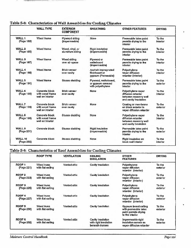
Table S-8: Characteristics of Wall Assemblies for Cooling Climates
WALL TYPE EXTERIOR SHEATHING OTHER FEATURES DRYING COMPONENT
WALL 1 Wood frame (Page 183)
Plywood siding None (Impermeable)
Permeable latex paint To the permits drying to the interior interior
WALL 2 Wood frame (Page 185)
Wood, vinyl, or Rigid insulation aluminum siding (Impermeable)
Permeable latex paint To the permits drying to the interior interior
WALL 3 (Page 187)
WALL 4 (Page 189)
WALLS (Page 191)
WALLS (Page 193)
WALL? (Page 19S)
WALL 8 (Page 198)
WALLS (Page 201)
WALL 10 (Page 203)
Wood frame
Wood frame
Wood frame
Concrete block with wood frame wall on Interior
Concrete block with wood frame wall on interior
Concrete block with wood frame wal! on interior
Concrete block
Concrete block
Wood siding over air space
Brick veneer over cavity
Stucco dad ding
Brick veneer over cavity
Brick veneer over cavity
Stucco dadding
Stucco dadding
Stucco dadding
Plywood or wafer board (Impermeable)
Asphalt-impregnated fiberboard or gypsum (Permeable)
Plywood, waferboard, or gypsum covered with polyethylene
None
None
None
Rigid insulation (Impermeable)
Permeable latex paint To the permits drying to the interior interior
Polyethylene To the vapor diffusion interior retarder (Interior)
Permeable latex paint To the permits drying to the exterior interior
Polyethylene vapor To the diffusion retarder interior between masonry wall and cavity insulation
Coating or membrane To the on block exterior is exterior vapor diffusion retarder
Polyethylene vapor To the diffusion retarder interior between masonry wail and cavity insulation
Permeable latex paint To the permits drying to the exterior interior
None Rigid insulation on To the block wall interior interior
Table S-9: Characteristics of Roof Assemblies for Cooling Climates ROOFTYPE VENTILATION CEIUNG
INSULATION OTHER FEATURES
DRYING
ROOF 1 (Page 221)
ROOF 2 (Page 223)
ROOF 3 (Page 225)
ROOF 4 (Page 227)
ROOFS (Page 230)
ROOF 6 (Page 232)
Wood truss with flat ceiling
Wood truss with flat ceiling
Wood truss with flat ceiling
Wood truss with flat ceiling
Wood truss with flat celling
Wood truss with flat ceiling
Vented attic
Vontod attic
Vented attic
Vented attic
Vented attic
Vented attic
Cavity insulation
Cavity insulation
Cavity insulation
Cavity insulation
Cavity insulation
Cavity insulation with rigid insulation beneath trusses
Polyethylene To the vapor diffusion exterior retarder (Interior)
Polyethylene To the vapor diffusion exterior retarder (Interior)
Polyethylene To the vapor diffusion exterior retarder (Inferior)
Polyethylene To the vapor diffusion exterior retarder (Interior)
Gypsum board ceiling To tile with permeable latex exterior paint permits drying to the interior
Impermeable rigid To the insulation serves as exterior vapor diffusion retarder
Moisture Control Handbook Page xxi
CHAPTER 1
Mold, Mildew, and Condensation
The most common surface moisture- related problems, regardless of climate, are mold, mildew, and condensation. The single most important factor influencing these problems is relative humidity near surfaces. Although a common term, relative humidity is typically misunderstood. Furthermore, the factors governing relative humidity are also typically misunderstood. Understanding the factors that govern relative humidity will enable builders and designers to control surface-related moisture problems.
Relative Humidity and Vapor Pressure
Air is capable of holding moisture in the vapor, or gas, phase. The amount of moisture contained in air is referred to as absolute humidity. More precisely, the absolute humidity is the ratio of the mass of water vapor to the mass of dry air. This is also referred to as the humidihj ratio.
Air is a mixture of several gases, the most notable being oxygen, nitrogen, and carbon dioxide. Since water vapor is a gas, air containing moisture is therefore a mixture of several gases including water vapor. The total air pressure exerted by a volume of air in a given container on that container is the sum of the individual or partial pressures of the constituent gases which make up the air, including water vapor. The WJ/rar pressure is the partial pressure of the water vapor gas on the container.
The terms absolute humidity, humidity ratio, and vapor pressure refer to the same concept: air contains varying amounts of
moisture in the gas or vapor form, depending on several factors. The amount of moisture air can hold—the air's vapor pressure, or absolute humidity—is dependent on die temperature of the air. The warmer air is, the greater the amount of moisture the air can hold; the cooler air is, the less moisture it can hold, Air is said to be saturated when it contains the maximum amount of moisture possible at a specific temperature, or 100 percent. Air holding half the maximum amount of moisture has a relative humidity of 50 percent. Relative hmnidiiu is defined as the amount of moisture contained in a unit of air relative to the maximum amount of moisture the unit of air can hold at a specific temperature.
Figure 1-1 illustrates the concepts of relative humidity, vapor pressure, and the influence of temperature and vapor pressure on relative humidity: Two containers, each containing the same amount of air, are sealed. The containers are assumed to be airtight, watertight and vaportight. The amount of moisture in each container is identical—1 trillion molecules of water in vapor form.
Container A is maintained at 70 degrees Fahrenheit, and container B is maintained at 50 degrees Fahrenheit. Recall that the warmer air is, the more moisture it can hold. Assume that the maximum amount of moisture the air in container A can hold is 2 trillion molecules of water in the vapor phase. Because the air in this container actually holds only 1 trillion molecules of water, the relative humidity is 50 percent. In contrast, the air in container B maintained at 50 degrees Fahrenheit can hold a maximum of only 1 trillion molecules of water, so the relative humidity of the air in container B is
Moisture Control Handbook Page 1
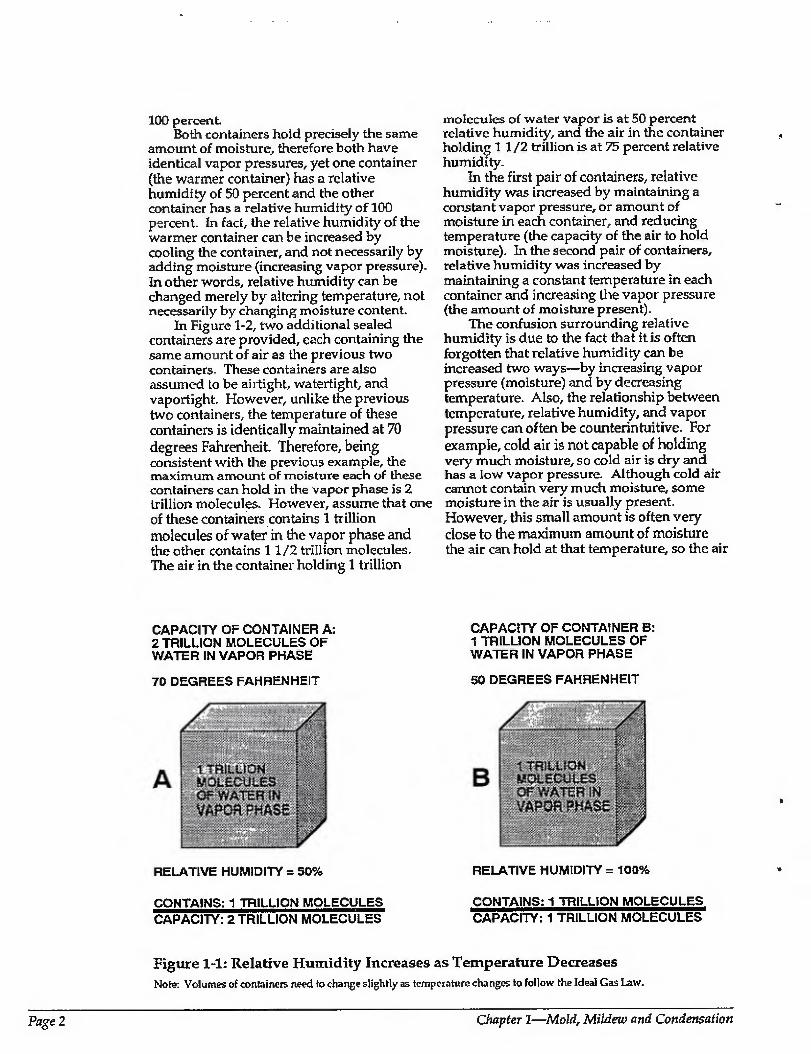
100 percent. Both containers hold precisely the same
amount of moisture, therefore both have identical vapor pressures, yet one container (the warmer container) has a relative humidity of 50 percent and the other container has a relative humidity of 100 percent. In fact, the relative humidity of the warmer container can be increased by cooling the container, and not necessarily by adding moisture (increasing vapor pressure). In other words, relative humidity can be changed merely by altering temperature, not necessarily by changing moisture content.
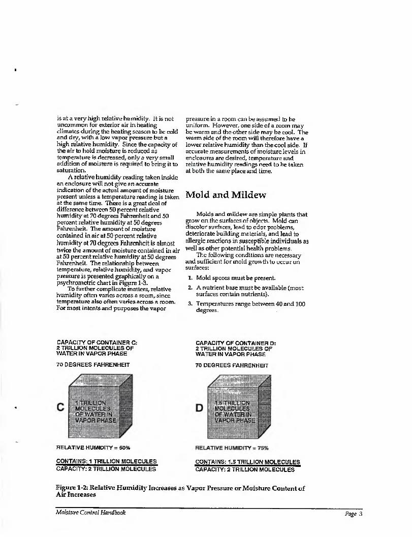
In Figure 1-2, two additional sealed containers are provided, each containing the same amount of air as the previous two containers. These containers are also assumed to be airtight, watertight, and vaportight. However, unlike the previous two containers, the temperature of these containers is identically maintained at 70 degrees Fahrenheit. Therefore, being consistent with the previous example, the maximum amount of moisture each of these containers can hold in the vapor phase is 2 trillion molecules. However, assume that one of these containers contains 1 trillion molecules of water in the vapor phase and the other contains 11/2 trillion molecules. The air in the container holding 1 trillion
CAPACITY OF CONTAINER A: 2 TRILLION MOLECULES OF WATER IN VAPOR PHASE
70 DEGREES FAHRENHEIT
RELATIVE HUMIDITY = 50%
CONTAINS: 1 TRILLION MOLECULES CAPACITY: 2 TRILLION MOLECULES
molecules of water vapor is at 50 percent relative humidity, and the air in the container holding 11/2 trillion is at 75 percent relative humidity.
In the first pair of containers, relative humidity was increased by maintaining a constant vapor pressure, or amount of moisture in each container, and reducing temperature (the capacity of the air to hold moisture). In the second pair of containers, relative humidity was increased by maintaining a constant temperature in each container and increasing the vapor pressure (the amount of moisture present).
The confusion surrounding relative humidity is due to the fact that it is often forgotten that relative humidity can be increased two ways—by increasing vapor pressure (moisture) and by decreasing temperature. Also, the relationship between temperature, relative humidity, and vapor pressure can often be counterintuitive. For example, cold air is not capable of holding very much moisture, so cold air is dry and has a low vapor pressure. Although cold air cannot contain very much moisture, some moisture in the air is usually present. However, this small amount is often very close to the maximum amount of moisture the air can hold at that temperature, so the air
CAPACITY OF CONTAINER B: 1 TRILLION MOLECULES OF WATER IN VAPOR PHASE
50 DEGREES FAHRENHEIT
RELATIVE HUMIDITY = 100%
CONTAINS: 1 TRILLION MOLECULES CAPACITY: 1 TRILLION MOLECULES
Figure 1-1: Relative Humidity Increases as Temperature Decreases Note: Volumes of containers need to change slightly as temperature changes to follow the Ideal Gas Law.
Page 2 Chapter 1—Mold, Mildeiv and Condensation
is at a very high relative humidity. It is not uncommon for exterior air in heating climates during the heating season to be cold and dry, with a low vapor pressure but a high relative humidity. Since the capacity of the air to hold moisture is reduced as temperature is decreased, only a very small addition of moisture is required to bring it to saturation.
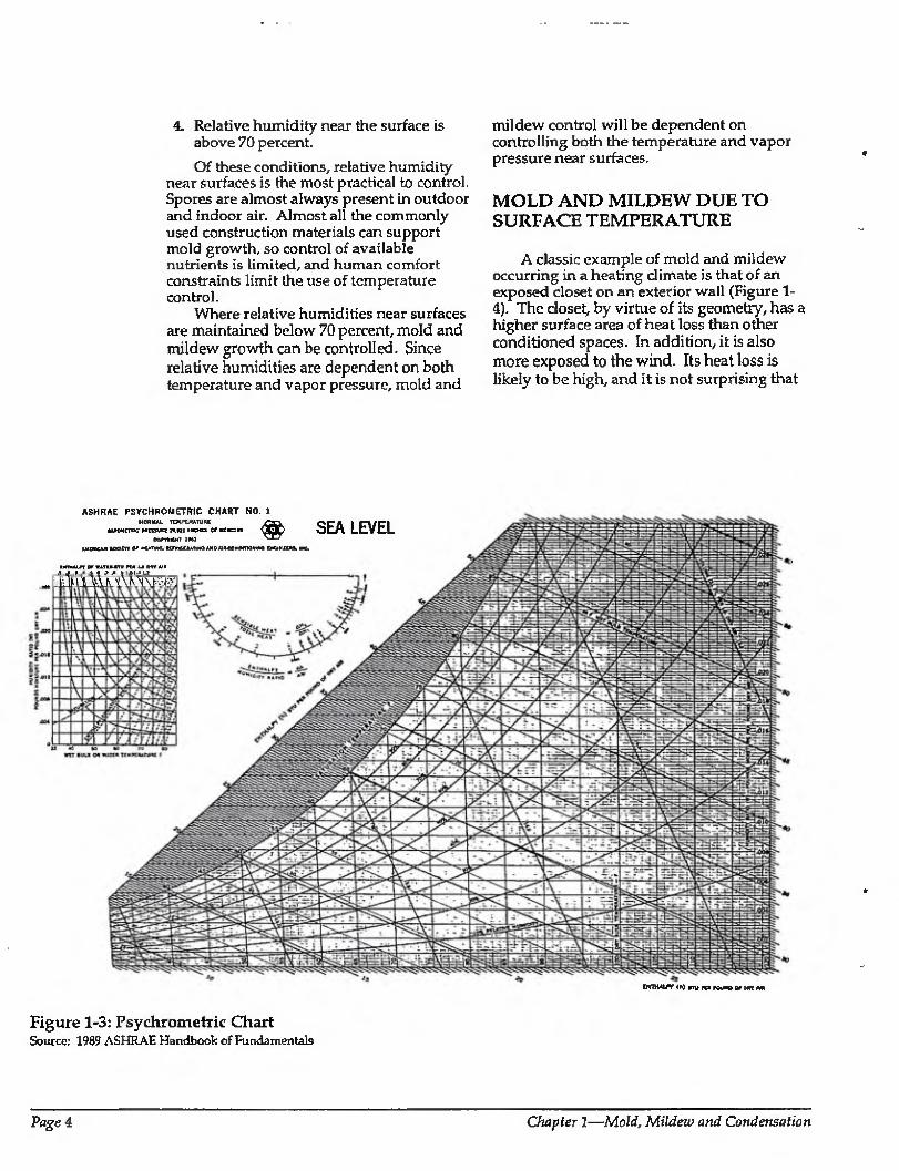
A relative humidity reading taken inside an enclosure will not give an accurate indication of the actual amount of moisture present unless a temperature reading is taken at the same time. There is a great deal of difference between 50 percent relative humidity at 70 degrees Fahrenheit and 50 percent relative humidity at 50 degrees Falirenheit. Tire amount of moisture contained in air at 50 percent relative humidity at 70 degrees Fahrenheit is almost twice the amount of moisture contained in air at 50 percent relative humidity at 50 degrees Fahrenheit. The relationship between temperature, relative humidity, and vapor pressure is presented graphically on a psychrometric chart in Figure 1-3.
To further complicate matters, relative humidity often varies across a room, since temperature also often varies across a room. For most intents and purposes the vapor
CAPACITY OF CONTAINER C: 2 TRILLION MOLECULES OF WATER !N VAPOR PHASE
70 DEGREES FAHRENHEIT
RELATIVE HUNUDiTY = 50%
CONTAINS: 1 TRILLION MOLECULES CAPACITY: 2 TRILLION MOLECULES
pressure in a room can be assumed to be uniform. However, one side of a room may be warm and the other side may be coot. The warm side of the room will therefore have a lower relative humidity than the cool side. If accurate measurements of moisture levels in enclosures are desired, temperature and relative humidity readings need to be taken at both the same place and time.
Mold and Mildew
Molds and mildew are simple plants that grow on the surfaces of objects. Mold can discolor surfaces, lead to odor problems, deteriorate building materials, and lead to allergic reactions in susceptible individuals as well as other potential health problems.
The following conditions are necessary and sufficient for mold growth to occur on surfaces:
1. Mold spores must be present.
2. A nutrient base must be available (most surfaces contain nutrients}.
3. Temperatures range between 40 and 100 degrees.
CAPACITY OF CONTAINER 0: 2 TRILLION MOLECULES OF WATER IN VAPOR PHASE
70 DEGREES FAHRENHEIT
CONTAINS: 1,5 TRILLION MOLECULES CAPACITY: 2 TRILLION MOLECULES
Figure 1-2: Relative Humidity Increases as Vapor Pressure or Moisture Content of Air Increases
Moisture Control Handbook Page 3
4. Relative humidity near the surface is above 70 percent.
Of these conditions, relative humidity near surfaces is the most practical to control. Spores are almost always present in outdoor and indoor air. Almost all the commonly used construction materials can support mold growth, so control of available nutrients is limited, and human comfort constraints limit the use of temperature control.
Where relative humidities near surfaces are maintained below 70 percent, mold and mildew growth can be controlled. Since relative humidities are dependent on both temperature and vapor pressure, mold and
mildew control will be dependent on controlling both the temperature and vapor pressure near surfaces.
MOLD AND MILDEW DUE TO SURFACE TEMPERATURE
A classic example of mold and mildew occurring in a heating climate is that of an exposed closet on an exterior wall (Figure 1- 4). The closet, by virtue of its geometry, has a higher surface area of heat loss than otfier conditioned spaces. In addition, it is also more exposed to the wind. Its heat loss is likely to be high, and it is not surprising that
ASHRAE FSYCHROMETRIC CHART NO. 1 MORUia. TtXPtfiAUIRt
tMotirroc rwai ihcho e# MKurF
comori )*U AMCKAw toarrr or matmc. h/kcuatiK) a*d Ai*cc«D<T»>nna ChgixiCjU, mc,
umuLrr Or waTaMTu ttJt ut Mr a/«
@ SEA LEVEL
DCfHAlW (*>> BTV TC* » W»T A*
Figure 1-3: Psychrometric Chart Source: 1989 ASHRAE Handbook of Fundamentals
Page 4 Oiapter 1—Mold, Mildew and Condensation
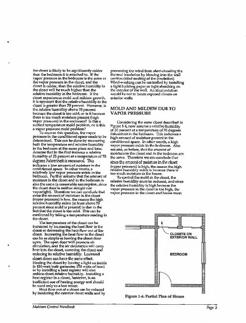
preventing the wind from short-circuiting the thermal insulation by blowing into the wall cavities (rsind-wssiting of the insulation). Wind-washing can be controlled by installing a tight building paper or tight sheathing on the exterior of the wall. An ideal solution would be not to locate exposed closets on exterior walls.
MOLD AND MILDEW DUE TO VAPOR PRESSURE
Considering Ihe same closet described in Figure 1-4, now assume a relative humidity of 50 percent at a temperature of 70 degrees Fahrenheit in the bedroom. This indicates a high amount of moisture present in the conditioned space. In other words, a high vapor pressure exists in the bedroom. Also assume, as before, that the amount of moisture in the closet and in the bedroom are the same Therefore we can conclude that since the amount of moisture in the closet (vapor pressure) is high, the reason the high relative humidity exists is because there is too much moisture in the house.
To control the mold in the closet, the relative humidity must be reduced, and since the relative humidity is high because the vapor pressure in the closet is too high, the vapor pressure in the closet and house must
the closet is likely to be significantly colder than the bedroom it is attached to. If the vapor pressure in the bedroom is the same as the vapor pressure in the closet, and the closet is colder, then the relative humidity in the closet will be much higher than the relative humidity in the bedroom. If the closet experiences mold and mildew growth, it Is apparent that the relative humidity in the closet is greater than 70 percent. However, is the relative humidity above 70 percent because the closet is too cold, or is it because there is too much moisture present (high vapor pressure) in the enclosure? Is this a surface temperature mold problem, or is this a vapor pressure mold problem?
To answer this question, the vapor pressure in the conditioned space needs to be determined. This can be done by measuring both the temperature and relative humidity in the bedroom at the same place and time. Assume that in the first instance a relative humidity of 25 percent at a temperature of 70 degrees Fahrenheit is measured. This indicates a low amount of moisture in the conditioned space. In other words, a relatively low vapor pressure exists in the bedroom. Further assume that the amount of moisture in the closet and in the bedroom is also the same (a reasonable assumption, since the closet door is neither airtight nor vaportight). Therefore we can conclude that since the amount of moisture in the closet (vapor pressure) is low, the reason the high relative humidity exists (at least above 70 percent since mold is present) is due to the fact that the closet is too cold. This can be confirmed by taking a temperature reading in the closet.
Tire temperature of the closet can be increased by increasing the heat flow to the closet or decreasing the heat flow out of the closet. Increasing the heat flow to the closet can be as simple as leaving the closet door open. The open door will promote air circulation, and the air circulation will carry heat into the closet, warming the closet and reducing its relative humidity. Louvered closet doors can have the same effect. Heating the closet by leaving a light on inside (a 150-watt bulb generates 150 watts of heat) or by installing a heat register will also reduce closet relative humidity. Installing a heat register in a closet, however, is an inefficient use of heating energy and should be used only as a last resort.
Heat flow out of a closet can be reduced by insulating the exterior closet walls and by
Moisture Control Handbook Page 5
be reduced. The vapor pressure or moisture levels in the closet and house can be reduced using three methods: source control,, dilution, and dehumidification.
Source control, the most energy efficient of the three approaches, involves controlling interior airborne moisture levels through the control of moisture sources. Common examples of source control are the direct venting of bathrooms, clothes dryers, and kitchen stoves to the exterior. Other strategies include the construction of dry basements and crawl spaces, the venting of space heaters directly to the exterior, the removal of unvented kerosene space heaters, and the storage of firewood outdoors rather than indoors.
Dilution involves the use of air change, or the exchange of interior moisture-laden air with exterior dry air. If the exterior air is dryer than the interior air, the greater the air change, the greater the dilution of interior airborne moisture levels. Dilution can occur through natural air change (uncontrolled infiltration and exfiltratton) or through mechanical ventilation (controlled air change) utilizing fans or blowers. Dilution by air change is only possible where the exterior air is dryer than the interior air. In cooling climates or during cooling periods this is often not the case. As such dilution of interior airborne moisture levels utilizing air change is limited to heating climates and during heating seasons. A common example of dilution control is installation of an exhaust fan that operates by timer or dehumidistat control.
Dehumidification involves the removal of moisture from a space and usually involves the cooling of warm, moisture-laden air to reduce its ability to hold moisture, thereby forcing the moisture to condense. As such dehumidification is often coupled with air conditioning and is common in cooling climates or during the cooling season. A common example of dehumidification control is the installation of a dehumidifier in a basement or bedroom.
COMMON EXAMPLES OF MOLD AND MILDEW
Most mold and mildew problems are either surface temperature related or vapor pressure related, or some combination of both. A surface-temperature-related mold problem may not be eliminated by increasing
ventilation or air change, whereas a vapor- pressure-related mold problem may not be eliminated by increasing temperatures. Understanding which factor dominates— surface temperature or vapor pressure—will limit the choice of effective strategies. An example of this would be an old, leaky, poorly insulated home in a heating climate which is suffering from mold and mildew. Since the house is leaky, it has a very high natural air change that dilutes interior airborne moisture levels and therefore maintains a very low interior vapor pressure- providing mechanical ventilation in this house by installing a fan in an attempt to control interior mold and mildew will likely not be effective since the interior moisture levels are already low. Increasing surface temperatures by insulating the exterior walls, thereby reducing surface relative humidities, would be a better strategy to control mold and mildew in this instance- Other common examples of mold and mildew follow.
Exterior Comers
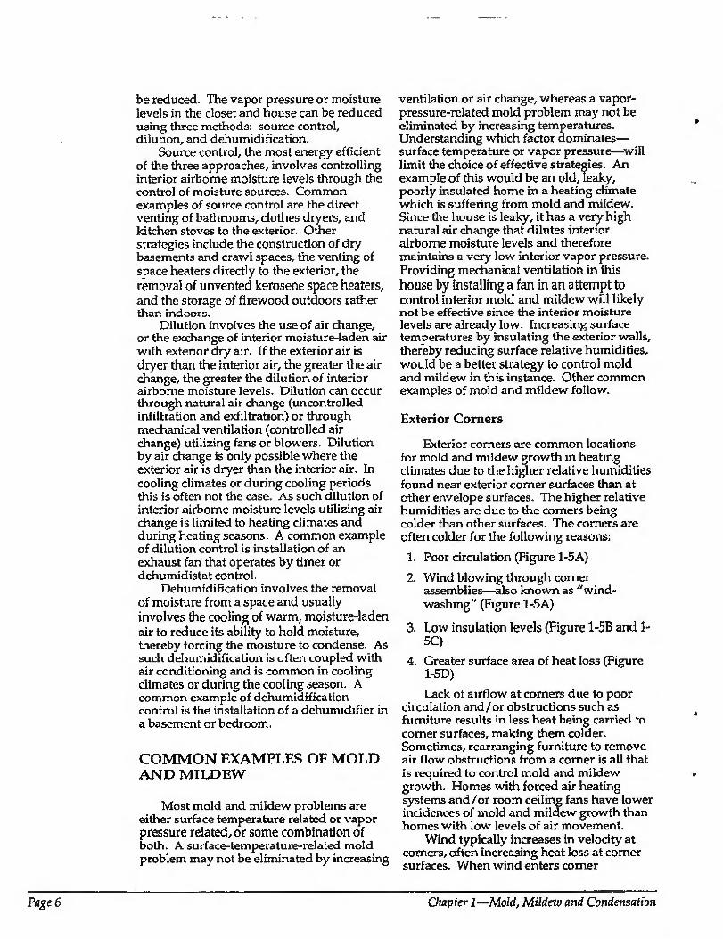
Exterior corners are common locations for mold and mildew growth in heating climates due to the higher relative humidities found near exterior comer surfaces than at other envelope surfaces. The higher relative humidities are due to the comers being colder than other surfaces. The comers are often colder for the following reasons:
1. Poor circulation (Figure 1-5A)
2. Wind blowing through corner assemblies—also known as "wind¬ washing" (Figure 1-5 A)
3. Low insulation levels (Figure 1-5B and 1- 5C)
4- Greater surface area of heat loss (Figure 1-5D)
Lack of airflow at corners due to poor circulation and/or obstructions such as furniture results in less heat being carried to comer surfaces, making them colder. Sometimes, rearranging furniture to remove air flow obstructions from a comer is all that is required to control mold and mildew growth. Homes with forced air heating systems and/or room ceiling fans have lower incidences of mold and mildew growth than homes with low levels of air movement.
Wind typically increases in velocity at comers, often increasing heat loss at comer surfaces. When wind enters comer
Page 6 Chapter 1—Mold, Mildew and Condensation
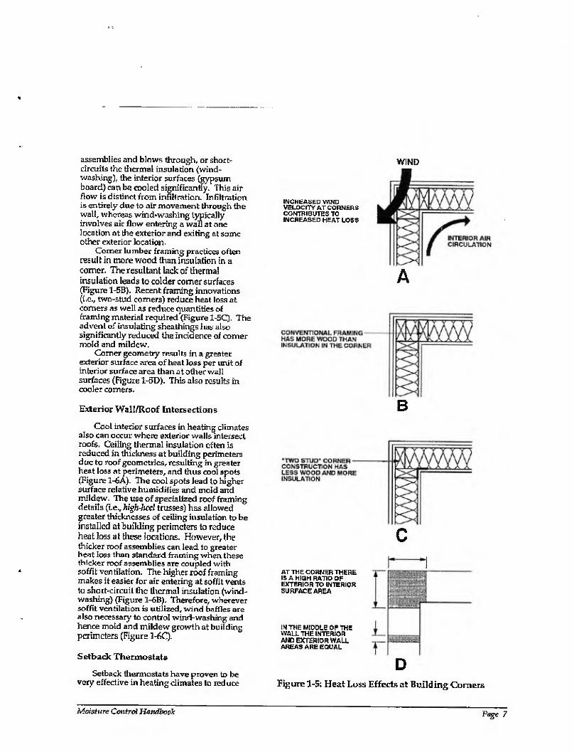
assemblies and blows through, or short- circuits the thermal insulation {wind¬ washing), the interior surfaces (gypsum board) can be coaled significantly. This air flow is distinct from infiltration. Infiltration is entirely due to air movement through the wall, whereas wind-washing typically involves air flow entering a wall at one location at the exterior and exiting at some other exterior location.
Comer lumber framing practices often result in more wood than insulation in a comer. The resultant lack of thermal insulation leads to colder comer surfaces (Figure 1-6B). Recent framing innovations (i.c., two-stud comers) reduce heat loss at comers as well as reduce quantities of framing material required (Figure 1-5C). The advent of insulating sheathings has also significantly reduced the incidence of comer mold and mildew.
Comer geometry results in a greater exterior surface area of heat loss per unit of interior surface area than at other wall surfaces (Figure 1-5D). This also results in cooler comers.
Exterior Wall/Roof Intersections
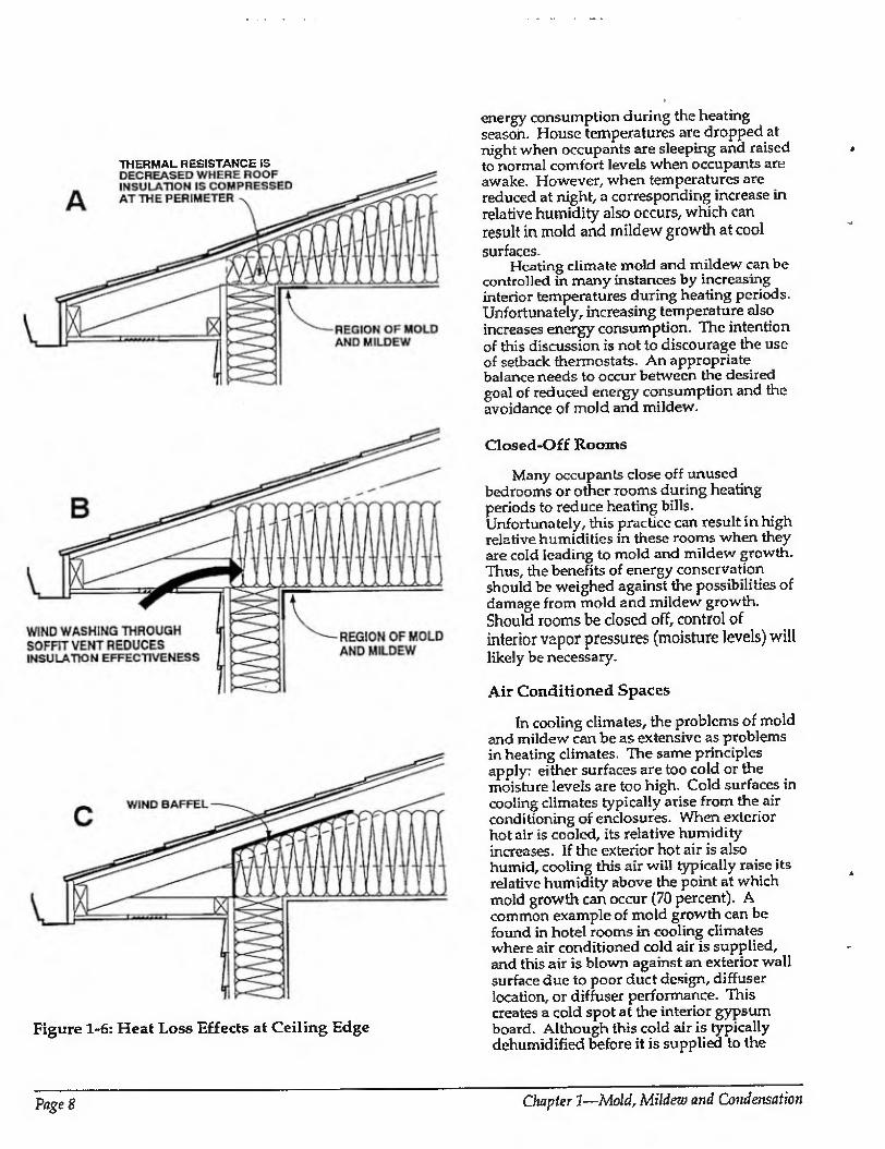
Cool interior surfaces in heating climates also can occur where exterior walls intersect roofs. Ceiling thermal insulation often is reduced in thickness at building perimeters due to roof geometries, resulting in greater heat loss at perimeters, and thus cool spots (Figure 1-6A). The cool spots lead to higher surface relative humidifies and mold and mildew. The use of specialized roof framing details (i.e., high-heel trusses) has allowed greater thicknesses of ceiling insulation to be installed at building perimeters to reduce heat loss at these locations. However, the thicker roof assemblies can lead to greater heat loss than standard framing when these thicker roof assemblies are coupled with soffit ventilation. The higher roof framing makes it easier for air entering at soffit vents to short-circuit the thermal insulation (wind¬ washing) (Figure 1-6B). Therefore, wherever soffit ventilation is utilized, wind baffles are also necessary to control wind-washing and hence mold and mildew growth at building perimeters (Figure 1-60).
Setback Thermostats
Setback thermostats have proven to be very effective in heating climates to reduce
INCREASED WIND VELOCITY AT CORNER S CONTRIBUTES TO INCREASED HEAT LOSS
WIND
A
B
c AT THE CORNER THERE IS A HIGH RATIO OF EXTERIOR to interior SURFACE AREA
INTHE MIDDLE OF THE WALL THE INTERIOR AND EXTERIOR WALL AREAS ARE EQUAL
D Figure 1-5: Heat Loss Effects at Building Comers
Moisture Control Handbook Page 7
THERMAL RESISTANCE IS
Figure 1-6: Heat Loss Effects at Ceiling Edge
energy consumption during the heating season. House temperatures are dropped at night when occupants are sleeping and raised to normal comfort levels when occupants are awake. However, when temperatures arc reduced at night, a corresponding increase in relative humidity also occurs, which can result in mold and mildew growth at cool surfaces.
Heating climate mold and mildew can be controlled in many instances by increasing interior temperatures during heating periods. Unfortunately, increasing temperature also increases energy consumption. The intention of this discussion is not to discourage the use of setback thermostats. An appropriate balance needs to occur between the desired goal of reduced energy consumption and the avoidance of mold and mildew.
Closed-Off Rooms
Many occupants close off unused bedrooms or other rooms during heating periods to reduce heating bills. Unfortunately, this practice can result in high relative humidities in these rooms when they are cold leading to mold and mildew growth. Thus, the benefits of energy conservation should be weighed against the possibilities of damage from mold and mildew growth. Should rooms be dosed off, control of interior vapor pressures (moisture levels) will likely be necessary.
Air Conditioned Spaces
In cooling climates, the problems of mold and mildew can be as extensive as problems in heating climates. The same principles apply: either surfaces are too cold or the moisture levels are too high. Cold surfaces in cooling climates typically arise from the air conditioning of enclosures. When exterior hot air is cooled, its relative humidity increases. If the exterior hot air is also humid, cooling this air will typically raise its relative humidity above the point at which mold growth can occur (70 percent). A common example of mold growth can be found in hotel rooms in cooling climates where air conditioned cold air is supplied, and this air is blown against an exterior wall surface due to poor duct design, diffuser location, or diffuser performance. This creates a cold spot at the interior gypsum board. Although this cold air is typically dehumidified before it is supplied to the
Page 8 Chapter 1—Mold, Mildew and Condensation
conditioned space, it can create a mold problem within a wall cavity due to exterior moisture rather than interior moisture. This occurs if exterior humid air comes in contact with the cavity side of the cooled interior gypsum board.
This is particularly a problem in hotel rooms due to the high usage of low maintenance interior finishes (impermeable wall coverings such as vinyl wallpaper), which can trap moisture between the interior finish and the gypsum board. When these interior finishes are coupled with cold spots and exterior moisture, mold growth is rampant. Several solutions are possible: (1) preventing the hot, humid exterior air from contacting the cold gypsum board (controlling the vapor pressure at the surface and air pressure differentials across assemblies); (2) eliminating the cold spots (elevating the temperature of the surface) by relocating ducts and diffusers; or (3) increasing enclosure temperatures (preventing the overcooling of rooms).
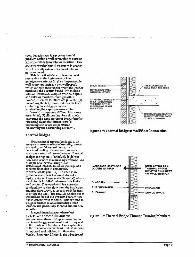
Thermal Bridges Figure 1-7: Thermal Bridge at Wall/Floar Intersection
The cooling of any surface leads to an increase in surface relative humidity, which can lead to mold and mildew growth. Localized cooling of surfaces commonly occurs as a result of thermal bridges. Thermal bridges are regions of relatively high heat flow conductance in a building envelope. An example of a thermal bridge is an uninsulated window lintel, or the edge of a concrete floor slab in commercial construction (Figure 1-7). An even more common example is the wood stud of a typical exterior frame wall (Figure 1-8) where insulation is installed between studs in the wall cavity. The wood stud has a greater conductivity to heat flow than the insulation, and therefore provides an easy path for heat to bridge the wall. The result is a cold spot at the interior face of the gypsum board where it is in contact with the stud. This can lead to a higher surface relative humidity at this location and potentially to mold and mildew growth.
In conditioned spaces where dust particles are airborne, the dust can accumulate at these cold spots, resulting in marks on the gypsum board that correspond to the location of the studs. One explanation of the phenomenon involved in dust marking is not mold and mildew, but Brownian Motion. Brownian Motion is the vibration of
INCREASED HEAT LOSS OCCURS AT STUD
CLADDING--
BUILDING PAPER
SHEATHING-
STUD ACTING AS A THERMAL BRIDGE CREATES COLD SPOT ON WALL INTERIOR
INSULATION
GYPSUM BOARD
Figure 1-8: Thermal Bridge Through Framing Members
Moisture Control Handbook Page 9
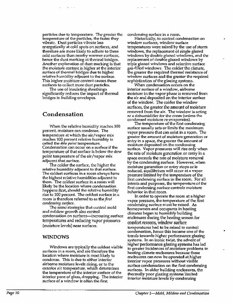
particles due to temperature. The greater the temperature of the particles, the faster they vibrate. Dust particles vibrate less energetically at cold spots on surfaces, and therefore are more likely to adhere to these cold surfaces than nearby warmer surfaces, hence the dust marking at thermal bridges. Another explanation of dust marking is that the moisture content is higher at the interior surface of thermal bridges due to higher relative humidity adjacent to the surface. This higher moisture content causes these surfaces to collect more dust particles.
The use of insulating sheathings significantly reduces the impact of thermal bridges in building envelopes.
Condensation
When the relative humidity reaches 100 percent, moisture can condense. The temperature at which the air/vapor mix reaches 100 percent relative humidity is called the dew point temperature. Condensation can occur on a surface if the temperature of that surface is below the dew point temperature of the air/vapor mix adjacent that surface.
The colder the surface, the higher the relative humidity adjacent to that surface. The coldest surfaces in a room always have the highest relative humidities adjacent to them. The coldest surface in a room will likely be the location where condensation happens first, should the relative humidity rise to 100 percent. The coldest surface in a room is therefore referred to as the jirsf condensing surface.
The same strategies that control mold and mildew growth also control condensation on surfaces—increasing surface temperatures and reducing vapor pressures (moisture levels) near surfaces.
WINDOWS
Windows are typically the coldest visible surfaces in a room, and are therefore the location where moisture is most likely to condense. This is due to either interior airborne moisture levels rising, or to the exterior air temperature, which determines the temperature of the interior surface of the interior pane of glass, dropping. The interior surface of a window is often the first
condensing surface in a room. Historically, to control condensation on
window surfaces, window surface temperatures were raised by the use of storm windows, the replacement of single glazed windows by double glazed windows, and the replacement of double glazed windows by triple glazed windows and selective surface gas-filled windows. The colder the climate, the greater the required thermal resistance of window surfaces and the greater the required sophistication of the glazing systems.
When condensation occurs on the interior surface of a window, airborne moisture in the vapor phase is removed from the air and deposited on the interior surface of the window. The colder the window surfaces, the greater the amount of moisture removed from the air. The window is acting as a dehumidifier for the room (unless the condensed moisture re-evaporates).
The temperature of the first condensing surface usually sets or limits the maximum vapor pressure that can exist in a room. The greater the amount of moisture generation or entry in a space, the greater the amount of moisture deposited on the condensing surface. Vapor pressures will rise only when the rate of moisture generation or entry in a space exceeds the rate of moisture removal by the condensing surface. However, when moisture generation or entry stops or is reduced, equilibrium will occur at a vapor pressure limited by the temperature of the first condensing surface in the room. For all intents and purposes, the temperature of the first condensing surface controls moisture behavior in that room.
In order to operate the room at a higher vapor pressure, the temperature of the first condensing surface must be raised. As homeowners and occupants in heating climates began to humidify building enclosures during the heating season for comfort reasons, window surface temperatures had to be raised to control condensation, hence this became one of the trends towards higher performance glazing systems. In an ironic twist, the advent of higher performance glazing systems has led to greater incidences of moisture problems in heating climate enclosures because these enclosures can now be operated at higher interior vapor pressures without visible surface condensation on the first condensing surfaces. In older building enclosures, the thermally poor glazing systems limited interior moisture levels by condensing
Page 10 Chapter I—Mold, Mildew and Condensation
moisture. The visible condensation often alerted occupants to the need for ventilation to flush out interior moisture. The windows acted as canaries for moisture and other indoor air pollutants.
CONCEALED CONDENSATION
The use of thermal insulation in wall cavities increases interior surface temperatures in heating climates and therefore reduces the likelihood of interior surface mold, mildew, and condensation. However, the use of thermal insulation also reduces the temperature of the outer portions of the wall cavities by reducing heat loss from the conditioned space into the wall cavities and therefore increases the likelihood of concealed condensation within the wall cavities. The first condensing surface in a wall cavity is typically the interior surface (back, side) of the exterior sheathing. The temperature of these surfaces is reduced by increasing the insulation values in the wall cavities.
Concealed condensation can be controlled by reducing the entry of moisture into the wall cavities or by elevating the temperature of the first condensing surface. Elevating the temperature of the first condensing surface in a heating climate wall assembly can be accomplished by installing insulation lo the exterior of the first condensing surface. Insulating sheathings serve this function. When insulating sheathings are installed on the exterior of wall framing, they warm up everything to the interior of them. They act like double glazing and triple glazing fur a wall.
The first condensing surface in a cooling climate is typically the back side of the interior gypsum finish. The temperature of the first condensing surface in a cooling climate can be elevated by installing impermeable insulating sheathing to the interior of the wall framing, between the wall framing and the interior gypsum board. In this manner, the first condensing surface is moved towards the exterior of the wall and becomes the cavity side of the insulating sheathing rather than the interior gypsum board.
CHAPTER 1: BIBLIOGRAPHY
Angell, W.J., Home Moisture Sources, (CD-FO 3396), Minnesota Extension Service, University of Minnesota, St. Paul, Minnesota, 1988-
Arg, N., A.L. Sescius, and J. Timusk, The Control of Wind Cooling of Wood Frame Building Enclosures, FF.RA Conference, Portland, Oregon, 1988.
Burge, H.A., "Indoor Sources for Airborne Microbes", Indoor Air and Human Health, edited by R.B. Gaminage and S.V. Kaye, Lewis Publishers, Chelsea, Michigan, 1985.
National Center for Appropriate Technology, Moisture and Home Energy Conservation: Hero in Detect, Solve and Avoid Related Problems, DOE/CE/15095 4, 1983.
Oatman, L. and C.A. Lane, Mold and Mildew in the Home, (CD-FO-3397), Minnesota Extension Service, University of Minnesota, St. Paul, Minne30fca,1988.
White, J., Moisture, Mould, Ventilation and Energy, paper presented at ENERhouse 91 Conference, Halifax, Canada, March 1991.
White, J., Ventilation for Humidity Control, CMHC, Ottawa, Canada, 1984.
Moisture Control Handbook Page 11

CHAPTER 2
Moisture Movement In order to control moisture levels and
moisture movement in buildings, the mechanisms governing such movement must be understood, along with their relative magnitude. Appreciating the magnitude of each transport mechanism is crucial in developing an effective design and construction strategy. When working with limited resources, it is unwise to concentrate a disproportionate share of those resources and effort on relatively minor factors, while allowing major factors to be ignored.
The four moisture transport mechanisms predominant in building science are:
1. Liquid flow due to gravity and/or an air pressure difference
2. Moisture transport due to capillary suction
3. Air movement
4. Vapor diffusion
All moisture movement, and therefore any moisture-related problem, is a result of one or a combination of these mechanisms.
Each of these mechanisms can act independently and must be dealt with during design and construction. The first mechanism, liquid flow, is primarily responsible for moving moisture into the building envelope from the exterior. Capillary suction typically moves moisture into the building envelope from the exterior and also redistributes condensed moisture within building envelopes. The latter two mechanisms, air movement and vapor diffusion, can move moisture both from the exterior as well as from within the conditioned space into the building envelope, depending on exterior and interior conditions. For example, when a building in a cold climate is being heated, air movement and vapor diffusion typically result in a net movement from within the conditioned space
into the building envelope. When a building in a warm climate is being cooled, air movement and vapor diffusion may result in a net movement of moisture from the exterior into the conditioned space.
This duality of movement is dependent on both climatic and interior conditions and is often overlooked by designers and builders. It is not unusual to find cold climate building envelope designs employed in warm climate regions. Even more confusing to the builder and designer are conditions where both heating and cooling occur for extended periods of time.
Of the four transport mechanisms, the most significant are liquid flow and capillary suction where groundwater and rain are the moisture sources. Controlling groundwater entry below grade and rain entry above grade have traditionally been the preoccupation of generations of builders and designers, and it is no different today. Liquid flow and capillarity are also recognized as the primary factors in the wetting of materials. Air transport and vapor diffusion are less obvious contributions.
Liquid Flow with Groundwater and Rain as Moisture Sources
The first and most significant moisture transport mechanism a designer and builder must deal with is liquid flow. This involves groundwater and rain as moisture sources moving under the influence of a driving force, typically gravity or air pressure. This mechanism is responsible for moving moisture from the exterior into the building envelope.
Page 12 Chapter 2—Moisture Movement

Leakage will occur if three conditions prevail;
1. Groundwater or rain is present.
2. An opening or hole in the building envelope exists.
3. A driving force (gravity and/or an air pressure difference) is present.
Understanding these conditions gives designers and builders flexibility in developing various strategies to control this moisture transport mechanism.
Designers or builders can seldom control whether groundwater or rain is present, and they certainly cannot control air pressure differences (wind) or gravity. However, a designer or builder may be able to influence the magnitude (or source strength) of the groundwater and rain by proper site selection (minimizing wind exposure and building on elevated dry ground), and are also likely able to control the number of Openings or holes in a building enclosure. Furthermore, although the driving forces cannot be eliminated, they can be controlled by cladding geometry, flashings, and drainage.
Experience has shown that controlling the effects of the driving forces, rather than eliminating openings, is the most effective approach for controlling liquid flow, since it is difficult to build an enclosure without openings. In the portions of the building envelope below grade, gravity {hydrostatic pressure) can be controlled by the use of the drain screen. The most common example of a drain screen is free-draining backfill material. Above grade, sir pressure differences across exterior cladding can be controlled by the use of the rain screen principle. This involves pressure equalization of an air space behind exterior cladding or within joints between cladding components. The most common example of a rain screen is an air space behind the brick cladding of a brick veneer wall,
It is also possible to provide a barrier below grade (waterproofing, or the elimination of below-grade openings) to resist hydrostatic pressure, and to provide a barrier above grade (weatherproofing, or the elimination of above-grade openings) to resist rain entry. However, waterproofing and weatherproofing are more dependent on workmanship and the appropriate choice of materials than both the drain screen and rain screen. Above grade, stucco claddings and
RAINWATER COLLECTED BY - THE ENTIRE ROOF AREA FALLS DIRECTLY TO THE GROUND AT THE BUILDING PERIMETER WHEN THERE ARE NO GUTTERS
LACK OF OVERHANGS PLACE TFIE WATER CLOSER TO THE BUILDING
THE GROUND NEAR THE FOUNDATION IS SATURATED
Figure 2-1A: Potential Surface Drainage Problems
RAINWATER FALLING ON THE ROOF IS COLLECTED IN GUTTERS
OVERHANG PROTECTS TOE AREA AROUND THE BUILDING
IMPERMEABLE BACKFILL - {CLAY CAP) AROUND BUILDING PERIMETER
DOWNSPOUTS CARRY ROOF WATER AWAY FROM THE FOUNDATION
GROUND SLOPES AWAY FROM WALL AT ST,
Figure 2-lB: Effective Surface Drainage Techniques
Moisture Control Handbook Page 13
the use of building papers, caulks, and sealants help eliminate openings to control rain entry.
GROUNDWATER
Groundwater control can be broken into the following two strategies:
1. Reduce the rate at which surface water and rainwater enter the ground adjacent to a building enclosure, thereby becoming groundwater.
2. Prevent groundwater from entering the building enclosure below grade.
Both strategies should be implemented to control groundwater effectively.
Reducing the rate at which surface water and rainwater enter the ground adjacent to a building enclosure is a rather straightforward exercise. The following steps have historically proven effective:
1. Roof assemblies typically concentrate rainwater collected from an entire building s footprint at the building's perimeter, where if it is not diverted can lead to serious groundwater problems (Figure 2-1A). Eavestroughs, gutters, and roof overhangs can control rainwater from roof assemblies very effectively. Where possible eavestrough, gutter, and downspout systems should direct water away from the building above grade, and not tie into a below-grade drainage system (Figure 2-IB).
2. Poor site location and/or site grading practices can lead to surface water flow toward building foundations. Ground should slope away from foundation walls, and swales and troughs should be considered in redirecting surface runoff (Figure 2-1B). Provision for backfill settlement over time should be made.
3. Rainwater and surface water absorption by backfill material can cause groundwater to concentrate at building perimeters. Locating heavily irrigated flower beds and gardens immediately adjacent to building perimeters has similar effects. Backfilling the upper portions of foundation excavations with impermeable material (a clay cap) has traditionally been effective (Figure 2-1B). Locating a sloping sidewalk adjacent to a foundation also works well in preventing
water absorption by the ground; however, this strategy needs to consider the effects of splash-back on wall/ cladding assemblies.
Preventing groundwater from entering the building enclosure below grade involves the implementation of two approaches, either singularly or in concert:
1. Provide a drain screen to control the effects of gravity or hydrostatic pressure.
2. Eliminate below-grade openings or provide a barrier/membrane to resist hydrostatic pressure (waterproofing).
Drain Screens
A drain screen is an approach for controlling below-grade water that involves placement of free-draining material immediately adjacent to foundation assemblies linked to some type of a subgrade drainage system (Figure 2-2). This free- draining material, typically sand or gravel, allows for the free flow of water downwards towards a subgrade drainage system under the influence of gravity. The rational is to prevent the development of hydrostatic pressure. Water running down the basement wall will not be forced in through cracks. In fact, it can be argued that given the alternatives of running between the soil pores or into the basement cracks in the absence of hydrostatic pressure, the water will travel through the smaller pores of the soil. Of course, if the free-draining material directs the flow of groundwater downwards, some provision for removing the water at the base of the free-draining material must be made, hence the subgrade drainage system. The subgrade drainage system in essence lowers the groundwater table immediately adjacent to the foundation.
The subgrade drainage system is usually a perforated drainage pipe located at the perimeter of the foundation below the basement floor level (if a basement space is present) to the exterior of the wall. The perforated drainage pipe is encased in crushed stone (free from fines) and surrounded by a filter medium. As groundwater rises, it rises into the drainage pipe and is carried away. Therefore, drainage pipe with holes only facing down are preferable. Drainpipes should be sloped to facilitate drainage and should be connected to a sump, or to daylight, or to a
Page 14 Chapter 2—Moisture Moroement
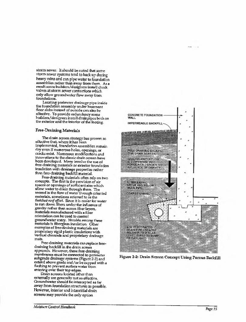
storm sewer. It should be noted that some storm sewer systems tend to back up during heavy rains and can pipe water to foundation assemblies rather than away from them. Asa result some builders/designers install check valves at storm sewer connections which only allow groundwater flow away from foundations.
Locating perimeter drainage pipe inside the foundation assembly under basement floor slabs instead of outside can also be effective. To provide redundancy some builders/designers install drainpipes both on the exterior and the interior of the footing.
Free-Draining Materials
The drain screen strategy has proven so effective that, where it has been implemented, foundation assemblies remain dry even if numerous holes, openings, or cracks exist. Numerous modifications and innovations to the classic drain screen have been developed. Many involve the use of tree-draining materials or exterior foundation insulation with drainage properties rather than free-draining backfill material.
Free-draining materials often rely on two concepts. The first is the provision of air spaces or openings of sufficient size which allow water to drain through them. The second is the flow of water through oriented materials, sometimes referred to as the thafehed-roof effect. Since it Is easier for water to run down fibers under the influence of gravity rather than across fiber layers, materials manufactured with a fiber orientation can be used to control groundwater entry. Notable among these materials is fiberglass insulation. Other examples of free-draining materials are proprietary rigid plastic insulations with vertical channels and proprietary drainage mats.
Free-draining materials can replace free- draining backfill in the drain screen approach. However, these free-draining membranes must be connected to perimeter subgrade drainage systems (Figure 2-3) and extend above grade and /or be capped with a flashing to prevent surface water from entering over their lop edges.
Drain screens located other than externally are generally not as effective. Groundwater should be intercepted as far away from foundation structures as possible. However, interior and interstitial drain screens may provide the only option
Figure 2-2: Drain Screen Concept Using Porous Backfill
Moisture Control Handbook Page 15
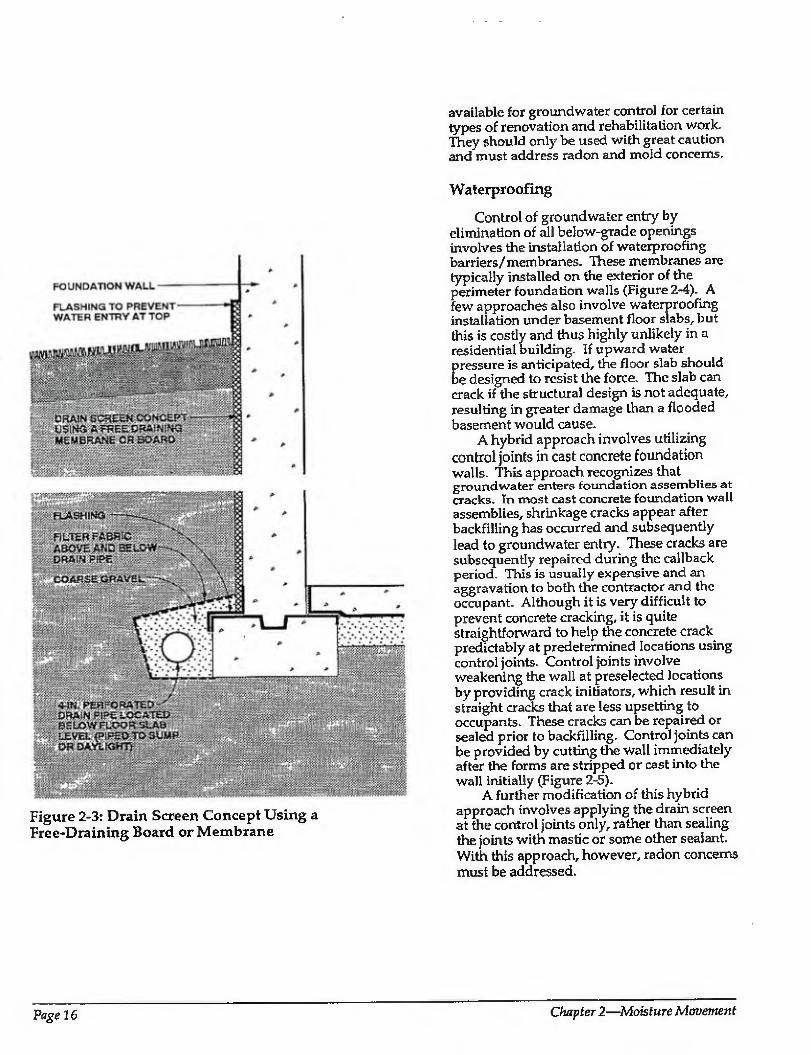
available for groundwater control for certain types of renovation and rehabilitation work. They should only be used with great caution and must address radon and mold concerns.
ivwffz&fff*';;-,:. W.'y.V-W'YSXii.vWw
XtSgfiS
ABOVE WD B£i
wm.
Figure 2-3: Drain Screen Concept Using a Free-Draining Board or Membrane
Waterproofing
Control of groundwater entry by elimination of all below-grade openings involves the installation of waterproofing barriers/membranes. These membranes are typically installed on the exterior of the perimeter foundation walls (Figure 2-4). A few approaches also involve waterproofing installation under basement floor slabs, but this is costly and thus highly unlikely in a residential building. If upward water pressure is anticipated, the floor slab should be designed to resist the force. The slab can crack if the structural design is not adequate, resulting in greater damage than a flooded basement would cause.
A hybrid approach involves utilizing control joints in cast concrete foundation walls. This approach recognizes that groundwater enters foundation assemblies at cracks- In most cast concrete foundation wall assemblies, shrinkage cracks appear after backfilling has occurred and subsequently lead to groundwater entry. These cracks are subsequently repaired during the callback period. This is usually expensive and an aggravation to both the contractor and the occupant. Although it is very difficult to prevent concrete cracking, it is quite straightforward to help the concrete crack predictably at predetermined locations using control joints. Control joints involve weakening the wall at preselected locations by providing crack initiators, which result in straight cracks that are less upsetting to occupants. These cracks can be repaired or sealed prior to backfilling. Control joints can be provided by cutting the wall immediately after the forms are stripped or cast into the wall initially (Figure 2~5).
A further modification of this hybrid approach involves applying the drain screen at the control joints only, rather than sealing the joints with mastic or some other sealant. With this approach, however, radon concerns must be addressed.
Page 16 Chapter 2—A4oisf«re Mcruement
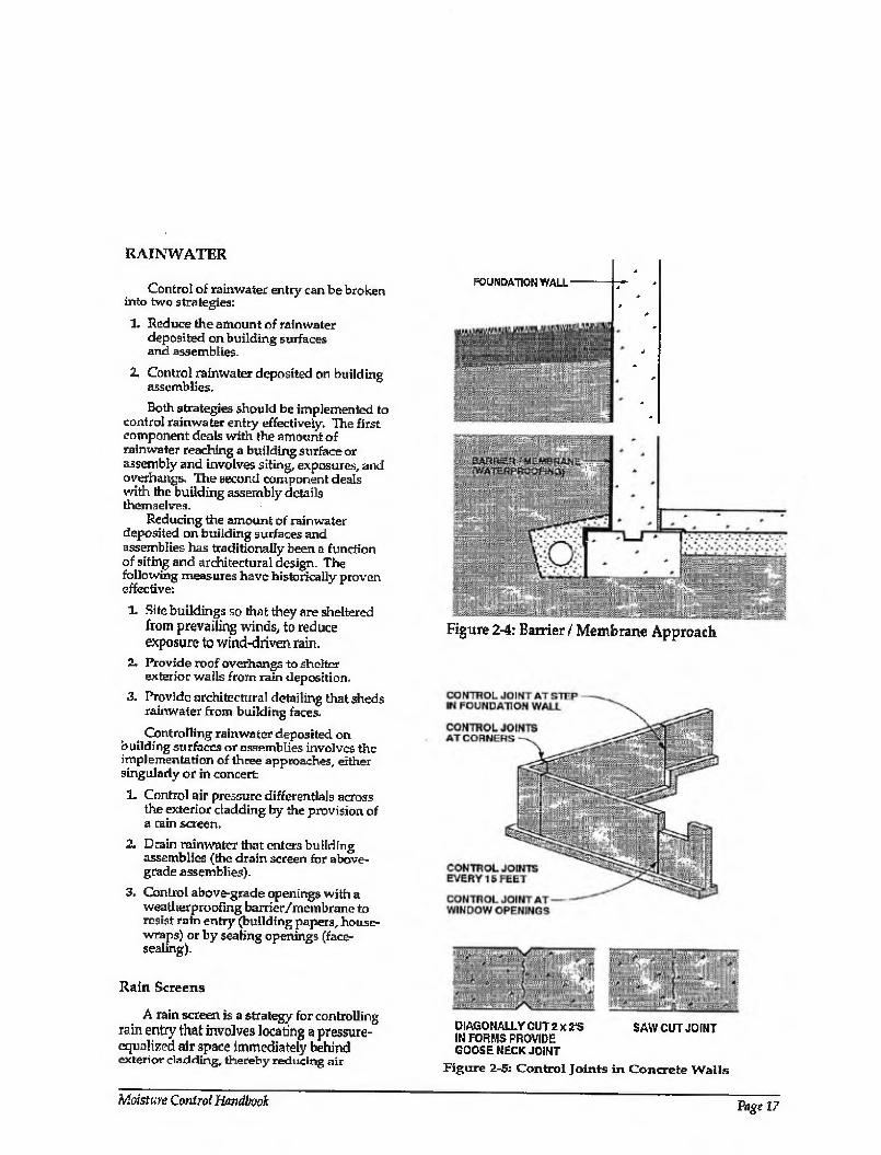
RAINWATER
Control of rainwater entry can be broken into two strategies:
1. Reduce the amount of rainwater deposited on building surfaces and assemblies.
2. Control rainwater deposited on building assemblies.
Both strategies should be implemented to control rainwater entry effectively. The first component deals with the amount of rainwater reaching a building surface or assembly and involves siting, exposures, and overhangs. The second component deals with the building assembly details themselves.
Reducing the amount of rainwater deposited on building surfaces and assemblies has traditionally been a function of siting and architectural design. The following measures have historically proven effective:
1- Site buildings so that they are sheltered from prevailing winds, to reduce exposure to wind-driven rain.
2, Provide roof overhangs to shelter exterior walls from rain deposition.
3. Provide architectural detailing that sheds rainwater from building faces.
Controlling rainwater deposited on building surfaces or assemblies involves the implementation of three approaches, either singularly or in concert
1. Control air pressure differentials across the exterior cladding by the provision of a rain screen.
2. Drain rainwater that enters building assemblies (the drain screen for above- grade assemblies).
3. Control above-grade openings with a weatherproofing barrier/membrane to resist rain entry (building papers, house- wraps) or by sealing openings (face¬ sealing).
Rain Screens
A rain screen is a strategy for controlling rain entry that involves locating a pressure- equalized air space immediately behind exterior cladding, thereby reducing air
FOUNDATION WALL
Figure 2-4: Barrier / Membrane Approach
DIAGONALLY CUT 2 xZ'S SAW CUT JOINT IN FORMS PROVIDE GOOSE NECK JOINT
Figure 2-5: Control Joints in Concrete Walls
Moisture Control Handbook Page 17
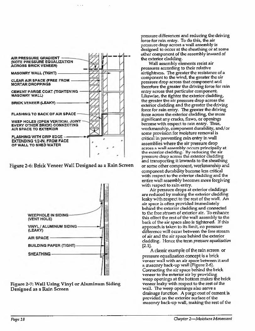
AIR PRESSURE GRADIENT (NOTE PRESSURE EQUALIZATION ACROSS BRICK VENEER)
MASONRY WALL (TIGHT)
CLEAR AIR SPACE (FREE FROM MORTAR DROPPINGS
CEMENT PARGE COAT (TIGHTENING MASONRY WALL)
BRICK VENEER (LEAKY)
FLASHING TO BACK OF AIR SPACE
WEEP HOLES (OPEN VERTICAL JOINT EVERY OTHER BRICK) CONNECTING AIR SPACE TO EXTERIOR
FLASHING WITH DRIP EDGE EXTENDING 1/2-IN. FROM FACE OF WALL TO SHED WATER
Figure 2-6: Brick Veneer Wall Designed as a Rain Screen
Figure 2-7: Wall Using Vinyl or Aluminum Siding Designed as a Rain Screen
pressure differences and reducing the driving force for rain entry. To do this, the air pressure drop across a wall assembly is designed to occur at the sheathing or at some other component of the assembly inward of the exterior cladding.
Wall assembly elements resist air pressures according to their relative airtightness. The greater the resistance of a component to the wind, the greater the air pressure drop across that component and therefore the greater the driving force for rain entry across that particular component. Likewise, the tighter the exterior cladding, the greater the air pressure drop across the exterior cladding and the greater the driving force for rain entry. The greater the driving force across the exterior cladding, the more significant any cracks, flaws, or openings become with respect to rain entry. Thus, workmanship, component durability, and/or some provision for moisture removal is critical in preventing rain entry in wall assemblies where the air pressure drop across a wall assembly occurs principally at the exterior cladding. By reducing the air pressure drop across the exterior cladding and transporting it inwards to the sheathing or some other component, workmanship and component durability become less critical with respect to the exterior cladding and the entire wall assembly becomes more forgiving with respect to rain entry.
Air pressure drops at exterior claddings are reduced by making the exterior cladding leaky with respect to the rest of the wall. An air space is often provided immediately behind the exterior cladding and connected to the free stream of exterior air. To enhance this effect the rest of the wall assembly to the back of the air space also is tightened. If this approach is taken to its limit, no pressure difference will occur between the free stream of air and the air space behind the exterior cladding. Hence the term pressure equalization
[2.1]. A classic example of the rain screen or
pressure equalization concept is a brick veneer wall with an air space between it and a masonry back-up wall (Figure 2-6). Connecting the air space behind the brick veneer to the exterior air by providing weep openings at the bottom makes the brick veneer leaky with respect to the rest of the wall. The weep openings also serve a drainage function. A parge coat of cement is provided on the exterior surface of the masonry back-up wall, making the rest of the
Page 18 Chapter 2—Moisture Movement
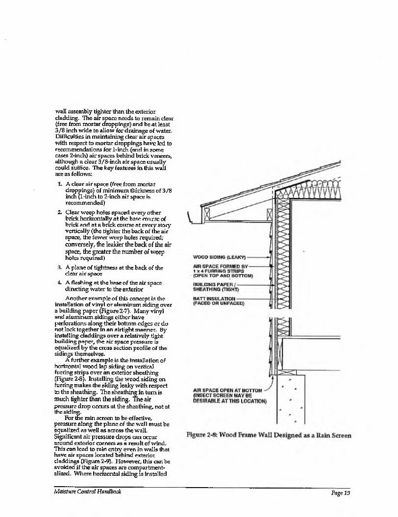
wall assembly tighter than the exterior cladding. The air space needs to remain clear (free from mortar droppings) and be at least 3/8 inch wide to allow for drainage of water. Difficulties in maintaining dear air spaces with respect to mortar droppings have led to recommendations for 1-inch (and in some cases 2-inch) air spaces behind brick veneers, although a clear 3/8-inch air space usually could suffice. The key features in this wall are as follows:
1. A clear air space (free from mortar droppings) of minimum thickness of 3/8 inch (1-inch to 2-inch air space is recommended)
2. Clear weep holes spaced every other brick horizontally at the base course of brick and at a brick course at every story vertically (the tighter the back of the air space, the fewer weep holes required; conversely, the leakier the back of the air space, the greater the number of weep holes required)
3. A plane of tightness at the back of the clear air space
4. A flashing at the base of the air space directing water to the exterior
Another example of this concept is the installation of vinyl or aluminum siding over a building paper (Figure 2-7). Many vinyl and aluminum sidings either have perforations along their bottom edges or do not lock together in an airtight manner. By installing claddings over a relatively tight building paper, the air space pressure is equalized by the cross section profile of the sidings themselves.
A further example is the installation of horizontal wood lap siding on vertical furring strips over an exterior sheathing (Figure 2-8). Installing the wood siding on furring makes the siding leaky with respect to the sheathing. The sheathing in turn is much tighter than the siding. The air pressure drop occurs at the sheathing, not at the siding.
For the rain screen to be effective, pressure along the plane of the wall must be equalized as well as across the wall. Significant air pressure drops can occur around exterior corners as a result of wind. This can lead to rain entry even in walls that have air spaces located behind exterior claddings (Figure 2-9). However, this can be avoided if the air spaces are compartment¬ alized. Where horizontal siding is installed
Moisture Control Handbook Page 19
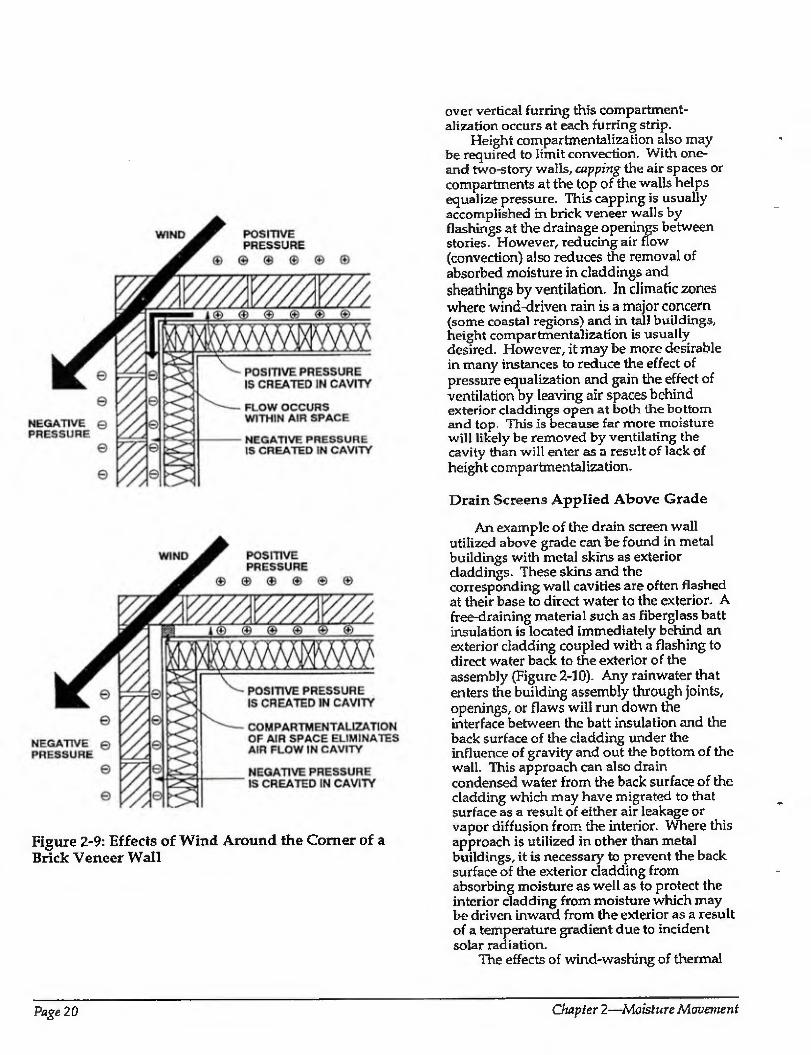
Figure 2-9: Effects of Wind Around the Comer of a Brick Veneer Wall
over vertical furring this compartment- alization occurs at each furring strip.
Height compartmentalization also may be required to limit convection. With one- and two-story walls, capping the air spaces or compartments at the top of the walls helps equalize pressure. This capping is usually accomplished in brick veneer walls by flashings at the drainage openings between stories. However, reducing air flow (convection) also reduces the removal of absorbed moisture in claddings and sheathings by ventilation. In climatic zones where wind-idriven rain is a major concern (some coastal regions) and in tall buildings, height compartmentalization is usually desired. However, it may be more desirable in many instances to reduce the effect of pressure equalization and gain the effect of ventilation by leaving air spaces behind exterior claddings open at both the bottom find top. This is because far more moisture will likely be removed by ventilating the cavity than will enter as a result of lack of height compartmentalization.
Drain Screens Applied Above Grade
An example of the drain screen wall utilized above grade can be found in metal buildings with metal skins as exterior claddings. These skins and the corresponding wall cavities are often flashed at their base to direct water to the exterior. A free-draining material such as fiberglass batt insulation is located immediately behind an exterior cladding coupled with a flashing to direct water back to the exterior of the assembly (Figure 2-10). Any rainwater that enters the building assembly through joints, openings, or flaws will run down the interface between the batt insulation and the back surface of the cladding under the influence of gravity and out the bottom of the wall. This approach can also drain condensed water from the back surface of the cladding which may have migrated to that surface as a result of either air leakage or vapor diffusion from the interior. Where this approach is utilized in other than metal buildings, it is necessary to prevent the back surface of the exterior cladding from absorbing moisture as well as to protect the interior cladding from moisture which may be driven inward from the exterior as a result of a temperature gradient due to incident solar radiation.
The effects of wind-washing of thermal
Page 20 Chapter 2—Moisture Movement
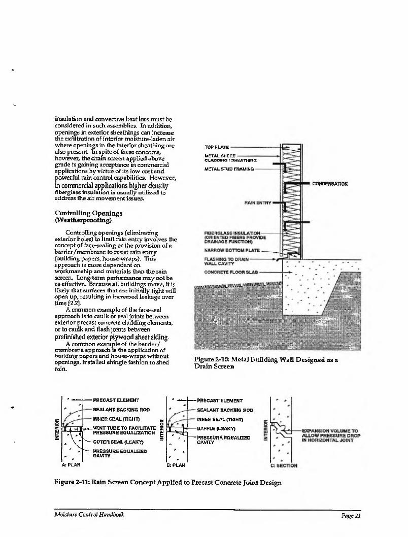
insulation and convective heat loss must be considered in such assemblies. In addition, openings in exterior sheathings can increase the exfiltration of interior moisture-laden air where openings in the interior sheathing are also present In spite of these concerns, however, the drain screen applied above grade is gaining acceptance in commercial applications by virtue of its low cost and powerful rain control capabilities. However, in commercial applications higher density fiberglass insulation is usually utilized to address the air movement issues.
Controlling Openings (Weatherproofing)
Controlling openings (eliminating exterior boles) to limit rain entry involves the concept of face-sealing or the provision of a barrier /membrane to resist rain entry (building papers, house-wraps). This approach is more dependent on workmanship and materials than the rain screen. Long-term performance may not be as effective. Because all buildings move, it is likely that surfaces that are initially tight will open up, resulting in increased leakage over time [2.2],
A common example of tire face-seal approach is to caulk or seal joints between exterior precast concrete cladding elements, or to caulk and flash joints between prefinished exterior plywood sheet siding.
A common example of the barrier/ membrane approach is the application of building papers and house-wraps without openings, installed shingle fashion to shed rain.
TOP PLATE
METAL SHEET CLADDING f SHEATHING
METAL STUD FRAMING
CONDENSATION
Figure 2-10: Metal Building Wall Designed as a Drain Screen
A: PLAN
PRECAST ELEMENT
SEALANT BACKING ROD
INNER SEAL (TIGHT)
VENT TUBE TO FACILITATE PRESSURE EQUALIZATION
OUTER SEAL (LEAKY)
PRESSURE EQUALIZED CAVITY
3r
-PRECAST ELEMENT
- SEALANT BACKING ROD
-INNER SEAL (TIGHT)
BAFFLE (LEAKY)
- pressure equalized CAVITY
B: PLAN
Figure 2-11: Bain Screen Concept Applied to Precast Concrete Joint Design
Moisture ControJ Handbook Page 21
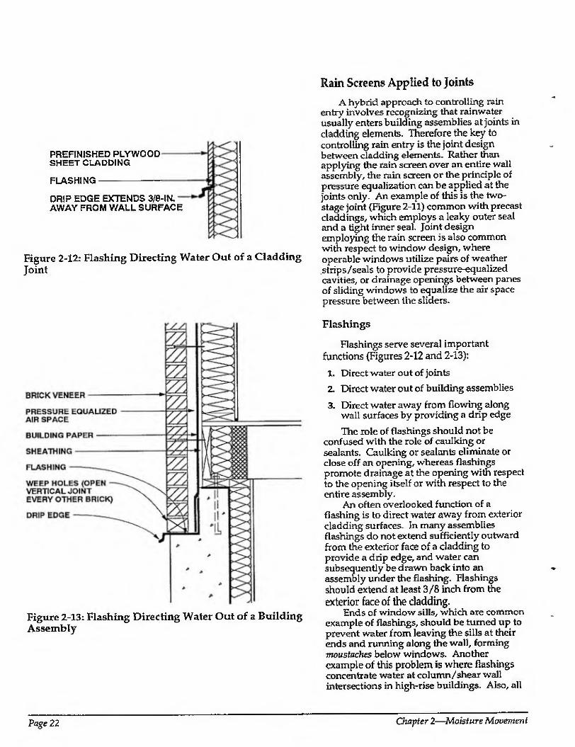
PREFINISHED PLYWOOD SHEET CLADDING
FLASHING
DRIP EDGE EXTENDS 3/6-IN AWAY FROM WALL SURFACE
Figure 2-12: Flashing Directing Water Out of a Cladding Joint
Rain Screens Applied to Joints
A hybrid approach to controlling rain entry involves recognizing that rainwater usually enters building assemblies at joints in cladding elements. Therefore the key to controlling rain entry is the joint design between cladding elements. Rather than applying the rain screen over an entire wall assembly, the rain screen or the principle of pressure equalization can be applied at the joints only. An example of this is the two- stage joint {Figure 2-11) common with precast claddings, which employs a leaky outer seal and a tight inner seal. Joint design employing the rain screen is also common with respect to window design, where operable windows utilize pairs of weather strips/seals to provide pressure-equalized cavities, or drainage openings between panes of sliding windows to equalize the air space pressure between the sliders.
Figure 2-13: Flashing Directing Water Out of a Building Assembly
Flashings
Flashings serve several important functions (Figures 2-12 and 2-13):
1. Direct water out of joints
2. Direct water out of building assemblies
3. Direct water away from flowing along wall surfaces by providing a drip edge
The role of flashings should not be confused with the role of caulking or sealants. Caulking or sealants eliminate or close off an opening, whereas flashings promote drainage at the opening with respect to the opening itself or with respect to the entire assembly.
An often overlooked function of a flashing is to direct water away from exterior cladding surfaces. In many assemblies flashings do not extend sufficiently outward from the exterior face of a cladding to provide a drip edge, and water can subsequently be drawn back into an assembly under the flashing. Flashings should extend at least 3/8 inch from the exterior face of the cladding.
Ends of window sills, which are common example of flashings, should be turned up to prevent water from leaving the sills at their ends and running along the wall, forming moustaches below windows. Another example of this problem is where flashings concentrate water at column/shear wall intersections in high-rise buildings. Also, all
Page 22 Chapter 2—Moisture Movement
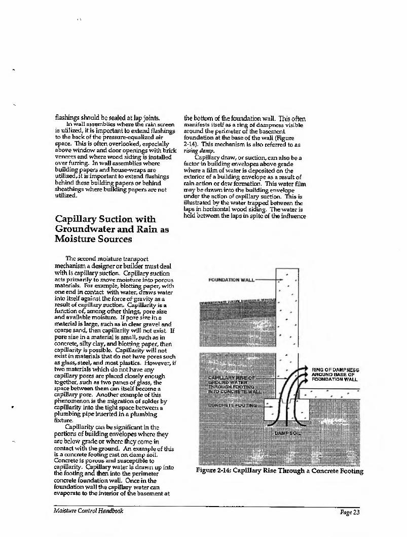
flashings should be sealed at lap joints. In wall assemblies where the rain screen
is utilized, it is important to extend flashings to the back of the pressure-equalized air space. This is often overlooked, especially above window and door openings with brick veneers and where wood siding is installed over furring. In wall assemblies where building papers and house-wraps are utilized, it is important to extend flashings behind these building papers or behind sheathings where building papers are not utilized.
Capillary Suction with Groundwater and Rain as Moisture Sources
the bottom of the foundation wall. This often manifests itself as a ring of dampness visible around the perimeter of the basement foundation at the base of the wall (Figure 2-14). This mechanism is also referred to as rising damp.
Capillary draw, or suction, can also be a factor in building envelopes above grade where a film of water is deposited on the exterior of a building envelope as a result of rain action or dew formation. This water film may be drawn into the building envelope under the action of capillary suction. This is illustrated by the water trapped between the laps in horizontal wood siding. The water is held between the iaps in spite of the influence
The second moisture transport mechanism a designer or builder must deal with is capillary suction. Capillary suction acts primarily to move moisture into porous materials. For example, blotting paper, with one end in contact with water, draws water into itself against the force of gravity as a result of capillary suction. Capillarity is a function of, among other things, pore size and available moisture. If pore size in a material is large, such as in dear gravel and coarse sand, then capillarity will not exist. If pore size in a material is small, such as in concrete, silty clay, and blotting paper, then capillarity is possible. Capillarity will not exist in materials that do not have pores such as glass, steel, and most plastics. However, if two materials which do not have any capillary pores are placed closely enough together, such as two panes of glass, the space between them can itself become a capillary pore. Another example of this phenomenon is the migration of solder by capillarity into the tight space between a plumbing pipe inserted in a plumbing fixture.
Capillarity can be significant in the portions of building envelopes where they are below grade or where they come in contact witii the ground. An example of this is a concrete footing cast on damp soil. Concrete is porous and susceptible to capillarity. Capillary water is drawn up into the footing and then into the perimeter concrete foundation wall. Once in the foundation wall the capillary water can evaporate to the interior of the basement at
RING OF DAMPNESS AROUND BASE OF FOUNDATION WALL
Figure 2-14: Capillary Rise Through a Concrete Footing
Moisture Control Handbook Page 23
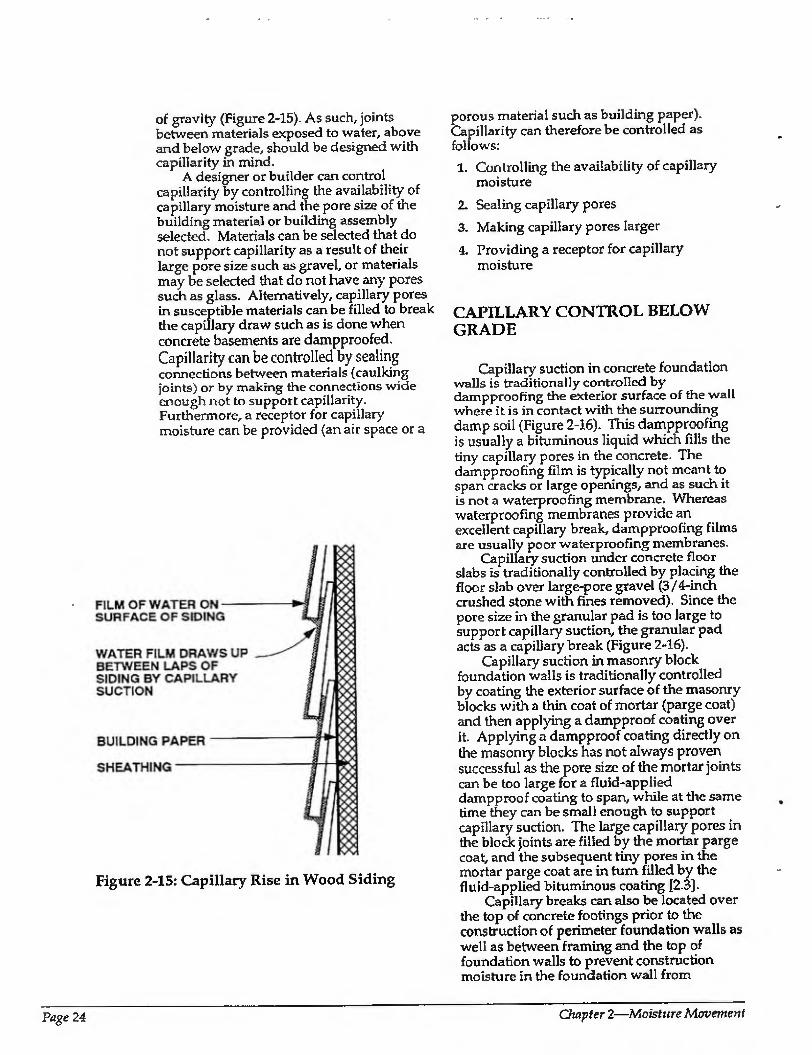
of gravity (Figure 2-15). As such, joints between materials exposed to water, above and below grade, should be designed with capillarity in mind.
A designer or builder can control capillarity by controlling the availability of capillary moisture and the pore size of the building material or building assembly selected. Materials can be selected that do not support capillarity as a result of their large pore size such as gravel, or materials may be selected that do not have any pores such as glass. Alternatively, capillary pores in susceptible materials can be filled to break the capillary draw such as is done when concrete basements are dampproofed. Capillarity can be controlled by sealing connections between materials (caulking joints) or by making the connections wide enough not to support capillarity. Furthermore, a receptor for capillary moisture can be provided (an air space or a
Figure 2-15: Capillary Rise in Wood Siding
porous material such as building paper). Capillarity can therefore be controlled as follows:
1. Controlling the availability of capillary moisture
2. Sealing capillary pores
3. Making capillary pores larger
4. Providing a receptor for capillary moisture
CAPILLARY CONTROL BELOW GRADE
Capillary suction inconcrete foundation walls is traditionally controlled by dampproofing the exterior surface of the wall where it is in contact with the surrounding damp soil (Figure 2-16). This dampproofing is usually a bituminous liquid which fills the tiny capillary pores in the concrete. The dampproofing film is typically not meant to span cracks or large openings, and as such it is not a waterproofing membrane. Whereas waterproofing membranes provide an excellent capillary break, dampproofing films are usually poor waterproofing membranes.
Capillary suction under concrete floor slabs is traditionally controlled by placing the floor slab over large-pore gravel (3/4-inch crushed stone with fines removed). Since the pore size in the granular pad is too large to support capillary suction, the granular pad acts as a capillary break (Figure 2-16).
Capillary suction in masonry block foundation walls is traditionally controlled by coating the exterior surface of the masonry blocks with a thin coat of mortar (parge coat) and then applying a dampproof coating over it. Applying a dampproof coating directly on the masonry blocks has not always proven successful as the pore size of the mortar joints can be too large for a fluid-applied dampproof coating to span, while at the same time they can be small enough to support capillary suction. The large capillary pores in the block joints are filled by the mortar parge coat, and the subsequent tiny pores in the mortar parge coat are in turn filled by the fluid-applied bituminous coating [2.3].
Capillary breaks can also be located over the top of concrete footings prior to the construction of perimeter foundation walls as well as between framing and the top of foundation walls to prevent construction moisture in the foundation wall from
Page 24 Chapter 2—Moisture Movement
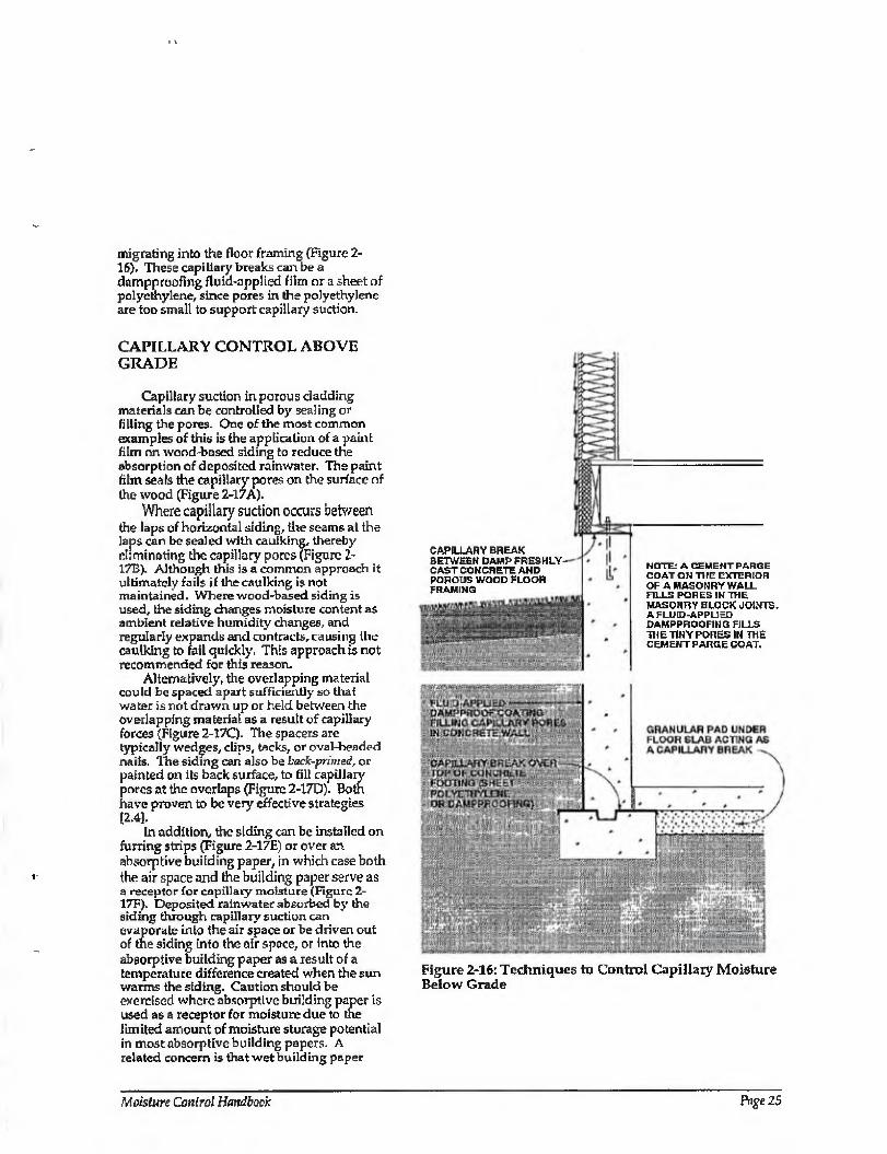
migrating into the floor framing (Figure 2- 16). These capillary breaks can be a dnmpproofing fluid-applied film or a sheet of polyethylene, since pores in the polyethylene are too small to support capillary suction.
CAPILLARY CONTROL ABOVE GRADE
Capillary suction in porous cladding materials can be controlled by sealing or filling the pores. One of the most common examples of this is the application of a paint film on wood-based siding to reduce the absorption of deposited rainwater. The paint film seals the capillary pores on the surface of the wood (Figure 2-17A).
Where capillary suction occurs between the laps of horizontal siding, the seams at the laps can be sealed with caulking, thereby eliminating the capillary pores (Figure 2- 17B). Although this is a common approach it ultimately fails if the caulking is not maintained. Where wood-based siding is used, the siding changes moisture content as ambient relative humidity changes, and regularly expands and contracts, causing the caulking to fail quickly. This approach is not recommended for this reason.
Alternatively, the overlapping material could be spaced apart sufficiently so that water is not drawn up or held between the overlapping material as a result of capillary forces (Figure 7.-17C). The spacers arc typically wedges, clips, tacks, or oval-headed nails. The siding can also be back-primed, or painted on its back surface, to fill capillary pores at the overlaps (Figure 2-17D). Both have proven to be very effective strategies [2.4],
In addition, the siding can be installed on furring strips (Figure 2-17E) or over an. absorptive building paper, in which case both the air space and the building paper serve as a receptor for capillary moisture (Figure 2- 17F). Deposited rainwater absorbed by the siding through capillary suction can evaporate into the air space or be driven out of the siding into the air space, or into the absorptive building paper as a result of a temperature difference created when the sun warms the siding. Caution should be exercised where absorptive building paper is used as a receptor for moisture due to the limited amount of moisture storage potential in most absorptive building papers. A related concern is that wet building paper
CAPILLARY BREAK BETWEEH DAMP FRESHLY- CAST COHCRETE AND POROUS WOOD FLOOR FRAMING
NOTE: A CEMENT PARGE COAT ON THE EXTERIOR OF A MASONRY WALL FILLS PORES IN THE MASONRY BLOCK JOINTS. A FLUID-APPLIED DAMPPROOFING FILLS THE TINY PORES IN THE CEMENTPARGE COAT.
Figure 2-16: Techniques to Control Capillary Moisture Below Grade
Moisture Control Handbook Page 25
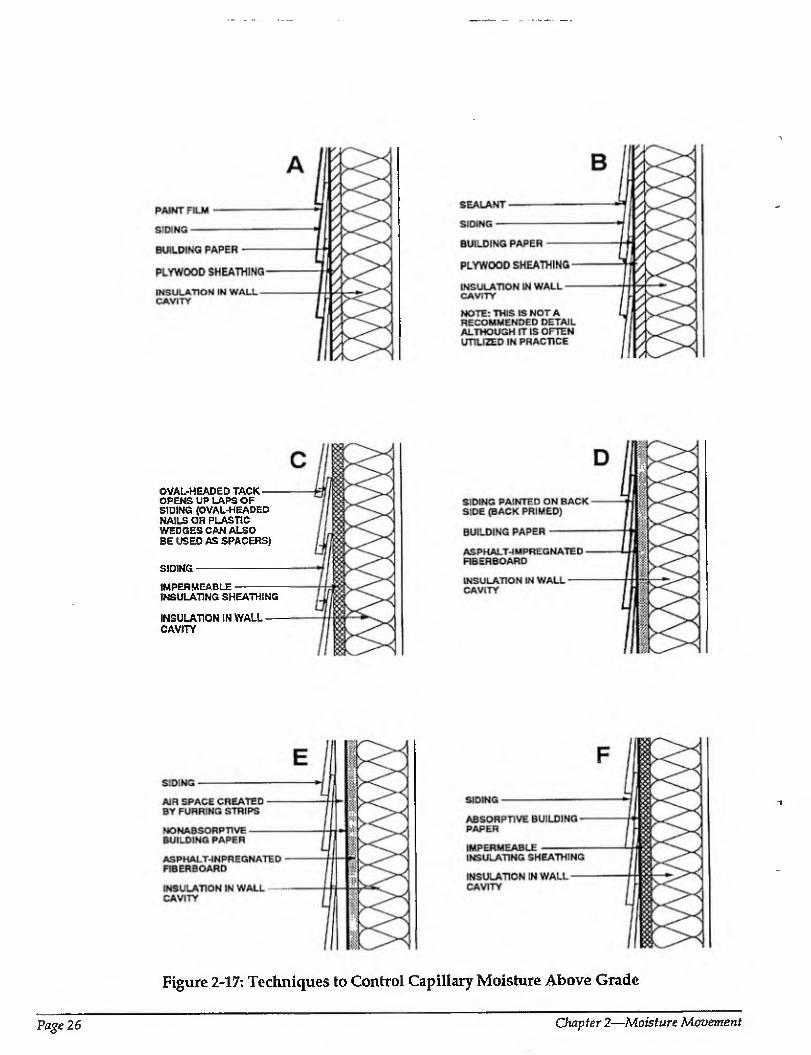
OVAL-HEADED TACK — OPENS UP LAPS OF SIDING {OVAL-HEADED NAILS OR PLASTIC WEDGES CAN ALSO BE USED AS SPACERS)
SIDING-
IMPERMEABLE- INSULATING SHEATHING
INSULATION IN WALL — CAVITY
Figure 2-17: Techniques to Control Capillary Moisture Above Grade
Page 26 Chapter 2—Moisture Movement
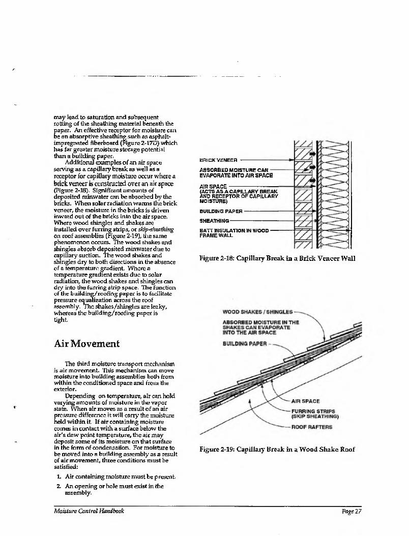
may lead to saturation and subsequent rotting of the sheathing material beneath the paper. An effective receptor for moisture can be an absorptive sheathing such as asphalt- impregnated fiberboard (Figure 2-17D) which has far greater moisture storage potential than a building paper,
Additional examples of an air space serving as a capillary break as well as a receptor for capillary moisture occur where a brick veneer is constructed over an air space (Figure 2-18). Significant amounts of deposited rainwater can be absorbed by the bricks. When solar radiation warms the brick veneer, the moisture in the bricks is driven inward out of the bricks into the air space. Where wood shingles and shakes are installed over furring strips, or skip-sheathing on roof assemblies (Figure 2-19), tire same phenomenon occurs. The wood shakes and shingles absorb deposited rainwater due to capillary suction. The wood shakes and shingles dry to both directions in the absence of a temperature gradient. Where a temperature gradient exists due to solar radiation, the wood shakes and shingles can dry into the furring strip space. The function of the building/roofing paper is to facilitate pressure equalization across the roof assembly. The shakes/shingles are leaky, whereas (he building/roofing paper is tight,
Air Movement
The third moisture transport mechanism is air movement. This mechanism can move moisture into building assemblies both from within the conditioned space and from the exterior.
Depending on temperature, air can hold varying amounts of moisture in the vapor state. When air moves as a result of an air pressure difference it will cany' the moisture held within it. If air containing moisture comes in contact with a surface below the air's dew point temperature, the air may deposit some of its moisture on that surface in the form of condensation. For moisture to be moved into a building assembly as a result of air movement, three conditions must be satisfied:
1. Air containing moisture must be present.
2. An opening or hole must exist in the assembly.
BRICK VENEER
ABSORBED MOISTURE CAN EVAPORATE INTO AIR SPACE
AIR SPACE (ACTS AS A CAPILLARY BREAK AND RECEPTOR OF CAPILLARY MOISTURE)
BUILDING PAPER
SHEATHING-
BATT INSULATION IN WOOD FRAME WALL
Figure 2-18: Capillary Break in a Brick Veneer Wall
Figure 2-19: Capillary Break in a Wood Shake Roof
Moisture Control Handbook Vage 27
3. An air pressure difference acting across the opening or hole must exist.
Although moisture may enter a building assembly if these three conditions are met, moisture may not necessarily be deposited within the assembly. Air flow speeds must be slow enough for the air to cool to the dew point temperature before it exits the air leakage path. Fast flowing air can warm the surfaces of the flow path above the dew point temperature of the outflowing air and condensation may not occur.
To control moisture movement as a result of the movement of air, three factors must be understood: the number, location, and size of openings in the building envelope; the air pressure differential acting across the building envelope; and the amount of moisture present in the air. It is as practical to control the moisture content in available air and the pressure differential acting across the building envelope as it is to control openings in the building envelope.
In heating climates or during heating periods, moisture content in interior air can be controlled by air change to dilute interior moisture levels, dehumidification, and the control of moisture sources. In cooling climates or during cooling periods with a high ambient vapor pressure, dehumidification through air conditioning can be used to accomplish the same effect.
Slight depressurization in heating climates or during the heating season can be used to induce infiltration across the building envelope. This limits moisture problems because cold infiltrating air does not carry much moisture. In cooling climates or during cooling periods, a dehumidified conditioned space can be maintained at a slight positive air pressure resulting in exfiftration to accomplish the same result. This is effective because the moisture content of exterior air is often greater than the moisture content of the interior air. Of course, there are exceptions to the interior/exterior air moisture content generalization with heating and cooling climates. An exception occurs in heating climates or during heating periods where exterior air infiltrates below grade into basement spaces and crawl spaces after being drawn through moisture-laden earth. This infiltrating air can be at a saturated moisture content and can be responsible for moving significant amounts of moisture into a conditioned space.
Controlling building envelope openings is one of the most recommended approaches
for dealing with this moisture transport mechanism. It should be noted, however, that as building envelope airtightness increases, particularly in heating climates, the dilution of moisture in interior air by natural air change decreases (unless intentional ventilation is provided). This leads to Increased moisture concentrations in interior air and subsequently to increased incidents of moisture-induced envelope problems if the other two factors are also not controlled. Tighter building envelopes also typically lead to greater air pressure differentials due to the operation of forced air heating and cooling systems. These pressure differentials can increase both infiltration and exfiltration of moisture-laden air. Proper control strategies are necessary to deal with these issues.
CONTROLLING MOISTURE IN AIR
It is obvious that only interior airborne moisture levels can be controlled, since the local climate controls exterior airborne moisture levels. However, the local climate and hence exterior moisture levels typically influence the approach taken to control interior moisture levels.
Interior moisture levels can be controlled three ways:
1. Source control
2. Dilution
3. Dehumidification
Source Control
One of the most effective approaches to controlling interior airborne moisture levels is the control of moisture sources. If moisture is not generated within a space or if it is removed at the point of generation and/or prevented from migrating into a space, it does not have to be removed or controlled after the fact. Source control is effective regardless of climate zone or season and is typically the most cost-effective and energy efficient approach .
One of the single largest sources of moisture in conditioned spaces, regardless of climate zone or season, is the migration of moisture from the surrounding soil into foundations and subsequently into conditioned spaces [2.5]. Therefore, building dry basements, slabs, and crawl spaces can be
Page 28 Chapter 2—Moisfwre Movement
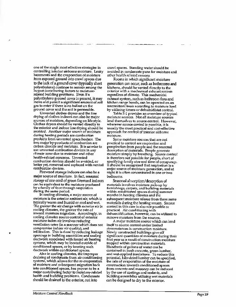
one of the single most effective strategies in controlling interior airborne moisture. Leaky basements and the evaporation of moisture from exposed ground into crawl spaces due to the lack of a ground cover (typically sheet polyethy lene) continue to remain among the largest contributing factors to moisture-
related building problems. Even if a polyethylene ground cover is present, it may move and permit a significant amount of soil gas to enter if there is no ballast on the ground cover and the soil is permeable.
Unvented clothes dryers and the line drying of clothes indoors can also be major sources of moisture, depending on life style. Clothes dryers should be vented directly to tlie exterior and indoor line drying should be avoided. Another major source of moisture during heating periods are combustion products from unvented space heaters. The two major by-products of combustion are carbon dioxide and moisture. It is unwise to use unvented combustion devices in any climate zone due to moisture and other health-related concerns. Unvented combustion devices should be avoided, or better yet, removed and replaced with vented combustion devices.
Firewood storage indoors can also be a major source of moisture. In fact, seasonal storage of one cord of green firewood indoors can be equivalent to the moisture produced by a family of four through respiration during the same period.
In cooling climates, a major source of moisture is the exterior ambient air, which is typically warm and humid or cool and wet. The greater the air change with exterior air in cooling climates, the greater the rate of inward moisture migration. Accordingly, in cooling climates source control of exterior moisture-laden air involves reducing ventilation rates (in a manner which does not compromise indoor air quality), and infiltration. This is done by reducing leakage openings in building assemblies and sealing ductwork associated with forced air heating systems, which may be located outside of conditioned spaces, or by locating such ductwork within conditioned spaces.
Also in cooling climates, the improper draining of condensate from air conditioning systems, which allows for the re-evaporation of moisture and subsequent migration back into conditioned spaces, has proven to be a major contributing factor to moisture-related health and building problems. Condensate should be drained to the exterior, not into
crawl spaces. Standing water should be avoided in condensate pans for moisture and other health related reasons.
Rooms in which significant moisture generation can occur, such as bathrooms and kitchens, should be vented directly to the exterior with a mechanical exhaust system regardless of climate. This mechanical exhaust system, such as bathroom fans and kitchen range hoods, can be operated on an intermittent basis according to moisture load by utilizing timers or dehumidistat control.
Table 2-1 provides an overview of typical moisture sources. Not all moisture sources lend themselves to source control. However, wherever source control is possible, it is usually the most practical and cost-effective approach for control of interior airborne moisture.
Some moisture sources that are not practical to control are respiration and perspiration from people and the seasonal desorption of materials. People generate moisture simply by breathing. Source control is therefore not possible for people, short of specifying family size and time of occupancy. It should be recognized that respiration is a major source of moisture generation, and at night it is often concentrated in one or two bedrooms.
Seasonal absorption/desorption of materials involves moisture pick-up by furnishings, carpets, and building materials within conditioned spaces during summer months in heating climates and the subsequent moisture release from these same materials during the heating season. Source control in this case is also not possible or practical. Air conditioning with dehumidification, however, can be utilized to remove moisture from the sources.
A major moisture source which can lend itsdf to source control under limited circumstances is construction moisture. Newly constructed buildings give off significant quantities of moisture during their first year as a result of construction moisture trapped within construction materials. Hundreds of gallons of water can be contained in fresh concrete, green lumber, and wet-applied insulations. To reduce this potential, kiln-dried lumber can be specified, the rate of evaporation of the moisture of construction towards conditioned spaces from concrete and masonry can be reduced by tire use of coatings and sealants, and building assemblies utilizing wet materials can be designed to dry to the exterior.
Moisture Control Handbook Page 29

Table 2-1: Household Moisture Sources
MOISTURE SOURCE BY TYPE
Household Produced
Aquariums
Bathing: tub (excludes towels and spillage)
shower (excludes towels and spillage)
Clothes washing (automatic, lid dosed, standpipe discharge)
Clothes drying: vented outdoors
not vented outdoors or indoor drying line
Combustion—unvented kerosene space heater
Cooking: breakfast (family of four, average)
lunch (family of four, average)
dinner (family of four, average)
simmer at 203 F., 10 minutes, 6-inch pan (plus gas)
boil 10 minutes, 6-inch pan (plus gas)
Dishwashing: breakfast (family of four, average)
(by hand) lunch (family of our, average)
dinner (family of four, average)
Firewood storage indoors (cord of green firewood)
Ho or mopping
Gas range pilot light (each)
House plants (5 to 7 average plants)
Humidifiers
Pets
Respiration and Perspiration (family of four, average)
Refrigerator defrost
Saunas, steam baths, and whirlpools
Vegetable storage (large-scale storage is significant)
ESTIMATED MOISTURE AMOUNT (PINTS)
Replacement of evaporative loss
0.12/standard size bath
0.52/5-minute shower
0+/load (usually nil)
0+/load (usually nil)
4.68 to 6.18/load (more if gas dryer)
7.6/gallon of kerosene burned
0.35 (plus 0,58 if gas cooking)
0.53 (plus 0.68 if gas cooking)
1.22 (plus 1.58 if gas cooking)
less than 0.01 if covered, 0.13 if uncovered
0.48 if covered, 0.57 if uncovered
0.21
0.16
0.68 400 to 800/6 months
0.03/square foot
0.37 or less/day
0.86 to 0.96/day
0 to 120+/day (2.08 average/hour)
Fraction of human adult weight
0,44/hour (family of four, average)
1.03/day (average)
0 to 2.7+/hour
0+ (not estimated)
Nonhousehold Produced Combustion exhaust gas backdrafting or spillage
Desorption of materials: seasonal
new construction
Ground moisture migration
Plumbing leaks
Rain or snowmelt penetration
Seasonal high outdoor absolute humidity
0 to 6,720+/year
6.33 to 16.91 /average day
10+/average day
0 to105/day
0+ (not estimated)
0+ (not estimated)
64 to249+/day
Source: W. Angell and W. Olson, Cold Climate Housing Information Center, University of Minnesota
Page 30 Chapter 2—Moisture Movement
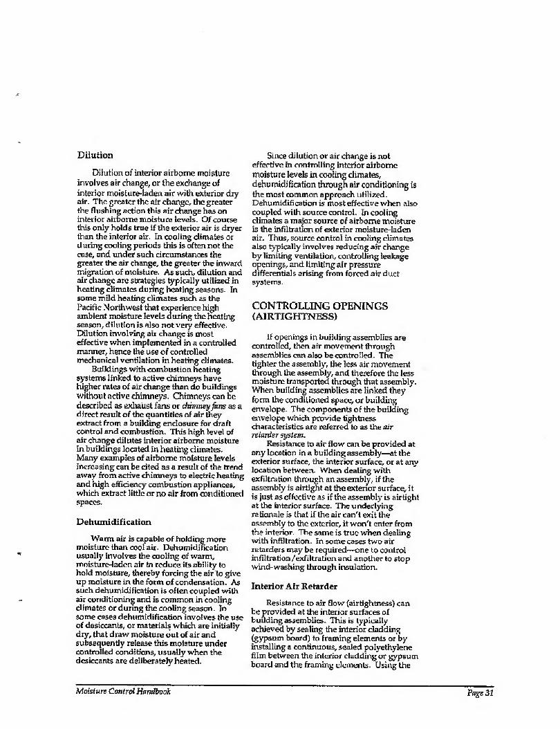
Dilution
Dilution of interior airborne moisture involves air change, or the exchange of interior moisture-laden air with exterior dry air. The greater the air change, the greater the flushing action this air change has on interior airborne moisture levels. Of course this only holds true if the exterior air is dryer than the interior air. In cooling climates or during cooling periods this is often not the case, and under such circumstances the greater the air change, the greater the inward migration of moisture. As such, dilution and air change are strategies typically utilized in heating climates during heating seasons. In some mild heating climates such as the Pacific Northwest that experience high ambient moisture levels during the heating season, dilution is also not very effective. Dilution involving air change is most effective when implemented in a controlled manner, hence the use of controlled mechanical ventilation in heating climates.
Buildings with combustion heating systems linked to active chimneys have higher rates of air change than do buildings without active chimneys. Chimneys can be described as exhaust fans or diimneyfans as a direct result of the quantities of air they extract from a building enclosure for draft control and combustion. This high level of air change dilutes interior airborne moisture in buildings located in heating climates. Many examples of airborne moisture levels increasing can be cited as a result of the trend away from active chimneys to electric heating and high efficiency combustion appliances, which extract little or no air from conditioned spaces.
Dehumidification
Warm air is capable of holding more moisture than cool air. Dehumidification usually involves the cooling of warm, moisture-laden air to reduce its ability to hold moisture, thereby forcing the air to give up moisture in the form of condensation. As such dehumidification is often coupled with air conditioning and is common in cooling climates or during the cooling season. In some cases dehumidification involves the use of desiccants, or materials which are initially dry, that draw moisture out of air and subsequently release this moisture under controlled conditions, usually when the desiccants are deliberately heated.
Since dilution or air change is not effective in controlling interior airborne moisture levels in cooling climates, dehumidification through air conditioning is the most common approach utilized. Dehumidification is most effective when also coupled with source control. In cooling climates a major source of airborne moisture is the infiltration of exterior moisture-laden air. Thus, source control in cooling climates also typically involves reducing air change by limiting ventilation, controlling leakage openings, and limiting air pressure differentials arising from forced air duct systems.
CONTROLLING OPENINGS (A1RTIGHTNESS)
If openings in building assemblies are controlled, then air movement through assemblies can also be controlled. The tighter the assembly, the less air movement through the assembly, and therefore the less moisture transported through that assembly. When building assemblies are linked they form the conditioned space, or building envelope- The components of the building envelope which provide tightness characteristics are referred to as the air retarder system.
Resistance to air flow can be provided at any location in a building assembly—at the exterior surface, the interior surface, or at any location between. When dealing with exfiltration through an assembly, if the assembly is airtight at the exterior surface, it is just as effective as if the assembly is airtight at the interior surface. The underlying rationale is that if the air can't exit the assembly to the exterior, it won't enter from the interior. The same is true when dealing with infiltration. In some cases two air retarders may be required—one to control infiltration/exfiltration and another to stop wind-washing through insulation.
Interior Air Retarder
Resistance to air flow (airtightness) can be provided at the interior surfaces of building assemblies. This is typically achieved by sealing the interior cladding (gypsum board) to framing elements or by installing a continuous, sealed polyethylene film between the interior cladding or gypsum board and the framing elements. Using the
Moisture Control Handbook Page 31
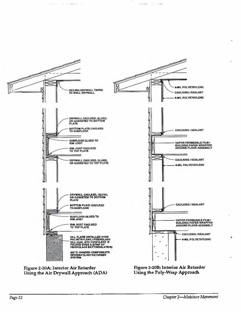
DHYWALL CAULKED, GLUED, OH GASKETED TO BOTTOM PLATE
BOTTOM PLATE CAULKED TO SUBFLOOR
SUBFLOOR GLUED TO RtM JOIST
RIM JOIST CAULKED TO TOP PLATE
SILL PLATE INSTALLED OVER POLYETH VLEN E / FI BERGLASS SILL SEAL (POLYETHYLENE IS FOLDED OVER A STRIP OF FIBERGLASS BATTINSULATION)
NOTE: SHADED COMPONENTS DESIGNATE AIR RETARDER SYSTEM
Figure 2-20A: Interior Air Retarder Figure 2-20B: Interior Air Retarder Using the Air Drywall Approach (ADA) Using the Poly-Wrap Approach
Page 32 Chapter 2—Moisture Movement
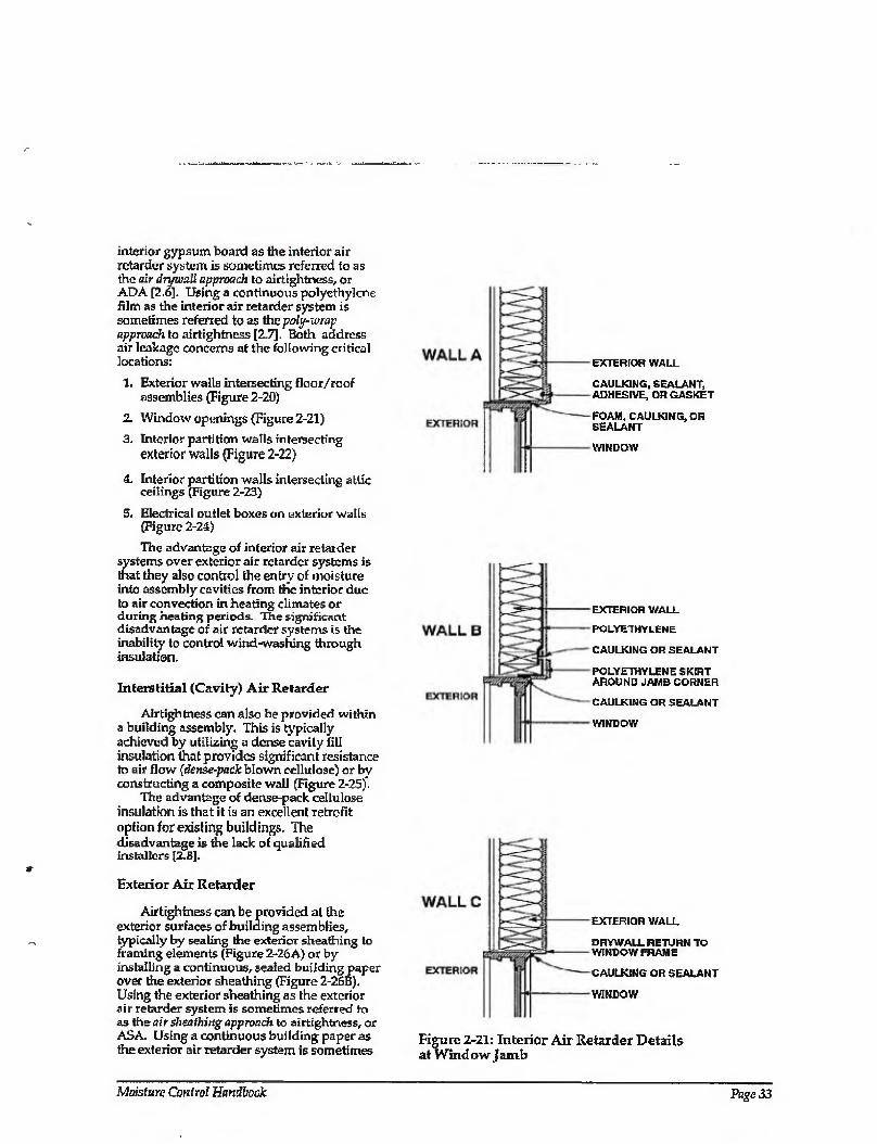
interior gypsum board as the interior air retarder system is sometimes referred to as the air drywall approach to airtightness, or ADA [2.6]. Using a continuous polyethylene film as the interior air retarder system is sometimes referred to as the poly-wrap approach to airtightness [2.7]. Both address air leakage concerns at the following critical locations:
1. Exterior walls intersecting floor/ roof assemblies (Figure 2-20)
2. Window openings (Figure 2-21)
3. Interior partition walls intersecting exterior walls (Figure 2-22)
4. Interior partition walls intersecting attic ceilings (Figure 2-23)
5. Electrical outlet boxes on exterior walls (Figure 2-24)
The advantage of interior air retarder systems over exterior air retarder systems is that they also control the entry of moisture into assembly cavities from the interior due to air convection in heating climates or during heating periods. The significant
disadvantage of air retarder systems is the inability to control wind-washing through insulation.
Interstitial (Cavity) Air Retarder
Airtightness can also be provided within a building assembly. This is typically achieved by utilizing a dense cavity fill insulation that provides significant resistance to air flow [dcnsc-pack blown cellulose) or by constructing a composite wall (Figure 2-25).
The advantage of dense-pack cellulose insulation is that it is an excellent retrofit option for exisling buildings. The disadvantage is the lack of qualified Installers [2.8].
Exterior Air Retarder
Airtightness can be provided at the exterior surfaces of building assemblies, typically by sealing the exterior sheathing to framing elements (Figure 2-26A) or by- installing a continuous, seated building paper over the exterior sheathing (Figure 2-26B). Using the exterior sheathing as the exterior air retarder system is sometimes referred to as the air sheathing approach to airtightness, or ASA, Using a continuous building paper as the exterior air retarder system is sometimes
EXTERIOR WALL
CAULKING, SEALANT, ADHESIVE, OR GASKET
-FOAM, CAULKING, OR SEALANT
-WINDOW
-EXTERIOR WALL
-POLYETHYLENE
- CAULKING OR SEALANT
-POLYETHYLENE SKIRT AROUND JAMB CORNER
CAULKING OR SEALANT
-WINDOW
-EXTERIOR WALL
DRYWALL RETURN TO -WINDOW FRAME
-CAULKING OR SEALANT
-WINDOW
Figure 2-21: Interior Air Retarder Details at Window jamb
Moisture Control Handbook Page 33
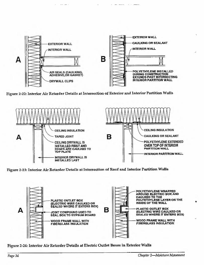
EXTERIOR WALL
CAULKING OR SEALANT
INTERIOR WALL
M POLYETHYLENE INSTALLED DURING CONSTRUCTION EXTENDS PAST INTERSECTING INTERIOR PARTITION WALL
Figure 2-22: Interior Air Retarder Details at Intersection of Exterior and Interior Partition Walls
INSTALLED FIRST AND EDGES ARE CAULKED TO TOP PLATE
INTERIOR DRYWALL IS INSTALLED LAST
OVER TOP OF INTERIOR PARTITION WALL
INTERIOR PARTITION WALL
Figure 2-23: Interior Air Retarder Details at Intersection of Roof and Interior Partition Walls
PLASTIC OUTLET BOX (ELECTRIC WIRE CAULKED OR SEALED WHERE IT ENTERS BOX)
JOINT COMPOUND USED TO SEAL BOX TO GYPSUM BOARD
WOOD FRAME WALL WITH FIBERGLASS INSULATION
POLYETHYLENE WRAPPED AROUND ELECTRIC BOX AND CAULKED TO THE POLYETHYLENE LAYER ON THE INSIDE OF THE WALL
PLASTIC OUTLET BOX (ELECTRIC WIRE CAULKED OR SEALED WHERE IT ENTERS BOX)
WOOD FRAME WALL WITH FIBERGLASS INSULATION
Figure 2-24: Interior Air Retarder Details at Electric Outlet Boxes in Exterior Walls
Page 34 Chapter 2—Moisture Movement
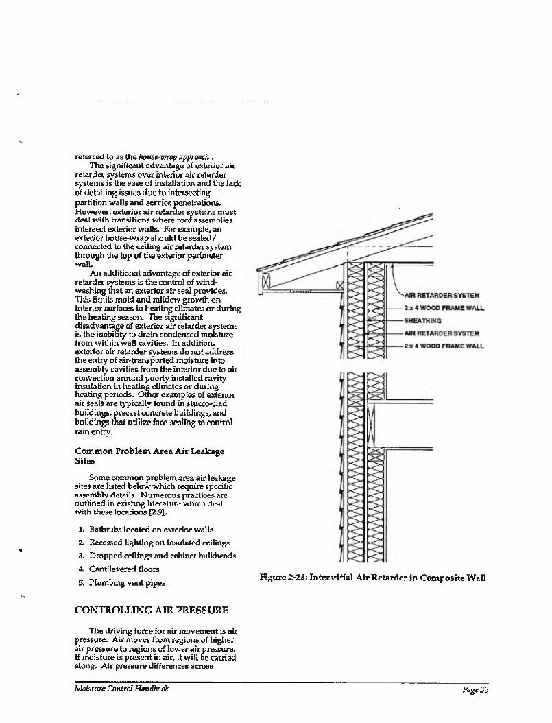
referred to as the house wrap approach . The significant advantage of exterior air
retarder systems over interior air retarder systems is the ease of installation and the lack of detailing issues due to intersecting partition walls and service penetrations. However, exterior air retarder systems must deai with transitions where roof assemblies intersect exterior walls. For example, an exterior house-wrap should be sealed/ connected to the ceiling air retarder system through the top of the exterior perimeter wall.
An additional advantage of exterior air retarder systems is the control of wind¬ washing that an exterior air seal provides. This limits mold and mildew growth on interior surfaces in heating climates or during the heating season. The significant disadvantage of exterior air retarder systems is the inability to drain condensed moisture from within wall cavities. In addition, exterior air retarder systems do not address the entry of air-transported moisture into assembly cavities from the interior due to air convection around poorly installed cavity Insulation in heating climates or during heating periods. Other examples of exterior air seals are typically found in stucco-clad buildings, precast concrete buildings, and buildings that utilize face-sealing to control rain entry.
Common Problem Area Air Leakage Sites
Some common problem area air leakage sites are listed below which require specific assembly details. Numerous practices are outlined in existing literature which deal with these locations [2.9].
1. Bathtubs Located on exterior walls
2. Recessed lighting on insulated ceilings
3. Dropped ceilings and cabinet bulkheads
4 Cantilevered floors
5. Plumbing vent pipes Figure 2-25: Interstitial Air Retarder in Composite Wall
CONTROLLING AIR PRESSURE
The driving force for air movement is air pressure. Air moves from regions of higher air pressure to regions of lower air pressure. If moisture is present in air, it will be carried along. Air pressure differences across
Mo/sfurc Control Handbook Page 35
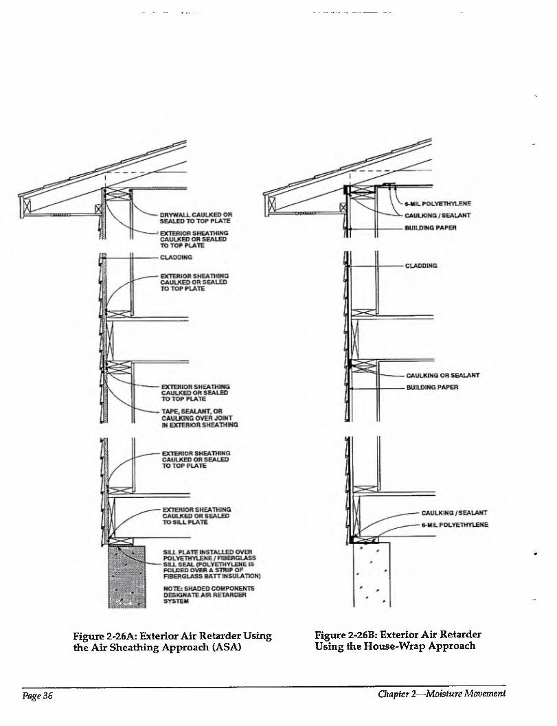
Figure 2-26A: Exterior Air Retarder Using Figure 2-26B: Exterior Air Retarder the Air Sheathing Approach (ASA) Using the House-Wrap Approach
Page 36 Chapter 2—Moisture Movement
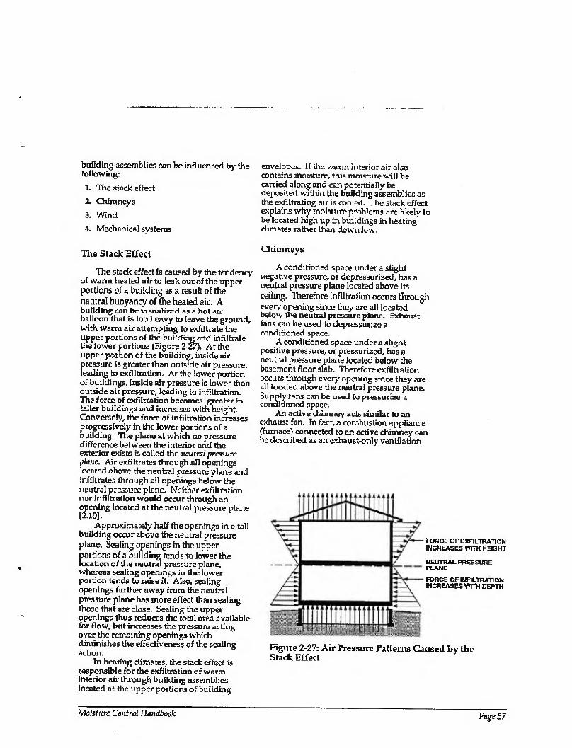
building assemblies can be influenced by the following;
1. The stack effect
2. Chimneys
3. Wind
4. Mechanical systems
envelopes. If the warm interior air also contains moisture, this moisture will be carried along and can potentially be deposited within the building assemblies as tire exfiltrating air is cooled. The stack effect explains why moisture problems are likely to be located high up in buildings in heating climates rather than down low.
The Stack Effect Chimneys
The stack effect is caused by the tendency of warm heated air to leak out of the upper portions of a building as a result of the natural buoyancy of the heated air. A building can be visualized as a hot air balloon that is too heavy to leave the ground, with warm air attempting to exfittrate the upper portions of the building and infiltrate the lower portions (Figure 2-27). At the upper portion of the building, inside air pressure is greater than outside air pressure, leading to exfiltration. At the lower portion of buildings, inside air pressure is lower than outside air pressure, leading to infiltration. The force of exfiltration becomes greater in taller buildings and increases with height. Conversely, the force of infiltration increases progressively in the lower portions of a building. The plane at which no pressure difference between the interior and the exterior exists is called the neutral pressure plane. Air exfiltrates through all openings located above the neutral pressure plane and infiltrates through all openings below the neutral pressure plane. Neither exfiltration nor infiltration would occur through an opening located at the neutral pressure plane [2.10],
Approximately half the openings in a tall building occur above the neutral pressure plane. Sealing openings in the upper portions of a building tends to lower the location of the neutral pressure plane, whereas sealing openings in the lower portion tends to raise it. Also, sealing openings further away from the neutral pressure plane has more effect than sealing those that are close. Sealing the upper openings thus reduces the total area available for flow, but increases the pressure acting over the remaining openings which diminishes the effectiveness of the sealing action.
In heating climates, the stack effect is responsible for the exfiltration of warm interior air through building assemblies located at the upper portions of building
A conditioned space under a slight negative pressure, or depressurized, has a neutral pressure plane located above its ceiling. Therefore infiltration occurs through every opening since they are all located below the neutral pressure plane. Exhaust fans can be used to depressurize a conditioned space.
A conditioned space under a slight positive pressure, or pressurized, has a neutral pressure plane located below the basement floor slab. Therefore exfiltration occurs through every opening since they are all located above the neutral pressure plane. Supply fans can be used to pressurize a conditioned space.
An active chimney acts similar to an exhaust fan. In fact, a combustion appliance (furnace) connected to an active chimney can be described as an exhaust-only ventilation
FORCE OF EXFILTRATION INCREASES WITH HEIGHT
NEUTRAL PRESSURE PLANE
FORCE OF INFILTRATION INCREASES WITH DEPTH
Figure 2-27: Air Pressure Patterns Caused by the Stack Effect
Moisture Control Handbook Page 37
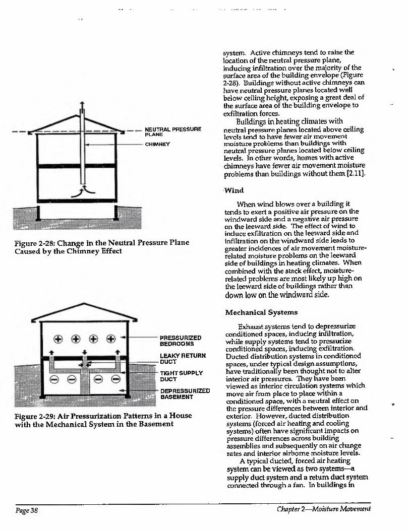
NEUTRAL PRESSURE PLANE
CHIMNEY
Figure 2-28: Change in the Neutral Pressure Plane Caused by the Chimney Effect
PRESSURIZED BEDROOMS
LEAKY RETURN DUCT
TK3HT SUPPLY DUCT
DEPRESSURIZED BASEMENT
Figure 2-29: Air Pressurization Patterns in a House with the Mechanical System in the Basement
system. Active chimneys tend to raise the location of the neutral pressure plane, inducing infiltration over the majority of the surface area of the building envelope (Figure 2-28). Buildings without active chimneys can have neutral pressure planes located well below ceiling height, exposing a great deal of the surface area of the building envelope to exfiltration forces.
Buildings in heating climates with neutral pressure planes located above ceiling levels tend to have fewer air movement moisture problems than buildings with neutral pressure planes located below ceiling levels. In other words, homes with active chimneys have fewer air movement moisture problems than buildings without them [2.11].
Wind
When wind blows over a building it tends to exert a positive air pressure on the windward side and a negative air pressure on the leeward side. The effect of wind to induce exfiltration on the leeward side and infiltration on the windward side leads to greater incidences of air movement moisture- related moisture problems on the leeward side of buildings in heating climates. When combined with the stack effect, moisture- related problems are most likely up high on the leeward side of buildings rather than down low on the windward side.
Mechanical Systems
Exhaust systems tend to depressurize conditioned spaces, inducing infiltration, while supply systems tend to pressurize conditioned spaces, inducing exfiltration. Ducted distribution systems in conditioned spaces, under typical design assumptions, have traditionally been thought not to alter interior air pressures. They have been viewed as interior circulation systems which move air from place to place within a conditioned space, with a neutral effect on the pressure differences between interior and exterior. However, ducted distribution systems (forced air heating and cooling systems) often have significant impacts on pressure differences across building assemblies and subsequently on air change rates and interior airborne moisture levels.
A typical ducted, forced air heating system can be viewed as two systems—a supply duct system and a return duct system connected through a fan. In buildings in
Page 38 Chapter 2—Moisture Movement
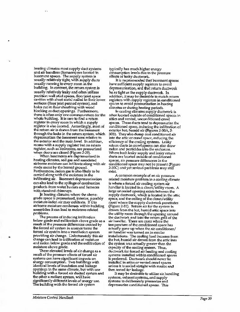
heating climates most supply duct systems and air handlers (furnaces) are located in basement spaces. The supply system is usually relatively tight, with supply ducts usually running to every room in the building. In contrast, the return system is usually relatively leaky and often utilizes partition wall stud spaces, floor joist space cavities with sheet metal nailed to their lower surfaces (floor joist panned system), and holes cut in floor sheathing with wood blocking as duct openings. Furthermore, there is often only one common return for the whole building. It is rare to find a return register in every room in which a supply register is also located. Accordingly, most of the return air is drawn from the basement through the leaks in the return system, which depressurizes the basement area relative to the exterior and the main level. In addition, rooms with a supply register but no return register, such as bedrooms, are pressurized when doors are closed (Figure 2-29).
When basements are depressurized in heating climates, soil gas and associated airborne moisture can infiltrate along with air made moist by the humid ground. Furthermore, radon gas is also likely to be carried along with the moisture in the infiltrating air, Basement depressurization can also lead to the spillage of combustion products from water heaters and furnaces with standard chimneys.
In heating climates where the above¬ grade space is pressurized, interior, possibly moisture-laden air may exfiltrate. If this airborne moisture condenses within building assemblies it can lead to moisture-related problems.
The process of inducing infiltration below grade and exfiltration above grade as a result of the pressure differences created by the forced air system in essence turns the forced air system into a ventilation system providing air change. Unfortunately this air change can lead to infiltration of moisture and radon below grade and the exfiltration of moisture above grade.
These elevated levels of air change as a result of the pressure effects of forced air systems can have significant impacts on energy consumption. Two buildings with identical levels of insulation and leakage openings in the same climate, but with one building with a forced air ducted system and the other a radiant system, will have significantly different levels of energy use. The building with the forced air system
typically has much higher energy consumption levels due to the pressure effects of leaky ductwork.
It is recommended that basement spaces have sufficient supply registers to avoid depressurization, and that return ductwork be as tight as the supply ductwork. In addition, it may be desirable to match return registers with supply registers in conditioned spaces to avoid pressurization in heating climates or during heating periods.
In cooling climates supply ductwork is often located outside of conditioned spaces in attics and vented, unconditioned crawl spaces. These ducts tend to depressurize the conditioned space, inducing the infiltration of exterior hot, humid air (Figures 2-30A, 2 SOB). They also dump cool conditioned air into the attic or crawl space, reducing the efficiency of the cooling systems. Leaky return ducts in crawl spaces can also draw radon and pesticides into the enclosure. Where both leaky supply and leaky return ducts are located outside of conditioned spaces, air pressure differences in the conditioned space may not be present (Figure 2-30C) and yet serious problems may still exist.
A common example of an air pressure related moisture problem in a cooling climate is where a forced air cooling system air handier is located in a doset/utility room, A large unsealed opening exists between the supply ductwork, which is located in the attic space, and the ceiling of the closet/utility room where the supply ductwork penetrates (Figure 2-31). Return air for the system is drawn from the hot, humid attic space into the utility room through the opening around the ductwork and into the return grill of the air handler. There are cases where the temperature of the conditioned space has actually gone up when the air conditioner/ air handler was turned on in similar installations. The cooling load increase from the hot, humid air drawn from the attic into the system was actually greater than the capacity of the cooling system. Thus, ductwork for forced air heating and cooling systems installed within conditioned spaces is preferred. Ductwork should never be installed in attics or vented crawl spaces unless it is sealed airtight with mastic and then tested for leakage.
It may be desirable to utilize air handling systems, exhaust systems, and supply systems to deliberately pressurize and depressurize conditioned spaces This
Moisture Control Handbook Page 39

LEAKY SUPPLY DUCTS
DEPRESSURIZED CONDITIONED SPACE INDUCING INFILTRATION
CRAWL SPACE
Figure 2-30A: Air Pressurization Pattern with Mechanical System Ducts in the Attic
DEPRESSURIZED CONDITIONED SPACE
LEAKY SUPPLY DUCTS
CRAWL SPACE
Figure 2-30B: Air Pressurization Pattern with Mechanical System Ducts in the Crawl Space
LEAKY SUPPLY DUCTS
NEUTRAL PRESSURE IN CONDITIONED SPACE
LEAKY RETURN DUCTS
CRAWL SPACE
rm Figure 2-30C: Air Pressurization Pattern with Mechanical System Ducts in the Attic and the Crawl Space
controls the exfiltration of warm, interior moisture-laden air in heating climates and/or during heating periods; the infiltration of warm, humid exterior air in cooling climates and/or during cooling periods; and the infiltration of soil gas, moisture, radon, and pesticides below grade.
Pressurizing Building Assemblies
A method of active control of air pressures in flat roof assemblies can be utilized to control the exfiltration of interior air. Exterior air can be used to pressurize a flat roof assembly to prevent the migration of airborne moisture from the conditioned space into the flat roof assembly (Figure 2-32). Pressurization can be maintained with a fan/ blower. The fan/blower need only operate when the exterior temperature drops below the dew point temperature of the conditioned space [2.13]. In cold climates, caution should be exercised to prevent overpressurization and the potential of freezing pipes in interior partition walls or promoting mold and mildew on cooled interior surfaces. This approach should be avoided in cooling climates where hot, humid air exterior air blown into the building assembly is undesirable.
Vapor Diffusion
The fourth, and final, moisture transport mechanism is vapor diffusion. It can move moisture into building assemblies both from within the conditioned space as well as from the exterior. Vapor diffusion is the movement of moisture in the vapor state through a material. Materials are not able to stop vapor diffusion, they are only able to slow the process down, or retard it. Hence, the term vapor diffusion retarder is appropriate, not vapor barrier.
Vapor diffusion is a function of the vapor permeability of a material and the driving force or vapor pressure differential acting across a material. The vapor pressure differential refers to the difference in amount of moisture or difference in moisture concentration across a material. If no vapor pressure difference exists across a materiai, then no moisture will move as a result of vapor diffusion.
In a cold climate where a building is being heated, vapor diffusion typically moves moisture from within the conditioned
huge 40 Chapter 2—Moisture Movement
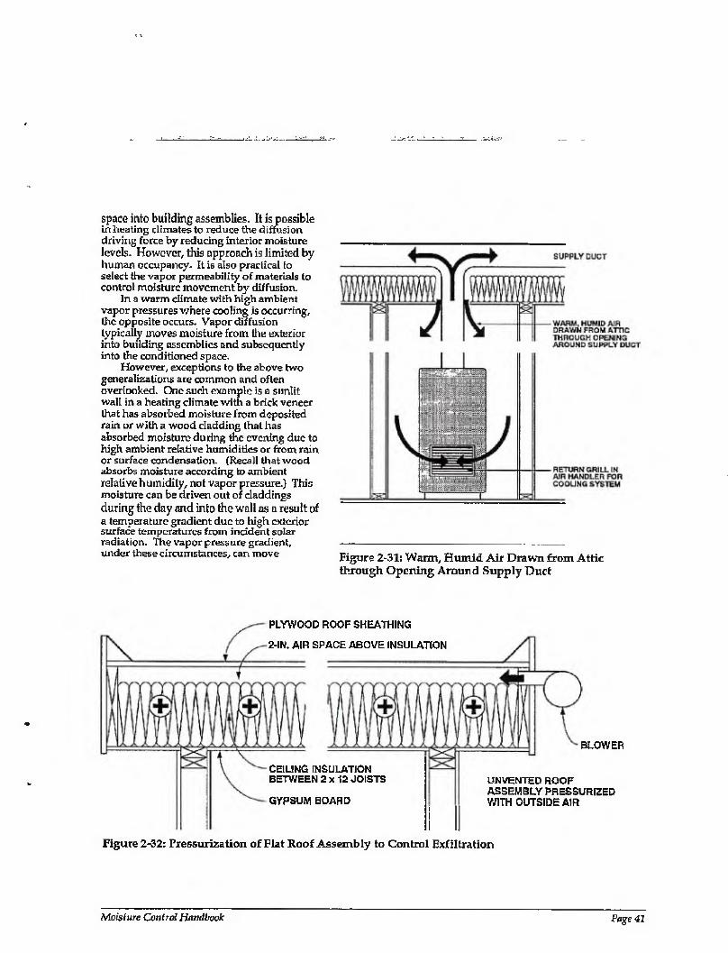
space into building assemblies. It is possible in heating climates to reduce the diffusion driving force by reducing interior moisture levels. However, this approach is limited by human occupancy. It is also practical to select the vapor permeability of materials to control moisture movement by diffusion.
In a warm climate with high ambient vapor pressures where cooling is occurring, the opposite occurs. Vapor diffusion typically moves moisture from the exterior into building assemblies and subsequently into the conditioned space.
However, exceptions to the above two generalizations are common and often overlooked. One such example is a sunlit wall in a heating climate with a brick veneer that has absorbed moisture from deposited rain or with a wood cladding that has absorbed moisture during the evening due to high ambient relative humidities or from rain or surface condensation. (Recall that wood absorbs moisture according to ambient relative humidity, not vapor pressure.) This moisture can be driven out of claddings during the day and into the wall as a result of a temperature gradient due to high exterior surface temperatures from incident solar radiation. The vapor pressure gradient, under these circumstances, can move Figure 2-31: Warm, Hmnid Air Drawn from Attic
through Opening Around Supply Duct
PLYWOOD ROOF SHEATHING
2-m. AIR SPACE ABOVE INSULATION
CEILING INSULATION BETWEEN 2x12 JOISTS
GYPSUM BOARD
BLOWER
UNVENTED ROOF ASSEMBLY PRESSURIZED WITH OUTSIDE AIR
Figure 2-32: Pressurization of Flat Roof Assembly to Control Exfiltration
Moisture Control Handbook Page 41

moisture by vapor diffusion from the exterior cladding into the building envelope during sunny periods.
In foundations and below-grade building assemblies, vapor diffusion can move moisture from the surrounding soil into the assembly as well as from the conditioned space into the assembly.
Vapor diffusion is also a function of surface area. If, for instance, 90 percent of a building envelope surface area is covered
VAPOR WFFUSJON RETARDER OH EXTERIOR OF CONCRETE OR MASONRYWALL
VAPOR CHFEUSION RETARDER UNDER CONCRETE SLAB AMD ABOVE GRAVEL DRAINAGE LAYER
Figure 2-33: Vapor Diffusion Retarder on the Exterior of a Concrete or Masonry Foundation Wall and Beneath the Concrete Slab
with a specific vapor diffusion retarder, then, all other things being equal, that vapor diffusion retarder is 90 percent effective. Continuity of a vapor diffusion retarder is not an overriding factor where vapor diffusion is concerned. For instance, a paint film of a appropriate permeance, applied only on the interior exposed surface of a building envelope, will typically act as an effective vapor diffusion retarder. However, this paint film vapor diffusion retarder does not deal with air-transported moisture which can leak through joints between the interior cladding (typically gypsum board) and wood framing elements, nor does it deal with vapor diffusion from the exterior migrating inwards due to incident solar radiation, or seasonal or other climatic effects.
CONTROL OF VAPOR DIFFUSION ABOVE GRADE
Vapor diffusion is controlled above grade by selecting the vapor permeability of the components of building assemblies. Materials that have a high resistance to vapor flow (low vapor permeability) are referred to as vapor diffusion retarders. In general, vapor diffusion retarders are located to the interior of building assemblies in heating climates and to the exterior of building assemblies in cooling climates. However, where cladding elements (which can store a great deal of moisture) are utilized, it may also be desirable to locate a vapor diffusion retarder to the exterior (behind the cladding) of a building assembly in a heating climate to prevent the inward flow of vapor resultant from a solar-radiation-induced temperature gradient. Commonly used vapor diffusion retarders are: polyethylene films, aluminum foils, low permeability paints, vinyl wall coverings, impermeable rigid insulations, sheet metal, dampproofing, plywood, and waferboard.
CONTROL OF VAPOR DIFFUSION BELOW GRADE
In general vapor diffusion retarders are located on the exterior of building assemblies below grade to retard the inward flow of water vapor by diffusion from the surrounding soil into the basement space. Dampproofing films typically have very high resistance to vapor flow and therefore also
Page 42 Chapter 2—Moisture Movement
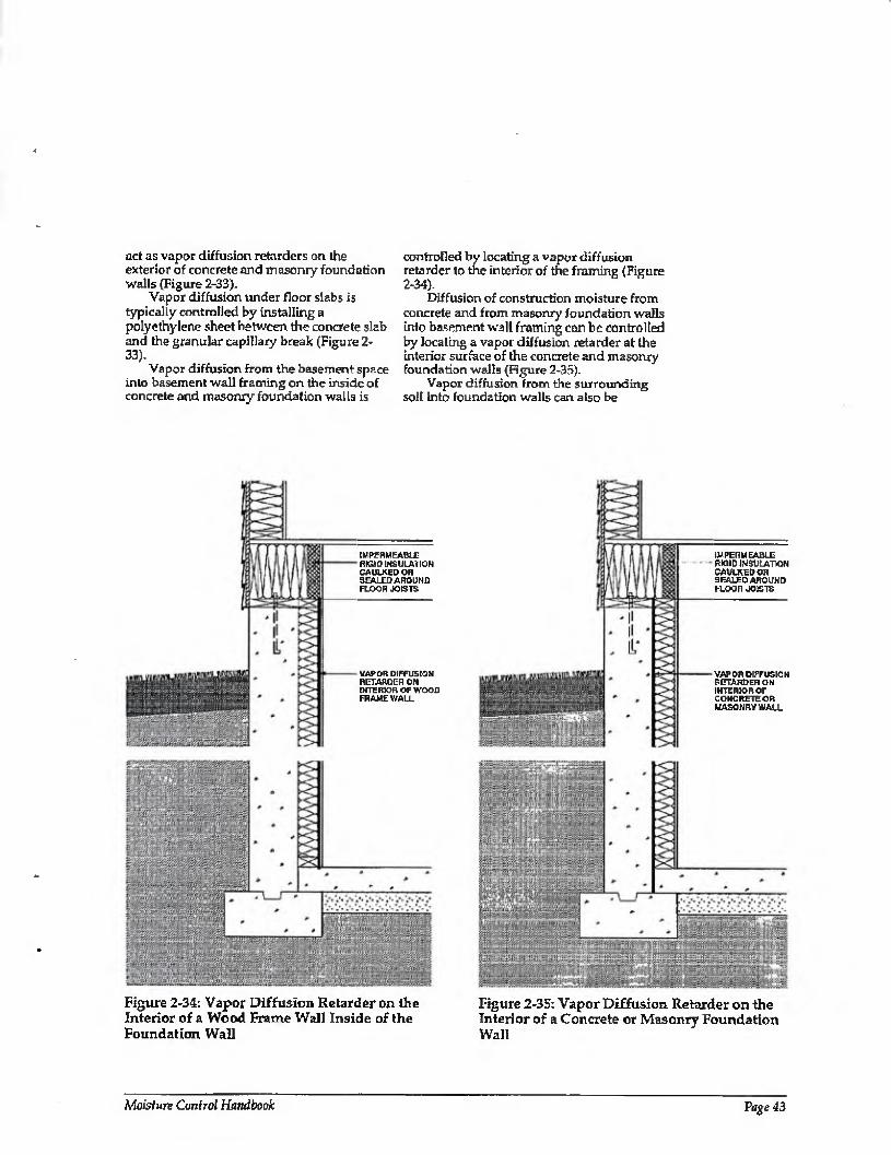
act as vapor diffusion retarders on the exterior of concrete and masonry foundation walls (Figure 2-33).
Vapor diffusion under floor slabs is typically controlled by installing a polyethylene sheet between the concrete slab and the granular capillary break (Figure 2- 33).
Vapor diffusion from the basement space into basement wall framing on the inside of concrete and masonry foundation walls is
controlled by locating a vapor diffusion retarder to the interior of the framing (Figure 2-34).
Diffusion of construction moisture from concrete and from masonry foundation walls into basement wall framing can be controlled by locating a vapor diffusion retarder at the interior surface of the concrete and masonry foundation walls (Figure 2-35).
Vapor diffusion from the surrounding soil into foundation walls can also be
IMPFPMFABl B RIGID INSULATION CAULKED OH SCALED AROUND FLOOR JOISTS
VAPOR DIFFUSION RETARDER ON INTERIOR OF WOOD FRAME WALL
IMPERMEABLE RK1ID INSULATION CAULKED OR SEALED AROUND FLOOR JOISTC
VAPOR DIFFUSION RETARDER ON INTERIOR OF CONCRETE OR MASONRY WALL
Figure 2-34: Vapor Diffusion Retarder on the Interior of a Wood Frame Wall Inside of the Foundation Wall
Figure 2-35: Vapor Diffusion Retarder on the Interior of a Concrete or Masonry Foundation Wall
Moisture Control Handbook Page 43
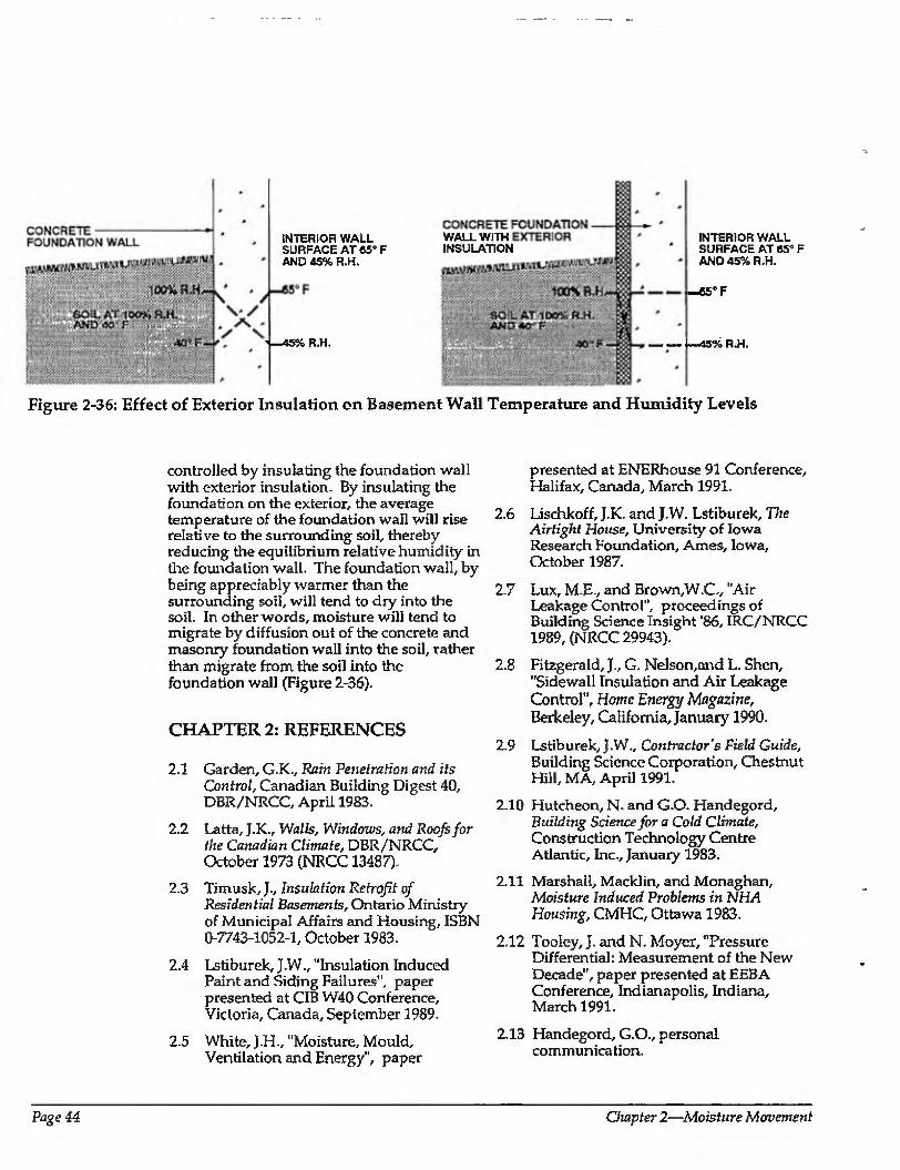
INTERIOR WALL SURFACE AT 65” F AND 45% R.H.
< —45% R.H.
WALL WIT INSULATION
INTERIOR WALL SURFACE AT 65° F AND 45% R.H.
«5°F
-—45% R.H.
Figure 2-36: Effect of Exterior Insulation on Basement Wall Temperature and Humidity Levels
controlled by insulating the foundation wall with exterior insulation. By insulating the foundation on the exterior, the average temperature of the foundation wall will rise relative to the surrounding soil, thereby reducing the equilibrium relative humidity in the foundation wall. The foundation wall, by being appreciably warmer than the surrounding soil, will tend to dry into the soil. In other words, moisture will tend to migrate by diffusion out of the concrete and masonry foundation wall into the soil, rather than migrate from the soil into the foundation wall (Figure 2-36).
CHAPTER 2: REFERENCES
2.1 Garden, G.K., Rain Penetration and its Control, Canadian Building Digest 40, DBR/NRCC, April 1983.
2.2 Latta, J.K., Walls, Windows, and Roofs for the Canadian Climate, DBR/NRCC, October 1973 (NRCC 13487).
2.3 Timusk, J., Insulation Retrofit of Residential Basements, Ontario Ministry of Municipal Affairs and Housing, ISBN 0-7743-1052-1, October 1983.
2.4 Lstiburek, J.W., "Insulation Induced Paint and Siding Failures", paper presented at CIB W40 Conference, Victoria, Canada, September 1989.
2.5 White, J.H., "Moisture, Mould, Ventilation and Energy", paper
presented at ENERhouse 91 Conference, Halifax, Canada, March 1991.
2.6 Lischkoff, J.K. and J.W. Lstiburek, The Airtight House, University of Iowa Research Foundation, Ames, Iowa, October 1987.
2.7 Lux, M.E., and Brown,W.C, "Air Leakage Control", proceedings of Building Science Insight '86, IRC/NRCC 1989, (NRCC 29943).
2.8 Fitzgerald, J., G. Nelson,and L. Shen, "Sidewall Insulation and Air Leakage Control", Home Energy Magazine, Berkeley, California, January 1990.
2.9 Lstiburek, J.W., Contractor's Field Guide, Building Science Corporation, Chestnut Hill, MA, April 1991.
2.10 Hutcheon, N. and GO. Handegord, Building Science for a Cold Climate, Construction Technology Centre Atlantic, Inc., January 1983.
2.11 Marshall, Macklin, and Monaghan, Moisture Induced Problems in hi HA Housing, CMHC, Ottawa 1983.
2.12 Tooley, J. and N. Moyer, "Pressure Differential: Measurement of the New Decade", paper presented at EEBA Conference, Indianapolis, Indiana, March 1991.
2.13 Handegord, G.O., personal communication.
Page 44 Chapter 2—Moisture Movement

CHAPTER 2: BIBLIOGRAPHY
American Society of Heating, Refrigerating and Air Conditioning Engineers, Inc., ASHRAE Handbook: 1989 Fundamentals, Atlanta, 1989.
Canada Mortgage and Housing Corporation, Moisture Problems, CMHC, Ottawa, Canada, 1987.
lowa Department of Natural Resources, A Builder's Guide to Iowa's Idea Homes, Dos Moines, Iowa, 1987.
Merrill, J.L., Moisture Problems in the Home,
University of Wisconsin - Extension, Madison, Wisconsin, 1986.
Peterson, R.A. and L,T. Hendricks, A Systems Approach to Cold Climate Housing, tCD-FO-3S6fi), Minnesota Extension Service, St. Paul, Minnesota, 1988.
Quirouette, R.T., M.N.Z. Rousseau, J. Rousseau, Humidity, Condesation and Ventilation in Houses, NRCC/DBR, Ottawa, 1984.
Timusk, J., External Insulation of Basement Walls, HUDAC Task Force on Basements, Ottawa, 1981.
Timusk, J., Design of the Building Envelope, M.W. Huggins Symposium on Structural Engineering, University of Toronto, September 1981.
Torp, A. and T. Grace, T7ie Effect of Air Currents in Moisture Migration and Condensation in Wood Frame Structures, Norwegian Building Research Institute, Reprint DBR/NRCC, 1964.
Wilson, AG., Condensation in Insulated Masonry Walls in Summer, RILEM/CIB Symposium on Moisture Problems in Building, (NRC 9130), Helsinki, 1965.
Moisture Control Handbook Page 45
CHAPTER 3
Wetting and Drying of Building Assemblies
Ideally, building assemblies would always be built with dry materials under dry conditions, and would never get wet from imperfect design, poor workmanship, or occupants. Unfortunately, these conditions do not exist.
It has been accepted by the building industry that many building assemblies become wet during service, and in many cases start out wet. Furthermore, the industry has recognized that in many circumstances it may be impractical to design and build assemblies that never get wet. This has given rise to the concept oiaccqjiable performance. Acceptable performance implies the design and construction of building assemblies which may periodically get wet, or start out wet, but yet are still durable and provide a long, useful service life. Repeated wetting followed by repeated drying can provide acceptable performance if during the wet period, materials do not stay wet long enough under adverse conditions to deteriorate.
Good design and practice involve controlling the wetting of building assemblies from the exterior and interior. They may also involve drying building assemblies should they become wet during service or start out wet as a result of building with wet materials or under wet conditions.
MOISTURE BALANCE
Moisture accumulates when the rate of moisture entry into an assembly exceeds the rate of moisture removal. When moisture accumulation exceeds the ability of the assembly materials to store the moisture without significantly degrading performance
or long-term service life, moisture problems may result.
Numerous strategies can be implemented to minimize the risk of moisture damage. The strategies fall into the following three groups:
1. Control of moisture entry
2. Control of moisture accumulation
3. Removal of moisture
The first, control of moisture entry, has been covered in Chapter! - Moisture Movement. This chapter covers the other two strategies.
Strategies in the three groupings can be utilized in combination and have been proven to be most effective in that manner. Strategies effective in the control of moisture entry, however, are often not effective if building assemblies start out wet, and in fact can be detrimental. If a technique is effective at preventing moisture from entering an assembly, it is also likely to be effective at preventing moisture from leaving an assembly. Conversely, a technique effective at removing moisture may also allow moisture to enter. Balance between entry and removal is the key.
Building assemblies can get wet from the interior or exterior, or they can start out wet as a result of the construction process due to wet building materials or construction under wet conditions. Moisture can enter from the interior in two ways: air movement and vapor diffusion. Moisture entering from the exterior can be from four sources:
1. Liquid flow (rain and groundwater as moisture sources)
Page 46 Chapter 3—Wetting and Drying of Building Assemblies
2. Capillary suction (rain and groundwater as moisture sources)
3. Air movement
4 Vapor diffusion
Moisture can be redistributed within an assembly by four processes:
1. Liquid flow due to gravity 2. Capillary suction
3. Air movement
4 Vapor diffusion
Finally, moisture can be removed (dried) to the exterior or to the interior in three ways:
4 Liquid flow due to gravity (drainage)
2. Air movement (ventilation)
3. Vapor diffusion (vapor pressure differences).
The above mechanisms can act singly or in combination. This chapter includes discussions relating to the movement of moisture within building assemblies, moisture accumulation within assemblies, and the removal of moisture from building assemblies (drying).
MOISTURE REDISTRIBUTION AND ACCUMULATION WITHIN ASSEMBLIES
Moisture typically enters an assembly in a liquid or vapor state. Under some limited circumstances moisture can also enter in the solid form, such as wind-deposited snow in ventilated roof assemblies. When moisture enters an assembly in a liquid state, or when it changes from a vapor state within an assembly by condensing, its movement is principally governed by liquid flow due to gravity and capillarity. When moisture enters an assembly in a vapor state, or evaporates/sublimates from the liquid or solid state within an assembly, its movement is principally governed by air movement and vapor diffusion.
Each of the four mechanisms mentioned (liquid flow due to gravity, capillarity, air transport, and diffusion) acts independently. For example, a temperature/vapor pressure difference may result in vapor diffusion
transporting moisture from the interior surfaces of an insulated wall cavity towards the exterior through the insulation, resulting in condensation on the exterior surfaces of the wall cavity. At the same time capillarity may be transporting some of the condensed moisture from the exterior surfaces back towards the interior surfaces through the cavity insulation.
Numerous combinations and permutations of the transport mechanisms within building assemblies can occur under the driving forces Imposed by both exterior and interior environments. Some of the typical combinations are described in the following sections. The examples given are not intended to be comprehensive, nor complete. They are intended for illustrative purposes only.
Wall Assemblies
The behavior of moisture in wall assemblies transported by vapor diffusion or air transport is discussed below. Several drawings are provided to illustrate moisture behavior in some typical wall assemblies. Strategies for controlling moisture are then described.
VAPOR DIFFUSION IN WALL ASSEMBLIES
Figure 3-1 illustrates a wood frame wall in a heating climate with unfaced fiberglass batt insulation installed within the cavities. Gypsum board painted with a relatively vapor permeable latex is installed to the interior. Relatively impermeable plywood sheathing is installed to the exterior. Wood- based lap siding over a permeable, nonabsorptive building paper is installed over the exterior plywood sheathing. The conditioned space operates at a high interior vapor pressure (5D percent relative humidity at 70 degrees Fahrenheit), and the average exterior temperature during the month of January is 0 degrees Fahrenheit. To simplify matters assume that the wall is constructed airtight and that no air pressure difference exists between the interior and exterior of the wall in order to eliminate air movement as a moisture transport mechanism. In addition, wall convection effects will be ignored.
In this example vapor diffusion will
Moisture Control Handbook Page 47
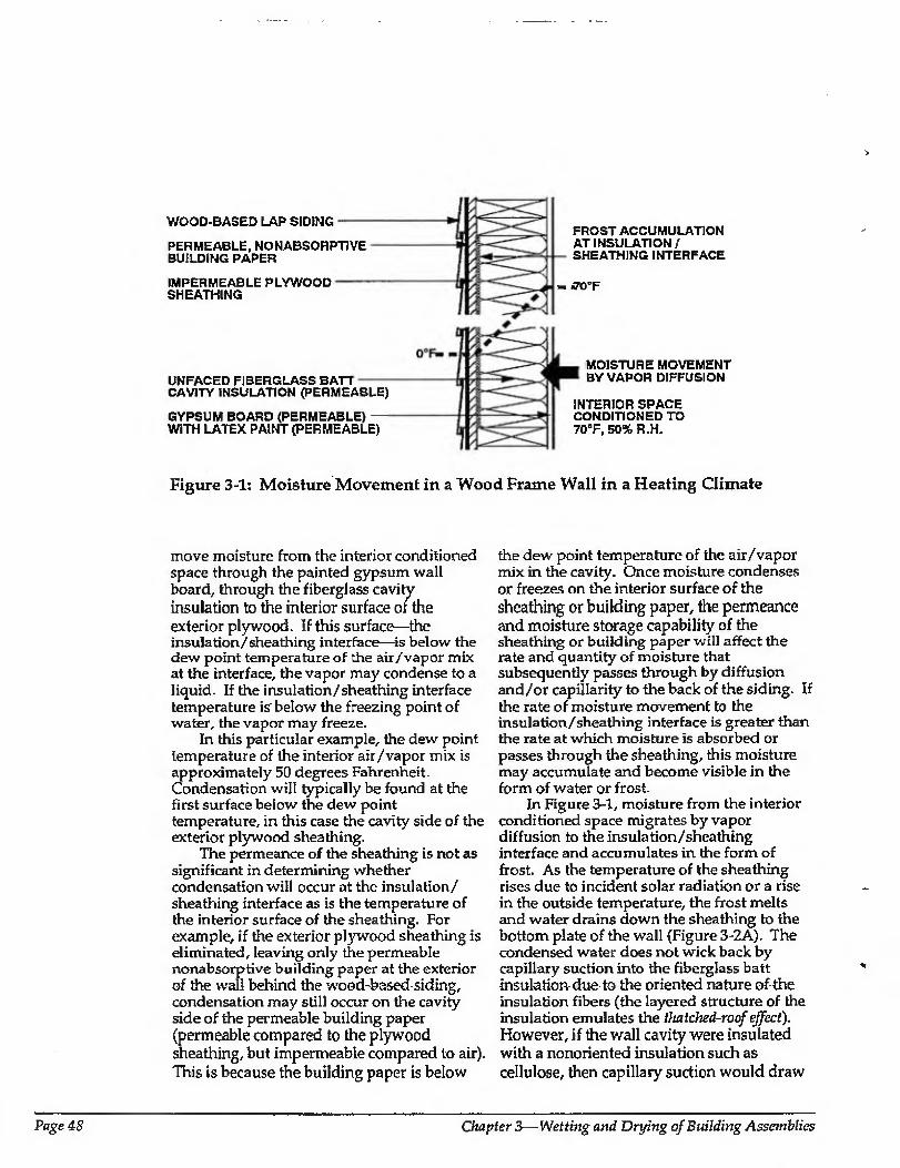
WOOD-BASED LAP SIDING
PERMEABLE, NONABSORPTJVE BUILDING PAPER
IMPERMEABLE PLYWOOD SHEATHING
UNFACED FIBERGLASS BATT CAVITY INSULATION (PERMEABLE)
GYPSUM BOARD (PERMEABLE) WITH LATEX PAINT (PERMEABLE)
FROST ACCUMULATION AT INSULATION / SHEATHING INTERFACE
- jo°F
MOISTURE MOVEMENT BY VAPOR DIFFUSION
INTERIOR SPACE CONDITIONED TO 70°F, 50% R.H.
Figure 3-1: Moisture Movement in a Wood Frame Wall in a Heating Climate
move moisture from the interior conditioned space through the painted gypsum wall board, through the fiberglass cavity insulation to the interior surface of the exterior plywood. If this surface—the insulation/sheathing interface—is below the dew point temperature of the air/vapor mix at the interface, the vapor may condense to a liquid. If the insulation/sheathing interface temperature is'below the freezing point of water, the vapor may freeze.
In this particular example, the dew point temperature of the interior air/vapor mix is approximately 50 degrees Fahrenheit. Condensation will typically be found at the first surface below the dew point temperature, in this case the cavity side of the exterior plywood sheathing.
The permeance of the sheathing is not as significant in determining whether condensation will occur at the insulation/ sheathing interface as is the temperature of the interior surface of the sheathing. For example, if the exterior plywood sheathing is eliminated, leaving only the permeable nonabsorptive building paper at the exterior of the wall behind the wood-based siding, condensation may still occur on the cavity side of the permeable building paper (permeable compared to the plywood sheathing, but impermeable compared to air). This is because the building paper is below
the dew point temperature of the air/vapor mix in the cavity. Once moisture condenses or freezes on the interior surface of the sheathing or building paper, the permeance and moisture storage capability of the sheathing or building paper will affect the rate and quantity of moisture that subsequently passes through by diffusion and/or capillarity to the back of the siding. If the rate of moisture movement to the insulation/sheathing interface is greater than the rate at which moisture is absorbed or passes through the sheathing, this moisture may accumulate and become visible in the form of water or frost.
In Figure 3-1, moisture from the interior conditioned space migrates by vapor diffusion to the insulation/sheathing interface and accumulates in the form of frost. As the temperature of the sheathing rises due to incident solar radiation or a rise in the outside temperature, the frost melts and water drains down the sheathing to the bottom plate of the wall (Figure 3-2A). The condensed water does not wick back by capillary suction into the fiberglass batt insulation-due to the oriented nature of the insulation fibers (the layered structure of the insulation emulates the fhatched-roof effect). However, if the wall cavity were insulated with a nonoriented insulation such as cellulose, then capillary suction would draw
Page 48 Chapter 3—Wetting and Drying of Building Assemblies
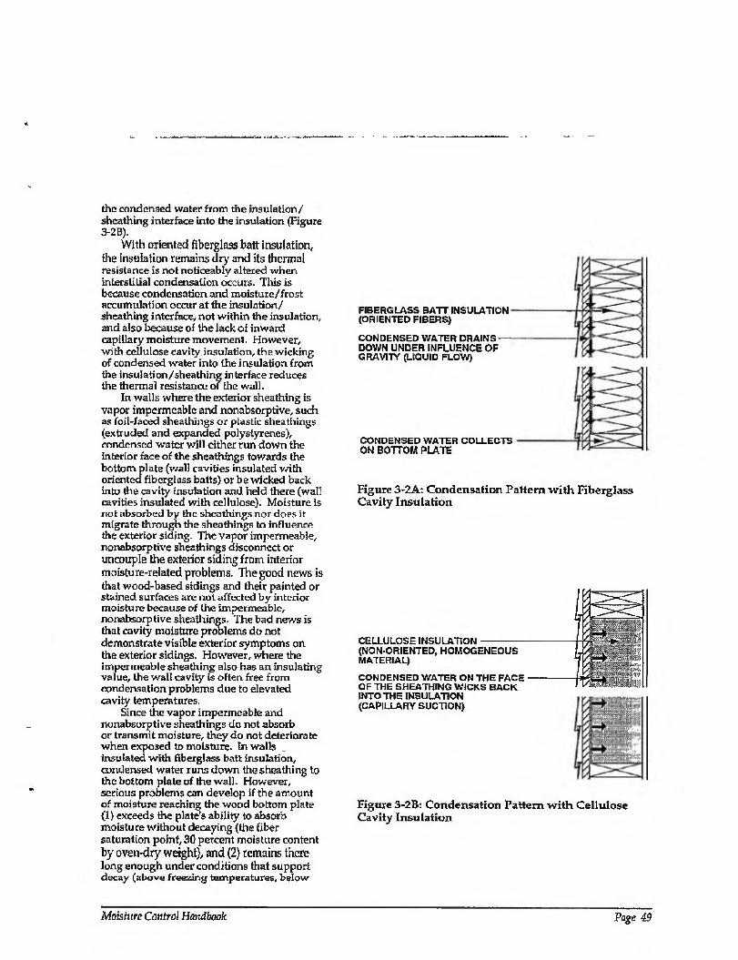
the condensed water from the insulation/ sheathing interface into the insulation (Figure 3-2B).
With oriented fiberglass batt insulation, the insulation remains dry and its therm a! resistance is not noticeably altered when interstitial condensation occurs. This is because condensation and moisture/frost accumulation occur at the insulation/ sheathing interface, not within the insulation, and also because of the lack of inward capillary moisture movement. However, with cellulose cavity insulation, the wickirg of condensed water into the insulation from the insulation/sheathing interface reduces the thermal resistance of the wall.
In walls where the exterior sheathing is vapor impermeable and nonabsorptive, such as foil-faced shea tilings or plastic shea tilings (extruded and expanded polystyrenes), condensed water will either run down the interior face of the sheathings towards the bottom plate (wall cavities insulated with oriented fiberglass batts) or be wicked back into the cavity insulation and held there (wall cavities insulated with cellulose). Moisture is not absorbed by the sheathings nor does it migrate through the sheathings to influence the exterior siding. The vapor impermeable, nonabsorptive sheathings disconnect or uncouple the exterior siding from interior moisture-related problems. The good news is that wood-based sidings and their painted or stained surfaces are nut affected by interior moisture because of the impermeable, nonabsorptive sheathings. The bad news is that cavity moisture problems do not demonstrate visible exterior symptoms on the exterior sidings. However, where the impermeable sheathing also has an insulating value, the wall cavity is often free from condensation problems due to elevated cavity temperatures.
Since the vapor impermeable and nonabsorptive sheathings do not absorb or transmit moisture, they do not deteriorate when exposed to moisture. In walls insulated with fiberglass batt insulation, condensed water runs down the sheathing to the bottom plate of the wall. However, serious problems can develop if the amount of moisture reaching the wood bottom plate (1) exceeds the plate’s ability to absorb moisture without decaying (the fiber saturation point, 30 percent moisture content by oven-dry weight), and (2) remains there long enough under conditions that support decay (above freezing temperatures, below
FIBERGLASS BATT INSULATION (ORIENTED FIBERS)
CONDENSED WATER DRAINS DOWN UNDER INFLUENCE OF GRAVITY (LIQUID FLOW)
CONDENSED WATER COLLECTS ON BOTTOM PLATE
Figure 3-2A: Condensation Pattern with Fiberglass Cavity Insulation
CELLULOSE INSULATION- (NON-ORIENTED, HOMOGENEOUS MATERIAL)
CONDENSED WATER ON THE FACE ■ OF THE SHEATHING WICKS BACK INTO THE INSULATION (CAPILLARY SUCTION)
/\ . .. ..
Figure 3-2B: Condensation Pattern with Cellulose Cavity Insulation
Moisti(re Control Handbook Page 49
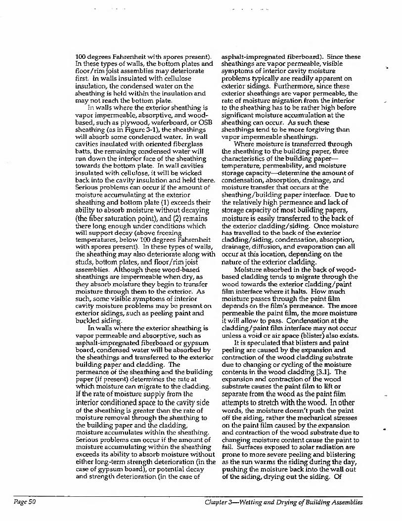
100 degrees Fahrenheit with spores present). In these types of walls, the bottom plates and floor/rim joist assemblies may deteriorate first. In walls insulated with cellulose insulation, the condensed water on the sheathing is held within the insulation and may not reach the bottom plate.
In walls where the exterior sheathing is vapor impermeable, absorptive, and wood- based, such as plywood, waferboard, or OSB sheathing (as in Figure 3-1), the sheathings will absorb some condensed water. In wall cavities insulated with oriented fiberglass batts, the remaining condensed water will run down the interior face of the sheathing towards the bottom plate. In wall cavities insulated with cellulose, it will be wicked back into the cavity insulation and held there. Serious problems can occur if the amount of moisture accumulating at the exterior sheathing and bottom plate (1) exceeds their ability to absorb moisture without decaying (the fiber saturation point), and (2) remains there long enough under conditions which will support decay (above freezing temperatures, below 100 degrees Fahrenheit with spores present). In these types of walls, the sheathing may also deteriorate along with studs, bottom plates, and floor/rim joist assemblies. Although these wood-based sheathings are impermeable when dry, as they absorb moisture they begin to transfer moisture through them to the exterior. As such, some visible symptoms of interior cavity moisture problems may be present on exterior sidings, such as peeling paint and buckled siding.
In walls where the exterior sheathing is vapor permeable and absorptive, such as asphalt-impregnated fiberboard or gypsum board, condensed water will be absorbed by the sheathings and transferred to the exterior building paper and cladding. The permeance of the sheathing and the building paper (if present) determines the rate at which moisture can migrate to the cladding. If the rate of moisture supply from the interior conditioned space to the cavity side of the sheathing is greater than the rate of moisture removal through the sheathing to the building paper and the cladding, moisture accumulates within the sheathing. Serious problems can occur if the amount of moisture accumulating within the sheathing exceeds its ability to absorb moisture without either long-term strength deterioration (in the case of gypsum board), or potential decay and strength deterioration (in the case of
asphalt-impregnated fiberboard). Since these sheathings are vapor permeable, visible symptoms of interior cavity moisture problems typically are readily apparent on exterior sidings. Furthermore, since these exterior sheathings are vapor permeable, the rate of moisture migration from the interior to the sheathing has to be rather high before significant moisture accumulation at the sheathing can occur. As such these sheathings tend to be more forgiving than vapor impermeable sheathings.
Where moisture is transferred through the sheathing to the building paper, three characteristics of the building paper— temperature, permeability, and moisture storage capacity—determine the amount of condensation, absorption, drainage, and moisture transfer that occurs at the sheathing/building paper interface. Due to the relatively high permeance and lack of storage capacity of most building papers, moisture is easily transferred to the back of the exterior cladding/siding. Once moisture has travelled to the back of the exterior cladding/siding, condensation, absorption, drainage, diffusion, and evaporation can all occur at this location, depending on the nature of the exterior cladding.
Moisture absorbed in the back of wood- based cladding tends to migrate through the wood towards the exterior cladding/paint film interface where it halts. How much moisture passes through the paint film depends on the film's permeance. The more permeable the paint film, the more moisture it will allow to pass. Condensation at the cladding/paint film interface may not occur unless a void or air space (blister) also exists.
It is speculated that blisters and paint peeling are caused by the expansion and contraction of the wood cladding substrate due to changing or cycling of the moisture contents in the wood cladding [3.1]. The expansion and contraction of the wood substrate causes the paint film to lift or separate from the wood as the paint film attempts to stretch with the wood. In other words, the moisture doesn't push the paint off the siding, rather the mechanical stresses on the paint film caused by the expansion and contraction of the wood substrate due to changing moisture content cause the paint to fail. Surfaces exposed to solar radiation are prone to more severe peeling and blistering as the sun warms the siding during the day, pushing the moisture back into the wall out of the siding, drying out the siding. Of
Page 50 Chapter 3—Wetting and Drying of Building Assemblies
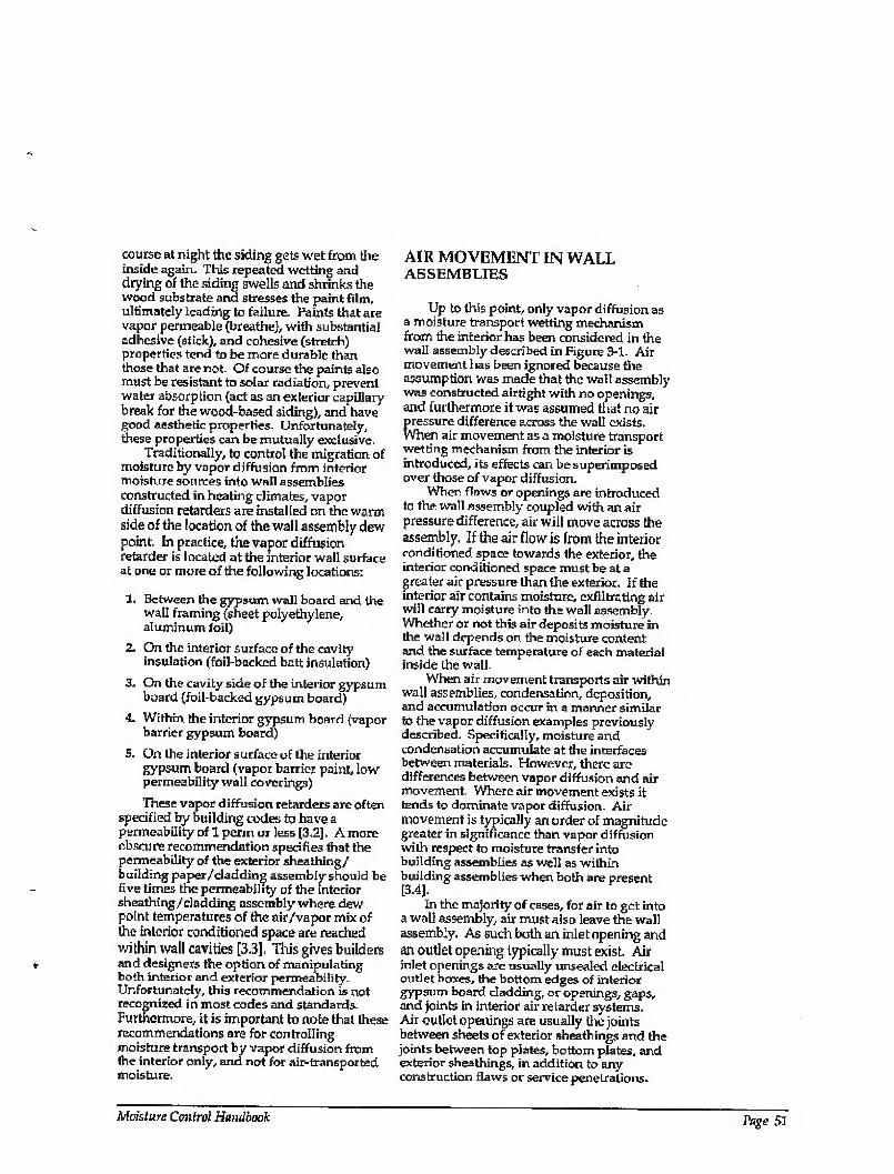
course at night the siding gets wet from the inside again. This repeated wetting and drying of the siding swells and shrinks the wood substrate and stresses the paint film, ultimately leading to failure. Paints that are vapor permeable (breathe), with substantial adhesive (stick), and cohesive (stretch) properties tend to be more durable than those that ate not. Of course the paints also must be resistant to solar radiation, prevent water absorption (act as an exterior capillary break for the wood-based siding), and have good aesthetic properties. Unfortunately, these properties cam be mutually exclusive.
Traditionally, to control the migration of moisture by vapor diffusion from interior moisture sources into wall assemblies constructed in heating climates, vapor diffusion retarders are installed on the warm side of the location of the wall assembly dew point. In practice, the vapor diffusion retarder is located at the interior wall surface at one or more of the following locations:
1. Between the gypsum wall board and the wall framing (sheet polyethylene, aluminum foil)
2. On the interior surface of the cavity insulation (foil-backed batt insulation)
3. On the cavity side of the interior gypsum board (foil-backed gypsum board)
4. Within the interior gypsum board (vapor barrier gypsum board)
5. On tlie inferior surface of the interior gypsum board (vapor barrier paint, low permeability wall coverings)
These vapor diffusion retarders are often specified by building codes to have a permeability of 1 perm or less [3.2]. A more obscure recommendation specifies that the permeability of the exterior sheathing/ building paper/cladding assembly should be five times the permeability of the interior sheathing/dadding assembly where dew point temperatures of the air/vapor mix of the interior conditioned space are reached within wall cavities [3.3], This gives builders and designers the option of manipulating both interior and exterior permeability. Unfortunately, this recommendation is not recognized in most codes and standards. Furthermore, it is important to note that these recommendations are for controlling moisture transport by vapor diffusion from the interior only, and not for air-transported moisture.
AIR MOVEMENT IN WALL ASSEMBLIES
Up to this point, only vapor diffusion as a moisture transport wetting mechanism from the interior has been considered in the wall assembly described in Figure 3-1. Air movement has been ignored because the assumption was made that the wall assembly was constructed airtight with no openings, and furthermore it was assumed that no air pressure difference across the wall exists. When air movement as a moisture transport wetting mechanism from the interior is introduced, its effects can be superimposed over those of vapor diffusion.
When flaws or openings are introduced to the wall assembly coupled with an air pressure difference, air will move across the assembly. If the air flow is from the interior conditioned space towards the exterior, the interior cond itioned space must be at a greater air pressure than the exterior. If the inferior air contains moisture, exfiltrating air will carry moisture into the wali assembly. Whether or not this air deposits moisture in the wall depends on the moisture content and the surface temperature of each material inside the wall.
When air movement transports air within wall assemblies, condensation, deposition, and accumulation occur in a manner similar to the vapor diffusion examples previously described. Specifically, moisture and condensation accumulate at the interfaces between materials. However, there are differences between vapor diffusion and air movement. Where air movement exists it tends to dominate vapor diffusion. Air movement is typically an order of magnitude greater in significance than vapor diffusion with respect to moisture transfer into building assemblies as well as within building assemblies when both are present [3.4J.
In the majority of cases, for air to get into a wall assembly, air must also leave the wall assembly. As such bo tit an inlet opening and an outlet opening typically must exist. Air inlet openings are usually unsealed electrical outlet boxes, the bottom edges of interior gypsum board cladding, or openings, gaps, and joints in interior air retarder systems. Air outlet openings are usually the joints between sheets of exterior sheathings and the joints between top plates, bottom plates, and exterior sheathings, in addition to any construction flaws or service penetrations.
Moisture Control Handbook Page 51
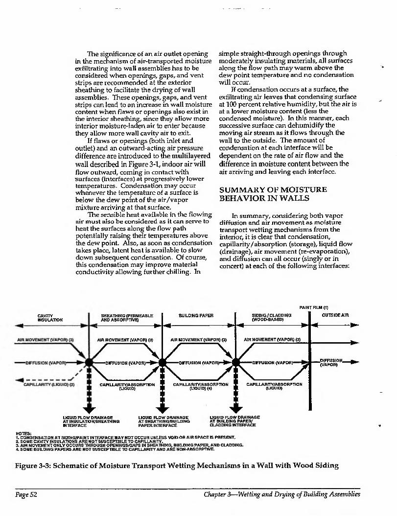
c4cW
The significance of an air outlet opening in the mechanism of air-transported moisture exfiltrating into wall assemblies has to be considered when openings, gaps, and vent strips are recommended at the exterior sheathing to facilitate the drying of wall assemblies. These openings, gaps, and vent strips can lead to an increase in wall moisture content when flaws or openings also exist in the interior sheathing, since they allow more interior moisture-laden air to enter because they allow more wall cavity air to exit.
If flaws or openings (both inlet and outlet) and an outward-acting air pressure difference are introduced to the multilayered wall described in Figure 3-1, indoor air will flow outward, coming in contact with surfaces (interfaces) at progressively lower temperatures. Condensation may occur whenever the temperature of a surface is below the dew point of the air/vapor mixture arriving at that surface.
The sensible heat available in the flowing air must also be considered as it can serve to heat the surfaces along the flow path potentially raising their temperatures above the dew point. Also, as soon as condensation takes place, latent heat is available to slow down subsequent condensation. Of course, this condensation may improve material conductivity allowing further chilling. In
simple straight-through openings through moderately insulating materials, all surfaces along the flow path may warm above the dew point temperature and no condensation will occur.
If condensation occurs at a surface, the exfiltrating air leaves that condensing surface at 100 percent relative humidity, but the air is at a lower moisture content (less the condensed moisture). In this manner, each successive surface can dehumidify the moving air stream as it flows through the wall to the outside. The amount of condensation at each interface will be dependent on the rate of air flow and the difference in moisture content between the air arriving and leaving each interface.
SUMMARY OF MOISTURE BEHAVIOR IN WALLS
In summary, considering both vapor diffusion and air movement as moisture transport wetting mechanisms from the interior, it is clear that condensation, capillarity/absorption (storage), liquid flow (drainage), air movement (re-evaporation), and diffusion can all occur (singly or in concert) at each of the following interfaces:
PAINT FILM (1)
CAVITY ISOLATION
SHEATHING (PERMEABLE AKD ABSORPTIVE)
BUILDING PAPER SIDING/CLADDING (WOOEM3ASED)
—-
OUTSIDE AIR
—* - B^
AIR MOVEMENT (VAPOR) (3)
^
AIR MOVEMENT (VAPOR) (3) AIR MOVEMENT (VAPOR) (3)
—DIFFUSION (VAP0H)-)^-i
\ 7\ fc—-'DrFUStON (VAPOR) 1
K 77 PIFFUSIOH ^ (VAPOR)
CAPILLAR ITY/ABSORPTION ‘ (LIQUID) 1
1
S CAPILLAHITWABSORPTION 1 (UQUID) (4)
1
l
CAPILLAR ITY/ABSO R P TKD H (UQUID)
UQUID FLOW DRAINAGE AT INSULATON/SHEATHING HTEH FACE
LIQUID FLOW DRAINAGE AT SHEATHING/BUILD1NG PAPER INTERFACE
LIQUID FLOW DRAINAGE AT BUILDING PAPEFV CLADDING INTERFACE
NOTES: " CONDENSATION AT SIDING/PAINT INTERFACE MAY NOT OCCUR UNLESS VOID OR AIR SPACE IS PRESENT.
SOME CAVITY INSULATIONS ARE NOT SUSCEPTIBLE TO CAPILLARITY. AIR MOVEMENT ONLY OCCURS THROUGH OPENINGS/GAPS IN SHEATHING, BUILDING PAPER, AND CLADDING. S DM E BUILDING PAPERS ARE NOT SU SCEPTIBLE TO CAPILLARITY AND ARE HON ABSORPTIVE.
Figure 3-3: Schematic of Moisture Transport Wetting Mechanisms in a Wall with Wood Siding
Page 52 Chapter 3—Wetting and Drying of Building Assemblies
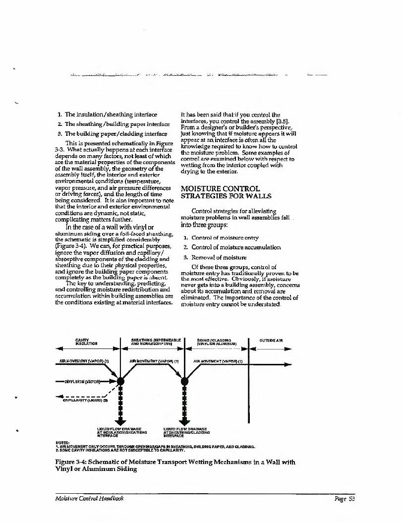
1. The ins illation/sheathing interface
2. The sheathing/building paper interface
3. The building paper/cladding interface
This is presented schematically in Figure 3-3. What actually happens at each interface depends on many factors, not least of which are the material properties of the components of the wall assembly, the geometry of the assembly itself, the interior and exterior environmental conditions (temperature, vapor pressure, and air pressure differences or driving forces), and the length of time being considered. It is also important to note (hat the interior and exterior environmental conditions are dynamic, not static, complicating matters further.
In the case of a wall with vinyl or aluminum siding over a foil-faced sheathing, the schematic is simplified considerably (Figure 3-4). We can, for practical purposes, ignore the vapor diffusion and capillary/ absorptive components of the cladding and sheathing due to their physical properties, and ignore the building paper components completely as the building paper is absent.
The key to understanding, predicting, and controlling moisture redistribution and accumulation within building assemblies are the conditions existing at material interfaces.
It has been said (hat if you control the interfaces, you control the assembly [3.5], From a designer's or builder’s perspective, just knowing that if moisture appears it will appear at an interface is often all the knowledge required to know how to control the moisture problem. Some examples of control are examined below with respect to wetting from the interior coupled with drying to the exterior.
MOISTURE CONTROL STRATEGIES FOR WALLS
Control strategies for alleviating moisture problems inwall assemblies fall into three groups:
1. Control of moisture entry
2. Control of moisture accumulation
3. Removal of moisture
Of these three groups, control of moisture entry has traditionally proven to be the most effective. Obviously, if moisture never gets into a building assembly, concerns about its accumulation and removal are eliminated. The importance of the control of moisture entry cannot be understated.
CAVITY 1HSULATIGW
SHEATHIKG (IMPERMEABLE AMD NUHABSOflPTJVE)
SIDING /'CLADDING (VINYLOR ALUMINUM}
OUTSIDE AIR
AIR MOVEH 6HT (VAPOR) (1) AIR MOVEMENT (VAPOR) (1) AIR MOVEMENT (VAPOR) (1)
\ —DIFFUSK5H (VAPOR)1 ^ 1
✓ y
CAPILLARITY (LIQUID) p>
LIQUID FLOW DRAINAGE LIQUID FLOW DRAINAGE AT IH3ULAT10HA3HEATH1NG ATSHEATHING/CLADDIHG INTERFACE HTERFACE
NOTES: 1, AIRUCVEUEHTOKLY OCCURS THROUGH CPENIMGSA3APS IN SH tAIHIHG, BUILDING PAPER, AND CLAUD [HG. t SOME CAVITY INSULATIONS ARE HOT SUSCEPTIBLE TO CAPILLARITY,
Figure 3-4: Schematic of Moisture Transport Wetting Mechanisms in a Wall with Vinyl or Aluminum Siding
Moisture Control Handbook
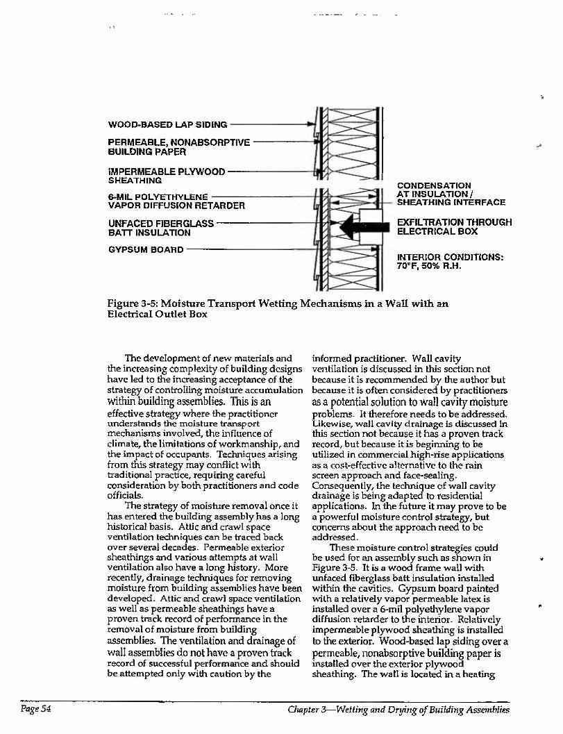
WOOD-BASED LAP SIDING-
PERMEABLE, NONABSORPTIVE BUILDING PAPER
IMPERMEABLE PLYWOOD- SHEATHING
6-MIL POLYETHYLENE - VAPOR DIFFUSION RETARDER
UNFACED FIBERGLASS BATT INSULATION
GYPSUM BOARD-
CONDENSATION AT INSULATION/ SHEATHING INTERFACE
EXFILTRATION THROUGH ELECTRICAL BOX
INTERIOR CONDITIONS: 70°F, 50% R.H.
Figure 3-5: Moisture Transport Wetting Mechanisms in a Wall with an Electrical Outlet Box
The development of new materials and the increasing complexity of building designs have led to the increasing acceptance of the strategy of controlling moisture accumulation within building assemblies. This is an effective strategy where the practitioner understands the moisture transport mechanisms involved, the influence of climate, the limitations of workmanship, and the impact of occupants. Techniques arising from this strategy may conflict with traditional practice, requiring careful consideration by both practitioners and code officials.
The strategy of moisture removal once it has entered the building assembly has a long historical basis. Attic and crawl space ventilation techniques can be traced back over several decades. Permeable exterior sheathings and various attempts at wall ventilation also have a long history. More recently, drainage techniques for removing moisture from building assemblies have been developed. Attic and crawl space ventilation as well as permeable sheathings have a proven track record of performance in the removal of moisture from building assemblies. The ventilation and drainage of wall assemblies do not have a proven track record of successful performance and should be attempted only with caution by the
informed practitioner. Wall cavity ventilation is discussed in this section not because it is recommended by the author but because it is often considered by practitioners as a potential solution to wall cavity moisture problems It therefore needs to be addressed. Likewise, wall cavity drainage is discussed in this section not because it has a proven track record, but because it is beginning to be utilized in commercial high-rise applications as a cost-effective alternative to the rain screen approach and face-sealing. Consequently, the technique of wall cavity drainage is being adapted to residential applications. In the future it may prove to be a powerful moisture control strategy, but concerns about the approach need to be addressed.
These moisture control strategies could be used for an assembly such as shown in Figure 3-5. It is a wood frame wall with unfaced fiberglass batt insulation installed within the cavities. Gypsum board painted with a relatively vapor permeable latex is installed over a 6-mil polyethylene vapor diffusion retarder to the interior. Relatively impermeable plywood sheathing is installed to the exterior. Wood-based lap siding over a permeable, nonabsorptive building paper is installed over the exterior plywood sheathing. The wall is located in a heating
Page 54 Ompter 3—Wetting and Drying of Building Assemblies
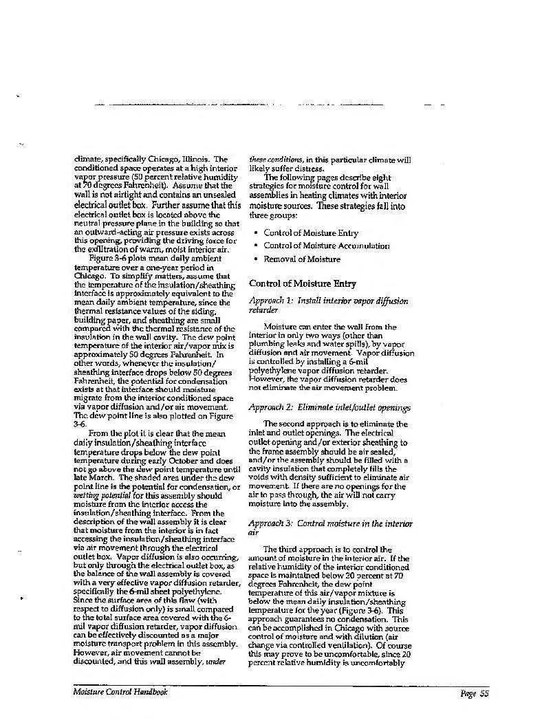
climate, specifically Chicago, Illinois. The conditioned space operates at a high interior vapor pressure (50 percent relative humidity at 70 degrees Fahrenheit). Assume that the wall is not airtight and contains an unseaied electrical outlet box. Further assume that this electrical outlet box is located above the neutral pressure plane in the building so that an outward-acting air pressure exists across this opening, providing the driving force for the exfiltration of warm, moist interior air.
Figure 3-6 plots mean daily ambient temperature over a one-year period in Chicago. To simplify matters, assume that the temperature of the insulation/sheathing interface is approximately equivalent to the mean daily ambient temperature, since the thermal resistance values of the siding, building paper, and sheathing are small compared with the thermal resistance of the insulation in the wall cavity. The dew point temperature of the interior air/vapor mix is approximately 50 degrees Fahrenheit. In other words, whenever the insulation/ sheathing interface drops below 50 degrees Fahrenheit, the potential for condensation exists at that interface should moisture migrate from the interior conditioned space via vapor diffusion and/or air movement. The dew point line is also plotted on Figure 3-6.
From the plot it is dear lhat the mean daily insulation/sheathing interface temperature drops below the dew point temperature during early October and does not go above the dew point temperature until late March. The shaded area under the dew point line is the potential for condensation, or wetting potential for this assembly should moisture from the interior access the insulation/sheathing interface. From the description, of the wall assembly it is clear that moisture from the interior is in fact accessing the insulation/sheathing interface via air movement through the electrical outlet box. Vapor diffusion is also occurring, but only through the electrical outlet box, as the balance of tire wall assembly is covered with a very effective vapor diffusion retarder, specifically the 6-mil sheet polyethylene. Since the surface area of this flaw (with respect to diffusion only) is small compared to the total surface area covered with the 6- mil vapor diffusion retarder, vapor diffusion can be effectively discounted as a major moisture transport problem in this assembly. However, air movement cannot be discounted, and this wall assembly, under
these conditions, in this particular climate will likely suffer distress.
The following pages describe eight strategies for moisture control for wall assemblies in heating climates with interior moisture sources. These strategies fall into three groups:
• Control of Moisture Entry
• Control of Moisture Accumulation
• Removal of Moisture
Control of Moisture Entry
Approach 1: Install interior vapor diffusion retarder
Moisture can enter the wall from the interior in only two ways (other than plumbing leaks and water spills), by vapor diffusion and air movement. Vapor diffusion is controlled by installing a 6-mil polyethylene vapor diffusion retarder. However, the vapor diffusion retarder does not eliminate the air movement problem.
Approach 2: Eliminate inlet/outlet openings
The second approach is to eliminate the inlet and outlet openings. The electrical outlet opening and/or exterior sheathing to the frame assembly should be air sealed, and/or the assembly should be filled with a cavity insulation that completely fills the voids with density sufficient to eliminate air movement If there are no openings for the air to pass through, the air will not carry moisture into the assembly.
Approach 3: Control moisture in the interior air
The third approach is to control the amount of moisture in the interior air. If the relative humidity of the interior conditioned space is maintained below 20 percent at 70 degrees Fahrenheit, the dew point temperature of this air/vapor mixture is below the mean daily insulation/sheathing temperature for theyear (Figure 3-6). This approach guarantees no condensation. This can be accomplished in Chicago with source control of moisture and with dilution (air change via controlled ventilation). Of course this may prove to be uncomfortable, since 20 percent relative humidity is uncomfortably
bAoisture Control Handbook Page 55
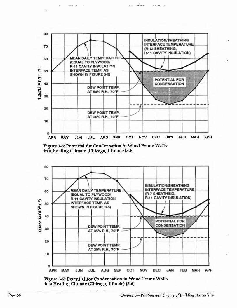
TE
MP
ER
AT
UR
E (
°F)
TE
MP
ER
AT
UR
E (
SF)
APR MAY JUN JUL AUG SEP OCT NOV DEC JAN FEB MAR APR
Figure 3-6: Potential for Condensation in Wood Frame Walls in a Heating Climate (Chicago, Illinois) [3.6]
Figure 3-7: Potential for Condensation in Wood Frame Walls in a Heating Climate (Chicago, Illinois) [3.6]
Page 56 Chapter 3—Wetting and Drying of Building Assemblies
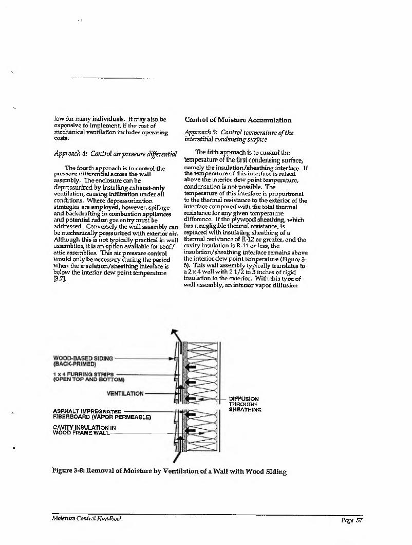
low for many individuals. It may also be expensive to implement, if the cost of mechanical ventilation includes operating costs.
Approach 4: Control air pressure differential
The fourth approach is to control the pressure differential across the wall assembly. The enclosure can be depressurized by installing exhaust-only ventilation, causing infiltration under all conditions. Where depressurization strategies are employed, however, spillage and backdrafting in combustion appliances and potential radon gas entry must be addressed. Conversely the wall assembly can be mechanically pressurized with exterior air. Although tills is nut typically practical in wall assemblies, it is an option available for roof/ attic assemblies. This air pressure control would only be necessary during the period when the insulation/sheathing interface is below the interior dew point temperature [3.7].
Control of Moisture Accumulation
Approach 5: Control temperature of the interstitial condensing surface
The fifth approach is to control the temperature of the first condensing surface, namely the insulation/sheathing interface. If the temperature of this interface is raised above the interior dew point temperature, condensation is not possible. The temperature of this interface is proportional to the thermal resistance to the exterior of the interface compared'with the total thermal resistance for any given temperature difference. If the plywood sheathing, which has a negligible thermal resistance, is replaced with insulating sheathing of a thermal resistance of R -12 or greater, and the cavity insulation is R-ll or less, the insulation/sheathing interface remains above the interior dew point temperature (Figure 3- 6), This wall assembly typically translates to a 2 x 4 wall with 2 1 /2 to 3 inches of rigid insulation to the exterior. With this type of wall assembly, an interior vapor diffusion
ASPHALT IMPREGNATED - RBERBOARD (VAPOR PERMEABLE)
DIFFUSION THROUGH SHEATHING
CAVITY INSULATION IN WOOD FRAME WALL —
Figure 3-8: Removal of Moisture by Ventilation of a Wall with Wood Siding
Moisture Control Handbook Page 57
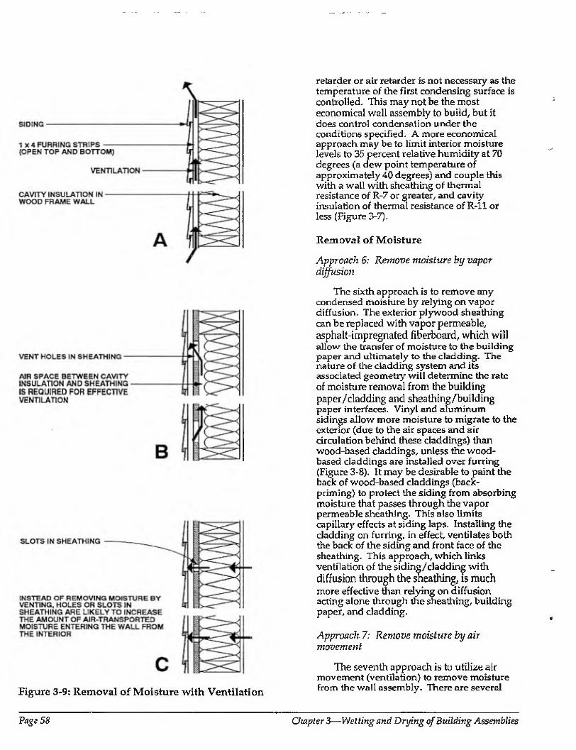
Figure 3-9: Removal of Moisture with Ventilation
retarder or air retarder is not necessary as the temperature of the first condensing surface is controlled. This may not be the most economical wall assembly to build, but it does control condensation under the conditions specified. A more economical approach may be to limit interior moisture levels to 35 percent relative humidity at 70 degrees (a dew point temperature of approximately 40 degrees) and couple this with a wall with sheathing of thermal resistance of R-7 or greater, and cavity insulation of thermal resistance of R-ll or less (Figure 3-7).
Removal of Moisture
Approach 6: Remove moisture by vapor diffusion
The sixth approach is to remove any condensed moisture by relying on vapor diffusion. The exterior plywood sheathing can be replaced with vapor permeable, asphalt-impregnated fiberboard, which will allow the transfer of moisture to the building paper and ultimately to the cladding. The nature of the cladding system and its associated geometry will determine the rate of moisture removal from the building paper/cladding and shea thing/building paper interfaces. Vinyl and aluminum sidings allow more moisture to migrate to the exterior (due to the air spaces and air circulation behind these claddings) than wood-based claddings, unless the wood- based claddings are installed over furring (Figure 3-8), It may be desirable to paint the back of wood-based claddings (back- priming) to protect the siding from absorbing moisture that passes through the vapor permeable sheathing. This also limits capillary effects at siding laps. Installing the cladding on furring, in effect, ventilates both the back of the siding and front face of the sheathing. This approach, which links ventilation of the siding/cladding with diffusion through the sheathing, is much more effective than relying on diffusion acting alone through the sheathing, building paper, and cladding.
Approach 7: Remove moisture by air movement
The seventh approach is to utilize air movement (ventilation) to remove moisture from the wall assembly- There are several
Page 58 Chapter 3—Welting and Drying of Building Assemblies
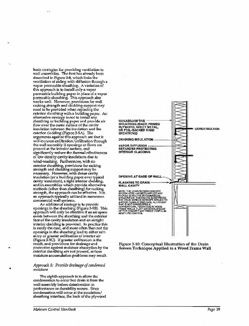
basic strategies for providing ventilation to v/aU assemblies. The first has already been described in Figure 3*8, which links ihe ventilation of siding with diffusion through a vapor permeable sheathing. A variation of this approach is to install only a vapor permeable building paper in place of a vapor permeable sheathing. This approach also works well. However, provisions for wall racking strength and cladding support may need to be provided when replacing the exterior sheathing with a building paper. An alternative strategy is not to install any sheathing or building paper and provide air flow over the outer surface of the cavity insulation between the insulation and the exterior cladding (Figure 3 9A). The arguments against this approach are that it will increase exfiltralion/infillration thiough the wall assembly if openings or flaws are present at the interior surface, and significantly reduce the thermal effectiveness of low density cavity insulations due to wind-washing. Furthermore, with no exterior sheathing, provisions for racking strength and cladding support may be necessary. However, with dense cavity insulation (or a building paper over typical cavity insulation), a tight interior cladding, and in assemblies which provide alternative methods (other than sheathing) for racking strength, the approach can be effective. It is an approach typically utilized in numerous commercial wall systems.
An additional strategy is to provide openings in the sheathing (Figure 3-9B). This approach will only be effective if an air space exists between the sheathing and the exterior face of the cavity insulation and an airtight interior cladding is provided. In practice tills is rarely the case, and more often than not the openings in the sheathing lead to either rain entry or greater exfiltration of interior air (Figure 3-9C). If greater exfiltration is the result, and provisions for drainage and protection against moisture absorption by the exterior sheathing are not present, serious moisture accumulation problems may result.
Approach 8: Provide drainage of condensed moisture
The eighth approach is to allow the condensation to occur but drain it from the wall assembly before deterioration in performance or durability occurs. Since condensation will occur at the insulation/ sheathing interface, the back of the plywood
NONABSORPTIVE SHEATHiNG (BACK PRIMED PLYWOOD, SHEET METAL, OR FOIL-BACKED RIGID SHEATHING)
DRAINING INSULATION
VAPOR DIFFUSION RETARDER PROTECTING INTERIOR CLADDING
a CONDENSATION
OPENING AT BASE OF WALL
FLASHING TO DRAIN WALL CAVITY
NOTE: THE DRAIN SCREEN CONCEPT SHOWN HERE HAS BEEN APPLIED AND PROVEN EFFECTIVE INCCMMERCIAL SmUCTURES. THIS FIGURE IUU3TTWES THE DRAIN SCREEN OONC EPT APPLIED TO A WOOD FRAME STRUCTURE ALTHOUGH THIS IS MOT CONSIDERED A CXINVENTlONAi, TECHNIQUE IN WOOD tram: walls, rurm cn development OF THE CONCEPT MAY PROVE USEFUL IN MOISTURE CONTROL
Figure 3-10: Conceptual Illustration of the Drain Screen Technique Applied to a Wood Frame Wall
Moisture Control Handbook Page 59
sheathing can be sealed to prevent capillarity and absorption of condensed water into the plywood, and drainage at the bottom of the wall assembly should be provided with an appropriate opening and flashing (Figure 3- 10). Protection of wood studs is also necessary.
The drainage strategy is successfully utilized in commercial metal buildings. It is important to note that drainage will not remove absorbed water from a material. It will only remove condensed water from nonabsorbent materials. Drainage will not work with nonoriented cavity insulations such as cellulose, or with non-back-primed or sealed wood-based sheathings. In addition, drainage will not remove absorbed moisture from asphalt-impregnated fiberboard or gypsum board. The principle argument against drainage is that by providing drainage openings, exfiltration of air through the wall assembly increases. If flaws or openings are present at the interior surfaces of a wall assembly, providing openings at the exterior of the assembly will increase the through-flow of air. Condensation will still take place at the insulation/sheathing interface, but now more of it will occur, and drainage will still occur to alleviate the problem. However, thermal performance will likely be reduced due to the air flow.
Summary of Moisture Control Strategies for Walls
In summary, eight control strategies for moisture control for wall assemblies in heating climates with interior moisture sources have been discussed. These strategies fall into three groups.
Control of Moisture Entry
1. Control of moisture entry by vapor diffusion by controlling the permeability of the interior surfaces (installing a vapor diffusion retarder)
2. Control of air inlet, outlet, or air flow paths/openings
3. Control of moisture in the interior air
4. Control of air pressure differentials
Control of Moisture Accumulation
5. Control of the temperatures of the interstitial condensing surfaces
Removal of Moisture
6. Provision for moisture removal by vapor diffusion
7. Provision for moisture removal by air movement (ventilation)
8. Provision for drainage of condensed moisture
Roof Assemblies
This section describes the moisture transport mechanisms that may affect roof assemblies, and lists strategies for controlling any moisture-related problems. Also included is a description of roofing assembly ventilation strategies.
MOISTURE BEHAVIOR IN ROOF ASSEMBLIES
Figure 3-11 illustrates an attic assembly located in a heating climate (Chicago). Gypsum board painted with a relatively vapor permeable latex is installed to the underside of the bottom chords of wood roof trusses. Ceiling insulation consists of unfaced fiberglass batts of thermal resistance R-30. The roof sheathing is plywood, and the roof assembly is not deliberately vented. The conditioned space operates at a high interior vapor pressure (50 percent relative humidity at 70 degrees Fahrenheit). Assume that the ceiling gypsum board has been installed in an airtight manner, and that no attic bypasses exist. No flaws or openings between the conditioned space and the unconditioned attic are present which would allow for air movement through the attic ceiling. Furthermore, assume that no air pressure difference exists between the interior conditioned space and the unconditioned attic in order to eliminate air movement as a moisture transport mechanism.
Vapor diffusion, during the heating season, will move moisture from the interior conditioned space through the painted ceiling gypsum board and into the ceiling fiberglass batt insulation. The first surface below the dew point temperature that this vapor comes in contact with is the underside of the roof sheathing (Figure 3-11),
If the roof sheathing is wood, this moisture is absorbed by tine wood sheathing
Page 60 Chapter 3—Wetting and Drying of Building Assemblies
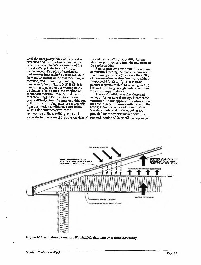
until the storage capability of the wood is exceeded and the moisture subsequently accumulates on the interior surface of the roof sheathing in the form of frost or condensation. Dripping of condensed moisture (or frost melted by solar radiation) from the underside of the roof sheathing is common, and the wetting of ceiling insulation follows (Figure 3-11} [3.B]. It k interesting to note that this wetting of the insulation is from above (the dripping of condensed moisture from the underside of roof sheathing) rather than from below (vapor diffusion from the interior), although in this case the original moisture source was from the interior conditioned space below. When solar radiation elevates Are temperature of the sheathing so that it is above the temperature of fhe upper surface of
the ceiling insulation, vapor diffusion can also transport moisture from the underside of the roof sheathing.
Serious problems can occur if the amount of moisture reaching the roof sheathing and roof framing members (1) exceeds the ability of these members to absorb moisture without the potential for decay (greater than 30 percent moisture-content-by weight), and-{2) remains there long enough under conditions which will support decay.
The most traditional and widespread vapor diffusion control strategy is roof/attic ventilation. In this approach, moisture enters the attic from below, mixes with the air in the attic space, and is removed by ventilation. Specific air inlet and outlet openings are provided for this ventilation air flow. The size and location of the ventilation openings
FHOST FORMED ON ROOF SHEATHING MELTS AND WATER DRIPS ONTO INSULATION
MCtSTORE MIGRATION TO COLD ROOF SHEATHING FROM TOP OF INSULATION
Figure 3-11: Moisture Transport Wetting Mechanisms in a Roof Assembly
Moisture Control Handbook Page 61
are typically specified in standards and codes. The requirements are usually presented as a ratio of free vent area to insulated ceiling area, with half the vent area located at the upper portion of the attic and the remainder at the soffit areas. The most common value specified is 1 square foot of vent area for every 300 square feet of insulated ceiling area, or a ratio of 1:300. No additional measure is introduced in most cases to provide for an operative pressure difference across these openings to ensure flow, other than the effect of wind or the difference in height, and the inferred stack effect when the attic space and the outdoor air are at different temperatures.
A further traditional vapor diffusion control strategy, as in the wall example, is the installation of a vapor diffusion retarder. In practice, this ceiling vapor diffusion retarder can be installed at one or more of the following locations:
1. Between the ceiling gypsum board and the bottom cords of roof trusses or the underside of the roof rafters (sheet polyethylene, aluminum foil, rigid impermeable insulation)
2. On the interior surface of the roof insulation (foil-backed bait insulation)
3. On the attic side of the ceiling gypsum board (foil-backed gypsum board)
4. Within the ceiling gypsum board (vapor barrier gypsum board)
5. On the interior surface of the ceiling gypsum board (vapor barrier paint, low permeability wall coverings)
These vapor diffusion retarders are usually required by building codes to have a permeability of 1 perm or less.
When air movement from the interior is introduced to the roof assembly described in Figure 3-11, its effects can be superimposed over those of vapor diffusion in a manner similar to the previous wall examples. Uke the wall examples, where air movement exists as a moisture transport mechanism, it tends to dominate vapor diffusion. As before, moisture deposition/accumulation from air movement is usually concentrated at surfaces adjacent or opposite to flaws and openings.
The key to understanding, predicting, and controlling moisture accumulation in roof assemblies, as in wall assemblies, is understanding the moisture balance, or the rate of moisture entry compared with the rate
of moisture removal. Some examples of control will now be examined with respect to roof assemblies.
MOISTURE CONTROL STRATEGIES FOR ROOFS
This discussion assumes a roof (Figure 3- 11) experiencing moisture distress from both vapor diffusion and air movement. The roof is located in Chicago, and the interior space is conditioned to 50 percent relative humidity at 70 degrees Fahrenheit during the heating season. The control strategies which can be implemented to alleviate the roof moisture problem, as well as all building assemblies, fall into three groups:
1. Control of moisture entry
2. Control of moisture accumulation
3. Removal of moisture
Control of Moisture Entry
Moisture can enter a roof assembly in four ways:
1. From the exterior by gravity (roof leaks)
2. From the exterior by air transport (ventilation)
3. From the interior by vapor diffusion
4. From the interior by air transport
These factors can provide a starting point for control strategies.
Approach 1: Prevent roof leaks
The first and most obvious approach to roof moisture control is to prevent roof leakage. Moisture entry from the exterior by gravity or roof leaks is clearly the most significant and most obvious. Roof leaks are typically addressed as a first priority, as the other moisture entry mechanisms are comparatively insignificant- If a roof assembly is leaking, the issues of vapor diffusion retarders, roof ventilation versus no roof ventilation, interior moisture levels, and effect of climate are insignificant. Ventilation or any other moisture removal mechanism to control moisture entry and accumulation from roof leaks is not practical, as the rate of moisture entry through leaks is typically much greater than the rate of removal by ventilation.
Page 62 Chapter 3—Wetting and Drying of Building Assemblies
Approach 2: Avoid roof assembly ventilation in extreme climates
The second approach to roof moisture control is not to ventilate roof assemblies under conditions where ventilation brings moisture from the exterior. Such conditions may be prevalent in extreme climates, such as hot, humid coastal regions where extensive mechanical cooling occurs, and cold, hostile, arctic, and subarctic climates with heavily insulated roof assemblies.
In hot, humid climates the ambient air often contains more moisture than the air within the roof assembly or cavity during cooling periods, especially during evenings or cloudy, overcast days. When fiiis is the case, roof ventilation can bring moisture into the roof assembly or cavity rather than remove it, and it can be a significant causal factor relating to mold and mildew problems on interior gypsum board surfaces. Similarly, crawl space ventilation in hot, humid climates also often brings moisture into crow] spaces. In mixed climates {where both heating and cooling occur for extended periods) and heating climates, ambient humid conditions can also reduce the removal rale from roof assemblies or cavities.
Where attics are framed with wood sheathing, wood rafters, and trusses, these wood materials absorb moisture according to the relative humidity present in the attic, rather than the vapor pressure. Cold air, although it typically has a low vapor pressure and as sum is dry in the absolute sense, normally has a high relative humidity ■ When exterior cold, dry, low vapor pressure air with a high relative humidity comes in contact with cold roof wood framing, the wood framing absorbs moisture- The wood does not dry out In heavily insulated roof assemblies in heating climates, low heat loss due to the insulation leads to attic spaces which operate at close to exterior or ambient temperatures. In this case, both the exterior air entering the attic space (ventilation air) and the roof sheathing are cold. Thus, the air entering the attic is moving moisture into the attic space because of the high relative humidity of the air.
In roof spaces, regardless of the sheathing or framing materials (wood, steel, or other), night sky radiation on a clear winter night can cool roof surfaces and roof decking 10 degrees Fahrenheit or more below exterior ambient conditions (often below the dew point). In such cases, it is typical for
moisture to be added to the roof space by air movement from the exterior. For example, the exterior air may be at 15 degrees Fahrenheit with a relative humidity of 80 percent. This corresponds to a vapor pressure of approximately 0.210 kPa. The roof sheathing can be at 0 degrees Fahrenheit due to night sky radiation, and at saiurabon this temperature corresponds to vapor pressure of approximately 0.110 kPa This is a lower vapor pressure than the ambient, so air movement from the exterior is actually moving moisture into the attic space, rather than out.
Approach 3; Install vapor diffusion retarder
The third approach to roof moisture control is to install an interior vapor diffusion retarder. Moisture from the interior can enter by air transport and vapor diffusion. Although air transport is more significant than vapor diffusion, in many cases vapor diffusion by itself can move sufficient moisture into a roof assembly to create moisture problems and should be addressed.
Vapor diffusion retarders are typically sheet polyethylene (visqueen); however, they may take many other forms such as low permeance paint-on surfaces, foil backing on insulation batts, foil backing on gypsum board, and low permeance wall and ceiling coverings- The effectiveness of a vapor diffusion retarder is dependent on both its resistance to moisture flow by diffusion (permeability) and its coverage (surface area). In other words, it is a direct or linear function of both surface area and permeability (Pick's Law).
The permeability of a vapor diffusion retarder has been arbitrarily limited to a permeability of 1 perm or less. Where surface area is concerned, the linearity of Pick's Law can be interpreted such that if 95 percent of the surface area of a ceiling or roof assembly is covered with a vapor diffusion retarder, then that vapor diffusion retarder is 95 percent effective, all other things being equal. Hence, vapor diffusion retarders need not be perfect to control vapor diffusion. Holes, rips, tears, punctures, and gaps in vapor diffusion retarders need not lead to catastrophic failure if their surface area is small relative to the total surface area of vapor diffusion retarder coverage.
An extension of this argument shows that several coats of paint on the exposed surfaces of ceilings are typically satisfactory to control
Moisture Control Handbook Page 63
moisture entry from the interior by vapor diffusion into roof assemblies in mixed and heating climates. However, paint does not control the movement of moisture into roof assemblies by air transport. Paint can act as an effective vapor diffusion retarder, but it cannot act as an air retarder. The distinction is important and often overlooked or misunderstood.
Vapor diffusion retarders are often not installed in mixed climates, although the trends towards higher levels of roof assembly insulation and the subsequent reduction of available energy to evaporate moisture has increased the number of vapor diffusion retarder installations in these climates.
Vapor diffusion retarders are rarely installed in the ceilings of cooling climate enclosures to control moisture entry into roof assemblies from the interior, as the moisture flow by diffusion is in the opposite direction. Air movement (attic ventilation) is typically responsible for moving moisture from the exterior into the roof assembly (attic). Vapor diffusion and air transport subsequently move the moisture from within the roof assembly to the interior conditioned space. It should be noted that vapor only moves from the attic to the conditioned space if the space is air conditioned or otherwise dehumidified. The recognition that this vapor diffusion moisture flow from the ventilated attic cavity into the enclosure increases the latent cooling loads is leading to the requirement of installing ceiling vapor diffusion retarders even in cooling climates.
Approach 4: Control moisture in the interior air
The fourth approach to roof moisture control is to control interior moisture levels. Control of interior conditioned space moisture levels can be a very powerful strategy with respect to both vapor diffusion and air transport. If moisture is not present in the first place then there is no moisture for vapor diffusion or air movement to transport. Since the roof assembly referred to in this discussion is located in Chicago, Illinois, the interior relative humidity during the winter is limited to less than 20 percent at 70 degrees Fahrenheit. This maintains the dew point temperature of the interior air/vapor mix below the mean daily roof sheathing temperature (see Figures 3-6,3-7). This is a simplification that does not take into account night sky radiation or solar heat gain, thus
resulting in a consrvative set of assumptions. As simple as this strategy is conceptually,
in practice it can become confusing. Interior moisture levels can be controlled in two ways (either separately or combined); source control and dilution. Source control involves controlling moisture at the point of generation or entry, whereas dilution involves removing moisture after it has been generated or has entered the conditioned space.
Dilution can take the following forms:
* Uncontrolled air change (natural ventilation in leaky buildings during heating periods)
* Controlled air change (fans providing mechanical ventilation during heating periods)
* Dehumidification (mechanical dehumidification or air conditioning during cooling periods)
Dilution is more energy intensive than source control. Thus, a significant component of any energy conservation program should be the source control of moisture. The alternatives—uncontrolled ventilation, controlled ventilation, and high evaporation energies (high drying potentials through low insulation levels)—all consume significant amounts of energy.
Approach 5: Eliminate air inlet/outlet openings
The fifth approach to roof moisture control is to control openings that allow air flow from the conditioned space through the ceiling into the roof assembly. Control of openings between the interior conditioned space and the roof assembly is one of the most common and most effective techniques for the control of moisture entry from the interior by air transport. Openings are often closed using continuous, sealed, sheet polyethylene and/or continuous sealed gypsum board in new construction. In existing construction they are closed with caulks, sealants, and spray foams. Recently, significant success in controlling openings in flat roofs with cavities by utilizing dry blown dense pack cellulose to completely fill cavities has been reported [3.9],
Openings are best controlled at the design stage for new construction. Almost all roof assembly penetrations can be eliminated by relocation (electrical, ductwork) or
Page 64 Chapter 3—Wetting and Drying of Building Assemblies
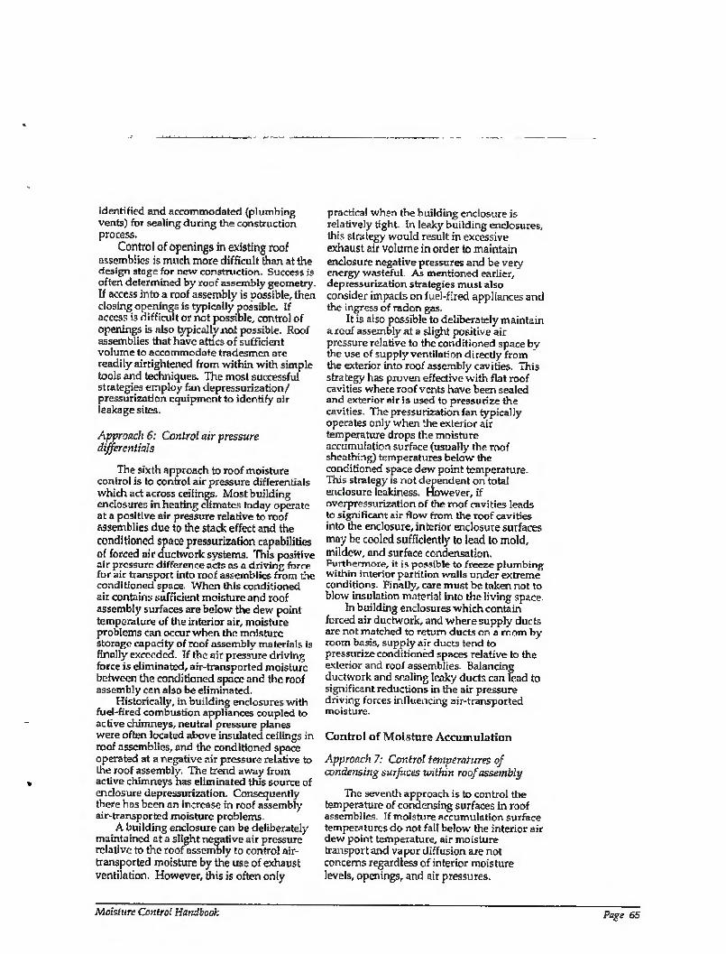
identified and accommodated (plumbing vents) for sealing during the construction process.
Control of openings in existing roof assemblies is much more difficult than at the design stage for new construction. Success is often determined by roof assembly geometry. If access into a roof assembly is possible, then closing openings is typically possible. If access is difficult or not possible, control of openings is also typically not possible. Roof assemblies that have attics of sufficient volume to accommodate tradesmen arc readily airtightened from within with simple tools and techniques. The mosl successful strategies employ fan depressurization/ pressurization equipment to identify air leakage sites.
Approach 6: Control air pressure differentials
The sixth approach to roof moisture control is to control air pressure differentials which act across ceilings. Most building enclosures in heating climates today operate at a positive air pressure relative to roof assemblies due to the stack effect and the conditioned space pressurization capabilities of forced air ductwork systems. This positive air pressure difference acts as a driving force for air transport into roof assemblies from the conditioned space. When this conditioned air contains sufficient moisture and roof assembly surfaces are below the dew point temperature of the interior air, moisture problems can occur when the moisture Storage capacity of roof assembly materials is finally exceeded. If the air pressure driving force is eliminated, air-transported moisture between the conditioned space and the roof assembly can also be eliminated.
Historically, in building enclosures with fuel-fired combustion appliances coupled to active chimneys, neutral pressure planes were often located above insulated ceilings in roof assemblies, and the conditioned space operated at a negative air pressure relative to the roof assembly. The trend away from active chimneys has eliminated this source of enclosure depressurization. Consequently there bos been an increase in roof assembly air-transported moisture problems.
A building enclosure can be deliberately maintained at a slight negative air pressure relative to the roof assembly to control air- transported moisture by the use of exhaust ventilation, However, this is often only
practical when the building enclosure is relatively tight. In leaky building enclosures, this strategy would result in excessive exhaust air volume in order to maintain enclosure negative pressures and be very energy wasteful. As mentioned earlier, depressurization strategies must also consider impacts on fuel-fired appliances and the ingress of radon gas.
It is also possible to deliberately maintain a roof assembly at a slight positive air pressure relative to the conditioned space by the use of supply ventilation directly from the exterior into roof assembly cavities. This strategy has proven effective with flat roof cavities where roof vents have been sealed and exterior air is used to pressurize the cavities. The pressurization fan typically operates only when the exterior air temperature drops the moisture accumulation surface (usually the roof sheathing) temperatures below the conditioned space dew point temperature. This strategy is nol dependent on total enclosure leakiness. However, if overpressurization of the roof cavities leads to significant air flow from the roof cavities into the enclosure, interior enclosure surfaces may be cooled sufficiently to lead to mold, mildew, and surface condensation. Furthermore, it is possible to freeze plumbing within interior partition walls under extreme conditions. Finally, care must be taken not to blow insulation material into the living space.
In building enclosures which contain forced air ductwork, and where supply ducts are not matched to return ducts on a room by room basis, supply air ducts tend to pressurize conditioned spaces relative to the exterior and roof assemblies. Balancing ductwork and sealing leaky ducts can lead to significant reductions in the air pressure driving forces influencing air-transported moisture.
Control of Moisture Accumulation
Approach 7: Control temperatures of condensing surfaces within roof assembly
The seventh approach is to control the temperature of condensing surfaces in roof assemblies. If moisture accumulation surface temperatures do not fall below the interior air dew point temperature, air moisture transport and vapor diffusion are not concerns regardless of interior moisture levels, openings, and air pressures.
Moisture Control Handbook Page 65
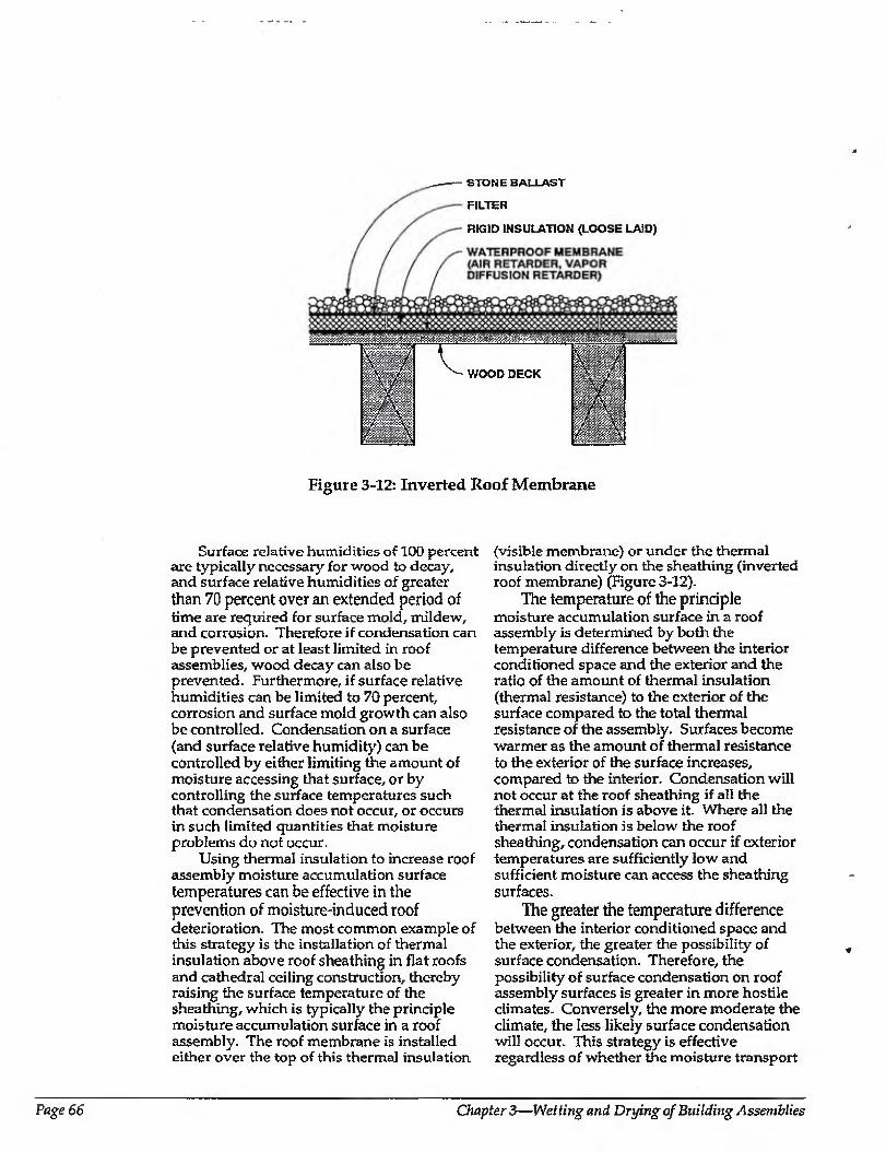
STONE BALLAST
FILTER
RIGID INSULATION (LOOSE LAID)
Wmm WOOD DECK
III ■p mmm.
- \
' : :’"X"
.: .. /
Figure 3-12: Inverted Roof Membrane
Surface relative humidities of 100 percent are typically necessary for wood to decay, and surface relative humidities of greater than 70 percent over an extended period of time are required for surface mold, mildew, and corrosion. Therefore if condensation can be prevented or at least limited in roof assemblies, wood decay can also be prevented. Furthermore, if surface relative humidities can be limited to 70 percent, corrosion and surface mold growth can also be controlled. Condensation on a surface (and surface relative humidity) can be controlled by either limiting die amount of moisture accessing that surface, or by controlling the surface temperatures such that condensation does not occur, or occurs in such limited quantities that moisture problems do not occur.
Using thermal insulation to increase roof assembly moisture accumulation surface temperatures can be effective in the prevention of moisture-induced roof deterioration. The most common example of this strategy is the installation of thermal insulation above roof sheathing in flat roofs and cathedral ceiling construction, thereby raising the surface temperature of the sheathing, which is typically the principle moisture accumulation surface in a roof assembly. The roof membrane is installed either over the top of this thermal insulation
(visible membrane) or under the thermal insulation directly on the sheathing (inverted roof membrane) (Figure 3-12).
The temperature of the principle moisture accumulation surface in a roof assembly is determined by both the temperature difference between the interior conditioned space and the exterior and the ratio of the amount of thermal insulation (thermal resistance) to the exterior of the surface compared to the total thermal resistance of the assembly. Surfaces become warmer as the amount of thermal resistance to the exterior of the surface increases, compared to the interior. Condensation will not occur at the roof sheathing if all the thermal insulation is above it. Where all the thermal insulation is below the roof sheathing, condensation can occur if exterior temperatures are sufficiently low and sufficient moisture can access the sheathing surfaces.
The greater the temperature difference between the interior conditioned space and the exterior, the greater the possibility of surface condensation. Therefore, the possibility of surface condensation on roof assembly surfaces is greater in more hostile climates. Conversely, the more moderate the climate, the less likely surface condensation will occur. This strategy is effective regardless of whether the moisture transport
Page 66 Chapter 3—Wetting and Drying of Building Assemblies
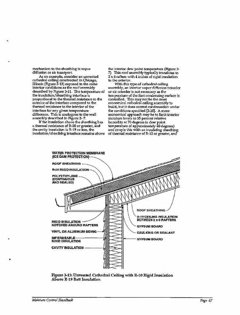
mechanism to the sheathing is vapor diffusion or air transport
As an example, consider an unvented cathedral ceiling constructed in Chicago, Illinois (Figure 3-13) exposed to the same interior conditions as the roof assembly described by Figure 3-11. The temperature of the insulation/sheathing interface is proportional to the thermal resistance to the exterior of the interface compared to the thermal resistance to the interior of the interface for any given temperature difference. This is analogous to the wall assembly described in Figure 3- 7.
If the insulation above the sheathing has a thermal resistance of R-20 or greater, and the cavity insulation is R-19 or Jess, the insulation/sheathing interface remains above
the interior dew point temperature (Figure 3- 7). This roof assembly typically translates to 2x6 rafters with 4 inches of rigid insulation to the exterior.
With this type of cathedral ceiling assembly, an interior vapor diffusion retarder or air retarder is not necessary as the temperature of the first condensing surface is controlled. This may not be the most economical caflredral ceiling assembly to build, but it does control condensation under the conditions specified [3.10]. A more economical approach may be to limit interior moisture levels to 35 percent relative humidity at 70 degrees (a dew point temperature of approximately 40 degrees) and couple this with an insulating sheathing of thermal resistance of R-12 or greater, and
WATER PROTECTION MEMBRANE (ICE DAM PROTECTION)
HOOF SHEATHING
R-20 RIGID INSULATION
POLYETHYLENE (CONTINUOUS AND SEALED)
RIGID INSULATION NOTCHED AROUND RAFTERS
VINYL OR ALUMINUM SIDING
IMPERMEABLE RIGID INSULATION
CAVITY INSULATION
R-19 CEILING INSULATION BETWEEN 2X6 RAFTERS
GYPSUM BOARD
CAULKING OR SEALANT
GYPSUM BOARD
Figure 3-13: Unvented Cathedral Ceiling with R-20 Rigid Insulation Above R-19 Batt Insulation
Moisture Control Handbook Page 67
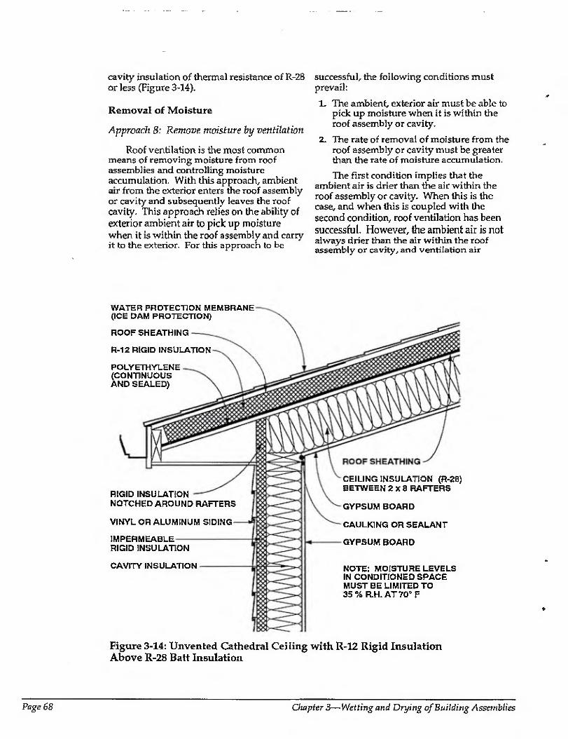
cavity insulation of thermal resistance of R-28 or less (Figure 3-14).
Removal of Moisture
Approach 8: Remove moisture by ventilation
Roof ventilation is the most common means of removing moisture from roof assemblies and controlling moisture accumulation. With this approach, ambient air from the exterior enters the roof assembly or cavity and subsequently leaves the roof cavity. This approach relies on the ability of exterior ambient air to pick up moisture when it Is within the roof assembly and carry it to the exterior. For this approach to be
successful, the following conditions must prevail:
1- The ambient, exterior air must be able to pick up moisture when it is within the roof assembly or cavity.
2. The rate of removal of moisture from the roof assembly or cavity must be greater than the rate of moisture accumulation.
The first condition implies that the ambient air is drier than the air within the roof assembly or cavity. When this is the case, and when this is coupled with the second condition, roof ventilation has been successful. However, the ambient air is not always drier than the air within the roof assembly or cavity, and ventilation air
WATER PROTECTION MEMBRANE (ICE DAM PROTECTION)
ROOF SHEATHING
R-12 RIGID INSULATION
POLYETHYLENE (CONTINUOUS AND SEALED)
RIGID INSULATION NOTCHED AROUND RAFTERS
VINYL OR ALUMINUM SIDING
IMPERMEABLE RIGID INSULATION
CAVITY INSULATION
CEILING INSULATION (R-28) BETWEEN 2x8 RAFTERS
GYPSUM BOARD
CAULKING OR SEALANT
GYPSUM BOARD
NOTE: MOISTURE LEVELS IN CONDITIONED SPACE MUST BE LIMITED TO 35% R.H. AT 70° F
Figure 3-14: Unvented Cathedral Ceiling with R-12 Rigid Insulation Above R-28 Batt Insulation
Page 68 Chapter 3—Wetting and Drying of Building Assemblies
entering roof assemblies may actually carry moisture into the roof assemblies as discussed previously.
In well-insulated roofs, sufficient energy may not be available to facilitate moisture evaporation from roof assembly materials. The ability of ambient air to pick up moisture depends on both the amount of moisture already contained in the ambient air and the temperature of the ambient air. The colder air is, the less moisture it can hold. Historically, roof assemblies have not contained significant levels of insulation and during heating periods, heat loss from within the conditioned space has warmed roof assemblies and cavities. When cold, ambient air entered these roof assemblies and cavities, it was warmed by the heat loss from the conditioned space, enhancing its ability to pick up moisture. The trend towards higher levels of insulation has reduced the heat or energy flow from the conditioned space and therefore reduced the effectiveness of ventilation in removing moisture from roof assemblies and cavities.
Solar radiation can raise roof cavity and assembly surface temperatures and provide energy for the evaporation of moisture. Roof assemblies that receivedirect solar radiation (south-facing surfaces and unshaded roofs) are therefore less prone to moisture problems than other roofs. Similarly, roof assemblies in climatic regions that get a great deal of solar radiation are less prone to moisture problems than those that do not. The same argument holds for roofs constructed with dark surfaces (therefore warmer) compared with light-colored surfaces.
Ventilation is more effective in removing moisture from roof assemblies and cavities where insulation levels are low, or during periods when the ambient air is sufficiently warm and dry to pick up moisture, or when incident solar radiation is intense. Ventilation may not be effective in removing significant amounts of moisture from well- insulated assemblies where the ventilation air remains coid and unable to pick up moisture, or where ambient air is humid and already saturated with moisture. Examples of this can be found in hot humid climates and during humid periods in mixed and heating climates during cloudy or overcast periods.
The second condition listed above relates to moisture balance. Where the rate of moisture entry into a roof assembly or cavity exceeds the rate of moisture removal, moisture accumulates.
If roof assemblies are initially constructed dry and prevented from getting wet during service, then the rate of moisture entry is zero, and removal of moisture is not necessary. Unvented roof assemblies have historically proven successful when the moisture entry mechanisms—gravity, vapor diffusion, and air transport (either exterior/ ventilation or interior/air leakage)—have been controlled. It is common practice to build unvented flat roof assemblies with air and vapor retarder systems. It is also possible to build unvented. cathedral ceilings where air-transported moisture and vapor diffusion are controlled.
Varying degrees of success have been reported where not all the moisture entry mechanisms have been controlled, but moisture removal (ventilation) is used to offset or balance moisture entry (3.11]. Experience has shown that ventilation cannot be relied upon to balance the gravity moisture entry mechanism (roof assemblies leaking rainwater). However, ventilation can balance the vapor diffusion and air transport (interior) moisture entry mechanisms, where the rates of moisture entry and accumulation are low and the rate of moisture removal is high. This is often the case in roof assemblies located in mixed climates. In such climates it has been common to build successfully performing roof assemblies without vapor diffusion retarders and relatively leaky (to air) ceilings- It is important to note that these roof assemblies have typically been constructed with relatively low levels of insulation and that as insulation levels increase, moisture problems may appear.
Experience has shown that where vapor diffusion retarders have been installed, roof assemblies do not need to be ventilated to control vapor diffusion. Experience has also shown that where roof assemblies are constructed tight, roof assemblies do not need to be ventilated to control air- transported moisture from the interior. The question of how "tight" is necessary is important. A psychrometric mixing model can be utilized to match roof assembly / cavity ventilation needed on a elimate-to- climate basis when roof assembly leakage areas are known and interior moisture levels are specified [3.12]. Unfortunately, roof assembly leakage areas are rarely known, and interior moisture levels are often not limited or controlled.
Several arguments against roof ventilation can be made because of the
Moisture Control Handbook Page 69
potential for creating rather than alleviating moisture problems. It should be noted however, that most local building codes require roof ventilation, and that builders omitting ventilation may be in violation of local code requirements.
Ventilation of well-insulated roof spaces that are over leaky ceilings can actually draw moisture-laden air out of the building enclosure into the cold roof cavity. This is analogous to the problems experienced with the ventilation of wall assemblies. In such a case if ventilation were not present, moisture would not be moved into the space due to air movement. If the attic space remains cold due to attic insulation, more moisture will be carried into the attic space as a result of the air pressure difference between the interior conditioned space and attic space. The resultant exfiltration of moisture-laden air through the leaky ceiling will not be removed from the attic by ventilation due to the ineffectiveness of ventilation in cold attics. Of course, should the ceiling be extremely leaky and the exfiltrating air flows large, the exfiltrating air flows may carry sufficient heat with them to warm the attic to such an extent that the attic ventilation may now be effective. This usually explains the fairly common phenomenon of homeowners' heating bills increasing after the installation of additional attic insulation coupled with attic ventilation and a leaky ceiling. The new attic vents dramatically increase the air leakage into the attic from the house through the leaky ceiling and hence increase the total house air change [3.13], The increased energy cost due to the increased air change is often greater than the energy savings from a reduced conductive heat loss.
The magnitude of this effect is even greater if powered or turbine vents are installed. These devices can vent the entire house through the attic if ceilings are leaky. The heat loss is often so great that the house furnace is not large enough to heat the house when the wind is blowing. As a result it is not uncommon to see plastic bags placed over these vents in the winter to stop them from operating. To make these turbine vents cost-effective from an operating perspective, the ceiling has to be tight and additional openings or vents may be necessary to provide make-up air from the exterior for the attic. The irony is that if these two requirements are implemented, a turbine vent is no longer necessary. Powered attic vents, although not practical for heating season moisture control, are often practical
for summertime cooling of poorly insulated attics as long as the attic ceiling remains leaky. Where the turbine vents are coupled with a leaky ceiling during the summer conditions, the turbine vents increase the air change by ventilating the house through the leaky ceiling. Power ventilation in an attic during the summer to reduce cooling loads is not very effective in a house with a tight ceiling, as most of the heat gain in a summer attic is due to radiation. There is poor coupling with the thermal mass of the attic air and the thermal mass of the shingle/ sheathing complex. The hot roof sheathing (160 degrees Fahrenheit plus) radiates heat to the top of the attic insulation. High attic air change through turbine ventilation does not provide a significant cooling effect.
Summary of Roof Moisture Control Strategies
Eight control strategies for moisture control for roof assemblies in heating climates have been discussed. These strategies fall into three groups and are listed below.
Control of Moisture Entry
1. Control of roof leaks (gravity)
2. Control of moisture entry by not ventilating roof assemblies in extreme climates
3. Control of moisture entry by vapor diffusion (installing an interior vapor diffusion retarder)
4. Control of moisture in the interior air
5. Control of air inlet, outlet or air flow paths /openings
6. Control of air pressure differentials
Control of Moisture Accumulation
7. Control of the temperatures of the condensing surfaces in roof assemblies
Ranoval of Moisture
8. Provision for moisture removal by air movement (ventilation)
Page 70 Chapter 3—Wetting and Drying of Building Assemblies
OTHER CONSIDERATIONS RELATED TO ROOF ASSEMBLY VENTILATION
Roofs and roof cavities traditionally have been vented for four reasons:
1. Removal of moisture from assembly cavities, structural members, sheathings, and insulation
Z Enhancement of roofing life span by a reduction of roofing and roof sheathing temperatures
3. Reduction of cooling loads and increased occupant comfort during the cooling season
4. Control of ice damming
Moisture removal has already been examined. Enhancement of roofing life span, cooling load reduction, occupant comfort, and control of ice damming are discussed below.
Enhancement of Roofing Life Span
The operating surface temperatures of roof membranes, shingles, and sheathings directly influence their service lives. The higher the operating surface temperature, the shorter the service life. Roof ventilation has traditionally been employed to control roof membrane, shingle, and sheathing temperatures. Unfortunately, traditional physics and recent evidence question this practice. It has been known for some time (but only recently accepted) that the operating surface temperatures of roof membranes, shingles, and sheathings are far more dependent on their color, orientation, solar intensity, and wind exposure than on roof ventilation [3.14].
Roof membranes and shingles are warmed directly by solar radiation, and transfer heat to sheathings and rigid insulation by conduction. In cavity roof assemblies, the underside of roof sheathings transfers heat principally by radiation to the top of the insulation. The intervening air in the cavity is typically much cooler than the underside of the sheathing and the upper surface of the insulation due to the radiant heat transfer.
Cavity ventilation can only remove significant heat from the roof assembly and lower shingle, membrane, and sheathing temperatures if good thermal coupling exists
between the underside of the sheathing and the air in the cavity. However, this is not the case, A ventilation rate of anywhere from 1 to 15 air changes per hour has a negligible effect on membrane, shingle, and sheathing temperatures. Typical average air change rates in ventilated roof assemblies range from 3 to 6 air changes per hour over the year [3.14],
As such, tradition aside, it does not make sense to ventilate roof assemblies to enhance service life. If service life is a concern, lighter-colored roof membranes and shingles have been shown to have much longer service lives since they operate a t lower surface temperatures.
Reduction of Cooling Loads
In some regions, roofs and roof cavities have traditionally been vented to reduce cooling loads during the cooling season. Although roof ventilation has a negligible impact on membrane, shingle, and sheathing operating surface temperatures, roof ventilation does affect roof assembly cavity air temperatures and to a lesser extent, the upper surface temperature of cavity insulation. This also affects cooling loads. However, the impact is reduced when the levels of roof assembly insulation and assembly celling airtightness are increased.
In roof cavity assemblies which are poorly insulated (less than R-10), ventilation can reduce cooling loads by 25 percent. However, when these assemblies have thermal resistances of greater than R-25, ventilation has a negligible effect [3.14]. Furthermore, the sensations of comfort that are felt by occupants when roof assemblies arc ventilated has been attributed to leaky ceiling assemblies, where the effect of roof ventilation also ventilates the conditioned space by drawing warm air out of the conditioned space through the roof cavity to the exterior. It also chills the ceiling surface.
Where roof assemblies are tight and well insulated, ventilation of roof assemblies has a negligible impact on cooling loads. In roof assemblies that are leaky and poorly insulated, ventilation or roof assemblies has a significant effect on reducing cooling loads. However, in any roof assembly where ventilation significantly impacts cooling loads, coupling between the conditioned space exists. Consequently, this same ventilation is likely to be responsible for drawing warm, interior moisture-laden air
Moisture Control Handbook Page 71
CHAPTER 3: REFERENCES from the conditioned space into the roof assembly during the heating season, leading to potential moisture problems if the space is well insulated (low drying potential) and if interior moisture levels are high.
The most effective strategy to reduce cooling loads through a roof assembly, tradition notwithstanding, is to select reflective roof membranes or shingles, insulate the roof assembly well, and construct the assembly in an airtight manner.
Control of Ice Damming
In heating climates, where sufficient heat loss occurs at the roof perimeter above insulated wall assemblies, ice damming can occur. The heat loss can melt snow on the roof causing water to run down over the roof overhang, where it can freeze forming a dam. The ice dam causes the water to back up and potentially leak under overlapped shingles and through roof sheathing. This heat loss can occur from either a lack of thermal insulation where exterior walls intersect roof and attic assemblies, or from air leakage up and out of exterior walls.
Continuous soffit ventilation has traditionally been used in heating climates to flush this heat away from the underside of the roof assembly, preventing it from melting accumulated snow on the roof and thus controlling the formation of ice dams. This strategy has proven to be very effective where a clear, continuous 2-inch air space has been provided over the entire roof eve perimeter. Ice damming can also be controlled by providing sufficient thermal insulation at the intersection of perimeter walls and ceilings, coupled with controlling air leakage up and out of walls.
3.1 Lsbiburek, J.W., "Insulation Induced Paint and Siding Failures", paper presented at CIB W40 Conference, Victoria, Canada, September 1989.
3-2 American Society of Heating, Refrigerating and Air Conditioning Engineers, Inc, ASHRAE Handbook: 1989 Fundamentals, Chapter 21, Atlanta, Georgia, 1989.
3.3 Joy, F.A., Basic Concepts of Water Vapor Migration and Their Application to Frame Walls, Pennsylvania State College Engineering Experiment Station, Technical Paper NOS9,1951.
3.4 Quirouette, R.L., The Difference Between a Vapor Barrier and an Air Barrier, Building Practice Note 54, DBR/NRCC, 1985.
3.5 Lischkoff, J. and J. Timusk, "Moisture and Thermal Aspects of Insulating Sheathing", paper presented at Second CSCE Conference on Building Science and Technology, London 1984.
3.6 Handegord, G.O., "Prediction of the Moisture Performance of Walls", ASHRAE Transactions, Vol. 91,1985-
3.7 Handegord, G.O., personal communication
3.8 Marshall, Macklin, and Monaghan, Moisture Induced Problems in NHA Housing, CMHC, Ottawa, 1983.
3.9 Fitzgerald, J., G. Nelson,and L. Shen, "Sidewall Insulation and Air Leakage Control", Home Energy Magazine, Berkeley, California, January 1990.
3.10 Handegord, G.O., "Prediction of the Moisture Performance of Walls", ASHRAE Transactions, Vol. 91,1985.
3.11 Cleary, P., Humidity in Attics - Sources and Control Methods, Lawrence Berkeley Laboratory, CA, January 1984.
3.12 Handegord, G. O. and Giroux, G., An Attic Condensation Ventilation Model, DBR/RRCC, 1984.
3.13 Blasnik, M., Attic Insulation Performance, Air Leakage and Ventilation, ACEEE1990 Summer Study, Vol. 9, Pacific Grove, California, 1990.
Page 72 Chapter 3—Wetting and Drying of Building Assemblies
3.14 Rose, W,, "Mote Data on Shingle Overheating with Unvented Roofs", Energy Design Update, March 1991.
CHAPTERS: BIBLIOGRAPHY
American Society of Heating, Refrigerating and Air Conditioning Engineers, Inc., ASHRAE Handbook: 1989 Fundamentals, Chapter 21, Atlanta, Georgia, 1989.
American Society of Heating, Refrigerating and Air Conditioning Engineers, Inc., VcnMatron for Accep table Indoor Air Quality, ASHRAE Standard, 62-1989, Atlanta, 1989.
Baker, M.C., Roofs: Design, Application and Maintainance, Multi-Science Publications, Ltd., Montreal, Canada, 1980,
Forgues, Y.E., The Ventilation of Insulated Roofs, Building Practice Notes NOS7, (NRCC/DBR).
Latta, J.K., Walls, Windows and Roofs for the Canadian Climate, DBR/NRCC, (NRCC 13487), October, 1973.
Tamura, G.T., G.H. Kuester, and G O. Handegord, "Condensation Problems in Flat Wood Frame Roofs", paper presented at second International QB/ RILEM Symposium on Moisture Problems in Buildings, (NRCC 14589), Rotterdam, 1974.
Wilson, A.G., and G.T. Tamura, Sfacfc Effect and Building Design, Canadian Building Digest 107, (DBR/NRCC), November, 1968.
Moisture Control Handbook
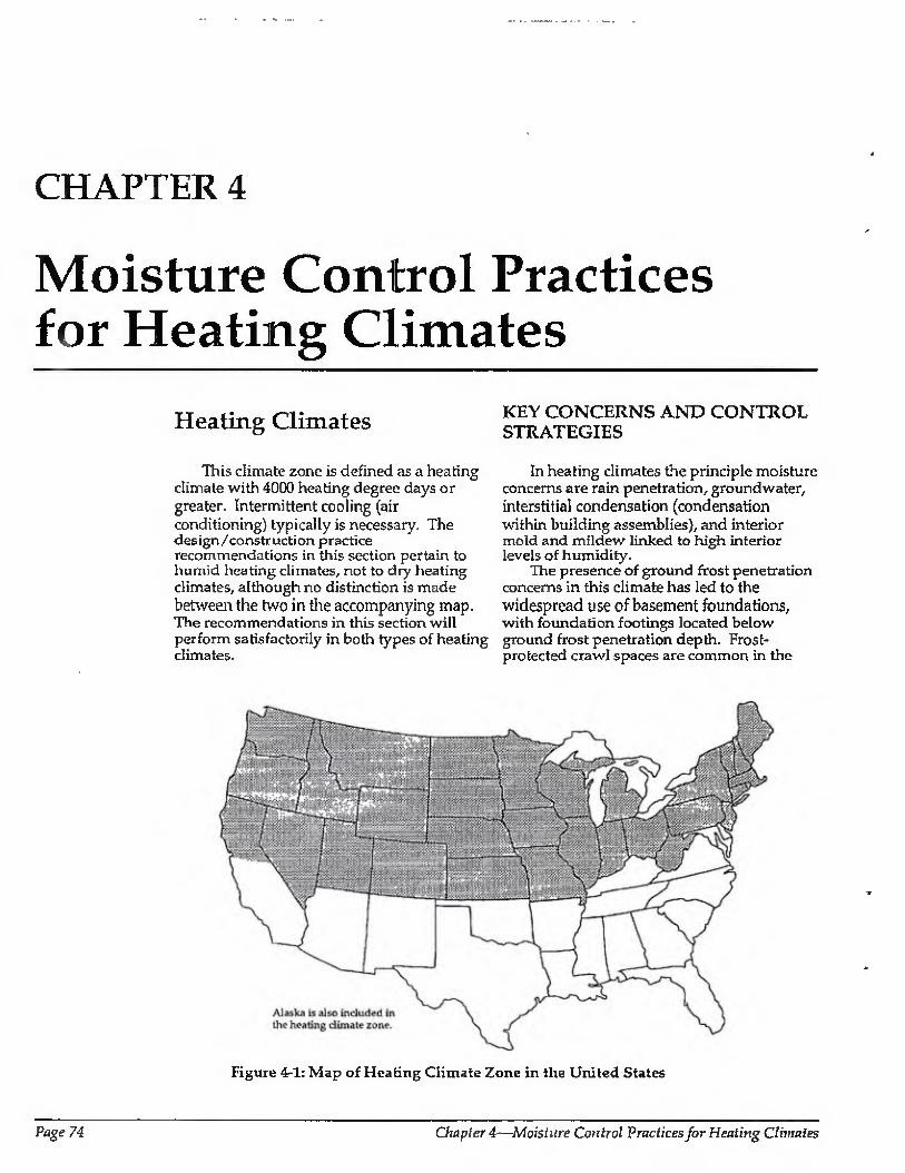
CHAPTER 4
Moisture Control Practices for Heating Climates
Heating Climates
This climate zone is defined as a heating climate with 4000 heating degree days or greater. Intermittent cooling (air conditioning) typically is necessary. The design/construction practice recommendations in this section pertain to humid heating climates, not to dry heating climates, although no distinction is made between the two in the accompanying map. The recommendations in this section will perform satisfactorily in both types of heating climates.
KEY CONCERNS AND CONTROL STRATEGIES
In heating climates the principle moisture concerns are rain penetration, groundwater, interstitial condensation (condensation within building assemblies), and interior mold and mildew linked to high interior levels of humidity.
The presence of ground frost penetration concerns in this climate has led to the widespread use of basement foundations, with foundation footings located below ground frost penetration depth. Frost- protected crawl spaces are common in the
Figure 4-1: Map of Heating Climate Zone in the United States
Page 74 Chapter 4—Moisture Control Practices for Heating Climates
more moderate regions of heating climates. Concrete and masonry foundations are common, with some limited use of wood foundations. Above-grade frame walls predominate.
Rain and Groundwater
Rain penetration and groundwater concerns are common to builders in all climates and the methods of contro! in this climate are similar to those of other climates. Examples include rain screens; building papers; appropriate placement of flashings, gutters, and downspouts to direct water away from foundations; careful site grading; and subgrade drainage.
Basement spaces are often conditioned and occupied. As such, concerns with groundwater penetration and infiltration of soil gas (including radon) are common.
Another source of external water—air conditioning condensate drains—should be plumbed directly to the graywater system.
Condensation within Building Assemblies
Conditioned spaces are heated by both electric and fuel-fired appliances. Traditional negative interior ai r pressures have been reduced as a result of the trend away from active chimneys toward high efficiency combustion appliances and electric heat sources. When combined with the trend towards tighter enclosures, reduced air change, and higher levels of interior moisture, this has led to concerns about the exfiltration of interior moisture-laden air causing condensation within insulated assemblies- Reduced air change and resultant higher levels of interior moisture have also led to elevated incidences of interior surface mold and mildew (discussed below).
Air leakage into insulated attics during heating months, coupled with insufficient attic ventilation, can lead to roof sheatiring decay. Air leakage into insulated wall cavities during the heating months, coupled with an insufficient or limited drying ability, can cause the decay of structural framing members.
Moisture movement by air leakage (the exfiltration of interior moisture-laden air) is controlled in several ways. Air leakage openings can be limited, the above-grade conditioned spaces can be depressurized, and
the interior moisture levels can be controlled by ventilation (dilution by air change), combined with source control. Source control involves direct venting of clothes dryers, as well as the use of sub-grade vapor retarders under concrete floor slabs, and bath and kitchen exhaust systems.
Moisture movement by vapor diffusion from the interior is controlled by the use of vapor diffusion retarders in walls, roofs, and foundations.
Cladding systems that can absorb significant amounts of moisture when exposed to rain, such as brick, masonry, wood, and stucco, should only be incorporated in wall assemblies designed and built to deal with the inward migration of moisture. Solar radiation warms exterior wall surfaces, and this warming creates temperature gradients from the exterior to the interior. Along with the air conditioning of interior surfaces, this can cause problems if not taken into account. An example of this is the installation of gypsum board covered with vinyi wallpaper on the interior of a masonry block wall without provision for an appropriate vapor diffusion retarder and air barrier system. Without these, the gypsum wall board is not protected from exterior moisture or from construction moisture which may be trapped in the masonry units. Thus, wherever vinyl interior wall coverings are used in this climate zone, precautions must be taken to prevent gypsum wall board from absorbing moisture either from the exterior or from construction moisture.
Building assemblies constructed with wet lumber (greater than 19 percent moisture content by weight) or employing wet-applied insulation (wet spray cellulose or wet blown fiberglass) merit special attention. These assemblies must be designed and built so that they can dry to the exterior or interior, or the materials must be allowed to dry prior to enclosure.
Ice Damming
Heat loss at the perimeter of roof and attic assemblies during heating months can lead to ice damming- This is caused by a lack of thermal insulation where exterior walls intersect roof and attic assemblies as well as air leakage up and out of exterior walls, coupled with insufficient or discontinuous soffit ventilation.
Moisture Control Handbook Page 75
High Interior Humidity Resulting in Mold and Mildew
The absence of a controlled ventilation system can lead to elevated moisture levels within the conditioned space during the heating months. These elevated levels can lead to condensation on window surfaces and give rise to surface mold and mildew, as well as concealed condensation within walls and roof spaces.
Cold interior surfaces during the heating months arising from thermal bridges or other thermal defects (wind blowing through insulation) create high interior surface relative humidities and often lead to mold and mildew at these locations. Most common locations are where exterior walls intersect insulated ceilings, exterior corners, and uninsulated (or poorly insulated) window lintels or headers.
Low air change during the heating season due to the construction of tight enclosures can lead to elevated interior levels of moisture. Cold air is not capable of holding as much moisture as warm air. Cold air is therefore typically dryer than warm air. During the heating season, cold, dry air from the exterior infiltrates through random leakage openings in building enclosures or is brought into the building by controlled ventilation. This cold, dry air is subsequently heated by the enclosure's heating system and becomes capable of holding appreciable amounts of moisture. Should moisture be available, it is picked up by this heated, dry air. This heated air, now containing moisture, exfiitrates to the exterior through other random leakage openings, or is deliberately exhausted by controlled ventilation.
Air change (infiltration/exfiltration combined with controlled ventilation) removes interior moisture from within building enclosures during the heating season. The greater the air change rate, the greater the removal rate of interior moisture. However, typical construction practice results in building enclosures which have air change rates from random leakage that are inadequate to control interior moisture levels. As such, in heating climates it is desirable to ventilate enclosures in a controlled manner to limit interior moisture levels.
Humidity is controlled within conditioned spaces by diluting interior moisture (air change), along with controlled mechanical ventilation and source control. In
the more moderate heating regions with high exterior vapor pressures during the heating season, such as the Pacific Northwest, mechanical dehumidification is also practical.
Mechanical System Concerns
Ductwork for forced air heating and cooling systems should be installed only within conditioned spaces. Ductwork should not be installed in attics or vented crawl spaces. Leaky return ducts located in attics draw significant amounts of cold air into conditioned spaces during heating months, increasing heating loads. They also draw significant amounts of warm, moisture-laden air into the conditioned space from the attic during cooling periods, increasing cooling loads. Leaky return ducts located in vented crawl spaces draw significant amounts of soil gas, moisture, pesticides, radon, and other pollutants into the conditioned spaces. This often creates moisture problems, increases heating loads during the heating months and cooling loads during the cooling periods, and risks occupant health and safety.
Leaky supply ducts located in attics or vented crawl spaces depressurize the conditioned space. Cold air thus infiltrates excessively during heating periods, heating loads increase, and sufficient interior moisture is potentially supplied to attic and roof assemblies to create roof sheathing moisture and decay problems. During cooling periods, the same mechanism can induce infiltration of exterior, warm, moisture-laden air, increasing cooling loads.
Where ductwork is located in dropped ceilings adjacent to attics and exterior walls, it is important that air barrier continuity is maintained above the dropped ceiling or at the exterior wall.
Combustion Appliances
Unvented combustion appliances such as gas stoves with standing pilot lights and room space heaters are significant sources of moisture as well as sources for other pollutants and should be avoided. Gas stoves and cook tops without standing pilot lights should be installed in conjunction with vented range hoods or some other vent provision.
Combustion appliances should be aerodynamically uncoupled (not influenced by enclosure air pressures or supply air availability) from the conditioned space. In
Page 76 Chapter 4—Moisture Co?itrol Practices for Heating Climates
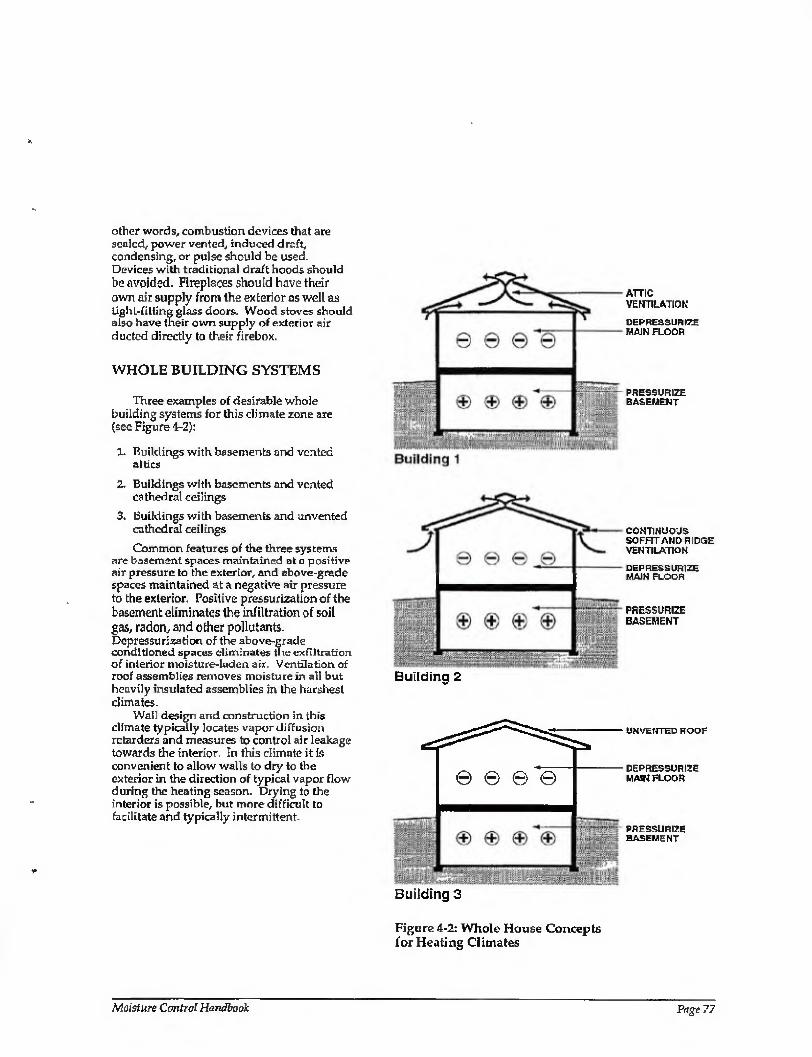
other words, combustion devices that are sealed, power vented, induced draft, condensing, or puise should be used. Devices with traditional draft hoods should be avoided. Fireplaces should have their own air supply from the exterior as well as Hght-fitling glass doors. Wood stoves should also have their own supply of exterior air ducted directly to their firebox.
WHOLE BUILDING SYSTEMS
Three examples of desirable whole building systems for this climate zone are (see Figure 4-2):
1. Buildings with basements and vented attics
2. Buildings with basements and vented cathedral ceilings
3. buildings with basements and unvented cathedral ceilings
Common features of the three systems are basement spaces maintained at a positive air pressure to the exterior, and above-grade spaces maintained at a negative air pressure to the exterior. Positive pressurization of the basement eliminates the infiltration of soil gas, radon, and other pollutants. Depressurization of the above-grade conditioned spaces eliminates the ex filtration of interior moisture-laden air. Ventilation of roof assemblies removes moisture in all but heavily insulated assemblies in the harshest climates.
Wail design and construction in this climate typically locates vapor diffusion retarders and measures to control air leakage towards the interior. In this climate it is convenient to allow walls to dry to the exterior in the direction of typical vapor flow during the heating season. Drying to the interior is possible, but more difficult to facilitate and typically intermittent.
ATTIC VENTILATION
DEPRESSOR IZF MAIN FLOOR
PRESSURIZE BASEMENT
Building 2
CONTINUOUS SOFFIT AND RIDGE VENTILATION
DEPRESSURIZE MAIN FLOOR
PRESSURIZE BASEMENT
Building 3
UNVENTED ROOF
DEPRESSURIZE MAIN FLOOR
PRESSURIZE BASE IS ENT
Figure 4-2: Whole House Concepts for Heating Climates
Moisture Control Handbook Page 77
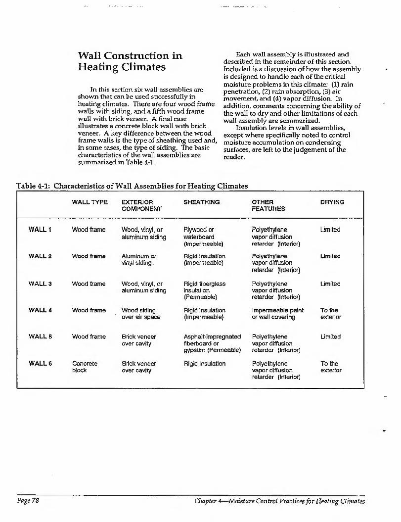
Wall Construction in Heating Climates
In this section six wall assemblies are shown that can be used successfully in heating climates. There are four wood frame walls with siding, and a fifth wood frame wall with brick veneer. A final case illustrates a concrete block wall with brick veneer. A key difference between the wood frame walls is the type of sheathing used and, in some cases, the type of siding. The basic characteristics of the wall assemblies are summarized in Table 4-1.
Each wall assembly is illustrated and described in the remainder of this section. Included is a discussion of how the assembly is designed to handle each of the critical moisture problems in this climate: (1) rain penetration, (2) rain absorption, (3) air movement, and (4) vapor diffusion. In addition, comments concerning the ability of the wall to dry and other limitations of each wall assembly are summarized.
Insulation levels in wall assemblies, except where specifically noted to control moisture accumulation on condensing surfaces, are left to the judgement of the reader.
Table 4-1: Characteristics of Wall Assemblies for Heating Climates
WALL TYPE EXTERIOR COMPONENT
SHEATHING OTHER FEATURES
DRYING
WALL 1
WALL 2
WALL 3
WALL 4
WALLS
WALL 6
Wood frame Wood, vinyl, or aluminum siding
Wood frame Aluminum or vinyl siding
Wood frame Wood, vinyl, or aluminum siding
Wood frame
Wood frame
Concrete block
Wood siding over air space
Brick veneer over cavity
Brick veneer over cavity
Plywood or waferboard (Impermeable)
Rigid insulation (Impermeable)
Rigid fiberglass insulation (Permeable)
Rigid insulation (Impermeable)
Asphalt-impregnated fiberboard or gypsum (Permeable)
Rigid insulation
Polyethylene Limited vapor diffusion retarder (Interior)
Polyethylene Limited vapor diffusion retarder (Interior)
Polyethylene Limited vapor diffusion retarder (Interior)
Impermeable paint To the or wall covering exterior
Polyethylene Limited vapor diffusion retarder (Interior)
Polyethylene To the vapor diffusion exterior retarder (Interior)
Page 78 Owpter 4—Moisture Control Practices for Heating Climates
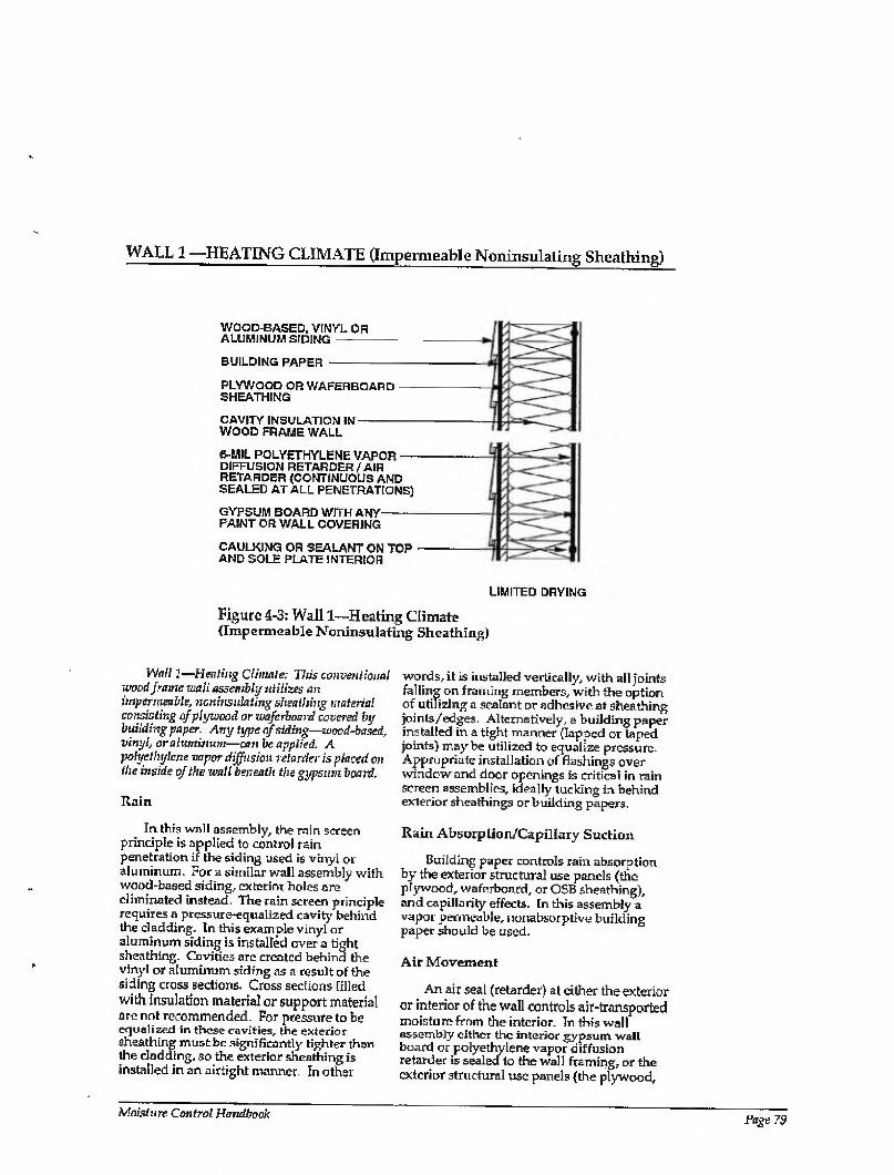
WALL 1 —HEATING CLIMATE (Impermeable Noninsulating Sheathing)
WOOD-BASED, VINYL OR ALUMINUM SIDING-
BUILDING PAPER -
PLYWOOD OR WAFERBOARD- SHEATHING
CAVITY INSULATION IN- WOOD FRAME WALL
6-MIL POLYETHYLENE VAPOR — DIFFUSION RETARDER/AIR RETARDER (CONTINUOUS AND SEALED AT ALL PENETRATIONS)
GYPSUM BOARD WITH ANY-- PAINT OR WALL COVERING
CAULKING OR SEALANT ON TOP AND SOLE PLATE INTERIOR
LIMITED DRYING
Figure 4-3: Wall 1—Heating Climate (Impermeable Noninsulating Sheathing)
Wall 1—-Heating Climate: This conventional wood frame wall assembly utilizes an impermeable, noninsulating sheathing material consisting af plywood or wafcrbonrd covered by building paper. Any type of siding—wood-based, vinyl, or aluminum—can be applied. A polyethylene vapor diffusion retarder is placed on the inside of the wall beneath the gypsum board.
Rain
In this wall assembly, the rain screen principle is applied to control rain penetration if the siding used is vinyl or aluminum. For a similar wall assembly with wood-based siding, exterior holes are eliminated instead. The rain screen principle requires a pressure-equalized cavity behind the cladding. In this example vinyl or aluminum siding is installed over a tight sheathing. Cavities are created behind the vinyl or aluminum siding as a result of the siding cross sections. Cross sections filled with insulation material or support material are not recommended. For pressure to be equalized in these cavities, the exterior sheathing must be significantly tighter than the cladding, so the exterior sheathing is installed in an airtight manner. In other
words, it is installed vertically, with all joints falling on framing members, with the option of utilizing a sealant or adhesive at sheathing joints/edges. Alternatively, a building paper installed in a tight manner (lapped or taped joints) may be utilized to equalize pressure. Appropriate installation of flashings over window and door openings is critical in rain screen assemblies, ideally tucking in behind exterior sheathings or building papers.
Rain Absorption/Capillary Suction
Building paper controls rain absorption by the exterior structural use panels (the plywood, waferbaard, or OSB sheathing), and capillarity effects. In this assembly a vapor permeable, rionabsorptive building paper should be used.
Air Movement
An ai r seal (retarder) at either the extenor or interior of the wall controls air-transported moisture from the interior. In this wall assembly cither the interior gypsum wall board or polyethylene vapor diffusion retarder is sealed to the wall framing, or the exterior structural use panels (the plywood,
Moisture Control Handbook Page 79
WALL 1—HEATING CLIMATE (CONTINUED)
waferboard, or OSB sheathing) are sealed to the wall framing. This air sealing can be accomplished with adhesive, caulk, or some other sealant. An exterior air seal at the exterior structural use panels in this example would facilitate pressure equalization of the exterior cladding.
Vapor Diffusion
To control vapor diffusion from the interior during heating periods, a vapor diffusion retarder is installed at the interior of the wall. A continuous polyethylene sheet is installed between the interior gypsum board and the wall framing and acts as the vapor diffusion retarder.
Comments
In this wall assembly, drying towards either the interior or exterior is limited by a vapor impermeable exterior sheathing and an interior vapor diffusion retarder. Should the wall assembly become wet during
service, or be built wet due to wet framing materials or wet-applied cavity insulations (wet spray cellulose or blown fiberglass), it may not dry. Accordingly, dry framing materials (wood at a moisture content of 19 percent by weight or lower) and dry-applied insulations are recommended. Alternatively, wall assemblies must be allowed to dry prior to enclosure.
Interior moisture levels should be limited to 35 percent relative humidity at 70 degrees Fahrenheit during heating periods. This will further control air-transported moisture and vapor diffusion with this wall assembly, since only limited drying of the assembly occurs.
Either vapor permeable or vapor impermeable interior surface finishes may be used in conjunction with this wall assembly. Where wood siding is utilized over plywood, waferboard, or OSB sheathing, the following steps are recommended: utilize dry materials, back-prime the siding, and nail according to manufacturers' recommended installation practices.
Page SO Chapter 4—Moisture Control Practices for Heating Climates
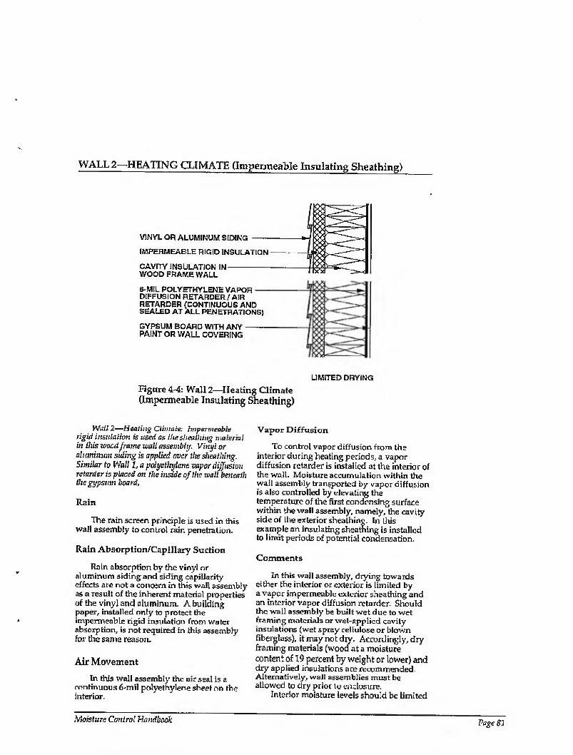
WALL 2—HEATING CLIMATE (Impermeable Insulating Sheathing)
VINYL OR ALUMINUM SIDING -
IMPERMEABLE RIGID INSULATION
CAVITY INSULATION IN- WOOD FRAME WALL fy>d
6-MIL POLYETHYLENE VAPOR — DIFFUSION RETARDER / AIR RETARDER (CONTINUOUS AND SEALED AT ALL PENETRATIONS)
GYPSUM BOARD WITH ANY- PAINT OR WALL COVERING
LIMITED DRYING
Figure 4-4: Wall 2—Heating Climate (Impermeable Insulating Sheathing)
Wall 2—Heating Climate. Impermeable rigid insulation is used as ihe sfieailiiug material in this wood frame wall assembly. Vinyl or aluminum siding is applied over the sheathing. Similar to Wall 1, a polyethylene vapor diffusion retarder is placed on the inside of the wall beneath the gypsum board.
Rain
The rain screen principle is used in this wall assembly to control rain penetration.
Rain Absorption/Capillary Suction
Rain absorption by the vinyl or aluminum siding and siding capillarity effects are not a concern in this wall assembly as a result of the inherent material properties of the vinyl and aluminum. A building paper, installed only to protect the impermeable rigid insulation from water absorption, is not required in this assembly for the same reason.
Air Movement
In this wall assembly the air seal is a continuous 6-mil polyethylene sheet on the interior.
Vapor Diffusion
To control vapor diffusion from the interior during heating periods, a vapor diffusion retarder is installed at the interior of the wall. Moisture accumulation within the wall assembly transported by vapor diffusion is also controlled by elevating the temperature of the first condensing surface within the wall assembly, namely, the cavity side of die exterior sheathing. In this example an insulating sheathing is installed to limit periods of potential condensation.
Comments
In this wall assembly, drying towards either the interior or exterior is limited by a vapor impermeable exterior sheathing arid an interior vapor d iffusion retarder. Should the wall assembly be built wet due to wet framing materials or wet-applied cavity insulations (wet spray cellulose or blown fiberglass), it may not dry. Accordingly, dry framing materials (wood at a moisture content of 19 percent by weight or lower) and dry applied insulations are recommended. Alternatively, wall assemblies must be allowed to dry prior to enclosure.
Interior moisture levels should be limited
Moisture Coirfrci Handbook Page 81
WALL 2—HEATING CLIMATE (CONTINUED)
to 35 percent relative humidity at 70 degrees Fahrenheit during heating periods. This will further control air-transported moisture and vapor diffusion with this wall assembly, since only limited drying of the assembly occurs.
Either vapor permeable or vapor impermeable surface finishes may be used in
conjunction with this wall assembly. Where wood siding is utilized over impermeable rigid insulation, the following steps are recommended: utilize dry materials, back- prime the siding, and nail according to manufacturers' recommended installation practices.
Page 82 Chapter 4—Moisture Control Practices for Heating Climates
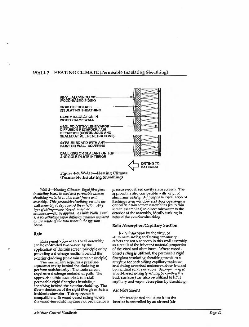
WALL 3—HEATING CLIMATE (Permeable Insulating Sheathing)
VINYL .ALUMINUM OR- WOOD-BASED SIDING
RIGID FIBERGLASS- INSULATING SHEATHING
CAVITY INSULATION IN- WOOD FRAME WALL
e-MIL POLYETHYLENE VAPOR — DIFFUSION RETARDER / AIR RETARDER {CONTINUOUS AND SEALED AT ALL PENETRATIONS)
GYPSUM BOARD WITH ANY- PAINT OR WALL COVERING
CAULKING OR SEALANT ON TOP AND SOLE PLATE INTERIOR
Figure 4-5: Wall 3—Heating Climate (Permeable Insulating Sheathing)
DRYING TO EXTERIOR
Wall 3—Healing Climate: Rigid fiberglass insulating board is used as a permeable exterior sheathing material in this wood frame wail assemblij. This permeable sheathing permits the wall assembly to dry toward the exterior. Any type of siding—wood-based, vinyl, or aluminum—can be applied. As with Walls 1 and 2, a polyethylene vapor diffusion retarder is placed on the inside of the wall beneath the gypsum board.
Rain
Rain penetration in this wall assembly can be controlled two ways: by the application of the rain screen principle or by providing a drainage medium behind the exterior cladding (the drain screen principle).
The rain screen requires a pressure- equalized cavity behind the cladding to perform satisfactorily. The drain screen requires a drainage material or path. The approach in this example is to install permeable rigid fiberglass insulating sheathing behind the exterior cladding. The fiber orientation of the rigid fiberglass drains incident rainwater. This approach is compatible with wood-based siding where the wood-based siding does not provide for a
pressure-equalized cavity {rain screen). The approach is also compatible with vinyl or aluminum siding- Appropriate installation of flashings over window and door openings is critical in drain screen assemblies {as in rain screen assemblies) to direct rainwater to the exterior of the assembly, ideally tucking in behind the exterior sheathing.
Rain Absurption/Capillary Suction
Rain absorption by the vinyl or aluminum siding and siding eapilinrity effects are not a concern in this wall assembly as a result of the inherent material properties of the vinyl and aluminum. Where wood- based siding is utilized, the permeable rigid fiberglass insulating sheathing provides a receptor for both siding capillary moisture and siding absorbed moisture driven inward by incident solar radiation- Back-priming of wood-based siding (painting or coating the back surfaces) can also be utilized to limit capillary and vapor absorption by the siding.
Air Movement
Air-trans ported moisture from the interior is controlled by an air seat (air
Moisture Control Handbook Page 83
WALL 3—HEATING CLIMATE (CONTINUED)
retarder) at the interior of the wall. An exterior air seal can be provided where the sheathing material comes with permeable sheet facing material and this material is utilized as the exterior air seal.
Vapor Diffusion
A vapor diffusion retarder at the wall interior controls vapor diffusion from the interior during heating periods. In this example a continuous polyethylene sheet is installed between the interior gypsum board and the wall framing.
During cooling periods and under the action of incident solar radiation, vapor diffusion from the exterior in this wall assembly is controlled by a vapor diffusion retarder at the interior of the wall assembly between the wall framing and the interior gypsum board. Although installing a vapor diffusion retarder at this location does not prevent moisture from entering the wall, the vapor diffusion retarder effectively protects the interior gypsum board and any interior finishes from moisture damage.
This interior vapor diffusion retarder can get wet on the cavity side during the day as a result of exterior absorbed moisture in the permeable rigid fiberglass insulating sheathing driven inward by incident solar radiation and the air conditioned interior. This moisture then typically migrates outward in the evening when the temperature gradient reverses.
This wall assembly can get intermittently wet from the exterior as well dry intermittently to the exterior. Since intermittent wetting of the vapor diffusion retarder may occur in this assembly, this
interior vapor diffusion retarder should be continuous to provide satisfactory performance. Foil-backed interior gypsum board and foil-backed cavity insulation may not be effective due to discontinuities at joints. A continuous polyethylene vapor diffusion retarder has proven to be effective in this type of assembly.
Comments
A vapor permeable sheathing on the exterior of the wall framing helps dry the wall towards the exterior in this wall assembly. An insulating sheathing also elevates the cavity temperature and acts as a receptor for interior cavity moisture. Furthermore, since the rigid insulating sheathing is close to the permeability of air, the exterior cladding in essence "sees" the wall cavity and framing members. When the cladding is cold, it attracts interior cavity and framing moisture, effectively freeze drying the wall. Should the wall assembly become wet during service or be built wet due to wet framing materials or wet-applied cavity insulations (wet spray cellulose or blown fiberglass), it dries rapidly to the exterior during the heating season or during evenings. Once the interior cavity moisture has migrated to the exterior cladding it can either drain to the exterior or evaporate. Where wood-based sidings are used, they should be protected from this moisture migration towards their back surfaces from the interior by back-priming.
Either vapor permeable or vapor impermeable interior surface finishes may be used in conjunction with this wall assembly.
Page 84 Chapter 4—Moisture Control Practices for Heating Climates
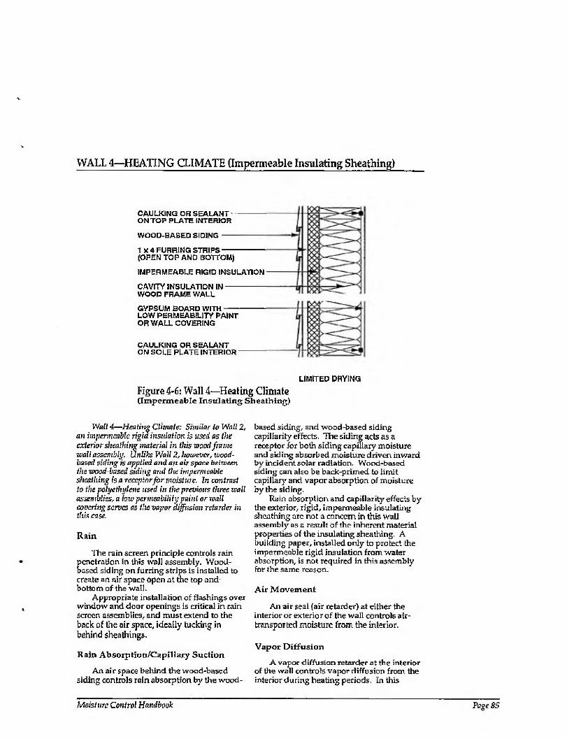
WALL 4—HEATING CLIMATE (Impermeable Insulating Sheathing)
CAULKING OR SEALANT- ON TOP PLATE INTERIOR
WOOD-BASED SIDING-
1 x 4 FURRING STRIPS- (OPEN TOP AND BOTTOM)
IMPERMEABLE RIGID INSULATION
CAVITY INSULATION IN- WOOD FRAME WALL
GYPSUM BOARD WITH- LOW PERMEABILITY PAINT OR WALL COVERING
CAULKING OR SEALANT ON SOLE PLATE INTERIOR
LIMITED DRYING
Figure 4-6: Wall 4—Heating Climate (Impermeable Insulating Sheathing)
Wall 4—Heating Climate; Similar lo Wall 2, an impermeable rigid insulation is used as the exterior sheathing material in this wood frame wall assemblt/, UnUke Wall 2, however, wood- based siding is applied and an air space between the wood based siding and the impermeable sheathing is a receptor for moisture. In contrast to the polyethylene used in the previous three wall assemblies, a low permeability paint or wall coucring serves as the vapor diffusion retarder in this case.
Rain
The rain screen principle controls rain penetration in this wall assembly. Wood- based siding on furring strips is installed to create an air space open at the top and bottom of the wall.
Appropriate installation of flashings over window and door openings is critical in rain screen assemblies, and must extend to the back of the air space, ideally tucking in behind sheathings.
Rain Absorption/CapUlary Suction
An air space behind the wood-based siding controls rain absorption by the wood-
based siding, and wood-based siding capillarity effects. The siding acts as a receptor for both siding capillary moisture and siding absorbed moisture driven inward by incident solar radiation. Wood-based siding can also be back-primed to limit capillary and vapor absorption of moisture by the siding.
Rain absorption and capillarity effects by the exterior, rigid, impermeable insulating sheathing are not a concern in this wall assembly as a result of the inherent material properties of the insulating sheathing. A building paper, installed only to protect the impermeable rigid insulation from water absorption, is not required in this assembly for the same reason.
Air Movement
An air seal (air retarder) at either the interior or exterior of the wall controls air- transported moisture from the interior.
Vapor Diffusion
A vapor diffusion retarder at the interior of the wall controls vapor diffusion from the interior during heating periods. In this
Moisture Control Handbook Page 85
WALL 4—HEATING CLIMATE (CONTINUED)
example a low permeability paint or wall covering acts as the vapor diffusion retarder.
Moisture accumulation within the wall assembly transported by vapor diffusion from the interior during heating periods is also controlled by elevating the temperature of the first condensing surface within the wall assembly, namely the cavity side of the exterior sheathing. This is accomplished in this example by installing an insulating sheathing which limits periods of potential condensation
Comments
In this wall assembly, drying towards either the interior or exterior is limited by a vapor impermeable exterior sheathing and an interior vapor diffusion retarder.
Should the wall assembly be built wet due to wet framing materials or wet-applied cavity insulations {wet spray cellulose or blown fiberglass), it may not dry. Accordingly, dry framing materials (wood at a moisture content of 19 percent by weight or lower) and dry applied insulations are recommended. Alternatively, wall assemblies must be allowed to dry prior to enclosure.
Interior moisture levels should be limited to 35 percent relative humidity at 70 degrees Fahrenheit during heating periods to further control air-transported moisture and vapor diffusion with this wall assembly, since only limited drying of the assembly occurs.
Vapor impermeable interior surface finishes must be used in conjunction with this wall assembly.
Page 86 Chapter 4—Moisture Control Practices for Heating Climates
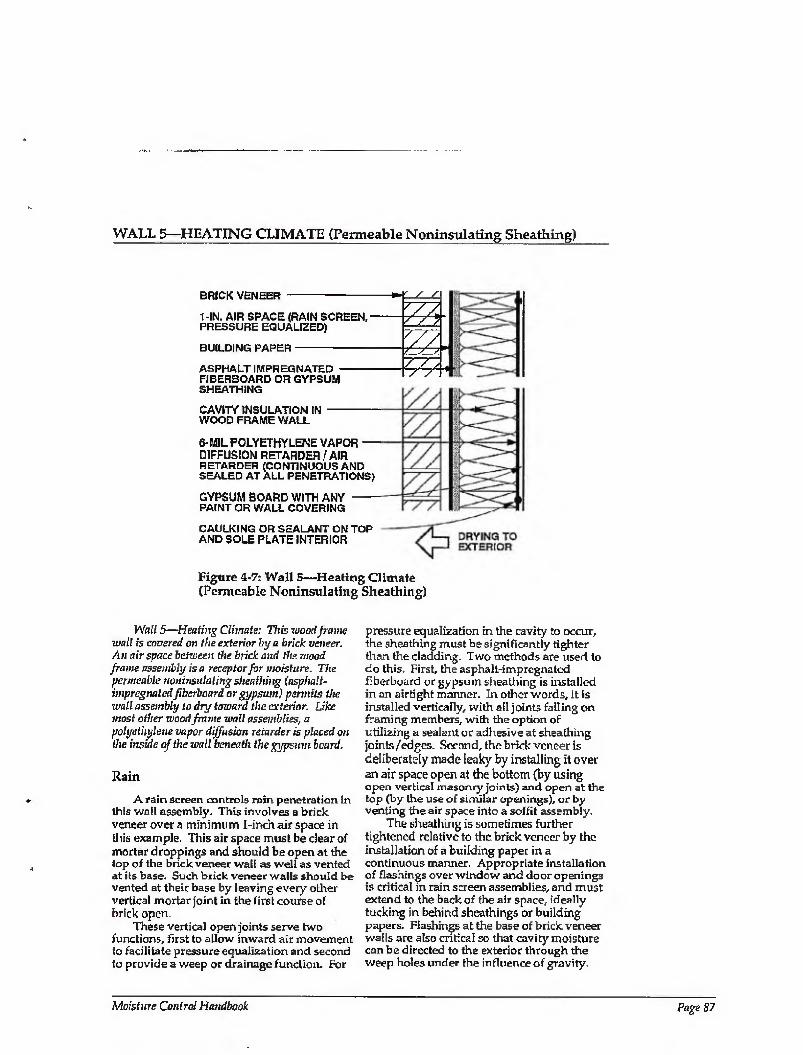
WALL 5—HEATING CLIMATE (Permeable Noninsulating Sheathing)
BRrCK VENEER -
1-IN. AIR SPACE (RAIN SCREEN, - PRESSURE EQUALIZED)
BUILDING PAPER-
ASPHALT IMPREGNATED - FIBERBOARD OR GYPSUM SHEATHING
CAVITY INSULATION IN - WOOD FRAME WALL
6-MIL POLYETHYLENE VAPOR — DIFFUSION RETARDER / AIR RETARDER [CONTINUOUS AND SEALED AT ALL PENETRATIONS)
GYPSUM BOARD WITH ANY - PAINT OR WALL COVERING
CAULKING OR SEALANT ON TOP AND SOLE PLATE INTERIOR
/ /
zz
//s / /
Figure 4-7: Wall 5—Heating Climate (Permeable Noninsulating Sheathing)
Wall 5—Heating Climate: This wood frame wall is covered on the exterior hy a brick veneer. An air space between the hick and the wood frame assembly is a receptor for moisture. The permeable noninsulaling sheathing (asphalt- impregnated fibcrboard or gypsum) permits the wall assembly to dry toward the exterior. Like most other wood frame wall assemblies, a polyethylene vapor diffusion retarder is placed on the inside of the wall beneath the gypsum board.
Rain
A rain screen controls rain penetration in this wall assembly. This involves a brick veneer over a minimum I-inch air space in (his example. This air space must be clear of mortar droppings and should be open at the top of the brick veneer wall as well as vented at its base. Such brick veneer waits should be vented at their base by leaving every other vertical mortar joint in the first course of brick open.
These vertical open joints serve two functions, first to allow inward air movement to facilitate pressure equalization and second to provide a weep or drainage function. For
pressure equalization in the cavity to occur, the sheathing must be significantly tighter than the cladding. Two methods are used to do this. First, the asphalt-impregnated fiberboard or gypsum sheathing is installed in an airtight manner. In other words, it is installed vertically, with all joints falling on framing members, with the option of utilizing a sealant or adhesive at sheathing joints/edges. Second, the brick veneer is deliberately made leaky by installing it over an air space open at the bottom (by using open vertical masonry joints) and open at the top [by the use of similar openings), or by venting the air space into a soffit assembly.
The sheathing is sometimes further tightened relative to the brick veneer by the installation of a building paper in a continuous manner. Appropriate installation of flashings over window and door openings is critical in rain screen assemblies, and must extend to the back of the air space, ideally tucking in behind sheathings or building papers. Flashings at the base of brick, veneer walls are also critical so that cavity moisture can be directed to the exterior through the weep holes under the influence of gravity.
Moisture Control Handbook Page 87
WALL 5—HEATING CLIMATE (CONTINUED)
These base flashings must extend to the back of the rain screen cavity and be placed behind the sheathing or building paper.
Rain Absorption/Capillary Suction
An air space behind the brick veneer controls rain absorption and brick veneer capillarity effects. The air space also acts as a receptor for both brick veneer capillary moisture and absorbed moisture driven inward by incident solar radiation. A building paper is installed in some assemblies to limit rain absorption by the asphalt-impregnated fiberboard or gypsum sheathing. In such cases a vapor permeable, nonabsorptive building paper should be used.
Air Movement
An air seal (air retarder) at either the interior or exterior of the wall controls air- transported moisture from the interior. In this wall assembly, the interior gypsum wall board, polyethylene vapor diffusion retarder, or exterior sheathing is sealed to the wall framing. This air sealing can be accomplished with adhesive, caulk, or some other sealant. An exterior air seal at the asphalt-impregnated fiberboard sheathing in this example would facilitate pressure equalization of the exterior cladding. Exterior air seals typically feature a continuous exterior building paper (vapor permeable and nonabsorptive is desirable).
Vapor Diffusion
A vapor diffusion retarder at the interior of the wall controls vapor diffusion from the interior. A continuous polyethylene sheet is installed between the interior gypsum board and the wall framing and acts as the vapor diffusion retarder.
During cooling periods and under the action of incident solar radiation, vapor diffusion from the exterior in this wall assembly is controlled by a vapor diffusion
retarder at the interior of the wall assembly between the wall framing and the interior gypsum board. Although installing a vapor diffusion retarder at this location does not prevent moisture from entering the wall from the outside, the vapor diffusion retarder effectively protects the interior gypsum board and any interior finishes from moisture damage.
This interior vapor diffusion retarder can get wet on the cavity side during the day as a result of exterior absorbed moisture in the brick veneer driven inward by incident solar radiation and the air conditioned interior. This moisture then typically migrates outward in the evening when the temperature gradient reverses.
This wall assembly can get intermittently wet from the exterior as well dry intermittently to the exterior. Since intermittent wetting of the vapor diffusion retarder may occur in this assembly, this interior vapor diffusion retarder should be continuous to provide satisfactory performance. Foil-backed interior gypsum board and foil-backed cavity insulation may not be effective due to discontinuities at joints. A continuous polyethylene vapor diffusion retarder has proven to be effective in this type of assembly.
Comments
A vapor permeable sheathing on the exterior of the wall framing helps dry the wall towards the exterior in this wall assembly. An air space between the cladding (brick veneer) and the sheathing acts as a receptor for interior cavity moisture. Should the wall assembly become wet during service or be built wet due to wet framing materials or wet-applied cavity insulations (wet spray cellulose or blown fiberglass), it can dry to the exterior into the air space behind the brick veneer during the heating season or during evenings.
Either vapor permeable or vapor impermeable interior surface finishes may be used in conjunction with this wall assembly.
Page 88 Chapter 4—Moisture Control Practices for Heating Climates

WALL 6—HEATING CLIMATE (Masonry Wall with Exterior Insulation)
BRICK VENEER -
1-IN. AIR SPACE (RAIN SCREEN, PRESSURE EQUALIZED)
RIGID INSULATION-
AIR RETARDER SYSTEM - (TROWEL-ON MASTIC, SHEET-ADHERED MEMBRANE)
MASONRY BLOCK-
1 X4 FURRING STRIPS -
GYPSUM BOARD WITH- PAINT OR WALL COVERING
LIMITED DRYING
Figure 4-8: Wall 6—Heating Climate (Masonry Wall with Exterior Insulation)
Wall 6—Hen ting Cliinufe: This concrete block wall assembly with brick veneer is the only one that is not wood frame construction. Either permeable or impermeable rigid insulation is placed in the cavity between the block wall and brick veneer. An air space between the brick and the insulation is a receptor for moisture. An air retarder systent (trowel-on mastic or a sheet- adhered membrane) is applied to the exterior face of the masonry wall to control vapor diffusion and air leakage.
Rain
Rain penetration in this wall assembly is controlled by the application of the rain screen principle.
This approach necessitates the construction of the masonry block wall first, followed by the application of the air retarder system and rigid insulation, and then by the construction of the brick veneer. Appropriate installation of flashings over window and door openings is critical in rain screen assemblies, and must extend to the back of the air space, ideally regletted into the masonry block wall or set into the masonry wall mortar joints. Flashings at the base of brick veneer walls are also critical so that
cavity moisture can be directed to the exterior through the weep holes under the influence of gravity'. These base flashings must also extend to the back of the rain screen cavity behind the rigid insulation and set into the masonry wall mortar joints.
Rain Absorption/Capillary Suction
An air space behind the brick veneer controls rain absorption and brief; veneer capillarity effects. The air space acts as a receptor for both brick veneer capillary moisture and brick veneer absorbed moisture driven inward by incident solar radiation.
Air Movement
An air retarder system on the exterior of the masonry block wall controls air- transported moisture from the interior in this wail assembly. Utilizing the rigid insulation as an integral air relarder system has in practice proven to be difficult due to the dimensional instability of rigid insulations.
The air retarder also controls air- transported moisture from the exterior (infiltration of warm, humid air during the cooling season) in this wall assembly. This
Moisture Control Handbook Page 89
WALL 6—HEATING CLIMATE (CONTINUED)
moisture transport mechanism can lead to moisture damage where significant moisture has been stored in the brick veneer.
Vapor Diffusion
A vapor diffusion retarder on the exterior of the masonry block wall between the masonry and the rigid insulation controls vapor diffusion from the interior during heating periods. In this example the air retarder system also acts as the vapor diffusion retarder. Moisture accumulation within the wall assembly transported by vapor diffusion is controlled by elevating the temperature of the first condensing surface within the wall assembly, namely, the masonry block wall. In this example an insulating sheathing is installed on the exterior of the masonry block wall.
A vapor diffusion retarder on the exterior of the masonry block wall controls vapor diffusion from the exterior. This vapor diffusion retarder is the air retarder system installed on the exterior of the masonry block wall.
Comments
A vapor permeable paint finish on the interior gypsum wall board promotes wall drying towards the interior from within the masonry block wall assembly. Should the
masonry block wall assembly become wet during service or be built wet through the use of wet masonry, it can dry to the interior due to an inward temperature and vapor pressure gradient present as a result of air conditioning the enclosure during the cooling season. However, it should be noted that only limited drying towards the interior may occur.
In cases where impermeable interior surface treatments are utilized, such as wall coverings and impermeable paints, the masonry block wall assembly should be allowed to dry prior to enclosure. Alternatively, an additional vapor diffusion retarder may be installed between the interior gypsum wall board and the interior surface of the masonry wall to retard the inward migration of construction moisture and reduce the possible damage to interior surface finishes.
Where wall assemblies with permeable interior surface treatments have been performing satisfactorily in service and are subsequently covered with impermeable interior surface treatments (repainting with impermeable paints or wall coverings by new or subsequent owners or tenants), mold and mildew problems may appear at the gypsum board/surface treatment interface if the previously mentioned moisture control strategies have not been effectively utilized.
Page 90 Qmpter 4—Moisture Control Practices for Heating Climates
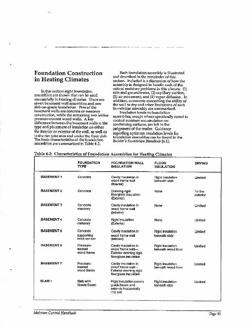
Foundation Construction in Heating Climates
Ih this section eight foundation assemblies are shown that can be used successfully in heating climates. There are seven basement wall assemblies and one slab-on-grade foundation. Five of the basement walls are concrete or masonry construction, while the remaining two utilize pressure-treated wood walls. A key difference between the basement walls is the type and placement of insulation on either the interior or exterior of the wall, as well as in tile rim Joist area and under the floor slab. The basic characteristics of the foundation assemblies are summarized in Tabic 4-2.
Each foundation assembly is illustrated and described in the remainder of this section. Included is a discussion of how the assembly is designed to handle each of the critical moisture problems in this climate: (1) rain and groundwater, (2) capillary suction, (3) air movement, and (4) vapor diffusion. In addition, comments concerning the ability of the wall to dry and other limitations of each foundation assembly are summarized.
Insulation levels in foundation assemblies, except where specifically noted to control moisture accumulation on condensing surfaces, are left to the judgement of the reader. Guidance regarding optimum insulation levels for foundation assemblies can be found in the Builder's Foundation Handbook [4.1].
Tabic 4-2: Characteristics of Foundation Assemblies for Heating Climates
BASEMENT 1
BASEMENT2
BASEMENT 3
BASEMENT 4
BASEMENTS
BASEMENT G
BASEMENT?
SLAB 1
FOUNDATION TYPE
FOUNDATION WALL INSULATION
Concrete
Concrete
Concrete masonry
Concrete masonry
Concrete supporting brick veneer
Pressure- treated wood frame
Pressure- treated wood frame
Slab with Grade Beam
Cavity insulation In wood frame wall (Interior)
Draining rigid fiberglass insulation (Exterior)
Cavity insulation in wood frame wall (Interior)
Rigid insulation (Exterior)
Cavity insulation in wood frame wall (Interior)
Cavity insulation in wood frame wail— Exterior draining rigid fiberglass insulation
Cavity insulation In wood frame wall— Exterior draining rigid fioerglass insulation
Rigid insulation covers grade beam and extends horizontally into soil
FLOOR INSULATION
DRYING
Rigid insulation beneath slab
None
None
None
Rigid insulation beneath slab
Rigid insulation beneath wood floor
Rigid insulation beneath wood floor
Rigid insulation beneath slab
Limited
To the exterior
Limited
Limited
Limited
Limited
Limited
Limited
Moisture Control Handbook Page 97
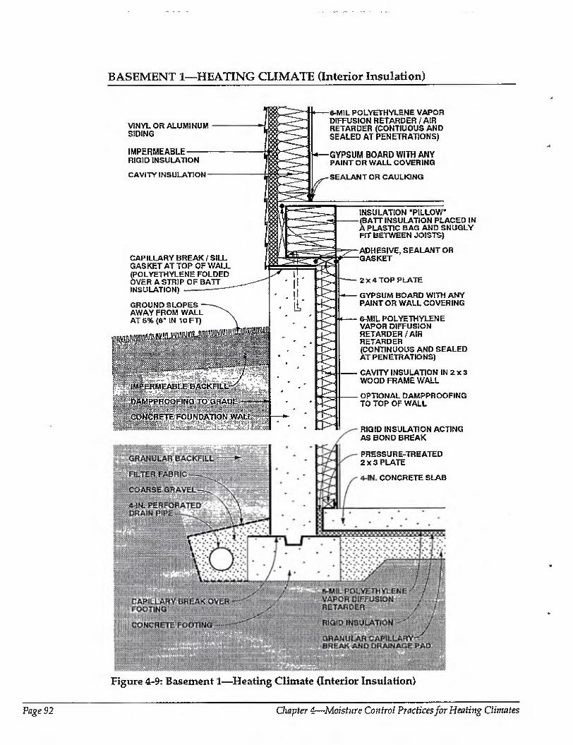
BASEMENT 1—HEATING CLIMATE (Interior Insulation)
r-G#?A«yiAR backfill;:
: riLTE-n FABRIC- -
COARSE GRAVEL —
'4ww. perforated ^DRAIHFipE-. j -
ifiFOOtliQ: PlliilliS llilCONOREI
Wfilil WsS.VSS. .-7-Sw‘'sZW.wX0rf}fr}. YsYSSi.WS. Y/sfrjS-sfS. \ jAW&WSvA
VINYL OR ALUMINUM SIDING
IMPERMEABLE RIGID INSULATION
CAVITY INSULATION
CAPILLARY BREAK / SILL GASKET AT TOP OF WALL (POLYETHYLENE FOLDED OVER A STRIP OF BATT INSULATION)
GROUND SLOPES AWAY FROM WALL AT 5% (6" IN 10 FT)
k.m-
l m ^ =1MEABLE BACKFILL -tt
iipi'DAMPPROOFINQ TO GRADE"*-*
lipfCOWeRETE FOUNDATION:WALL^Sr
&-MIL POLYETHYLENE VAPOR DIFFUSION RETARDER / AIR RETARDER (CONTIUOUS AND SEALED AT PENETRATIONS)
GYPSUM BOARD WITH ANY PAINT OR WALL COVERING
SEALANT OR CAULKING
INSULATION ’PILLOW (BATT INSULATION PLACED IN A PLASTIC BAG AND SNUGLY FIT BETWEEN JOISTS)
ADHESIVE, SEALANT OR GASKET
2X4 TOP PLATE
GYPSUM BOARD WITH ANY PAINT OR WALL COVERING
6-MIL POLYETHYLENE VAPOR DIFFUSION RETARDER/ AIR RETARDER (CONTINUOUS AND SEALED AT PENETRATIONS)
CAVITY INSULATION IN 2 x 3 WOOD FRAME WALL
OPTIONAL DAMPPROOFING TO TOP OF WALL
RIGID INSULATION ACTING AS BOND BREAK
PRESSURE-TREATED 2X3 PLATE
4-IN. CONCRETE SLAB
Figure 4-9: Basement 1—Heating Climate (Interior Insulation)
Page 92 Chapter 4—Moisture Coufroi Practices for Heating Climates

BASEMENT 1—HEATING CUMATE (CONTINUED)
Basement 1—Heating Climate: This concrete basement wall assembly illustrates the use of cavity insulation in a wood frame wail on the mterior of the foundation wall. Cavity insulation is placed between joists on the. rim joist interior, and rigid insulation cavers the rim joist on the exterior as well. A layer of rigid insulation is also shown beneath the concrete floor slab. A vapor diffusion retarder covers all insulation on the in terior side of the wall assembly. The above¬ grade wall shown here corresponds to Wall 2 in the previous section.
Rain and Groundwater
Gutters and downspouts, along with careful site grading, which direct water away from basement perimeters, should be used to prevent rain and surface water from entering basements. Surface water penetration into tire ground immediately adjacent to basements is limited by a cap of impermeable backfill material.
A subgrade drainage system controls groundwater entry into basements. This consists of a drain pipe located at the perimeter of the concrete footings coupled with free-draining backfill material. The drain pipe and the free-draining backfill material act together to provide a drain screen. The drain pipe is connected to a sump, storm sewer, or to daylight, Perforations in the perimeter drain pipe should be installed with the holes down to allow groundwater to rise up into the drain pipe and be carried away. Coarse gravel should surround the perimeter drain pipe and in turn be surrounded by a filter fabric. Filter fabric should be located both below and above the perimeter drain pipe, as drain pipe perforations face down and often clog from underneath. Drain tile should have at least 2 inches of gravel underneath, yet still be below the bottom surface of the basement floor slab.
Capillary Suction
Capillary moisture may move into (1) the concrete foundation wall; (2) concrete floor slab and underslab insulation; and (3) the sill/rim joist/floor assembly. The concrete foundation wall is protected by a dampproof coating on the exterior of the concrete foundation wall as well os by a capillary break (dampproofing or polyethylene) over
the top of the concrete footing. The footings can also be constructed on a granular pad.
Capillary moisture movement into the floor slab and underslab insulation is controlled by a granular capillary break under the slab. The break is a 4-inch- to 6- inch-thick layer of 3/4-inch gravel with fines removed.
The movement of construction moisture from the perimeter concrete foundation wall into the sill/rim joist/floor assembly is controlled by a capillary break at the top of the perimeter concrete foundation wall.
Air Movement
In basement assemblies it is important to eliminate air flow between the surrounding soil and the basement space. To control air- transported moisture infiltrating into the basement space, (lie basement is pressurized relative to the surrounding soil and air leakage openings are limited (tight construction).
Where perimeter concrete foundation walls are insulated on the interior, it is also important to prevent warm, interior, moisture-laden air from the basement space from coming in contact with cold, concrete surfaces during both heating and cooling periods.
Air leakage openings in this basement construction, which deal with both exterior and interior moisture-laden air, are limited by sealing the floor slab polyethylene vapor diffusion retarder to the foundation wail perimeter polyethylene vapor diffusion retarder. In addition, air leakage openings at the rim joist/floor assembly are controlled by sealing the joints of the elements which form the sill/rim joist/floor assembly.
A tight-fitting, insulation "pillow” is installed at the interior of the rim joist assembly between floor joists. The insulation pillow is formed by placing batt insulation in a plastic bag and snugly fitting the bag containing the insulation between the floor joists. Gaps at this location around the insulation pillow need to be minimized to control potential convective moisture transfer from the interior basement space to the interior surface of the rim joist. Pipe penetrations and electrical conduits through concrete floor slabs and perimeter concrete walls, floor drains, and sump openings are also sealed or closed with tight covers.
Moisture Control Handbook Page 93
BASEMENT 1—HEATING CLIMATE (CONTINUED)
Vapor Diffusion
Moisture movement by vapor diffusion can affect various basement assemblies, depending on the moisture source. When moisture moves from the surrounding soil into the concrete foundation wall, it is controlled by installing a vapor diffusion retarder on the exterior of the concrete foundation wall. In this example, the dampproofing on the exterior of the concrete foundation wall also acts as a vapor diffusion retarder.
When moisture diffuses from the surrounding soil into the concrete floor slab, it is controlled with a polyethylene vapor diffusion retarder under the slab.
Construction moisture contained in the perimeter concrete foundation wall is prevented from diffusing into the perimeter foundation frame wall cavity by dampproofing on the interior of the perimeter foundation wall. Alternatively, the wall can be allowed to dry prior to enclosure.
Moisture from the interior basement space is prevented from diffusing into the perimeter foundation wall framing by installing a polyethylene vapor diffusion retarder on the interior of the perimeter foundation wall framing.
Finally, moisture diffusing from the interior basement space into the perimeter rim joist assembly during the heating season is controlled by the plastic bag facing on the batt insulation, which acts as a vapor diffusion retarder. Moisture accumulation from vapor diffusion migrating from within the interior basement space at the rim joist assembly is limited by installing insulating sheathing at the exterior of the rim joist. This elevates the temperature of the first condensing surface at this location (the interior surface of the rim joist).
Comments
In this perimeter foundation frame wall assembly, drying towards either the interior or exterior is limited by the impermeability of the perimeter foundation wall concrete and the interior polyethylene vapor diffusion retarder. Should the wall assembly become wet during service or be built wet due to wet framing materials or wet-applied cavity insulations (wet spray cellulose or blown fiberglass), it may not dry. Accordingly, dry
framing materials (wood at a moisture content of 19 percent by weight or lower) and dry-applied insulations are recommended. Alternatively, wall assemblies must be allowed to dry prior to enclosure.
The perimeter foundation frame wall is held away from the concrete in order to enhance the durability of the wood members. This is accomplished by using a 2 x 4 top plate with 2x3 studs and a 2 x 3 bottom plate. The cavity insulation, however, fills the entire void and touches the interior face of the concrete foundation wall. Fiberglass batt insulation is recommended as the cavity insulation by virtue of its draining characteristics and nonhygroscopic nature.
Interior basement space moisture levels should be limited to 35 percent relative humidity at 70 degrees Fahrenheit during heating periods. This is needed to further control air-transported moisture and vapor diffusion with this wall assembly, since only limited drying of the assembly occurs.
Either vapor permeable or vapor impermeable interior surface finishes may be used in conjunction with this foundation wall assembly.
The concrete floor slab contains significant quantities of moisture when initially placed. Covering this surface with an impermeable surface finish or floor covering may lead to deterioration of these surfaces if the construction moisture is not allowed to dry. Initial drying of the construction moisture contained in concrete may also lead to elevated interior moisture levels during the first few months of occupancy.
Installing carpets on cold, damp, concrete floor slabs can lead to serious allergenic reactions in sensitive individuals and other health-related consequences. It is not recommended that carpets be installed on concrete slabs unless the carpets can be kept dry and warm; that is, carpet relative humidities should be kept below 40 percent [4.2]. In practice this is typically not possible unless floor slab assemblies are insulated and basement areas are conditioned.
The granular drainage pad located under the basement concrete floor slab can be integrated into a subslab ventilation system to control radon migration by adding a vent pipe connected to the surface and an exhaust fan.
Page 94 Chapter 4—Moisture Control Practices for Heating Climates
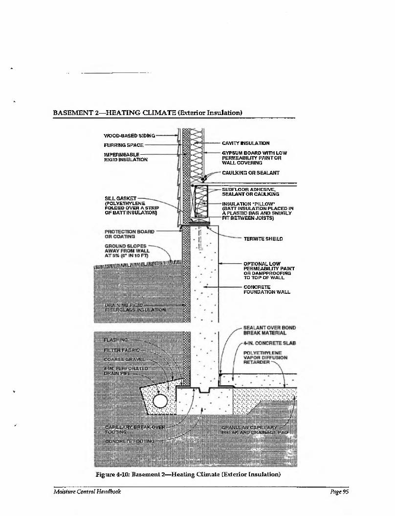
BASEMENT 2—HEATING CLIMATE (Exterior Insulation)
WOOD-BASED SIDING
FURRING SPACE
IMPERMEABLE RIGID INSULATION
SILL GASKET (POLYETHYLENE FOLDED OVER A STRIP OF BATT INSULATION)
CAVITY INSULATION
GYPSUM BOARD WITH LOW PERMEABILITY PAINT OR WALL COVERING
CAULKING OR SEALANT
SUBFLOOR ADHESIVE, SEALANT OR CAULKING
INSULATION ’PILLOW (BATT INSULATION PLACED IN A PLASTIC BAG AND SNUGLY FIT BETWEEN JOISTS)
TERMITE SHE ILD
OPTIONAL LOW PERMEABILITY PAINT OR DAMPPROOFING TO TOP OF WALL
CONCRETE FOUNDATION WALL
Figure 4-10: Basement 2—Heating Climate (Exterior Insulation)
Moisture Control Handbook Page 95
BASEMENT 2—HEATING CLIMATE (CONTINUED)
Basement 2—Heating Climate: Draining rigid fiberglass insulation board covers the exterior of this concrete basement wall. Rigid insulation covers the exterior of the rim joist, and cavity insulation (with a vapor diffusion retarder) is placed between joists on the rim joist interior. This is the only foundation wall assembly that dries to the exterior. The above-grade wall shown here corresponds to Wall 4 in the previous section.
Rain and Groundwater
Gutters and downspouts, along with careful site grading, which direct water away from basement perimeters, should be used to prevent rain and surface water from entering basements. Surface water penetration into the ground immediately adjacent to basements is limited by a cap of impermeable backfill material (not shown).
A subgrade drainage system controls groundwater entry into basements. This consists of a drain pipe located at the perimeter of the concrete footings coupled with free-draining insulation board. The drain pipe and the free-draining rigid fiberglass insulation board act together to provide a drain screen.
Capillary Suction
Several methods are used to control moisture movement by capillarity into the foundation wall. Rigid draining fiberglass insulation, which acts as a capillary break, is installed on the exterior of the concrete foundation wall, and a capillary break (dampproofing or polyethylene) is placed over the top of the concrete footing. Alternatively, the footings can be constructed on a granular pad.
A granular capillary break is installed under the slab to control capillary moisture moving into the floor slab and underslab insulation. The break is a 4-inch- to 6-inch- thick layer of 3/4-inch gravel with fines removed.
Air Movement
To limit air leakage openings in this basement, the concrete floor slab is sealed to the perimeter concrete foundation wall with caulking, and the joints of the elements which form the sill/rim joist/floor assembly are sealed.
Vapor Diffusion
Moisture may diffuse into several building assemblies. Rigid insulation on the exterior of the concrete foundation wall controls moisture entering from the surrounding soil. The rigid insulation raises the temperature of the concrete, lowers its equilibrium relative humidity, and thereby allows the concrete foundation wall to dry into the surrounding soil- A vapor diffusion retarder on the exterior of this foundation wall is therefore not necessary.
A polyethylene vapor diffusion retarder under the concrete floor slab controls moisture diffusing into this slab.
Moisture accumulation from vapor diffusion migrating from within the interior basement space at the rim joist assembly is limited by installing insulating sheathing at the exterior of the rim joist. This elevates the temperature of the first condensing surface at this location (the interior surface of the rim joist).
Comments
Rigid insulation is installed on the exterior of the perimeter concrete foundation wall to reduce heating and cooling loads and is protected above grade on its exterior from mechanical damage. This rigid insulation can act as a conduit for insects to enter the enclosure, and as such appropriate flashings or other protection may be necessary.
Rigid insulation installed on the exterior of the rim joist assembly elevates the temperature of the first condensing surface during the heating season (the inside face of the rim joist) and thereby limits the potential for condensation at this location.
A tight-fitting, insulation "pillow" is installed at the interior of the rim joist assembly between floor joists. The insulation pillow is formed by placing batt insulation in a plastic bag and snugly fitting the bag containing the insulation between the floor joists. Gaps at this location around the insulation pillow need to be minimized to control potential convective moisture transfer from the interior basement space to the interior surface of the rim joist. If convective moisture transfer is inhibited at this location and the facing on the insulation acts as an interior vapor diffusion retarder, the thermal resistance of the rigid insulation on the
Page 96 Chapter 4—Moisture Control Practices for Heating Climates
BASEMENT 2—HEATING CLIMATE (CONTINUED)
exterior of the rim joist can be reduced and the thermal resistance of the insulation at the interior of the rim joist can be increased.
The concrete floor slab and perimeter concrete foundation wall contain significant quantities of moisture when initially placed. Covering these surfaces with impermeable surface finishes or floor coverings may lead to deterioration of these surfaces if the construction moisture is not allowed to dry. Initial drying of the construction moisture conlained in concrete may lead to elevated interior moisture levels during the first few months of occupancy.
Installing carpets on coldj damp, concrete floor slabs can lead to serious allergenic
reactions in sensitive individuals and other health-related consequences. It is not recommended that carpets be installed on concrete slabs unless the carpets can be kept dry and warm; that is, carpet relative humidities should be kept below 40 percent [4.2]. In practice this is typically not possible unless floor assemblies are insulated and basement areas are conditioned.
The granular drainage pad located under the basement concrete floor slab can be integrated into a subslab ventilation system to control radon migration by adding a vent pipe connected to the surface and an exhaust fan.
Moisture Control Handbook Page 97
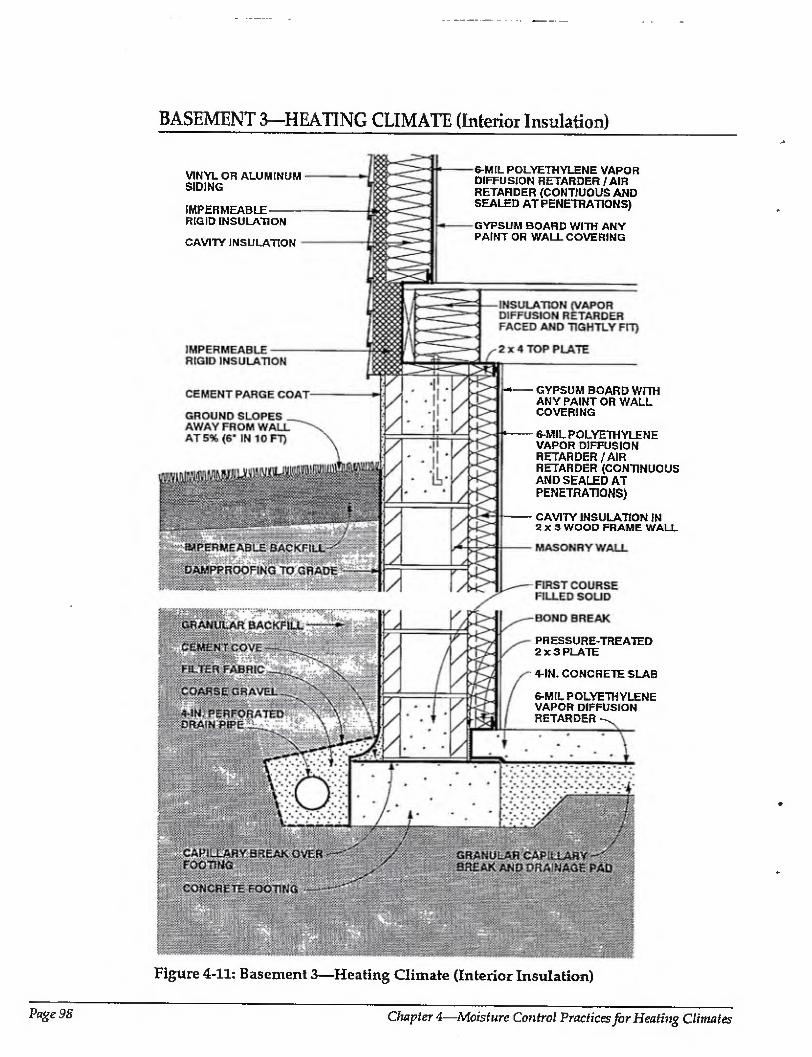
BASEMENT 3—HEATING CLIMATE (Interior Insulation)
VINYL OR ALUMINUM SIDING
IMPERMEABLE- RIGID INSULATION
CAVITY INSULATION
6-MIL POLYETHYLENE VAPOR DIFFUSION RETARDER/AIR RETARDER (CONTJUOUS AND SEALED AT PENETRATIONS)
GYPSUM BOARD WITH ANY PAINT OR WALL COVERING
GYPSUM BOARD WITH ANY PAINT OR WALL COVERING
6-MIL POLYETHYLENE VAPOR DIFFUSION RETARDER/AIR RETARDER (CONTINUOUS AND SEALED AT PENETRATIONS)
CAVITY INSULATION IN 2x3 WOOD FRAME WALL
PRESSURE-TREATED 2x3 PLATE
4-IN. CONCRETE SLAB
6-MIL POLYETHYLENE VAPOR DIFFUSION RETARDER
Figure 4-11: Basement 3—Heating Climate (Interior Insulation)
Page 98 Chapter 4—Moisture Control Practices for Heating Climates
BASEMENT 3—HEATING CLIMATE (CONTINUED)
Basement 3—Heating Climate: Unlike the previous examples, this foundation assembly illustrates a concrete masonry basement wall. Similar to Basement l, cavity insulation in a wood frame wall on the interior of the foundation wall, Cavity insulation is placed between joists on the rim joist interior, and rigid insulation covers the rim joist on the exterior as well. Unlike previous basement wall assemblies, the polyethylene mpor diffusion retarder is continuous from the above-grade wall interior,
through the rim joist area, extending over the basement wall interior, and then beneath the slab. The unique aspect of (his is the rim joist area lohere sufficiently thick rigid insulation on the exterior permits the polyethylene to be placed in the middle of the assembly. The above-grade wall shown here corresponds to Wall 2 in the previous section.
Rain and Groundwater
Gutters and downspouts, along with careful site grading, which direct water away from basement perimeters, should be used to prevent rain and surface water from entering basements. Surface water penetration into the ground immediately adjacent to basements is limited by a cap of impermeable backfill material. A subgrade drainage system controls groundwater entry into basements.
Capillary Suction
Several methods are used to control moisture movement by capillarity into the foundation wall. A dampproof coating is installed on tire exterior of the masonry block foundation wall (bitumen over a cement parge), and a capillary break (dampproofing or polyethylene) is placed over the top of the concrete footing. Alternatively, the footings can be constructed on a granular pad
Moisture movement by capillarity into the concrete floor slab is controlled by installing a granular capillary break under the slab. The break, is a 4-inch- to 6-indr-thick layer of 3/4inch gravel with fines removed.
Air Movement
To limit air leakage openings in this basement, which deal with both exterior and interior moisture-laden air, the floor slab polyethylene vapor diffusion retarder is
sealed to the foundation wall perimeter polyethylene vapor diffusion retarder. In addition the rim joist/floor assembly is wrapped by polyethylene and this polyethylene is sealed to both the foundation wall perimeter vapor diffusion retarder and Ihe above-grade wall vapor diffusion retarder.
Vapor Diffusion
Vapor diffusion may carry moisture into several building components. To prevent moisture from the surrounding soil from entering the masonry block foundation wall, a vapor diffusion retarder is installed on the exterior of the concrete foundation wall. In this example, the dampproofing on the exterior of the concrete foundation wall acts as a vapor diffusion retarder.
Moisture movement from the surrounding soil into the concrete floor slab is controlled by a polyethylene vapor diffusion retarder under the concrete floor slab.
Moisture movement from the interior basement space into the perimeter foundation wall framing is controlled by a polyethylene vapor diffusion retarder on the interior of the perimeter foundation wall framing.
Moisture accumulation from vapor diffusion migrating from within the interior basement space at the rim joist assembly is limited by installing insulating sheathing at tire exterior of the rim joist. This elevates the temperature of the first condensing surface at this location (the interior surface of the rim joist).
Comments
tn this perimeter foundation frame wall assembly, drying towards either the interior or exterior is limited by the impermeability of the perimeter masonry block wall and the interior polyethylene vapor diffusion retarder. Should lire wall assembly become wet during service or be built wet through the use of wet masonry units, wet framing materials, or wet-applied cavity insulations (wet spray cellulose or blown fiberglass), it may not dry. Accordingly, dry framing materials (wood at a moisture content of 19 percent by weight or lower) and dry-applied insulations are recommended. Alternatively,
Moisture Control Handbook Page 99
BASEMENT 3—HEATING CLIMATE (CONTINUED)
wall assemblies should be allowed to dry prior to enclosure.
The perimeter foundation frame wall is held away from the masonry in order to enhance die durability of the wood members. This is accomplished by using a 2 x 4 top plate with 2x3 studs and a 2 x 3 bottom plate. The cavity insulation, however, fills the entire void and touches the interior face of the masonry foundation wall. Fiberglass batt insulation is recommended as the cavity insulation by virtue of its draining characteristics and nonhygroscopic nature.
Interior basement space moisture levels should be limited to 35 percent relative humidity at 70 degrees Fahrenheit during heating periods. This is needed to further control air-transported moisture and vapor diffusion with this wall assembly, since only limited drying of the assembly occurs.
Rigid insulation installed on the exterior of the rim joist assembly elevates the temperature of the first condensing surface during the heating season (the inside face of the rim joist) and thereby limits the potential for condensation at this location. This is facilitated at this location by setting the rim joist assembly in from the face of the masonry block wall to allow space for additional exterior rigid insulation.
Tight-fitting faced insulation should be installed at the interior of the rim joist assembly between floor joists. Gaps at this location in the insulation need to be minimized to control potential convective moisture transfer from the interior basement space to the interior surface of the rim joist.
If convective moisture transfer is inhibited at this location and the facing on the insulation acts as an interior vapor diffusion retarder, the thermal resistance of the rigid insulation on the exterior of the rim joist can be reduced and the thermal resistance of the insulation at the interior of the rim joist can be increased.
Either vapor permeable or vapor impermeable interior surface finishes may be used with this foundation wall assembly.
The concrete floor slab contains significant quantities of moisture when initially placed. Covering this surface with an impermeable surface finish or floor covering may lead to deterioration of these surfaces if the construction moisture is not allowed to dry. Initial drying of the construction moisture contained in concrete may also lead to elevated interior moisture levels during the first few months of occupancy.
Installing carpets on cold, damp, concrete floor slabs can lead to serious allergenic reactions in sensitive individuals and other health-related consequences. It is not recommended that carpets be installed on concrete slabs unless the carpets can be kept dry and warm; that is, carpet relative humidities should be kept below 40 percent [4.2]. In practice this is typically not possible unless floor slab assemblies are insulated and basement areas are conditioned.
The granular drainage pad located under the basement concrete floor slab can be integrated into a subslab ventilation system to control radon migration by adding a vent pipe connected to the surface and an exhaust fan.
Page 2 00 Chapter 4—Moisture Control Practices for Heating Climates
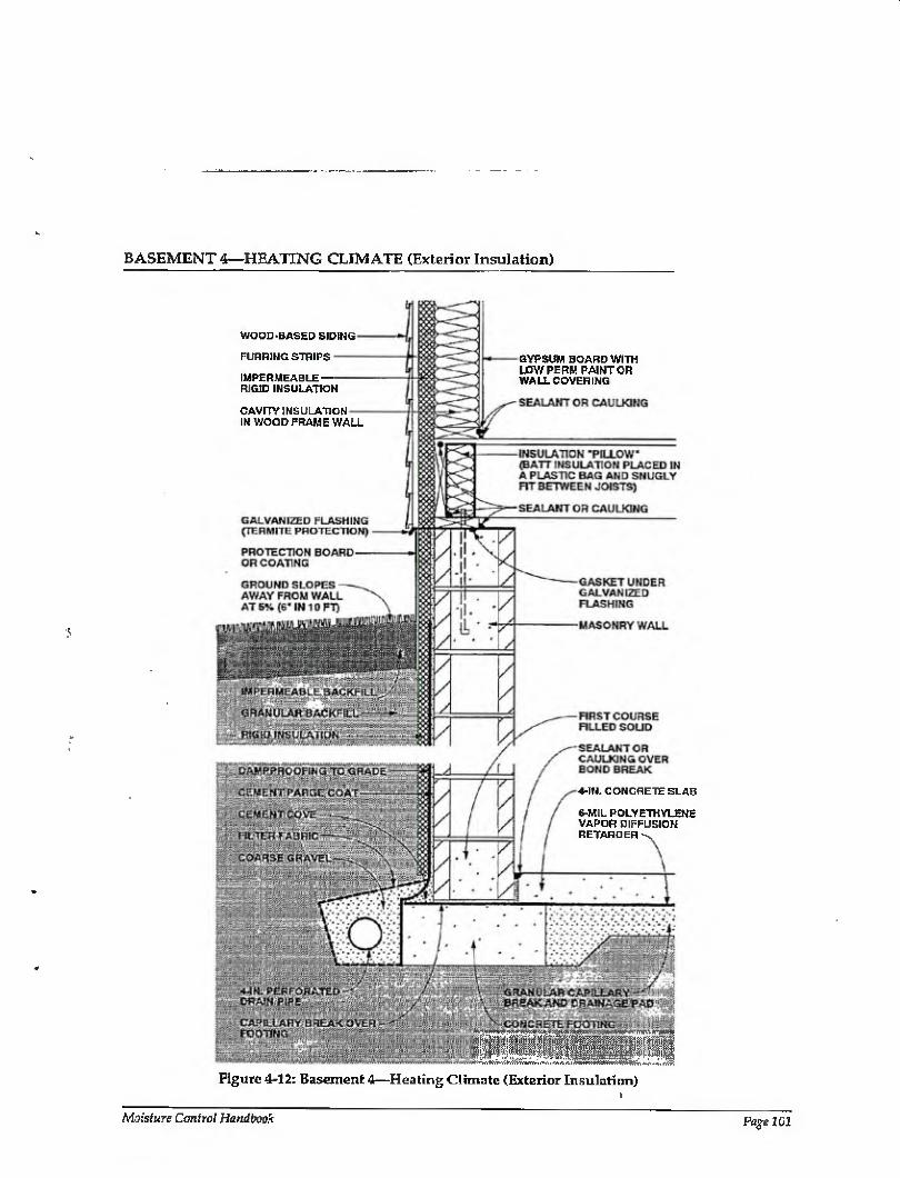
BASEMENT 4—HEATING CLIMATE (Exterior Insulation)
WOOD-BASED SIDING
FURRING STRIPS
IMPERMEABLE RIGID INSULATION
CAVrTY INSULATION IN WOOD FRAME WALL
GYPSUM BOARD WITH LOW PERM PAINT OR WALLCOVERING
4-IN. CONCRETE SLAB
6-MIL POLYETHYLENE VAPOR DIFFUSION RETARDER
--— - — ........... .-V-1...'v.
Figure 4-12: Basement 4—Heating Climate (Exterior Insulation)
Moisture Control Handbook Page 101
BASEMENT 4—HEATING CLIMATE (CONTINUED)
Basement 4—Heating Climate: This concrete masonry basement wall assembly illustrates the use of rigid insulation board on the exterior. This is somewhat similar to basement 2 where a rigid draining fiberglass board is used on the exterior, however granular backfill is necessary in this case (Basement 4) since the rigid insulation has no drainage characteristics. Like all previous foundation assemblies, rigid insulation covers the exterior of the rim joist, and cavity insulation (with a vapor diffusion retarder) is placed between joists on the rim joist interior. The above-grade wall shown here corresponds to Wall 4 in the previous section.
Rain and Groundwater
Gutters, downspouts, and careful site grading, which direct water away from basement perimeters, should be used to prevent rain and surface water from entering basements. Surface water penetration into the ground immediately adjacent to basements is limited by a cap of impermeable backfill material.
A subgrade drainage system controls groundwater entry into basements.
Capillary Suction
Several methods are used to control moisture movement by capillarity into the masonry foundation wall. A dampproof coating is installed on the exterior of the masonry block foundation wall (bitumen over a cement parge), and a capillary break is placed over the top of the concrete footing by extending the basement floor slab polyethylene vapor diffusion retarder. Alternatively, the footings can be constructed on a granular pad.
Moisture movement by capillarity into the concrete floor slab is controlled by installing a granular capillary break under the slab. The break is a 4-inch- to 6-inch-thick layer of 3/4-inch gravel with fines removed.
Air Movement
To limit air leakage openings in this basement, the concrete floor slab is sealed to the perimeter masonry block foundation wall with caulking, the first course of masonry is filled with mortar, and the basement floor slab vapor retarder is extended over the top of the concrete footings. The joints of the
elements which form the sill/rim joist/floor assembly are also sealed.
Vapor Diffusion
Vapor diffusion may carry moisture into several building components. A vapor diffusion retarder on the exterior of the concrete foundation wall controls moisture entering the wall from the surrounding soil. In this example, the dampproofing on the exterior of the concrete foundation wall also acts as a vapor diffusion retarder.
Moisture diffusing into the concrete floor slab is controlled by a polyethylene vapor diffusion retarder under the slab.
Moisture accumulation from vapor diffusion migrating from within the interior basement space at the rim joist assembly is limited by installing insulating sheathing at the exterior of the rim joist. This elevates the temperature of the first condensing surface at this location (the interior surface of the rim joist).
Comments
Rigid insulation is installed on the exterior of the perimeter concrete foundation wall to reduce heating and cooling loads and is protected above grade on its exterior from mechanical damage. This rigid insulation can act as a conduit for insects to enter the enclosure, and as such appropriate flashings or other protection may be necessary.
Rigid insulation installed on the exterior of the rim joist assembly elevates the temperature of the first condensing surface during the heating season (the inside face of the rim joist) and thereby limits the potential for condensation at this location.
A tight-fitting, insulation ,’pillow,, is installed at the interior of the rim joist assembly between floor joists. The insulation pillow is formed by placing batt insulation in a plastic bag and snugly fitting the bag containing the insulation between the floor joists. Gaps at this location around the insulation pillow need to be minimized to control potential convective moisture transfer from the interior basement space to the interior surface of the rim joist. If convective moisture transfer is inhibited at this location and the facing on the insulation acts as an interior vapor diffusion retarder, the thermal resistance of the rigid insulation on the
- n
Page 102 Chapter 4—Moisture Control Practices for Heating Climates
BASEMENT 4—HEATING CLIMATE (CONTINUED)
exterior of the rim joist can be reduced and the thermal resistance of the insulation at the interior of the rim joist can be increased.
The concrete floor slab and perimeter concrete foundation wall contain, significant quantities of moisture when initially placed. Covering these surfaces with impermeable surface finishes or floor coverings may lead to deterioration of these surfaces if the construction moisture is not allowed to dry. Initial drying of the construction moisture contained in concrete may lead to elevated interior moisture levels during the first few months of occupancy.
Installing carpets on cold, damp, concrete floor slabs can lead to serious allergenic
reactions in sensitive individuals and other health-related consequences, It Is not recommended that carpets be installed on concrete slabs unless the carpets can be kept dry and warm; that is, carpet relative humidities should be kept below 40 percent {4.2]. Tn practice this is typically not possible unless floor assemblies are insulated and basement areas are conditioned.
The granular drainage pad located under the basement concrete floor slab can be integrated into a subslab ventilation system to control radon migration by adding a vent pipe connected to the surface and an exhaust fan.
Moisture Control Handbook

BASEMENT 5—HEATING CLIMATE (Interior Insulation)
BRICK VENEER
GALVANIZED NAILS AS BRICK- TIES {PENETRATING SHEATHING TO WOOD FRAMING)
1-IN. AIR SPACE (RAIN SCREEN / PRESSURE EQUALIZED)-
IMPERMEABLE RIGID INSULATION
WEEP HOLES (OPEN VERTICAL JOINT EVERY OTHER BRICK)
GROUND SLOPES AWAY FROM WALL AT 5% (6" IN 10 FT)
IMPERMEABLE BACKFILL
.^GRANULAR BACKFILL1 . :.
FOIL-BACKED GYPSUM BOARD WITH ANY PAINT OR WALL COVERING
CAVITY INSULATION
SEALANT OR CAULKING
SEALANT/CAULKING
IMPERMEABLE RIGID INSULATION
CAVITY INSULATION
GYPSUM BOARD
SEALANT/CAULKING
2x4 TOP PLATE
FOIL-BACKED GYPSUM BOARD
CAVITY INSULATION IN 2 x 3 WOOD FRAME WALL
OPTIONAL DAMPPROOFING TO TOP OF WALL (6-MIL POLY DRAPED FROM UNDER SILL PLATE TO BOTTOM OF WALL)
FLASHING
Figure 4-13: Basement 5—Heating Climate (Interior Insulation)
Page 104 Chapter 4—Moisture Control Practices for Heating Climates
BASEMENT 5—HEATING CLIMATE (CONTINUED)
'Basement 5—Heating Climate: In this example, a concrete baseme?it wall assembly supports a wood frame wall with brick veneer. Similar to Basement 1, there is cavity insulation in a wood frame wall on the interior of the foundation wall. Also, a layer of rigid insulation is shown beneath the concrete floor slab. Rather than a polyethylene sheet on the interior walls,
foil-backed gypsum board is used as a vapor diffusion retarder in both the above- and below- grade wall assemblies. Like all previous foundation assemblies, rigid insulation covers the exterior of the rim joist, and cavity insulation is placed between joists on the rim joist interior. A variation shown here, however, is the use of impermeable rigid insulation as a vapor diffusion retarder inside the rim joist cavity insulation (in place of faced cavity insulation). The above-grade wall shown here is similar to Wall 5 in the previous section, except for the use of impermeable rigid insulation sheathing and foil-backed gypsum board.
Rain and Groundwater
Gutters, downspouts and careful site grading, which direct water away from basement perimeters, should be used to prevent rain and surface water from entering basements.
Surface water penetration into the ground immediately adjacent to basements is limited by a cap of impermeable backfill material.
A subgrade drainage system controls groundwater entry.
In this foundation assembly, rainwater from the above-grade wall assembly controlled by the rain screen must be prevented from draining into the top of the perimeter concrete foundation wall. To do so, flashing is installed at the base of the brick veneer wall extending to the back of the rain screen cavity and up over the top of the concrete foundation wall. This flashing directs water to the exterior of the assembly.
Capillary Suction
Several methods are used to control moisture movement by capillarity into the foundation wall. A dampproof coating is installed on the exterior of the concrete foundation wall, and a capillary break (dampproofing or polyethylene) is placed over the top of the concrete footing.
Alternatively, the footings can be constructed on a granular pad.
Capillary moisture from the concrete foundation wall migrating into the brick veneer is controlled by an impermeable flashing at the base of the brick veneer and the rain screen cavity.
Moisture movement into the concrete floor slab and underslab insulation is controlled by a granular capillary break under the slab. The break is a 4-inch- to 6- inch-thick layer of 3/4-inch gravel with fines removed.
The movement of construction moisture from the concrete foundation wall into the sill/rim joist/floor assembly is controlled by a capillary break at the top of the perimeter concrete foundation wall.
Air Movement
To limit air leakage openings in this basement, which deal with both exterior and interior moisture ■laden air, the floor slab polyethylene vapor diffusion retarder is sealed to the foundation wall perimeter interior gypsum wail board. The foundation perimeter interior gypsum wall board is sealed to the perimeter framing. In addition the rim joist/floor assembly air leakage openings are controlled by installing blocks of rigid insulation between floor joists and seating them to the top of the perimeter basement frame wall and the underside of the subfloor sheathing.
Vapor Diffusion
Vapor diffusion may carry moisture into several building assemblies. A vapor diffusion retarder on the exterior of the concrete foundation wall controls moisture entering the wall from the surrounding soil. In this example, the dampproofing on tire exterior of the concrete foundation wall also acts as a vapor diffusion retarder.
Moisture movement by vapor diffusion from (he surrounding soil into the concrete floor slab is controlled by a polyethylene vapor diffusion retarder under the slab.
Construction moisture in the perimeter concrete foundation wall can be prevented from diffusing into the perimeter wall foundation interior frame wall cavities by a vapor diffusion retarder (dampproofing the interior surface of the perimeter concrete
Moisture Control Handbook Page 105

BASEMENT 5—HEATING CLIMATE (CONTINUED)
foundation wall). Alternatively, the concrete foundation wall can be allowed to dry prior to enclosure.
Two methods control moisture movement by vapor diffusion from the interior basement space into the perimeter foundation wall framing. A vapor diffusion retarder is installed (the foil backing on foil¬ faced gypsum wall board), and interior basement space moisture levels are limited to 35 percent relative humidity at 70 degrees Fahrenheit during heating periods.
Comments
Rigid insulation installed on the exterior of the rim joist assembly elevates the temperature of the first condensing surface during the heating season (the inside face of the rim joist) and thereby limits the potential for condensation at this location.
In this perimeter foundation frame wall assembly, drying towards either the interior or exterior is limited by the impermeability of the perimeter foundation wall concrete and the interior vapor diffusion retarder (foil backing on the interior drywall). Should the wall assembly become wet during service or be built wet due to wet framing materials or wet-applied cavity insulations (wet spray cellulose or blown fiberglass), it may not dry. Accordingly, dry framing materials (wood at a moisture content of 19 percent by weight or lower) and dry-applied insulations are recommended. Alternatively, wall assemblies must be allowed to dry prior to enclosure.
The perimeter foundation frame wall is held away from the concrete in order to enhance the durability of the wood members. This is accomplished by using a 2 x 4 top plate with 2x3 studs and a 2 X 3 bottom plate. The cavity insulation, however, fills
the entire void and touches the interior face of the concrete foundation wall. Fiberglass batt insulation is recommended as the cavity insulation by virtue of its draining characteristics and nonhygroscopic nature.
Interior basement space moisture levels should be limited to 35 percent relative humidity at 70 degrees Fahrenheit during heating periods. This is needed to further control airborne moisture and vapor diffusion with this wall assembly, since only limited drying of the assembly occurs.
Either vapor permeable or vapor impermeable interior surface finishes may be used with this foundation wall assembly.
The concrete floor slab contains significant quantities of moisture when initially placed. Covering this surface with an impermeable surface finish or floor covering may lead to deterioration of these surfaces if the construction moisture is not allowed to dry. Initial drying of the construction moisture contained in concrete may also lead to elevated interior moisture levels during the first few months of occupancy.
Installing carpets on cold, damp, concrete floor slabs can lead to serious allergenic reactions in sensitive individuals and other health-related consequences. It is not recommended that carpets be installed on concrete slabs unless the carpets can be kept dry and warm; that is, carpet relative humidities should be kept below 40 percent [4.2]. In practice this is typically not possible unless floor assemblies are insulated and basement areas are conditioned.
The granular drainage pad located under the basement concrete floor slab can be integrated into a subslab ventilation system to control radon migration by adding a vent pipe connected to the surface and an exhaust fan.
Page 106 Chapter 4—Moisture Control Practices for Heating Climates
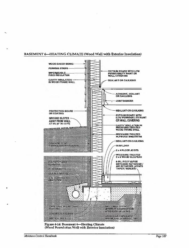
BASEMENT 6—HEATING CLIMATE (Wood Wall with Exterior Insulation)
WOOD-BASED SIDING
FURRING STRIPS -
IMPERMEABLE RIGID INSULATION
CAVITY INSULATION
GYPSUM BOARD WITH LOW PERMEABILITY PAINT OR WALLCOVERING
SEALANT OR CAULKING
ADHESIVE, SEALANT OR CAULKING
-JOIST HANGER
SEALANT OR CAULKING
GYPSUM BOARD WITH LOW PERMEABILITY PAINT OR WALL COVERING
CAVITY INSULATION IN PRESSURE-TREATED WOOD FRAME WALL
PRESSURE-TREATED PLYWOOD SHEATHING
SEALANT OR CAULKING
SUBFLOOR
2x4 FLOOR JOISTS
PRES5U RETREATED 2 X 6 WOOD SLEEPERS
6-MIL POLY VAPOR DIFFUSION RETARDER/ AIR RETARDER (JOINTS TAPED/SEALED)-
Figure 4-14: Basement 6—Heating Climate (Wood Foundation Wall with Exterior Insulation)
Moisture Control Handbook Page 107
BASEMENT 6—HEATING CLIMATE (CONTINUED)
Basement 6—Heating Climate: This pressure-treated wood foundation wall rests on a concrete footing. Cavity insulation is placed within the wood frame wall and draining rigid fiberglass board covers the exterior. A layer of rigid insulation is placed beneath the wood floor. Because of the balloon-style framing at the rim joist, the insulated wood foundation wall extends over the rim joist on the exterior. Rigid insulation covers the rim joist on the exterior as well. Gypsum board with low permeability paint or wall covering serves as a vapor diffusion retarder on the interior side of the wall assembly. The above-grade wall shown here corresponds to Wall 4 in the previous section.
Rain and Groundwater
Gutters, downspouts, and careful site grading, which direct water away from basement perimeters, should be used to prevent rain and surface water from entering basements. Surface water penetration into the ground immediately adjacent to basements is limited by a cap of impermeable backfill material,
A subgrade drainage system controls groundwater entry. This system consists of a drainpipe located at the perimeter of the concrete footings coupled with free-draining insulation board.
Capillary Suction
Several systems are used to control moisture movement by capillarity into the wood foundation wall. Rigid draining fiberglass insulation, which acts as a capillary break, is installed on the exterior of the concrete foundation wall, and a capillary break (dampproofing or polyethylene) is placed over the top of the concrete footing. Alternatively, the footings can be constructed on a granular pad.
Moisture movement by capillarity into the basement wood floor and underslab insulation is controlled by a granular capillary break under the slab. The break is a 4-inch- to 6-inch-thick layer of 3 /4-inch gravel with fines removed.
Air Movement
Where wood foundation wall cavities are insulated, it is important to prevent warm, interior, moisture-laden air from the
basement space from coming in contact with cold sheathing surfaces during both heating and cooling periods.
To limit air leakage openings in this basement, which deal with both exterior and interior moisture-laden air, the floor slab polyethylene vapor diffusion retarder is sealed to the wood foundation wall perimeter interior gypsum wall board. The foundation perimeter interior gypsum wall board is sealed to the perimeter framing. In addition, the rim joist/floor assembly is balloon framed and the perimeter rim joist is sealed to the foundation wall perimeter interior gypsum wall board and to the underside of the subfloor sheathing.
Vapor Diffusion
Vapor diffusion may carry moisture into several building assemblies. A vapor diffusion retarder on the exterior of the wood foundation wall controls moisture entering the wood foundation wall from the surrounding soil- In this example, the impermeability of the sheathing on the exterior of the wood foundation wall also acts as a vapor diffusion retarder.
Moisture diffusing from the surrounding soil into the wood floor framing is controlled by a polyethylene vapor diffusion retarder under the wood floor framing.
Moisture movement from the interior basement space into the perimeter foundation wall framing is controlled by a vapor diffusion retarder at the interior of the framing. In this example, low permeability interior paint acts as the vapor diffusion retarder.
During heating periods, vapor diffusion from the interior may transmit moisture into the wall assembly, where is accumulates. To control this, the temperature of the first condensing surface within the wall assembly is elevated, namely, the cavity side of the exterior wood foundation wall sheathing. In this example a rigid insulation is installed on the exterior of the foundation, which limits periods of potential condensation
Comments
Rigid insulation on the exterior of the rim joist assembly as well as balloon framing this assembly elevates the temperature of potential condensing surfaces during the
Page 108 Chapter 4—Moisture Control Practices for Heating Climates
BASEMENT 6—HEATING CLIMATE (CONTINUED)
heating season (the inside face of exterior wood sheathing, and the inside face of the perimeter rim joist), and thereby limits the potential for condensation at this location. However, thb rigid insulation can act as a conduit for insects to enter the enclosure, and as such appropriate flashings or other protection may be necessary.
In this foundation wall assembly, drying towards either the exterior or interior is limited by the installation of an interior vapor diffusion retarder and an impermeable exterior sheathing (pressure-treated plywood). Should the wait assembly become wet during service, be built wet due to wet framing materials, or became wet due to wet- applied cavity insulations (wet spray cellulose or blown fiberglass), it may not dry. Accordingly, dry framing materials (wood at moisture content of 19 percent by weight or lower) and dry-applied insulations are recommended, Alternatively, wall assemblies could be allowed to dry prior to enclosure.
Interior basement space moisture levels
should be limited to 35 percent relative humidity at 70 degrees Fahrenheit during heating periods. This is needed to further control airborne moisture and vapor diffusion with this basement wall assembly, since only limited drying of the assembly occurs.
The facing material on faced insulations installed with the facing towards the interior of the wall can also act as an interior vapor diffusion retarder, depending on the permeance of the faring material.
The rigid insulation under the basement floor framing requires a compressive strength of 25 psi to control settling. The granular drainage pad located under the basement floor can be integrated into a subslab ventilation system to control radon migration by adding a vent pipe connected to the surface and an exhaust fan.
Readers should also consult the relevant publications of the National Forest Products Association including Permanent Wood Foundation System: Design, Fabrication and Installation Manual [4.4]
Moisture Control Handbook Page i 09
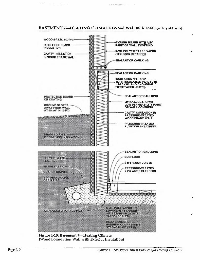
BASEMENT 7—HEATING CLIMATE (Wood Wall with Exterior Insulation)
WOOD-BASED SIDING
RIGID FIBERGLASS INSULATION
CAVITY INSULATION — IN WOOD FRAME WALL
GYPSUM BOARD WITH ANY PAINT OR WALL COVERING
-S-MIL POLYETHYLENE VAPOR DIFFUSION RETARDER
SEALANT OR CAULKING
-SEALANTOR CAULKING
INSULATION "PILLOW -{BATT INSULATION PLACED IN A PLASTIC BAG AND SNUGLY FIT BETWEEN JOISTS)
-SEALANTOR CAULKING
GYPSUM BOARD WITH LOW PERMEABILITY PAINT OR WALL COVERING
CAVITY INSULATION IN PRESSURE-TREATED WOOD FRAME WALL
-PRESSURE-TREATED PLYWOOD SHEATHING
Figure 4-15: Basement 7—Heating Climate (Wood Foundation Wall with Exterior Insulation)
SEALANT OR CAULKING
x 4 FLOOR JOISTS
PRESS URE-TR BATED 2x6 WOOD SLEEPERS
Page 110 Ompter 4—Moisture Control Practices for Heating Climates
BASEMENT 7—HEATING CLIMATE (CONTINUED)
Easement 7—Heating Climate: Similar to Basement 6, this is a pressure-treated wood
foundation wall, Cavity insulation is placed within the wood frame wall and draining rigid fiberglass board corners the exterior. A layer of rigid insulation is placed beneath the wood floor. Unlike Basement 6, Ihis assembly illustrates the wood wall resting directly on a gravel drainage pad rather than on a concrete footing. Another difference is that the rim joist insulation shown Iwre is conventional platform framing rather than the balloon foaming of Basement 6. Cavity insulation is placed between joists on the rim joist interior, and rigid insulation covers the rim joist on the exterior as well Gypsum board with low permeability paint or wall covering serves as a vapor diffusion retarder on the interior side of the basement wall assembly. The above-grade wall shown here corresponds to Wall 3 in the previous section.
Rain and Groundwater
Gutters, downspouts, and careful site trading, which direct water away from basement perimeters, should be used to prevent rain and surface water from entering basements. Surface water penetration into the ground immediately adjacent to basements is limited by a cap of impermeable backfill material.
A subgrade drainage system controis groundwater entry.
Capillary Suction
To control moisture movement by capillarity into the wood foundation wall, rigid draining fiberglass insulation, which acts as a capillary break, is installed on the exterior of the wood foundation wall. A capillary break is installed below the wood footings by constructing the wood footings on a granular pad.
Moisture movement by capillarity into the basement wood floor and underslab insulation is controlled by a granular capillary break under the slab. The break is a 4-inch- to 6-inch-thick layer of 3/4-inch gravel with fines removed.
Air Movement
Air leakage openings in this basement deal with both exterior and interior moisture- laden air. They are Limited by seating the
floor slab polyethylene vapor diffusion retarder to the wood foundation wall perimeter interior gypsum wall board. The foundation perimeter interior gypsum wall board is sealed to the perimeter framing. The joints of the elements that form the sill/rim joist/floor assembly are also sealed.
Vapor Diffusion
Vapor diffusion may carry moisture from several sources into building assemblies. A vapor diffusion retarder on the exterior of the wood foundation wall controls moisture entering the wood foundation from the surrounding soil. In this example, the impermeability of the sheathing on the exterior of the wood foundation wall also acts as a vapor diffusion retarder.
Capillarity moisture moving from the surrounding soil into the wood floor framing is controlled by a polyethylene vapor diffusion retarder under the wood floor framing and over the rigid insulation.
Moisture movement from the interior basement space into the perimeter foundation wall framing is controlled by a vapor diffusion retarder at the interior face of the framing. In this example, low permeability paint acts as a vapor diffusion retarder.
During heating periods, vapor diffusion from the interior carries moisture into the foundation wall assembly, where it accumulates. It is controlled by elevating the temperature of the first condensing surface within the wall assembly, namely, the cavity side of the exterior wood foundation wall sheathing. In this example by installing a rigid insulation is installed on the exterior of the foundation, which limits periods of potential condensation
Comments
Rigid insulation is installed on the exterior of the perimeter wood foundation wall to reduce heating and cooling loads and is protected on its exterior from mechanical damage. This rigid insulation can act as a conduit for insects to enter the enclosure, and as such appropriate flashings or other protection may be necessary.
Rigid insulation installed on the exterior of the rim joist assembly elevates the temperature of the first condensing surface
Moisture Control Handbook PageUl
BASEMENT 7—HEATING CLIMATE (CONTINUED)
during the heating season (the inside face of the rim joist), and thereby limits the potential for condensation at this location.
A tight-fitting, insulation "pillow" is installed at the interior of the rim joist assembly between floor joists. The insulation pillow is formed by placing batt insulation in a plastic bag and snugly fitting the bag containing the insulation between the floor joists. Gaps at this location around the insulation pillow need to be minimized to control potential convective moisture transfer from the interior basement space to the interior surface of the rim joist. If convective moisture transfer is inhibited at this location and the facing on the insulation acts as an interior vapor diffusion retarder, the thermal resistance of the rigid insulation on the exterior of the rim joist can be reduced and the thermal resistance of the insulation at the interior of the rim joist can be increased.
In this foundation wall assembly, drying towards either the exterior or the interior is limited by an interior vapor diffusion retarder and an impermeable exterior sheathing (pressure-treated plywood). Should the wall assembly become wet during service, be built wet through the use of wet framing materials, or become wet due to wet- applied cavity insulations (wet spray cellulose or blown fiberglass), it may not dry.
Accordingly, dry framing materials (wood at moisture content of 19 percent by weight or lower) and dry-applied insulations are recommended. Alternatively, wall assemblies could be allowed to dry prior to enclosure.
Interior basement space moisture levels should be limited to 35 percent relative humidity at 70 degrees Fahrenheit during heating periods. This is needed to further control airborne moisture and vapor diffusion with this basement wall assembly, since only limited drying of the assembly occurs.
The facing material on faced insulations installed with the facing towards the interior of the wall can also act as an interior vapor diffusion retarder, depending on the permeance of the facing material.
The rigid insulation under the basement floor framing requires a compressive strength of 25 psi to control settling. The granular drainage pad located under the basement floor can be integrated into a subslab ventilation system to control radon migration by adding a vent pipe connected to the surface and an exhaust fan.
Readers should also consult the relevant publications of the National Forest Products Association including Permanenf Wood Foundation System: Design, Fabrication and Installation Manual [4.4]
Page 112 Chapter 4—Moisture Control Practices for Heating Climates
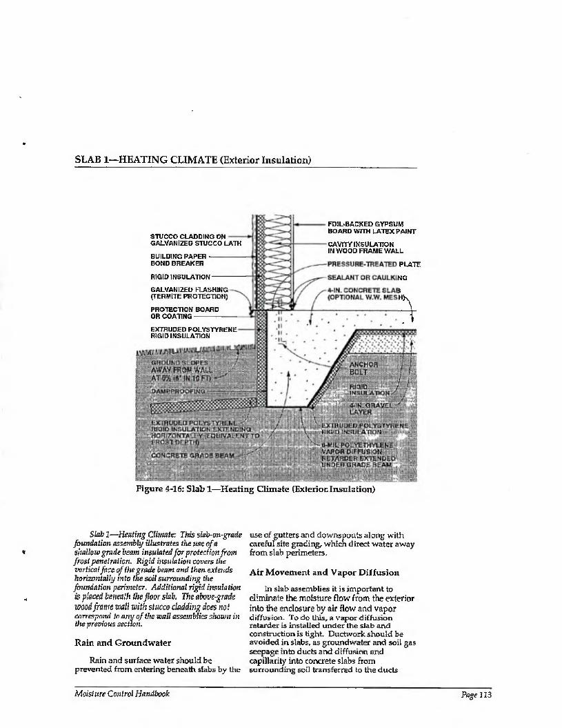
SLAB 1—HEATING CLIMATE (Exterior Insulation)
STUCCO CLADDING ON GALVANIZED STUCCO LATH
BUILDING PAPER BOND BREAKER
RIGID INSULATION-
GALVANIZED FLASHING (TERMITE PROTECTION)
PROTECTION BOARD OR COATING-
EXTRUDED POLYSTYRENE RIGID INSULATION
FOIL-BACKED GYPSUM BOARD WITH LATEX PAINT
CAVITY INSULATION IN WOOD FRAME WALL
PLATE
Figure 4-16: Slab 1—Heating Climate (Exterior. Insulation)
Slab 2—Heating Climate: This siub-on-gratle foundation assetnbly illustrates the use of a shallow grade beam insulated for protection from frost penetration. Rigid insulation covers the vertical face of the grade beam and then extends horizontally into the soil surrounding the foundation perimeter. Additional rigid insulation is placed beneath the floor slab. The above-grade wood frame wall with stucco cladding dees not correspond to any of the wall assemblies shown in the previous section.
Rain and Groundwater
Rain and surface water should be prevented from entering beneath slabs by the
use of gutters and downspouts along with careful site grading, which direct water away from slab perimeters.
Air Movement and Vapor Diffusion
In slab assemblies it is important to eliminate the moisture flow from the exterior into the enclosure by air flow and vapor diffusion. To do this, a vapor diffusion retarder is installed under the slab and construction is tight. Ductwork should be avoided in slabs, as groundwater and soil gas seepage into ducts and diffusion and capillarity into concrete slabs from surrounding soil transferred to the ducts
Moisture Control Handbook Page ] 13
SLAB 1—HEATING CLIMATE (CONTINUED)
often become significant sources of moisture to the enclosure.
Capillary Suction
Moisture movement by capillarity into the slab from the ground is controlled by the placement of a capillary break, in this case the granular layer under the slab. Where slab construction is utilized with a perimeter concrete grade beam, the slab vapor diffusion retarder is extended under the concrete grade beam to act as a capillary break at this location. Furthermore, dampproofing is installed on the exterior of the perimeter of the grade beam also to act as a capillary break. This dampproofing, if it is fluid or spray applied, must be chemically compatible with any rigid insulation installed over it.
Comments
Rigid insulation is installed on the exterior of the perimeter foundation assembly to reduce cooling loads and is protected above grade on its exterior from mechanical damage. This rigid insulation can act as a conduit for insects to enter the enclosure, and as such appropriate flashings or other protection may be necessary.
Perimeter rigid insulation installed horizontally protects this foundation assembly from frost. The rigid insulation should extend horizontally a distance equivalent to the depth of local frost
penetration and have a minimum thermal resistance determined by the local freezing degree days [4.3]. In addition, the rigid insulation should resist capillarity effects and be sufficiently protected from mechanical damage during construction and during service. Specific information regarding frost- protected slab foundations should be obtained from local authorities.
The concrete floor slab contains significant quantities of.moisture when initially placed. Covering this surface with an impermeable surface finish or floor covering may lead to deterioration of these surfaces if the construction moisture is not allowed to dry. Initial drying of the construction moisture contained in concrete may also lead to elevated interior moisture levels during the first few months of occupancy.
Installing carpets on cold, damp, concrete floor slabs can lead to serious allergenic reactions in sensitive individuals and other health-related consequences. It is not recommended that carpets be installed on concrete slabs unless the carpets can be kept dry and warm; that is, carpet relative humidities should be kept below 40 percent [4.2]. In practice this is typically not possible unless floor assemblies are insulated and floor areas are conditioned.
The granular drainage pad located under the concrete floor slab can also be integrated into a subslab ventilation system to control radon migration, adding a vent pipe connected to the surface and an exhaust fan.
Page 114 Chapter 4—Moisture Control Practices for Heating Climates
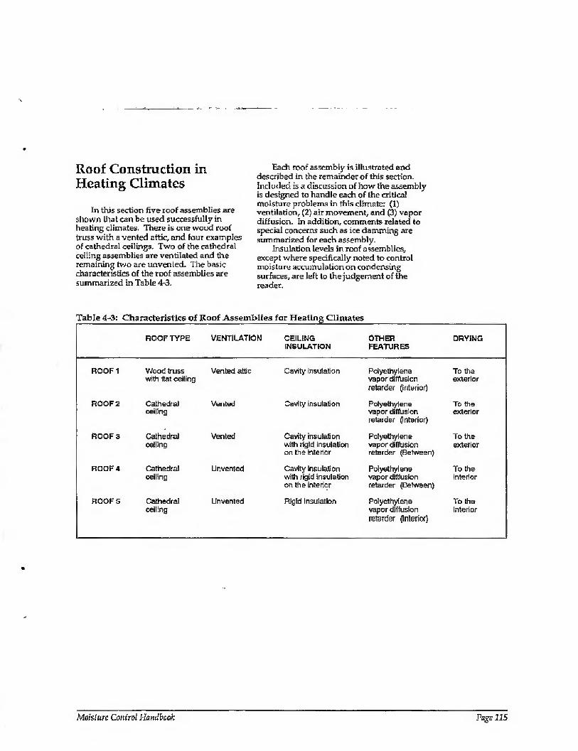
Roof Construction in Heating Climates
In this section five roof assemblies are shown (hat can be used successfully in healing climates. There is one wood roof truss with a vented attic, and four examples of cathedral ceilings. Two of the cathedral ceiling assemblies are ventilated and the remaining two are unvented. The basic characteristics of the roof assemblies are summarized in Table 4-3.
Each roof assembly is illustrated and described in the remainder of this section, included is a discussion of how the assembly is designed to handle each of the critical moisture problems in this climate: (1) ventilation, (2) air movement, and (3) vapor diffusion. In addition, comments related to special concerns such as ice damming are summarized for each assembly.
Insulation levels in roof assemblies, except where specifically noted to control moisture accumulation on condensing surfaces, are left to the judgement of the reader.
ROOF TYPE VENTILATION CEILING OTHER DRYING INSULATION FEATURES
ROOF 1 Wood truss Vented attic with flat ceiling
Cavity insulation Polyethylene To the vapor diffusion exterior retarder (Interior)
ROOF 2 Cathedral Vented ceiling
Cavity insulation Polyethylene To the vapor diffusion exterior retarder (Interior)
ROOF 3 Cathedral Vented ceiling
Cavity insulation with rigid insulation on the intenor
Polyethylene To the vapor diffusion exterior retarder (Between)
ROOF 4 Cathedral ceiling
Unvented Cavity insulation Polyethylene To the with rigid insulation vapor diffusion interior on the interior retarder (Between)
ROOF 5 Cathedral Unvented ceiling
Rigid Insulation Polyethylene To the vapor diffusion interior retarder (Interior)
Moisture Control Handbook Page 215

ROOF 1—HEATING CLIMATE (Vented Attic)
INSULATION WIND BAFFLE 2-IN. MINIMUM SPACE
WATER PROTECTION MEMBRANE (ICE DAM PROTECTON)
CONTINUOUS SOFFIT VENT
VINYL OR ALUMINUM SIDING
IMPERMEABLE RIGID INSULATION
CAVITY INSULATION
CONTINUOUS CEILING VAPOR DIFFUSION RETARDER / AIR RETARDER SEALED TO PERIMETER WALL VAPOR DIFFUSION RETARDER / AIR BARRIER (6-MIL POLYETHYLENE)
CEIUNG INSULATION
6-MIL POLYETHYLENE VAPOR DIFFUSION RETARDER /AIR RETARDER (CONTINUOUS AND SEALED AT ALL PENETRATIONS)
GYPSUM BOARD WITH ANY PAINT OR WALL COVERING
Figure 4-17: Roof 1—Heating Climate (Vented Attic)
Roof 1—Heating Climate: This conventional
wood truss roof system is uisulated above the flat ceiling. The attic space is ventilated. A polyethylene vapor diffusion retarder is placed above the ceiling gypsum board on the interior side of the insulation. The wall shown here corresponds to Wall 2 in a previous section of this chapter.
Ventilation
Roof assemblies in this climate are ventilated to remove moisture from attic spaces and, to a limited extent, to reduce cooling loads by reducing solar heat gain through the assembly. Ventilation should be provided, at a minimum, according to the 1/
300 ratio, where 1 square foot of vent area is provided for every 300 square feet of insulated ceiling area. In addition, vents should be distributed between the soffit and ridge to prevent zones of dead or stagnation air and should not be blocked by roof assembly insulation or other obstructions.
Air Movement
In vented roof assemblies it is important to eliminate air flow between conditioned spaces and the attic. The attic needs to be uncoupled from the conditioned space so that conditions within the building enclosure influence the attic to a minimum. This is best accomplished by not installing any forced air
Page 236 Chapter A—Moisture Control Practices for Heating Climates
ROOF 1—HEATING CLIMATE (CONTINUED)
ductwork, furnaces, or air conditioners in attics. In addition, penetrations for plumbing, wiring, dropped ceilings, and kitchen cabinet bulkheads should be sealed.
To control airborne moisture exfiltrating during the heating season, from the enclosure into the attic, the enclosure is depressurized relative to the attic and the exterior, and air leakage openings are limited (tight ceiling construction).
Vapor Diffusion
Moisture movement by diffusion during the heating season from the enclosure into the attic is retarded by a continuous ceiling vapor diffusion retarder sealed to the perimeter wall vapor diffusion retarder.
Comments
A wind baffle should be installed at the perimeter of the roof area where the insulated ceiling intersects the exterior wall to prevent thermal short-circuiting of the insulation by wind (wind-washing). In this climate, wind-washing during the heating
season can cool the perimeter wall top plate and ceiling gypsum board surfaces, subsequently causing interior mold and mildew growth.
Exterior ventilation air entering soffit assemblies experiences a pressure drop, as the soffit assembly acts as an expansion space. This is due to the combination of a narrow soffit vent opening up to a relatively large volume soffit assembly and then being squeezed into a narrow space between the underside of the roof sheathing and the wind baffle. This pressure drop induces the ventilation air to deposit airborne rain droplets and snow in the soffit assembly rather than transport them farther into the roof assembly. Accordingly, it may be desirable to back prime wood soffit materials.
Ice damming in this climate is controlled by a water protection membrane at the eve and by providing sufficient thermal insulation and air tightening at the intersection of the perimeter wall and ceiling to reduce heat loss, which can lead to snow melt. In addition, the soffit assembly is vented to flush heat from the conditioned space away from the roof sheathing to maintain a cold deck.
Moisture Control Handbook Page 117
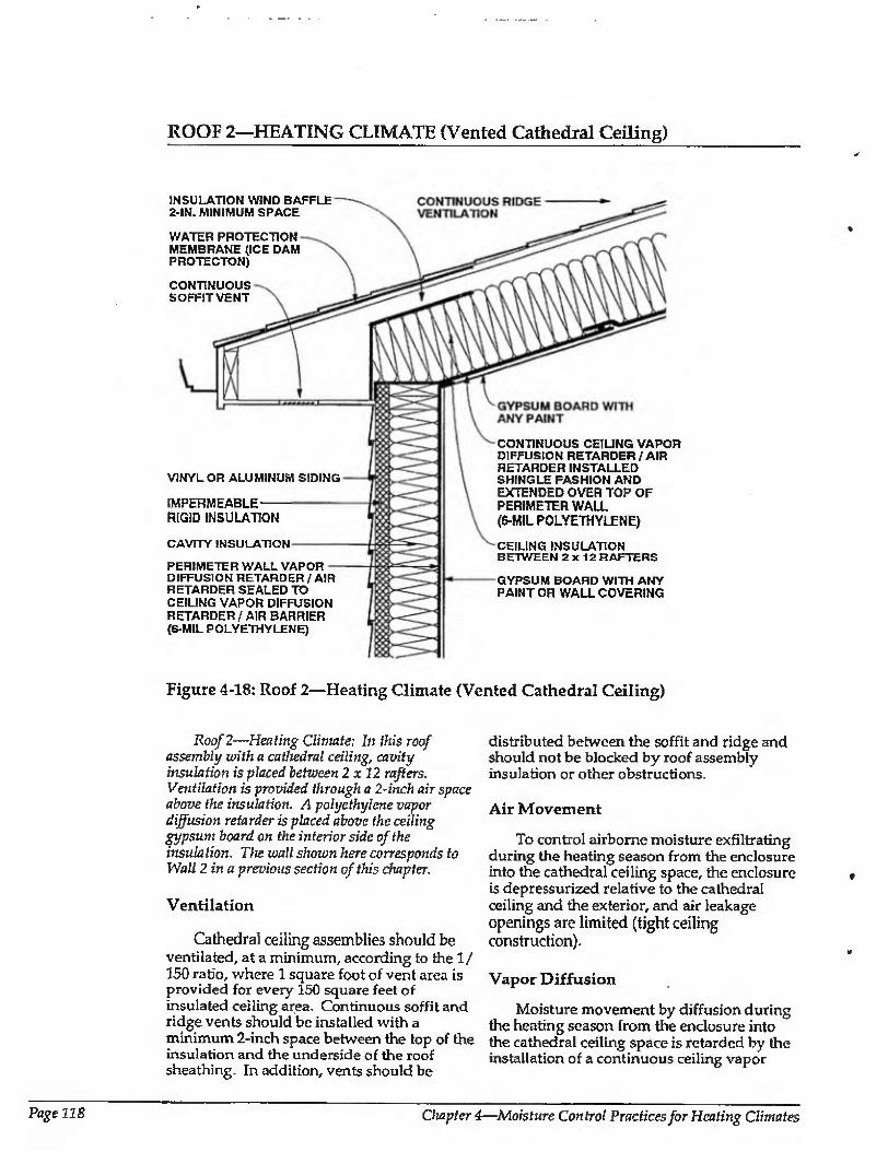
ROOF 2—HEATING CLIMATE (Vented Cathedral Ceiling)
INSULATION WIND BAFFLE 2-tN. MINIMUM SPACE
WATER PROTECTION MEMBRANE (ICE DAM PROTECTON)
CONTINUOUS SOFFIT VENT
VINYL OR ALUMINUM SIDING
IMPERMEABLE RIGID INSULATION
CAVITY INSULATION
PERIMETER WALL VAPOR DIFFUSION RETARDER / AIR RETARDER SEALED TO CEILING VAPOR DIFFUSION RETARDER / AIR BARRIER (6-MIL POLYETHYLENE)
CONTINUOUS CEILING VAPOR DIFFUSION RETARDER / AIR RETARDER INSTALLED SHINGLE FASHION AND EXTENDED OVER TOP OF PERIMETER WALL (6-MIL POLYETHYLENE)
CEILING INSULATION BETWEEN 2x12 RAFTERS
GYPSUM BOARD WITH ANY PAINT OR WALL COVERING
Figure 4-18: Roof 2—Heating Climate (Vented Cathedral Ceiling)
Roof 2—Heating Climate; In this roof assembly with a cathedral ceiling, cavity insulation is placed between 2x12 rafters. Ventilation is provided through a 2-inch airspace above the insulation. A polyethylene vapor diffusion retarder is placed above the ceiling gypsum board on the interior side of the insulation. The wall shown here corresponds to Wall 2 in a previous section of this chapter.
Ventilation
Cathedra] ceiling assemblies should be ventilated, at a minimum, according to the 1/ 150 ratio, where 1 square foot of vent area is provided for every 150 square feet of insulated ceiling area. Continuous soffit and ridge vents should be installed with a minimum 2-inch space between the top of the insulation and the underside of the roof sheathing. In addition, vents should be
distributed between the soffit and ridge and should not be blocked by roof assembly insulation or other obstructions.
Air Movement
To control airborne moisture exfiltrating during the heating season from the enclosure into the cathedral ceiling space, the enclosure is depressurized relative to the cathedral ceiling and the exterior, and air leakage openings are limited (tight ceiling construction).
Vapor Diffusion
Moisture movement by diffusion during the heating season from the enclosure into the cathedral ceiling space is retarded by the installation of a continuous ceiling vapor
»
Page 118 Chapter 4—Moisture Control Practices for Heating Climates
ROOF 2—HEATING CLIMATE (CONTINUED)
diffusion retarder sealed to the perimeter wall vapor diffusion retarder.
Comments
The continuous ceiling vapor diffusion retarder is installed shingle fashion and extended over the top of the exterior perimeter wall to allow for drainage of any condensed moisture on the top surface and to provide secondary protection for roof rainwater leakage.
A wind baffle should be installed at the perimeter of the cathedral ceiling area where the insulated cathedral ceiling intersects the exterior wall to prevent thermal short- circuiting of the insulation by wind (wind¬ washing). In this climate, wind-washing during the heating season can cool the perimeter wall top plate and ceiling gypsum board surfaces, subsequently causing interior mold and mildew growth.
Exterior ventilation air entering soffit assemblies experiences a pressure drop, as the soffit assembly acts as an expansion space. This is due to the combination of a narrow soffit vent opening up to a relatively large volume soffit assembly and then being squeezed into a narrow space between the underside of the roof sheathing and the wind baffle. This pressure drop induces the ventilation air to deposit airborne rain droplets and snow in the soffit assembly rather than transport them farther into the roof assembly. Accordingly, it may be desirable to back prime wood soffit materials.
Ice damming in this dimate is controlled by a water protection membrane at the eve and by providing sufficient thermal insulation and air tightening at the intersection of the perimeter wall and ceiling to reduce heal loss, which can lead to snow melt. In addition, the soffit assembly is vented to flush heat from the conditioned space away from the roof sheathing to maintain a cold deck.
Moisture Control Handbook Page 119
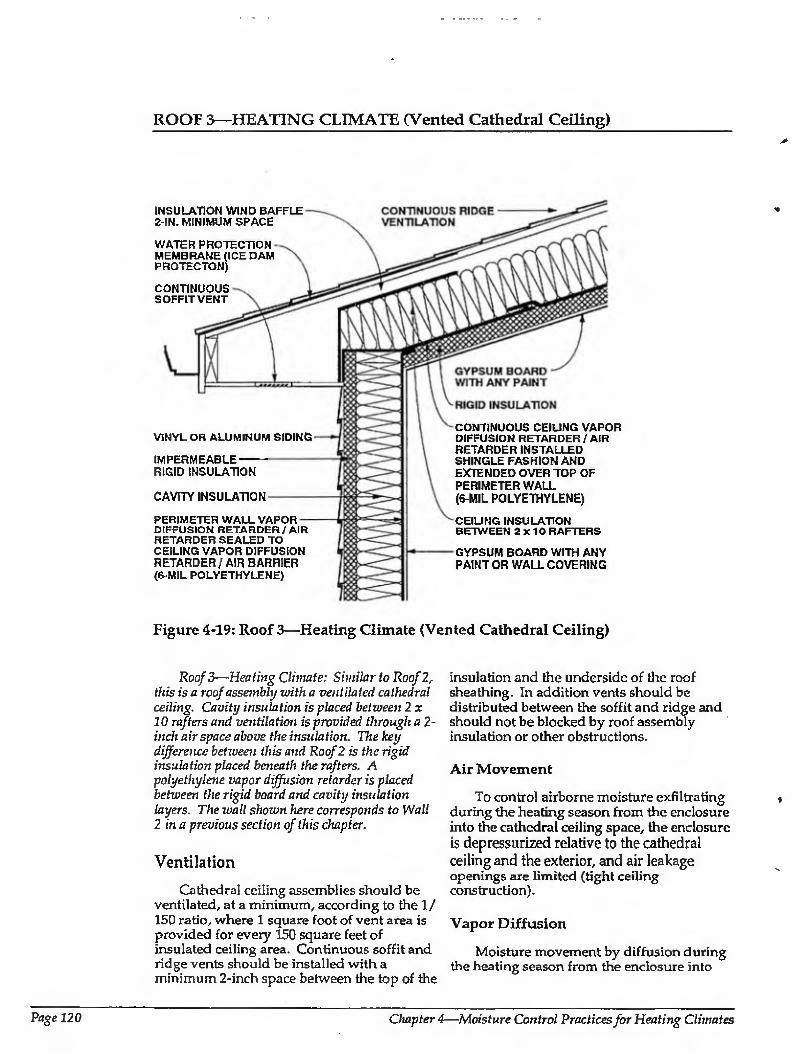
ROOF 3—HEATING CLIMATE (Vented Cathedral Ceiling)
INSULATION WIND BAFFLE 2-IN. MINIMUM SPACE
WATER PROTECTION MEMBRANE (ICE DAM PROTECTON)
CONTINUOUS SOFFIT VENT
VINYL OR ALUMINUM SIDING
IMPERMEABLE RIGID INSULATION
CAVITY INSULATION
PERIMETER WALL VAPOR DIFFUSION RETARDER/AIR RETARDER SEALED TO CEILING VAPOR DIFFUSION RETARDER/AIR BARRIER (6-MIL POLYETHYLENE)
CONTINUOUS CEILING VAPOR DIFFUSION RETARDER/AIR RETARDER INSTALLED SHINGLE FASHION AND EXTENDED OVER TOP OF PERIMETER WALL (6-MIL POLYETHYLENE)
CEILING INSULATION BETWEEN 2x10 RAFTERS
GYPSUM BOARD WITH ANY PAINT OR WALL COVERING
Figure 4-19: Roof 3—Heating Climate (Vented Cathedral Ceiling)
Roof 3—Heating Climate: Similar to Roof 2, this is a roof assembly with a ventilated cathedral ceiling. Cavity insulation is placed between 2 x 10 rafters and ventilation is provided through a 2- inch air space above the insulation. The key difference behueen this and Roof 2 is the rigid insulation placed beneath the rafters. A polyethylene vapor diffusion retarder is placed between the rigid board and cavity insulation layers. The wall shown here corresponds to Wall 2 in a previous section of this chapter.
Ventilation
Cathedra! ceiling assemblies should be ventilated, at a minimum, according to the 1 / 150 ratio, where 1 square foot of vent area is provided for every 150 square feet of insulated ceiling area. Continuous soffit and ridge vents should be installed with a minimum 2-inch space between the top of the
insulation and the underside of the roof sheathing. In addition vents should be distributed between the soffit and ridge and should not be blocked by roof assembly insulation or other obstructions.
Air Movement
To control airborne moisture exfiltrating during the heating season from the enclosure into the cathedral ceiling space, the enclosure is depressurized relative to the cathedral ceiling and the exterior, and air leakage openings are limited (tight ceiling construction).
Vapor Diffusion
Moisture movement by diffusion during the heating season from the enclosure into
Page 120 Cltapter4—Moisture Control Practices for Heating Climates
ROOF 3—HEATING CLIMATE (CONTINUED)
the cathedral ceiling space is retarded by a continuous ceiling vapor diffusion retarder sealed to the perimeter wall vapor diffusion retarder.
Comments
The continuous ceding vapor diffusion retarder is installed shingle fashion and extended over the top of the exterior perimeter wail. This allows any condensed moisture to drain and provides secondary protection for roof rainwater leakage.
In this vented cathedral ceiling, rigid insulation on the interior side of the roof rafters beneath the sheet polyethylene vapor diffusion retarder provides additional thermal resistance. In cases where the rigid insulation is impermeable, the sheet polyethylene ceiling vapor retarder is replaced by the rigid insulation alone. It is installed in a continuous fashion (edges sealed) and sealed to the perimeter wall vapor diffusion retarder or air retarder.
In cases where attachment of the interior- applied rigid insulation and ceiling gypsum board is a concern, the rigid insulation can be held in place by furring (installed to the interior of the rigid insulation), and the gypsum board subsequently fastened to the furring.
A wind baffle should be installed at the
perimeter of the cathedral ceiling area where the insulated cathedral ceiling intersects the exterior wall to prevent thermal short- circuiting of the insulation by wind (wind- washing). In this climate, wind washing by cold air during the heating season can cool the perimeter wall top plate and ceiling gypsum board surfaces, subsequently causing interior mold and mildew growth.
Exterior ventilation air entering soffit assemblies experiences a pressure drop, as the soffit assembly acts as an expansion space- This is due to the combination of a narrow soffit vent opening up to a relatively large volume soffit assembly and then being squeezed into a narrow space between the underside of the roof sheathing and the wind baffle. This pressure drop induces the ventilation air to deposit airborne rain droplets and snow in the soffit assembly rather than transport them farther into the roof assembly. Accordingly, it may be desirable to back prime wood soffit materials.
Ice damming in this climate is controlled by a water protection membrane at the eve and by providing sufficient thermal insulation and air tightening at the intersection of the perimeter wall and ceiling to reduce heat loss, which can lead to snow melt. In addition, the soffit assembly is vented to flush heat from the conditioned space away from the roof sheathing to maintain a cold deck.
Moisture Control Handbook Page 121
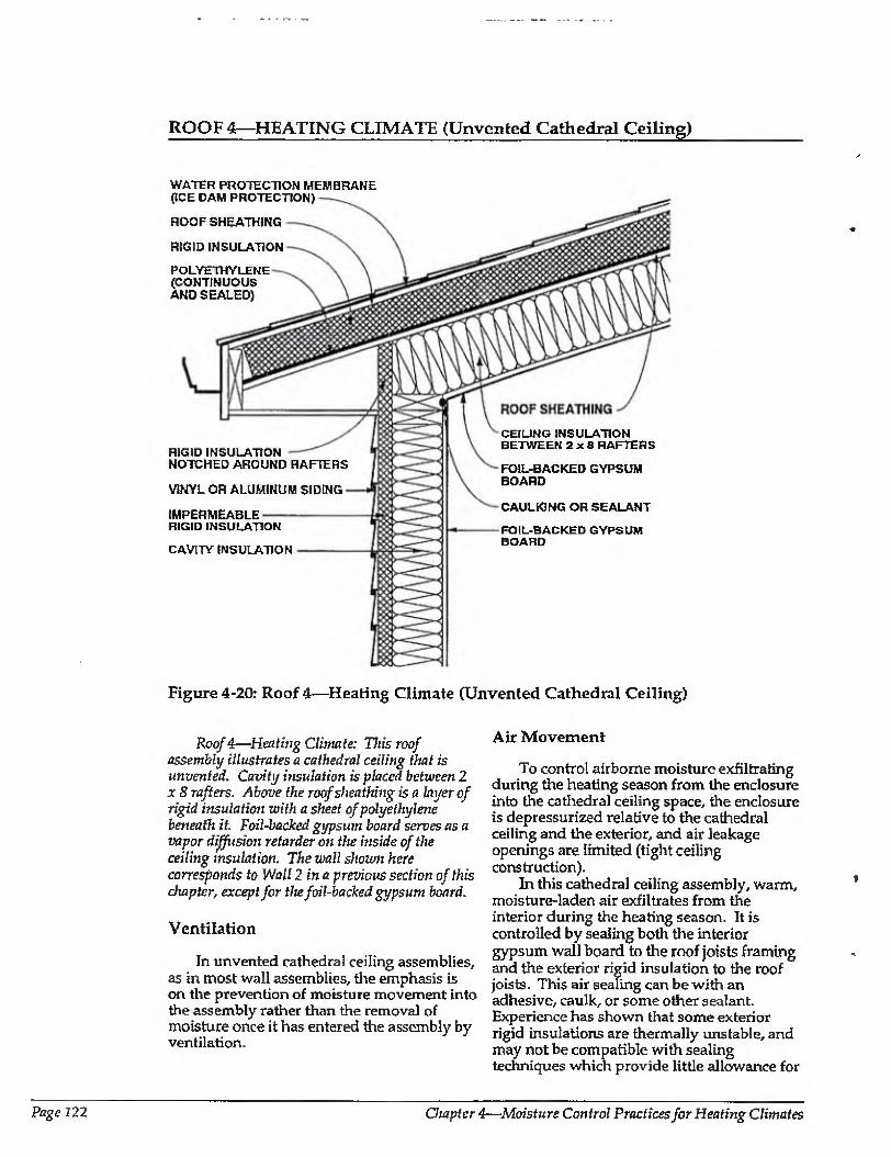
ROOF 4—HEATING CLIMATE (Unvenfced Cathedral Ceiling)
WATER PROTECTION MEMBRANE {ICE DAM PROTECTION)
ROOF SHEATHING
RIGID INSULATION
POLYETHYLENE (CONTINUOUS AND SEALED)
RIGID INSULATION NOTCHED AROUND RAFTERS
VINYL OR ALUMINUM SIDING
IMPERMEABLE RIGID INSULATION
CAVITY INSULATION
CEILING INSULATION BETWEEN 2x8 RAFTERS
FOIL-BACKED GYPSUM BOARD
CAULKING OR SEALANT
FOIL-BACKED GYPSUM BOARD
Figure 4-20: Roof 4—Heating Climate (Unvented Cathedral Ceiling)
Roof 4—Heating Climate: This roof assembly illustrates a cathedral ceiling that is unvented. Cavity insulation is placed between 2 x 8 rafters. Above the roof sheathing is a layer of rigid insulation with a sheet of polyethylene beneath it. Foil-backed gypsum board serves as a vapor diffusion retarder on the inside of the ceiling insulation. The wall shown here corresponds to Wall 2 in a previous section of this chapter, except for the foil-backed gypsum board.
Ventilation
In unvented cathedral ceiling assemblies, as in most wall assemblies, the emphasis is on the prevention of moisture movement into the assembly rather than the removal of moisture once it has entered the assembly by ventilation.
Air Movement
To control airborne moisture exfiltrating during the heating season from the enclosure into the cathedral ceiling space, the enclosure is depressurized relative to the cathedral ceiling and the exterior, and air leakage openings are limited (tight ceiling construction).
In this cathedral ceiling assembly, warm, moisture-laden air exfiltrates from the interior during the heating season. It is controlled by sealing both the interior gypsum wall board to the roof joists framing and the exterior rigid insulation to the roof joists. This air sealing can be with an adhesive, caulk, or some other sealant. Experience has shown that some exterior rigid insulations are thermally unstable, and may not be compatible with sealing techniques which provide little allowance for
Page 122 Chapter 4—Moisture Control Practices for Heating Climates
ROOF 4—HEATING CLIMATE (CONTINUED)
movement. Accordingly, polyethylene is installed under the rigid insu3ariony and the joints in the roof sheathing installed over the rigid insulation are staggered over the joints in the rigid insulation to enhance air tightness.
Vapor Diffusion
A vapor diffusion retarder at the interior of the cathedra] ceiling assembly controls vapor diffusion from the interior during heating periods. In this example the foil backing on the ceiling gypsum board acts as the vapor diffusion retarder.
During heating periods, vapor diffusion from the interior may carry moisture into the wall assembly, where it accumulates. This is controlled by elevating the temperature of the first condensing surface within the cathedral ceiling assembly, namely, the cavity side of the roof sheathing. In this example rigid insulation is installed to limit periods of potential condensation.
Comments
In this cathedral ceiling assembly, drying towards either the interior or exterior is limited by the vapor impermeable rigid insulation and an interior vapor diffusion retarder.
Should the cathedral celling assembly be built wet through the use of wet framing materials or webappited cavity insulations (wet spray cellulose or blown fiberglass), it may not dry. Accordingly, dry framing materials (wood at a moisture content of 19 percent by weight or lower) and dry- applied insulations are recommended. Alternatively, cathedra] ceiling assemblies should be allowed to dry prior to enclosure.
Interior moisture levels should be limited to 35 percent relative humidity at 70 degrees
Fahrenheit during heating periods. This is needed to further control airborne moisture and vapor diffusion with this cathedral ceiling assembly, since only limited drying of the assembly occurs.
A wind baffle should be installed at the perimeter of the cathedral ceiling area where lire insulated cathedra] ceiling intersects the exterior wall. Tills prevents thermal short- circuiting of the insulation by wind (wind- washing). In this climate, wind-washing bv hot, humid air during the cooling season can induce moisture deposition on perimeter wail top plate and ceiling gypsum board surfaces cooled by air conditioning. Wind-
. washing by cold air during the heating season can cool the perimeter wall top plate and ceiling gypsum board surfaces and cause subsequent interior mold and mildew growth. In this particular example, extending the exterior rigid insulation on the perimeter wall up so that it intersects the underside of the rigid insulation installed on top the roof joists will effectively control wind-washing. The rigid insulation installed in the roof assembly is typically fastened with long wood screws passing through the upper roof sheathing.
Ice damming in this climate is controlled by a water protection membrane at the eve and by providing sufficient thermal insulation and air tightening at the intersection of the perimeter wall and ceiling to reduce heat loss, which can lead to snow melt.
Some unvented roof assemblies have led to an elevation of shingle/ shake/sheathing temperatures and subsequently to premature degradation of shingles/shakes/sheathings and a reduced service life [4.5]. Accordingly, light- colored shakes and shingles should be utilized, fn addition, it may be desirable to install roofing papers to provide additional protection against rainwater entry should shakes and shingles deteriorate prematurely.
Moisture Control Handbook Page 123
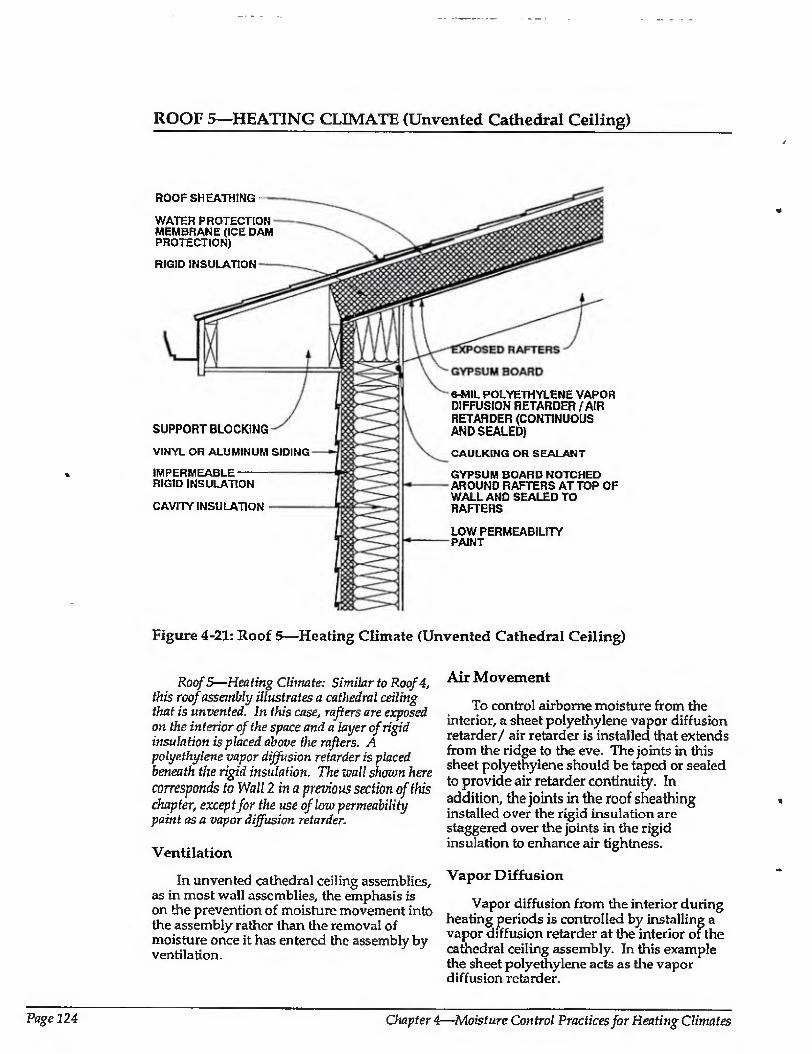
ROOF 5—HEATING CLIMATE (Unvented Cathedral Ceiling)
ROOF SHEATHING
WATER PROTECTION MEMBRANE (ICE DAM PROTECTION)
RIGID INSULATION
SUPPORT BLOCKING
VINYL OR ALUMINUM SIDING
IMPERMEABLE RIGID INSULATION
CAVITY INSULATION
a-MIL POLYETHYLENE VAPOR DIFFUSION RETARDER/AIR RETARDER (CONTINUOUS AND SEALED)
CAULKING OR SEALANT
GYPSUM BOARD NOTCHED AROUND RAFTERS AT TOP OF WALLAND SEALED TO RAFTERS
LOW PERMEABILITY PAINT
Figure 4-21: Roof 5—Heating Climate (Unvented Cathedral Ceiling)
Roof 5—Heating Climate: Similar to Roof 4, this roof assembly illustrates a cathedral ceiling that is unvented. In this case, rafters are exposed on the interior of the space and a layer of rigid insulation is placed above the rafters. A polyethylene vapor diffusion retarder is placed beneath the rigid insulation. The mall shown here
corresponds to Wall 2 in a previous section of this chapter, except for the use of low permeability paint as a vapor diffusion retarder.
Ventilation
In unvented cathedral ceiling assemblies, as in most wall assemblies, the emphasis is on the prevention of moisture movement into the assembly rather than the removal of moisture once it has entered the assembly by ventilation.
Air Movement
To control airborne moisture from the interior, a sheet polyethylene vapor diffusion retarder/ air retarder is installed that extends from the ridge to the eve. The joints in this sheet polyethylene should be taped or sealed to provide air retarder continuity. In addition, the joints in the roof sheathing installed over the rigid insulation are staggered over the joints in the rigid insulation to enhance air tightness.
Vapor Diffusion
Vapor diffusion from the interior during heating periods is controlled by installing a vapor diffusion retarder at the interior of the cathedral ceiling assembly. In this example the sheet polyethylene acts as the vapor diffusion retarder.
Page 124 Chapter 4—Moisture Control Practices for Heating Climates
ROOF 5—HEATING CLIMATE (CONTINUED)
Coimnents
In this cathedral ceiling assembly, the rafters are exposed to facilitate drying of the wood framing towards the interior. The rigid insulation installed in the roof assembly is typically fastened with long wood screws passing through the upper roof sheathing.
Ice damming in this dimate is controlled by a water protection membrane at the eve and by providing sufficient thermal insulation and air tightening at the intersection of the perimeter wall and ceiling to reduce heat loss, which can lead to snow melt.
Some unvemcd roof assemblies have led to an elevation of shingle/slrake/sheathing temperatures and subsequently to premature degradation of shingles/shakes/sheathings and a reduced service life. Accordingly, light- colored shakes and shingles should be utilized. In addition, it may be desirable to install roofing papers to provide additional protection against rainwater entry should shakes and shingles deteriorate prematurely. Rigid insulation is fastened with5- to 6-inch wood screws penetrating into the rafters.
CHAPTER 4: REFERENCES
4.1 Carmody,J.,J. Christian, and K. Labs, Builder's Foundation Handbook, Oak Ridge National Laboratory, ORNL/ CON-295,1991.
4.2 Godish, T., Indoor Air Pollution Control, Lewis Publishers, Chelsea, Michigan, 1989.
4.3 National Association of Home Builders, Frost-Protected Shallow Foundations: Design Details Developed by the Norwegian Building Research Institute, NAHB Research Center, Upper Marlboro, Maryland, January 1988.
4.4 National Forest Products Association, Permanent Wood Foundation System: Design, Fabrication and Installation Manual, Washington, D.C., 1987.
4.5 Rose, W., "More Data on Shingle Overheating with Unvented Roofs", Energy Design Update, March 1991.
Moisture Control Handbook Page 125
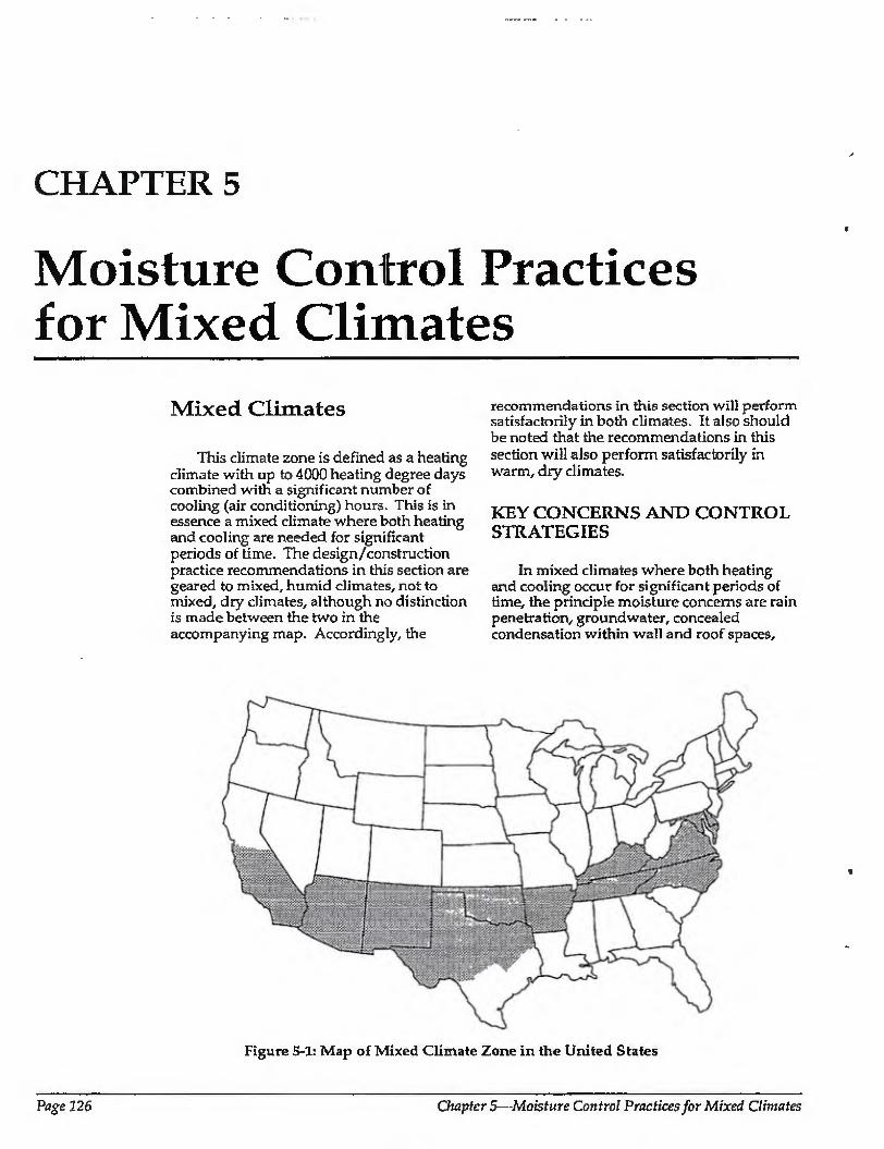
CHAPTER 5
Moisture Control Practices for Mixed Climates
Mixed Climates
This climate zone is defined as a heating climate with up to 4000 heating degree days combined with a significant number of cooling (air conditioning) hours. This is in essence a mixed climate where both heating and cooling are needed for significant periods of time. The design/construction practice recommendations in this section are geared to mixed, humid climates, not to mixed, dry climates, although no distinction is made between the two in the accompanying map. Accordingly, the
recommendations in this section will perform satisfactorily in both climates. It also should be noted that the recommendations in this section will also perform satisfactorily in warm, dry climates.
KEY CONCERNS AND CONTROL STRATEGIES
In mixed climates where both heating and cooling occur for significant periods of time, the principle moisture concerns are rain penetration, groundwater, concealed condensation within wall and roof spaces.
Figure 5-1: Map of Mixed Climate Zone in the United States
Page 126 Chapters—-Moisture Control Practices for Mixed Climates
and interior mold and mildew. High interior leveia of humidity during heating periods encourage mold and mildew growth, as do high exterior levels of humidity and cool interior surfaces due to the air conditioning of enclosures during cooling periods.
Due to shallow ground frost penetration, this climate is marked by a mix of basement foundations and frost- protected crawl spaces. Concrete and masonry foundations are common, with some limited use of wood foundations and wood crawl spaces. Frame walls predominate.
Rain and Groundwater
Rain penetration and groundwater concerns are common to builders in all climates, and control methods in this climate are similar to those of other climates. These include the rain screen; building papers; appropriate placement of flashings, gutters, and downspouts to direct water away from foundations; careful site grading; and subgrade drainage.
Basement spaces are typically conditioned and occupied. Concerns with groundwater penetration and infiltration of soil gas and radon are common with this type of construction.
Another source of externai water—air conditioning condensate drains—should be plumbed directly to the graywater system.
Condensation within Building Assemblies
Conditioned spaces are heated by both electric and fuel-fired appliances. Traditional negative interior air pressures have been reduced as a result of the trend away from active chimneys towards high efficiency combustion appliances and electric heat sources. When combined with the trend towards tighter enclosures, reduced air change, and higher levels of interior moisture, concerns have grown about air ex filtration leading to condensation within insulated assemblies. Reduced air change and resultant higher levels of interior moisture have also led to elevated incidences of interior surface mold and mildew during heating periods.
During cooling periods, mechanical cooling coupled with dehumidification is widespread. Air movement and vapor diffusion thus carry moisture from the exterior to the interior cooled area, because
outdoor vapor pressure is higher than indoor vapor pressure. These vapor pressure differences during cooling periods in this climate can be greater than the indoor to outdoor vapor pressure differences during heabng periods in this same climate.
High inward flow of moisture during cooling periods can increase energy costs due to high cooling loads, as well as increase building fabric deterioration from decay and corrosion and health and safety concerns from mold and mildew growth.
Leakage of warm, interior moisture¬ laden air during heating periods into insulated attics, coupled with insufficient attic ventilation, can lead to roof sheathing decay. T eakage of this warm air into insulated wall cavities, coupled with an insufficient or limited drying ability, can also lead to decay of structural framing members.
Moisture can move by air leakage, Le., the exfiltration of interior moisture-laden air during heating periods and the infiltration of exterior moisture-laden air during cooling periods. Several methods are used to control this movement: air leakage openings are limited; the above-grade conditioned space is depressurized during heating periods; the above-grade conditioned space is pressurized during cooling periods; and interior moisture levels during heating periods are controlled by ventilation (dilution by air change) combined with source control (direct venting of clothes dryers as well as the use of subgrade vapor relarders under concrete floor slabs, and bath and kitchen exhaust systems). In addition, interior moisture levels are controlled during cooling periods by the dehumidification capabilities of mechanical cooling systems and by limiting controlled ventilation to minimum values established by indoor air quality concerns.
Moisture movement by vapor diffusion from the interior and from the exterior is controlled by vapor diffusion retarders in walls, roofs, and foundations.
Cladding systems which can absorb significant amounts of moisture when exposed to rain, such as brick, masonry, wood, and stucco, should only be incorporated in certain wall assemblies. Such assemblies are designed and built to deal with the inward migration of moisture driven by temperature gradients from the exterior to the interior. Solar radiation warming exterior wall surfaces creates those gradients, along with the air conditioning of interior surfaces. Problems often arise where this is not taken
Moisture Control Handbook Page 327
into account, such as the installation of vinyl- wallpaper-covered gypsum wall board on the interior of a masonry block wall without provision for an appropriate vapor diffusion retarder and air barrier system. The retarder and barrier protect the gypsum wall board from this exterior moisture or from construction moisture, which may be trapped in the masonry units.
Thus, wherever vinyl interior wall coverings are used in this climate zone, precautions must be taken to prevent the gypsum wall board from absorbing moisture from the exterior or construction moisture.
Where wet lumber (greater than 19 percent moisture content by weight) or wet- applied insulations (wet spray cellulose or wet blown fiberglass) are installed in building assemblies, those assemblies must be designed and built so that they can dry to the exterior or interior, or the materials must be allowed to dry prior to enclosure.
High Interior Humidity Resulting in Mold and Mildew
Without a controlled ventilation system, moisture levels within the conditioned space can be elevated during the heating months as a result of a low air change rate. These elevated levels can cause condensation on window surfaces and give rise to surface mold and mildew and concealed condensation within walls and roof spaces.
If thermal bridges or other thermal defects such as wind blowing through insulation create cold interior surface during heating months, interior surfaces will have high relative humidities, and mold and mildew will often grow at these locations. Most common locations are where exterior walls intersect insulated ceilings, exterior comers, and uninsulated (or poorly insulated) window lintels or headers.
Low air change during heating periods due to tight enclosures can elevate interior moisture. Cold air is not capable of holding as much moisture as warm air, so cold air is typically dryer. During heating periods, cold, dry air from the exterior infiltrates through random leakage openings in building enclosures or is brought into the building by controlled ventilation. This cold, dry air is subsequently heated by the enclosure's heating system and becomes capable of holding appreciable amounts of moisture. Should moisture be available, it is picked up by this heated, dry air. This
heated air, now containing moisture, exfiltrates to the exterior ^trough other random leakage openings, or is deliberately exhausted by controlled ventilation.
Air change (infiltration/exfiltration combined with controlled ventilation) removes moisture from within building enclosures during heating periods. The greater the air change rate during heating periods, the greater the removal rate of interior moisture. Typical construction practice results in building enclosures which have air change rates inadequate to control interior moisture levels by random leakage alone. As such, during heating periods it is desirable to ventilate enclosures in a controlled manner.
High air change during cooling periods due to infiltration/exfiltration, duct leakage, and excessive ventilation can lead to elevated interior moisture levels. This is due to high exterior humidity conditions during the cooling season. The greater the amount of exterior air brought into an enclosure during cooling periods, the greater the amount of moisture brought in with it. As such, in mixed climates it is desirable to build tight enclosures and ventilate them during cooling periods with outside air at a minimum, controlled rate. Minimum ventilation rates typically are established by indoor air quality issues and are often stipulated by ASHRAE guidelines, the strength of pollutant sources within enclosures, and/or local authorities [5.1].
Humidity within conditioned spaces is controlled during heating periods by the dilution of interior moisture (air change) along with controlled mechanical ventilation and source control- During cooling periods humidity is controlled by the dehumidification capabilities of air conditioning systems and source control. Since latent cooling loads on air conditioning systems can be higher than sensible cooling loads, proper sizing of air conditioning systems, with consideration of dehumidification capabilities, is important. Oversizing of air conditioning equipment can lead to high interior humidity problems, because oversized equipment will not operate as often, and therefore will dehumidify less than properly sized equipment.
Page 128 Chapters—Moisture Control Practices for Mixed Climates
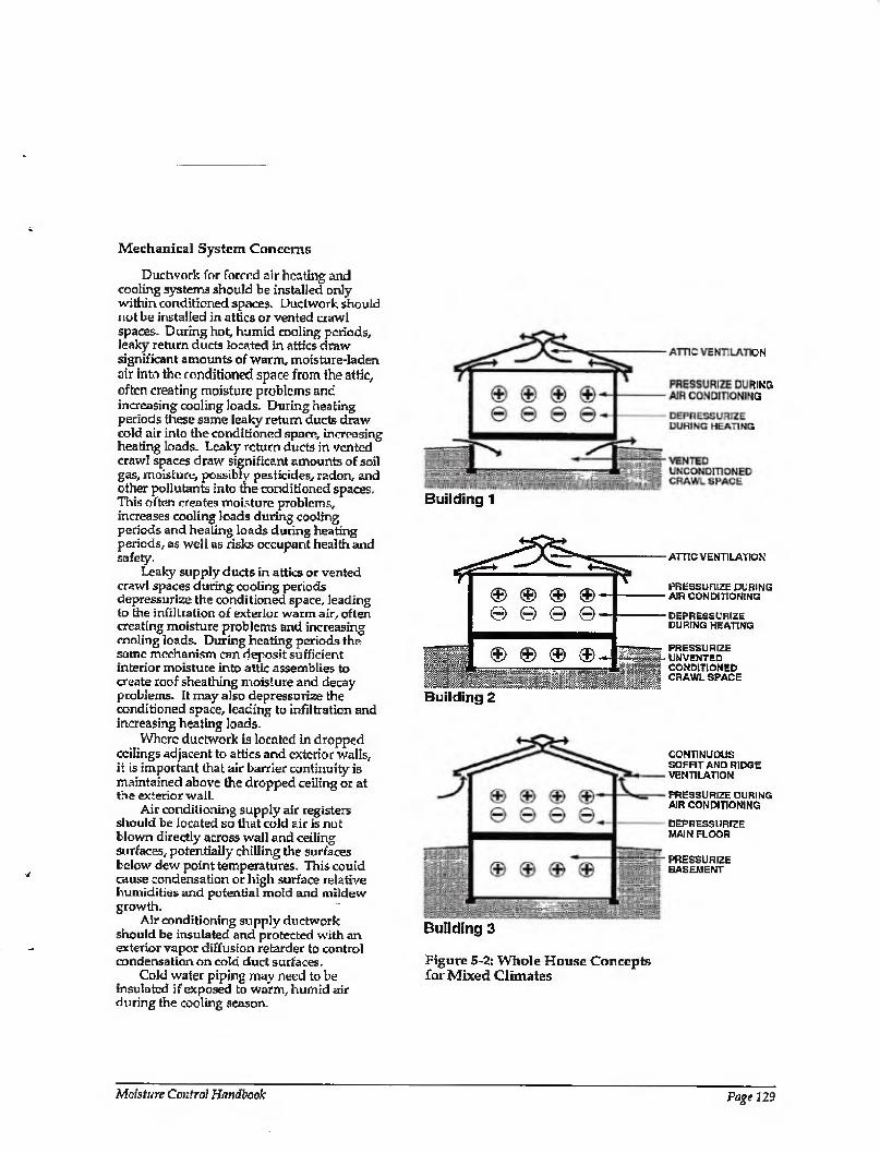
Mechanical System Concerns
Ductwork for forced air heating and cooling systems should be installed only within conditioned spaces. Ductwork should not be installed in attics or vented crawl spaces. During hot, humid coaling periods, leaky return ducts located in attics draw significant amounts of warm, moisture-laden air into the conditioned space from the attic, often creating moisture problems and increasing cooling loads. During heating periods these same leaky return ducts draw cold air into the conditioned space, increasing heating loads. Leaky return ducts in vented crawl spaces draw significant amounts of soil gas, moisture, possibly pesticides, radon, and other pollutants into toe conditioned spaces. This often creates moisture problems, increases coaling loads during cooling periods and heating loads during heating periods, as well as risks occupant health and safely.
Leaky supply ducts in attics or vented crawl spaces during cooling periods depressurize the conditioned space, leading to the infiltration of exterior warm air, often creating moisture problems and increasing cooling loads. During heating periods the same mechanism can deposit sufficient interior moisture into attic assemblies to create roof sheathing moisture and decay problems. It may also depressurize the conditioned space, leading to infiltration and increasing heating loads.
Where ductwork is located in dropped ceilings adjacent to attics and exterior walls, it is important that air barrier continuity is maintained above the dropped ceiling or at the exterior wall.
Air conditioning supply air registers should be located so that cold air is not blown directly across wall and ceiling surfaces, potentially chilling the surfaces below dew point temperatures. This could cause condensation or high surface relative humidities and potential mold and mildew growth.
Air conditioning supply ductwork should be insulated and protected with an exterior vapor diffusion retarder to control condensation on cold duct surfaces.
Cold water piping may need to be insulated if exposed to warm, humid air during the cooling season.
Building 1
® ® ® © © © ©-
€> ® ® I Mumm Building 2
ATTIC VENTILATION
PRESSURIZE DURING AIR CONDITIONING
DEPRESSURIZE DURING HEATING
PRESSURIZE UNVENTED CONDITIONED CRAWL SPACE
CONTINUOUS SOFFIT AND RIDGE VENTILATION
PRESSURIZE DURING AIR CONDITIONING
DEPRESSURIZE MAIN FLOOR
PRESSURIZE BASEMENT
Building 3
Figure 5-2: Whole House Concepts for Mixed Climates
Moisture Control Handbook Page 129
Combustion Appliances
Unvented combustion appliances such as gas stoves with standing pilot lights and room space heaters are significant sources of moisture as well as sources for other pollutants and should be avoided. Gas stoves and cook tops without standing pilot lights should be installed with vented range hoods or some other vent provision.
Where vented combustion appliances are installed they should be aerodynamically uncoupled (not influenced by enclosure air pressures or supply air availability) from the conditioned space. In other words, sealed combustion, power vented, induced draft, condensing, or pulse combustion devices should be used. Devices with traditional draft hoods should be avoided. Fireplaces should have their own air supply from the exterior as well as tight-fitting glass doors. Wood stoves should also have their own supply of exterior air ducted directly to their firebox.
WHOLE BUILDING SYSTEMS
Three examples of desirable whole building systems for this climate zone are (see Figure 5-2):
1. Buildings with vented, unconditioned crawl spaces and vented attics
2. Buildings with unvented, conditioned crawl spaces and vented attics
3. Buildings with basements and vented cathedral ceilings
Common features of the three systems are basement spaces and crawl spaces maintained at a positive air pressure to the exterior. Above-grade spaces are maintained at a negative air pressure to the exterior during heating periods and at a positive air pressure to the exterior during cooling periods. Vented roofs are also common to the three systems.
Positive pressurization of the basement spaces and crawl spaces eliminates the infiltration of soil gas, radon, and other pollutants- Depressurization of the above- grade conditioned spaces during heating periods eliminates the exfiltration of interior moisture-laden air. Pressurization of the above-grade conditioned space during cooling periods eliminates the infiltration of exterior moisture-laden air.
Ventilation of roof assemblies removes moisture continuously during heating months and intermittently during cooling months.
Wall design and construction in this climate locates vapor diffusion retarders and measures to control air leakage towards both the exterior and interior. In this climate it is convenient to allow walls to dry to either the interior or the exterior.
Page ISO Chapters—Moisture Control Practices for Mixed Climates
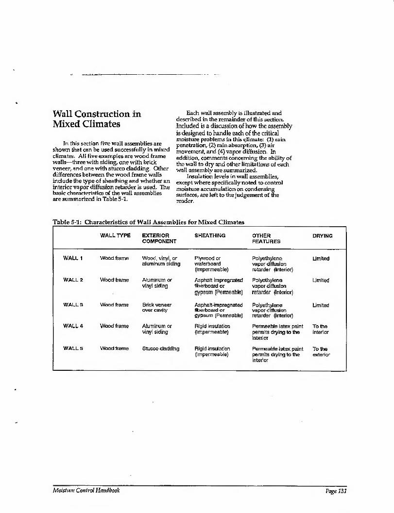
Wall Construction in Mixed Climates
In this section five wall assemblies are shown that can be used successfully in mixed climates. All five examples are wood frame walls—three with siding, one with brick veneer, and one with stucco cladding. Other differences between the wood frame walls include the type of sheathing and whether an interior vapor diffusion retarder is used. The basic characteristics of the wall assemblies are summarized in Table5-1.
Each wall assembly is illustrated and described in the remainder of this section. Included is a discussion of how the assembly is designed to handle each of the critical moisture problems in this climate: (1) rain
penetration, (2) rain absorption, (3) air movement, and (4) vapor diffusion. In addition, comments concerning the ability of the wall to dry and other limitations of each wall assembly are summarized.
Insulation levels inwall assemblies, except where specifically noted to control moisture accumulation on condensing surfaces, are left to the judgement of the reader.
Table 5-1: Characteristics of Wall Assemblies for Mixed Climates
WALL TYPE EXTERIOR SHEATHING COMPONENT
OTHER FEATURES
DRYING
WALL 1
WALL 2
WALL 3
WALL 4
WALLS
Wood frame
Wood frame
Wood, vinyl, or aluminum siding
Aluminum or vinyl siding
Plywood or waferboard (Impermeable)
Asphalt-impregnated fiberhoard cr gypsum (Permeable)
Polyethylene vapor diffusion retarder (Interior)
Polyethylene vapor diffusion retarder (interior)
Limited
Limited
Wood frame Brick veneer over cavity
Asphalt-impregnated Polyethylene Limited fiberboard or vapor diffusion gypsum (Permeable) retarder (interior)
Wood frame Aluminum or vinyt siding
Rigid insulation Permeable latex pant To the (Impermeable) permits drying to the interior
interior
Wood frame Stucco cladding Rigid insulation (Impermeable)
Permeable latex paint To the permits drying to the exterior interior
Moisture Control Handbook Page 131
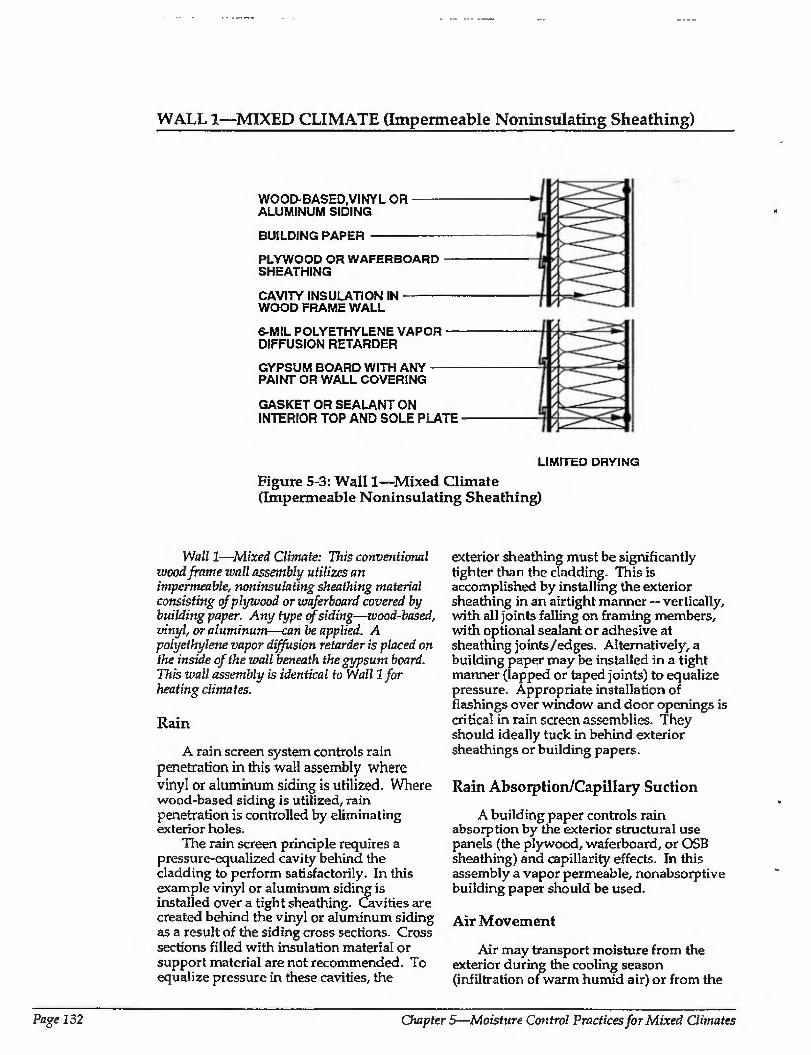
WALL 1—MIXED CLIMATE (Impermeable Noninsulating Sheathing)
WOOD-BASED,VINYL OR- ALUMINUM SIDING
BUILDING PAPER -
PLYWOOD OR WAFERBOARD — SHEATHING
CAVITY INSULATION IN-- WOOD FRAME WALL
6-MIL POLYETHYLENE VAPOR — DIFFUSION RETARDER
GYPSUM BOARD WITH ANY- PAINT OR WALL COVERING
GASKET OR SEALANT ON INTERIOR TOP AND SOLE PLATE
LIMITED DRYING
Figure 5-3: Wall 1—Mixed Climate (Impermeable Noninsulating Sheathing)
Wall 1—Mixed Climate: This conventional wood frame wall assembly utilizes an impermeable, noninsulating sheathing material consisting of plywood orwaferboard covered by building paper. Any type of siding—wood-based, vinyl, or aluminum—can be applied. A polyethylene vapor diffusion retarder is placed on the inside of the wall beneath the gypsum board. This wall assembly is identical to Wall 1 for heating climates.
Rain
A rain screen system controls rain penetration in this wall assembly where vinyl or aluminum siding is utilized. Where wood-based siding is utilized, rain penetration is controlled by eliminating exterior holes.
The rain screen principle requires a pressure-equalized cavity behind the cladding to perform satisfactorily. In this example vinyl or aluminum siding is installed over a tight sheathing. Cavities are created behind the vinyl or aluminum siding as a result of the siding cross sections. Cross sections filled with insulation material or support material are not recommended. To equalize pressure in these cavities, the
exterior sheathing must be significantly tighter than the cladding. This is accomplished by installing the exterior sheathing in an airtight manner — vertically, with all joints failing on framing members, with optional sealant or adhesive at sheathing joints/edges. Alternatively, a building paper may be installed in a tight manner (lapped or taped joints) to equalize pressure. Appropriate installation of flashings over window and door openings is critical in rain screen assemblies. They should ideally tuck in behind exterior sheathings or building papers.
Rain Absorption/Capillary Suction
A building paper controls rain absorption by the exterior structural use panels (the plywood, waferboard, or OSB sheathing) and capillarity effects. In this assembly a vapor permeable, nonabsorptive building paper should be used.
Air Movement
Air may transport moisture from the exterior during the cooling season (infiltration of warm humid air) or from the
Page 132 Chapters—Moisture Control Practices for Mixed Climates
WALL 1—MIXED CLIMATE (CONTINUED)
interior during the heating season {exfiltration of warm moisture-laden interior air). To control this moisture, an air seal (air retarder) is installed at either the interior or exterior of the wall. In this assembly either the exterior structural use panels {the plywood, waferboard, or OSB sheathing) are sealed to the wall framing, or the interior gypsum wall board or polyethylene vapor diffusion retarder is sealed to the wall framing. This can be accomplished with adhesive, caulk, or some other sealant. An exterior air seal at the exterior structural use panels in this example would equalize the exterior air space pressure.
Vapor Diffusion
During cooling periods, vapor diffusion from the exterior is controlled by a vapor diffusion retarder on the exterior of the wall. Structural use panels such as plywood, waferboard, or OSB sheathings are impermeable and act as effective vapor diffusion retarders.
During heating periods, vapor diffusion from the interior is controlled by a vapor diffusion retarder at the interior of the wall. In this example a continuous polyethylene
sheet is installed between the interior gypsum board and the wall framing and acts as the vapor diffusion retarder.
Comments
In this wall assembly, drying towards either the interior or exterior is limited by a vapor impermeable exterior sheathing and an interior vapor diffusion retarder. Should the wall assembly become wet during service or be built wet through the use of wet framing materials or wet-applied cavity insulations (wet spray cellulose or blown fiberglass), it may not dry. Accordingly, dry framing materials (wood at a moisture content of 19 percent by weight or lower) and dry- applied insulations are recommended. Alternatively, wall assemblies must be allowed to dry prior to enclosure.
Either vapor permeable or vapor impermeable interior surface finishes may be used with this wall assembly. Where wood siding is utilized over plywood, waferboard, or OSB sheathing, it is recommended to utilize dry materials, back-prime the siding, and nail according to manufacturer's recommended installation practices.
Moisture Control Handbook Page 233
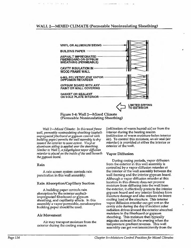
WALL 2—MIXED CLIMATE (Permeable Noninsulating Sheathing)
VINYL OR ALUMINUM SIDING
BUILDING PAPER -
ASPHALT IMPREGNATED- FIBERBOARD OR GYPSUM SHEATHING (PERMEABLE)
CAVITY INSULATION IN- WOOD FRAME WALL
6-MIL POLYETHYLENE VAPOR DIFFUSION RETARDER
GYPSUM BOARD WITH ANY PAINT OR WALL COVERING
GASKET OR SEALANT ON SOLE PLATE INTERIOR
Figure 5-4: Wall 2—Mixed Climate (Permeable Noninsulating Sheathing)
LIMITED DRYING TO EXTERIOR
Wall 2—Mixed Climate: In this xvood frame wall, permeable noninsidating sheathing (asphalt- impregnated fiberboard or gypsum covered with building paper) permits the wall assembly to dry toward the exterior to sortie extent. Vinyl or aluminum siding is applied over the sheathing. Similar to Wall 1, a polyethylene vapor diffusion retarder is placed on the inside of the wall beneath the gypsum board.
Rain
A rain screen system controls rain penetration in this wall assembly.
Rain Absorption/Capillary Suction
A building paper controls rain absorption by the exterior asphalt- impregnated fiberboard or gypsum sheathing, and capillarity effects. In this assembly a vapor permeable, nonabsorptive building paper should be used.
Air Movement
Air may transport moisture from the exterior during the cooling season
(infiltration of warm humid air) or from the interior during the heating season (exfiltration of warm moisture-laden interior air). To control this moisture, an air seal (air retarder) is provided at either the interior or exterior of the wall.
Vapor Diffusion
During cooing periods, vapor diffusion from the exterior in this wall assembly is controlled by a vapor diffusion retarder at the interior of the wall assembly between the wall framing and the interior gypsum board. Although a vapor diffusion retarder at this location in this climate does not prevent moisture from diffusing into the wall from the exterior, it effectively protects the interior gypsum board and any interior finishes from moisture damage and also reduces the latent cooling load of the structure. This interior vapor diffusion retarder can get wet on the cavity side during the day if incident solar radiation drives inward the exterior absorbed moisture in the fiberboard or gypsum sheathing. This moisture then typically migrates outward in the evening when the temperature gradient reverses. This wall assembly can get wet intermittently from the
Page 134 Chapter 5—Moisture Control Practices for Mixed Climates
WALL 2—MIXED CLIMATE (CONTINUED)
exterior as well as dry intermittently to the exterior. Since intermittent wetting of the vapor diffusion retarder may occur, this interior vapor diffusion retarder should be confirm nus to provide satisfactory performance. Foil-backed interior gypsum board may not be sufficiently effective due to discontinuities at joints. Foil-back insulation baits may not be effective for the same reason. A continuous polyethylene vapor diffusion retarder has proven to be effective in this type of assembly.
During heating periods, vapor diffusion from the interior is controlled by a vapor diffusion retarder at the interior of the wall. In tliis example a continuous polyethylene sheet is installed between the interior gypsum board and the wall framing and acts as the vapor diffusion retarder.
Comments
In this wall assembly, drying towards the exterior through the vapor permeable
exterior sheathing (asphalt-impregnated fiberboard or gypsum board) occurs but is limited somewhat by a vapor impermeable exterior cladding (vinyl or aluminum siding). Drying towards the interior is limited by an interior vapor diffusion retarder. Should the wall assembly become wet during service or be built wet through the use of wet framing materials or wet-applied cavity insulations (wet spray cellulose or blown fiberglass), the wall assembly will dry to the exterior. However, the rate of drying may not be sufficient to prevent problems. In the absence of prior experience or local historical experience, it may be desirable to use dry framing materials (wood at a moisture content of 19 percent by weight or lower) and dry-applied insulations. Alternatively, wall assemblies could be allowed to dry prior to enclosure.
Either vapor permeable or vapor impermeable interior surface finishes may be used with this wall assembly.
Moisture Control Handbook Page 135
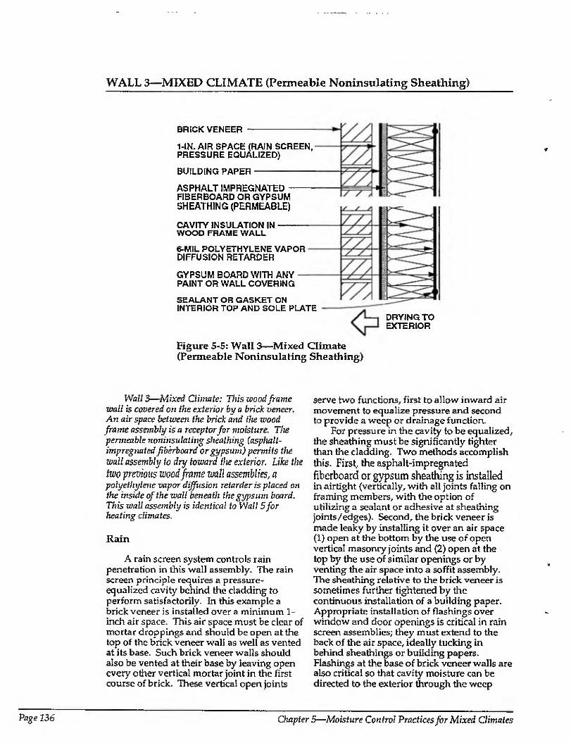
WALL 3—MIXED CLIMATE (Permeable Noninsulating Sheathing)
BRICK VENEER
1-IN. AIR SPACE (RAIN SCREEN, PRESSURE EQUALIZED)
BUILDING PAPER
ASPHALT IMPREGNATED FIBERBOARD OR GYPSUM SHEATHING (PERMEABLE)
CAVITY INSULATION IN WOOD FRAME WALL
6-MIL POLYETHYLENE VAPOR DIFFUSION RETARDER
GYPSUM BOARD WITH ANY PAINT OR WALL COVERING
SEALANT OR GASKET ON INTERIOR TOP AND SOLE PLATE
DRYING TO EXTERIOR
Figure 5-5: Wall 3—Mixed Climate (Permeable Noninsulating Sheathing)
Wall 3—Mixed Clunate: This wood frame wall is covered on the exterior by a brick veneer. An air space between the brick and the wood frame assembly is a receptor for moisture. The permeable noninsulating sheathing (asphalt- impregnated fiberboard or gypsum) permits the wall assembly to dry toward the exterior. Like the
two previous wood frame wall assemblies, a polyethylene vapor diffusion retarder is placed on the inside of the wall beneath the gypsum board. This wall assembly is identical to Wall 5for heating climates.
Rain
A rain screen system controls rain penetration in this wall assembly. The rain screen principle requires a pressure- equalized cavity behind the cladding to perform satisfactorily. In this example a brick veneer is installed over a minimum 1- inch air space. This air space must be clear of mortar droppings and should be open at the top of the brick veneer wall as well as vented at its base. Such brick veneer walls should also be vented at their base by leaving open every other vertical mortar joint in the first course of brick. These vertical open joints
serve two functions, first to allow inward air movement to equalize pressure and second to provide a weep or drainage function.
For pressure in the cavity to be equalized, the sheathing must be significantly tighter than the cladding. Two methods accomplish this. First, the asphalt-impregnated fiberboard or gypsum sheathing is installed in airtight (vertically, with all joints falling on framing members, with the option of utilizing a sealant or adhesive at sheathing joints/edges). Second, the brick veneer is made leaky by installing it over an air space (1) open at the bottom by the use of open vertical masonry joints and (2) open at the top by the use of similar openings or by venting the air space into a soffit assembly. The sheathing relative to the brick veneer is sometimes further tightened by the continuous installation of a building paper. Appropriate installation of flashings over window and door openings is critical in rain screen assemblies; they must extend to the back of the air space, ideally tucking in behind sheathings or building papers. Flashings at the base of brick veneer walls are also critical so that cavity moisture can be directed to the exterior through the weep
Page 136 Chapters—Moisture Control Practices for Mixed Climates

WALL 3—MIXED CLIMATE (CONTINUED)
holes under the influence of gravity. These base flashings must also extend to the back of the rain screen cavity.
Rain Absorption/Capillary Suction
An air space behind the brick veneer controls rain absorption by the brick veneer and brick veneer capillarity effects. The air space receives capillary moisture and moisture driven inward by incident solar radiation. A building paper is installed in some assemblies to limit rain absorption by the asphalt-impregnated fiberboard or gypsum sheathing. In such cases a vapor permeable, nonabsorptive building paper should be used.
Air Movement
Air may transport moisture from the exterior during the cooling season (infiltration of warm humid air) or from the interior during the heating season (exfiltration or warm moisture-laden interior air). To control this moisture, either the exterior asphalt-impregnated fiberboard or gypsum sheathing is sealed to the wall framing, or the interior gypsum wall board or polyethylene vapor diffusion retarder is sealed to the wall framing. This can be accomplished with adhesive, caulk, or some other seal ant.
An air seal located at either the exterior or the interior of the wall will be effective. An exterior air seal at the asphalt- impregnated fiberboard or gypsum sheathing would equalize pressure of the exterior air space. As a practical note of caution, it has proven difficult in practice to seal asphalt- impregnated fiberboard sheathing. As such, in wall assemblies with asphalt-impregnated fiberboard sheathing, the plane of airtightness is often located to the interior of the wall assembly at the interior gypsum board or polyethylene vapor diffusion retarder. Alternatively, a tightly sealed exterior building paper in this climate can also be effective in reducing air transported moisture.
Vapor Diffusion
During cooling periods, vapor diffusion from the exterior is controlled by a vapor
diffusion retarder at the interior of the wall assembly between the wall framing and the interior gypsum board. Although a vapor diffusion retarder at this Location in this climate does not prevent moisture from diffusing into the wall, it effectively protects the interior gypsum board and any interior finishes from moisture damage and also reduces the latent cooling load of the structure. This interior vapor diffusion retarder can get wet on the cavity side during the day if incident solar radiation drives inward the exterior absorbed moisture in the brick veneer. This moisture then typically migrates outward in the evening when the temperature gradient reverses. This wall assembly typically gets wei intermittently from the exterior and dries intermittently to the exterior. Since intermittent wetting of the vapor diffusion retarder is common, this interior vapor diffusion retarder must be continuous to perform satisfactorily. Foil- backed interior gypsum board is typically not effective due to discontinuities at joints. Foil- back insulation bafts are also not effective for the same reason. A continuous polyethylene vapor diffusion retarder has proven to be effective in this type of assembly.
During heating periods, vapor diffusion from the interior is controlled by a vapor diffusion retarder at file interior of the wall, to tills example a continuous polyethyiene sheet is installed between the interior gypsum board and the wall framing and acts as the vapor diffusion retarder.
Comments
to this wall assembly, two components foster wall drying towards the exterior: a vapor permeable sheathing on the exterior of the wall framing, and an air space between the cladding {brick veneer) and the sheathing that acts as a receptor for interior cavity moisture. Should the wall assembly become wet during service or be built wet through the use of wet framing materials or wet- applied cavity insulations (wet spray cellulose or blown fiberglass), it can dry intermittently to the exterior into the air space behind the brick veneer during cool weather or during evenings.
Either vapor permeable or vapor impermeable interior surface finishes may be usAi with this wall assembly.
Moisture Control Handbook Page 137
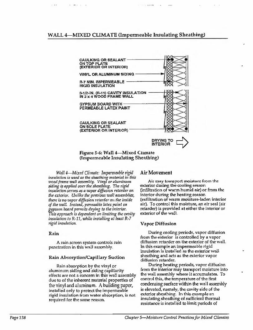
WALL 4—MIXED CLIMATE (Impermeable Insulating Sheathing)
CAULKING OR SEALANT- ON TOP PLATE (EXTERIOR OR INTERIOR)
VINYL OR ALUMINUM SIDING
R-7 MIN. IMPERMEABLE - RIGID INSULATION
3-1/2-IN. (R-11) CAVITY INSULATION IN 2 X 4 WOOD FRAME WALL
GYPSUM BOARD WITH- PERMEABLE LATEX PAINT
CAULKING OR SEALANT ON SOLE PLATE (EXTERIOR OR INTERIOR)
DRYING TO i—f\ INTERIOR 1—,/
Figure 5-6: Wall 4—Mixed Climate (Impermeable Insulating Sheathing)
Wall 4—Mixed Climate: Impermeable rigid insulation is used as the sheathing material in this wood frame wall assembly. Vinyl or aluminum siding is applied over the sheathing. The rigid insulation serves as a vapor diffusion retarder on the exterior. Unlike the previous wall assemblies, there is no vapor diffusion retarder on the inside of the wall. Instead, permeable latex paint on gypsum board permits drying to the inferior. This approach is dependent on limiting the cavity insulation to R-ll, while installing at least R-7 rigid insulation.
Rain
A rain screen system controls rain penetration in this wall assembly.
Rain Absorption/Capillary Suction
Rain absorption by the vinyl or aluminum siding and siding capillarity effects are not a concern in this wall assembly due to of the inherent material properties of the vinyl and aluminum. A building paper, installed only to protect the impermeable rigid insulation from water absorption, is not required for the same reason.
Air Movement
Air may transport moisture from the exterior during the cooling season (infiltration of warm humid air) or from the interior during the heating season (exfiltration of warm moisture-laden interior air). To control this moisture, an air seal (air retarder) is provided at either the interior or exterior of the wall.
Vapor Diffusion
During cooling periods, vapor diffusion from the exterior is controlled by a vapor diffusion retarder on the exterior of the wall. In this example an impermeable rigid insulation is installed as the exterior wall sheathing and acts as the exterior vapor diffusion retarder.
During heating periods, vapor diffusion from the interior may transport moisture into the wall assembly where it accumulates. To control this, the temperature of the first condensing surface within the wall assembly is elevated, namely, the cavity side of the exterior sheathing. In this example an insulating sheathing of sufficient thermal resistance is installed to limit periods of
Page 138 Chapter 5—Moisture Control Practices for Mixed Climates
WALL 4—MIXED CLIMATE (CONTINUED)
potential condensation to acceptable levels. An acceptable period would be sufficiently brief so that wood decay does not begin or interior surface water stain marks or mold or mildew do not appear. This period is determined by the temperature of the first condensing surface and the interior moisture level. The temperature of the first condensing surface is determined by the ratio of the amount of thermal insulation installed to the exterior of the condensing surface compared to the amount of thermal insulation installed to the interior of the condensing surface. For this wall assembly in this climate zone, the thermal resistance of insulating sheathings should be R-7 or greater, and the thermal resistance of cavity insulation should be R-ll or less, where an interior vapor diffusion retarder is not utilized. Furthermore, interior moisture levels during heating periods should be limited to 35 percent relative humidity at 70 degrees Fahrenheit.
Comments
In this wall assembly, a vapor permeable paint finish on the interior gypsum wall board promotes wall drying towards the interior. Should the wail assembly become wet during service or be built wet through the use of wet framing materials or wet- applied cavity insulations ('wet spray cellulose or blown fiberglass), it can dry to the interior. This is due to (1) an inward temperature and vapor pressure gradient present as a result of air conditioning the enclosure during the cooling season, and (2) ambient climatic conditions during the spring and fall.
Interior moisture levels should be limited to 35 percent relative humidity at 70 degrees Fahrenheit during heating periods. This is needed to further control airborne moisture
and vapor diffusion with this wall assembly, since limited drying of the assembly can only occur to the interior.
The facing material on faced cavity insulations can retard drying to the interior if the facing is installed towards the wall interior. Faced cavity insulations can be installed where drying to the interior is not required, or alternatively, lire cavity insulation can be installed with the facing material towards the outside of the cavity
If the facing material is installed with the facing towards the interior of the wall, it can also act as an interior vapor diffusion retarder, depending on the permeance of the facing material. An interior vapor diffusion retarder would significantly reduce the potential for condensation on the cavity side of the exterior insulating sheathing during the heating season, therefore reducing the amount of thermal resistance of the insulating sheathing needed for limiting wetting potential- However, this same interior vapor retarder would also significantly reduce drying to the interior.
Dry-applied insulations and dry framing materials are recommended where impermeable surface treatments are utilized, such as wall coverings and impermeable paints, or where interior vapor diffusion retarders are installed (faced cavity insulations or sheet polyethylene). Alternatively, wall assemblies must be allowed to dry prior to enclosure.
Wall assemblies with permeable interior surface treatments that have been performing satisfactorily in service are sometimes subsequently covered with impermeable interior surface treatments. For example, new owners or tenants are repaint with impermeable paints or wall coverings. In these cases, mold and mildew problems may appear at the gypsum board/surface treatment interface if the previously mentioned moisture control strategies have not been effectively utilized.
Moisture Control handbook Page 139
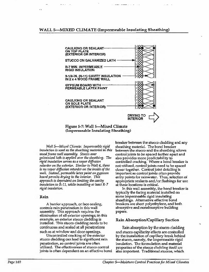
WALL 5—-MIXED CLIMATE (Impermeable Insulating Sheathing)
CAULKING OR SEALANT- ON TOP PLATE {EXTERIOR OR INTERIOR)
STUCCO ON GALVANIZED LATH —
R-7 MIN. IMPERMEABLE -- RIGID INSULATION
3-1/2-1N. (R-11) CAVITY INSULATION IN 2 X 4 WOOD FRAME WALL
GYPSUM BOARD WITH- PERMEABLE LATEX PAINT
CAULKING OR SEALANT ON SOLE PLATE (EXTERIOR OR INTERIOR)
DRYING TO INTERIOR
Figure 5-7: Wall 5—Mixed Climate (Impermeable Insulating Sheathing)
Wall 5—Mixed Climate: Impermeable rigid insulation is used as the sheathing material in this wood frame wall assembly. Stucco over galvanized lath is applied over the sheathing. The rigid insulation serves as a vapor diffusion retarder on the exterior. Similar to Wall 4, there is no vapor diffusion retarder on the inside of the wall. Instead, permeable latex paint on gypsum board permits drying to the interior. This approach is dependent on limiting the cavity insulation to R-11, while installing at least R-7 rigid insulation.
Rain
A barrier approach, or face-sealing, controls rain penetration in this wall assembly. This approach requires the elimination of all exterior openings; in this example, an exterior stucco cladding is installed. This stucco cladding needs to be continuous and sealed at all penetrations such as at window and door openings.
Uncontrolled cracking of the exterior stucco cladding can lead to significant rain penetration, so control joints are often utilized. The effectiveness of stucco control joints is often dependent on an effective bond
breaker between the stucco cladding and any sheathing material. The bond breaker between the stucco and the sheathing allows control joints to be spaced farther apart and also provides more predictability to controlled cracking. Where a bond breaker is not utilized, control joints need to be spaced closer together. Control joint detailing is important as control joints often provide entry points for rainwater. Thus, selection of appropriate sealants and/or flashings for use at these locations is critical.
In this wall assembly, the bond breaker is typically the facing material installed on some impermeable rigid insulating sheathings. Alternative effective bond breakers are sheet polyethylene, and both absorptive and nonabsorptive building papers.
Rain Absorption/Cap illary Suction
Rain absorption by the stucco cladding and stucco capillarity effects are controlled by the installation of capillary break behind the stucco, namely, the impermeable rigid insulation. The formulation and material properties of the stucco cladding itself are also important. Traditional stuccos, which
Page 140 Chapters—Moisture Control Practices for Mixed Climates
WALL 5—MIXED CLIMATE (CONTINUED)
have provided the best service life, have been composed of three layers, where each successive layer to the exterior has been weaker and more permeable than the layer under it. In other words, the base coat is the thickest and has the lowest water to cement ratio, and therefore is the most impermeable. The second coat is thinner and weaker (more permeable) than the base coat, and the finish coat is the thinnest, weakest and most permeable of the three. The rationale for this approach is that the farther inward from the exterior that water penetrates, the more difficult it becomes for the water to go farther. Conversely, once water has penetrated the stucco it is always easier for it to migrate to the exterior than any farther to the interior. Accordingly, any paint finishes or hydrophobic sealants installed ovet the outermost surface of a stucco cladding need to be more permeable than the outermost surface of the stucco cladding. This is typically very difficult to achieve in practice; as such, stains or colorants added to stuccos during stucco application are often more successful than paint films subsequently applied.
Rain absorption by the stucco cladding and stucco capillarity effects can also be controlled by exterior paint films and hydrophobic coatings. However, caution and judgment need to be exercised in the application of this control strategy. Although these coatings reduce rain absorption and capillarity, they also often retard the drying of the wall assembly to the exterior if it gets wet through other mechanisms such as interior moisture or failure at control joints.
Air Movement
Air may transport moisture from either the exlerior during the cooling season (infiltration of warm humid air) or from the interior during the heating season (exfiltration or warm moisture-laden interior air). To control this moisture, an air seal (air retarder) is provided at either the interior or exterior of the wall.
Vapor Diffusion
During cooling periods, vapor diffusion from Ihe exterior is controlled by a vapor diffusion retarder on the exterior of the wall. In this example an impermeable rigid
insulation is installed as the exterior wall sheathing and acts as the exterior vapor diffusion retarder.
During heating periods, vapor diffusion from the interior may transport moisture into the wall assembly, where it accumulates. To control this, the temperature of the first condensing surface within the wall assembly is elevated, namely, the cavity side of the exterior sheathing. In this example an insulating sheathing of sufficient thermal resistance is installed to limit periods of potential condensation to acceptable levels. An acceptable period would be sufficiently brief so that wood decay does not begin or interior surface water stain marks or mold or mildew do not appear. This period is determined by the temperature of the first condensing surface, which in this wall assembly is determined by the ratio of the amount of thermal insulation installed to the exterior of the condensing surface compared to the amount of thermal insulation installed to the interior of the condensing surface. For this wall assembly in this climate zone, the thermal resistance of insulating sheathings should be R-7 or greater, and the thermal resistance of cavity insulation should be R-Il or less.
Comments
In this wall assembly, a vapor permeable paint finish on the interior gypsum wall board promotes wall drying towards the interior. Should the wall assembly become wet during service or be built wet through the use of wet framing materials or wet- applied cavity insulations (wet spray cellulose or blown fiberglass), it can dry to the interior. This is due to (I) an inward temperature and vapor pressure gradient present as a result of air conditioning the enclosure during the cooling season, and (2) ambient climatic conditions during the spring and fall.
Inferior moisture levels should be limited to 35 percent relative humidity at 70 degrees Fahrenheit during heating periods. This is needed to further control airborne moisture and vapor diffusion with this wall assembly since, limited drying of the assembly can only occur towards the interior.
The facing material on faced cavity insulations can retard drying to the interior if the facing is installed towards the interior.
Moisture Control Handbook Page 141
WALL 5—MIXED CLIMATE (CONTINUED)
Faced cavity insulations can be installed where drying to the interior is not required/ or alternatively, the cavity insulation can be installed with the facing material towards the outside of the cavity.
If he facing material is installed with the facing towards the interior of the wall, it can also act as an interior vapor diffusion retarder, depending on the permeance of the facing material. An interior vapor diffusion retarder would significantly reduce the potential for condensation on the cavity side of the exterior insulating sheathing during the heating season, and therefore reduce the amount of thermal resistance of the insulating sheathing needed for limiting wetting potential. However, this same interior vapor diffusion retarder would also significantly reduce drying to the interior.
Dry framing materials (wood at a
moisture content of 19 percent by weight or lower) and dry-applied insulations are recommended (1) where impermeable surface treatments are utilized, such as wall coverings and impermeable paints, or (2) where interior vapor diffusion retarders are installed (faced cavity insulations or sheet polyethylene). Alternatively, wall assemblies must be allowed to dry prior to enclosure.
Wall assemblies with permeable interior surface treatments that have been performing satisfactorily in service are sometimes subsequently covered with impermeable interior surface treatments. For example, new owners or tenants may repaint with impermeable paints or wall coverings. In these cases, mold and mildew problems may appear at the gypsum board/surface treatment interface if the previously mentioned moisture control strategies have not been effectively utilized.
Page 142 Chapters—Moisture Control Practices for Mixed Climates
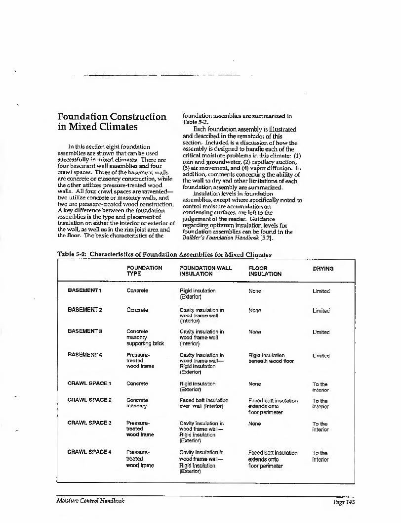
Foundation Construction in Mixed Climates
In this section eight foundation assemblies are shown that can be used successfully in mixed climates. There are four basement wall assemblies and four crawl spaces. Three of the basement walls are concrete or masonry construction, while the other utilizes pressure-treated wood walls. All four crawl spaces are unvented— two utilize concrete or masonry walls, and two arc pressure-treated wood construction. A key difference between the foundation assemblies is the type and placement of insulation on either the interior or exterior of the wall, as well as in the rim j'oist area and the floor. The basic characteristics of the
foundation assemblies are summarized in Table 5-2.
Each foundation assembly is Illustrated and described in the remainder of this section. Included is a discussion of how the assembly is designed to handle each of the critical moisture problems in this climate: (1) rain and groundwater, (2) capillary suction, (3) air movement, and (4) vapor diffusion. In addition, comments concerning the ability of the wall to dry and other limitations of each foundation assembly are summarized.
Insulation levels in foundation assemblies, except where specifically noted to control moisture accumulation on condensing surfaces, are left to the judgement of tire reader. Guidance regarding optimum insulation levels for foundation assemblies can be found in the Builder's Foundation Handbook [5.?].
Table 5-2: Characteristics of Foundation Assemblies for Mixed Climates
FOUNDATION FOUNDATION WALL FLOOR DRYING TYPE INSULATION INSULATION
BASEMENT 1 Concrete Rigid insulation (Exterior)
None Limited
BASEMENT2
BASEMENT 3
BASEMENT 4
CRAWL SPACE 1
CRAWL SPACE 2
CRAWL SPACE 3
CRAWL SPACE 4
Concrete
Concrete masonry supporting brick
Pnessure- treaied wood frame
Concrete
Concrete masonry
Pressu re¬ treated wood frame
Pressure- treated wood frame
Cavity insulation in wood frame wall (Interior)
Cavity insulation in wood frame wail (Interior)
Cavity Insulation in wood frame wall— Rigid insulation (Exterior)
Rigid insulation (Exterior)
Faced batt insulation over wall (interior)
Cavity insulation in wood frame wall— Rigid insulation (Exterior)
Cavity insulation in wood frame Wall- Rigid insulation (Exterior)
None Limited
Norte Umited
Rigid insulation Umited beneath wood floor
None To the interior
Faced batt insulation Toths extends onto interior floor perimeter
None To the interior
Faced batt insulation To the extends onto interior floor perimeter
Moisture Control Handbook Page 143
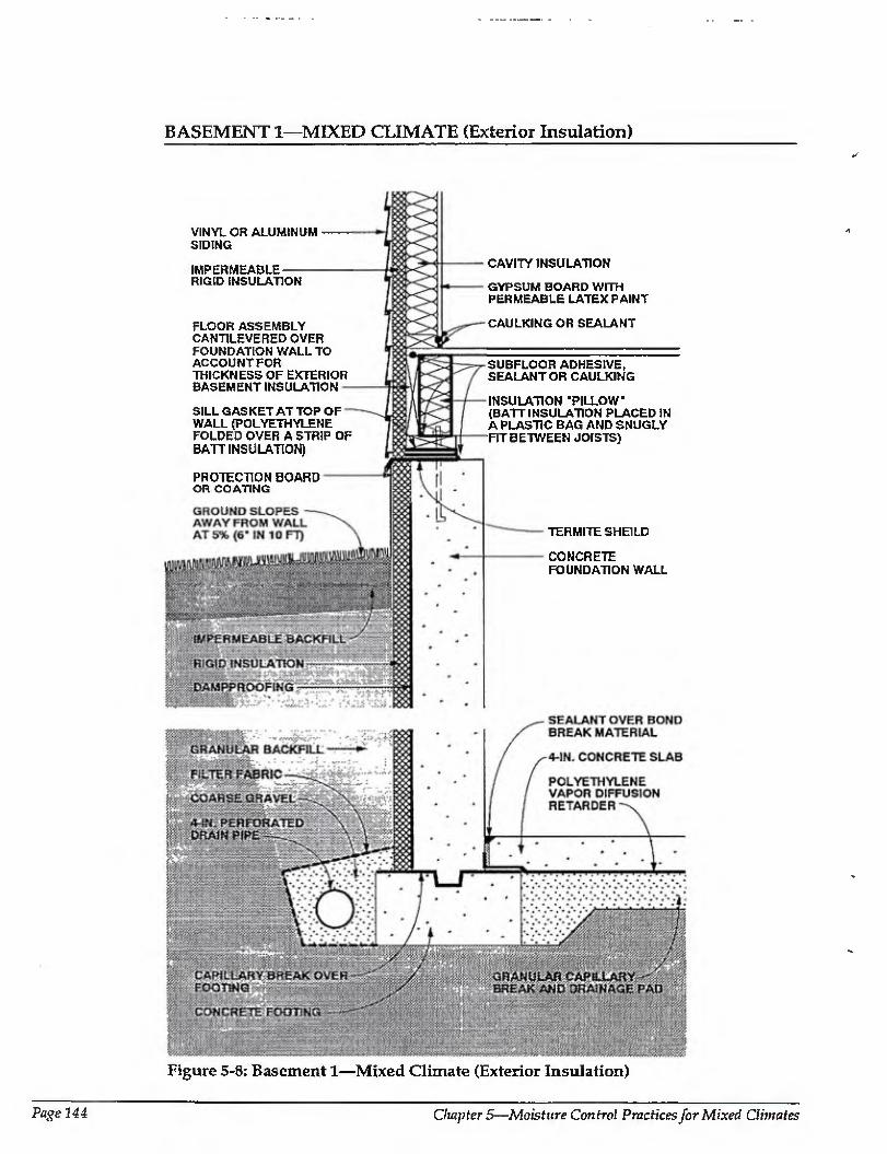
BASEMENT 1—MIXED CLIMATE (Exterior Insulation)
VINYL OR ALUMINUM SIDING
IMPERMEABLE RIGID INSULATION
FLOOR ASSEMBLY CANTILEVERED OVER FOUNDATION WALL TO ACCOUNTFOR TRICKNESS OF EXTERIOR BASEMENT INSULATION
SILL GASKET AT TOP OF WALL(POLYETHYLENE FOLDED OVER A STRIP OF BATT INSULATION)
PROTECTION BOARD OR COATING
CAVITY INSULATION
GYPSUM BOARD WITH PERMEABLE LATEX PAINT
CAULKING OR SEALANT
SUBFLOOR ADHESIVE, SEALANT OR CAULKING
INSULATION ‘PILLOW (BATT INSULATION PLACED IN A PLASTIC BAG AND SNUGLY FIT BETWEEN JOISTS)
TERMITE SHEILD
CONCRETE FOUNDATION WALL
Figure 5-8: Basement 1—Mixed Climate (Exterior Insulation)
Page 144 Chapter 5—Moisture Control Practices for Mixed Climates
BASEMENT 1—MIXED CLIMATE (CONTINUED)
Basement 1—Mixed Climate; This concrete basement wall assembly illustrates the use of rigid insulation board on the exterior. Rigid insulation covers the exterior of the rim joist, and cavity insulation (with a vapor diffusion retarder) is placed between joists on the rim joist interior. The above-grade wall shown here corresponds to Wall 4 in the previous section.
Rain and Ground Water
Gutters, downspouts, and careful site grading, which direct water away from basement perimeters, should be used to prevent rain and surface water from entering basements. Surface water penetration into the ground immediately adjacent to basements is limited by a cap of impermeable backfill material.
A subgrade drainage system controls groundwater entry into basements . This consists of a drainpipe located at the perimeter of the concrete footings coupled with free-draining backfill material TTie drainpipe and the free-draining backfill material act together to provide a drain screen. The drain pipe, is connected to a sump, storm sewer, or to daylight. Perforations in the perimeter drain pipe should be installed with the holes down to allow groundwater to rise up into the drain pipe and be carried away. Coarse gravel should surround the perimeter drain pipe and in turn be surrounded by a fitter fabric. Filter fabric should be located both below and above the perimeter drain pipe, as drain pipe perforations face down and often clog from underneath. Drainpipes should have at least 2 inches of gravel underneath, yet still be below the bottom surface of the basement floor slab.
Capillary Suction
Capillarity may transmit moisture into the concrete foundation wall. To control this, a dampproof coating is installed on the exterior of lire concrete foundation wall and a capillary break (dampproofing or polyethylene) is placed over the top of the concrete footing. Alternatively, the footings may be constructed on a granular pad-
Capiliary moisture movement into the floor slab is controlled by a granular capillary break under the slab. The break is a 4-inch-
to 6-inch-thick layer of 3/4-inch gravel with fines removed.
Air Movement
In basement assemblies it is important to eliminate air flow between the surrounding soil and the basement space. To control airborne moisture infiltrating into the basement space, the basement space is pressurized relative to the surrounding soil and air leakage openings are iimited (tight construction).
Air leakage openings in this basement construction are limited by (1) sealing with caulking the concrete floor slab to the perimeter concrete foundation wail, and (2) sealing the joints of the elements which form the sill/rim joist/floor assembly. In addition, pipe penetrations and electrical conduits through concrete floor slabs, perimeter concrete walls, floor drains, and sump openings are sealed or dosed with tight covers.
Vapor Diffusion
Moisture may move by vapor diffusion from the surrounding soil into the concrete foundation wall. It is controlled by a vapor diffusion retarder on the exterior of the concrete foundation wall. In this example, the dampproofing on the exterior of the concrete foundation wall also acts as a vapor
retarder. A polyethylene vapor diffusion retarder
under the concrete floor slab controls moisture carried by diffusion into the slab.
During heating periods, vapor diffusion from the interior of the basement may transport moisture into the perimeter foundation wail rim joist framing where it accumulates. To control moisture, the temperature of the first condensing surface within the rim joist assembly, namely, the cavity side of the rim joist is elevated. In this example rigid insulation is installed on the exterior of the rim joist, which limits periods of potential condensation.
Comments
Rigid insulation is installed on the exterior of the perimeter concrete foundation wall to reduce heating and cooling loads and is protected above grade on its exterior from
Moisture Control Handbook Page 145
BASEMENT 1—MIXED CLIMATE (CONTINUED)
mechanical damage. This rigid insulation can act as a conduit for insects to enter the enclosure, and as such appropriate flashings or other protection may be necessary.
The concrete floor slab and perimeter concrete foundation wall contain significant quantities of moisture when initially placed. Covering these surfaces with impermeable surface finishes or floor coverings may lead to deterioration of these surfaces if the construction moisture is not allowed to dry. Initial drying of the construction moisture contained in concrete may elevate interior moisture levels during the first few months of occupancy.
Installing carpets on cold, damp, concrete floor slabs can Lead to serious allergenic reactions in sensitive individuals and other health-related consequences. It is not recommended that carpets be installed on concrete slabs unless the carpets can be kept dry and warm; that is, carpet relative humidities should be kept below 40 percent [5.3], In practice this is typically not possible unless floor assemblies are insulated and basements areas are conditioned.
The granular drainage pad located under the basement floor slab can be integrated into a subslab ventilation system to control radon migration by adding a vent pipe connected to the surface and an exhaust fan.
Page 146 Chapters—Moisture Control Practices for Mixed Climates
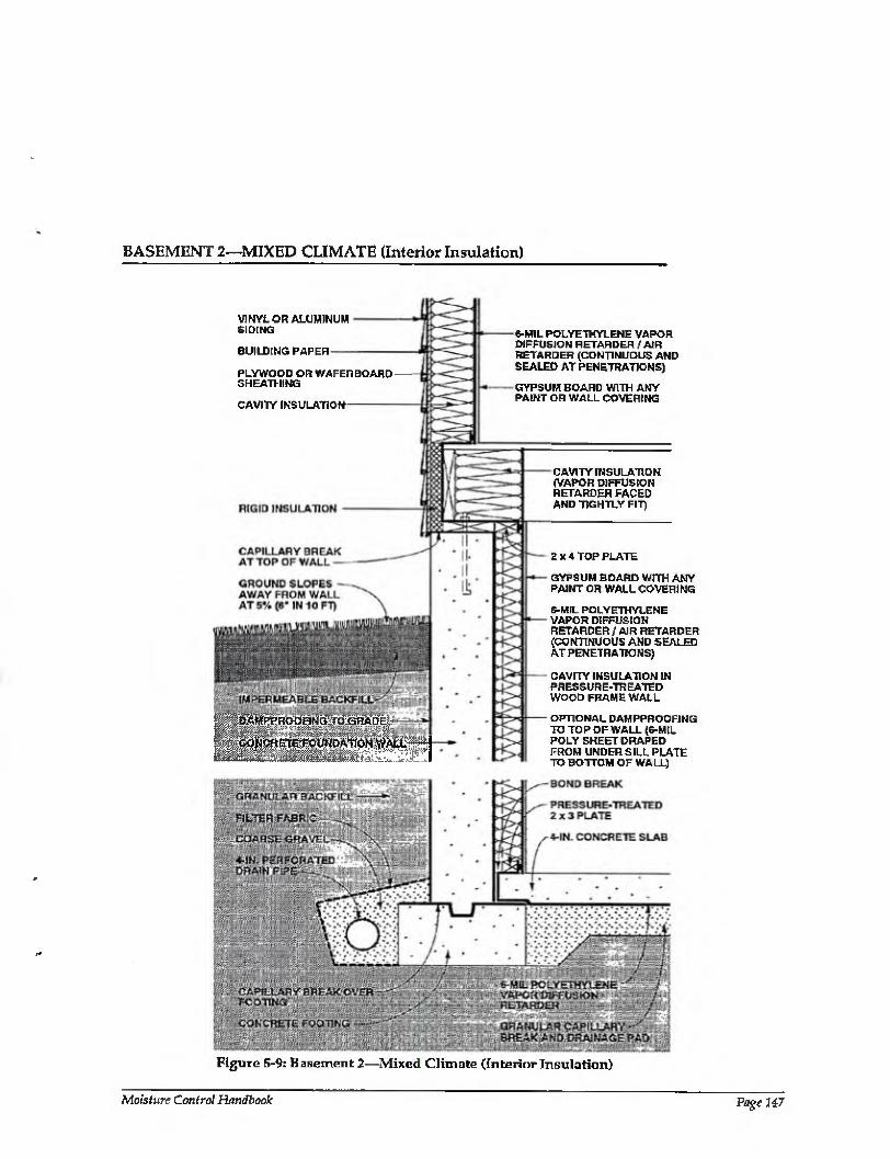
BASEMENT 2—MIXED CLIMATE (Interior Insulation)
VINYL on ALUMINUM SIDING
BUILDING PAPER
PLYWOOD OR WAFERBOARD - SHEATHING
CAVITY INSULATION-
a&MPPHPoqNG:;fq:BHAOE^
‘''C^ETEFCUNDAtlON ^ALL^
6-MIL POLYETHYLENE VAPOR DIFFUSION RETARDER / AIR RETARDER (CONTINUOUS AND SEALED AT PENETRATIONS)
GYPSUM BOARD WITH ANY PAINT OR WALL COVERING
CAVITY INSULATION (VAPOR DIFFUSION RETARDER FACED AND TIGHTLY FIT)
2X4 TOP PLATE
GYPSUM BOARD WITH ANY PAINT OR WALL COVERING
S-MIL POLYETHYLENE VAPOR DIFFUSION RETARDER / AIR RETARDER (CONTINUOUS AND SEALED AT PENETRATIONS)
CAVITY INSULATION IN PRESSURE-TREATED WOOD FRAME WALL
OPTIONAL DAMPPHOOFING TO TOP OF WALL (6-MJL POLY SHEET DRAPED FROM UNDER SILL PLATE TO BOTTOM OF WALL)
Figure 5-9: Basement 2—Mixed Climate (Interior Insulation)
Moisture Control Handbook Page 147
BASEMENT 2—MIXED CLIMATE (CONTINUED)
Basement!—Mixed Climate: This concrete basement wall assembly illustrates the use of cavity insulation in a wood frame wall on the interior of the foundation wall. Cavity insulation is placed between joists on the rim joist interior, and rigid insulation covers the rim joist on the exterior as well. Unlike other basement wall assemblies, the vapor diffusion retarder is continuous from the above-grade wall interior, through the rim joist area, extending over the basement wall interior, and then beneath the slab. The above-grade wall shown here corresponds to Wall 1 in the previous section.
Rain and Ground Water
Gutters, downspouts, and careful site grading, which direct water away from basement perimeters, should be used to prevent rain and surface water from entering basements. Surface water penetration into the ground immediately adjacent to basements is limited by a cap of impermeable backfill material.
A subgrade drainage system controls groundwater entry.
Capillary Suction
Capillarity may transmit moisture into the concrete foundation wall. To control this, a dampproof coating is installed on the exterior of the concrete foundation wall and a capillary break (dampproofing or polyethylene) is placed over the top of the concrete footing. Alternatively, the footings may be constructed on a granular pad.
Capillary moisture movement into the floor slab is controlled by a granular capillary break under the slab. The break is a 4-inch- to 6-inch-thick layer of 3/4-inch gravel with fines removed.
Construction moisture contained in the perimeter concrete foundation wall may move by capillarity into the sill/rim joist/ floor assembly. It is controlled by installing a capillary break at the top of the perimeter concrete foundation wall.
Air Movement
Where perimeter concrete foundation walls are insulated on the interior, it is important to prevent warm, interior, moisture-laden air from the basement space from coming in contact with cold, concrete
surfaces during both heating and cooling periods.
Air leakage openings in this basement deal with both exterior and interior moisture¬ laden air. They are limited by sealing the floor slab polyethylene vapor diffusion retarder to the foundation wall perimeter polyethylene vapor diffusion retarder. In addition, the rim joist/floor assembly is wrapped by polyethylene and this polyethylene is sealed to both the foundation wall perimeter polyethylene vapor diffusion retarder and the above-grade wall polyethylene vapor diffusion retarder.
Vapor Diffusion
Vapor diffusion may carry moisture into several building components. To prevent moisture from the surrounding soil from entering the concrete foundation wall, a vapor diffusion retarder is installed on the exterior of the concrete foundation wall. In this example, the dampproofing on the exterior of the concrete foundation wall also acts as a vapor diffusion retarder.
A polyethylene vapor diffusion retarder under the concrete floor slab controls moisture carried by diffusion from the surrounding soil into the slab.
Construction moisture contained in the perimeter concrete foundation wall may diffuse into the perimeter foundation frame wall cavity. It is controlled by installing dampproofing on the interior of the perimeter concrete foundation wall. Alternatively, the concrete foundation wall can be allowed to dry prior to enclosure.
Moisture moving from the interior basement space into the perimeter foundation wall framing is controlled by a polyethylene vapor diffusion retarder on the interior of the perimeter foundation wall framing.
During heating periods, vapor diffusion from the interior of the basement may transport moisture into the perimeter foundation wall rim joist framing, where it accumulates. To control this, the temperature of the first condensing surface within the rim joist assembly is elevated, namely, the cavity side of the rim joist. In this example rigid insulation is installed on the exterior of the rim joist, which limits periods of potential condensation
Page 148 Chapters—Moisture Control Practices for Mixed Climates
BASEMENT 2—MIXED CLIMATE (CONTINUED)
v,
*
Comments
In this perimeter foundation frame wall assembly, drying towards either the interior or exterior is limited by the impermeability of the perimeter foundation wall concrete and the interior polyethylene vapor diffusion retarder. Should the wall assembly become wet during service or be built wet through the use of wet framing materials or wet- applied cavity insulations (wet spray cellulose or blown fiberglass), it may not dry. Accordingly, dry framing materials (wood at a moisture content of 19 percent by weight or lower) and dry-applied insulations are recommended. Alternatively, wall assemblies must be allowed to dry prior to enclosure.
The perimeter foundation frame wall is held away from the concrete in order to enhance the durability of the wood members. This is accomplished by using a 2 x 4 top plate with 2 x 3 studs and a 2 x 3 bottom plate. The cavity insulation, however, fills the entire void and touches the interior face of the concrete foundation wall. Fiberglass batt insulation is recommended as the cavity insulation by virtue of its draining characteristics and nonhygroscopic nature.
Interior basement space moisture levels should be limited to 35 percent relative
humidity at 70 degrees Fahrenheit during heating periods. This is needed to further control airborne moisture and vapor diffusion with this wall assembly, since only limited drying of the assembly occurs.
The concrete floor slab contains significant quantities of moisture when initially placed. Covering this surface with an impermeable surface finish or floor covering may lead to deterioration of these surfaces if the construction moisture is not allowed to dry. Initial drying of the construction moisture contained in concrete may also lead to elevated interior moisture levels during the first few months of occupancy.
Installing carpets on cold, damp, concrete floor slabs can lead to serious allergenic reactions in sensitive individuals and other health-related consequences. It is not recommended that carpets be installed on concrete slabs unless the carpets can be kept dry and warm; that is, carpet relative humidities should be kept below 40 percent [5.3], In practice this is typically not possible unless floor assemblies are insulated and basements areas are conditioned.
The granular drainage pad located under the basement floor slab can be integrated into a subslab ventilation system to control radon migration by adding a vent pipe connected to the surface and an Kchaust fan.
Moisture Control Handbook Page 149
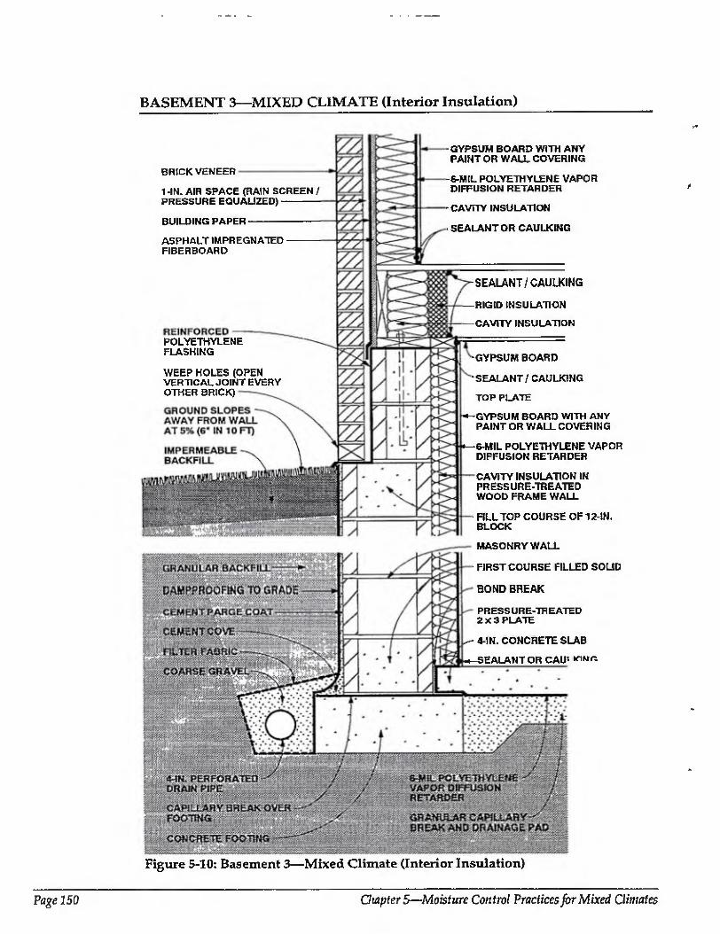
BASEMENT 3—MIXED CLIMATE (Interior Insulation)
BRICK VENEER
1-IN. AIR SPACE (RAIN SCREEN / PRESSURE EQUALIZED)-
BUILDING PAPER
ASPHALT IMPREGNATED FIBERBOARD
POLYETHYLENE FLASHING
WEEP HOLES (OPEN VERTICAL JOINT EVERY OTHER BRICK)
- GYPSUM BOARD WITH ANY PAINT OR WALL COVERING
-6-MIL POLYETHYLENE VAPOR DIFFUSION RETARDER
-CAVITY INSULATION
SEALANT OR CAULKING
-SEALANT/CAULKING
-RIGID INSULATION
CAVITY INSULATION
GYPSUM BOARD
SEALANT/CAULKING
TOP PLATE
-GYPSUM BOARD WITH ANY PAINT OR WALL COVERING
-6-MIL POLYETHYLENE VAPOR DIFFUSION RETARDER
CAVITY INSULATION IN PRESSURE-TREATED WOOD FRAME WALL
FILL TOP COURSE OF 12-IN. BLOCK
MASONRY WALL
FIRST COURSE FILLED SOLID
BOND BREAK
PRESSURE-TREATED 2X3 PLATE
4-IN. CONCRETE SLAB
-SEALANT OR CAUi
Figure 5-10: Basement 3—Mixed Climate (Interior Insulation)
Page 150 Gwpter 5—Moisture Control Practices for Mixed Climates
BASEMENT 3—MIXED CLIMATE (CONTINUED)
Basement 3—Mixed Climate: In this example, a concrete masonry basement wall assembly supports a wood frame wall with brick veneer. Similar to Basement 1, there is cavity insulation in a wood frame wall on the interior of the fbundation wall. Ujilike the previous
foundation assemblies, there is no rigid insulation covering the exterior of the rim joist, however cavity insulation is still placed between joists on the rim joist interior. A variation shown here, however, is the use of impermeable rigid insulation as a vapor diffusion retarder inside the rim joist cavity insulation (in place of faced cavity insulation). A vapor diffusion retarder covers the interior side of the above- and belaw-grade walls, The above-grade wall shown here corresponds to Wall 3 in the previous section.
Rain and Ground Water
Gutters, downspouts, and careful site fading, which direct water away from asement perimeters, should be used to
prevent rain and surface water from entering basements. Surface water penetration into tire ground immediately adjacent to basements is limited by a cap of impermeable backfill material.
A subgrade drainage system controls groundwater entry.
In this foundation assembly, rainwater from the above-grade wall assembly controlled by the rain screen must be prevented from draining into the top of the perimeter block foundation wall. To do so, flashing is installed at the base of the brick, veneer wall extending to the back of the rain screen cavity and up over the top of the upper course of blocks in the masonry wall. This flashing directs water to the exterior of the assembly.
Capillary Suction
Several methods are used to control moisture movement by capillarity into the masonry foundation wall. A dampptoof coating (bitumen over a cement parge coat) is installed on the exterior of the concrete foundation wall, and a capillary break (dampproofing or polyethylene) is placed over the top of the concrete footing. Alternatively, the footings can be constructed on a granular pad.
Capillary moisture from the masonry block foundation wall migrating into the
brick veneer is controlled by an impermeable flashing at the base of the brick veneer and the rain screen cavity.
Capillary moisture movement into the floor slab is controlled by a granular capillary break under the slab. The break is a 4-inch- to 6-inch-thick layer of 3/4-inch gravel with fines removed.
Construction moisture contained in the masonry block foundation wall may move into the sill/rim joist/floor assembly. It is controlled by a capillary break at the top of the perimeter concrete foundation wall.
Air Movement
Air leakage openings in this basement deal with both exterior and interior moisture- laden air. They are limited by sealing the floor slab polyethylene vapor diffusion retarder to the foundation wall perimeter interior gypsum wall board. The foundation perimeter interior gypsum wail board is sealed to the perimeter framing. In addition, the rim joist/floor assembly air leakage openings are controlled by installing blocks of rigid insulation between floor joists and sealing them lo Ihe top of the perimeter basement frame wall and the underside of the subfloor sheathing.
Vapor Diffusion
Vapor diffusion may carry moisture into several building components. A vapor diffusion retarder on the exterior of the masonry block foundation watt controls moisture entering the masonry wall from the surrounding soil, fn this example, the dampproofing or the exterior of the masonry block foundation wall also acts as a vapor diffusion retarder.
Moisture movement from the surrounding soil into the concrete floor siab is controlled by a polyethylene vapor diffusion retarder under Are slab.
Moisture movement from the interior basement space into the perimeter foundation wait framing is controlled by a polyethylene vapor diffusion retarder on the interior of the perimeter wall framing.
Comments
In this perimeter foundation frame wall assembly, drying towards either the exterior
Moisture Control Handbook Page 151
BASEMENT 3—MIXED CLIMATE (CONTINUED)
or the interior is limited by the impermeability of the concrete block assembly and the interior polyethylene vapor diffusion retarder. Should this wall assembly become wet during service, be built with wet framing materials, or become wet through the use of wet-applied cavity insulations (wet spray cellulose or blown fiberglass), it may not dry. Accordingly, dry framing materials (wood at a moisture content of 19 percent by weight or lower) and dry-applied insulations are recommended. Alternatively, wall assemblies can be permitted to dry prior to enclosure
The perimeter foundation frame wall Is held away from the masonry in order to enhance the durability of the wood members. This is accomplished by using a 2 x 4 top plate with 2x3 studs and a 2 x 3 bottom plate. The cavity insulation, however, fills the entire void and touches the interior face of the masonry foundation wall. Fiberglass batt insulation is recommended as the cavity insulation by virtue of its draining characteristics and nonhygroscopic nature.
Interior basement space moisture levels should be limited to 35 percent relative humidity at 70 degrees Fahrenheit during heating periods. This is needed to further control airborne moisture and vapor diffusion with this basement wall assembly, since only limited drying of the assembly occurs.
Depending on its permeance, the facing material on faced cavity insulations, installed with the facing towards the interior of the wall, can also act as an interior vapor diffusion retarder.
The concrete floor slab contains significant quantities of moisture when initially placed. Covering this surface with an impermeable surface finish or floor covering may lead to deterioration of these surfaces if the construction moisture is not allowed to dry. Initial drying of the construction moisture contained in concrete may also elevate interior moisture levels during the first few months of occupancy.
Installing carpets on cold, damp, concrete floor slabs can lead to serious allergenic reactions in sensitive individuals and other health-related consequences. It is not recommended that carpets be installed on concrete slabs unless the carpets can be kept dry and warm; that is, carpet relative humidities should be kept below 40 percent [5.3]. In practice this is typically not possible unless floor assemblies are insulated and basements areas are conditioned.
The granular drainage pad located under the basement concrete floor slab can be integrated into a subslab ventilation system to control radon migration by adding a vent pipe connected to the surface and an exhaust fan.
Page 252 Chapter 5—Moisture Control Practices for Mixed Climates
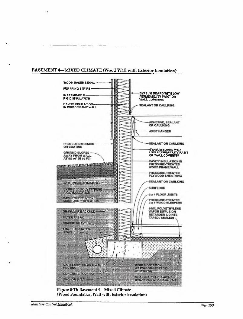
BASEMENT 4—MIXED CLIMATE (Wood Wall with Exterior Insulation)
WOOD-BASED SIDING -
RJRRRING STRIPS-
IMPERMEABLE- RIGID INSULATION
CAVITY INSULATION- IN WOOD FRAME WALL
GYPSUM BOARD WITH LOW PERMEABILITY PAINT OR WALL COVERING
-GYPSUM BOARD WITH LOW PERMEABILITY PAINT OR WALL COVERING
Figure 5-11: Basement 4—Mixed Climate (Wood Foundation Wall with Exterior Insulation)
Moisture Control Handbook Page 253
BASEMENT 4—MIXED CLIMATE (CONTINUED)
Basement 4—Mixed Climate: This pressure- treated wood foundation wall rests on a concrete footing. Cavity insulation is placed within the wood frame wall and rigid insulation board covers the exterior. A layer of rigid insulation is placed beneath the wood floor. Because of the balloon- style framing at the rim joist, the insulated wood foundation wall extends over the rim joist on the exterior. Rigid insulation covers the rim joist on the exterior as well. Gypsum board with low permeability paint or wail covering serves as a vapor diffusion retarder on the interior side of the wall assembly. The above-grade wall shown here is similar to Wall 4 in the previous section, except that wood siding with an air space behind it is shown instead of vinyl or aluminum siding.
Rain and Ground Water
Gutters, downspouts, and careful site grading, which direct water away from basement perimeters, should be used to prevent rain and surface water from entering basements. Surface water penetration into the ground immediately adjacent to basements is limited by a cap of impermeable backfill material.
A subgrade drainage system controls groundwater entry.
Cap illary Suction
Capillary moisture may move into the wood foundation wall. It is controlled by sheet polyethylene (moisture protection) on the exterior of the foundation wood sheathing and a capillary break {dampproofing or polyethylene) over the top of the concrete footing. Alternatively, the concrete footing can be constructed on a granular pad.
Moisture movement by capillarity into the wood floor framing and rigid floor insulation is controlled by a granular capillary break under the slab. The break is a 4-inch- to 6-inch-thick layer of 3/4-inch gravel with fines removed.
Air Movement
Where wood foundation wall cavities are insulated, it is important to prevent warm, interior, moisture-laden air from the basement space from coming in contact with cold sheathing surfaces during both heating and cooling periods.
Air leakage openings in this basement construction deal with both exterior and interior moisture-laden air. They are limited by sealing the floor slab polyethylene vapor diffusion retarder to the wood foundation wall perimeter interior gypsum wall board. The foundation perimeter interior gypsum wall board is sealed to the perimeter framing. In addition, the rim joist/floor assembly is balloon framed and the perimeter rim joist is sealed to the foundation wall perimeter interior gypsum wall board and to the underside of the subfloor sheathing.
Vapor Diffusion
Vapor diffusion may transmit moisture into several building assemblies. A vapor diffusion retarder on the exterior of the wood foundation wall controls moisture entering the wood foundation wall from the surrounding soil. In this example, the sheet polyethylene on the exterior of the wood foundation wall sheathing also acts as a vapor diffusion retarder.
Moisture movement from the surrounding soil into the wood floor framing is controlled by a polyethylene vapor diffusion retarder under the framing.
To control capillary moisture movement from the interior basement space into the perimeter foundation wall framing, interior basement space moisture levels are limited to 35 percent relative humidity at 70 degrees Fahrenheit during heating periods.
During heating periods, vapor diffusion from the interior may transport moisture into the wall assembly, where it accumulates. To control this, the temperature of the first condensing surface within the wall assembly is elevated, namely, the cavity side of the exterior wood foundation wall sheathing. In this example rigid insulation is installed on the exterior of die foundation, which limits periods of potential condensation
Comments
During the heating season, two systems elevate the temperature of potential condensing surfaces: (1) rigid insulation is installed on the exterior of the rim joist assembly, and (2) this assembly is balloon framed. This limits the potential for condensation at this location (the inside face of exterior wood sheathing, and the inside
Page 154 Chapter 5—Moisture Control Practices for Mixed Climates
BASEMENT 4-MIXED CLIMATE (CONTINUED)
face of the perimeter rim joist). However, this rigid insulation can act as a conduit for insects to enter the enclosure, and as such appropriate flashings or other protection may be necessary.
In this foundation wall assembly, drying towards the interior is promoted by a vapor permeable interior surface finish on the interior perimeter gypsum wall board. Should the wall assembly become wet during service or be built wet through the use of wet framing materials, drying to the interior is limited. However, the rate of drying may not be sufficient to prevent problems where wet- applied cavity insulations (wet spray cellulose or blown fiberglass) are utilized. In the absence of prior experience or local historical experience, it may be desirable to use dry-applied insulations. Alternatively, wall assemblies could be allowed to dry prior to enclosure.
Interior basement space moisture levels should be limiled to 35 percent relative humidity at 70 degrees Fahrenheit during heating periods. This is needed to further control airborne moisture and vapor diffusion with this basement wall assembly, since only limited drying of the assembly occurs.
Depending on its permeance, the facing material on faced cavity insulations, installed with the facing towards the interior of the wall, can also act as an interior vapor diffusion retarder. An interior vapor diffusion retarder would significantly reduce condensation potential on the interior surface
of the wood foundation wall sheathing. However, this same interior vapor diffusion retarder would also significantly reduce drying to the interior should it be required.
Dry framing materials (wood at a moisture content of 19 percent by weight or less and dry-applied insulations are recommended (1) where impermeable interior surface treatments are utilized, such as wall coverings and impermeable paints, or (2) where interior vapor diffusion retarders are installed (faced cavity insulations or sheet polyethylene). Aitematively, wall assemblies must be allowed to dry prior to enclosure.
Foundalion wall assemblies with permeable interior surface treatments that have been performing satisfactorily in service are sometimes subsequently covered with impermeable interior surface treatments. For example, new owners or tenants may repaint with impermeable paints or wall coverings. In these cases, mold and mildew problems may appear at the gypsum board/surface treatment interface if the previously mentioned moisture control strategies have not been effectively utilized.
The granular drainage pad located under the basement floor slab can be integrated into a subslab ventilation system to control radon migration by adding a vent pipe connected to the surface and an exhaust fan.
Readers should also consult the relevant publications of the National Forest Products Association including Permanent Wood Foundation System: Design, Fabrication and installation Manual [5.4]
Moisture Control Handbook Page 155
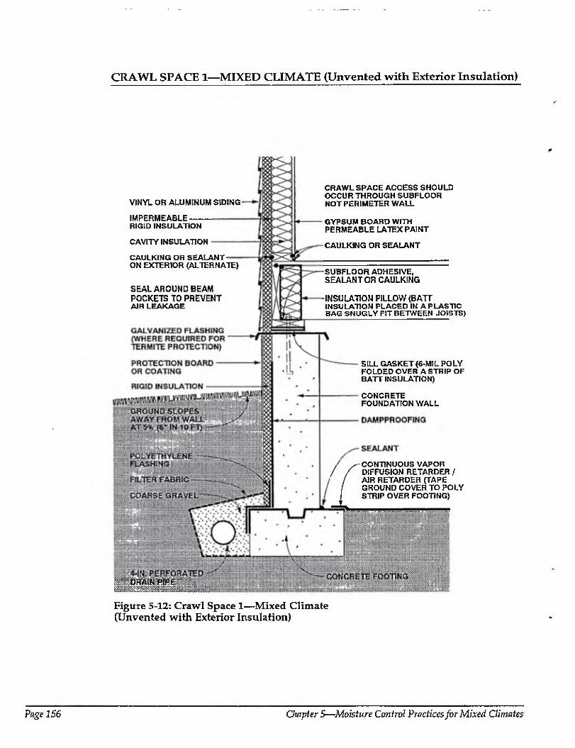
CRAWL SPACE 1—MIXED CLIMATE (Unvented with Exterior Insulation)
VINYL OR ALUMINUM SIDING'
IMPERMEABLE- RIGID INSULATION
CAVITY INSULATION
CAULKING OR SEALANT- ON EXTERIOR (ALTERNATE)
SEAL AROUND BEAM POCKETS TO PREVENT AIR LEAKAGE
CRAWL SPACE ACCESS SHOULD OCCUR THROUGH SUBFLOOR NOT PERIMETER WALL
GYPSUM BOARD WITH PERMEABLE LATEX PAINT
CAULKING OR SEALANT
-SUBFLOOR ADHESIVE, SEALANT OR CAULKING
-INSULATION PILLOW (BATT INSULATION PLACED IN A PLASTIC BAG SNUGLY FIT BETWEEN JOISTS)
SILL GASKET (6-MIL POLY FOLDED OVER A STRIP OF BATT INSULATION)
CONCRETE FOUNDATION WALL
/ ^ CONTINUOUS VAPOR / / DIFFUSION RETARDER / 1 / AIR RETARDER (TAPE
/ GROUND COVER TO POLY STRIP OVER FOOTING)
DRAIN P)PE:::
Figure 5-12: Crawl Space 1—Mixed Climate (Unvented with Exterior Insulation)
Page 156 Ouipter 5—Moisture Control Practices for Mixed Climates
CRAWL SPACE 1—MIXED CLIMATE (CONTINUED)
Crawl Space 1—Mixed Climate: This lamented crawl space illustrates a concrete foundation wall with rigid insulation board on the exterior. Rigid insulation covers the exterior of the rim joist, and cavity insulation (with a vapor diffusion retarder) is placed between joists on the rtm joist interior. A continuous vapor diffusion retarder is placed on the floor of the crawl space and extends over the top of the footing. The above-grade wall shown here corresponds to Wall 4 in the previous section.
Rain and Ground Water Gutters, downspouts, and careful site
grading, which direct water away from crawl space perimeters, should be used to prevent rain and surface water from entering crawl spaces.
Subgrade drainage at the perimeter of the concrete footing controls groundwater entry.
Capillary Suction
Two systems are installed to control capillary moisture entering the concrete foundation wall. (1) a dampproof coating on the exterior of the wall, and (2) a capillary break (dampproofing or polyethylene) over the top of the concrete footing (extending the crawl space ground cover over the top of the concrete footing).
Capillary moisture entering the perimeter framing assembly from the concrete foundation wall is controlled by a capillary break at the top of the foundation wall. (The sheet metal flashing doubles as termite protection)
Air Movement
In unvented crawl space assemblies it is important to eliminate air flow between the surrounding soil and the crawl space,. Airborne moisture infiltrating into the crawl space is controlled by pressurizing the crawl space relative to the surrounding soil and by limiting air leakage openings (tight construction).
In enclosures with forced air systems, the crawl space can be pressurized by a supply air register in the crawl space, with no corresponding return air register. In this approach the air distribution fan should run continuously. In enclosures wi thout forced air systems, a separate fan for this purpose
can be installed, taking air from the other conditioned spaces. The tighter the space construction, the less air that has to be introduced to pressurize the crawl space. As such it is desirable to build as tight as is practical. To do so, the ground co very vapor diffusion retarder is extended up over the top of the footings and all joints are sealed. In addition, the rim joist assembly is sealed against air leakage with adhesive, caulking, gaskets, or other air seals.
Exterior wall sheathing is also extended down over the rim joist assembly to further reduce air leakage at this location. This exterior wall sheathing can be utilized as the principal air seal at this location and hence to eliminate seals at the top and bottom of the rim joist if the exterior wall sheathing is sealed directly to the exterior of the sill plate the sUl/rim joist/floor assembly. In addition, pipe penetrations and electrical conduits through perimeter concrete walls, floor drains, and sump openings are sealed or closed with tight covers.
Crawl spaces in this climate zone should not be pressurized at the expense of depressurizing the rest of the conditioned space during cooling periods. In other words, the entire building should be pressurized relative to the exterior, including the crawl space during cooling periods. As such, air taken from the building to pressurize the crawl space needs to be replaced by outside air introduced in a controlled manner, typically to the air conditioning duct system.
Pressurization will only occur when the forced air distribution fan is operating (when mechanical cooling or heating is occurring). This should be effective under most conditions.
Vapor Diffusion
Moisture movement by vapor diffusion from the surrounding soil into the concrete foundation wall is controlled by installing a vapor diffusion retarder on the exterior of the concrete foundation wall. In this example, the dampproofing on the exterior of the concrete foundation wall also acts as a vapor diffusion retarder.
Moisture movement by vapor diffusion into the crawl space from the soil is controlled by a continuous polyethylene vapor diffusion retarder as a ground cover.
Moisture Control Handbook Page 157
CRAWL SPACE 1—MIXED CLIMATE {CONTINUED)
During heating periods, vapor diffusion from the interior of the crawl space may transport moisture into the perimeter foundation wall rim joist framing, where it accumulates. To control this, the temperature of the first condensing surface within the rim joist assembly is elevated, namely, the cavity side of the rim joist- In this example rigid insulation is installed on the exterior of the rim joist, which limits periods of potential condensation.
Comments
Rigid insulation is installed on the exterior of the perimeter concrete foundation wall to reduce heating and cooling loads and is protected on its exterior from mechanical damage. This rigid insulation can act as a conduit for insects to enter the enclosure, and as such appropriate flashings or other protection may be necessary.
In unvented conditioned crawl spaces it is convenient to install ductwork, plumbing, and other mechanical components, since concerns about the effects of duct leakage and freezing pipes are minimized.
Page 158 Chapter 5—Moisture Control Practices for Mixed Climates
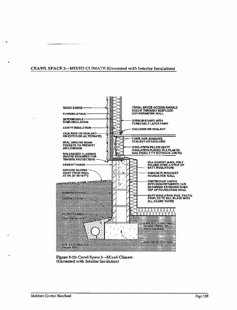
CRAWL SPACE 2—MIXED CLIMATE (Unvented with Interior Insulation)
WOOD SIDING
FURRING SPACE
IMPERMEABLE RIGID INSULATION
CAVITY INSULATION
CAULKING OR SEALANT ON EXTERIOR (ALTERNATE)
SEAL AROUND BEAM POCKETS TO PREVENT AIR LEAKAGE
GALVANIZED FLASHING (WHERE REQUIRED FOR TERMITE PROTECTION)
CRAWL SPACE ACCESS SHOULD OCCUR THROUGH SUBFLOOR NOT PERIMETER WALL
GYPSUM BOARD WITH PERMEABLE LATEX PAINT
CAULKING OR SEALANT
SUBFLOOR ADHESIVE, SEALANT OR CAULKING
INSULATION PILLOW (BAIT INSULATION PLACED IN A PLASTIC BAG SNUGLY FIT BETWEEN JOISTS)
SILL GASKET (6-MIL POLY FOLDED OVER A STRIP OF BATTINSULATION)
CONCRETE MASONRY FOUNDATION WALL
-CONTINUOUS VAPOR DIFFUSION RETARDER (AIR RETARDER EXTENDED OVER TOP OF FOUNDATION WALL
-BATTINSULATION (FOIL FACED) STAPLED TO SILL PLATE WITH ALL SEAMS TAPED
Figure 5-13: Crawl Space 2—Mixed Climate (Unvented with Interior Insulation)
Moisture Control Handbook Page 1S9
CRAWL SPACE 2—MIXED CLIMATE (CONTINUED)
Crawl Space!—Mixed Cliimte: This unvenled crawl space illustrates a concrete masonry foundation wall with faced batt insulation covering the interior wall and extending over the floor perimeter. Rigid insulation covers the exterior of the rim joist, and cavity insulation (with a vapor diffusion retarder) is placed between joists on the rim joist interior. A continuous vapor diffusion retarder is placed on the floor of the crawl space and extends over the interior face and top of the foundation wall. The above-grade wall shown here is similar to Wall 4 in the previous section, except that wood siding with an air space behind it is shown instead of vinyl or aluminum siding.
Rain and Ground Water
Gutters, downspouts, and careful site grading, which direct water away from crawl space perimeters, should be used to prevent rain and surface water from entering crawl spaces.
Subgrade drainage at the perimeter of the concrete footing controls groundwater entry.
Capillary Suction
Moisture movement by capillarity into the masonry block foundation wall is controlled by a dampproof coating (bitumen over a cement parge coat) on the exterior of the concrete foundation wall.
Construction moisture contained in the masonry block foundation wall may move into the sill/rim joist/floor assembly. It is controlled by installing a capillary break at the top of the perimeter concrete foundation wall, by extending the crawl space ground cover over the top of the masonry block foundation wall.
Air Movement
In unvented crawl space assemblies it is important to eliminate air flow between the surrounding soil and the crawl space. Airborne moisture infiltrating into the crawl space is controlled by pressurizing the crawl space relative to the surrounding soil and by limiting air leakage openings (tight construction).
In enclosures with forced air systems, the crawl space can be pressurized by a supply air register in the crawl space, with no corresponding return air register. In this
approach the air distribution fan should run continuously. In enclosures without forced air systems, a separate fan for this purpose can be installed, taking air from the other conditioned spaces. The tighter the space construction, the less air that has to be introduced to pressurize the crawl space. As such it is desirable to build as tight as is practical. To do so, the ground cover/vapor diffusion retarder is extended up over the top of the perimeter masonry block foundation wall and all joints are sealed. In addition, the rim joist assembly is sealed against air leakage with adhesive, caulking, gaskets, or other air seals. Exterior wall sheathing is also extended down over the rim joist assembly to further reduce air leakage at this location. This exterior wall sheathing can be utilized as the principal air seal at this location and hence to eliminate seals at the top and bottom of the rim joist if the exterior wall sheathing is sealed directly to the exterior of the sill/ rim joist/floor assembly. In addition, pipe penetrations and electrical conduits through perimeter concrete masonry walls, floor drains, and sump openings are sealed or closed with tight covers.
Crawl spaces in this climate zone should not be pressurized at the expense of depressurizing the rest of the conditioned space during cooling periods. In other words, the entire building should be pressurized relative to the exterior, including the crawl space during cooling periods. As such, air taken from the building to pressurize the crawl space needs to be replaced by outside air introduced in a controlled manner, typically to the air conditioning duct system.
Pressurization will only occur when the forced air distribution fan is operating (when mechanical cooling or heating is occurring). This should be effective under most conditions.
Vapor Diffusion
Vapor diffusion may carry moisture from the surrounding soil into the masonry block foundation wall. It is controlled by installing a vapor diffusion retarder on the exterior of the concrete foundation wall. In this example, the dampproofing on the exterior of the masonry block foundation wall also acts as a vapor diffusion retarder.
Moisture may also diffuse from the soil
Page 160 Chapter 5—Moisture Control Practices for Mixed Climates

CRAWL SPACE 2—MIXED CLIMATE (CONTINUED)
into the crawl space. It is controlled by a continuous polyethylene vapor diffusion retarder as a ground cover.
Moisture movement from within the crawl space into the perimeter batt insulation is controlled by choosing a batt insulation with an impermeable facing that can act as an interior vapor diffusion retarder.
During heating periods, vapor diffusion from the interior of the crawl space may transport moisture into the perimeter foundation, wall rim joist framing, where it accumulates. To control this, the temperature of the first condensing surface within the rim joist assembly is elevated, namely, the cavity side of the rim joist. In this example rigid insulation is installed on
the exterior of the rim joist, which limits periods of potential condensation
Comments
Insulation is installed on the interior of the perimeter concrete foundation wall to reduce heating and coding loads. This insulation can act as a conduit for insects to enter the rim joist assembly, and as such appropriate flashings or other protection may be necessary.
In unvented conditioned crawl spaces it is convenient to install ductwork, plumbing, and other mechanical components, since concerns about the effects of duct leakage and freezing pipes are minimized.
Moisture Control Handbook Page 161
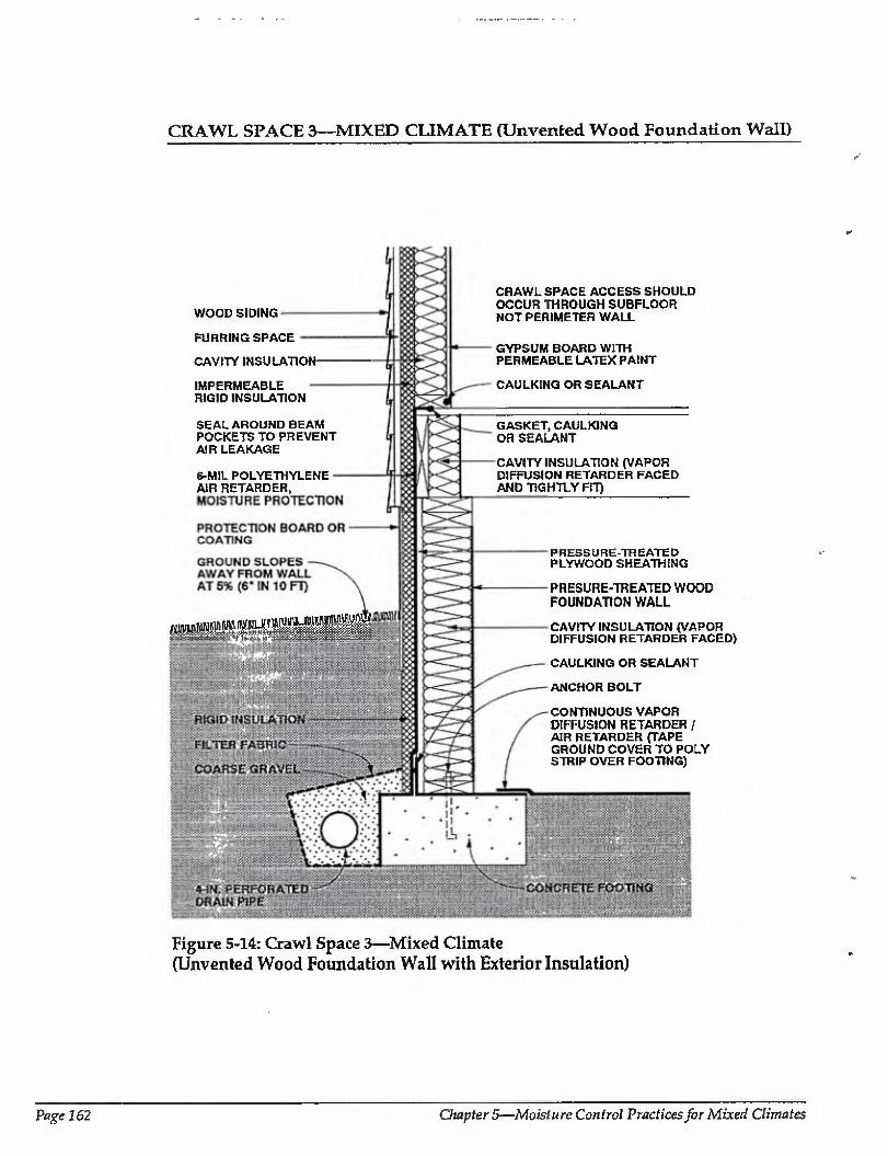
CRAWL SPACE 3—MIXED CLIMATE (Unvented Wood Foundation Wall)
WOOD SIDING
FURRING SPACE
CAVITY INSULATION-
IMPERMEABLE RIGID INSULATION
SEAL AROUND BEAM POCKETS TO PREVENT AIR LEAKAGE
S-M1L POLYETHYLENE AIR RETARDER,
CRAWL SPACE ACCESS SHOULD OCCUR THROUGH SUBFLOOR NOT PERIMETER WALL
GYPSUM BOARD WITH PERMEABLE LATEX PAINT
CAULKING OR SEALANT
GASKET, CAULKING OR SEALANT
CAVITY INSULATION (VAPOR DIFFUSION RETARDER FACED AND TIGHTLY FIT)
PRESSURE-TREATED PLYWOOD SHEATHING
A-/1"/..;...
PRESURE-THEATED WOOD FOUNDATION WALL
CAVITY INSULATION (VAPOR DIFFUSION RETARDER FACED)
CAULKING OR SEALANT
ANCHOR BOLT
CONTINUOUS VAPOR DIFFUSION RETARDER / AIR RETARDER (TAPE GROUND COVER TO POLY STRIP OVER FOOTING)
Figure 5-14: Crawl Space 3—Mixed Climate (Unvented Wood Foundation Wall with Exterior Insulation)
Page 162 Chapter 5—Moisture Control Practices for Mixed Climates
CRAWL SPACE 3—MIXED CLIMATE (CONTINUED)
Crawl Space 3—Mixed Climate; This unvenfed crawl space illustrates a pressure treated wood foundation wall on a concrete footing. Cavity insulation (faced with a vapor diffusion retarder) is placed within the wood frame wall and rigid insulation hoard covers the exterior. Rigid insulation covers the exterior of the rim joist, and cavity insulation (with a vapor diffusion retarder) is placed between joists on the wn joist interior. A continuous vapor diffusion retarder is placed on thefloor of the crawl space and extends over the top of the footing. The above-grade wall shown here is similar to Wall 4 in the previous section, except that wood siding with an air space behind it is shown instead oj vinyl or aluminum siding.
Rain and Ground Water
Gutters, downspouts, and careful site grading, which direct water away from crawl Space perimeters, should be used to prevent rain and surface water from entering crawl spaces.
Subgrade drainage at the perimeter of the concrete footing controls groundwater entry.
Capillary Suction
Two systems are installed to control capillary moisture entering the wood foundation crawl space wall: (1) sheet polyethylene (moisture protection) on the exterior of the foundation wood sheathing, and (2) a capillary break over the top of the concrete footing, by extending the polyethylene ground cover over the top of the footings. Alternatively, the footings can be constructed on a granular pad.
Air Movement
Ln unvented crawl space assemblies it is important to eliminate air flow between the surrounding soil and the crawl space. Airborne moisture infiltrating into the crawl space is controlled by pressurizing the basement space relative to the surrounding soil and by limiting air leakage openings (tight construction).
Where wood foundation wall cavities are insulated, it is also important to prevent warm, moisture-laden crawl space air from coming in contact with cold sheathing surfaces during both heating and cooling periods.
In enclosures with forced air systems, the crawl space can be pressurized by a supply air register in the crawl space, with no corresponding return air register. In this approach the air distribution fan should run continuously. In enclosures without forced air systems, a separate fan for this purpose can be installed, taking air from the other conditioned spaces. The tighter the space construction, the less air that has to be introduced to pressurize the crawl space. As such it is desirable to build as tight as is practical. To do so, the ground cover/vapor diffusion retarder is extended up over the top of the concrete footing and all joints arc sealed. In addition, the perimeter sheet polyethylene moisture protection on the exterior of the wood crawl space foundation wall sheathing is sealed to the polyethylene ground cover and to the above-grade wall framing- Exterior wall sheathing is also extended down over the rim joist assembly to further reduce air leakage at this location. Pipe penetrations, floor drains, and sump openings are seated or closed with tight covers.
Crawl spaces in this climate zone should not be pressurized at the expense of depressurizing the rest of the conditioned space during cooling periods. In other words, the entire building should be pressurized relative to the exterior, including the crawl space during cooling periods. As such, air taken from the building to pressurize the crawl space needs to be replaced by outside air introduced in a controlled manner, typically to lire air conditioning duct system.
Pressurization will only occur when the forced air distribution fan is operating (when mechanical cooling or heating is occurring). This should be effective under most conditions.
Vapor Diffusion
Vapor diffusion may carry moisture from the surrounding soil into the wood foundation wall. It is controlled by a vapor diffusion retarder on the exterior of the wood foundation wall. In this example, the sheet polyethylene on the exterior of the wood foundation wall sheathing also acts as a vapor diffusion retarder.
Moisture may also diffuse from the surrounding soil into the wood floor framing.
Moisture Control Handbook Page 163
CRAWL SPACE 3—MIXED CLIMATE (CONTINUED)
It is controlled by installing a polyethylene vapor diffusion retarder under the wood floor framing.
During heating periods, vapor diffusion from the crawl space interior may carry moisture into the crawl space wall assembly, where it accumulates. To control this, the temperature of the first condensing surface within the crawl space wall assembly is elevated, namely, the cavity side of the exterior wood crawl space foundation wall sheathing. In this example rigid insulation is installed on the exterior of the craw! space foundation, which limits periods of potential condensation
Comments
Rigid insulation on the exterior of the rim joist assembly elevates the temperature of
potential condensing surfaces during the heating season (the inside face of the perimeter rim joist) and thereby limits the potential for condensation at this location. However, this rigid insulation can act as a conduit for insects to enter the enclosure, and as such appropriate flashings or other
protection may be necessary. In this foundation wall assembly, drying
towards the interior is promoted by the lack of an interior surface on the perimeter crawl space framing- Should the wall assembly become wet during service or be built wet through the use of wet framing materials or wet-applied cavity insulations (wet spray cellulose or blown fiberglass), drying to the interior can occur.
Depending on its permeance, the facing material on faced cavity insulations, installed with the facing towards the interior of the wall, can also act as an interior vapor diffusion retarder. An interior vapor diffusion retarder would significantly reduce the potential for condensation on the interior surface of the wood craw] space foundation wall sheathing. However, this same interior vapor diffusion retarder would also
significantly reduce drying to the interior, should it be required.
Readers should also consult the relevant publications of the National Forest Products Association including Permanent Wood Foundation System: Design, Fabrication and Installation Manual [5.4]
Page 164 Chapters—Moisture Control Practices for Mixed Climates
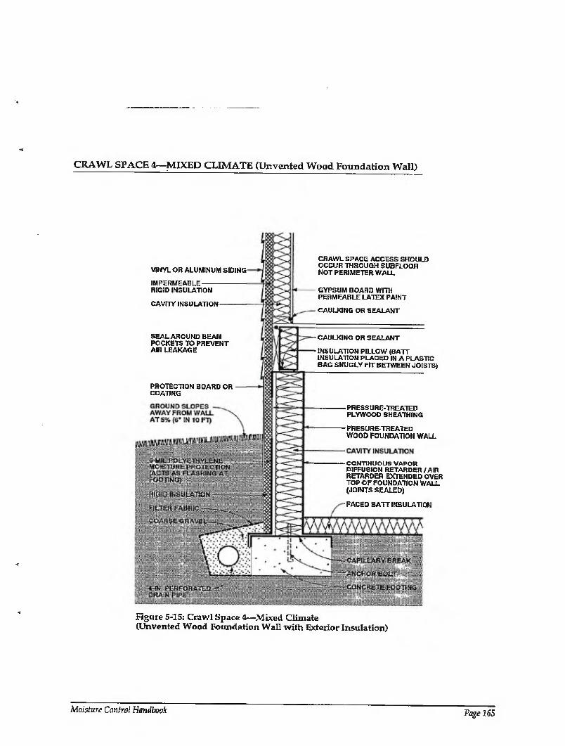
CRAWL SPACE 1—MIXED CLIMATE (Urrvented Wood Foundation Wall)
VIMYLOR ALUMINUM SIDfNG
IMPERMEABLE REID INSULATION
CAVITY INSULATION
CRAWL SPACE ACCESS SHOULD OCCUR THROUGH SUBFLOOR NOT PERIMETER WALL
GYPSUM BOARD WITH PERMEABLE LATEX PAINT
CAULKING or sealant
SEAL AROUND BEAM POCKETS TO PREVENT AIR LEAKAGE
PROTECTION BOARD OR COATING
- CAULKING OR SEALANT
- INSULATION PILLOW (BAIT INSULATION PLACED IN A PLASTIC BAG SNUGLY FIT BETWEEN JOISTS)
- PRESSURE-TREATED PLYWOOD SHEATHING
- PRESURE-TREATED WOOD FOUNDATION WALL
-CONTINUOUS VAPOR DIFFUSION RETARDER / AIR RETARDER EXTENDED OVER TOP OF FOUNDATION WALL (JOINTS SEALED)
- FACED BATT INSULATION
Figure 5-15: Crawl Space 4—Mixed Climate [Unvented Wood Foundation Wall with Exterior Insulation)
Moisture Control Handbook Page 165
CRAWL SPACE 4—MIXED CLIMATE (CONTINUED)
Crawl Space 4—Mixed Climate: Similar to Crawl Space 3, this unvented crawl space illustrates a pressure-treated wood foundation wall on a concrete footing. Cavity insulation (faced with a vapor diffusion retarder) is placed within the wood frame wall and rigid insulation board covers the exterior. Rigid insulation covers the exterior of the rim joist, and cavity insulation (with a vapor diffusion retarder) is placed between joists on the rim joist interior. Unlike Crawl Space 3, the vapor diffusion retarder placed on the floor of the crawl space continues up over the inside face and top of the foundation wall. In addition, faced batt insulation is laid on the perimeter of the crawl space floor. The above¬ grade wall shown here corresponds to Wall 4 in the previous section.
Rain and Ground Water
Gutters, downspouts, and careful site grading, which direct water away from crawl space perimeters, should be used to prevent rain and surface water from entering crawl spaces.
Subgrade drainage at the perimeter of the concrete footing controls groundwater entry.
Capillary Suction
To control moisture movement by capillarity into the wood foundation crawl space wall, sheet polyethylene (moisture protection) is installed on the exterior of the foundation wood sheathing, and a capillary break is placed over the top of the concrete footing. Alternatively, the footings can be constructed on a granular pad.
Air Movement
In unvented crawl space assemblies it is important to eliminate air flow between the surrounding soil and the crawl space. Airborne moisture infiltrating into the crawl space is controlled by pressurizing the crawl space relative to the surrounding soil and by limiting air leakage openings (tight construction).
Where wood foundation wall cavities are insulated, it is also important to prevent warm, moisture-laden crawl space air from coming in contact with cold sheathing surfaces during both heating and cooling periods.
In enclosures with forced air systems, the
crawl space can be pressurized by a supply air register in the crawl space, with no corresponding return air register. In this approach the air distribution fan should run continuously. In enclosures without forced air systems, a separate fan for this purpose can be installed, taking air from the other conditioned spaces. The tighter the space construction, the less air that has to be introduced to pressurize the crawl space. As such it is desirable to build as tight as is practical, To do so, the ground cover/vapor diffusion retarder is extended up over the top of the perimeter crawl space wood foundation wall and all Joints are sealed. The exterior wall sheathing is extended down over the rim joist assembly to further reduce air leakage at this location. Pipe penetrations, floor drains, and sump openings are sealed or closed with tight covers.
Crawl spaces in this climate zone should not be pressurized at the expense of depressurizing the rest of the conditioned space during cooling periods. In other words, the entire building should be pressurized relative to the exterior, including the crawl space during cooling periods. As such, air taken from the building to pressurize the crawl space needs to be replaced by outside air introduced in a controlled manner, typically to the air conditioning duct system.
Pressurization will only occur when the forced air distribution fan is operating (when mechanical cooling or heating is occurring). This should be effective under most conditions.
Vapor Diffusion
Vapor diffusion may carry moisture from the surrounding soil into the wood foundation wall. It is controlled by a vapor diffusion retarder on the exterior of the wood foundation wall. In this example, the sheet polyethylene on the exterior of the wood foundation wall sheathing also acts as a vapor diffusion retarder.
Moisture may also diffuse from the surrounding soil into the wood floor framing. To control this, a polyethylene vapor diffusion retarder is installed under the wood floor framing.
Moisture movement from within the crawl space into the perimeter foundation
Page 166 Clmpter 5—Moisture Control Practices for Mixed Climates
CRAWL SPACE 4—MIXED CLIMATE (CONTINUED)
wall framing is controlled by a vapor diffusion retarder. In this particular example, the ground cover which is extended up over the top of the perimeter foundation wall framing also acts as the vapor diffusion retarder.
During heating periods, vapor diffusion from the craw! space interior may carry moisture into the wood crawl space wall assembly, where it accumulates. To control this, the temperature of the first condensing surface within the crawl space wall assembly is elevated, namely, the cavity side of the exterior wood crawl space foundation wall sheathing. In this example rigid insulation is installed on the exterior of the crawl space foundation, which limits periods of potential condensation
Comments
Rigid insulation on the exterior of the rim joist assembly elevates the temperature of potential condensing surfaces during the heating season (the inside face of the perimeter rim joist) and thereby limits the
potential for condensation at this location. However, this rigid insulation can act as a conduit for insects to enter the enclosure, and as such appropriate flashings or other protection ma5' be necessary.
In this crawl space foundation wall assembly, drying towards either the interior or exterior is limited a vapor impermeable exterior sheathing and an interior vapor diffusion retarder. Should the crawl space foundation wall assembly become wet during service or be built wet through the use of wet framing materials or wet-applied cavity insulations (wet spray cellulose or blown fiberglass), it may not dry. Accordingly, dry framing materials (wood at a moisture content of 19 percent by weight or lower) and dry applied insulations are recommended. Alternatively, crawl space foundation wall assemblies must be allowed to dry prior to enclosure.
Readers should also consult the relevant publications of the National Forest Products Association including Permanent Wood Foundation System: Design, Fabrication and Installation Manual [5-4]
Moisture Control Handbook Page 167
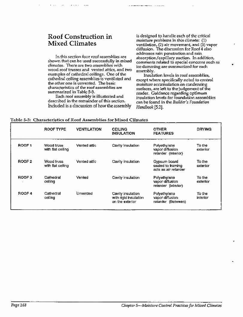
Roof Construction in Mixed Climates
In this section four roof assemblies are shown that can be used successfully in mixed climates. There are two assemblies with wood roof trusses and vented attics, and two examples of cathedral ceilings. One of the cathedral ceiling assemblies is ventilated and the other one is unvented. The basic characteristics of the roof assemblies are summarized in Table 5-3.
Each roof assembly is illustrated and described in the remainder of this section. Included is a discussion of how the assembly
is designed to handle each of the critical moisture problems in this climate: (1) ventilation, (2) air movement, and (3) vapor diffusion. The discussion for Roof 4 also addresses rain penetration and rain absorption/capillary suction. In addition, comments related to special concerns such as ice damming are summarized for each assembly.
Insulation levels in roof assemblies, except where specifically noted to control moisture accumulation on condensing surfaces, are left to the judgement of the reader. Guidance regarding optimum insulation levels for foundation assemblies can be found in the Builder's Foundation
Handbook [5.2].
Tabfe 5-3: Characteristics of Roof Assemblies for Mixed Climates
ROOF TYPE VENTILATION CEILING INSULATION
OTHER FEATURES
DRYING
ROOF 1
ROOF 2
ROOF 3
ROOF 4
Wood truss Vented attic with flat ceiling
Wood truss Vented attic with flat ceiling
Cathedra! ceiling
Cathedral ceiling
Vented
Unvented
Cavity insulation
Cavity insulation
Cavity insulation
Cavity insulation with rigid insulation on the exterior
Polyethylene To the vapor diffusion exterior retarder (interior)
Gypsum board To the sealed to framing exterior acts as air retarder
Polyethylene To the vapor diffusion exterior retarder (Interior)
Polyethylene To the vapor diffusion interior retarder (Between)
Page 168 Chapters—Moisture Control Practices for Mixed Climates
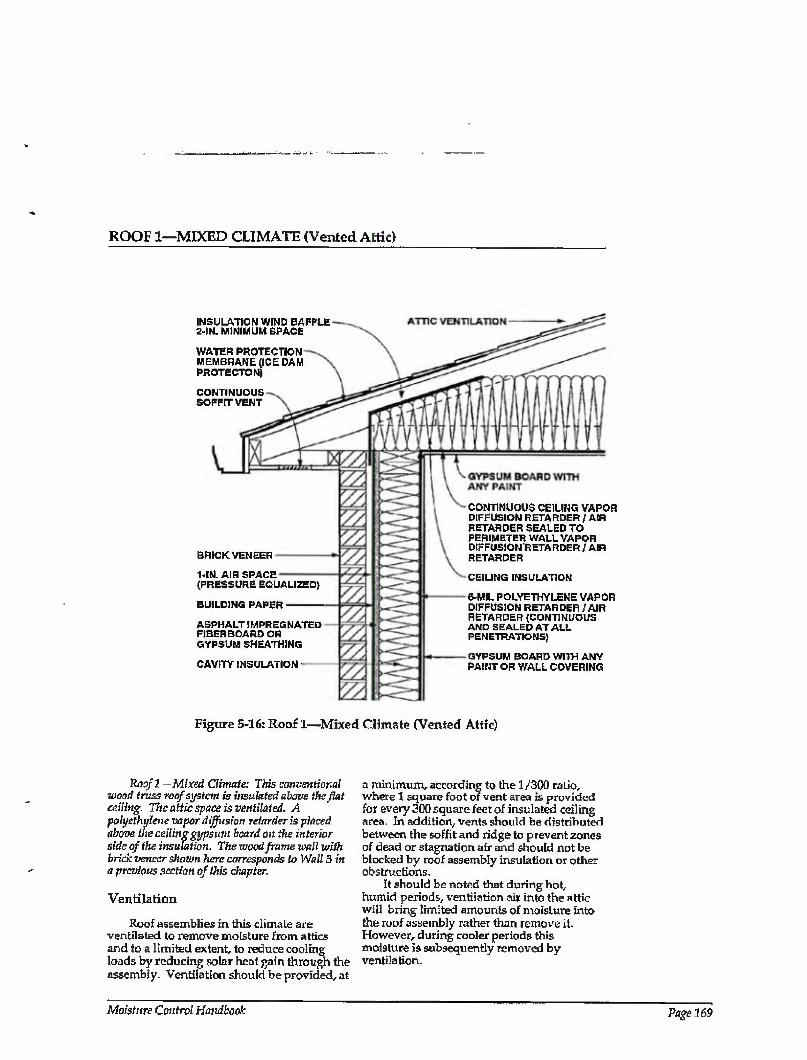
ROOF 1—MIXED CLIMATE (Vented Attic)
INSULATION WIND BAFFLE 2-IN. MINIMUM SPACE
WATER PROTECTION MEMBRANE (ICE DAM PROTECTON)
CONTINUOUS SOFFIT VENT
BRICK VENEER
1-IN. AIR SPACE (PRESSURE EQUALIZED)
BUILDING PAPER
ASPHALT IMPREGNATED FIBER BOARD OR GYPSUM SHEATHING
CAVITY INSULATION
CONTINUOUS CEILING VAPOR DIFFUSION RETARDER / AIR RETARDER SEALED TO PERIMETER WALL VAPOR DIFFUSION RETARDER / AIR RETARDER
CEILING INSULATION
6-MIL POLYETHYLENE VAPOR DIFFUSION RETARDER / AIR RETARDER (CONTINUOUS AND SEALED AT ALL PENETRATIONS)
GYPSUM BOARD WITH ANY PAINT OR WALL COVERING
Figure 5-16: Roof 1—Mixed Climate (Vented Attic)
Roof 1—Mixed Climate: This conventional wood truss roof system is insulated above the fiat ceiling. The attic space is ventilated. A polyethylene vapor diffusion retarder is placed above the ceiling gypsum board on the interior side of the insulation. The wood frame wall with brick veneer shown here corresponds to Wall 3 in a previous section of this chapter.
Ventilation
Roof assemblies in this climate are ventilated to remove moisture from attics and to a limited extent, to reduce cooling loads by reducing solar heat gain through the assembly. Ventilation should be provided, at
a minimum, according to the 1/300 ratio, where 1 square foot of vent area is provided for every 300 square feet of insulated ceiling area In addition, vents should he distributed between the soffit and ridge to prevent zones of dead or stagnation air and should not be blocked by roof assembly insulation or other obstructions.
It should be noted that during hot, humid periods, ventilation air into the attic will bring limited amounts of moisture into the roof assembly rather than remove it. However, during cooler periods this moisture is subsequently removed by ventilation.
Moisture Control Handbook Page 169
ROOF 1—MIXED CLIMATE (CONTINUED)
Air Movement
In vented roof assemblies it is important to eliminate air flow between the attic and the conditioned space. The attic needs to be uncoupled from the conditioned space so that conditions within the attic influence the building enclosure to a minimum. This is best accomplished by not installing any forced air ductwork, furnaces, or air- conditioners in attics. In addition, penetrations for plumbing, wiring, dropped ceilings, and kitchen cabinet bulkheads should be sealed.
Two methods control airborne moisture exfiltrating during the heating season from the enclosure into the attic. The enclosure is depressurized relative to the attic and the exterior, and air leakage openings are limited (tight ceiling construction).
During the cooling season, moisture infiltrates from the attic into the enclosure. It is controlled by pressurizing the enclosure relative to the attic and the exterior and by limiting air leakage openings.
Vapor Diffusion
During the heating season, moisture diffuses from the enclosure into the attic. During the cooling season, moisture diffuses from the attic into the enclosure.
In both seasons, this moisture is retarded by a continuous ceiling vapor diffusion retarder sealed to the perimeter wall vapor diffusion retarder. This continuous ceiling vapor retarder can also act as the air retarder system.
Comments
This continuous ceiling vapor diffusion retarder protects the ceiling gypsum board from moisture accumulation from the exterior during the cooling season, as well as subsequent mold and mildew growth or
water staining. Therefore, impermeable wall/ceiling coverings, paints, and textured treatments may be installed.
A wind baffle should be installed at the perimeter of the roof area where the insulated ceiling intersects the exterior wall. This prevents thermal short-circuiting of the insulation by wind (wind-washing). In this climate, wind-washing by hot, humid air during the cooling season can induce moisture deposition on perimeter wall top plate and ceiling gypsum board surfaces cooled by air conditioning. Wind-washing by cold air during the heating season can cool the perimeter wall top plate and ceiling gypsum board surfaces and cause subsequent interior mold and mildew growth.
Exterior ventilation air entering soffit assemblies experiences a pressure drop as the soffit assembly acts as an expansion space. This is due to the combination of a narrow soffit vent opening up to a relatively large volume soffit assembly and then being squeezed into a narrow space between the underside of the roof sheathing and the wind baffle. This pressure drop induces the ventilation air to deposit airborne rain droplets and snow in the soffit assembly rather transport them farther into the roof assembly. Accordingly, it may be desirable to back prime wood soffit materials.
Ice damming in this climate is controlled by a water protection membrane at the eave and by providing sufficient thermal insulation and air tightening at the intersection of the perimeter wall and ceiling to reduce heat loss, which can lead to snow melt. In addition, the soffit assembly is ventilated to flush heat from the conditioned space away from the roof sheathing to maintain a cold deck.
The pressure-equalized air space behind the brick veneer is open to the soffit assembly to promote moisture removal from the air space by ventilation.
Page 170 Chapter 5—Moisture Control Practices for Mixed Climates
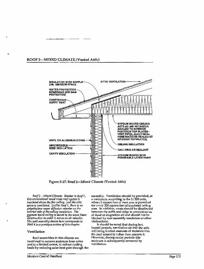
ROOF 2—MIXED CLIMATE (Vented Attic)
INSULATION WIND BAFFLE 2-IN. MINIMUM SPACE
WATER PROTECTION MEMBRANE (ICE DAM PROTECTONj
CONTINUOUS SOFFIT VENT
VINYL OR ALUMINUM SIDING
IMPERMEABLE RIGID INSULATION
CAVITY INSULATION
GYPSUM BOARD CEILING ACTS AS AIR RETARDER (SEALED TO INTERIOR PARTITION TOP PLATES- VENT PIPES, ELECTRICAL PENETRATIONS SEALED AT INTERIOR TOP PLATES)
CEIUNG INSULATION
CAULKING OR SEALANT
GYPSUM BOARD WITH PERMEABLE LATEX PAINT
Figure 5-17: Roof 2—Mixed Climate (Vented Attic)
Roof 2—Mixed Climate: Similar to Roof l, this eonventiotuil wood truss roof system is insulated above the flat ceiling, and the attic space is ventilated. Unlike Roofl, there is no polyethylene vapor diffusion retarder on the interior side of the ceiling insulation. The gypsum board ceiling is sealed to the wood frame construction in order to act as an air retarder. The wall assembly shown here corresponds to Wall Una previous section of this chapter.
Ventilation
Roof assemblies in this climate are ventilated to remove moisture from attics and to a limited extent, to reduce cooling loads by reducing solar heat gain through the
assembly. Ventilation should be provided, at a minimum, according to the 1/300 ratio, where 1 square foot of vent area is provided for every 300 square feet of insulated ceiling area. In addition, vents should be distributed between the soffit and ridge to prevent zones of dead or stagnation air and should not be blocked by roof assembly insulation or other obstructions.
It should be noted that during hot, humid periods, ventilation air into the attic will bring limited amounts of moisture into the roof assembly rather than, remove it. However, during cooler periods this moisture is subsequently removed by ventilation.
Moisture Control Handbook Page 171
ROOF 2—MIXED CLIMATE (CONTINUED)
Air Movement
During the heating season, airborne moisture exfiltrates from the enclosure into the attic. To control this, the enclosure is depressurized relative to the attic and the exterior, and air leakage openings are limited (tight ceiling construction).
During the cooling season, airborne moisture infiltrates from the attic into the enclosure. This is controlled by pressurizing the enclosure relative to the attic and the exterior and limiting air leakage openings (tight ceiling construction).
Vapor Diffusion
Moisture diffuses from the enclosure into the attic during the heating season. It is controlled by limiting enclosure moisture levels to below 35 percent relative humidity at 70 degrees Fahrenheit.
In this example, moisture movement by diffusion from the attic into the enclosure during the cooling season is not controlled. In other words, there is no ceiling vapor diffusion retarder. Omitting the ceiling vapor diffusion retarder in this climate provides acceptable assembly performance when impermeable ceiling finishes, paints, and textured treatments are also not installed. Accordingly, these impermeable interior ceiling surface finishes should be avoided if this approach is utilized.
Comments
A wind baffle should be installed at the perimeter of the roof area where the insulated ceiling intersects the exterior wall, This prevents thermal short -circuiting of the insulation by wind (wind-washing). In this climate, wind-washing by hot, humid air during the cooling season can induce moisture deposition on perimeter wall top plate and ceiling gypsum board surfaces cooled by air conditioning. Wind-washing by cold air during the heating season can cool the perimeter wall top plate and ceiling gypsum board surfaces and cause subsequent interior mold and mildew growth.
Exterior ventilation air entering soffit assemblies experiences a pressure drop as the soffit assembly acts as an expansion space. This is due to the combination of a narrow soffit vent opening up to a relatively large volume soffit assembly and then being squeezed into a narrow space between the underside of the roof sheathing and the wind baffle. This pressure drop induces the ventilation air to deposit airborne rain droplets and snow in the soffit assembly rather transport them farther into the roof assembly. Accordingly, it may be desirable to back prime wood soffit materials.
Ice damming in this climate is controlled by a water protection membrane at the eave and by providing sufficient thermal insulation and air tightening at the intersection of the perimeter wall and ceiling to reduce heat loss, which can lead to snow melt. In addition, the soffit assembly is ventilated to flush heat from the conditioned space away from the roof sheathing to maintain a cold deck.
Page 172 Chapters—Moisture Control Practices for Mixed Climates
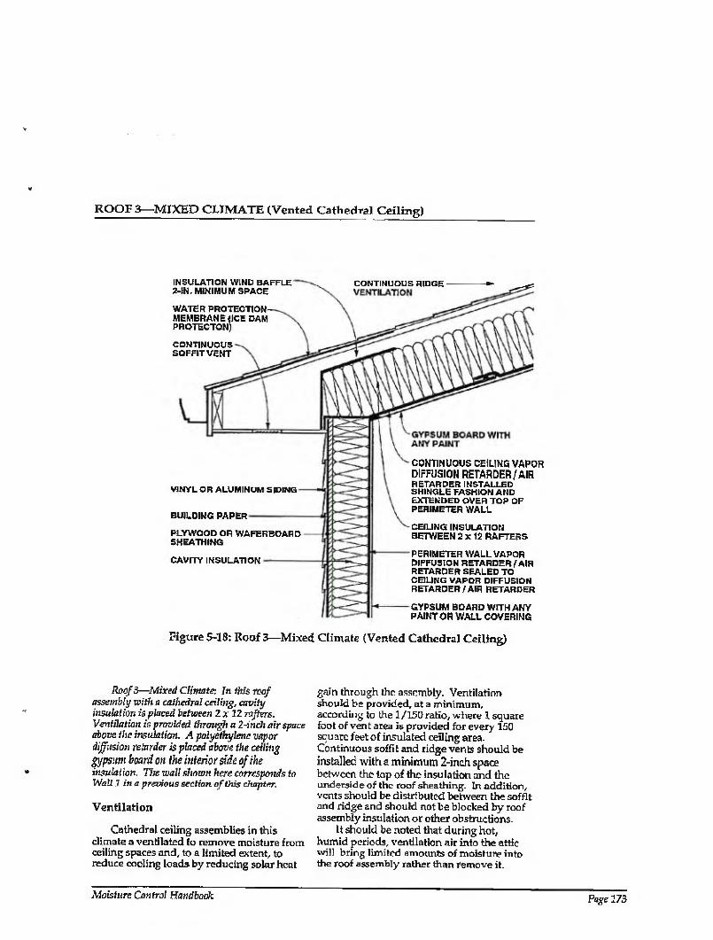
ROOr 3—MIXED CLIMATE (Vented Cathedral Ceiling)
INSULATION WIND BAFFLE 2-IN. MINIMUM SPACE
WATER PROTECTION MEMBRANE (ICE DAM PROTECTOH)
CONTINUOUS SOFFITVENT
CONTINUOUS RIDGE
VINYL OR ALUMINUM SIDING
BUILDING PAPER
PLYWOOD OR WAFER BOARD SHEATHING
CAVITY INSULATION
CONTINUOUS CEILING VAPOR DIFFUSION RETARDER/AIR RETARDER INSTALLED SHINGLE FASHION AND EXTENDED OVER TOP OF PERIMETER WALL
CEILING INSULATION BETWEEN 2x12 RAFTERS
PERIMETER WALL VAPOR DIFFUSION RETARDER/ AIR RETARDER SEALED TO CEILING VAPOR DIFFUSION RETARDER/AIR RETARDER
GYPSUM BOARD WITH ANY PAINT OR WALL COVERING
figure 5-18: Roof 3—Mixed Climate (Vented Cathedra) Ceiling)
Roof 3—Mixed Climate: In this roof assembly with a cathedral ceiling, cavity insulation is placed between 2 x 12 rafters. Ventilation is provided through a 2-inch air space above the insulation. A polyethylene vapor diffusion retarder is placed above the ceiling
gypsm board on the interior side of the insulation. The wall shown here corresponds to Wall 1 in a previous section of this chapter.
Ventilation
Cathedral ceiling assemblies in this climate a ventilated to remove moisture from ceiling spaces and, to a limited extent, to reduce cooling loads by reducing solar heat
gain through the assembly. Ventilation should be provided, at a minimum, according to the 1/150 ratio, where 1 square fool of vent area is provided for every 150 square feet of insulated ceiling area. Continuous soffit and ridge vents should be installed with a minimum 2-inch space between the top of the insulation and the underside of the roof sheathing. In addition, vents should be distributed between the soffit and ridge and should not be blocked by roof assembly insulation or other obstructions.
It should be noted that during hot, humid periods, ventilation air into the attic will bring limited amounts of moisture into the roof assembly rather than remove it.
Moisture Control Handbook Page 173
ROOF 3—MIXED CLIMATE (CONTINUED)
However, during cooler periods this moisture is subsequently removed by the same ventilation air.
Air Movement
During the heating season, airborne moisture exfiltrates from the enclosure into the cathedral ceiling space. To control this, the enclosure is depressurized relative to the cathedral ceiling and the exterior, and air leakage openings are limited (tight ceiling construction).
During the cooling season, moisture infiltrates from the cathedral ceiling space into the enclosure. It is controlled by pressurizing the enclosure relative to the cathedral ceiling and the exterior and limiting air leakage openings (tight ceiling construction).
Vapor Diffusion
During the heating season, moisture diffuses from the enclosure into the cathedral ceiling space. During the cooling season, moisture diffuses from the cathedral ceiling space into the enclosure. In both cases, this moisture is retarded by a continuous ceiling vapor diffusion retarder sealed to the perimeter wall vapor retarder. This continuous ceiling vapor diffusion retarder can also act as the air retarder system.
Comments
The continuous ceiling vapor diffusion retarder is installed shingle fashion and extended over the top of the exterior perimeter wall. This allows any condensed moisture to drain and provides secondary protection for roof rainwater leakage.
This continuous ceiling vapor diffusion retarder also protects the ceiling gypsum
board from moisture accumulation from the exterior during the cooling season, as well as subsequent mold and mildew growth or water staining. Therefore, impermeable wall/ceiling coverings, paints, and textured treatments may be installed.
A wind baffle should be installed at the perimeter of the cathedral ceiling area where the insulated cathedral ceiling intersects the exterior wall. This prevents thermal short- circuiting of the insulation by wind (wind¬ washing). In this climate, wind-washing by hot, humid air during the cooling season can induce moisture deposition on perimeter wall top plate and ceiling gypsum board surfaces cooled by air conditioning. Wind¬ washing by cold air during the heating season can cool the perimeter wall top plate and ceiling gypsum board surfaces and cause subsequent interior mold and mildew growth.
Exterior ventilation air entering soffit assemblies experiences a pressure drop as the soffit assembly acts as an expansion space. This is due to the combination of a narrow soffit vent opening up to a relatively large volume soffit assembly and then being squeezed into a narrow space between the underside of the roof sheathing and the wind baffle. This pressure drop induces the ventilation air to deposit airborne rain droplets and snow in the soffit assembly rather transport them farther into the roof assembly. Accordingly, it may be desirable to back prime wood soffit materials.
Ice damming in this climate is controlled by a water protection membrane at the eave and by providing sufficient thermal insulation and air tightening at the intersection of the perimeter wall and ceiling to reduce heat loss, which can lead to snow melt. In addition, the soffit assembly is ventilated to flush heat from the conditioned space away from the roof sheathing to maintain a cold deck.
Page 174 Chapter 5—Moisture Control Practices for Mixed Climates
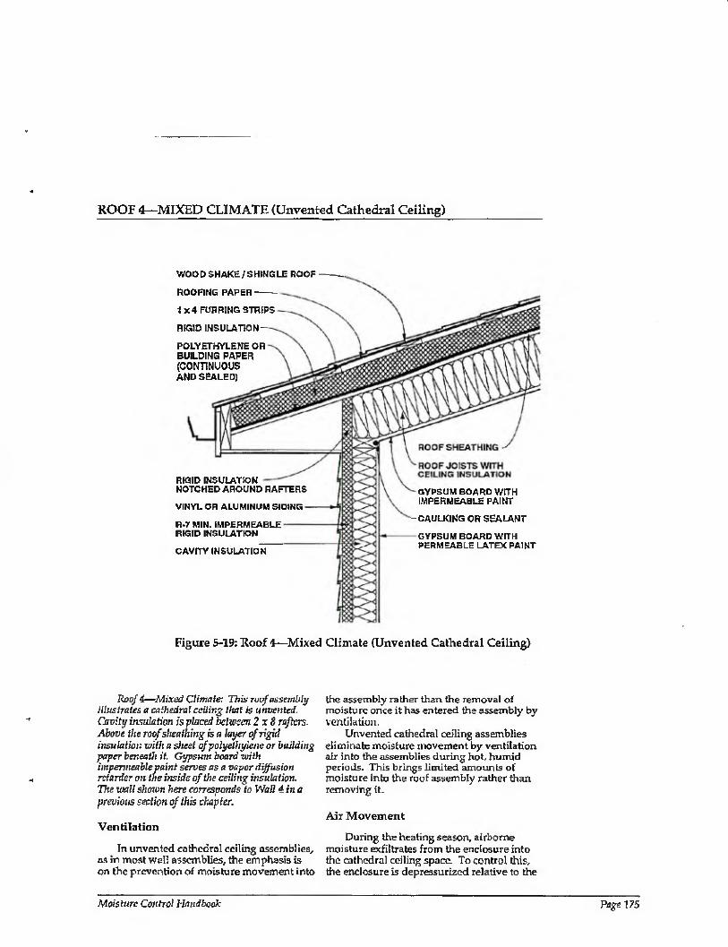
ROOF 4—MIXED CLIMATE (Unvented Cathedral Ceiling)
WOOD SHAKE/SHINGLE ROOF
ROOFING PAPER-
1x4 FURRING STRIPS
RIGID INSULATION
POLYETHYLENE OR BUILDING PAPER (CONTINUOUS AND SEALED)
RIGID INSULATION NOTCHED AROUND RAFTERS
VINYL OR ALUMINUM SIDING
R-7 MIN. IMPERMEABLE RIGID INSULATION
CAVITY INSULATION
GYPSUM BOARD WITH IMPERMEABLE PAINT
-CAULKING OR SEALANT
GYPSUM BOARD WRH PERMEABLE LATEX PAINT
Figure 5-19: Roof 4—Mixed Climate (Unvented Cathedral Ceiling)
Roof 4—Mixed Climate; This roof assembly illustrates a cathedral ceiling that is unvented. Cavity insulation is placed between 2x8 rafters. Above the roof sheathing is a layer of rigid insulation with a sheet of polyethylene or building paper beneath it Gypsum board with impermeable paint serves as a vapor diffusion retarder on the inside of the ceiling insulation. The wall shown here corresponds to Wall 4 in a previous section of this chapter.
Ventilation
In unvented cathedral ceiling assemblies, as in most wall assemblies, the emphasis is on the prevention of moisture movement into
the assembly ralher than the removal of moisture once it has entered the assembly by ventilation,
Unvented cathedral ceiling assemblies eliminate moisture movement by ventilation air into the assemblies during hot, humid periods. This brings limited amounts of moisture into the roof assembly rather than removing it.
Air Movement
During ttie heating season, airborne moisture exfiltrates from the enclosure into the cathedral ceiling space. To control this, the enclosure is depressurized relative to the
A'fcisfiw Control Handbook Page 175

ROOF 4—MIXED CLIMATE (CONTINUED)
cathedral ceiling and the exterior, and air leakage openings are limited (tight ceiling construction).
During the cooling season, airborne moisture infiltrates from the cathedral ceiling space into the enclosure. It is controlled by pressurizing the enclosure relative to the cathedral ceiling and the exterior and by limiting air leakage openings.
During the heating season, warm moisture-laden interior air exfiltrates, while during the cooling season hot, humid air infiltrates. To control moisture movement in this assembly, the interior gypsum wall board is sealed to the roof joist framing, and polyethylene is installed under the exterior rigid insulation. This air sealing can be adhesive, caulk, or some other sealant. Experience has shown that some exterior rigid insulations are thermally unstable, and may not be compatible with sealing techniques which provide little allowance for movement.
Vapor Diffusion
During heating periods, vapor diffusion from the interior may transmit moisture into
the cathedral ceiling assembly, where it accumulates. To control this, the temperature of the first condensing surface within the cathedral ceiling assembly is elevated, namely, the cavity side of the rigid insulation installed on top of the roof joists. In this example rigid insulation of sufficient thermal resistance is installed to limit periods of potential condensation to acceptable levels. An acceptable period would be sufficiently brief so that wood does not begin to decay or interior surface water stain marks or mold or mildew do not appear. This period is determined by the temperature of the first condensing surface and the interior moisture level. The temperature of the first condensing surface is determined by the ratio of the amount of thermal insulation installed to the exterior of the condensing surface compared to the amount of thermal insulation installed to the interior of the condensing surface. For this cathedral ceiling assembly in this climate zone, the thermal resistance of the rigid insulation should be R- 15 or greater, and the thermal resistance of
cavity insulation should be R-28 or less,
where an interior vapor diffusion retarder is not utilized. Furthermore, interior moisture
levels should be limited to 35 percent relative humidity at 70 degrees Fahrenheit during heating periods.
During the cooling season, moisture diffuses from the exterior into the cathedral ceiling assembly. Rigid insulation over the top of the roof joists is installed to retard this movement (the rigid insulation acts as a vapor diffusion retarder).
Rain
A rain screen controls rain penetration in this roof assembly. The rain screen principle requires a pressure-equalized cavity behind the wood shakes/shingles to perform satisfactorily. In this example wood shakes/ shingles are installed over a roofing paper. The shakes/shingles are loose; the roofing paper is tight. A roofing paper woven into the shakes/shingles installed over the top of the furring strips also helps drain rainwater to the exterior. Appropriate installation of flashings is critical in rain screen wood shake/shtngle assemblies.
Rain Absorption/Capillary Suction
An air space controls rain absorption by the wood shakes/shingles, and wood shake/ shingle capillarity effects. The air space, behind the wood shakes/shingles, acts as a receptor for both shake/shingle capillary moisture and shake/shingle absorbed moisture driven inward by incident solar radiation. Wood shakes/shingles can also be dipped (painting or coating the front and back surfaces) to limit their capillary and vapor absorption of moisture.
Comments
Impermeable rigid insulation on the exterior of the roof framing limits drying towards the exterior.
Interior moisture levels should be limited to 35 percent relative humidity at 70 degrees Fahrenheit during heating periods. This is needed to further control airborne moisture and vapor diffusion with this cathedral ceiling assembly, since only limited drying of the assembly occurs.
Depending on its permeance, the facing
material on faced batt insulations installed with the facing towards the interior can also act as an interior vapor diffusion retarder.
Page 176 Chapter 5—Moisture Control Practices for Mixed Climates
ROOF 4—MIXED CLIMATE (CONTINUED)
The cathedral ceiling assembly may not dry (1) where impermeable interior surface treatments are utilized, such as wall coverings and impermeable paints, or (2) if it becomes wet during service or is built wet through the use of wet framing materials or wet-applied cavity insulations (wet spray cellulose or blown fiberglass). Accordingly, dry framing materials (wood at a moisture content of 19 percent by weight or lower) and dry-applied insulations are recommended in such applications. Alternatively, cathedral ceiling assemblies should be allowed to dry prior to enclosure.
Cathedral ceiling assemblies with permeable interior surface treatments that have been performing satisfactorily in service are sometimes subsequently covered with impermeable interior surface treatments. For example, new owners or tenants may repaint with impermeable paints or wall coverings. In these cases, mold and mildew problems may appear at the gypsum board/surface treatment interface if the previously mentioned moisture control strategies have not been effectively utilized.
A wind baffle should be installed at the perimeter of the cathedral ceiling area where the insulated cathedral ceiling intersects the exterior wall. This prevents thermal short- circuiting of the insulation by wind (wind- washing). In this climate, wind-washing by hot, humid air during the cooling season can induce moisture deposition on perimeter wall top plate and ceiling gypsum board surfaces cooled by air conditioning. Wind¬ washing by cold air during the heating season can cool the perimeter wall top plate and ceiling gypsum board surfaces and cause subsequent interior mold and mildew growth. In this particular example, extending the exterior rigid insulation on the perimeter wall up so that it intersects the underside of the rigid insulation installed on top the roof joists, will effectively control
wind-washing. The rigid insulation installed in this roof assembly is typically fastened with long wood screws passing through the 1 x4 furring strips.
Ice damming in this climate is controlled by (1) a water protection membrane at the eave (the roofing paper woven into the wood shakes/shingles), and (2) providing sufficient thermal insulation and air tightening at the intersection of the perimeter wall and ceiling to reduce heat loss, which can lead to snow melt.
Some un vented roof assemblies have led to an elevation of shingle/shake/sheathing temperatures and subsequently to premature degradation of shingles/shakes/sheathings and a reduced service life. Accordingly, light-colored shakes/shingles should be utilized. In addition, it may be desirable to install roofing papers to provide additional protection against rainwater entry should shakes/shingles deteriorate prematurely.
CHAPTER 5: REFERENCES
5.1 American Society of Heating, Refrigerating and Air Conditioning Engineers, Inc., Ventilation for Acceptable bidoor Air Quality, ASHRAE Standard 62 - 1989, Atlanta, Georgia, 1989.
5.2 Carmody, J., J. Christian, and K. 1 abs. Builder's Foundation Handbook, Oak Ridge National Laboratory, ORNL/ CON-295,1991.
5.3 Godish, Tv Indoor Air Pollution Control, Lewis Publishers, Chelsea, Michigan, 1989.
5.4 National Forest Products Association, Permanent Wood Foundation System: Design, Fabrication and Installation Manual, Washington, D.C., 1987.
Moisture Control Handbook Page 277
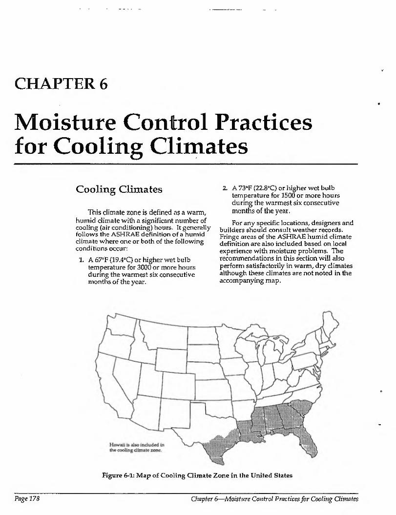
CHAPTER 6
Moisture Control Practices for Cooling Climates
Cooling Climates
This climate zone is defined as a warm, humid climate with a significant number of cooling (air conditioning) hours. It generally follows the ASHRAE definition of a humid climate where one or both of the following conditions occur:
1. A 670F (19.4°C) or higher wet bulb temperature for 3000 or more hours during the warmest six consecutive months of the year.
2. A 73°F (22.8°C) or higher wet bulb temperature for 1500 or more hours during the warmest six consecutive months of the year.
For any specific locations, designers and builders should consult weather records. Fringe areas of the ASHRAE humid climate definition are also included based on local experience with moisture problems. The recommendations in this section will also perform satisfactorily in warm, dry climates although these climates are not noted in the accompanying map.
Figure 6-1: Map of Cooling Climate Zone in the United States
Page 178 Chapter 6—Moisture Control Practices for Cooling Climates
KEY CONCERNS AND CONTROL STRATEGIES
In warm humid climates the principle moisture concerns are rain penetration, groundwater, and mold and mildew. High exterior levels of humidity encourage mold and mildew growth, as do cool interior surfaces due to the air conditioning of enclosures.
The absence of ground frost penetration concerns in this climate zone has created a preponderance of crawl space and ground slab construction. Basement foundations are rare, if not completely nonexistent. Both frame walls and masonry walls are common.
Rain and Groundwater
Rain penetration and groundwater concerns are common to builders in ail climates, and control methods are similar in this climate to those of other climates. These include the rain screen; building papers; appropriate placement of flashings, gutters, and downspouts which direct water away from foundations; careful site grading; and subgrade drainage.
Another source of external water—air conditioning condensate drains—should be plumbed directly to the graywater system.
Moisture within Building Assemblies
Cladding systems which can absorb significant amounts of moisture when exposed to rain, such as brick, masonry, wood, and stucco, should only be incorporated in certain wall assemblies. Such assemblies are designed and built to deal with tire inward migration of moisture driven by temperature gradients from the exterior to the interior. Solar radiation warming exterior wall surfaces creates these gradients, along with the air conditioning of interior surfaces. Problems often arise where this is not taken into account, such as the installation of vinyl- wallpaper-covered gypsum wall board on the interior of a masonry block wall without provision for an appropriate vapor diffusion retarder and air barrier system. The retarder and barrier protect the gypsum wall board from this exterior moisture or from construction moisture, which may be trapped in the masonry units.
Thus, wherever vinyl interior wall coverings are used in this climate zone, precautions must be taken to prevent
gypsum wall board from absorbing moisture from the exterior or from construction moisture.
Where wet lumber (greater than 19 percent moisture content by weight) or wet- applied insulations (wet spray cellulose or wet blown fiberglass) are installed in building assemblies, those assemblies must be designed and built so that they can dry to either the interior or exterior, or tire materials must be allowed to dry prior to enclosure.
High Interior Humidity Resulting in Mold and Mildew
The practice of mechanical cooling coupled with some dehumidification for comfort reasons is widespread. Air leakage and vapor diffusion from the exterior thus carry moisture continuously to the interior cooled area, because outdoor vapor pressure is higher than indoor vapor pressure. The outdoor to indoor vapor pressure differences in humid climates are typically much greater than the vapor pressure differences in cold climates.
The impacts of this high inward moisture flow are manifested as elevated energy costs due to high cooling loads, building fabric deterioration from decay and corrosion, and health and safety concerns from mold and mildew growth.
Moisture may move by air leakage, i.e., the infiltration of exterior moisture-laden air. Several methods are used to control this movement; air leakage openings are limited; a positive air pressure is maintained within conditioned spaces relative to the exterior (pressurization); and forced air ductwork is located within conditioned spaces to limit the effects of duct leakage.
Moisture movement by vapor diffusion from the exterior is controlled by vapor diffusion retarders in walls, roofs, and crawl spaces.
High air change due to infiltration/ exfiltration, duct leakage, and excessive ventilation can lead to elevated interior moisture levels- This is contrary to heating climates, where the same mechanisms Lead to low levels of interior moisture. This is due to the high exterior humidity conditions present for most of the year in warm humid climates. The greater the amount of exterior air brought into an enclosure, the greater the amount of moisture brought in with it. As such, in warm, humid climates it is desirable to build tight enclosures and to ventilate
Moisture Control Handbook Page 179
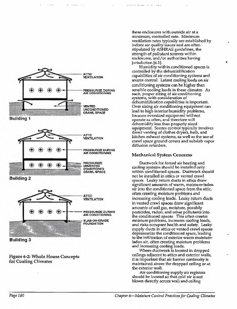
ATTIC VENTILATION
PRESSURIZE DURING AIR CONDITIONING
VENTED UNCONDITIONED CRAWL SPACE
ATTIC VENTILATION
PRESSURIZE DURING AIR CONDITIONING
PRESSURIZE UNVENTED CONDITIONED CRAWL SPACE
€>€>(§>€>-
Building 3
ATTIC VENTILATION
PRESSURIZE DURING AIR CONDITIONING
SLAB-ON-GRADE FOUNDATION
Figure 6-2: Whole House Concepts for Cooling Climates
these enclosures with outside air at a minimum, controlled rate. Minimum ventilation rates typically are established by indoor air quality issues and are often stipulated by ASHRAE guidelines, the strength of pollutant sources within enclosures, and/or authorities having jurisdiction [6.1].
Humidity within conditioned spaces is controlled by the dehumidification capabilities of air conditioning systems and source control. Latent cooling loads on air
conditioning systems can be higher than sensible cooling loads in these climates. As such, proper sizing of air conditioning systems, with consideration of dehumidification capabilities is important. Over sizing air conditioning equipment can lead to high interior humidity problems, because oversized equipment will not operate as often, and therefore will dehumidify less than properly sized equipment. Source control typically involves direct venting of clothes dryers, bath, and kitchen exhaust systems, as well as the use of crawl space ground covers and subslab vapor diffusion retarders.
Mechanical System Concerns
Ductwork for forced air heating and cooling systems should be installed only within conditioned spaces. Ductwork should not be installed in attics or vented crawl spaces. Leaky return ducts in attics draw significant amounts of warm, moisture-laden air into the conditioned space from the attic, often creating moisture problems and increasing cooling loads. Leaky return ducts in vented crawl spaces draw significant amounts of soil gas, moisture, possibly pesticides, radon, and other pollutants into the conditioned spaces. This often creates moisture problems, increases cooling loads, and risks occupant health and safety. Leaky supply ducts in attics or vented crawl spaces depressurize the conditioned space, leading to the infiltration of exterior warm moisture¬ laden air, often creating moisture problems and increasing cooling loads.
Where ductwork is located in dropped ceilings adjacent to attics and exterior walls, it is important that air barrier continuity is maintained above the dropped ceiling or at the exterior wall.
Air conditioning supply air registers should be located so that cold air is not blown directly across wall and ceiling
Page ISO Chapter 6—Moisture Control Practices for Cooling Climates
surfaces, potentially chilling the surfaces below dew point temperatures. This could cause condensation or high surface relative humidities and potential mold and mildew growth.
Air conditioning supply ductwork should be insulated and protected with an exterior vapor diffusion retarder to control condensation on cold duct surfaces.
Cold water piping may need to be insulated if exposed to warm, humid ambient or non conditioned air.
Combustion Appliances
Unvented combustion appliances such as gas stoves with standing pilot lights and room space heaters are significant sources of moisture as well as sources for other pollutants and should be avoided. Gas stoves and cook tops without standing pilot lights should be installed with vented range hoods or some other vent provision.
Where vented combustion appliances are installed they should be aerodynamically uncoupled {not influenced by enclosure air pressures or supply air availability) from the conditioned space. In other words, sealed combustion, power vented, induced draft, condensing, or pulse combustion devices should be used. Devices with traditional draft hoods should be avoided. Where fireplaces are installed, they should have their own air supply from the exterior as well as tight-fitting glass doors. Wood stoves should also have their own supply of exterior air ducted directly to their firebox.
WHOLE BUILDING SYSTEMS
Three typical whole building systems for this climate zone are listed below (see Figure 6-2):
1. Buildings with vented, unconditioned crawl spaces and vented attics
2. Buildings with unvented, conditioned crawl spaces and vented attics
3. Buildings built onground slabs and vented attics
Common features of the three systems are vented roofs and conditioned spaces maintained at a positive air pressure to the exterior.
Buildings with unvented, conditioned crawl spaces treat the crawl space as if it were part of the living area, (connected to the living area).
Positive air pressurization of the conditioned space eliminates the infiltration of exterior moisture-laden air. Positive pressurization of crawl space eliminates the infiltration of soil gas, radon, and other pollutants.
Ventilation of roof assemblies reduces cooling loads.
Wall design and construction in this climate typically locate vapor diffusion retarders and measures to control air leakage towards the exterior. In this climate it is convenient to allow walls to dry to the interior in the direction of typical vapor flow. Drying to the exterior is possible, but more difficult to facilitate and is usually intermittent.
Moisture Control Handbook Page 181
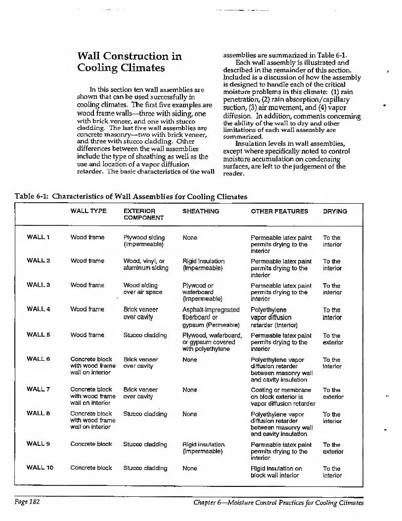
Wall Construction in Cooling Climates
In this section ten wall assemblies are shown that can be used successfully in cooling climates. The first five examples are wood frame walls—three with siding, one with brick veneer, and one with stucco cladding. The last five wall assemblies are concrete masonry—two with brick veneer, and three with stucco cladding. Other differences between the wall assemblies include the type of sheathing as well as the use and location of a vapor diffusion retarder. The basic characteristics of the wall
assemblies are summarized in Table 6-1. Each wall assembly is illustrated and
described in the remainder of this section. Included is a discussion of how the assembly is designed to handle each of the critical moisture problems in this climate: (1) rain penetration, {2) rain absorption/capillary suction, (3) air movement, and (4) vapor diffusion. In addition, comments concerning the ability of the wall to dry and other limitations of each wall assembly are summarized.
Insulation levels in wall assemblies, except where specifically noted to control moisture accumulation on condensing surfaces, are left to the judgement of the reader.
Table 6-1: Characteristics of Wall Assemblies for Cooling Climates
WALL TYPE EXTERIOR SHEATHING OTHER FEATURES DRYING COMPONENT
WALL 1
WALL 2
WALL 3
WALL 4
WALLS
WALL 6
WALL?
WALL 8
WALL 9
WALL 10
Wood frame
Wood frame
Wood frame
Wood frame
Wood frame
Concrete block with wood frame wall on interior
Concrete block with wood frame wall on interior
Concrete block with wood frame wall on interior
Concrete block
Concrete block
Plywood siding (Impermeable)
Wood, vinyl, or aluminum siding
Wood siding over air space
Brick veneer over cavity
Stucco cladding
Brick veneer over cavity
Brick veneer over cavity
Stucco cladding
Stucco cladding
Stucco cladding
None
Rigid insulation (Impermeable)
Plywood or waterboard (Impermeable)
Asphalt-impregnated fiberboard or gypsum (Permeable)
Plywood, waferboard, or gypsum covered with polyethylene
None
None
None
Rigid insulation (Impermeable)
None
Permeable latex paint To the permits drying to the interior interior
Permeable latex paint To the permits drying to the interior interior
Permeable latex paint To the permits drying to the interior intenor
Polyethylene To the vapor diffusion interior retarder (Interior)
Permeable latex paint To the permits drying to the exterior interior
Polyethylene vapor To the diffusion retarder interior between masonry wall and cavity insulation
Coating or membrane To the on block exterior is exterior vapor diffusion retarder
Polyethylene vapor To the diffusion retarder interior between masonry wall and cavity insulation
Permeable latex paint To the permits drying to the exterior interior
Rigid insulation on To the block wall interior interior
Page 182 Chapter 6—Moisture Control Practices for Cooling Climates
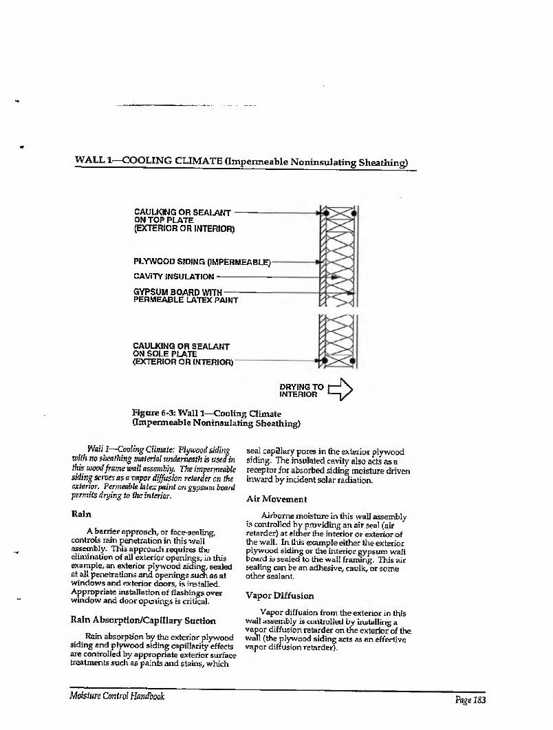
WALL 1—COOLING CLIMATE (Impermeable Noninsulating Sheathing)
CAULKING OR SEALANT ON TOP PLATE (EXTERIOR OR INTERIOR)
PLYWOOD SIDING (IMPERMEABLE)
CAVITY INSULATION ■-
GYPSUM BOARD WITH- PERMEABLE LATEX PAINT
CAULKING OR SEALANT ON SOLE PLATE (EXTERIOR OR INTERIOR)
DRYING TO I— INTERIOR '—
Figure 6-3: Wall 1—Cooling Climate (Impermeable Noninsulating Sheathing)
Wall 1—Cooling Climate; Plywood siding wilh no sheathing material underneath is used in this wood frame wall assembly. The impermeable siding serves as a vapor diffusion retarder on the exterior. Permeable latex paint on gypsum board permits drying to the interior.
Rain
A barrier approach, or face-sealing, controls rain penetration in this wall assembly. This approach requires the elimination of all exterior openings; in this example, an exterior plywood siding, sealed at all penetrations and openings such as at windows and exterior doors, is installed. Appropriate installation of flashings over window and door openings is critical.
Rain Absorption/Capillary Suction
Rain absorption by the exterior plywood siding and plywood siding capillarity effects are controlled by appropriate exterior surface treatments such as paints and stains, which
seal capillary pores in (he exterior plywood siding. The insulated cavity also acts as a receptor for absorbed siding moisture driven inward by incident solar radiation.
Air Movement
Airborne moisture in this wall assembly is controlled by providing an air seal (air retarder) at either the interior or exterior of the wall. In this example either the exterior plywood siding or the interior gypsum wall board is sealed to the wall framing. This air sealing can be an adhesive, caulk, or some other sealant.
Vapor Diffusion
Vapor diffusion from the exterior in this wall assembly is controlled by installing a vapor diffusion retarder on the exterior of the wall (the plywood siding acts as an effective vapor diffusion retarder).
Moisture Control Handbook Page 183
WALL 1—COOLING CLIMATE (CONTINUED)
Comments
Where significant rain absorption occurs and is coupled with incident solar radiation and an air conditioned enclosure, moisture can be driven from the exterior across the entire cavity and lead to potential interior surface problems such as mold, mildew, and paint peeling- An interior polyethylene sheet has proven effective in protecting interior gypsum board and interior finishes in such situations. However, it should be noted that an interior polyethylene sheet can also reduce the drying of the wall towards the interior and should only be utilized with dry framing materials (wood at a moisture content of 19 percent by weight or less) and dry-applied insulations. Alternatively, wall assemblies must be allowed to dry prior to enclosure.
In this wall assembly, a vapor permeable paint finish on the interior gypsum wall board dries the wall toward the interior. Should the wall assembly become wet during service or be built wet through the use of wet framing materials or wet-applied cavity insulations (wet spray cellulose or blown fiberglass), it can dry to the interior. This is due to (1) an inward temperature and vapor pressure gradient present as a result of air conditioning the enclosure, and (2) ambient climatic conditions.
The facing material on faced cavity insulations can retard drying to the interior if
the facing is installed towards the interior. Faced cavity insulations can be installed where drying to the interior is not required, or alternatively, the cavity insulation can be installed with the facing material towards the outside of the cavity. In this wall assembly, faced cavity insulations installed with the facing material towards the outside of the cavity can protect the interior gypsum board and interior surface finishes from siding- absorbed moisture driven inward by incident solar radiation.
Dry framing materials (wood at a moisture content of 19 percent by weight or lower) and dry-applied insulations are recommended where impermeable surface treatments are utilized, such as wall coverings and impermeable paints. Alternatively, wall assemblies must be allowed to dry prior to enclosure.
Wall assemblies with permeable interior surface treatments that have been performing satisfactorily in service are sometimes subsequently covered with impermeable interior surface treatments. For example, new owners or tenants may repaint with impermeable paints or wall coverings. In these cases, mold and mildew problems may appear at the gypsum board/surface treatment interface if the previously mentioned moisture control strategies have not been effectively utilized.
Page 184 Chapter 6—Moisture Control Practices for Cooling Climates

WALL 2—COOLING CLIMATE (Impermeable Insulating Sheathing)
CAULKING OR SEALANT -— ON TOP PLATE (EXTERIOR OR INTERIOR)
WOOD-BASED,VINYL OR- ALUMINUM SIDING
IMPERMEABLE RIGID INSULATION
CAVITY INSULATION-
GYPSUM BOARD WITH- PERMEABLE LATEX PAINT
CAULKING OR SEALANT ON SOLE PLATE (EXTERIOR OR INTERIOR)"
DRYING TO INTERIOR
Figure 6-4; Wall 2—Cooling Climate (Impermeable Insulating Sheathing)
Wall 2—Cooling Climate: Impermeable rigid insubtion is used as the sheathing material in this wood frame wait assembly. Wood-based, vinyl, or aluminum siding is applied over the sheathing. The rigid insulation serves as a vapor diffusion retarder on the exterior. Similar to Walll, permeable latex paint on gypsum board permits drying to the interior.
Rain
A rain screen system controls rain penetration in this wall assembly where vinyl or aluminum siding is used. The barrier approach is used if the siding is wood-based. The rain screen principle requires a pressure- equalized cavity behind the cladding to perform satisfactorily. In this example vinyl or aluminum siding is installed over a tight sheathing. Cavities are created behind the vinyl or aluminum siding as a result of the siding cross sections. Cross sections filled with insulation material or support materia! are not recommended.
To equalize pressure in these cavities, the exterior sheathing must be significantly
tighter than the cladding. This is accomplished by installing the impermeable rigid insulation (the exterior sheathing) in an airtight manner (vertically, with all joints falling on framing members, with optional sealant or adhesive at sheathing joints/ edges). Alternatively, a building paper may be installed tightly (lapped or taped joints) to equalize pressure. Appropriate installation of flashings over window and door openings is critical in rain screen assemblies. They should ideally tuck in behind exterior sheathings or building papers. Where wood- based sidings are used, the tight sheathing and/or building paper control the rain.
Rain Absorption/Capillary Suction
Rain absorption by the vinyl or aluminum siding and siding capillarity effects are not a concern in this wall assembly as a result of the inherent material properties of the vinyl and aluminum. A building paper, installed only to protect the impermeable rigid insulation from water absorption, is not required in this assembly
Moisture Control Handbook Page 185
WALL 2—COOLING CLIMATE (CONTINUED)
for the same reason. If wood-based siding is used, rain
absorption and siding capillarity effects are a potential concern. Wood-based siding should be back-primed with the bottom edges carefully painted. Opening the siding laps with spacers, wedges, clips, etc. should also be considered.
Air Movement
During the cooling season, airborne moisture from the exterior (infiltration of warm humid air) is controlled by providing an air seal (air retarder) at either the interior or exterior of the wall. In this example, either the exterior impermeable rigid insulation or the interior gypsum wall board is sealed to the wall framing. This air sealing can be an adhesive, caulk, or some other sealant. An exterior air seal at the exterior rigid insulation in this example equalize pressure of the vinyl or aluminum siding itself.
Vapor Diffusion
Vapor diffusion from the exterior is controlled by a vapor diffusion retarder on the exterior of the wall. In this example an impermeable rigid insulation is installed as the exterior wall sheathing and acts as the vapor diffusion retarder.
Comments
Wall drying towards the interior is promoted by a vapor permeable paint finish
on the interior gypsum wall board. Should the wall assembly become wet during service or be built wet through the use of wet framing materials or wet-applied cavity insulations (wet spray cellulose or blown fiberglass), it can dry to the interior. This is due to (1) an inward temperature and vapor pressure gradient present as a result of air conditioning the enclosure, and (2) ambient climatic conditions.
The facing material on faced cavity insulations can retard drying to the interior if the facing is towards the wall interior. Faced cavity insulations can be installed where drying to the interior is not required, or alternatively, the cavity insulation can be installed with the facing material towards the outside of the cavity
Where impermeable surface treatments are utilized, such as wall coverings and impermeable paints, dry-applied insulations and dry framing materials (wood at a moisture content of 19 percent by weight or lower) are recommended. Alternatively, wall assemblies must be allowed to dry prior to enclosure.
Wall assemblies with permeable interior surface treatments that have been performing satisfactorily in service are sometimes subsequently covered with impermeable interior surface treatments. For example, new owners or tenants repaint with impermeable paints or wall coverings. In these cases, mold and mildew problems may appear at the gypsum board/surface treatment interface if the previously mentioned moisture control strategies have not been effectively utilized.
Page 186 Chapter 6—Moisture Control Practices for Cooling Climates
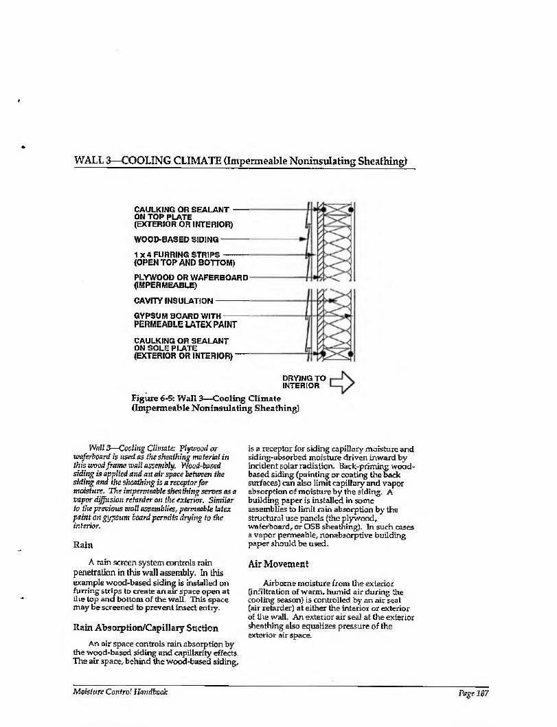
WALL 3—COOLING CLIMATE (Impermeable Noninsulating Sheathing)
CAULKING OR SEALANT - ON TOP PLATE (EXTERIOR OR INTERIOR)
WOOD-BASED SIDING -
1 X 4 FURRING STRIPS- (OPEN TOP AND BOTTOM)
PLYWOOD OR WAFERBOARD (IMPERMEABLE)
CAVITY INSULATION-
GYPSUM BOARD WITH PERMEABLE LATEX PAINT
CAULKING OR SEALANT ON SOLE PLATE (EXTERIOR OR INTERIOR)-
DRYING TO INTERIOR
Figure 6-5: Wall 3—Cooling Climate (Impermeable Noninsulating Sheathing)
Wall 3—Coding Climate; Plywood or waferboard is used as the sheathing material in this wood frmne wall assembly. Wood-based siding is applied and an airspace between the siding and the sheathing is a receptor for moisture. The impermeable shea thing serves as a vapor diffusion retarder on the exterior. Similar to the previous wall assemblies, permeable latex paint on gypsum board permits drying to the interior.
Rain
A rain screen system controls rain penetration in this wall assembly. In this example wood-based siding is installed on furring strips to create an air space open at
die lop and bollom of the wall. This space may be screened to prevent insect entry.
Rain Absorption/Capillary Suction
An air space controls rain absorption by the wood-based siding and capillarity effects. The air space, behind the wood-based siding.
is a receptor for siding capillary moisture and siding-absorbed moisture driven inward by incident solar radiation. Back-priming wood- based siding (painting or coating the back surfaces) can also limit capillary and vapor absorption of moisture by the siding. A building paper is installed in some assemblies to limit rain absorption by the structural use panels (the plywood, waferboard, or OSB sheathing). In such cases a vapor permeable, nonabsorptive building paper should be used.
Air Movement
Airborne moisture from the exterior (infiltration of warm, humid air during the cooling season) is controlled by an air seal (air retarder) at either the interior or exterior of the wall. An exterior air seal at the exterior sheathing also equalizes pressure of the exterior air space.
Moisture Control liandbeok Page 187
WALL 3—COOLING CLIMATE (CONTINUED)
Vapor Diffusion
Vapor diffusion from the exterior is controlled by installing a vapor diffusion retarder on the exterior of the wall. Structural use panels such as plywood, waferboard or OSB sheathings are impermeable and act as effective vapor diffusion retarders.
Comments
A vapor permeable paint finish on the interior gypsum wall board dries the wall towards the interior. Should the wall assembly become wet during service or be built wet through the use of wet framing materials or wet-applied cavity insulations (wet spray cellulose or blown fiberglass), it can dry to the interior. This is due to (1) an inward temperature and vapor pressure gradient present as a result of air conditioning the enclosure, and (2) ambient climatic conditions.
The facing material on faced cavity insulations can retard drying to the interior if
the facing is installed towards the wall interior. Faced cavity insulations can be installed where drying to the interior is not required. Alternatively, the cavity insulation can be installed with the facing material towards the outside of the cavity.
Where impermeable surface treatments are utilized, such as wall coverings and impermeable paints, dry-applied insulations and dry framing materials (wood at a moisture content of 19 percent by weight or lower) are recommended. Alternatively, wall assemblies must be allowed to dry prior to enclosure.
Wall assemblies with permeable interior surface treatments that have been performing satisfactorily in service are sometimes subsequently covered with impermeable interior surface treatments For example, new owners or tenants may repaint with impermeable paints or wall coverings. In these cases, mold and mildew problems may appear at the gypsum board/surface treatment interface if the previously mentioned moisture control strategies have not been effectively utilized.
Page 188 Chapter 6—Moisture Control Practices for Cooling Climates
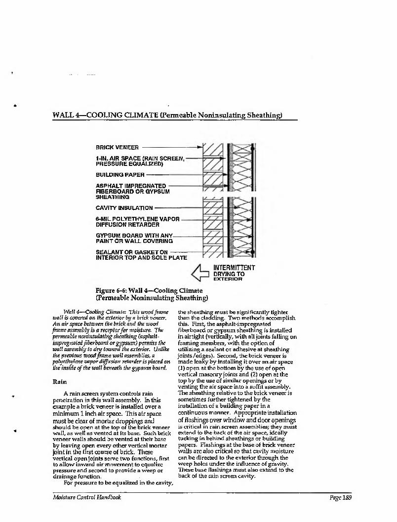
WALL 4—COOLING CLIMATE (Permeable Noninsula.ting Sheathing)
BRICK VENEER
1-IN. AIR SPACE CRAIN SCREEN, PRESSURE EQUALIZED}
BUILDING PAPER
ASPHALT IMPREGNATED F1BERBOARD OR GYPSUM SHEATHING
CAVITY INSULATION
6-MIL POLYETHYLENE VAPOR DIFFUSION RETARDER
GYPSUM BOARD WITH ANY PAINT OR WALL COVERING
SEALANT OR GASKET ON INTERIOR TOP AND SOLE PLATE
INTERMITTENT DRYING TO EXTERIOR
Figure 6-6: Wall 4—Cooling Climate (Permeable Noninsulating Sheathing)
Wall 4—Cooling Climate: This wood frame wall is covered on the exterior by a brick veneer. An air space between the brick and the wood frame assembly is a receptor for moisture. The permeable noninsulating sheathing (asphalt- impregnated fiberboard or gypsum) permits the wall assembly to dry toward the exterior. Unlike the previous wood frame wall assemblies, a polyethylene vapor diffusion retarder is placed on the inside of the wall beneath the gypsum board.
Rain
A rain screen system controls rain penetration in this xvall assembly. In this example a brick veneer is installed over a minimum 1 inch air space. This air space must be dear of mortar droppings and should be open at the top of the brick veneer wall, as well as vented at its base. Such brick veneer walls should be vented at their base by leaving open every other vertical mortar joint in the first course of brick. These vertical open joints serve two functions, first to allow inward air movement to equalize pressure and second to provide a weep or drainage function.
For pressure to be equalized in the cavity.
the sheathing must be significantly tighter than the cladding. Two methods accomplish this. First, the asphalt-impregnated fiberboard or gypsum sheathing is installed in airtight (vertically, with all joints falling on framing members, with the option of utilizing a sealant or adhesive at sheathing joints/edges). Second, the brick veneer is made leaky by installing it over an air space (1) open at the bottom by the use of open vertical masonry joints and (2) open at the top by the use of similar openings or by venting the air space into a soffit assembly. The sheathing relative to the brick veneer is sometimes further tightened by the installation of a building paper in a continuous manner. Appropriate installation of flashings aver window and door openings is critical in rain screen assemblies; they must extend to the back of the air space, ideally tucking in behind sheathings or building papers. Flashings at the base of brick veneer walls are also critical so that cavity moisture can be directed to the exterior through the weep holes under the influence of gravity. These base flashings must also extend to the back of the rain screen cavity.
Moisture Control Handbook Page 189

WALL 4—COOLING CLIMATE (CONTINUED)
Rain Absorption/Capillary Suction.
An air space behind the brick veneer controls rain absorption by the brick veneer and brick veneer capillarity effects. The air space acts as a receptor for both brick veneer capillary moisture and brick veneer absorbed moisture driven inward by incident solar radiation. A building paper is installed in some assemblies to limit rain absorption by the asphalt-impregnated fiberboard or gypsum sheathing. In such cases a vapor permeable, nonabsorptive building paper should be used.
Air Movement
Air may transport moisture from the exterior during the cooling season (infiltration of warm, humid air). It is controlled by providing an air seal (air retarder) at either the interior or exterior of the wall. In this example either the exterior asphalt-impregnated fiberboard or gypsum sheathing is sealed to the wall framing, or the interior gypsum wall board or polyethylene vapor diffusion retarder is sealed to the wall framing. This air sealing can be with an adhesive, caulk, or some other sealant.
An exterior air seal at the asphalt- impregnated fiberboard or gypsum sheathing also equalizes the pressure of the exterior air space. As a practical note of caution, it has proven difficult in practice to seal asphalt- impregnated fiberboard sheathing. As such, in wall assemblies with asphalt-impregnated fiberboard sheathing, the plane of airtightness is often located to the interior of the wall assembly at the interior gypsum board or polyethylene vapor diffusion retarder. Alternatively, a building paper located to the exterior of the sheathing can be used to provide the air seal.
Vapor Diffusion
Vapor diffusion from the exterior is controlled by installing a vapor diffusion retarder at the interior of the wall assembly between the wall framing and the interior gypsum board. Although a vapor diffusion retarder at this location in this climate does not prevent moisture diffusion into the wall, the vapor diffusion retarder effectively
protects the interior gypsum board and any interior finishes from moisture damage and also reduces the latent cooling load of the Structure-
Comments
The interior vapor diffusion retarder often gets wet on the cavity side during the day as a result of exterior absorbed moisture in the brick veneer driven inward by incident solar radiation. This moisture then typically migrates outward in the evening when the temperature gradient reverses. This wall assembly in this climate typically gets intermittently wet from the exterior and also dries intermittently to the exterior. Since intermittent wetting of the vapor diffusion retarder is common, this interior vapor diffusion retarder must be continuous to provide satisfactory performance. Foil- backed interior gypsum board is typically not effective due to discontinuities at joints. Foil- back insulation batts are also not effective for the same reason. A continuous polyethylene vapor diffusion retarder has proven to be effective in this type of assembly.
In extreme hot, humid conditions, the temperature of the interior vapor diffusion retarder and the interior gypsum board may be below the dew point temperature of the ambient air for extended periods of time if the enclosure is heavily air conditioned. Significant condensation may occur at the interior vapor diffusion retarder under such extreme conditions, and alternative control strategies may need to be considered.
A vapor permeable sheathing on the exterior of the wall framing promotes intermittent wall drying towards the exterior, as docs an air space between the cladding (brick veneer) and the sheathing, which acts as a receptor for interior cavity moisture. Should the wall assembly become wet during service or be built wet through the use of wet framing materials or wet-applied cavity insulations (wet spray cellulose or blown fiberglass), it can dry intermittently to the exterior into the air space behind the brick veneer during cool weather or during evenings.
Either vapor permeable or vapor impermeable surface finishes may be used with this wall assembly.
Page J90 Chapters—Moisture Control Practices for Cooling Climates
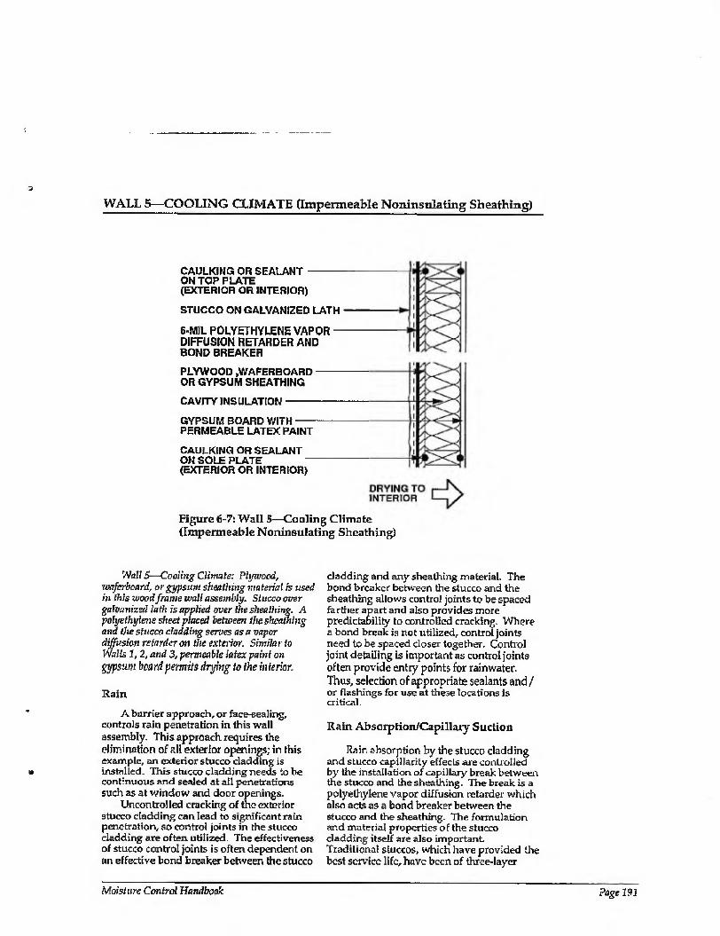
WALL 5—COOLING CLIMATE (Impermeable Noninsulating Sheathing)
CAULKING OR SEALANT - ON TOP PLATE (EXTERIOR OR INTERIOR)
STUCCO ON GALVANIZED LATH
6-MIL POLYETHYLENE VAPOR - DIFFUSION RETARDER AND BOND BREAKER
PLYWOOD ,WAFERBOARD - OR GYPSUM SHEATHING
CAVITY INSULATION-
GYPSUM BOARD WITH- PERMEABLE LATEX PAINT
CAULKING OR SEALANT ON SOLE PLATE (EXTERIOR OR INTERIOR)
Figure 6-7: Wall 5—Coaling Climate (Impermeable Noninsulating Sheathing)
Wall 5—Crmlittg Climate: Plywood, Tvaferboard, or gypsum sheathing material is used in this wood frame wall assembly. Stucco over galvanized lath is applied over the sheathing. A polyethylene sheet placed between the sheathing and the stucco cladding serves as a vapor diffusion retarder on the exterior. Similar to Walls 1, 2, and 3, permeable latex paint on pjpsum board permits drying to the mterior.
Rain
A barrier approach, or face-sealing, controls rain penetration in this wall assembly. This approach requires the elimination of all exterior openings; in this example, an exterior stucco cladding is installed. This stucco cladding needs to be continuous and sealed at all penetrations such as at window and door openings.
Uncontrolled cracking of the exterior stucco cladding can lead to significant rain penetration, so control joints in the stucco cladding are often utilized The effectiveness of stucco control joints is often dependent on an effective bond breaker between the stucco
cladding and any sheathing material- The bond breaker between the stucco and the sheathing allows control joints to be spaced farther apart and also provides more predictability to controlled cracking. Where a bond break is not utilized, control joints need to be spaced closer together. Control joint detailing is important as control joints often provide entry points for rainwater, Thus, selection of appropriate sealants and / or flashings for use at these locations is critical.
Rain Absorption/Capillary Suction
Rain absorption by the stucco cladding and stucco capillarity effects are controlled by the installation of capillary break between the stucco and the sheathing. The break is a polyethylene vapor diffusion retarder which also acts as a bond breaker between the Stuccoand the sheathing. The formulation and material properties of the stucco cladding itself are also important. Traditional stuccos, which have provided the best service life, have been of three-layer
Moisture Control Handbook Page 191
WALL 5—COOLING CLIMATE (CONTINUED)
composition, where each successive layer to the exterior is weaker and more permeable than the layer under it. In other words, the base coat is the thickest and has the lowest water to cement ratio, and therefore is the most impermeable. The second coat is thinner and weaker (more permeable) than the base coat, and the finish coat is the thinnest, weakest and most permeable of the three. The rationale for this approach is that the farther inward from the exterior that water penetrates, the more difficult it becomes for the water to go farther. Conversely, once water has penetrated the stucco it is always easier for it to migrate to the exterior than any farther to the interior. Accordingly, any paint finishes or hydrophobic sealants installed over the outermost surface of a stucco cladding need to be more permeable than the outermost surface of the stucco cladding. This is typically very difficult to achieve in practice; as such, stains or colorants added to stuccos during stucco application are often more successful than paint films subsequently applied.
Rain absorption by the stucco cladding and stucco capillarity effects can also be controlled by exterior paint films and hydrophobic coatings. However, caution and judgment need to be exercised in the application of this control strategy. Although these coatings reduce rain absorption and capillarity, these same coatings also often retard the drying of the wall assembly to the exterior should it become wet through other mechanisms.
Air Movement
Airborne moisture from the exterior (infiltration of warm, humid air during the cooling season) in this wall assembly is controlled by providing an air seal (air retarder) at either the interior or exterior of the wall.
Vapor Diffusion
Vapor diffusion from the exterior in this wall assembly is controlled by a vapor
diffusion retarder on the exterior of the wall. In this assembly, the vapor diffusion retarder is the polyethylene sheet that also acts as tire capillary break and tire bond breaker between the stucco cladding and the sheathing.
Comments
In this wall assembly, a vapor permeable paint finish on the interior gypsum wall board promotes wall drying towards the interior. Should the wall assembly become wet during service or be built wet through the use of wet framing materials or wet- applied cavity insulations (wet spray cellulose or blown fiberglass), it can dry to the interior- This is due to (1) an inward temperature and vapor pressure gradient present as a result of air conditioning the enclosure, and (2) ambient climatic conditions.
The facing material on faced cavity insulations can retard drying to the interior, if the facing is installed towards the interior of the wall. Faced cavity insulations can be installed where drying to the interior is not required, or alternatively, the cavity insulation can be installed with the facing material towards the outside of the cavity
Dry framing materials (wood at a moisture content of 19 percent by weight or lower) and dry applied insulations are recommended where impermeable surface treatments are utilized, such as wall coverings and impermeable paints. Alternatively, wail assemblies must be allowed to dry prior to enclosure.
Wall assemblies with permeable interior surface treatments that have been performing satisfactorily in service are sometimes subsequently covered with impermeable interior surface treatments. For example, new owners or tenants may repaint with impermeable paints or wall coverings. In these cases, mold and mildew problems may appear at the gypsum board/surface treatment interface if the previously mentioned moisture control strategies have not been effectively utilized.
Page 192 Chapter 6—Moisture Control Practices for Cooling Climates
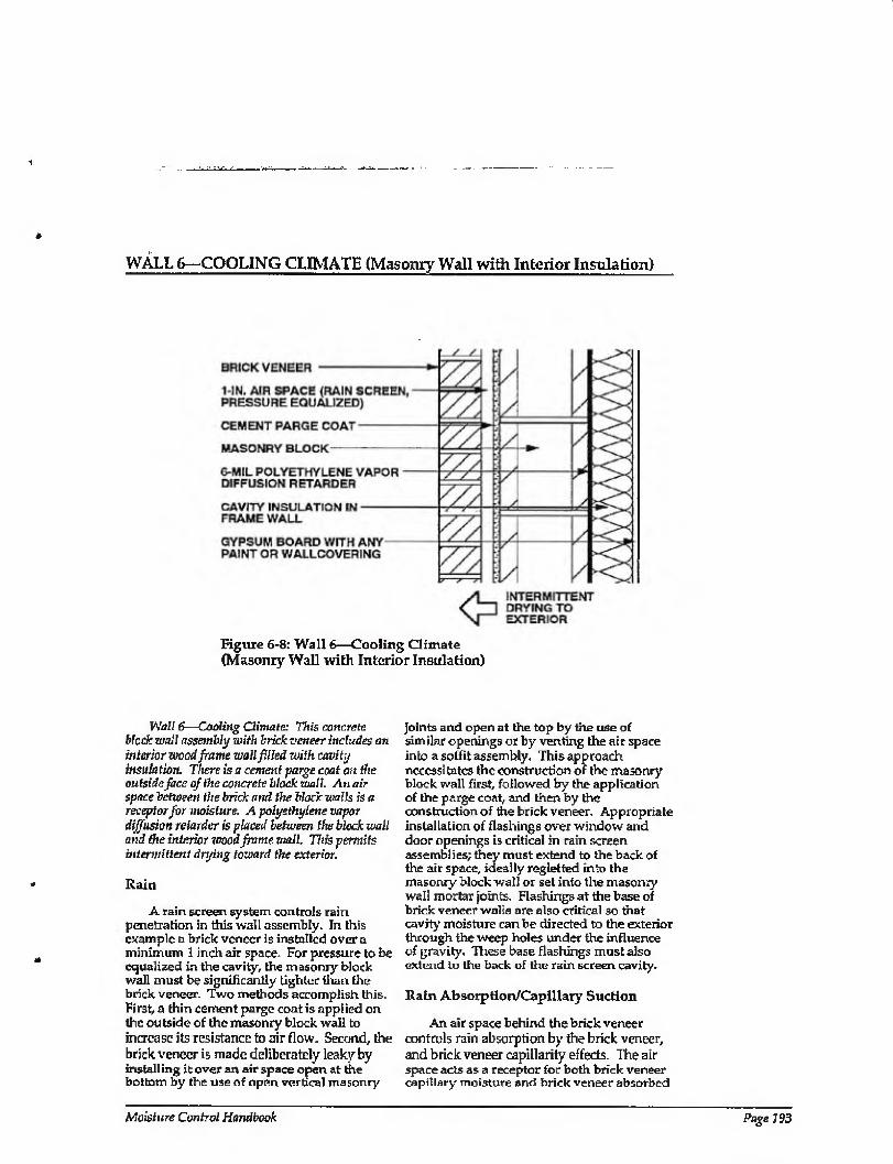
WALL 6—COOLING CLIMATE (Masonry Wall with Interior Insulation)
Figure 6-8: Wall 6—Cooling Climate (Masonry Wall with Interior Insulation)
Wall 6—Cooling Climate: This concrete block wall assembly with brick veneer includes an interior wood frame wall filled with cavity insulation. There is a cement parge coat on the outside face of the concrete block wall. An air space between the brick and the block walls is a receptor for moisture. A polyethylene vapor diffusion retarder is placed between the block wall and the interior wood frame wall. This permits intermittent drying toward the exterior.
Rain
A rain screen system, controls rain penetration in this wall assembly. In this example a brick veneer is installed over a minimum 1 inch air space. For pressure to be equalized in the cavity, the masonry block wall must be significantly tighter than the brick veneer. Two methods accomplish this. First, a thin cement parge coat is applied on the outside of the masonry block wall to increase its resistance to air flow. Second, the brick veneer is made deliberately leaky by installing it over an air space open at the bottom by the use of open vertical masonry
joints and open at the top by the use of similar openings or by venting the air space into a soffit assembly. This approach necessitates the construction of the masonry block wall first, followed by the application of the parge coat, and then by the construction of the brick veneer. Appropriate installation of flashings over window and door openings is critical in rain screen assemblies; they must extend to the back of the air space, ideally reglelted into the masonry block wall or set into the masonry wall mortar joints. Flashings at the base of brick veneer walls are also critical so that cavity moisture can be directed to the exterior through the weep holes under the influence of gravity. These base flashings must also extend to the back of the rain screen cavity.
Rain Absorption/Capillary Suction
An air space behind the brick veneer controls rain absorption by the brick veneer, and brick veneer capillarity effects. The air space acts as a receptor for both brick veneer capillary moisture and brick veneer absorbed
Moisture Control Handbook Page 193
WALL 6—COOLING CLIMATE (CONTINUED)
moisture driven inward by incident solar radiation.
Air Movement
Three strategies are used to control airborne moisture from the exterior (infiltration of warm, humid air during the cooling season) in this wall assembly. A cement parge coat (air retarder) is installed on the outside of the masonry block wall; the upper course of masonry blocks is filled with mortar; ceiling gypsum board is sealed to this masonry block wall. Alternatively, the air retarder system may be located towards the interior of the assembly and consist of the 6- mil polyethylene vapor diffusion retarder between the masonry blocks and the frame wall. It would be installed in a continuous manner and sealed to the ceiling vapor diffusion retarder.
Vapor Diffusion
Vapor diffusion from the exterior is controlled by a vapor diffusion retarder at the interior of the wall assembly between the wall framing and the interior surface of the masonry block wall. Although installing a vapor diffusion retarder at this location in this climate does not prevent moisture from diffusing into the wall, the vapor diffusion retarder effectively protects the interior gypsum board and any interior finishes from moisture damage and also reduces the latent cooling load of the structure. This interior vapor diffusion retarder often gets wet on the cavity side during the day as a result of exterior absorbed moisture in the brick veneer and masonry block wall driven inward by incident solar radiation. This moisture then typically migrates outward in the evening when the temperature gradient reverses. This wall assembly typically gets wet intermittently from the exterior and dries intermittently to the exterior. Since intermittent wetting of the vapor diffusion retarder is common, this interior vapor diffusion retarder must be continuous to provide satisfactory performance. A continuous polyethylene vapor diffusion retarder has proven to be effective in this type of assembly.
Comments
In instances where the polyethylene has been installed discontinuously or where it has been punctured (at electrical wall outlets), hot, humid exterior air has been shown to infiltrate down the masonry cavities and through the polyethylene openings into the frame wall stud cavjties. This causes mold and mildew on the interior gypsum wall board. This failure mechanism can be dramatically enhanced if several other conditions are present: (1) the masonry wall is saturated from rain penetration or construction moisture; (2) the enclosure is air conditioned, possibly under a slight negative air pressure due to poorly designed or installed HVAC systems; and (3) incident solar radiation drives moisture inward. To reduce air migration down the masonry cavities, the upper course of blocks should be filled with mortar.
An air space between the cladding (brick veneer) and the masonry block wall promotes intermittent wall drying towards the exterior. The air space acts as a receptor for masonry block moisture. Should the wall assembly become wet during service or be built wet through the use of wet masonry blocks, it can dry intermittently to the exterior into the air space behind the brick veneer during cool weather or evenings.
A vapor permeable paint finish on the interior gypsum wall board promotes wall drying towards the interior from within the frame assembly. Should the frame wall assembly become wet during service or be built wet through the use of wet framing materials or wet-applied cavity insulations (wet spray cellulose or blown fiberglass), it can dry to the interior. This is due to (1) an inward temperature and vapor pressure gradient present as a result of air conditioning the enclosure, and (2) ambient climatic conditions.
The facing material on faced cavity insulations can retard drying to the interior, if the facing is installed towards the wall interior. Faced cavity insulations can be installed where drying to the interior is not required, or alternatively, the cavity insulation can be installed with the facing material towards the outside of the cavity
Where impermeable interior surface treatments are utilized, such as wall coverings and impermeable paints, dry
Page 194 Chapter 6—Moisture Control Practices for Cooling Climates
WALL 6—COOLING CLIMATE (CONTINUED)
framing materials {wood at a moisture content of 19 percent by weight or lower) and dry-applied insulations are recommended. Alternatively, wait assemblies must be allowed to dby prior to enclosure.
Wall assemblies with permeable interior surface treatments that have been performing satisfactorily in service are sometimes subsequently covered with impermeable
interior surface treatments. For example, new owners or tenants may repaint with impermeable paints or wall coverings. In these cases, mold and mildew problems may appear at the gypsum board/surface treatment interface if the previously mentioned moisture control strategies have not been effectively utilized.
Moisture Control Handbook Page1SS

WALL 7—COOLING CLIMATE (Masonry Wall with Interior Insulation)
BRICK VENEER -
1-IN. AIR SPACE (RAIN SCREEN, PRESSURE EQUALIZED)
SPRAY-, TROWEL-, OR - FLUID-APPLIED COATING ON CEMENT PARGE COAT OR CONTINUOUSLY ADHERED SHEET SERVES AS A VAPOR DIFFUSION RETARDER
MASONRY BLOCK -
CAVITY INSULATION-
GYPSUM BOARD WITH- PERMEABLE LATEX PAINT
DRYING TO INTERIOR
Figure 6-9: Wall 7—Cooling Climate (Masonry Wall with Interior Insulation)
Wall 7—Cooling Climate: Similar to Wall 6, this concrete block wall assembly with brick veneer includes an interior wood frame wall filled with cavity insulation. There is a cement parge coat on the outside face of the concrete block wall. An air space between the brick and the block walls is a receptor for moisture. Unlike Wall 6, however, there is no polyethylene vapor diffusion retarder placed between the block wall and the interior wood frame wall. Instead, a coating or sheet membrane, which serves as a vapor diffusion retarder, is applied to the exterior face of the cement parge coat on the block wall. This permits the wall to dry toward the interior.
Rain
The rain screen principle controls rain penetration in this wall assembly.
Rain Absorption/Capillary Suction
An air space behind the brick veneer controls rain absorption by the brick veneer and brick veneer capillarity effects. The air
space acts as a receptor for both brick veneer capillary moisture and brick veneer absorbed moisture driven inward by incident solar radiation.
Air Movement
Airborne moisture from the exterior (infiltration of warm, humid air during the cooling season) is controlled by installing a cement parge coat (air retarder) on the outside of the masonry block wall. It is covered with a spray, trowel, or fluid-applied vapor diffusion retarder and sealed to the ceiling gypsum board (air retarder) or to the ceiling vapor diffusion retarder/air retarder, which should be extended over the top of the masonry wall. To reduce the migration of hot, humid exterior air down the masonry cavities from the attic space, the upper course of blocks of the masonry perimeter wall should be filled with mortar.
Page 196 Chapter 6—Moisture Control Practices for Cooling Climates
WALL 7—COOLING CLIMATE (CONTINUED)
Vapor Diffusion
Vapor diffusion from the exterior is controlled by a vapor diffusion retarder on the exterior of the masonry block wall. In this particular assembly this vapor diffusion retarder can be spray, trowel, or fluid- applied over a cement parge coat, or alternatively a continuously adhered sheet vapor diffusion retarder or air retarder system.
Comments
In instances where the ceiling polyethylene has been installed discontinuously where it intersects the perimeter masonry wall, or where provisions for air tightening the perimeter masonry wall have not been implemented, hot, humid exterior air has been shown to infiltrate through openings into the masonry wall. This causes mold and mildew on the interior gypsum wall board. This failure mechanism can be dramatically enhanced if several other conditions are present; (1) the masonry wail is saturated from rain penetration or construction moisture; (2) the enclosure is air conditioned (possibly under a slight negative air pressure due to poorly designed or installed HVAC systems); and (3) incident solar radiation drives moisture inward. Accordingly, gypsum wall hoard installed on the perimeter masonry walls should not be covered with impermeable wall coverings or paints unless the following conditions are satisfied:
1. The gypsum wall board is protected with a continuous vapor diffusion retarder located between it and the exterior cladding. Foil-backed gypsum board or foil-backed insulation baits are not sufficiently continuous. In this example, the vapor diffusion retarder is located on thcoutsideof the ma sonry block wall.
2. If the vapor diffusion retarder is located to the exterior of the masonry block, perimeter wall, construction moisture is not trapped within the wall assembly prior to installation of the interior gypsum wall board.
A vapor permeable paint finish on the interior gypsum wall board promotes wall drying towards lire interior from within tire frame assembly. Should the frame wall assembly become wet during service or be built wet through the use of wet masonry, wet framing materials, or wet-applied cavity insulations (wet spray cellulose or blown fiberglass), it can dry to the interior. This is due to (1) an inward temperature and vapor pressure gradient present as a result of air conditioning the enclosure, and (2) ambient climatic conditions.
The facing materia] on faced cavity insulations can retard drying to the interior when the facing is installed towards the wall interior. Faced cavity insulations can be installed where drying to the interior is not required, or alternatively, the cavity insulation can he installed with the facing material towards the outside of the cavity
In cases where impermeable interior surface treatments are utilized, such as wall coverings and impermeable paints, dry framing materials (wood at a moisture content of 19 percent by weight or lower) and dry-applied insulations are recommended. Alternatively, wall assemblies (masonry and frame) must be allowed to dry prior to enclosure. Another option is to install an additional vapor diffusion retarder between the interior frame structure and the interior surface of the masonry wall. This retards the inward migration of construction moisture in the masonry and reduces possible damage to inferior surface finishes. In this final approach, dry framing and dty insulation are still necessary.
Wall assemblies with permeable interior surface treatments that have been performing satisfactorily in service are sometimes subsequently covered with impermeable interior surface treatments. For example, new owners or tenants may repaint with impermeable paints or wall coverings. In these cases, mold and mildew problems may appear at the gypsum board/surface treatment interface if the previously mentioned moisture control strategies have not been effectively utilized.
Moisture Control Handbook Page 197
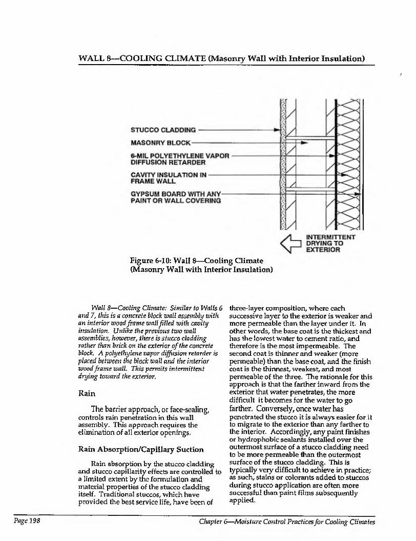
WALL 8—COOLING CLIMATE {Masonry Wall with Interior Insulation)
Figure 6-10: Wall 8—Cooling Climate (Masonry Wall with Interior Insulation)
Wall 8—Cooling Climate: Similar to Walls 6 and 7, this is a concrete block ivall assembly with an interior wood frame wall filled with cavity insulation. Unlike the previous two wall assemblies, however, there is stucco cladding rather than brick on the exterior of the concrete block. A polyethylene vapor diffusion retarder is placed between the block wall and the interior wood frame wall. This permits intermittent drying toward the exterior.
Rain
The barrier approach, or face-sealing, controls rain penetration in this wall assembly. This approach requires the elimination of all exterior openings.
Rain Absoiption/Capillary Suction
Rain absorption by the stucco cladding and stucco capillarity effects are controlled to a limited extent by the formulation and material properties of the stucco cladding itself. Traditional stuccos, which have provided the best service life, have been of
three-layer composition, where each successive layer to the exterior is weaker and more permeable than the layer under it. In other words, the base coat is the thickest and has the lowest water to cement ratio, and therefore is the most impermeable. The second coat is thinner and weaker (more permeable) than the base coat, and the finish coat is the thinnest, weakest, and most permeable of the three. The rationale for this approach is that the farther inward from the exterior that water penetrates, the more difficult it becomes for the water to go farther. Conversely, once water has penetrated the stucco it is always easier for it to migrate to the exterior than any farther to the interior. Accordingly, any paint finishes or hydrophobic sealants installed over the outermost surface of a stucco cladding need to be more permeable than the outermost surface of the stucco cladding. This is typically very difficult to achieve in practice; as such, stains or colorants added to stuccos during stucco application are often more successful than paint films subsequently applied.
Page 198 Chapter 6—Moisture Control Practices for Cooling Climates
WALL 8—COOLING CLIMATE (CONTINUED)
Stucco rain absorption and capillarity effects can also be controlled by exterior paint films and hydrophobic coatings. However, caution and judgment need to be exercised in the application of this control strategy. Although these coatings reduce rain absorption and capillarity, these also often retard the drying of the wall assembly to the exterior should it become wet through other mechanisms.
Air Movement
Several factors control airborne moisture from the exterior (infiltration of warin, humid air during the cooling season) in this wall assembly. The first is the airtightness of the stucco cladding on the outside of the masonry block wall. Second, the upper course of masonry blocks are filled with mortar, and third, ceiling gypsum board is sealed to this masonry block wall.
Alternatively, the air retarder system may be located towards the interior of the assembly and consist of the 6-mil polyethylene vapor diffusion retarder between the masonry blocks and the frame wall. It would be installed continuously and scaled to the ceiling vapor diffusion retarder.
Vapor Diffusion
Vapor diffusion from the exterior is controlled by a vapor diffusion retarder at the interior of the wall assembly between the wall framing and the interior surface of the masonry block wall. Although installing a vapor diffusion retarder at this location in tills climate does not prevent moisture from diffusing into the wall, the vapor diffusion retarder effectively protects the interior gypsum board and any interior finishes from moisture damage and also reduces the latent cooling load of the structure. This interior vapor diffusion relarder often gets wet on the cavity side during the day as a result of exterior absorbed moisture in the brick veneer and masonry block wall driven inward by incident solar radiation. This moisture then typically migrates outward in the evening when the temperature gradient reverses. This wall assembly typically gets wet intermittently from the exterior and dries intermittently to the exterior. Since intermittent wetting of the vapor diffusion retarder is common, this interior vapor
diffusion retarder must be continuous to provide satisfactory performance. A continuous polyethylene vapor diffusion retarder has proven to be effective in this type of assembly.
Comments
In instances where the polyethylene is installed discontinuously, or has been punctured (at electrical wall outlets), hot, humid exterior air has been shown to infiltrate down the masonry cavities and through the polyethylene openings into the frame wall stud cavities. This causes mo id and mildew on the interior gypsum wall board. This failure mechanism can be dramatically enhanced if several other conditions are present: (1) the masonry wall is saturated from rain penetration or construction moisture; (2) the enclosure is air conditioned, possibly under a slight negative air pressure due to poorly designed or installed HVAC systems; and (3) incident solar radiation drives moisture inward. To reduce the migration of air down the masonry cavities, the upper course of blocks should be filled with mortar.
Only vapor permeable surface finishes are installed on the stucco cladding, which promotes intermittent wall drying towards the exterior. Should the wall assembly become wet during service or be built wet through the use of wet masonry blocks, it can dry intermittently to the exterior during cool weather or during evenings.
A vapor permeable paint finish on the interior gypsum wall board promotes wall drying towards the interior from within the frame assembly. Should the frame wall assembly become wet during service or be built wet through the use of wet framing materials or wet-applied cavity insulations (wet spray cellulose or blown fiberglass), it can dry to the interior due to (1) an inward temperature and vapor pressure gradient present as a result of air conditioning the enclosure, and (2) ambient climatic conditions.
The facing material on faced cavity insulations can retard drying to the interior when the facing is installed towards the wall interior. Faced cavity insulations can be installed where drying to the interior is not required, or alternatively, the cavity insulation can be installed with the facing
Moisture Control Handbook Page 199
WALL 8—COOLING CLIMATE (CONTINUED)
material towards the outside of the cavity. Where impermeable interior surface
treatments are utilized, such as wall coverings and impermeable paints, dry framing materials (wood at a moisture content of 19 percent by weight or lower) and dry-applied insulations are recommended. Alternatively, the frame wall assemblies must be allowed to dry prior to enclosure.
Wall assemblies with permeable interior surface treatments that have been performing
satisfactorily in service are sometimes subsequently covered with impermeable interior surface treatments. This may occur if new tenants or owners repaint with impermeable paints or wall coverings. In these cases, mold and mildew problems may appear at the gypsum board/surface treatment interface if the previously mentioned moisture control strategies have not been effectively utilized.
Page 200 Chapter 6—-Moisture Control Practices for Cooling Climates
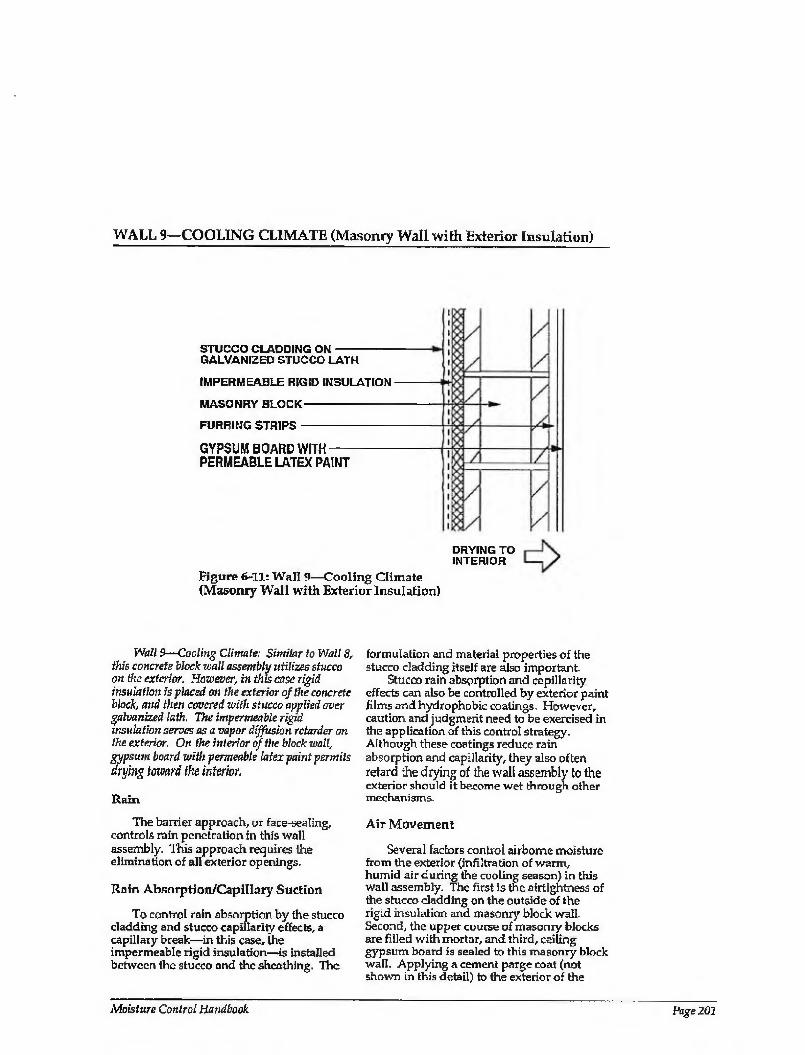
WALL 9—COOLING CLIMATE (Masonry Wall with Exterior Insulation)
STUCCO CLADDING ON- GALVANIZED STUCCO LATH
IMPERMEABLE RIGID INSULATION
MASONRY BLOCK-
FURRING STRIPS-
GYPSUM BOARD WITH- PERMEABLE LATEX PAINT
Figure 6-11: Wall 9—Cooling Climate (Masonry Wall with Exterior Insulation)
DRYING TO INTERIOR
Wall 9—Cooling Climate: Similar to Watt 8, this concrete block wall assembly utilizes stucco on the exterior. However, in this case rigid insulation is placed on the exterior of the concrete block, and then covered with stucco applied over galvanized lath. The impermeable rigid insulation serves as a vapor diffusion retarder on the exterior. On the interior of the block wall, gypsum board with permeable latex paint permits drying toward the interior.
Rain
The barrier approach,, or face-sealing, controls rain penetration in this wall assembly. This approach requires the elimination of all exterior openings,
Rain Absnrption/Capillary Suction
To control rain absorption by the stucco cladding and stucco capillarity effects, a capillary break—in this case, the impermeable rigid insulation—is installed between the stucco and the sheathing. The
formulation and material properties of the stucco cladding itself are also important-
Stucco rain absorption and capillarity effects can also be controlled by exterior paint films and hydrophobic coatings. However, caution and judgment need to be exercised in the application of this control strategy. Although these coatings reduce rain absorption and capillarity, they also often retard the drying of the wall assembly to the exterior should it become wet through other mechanisms.
Air Movement
Several factors control airborne moisture from the exterior {infiltration of warm, humid air during the cooling season) in this wall assembly. The first is the airtightness of the stucco cladding on the outside of the rigid insulation and masonry block wall. Second, the upper course of masonry blocks are filled with mortar, and third, ceiling gypsum board is sealed to this masonry block wall. Applying a cement parge coat (not shown in this detail) to the exterior of the
Moisture Control Handbook Page 201
WALL 9—COOLING CLIMATE (CONTINUED)
masonry block wall can also serve to significantly retard air movement. Alternatively, the air retarder system may be located towards the interior of the assembly and consist of a 6-mil polyethylene vapor diffusion retarder (not shown in this detail) between the masonry blocks and the furring strips. It would be installed in continuously and sealed to the ceiling vapor diffusion retarder.
Vapor Diffusion
Vapor diffusion from the exterior in this wall assembly is controlled by a vapor diffusion retarder on the exterior of the masonry block wall, namely, the rigid impermeable insulation.
Comments
When sheet polyethylene provides airtightness provisions (not shown in this detail) and this polyethylene is installed discontinuously, or it has been punctured (at electrical wall outlets), hot, humid exterior air has been shown to infiltrate down the masonry cavities and through the polyethylene openings into the frame wall stud cavities. This causes mold and mildew on the interior gypsum wall board. This failure mechanism can be dramatically enhanced if several other conditions are present: (1) the masonry wall is saturated from rain penetration or construction moisture; (2) the enclosure is air conditioned, possibly under a slight negative air pressure due to poorly designed or installed HVAC systems; and (3) incident solar radiation
drives moisture inward. To reduce the migration of air down the masonry cavities, the upper course of blocks should be filled with mortar.
A vapor permeable paint finish on the interior gypsum wall board promotes wall drying toward the interior. Should the wall assembly become wet during service or be built wet through the use of wet masonry, it can dry to the interior. This is due to (1) an inward temperature and vapor pressure gradient present as a result of air conditioning the enclosure, and (2) ambient climatic conditions.
Where impermeable interior surface treatments are utilized, such as wall coverings and impermeable paints, the masonry wall must be allowed to dry prior to enclosure. Alternatively, a polyethylene vapor diffusion retarder may be installed between the gypsum board and the masonry wall with the express purpose to protect the gypsum board and interior surface finishes from construction moisture.
In cases where gypsum board is adhered directly to the masonry wall, the masonry wall should be allowed to dry prior to installation of the gypsum board.
Wall assemblies with permeable interior surface treatments that have been performing satisfactorily in service are sometimes subsequently covered with impermeable interior surface treatments. This may occur if new owners or tenants repaint with impermeable paints or wall coverings. In these cases, mold and mildew problems may appear at the gypsum board/surface treatment interface if the previously mentioned moisture control strategies have not been effectively utilized.
Page 202 Chapter 6—Moisture Control Practices for Cooling Climates
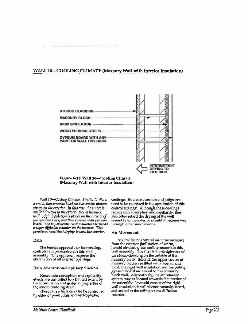
WALL 10—COOLING CLIMATE (Masonry Wall with Interior Insulation)
Figure 6-12: Wall 10—Cooling Climate (Masonry Wall with Interior Insulation)
Wall 10—Cooling Climate: Similar to Walls 8 and 9, this concrete block wall assembly utilizes stucco on the exterior. In this case, the stucco is applied directly to the exterior face of the block wall. Rigid insulation is placed on the interior of the concrete block, and then covered with gypsum board. The impermeable rigid insulation serves as a vapor diffusion retarder on the interior. This permits intermittent drying toward the exterior.
Rain
The barrier approach, or face-sealing, controls rain penetration in this wall assembly. This approach requires the elimination of all exterior openings.
Rain Absorption/Capillary Suction
Stucco rain absorption and capillarity effects are controlled to a limited extent by the formulation and material properties of the stucco cladding itself.
These rain effects can also be controlled by exterior paint films and hydrophobic
coatings- However, cautiorisnd judgment need to be exercised in the application of this control strategy- Although these coatings reduce rain absorption and capillarity, they also often retard the drying of the wall assembly to the exterior should it become wet through other mechanisms.
Air Movement
Several factors control airborne moisture from the exterior {infiltration of warm, humid air during the cooling season) in this wall assembly. The first is the airtightness of the stucco cladding on the outside of the masonry block. Second, the upper course of masonry blocks are filled with mortar, and third, the rigid wall insulation and the ceiling gypsum board are sealed to this masonry block wall. Alternatively, the air retarder system may be located towards the interior of the assembly. It would consist of the rigid wall insulation installed continuously, taped, and sealed to the ceiling vapor diffusion retarder.
Moisture Control Handbook Page 203
WALL 10—COOLING CLIMATE (CONTINUED)
Vapor Diffusion
Vapor diffusion from the exterior in this wall assembly is controlled by the rigid insulation, which acts as a vapor diffusion retarder at the interior surface of the masonry block wall. Although installing a vapor diffusion retarder at this location in this climate does not prevent moisture from diffusing into the wall, the vapor diffusion retarder effectively protects the interior gypsum board and any interior finishes from moisture damage and also reduces the latent cooling load of the structure.
Comments
In instances where the rigid insulation is installed discontinuously, or has been punctured (at electrical wall outlets), hot, humid exterior air has been shown to infiltrate down the masonry cavities and through the openings. This causes mold and mildew on the interior gypsum wall board. This failure mechanism can be dramatically enhanced if several other conditions are present: (1) the masonry wall is saturated from rain penetration or construction moisture; (2) the enclosure is air conditioned, possibly under a slight negative air pressure
due to poorly designed or installed HVAC systems; and (3) incident solar radiation drives moisture inward. To reduce the migration of air down the masonry cavities, the upper course of blocks should be filled with mortar.
Installing only vapor permeable surface finishes on the stucco cladding promotes intermittent wall drying towards the exterior. Should the wall assembly become wet during service or be built wet through the use of wet masonry blocks, it can dry intermittently to the exterior during cool weather or during cool dry evenings.
A vapor permeable paint finish on the interior gypsum wall board promotes wall drying towards the interior from within the assembly.
Wall assemblies with permeable interior surface treatments that have been performing satisfactorily in service are sometimes subsequently covered with impermeable interior surface treatments. This may occur if new tenants or owners repaint with impermeable paints or wall coverings. In these cases, mold and mildew problems may appear at the gypsum board/surface treatment interface if the previously mentioned moisture control strategies have not been effectively utilized.
Page 204 Chapter 6—Moisture Control Practices for Cooling Climates
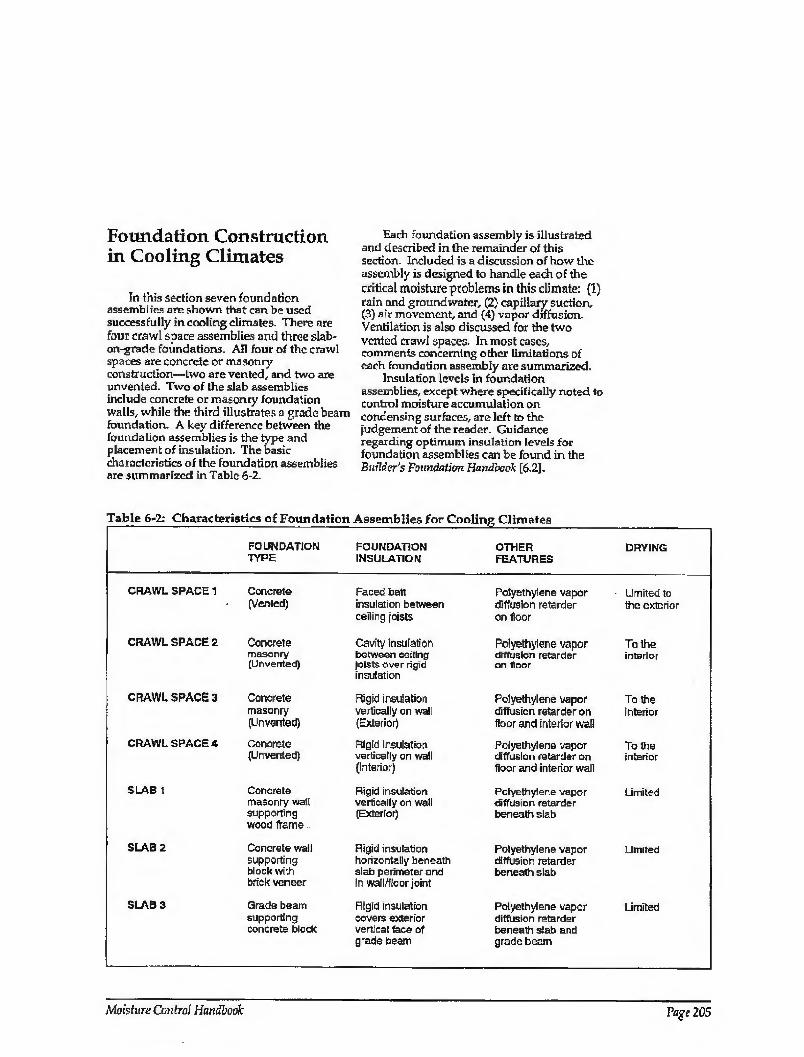
Foundation Construction in Cooling Climates
In this section seven foundation assemblies are shown that can be used successfully in cooling climates. There arc four crawl space assemblies and three slab- on-grade foundations. All four of the crawl spaces are concrete or masonry- construction—two are vented, and two are unvenied. Two of the slab assemblies include concrete or masonry foundation walls, while the third illustrates a grade beam foundation. A key difference between the foundation assemblies is the type and placement of insulation. The basic characteristics of the foundation assemblies are summarized in Table 6-2.
Each foundation assembly is illustrated and described in the remainder of this section. Included is a discussion of how the assembly is designed to handle each of the critical moisture problems in this climate: (1) rain and groundwater, (2) capillary suction, (3) air movement, and (4) vapor diffusion. Ventilation is also discussed for the two vented crawl spaces. In most cases, comments concerning other limitations of each foundation assembly are summarized.
Insulation levels in foundation assemblies, except where specifically noted to control moisture accumulation on condensing surfaces, are left to the judgement of the reader. Guidance regarding optimum insulation levels for foundation assemblies can be found in the Builder's Foundation Handbook [6.2].
Table 6-2: Characteristics of Foundation Assemblies for Cooling Climates
FOUNDATION TYPE
FOUNDATION INSULATION
OTHER FEATURES
DRYING
CRAWL SPACE 1
CRAWL SPACE 2
CRAWL SPACE 3
CRAWL SPACE 4
SLAB 1
SLAB 2
SLAB 3
Concrete (Vented)
Concrete masonry (Un vented)
Concrete masonry (Un vented)
Concrete (Unvented)
Concrete masonry wait supporting wood frame -
Concrete wall supporting block with brick veneer
Grade beam supporting concrete block
Faced batt insulation between ceiling joists
Cavity insulation between ceiling joists over rigid insulation
Rigid insulation vertically on waT (Exterior)
Rigid insulation vertically on wall (Interior)
Rigid insulation vertically on wall (Exterior)
Rigid insulation horizontally beneath slab perimeter and in wati/ffoor joint
Rigid Insulation covers exterior vertical lace of grade beam
Polyethylene vapor diffusion retarder on floor
Polyethylene vapor diffusion retarder on floor
Polyethylene vapor diffusion retarder on floor and interior wall
Polyethylene vapor diffusion retarder on floor and interior wall
Polyethylene vapor diffusion retarder beneath slab
Polyethylene vapor diffusion retarder beneath slab
Polyethylene vapor diffusion retarder beneath slab and grade beam
Limited to the exterior
To the interior
To the interior
To the interior
Limited
Limited
Limited
Moisture Control Handbook Page 205
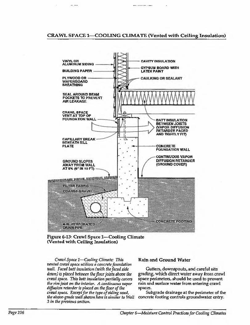
CRAWL SPACE 1—COOLING CLIMATE (Vented with Ceiling Insulation)
VINYL OR ALUMINUM SIDING
BUILDING PAPER
PLYWOOD OR WAFERBOARD SHEATHING
SEAL AROUND BEAM POCKETS TO PREVENT AIR LEAKAGE
CRAWL SPACE VENT AT TOP OF FOUNDATION WALL
CAPILLARY BREAK BENEATH SILL PLATE
GROUND SLOPES AWAY FROM WALL AT 5% (6" IN 10 FT)
CAVITY INSULATION
GYPSUM BOARD WITH LATEX PAINT
BATT INSULATION BETWEEN JOISTS (VAPOR DIFFUSION RETARDER FACED AND TIGHTLY FIT)
-CONCRETE FOUNDATION WALL
CONTINUOUS VAPOR DIFFUSION RETARDER (GROUND COVER)
Figure 6-13: Crawl Space 1—Cooling Climate (Vented with Ceiling Insulation)
Crawl Space 1—Cooling Climate: This vented crawl space utilizes a concrete foundation wall. Faced batt insulation (with the faced side down) is placed between the floor joists above the crawl space. This batt insulation partially covers the rim joist on the interior. A continuous vapor diffusion retarder is placed on the floor of the crawl space. Except for the type of siding used, the above-grade wall shown here is similar to Wall 3 in the previous section.
Rain and Ground Water
Gutters, downspouts, and careful site grading, which direct water away from crawl space perimeters, should be used to prevent rain and surface water from entering crawl spaces.
Subgrade drainage at the perimeter of the concrete footing controls groundwater entry.
Page 206 Chapter 6—Moisture Control Practices for Cooling Climates
CRAWL SPACE X—COOLING CLIMATE (CONTINUED)
The perimeter drainpipe is connected to a sump, storm sewer, or to daylight. Perforations in the perimeter drainpipe should be installed with the holes down to allow groundwater to rise up into the drainpipe and be carried away. Coarse gravel should surround the perimeter drainpipe and in turn be surrounded by a filler fabric. Filler fabric should be located both below and above the perimeter drainpipe, as drainpipe perforations face down and often dog from underneath.
A continuous vapor diffusion retarder, 6- mil or greater polyethylene, is essential as a groundcover to reduce moisture evaporation from the soil into the crawl space.
Ventilation.
Crawl space ventilation removes moisture and should be provided, at a minimum, according to the 1/1500 ratio, where 1 square foot of vent area is provided for every 1500 square feet of floor area In addition, vents should be distributed over the crawl space perimeter to prevent zones of dead or stagnation air and should not be blocked by shrubs, plants, or other obstructions.
It should be noted that during hot, humid periods, ventilation air will often bring moisture into the crawl space rather than remove it. However, during cooler periods this moisture is subsequently removed by ventilation. Under severe ambient hot/humid conditions, moisture accumulation in the crawl space from ventilation air can exceed moisture removal on a seasonal basis. When this is combined with a heavily air conditioned enclosure, it is necessary to protect the floor system from this moisture or consider alternative strategies {See Crawl Space 2—Cooling Climate).
Air Movement
In vented crawl space assemblies it is important to eliminate air flow between the crawl space and the conditioned spaces. The
crawl space needs to be uncoupled from the conditioned space so that conditions within the craw] space influence the building enclosure to a minimum. This is best accomplished by not installing any forced air ductwork, furnaces, or air conditioners in the crawl space. Experience has shown that it is difficult to seal such units or ductwork sufficiently to prevent leakage. In addition, penetrations for plumbing, wiring, bathtubs, etc., must be sealed, making the crawl space subfloor airtight.
Airborne moisture infiltrating from the crawl space into the conditioned space is controlled by pressurizing the conditioned space relative to the crawl space and the exterior, and by limiting air leakage openings (tight consbruction).
Vapor Diffusion
The impermeability of the subfloor sheathing retards moisture movement by diffusion from the crawl space into the conditioned space In other words, the subfloor sheathing acts as a vapor diffusion retarder. However, the subfloor sheathing impermeability characteristics can create moisture accumulation on the crawl space side of the subfloor. Vapor diffusion retarder faced insulation is recommended to prevent moisture accumulation in the insulation by vapor diffusion (faccd-sidc down). In less humid climates, unfaced insulation can be installed to promote drying should such moisture accumulate at the underside of the subfloor. Local experience can determine the correct choice. Unfaced insulation has traditionally been limited to climates with less extreme humidity.
Capillary Suction
To control moisture movement by capillarity into the perimeter framing assembly from the concrete foundation wall, a capillary break is placed at the top of the foundation wall. The break can be polyethylene, or a sheet metal also doubling as termite protection.
Moisture Control Handbook Page 207
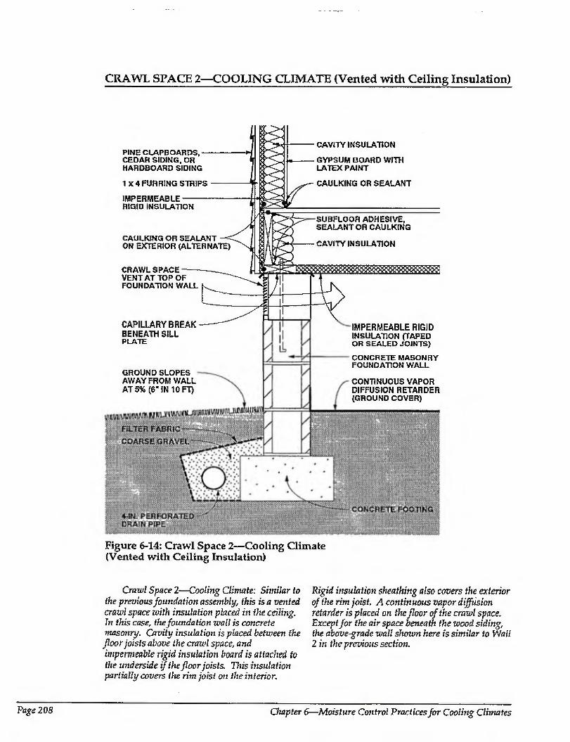
CRAWL SPACE 2—COOLING CLIMATE (Vented with Ceiling Insulation)
GROUND SLOPES AWAY FROM WALL AT 5% (6‘ IN 10 FT)
CAVITY INSULATION
GYPSUM BOARD WITH LATEX PAINT
CAULKING OR SEALANT
PINE CLAPBOARDS, CEDAR SIDING, OR HARDBOARD SIDING
1 X 4 FURRING STRIPS
IMPERMEABLE RIGID INSULATION
CAULKING OR SEALANT ON EXTERIOR (ALTERNATE)
CRAWL SPACE VENT AT TOP OF FOUNDATION WALL
CAPILLARY BREAK BENEATH SILL PLATE
SUBFLOOR ADHESIVE, SEALANT OR CAULKING
CAVITY INSULATION
IMPERMEABLE RIGID INSULATION (TAPED OR SEALED JOINTS)
CONCRETE MASONRY FOUNDATION WALL
CONTINUOUS VAPOR DIFFUSION RETARDER (GROUND COVER)
Figure 6-14: Crawl Space 2—Cooling Climate (Vented with Ceiling Insulation)
Crawl Space!—Cooling Climate: Similar to
the previous foundation assembly, this is a vented crawl space with insulation placed iti the ceiling. In this case, the foundation wall is concrete masonry. Cavity insulation is placed between the floor joists above the crawl space, and
impermeable rigid insulation board is attached to
the underside if the floor joists. This insulation partially covers the rim joist on the interior.
Rigid insulation sheathing also covers the exterior
of the rim joist. A continuous vapor diffusion retarder is placed on the floor of the crawl space. Except for the air space beneath the wood siding, the above-grade wall shown here is similar to Wall 2 in the previous section.
Page 2 08 Chapter 6—Moisture Control Practices for Cooling Climates
CRAWL SPACE 2—COOLING CLIMATE (CONTINUED)
Rain and Ground Water
Gutters, downspouts, and earefill site grading, which direct water away from crawl space perimeters, should be used to prevent rain and surface water from entering crawl spaces.
Subgrade drainage at the perimeter of the concrete footing controls groundwater entry.
A continuous vapor diffusion retarder, 6 mil or greater polyethylene is essential as a ground cover to reduce moisture evaporation from the soil into the crawl space.
Ventilation
Crawl space ventilation removes moisture from crawl spaces and should be provided, at a minimum, according to the 1/ 1500 ratio, where 1 square foot of vent area is provided for every 1500 square feet of subfloor area. In addition, vents should be distributed over the crawl space perimeter to prevent zones ot dead or stagnation air and should not be blocked by shrubs, plants, or other obstructions.
It should be noted that during hot, humid periods, ventilation air will often bring moisture into the crawl space rather than remove it. However, during cooler periods this moisture is subsequently removed by ventilation. Under severe ambient hot/humid conditions, moisture accumulation in the crawl space from ventilation air can exceed moisture removal on a seasonal basis. When this is combined with a heavily air conditioned enclosure, it is necessary to protect the floor system from this moisture. It is for this reason that rigid impermeable insulation is installed on the underside of the floor system in this example.
Air Movement
In vented crawl space assemblies it is important to eliminate air flow between the crawl space and the conditioned space. The crawl space needs to be uncoupled from the conditioned space so that conditions within the crawl space influence the building
enclosure to a minimum. This is best accomplished by not installing any forced air ductwork, furnaces, or air conditioners in the crawl space. Experience has shown that it is difficult to seal such units or ductwork sufficiently to prevent leakage. In addition penetrations for plumbing, wiring, bathtubs, etc., must be sealed, making the crawl space subfloor assembly airtight.
Airborne moisture infiltrating from the crawl space into the conditioned space is controlled by pressurizing the conditioned space relative to the crawl space and the exterior, and by limiting air leakage openings (tight construction).
Where vented crawl spaces experience extreme humid conditions during heavy air conditioning, the installation of impermeable rigid insulation on the underside of the floor joists protects the entire floor system from moisture brought into the crawl space by ventilation air. This rigid insulation acts as both a vapor diffusion retarder and air retarder system. As such, it needs to be installed in airtight and should completely enclose any supporting beam structures. The rigid insulation installed as wall sheathing is extended down to cover the rim joist and should be sealed to the sill plate.
Cavity insulation within the floor joists (if installed) should be installed in contact with the rigid insulation
Vapor Diffusion
Moisture movement by diffusion from the crawl space into the conditioned space is retarded by the impermeability of the rigid insulation installed on the underside of the floor joists.
Capillary Suction
To control moisture movement by capillarity into the perimeter framing assembly from the concrete foundation wall, a capillary break is placed at the top of the foundation wall. The break can be polyethylene, or a sheet metal also doubling as termite protection.
Moisture Control Handbook Page 209
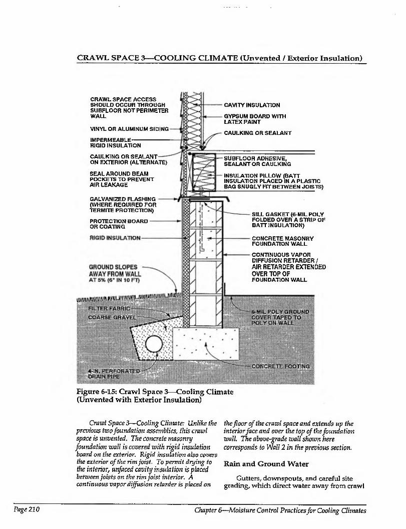
CRAWL SPACE 3—COOLING CLIMATE (Unvented / Exterior Insulation)
CRAWL SPACE ACCESS SHOULD OCCUR THROUGH SUBFLOOR NOT PERIMETER WALL
VINYL OR ALUMINUM SIDING
IMPERMEABLE RIGID INSULATION
CAULKING OR SEALANT ON EXTERIOR (ALTERNATE)
SEAL AROUND BEAM POCKETS TO PREVENT AIR LEAKAGE
GALVANIZED FLASHING (WHERE REQUIRED FOR TERMITE PROTECTION)
PROTECTION BOARD OR COATING
CAVITY INSULATION
GYPSUM BOARD WITH LATEX PAINT
CAULKING OR SEALANT
SUBFLOOR ADHESIVE, SEALANT OR CAULKING
INSULATION PILLOW (BAIT INSULATION PLACED IN A PLASTIC BAG SNUGLY FIT BETWEEN JOISTS)
SILL GASKET (6-MIL POLY FOLDED OVER A STRIP OF BATT INSULATION)
CONCRETE MASONRY FOUNDATION WALL
CONTINUOUS VAPOR DIFFUSION RETARDER/ AJR RETARDER EXTENDED OVER TOP OF FOUNDATION WALL
Figure 6-15: Crawl Space 3—Cooling Climate (Unvented with Exterior Insulation)
Crawl Space 3—Cooling Climate: Unlike the previous two foundation assemblies, this crawl space is unvented. The concrete masonry foundation wall is covered with rigid insulation board on the exterior. Rigid insulation also covers the exterior of the rim joist. To permit drying to the interior, unfaced cavity insulation is placed between joists on the rim joist interior. A continuous vapor diffusion retarder is placed on
the floor of the crawl space and extends up the interior face and over the top of the foundation wall. The above-grade wall shown here
corresponds to Wall 2 in the previous section.
Rain and Ground Water
Gutters, downspouts, and careful site grading, which direct water away from crawl
Page 210 Chapter 6—AToisfure Control Practices for Cooling Climates
CRAWL SPACE 3—COOLING CLIMATE (CONTINUED)
space perimeters, should be used to prevent rain and surface water from entering crawl spaces.
Subgrade drainage at the perimeter of the concrete footing controls groundwater entry.
Air Movement
Airborne moisture infiltrating from the exterior is controlled by pressurizing the crawl space relative to the exterior and by limiting air leakage openings (tight construction). The crawl space can be pressurized in enclosures with forced air systems by providing a supply air register in the crawl space, with no corresponding return air register. In enclosures without forced air systems, a separate fan for this purpose can be installed, taking air from the other conditioned spaces. The tighter the crawl space construction, the less air that has to be introduced to pressurize the crawl space. As such it is desirable to build as tight as is practical. To do so, the ground cover/ vapor diffusion retarder is extended up over the foundation wall and at) joints are sealed. In addition, the rim joist assembly is sealed against air leakage with adhesive, caulking, gaskets, or other air seals. Exterior wall sheathing is aiso extended down over the rim joist assembly to further reduce air leakage at this location. This exterior wall sheathing can be utilized as the principal air seal at this location and hence to eliminate seals at the top and bottom of the rim joist if the exterior wall sheathing is sealed directly to the exterior of the sill plate.
Crawl spaces in this climate zone should not be pressurized at the expense of depressurizing the rest of the conditioned space. In other words, the entire building should be pressurized relative to the exterior, including the crawl space. As such, air taken
from the building to pressurize the crawl space needs to be replaced by outside air introduced in a controlled manner, typically to the air conditioning duct system.
Pressurization will only occur when the forced air distribution fan is operating (when mechanical cooling is occurring). This sho uld be effective under most conditions.
Vapor Diffusion
The continuous vapor diffusion retarder, 6 mil or greater polyethylene, also acts as a ground cover, It reduces moisture migration by evaporation from the soil into the crawl space.
Capillary Suction
To control moisture movement by capillarity into the perimeter framing assembly from the concrete foundation wall, a capillary break is placed at tire top of the foundation wall. The break can be the polyethylene ground cover extended up over the wall, or the sheet metal flashing also doubling as termite protection.
Comments
Rigid insulation is installed on the exterior of the perimeter crawl space foundation walls to reduce cooling loads. It is protected above grade on its exterior from mechanical damage. This rigid insulation can act as a conduit for insects to enter the enclosure, and as such appropriate flashings or other protection may be necessary.
In unvented, conditioned crawl spaces it is convenient to install ductwork, plumbing, and other mechanical components, because concerns about the effects of duct leakage and freezing pipes are minimized.
Moisture Control Handbook Page 211
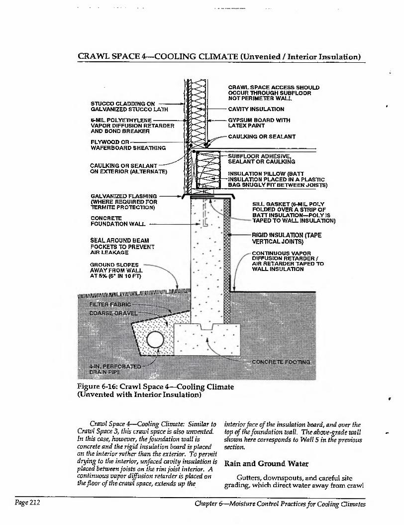
CRAWL SPACE 4—COOLING CLIMATE (Unvented / Interior Insulation)
STUCCO CLADDING ON GALVANIZED STUCCO LATH
6-MIL POLYETHYLENE VAPOR DIFFUSION RETARDER AND BOND BREAKER
PLYWOOD OR WAFERBOARD SHEATHING
CAULKING OR SEALANT ON EXTERIOR (ALTERNATE)
GALVANIZED FLASHING (WHERE REQUIRED FOR TERMITE PROTECTION)
CONCRETE FOUNDATION WALL
SEAL AROUND BEAM POCKETS TO PREVENT AIR LEAKAGE
GROUND SLOPES AWAY FROM WALL AT 5% (6' IN 10 FT)
CRAWL SPACE ACCESS SHOULD OCCUR THROUGH SUBFLOOR NOT PERIMETER WALL
CAVITY INSULATION
GYPSUM BOARD WITH LATEX PAINT
CAULKING OR SEALANT
SUBFLOOR ADHESIVE, SEALANT OR CAULKING
INSULATION PILLOW (BATT INSULATION PLACED IN A PLASTIC BAG SNUGLY FIT BETWEEN JOISTS)
SILL GASKET (6-MIL POLY FOLDED OVER A STRIP OF BATT INSULATION—POLY IS TAPED TO WALL INSULATION)
RIGID INSULATION (TAPE VERTICAL JOINTS)
CONTINUOUS VAPOR DIFFUSION RETARDER / AIR RETARDER TAPED TO WALL INSULATION
Figure 6-16: Crawl Space 4—Cooling Climate (Unvented with Interior Insulation)
Crawl Space 4—Cooling Climate: Similar to Crawl Spaced, this crawl space is also unvented. In this case, however, the foundation wall is concrete and the rigid insulation hoard is placed on the interior rather than the exterior. To permit drying to the interior, unfaced cavity insulation is placed between joists on the rim joist interior. A continuous vapor diffusion retarder is placed on the floor of the crawl space, extends up the
interior face of the insulation board, and over the top of the foundation wall. The above-grade wall shown here corresponds to Wall 5 in the previous section.
Rain and Ground Water
Gutters, downspouts, and careful site grading, which direct water away from crawl
Page 212 Chapter 6—Moisture Control Practices for Coolmg Climates
CRAWL SPACE 4—COOLING CLIMATE (CONTINUED)
space perimeters, are used to prevent rain and surface water from entering crawl spaces.
Subgrade drainage at the perimeter of the concrete footing controls groundwater entry.
Air Movement
Airborne moisture infiltrating from the exterior is controlled by pressurizing the crawl space relative to the exterior and by limiting air leakage openings (tight construction). The crawl space can be pressurized in enclosures with forced air systems by providing a supply air register in the crawl space, with no corresponding return air register. In enclosures without forced air systems, a separate fan for this purpose can be installed, taking air from the other conditioned spaces. The tighter the crawl space construction, the less air that has to be introduced to pressurize the crawl space. As such it is desirable to build as tight as is practical. To do so, the ground cover/ vapor diffusion retarder is extended up over the foundation wall and all joints are sealed. In addition, the rim joist assembly is sealed against air leakage with adhesive, caulking, gaskets, or other air seals. Exterior wall sheathing is also extended down over the rim joist assembly to further reduce air leakage at this location. This exterior wall sheathing can be utilized as the principal air seal at this location and hence to eliminate seals at the top and bottom of the rim joist if the exterior wall sheathing is sealed directly to the exterior of the sill plate.
Crawl spaces in this climate zone should not be pressurized at the expense of depressurizing the rest of the conditioned space. In other words, the entire building should be pressurized relative to the exterior, including the crawl space. As such, air taken from the building to pressurize the crawl space needs to be replaced by outside air introduced in a control led manner, typically
to the air conditioning duct system. Pressurization wd] only occur when the
forced air distribution fan is operating (when mechanical cooling is occurring). This should be effective under most conditions.
Vapor Diffusion
The continuous vapor diffusion retarder, 6 mil or greater polyethylene, also acts as a ground cover. It reduces moisture migration by evaporation from the soil into the crawl space.
Capillary Suction
To control moisture movement by capillarity into the perimeter framing assembly from the concrete foundation wall, a capillary break is placed at the top of the foundation wall. The break can be the polyethylene ground cover extended up over the wall, or the sheet metal flashing also doubling as termite protection.
Comments
As a result of fire code flame spread requirements, rigid insulation installed on the interior of the perimeter of unvented, conditioned crawl space foundation walls may need to be protected on its interior surface by gypsum wall board or some other treatment. Local authorities may need to be consulted.
Rigid insulation in this location can act as a conduit for insects to enter the enclosure. As such, it should terminate at the upper edge of the concrete foundation wall to allow for insect pathways.
In unvented, conditioned crawl spaces it is convenient to install ductwork, plumbing, and other mechanical components, because concerns about the effects of duct leakage and freezing pipes are minimized.
Moisture Control Handbook Page 213
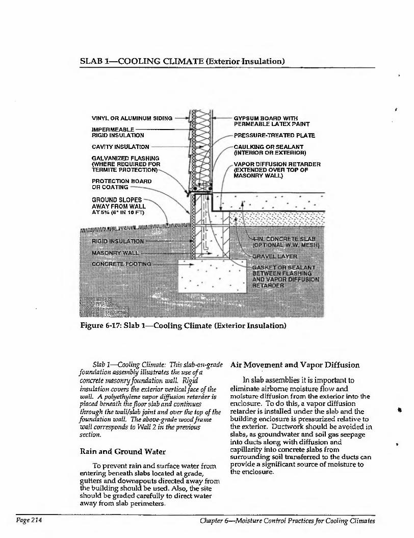
SLAB 1—COOLING CLIMATE (Exterior Insulation)
GYPSUM BOARD WITH PERMEABLE LATEX PAINT
PRESSURE-TREATED PLATE
CAULKING OR SEALANT {INTERIOR OR EXTERIOR)
VAPOR DIFFUSION RETARDER (EXTENDED OVER TOP OF MASONRY WALL)
VINYL OR ALUMINUM SIDING
IMPERMEABLE RIGID INSULATION
CAVITY INSULATION
GALVANIZED FLASHING (WHERE REQUIRED FOR TERMITE PROTECTION)
PROTECTION BOARD OR COATING
GROUND SLOPES AWAY FROM WALL AT 5% (6' IN 10 FT)
.
mmPsm Figure 6-17: Slab 1—Cooling Climate (Exterior Insulation)
Slab 1—Cooling Climate: This slab-on-grade foundation assembly illustrates the use of a
concrete masonry foundation wall Rigid
insulation covers the exterior vertical face of the wall. A polyethylene vapor diffusion retarder is placed beneath the floor slab and continues through the wall/slab joint and over the top of the foundation wall. The above-grade wood frame wall corresponds to Wall 2 in the previous section.
Rain and Ground Water
To prevent rain and surface water from entering beneath slabs located at grade,, gutters and downspouts directed away from the building should be used. Also, the site should be graded carefully to direct water away from slab perimeters.
Air Movement and Vapor Diffusion
In slab assemblies it is important to eliminate airborne moisture flow and moisture diffusion from the exterior into the enclosure. To do this, a vapor diffusion retarder is installed under the slab and the building enclosure is pressurized relative to the exterior. Ductwork should be avoided in slabs, as groundwater and soil gas seepage into ducts along with diffusion and capillarity into concrete slabs from surrounding soil transferred to the ducts can provide a significant source of moisture to the enclosure.
«
Page 214 Chapter 6—Moisture Control Practices for Cooling Climates
SLAB 1—COOLING CLIMATE (CONTINUED)
Capillary Suction
Moisture may move by capillarity into the slab and perimeter wall framing assembly from the ground and from the perimeter masonry foundation wall. It is controlled by a capillary break, which consists of the granular layer under the slab and the extension of the vapor diffusion retarder over the top of the masonry perimeter wall.
Comments
In some assemblies it may not be practical or possible to extend the vapor diffusion retarder over the top of the perimeter masonry wall foundation assembly. In such cases, the cavities in the masonry blocks should be filled with mortar to create an air seal with a strip of sheet polyethylene installed under the wall framing to act as a capillary break.
Rigid insulation is installed on the exterior of the perimeter foundation assembly to reduce cooling loads and is protected above grade on its exterior from mechanical damage. This rigid insulation
can act as a conduit for insects to enter the enclosure, and as such appropriate flashings or other protection may be necessary.
The concrete floor slab contains significant quantities of moisture when initially placed. Covering this surface with an impermeable surface finish or floor covering may lead to deterioration of these surfaces if the construction moisture is not allowed to dry. Initial drying of the construction moisture contained in concrete may also elevate interior moisture levels during the first few months of occupancy.
Installing carpets on cold, damp, concrete floor slabs can lead to serious allergenic reactions in sensitive individuals and other health-related consequences. It is not recommended that carpets be installed on concrete slabs unless the carpets can be kept dry and warm; that is, carpet relative humidities should be kept below 40 percent [6.3],
The granular drainage pad located under the concrete floor slab can also be integrated into a subslab ventilation system to control radon migration by adding a vent pipe connected to the surface and an exhaust fan-
Moisturc Control Handbook Page 215
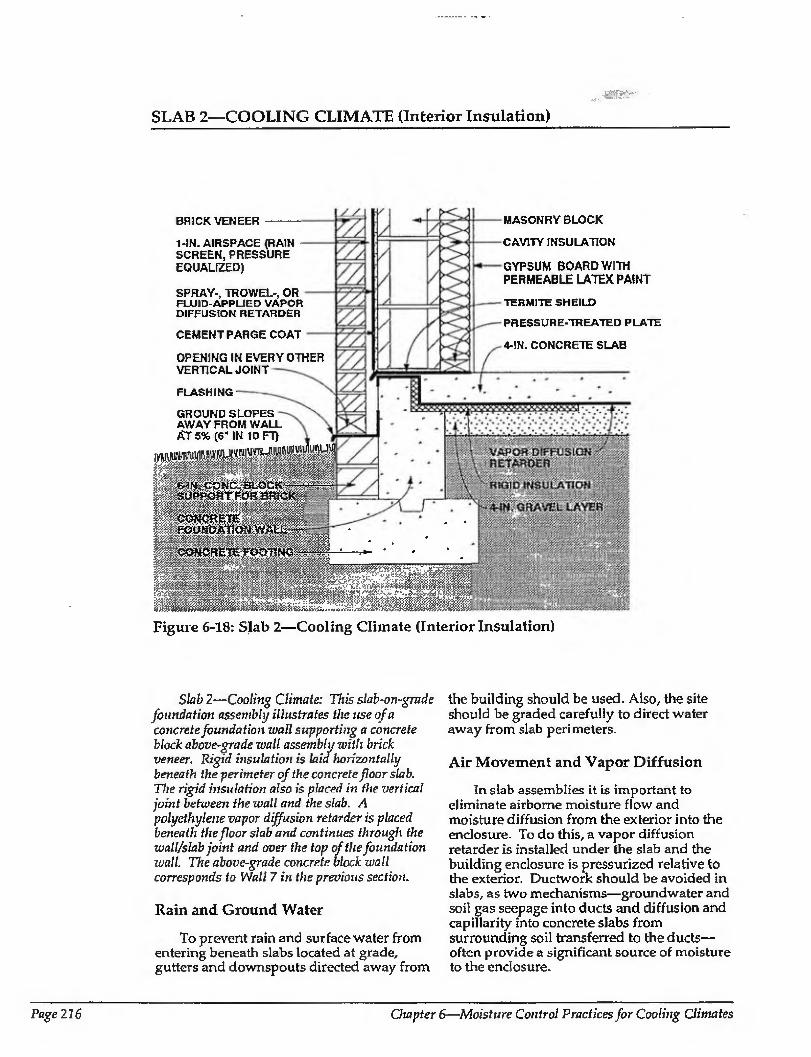
SLAB 2—COOLING CLIMATE (Interior Insulation)
BRICK VENEER
1-IN. AIRSPACE (RAIN SCREEN,PRESSURE EQUALIZED)
SPRAY-, TROWEL-, OR FLUID-APPUED VAPOR DIFFUSION RETARDER
CEMENT PARGE COAT
OPENING IN EVERY OTHER VERTICAL JOINT
MASONRY BLOCK
CAVITY INSULATION
GYPSUM BOARD WITH PERMEABLE LATEX PAINT
TERMITE SHEILD
PRESSURE-TREATED PLATE
4-!N. CONCRETE SLAB
FLASHING
GROUND SLOPES AWAY FROM WALL At 5% (6' IN 10 FT)
IpSUPPORTFOUBRICK-
immMmmWMmiMm
Figure 6-18: Slab 2—Cooling Climate (Interior Insulation)
Slab 2—Coolmg Climate: Ttzis slab-on-grade foundation assembly illustrates the use of a concrete foundation wall supporting a concrete block above-grade wall assembly with brick veneer. Rigid insulation is laid horizontally beneath the perimeter of the concrete floor slab. The rigid insulation also is placed in the vertical joint between the wall and the slab. A polyethylene vapor diffusion retarder is placed beneath the floor slab and continues through the wall/slab joint and over the top of the foundation wall. The above-grade concrete block wall corresponds to Wall 7 in the previous section.
Rain and Ground Water
To prevent rain and surface water from entering beneath slabs located at grade, gutters and downspouts directed away from
the building should be used. Also, the site should be graded carefully to direct water away from slab peri meters.
Air Movement and Vapor Diffusion
In slab assemblies it is important to eliminate airborne moisture flow and moisture diffusion from the exterior into the enclosure. To do this, a vapor diffusion retarder is installed under the slab and the building enclosure is pressurized relative to the exterior. Ductwork should be avoided in slabs, as two mechanisms—groundwater and soil gas seepage into ducts and diffusion and capillarity into concrete slabs from surrounding soil transferred to the ducts— often provide a significant source of moisture to the enclosure.
Page 216 Chapter 6—Moisture Control Practices for Cooling Climates
SLAB 2—COOLING CLIMATE (CONTINUED)
Capillary Suction
Moisture may move by capillarity into the slab and perimeter wall framing assembly from the ground and from the perimeter masonry foundation wall. It is controlled by a capillary break, which consists of the granular layer under the slab and the extension of the vapor diffusion retarder over
the top of the concrete perimeter wall. Assemblies with brick veneers should
use a capillary break at grade to protect the brick veneer from capillary rise. An appropriate flashing at this location can serve this function in addition to facilitating the drainage function of the rain screen.
Comments
In some assemblies it may not be practical or possible to extend the vapor diffusion retarder over the top of the perimeter concrete foundation wall assembly. In such cases a strip of sheet polyethylene should be installed under the perimeter masonry block wall to act as a capillary break. Structural considerations in certain Jurisdictions may necessitate the placement of ties or reinforcing, puncturing this sheet polyethylene. Appropriate authorities having jurisdiction should be consulted.
Rigid insulation is installed on the interior of the perimeter foundation in this assembly to reduce cooling loads. It can extend inwards horizontally several feet, or alternatively extend downwards vertically to the footing. This rigid insulation can act as a conduit for insects to enter the enclosure. Although the slab vapor diffusion retarder is extended up over this insulation and the perimeter foundation wall, it may not be sufficient to protect against insect migration. Additional protection may be necessary, such as metal flashings or other treatments.
The wall assembly shown does not have a vapor diffusion retarder on the interior. Accordingly, this wall will dry towards the interior. This wall assembly has a vapor diffusion retarder Located on its exterior to control vapor diffusion migrating from the exterior. Construction moisture may be present in the masonry wall and may lead to moisture problems ii\ the gypsum board interior finish as the wall dries to the interior. As such, impermeable wall coverings or impermeable paint finishes are not recommended unless the assembly has completely dried prior to enclosure or unless an additional vapor diffusion retarder (polyethylene film) is installed between the masonry and the gypsum board. Foil-backed gypsum board may not be sufficient protection in this application as a result of discontinuity at gypsum board joints.
The concrete floor slab contains significant quantities of moisture when initially placed. Covering this surface with an impermeable surface finish or floor covering may lead to deterioration of these surfaces if the construction moisture is not allowed to dry. Initial drying of the construction moisture contained in concrete may also elevate interior moisture levels during the first few months of occupancy.
Installing carpets on cold, damp, concrete floor slabs can lead to serious allergenic reactions in sensitive individuals and other health-related consequences. It is not recommended that carpets be installed on concrete slabs unless the carpets can be kept dry and warm; that is, carpet relative humidities should be kept below 40 percent
l6-3]- The granular drainage pad located under
the concrete floor slab can also be integrated into a subslab ventilation system to control radon migration by adding a vent pipe connected to the surface and an exhaust fan.
Moisture Control Handbook Page 217
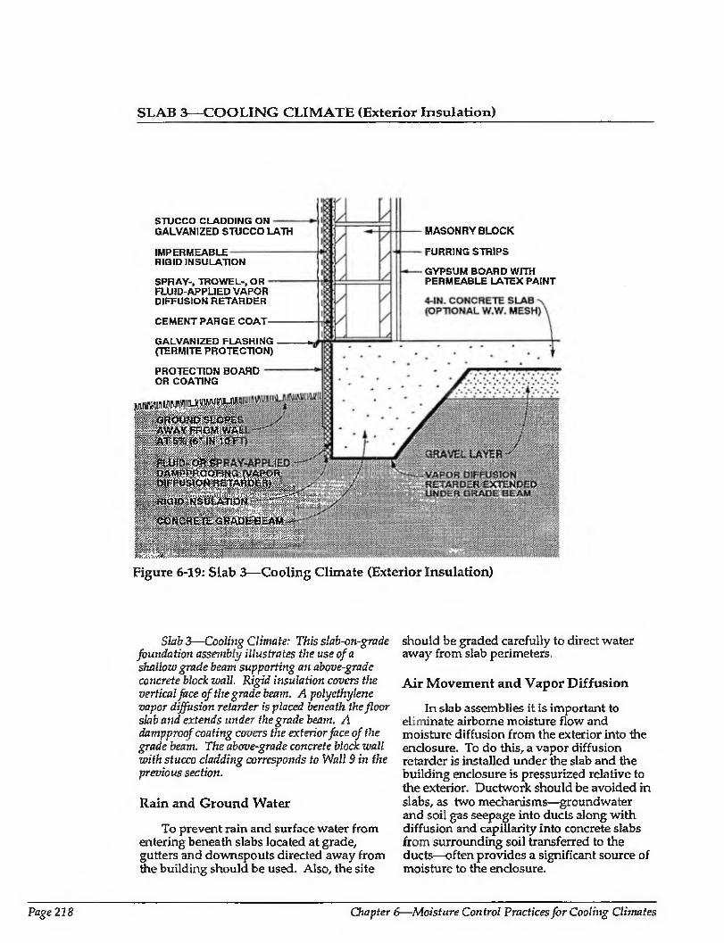
SLAB 3—COOLING CLIMATE (Exterior Insulation)
STUCCO CLADDING ON GALVANIZED STUCCO LATH
IMPERMEABLE RIGID INSULATION
SPRAY-, TROWEL-, OR - FLUID-APPLIED VAPOR DIFFUSION RETARDER
CEMENT PARGE COAT-
GALVANIZED FLASHING (TERMITE PROTECTION)
PROTECTION BOARD OR COATING
■0:- OROU ND 'SkOPE plistWAY j^OMsWAt.
RIGID INSULATION-'—^"'
WMtkM
MASONRY BLOCK
FURRING STRIPS
GYPSUM BOARD WITH PERMEABLE LATEX PAINT
Figure 6-19: Slab 3—Cooling Climate (Exterior Insulation)
Slab 3—Coolmg Climate: This slab-on-grade foundation assembly illustrates the use of a shallow grade beam supporting an above-grade concrete block wall. Rigid insulation covers the vertical face of the grade beam. A polyethylene vapor diffusion retarder is placed beneath the floor slab and extends under the grade beam, A damp proof coating covers the exterior face of the grade beam. The above-grade concrete block wall with stucco cladding corresponds to Wall 9 in the previous section.
Rain and Ground Water
To prevent rain and surface water from entering beneath slabs located at grade, gutters and downspouts directed away from the building should be used. Also, the site
should be graded carefully to direct water away from slab perimeters.
Air Movement and Vapor Diffusion
In slab assemblies it is important to eliminate airborne moisture flow and moisture diffusion from the exterior into the enclosure. To do this, a vapor diffusion retarder is installed under the slab and the building enclosure is pressurized relative to the exterior. Ductwork should be avoided in slabs, as two mechanisms—groundwater and soil gas seepage into ducts along with diffusion and capillarity into concrete slabs from surrounding soil transferred to the ducts—often provides a significant source of moisture to the enclosure.
Page 218 Chapter 6—Moisture Control Practices for Cooling Climates
SLAB 3-COOLING CLIMATE (CONTINUED)
Capillary Suction
Capillary moisture movement into the slab from the ground is controlled by a capillary break, in this case the granular layer under the slab. Where slab construction includes a perimeter concrete grade beam, the slab vapor diffusion retarder is extended under the concrete grade beam to act as a capillary break at this location. Furthermore, dampproofing is installed on the exterior of the perimeter of the grade beam, also to act as a capillary break. This dampproofing, if it is fluid or spray applied, must be chemically compatible with any rigid insulation installed over it
Comments
Rigid insulation is installed on the exterior of the perimeter foundation assembly to reduce cooling loads. It is protected on its exterior from mechanical damage. This rigid insulation can act as a conduit for insects to enter the enclosure, and as such appropriate flashings or other protection may be necessary.
The wall assembly shown does not have a vapor diffusion retarder on the interior. Accordingly, this wall will dry towards the interior in this climate. This wall assembly has a vapor diffusion retarder located on its exterior to control vapor diffusion migrating from the exterior. Construction moisture may be present in the masonry wall and may lead to moisture problems in the gypsum
board interior finish as the wall dries to the interior. As such, impermeable wall coverings or impermeable paint finishes are not recommended unless the assembly has completely dried prior to enclosure or an additional vapor diffusion retarder (polyethylene film) is installed between the masonry and the gypsum board. Foil -backed gypsum board may not be sufficient protection in this application as a result of discontinuity at gypsum board joints.
Tlic concrete floor slab contains significant quantities of moisture when initially placed. Covering this surface with an impermeable surface finish or floor covering may lead to deterioration of these surfaces if construction moisture is not allowed to dry. Initial drying of the construction moisture contained in concrete may also elevate interior moisture levels during the first few months of occupancy.
Installing carpets on cold, damp, concrete floor slabs can lead to serious allergenic reactions in sensitive individuals and other health related consequences. It is not recommended that carpets be installed on concrete slabs unless the carpets can be kept dry and warm; that is, carpet relative humidities should be kept below 40 percent [6.3].
The granular drainage pad located under the concrete floor slab can also be integrated into a subslab ventilation system to control radon migration by adding a vent pipe connected to the surface and an exhaust fan.
Moisture Contra! Handbook Page 219

Roof Construction in Cooling Climates
In this section six roof assemblies are shown that can be used successfully in cooling climates. All six assemblies utilize wood roof trusses and vented attics. The first four roofs are identical except that they illustrate ways of connecting to different wall assemblies. The last two roof assemblies illustrate different approaches to vapor diffusion retarders and insulation. The basic characteristics of the roof assemblies are
summarized in Table 6-3. Each roof assembly is illustrated and
described in the remainder of this section. Included is a discussion of how the assembly is designed to handle each of the critical moisture problems in this climate: (1) ventilation, (2) air movement, and (3) vapor diffusion. In addition, comments related to special concerns are summarized for each assembly.
Insulation levels in roof assemblies, except where specifically noted to control moisture accumulation on condensing surfaces, are left to the judgement of the reader.
Table 6-3: Characteristics of Roof Assemblies for Cooling Climates
ROOF TYPE VENTILATION CEILING INSULATION
OTHER FEATURES
DRYING
ROOF 1
ROOF 2
ROOF 3
ROOF 4
ROOF 5
ROOF 6
Wood truss with flat ceiling
Wood truss with flat ceiling
Vented attic
Vented attic
Wood truss Vented attic with flat ceiling
Wood truss Vented attic with flat ceiling
Wood truss Vented attic with flat ceiling
Wood truss Vented attic with fiat ceiling
Cavity insulation
Cavity insulation
Cavity insulation
Cavity insulation
Cavity insulation
Cavity insulation with rigid insulation beneath tmsses
Polyethylene To the vapor diffusion exterior retarder (Interior)
Polyethylene To the vapor diffusion exterior retarder (Interior)
Polyethylene To the vapor diffusion exterior retarder (Interior)
Polyethylene To the vapor diffusion exterior retarder (Interior)
Gypsum board ceiling To the with permeable latex exterior paint permits drying to the interior
Impermeable rigid To the insulation serves as exterior vapor diffusion retarder
Page 220 Chapter 6—Moisture Control Practices for Cooling Climates
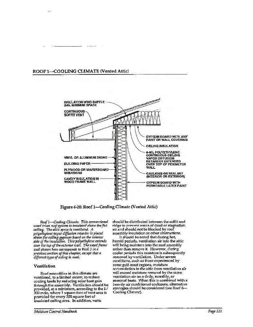
ROOF 1—COOLING CLIMATE (Vented Attic)
INSULATION WIND BAFFLE 2-IN. MINIMUM SPACE
CONTINUOUS SOFFIT VENT
VINYL OR ALUMINUM SIDING
BUILDING PAPER
PLYWOOD OR WAFERBOAHD SHEATHING
CAVITY INSULATION IN WOOD FRAME WALL
GYPSUM BOARD WITH ANY PAINT OR WALL COVERING
CEILING INSULATION
6-MIL POLYETHYLENE CONTINUOUS CEILING VAPOR DIFFUSION RETARDER EXTENDED OVER TOP OF PERIMETER WALL
CAULKING OR SEALANT (INTERIOR OR EXTERIOR)
GYPSUM BOARD WITH PERMEABLE LATEX PAINT
Figure 6-20: Roof 1—Cooling Climate (Vented Attic)
Roof 1—Cooling Climate: This conventional wood truss roof system is insulated abane the flat ceiling. The attic space is ventilated. A polyethylene vapor diffusion retarder is placed above ins ceiling gypsum board on the inierior side of the insulation. This polyethylene extends over the top of the exterior wall The wood frame wall shown here corresponds to Walt 3 in a previous section of this chapter, except that a different type of siding is used.
Ventilation
Roof assemblies in this climate are ventilated, to a limited extent, to reduce cooling loads by reducing solar heat gain through the assembly. Ventilation should be provided, at a minimum, according to the 1/ 300 ratio, where 1 square foot of vent area is provided for every 300 square feet of insulated ceiling area. In addition, vents
should be distributed between the soffit and ridge to prevent zones of dead or stagnation air and should not be blocked by roof assembly insulation or other obstructions.
It should be noted that during hot, humid periods, ventilation air into the attic will bring moisture into the roof assembly rather than remove it. However, during cooler periods this moisture is subsequently removed by ventilation. Under severe conditions, such as those experienced by some gulf coast regions, moisture accumulation in the attic from ventilation air will exceed moisture removal by the same ventilation air on a daily, monthly, or seasonal basis. When this is combined with a heavily air conditioned enclosure, alternative strategies should be considered {see Roof 6— Cooling Climate).
Moisture Control Handbook Page 221
ROOF 1—COOLING CLIMATE (CONTINUED)
Air Movement
In vented roof assemblies it is important to eliminate air flow between the attic and the conditioned space. The attic needs to be uncoupled from the conditioned space so that conditions within the attic influence the building enclosure to a minimum. This is best accomplished by not installing any forced air ductwork, furnaces, or air conditioners in attics. Experience has shown that it is difficult to seal such units or ductwork sufficiently to prevent leakage. In addition, penetrations for plumbing, wiring, dropped ceilings, and kitchen cabinet bulkheads should be sealed-
Airborne moisture infiltrating from the attic into the enclosure is controlled by (1) pressurizing the enclosure relative to the attic and the exterior, and (2) limiting air leakage openings (tight ceiling construction).
Vapor Diffusion
To retard moisture movement by diffusion from the attic into the enclosure, a continuous ceiling vapor diffusion retarder is extended over the top of the exterior perimeter wall and sealed to the perimeter wall exterior plywood or waferboard sheathing. This also acts as the perimeter wall vapor diffusion retarder. This continuous ceiling vapor diffusion retarder can also act as the air retarder system.
Comments
This continuous ceiling vapor diffusion retarder protects the ceiling gypsum board from moisture accumulation from the
exterior and subsequent mold and mildew growth or water staining. It therefore allows impermeable wall/ceiling coverings, paints, and textured treatments to be installed.
In severe hot, humid conditions, the temperature of the ceiling vapor diffusion retarder in this location, as well as the temperature of the ceiling gypsum board, may be below the dew point temperature of the ambient air if the enclosure is heavily air conditioned. As a result, condensation or mold and mildew growth may occur. Under such conditions alternative control strategies should be considered (see Roof 6—Cooling Climate).
A wind baffle should be installed at the perimeter of the roof area where the insulated ceiling intersects the exterior wall. This prevents thermal short-circuiting of the insulation by wind (wind-washing). In this climate, wind-washing by hot, humid air can induce deposition of significant amounts of moisture on perimeter wall top plate and ceiling gypsum board surfaces cooled by air conditioning.
Exterior ventilation air entering soffit assemblies experiences a pressure drop as the soffit assembly acts as an expansion space. This is due to the combination of a narrow soffit vent opening up to a relatively large volume soffit assembly and then being squeezed into a narrow space between the underside of the roof sheathing and the wind baffle. This pressure drop induces the ventilation air to deposit airborne rain droplets in the soffit assembly rather than transport them farther into the roof assembly. Accordingly, it may be desirable to back prime wood soffit material.
Page 222 Chapter 6—Moisture Control Practices for Cooling Climates
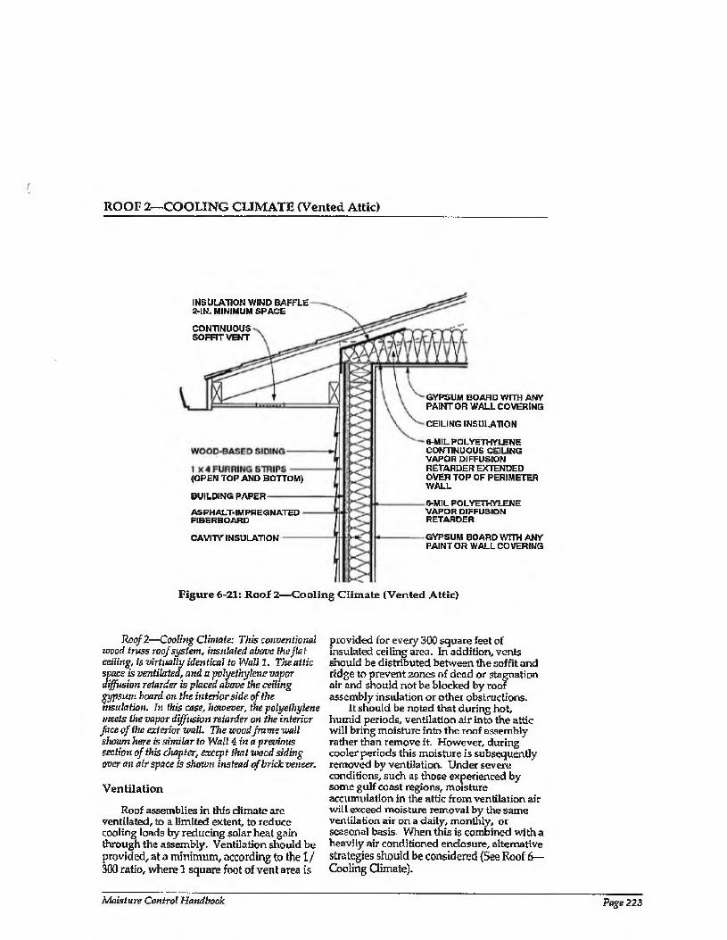
ROOF 2—COOLING CLIMATE (Vented Attic)
INSULATION WIND BAFFLE 2-IN. MINIMUM SPACE
CONTINUOUS SOFFIT VENT
(OPEN TOP AND BOTTOM)
BUILDING PAPER
ASPHALT-IMPREGNATED FIBERBOARD
CAVITY INSULATION
GYPSUM BOARD WITH ANY PAINT OR WALL COVERING
CEILING INSULATION
6-MIL POLYETHYLENE CONTINUOUS CEILING VAPOR DIFFUSION RETARDER EXTENDED OVER TOP OF PERIMETER WALL
6-MIL POLYETHYLENE VAPOR DIFFUSION RETARDER
GYPSUM BOARD WITH ANY PAINT OR WALL COVERING
Figure 6-21: Rool 2—Cooling Climate (Vented Attic)
Roof 2—Cooling Climate: This conventional wood truss roof system, insulated above the flat celling, is virtually identical to Wall 1, The attic space is ventilated, and a polyethylene vapor diffusion retarder is placed above the ceiling gypsum board on the interior side of the insulation. In this case, however, the polyethylene meets the vapor diffusion retarder on the interior
face of the exterior wall. The wood frame wall shown here is similar to Wall 4. in a previous section of this chapter, except that wood siding over an airspace is shown instead of brick veneer.
Ventilation
Roof assemblies in this climate are ventilated, to a limited extent, to reduce cooling loads by reducing solar heat gain through the assembly. Ventilation should be provided, at a minimum, according to the 1/ 300 ratio, where 1 square foot of vent area is
provided for every 300 square feet of insulated ceiling area. In addition, vents should be distributed between the soffit and ridge to prevent zones of dead or stagnation air and should not be blocked by roof assembly insulation or other obstructions.
It should be noted that during hot, humid periods, ventilation air into the attic will bring moisture into the roof assembly rather than remove it. However, during cooler periods this moisture is subsequently removed by ventilation. Under severe conditions, such as those experienced by some gulf coast regions, moisture accumulation in the attic from ventilation air will exceed moisture removal by the same ventilation air on a daily, monthly, or seasonal basis. When this is combined with a heavily air conditioned enclosure, alternative strategies should be considered (See Roof 6— Cooling Gimate).
Moisture Control Handbook Page 223
ROOF 2—COOLING CLIMATE (CONTINUED)
Air Movement
In vented roof assemblies it is important to eliminate air flow between the attic and the conditioned space. The attic needs to be uncoupled from die conditioned space so that conditions within the attic influence the building enclosure to a minimum. This is best accomplished by not installing any forced air ductwork, furnaces, or air conditioners in attics. Experience has shown that it is difficult to seal such units or ductwork sufficiently to prevent leakage. In addition, penetrations for plumbing, wiring, dropped ceilings, and kitchen cabinet bulkheads should be sealed.
Airborne moisture infiltrating from the attic into the enclosure is controlled by (1) pressurizing the enclosure relative to the attic and the exterior, and {2) limiting air leakage openings (tight ceiling construction).
Vapor Diffusion
To retard moisture movement by diffusion from the attic into the enclosure, a continuous ceiling vapor diffusion retarder is sealed to the perimeter interior wall vapor diffusion retarder. This continuous ceiling vapor retarder can also act as the air retarder system.
Comments
This continuous ceiling vapor diffusion retarder protects the ceiling gypsum board from moisture accumulation from the exterior and subsequent mold and mildew growth or water staining. It therefore allows impermeable wall/ceiling coverings, paints.
and textured treatments to be installed. In severe hot, humid conditions, the
temperature of the ceiling vapor diffusion retarder in this location, as well as the temperature of the ceiling gypsum board, may be below the dew point temperature of the ambient air if the enclosure is heavily air conditioned. Thus, condensation or mold and mildew growth may result. Under such extreme conditions alternative control strategies should be considered (see Roof 6— Cooling Climate).
A wind baffle should be installed at the perimeter of the roof area where the insulated ceiling intersects the exterior wall. This prevents thermal short-circuiting of the insulation by wind (wind-washing). In this climate, wind-washing by hot, humid air can induce deposition of significant amounts of moisture on perimeter wall top plate and ceiling gypsum board surfaces cooled by air conditioning.
Exterior ventilation air entering soffit assemblies experiences a pressure drop as the soffit assembly acts as an expansion space. This is due to the combination of a narrow soffit vent opening up to a relatively large volume soffit assembly and then being squeezed into a narrow space between the underside of the roof sheathing and the wind baffle. This pressure drop induces the ventilation air to deposit airborne rain droplets in the soffit assembly rather than transport them farther into the roof assembly. Accordingly, it may be desirable to back prime wood soffit material.
The pressure-equalized air space behind the wood-based siding is open to the soffit assembly to facilitate moisture removal from the air space by ventilation.
Page 224 Chapter 6—Moisture Control Practices for Cooling Climates
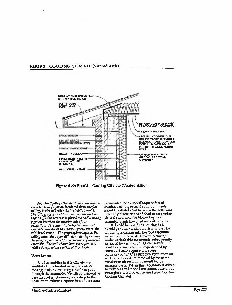
ROOF 3—COOLING CLIMATE (Vented Attic)
INSULATION WIND BAFFLE 2-IN. MINIMUM SPACE
CONTINUOUS SOFFIT VENT
MASONRY BLOCK'
B-MIL POLYETHYLENE VAPOR DIFFUSION RETARDER
CAVITY INSULATION
v GYPSUM BOARD WITH ANY PAINT OR WALLCOVERING
'V' CEILING INSULATION
6-MIL POLY CONTNUOUS CEILING VAPOR DIFFUSION RETARDER / AIR RETARDER DOENDED OVER TOP OF PERIMETER WOOD FRAME WALL
GYPSUM BOARD WITH ANY PAINT OR WALL COVERING
Figure 6-22: Roof 3—Cooling Climate (Vented Attic)
Roof 3—Cooling Climate: This conventional wood truss roof system, insulated above the flat ceiling, is virtually identical to Walls 1 and 2. The attic space i$ ventilated, and a polyethylene vapor diffusion retarder is placed above the ceiling gypsum board on the interior side of the insulation. This case illustrates how this roof assembly is attached to a masonry wall assembly with brick veneer. The poluethylene layer in the ceiling meets the vapor diffusion retarder between the masonry and wood frame portions of the wall assembly. The wall shown here corresponds to Wali 6 in a previous section of this chapter.
Ventilation
Roof assemblies in this climate are ventilated, to a limited extent, to reduce cooling loads by reducing solar heat gain through the assembly. Ventilation should be provided, at a minimum, according to the t/300 ratio, where 1 square foot of vent area
is provided for every 300 square feet of insulated ceiling area. In addition, vents should be distributed between lire soffit and ridge to prevent zones of dead or stagnation air and should not be blocked by roof assembly insulation or other obstructions.
It should be noted that during hot, humid periods, ventilation air into the attic will bring moisture into the roof assembly rather than remove it- However, during cooler periods this moisture is subsequently removed by ventilation. Under severe conditions, such as those experienced by some gulf coast regions, moisture accumulation in the attic from ventilation air will exceed moisture removal by the same ventilation air on a daily, monthly, or seasonal basis. When this is combined with a heavily air conditioned enclosure, alternative strategies should be considered (see Roof 6— Cooling Climate).
Moisturc Control Handbook Page 225
ROOF 3—COOLING CLIMATE (CONTINUED)
Air Movement
In vented roof assemblies it is important to eliminate air flow between the attic and the conditioned space. The attic needs to be uncoupled from the conditioned space so that conditions within the attic space influence the building enclosure to a minimum. This is best accomplished by not installing any forced air ductwork, furnaces, or air conditioners in attics. Experience has shown that it is difficult to seal such units or ductwork sufficiently to prevent leakage. In addition, penetrations for plumbing, wiring, dropped ceilings, and kitchen cabinet bulkheads should be sealed.
Airborne moisture infiltrating from the attic into the enclosure is controlled by (1) pressurizing the enclosure relative to the attic and the exterior, and (2) limiting air leakage openings (tight ceiling construction).
In this particular detail it important to note the airtightness provisions of the wall assembly (air barrier system). They are located towards the interior and consist of the 6-mil polyethylene vapor diffusion retarder between the masonry blocks and the frame wall, installed continuously and sealed
to the ceiling vapor diffusion retarder. In instances where the polyethylene is
installed discontinuously, or is punctured (at electrical wall outlets), hot, humid exterior air has been shown to infiltrate down the masonry cavities and through the polyethylene openings into the frame wall stud cavities. This causes mold and mildew on the interior gypsum wall board. This failure mechanism can be dramatically enhanced if three other conditions are present: (1) the masonry wall is saturated from rain penetration or construction moisture; (2) the enclosure is air conditioned; and (3) incident solar radiation drives moisture inward. To reduce air migration down the masonry cavities, the upper course of blocks should be filled with mortar.
Vapor Diffusion
To control moisture movement by diffusion from the attic into the enclosure, a continuous ceiling vapor diffusion retarder is sealed to the perimeter wall vapor diffusion
retarder. This continuous ceiling vapor retarder can also act as the air retarder system.
Comments
This continuous ceiling vapor diffusion retarder protects the ceiling gypsum board from moisture accumulation from the exterior and subsequent mold and mildew growth or water staining. It therefore allows impermeable wall/ceiling coverings, paints, and textured treatments to be installed.
In severe hot, humid conditions, the temperature of the ceiling vapor diffusion retarder in this location, as well as the temperature of the ceiling gypsum board, may be below the dew point temperature of the ambient air if the enclosure is heavily air conditioned. Thus, condensation or mold and mildew growth may result. Under such extreme conditions alternative control strategies should be considered (see Roof 6— Cooling Climate).
A wind baffle should be installed at the perimeter of the roof area where the insulated ceiling intersects the exterior wall. This prevents thermal short-circuiting of the insulation by wind (wind-washing). In this climate, wind-washing by hot, humid air can induce deposition of significant amounts of moisture on perimeter wall top plate and ceiling gypsum board surfaces cooled by air conditioning.
Exterior ventilation air entering soffit assemblies experiences a pressure drop as the soffit assembly acts as an expansion space. This is due to the combination of a narrow soffit vent opening up to a relatively large volume soffit assembly and then being squeezed into a narrow space between the underside of the roof sheathing and the wind baffle. This pressure drop induces the ventilation air to deposit airborne rain droplets in the soffit assembly rather than transport them farther into the roof assembly. Accordingly, it may be desirable to back prime wood soffit material.
The pressure-equalized air space behind the brick veneer is open to the soffit assembly to facilitate moisture removal from the air space by ventilation.
Page 226 Chapter 6—Moisture Control Practices for Cooling Climates
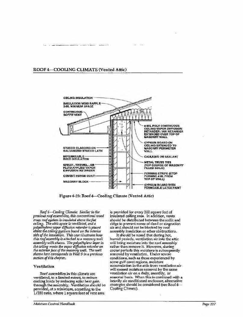
ROOF 4—COOLING CLIMATE (Vented Attic)
CEILING INSULATION
INSULATION WIND BAFFLE 2-IN. MINIMUM SPACE
CONTINUOUS SOFFIT VENT
IMPERMEABLE
SPRAY-, TR OWEL-, OR FLUID-APPLIED VAPOR DIFFUSION RETARDER
CEMENT PARGECOAT'
MASONRY BLOCK
e-MIL POLY CONTINUOUS CEILING VAPOR DIFFUSION RETARDER/AIR RETARDER EXTENDED OVER TOP OF MASONRY WALL
GYPSUM BOARD ON CEILING EXTENDED TO MASONRY PERIMETER WALL
CAULKING OR SEALANT
METAL TRUSS TIES (TOP COURSE OF MASONRY FILLED SOLID)
FURRING STRIPS (STOP FURRING 4 IN. FROM TOP OF WALL)
GYPSUM BOARD WITH PERMEABLE LATEX PAINT
Figure 6-23: Roof 4—Cooling Climate (Vented Attic)
Roof i—Cooling Climate: Similar to the previous roof assemblies, this conventional wood truss roof system is insulated above the flat ceiling. The attic space is ventilated, and a polyethylene vapor diffusion retarder is placed above the ceiling gypsum board on the interior side of the insulation. This case illustrates how this roof assembly is attached to a masonry wall assembly with stucco. The polyethylene layer in the ceiling meets the vapor diffusion retarder on the extenor face of the masonry wall. The u>all shown here corresponds to Wail 9 in a previous section of this chapter.
Ventilation
Roof assemblies in this climate are ventilated, to a limited extent, to reduce cooling loads by reducing solar heat gain through the assembly. Ventilation should be provided, at a minimum, according to the 1 /300 ratio, where 1 square foot of vent area
is provided for every 300 square feet of insulated ceiling area. In addition, vents should be distributed between the soffit and ridge to prevent zones of dead or stagnation air and should not be blocked by roof assembly insulation or other obstructions.
It should be noted that during hot, humid periods, ventilation air into the attic will bring moisture into the roof assembly rather than remove it However, during cooler periods this moisture is subsequently removed by ventilation. Under severe conditions, such as those experienced by some gulf coast regions, moisture accumulation in the attic from ventilation air will exceed moisture removal by the same ventilation air on a daily, monthly, or seasonal basis. When this is combined with a heavily air conditioned enclosure, alternative strategies should be considered (see Roof 6— Cooling Climate).
Moisture Control Handbook Page 227
ROOF 4—COOLING CLIMATE (CONTINUED)
Air Movement
In vented roof assemblies it is important to eliminate air flow between the attic and the conditioned space. The attic needs to be uncoupled from the conditioned space so that conditions within the attic influence the building enclosure to a minimum. This is best accomplished by not installing any forced air ductwork, furnaces, or air conditioners in attics. Experience has shown that it is difficult to seal such units or ductwork sufficiently to prevent leakage. In addition, penetrations for plumbing, wiring, dropped ceilings, and kitchen cabinet bulkheads should be sealed.
Airborne moisture infiltrating from the attic into the enclosure is controlled by (1) pressurizing the enclosure relative to the attic and the exterior, and (2) limiting air leakage openings (tight ceiling construction).
In this particular detail it important to note the airtightness provisions of the wall assembly (air barrier system). They are located towards the exterior and consist of the spray, trowel, or fluid-applied vapor diffusion retarder installed over a cement parge coat on the masonry blocks and sealed to the ceiling vapor diffusion retarder, which has been extended over the top of the masonry wall. To reduce the migration of hot, humid exterior air down the masonry cavities from the attic space, the upper course of blocks of the masonry perimeter wall should be filled with mortar.
To further reduce the infiltration of hot, humid air at the perimeter wall/ceiling interface, the ceiling wall gypsum board is extended to the edge of the perimeter masonry block wall and sealed. The furring strips on the masonry perimeter wall installed for the attachment of the interior gypsum wall board are cut short. The ceiling gypsum wall board is installed first, and the perimeter wall gypsum wall board subsequently conceals the bead of sealant.
Vapor Diffusion
To control moisture movement by diffusion from the attic into the enclosure, a continuous ceiling vapor diffusion retarder is sealed to the perimeter wall vapor diffusion retarder. This continuous ceiling vapor diffusion retarder can also act as the air retarder system.
Comments
This continuous ceiling vapor diffusion retarder protects the ceiling gypsum board from moisture accumulation from the exterior and subsequent mold and mildew growth or water staining. It therefore allows impermeable wall/ceiling coverings, paints, and textured treatments to be installed. However, in this example the exterior perimeter wall gypsum wall board is not similarly protected.
If the polyethylene is installed discontinuously where it intersects the perimeter masonry wall or provisions for airtightening the perimeter masonry wall are implemented, hot, humid exterior air has been shown to infiltrate through openings into the masonry wall. This causes mold and mildew on the interior gypsum wall board. This failure mechanism can be dramatically enhanced if three other conditions are present: (!) the masonry wall is saturated from rain penetration or construction moisture; (2) the enclosure is air conditioned, possibly under a slight negative air pressure due to poorly designed or installed HVAC systems; and (3) incident solar radiation drives moisture inward. Accordingly, gypsum wall board installed on the perimeter masonry walls should not be covered with impermeable wall coverings or paints unless the following conditions are satisfied:
1. The gypsum wall board is protected with a continuous vapor diffusion retarder located between it and the exterior cladding. Foil-backed gypsum board or foil-backed insulation batts are not sufficiently continuous. In this example, the vapor diffusion retarder is located on the outside of the masonry block wall.
2- If the vapor diffusion retarder is located to the exterior of the masonry block perimeter wall, construction moisture is not trapped within the wall assembly prior to installation of the interior gypsum wail board.
In severe hot, humid conditions, the temperature of the ceiling vapor diffusion retarder in this location, as well as the temperature of the ceiling gypsum board, may be below the dew point temperature of the ambient air if the enclosure is heavily air
Page 228 Chapter 6—Moisture Control Practices for Cooling Climates
ROOF 4—COOLING CLIMATE (CONTINUED)
conditioned. Thus, condensation or mold and mildew growth may result. Under such extreme conditions alternative control strategies should be considered (see Roof 6— Cooling Climate).
A wind baffle should be installed at the perimeter of the roof area where the insulated ceiling intersects the exterior wall. This prevents thermal short-circuiting of the insulationby wind (wind-washing). In this climate, wind-washing by hot, humid air can induce the deposition of significant amounts of moisture on perimeter ceiling gypsum board surfaces cooled by air conditioning.
Exterior ventilation air entering soffit assemblies experiences a pressure drop as the soffit assembly acts as an expansion space. This is due to the combination of a narrow soffit vent opening up to a relatively large volume soffit assembly and then being squeezed into a narrow space between the underside of the roof sheathing and the wind baffle- This pressure drop induces the ventilation air to deposit airborne rain droplets in the soffit assembly rather than transport them farther into the roof assembly. Accordingly, it may be desirable to back prime wood soffit material.
Moisture Control Handbook Page 229
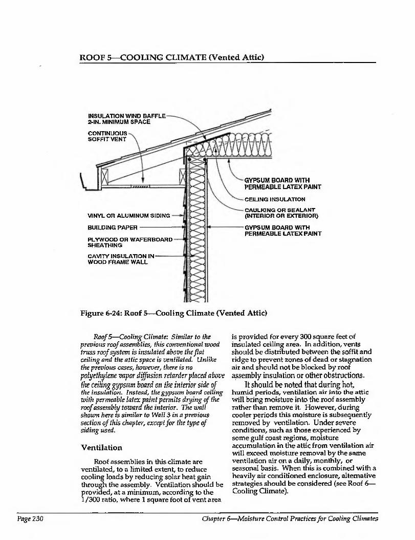
ROOF 5—COOLING CLIMATE (Vented Attic)
INSULATION WIND BAFFLE 2-IN. MINIMUM SPACE
CONTINUOUS SOFFIT VENT
VINYL OR ALUMINUM SIDING
BUILDING PAPER
PLYWOOD OR WAFERBOARD SHEATHING
CAVITY INSULATION IN WOOD FRAME WALL
GYPSUM BOARD WITH PERMEABLE LATEX PAINT
CEILING INSULATION
CAULKING OR SEALANT (INTERIOR OR EXTERIOR)
GYPSUM BOARD WITH PERMEABLE LATEX PAINT
Figure 6-24: Roof 5—Cooling Climate (Vented Attic)
Roof 5—Cooling Climate: Similar to the previous roof assemblies, this conventional wood truss roof system is insulated above the flat ceiling and the attic space is ventilated. Unlike the previous cases, however, there is no polyethylene vapor diffusion retarder placed above
the ceiling gypsum board on the interior side of the insulation. Instead, the gypsum board ceiling with permeable latex paint permits drying of the roof assembly toward the interior. The wall shown here is similar to Wall 3 in a previous section of this chapter, except for the type of siding used.
Ventilation
Roof assemblies in this climate are ventilated, to a limited extent, to reduce cooling loads by reducing solar heat gain through the assembly. Ventilation should be provided, at a minimum, according to the 1/300 ratio, where 1 square foot of vent area
is provided for every 300 square feet of insulated ceiling area. In addition, vents should be distributed between the soffit and ridge to prevent zones of dead or stagnation air and should not be blocked by roof assembly insulation or other obstructions.
It should be noted that during hot, humid periods, ventilation air into the attic will bring moisture into the roof assembly rather than remove it. However, during cooler periods this moisture is subsequently removed by ventilation. Under severe conditions, such as those experienced by some gulf coast regions, moisture accumulation in the attic from ventilation air will exceed moisture removal by the same ventilation air on a daily, monthly, or seasonal basis. When this is combined with a heavily air conditioned enclosure, alternative strategies should be considered (see Roof 6— Cooling Climate).
Page 230 Chapter 6—Moisture Control Practices for Cooling Climates
ROOF 5—COOLING CLIMATE (CONTINUED)
Air Movement
In vented roof assemblies it is important to eliminate air flow between die attic and the conditioned space. The attic needs to be uncoupled from the conditioned space so that conditions within the attic influence the building enclosure to a minimum- This is best accomplished by not installing any forced air ductwork, furnaces, or air conditioners in attics. Experience has shown that it is difficult to seal such units or ductwork sufficiently to prevent leakage. In addition, penetrations for plumbing, wiring, dropped ceilings, and kitchen cabinet bulkheads should be sealed.
Airborne moisture infiltrating from the attic into the enclosure is controlled by (1) pressurizing the enclosure relative to the attic and the exterior, and (2) limiting air leakage openings (tight ceiling construction). In this example, the ceiling gypsum board acts as Ihe air retarder system and is sealed through the perimeler wall top plate to the exterior perimeter wall plywood of waferboard sheathing, wliich acts as the perimeter wall air barrier.
Vapor Diffusion
In this example moisture movement by diffusion from ihe attic into the enclosure is not controlled. A ceiling vapor diffusion retarder has not been installed. Omitting the ceiling vapor diffusion retarder provides acceptable performance when impermeable ceiling finishes, paints, and textured treatments are also not installed. Accordingly, these impermeable interior
ceiling surface finishes should be avoided if this approach is utilized
Comments
In severe hot, humid conditions, the temperature of the ceiling gypsum board may be below the dew point temperature of the ambient air if the enclosure is heavily air conditioned. Thus, condensation or mold and mildew growth may result on the ceiling gypsum wall board. Under such extreme conditions alternative control strategies should be considered (see Roof 6—Cooling Climate).
A wind baffle should be installed at the perimeter of the roof area where the insulated ceiling intersects the exterior wall. This prevents thermal short-circuiting of the insulation by wind {wind-washing). In this climate, wind-washing by hot, humid air can induce the deposition of significant amounts of moisture on perimeter wall top plate and ceiling gypsum board surfaces cooled by air conditioning.
Exterior ventilation air entering soffit assemblies experiences a pressure drop as the soffit assembly acts as an expansion space. This is due to the combination of a narrow soffit vent opening up to a relatively large volume soffit assembly and then being squeezed into a narrow space between the underside of the roof sheathing and the wind baffle. This pressure drop induces the ventilation air to deposit airborne rain droplets in the soffit assembly rather than transport them farther into the roof assembly. Accordingly, it may be desirable to back prime wood soffit material.
Moisture Control Handbook Page 231
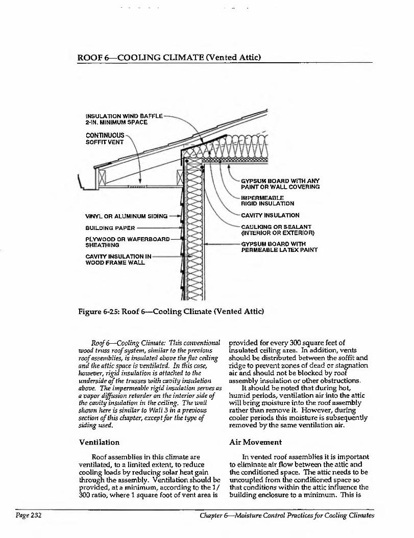
ROOF 6—COOLING CLIMATE (Vented Attic)
INSULATION WIND BAFFLE 2-IN. MINIMUM SPACE
CONTINUOUS SOFFIT VENT
VINYL OR ALUMINUM SIDING
BUILDING PAPER
PLYWOOD OR WAFERBOARD SHEATHING
CAVITY INSULATION IN WOOD FRAME WALL
GYPSUM BOARD WITH ANY PAINT OR WALL COVERING
IMPERMEABLE RIGID INSULATION
CAVITY INSULATION
CAULKING OR SEALANT (INTERIOR OR EXTERIOR)
GYPSUM BOARD WITH PERMEABLE LATEX PAINT
Figure 6-25: Roof 6—Cooling Climate (Vented Attic)
Roof 6—Cooling Climate: This conventional wood truss roof system, similar to the previous roof assemblies, is insulated above the flat ceiling and the attic space is ventilated. In this case, however, rigid insulation is attached to the underside of the trusses with cavity insulation above. The impermeable rigid insulation serves as a vapor diffusion retarder on the interior side of the cavity insidation in the ceiling. The wall shown here is similar to Wall 3 in a previous section of this chapter, except for the type of siding used.
Ventilation
Roof assemblies in this climate are ventilated,, to a limited extent, to reduce cooling loads by reducing solar heat gain through the assembly. Ventilation should be provided, at a minimum, according to the 1 / 300 ratio, where 1 square foot of vent area is
provided for every 300 square feet of insulated ceiling area. In addition, vents should be distributed between the soffit and ridge to prevent zones of dead or stagnation air and should not be blocked by roof assembly insulation or other obstructions.
It should be noted that during hot, humid periods, ventilation air into the attic will bring moisture into the roof assembly rather than remove it. However, during cooler periods this moisture is subsequently removed by the same ventilation air.
Air Movement
In vented roof assemblies it is important to eliminate air flow between the attic and the conditioned space. The attic needs to be uncoupled from the conditioned space so that conditions within the attic influence the building enclosure to a minimum. This is
Page 232 Chapter 6—Moisture Control Practices for Cooling Climates
ROOF 6—COOLING CLIMATE (CONTINUED)
best accomplished by not installing any forced air ductwork, furnaces, or air conditioners in attics. Experience has shown that it is difficult to seal such units or ductwork sufficiently to prevent leakage. In addition, penetrations for plumbing, wiring, dropped ceilings, and kitchen cabinet bulkheads should be sealed.
Airborne moisture infiltrating from the attic into the enclosure is controlled by (1) pressurizing the enclosure relative to the attic and the exterior, and (2) limiting air leakage openings (tight ceiling construction). In this example the ceiling gypsum board acts as the air retarder system and is sealed through the perimeter wall top plate to the exterior perimeter wall plywood of waferboard sheathing, which acts as the perimeter wall air retarder.
Vapor Diffusion
To control moisture movement by diffusion from the attic into the enclosure, impermeable rigid insulation is installed at the underside of the ceiling framing, which acts as a vapor diffusion retarder.
This impermeable rigid Insulation, which acts as the ceiling vapor diffusion retarder, also protects the ceiling gypsum board from moisture accumulation from the exterior and subsequent mold and mildew growth or water staining. It therefore allows impermeable wall/ceiling coverings, paints, arid textured treatments to be installed.
In severe hot, humid conditions, the installation of the rigid, impermeable insulation at the underside of the ceiling framing has tire following effect- The temperature of the upper surface of the impermeable rigid insulation, which acts as the ceiling vapor diffusion retarder, as well as the temperature of the ceiling gypsum board, will no longer be below the dew point temperature of the ambient air, even if the enclosure is heavily air conditioned. As such.
condensation or mold and mildew growth on these surfaces is prevented.
Comments
A wind baffle should be installed at the perimeter of the roof area where the insulated ceiling intersects the exterior wall. This prevents thermal short-circuiting of the insulation by wind (wind-washing). In this climate, wind-washing by hot, humid air can induce the deposition of significant amounts of moisture on perimeter wall top plate and ceiling gypsum board surfaces cooled by air conditioning.
Exterior ventilation air entering soffit assemblies experiences a pressure drop as the soffit assembly acts as an expansion space. This is due to the combination of a narrow soffit vent opening up to a relatively large volume soffit assembly and then being squeezed into a narrow space between the underside of the roof sheathing and the wind baffle. This pressure drop induces the ventilation air to deposit airborne rain droplets in the soffit assembly rather than transport them farther into the roof assembly. Accordingly, it may be desirable to back prime wood soffit material.
CHAPTER 6: REFERENCES
6.1 American Society of Heating, Refrigerating and Air Conditioning Engineers, Inc., Ventilation for Acceptable Indoor Air Quality, ASHRAE Standard 62 - 1989, Atlanta, Georgia, 1989.
6.2 Carmody, J., J. Christian, and K. Labs, Builder's Foundation Handbook, Oak Ridge National Laboratory, ORNL/ CON-295,1991.
6.3 Godish, T., Indoor Air Pollution Con trol, Lewis Publishers, Chelsea, Michigan, 1989.
Moisture Control Handbook Page 233

Glossary Above grade: The portions of a foundation
wall or other building assembly above ground level.
Absolute humidity: The mass of water vapor per unit volume of air.
Absolute zero: The point at which air is totally without heat: -460® F.
Absorption: Ability of a porous solid material to hold within its body relatively large quantities of gases or liquids.
Absorptive film: A film applied to the inside surface of glass which absorbs selected wavelengths of light from the sun, thus preventing its entrance into the building.
Adhesive: A cementing substance that produces a steady and firm attachment or adhesion between two surfaces. Adhesion, is measured in shear and peel modes.
Adiabatic process: A thermodynamic process during which no heat is added to, or taken from, a substance or system.
Adsorption: The adhesion of an extremely thin layer of molecules (of gases or liquids) to the surface of solids or liquids with which they are in contact.
Aging: The effect on materials of exposure or the process of exposing materials for an interval of time to a natural environment or simulated environment,
Air changes per hour (Ac/h): The rate at which the volume of air in a building changes.
simultaneously Us temperature, humidity, cleanliness, and distribution.
Air, dry: Air without contained water vapor; air only.
Air infiltration; Air leakage into a building.
Air leakage: The movement of air through spaces between constituent parts of an assembly as a result of air-pressure differences between one and the other side.
Air, outdoor: Air taken from outdoors and, therefore, not previously circulated through the system.
Air, rediculated: Return air passed through the conditioner before being again supplied to the conditioned space.
Air retarder: An assembly or building element that provides resistance to through-flow of air from inside to outside and vice-versa.
Air, return: Air returned from conditioned or refrigerated space.
Air, saturated; Moist air in which the partial pressure of the water vapor is equal to the vapor pressure of water at the existing temperature. This occurs when dry air and saturated water vapor coexist at the same dry-bulb temperature.
Air space: A cavity or unfilled space
between two constituent parts in an assembly or other element of a building.
Ambient temperature: Temperature of the surrounding outside air.
Air conditioning: The process of treating air ASHRAE: American Society of Heating, to meet the requirements of the Refrigerating, and Air Conditioning conditioned space by controlling Engineers, Inc.
Moisture Control Handbook Page 235
Ballast: Crushed rock or gravel placed on roof insulation boards to hold them down from wind uplift, as in the case of an inverted roof.
Balloon construction: A type of frame construction that uses a one-member sill platform, and a ribband to support floor joists, rather than individual platforms for each floor.
Band joist: A board that rests on the sill and covers the outside surface of the joists, and the space between them. It is usually the same size as the joist and is installed completely around the house (also called the header or the rim joist).
Barometer. Instrument for measuring atmospheric pressure.
Below grade: The portions of a building below ground level.
Bitumen: A generic term applied to mixtures of predominantly hydrocarbons in viscous or solid form, derived from coal or petroleum.
British Thermal Unit (Btu): The Btu is defined as the heat required to raise the temperature of a pound of water from 59° to 60° F.
Bond: 1. To hold together two assembly components by means of an adhesive. 2. The adhesive strength that prevents delamination of two assembly components.
Carbon monoxide (CO): A colorless, odorless, highly poisonous gas, produced by the incomplete combustion of carbonaceous material.
Caulking: Any of a wide range of bituminous, rubber, plastic, or other materials suitable for filling seams or cracks to make them tight against water leakage and remain plastic for an extended time after application. See sealant.
Celsius (formerly Centigrade): A thermometric scale in which the freezing point of water is called 0° C and its boiling point 100° C at normal atmospheric pressure (14.696 psi).
Change of state (or phase change): The change from solid, liquid, or gas to either of the other two (for instance, when an ice cube melts).
Coating: A thin layer of a substance used to cover other materials, to provide an aesthetic or protective function.
Combustion: The act or process of burning, rapid oxidation, accompanied by heat and usually light.
Concealed condensation: Condensation that takes place within a building assembly and is not seen.
Condensation: The process of changing a vapor to a liquid by extracting heat from the vapor.
Conductance: The rate of heat flow (in Btu's per hour) through an object when a temperature difference of one degree Fahrenheit is maintained between the sides of the object.
Conduction: A process of heat transfer whereby heat moves through a material; the flow of heat due to temperature variations within a material.
Conductivity: A measure of the ability of a material to permit conductive heat flow through it.
Convection: Transfer of heat by movement of a fluid or gas.
Cooling load: The total heat/humidity gain of a home.
Crawl space: The space between the foundation and the rest of the building.
Crushed stone: The product resulting from the artificial crushing of rocks, boulders, or large cobblestones, substantially all faces of which have resulted from the crushing operation.
Dalton's Law of Partial Pressure: Each constituent of a mixture of gases behaves thermodynamically as if it alone occupied the space. The sum of the individual pressures of the constituents equals the total pressure of the mixture.
Dampproofing: The treatment of a building material or component surface with a bituminous or other coating to provide some measure of resistance to the passage of moisture by capillarity or vapor diffusion.
Degree day (DD): The degree day is a unit of heat measurement equal to one
Page 236
degree variation from a standard temperature to the average temperature of one day- If the standard is 65° and the average outside temperature is 50“ for two days, then the number of degree days is 30-
Degree days: The number of degrees difference from 65° each day, whether above (cooling degree days) or below (heating degree days); the days are added together for the entire heating or cooling season.
Dehumidification: The condensation of water vapor from air by cooling below the dew point or removal of water vapor from air by chemical or physical methods.
Dehumidifier: 1. An air cooler or washer used for lowering the moisture content of the air passing through it. 2- An absorption or adsorption device for removing moisture from air.
Degradation: A deleterious change in the chemical structure, physical properties, or appearance of an organic material.
Desiccant; Any absorbent or adsorbent, liquid or solid, that will remove water or water vapor from a material.
Dew point: The temperature at which a sample of humid air becomes saturated and the water vapor begins to condense to liquid water.
Diffusion: The movement of water vapor from a region of high concentration to a region of low concentration.
Draft hood: A component of gas-fired furnaces or boilers which mixes secondary air with the combustion gases leaving the unit, thus enabling a smooth, continuous relief of exhaust gases up the vent pipe.
Drip edge: The formed edge on metal flashing used at the eaves or other roof details to encourage water to drip away from vertical surfaces of the building detail.
Duck A passageway made of sheet metal or other suitable material, not necessarily leaktighl, used for conveying air or other gas at low pressures.
have: The end of a roof.
Elasticity: The property of matter of immediately returning to its original size and shape after removal of tire stress that caused the deformation.
Emission (or cmissivity, omittance): A measure of the propensity of a material to radiate heat to its surroundings in the form of longwave radiation.
Energy: The capacity for doing work— taking a number of forms, which may be transformed from one into another, such as thermal (heat), mechanical (work), electrical, and chemical; in customary units, measured in kilowatt hours (kwh) or British Thermal Units (Btu); in SI units, measured in joules 0), where 1 joule = 1 watt-second.
Energy efficiency ratio (EER); The ratio of usable output to input of energy; in the case of cooling units, since the input is usually electrical power (measurable in watts); and the amount of heat removed is measurable in Btu's, the EER is the ratio of the number of Btu’s per hour to the number of watts used.
Enthalpy: Thermodynamic property of a substance defined as the sum. of its internal energy' plus the quantity Pv/J, where P = pressure of the substance, v = its volume, and J = the mechanical equivalent of heat. Formerly called by the obsolescent names "total heat" and "heat content.''
Entropy: The ratio of the heat added to a substance to the absolute temperature at which it is added.
Envelope: The protective shell of a building that separates the outside environment from the inside environment.
Equilibrium moisture content; 1. The moisture content of a material stabilized at a given temperature and relative humidity, expressed as percent moisture by weight. 2, The typical moisture content of a material in any given geographical area.
Expanded polystyrene (EPS): Insulation composed principally of polystyrene resin processed to form a rigid foam having a predominantly closed-cell structure. Boards or blocks are formed during expansion. See also insulation.
Moisture Control Handbook Page 237
Expansion Joint: A structural separation between two building elements that allows free movement due to expansion, contraction, or deflection between the elements without damage.
Extruded polystyrene: Insulation board produced by a continuous extrusion process as the resin foams. This forms a tight and complete skin on each side of the board.
Fahrenheit A thermometric scale in which 32° (F) denotes freezing and 212° (F) the boiling point of water under normal pressure at sea level (14.696 psi).
Fascia: Any cover board at the edge or eaves of a flat or sloping overhanging roof-
Fiberboard: Insulation composed principally of cellulose fibers usually derived from paper, paperboard stock, or wood, with or without binders. See also insulation.
Filter A device to remove solid material from a fluid.
Flashing: The system used to direct water out of building assemblies or joints.
Flue: A tube, pipe, or shaft that allows for the passage of exhaust gases to the outside environment.
Fluid: Gas, vapor, or liquid.
Force: The action on a body which tends to change its relative condition as to rest or motion.
Footings: The projecting base or enlarged foundation put under a column or wall of a foundation, to spread its weight and prevent settling.
Frost line: The depth of frost penetration in the soil.
Gable end: The triangular end of an exterior wall from the level of the eaves to the ridge of a double-sloped roof.
Gable roof: A ridged or double-sloped roof that terminates at one or both ends in a gable.
Gravel: Small pieces of aggregate larger than sand grains resulting from the natural erosion or the crushing of rock, used to protect bituminous surfaces or ballast in roofing systems.
Header A horizontal supporting member, supported by jack studs, which runs across the top of a door or window space (also called a band).
HeaE A form of energy that is transferred by virtue of a temperature difference.
Heat, latent: Change of enthalpy during a change of state, usually expressed in Btu per lb. With pure substances, latent heat is absorbed or rejected at constant pressure.
Heat, sensible: Heat which is associated with a change in temperature; specific heat exchange of temperature; in contrast to a heat interchange in which a change of state (latent heat) occurs.
Heat transmission: The quantity of heat flowing through unit area due to all modes of heat transfer induced by the prevailing conditions.
Humidifier: A device to add moisture to air.
Humidistafc A regulatory device, actuated by changes in humidity, used for the automatic control of relative humidity.
Humidity: Water vapor within a given space.
Humidity, absolute: The weight of water vapor per unit volume.
Humidity, relative: The ratio of the mol fraction of water vapor present in the air, to the mol fraction of water vapor present in saturated air at the same temperature and barometric pressure; approximately, it equals the ratio of the partial pressure or density of the water vapor in the air, to the saturation pressure or density, respectively, of water vapor at the same temperature.
HVAC: Heating, ventilation, and air conditioning.
Hygroscopic: Attracting, absorbing, and retaining atmospheric moisture.
Ice dam: A mass of ice formed at the transition from a warm to a cold roof surface. Frequently formed by re¬ freezing meltwater at the overhang of a sloping roof, an ice dam may cause ice and water to back up and make the surface slippery for snow to slide down.
Infiltration: The uncontrolled flow of air into a building through cracks, openings, doors, or other areas that allow air to penetrate.
Infrared radiation: Electromagnetic radiation from the sun that has wavelengtiis slightly longer than visible light and that is felt as heat.
Inorganic Being or composed of matter other than hydrocarbons and Iheir derivatives, or matter that is not of plant or animal origin.
Insulate: To separate conducting bodies in order to prevent transfer of heat
Insulation: A material used as part of a building enclosure lo retard the flow of heal through the enclosure. It is made from a variety of organic and inorganic fibers and foams, e.g., expanded/ extruded polystyrene, glass fiber, cellular glass, phenolic foam, perlite, polyurethane roam, polyisocyanurate foam. It can be loose-filled, or used in batt, board, or block form.
Interstitial condensation; Condensation that occurs in the interstices between constituent parts of a building assembly.
Inverted roof: See protected membrane roof.
Joists: Any of the parallel beams that support the floor or the ceiling.
Latent heat: A change in heat content that occurs without a corresponding change in temperature, usually accompanied by a change of state.
Leaching: The dissolving-out of soluble substances when water seeps through a building assembly, often responsible for ugly staining on ceilings und walls when the water drains to the interior.
Loose-fill insulation: Insulation in granular, nodular, fibrous, powdery, or similar form designed to be installed by pouring, blowing, or hand placement See also insulation.
Manometer: An instrument for measuring pressures.
Masonry: Stone, brick, rammed earth, adobe, ceramic, hoi tow tile, concrete block, gypsum block, or other similar building units or materials, or a combination thereof, bonded together with mortar to
form a wall, pier, floor, roof, or similar form.
Mastic: 1. A material of relatively viscous consistency that dries or cures to form a protective finish, suitable for application to thermal insulation in Ihickness greater than 0.75 mm per coat. 2. Trowelablebituminous paste made by adding mineral fillers to concentrated cutbacks.
Membrane: The term membrane applies to a continuous sheet of material whether it is prefabricated as a flexible polymeric sheeting or is sprayed or coated in the field, in single ply or in multiple plies.
Microclimate: The climate of a specific site or portion of a site. Microclimates result from the overall regional climate as it is affected by local site conditions, including ground slope and orientation, topographic features, elevation, vegetation, winds, water bodies, ground surface, and buildings.
Mineral fiber: Insulation composed principally of fibers manufactured from rock, slag, or glass, with or without binders.
Mud sill: The lowest sill placed on the foundation of a structure.
Nailing strips: A member, usually of wood, set into or secured to non-nail able building assemblies to allow for positive anchorage by nailing of other assembly materials.
Organic; Being or composed of hydrocarbons or their derivatives, or matter of plant or animal origin.
Overhang: The part of a roof structure that extends beyond the exterior walls of a building.
Phenolic foam: A closed-cell, rigid, thermosetting foam in the core material for making insulation boards of various thicknesses. See also insulation.
Plaster: A mixture of lime, sand, and water which hardens on drying, for coating walls, ceilings, and partitions.
Platform construction: A system of framing a building that uses individual platforms for each floor. The floor joists for second stories rest on the top plate of the first story.
Moisture Control Handbook Page 239
Plywood: A construction material made of thin layers of wood glued and pressed together to form sheets of varying thicknesses.
Polyurethane (PU): Insulation composed principally of the catalyzed reaction product of polyisocyanurate and polyhydroxy compounds, processes usually with fluorocarbon gas to form a rigid foam having a predominantly closed-cell structure. It is sprayed in place or preformed into boards. See also insulation.
Pressure: The normal force exerted by a homogeneous liquid or gas, per unit of area, on the wall of its container.
Pressure, absolute: Pressure referred to that of a perfect vacuum. It is the sum of gauge pressure and atmospheric pressure-
Pressure, atmospheric: It is the pressure indicated by a barometer. Standard atmosphere is the pressure equivalent to 14.696 psi or 29.921 in. of mercury at 32° F.
Pressure, gauge: Pressure above atmospheric,
Pressure, partial: Portion of total gas pressure of a mixture attributable to one component.
Protected membrane roof (PMR): A roofing system wherein the roofing membrane is applied to the structural deck and the insulation is placed on top of the membrane and is ballasted. Also called inverted roof.
Psychrometric chart; A graphical representation of the thermodynamic properties of moist air.
Radiation, thermal: The transmission of heat through space by wave motion; the passage of heat from one object to another without warming the space between.
Rafters: Any of the beams in a pitched roof that slope from the ridge of a roof to the eaves, and serve to support the roof.
Reflectance: The fraction of the incident radiation upon a surface that is reflected from the surface.
Reflective film: A film applied to the inside surface of glass that reflects sunlight back out of the window.
Regieh A groove cut in masonry or concrete walls for inserting flashing.
Relative humidity (RH): The ratio of water vapor in the air to the amount it could potentially hold at that given temperature.
Retrofit: Alteration of a home or addition of materials or devices to improve its performance or service life.
Return ain Air returned from conditioned or refrigerated space.
Ridge: The horizontal line where two opposite sloping sides of a roof join at the highest level of the roof.
Ridge vent A type of vent that replaces a portion of the peak of the roof of a building to provide ventilation.
R-value (resistance): A measure of the insulating value of a substance, or measure of a material’s resistance to the flow of heat; equal to:
1 or 1
lWh/ft20F TT
Saturation: The point at which the air has reached 100% relative humidity and can hold no more water vapor.
Sealant: A mixture of polymers, fillers, and pigments used to fill and seal joints where moderate movement is expected; unlike caulking, it cures to a resilient solid. See also caulking.
Selective surface coating: A surface that absorbs radiation of one wavelength (for example, sunlight) but emits little radiation of another wavelength (for example, infrared).
Sensible heat: Heat that is associated with a change in temperature; specific heat exchange of temperature.
Shingle: 1. A small unit of prepared roofing designed for installation with similar units in overlapping rows on inclines. 2. To cover with shingles. 3- To apply any sheet material in overlapping rows like shingles.
Sill plate: A board placed horizontally across the top of a foundation wall. Holes are drilled through the sill plate and anchor bolts passed through them to secure it to the foundation.
Soffit: The underside of a roof overhang.
Sole, or sole plate: The horizontal base for the wall in platform construction. It sits on the subflooring, and is also called the base plate. Studs are nailed al right angles to the sole plate.
Stack effect Air flow into a building at the lower levels and ou t at the higher levels caused by the pressure difference that exists because of the temperature differences of the air masses inside and outside of buildings; similar to the phenomenon that produces draft in a chimney.
Stud: A vertical wooden member used ill framing walls.
Subfloor: A rough floor upon which a finished floor is laid.
Temperature: Measurement of the level of motion or agitation of molecules and atoms.
Thermal: Relating to heat
Thermal bridge: A heat-conductive element in a building assembly that extends from the warm to the cold side and provides less heat-flow resistance than the adjacent construction.
Thermal conductance: A unit of heat flow and a measure of the heat-insulating efficiency of a ma terial.
Thermal conduction: The movement of heat from molecule to adjacent molecule, through a substance or from one substance to another in contact with it.
Thermal convection: 1'he circulation of heat within a gas or liquid due to the differences in density resulting from temperature changes.
Thermal insulation: See insulation.
Thermal radiation: Electromagnetic radiation emitted by a warm body. (See infrared radiation).
Thermal resistance: A measure of the resistance to heat flow of a material or component of construction of a
particular thickness. It is the inverse of thermal conductance. The symbol RSI is used. RSI = 1/C = {m2 C)/W.
Thermal transmittance: A measure of the heat conducted through a unit of a building in unit time with unit temperature difference between inside and outside. Also called the coefficient of heat transfer or 'TJ" value for the assembly, its units are VV/(m2 C). It is the reciprocal of the total resistance for the system obtained by adding all the individual resistances of the components of the system including surface and air space resistances. U = 1/RSI (total).
Thermodynamics: The science of heat energy and its transformations to and from other forms of energy.
Top plate: A horizontally placed board which connects the tops of studs in wall construction.
Ultraviolet radiation: Electromagnetic radiation with wavelengths slightly shorter than visible light.
U-value: The capability of a substance to transfer heat Used to describe the conductance of a material, or a composite of materials, in construction. The reciprocal of resistance is given as:
1= R
U
Vapor: A substance in gaseous state. In relation to building it generally refers to water vapor.
Vapor diffusion retarder Material used to retard the passage of vapor or moisture into building assemblies.
Vapor migrations: The movement of water molecules from a region of high to one of lower vapor pressure through building assemblies.
Vapor permeability: The rate at which water vapor wil 1 diffuse or permeate through a unit area in unit time with unit vapor pressure difference across a unit thickness of a material. The units are nanograms per square meter per meter of thickness per second of time per pascal of pressure difference. The symbol is u and the units are written ng/fPa-sm7).
Moisture Control Handbook Page 241
Vapor permeance: The rate at which water vapor will diffuse through a material of a particular thickness. The symbol is M and the units nanograms per square meter per second per pascal vapor pressure difference, written ng/ (Pasm2), M = u/1, where 1 = thickness in meters.
Vapor pressure: The lowest absolute pressure that a given liquid at a given temperature will remain liquid before evaporating into its gaseous form or state.
Vapor resistance: A measure of the resistance to water vapor flow. Vapor resistance is the reciprocal of permeance = 1 /M and the units are written (Pasm2)/ng.
Vent: An opening designed for the purpose of supplying or removing air by a natural or mechanical means to or from any space.
Ventilation: The process of supplying or removing air by a natural or mechanical means to or from a space.
Waterproofing: 1. A material used to treat or cover a building element or component
to prevent leakage of water. 2. Treatment of a surface or structure to prevent the passage of water under hydrostatic pressure.
Water vapor diffusion: The process by which water vapor spreads or moves through permeable materials caused by a difference in water vapor pressure.
Water vapor permeability: See vapor permeability.
Water vapor pressure: The pressure of water vapor at a given temperature; also the component of atmospheric pressure contributed by the presence of water vapor.
Watt: Unit of measurement for electric power. One volt times one ampere equals one watt.
Weatherization: Making a house more energy efficient and comfortable.
Weathers tripping: Narrow strips of flexible metal, vinyl, foam, or felt placed over or in movable joints of windows and doors to reduce the passage of atr and moisture.
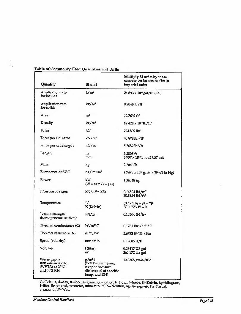
Table of Commonly Used Quantities and Units
Quantity
Application rate for liquids
Application rate for solids
Area
Density
Force
Force per unit area
Force per unit length
Length
Mass
Permeance at 23®C
Power
Pressure or stress
Temperature
Tensile strength (homogeneous section)
Thermal conductance (C)
Thermal resistance (R)
Speed (velocity)
Volume
Water vapor transmission rate (WVTR) at 23°C and 50% RH
SI unit
l/rtf
kg/m7
m2
kg/m3
kN
kN/m2
kN/m
m mm
kg
ng/Pasm7
kW (W = N-m/s = J/s)
kN/m2 = kPa
“C K (Kelvin)
kN/m2
W/m7°C
m2°C/W
min/min
g/rmd {WVT - permeance x vapor pressure differential at specific temp, and RH)
Multiply SI units by these conversion factors to obtain imperial units
24.543 X 10"3 gal/ft1 (US)
0.2048 lb/ft2
"10.7639 ft2
62.428 x iO’3 lb/ft3
224.809 Ibf
20.878 Ibf/ft2
5.7082 ibf/ft
3.2808 ft 3-937 x UH in or 39 37 mil
2.2046 lb
1,7478 x IO'2 grain/(ft2,hl in Hg)
1.34048 hp
0.14504 lbf/in2 20.8854 Ibf/ft2
(aCxl.8) +32 = ®F “0+273.15 = K
0-14504 lbf/in2
0.1761 Btu/hft^F
5.6783 ftLOFh/Btu
0.19685 ft/h
1 (liter) 0.26417 US gal m3 264.172 US gal
1.43368 grain/fpd
C=CeJsius, d=day, ft=foot, g=gram, gal=gallon, h=hour, J=Joule, K=Kelvin, kg=kilogram, l=liter, lb-pound, m=meter, min-mmute, N=Newton, ng=nanogram, Pa=Pasca], s-second, W-Watt
Moisture Control Handbook Page 243
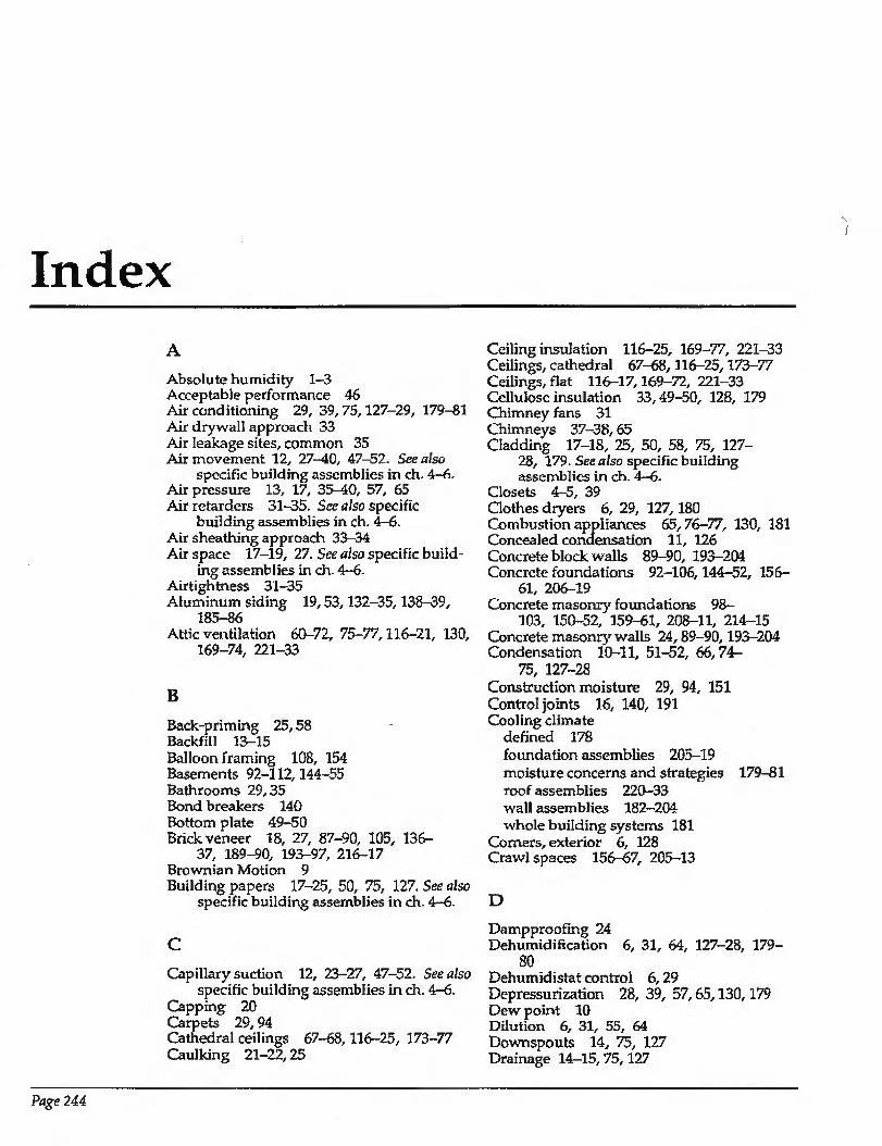
Index A
Absolute humidity 1-3 Acceptable performance 46 Air conditioning 29, 39, 75,127-29, 179-81 Air drywall approach 33 Air leakage sites, common 35 Air movement 12, 27-40, 47-52. See also
specific building assemblies in ch. 4-6. Air pressure 13, 17, 35-40, 57, 65 Air retarders 31-35. See also specific
building assemblies in ch. 4—6. Air sheathing approach 33-34 Air space 17-19, 27. See also specific build¬
ing assemblies in ch. 4-6. Airtightness 31-35 Aluminum siding 19,53,132-35,138-39,
185-86 Attic ventilation 60-72, 75-77,116-21, 130,
169-74, 221-33
B Back-priming 25,58 Backfill 13-15 Balloon framing 108, 154 Basements 92-112,144-55 Bathrooms 29,35 Bond breakers 140 Bottom plate 49-50 Brick veneer 18, 27, 87-90, 105, 136-
37, 189-90, 193-97, 216-17 Brownian Motion 9 Building papers 17-25, 50, 75, 127, See also
specific building assemblies in ch. 4r-6.
c Capillary suction 12, 23-27, 47—52. See also
specific building assemblies in ch. 4-6. Capping 20 Carpets 29,94 Cathedral ceilings 67-68,116-25, 173-77 Caulking 21-22,25
Ceiling insulation 116-25, 169-77, 221-33 Ceilings, cathedral 67-68,116-25,173-77 Ceilings, flat 116-17,169-72, 221-33 Cellulose insulation 33,49-50, 128, 179 Chimney fans 31 Chimneys 37-38, £6 Cladding 17-18, 25, 50, 58, 75, 127-
28, 179. See also specific building assemblies in ch. 4—6.
Closets 4-5, 39 Clothes dryers 6, 29, 127,180 Combustion appliances 65, 76-77, 130, 181 Concealed condensation 11, 126 Concrete block walls 89-90, 193-204 Concrete foundations 92-106,144-52, 156-
61, 206-19 Concrete masonry foundations 98—
103, 150-52, 159-61, 208-11, 214-15 Concrete masonry walls 24, 89-90,193-204 Condensation 10-11, 51-52, 66,74-
75, 127-28 Construction moisture 29, 94, 151 Control joints 16, 140, 191 Cooling climate
defined 178 foundation assemblies 205-19 moisture concerns and strategies 179-81 roof assemblies 220-33 wall assemblies 182-204 whole building systems 181
Comers, exterior 6, 128 Crawl spaces 156-67, 205-13
D
Dampproofing 24 Dehumidification 6, 31, 64, 127-28, 179-
80 Dehumidistat control 6,29 Depressurization 28, 39, 57,65,130,179 Dew point 10 Dilution 6, 31, 55, 64 Downspouts 14, 75, 127 Drainage 14-15,75,127
Page 244
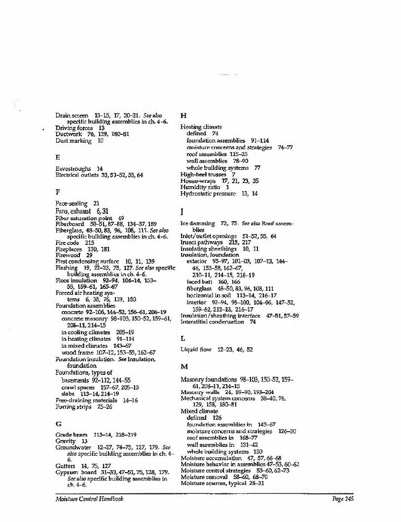
Drain screen 13-15, 17, 20-21. See also specific building assemblies in ch. 4-6.
Driving forces 13 Ductwork 76, 129, 180-81 Dust marking 10
E
Eavestroughs 14 Electrical ouflets 33,51-52,55,64
F
Face-sealing 21
Fans, exhaust 6,31 Fiber saturation point 49 Fibetboard 50-51,87-88, 134-37,1S9 Fiberglass, 48-50,83, 96, 108, 111. See also
specific building assemblies in ch. 4-6. Fire code 215 Fireplaces 130, 181 Firewood 29 First condensing surface 10, 11, 139 Flashing 19, 22-23, 75, 127. See also specific
building assemblies in ch. 4-6. Floor insulation 92—94, 104-14, 153-
55, 159-61, 165-67 Forced air heating sys¬
tems 6, 38, 76, 129, 180 Foundation assemblies
concrete 92-106,144-52,156-61,206-19 concrete masonry 98-103,150-52,159-61,
208-11,214-15 in cooling climates 205-19 in heating climates 91-114 in mixed climates 143-67 wood frame 107-12,153-55, 162h57
Foundation insulation. See Insulation, foundation
Foundations, types of basemenis 92-112,144-55 crawl spaces 157-67, 205-13 slabs 113-14,214-19
Free-draining materiab 14—16 Furring strips 25—26
G
Grade beam 113-14, 218-219 Gravity 13 Groundwater 12-27, 74-75, 127, 179. See
also specific building assemblies in ch. 4- 6.
Gutters 14, 75, 127 Gypsum board 31-33,47-51,75,128, 179.
See also specific building assemblies in ch. 4-6.
H
Heating climate defined 74 foundation assemblies 91-114 moisture concerns and strategies 74—77 roof assemblies 115-25 wall assemblies 78 -90 whole building systems 77
High-heel trusses 7 House-wraps 17, 21, 23, 35 Humidity ratio 1 Hydrostatic pressure 13, 14
I Ice damming 72, 75. See also Roof assem¬
blies Inlet/outlet openings 51-52,55, 64 Insect pathways 215, 217 Insulating sheathings 10, 11 Insulation, foundation
exterior 95-97, 101-03, 107-13, 144- 46, 153-58,162-67, 210-11, 214-15, 218-19
faced batt 160, 166 fiberglass 48-50,83,96,108,111 horizontal in soil 113-14, 216-17 interior 92-94, 98-100, 104-06, 147-52,
159-62,212-13, 216-17 Insulation/sheathing interface 47-51,57-59 Interstitial condensation 74
L
Liquid flow 12-23, 46, 52
M
Masonry foundations 98-103,150-52,159- 61,208-11,214-15
Masonry walls 24, 89-90,193-204 Mechanical system concerns 38-40, 76,
129, 158, 180-81 Mixed climate
defined 126 foundation assemblies in 143-67 moisture concerns and strategies 126-30 roof assemblies in 168-77 wall assemblies in 131^2 whole building systems 130
Moisture accumulation 47, 57,66-68 Moisture behavior in assemblies 47-53,60-62 Moisture control strategies 53—60,62-73 Moisture removal 58-60, 68-70 Moisture sources, typical 28-31
Moisture Control Handbook Page 245
Moisture transport mechanisms air movement 12, 27-40,47,52 capillary suction 12, 23-27, 47, 52 liquid flow 12-23,46,52 vapor diffusion 12, 40-44, 47,58
Mold and mildew 3-10, 76, 127-28, 179- 180
Moustaches 22
N
Neutral pressure plane 37
P
Paint, latex 138-42, 183-88, 191-92,201-02 Paint peeling 49-51 Pillow, insulation 93, 96, 102, 112 Plywood sheathing 57, 79-80, 132-33, 187-
88,191-92 Plywood siding 183-84 Poly-wrap approach 33 Pressure equalization 18 Pressurization 40, 65, 130,179,181 Psychrometric chart 3, 70
R
Radon 16, 39, 57, 127, 129-30, 180-81 Rain penetration/absorption 12-13, 17-
27, 74-75, 127, 179 Rain screen 13, 17-20, 22, 75, 127. See also
specific building assemblies in ch. 4-6. Relative humidity 1-3, 4, 5, 10,66 Rim joist insulation 92-112,144-67, 206-13 Roof assemblies
cathedral ceiling 67-68,116-25,175-77 in cooling climates 220-33 flat ceiling 115-16,169-72,221-33 in heating climates 115-25 in mixed climates 169-77 moisture behavior in 60-62 moisture control strategies 62-73 ventilation of 61-63, 68-72,116-21,130,
169-74,221-33 Roofing lifespan 71 Roof leaks 62 Roof overhangs 17
s Sealants 22 Setback thermostats 7 Sheathing, roof 60-70
Sheathing, wall fiberboard or gypsum 87-88, 134-
37, 189-92 impermeable insulating 81-82, 85-
86, 138-42, 185-86 impermeable noninsulating 79-80, 132-
33, 187-88, 191-92 moisture behavior in 47-51,57-60 permeable insulating 83—84 permeable nonlnsulating 87—88, 134—
37, 189-90 plywood or waferboard 57, 79-80, 132—
33, 187-88, 191-92 rigid fiberglass 83-84
Short-circuiting 5 Siding
aluminum 19,132-35, 138-39, 185-86 back-priming of 25 stucco 140-42,191-92,198-204 vinyl 19, 53, 79-84,132-35,138-39,179,
185-86 wood 25,49, 85-86,132-33,183-88
Site grading 75, 127 Site selection 13, 14 Skip-sheathing 27 Slab foundations 113-14, 214-19 Soffit vents 7, 72. See also Roof assemblies Source control 6, 28-31, 64, 75, 127, 180 Space heaters 6, 29 Splash-back 14 Stack effect 37 Stucco cladding 140-42, 191-92, 198-204 Subgrade drainage 14-15, 75, 127 Subslab insulation 113-14,216-17. See also
Floor insulation Surface drainage 75,127
T
Thatched-roof effect 15, 48 Thermal bridges 9, 76,128
u Unvented crawl spaces 156-67,210-13
V
Vapor diffusion 12, 40-44, 47-51, 55-70 Vapor diffusion retarders 40-
44, 51, 55, 62, 64. See also specific building assemblies in ch. 4-6.
Vapor pressure 1-6 Vented crawl spaces 206-09 Ventilation rates, minimum 180

Ventilation, roof/attic 60 72,75-77,116- 21, 130, 169-74,221-33
Vinyl interior wall coverings 75,128, 179 Vinyl siding 19,53,79-84,132-35,138-39,
179,185-86
W
Waferboard 79-80, 132-33, 187-88,191-92 Wall assemblies
air movement in 51-52 concrete 89-90,193-204 concrete masonry 24,89-90,193-204 in cooling climates 182-204 in heating climates 79-90 in mixed climates 131-42 moisture control strategies for 53-60 vapor diffusion in 47-51 wood 79-88,132-42,183-92
Wall/roof intersection 7 Waterproofing 13, 16,24 Weatherproofing 13, 17,21 Weep holes 18, 19 Wet lumber 29, 75, 128, 179 Wet-applied insulation 75, 128, 179 Wetting potential 55 Whole building systems 77, 130,181 Wind baffle See Roof assemblies Wind-washing 5, 6, 7, 21 Windows 10-11, 22, 33, 128 Wood frame foundations 107-12, 153-
55, 162-67 Wood frame walls 79-88, 132-42, 183-92 Wood siding 25,49,85-86,132-33,183-88 Wood trusses 116-17, 169-72, 221-33
Moisture Control Handbook Page 247
ORNL/Sub/SD350/1
INTERNAL DISTRIBUTION
1-5. J. E. Christian 6. G. E- CourvilSe 7. R. B. Shelton 8. R. S. Carlsmith 9. C. L. Brown
10. M. A Brown 11. G. C. Burn 12. G V. Chester 13. K. W. Childs 14. J. W. Cooke 15. D. F. Craig 16. R. C. DeVault 17. M. B. Gettings 18. P. G. Gillis 19. R. S. Graves 20. P. J. Hughes 21. B. K. Jones 22. J. O. Kolb 23. T. G. Kollie
24. M. A. Kuliasha 25. P. M. Love 26. J. M. MacDonald 27. L. N. McCold 28. D. L. McElroy 29. H. A- McLain 30. V. C. Mei 31. W. R. Mixon 32. W. Rust 33. T. R. Sharp 34. S. S. Stevens 35. J. N. Stone 36. M. P. Ternes 37. K. E. Wilkes 38. ORNL Patent Office 39. Central Research Library 40. Document Reference Section 41-43. Laboratory Records 44. Laboratory Records - RC
EXTERNAL DISTRIBUTION
45. B. G. Buchanan, Department of Computer Science, University of Pittsburgh, 206
Mineral Industries Building, Pittsburgh, PA 15260 46-49. John Carmody, University of Minnesota, Underground Space Center, 790 Civil and
Mineral Engineering Bldg., 500 Pillsbury Dr., S.E., Minneapolis, MN 55455 50. J. J. Cuttica, Vice President, End Use Research and Development, Gas Research
Institute, 8600 W. Bryn Mawr Avenue, Chicago, IL 60631 51-53. John Goldsmith, Dept, of Energy, CE-421, FORSTL, 1000 Independence Avenue,
S.W., Washington, D.C. 20585 54. Donna Hawkins, Dept, of Energy, CE-40, FORSTL, 1000 Independence Ave, S.W.,
Washington, D.C. 20585 55. A Hirsch, Midwest Research Institute, 5109 Leesburg Pike, Suite 414, Falls Church,
VA 22041 56. Ted Kapus, Dept, of Energy, CE^2, FORSTL, 1000 Independence Avenue, S.W.,
Washington, D.C. 20585 57-61. Joe Lstiburek, Building Science Corp., 273 Russett Road, Chestnut Hill, MA 02167 62. John Millhone, Dept, of Energy, CE-40, FORSTL, 1000 Independence Avenue, S.W.,
Washington D.C. 205S5

63. D. E. Morrison, 333 Oxford Road, East Lansing, MI 48823 64. Ralph Nader, Post Office Box 19367, Washington, D.C. 20036 65. Robert Oliver, Dept, of Energy, CE-421, FORSTL, 1000 Independence Avenue
S.W., Washington, D.C. 20585
66‘ Dept of Encrgy’ CE-421> FORSTL, 1000 Independence Avenue, S.W., Washington, D.C. 20585
67-70. Sam Taylor, Dept, of Energy, CE-421, FORSTL, 1000 Independence Avenue, S W Washington, D.C. 20585
71. M. Williams, Professor, Department of Economics, Northern Illinois University DeKalb, IL 60115 J
72. Office of Assistant Manager for Energy Research and Development, DOE-ORO P.O. Box 2001, Oak Ridge, Tennessee 37831-8600
DepartI“ent of Encr£V- r 0- Box 62, Oak Ridge, Tennessee 37831 83 432. BTESM Program Office, Bldg. 3114, MS-6070
ADDITIONAL EXTERNAL DISTRIBUTION
L David R. Abrey, New York State Energy Office, Albany, NY 2. P. R. Achenbach, McLean, VA 3. Robert L. Alumbaugh, NCEL, Ventura, CA 4. Rick Alvaro, Lenoir City, TN 5. James L. Andersen, Foam Enterprises, Inc., Minneapolis, MN 6. James Anderson, Gold Spring, TX. 7. John Andrews, Custom Builder, Yarmouth, ME 8. Terry Applegate, Applegate Insulation, Okemos, MI 9. Jim Atkinson, Reliable Home Improvements, Bowie, MD 10. Bob Aulback, Roback, Inc., Torrance, CA 11. Erv Bales, New Jersey Institute of Technology, Newark, NJ 12. Roger Barker, Georgia Pacific Corp., Atlanta, GA 13. George Batchelor, Cutter Information, Arlington, MA 14. Black Gold, Inc., Topeka, KS 15. Bryan Blundell, PRG, Inc., Rockville, MD 16. Bruce E. Bolton, Pittsburgh, PA 17. Mark Bomberg, Natl’ Research Council of Canada, Ottawa, Ontario, Canada 18. Jim Boone, Wichita Insulation, Wichita, KS 19. Wm. Harvey Bowers, Alaska Craftsman Home Program, Wasilla, AK
20. Steve Braun, MIMA, Alexandria, VA 21. William Brod, Barrier System, Canastota, NY 22. Barton W. Bromley, American Rockwool, Inc., Spring Hope, NC 23. William C. Brown, National Research Council Canada, Ottawa, Ontario 24. Doug Burch, National Institute of Standards, Gaithersburg, MD 25. William Campbell, Tennessee Valley Authority, Chattanooga, TN 26. CAREIRS Librarian, Advanced Sciences, Inc., Arlington, VA 27. Axel Carlson, Energy Condensation Consultants,'Fairbanks, AK
28. John Clinton, NRG Barriers, Saco, ME 29. Charles C. Cocotas, Lehr Associates, New York, NY 30. Patrick Collins, Manhattan East Suite Hotels, New York, NY 31. Lance Collister, Traditional Management, Missoula, MT 32. David Crouse, Stepan R&D, Northfield, IL 33. E. F. Cusick, Jr., Rockwool Mfg. Co., Leeds, AL 34. Clayton KeKorne, Journal of Light Construction, Richmond, VT 35. Craig Dewitt, Clemson University, Clemson, SC 36. James Diluigi, Marriott Corp., Washington, D.C. 37. Bradford Doane, Roxbury, VT 38. Rene M. Dupuis, Structural Research, Inc., Middleton, WI 39. Steve Easley, Purdue University, Mill Valley, CA 40. W. M. Edmunds, Owens-Corning Fiberglas, Granville, OH 41. Peter Egan, Naval Facilities Eng., Com., Alexandria, VA 42. Wayne P. Ellis, Standards Consultant, Harleysville, PA 43. Deane Evans, ACSA, Washington, D.C. 44. Philip Fairey, Florida Solar Energy Center, Cape Canaveral, FL 45-46. Paul Fisette, University of Mass., Amherst, MA 47. Stuart Flatow, Montgomery Co. Public Schools, Rockville, MD 48. William Freeborne, HUD, Washington, D.C.
49. 50. 51. 52. 53. 54. 55. 56. 57. 58. 59. 60. 61. 62. 63. 64. 65. 66.
67. 68.
69. 70. 71. 72. 73. 74.
75. 76. 77. 78. 79. 80.
81. 82. 83. 84. 85. 86.
87. 88.
89. 90. 91. 92. 93. 94.
95. 96. 97. 98.
Warren R. French, French Engineering, Inc., Houston, TX Forrest Fuller, Bonita, CA Robert Gardner, Knauf Fiberglass, Shelbyville, IN Don Gatley, Atlanta, GA Pat Gavin, Owens-Coming Fiberglas, Granville, OH Steve Gerber, Louisiana-Pacific Weatherguard Div., Bucyrus, OH Charles F. Gilbo, Lancaster, PA Richard Gillcmvater, Carlisle Syntec, Carlisle, PA John Gird, Southern Maryland Electric, Hughesville, MD Leon R. Glicksman, Mass. Institute of Technology, Cambridge, MA Frank C. Gorham, Roofing Services, Inc., Springfield, VA William P. Goss, University of Mass., Amherst, MA Edward Green, Holiday Corporation, Memphis, TN Tim Grelher, Owens-Corning Fiberglas, Toledo, OH Joe Hagan, Jim Waller Research, St. Petersburg, FL Fritz Hagenmeyer, Florida International University, Miami, FL Pat Halsey, Rochester, MN Raymond Hambel, Hilton Hotels Corporation, Beverly Hills, CA D. A. Harris, National Institute of Building Sciences, Washington, D.C. Jeff Harris, Northwest Power Planning Council, Portland, OR Ron E. Haynes, Dept, of the Navy, Charleston, SC Phil Hendrickson, DOW Chemica'l, Granville, OH Rudolph Hensley, Naval Air Station, Cecil Field, Jacksonville, FL John Holton, Burt Hill, Washington, D.C. Bion Howard, Alliance to Save Energy, Washington, D.C. Patrick Huclman, Dept, of Forest Products, St. Paul, MN
Marshall Hurt, Hunt Engineering Services, Sacramento, CA Claire Huson. Apex Environmental, Inc., Rockville, MD Bowen Hyma, Foil-Ray, Inc., Broomfield, CO Julian L. lus, HQ AFCESA/ENG, Tyndall Air Force Base, FL Charles Jennings, Tennessee Valley Authority, Chattanooga, TN Larry Johnson, Chevron, USA, Pascagoula, MS F. R. Kalhammer, EPRI, Palo Alto, CA Philip Keb, Hyatt Hotels Corporation, Chicago, IL Kevin Kelly, Jay/K Lumber, Hartford, NY Steve Kester, McAvoy Insulation Co., Wilkes-Barre, PA William Kirn, Rohm and Haas Co., Spring House, PA Paul G. Klemens, University of Connecticut, Storrs, CT Robert J. Kudder, Raths, Raths & Johnson, Inc., Wiilowbrook, IL M. B. Lacher, CertainTeed Corp., Valley Forge, PA Robert A. LaCosse, Mt. Prospect, IL Mary Lamielle, The Delicate Balance, Vorhees, NJ Dick Lamar, Columbia, SC Raymond Lapoinge, Dept, of Human Resources, Hartford, CT Thomas Larsen, Park Lane Hotels International, San Francisco, CA Randy Larson, Duluth, MN
Reed H. Larson, Manvitle Corp., Denver, CO Daniel Lea, CISEP, Dayton, OH Gene Leger, Leger Designs, New Boston, NH Michael Lennon, Homepro Systems, Inc., Falls Church, VA
99. Dick Leut'hold, Advanced Fiber Technology, Bucyrus, OH 100. Richard H. Loney, GTE Telephone Operations, Ft. Wayne, IN 101. Dave Lovich, Owens-Corning Fiberglas, Granville, OH 102. Russel T. Mack, DOW Chemical, USA, Freeport, TX 103. James E. Magowan, Roof Industry Consultants, Inc., Dublin, CA 104. Don Markle, National Assoc, of Home Builders, Washington, D.C. 105. Robert F. Martin, Roof Maintenance Systems, Farmingdale, NJ 106. William F. Martin, Roof Design Works, Inc., Knoxville, TN
107. Jeffrey May, JMHI, Inc., Cambridge, MA 10S. Merle F. McBride, Owens-Corning, Granville, OH 109. David J. McCaa, CertainTeed, Blue Bell, PA 110. Michael McCabe, NIST, Gaithersburg, MD HI, Duvon McGuire, Regal Industries, Crothersville, IN 112. Maxine McManus, University of Tennessee, Knoxville, TN 113. Harry T. Mei, Lamar University, Beaumont, TX 114. R. Gerry Miller, Jim Walter Research Corp., St. Petersburg, FL 115. Monty Millspaugh, Reflectix, Markleville, IN 116. John Mumaw, Owens-Corning Fiberglas, Granville, OH 117. Charlie Murphy, Reemay, Inc., Old Hickory, TN 118. Bruce D. Nelson, Minnesota Dept, of Public Service, St. Paul, MN
119. Bill Newland, Boone, IA 120. Timothy Nogler, Energy Office, Olympia, WA 121. David Ober, Manville Sales Corp., Denver, CO 122. Michael O’Brien, Tualatian, OR 123. T. J. Ohlemiller, National Institute of Standards and Technology, Washington, D.C. 124. Kenneth O’Keefe, MMI Hotel Group, Jackson, MS 125. State of Oregon, Building Codes Agency, Salem, OR 126. Richard Palmer, Richard Palmer & Assoc., Santa Anna, CA 127. Kathleen Paulson, NEESA Port Hueneme, CA 128. Becky Perry, Memphis Light, Gas & Water, Memphis, TN 129. R. W. Phillips, ADSS, Raleigh, NC
130. Dick Piper, ORJ Kennedy, Flainville, MA
131. Larry Plocher, Central Insulation, Waconia, MN 132. Faye Plowman, University of New Hampshire, UNH Durham, NH 133. Frank J. Powell, Jacksonville, FL 32223 134. Robert Rasmussen, Honeywell, Minneapolis, MN 135. Richard Ray, Manville Sales Corp., Denver, CO 136. Michael Redlin, Cornell University, Ithaca, N 137. Paul Remmele, Morton Buildings, Inc., Morton, IL 138. Paul Robinson, Owens-Corning Fiberglas, Redwood City, CA 139. James Rooney, Free State Inspections, Annapolis, MD 140. William Rowe, Knowles Drywall, Doylestown, PA 141. Michael Rubala, Southern Maiyland Electric Coop, Hughesville, MD 142. J. Patrick Rynd, UC Industries, Tallmadge, OH 143. John Salmen, AH&M Association, Washington, D.C. 144. Ingemar Samuelson, National Testing and Research Institute, Sweden
145. David Sander, E. Lansing, MI 146. Erwin L. Schaffer, U.S. Dept, of Agriculture, Madison, WI 147. R. C. Schroter, Product Technical Services Associates, Orinda, CA 148. Wm. W. Seaton, ASHRAE, Inc., Atlanta, GA

149. Stephen E. Selkowitz, Lawrence Berkeley Laboratory, Berkeley, CA 150. Lynette Serguis, Selton, CA 151. Morton Sherman, R&D Consultant, St. Petersburg, FL 152. Gerry Sherwood, National Forest Products Assoc., Washington, D.C. 153. Paul Shipp, USG Corporation, Libertyville, IL 354. George Sievert, The Society of the Plastics Industry, Washington, D.C. 155. Bill Smith, Tennessee Energy Division, Burns, TN 156. Tom Smith, National Roofing Contractors Assoc., Rosemont, IL 157. Lawrence Spielvogel, L awrence Spiclvogel, Inc., Wyncote, PA 158. B. Stanton, Weyerhaeuser Company, Auburn, WA 159. Rick Stephens, The Keller Companies, Inu., Manchester, NH 160. Ray Sterling, University of Minnesota, Minneapolis, MN 161. E. R. Story, Insul-Tray, Inc., Redmond, WA 162. M. Slranathan, National Insulation, Lincoln, MR 163. Frank M. Stumpf, Dalen Corporation, Netcong, NJ 164. Rose Sullivan, Nat’l Center for Appropriate Technology, Butte, MT 165. Barrie Svenson, Svenson Building, Inc., Bemus Point, NY 166. Stephen S. Szoke, National Concrete Masonry Assoc., Herndon, VA 167. Anton Tenwolde, U.S. Dept, of Agriculture, Madison, WI 168. S. Tewes, Small Homes Council, One East St. Mary’s Road, Champaign, IL 169. William C. Thomas, Virginia Polytechnic Institute, Blacksburg, VA 170. Tim Thompson, University of California, Davis, CA 171. Adrian Tuluca, Stephen Winter & Associates, Norwalk, CT 172. Boh Turner, Keller Companies, Inc., Manchester, Nil 173. Ronald P. Tye, Cohasset, MA
174. Martha Van Geem, Construction Technology Lab, Skokie, IL 175. Mary Varghesc, Dept, of Mines and Energy, St Johns, Newfoundland 176. J. D. Verschoor, Bailey, CO 177. Bruce E. Vogelsinger, NIBS, Washington, D.C. 178. Arun Vohra, Dept, of Energy, Washington, D.C. 179. Dan Voissen, Badger Plug, Appleton, WI ISO. Louis Wagner, American Hardboard Assoc., Palatine, IL 181. Jack R. Warner, CheverJy, MD 182. P. Wemttoff, Jacksonville Electric Authority, Jacksonville, FL 183. Jim White, CMHC National Office, Ottawa, Ontario, Canada 184. David Whiting, Construction Technology Labs, Skokie, IL 185. Alex Wilson, RR1, Box 161, Brattleboro, VT 1S6. Glenn Wilson, Hoover Treated Wood, Thomson, GA 187. Keith Wilson, Fiberglas Canada, Inc., 188. Martin Wysocki, Hanlon Construction, Chicago, IL 189. Gren Yuill, Penn State University, University Park, PA 190. Stephen Zechcr, Zecher Associates, Cambridge, MA 191. Steven Zylkowsld, American Plywood Assoc., Tacoma, WA

NT
IS d
oe
s not
pe
rmit r
etu
rn o
f ite
ms fo
r c
red
it
or
refu
nd.
A r
epla
cem
ent w
ill
be p
rovid
ed if
an e
rror
is m
ade i
n f
illin
g y
our
ord
er, i
f th
e i
tem
was r
ece
ive
d
in d
am
aged c
onditio
n,
or
if the i
tem
is
defe
ctive.
Reproduced by NTIS National Technical Information Service Springfield, VA 22161
This report was printed specifically for your order from nearly 3 million titles available in our collection.
For economy and efficiency, NTIS does not maintain stock of its vast collection of technical reports. Rather, most documents are printed for each order. Documents that are not in electronic format are reproduced from master archival copies and are the best possible reproductions available. If you have any questions concerning this document or any order you have placed with NTIS, please call our Customer Service Department at (703) 605-6050.
About NTIS NTIS collects scientific, technical, engineering, and business related information — then organizes, maintains, and disseminates that information in a variety of formats — from microfiche to online services. The NTIS collection of nearly 3 million titles includes reports describing research conducted or sponsored by federal agencies and their contractors; statistical and business information; U.S. military publications; multimedia/training products; computer software and electronic databases developed by federal agencies; training tools; and technical reports prepared by research organizations worldwide. Approximately 100,000 new titles are added and indexed into the NTIS collection annually.
For more information about NTIS products and services, call NTIS at 1-800-553-NTIS (6847) or (703) 605-6000 and request the free NJiS Products Catalog, PR-827LPG, or visit the NTIS Web site
http://www.ntis.gov.
NTIS Your indispensable resource for government-sponsored
information—U.S. and worldwide
44009156
U.S. DEPARTMENT OF COMMERCE Technology Administration
National Technical Information Service Springfield, VA 22161 (703) 605-6000
*P0*
B|N; M318 04-26-01 INVOICE: 1040487 SHIPTO: 1*77064 PAYMENT: NONE