Animation and Performance Capture using Digitized Models
199
Animation and Performance Capture using Digitized Models Edilson de Aguiar Max-Planck-Institut f ¨ ur Informatik Campus E1 4, Saarbr ¨ ucken, Germany [email protected] Dissertation zur Erlangung des Grades Doktor der Ingenieurwissenschaften (Dr.-Ing) der Naturwissenschaftlich-Technischen Fakult¨ aten der Universit¨ at des Saarlandes
-
Upload
khangminh22 -
Category
Documents
-
view
0 -
download
0
Transcript of Animation and Performance Capture using Digitized Models

Animation and Performance Capture usingDigitiz ed Models
Edilson de AguiarMax-Planc k-Institut fur Informatik
Campus E1 4, Saarbrucken, [email protected]
Dissertation zur Erlangung des GradesDoktor der Ingenieurwissenschaften (Dr.-Ing)der Naturwissenschaftlich-Technischen Fakultatender Universitat des Saarlandes

ii
Betreuende Wissenschaftler — SupervisorsProf. Dr. Hans-Peter SeidelMPI Informatik, Saarbrucken, Germany
Prof. Dr. Christian TheobaltStanford University, USA
Gutachter — ReviewersProf. Dr. Hans-Peter SeidelMPI Informatik, Saarbrucken, Germany
Prof. Dr. Christian TheobaltStanford University, USA
Prof. Dr. Jessica K. HodginsCarnegie Mellon University, USA
Dekan — DeanProf. Dr. Joachim WeickertUniversitat des Saarlandes, Saarbrucken, Germany
Mitglieder des Prufunsausschusses — Committee MembersProf. Dr. Christoph WeidenbachSaarland University, Saarbrucken, Germany
Prof. Dr. Hans-Peter SeidelMPI Informatik, Saarbrucken, Germany
Prof. Dr. Christian TheobaltStanford University, USA
Dr-Ing.. Thorsten ThormalenMPI Informatik, Saarbrucken, Germany
Datum des Kolloquiums — Date of Defense22. Dezember 2008 — December 22th, 2008

iii
Abstract
The realistic generation of virtual doubles of real-world actors has been the focusof computer graphics research for many years. However, some problems still re-main unsolved: it is still time-consuming to generate character animations usingthe traditional skeleton-based pipeline, passive performance capture of human ac-tors wearing arbitrary everyday apparel is still challenging, and until now, there isonly a limited amount of techniques for processing and modifying mesh anima-tions, in contrast to the huge amount of skeleton-based techniques.
In this thesis, we propose algorithmic solutions to each of these problems. First,two efficient mesh-based alternatives to simplify the overall character animationprocess are proposed. Although abandoning the concept of a kinematic skele-ton, both techniques can be directly integrated in the traditional pipeline, gener-ating animations with realistic body deformations. Thereafter, three passive per-formance capture methods are presented which employ a deformable model asunderlying scene representation. The techniques are able to jointly reconstructspatio-temporally coherent time-varying geometry, motion, and textural surfaceappearance of subjects wearing loose and everyday apparel. Moreover, the ac-quired high-quality reconstructions enable us to render realistic 3D Videos. At theend, two novel algorithms for processing mesh animations are described. The firstone enables the fully-automatic conversion of a mesh animation into a skeleton-based animation and the second one automatically converts a mesh animation intoan animation collage, a new artistic style for rendering animations.
The methods described in the thesis can be regarded as solutions to specific prob-lems or important building blocks for a larger application. As a whole, they forma powerful system to accurately capture, manipulate and realistically render real-world human performances, exceeding the capabilities of many related capturetechniques. By this means, we are able to correctly capture the motion, the time-varying details and the texture information of a real human performing, and trans-form it into a fully-rigged character animation, that can be directly used by ananimator, or use it to realistically display the actor from arbitrary viewpoints.
iv
KurzfassungSeit vielen Jahren ist die realistische Erzeugung von virtuellen Charakteren einzentraler Teil der Computergraphikforschung. Dennoch blieben bisher einige Pro-bleme ungelost. Dazu zahlt unter anderem die Erzeugung von Charakteranimatio-nen, welche unter der Benutzung der traditionellen, skelettbasierten Ansatze im-mer noch zeitaufwandig sind. Eine weitere Herausforderung stellt auch die pas-sive Erfassung von Schauspielern in alltaglicher Kleidung dar. Daruber hinausexistieren im Gegensatz zu den zahlreichen skelettbasierten Ansatzen nur wenigeMethoden zur Verarbeitung und Veranderung von Netzanimationen.
In dieser Arbeit prasentieren wir Algorithmen zur Losung jeder dieser Aufga-ben. Unser erster Ansatz besteht aus zwei Netz-basierten Verfahren zur Ver-einfachung von Charakteranimationen. Obwohl das kinematische Skelett beisei-te gelegt wird, konnen beide Verfahren direkt in die traditionelle Pipeline inte-griert werden, wobei die Erstellung von Animationen mit wirklichkeitsgetreu-en Korperverformungen ermoglicht wird. Im Anschluss prasentieren wir dreipassive Aufnahmemethoden fur Korperbewegung und Schauspiel, die ein defor-mierbares 3D-Modell zur Reprasentation der Szene benutzen. Diese Methodenkonnen zur gemeinsamen Rekonstruktion von zeit- und raummassig koharenterGeometrie, Bewegung und Oberflachentexturen benutzt werden, die auch zeit-lich veranderlich sein durfen. Aufnahmen von lockerer und alltaglicher Klei-dung sind dabei problemlos moglich. Daruber hinaus ermoglichen die qualita-tiv hochwertigen Rekonstruktionen die realistische Darstellung von 3D Video-Sequenzen. Schließlich werden zwei neuartige Algorithmen zur Verarbeitungvon Netz-Animationen beschrieben. Wahrend der erste Algorithmus die voll-automatische Umwandlung von Netz-Animationen in skelettbasierte Animatio-nen ermoglicht, erlaubt der zweite die automatische Konvertierung von Netz-Animationen in so genannteAnimations-Collagen, einem neuen Kunst-Stil zurAnimationsdarstellung.
Die in dieser Dissertation beschriebenen Methoden konnen als Losungen spe-zieller Probleme, aber auch als wichtige Bausteine großerer Anwendungen be-trachtet werden. Zusammengenommen bilden sie ein leistungsfahiges Systemzur akkuraten Erfassung, zur Manipulation und zum realistischen Rendern vonkunstlerischen Auffuhrungen, dessen Fahigkeitenuber diejenigen vieler verwand-ter Capture-Techniken hinausgehen. Auf diese Weise konnen wir die Bewe-gung, die im Zeitverlauf variierenden Details und die Textur-Informationen ei-nes Schauspielers erfassen und sie in eine mit vollstandiger Information verse-hene Charakter-Animation umwandeln, die unmittelbar weiterverwendet werdenkann, sich aber auch zur realistischen Darstellung des Schauspielers aus beliebi-gen Blickrichtungen eignet.
v
Summary
In computer graphics, it is still challenging to authentically create virtual doublesof real-world actors. Although the interplay of all steps required by the traditionalskeleton-based animation pipeline delivers realistic animations, the whole processis still very time-consuming. Current motion capture methods are not able tocapture the time-varying dynamic geometry of the moving actors and need to beintegrated with other special acquisition techniques. Furthermore, dealing withsubjects wearing arbitrary apparel is still not possible. Another problem is that,even if it was possible to capture mesh animations, it would still be difficult topost-process or modify them. Not many papers in the literature have looked intothis problem so far.
In this thesis, we propose algorithms to solve these problems: first, we describetwo efficient techniques to simplify the overall animation process. Afterwards,we detail three algorithmic solutions to capture a spatio-temporally coherent dy-namic scene representation even from subjects wearing loose and arbitrary every-day apparel. At the end, we also propose two novel algorithms to process meshanimations. By this means, real-world sequences can be accurately captured andtransformed into fully-rigged virtual characters and become amenable to higher-level animation creation, e.g. by applying non-photorealistic rendering styles.
This thesis consists of four parts:
Part I begins with the description of some general theoretical background informa-tion and elementary techniques shared by many projects in this thesis. Thereafter,the studio used to acquire the input data for the projects described in this thesis ispresented.
Part II reviews the steps involved in the traditional skeleton-based character ani-mation paradigm and proposes two mesh-based alternatives to simplify the over-head of the conventional process. Both techniques can be directly integrated inthe traditional pipeline and are able to generate character animations with realisticbody deformations, as well as transfer motions between different subjects.
Part III describes three algorithmic variants to passively capture the performanceof human actors using a deformable model as underlying scene representationfrom multiple video streams. The algorithms jointly reconstruct spatio-temporallycoherent time-varying geometry, motion, and textural surface appearance evenfrom subjects wearing everyday apparel, which is still challenging for relatedmarker-based or marker-free systems. By using the acquired high-quality scenerepresentations, we also developed a system to generate realistic 3D Videos.

vi
Part IV proposes two novel techniques to simplify the processing of mesh anima-tions. First, an automatic method to bridge the gap between the mesh-based andthe skeletal paradigms is presented. Thereafter, a method to automatically trans-form mesh animations into animation collages, a new non-photorealistic renderingstyle for animations, is proposed.
Although the methods described in this thesis are usually tailored to deal withhuman actors, their fundamental principles can also be applied to a larger classof subjects. Each method described here can be regarded as a solution to a par-ticular problem or used as a building block for a larger application. All together,they exceed the capabilities of many related capture techniques and form a pow-erful system to accurately capture, manipulate, and realistically render real-worldhuman performances.

vii
Zusammenfassung
Die Erstellung authentischer virtueller Doubles ist eine der großten Herausforde-rungen in der Computergrafikforschung. Obwohl das Zusammenspiel aller Schrit-te, die fur traditionelle Skelett-basierte Animationen notwendig sind, das Erzeu-gen realistischer Animationen erlaubt, ist der komplette Prozess immer noch sehrzeitaufwandig. Moderne Motion-Capture Techniken sind nicht in der Lage diezeitveranderliche, dynamische Geometrie sich bewegender Darsteller aufzuneh-men, und mussen mit speziellen Erfassungstechniken kombiniert werden, um dieszu ermoglichen. Weiterhin ist es nicht moglich, Darsteller aufzunehmen, die be-liebige Kleidung tragen. Auch wenn es moglich ware, Netz-Animationen aufzu-nehmen, ware es immer noch eine Herausforderung diese weiterzubearbeiten odernachtraglich zu verandern. Bisher wurde diese Problematik in der Literatur kaumbeachtet.
In dieser Doktorarbeit stellen wir Algorithmen vor, die diese Probleme losen: Zu-erst beschreiben wir zwei effiziente Methoden, um den gesamten Animationspro-zess zu vereinfachen. Danach gehen wir naher auf drei Algorithmen ein, die esuns ermoglichen, raum-zeit-koharente dynamische Szenen von Darstellern, wel-che beliebige Kleider tragen, zu erfassen. Anschließend zeigen wir zwei neue Al-gorithmen, um Netz-Animationen zu verarbeiten. Dadurch sind wir in der Lage,beliebig komplexe Sequenzen akkurat zu erfassen und in virtuelle Charaktere um-zuwandeln, welche mit abstrakteren Animationstechniken einfach bearbeitet wer-den konnen.
Diese Arbeit besteht aus vier Teilen:
Teil I liefert einige generelle theoretischer Hintergrundinformationen und be-schreibt Basismethoden, welche von vielen Projekten dieser Arbeit genutzt wer-den. Danach prasentieren wir das Studio, in dem die Eingabedaten fur die Projekteaufgenommen wurden.
Teil II erlautert die Techniken, mit denen in der traditionellen Skelett-basiertenAnimation gearbeitet wird und schlagt zwei Netz-basierte Alternativen vor, dieden Overhead des konventionellen Prozesses reduzieren. Beide Methoden konnendirekt in den traditionellen Arbeitsverlauf integriert werden und ermoglichen dasErstellen von Animationen mit realistischen Korperbewegungen, und ebenso dasUbertragen von Bewegungen zwischen verschiedenen Darstellern.
Teil III beschreibt drei Techniken, die es erlauben, Auftritte menschlicher Darstel-ler basierend auf deformierbaren Modellen passiv aus mehreren Videostromen zuerfassen. Die Algorithmen rekonstruieren raum-zeit-koharente zeit-veranderlicheGeometrie, Bewegung und Oberflachenbeschaffenheit von Darstellern, sogar

viii
wenn diese beliebig weite Kleidung tragen, was auch heute noch eine große Her-ausforderung fur verwandte Marker-basierte oder Marker-lose Systeme darstellt.Zudem stellen wir ein System vor, welches die erfassten hoch-qualitativen Datenverwendet, um realistische 3D Videos zu erstellen.
Teil IV schlagt zwei neue Methoden zur vereinfachten Bearbeitung von Netz-Animationen vor. Zuerst beschreiben wir einen automatischen Algorithmus umdie Lucke zwischen Netz-basierten und Skelett-basierten Techniken zu schließen.Anschließend prasentieren wir eine Methode um aus Netz-Animationen automa-tisiert Animations-Collagen, einen neuen nicht-photorealistische Rendering-Stilfur Animationen, zu erstellen.
Obwohl die in dieser Arbeit beschriebenen Technikenublicherweise auf das Ar-beiten mit menschlichen Darstellern optimiert sind, erlauben die zugrundeliegen-den Prinzipien auch ihre Verwendung fur eine breitere Klasse von Darstellern.Jeder der hier vorgestellten Algorithmen kann als Losung fur ein spezifisches Pro-blem betrachtet werden oder als Baustein fur eine großere Anwendung verwendetwerden. Zusammengenommenubersteigen sie die Fahigkeit vieler anderer Ver-wandter Methoden und stellen ein leistungsstarkes System fur akkurate Erfassung,Manipulation und realistischem Rendering von komplexen Darbietungen mensch-licher Darsteller dar.

ix
Acknowledgements
This thesis would not have been possible without the help and support of manypeople. First of all, I would like to thank my supervisors Prof. Dr. Hans-PeterSeidel and Prof. Dr. Christian Theobalt. Prof. Seidel gave me the opportunityto work in an excellent and inspiring environment as the Max-Planck-Institut furInformatik (MPI) and supported me pursuing my own research interests.
I am also grateful to Prof. Theobalt, who always had time to discuss ongoingand future projects. I also thank him for the invaluable scientific guidance in myresearch. He has been working with me since the beginning of my PhD and weworked together on all projects described in this thesis. I also thank him for beinga reviewer of this dissertation.
Furthermore, I would like to thank Prof. Dr. Marcus Magnor for being my seniorsupervisor during the beginning of my PhD, Prof. Dr. Sebastian Thrun for host-ing me in Stanford during my exchange research visit, and Prof. Dr. Jessica K.Hodgins who have agreed to be part of my graduation committee.
Special thanks go to all my former and present colleagues in the Computer Graph-ics Group at the MPI. Their cooperation, competence, creativity, and steady moti-vation makes the MPI the special place it is. In particular, I owe thanks to NaveedAhmed, Christian Rossl, Carsten Stoll and Rhaleb Zayer, who were co-authors onsome of my papers, Hitoshi Yamauchi for the support with the geometric model-ing library, and Andreas Pomi for helping with the studio.
I also thank the people who kindly allowed me to record and scan them for myresearch: Yvonne Flory, Samir Hammann, Maria Jacob, Natascha Sauber andAkiko Yoshida. Thanks to many colleagues at the MPI for proofreading parts ofmy thesis, including Boris Ajdin, Martin Fuchs, Jurgen Gall, Nils Hasler, TorstenLanger, Bodo Rosenhahn, Oliver Schall, Art Tevs and Gernot Ziegler. I am alsograteful to the secretaries, Sabine Budde, Conny Liegl and Sonja Lienard, thenon-scientific employees of the institute, Michael Laise and Axel Koppel, and thehelpdesk team.
I also acknowledge the Max-Planck Center for Visual Computing and Communi-cation, the International Max-Planck Research School for Computer Science, andthe EU-Project 3DTV within FP6 under Grant 511568 for their partial financialsupport during my PhD studies.
Finally, I would like to thank my whole family and in particular my parents, Apari-cio de Aguiar and Maria Auxiliadora de Aguiar, who always encouraged and sup-ported me.

x
Contents
1 Introduction 11.1 Main Contributions and Organization of the Thesis . . . . . . . . 3
1.1.1 Part I - Background and Basic Definitions . . . . . . . . . 31.1.2 Part II - Natural Animation of Digitized Models . . . . . . 41.1.3 Part III - Towards Performance Capture using Deformable
Mesh Tracking . . . . . . . . . . . . . . . . . . . . . . . 41.1.4 Part IV - Processing Mesh Animations . . . . . . . . . . . 5
I Background and Basic Definitions 7
2 Preliminary Techniques 92.1 The Camera Model . . . . . . . . . . . . . . . . . . . . . . . . . 10
2.1.1 Mathematical Model . . . . . . . . . . . . . . . . . . . . 102.1.2 Camera Calibration . . . . . . . . . . . . . . . . . . . . . 112.1.3 Geometry of Stereo Cameras . . . . . . . . . . . . . . . . 11
2.2 Modeling Humans . . . . . . . . . . . . . . . . . . . . . . . . . 122.2.1 Modeling the Shape . . . . . . . . . . . . . . . . . . . . 132.2.2 Modeling the Appearance . . . . . . . . . . . . . . . . . 132.2.3 Modeling the Kinematics . . . . . . . . . . . . . . . . . . 14
2.3 Computer Vision Algorithms . . . . . . . . . . . . . . . . . . . . 142.3.1 Background Subtraction . . . . . . . . . . . . . . . . . . 142.3.2 Optical Flow . . . . . . . . . . . . . . . . . . . . . . . . 152.3.3 Scene Flow . . . . . . . . . . . . . . . . . . . . . . . . . 172.3.4 Image Features . . . . . . . . . . . . . . . . . . . . . . . 18
3 Interactive Shape Deformation and Editing Methods 193.1 Related Work . . . . . . . . . . . . . . . . . . . . . . . . . . . . 203.2 Mesh Editing Techniques . . . . . . . . . . . . . . . . . . . . . . 22
3.2.1 Guided Poisson-Based Method . . . . . . . . . . . . . . . 223.2.2 Guided Laplacian-Based Method . . . . . . . . . . . . . 24

xii CONTENTS
3.3 Iterative Volumetric Laplacian Approach . . . . . . . . . . . . .. 25
4 Recording Studio: Data Acquisition and Data Processing 274.1 Introduction . . . . . . . . . . . . . . . . . . . . . . . . . . . . . 274.2 Related Acquisition Facilities . . . . . . . . . . . . . . . . . . . . 284.3 Recording Studio . . . . . . . . . . . . . . . . . . . . . . . . . . 29
4.3.1 Studio Room . . . . . . . . . . . . . . . . . . . . . . . . 294.3.2 Camera System . . . . . . . . . . . . . . . . . . . . . . . 304.3.3 Lighting System . . . . . . . . . . . . . . . . . . . . . . 304.3.4 Full Body Laser Scanner . . . . . . . . . . . . . . . . . . 31
4.4 Data Acquisition . . . . . . . . . . . . . . . . . . . . . . . . . . 324.4.1 Pre-Recording . . . . . . . . . . . . . . . . . . . . . . . 324.4.2 Recording . . . . . . . . . . . . . . . . . . . . . . . . . . 34
II Natural Animation of Digitized Models 35
5 Problem Statement and Preliminaries 375.1 Related Work . . . . . . . . . . . . . . . . . . . . . . . . . . . . 38
6 Poisson-based Skeleton-less Character Animation 416.1 Overview . . . . . . . . . . . . . . . . . . . . . . . . . . . . . . 426.2 Prototype Interface . . . . . . . . . . . . . . . . . . . . . . . . . 436.3 Animating Human Scans using Motion Capture Data . . . . . . . 44
6.3.1 Mesh-Based Character Animation . . . . . . . . . . . . . 456.3.2 Video-driven Animation . . . . . . . . . . . . . . . . . . 46
6.4 Results and Discussion . . . . . . . . . . . . . . . . . . . . . . . 48
7 Laplacian-based Skeleton-less Character Animation 517.1 Overview . . . . . . . . . . . . . . . . . . . . . . . . . . . . . . 527.2 Animating Human Scans with Motion Capture Data . . . . . . . . 53
7.2.1 Mesh-Based Character Animation . . . . . . . . . . . . . 537.2.2 Video-driven Animation . . . . . . . . . . . . . . . . . . 55
7.3 Results and Discussion . . . . . . . . . . . . . . . . . . . . . . . 55
III Towards Performance Capture using Deformable MeshTracking 57
8 Problem Statement and Preliminaries 598.1 Related Work . . . . . . . . . . . . . . . . . . . . . . . . . . . . 60
8.1.1 Human Motion Capture . . . . . . . . . . . . . . . . . . 60

CONTENTS xiii
8.1.2 Dynamic Scene Reconstruction . . . . . . . . . . . . . . 628.1.3 3D Video . . . . . . . . . . . . . . . . . . . . . . . . . . 64
9 Video-Based Tracking of Scanned Humans 659.1 Framework . . . . . . . . . . . . . . . . . . . . . . . . . . . . . 66
9.1.1 Acquisition and Initial Alignment . . . . . . . . . . . . . 669.1.2 Step A: Purely Flow-driven Tracking . . . . . . . . . . . 679.1.3 Automatic Marker Selection . . . . . . . . . . . . . . . . 699.1.4 Step B: Flow-driven Laplacian Tracking . . . . . . . . . . 70
9.2 Results and Discussion . . . . . . . . . . . . . . . . . . . . . . . 72
10 Feature Tracking for Mesh-based Performance Capture 7910.1 Overview . . . . . . . . . . . . . . . . . . . . . . . . . . . . . . 8010.2 Hybrid 3D Point Tracking . . . . . . . . . . . . . . . . . . . . . 8110.3 Feature-based Laplacian Mesh Tracking . . . . . . . . . . . . . . 8410.4 Results and Discussion . . . . . . . . . . . . . . . . . . . . . . . 86
11 Video-Based Performance Capture 9311.1 Overview . . . . . . . . . . . . . . . . . . . . . . . . . . . . . . 9411.2 Capturing the Global Model Pose . . . . . . . . . . . . . . . . . . 96
11.2.1 Pose Initialization from Image Features . . . . . . . . . . 9711.2.2 Refining the Pose using Silhouette Rims . . . . . . . . . . 9911.2.3 Optimizing Key Handle Positions . . . . . . . . . . . . . 10011.2.4 Practical Considerations . . . . . . . . . . . . . . . . . . 101
11.3 Capturing Surface Detail . . . . . . . . . . . . . . . . . . . . . . 10211.3.1 Adaptation along Silhouette Contours . . . . . . . . . . . 10211.3.2 Model-guided Multi-view Stereo . . . . . . . . . . . . . . 103
11.4 Results and Discussion . . . . . . . . . . . . . . . . . . . . . . . 10411.4.1 Validation and Discussion . . . . . . . . . . . . . . . . . 106
12 High-Quality 3D Videos 11112.1 Creating 3D Videos . . . . . . . . . . . . . . . . . . . . . . . . . 11212.2 Results and Discussion . . . . . . . . . . . . . . . . . . . . . . . 114
IV Processing Mesh Animations 117
13 Problem Statement and Preliminaries 11913.1 Related Work . . . . . . . . . . . . . . . . . . . . . . . . . . . . 120
13.1.1 Motion-Driven Mesh Segmentation . . . . . . . . . . . . 12013.1.2 Skeleton Reconstruction . . . . . . . . . . . . . . . . . . 12113.1.3 Character Skinning . . . . . . . . . . . . . . . . . . . . . 121

xiv CONTENTS
13.1.4 Editing Mesh Animations . . . . . . . . . . . . . . . . . 12213.1.5 Shape Matching . . . . . . . . . . . . . . . . . . . . . . 123
14 Reconstructing Fully-Rigged Characters 12514.1 Overview . . . . . . . . . . . . . . . . . . . . . . . . . . . . . . 12714.2 Motion-driven Segmentation . . . . . . . . . . . . . . . . . . . . 12814.3 Automatic Skeleton Extraction . . . . . . . . . . . . . . . . . . . 13014.4 Motion Parameters Estimation . . . . . . . . . . . . . . . . . . . 13214.5 Skinning Weight Computation . . . . . . . . . . . . . . . . . . . 13314.6 Results and Discussion . . . . . . . . . . . . . . . . . . . . . . . 135
15 Designing Non-Photorealistic Animation Collages 14115.1 Overview . . . . . . . . . . . . . . . . . . . . . . . . . . . . . . 14215.2 Rigid Body Segmentation . . . . . . . . . . . . . . . . . . . . . . 14315.3 Building Animation Cells . . . . . . . . . . . . . . . . . . . . . . 14415.4 Assembling the Collage . . . . . . . . . . . . . . . . . . . . . . . 146
15.4.1 Shape Similarity Measure . . . . . . . . . . . . . . . . . 14615.4.2 Spatio-temporal Shape Fitting . . . . . . . . . . . . . . . 147
15.5 Animating the 3D collage . . . . . . . . . . . . . . . . . . . . . . 14915.6 Results and Discussion . . . . . . . . . . . . . . . . . . . . . . . 150
16 Conclusions 155
Bibliography 159
A List of Publications 183
B Curriculum Vitae – Lebenslauf 185
Chapter 1
Introduction
While the technology to render and model scene environments with landscapesand buildings, natural phenomena like water and fire, and plants has reached ahigh level of maturity in computer graphics, it is still hard to authentically createvirtual doubles of real-world actors. One recent example illustrating this fact isthe photo-realistic CGI movie Beowulf [Paramount07]. Only by capitalizing onrecent advances in shape acquisition, marker-based motion capture, and by draw-ing from the talent of a large team of animators, it became possible to finish themovie within an allowable time frame. Nonetheless, the high production costsillustrate that the price to be paid are millions of man hours of tedious manualediting and post-processing.
In order to obtain a realistic virtual actor, it is important that he/she mimics asclosely as possible the motion of his/her real-world counterpart. It is thus nowonder that the number of working hours that animators spend in order to liveup to these high requirements in visual quality is considerable. For generatingvirtual people, animators commonly use the traditional skeleton-based anima-tion pipeline: first, a kinematic skeleton model is implanted into the geometryof the human model [Herda00]. Thereafter, the skeleton is attached to the sur-face [Lewis00]. Finally, a description of the motion in terms of joint parametersof the skeleton is required. It can either be manually designed or learned from areal person by means of motion capture [Bodenheimer97, Poppe07].
Although the interplay of all these steps delivers realistic animations, the wholeprocess is still very expensive and tedious. In this thesis, we first describe twoversatile, fast and simple alternatives to attack this problem that aim at simplifyingthe overall animation process. Our methods streamline the whole pipeline from

2 Chapter 1: Introduction
laser-scanning to animation from motion capture, and can be directly integratedinto the traditional animation workflow.
Another complex problem in computer graphics is to capture the time-varying dy-namic geometry of actors in the real world. Currently, marker-based and marker-free motion capture systems only measure the subject’s motion in terms of akinematic skeleton. If a dynamic representation is required, motion capture ap-proaches need to be combined with other special techniques [Allen02, Sand03,Park06]. However, as these methods demand the actors to wear skin-tight bodysuits, it remains impossible to record performances under natural conditions, suchas in normal clothing.
To bridge this gap, we also present in this thesis three algorithmic alternativesto capture the motion and the time-varying shape deformations of people wear-ing even wide everyday apparel and performing fast and complex motions. Thisis achieved by combining an efficient mesh-deformation method and a trackingframework based on image cues in multi-view video sequences. The proposedmethods achieve a high level of flexibility and versatility by explicitly abandon-ing any traditional skeletal parametrization and by posingperformance captureasdeformation capture. Moreover, they enable us to record the subject’s appearance,which can be used to display the recorded actor from arbitrary viewpoints, and toproduce a spatio-temporally coherence dynamic representation that can be easilymade available to animators.
By using our novel performance capture techniques, we offer a great level of flex-ibility during animation creation. However, currently there is only a limited num-ber of techniques that are able to post-process and modify the generated meshanimations. To overcome this limitation, in this thesis we also propose two novelalgorithms for processing mesh animations. The first approach enables the fully-automatic conversion of a mesh animation into a skeleton-based animation thatcan be easily edited by animators. The second one automatically converts a meshanimation into an animation collage, i.e. a moving assembly of 3D shape primi-tives from a database. Together, they are important contributions to the animatortoolbox with a variety of applications in visual arts, movie and game productions.
Each method described here can be regarded as a solution to a particular problemor as a building block that enables the development of novel interesting applica-tions. All together, they also create a powerful system to accurately capture, ma-nipulate and realistically render real-world human performances, going beyondthe limits of related capture techniques. The methods described in this thesis areusually tailored to deal with human actors. However, the fundamental principlescan also be applied to a larger class of scenes, as described in the respective chap-ters.

1.1 Main Contributions and Organization of the Thesis 3
1.1 Main Contributions and Organization ofthe Thesis
This thesis contains 16 chapters and it is divided into four parts, each of whichfocuses on one major algorithmic subproblem. In the first part (Chapters 2, 3and 4) some technical and theoretical background information needed to under-stand the following projects is provided. After that, we begin describing the maincontributions of this work in the second part (Chapters 5, 6 and 7), where twoefficient and easy-to-use solutions to directly animate a laser-scanned model frommarker-based or marker-less motion capture data are presented. These methodscan be considered alternatives to the complex traditional skeleton-based characteranimation pipeline.
Thereafter, the third part of the thesis (Chapters 8, 9, 10, 11 and 12) describesthree alternative solutions to directly and realistically create a virtual double of amoving real-world actor, by capturing its time-varying geometry using a mesh-deformation method from unaltered video footage. By using this high-qualitycaptured performance, we are also able to display the recorded actor from arbitraryviewpoints. In the last part of the thesis (Chapters 13, 14 and 15), we propose twonovel approaches for processing mesh animations acquired by our performancecaptured methods or generated by animators.
We conclude in Chapter 16 with a description of possible future work. The meth-ods and algorithms described in this thesis have been published before in a varietyof peer-reviewed conference and journal articles (please see Appendix A for thelist of publications). The main scientific contributions as well as the appropriatereferences are briefly summarized in the following sections.
1.1.1 Part I - Background and Basic Definitions
We begin in Chapter 2 by describing how a real-world camera, and the kinemat-ics, the shape and the appearance of a real-world subject can be modelled in acomputer. Afterwards, important computer vision algorithms that are employedby several projects in the thesis are described.
Chapter 3 details the interactive shape deformation and editing techniques thatare also employed by several projects in the thesis. These methods are able toefficiently manipulate the input scanned model as naturally as possible, generatingphysically plausible and aesthetically pleasing deformation results.
Finally, Chapter 4 presents our recording setup that provides high quality data for

4 Chapter 1: Introduction
the different projects proposed in the thesis. The details ofthe main componentsof our studio and all necessary recording steps to generate the multi-view videodata are described.
1.1.2 Part II - Natural Animation of Digitized Models
Animators are able to generate photo-realistic animations using their well-established but often inflexible set of tools. However, the skeleton-based paradigmstill requires a high amount of manual interaction. In Chapter 5, we first describethe drawbacks of the traditional skeleton-based character animation pipeline.Thereafter, we review the most important related work on character animation,as well as possible solutions to simplify the overall animation process.
Chapter 6 and 7 present two versatile, fast and simple methods that streamlinethe whole pipeline from laser-scanning to character animation [de Aguiar07b,de Aguiar07d, de Aguiar07e]. Although the algorithms abandon the concept ofa kinematic skeleton, they integrate into the traditional animation workflow andenable animators to quickly produce convincing animation results with minimalmanual effort.
1.1.3 Part III - Towards Performance Capture using De-formable Mesh Tracking
Stepping directly from a captured real-world sequence to the corresponding realis-tic moving character is still a challenging task. In chapter 8, we first introduce ourthree solutions to attack this problem. Thereafter, we review the closely relatedwork in human motion capture, dynamic scene reconstruction, and 3D video.
Chapter 9 presents the first alternative to accurately and automatically track themotion and time-varying non-rigid surface deformations of people wearing ev-eryday apparel from a handful of multi-view video streams. This is achieved bycombining an optical flow-based 3D correspondence estimation technique with afast Laplacian-based tracking scheme [de Aguiar07a].
Chapter 10 presents a second alternative that combines a flow-based and an image-feature based tracking method. Furthermore, we divide the problem into twosteps: first, a simple and robust method is proposed to automatically identify andtrack features on arbitrary subjects. Thereafter, using the 3D trajectories of thefeatures, an efficient Laplacian-based tracking scheme is used to realistically ani-mate a static human body scan over time [de Aguiar07c].

1.1 Main Contributions and Organization of the Thesis 5
Chapter 11 presents our more advanced video-based performance capture systemthat passively reconstructs spatio-temporally coherent shape, motion, and textureof actors at an unprecedented quality [de Aguiar08a]. The approach combines anew skeleton-less shape deformation method, a new marker-less analysis-through-synthesis framework for pose recovery, and a new model-guided multi-view stereoapproach for shape refinement, thereby exceeding the capabilities of many relatedcapturing approaches.
Finally, in Chapter 12, we present a system to render high-quality 3D Videosthat enables convincing display of human subjects from arbitrary synthetic view-points. Our approach combines our detailed dynamic scene representation with aprojective texture method [de Aguiar08a] and leads to a better visual quality ascompared with previous approaches.
1.1.4 Part IV - Processing Mesh Animations
Animators are used to a large repertoire of tools for editing and rendering tra-ditional skeletal animations, but yet lack the same set of tools for working withmesh animations, i.e. our mesh-based dynamic scene representations. In Chap-ter 13, we first introduce two novel approaches for processing mesh animations.Afterwards, we review the closely related work in mesh segmentation, skeletonreconstruction, character skinning, mesh animation editing, and shape matching.
Chapter 14 presents our first algorithm to process mesh animations. We de-scribe an algorithm to fully-automatically extract a skeleton structure, skeletalmotion parameters, and surface skinning weights from arbitrary deforming meshsequences, thereby enabling easy post-processing and fast rendering of mesh ani-mations with standard skeleton-based tools [de Aguiar08b].
The second method for post-processing mesh animations is presented in Chap-ter 15. Our system is able to automatically transform mesh animations into an-imation collages, i.e. a complete reassembly of the original animation in a newabstract visual style that imitates the spatio-temporal shape and deformation ofthe input [Theobalt07b].

6 Chapter 1: Introduction

Part I
Background and BasicDefinitions


Chapter 2
Preliminary Techniques
In this chapter, first some general theoretical background informationabout camera and human models are given. Thereafter, elementarycomputer vision techniques that many of the projects in this thesiscapitalize on are described.
Several projects described in this thesis have synchronized multiple video streamsas input, Chapter 4. Therefore, in order to correctly simulate the imaging processof the cameras in a computer, a mathematical camera model is required. Such for-mulation is detailed in Sect. 2.1, where the correspondence between a real cameraand its computational equivalent is presented. After that, we briefly describe theprocess of camera calibration and the imaging geometry of stereo cameras.
The description of how we model the shape, kinematics and appearance of a real-world subject in a computer is detailed in Sect. 2.2. Although the projects in thisthesis are usually tailored to human actors, the fundamental principles describedhere can also be applied to a larger class of real-world subjects, like animals.
This chapter concludes in Sect. 2.3 with a description of important computer vi-sion algorithms employed by several projects proposed in this thesis. In particular,we briefly describe how to perform background subtraction, and how to calculateoptical flow, scene flow and SIFT features.

10 Chapter 2: Preliminary Techniques
2.1 The Camera Model
The information contained in a 3D scene can be captured to a 2D image plane bya camera as follows: first, a lens collects the incident illumination. Afterwards,the light rays are deflected towards a focal point, and at the end, the deflected rayscreate an image of the observed scene. In the following sections, we will describethe mathematical framework for mapping the 3D world space to the 2D imageplane, the process of camera calibration and the geometry of stereo cameras.
2.1.1 Mathematical Model
A pinhole camera model describes the image formation process of a camera by aprojective linear transformation [Hartley00]. Letpwo = (px, py, pz, 1)T be a pointspecified in the world coordinate frame, Fig. 2.1. Its projected location in theimage planepim of the camera evaluates to:
pim = KOpwo =
αx 0 x0
0 αy y0
0 0 1
[
R −Rc0 1
]
pwo (2.1)
In Eq. 2.1,R is a 3 × 3 rotation matrix that represents the orientation of thecamera’s local coordinate frame with respect to the world coordinate frame andc ∈ R
3 is the Euclidean world coordinate of the camera’s center of projection. TheparametersR andc are called the external or extrinsic parameters of the camera.The matrixK can be referred to as the calibration matrix and its entries are calledthe intrinsic parameters of the camera. The principal point in the image plane is atposition(x0, y0), at the intersection of the optical axis with the image plane. Thecoefficientsαx = fmx andαy = fmy represent the focal length of the camera interms of pixel dimensions inx andy directions, respectively. The focal lengthfof the camera, andmx andmy represent the number of pixels per unit distance inimage coordinates inx andy respectively. Therefore, a real-world camera can berepresented by 10 parameters.
However, unfortunately the physical properties of lenses make the previous imageformation process geometrically deviate from the ideal pinhole model. Geometricdeviations are typically caused by radial or tangential distortion artifacts [Jain95].Radial distortion happens since a real lens bents light rays towards the opticalcenter by more or less than the ideal amount. Tangential distortion are caused bythe bad alignment of the individual lenses in an optical system with respect to theoverall optical axis [Weng90].

2.1 The Camera Model 11
Figure 2.1: The imaging process of a real-world camera is simulated by themathematical camera model.
2.1.2 Camera Calibration
Camera calibration is the process of determining the parameters of the mathemati-cal model that optimally reflect the geometric and photometric imaging propertiesof the real camera. The most important calibration step is the geometric calibra-tion, where the parameters of the imaging model detailed in Sect. 2.1.1 are esti-mated. The majority of the calibration algorithms [Tsai86, Jain95, Heikkila96]take into account radial and tangential lens distortions and derive these parame-ters from images of a calibration object with known physical dimensions, such asa checkerboard pattern, Sect. 4.4.1. The parameters are estimated by means ofan optimization procedure that modifies the model parameters until the predictedappearance of the calibration object optimally aligns with the captured images.
Additionally, color calibration can be applied to ensure correct color reproductionunder a given illumination setup. White balancing is the simplest color calibrationprocedure that computes multiplicative scaling factors from an image of a purelywhite or gray object. In our projects, we also developed a more sophisticatedrelative calibration procedure that assure color-consistency across the cameras,Sect. 4.4.1.
2.1.3 Geometry of Stereo Cameras
A stereo camera comprises of a pair of cameras whose viewing directions con-verge, and it can be used to derive 3D structural information about the scene.If both cameras are fully-calibrated (intrinsic and extrinsic parameters), the 3Dposition of a pointp visible in both cameras can be calculated via triangulation,

12 Chapter 2: Preliminary Techniques
(a) (b)
Figure 2.2: (a) Triangulation: the 3D position of a point p is calculated bythe intersection of the two rays,rA and rB, through the respective cameras’centers of projection, cA and cB, and the respective projected image planepositions,pA and pB. (b) Epipolar geometry: The point pA in camera A cor-responds to the pointpB in camera B that lies in the epipolar lineeB.
Fig. 2.2(a). The positionp is estimated by computing the intersection point of tworays,rA andrB. The rayrA originates in the center of projection of camera A,cA,and passes the image plane in the positionpA. The same construction is valid forrayrB from camera B. However, due to measurement noise, the rays will not inter-sect exactly at a single point. In this case, we can compute a pseudo-intersectionpoint that minimizes the sum of squared distance to each pointing ray.
The epipolar geometry describes the image formation process in a stereo pairof cameras, Fig. 2.2(b). It describes the fact that an image pointpA in cameraview A has a corresponding pointpB in the camera view B, which lies on a lineeB in image B, the so-called epipolar line. The epipolar geometry of a stereopair is fully-specified by its fundamental matrix. The fundamental matrix can beinferred from 8 point correspondences between two uncalibrated cameras, and itis directly available for fully-calibrated camera pairs [Faugeras93, Hartley00]. Byusing the fundamental matrix and the epipolar line, image correspondences canbe computed using simple matrix multiplications, which reduces the problem toan one-dimensional search space along a line.
2.2 Modeling Humans
The appearance, and the physical and kinematic properties of a real-world humanbody are the result of the interplay of many complex physiological components.For example, the appearance of the skin is the result of structural pigmentation,light interaction on the body surface, and the deformation of muscles and connec-tive tissues. The kinematic properties of the human body are mainly determined

2.2 Modeling Humans 13
by its skeleton structure, i.e. bones and interconnecting joints. The kinematicsalso influences the physical shape of the person. Therefore, an authentic com-putational human model has to realistically represent the shape, kinematics andappearance of the real human. Such representations are described in the followingsections.
2.2.1 Modeling the Shape
The surface geometry of the human body is typically modelled by means of atriangle mesh. A mesh is a collection of vertices, edges and faces that defines theshape of an object in computer graphics. The faces usually consist of triangles,which are connected by their common edges.
In our projects, we acquired the geometric details of the human body by usinga full body laser scanner, Sect. 4.3.4. Our computational model of the shape isobtained by transforming the raw scans, i.e. triangulated depth maps, into a high-quality surface mesh employing a Poisson reconstruction method [Kazhdan06].By using such scanning device, we are able to capture not only the coarse shapeof the actor, but also fine details in the body shape and in the apparel. Moreover,such acquisition technology enables us to easily model different subjects.
In most projects in this thesis, we abandon the concept of a kinematic skeletonto represent the motion and deformations of the virtual actor. By doing this, ournovel algorithms rely mostly on the high-quality model of the actor’s shape tosimultaneously capture rigid and non-rigidly deforming surfaces from multiplesynchronized video streams.
2.2.2 Modeling the Appearance
Another important component contributing to a realistic look of a virtual humanis the surface texture. A possible way to reproduce the appearance of a real-world actor is to reconstruct a consistent surface texture from images showingthe subject. However, a static texture cannot reproduce dynamic details, such aswrinkles in the apparel.
In our projects, we use dynamic surface textures that incorporate such time-varying details. The multiple video streams are recorded in our studio by camerasproviding high frame-rates, high resolution and precise color reproduction, Chap-ter 4. Therefore, realistic virtual actors are generated by combining the multiplesynchronized footage with the model’s pose at each particular frame, Chapter 12.

14 Chapter 2: Preliminary Techniques
2.2.3 Modeling the Kinematics
The computational equivalent of the human skeleton is a kinematic skeleton, thatmathematically models a hierarchical arrangement of joints and interconnectingbones [Murray94]. The human skeleton is usually approximated by a collection ofkinematic sub-chains, where the relative orientation between one segment and thesubsequent one in the hierarchy is controlled via a rigid body transformation. Itjointly describes a rotational and a translational transformation between the localcoordinate frames of adjacent rigid bodies.
The translational components of the rigid body transformations are implicitly rep-resented by the bone lengths and the joints model the rotational components.Since the bone lengths are constant, the pose of the skeleton is fully-specifiedby the rotation parameters for each joint and an additional translational parame-ter for the root. Such kinematic models are automatically learned from arbitrarymesh animations in Chapter 14.
2.3 Computer Vision Algorithms
2.3.1 Background Subtraction
In the projects described in this thesis, a method to robustly segment a person inthe foreground of a scene from the background is necessary. Due to its robustness,we decided to use the color-based method originally proposed in [Cheung00],which incorporates an additional criterion to prevent shadows from being erro-neously classified as part of the scene foreground. The technique employs per-pixel color statistics for each background pixel that is represented by a mean im-ageΠ = {µ(x, y) | 0 ≤ x < width, 0 ≤ y < height} and a standard-deviationimageΣ = {σ(x, y) | 0 ≤ x < width, 0 ≤ y < height}, with each pixel valuebeing a 3-vector comprising all three color channels. The statistics is generatedfrom consecutive input image frames of the background scene without an objectin the foreground, in order to incorporate the pixel intensity variations due to noiseand natural illumination changes.
The background subtraction method classifies an image pixelp(px, py) as fore-ground if the color ofp(px, py) differs in at least one RGB channel by more thanan upper thresholdTu from the background distribution
| p(px, py)c − µ(px, py)c |> Tu · σ(px, py)c , c ∈ {r, g, b} (2.2)
2.3 Computer Vision Algorithms 15
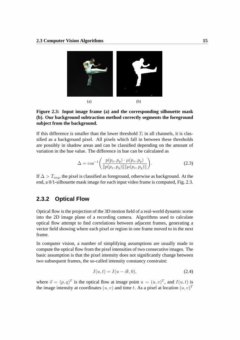
(a) (b)
Figure 2.3: Input image frame (a) and the corresponding silhouette mask(b). Our background subtraction method correctly segments the foregroundsubject from the background.
If this difference is smaller than the lower thresholdTl in all channels, it is clas-sified as a background pixel. All pixels which fall in between these thresholdsare possibly in shadow areas and can be classified depending on the amount ofvariation in the hue value. The difference in hue can be calculated as
∆ = cos−1
(
p(px, py) · µ(px, py)
‖p(px, py)‖‖µ(px, py)‖
)
. (2.3)
If ∆ > Tang, the pixel is classified as foreground, otherwise as background. At theend, a 0/1-silhouette mask image for each input video frame is computed, Fig. 2.3.
2.3.2 Optical Flow
Optical flow is the projection of the 3D motion field of a real-world dynamic sceneinto the 2D image plane of a recording camera. Algorithms used to calculateoptical flow attempt to find correlations between adjacent frames, generating avector field showing where each pixel or region in one frame moved to in the nextframe.
In computer vision, a number of simplifying assumptions are usually made tocompute the optical flow from the pixel intensities of two consecutive images. Thebasic assumption is that the pixel intensity does not significantly change betweentwo subsequent frames, the so-called intensity constancy constraint:
I(u, t) = I(u − ~ot, 0), (2.4)
where~o = (p, q)T is the optical flow at image pointu = (u, v)T , andI(u, t) isthe image intensity at coordinates(u, v) and timet. As a pixel at location(u, v)T

16 Chapter 2: Preliminary Techniques
with intensityI(u, t) moves byδu between two frames, the intensity constraintequation can be formulated as follows:
I(u, t) = I(u + δu, t + δt). (2.5)
From the Taylor series approximations, Eq. 2.5 leads to:
∇I(u, t) · ~o + It(u, t) = 0, (2.6)
where It(u, t) is the temporal derivative of the image intensity. In order tomake the problem well-posed, additional assumptions need to be made about thesmoothness of the optical flow field in a local spatial neighborhood.
In the differential optical flow approach by Lucas and Kanade [Lucas81], the flowis assumed to be constant in a small neighborhood. The solution is achieved byminimizing the following functional
∑
u∈W
W 2(u)[∇I(u, t) · ~o + It(u, t)]2, (2.7)
whereW (u) defines a Gaussian neighborhood around the current position in theimage plane for which the optical flow is computed. Alternatively, a hierarchicalvariant can be employed that incorporates flow estimates from multiple levels ofan image pyramid into its final result.
Using the same basic formulation, a large number of algorithms have beenproposed in the literature. In general, they are based on the Horn-Schunckmodel [Horn81], that additionally uses a global smoothness constraint to regu-larize the optical flow computation. An example is the dense optical flow methodby Black et al. [Black93]. The approach is based on a statistical framework thatenables the robust estimation of flow fields addressing violations of the intensityconstancy and spatial smoothness assumptions. As a result, the method is able todeal with discontinuities in the flow field.
Recently, Brox et al. [Brox04] proposed a multiresolution warping-based methodfor dense optical flow that uses a continuous, rotationally invariant energy func-tional. The energy functionalE(u, v) is composed by a weighted sum between adata termED(u, v) and a smoothing termES(u, v) as follows:
E(u, v) = ED(u, v) + αES(u, v).
The data term contains the intensity constancy assumption, as in Eq. 2.4, and a gra-dient constancy assumption described by∇I(u, t) = ∇I(u−~ot, 0), which makes

2.3 Computer Vision Algorithms 17
the framework susceptible to slight changes in brightness. Bythis means, the over-all energy functional becomes more robust against intensity value changes. Thesmoothness termES(u, v) takes into account neighboring information to improvethe calculation of the flow field by penalizing its total variation.
The global minimum solution is found via a multiscale approach. One starts bysolving a coarse, smoothed version of the problem. Thereafter, the coarse solutionis used as initialization for solving a refined version of the problem until step bystep the original problem is solved. Additionally, the energy functionalE(u, v)is designed using the non-linearized data terms and linearizations are computedduring the numerical scheme used to solve it. By this means, the overall methodimproves the convergence of the solution to the global minimum, generating moreaccurate results.
2.3.3 Scene Flow
The scene flow is a three-dimensional flow field describing the motion of every3D point in the scene. Following [Vedula05], we considerx = x(t) the 3D pathof a point in the world, anddx
dtits instantaneous scene flow. If the image of this
point in cameraCi is ui = ui(t), the optical flow~o = dui
dtis the projection of the
scene flow into the image plane:
dui
dt=
∂ui
∂x
dx
dt, (2.8)
where∂ui
∂xis the2× 3 Jacobian matrix that represents the differential relationship
betweenx andui. The Eq. 2.8 expresses the fact that any optical flowdui
dtis the
projection of the scene flowdxdt
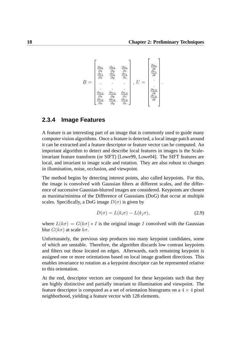
. Therefore, assuming that the optical flow has beencomputed for a particular point in the scene for two or more cameras views, thescene flow can be recovered.
If N > 2 cameras see a particular point, the solution that minimizes the sum ofleast squares of the error can be obtained by reprojecting the scene flow onto eachof the optical flows. Therefore, the values ofdxj
dtcan be calculated by solving the
system of equationsB dxj
dt= U via singular value decomposition, where
18 Chapter 2: Preliminary Techniques
B =
∂u1
∂x∂u1
∂y∂u1
∂z∂v1
∂x∂v1
∂y∂v1
∂z
. . .
. . .∂uN
∂x∂uN
∂y∂uN
∂z∂vN
∂x∂vN
∂y∂vN
∂z
, U =
∂u1
∂t∂v1
∂t
.
.∂uN
∂t∂vN
∂t
.
2.3.4 Image Features
A feature is an interesting part of an image that is commonly used to guide manycomputer vision algorithms. Once a feature is detected, a local image patch aroundit can be extracted and a feature descriptor or feature vector can be computed. Animportant algorithm to detect and describe local features in images is the Scale-invariant feature transform (or SIFT) [Lowe99, Lowe04]. The SIFT features arelocal, and invariant to image scale and rotation. They are also robust to changesin illumination, noise, occlusion, and viewpoint.
The method begins by detecting interest points, also called keypoints. For this,the image is convolved with Gaussian filters at different scales, and the differ-ence of successive Gaussian-blurred images are considered. Keypoints are chosenas maxima/minima of the Difference of Gaussians (DoG) that occur at multiplescales. Specifically, a DoG imageD(σ) is given by
D(σ) = L(kiσ) − L(kjσ), (2.9)
whereL(kσ) = G(kσ) ∗ I is the original imageI convolved with the Gaussianblur G(kσ) at scalekσ.
Unfortunately, the previous step produces too many keypoint candidates, someof which are unstable. Therefore, the algorithm discards low contrast keypointsand filters out those located on edges. Afterwards, each remaining keypoint isassigned one or more orientations based on local image gradient directions. Thisenables invariance to rotation as a keypoint descriptor can be represented relativeto this orientation.
At the end, descriptor vectors are computed for these keypoints such that theyare highly distinctive and partially invariant to illumination and viewpoint. Thefeature descriptor is computed as a set of orientation histograms on a4 × 4 pixelneighborhood, yielding a feature vector with 128 elements.
Chapter 3
Interactive Shape Deformationand Editing Methods
This chapter reviews the most relevant work on interactive shapedeformation and editing techniques, and describes the three maindeformation approaches used in this thesis.
In recent years, interactive shape deformation and editing techniques have becomean active field of research in computer graphics, Sect. 3.1. Commonly, the input tosuch techniques is a triangle mesh to be deformed, denoted byMtri = (Vtri, Ttri),which consists ofn verticesVtri = {v1 · · · vn} andm trianglesTtri = {t1 · · · tm}.The goal is the development of algorithms to efficiently edit and manipulateMtri
as naturally as possible under the influence of a set of constraints specified by theuser.
Physical simulation [Mueller02] and non-linear deformation methods [Sheffer04,Botsch06a] are able to deliver accurate and physically-correct deformation re-sults. However, unfortunately these methods require the minimization of complexnon-linear energies, which often makes them difficult to implement and compu-tationally too expensive to be used in an interactive environment, where differentconstraints are used to update and correct the shape of a model on-the-fly.
In general, in order to be interactive, editing methods need to be based on easy-to-compute linear deformations that still generate physically plausible and aes-thetically pleasing deformation results, i.e. deformations should be smooth orpiecewise smooth and the result should preserve the local appearance of the sur-

20 Chapter 3: Interactive Shape Deformation and Editing Methods
face under deformation. Recently, linear deformation methods based on differ-ential representations have gained more popularity because they are fast to com-pute, robust, and easy to implement, as the associated linear system is sparse.Instead of directly modify the spatial location of each vertex in the model, theyuse a local differential representation of the shape, which encodes informationabout its local shape and the size and orientation of the local details, to obtain adetail-preserving deformation result. Deformation is performed by constructinga differential representation of the shape, manipulating it according to the givenconstraints, and finally reconstructing the shape from the modified differentialrepresentation. While sharing the same general framework, the two main cate-gories of differential techniques differ by the particular representation they use:deformation gradients, Sect. 3.2.1, or Laplacian coordinates, Sect. 3.2.2.
In general, when applying these methods, the resulting deformation is dependenton the particular embedding of the surface in space. During model manipulation,its local representation is not updated, which may lead to unnatural deformations.This happens since the surface deformation problem is inherently non-linear, asit requires the estimation of local rotations to be applied to the local differentialrepresentations. To correct this limitation in the linearization process, many ap-proaches were developed in the last years attacking this problem from differentdirections, Sect. 3.1. After reviewing the most relevant related work on interac-tive shape deformation techniques in the next section, we first present two surface-based techniques used later in this thesis: the guided Poisson-based approach andthe guided Laplacian-based technique, Sect. 3.2.1 and Sect. 3.2.2 respectively.Thereafter, an iterative volumetric approach is described, Sect 3.3. As can be seenlater, the mesh deformation techniques presented in this chapter are key compo-nents for the advanced methods proposed in this thesis.
3.1 Related Work
Interactive shape editing is an important field of research in computer graph-ics, and consequently a variety of different solutions were proposed to solve thisproblem [Botsch08]. Early methods like free-form deformation [Sederberg86] orspace deformations [Bechmann94, Milliron02] enable high-quality shape model-ing by directly manipulating the 3D space where the object is embedded. How-ever, they typically fail to reproduce correct deformation results if only a smallnumber of constraints is used.
Some approaches propose to solve the computationally expensive non-linear sur-face deformation problem directly. [Sheffer04, Kraevoy06] propose a non-linear

3.1 Related Work 21
differential coordinate setup, while [Botsch06a] minimizesbending and stretch-ing energies using a coupled shell of prisms. [Huang06] employs a non-linearversion of the volumetric graph Laplacian and [Xu07a] presents an extension ofthe non-linear Poisson-based deformation approach applied to mesh sequences.Alternatively, [Au07] proposes a non-linear handle-aware isoline technique and[Shi07] combines Laplacian-based deformation with skeleton-based inverse kine-matics. In general, the main limitation of these non-linear methods is often thatinteractive deformation is only feasible on models of reduced complexity.
Interactive performance for more complex objects can be achieved by simplify-ing the inherent non-linear problem. One way to preserve geometric details underglobal deformations is to use multi-resolution techniques [Zorin97, Kobbelt98,Guskov99, Lee00, Botsch04]. While these approaches are an effective tool forenhancing fine-scale detail preservation, the generation of the hierarchy can beexpensive for complex models. Moreover, it is hard to deal with large deforma-tions in a single step. These limitations are the main reason for differential-baseddeformation approaches, which represent the model using its local differential co-ordinates instead of using its spatial coordinates.
Typically, two differential representations can be used: deformation gradients orLaplacian coordinates. Poisson-based methods use the input transformation con-straints given by the user to modify the surface gradients of the model. [Yu04]presents a Poisson-based mesh editing method where the local transformationsare propagated based on the geodesic distances. [Zayer05] replaces the geodesicpropagation scheme by harmonic field interpolation and shows that this leadsto a better estimation of the local transformations. [Popa06] extends the har-monic field interpolation scheme to deal with different materials. Unfortunately,although these methods work well for rotations, since they are handled explicitly,they are insensitive to translations.
Laplacian-based methods represent vertex coordinates relative to their neighborsin the model [Alexa01]. Although the original framework can not correctly dealwith rotations, recent improvements allow the methods to work similarly well fortranslations and rotations. [Lipman04] describes how local rotations can be esti-mated and incorporated to the original framework. [Sorkine04] proposes to usethe Laplacian representation combined with implicit transformation optimization.[Fu07] presents a hybrid scheme combining implicit optimization with a two-steplocal transformation estimation. In general, although these methods are able to es-timate local rotations, the required linearization yields artifacts for large rotations.
Generally, most of these methods suffer from linearization problems: methodswhich use translational constraints are insensitive to rotations, whereas methodsrelying on rotational constraints exhibit insensitivity to translations. To solve this

22 Chapter 3: Interactive Shape Deformation and Editing Methods
problem, recent methods use skeleton-based techniques [Yoshizawa03], multi-step approaches [Botsch06b], or iterative approaches [Sorkine07].
Most linear deformation methods rely on a triangle mesh representation. How-ever, deforming a surface model may cause local self intersections and shrinkingeffects. To prevent such artifacts, some methods use a volumetric structure asbasis for the linear deformation [Zhou05, Stoll07].
Another class of approaches is able to manipulate an object while guar-anteeing volume preservation by defining deformations based on vectorfields [von Funck06]. Although it enables the definition of advanced implicit de-formation tools, it is still hard to construct vector fields that satisfy the user-definedconstraints.
3.2 Mesh Editing Techniques
In this section, we review the two surface-based deformation techniques based ondifferential representations and describe the respective steps needed to reconstructthe deformed surfaces.
3.2.1 Guided Poisson-Based Method
Inputs to this method are a static triangle meshMtri and affine transformations(rotation and scale/shear components)Rj, j ∈ {1, . . . , nc}, to be applied tonc
selected triangles of the input model. The Poisson-based editing scheme manipu-lates the mesh gradient field instead of directly deforming the spatial coordinatesof a triangle mesh. By expressing the mesh in terms of the gradient operatorsGj,for each triangletj, Poisson-based methods are able to derive a novel surface meshM′
tri that matches the deformed gradient field subject to the user’s constraints.
Gradient operatorsGj contain the gradients of the triangle’s shape functionsφi
and can be expressed by
Gj = (▽φ1,▽φ2,▽φ3)
=
(p1 − p3)T
(p2 − p3)T
nT
−1
1 0 −10 1 −10 0 0
Here pj are the three vertices of the triangletj and n is its unit normal. ThematricesGj can be combined into a large3m×n gradient operator matrixG, and

3.2 Mesh Editing Techniques 23
the gradients of the entire input triangle mesh then can be represented by
Gpx = gx .. (3.1)
The same holds true for the other two coordinate functions (gy andgz). By multi-plying with GT M an both sides, we can rewrite Eq. 3.1 as follows
GT MGpx = GT Mgx , (3.2)
where the3m × 3m weight matrixM contains the areas of the triangles. Thematrix GT MG is the cotangent discretization of the Laplace-Beltrami operatorLs [Botsch06b, Meyer03] andδ := GT Mgx represents the differential coordinatesof Mtri.
This construction allows us to manipulateMtri by applying the user constraintsas separate transformationsRj to eachδj, which yieldsδ′j = δjRj. At the end,we can reconstructM′
tri in its new target configuration by computing the newvertex positionsp′ such that the resulting mesh complies with the new, rotatedgradients. This can be computed by solving the Poisson systemLsp
′ = δ′, whichis formulated as a least-squares system for eachx, y andz-coordinate separately.
Unfortunately, this formulation is only able to correctly reconstructM′tri if con-
straints are given for all triangles, i.e. such that we can transform all gradi-ents. Alternatively, if only a sparse set of constraints is giving, the idea proposedin [Zayer05, de Aguiar07e] can be used to propagate the rotations over the wholemodel based on harmonic field interpolation.
After converting the input transformationsRj to unit quaternions, we regard eachcomponent of the quaternionq = [qx, qy, qz, qw] as a scalar field defined over theentire mesh. A smooth interpolation is generated by regarding these scalar fieldsas harmonic fields defined overMtri, and can be computed efficiently by solvingthe Laplace equation (Lsq = 0) with constraints at the selected vertices. Oncethe rotational components (qx, qy, qz andqw) are computed for all vertices, weaverage the quaternion rotations of the vertices to obtain a quaternion rotationfor each triangle. This way, we establish a geometric transformationRj for eachtriangletj of Mtri.
After estimating the rotations for all triangles, we perform the procedure describedabove to transform all gradients and obtain a realistic reconstruction of the modelin a new pose. During the interactive editing process, the differential operatormatrix Ls does not change. Furthermore, since it is symmetric positive definite,we can perform a sparse Cholesky decomposition as a preprocessing step and useback-substitution for each new set of input constraintsR.

24 Chapter 3: Interactive Shape Deformation and Editing Methods
3.2.2 Guided Laplacian-Based Method
The input to this approach is a static triangle meshMtri and positional constraintsvj ≈ pcj, j ∈ {1, . . . , nc} for selectednc vertices ofMtri. The Laplacian-basedediting scheme represents the surface by the differential coordinatesδ. The goalis to reconstruct the vertex positions ofM′
tri such that the mesh approximates theinitial differential coordinatesδ, and the positional constraints given by the user.
Differential coordinatesδ for Mtri are computed by solving a linear system ofthe form δ = LsVtri, whereLs is the discrete Laplace operator based on thecotangent-weights [Meyer03]. Thereafter, the modelM′
tri can be reconstructedin a new pose subject to the positional constraintspc by solving the followingleast-squares system:
argminV ′
tri
{‖LsV′tri − δ‖2 + ‖AV ′
tri − pc‖2}, (3.3)
which can be transformed into a linear system
(LTs Ls + AT A)V ′
tri = LTs δ + AT pc. (3.4)
In Eq. 3.4,pc is the vector of positional constraints specified by the user and thematrix A is a diagonal matrix containing non-zero weightsAij = wj for con-strained verticesvj. The weightswj indicate the influence of the correspondingpositional constraintpcj on the final deformation result.
Unfortunately, if the mesh undergoes large rotations, this scheme will reconstructthe mesh with an unnatural look, since most of the triangles will be oriented ac-cording to the original differential coordinates ofMtri [Sorkine04]. However, thequality of the deformation result can be improved by carefully handling the localtransformations of the differential coordinates [Stoll06, de Aguiar07b].
As in Sect. 3.2.1, after converting the input rotationsR to quaternions, we inter-polate the transformationsq overMtri. Each component of the quaternionq isregarded as a scalar field defined on the entire mesh. A smooth interpolation isguaranteed by regarding these scalar fields as harmonic fields. The interpolationis performed efficiently by solving the Laplace equationLsq = 0 over the entiremesh with constraints at the selected vertices.
Thereafter, we use the interpolated local transformations to rotate the differentialcoordinates,δ′ = q · δ · q. At the end, the vertex positionsV ′
tri of M′tri are recon-
structed such that the mesh approximates the rotated differential coordinatesδ′,as well as the positional constraintspc. Rewriting Eq. 3.4, we have the followinglinear system
(LTs Ls + AT A)V ′
tri = LTs δ′ + AT pc. (3.5)

3.3 Iterative Volumetric Laplacian Approach 25
During the mesh editing process, the Laplacian matrixLs does not change. There-fore, we are able to perform a sparse matrix decomposition and execute only back-substitution for each new set of input constraints.
3.3 Iterative Volumetric Laplacian Approach
In contrast to the two previous methods, the iterative volumetric Laplacianmethod works on a tetrahedral meshTtet = (Vtet, Ttet), with nt verticesVtet ={vt1 · · · vtnt
} andmt tetrahedraTtet = {tt1 · · · ttmt}. A tetrahedral mesh can,
for instance, be created from a triangle meshMtri by performing a quadric errordecimation onMtri [Garland97] and then building a face-constrained Delaunaytetrahedralization [Si05].
The input to this approach [Stoll07] isTtet and positional constraintspcj, j ∈{1, . . . , nc} for nc selected vertices. This method infers rotational constraintsfrom the given positional constraints and also improves the overall deformationperformance by implicitly encoding stronger prior on the shape properties thatshould be preserved after the deformation, such as local cross-sectional areas.
It is our goal to deform the tetrahedral meshTtet as naturally as possible underthe influence of a set of positional constraintsvtj ≈ pcj, j ∈ {1, . . . , nc}. Tothis end, we iterate a linear Laplacian deformation step and a subsequent updatestep, which compensates the (mainly rotational) errors introduced by the natureof the linear deformation. This algorithm is related to [Sorkine07]. However,here a tetrahedral construction is used rather than a triangle mesh, as this enablesthe implicit preservation of certain shape properties, such as cross-sectional areas,after deformation.
The approach starts by constructing the tetrahedral Laplacian systemLsVtet = δwith
Ls = GT DG , (3.6)
andδ = GT Dg , (3.7)
whereG is the discrete gradient operator matrix for the volumetric model,D isa 4mt × 4mt diagonal matrix containing the tetrahedra’s volumes,g is the set oftetrahedron gradients, each being calculated asgj = Gjpj [Botsch06b], andpj isa matrix containing the vertex coordinates of tetrahedronttj. The constraintspcj
can be factorized into the matrixLs by eliminating the corresponding rows andcolumns in the matrix and incorporating the values into the right-hand sideδ.

26 Chapter 3: Interactive Shape Deformation and Editing Methods
By solving the previous tetrahedral Laplacian system, we obtain a set of new ver-tex positionsV
′
tet = {vt′
1 . . . vt′
nt}. After calculating a transformation matrixTi
which bringstti into configurationtt′i, the matrixTi is split into a rigid partRi anda non-rigid partSi using an iterative polar decomposition method [Shoemake92].Thereafter, only the rigid transformations are applied to the gradients of all respec-tive tetrahedra in Eq. 3.7 and we rebuild the right-hand side of the linear systemusing these rotated gradientsg′ = g · R. It is possible to pre-calculate a factoriza-tion of the left-hand side matrix once (since it never changes) and only performan efficient back-substitution in each iteration.
During the iteration process we search for a new configuration of the input shapethat minimizes the amount of non-rigid deformationSi remaining in each tetra-hedron. We refer to this deformation energy asED =
∑
i∈TtetSi. In comparison
with simulation methods such as [Mueller02, Botsch07], this technique has theadvantages of being extremely fast, of being very easy to implement, and of pro-ducing plausible results even if material properties are unknown.
Propagating the deformation from Ttet to Mtri. After deformingTtet, wecan transfer the pose fromT ′
tet to the input triangle mesh. Initially, we representthe vertices ofMtri as linear combinations of tetrahedra in the local neighbor-hood. To this end, for each vertexvi in Mtri, we find the subsetTr(vi) of alltetrahedra fromTtet that lie within a local spherical neighborhood of radiusr andcontain a boundary face with a face normal similar to that ofvi. Subsequently, wecalculate the barycentric coordinate coefficientsci(j) of the vertex with respect toall ttj ∈ Tr(vi) and compute the combined coefficient vectorci as
ci =
∑
ttj∈Tr(vi)ci(j)φ(vi, ttj)
∑
ttj∈Tr(vi)φ(vi, ttj)
.
φ(vi, ttj) is a compactly supported radial basis function with respect to the dis-tance ofvi to the barycenter of tetrahedronttj:
φ(vi, ttj) =
{
0 if d > r(1 − d
r)4(4d
r+ 1) if d ≤ r
with d = ‖vi − center(ttj)‖ .
The coefficients for all vertices ofMtri are combined into a matrixB. Thanks tothe smooth partition of unity definition and the local support of our parameteriza-tion, we can quickly compute a smooth and natural looking deformed poseM′
tri
by calculating the new vertex positions asV ′tri = V ′
tetB .

Chapter 4
Recording Studio: DataAcquisition and Data Processing
This chapter describes our recording studio. First, the physicalstudio, the camera system, and the full body laser scanner arepresented. Thereafter, the acquisition pipeline is detailed, with allnecessary steps to generate the input data for the projects describedin this thesis.
4.1 Introduction
It is a new trend in computer graphics to employ data acquired from the real worldinto the animation or rendering pipeline. For instance, the new research directionsof performance capture and 3D Video investigate the possibility of generatingrealistic moving human models of real subjects from a set of images or videostreams of the subject performing.
In this chapter, we extend the studio described in [Theobalt03], which was origi-nally designed for different surround vision applications. We present our new ac-quisition setup that provides high quality data for the different projects involvingarbitrary subjects, motions, and clothing styles. Although our focus is differentfrom previous work, the old functionality should be preserved, and augmented tomeet the new requirements: high frame rates, high image resolution, better light-
28 Chapter 4: Recording Studio: Data Acquisition and Data Processing
ing conditions, and a device to reconstruct high-quality surface models for thesubjects being recorded.
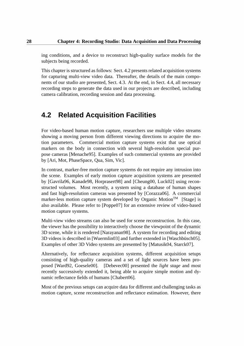
This chapter is structured as follows: Sect. 4.2 presents related acquisition systemsfor capturing multi-view video data. Thereafter, the details of the main compo-nents of our studio are presented, Sect. 4.3. At the end, in Sect. 4.4, all necessaryrecording steps to generate the data used in our projects are described, includingcamera calibration, recording session and data processing.
4.2 Related Acquisition Facilities
For video-based human motion capture, researchers use multiple video streamsshowing a moving person from different viewing directions to acquire the mo-tion parameters. Commercial motion capture systems exist that use opticalmarkers on the body in connection with several high-resolution special pur-pose cameras [Menache95]. Examples of such commercial systems are providedby [Ari, Mot, PhaseSpace, Qua, Sim, Vic].
In contrast, marker-free motion capture systems do not require any intrusion intothe scene. Examples of early motion capture acquisition systems are presentedby [Gavrila96, Kanade98, Horprasert98] and [Cheung00, Luck02] using recon-structed volumes. Most recently, a system using a database of human shapesand fast high-resolution cameras was presented by [Corazza06]. A commercialmarker-less motion capture system developed by Organic MotionTM [Stage] isalso available. Please refer to [Poppe07] for an extensive review of video-basedmotion capture systems.
Multi-view video streams can also be used for scene reconstruction. In this case,the viewer has the possibility to interactively choose the viewpoint of the dynamic3D scene, while it is rendered [Narayanan98]. A system for recording and editing3D videos is described in [Wuermlin03] and further extended in [Waschbusch05].Examples of other 3D Video systems are presented by [Matusik04, Starck07].
Alternatively, for reflectance acquisition systems, different acquisition setupsconsisting of high-quality cameras and a set of light sources have been pro-posed [Ward92, Goesele00]. [Debevec00] presented thelight stageand mostrecently successively extended it, being able to acquire simple motion and dy-namic reflectance fields of humans [Chabert06].
Most of the previous setups can acquire data for different and challenging tasks asmotion capture, scene reconstruction and reflectance estimation. However, there

4.3 Recording Studio 29
(a) (b) (c)
Figure 4.1: Our recording studio includes (a) the recording area, (b) the con-trol room, and (c) the laser scanner.
is no system described in the literature yet that is able to provide high-resolutiontemporally-coherent virtual actors for arbitrary real-world subjects.
4.3 Recording Studio
Our studio is designed to acquire high-quality surface models of human subjects aswell as image footage for measuring human motion, dynamic shape deformations,and appearance. In the following sections, we describe in details the requirementsand solutions for each component of our studio: the studio room, the camera andlighting system, and the full body laser scanner.
4.3.1 Studio Room
The studio is installed in a room of approximately9×4.8 meters in size. Its spatialdimensions are large enough to allow the scanning of subjects as well as recordingof dynamic scenes from a large number of viewpoints. The ceiling has a heightof approximately 4m. Along one of the shorter walls, an area of2.5 × 4.8 metersis separated as a control room of the studio and for our full body laser scanner,Sect. 4.3.4. The walls and the floor can be covered with opaque black curtainsand a carpet, respectively, which enables us to minimize the effects of indirectillumination in a scene. The recording area, the control room of our studio, andthe laser scanner are shown in Fig. 4.1.

30 Chapter 4: Recording Studio: Data Acquisition and Data Processing
4.3.2 Camera System
The cameras used in the studio need to provide high frame-rates, high resolu-tion, precise color reproduction, lossless data capture, and external synchroniza-tion, which ensures that the multiple streams are correctly registered in time.Our camera system was ordered out-of-the box according to these specifications.The manufacturer [COS] also provided us with a custom-made control software,Streams [STR].
The system is composed of eight ImperxTM MDC1004 single chip CCD cam-eras that feature a 1004x1004 CCD sensor with linear 12 bits-per-pixel resolution,Fig. 4.2(a). The CCD uses a Bayer mosaic to record red, green, and blue channelinformation. The CCD sensor is connected to two controller chips. With bothcontrollers activated, the camera provides a sustained frame rate of 48 fps at fullresolution. However, in dual-mode the photometric responses of the sensors donot comply and an intra-frame color adjustment step is necessary. With only onechip activated, 25 fps at full resolution are feasible and no color balancing in theimages is required.
The cameras are linked to a control PC equipped with 8 high-speed frame grabberboards. Each frame grabber is connected to a camera through a Camera LinkTM in-terface. For maximal performance, each capture card is equipped with an on boardSCSI interface enabling direct streaming of image data to a RAID system. EightRAID systems are employed in parallel to enable real-time storage of the videostreams. The synchronization is performed via a trigger pulse that is broadcastedto each capture card.
The cameras can be installed at arbitrary locations in the studio. For positioningthem, telescope poles (ManfrottoTM Autopole [MANFROTTO]) with 3-degree-of-freedom mounting brackets (ManfrottoTM Gear Head Junior [MANFROTTO])are used that can be jammed between the floor and the ceiling. In general, thecameras are placed in an circular arrangement around the center of the scene andenable us to capture a volume of approximately3.5 × 3.5 × 3 meters.
4.3.3 Lighting System
The illumination of the studio is a fundamental issue for generating quality imagefootage. In our studio, the lighting conditions are fully controllable. For exam-ple, no exterior light can enter the recording area and the influence of indirectillumination is minimized by the black curtains and the carpet. Robust separationbetween foreground and background is also essential, i.e. the amount of shadows

4.3 Recording Studio 31
(a) (b)
Figure 4.2: (a) Camera and (b) softlight used in the studio.
cast on the floor has to be minimized. Furthermore, the lighting system shouldproduce a very uniform lighting, giving the scene a natural appearance.
In our studio, we employ a generic lighting configuration using 8 NesyFlex 440DI TM compact softlights [Nesys] that are optimized for universal use in TV andvideo studios, Fig. 4.2(b). Each light component contains 8 fluorescent day lighttubes that radiate even light at an wide angle. They illuminate objects in the centerof the scene from the top of the recording area and spread the light homogeneouslydownwards. The system can be controlled as a single unit using the DMXTM con-trols. Additionally, each light can be rotated to fulfil specific requirements. Bythis end, the lighting system prevents direct illumination into the camera lenses,which could lead to glares. The illumination system produces a uniform diffuselighting in the scene, which avoids sharp shadows and unwanted highlights on therecorded subjects.
4.3.4 Full Body Laser Scanner
The geometric detail of the body of each recorded subject is captured by our VitusSmartTM full body laser scanner [Vitronic], Fig. 4.1(c). The device is compact,measuring2.1 × 1.9 × 2.8 meters, and could be easily integrated in our studio.The scanner uses four columns which are mounted at an angle of approximately90 degrees in relation with the subject to be scanned. Each column hosts an eye-safe laser scanner and two cameras that sit on a vertically moving gantry. Thedevice employs a light-stripe method to collect high-speed 3D measurements. Thefinal scan comprises of a 3D point cloud measured at an accuracy of5 × 5 × 4millimeters.
With a person standing on the scanner’s platform, the scanning instruments startat the person’s head and move down to scan the entire body. The scanning deviceis designed to handle different subjects and many different poses for a wide range
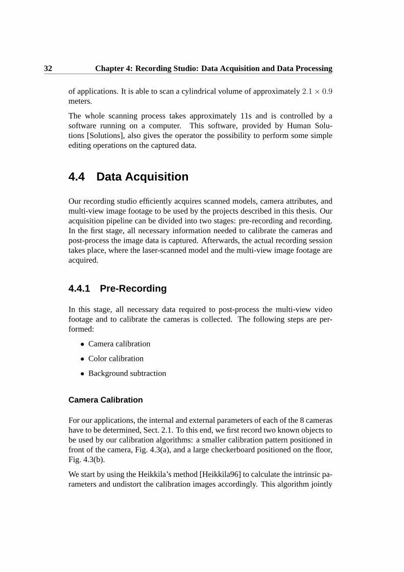
32 Chapter 4: Recording Studio: Data Acquisition and Data Processing
of applications. It is able to scan a cylindrical volume of approximately2.1 × 0.9meters.
The whole scanning process takes approximately 11s and is controlled by asoftware running on a computer. This software, provided by Human Solu-tions [Solutions], also gives the operator the possibility to perform some simpleediting operations on the captured data.
4.4 Data Acquisition
Our recording studio efficiently acquires scanned models, camera attributes, andmulti-view image footage to be used by the projects described in this thesis. Ouracquisition pipeline can be divided into two stages: pre-recording and recording.In the first stage, all necessary information needed to calibrate the cameras andpost-process the image data is captured. Afterwards, the actual recording sessiontakes place, where the laser-scanned model and the multi-view image footage areacquired.
4.4.1 Pre-Recording
In this stage, all necessary data required to post-process the multi-view videofootage and to calibrate the cameras is collected. The following steps are per-formed:
• Camera calibration
• Color calibration
• Background subtraction
Camera Calibration
For our applications, the internal and external parameters of each of the 8 camerashave to be determined, Sect. 2.1. To this end, we first record two known objects tobe used by our calibration algorithms: a smaller calibration pattern positioned infront of the camera, Fig. 4.3(a), and a large checkerboard positioned on the floor,Fig. 4.3(b).
We start by using the Heikkila’s method [Heikkila96] to calculate the intrinsic pa-rameters and undistort the calibration images accordingly. This algorithm jointly

4.4 Data Acquisition 33
estimates intrinsic and extrinsic parameters from the images of our small calibra-tion pattern and models the lens aberrations more accurately by considering radialand tangential lens distortions up to second order [Jain95]. Afterwards, we alsoapply this information to correct and undistort each recorded camera stream.
Thereafter, using the undistorted images, we estimate the external parameters bymeans of the Tsai algorithm [Tsai86]. The corners of the checkerboard are auto-matically detected [Intel02] and an optimization procedure determines the extrin-sic parameters that minimize the reprojection error between the camera model’sprediction of the pattern appearance and the actual images.
Color Calibration
Faithful color reproduction is ensured by white-balancing all cameras before therecording session. However, even after this step the color response of the cam-eras can be different, for example due to noise and slight physical differences inthe built-in camera components. In order to assure color-consistency across thecameras, we record a large diffuse calibration pattern which consists of an arrayof 237 uniformly colored squares with purely lambertian reflectance, Fig. 4.3(c).
We use the recorded images of this color pattern to estimate for each camera atrilinear transformation of the RGB color values in a least-squares sense. We typ-ically perform relative photometric calibration. We define one camera to be thereference camera and for each remaining one, a color transformation is computedsuch that the color values of the pattern in the reference view are reproduced. Atthe end, color-consistency across the cameras is assured by applying this transfor-mation to each recorded camera stream.
Background Subtraction
For the projects described in this thesis, the separation of the foreground subjectfrom the background is essential. Our studio design already simplifies this processsince the effects of external light on the scene and shadows cast on the wallsare minimized. In order to segment the multi-view image data, we employ thealgorithm described in Sect. 2.3.1 that robustly separates the moving human actorfrom the background. This algorithm computes mean color and standard deviationfor each background pixel from a sequence of images without a foreground object,which is recorded prior to each human performance. By this means, foregroundpixels can be identified by a large deviation of their color from the backgroundstatistics.

34 Chapter 4: Recording Studio: Data Acquisition and Data Processing
(a) (b) (c)
Figure 4.3: Information acquired during the pre-recording session: (a)smaller calibration pattern used for intrinsic parameter estimation; (b) largecheckerboard on the floor used for extrinsic parameter estimation; (c) colorcalibration pattern used for color adjustment.
4.4.2 Recording
Our recording session consists of three steps. Before recording a set of perfor-mances, the data needed for camera calibration and post-processing is acquired:small and large checkerboard images, color pattern and background images. Then,for each subject, we acquire a triangle mesh model with our Vitus SmartTM fullbody laser scanner. Thereafter, the subject immediately moves to the nearby areawhere his/her performance is recorded by our eight synchronized video cameras.
In general, before recording each sequence, we ask the person to initially strikethe same pose that he/she was scanned in. This simplifies the alignment processbetween scanned model and recorded images.

Part II
Natural Animation of DigitizedModels


Chapter 5
Problem Statement andPreliminaries
This part reviews the steps involved in the traditional skeleton-basedcharacter animation paradigm, and proposes two mesh-based alter-natives that simplify the conventional process.
In recent years, photo-realistic computer-generated animations of humans havebecome the most important visual effect in motion pictures and computer games.In order to obtain an authentic virtual actor, it is of great importance that he/shemimics as closely as possible the motion of his/her real-world counterpart. Eventhe slightest unnaturalness would be instantaneously unmasked by the unforgivingeye of the viewer and the illusion of seeing a real person would be compromised.
In order to generate virtual people, animators make use of a well-established butoften inflexible set of tools (see Sect. 5.1) that makes a high amount of man-ual interaction unavoidable. First, the geometry of the human body is hand-crafted in a modeling software or obtained from a laser scan of a real individ-ual [Allen03]. In a second step, a kinematic skeleton model is implanted into thebody by means of, at best, a semi-automatic procedure [Herda00]. In order tocouple the skeleton with the surface mesh, an appropriate representation of pose-dependent skin deformation has to be found [Lewis00]. Finally, a description ofbody motion in terms of joint parameters of the skeleton is required. It can eitherbe designed in a computer or learned from a real actor by means of motion cap-ture [Bodenheimer97, Poppe07]. Although the interplay of all these steps deliversanimations of stunning naturalness, the whole process is very labor-intensive and

38 Chapter 5: Problem Statement and Preliminaries
does not easily allow for the interchange of animation descriptions between dif-ferent virtual subjects.
In this part of the thesis, we present two versatile, fast and simple alternatives thatstreamline the whole pipeline from laser-scanning to animation. Although ourapproaches abandon the concept of a kinematic skeleton, they integrate into thetraditional animation workflow and enable animators to quickly produce convinc-ing animation results with minimal manual labor, while still allowing for controlover the production process.
The first approach, Chapter 6, is based on the Guided Poisson-based DeformationMethod (Sect. 3.2.1) and the second one, Chapter 7, extends the first animationscheme by using the Guided Laplacian-based Deformation Method (Sect. 3.2.2).In general, both algorithms expect as input a geometric model (scanned or hand-crafted) in the form of a triangle mesh, and a description of the motion that themodel should perform. As a result, they animate the input model generating con-vincing skinned body surfaces and also enabling simple motion retargeting, i.e.they enable the animator to interchange motions between persons of even widelydifferent body proportions with no additional effort. Moreover, animations can begenerated at interactive frame rates and the animators have instantaneous feedbackwhen designing or modifying the animations. We demonstrate the performanceof the proposed methods by using marker-based and marker-less motion capturedata.
The main contributions of this part of the thesis is the
• integration of a Poisson-based and a Laplacian-based mesh deformationtechnique with a motion capture system to create an efficient and easy-to-use alternative to the traditional skeleton-based character animationpipeline [de Aguiar07b, de Aguiar07d, de Aguiar07e],
• and the development of an intuitive animation tool providing full controlover motion characteristics and deformation properties.
This chapter proceeds with a review of closely related work in Sect. 5.1. After-wards, in Chapter 6 and 7, we describe the details of both mesh-based characteranimation methods.
5.1 Related Work
The first step in human character animation is the acquisition of a humanbody model comprising of a surface mesh and an underlying animation skele-

5.1 Related Work 39
ton [Badler99]. Surface geometry can either be hand-crafted or scanned from areal person [Allen03].
The skeleton model can be either manually designed, inferred from markertrajectories [Kirk05, de Aguiar06] or inferred from shape-from-silhouette vol-umes [de Aguiar04]. Similarly, kinematic skeletons can be reconstructed froma set of range scans of humans [Anguelov04] or by fitting a template to bodyscans [Anguelov05]. Recently, new methods are also able to extract plausible hu-man animation skeletons from a static surface mesh of a character by using priorknowledge [Aujay07, Schaefer07].
Geometry and skeleton need to be connected such that the surface deforms real-istically with the body motion. A popular method serving this purpose is vertexskinning [Lewis00] (see also Sect. 13.1). It represents position changes of individ-ual vertices as a weighted set of transformations associated with adjacent joints.Deformation models can also be created by interpolating a set of scans [Allen02],by combining a marker-based motion capture system with a shape-from silhou-ette method [Sand03] or by capturing and animating surface deformations using acommercial motion capture system and approximately 350 markers [Park06].
The virtual human is animated by assigning motion parameters to the joints inthe skeleton. Common methods to generate such motion descriptions are key-framing [Davis03], physics-based animation [Faloutsos01] or optimization-basedcreation of physically plausible movements [Fang03]. However, the most au-thentic motion representation is acquired through marker-based [Bodenheimer97,Herda00] or marker-less motion capture systems [Poppe07]. Unfortunately,reusing motion capture data for subjects of different body proportions is not triv-ial, and requires computationally expensive motion editing [Gleicher97, Lee99]and motion retargeting techniques [Gleicher98, Tak05].
In general, most current work on character animation is focused on improvingparticular steps of the traditional pipeline such that animators can create realisticresults efficiently. Only a small number of people has been working on methodsto make the overall production process easier [Baran07] and less dependent on theuse of an underlying skeleton [Igarashi05].
On the other hand, as highly detailed 3D triangle meshes become more and moreaccessible, there has been an increasing interest in devising techniques which canwork directly on these geometric representations without requiring the overheadof intermediate pipelines such as the one mentioned above. The potential of mesh-based deformation techniques for character animation has already been stated inthe literature. Using a complete set of correspondences between different syn-thetic models, [Sumner04] can transfer the motion of one model to the other one.

40 Chapter 5: Problem Statement and Preliminaries
Following a similar line of thinking, [Sumner05, Der06] propose a mesh-basedinverse kinematics framework based on pose examples. [Shi06] presents a multi-grid technique for efficient deformation of large meshes and [Huang06] presents aframework for performing constrained mesh deformation using gradient domaintechniques. Most recently, [Xu07a] proposes a set of mesh-based operations topost-process mesh animations that unfortunately requires a fundamental redesignof existing animation tools.
In the following chapters, we present two methods that are able to simplify thetraditional animation process [de Aguiar07b, de Aguiar07d, de Aguiar07e]. Al-though they abandon the concept of a kinematic skeleton, the approaches integrateinto the traditional animation workflow and enable animators to quickly produceconvincing animation results. In contrast to related methods, they provide a com-plete integration with a motion acquisition system and provide an intuitive an-imation tool that gives full control over motion characteristics and deformationproperties.

Chapter 6
Poisson-based Skeleton-lessCharacter Animation
This chapter presents an approach to efficiently generate high-qualityanimations of human characters from input motion data. Using aPoisson-based deformation method, as described in Sect. 3.2.1, theproposed approach outputs character animations with realistic bodydeformations, only requiring a minimum of manual interaction.
In order to generate photo-realistic animations of humans, animators make use ofa well-established but often inflexible set of tools that makes a high amount ofmanual interaction unavoidable, Sect. 5.1. In this chapter, we describe a versatile,fast and simple mesh-based alternative to animate human models that completelyintegrates into the traditional animation workflow.
Our approach can be used to realistically animate models of humans without rely-ing on kinematic skeletons, which reduces the animator’s effort to a great extent.Furthermore, it produces realistic pose-dependent body deformations and it solvesthe motion transfer problem, i.e. it enables the animator to interchange motionsbetween persons of even widely different body proportions with no additional ef-fort.
The main contributions of this chapter are
• the integration of a Poisson-based mesh deformation technique with a mo-tion capture system to create an efficient and simple alternative to the con-ventional character animation pipeline [de Aguiar07d, de Aguiar07e], and

42 Chapter 6: Poisson-based Skeleton-less Character Animation
Figure 6.1: Illustration of the workflow of our system.
• the development of an intuitive animation tool providing full control overmotion characteristics and deformation properties.
This chapter proceeds with an overview of our algorithm in Sect. 6.1, and thedescription of our simple interface prototype in Sect. 6.2. Thereafter, we demon-strate that we can realistically animate human models using marker-based andmarker-less motion capture data, Sect. 6.3. Finally, results and conclusions arepresented in Sect. 6.4.
6.1 Overview
Our goal is to provide animators with a simple and fast method to directly ap-ply captured motion to human models, e. g. scanned models. The input to ourmethod is a human body scanMtri and motion data generated from real individ-uals using optical motion estimation methods, Fig. 6.1. The first processing stepnormalizes these sequences of key body poses by transforming them into a se-quence of postures of a simple triangle mesh model, henceforth termedtemplatemesh. In Sect. 6.3.1 and 6.3.2 we exemplify that it is straightforward to generatesuch templates from motion capture data.
By regarding motion transfer as a pure deformation problem, we can put asideall difficulties related to the dissimilarities between the template and the inputmodel, as anatomical disparities or body proportions, and take advantage of theirsemantic similarities, e.g. the fact that both mesh representations have knees andelbows. To this end, we ask the user to specify a set ofcorrespondence trianglesbetween the template andMtri.

6.2 Prototype Interface 43
(a) (b) (c) (d)
Figure 6.2: A template model (a) and a high-resolution body scan (b) in theirrespective reference poses. The template in a pose obtained via motion cap-ture (c) and its pose transferred to the human scan (d).
The motion of the template mesh from a reference pose, as shown in Fig 6.2(a),into another pose (Fig 6.2(c)) is captured by the deformation of a small set of tri-angles marked under the guidance of the user. Applying these deformations to thecorresponding triangles ofMtri brings it from its own reference pose, as shown inFig 6.2(b), into the deformed template’s pose, Fig 6.2(d). For this purpose, we firstalign template and input models in a given reference pose. By subsequently apply-ing the motion transfer procedure to all input frames, the motion from the movingtemplate mesh is correctly transfered to the input high-quality body model.
6.2 Prototype Interface
Our method does not require skeleton information or full correspondence betweenthe template and the input model. The motion transfer process is controlled by theset of markers chosen by the user. We decided to resort to this interactive stepsince there is no viable automatic approach that can identify body segments onmeshes standing in general poses.
Our easy and intuitive prototype interface allows access to both models at theirreference poses simultaneously, Fig. 6.3. An automatic alignment of the mod-els is performed upon loading the mesh files. When a triangle is selected onone model, a corresponding triangle on the other one is highlighted. The artistcan decide to keep this correspondence or improve it manually. For cylindricallyshaped body parts, we require the user to specify a single correspondence triangleand we mark additional triangles automatically by taking additional directions inthe cross-sectional plane and intersecting them with the mesh. For geometricallymore complex body parts, such as the lap or the shoulders, correspondences needto be specified by the user.

44 Chapter 6: Poisson-based Skeleton-less Character Animation
Figure 6.3: Prototype interface used in our system, featuring easy selectionof correspondences and instantaneous feedback.
Using our prototype interface, the user can verify instantaneously how the cor-respondences will influence the deformation transfer process. By loading a tem-plate mesh in a deformed pose, the input modelMtri can be deformed using theactual selected correspondences. This enables the artist to decide on-the-fly if thecorrespondences yield satisfactory results. Note that except from setting the cor-respondences, our whole framework is fully automatic. The number of trianglecorrespondences used in our animations ranges from 140 to 220, half of which isautomatically generated.
As the placement of the markers directly affects the pose-dependent surface de-formation of the scanned mesh, the user does not have to tweak any weights as inthe commonly used skinning methods. The principle here is simple: for havinga sharp bend in the surface, the correspondences should be placed close to eitherside of the joint, Fig. 6.4 (left). Increasing the distance of the markers from thejoint allows for a softer bending, Fig. 6.4 (right).
6.3 Animating Human Scans using MotionCapture Data
Using motion capture data as the front-end to our framework, we create two in-triguing applications: mesh-based character animation and video-driven anima-tion.

6.3 Animating Human Scans using Motion Capture Data 45
(a) (b)
Figure 6.4: Influence of the markers’ placement on the deformation quality:marking correspondence triangles (red dots) close to an (anatomical) jointcreates a sharp bend in the skin (left), while increasing the distance to thejoint enables smoother bending (right).
6.3.1 Mesh-Based Character Animation
Marker-based tracking systems [Bodenheimer97] provide the animator with mo-tion descriptions of unequaled accuracy and naturalness. Even subtle details inmotion patterns are faithfully captured. However, the high quality of the cap-tured motion data comes at the expense of many inflexibilities in their applica-tion. Firstly, motion parameters cannot easily be reused with virtual persons thatdiffer in skeletal proportions from the captured individual. To make this pos-sible, computationally expensive motion retargeting algorithms have to be ap-plied [Gleicher98]. Secondly, motion capture systems only deliver a descriptionof human motion in terms of interconnected rigid bodies. The non-rigid defor-mations of the skin and the soft-tissue surrounding the bones usually have to bemanually modeled, e.g. by means of vertex skinning [Lewis00].
Our approach is able to simplify this process by directly animating human bodyscans with motion capture data. Paradoxically, despite discarding the use of akinematic skeleton, it allows us to generate high-quality animations. The stepsthat have to be taken to animate the input scan are very simple: first, using anystandard animation software, like 3D Studio MaxTM, the input motion data, asshown in Fig. 6.5(a), is transformed into a surface model in which the bones ofthe biped are represented as triangle meshes, Fig. 6.5(b). Consequently, usingour prototype interface, static per-triangle correspondences between the triangu-lated biped and the input scanned mesh are defined. Finally, the Guided Poisson-based mesh deformation approach, as described in 3.2.1, realistically deforms thescanned modelMtri, mimicking the motion of the animated template, Fig. 6.5(c).

46 Chapter 6: Poisson-based Skeleton-less Character Animation
(a) (b) (c)
Figure 6.5: The set of input markers (a) are used to generate an intermedi-ate biped model using any standard animation software (b). By applying theGuided Poisson-based deformation technique, the acquired motion is realis-tically transferred to the input human body scan (c).
In order to use the deformation approach, the local transformations to be appliedto the selected triangles ofMtri need to be estimated. This is done by calculatingthe transformation matrixRi that brings the triangletREF
i at the reference frameinto the configurationtti at framet, i.e. using the Jacobian. Using as inputMtri
and the estimated transformationsR, the deformation method is able to transferthe pose of the template to the scanned model. At the end, since the deformationapproach is insensitive to translation, we also apply a global translation toM′
tri
to bring it to the same location as the template model at the current frame.
We have applied our method to animate a male and a female scanned model.Input motion capture data are taken from a database of motion files provided byEyes, Japan Co. Ltd. Fig. 6.6 shows several frames of an animation in whichwe made the female model perform a soccer kick. The input is a motion capturefile comprising of 90 key body poses. The actress realistically blocks the ball,kicks it and scores. Note that the animation nicely displays even subtle detailslike the protrusion of the chest during blocking. The skin deformation around theknees and the elbows is also authentically reproduced. Fig. 6.7 shows the malemodel performing boxing punches and jumping. Note that despite the fact thatthe input motions stem from persons with totally different anatomical dimensions,very natural animations are generated.
6.3.2 Video-driven Animation
For non-intrusively estimating motion parameters, the passive optical motion cap-ture approach proposed in [Carranza03] is used. To this end, a moving subjectis recorded by eight static video cameras in our studio, Chapter 4. From the

6.3 Animating Human Scans using Motion Capture Data 47
Figure 6.6: Subsequent frames generated by our system showing the femalescan authentically performing a soccer kick. Note the realistic protrusion ofthe chest when she blocks the ball, as well as the original head motion.
frame-synchronized multi-view video (MVV) streams, the shape and the motionparameters of the human are estimated. To achieve this purpose, the templatemodel shown in Fig. 6.2(a), comprising of a kinematic skeleton and sixteen sep-arate closed surface segments, is fitted to each time step of video by means ofsilhouette-matching. The output of the method conveniently represents the cap-tured motion as a sequence in which the template model subsequently strikes theestimated body poses.
This output format can be directly used as input to our pipeline. First, the an-imator specifies triangle correspondences between the template and the scannedmodelMtri at their reference poses. Thereafter, the mesh deformation scheme(Sect. 3.2.1) makes the human scan mimic the motion that we have captured invideo. As in Sect. 6.3.1, local transformationsR are calculated based on the de-formation of the selected triangles of the template model between the referenceand the current frame. The deformation method transfers the pose of the tem-plate to the scanned mesh, and at the end, a global translation is applied toM′
tri
bringing it to the same position as the template model at the current frame.
We demonstrate the performance of our video-driven animation system by ani-mating a female and a male scan with two different captured motion sequences.The first sequence contains 156 frames and shows a female subject performinga capoeira move. The second sequence is 330 frames long and shows a dancingmale subject. Fig. 6.8 shows a comparison between actual input video framesand human scans striking similar poses. It illustrates that body poses recorded onvideo can be faithfully transferred to models of arbitrary human subjects. Dif-ferences in body shape and skeletal proportions can be neglected. These resultsalso demonstrate that our method provides animators with a tool to convenientlytransfer motion extracted from normal video streams onto human scans.

48 Chapter 6: Poisson-based Skeleton-less Character Animation
Figure 6.7: Male model boxing (left) and jumping (right). Note the realisticskin deformation of the animated scanned model.
6.4 Results and Discussion
To demonstrate the potential of our framework, we conducted several experimentswith both marker-based and marker-less motion acquisition techniques. Sincefor this project we did not have access to a full body laser scanner, we used theCyberware models provided with their original surface colors in most of our ex-periments: a female model (264K∆) and a male model (294K∆). As shown inFig. 6.6 and Fig. 6.7, the models faithfully reproduce the acquired performancesof professional athletes. Marker-less motion acquisition enables us to performvideo-driven animation. Both of our models in Fig. 6.8 authentically mimic thehuman performances captured on video.
The results confirm that our method is capable of delivering visually convincingcharacter animation at a low interaction cost. The method is able to process largedata sets in the order of 200 to 300 K∆in just seconds. For smaller models of 30to 50 K∆, the results are generated at 2-5 frames per second. All the experimentswere conducted on a single 3.2GHz notebook.
Our method can be seen as an enhancement to the artist’s traditional animationworkflow. In order to evaluate its performance, we conducted several experi-ments asking unexperienced users to animate a character using both our animationframework and a traditional animation software. A comparison of the resultinganimations is shown in Fig. 6.9. This further confirms that our system is able togenerate results comparable to professional animation packages, like CharacterStudioTM, without requiring much effort. In the traditional animation pipeline,an unexperienced user needs many hours to correctly adjust the skinning weights.However, in our system, he/she is able to specify the correspondences quicklythanks to our prototype interface. After less than one hour, the animations shownin Fig. 6.9(b) can be produced. In fact, specifying correspondences is more intu-itive to the user than working on building envelopes during the skinning process.

6.4 Results and Discussion 49
Figure 6.8: Video-driven animation. Motion parameters are extracted fromraw video footage of human performances (top row). By this means, bodyposes of a video-taped individual can easily be mapped to body scans of otherhuman subjects (bottom rows).
In addition, correspondences can be tested instantaneously on our system, givingthe user an adequate feedback.
As for any novel technique, our method still has some limitations. While our cur-rent system can handle different motion capture data as input, it does not provideintuitive key-framing capabilities. For extreme deformations, we also note thatthere is generally some loss in volume due to the nature of our mesh deforma-tion technique, Sect. 3.2.1. Another limitation is that our system can not enforcepositional constraints. Although it is not possible to explicitly enforce positionalconstraints, they can be implicitly specified by increasing the number of corre-spondences associated with a triangle or a region. For instance, we can ensurestable feet placement simply by marking a sufficient number of constraints on thefeet. While allowing for an easy and intuitive control over the animation result, awrong placement of correspondences can lead to unsatisfactory animation results,in the same way as bad skinning weights do in the classical animation pipeline.However, during our experiments, we could verify that bad correspondences can

50 Chapter 6: Poisson-based Skeleton-less Character Animation
(a)
(b)
Figure 6.9: Direct comparison between a character animation generated byan animation software package (a) and our system (b). Our method is ableto provide the same visual quality, while requiring less effort and time fromunexperienced users.
easily be detected and corrected using the instantaneous feedback provided byour prototype interface. On the other hand, correcting problems in the traditionalanimation pipeline needs a big amount of time and experience.
Most recently, a variety of mesh deformation techniques have been described inthe literature, Sect. 3.1. The majority of these methods are conceptually relatedto our algorithm and could also be used to enhance the animation quality andthe speed of our system. In the next chapter, we improve the performance ofour animation framework by using a Laplacian-based mesh deformation scheme(Sect. 3.2.2) instead of a Poisson-based technique. This solves the translation in-sensibility problem of the current system, enabling the specification of positionalconstraints. Moreover, it allows the user to generate animations using a smallernumber of correspondences, thus reducing the animator’s effort.
Nonetheless, the proposed method is a step towards simplifying the traditional,not so straightforward acquisition-to-animation pipeline. It is easy and intuitiveto use, and does not require any training. By means of the same efficient method-ology, it simultaneously solves the animation, the surface deformation, and themotion retargeting problem.

Chapter 7
Laplacian-based Skeleton-lessCharacter Animation
This chapter extends the original mesh-based animation frameworkdescribed in the previous chapter. By using a Laplacian-basedscheme to guide the mesh deformation process, the improved systemdescribed here allows for more accurate control producing anima-tions from motion capture data.
In the previous chapter, we introduced a versatile, fast and simple approach to an-imate characters from motion capture data. It uses a purely mesh-based animationparadigm that realistically animates static meshes of arbitrary humans without re-lying on kinematic skeletons. However, the previous approach does not allow theanimator to specify positional constraints. Although they can be implicitly en-forced by increasing the number of correspondences associated with a triangle,the lack of positional constraints makes it hard to produce an animation, as theuser needs to specify more correspondences.
In this chapter, we extend the previous approach by employing a Laplacian-basedtechnique, as described in Sect. 3.2.2, to guide the motion transfer process. As aresult, our system is able to animate the human character taking into account rota-tional and positional constraints set by the user. This enhances the performance ofthe method, and makes it more robust against retargeting artifacts, e.g. feet slidingon the floor.
The main contribution of this chapter is the

52 Chapter 7: Laplacian-based Skeleton-less Character Animation
• integration of a Laplacian-based mesh deformation technique with a motioncapture system to create a simpler alternative to the traditional characteranimation pipeline [de Aguiar07b].
The remainder of this chapter is structured as follows: Sect. 7.1 presents anoverview of our improved animation framework. Applications of our method us-ing both marker-based and marker-less motion capture data are shown in Sect. 7.2.Finally, results and conclusions are presented in Sect. 7.3.
7.1 Overview
As in Chapter 6, inputs to this method are a scanned meshMtri and a descriptionof the motion that the model should perform. To apply our framework, an in-put motion description has to be converted into a moving template model, whichcan either be a template triangle mesh or a template point cloud. After roughlyaligning template and scanned models at their reference poses, a small set of cor-responding vertices between the template andMtri are specified. Thereafter, ourLaplacian-based mesh deformation technique is used to efficiently transfer themotion of the template model toMtri. The deformation method generates anima-tions at interactive frame rates, creates convincingly skinned body surfaces, andallows for simple motion retargeting.
Through placement of markers, the characteristics of the motion, the surface skin-ning, and the retargeting constraints are defined. Our graphical user interface,adapted from Sect. 6.2, assists the animator in controlling marker placement. Atypical session consists of the following steps: first the user selects a vertex in thetemplate model. Since template and input model have been roughly aligned, thesystem proposes a corresponding closest target vertex. Fortunately, we can com-pute deformed mesh poses at interactive rates, and thus a new poseM′
tri is showninstantaneously after setting each pairwise correspondence. Due to the immediatevisual feedback, it is easy for the user to interactively modify correspondences.
As the corresponding vertices will drive the Laplacian-based deformation method,it is important that their choice captures as much as possible of the geometricdeformation. The principle to place the markers is simple: they should be spec-ified in areas where deformations are expected to happen, e.g. near anatomicaljoints. In addition, they can be specified in regions where the animator wants toenforce detailed deformation, for example in the torso, or explicit positional con-straints. With the assistance of our interactive application, even unexperiencedusers quickly get a feeling of how to place markers. Each of the animations pre-

7.2 Animating Human Scans with Motion Capture Data 53
(a) (b) (c)
Figure 7.1: (a) Template (used for marker-less data) and human models attheir reference poses. Colored spheres represent corresponding selected ver-tices. (b-c) Models in different poses. Note how the human model is accu-rately deformed, mimicking the template model’s pose.
sented in Sect. 7.3 were generated in less than 15 minutes. Typically, between 35to 65 markers are sufficient to create realistic animations.
7.2 Animating Human Scans with MotionCapture Data
7.2.1 Mesh-Based Character Animation
Nowadays, skeletal motion data acquired with a marker-based optical system iswidely-used in animation production. It is thus one of our main motivations todevelop a method to easily apply these data to high-quality surface models, whilebypassing the drawbacks of the traditional skeletal animation. Nearly all motioncapture systems output a kinematic skeleton and a sequence of joint parameters.As stated in Sect. 6.3.1, we first automatically transform this kinematic represen-tation into a moving template model using a standard animation software, like3D Studio MAXTM. Note that we do not generate another surface model, and thatthere are no requirements at all concerning shape and connectivity of the template,apart from it containing moving vertices.
Once the mesh template has been generated, local transformationsR are calcu-lated from the rotation of the selected vertices of the template between its ref-erence pose and its pose at timet, by means of a graph-based method. To thisend, the selected vertices on the template are considered nodes in a graph, andedges between them are determined by constructing the extended minimal span-ning tree [Kruskal56]. For each selected vertex, a local frame is generated bylooking at its neighboring edges. A local rotation for each vertex is estimated

54 Chapter 7: Laplacian-based Skeleton-less Character Animation
Figure 7.2: Several frames showing the input human model performing soc-cer moves. The input motion was captured by means of a marker-based op-tical motion capture system. Note the lifelike non-rigid surface deformationsautomatically generated.
from the change of the local frame between reference time and timet, i.e. usingthe Jacobian. These rotations are then assigned to the corresponding vertices ofMtri. Positional constraintspc are derived from the positions of the selected ver-tices of the template mesh at timet, and assigned to the corresponding vertices ofMtri. Using as inputsMtri, R andpc, the Guided Laplacian-based approach isapplied to animate the scanned human model over time.
We can even use the raw marker-trajectories output by the motion capture systemas input to our method, as opposed to in Chapter 6. However, please note thatthe best positions of markers on the body for our purpose are different from thebest marker positions for skeletal motion estimation. Obviously, most publiclyavailable sequences have been captured with the latter application in mind, whichmakes it necessary to build a template prior to feeding them to our algorithm.
We have animated several laser-scanned subjects with motion files provided byEyes Japan Co. Ltd. We generated convincingly moving characters, examplesof which are shown in Fig. 7.2. Motion retargeting is achieved by appropriatelyplacing constraints. With synthetic data, we could also verify that raw markertrajectories are a feasible input motion description.

7.3 Results and Discussion 55
Figure 7.3: Video-driven animation. Two comparisons between an inputvideo frame and two models striking the same pose. Although the modelshave different body dimension with respect to the real human subject, theposes are reconstructed accurately.
7.2.2 Video-driven Animation
Instead of explicitly-placed markings on the body, marker-less systems employimage features to estimate motion parameters from video. Similar to Sect. 6.3.2,using a silhouette-based marker-less motion capture system [Carranza03], the ac-tor’s motion parameters are measured, using a template body model comprising asegmented surface mesh and an underlying skeleton, from 8 MVV streams.
Since a mesh template is already used for tracking, we can employ the deformationscheme to straightforwardly map the captured motion to scans of other persons.As in Sect. 7.2.1, positional constraintspc are assigned to vertices ofMtri fromthe corresponding vertices of the template mesh at timet. Rotational constraintsR are derived from the movement of the selected markers of the template fromthe reference frame to the current frame. By applying these constraints to theGuided Laplacian-based approach, the scanned human model is animated overtime. Fig. 7.3 shows screenshots of animations that are obtained by mapping non-intrusively captured human performances to laser-scans of different subjects.
7.3 Results and Discussion
The animated body meshes of male and female subjects, captured with aCyberwareTM full-body scanner, exemplify the performance of our improvedmethod. In the marker-based setting, we generated results from 10 different mo-tion sequences, showing a variety of motions ranging from simple walking tosoccer moves. The sequences were typically between 100 and 300 frames long.

56 Chapter 7: Laplacian-based Skeleton-less Character Animation
Figure 7.4: Example of a simple virtual environment using the male model.Some frames of the animated dancing sequence, captured from the perfor-mance of a real actor, are shown.
Fig. 7.2 shows several frames of different animations where the male model per-forms soccer moves. The human model realistically performs the motion, whileexhibiting lifelike non-rigid surface deformations. Note that the fact that thescanned model has different dimensions compared with the recorded human sub-ject is not a problem for our algorithm.
Marker-less animation examples are shown in Fig. 7.3 and Fig. 7.4. Fig. 7.3 showsa comparison between actual input video frames and two models striking similarposes. It illustrates that our method can accurately transfer poses captured onvideo to virtual characters. Fig. 7.4 shows some frames of a captured dancingsequence (330 frames) being mapped into a male model.
The quality of the results confirms that our animation framework is able tosimplify the traditional, not so straightforward skeletal acquisition-to-animationpipeline. The framework described in this chapter is simple, versatile and en-ables us to compute target poses forMtri at an interactive frame rate of 5 fps formodels comprising of 10K∆to 30K∆. As in Chapter 6, this approach also re-quires manual interaction. However, the main advantage over the previous one isthe addition of positional constraints. This allows the user to animate a characterusing less correspondences and makes the system more robust against retarget-ing artifacts. Moreover, the improved framework does not require a sequence oftemplate models and it is able to create character animations using only the rawmarker positions. By this means, animation production is simplified even further,as animations can be generated interactively during the motion capture process.
Our current method still presents some limitations regarding loss in volume duringextreme deformations. However, this can be corrected by using advanced surfaceor volumetric mesh deformation methods as shown in [Shi06, Sorkine07, Stoll07].Nonetheless, in this part of the thesis we describe an efficient methodology to di-rectly animate characters from motion data, simultaneously solving the animation,the surface deformation, and the motion retargeting problem.

Part III
Towards Performance Captureusing Deformable Mesh Tracking


Chapter 8
Problem Statement andPreliminaries
This part of the thesis first reviews the most relevant work on motioncapture, scene reconstruction, and 3D Video. Thereafter, it describesthree algorithms to passively capture the performance of humanactors, and presents a system to generate high-quality 3D Videos.
Nowadays, stepping directly from a captured real-world sequence to the corre-sponding realistic moving character is still challenging. Since marker-based andmarker-free motion capture systems measure the motion in terms of a kinematicskeleton, they have to be combined with other scanning technologies to capturethe time-varying shape of the human body surface [Allen02, Sand03, Park06].However, dealing with people wearing arbitrary clothing from only video streamsis still not possible.
In this part of the thesis, we propose three solutions to bridge this gap, enabling thedirect animation of a high-quality static human scan from unaltered video footage.The algorithms presented in this part of the thesis jointly capture motion and time-varying shape detail even of people wearing wide apparel, while preserving aspatio-temporally coherent geometry over time. By being completely passive,they also enable us to record the subject’s appearance, which can then be used todisplay the recorded actor from arbitrary viewpoints.
The proposed methods achieve a high level of flexibility and versatility by explic-itly abandoning any traditional skeletal motion parameterization, and by posing

60 Chapter 8: Problem Statement and Preliminaries
performance captureas deformation capture. As a result, they produce a rich dy-namic scene representation that can be easily made available to and modified byanimators, which enables new applications in motion capture, computer animationand 3D Video.
To summarize, this part of the thesis presents the following contributions:
• a method to fully-automatically capture motion and time-varying deforma-tion of people by combining optical flow and a fast Laplacian-based trackingscheme [de Aguiar07a];
• a simple and robust method to automatically identify and track features ona moving arbitrary subject over time [de Aguiar07c];
• an efficient approach to directly and realistically animate a static body scanfrom sparse marker trajectories [de Aguiar07c];
• a dense performance capture technique that reconstructs motion, time-varying geometry, and texture of actors performing fast and complex mo-tions [de Aguiar08a];
• a system to render high-quality 3D Videos of captured human perfor-mances [de Aguiar08a].
This chapter proceeds with a review of closely related work in Sect. 8.1. There-after, in Chapters 9, 10, and 11, we describe the details of three performancecapture methods. Finally, Chapter 12 presents a system to generate high-quality3D Videos.
8.1 Related Work
We defineperformance captureas the full process of passively recording motion,dynamic geometry, and dynamic surface appearance of actors from multi-viewvideo. Therefore, the work presented in this part of the thesis jointly solves avariety of algorithmic subproblems, and extends previous work in the fields ofhuman motion capture, dynamic scene reconstruction, and 3D Video.
8.1.1 Human Motion Capture
Optical motion capture systems are the workhorses in many game and movie pro-duction companies for measuring motion of real performers [Bodenheimer97].

8.1 Related Work 61
Optical markings, which are either made of a retroreflective material or LEDsare placed on the body of a tracked subject and several high-frame-rate cam-eras are used to record the moving person. The locations of the markers in thevideo streams are tracked and their 3D trajectories over time are reconstructed bymeans of optical triangulation [Vic]. Thereafter, a kinematic skeleton is matchedto the marker trajectories to parameterize the captured motion in terms of joint an-gles [Herda00]. Although many commercial marker-based capturing systems areavailable, e.g. [Ari, Mot, PhaseSpace, Qua, Sim, Vic], that deliver highly accu-rate motion data, the application of marker-based systems is still time-consuming,see Chapter 5. Furthermore, the captured individuals typically have to wear spe-cial body suits, and the use of markers does not allow the video streams to beemployed for further processing, e.g. texture reconstruction.
Marker-less motion capture approaches are designed to overcome some re-strictions of marker-based techniques and enable performance recording with-out optical scene modification [Moeslund01, Moeslund06, Poppe07]. A kine-matic body model, typically consisting of a linked kinematic chain of bonesand interconnecting joints, can be combined with a simple geometric prim-itive to model the physical outline of the human subject, enabling its mo-tion estimation. Primitives like cylinders [Sidenbladh00], stick figures [Lee85],patches [Kameda93], cones [Goncalves95], boxes [Meyer97], scaled prismat-ics [Cham99], ellipsoids [Cheung00, Mikic01] and superquadrics [Gavrila96,Kakadiaris96, Sminchisescu03] can be used. Implicit surface models based onmetaballs are also feasible [Plankers03]. Recently, more realistic models based onpolygon meshes [Carranza03, Starck03a, Mikic03] and high-resolution scannedmodels [Corazza06, Balan07a, Gall08] have also been employed.
In [O’Rourke80], an analysis-by-synthesis framework has been proposed thatsearches the space of possible body configurations, synthesizes model poses,and compares them to features in the image plane. By this means, the mis-alignment between these features, such as silhouettes [Plankers03, Carranza03,de Aguiar05], and the corresponding features of the projected model, drives apose estimation and refinement process [Koch93, Martinez95, Grammalidis01].Another category of approaches uses optical flow constraints [Bregler98,Brox06], appearance models [Vacchetti04, Balan06], edges [Sminchisescu03,Deutscher05], textured-models [Gall06], depth constraints [Covelle00], inversekinematics [Yonemoto00] and conformal geometric algebra [Rosenhahn06a] todrive the pose estimation procedure. Alternatively, divide and conquer meth-ods using silhouettes [Mittal03], constraint propagation methods [Chen92], andphysics-based approaches [Kakadiaris95, Delamarre99] have also been devel-oped.

62 Chapter 8: Problem Statement and Preliminaries
In contrast to the methods based on local [Carranza03, Cheung05, Rosenhahn06b,Mundermann07] or global [Corazza06] optimization, recently, the application offiltering approaches in the context of human motion capture has become verypopular. If the model dynamics can be described by a linear model, a KalmanFilter can be used for tracking [Pentland91, Bregler97, Mikic01]. Assuminga non-linear dynamic model and Gaussian noise, particle filter approaches canbe also employed [Deutscher00, Sidenbladh00, MacCormick00, Drummond01,Sidenbladh02, Wang06, Xu07b]. Moreover, the combination of optimizationand filtering techniques for tracking sophisticated 3D body models has also beendemonstrated in several other publications [Sminchisescu03, Bray07].
Recent systems are also based on learning approaches, where additional priorknowledge is taken into account during human motion estimation. This in-cludes the use of prior poses or patterns from a motion database [Sidenbladh00,Urtasun04, Rosenhahn07], tracking-by-detection approaches [Shakhnarovich03,Loy04, Mori06], or approaches that learn a map between image and posespaces [Grauman03, Agarwal06, Lee07, Sminchisescu07].
Alternatively, instead of working with image features, kinematic body modelscan be fitted to dynamic 3D scene models that are reconstructed from multiplesilhouette views [Theobalt02, Cheung03, de Aguiar04].
8.1.2 Dynamic Scene Reconstruction
Motion capture systems [Bodenheimer97, Herda00] take into account the sub-ject’s underlying kinematic structure to simplify the motion estimation pro-cess. However, the use of a skeleton structure restricts such methods to cap-ture only articulated rigid body motions. Non-rigid surface deformations dueto apparel or skin are not captured. Some approaches have been described inthe literature aiming at solving this problem by using hundreds of optical mark-ings [Park06], by jointly using a motion capture system and laser range scans ofhumans [Allen02, Anguelov05] or by jointly employing a marker-based motioncapture method and multi-view silhouette matching [Sand03]. Although theseapproaches produce highly detailed deformable bodies, their commitment to amarker-based motion capture system makes it hard to use them for applicationswhere interference in the scene is not allowed, e.g. 3D Video. Another limitationis the use of a priori knowledge about the subject, which makes generalization toanimals or other objects difficult.
Marker-less motion capture approaches [Poppe07] are more flexible than intrusivemethods. However, it is still difficult for them to achieve the same level of accu-

8.1 Related Work 63
racy and the same application range. Furthermore, since mostapproaches employkinematic body models, they cannot capture the motion and detailed shape of peo-ple in loose everyday apparel. Some methods try to capture more detailed bodydeformations, in addition to skeletal joint parameters, by adapting the modelscloser to the observed silhouettes [Sand03, Balan07a] or by jointly using silhou-ettes and cast shadows [Balan07b]. However, these algorithms require the subjectsto wear tight clothes. Only few approaches, such as the work by [Rosenhahn06b],aim at capturing humans wearing more general attire, e.g. by jointly relying onkinematic body and cloth models.
Alternatively, shape-from-silhouette algorithms [Goldluecke04], multi-viewstereo approaches [Zitnick04], methods combining silhouette and stereo con-straints [Esteban04, Furukawa06], and data-driven techniques [Wilburn05,Einarsson06] can be used to reconstruct dynamic scene geometry. To obtain goodquality results, however, many cameras are needed and it is hard for these algo-rithms to generate connectivity-preserving dynamic mesh models [Starck05].
Some passive deformable model tracking methods extract 3D correspondencesfrom images to track simple deformable objects [Decarlo00], cloth [Pritchard03],and surface deformations of tightly dressed humans [Plankers03, de Aguiar05].Statistical models have also shown their potential to track confined deformablesurface patches [Torresani04] and moving hands [Heap96]. Researchers have alsoused physics-based shape models to track garment [Salzmann05] or simple articu-lated humans [Pentland91, Metaxas93, Brubaker07]. Unfortunately, none of thesemethods is able to track arbitrarily dressed people completely passively. It mayalso be difficult to apply them for tracking a human wearing different garments,since the specification of material parameters is non-trivial.
Recently, new animation design [Botsch08], animation editing [Xu07a], anima-tion capture methods [Bickel07], and approaches to deform mesh-models intoactive scanner data [Stoll06] or visual hulls [Shinya04] have been developed. Inanother line of research, methods that jointly perform model generation and de-formation capture from scanner data [Wand07] have also been proposed. All thesemethods are no longer based on skeletal shape and motion parameterizations, butrely on surface models and general shape deformation approaches. Similar tothese previous approaches, the performance capture methods proposed in this the-sis follow this research direction. Although the explicit abandonment of kinematicparameterizations makes performance capture a harder problem, it bears the strik-ing advantage that it enables capturing both rigidly and non-rigidly deformingsurfaces with the same underlying technology.

64 Chapter 8: Problem Statement and Preliminaries
8.1.3 3D Video
Research in 3D Video, or free-viewpoint video, aims at developing methods forphoto-realistic, real-time rendering of previously captured real-world scenes. Thegoal is to give the user the freedom to interactively reconstruct real-world scenesfrom new synthetic camera views never seen by any real camera.
Early research that paved the way for free-viewpoint video was presented in thefield of image-based rendering [Shum07]. Shape-from-silhouette methods recon-struct rather coarse approximate 3D video geometry by intersecting multi-viewsilhouette cones. Examples are image-based [Matusik00, Wuermlin02] or polyhe-dral visual hull methods [Matsuyama02], as well as approaches performing point-based reconstruction [Gross03].
Despite their computational efficiency, the moderate quality of the texturedcoarse scene reconstructions often falls short of production standards in themovie and game industry. To boost 3D video quality, researchers ex-perimented with multi-view stereo [Zitnick04], multi-view stereo with ac-tive illumination [Waschbusch05], combinations of stereo and shape-from-silhouette [Starck07], or model-based free-viewpoint video capture [Carranza03,de Aguiar05]. However, the first three categories of approaches do not deliverspatio-temporally coherent geometry or 360 degree shape models, which are bothessential prerequisites for animation post-processing. At the same time, it is ex-tremely challenging for previous kinematic model-based techniques to captureperformers in general clothing.
In contrast, by combining the captured detailed dynamic scene representationswith a projective texture method, a system to render high-quality 3D Videos isdesigned, Chapter 12, enabling convincing renditions of human subjects from ar-bitrary synthetic viewpoints.

Chapter 9
Video-Based Tracking ofScanned Humans
In this chapter, we propose our first performance capture algorithm.By combining an image-based 3D correspondence estimation al-gorithm and a Guided Laplacian-based mesh deformation scheme(Sect. 3.2.2), our system captures the performance of a movingsubject from multiple video streams, while preserving the connectivityof the underlying mesh structure over time.
Nowadays, reconstructing time-varying models of real-world human actors frommulti-view video is still challenging. As presented in Sect. 8.1, optical marker-based motion capture systems are inappropriate for applications where interfer-ence with the scene is not allowed, such as 3D Video. Moreover, since mostmarker-less motion capture methods proposed so far are based on a kinematicskeleton structure, capturing people wearing anything more general then skin-tight clothing is difficult.
In contrast, in this chapter, we propose a flexible performance capture algorithmto reconstruct the motion and the deforming geometry of a recorded subject, evenwhen he/she is wearing arbitrary clothing, including a wide t-shirt, a skirt, and akimono. In addition, our algorithm delivers a triangle mesh representation thatmaintains its connectivity over time. Our method employs a high-quality laser-scan of the tracked subject as underlying scene representation, and uses an opticalflow-based 3D correspondence estimation method to guide the deformations of

66 Chapter 9: Video-Based Tracking of Scanned Humans
the model over time, such that it follows the motion of the actor in the input multi-view video streams.
The main contribution of this chapter is
• a complete framework to accurately and automatically track the motion andthe time-varying non-rigid surface deformation of people wearing everydayapparel from a handful of multi-view video streams [de Aguiar07a].
The remainder of this chapter is structured as follows: Sect. 9.1 describes thedetails of our performance capture technique. Afterwards, experiments and resultswith both synthetic and captured real-world data are presented in Sect. 9.2.
9.1 Framework
An overview of our performance capture technique is shown in Fig. 9.1. The in-put comprises of a static laser-scanned triangle meshMtri of the moving subject,and a multi-view video (MVV) sequence that shows the person moving arbitrar-ily. After data acquisition, we first align the laser scan to the pose of the person inthe first time step of video, Sect. 9.1.1. Our framework comprises of two differenttracking procedures, step A and step B, that are subsequently applied. In step A,we apply an iterative 3D flow-based deformation scheme to extract the motioninformation of each vertex over time from the images, Sect. 9.1.2. The results ofstep A quickly deteriorate due to accumulation of correspondence estimation er-rors. Nonetheless, they give us the possibility to automatically identifyN markervertices that can be tracked reliably, Sect. 9.1.3. Tracking step B, Sect. 9.1.4,is more robust against flow errors since it implicitly enforces structural integrityof the underlying mesh. It uses the moving marker vertices as deformation con-straints to drive a Laplacian-based deformation scheme that makes all verticescorrectly follow the motion of the actor in all video frames.
9.1.1 Acquisition and Initial Alignment
For each subject, we acquire the model and several MVV sequences in our studio,Chapter 4. After capturing the triangle meshMtri, the subject immediately movesto the nearby area where he/she is recorded with our synchronized video cameras.After acquiring the sequence, silhouette images are calculated via color-basedbackground subtraction, Sect. 2.3.1.

9.1 Framework 67
+
INPUTALIGNMENT
TRACKINGRESULTSTEP A
MARKERSELECTION STEP B
Figure 9.1: Overview of our first performance capture framework. Given alaser-scan of a person and a multi-view video sequence showing her motion,the method deforms the scan in the same way as its real-world counterpartin the video streams.
In an initial alignment, we register the scanned mesh with the pose of the per-son in the first time step of video. To this end, he/she initially strikes the samepose that he/she was scanned in. By means of an ICP-like registration the meshis first coarsely aligned to a shape-from-silhouette reconstruction of the person.Thereafter, we run our flow-based Laplacian deformation scheme (Sect. 3.2.2) tocorrect for subtle non-rigid pose differences.
9.1.2 Step A: Purely Flow-driven Tracking
After initial alignment, we iteratively deform each individual vertex of the meshMtri based on 3D flow fields that have been reconstructed from the multi-viewimages. As none structural information about the underlying shape of the modelis considered, each vertex moves individually without considering the motion ofits neighbors. This makes this simple procedure not robust against errors in the3D flow field and leads to accumulation of correspondence estimation errors overtime. However, this simple step still allows us to deduce valuable motion infor-mation about certain vertices on the surface which we can capitalize on in step B,where structural information about the underlying model is used to improve thetracking. Using subsequent time stepst andt+1, our purely flow-driven trackingapproach consists of the following steps (see Fig. 9.2):
1. Projectively texture the model using the imagesI0t · · · IK−1
t recorded withthe K cameras at time stept and blend them according to the weights de-scribed in Sect. 12.1. From now on, for all deformation iterations betweent andt + 1, the texture coordinates are fixed.
2. GenerateK temporary imagesT 0t · · ·TK−1
t by projecting the texturedmodel back into allK camera views.

68 Chapter 9: Video-Based Tracking of Scanned Humans
(1)
( 2 - 3 )
( IV)
(I)
( I I - I I I )
(4)
(V)
(5)
(VI - IX)
(6)
(XI)
(8)
(X)
(7)Time t+1Time t
E (t+1)OV
Iteration in-betweenandt t+1
Optical flows
Figure 9.2: The workflows of tracking steps A and B are very similar: Ara-bic numerals indicate the workflow specific to step A as it is described inSect. 9.1.2, whereas Roman numerals denote step B which is detailed inSect. 9.1.4.
3. CalculateK 2D optical flow fields~ok(T kt , Ik
t+1) between imageT kt andIk
t+1
with k = {0 · · ·K − 1}.
4. Given the model, calibrated cameras, and the optical flow fields for allcamera views, we can compute the 3D motion field, also known as thescene flow, by solving a linear system for each vertexvi that is visiblefrom at least two camera views, Sect. 2.3.3. The generated 3D flow field~f(vi) = (xi, yi, zi) is parameterized over the mesh’s surface, and it de-scribes the displacement by whichvi should move from its current position.
5. Filter the 3D motion field~f(· ) to remove noise and outliers. During thefiltering process, the 3D flow vectors for all vertices are first classified asvalid or invalid according to a silhouette-consistency criterion:~f(· ) is validif the position ofvi after displacement projects inside the silhouette imagesfor all camera views and it is invalid otherwise. Thereafter, a Gaussian low-pass kernel is applied over the entire flow field. All invalid displacements~f(· ) are set to zero.
6. Using the filtered version of~f(· ), update the model by moving its ver-tices according to the computed displacements. Add the displacements~f(· ) to the accumulated displacement field~dACCUM(· ) according to the rule:~dACCUM(vi) = ~dACCUM(vi) + ~f(vi). ~dACCUM(· ) describes the complete dis-placement of all vertices from captured time stept to the current intermedi-ate position.

9.1 Framework 69
7. Iterate from step 2 until the overlap errorEov(t + 1) between the renderedmodel silhouettes (see Fig. 9.2) and the video-image silhouettes at timet+1in all camera views is below TROV. Eov(t + 1) is efficiently implementedon the GPU as a pixel-wise XOR [Carranza03].
8. Update the complete motion field~d(t, vi), which describes the displacementof each vertexvi from time step0 to t, according to~d(t, vi) = ~d(t− 1, vi)+~dACCUM(vi).
The meshMtri is tracked over the whole sequence by applying the previouslydescribed steps to all pairs of consequent time steps. As a result, a completemotion field~d(t, vi) is generated for each vertexvi that describes its displacementover time.
Since our scheme calculates3D displacements without taking into account a prioriinformation about the shape of the model, deformation errors accumulate overtime. Step B solves this problem by explicitly enforcing structural properties ofMtri during tracking. To this end, the model is deformed based on constraintsderived from reliably tracked marker vertices. These vertices are automaticallyselected from the results of step A based on the method described in the followingsection.
9.1.3 Automatic Marker Selection
Based on the deformation results of step A, our approach selectsN marker ver-tices of the model that were accurately tracked over time. To this end, we firstchooseL candidate vertices for markers that are regularly distributed over themodel’s surface, Fig. 9.3(a). To find these candidates, we segment the surface ofthe mesh by means of a curvature-based segmentation approach [Yamauchi05].This algorithm creates surface patches with similar numbers of vertices whoseboundaries do not cross important shape features. In each region, the vertex lo-cated nearest to the center of gravity is selected as a candidate.
A candidatevi is considered a marker vertex if it has a low error according to thetwo spatio-temporal selection criteriatsc(· ) andmov(· ). tsc(· ) penalizes markercandidates that do not project into the silhouettes in all camera views and at alltime steps.mov(· ) penalizes candidates whose motions are not consistent withthe average motion of all vertices in the model. This way, we can prevent theplacement of constraints in surface areas for which the flow estimates might be

70 Chapter 9: Video-Based Tracking of Scanned Humans
inaccurate. The two functions are defined as follows:
tsc(vi) =1
NF ∗ K
NF∑
t=0
K∑
k=0
(1 − PROJksil(pi + ~d(t, vi), t)) (9.1)
mov(vi) =1
NF
NF∑
t=0
(‖~d(t, vi) −1
NV
NV∑
j=0
~d(t, vj)‖) (9.2)
NF is the number of frames in the sequence,NV is the number of vertices in themodel, andpi is the position ofvi at the first time step.PROJk
sil(x, t) is a functionthat evaluates to 1 if a 3D pointx projects inside the silhouette image of cameraview k at time stept, and it is 0 otherwise. A candidatevi is accepted as a markervertex if tsc(vi) < TRTSC andmov(vi) < TRMOV. Appropriate thresholds TRTSC
and TRMOV are found through experiments. The indexi of each markervi is thenstored in the setQ.
9.1.4 Step B: Flow-driven Laplacian Tracking
In step B, we extract rotation and translation constraints from the motion of theN marker vertices to drive a Guided Laplacian deformation approach, Sect. 3.2.2.By this means we can extract novel motion fields~d(t, vi) for each vertex that makethe model correctly move and deform like the recorded individual. The individualsteps of the Laplacian tracking scheme are very similar to step A (Fig. 9.2), butdiffer in the details of the deformation procedure. For two subsequent time stepst andt + 1, tracking works as follows:
I-V are identical to steps 1-5 in Sect. 9.1.2.
VI From the motion of each marker vertexmi=vi, with i ∈ Q, relative to thedefault position, a set of rotation and translation constraints is computed.Local coordinate frames for eachmi are derived from a graph connectingthe markers. Each marker corresponds to a node in the graph. Edges areconstructed by building an extended minimal spanning tree between themusing geodesics as distance measure [Kruskal56], Fig. 9.3(b).
VII For each markermi, a local rotationRi is estimated from the change ofits local frame between its reference orientation att = 0 and its currentorientation, Fig. 9.3(c).
VIII Thereafter, the modelM′tri in its new target pose is reconstructed by ap-
plying the deformation method described in Sect. 3.2.2, subject to position

9.1 Framework 71
( A ) ( B )
( E )( D ) ( C )
Time Time0 t
qm I
m I
Local frames
Figure 9.3: (a) Segmented meshMtri and marker candidates (Sect. 9.1.3);(b) Graph connecting marker vertices; (c) Rotation for eachmi calculatedaccording to the change in its local frame from time0 to t; (d-e) Model isreconstructed subject to constraints derived from the motion of the markers.
constraintspc, derived from the position of the markersm, and the calcu-lated rotation constraintsR = q · mi, Fig. 9.3(d-e).
IX Update the accumulated displacement field for all vertices~dACCUM(· ) ac-cording to the rule:~dACCUM(vi) = pREC
i − pi − ~d(t− 1,mi), wherepRECi is
the reconstructed vertex position forvi.
X Iterate from step II until the overlap errorEov(t + 1) between renderedmodel silhouettes and video-image silhouettes in all cameras att + 1 isbelow a threshold TROV.
XI Update the complete motion field~d(t, vi) by ~d(t, vi) = ~d(t − 1, vi) +~dACCUM(vi).
By applying this algorithm to all subsequent time steps we can track the modelMtri over the whole video sequence. The Laplacian scheme reconstructs the mesh

72 Chapter 9: Video-Based Tracking of Scanned Humans
0
20
40
60
80
100
120
140
0 20 40 60 80 100 120 140 160 180 200
Tra
ckin
g E
stim
ation E
rror
[mm
]
Frame [Nr]
BR methodBA methodLK method
Figure 9.4: Three different optical flow methods have been tested with ourframework. The average vertex position errors for each frame relative to theground truth are plotted in this figure. The method by Brox et al. (Sect. 2.3.2)(red line) shows the best performance.
in its new pose in a way that it preserves the differential surface properties of theoriginal scan. Due to this implicit shape regularization, our tracking approach instep B is robust against inaccurate flow estimates and deforms the mesh in ac-cordance to its real-world counterpart in the video streams. Thanks to the guidedLaplacian-based scheme, details and features of the mesh are preserved. The re-sulting scanned model is correctly reconstructed at all frames of the input videosequence and rigid and non-rigid surface deformations are captured, Sect. 9.2.
9.2 Results and Discussion
Our framework has been tested on several synthetic and captured real-world datasets. Synthetic sequences enable us to compare our results against the groundtruth. They were generated by animating a textured scan of a woman (26K△)provided by CyberwareTM (Fig. 9.1) with publically available motion capture filesshowing soccer moves and a simple walk. Output streams were rendered into eightvirtual cameras (1004x1004 pixels, 25 fps) that were placed in a circular arrange-ment like in our real studio, Chapter 4. Gaussian noise was purposefully addedto the images to mimic the characteristics of our real cameras. We ran a series ofexperiments to evaluate the performance of different algorithmic alternatives and

9.2 Results and Discussion 73
0
50
100
150
200
0 20 40 60 80 100 120 140 160 180 200
Tra
ckin
g E
stim
ation E
rror
[mm
]
Frame [Nr]
ST-ABST-A
RAWFL
Figure 9.5: Average tracking error for all time steps of the synthetic walkingsequence obtained with different mesh tracking alternatives. The pipeline wepropose (ST-AB) clearly produces the best results.
to decide on the best optical flow estimation scheme for our purpose.
The latter question was answered by our first experiment. To test a representa-tive set of alternative flow algorithms, we compared the results obtained by usingour complete tracking framework (steps A and B) in conjunction with the localLukas Kanade method [Lucas81] (LK), the dense optical flow method by Black etal. [Black93] (BA), and the warping-based method for dense optical flow by Broxet al. [Brox04] (BR), Sect. 2.3.2. The plot in Fig. 9.4 shows the average positionerrors between ground truth and tracking results for each frame of a walking se-quence. By using the local Lukas Kanade method, we are unable to track the meshand the error constantly increases over time. The error plot forBA is much better,but it is clearly outperformed byBR. The positional inaccuracy obtained withBRnever exceeds 4 cm and even decreases after a peak in the middle. Note that thesynthetic model (Fig. 9.1) is textured with very uniform colors which makes op-tical flow computation extremely hard. Even on such difficult data,BR tracks themesh reliably, and thus the method by Brox et al. is our method of choice for flowestimation.
In a second experiment, we compared the different deformation alternatives,namely deformation along the unfiltered flow (RAWFL), deformation according tostep A only (ST-A), and deformation with our complete pipeline (ST-AB). Fig. 9.5plots the average vertex position error against the frame number. UsingRAWFL,the measurement error grows almost exponentially. Tracking with a filtered flow

74 Chapter 9: Video-Based Tracking of Scanned Humans
METHOD TIME VOLCHG MQLT ERROR
RAWFL 109s 17.65% 0.46 98.66mmST-A 111s 4.97% 0.30 49.39mmBR / ST-AB 111s 2.79% 0.035 26.45mmBA 426s 2.77% 0.029 35.28mmLK 89s 10.73% 1.72 76.24mm
Table 9.1: Different algorithmic alternatives are comparedin terms of runtime, volume change (VOLCHG), mesh quality (MQLT), and position error(ERROR). Our proposed pipeline with the dense optical flow method by Broxet al. (ST-AB/BR) leads to the best results.
field leads to significantly better results, but the absolute inaccuracy is still com-parably high. In contrast, our complete pipeline leads to a very low peak positionerror of 3.5 cm that even decreases over time.
Table 9.1 summarizes the results that we obtained by assessing different combina-tions of mesh tracking and flow computation methods. The columnTIME containsthe time needed on a Pentium IV with 3GHz to compute the deformation fromone video time stept to the next onet + 1. We also analyzed the average volumechange over the whole sequence,VOLCHG, in order to get a numerical indicatorfor unreasonable deformations. The preservation of mesh quality is analyzed bylooking at the average distortion of the triangles,MQLT. It is computed by averag-ing the per-triangle Frobenius norm over the mesh and over time [Pebay01]. Thisnorm is0 for an equilateral triangle and approaches infinity with increasing de-generacy. Finally, the column labeledERRORcontains the average of the positionerror over all vertices and time steps.
The run times of the first three alternatives are almost identical since109 s haveto be spent on the calculation of the eight megapixel optical flow fields. Even inour complete pipeline, the deformation itself runs at almost interactive frame ratessince the involved linear systems can be solved quickly. As expected, the trackingerror is highest if one deformsMtri using the unfiltered flow,RAWFL. Further-more, the mesh distortion is fairly high and the volume change rises to implausi-ble values. The best overall performance is achieved when we use our completepipelineST-AB/BR. Here, the position error is lowest, the volume change is in therange of normal non-rigid body deformations, and the triangles remain in niceshape. Although the alternativeBA produces a fairly low triangle distortion, itsrun time is four times slower than the best alternative and the resulting positionalaccuracy is almost 1 cm lower.LK is fastest, but leads to bad results accordingto all other criteria. Our tests thus confirm that the complete tracking pipeline

9.2 Results and Discussion 75
Figure 9.6: Side-by-side comparisons between an input videoframe and thepose of the laser scan that our approach reconstructed. The poses of thepersons and even the deformations of complex apparel, like the kimono, arefaithfully reproduced.
in combination with a high-quality dense flow method can reliably track humanmotion from raw unmodified video streams.
For our tests with real data we captured video footage and body models for dif-ferent male and female test subjects using the setup described in Chapter. 4. Thecaptured video sequences are between 300 and 600 frames long and show a varietyof different clothing styles, including normal everyday apparel and a traditionalJapanese kimono. Many different motions have been captured ranging from sim-ple walking to gymnastic moves.
Fig. 9.6 shows several side-by-side comparisons between input video frames andrecovered mesh poses. The algorithm reliably recovers the pose and surface de-formation for the male subject who wears comparably wide apparel. This is alsoconfirmed by the very precise overlap between the reprojected model and the in-put image silhouettes. Our algorithm can even capture the motion and the clothdeformation for a woman wearing a kimono, Fig. 9.6 and Fig. 9.7. Since the limbsare completely occluded, this would not have been possible with a normal motion

76 Chapter 9: Video-Based Tracking of Scanned Humans
Figure 9.7: Our method realistically captures the motion andthe dynamicshape of a woman wearing a Japanese kimono from only eight video streams.
capture approach.
The results show that our purely passive performance capture approach can auto-matically capture both pose and surface deformation of human actors. It illustratesthat a skeleton-less algorithm is capable of tracking even complex deformationsof different materials by means of the same framework. Our system neither re-quires any segmentation of the model into parts, e.g. clothing and body, nor doesit expect the specification of explicit material parameters as they are often used ingarment motion tracking. Both of this would be very difficult for a human wearingdifferent kinds of fabrics. The combination of an a priori model, a fast Laplaciandeformation scheme, and a 3D flow-based correspondence estimation method en-ables us to capture complex shape deformations from only a few cameras. As anadditional benefit, our method preserves the mesh’s connectivity which is partic-ularly important for model-based 3D Video applications, Chapter 12.
Nonetheless, our algorithm is subject to a few limitations. Currently, our GuidedLaplacian-based scheme cannot handle volume constraints. In some situationssuch a constraint may prevent incorrect mesh deformations and thus compensatethe effect of incorrect flow estimates. However, for some types of apparel, such asa long skirt or our kimono, a volume constraint may even prevent correct tracking.From this point of view our system is more flexible. Another limitation arises ifthe subject in the scene moves very quickly, since in these situations optical flowtracking may fail, Fig. 9.8. One way to attack this problem is to use a high-speedcamera for capturing fast scenes. However, they are more expensive and wouldrequire more computation power. Another option is to combine our Laplacian-tracking scheme with a marker-less 3D feature tracking algorithm that jointly usesimage features and optical flow to handle faster scenes, Chapter 10.
Finally, our algorithm cannot capture the true shape variation of low-frequency

9.2 Results and Discussion 77
Figure 9.8: Analysis of a fast capoeira turn kick sequence. Theleft columnshows frames for timet, the middle column shows frames for timet + 1, andthe right column shows the frames fromt morphed onto time t + 1 using thedense optical flow method by Brox et al. Top row: For motion at normalspeed, the flow field produces good results, and therefore the extracted 3Ddeformation constraints enables our framework to correctly track the motionof the subject. Bottom row: If the motion is very fast, however, the opticalflow is not able to compute reliable correspondences anymore, as seen by theerroneous warp.
surface details, such as wrinkles in clothing. While they globally deform with themodel, they seem to be “baked in” to the surface. In Chapter 11, we show thatmore fine details can be captured by employing a silhouette rim-based method anda multi-view stereo algorithm.
Despite these limitations, our method is a flexible and reliable purely passivemethod to capture the motion and time-varying shape of moving subjects froma handful of video streams. Our algorithm can handle a large range of humanmotions and clothing styles, making a laser scan of a subject move and deform inthe same way as its real-world counterpart in video.

78 Chapter 9: Video-Based Tracking of Scanned Humans

Chapter 10
Feature Tracking for Mesh-basedPerformance Capture
In this chapter, we propose our second performance capture frame-work. First, a robust method to track 3D trajectories of featureson a moving subject recorded with multiple cameras is described.Thereafter, by combining the 3D trajectories with a mesh deformationscheme, the performance of a moving actor is captured and thehigh-quality scanned model can be directly animated such that itmimics the subject’s motion.
As described in Chapter 8, the generation of realistic and lifelike animated charac-ters from captured real-world motion sequences is still a hard and time-consumingtask. In the previous chapter, we presented our first performance capture system,that uses an optical flow-based 3D correspondence estimation method to capturethe motion and dynamic shape of the moving actor. Although achieving goodresults, as mentioned in Sect. 9.2, one of the main limitations of the previousapproach is its lack of robustness when the motion sequence is fast or complex.
In this chapter, we present an alternative solution, that improves the performanceof the previous technique, by combining a flow-based and an image-feature basedmethod. Furthermore, we divide the problem into two steps: first, image fea-tures in 3D space are robustly identified and tracked. Afterwards, using the 3Dtrajectories of the features as constraints in a Laplacian-based tracking scheme,Sect. 3.2.2, the scanned model is realistically animated over time. The simpleand robust algorithm proposed here creates shape deformations for the scanned

80 Chapter 10: Feature Tracking for Mesh-based Performance Capture
model without specification of explicit material parameters, and it works even forarbitrary moving subjects or people wearing wide and loose apparel.
The main contributions of this chapter is
• a simple and robust method to automatically identify important featuresand track their 3D trajectories on arbitrary subjects from multi-viewvideo [de Aguiar07c],
• and an efficient Laplacian-based tracking scheme that uses only a handful offeature trajectories to realistically animate a scanned model of the recordedsubject [de Aguiar07c].
The remainder of this chapter is structured as follows: Sect. 10.1 briefly describesour second performance capture framework. Thereafter, Sect. 10.2 details the au-tomatic approach to identify features and track their 3D trajectories over time.Sect. 10.3 describes the Laplacian-based tracking scheme used to animate thescanned model according to the constraints derived from the estimated 3D pointtrajectories. Results with several captured real-world sequences and discussionare presented in Sect. 10.4.
10.1 Overview
An overview of our second performance capture approach is shown in Fig. 10.1.Our system expects a multi-view video (MVV) sequence as input that shows thesubject moving arbitrarily. After acquiring the sequence in our studio, Chap-ter 4, silhouette images are calculated via color-based background subtraction(Sect. 2.3.1), and we use the synchronized video streams to extract and track im-portant features in 3D space over time, Sect. 10.2.
Our hybrid 3D point tracking framework jointly uses two techniques to estimatethe 3D trajectories of the features from unmodified multi-view video streams.First, features in the images are identified using the Scale Invariant Feature Trans-form (SIFT), Sect. 2.3.4. Furthermore, SIFT is able to match a feature to itscorresponding one from a different camera viewpoint. This allows us to generatea set of pairwise pixel correspondences between different camera views for eachtime step of input video. Unfortunately, tracking the features over time using onlylocal descriptors is not robust if the human subject is wearing sparsely texturedclothing. Therefore, we use a robust dense optical flow method as an additionalstep to track the features for each camera view separately in order to fill the gapsin the SIFT tracking. By merging both sources of information, we are able to

10.2 Hybrid 3D Point Tracking 81
(1)
SIFT
Human Scan
MVV sequence
Pixel correspondences
Silhouette Optical flow
3D markersover time
Scan moving
Hybrid 3D Point Tracking
Feature-basedMesh Tracking
Figure 10.1: Overview of our second performance capture framework: givena multi-view video sequence showing a moving subject, our method automat-ically identifies features and tracks their 3D trajectories. By applying thecaptured trajectories to a static laser-scan of the subject, we are able to re-alistically animate the scanned model making it move the same way as itsreal-world counterpart in the video streams.
reconstruct the 3D trajectories for many features over the whole sequence.
Our hybrid technique is able to correctly identify and track many 3D points. Inaddition to the estimation of 3D point positions, our approach also calculates aconfidence value for each estimation, which indicates how reliable a particularfeature has been located. Using confidence-weighted feature trajectories as defor-mation constraints in the guided Laplacian-based method described in Sect. 3.2.2,our system robustly brings a static laser-scanned meshMtri of the subject intolife, by making it follow the motion of the recorded actor.
10.2 Hybrid 3D Point Tracking
Our hybrid framework jointly employs local descriptors and dense optical flowto identify features and estimate their 3D positions over time from multiple cal-ibrated camera views. In contrast to many other approaches [Balan06, Brox06,Kehl06], we developed an automatic tracking algorithm that works directly on theimages and does not require any a priori knowledge about the moving subject.It is our goal to create a simple and generic algorithm that can be used to trackfeatures on rigid bodies, articulated objects, and non-rigidly deforming subjectsin the same way. Therefore, at this point, we do not use shape information aboutthe subject.

82 Chapter 10: Feature Tracking for Mesh-based Performance Capture
The input to our algorithm is comprised of synchronized videostreams recordedby K cameras, each containingN video frames, Fig. 10.2(a). In the first step,we automatically identifyL important features, also called keypoints, for eachcamera viewk and time stept, and generate a set of local descriptorsFk,t ={f 0
k,t, . . . , fLk,t} using SIFT [Lowe04] (see also Sect. 2.3.4).
Since the SIFT descriptors are robust against image scale, rotation, change inviewpoints, and change in illumination, they can be used to find correspondingfeatures across different camera views. Given an imageIk,t, from camera viewkand time stept, and the respective set of SIFT descriptorsFk,t, we try to matcheach element ofFk,t with the set of keypoints from all other camera views. Weuse a matching function similar to [Lowe04], which assigns a match betweenf i
k,t
and a keypoint inFj,t if the Euclidean distance between their invariant descriptorvectors is minimum. In order to discard false correspondences, nearest neighbordistance ratio matching is used with a thresholdTMATCH [Mikolajczyk03].
After matching the keypoints across allK camera views at individual time steps,we gather allR correct pairwise matches into a list of pixel correspondencesCt = {c0
t , . . . , cRt }, by using all reliable matches found for each time stept,
Fig. 10.2(c). Each elementcrt = ((camu, P
it ), (camv, P
jt )) stores the informa-
tion about a correspondence between two different camera views, i.e. that pixelP i
t in cameracamu corresponds to pixelP jt in camera viewcamv at timet.
Unfortunately, tracking the features over time using only the list of correspon-dencesC and connecting their elements at different time steps is not robust, be-cause it is very unlikely that the same feature will be found at all time instants.This is specially true if the captured images show subjects performing fast move-ments, where features can be occluded for a long period of time, or when thesubject wears everyday apparel with sparse texture. In the latter case, SIFT onlydetects a small number of keypoints per time step, which is usually not enoughfor tracking articulated objects. Therefore, in order to robustly reconstruct the 3Dtrajectories for the features, we decided to use optical flow to track both elementsof all cr
t for each camera view separately, i.e. the pixelP it is tracked using camera
view camu and the pixelP jt using camera viewcamv.
The 2D flow-based tracking method works as follows: for each camera viewk, wetrack all pixels over time using the warping-based method for dense optical flowproposed by Brox et al. [Brox04]. After calculating the optical flow~ot
k(Ik,t, Ik,t+1)
between time stept andt+1 for camerak, we use~otk to warp the imageIk,t and we
verify for each pixel in the warped image if it matches the corresponding pixel inIk,t+1. We eliminate the pixels that do not have a partner int+1, and the pixels thatbelong to the background by comparing the warped pixels with the pre-computed

10.2 Hybrid 3D Point Tracking 83
Fk,tIk,t
...
Dk
...
Ct
...
...
( A ) ( B )
( C )( D )
( E )
L3DCt
D0
DK
Figure 10.2: Using the synchronized video streams as input (a), our hybridapproach first identifies features in the images using SIFT (b), and thenmatches these features between different pairs of camera views based ontheir descriptors (c). In addition, we track these features for each cameraview separately using optical flow (d). At the end, reliable 3D trajectories forthe features are reconstructed by merging both information (e).
silhouetteSILk,t+1. This process is repeated for all consecutive time steps andfor all camera views. As a result, we construct a tracking listDk = {E0, . . . , Eg}with G pixel trajectories for each camera viewk, Fig. 10.2(d). Each elementEi = {P i
0, . . . , PiN} contains the positions of the pixelP i
t for all time stepst.
The last step of our hybrid tracking scheme merges the optical flow tracking in-formation with the list of correspondences to reconstruct the 3D trajectories forall features. We take pixel correspondences from all time steps into account. Forinstance, if a matchingcr
t is detected by SIFT only at the end of the sequence, weare still able to recover the anterior positions of the feature by using the opticalflow information.
For each entrycrt = ((camu, P
it ), (camv, P
jt )), we verify if the pixelP i
t is found in

84 Chapter 10: Feature Tracking for Mesh-based Performance Capture
Dcamuand if the pixelP j
t is found inDcamv. In case both elements are found, we
estimate the position of the respective 3D point,mmr(t), for the whole sequence,as shown in Fig. 10.2(e), otherwisecr
t is discarded. The 3D positions are estimatedby triangulating the viewing rays that start at the camera viewscamu andcamv
and pass through the respective image plane pixel atP it andP j
t . However, due toinaccuracies, these rays will not intersect exactly at a single point. In this case,we compute a pseudo-intersection pointposr
t = {x, y, z} that minimizes the sumof squared distance to each pointing ray. We also use the inverse of this distance,sr, as a confidence measure indicating how reliable a particular feature has beenlocated. Ifsr is below a thresholdTCONF we discard it, since it indicates thatcr
t
assigns a wrong pixel correspondence between two different camera views.
We also discard a trajectorymmr if it does not project into the silhouettes in allcamera views and at all time steps. This way, we can prevent the use of 3D pointswhose trajectories degenerate over time as deformation constraints. We assesssilhouette-consistency using the following measure:
TSIL(mmr) =N
∑
t=0
K∑
k=0
PROJksil(pos
rt , t), (10.1)
wherePROJksil(pos
rt , t) is a function that evaluates to 1 ifmmr(t) projects inside
the silhouette image of camera viewk at time stept, and it is 0 otherwise. We onlyconsidermmr a reliable 3D trajectory ifTSIL(mmr) > TRSIL. Appropriatevalues for the thresholds are found through experiments.
After processing all elements ofC for all time steps, we generate a list withreliable 3D trajectories for the features. The listL3D = {mm0, . . . ,mmh} ={(LP0, LE0), . . . , (LPH , LEH)} assigns to each trajectorymmi, a tuple(LPi, LEi) containing the 3D point positions,LPi = {posi
0, . . . , posiN}, and
the respective list of confidence values for each estimated 3D position,LEi ={si
0, . . . , siN}. As shown in Sect. 10.4, our hybrid approach is able to identify and
accurately track many 3D points for sequences where the human subject is per-forming reasonably fast motion, even when he/she is dressed in everyday apparel.
10.3 Feature-based Laplacian Mesh Tracking
Using the reconstructed 3D point trajectories, the performance of the moving sub-ject can be captured using a scanned model of the real-world actor. For this pur-pose, we first roughly align the scanMtri with the 3D point positions at the first

10.3 Feature-based Laplacian Mesh Tracking 85
( B ) ( C )( A )
Figure 10.3: After aligning the 3D point positions (a) with the scanned modelat the reference time step (b), our method reconstructs a novel pose forMtri
by jointly using rotational and positional constraints on the marked vertices,derived from the 3D feature trajectories (c).
time step of video (our reference), Fig. 10.3(a). This is automatically done by ap-plying a PCA-based alignment scheme to a reconstructed volumetric shape-from-silhouette model of the moving subject. Afterwards, we selectH marked verticesVT = {vTh|h ∈ {0 · · ·H}} in Mtri by choosing vertices that are closest to the3D point positions at the reference time step, Fig. 10.3(b). These marked verticesVT are used to guide the Laplacian-based deformation technique (Sect. 3.2.2) thatdeforms the static scanned model over time mimicking its real-world counterpartin the input video.
In summary, the following procedure is performed for each time stept: first,we calculate the local rotationsR that should be applied to the marked verticesof Mtri. The local rotation for each marked vertexvTh is calculated from therotation of the corresponding 3D pointmmh(t) between reference time and timetby means of a graph-based method, Sect. 9.1.4. Since we want the marked verticesVT to perform the same rotations as the 3D points, we setRvTh
= Rmmh(t) forall H 3D points. Thereafter, we apply the Laplacian-based deformation methoddescribed in Sect. 3.2.2 to reconstruct the vertex positions ofM′
tri, such that itbest approximates the rotated differential coordinatesR, as well as the positionalconstraintspc, with pc = post for all marked vertices at timet.
In Eq. 3.5, the matrixA is a diagonal matrix containing non-zero weightsAij =c ∗ sj
t , c being a constant, only for constrained verticesvj. We weight the markedvertex positionposj
t for vTj at timet proportionally with respect to its correspond-ing confidence value, since small values forsj
t indicate inaccuracies in the es-timated 3D position. This weighting scheme leads to a better visual animationquality for the animated human scans, Sect.10.4.

86 Chapter 10: Feature Tracking for Mesh-based Performance Capture
After applying this procedure to the whole sequence, the Laplacian-based trackingscheme is able to animate the scanned model making it correctly follow the motionof the actor recorded in all video frames. As shown in Sect. 10.4, our approachpreserves the details and features of the mesh, and is able to generate plausible andrealistic surface deformations for subjects wearing even loose everyday apparel.
10.4 Results and Discussion
We tested our framework on several real-world sequences with different male andfemale test subjects recorded in our studio, Chapter 4. Our acquisition procedureis similar to the one described in Sect. 9.2. The captured video sequences arebetween 150 and 400 frames long, and show a variety of different clothing stylesand motions, ranging from simple walking to yoga and capoeira moves.
As shown in the second and third columns of Table 10.1, our hybrid 3D pointtracking approach is able to identify and track many features in 3D space accu-rately. The average confidence value (S) for the 3D point positions are large, i.e.corresponding to position errors of around1.0 − 2.2cm, which indicates that cor-rect correspondences between different camera views are found over the wholesequence. Three different frames for the yoga (YOGA) and walking (WALK) se-quences, with selected features shown as dots, can be seen in the upper row ofFig. 10.4. Looking at the temporal evolution, one can see that the features are re-liably tracked over time. The lower images of Fig. 10.4 also show three closeupsof the legs in the walking sequence. Features were accurately tracked, despite theappearance ambiguities caused by the trousers with homogeneous color. If we hadused only SIFT descriptors to track these features, it would have been impossibleto track them in these homogeneous areas. In this case, the pixel correspondenceswould be removed due toTMATCH , or the features would be matched in a wrongway, i.e. features from one side of the trousers would have been matched againstthe ones in the other side.
High tracking accuracy and reliability even in such difficult situations is upheldby additionally taking into account optical flow information. Even if a correspon-dence was only found for one time step, we can reconstruct the complete trajectoryfor this feature by looking at the optical flow information. This second source ofinformation also enables us to apply a very high thresholdTMATCH which elim-inates unreliable 3D feature matches already at an early stage. Using only thereliable ones, optical flow robustly tracks the features separately in each cameraview, and at the end, we merge both results to reconstruct the 3D point trajectories.

10.4 Results and Discussion 87
SEQ FEAT S [m−1] OVLP VOL QLT
CAPO 1207 65.18 95.4% 3.2% 0.03DANC 1232 58.30 95.6% 1.8% 0.01YOGA 1457 112.23 93.7% 3.6% 0.10WALK 2920 71.78 95.5% 1.5% 0.01DRSS 3132 45.72 94.4% 2.0% 0.01
Table 10.1: For each captured real-world sequence, the number of identifiedfeatures (FEAT) and the average confidence value (S) are shown. We alsoemploy accuracy and quality measures for the animated scan, i.e. changesin volume (VOL), distortion of triangles (QLT), and multi-view silhouetteoverlap (OVL), to demonstrate the performance of our performance captureframework.
Before using the 3D point trajectories to guide the deformation of the scannedmodelMtri we first choose a subset ofNM points from the initial set of 3D tra-jectoriesL3D at the reference time step. This subset of points should be distributedevenly on the model surface. This is done by ramdonly choosing an element inL3D and all adjacent points next to it at the reference time step by using a distancethresholdTDIST . We compare the confidence values for this group of elementsand choose the point with the maximum confidence value. We continue the sameprocedure choosing another point inL3D until all selected points are separatedby a distanceTDIST , and consequently distributed over the model’s surface. Weconducted several experiments with different values forTDIST , and found out thatin general, values between10cm and20cm produce best results. For a typical se-quence, this leads to around20−50 selected points. Note that although our hybrid3D tracking approach is able to correctly track many more points over time, evena subset of points is sufficient to track body poses reliably. Our selection criteriaalso enable us to eliminate multiple trajectories of the same feature (stemming fordifferent camera pairs), which bears no useful information.
Fig. 10.5 show several side-by-side comparisons between input video frames andtracked poses of the human scan. Our algorithm reliably recovers the poses andcreates plausible and realistic surface deformations for the male actor performinga capoeira move, and even for the female subject wearing a long dress. Due to theocclusion of the limbs or the wide and loose apparel, tracking the motion of thesesubjects over time would have been hard with a normal motion capture system.
Due to the lack of ground truth for our experiments, we evaluate our results byoverlapping the reprojected model with the input images as shown in Fig. 10.6.We also calculate a multi-view overlap measure by counting the average numberof pixels that do not match between the reprojected model and the input image sil-

88 Chapter 10: Feature Tracking for Mesh-based Performance Capture
Figure 10.4: (upper row) Selected features tracked in three different framesfor the yoga and walking sequences and (lower row) three frames of the walk-ing sequence in detail. Our hybrid framework correctly identifies and tracks3D trajectories of features even in the presence of occlusions or appearanceambiguities.
houettes for all camera views and all time steps. As shown in the plot in Fig. 10.7,our system automatically animates the human scan making it follow the motionof the real-world actor with a consistent silhouette-accuracy of more than94%.
We also performed experiments to evaluate the performance of our framework inanimating the human scan. Table 10.1 summarizes the results we have obtainedemploying quality and accuracy measures for several sequences. The columnVOLshows the average volume change in the animated scan over the whole sequencerelative to the initial scanned model. This measure is a numerical indicator forimplausible deformations. The preservation of mesh quality is analyzed by look-ing at the average distortion of the triangles,QLT. It is computed by averaging theper-triangle Frobenius norm over the mesh and over time [Pebay01]. This normis 0 for an equilateral triangle and approaches infinity with increasing degener-acy. Finally, the column labeledOVLP contains the average multi-view overlapbetween the reprojected model and the input image silhouettes over time.
Table 10.1 shows that the volume change in the animated human scan is in therange of normal non-rigid body deformations, and that triangles remain in nice

10.4 Results and Discussion 89
Figure 10.5: Side-by-side comparisons between input video frames and re-constructed poses for the human scan. By combining the 3D point trajecto-ries tracked with the Laplacian-based deformation scheme, our algorithm isable to directly animate a human body scan.
Figure 10.6: Overlap between reprojected model (red) and input image forthe female and male subjects. Our framework is able to correctly reconstructtheir pose even when they are wearing wide and loose apparel.
shape. It also shows that the Laplacian-based deformation approach reconstructsthe poses of the scan with high accuracy, even if the subjects wear wide and looseeveryday apparel.
We performed experiments to demonstrate the importance of the confidence valueas a weight in Eq. 3.5 as well, Sect. 10.3. Our experiments show that when usingthe confidence value in the Laplacian-based scheme, surface deformations aregenerated in a more reasonable and lifelike way, which leads to a better visualreconstruction quality. On the other hand, when not using it, changes in volumeand triangle distortions increase, which reduce the surface deformation qualityand the multi-view silhouette-accuracy.
Our results show that our purely passive hybrid tracking method can automaticallyidentify and track the 3D trajectories of features on a moving subject withoutthe need of any a priori information or optical markers. By combining it withan efficient deformation technique, it also enables us to directly and realistically
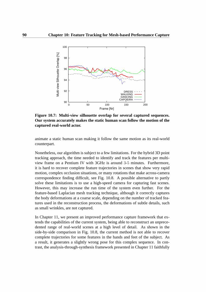
90 Chapter 10: Feature Tracking for Mesh-based Performance Capture
90
92
94
96
98
100
0 50 100 150 200
Multi-vie
w S
ilhouette O
verlap [%
]
Frame [Nr]
DRESSWALKINGDANCING
CAPOEIRA
Figure 10.7: Multi-view silhouette overlap for several captured sequences.Our system accurately makes the static human scan follow the motion of thecaptured real-world actor.
animate a static human scan making it follow the same motion as its real-worldcounterpart.
Nonetheless, our algorithm is subject to a few limitations. For the hybrid 3D pointtracking approach, the time needed to identify and track the features per multi-view frame on a Pentium IV with 3GHz is around3-5 minutes. Furthermore,it is hard to recover complete feature trajectories in scenes that show very rapidmotion, complex occlusion situations, or many rotations that make across-cameracorrespondence finding difficult, see Fig. 10.8. A possible alternative to partlysolve these limitations is to use a high-speed camera for capturing fast scenes.However, this may increase the run time of the system even further. For thefeature-based Laplacian mesh tracking technique, although it correctly capturesthe body deformations at a coarse scale, depending on the number of tracked fea-tures used in the reconstruction process, the deformations of subtle details, suchas small wrinkles, are not captured.
In Chapter 11, we present an improved performance capture framework that ex-tends the capabilities of the current system, being able to reconstruct an unprece-dented range of real-world scenes at a high level of detail. As shown in theside-by-side comparison in Fig. 10.8, the current method is not able to recovercomplete trajectories for some features in the hands and feet of the subject. Asa result, it generates a slightly wrong pose for this complex sequence. In con-trast, the analysis-through-synthesis framework presented in Chapter 11 faithfully

10.4 Results and Discussion 91
Figure 10.8: Female jazz dance sequence: the left column shows the cor-rect input pose, the middle column shows the slightly wrong pose capturedif we apply the current performance capture method, and the right columnshows the better result if we apply the improved method described in Chap-ter 11. While at some point in this complex sequence the feature trajectoriesat the hand and feet are lost with the current method, the analysis-through-synthesis framework, described in the next chapter, is able to accurately cap-ture the female pose.
reconstructs the pose. Furthermore, the proposed silhouette rim-based techniqueand the model-guided multi-view stereo approach are able to capture the dynamicsubtle details more accurately.
Despite these limitations, the hybrid approach still has the advantage of being ap-plicable in other problem settings where no geometry is available. Moreover, thecurrent performance capture framework is able to move and deform a high-qualityscanned model in the same way as its real-world counterpart, while preserving itsconnectivity over time. Our flexible algorithm does not require optical markings,and behaves robustly even for humans wearing sparsely textured and wide apparel.

92 Chapter 10: Feature Tracking for Mesh-based Performance Capture

Chapter 11
Video-Based PerformanceCapture
In this chapter, by combining the power of surface- and volume-based shape deformation techniques with a novel mesh-basedanalysis-through-synthesis framework, a new marker-less ap-proach to capture human performances from multi-view video isdescribed. Furthermore, a silhouette rim-based technique and amodel-guided multi-view stereo approach are also presented, whichenables the acquisition of fine dynamic subtle details more accurately.
In the previous chapters (Chapter 8, 9 and 10), the difficulties of human per-formance capture have been presented. In general, current methods do not allowfor what both actors and directors would prefer: to capture human performancesdensely in space and time, i.e. to be able to jointly capture accurate dynamicshape, motion and textural appearance of actors in arbitrary everyday apparel.
To bridge this gap, in this chapter, we describe a new marker-less dense perfor-mance capture technique that is able to reconstruct motion and spatio-temporallycoherent time-varying geometry of a performer moving in his/her normal andeven loose or wavy clothing from multiple video streams. Our algorithm jointlydelivers time-varying scene geometry with coherent connectivity, accurate time-varying shape detail even of people wearing wide apparel such as skirts, and,being completely passive, enables us to record time-varying surface appearanceas well. It thus produces a rich dynamic scene representation which, in particulardue to the coherent geometry discretization, can be easily made available to and

94 Chapter 11: Video-Based Performance Capture
modified by animators. The method described in this chapter improves over theprevious approaches (Chapter 9 and 10) since it allows the acquisition of fasterand more complex human performances. Furthermore, fine dynamic subtle detailsare captured more accurately by combining a silhouette rim-based technique anda model-guided multi-view stereo approach.
The main contribution of the chapter is a new video-based performance capturemethod [de Aguiar08a], which
• passively reconstructs spatio-temporally coherent shape, motion and textureof actors at high quality;
• draws its strength from an effective combination of a new skeleton-lessshape deformation method, a new analysis-through-synthesis frameworkfor pose recovery, and a new model-guided multi-view stereo approach forshape refinement;
• and exceeds capabilities of many previous capture techniques, by allowingthe user to record people wearing loose apparel and people performing fastand complex motion.
The remainder of this chapter is structured as follows: Sect. 11.1 briefly describesour efficient performance capture framework. Performances are captured by firstemploying a new analysis-through-synthesis procedure for global pose alignmentin each frame (Sect. 11.2), and thereafter, a model-guided multi-view stereo anda contour alignment method recovers small-scale surface detail, Sect. 11.3. Atthe end, we present the results, showing that our approach can reliably recon-struct very complex motion, which would even challenge the limits of traditionalskeleton-based optical capturing approaches, Sect. 11.4.
11.1 Overview
Prior to capturing human performances, we take a full-body laser scan of thesubject in its current apparel by means of a Vitus SmartTM laser scanner. Af-ter scanning, the subject immediately moves to the adjacent multi-view recordingarea, Chapter 4. For each subject and each type of apparel, we record a multitudeof different performances. As a pre-processing step, color-based background sub-traction is applied to all video footage, yielding silhouette images of the capturedperformers, Sect. 2.3.1.
Once all of the data has been captured, our automatic performance reconstructionpipeline begins. Our computational model of shape and motion is obtained by first

11.1 Overview 95
Figure 11.1: A surface scanMtri of an actress (l) and the correspondingtetrahedral meshTtet in an exploded view (r).
transforming the raw scan into a high-quality surface meshMtri = (Vtri, Ttri)(with ns verticesVtri = {v1 . . . vns
} andms trianglesTtri = {t1 . . . tms}) employ-
ing the method of [Kazhdan06], see Fig. 11.1(l). Additionally, we create a coarsertetrahedral version of the surface scanTtet = (Vtet, Ttet) (comprising ofnt ver-ticesVtet andmt tetrahedronsTtet) by applying a quadric error decimation and asubsequent constrained Delaunay tetrahedralization, Fig. 11.1(r). Typically,Mtri
contains between 30000 and 40000 triangles, and the corresponding tet-versionbetween 5000 and 6000 tetrahedrons. Both models are automatically registered tothe first pose of the actor in the input footage by means of a procedure based oniterative closest points (ICP).
Our capturing framework is designed to meet the difficult challenges imposedby our goal: to capture from sparse multi-view video a spatio-temporally coher-ent shape, motion, subtlest surface deformation and textural appearance of actorsperforming fast and complex motion in general apparel. Our method explicitlyabandons a skeletal motion parametrization and resorts to deformable models asscene representation. Thereby, we are facing a harder tracking problem, but gainan intriguing advantage: we are now able to track non-rigidly deforming surfaces(like wide clothing) in the same way as rigidly deforming models, and do notrequire prior assumptions about material distributions or the segmentation of themodel.
The first core algorithmic ingredient of our performance capture framework is afast and reliable shape deformation framework, that expresses the deformation ofthe whole model based on a few point handles, Sect. 3.3. The second ingredientis a robust way to infer the motion of the deformation handles from the multi-view video data, Sect. 11.2 and Sect. 11.3. We capture performances in a multi-

96 Chapter 11: Video-Based Performance Capture
resolution way to increase reliability. First, an analysis-through-synthesis methodbased on image and silhouette cues estimates the global pose of an actor at eachframe on the basis of the lower-detail tetrahedral input model, Sect. 11.2. Onceglobal poses were found, the low-frequency aspect of the performances, i.e. small-scale time-varying shape details on the surface, are captured. To this end, theglobal poses are transferred to the high-detail surface scan, and surface shapeis refined by enforcing contour alignment and performing model-guided stereo,Sect. 11.3.
The output of our method is a dense representation of the performance in bothspace and time. It comprises of accurately deformed spatio-temporally coherentgeometry that nicely captures the liveliness, motion and shape detail of the originalinput.
11.2 Capturing the Global Model Pose
Our first step aims at recovering, for each time step of the video, a global poseof the tetrahedral input model that matches the pose of the real actor. Decouplingglobal pose computation from the estimation of small surfaces makes performancecapture a more stable procedure. Consequently, our model representation at thispoint is the coarse tetrahedral meshTtet. To modify its pose, we employ the volu-metric deformation method, Chapter 3, with its noted advantageous shape preser-vation properties that facilitate tracking. In a nutshell, our global pose extractionmethod computes deformation constraints from each pair of subsequent multi-view input video frames at timest andt + 1. It then applies the volumetric shapedeformation procedure to modify the pose ofTtet at timet (that was found pre-viously) until it aligns with the input data at timet + 1. In order to convergeto a plausible pose under this highly multi-modal goodness-of-fit criterion, it isessential that we extract the right types of features from the images in the rightsequence and apply the resulting deformation constraints in the correct order.
To serve this purpose, our pose recovery process begins with the extraction of 3Dvertex displacements from reliable image features, which brings our model closeto its final pose even if scene motion is rapid, Sect. 11.2.1. The distribution of3D features on the model surface depends on the scene structure, e.g. texture, andcan, in general, be non-uniform or sparse. Therefore, the resulting pose may notbe entirely correct. Furthermore, potential outliers in the correspondences makeadditional pose update steps unavoidable. We therefore subsequently resort to twoadditional steps that exploit silhouette data to fully recover the global pose. Thefirst step refines the shape of the outer model contours until they match the multi-

11.2 Capturing the Global Model Pose 97
Figure 11.2: 3D correspondences are extracted from corresponding SIFT fea-tures in respective input camera views att and t + 1. These 3D correspon-dences, two of them illustrated by lines, are used to deform the model into afirst pose estimate fort + 1.
view input silhouette boundaries, Sect. 11.2.2. The second step optimizes 3Ddisplacements of key vertex handles until optimal multi-view silhouette overlapis reached, Sect. 11.2.3. Conveniently, the multi-view silhouette overlapSIL canbe quickly computed as an XOR operation on the GPU [Carranza03].
We gain further tracking robustness by subdividing the surface of the volumemodel into a setR of approximately 100-200 regions of similar size during pre-processing [Yamauchi05]. Rather than inferring displacements for each vertex,we determine representative displacements for each region as explained in thefollowing sections.
11.2.1 Pose Initialization from Image Features
Given two sets of multi-view video framesI1(t), . . . , Ik(t) and I1(t +1), . . . , Ik(t + 1) from subsequent time steps, our first processing step extractsSIFT features in each frame [Lowe99] (see Fig. 11.2). This yields, for each cam-era viewk and either time step, a list ofℓ(k) = 1, . . . , Lk 2D feature locationsu
ℓ(k)k,t along with their SIFT feature descriptorsdd
ℓ(k)k,t – henceforth we refer to each
such list asLDk,t. SIFT features are our descriptors of choice, as they are ro-bust against illumination changes and out-of-plane rotation, and enable reliablecorrespondence finding even if the scene motion is fast.
Let Ttet(t) be the pose ofTtet at timet. To transform feature data into deformation

98 Chapter 11: Video-Based Performance Capture
constraints for vertices ofTtet(t), we first need to pair image features from timet with vertices in the model. We therefore first associate eachvti of Ttet(t) withthat descriptorddi
k,t from eachIk(t) that is located closest to the projected loca-tion of vti in this respective camera. We perform this computation for all cameraviews and discard a feature association ifvti is not visible fromk or if the dis-tance between the projected position ofvti and the image position ofddi
k,t is too
large. This way, we obtain a set of associationsA(vti, t) = {ddj11,t, · · · , ddjK
K,t} fora subset of vertices that contains at most one feature from each camera. Lastly,we check the consistency of eachA(vti, t) by comparing the pseudo-intersectionpoint pINT
i of the reprojected rays passing throughuj11,t, . . . , u
jKK,t to the 3D posi-
tion of vti in model poseTtet(t). If the distance‖vti − pINTi ‖ is greater than a
thresholdEDIST , the original feature association is considered implausible andvtiis removed from the candidate list for deformation handles.
The next step is to establish temporal correspondences, i.e. to find for each vertexvti with feature associationA(vti, t) the corresponding associationA(vti, t + 1)with features from the next time step. To this end, we preliminarily find for eachddj
k,t ∈ A(vti, t) a descriptorddfk,t+1 ∈ LDk,t+1 by means of nearest neighbor
distance matching in the descriptor values, and addddfk,t+1 to A(vti, t + 1). In
practice, this initial assignment is likely to contain outliers, and therefore wecompute the final set of temporal correspondences by means of robust spectralmatching [Leordeanu05]. This method efficiently bypasses the combinatorialcomplexity of the correspondence problem by formulating it in closed form asa spectral analysis problem on a graph adjacency matrix. Incorrect matches areeliminated by searching for an assignment in which both the feature descriptorvalues across time are consistent, and pairwise feature distances across time arepreserved. Fig. 11.2 illustrates a subset of associations found for two cameraviews. From the final set of associationsA(vti, t + 1), we compute the predicted3D target positionpEST
i of vertexvti again as the virtual intersection point ofreprojected image rays through the 2D feature positions.
Each vertexvti for which a new estimated position was found is a candidate fora deformation handle. However, we do not straightforwardly apply all handlesto moveTtet directly to the new target pose. We rather propose the followingstep-wise procedure which, in practice, is less likely to converge to implausiblemodel configurations: We resort to the set of regionsR on the surface of thetet-mesh (as described above) and find for each regionri ∈ R one best handlefrom all candidate handles that lie inri. The best handle vertexvti is the onewhose local normal is most collinear with the difference vectorp
ESTi − vi. If no
handle is found for a region, we constrain the center of that region to its original3D position inTtet(t) which prevents unconstrained surface areas from arbitrary

11.2 Capturing the Global Model Pose 99
(a) (b)
Figure 11.3: (a) Color-coded distance field from the image silhouette contourshown for one camera view. (b) Rim vertices with respect to one camera viewmarked in red on the tetrahedral model.
drifting. For each region handle, we define a new intermediate target position
asq′i = vti +pEST
i −vti‖pEST
i −vti‖ . Typically, we obtain position constraintsq′i for around
70% to 90% of the surface regionsR that are then used to change the pose ofthe model. This step-wise deformation is repeated until the multi-view silhouetteoverlap errorSIL(Ttet, t + 1) cannot be further improved.
In contrast to the method proposed in Chapter 10, we do not require tracking offeatures across the entire sequence, which greatly contributes to the reliability ofthis method. The output of this step is a feature-based pose estimateT F
tet(t + 1).
11.2.2 Refining the Pose using Silhouette Rims
In image regions with sparse or low-frequency textures, only few SIFT featuresmay have been found, which may cause a starkly uneven distribution of deforma-tion handles, or may generate areas with no handles at all. In consequence, thepose ofT F
tet(t + 1) may not be correct in all parts. We therefore resort to anotherconstraint that is independent of image texture and has the potential to correctsuch misalignments. To this end, we derive additional deformation constraintsfor a subset of vertices onT F
tet(t + 1) that we callrim verticesVRIM(t + 1), seeFig. 11.3(b). Rim vertices are vertices whose projections lie on the silhouette con-tour of the performer in at least oneIk(t+1), and whose normals are perpendicularto its viewing direction. By displacing them along their normals until alignmentwith the respective silhouette boundaries in 2D is reached, we are able to improvethe pose accuracy for the model att + 1.

100 Chapter 11: Video-Based Performance Capture
In order to find the elements ofVRIM(t + 1), we first calculate contour imagesCk,t+1 using the rendered volumetric model silhouettes. A vertexvti is considereda rim vertex if it projects into close vicinity of the silhouette contour in (at least)one of theCk,t+1, and if the normal ofvti is perpendicular to the viewing directionof the camerak.
For each elementvti ∈ VRIM(t + 1) a 3D displacement is computed by analyz-ing the projected locationuk,t+1 of the vertex into the camerak that originallydefined its rim status. The value of the distance field from the contour at the pro-jected location defines the total displacement length in vertex normal direction,Fig. 11.3(a). This way, we obtain deformation constraints for rim vertices whichwe apply in the same step-wise deformation procedure that was already used inSect. 11.2.1. The result is a new model configurationT R
tet(t + 1) in which theprojections of the outer model contours more closely match the input silhouetteboundaries.
11.2.3 Optimizing Key Handle Positions
In the majority of cases, the pose of the model inT Rtet(t + 1) is already close to
a good match. However, in particular if the scene motion was fast or the initialpose estimate from SIFT was not entirely correct, residual pose errors remain. Wetherefore perform an additional optimization step that corrects such residual errorsby globally optimizing the positions of a subset of deformation handles until goodsilhouette overlap is reached. Note that for the success of this step, a good poseinitialization from the preceding steps is indispensable. Only in their combinationall pose update strategies make up a robust analysis-through-synthesis framework.
Instead of optimizing the position of all1000 − 2000 vertices of the volumetricmodel, we only optimize the position of typically 15-25 key verticesVk ⊂ Vtet
until the tetrahedral deformation scheme produces optimal silhouette overlap. Weask the user to specify key vertices manually, a procedure that has to be doneonly once for every model. Typically, key vertices are marked close to anatomicaljoints, and in case of model parts representing loose clothing, a simple uniformhandle distribution produces good results. Tracking robustness is increased bydesigning our energy function such that surface distances between key handles arepreserved, and pose configurations with low distortion energyED are preferred,Sect. 3.3.
Given all key vertex positionsvti ∈ Vk in the current model poseT Rtet(t + 1), we
optimize for their new positionspi by minimizing the following energy functional:
E(Vk) = wS · SIL(Ttet(Vk), t + 1) + wD · ED + wC · EC . (11.1)

11.2 Capturing the Global Model Pose 101
(a) (b) (c) (d)
Figure 11.4: Model (a) and silhouette overlap (b) after the rim step; slightpose inaccuracies in the leg and the arms appear black in the silhouette over-lap image. (c),(d) After key vertex optimization, these pose inaccuracies areremoved and the model strikes a correct pose.
Here,SIL(Ttet(Vk), t + 1) denotes the multi-view silhouette overlap error of thetet-mesh in its current deformed poseTtet(Vk), which is defined by the new posi-tions of theVk. ED is the deformation energy as defined in Sect. 3.3. Implicitly wereason that low energy configurations are more plausible.EC penalizes changes indistance between neighboring key vertices. All three terms are normalized and theweightswS, wD, andwC are chosen such thatSIL(Ttet(Vk), t+1) is the dominantterm. In our solution,ED andEC are used to regularize the solution avoiding thatthe distance between neighboring key vertices increases or decreases too much,which creates bad deformations. We use a Quasi-Newton LBFGS-B method tominimize Eq. 11.1 [Byrd95].
Fig. 11.4 illustrates the improvements in the new output poseT Otet(t + 1) achieved
through key handle optimization. The output of this step is a new configuration ofthe tetrahedral modelT O
tet(t + 1) that captures the overall stance of the model andserves as the starting point for the subsequent surface detail capture.
11.2.4 Practical Considerations
The above sequence of steps is performed for each pair of subsequent time in-stants. Surface detail capture, Sect. 11.3, commences after the global poses werefound for all frames.
Typically, the rim step described in Sect. 11.2.2 is performed once more afterthe last silhouette optimization step, which in some cases leads to a better modelalignment. We also perform a consistency check on the output of our low fre-quency pose capture approach to correct potential self-intersections. To this end,

102 Chapter 11: Video-Based Performance Capture
(a) (b) (c)
Figure 11.5: Capturing small-scale surface detail: (a) first, deformation con-straints from silhouette contours, shown as red arrows, are estimated. (b)Additional deformation handles are extracted from a 3D point cloud thatwas computed via model-guided multi-view stereo. (c) Together, both sets ofconstraints deform the surface scan to a highly accurate pose.
for every vertex lying inside another tetrahedron, we use the volumetric deforma-tion method to displace this vertex in outward direction along its normal until theintersection is resolved.
11.3 Capturing Surface Detail
Once global pose has been recovered for each frame, the pose sequence ofTtet ismapped toMtri, Sect. 3.3. In the following section, the process of shape detailcapture at a single time step is explained.
11.3.1 Adaptation along Silhouette Contours
In a first step, we adapt the silhouette rims of our fine mesh to better match theinput silhouette contours. As we are now working on a surface mesh which isalready very close to the correct configuration, we can allow a much broader andless smooth range of deformations than in the volumetric case, and thereby bringthe model to much closer alignment with the input data. At the same time, wehave to be more careful in selecting our constraints, since noise in the data nowhas more deteriorating influence. This also means that our deformation is lessrobust against errors and we have to carefully select the constraints.
We calculate rim vertices for the high-resolution surface mesh similarly to

11.3 Capturing Surface Detail 103
Sect. 11.2.2, Fig. 11.5(a). For each rim vertex, the closest 2D point on the sil-houette boundary is found in the camera view that defines its rim status, and wecheck if the image gradient at the input silhouette point has a similar orientationto the image gradient in the reprojected model contour image. If this is the case,the back-projected input contour point defines the target position for the rim ver-tex. If the distance between back-projection and original position is smaller thanthresholdERIM , we add it as a constraint to Eq. 3.5. We also check if the vertexvi and the 2D contour point have a similar orientation by comparing their imageprojected gradients.
We use a low weightwi for the rim constraint points in Eq. 3.5. This has a regu-larizing and damping effect on the deformation that minimizes implausible shapeadaptation in the presence of noise. After processing all vertices, we solve for thenew surfaceM′(t)tri. This procedure is iterated up to20 times or until silhouetteoverlap cannot be further improved.
11.3.2 Model-guided Multi-view Stereo
Although the silhouette rims only provide reliable constraints on outer boundaries,they are usually evenly distributed on the surface. Hence, the Laplacian-baseddeformation method in general nicely adapts the shape of the whole model alsoin areas which do not project on image contours. Unless the surface of the actorhas a complicated shape with many concavities, the result of the rim adaptation isalready a realistic representation of the correct shape.
However, in order to recover shape details in regions that do not project to sil-houette boundaries, such as folds and concavities in a skirt, we resort to photo-consistency information. To serve this purpose, we derive additional deformationconstraints by applying the multi-view stereo method proposed by [Goesele06].Since our model is already close to the correct surface, we can initialize the stereooptimization from the current surface estimate and constrain the correlation searchto 3D points that are at most±2 cm away fromM(t)tri.
As we have far less viewpoints of our subject than Goesele et al. and our actorscan wear apparel with little texture, the resulting depth maps (one for each inputview) are often sparse and noisy. Nonetheless, they provide important additionalcues about the object’s shape. We merge the depth maps produced by the stereoapproach into a single point cloudP, Fig. 11.5(b), and thereafter project pointsfrom Vtri onto P using a method similar to [Stoll06]. These projected pointsprovide additional position constraints that we can use in conjunction with therim vertices in the Laplacian-based deformation framework, Eq. 3.5.PVt give us

104 Chapter 11: Video-Based Performance Capture
Figure 11.6: A sequence of poses captured from eight video recordings of acapoeira turn kick. Our algorithm delivers spatio-temporally coherent geom-etry of the moving performer, capturing both the time-varying surface detailas well as details in his motion faithfully.
additional positional constraints to add to the energy minimization from Eq. 3.5in addition to the rim constraintsRVt. Given the uncertainty in the data, we solvethe Laplace system with lower weights for the stereo constraints, Sect. 3.2.2.
11.4 Results and Discussion
Our test data were recorded in our acquisition setup described in Chapter 4. Itcomprises of12 sequences showing four different actors, and feature between200and600 frames each. To show the large application range of our performance cap-ture algorithm, the subjects wore a wide range of different apparel, ranging fromtight to loose, and made of fabrics with prominent texture as well as plain colorsonly. Also, the recovered set of motions ranges from simple walks, over differentdance styles, to fast capoeira sequences. As shown in Figs. 11.6, 11.7 and 11.9,our algorithm faithfully reconstructs this wide spectrum of scenes. We would alsolike to note that, although we focused on human performers, our algorithm wouldwork equally well for animals provided that a laser scan can be acquired.
Fig. 11.6 shows several captured poses of a very rapid capoeira sequence in whichthe actor performs a series of turn kicks. Despite the fact that in our24 fpsrecordings the actor rotates by more than25 degrees in-between some subsequentframes, both shape and motion are reconstructed with high fidelity. The result-ing animation even shows small deformation details such as the waving of thetrouser legs. Furthermore, even with the plain white clothing that the actor wearsin the input, which exhibits only few traceable SIFT features, our method per-forms reliably as it can capitalize on rims and silhouettes as additional sources ofinformation. Comparing a single moment from the kick to an input frame con-
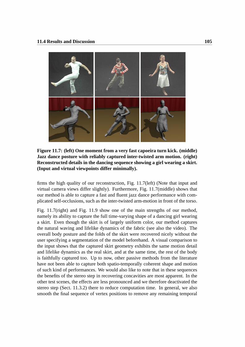
11.4 Results and Discussion 105
Figure 11.7: (left) One moment from a very fast capoeira turn kick. (middle)Jazz dance posture with reliably captured inter-twisted arm motion. (right)Reconstructed details in the dancing sequence showing a girl wearing a skirt.(Input and virtual viewpoints differ minimally).
firms the high quality of our reconstruction, Fig. 11.7(left) (Note that input andvirtual camera views differ slightly). Furthermore, Fig. 11.7(middle) shows thatour method is able to capture a fast and fluent jazz dance performance with com-plicated self-occlusions, such as the inter-twisted arm-motion in front of the torso.
Fig. 11.7(right) and Fig. 11.9 show one of the main strengths of our method,namely its ability to capture the full time-varying shape of a dancing girl wearinga skirt. Even though the skirt is of largely uniform color, our method capturesthe natural waving and lifelike dynamics of the fabric (see also the video). Theoverall body posture and the folds of the skirt were recovered nicely without theuser specifying a segmentation of the model beforehand. A visual comparison tothe input shows that the captured skirt geometry exhibits the same motion detailand lifelike dynamics as the real skirt, and at the same time, the rest of the bodyis faithfully captured too. Up to now, other passive methods from the literaturehave not been able to capture both spatio-temporally coherent shape and motionof such kind of performances. We would also like to note that in these sequencesthe benefits of the stereo step in recovering concavities are most apparent. In theother test scenes, the effects are less pronounced and we therefore deactivated thestereo step (Sect. 11.3.2) there to reduce computation time. In general, we alsosmooth the final sequence of vertex positions to remove any remaining temporal

106 Chapter 11: Video-Based Performance Capture
Step TimeSIFT step (Sect. 11.2.1) ∼5s
Global rim step (Sect. 11.2.2) ∼4sKey handle optimization (Sect. 11.2.3) ∼40sContour-based refinement (Sect. 11.3.1) ∼4s
Stereo,340 × 340 depth maps (Sect. 11.3.2)∼30s
Table 11.1: Average run times per frame for individual steps.
noise.
11.4.1 Validation and Discussion
Table 11.1 gives detailed average timings for each individual step in our algorithm.These timings were obtained with an unoptimized single-threaded code runningon a Quad Core Intel Xeon Processor E5410 workstation with 2.33 GHz. We seeplenty of room for implementation improvement, and anticipate that paralleliza-tion can lead to a significant run time reduction.
So far, we have visually shown the high capture quality, as well as the large appli-cation range and versatility of our approach. To formally validate the accuracy ofour method, we have compared the silhouette overlap of our tracked output modelswith the segmented input frames. We use this criterion since, to our knowledge,there is no gold-standard alternative capturing approach that would provide uswith accurate time-varying 3D data. The re-projections of our final results typ-ically overlap with over85% of the input silhouette pixels, already after globalpose capture only (blue curve in Fig. 11.8(a)). Surface detail capture further im-proves this overlap to more than90% as shown by the green curve. Please notethat this measure is slightly negatively biased by errors in foreground segmenta-tion in some frames that appear as erroneous silhouette pixels. Visual inspectionof the silhouette overlap therefore confirms the almost perfect alignment of modeland actual person silhouette. Fig. 11.8(b) shows a blended overlay between therendered model and an input frame which proves this point.
Our algorithm robustly handles even noisy input, e.g. due to typically observedsegmentation errors in our color-based segmentation. In particular, if foregroundcolors resemble the background (e.g. black hair in front of a black backgroundin some of our data), color-based segmentation may produce erroneous silhou-ettes. Nonetheless, our method delivers reliable reconstructions under typicallyobserved segmentation errors. All12 input sequences were reconstructed fully-automatically after only minimal initial user input. As a pre-processing step, the

11.4 Results and Discussion 107
(a) (b)
Figure 11.8: Evaluation: (a) per-frame silhouette overlap in per cent afterglobal pose estimation (blue) and after surface detail reconstruction (green).(b) Blended overlay between an input image and the reconstructed modelshowing the almost perfect alignment of our performance capture approach.
user marks the head and foot regions of each model to exclude them from sur-face detail capture. Even slightest silhouette errors in these regions (in particulardue to shadows on the floor and black hair color) would otherwise cause unnat-ural deformations. Furthermore, for each model the user once marks at most25deformation handles needed for the key handle optimization step, Sect. 11.2.3.
In individual frames of two out of three capoeira turn kick sequences (11out ofaround1000 frames), as well as in one frame of each of the skirt sequences (2frames from850 frames), the output of global pose recovery showed slight mis-alignments in one of the limbs. Please note that, despite these isolated pose errors,the method always recovers immediately and tracks the whole sequence withoutdrifting – this means the algorithm can run without supervision and the results canbe checked afterwards. All observed pose misalignments were exclusively due tooversized silhouette areas because of either motion blur or strong shadows on thefloor. Both of this could have been prevented by better adjustment of lighting andshutter speed, and by using more advanced segmentation schemes. In either caseof global pose misalignment, at most two deformation handle positions had to beslightly adjusted by the user. In none of the over3500 input frames we processedin total, it was necessary to manually correct the output of surface detail capture(Sect. 11.3).
Despite our method’s large application range, there are a few limitations to be

108 Chapter 11: Video-Based Performance Capture
Figure 11.9: Side-by-side comparison of the input image and the reconstruc-tion of a dancing girl wearing a skirt (input and virtual viewpoints differminimally). Body pose and detailed geometry of the waving skirt, includinglifelike folds and wrinkles visible in the input, have been recovered.
considered. Our current silhouette rim matching may produce erroneous defor-mations if the topological structure of the input silhouette is too different from thereprojected model silhouette. As our low-frequency adaptation generates a goodinitialization, which is already close to the actual silhouette, this effect can beovercome by careful selection of parameters. However, in none of our test scenesthis turned out to be an issue. Currently, we are recording in a controlled studioenvironment to obtain good segmentations, but are confident that a more advancedbackground segmentation will enable us to handle outdoor scenes.
Moreover, there is a resolution limit to our deformation capture. Some of the high-frequency detail in our final result, such as fine wrinkles in clothing or details ofthe face, has been part of the laser-scan in the first place. The deformation onthis level of detail is not actually captured, but it is ”baked in” to the deformingsurface. To illustrate the level of detail that we are actually able to reconstruct,we generated a result with a coarse scan that lacks fine surface detail. Fig. 11.10shows an input frame (l), as well as the reconstructions using the detailed scan (m)and the coarse model (r). While, as noted before, finest detail in Fig. 11.10(m) is
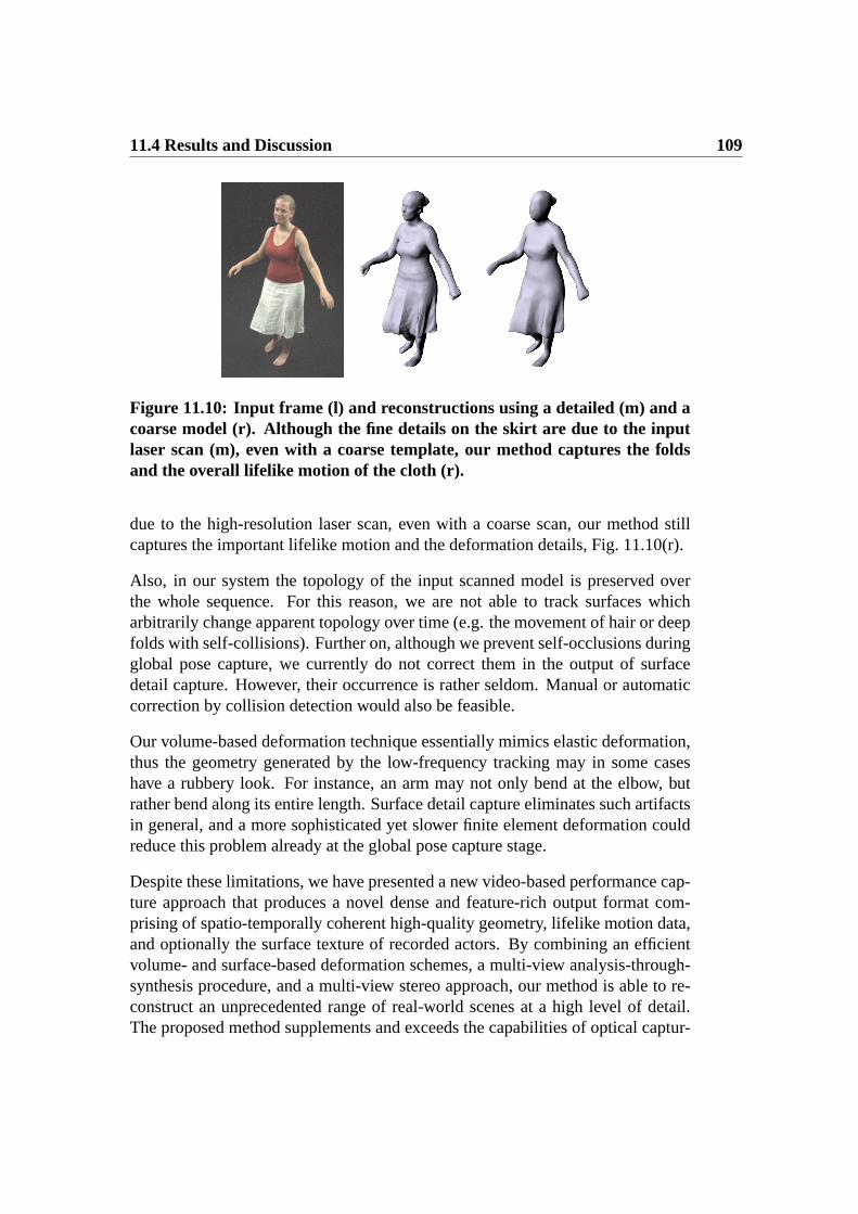
11.4 Results and Discussion 109
Figure 11.10: Input frame (l) and reconstructions using a detailed (m) and acoarse model (r). Although the fine details on the skirt are due to the inputlaser scan (m), even with a coarse template, our method captures the foldsand the overall lifelike motion of the cloth (r).
due to the high-resolution laser scan, even with a coarse scan, our method stillcaptures the important lifelike motion and the deformation details, Fig. 11.10(r).
Also, in our system the topology of the input scanned model is preserved overthe whole sequence. For this reason, we are not able to track surfaces whicharbitrarily change apparent topology over time (e.g. the movement of hair or deepfolds with self-collisions). Further on, although we prevent self-occlusions duringglobal pose capture, we currently do not correct them in the output of surfacedetail capture. However, their occurrence is rather seldom. Manual or automaticcorrection by collision detection would also be feasible.
Our volume-based deformation technique essentially mimics elastic deformation,thus the geometry generated by the low-frequency tracking may in some caseshave a rubbery look. For instance, an arm may not only bend at the elbow, butrather bend along its entire length. Surface detail capture eliminates such artifactsin general, and a more sophisticated yet slower finite element deformation couldreduce this problem already at the global pose capture stage.
Despite these limitations, we have presented a new video-based performance cap-ture approach that produces a novel dense and feature-rich output format com-prising of spatio-temporally coherent high-quality geometry, lifelike motion data,and optionally the surface texture of recorded actors. By combining an efficientvolume- and surface-based deformation schemes, a multi-view analysis-through-synthesis procedure, and a multi-view stereo approach, our method is able to re-construct an unprecedented range of real-world scenes at a high level of detail.The proposed method supplements and exceeds the capabilities of optical captur-

110 Chapter 11: Video-Based Performance Capture
ing systems that are widely used in the industry, and will provide animators andCG artists with a new level of flexibility in acquiring and modifying real-worldcontent.
Chapter 12
High-Quality 3D Videos
In this chapter, we describe a method to render realistic 3D Videos byapplying a clever dynamic 3D texturing scheme to the moving geom-etry representation captured by the methods proposed in the previouschapters. By displaying high-quality renderings of the recorded actorfrom any viewpoint, our system enables new interesting applicationsfor 3D Television.
In recent years, an increasing research interest in the field of 3D Video processinghas been observed. The goal is to render a real-world scene from arbitrary novelviewpoints photo-realistically. Since the human actor is presumably the most im-portant element of many real-world scenes, the analysis of motion and shape ofhumans from video, as well as their convincing graphical rendition is required,which is still a challenging task.
In the traditional model-based approach to 3D Video, the motion of a sim-plified body model is first estimated from multiple video streams [Starck03b,Carranza03], and during rendering, it is textured using the input footage. Al-though these methods deliver realistic free-viewpoint renderings of virtual actors,we expect that a more accurate underlying geometry increases realism even fur-ther.
By combining the detailed captured human performances, using any of the meth-ods presented in Chapters 9, 10, or 11, with the multi-view projective texturemethod proposed in [Carranza03], convincing renditions of human actors fromarbitrary synthetic viewpoints can be generated in real-time. Due to the highly-

112 Chapter 12: High-Quality 3D Videos
detailed underlying scene geometry, the visual results are much better than previ-ous model-based or shape from silhouette-based 3D Video methods, Sect. 8.1.3.In addition, since our performance capture methods generate a natural and time-consistent geometry, 3D Video applications that until now would require a lot ofeffort are simplified, e.g. 3D Video editing and 3D Video compositing. For ex-ample, one can generate multiple single 3D Video scenes, which afterwards couldeasily be edited and composed together in order to create new sequences.
The main contribution of this chapter is a
• system combining a detailed dynamic scene representation with a projec-tive texture method, enabling realistic renditions of human subjects fromarbitrary synthetic viewpoints [de Aguiar08a].
In this chapter, we first describe a dynamic multi-view texturing method,Sect. 12.1. Thereafter, Sect. 12.2 presents the results obtained with our 3D Videosystem, showing the captured real world scenes from novel synthetic camera per-spectives.
12.1 Creating 3D Videos
By combining any of the three previous performance capture methods describedin this thesis, the motion, dynamic shape, and texture information from mov-ing subjects is acquired. This data can be used to create and render convincingfree-viewpoint videos that reproduce the omni-directional appearance of the ac-tor. Since no markers are needed to capture the scene, time-varying video footageis available and lifelike surface appearance can be generated using the projectivetexturing technique described in [Carranza03].
In order to display the model, the color of each rendered pixelc(j) is determinedby blending allk input multi-view video imagesIi according to
c(j) =k
∑
i=1
νi(j)ωi(j)Ii(j) (12.1)
whereωi(j) denotes the blending weight of camerai andνi(j) = {0, 1} is thelocal visibility. During texture pre-processing, the weights are calculated and theproductνi(j)ωi(j) is normalized to ensure energy conservation.
Technically, Eq. 12.1 can be evaluated for each fragment on the GPU, and therasterization engine interpolates the blending values from the triangle vertices. Bythis means, time-varying cloth folds and creases, shadows, and facial expressions

12.1 Creating 3D Videos 113
are faithfully reproduced, leading to a very natural, dynamic appearance of therendered object.
Blending Weights. The blending weights determine the contribution of eachinput camera image to the final color of a surface point. If surface reflectance canbe assumed to be approximately Lambertian, view-dependent reflection effectsplay no significant role, and high-quality renditions can be obtained by blendingthe video images intelligently. Letθi denote the angle between a vertex normaland the optical axis of camerai. By emphasizing the camera view with the small-est angleθi for each vertex, i.e. the camera that views the vertex most head-on, aconsistent, detail-preserving texture is obtained.
Following [Carranza03], a visually convincing weight assignment has been foundto be
ωi =1
(1 + maxj(1/θj) − 1/θi)α. (12.2)
The parameterα determines the influence of a vertex orientation with respect tothe camera viewing directions and consequently the impact of the most head-oncamera view per vertex. Singularities are avoided by clamping the value of1/θi
to a maximal value. Additionally, the weightsωi are normalized to sum up to one.
Visibility. Unfortunately, in projective texturing, occlusions are not taken intoaccount and hidden surfaces can be erroneous textured. However, the z-buffer testcan be used to determine for every time step which regions are visible from eachcamera view. Due to inaccuracies in the geometry model, it can happen that thesilhouette outlines in the images do not correspond exactly to the outline of themodel. As a result, when projecting video images onto the model, a texture seambelonging to some frontal body part may fall into another body part farther back,Fig. 12.1(a).
To avoid such artifacts, extended soft shadowing is applied. For each cameraview, all object regions of zero visibility are determined not only from the actualposition of the camera, but also from several slightly displaced virtual camera po-sitions. Each vertex is tested whether it is visible from all camera positions. Atriangle is textured by a camera image only if all of its three vertices are com-pletely visible from that camera, Fig. 12.1(b).
Furthermore, to reduce rendering artefacts caused by small segmented silhouetteoutlines, all image silhouettes are expanded by a couple of pixels prior to ren-dering. Using a morphological filter operation, the subject’s outline in all video

114 Chapter 12: High-Quality 3D Videos
(a) (b) (c)
Figure 12.1: Small differences between object silhouette and model outlinecauses erroneous texture projections (a) that can be corrected by applyingan extended soft shadowing method (b). Morphologically dilated segmentedinput video frames can be used to improve projective texturing (c).
images is dilated by copying the silhouette boundary pixel values to adjacent back-ground pixel positions, Fig. 12.1(c).
12.2 Results and Discussion
By coupling our performance capture methods with the texturing approach de-scribed in this chapter, realistic 3D Videos can be displayed in real-time. Fig. 12.2shows two free-viewpoint renditions of a dynamically textured animated model incomparison to the original images of the subject. The free-viewpoint renditionsreflect the true appearance of the actor, confirming that the virtual viewpoint ren-ditions look very lifelike. Since we are given a better surface geometry, textureblending artifacts are hardly observed. Furthermore, we can even reproduce thetrue shape of the sweater which would not have been possible with a coarse tem-plate model [Carranza03].
We have created 3D Videos from a variety of scenes ranging from simple walkingsequences over dancing moves to complex and expressive capoeira turn kicks.Fig. 12.3 displays renditions showing the female dancer wearing a skirt and themale actor performing a fast and complex turn kick. These sequences are ideal testcases to validate the high-quality of the generated 3D Videos as they exhibit rapid

12.2 Results and Discussion 115
Figure 12.2: Free-viewpoint renditions with high-quality geometry models.Due to the accurate geometry, the rendered appearance of the actor (left sub-images) nicely corresponds to his true appearance in the real world (rightsub-images).
and complex rigid and non-rigid motions. Another advantage of our scheme isthat it allows a contiguous surface parameterization of the model, which facilitateshigher-level processing operations, as they are needed for 3D Video editing or inreflectance estimation techniques [Theobalt05, Theobalt07a]
Although clever texture blending can mask most geometry inaccuracies if a coarsegeometry is used, combining a dynamically refined shape representation, acquiredby our previous performance capture approaches, leads to an even better visualquality. Improvements in the renderings are due to the improved geometry and,consequently, less surface blending errors during projective texturing are gener-ated. This combination enables high-quality reconstruction of human actors com-pletely passively, and opens the door for attacking new challenging reconstructionproblems that were hard due to the lack of a decent dynamic scene capture tech-nology.

116 Chapter 12: High-Quality 3D Videos
Figure 12.3: (top-middle) High-quality renditions showing a female dancerwearing a skirt and (bottom) renditions of a male actor performing a fast andcomplex capoeira turn kick. The time-varying refined geometry acquired byour previous performance capture approaches leads to a better visual quality.

Part IV
Processing Mesh Animations


Chapter 13
Problem Statement andPreliminaries
In this part of the thesis, we propose two novel techniques to simplifythe process of mesh animations. First, an automatic method toextract a plausible kinematic skeleton, skeletal motion parameters,and surface skinning weights from arbitrary mesh animations ispresented. Thereafter, a method to automatically transform meshanimations into animation collages, i.e. moving assemblies of shapeprimitives from a database, is described.
It has become increasingly popular to create, edit and represent animations notby means of a classical skeleton-based model, but in the form of deforming meshsequences. The reason for this new trend is that novel mesh deformation methods,as the ones presented in Chapter 3, as well as new surface based scene capturetechniques, like the methods presented in the third part of the thesis, offer a greatlevel of flexibility during animation creation. However, unfortunately the resultingscene representation is less compact than skeletal ones and there is not yet a richtoolbox available which enables easy post-processing and modification of meshanimations.
Animators are used to a large repertoire of tools for editing and rendering tra-ditional skeletal animations, but yet lack the same set of tools for working withmesh-based dynamic scene representations. The method proposed in Chapter 14bridges this gap, enabling the fully-automatic conversion of a mesh animation intoa skeleton-based animation, that can be edited with off-the-shelf tools.

120 Chapter 13: Problem Statement and Preliminaries
A second novel application is described in Chapter 15. Frequently, researchersin computer graphics aim at developing algorithms that enable the computer andeven unexperienced users to reproduce the look of certain styles of visual arts.The proposed system brings together the traditional art form of a collage with themost prominent art form in computer graphics, namely 3D animation, allowingthe computer artist to automatically convert her favorite mesh animation into amoving assembly of 3D shape primitives from a database.
In summary, the main contributions of this part of the thesis are
• a motion-driven mesh segmentation method [de Aguiar08b];
• an algorithm to fully-automatic extract a skeleton structure, skeletal motionparameters, and surface skinning weights from arbitrary deforming meshsequences [de Aguiar08b];
• a system to create animation collages from mesh animations, generatinga complete reassembly of the original animation in a new abstract visualstyle that imitates the spatio-temporal shape and deformation of the in-put [Theobalt07b].
This chapter proceeds with a review of closely related work in Sect. 13.1. There-after, in the following chapters, our two novel approaches to process mesh ani-mations are described in Chapter 14 and Chapter 15. We believe that our newmethods are important contributions to the animator’s toolbox with a variety ofapplications in visual arts, animated movie production, and game productions.
13.1 Related Work
In our projects, we jointly solve a variety of algorithmic subproblems by extend-ing ideas from different research areas. In the following sections, we highlightselected related papers from these research categories.
13.1.1 Motion-Driven Mesh Segmentation
Segmenting a static mesh in meaningful parts is an active field of re-search [Shamir08]. However, recently researchers started to also exploit temporalinformation in mesh animations to create level of detail [Shamir01], to improvecompression [Lengyel99, Lee05, Sattler05], to motion-decompose mesh anima-tions for fast ray-tracing [Gunther06], and to cluster triangles in mesh animations

13.1 Related Work 121
for fast rendering [James05]. Unfortunately, these methodsmay generate seg-ments that are not spatially and temporally consistent, i.e. they do not correspondto underlying kinematic hierarchies and are not guaranteed to be spatially con-nected.
Most recently, [Schaefer07] proposed a method for extracting a hierarchical, rigidskeleton from a set of example poses, that can also be used for motion-drivensegmentation. The main difference to a segmentation method that we proposein the next chapter is the fact that we robustly segment the model by means ofspectral clustering. This gives us much greater flexibility, as we can producesegmentations at different user-controlled levels of detail, or automatically detectthe optimal number of clusters.
13.1.2 Skeleton Reconstruction
Different ways for performing skeleton extraction, each of them tailored to a spe-cific data type and application, have been proposed in the literature. Some ap-proaches extract skeletons from static meshes to hierarchically decompose theshape [Lien06], to segment the mesh in meaningful regions [Katz03], to gain in-formation on the model’s topology [Sharf07], and to perform simple mesh editingoperations [Liu03, Wu06, Tierny06]. Thus, extraction of an animation skeleton isnot the goal.
The accurate extraction of kinematically and biologically plausible animationskeletons is of great importance in optical motion capture, where the skeletalstructure needs to be inferred from marker trajectories [Kirk05, de Aguiar06] orshape-from-silhouette volumes [de Aguiar04]. Similarly, kinematic skeletons canbe reconstructed from a set of range scans of humans [Anguelov04], from CTscans of the human hand [Kurihara04], from a static surface mesh of a knowncharacter [Aujay07], or from pose examples [Schaefer07].
In contrast, the approach proposed in Chapter 14 makes use of entire motion se-quences to extract kinematic hierarchies more robustly. It creates a plausible an-imation skeleton that best explains the data and that closely resembles a skeletondesigned by an animator, in case such a skeleton exists for the data set.
13.1.3 Character Skinning
Skinning (also called enveloping) maps the articulated motion of the skeleton todeformations of the character’s surface. Due to its efficiency, ease of implemen-

122 Chapter 13: Problem Statement and Preliminaries
tation, and support in many commercial packages, the most widely used methodis linear blend skinning [Lewis00], where vertex transformations are expressed asweighted linear combinations of bone transformations. Unfortunately, standardlinear blending has limited modeling power and cannot reliably reproduce certaineffects, such as muscle bulging. Recent blending schemes look at several exampleposes and suggest methods to overcome the limitations inherent to linear blendingby using multi-linear blending weights [Wang02], additional bones to increasereconstruction faithfulness [Mohr03], or affine transformations to calculate thedeformations [James05]. More recently, an improved example-based method hasbeen proposed by [Kurihara04] and augmented with a GPU approach [Rhee06].
In general, the former approaches offer a great level of realism, but are limitedby the number of input examples. Alternatively, advanced skinning techniquescan also be used to remove some artifacts of the traditional linear method, suchas direct quaternion blending [Hejl04], spherical blending [Kavan05], log-matrixblending [Cordier05], or dual quaternion skinning [Kavan07].
In a different line of thinking, researchers recently suggested to use the motion ofa kinematic skeleton to express constraints for a surface deformation method likea Laplacian deformation [Yoshizawa07] or a Poisson deformation [Wang07]. Bythis means, convincing animations can be obtained as one can capitalize on thefull modeling flexibility of a more complex mesh deformation approach.
The skinning method that we detail in the next chapter is closely related to the oneproposed in [Baran07], where the skeleton fitted to a static model is used to auto-matically compute the skinning weights. However, in contrast to their method, theproposed approach uses an entire sequence of mesh poses and extracted skeletonsto improve the estimation of the skinning weights.
13.1.4 Editing Mesh Animations
Similar in spirit to our algorithm are methods that manipulate a mesh animationdirectly based on the spatio-temporal mesh editing operators [Xu07a, Kircher06].While the flexibility of these methods is very high and the resulting edited ani-mations are of high visual quality, they require a fundamental redesign of existinganimation tools and do not allow data compression. In particular, when the meshanimation can be explained by a skeleton, transforming a mesh animation into askeletal one is advantageous, as it enables fast and easy post-processing using thefull spectrum of already existing software.
A first step in this direction was taken in [Schaefer07] where a skeleton and itsskinning weights are estimated from a set of example poses. The main differences

13.1 Related Work 123
to the method described in Chapter 14 is that we exploit the fullmotion informa-tion in the input to robustly learn a skeleton by means of spectral clustering, thatwe get a full range of skeletal motion parameters for the input animation whichgives us greater flexibility during post-processing, and that we fit our skinningweights to the entire range of animation frames leading to more reliable estimates.
13.1.5 Shape Matching
The fitting of static shapes to generic primitives, like ellipsoids or generalquadrics, has been widely used in geometry processing for efficient data trans-mission [Bischoff02], medical visualization [Banegas01], or segmentation andpiecewise shape approximation [Wu05] in reverse engineering. Alternatively, ifthe application is bound to work with given primitives, 3D shape matching tech-niques can also be employed [Veltkamp01, Tangelder04].
Global shape matching approaches compare different shapes based on numericaldescriptors such as shape distributions [Osada01], Fourier descriptors [Vranic01],moment invariants [Elad02, Novotni03], or spherical harmonics [Kazhdan03].Local shape matching can also be used to identify correspondences between sub-parts of shapes using artificial surface features [Gal06] or topology graph-basedalignment [Hilaga01].
In our work on animation collages, Chapter 15, we have developed anovel spatio-temporal matching approach based on spherical harmonic descrip-tors [Kazhdan03], which is more robust and provides a more compact representa-tion to describe the shapes in our time-dependent matching problem.

124 Chapter 13: Problem Statement and Preliminaries

Chapter 14
Reconstructing Fully-RiggedCharacters
In this chapter, we propose a method to automatically extract aplausible kinematic skeleton, skeletal motion parameters, and surfaceskinning weights from arbitrary mesh animations, bridging the gapbetween the mesh-based and the skeletal paradigms. By this means,sequences captured in the previous chapters can be automaticallytransformed into fully-rigged virtual characters.
As mentioned in Chapter 13, a great level of flexibility during animation creationcan be achieved by representing animations not by means of a classical skeleton-based model, but in the form of deforming mesh sequences. This is demonstratedin the part III of the thesis, where we described algorithms to perform mesh-based performance capture. However, until now there is not yet a large amount ofmethods available which enables easy post-processing and compression of meshanimations.
Xu et al. [Xu07a] propose to close this gap by introducing a set of mesh-basedoperations to post-process surface animations in a similar manner as kinematicrepresentations. Although their method allows for flexible post-processing oftime-varying surfaces, it requires a fundamental redesign of existing animationtools and also does not explore data compression possibilities. The latter was thefocus of the work by James et al. [James05] who aim at extracting a skinningrepresentation from mesh sequences that is well-suited for rendering on graphicshardware but not meant to be used for editing.
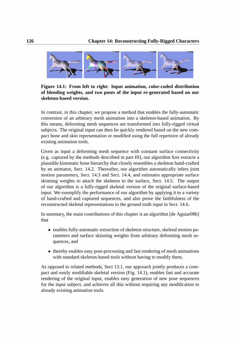
126 Chapter 14: Reconstructing Fully-Rigged Characters
Figure 14.1: From left to right: Input animation, color-coded distributionof blending weights, and two poses of the input re-generated based on ourskeleton-based version.
In contrast, in this chapter, we propose a method that enables the fully-automaticconversion of an arbitrary mesh animation into a skeleton-based animation. Bythis means, deforming mesh sequences are transformed into fully-rigged virtualsubjects. The original input can then be quickly rendered based on the new com-pact bone and skin representation or modified using the full repertoire of alreadyexisting animation tools.
Given as input a deforming mesh sequence with constant surface connectivity(e.g. captured by the methods described in part III), our algorithm first extracts aplausible kinematic bone hierarchy that closely resembles a skeleton hand-craftedby an animator, Sect. 14.2. Thereafter, our algorithm automatically infers jointmotion parameters, Sect. 14.3 and Sect. 14.4, and estimates appropriate surfaceskinning weights to attach the skeleton to the surface, Sect. 14.5. The outputof our algorithm is a fully-rigged skeletal version of the original surface-basedinput. We exemplify the performance of our algorithm by applying it to a varietyof hand-crafted and captured sequences, and also prove the faithfulness of thereconstructed skeletal representations to the ground truth input in Sect. 14.6.
In summary, the main contributions of this chapter is an algorithm [de Aguiar08b]that
• enables fully-automatic extraction of skeleton structure, skeletal motion pa-rameters and surface skinning weights from arbitrary deforming mesh se-quences, and
• thereby enables easy post-processing and fast rendering of mesh animationswith standard skeleton-based tools without having to modify them.
As opposed to related methods, Sect 13.1, our approach jointly produces a com-pact and easily modifiable skeletal version (Fig. 14.1), enables fast and accuraterendering of the original input, enables easy generation of new pose sequencesfor the input subject, and achieves all this without requiring any modification toalready existing animation tools.

14.1 Overview 127
SKELETONSKINNING
WEIGHTSSKELETON-BASED
ANIMATION
MESH
ANIMATION
SEGMENTATION
Figure 14.2: Overview of our algorithm: using an animated mesh as input,our approach segments the model into plausible approximately rigid surfacepatches (shown in different colors), estimates the kinematic skeleton (jointsshown in red) and its motion parameters, and calculates the skinning weightsconnecting the skeleton to the mesh. The output is a skeleton-based versionof the input mesh animation.
14.1 Overview
An overview of our approach is shown in Fig. 14.2. The input to our algorithm isan animated mesh sequence comprising of N frames. We represent an animatedmesh sequence by a mesh modelMtri = (Vtri, Ttri) and position datapt(vj) =(xj, yj, zj)t for each vertexvj ∈ Vtri at all time stepst.
In the first step of our algorithm, we employ spectral clustering to group seed ver-tices on the mesh into approximately rigid segments. By using the clustered seedvertices we are able to segment the moving mesh into kinematically meaningfulapproximately rigid patches, Sect. 14.2. Thereafter, adjacent body parts are deter-mined and the topology of the kinematic structure of the mesh is found, Sect. 14.3.Using the estimated topology, joint positions between interconnecting segmentsare calculated over time. In order to eliminate temporal bone length variations dueto per-time step fitting inaccuracies, joint positions are updated at all time stepsand an inverse kinematics approach is applied to determine the subject’s joint pa-rameters over time, Sect. 14.4. In a last step, we calculate appropriate skinningweights to attach the learned skeleton to the surface, Sect. 14.5. This way, weproduce a complete skeleton-based new version of the original input.
128 Chapter 14: Reconstructing Fully-Rigged Characters
14.2 Motion-driven Segmentation
The first step of our algorithm segments the animated input mesh (given byMtri
andPt) into spatially coherent patches that undergo approximately the same rigidtransformations over time. We initialize our approach by selecting a subset oflvertices that are distributed evenly over the mesh, Fig. 14.3(left). For the selectionof the seeds we only consider a reference posePtr (typically tr = 0), and employa curvature-based segmentation method [Yamauchi05] to decompose the modelinto l surface patches. The seed vertices are chosen as the vertices closest to thecenters of the patches. We typically choosel to be in the range of0.3 − 1.0% ofthe total vertex count of the model, which enables reasonably fast decompositionof even large meshes.
Similar to [Kirk05, de Aguiar06] in the context of optical motion capture, themotion trajectories of the seed vertices throughout the whole sequence form theinput to a spectral clustering approach [Ng02] which automatically groups thelseeds intok approximately rigidly moving groups. We capitalize on the invariantthat mutual distances between points on the same rigid part should only exhibit asmall variance while the mesh is moving. After clustering the vertices with similarmotion, we transform them into rigidly moving coherent triangle patches.
In order to use spectral clustering, we first construct a spatial affinity matrixA. Wedeveloped an affinity criterion specifically for our setting that defines the entriesof A as follows:
Ai,j = e−σi,j+
√ρi,j
S2 , (14.1)
whereρi,j = 1N2
∑
t δ(vi, vj, t) is the mutual Euclidean distanceδi,j,t betweenseed vertexvi and seed vertexvj over time andσi,j is its standard deviation.S = 1
N2
∑
i,j (σi,j +√
ρi,j) is a scaling term controlling the convergence behav-ior. We construct the entries ofA such that the affinity values of vertex pairswith large average mutual distance is reduced, which forces our spectral cluster-ing algorithm to put spatially far apart groups of vertices with similar motion intoseparate clusters.
Spectral clustering is our method of choice as it can robustly infer complex clus-ter topologies as they are typical for our motion segmentation problem. Insteadof grouping the vertices directly based on the individual valuesAi,j, spectral clus-tering proceeds by rearranging thel input samples ink well-separated clusters onthe surface of ak-dimensional hypersphere. It achieves this by building a diago-nal matrixD whose(i, i)-element is the sum ofA’s i-th row. Now the Laplacianmatrix L = D−1/2A D−1/2 is built, its k largest eigenvaluese1, . . . , ek are com-puted and stacked into columns to form the matrixX ∈ R
l×k. The rows ofX are

14.2 Motion-driven Segmentation 129
Figure 14.3: (left) Subset of vertices distributed evenly over the mesh and(right) resulting approximately rigid surface patches.
normalized and considered as points inRk. Then thel row vectors are split into
k clusters using standardk-means clustering. Every original sample vertexvi isassigned to a clusterj if and only if row i of X was assigned to clusterj. Weremind thatk-means clustering is effective here because in the transformed dataX clusters are well-separated.
Spectral clustering makes the clustering more robust against outliers and leads to amore robust and kinematically more meaningful segmentation than, for instance,standard k-means [Duda01]. As an additional benefit, the optimal number of clus-tersk can be automatically calculated based on the data set’s eigen-gap. In oursystem, we automatically cluster the seeds intok groups such that around99.0%of the total variation of the data is explained. However, for some applications, asthe system in Chapter 15, the automatic optimal segmentation is not always thebest one. In this case, spectral clustering also allows the specification of a num-ber of rigid surface patches to be used to segment the model. Fig. 14.4 showsthe segmentation of the camel’s mesh for two different values ofk. At a smallerk-value, the lower legs and the hoofs form one cluster since the relative motionbetween these two was less significant than the relative motion between other seg-ments. For a largerk-value, they have been split in two, which shows that withincreasing levelk of detail, our segmentation intuitively produces plausible andmore detailed segmentations.
Using thek optimal vertex clusters, we create triangle clustersT0 . . . Tk−1 = Ttri
by assigning each triangle∆ = (w0, w1, w2) ∈ Ttri to the closest seed vertexclass considering the average Euclidean distance from a seed vertexvu to w0, w1,andw2. The resulting clusters divide the mesh intok approximately rigid sur-face patches, Fig 14.3(right). Note that although a structurally motivated distancemeasure like the geodesic distance could also be used for clustering the trianglesand to determine affinities in Eq. 14.1, our experiments show that similar results

130 Chapter 14: Reconstructing Fully-Rigged Characters
Figure 14.4: While with k = 13 patches (left) merely the larger rigid segmentsare identified, but the feet are merged with the lower legs, atk = 31 the fullkinematic detail has been discovered (each color used several times, adjacentsegments colored differently).
can be achieved using simple Euclidean distance which reduces the algorithm’scomputation time considerably. As seen in Sect. 14.6, our segmentation approachis able to create triangle patches that divide the mesh into plausible approximatelyrigid body parts.
14.3 Automatic Skeleton Extraction
Given the list of body segments, their associated seed vertices and triangle patches,we extract the kinematic skeleton structure of the animated mesh by first findingits kinematic topology (i.e. find which body parts are adjacent) and, thereafter, byestimating the positions of the interconnecting joints for the whole sequence.
To determine which body segments are adjacent, we analyze the triangles at theboundaries of the triangle patches. Body partsA andB are adjacent if they havemutually adjacent triangles in their respective patch boundaries. Unfortunately,in practice a patch may be adjacent to more than one other patch. If more thantwo patches are directly connected (e.g. head, torso and arm), we need to decidewhich segments are truly kinematically connected and which are not. Here wetake a heuristic approach and consider only those patches to be adjacent that sharethe longest common boundary (in terms of the number of adjacent boundary trian-gles). For instance, if head, arm and torso are connected, we calculate the numberof neighboring triangles for all combinations of patch pairings (e.g. head-torso,head-arm and torso-arm) and do not assign the pair head-arm as an adjacent seg-ment since it has less neighbors in comparison with the other two options. Forany adjacent pair of patches, a joint has to be found later. Note that in our systemwe assume that the body part in the center of gravity of the mesh at the reference

14.3 Automatic Skeleton Extraction 131
time step is the root of the hierarchy.
In order to estimate the joint positions between two adjacent body segmentsA andB quickly, we only consider the information from the sets of seed verticesVA andVB located on these segments, and not the information from all vertices ofMtri.Instead of solving for the complete sequence of joint positions, we significantlyreduce the problem’s complexity by first aligning the segment poses to a referencetime steptr (usuallytr = 0), then solving for a single optimal joint position atctr
in the reference pose, and finally retransformingctr into the original poses ofAandB.
To serve this purpose, for each time stept, we first compute two rigid body trans-formsTAt→tr
andTBt→trthat align the positions of the seed vertices in both sets
with the positions of the seed verticesVA at the reference time step [Horn87].
For findingctr, we follow an idea proposed in [Kirk05] and assume that a goodestimate for the correct sequence of joint positions is the sequence of locationsthat minimizes the variance in joint-to-vertex distance for all seed vertices of theadjacent parts at all frames. Using this assumption, [de Aguiar06] solves for thejoint location at the reference timectr by using a distance penalty based on theaverage Euclidean distance to regularize the solution. Alternatively, we use theregularization term proposed by [Anguelov04], which makes the estimated jointposition come closer to the centroid positionbt of the boundary curve betweenthe two adjacent body parts at all time stepst. Therefore, we solve forctr byminimizing:
J(ctr) =1
2∗
∑
va∈VA
σa(ctr) +1
2∗
∑
vb∈VB
σb(ctr) + α ∗ d(ctr, btr), (14.2)
whereσa(ctr) and σb(ctr) corresponds to the Euclidean distance variance overtime between the joint positionctr and the vertexva and betweenctr andvb, re-spectively.d(ctr, btr) is the Euclidean distance betweenctr andbtr at the referencetime step. The coefficientα is used to regularize the solution, making the jointposition be located as closed as possible to the interior of the mesh. The resultsin Sect. 14.6 were generated using a value ofα = 0.05 (which we found to besatisfactory in our experiments).
After solving Eq. 14.2 and finding the optimal joint locationctr, the joint positionsat all other frames can be easily computed byct = T−1
At→tr∗ ctr. By applying the
above procedure to all adjacent body parts, we reconstruct all joint positions forthe whole sequence (see Fig. 14.5).

132 Chapter 14: Reconstructing Fully-Rigged Characters
14.4 Motion Parameters Estimation
A consistent parameterization of the skeletal motion in terms of rotational jointparameters is only feasible in case the skeleton structure preserves constant di-mensions over time. However, due to possible errors generated by aligning thebody parts in the reference frame (mostly caused by subtle (non-rigid) relativemotion between vertices on the same segment), the lengths of the bones in theskeleton may slightly vary over time. We enforce the bone lengths to be constantby stepping through the hierarchy of the estimated skeleton from the root down tothe leaves and correcting the joint positions for each pair of subsequent joints inthe kinematic chain separately such that the bone length constraint is satisfied.
Let cit be the position of a jointi andci−1
t the position of its parent joint at timet.We are able to calculate the optimal value for the length of the bone connectingjoint i − 1 andi, li−1,i, over time and the new positions for the jointsi, nci
t, byminimizing the following energy:
S(nci,li−1,i) =N
∑
t=0
‖cit − nci
t‖2 + (‖ncit − ci−1
t ‖ − li−1,i)2 . (14.3)
The first term in Eq. 14.3 keeps the new joint positionncit as close as possible to
the old position, while the second term constrains the bone length to be the samein all frames.
After solving this equation for each pair of subsequent joints in the hierarchy, weobtain a consistent kinematic structure of the meshMtri. To infer joint motionparameters, i.e. a rotational transformationRi
t for all joints i at all timest, we firstspecify the skeletal pose at the first time step as reference pose (this is the bestwe can do given no explicit reference). Thereafter, we apply a Cyclic-Coordinate-Descent (CCD) like algorithm [Luenberger73, Badler87] to infer allRi
t relativeto the reference using Euler angle parameterization. To this end, we optimizeone joint variable at a time by calculating the positional error with respect to theestimated joint positions found for that time step. Since we have all in-betweenjoint positions of each kinematic sub-chain, our method converges quickly andreliably. Finally, the translation of the root is stored as additional parameter foreach frame.

14.5 Skinning Weight Computation 133
Figure 14.5: (top) Visual comparison between the reconstructed joint posi-tions and the true positions (shown as white spheres) at four different frames.(bottom) Plot of the low difference in z-coordinate between the reconstructedleft elbow joint position and the ground truth position over time (biped walk-ing sequence).
14.5 Skinning Weight Computation
Skinning is the process of attaching the skeleton to the surface in such a waythat changes in skeletal pose lead to plausible surface deformations. Althoughmore advanced deformation schemes exist (see Sect. 13.1), we decided to use thestandard linear blend skinning method [Lewis00], also called skeletal subspacedeformation method - SSD, since it is widely supported in games and animationpackages.
Let p0(vi) be the position of the vertexvi of Mtri in the reference pose (or restpose), letRb
t be the transformation of the boneb from the reference to timet, and letwb(vi) be the weight of the boneb for the vertexvi. Note that thebone transformationRb
t equals the transformationRjt of the preceding jointj
from the hierarchy. SSD expresses the new position of vertexvi at time t as
134 Chapter 14: Reconstructing Fully-Rigged Characters
pt(vi) =∑
b wbiR
btp0(vi). Therefore, in order to use the SSD method to re-animate
the sequences using a more compact representation, we need to determine thebone weightswb
i for each vertexvi, i.e. we need to know how much each boneinfluences each vertex.
We employ the method proposed in [Baran07] to determine the skinning weightdistribution for each bone. This method computes the distribution based on theresults of a heat diffusion process rather than based on simple vertex proximityto the bone, which makes the estimation process more robust. In contrast to theirwork, however, we consider the entire sequence of mesh and skeleton poses fromthe input when finding optimal weights. In particular, we first solve for the weightdistributionswb
f of each framef separately, and thereafter average them to obtainthe final distributionswb.
When computing the weight distributionwbf we regard the volume of the model
Mtri as an insulated heat-conducting body and force the temperature of the boneb to be1 and the temperature of all others to be0. The weightwb
f (vi) equalsthe equilibrium temperature atvi. For computational simplicity, the equilibrium
equation is only solved on the mesh’s surface yielding∂wb
f
∂t= ∆wb
f + Hf (pbf −
wbf ) = 0. In our discrete case this can be reformulated as
(−∆f + Hf )wbf = Hfp
bf . (14.4)
In this equation,∆f is the discrete Laplacian operator at framef (see Sect 3),pbf
is a vector wherepbf (vi) equals 1 in caseb is the nearest bone to vertexvi and0
otherwise.Hf is a diagonal matrix with entriesHii = 1/dist(vi)2 representing
the heat contribution weight of the nearest bone to vertexvi at framef . Here,dist(vi) is the Euclidean distance between vertexvi and the nearest bone in case itis contained in the model’s volume and0 otherwise. The final weight distributionswb for each bone is the average of the weightswb
f for all frames.
The heat diffusion solution provides smooth and realistic blending weight dis-tributions since it respects geodesic surface proximity during weight assignmentrather than error-prone Euclidean proximity [Baran07]. Furthermore, our experi-ments show that by computing the optimal weights from all available poses, ourresulting skeletal animation reproduces the entire original mesh animation morefaithfully, Sect. 14.6.

14.6 Results and Discussion 135
14.6 Results and Discussion
To demonstrate and validate our algorithm, we applied it to a set of mesh ani-mations generated in a variety of different ways, see Tab. 14.1 for a list. Somesynthetic sequences, such as the horse sequence (Fig. 14.1), were generatedwith a mesh deformation method [Sumner04]. Other synthetic sequences likethe bird and the walking biped were originally created with a skeleton-basedmethod which conveniently gives us ground truth data. We also have capturedperformances of humans at our disposition. The dancing and capoeira sequences,Fig. 14.7 and Fig. 14.9, were reconstructed by the performance capture approachdescribed in Chapter 11. The cartwheel and posing sequences (Fig. 14.9) wereobtained by using raw motion capture marker trajectories as constraints in ourmesh-based animation framework described in Chapter 7.
Fig. 14.9 shows one original input mesh, the color-coded skinning weight distri-butions, and some poses of the original animation re-rendered using our skeleton-based reparametrization. A visual comparison between our result and the input,Fig. 14.7, shows that our result is visually almost indistinguishable from the orig-inal mesh animation and exhibits very natural surface deformations. Further-more, visual inspection already suggests that the estimated kinematic structuresare nicely embedded into the subjects at all frames and possess biologically plau-sible dimensions and hierarchies. Here, we would like to note again that all theseresults were obtained fully-automatically. Our new representation is very com-pact. For the horse animation, for instance, we only need to store geometry andskinning weights once, and for each time step only store 60 motion parameters(3-DOF per joint) rather than approximately25000 coordinate values.
Figure 14.6: Visual comparison between pre-defined skeletonembedded tothe mesh (left sub-images) and the skeleton extracted by our approach (rightsub-images). Despite slight differences in the torso area, our estimated skele-ton closely resembles the fitted template.

136 Chapter 14: Reconstructing Fully-Rigged Characters
Figure 14.7: (top) Two pairs of images comparing the input (left sub-images)to our skeleton-based result (right sub-images). In either case the renderingsare visually almost indistinguishable. (bottom) Plot showing the low averageEuclidean distance error between input and reconstructed vertex positionsfor the human-sized model.
To get a quantitative impression of the faithfulness and quality of our results, weanalyze individual aspects of our method more closely.
Skeleton Reconstruction Since for most synthetic data we know the truesequence of joint positions, we are able to provide a quantitative estimate of theaccuracy of our skeleton extraction and motion capture approach. Fig. 14.5(top)shows a visual comparison between the joint positions estimated by our approachand the true joint positions, shown as white spheres, for the walking biped se-quence. Fig. 14.5(bottom) illustrates the accuracy of the reconstructed motionparameters over time. The plot shows a comparison between the z-coordinate ofthe true and estimated positions of the left elbow joint for the same walking se-quence. The difference between true and estimated joint positions is very smalland consistent over time, which illustrates the robustness of our method. Similarlow errors could be observed in all our sequences with available ground truth. Thecolumn JACC in Tab. 14.1 shows the average Euclidean distance error between es-timated joint position and true joint position for all joints over time. Due to thelack of absolute coordinates, the error is given in percent of the longest bounding

14.6 Results and Discussion 137
Figure 14.8: New poses for the input mesh can be easily generated by simplychanging the joint parameters of the extracted skeleton.
box dimension of the model. In all our examples, major misalignments betweenthe original and the reconstructed skeleton could only be found if the part of theinput corresponding to that joint was not prominently articulated.
Our automatically computed bone hierarchies closely match the skeletons thatwould typically be created by animators. This is demonstrated in Fig. 14.6, wherewe show a side-by-side comparison between our result and the skeleton fitted bythe method of Baran et al. [Baran07]. Although the topology of the root/spinearea slightly differs, our calculated skeleton closely resembles the a priori fittedtemplate.
Accuracy of reparameterized animation Fig. 14.7(top) shows a compar-ison between two frames of the input dancing sequence (left sub-images) andthe generated skeleton-based animation (right sub-images). Visually, almost nodifference can be seen. Fig. 14.7(bottom) plots the consistently low average dif-ference between the vertex positions of the input and the reparameterized outputover time for the dancing sequence. For the human-sized figure, the error is mostlybelow one centimeter which shows the high reconstruction quality also quantita-tively. Column ACCU of Tab. 14.1 shows that similarly low errors are observedin the other test sequences.
Pose and animation editing Using our system, we are able not only to recre-ate the original input based on a more compact representation, but can straight-forwardly produce novel postures of the input mesh, Fig. 14.8. To this end, weonly need to modify the joint parameters which can easily be done in any standardanimation package. Since we have a complete set of motion parameters for theinput, we can also easily modify aspects of the original animation by altering thejoint parameter curves of selected joints.

138 Chapter 14: Reconstructing Fully-Rigged Characters
SEQUENCE FR ∆ SEGM SKEL SKIN JACC ACCUHorse 47 17K 4s 17s 7s/frame N/A 0.56%Bird 60 55K 5s 49s 10s/frame 2.9% 0.42%
Biped 80 32K 5s 36s 14s/frame 1.7% 0.52%Cartwheel 120 7K 4s 63s 3s/frame N/A 0.81%
Posing 280 7K 9s 261s 4s/frame N/A 0.43%Capoeira 150 106K 44s 244s 28s/frame N/A 0.47%Dancing 220 106K 37s 312s 28s/frame N/A 0.37%
Table 14.1: Given an animated mesh sequence withT triangles (∆) andN frames (FR), the processing times for segmenting the mesh into trianglepatches (SEGM), to extract its kinematic structure and reconstruct its mo-tion parameters (SKEL), and to calculate the skinning weights based on theinput data (SKIN) are shown. Also, the low average difference between es-timated joint positions and true joint locations (JACC) - in percent of themaximal side length of the overall bounding box - and the average differencebetween original and reconstructed vertex positions (ACCU) are indicated.
Computation time Tab. 14.1 lists the run times of each processing step in ouralgorithm. The second and third columns show the number of frames in each se-quence (FR) and the number of triangles in each model (∆). The column SEGMlists the time needed for clustering and mesh segmentation. Column SKEL liststhe time needed to build the skeleton and estimate all motion parameters, and col-umn SKIN lists the time needed to find the blending weights. With the exceptionof SKIN which shows per-frame times, all times given are for processing entiresequences. All run times were measured on an unoptimized single-threaded coderunning at a Laptop featuring an Intel Core Duo CPU with 1.7 GHz.
Discussion Our approach is subject to a few limitations. During skeleton ex-traction, it is impossible to locate a joint if there is no relative motion between ad-jacent body parts. Therefore, in some of our sequences hands and feet are misseddue to insignificant relative motion. However, we consider this to be a principalproblem of any data-driven skeleton extraction method, and user interaction isfeasible in this case.
Most remaining reconstruction inaccuracies are due to non-rigid deformationcomponents in the input that are not well explainable by a rigid skeleton and linearskinning weights. However, alternative skinning methods can be applied to evenfurther reduce the residual errors, e.g. [Merry06, Kavan07, Angelidis07, Wang07].Furthermore, skeletal reparametrization works very well for subjects whose mo-

14.6 Results and Discussion 139
tion is largely due to a skeleton such as humans and most animals. In largelynon-rigidly moving animations, such as a deforming piece of cloth, our algo-rithm would still determine a skeleton, but it is not physically plausible. There-fore, mesh-based editing approaches might be preferred in this case [Kircher06,Xu07a].
Despite these limitations, in this chapter we have presented a fully-automaticmethod to extract a kinematic skeleton, joint motion parameters, and surface skin-ning weights from arbitrary mesh animations. The result is a compact represen-tation of the original input that can be easily rendered and modified in standardskeleton-based animation tools without having to modify them. This way, we areable to preserve the great modeling flexibility of purely mesh-based approacheswhile making the resulting skeleton-less animations straightforwardly available tothe animator’s repertoire of processing tools.
Our results show that the efficient combination of skeleton learning andtemporally-coherent blending weight computation enables us to effectively bridgethe gap between the mesh-based and the skeleton-based animation paradigms.

140 Chapter 14: Reconstructing Fully-Rigged Characters
Figure 14.9: Results obtained with different captured performances (left toright in each row): One frame of the input sequence, color-coded blendingweight distribution, and two poses of the input recreated with our skeleton-based representation. Our method efficiently and fully-automatically con-verts mesh animations, created by animators or captured from moving sub-jects, into skeleton-based animations.

Chapter 15
Designing Non-PhotorealisticAnimation Collages
In this chapter, we present a method to automatically transform meshanimations into animation collages, i.e. a new non-photorealisticrendering style for animations. By automatically decomposinginput animations and fitting a shape from the database into eachsegment, our algorithm creates a new rendering style. It has manyapplications in arts, non-photorealistic rendering, and animatedmovie productions.
An animation collage is a complete reassembly of the original animation in anew abstract visual style that imitates the spatio-temporal shape and deforma-tion of the input. Many researchers in computer graphics have been inspiredby the idea to develop algorithms that enable the computer and even unexperi-enced users to reproduce the look of certain styles of visual arts, such as collages.Kim et al. [Kim02] develop a system that can automatically turn arbitrary pho-tographs into collage mosaics that comprise of an arrangement of elementary im-age tiles. Rother et al. [Rother06] automatically arrange and blend photographsfrom a database into a perceptually pleasing way. Gal et al. [Gal07] show resultsof a method to approximate static 3D shapes with other meshes, but they do nothandle the general case of mesh animations.
In contrast, this chapter presents a method allowing a computer artist to auto-matically convert his/her favorite mesh animation into a moving assembly of 3Dshape primitives in a database. This so-called animation collage is glued together

142 Chapter 15: Designing Non-Photorealistic Animation Collages
in such a way that it approximates the sequence of shapes from the original meshanimation, while deforming in the same spatio-temporally consistent way as theoriginal. While our method can fully-automatically build moving collages, it alsopurposefully gives the artist the possibility to post-process and fine-tune the resultsaccording to his/her imagination.
An overview of our system is presented in Sect. 15.1. It first automatically de-composes the input mesh animation into moving approximately rigid volume seg-ments, henceforth calledanimation cells, Sect. 15.2 and Sect. 15.3. This decom-position is learned from the moving input meshes by means of a spectral clus-tering approach, Sect 14.2. Thereafter, it employs a spatio-temporal matchingcriterion that analyzes the motion and deformation of each animation cell andfinds a shape primitive in the database that best approximates its time-varyinggeometry, Sect. 15.4. Shape primitives and cells are spatio-temporally aligned,and the fitted shapes are moved and deformed according to the deformation of thecells, Sect 15.5. Since it is also our goal to develop new algorithmic recipes fora novel artistic tool, an animator can influence the final result at all stages of theprocessing pipeline, Sect 15.6.
The main contribution of this chapter is a system [Theobalt07b] to
• automatically transform mesh animations, which are created directly by an-imators or captured using our previous performance capture methods, intoanimation collages.
Our software prototype is easy to use and allows even untrained users to createvery aesthetic collages. Therefore, our system is an interesting add-on to thegraphics artist’s toolbox, with many applications in visual arts, non-photorealisticrendering, and productions of games and cartoons.
15.1 Overview
As in Chapter 14, the input to our algorithm is an animated mesh sequence com-prising ofN frames, represented by a mesh modelMtri = (Vtri, Ttri) and positiondatapt(vj) = (xj, yj, zj)t for each vertexvj ∈ Vtri at all time stepst. The coordi-nate setsPt = {pt(vj)} together withMtri describe a time-varying surface. Thesecond input element is a database ofK static shapes, each being represented asa textured triangle mesh.
The first step in our pipeline is the motion-decomposition of the mesh. To thisend, we employ the method described in Sect. 14.2 that analyzes the motion
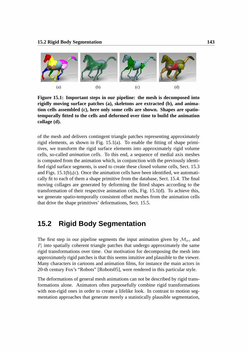
15.2 Rigid Body Segmentation 143
(a) (b) (c) (d)
Figure 15.1: Important steps in our pipeline: the mesh is decomposed intorigidly moving surface patches (a), skeletons are extracted (b), and anima-tion cells assembled (c), here only some cells are shown. Shapes are spatio-temporally fitted to the cells and deformed over time to build the animationcollage (d).
of the mesh and delivers contingent triangle patches representing approximatelyrigid elements, as shown in Fig. 15.1(a). To enable the fitting of shape primi-tives, we transform the rigid surface elements into approximately rigid volumecells, so-calledanimation cells. To this end, a sequence of medial axis meshesis computed from the animation which, in conjunction with the previously identi-fied rigid surface segments, is used to create these closed volume cells, Sect. 15.3and Figs. 15.1(b),(c). Once the animation cells have been identified, we automati-cally fit to each of them a shape primitive from the database, Sect. 15.4. The finalmoving collages are generated by deforming the fitted shapes according to thetransformation of their respective animation cells, Fig. 15.1(d). To achieve this,we generate spatio-temporally consistent offset meshes from the animation cellsthat drive the shape primitives’ deformations, Sect. 15.5.
15.2 Rigid Body Segmentation
The first step in our pipeline segments the input animation given byMtri andPt into spatially coherent triangle patches that undergo approximately the samerigid transformations over time. Our motivation for decomposing the mesh intoapproximately rigid patches is that this seems intuitive and plausible to the viewer.Many characters in cartoons and animation films, for instance the main actors in20-th century Fox’s “Robots” [Robots05], were rendered in this particular style.
The deformations of general mesh animations can not be described by rigid trans-formations alone. Animators often purposefully combine rigid transformationswith non-rigid ones in order to create a lifelike look. In contrast to motion seg-mentation approaches that generate merely a statistically plausible segmentation,

144 Chapter 15: Designing Non-Photorealistic Animation Collages
we intend to isolate the underlying rigid deformations from the non-rigid ones ina kinematically plausible way. By this, we mean that in case there exists a truekinematic segment hierarchy, our method approximates it as good as possible. Forus, it is also important that regions on the surface are spatially connected. Onlyif this is assured, a faithful decomposition into volume cells becomes feasible,Sect. 15.3.
We apply the motion-driven segmentation method described in Sect. 14.2 to dividethe input animation into rigidly moving coherent triangle patches as shown inFig. 14.4. The approach is initialized by first selectingl sample vertices distributedevenly on the model. The motion trajectories of these vertices throughout thewhole animation form the input to our spectral clustering approach which groupsthem intok approximately rigidly moving groups. From this, we associate triangleclustersT0 . . . Tk−1 = Ttri by assigning each triangle∆ = (w0, w1, w2) ∈ Ttri tothe marker vertexvj whose average distance tow0, w1, andw2 is minimal. Theresulting clusters divide the mesh ink segments.
As mentioned in Sect. 14.2, our method is able to automatic infer the optimalnumber of clusters from the dataset’s eigen-gap. However, the optimal number ofsegments is not always the one favored by an artist. Therefore, we also allow theuser to specify the number of rigid surface patchesk and perform the segmentationaccordingly. Fig. 14.4 shows two segmentations for the camel’s model. Using asmallerk-value, the lower legs and the hoofs form one cluster. For a largerk-value, they are split in two, showing that with increasing levelk of detail, ourmethod produces plausible and more detailed segmentations.
15.3 Building Animation Cells
Approximately rigid surface patches are not the appropriate shape representationfor building animation collages. Although each patch is the outer boundary of avolumetric subsegment that moves approximately rigidly, it does not describe thespatial extent of this subsegment in the interior of the original mesh. To approxi-mate these volumetric subsegments, we extend each surface patch into a so-calledanimation cell, i.e. a closed watertight triangle mesh that bounds an approximatelyrigidly moving slice of the original mesh’s volume, Fig. 15.1(c). This volumetricdecomposition of input animations has a couple of advantages. First, volumetricanimation cells define 3D placeholders to which approximating shapes are to befitted in order to generate visually pleasing collages with decent shape and defor-mation approximation. Thus, volumetric decomposition is a clever way to breakdown the fitting problem for the whole mesh into a set of fitting problems for

15.3 Building Animation Cells 145
Figure 15.2: An animation cell for the center segment of the horse (left), thestrawberry fitted to it (middle), and the offset cell for the center segment(right), all shown for the same time step.
individual cells. Furthermore, by deforming approximating shapes like their en-compassing rigid cells, the deformation of the shapes remains in visually pleasingbounds.
The input for building animation cells is the set of rigid surface patchesT0, . . . , Tk−1 that was computed in the previous section. It is our goal to extendeach surface patch into a closed and watertight animation cell mesh. Looking onlyat the graph structure of each patch, this is easily achieved by inserting a new ver-tex for every boundary loop, triangulating the arising fan, and thereby removingthe boundary loop. Although the principal idea is fairly easy, a proper way toinsert the additional vertex for the boundary loop is crucial.
We firstly compute a sequence of medial axis meshesS0, . . . , SN−1 from the in-put animation, Fig. 15.1(b). The number of vertices and the connectivity of eachSi matches the properties of the respectiveMi
tri that it was computed from: forcomputing the skeletal meshSi, we employ the Voronoi-based two-sided approx-imation of the medial axis that has originally been proposed in [Hisada02]. Everyvertex ofMi
tri is associated with a Voronoi cell. One-to-one correspondencesbetween the vertices ofMi
tri and the vertices ofSi are established by using theVoronoi poles as skeletal mesh vertices [Amenta98]. The connectivity ofSi iscopied fromMi
tri. In order to remove undesired spikes in the skeletal mesh, weemploy tangential Laplacian smoothing.
As the skeletons share the graph structure of the animation meshes, they can bepartitioned into the same patches. In the following, we describe how to buildanimation cells for all patches at a single time stept. By applying the same pro-cedure to all time steps, we generate the appropriately deformed versions of eachcell. Consider a patchTk and its associated vertex positions taken fromPt. For all

146 Chapter 15: Designing Non-Photorealistic Animation Collages
boundary loops ofTk at a time stept, we compute the center of gravity of asso-ciated vertex positions in the skeletonSt. The new vertex for fan-triangulation ofthe boundary loop is positioned at this center. Fig. 15.2 (left) illustrates this usinga center segment of the horse animation as an example.
Note that a simple strategy like choosing the center of gravity of the boundaryloop’s vertices for fan-triangulation would not have fulfilled our requirements.Our experiments showed that, in this case, very flat animation cells may occur forextreme geometric configurations which would lead to inappropriate volumes forthe subsequent steps of our method. Depending on the geometric setting, similarproblems may occur if one tries to directly triangulate a hole without inserting avertex. Although our cell decomposition does not strictly partition the volume, itgenerates volume slices that are tailored to our purpose.
15.4 Assembling the Collage
As already outlined in the previous section, the sequence of moving animationcells can be regarded as a sequence of volumetric placeholders to which approx-imating shapes from the database are fitted. While, by this means, it may not bepossible to exactly reproduce the true shape of each cell, in particular its outer sur-face, the overall appearance of the mesh animation is still faithfully approximated.The decomposition of the animation into cells also bears many further algorithmicadvantages since the overall fitting problem simplifies to a fitting problem betweenindividual shapes and segments. Furthermore, it becomes easier to assure that theshapes to fit not only match the outlines of their respective animation cells at asingle time step. Since the animation cells undergo mainly rigid deformations, theslight non-rigid deformations of the approximate shapes that may be necessaryto assure good approximation over the whole sequence can be kept in reasonablebounds, Sect. 15.5.
To put this into practice, a shape similarity measure is needed (Sect. 15.4.1) that isapplied in our spatio-temporal matching and alignment approach to fit a databaseshape to a deforming animation cell, as described in Sect. 15.4.2.
15.4.1 Shape Similarity Measure
Due to the diversity of database shapes, and potential differences in orientationand uniform scaling, we require a similarity measure that is rotation-, pose- andscale-independent. Spherical harmonic descriptors fulfill all these requirements

15.4 Assembling the Collage 147
and have proven to be superior to many other global descriptors [Kazhdan03].Given a meshK, we compute its spherical harmonic descriptor as follows: first,the spatial occupancy functionO(x, y, z) is sampled on a regular grid withinthe mesh’s bounding box by rasterizing the mesh into a voxel volume of di-mensionℓ1 × ℓ2 × ℓ3 [Nooruddin03, Min03]. The voxel volume is intersectedwith q equidistant spheresW0, . . . ,Wq−1 that are concentrically arranged aroundthe center of gravity of the voxel set. The discretized occupancy function isresampled on the surface of each spherical shell, yieldingq spherical functionso0(θ, φ), . . . , oq−1(θ, φ). Each of theseq spherical functions is decomposed intoits harmonic frequency components as
fℓ(θ, φ) =m=ℓ∑
m=−ℓ
aℓmY mℓ (θ, φ),
whereℓ is the frequency band,aℓm is them-th coefficient on a bandℓ, andY mℓ
is them-th spherical harmonic basis function for a bandℓ [Green03]. For eachspherical function, the norms of its frequency components are computed as
SH(oh) = {‖f0(θ, φ)‖, ‖f1(θ, φ)‖, . . . , ‖fℓ−1(θ, φ)‖} .
The complete shape descriptorD(K) is the two-dimensionalq × h-array that isindexed by the sphere radius and the frequency band. For our purpose, we foundthat descriptors withh = 20 andℓ = 10 are sufficient.
The differenced(D1, D2) between two descriptorsD1 andD2 is obtained by in-terpreting each of them as(q · h)-dimensional vectors and computing the anglethat they span.
15.4.2 Spatio-temporal Shape Fitting
Using the above shape descriptor and the associated distance measure, we find ashape from the database that best matches the time-varying shape of each anima-tion cell throughout the whole sequence. To keep processing times and memoryconsumption in reasonable bounds while sampling the range of deformations suf-ficiently densely, we propose the following approach to fit a shape to one anima-tion cellZj: at first, a set of representative time steps0 ≤ t1, . . . , tr < N is chosenin which the whole mesh undergoes a characteristic range of deformations. Let thevertex positions ofZj at ther time steps bePt1(Zj), . . . , Ptr(Zj). For each of thercell poses, a descriptor is computed, yielding a setU = {Dt1(Zj), . . . , Dtr(Zj)}.For each of the shapes in the database and their associated descriptorsDi, a globaldistance to all descriptors inU is computed as

148 Chapter 15: Designing Non-Photorealistic Animation Collages
Figure 15.3: Effect of spatio-temporal fitting for the tail of the camel (left).One frame of the result animation is shown with a single (center) or threerepresentative time steps (right) used during spatio-temporal fitting.
dglob(Di, U) =∑
t∈t1,...,tr
d(Di, Dt(Zj)) for 0 ≤ i < K .
The above distance assesses the spatio-temporal goodness of fit between adatabase shape and a cell over time. Accordingly, the indexc of the databaseshape that matches the shape ofZj at all representative time steps best is found as
c = argmini
dglob(Di, U).
Database shapec is fitted to the single posePtm(Zj) of Zj out of all the represen-tative poses which best matches the shape ofc, thus
tm = argmint∈{t1,...,tr}
dglob(Dc, Pt(Zj)).
By this way, we guarantee that the shape is fitted to the optimally matching con-figuration of the cell, and thus the required transformation ofc during the fittingitself is minimal. The effect of spatio-temporal fitting is compared to single timestep fitting in Fig. 15.3.
The fitting itself first coarsely registers shapec andZj in posePtm(Zj) by align-ing their centers of gravities and principal components in orientation and scaling.Thereafter, the initial fitting is refined by running an ICP-like alignment [Besl92].
Although shape matching and fitting are fully automatic processes, user interac-tion is possible to meet artistic preferences. On the one hand, a user can restrictmatching to a subset of the database or even manually choose a collage shapewhich will be fitted into the cell. Additionally, a user can also manually adjust thefitted shape’s position, scale and orientation.
Finally, we note that, while there are many applications forpartial shape match-ing, the use of aglobal approach is essential to our method, as our goal is to

15.5 Animating the 3D collage 149
faithfully fill in the whole cell. This way, self-intersections and artifacts duringthe animation are minimized since the cells have a near-rigid structure. Further-more, bigger holes in the collage are prevented. Consequently, we decided to fitonly one shape per cell to provide the most plausible results for the animation.
15.5 Animating the 3D collage
In the final stage of our method, we compute the animation collage from the set ofanimation cells and associated collage shapes. Note that each of the collage shapeshas potentially been fitted to a different reference time steptm by the proceduredescribed in the previous section.
Our approach proceeds again cell-wise; per-frame transformation of the ani-mation cells is propagated to the fitted shapes. We consider this transforma-tion as a general deformation of the cell, which is expected to be nearly rigid.Among the many surface deformation methods which are available in the lit-erature, we chose free-form deformation based on 3D mean-value coordinates[Floater03, Floater05, Ju05], because it can directly process our input data, pro-duces good results, and is robust and simple in implementation. Using the stan-dard approach, the triangulation of the animation cell would serve directly as con-trol mesh for the deformation. The collage shape is rigidly fitted into the geometryof the animation cellPtm(Z) at a reference time steptm, and then mean value co-ordinates are used to reconstruct shapes which deform like the geometry of cellPt(Z) at any other time step0 ≤ t < N . However, there are two requirementswhich render this immediate deformation impractical for our special animationcollage setting: first, we want to provide the user some additional global con-trol over the deformation, and second, we have to ensure numerical robustness.Both requirements are related, and we apply a two-step deformation approachwith spatio-temporal offsets.
The key idea of our deformation is to use certain morphological offsets of theanimation cells as control meshes, i.e. the cells’ geometry is extruded in the di-rection of the surface normal (but avoiding self-intersections). By this way, we cancontrol the stiffness of the deformation by taking advantage of the well-known be-havior of the pseudo-harmonic fields induced by mean value coordinates for thenew, enlarged boundary polyhedra, as shown in Fig. 15.4. One such offset cell forthe torso segment of a horse is shown in Fig. 15.2(right)
At the same time, we avoid numerical instabilities resulting from evaluating thefield in the vicinity of the control mesh, a situation which cannot be generally

150 Chapter 15: Designing Non-Photorealistic Animation Collages
Figure 15.4: With larger offset segments, the fruits in the horse’s leg deformmore stiffly (right) than with tighter offsets (left).
avoided when using the animation cells’ geometry directly. Our offsets can beeasily constructed in a volumetric representation using level-sets. As accuracy isnot crucial here, we use an even simpler approach and compute a discrete voxelmodel for each animation cell mesh following [Min03], which is then dilated andconverted back into a triangle mesh using marching cubes. Here the voxel resolu-tion and dilation radius define the offset radius. Then, we compute an offset cellfor each animation cell with respect to the reference time step. The computationis efficient and guarantees watertightness and no self-intersections. However, welose control over the combinatorial structure of the offset mesh, i.e. it does notshare the animation cell’s connectivity, and an alternative mapping to the anima-tion cell need to be provided by the second deformation step.
The final animation of a single collage shape proceeds as follows. First, the time-dependent geometry of the animation cell is used as control mesh to compute adeformed offset cell. Second, the offset cell is used as control mesh and its defor-mation is propagated to the collage shape. Note that, by volumetric construction,the genus of the offset cell might differ from that of the respective animationcell. However, using the free-form deformation approach influencing the wholevolume of the animation cell, this does not imply any problem. The offset radiusprovides an additional parameter to control the effect of the deformation: the moredistant the offset, the stiffer the deformation. Fig. 15.4 shows that the shapes inthe horse’s leg bend more crisply, if the offset segments are tighter. While thisparameter has no physically plausible meaning, we find it intuitive to use.
15.6 Results and Discussion
We have generated a variety of animation collages from mesh sequences of a gal-loping and a collapsing horse, a galloping camel, as well as two scanned humans

15.6 Results and Discussion 151
Figure 15.5: Our method automatically generates moving 3D collages out ofmesh animations by rebuilding them as moving assemblies of shape primi-tives. In the example above, the galloping horse (top row) has been trans-formed into two galloping sets of fruits.
performing a motion captured jump and a cartwheel. For none of the sequences,ground truth kinematics, e.g. in the form of animation skeletons, are available.Our shape database comprises of20 collage shapes, ranging from fruits, overindustrial shapes like screws, to barrels and bottles, Fig. 15.6. A variety of anima-tion collages with different appealing visual styles were created, Fig. 15.8. Thecollages do not only have very aesthetic looks at a single time step, but nicelyapproximate the spatio-temporal appearance of the input animation, see Fig. 15.5and, in particular, the resulting video.
The top row in Fig. 15.8 shows freeze-frames from the front and the back of ananimation collage showing a jumping human. For the original sequence, mo-tion capture data was used to animate a laser-scan using the method describedin Chapter 7. With both fruits, as well as barrels, bottles, and screws, the25computed animation cells are both faithfully and sometimes funnily approxi-mated. We particularly like the head being automatically approximated by astrawberry or a pear. Please refer to the accompanying video (http://www.mpi-inf.mpg.de/∼edeaguia/thesis/animcollage.avi) to also see that, due to our offset-based deformation, the moving collages maintain the subtle motion details of theinput which lends them a very human-like motion style.
The galloping horse is shown for fine and coarse segmentations with35 and17animation cells in the upper middle row in Fig. 15.8. In comparison, one seesclearly the non-rigid transformation for the coarse segmentations, for instance,in the lower legs where the hoofs are not covered by additional cells. However,

152 Chapter 15: Designing Non-Photorealistic Animation Collages
Figure 15.6: Shape database used in our system comprising of 20 shapes,ranging from fruits, over industrial shapes like screws, to barrels and bottles.
even these deformations appear rather natural due to stiffness provided by theoffset cells. Of course the individual impression depends on the viewers particularexpectations and preferences, and spending more animation cells usually leadsto better approximations of rigid parts. Moreover, our choice of using a singlecollage shape per cell is justified by the fact that the animation looks plausible,and there are few holes and self-intersections.
The galloping camel is shown for fine (lower middle row) and coarse segmenta-tions (bottom row) with31 and13 animation cells in Fig. 15.8, respectively. Wewould like to point out the nice approximation of the hunch, e.g. by pears (coarse)and by bananas (fine). Specially, the arrangement of bananas is non-trivial, andthe impression of a sophisticated design is given. Such arrangements are enabledby the partition in animation cells, and the example thus nicely confirms our algo-rithmic approach to break the fitting problem into cell-wise problems.
The majority of the results in Fig. 15.8 was generated fully-automatically. Only insome cases, marked with a black dot in the upper right, we changed the positionor the kind of at most two shapes to match personal preferences, Fig. 15.7.
Table 15.1 summarizes information on input animation complexity and run timesmeasured on a Pentium IV 3.0 GHz. Our approach is very efficient: run times aredominated by rigid body segmentation (Seg) and cell generation (Cell), both ofwhich need to be run just once per input sequence. Shape fitting and alignment

15.6 Results and Discussion 153
Figure 15.7: Although the automatic result generated with our frameworklooks nice (left), the user is able to perform small changes at the tail and theleg of the animation collage to match personal preferences (right).
(Fit), as well as the animation of the collage (Anim), are performed once for eachcollage style created from an input sequence. Even for sequences with more than200 frames, both steps can be finished in less than four minutes. Run times couldbe further sped up by working with decimated input or cell meshes, however, wealways worked on the originals.
Our approach is subject to a couple of limitations. As mentioned in Sect. 14.6,while our clustering algorithm provides excellent results for the shown input ani-mations, its output generally depends on these inputs: a meaningful segmentationcan only be expected if there is actual relative motion of all limbs in an anima-tion. We conclude that this approach works best for animations with kinematicstructure. Inherently, fitting is limited by the shapes available in the database. Ifno proper shape is available, unnatural deformations may be necessary. As thedatabase also defines the visual style, we leave this as an artistic problem that hasto be considered by the user. From a more technical point of view, our approachrequires that segments span a volume. The approach is thus not able to fit collageshapes to nearly planar segments. Note that the spatio-temporal segmentation,which provides the segments, is not at all affected.
Furthermore, for fitting, we assume that the animation cells are in motion andhence being transformed. This is different from considering a static fitting prob-lem, where alternative approaches such as Gal et al. [Gal07] may show betterresults, and where it may be advantageous to allow for more shapes per cell.
Despite these limitations, we present a novel approach to fully-automatically gen-erate animation collages from input mesh animations, providing a compendium ofspatio-temporal matching and segmentation techniques. Our software prototypeis an interesting add-on to the graphics artist’s toolbox and also allows untrainedpeople to produce high-quality results.

154 Chapter 15: Designing Non-Photorealistic Animation Collages
Seq. N ∆ k Seg Cell Fit Animjumping 216 26 312 25 416 401 46 171
gal. horse 48 16 843 35 297 190 64 134camel 47 43 758 13 914 139 59 131
cartwheel 120 7 318 11 45 188 22 68
Table 15.1: Typical animation data. Shown are time stepsN , number oftriangles in the mesh∆, and number of animation cellsk. Furthermore,measured computation times (in seconds) are given for the four parts of thepipeline: Seg = Rigid patch segmentation; Cell = Animation cell + offset cellcomputation for each sequence; Fit = Shape fitting and alignment; Anim =Animation of the collage.
Figure 15.8: Different visual styles for distinct frames of ajumping human,a galloping horse, and a galloping camel sequence. Black dots in the upperright mark animations including manual changes of position or kind of atmost two shape primitives.

Chapter 16
Conclusions
This thesis has presented novel algorithms to accurately capture, manipulate andrealistically render real-world human performances, going beyond the limits ofrelated capture techniques. Each method described in this work can be regardedas a specific solution to a challenging problem or as a building block that enablesthe development of novel applications. The methods outlined in this thesis havebeen originally tailored to deal with human actors. However, the fundamentalprinciples are also applicable to a larger class of real-world scenes.
In part I of this thesis, we described how we model a real-world camera, andthe kinematics, shape and appearance of a real-world subject in a computer. Wealso detailed the differential-based mesh deformation methods, which are usedthroughout the thesis to manipulate and track the input static scanned model. Fur-thermore, we presented the technical components of a new acquisition setup thatprovides high quality data for the different projects proposed in the thesis. Ourstudio allows us to generate realistic virtual doubles of real-world subjects by pro-viding high-quality models and multiple video streams of the subject performing.The description of our studio also serves as a practical guide for people planningto build such facility.
Part II of this thesis introduced a simple framework to reduce the overhead causedby the traditional skeleton-based animation pipeline. By abandoning the conceptof a kinematic skeleton, which most commercial softwares rely on, our mesh-based algorithms enable animators, or even untrained users, to quickly and effec-tively create realistic animations. The first approach (Chapter 6) and its extension(Chapter 7) integrate into the traditional animation workflow and simplify thewhole procedure by employing mesh deformation methods to guide the motion
156 Chapter 16: Conclusions
generation and the motion transfer processes. Moreover, ourexperiments haveshown that our new pipeline is able to simultaneous solve the animation, the sur-face deformation, and the motion retargeting problem.
Our proposed approach streamlines the whole pipeline from laser-scanning to an-imation from marker-based or marker-less motion capture data, and it is a step to-wards simplifying the traditional, not so straightforward acquisition-to-animationpipeline. As future work, we plan to incorporate a volumetric mesh deformationmethod, as the one presented in Sect. 3.3, to guide the motion transfer process.By this means, local cross-sectional areas are preserved, which will enable us tohandle extreme deformations properly. We also would like to add intuitive key-framing capabilities into our framework.
In part III, we have described the evolution of a system to directly capture real-world performances using a high-quality deformable model and multi-view videosequences. We demonstrated that by explicitly abandoning any traditional skeletalor motion parameterization and by posing performance capture as deformationcapture, acquisition methods with a high level of flexibility and versatility can bedeveloped. As a result, a spatio-temporally coherent dynamic scene representationcan be produced which can easily be modified by animators.
The first algorithm is described in Chapter 9. By combining an optical flow-based 3D correspondence estimation technique with a fast Laplacian-based track-ing scheme, the method is able to accurately and automatically capture both poseand surface deformation of human actors wearing everyday apparel. The secondalgorithm is presented in Chapter 10. The purely passive hybrid tracking approachis able to identify and track the 3D trajectories of features on a moving subjectwithout requiring any a priori information or optical markers. By combining thetrajectories, a static laser-scanned model and an efficient deformation technique,the human scan can be animated and follows the same motion as its real-worldcounterpart.
In Chapter 11, we have presented our more advanced video-based performancecapture system that augments the previously described approaches and overcomesmany of their shortcomings. It produces a novel dense and feature-rich outputformat comprising of spatio-temporally coherent high-quality geometry, lifelikemotion data, and surface texture of recorded actors. This is achieved by combiningefficient volume- and surface-based deformation schemes, a multi-view analysis-through-synthesis procedure, and a multi-view stereo approach. By this means,our method is able to reconstruct an unprecedented range of real-world scenesat a high level of detail. It supplements and exceeds the capabilities of opticalcapturing systems that are widely used in the industry, and provides animatorsand CG artists with a new level of flexibility in acquiring and modifying real-

157
world content.
By being completely passive, our performance capture methods also enable us torecord the subject’s appearance. By combining the input footage with our high-quality spatio-temporally coherent scene representation, a system to render high-quality 3D Videos can be created, which enables convincing renditions of therecorded subject from arbitrary synthetic viewpoints. This combination also opensthe door for attacking new challenging reconstruction problems that were hard dueto the lack of a decent dynamic scene capture technology.
Currently, there is a resolution limit to our capture techniques. Some of the high-frequency details, such as fine wrinkles in clothing or details of the face, has beenpart of the laser-scan in the first place. The deformation on this level of detail isnot actually captured, but it is ”baked in” to the deforming surface. In the future,we want to investigate ways to capture such complex time-varying details. Wealso intend to create tools for higher-level 3D Video editing operations.
In part IV of this thesis, we proposed novel algorithmic solutions for processingmesh animations, either generated by animators or acquired by our performancecaptured methods. With our proposed tools, we have made important contribu-tions to the animator toolbox with a variety of applications in visual arts, movieand game productions.
The first approach is presented in Chapter 14 and enables the fully-automaticconversion of a mesh animation into a skeleton-based animation. Our resultsshow that the efficient combination of skeleton learning and temporally-coherentblending weight computation enables us to effectively bridge the gap between themesh-based and the skeleton-based animation paradigms. This way, we are ableto preserve the great modeling flexibility of purely mesh-based approaches whilemaking the resulting skeleton-less animations straightforwardly available to theanimator’s repertoire of processing tools.
The second method is presented in Chapter 15 and converts a mesh animation intoa novel non-photorealistic animation style, the so-called animation collage. Oursystem is able to fully-automatically generate animation collages from input meshanimations, providing a compendium of spatio-temporal matching and segmenta-tion techniques. Our software prototype is an interesting add-on to the graphicsartist’s toolbox and also allows untrained people to produce high-quality results.
The methods described in this thesis demonstrate that today it is possible to create,manipulate and render authentic virtual doubles of real-world actors performing.Although most projects are still research prototypes, we are convinced that thealgorithmic solutions described in the thesis can be integrated in commercial ap-plications, thus augmenting the power of current animation and capturing tools.

158 Chapter 16: Conclusions

Bibliography
[Agarwal06] A. AGARWAL AND B. TRIGGS. Recovering 3D Human Posefrom Monocular Images.IEEE PAMI, 28(1):44–58, 2006.
[Alexa01] M. ALEXA . Local Control for Mesh Morphing. InProc. ofSMI ’01, pages 209–ff, 2001.
[Allen02] B. ALLEN , B. CURLESS, AND Z. POPOVIC. ArticulatedBody Deformation from Range Scan Data.ACM Trans.Graph., 21(3):612–619, 2002.
[Allen03] B. ALLEN , B. CURLESS, AND Z. POPOVIC. The Spaceof Human Body Shapes: Reconstruction and Parameteriza-tion from Range Scans.ACM Trans. Graph., 22(3):587–594,2003.
[Amenta98] N. AMENTA , M. BERN, AND M. K AMVYSSELIS. A NewVoronoi-based Surface Reconstruction Algorithm. InProc.ACM SIGGRAPH, pages 415–421, 1998.
[Angelidis07] A. ANGELIDIS AND K. SINGH. Kinodynamic Skinning us-ing Volume-preserving Deformations. InSCA, pages 129–140, 2007.
[Anguelov04] D. ANGUELOV, D. KOLLER, H. PANG, P. SRINIVASAN ,AND S. THRUN. Recovering Articulated Object Models from3D Range Data.Proc. of UAI, pages 18–26, 2004.
[Anguelov05] D. ANGUELOV, P. SRINIVASAN , D. KOLLER, S. THRUN,J. RODGERS, AND J. DAVIS. SCAPE: Shape Completionand Animation of People.ACM Trans. Graph., 24(3):408–416, 2005.
[Ari] Ariel Dynamics: APAS Performance Analysis System.http://www.arielnet.com.
160 BIBLIOGRAPHY
[Au07] O. K.-C. AU, H. FU, C.-L. TAI , AND D. COHEN-OR.Handle-aware Isolines for Scalable Shape Editing. InACMSIGGRAPH, 2007.
[Aujay07] G. AUJAY, F. HETROY, F. LAZARUS, AND C. DEPRAZ. Har-monic Skeleton for Realistic Character Animation. InSCA’07, pages 151–160, 2007.
[Badler87] N. I. BADLER, K. H. MANOOCHEHRI, AND D. BARAFF.Multi-dimensional Input Techniques and Articulated FigurePositioning by Multiple Constraints. InSI3D, pages 151–169, 1987.
[Badler99] N. BADLER, D. METAXAS, AND N. MAGNENAT-THALMANN . Virtual Humans. Morgan Kaufmann, 1999.
[Balan06] A. BALAN AND M. BLACK . An Adaptive AppearanceModel Approach for Model-based Articulated Object Track-ing. In Proc. of CVPR, pages 758–765, 2006.
[Balan07a] A. BALAN , L. SIGAL , M. BLACK , J. E. DAVIS , AND H. W.HAUSSECKER. Detailed Human Shape and Pose from Im-ages. InProc. CVPR, 2007.
[Balan07b] A. BALAN , L. SIGAL , M. BLACK , AND H. HAUSSECKER.Shining a Light on Human Pose: On Shadows, Shading andthe Estimation of Pose and Shape. InProc. ICCV, 2007.
[Banegas01] F. BANEGAS, M. JAEGER, D. MICHELUCCI, AND M. ROE-LENS. The Ellipsoidal Skeleton in Medical Applications. InACM Solid Modeling and Applications, pages 30–38, 2001.
[Baran07] I. BARAN AND J. POPOVIC. Automatic Rigging and Anima-tion of 3D Characters.ACM Trans. Graph., 26(3):72, 2007.
[Bechmann94] D. BECHMANN. Space Deformation Models Survey.Com-puters and Graphics, 18(4):571–586, 1994.
[Besl92] P. J. BESL AND N. D. MCKAY . A Method for Registrationof 3-D Shapes.IEEE Trans. PAMI, 14(2):239–256, 1992.
[Bickel07] B. BICKEL , M. BOTSCH, R. ANGST, W. MATUSIK ,M. OTADUY, H. PFISTER, AND M. GROSS. Multi-scaleCapture of Facial Geometry and Motion. InProc. of SIG-GRAPH, 2007.

BIBLIOGRAPHY 161
[Bischoff02] S. BISCHOFF AND L. KOBBELT. Ellipsoid Decompositionof 3D-model. InIEEE 3DPVT, pages 480–489, 2002.
[Black93] M. BLACK AND P. ANANDAN . A Framework for the RobustEstimation of Optical Flow. InProc. of ICCV, pages 231–236, 1993.
[Bodenheimer97] B. BODENHEIMER, C. ROSE, S. ROSENTHAL, AND
J. PELLA . The Process of Motion Capture: Dealing withthe Data. InComputer Animation and Simulation ’97, pages3–18, 1997.
[Botsch04] M. BOTSCH AND L. KOBBELT. An Intuitive Framework forReal-time Freeform Modeling. InProc. ACM SIGGRAPH,pages 630–634, 2004.
[Botsch06a] M. BOTSCH, M. PAULY, M. GROSS, AND L. KOBBELT.PriMo: Coupled Prisms for Intuitive Surface Modeling. InProc. SGP, pages 11–20, 2006.
[Botsch06b] M. BOTSCH, R. SUMNER, M. PAULY, AND M. GROSS. De-formation Transfer for Detail-Preserving Surface Editing. InProc. VMV, pages 357–364, 2006.
[Botsch07] M. BOTSCH, M. PAULY, M. WICKE, AND M. GROSS.Adaptive Space Deformations Based on Rigid Cells.Com-puter Graphics Forum, 26(3):339–347, 2007.
[Botsch08] M. BOTSCH AND O. SORKINE. On Linear Variational Sur-face Deformation Methods.IEEE TVCG, 14(1):213–230,2008.
[Bray07] M. BRAY, E. KOLLER-MEIER, AND L. VAN GOOL. SmartParticle Filtering for High-dimensional Tracking.Comput.Vis. Image Underst., 106(1):116–129, 2007.
[Bregler97] C. BREGLER. Learning and Recognizing Human Dynam-ics in Video Sequences. InProc. of CVPR’97, pages 568–ff,1997.
[Bregler98] C. BREGLER AND J. MALIK . Tracking People with Twistsand Exponential Maps. InProc. of CVPR 98, pages 8–15,1998.

162 BIBLIOGRAPHY
[Brox04] T. BROX, A. BRUHN, N. PAPENBERG, AND J. WEICKERT.High Accuracy Optical Flow Estimation Based on a Theoryfor Warping. InECCV, pages 25–36, 2004.
[Brox06] T. BROX, B. ROSENHAHN, D. CREMERS, AND H.-P. SEI-DEL. High Accuracy Optical Flow Serves 3-D Pose Tracking:Exploiting Contour and Flow Based Constraints. InECCV(2), pages 98–111, 2006.
[Brubaker07] M. A. BRUBAKER, D. J. FLEET, AND A. HERTZMANN.Physics-Based Person Tracking Using Simplified Lower-Body Dynamics. InProc. CVPR, 2007.
[Byrd95] R. BYRD, P. LU, J. NOCEDAL, AND C. ZHU. A Lim-ited Memory Algorithm for Bound Constrained Optimiza-tion. SIAM J. Sci. Comp., 16(5):1190–1208, 1995.
[Carranza03] J. CARRANZA , C. THEOBALT, M. MAGNOR, AND H.-P.SEIDEL. Free-Viewpoint Video of Human Actors.ACM TOG(Proc. of SIGGRAPH’03), 22(3):569–577, 2003.
[Chabert06] C.-F. CHABERT, P. EINARSSON, A. JONES, B. LAMOND ,W.-C. MA , S. SYLWAN , T. HAWKINS , AND P. DEBEVEC.Relighting Human Locomotion with Flowed ReflectanceFields. InACM SIGGRAPH 2006 Sketches, page 76, 2006.
[Cham99] T.-J. CHAM AND J. M. REHG. A Multiple Hypothesis Ap-proach to Figure Tracking. InProc. of CVPR, pages 2239–2245, 1999.
[Chen92] Z. CHEN AND H. LEE. Knowledge-guided Visual Perceptionof 3D Human Gait from a Single Image Sequence.IEEETransactions on Systems, Man and Cybernetics, 22(2):336–342, 1992.
[Cheung00] G. CHEUNG, T. KANADE , J.-Y. BOUGUET, AND
M. HOLLER. A Real Time System for Robust 3D Voxel Re-construction of Human Motions. InProc. of CVPR, volume 2,pages 714 – 720, June 2000.
[Cheung03] G. CHEUNG, S. BAKER, AND T. KANADA . Shape-From-Silhouette of Articulated Objects and its Use for HumanBody Kinematics Estimation and Motion Capture. InProc.of CVPR, pages 77–84, 2003.

BIBLIOGRAPHY 163
[Cheung05] G. CHEUNG, S. BAKER, AND T. KANADE. Shape-From-Silhouette Across Time Part II: Applications to Human Mod-eling and Markerless Motion Tracking.Int. J. Comput. Vi-sion, 63(3):225–245, 2005.
[Corazza06] S. CORAZZA, L. MUNDERMANN, A. CHAUDHARI , T. DE-MATTIO , C. COBELLI , AND T. ANDRIACCHI. A MarkerlessMotion Capture System to Study Musculoskeletal Biome-chanics: Visual Hull and Simulated Annealing Approach.Annals of Biomedical Engineering, 34:1019–1029(11), 2006.
[Cordier05] F. CORDIER AND N. MAGNENAT-THALMANN . A Data-driven Approach for Real-time Clothes Simulation. InCom-puter Graphics Forum, volume 24, pages 173–183, 2005.
[COS] Cosyco. http://www.cosyco.de.
[Covelle00] M. M. COVELLE, A. RAHIMI , M. HARVILLE , AND T. J.DARRELL. Articulated Pose Estimation using Brighness andDepth Constancy Constraints. InProc. of CVPR, volume 2,pages 438–445, 2000.
[Davis03] J. DAVIS , M. AGRAWALA , E. CHUANG, Z. POPOVIC, AND
D. SALESIN. A Sketching Interface for Articulated FigureAnimation. InProc. of SCA ’03, pages 320–328, 2003.
[de Aguiar04] E.DE AGUIAR, C. THEOBALT, M. MAGNOR, H. THEISEL,AND H.-P. SEIDEL. M3 : Marker-free Model Reconstructionand Motion Tracking from 3D Voxel Data. InProc. of PG,pages 101–110, 2004.
[de Aguiar05] E.DE AGUIAR, C. THEOBALT, M. MAGNOR, AND H.-P.SEIDEL. Reconstructing Human Shape and Motion fromMulti-View Video. In CVMP’05, pages 42–49, 2005.
[de Aguiar06] E.DE AGUIAR, C. THEOBALT, AND H.-P. SEIDEL. Au-tomatic Learning of Articulated Skeletons from 3D MarkerTrajectories. InProc. ISVC, pages 485–494, 2006.
[de Aguiar07a] E.DE AGUIAR, C. THEOBALT, C. STOLL , AND H.-P. SEI-DEL. Marker-less Deformable Mesh Tracking for HumanShape and Motion Capture. InProc. CVPR, 2007.
[de Aguiar07b] E.DE AGUIAR, C. THEOBALT, C. STOLL , AND H.-P. SEI-DEL. Rapid Animation of Laser-scanned Humans. InIEEEVirtual Reality 2007, pages 223–226, 2007.
164 BIBLIOGRAPHY
[de Aguiar07c] E.DE AGUIAR, C. THEOBALT, C. STOLL , AND H.P. SEI-DEL. Marker-Less 3D Feature Tracking for Mesh-Based Hu-man Motion Capture. InProc. ICCV HUMO07, pages 1–15,2007.
[de Aguiar07d] E.DE AGUIAR, R. ZAYER, C. THEOBALT, M. MAGNOR,AND H.-P. SEIDEL. A Simple Framework for Natural Ani-mation of Digitized Models. InIEEE SIBGRAPI, 2007.
[de Aguiar07e] E.DE AGUIAR, R. ZAYER, C. THEOBALT, M. MAGNOR,AND H.-P. SEIDEL. Video-driven Animation of HumanBody Scans. InIEEE 3DTV Conference, 2007.
[de Aguiar08a] E.DE AGUIAR, C. STOLL , C. THEOBALT, N. AHMED,H.-P. SEIDEL, AND S. THRUN. Performance Capture fromSparse Multi-view Video. InACM TOG (Proc. SIGGRAPH),2008.
[de Aguiar08b] E.DE AGUIAR, C. THEOBALT, S. THRUN, AND H.-P.SEIDEL. Automatic Conversion of Mesh Animations intoSkeleton-based Animations. Computer Graphics Forum(Proc. Eurographics EG’08), 27(2):389–397, 2008.
[Debevec00] P. DEBEVEC, T. HAWKINS , C. TCHOU, H.-P. DUIKER,W. SAROKIN , AND M. SAGAR. Acquiring the ReflectanceField of a Human Face. InACM SIGGRAPH ’00, pages 145–156, 2000.
[Decarlo00] D. DECARLO AND D. METAXAS. Optical Flow Constraintson Deformable Models with Applications to Face Tracking.IJCV, 38(2):99–127, 2000.
[Delamarre99] Q. DELAMARRE AND O. FAUGERAS. 3D Articulated Mod-els and Multi-View Tracking with Silhouettes. InICCV99,pages 716–721, 1999.
[Der06] K. G. DER, R. W. SUMNER, AND J. POPOVIC. InverseKinematics for Reduced Deformable Models. InProc. ACMSIGGRAPH, pages 1174–1179, 2006.
[Deutscher00] B. DEUTSCHER, A. BLAKE , AND I. REID. Articulated BodyMotion Capture by Annealed Particle Filtering. InProc. ofCVPR’00, volume 2, pages 126–133, 2000.

BIBLIOGRAPHY 165
[Deutscher05] J. DEUTSCHER ANDI. REID. Articulated Body Motion Cap-ture by Stochastic Search.Int. J. Comput. Vision, 61(2):185–205, 2005.
[Drummond01] T. DRUMMOND AND R. CIPOLLA. Real-time Tracking ofHighly Articulated Structures in the Presence of Noisy Mea-surements. InProc. of ICCV, volume 2, pages 315–320,2001.
[Duda01] R. O. DUDA AND P. E. HART. Pattern Classification (2ndEdition). Wiley, New York, 2001.
[Einarsson06] P. EINARSSON, C.-F. CHABERT, A. JONES, W.-C. MA ,B. LAMOND , T. HAWKINS , M. BOLAS, S. SYLWAN , AND
P. DEBEVEC. Relighting Human Locomotion with FlowedReflectance Fields. InProc. EGSR, pages 183–194, 2006.
[Elad02] M. ELAD , A. TAL , AND S. AR. Content Based Retrievalof VRML Objects: an Iterative and Interactive Approach.In Proc. Eurographics Workshop on Multimedia 2001, pages107–118, 2002.
[Esteban04] C. H. ESTEBAN AND F. SCHMITT. Silhouette and StereoFusion for 3D Object Modeling.CVIU, 96(3):367–392, 2004.
[Faloutsos01] P. FALOUTSOS, M. VAN DE PANNE, AND D. TERZOPOU-LOS. The Virtual Stuntman: Dynamic Characters with aRepertoire of Autonomous Motor Skills.Computers andGraphics, 25(6):933–953, 2001.
[Fang03] A. C. FANG AND N. S. POLLARD. Efficient Synthesisof Physically Valid Human Motion. ACM Trans. Graph.,22(3):417–426, 2003.
[Faugeras93] O. FAUGERAS. Three-Dimensional Computer Vision : a Ge-ometric Viewpoint. MIT Press, 1993.
[Floater03] M. S. FLOATER. Mean Value Coordinates.Computer AidedGeometric Design, 20(1):19–27, 2003.
[Floater05] M. S. FLOATER, G. KOS, AND M. REIMERS. Mean ValueCoordinates in 3D. Computer Aided Geometric Design,22(7):623–631, 2005.

166 BIBLIOGRAPHY
[Fu07] H. FU, O. K.-C. AU, AND C.-L. TAI . Effective Derivationof Similarity Transformations for Implicit Laplacian MeshEditing. Computer Graphics Forum, 26(1):34–45, 2007.
[Furukawa06] Y. FURUKAWA AND J. PONCE. Carved Visual Hulls forImage-Based Modeling. InECCV(1), pages 564–577, 2006.
[Gal06] R. GAL AND D. COHEN-OR. Salient Geometric Featuresfor Partial Shape Matching and Similarity.ACM TOG,25(1):130–150, 2006.
[Gal07] R. GAL , O. SORKINE, T. POPA, A. SHEFFER, AND
D. COHEN-OR. 3D Collage: Expressive Non-realistic Mod-eling. InNPAR ’07, pages 7–14, 2007.
[Gall06] J. GALL , B. ROSENHAHN, AND H.-P. SEIDEL. Robust PoseEstimation with 3D Textured Models. InIEEE PSIVT’06,pages 84–95, 2006.
[Gall08] J. GALL , B. ROSENHAHN, AND H.-P. SEIDEL. Drift-freeTracking of Rigid and Articulated Objects. InProc. of CVPR,2008.
[Garland97] M. GARLAND AND P. S. HECKBERT. Surface Simplifica-tion using Quadric Error Metrics. InProc. ACM SIGGRAPH,pages 209–216, 1997.
[Gavrila96] D. M. GAVRILA AND L. S. DAVIS. 3D Model-Based Track-ing of Humans in Action: A Multi-View Approach. InProc.of CVPR, pages 73–80, 1996.
[Gleicher97] M. GLEICHER. Motion Editing with Space-time Constraints.In Proc. of Symposium on Interactive 3D Graphics, pages139–ff, 1997.
[Gleicher98] M. GLEICHER. Retargetting Motion to New Characters. InProc. of ACM SIGGRAPH, pages 33–42, 1998.
[Goesele00] M. GOESELE, H. LENSCH, W. HEIDRICH, AND H.-P. SEI-DEL. Building a Photo Studio for Measurement Purposes. InProc. of VMV2000, pages 231–238, 2000.
[Goesele06] M. GOESELE, B. CURLESS, AND S. M. SEITZ. Multi-ViewStereo Revisited. InProc. CVPR, pages 2402–2409, 2006.

BIBLIOGRAPHY 167
[Goldluecke04] B. GOLDLUECKE AND M. M AGNOR. Space-Time Isosur-face Evolution for Temporally Coherent 3D Reconstruction.In Proc. CVPR, volume I, pages 350–355, 2004.
[Goncalves95] L. GONCALVES, E. DI BERNARDO, E. URSELLA, AND
P. PERONA. Monocular Tracking of the Human Arm in 3D.In Proc. of CVPR, pages 764–770, 1995.
[Grammalidis01] N. GRAMMALIDIS , G. GOUSSIS, G. TROUFAKOS, AND
M. G. STRINTZIS. Estimating Body Animation ParametersFrom Depth Images Using Analysis By Synthesis. InProc.of DCV’01, pages 93–ff, 2001.
[Grauman03] K. GRAUMAN , G. SHAKHNAROVICH , AND T. DARRELL.Inferring 3D Structure with a Statistical Image-Based ShapeModel. InProc. of ICCV ’03, pages 641–ff, 2003.
[Green03] R. GREEN. Spherical Harmonic Lighting: The Gritty Details.In Tutorial: Game Develpers Conference, 2003.
[Gross03] M. GROSS, S. WURMLIN , M. NAF, E. LAMBORAY,C. SPAGNO, A. KUNZ, E. KOLLER-MEIER, T. SVOBODA,L. VAN GOOL, S. LANG, K. STREHLKE, A. VANDE MO-ERE, AND O. STAADT . Blue-c: a Spatially Immersive Dis-play and 3D Video Portal for Telepresence.ACM TOG,22(3):819–827, 2003.
[Gunther06] J. GUNTHER, H. FRIEDRICH, I. WALD , H.-P. SEIDEL, AND
P. SLUSALLEK . Ray Tracing Animated Scenes using Mo-tion Decomposition.Computer Graphics Forum (Proc. Eu-rographics), 25(3):517–525, 2006.
[Guskov99] I. GUSKOV, W. SWELDENS, AND P. SCHRODER. Multi-resolution Signal Processing for Meshes. InProc. SIG-GRAPH ’99, pages 325–334, 1999.
[Hartley00] R. HARTLEY AND A. Z ISSERMAN. Multiple View Geometryin Computer Vision. Cambridge University Press, 2000.
[Heap96] T. HEAP AND D. HOGG. Towards 3D Hand Tracking usinga Deformable Model. InFG ’96, pages 140–ff, 1996.
[Heikkila96] J. HEIKKILA AND O. SILVEN . Calibration Procedure forShort Focal Length Off-the-shelf CCD Cameras. InProc. of13th ICPR, pages 166–170, 1996.

168 BIBLIOGRAPHY
[Hejl04] J. HEJL. Hardware Skinning with Quaternions. InGameProgramming Gems 4, pages 487–495, 2004.
[Herda00] L. HERDA, P. FUA , R. PLANKERS, R. BOULIC, AND
D. THALMANN . Skeleton-Based Motion Capture for RobustReconstruction of Human Motion. InCA ’00: Proc. of theComputer Animation, pages 77–ff, 2000.
[Hilaga01] M. HILAGA , Y. SHINAGAWA , T. KOHMURA, AND T. L.KUNII . Topology Matching for Fully Automatic SimilarityEstimation of 3D Shapes. InACM TOG (Proc. SIGGRAPH),pages 203–212, 2001.
[Hisada02] M. HISADA , A. BELYAEV, AND T. L. KUNII . A Skeleton-based Approach for Detection of Perceptually Salient Fea-tures on Polygonal Surfaces.Computer Graphics Forum,21(4):1–12, 2002.
[Horn81] B. K. P. HORN AND B. G. SCHUNCK. Determining OpticalFlow. Artificial Intelligence, 17:185–203, 1981.
[Horn87] B. K. P. HORN. Closed-form Solution of Absolute Orienta-tion using unit Quaternions.Journal of the Optical Society ofAmerica, 4(4):629–642, 1987.
[Horprasert98] T. HORPRASERT, I. HARITAOGLU , D. HARWOOD,L. DAVIS , C. WREN, AND A. PENTLAND. Real-time 3DMotion Capture. InSecond Workshop on Perceptual Inter-faces, pages 87–90, 1998.
[Huang06] J. HUANG, X. SHI , X. L IU , K. ZHOU, L.-Y. WEI, S.-H.TENG, H. BAO, B. GUO, AND H.-Y. SHUM. SubspaceGradient Domain Mesh Deformation.ACM Trans. Graph.,25(3):1126–1134, 2006.
[Igarashi05] T. IGARASHI, T. MOSCOVICH, AND J. F. HUGHES. As-rigid-as-possible Shape Manipulation. InSIGGRAPH ’05,pages 1134–1141, 2005.
[Intel02] INTEL. Open Source Computer Vision Library.http://www.sourceforge.net/projects/opencvlibrary, 2002.
[Jain95] R. JAIN , R. KASTURI, AND B. G. SCHUNCK. Machine Vi-sion. McGraw Hill International, 1995.

BIBLIOGRAPHY 169
[James05] D. L. JAMES AND C. D. TWIGG. Skinning Mesh Anima-tions. InProc. SIGGRAPH, pages 399–407, 2005.
[Ju05] T. JU, S. SCHAEFER, AND J. D. WARREN. Mean ValueCoordinates for Closed Triangular Meshes.ACM TOG (Proc.SIGGRAPH), 24(3):561–566, 2005.
[Kakadiaris95] I. A. KAKADIARIS AND D. METAXAS. 3D Human BodyModel Acquisition from Multiple Views. InProc. ofICCV’95, pages 618–623, 1995.
[Kakadiaris96] I. A. KAKADIARIS AND D. METAXAS. Model-Based Esti-mation of 3D Human Motion with Occlusion Based on Ac-tive Multi-Viewpoint Selection. InProc. CVPR, pages 81–87,1996.
[Kameda93] Y. KAMEDA , M. M INOH, AND K. I KEDA. Three Dimen-sional Pose Estimation of an Articulated Object from its Sil-houette Image. InProc. of ACCV ’93, pages 612–615, 1993.
[Kanade98] T. KANADE , H. SAITO , AND S. VEDULA. The 3D Room:Digitizing Time-Varying 3D Events by Synchronized Mul-tiple Video Streams. Technical Report CMU-RI-TR-98-34,Robotics Institute - Carnegie Mellon University, 1998.
[Katz03] S. KATZ AND A. TAL . Hierarchical Mesh Decompositionusing Fuzzy Clustering and Cuts. InSIGGRAPH ’03, pages954–961, 2003.
[Kavan05] L. KAVAN AND J. ZARA. Spherical Blend Skinning: a Real-time Deformation of Articulated Models. InI3D ’05, pages9–16, 2005.
[Kavan07] L. KAVAN , S. COLLINS, J. ZARA , AND C. O’SULLIVAN .Skinning with Dual Quaternions. InI3D ’07, pages 39–46,2007.
[Kazhdan03] M. KAZHDAN , T. FUNKHOUSER, AND S. RUSINKIEWICZ.Rotation Invariant Spherical Harmonic Representation of 3DShape Descriptors. InProc. SGP, pages 156–164, 2003.
[Kazhdan06] M. KAZHDAN , M. BOLITHO, AND H. HOPPE. Poisson Sur-face Reconstruction. InProc. SGP, pages 61–70, 2006.

170 BIBLIOGRAPHY
[Kehl06] R. KEHL AND L. VAN GOOL. Markerless Tracking ofComplex Human Motions from Multiple Views. CVIU,104(2):190–209, 2006.
[Kim02] J. KIM AND F. PELLACINI . Jigsaw Image Mosaics. InProc.ACM SIGGRAPH, pages 657–664, 2002.
[Kircher06] S. KIRCHER AND M. GARLAND . Editing Arbitrarily De-forming Surface Animations. InSIGGRAPH ’06, pages1098–1107, 2006.
[Kirk05] A. G. K IRK , J. F. O’BRIEN, AND D. A. FORSYTH. SkeletalParameter Estimation from Optical Motion Capture Data. InCVPR, pages 782–788, June 2005.
[Kobbelt98] L. KOBBELT, S. CAMPAGNA , J. VORSATZ, AND H.-P. SEI-DEL. Interactive Multi-resolution Modeling on ArbitraryMeshes. InProc. SIGGRAPH ’98, pages 105–114, 1998.
[Koch93] R. KOCH. Dynamic 3D Scene Analysis through SynthesisFeedback Control.PAMI, 15(6):556–568, 1993.
[Kraevoy06] V. KRAEVOY AND A. SHEFFER. Mean-value Geometry En-coding. InInternational Journal of Shape Modeling, pages29–46, 2006.
[Kruskal56] J. B. KRUSKAL. On the Shortest Spanning Subtree of aGraph and the Traveling Salesman Problem.Proc. of theAmerican Mathematical Society, 7:48–50, 1956.
[Kurihara04] T. KURIHARA AND N. M IYATA . Modeling Deformable Hu-man Hands from Medical Images. InSCA ’04, pages 355–363, 2004.
[Lee85] H. J. LEE AND Z. CHEN. Determination of 3D Human BodyPostures from a Single View. 30(2):148–168, 1985.
[Lee99] J. LEE AND S. Y. SHIN. A hierarchical Approach to Interac-tive Motion Editing for Human-like Figures. InProc. of ACMSIGGRAPH, pages 39–48, 1999.
[Lee00] A. LEE, H. MORETON, AND H. HOPPE. Displaced Subdivi-sion Surfaces. InProc. SIGGRAPH ’00, pages 85–94, 2000.
[Lee05] T.-Y. LEE, P.-H. LIN , S.-U. YAN , AND C.-H. LIN. MeshDecomposition using Motion Information from Animation

BIBLIOGRAPHY 171
Sequences: Animating Geometrical Models.Comput. Ani-mat. Virtual Worlds, 16(3-4):519–529, 2005.
[Lee07] C.-S. LEE AND A. ELGAMMAL . Modeling View and PostureManifolds for Tracking. InProc. of ICCV’07, 2007.
[Lengyel99] J. E. LENGYEL. Compression of Time-dependent Geometry.In Proc. I3D, pages 89–95, 1999.
[Leordeanu05] M. LEORDEANU AND M. HEBERT. A Spectral Techniquefor Correspondence Problems using Pairwise Constraints. InProc. ICCV, pages 1482 – 1489, 2005.
[Lewis00] J. P. LEWIS, M. CORDNER, AND N. FONG. Pose SpaceDeformation: a Unified Approach to Shape Interpolationand Skeleton-driven Deformation. InProc. of ACM SIG-GRAPH’00, pages 165–172, 2000.
[Lien06] J.-M. LIEN, J. KEYSER, AND N. M. AMATO. Simultane-ous Shape Decomposition and Skeletonization. InSPM ’06,pages 219–228, 2006.
[Lipman04] Y. LIPMAN , O. SORKINE, D. COHEN-OR, D. LEVIN ,C. ROSSL, AND H.-P. SEIDEL. Differential Coordinates forInteractive Mesh Editing. InProc. of Shape Modeling Inter-national, pages 181–190, 2004.
[Liu03] P.-C. LIU , F.-C. WU, W.-C. MA , R.-H. LIANG , AND
M. OUHYOUNG. Automatic Animation Skeleton Construc-tion Using Repulsive Force Field. InPG ’03, pages 409–ff,2003.
[Lowe99] D. G. LOWE. Object Recognition from Local Scale-InvariantFeatures. InProc. of ICCV, pages 1150–1157, 1999.
[Lowe04] D. G. LOWE. Distinctive Image Features from Scale-invariant Keypoints. InIJCV, volume 20, pages 91–110,2004.
[Loy04] G. LOY, M. ERIKSSON, J. SULLIVAN , AND S. CARLSSON.Monocular 3D Reconstruction of Human Motion in Long Ac-tion Sequences. InProc. of ECCV’04, pages 442–455, 2004.
[Lucas81] B. LUCAS AND T. KANADE. An Iterative Image RegistrationTechnique with an Application to Stereo Vision. InProc.DARPA IU Workshop, pages 121–130, 1981.

172 BIBLIOGRAPHY
[Luck02] J. LUCK AND D. SMALL . Real-Time Markerless Mo-tion Tracking Using Linked Kinematic Chains. InProc. ofCVPRIP, 2002.
[Luenberger73] D. G. LUENBERGER. Introduction to Linear and NonlinearProgramming. New York, 1973.
[MacCormick00] J. MACCORMICK AND M. I SARD. Partitioned Sampling,Articulated Objects, and Interface-quality Hand Tracking. InProc. ECCV, volume 2, pages 3–19, 2000.
[MANFROTTO] MANFROTTO. http://www.manfrotto.com.
[Martinez95] G. MARTINEZ. 3D Motion Estimation of Articulated Objectsfor Object-Based Analysis-Synthesis Coding (OBASC). InVLBV 95, pages 175–199, 1995.
[Matsuyama02] T. MATSUYAMA AND T. TAKAI . Generation, Visualization,and Editing of 3D Video. InProc. of 3DPVT’02, pages 234–ff, 2002.
[Matusik00] W. MATUSIK , C. BUEHLER, R. RASKAR, S. J. GORTLER,AND L. M CM ILLAN . Image-based Visual Hulls. InProc.SIGGRAPH, pages 369–374, 2000.
[Matusik04] W. MATUSIK AND H. PFISTER. 3D TV: a Scalable Systemfor Real-time Acquisition, Transmission, and Autostereo-scopic Display of Dynamic Scenes. InACM SIGGRAPH ’04,pages 814–824, 2004.
[Menache95] A. MENACHE. Understanding Motion Capture for ComputerAnimation and Video Games. Morgan Kaufmann, 1995.
[Merry06] B. MERRY, P. MARAIS, AND J. GAIN . Animation Space:A Truly Linear Framework for Character Animation.ACMTrans. Graph., 25(4):1400–1423, 2006.
[Metaxas93] D. METAXAS AND D. TERZOPOULOS. Shape and NonrigidMotion Estimation Through Physics-Based Synthesis.IEEEPAMI, 15(6):580–591, 1993.
[Meyer97] D. MEYER AND J. DENZLER. Model Based Extraction ofArticulated Objects in Image Sequences for Gait Analysis. InProc. of ICIP ’97, pages 78–ff, 1997.
[Meyer03] M. MEYER, M. DESBRUN, P. SCHRODER, AND A. H.BARR. Discrete Differential Geometry Operators for Tri-

BIBLIOGRAPHY 173
angulated 2-Manifolds.Visualization and Mathematics III,pages 35–57, 2003.
[Miki c01] I. MIKI C, M. TRIVERDI, E. HUNTER, AND P. COS-MAN . Articulated Body Posture Estimation from Multicam-era Voxel Data. InProc. of CVPR, volume 1, pages 455–ff,2001.
[Miki c03] I. MIKI C, M. TRIVEDI , E. HUNTER, AND P. COSMAN.Human Body Model Acquisition and Tracking Using VoxelData. Int. J. Comput. Vision, 53(3):199–223, 2003.
[Mikolajczyk03] K. M IKOLAJCZYK AND C. SCHMID. A Performance Eval-uation of Local Descriptors. InProc. of CVPR, volume 2,pages 257–263, 2003.
[Milliron02] T. M ILLIRON , R. J. JENSEN, R. BARZEL, AND A. FINKEL -STEIN. A Framework for Geometric Warps and Deforma-tions. ACM Trans. Graph., 21(1):20–51, 2002.
[Min03] P. MIN. BINVOX. http://www.cs.princeton.edu/ min/binvox/,2003.
[Mittal03] A. M ITTAL , L. ZHAO, AND L. S. DAVISM . Human BodyPose Estimation using Silhouette Shape Analysis. InProc. ofAVSS, pages 263–ff, 2003.
[Moeslund01] T. B. MOESLUND AND E. GRANUM. A Survey of ComputerVision-Based Human Motion Capture.CVIU, 81(3):231–268, 2001.
[Moeslund06] T. B. MOESLUND, A. HILTON , AND V. K RUGER. A Sur-vey of Advances in Vision-based Human Motion Captureand Analysis.Comput. Vis. Image Underst., 104(2):90–126,2006.
[Mohr03] A. MOHR AND M. GLEICHER. Building Efficient, AccurateCharacter Skins From Examples. InSIGGRAPH ’03, pages562–568, 2003.
[Mori06] G. MORI AND J. MALIK . Recovering 3D Human Body Con-figurations Using Shape Contexts.IEEE PAMI, 28(7):1052–1062, 2006.
[Mot] Motion Analysis Corporation: Eagle and Hawk.http://www.motionanalysis.com.
174 BIBLIOGRAPHY
[Mueller02] M. MUELLER, J. DORSEY, L. MCM ILLAN , R. JAGNOW,AND B. CUTLER. Stable Real-time Deformations. InProc.of SCA ’02, pages 49–54, 2002.
[Mundermann07] L. MUNDERMANN, S. CORAZZA, AND T. P. ANDRIACCHI.Accurately Measuring Human Movement using ArticulatedICP with Soft-joint Constraints and a Repository of Articu-lated Models. InProc. of CVPR, 2007.
[Murray94] R. M. MURRAY, Z. LI , AND S. S. SASTRY. A MathematicalIntroduction to Robotic Manipulation. CRC Press, 1994.
[Narayanan98] P. J. NARAYANAN , P. RANDER, AND T. KANADE. Con-structing Virtual Worlds using Dense Stereo. InProc. ofICCV’98, pages 3–10, 1998.
[Nesys] NESYS. http://www.nesys.de/.
[Ng02] A. Y. NG, M. JORDAN, AND Y. WEISS. On Spectral Clus-tering: Analysis and an Algorithm. InProc. NIPS, pages849–856, 2002.
[Nooruddin03] F. S. NOORUDDIN AND G. TURK. Simplification and Repairof Polygonal Models Using Volumetric Techniques.IEEETVCG, 9(2):191–205, 2003.
[Novotni03] M. NOVOTNI AND R. KLEIN. 3D Zernike Descriptors forContent Based Shape Retrieval. InProc. ACM Symp. on SolidModeling, pages 216–225, 2003.
[O’Rourke80] J. O’ROURKE AND N. I. BADLER. Model-based ImageAnalysis of Human Motion using Constraint Propagation.PAMI, 2(6):522–536, 1980.
[Osada01] R. OSADA, T. FUNKHOUSER, B. CHAZELLE , AND
D. DOBKIN. Matching 3D Models with Shape Distribu-tions. In Proc. Shape Modeling International, pages 154–166, 2001.
[Paramount07] PARAMOUNT. Beowulf. http://www.beowulfmovie.com/,2007.
[Park06] S. I. PARK AND J. K. HODGINS. Capturing and AnimatingSkin Deformation in Human Motion.ACM Transactions onGraphics (SIGGRAPH 2006), 25(3):881–889, 2006.

BIBLIOGRAPHY 175
[Pebay01] P. P. PEBAY AND T. J. BAKER. A Comparison of TriangleQuality Measures.In Proceedings to the 10th InternationalMeshing Roundtable, pages 327–340, 2001.
[Pentland91] A. PENTLAND AND B. HOROWITZ. Recovery of NonrigidMotion and Structure.IEEE PAMI, 13(7):730–742, 1991.
[PhaseSpace] PHASESPACE. http://www.phasespace.com.
[Plankers03] R. PLANKERS AND P. FUA. Articulated Soft Objectsfor Multiview Shape and Motion Capture.IEEE PAMI,25(9):1182–1187, 2003.
[Popa06] T. POPA, D. JULIUS, AND A. SHEFFER. Material-AwareMesh Deformations. InProc. of SMI ’06, page 22, 2006.
[Poppe07] R.W. POPPE. Vision-based Human Motion Analysis: AnOverview.CVIU, 108:4–18, 2007.
[Pritchard03] D. PRITCHARD AND W. HEIDRICH. Cloth Motion Capture.In Eurographics, pages 263–271, 2003.
[Qua] Qualisys: Oqus and ProReflex. http://www.qualisys.com.
[Rhee06] T. RHEE, J. LEWIS, AND U. NEUMANN. Real-timeWeighted Pose-space Deformation on the GPU. InComputerGraphics Forum, volume 25, pages 439–448, 2006.
[Robots05] ROBOTS. www.robotsmovie.com, 2005.
[Rosenhahn06a] B. ROSENHAHN, T. BROX, AND J. WEICKERT. Three-Dimensional Shape Knowledge for Joint Image Segmenta-tion and Pose Tracking.IJCV, pages 243–262, 2006.
[Rosenhahn06b] B. ROSENHAHN, U. KERSTING, K. POWEL, AND H.-P.SEIDEL. Cloth X-Ray: MoCap of People Wearing Textiles.In LNCS 4174: Proc. DAGM, pages 495–504, 2006.
[Rosenhahn07] B. ROSENHAHN, T. BROX, AND H.-P. SEIDEL. ScaledMotion Dynamics for Markerless Motion Capture. InProc.CVPR, 2007.
[Rother06] C. ROTHER, L. BORDEAUX, Y. HAMADI , AND A. BLAKE .AutoCollage. ACM Transactions on Graphics (Proc. SIG-GRAPH), 25(3):847–852, 2006.

176 BIBLIOGRAPHY
[Salzmann05] M. SALZMANN , S. ILIC , AND P. FUA. Physically ValidShape Parameterization for Monocular 3-D Deformable Sur-face Tracking. InBMVC, 2005.
[Sand03] P. SAND , L. MCM ILLAN , AND J. POPOVIC. Continu-ous Capture of Skin Deformation.ACM Trans. Graph.,22(3):578–586, 2003.
[Sattler05] M. SATTLER, R. SARLETTE, AND R. KLEIN. Simple andEfficient Compression of Animation Sequences. InProc.SCA, pages 209–217, 2005.
[Schaefer07] S. SCHAEFER AND C. YUKSEL. Example-based SkeletonExtraction. InSGP ’07, pages 153–162, 2007.
[Sederberg86] T. W. SEDERBERG ANDR. P. SCOTT. Free-form Deforma-tion of Solid Geometric Models. InProc. ACM SIGGRAPH,pages 151–160, 1986.
[Shakhnarovich03] G. SHAKHNAROVICH , P. VIOLA , AND T. DARRELL. FastPose Estimation with Parameter-Sensitive Hashing. InProc.of ECCV’03, pages 750–757, 2003.
[Shamir01] A. SHAMIR AND V. PASCUCCI. Temporal and Spatial Levelof Details for Dynamic Meshes. InVRST ’01, pages 77–84,2001.
[Shamir08] A. SHAMIR . A survey on Mesh Segmentation Techniques.Computer Graphics Forum, 2008.
[Sharf07] A. SHARF, T. LEWINER, A. SHAMIR , AND L. KOBBELT.On–the–fly Curve-skeleton Computation for 3D Shapes. InEurographics, pages 323–328, 2007.
[Sheffer04] A. SHEFFER AND V. K RAEVOY. Pyramid Coordinates forMorphing and Deformation. InProc. 3D Data Processing,Visualization, and Transmission, pages 68–75, 2004.
[Shi06] L. SHI , Y. YU, N. BELL , AND W.-W. FENG. A Fast Multi-grid Algorithm for Mesh Deformation.ACM Trans. Graph.,25(3):1108–1117, 2006.
[Shi07] X. SHI , K. ZHOU, Y. TONG, M. DESBRUN, H. BAO, AND
B. GUO. Mesh Puppetry: Cascading Optimization of MeshDeformation with Inverse Kinematics. InACM SIGGRAPH2007, 2007.

BIBLIOGRAPHY 177
[Shinya04] M. SHINYA . Unifying Measured Point Sequences of Deform-ing Objects. InProc. of 3DPVT, pages 904–911, 2004.
[Shoemake92] K. SHOEMAKE AND T. DUFF. Matrix Animation and PolarDecomposition. InProc. of Graphics Interface, pages 258–264, 1992.
[Shum07] H.-Y. SHUM , S.-C. CHAN , AND S. B. KANG. Image-BasedRendering. InSpringer Verlag, 2007.
[Si05] H. SI AND K. GAERTNER. Meshing Piecewise Linear Com-plexes by Constrained Delaunay Tetrahedralizations. InProc.International Meshing Roundtable, pages 147–163, 2005.
[Sidenbladh00] H. SIDENBLADH , M. J. BLACK , AND J. D. FLEET. Stochas-tic Tracking of 3D Human Figures using 2D Image Motion.In Proc. of ECCV, volume 2, pages 702–718, 2000.
[Sidenbladh02] H. SIDENBLADH , M. BLACK , AND R. SIGAL . ImplicitProbabilistic Models of Human Motion for Synthesis andTracking. InProc. of ECCV, volume 1, pages 784–800, 2002.
[Sim] Simi Reality Motion Systems: Simi Motion.http://www.simi.com.
[Sminchisescu03] C. SMINCHISESCU AND B. TRIGGS. Kinematic Jump Pro-cesses For Monocular 3D Human Tracking. InProc.of IEEECVPR, pages 69–76, 2003.
[Sminchisescu07] C. SMINCHISESCU, A. KANAUJIA , AND D. N. METAXAS.BM3E : Discriminative Density Propagation for VisualTracking. IEEE PAMI, 29(11):2030–2044, 2007.
[Solutions] HUMAN SOLUTIONS. http://www.human-solutions.com/.
[Sorkine04] O. SORKINE, Y. L IPMAN , D. COHEN-OR, M. ALEXA ,C. ROSSL, AND H.-P. SEIDEL. Laplacian Surface Editing.In Proc. SGP, pages 179–188, 2004.
[Sorkine07] O. SORKINE AND M. A LEXA . As-Rigid-As-Possible Sur-face Modeling. InProc. SGP, pages 109–116, 2007.
[Stage] ORGANIC MOTION: STAGE.http://www.organicmotion.com.

178 BIBLIOGRAPHY
[Starck03a] J. STARCK AND A. H ILTON. Model-Based Multiple ViewReconstruction of People. InProc. of ICCV, pages 915–ff,2003.
[Starck03b] J. STARCK AND A. H ILTON. Towards a 3D Virtual Studiofor Human Appearance Capture. InProc. of Vision, Videoand Graphics, pages 17–24, 2003.
[Starck05] J. STARCK AND A. H ILTON. Spherical Matching for Tem-poral Correspondence of Non-Rigid Surfaces.IEEE ICCV,pages 1387–1394, 2005.
[Starck07] J. STARCK AND A. H ILTON. Surface Capture for Perfor-mance Based Animation.IEEE CGAA, 27(3):21–31, 2007.
[Stoll06] C. STOLL , Z. KARNI , C. ROSSL, H. YAMAUCHI , AND H.-P. SEIDEL. Template Deformation for Point Cloud Fitting. InSymposium on Point-Based Graphics, pages 27–35, 2006.
[Stoll07] C. STOLL , E. DE AGUIAR, C. THEOBALT, AND H.-P. SEI-DEL. A Volumetric Approach to Interactive Shape Editing.In Technical Report MPI-I-2007-4-004, MPII, 2007.
[STR] STREAMS. http://www.ioindustries.com.
[Sumner04] R. W. SUMNER AND J. POPOVIC. Deformation Transfer forTriangle Meshes. InProc. ACM SIGGRAPH, pages 399–405,2004.
[Sumner05] R. W. SUMNER, M. ZWICKER, C. GOTSMAN, AND
J. POPOVIC. Mesh-based Inverse Kinematics. InProc. ACMSIGGRAPH, pages 488–495, 2005.
[Tak05] S. TAK AND H.-S. KO. A Physically-based Motion Retar-geting Filter.ACM Trans. Graph., 24(1):98–117, 2005.
[Tangelder04] J. W. TANGELDER AND R. C. VELTKAMP. A Survey ofContent Based 3D Shape Retrieval Methods. InInt. Conf. onShape Modeling and Applications, pages 145–156, 2004.
[Theobalt02] C. THEOBALT, M. MAGNOR, P. SCHULER, AND H.-P. SEI-DEL. Combining 2D Feature Tracking and Volume Recon-struction for Online Video-Based Human Motion Capture. InProc. PG, pages 96–103, 2002.

BIBLIOGRAPHY 179
[Theobalt03] C. THEOBALT, M. L I , M. MAGNOR, AND H.-P. SEIDEL.A Flexible and Versatile Studio for Synchronized Multi-viewVideo Recording. InProc. of VVG, pages 9–16, 2003.
[Theobalt05] C. THEOBALT, N. AHMED, E. DE AGUIAR, G. ZIEGLER,H. P. A. LENSCH, M. MAGNOR, AND H.-P. SEIDEL. JointMotion and Reflectance Capture for Creating Relightable 3DVideos. InTechnical Report MPI-I-2005-4-004, MPII, Saar-bruecken, Germany, 2005.
[Theobalt07a] C. THEOBALT, N. AHMED, H. LENSCH, M. MAGNOR,AND H.-P. SEIDEL. Seeing People in Different Light -Joint Shape, Motion, and Reflectance Capture.IEEE TVCG,13(4):663–674, 2007.
[Theobalt07b] C. THEOBALT, C. ROSSL, E. DE AGUIAR, AND H.-P. SEI-DEL. Animation Collage. InSCA ’07, pages 271–280, 2007.
[Tierny06] J. TIERNY, J. VANDEBORRE, AND M. DAOUDI. 3DMesh Skeleton Extraction using Topological and Geometri-cal Analyses. InPG ’06, pages 409–413, 2006.
[Torresani04] L. TORRESANI AND A. HERTZMANN. Automatic Non-rigid3D Modeling from Video. InECCV(2), pages 299–312, 2004.
[Tsai86] R. Y. TSAI. An Efficient and Accurate Camera CalibrationTechnique for 3D Machine Vision. InProc. of CVPR, pages364–374, 1986.
[Urtasun04] R. URTASUN AND P. FUA. 3D Human Body Tracking UsingDeterministic Temporal Motion Models. InProc. of ECCV,volume 3, pages 92–106, 2004.
[Vacchetti04] L. VACCHETTI, V. LEPETIT, AND P. FUA. Stable Real-Time3D Tracking Using Online and Offline Information.IEEETrans. Pattern Anal. Mach. Intell., 26(10):1385–1391, 2004.
[Vedula05] S. VEDULA , S. BAKER, P. RANDER, R. COLLINS, AND
T. KANADE. Three-Dimensional Scene Flow.IEEE PAMI,27(3):475–480, 2005.
[Veltkamp01] R. C. VELTKAMP AND M. HAGEDOORN. State of the Artin Shape Matching. InConference on Principles of VisualInformation Retrieval, pages 87–119, 2001.
[Vic] Vicon - Vicon MX and Vicon Motus. http://www.vicon.com.

180 BIBLIOGRAPHY
[Vitronic] V ITRONIC. http://www.vitronic.de/.
[von Funck06] W.VON FUNCK, H. THEISEL, AND H.-P. SEIDEL. VectorField Based Shape Deformations. InProc. ACM SIGGRAPH,pages 1118–1125, 2006.
[Vranic01] D. V. VRANIC, D. SAUPE, AND J. RICHTER. Tools for 3D-object Retrieval: Karhunen-Loeve Transform and SphericalHarmonics. InIEEE MMSP, pages 293–298, 2001.
[Wand07] M. WAND , P. JENKE, Q. HUANG, M. BOKELOH,L. GUIBAS, AND A. SCHILLING . Reconstruction of De-forming Geometry from Time-varying Point Clouds. InProc.SGP, pages 49–58, 2007.
[Wang02] X. C. WANG AND C. PHILLIPS. Multi-weight Enveloping:Least-squares Approximation Techniques for Skin Anima-tion. In SCA ’02, pages 129–138, 2002.
[Wang06] P. WANG AND J. M. REHG. A Modular Approach to theAnalysis and Evaluation of Particle Filters for Figure Track-ing. In Proc. CVPR ’06, pages 790–797, 2006.
[Wang07] R. Y. WANG, K. PULLI , AND J. POPOVIC. Real-time En-veloping with Rotational Regression.ACM Trans. Graph.,26(3):73, 2007.
[Ward92] G. J. WARD. Measuring and Modeling Anisotropic Reflec-tion. In Proc. of SIGGRAPH, pages 265–272, 1992.
[Waschbusch05] M. WASCHBUSCH, S. WURMLIN , D. COTTING, F. SADLO ,AND M. GROSS. Scalable 3D Video of Dynamic Scenes. InProc. PG, pages 629–638, 2005.
[Weng90] J. WENG, P. COHEN, AND M. HERNIOU. Calibration ofStereo Cameras Using a Non-Linear Distortion Model. InICPR, pages 246–253, 1990.
[Wilburn05] B. WILBURN , N. JOSHI, V. VAISH, E. TALVALA , E. AN-TUNEZ, A. BARTH, A. ADAMS, M. HOROWITZ, AND
M. L EVOY. High Performance Imaging using Large Cam-era Arrays.ACM TOG, 24(3):765–776, 2005.
[Wu05] J. WU AND L. KOBBELT. Structure Recovery via HybridVariational Surface Approximation. InComp. Graphics Fo-rum (Proc. Eurographics), volume 24, pages 277–284, 2005.
BIBLIOGRAPHY 181
[Wu06] F.-C. WU, W.-C. MA , R.-H. LIANG , B.Y. CHEN, AND
M. OUHYOUNG. Domain Connected Graph: the Skeleton ofa Closed 3D Shape for Animation.Vis. Comput., 22(2):117–135, 2006.
[Wuermlin02] S. WUERMLIN , E. LAMBORAY, O. G. STAADT, AND M. H.GROSS. 3D Video Recorder. InProc. PG, pages 325–334,2002.
[Wuermlin03] S. WUERMLIN , E. LAMBORAY, O. G. STAADT, AND M. H.GROSS. 3D Video Recorder: a System for Recording andPlaying Free-Viewpoint Video. Comput. Graph. Forum,22(2):181–194, 2003.
[Xu07a] W. XU, K. ZHOU, Y. YU, Q. TAN , Q. PENG, AND B. GUO.Gradient Domain Editing of Deforming Mesh Sequences.ACM TOG, 26(3):84, 2007.
[Xu07b] X. XU AND B. L I. Learning Motion Correlation for TrackingArticulated Human Body with a Rao-Blackwellised ParticleFilter. Proc. ICCV, 2007.
[Yamauchi05] H. YAMAUCHI , S. GUMHOLD , R. ZAYER, AND H.-P. SEI-DEL. Mesh Segmentation Driven by Gaussian Curvature.Vi-sual Computer, 21(8-10):649–658, 2005.
[Yonemoto00] S. YONEMOTO, D. ARITA , AND R. TANIGUCHI. Real-timeHuman Motion Analysis and IK-based Human Figure Con-trol. In Proc. of IEEE Workshop on Human Motion, pages149–154, 2000.
[Yoshizawa03] S. YOSHIZAWA, A. G. BELYAEV, AND H.-P. SEIDEL. Free-form Skeleton-driven Mesh Deformations. InProc. Sympo-sium on Solid Modeling and Applications, pages 247–253,2003.
[Yoshizawa07] S. YOSHIZAWA, A. G. BELYAEV, AND H.-P. SEIDEL.Skeleton-based Variational Mesh Deformations. InEuro-graphics, pages 255–264, 2007.
[Yu04] Y. Y U, K. ZHOU, D. XU, X. SHI , H. BAO, B. GUO, AND
H.-Y. SHUM. Mesh Editing with Poisson-based GradientField Manipulation. InProc. ACM SIGGRAPH, pages 644–651, 2004.

182 BIBLIOGRAPHY
[Zayer05] R. ZAYER, C. ROSSL, Z. KARNI , AND H.-P. SEIDEL. Har-monic Guidance for Surface Deformation. InProc. Euro-graphics, pages 601–609, 2005.
[Zhou05] K. ZHOU, J. HUANG, J. SNYDER, X. L IU , H. BAO,B. GUO, AND H.-Y. SHUM. Large Mesh Deformation usingthe Volumetric Graph Laplacian. InProc. ACM SIGGRAPH,pages 496–503, 2005.
[Zitnick04] C. L. ZITNICK , S. B. KANG, M. UYTTENDAELE,S. WINDER, AND R. SZELISKI. High-quality Video ViewInterpolation using a Layered Representation.ACM TOG,23(3):600–608, 2004.
[Zorin97] D. ZORIN, P. SCHRODER, AND W. SWELDENS. Interac-tive Multiresolution Mesh Editing. InProc. SIGGRAPH ’97,pages 259–268, 1997.

Appendix A
List of Publications
[A] E. de Aguiar, C. Stoll, C. Theobalt, N. Ahmed, H.-P. Seidel and S. Thrun:Performance Capture from Sparse Multi-view Video. ACM Transactionson Graphics 27(3), 2008 (Proc. of ACM SIGGRAPH 2008), Los Angeles,USA.
[B] E. de Aguiar, C. Theobalt, S. Thrun, and H.-P. Seidel:Automatic Conver-sion of Mesh Animations into Skeleton-based Animations. Computer Graph-ics Forum, vol. 27 issue 2 (Proc. of EUROGRAPHICS 2008), pages 389-397, Crete, Greece.
[C] M. Eisemann, B. de Decker, M. Magnor, P. Bekaert, E. de Aguiar, N.Ahmed, C. Theobalt and A. Sellent:Floating Textures.Computer GraphicsForum, vol. 27 issue 2 (Proc. of EUROGRAPHICS 2008), pages 409-418,Crete, Greece.
[D] E. de Aguiar, C. Theobalt, C. Stoll, and H.-P. Seidel:Marker-less 3D Fea-ture Tracking for Mesh-based Motion Capture.In 2nd Workshop on HumanMotion. ICCV’07, pages 1-15, Rio de Janeiro, Brazil
[E] C. Theobalt, C. Roessl, E. de Aguiar and H.-P. Seidel:Animation Collage.In Proc. of ACM Symposium on Computer Animation (SCA 2007), pages271-280, San Diego, USA.
[F] E. de Aguiar, C. Theobalt, C. Stoll and H.-P. Seidel:Marker-less De-formable Mesh Tracking for Human Shape and Motion Capture.In Proc.of IEEE CVPR 2007, Minneapolis, USA.
184 Chapter A: List of Publications
[G] E. de Aguiar, R. Zayer, C. Theobalt, M. Magnor and H.-P. Seidel: Video-driven Animation of Human Body Scans.In IEEE 3DTV Conference 2007,Kos Island, Greece.
[H] E. de Aguiar, C. Theobalt, C. Stoll and H.-P. Seidel:Rapid Animation ofLaser-scanned Humans.In Proc. of IEEE Virtual Reality 2007, pages 223-226, Charlotte, USA.
[I] E. de Aguiar, R. Zayer, C. Theobalt, M. Magnor, H.-P. Seidel:A SimpleFramework for Natural Animation of Digitized Models.Proc. of IEEESIBGRAPI, 2007.
[J] E. de Aguiar, C. Theobalt, H.-P. Seidel:Automatic Learning of Articu-lated Skeletons from 3D Marker Trajectories.In Proc. of Second Inter-national Symposium on Visual Computing (ISVC), 2006, pages 485-494,Lake Tahoe, USA.
[K] E. de Aguiar, C. Theobalt, M. Magnor, H.-P. Seidel:Reconstructing HumanShape and Motion from Multi-view Video.2nd European Conference onVisual Media Production (CVMP), pages 42-49. London, UK. 2005.
[L] N. Ahmed, E. de Aguiar, C. Theobalt, M. Magnor, H.-P. Seidel:AutomaticGeneration of Personalized Human Avatars from Multi-view Video.Proc.of the ACM VRST ’05, pages 257-260. Monterey, USA. 2005.
[M] C. Theobalt, N. Ahmed, E. de Aguiar, G. Ziegler, H. Lensch, M. Mag-nor, H.-P. Seidel:Joint Motion and Reflectance Capture for Relightable 3DVideo.Technical Sketch, ACM SIGGRAPH, Los Angeles, USA. 2005.
[N] C. Theobalt, E. de Aguiar, M. Magnor, H. Theisel, H.-P. Seidel:Marker-freeKinematic Skeleton Estimation from Sequences of Volume Data.In Proc. ofACM VRST’04, pages 57-64, Hong Kong, China, 2004.
[O] E. de Aguiar, C. Theobalt, M. Magnor, H. Theisel, H.-P. Seidel:M3:Marker-free Model Reconstruction and Motion Tracking from 3D VoxelData. In Proc. of Pacific Graphics 2004, pages 101-110, Seoul, Korea.

Appendix B
Curriculum Vitae – Lebenslauf
Curriculum Vitae
1979 Born in Vila Velha, ES, Brazil1994-1997 Technical Degree in Informatics, CEFET-ES, Vitoria-ES, Brazil1997-2002 Study of Computer Engineering (B.S.), UFES, Brazil03/2002 Bachelor Degree (B.S.) in Computer Engineering, UFES, Brazil2002-2003 Study of Computer Science (MSc.), University of Saarland12/2003 MSc degree in Computer Science, University of Saarland01/2004- Ph.D. Student at the Max-Planck-Institut fur Informatik, Saarbrucken, Germany2007-2008 Visiting Researcher, Stanford University, USA
Lebenslauf
1979 Geboren in Vila Velha, ES, Brasilien1994-1997 Ausbildung Informatik, CEFET-ES, Vitoria-ES, Brasilien1997-2002 Studium der Informatik (Bachelor in Computer Engineering), UFES, Brasilien03/2002 Abschluß als Bachelor in Computer Engineering, UFES, Brasilien2002-2003 Studium der Informatik (MSc in Computer Science), Universitat des Saarlandes12/2003 Abschluß als MSc in Computer Science, Universitat des Saarlandes01/2004- Promotion am Max-Planck-Institut fur Informatik, Saarbrucken2007-2008 Gastwissenschaftler, Stanford University, USA