
AAT2893 - Micro-Semiconductor.com
53
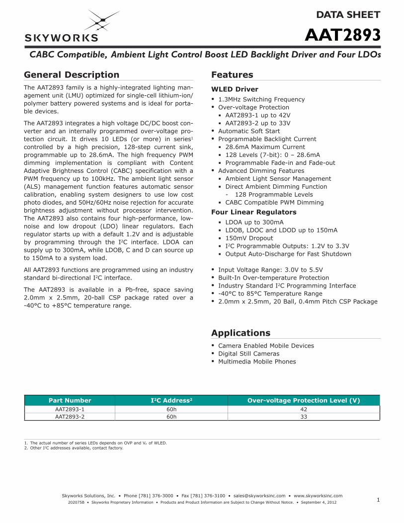
AAT2893 DATA SHEET CABC Compatible, Ambient Light Control Boost LED Backlight Driver and Four LDOs 1 Skyworks Solutions, Inc. • Phone [781] 376-3000 • Fax [781] 376-3100 • [email protected] • www.skyworksinc.com 202075B • Skyworks Proprietary Information • Products and Product Information are Subject to Change Without Notice. • September 4, 2012 General Description The AAT2893 family is a highly-integrated lighting man- agement unit (LMU) optimized for single-cell lithium-ion/ polymer battery powered systems and is ideal for porta- ble devices. The AAT2893 integrates a high voltage DC/DC boost con- verter and an internally programmed over-voltage pro- tection circuit. It drives 10 LEDs (or more) in series 1 controlled by a high precision, 128-step current sink, programmable up to 28.6mA. The high frequency PWM dimming implementation is compliant with Content Adaptive Brightness Control (CABC) specification with a PWM frequency up to 100kHz. The ambient light sensor (ALS) management function features automatic sensor calibration, enabling system designers to use low cost photo diodes, and 50Hz/60Hz noise rejection for accurate brightness adjustment without processor intervention. The AAT2893 also contains four high-performance, low- noise and low dropout (LDO) linear regulators. Each regulator starts up with a default 1.2V and is adjustable by programming through the I 2 C interface. LDOA can supply up to 300mA, while LDOB, C and D can source up to 150mA to a system load. All AAT2893 functions are programmed using an industry standard bi-directional I 2 C interface. The AAT2893 is available in a Pb-free, space saving 2.0mm x 2.5mm, 20-ball CSP package rated over a -40°C to +85°C temperature range. Features WLED Driver • 1.3MHz Switching Frequency • Over-voltage Protection ▪ AAT2893-1 up to 42V ▪ AAT2893-2 up to 33V • Automatic Soft Start • Programmable Backlight Current ▪ 28.6mA Maximum Current ▪ 128 Levels (7-bit): 0 – 28.6mA ▪ Programmable Fade-in and Fade-out • Advanced Dimming Features ▪ Ambient Light Sensor Management ▪ Direct Ambient Dimming Function - 128 Programmable Levels ▪ CABC Compatible PWM Dimming Four Linear Regulators ▪ LDOA up to 300mA ▪ LDOB, LDOC and LDOD up to 150mA ▪ 150mV Dropout ▪ I 2 C Programmable Outputs: 1.2V to 3.3V ▪ Output Auto-Discharge for Fast Shutdown • Input Voltage Range: 3.0V to 5.5V • Built-In Over-temperature Protection • Industry Standard I 2 C Programming Interface • -40°C to 85°C Temperature Range • 2.0mm x 2.5mm, 20 Ball, 0.4mm Pitch CSP Package Applications • Camera Enabled Mobile Devices • Digital Still Cameras • Multimedia Mobile Phones Part Number I 2 C Address 2 Over-voltage Protection Level (V) AAT2893-1 60h 42 AAT2893-2 60h 33 1. The actual number of series LEDs depends on OVP and VF of WLED. 2. Other I 2 C addresses available, contact factory.
-
Upload
khangminh22 -
Category
Documents
-
view
6 -
download
0
Transcript of AAT2893 - Micro-Semiconductor.com
AAT2893DATA SHEET
CABC Compatible, Ambient Light Control Boost LED Backlight Driver and Four LDOs
1Skyworks Solutions, Inc. • Phone [781] 376-3000 • Fax [781] 376-3100 • [email protected] • www.skyworksinc.com
202075B • Skyworks Proprietary Information • Products and Product Information are Subject to Change Without Notice. • September 4, 2012
General DescriptionThe AAT2893 family is a highly-integrated lighting man-agement unit (LMU) optimized for single-cell lithium-ion/polymer battery powered systems and is ideal for porta-ble devices.
The AAT2893 integrates a high voltage DC/DC boost con-verter and an internally programmed over-voltage pro-tection circuit. It drives 10 LEDs (or more) in series1 controlled by a high precision, 128-step current sink, programmable up to 28.6mA. The high frequency PWM dimming implementation is compliant with Content Adaptive Brightness Control (CABC) specification with a PWM frequency up to 100kHz. The ambient light sensor (ALS) management function features automatic sensor calibration, enabling system designers to use low cost photo diodes, and 50Hz/60Hz noise rejection for accurate brightness adjustment without processor intervention. The AAT2893 also contains four high-performance, low-noise and low dropout (LDO) linear regulators. Each regulator starts up with a default 1.2V and is adjustable by programming through the I2C interface. LDOA can supply up to 300mA, while LDOB, C and D can source up to 150mA to a system load.
All AAT2893 functions are programmed using an industry standard bi-directional I2C interface.
The AAT2893 is available in a Pb-free, space saving 2.0mm x 2.5mm, 20-ball CSP package rated over a -40°C to +85°C temperature range.
FeaturesWLED Driver• 1.3MHz Switching Frequency • Over-voltage Protection
AAT2893-1 up to 42V AAT2893-2 up to 33V
• Automatic Soft Start• Programmable Backlight Current
28.6mA Maximum Current 128 Levels (7-bit): 0 – 28.6mA Programmable Fade-in and Fade-out
• Advanced Dimming Features Ambient Light Sensor Management Direct Ambient Dimming Function - 128 Programmable Levels CABC Compatible PWM Dimming
Four Linear Regulators LDOA up to 300mA LDOB, LDOC and LDOD up to 150mA 150mV Dropout I2C Programmable Outputs: 1.2V to 3.3V Output Auto-Discharge for Fast Shutdown
• Input Voltage Range: 3.0V to 5.5V• Built-In Over-temperature Protection• Industry Standard I2C Programming Interface• -40°C to 85°C Temperature Range• 2.0mm x 2.5mm, 20 Ball, 0.4mm Pitch CSP Package
Applications• Camera Enabled Mobile Devices• Digital Still Cameras • Multimedia Mobile Phones
Part Number I2C Address2 Over-voltage Protection Level (V)AAT2893-1 60h 42AAT2893-2 60h 33
1. The actual number of series LEDs depends on OVP and VF of WLED. 2. Other I2C addresses available, contact factory.

AAT2893DATA SHEET
CABC Compatible, Ambient Light Control Boost LED Backlight Driver and Four LDOs
2Skyworks Solutions, Inc. • Phone [781] 376-3000 • Fax [781] 376-3100 • [email protected] • www.skyworksinc.com
202075B • Skyworks Proprietary Information • Products and Product Information are Subject to Change Without Notice. • September 4, 2012
Typical Application Circuit
INOUTLX
ILED
LDOA
LDOB
LDOC
LDODPGNDAGND
AMB_IN
SBIAS
FLTR
COMP
PWM
SCL
SDA
EN
Enable
I2C Data Input
I2C Clock Input
PWM Control Input
VBAT
3.6V 4.7μFCIN
L1
4.7μH0.1μF
CCOMP 56nF
CFLTR 10nF
CSBIAS
2.2μF
External Ambient Light Sensor (Photo Diode )
VLDOD
150mACLDOD2.2μF
CLDOC
2.2μF
150mA
2.2μF
VLDOB
150mACLDOA4.7μF
VLDOA
300mA
Backlight
AAT2893
DS1
VLDOC
IN_LDO
2.2μF
CIN_LDO
COUT
VOUT

AAT2893DATA SHEET
CABC Compatible, Ambient Light Control Boost LED Backlight Driver and Four LDOs
3Skyworks Solutions, Inc. • Phone [781] 376-3000 • Fax [781] 376-3100 • [email protected] • www.skyworksinc.com
202075B • Skyworks Proprietary Information • Products and Product Information are Subject to Change Without Notice. • September 4, 2012
Pin Descriptions
Pin # Symbol Description
A1 LDOD LDOD regulated voltage output pin. Bypass LDOD to AGND with a 2.2μF or larger capacitor as close to the AAT2893 as possible.
A2 LDOC LDOC regulated voltage output pin. Bypass LDOC to AGND with a 2.2μF or larger capacitor as close to the AAT2893 as possible.
A3 LDOB LDOB regulated voltage output pin. Bypass LDOB to AGND with a 2.2μF or greater capacitor as close to the AAT2893 as possible.
A4 LDOA LDOA regulated voltage output pin. Bypass LDOA to AGND with a 4.7μF or larger ceramic capacitor as close to the AAT2893 as possible.
B1 IN_LDO Input power supply pin for all four LDO voltage regulators. Bypass IN_LDO to PGND with a 2.2μF or larger ce-ramic capacitor located as close to the AAT2893 as possible.
B2 IN Power input. Connect IN to the input source voltage. Bypass IN to PGND with a 4.7μF or larger ceramic capacitor as close to the AAT2893 as possible.
B3 EN Enable Pin. Drive high to enable, low to shutdown.
B4 SBIAS Ambient light sensor bias supply output. This pin provides a regulated bias supply to the attached ambient light sensor.
C1 AGND Analog ground. Connect AGND to PGND at a single point as close to the AAT2893 as possible.C2 DGND Digital ground. Connect AGND and DGND and PGND at a single point as close to the AAT2893 as possible.C3 SCL I2C Serial Clock input pin
C4 AMB_IN Ambient light sensor input connection pin. Connect the photo diode anode or ambient light sensor module out-put to this pin.
D1 PGND Power ground. Connect AGND to PGND at a single point as close to the AAT2893 as possible.D2 PWM Content controlled backlight brightness PWM signal input pin. Pull high to disable the PWM dimming feature.D3 SDA I2C Serial Data pin, this pin is bi-directional.D4 FLTR PWM input filter capacitor pin. Connect a 10nF ceramic capacitor between this pin and AGND.E1 LX Boost converter switching node. Connect a inductor between this node and IN.E2 OUT Boost converter output, place an external schottky between this node and LX
E3 ILED Series LED string current sink. ILED controls the current through backlight LED constant current sink. Connect to the cathode of the last LED in the LED string.
E4 COMP Compensation pin. Connect a capacitor via this pin to GND. Compensation components are mainly related to the output capacitor value.
Pin Configurations
2.0mm × 2.5mm, 4 × 5 Ball Array CSP (Top View)
LDOALDOBLDOCLDOD
SBIASENININ_LDO
AMB_INSCLDGNDAGND
FLTRSDAPWMPGND
COMPILEDOUTLX
A
B
C
D
E
4321

AAT2893DATA SHEET
CABC Compatible, Ambient Light Control Boost LED Backlight Driver and Four LDOs
4Skyworks Solutions, Inc. • Phone [781] 376-3000 • Fax [781] 376-3100 • [email protected] • www.skyworksinc.com
202075B • Skyworks Proprietary Information • Products and Product Information are Subject to Change Without Notice. • September 4, 2012
1. Stresses above those listed in Absolute Maximum Ratings may cause permanent damage to the device. Functional operation at conditions other than the operating conditions specified is not implied.
2. Mounted on a FR4 circuit board. 3. Derate 12.6mW/°C above 25°C ambient temperature.
Absolute Maximum Ratings1
Symbol Description Value UnitsVIN, VIN_LDO Input Voltage to AGND, PGND -0.3 to 6
V
VLX, VILED, VOUT High Voltage to AGND, PGNDAAT2893-1 -0.3 to 50AAT2893-2 -0.3 to 44
EN, SDA, SCL, COMP, PWM, FLTR,
SBIAS, LDOA, LDOB, LDOC, LDOD
Pin Voltage to AGND, PGND -0.3 to VIN+0.3
VAMB-IN Ambient Light Sensor Maximum Input Voltage to AGND, PGND VIN
Thermal Information2
Symbol Description Value UnitsΘJA Thermal Resistance3 79 °C/WPD Maximum Power Dissipation 1.26 WTJ Operating Junction Temperature Range -40 to 150
°CTLEAD Maximum Soldering Temperature (at Leads, 10s) 300
Recommended Operating Conditions
Symbol DescriptionValue
UnitsMin Typ Max
VIN Input Supply Voltage 3.0 5.5V
VOUT Boost Converter Output Voltage VIN+3V VOVP_T
L1 Inductor Value 4.7 10 22 µHfPWM-F Filtered PWM Input Frequency 0.1 100 kHz
TA Ambient Operating Temperature -40 25 85 °C
AAT2893DATA SHEET
CABC Compatible, Ambient Light Control Boost LED Backlight Driver and Four LDOs
5Skyworks Solutions, Inc. • Phone [781] 376-3000 • Fax [781] 376-3100 • [email protected] • www.skyworksinc.com
202075B • Skyworks Proprietary Information • Products and Product Information are Subject to Change Without Notice. • September 4, 2012
1. The AAT2893 is guaranteed to meet performance specifications over the -40°C to +85°C operating temperature range and is assured by design, characterization, and correla-tion with statistical process controls.
2. Current matching is defined as the deviation of any sink current from the average of all active channels.3. VDO[A/B/C/D] is defined as VIN – LDO[A/B/C/D] when LDO[A/B/C/D] is 98% of nominal.
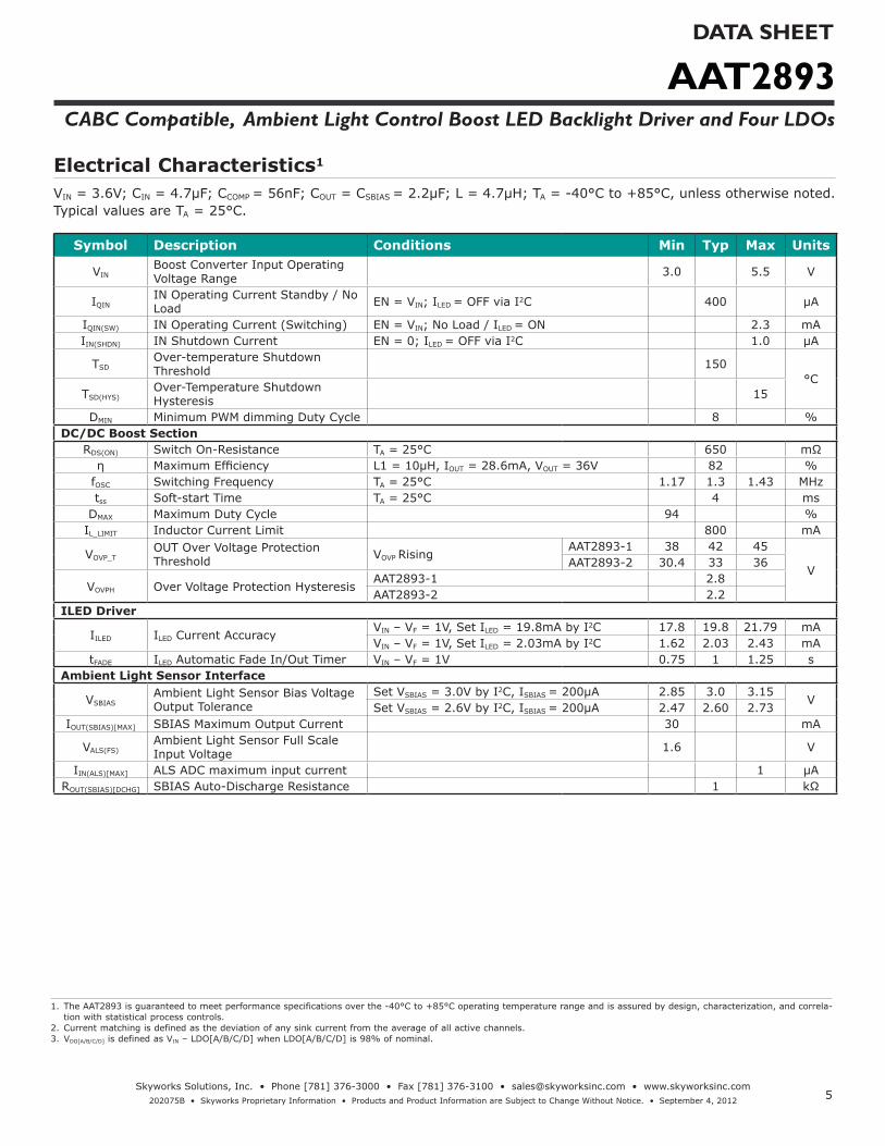
Electrical Characteristics1
VIN = 3.6V; CIN = 4.7μF; CCOMP = 56nF; COUT = CSBIAS = 2.2µF; L = 4.7μH; TA = -40°C to +85°C, unless otherwise noted. Typical values are TA = 25°C.
Symbol Description Conditions Min Typ Max Units
VINBoost Converter Input Operating Voltage Range 3.0 5.5 V
IQININ Operating Current Standby / No Load EN = VIN; ILED = OFF via I2C 400 µA
IQIN(SW) IN Operating Current (Switching) EN = VIN; No Load / ILED = ON 2.3 mAIIN(SHDN) IN Shutdown Current EN = 0; ILED = OFF via I2C 1.0 µA
TSDOver-temperature Shutdown Threshold 150
°CTSD(HYS)
Over-Temperature Shutdown Hysteresis 15
DMIN Minimum PWM dimming Duty Cycle 8 %DC/DC Boost Section
RDS(ON) Switch On-Resistance TA = 25°C 650 mΩη Maximum Efficiency L1 = 10µH, IOUT = 28.6mA, VOUT = 36V 82 %
fOSC Switching Frequency TA = 25°C 1.17 1.3 1.43 MHztss Soft-start Time TA = 25°C 4 ms
DMAX Maximum Duty Cycle 94 %IL_LIMIT Inductor Current Limit 800 mA
VOVP_TOUT Over Voltage Protection Threshold VOVP Rising
AAT2893-1 38 42 45
VAAT2893-2 30.4 33 36
VOVPH Over Voltage Protection HysteresisAAT2893-1 2.8AAT2893-2 2.2
ILED Driver
IILED ILED Current AccuracyVIN – VF = 1V, Set ILED = 19.8mA by I2C 17.8 19.8 21.79 mAVIN – VF = 1V, Set ILED = 2.03mA by I2C 1.62 2.03 2.43 mA
tFADE ILED Automatic Fade In/Out Timer VIN – VF = 1V 0.75 1 1.25 sAmbient Light Sensor Interface
VSBIASAmbient Light Sensor Bias Voltage Output Tolerance
Set VSBIAS = 3.0V by I2C, ISBIAS = 200µA 2.85 3.0 3.15V
Set VSBIAS = 2.6V by I2C, ISBIAS = 200µA 2.47 2.60 2.73IOUT(SBIAS)[MAX] SBIAS Maximum Output Current 30 mA
VALS(FS)Ambient Light Sensor Full Scale Input Voltage 1.6 V
IIN(ALS)[MAX] ALS ADC maximum input current 1 µAROUT(SBIAS)[DCHG] SBIAS Auto-Discharge Resistance 1 kΩ
AAT2893DATA SHEET
CABC Compatible, Ambient Light Control Boost LED Backlight Driver and Four LDOs
6Skyworks Solutions, Inc. • Phone [781] 376-3000 • Fax [781] 376-3100 • [email protected] • www.skyworksinc.com
202075B • Skyworks Proprietary Information • Products and Product Information are Subject to Change Without Notice. • September 4, 2012
1. The AAT2893 is guaranteed to meet performance specifications over the -40°C to +85°C operating temperature range and is assured by design, characterization, and correla-tion with statistical process controls.
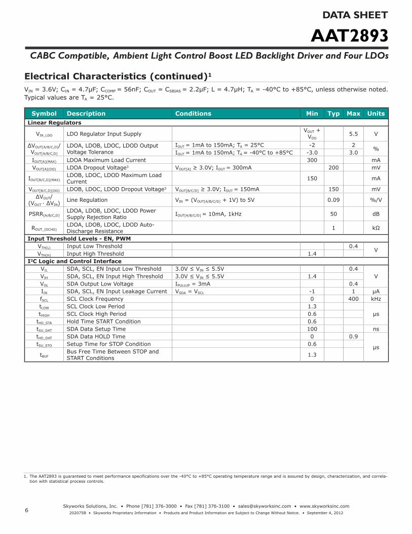
Electrical Characteristics (continued)1
VIN = 3.6V; CIN = 4.7μF; CCOMP = 56nF; COUT = CSBIAS = 2.2µF; L = 4.7μH; TA = -40°C to +85°C, unless otherwise noted. Typical values are TA = 25°C.
Symbol Description Conditions Min Typ Max UnitsLinear Regulators
VIN_LDO LDO Regulator Input SupplyVOUT +
VDO5.5 V
ΔVOUT[A/B/C,D]/VOUT[A/B/C,D]
LDOA, LDOB, LDOC, LDOD Output Voltage Tolerance
IOUT = 1mA to 150mA; TA = 25°C -2 2%
IOUT = 1mA to 150mA; TA = -40°C to +85°C -3.0 3.0IOUT[A](MAX) LDOA Maximum Load Current 300 mAVOUT[A](DO) LDOA Dropout Voltage3 VOUT[A] ≥ 3.0V; IOUT = 300mA 200 mV
IOUT[B/C,D](MAX)LDOB, LDOC, LDOD Maximum Load Current 150 mA
VOUT[B/C,D](DO) LDOB, LDOC, LDOD Dropout Voltage3 VOUT[B/C/D] ≥ 3.0V; IOUT = 150mA 150 mV∆VOUT/
(VOUT · ∆VIN)Line Regulation VIN = (VOUT[A/B/C/D] + 1V) to 5V 0.09 %/V
PSRR[A/B/C,D]LDOA, LDOB, LDOC, LDOD Power Supply Rejection Ratio IOUT[A/B/C/D] = 10mA, 1kHz 50 dB
ROUT_(DCHG)LDOA, LDOB, LDOC, LDOD Auto- Discharge Resistance 1 kΩ
Input Threshold Levels - EN, PWMVTH(L) Input Low Threshold 0.4
VVTH(H) Input High Threshold 1.4
I2C Logic and Control InterfaceVIL SDA, SCL, EN Input Low Threshold 3.0V ≤ VIN ≤ 5.5V 0.4
VVIH SDA, SCL, EN Input High Threshold 3.0V ≤ VIN ≤ 5.5V 1.4VOL SDA Output Low Voltage IPULLUP = 3mA 0.4IIN SDA, SCL, EN Input Leakage Current VSDA = VSCL -1 1 µAfSCL SCL Clock Frequency 0 400 kHztLOW SCL Clock Low Period 1.3
µstHIGH SCL Clock High Period 0.6tHD_STA Hold Time START Condition 0.6tSU_DAT SDA Data Setup Time 100 nstHD_DAT SDA Data HOLD Time 0 0.9
µstSU_STO Setup Time for STOP Condition 0.6
tBUFBus Free Time Between STOP and START Conditions 1.3
AAT2893DATA SHEET
CABC Compatible, Ambient Light Control Boost LED Backlight Driver and Four LDOs
7Skyworks Solutions, Inc. • Phone [781] 376-3000 • Fax [781] 376-3100 • [email protected] • www.skyworksinc.com
202075B • Skyworks Proprietary Information • Products and Product Information are Subject to Change Without Notice. • September 4, 2012
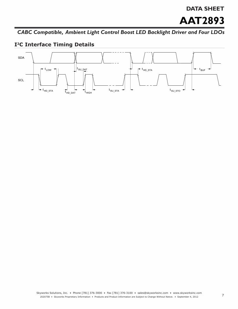
I2C Interface Timing Details
t SU_STOt SU_STAt HD_STA t HIGH
t LOWt SU_DAT
t HD_DAT
SDA
SCL
t BUFt HD_STA

AAT2893DATA SHEET
CABC Compatible, Ambient Light Control Boost LED Backlight Driver and Four LDOs
8Skyworks Solutions, Inc. • Phone [781] 376-3000 • Fax [781] 376-3100 • [email protected] • www.skyworksinc.com
202075B • Skyworks Proprietary Information • Products and Product Information are Subject to Change Without Notice. • September 4, 2012
Typical Characteristics
100
160
220
280
340
400
460
520
580
640
3 3.3 3.6 3.9 4.2 4.5 4.8 5.1 5.4
25°C
-40°C
85°C
IQ vs Supply Voltage(LED = OFF , Disable LDO via I2C)
Supply Voltage (V)
I Q (µ
A)
100
160
220
280
340
400
460
520
580
640
3 3.3 3.6 3.9 4.2 4.5 4.8 5.1 5.4
25°C
-40°C
85°C
IQ vs Supply Voltage(Enable LDO, Disable LED via I2C, ILDO = 0)
Supply Voltage (V)
I Q (µ
A)
25
26
27
28
29
30
-40 -15 10 35 60 85
LED Current vs Temperature(AAT2893-2, VIN = 3.6V, ILED = 28.6mA, 8 WLEDs)
Temperature (°C)
LED
Cur
rent
(mA)
25
26
27
28
29
30
-40 -15 10 35 60 85
LED Current vs Temperature(AAT2893-1, VIN = 3.6V, ILED = 28.6mA, 10 WLEDs)
Temperature (°C)
LED
Cur
rent
(mA)
-0.2
0
0.2
0.4
0.6
0.8
1
-40 -15 10 35 60 85
Shutdown Current vs Temperature(VIN = 3.6V , EN = GND)
Temperature (°C)
I SHU
TDO
WN (µ
A)
0
5
10
15
20
25
30
0 10 20 30 40 50 60 70 80 90 100 110 120
VIN = 3.0V
VIN = 3.6V
VIN = 4.2V
VIN = 5.0V
VIN = 5.5V
LED Current vs Register (Addr. 00h) Code(4.7µH , 10 WLEDs)
Register (Addr. 00h) Code
LED
Cur
rent
(mA)

AAT2893DATA SHEET
CABC Compatible, Ambient Light Control Boost LED Backlight Driver and Four LDOs
9Skyworks Solutions, Inc. • Phone [781] 376-3000 • Fax [781] 376-3100 • [email protected] • www.skyworksinc.com
202075B • Skyworks Proprietary Information • Products and Product Information are Subject to Change Without Notice. • September 4, 2012
Typical Characteristics
0
5
10
15
20
25
30
0 10 20 30 40 50 60 70 80 90 100
VIN = 3.0V
VIN = 3.6V
VIN = 4.2V
VIN = 5.0V
VIN = 5.5V
PWM Duty vs LED Current(AAT2893-1 10 WLEDs)
PWM Duty (%)
LED
Cur
rent
(mA)
0
5
10
15
20
25
30
0 10 20 30 40 50 60 70 80 90 100
VIN = 3.0
VIN = 3.6
VIN = 4.2
VIN = 5.0
VIN = 5.5
PWM Duty vs LED Current(AAT2893-2 10 WLEDs)
PWM Duty (%)
LED
Cur
rent
(mA)
26
27
28
29
30
3 3.5 4 4.5 5 5.5
25C
-40C
85C
LED Current vs Supply Voltage(AAT2893-1, ILED = 28.6mA , 10 WLEDs)
Supply Voltage (V)
LED
Cur
rent
(mA)
26
26.8
27.6
28.4
29.2
30
3 3.5 4 4.5 5 5.5
25°C-40°C85°C
LED Current vs Supply Voltage(AAT2893-2, ILED = 28.6mA , 8 WLEDs)
Supply Voltage (V)
LED
Cur
rent
(mA)
40
45
50
55
60
65
70
75
80
85
0 5 10 15 20 25 30
VIN = 3.0VVIN = 3.6VVIN = 4.2VVIN = 5.0VVIN = 5.5V
Efficiency vs LED Current(AAT2893-1, 10 WLEDs)
LED Current (mA)
Effic
ienc
y (%
)
40
45
50
55
60
65
70
75
80
85
0 5 10 15 20 25 30
VIN = 3.0V
VIN = 3.6V
VIN = 4.2V
VIN = 5.0V
VIN = 5.5V
Efficiency vs LED Current(AAT2893-2, 8 WLEDs)
LED Current (mA)
Effic
ienc
y (%
)
AAT2893DATA SHEET
CABC Compatible, Ambient Light Control Boost LED Backlight Driver and Four LDOs
10Skyworks Solutions, Inc. • Phone [781] 376-3000 • Fax [781] 376-3100 • [email protected] • www.skyworksinc.com
202075B • Skyworks Proprietary Information • Products and Product Information are Subject to Change Without Notice. • September 4, 2012
Typical Characteristics
0
10
20
30
40
50
60
70
80
90
0 5 10 15 20 25 30
VIN = 3.0V
VIN = 3.6V
VIN = 4.2V
VIN = 5.0V
VIN = 5.5V
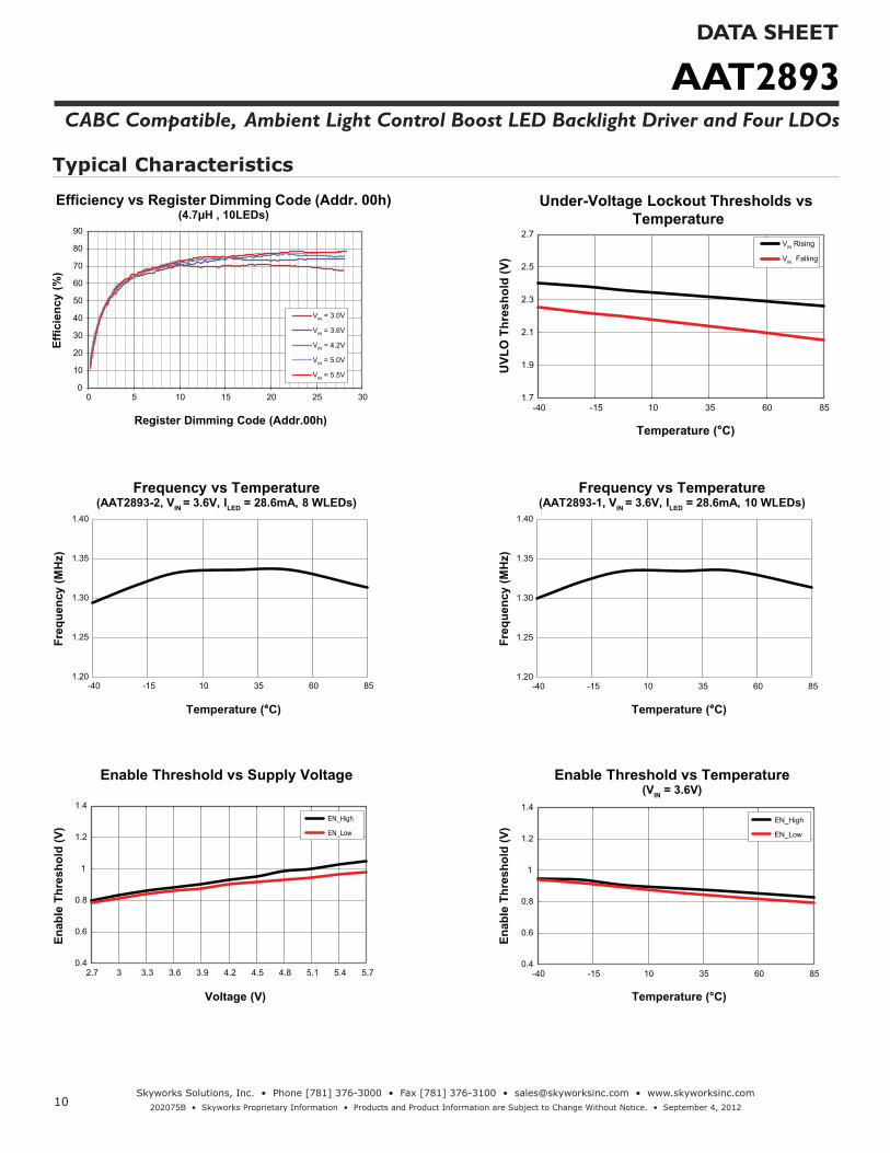
Efficiency vs Register Dimming Code (Addr. 00h)(4.7µH , 10LEDs)
Register Dimming Code (Addr.00h)
Effic
ienc
y (%
)
1.7
1.9
2.1
2.3
2.5
2.7
-40 -15 10 35 60 85
VIN Rising
VIN Falling
Under-Voltage Lockout Thresholds vs Temperature
Temperature (°C)
UVL
O T
hres
hold
(V)
1.20
1.25
1.30
1.35
1.40
-40 -15 10 35 60 85
Frequency vs Temperature(AAT2893-2, VIN = 3.6V, ILED = 28.6mA, 8 WLEDs)
Temperature (°C)
Freq
uenc
y (M
Hz)
1.20
1.25
1.30
1.35
1.40
-40 -15 10 35 60 85
Frequency vs Temperature(AAT2893-1, VIN = 3.6V, ILED = 28.6mA, 10 WLEDs)
Temperature (°C)
Freq
uenc
y (M
Hz)
0.4
0.6
0.8
1
1.2
1.4
2.7 3 3.3 3.6 3.9 4.2 4.5 4.8 5.1 5.4 5.7
EN_High
EN_Low
Enable Threshold vs Supply Voltage
Voltage (V)
Enab
le T
hres
hold
(V)
0.4
0.6
0.8
1
1.2
1.4
-40 -15 10 35 60 85
EN_High
EN_Low
Enable Threshold vs Temperature(VIN = 3.6V)
Temperature (°C)
Enab
le T
hres
hold
(V)
AAT2893DATA SHEET
CABC Compatible, Ambient Light Control Boost LED Backlight Driver and Four LDOs
11Skyworks Solutions, Inc. • Phone [781] 376-3000 • Fax [781] 376-3100 • [email protected] • www.skyworksinc.com
202075B • Skyworks Proprietary Information • Products and Product Information are Subject to Change Without Notice. • September 4, 2012
Typical Characteristics
38
39
40
41
42
43
44
45
-40 -15 10 35 60 85
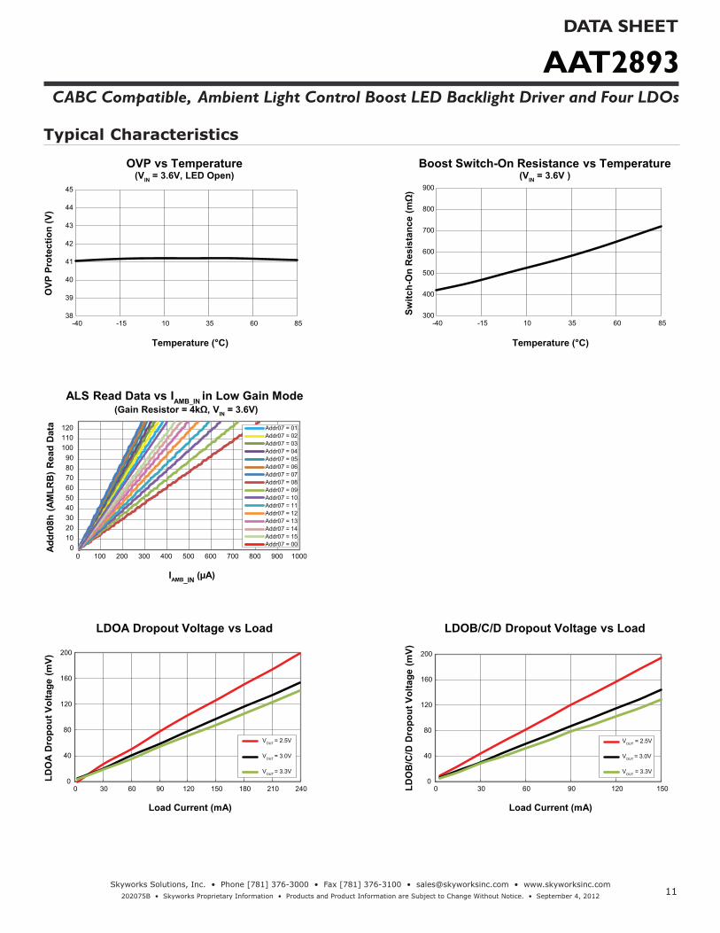
OVP vs Temperature(VIN = 3.6V, LED Open)
Temperature (°C)
OVP
Pro
tect
ion
(V)
300
400
500
600
700
800
900
-40 -15 10 35 60 85
Boost Switch-On Resistance vs Temperature(VIN = 3.6V )
Temperature (°C)
Switc
h-O
n R
esis
tanc
e (m
Ω)
0102030405060708090
100110120
0 100 200 300 400 500 600 700 800 900 1000
Addr07 = 01Addr07 = 02Addr07 = 03Addr07 = 04Addr07 = 05Addr07 = 06Addr07 = 07Addr07 = 08Addr07 = 09Addr07 = 10Addr07 = 11Addr07 = 12Addr07 = 13Addr07 = 14Addr07 = 15Addr07 = 00
ALS Read Data vs IAMB_IN in Low Gain Mode (Gain Resistor = 4kΩ, VIN = 3.6V)
IAMB_IN (µA)
Addr
08h
(AM
LRB
) Rea
d D
ata
0
40
80
120
160
200
0 30 60 90 120 150 180 210 240
VOUT = 2.5V
VOUT = 3.0V
VOUT = 3.3V
LDOA Dropout Voltage vs Load
Load Current (mA)
LDO
A D
ropo
ut V
olta
ge (m
V)
0
40
80
120
160
200
0 30 60 90 120 150
VOUT = 2.5V
VOUT = 3.0V
VOUT = 3.3V
LDOB/C/D Dropout Voltage vs Load
Load Current (mA)
LDO
B/C
/D D
ropo
ut V
olta
ge (m
V)

AAT2893DATA SHEET
CABC Compatible, Ambient Light Control Boost LED Backlight Driver and Four LDOs
12Skyworks Solutions, Inc. • Phone [781] 376-3000 • Fax [781] 376-3100 • [email protected] • www.skyworksinc.com
202075B • Skyworks Proprietary Information • Products and Product Information are Subject to Change Without Notice. • September 4, 2012
Typical Characteristics
-2.0
-1.2
-0.4
0.4
1.2
2.0
-40 -15 10 35 60 85
VOUT = 1.2V
VOUT = 3.3V
VLDOA Accuracy vs Temperature
Temperature (°C)
V LDO
A A
ccur
acy
(%)
-2.0
-1.2
-0.4
0.4
1.2
2.0
-40 -15 10 35 60 85
VOUT = 1.2V
VOUT = 3.3V
VLDOB/C/D Accuracy vs Temperature
Temperature (°C)
V LDO
B/C
/D A
ccur
acy
(%)
-0.800
-0.400
0.000
0.400
0.800
1 10 100 1000
LDOA Output Voltage Load Regulation(VIN = 3.6V , VLDOA = 1.2V)
Load Current (mA)
Load
Reg
ulat
ion
(%)
-0.800
-0.400
0.000
0.400
0.800
1 10 100 1000
LDOA Output Voltage Load Regulation(VIN = 3.6V , VLDOA = 3.3V)
Load Current (mA)
Load
Reg
ulat
ion
(%)
-0.800
-0.400
0.000
0.400
0.800
1 10 100 1000
LDOB/C/D Output Voltage Load Regulation(VIN = 3.6V , VLDOB/C/D = 1.2V)
Load Current (mA)
Load
Reg
ulat
ion
(%)
-0.800
-0.400
0.000
0.400
0.800
1 10 100 1000
LDOB/C/D Output Voltage Load Regulation(VIN = 3.6V , VLDOB/C/D = 3.3V)
Load Current (mA)
Load
Reg
ulat
ion
(%)

AAT2893DATA SHEET
CABC Compatible, Ambient Light Control Boost LED Backlight Driver and Four LDOs
13Skyworks Solutions, Inc. • Phone [781] 376-3000 • Fax [781] 376-3100 • [email protected] • www.skyworksinc.com
202075B • Skyworks Proprietary Information • Products and Product Information are Subject to Change Without Notice. • September 4, 2012
Typical Characteristics
0V
0A
Switching Operation (AAT2893-2, VIN = 3.6V, ILED = 19.8mA, 8 WLEDs)
Time (500ns/div)
ILED (AC)2mA/div
VOUT(AC)50mV/div
VLX
20V/div
IL
500mA/div
0V
0A
Switching Operation (AAT2893-1, VIN = 3.6V, ILED = 19.8mA, 10 WLEDs)
Time (500ns/div)
ILED(AC)
2mA/div
VOUT(AC)100mV/div
VLX
20V/div
IL
500mA/div
3.6V
42V
OVP (VIN = 3.6V, Open LED)
Time (10ms/div)
VOUT(AC) 5V/div
VLX
20V/div
VIN(AC)50mV/div
3V
3.6V
5V
0mA
Boost Start Up (AAT2893-1, VIN = 3.6V, ILED = 28.6mA, 10WLEDs)
Time (10ms/div)
ILED
20mA/div
VOUT
20V/div
VSDA
4V/div
VLX
20V/div
0V
PWM Dimming Switching(VIN = 3.6V, Duty Cycle = 80%, ILED = 19.8mA)
Time (50µs/div)
PWM2V/div
VOUT(AC) 50mV/div
ILED1mA/div
VLX
20V/div
(AC)
0V
PWM Dimming Switching(VIN = 3.6V, Duty Cycle = 30%, ILED = 19.8mA)
Time (50µs/div)
PWM2V/div
VOUT
50mV/div
ILED(AC) 1mA/div
VLX
20V/div
(AC)
AAT2893DATA SHEET
CABC Compatible, Ambient Light Control Boost LED Backlight Driver and Four LDOs
14Skyworks Solutions, Inc. • Phone [781] 376-3000 • Fax [781] 376-3100 • [email protected] • www.skyworksinc.com
202075B • Skyworks Proprietary Information • Products and Product Information are Subject to Change Without Notice. • September 4, 2012
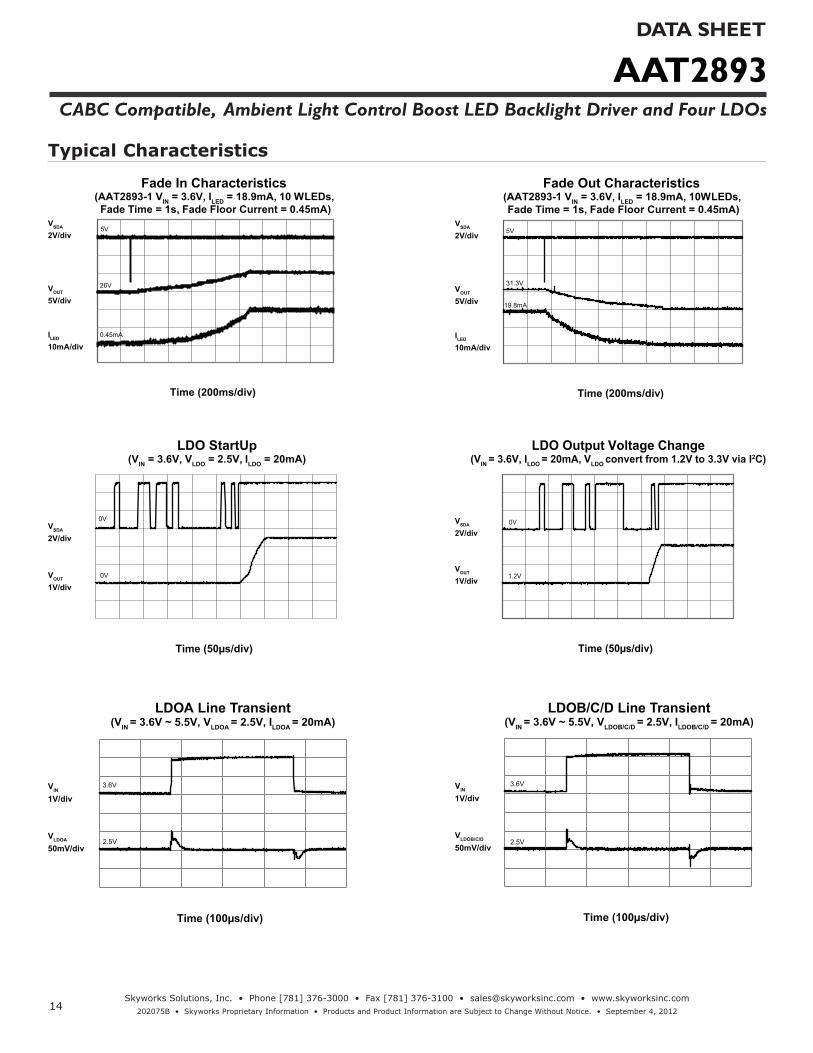
Typical Characteristics
26V
0.45mA
5V
Fade In Characteristics (AAT2893-1 VIN = 3.6V, ILED = 18.9mA, 10 WLEDs, Fade Time = 1s, Fade Floor Current = 0.45mA)
Time (200ms/div)
VOUT 5V/div
ILED
10mA/div
VSDA 2V/div
31.3V
5V
19.8mA
Fade Out Characteristics (AAT2893-1 VIN = 3.6V, ILED = 18.9mA, 10WLEDs, Fade Time = 1s, Fade Floor Current = 0.45mA)
Time (200ms/div)
VOUT 5V/div
ILED
10mA/div
VSDA 2V/div
0V
0V
LDO StartUp(VIN = 3.6V, VLDO = 2.5V, ILDO = 20mA)
Time (50µs/div)
VOUT 1V/div
VSDA 2V/div
0V
1.2V
LDO Output Voltage Change(VIN = 3.6V, ILDO = 20mA, VLDO convert from 1.2V to 3.3V via I2C)
Time (50µs/div)
VOUT 1V/div
VSDA 2V/div
3.6V
2.5V
LDOA Line Transient(VIN = 3.6V ~ 5.5V, VLDOA = 2.5V, ILDOA = 20mA)
Time (100µs/div)
VLDOA 50mV/div
VIN 1V/div
3.6V
2.5V
LDOB/C/D Line Transient(VIN = 3.6V ~ 5.5V, VLDOB/C/D = 2.5V, ILDOB/C/D = 20mA)
Time (100µs/div)
VLDOB/C/D 50mV/div
VIN 1V/div

AAT2893DATA SHEET
CABC Compatible, Ambient Light Control Boost LED Backlight Driver and Four LDOs
15Skyworks Solutions, Inc. • Phone [781] 376-3000 • Fax [781] 376-3100 • [email protected] • www.skyworksinc.com
202075B • Skyworks Proprietary Information • Products and Product Information are Subject to Change Without Notice. • September 4, 2012
Typical Characteristics
0mA
2.5V
LDOA Load Transient(VIN = 3.6V, ILDOA= 1mA~300mA, VLDOA = 2.5V)
Time (100µs/div)
VLDOA 50mV/div
ILDOA
100mA/div
0mA
2.5V
LDOB/C/D Load Transient(VIN = 3.6V, ILDOB/C/D = 1mA~150mA, VLDOB/C/D = 2.5V)
Time (100µs/div)
VLDOB/C/D 50mV/div
ILDOB/C/D
100mA/div
0mA
2.5V
2.5V
Cross Talk between LDOA and LDOB/C/D(VIN = 3.6V, ILDOB/C/D = 1mA~150mA, VLDOA = VLDOB/C/D = 2.5V)
Time (100µs/div)
ILDOB/C/D
(100mA/div)
VLDOA
10mV/div
VLDOB/C/D
50mV/div
AAT2893DATA SHEET
CABC Compatible, Ambient Light Control Boost LED Backlight Driver and Four LDOs
16Skyworks Solutions, Inc. • Phone [781] 376-3000 • Fax [781] 376-3100 • [email protected] • www.skyworksinc.com
202075B • Skyworks Proprietary Information • Products and Product Information are Subject to Change Without Notice. • September 4, 2012
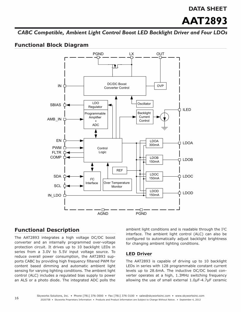
Functional DescriptionThe AAT2893 integrates a high voltage DC/DC boost converter and an internally programmed over-voltage protection circuit. It drives up to 10 backlight LEDs in series from a 3.0V to 5.5V input voltage source. To reduce overall power consumption, the AAT2893 sup-ports CABC by providing high frequency filtered PWM for content based dimming and automatic ambient light sensing for varying lighting conditions. The ambient light control (ALC) includes a regulated bias supply to power an ALS or a photo diode. The integrated ADC polls the
ambient light conditions and is readable through the I2C interface. The ambient light control (ALC) can also be configured to automatically adjust backlight brightness for changing ambient lighting conditions.
LED DriverThe AAT2893 is capable of driving up to 10 backlight LEDs in series with 128 programmable constant current levels up to 28.6mA. The inductive DC/DC boost con-verter operates at a high, 1.3MHz switching frequency allowing the use of small external 1.0μF-4.7μF ceramic
Functional Block DiagramPGND
AGND
IN DC/DC Boost Converter Control
LDO Regulator
Programmable Amplifier
+ ADC
ControlLogic
REF
I2CInterface Over Temperature
Monitor
OVP
Oscillator
BacklightCurrentControl
LDOA300mA
LDOB150mA
LDOC150mA
LDOD150mA
SBIAS
AMB_IN
EN
PWMFLTR
COMP
SDA
SCL
PGND
LDOD
LDOC
LDOB
LDOA
ILED
OUTLX
IN_LDO
AAT2893DATA SHEET
CABC Compatible, Ambient Light Control Boost LED Backlight Driver and Four LDOs
17Skyworks Solutions, Inc. • Phone [781] 376-3000 • Fax [781] 376-3100 • [email protected] • www.skyworksinc.com
202075B • Skyworks Proprietary Information • Products and Product Information are Subject to Change Without Notice. • September 4, 2012
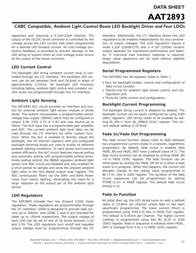
capacitors and requiring a 4.7µH-22µH inductor. The output of the DC/DC boost converter is controlled by the voltage across the LED current sink when programmed for a desired LED forward current. An over-voltage pro-tection feedback is provided to prevent damage to the LED string or system when an over-voltage event occurs at the output of the boost converter.
LED Current ControlThe backlight LED string constant current level is con-trolled through the I2C interface. The backlight LED cur-rent can be set between 0mA and 28.6mA in steps of approximately 0.23mA. All backlight LED functions including fading, ambient light control and constant cur-rent levels are programmed through the I2C interface.
Ambient Light Sensing The AAT2893 ALC circuit provides an interface and con-trol for external ambient light sensor module or photo diode. The system incorporates a programmable sensor voltage bias supply (SBIAS) which may be configured to output 3.0V, 2.8V, 2.7V or 2.6V and may source up to 30mA. The ALS input has a programmable gain amplifier and ADC. The current ambient light level data can be read through the I2C interface for other system func-tions. When the ALC is enabled to directly adjust the backlight, the 16 internal registers with pre-configured backlight dimming levels are used to profile 16 different ambient lighting conditions. To save power and improve system efficiency, the ALC circuit features manual polling and automatic polling with programmable polling times. Under polling control, the SBIAS regulator, ambient light sensor and ADC circuit are disabled and only enabled for a short period to sample and store the present ambient light value in the ALS digital output read register. The ADC continuously filters out the 50Hz and 60Hz flicker noise from indoor lighting, eliminating the need for a large capacitor at the output pin of the ambient light sensor.
LDO RegulatorsThe AAT2893 includes four low dropout (LDO) linear regulators. These regulators are programmable through the I2C interface. LDOA is designed to provide load cur-rent up to 300mA, and LDOB, C and D are intended for loads up to 150mA respectively. The output voltage of each LDO can be set to one of 16 levels between 1.2V and 3.3V. The LDO regulators turn on/off and regulate output voltage level by programming through the I2C
interface. Additionally, the I2C interface allows the LDO regulators to be enabled independently for any combina-tion of output voltages. The LDO regulators require a small 2.2μF (LDOB/C/D) and a 4.7μF (LDOA) ceramic output capacitor for maximized performance and stabil-ity. If improved load transient response is required, larger value capacitors can be used without stability degradation.
Serial Programmed RegistersThe AAT2893 has 28 registers listed in Table 1:
• Four for backlight enable, control and configuration of fade in/out function
• Twenty-one for ambient light sensor control and con-figuration and
• Three for LDOs control and configuration.
Backlight Current ProgrammingThe backlight string current is disabled by default. The backlight current can be easily configured by using ILED (00h) registers. LED string needs to be enabled by set-ting BL_EN=1 from BL_ENBLS (01h) register. The cur-rent default setting is 19.8mA.
Fade In/Fade Out ProgrammingThe fade in/out function allows LEDs to fade between two programmed current levels in a smooth, logarithmic progression. By default, fade in/out is enabled (bits FADE_EN and FADE_INIT have a default value of 1). The fade in/out function can be disabled by writing FADE_EN =0 in FADE (03h) register. The fade function can be interrupted by writing the FADE_EN bit to 0 when a fade event is in progress. When this happens, the current will abruptly change to the ceiling value programmed in BL<7:0> bits in ILED register. The duration of the fade in/out sequences can be programmed by setting FTIME<1:0> in FADE register. The default fade in/out timing is 1s.
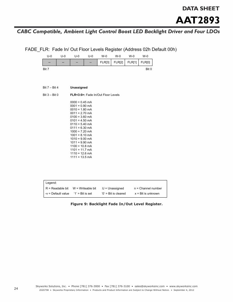
Fade In Function At initial start up, the LED string turns on with a default value of 19.8mA per channel unless fade in has been specifically programmed. The lower current (floor) is programmed using FLR[3:0] bits in FADE_FLR register. The default is 0.45mA per channel. The higher current (ceiling) is programmed using bits BL [6:0] in ILED (00h) register. Fade in sequence is initiated when FADE_INIT is changed from 0 to 1 in FADE (03h) register.

AAT2893DATA SHEET
CABC Compatible, Ambient Light Control Boost LED Backlight Driver and Four LDOs
18Skyworks Solutions, Inc. • Phone [781] 376-3000 • Fax [781] 376-3100 • [email protected] • www.skyworksinc.com
202075B • Skyworks Proprietary Information • Products and Product Information are Subject to Change Without Notice. • September 4, 2012
AAT2893 Device Address Id = 60h w ack Addr = 0 0 h ack Address = 00h Data = 06h ack stop start
SDA
SCL
start w ack ack ack stop
First Byte Writes as 0xC0
Chip Address msb lsb Register Address msb lsb Register Data msb lsb
Figure 1: Typical I2C Timing Diagram.
Fade Out Function The fade out sequence is initiated when FADE_INIT is changed from 1 to 0 in FADE (03h) register. The floor current will persist until LED string is disabled by writing BL_EN=1 to BL_ENBLS (01h) register.
I2C Serial Interface ProtocolThe AAT2893 uses an I2C serial interface to set backlight LED current, LDO on/off and output voltage, as well as other housekeeping functions. The AAT2893 acts only as a slave device. The I2C protocol uses two open-drain inputs: SDA (serial data line) and SCL (serial clock line). Both inputs require an external pull up resistor, typically
to the input voltage. The I2C protocol is bidirectional. The timing diagram in Figure 1 shows the typical I2C interface protocol.
Devices on the I2C bus can either be a master or a slave. Both master and slave devices can send and receive data over the bus, the difference being that the master device controls all communication on the bus. The I2C communications begin by the master making a START condition. Next the master transmits the 7-bit device address and a Read/Write bit. Each slave device on the bus has a unique address. The AAT2893's 7-bit device address is 0x60.
AAT2893DATA SHEET
CABC Compatible, Ambient Light Control Boost LED Backlight Driver and Four LDOs
19Skyworks Solutions, Inc. • Phone [781] 376-3000 • Fax [781] 376-3100 • [email protected] • www.skyworksinc.com
202075B • Skyworks Proprietary Information • Products and Product Information are Subject to Change Without Notice. • September 4, 2012
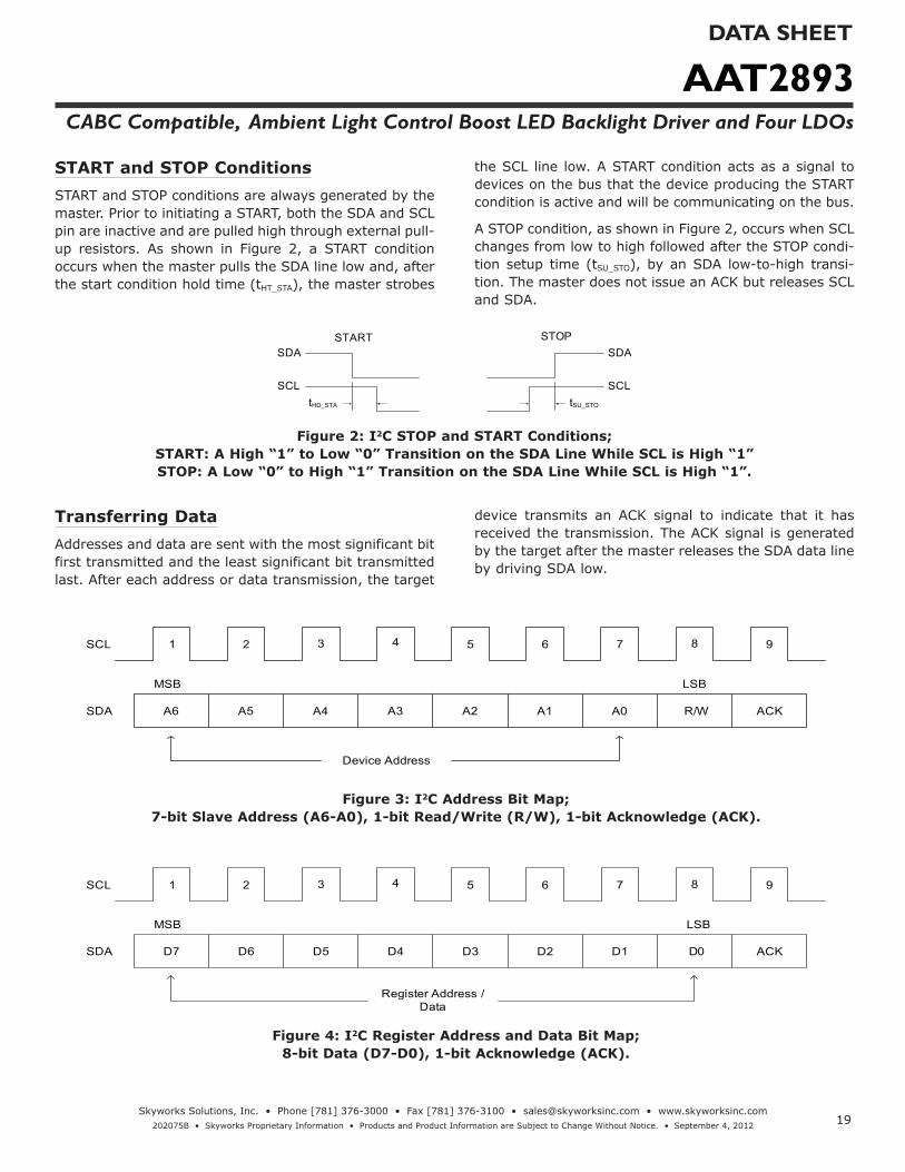
START and STOP ConditionsSTART and STOP conditions are always generated by the master. Prior to initiating a START, both the SDA and SCL pin are inactive and are pulled high through external pull-up resistors. As shown in Figure 2, a START condition occurs when the master pulls the SDA line low and, after the start condition hold time (tHT_STA), the master strobes
the SCL line low. A START condition acts as a signal to devices on the bus that the device producing the START condition is active and will be communicating on the bus.
A STOP condition, as shown in Figure 2, occurs when SCL changes from low to high followed after the STOP condi-tion setup time (tSU_STO), by an SDA low-to-high transi-tion. The master does not issue an ACK but releases SCL and SDA.
SDA
SCL
SDA
SCL
START STOP
tSU_STOtHD_STA
Figure 2: I2C STOP and START Conditions; START: A High “1” to Low “0” Transition on the SDA Line While SCL is High “1” STOP: A Low “0” to High “1” Transition on the SDA Line While SCL is High “1”.
Transferring DataAddresses and data are sent with the most significant bit first transmitted and the least significant bit transmitted last. After each address or data transmission, the target
device transmits an ACK signal to indicate that it has received the transmission. The ACK signal is generated by the target after the master releases the SDA data line by driving SDA low.
SCL 1 2 3 4 5 6 7 8 9
SDA A6 A5 A4 A3 A2 A1 A0 R/W ACK
Device Address
LSBMSB
Figure 3: I2C Address Bit Map; 7-bit Slave Address (A6-A0), 1-bit Read/Write (R/W), 1-bit Acknowledge (ACK).
SCL 1 2 3 4 5 6 7 8 9
SDA D7 D6 D5 D4 D3 D2 D1 D0 ACK
Register Address / Data
LSBMSB
Figure 4: I2C Register Address and Data Bit Map; 8-bit Data (D7-D0), 1-bit Acknowledge (ACK).

AAT2893DATA SHEET
CABC Compatible, Ambient Light Control Boost LED Backlight Driver and Four LDOs
20Skyworks Solutions, Inc. • Phone [781] 376-3000 • Fax [781] 376-3100 • [email protected] • www.skyworksinc.com
202075B • Skyworks Proprietary Information • Products and Product Information are Subject to Change Without Notice. • September 4, 2012
Writing to Slave DeviceWhen the Read/Write bit is set to 0 and the address transmitted by the master matches the slave device’s address, the slave device transmits an Acknowledge (ACK) signal to indicate that it is ready to receive data. Next, the master transmits the 8-bit register address,
and the slave device transmits an ACK to indicate that it received the register address. After that, the master transmits the 8-bit data word, and again the slave device transmits an ACK indicating that it received the data. This process continues until the master finishes writing to the slave device at which time the master generates a STOP condition.
AAT2893 Device Address Id = 60h w ack Addr = 0 0 h ack Address = 00h Data = 06h ack stop start
SDA
SCL
start w ack ack ack stop
First Byte Writes as 0xC0
Chip Address msb lsb Register Address msb lsb Register Data msb lsb
Figure 5: AAT2893 I2C Write Timing Diagram.
Reading from Slave DeviceWhen the Read/Write bit is set to 1 and the address transmitted by the master matches the slave device’s address, the slave device transmits an Acknowledge (ACK) signal to indicate that it is ready to receive data.
Next, the slave device transmits the 8-bit data word, and the master reads the data byte and transmits an Acknowledge ACK to indicate that it received the byte, and generates a STOP condition.
AAT2893 Device Address Id = 60h r ack Data = 0 8 h ack stopstart
SDA
SCL
start Chip Address w ack ack Register Data stop
msb lsb msb lsb
First Byte Writes as 0xC1
Figure 6: AAT2893 I2C Read Timing Diagram.
AAT2893DATA SHEET
CABC Compatible, Ambient Light Control Boost LED Backlight Driver and Four LDOs
21Skyworks Solutions, Inc. • Phone [781] 376-3000 • Fax [781] 376-3100 • [email protected] • www.skyworksinc.com
202075B • Skyworks Proprietary Information • Products and Product Information are Subject to Change Without Notice. • September 4, 2012
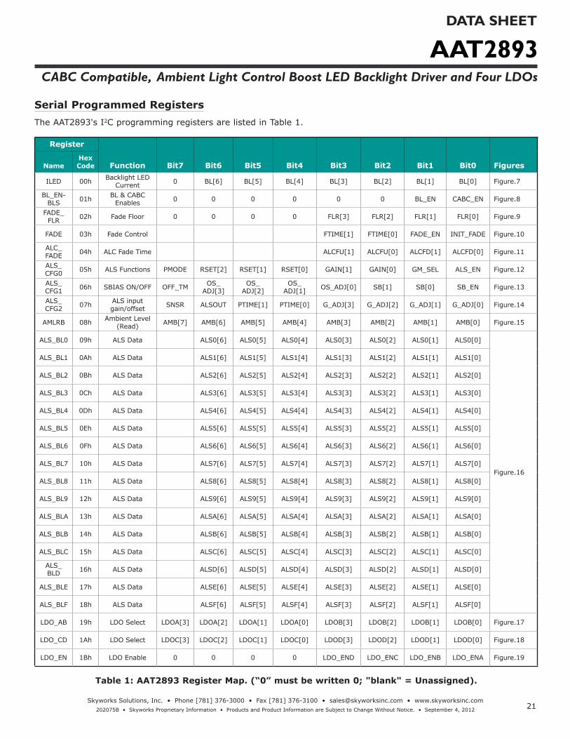
Serial Programmed RegistersThe AAT2893's I2C programming registers are listed in Table 1.
Register
Function Bit7 Bit6 Bit5 Bit4 Bit3 Bit2 Bit1 Bit0 FiguresNameHex Code
ILED 00h Backlight LED Current 0 BL[6] BL[5] BL[4] BL[3] BL[2] BL[1] BL[0] Figure.7
BL_EN-BLS 01h BL & CABC
Enables 0 0 0 0 0 0 BL_EN CABC_EN Figure.8
FADE_FLR 02h Fade Floor 0 0 0 0 FLR[3] FLR[2] FLR[1] FLR[0] Figure.9
FADE 03h Fade Control FTIME[1] FTIME[0] FADE_EN INIT_FADE Figure.10
ALC_FADE 04h ALC Fade Time ALCFU[1] ALCFU[0] ALCFD[1] ALCFD[0] Figure.11
ALS_CFG0 05h ALS Functions PMODE RSET[2] RSET[1] RSET[0] GAIN[1] GAIN[0] GM_SEL ALS_EN Figure.12
ALS_CFG1 06h SBIAS ON/OFF OFF_TM OS_
ADJ[3]OS_
ADJ[2]OS_
ADJ[1] OS_ADJ[0] SB[1] SB[0] SB_EN Figure.13
ALS_CFG2 07h ALS input
gain/offset SNSR ALSOUT PTIME[1] PTIME[0] G_ADJ[3] G_ADJ[2] G_ADJ[1] G_ADJ[0] Figure.14
AMLRB 08h Ambient Level (Read) AMB[7] AMB[6] AMB[5] AMB[4] AMB[3] AMB[2] AMB[1] AMB[0] Figure.15
ALS_BL0 09h ALS Data ALS0[6] ALS0[5] ALS0[4] ALS0[3] ALS0[2] ALS0[1] ALS0[0]
Figure.16
ALS_BL1 0Ah ALS Data ALS1[6] ALS1[5] ALS1[4] ALS1[3] ALS1[2] ALS1[1] ALS1[0]
ALS_BL2 0Bh ALS Data ALS2[6] ALS2[5] ALS2[4] ALS2[3] ALS2[2] ALS2[1] ALS2[0]
ALS_BL3 0Ch ALS Data ALS3[6] ALS3[5] ALS3[4] ALS3[3] ALS3[2] ALS3[1] ALS3[0]
ALS_BL4 0Dh ALS Data ALS4[6] ALS4[5] ALS4[4] ALS4[3] ALS4[2] ALS4[1] ALS4[0]
ALS_BL5 0Eh ALS Data ALS5[6] ALS5[5] ALS5[4] ALS5[3] ALS5[2] ALS5[1] ALS5[0]
ALS_BL6 0Fh ALS Data ALS6[6] ALS6[5] ALS6[4] ALS6[3] ALS6[2] ALS6[1] ALS6[0]
ALS_BL7 10h ALS Data ALS7[6] ALS7[5] ALS7[4] ALS7[3] ALS7[2] ALS7[1] ALS7[0]
ALS_BL8 11h ALS Data ALS8[6] ALS8[5] ALS8[4] ALS8[3] ALS8[2] ALS8[1] ALS8[0]
ALS_BL9 12h ALS Data ALS9[6] ALS9[5] ALS9[4] ALS9[3] ALS9[2] ALS9[1] ALS9[0]
ALS_BLA 13h ALS Data ALSA[6] ALSA[5] ALSA[4] ALSA[3] ALSA[2] ALSA[1] ALSA[0]
ALS_BLB 14h ALS Data ALSB[6] ALSB[5] ALSB[4] ALSB[3] ALSB[2] ALSB[1] ALSB[0]
ALS_BLC 15h ALS Data ALSC[6] ALSC[5] ALSC[4] ALSC[3] ALSC[2] ALSC[1] ALSC[0]
ALS_BLD 16h ALS Data ALSD[6] ALSD[5] ALSD[4] ALSD[3] ALSD[2] ALSD[1] ALSD[0]
ALS_BLE 17h ALS Data ALSE[6] ALSE[5] ALSE[4] ALSE[3] ALSE[2] ALSE[1] ALSE[0]
ALS_BLF 18h ALS Data ALSF[6] ALSF[5] ALSF[4] ALSF[3] ALSF[2] ALSF[1] ALSF[0]
LDO_AB 19h LDO Select LDOA[3] LDOA[2] LDOA[1] LDOA[0] LDOB[3] LDOB[2] LDOB[1] LDOB[0] Figure.17
LDO_CD 1Ah LDO Select LDOC[3] LDOC[2] LDOC[1] LDOC[0] LDOD[3] LDOD[2] LDOD[1] LDOD[0] Figure.18
LDO_EN 1Bh LDO Enable 0 0 0 0 LDO_END LDO_ENC LDO_ENB LDO_ENA Figure.19
Table 1: AAT2893 Register Map. (“0” must be written 0; "blank" = Unassigned).

AAT2893DATA SHEET
CABC Compatible, Ambient Light Control Boost LED Backlight Driver and Four LDOs
22Skyworks Solutions, Inc. • Phone [781] 376-3000 • Fax [781] 376-3100 • [email protected] • www.skyworksinc.com
202075B • Skyworks Proprietary Information • Products and Product Information are Subject to Change Without Notice. • September 4, 2012
-- BL[4] BL[3] BL[2] BL[1] BL[0]
ILED: Backlight LED Current Control Register (Address 00h, Default 58h)
Bit 7 Bit 0
U-0 W-1 W-1 W-0 W-0 W-0
Legend:
R = Readable bit W = Writeable bit
x = Bit is unknown-v = Default value ‘1’ = Bit is set ‘0’ = Bit is cleared
n = Channel numberU = Unassigned
W-1 W-0
Bit 7 Unassigned
Bit 6 – Bit 0 BL<6:0>: Backlight LED Current Magnitude
0000000 = 0.00 mA0000001 = 0.23 mA0000010 = 0.45 mA0000011 = 0.68 mA0000100 = 0.90 mA0000101 = 1.13 mA0000110 = 1.35 mA0000111 = 1.58 mA0001000 = 1.80 mA0001001 = 2.03 mA0001010 = 2.25 mA0001011 = 2.48 mA0001100 = 2.70 mA0001101 = 2.93 mA0001110 = 3.15 mA0001111 = 3.38 mA0010000 = 3.60 mA0010001 = 3.83 mA0010010 = 4.05 mA0010011 = 4.28 mA0010100 = 4.50 mA0010101 = 4.73 mA0010110 = 4.95 mA0010111 = 5.18 mA0011000 = 5.40 mA0011001 = 5.63 mA0011010 = 5.85 mA0011011 = 6.08 mA0011100 = 6.30 mA0011101 = 6.53 mA0011110 = 6.75 mA0011111 = 6.98 mA0100000 = 7.20 mA0100001 = 7.43 mA0100010 = 7.65 mA0100011 = 7.87 mA0100100 = 8.10 mA0100101 = 8.32 mA0100110 = 8.55 mA0100111 = 8.77 mA0101000 = 9.00 mA0101001 = 9.22 mA0101010 = 9.45 mA0101011 = 9.67 mA
BL[6] BL[5]
0101100 = 9.90 mA0101101 = 10.13 mA0101110 = 10.35 mA0101111 = 10.58 mA0110000 = 10.80 mA0110001 = 11.03 mA0110010 = 11.25 mA0110011 = 11.48 mA0110100 = 11.70 mA0110101 = 11.93 mA0110110 = 12.15 mA0110111 = 12.38 mA0111000 = 12.60 mA0111001 = 12.83 mA0111010 = 13.05 mA0111011 = 13.28 mA0111100 = 13.50 mA0111101 = 13.73 mA0111110 = 13.95 mA0111111 = 14.18 mA1000000 = 14.40 mA1000001 = 14.63 mA1000010 = 14.85 mA1000011 = 15.08 mA1000100 = 15.30 mA1000101 = 15.53 mA1000110 = 15.75 mA1000111 = 15.98 mA1001000 = 16.20 mA1001001 = 16.43 mA1001010 = 16.65 mA1001011 = 16.88 mA1001100 = 17.10 mA1001101 = 17.33 mA1001110 = 17.55 mA1001111 = 17.78 mA1010000 = 18.00 mA1010001 = 18.23 mA1010010 = 18.45 mA1010011 = 18.68 mA1010100 = 18.90 mA1010101 = 19.13 mA1010110 = 19.35 mA1010111 = 19.58 mA
1011000 = 19.80 mA1011001 = 20.03 mA1011010 = 20.25 mA1011011 = 20.48 mA1011100 = 20.70 mA1011101 = 20.93 mA1011110 = 21.15 mA1011111 = 21.38 mA1100000 = 21.60 mA1100001 = 21.83 mA1100010 = 22.05 mA1100011 = 22.28 mA1100100 = 22.50 mA1100101 = 22.73 mA1100110 = 22.95 mA1100111 = 23.18 mA1101000 = 23.40 mA1101001 = 23.63 mA1101010 = 23.85 mA1101011 = 24.08 mA1101100 = 24.30 mA 1101101 = 24.53 mA1101110 = 24.75 mA1101111 = 24.98 mA1110000 = 25.20 mA1110001 = 25.43 mA1110010 = 25.65 mA1110011 = 25.88 mA1110100 = 26.10 mA1110101 = 26.33 mA1110110 = 26.55 mA1110111 = 26.78 mA1111000 = 27.00 mA1111001 = 27.23 mA1111010 = 27.45 mA1111011 = 27.68 mA1111100 = 27.90 mA1111101 = 28.13 mA1111110 = 28.35 mA1111111 = 28.58 mA
Figure 7: Backlight Current Control Register.
AAT2893DATA SHEET
CABC Compatible, Ambient Light Control Boost LED Backlight Driver and Four LDOs
23Skyworks Solutions, Inc. • Phone [781] 376-3000 • Fax [781] 376-3100 • [email protected] • www.skyworksinc.com
202075B • Skyworks Proprietary Information • Products and Product Information are Subject to Change Without Notice. • September 4, 2012
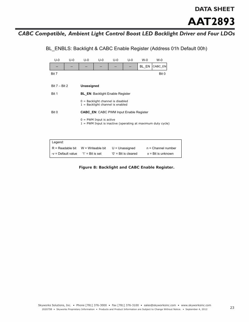
-- -- -- -- -- --
Bit 7 – Bit 2 Unassigned
Bit 1 BL_EN: Backlight Enable Register
0 = Backlight channel is disabled1 = Backlight channel is enabled
Bit 0 CABC_EN: CABC PWM Input Enable Register
0 = PWM Input is active1 = PWM Input is inactive (operating at maximum duty cycle)
BL_EN CABC_EN
BL_ENBLS: Backlight & CABC Enable Register (Address 01h Default 00h)
Bit 7 Bit 0
U-0 U-0 U-0 U-0 U-0 U-0 W-0 W-0
Legend:
R = Readable bit W = Writeable bit
x = Bit is unknown-v = Default value ‘1’ = Bit is set ‘0’ = Bit is cleared
n = Channel numberU = Unassigned
Figure 8: Backlight and CABC Enable Register.
AAT2893DATA SHEET
CABC Compatible, Ambient Light Control Boost LED Backlight Driver and Four LDOs
24Skyworks Solutions, Inc. • Phone [781] 376-3000 • Fax [781] 376-3100 • [email protected] • www.skyworksinc.com
202075B • Skyworks Proprietary Information • Products and Product Information are Subject to Change Without Notice. • September 4, 2012
-- -- -- --
Bit 7 – Bit 4 Unassigned
Bit 3 – Bit 0 FLR<3:0>: Fade In/Out Floor Levels
0000 = 0.45 mA0001 = 0.90 mA0010 = 1.80 mA0011 = 2.70 mA0100 = 3.60 mA0101 = 4.50 mA0110 = 5.40 mA0111 = 6.30 mA1000 = 7.20 mA1001 = 8.10 mA1010 = 9.00 mA1011 = 9.90 mA1100 = 10.8 mA1101 = 11.7 mA1110 = 12.6 mA1111 = 13.5 mA
Bit 7 Bit 0
U-0 U-0 W-0 W-0 W-0 W-0
Legend:
R = Readable bit W = Writeable bit
x = Bit is unknown-v = Default value ‘1’ = Bit is set ‘0’ = Bit is cleared
n = Channel numberU = Unassigned
U-0 U-0
FLR[3] FLR[2] FLR[1] FLR[0]
FADE_FLR: Fade In/ Out Floor Levels Register (Address 02h Default 00h)
Figure 9: Backlight Fade In/Out Level Register.

AAT2893DATA SHEET
CABC Compatible, Ambient Light Control Boost LED Backlight Driver and Four LDOs
25Skyworks Solutions, Inc. • Phone [781] 376-3000 • Fax [781] 376-3100 • [email protected] • www.skyworksinc.com
202075B • Skyworks Proprietary Information • Products and Product Information are Subject to Change Without Notice. • September 4, 2012
Bit 7 – Bit 4 Unassigned
Bit 3 – Bit 2 FTIME<1:0>: Fade In/Out Timing
00 = 1.0 sec01 = 0.8 sec10 = 0.6 sec11 = 0.4 sec
Bit 1 FADE_EN: Fade In/Out Enable
0 = Fade in/out is enabled for backlight group1 = Fade in/out is disabled for backlight group
Bit 0 INIT_FADE: Fade In/Out Initiation
0 = Fade out is initiated for backlight group
1 = Fade in is initiated for backlight group
FADE: Fade In/ Out Control Register (Address 03h Default 03h)
Bit 7 Bit 0
U-0 U-0 W-0 W-0 W-1 W-1U-0 U-0
FTIME[1] FTIME[0] FADE_EN INIT_FADE-- -- -- --
Legend:
R = Readable bit W = Writeable bit
x = Bit is unknown-v = Default value ‘1’ = Bit is set ‘0’ = Bit is cleared
n = Current Sink numberU = Unassigned
Figure 10: Backlight Fade In/Out Time and Enable Control Register.

AAT2893DATA SHEET
CABC Compatible, Ambient Light Control Boost LED Backlight Driver and Four LDOs
26Skyworks Solutions, Inc. • Phone [781] 376-3000 • Fax [781] 376-3100 • [email protected] • www.skyworksinc.com
202075B • Skyworks Proprietary Information • Products and Product Information are Subject to Change Without Notice. • September 4, 2012
-- -- -- --
Bit 7 – Bit 4 Unassigned
Bit 3 – Bit 2 ALCFU<1:0>: Ambient Light Control Fade Up Time and Rate Register
00 = Fade Up Time is 100ms, Fade Up Rate is 0.8ms/step01 = Fade Up Time is 200ms, Fade Up Rate is 1.6ms/step10 = Fade Up Time is 400ms, Fade Up Rate is 3.1ms/step11 = Fade Up Time is 800ms, Fade Up Rate is 6.3ms/step
Bit 1 – Bit 0 ALCFD<1:0>: Ambient Light Control Fade Down Time and Rate Register
00 = Fade Down Time is 50ms, Fade Down Rate is 0.4ms/step01 = Fade Down Time is 100ms, Fade Down Rate is 0.8ms/step10 = Fade Down Time is 200ms, Fade Down Rate is 1.6ms/step11 = Fade Down Time is 400ms, Fade Down Rate is 3.1ms/step
ALC_FADE: Ambient Light Control Fade up/down Time and Rate Register (Address 04h Default 0Bh)
Bit 7 Bit 0
U-0 U-0 W-1 W-0 W-1 W-1U-0 U-0
Legend:
R = Readable bit W = Writeable bit
x = Bit is unknown-v = Default value ‘1’ = Bit is set ‘0’ = Bit is cleared
n = Current Sink numberU = Unassigned
ALCFU[1] ALCFU[0] ALCFD[1] ALCFD[0]
Figure 11: ALS Fade Up/Down Time and Rate Register.
AAT2893DATA SHEET
CABC Compatible, Ambient Light Control Boost LED Backlight Driver and Four LDOs
27Skyworks Solutions, Inc. • Phone [781] 376-3000 • Fax [781] 376-3100 • [email protected] • www.skyworksinc.com
202075B • Skyworks Proprietary Information • Products and Product Information are Subject to Change Without Notice. • September 4, 2012
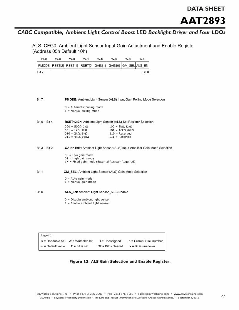
Bit 7 PMODE: Ambient Light Sensor (ALS) Input Gain Polling Mode Selection
0 = Automatic polling mode1 = Manual polling mode
Bit 6 – Bit 4 RSET<2:0>: Ambient Light Sensor (ALS) Set Resistor Selection000 = 500Ω, 2kΩ 100 = 8kΩ, 32kΩ 001 = 1kΩ, 4kΩ 101 = 16kΩ, 64kΩ010 = 2kΩ, 8kΩ 110 = Reserved011 = 4kΩ, 16kΩ 111 = Reserved
Bit 3 – Bit 2 GAIN<1:0>: Ambient Light Sensor (ALS) Input Amplifier Gain Mode Selection
00 = Low gain mode01 = High gain mode1X = Fixed gain mode (External Resistor Required)
Bit 1 GM_SEL: Ambient Light Sensor (ALS) Gain Mode Selection
0 = Auto gain mode1 = Manual gain mode
Bit 0 ALS_EN: Ambient Light Sensor (ALS) Enable
0 = Disable ambient light sensor1 = Enable ambient light sensor
ALS_CFG0: Ambient Light Sensor Input Gain Adjustment and Enable Register (Address 05h Default 10h)
Bit 7 Bit 0
W-0 W-1 W-0 W-0 W-0 W-0W-0 W-0
Legend:
R = Readable bit W = Writeable bit
x = Bit is unknown-v = Default value ‘1’ = Bit is set ‘0’ = Bit is cleared
n = Current Sink numberU = Unassigned
RSET[2]PMODE RSET[1] RSET[0] GAIN[1] GAIN[0] GM_SEL ALS_EN
Figure 12: ALS Gain Selection and Enable Register.
AAT2893DATA SHEET
CABC Compatible, Ambient Light Control Boost LED Backlight Driver and Four LDOs
28Skyworks Solutions, Inc. • Phone [781] 376-3000 • Fax [781] 376-3100 • [email protected] • www.skyworksinc.com
202075B • Skyworks Proprietary Information • Products and Product Information are Subject to Change Without Notice. • September 4, 2012
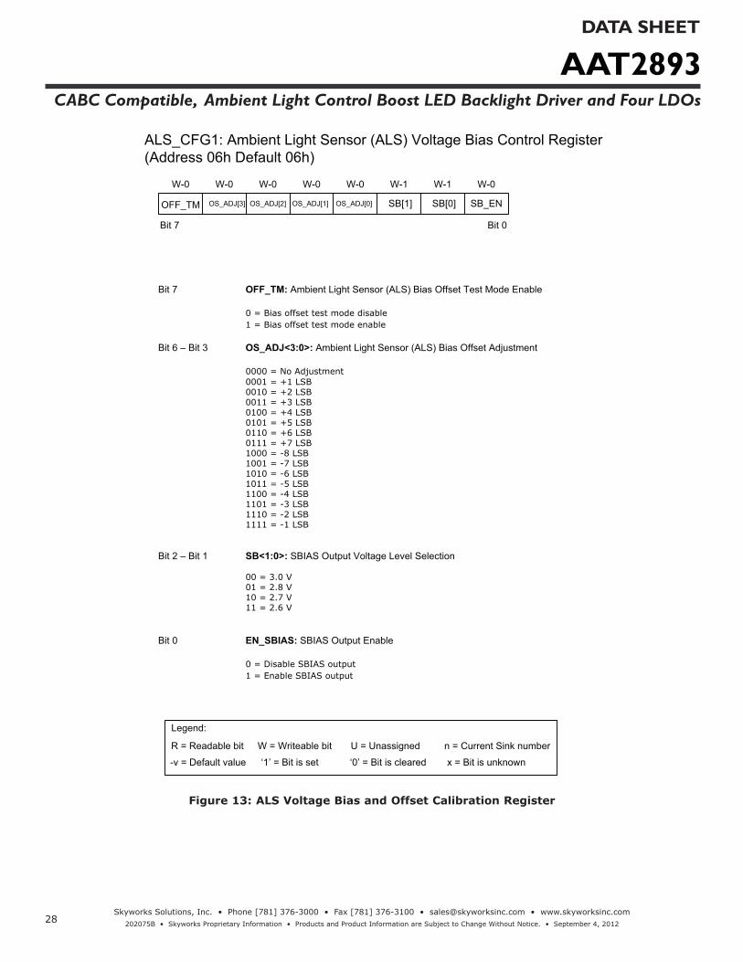
Bit 7 OFF_TM: Ambient Light Sensor (ALS) Bias Offset Test Mode Enable
0 = Bias offset test mode disable1 = Bias offset test mode enable
Bit 6 – Bit 3 OS_ADJ<3:0>: Ambient Light Sensor (ALS) Bias Offset Adjustment
0000 = No Adjustment0001 = +1 LSB0010 = +2 LSB0011 = +3 LSB0100 = +4 LSB0101 = +5 LSB0110 = +6 LSB0111 = +7 LSB1000 = -8 LSB1001 = -7 LSB1010 = -6 LSB1011 = -5 LSB1100 = -4 LSB1101 = -3 LSB1110 = -2 LSB1111 = -1 LSB
Bit 2 – Bit 1 SB<1:0>: SBIAS Output Voltage Level Selection
00 = 3.0 V01 = 2.8 V10 = 2.7 V11 = 2.6 V
Bit 0 EN_SBIAS: SBIAS Output Enable
0 = Disable SBIAS output1 = Enable SBIAS output
ALS_CFG1: Ambient Light Sensor (ALS) Voltage Bias Control Register (Address 06h Default 06h)
Bit 7 Bit 0
W-0 W-0 W-0 W-1 W-1 W-0W-0 W-0
SB[1] SB[0] SB_EN
Legend:
R = Readable bit W = Writeable bit
x = Bit is unknown-v = Default value ‘1’ = Bit is set ‘0’ = Bit is cleared
n = Current Sink numberU = Unassigned
OS_ADJ[3]OFF_TM OS_ADJ[2] OS_ADJ[1] OS_ADJ[0]
Figure 13: ALS Voltage Bias and Offset Calibration Register
AAT2893DATA SHEET
CABC Compatible, Ambient Light Control Boost LED Backlight Driver and Four LDOs
29Skyworks Solutions, Inc. • Phone [781] 376-3000 • Fax [781] 376-3100 • [email protected] • www.skyworksinc.com
202075B • Skyworks Proprietary Information • Products and Product Information are Subject to Change Without Notice. • September 4, 2012
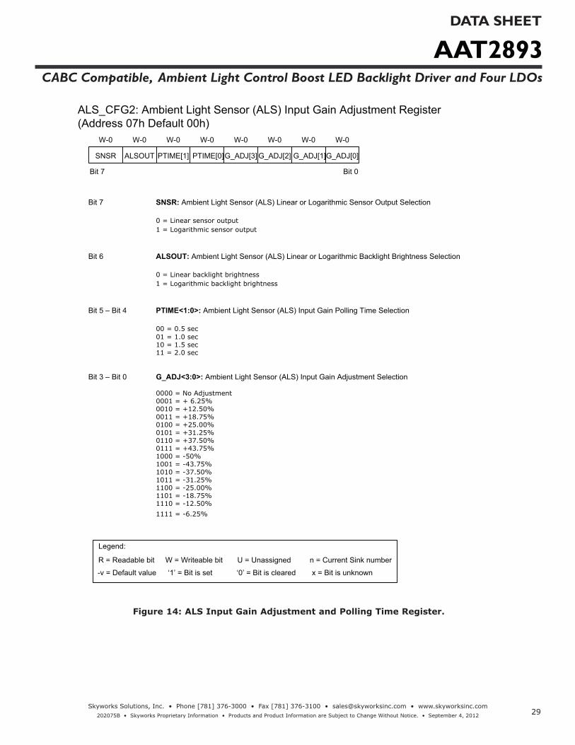
Bit 7 SNSR: Ambient Light Sensor (ALS) Linear or Logarithmic Sensor Output Selection
0 = Linear sensor output1 = Logarithmic sensor output
Bit 6 ALSOUT: Ambient Light Sensor (ALS) Linear or Logarithmic Backlight Brightness Selection
0 = Linear backlight brightness1 = Logarithmic backlight brightness
Bit 5 – Bit 4 PTIME<1:0>: Ambient Light Sensor (ALS) Input Gain Polling Time Selection
00 = 0.5 sec01 = 1.0 sec10 = 1.5 sec11 = 2.0 sec
Bit 3 – Bit 0 G_ADJ<3:0>: Ambient Light Sensor (ALS) Input Gain Adjustment Selection
0000 = No Adjustment0001 = + 6.25%0010 = +12.50%0011 = +18.75% 0100 = +25.00% 0101 = +31.25% 0110 = +37.50% 0111 = +43.75%1000 = -50%1001 = -43.75%1010 = -37.50% 1011 = -31.25% 1100 = -25.00% 1101 = -18.75% 1110 = -12.50% 1111 = -6.25%
ALS_CFG2: Ambient Light Sensor (ALS) Input Gain Adjustment Register (Address 07h Default 00h)
Bit 7 Bit 0
W-0 W-0 W-0 W-0 W-0 W-0W-0 W-0
Legend:
R = Readable bit W = Writeable bit
x = Bit is unknown-v = Default value ‘1’ = Bit is set ‘0’ = Bit is cleared
n = Current Sink numberU = Unassigned
ALSOUTSNSR PTIME[1] PTIME[0]G_ADJ[3] G_ADJ[2] G_ADJ[1]G_ADJ[0]
Figure 14: ALS Input Gain Adjustment and Polling Time Register.
AAT2893DATA SHEET
CABC Compatible, Ambient Light Control Boost LED Backlight Driver and Four LDOs
30Skyworks Solutions, Inc. • Phone [781] 376-3000 • Fax [781] 376-3100 • [email protected] • www.skyworksinc.com
202075B • Skyworks Proprietary Information • Products and Product Information are Subject to Change Without Notice. • September 4, 2012
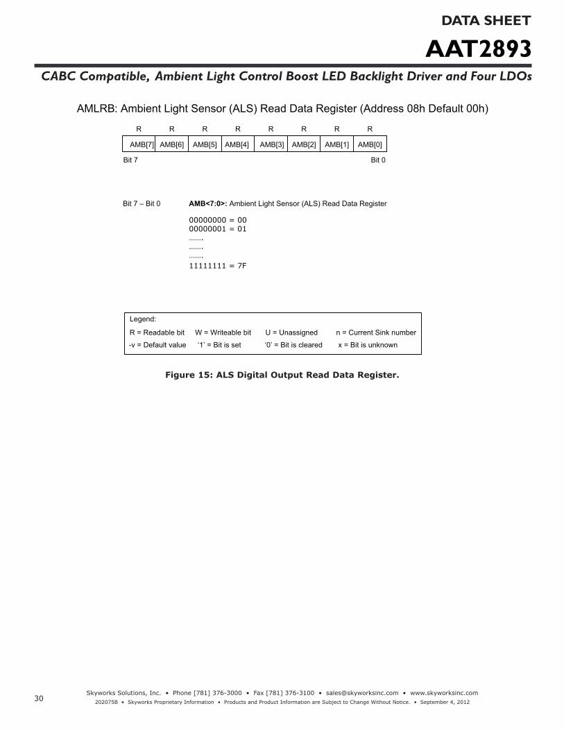
Bit 7 – Bit 0 AMB<7:0>: Ambient Light Sensor (ALS) Read Data Register
00000000 = 0000000001 = 01…….…….…….11111111 = 7F
AMLRB: Ambient Light Sensor (ALS) Read Data Register (Address 08h Default 00h)
Bit 7 Bit 0
R R R R R RR R
Legend:
R = Readable bit W = Writeable bit
x = Bit is unknown-v = Default value ‘1’ = Bit is set ‘0’ = Bit is cleared
n = Current Sink numberU = Unassigned
AMB[7] AMB[6] AMB[5] AMB[4] AMB[3] AMB[2] AMB[1] AMB[0]
Figure 15: ALS Digital Output Read Data Register.

AAT2893DATA SHEET
CABC Compatible, Ambient Light Control Boost LED Backlight Driver and Four LDOs
31Skyworks Solutions, Inc. • Phone [781] 376-3000 • Fax [781] 376-3100 • [email protected] • www.skyworksinc.com
202075B • Skyworks Proprietary Information • Products and Product Information are Subject to Change Without Notice. • September 4, 2012
ALS_BLn: Ambient Light Sensor (ALS) Backlight Current Level Programming Register (Address 09h – Address 18h Default 00h)
Bit 7 Bit 0
U-0
Legend:
R = Readable bit W = Writeable bit
x = Bit is unknown-v = Default value ‘1’ = Bit is set ‘0’ = Bit is cleared
n = Current Sink numberU = Unassigned
ALSn[6] ALSn[5] ALSn[4] ALSn[3] ALSn[2] ALSn[1] ALSn[0]
W-0 W-0 W-0 W-0 W-0 W-0 W-0
LED Current(Log)
LED Current(mA)
Brightness(Lux)
Bit 6 – Bit 0 ALSn<6:0>: Ambient Light Sensor (ALS) Backlight Current Level Programming
0000100 = 0.00 0.9 640000101 = 0.10 1.1 910000111 = 0.19 1.4 1300001001 = 0.29 1.8 1850001011 = 0.39 2.3 2630001110 = 0.49 2.9 3740010001 = 0.58 3.6 5320010101 = 0.68 4.5 7580011011 = 0.78 5.7 10790100010 = 0.88 7.2 15350101010 = 0.97 9.0 21850110100 = 1.07 11.4 31111000001 = 1.17 14.3 44281010010 = 1.26 18.0 63031100110 = 1.36 22.7 89711111111 = 1.46 28.6 12770
--
Figure 16: ALS Controlled Current Dimming Levels Programming Register.
AAT2893DATA SHEET
CABC Compatible, Ambient Light Control Boost LED Backlight Driver and Four LDOs
32Skyworks Solutions, Inc. • Phone [781] 376-3000 • Fax [781] 376-3100 • [email protected] • www.skyworksinc.com
202075B • Skyworks Proprietary Information • Products and Product Information are Subject to Change Without Notice. • September 4, 2012
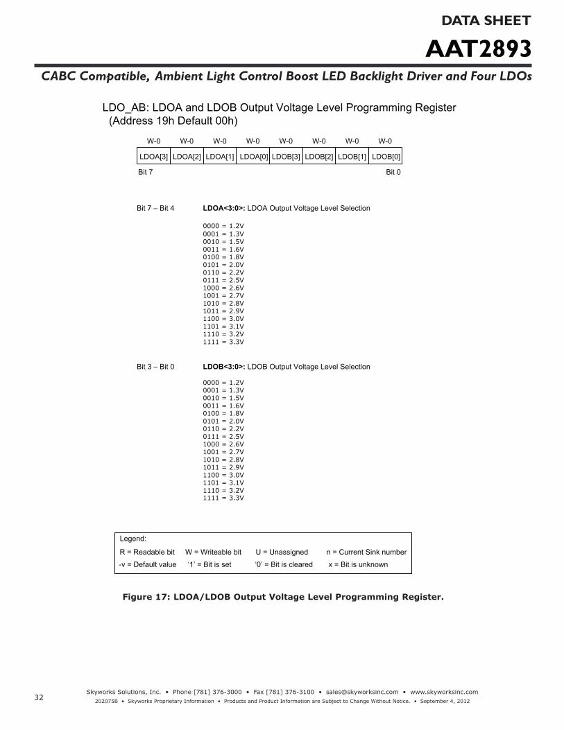
Bit 7 – Bit 4 LDOA<3:0>: LDOA Output Voltage Level Selection
0000 = 1.2V 0001 = 1.3V 0010 = 1.5V 0011 = 1.6V 0100 = 1.8V 0101 = 2.0V 0110 = 2.2V 0111 = 2.5V 1000 = 2.6V 1001 = 2.7V 1010 = 2.8V 1011 = 2.9V 1100 = 3.0V 1101 = 3.1V 1110 = 3.2V 1111 = 3.3V
Bit 3 – Bit 0 LDOB<3:0>: LDOB Output Voltage Level Selection
0000 = 1.2V 0001 = 1.3V 0010 = 1.5V 0011 = 1.6V 0100 = 1.8V 0101 = 2.0V 0110 = 2.2V 0111 = 2.5V 1000 = 2.6V 1001 = 2.7V 1010 = 2.8V 1011 = 2.9V 1100 = 3.0V 1101 = 3.1V 1110 = 3.2V 1111 = 3.3V
LDO_AB: LDOA and LDOB Output Voltage Level Programming Register (Address 19h Default 00h)
Bit 7 Bit 0
W-0 W-0 W-0 W-0 W-0 W-0W-0 W-0
Legend:
R = Readable bit W = Writeable bit
x = Bit is unknown-v = Default value ‘1’ = Bit is set ‘0’ = Bit is cleared
n = Current Sink numberU = Unassigned
LDOA[3] LDOA[2] LDOA[1] LDOA[0] LDOB[3] LDOB[2] LDOB[1] LDOB[0]
Figure 17: LDOA/LDOB Output Voltage Level Programming Register.

AAT2893DATA SHEET
CABC Compatible, Ambient Light Control Boost LED Backlight Driver and Four LDOs
33Skyworks Solutions, Inc. • Phone [781] 376-3000 • Fax [781] 376-3100 • [email protected] • www.skyworksinc.com
202075B • Skyworks Proprietary Information • Products and Product Information are Subject to Change Without Notice. • September 4, 2012
Bit 7 – Bit 4 LDOC<3:0>: LDOC Output Voltage Level Selection
0000 = 1.2V 0001 = 1.3V 0010 = 1.5V 0011 = 1.6V 0100 = 1.8V 0101 = 2.0V 0110 = 2.2V 0111 = 2.5V 1000 = 2.6V 1001 = 2.7V 1010 = 2.8V 1011 = 2.9V 1100 = 3.0V 1101 = 3.1V 1110 = 3.2V 1111 = 3.3V
Bit 3 – Bit 0 LDOD<3:0>: LDOD Output Voltage Level Selection
0000 = 1.2V 0001 = 1.3V 0010 = 1.5V 0011 = 1.6V 0100 = 1.8V 0101 = 2.0V 0110 = 2.2V 0111 = 2.5V 1000 = 2.6V 1001 = 2.7V 1010 = 2.8V 1011 = 2.9V 1100 = 3.0V 1101 = 3.1V 1110 = 3.2V 1111 = 3.3V
LDO_CD: LDOC and LDOD Output Voltage Level Programming Register (Address 1Ah Default 00h)
Bit 7 Bit 0
W-0 W-0 W-0 W-0 W-0 W-0W-0 W-0
Legend:
R = Readable bit W = Writeable bit
x = Bit is unknown-v = Default value ‘1’ = Bit is set ‘0’ = Bit is cleared
n = Current Sink numberU = Unassigned
LDOC[3] LDOC[2] LDOC[1] LDOC[0] LDOD[3] LDOD[2] LDOD[1] LDOD[0]
Figure 18: LDOC/LDOD Output Voltage Level Programming Register.

AAT2893DATA SHEET
CABC Compatible, Ambient Light Control Boost LED Backlight Driver and Four LDOs
34Skyworks Solutions, Inc. • Phone [781] 376-3000 • Fax [781] 376-3100 • [email protected] • www.skyworksinc.com
202075B • Skyworks Proprietary Information • Products and Product Information are Subject to Change Without Notice. • September 4, 2012
Bit 7 – Bit 5 Unassigned
Bit 4
LDOD_ENA
: LDOD Output Enable
0 = LDOD output is disabled1 = LDOD output is enabled
Bit 3 : LDOC Output Enable
0 = LDOC output is disabled1 = LDOC output is enabled
Bit 2 : LDOB Output Enable
0 = LDOB output is disabled1 = LDOB output is enabled
Bit 3 : LDOA Output Enable
0 = LDOA output is disabled1 = LDOA output is enabled
LDO_EN: LDOA/B/C/D Output Enable Register (Address 1Bh Default 00h)
Bit 7 Bit 0
U-0 U-0 W-0 W-0 W-0 W-0U-0 U-0
-- -- -- --
Legend:
R = Readable bit W = Writeable bit
x = Bit is unknown-v = Default value ‘1’ = Bit is set ‘0’ = Bit is cleared
n = Current Sink numberU = Unassigned
LDO_END LDO_ENALDO_ENBLDO_ENC
LDOD_ENB
LDOD_ENC
LDOD_END
Figure 19: LDO Output Enable Register.
AAT2893DATA SHEET
CABC Compatible, Ambient Light Control Boost LED Backlight Driver and Four LDOs
35Skyworks Solutions, Inc. • Phone [781] 376-3000 • Fax [781] 376-3100 • [email protected] • www.skyworksinc.com
202075B • Skyworks Proprietary Information • Products and Product Information are Subject to Change Without Notice. • September 4, 2012
Application Information
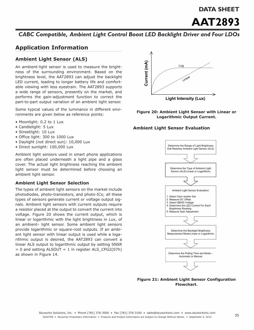
Ambient Light Sensor (ALS)An ambient-light sensor is used to measure the bright-ness of the surrounding environment. Based on the brightness level, the AAT2893 can adjust the backlight LED current, leading to longer battery life and comfort-able viewing with less eyestrain. The AAT2893 supports a wide range of sensors, presently on the market, and performs the gain-adjustment function to correct the part-to-part output variation of an ambient light sensor.
Some typical values of the luminance in different envi-ronments are given below as reference points:
• Moonlight: 0.2 to 1 Lux• Candlelight: 5 Lux• Streetlight: 10 Lux• Office light: 300 to 1000 Lux• Daylight (not direct sun): 10,000 Lux• Direct sunlight: 100,000 Lux
Ambient light sensors used in smart phone applications are often placed underneath a light pipe and a glass cover. The actual light brightness reaching the ambient light sensor must be determined before choosing an ambient light sensor.
Ambient Light Sensor SelectionThe types of ambient light sensors on the market include photodiodes, photo-transistors, and photo-ICs; all these types of sensors generate current or voltage output sig-nals. Ambient light sensors with current outputs require a resistor placed at the output to convert the current into voltage. Figure 20 shows the current output, which is linear or logarithmic with the light brightness in Lux, of an ambient- light sensor. Some ambient light sensors provide logarithmic or square-root outputs. If an ambi-ent light sensor with linear output is used while a loga-rithmic output is desired, the AAT2893 can convert a linear ALS output to logarithmic output by setting SNSR = 0 and setting ALSOUT = 1 in register ALS_CFG2(07h) as shown in Figure 14.
Light Intensity (Lux)
Cur
rent
(mA
)
Log
Linear
Figure 20: Ambient Light Sensor with Linear or Logarithmic Output Current.
Ambient Light Sensor Evaluation
Determine the Range of Light Brightness that Reaches Ambient Light Sensor (ALS)
Determine the Type of Ambient Light Sensor (ALS)-Linear or Logarithmic
Ambient Light Sensor Evaluation:
1. Select Gain resistor Set2. Measure DC Offset 3. Select SBIAS Voltage4. Determine the LED Current For Each Brightness Reading5. Measure Gain Adjustment
Determine the Backlight Brightness Measurement Mode-Linear or Logarithmic
Determine the Polling Time and Mode – Automatic or Manual
Figure 21: Ambient Light Sensor Configuration Flowchart.

AAT2893DATA SHEET
CABC Compatible, Ambient Light Control Boost LED Backlight Driver and Four LDOs
36Skyworks Solutions, Inc. • Phone [781] 376-3000 • Fax [781] 376-3100 • [email protected] • www.skyworksinc.com
202075B • Skyworks Proprietary Information • Products and Product Information are Subject to Change Without Notice. • September 4, 2012
EN_ALS
ADC
SBIAS
AMB<3:0>
Measurement100 ms for 1st Sample
500ms for PTIME<1:0> =00
200ms for Manual and Automatic Measurement with AMB_IN ≥ 0.4V (normal ambient brightness)300ms for Automatic Measurement with AMB_IN < 0.4V (dim ambient brightness)
Figure 22: Ambient Light Sensor A/D Conversion Timing Diagram.
Ambient Light Sensor Gain Resistor SelectionWhen an ambient light sensor with current output is selected, a load resistor is used to convert the output current into an output voltage. The AAT2893 provides a set of 6 internal resistor pairs that are listed in Figure 12. An external resistor can be used if none of the integrated resistor pairs fit the application requirement.
Example 1: The light luminance of the ambient light sensor is from 0 Lux to 10,000 Lux. If the output current of an ambient light sensor is 4μA per 100Lux, the resis-tor required to cover the whole luminance range can be calculated as follows:
The chosen resistor set is 4kΩ, 16kΩ.
Ambient Light Sensor Offset AdjustmentAny leakage current present will cause an offset at the output of the ambient light sensor, leading to inaccurate measurement of the light brightness. This offset can be corrected by programming bits OS_ADJ<3:0> in register ALS_CFG1 (06h) of the AAT2893. The four allocated bits provide offset correction from -8LSB to +7LSB, as shown in Figure 13.
The DC offset of the ambient-light sensor output can be
measured with the AAT2893. The AAT2893 is powered up and enabled with a power supply or a battery; the ambient light sensor is then enabled by writing ALS_EN = 1 to the ALS_CFG0 (05h) register (see Figure 12). The voltage bias for the ambient light sensor needs to be enabled as well by writing SB_EN = 1 to the ALS_CFG1 (06h) register (see Figure 13). The test mode of the ambient light sensor offset commences when writing OFF_TM = 1 to the ALS_CFG1 (06h) register.
Example 2: The procedure to determine the ambient light-sensor offset is explained below, assuming a resis-tor set of 4kΩ, 16kΩ is used:
• Connect the SBIAS pin of the AAT2893 to the input voltage pin of an ambient light sensor, and connect the AMB_IN pin of AAT2893 to the output pin of the ambi-ent- light sensor.
• The BH1600FVC ambient light sensor from Rohm is used with the AAT2893 demo board (Figures 30 and 31). Depending on how much light goes through the light pipe and reaches the ambient light sensor, the GC1 and GC2 setting can be determined. If the range of light is up to 10,000 Lux, the L-Gain mode should be chosen by connecting GC1 to GND and GC2 to SBIAS. If the range of light is up to 3,000 Lux or lower, then the H-Gain mode should be chosen by connecting GC1 to SBIAS and GC2 to GND. The difference between H-Gain mode and L-Gain mode is the amount of output current from the ambient light sensor (see Table 6).
4µAVAMB_IN (MAX)Low-gain Resistor =
∙ 10000Lux100Lux
= 4kΩ
AAT2893DATA SHEET
CABC Compatible, Ambient Light Control Boost LED Backlight Driver and Four LDOs
37Skyworks Solutions, Inc. • Phone [781] 376-3000 • Fax [781] 376-3100 • [email protected] • www.skyworksinc.com
202075B • Skyworks Proprietary Information • Products and Product Information are Subject to Change Without Notice. • September 4, 2012
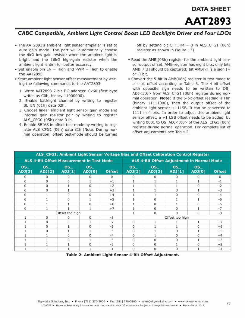
• The AAT2893’s ambient light sensor amplifier is set to auto gain mode. The part will automatically choose the 4kΩ low-gain resistor when the ambient light is bright and the 16kΩ high-gain resistor when the ambient light is dim for better accuracy.
• Set enable pin EN = High and PWM = High to enable the AAT2893.
• Start ambient light sensor offset measurement by writ-ing the following commands to the AAT2893:
1. Write AAT2893 7-bit I2C address: 0x60 (first byte writes as C0h, binary 11000000).
2. Enable backlight channel by writing to register BL_EN (01h) data 02h.
3. Choose linear ambient light sensor gain mode and internal gain resistor pair by writing to register ALS_CFG0 (05h) data 31h.
4. Enable SBIAS in offset test mode by writing to reg-ister ALS_CFG1 (06h) data 81h (Note: During nor-mal operation, offset test-mode should be turned
off by setting bit OFF_TM = 0 in ALS_CFG1 (06h) register as shown in Figure 13).
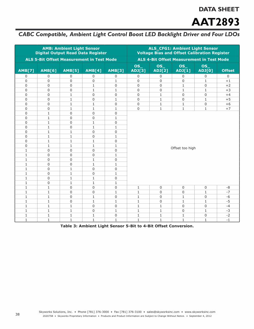
• Read the AMB (08h) register for the ambient light sen-sor output offset. AMB register has eight bits, only bits AMB[7:3] should be captured; bit AMB[7] is a sign (+ or -) bit.
• Convert the 5-bit in AMB(08h) register in test mode to a 4-bit offset according to Table 3. The 4-bit offset with opposite sign needs to be written to OS_ADJ<3:0> from ALS_CFG1 (06h) register during nor-mal operation. Note: If the 5-bit offset reading is F8h (binary 11111000), then the output offset of the ambient light sensor is -1LSB. It can be converted to 1111 in 4 bits. In order to adjust this ambient light sensor offset, a +1 LSB offset needs to be added, by writing 0001 to OS_ADJ<3:0> of the ALS_CFG1 (06h) register during normal operation. For complete list of offset adjustments see Table 2.
ALS_CFG1: Ambient Light Sensor Voltage Bias and Offset Calibration Control Register
ALS 4-Bit Offset Measurement in Test Mode ALS 4-Bit Offset Adjustment in Normal Mode
OS_ADJ[3]
OS_ADJ[2]
OS_ADJ[1]
OS_ADJ[0] Offset
OS_ADJ[3]
OS_ADJ[2]
OS_ADJ[1]
OS_ADJ[0] Offset
0 0 0 0 0 0 0 0 0 00 0 0 1 +1 1 1 1 1 -10 0 1 0 +2 1 1 1 0 -20 0 1 1 +3 1 1 0 1 -30 1 0 0 +4 1 1 0 0 -40 1 0 1 +5 1 0 1 1 -50 1 1 0 +6 1 0 1 0 -60 1 1 1 +7 1 0 0 1 -7
Offset too high 1 0 0 0 -81 0 0 0 -8 Offset too high1 0 0 1 -7 0 1 1 1 +71 0 1 0 -6 0 1 1 0 +61 0 1 1 -5 0 1 0 1 +51 1 0 0 -4 0 1 0 0 +41 1 0 1 -3 0 0 0 1 +31 1 1 0 -2 0 0 1 0 +21 1 1 1 -1 0 0 0 1 +1
Table 2: Ambient Light Sensor 4-Bit Offset Adjustment.
AAT2893DATA SHEET
CABC Compatible, Ambient Light Control Boost LED Backlight Driver and Four LDOs
38Skyworks Solutions, Inc. • Phone [781] 376-3000 • Fax [781] 376-3100 • [email protected] • www.skyworksinc.com
202075B • Skyworks Proprietary Information • Products and Product Information are Subject to Change Without Notice. • September 4, 2012
AMB: Ambient Light Sensor Digital Output Read Data Register
ALS_CFG1: Ambient Light Sensor Voltage Bias and Offset Calibration Register
ALS 5-Bit Offset Measurement in Test Mode ALS 4-Bit Offset Measurement in Test Mode
AMB[7] AMB[6] AMB[5] AMB[4] AMB[3]OS_
ADJ[3] OS_
ADJ[2]OS_
ADJ[1]OS_
ADJ[0] Offset0 0 0 0 0 0 0 0 0 00 0 0 0 1 0 0 0 1 +10 0 0 1 0 0 0 1 0 +20 0 0 1 1 0 0 1 1 +30 0 1 0 0 0 1 0 0 +40 0 1 0 1 0 1 0 1 +50 0 1 1 0 0 1 1 0 +60 0 1 1 1 0 1 1 1 +70 1 0 0 0
Offset too high
0 1 0 0 10 1 0 1 00 1 0 1 10 1 1 0 00 1 1 0 10 1 1 1 00 1 1 1 11 0 0 0 01 0 0 0 11 0 0 1 01 0 0 1 11 0 1 0 01 0 1 0 11 0 1 1 01 0 1 1 11 1 0 0 0 1 0 0 0 -81 1 0 0 1 1 0 0 1 -71 1 0 1 0 1 0 1 0 -61 1 0 1 1 1 0 1 1 -51 1 1 0 0 1 1 0 0 -41 1 1 0 1 1 1 0 1 -31 1 1 1 0 1 1 1 0 -21 1 1 1 1 1 1 1 1 -1
Table 3: Ambient Light Sensor 5-Bit to 4-Bit Offset Conversion.
AAT2893DATA SHEET
CABC Compatible, Ambient Light Control Boost LED Backlight Driver and Four LDOs
39Skyworks Solutions, Inc. • Phone [781] 376-3000 • Fax [781] 376-3100 • [email protected] • www.skyworksinc.com
202075B • Skyworks Proprietary Information • Products and Product Information are Subject to Change Without Notice. • September 4, 2012
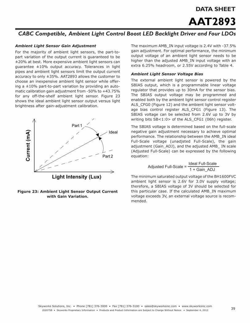
Ambient Light Sensor Gain AdjustmentFor the majority of ambient light sensors, the part-to-part variation of the output current is guaranteed to be ±20% at best. More expensive ambient light sensors can guarantee ±10% output accuracy. Tolerances in light pipes and ambient light sensors limit the output current accuracy to only ±35%. AAT2893 allows the customer to choose an inexpensive ambient light sensor while offer-ing a ±10% part-to-part variation by providing an auto-matic calibration gain adjustment from -50% to +43.75% for any off-the-shelf ambient light sensor. Figure 23 shows the ideal ambient light sensor output versus light brightness after gain-adjustment calibration.
Light Intensity (Lux)
Cur
rent
(mA
) Ideal
Part 2
Part 1
Figure 23: Ambient Light Sensor Output Current with Gain Variation.
The maximum AMB_IN input voltage is 2.4V with -37.5% gain adjustment. For optimal performance, the minimum output voltage of an ambient light sensor needs to be higher than the adjusted AMB_IN input voltage with an extra 6.25% headroom, or 2.55V according to Table 4.
Ambient Light Sensor Voltage BiasThe external ambient light sensor is powered by the SBIAS output, which is a programmable linear voltage regulator that provides up to 30mA for the sensor bias. The SBIAS output voltage may be programmed and enabled both by the ambient light sensor control register ALS_CFG0 (Figure 12) and the ambient light sensor volt-age bias control register ALS_CFG1 (Figure 13). The SBIAS voltage can be selected from 2.6V up to 3V by writing bits SB<1:0> of the ALS_CFG1 (06h) register.
The SBIAS voltage is determined based on the full-scale negative gain adjustment necessary to achieve optimal performance. The relationship between the AMB_IN ideal Full-Scale voltage (unadjsted Full-Scale), the gain adjustment (Gain_ADJ), and the adjusted AMB_ IN scale (Adjusted Full-Scale) can be expressed by the following equation:
1 + Gain_ADJIdeal Full-Scale
Adjusted Full-Scale =
The minimum saturated output voltage of the BH1600FVC ambient light sensor is 2.6V for 3.0V supply voltage; therefore, a SBIAS voltage of 3V should be selected for this particular case. If the calculated AMB_IN maximum voltage exceeds 3V, an external voltage source is recom-mended.

AAT2893DATA SHEET
CABC Compatible, Ambient Light Control Boost LED Backlight Driver and Four LDOs
40Skyworks Solutions, Inc. • Phone [781] 376-3000 • Fax [781] 376-3100 • [email protected] • www.skyworksinc.com
202075B • Skyworks Proprietary Information • Products and Product Information are Subject to Change Without Notice. • September 4, 2012
G_ADJ[3:0] Gain Adjustment (%)
AMB_IN Full Scale (V) ALS_CFG2 (07h) AMB_IN Min
(V)AMB_IN Max
(V)0111 43.75 1.11 07h 1.04 1.180110 37.50 1.16 06h 1.09 1.240101 31.25 1.22 05h 1.14 1.300100 25.00 1.28 04h 1.20 1.360011 18.75 1.35 03h 1.26 1.430010 12.50 1.42 02h 1.33 1.510001 6.25 1.51 01h 1.41 1.600000 0 1.60 00h 1.50 1.701111 -6.25 1.71 0Fh 1.60 1.811110 -12.5 1.83 0Eh 1.71 1.941101 -18.75 1.97 0Dh 1.85 2.091100 -25.00 2.13 0Ch 2.00 2.271011 -31.25 2.33 0Bh 2.18 2.471010 -37.50 2.56 0Ah 2.40 2.721001 -43.75 2.84 09h 2.67 3.021000 -50.00 3.20 08h 3.00 3.40
Table 4: Ambient Light Sensor Gain Adjustment.
Backlight LED Current Settings for Different Brightness ReadingsThe main recipient of the light emitted by all visible spectrum LEDs is the human eye. It responds to light luminance in a non-linear, logarithmic way. The sensitiv-ity of the human eye decreases rapidly as the luminance of the source increases. The LED current needs to change logarithmically in relation to the light brightness in order for the light brightness to be perceived linearly by the human eye.
The AAT2893 has sixteen default LED current setting
levels programmed in ALSn (from 09h to 18h) registers. These sixteen current level settings follow the logarith-mic trend shown in Figure 24. A linear ambient light sensor output and a linear output brightness are set by using the default setting of SNSR=0 and ALSOUT=0 of the ALS_CFG2 (07h) register. For each light brightness sampling, one of the current levels corresponding to the ambient light reading will be selected to control the backlight LED current. If the desired current settings are different than the default, the user can change them by writing to ALSn (09h through 18h) registers.
0.1
1
10
100
0.1 1 10 100 1000 10000 100000
LED
Cur
rent
(mA)
Brightness (Lux)
Figure 24: Backlight LED Current vs Light Brightness.

AAT2893DATA SHEET
CABC Compatible, Ambient Light Control Boost LED Backlight Driver and Four LDOs
41Skyworks Solutions, Inc. • Phone [781] 376-3000 • Fax [781] 376-3100 • [email protected] • www.skyworksinc.com
202075B • Skyworks Proprietary Information • Products and Product Information are Subject to Change Without Notice. • September 4, 2012
Ambient Light Sensor Brightness Gain ModeAAT2893 allows automatic and manual modes for mea-surement of the ambient light sensor brightness. The automatic gain mode is selected by default value GM_SEL = 0 in ALS_CFG0 (05h) register. For better accuracy during automatic mode, the AAT2893 will choose low gain resistor when the ambient light is bright and high gain resistor when the ambient light is dim. For the manual gain mode, all light brightness measurements are completed with the low gain resistor as set by GM_SEL = 1 of the ALS_CFG0 (05h) register.
Ambient Light Sensor Brightness Polling TimeThe AAT2893 offers two bits for programming the ambi-ent light sensor brightness polling time. There are four different polling times: 0.5s, 1s, 1.5s and 2s selected by writing PTIME<1:0> bits of the ALS_CFG2 (07h) regis-ter.
If an automatic ambient light sensor polling mode is selected by default PMODE = 0 of ALS_CFG0 (05h) reg-ister, the AAT2893 will periodically update the informa-tion about the surrounding brightness at an interval of every elapsed time. Refer to Figure 22 for A/D conver-sion timing diagram. Manual ambient sensor polling mode can also be selected by writing PMODE = 1 to ALS_CFG0 (05h) register.
AAT2893 Programming ExamplesExample 1: Ambient Light Sensor Linear Brightness Readings and Logarithmic Backlight Response
SNSR = 0: Linear Measurement
ALSOUT = 0: Linear Output
Backlight Current: Logarithmic Response
Brightness (Lux) LED Current (mA)1--64 0.9
64--10000 0.9 to 28.6 in log scale
Table 5: Sensor Requirements for Example 1.
Ambient light sensor model BH1600FVC from Rohm is used for all examples:
Mode GC1 GC2 Current µA/100Lux
H-Gain Mode 1 0 60L-Gain Mode 0 1 6.31
Table 6: Rohm BH1600FVC Ambient Light Sensor Output Current Level.
Parameter ValueMaximum Brightness (Lux) 10000
Floor Brightness (Lux) 64ALS Output (μA/10 Lux) 0.63
Gain Resistor (KΩ) 4Gain Adjustment (%) -18.75AMB-IN Full-Scale (V) 1.92
Maximum. LED Current (mA) 28.60Floor Current (mA) 0.9Brightness / Floor 156.25
Log (Brightness / Floor) 2.19Log current per level 0.10Brightness / Level 662.4
k factor 0.68
Table 7: Determination of LED Current vs Brightness in a Logarithmic Relationship.
Eq.1:
= 0.15 15
log Brightness
Floor( (
Setup Description:Ambient light sensor model BH1600FVC from Rohm is used with the AAT2893 demo board (Figures 30 and 31). The demo board jumper P3 controls the gain setting GC2 and jumper P4 controls the gain setting GC1. Pin 1 (logic 1) on the jumpers P3 and P4 is designated by the square pad in Figure 28.
• Select low gain ALS output (GC1 = 0, GC2 = 1)• Backlight LED Current=28.6mA is selected, or doesn't
need to be set• Resistor set of 4KΩ, 16KΩ is calculated for the applica-
tion• Enable Backlight channel. (BL_EN = 1) • Ambient light sensor has no DC offset• Ambient light sensor gain adjustment is -18.75%• Linear ALSOUT and SNSR are selected• SBIAS = 3.0V is selected• Enable Ambient Light Sensor. (ALS_EN = 1)• Light brightness is measured at 1s time intervals• Read register AMLRB (08h).
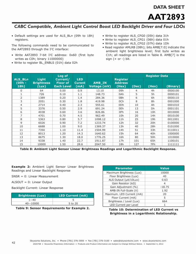
AAT2893DATA SHEET
CABC Compatible, Ambient Light Control Boost LED Backlight Driver and Four LDOs
42Skyworks Solutions, Inc. • Phone [781] 376-3000 • Fax [781] 376-3100 • [email protected] • www.skyworksinc.com
202075B • Skyworks Proprietary Information • Products and Product Information are Subject to Change Without Notice. • September 4, 2012
• Default settings are used for ALS_BLn (09h to 18h) registers.
The following commands need to be communicated to the AAT2893 through the I2C interface:
• Write AAT2893 7-bit I2C address: 0x60 (first byte writes as C0h; binary 11000000)
• Write to register BL_ENBLS (01h) data 02h
• Write to register ALS_CFG0 (05h) data 31h• Write to register ALS_CFG1 (06h) data 01h• Write to register ALS_CFG2 (07h) data 1Dh• Read register AMLRB (08h); bits AMB[7:0] indicate the
ambient light brightness level; first byte writes as C1h; all readings are listed in Table 8. AMB[7] is the sign (+ or -) bit.
ALS_BLn (09h - 18h)
Light Brightness
(Lux)
Log of Current/Floor of
Each Level
LED Curent (mA)
AMB_IN Voltage (mV)
Register Address (Hex)
Register Data
(Dec) (Hex) (Binary)0 64 0.00 0.9 13.10 09h 4 4h 00001001 726 0.10 1.1 148.73 0Ah 5 5h 00001012 1389 0.20 1.4 284.36 0Bh 6 6h 00001103 2051 0.30 1.8 419.98 0Ch 8 8h 00010004 2714 0.40 2.3 555.61 0Dh 10 Ah 00010105 3376 0.50 2.9 691.24 0Eh 13 Dh 00011016 4038 0.60 3.6 826.86 0Fh 16 10h 00100007 4701 0.70 4.5 962.49 10h 20 14h 00101008 5363 0.80 5.7 1098.12 11h 25 19h 00110019 6026 0.90 7.2 1233.74 12h 32 20h 010000010 6688 1.00 9.0 1369.37 13h 40 28h 010100011 7350 1.10 11.4 1504.99 14h 51 33h 011001112 8013 1.20 14.3 1640.62 15h 64 40h 100000013 8675 1.30 18.0 1776.25 16h 80 50h 101000014 9338 1.40 22.7 1911.87 17h 101 65h 110010115 10000 1.50 28.6 2047.50 18h 127 7Fh 1111111
Table 8: Ambient Light Sensor Linear Brightness Readings and Logarithmic Backlight Response.
Example 2: Ambient Light Sensor Linear Brightness Readings and Linear Backlight Response
SNSR = 0: Linear Measurement
ALSOUT = 0: Linear Output
Backlight Current: Linear Response
Brightness (Lux) LED Current (mA)1--40 5
40--10000 5 to 20
Table 9: Sensor Requirements for Example 2.
Parameter ValueMaximum Brightness (Lux) 10000
Floor Brightness (Lux) 40ALS Output (μA/10Lux) 0.63
Gain Resistor (kΩ) 4Gain Adjustment (%) -18.75AMB-IN Full-Scale (V) 1.92
Maximum. LED Current (mA) 20Floor Current (mA) 5
Brightness / Level (Lux) 664LED Current per Level 1
Table 10: Determination of LED Current vs Brightness in a Logarithmic Relationship.
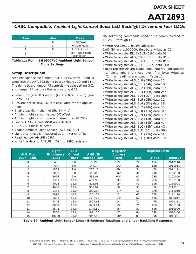
AAT2893DATA SHEET
CABC Compatible, Ambient Light Control Boost LED Backlight Driver and Four LDOs
43Skyworks Solutions, Inc. • Phone [781] 376-3000 • Fax [781] 376-3100 • [email protected] • www.skyworksinc.com
202075B • Skyworks Proprietary Information • Products and Product Information are Subject to Change Without Notice. • September 4, 2012
GC2 GC1 Mode0 0 Shutdown0 1 H-Gain Mode1 0 L-Gain Mode
1 1 Test Mode (input prohibition)
Table 11: Rohm BH1600FVC Ambient Light Sensor Mode Settings.
Setup Description:Ambient light sensor model BH1600FVC from Rohm is used with the AAT2893 demo board (Figures 30 and 31). The demo board jumper P3 controls the gain setting GC2 and jumper P4 controls the gain setting GC1.
• Select low gain ALS output (GC1 = 0, GC2 = 1) (see Table 11)
• Resistor set of 4kΩ, 16kΩ is calculated for the applica-tion
• Enable backlight channel (BL_EN = 1)• Ambient light sensor has no DC offset• Ambient light sensor gain adjustment is -18.75%• Linear ALSOUT and SNSR are selected• SBIAS = 3.0V is selected• Enable Ambient Light Sensor. (ALS_EN = 1)• Light brightness is measured at an interval of 1s• Read register AMLRB (08h)• Write the data to ALS_BLn (09h to 18h) registers
The following commands need to be communicated to AAT2893 through I2C:
• Write AAT2893 7-bit I2C address:0x60 (binary 11000000, first byte writes as C0h)• Write to register BL_ENBLS (01h) data 02h• Write to register ALS_CFG0 (05h) data 31h• Write to register ALS_CGF1 (06h) data 01h• Write to register ALS_CFG2 (07h) data 1Dh• Read register AMLRB (08h); bits AMB[7:0] indicate the
ambient light brightness level; first byte writes as C1h; all readings are listed in Table 12
• Write to register ALS_BL0 (09h) data 16h• Write to register ALS_BL1 (0Ah) data 1Bh• Write to register ALS_BL2 (0Bh) data 1Fh• Write to register ALS_BL3 (0Ch) data 24h• Write to register ALS_BL4 (0Dh) data 28h• Write to register ALS_BL5 (0Eh) data 2Ch• Write to register ALS_BL6 (0Fh) data 31h• Write to register ALS_BL7 (10h) data 35h• Write to register ALS_BL8 (11h) data 3Ah• Write to register ALS_BL9 (12h) data 3Eh• Write to register ALS_BLA (13h) data 43h• Write to register ALS_BLB (14h) data 47h• Write to register ALS_BLC (15h) data 4Ch• Write to register ALS_BLD (16h) data 50h• Write to register ALS_BLE (17h) data 54h• Write to register ALS_BLF (18h) data 59h
ALS_BLn (09h - 18h)
Light Brightness
(Lux)
LED Curent (mA)
AMB_IN Voltage (mV)
Register Address (Hex)
Register Data
(Dec) (Hex) (Binary)0 40 5.0 8.19 09h 22 16h 00101101 704 6.0 144.14 0Ah 27 1Bh 00110112 1368 7.0 280.10 0Bh 31 1Fh 00111113 2032 8.0 416.05 0Ch 36 24h 01001004 2696 9.0 552.01 0Dh 40 28h 01010005 3360 10.0 687.96 0Eh 44 2Ch 01011006 4024 11.0 823.91 0Fh 49 31h 01100017 4688 12.0 959.87 10h 53 35h 01101018 5352 13.0 1095.82 11h 58 3Ah 01110109 6016 14.0 1231.78 12h 62 3Eh 011111010 6680 15.0 1367.73 13h 67 43h 100001111 7344 16.0 1503.68 14h 71 47h 100011112 8008 17.0 1639.64 15h 76 4Ch 100110013 8672 18.0 1775.59 16h 80 50h 101000014 9336 19.0 1911.55 17h 84 54h 101010015 10000 20.0 2047.50 18h 89 59h 1011001
Table 12: Ambient Light Sensor Linear Brightness Readings and Linear Backlight Response.

AAT2893DATA SHEET
CABC Compatible, Ambient Light Control Boost LED Backlight Driver and Four LDOs
44Skyworks Solutions, Inc. • Phone [781] 376-3000 • Fax [781] 376-3100 • [email protected] • www.skyworksinc.com
202075B • Skyworks Proprietary Information • Products and Product Information are Subject to Change Without Notice. • September 4, 2012
Example 3: Ambient Light Sensor Logarithmic Brightness and Logarithmic Backlight Response
SNSR = 0: Linear Measurement
ALSOUT = 1: Logarithmic Output
Backlight Current: Logarithmic Response
Brightness (Lux) LED Current (mA)1--10 5
10--100 10100--1000 15
1000--10000 20
Table 13: Sensor Requirements for Example 3.
Parameter ValueMaximum Brightness (Lux) 1000
Floor Brightness (Lux) 40ALS Output (μA/10Lux) 6
Gain Resistor (kΩ) 4Gain Adjustment (%) -18.75AMB-IN Full-Scale (V) 1.92
Maximum. LED Current (mA) 20Floor Current (mA) 5Brightness/Floor 25
Log(Brightness/Floor) 1.40Log current per level 0.04
k factor 0.43
Table 14: Determination of LED Current vs Brightness in a Logarithmic Relationship.
Eq 2:
= 0.09 15
log Brightness
Floor( (
Setup Description:Ambient light sensor model BH1600FVC from Rohm is used with the AAT2893 demo board (Figures 30 and 31). The demo board jumper P3 controls the gain setting GC2 and jumper P4 controls the gain setting GC1.
• Select high gain ALS output (GC1 = 1, GC2 = 0) (see Table 11).
• Resistor set of 4kΩ, 16kΩ is calculated for the applica-tion
• Enable backlight channel (BL_EN = 1)• Ambient light sensor has no DC offset• Ambient light sensor gain adjustment is -18.75%• Logarithmic ALSOUT and Linear SNSR are selected• SBIAS = 3.0V is selected• Light brightness is measured at an interval of 1s time• Read register AMLRB (08h)• Write to registers ALS_BLn (09h to 18h) the data
The following commands need to be communicated to AAT2893 through I2C:
• Write AAT2893 7-bit I2C address: 0x60(binary 11000000; first byte writes as C0h)• Write to register BL_ENBLS (01h) data 02h• Write to register ALS_CFG0 (05h) data 31h• Write to register ALS_CFG1 (06h) data 01h• Write to register ALS_CFG2 (07h) data 5Dh• Read register AMLRB (08h); bits AMB[7:0] indicate the
ambient light brightness level; first byte writes C1h; all readings are listed in Table 15.
• Write to register ALS_BL0 (09h) data 16h• Write to register ALS_BL1 (0Ah) data 1Bh• Write to register ALS_BL2 (0Bh) data 1Fh• Write to register ALS_BL3 (0Ch) data 24h• Write to register ALS_BL4 (0Dh) data 28h• Write to register ALS_BL5 (0Eh) data 2Ch• Write to register ALS_BL6 (0Fh) data 31h• Write to register ALS_BL7 (10h) data 35h• Write to register ALS_BL8 (11h) data 3Ah• Write to register ALS_BL9 (12h) data 3Eh• Write to register ALS_BLA (13h) data 43h• Write to register ALS_BLB (14h) data 47h• Write to register ALS_BLC (15h) data 4Ch• Write to register ALS_BLD (16h) data 50h• Write to register ALS_BLE (17h) data 54h• Write to register ALS_BLF (18h) data 59h
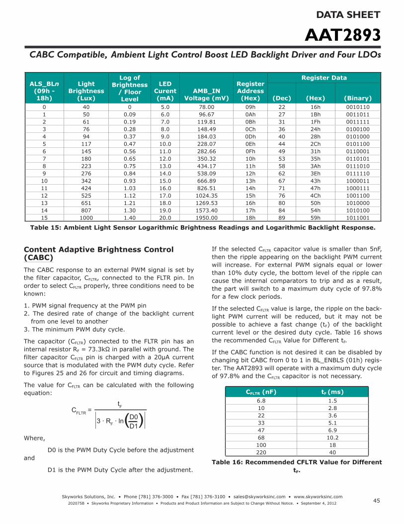
AAT2893DATA SHEET
CABC Compatible, Ambient Light Control Boost LED Backlight Driver and Four LDOs
45Skyworks Solutions, Inc. • Phone [781] 376-3000 • Fax [781] 376-3100 • [email protected] • www.skyworksinc.com
202075B • Skyworks Proprietary Information • Products and Product Information are Subject to Change Without Notice. • September 4, 2012
ALS_BLn (09h - 18h)
Light Brightness
(Lux)
Log of Brightness
/ Floor Level
LED Curent (mA)
AMB_IN Voltage (mV)
Register Address (Hex)
Register Data
(Dec) (Hex) (Binary)0 40 0 5.0 78.00 09h 22 16h 00101101 50 0.09 6.0 96.67 0Ah 27 1Bh 00110112 61 0.19 7.0 119.81 0Bh 31 1Fh 00111113 76 0.28 8.0 148.49 0Ch 36 24h 01001004 94 0.37 9.0 184.03 0Dh 40 28h 01010005 117 0.47 10.0 228.07 0Eh 44 2Ch 01011006 145 0.56 11.0 282.66 0Fh 49 31h 01100017 180 0.65 12.0 350.32 10h 53 35h 01101018 223 0.75 13.0 434.17 11h 58 3Ah 01110109 276 0.84 14.0 538.09 12h 62 3Eh 011111010 342 0.93 15.0 666.89 13h 67 43h 100001111 424 1.03 16.0 826.51 14h 71 47h 100011112 525 1.12 17.0 1024.35 15h 76 4Ch 100110013 651 1.21 18.0 1269.53 16h 80 50h 101000014 807 1.30 19.0 1573.40 17h 84 54h 101010015 1000 1.40 20.0 1950.00 18h 89 59h 1011001
Table 15: Ambient Light Sensor Logarithmic Brightness Readings and Logarithmic Backlight Response.
Content Adaptive Brightness Control (CABC)The CABC response to an external PWM signal is set by the filter capacitor, CFLTR, connected to the FLTR pin. In order to select CFLTR properly, three conditions need to be known:
1. PWM signal frequency at the PWM pin2. The desired rate of change of the backlight current
from one level to another3. The minimum PWM duty cycle.
The capacitor (CFLTR) connected to the FLTR pin has an internal resistor RF = 73.3kΩ in parallel with ground. The filter capacitor CFLTR pin is charged with a 20μA current source that is modulated with the PWM duty cycle. Refer to Figures 25 and 26 for circuit and timing diagrams.
The value for CFLTR can be calculated with the following equation:
CFLTR = tF
3 ∙ RF ∙ lnD0
D1( (
Where,
D0 is the PWM Duty Cycle before the adjustment and
D1 is the PWM Duty Cycle after the adjustment.
If the selected CFLTR capacitor value is smaller than 5nF, then the ripple appearing on the backlight PWM current will increase. For external PWM signals equal or lower than 10% duty cycle, the bottom level of the ripple can cause the internal comparators to trip and as a result, the part will switch to a maximum duty cycle of 97.8% for a few clock periods.
If the selected CFLTR value is large, the ripple on the back-light PWM current will be reduced, but it may not be possible to achieve a fast change (tF) of the backlight current level or the desired duty cycle. Table 16 shows the recommended CFLTR Value for Different tF.
If the CABC function is not desired it can be disabled by changing bit CABC from 0 to 1 in BL_ENBLS (01h) regis-ter. The AAT2893 will operate with a maximum duty cycle of 97.8% and the CFLTR capacitor is not necessary.
CFLTR (nF) tF (ms)6.8 1.510 2.822 3.633 5.147 6.968 10.2100 18220 40
Table 16: Recommended CFLTR Value for Different tF.

AAT2893DATA SHEET
CABC Compatible, Ambient Light Control Boost LED Backlight Driver and Four LDOs
46Skyworks Solutions, Inc. • Phone [781] 376-3000 • Fax [781] 376-3100 • [email protected] • www.skyworksinc.com
202075B • Skyworks Proprietary Information • Products and Product Information are Subject to Change Without Notice. • September 4, 2012
PWM
VFLTR
20μA
RF73.3kΩ
FLTR
VIN
CF
ILED
External PWM Control Input
I2C & ALS Control
Figure 25: CABC Circuit Diagram.
ILED
Time0
tF
Figure 26: CABC Timing.
Note: A small value CFLTR will result in faster transition time (tF) between current levels but is limited to 5nF by the backlight PWM current ripple.

AAT2893DATA SHEET
CABC Compatible, Ambient Light Control Boost LED Backlight Driver and Four LDOs
47Skyworks Solutions, Inc. • Phone [781] 376-3000 • Fax [781] 376-3100 • [email protected] • www.skyworksinc.com
202075B • Skyworks Proprietary Information • Products and Product Information are Subject to Change Without Notice. • September 4, 2012
LED SelectionThe AAT2893 is specifically designed for driving white LEDs in TFT-LCD backlighting applications but the device design allows the AAT2893 to drive most types of LEDs with forward voltage specifications ranging from 2.0V to 4.7V. LED applications may include mixed arrangements for display backlighting, color (RGB) LEDs, infrared (IR) diodes or any other load needing a constant current source generated from a varying input voltage.
The low-dropout current sinks in the AAT2893 maximize performance and make it capable of driving LEDs with high forward voltage.
Driving 11 WLEDs ApplicationThe maximum number of WLED depends on the OVP of the AAT2893 part and the forward voltage (VF) of WLED. The OVP of AAT2893-1 is 42V, to a general WLED with about 3.3V forward voltage, it means AAT2893 has abil-ity to drive more than 10 LEDs in series. Figure 27, 28 and 29 show the efficiency, PWM duty vs WLED current and WLED current at different input voltage when AAT2893 drive 11 WLEDs.
40
45
50
55
60
65
70
75
80
85
0 5 10 15 20 25 30
VIN = 3.0V
VIN = 3.6V
VIN = 4.2V
VIN = 5.0V
VIN = 5.5V
ILED vs Efficiency(11 WLEDs)
ILED (mA)
Effic
ienc
y (%
)
Figure 27: WLED Current vs Efficiency at 11 WLEDs Application.
0
5
10
15
20
25
30
0 10 20 30 40 50 60 70 80 90 100
VIN = 3.0VVIN = 3.6VVIN = 4.2VVIN = 5.0VVIN = 5.5V
PWM Duty Cycle vs WLED Current(11 WLEDs)
PWM Duty (%)
I LED (m
A)
Figure 28: PWM Duty Cycle vs WLED Current at 11 WLEDs Application.
Max
. ILE
D (m
A)
Input Voltage (V)
Input Voltage vs Max WLED Current(AAT2893 - 1)
21
22
23
24
25
26
27
28
29
30
3 3.25 3.5 3.75 4 4.25 4.5 4.75 5 5.25 5.5
11 WLEDs
20
Figure 29: Input Voltage vs Max WLED Current at 11 WLEDs Application.
Inductor SelectionInductor value, saturation current and DCR are the most important parameters in selecting an inductor for the AAT2893.
The suitable inductance range for the AAT2893 is 4.7μH to 22μH. Higher inductance lowers the step-up convert-er's RMS current value. Together with lower DCR value of the inductor, it makes the total inductor power loss become much lower. Considering inductor size and cost, 4.7μH inductance is most suitable.
Considering the inductor copper loss, the inductor DCR value together with the RMS current flowing through the

AAT2893DATA SHEET
CABC Compatible, Ambient Light Control Boost LED Backlight Driver and Four LDOs
48Skyworks Solutions, Inc. • Phone [781] 376-3000 • Fax [781] 376-3100 • [email protected] • www.skyworksinc.com
202075B • Skyworks Proprietary Information • Products and Product Information are Subject to Change Without Notice. • September 4, 2012
inductor leads to inductor conduction loss and also affects total efficiency. Larger DCR leads to larger con-duction loss and reduces total efficiency. The inductor conduction loss can be estimated using the following equation:
PL_LOSS = I2L_RMS ∙ DCR =
3
(I2L_MAX + I2
L_MIN + IL_MAX ∙ IL_MIN) ∙ DCR
Where IL_MAX and IL_MIN are the inductor peak current and minimum current respectively.
Inductor saturation current is also a key parameter in selecting an inductor. For the step-up converter, the peak inductor current is the DC input current plus half the inductor peak-to-peak current ripple.
DC input current:
IIN = VOUT ∙ ILED
VIN ∙ η
Inductor peak-to-peak current ripple:
IL_PP = VIN ∙ (VOUT - VIN)
VOUT ∙ L ∙ f
Inductor peak current:
IL_PEAK = IIN + VIN ∙ (VOUT - VIN)
2 ∙ VOUT ∙ L ∙ f =
VOUT ∙ ILED
VIN ∙ η
IL_PP
2+
For example, for a white LED with 3.2V VF, 20mA cur-rent, 81% efficiency and VIN less than 3.6V, the inductor peak current is:
IL_PEAK = 3.6 ∙ (3.2 ∙ 8 - 3.6)
2 ∙ 3.2 ∙ 8 ∙ 10μ ∙ 1M 3.2 ∙ 8 ∙ 0.02
3.6 ∙ 0.81 + = 330mA
Compensation Component SelectionA compensation capacitor CCOM is used for step-up con-verter loop compensation and soft startup time control. Loop compensation requires matching values for CCOM, COUT, ILED, and VOUT:
ILED
30 ∙ 10-6 ∙ VOUT
COUT
CCOM
<
For example, considering the worse case of AAT2893 driving 10 white LEDs with forward voltages 4V, a COUT
value of 1μF, and LED maximum current of about 30mA, the value of CCOM should be higher than 40nF.
(1 ∙ 30 ∙ 40)
30(nF)
CCOM > (COUT ∙30 ∙ VOUT)
ILED (nF)= = 40(nF)
A higher value for CCOM lengthens the soft startup time. So to balance the startup time and the loop stability, 56nF is selected. The relationship between CCOM and startup time is almost linear, with startup time x 105 magnification of CCOM; thus 56nF CCOM leads to a soft startup time of 5.6ms. Values of 56nF for CCOM and 1μF for COUT are suitable in most cases.
Schottky Diode Selection To achieve maximum efficiency, a low VF Schottky diode is recommended. For an AAT2893 driving 10 white LEDs with up to 4V forward voltage, the diode voltage rating should be higher than 40V. Selecting a diode with DC rated current being equal to the input current allows an adequate margin for safe use.
Printed Circuit Board Layout RecommendationsBoost converter performance can be adversely affected by poor layout. Possible impact includes high input and output voltage ripple, poor EMI performance, and reduced operating efficiency. Every attempt should be made to optimize the layout in order to minimize para-sitic effects on PCB (stray resistance, capacitance, and inductance) and EMI coupling at the high frequency switching node. A suggested PCB layout for the AAT2893 is shown in Figures 31. The following PCB layout guide-lines should be considered:
1. Place the input and output decoupling capacitors C1, C3, C5, C2, C4, C8, C9 as close to the chip as possible to reduce switching noise and output ripple.
2. Keep the power traces (GND, LX VOUT and VIN) short, direct, and wide to allow large current flow. Place suf-ficient multiple-layer pads, when needed, to change the trace layer.
3. Maintain a ground plane and connect to the IC PGND pin(s) as well as the PGND connections of CIN and COUT.
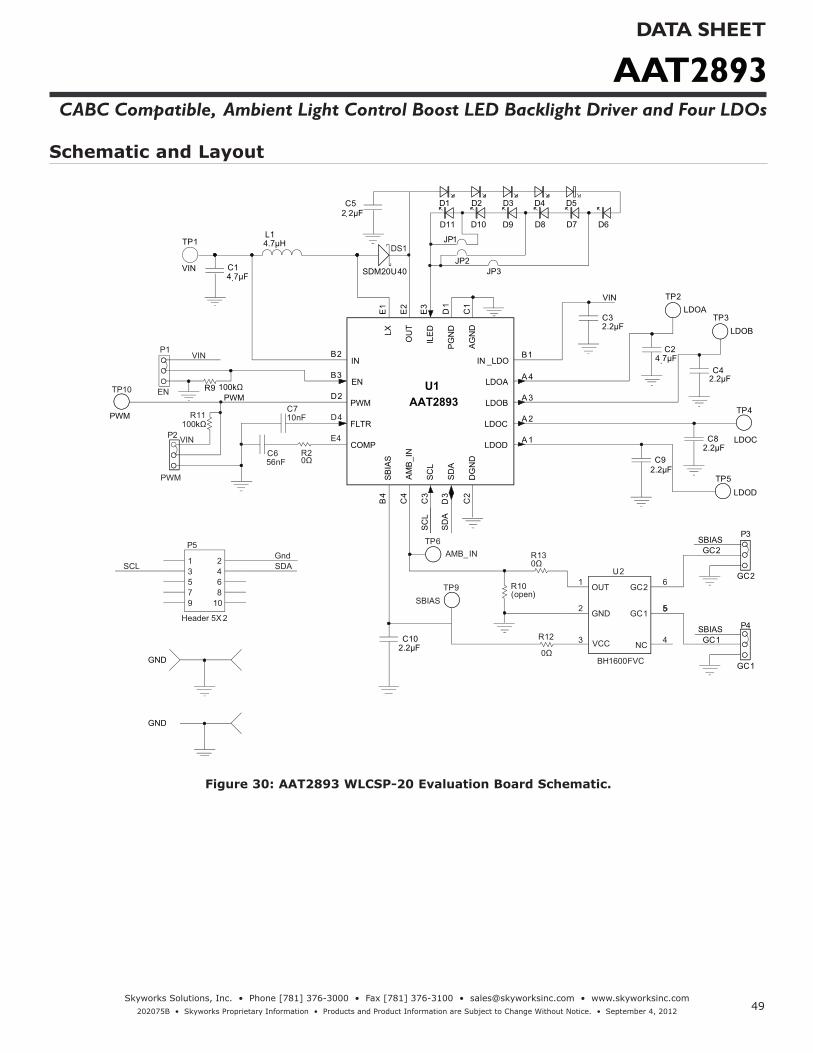
AAT2893DATA SHEET
CABC Compatible, Ambient Light Control Boost LED Backlight Driver and Four LDOs
49Skyworks Solutions, Inc. • Phone [781] 376-3000 • Fax [781] 376-3100 • [email protected] • www.skyworksinc.com
202075B • Skyworks Proprietary Information • Products and Product Information are Subject to Change Without Notice. • September 4, 2012
Schematic and Layout
D1
C42.2µF
C24.7µF
C82.2µF
C92.2µF
C102.2µF
C32.2µF
C14.7µF
TP1
VIN
C52.2µF
JP1
OUT1
GND2
NC 4
GC2 6
GC1 5
VCC3
U2
BH1600FVC
R9 100kΩ
VIN
SC
L
SD
A
GC2
GC1SBIAS
SBIAS
OU
TE
2
ILE
DE
3
LXE
1
INB2
ENB3
PWMD2
SC
LC
3
IN _LDOB1
LDOD A 1
DG
ND
C2
PG
ND
D1
AG
ND
C1
COMPE4
SD
AD
3
AM
B_I
NC
4
SB
IAS
B4
LDOC A 2
LDOB A 3
LDOA A 4
FLTRD4
U1AAT2893
EN
P3
GC2
P4
GC1
1 23 45 67 89 10
P5
Header 5X 2
Gnd
D2 D3 D4 D5
D6D7D8
TP2LDOA
TP3LDOB
TP4
LDOC
TP5LDOD
P2
PWM
VINC656nF
C710nF
R10(open)
SDASCL
VIN
TP6AMB_IN
TP9SBIAS
0Ω
R12
4.7µHL1
D9D10
R20Ω
SDM20U40
DS1
TP10
PWM
PWM
JP2JP3
R11100kΩ
GND
GND
0Ω
D11
P1
••• •
••
•
R13
Figure 30: AAT2893 WLCSP-20 Evaluation Board Schematic.

AAT2893DATA SHEET
CABC Compatible, Ambient Light Control Boost LED Backlight Driver and Four LDOs
50Skyworks Solutions, Inc. • Phone [781] 376-3000 • Fax [781] 376-3100 • [email protected] • www.skyworksinc.com
202075B • Skyworks Proprietary Information • Products and Product Information are Subject to Change Without Notice. • September 4, 2012
Figure 31: AAT2893 Evaluation Board Top and Bottom Side Layout.
Figure 32: AAT2893 Evaluation Board WLCSP-20 package Top and Bottom Side Layout.

AAT2893DATA SHEET
CABC Compatible, Ambient Light Control Boost LED Backlight Driver and Four LDOs
51Skyworks Solutions, Inc. • Phone [781] 376-3000 • Fax [781] 376-3100 • [email protected] • www.skyworksinc.com
202075B • Skyworks Proprietary Information • Products and Product Information are Subject to Change Without Notice. • September 4, 2012
Component Part Number Description Manufacturer
U1 AAT2893IUL Ambient Light Control Boost LED Backlight Driver IC with 4 LDOs; WLCSP20 Skyworks
U2 BH1600FVC Ambient Light Sensor IC; WSOF6 RohmC1,C2 GRM188R60J475K Cap Ceramic 4.7μF 0603 X5R 6.3V 10%
Murata
C3, C4, C8, C9, C10 GCM188R70J225KE22 2.2μF, 6.3V, X7R, 0603
C5 GRM21BR61H225KA73L 2.2μF, 50V, X7R, 0805C6 GRM188R71C563K Cap Ceramic 0.056μF 0603 X7R 16V 10%C7 GRM188R71H103KA01 10nF, 50V, X7R, 0603
D1-D10 RS-0805UW 30mA White LED 0805 RealstarD11 Not populated. Do not solderDS1 SDM20U40 Surface Mount Schottky Barrier Diode DiodesL1 CDRH3D14-4R7NC Power Inductor 4.7μH 1.1A SMD SumidaP5 0.1" Header, 2x5 pins
R2,R13, R12Chip Resistor
0Ω, 1%, 1/8W; 0402Vishay
R9, R11 100kΩ, 1%, 1/4W; 0603R10 Open, reserved for external Gain Resistor adjust
Table 16: AAT2893 Evaluation Board Bill of Materials (BOM).
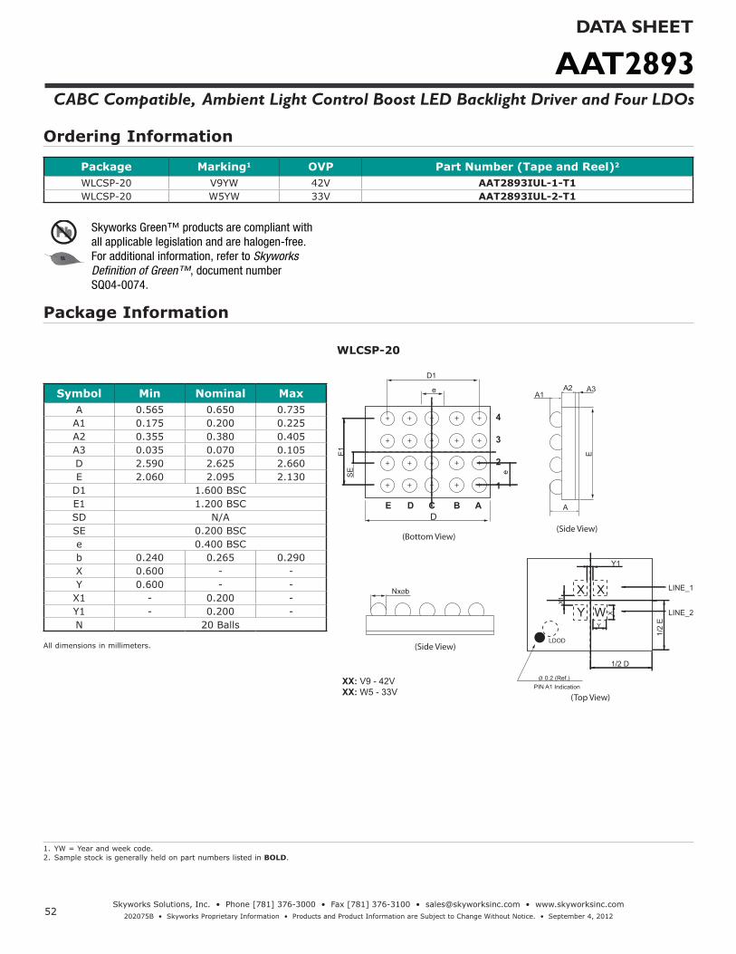
AAT2893DATA SHEET
CABC Compatible, Ambient Light Control Boost LED Backlight Driver and Four LDOs
52Skyworks Solutions, Inc. • Phone [781] 376-3000 • Fax [781] 376-3100 • [email protected] • www.skyworksinc.com
202075B • Skyworks Proprietary Information • Products and Product Information are Subject to Change Without Notice. • September 4, 2012
Ordering Information
Package Marking1 OVP Part Number (Tape and Reel)2
WLCSP-20 V9YW 42V AAT2893IUL-1-T1WLCSP-20 W5YW 33V AAT2893IUL-2-T1
Package Information
WLCSP-20
Symbol Min Nominal MaxA 0.565 0.650 0.735A1 0.175 0.200 0.225A2 0.355 0.380 0.405A3 0.035 0.070 0.105D 2.590 2.625 2.660E 2.060 2.095 2.130
D1 1.600 BSCE1 1.200 BSCSD N/ASE 0.200 BSCe 0.400 BSCb 0.240 0.265 0.290X 0.600 - -Y 0.600 - -
X1 - 0.200 -Y1 - 0.200 -N 20 Balls
All dimensions in millimeters.
1. YW = Year and week code.2. Sample stock is generally held on part numbers listed in BOLD.
C BD
A
Y
X X
W
Y1
LINE_1
LINE_2
1/2
E1/2 D
LDOD
PIN A1 Indication
Y
X
X1
E
A1A2 A3
1
2
3
4
D1
e
E1
SE
(Bottom View)(Side View)
(Side View)
(Top View)
ADEe
XX: V9 - 42VXX: W5 - 33V
+ + +
+ + +
+ + +
+ + +
NxØb
Ø 0.2 (Ref.)
+ +
+ +
+ +
+ +
Skyworks Green™ products are compliant with all applicable legislation and are halogen-free.For additional information, refer to Skyworks Definition of Green™, document number SQ04-0074.

AAT2893DATA SHEET
CABC Compatible, Ambient Light Control Boost LED Backlight Driver and Four LDOs
53Skyworks Solutions, Inc. • Phone [781] 376-3000 • Fax [781] 376-3100 • [email protected] • www.skyworksinc.com
202075B • Skyworks Proprietary Information • Products and Product Information are Subject to Change Without Notice. • September 4, 2012
Copyright © 2012 Skyworks Solutions, Inc. All Rights Reserved.
Information in this document is provided in connection with Skyworks Solutions, Inc. (“Skyworks”) products or services. These materials, including the information contained herein, are provided by Skyworks as a service to its customers and may be used for informational purposes only by the customer. Skyworks assumes no responsibility for errors or omissions in these materials or the information contained herein. Sky-works may change its documentation, products, services, specifications or product descriptions at any time, without notice. Skyworks makes no commitment to update the materials or information and shall have no responsibility whatsoever for conflicts, incompatibilities, or other difficulties arising from any future changes.
No license, whether express, implied, by estoppel or otherwise, is granted to any intellectual property rights by this document. Skyworks assumes no liability for any materials, products or information provided here-under, including the sale, distribution, reproduction or use of Skyworks products, information or materials, except as may be provided in Skyworks Terms and Conditions of Sale.
THE MATERIALS, PRODUCTS AND INFORMATION ARE PROVIDED “AS IS” WITHOUT WARRANTY OF ANY KIND, WHETHER EXPRESS, IMPLIED, STATUTORY, OR OTHERWISE, INCLUDING FITNESS FOR A PARTICULAR PURPOSE OR USE, MERCHANTABILITY, PERFORMANCE, QUALITY OR NON-INFRINGEMENT OF ANY INTELLECTUAL PROPERTY RIGHT; ALL SUCH WARRANTIES ARE HEREBY EXPRESSLY DISCLAIMED. SKYWORKS DOES NOT WARRANT THE ACCURACY OR COMPLETENESS OF THE INFORMATION, TEXT, GRAPHICS OR OTHER ITEMS CONTAINED WITHIN THESE MATERIALS. SKYWORKS SHALL NOT BE LIABLE FOR ANY DAMAGES, IN-CLUDING BUT NOT LIMITED TO ANY SPECIAL, INDIRECT, INCIDENTAL, STATUTORY, OR CONSEQUENTIAL DAMAGES, INCLUDING WITHOUT LIMITATION, LOST REVENUES OR LOST PROFITS THAT MAY RESULT FROM THE USE OF THE MATERIALS OR INFORMATION, WHETHER OR NOT THE RECIPIENT OF MATERIALS HAS BEEN ADVISED OF THE POSSIBILITY OF SUCH DAMAGE.
Skyworks products are not intended for use in medical, lifesaving or life-sustaining applications, or other equipment in which the failure of the Skyworks products could lead to personal injury, death, physical or en-vironmental damage. Skyworks customers using or selling Skyworks products for use in such applications do so at their own risk and agree to fully indemnify Skyworks for any damages resulting from such improper use or sale.
Customers are responsible for their products and applications using Skyworks products, which may deviate from published specifications as a result of design defects, errors, or operation of products outside of pub-lished parameters or design specifications. Customers should include design and operating safeguards to minimize these and other risks. Skyworks assumes no liability for applications assistance, customer product design, or damage to any equipment resulting from the use of Skyworks products outside of stated published specifications or parameters.
Skyworks, the Skyworks symbol, and “Breakthrough Simplicity” are trademarks or registered trademarks of Skyworks Solutions, Inc., in the United States and other countries. Third-party brands and names are for identification purposes only, and are the property of their respective owners. Additional information, including relevant terms and conditions, posted at www.skyworksinc.com, are incorporated by reference.