Onsrud.pdf - Micro Fence
100
Leitz Metalworking Technology Group WOOD PLASTIC COMPOSITES NON-FERROUS Production Routing Tools for
-
Upload
khangminh22 -
Category
Documents
-
view
1 -
download
0
Transcript of Onsrud.pdf - Micro Fence
Leitz Metalworking Technology Group
WOODPLASTICCOMPOSITESNON-FERROUS
ProductionRouting Tools
for

Onsrud Cutter pledges continued
support for the CNC/Router
Industry by launching “On-Call”
...an exclusive no-charge service
for the woodworking, plastic, and
non-ferrous fabricator. On-Call
services include comprehensive
training, technical support, on-site
trouble shooting and custom tool
design. The On-Call Team offers
tailored solutions for problem
solving and productivity gains.
Call today to schedule your
On-Call Team visit and begin
reaping the benefits now!
Onsrud Cutter
800 Liberty Drive
Libertyville, IL 60048
800-234-1560 or visit
us at www.onsrud.com
comprehensive trainingIncreased productivity equals lower cost, improved profitability,
and ultimately, survival of your business in today’s competitive
environment. The On-Call Team will work with all levels of
your operation to increase your productivity. All levels of training,
general to production-specific on the shop floor, are only a call away!
factory technical supportOnsrud Cutter provides your business with access to our staff of
highly trained professional factory technicians. The On-Call Team
can assist you with those difficult production routing problems
while increasing your performance and productivity.
on-site trouble shootingCorrect tool selection, proper hold-down techniques, faster feed
rates, fewer and quicker set ups are all pieces to the productivity
puzzle. The On-Call Team offers tailored solutions for problem
solving and productivity gains. Call today to schedule your
On-Call Team visit and begin reaping the benefits now!
custom tool designNot only does Onsrud Cutter offer the largest selection of router
bits for day to day operations, but we will also design a tool for
your specific application or material. The On-Call Team will take
your tool requirements from the drawing board, to sophisticated
computer-aided design, to in-house testing on our CNC router.
Custom made to meet your productivity goals.
1-800-234-1560 • www.onsrud.com
Onsrud Cutter Lp

www.plasticrouting.com ONSRUD CUTTER 2
Table of Contents by Material
SOFT WOODCedar, Cottonwood, Pine, Redwood PAGE
10-0014HSS S/E O Flute Straight
15-0015HSS S/E Downcut Spiral
37-50/6020Carbide D/E V Bottom
37-8021CT D/E Lettering Bits
38-50/6021SC D/E Round Bottom
40-00027HSS S/E Upcut Spiral
40-00028HSS S/E Downcut Spiral
40-10028HSS D/E Upcut Spiral
40-10029HSS D/E Downcut Spiral
40-5021CT D/E Round & Rout
52-20032SC D/E Spiral Upcut Wood Rout
52-400*33SC D/E Spiral Upcut Wood Rout
52-90035SC D/E Upcut Heavy Duty
56-20037SC D/E Straight Wood Rout
57-20039SC D/E Downcut Spiral Wood Rout
57-400*39SC D/E Downcut Spiral Wood Rout
57-90040SC D/E Downcut Heavy Duty
60-000*41SC 3/E High Helix Chipbreaker
60-000*41SC 3/E Low Helix Chipbreaker
60-090*42SC 3/E Upcut Lock Mortise
60-100SE*42SC S/E Compression Spiral
60-100DE*43SC D/E Compression Spiral
60-100TE44SC 3/E Compression Spiral
* Available In Metric
SOFT WOODCedar, Cottonwood, Pine, Redwood PAGE
60-100C*43SC D/E Chipbreaker/Finisher
60-20045SC 3/E Low Helix Finisher
60-30046SC D/E Chipbreaker Finisher
60-35046SC 3/E Chipbreaker Finisher
60-400*46SC D/E Chipbreaker Finisher
60-430*47SC 3/E Chipbreaker Finisher
60-50047SC 4/E Compression Spiral
60-500M48SC 4/E Mortise Compression Spiral
60-60048SC 4/E High Velocity Compression Spiral
60-70048SC 4/E High Velocity Upcut Spiral
60-70049SC 4/E High Velocity Downcut Spiral
60-80049SC D/E Roughers
60-85049SC D/E Rougher Compression
60-90050SC 3/E Heavy Duty Hogger
60-95050SC D/E Heavy Duty Chipbreaker/Finisher
61-00050SC S/E "O" Flute Straight
61-20051SC S/E Straight Wood Rout
63-20054SC S/E Upcut Spiral Wood Rout
64-00057SC S/E Downcut Super O
65-00057SC S/E Upcut Super O
72-000*69SC Boring Bits
77-10070SC S/E & D/E Taper Tools
82-200*74, 75Indexable Insert Cutters
* Available In Metric
Table of ContentsTable of Contents 2 - 13Router Bit Selection Guide & Technical Data 76 - 79Chiploads 80 - 92
Safety Information 93 - 95Quote Request Form 97Custom Tool Design 98
SW SW

3 ONSRUD CUTTER www.onsrud.com
Table of Contents by Material
HARD WOODAsh, Beech, Birch, Cherry, Mahogany, Maple,Oak, Poplar, Teak, Walnut PAGE
12-0015HSS D/E V Flute Straight
37-50/6020Carbide D/E V Bottom
37-8021CT D/E Lettering Bits
38-50/6021SC D/E Round Bottom
40-00027HSS S/E Upcut Spiral
40-00028HSS S/E Downcut Spiral
40-10028HSS D/E Upcut Spiral
40-10029HSS D/E Downcut Spiral
40-5021CT D/E Round & Rout
48-00029, 30CT S/E & D/E Straight
48-50030CT D/E Straight Left Hand
52-20032SC D/E Spiral Upcut Wood Rout
52-400*33SC D/E Spiral Upcut Wood Rout
52-90035SC D/E Upcut Heavy Duty
56-20037SC D/E Straight Wood Rout
57-20039SC D/E Downcut Spiral Wood Rout
57-400*39SC D/E Downcut Spiral Wood Rout
57-90040SC D/E Downcut Heavy Duty
60-000*41SC 3/E High Helix Chipbreaker
60-000*41SC 3/E Low Helix Chipbreaker
60-090*42SC 3/E Upcut Lock Mortise
60-100SE*42SC S/E Compression Spiral
60-100DE*43SC D/E Compression Spiral
60-100TE44SC 3/E Compression Spiral
* Available In Metric
HARD WOODAsh, Beech, Birch, Cherry, Mahogany, Maple,Oak, Poplar, Teak, Walnut PAGE
60-100C*43SC D/E Chipbreaker/Finisher
60-20045SC 3/E Low Helix Finisher
60-30046SC D/E Chipbreaker Finisher
60-35046SC 3/E Chipbreaker Finisher
60-400*46SC D/E Chipbreaker Finisher
60-430*47SC 3/E Chipbreaker Finisher
60-50047SC 4/E Compression Spiral
60-500M48SC 4/E Mortise Compression Spiral
60-60048SC 4/E High Velocity Compression Spiral
60-70048SC 4/E High Velocity Upcut Spiral
60-70049SC 4/E High Velocity Downcut Spiral
60-80049SC D/E Roughers
60-85049SC D/E Rougher Compression
60-90050SC 3/E Heavy Duty Hogger
60-95050SC D/E Heavy Duty Chipbreaker/Finisher
61-20051SC S/E Straight Wood Rout
62-20052SC S/E Downcut Spiral Wood Rout
63-20054SC S/E Upcut Spiral Wood Rout
64-00057SC S/E Downcut Super O
65-00057SC S/E Upcut Super O
72-000*69SC Boring Bits
77-10070SC S/E & D/E Taper Tools
82-200*74, 75Indexable Insert Cutters
* Available In Metric
HW HW
www.plasticrouting.com ONSRUD CUTTER 4
Table of Contents by Material
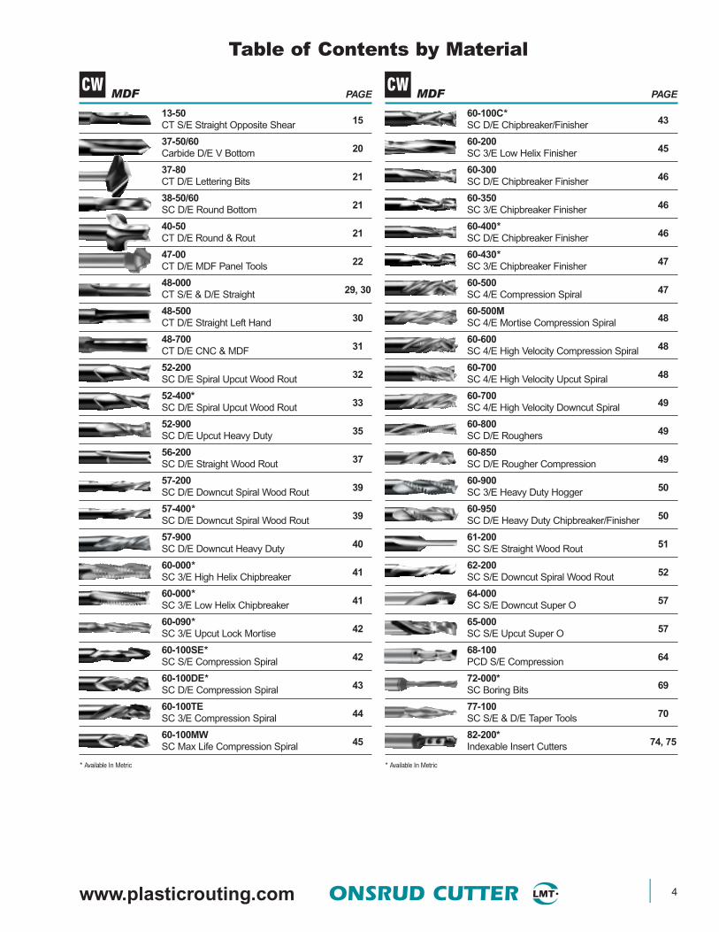
MDF PAGE
13-5015CT S/E Straight Opposite Shear
37-50/6020Carbide D/E V Bottom
37-8021CT D/E Lettering Bits
38-50/6021SC D/E Round Bottom
40-5021CT D/E Round & Rout
47-0022CT D/E MDF Panel Tools
48-00029, 30CT S/E & D/E Straight
48-50030CT D/E Straight Left Hand
48-70031CT D/E CNC & MDF
52-20032SC D/E Spiral Upcut Wood Rout
52-400*33SC D/E Spiral Upcut Wood Rout
52-90035SC D/E Upcut Heavy Duty
56-20037SC D/E Straight Wood Rout
57-20039SC D/E Downcut Spiral Wood Rout
57-400*39SC D/E Downcut Spiral Wood Rout
57-90040SC D/E Downcut Heavy Duty
60-000*41SC 3/E High Helix Chipbreaker
60-000*41SC 3/E Low Helix Chipbreaker
60-090*42SC 3/E Upcut Lock Mortise
60-100SE*42SC S/E Compression Spiral
60-100DE*43SC D/E Compression Spiral
60-100TE44SC 3/E Compression Spiral
60-100MW45SC Max Life Compression Spiral
* Available In Metric
MDF PAGE
60-100C*43SC D/E Chipbreaker/Finisher
60-20045SC 3/E Low Helix Finisher
60-30046SC D/E Chipbreaker Finisher
60-35046SC 3/E Chipbreaker Finisher
60-400*46SC D/E Chipbreaker Finisher
60-430*47SC 3/E Chipbreaker Finisher
60-50047SC 4/E Compression Spiral
60-500M48SC 4/E Mortise Compression Spiral
60-60048SC 4/E High Velocity Compression Spiral
60-70048SC 4/E High Velocity Upcut Spiral
60-70049SC 4/E High Velocity Downcut Spiral
60-80049SC D/E Roughers
60-85049SC D/E Rougher Compression
60-90050SC 3/E Heavy Duty Hogger
60-95050SC D/E Heavy Duty Chipbreaker/Finisher
61-20051SC S/E Straight Wood Rout
62-20052SC S/E Downcut Spiral Wood Rout
64-00057SC S/E Downcut Super O
65-00057SC S/E Upcut Super O
68-10064PCD S/E Compression
72-000*69SC Boring Bits
77-10070SC S/E & D/E Taper Tools
82-200*74, 75Indexable Insert Cutters
* Available In Metric
CW CW
5 ONSRUD CUTTER www.onsrud.com
Table of Contents by Material
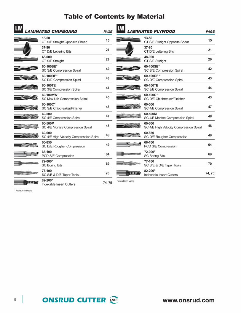
LAMINATED CHIPBOARD PAGE
13-5015CT S/E Straight Opposite Shear
37-8021CT D/E Lettering Bits
48-00029CT S/E Straight
60-100SE*42SC S/E Compression Spiral
60-100DE*43SC D/E Compression Spiral
60-100TE44SC 3/E Compression Spiral
60-100MW45SC Max Life Compression Spiral
60-100C*43SC S/E Chipbreaker/Finisher
60-50047SC 4/E Compression Spiral
60-500M48SC 4/E Mortise Compression Spiral
60-60048SC 4/E High Velocity Compression Spiral
60-85049SC D/E Rougher Compression
68-10064PCD S/E Compression
72-000*69SC Boring Bits
77-10070SC S/E & D/E Taper Tools
82-200*74, 75Indexable Insert Cutters
* Available In Metric
LAMINATED PLYWOOD PAGE
13-5015CT S/E Straight Opposite Shear
37-8021CT D/E Lettering Bits
48-00029CT S/E Straight
60-100SE*42SC S/E Compression Spiral
60-100DE*43SC D/E Compression Spiral
60-100TE44SC 3/E Compression Spiral
60-100C*43SC D/E Chipbreaker/Finisher
60-50047SC 4/E Compression Spiral
60-500M48SC 4/E Mortise Compression Spiral
60-60048SC 4/E High Velocity Compression Spiral
60-85049SC D/E Rougher Compression
68-10064PCD S/E Compression
72-000*69SC Boring Bits
77-10070SC S/E & D/E Taper Tools
82-200*74, 75Indexable Insert Cutters
* Available In Metric
LW LW

www.plasticrouting.com ONSRUD CUTTER 6
Table of Contents by Material
SOFT PLYWOOD PAGE
13-5015CT S/E Straight Opposite Shear
37-50/6020SC D/E V Bottom
37-8021CT D/E Lettering Bits
38-50/6021Carbide D/E Round Bottom
40-5021CT D/E Round & Rout
48-00029, 30CT S/E & D/E Straight
48-50030CT D/E Straight Left Hand
48-70031CT D/E CNC & MDF
56-20037SC D/E Straight Wood Rout
60-000*41SC 3/E High Helix Chipbreaker
60-000*41SC 3/E Low Helix Chipbreaker
60-090*42SC 3/E Upcut Lock Mortise
60-100SE*42SC S/E Compression Spiral
60-100DE*43SC D/E Compression Spiral
60-100TE44SC 3/E Compression Spiral
60-100C*43SC D/E Chipbreaker/Finisher
60-30046SC D/E Chipbreaker Finisher
60-35046SC 3/E Chipbreaker Finisher
* Available In Metric
SOFT PLYWOOD PAGE
60-400*46SC D/E Chipbreaker Finisher
60-430*47SC 3/E Chipbreaker Finisher
60-50047SC 4/E Compression Spiral
60-500M48SC 4/E Mortise Compression Spiral
60-60048SC 4/E High Velocity Compression Spiral
60-70048SC 4/E High Velocity Upcut Spiral
60-70049SC 4/E High Velocity Downcut Spiral
60-80049SC D/E Roughers
60-85049SC D/E Rougher Compression
60-90050SC 3/E Heavy Duty Hogger
60-95050SC D/E Heavy Duty Chipbreaker/Finisher
61-20051SC S/E Straight Wood Rout
64-00057SC S/E Downcut Super O
65-00057SC S/E Upcut Super O
68-10064PCD S/E Compression
72-000*69SC Boring Bits
77-10070SC S/E & D/E Taper Tools
82-200*74, 75Indexable Insert Cutters
* Available In Metric
CW CW

7 ONSRUD CUTTER www.onsrud.com
Table of Contents by Material
HARD PLYWOOD PAGE
13-5015CT S/E Straight Opposite Shear
37-50/6020Carbide D/E V Bottom
37-8021CT D/E Lettering Bits
38-50/6021SC D/E Round Bottom
40-5021CT D/E Round & Rout
48-00029, 30CT S/E & D/E Straight
48-50030CT D/E Straight Left Hand
48-70031CT D/E CNC & MDF
56-20037SC D/E Straight Wood Rout
60-000*41SC 3/E High Helix Chipbreaker
60-000*41SC 3/E Low Helix Chipbreaker
60-090*42SC 3/E Upcut Lock Mortise
60-100SE*42SC S/E Compression Spiral
60-100DE*43SC D/E Compression Spiral
60-100TE44SC 3/E Compression Spiral
60-100C*43SC D/E Chipbreaker/Finisher
60-30046SC D/E Chipbreaker Finisher
60-35046SC 3/E Chipbreaker Finisher
* Available In Metric
HARD PLYWOOD PAGE
60-400*46SC D/E Chipbreaker Finisher
60-430*47SC 3/E Chipbreaker Finisher
60-50047SC 4/E Compression Spiral
60-500M48SC 4/E Mortise Compression Spiral
60-60048SC 4/E High Velocity Compression Spiral
60-70048SC 4/E High Velocity Upcut Spiral
60-70049SC 4/E High Velocity Downcut Spiral
60-80049SC D/E Roughers
60-85049SC D/E Rougher Compression
60-90050SC 3/E Heavy Duty Hogger
60-95050SC D/E Heavy Duty Chipbreaker/Finisher
61-20051SC S/E Straight Wood Rout
64-00057SC S/E Downcut Super O
65-00057SC S/E Upcut Super O
68-10064PCD S/E Compression
72-000*69SC Boring Bits
77-10070SC S/E & D/E Taper Tools
82-200*74, 75Indexable Insert Cutters
* Available In Metric
CW CW

www.plasticrouting.com ONSRUD CUTTER 8
Table of Contents by Material
SOFT PLASTICABS, Polycarbonate, Polyethylene, PVC,Polypropylene, HDPE, Polystyrene, UHMW,Extruded Acrylic PAGE
10-0014HSS S/E O Flute Straight
37-50/6020Carbide D/E V Bottom
38-50/6021SC D/E Round Bottom
52-20032SC D/E Spiral Upcut Wood Rout
52-200B/BL33SC D/E Ball Nose
52-400*33SC D/E Spiral Upcut Wood Rout
52-60034SC D/E Upcut "O" Flute
52-700*34SC D/E Upcut "O" Flute
56-430*37SC D/E Straight O Flute
56-60038SC D/E Straight "O" Flute
57-600*40SC D/E Downcut "O" Flute
60-000*41SC 3/E High Helix Chipbreaker
60-000*41SC 3/E Low Helix Chipbreaker
60-90050SC 3/E Heavy Duty Hogger
61-000P51SC S/E "O" Flute Straight
* Available In Metric
SOFT PLASTICABS, Polycarbonate, Polyethylene, PVC,Polypropylene, HDPE, Polystyrene, UHMW,Extruded Acrylic PAGE
61-400*52SC S/E Straight
62-75053SC S/E Downcut "O" Flute
62-850*53SC S/E Downcut "O" Flute
63-75056SC S/E Upcut "O" Flute
63-850*56SC S/E Upcut "O" Flute
64-00057SC S/E Downcut Super O
65-00057SC S/E Upcut Super O
66-000*58SC Edge Rounding Bits
66-20059SC D/E Rout and Chamfer
66-30059SC D/E Upcut Bottom Surfacing
66-350*59SC D/E Upcut Bottom Surfacing
70-500*68HSS Plastic Drills
77-10070SC S/E & D/E Taper Tools
82-10073D/E and 3/E Inserted Milling Cutters
82-10073Shell Mill
* Available In Metric
SP SP

9 ONSRUD CUTTER www.onsrud.com
Table of Contents by Material
HARD PLASTICCast Acrylic, Melamine, Nylon, PVC, Vinyl PAGE
37-50/6020Carbide D/E V Bottom
38-50/6021SC D/E Round Bottom
52-200B/BL33SC D/E Ball Nose
52-60034SC D/E Upcut "O" Flute
56-000P37SC D/E Straight
56-430*37SC D/E Straight O Flute
56-450*38SC D/E Straight
56-60038SC D/E Straight "O" Flute
57-600*40SC D/E Downcut "O" Flute
60-000*41SC 3/E High Helix Chipbreaker
60-000*41SC 3/E Low Helix Chipbreaker
60-20045SC 3/E Low Helix Finisher
60-470*47SC 3/E Low Helix Finisher
60-90050SC 3/E Heavy Duty Hogger
61-000P51SC S/E "O" Flute Straight
61-400*52SC S/E Straight
62-70053SC S/E Downcut "O" Flute
* Available In Metric
HARD PLASTICCast Acrylic, Melamine, Nylon, PVC, Vinyl PAGE
62-75053SC S/E Downcut "O" Flute
62-800*53SC S/E Downcut "O" Flute
62-850*53SC S/E Downcut "O" Flute
63-70056SC S/E Upcut "O" Flute
63-75056SC S/E Upcut "O" Flute
63-800*56SC S/E Upcut "O" Flute
63-850*56SC S/E Upcut "O" Flute
64-00057SC S/E Downcut Super O
65-00057SC S/E Upcut Super O
66-000*58SC Edge Rounding Bits
66-20059SC D/E Rout and Chamfer
66-30059SC D/E Upcut Bottom Surfacing
66-350*59SC D/E Upcut Bottom Surfacing
70-500*68HSS Plastic Drills
77-10070SC S/E & D/E Taper Tools
82-10073D/E and 3/E Inserted Milling Cutters
82-10073Shell Mill
* Available In Metric
HP HP

www.plasticrouting.com ONSRUD CUTTER 10
Table of Contents by Material
COMPOSITEFiberglass, Phenolic, Reinforced Acetal PAGE
29-00023HSS Hollow Core Cutters
30-00024Replaceable Ring Type Honeycomb Cutter
30-30024HSS Integral Shank Honeycomb Cutter
31-00025High Speed Steel Type
31-10025SC Small Diameter Honeycomb Cutters
32-000*26HSS Hogger
34-00027Aircraft Panel Tools
48-00029, 30CT S/E & D/E Straight
52-00032SC D/E Spiral Upcut
53-00035SC 3/E Straight
54-30035SC 4/E Upcut Spiral
55-000/54-00036SC 4/E Spiral Flute
55-30036SC 4/E Upcut Spiral
56-00036SC D/E Straight
56-450*38SC D/E Straight
57-00038SC D/E Downcut Spiral
* Available In Metric
COMPOSITEFiberglass, Phenolic, Reinforced Acetal PAGE
58-000/59-00040SC 3/E Spiral Flute
60-470*47SC 3/E Low Helix Finisher
62-00052SC S/E Downcut Spiral
63-00054SC S/E Upcut Spiral
67-000*60SC Fiberglass Burr Bits
67-20061SC 3/E Phenolic/Composite Cutter
67-250603/E Diamond Grit Tools
67-30061SC D/E Compression Spiral
67-40061SC Un-Ruffer
67-50062SC Carbon Graphite Tool
67-60062SC Fiber Metal Router
67-800*63SC 8 Facet Drill
68-00064D/E PCD Tipped Tools
68-20064PCD D/E SERF
68-90065PCD 8 Facet Drills
86-00075SC Kevlar Drills
* Available In Metric
SPECIAL PURPOSE PAGE
37-0020SC S/E 60° Engraving Tools
37-2020SC S/E 30° Engraving Tools
70-10065CT Saw and Arbor
70-20065SC Flush Mount Saw
70-30066CT Flush Mount Saw
* Available In Metric
SPECIAL PURPOSE PAGE
70-40067CT Plastic Saws
77-00069SC S/E Top Loading Router Bits
91-00076CT Spoilboard Cutter
91-10076Insert Spoilboard Cutter
* Available In Metric
CP CP
11 ONSRUD CUTTER www.onsrud.com
Table of Contents by Material
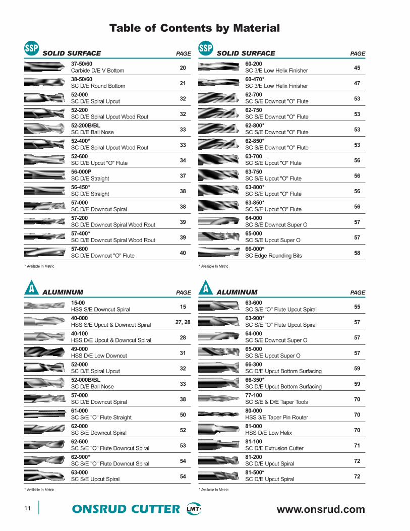
SOLID SURFACE PAGE
37-50/6020Carbide D/E V Bottom
38-50/6021SC D/E Round Bottom
52-00032SC D/E Spiral Upcut
52-20032SC D/E Spiral Upcut Wood Rout
52-200B/BL33SC D/E Ball Nose
52-400*33SC D/E Spiral Upcut Wood Rout
52-60034SC D/E Upcut "O" Flute
56-000P37SC D/E Straight
56-450*38SC D/E Straight
57-00038SC D/E Downcut Spiral
57-20039SC D/E Downcut Spiral Wood Rout
57-400*39SC D/E Downcut Spiral Wood Rout
57-60040SC D/E Downcut "O" Flute
* Available In Metric
SOLID SURFACE PAGE
60-20045SC 3/E Low Helix Finisher
60-470*47SC 3/E Low Helix Finisher
62-70053SC S/E Downcut "O" Flute
62-75053SC S/E Downcut "O" Flute
62-800*53SC S/E Downcut "O" Flute
62-850*53SC S/E Downcut "O" Flute
63-70056SC S/E Upcut "O" Flute
63-75056SC S/E Upcut "O" Flute
63-800*56SC S/E Upcut "O" Flute
63-850*56SC S/E Upcut "O" Flute
64-00057SC S/E Downcut Super O
65-00057SC S/E Upcut Super O
66-000*58SC Edge Rounding Bits
* Available In Metric
ALUMINUM PAGE
15-0015HSS S/E Downcut Spiral
40-00027, 28HSS S/E Upcut & Downcut Spiral
40-10028HSS D/E Upcut & Downcut Spiral
49-00031HSS D/E Low Downcut
52-00032SC D/E Spiral Upcut
52-000B/BL33SC D/E Ball Nose
57-00038SC D/E Downcut Spiral
61-00050SC S/E "O" Flute Straight
62-00052SC S/E Downcut Spiral
62-60053SC S/E "O" Flute Downcut Spiral
62-900*54SC S/E "O" Flute Downcut Spiral
63-00054SC S/E Upcut Spiral
* Available In Metric
ALUMINUM PAGE
63-60055SC S/E "O" Flute Upcut Spiral
63-900*57SC S/E "O" Flute Upcut Spiral
64-00057SC S/E Downcut Super O
65-00057SC S/E Upcut Super O
66-30059SC D/E Upcut Bottom Surfacing
66-350*59SC D/E Upcut Bottom Surfacing
77-10070SC S/E & D/E Taper Tools
80-00070HSS 3/E Taper Pin Router
81-00070HSS D/E Low Helix
81-10071SC D/E Extrusion Cutter
81-20072SC D/E Upcut Spiral
81-500*72SC D/E Upcut Spiral
* Available In Metric
A
SSP SSP
A
www.plasticrouting.com ONSRUD CUTTER 12
Table of Contents by Material
FOAM PAGE
12-0015HSS D/E V Flute Straight
13-5015CT S/E Straight Opposite Shear
56-000P37SC D/E Straight
48-00029, 30CT S/E & D/E Straight
* Available In Metric
FOAM PAGE
40-55029HSS 4/E Foam Cutters
52-55033SC D/E Foam Cutters
77-10070SC S/E & D/E Taper Tools
* Available In Metric
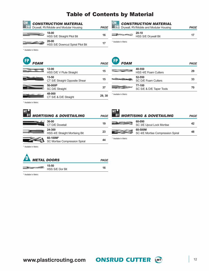
CONSTRUCTION MATERIALDrywall, RV/Mobile and Modular Housing PAGE
18-0016HSS S/E Straight Pilot Bit
20-0017HSS S/E Downcut Spiral Pilot Bit
* Available In Metric
CONSTRUCTION MATERIALDrywall, RV/Mobile and Modular Housing PAGE
20-1017HSS S/E Drywall Bit
* Available In Metric
METAL DOORS PAGE
15-5016HSS S/E Dor Bit
* Available In Metric
MORTISING & DOVETAILING PAGE
36-0019CT D/E Dovetail
24-30023HSS 4/E Straight Mortising Bit
60-100M*44SC Mortise Compression Spiral
* Available In Metric
MORTISING & DOVETAILING PAGE
60-09042SC 3/E Upcut Lock Mortise
60-500M48SC 4/E Mortise Compression Spiral
* Available In Metric
CMDW
FP
MTDT
D
CMDW
FP
MTDT

13 ONSRUD CUTTER www.onsrud.com
TABLE OF CONTENTS
10-00 HSS S/E O Flute Straight 1411-00 HSS O flute Straight 1412-00 HSS D/E V Flute Straight 1513-50 CT S/E Straight Opposite Shear 1515-00 HSS S/E Downcut Spiral 1515-50 HSS S/E Steel Dor Bit 1615-75 HSS 3/E CNC Dor Bit 1618-00 HSS S/E Straight Pilot 1620-00 HSS S/E Downcut Spiral Pilot 1720-10 HSS S/E Drywall Bit 1727-00 SC S/E Laminate Trim 1727-50 SC D/E Laminate Trim 1828-20 SC Double-Bearing Plastic Trim 1828-50 CT Flush Trim 1828-75 Bearing Kits for Bearing Tools 1929-50 CT Chamfer 1936-00/60 CT D/E Dovetail 1937-00 SC S/E 60° Engraving Tools 2037-20 SC S/E 30° Engraving Tools 2037-50/60 Carbide D/E V Bottom 2037-70 CT D/E Dibond/Alucobond 20
Folding Tool37-80 CT D/E Lettering Bits 2138-50/60 SC D/E Round Bottom 2140-50 CT D/E Round & Rout 2142-00 CT D/E Corner Round 2247-00 CT D/E MDF Panel Bits 2290-00 T Slot 2324-300 HSS 4/E Straight Mortising 2329-000 HSS Hollow Core Cutters 2330-000 Replaceable Ring Type 24
Honeycomb Cutter30-300 HSS Integral Shank 24
Honeycomb Cutter31-000 High Speed Steel Type 2531-100 HSS Small Dia. HCC Cutters 2532-000* HSS Hogger 2634-000 Aircraft Panel Tools 2740-000 HSS S/E Upcut Spiral 2740-000 HSS S/E Downcut Spiral 2840-100 HSS D/E Upcut Spiral 2840-100 HSS D/E Downcut Spiral 2940-550 HSS 4/E Foam Cutters 2948-000 CT S/E Straight 2948-000 CT D/E Straight 3048-500 CT D/E Straight Left Hand 3048-600 CT S/E & D/E Straight 3148-700 CT D/E CNC & MDF 3149-000 HSS D/E Low Downcut 3152-000 SC D/E Spiral Upcut 3252-200 SC D/E Spiral Upcut Wood Rout 3252-200B/BL SC D/E Ball Nose 3352-400* SC D/E Spiral Upcut Wood Rout 33
52-550 SC D/E Foam Cutters 3352-600 SC D/E Upcut "O" Flute 3452-700* SC D/E Upcut "O" Flute 3452-900 SC D/E Upcut Heavy Duty 3553-000 SC 3/E Straight 3554-300 SC 4/E Downcut Spiral 3555-000 / 54-000 SC 4/E Spiral Flute 3655-300 SC 4/E Upcut Spiral 3656-000 SC D/E Straight 3656-000P SC D/E Straight 3756-200 SC D/E Straight Wood Rout 3756-430* SC D/E Straight O Flute 3756-450* SC D/E Straight 3856-600 SC D/E Straight "O" Flute 3857-000 SC D/E Downcut Spiral 3857-200 SC D/E Downcut Spiral Wood Rout 3957-400* SC D/E Downcut Spiral Wood Rout 3957-600* SC D/E Downcut "O" Flute 4057-900 SC D/E Downcut Heavy Duty 4058-000 / 59-000 SC 3/E Spiral Flute 4060-000* SC 3/E High Helix Chipbreaker 4160-000* SC 3/E Low Helix Chipbreaker 4160-090* SC 3/E Upcut Lock Mortise 4260-100SE* SC S/E Compression Spiral 4260-100DE* SC D/E Compression Spiral 4360-100C* SC D/E Chipbreaker/Finisher 4360-100TE SC 3/E Compression Spiral 4460-100M* SC Mortise Compression Spiral 4460-100MW SC Max Life Compression Spiral 4560-200 SC 3/E Low Helix Finisher 4560-300 SC D/E Chipbreaker Finisher 4660-350 SC 3/E Chipbreaker Finisher 4660-400* SC D/E Chipbreaker Finisher 4660-430* SC 3/E Chipbreaker Finisher 4760-470* SC 3/E Low Helix Finisher 4760-500 SC 4/E Compression Spiral 4760-500M SC 4/E Mortise 48
Compression Spiral60-600 SC 4/E High Velocity 48
Compression Spiral60-700 SC 4/E High Velocity Upcut Spiral 4860-700 SC 4/E High Velocity Dwncut Spiral 4960-800 SC D/E Roughers 4960-850 SC D/E Rougher Compression 4960-900 SC 3/E Heavy Duty Hogger 5060-950 SC D/E Heavy Duty 50
Chipbreaker/Finisher61-000 SC S/E "O" Flute Straight 5061-000P SC S/E "O" Flute Straight 5161-200 SC S/E Straight Wood Rout 5161-400* SC S/E Straight 5262-000 SC S/E Downcut Spiral 52
62-200 SC S/E Downcut Spiral Wood Rout 5262-600 SC S/E "O" Flute Downcut Spiral 5362-700 SC S/E Downcut "O" Flute 5362-750 SC S/E Downcut "O" Flute 5362-800* SC S/E Downcut "O" Flute 5362-850* SC S/E Downcut "O" Flute 5362-900* SC S/E "O" Flute Downcut Spiral 5463-000 SC S/E Upcut Spiral 5463-200 SC S/E Upcut Spiral Wood Rout 5463-600 SC S/E "O" Flute Upcut Spiral 5563-700 SC S/E Upcut "O" Flute 5663-750 SC S/E Upcut "O" Flute 5663-800* SC S/E Upcut "O" Flute 5663-850* SC S/E Upcut "O" Flute 5663-900* SC S/E "O" Flute Upcut Spiral 5764-000 SC S/E Downcut Super O 5765-000 SC S/E Upcut Super O 5766-000* SC Edge Rounding Bits 5866-200 SC D/E Rout and Chamfer 5966-300 SC D/E Upcut Bottom Surfacing 5966-350* SC D/E Upcut Bottom Surfacing 5967-000* SC Fiberglass Burr Bits 6067-200 SC 3/E Phenolic/Composite Cutter 6167-250 3/E Diamond Grit Tools 6067-300 SC D/E Compression Spiral 6167-400 SC Un-Ruffer 6167-500 SC Carbon Graphite Tool 6267-600 SC Fiber Metal Router 6267-800* SC 8 Facet Drills 6368-000 D/E PCD Tipped Tools 6468-100 PCD S/E Compression 6468-200 PCD D/E SERF 6468-900 PCD 8 Facet Drills 6570-100 CT Saw and Arbor 6570-200 SC Flush Mount Saw 6570-300 CT Flush Mount Saw 6670-400 CT Plastic Saws 6770-500* HSS Plastic Drill 6872-000* SC Boring Bits 6977-000 SC S/E Top Loading Router Bits 6977-100 SC S/E & D/E Taper Tools 7080-000 HSS 3/E Taper Pin Router 7081-000 HSS D/E Low Helix 7081-100 SC D/E Extrusion Cutter 7181-200 SC D/E Upcut Spiral 7281-500* SC D/E Upcut Spiral 7282-100 D/E & 3/E Inserted Milling Cutters 7382-100 3/E Shell Mill 7382-200* Indexable Insert Cutters 74, 7586-000 SC Kevlar Drills 7591-000 CT Spoilboard Cutter 7691-100 Insert Spoilboard Cutter 76
* Available in Metric
www.plasticrouting.com ONSRUD CUTTER 14
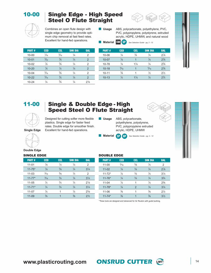
11-00 Single & Double Edge - HighSpeed Steel O Flute Straight
PART # CED CEL SHK DIA OAL
10-06 1⁄4 3⁄4 1⁄4 21⁄8
10-07 1⁄4 1 1⁄4 23⁄8
10-78 1⁄4 11⁄4 1⁄4 25⁄8
10-18 5⁄16 1 5⁄16 23⁄8
10-11 3⁄8 1 1⁄2 21⁄2
10-13 1⁄2 11⁄4 1⁄2 23⁄4
10-00 Single Edge - High SpeedSteel O Flute Straight
Combines an open flute design withsingle edge geometry to provide opti-mum chip removal at fast feed rates.Excellent for hand-fed operations.
■ Usage ABS, polycarbonate, polyethylene, PVC,PVC, polypropylene, polystyrene, extrudedacrylic, HDPE, UHMW, and natural wood
■ Material See Selection Guide - pg. 2 - 12
PART # CED CEL SHK DIA OAL
10-00 1⁄163⁄16 1⁄4 2
10-01 3⁄323⁄8 1⁄4 2
10-02 1⁄8 3⁄8 1⁄4 2
10-20 1⁄8 1⁄2 1⁄4 2
10-04 3⁄165⁄8 1⁄4 2
10-22 3⁄163⁄4 1⁄4 2
10-24 1⁄4 5⁄8 1⁄4 21⁄8
SW SP
PART # CED CEL SHK DIA OAL
11-00 3⁄16 5⁄8 1⁄4 2
11-02 1⁄4 3⁄4 1⁄4 21⁄8
11-72* 1⁄4 3⁄4 1⁄4 31⁄4
11-76* 1⁄4 3⁄4 1⁄4 33⁄4
11-04 1⁄4 1 1⁄4 23⁄8
11-78* 1⁄4 2 1⁄4 31⁄4
11-06 3⁄8 1 3⁄8 21⁄2
11-74* 3⁄8 1 3⁄8 31⁄2
*These tools are designed and toleranced for Air Routers with guide bushing.
Designed for cutting softer more flexibleplastics. Single edge for faster feedrates. Double edge for smoother finish.Excellent for hand-fed operations.
■ Usage ABS, polycarbonate,polyethylene, polystyrene,PVC, polypropylene extruded acrylic, HDPE, UHMW
■ Material See Selection Guide - pg. 2 - 12
PART # CED CEL SHK DIA OAL
11-01 1⁄8 1⁄2 1⁄4 2
11-75* 1⁄8 5⁄8 1⁄4 31⁄4
11-03 3⁄16 5⁄8 1⁄4 2
11-77* 3⁄16 3⁄4 1⁄4 31⁄4
11-05 1⁄4 3⁄4 1⁄4 21⁄8
11-71* 1⁄4 3⁄4 1⁄4 31⁄4
11-07 1⁄4 1 1⁄4 23⁄8
11-09 3⁄8 1 3⁄8 21⁄2
SP HP
SINGLE EDGE DOUBLE EDGE
Single Edge
Double Edge
15 ONSRUD CUTTER www.onsrud.com
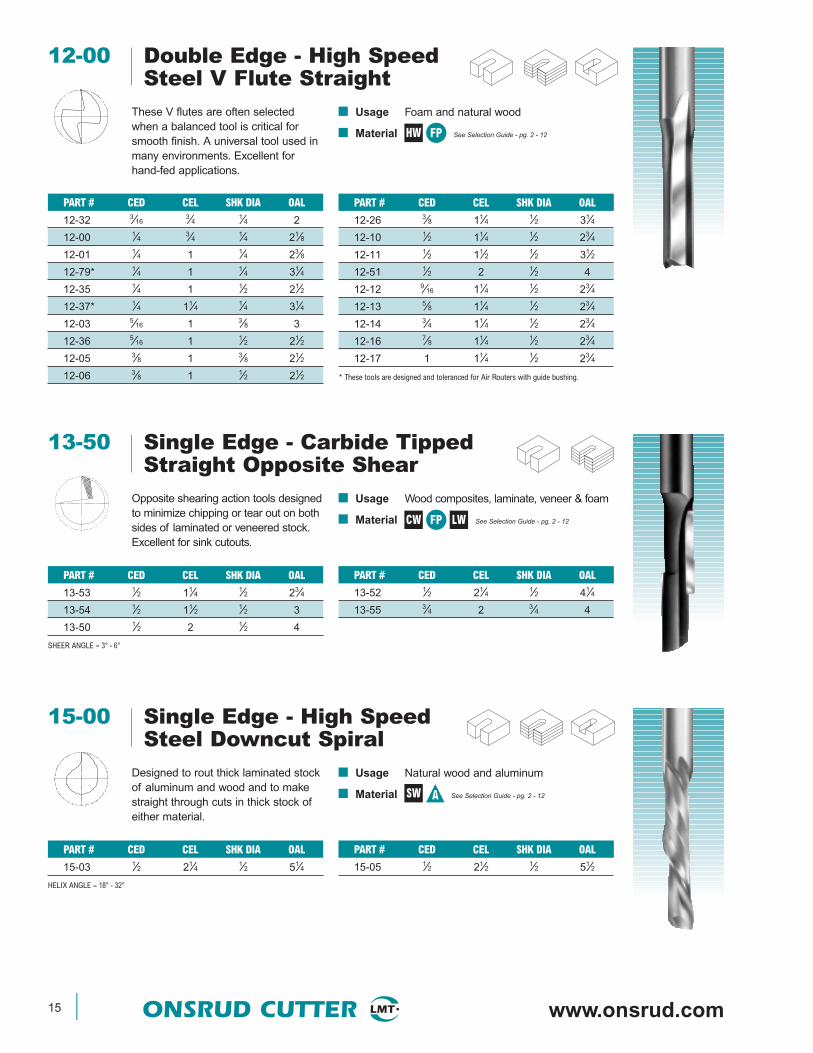
13-50 Single Edge - Carbide TippedStraight Opposite Shear
CW LWFP
PART # CED CEL SHK DIA OAL
13-52 1⁄2 21⁄4 1⁄2 41⁄4
13-55 3⁄4 2 3⁄4 4
Opposite shearing action tools designedto minimize chipping or tear out on bothsides of laminated or veneered stock.Excellent for sink cutouts.
■ Usage Wood composites, laminate, veneer & foam
■ Material See Selection Guide - pg. 2 - 12
PART # CED CEL SHK DIA OAL
13-53 1⁄2 11⁄4 1⁄2 23⁄4
13-54 1⁄2 11⁄2 1⁄2 3
13-50 1⁄2 2 1⁄2 4
SHEER ANGLE ≈ 3° - 6°
■ Usage Natural wood and aluminum
■ Material See Selection Guide - pg. 2 - 12SW A
15-00 Single Edge - High SpeedSteel Downcut Spiral
PART # CED CEL SHK DIA OAL
15-05 1⁄2 21⁄2 1⁄2 51⁄2
Designed to rout thick laminated stockof aluminum and wood and to makestraight through cuts in thick stock ofeither material.
PART # CED CEL SHK DIA OAL
15-03 1⁄2 21⁄4 1⁄2 51⁄4
HELIX ANGLE ≈ 18° - 32°
12-00 Double Edge - High SpeedSteel V Flute Straight
PART # CED CEL SHK DIA OAL
12-26 3⁄8 11⁄4 1⁄2 31⁄4
12-10 1⁄2 11⁄4 1⁄2 23⁄4
12-11 1⁄2 11⁄2 1⁄2 31⁄2
12-51 1⁄2 2 1⁄2 4
12-12 9⁄16 11⁄4 1⁄2 23⁄4
12-13 5⁄8 11⁄4 1⁄2 23⁄4
12-14 3⁄4 11⁄4 1⁄2 23⁄4
12-16 7⁄8 11⁄4 1⁄2 23⁄4
12-17 1 11⁄4 1⁄2 23⁄4
* These tools are designed and toleranced for Air Routers with guide bushing.
These V flutes are often selectedwhen a balanced tool is critical forsmooth finish. A universal tool used inmany environments. Excellent forhand-fed applications.
■ Usage Foam and natural wood
■ Material See Selection Guide - pg. 2 - 12
PART # CED CEL SHK DIA OAL
12-32 3⁄163⁄4 1⁄4 2
12-00 1⁄4 3⁄4 1⁄4 21⁄8
12-01 1⁄4 1 1⁄4 23⁄8
12-79* 1⁄4 1 1⁄4 31⁄4
12-35 1⁄4 1 1⁄2 21⁄2
12-37* 1⁄4 11⁄4 1⁄4 31⁄4
12-03 5⁄16 1 3⁄8 3
12-36 5⁄16 1 1⁄2 21⁄2
12-05 3⁄8 1 3⁄8 21⁄2
12-06 3⁄8 1 1⁄2 21⁄2
HW FP
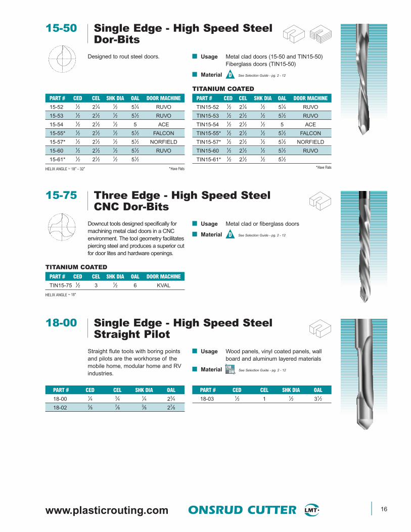
www.plasticrouting.com ONSRUD CUTTER 16
■ Usage Wood panels, vinyl coated panels, wallboard and aluminum layered materials
■ Material See Selection Guide - pg. 2 - 12CM
DW
18-00 Single Edge - High Speed SteelStraight Pilot
PART # CED CEL SHK DIA OAL
18-03 1⁄2 1 1⁄2 31⁄2
Straight flute tools with boring pointsand pilots are the workhorse of themobile home, modular home and RVindustries.
PART # CED CEL SHK DIA OAL
18-00 1⁄4 3⁄4 1⁄4 23⁄4
18-02 3⁄8 7⁄8 3⁄8 27⁄8
TITANIUM COATED
■ Usage Metal clad doors (15-50 and TIN15-50)Fiberglass doors (TIN15-50)
■ Material See Selection Guide - pg. 2 - 12D
15-50 Single Edge - High Speed SteelDor-Bits
PART # CED CEL SHK DIA OAL DOOR MACHINE
TIN15-52 1⁄2 21⁄4 1⁄2 51⁄4 RUVO
TIN15-53 1⁄2 21⁄2 1⁄2 51⁄2 RUVO
TIN15-54 1⁄2 21⁄2 1⁄2 5 ACE
TIN15-55* 1⁄2 21⁄2 1⁄2 51⁄2 FALCON
TIN15-57* 1⁄2 21⁄2 1⁄2 51⁄2 NORFIELD
TIN15-60 1⁄2 21⁄2 1⁄2 51⁄2 RUVO
TIN15-61* 1⁄2 21⁄2 1⁄2 51⁄2*Have Flats
Designed to rout steel doors.
PART # CED CEL SHK DIA OAL DOOR MACHINE
15-52 1⁄2 21⁄4 1⁄2 51⁄4 RUVO
15-53 1⁄2 21⁄2 1⁄2 51⁄2 RUVO
15-54 1⁄2 21⁄2 1⁄2 5 ACE
15-55* 1⁄2 21⁄2 1⁄2 51⁄2 FALCON
15-57* 1⁄2 21⁄2 1⁄2 51⁄2 NORFIELD
15-60 1⁄2 21⁄2 1⁄2 51⁄2 RUVO
15-61* 1⁄2 21⁄2 1⁄2 51⁄2
HELIX ANGLE ≈ 18° - 32° *Have Flats
TITANIUM COATED
■ Usage Metal clad or fiberglass doors
■ Material See Selection Guide - pg. 2 - 12D
15-75 Three Edge - High Speed SteelCNC Dor-Bits
PART # CED CEL SHK DIA OAL DOOR MACHINE
TIN15-75 1⁄2 3 1⁄2 6 KVAL
HELIX ANGLE ≈ 18°
Downcut tools designed specifically formachining metal clad doors in a CNCenvironment. The tool geometry facilitatespiercing steel and produces a superior cutfor door lites and hardware openings.

17 ONSRUD CUTTER www.onsrud.com
■ Usage Aluminum and plywood sandwich panels,vinyl coated panels, wall board, drywalland layered material
■ Material See Selection Guide - pg. 2 - 12CM
DW
20-00 Single Edge - High Speed SteelDowncut Spiral Pilot
PART # CED CEL SHK DIA OAL
20-03 1⁄2 11⁄4 1⁄2 4
Spiral tools designed to push chipsaway from the operator in mobilehome and RV manufacturing plants.
PART # CED CEL SHK DIA OAL
20-00 1⁄4 3⁄4 1⁄4 3
20-02 3⁄8 1 3⁄8 37⁄16
HELIX ANGLE ≈ 21° - 38°
■ Usage Drywall cut outs
■ Material See Selection Guide - pg. 2 - 12CM
DW
20-10 Single Edge - High Speed SteelDrywall Bit
PART # CED CEL SHK DIA OAL
20-12 1⁄8 51⁄641⁄8 21⁄2
20-15 1⁄8 1 1⁄8 21⁄2
Spiral flute tools designed to make cutouts in drywall. Used in manufacturedhousing and on site construction.
PART # CED CEL SHK DIA OAL
20-10 3⁄16 1 1⁄4 31⁄4
20-11 1⁄8 3⁄4 1⁄8 21⁄2
HELIX ANGLE ≈ 30° - 41°
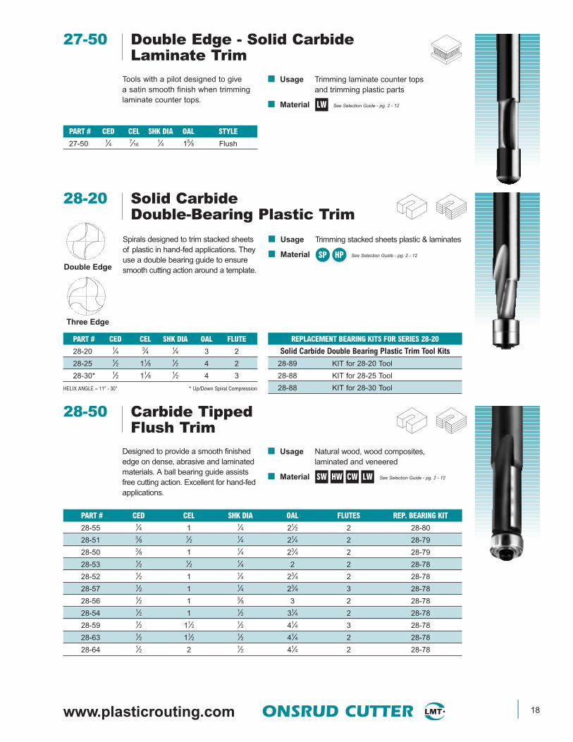
27-00 Single Edge - Solid CarbideLaminate Trim
■ Usage Trimming laminate counter tops andtrimming plastic parts
■ Material See Selection Guide - pg. 2 - 12
PART # CED CEL SHK DIA OAL STYLE
27-03 1⁄4 3⁄8 1⁄4 11⁄2 Flush
27-04 1⁄4 3⁄8 1⁄4 11⁄2 7° Bevel/Flush
Designed to trim counter tops. Thepilot bears on the finished surface andacts as a guide to trim flush or with abevel. Available with boring point ifnecessary to plunge and rout.
PART # CED CEL SHK DIA OAL STYLE
27-00 1⁄4 1⁄4 1⁄4 11⁄2 Flush
27-01 1⁄4 1⁄4 1⁄4 11⁄2 7° Bevel
LW
www.plasticrouting.com ONSRUD CUTTER 18
27-50 Double Edge - Solid CarbideLaminate Trim
■ Usage Trimming laminate counter topsand trimming plastic parts
■ Material See Selection Guide - pg. 2 - 12
Tools with a pilot designed to givea satin smooth finish when trimminglaminate counter tops.
PART # CED CEL SHK DIA OAL STYLE
27-50 1⁄4 7⁄161⁄4 15⁄8 Flush
LW
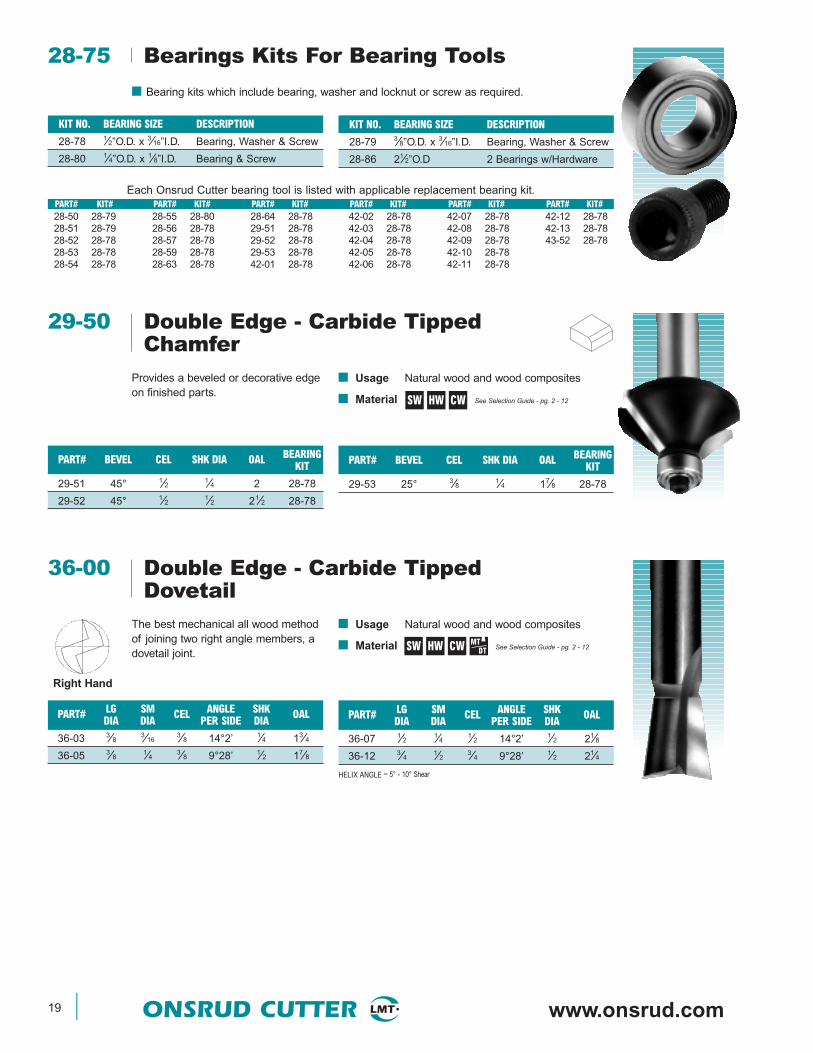
28-20 Solid CarbideDouble-Bearing Plastic Trim
■ Usage Trimming stacked sheets plastic & laminates
■ Material See Selection Guide - pg. 2 - 12
REPLACEMENT BEARING KITS FOR SERIES 28-20
Solid Carbide Double Bearing Plastic Trim Tool Kits
28-89 KIT for 28-20 Tool
28-88 KIT for 28-25 Tool
28-88 KIT for 28-30 Tool
Spirals designed to trim stacked sheetsof plastic in hand-fed applications. Theyuse a double bearing guide to ensuresmooth cutting action around a template.
PART # CED CEL SHK DIA OAL FLUTE
28-20 1⁄4 3⁄4 1⁄4 3 2
28-25 1⁄2 11⁄8 1⁄2 4 2
28-30* 1⁄2 11⁄8 1⁄2 4 3
HELIX ANGLE ≈ 11° - 30° * Up/Down Spiral Compression
SP HPDouble Edge
Three Edge
28-50 Carbide TippedFlush Trim
■ Usage Natural wood, wood composites,laminated and veneered
■ Material See Selection Guide - pg. 2 - 12
Designed to provide a smooth finishededge on dense, abrasive and laminatedmaterials. A ball bearing guide assistsfree cutting action. Excellent for hand-fedapplications.
PART # CED CEL SHK DIA OAL FLUTES REP. BEARING KIT
28-55 1⁄4 1 1⁄4 21⁄2 2 28-80
28-51 3⁄8 1⁄2 1⁄4 21⁄4 2 28-79
28-50 3⁄8 1 1⁄4 23⁄4 2 28-79
28-53 1⁄2 1⁄2 1⁄4 2 2 28-78
28-52 1⁄2 1 1⁄4 23⁄4 2 28-78
28-57 1⁄2 1 1⁄4 23⁄4 3 28-78
28-56 1⁄2 1 3⁄8 3 2 28-78
28-54 1⁄2 1 1⁄2 31⁄4 2 28-78
28-59 1⁄2 11⁄2 1⁄2 41⁄4 3 28-78
28-63 1⁄2 11⁄2 1⁄2 41⁄4 2 28-78
28-64 1⁄2 2 1⁄2 41⁄4 2 28-78
SW HW CW LW
19 ONSRUD CUTTER www.onsrud.com
28-75 Bearings Kits For Bearing Tools
KIT NO. BEARING SIZE DESCRIPTION
28-79 3⁄8”O.D. x 3⁄16”I.D. Bearing, Washer & Screw
28-86 21⁄2”O.D 2 Bearings w/Hardware
■ Bearing kits which include bearing, washer and locknut or screw as required.
KIT NO. BEARING SIZE DESCRIPTION
28-78 1⁄2”O.D. x 3⁄16”I.D. Bearing, Washer & Screw
28-80 1⁄4”O.D. x 1⁄8”I.D. Bearing & Screw
PART# KIT# PART# KIT# PART# KIT# PART# KIT# PART# KIT# PART# KIT#28-50 28-7928-51 28-7928-52 28-7828-53 28-7828-54 28-78
28-55 28-8028-56 28-7828-57 28-7828-59 28-7828-63 28-78
28-64 28-7829-51 28-7829-52 28-7829-53 28-7842-01 28-78
42-02 28-7842-03 28-7842-04 28-7842-05 28-7842-06 28-78
42-07 28-7842-08 28-7842-09 28-7842-10 28-7842-11 28-78
42-12 28-7842-13 28-7843-52 28-78
Each Onsrud Cutter bearing tool is listed with applicable replacement bearing kit.
29-50 Double Edge - Carbide TippedChamfer
■ Usage Natural wood and wood composites
■ Material See Selection Guide - pg. 2 - 12
PART# BEVEL CEL SHK DIA OAL BEARINGKIT
29-53 25° 3⁄8 1⁄4 17⁄8 28-78
Provides a beveled or decorative edgeon finished parts.
PART# BEVEL CEL SHK DIA OAL BEARINGKIT
29-51 45° 1⁄2 1⁄4 2 28-78
29-52 45° 1⁄2 1⁄2 21⁄2 28-78
SW HW CW
Right Hand
■ Usage Natural wood and wood composites
■ Material See Selection Guide - pg. 2 - 12
36-00 Double Edge - Carbide TippedDovetail
PART# LG SM CEL ANGLE SHK OALDIA DIA PER SIDE DIA
36-07 1⁄2 1⁄4 1⁄2 14°2’ 1⁄2 21⁄8
36-12 3⁄4 1⁄2 3⁄4 9°28’ 1⁄2 21⁄4
HELIX ANGLE ≈ 5° - 10° Shear
The best mechanical all wood methodof joining two right angle members, adovetail joint.
PART# LG SM CEL ANGLE SHK OALDIA DIA PER SIDE DIA
36-03 3⁄8 3⁄163⁄8 14°2’ 1⁄4 13⁄4
36-05 3⁄8 1⁄4 3⁄8 9°28’ 1⁄2 17⁄8
SW HW CW MTDT

www.plasticrouting.com ONSRUD CUTTER 20
CARBIDE TIPPEDSOLID CARBIDE
■ Usage Plastic and solid surface, composites,laminated and veneer
■ MaterialSee SelectionGuide - pg. 2 - 12
37-50 Double Edge - V Bottom37-60
PART # CED CEL SHK DIA OAL
37-61 1⁄2 13⁄32 1⁄4 125⁄32
37-62 3⁄4 1⁄2 1⁄2 21⁄8
37-63 1 27⁄32 1⁄2 227⁄32
Designed for V grooving or beveling90°.
PART # CED CEL SHK DIA OAL
37-50 3⁄16 5⁄8 1⁄4 2
37-51 1⁄4 3⁄4 1⁄4 2
37-52 3⁄8 3⁄4 3⁄8 21⁄2
HELIX ANGLE ≈ 3° - 5° Shear
SW HW CW LWSP HP SSP
■ Usage Wood, plastic, aluminum andsolid surface
■ Material See SelectionGuide - pg. 2 - 12
37-00 Single Edge - Solid Carbide37-20 Engraving Tools
PART # TIP ANGLE SHK DIA OAL
37-21 0.005 30 1⁄4 2
37-23 0.010 30 1⁄4 2
37-25 0.020 30 1⁄4 2
37-27 0.030 30 1⁄4 2
37-29 0.040 30 1⁄4 2
37-31 0.060 30 1⁄4 2
37-35 0.090 30 1⁄4 2
37-39 30 Degree Kit
The half round engraving tools are offeredwith a wide range of tip sizes and anglesto accommodate many engraving styles.
PART # TIP ANGLE SHK DIA OAL
37-01 0.005 60 1⁄4 2
37-03 0.010 60 1⁄4 2
37-05 0.020 60 1⁄4 2
37-07 0.030 60 1⁄4 2
37-09 0.040 60 1⁄4 2
37-11 0.060 60 1⁄4 2
37-15 0.090 60 1⁄4 2
37-19 60 Degree Kit
SW HW SP HP SSP
■ Usage Aluminum/plastic sandwich materials
■ Material See Selection Guide - pg. 2 - 12
37-70 Double Edge - Carbide TippedFolding Tool for Dibond/Alucobond
PART # CED CEL SHK DIA OAL
37-72 1⁄2 3⁄8 1⁄2 2
Designed for cutting aluminum/plasticsandwich materials with 90° angle andflat bottom.
PART # CED CEL SHK DIA OAL
37-71 1⁄2 3⁄8 1⁄4 2
90° angle and .090 flat for folding material
A
A

21 ONSRUD CUTTER www.onsrud.com
CARBIDE TIPPEDSOLID CARBIDE
■ Usage Natural wood, wood composites, laminatedand veneered, plastic and solid surface
■ Material See SelectionGuide - pg. 2 - 12
38-50 Double Edge - Round Bottom 38-60
PART # CED CEL SHK DIA OAL
38-53 3⁄8 3⁄4 3⁄8 21⁄4
38-61 1⁄2 11⁄321⁄4 2
Round bottom tools featuring upshearaction for grooving and decorativeface cutting.
PART # CED CEL SHK DIA OAL
38-50 1⁄8 3⁄8 1⁄4 2
38-51 3⁄165⁄8 1⁄4 2
38-52 1⁄4 3⁄4 1⁄4 2
HELIX ANGLE ≈ 2° - 4° Shear
SW HW CW LWSP HP SSP
■ Usage Natural wood, wood composites,plastic and solid surface
■ Material See SelectionGuide - pg. 2 - 12
40-50 Double Edge - Carbide Tipped Round & Rout
PART# CED SM CEL SHK OAL CE CED DIA RAD
40-53 11⁄8 1⁄2 1.437 1⁄2 311⁄161⁄4
40-54 13⁄8 1⁄2 .938 1⁄2 33⁄163⁄8
40-55 13⁄8 1⁄2 1.437 1⁄2 311⁄163⁄8
Designed to put a radius on the edgeand dress the stock. They will providea smooth finish.
PART# CED SM CEL SHK OAL CE CED DIA RAD
40-50 1 1⁄2 .938 1⁄2 33⁄163⁄16
40-51 1 1⁄2 1.437 1⁄2 311⁄163⁄16
40-52 11⁄8 1⁄2 .937 1⁄2 33⁄161⁄4
SW HW CW SP HP SSP
PART # CED CEL SHK DIA OAL ANGLE
37-92 2 0.577 1⁄2 27⁄8 120º
37-97 2 0.363 1⁄2 25⁄8 140º
37-80 Double Edge - Carbide TippedNEW Lettering Bits
Designed for V grooving or bevelingedges of parts. The tools are designedto cut a wide variety of wood productsand produce a clean edge.
■ Usage Wood
■ Material See Selection Guide - pg. 2 - 12
PART # CED CEL SHK DIA OAL ANGLE
37-82 1 0.856 1⁄2 31⁄2 60º
37-87 11⁄2 0.750 1⁄2 3 90º
SW CWHW
www.plasticrouting.com ONSRUD CUTTER 22
■ Usage Natural wood, wood compositesand solid surface
■ Material See Selection Guide - pg. 2 - 12
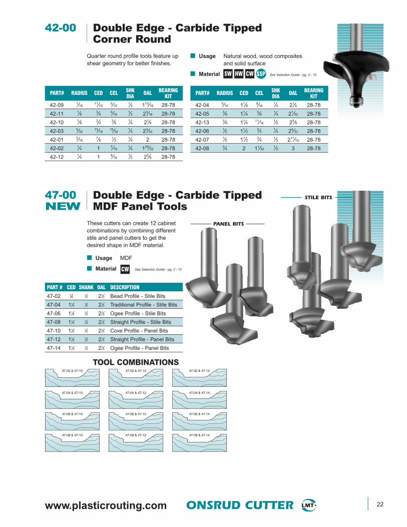
42-00 Double Edge - Carbide Tipped Corner Round
PART# RADIUS CED CEL SHK OAL BEARINGDIA KIT
42-04 5⁄16 11⁄8 9⁄161⁄4 21⁄4 28-78
42-05 3⁄8 11⁄4 5⁄8 1⁄4 21⁄32 28-78
42-13 3⁄8 11⁄4 11⁄161⁄2 25⁄8 28-78
42-06 1⁄2 11⁄2 3⁄4 1⁄4 25⁄32 28-78
42-07 1⁄2 11⁄2 3⁄4 1⁄2 211⁄16 28-78
42-08 3⁄4 2 11⁄321⁄2 3 28-78
Quarter round profile tools feature upshear geometry for better finishes.
PART# RADIUS CED CEL SHK OAL BEARINGDIA KIT
42-09 1⁄1611⁄16
5⁄161⁄4 115⁄16 28-78
42-11 1⁄8 3⁄4 5⁄161⁄2 23⁄16 28-78
42-10 1⁄8 3⁄4 3⁄8 1⁄4 21⁄8 28-78
42-03 5⁄3213⁄16
15⁄321⁄4 23⁄32 28-78
42-01 3⁄167⁄8 1⁄2 1⁄4 2 28-78
42-02 1⁄4 1 7⁄161⁄4 129⁄32 28-78
42-12 1⁄4 1 9⁄161⁄2 25⁄8 28-78
SW HW CW SSP
47-00 Double Edge - Carbide TippedNEW MDF Panel Tools
These cutters can create 12 cabinetcombinations by combining differentstile and panel cutters to get thedesired shape in MDF material.
■ Usage MDF
■ Material See Selection Guide - pg. 2 - 12
PART # CED SHANK OAL DESCRIPTION
47-02 7⁄8 1⁄2 21⁄2 Bead Profile - Stile Bits
47-04 11⁄4 1⁄2 21⁄2 Traditional Profile - Stile Bits
47-06 11⁄4 1⁄2 21⁄2 Ogee Profile - Stile Bits
47-08 11⁄4 1⁄2 21⁄2 Straight Profile - Stile Bits
47-10 11⁄2 1⁄2 21⁄2 Cove Profile - Panel Bits
47-12 11⁄2 1⁄2 21⁄2 Straight Profile - Panel Bits
47-14 11⁄2 1⁄2 21⁄2 Ogee Profile - Panel Bits
CW
STILE BITS
PANEL BITS
TOOL COMBINATIONS47-02 & 47-1247-02 & 47-10 47-02 & 47-14
47-04 & 47-1247-04 & 47-10 47-04 & 47-14
47-06 & 47-1247-06 & 47-10 47-06 & 47-14
47-08 & 47-1247-08 & 47-10 47-08 & 47-14
23 ONSRUD CUTTER www.onsrud.com
HIGH SPEED STEEL SOLID CARBIDE
■ Usage Natural wood and wood composites
■ Material See Selection Guide - pg. 2 - 12
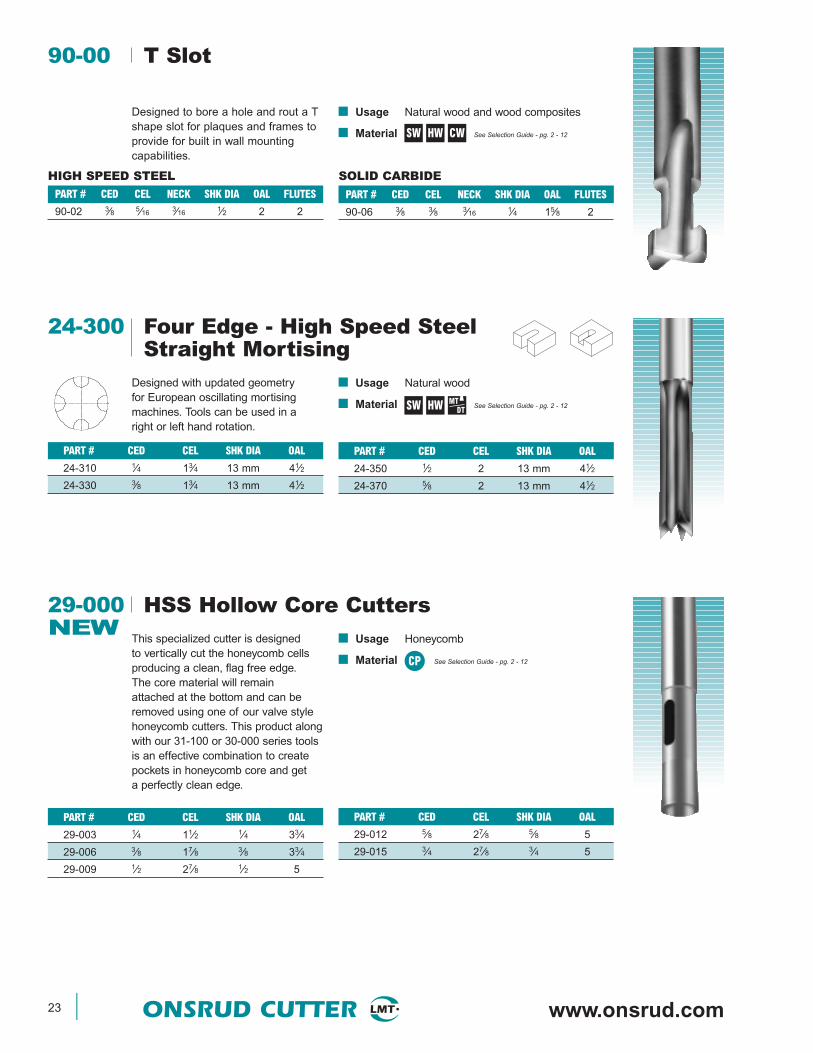
90-00 T Slot
PART # CED CEL NECK SHK DIA OAL FLUTES
90-06 3⁄8 3⁄8 3⁄16 1⁄4 15⁄8 2
Designed to bore a hole and rout a Tshape slot for plaques and frames toprovide for built in wall mountingcapabilities.
PART # CED CEL NECK SHK DIA OAL FLUTES
90-02 3⁄8 5⁄16 3⁄16 1⁄2 2 2
SW HW CW
■ Usage Natural wood
■ Material See Selection Guide - pg. 2 - 12
24-300 Four Edge - High Speed Steel Straight Mortising
PART # CED CEL SHK DIA OAL
24-350 1⁄2 2 13 mm 41⁄2
24-370 5⁄8 2 13 mm 41⁄2
Designed with updated geometry for European oscillating mortisingmachines. Tools can be used in aright or left hand rotation.
PART # CED CEL SHK DIA OAL
24-310 1⁄4 13⁄4 13 mm 41⁄2
24-330 3⁄8 13⁄4 13 mm 41⁄2
SW HW MTDT
PART # CED CEL SHK DIA OAL
29-012 5⁄8 27⁄8 5⁄8 5
29-015 3⁄4 27⁄8 3⁄4 5
29-000 HSS Hollow Core CuttersNEW
This specialized cutter is designedto vertically cut the honeycomb cellsproducing a clean, flag free edge.The core material will remainattached at the bottom and can beremoved using one of our valve stylehoneycomb cutters. This product alongwith our 31-100 or 30-000 series toolsis an effective combination to createpockets in honeycomb core and geta perfectly clean edge.
PART # CED CEL SHK DIA OAL
29-003 1⁄4 11⁄2 1⁄4 33⁄4
29-006 3⁄8 17⁄8 3⁄8 33⁄4
29-009 1⁄2 27⁄8 1⁄2 5
■ Usage Honeycomb
■ Material See Selection Guide - pg. 2 - 12CP
www.plasticrouting.com ONSRUD CUTTER 24
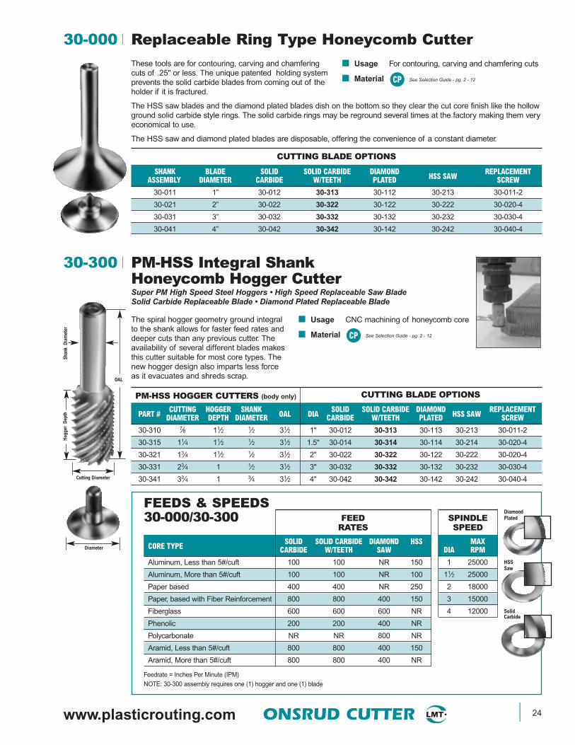
These tools are for contouring, carving and chamferingcuts of .25" or less. The unique patented holding systemprevents the solid carbide blades from coming out of theholder if it is fractured.
The HSS saw blades and the diamond plated blades dish on the bottom so they clear the cut core finish like the hollowground solid carbide style rings. The solid carbide rings may be reground several times at the factory making them veryeconomical to use.
The HSS saw and diamond plated blades are disposable, offering the convenience of a constant diameter.
30-300 PM-HSS Integral ShankHoneycomb Hogger CutterSuper PM High Speed Steel Hoggers • High Speed Replaceable Saw Blade Solid Carbide Replaceable Blade • Diamond Plated Replaceable Blade
Shan
k D
iam
eter
Cutting Diameter
Diameter
Hog
ger
Dep
th
OAL
PART # CUTTING HOGGER SHANK OAL DIA SOLID SOLID CARBIDE DIAMOND HSS SAW REPLACEMENTDIAMETER DEPTH DIAMETER CARBIDE W/TEETH PLATED SCREW
30-310 7⁄8 11⁄2 1⁄2 31⁄2 1" 30-012 30-313 30-113 30-213 30-011-2
30-315 11⁄4 11⁄2 1⁄2 31⁄2 1.5" 30-014 30-314 30-114 30-214 30-020-4
30-321 13⁄4 11⁄2 1⁄2 31⁄2 2" 30-022 30-322 30-122 30-222 30-020-4
30-331 23⁄4 1 1⁄2 31⁄2 3" 30-032 30-332 30-132 30-232 30-030-4
30-341 33⁄4 1 3⁄4 31⁄2 4" 30-042 30-342 30-142 30-242 30-040-4
FEEDS & SPEEDS30-000/30-300
PM-HSS HOGGER CUTTERS (body only)
CUTTING BLADE OPTIONS
CUTTING BLADE OPTIONS
FEEDRATES
SPINDLESPEED
30-000 Replaceable Ring Type Honeycomb Cutter
SHANK BLADE SOLID SOLID CARBIDE DIAMOND HSS SAW REPLACEMENTASSEMBLY DIAMETER CARBIDE W/TEETH PLATED SCREW
30-011 1” 30-012 30-313 30-112 30-213 30-011-2
30-021 2” 30-022 30-322 30-122 30-222 30-020-4
30-031 3” 30-032 30-332 30-132 30-232 30-030-4
30-041 4” 30-042 30-342 30-142 30-242 30-040-4
CORE TYPE SOLID SOLID CARBIDE DIAMOND HSSCARBIDE W/TEETH SAW
Aluminum, Less than 5#/cuft 100 100 NR 150
Aluminum, More than 5#/cuft 100 100 NR 100
Paper based 400 400 NR 250
Paper, based with Fiber Reinforcement 800 800 400 150
Fiberglass 600 600 600 NR
Phenolic 200 200 400 NR
Polycarbonate NR NR 800 NR
Aramid, Less than 5#/cuft 800 800 400 150
Aramid, More than 5#/cuft 800 800 400 NR
Feedrate = Inches Per Minute (IPM)
NOTE: 30-300 assembly requires one (1) hogger and one (1) blade
MAXDIA RPM
1 25000
11⁄2 25000
2 18000
3 15000
4 12000
■ Usage For contouring, carving and chamfering cuts
■ Material See Selection Guide - pg. 2 - 12CP
The spiral hogger geometry ground integralto the shank allows for faster feed rates anddeeper cuts than any previous cutter. Theavailability of several different blades makesthis cutter suitable for most core types. Thenew hogger design also imparts less forceas it evacuates and shreds scrap.
■ Usage CNC machining of honeycomb core
■ Material See Selection Guide - pg. 2 - 12CP
Solid Carbide
Diamond Plated
HSSSaw

25 ONSRUD CUTTER www.onsrud.com
CORE TYPE RATING
Aluminum, Lo Density (Less than 5#/cuft) 1
Aluminum, Hi Density (More than 5#/cuft) 2
Paper 2
Paper, Reinforced N
Fiberglass N
Phenolic N
Polycarbonate N
Aramid N
1 - Excellent, 2 - Good, N - Not Recommended
31-000 High Speed Steel Cutter
PART # CED SHK DIA OAL
31-010 1⁄2 1⁄4 21⁄16
31-015 3⁄4 1⁄4 23⁄32
31-020 1 1⁄4 21⁄831-025 11⁄2 1⁄2 21⁄431-030 2 1⁄2 2 3⁄431-040 3 1⁄2 215⁄16
■ Usage Aluminum Core
■ Material See Selection Guide - pg. 2 - 12
This cutter is designed primarily for use on aluminum core, offering theversatility of smaller sizes for use on hand-held machines in field ormaintenance type repairs. This cutter offers the strength of an integralshank and blade that has an edge sharpness unattainable with any othermaterial. This sharpness and the relieved bottom yield part surfaces thatrequire a minimum of preparation before bonding operation.
CP
PART # CED SHK DIA OAL
31-106TCN 5⁄8 1⁄4 3
31-108TCN 3⁄4 1⁄4 3
31-100 High Speed SteelNEW Honeycomb Cutter With Teeth
The small diameter honeycombcutters were designed to offer theflexibility of cutting small slots orpockets in honeycomb core. The toolsare versatile and can be used on CNCmachines or hand held machines forfield or maintenance type repairs.
■ Usage For contouring, carving, pocketing, andchamfer cuts
■ Material See Selection Guide - pg. 2 - 12
PART # CED SHK DIA OAL
31-102TCN 3⁄8 1⁄4 3
31-104TCN 1⁄2 1⁄4 3
CP

www.plasticrouting.com ONSRUD CUTTER 26
MAXDIA RPM3⁄8 350001⁄2 350003⁄4 35000
1 30000
11⁄2 25000
13⁄4 25000
2 20000
21⁄2 20000
3 20000
Solid Carbide
Diamond Plated
FEEDS AND SPEEDSAvailable Cutting Blades for 31-000 and 32-000 Series.
Hogger
Shank
1/2”
32-000 PM High Speed Steel Hogger
PART # HOGGER HOGGER SHANK BLADE SOLID DIAMOND HSS HSS SAW ADAPTER FORDIAMETER DEPTH PART # DIAMETER CARBIDE PLATED WAVY RING HSS SAW
32-022 (44mm) (16mm) 32-021 (45mm) 1.77” 32-026 - 32-023 - -
1.73 ” 0.63 “ (50mm) 1.97” - 32-029* - 32-027* 32-028
32-032 (61.5mm) (16mm) 32-031 (63mm) 2.48” 32-036 - 32-033 - -
2.42 “ 0.63 “ (75mm) 2.95” - 32-039* - 32-037* 32-038
PM-HSS HOGGER CUTTING BLADE OPTIONSSHK
(All Shanks are 1/2” Diameter) 32-100 Wrench for 32-000 Series Tools * Requires adapter for saws
HSS Saw
PM-HSSWavy Ring
FEEDRATES
SPINDLESPEED
CORE TYPE SOLID DIAMOND HSS HSS HSS HSSCARBIDE PLATED SAW WAVY (31-000) (31-100)
Aluminum, Less than 5#/cuft 100 NR 150 100 100-140 90-140
Aluminum, More than 5#/cuft 100 NR 100 100 70 70
Paper based 300 NR 200 300 50 50
Paper, based w/Fiber Reinforcement 400 300 600 300 100-150 100-150
Fiberglass NR 600 NR NR NR NR
Phenolic NR 600 NR NR NR NR
Polycarbonate NR 800 NR NR NR NR
Aramid, Less than 5#/cuft 200 NR 150 200 100-150 100-150
Aramid, More than 5#/cuft 200 400 NR NR NR NR
Feedrate = Inches Per Minute (IPM)
■ Usage Fast removal of excess core
■ Material See Selection Guide - pg. 2 - 12
These cutters are specifically designed for fast (lowforce) removal of excess core followed by a finalfinish pass to obtain excellent finishes with one tool.These cutters enable cuts of up to .60” depths in asingle pass. The availability of several differentblades makes this cutter suitable for most core types.
All assemblies require a shank, hogger and blade.
CP
27 ONSRUD CUTTER www.onsrud.com
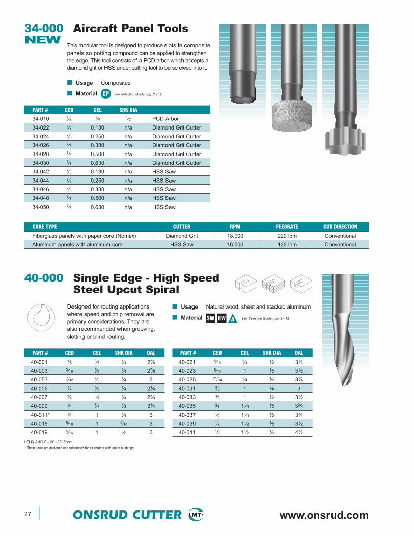
34-000 Aircraft Panel ToolsNEW
This modular tool is designed to produce slots in compositepanels so potting compound can be applied to strengthenthe edge. This tool consists of a PCD arbor which accepts adiamond grit or HSS under cutting tool to be screwed into it.
■ Usage Composites
■ Material See Selection Guide - pg. 2 - 12CP
PART # CED CEL SHK DIA
34-010 1⁄2 1⁄4 1⁄2 PCD Arbor
34-022 7⁄8 0.130 n/a Diamond Grit Cutter
34-024 7⁄8 0.250 n/a Diamond Grit Cutter
34-026 7⁄8 0.380 n/a Diamond Grit Cutter
34-028 7⁄8 0.500 n/a Diamond Grit Cutter
34-030 7⁄8 0.630 n/a Diamond Grit Cutter
34-042 7⁄8 0.130 n/a HSS Saw
34-044 7⁄8 0.250 n/a HSS Saw
34-046 7⁄8 0.380 n/a HSS Saw
34-048 7⁄8 0.500 n/a HSS Saw
34-050 7⁄8 0.630 n/a HSS Saw
CORE TYPE CUTTER RPM FEEDRATE CUT DIRECTION
Fiberglass panels with paper core (Nomex) Diamond Grit 18,000 220 lpm Conventional
Aluminum panels with aluminum core HSS Saw 16,000 120 lpm Conventional
■ Usage Natural wood, sheet and stacked aluminum
■ Material See Selection Guide - pg. 2 - 12
40-000 Single Edge - High SpeedSteel Upcut Spiral
PART # CED CEL SHK DIA OAL
40-021 5⁄16 3⁄4 1⁄2 31⁄4
40-023 5⁄16 1 1⁄2 31⁄2
40-025 21⁄64 3⁄4 1⁄2 31⁄4
40-031 3⁄8 1 3⁄8 3
40-033 3⁄8 1 1⁄2 31⁄2
40-035 3⁄8 11⁄4 1⁄2 33⁄4
40-037 1⁄2 11⁄4 1⁄2 31⁄4
40-039 1⁄2 11⁄2 1⁄2 31⁄2
40-041 1⁄2 11⁄2 1⁄2 41⁄2
Designed for routing applicationswhere speed and chip removal areprimary considerations. They arealso recommended when grooving,slotting or blind routing.
PART # CED CEL SHK DIA OAL
40-001 1⁄8 3⁄8 1⁄4 25⁄8
40-003 3⁄16 5⁄8 1⁄4 27⁄8
40-053 7⁄32 7⁄8 1⁄4 3
40-005 1⁄4 5⁄8 1⁄4 23⁄4
40-007 1⁄4 3⁄4 1⁄4 23⁄4
40-009 1⁄4 3⁄4 1⁄2 31⁄4
40-011* 1⁄4 1 1⁄4 3
40-015 5⁄16 1 5⁄16 3
40-019 5⁄16 1 3⁄8 3
HELIX ANGLE ≈19° - 32° Shear
* These tools are designed and toleranced for air routers with guide bushings.
SW HW A
www.plasticrouting.com ONSRUD CUTTER 28
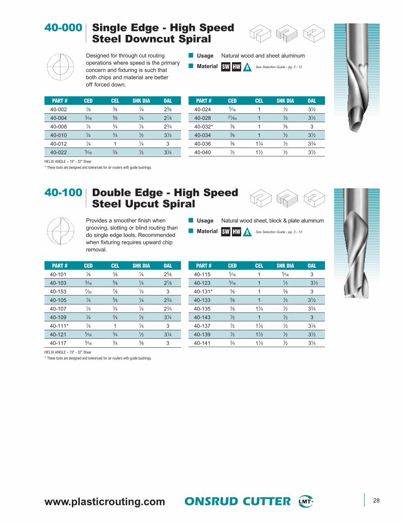
■ Usage Natural wood and sheet aluminum
■ Material See Selection Guide - pg. 2 - 12
40-000 Single Edge - High SpeedSteel Downcut Spiral
PART # CED CEL SHK DIA OAL
40-024 5⁄16 1 1⁄2 31⁄2
40-028 21⁄64 1 1⁄2 31⁄2
40-032* 3⁄8 1 3⁄8 3
40-034 3⁄8 1 1⁄2 31⁄2
40-036 3⁄8 11⁄4 1⁄2 33⁄4
40-040 1⁄2 11⁄2 1⁄2 31⁄2
Designed for through cut routingoperations where speed is the primaryconcern and fixturing is such thatboth chips and material are betteroff forced down.
PART # CED CEL SHK DIA OAL
40-002 1⁄8 3⁄8 1⁄4 25⁄8
40-004 3⁄16 5⁄8 1⁄4 27⁄8
40-008 1⁄4 3⁄4 1⁄4 23⁄4
40-010 1⁄4 3⁄4 1⁄2 31⁄4
40-012 1⁄4 1 1⁄4 3
40-022 5⁄16 3⁄4 1⁄2 31⁄4
HELIX ANGLE ≈ 19° - 32° Shear
* These tools are designed and toleranced for air routers with guide bushings.
SW HW A
■ Usage Natural wood sheet, block & plate aluminum
■ Material See Selection Guide - pg. 2 - 12
40-100 Double Edge - High SpeedSteel Upcut Spiral
PART # CED CEL SHK DIA OAL
40-115 5⁄16 1 5⁄16 3
40-123 5⁄16 1 1⁄2 31⁄2
40-131* 3⁄8 1 3⁄8 3
40-133 3⁄8 1 1⁄2 31⁄2
40-135 3⁄8 11⁄4 1⁄2 33⁄4
40-143 1⁄2 1 1⁄2 3
40-137 1⁄2 11⁄4 1⁄2 31⁄4
40-139 1⁄2 11⁄2 1⁄2 31⁄2
40-141 3⁄4 11⁄4 1⁄2 31⁄4
Provides a smoother finish whengrooving, slotting or blind routing thando single edge tools. Recommendedwhen fixturing requires upward chipremoval.
PART # CED CEL SHK DIA OAL
40-101 1⁄8 3⁄8 1⁄4 25⁄8
40-103 3⁄16 5⁄8 1⁄4 27⁄8
40-153 7⁄32 7⁄8 1⁄4 3
40-105 1⁄4 5⁄8 1⁄4 23⁄4
40-107 1⁄4 3⁄4 1⁄4 23⁄4
40-109 1⁄4 3⁄4 1⁄2 31⁄4
40-111* 1⁄4 1 1⁄4 3
40-121 5⁄16 3⁄4 1⁄2 31⁄4
40-117 5⁄16 3⁄4 3⁄8 3
HELIX ANGLE ≈ 19° - 32° Shear
* These tools are designed and toleranced for air routers with guide bushings.
SW HW A
29 ONSRUD CUTTER www.onsrud.com
■ Usage Natural wood, sheet & aluminum extrusions
■ Material See Selection Guide - pg. 2 - 12
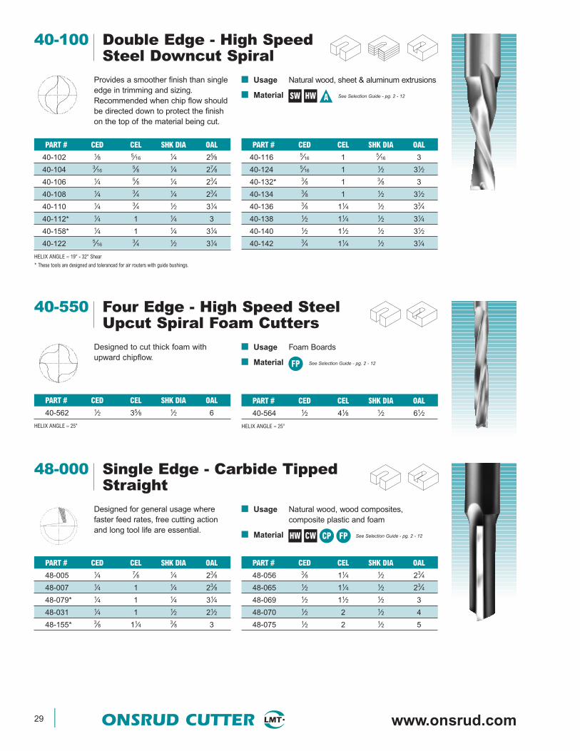
40-100 Double Edge - High SpeedSteel Downcut Spiral
PART # CED CEL SHK DIA OAL
40-116 5⁄16 1 5⁄16 3
40-124 5⁄16 1 1⁄2 31⁄2
40-132* 3⁄8 1 3⁄8 3
40-134 3⁄8 1 1⁄2 31⁄2
40-136 3⁄8 11⁄4 1⁄2 33⁄4
40-138 1⁄2 11⁄4 1⁄2 31⁄4
40-140 1⁄2 11⁄2 1⁄2 31⁄2
40-142 3⁄4 11⁄4 1⁄2 31⁄4
Provides a smoother finish than singleedge in trimming and sizing.Recommended when chip flow shouldbe directed down to protect the finishon the top of the material being cut.
PART # CED CEL SHK DIA OAL
40-102 1⁄8 5⁄16 1⁄4 25⁄8
40-104 3⁄165⁄8 1⁄4 27⁄8
40-106 1⁄4 5⁄8 1⁄4 23⁄4
40-108 1⁄4 3⁄4 1⁄4 23⁄4
40-110 1⁄4 3⁄4 1⁄2 31⁄4
40-112* 1⁄4 1 1⁄4 3
40-158* 1⁄4 1 1⁄4 31⁄4
40-122 5⁄163⁄4 1⁄2 31⁄4
HELIX ANGLE ≈ 19° - 32° Shear
* These tools are designed and toleranced for air routers with guide bushings.
SW HW A
■ Usage Foam Boards
■ Material See Selection Guide - pg. 2 - 12
40-550 Four Edge - High Speed SteelUpcut Spiral Foam Cutters
PART # CED CEL SHK DIA OAL
40-564 1⁄2 41⁄8 1⁄2 61⁄2
HELIX ANGLE ≈ 25°
Designed to cut thick foam withupward chipflow.
PART # CED CEL SHK DIA OAL
40-562 1⁄2 35⁄8 1⁄2 6
HELIX ANGLE ≈ 25°
FP
■ Usage Natural wood, wood composites,composite plastic and foam
■ Material See Selection Guide - pg. 2 - 12
48-000 Single Edge - Carbide TippedStraight
PART # CED CEL SHK DIA OAL
48-056 3⁄8 11⁄4 1⁄2 23⁄4
48-065 1⁄2 11⁄4 1⁄2 23⁄4
48-069 1⁄2 11⁄2 1⁄2 3
48-070 1⁄2 2 1⁄2 4
48-075 1⁄2 2 1⁄2 5
Designed for general usage wherefaster feed rates, free cutting actionand long tool life are essential.
PART # CED CEL SHK DIA OAL
48-005 1⁄4 7⁄8 1⁄4 23⁄8
48-007 1⁄4 1 1⁄4 23⁄8
48-079* 1⁄4 1 1⁄4 31⁄4
48-031 1⁄4 1 1⁄2 21⁄2
48-155* 3⁄8 11⁄4 3⁄8 3
HW CW CP FP
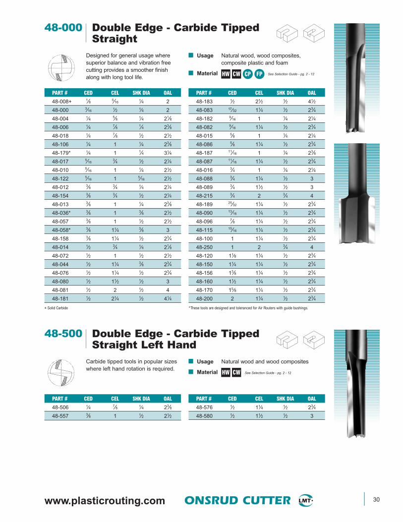
www.plasticrouting.com ONSRUD CUTTER 30
■ Usage Natural wood and wood composites
■ Material See Selection Guide - pg. 2 - 12
48-500 Double Edge - Carbide TippedStraight Left Hand
PART # CED CEL SHK DIA OAL
48-576 1⁄2 11⁄4 1⁄2 23⁄4
48-580 1⁄2 11⁄2 1⁄2 3
Carbide tipped tools in popular sizeswhere left hand rotation is required.
PART # CED CEL SHK DIA OAL
48-506 1⁄4 7⁄8 1⁄4 23⁄8
48-557 3⁄8 1 1⁄2 21⁄2
HW CW
■ Usage Natural wood, wood composites,composite plastic and foam
■ Material See Selection Guide - pg. 2 - 12
48-000 Double Edge - Carbide TippedStraight
PART # CED CEL SHK DIA OAL
48-183 1⁄2 21⁄2 1⁄2 41⁄2
48-083 17⁄32 11⁄4 1⁄2 23⁄4
48-182 9⁄16 1 1⁄4 21⁄4
48-082 9⁄16 11⁄4 1⁄2 23⁄4
48-015 5⁄8 1 1⁄4 21⁄4
48-086 5⁄8 11⁄4 1⁄2 23⁄4
48-187 11⁄16 1 1⁄4 23⁄8
48-087 11⁄16 11⁄4 1⁄2 23⁄4
48-016 3⁄4 1 1⁄4 21⁄4
48-088 3⁄4 11⁄4 1⁄2 3
48-089 3⁄4 11⁄2 1⁄2 3
48-215 3⁄4 2 3⁄4 4
48-189 25⁄32 11⁄4 1⁄2 23⁄4
48-090 13⁄16 11⁄4 1⁄2 23⁄4
48-096 7⁄8 11⁄4 1⁄2 23⁄4
48-115 15⁄16 11⁄4 1⁄2 23⁄4
48-100 1 11⁄4 1⁄2 23⁄4
48-250 1 2 3⁄4 4
48-120 11⁄8 11⁄4 1⁄2 23⁄4
48-150 11⁄4 11⁄4 1⁄2 23⁄4
48-156 13⁄8 11⁄4 1⁄2 23⁄4
48-160 11⁄2 11⁄4 1⁄2 23⁄4
48-170 15⁄8 11⁄4 1⁄2 23⁄4
48-200 2 11⁄4 1⁄2 23⁄4
*These tools are designed and toleranced for Air Routers with guide bushings.
Designed for general usage wheresuperior balance and vibration freecutting provides a smoother finishalong with long tool life.
PART # CED CEL SHK DIA OAL
48-008+ 1⁄8 5⁄16 1⁄4 2
48-000 3⁄16 1⁄2 1⁄4 2
48-004 1⁄4 5⁄8 1⁄4 21⁄8
48-006 1⁄4 7⁄8 1⁄4 23⁄8
48-018 1⁄4 7⁄8 1⁄2 21⁄2
48-106 1⁄4 1 1⁄4 23⁄8
48-179* 1⁄4 1 1⁄4 31⁄4
48-017 5⁄163⁄4 1⁄2 21⁄4
48-010 5⁄16 1 1⁄4 21⁄2
48-122 5⁄16 1 5⁄16 21⁄2
48-012 3⁄8 3⁄4 1⁄4 21⁄4
48-154 3⁄8 3⁄4 1⁄2 21⁄4
48-013 3⁄8 1 1⁄4 23⁄8
48-036* 3⁄8 1 3⁄8 21⁄2
48-057 3⁄8 1 1⁄2 21⁄2
48-058* 3⁄8 11⁄4 3⁄8 3
48-158 3⁄8 11⁄4 1⁄2 23⁄4
48-014 1⁄2 3⁄4 1⁄4 21⁄8
48-072 1⁄2 1 1⁄2 21⁄2
48-044 1⁄2 11⁄4 3⁄8 23⁄4
48-076 1⁄2 11⁄4 1⁄2 23⁄4
48-080 1⁄2 11⁄2 1⁄2 3
48-081 1⁄2 2 1⁄2 4
48-181 1⁄2 21⁄4 1⁄2 41⁄4
+ Solid Carbide
HW CW CP FP
31 ONSRUD CUTTER www.onsrud.com
Single Edge
Double Edge
SINGLE EDGE DOUBLE EDGE
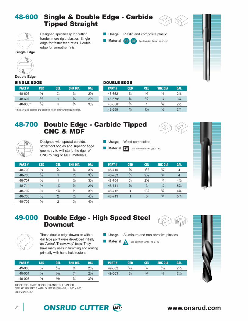
■ Usage Plastic and composite plastic
■ Material See Selection Guide - pg. 2 - 12
48-600 Single & Double Edge - CarbideTipped Straight
PART # CED CEL SHK DIA OAL
48-652 1⁄4 3⁄4 1⁄4 21⁄8
48-679* 1⁄4 3⁄4 1⁄4 31⁄4
48-656 3⁄8 1 3⁄8 21⁄2
48-658 1⁄2 11⁄4 1⁄2 23⁄4
Designed specifically for cuttingharder, more rigid plastics. Singleedge for faster feed rates. Doubleedge for smoother finish.
PART # CED CEL SHK DIA OAL
48-603 1⁄4 3⁄4 1⁄4 21⁄8
48-607 3⁄8 1 3⁄8 21⁄2
48-635* 3⁄8 1 3⁄8 31⁄2
* These tools are designed and toleranced for air routers with guide bushings.
HP CP
■ Usage Wood composites
■ Material See Selection Guide - pg. 2 - 12
48-700 Double Edge - Carbide TippedCNC & MDF
PART # CED CEL SHK DIA OAL
48-710 3⁄4 15⁄8 3⁄4 4
48-703 3⁄4 21⁄8 3⁄4 4
48-704 3⁄4 25⁄8 3⁄4 41⁄2
48-711 3⁄4 3 3⁄4 53⁄8
48-712 1 21⁄8 3⁄4 41⁄4
48-713 1 3 3⁄4 51⁄8
Designed with special carbide,stiffer tool bodies and superior edgegeometry to withstand the rigor ofCNC routing of MDF materials.
PART # CED CEL SHK DIA OAL
48-700 1⁄4 7⁄8 1⁄4 31⁄4
48-706 3⁄8 1 1⁄2 33⁄8
48-707 1⁄2 1 1⁄2 31⁄4
48-714 1⁄2 11⁄4 1⁄2 23⁄4
48-702 1⁄2 11⁄4 1⁄2 31⁄2
48-708 1⁄2 2 1⁄2 43⁄8
48-709 5⁄8 2 5⁄8 41⁄4
CW
■ Usage Aluminum and non-abrasive plastics
■ Material See Selection Guide - pg. 2 - 12
49-000 Double Edge - High Speed SteelDowncut
PART # CED CEL SHK DIA OAL
49-002 5⁄16 3⁄4 5⁄16 21⁄2
49-003 3⁄8 3⁄4 3⁄8 21⁄2
These double edge downcuts with adrill type point were developed initiallyas “Aircraft Throwaway” tools. Theyhave many uses in trimming and routingprimarily with hand held routers.
PART # CED CEL SHK DIA OAL
49-005 1⁄4 9⁄16 1⁄4 21⁄2
49-001 1⁄4 9⁄16 1⁄4 23⁄4
49-007 1⁄4 9⁄16 1⁄4 31⁄4
THESE TOOLS ARE DESIGNED AND TOLERANCEDFOR AIR ROUTERS WITH GUIDE BUSHINGS, + .000 - .006
HELIX ANGLE ≈ 24°
A
www.plasticrouting.com ONSRUD CUTTER 32
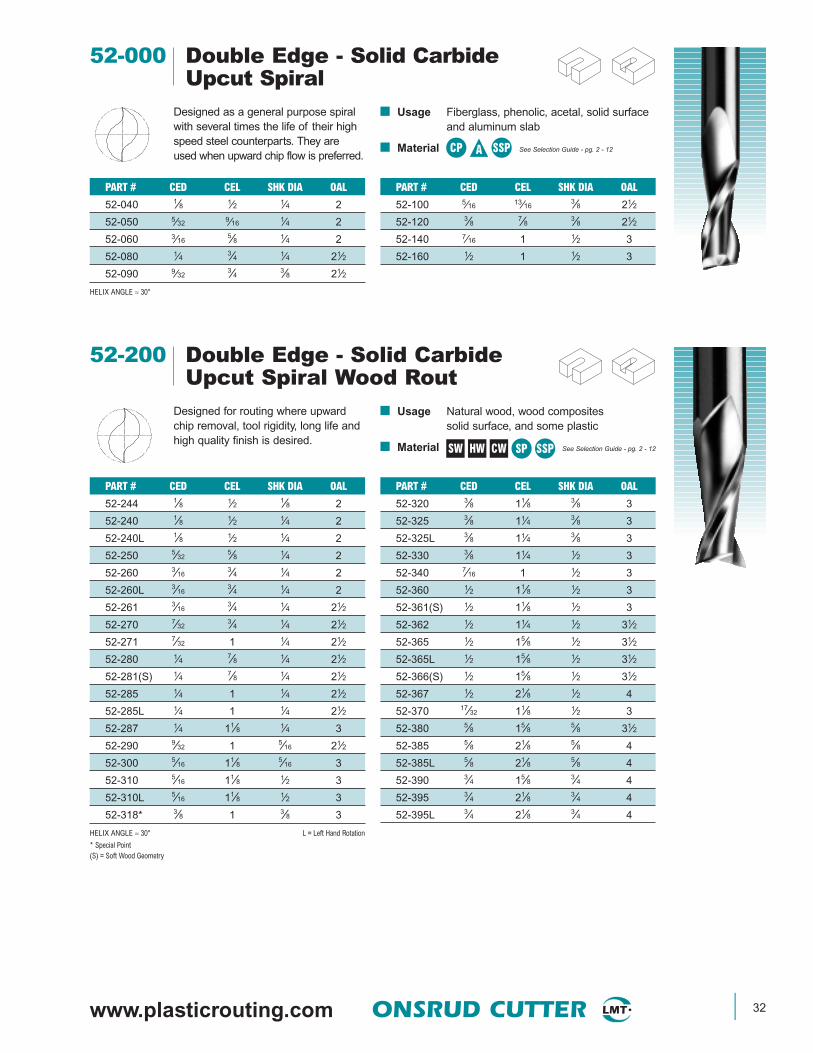
■ Usage Fiberglass, phenolic, acetal, solid surfaceand aluminum slab
■ Material See Selection Guide - pg. 2 - 12
52-000 Double Edge - Solid CarbideUpcut Spiral
PART # CED CEL SHK DIA OAL
52-100 5⁄16 13⁄163⁄8 21⁄2
52-120 3⁄8 7⁄8 3⁄8 21⁄2
52-140 7⁄16 1 1⁄2 3
52-160 1⁄2 1 1⁄2 3
Designed as a general purpose spiralwith several times the life of their highspeed steel counterparts. They areused when upward chip flow is preferred.
PART # CED CEL SHK DIA OAL
52-040 1⁄8 1⁄2 1⁄4 2
52-050 5⁄32 9⁄16 1⁄4 2
52-060 3⁄165⁄8 1⁄4 2
52-080 1⁄4 3⁄4 1⁄4 21⁄2
52-090 9⁄323⁄4 3⁄8 21⁄2
HELIX ANGLE ≈ 30°
CP SSPA
■ Usage Natural wood, wood compositessolid surface, and some plastic
■ Material See Selection Guide - pg. 2 - 12
52-200 Double Edge - Solid CarbideUpcut Spiral Wood Rout
PART # CED CEL SHK DIA OAL
52-320 3⁄8 11⁄8 3⁄8 3
52-325 3⁄8 11⁄4 3⁄8 3
52-325L 3⁄8 11⁄4 3⁄8 3
52-330 3⁄8 11⁄4 1⁄2 3
52-340 7⁄16 1 1⁄2 3
52-360 1⁄2 11⁄8 1⁄2 3
52-361(S) 1⁄2 11⁄8 1⁄2 3
52-362 1⁄2 11⁄4 1⁄2 31⁄2
52-365 1⁄2 15⁄8 1⁄2 31⁄2
52-365L 1⁄2 15⁄8 1⁄2 31⁄2
52-366(S) 1⁄2 15⁄8 1⁄2 31⁄2
52-367 1⁄2 21⁄8 1⁄2 4
52-370 17⁄32 11⁄8 1⁄2 3
52-380 5⁄8 15⁄8 5⁄8 31⁄2
52-385 5⁄8 21⁄8 5⁄8 4
52-385L 5⁄8 21⁄8 5⁄8 4
52-390 3⁄4 15⁄8 3⁄4 4
52-395 3⁄4 21⁄8 3⁄4 4
52-395L 3⁄4 21⁄8 3⁄4 4
Designed for routing where upwardchip removal, tool rigidity, long life andhigh quality finish is desired.
PART # CED CEL SHK DIA OAL
52-244 1⁄8 1⁄2 1⁄8 2
52-240 1⁄8 1⁄2 1⁄4 2
52-240L 1⁄8 1⁄2 1⁄4 2
52-250 5⁄325⁄8 1⁄4 2
52-260 3⁄163⁄4 1⁄4 2
52-260L 3⁄163⁄4 1⁄4 2
52-261 3⁄163⁄4 1⁄4 21⁄2
52-270 7⁄323⁄4 1⁄4 21⁄2
52-271 7⁄32 1 1⁄4 21⁄2
52-280 1⁄4 7⁄8 1⁄4 21⁄2
52-281(S) 1⁄4 7⁄8 1⁄4 21⁄2
52-285 1⁄4 1 1⁄4 21⁄2
52-285L 1⁄4 1 1⁄4 21⁄2
52-287 1⁄4 11⁄8 1⁄4 3
52-290 9⁄32 1 5⁄16 21⁄2
52-300 5⁄16 11⁄8 5⁄16 3
52-310 5⁄16 11⁄8 1⁄2 3
52-310L 5⁄16 11⁄8 1⁄2 3
52-318* 3⁄8 1 3⁄8 3
HELIX ANGLE ≈ 30° L = Left Hand Rotation
* Special Point(S) = Soft Wood Geometry
SW HW CW SP SSP
33 ONSRUD CUTTER www.onsrud.com
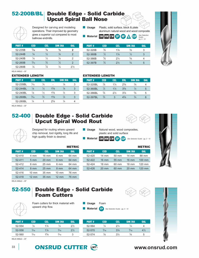
■ Usage Plastic, solid surface, block & platealuminum natural wood and wood composite
■ Material
52-200B/BL Double Edge - Solid CarbideUpcut Spiral Ball Nose
PART # CED CEL SHK DIA OAL
52-320B 3⁄8 11⁄8 3⁄8 3
52-360B 1⁄2 11⁄8 1⁄2 3
52-386B 5⁄8 21⁄4 5⁄8 4
52-397B 3⁄4 21⁄2 3⁄4 5
Designed for carving and modelingoperations. Their improved tip geometrygives a superior cut compared to mostballnose endmills.
PART # CED CEL SHK DIA OAL
52-235B 1⁄16 1⁄4 1⁄8 2
52-244B 1⁄8 1⁄2 1⁄8 2
52-240B 1⁄8 1⁄2 1⁄4 2
52-260B 3⁄163⁄4 1⁄4 2
52-280B 1⁄4 7⁄8 1⁄4 21⁄2
HELIX ANGLE ≈ 30°
PART # CED CEL ERL SHK DIA OAL
52-320BL 3⁄8 11⁄4 25⁄8 3⁄8 4
52-360BL 1⁄2 11⁄2 35⁄8 1⁄2 5
52-386BL 5⁄8 21⁄2 35⁄8 5⁄8 5
52-397BL 3⁄4 3 45⁄8 3⁄4 6
PART # CED CEL ERL SHK DIA OAL
52-235BL 1⁄16 1⁄4 - 1⁄8 3
52-244BL 1⁄8 1⁄2 15⁄8 1⁄8 3
52-240BL 1⁄8 1⁄2 15⁄8 1⁄4 3
52-260BL 3⁄163⁄4 15⁄8 1⁄4 3
52-280BL 1⁄4 1 25⁄8 1⁄4 4
HELIX ANGLE ≈ 30°
EXTENDED LENGTH EXTENDED LENGTH
SW HW CW SP HP SSPASee SelectionGuide - pg. 2 - 12
■ Usage Natural wood, wood composites,plastic and solid surface
■ Material See Selection Guide - pg. 2 - 12
52-400 Double Edge - Solid CarbideUpcut Spiral Wood Rout
PART # CED CEL SHK DIA OAL
52-420 14 mm 50 mm 14 mm 88 mm
52-422 16 mm 55 mm 16 mm 100 mm
52-424 18 mm 60 mm 18 mm 120 mm
52-426 20 mm 60 mm 20 mm 120 mm
Designed for routing where upwardchip removal, tool rigidity, long life andhigh quality finish is desired.
PART # CED CEL SHK DIA OAL
52-410 4 mm 16 mm 6 mm 64 mm
52-411 5 mm 20 mm 6 mm 64 mm
52-412 6 mm 25 mm 6 mm 64 mm
52-414 8 mm 25 mm 8 mm 64 mm
52-416 10 mm 35 mm 10 mm 76 mm
52-418 12 mm 35 mm 12 mm 76 mm
HELIX ANGLE ≈ 30°
SW HW CW SP SSP
METRIC METRIC
■ Usage Foam
■ Material See Selection Guide - pg. 2 - 12
52-550 Double Edge - Solid CarbideFoam Cutters
PART # CED CEL SHK DIA OAL
52-564 1⁄4 21⁄4 1⁄4 4
52-570 5⁄16 31⁄8 5⁄16 41⁄2
52-574 3⁄8 31⁄2 3⁄8 5
Foam cutters for thick material withupward chip flow.
PART # CED CEL SHK DIA OAL
52-554 1⁄8 11⁄8 1⁄4 21⁄2
52-558 3⁄16 11⁄8 3⁄16 21⁄2
52-560 3⁄16 15⁄8 3⁄16 3
HELIX ANGLE ≈ 25°
FP

www.plasticrouting.com ONSRUD CUTTER 34
■ Usage Soft and hard plastic, acrylic, nylon, ABS,PE, acetal, PET, HDPE, UHMW,polycarbonate and solid surface
■ Material See Selection Guide - pg. 2 - 12
52-600 Double Edge - Solid CarbideUpcut Spiral O Flute
PART # CED CEL SHK DIA OAL
52-652 1⁄2 15⁄8 1⁄2 31⁄2
52-655 1⁄2 21⁄8 1⁄2 41⁄2
52-660 5⁄8 21⁄8 5⁄8 5
52-664 3⁄4 31⁄8 3⁄4 6
Low helix geometry designed to cutsoft and hard plastic with a smoothfinish and upward chip flow.
PART # CED CEL SHK DIA OAL
52-622 1⁄4 3⁄8 1⁄4 21⁄2
52-624 1⁄4 3⁄4 1⁄4 21⁄2
52-638 3⁄8 1 3⁄8 3
52-650 1⁄2 11⁄8 1⁄2 31⁄2
HELIX ANGLE ≈ 11°
SP HP SSP
■ Usage Soft plastic, extruded acrylic, nylon, ABS,PE, acetal, PET, HDPE, UHMW,polycarbonate and solid surface.
■ Material See Selection Guide - pg. 2 - 12
52-700 Double Edge - Solid CarbideUpcut Spiral O Flute
PART # CED CEL SHK DIA OAL
52-742 12mm 35mm 12mm 100mm
52-744 12mm 45mm 12mm 100mm
52-746 12mm 55mm 12mm 100mm
52-752 16mm 45mm 16 mm 120mm
52-754 16mm 55mm 16mm 120mm
52-764 20mm 65mm 20mm 125mm
High helix geometry designed to cutsoft plastic with a smooth finish andupward chip flow. Special point geom-etry for improved bottom finish.
PART # CED CEL SHK DIA OAL
52-703 1⁄8 1⁄2 1⁄4 2
52-705 1⁄4 3⁄8 1⁄4 21⁄2
52-707 1⁄4 7⁄8 1⁄4 3
52-700 1⁄4 11⁄4 1⁄4 3
52-709 3⁄8 1 3⁄8 3
52-701 3⁄8 11⁄2 3⁄8 4
52-702 1⁄2 11⁄4 1⁄2 4
52-704 1⁄2 13⁄4 1⁄2 4
52-706 1⁄2 21⁄8 1⁄2 4
52-712 5⁄8 13⁄4 5⁄8 5
52-714 5⁄8 21⁄4 5⁄8 5
52-726 3⁄4 13⁄4 3⁄4 5
52-724 3⁄4 21⁄2 3⁄4 5
52-728 3⁄4 4 3⁄4 6
52-734 1 4 1 6
HELIX ANGLE ≈ 22°
METRIC
SP
NEW TOOLS in BOLD

35 ONSRUD CUTTER www.onsrud.com
■ Usage Natural wood andwood composites
■ Material See Selection Guide - pg. 2 - 12
52-900 Double Edge - Solid CarbideUpcut Extreme Heavy Duty Standard
PART # CED CEL SHK DIA OAL
52-924 3⁄8 11⁄4 3⁄8 3
52-936 1⁄2 11⁄4 1⁄2 3
Developed for demanding applicationswhere upward chip removal, tool rigidityand long life are essential to success.
PART # CED CEL SHK DIA OAL
52-910 1⁄4 7⁄8 1⁄4 21⁄2
52-914 1⁄4 11⁄4 1⁄4 3
52-923 3⁄8 11⁄8 3⁄8 3
HELIX ANGLE ≈ 30°
SW HW CW
■ Usage Natural wood and wood composites
■ Material See Selection Guide - pg. 2 - 12
53-000 Three Edge - Solid CarbideStraight
PART # CED CEL SHK DIA OAL
53-080 1⁄4 3⁄4 1⁄4 21⁄2
Designed for routing extremely hardmaterials or when spindle RPM islower than normal for routing.
PART # CED CEL SHK DIA OAL
53-040 1⁄8 1⁄2 1⁄4 2
CP
CP
■ Usage Fiberglass
■ Material See Selection Guide - pg. 2 - 12
54-300 Four Edge - Solid CarbideDowncut Spiral
PART # CED CEL SHK DIA OAL
54-360 1⁄2 5⁄8 1⁄2 31⁄2
54-365 1⁄2 11⁄8 1⁄2 31⁄2
HELIX ANGLE ≈ 30°
Designed to be equally adaptable to lowor high spindle speed applications in anyCNC machining environment. The freecutting action of the tools provides forbetter finishes.
PART # CED CEL SHK DIA OAL
54-320 3⁄8 5⁄8 3⁄8 3
54-325 3⁄8 11⁄8 3⁄8 3
HELIX ANGLE ≈ 30°

www.plasticrouting.com ONSRUD CUTTER 36
CP
■ Usage Fiberglass
■ Material See Selection Guide - pg. 2 - 12
55-300 Four Edge - Solid CarbideUpcut Spiral
PART # CED CEL SHK DIA OAL
55-360 1⁄2 5⁄8 1⁄2 31⁄2
55-365 1⁄2 11⁄8 1⁄2 31⁄2
HELIX ANGLE ≈ 30°
Designed to be equally adaptable to lowor high spindle speed applications inany CNC machining environment. Thefree cutting action of the tools providesfor better finishes.
PART # CED CEL SHK DIA OAL
55-320 3⁄8 5⁄8 3⁄8 3
55-325 3⁄8 11⁄8 3⁄8 3
HELIX ANGLE ≈ 30°
PART # CED CEL SHK DIA OAL
55-040 1⁄8 1⁄2 1⁄4 2
55-050 5⁄32 9⁄16 1⁄4 2
55-080 1⁄4 3⁄4 1⁄4 21⁄2
HELIX ANGLE ≈ 15°
PART # CED CEL SHK DIA OAL
54-040 1⁄8 1⁄2 1⁄4 2
54-080 1⁄4 3⁄4 1⁄4 21⁄2
HELIX ANGLE ≈ 30°
UPCUT DOWNCUT
54-000 Four Edge - Solid Carbide55-000 Spiral
Equally adaptable to low or highspindle speed applications in anyCNC machining environment.The free cutting action of the tools provides for better finishes.
■ Usage Composite plastic
■ Material See Selection Guide - pg. 2 - 12
56-000 Double Edge - Solid CarbideStraight
PART # CED CEL SHK DIA OAL
56-090 9⁄32 3⁄4 3⁄8 21⁄2
56-100 5⁄16 13⁄16 3⁄8 21⁄2
56-120 3⁄8 7⁄8 3⁄8 21⁄2
56-140 7⁄16 1 1⁄2 3
56-160 1⁄2 1 1⁄2 3
Designed to rout composite plastic
PART # CED CEL SHK DIA OAL
56-040 1⁄8 1⁄2 1⁄4 2
56-050 5⁄32 9⁄16 1⁄4 2
56-060 3⁄16 5⁄8 1⁄4 2
56-070 7⁄32 5⁄8 1⁄4 21⁄2
56-080 1⁄4 3⁄4 1⁄4 21⁄2
56-084* 1⁄4 3⁄4 1⁄4 31⁄4
* These tools are designed and toleranced for air routers with guide bushings.
HP CP SSP FP
CP
■ Usage Fiberglass
■ Material See Selection Guide - pg. 2 - 12
37 ONSRUD CUTTER www.onsrud.com
56-000P Double Edge - Solid CarbideStraight
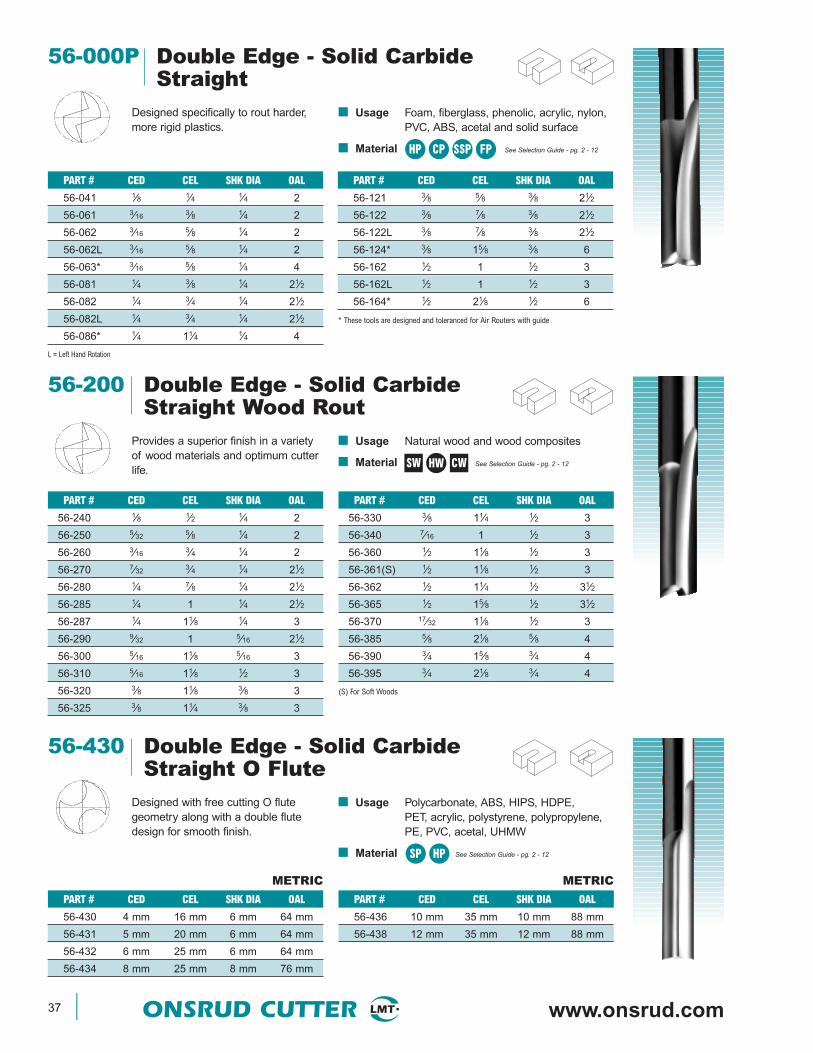
Designed specifically to rout harder,more rigid plastics.
■ Usage Foam, fiberglass, phenolic, acrylic, nylon,PVC, ABS, acetal and solid surface
■ Material See Selection Guide - pg. 2 - 12
PART # CED CEL SHK DIA OAL
56-121 3⁄8 5⁄8 3⁄8 21⁄2
56-122 3⁄8 7⁄8 3⁄8 21⁄2
56-122L 3⁄8 7⁄8 3⁄8 21⁄2
56-124* 3⁄8 15⁄8 3⁄8 6
56-162 1⁄2 1 1⁄2 3
56-162L 1⁄2 1 1⁄2 3
56-164* 1⁄2 21⁄8 1⁄2 6
* These tools are designed and toleranced for Air Routers with guide
PART # CED CEL SHK DIA OAL
56-041 1⁄8 1⁄4 1⁄4 2
56-061 3⁄16 3⁄8 1⁄4 2
56-062 3⁄16 5⁄8 1⁄4 2
56-062L 3⁄16 5⁄8 1⁄4 2
56-063* 3⁄16 5⁄8 1⁄4 4
56-081 1⁄4 3⁄8 1⁄4 21⁄2
56-082 1⁄4 3⁄4 1⁄4 21⁄2
56-082L 1⁄4 3⁄4 1⁄4 21⁄2
56-086* 1⁄4 11⁄4 1⁄4 4
L = Left Hand Rotation
HP CP SSP FP
PART # CED CEL SHK DIA OAL
56-330 3⁄8 11⁄4 1⁄2 3
56-340 7⁄16 1 1⁄2 3
56-360 1⁄2 11⁄8 1⁄2 3
56-361(S) 1⁄2 11⁄8 1⁄2 3
56-362 1⁄2 11⁄4 1⁄2 31⁄2
56-365 1⁄2 15⁄8 1⁄2 31⁄2
56-370 17⁄32 11⁄8 1⁄2 3
56-385 5⁄8 21⁄8 5⁄8 4
56-390 3⁄4 15⁄8 3⁄4 4
56-395 3⁄4 21⁄8 3⁄4 4
(S) For Soft Woods
56-200 Double Edge - Solid CarbideStraight Wood Rout
Provides a superior finish in a varietyof wood materials and optimum cutterlife.
■ Usage Natural wood and wood composites
■ Material See Selection Guide - pg. 2 - 12
PART # CED CEL SHK DIA OAL
56-240 1⁄8 1⁄2 1⁄4 2
56-250 5⁄32 5⁄8 1⁄4 2
56-260 3⁄16 3⁄4 1⁄4 2
56-270 7⁄32 3⁄4 1⁄4 21⁄2
56-280 1⁄4 7⁄8 1⁄4 21⁄2
56-285 1⁄4 1 1⁄4 21⁄2
56-287 1⁄4 11⁄8 1⁄4 3
56-290 9⁄32 1 5⁄16 21⁄2
56-300 5⁄16 11⁄8 5⁄16 3
56-310 5⁄16 11⁄8 1⁄2 3
56-320 3⁄8 11⁄8 3⁄8 3
56-325 3⁄8 11⁄4 3⁄8 3
SW CWHW
56-430 Double Edge - Solid CarbideStraight O Flute
Designed with free cutting O flutegeometry along with a double flutedesign for smooth finish.
■ Usage Polycarbonate, ABS, HIPS, HDPE,PET, acrylic, polystyrene, polypropylene,PE, PVC, acetal, UHMW
■ Material See Selection Guide - pg. 2 - 12SP HP
PART # CED CEL SHK DIA OAL
56-436 10 mm 35 mm 10 mm 88 mm
56-438 12 mm 35 mm 12 mm 88 mm
PART # CED CEL SHK DIA OAL
56-430 4 mm 16 mm 6 mm 64 mm
56-431 5 mm 20 mm 6 mm 64 mm
56-432 6 mm 25 mm 6 mm 64 mm
56-434 8 mm 25 mm 8 mm 76 mm
METRIC METRIC
www.plasticrouting.com ONSRUD CUTTER 38
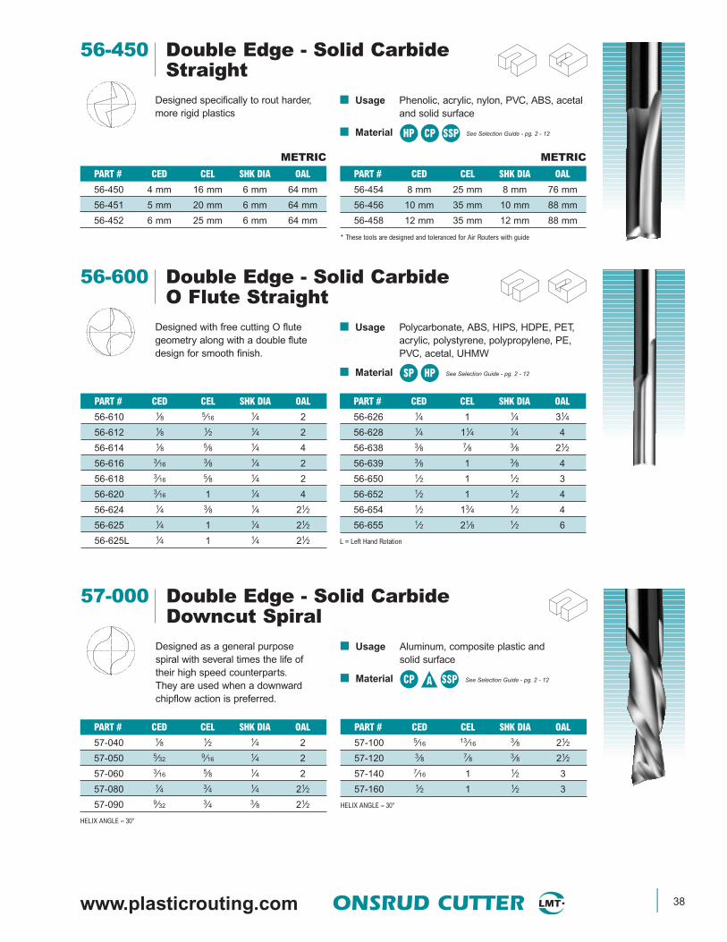
56-450 Double Edge - Solid CarbideStraight
Designed specifically to rout harder,more rigid plastics
■ Usage Phenolic, acrylic, nylon, PVC, ABS, acetaland solid surface
■ Material See Selection Guide - pg. 2 - 12HP CP SSP
PART # CED CEL SHK DIA OAL
56-454 8 mm 25 mm 8 mm 76 mm
56-456 10 mm 35 mm 10 mm 88 mm
56-458 12 mm 35 mm 12 mm 88 mm
* These tools are designed and toleranced for Air Routers with guide
PART # CED CEL SHK DIA OAL
56-450 4 mm 16 mm 6 mm 64 mm
56-451 5 mm 20 mm 6 mm 64 mm
56-452 6 mm 25 mm 6 mm 64 mm
METRIC METRIC
56-600 Double Edge - Solid CarbideO Flute Straight
Designed with free cutting O flutegeometry along with a double flutedesign for smooth finish.
■ Usage Polycarbonate, ABS, HIPS, HDPE, PET,acrylic, polystyrene, polypropylene, PE,PVC, acetal, UHMW
■ Material See Selection Guide - pg. 2 - 12
PART # CED CEL SHK DIA OAL
56-626 1⁄4 1 1⁄4 31⁄4
56-628 1⁄4 11⁄4 1⁄4 4
56-638 3⁄8 7⁄8 3⁄8 21⁄2
56-639 3⁄8 1 3⁄8 4
56-650 1⁄2 1 1⁄2 3
56-652 1⁄2 1 1⁄2 4
56-654 1⁄2 13⁄4 1⁄2 4
56-655 1⁄2 21⁄8 1⁄2 6
L = Left Hand Rotation
PART # CED CEL SHK DIA OAL
56-610 1⁄8 5⁄16 1⁄4 2
56-612 1⁄8 1⁄2 1⁄4 2
56-614 1⁄8 5⁄8 1⁄4 4
56-616 3⁄16 3⁄8 1⁄4 2
56-618 3⁄16 5⁄8 1⁄4 2
56-620 3⁄16 1 1⁄4 4
56-624 1⁄4 3⁄8 1⁄4 21⁄2
56-625 1⁄4 1 1⁄4 21⁄2
56-625L 1⁄4 1 1⁄4 21⁄2
SP HP
57-000 Double Edge - Solid CarbideDowncut Spiral
Designed as a general purposespiral with several times the life oftheir high speed counterparts.They are used when a downwardchipflow action is preferred.
■ Usage Aluminum, composite plastic andsolid surface
■ Material See Selection Guide - pg. 2 - 12
PART # CED CEL SHK DIA OAL
57-040 1⁄8 1⁄2 1⁄4 2
57-050 5⁄32 9⁄16 1⁄4 2
57-060 3⁄16 5⁄8 1⁄4 2
57-080 1⁄4 3⁄4 1⁄4 21⁄2
57-090 9⁄32 3⁄4 3⁄8 21⁄2
HELIX ANGLE ≈ 30°
PART # CED CEL SHK DIA OAL
57-100 5⁄16 13⁄16 3⁄8 21⁄2
57-120 3⁄8 7⁄8 3⁄8 21⁄2
57-140 7⁄16 1 1⁄2 3
57-160 1⁄2 1 1⁄2 3
HELIX ANGLE ≈ 30°
CP SSPA

39 ONSRUD CUTTER www.onsrud.com
57-200 Double Edge - Solid CarbideDowncut Spiral Wood Rout
PART # CED CEL SHK DIA OAL
57-330 3⁄8 11⁄4 1⁄2 3
57-340 7⁄16 1 1⁄2 3
57-360 1⁄2 11⁄8 1⁄2 3
57-361(S) 1⁄2 11⁄8 1⁄2 3
57-362 1⁄2 11⁄4 1⁄2 31⁄2
57-365 1⁄2 15⁄8 1⁄2 31⁄2
57-365L 1⁄2 15⁄8 1⁄2 31⁄2
57-366(S) 1⁄2 15⁄8 1⁄2 31⁄2
57-367 1⁄2 21⁄8 1⁄2 4
57-370 17⁄32 11⁄8 1⁄2 3
57-380 5⁄8 15⁄8 5⁄8 31⁄2
57-385 5⁄8 21⁄8 5⁄8 4
57-385L 5⁄8 21⁄8 5⁄8 4
57-390 3⁄4 15⁄8 3⁄4 4
57-395 3⁄4 21⁄8 3⁄4 4
57-395L 3⁄4 21⁄8 3⁄4 4
Designed for routing where downwardchip removal, tool rigidity, long life, andhigh quality finish is desired.
■ Usage Natural wood, wood composites,solid surface
■ Material See Selection Guide - pg. 2 - 12
PART # CED CEL SHK DIA OAL
57-244 1⁄8 1⁄2 1⁄8 2
57-240 1⁄8 1⁄2 1⁄4 2
57-240L 1⁄8 1⁄2 1⁄4 2
57-251 5⁄32 1⁄2 1⁄4 21⁄2
57-250 5⁄32 5⁄8 1⁄4 2
57-260 3⁄16 3⁄4 1⁄4 2
57-260L 3⁄16 3⁄4 1⁄4 2
57-261 3⁄16 3⁄4 1⁄4 21⁄2
57-270 7⁄32 3⁄4 1⁄4 21⁄2
57-271 7⁄32 1 1⁄4 21⁄2
57-280 1⁄4 7⁄8 1⁄4 21⁄2
57-281(S) 1⁄4 7⁄8 1⁄4 21⁄2
57-285 1⁄4 1 1⁄4 21⁄2
57-285L 1⁄4 1 1⁄4 21⁄2
57-287 1⁄4 11⁄8 1⁄4 3
57-290 9⁄32 1 5⁄16 21⁄2
57-300 5⁄16 11⁄8 5⁄16 3
57-310 5⁄16 11⁄8 1⁄2 3
57-310L 5⁄16 11⁄8 1⁄2 3
57-318* 3⁄8 1 3⁄8 3
57-320 3⁄8 11⁄8 3⁄8 3
57-325 3⁄8 11⁄4 3⁄8 3
57-325L 3⁄8 11⁄4 3⁄8 3
HELIX ANGLE ≈ 30° L = Left Hand Rotation
* Special Point (S) = Soft Wood Geometry
SW HW CW SSP
57-400 Double Edge - Solid CarbideDowncut Spiral Wood Rout
Designed for routing where downwardchip removal, tool rigidity, long life, andhigh quality finish is desired.
■ Usage Natural wood, wood composites and solid surface
■ Material See Selection Guide - pg. 2 - 12SW HW CW SSP
PART # CED CEL SHK DIA OAL
57-420 14 mm 50 mm 14 mm 88 mm
57-424 18 mm 60 mm 18 mm 120 mm
57-426 20 mm 60 mm 20 mm 120 mm
PART # CED CEL SHK DIA OAL
57-410 4 mm 16 mm 6 mm 64 mm
57-411 5 mm 20 mm 6 mm 64 mm
57-412 6 mm 25 mm 6 mm 64 mm
57-414 8 mm 25 mm 8 mm 64 mm
57-416 10 mm 35 mm 10 mm 76 mm
57-418 12 mm 35 mm 12 mm 76 mm
HELIX ANGLE ≈ 30°
METRIC METRIC
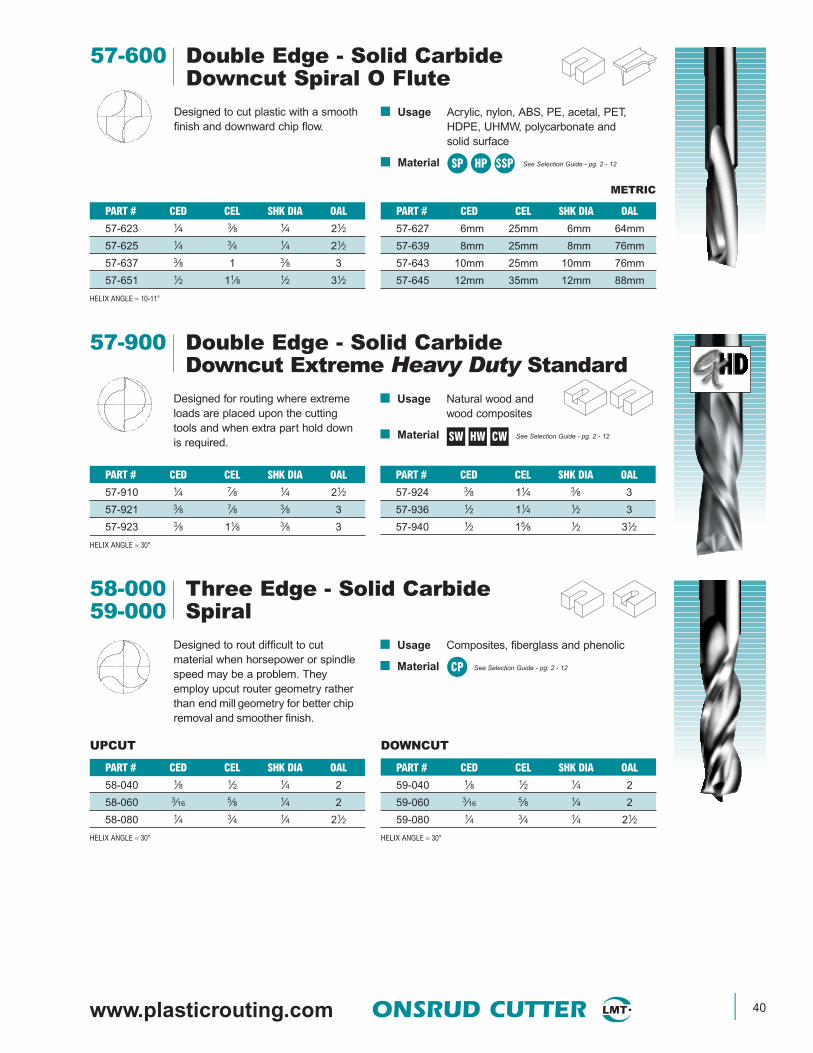
www.plasticrouting.com ONSRUD CUTTER 40
57-600 Double Edge - Solid CarbideDowncut Spiral O Flute
Designed to cut plastic with a smoothfinish and downward chip flow.
■ Usage Acrylic, nylon, ABS, PE, acetal, PET,HDPE, UHMW, polycarbonate andsolid surface
■ Material See Selection Guide - pg. 2 - 12
METRIC
PART # CED CEL SHK DIA OAL
57-623 1⁄4 3⁄8 1⁄4 21⁄2
57-625 1⁄4 3⁄4 1⁄4 21⁄2
57-637 3⁄8 1 3⁄8 3
57-651 1⁄2 11⁄8 1⁄2 31⁄2
HELIX ANGLE ≈ 10-11°
PART # CED CEL SHK DIA OAL
57-627 6mm 25mm 6mm 64mm
57-639 8mm 25mm 8mm 76mm
57-643 10mm 25mm 10mm 76mm
57-645 12mm 35mm 12mm 88mm
SP HP SSP
57-900 Double Edge - Solid CarbideDowncut Extreme Heavy Duty Standard
PART # CED CEL SHK DIA OAL
57-924 3⁄8 11⁄4 3⁄8 3
57-936 1⁄2 11⁄4 1⁄2 3
57-940 1⁄2 15⁄8 1⁄2 31⁄2
Designed for routing where extremeloads are placed upon the cuttingtools and when extra part hold downis required.
■ Usage Natural wood and wood composites
■ Material See Selection Guide - pg. 2 - 12
PART # CED CEL SHK DIA OAL
57-910 1⁄4 7⁄8 1⁄4 21⁄2
57-921 3⁄8 7⁄8 3⁄8 3
57-923 3⁄8 11⁄8 3⁄8 3
HELIX ANGLE ≈ 30°
SW HW CW
58-000 Three Edge - Solid Carbide59-000 Spiral
Designed to rout difficult to cutmaterial when horsepower or spindlespeed may be a problem. Theyemploy upcut router geometry ratherthan end mill geometry for better chipremoval and smoother finish.
■ Usage Composites, fiberglass and phenolic
■ Material See Selection Guide - pg. 2 - 12
UPCUT DOWNCUT
PART # CED CEL SHK DIA OAL
58-040 1⁄8 1⁄2 1⁄4 2
58-060 3⁄16 5⁄8 1⁄4 2
58-080 1⁄4 3⁄4 1⁄4 21⁄2
HELIX ANGLE ≈ 30°
PART # CED CEL SHK DIA OAL
59-040 1⁄8 1⁄2 1⁄4 2
59-060 3⁄16 5⁄8 1⁄4 2
59-080 1⁄4 3⁄4 1⁄4 21⁄2
HELIX ANGLE ≈ 30°
CP

41 ONSRUD CUTTER www.onsrud.com
60-000 Three Edge - Solid CarbideHigh Helix Hogger
Designed with unique scallopedcutting edge design for extremely fastmachining and roughing. Faster chipremoval with upcuts. Better hold downwith downcuts.
■ Usage Natural wood & wood composites,hard & soft plastic and plastic composites
■ Material See Selection Guide - pg. 2 - 12
UPCUT DOWNCUT
PART # CED CEL SHK DIA OAL
60-002 3⁄8 11⁄8 3⁄8 31⁄2
60-006 1⁄2 11⁄8 1⁄2 31⁄2
60-008 1⁄2 15⁄8 1⁄2 4
60-010 5⁄8 15⁄8 5⁄8 4
60-012 5⁄8 21⁄8 5⁄8 5
60-018 3⁄4 15⁄8 3⁄4 4
60-020 3⁄4 21⁄8 3⁄4 5
PART # CED CEL SHK DIA OAL
60-001 3⁄8 11⁄8 3⁄8 31⁄2
60-005 1⁄2 11⁄8 1⁄2 31⁄2
60-007 1⁄2 15⁄8 1⁄2 4
60-009 5⁄8 15⁄8 5⁄8 4
60-011 5⁄8 21⁄8 5⁄8 5
60-017 3⁄4 15⁄8 3⁄4 4
60-019 3⁄4 21⁄8 3⁄4 5
HELIX ANGLE ≈ 30°
UPCUT METRIC DOWNCUT METRIC
PART # CED CEL SHK DIA OAL
60-004 12mm 25mm 12mm 76mm
60-014 16mm 55mm 16mm 120mm
60-016 18mm 60mm 18mm 120mm
PART # CED CEL SHK DIA OAL
60-003 12mm 25mm 12mm 76mm
60-013 16mm 55mm 16mm 120mm
60-015 18mm 60mm 18mm 120mm
HELIX ANGLE ≈ 30°
60-000 Three Edge - Solid CarbideLow Helix Hogger
Designed with unique scallopedcutting edge design for extremelyfast machining and roughing. Lowerhorsepower and longer tool life areadditional advantages.
■ Usage Natural wood & wood composites,hard & soft plastic and plastic composites
■ Material See Selection Guide - pg. 2 - 12
UPCUT DOWNCUT
PART # CED CEL SHK DIA OAL
60-038 3⁄8 11⁄8 3⁄8 31⁄2
60-054 1⁄2 11⁄8 1⁄2 31⁄2
60-052 1⁄2 15⁄8 1⁄2 4
60-066 5⁄8 15⁄8 5⁄8 4
60-062 5⁄8 21⁄8 5⁄8 5
60-074 3⁄4 15⁄8 3⁄4 5
60-072 3⁄4 21⁄8 3⁄4 5
PART # CED CEL SHK DIA OAL
60-037 3⁄8 11⁄8 3⁄8 31⁄2
60-053 1⁄2 11⁄8 1⁄2 31⁄2
60-051 1⁄2 15⁄8 1⁄2 4
60-061 5⁄8 21⁄8 5⁄8 5
60-073 3⁄4 15⁄8 3⁄4 4
60-071 3⁄4 21⁄8 3⁄4 5
HELIX ANGLE ≈ 10°
UPCUT METRIC DOWNCUT METRIC
PART # CED CEL SHK DIA OAL
60-056 12mm 25mm 12mm 76mm
60-064 16mm 55mm 16mm 120mm
60-076 18mm 60mm 18mm 120mm
PART # CED CEL SHK DIA OAL
60-055 12mm 25mm 12mm 76mm
60-063 16mm 55mm 16mm 120mm
60-075 18mm 60mm 18mm 120mm
HELIX ANGLE ≈ 10°
SW HW CW
SW HW CW
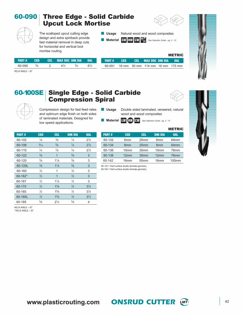
www.plasticrouting.com ONSRUD CUTTER 42
60-090 Three Edge - Solid CarbideUpcut Lock Mortise
PART # CED CEL MAX DOC SHK DIA OAL
60-091 16 mm 50 mm 114 mm 16 mm 170 mm
The scalloped upcut cutting edgedesign and extra spinback providefast material removal in deep cutsfor horizontal and vertical lockmortise routing.
■ Usage Natural wood and wood composites
■ Material See Selection Guide - pg. 2 - 12
PART # CED CEL MAX DOC SHK DIA OAL
60-090 5⁄8 2 41⁄2 5⁄8 61⁄2
HELIX ANGLE ≈ 30°
SW HW CW MTDT
METRIC
LW
PART # CED CEL SHK DIA OAL
60-132 6mm 25mm 6mm 64mm
60-134 8mm 25mm 8mm 64mm
60-136 10mm 35mm 10mm 76mm
60-138 12mm 35mm 12mm 76mm
60-142 16mm 55mm 16mm 100mm
60-122 = Hard surface double laminate geometry.60-162 = Hard surface double laminate geometry.
PART # CED CEL SHK DIA OAL
60-102 1⁄8 3⁄8 1⁄4 21⁄2
60-106 3⁄16 5⁄8 1⁄4 21⁄2
60-110 1⁄4 7⁄8 1⁄4 21⁄2
60-122 3⁄8 1 3⁄8 3
60-120 3⁄8 11⁄8 3⁄8 3
60-120L 3⁄8 11⁄8 3⁄8 3
60-160 1⁄2 1 1⁄2 3
60-162* 1⁄2 1 1⁄2 3
60-167 1⁄2 11⁄8 1⁄2 3
60-170 1⁄2 13⁄8 1⁄2 31⁄2
60-165 1⁄2 15⁄8 1⁄2 31⁄2
60-165L 1⁄2 15⁄8 1⁄2 31⁄2
60-185 5⁄8 21⁄4 5⁄8 4
HELIX ANGLE ≈ 30°*HELIX ANGLE ≈ 20°
60-100SE Single Edge - Solid CarbideCompression Spiral
Compression design for fast feed ratesand optimum edge finish on both sidesof laminated materials. Designed forlow speed applications.
■ Usage Double sided laminated, veneered, naturalwood and wood composites
■ Material See Selection Guide - pg. 2 - 12CWHW
METRIC

43 ONSRUD CUTTER www.onsrud.com
■ Usage Double sided laminated, veneered, naturalwood and wood composites
■ Material See Selection Guide - pg. 2 - 12LW
60-100DE Double Edge - Solid CarbideCompression Spiral
Compression design for fast feed ratesand optimum edge finish on both sidesof laminated materials.
CWHW
PART # CED CEL SHK DIA OAL
60-133 6 mm 25 mm 6 mm 64 mm
60-135 8 mm 25 mm 8 mm 64 mm
60-137 10 mm 35 mm 10 mm 76 mm
60-139 12 mm 35 mm 12 mm 76 mm
60-140 20 mm 50 mm 20 mm 100 mm
HELIX ANGLE ≈ 30°
L = Left Hand Rotation
PART # CED CEL SHK DIA OAL
60-112 1⁄4 7⁄8 1⁄4 21⁄2
60-124 3⁄8 11⁄8 3⁄8 3
60-164 1⁄2 1 1⁄2 3
60-171 1⁄2 13⁄8 1⁄2 31⁄2
60-169 1⁄2 11⁄8 1⁄2 3
60-172 1⁄2 15⁄8 1⁄2 4
60-172L 1⁄2 15⁄8 1⁄2 4
60-186 5⁄8 21⁄4 5⁄8 5
60-196 3⁄4 17⁄8 3⁄4 4
60-198 3⁄4 21⁄2 3⁄4 5
60-198L 3⁄4 21⁄2 3⁄4 5
METRIC
60-100C Double Edge - Solid CarbideChipbreaker/Finisher CompressionSpiral
PART # CED CEL SHK DIA OAL
60-135C 8 mm 25 mm 8 mm 64 mm
60-137C 10 mm 35 mm 10 mm 76 mm
60-139C 12 mm 35 mm 12 mm 76 mm
60-140C 20 mm 50 mm 20 mm 100 mm
Designed to give the optimum edgefinish of the compression spiral bitsalong with the increased feed ratesof the chipbreaker/finisher design.
■ Usage Double sided laminated,veneered, natural woodand wood composites
■ Material See Selection Guide - pg. 2 - 12
PART # CED CEL SHK DIA OAL
60-123C 3⁄8 7⁄8 3⁄8 3
60-124C 3⁄8 11⁄8 3⁄8 3
60-163C 1⁄2 7⁄8 1⁄2 3
60-164C 1⁄2 1 1⁄2 3
60-169C 1⁄2 11⁄8 1⁄2 3
60-171C 1⁄2 13⁄8 1⁄2 31⁄2
60-172C 1⁄2 15⁄8 1⁄2 4
60-186C 5⁄8 21⁄4 5⁄8 5
60-196C 3⁄4 17⁄8 3⁄4 4
HELIX ANGLE ≈ 30°
HW CW LW
METRIC
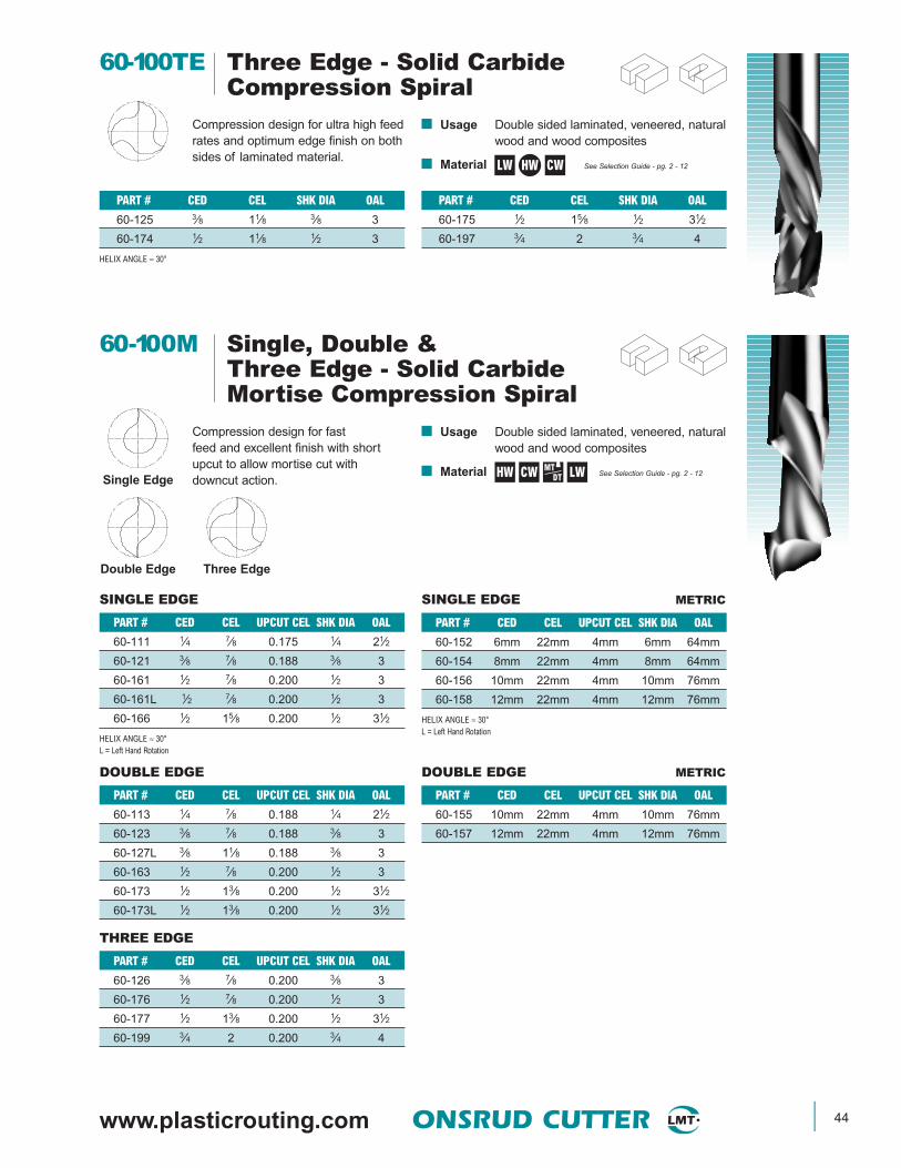
www.plasticrouting.com ONSRUD CUTTER 44
LW
PART # CED CEL SHK DIA OAL
60-175 1⁄2 15⁄8 1⁄2 31⁄2
60-197 3⁄4 2 3⁄4 4
PART # CED CEL SHK DIA OAL
60-125 3⁄8 11⁄8 3⁄8 3
60-174 1⁄2 11⁄8 1⁄2 3
HELIX ANGLE ≈ 30°
60-100TE Three Edge - Solid CarbideCompression Spiral
Compression design for ultra high feedrates and optimum edge finish on bothsides of laminated material.
■ Usage Double sided laminated, veneered, naturalwood and wood composites
■ Material See Selection Guide - pg. 2 - 12CWHW
Single EdgeHW CW LWMT
DT
DOUBLE EDGE
PART # CED CEL UPCUT CEL SHK DIA OAL
60-113 1⁄4 7⁄8 0.188 1⁄4 21⁄2
60-123 3⁄8 7⁄8 0.188 3⁄8 3
60-127L 3⁄8 11⁄8 0.188 3⁄8 3
60-163 1⁄2 7⁄8 0.200 1⁄2 3
60-173 1⁄2 13⁄8 0.200 1⁄2 31⁄2
60-173L 1⁄2 13⁄8 0.200 1⁄2 31⁄2
PART # CED CEL UPCUT CEL SHK DIA OAL
60-111 1⁄4 7⁄8 0.175 1⁄4 21⁄2
60-121 3⁄8 7⁄8 0.188 3⁄8 3
60-161 1⁄2 7⁄8 0.200 1⁄2 3
60-161L 1⁄2 7⁄8 0.200 1⁄2 3
60-166 1⁄2 15⁄8 0.200 1⁄2 31⁄2
HELIX ANGLE ≈ 30°L = Left Hand Rotation
SINGLE EDGE
Double Edge Three Edge
THREE EDGE
PART # CED CEL UPCUT CEL SHK DIA OAL
60-126 3⁄8 7⁄8 0.200 3⁄8 3
60-176 1⁄2 7⁄8 0.200 1⁄2 3
60-177 1⁄2 13⁄8 0.200 1⁄2 31⁄2
60-199 3⁄4 2 0.200 3⁄4 4
60-100M Single, Double &Three Edge - Solid CarbideMortise Compression Spiral
Compression design for fast feed and excellent finish with shortupcut to allow mortise cut with downcut action.
■ Usage Double sided laminated, veneered, naturalwood and wood composites
■ Material See Selection Guide - pg. 2 - 12
PART # CED CEL UPCUT CEL SHK DIA OAL
60-152 6mm 22mm 4mm 6mm 64mm
60-154 8mm 22mm 4mm 8mm 64mm
60-156 10mm 22mm 4mm 10mm 76mm
60-158 12mm 22mm 4mm 12mm 76mm
HELIX ANGLE ≈ 30°L = Left Hand Rotation
SINGLE EDGE METRIC
DOUBLE EDGE METRIC
PART # CED CEL UPCUT CEL SHK DIA OAL
60-155 10mm 22mm 4mm 10mm 76mm
60-157 12mm 22mm 4mm 12mm 76mm
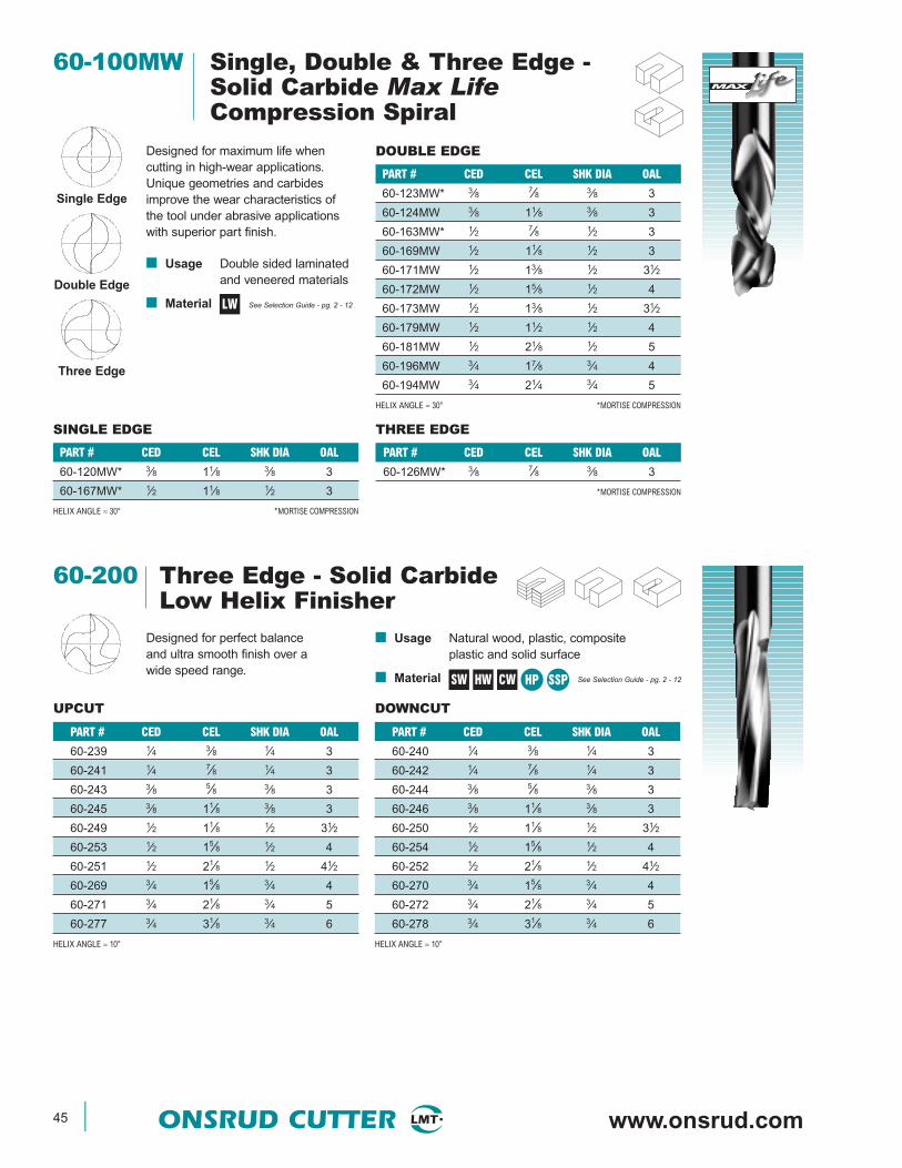
45 ONSRUD CUTTER www.onsrud.com
60-100MW Single, Double & Three Edge -Solid Carbide Max LifeCompression Spiral
Designed for maximum life when cutting in high-wear applications.Unique geometries and carbidesimprove the wear characteristics ofthe tool under abrasive applicationswith superior part finish.
■ Usage Double sided laminatedand veneered materials
■ Material See Selection Guide - pg. 2 - 12LW
THREE EDGE
PART # CED CEL SHK DIA OAL
60-126MW* 3⁄8 7⁄8 3⁄8 3
*MORTISE COMPRESSION
PART # CED CEL SHK DIA OAL
60-120MW* 3⁄8 11⁄8 3⁄8 3
60-167MW* 1⁄2 11⁄8 1⁄2 3
HELIX ANGLE ≈ 30° *MORTISE COMPRESSION
SINGLE EDGE
Double Edge
Three Edge
PART # CED CEL SHK DIA OAL
60-123MW* 3⁄8 7⁄8 3⁄8 3
60-124MW 3⁄8 11⁄8 3⁄8 3
60-163MW* 1⁄2 7⁄8 1⁄2 3
60-169MW 1⁄2 11⁄8 1⁄2 3
60-171MW 1⁄2 13⁄8 1⁄2 31⁄2
60-172MW 1⁄2 15⁄8 1⁄2 4
60-173MW 1⁄2 13⁄8 1⁄2 31⁄2
60-179MW 1⁄2 11⁄2 1⁄2 4
60-181MW 1⁄2 21⁄8 1⁄2 5
60-196MW 3⁄4 17⁄8 3⁄4 4
60-194MW 3⁄4 21⁄4 3⁄4 5
HELIX ANGLE ≈ 30° *MORTISE COMPRESSION
DOUBLE EDGE
Single Edge
60-200 Three Edge - Solid CarbideLow Helix Finisher
Designed for perfect balanceand ultra smooth finish over awide speed range.
■ Usage Natural wood, plastic, compositeplastic and solid surface
■ Material See Selection Guide - pg. 2 - 12
UPCUT DOWNCUT
PART # CED CEL SHK DIA OAL
60-239 1⁄4 3⁄8 1⁄4 3
60-241 1⁄4 7⁄8 1⁄4 3
60-243 3⁄8 5⁄8 3⁄8 3
60-245 3⁄8 11⁄8 3⁄8 3
60-249 1⁄2 11⁄8 1⁄2 31⁄2
60-253 1⁄2 15⁄8 1⁄2 4
60-251 1⁄2 21⁄8 1⁄2 41⁄2
60-269 3⁄4 15⁄8 3⁄4 4
60-271 3⁄4 21⁄8 3⁄4 5
60-277 3⁄4 31⁄8 3⁄4 6
HELIX ANGLE ≈ 10°
PART # CED CEL SHK DIA OAL
60-240 1⁄4 3⁄8 1⁄4 3
60-242 1⁄4 7⁄8 1⁄4 3
60-244 3⁄8 5⁄8 3⁄8 3
60-246 3⁄8 11⁄8 3⁄8 3
60-250 1⁄2 11⁄8 1⁄2 31⁄2
60-254 1⁄2 15⁄8 1⁄2 4
60-252 1⁄2 21⁄8 1⁄2 41⁄2
60-270 3⁄4 15⁄8 3⁄4 4
60-272 3⁄4 21⁄8 3⁄4 5
60-278 3⁄4 31⁄8 3⁄4 6
HELIX ANGLE ≈ 10°
SW HW CW HP SSP
MAX
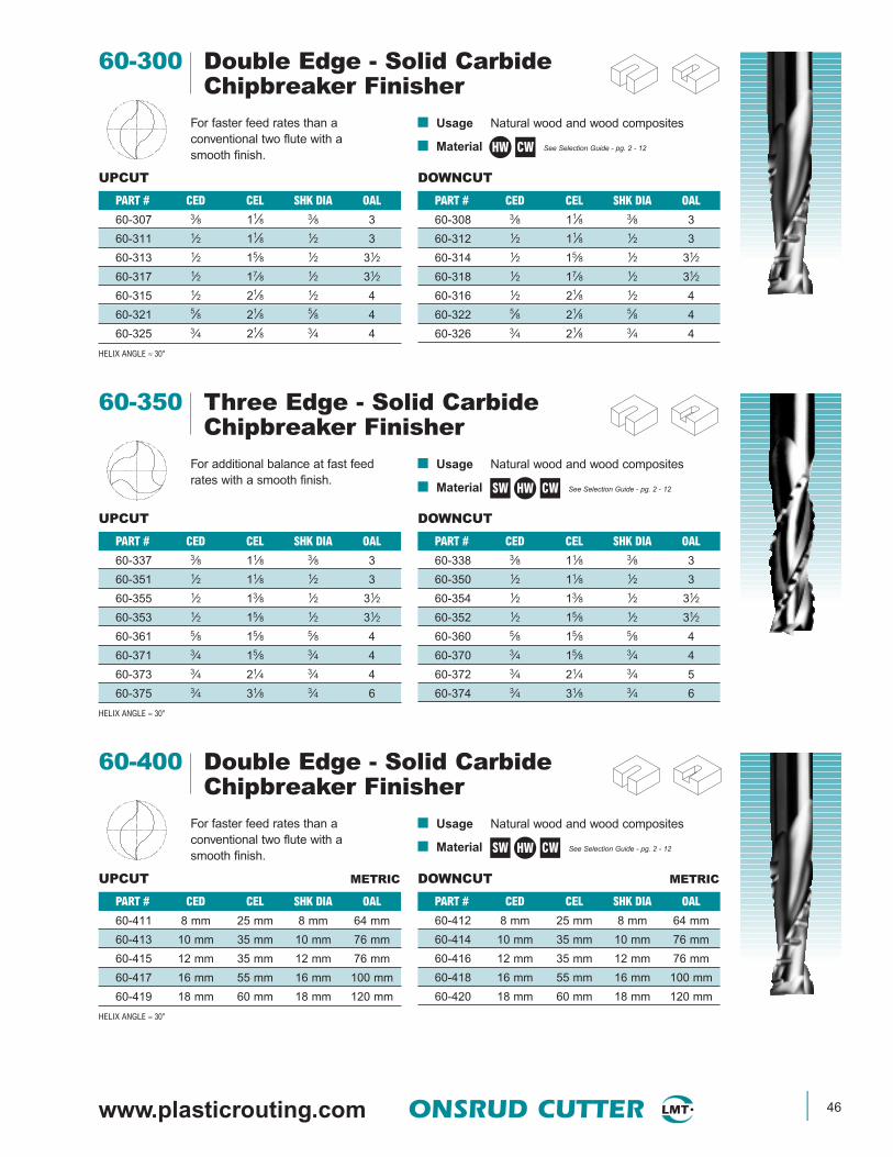
www.plasticrouting.com ONSRUD CUTTER 46
DOWNCUT
PART # CED CEL SHK DIA OAL
60-308 3⁄8 11⁄8 3⁄8 3
60-312 1⁄2 11⁄8 1⁄2 3
60-314 1⁄2 15⁄8 1⁄2 31⁄2
60-318 1⁄2 17⁄8 1⁄2 31⁄2
60-316 1⁄2 21⁄8 1⁄2 4
60-322 5⁄8 21⁄8 5⁄8 4
60-326 3⁄4 21⁄8 3⁄4 4
PART # CED CEL SHK DIA OAL
60-307 3⁄8 11⁄8 3⁄8 3
60-311 1⁄2 11⁄8 1⁄2 3
60-313 1⁄2 15⁄8 1⁄2 31⁄2
60-317 1⁄2 17⁄8 1⁄2 31⁄2
60-315 1⁄2 21⁄8 1⁄2 4
60-321 5⁄8 21⁄8 5⁄8 4
60-325 3⁄4 21⁄8 3⁄4 4
HELIX ANGLE ≈ 30°
UPCUT
60-300 Double Edge - Solid CarbideChipbreaker Finisher
For faster feed rates than a conventional two flute with a smooth finish.
■ Usage Natural wood and wood composites
■ Material See Selection Guide - pg. 2 - 12CWHW
DOWNCUT
PART # CED CEL SHK DIA OAL
60-338 3⁄8 11⁄8 3⁄8 3
60-350 1⁄2 11⁄8 1⁄2 3
60-354 1⁄2 13⁄8 1⁄2 31⁄2
60-352 1⁄2 15⁄8 1⁄2 31⁄2
60-360 5⁄8 15⁄8 5⁄8 4
60-370 3⁄4 15⁄8 3⁄4 4
60-372 3⁄4 21⁄4 3⁄4 5
60-374 3⁄4 31⁄8 3⁄4 6
PART # CED CEL SHK DIA OAL
60-337 3⁄8 11⁄8 3⁄8 3
60-351 1⁄2 11⁄8 1⁄2 3
60-355 1⁄2 13⁄8 1⁄2 31⁄2
60-353 1⁄2 15⁄8 1⁄2 31⁄2
60-361 5⁄8 15⁄8 5⁄8 4
60-371 3⁄4 15⁄8 3⁄4 4
60-373 3⁄4 21⁄4 3⁄4 4
60-375 3⁄4 31⁄8 3⁄4 6
HELIX ANGLE ≈ 30°
UPCUT
60-350 Three Edge - Solid CarbideChipbreaker Finisher
For additional balance at fast feedrates with a smooth finish.
■ Usage Natural wood and wood composites
■ Material See Selection Guide - pg. 2 - 12SW CWHW
DOWNCUT METRIC
PART # CED CEL SHK DIA OAL
60-412 8 mm 25 mm 8 mm 64 mm
60-414 10 mm 35 mm 10 mm 76 mm
60-416 12 mm 35 mm 12 mm 76 mm
60-418 16 mm 55 mm 16 mm 100 mm
60-420 18 mm 60 mm 18 mm 120 mm
PART # CED CEL SHK DIA OAL
60-411 8 mm 25 mm 8 mm 64 mm
60-413 10 mm 35 mm 10 mm 76 mm
60-415 12 mm 35 mm 12 mm 76 mm
60-417 16 mm 55 mm 16 mm 100 mm
60-419 18 mm 60 mm 18 mm 120 mm
HELIX ANGLE ≈ 30°
UPCUT METRIC
60-400 Double Edge - Solid CarbideChipbreaker Finisher
For faster feed rates than a conventional two flute with a smooth finish.
■ Usage Natural wood and wood composites
■ Material See Selection Guide - pg. 2 - 12SW CWHW

47 ONSRUD CUTTER www.onsrud.com
LW
PART # CED CEL SHK DIA OAL
60-572 1⁄2 15⁄8 1⁄2 4
60-586 5⁄8 21⁄4 5⁄8 5
60-598 3⁄4 21⁄2 3⁄4 5
PART # CED CEL SHK DIA OAL
60-564 1⁄2 1 1⁄2 3
60-569 1⁄2 11⁄8 1⁄2 3
60-571 1⁄2 13⁄8 1⁄2 31⁄2
HELIX ANGLE ≈ 30°
60-500 Four Edge - Solid CarbideCompression Spiral
The ultimate in compression spiraltooling, these tools are designed torun on the newest generation CNCrouters. They produce extremely finefinishes at high feed rates.
■ Usage Double sided laminated and veneered,natural wood and wood composites
■ Material See Selection Guide - pg. 2 - 12SW CWHW
DOWNCUT METRIC
PART # CED CEL SHK DIA OAL
60-432 8 mm 25 mm 8 mm 64 mm
60-434 10 mm 35 mm 10 mm 76 mm
60-436 12 mm 35 mm 12 mm 76 mm
60-438 16 mm 55 mm 16 mm 100 mm
60-440 18 mm 60 mm 18 mm 120 mm
PART # CED CEL SHK DIA OAL
60-431 8 mm 25 mm 8 mm 64 mm
60-433 10 mm 35 mm 10 mm 76 mm
60-435 12 mm 35 mm 12 mm 76 mm
60-437 16 mm 55 mm 16 mm 100 mm
60-439 18 mm 60 mm 18 mm 120 mm
HELIX ANGLE ≈ 30°
UPCUT METRIC
60-430 Three Edge - Solid CarbideChipbreaker Finisher
For additional balance at fast feedrates with a smooth finish.
■ Usage Natural wood and wood composites
■ Material See Selection Guide - pg. 2 - 12SW CWHW
60-470 Three Edge - Solid CarbideLow Helix Finisher
Designed for perfect balanceand ultra smooth finish over awide speed range.
■ Usage Natural wood, wood, plastic, compositeplastic and solid surface
■ Material See Selection Guide - pg. 2 - 12
UPCUT METRIC DOWNCUT METRIC
PART # CED CEL SHK DIA OAL
60-482 6mm 25mm 6mm 76mm
60-472 8mm 25mm 8mm 76mm
60-474 10mm 35mm 10mm 76mm
60-476 12mm 35mm 12mm 88mm
60-484 14mm 45mm 14mm 110mm
60-478 16mm 55mm 16mm 120mm
60-480 18mm 60mm 18mm 120mm
HELIX ANGLE ≈ 10°
PART # CED CEL SHK DIA OAL
60-481 6mm 25mm 6mm 76mm
60-471 8mm 25mm 8mm 76mm
60-473 10mm 35mm 10mm 76mm
60-475 12mm 35mm 12mm 88mm
60-483 14mm 45mm 14mm 110mm
60-477 16mm 55mm 16mm 120mm
60-479 18mm 60mm 18mm 120mm
HELIX ANGLE ≈ 10°
HW HPCP SSP
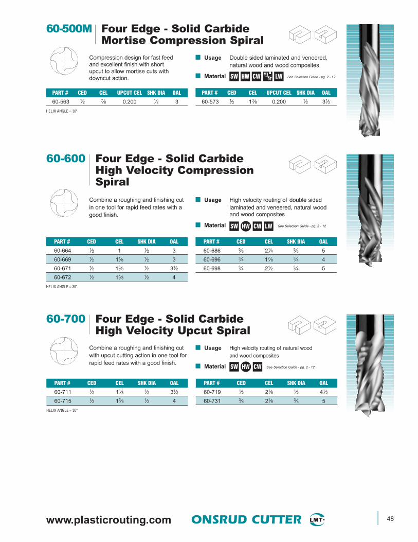
www.plasticrouting.com ONSRUD CUTTER 48
SW HW CW LWMTDT
PART # CED CEL UPCUT CEL SHK DIA OAL
60-573 1⁄2 13⁄8 0.200 1⁄2 31⁄2
PART # CED CEL UPCUT CEL SHK DIA OAL
60-563 1⁄2 7⁄8 0.200 1⁄2 3
HELIX ANGLE ≈ 30°
60-500M Four Edge - Solid CarbideMortise Compression Spiral
Compression design for fast feed and excellent finish with short upcut to allow mortise cuts with downcut action.
■ Usage Double sided laminated and veneered,natural wood and wood composites
■ Material See Selection Guide - pg. 2 - 12
PART # CED CEL SHK DIA OAL
60-686 5⁄8 21⁄4 5⁄8 5
60-696 3⁄4 17⁄8 3⁄4 4
60-698 3⁄4 21⁄2 3⁄4 5
PART # CED CEL SHK DIA OAL
60-664 1⁄2 1 1⁄2 3
60-669 1⁄2 11⁄8 1⁄2 3
60-671 1⁄2 13⁄8 1⁄2 31⁄2
60-672 1⁄2 15⁄8 1⁄2 4
HELIX ANGLE ≈ 30°
60-600 Four Edge - Solid CarbideHigh Velocity CompressionSpiral
Combine a roughing and finishing cutin one tool for rapid feed rates with agood finish.
■ Usage High velocity routing of double sided laminated and veneered, natural woodand wood composites
■ Material See Selection Guide - pg. 2 - 12SW CWHW LW
PART # CED CEL SHK DIA OAL
60-719 1⁄2 21⁄8 1⁄2 41⁄2
60-731 3⁄4 21⁄8 3⁄4 5
PART # CED CEL SHK DIA OAL
60-711 1⁄2 11⁄8 1⁄2 31⁄2
60-715 1⁄2 15⁄8 1⁄2 4
HELIX ANGLE ≈ 30°
60-700 Four Edge - Solid CarbideHigh Velocity Upcut Spiral
Combine a roughing and finishing cutwith upcut cutting action in one tool forrapid feed rates with a good finish.
■ Usage High velocity routing of natural wood and wood composites
■ Material See Selection Guide - pg. 2 - 12SW CWHW

49 ONSRUD CUTTER www.onsrud.com
PART # CED CEL SHK DIA OAL
60-720 5⁄8 21⁄8 5⁄8 5
60-730 3⁄4 21⁄8 3⁄4 5
PART # CED CEL SHK DIA OAL
60-710 1⁄2 11⁄8 1⁄2 31⁄2
60-714 1⁄2 15⁄8 1⁄2 4
60-718 1⁄2 21⁄8 1⁄2 41⁄2
HELIX ANGLE ≈ 30°
60-700 Four Edge - Solid CarbideHigh Velocity Downcut Spiral
Combine a roughing and finishing cutwith downcut cutting action in one toolfor rapid feed rates with a good finish.
■ Usage High velocity routing of natural wood and wood composites
■ Material See Selection Guide - pg. 2 - 12SW CWHW
60-800 Double Edge - Solid CarbideRougher
Designed for use when faster feedrates cannot be achieved, or on lowhorsepower machines.
■ Usage Wood and wood composites
■ Material See Selection Guide - pg. 2 - 12
UPCUT DOWNCUT
PART # CED CEL SHK DIA OAL
60-816 3⁄8 13⁄8 3⁄8 31⁄2
60-826 1⁄2 13⁄8 1⁄2 31⁄2
60-830 1⁄2 17⁄8 1⁄2 4
60-842 5⁄8 25⁄8 5⁄8 5
60-848 3⁄4 27⁄8 3⁄4 6
PART # CED CEL SHK DIA OAL
60-815 3⁄8 13⁄8 3⁄8 31⁄2
60-825 1⁄2 13⁄8 1⁄2 31⁄2
60-829 1⁄2 17⁄8 1⁄2 4
60-841 5⁄8 25⁄8 5⁄8 5
60-847 3⁄4 27⁄8 3⁄4 6
HELIX ANGLE ≈ 20°
SW CWHW
60-850 Double Edge - Solid CarbideRougher Compression
Compression Rougher designallows for increased feedrates overa standard compression and providesa clean edge on the top and bottomsurfaces. This tool excels in single orstack sheet plywood where the edgeis hidden or covered.
■ Usage Double sided laminated, veneered,natural wood and wood composites
■ Material See Selection Guide - pg. 2 - 12
PART # CED CEL SHK DIA OAL
60-867 1⁄2 13⁄4 1⁄2 5
PART # CED CEL SHK DIA OAL
60-855* 3⁄8 11⁄4 3⁄8 31⁄2
60-865* 1⁄2 11⁄4 1⁄2 5
HELIX ANGLE ≈ 30° * = Mortise Compression
LW CWHW

www.plasticrouting.com ONSRUD CUTTER 50
60-900 Three Edge - Solid CarbideExtreme Heavy Duty Hogger
Designed for heavy material removaloperations where the cutter is subjectto excessive cutting forces and finishis not a primary concern.
■ Usage Natural wood, wood composites, hardand soft plastic and plastic composites
■ Material See Selection Guide - pg. 2 - 12
UPCUT DOWNCUT
PART # CED CEL SHK DIA OAL
60-902 3⁄8 11⁄8 3⁄8 3
60-906 1⁄2 11⁄8 1⁄2 3
60-908 1⁄2 15⁄8 1⁄2 31⁄2
60-910 1⁄2 21⁄8 1⁄2 4
60-916 3⁄4 21⁄8 3⁄4 5
PART # CED CEL SHK DIA OAL
60-901 3⁄8 11⁄8 3⁄8 3
60-905 1⁄2 11⁄8 1⁄2 3
60-907 1⁄2 15⁄8 1⁄2 31⁄2
60-909 1⁄2 21⁄8 1⁄2 4
60-915 3⁄4 21⁄8 3⁄4 5
HELIX ANGLE ≈ 30°
DOWNCUT
PART # CED CEL SHK DIA OAL
60-950 3⁄8 11⁄8 3⁄8 3
60-954 1⁄2 11⁄8 1⁄2 3
60-956 1⁄2 15⁄8 1⁄2 31⁄2
60-958 1⁄2 21⁄8 1⁄2 4
60-966 3⁄4 21⁄8 3⁄4 5
PART # CED CEL SHK DIA OAL
60-951 3⁄8 11⁄8 3⁄8 3
60-955 1⁄2 11⁄8 1⁄2 3
60-957 1⁄2 15⁄8 1⁄2 31⁄2
60-959 1⁄2 21⁄8 1⁄2 4
60-965 3⁄4 21⁄8 3⁄4 5
HELIX ANGLE ≈ 30°
UPCUT
60-950 Double Edge - Solid CarbideExtreme Heavy DutyChipbreaker/Finisher
Designed to be fed very fast whilewithstanding excessive cutting forcesand at the same time leaving asmooth finish.
■ Usage Natural wood and wood composites
■ Material See Selection Guide - pg. 2 - 12SW CWHW
SW CWHW
61-000 Single Edge - Solid CarbideStraight
Designed to combine the fast freecutting of O flute geometry with thetool life available from solid carbideparticularly in small diameters.
■ Usage Natural wood and aluminum
■ Material See Selection Guide - pg. 2 - 12
PART # CED CEL SHK DIA OAL
61-090 9⁄32 3⁄4 3⁄8 21⁄2
61-100 5⁄16 13⁄16 3⁄8 21⁄2
61-120 3⁄8 7⁄8 3⁄8 21⁄2
61-140 7⁄16 1 1⁄2 3
61-160 1⁄2 1 1⁄2 3
PART # CED CEL SHK DIA OAL
61-040 1⁄8 1⁄2 1⁄4 2
61-050 5⁄32 9⁄16 1⁄4 2
61-060 3⁄16 5⁄8 1⁄4 2
61-070 7⁄32 5⁄8 1⁄4 21⁄2
61-080 1⁄4 3⁄4 1⁄4 21⁄2
ASW

51 ONSRUD CUTTER www.onsrud.com
61-000P Single Edge - Solid CarbideStraight
Designed to combine the fast freecutting of O flute geometry with thetool life available from solid carbideparticularly in small diameters.
■ Usage Polycarbonate, polyethylene,polypropylene, polystyrene, PVC,extruded acrylic, HDPE, UHMW andhard plastic
■ Material See Selection Guide - pg. 2 - 12
PART # CED CEL SHK DIA OAL
61-081 1⁄4 3⁄8 1⁄4 21⁄2
61-082 1⁄4 3⁄4 1⁄4 21⁄2
61-082L 1⁄4 3⁄4 1⁄4 21⁄2
61-083* 1⁄4 3⁄4 1⁄4 31⁄4
61-083L* 1⁄4 3⁄4 1⁄4 31⁄4
61-085* 1⁄4 1 1⁄4 31⁄4
61-084* 1⁄4 11⁄4 1⁄4 4
61-121 3⁄8 5⁄8 3⁄8 21⁄2
61-122 3⁄8 7⁄8 3⁄8 21⁄2
61-123* 3⁄8 15⁄8 3⁄8 6
61-162 1⁄2 1 1⁄2 3
61-164 1⁄2 15⁄8 1⁄2 4
61-166 1⁄2 21⁄8 1⁄2 6
PART # CED CEL SHK DIA OAL
61-041 1⁄8 5⁄16 1⁄4 2
61-044 1⁄8 1⁄2 1⁄8 2
61-042 1⁄8 1⁄2 1⁄4 2
61-042L 1⁄8 1⁄2 1⁄4 2
61-045 1⁄8 5⁄8 1⁄8 3
61-043 1⁄8 5⁄8 1⁄4 4
61-052 5⁄32 9⁄16 1⁄4 2
61-061 3⁄16 3⁄8 1⁄4 2
61-064 3⁄16 5⁄8 3⁄16 21⁄2
61-062 3⁄16 5⁄8 1⁄4 2
61-062L 3⁄16 5⁄8 1⁄4 2
61-063* 3⁄16 1 1⁄4 4
61-072 7⁄32 5⁄8 1⁄4 21⁄2
* These tools are designed and toleranced for air routers with guide bushings.L= left hand rotation
SP HP
PART # CED CEL SHK DIA OAL
61-285 1⁄4 1 1⁄4 21⁄2
61-320 3⁄8 11⁄8 3⁄8 3
PART # CED CEL SHK DIA OAL
61-240 1⁄8 1⁄2 1⁄4 2
61-260 3⁄16 3⁄4 1⁄4 2
61-280 1⁄4 7⁄8 1⁄4 21⁄2
61-200 Single Edge - Solid CarbideStraight Wood Rout
Designed to enhance operationswhere the benefits of spiral actionare not needed. The single edge provides fast, free cutting with optimum cutter life.
■ Usage Natural wood and wood composites
■ Material See Selection Guide - pg. 2 - 12SW CWHW

www.plasticrouting.com ONSRUD CUTTER 52
SP HP
PART # CED CEL SHK DIA OAL
61-414 8 mm 25 mm 8 mm 64 mm
61-418 12 mm 35 mm 12 mm 88 mm
PART # CED CEL SHK DIA OAL
61-410 4 mm 16 mm 6 mm 64 mm
61-411 5 mm 20 mm 6 mm 64 mm
61-412 6 mm 25 mm 6 mm 64 mm
61-400 Single Edge - Solid CarbideStraight
Designed to combine the fast free cutting of O flute geometry with thetool life available from solid carbideparticularly in small diameters.
■ Usage Polycarbonate, polyethylene,polypropylene, polystyrene, PVC,extruded acrylic, HDPE, UHMW and hard plastic
■ Material See Selection Guide - pg. 2 - 12
METRICMETRIC
PART # CED CEL SHK DIA OAL
62-100 5⁄16 13⁄16 3⁄8 21⁄2
PART # CED CEL SHK DIA OAL
62-040 1⁄8 1⁄2 1⁄4 2
62-080 1⁄4 3⁄4 1⁄4 21⁄2
HELIX ANGLE ≈ 30°
62-000 Single Edge - Solid CarbideDowncut Spiral
Good general purpose tools that hold up well in abrasive plastics and aluminum where downward chip flow is preferred.
■ Usage Fiberglass, phenolic and aluminum
■ Material See Selection Guide - pg. 2 - 12HWCP A
PART # CED CEL SHK DIA OAL
62-320 3⁄8 11⁄8 3⁄8 3
62-360 1⁄2 11⁄8 1⁄2 3
PART # CED CEL SHK DIA OAL
62-240 1⁄8 1⁄2 1⁄4 2
62-280 1⁄4 5⁄8 1⁄4 21⁄2
62-285 1⁄4 1 1⁄4 21⁄2
HELIX ANGLE ≈ 30°
62-200 Single Edge - Solid CarbideDowncut Spiral Wood Rout
Designed for routing wood and wood composites where aggressive downward chip removal is necessary in hand-fed or CNC applications.Tool rigidity, long life, and high qualityfinish are also characteristic ofthese tools.
■ Usage Natural wood and wood composites
■ Material See Selection Guide - pg. 2 - 12SW CWHW
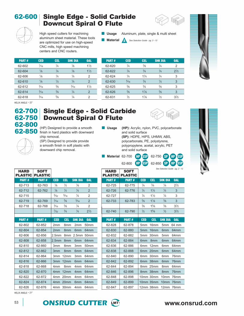
53 ONSRUD CUTTER www.onsrud.com
62-600 Single Edge - Solid CarbideDowncut Spiral O Flute
High speed cutters for machiningaluminum sheet material. These toolsare optimized for use on high-speedCNC mills, high speed machiningcenters and CNC routers.
■ Usage Aluminum, plate, single & multi sheet
■ Material See Selection Guide - pg. 2 - 12A
PART # CED CEL SHK DIA OAL
62-602 1⁄16 1⁄4 1⁄8 11⁄2
62-604 1⁄8 1⁄4 1⁄8 11⁄2
62-606 1⁄8 1⁄4 1⁄4 2
62-610 1⁄8 1⁄2 1⁄4 2
62-612 3⁄16 3⁄8 3⁄16 11⁄2
62-614 3⁄16 3⁄8 1⁄4 2
62-618 3⁄16 5⁄8 1⁄4 2
HELIX ANGLE ≈ 22°
PART # CED CEL SHK DIA OAL
62-620 1⁄4 3⁄8 1⁄4 2
62-622 1⁄4 3⁄4 1⁄4 21⁄2
62-624 1⁄4 11⁄4 1⁄4 3
62-630 5⁄16 3⁄4 1⁄2 3
62-625 3⁄8 3⁄4 3⁄8 3
62-626 3⁄8 11⁄8 3⁄8 3
62-631 1⁄2 11⁄8 1⁄2 31⁄2
62-700 Single Edge - Solid Carbide62-750 Downcut Spiral O Flute62-80062-850
(HP) Designed to provide a smoothfinish in hard plastics with downwardchip removal.(SP) Designed to provide providea smooth finish in soft plastic withdownward chip removal.
■ Usage (HP): Acrylic, nylon, PVC, polycarbonateand solid surface(SP): HDPE, HIPS, UHMW, ABS,polycarbonate, PE, polystyrene,polypropylene, acetal, acrylic, PETand solid surface
■ Material 62-700 62-750
62-800 62-850See Selection Guide - pg. 2 - 12
HP SSP SP HP SSP
HP SSP SP HP SSP
PART # PART # CED CEL SHK DIA OAL
62-828 62-878 5mm 16mm 5mm 64 mm
62-830 62-880 5mm 16mm 6mm 64mm
62-832 62-882 5mm 30mm 5mm 64mm
62-834 62-884 6mm 8mm 6mm 64mm
62-836 62-886 6mm 12mm 6mm 64mm
62-838 62-888 6mm 20mm 6mm 64mm
62-840 62-890 6mm 30mm 6mm 76mm
62-842 62-892 6mm 38mm 6mm 76mm
62-844 62-894 8mm 25mm 8mm 64mm
62-846 62-896 8mm 38mm 8mm 76mm
62-848 62-898 10mm 30mm 10mm 76mm
62-849 62-899 10mm 35mm 10mm 76mm
62-847 62-897 12mm 38mm 12mm 76mm
PART # PART # CED CEL SHK DIA OAL
62-802 62-852 2mm 8mm 2mm 50mm
62-804 62-854 2mm 8mm 6mm 64mm
62-806 62-856 2.5mm 8mm 2.5mm 50mm
62-808 62-858 2.5mm 8mm 6mm 64mm
62-810 62-860 3mm 8mm 3mm 50mm
62-812 62-862 3mm 8mm 6mm 64mm
62-814 62-864 3mm 12mm 3mm 64mm
62-816 62-866 3mm 12mm 6mm 64mm
62-818 62-868 4mm 8mm 4mm 64mm
62-820 62-870 4mm 12mm 4mm 64mm
62-822 62-872 4mm 20mm 4mm 64mm
62-824 62-874 4mm 20mm 6mm 64mm
62-826 62-876 4mm 30mm 4mm 64mm
HELIX ANGLE ≈ 21°
METRIC
PART # PART # CED CEL SHK DIA OAL
62-725 62-775 1⁄4 3⁄4 1⁄4 21⁄2
62-726 62-776 1⁄4 11⁄4 1⁄4 3
62-727 1⁄4 11⁄2 1⁄4 3
62-733 62-783 3⁄8 11⁄8 3⁄8 33⁄8 15⁄8 3⁄8 31⁄2
62-740 62-790 1⁄2 15⁄8 1⁄2 31⁄2
PART # PART # CED CEL SHK DIA OAL
62-713 62-763 1⁄8 1⁄2 1⁄8 2
62-712 62-762 1⁄8 1⁄2 1⁄4 2
62-715 5⁄32 9⁄16 1⁄4 2
62-719 62-769 3⁄16 5⁄8 3⁄16 2
62-718 62-768 3⁄16 5⁄8 1⁄4 27⁄32 3⁄4 1⁄4 21⁄2
HARD PLASTIC
SOFTPLASTIC
HARD PLASTIC
SOFTPLASTIC
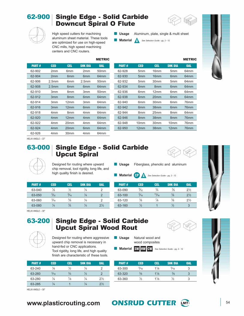
www.plasticrouting.com ONSRUD CUTTER 54
62-900 Single Edge - Solid CarbideDowncut Spiral O Flute
High speed cutters for machiningaluminum sheet material. These toolsare optimized for use on high-speedCNC mills, high speed machiningcenters and CNC routers.
■ Usage Aluminum, plate, single & multi sheet
■ Material See Selection Guide - pg. 2 - 12A
PART # CED CEL SHK DIA OAL
62-902 2mm 6mm 2mm 50mm
62-904 2mm 6mm 6mm 64mm
62-906 2.5mm 6mm 2.5mm 50mm
62-908 2.5mm 6mm 6mm 64mm
62-910 3mm 8mm 3mm 50mm
62-912 3mm 8mm 6mm 64mm
62-914 3mm 12mm 3mm 64mm
62-916 3mm 12mm 6mm 64mm
62-918 4mm 8mm 4mm 64mm
62-920 4mm 12mm 4mm 64mm
62-922 4mm 20mm 4mm 64mm
62-924 4mm 20mm 6mm 64mm
62-926 4mm 30mm 4mm 64mm
HELIX ANGLE ≈ 22°
METRIC
PART # CED CEL SHK DIA OAL
62-928 5mm 16mm 5mm 64mm
62-930 5mm 16mm 6mm 64mm
62-932 5mm 30mm 5mm 64mm
62-934 6mm 8mm 6mm 64mm
62-936 6mm 12mm 6mm 64mm
62-938 6mm 20mm 6mm 64mm
62-940 6mm 30mm 6mm 76mm
62-942 6mm 38mm 6mm 76mm
62-944 8mm 25mm 8mm 64mm
62-946 8mm 38mm 8mm 76mm
62-948 10mm 30mm 10mm 76mm
62-950 12mm 38mm 12mm 76mm
METRIC
PART # CED CEL SHK DIA OAL
63-090 9⁄323⁄4 3⁄8 21⁄2
63-100 5⁄1613⁄16
3⁄8 21⁄2
63-120 3⁄8 7⁄8 3⁄8 21⁄2
63-160 1⁄2 1 1⁄2 3
PART # CED CEL SHK DIA OAL
63-040 1⁄8 1⁄2 1⁄4 2
63-050 5⁄329⁄16 1⁄4 2
63-060 3⁄165⁄8 1⁄4 2
63-080 1⁄4 3⁄4 1⁄4 21⁄2
HELIX ANGLE ≈ 30°
63-000 Single Edge - Solid CarbideUpcut Spiral
Designed for routing where upwardchip removal, tool rigidity, long life, andhigh quality finish is desired.
■ Usage Fiberglass, phenolic and aluminum
■ Material See Selection Guide - pg. 2 - 12HWCP A
SW HW CW
PART # CED CEL SHK DIA OAL
63-300 5⁄16 11⁄8 5⁄16 3
63-320 3⁄8 11⁄8 3⁄8 3
63-360 1⁄2 11⁄8 1⁄2 3
PART # CED CEL SHK DIA OAL
63-240 1⁄8 1⁄2 1⁄4 2
63-260 3⁄16 3⁄4 1⁄4 2
63-280 1⁄4 7⁄8 1⁄4 21⁄2
63-285 1⁄4 1 1⁄4 21⁄2
HELIX ANGLE ≈ 30°
63-200 Single Edge - Solid CarbideUpcut Spiral Wood Rout
Designed for routing where aggressiveupward chip removal is necessary inhand-fed or CNC applications.Tool rigidity, long life, and high qualityfinish are characteristic of these tools.
■ Usage Natural wood andwood composites
■ Material See Selection Guide - pg. 2 - 12
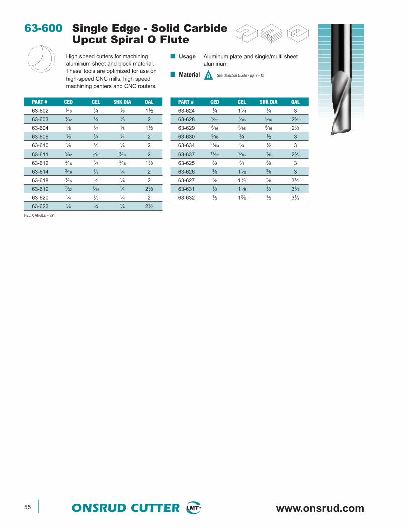
55 ONSRUD CUTTER www.onsrud.com
63-600 Single Edge - Solid CarbideUpcut Spiral O Flute
High speed cutters for machiningaluminum sheet and block material.These tools are optimized for use onhigh-speed CNC mills, high speedmachining centers and CNC routers.
■ Usage Aluminum plate and single/multi sheetaluminum
■ Material See Selection Guide - pg. 2 - 12A
PART # CED CEL SHK DIA OAL
63-602 1⁄16 1⁄4 1⁄8 11⁄2
63-603 3⁄32 1⁄4 1⁄8 2
63-604 1⁄8 1⁄4 1⁄8 11⁄2
63-606 1⁄8 1⁄4 1⁄4 2
63-610 1⁄8 1⁄2 1⁄4 2
63-611 5⁄32 5⁄16 3⁄16 2
63-612 3⁄16 3⁄8 3⁄16 11⁄2
63-614 3⁄16 3⁄8 1⁄4 2
63-618 3⁄16 5⁄8 1⁄4 2
63-619 7⁄32 7⁄16 1⁄4 21⁄2
63-620 1⁄4 3⁄8 1⁄4 2
63-622 1⁄4 3⁄4 1⁄4 21⁄2
HELIX ANGLE ≈ 22°
PART # CED CEL SHK DIA OAL
63-624 1⁄4 11⁄4 1⁄4 3
63-628 9⁄32 7⁄16 5⁄16 21⁄2
63-629 5⁄16 9⁄16 5⁄16 21⁄2
63-630 5⁄16 3⁄4 1⁄2 3
63-634 21⁄64 3⁄4 1⁄2 3
63-637 11⁄32 9⁄16 3⁄8 21⁄2
63-625 3⁄8 3⁄4 3⁄8 3
63-626 3⁄8 11⁄8 3⁄8 3
63-627 3⁄8 13⁄8 3⁄8 31⁄2
63-631 1⁄2 11⁄8 1⁄2 31⁄2
63-632 1⁄2 13⁄8 1⁄2 31⁄2
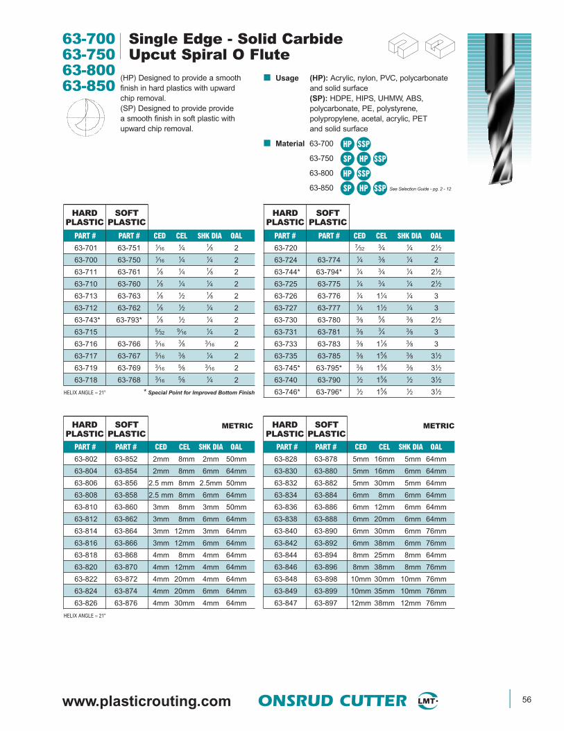
www.plasticrouting.com ONSRUD CUTTER 56
63-700 Single Edge - Solid Carbide63-750 Upcut Spiral O Flute63-80063-850
(HP) Designed to provide a smoothfinish in hard plastics with upwardchip removal.(SP) Designed to provide providea smooth finish in soft plastic withupward chip removal.
■ Usage (HP): Acrylic, nylon, PVC, polycarbonateand solid surface(SP): HDPE, HIPS, UHMW, ABS,polycarbonate, PE, polystyrene,polypropylene, acetal, acrylic, PETand solid surface
■ Material 63-700
63-750
63-800
63-850 See Selection Guide - pg. 2 - 12
HP SSP
PART # PART # CED CEL SHK DIA OAL
63-802 63-852 2mm 8mm 2mm 50mm
63-804 63-854 2mm 8mm 6mm 64mm
63-806 63-856 2.5 mm 8mm 2.5mm 50mm
63-808 63-858 2.5 mm 8mm 6mm 64mm
63-810 63-860 3mm 8mm 3mm 50mm
63-812 63-862 3mm 8mm 6mm 64mm
63-814 63-864 3mm 12mm 3mm 64mm
63-816 63-866 3mm 12mm 6mm 64mm
63-818 63-868 4mm 8mm 4mm 64mm
63-820 63-870 4mm 12mm 4mm 64mm
63-822 63-872 4mm 20mm 4mm 64mm
63-824 63-874 4mm 20mm 6mm 64mm
63-826 63-876 4mm 30mm 4mm 64mm
HELIX ANGLE ≈ 21°
PART # PART # CED CEL SHK DIA OAL
63-701 63-751 1⁄16 1⁄4 1⁄8 2
63-700 63-750 1⁄16 1⁄4 1⁄4 2
63-711 63-761 1⁄8 1⁄4 1⁄8 2
63-710 63-760 1⁄8 1⁄4 1⁄4 2
63-713 63-763 1⁄8 1⁄2 1⁄8 2
63-712 63-762 1⁄8 1⁄2 1⁄4 2
63-743* 63-793* 1⁄8 1⁄2 1⁄4 2
63-715 5⁄32 9⁄16 1⁄4 2
63-716 63-766 3⁄163⁄8 3⁄16 2
63-717 63-767 3⁄16 3⁄8 1⁄4 2
63-719 63-769 3⁄16 5⁄8 3⁄16 2
63-718 63-768 3⁄16 5⁄8 1⁄4 2
HELIX ANGLE ≈ 21° * Special Point for Improved Bottom Finish
METRIC METRIC
PART # PART # CED CEL SHK DIA OAL
63-720 7⁄32 3⁄4 1⁄4 21⁄2
63-724 63-774 1⁄4 3⁄8 1⁄4 2
63-744* 63-794* 1⁄4 3⁄4 1⁄4 21⁄2
63-725 63-775 1⁄4 3⁄4 1⁄4 21⁄2
63-726 63-776 1⁄4 11⁄4 1⁄4 3
63-727 63-777 1⁄4 11⁄2 1⁄4 3
63-730 63-780 3⁄8 5⁄8 3⁄8 21⁄2
63-731 63-781 3⁄8 3⁄4 3⁄8 3
63-733 63-783 3⁄8 11⁄8 3⁄8 3
63-735 63-785 3⁄8 15⁄8 3⁄8 31⁄2
63-745* 63-795* 3⁄8 15⁄8 3⁄8 31⁄2
63-740 63-790 1⁄2 15⁄8 1⁄2 31⁄2
63-746* 63-796* 1⁄2 15⁄8 1⁄2 31⁄2
HARD PLASTIC
SOFTPLASTIC
HARD PLASTIC
SOFTPLASTIC
HARD PLASTIC
SOFTPLASTIC
HARD PLASTIC
SOFTPLASTIC
PART # PART # CED CEL SHK DIA OAL
63-828 63-878 5mm 16mm 5mm 64mm
63-830 63-880 5mm 16mm 6mm 64mm
63-832 63-882 5mm 30mm 5mm 64mm
63-834 63-884 6mm 8mm 6mm 64mm
63-836 63-886 6mm 12mm 6mm 64mm
63-838 63-888 6mm 20mm 6mm 64mm
63-840 63-890 6mm 30mm 6mm 76mm
63-842 63-892 6mm 38mm 6mm 76mm
63-844 63-894 8mm 25mm 8mm 64mm
63-846 63-896 8mm 38mm 8mm 76mm
63-848 63-898 10mm 30mm 10mm 76mm
63-849 63-899 10mm 35mm 10mm 76mm
63-847 63-897 12mm 38mm 12mm 76mm
SP HP SSP
HP SSP
SP HP SSP

57 ONSRUD CUTTER www.onsrud.com
■ Usage Plastic, wood, aluminum and solid surface
■ Material
63-900 Single Edge - Solid CarbideUpcut Spiral O Flute
High speed cutters for machiningaluminum sheet and block material.These tools are optimized for use onhigh-speed CNC mills, high speedmachining centers and CNC routers.
■ Usage Aluminum plate and single/multi sheetaluminum
■ Material See Selection Guide - pg. 2 - 12A
A
PART # CED CEL SHK DIA OAL
63-902 2mm 6mm 2mm 50mm
63-904 2mm 6mm 6mm 64mm
63-906 2.5mm 6mm 2.5mm 50mm
63-908 2.5mm 6mm 6mm 64mm
63-910 3mm 8mm 3mm 50mm
63-912 3mm 8mm 6mm 64mm
63-914 3mm 12mm 3mm 64mm
63-916 3mm 12mm 6mm 64mm
63-918 4mm 8mm 4mm 64mm
63-920 4mm 12mm 4mm 64mm
63-922 4mm 20mm 4mm 64mm
63-924 4mm 20mm 6mm 64mm
63-926 4mm 30mm 4mm 64mm
HELIX ANGLE ≈ 22°
METRIC
PART # CED CEL SHK DIA OAL
63-928 5mm 16mm 5mm 64mm
63-930 5mm 16mm 6mm 64mm
63-932 5mm 30mm 5mm 64mm
63-934 6mm 8mm 6mm 64mm
63-936 6mm 12mm 6mm 64mm
63-938 6mm 20mm 6mm 64mm
63-940 6mm 30mm 6mm 76mm
63-942 6mm 38mm 6mm 76mm
63-944 8mm 25mm 8mm 64mm
63-946 8mm 38mm 8mm 76mm
63-948 10mm 30mm 10mm 76mm
63-950 12mm 38mm 12mm 76mm
METRIC
PART # CED CEL SHK DIA OAL
64-025 1⁄4 3⁄4 1⁄4 2
64-026 1⁄4 11⁄4 1⁄4 3
64-031 3⁄8 3⁄4 3⁄8 3
64-033 3⁄8 11⁄8 3⁄8 3
64-000 Single Edge - Solid CarbideDowncut Spiral O Flute
The polished flute allows for razor sharpcutting edge and easy chip evacuation.The tool is available in a down cut spiralfor improved part holding.
PART # CED CEL SHK DIA OAL
64-000 1⁄16 1⁄4 1⁄8 2
64-012 1⁄8 1⁄2 1⁄4 2
64-016 3⁄16 3⁄8 3⁄16 2
64-018 3⁄16 5⁄8 1⁄4 2
64-024 1⁄4 3⁄8 1⁄4 2
HELIX ANGLE ≈ 21°
PART # CED CEL SHK DIA OAL
65-020 3⁄16 11⁄4 1⁄4 3
65-023 1⁄4 5⁄8 1⁄4 2
65-025 1⁄4 7⁄8 1⁄4 21⁄2
65-026 1⁄4 11⁄4 1⁄4 3
65-027 1⁄4 11⁄2 1⁄4 3
65-033 3⁄8 11⁄8 3⁄8 3
65-000 Single Edge - Solid CarbideUpcut Spiral O Flute
The polished flute allows for razor sharpcutting edge and easy chip evacuation.The tool is available in a upcut spiral forimproved part holding.
■ Usage Plastic, wood, aluminum and solid surface
■ Material
PART # CED CEL SHK DIA OAL
65-000 1⁄16 1⁄4 1⁄8 2
65-010 1⁄8 1⁄4 1⁄4 2
65-013 1⁄8 1⁄2 1⁄8 2
65-012 1⁄8 1⁄2 1⁄4 2
65-019 3⁄165⁄8 3⁄16 2
65-018 3⁄165⁄8 1⁄4 2
HELIX ANGLE ≈ 21°
SW HW CW SP HP SSP See SelectionGuide - pg. 2 - 12
ASW HW CW SP HP SSP See SelectionGuide - pg. 2 - 12

www.plasticrouting.com ONSRUD CUTTER 58
■ Usage Edge rounding of parts
■ Material See Selection Guide - pg. 2 - 12
66-000 Solid Carbide Edge RoundingDesigned for rounding the edge ofsheets or parts. They come in bothsingle edge and double edge.
SP HP SSP
PART # CED CEL SHK DIA OAL OPENING RADIUS SM CED TIP TO RAD PLASTIC SIZE
66-120 3⁄8 3⁄8 3⁄8 21⁄2 5⁄32 1⁄8 .320 1⁄16 1⁄8
66-121 3⁄8 3⁄8 3⁄8 21⁄2 7⁄32 3⁄16 .305 1⁄16 3⁄16
66-122 3⁄8 3⁄8 3⁄8 21⁄2 9⁄32 1⁄4 .288 1⁄16 1⁄4
66-123 3⁄8 1⁄2 3⁄8 21⁄2 13⁄32 3⁄8 .255 1⁄16 3⁄8
66-160 1⁄2 3⁄8 1⁄2 3 5⁄32 1⁄8 .445 1⁄16 1⁄8
66-161 1⁄2 3⁄8 1⁄2 3 7⁄32 3⁄16 .430 1⁄16 3⁄16
66-162 1⁄2 3⁄8 1⁄2 3 9⁄32 1⁄4 .413 1⁄16 1⁄4
66-163 1⁄2 5⁄8 1⁄2 3 17⁄32 1⁄2 .347 1⁄16 1⁄2
PART # CED CEL SHK DIA OAL OPENING RADIUS SM CED TIP TO RAD PLASTIC SIZE
66-082 1⁄4 3⁄8 1⁄4 21⁄2 5⁄32 1⁄8 .195 1⁄16 1⁄8
66-083 1⁄4 3⁄8 1⁄4 21⁄2 7⁄32 3⁄16 .180 1⁄16 3⁄16
66-084 1⁄4 3⁄8 1⁄4 21⁄2 9⁄32 1⁄4 .163 1⁄16 1⁄4
SINGLE EDGE STRAIGHT 0-FLUTE
PART # CED CEL SHK DIA OAL OPENING RADIUS SM CED TIP TO RAD PLASTIC SIZE
66-085 1⁄4 3⁄8 1⁄4 21⁄2 5⁄32 1⁄8 .195 1⁄16 1⁄8
66-086 1⁄4 3⁄8 1⁄4 21⁄2 7⁄32 3⁄16 .180 1⁄16 3⁄16
66-087 1⁄4 3⁄8 1⁄4 21⁄2 9⁄32 1⁄4 .163 1⁄16 1⁄4
HELIX ANGLE ≈ 22°
SINGLE EDGE SPIRAL 0-FLUTE
PART # CED CEL SHK DIA OAL OPENING RADIUS SM CED TIP TO RAD PLASTIC SIZE
66-092 1⁄4 3⁄8 1⁄4 21⁄2 5⁄32 1⁄8 .195 1⁄16 1⁄8
66-093 1⁄4 3⁄8 1⁄4 21⁄2 7⁄32 3⁄16 .180 1⁄16 3⁄16
66-094 1⁄4 3⁄8 1⁄4 21⁄2 9⁄32 1⁄4 .163 1⁄16 1⁄4
DOUBLE EDGE STRAIGHT 0-FLUTE
DOUBLE EDGE STRAIGHT V-FLUTE
PART # CED CEL SHK DIA OAL OPENING RADIUS SM CED TIP TO RAD PLASTIC SIZE
66-073 6mm 10mm 6mm 64mm 4mm 3mm 4.47mm 1.5mm 3mm
66-074 6mm 10mm 6mm 64mm 5mm 4mm 4.24mm 1.5mm 4mm
66-075 6mm 10mm 6mm 64mm 6mm 5mm 3.96mm 1.5mm 5mm
66-076 6mm 10mm 6mm 64mm 7mm 6mm 3.73mm 1.5mm 6mm
DOUBLE EDGE STRAIGHT 0-FLUTE METRIC
PART # CED CEL SHK DIA OAL OPENING RADIUS SM CED TIP TO RAD PLASTIC SIZE
66-077 8mm 12mm 8mm 64mm 9mm 8mm 5.21mm 1.5mm 8mm
66-078 10mm 14mm 10mm 70mm 11mm 10mm 6.68mm 1.5mm 10mm
66-079 12mm 16mm 12mm 76mm 13mm 12mm 8.18mm 1.5mm 12mm
DOUBLE EDGE STRAIGHT V-FLUTE METRIC
Opening
Tip toRadius
CED
CEL
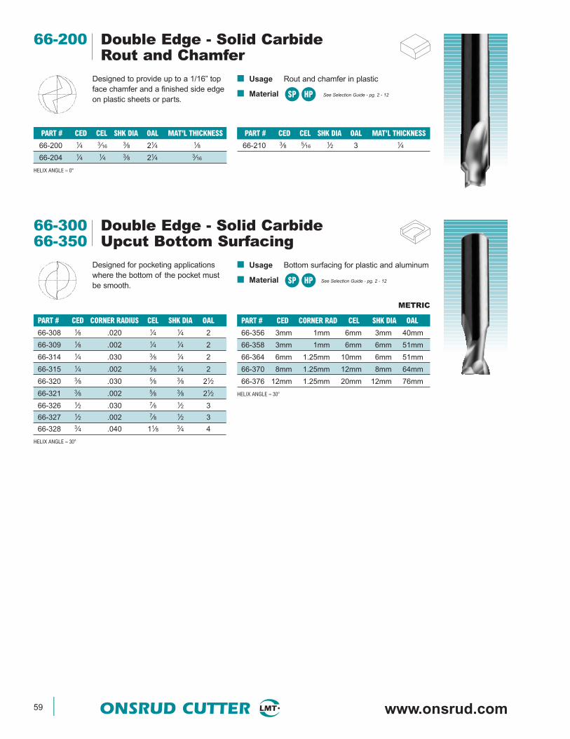
59 ONSRUD CUTTER www.onsrud.com
66-200 Double Edge - Solid CarbideRout and Chamfer
Designed to provide up to a 1/16” topface chamfer and a finished side edgeon plastic sheets or parts.
■ Usage Rout and chamfer in plastic
■ Material See Selection Guide - pg. 2 - 12SP HP
PART # CED CEL SHK DIA OAL MAT’L THICKNESS
66-200 1⁄4 3⁄16 3⁄8 21⁄4 1⁄8
66-204 1⁄4 1⁄4 3⁄8 21⁄4 3⁄16
HELIX ANGLE ≈ 0°
PART # CED CEL SHK DIA OAL MAT’L THICKNESS
66-210 3⁄8 5⁄16 1⁄2 3 1⁄4
66-300 Double Edge - Solid Carbide66-350 Upcut Bottom Surfacing
Designed for pocketing applicationswhere the bottom of the pocket mustbe smooth.
■ Usage Bottom surfacing for plastic and aluminum
■ Material See Selection Guide - pg. 2 - 12SP HP
PART # CED CORNER RADIUS CEL SHK DIA OAL
66-308 1⁄8 .020 1⁄4 1⁄4 2
66-309 1⁄8 .002 1⁄4 1⁄4 2
66-314 1⁄4 .030 3⁄8 1⁄4 2
66-315 1⁄4 .002 3⁄8 1⁄4 2
66-320 3⁄8 .030 5⁄8 3⁄8 21⁄2
66-321 3⁄8 .002 5⁄8 3⁄8 21⁄2
66-326 1⁄2 .030 7⁄8 1⁄2 3
66-327 1⁄2 .002 7⁄8 1⁄2 3
66-328 3⁄4 .040 11⁄8 3⁄4 4
HELIX ANGLE ≈ 30°
PART # CED CORNER RAD CEL SHK DIA OAL
66-356 3mm 1mm 6mm 3mm 40mm
66-358 3mm 1mm 6mm 6mm 51mm
66-364 6mm 1.25mm 10mm 6mm 51mm
66-370 8mm 1.25mm 12mm 8mm 64mm
66-376 12mm 1.25mm 20mm 12mm 76mm
HELIX ANGLE ≈ 30°
METRIC
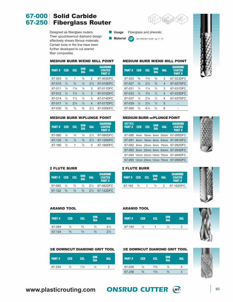
www.plasticrouting.com ONSRUD CUTTER 60
67-000 Solid Carbide67-250 Fiberglass Router
Designed as fiberglass routers.Their upcut/downcut diamond designeffectively shears fibrous materials.Certain tools in the line have beenfurther developed to cut aramidfiber composites.
■ Usage Fiberglass and phenolic
■ Material See Selection Guide - pg. 2 - 12
MEDIUM BURR W/PLUNGE POINT
DIAMONDPART # CED CEL SHK OAL COATEDDIA PART #
67-080 1⁄4 3⁄4 1⁄4 21⁄2 67-080DFC
67-120 3⁄8 7⁄8 3⁄8 21⁄2 67-120DFC
67-160 1⁄2 1 1⁄2 3 67-160DFC
METRIC DIAMONDPART # CED CEL SHK OAL COATEDDIA PART #
67-090 4mm 16mm 6mm 50mm 67-090DFC
67-091 6mm 19mm 6mm 63mm 67-091DFC
67-092 6mm 25mm 6mm 75mm 67-092DFC
67-093 8mm 25mm 8mm 63mm 67-093DFC
67-094 10mm 25mm 10mm 75mm 67-094DFC
67-095 12mm 25mm 12mm 75mm 67-095DFC
MEDIUM BURR W/END MILL POINT
DIAMONDPART # CED CEL SHK OAL COATEDDIA PART #
67-003 1⁄8 1 1⁄8 2 67-003DFC
67-010 1⁄4 3⁄4 1⁄4 21⁄2 67-010DFC
67-011 1⁄4 11⁄8 1⁄4 3 67-011DFC
67-012 1⁄4 11⁄4 1⁄4 3 67-012DFC
67-014 1⁄4 11⁄2 1⁄4 3 67-014DFC
67-017 1⁄4 21⁄8 1⁄4 4 67-017DFC
67-030 3⁄8 7⁄8 3⁄8 21⁄2 67-030DFC
MEDIUM BURR W/END MILL POINT
DIAMONDPART # CED CEL SHK OAL COATEDDIA PART #
67-023 3⁄8 15⁄8 3⁄8 3 67-023DFC
67-027 3⁄8 21⁄8 3⁄8 4 67-027DFC
67-031 1⁄2 11⁄8 1⁄2 3 67-031DFC
67-033 1⁄2 15⁄8 1⁄2 4 67-033DFC
67-037 1⁄2 21⁄8 1⁄2 4 67-037DFC
67-039 1⁄2 31⁄8 1⁄2 5 -
67-065 3⁄4 41⁄8 3⁄4 6 -
3/E DOWNCUT DIAMOND GRIT TOOL
PART # CED CEL SHK OALDIA
67-256 1⁄4 13⁄8 1⁄4 3
67-258 3⁄8 13⁄8 3⁄8 3
PART # CED CEL SHK OALDIA
67-254 1⁄4 11⁄8 1⁄4 3
ARAMID TOOL
PART # CED CEL SHK OALDIA
67-084 1⁄4 3⁄4 1⁄4 21⁄2
67-124 3⁄8 7⁄8 3⁄8 21⁄2
ARAMID TOOL
PART # CED CEL SHK OALDIA
67-164 1⁄2 1 1⁄2 3
2 FLUTE BURR
DIAMONDPART # CED CEL SHK OAL COATEDDIA PART #
67-082 1⁄4 3⁄4 1⁄4 21⁄2 67-082DFC
67-122 3⁄8 7⁄8 3⁄8 21⁄2 67-122DFC
2 FLUTE BURR
DIAMONDPART # CED CEL SHK OAL COATEDDIA PART #
67-162 1⁄2 1 1⁄2 3 67-162DFC
3/E DOWNCUT DIAMOND GRIT TOOL
MEDIUM BURR w/PLUNGEPOINT
CP
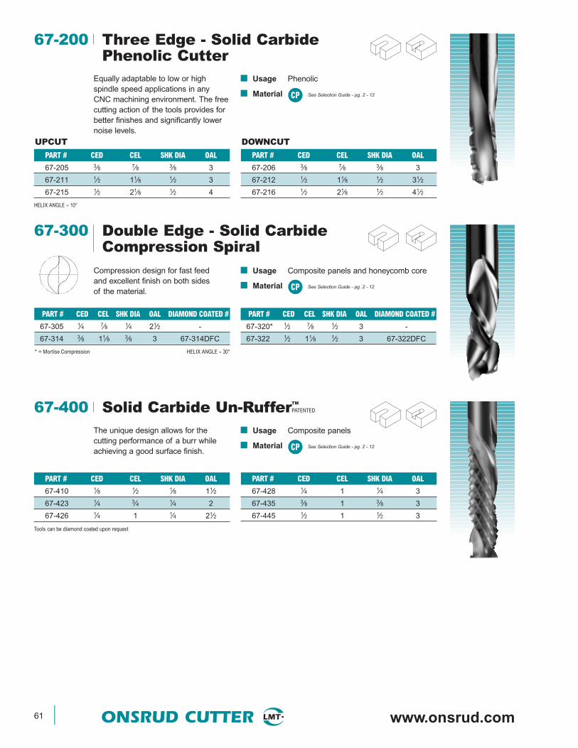
61 ONSRUD CUTTER www.onsrud.com
■ Usage Composite panels and honeycomb core
■ Material See Selection Guide - pg. 2 - 12
UPCUT DOWNCUT
CP
CP
67-300 Double Edge - Solid CarbideCompression Spiral
Compression design for fast feedand excellent finish on both sidesof the material.
PART # CED CEL SHK DIA OAL DIAMOND COATED #
67-305 1⁄4 7⁄8 1⁄4 21⁄2 -
67-314 3⁄8 11⁄8 3⁄8 3 67-314DFC
* = Mortise Compression HELIX ANGLE ≈ 30°
PART # CED CEL SHK DIA OAL DIAMOND COATED #
67-320* 1⁄2 7⁄8 1⁄2 3 -
67-322 1⁄2 11⁄8 1⁄2 3 67-322DFC
67-400 Solid Carbide Un-Ruffer™PATENTED
The unique design allows for thecutting performance of a burr whileachieving a good surface finish.
■ Usage Composite panels
■ Material See Selection Guide - pg. 2 - 12
PART # CED CEL SHK DIA OAL
67-410 1⁄8 1⁄2 1⁄8 11⁄2
67-423 1⁄4 3⁄4 1⁄4 2
67-426 1⁄4 1 1⁄4 21⁄2
Tools can be diamond coated upon request
PART # CED CEL SHK DIA OAL
67-428 1⁄4 1 1⁄4 3
67-435 3⁄8 1 3⁄8 3
67-445 1⁄2 1 1⁄2 3
■ Usage Phenolic
■ Material See Selection Guide - pg. 2 - 12
67-200 Three Edge - Solid CarbidePhenolic Cutter
CP
Equally adaptable to low or high spindle speed applications in any CNC machining environment. The freecutting action of the tools provides forbetter finishes and significantly lowernoise levels.
PART # CED CEL SHK DIA OAL
67-205 3⁄8 7⁄8 3⁄8 3
67-211 1⁄2 11⁄8 1⁄2 3
67-215 1⁄2 21⁄8 1⁄2 4
HELIX ANGLE ≈ 10°
PART # CED CEL SHK DIA OAL
67-206 3⁄8 7⁄8 3⁄8 3
67-212 1⁄2 11⁄8 1⁄2 31⁄2
67-216 1⁄2 21⁄8 1⁄2 41⁄2

www.plasticrouting.com ONSRUD CUTTER 62
■ Usage Carbon graphite andcarbon fiber panels
■ Material See Selection Guide - pg. 2 - 12
67-500 Solid CarbideCG Tool (Carbon Graphite)
CP
The geometry of these tools increasesthe amount of effective cutting flutesresulting in superior performance overa standard burr.
PART # CED CEL SHK DIA OAL
67-505 1⁄8 1⁄2 1⁄8 2
67-508 3⁄16 5⁄8 3⁄16 2
67-511 1⁄4 3⁄4 1⁄4 3
67-514 1⁄4 11⁄2 1⁄4 3
PART # CED CEL SHK DIA OAL
67-520 3⁄8 11⁄8 3⁄8 3
67-523 1⁄2 11⁄8 1⁄2 31⁄2
67-526 1⁄2 21⁄8 1⁄2 4
■ Usage Carbon graphite,aramid, composite sheets
■ Material See Selection Guide - pg. 2 - 12
67-600 Solid CarbideFMR (Fiber Metal Router)
CP
Similar to the CG Tool, but theenhanced tooth design allows the toolto cut fiber metals and other abrasivematerials quickly and easily. The spe-cial clean out flutes allows the materialto be quickly removed from the cuttingarea improving the surface finish.
PART # CED CEL SHK DIA OAL
67-605 1⁄8 1⁄2 1⁄8 2
67-608 3⁄16 5⁄8 3⁄16 2
67-611 1⁄4 3⁄4 1⁄4 3
67-614 1⁄4 11⁄2 1⁄4 3
PART # CED CEL SHK DIA OAL
67-620 3⁄8 11⁄8 3⁄8 3
67-623 1⁄2 11⁄8 1⁄2 31⁄2
67-626 1⁄2 21⁄8 1⁄2 4
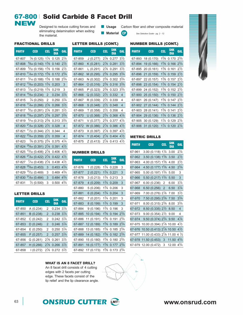
63 ONSRUD CUTTER www.onsrud.com
PART# CED CEL SHK OALDIA
67-807 1⁄8 (0.125) 11⁄4 0.125 21⁄4
67-808 9⁄64 (0.140) 13⁄8 0.140 21⁄2
67-809 5⁄32 (0.156) 13⁄8 0.156 21⁄2
67-810 11⁄64 (0.172) 15⁄8 0.172 23⁄4
67-811 3⁄16 (0.188) 15⁄8 0.188 23⁄4
67-812 13⁄64 (0.203) 13⁄4 0.203 3
67-813 7⁄32 (0.219) 13⁄4 0.219 3
67-814 15⁄64 (0.234) 2 0.234 31⁄4
67-815 1⁄4 (0.250) 2 0.250 31⁄4
67-816 17⁄64 (0.266) 21⁄8 0.266 31⁄2
67-817 9⁄32 (0.281) 21⁄8 0.281 31⁄2
67-818 19⁄64 (0.297) 23⁄8 0.297 33⁄4
67-819 5⁄16 (0.313) 23⁄8 0.313 33⁄4
67-820 21⁄64 (0.328) 21⁄2 0.328 4
67-821 11⁄32 (0.344) 21⁄2 0.344 4
67-822 23⁄64 (0.359) 21⁄2 0.359 4
67-823 3⁄8 (0.375) 23⁄4 0.375 41⁄4
67-824 25⁄64 (0.391) 27⁄8 0.391 41⁄2
67-825 13⁄32 (0.406) 27⁄8 0.406 41⁄2
67-826 27⁄64 (0.422) 27⁄8 0.422 41⁄2
67-827 7⁄16 (0.438) 27⁄8 0.438 41⁄2
67-828 29⁄64 (0.453) 3 0.453 43⁄4
67-829 15⁄32 (0.469) 3 0.469 43⁄4
67-830 31⁄64 (0.484) 3 0.484 43⁄4
67-831 1⁄2 (0.500) 3 0.500 43⁄4
67-800 Solid Carbide 8 Facet DrillNEW
Designed to reduce cutting forces andeliminating delamination when exitingthe material.
■ Usage Carbon fiber and other composite material
■ Material See Selection Guide - pg. 2 - 12
FRACTIONAL DRILLS
PART# CED CEL SHK OALDIA
67-859 J (0.277) 21⁄8 0.277 31⁄2
67-860 K (0.281) 21⁄8 0.281 31⁄2
67-861 L (0.291) 21⁄8 0.291 31⁄2
67-862 M (0.295) 23⁄8 0.295 33⁄4
67-863 N (0.302) 23⁄8 0.302 33⁄4
67-864 O (0.316) 23⁄8 0.316 33⁄4
67-865 P (0.323) 23⁄8 0.323 33⁄4
67-866 Q (0.332) 21⁄2 0.332 4
67-867 R (0.339) 21⁄2 0.339 4
67-868 S (0.348) 21⁄2 0.348 4
67-869 T (0.358) 21⁄2 0.358 4
67-870 U (0.368) 23⁄4 0.368 41⁄4
67-871 V (0.377) 23⁄4 0.377 41⁄4
67-872 W (0.386) 27⁄8 0.386 41⁄2
67-873 X (0.397) 27⁄8 0.397 41⁄2
67-874 Y (0.404) 27⁄8 0.404 41⁄2
67-875 Z (0.413) 27⁄8 0.413 41⁄2
LETTER DRILLS (CONT.)
PART# CED CEL SHK OALDIA
67-850 A (0.234) 2 0.234 31⁄4
67-851 B (0.238) 2 0.238 31⁄4
67-852 C (0.242) 2 0.242 31⁄4
67-853 D (0.246) 2 0.246 31⁄4
67-854 E (0.250) 2 0.250 31⁄4
67-855 F (0.257) 2 0.257 31⁄4
67-856 G (0.261) 21⁄8 0.261 31⁄2
67-857 H (0.266) 21⁄8 0.266 31⁄2
67-858 I (0.272) 21⁄8 0.272 31⁄2
LETTER DRILLS
PART# CED CEL SHK OALDIA
67-876 1 (0.228) 13⁄4 0.228 3
67-877 2 (0.221) 13⁄4 0.221 3
67-878 3 (0.213) 13⁄4 0.213 3
67-879 4 (0.209) 13⁄4 0.209 3
67-880 5 (0.206) 13⁄4 0.206 3
67-881 6 (0.204) 13⁄4 0.204 3
67-882 7 (0.201) 13⁄4 0.201 3
67-883 8 (0.199) 13⁄4 0.199 3
67-884 9 (0.196) 13⁄4 0.196 3
67-885 10 (0.194) 15⁄8 0.194 23⁄4
67-886 11 (0.191) 15⁄8 0.191 23⁄4
67-887 12 (0.189) 15⁄8 0.189 23⁄4
67-888 13 (0.185) 15⁄8 0.185 23⁄4
67-889 14 (0.182) 15⁄8 0.182 23⁄4
67-890 15 (0.180) 15⁄8 0.180 23⁄4
67-891 16 (0.177) 15⁄8 0.177 23⁄4
67-892 17 (0.173) 15⁄8 0.173 23⁄4
NUMBER DRILLS
PART# CED CEL SHK OALDIA
67-961 3.00 (0.118) 11⁄4 3.00 21⁄4
67-962 3.50 (0.138) 13⁄8 3.50 21⁄2
67-963 4.00 (0.157) 13⁄8 4.00 21⁄2
67-964 4.50 (0.177) 15⁄8 4.50 23⁄4
67-965 5.00 (0.197) 13⁄4 5.00 3
67-966 5.50 (0.217) 13⁄4 5.50 3
67-967 6.00 (0.236) 2 6.00 31⁄4
67-968 6.50 (0.256) 2 6.50 31⁄4
67-969 7.00 (0.276) 21⁄8 7.00 31⁄2
67-970 7.50 (0.295) 23⁄8 7.50 33⁄4
67-971 8.00 (0.315) 23⁄8 8.00 33⁄4
67-972 8.50 (0.335) 21⁄2 8.50 4
67-973 9.00 (0.354) 21⁄2 9.00 4
67-974 9.50 (0.374) 23⁄4 9.50 41⁄4
67-975 10.00 (0.394) 27⁄8 10.00 41⁄2
67-976 10.50 (0.413) 27⁄8 10.50 41⁄2
67-977 11.00 (0.433) 27⁄8 11.00 4 1⁄2
67-978 11.50 (0.453) 3 11.50 43⁄4
67-979 12.00 (0.472) 3 12.00 43⁄4
METRIC DRILLS
PART# CED CEL SHK OALDIA
67-893 18 (0.170) 15⁄8 0.170 23⁄4
67-894 19 (0.166) 15⁄8 0.166 23⁄4
67-895 20 (0.161) 13⁄8 0.161 21⁄2
67-896 21 (0.159) 13⁄8 0.159 21⁄2
67-897 22 (0.157) 13⁄8 0.157 21⁄2
67-898 23 (0.154) 13⁄8 0.154 21⁄2
67-899 24 (0.152) 13⁄8 0.152 21⁄2
67-900 25 (0.150) 13⁄8 0.150 21⁄2
67-901 26 (0.147) 13⁄8 0.147 21⁄2
67-902 27 (0.144) 13⁄8 0.144 21⁄2
67-903 28 (0.141) 13⁄8 0.141 21⁄2
67-904 29 (0.136) 13⁄8 0.136 21⁄2
67-905 30 (0.129) 11⁄4 0.129 21⁄4
67-906 31 (0.120) 11⁄4 0.120 21⁄4
NUMBER DRILLS (CONT.)
CP
X∞
X∞WHAT IS AN 8 FACET DRILL?An 8 facet drill consists of 4 cuttingedges with 2 facets per cuttingedge. These facets consist of thelip relief and the lip clearance angle.

www.plasticrouting.com ONSRUD CUTTER 64
■ Usage Composite panels and fiberglass
■ Material See Selection Guide - pg. 2 - 12
68-000 Double Edge - PCD TippedTooling
Designed for use in abrasivematerials where cut quality andtool life are important.
PART # CED CEL SHK DIA OAL
68-050 1⁄4 3⁄4 1⁄4 3
68-055 3⁄8 7⁄8 3⁄8 3
68-062 1⁄2 11⁄4 1⁄2 4
68-070 3⁄4 11⁄4 3⁄4 4
68-072 3⁄4 11⁄4 3⁄4 4Down Shear
PART # CED CEL SHK DIA OAL
68-005 1⁄4 3⁄4 1⁄4 3
68-010 3⁄8 3⁄4 3⁄8 3
68-020 1⁄2 3⁄4 1⁄2 4
68-030 3⁄4 1 3⁄4 4
HELIX ANGLE ≈ 0-3°
PCD TIPPED PCD FULL FACE
PCD TIPPED PCD FULL FACE
CP
68-100 Single Edge - PCD Compression ToolNEW
This economical PCD compression toolwill provide long tool life in abrasive woodproducts. The tools have a mortise tipallowing for through cuts and dado’sto be produced using one tool. Thecompression design ensures chip freeedges on the top and bottom.
■ Usage Composite wood
■ Material See Selection Guide - pg. 2 - 12
PART# CED CEL UPCUT SHANK OAL FLUTESCEL
68-104L* 5⁄8 1 0.200 5⁄8 31⁄2 1
68-110 5⁄8 15⁄8 0.200 5⁄8 4 1
68-110L* 5⁄8 15⁄8 0.200 5⁄8 4 1
68-106 3⁄4 1 0.200 3⁄4 4 1
68-106L* 3⁄4 1 0.200 3⁄4 4 1
68-112 3⁄4 15⁄8 0.200 3⁄4 4 1
68-112L* 3⁄4 15⁄8 0.200 3⁄4 4 1
L = Left Hand Rotation* = Tools are not stocked and must be special ordered. Approximately 4 week lead time.
CW
PART# CED CEL UPCUT SHANK OAL FLUTESCEL
68-101 3⁄8 1 0.188 3⁄8 3 1
68-101L 3⁄8 1 0.188 3⁄8 3 1
68-100 3⁄8 1 0.188 1⁄2 3 1
68-100L 3⁄8 1 0.188 1⁄2 3 1
68-102 1⁄2 1 0.200 1⁄2 3 1
68-102L 1⁄2 1 0.200 1⁄2 3 1
68-104 5⁄8 1 0.200 5⁄8 31⁄2 1
68-200 Double Edge - PCD SERF™ CutterNEW
This tool is designed to act like arougher and finishing tool in one. Theunique geometry reduces the cuttingforces resulting in longer tool life,higher feed rates and reduced noise.
■ Usage Composites
■ Material See Selection Guide - pg. 2 - 12CP
PART # CED CEL SHK DIA OAL
68-210 1⁄4 3⁄8 1⁄4 3
68-213 1⁄4 3⁄4 1⁄4 3
68-216 1⁄4 1 1⁄4 31⁄2
68-220 3⁄8 3⁄8 3⁄8 3
68-223 3⁄8 3⁄4 3⁄8 3
PART # CED CEL SHK DIA OAL
68-226 3⁄8 1 3⁄8 31⁄2
68-230 1⁄2 3⁄4 1⁄2 4
68-233 1⁄2 1 1⁄2 4
68-236 1⁄2 11⁄4 1⁄2 4
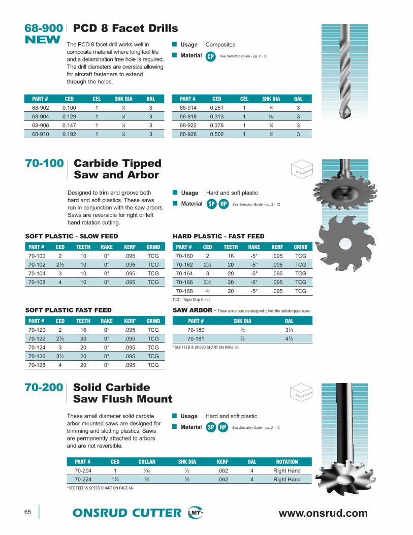
65 ONSRUD CUTTER www.onsrud.com
68-900 PCD 8 Facet DrillsNEW The PCD 8 facet drill works well in
composite material where long tool lifeand a delamination free hole is required.The drill diameters are oversize allowingfor aircraft fasteners to extendthrough the holes.
■ Usage Composites
■ Material See Selection Guide - pg. 2 - 12
PART # CED CEL SHK DIA OAL
68-902 0.100 1 1⁄4 3
68-904 0.129 1 1⁄4 3
68-908 0.147 1 1⁄4 3
68-910 0.192 1 1⁄4 3
PART # CED CEL SHK DIA OAL
68-914 0.251 1 1⁄4 3
68-918 0.313 1 5⁄16 3
68-922 0.376 1 3⁄8 3
68-926 0.502 1 1⁄2 3
CP
70-100 Carbide TippedSaw and Arbor
Designed to trim and groove bothhard and soft plastics. These sawsrun in conjunction with the saw arbors.Saws are reversible for right or lefthand rotation cutting.
■ Usage Hard and soft plastic
■ Material See Selection Guide - pg. 2 - 12
PART # CED TEETH RAKE KERF GRIND
70-100 2 10 0° .095 TCG
70-102 21⁄2 10 0° .095 TCG
70-104 3 10 0° .095 TCG
70-108 4 10 0° .095 TCG
PART # CED TEETH RAKE KERF GRIND
70-120 2 16 0° .095 TCG
70-122 21⁄2 20 0° .095 TCG
70-124 3 20 0° .095 TCG
70-126 31⁄2 20 0° .095 TCG
70-128 4 20 0° .095 TCG
PART # CED TEETH RAKE KERF GRIND
70-160 2 16 -5° .095 TCG
70-162 21⁄2 20 -5° .095 TCG
70-164 3 20 -5° .095 TCG
70-166 31⁄2 20 -5° .095 TCG
70-168 4 20 -5° .095 TCG
TCG = Triple Chip Grind
SOFT PLASTIC - SLOW FEED HARD PLASTIC - FAST FEED
SOFT PLASTIC FAST FEED
PART # SHK DIA OAL
70-180 1⁄2 31⁄4
70-181 1⁄2 41⁄2
*SEE FEED & SPEED CHART ON PAGE 66.
SAW ARBOR - These saw arbors are designed to hold the carbide tipped saws.
SP HP
70-200 Solid CarbideSaw Flush Mount
These small diameter solid carbidearbor mounted saws are designed fortrimming and slotting plastics. Sawsare permanently attached to arborsand are not reversible.
■ Usage Hard and soft plastic
■ Material See Selection Guide - pg. 2 - 12
PART # CED COLLAR SHK DIA KERF OAL ROTATION
70-204 1 9⁄16 1⁄2 .062 4 Right Hand
70-224 11⁄4 5⁄8 1⁄2 .062 4 Right Hand
*SEE FEED & SPEED CHART ON PAGE 66.
SP HP
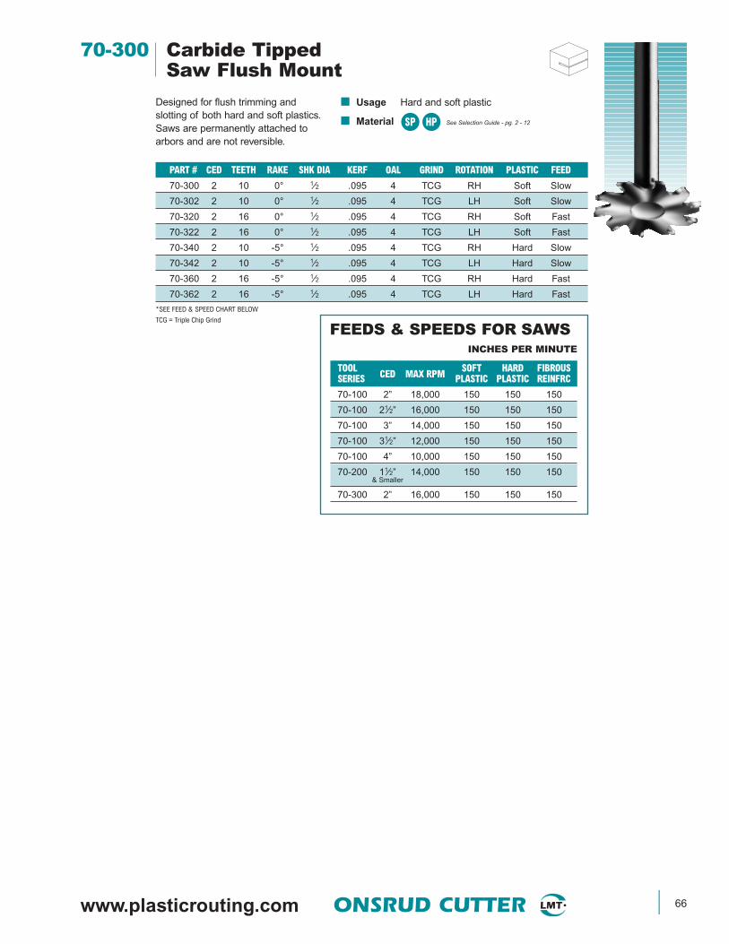
www.plasticrouting.com ONSRUD CUTTER 66
70-300 Carbide TippedSaw Flush Mount
Designed for flush trimming andslotting of both hard and soft plastics.Saws are permanently attached toarbors and are not reversible.
■ Usage Hard and soft plastic
■ Material See Selection Guide - pg. 2 - 12
PART # CED TEETH RAKE SHK DIA KERF OAL GRIND ROTATION PLASTIC FEED
70-300 2 10 0° 1⁄2 .095 4 TCG RH Soft Slow
70-302 2 10 0° 1⁄2 .095 4 TCG LH Soft Slow
70-320 2 16 0° 1⁄2 .095 4 TCG RH Soft Fast
70-322 2 16 0° 1⁄2 .095 4 TCG LH Soft Fast
70-340 2 10 -5° 1⁄2 .095 4 TCG RH Hard Slow
70-342 2 10 -5° 1⁄2 .095 4 TCG LH Hard Slow
70-360 2 16 -5° 1⁄2 .095 4 TCG RH Hard Fast
70-362 2 16 -5° 1⁄2 .095 4 TCG LH Hard Fast
*SEE FEED & SPEED CHART BELOW
TCG = Triple Chip Grind
TOOL CED MAX RPM SOFT HARD FIBROUSSERIES PLASTIC PLASTIC REINFRC
70-100 2” 18,000 150 150 150
70-100 21⁄2” 16,000 150 150 150
70-100 3” 14,000 150 150 150
70-100 31⁄2” 12,000 150 150 150
70-100 4” 10,000 150 150 150
70-200 11⁄2” 14,000 150 150 150& Smaller
70-300 2” 16,000 150 150 150
INCHES PER MINUTE
FEEDS & SPEEDS FOR SAWS
SP HP
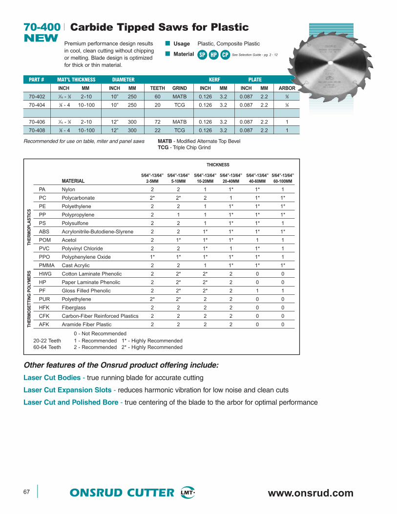
67 ONSRUD CUTTER www.onsrud.com
70-400 Carbide Tipped Saws for PlasticNEW
Premium performance design resultsin cool, clean cutting without chippingor melting. Blade design is optimizedfor thick or thin material.
■ Usage Plastic, Composite Plastic
■ Material See Selection Guide - pg. 2 - 12SP
PART # MAT’L THICKNESS DIAMETER KERF PLATE
INCH MM INCH MM TEETH GRIND INCH MM INCH MM ARBOR
70-402 1⁄16 - 3⁄8 2-10 10” 250 60 MATB 0.126 3.2 0.087 2.2 5⁄8
70-404 3⁄8 - 4 10-100 10” 250 20 TCG 0.126 3.2 0.087 2.2 5⁄8
70-406 1⁄16 - 3⁄8 2-10 12” 300 72 MATB 0.126 3.2 0.087 2.2 1
70-408 3⁄8 - 4 10-100 12” 300 22 TCG 0.126 3.2 0.087 2.2 1
PART # MAT’L THICKNESS DIAMETER KERF PLATE
5/64”-13/64” 5/64”-13/64” 5/64”-13/64” 5/64”-13/64” 5/64”-13/64” 5/64”-13/64”MATERIAL 2-5MM 5-10MM 10-20MM 20-40MM 40-60MM 60-100MM
PA Nylon 2 2 1 1* 1* 1
PC Polycarbonate 2* 2* 2 1 1* 1*
PE Polyethylene 2 2 1 1* 1* 1*
PP Polypropylene 2 1 1 1* 1* 1*
PS Polysulfone 2 2 1 1* 1* 1
ABS Acrylonitrile-Butodiene-Slyrene 2 2 1* 1* 1* 1*
POM Acetol 2 1* 1* 1* 1 1
PVC Polyvinyl Chloride 2 2 1* 1 1* 1
PPO Polyphenylene Oxide 1* 1* 1* 1* 1* 1
PMMA Cast Acrylic 2 2 1 1* 1* 1*
HWG Cotton Laminate Phenolic 2 2* 2* 2 0 0
HP Paper Laminate Phenolic 2 2* 2* 2 0 0
PF Gloss Filled Phenolic 2 2* 2* 2 1 1
PUR Polyethylene 2* 2* 2 2 0 0
HFK Fiberglass 2 2 2 2 0 0
CFK Carbon-Fiber Reinforced Plastics 2 2 2 2 0 0
AFK Aramide Fiber Plastic 2 2 2 2 0 0
0 - Not Recommended20-22 Teeth 1 - Recommended 1* - Highly Recommended60-64 Teeth 2 - Recommended 2* - Highly Recommended
HP CP
Other features of the Onsrud product offering include:
Laser Cut Bodies - true running blade for accurate cutting
Laser Cut Expansion Slots - reduces harmonic vibration for low noise and clean cuts
Laser Cut and Polished Bore - true centering of the blade to the arbor for optimal performance
Recommended for use on table, miter and panel saws MATB - Modified Alternate Top BevelTCG - Triple Chip Grind
THICKNESS
THE
RM
OP
LAS
TIC
STH
ER
MO
SE
TTIN
G P
OLY
ME
RS

www.plasticrouting.com ONSRUD CUTTER 68
70-500 HSS Plastic DrillNEW
Designed to produce holes in hard andsoft plastic while eliminating edgechipping and chip wrapping.
■ Usage Hard and soft plastic
■ Material See Selection Guide - pg. 2 - 12
FRACTIONAL DRILLS
SP HP
FRAC. DRILLS (CONT.)
LETTER DRILLS
WIRE DRILLS (CONT.)
PART# CED CEL SHK OALDIA70-643 14 (0.182) 23⁄16 0.182 33⁄870-644 15 (0.180) 23⁄16 0.180 33⁄870-645 16 (0.177) 23⁄16 0.177 33⁄870-646 17 (0.173) 23⁄16 0.173 33⁄870-647 18 (0.170) 21⁄8 0.170 31⁄470-648 19 (0.166) 21⁄8 0.166 31⁄470-649 20 (0.161) 21⁄8 0.161 31⁄470-650 21 (0.159) 21⁄8 0.159 31⁄470-651 22 (0.157) 2 0.157 31⁄870-652 23 (0.154) 2 0.154 31⁄870-653 24 (0.152) 2 0.152 31⁄870-654 25 (0.150) 17⁄8 0.150 370-655 26 (0.147) 17⁄8 0.147 370-656 27 (0.144) 17⁄8 0.144 370-657 28 (0.141) 13⁄4 0.141 27⁄870-658 29 (0.136) 13⁄4 0.136 27⁄870-659 30 (0.129) 15⁄8 0.129 23⁄470-660 31 (0.120) 15⁄8 0.120 23⁄4
PART# CED CEL SHK OALDIA70-600 A (0.234) 25⁄8 0.234 37⁄870-601 B (0.238) 23⁄4 0.238 470-602 C (0.242) 23⁄4 0.242 470-603 D (0.246) 23⁄4 0.246 470-604 E (0.250) 23⁄4 0.250 470-605 F (0.257) 27⁄8 0.257 41⁄870-606 G (0.261) 27⁄8 0.261 41⁄870-607 H (0.266) 27⁄8 0.266 41⁄870-608 I (0.272) 27⁄8 0.272 41⁄870-609 J (0.277) 27⁄8 0.277 41⁄870-610 K (0.281) 215⁄16 0.281 41⁄470-611 L (0.291) 215⁄16 0.291 41⁄470-612 M (0.295) 31⁄16 0.295 43⁄870-613 N (0.302) 31⁄16 0.302 43⁄870-614 O (0.316) 33⁄16 0.316 41⁄270-615 P (0.323) 35⁄16 0.323 45⁄870-616 Q (0.332) 37⁄16 0.332 43⁄470-617 R (0.339) 37⁄16 0.339 43⁄470-618 S (0.348) 31⁄2 0.348 47⁄870-619 T (0.358) 3 1⁄2 0.358 47⁄870-620 U (0.368) 35⁄8 0.368 570-621 V (0.377) 35⁄8 0.377 570-622 W (0.386) 33⁄4 0.386 51⁄870-623 X (0.397) 33⁄4 0.397 51⁄870-624 Y (0.404) 37⁄8 0.404 51⁄470-625 Z (0.413) 315⁄16 0.413 51⁄4
PART# CED CEL SHK OALDIA70-561 61⁄64 (0.953) 31⁄8 1⁄2 670-562 31⁄32 (0.969) 31⁄8 1⁄2 670-563 63⁄64 (0.984) 31⁄8 1⁄2 6
PART# CED CEL SHK OALDIA70-502 1⁄8 (0.125) 11⁄2 1⁄8 23⁄470-503 9⁄64 (0.141) 13⁄4 9⁄64 27⁄870-506 5⁄32 (0.156) 115⁄16 5⁄32 31⁄870-509 11⁄64 (0.172) 13⁄4 11⁄64 31⁄470-510 3⁄16 (0.188) 21⁄8 3⁄16 31⁄270-511 13⁄64 (0.203) 27⁄16 13⁄64 35⁄870-512 7⁄32 (0.219) 21⁄2 7⁄32 33⁄470-513 15⁄64 (0.234) 25⁄8 15⁄64 37⁄870-514 1⁄4 (0.250) 27⁄16 1⁄4 470-515 17⁄64 (0.266) 27⁄8 17⁄64 41⁄870-516 9⁄32 (0.281) 215⁄16 9⁄32 41⁄470-517 19⁄64 (0.297) 31⁄16 19⁄64 43⁄870-520 5⁄16 (0.313) 13⁄4 1⁄4 31⁄870-521 21⁄64 (0.328) 35⁄16 21⁄64 45⁄870-522 11⁄32 (0.344) 37⁄16 11⁄32 43⁄470-523 23⁄64 (0.359) 31⁄2 23⁄64 47⁄870-524 3⁄8 (0.375) 21⁄4 1⁄4 43⁄870-525 25⁄64 (0.391) 33⁄4 25⁄64 51⁄870-526 13⁄32 (0.406) 37⁄8 13⁄32 51⁄870-527 27⁄64 (0.422) 315⁄16 27⁄64 53⁄870-528 7⁄16 (0.438) 21⁄2 1⁄4 43⁄470-529 29⁄64 (0.453) 43⁄16 29⁄64 55⁄870-530 15⁄32 (0.469) 45⁄16 15⁄32 53⁄470-531 31⁄64 (0.484) 43⁄8 31⁄64 57⁄870-532 1⁄2 (0.500) 25⁄8 1⁄4 51⁄870-533 33⁄64 (0.516) 31⁄8 1⁄2 670-534 17⁄32 (0.531) 31⁄8 1⁄2 670-535 35⁄64 (0.547) 31⁄8 1⁄2 670-536 9⁄16 (0.563) 31⁄8 1⁄2 670-537 37⁄64 (0.578) 31⁄8 1⁄2 670-538 19⁄32 (0.594) 31⁄8 1⁄2 670-539 39⁄64 (0.609) 31⁄8 1⁄2 670-540 5⁄8 (0.625) 31⁄8 1⁄2 670-541 41⁄64 (0.641) 31⁄8 1⁄2 670-542 21⁄32 (0.656) 31⁄8 1⁄2 670-543 43⁄64 (0.672) 31⁄8 1⁄2 670-544 11⁄16 (0.688) 31⁄8 1⁄2 670-545 45⁄64 (0.703) 31⁄8 1⁄2 670-546 23⁄32 (0.719) 31⁄8 1⁄2 670-547 47⁄64 (0.734) 31⁄8 1⁄2 670-548 3⁄4 (0.750) 31⁄8 1⁄2 670-549 49⁄64 (0.766) 31⁄8 1⁄2 670-550 25⁄32 (0.781) 31⁄8 1⁄2 670-551 51⁄64 (0.797) 31⁄8 1⁄2 670-552 13⁄16 (0.813) 31⁄8 1⁄2 670-553 53⁄64 (0.828) 31⁄8 1⁄2 670-554 27⁄32 (0.844) 31⁄8 1⁄2 670-555 55⁄64 (0.859) 31⁄8 1⁄2 670-556 7⁄8 (0.875) 31⁄8 1⁄2 670-557 57⁄64 (0.891) 31⁄8 1⁄2 670-558 29⁄32 (0.906) 31⁄8 1⁄2 670-559 59⁄64 (0.922) 31⁄8 1⁄2 670-560 15⁄16 (0.938) 31⁄8 1⁄2 6
WIRE DRILLS
PART# CED CEL SHK OALDIA70-630 1 (0.228) 25⁄8 0.228 37⁄870-631 2 (0.221) 25⁄8 0.221 37⁄870-632 3 (0.213) 21⁄2 0.213 33⁄470-633 4 (0.209) 21⁄2 0.209 33⁄470-634 5 (0.206) 21⁄2 0.206 33⁄470-635 6 (0.204) 21⁄2 0.204 33⁄470-636 7 (0.201) 27⁄16 0.201 35⁄870-637 8 (0.199) 27⁄16 0.199 35⁄870-638 9 (0.196) 27⁄16 0.196 35⁄870-639 10 (0.194) 27⁄16 0.194 35⁄870-640 11 (0.191) 25⁄16 0.191 31⁄270-641 12 (0.189) 25⁄16 0.189 31⁄270-642 13 (0.185) 25⁄16 0.185 31⁄2
METRIC DRILLS
PART# CED CEL SHK OALDIA70-714 3.00 (0.118) 41 3.00 7070-715 3.50 (0.138) 44 3.50 7370-716 4.00 (0.157) 54 4.00 8370-717 4.50 (0.177) 56 4.50 8670-718 5.00 (0.197) 62 5.00 9270-719 5.50 (0.217) 64 5.50 9570-720 6.00 (0.236) 70 6.00 10270-721 6.50 (0.256) 73 6.50 10570-722 7.00 (0.276) 73 7.00 10570-723 7.50 (0.295) 78 7.50 11170-724 8.00 (0.315) 81 8.00 11470-725 8.50 (0.335) 87 8.50 12170-726 9.00 (0.354) 89 9.00 12470-727 9.50 (0.374) 92 9.50 12770-728 10.00 (0.394) 95 10.00 13070-729 10.50 (0.413) 98 10.50 13370-730 11.00 (0.433) 103 11.00 14070-731 11.50 (0.453) 106 11.50 14370-732 12.00 (0.472) 111 12.00 14970-733 12.50 (0.492) 114 12.50 15270-734 13.00 (0.512) 114 13.00 15270-735 13.50 (0.531) 122 13.50 16870-736 14.00 (0.551) 122 14.00 16870-737 14.50 (0.571) 122 14.50 16870-738 15.00 (0.591) 132 15.00 18170-739 15.50 (0.610) 132 15.50 18170-740 16.00 (0.630) 132 16.00 18170-741 16.50 (0.650) 132 16.50 18170-742 17.00 (0.669) 143 17.00 19470-743 17.50 (0.689) 143 17.50 194
NO Wrapping
NO Cleaning
NO Melting
NO SurfaceMarring
NO InterruptedOperation
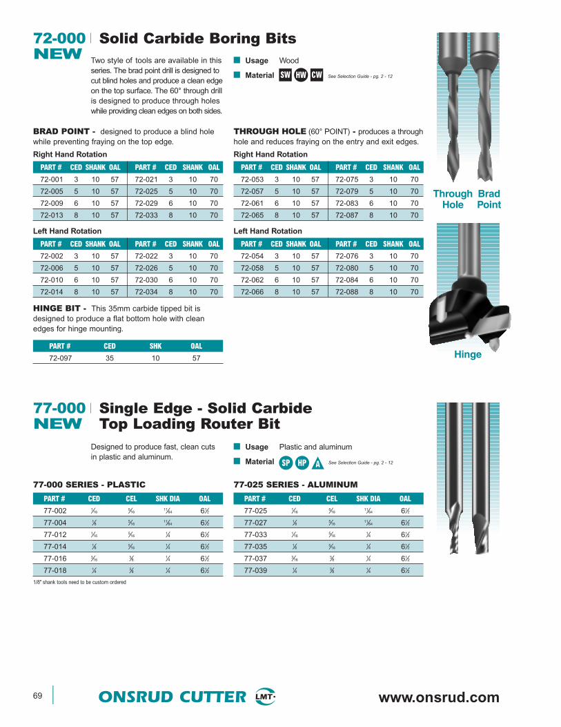
69 ONSRUD CUTTER www.onsrud.com
72-000 Solid Carbide Boring BitsNEW Two style of tools are available in this
series. The brad point drill is designed tocut blind holes and produce a clean edgeon the top surface. The 60° through drillis designed to produce through holeswhile providing clean edges on both sides.
■ Usage Wood
■ Material See Selection Guide - pg. 2 - 12
PART # CED SHANK OAL PART # CED SHANK OAL
72-001 3 10 57 72-021 3 10 70
72-005 5 10 57 72-025 5 10 70
72-009 6 10 57 72-029 6 10 70
72-013 8 10 57 72-033 8 10 70
ThroughHole
BradPoint
BRAD POINT - designed to produce a blind holewhile preventing fraying on the top edge.
HINGE BIT - This 35mm carbide tipped bit isdesigned to produce a flat bottom hole with cleanedges for hinge mounting.
Right Hand Rotation
PART # CED SHANK OAL PART # CED SHANK OAL
72-002 3 10 57 72-022 3 10 70
72-006 5 10 57 72-026 5 10 70
72-010 6 10 57 72-030 6 10 70
72-014 8 10 57 72-034 8 10 70
Left Hand Rotation
PART # CED SHANK OAL PART # CED SHANK OAL
72-053 3 10 57 72-075 3 10 70
72-057 5 10 57 72-079 5 10 70
72-061 6 10 57 72-083 6 10 70
72-065 8 10 57 72-087 8 10 70
THROUGH HOLE (60° POINT) - produces a throughhole and reduces fraying on the entry and exit edges.
Right Hand Rotation
PART # CED SHANK OAL PART # CED SHANK OAL
72-054 3 10 57 72-076 3 10 70
72-058 5 10 57 72-080 5 10 70
72-062 6 10 57 72-084 6 10 70
72-066 8 10 57 72-088 8 10 70
Left Hand Rotation
SW CWHW
PART # CED SHK OAL
72-097 35 10 57 Hinge
77-000 Single Edge - Solid CarbideNEW Top Loading Router Bit
Designed to produce fast, clean cutsin plastic and aluminum.
■ Usage Plastic and aluminum
■ Material See Selection Guide - pg. 2 - 12
77-000 SERIES - PLASTIC
PART # CED CEL SHK DIA OAL
77-002 1⁄165⁄16
11⁄64 61⁄2
77-004 1⁄8 5⁄1611⁄64 61⁄2
77-012 1⁄165⁄16
1⁄4 61⁄2
77-014 1⁄8 5⁄161⁄4 61⁄2
77-016 3⁄163⁄8 1⁄4 61⁄2
77-018 1⁄4 3⁄8 1⁄4 61⁄2
1/8" shank tools need to be custom ordered
SP HP A
77-025 SERIES - ALUMINUM
PART # CED CEL SHK DIA OAL
77-025 1⁄165⁄16
11⁄64 61⁄2
77-027 1⁄8 5⁄1611⁄64 61⁄2
77-033 1⁄165⁄16
1⁄4 61⁄2
77-035 1⁄8 5⁄161⁄4 61⁄2
77-037 3⁄163⁄8 1⁄4 61⁄2
77-039 1⁄4 3⁄8 1⁄4 61⁄2
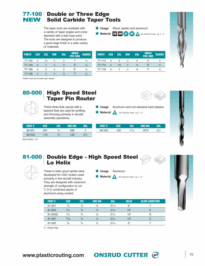
www.plasticrouting.com ONSRUD CUTTER 70
77-100 Double or Three EdgeNEW Solid Carbide Taper Tools
The taper tools are available with a variety of taper angles and come standard with a ball nose point.The tools are designed to produce a good edge finish in a wide variety of materials.
■ Usage Wood, plastic and aluminum
■ Material See Selection Guide - pg. 2 - 12SW HW SP HP A
PART# CED CEL SHK OAL ANGLE RADIUSPER SIDE
77-102 1⁄8 11⁄2 1⁄4 3 1° 1⁄16
77-104 1⁄8 1 1⁄4 3 3° 1⁄16
77-106 1⁄8 3⁄4 1⁄4 3 5° 1⁄16
77-108 1⁄8 1⁄2 1⁄4 3 7° 1⁄16
Custom tools can be made upon request
PART# CED CEL SHK OAL ANGLE RADIUSPER SIDE
77-112 1⁄4 2 1⁄2 4 3° 1⁄8
77-114 1⁄4 13⁄8 1⁄2 4 5° 1⁄8
77-116 1⁄4 1 1⁄2 4 7° 1⁄8
PART # CED CEL SHK DIA OAL
80-003 .165 11⁄16 .1875 21⁄2
80-000 High Speed SteelTaper Pin Router
These three flute upcuts with atapered flute are used for profilingand trimming primarily in aircraftassembly operations.
■ Usage Aluminum and non-abrasive hard plastics
■ Material See Selection Guide - pg. 2 - 12
PART # CED CEL SHK DIA OAL
80-001 .081 3⁄4 .098 2
80-002 .110 7⁄8 .128 21⁄4
HELIX ANGLE ≈ 24°
81-000 Double Edge - High Speed SteelLo Helix
These lo helix upcut spirals weredeveloped for CNC routers usedprimarily in the aircraft industry.They are designed with maximumstrength of configuration to cutT, O or combined stacks ofaluminum-using coolant.
■ Usage Aluminum
■ Material See Selection Guide - pg. 2 - 12
PART # CED CEL SHK DIA OAL HELIX ALUM CONDITION
81-001 1⁄4 3⁄4 1⁄2 31⁄16 5° T
81-003 5⁄16 3⁄4 1⁄2 31⁄16 10° C
81-004S 5⁄16 3⁄4 1⁄2 31⁄16 10° O
81-007 21⁄64 3⁄4 1⁄2 31⁄16 10° C
81-005 3⁄8 3⁄4 1⁄2 31⁄16 5° T
S = Single Edge
A
A

71 ONSRUD CUTTER www.onsrud.com
Designed for reduced vibrationproducing smoother finish cuts.Extended reach during side thinningand gage reduction. Longer tool lifeto reduce tool changes.
■ Usage Extrusion and sheet aluminum. Optimizedfor use on multi-head extrusion mills CNCmills and routers
■ Material See Selection Guide - pg. 2 - 12
PART # CED CEL ERL SHK DIA OAL HELIX & DIR FLUTES CNR RAD ALUMINUM MACH ENVCHAMFER CONDITION
Tolerance +.002 ±.03 +.0000 ±.03
81-103 5⁄16 13⁄16 - 1⁄2 3 10° RH 2 .02 x 45° C Wet
81-111 21⁄64 3⁄4 - 1⁄2 3 10° RH 2 .02 x 45° C Wet
81-104 3⁄8 13⁄16 - 1⁄2 3 10° RH 2 .02 x 45° O Wet
81-106 1⁄2 1 - 1⁄2 31⁄2 3° RH 2 .02 x 45° O Wet
81-108 5⁄8 1 - 5⁄8 31⁄2 3° RH 2 .02 x 45° C Wet
UPCUT
-.0005
81-100 Solid Carbide Spiral ExtrusionCutters
A
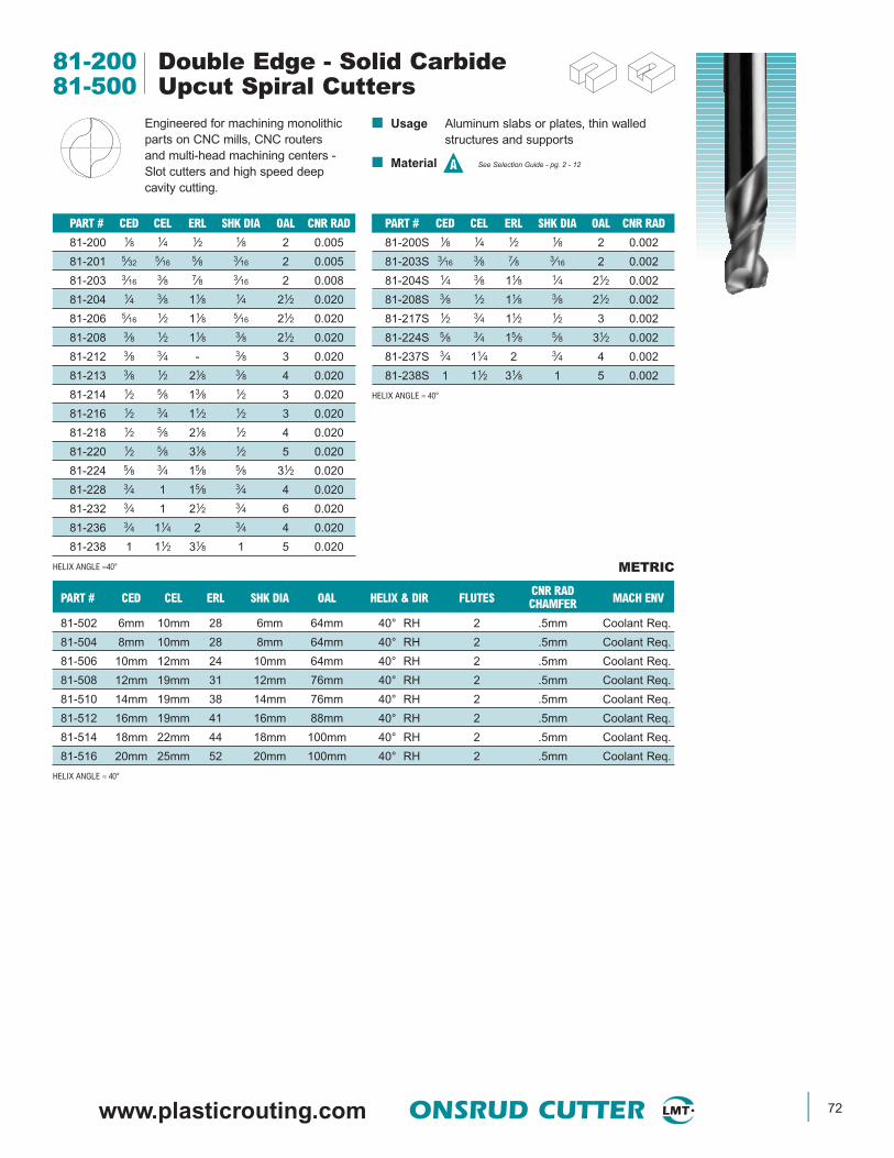
www.plasticrouting.com ONSRUD CUTTER 72
81-200 Double Edge - Solid Carbide81-500 Upcut Spiral Cutters
Engineered for machining monolithicparts on CNC mills, CNC routersand multi-head machining centers -Slot cutters and high speed deepcavity cutting.
■ Usage Aluminum slabs or plates, thin walledstructures and supports
■ Material See Selection Guide - pg. 2 - 12
PART # CED CEL ERL SHK DIA OAL HELIX & DIR FLUTES CNR RAD MACH ENVCHAMFER
81-502 6mm 10mm 28 6mm 64mm 40° RH 2 .5mm Coolant Req.
81-504 8mm 10mm 28 8mm 64mm 40° RH 2 .5mm Coolant Req.
81-506 10mm 12mm 24 10mm 64mm 40° RH 2 .5mm Coolant Req.
81-508 12mm 19mm 31 12mm 76mm 40° RH 2 .5mm Coolant Req.
81-510 14mm 19mm 38 14mm 76mm 40° RH 2 .5mm Coolant Req.
81-512 16mm 19mm 41 16mm 88mm 40° RH 2 .5mm Coolant Req.
81-514 18mm 22mm 44 18mm 100mm 40° RH 2 .5mm Coolant Req.
81-516 20mm 25mm 52 20mm 100mm 40° RH 2 .5mm Coolant Req.
HELIX ANGLE ≈ 40°
METRIC
PART # CED CEL ERL SHK DIA OAL CNR RAD
81-200S 1⁄8 1⁄4 1⁄2 1⁄8 2 0.002
81-203S 3⁄16 3⁄8 7⁄8 3⁄16 2 0.002
81-204S 1⁄4 3⁄8 11⁄8 1⁄4 21⁄2 0.002
81-208S 3⁄8 1⁄2 11⁄8 3⁄8 21⁄2 0.002
81-217S 1⁄2 3⁄4 11⁄2 1⁄2 3 0.002
81-224S 5⁄8 3⁄4 15⁄8 5⁄8 31⁄2 0.002
81-237S 3⁄4 11⁄4 2 3⁄4 4 0.002
81-238S 1 11⁄2 31⁄8 1 5 0.002
HELIX ANGLE ≈ 40°
PART # CED CEL ERL SHK DIA OAL CNR RAD
81-200 1⁄8 1⁄4 1⁄2 1⁄8 2 0.005
81-201 5⁄32 5⁄16 5⁄8 3⁄16 2 0.005
81-203 3⁄16 3⁄8 7⁄8 3⁄16 2 0.008
81-204 1⁄4 3⁄8 11⁄8 1⁄4 21⁄2 0.020
81-206 5⁄16 1⁄2 11⁄8 5⁄16 21⁄2 0.020
81-208 3⁄8 1⁄2 11⁄8 3⁄8 21⁄2 0.020
81-212 3⁄8 3⁄4 - 3⁄8 3 0.020
81-213 3⁄8 1⁄2 21⁄8 3⁄8 4 0.020
81-214 1⁄2 5⁄8 13⁄8 1⁄2 3 0.020
81-216 1⁄2 3⁄4 11⁄2 1⁄2 3 0.020
81-218 1⁄2 5⁄8 21⁄8 1⁄2 4 0.020
81-220 1⁄2 5⁄8 31⁄8 1⁄2 5 0.020
81-224 5⁄8 3⁄4 15⁄8 5⁄8 31⁄2 0.020
81-228 3⁄4 1 15⁄8 3⁄4 4 0.020
81-232 3⁄4 1 21⁄2 3⁄4 6 0.020
81-236 3⁄4 11⁄4 2 3⁄4 4 0.020
81-238 1 11⁄2 31⁄8 1 5 0.020
HELIX ANGLE ≈40°
A
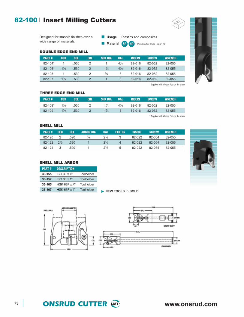
73 ONSRUD CUTTER www.onsrud.com
■ Usage Plastics and composites
■ Material See Selection Guide - pg. 2 - 12
82-100 Insert Milling Cutters
Designed for smooth finishes over awide range of materials.
DOUBLE EDGE END MILL
THREE EDGE END MILL
PART # CED CEL ARBOR DIA OAL FLUTES INSERT SCREW WRENCH
82-120 2 .590 3⁄4 21⁄8 3 82-022 82-054 82-055
82-122 21⁄2 .590 1 21⁄8 4 82-022 82-054 82-055
82-124 3 .590 1 21⁄8 5 82-022 82-054 82-055
SHELL MILL
PART # CED CEL ERL SHK DIA OAL INSERT SCREW WRENCH
82-104* 1 .530 2 1 41⁄4 82-016 82-052 82-055
82-106* 11⁄4 .530 2 11⁄4 41⁄4 82-016 82-052 82-055
82-105 1 .530 2 3⁄4 8 82-016 82-052 82-055
82-107 11⁄4 .530 2 1 8 82-016 82-052 82-055
* Supplied with Weldon Flats on the shank
PART # CED CEL ERL SHK DIA OAL INSERT SCREW WRENCH
82-108* 11⁄2 .530 2 11⁄4 47⁄8 82-016 82-052 82-055
82-109 11⁄2 .530 2 11⁄4 8 82-016 82-052 82-055
* Supplied with Weldon Flats on the shank
SP HP
PART # DESCRIPTION
33-155 ISO 30 x 3⁄4" Toolholder
33-157 ISO 30 x 1" Toolholder
33-165 HSK 63F x 3⁄4" Toolholder
33-167 HSK 63F x 1" Toolholder
SHELL MILL ARBOR
NEW TOOLS in BOLD
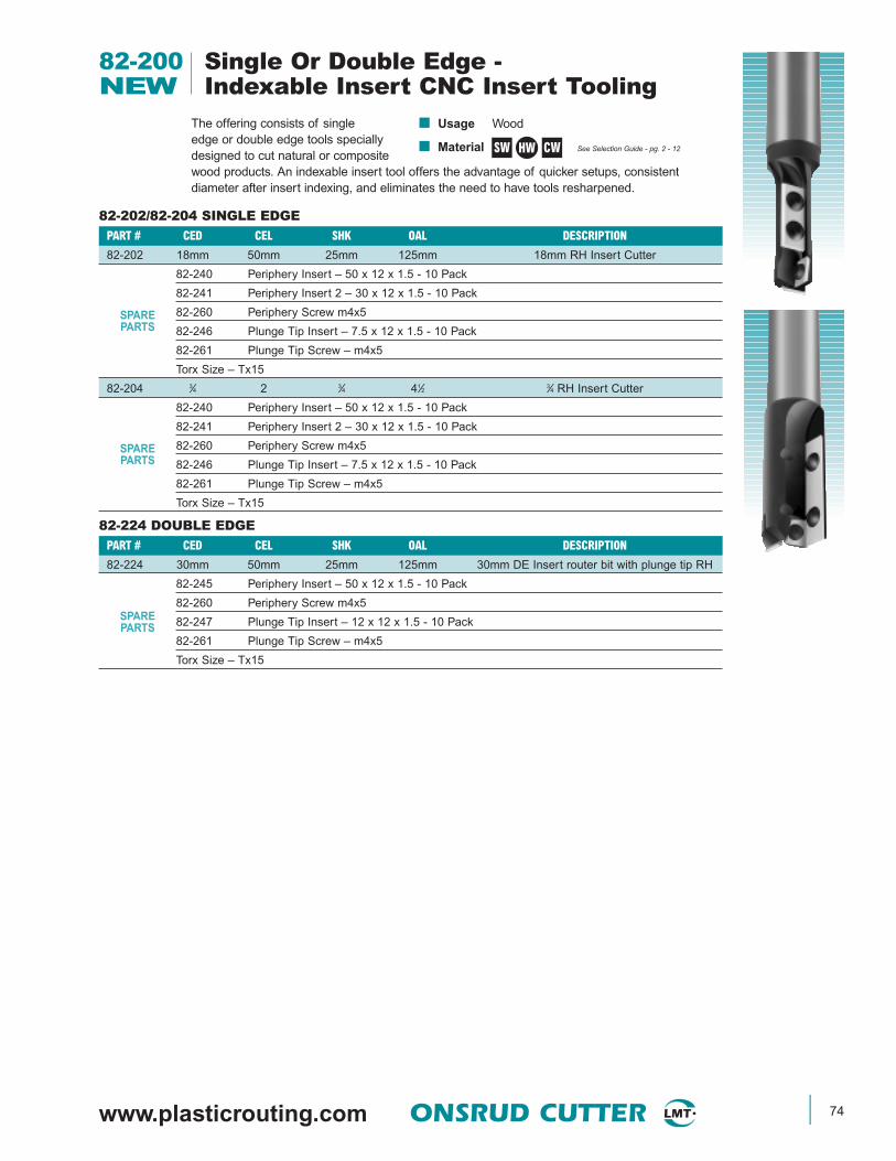
www.plasticrouting.com ONSRUD CUTTER 74
82-200 Single Or Double Edge -NEW Indexable Insert CNC Insert Tooling
The offering consists of singleedge or double edge tools speciallydesigned to cut natural or compositewood products. An indexable insert tool offers the advantage of quicker setups, consistentdiameter after insert indexing, and eliminates the need to have tools resharpened.
■ Usage Wood
■ Material See Selection Guide - pg. 2 - 12SW CWHW
82-202/82-204 SINGLE EDGEPART # CED CEL SHK OAL DESCRIPTION
82-202 18mm 50mm 25mm 125mm 18mm RH Insert Cutter
82-240 Periphery Insert – 50 x 12 x 1.5 - 10 Pack
82-241 Periphery Insert 2 – 30 x 12 x 1.5 - 10 Pack
SPARE 82-260 Periphery Screw m4x5PARTS 82-246 Plunge Tip Insert – 7.5 x 12 x 1.5 - 10 Pack
82-261 Plunge Tip Screw – m4x5
Torx Size – Tx15
82-204 3⁄4 2 3⁄4 41⁄2 3⁄4 RH Insert Cutter
82-240 Periphery Insert – 50 x 12 x 1.5 - 10 Pack
82-241 Periphery Insert 2 – 30 x 12 x 1.5 - 10 Pack
SPARE 82-260 Periphery Screw m4x5PARTS 82-246 Plunge Tip Insert – 7.5 x 12 x 1.5 - 10 Pack
82-261 Plunge Tip Screw – m4x5
Torx Size – Tx15
82-224 DOUBLE EDGEPART # CED CEL SHK OAL DESCRIPTION
82-224 30mm 50mm 25mm 125mm 30mm DE Insert router bit with plunge tip RH
82-245 Periphery Insert – 50 x 12 x 1.5 - 10 Pack
SPARE82-260 Periphery Screw m4x5
PARTS 82-247 Plunge Tip Insert – 12 x 12 x 1.5 - 10 Pack
82-261 Plunge Tip Screw – m4x5
Torx Size – Tx15

75 ONSRUD CUTTER www.onsrud.com
PART # CED CEL SHK DIA OAL
86-012 1⁄4 2 1⁄4 31⁄4
86-014 5⁄16 23⁄8 5⁄16 33⁄4
86-016 3⁄8 23⁄4 3⁄8 41⁄4
86-018 7⁄16 27⁄8 7⁄16 41⁄2
86-020 1⁄2 3 1⁄2 43⁄4
86-000 Solid Carbide Kevlar DrillNEW
This tool is designed to drill Aramidmaterials and produce a clean hole. Thespecific point design shears the aramidfibers eliminating whiskers or delamination.
PART # CED CEL SHK DIA OAL
86-002 #39 (.0995) 11⁄4 0.099 21⁄4
86-004 1⁄8 11⁄4 1⁄8 21⁄4
86-006 #30 (.129) 11⁄4 0.129 21⁄4
86-008 #26 (.147) 13⁄8 0.147 21⁄2
86-010 3⁄16 15⁄8 3⁄16 23⁄4
■ Usage Aramid materials
■ Material See Selection Guide - pg. 2 - 12CP
82-200 Single Edge -NEW Indexable Insert CNC Insert Tooling
82-206/82-220 SINGLE EDGEPART # CED CEL SHK OAL DESCRIPTION
82-206 5⁄16 25⁄32 1⁄2 23⁄8 5⁄16 Insert router bit RH
82-242 Periphery Insert – 20 x 4.1 x 1.1 - 10 PackSPARE
82-280 Clamping Wedge Torx Size – Tx8PARTS82-262 Clamping Wedge Screws – M2.5 x 5
82-208 3⁄8 25⁄32 1⁄2 23⁄8 3⁄8 Insert router bit RH
82-242 Periphery Insert – 20 x 4.1 x 1.1 - 10 PackSPARE
82-280 Clamping Wedge Torx Size – Tx8PARTS82-263 Clamping Wedge Screws – M2.5 x 5.5
82-210 1⁄2 23⁄16 1⁄2 27⁄8 1⁄2 Insert router bit RH
82-243 Periphery Insert – 30 x 5.5 x 1.1 - 10 PackSPARE
82-281 Clamping Wedge Torx Size – Tx8PARTS82-264 Clamping Wedge Screws – M3 x 7
82-212 5⁄8 2 1⁄2 311⁄16 5⁄8 Insert router bit RH
82-244 Periphery Insert – 50 x 5.5 x 1.1 - 10 PackSPARE
82-282 Clamping Wedge Torx Size – Tx15PARTS82-265 Clamping Wedge Screws – M4 x 11.5
82-214 3⁄4 2 1⁄2 311⁄16 3⁄4 Insert router bit RH
82-244 Periphery Insert – 50 x 5.5 x 1.1 - 10 PackSPARE
82-282 Clamping Wedge Torx Size – Tx15PARTS82-265 Clamping Wedge Screws – M4 x 11.5
82-216 3⁄8 25⁄32 1⁄2 23⁄8 3⁄8 Insert router bit LH
82-242 Periphery Insert – 20 x 4.1 x 1.1 - 10 PackSPARE
82-280 Clamping Wedge Torx Size – Tx8PARTS82-263 Clamping Wedge Screws – M2.5 x 5.5
82-218 1⁄2 13⁄16 1⁄2 23⁄4 1⁄2 Insert router bit LH
82-243 Periphery Insert – 30 x 5.5 x 1.1 - 10 PackSPARE
82-281 Clamping Wedge Torx Size – Tx8PARTS82-264 Clamping Wedge Screws – M3 x 7
82-220 3⁄4 131⁄32 3⁄4 41⁄4 3⁄4 Insert router bit LH
82-244 Periphery Insert – 50 x 5.5 x 1.1 - 10 PackSPARE
82-282 Clamping Wedge Torx Size – Tx15PARTS82-265 Clamping Wedge Screws – M4 x 11.5
The offering consists of singleedge or double edge tools speciallydesigned to cut natural or compositewood products. An indexable insert tool offers the advantage of quicker setups, consistentdiameter after insert indexing, and eliminates the need to have tools resharpened.
■ Usage Wood
■ Material See Selection Guide - pg. 2 - 12SW CWHW
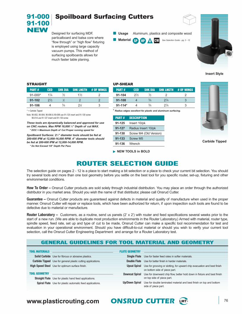
www.plasticrouting.com ONSRUD CUTTER 76
PART # CED SHK DIA SHK LNGTH # OF WINGS
91-000* 11⁄4 1⁄2 11⁄2 2
91-102 21⁄2 1⁄2 2 2
91-106 4 3⁄4 21⁄4 3
* = Carbide Tipped
Note: 90-002, 90-004, 90-006 & 90-008 use 91-125 insert and 91-130 screw90-014 use 91-127 insert and 91-130 screw
STRAIGHT UP-SHEAR
PART # CED SHK DIA SHK LNGTH # OF WINGS
91-104 21⁄2 1⁄2 2 2
91-108 4 3⁄4 21⁄4 3
91-114* 4 3⁄4 21⁄4 3
* Radius edges excellent for plastic and aluminum surfacing.
PART # DESCRIPTION
91-125 Insert 10/pk
91-127 Radius Insert 10/pk
91-130 Screw M4 (Old Version)
91-133 Screw M5
91-136 Wrench
These tools are dynamically balanced and approved for use on CNC routers. Max RPM 18,000 1⁄8” Depth of cut MAX.
* DOC = Maximum Depth of Cut Proper running speed for
Spoilboard Surfaces: 21⁄2” diameter tools should be fed at 200-600 IPM at 12,000-16,000 RPM. 4” diameter tools should be fed at 200-600 IPM at 12,000-14,000 RPM.
* Do Not Exceed 1/8” Depth Per Pass
NEW TOOLS in BOLD
■ Usage Aluminum, plastics and composite wood
■ Material See Selection Guide - pg. 2 - 12
91-000 Spoilboard Surfacing Cutters91-100NEW
Designed for surfacing MDF,particalboard and balsa core where“flow through” or “high flow” fixturingis employed using large capacityvacuum pumps. This method ofsurfacing spoilboards allows formuch faster table planing.
Insert Style
Carbide Tipped
SP HP A CW
ROUTER SELECTION GUIDEThe selection guide on pages 2 - 12 is a place to start making a bit selection or a place to check your current bit selection. You shouldtry several tools and more than one tool geometry before you settle on the best tool for you specific router, set-up, fixturing and otherenvironmental conditions.
How To Order – Onsrud Cutter products are sold solely through industrial distribution. You may place an order through the authorizeddistributor in you market area. Should you wish the name of that distributor, please call Onsrud Cutter.
Guarantee – Onsrud Cutter products are guaranteed against defects in material and quality of manufacture when used in the propermanner. Onsrud Cutter will repair or replace tools, which have been authorized for return, if upon inspection such tools are found to bedefective due to material or manufacture.
Router Laboratory – Customers, as a routine, send us panels (2’ x 2’) with router and feed specifications several weeks prior to thestart of a new run. (We are able to duplicate most production environments in the Router Laboratory.) Armed with material, router type,spindle speed, feed rate, set up and type of cut to be made, Onsrud Cutter can make a specific tool recommendation for test andevaluation in your operational environment. Should you have difficult-to-cut material or should you wish to verify your current toolselection, call the Onsrud Cutter Engineering Department and arrange for a Router Laboratory test.
GENERAL GUIDELINES FOR TOOL MATERIAL AND GEOMETRY
TOOL MATERIALS __________________________________________
Solid Carbide Use for fibrous or abrasive plastics.
Carbide Tipped Use for general plastic cutting applications.
High Speed Steel Use for optimum surface finish.
TOOL GEOMETRY __________________________________________
Straight Flute Use for plastic hand feed applications.
Spiral Flute Use for plastic automatic feed applications.
FLUTE GEOMETRY __________________________________________________________
Single Flute Use for faster feed rates in softer materials.
Double Flute Use for better finish in harder materials.
Upcut Spiral Use for grooving or slotting, for upward chip evacuation and best finish
on bottom side of piece part.
Downcut Spiral Use for downward chip flow, better hold down in fixture and best finishon top side of piece part.
Up/Down Spiral Use for double laminated material and best finish on top and bottomside of piece part.
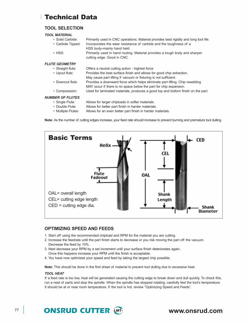
77 ONSRUD CUTTER www.onsrud.com
Technical Data
TOOL SELECTION
TOOL MATERIAL• Solid Carbide: Primarily used in CNC operations. Material provides best rigidity and long tool life.• Carbide Tipped: Incorporates the wear resistance of carbide and the toughness of a
HSS body-mainly hand held.• HSS: Primarily used in hand routing. Material provides a tough body and sharper
cutting edge. Good in CNC.
FLUTE GEOMETRY• Straight flute: Offers a neutral cutting action - highest force• Upcut flute: Provides the best surface finish and allows for good chip extraction.
May cause part lifting if vacuum or fixturing is not sufficient.• Downcut flute: Provides a downward force which helps eliminate part lifting. Chip rewelding
MAY occur if there is no space below the part for chip expansion.• Compression: Used for laminated materials, produces a good top and bottom finish on the part.
NUMBER OF FLUTES• Single Flute: Allows for larger chiploads in softer materials• Double Flute: Allows for better part finish in harder materials.• Multiple Flutes: Allows for an even better part finish in harder materials.
Note: As the number of cutting edges increase, your feed rate should increase to prevent burning and premature tool dulling.
OPTIMIZING SPEED AND FEEDS
1. Start off using the recommended chipload and RPM for the material you are cutting.2. Increase the feedrate until the part finish starts to decrease or you risk moving the part off the vacuum.
Decrease the feed by 10%.3. Next decrease your RPM by a set increment until your surface finish deteriorates again.
Once this happens increase your RPM until the finish is acceptable.4. You have now optimized your speed and feed by taking the largest chip possible.
Note: This should be done in the first sheet of material to prevent tool dulling due to excessive heat.
TOOL HEATIf a feed rate is too low, heat will be generated causing the cutting edge to break down and dull quickly. To check this,run a nest of parts and stop the spindle. When the spindle has stopped rotating, carefully feel the tool’s temperature.It should be at or near room temperature. If the tool is hot, review “Optimizing Speed and Feeds”.
OAL= overall length CEL= cutting edge lengthCED = cutting edge dia.
Basic Terms

www.plasticrouting.com ONSRUD CUTTER 78
Technical Data
FIXTURING METHODS
FLOW THROUGH VACUUMThis style uses LDF (Low Density Fiberboard) or MDF (Medium Density Fiberboard) as a sacrificial surfacefor sheet material to be cut on. The porous nature of LFD or MDF allows vacuum to pass through allowingthe material to be held in place for machining. As parts are cut out of the sheet material, vacuum loss startsto occur from the slot produced by the cutting tool. This can lead to part lifting or movement especially insmall parts. Cutter diameter will also influence part movement. A 1/2 diameter tool will exert 25% more lateralpressure than a 3/8 diameter tool.
When cutting small parts in sheet material, one may want to consider tab or skin cutting to prevent part movement.
DEDICATED SPOILBOARDDedicated spoilboards are used for reoccurringproduction runs where optimal cycle times areneeded. This work holding method creates vacuumchambers in the sacrificial board specifically to theshape of the parts being cut. This elimination of vacuumloss relates to improved cycle times and part finish.
STEPS TO CREATE A DEDICATED SPOILBOARD:1. Surface both sides of your MDF board2. Lay out the part pattern on the MDF and determine
quantity that will fit.3. Cut the part profile into the MDF board using a larger
diameter tool than would normally cut the part.Make your slot depth 1 to 1.5 times the cutter diameter.
4. A gasket groove must be cut next inside the part profileto create a vacuum seal. The groove should be 1/2 thegasket material thickness to allow for proper compression.
5. A grid pattern must then be cut inside the gasket groove todistribute the vacuum evenly through out the vacuum area.
6. Drill holes through out the pattern in the intersectionsof the vacuum grid until there is no resistance on yourvacuum gage on the machine table.
7. Seal the board using rubberized coatings, polyurethanesealers or a sanding sealer to prevent vacuum frompassing through the board in unwanted areas.
8. Apply the gasket tape.
This operations sounds time consuming. It will be for your first board. Once you become familiar making thesefixtures, you will make up for it in your cycle time reductions and part finish. A lot of headaches and problems can beresolved by using the proper work holding.
RAISED SPOILBOARDThis is generally used where secondary operations are needed and the spoilboard will interfere with the secondary tool.
Raised spoilboards are another type of fixturing that works well for routing parts such as circles from squares where the scrap or off-fall is of such a size to be potentially harmful to the tool and or operator when it is cut free. A raisedspoilboard should make sure the off-fall would not interfere with the first and second tool and that the off-fall would befree and clear of the tool path.
SURFACING SPOILBOARDSWhen creating new fixtures or using a new MDF sheet, the spoilboard must be surfaced to level the board to themachine table. This consists using a large diameter cutter (OC 91-100 series) to quickly level the entire surface.
The following benefits will be achieved by surfacing your spoilboard:• Leveling material to get consistent cuts.• Remove grooves caused by routing.• Reduce vacuum loss due to clogged pores at the material surface due to dust and chips.• Preventing material warpage caused by humidity in summer time.
Proper SpoilboardTechniques

79 ONSRUD CUTTER www.onsrud.com
Technical Data
COLLETING
COLLET LIFE SPANCollets have a life span of 3 months if used 8 hours a day. Replacing the collets will ensure your operation runs consistentlyand prevents tool breakage. When inserting a tool into the collet make sure the flute fadeout does not enter the collet. Thiswill cause run out and potentially lead to tool breakage. To ensure proper clamping the tool shank should fill, at the minimum,80% of the depth of the collet. If this can not be achieved, use a collet life plug to ensure a proper clamping effect.
COLLET MAINTENANCECleaning is an essential part of collet maintenance. As material is cut it causes the collet, tool holder, collet nut and spindleto become dirty. This causes your tool to cut in an elliptical fashion which will decrease tool life and cause inconsistency inyour operation. Collets, tool holder, and collet nut should be cleaned daily using the Rust Free solvent and a brass brush(OC series 33-21 and 33-10). Refer to the critical areas diagram to see which surfaces must be clean.
CLEANING INSTRUCTIONS1. Spray the cleaner on the surface and allow it to soak for a minute2. Use a brass brush to clean the surface thoroughly.3. Rinse off using distilled alcohol. Feel the surface using your fingers
to make sure the surface is clean4. Apply a small amount of Lubricant T-9 to prevent rusting.
TOOL BREAKAGE
If a condition arises where multiple tools should break, follow these steps to solve your problem:1. Are you using the proper tool for the job?2. Make sure your collets and tool holders are clean and the tool is colleted properly.3. Check your speed and feed (is your tool hot?)4. Is your depth of cut too excessive for the material you’re cutting?5. Do you have any part movement?6. Do you have ample part hold down?7. Stop running parts and check with your distributor or Onsrud’s Technical Support.
If you have to contact your distributor or Technical Support, have the following information:1. Machine being used.2. Material being cut.3. Part number of tool along with the batch number which is below the part number.4. Speed / Feed / Depth of cut.5. Where did the tool break (flute, shank, or in the collet)?6. How long did the tool work before it broke?7. Have you done this operation in the past using this tool?
CRITICALCLEANAREAS CRITICAL
CLEANAREAS
INSIDETAPER
BEARING STYLE NUT BEARING STYLE NUT
STANDARD SPINDLE
QUICK CHANGEBT30 TOOL HOLDER
INSIDETAPER
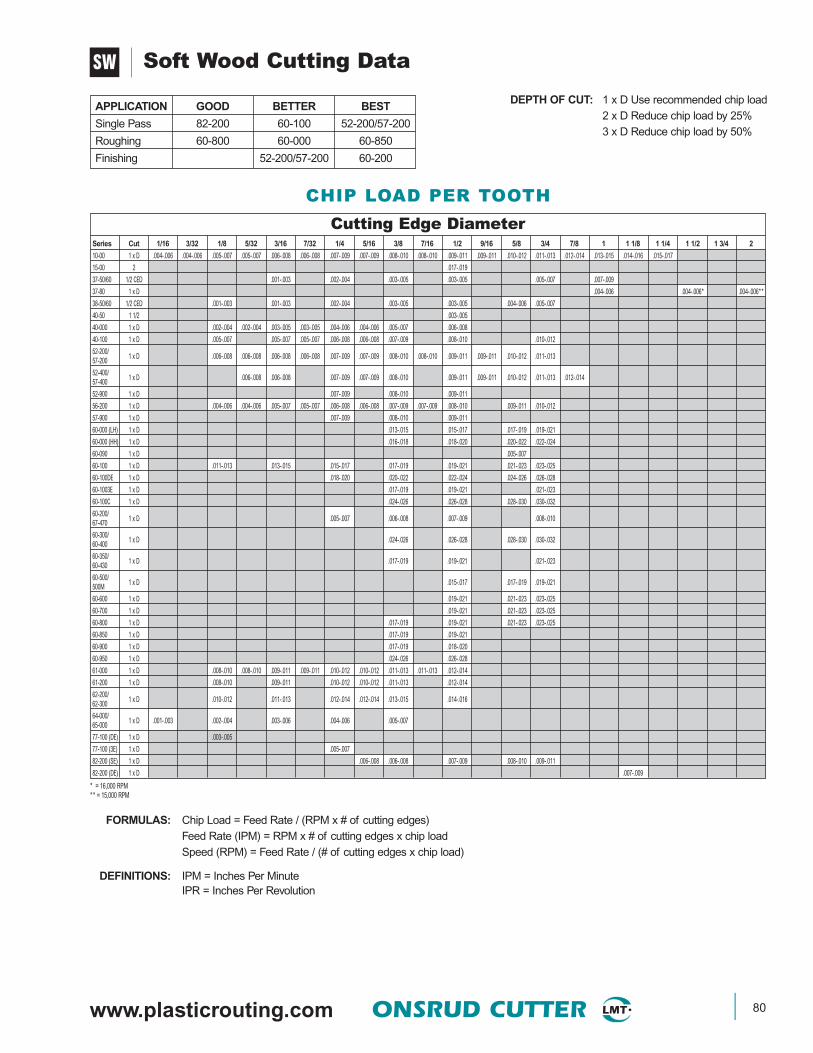
www.plasticrouting.com ONSRUD CUTTER 80
Soft Wood Cutting Data
DEPTH OF CUT: 1 x D Use recommended chip load2 x D Reduce chip load by 25%3 x D Reduce chip load by 50%
APPLICATION GOOD BETTER BEST
Single Pass 82-200 60-100 52-200/57-200
Roughing 60-800 60-000 60-850
Finishing 52-200/57-200 60-200
SW
CHIP LOAD PER TOOTH
Cutting Edge DiameterSeries Cut 1/16 3/32 1/8 5/32 3/16 7/32 1/4 5/16 3/8 7/16 1/2 9/16 5/8 3/4 7/8 1 1 1/8 1 1/4 1 1/2 1 3/4 2
10-00 1 x D .004-.006 .004-.006 .005-.007 .005-.007 .006-.008 .006-.008 .007-.009 .007-.009 .008-.010 .008-.010 .009-.011 .009-.011 .010-.012 .011-.013 .012-.014 .013-.015 .014-.016 .015-.017
15-00 2 .017-.019
37-50/60 1/2 CED .001-.003 .002-.004 .003-.005 .003-.005 .005-.007 .007-.009
37-80 1 x D .004-.006 .004-.006* .004-.006**
38-50/60 1/2 CED .001-.003 .001-.003 .002-.004 .003-.005 .003-.005 .004-.006 .005-.007
40-50 1 1/2 .003-.005
40-000 1 x D .002-.004 .002-.004 .003-.005 .003-.005 .004-.006 .004-.006 .005-.007 .006-.008
40-100 1 x D .005-.007 .005-.007 .005-.007 .006-.008 .006-.008 .007-.009 .008-.010 .010-.012
52-200/57-200 1 x D .006-.008 .006-.008 .006-.008 .006-.008 .007-.009 .007-.009 .008-.010 .008-.010 .009-.011 .009-.011 .010-.012 .011-.013
52-400/57-400 1 x D .006-.008 .006-.008 .007-.009 .007-.009 .008-.010 .009-.011 .009-.011 .010-.012 .011-.013 .012-.014
52-900 1 x D .007-.009 .008-.010 .009-.011
56-200 1 x D .004-.006 .004-.006 .005-.007 .005-.007 .006-.008 .006-.008 .007-.009 .007-.009 .008-.010 .009-.011 .010-.012
57-900 1 x D .007-.009 .008-.010 .009-.011
60-000 (LH) 1 x D .013-.015 .015-.017 .017-.019 .019-.021
60-000 (HH) 1 x D .016-.018 .018-.020 .020-.022 .022-.024
60-090 1 x D .005-.007
60-100 1 x D .011-.013 .013-.015 .015-.017 .017-.019 .019-.021 .021-.023 .023-.025
60-100DE 1 x D .018-.020 .020-.022 .022-.024 .024-.026 .026-.028
60-1003E 1 x D .017-.019 .019-.021 .021-.023
60-100C 1 x D .024-.026 .026-.028 .028-.030 .030-.032
60-200/67-470 1 x D .005-.007 .006-.008 .007-.009 .008-.010
60-300/60-400 1 x D .024-.026 .026-.028 .028-.030 .030-.032
60-350/60-430 1 x D .017-.019 .019-.021 .021-.023
60-500/500M 1 x D .015-.017 .017-.019 .019-.021
60-600 1 x D .019-.021 .021-.023 .023-.025
60-700 1 x D .019-.021 .021-.023 .023-.025
60-800 1 x D .017-.019 .019-.021 .021-.023 .023-.025
60-850 1 x D .017-.019 .019-.021
60-900 1 x D .017-.019 .018-.020
60-950 1 x D .024-.026 .026-.028
61-000 1 x D .008-.010 .008-.010 .009-.011 .009-.011 .010-.012 .010-.012 .011-.013 .011-.013 .012-.014
61-200 1 x D .008-.010 .009-.011 .010-.012 .010-.012 .011-.013 .012-.014
62-200/62-300 1 x D .010-.012 .011-.013 .012-.014 .012-.014 .013-.015 .014-.016
64-000/65-000 1 x D .001-.003 .002-.004 .003-.006 .004-.006 .005-.007
77-100 (DE) 1 x D .003-.005
77-100 (3E) 1 x D .005-.007
82-200 (SE) 1 x D .006-.008 .006-.008 .007-.009 .008-.010 .009-.011
82-200 (DE) 1 x D .007-.009
FORMULAS: Chip Load = Feed Rate / (RPM x # of cutting edges)Feed Rate (IPM) = RPM x # of cutting edges x chip loadSpeed (RPM) = Feed Rate / (# of cutting edges x chip load)
DEFINITIONS: IPM = Inches Per MinuteIPR = Inches Per Revolution
* = 16,000 RPM** = 15,000 RPM
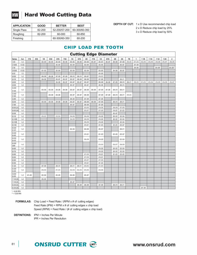
81 ONSRUD CUTTER www.onsrud.com
Hard Wood Cutting Data
DEPTH OF CUT: 1 x D Use recommended chip load2 x D Reduce chip load by 25%3 x D Reduce chip load by 50%
APPLICATION GOOD BETTER BEST
Single Pass 82-200 52-200/57-200 60-300/60-350
Roughing 82-200 60-000 60-850
Finishing 60-300/60-350 60-200
HW
FORMULAS: Chip Load = Feed Rate / (RPM x # of cutting edges)Feed Rate (IPM) = RPM x # of cutting edges x chip loadSpeed (RPM) = Feed Rate / (# of cutting edges x chip load)
DEFINITIONS: IPM = Inches Per MinuteIPR = Inches Per Revolution
CHIP LOAD PER TOOTH
Cutting Edge DiameterSeries Cut 1/16 3/32 1/8 5/32 3/16 7/32 1/4 5/16 3/8 7/16 1/2 9/16 5/8 3/4 7/8 1 1 1/8 1 1/4 1 1/2 1 3/4 2
12-00 1 x D .002-.004 .002-.004 .002-.004 .003-.005 .003-.005 .004-.006 .004-.006 .005-.007 .005-.007 .005-.007 .006-.008 .007-.009 .010-.012 .011-.013 .012-.014 .013-.015 .014-.016 .015-.017 .016-.018
37-50/60 1/2 CED .002-.004 .002-.004 .002-.004 .003-.005 .005-.007 .007-.009
37-80 1 x D .004-.006 .004-.006* .004-.006**
38-50/60 1/2 CED .001-.003 .002-.004 .002-.004 .002-.004 .003-.005 .004-.006 .005-.007
40-50 1 1/2 .003-.005
40-000 1 x D .006-.008 .006-.008 .007-.009 .007-.009 .008-.010 .008-.010 .009-.007 .010-.012
40-100 1 x D .004-.006 .005-.007 .005-.007 .005-.007 .006-.008 .006-.008 .007-.009 .009-.011
48-000 1 x D .004-.006 .005-.007 .005-.007 .005-.007 .005-.007 .006-.008 .006-.008 .007-.009 .008-.010 .009-.011 .010-.012 .011-.013 .012-.014 .013-.015 .014-.016 .015-.017
48-500 1 x D .005-.007 .005-.007 .006-.008 .008-.010
52-200/
57-200 1 x D .003-.005 .003-.005 .004-.006 .004-.006 .005-.007 .005-.007 .006-.008 .006-.008 .007-.009 .007-.008 .008-.010 .009-.011
52-400/57-400 1 x D .004-.006 .004-.006 .005-.007 .005-.007 .006-.008 .007-.009 .007-.009 .008-.010 .009-.011 .010-.012
52-900 1 x D .006-.008 .007-.009 .007-.009
56-200 1 x D .003-.005 .003-.005 .004-.006 .004-.006 .005-.007 .005-.007 .006-.008 .006-.008 .007-.009 .008-.010 .009-.011
57-900 1 x D .005-.007 .006-.008 .007-.009
60-000 (LH) 1 x D .013-.015 .014-.016 .016-.018 .017-.019
60-000 (HH) 1 x D .015-.017 .017-.019 .019-.021 .021-.023
60-090 1 x D .005-.007
60-100 1 x D .010-.012 .012-.014 .014-.016 .016-.018 .018-.020 .020-.022 .022-.024
60-100DE 1 x D .014-.016 .016-.018 .018-.020 .020-.022 .022-.024
60-1003E 1 x D .016-.018 .018-.020 .022-.024
60-100C 1 x D .019-.021 .021-.023 .023-.025 .025-.027
60-200/67-470 1 x D .002-.004 .004-.006 .005-.007 .009-.011
60-300/60-400 1 x D .019-.021 .021-.023 .023-.025 .025-.027
60-350/60-430 1 x D .016-.018 .018-.020 .022-.024
60-500/500M 1 x D .013-.015 .015-.017 .016-.018
60-600 1 x D .018-.020 .020-.022 .022-.024
60-700 1 x D .018-.020 .020-.022 .022-.024
60-800 1 x D .017-.019 .019-.021 .021-.023 .023-.025
60-850 1 x D .017-.019 .019-.021
60-900 1 x D .015-.017 .017-.019
60-950 1 x D .019-.021 .021-.023
61-200 1 x D .007-.009 .008-.010 .009-.011 .009-.011 .010-.012 .011-.013
62-200/63-200 1 x D .010-.012 .011-.013 .012-.014 .012-.014 .013-.015 .014-.016
64-000/65-000 1 x D .001-.003 .002-.004 .003-.005 .004-.006 .005-.007
77-100 (DE) 1 x D .003-.005
77-100 (3E) 1 x D .005-.007
82-200 (SE) 1 x D .006-.008 .006-.008 .007-.009 .008-.010 .009-.011
82-200 (DE) 1 x D .007-.009
* = 16,000 RPM** = 15,000 RPM

www.plasticrouting.com ONSRUD CUTTER 82
MDF Cutting Data
DEPTH OF CUT: 1 x D Use recommended chip load2 x D Reduce chip load by 25%3 x D Reduce chip load by 50%
APPLICATION GOOD BETTER BEST
Single Pass 52-200/57-200 60-300/60-350 60-100
Roughing 82-200 60-000 60-850
Finishing 60-300/60-350 60-200
CW
CHIP LOAD PER TOOTH
Cutting Edge DiameterSeries Cut 1/16 3/32 1/8 5/32 3/16 7/32 1/4 5/16 3/8 7/16 1/2 9/16 5/8 3/4 7/8 1 1 1/8 1 1/4 1 1/2 1 3/4 2
13-50 1 x D .013-.015 .016-.018
37-50/60 1/2 CED .001-.003 .001-.003 .002-.004 .003-.005 .005-.007 .007-.009
37-80 1 x D .004-.006 .004-.006* .004-.006**
38-50/60 1/2 CED .001-.003 .001-.003 .001-.003 .002-.004 .003-.005 .004-.006 .005-.007
40-50 1 1/2 .003-.005
47-00 1 x D .004-.006 .004-.006 .004-.006
48-000 1 x D .004-.006 .004-.006 .005-.007 .005-.007 .005-.007 .006-.008 .006-.008 .006-.008 .007-.009 .008-.010 .009-.011
48-500 1 x D .005-.007 .005-.007 .006-.008 .009-.011
48-700 1 x D .005-.007 .005-.007 .006-.008 .006-.008 .007-.009 .009-.011
52-200/57-200 1 x D .005-.007 .005-.007 .006-.008 .006-.008 .006-.008 .006-.008 .007-.009 .007-.009 .008-.010 .008-.010 .009-.011 .009-.011
52-400/57-400 1 x D .003-.005 .004-.006 .005-.007 .005-.007 .006-.008 .008-.010 .009-.011 .010-.012 .011-.013 .012-.014
52-900 1 x D .006-.008 .007-.009 .008-.010
56-200 1 x D .003-.005 .003-.005 .004-.006 .004-.006 .005-.007 .005-.007 .006-.008 .006-.008 .007-.009 .008-.010 .009-.011
57-900 1 x D .006-.008 .007-.009 .008-.010
60-000 (LH) 1 x D .012-.014 .013-.015 .014-.016 .016-.018
60-000 (HH) 1 x D .017-.019 .018-.020 .020-.022 .023-.025
60-090 1 x D .004-.006
60-100 1 x D .010-.012 .010-.012 .013-.015 .014-.016 .016-.018 .017-.019 .019-.021
60-100DE 1 x D .013-.015 .014-.016 .016-.018 .018-.020 .019-.021
60-1003E 1 x D .014-.016 .016-.018 .018-.020
60-100C 1 x D .017-.019 .018-.020 .020-.022 .023-.025
60-200/67-470 1 x D .004-.006 .005-.007 .005-.007 .006-.008
60-300/60-400 1 x D .017-.019 .018-.020 .020-.022 .023-.025
60-350/60-430 1 x D .014-.016 .016-.018 .017-.019 .019-.021
60-500/500M 1 x D .014-.016 .016-.018 .018-.020
60-600 1 x D .020-.022 .022-.024 .024-.026
60-700 1 x D .020-.022 .022-.024 .024-.026
60-800 1 x D .017-.019 .019-.021 .021-.023 .023-.025
60-850 1 x D .017-.019 .019-.021
60-900 1 x D .017-.019 .019-.021
60-950 1 x D .017-.019 .018-.020
61-200 1 x D .007-.009 .008-.010 .009-.011 .009-.011 .010-.012 .011-.013
62-200 1 x D .010-.012 .011-.013 .012-.014 .012-.014 .013-.015 .014-.016
64-000/65-000 1 x D .001-.003 .002-.004 .003-.005 .004-.006 .005-.007
68-100 1 x D .008-.010 .012-.014 .015-.017 .018-.020
77-100 (DE) 1 x D .003-.005
77-100 (3E) 1 x D .005-.007
82-200 (SE) 1 x D .006-.008 .006-.008 .007-.009 .008-.010 .009-.011
82-200 (DE) 1 x D .007-.009
FORMULAS: Chip Load = Feed Rate / (RPM x # of cutting edges)Feed Rate (IPM) = RPM x # of cutting edges x chip loadSpeed (RPM) = Feed Rate / (# of cutting edges x chip load)
DEFINITIONS: IPM = Inches Per MinuteIPR = Inches Per Revolution
* = 16,000 RPM** = 15,000 RPM
83 ONSRUD CUTTER www.onsrud.com
Soft Plywood Cutting Data
DEPTH OF CUT: 1 x D Use recommended chip load2 x D Reduce chip load by 25%3 x D Reduce chip load by 50%
APPLICATION GOOD BETTER BEST
Single Pass 60-300/60-350 60-100 60-100C
Roughing 60-800 60-000 60-850
Finishing 60-300/60-350 60-200
CW
CHIP LOAD PER TOOTH
FORMULAS: Chip Load = Feed Rate / (RPM x # of cutting edges)Feed Rate (IPM) = RPM x # of cutting edges x chip loadSpeed (RPM) = Feed Rate / (# of cutting edges x chip load)
DEFINITIONS: IPM = Inches Per MinuteIPR = Inches Per Revolution
* = 16,000 RPM** = 15,000 RPM
Cutting Edge DiameterSeries Cut 1/16 1/8 5/32 3/16 7/32 1/4 5/16 3/8 7/16 1/2 9/16 5/8 3/4 7/8 1 1-1/8 1-1/4 1-1/2 213-50 1 x D .016-.018 .018-.02037-50/60 1/2 CED .001-.003 .002-.004 .002-.004 .003-.005 .004-.006 .006-.00837-80 1 x D .004-.006 .004-.006* .004-.006**38-50/60 1/2 CED .0005-.0025 .001-.003 .002-.004 .002-.004 .003-.005 .003-.005 .004-.00640-50 1 1/2 .003-.00548-000 1 x D .005-.007 .005-.007 .005-.007 .006-.008 .006-.008 .007-.009 .007-.009 .008-.010 .009-.011 .010-.012 .011-.013 .012-.014 .013 - .01548-500 1 x D .005-.007 .006-.008 .007-.009 .009-.01148-700 1 x D .005-.007 .006-.008 .007-.009 .008-.010 .009-.011 .011-.01356-200 1 x D .003-.005 .003-.005 .004-.006 .004-.006 .005-.007 .005-.007 .006-.008 .006-.008 .007-.009 .008-.010 .009-.01160-000 (LH) 1 x D .014-.016 .016-.018 .018-.020 .020-.02260-000 (HH) 1 x D .017-.019 .019-.021 .021-.023 .023-.02560-090 1 x D .003-.00560-100 1 x D .013-.015 .014-.016 .015-.017 .016-.018 .018-.020 .020-.022 .022-.02460-100DE 1 x D .017-.019 .019-.021 .021-.023 .023-.025 .025-.02760-1003E 1 x D .020-.022 .022-.024 .024-02660-100C 1 x D .022-.024 .024-.026 .026-.028 .028-.03060-300/60-400 1 x D .022-.024 .024-.026 .026-.028 .028-.030
60-35060-430 1 x D .020-.022 .022-.024 .024-.026 .026-.028
60-500/500M 1 x D .021-.023 .023-.025 .025-.027
60-600 1 x D .028-.030 .030-.032 .032-.03460-700 1 x D .028-.030 .030-.032 .032-.03460-800 1 x D .017-.019 .019-.021 .021-.023 .023-.02560-850 1 x D .017-.019 .019-.02160-900 1 x D .017-.019 .019-.02160-950 1 x D .022-.024 .024-.02661-200 1 x D .006-.008 .007-.009 .008-.010 .008-.010 .009-.011 .010-.01264-000/65-000 1 x D .001-.003 .002-.004 .003-.005 .004-.006 .005-.007
68-100 .010-.012 .012-.014 .017-.019 .018-.02082-200 (SE) .008-.010 .009-.011 .010-.012 .011-.013 .012-.01482-200 (DE) .009-.011

www.plasticrouting.com ONSRUD CUTTER 84
Hard Plywood Cutting Data
DEPTH OF CUT: 1 x D Use recommended chip load2 x D Reduce chip load by 25%3 x D Reduce chip load by 50%
APPLICATION GOOD BETTER BEST
Single Pass 60-300/60-350 60-100 60-100C
Roughing 60-800 60-000 60-850
Finishing 60-300/60-350 60-200
CW
CHIP LOAD PER TOOTH
FORMULAS: Chip Load = Feed Rate / (RPM x # of cutting edges)Feed Rate (IPM) = RPM x # of cutting edges x chip loadSpeed (RPM) = Feed Rate / (# of cutting edges x chip load)
DEFINITIONS: IPM = Inches Per MinuteIPR = Inches Per Revolution
* = 16,000 RPM** = 15,000 RPM
Cutting Edge DiameterSeries Cut 1/16 3/32 1/8 5/32 3/16 7/32 1/4 5/16 3/8 7/16 1/2 9/16 5/8 3/4 7/8 1 1 1/8 1 1/4 1 1/2 1 3/4 2
13-50 1 x D .016-.018 .018-.020
37-50/60 1/2 CED .001-.003 .001-.003 .002-.004 .003-.005 .005-.007 .007-.009
37-80 1 x D .004-.006 .004-.006* .004-.006**
38-50/60 1/2 CED .0005-.0025 .001-.003 .001-.003 .002-.004 .003-.005 .004-.006 .005-.007
40-50 1 1/2 .003-.005
48-000 1 x D .004-.006 .004-.006 .005-.007 .005-.007 .006-.008 .007-.009 .007-.009 .008-.010 .009-.011 .010-.012 .011-.013 .012-.014 .013-.015
48-500 1 x D .005-.007 .006-.008 .007-.009 .009-.011
48-700 1 x D .005-.007 .006-.008 .007-.009 .008-.010 .009-.011 .011-.013
56-200 1 x D .003-.005 .003-.005 .004-.006 .004-.006 .005-.007 .005-.007 .006-.008 .006-.008 .007-.009 .008-.010 .009-.011
60-000 (LH) 1 x D .014-.016 .016-.018 .018-.020 .020-.022
60-000 (HH) 1 x D .017-.019 .019-.021 .021-.023 .023-.025
60-090 1 x D .003-.005
60-100 1 x D .012-.018 .012-.018 .014-.016 .016-.018 .018-.020 .020-.022 .022-.024
60-100DE 1 x D .014-.016 .016-.018 .018-.020 .020-.022 .022-.024
60-1003E 1 x D .020-.022 .022-.024 .026-.028
60-100C 1 x D .019-.021 .021-.023 .023-.025 .025-.027
60-300/60-400 1 x D .019-.021 .021-.023 .023-.025 .025-.027
60-350/60-430 1 x D .018-.020 .020-.022 .022-.025 .024-.026
60-500/500M 1 x D .039-.041 .043-.045 .047-.049
60-600 1 x D .027-.029 .030-.032 .032-.034
60-700 1 x D .027-.029 .029-.031 .032-.034
60-800 1 x D .017-.019 .019-.021 .021-.023 .023-.025
60-850 1 x D .017-.019 .019-.021
60-900 1 x D .017-.019 .019-.021
60-950 1 x D .019-.021 .021-.023
61-200 1 x D .005-.007 .006-.008 .007-.009 .007-.009 .008-.010 .009-.011
64-000/65-000 1 x D .001-.003 .002-.004 .003-.005 .004-.006 .005-.007
68-100 1 x D .010-.012 .012-.014 .017-.019 .018-.020
82-200 (SE) 1 x D .008-.010 .009-.011 .010-.012 .011-.013 .012-.014
82-200 (DE) 1 x D .009-.011
85 ONSRUD CUTTER www.onsrud.com
Laminated Chipboard Cutting Data
DEPTH OF CUT: 1 x D Use recommended chip load2 x D Reduce chip load by 25%3 x D Reduce chip load by 50%
APPLICATION GOOD BETTER BEST
Single Pass 60-100 60-100MW 60-100C
Roughing 60-850
LW
FORMULAS: Chip Load = Feed Rate / (RPM x # of cutting edges)Feed Rate (IPM) = RPM x # of cutting edges x chip loadSpeed (RPM) = Feed Rate / (# of cutting edges x chip load)
DEFINITIONS: IPM = Inches Per MinuteIPR = Inches Per Revolution
CHIP LOAD PER TOOTH
* = 16,000 RPM** = 15,000 RPM
Cutting Edge DiameterSeries Cut 1/8 3/16 7/32 1/4 5/16 3/8 1/2 9/16 5/8 3/4 7/8 1 1-1/8 1-1/4 1-1/2 213-50 1 x D .017-.019 .019-.02137-80 1 x D .004-.006 .004 -.006* .004 -.006**48-000 1 x D .005-.007 .005-.007 .006-.008 .006-.008 .007-.009 .008-.010 .008-.010 .009-.011 .010-.012 .011-.013 .012-.014 .013-.015 .014-.01660-100 1 x D .013-.015 .014-.016 .015-.017 .016-.018 .018-.020 .019-.021 .021-.02360-100 (DE) 1 x D .017-.019 .019-.021 .021-.023 .025-.027 .027-.02960-100 (3E) 1 x D .020-.022 .022-.024 .024-.02660-100C 1 x D .022-.024 .024-.026 .026-.028 .028-.03060-500/500M 1 x D .021-.023 .023-.025 .025-.02760-600 1 x D .028-.030 .030-.032 .032-.03460-850 1 x D .017-.019 .019-.02168-100 1 x D .008-.010 .012-.014 .016-.018 .019-.02182-200 (SE) 1 x D .008-.010 .009-.011 .010-.012 .011-.013 .012-.01482-200 (DE) 1 x D .009-.011
www.plasticrouting.com ONSRUD CUTTER 86
FORMULAS: Chip Load = Feed Rate / (RPM x # of cutting edges)Feed Rate (IPM) = RPM x # of cutting edges x chip loadSpeed (RPM) = Feed Rate / (# of cutting edges x chip load)
DEFINITIONS: IPM = Inches Per MinuteIPR = Inches Per Revolution
CHIP LOAD PER TOOTH
Laminated Plywood Cutting Data
DEPTH OF CUT: 1 x D Use recommended chip load2 x D Reduce chip load by 25%3 x D Reduce chip load by 50%
APPLICATION GOOD BETTER BEST
Single Pass 60-100 60-100MW 60-100C
Roughing 60-850
LW
* = 16,000 RPM** = 15,000 RPM
Cutting Edge DiameterSeries Cut 1/16 3/32 1/8 5/32 3/16 7/32 1/4 5/16 3/8 7/16 1/2 9/16 5/8 3/4 7/8 1 1 1/8 1 1/4 1 1/2 1 3/4 2
13-50 1 x D .014-.016 .018-.020
37-80 1 x D .004-.006 .004-.006* .004-.006**
48-000 1 x D .004-.006 .005-.007 .005-.007 .006-.008 .006-.008 .007-.009 .008-.010 .009-.011 .010-.012 .011-.013 .012-.014 .013-.015 .014-.016
60-100 1 x D .013-.015 .014-.016 .015-.017 .016-.018 .018-.020 .019-.021 .021-.023
60-100DE 1 x D .015-.017 .016-.018 .018-.020 .019-.021 .021-.023
60-1003E 1 x D .018-.020 .020-.022 .022-.024
60-100C 1 x D .019-.021 .021-.023 .023-.025 .025-.027
60-500/500M 1 x D .019-.021 .021-.023 .023-.025
60-600 1 x D .027-.029 .030-.032 .032-.034
60-850 1 x D .017-.019 .019-.02
68-100 1 x D .008-.010 .012-.014 .016-.018 .019-.021
77-100 (DE) 1 x D .003-.005
77-100 (3E) 1 x D .005-.007
82-200 (SE) 1 x D .008-.010 .009-.011 .010-.012 .011-.013 .012-.014
82-200 (DE) 1 x D .009-.011

87 ONSRUD CUTTER www.onsrud.com
Soft Plastic Cutting Data
DEPTH OF CUT: 1 x D Use recommended chip load2 x D Reduce chip load by 25%3 x D Reduce chip load by 50%
* = 12,500 RPM
SHEET ‹ 1/2” DIAMETER
APPLICATION GOOD BETTER BEST
Single Pass 61-000 61-000P 63-750
Roughing 60-000
Finishing 60-200
FORMULAS: Chip Load = Feed Rate / (RPM x # of cutting edges)Feed Rate = RPM x # of cutting edges x chip loadSpeed (RPM) = Feed Rate / (# of cutting edges x chip load)
NOTE: To eliminate rewelding increase the feedrate or change to a single edge toolIf using a downcut spiral and chip rewelding occurs, cut a slot in your spoilboard to allow the chips a place to expandIncorrect chiploads can lead to knife marks occurring
SHEET › 1/2” DIAMETER
APPLICATION GOOD BETTER BEST
Single Pass 52-700 52-600
Roughing 82-100 60-000
Finishing 60-200
CHIP LOAD PER TOOTH
SP
Cutting Edge DiameterSeries Cut 1/16 3/32 1/8 5/32 3/16 7/32 1/4 5/16 3/8 7/16 1/2 9/16 5/8 3/4 7/8 1 1 1/8 1 1/4 1 1/2 1 3/4 2
10-00 1 x D .002 - .004 .004 - .006 .006 - .008 .006 - .008 .007 - .009 .008 - .010
38-50/38-60
1 x D .001 - .003 .002 - .004 .003 - .005 .004 - .006 .005 - .007 .006 - .008 .007 - .009
52-200B/BL 1 x D .002 - .004 .002 - .004 .004 - .006 .004 - .006 .004 - .006 .006 - .008 .010 - .012 .012 - .014
52-400 1 x D .002 - .004 .003 - .005 .004 - .008 .005 - .007 .006 - .008 .007 - .009
52-600 1 x D .008 - .010 .010 - .012 .012 - .014 .014 - .016 .016 - .018
52-700 1 x D .012 - .014 .014 - .016 .016 - .018
56-430 1 x D .006 - .008 .006 - .008 .007 - .009 .008 - .010 .009 - .011
56-600 1 x D .004 - .006 .006 - .008 .008 - .010 .010 - .012 .012 - .014
57-600 1 x D .008 - .010 .010 - .012 .012 - .014 .014 - .016 .016 - .018
60-000 1 x D .004 - .006 .006 - .008 .008 - .012 .012 - .016
60-200 1 x D .004 - .006 .004 - .006 .006 - .010 .012 - .016
60-470 1 x D .004 - .006 .004 - .006 .006 - .010 .012 - .016
60-900 1 x D .004 - .006 .006 - .008
61-000P 1 x D .004 - .006 .006 - .008 .008 - .012 .014 - .018 .018 - .022
61-400 1 x D .017 - .019 .017 - .019 .018 - .020 .019 - .021 .020 - .021
62-750 1 x D .004 - .006 .006 - .008 .008 - .012 .008 - .012 .010 - .014
62-850 1 x D .004 - .006 .006 - .008 .008 - .012 .008 - .012 .010 - .014
63-750 1 x D .002 - .004 .004 - .006 .006 - .008 .008 - .012 .008 - .012 .010 - .014
63-850 1 x D .002 - .004 .004 - .006 .006 - .008 .008 - .012 .008 - .012 .010 - .014
64-000/65-000
1 x D .002 - .004 .004 - .006 .006 - .008 .008 - .012 .008 - .012
77-100 (DE) 1 x D .005 - .007
77-100 (3E) 1 x D .008 - .010
82-100 1 x D .003-.005 .004-.006 .007-.009*
www.plasticrouting.com ONSRUD CUTTER 88
Hard Plastic Cutting Data
DEPTH OF CUT: 1 x D Use recommended chip load2 x D Reduce chip load by 25%3 x D Reduce chip load by 50%
SHEET ‹ 1/2” DIAMETER
APPLICATION GOOD BETTER BEST
Single Pass 63-750 63-700 56-000P
Roughing 60-000
Finishing 60-200 75-000
FORMULAS: Chip Load = Feed Rate / (RPM x # of cutting edges)Feed Rate (IPM) = RPM x # of cutting edges x chip loadSpeed (RPM) = Feed Rate / (# of cutting edges x chip load)
DEFINITIONS: IPM = Inches Per MinuteIPR = Inches Per Revolution
NOTE: When chip rewelding occurs while cutting soft plastic, increase feedrate or go to a single edge tool.Incorrect chiploads can result in cratering
SHEET › 1/2” DIAMETER
APPLICATION GOOD BETTER BEST
Single Pass 52-700 52-600 56-000P
Roughing 82-100 60-000
Finishing 60-200 75-000
HP
CHIP LOAD PER TOOTH
Cutting Edge DiameterSeries Cut 1/16 3/32 1/8 5/32 3/16 7/32 1/4 5/16 3/8 7/16 1/2 9/16 5/8 3/4 7/8 1 1 1/8 1 1/4 1 1/2 1 3/4 2
38-50/38-60
1 x D .002 - .005 .002 - .005 .003 - .005 .004 - .006 .005 - .007 .006 - .008 .007 - .009
48-600SE 1 x D .009 - .011 .010 - .012 .011 - .013 .012 - .014
48-600DE 1 x D .003 - .005 .004 - .006 .005 - .007 .006 - .008
52-200B/BL 1 x D .002 - .004 .002 - .004 .004 - .006 .004 - .006 .004 - .006 .006 - .008 .008 - .010 .010 - .012
52-600 1 x D .006 - .008 .008 - .010 .010 - .012 .012 - .014 .014 - .016
56-000P 1 x D .002 - .004 .004 - 006 .004 - .006 .006 - .008 .008 - .010
56-430 1 x D .005 - .007 .005 - .007 .006 - .008 .007 - .009 .008 - .010
56-450 1 x D .005 - .007 .006 - .008 .007 - .009 .008 - .010
56-600 1 x D .003 - .005 .005 - .007 .007 - .009 .009- .011 .011 - .013
57-600 1 x D .006 - .008 .008 - .010 .010 - .012 .012 - .014 .014 - .016
60-000 1 x D .004 - .006 .006 - .008 .008 - .012 .012 - .016
60-200 1 x D .004 - .006 .004 - .006 .006 - .010 .012 - .016
60-470 1 x D .004 - .006 .004 - .006 .006 - .010 .012 - .016
60-900 1 x D .004 - .006 .006 - .008
61-000P 1 x D .003 - .005 .005 - .007 .007 - .011 .013 - .017 .017 - .021
61-400 1 x D .014 - .016 .014 - .016 .015 - .017 .016 - .018 .017 - .019
62-700 1 x D .006 - .008 .008 - .010 .010 - .012 .010 - .012 .012 - .016
62-750 1 x D .004 - .006 .006 - .008 .008 - .012 .008 - .012 .010 - .014
62-800 1 x D .006 - .008 .008 - .010 .010 - .012 .010 - .012 .012 - .016
62-850 1 x D .004 - .006 .006 - .008 .008 - .012 .008 - .012 .010 - .014
63-700 1 x D .002 - .004 .006 - .008 .008 - .010 .010 - .012 .010 - .012 .012 - .016
63-750 1 x D .002 - .004 .004 - .006 .006 - .008 .008 - .012 .008 - .012 .010 - .014
63-800 1 x D .002 - .004 .006 - .008 .008 - .010 .010 - .012 .010 - .012 .012 - .016
63-850 1 x D .002 - .004 .004 - .006 .006 - .008 .008 - .012 .008 - .012 .010 - .014
64-000/65-000
1 x D .002 - .004 .006 - .008 .008 - .010 .010 - .012 .010 - .012
77-000 1 x D .002 - .004 .002 - .004 .006 - .008 .008 - .012
77-000 (DE) 1 x D .005 - .007
77-000 (3E) 1 x D .008 - .010
82-100 1 x D .002 - .003 .007 - .015 .003 - .012
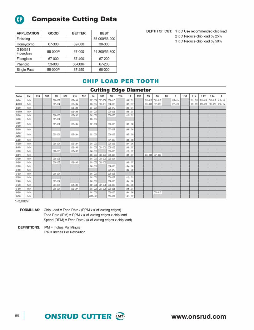
89 ONSRUD CUTTER www.onsrud.com
CP Composite Cutting Data
DEPTH OF CUT: 1 x D Use recommended chip load2 x D Reduce chip load by 25%3 x D Reduce chip load by 50%
APPLICATION GOOD BETTER BEST
Finishing 55-000/58-000
Honeycomb 67-300 32-000 30-300
G10/G11Fiberglass 56-000P 67-000 54-300/55-300
Fiberglass 67-000 67-400 67-200
Phenolic 53-000 56-000P 67-200
Single Pass 56-000P 67-250 68-000
FORMULAS: Chip Load = Feed Rate / (RPM x # of cutting edges)Feed Rate (IPM) = RPM x # of cutting edges x chip loadSpeed (RPM) = Feed Rate / (# of cutting edges x chip load)
DEFINITIONS: IPM = Inches Per MinuteIPR = Inches Per Revolution
* = 10,000 RPM
CHIP LOAD PER TOOTH
Cutting Edge DiameterSeries Cut 1/16 3/32 1/8 5/32 3/16 7/32 1/4 5/16 3/8 7/16 1/2 9/16 5/8 3/4 7/8 1 1 1/8 1 1/4 1 1/2 1 3/4 2
48-000 1 x D .006 - .008 .006 - .008 .007 - .009 .007 - .009 .008 - .010 .009 - .011 .010 - .012 .011 - .013 .012 - .014 .013 - .015 .014 - .016 .015 - .017 .016 - .018
48-000DE 1 x D .002 - .004 .002 - .004 .003 - .005 .003 - .005 .004 - .006 .005 - .007 .006 - .008 .007 - .009 .008 - .010 .009 - .011 .010 - .012 .011 - .013 .012 - .014
48-600 1 x D .006 - .008 .007 - .009 .008 - .010 .009 - .011
48-600DE 1 x D .002 - .005 .003 - .005 .004 - .006 .005 - .007
52-000 1 x D .003 - .005 .003 - .005 .004 - .006 .006 - .008 .010 - .012
53-000 1 x D .002 - .004 .003 - .005
54-000 /59-000
1 x D .002 - .004 .002 - .004 .002 - .004 .003 - .006 .005 - .010
54-300 1 x D .007 - .009 .008 - .010
55-000 /58-000
1 x D .002 - .004 .002 - .004 .002 - .004 .003 - .006 .007 - .009
55-300 1 x D .007 - .009 .008 - .010
56-000P 1 x D .002 - .004 .002 - .004 .004 - .006 .004 - .006 .004 - .006
56-450 1 x D .002 - .005 .003 - .005 .003 - .006 .004 - .006 .005 - .007
57-000 1 x D .003 - .005 .003 - .005 .004 - .006 .006 - .008 .010 - .012
60-470 1 x D .003 - .005 .003 - .005 .004 - .008 .005 - .007 .006 - .008 .007 - .009
62-000 1 x D .003 - .005 .004 - .006 .004 - .006 .005 - .007
63-000 1 x D .003 - .005 .003 - .005 .003 - .005 .004 - .006 .005 - .007
67-000 1 x D .004 - .006 .004 - .006 .004 - .006
67-200 1 x D .002 - .010 .002 - .010
67-250 1 x D .002 - .004 .004 - .006 .004 - .006
67-300 1 x D .004 - .006 .006 - .008 .010 - .012
67-400 1 x D .002 - .004 .004 - .006 .004 - .006 .004 - .006
67-500 1 x D .001 - .003 .001 - .003 .002 - .004 .002 - .004 .003 - .005 .004 - .006
67-600 1 x D .002 - .004 .002 - .004 .003 - .005 .003 - .005 .004 - .006 .005 - .007
68-000 1 x D .004 - .006 .004 - .006 .004 - .006 .008 - .010
68-200 1 x D .0005 - .001 .001 - .002 .001 - .002
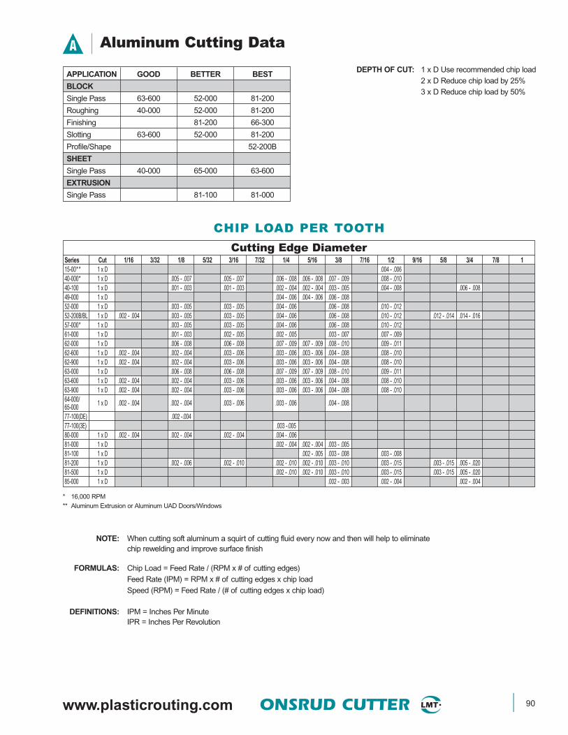
www.plasticrouting.com ONSRUD CUTTER 90
A Aluminum Cutting Data
DEPTH OF CUT: 1 x D Use recommended chip load2 x D Reduce chip load by 25%3 x D Reduce chip load by 50%
APPLICATION GOOD BETTER BEST
BLOCK
Single Pass 63-600 52-000 81-200
Roughing 40-000 52-000 81-200
Finishing 81-200 66-300
Slotting 63-600 52-000 81-200
Profile/Shape 52-200B
SHEET
Single Pass 40-000 65-000 63-600
EXTRUSION
Single Pass 81-100 81-000
FORMULAS: Chip Load = Feed Rate / (RPM x # of cutting edges)Feed Rate (IPM) = RPM x # of cutting edges x chip loadSpeed (RPM) = Feed Rate / (# of cutting edges x chip load)
DEFINITIONS: IPM = Inches Per MinuteIPR = Inches Per Revolution
NOTE: When cutting soft aluminum a squirt of cutting fluid every now and then will help to eliminatechip rewelding and improve surface finish
CHIP LOAD PER TOOTH
* 16,000 RPM
** Aluminum Extrusion or Aluminum UAD Doors/Windows
Cutting Edge DiameterSeries Cut 1/16 3/32 1/8 5/32 3/16 7/32 1/4 5/16 3/8 7/16 1/2 9/16 5/8 3/4 7/8 115-00** 1 x D .004 - .00640-000* 1 x D .005 - .007 .005 - .007 .006 - .008 .006 - .008 .007 - .009 .008 - .01040-100 1 x D .001 - .003 .001 - .003 .002 - .004 .002 - .004 .003 - .005 .004 - .008 .006 - .00849-000 1 x D .004 - .006 .004 - .006 .006 - .00852-000 1 x D .003 - .005 .003 - .005 .004 - .006 .006 - .008 .010 - .01252-200B/BL 1 x D .002 - .004 .003 - .005 .003 - .005 .004 - .006 .006 - .008 .010 - .012 .012 - .014 .014 - .01657-000* 1 x D .003 - .005 .003 - .005 .004 - .006 .006 - .008 .010 - .01261-000 1 x D .001 - .003 .002 - .005 .002 - .005 .003 - .007 .007 - .00962-000 1 x D .006 - .008 .006 - .008 .007 - .009 .007 - .009 .008 - .010 .009 - .01162-600 1 x D .002 - .004 .002 - .004 .003 - .006 .003 - .006 .003 - .006 .004 - .008 .008 - .01062-900 1 x D .002 - .004 .002 - .004 .003 - .006 .003 - .006 .003 - .006 .004 - .008 .008 - .01063-000 1 x D .006 - .008 .006 - .008 .007 - .009 .007 - .009 .008 - .010 .009 - .01163-600 1 x D .002 - .004 .002 - .004 .003 - .006 .003 - .006 .003 - .006 .004 - .008 .008 - .01063-900 1 x D .002 - .004 .002 - .004 .003 - .006 .003 - .006 .003 - .006 .004 - .008 .008 - .01064-000/65-000 1 x D .002 - .004 .002 - .004 .003 - .006 .003 - .006 .004 - .008
77-100(DE) .002 -.00477-100(3E) .003 -.00580-000 1 x D .002 - .004 .002 - .004 .002 - .004 .004 - .00681-000 1 x D .002 - .004 .002 - .004 .003 - .00581-100 1 x D .002 - .005 .003 - .008 .003 - .00881-200 1 x D .002 - .006 .002 - .010 .002 - .010 .002 - .010 .003 - .010 .003 - .015 .003 - .015 .005 - .02081-500 1 x D .002 - .010 .002 - .010 .003 - .010 .003 - .015 .003 - .015 .005 - .02085-000 1 x D .002 - .003 .002 - .004 .002 - .004
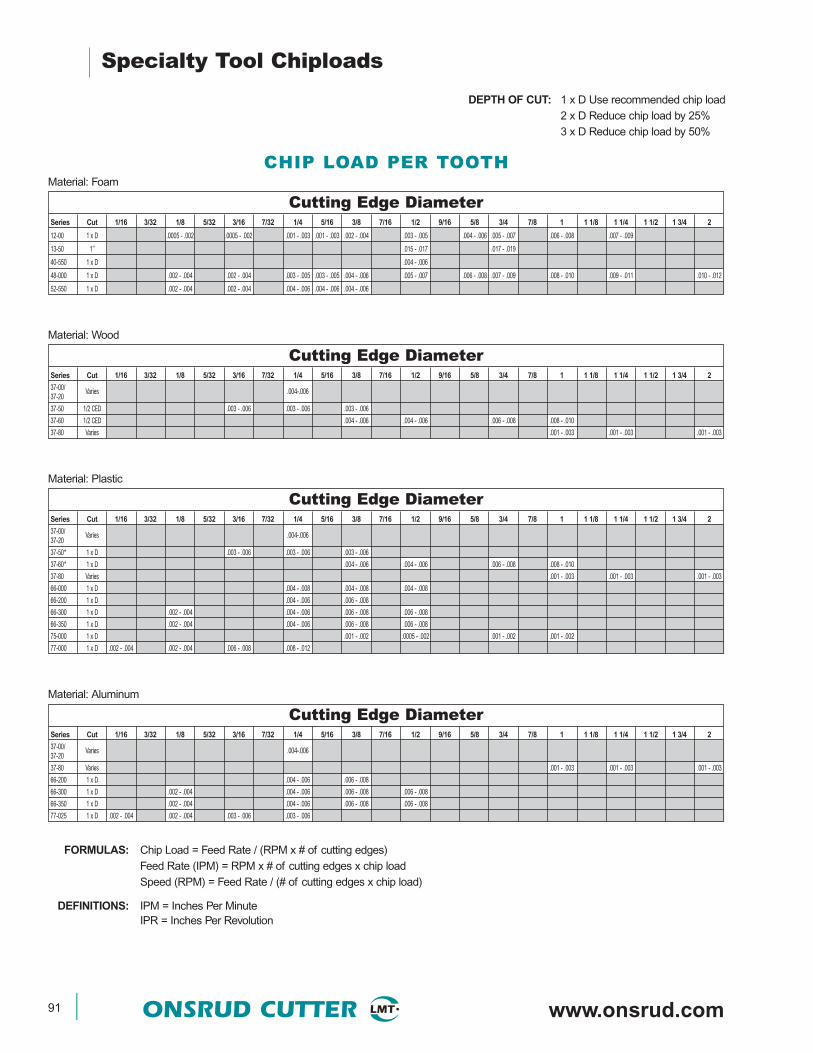
91 ONSRUD CUTTER www.onsrud.com
Cutting Edge DiameterSeries Cut 1/16 3/32 1/8 5/32 3/16 7/32 1/4 5/16 3/8 7/16 1/2 9/16 5/8 3/4 7/8 1 1 1/8 1 1/4 1 1/2 1 3/4 2
12-00 1 x D .0005 - .002 .0005 - .002 .001 - .003 .001 - .003 .002 - .004 .003 - .005 .004 - .006 .005 - .007 .006 - .008 .007 - .009
13-50 1” .015 - .017 .017 - .019
40-550 1 x D .004 - .006
48-000 1 x D .002 - .004 .002 - .004 .003 - .005 .003 - .005 .004 - .006 .005 - .007 .006 - .008 .007 - .009 .008 - .010 .009 - .011 .010 - .012
52-550 1 x D .002 - .004 .002 - .004 .004 - .006 .004 - .006 .004 - .006
Specialty Tool Chiploads
DEPTH OF CUT: 1 x D Use recommended chip load2 x D Reduce chip load by 25%3 x D Reduce chip load by 50%
FORMULAS: Chip Load = Feed Rate / (RPM x # of cutting edges)Feed Rate (IPM) = RPM x # of cutting edges x chip loadSpeed (RPM) = Feed Rate / (# of cutting edges x chip load)
DEFINITIONS: IPM = Inches Per MinuteIPR = Inches Per Revolution
CHIP LOAD PER TOOTHMaterial: Foam
Material: Wood
Material: Plastic
Material: Aluminum
Cutting Edge DiameterSeries Cut 1/16 3/32 1/8 5/32 3/16 7/32 1/4 5/16 3/8 7/16 1/2 9/16 5/8 3/4 7/8 1 1 1/8 1 1/4 1 1/2 1 3/4 2
37-00/37-20
Varies .004-.006
37-50 1/2 CED .003 - .006 .003 - .006 .003 - .006
37-60 1/2 CED .004 - .006 .004 - .006 .006 - .008 .008 - .010
37-80 Varies .001 - .003 .001 - .003 .001 - .003
Cutting Edge DiameterSeries Cut 1/16 3/32 1/8 5/32 3/16 7/32 1/4 5/16 3/8 7/16 1/2 9/16 5/8 3/4 7/8 1 1 1/8 1 1/4 1 1/2 1 3/4 2
37-00/37-20
Varies .004-.006
37-50* 1 x D .003 - .006 .003 - .006 .003 - .006
37-60* 1 x D .004 - .006 .004 - .006 .006 - .008 .008 - .010
37-80 Varies .001 - .003 .001 - .003 .001 - .003
66-000 1 x D .004 - .008 .004 - .008 .004 - .008
66-200 1 x D .004 - .006 .006 - .008
66-300 1 x D .002 - .004 .004 - .006 .006 - .008 .006 - .008
66-350 1 x D .002 - .004 .004 - .006 .006 - .008 .006 - .008
75-000 1 x D .001 - .002 .0005 - .002 .001 - .002 .001 - .002
77-000 1 x D .002 - .004 .002 - .004 .006 - .008 .008 - .012
Cutting Edge DiameterSeries Cut 1/16 3/32 1/8 5/32 3/16 7/32 1/4 5/16 3/8 7/16 1/2 9/16 5/8 3/4 7/8 1 1 1/8 1 1/4 1 1/2 1 3/4 2
37-00/37-20
Varies .004-.006
37-80 Varies .001 - .003 .001 - .003 .001 - .003
66-200 1 x D .004 - .006 .006 - .008
66-300 1 x D .002 - .004 .004 - .006 .006 - .008 .006 - .008
66-350 1 x D .002 - .004 .004 - .006 .006 - .008 .006 - .008
77-025 1 x D .002 - .004 .002 - .004 .003 - .006 .003 - .006

www.plasticrouting.com ONSRUD CUTTER 92
Solid Surface Cutting Data
DEPTH OF CUT: 1 x D Use recommended chip load2 x D Reduce chip load by 25%3 x D Reduce chip load by 50%
SSP
Cutting Edge DiameterSeries Cut 1/16 3/32 1/8 5/32 3/16 7/32 1/4 5/16 3/8 7/16 1/2 9/16 5/8 3/4 7/8 137-50 1 x D .003 - .006 .003 - .006 .003 - .00637-60 1 x D .004 - .006 .004 - .006 .006 - .008 .008 -.01038-50/38-60 1 x D .002 - .004 .002 - .004 .003 - .005 .004 - .006 .005 - .007 .006 - .008 .007 - .009
52-000 1 x D .003 - .006 .003 - .006 .004 - .006 .008 - .010 .012 - .01452-200B/BL 1 x D .002 - .004 .002 - .004 .002 - .004 .004 - .006 .004 - .006 .006 - .008 .008 - .010 .010 - .01252-400 1 x D .002 - .004 .002 - .004 .003 - .005 .004 - .006 .005 - .007 .006 - .008 .007 - .00952-600 1 x D .004 - .006 .006 - .008 .008 - .010 .008 - .010 .010 - .01256-000P 1 x D .002 - .004 .002 - .004 .004 - .006 .006 - .008 .008 - .01056-450 1 x D .002 - .004 .002 - .004 .003 - .005 .004 - .006 .005 - .00757-000 1 x D .002 - .004 .002 - .004 .003 - .005 .004 - .006 .005 - .00757-200 1 x D .002 - .004 .002 - .004 .003 - .005 .004 - .006 .005 - .007 .006 - .008 .007 - .00957-400 1 x D .002 - .004 .002 - .004 .003 - .005 .004 - .006 .005 - .007 .006 - .008 .007 - .00957-600 1 x D .004 - .006 .006 - .008 .008 - .010 .008 - .010 .010 - .01260-200 1 x D .002 - .004 .002 - .006 .002 - .006 .004 - .00860-470 1 x D .002 - .004 .002 - .006 .002 - .006 .004 - .00862-700 1 x D .002 - .004 .004 - .006 .006 - .010 .006 - .010 .010 - .01262-750 1 x D .002 - .004 .004 - .006 .006 - .010 .006 - .010 .010 - .01262-800 1 x D .002 - .004 .004 - .006 .006 - .010 .006 - .010 .010 - .01262-850 1 x D .002 - .004 .004 - .006 .006 - .010 .006 - .010 .010 - .01263-700 1 x D .002 - .003 .002 - .004 .004 - .006 .006 - .010 .006 - .010 .010 - .01263-750 1 x D .002 - .003 .002 - .004 .004 - .006 .006 - .010 .006 - .010 .010 - .01263-800 1 x D .002 - .003 .002 - .004 .004 - .006 .006 - .010 .006 - .010 .010 - .01263-850 1 x D .002 - .003 .002 - .004 .004 - .006 .006 - .010 .006 - .010 .010 - .01264-000/65-000 1 x D .002 - .004 .006 - .008 .008 - .010 .010 - .012 .010 - .012 .010 - .012
66-000 1 x D .002 - .004 .003 - .005 .004 - .006
FORMULAS: Chip Load = Feed Rate / (RPM x # of cutting edges) DEFINITIONS:Feed Rate (IPM) = RPM x # of cutting edges x chip load IPM = Inches Per MinuteSpeed (RPM) = Feed Rate / (# of cutting edges x chip load) IPR = Inches Per Revolution
CHIP LOAD PER TOOTH
Drilling Cutting Data DEPTH OF CUT: 1 x D Use recommended chip load2 x D Reduce chip load by 25%3 x D Reduce chip load by 50%
FORMULAS: RPM = (3.82 x SFM) / tool dia. DEFINITIONS:Feedrate (IPM) = RPM x IPR IPM = Inches Per Minute
IPR = Inches Per Revolution
* Gang drills run at 4,500 RPM and 150 IPM
Drill DiameterSeries SFM 3 1/8 3/16 5 6 1/4 5/16 8 3/8 7/16 1/2 5/8 3/4 7/8 167-800 Composites 230 .001 - .003 .001 - .003 .002 - .004 .002 - .004 .003 - .005 .003 - .005 .003 - .00568-900 Composites 165 0.001 0.0015 0.0015 0.001570-500 Plastic 200 .019 - .021 .021 - .023 .023 - .025 .025 - .027 .027 - .029 .029 - .031 .031 - .033 .033 - .03572-000* Wood .009 - .011 .011 - .013 .013 - .015 .015 - .01786-000 Kevlar 132 0.0005 0.0005 0.001 0.001 0.001 0.001 0.001

93 ONSRUD CUTTER www.onsrud.com
These safety and operating instructions are not intended tobe and are not totally comprehensive. They do not, and cannot,cover every possible safety problem which may arise in usingspecialized and standard tooling on varying machines andapplications. These guidelines are intended to generally describemany of the basic safety and operating procedures which shouldbe followed and to describe the types of safety considerationswhich should be considered in operating cutting tools.
None of the statements or information presented should beinterpreted to imply any warranty or safety protection.
The drawings do not depict any particular design, type, or sizeof tools, equipment or machines. The drawings are illustrativeonly and are not to be construed to establish any exact mode,method or procedure.
All Federal and State laws and regulations having jurisdictioncovering the safety requirements of cutting tools at the point ofusage take precedence over the statements and information pre-sented in this publication. Users of cutting tools must, of course,adhere to all such regulations. As an aid to cutting tool users anumber of such regulations are listed below. The list does notinclude all regulations that may apply.
1. The Federal Register dated June 27, 1974, Dept. of Labor,Office of Safety and Health Administration (The OSHA Act)
2. American National Standards Institute,01.1-1975 (Safety Regulations for Woodworking Machinery)
3. American National Standards Institute,02.1-1969 (Safety Requirements for Sawmills)
4. American National Standards Institute,P1.1-1969 (Safety Requirements for Pulp,Paper and Paperboard Mills)
5. Other ANSI, State and/or Federal Codes and Regulationswhich may apply in your operation
1.Safety Rules Which Apply to the Operationof ALL Cutting Tools
• Always inspect the cutting tool completely before mounting.Never attempt to operate a tool which has chipped or bentteeth or cutting edges or teeth that are not sharp. You must befamiliar with normal wear conditions for the type of tooling tobe used. The tool must be completely clean to allow propervisual inspection.
• Do not attempt to operate cutting tools or machinery withwhich you are not familiar or have not received operationaltraining - get assistance from your supervisor, his designatedrepresentative or a trainer who is familiar and properly trainedand experienced on the machine to insure your safety.Become completely familiar with all of the machinerymanufacturer’s written instructions, guides and manualsbefore operating machine. You must use and be familiar withall controls, safety devices and emergency stop mechanismsto operate a machine safely.
• Never operate a cutting tool that is not properly aligned to thedirection of feed. Do not allow sideward, twisting or other thanforward pressure on the cutting tool in feeding material into a cut.
• Make sure the tool is mounted to rotate in the proper directionbefore cutting any material. The tool must rotate against, ratherthan with, the direction of feed on all hand feed machines. Donot climb on hand feed machines.
• Do not cut materials of a type, hardness or density other thanthat which the cutting tool was designed to cut. Never attemptto cut materials with a tool unless you have personally checkedwith your supervisor to make sure the cutting tool wasdesigned for the specific type of material you wish to cut, andfor the depth of cut desired. This is particularly important whenattempting to cut “stacked” material, i.e., cutting more than onepiece at a time.
• Never force-feed materials into a cutting tool such that itcauses the tool or machine motor to slow down below oper-ating speeds. A safe and proper cutting operation will notrequire much force in feeding material. If material begins to“ride up” on the cutting tool, or requires undue pressure tofeed the material into the tool, or if unduevibration is experienced, do not continue the cut – turn offall power and correct the condition.
• Keep body and clothing well clear of all cutting tools andother moving parts while the machine is in operation. Usework holding fixtures and mechanical feed devices in allpossible cases. When cutting material of such size, shapeor type that it necessitates close approximation to thecutter and mechanical feed mechanisms can not be used,use a wood “push stick” to feed the material so that no partof your body or clothing comes close to the cutting tool.
• Never attempt to clean a cutting tool or clear pieces ofmaterial from the cutting area while machine power is “on”or when cutting tools, material or any part of the machine ismoving. Allow cutter rotation to stop by itself, or by use of abrake if supplied on the machine. Never attempt to stop orslow a rotating cutting tool by applying a hand-held or anyother object to the cutter, arbor, spindle or drive as a brake.
• Do not place your body in the rotational path of a cuttingtool unless absolutely necessary , and then only if there isa complete and adequate barrier between you and thecutting tool. Remember that carbide tips are very hard and,therefore, brittle. The tips can break away under incorrectside thrust or twisting forces, or if foreign material isallowed to contact the tips. An operator can reduce thedanger of being hurt by a “kickback” of the material if healways stands beside the material he is feeding into themachine rather than in back of it.
• Never leave machines unattended while cutting tools are stillrotating or any part of the machine or material is moving.
• Never operate a machine without using all of the hoods,guards, hold downs and safety devices for the machinebeing operated.
• Machines must be maintained to the manufacturer’s standardsand current safety standards.
• Always wear safety glasses or face shield to completely protectyour eyes when operating cutting tools.
SAFETY GUIDELINES

www.plasticrouting.com ONSRUD CUTTER 94
2.Router Tool Mounting Instructions
• TURN OFF AND LOCK OUT ALL MACHINE POWER.Remove the collet chuck and collet (see the machinemanufacturer’s instructions ) and clean them. Also clean thespindle and tool. Remove all nicks and burrs by very lightlyhoning (do not use coarse files or coarse abrasives). Whenremoving parts and tools from a machine, handle themcarefully. Never use hard metal hammers to loosen machineparts or tools, and never allow the teeth of cutting tools totouch steel even when they are dull, for this will cause thecutting edges to be damaged.
• WITH ALL MACHINE POWER OFF AND LOCKED OUT,push the machine spindle up and down and to and fro by handpressure (without rotating the spindle). There should be nofeeling of movement. Next, rotate the spindle by hand. Thespindle should turn freely without sticking or rubbing if thebearings are in proper condition.
• WITH ALL MACHINE POWER OFF AND LOCKED OUT,check the condition of the collet chuck by mounting thecollet and collet chuck in the spindle with a ground test barpositioned full depth into the chuck. A 3 inch length of drillrod will serve as a test bar. Set up a dial indicator as shownin Fig. 1, and check the runout of the test bar, turning themachine spindle by hand. Runout of the test bar in excessof machinery manufacturer’s recommendation couldindicate a worn or damaged collet, or worn spindlebearings or spindle assembly. Make all correctionsnecessary before mounting the cutting tool.
• WITH ALL MACHINE POWER OFF AND LOCKED OUT,remove the test bar and mount the router bit or router tool inthe machine after inspecting the tool. Do not mount any toolthat is dull or damaged and check shank of bit to be sure it fitssecurely into collet. Be sure the router bit or tool is positionedcompletely into the collet to the full depth of the shank andclamped only on the smooth, straight surface of the shank (seeFig. 2). Never clamp only a portion of the shank to “extend” thecutting depth, or clamp on the body below the shank. If there isa radius between the tool shank and body, be sure to clampabove the radius. Check the tool with the dial indicator (as inFig. 3). Tools that have an excess runout (more than ±.002) orthat wobble, are unsafe at the high spindle rotating speeds ofrouter machines, and must be corrected or replaced.
• SPECIAL NOTE: Whenever a router bit is removed from amachine, inspect the shank for collet markings (brown or blackspots, or lines on the shank). If markings are present, thecollet may be worn and should be checked. Worn collets causeundue vibration in the router bit, which can work harden thetool causing it to break.
Fig. 1
Fig. 2
Fig. 3
SAFETY GUIDELINES

95 ONSRUD CUTTER www.onsrud.com
3.Router Tool Special Operation Precautions
• Never run router tools in machines other than router machines.Do not operate router tools in drill presses, portable drills, etc.
• Operate only router tools and router bits that have the shortestpossible cutting edge length in order to maintain the cuttingload as close as possible to the collet chuck support (never usea longer cutting edge length to “reach” the material). Materialshould just clear the collet chuck as it moves through the cut.Do not operate router tools with only part of the tool shankclamped in the collet to make the tool “reach” deep cuts. Theentire shank must be clamped in the collet. Do not clamp thetool on any radius between the shank and body.
• Router tools are often limited in capacity of the chip pocket(area in front of the cutting edge which carries away the chip)because of the small diameter of the tool. Over-feeding (forcingmaterial into the cut) can cause compression of chips that canresult in bending or breaking of the router bit of tool. Smalldiameter router bits are limited in the amount of clearancethat can be designed and manufactured into the tool due to theneed to maximize strength in the tool body. Fast feedingof router bits can result in overloading the clearance spacebetween the material cut and the steel behind the cutting edge.When such an operating condition occurs, dangerous,high overload pressures rapidly develop that can causebending and breakage of the tool. Don’t force-feed materialinto these tools.
• If the cutting tool and the material tend to push away from oneanother, or if they bounce or vibrate against each other, stopthe machine immediately. Do not use force to continue the cut.Do not operate the machine until the machine or tool conditionis corrected.
• Never feed material into a router tool when the material is notsupported by the machine table and table guide rails, or thatrequires the hands or clothing to be dangerously close to therotating parts of the machine. Keep body and clothing wellclear of the cutting tool while in operation.
• Always wear safety glasses to completely protect eyes whenoperating routing tools.
Special Notes On Portable Routers
• Follow machinemanufacturer’s recommendationson properinspection andoperation of theportable router.
• Insure that theunit is unpluggedat all times duringinspection.
• Make sure that therouter motor isclamped securelyin the base at all times.
• Insure that the router bit shank is always inserted aMINIMUM of 5/8” up into the collet.
• Total router bit runout should not exceed ± .004.
• Inspect the collet frequently. The collet should be replacedwhen use causes wear at point A or at point B (see Fig. 4).Continued use of such a worn collet can cause bit vibrationand set up stresses that result in bit breakage.
SAFETY GUIDELINES
THESE SAFETY GUIDELINES ARE REPRINTED BY AUTHORIZATION
OF THE WOOD MACHINERY MANUFACTURERS OF AMERICA
Fig. 4
WOOD MACHINERYMANUFACTURERSOF AMERICA
PROFIT THROUGH AMERICAN TECHNOLOGY

TOOL MODIFICATIONPart Number Description
BALLNOSE RADIUS: _____________
RADIUS DIAMETER: ___________
CHAMFER CUT OFF AND CHAMFER
CUT-REPOINT CUT OFF TIP AND REPOINT
CUT-TIP CUT OFF TIP UNDER 1/8
*ERL/SPNBCK CEL RQD: _____ DIA: _____
FLAT FLATS ON SHANK
REPOINT-1/8 REPOINT LESS THAN 1/8"
• Note: ERL price is based on one inch length.Actual ERL length = ERL length - CEL
www.plasticrouting.com ONSRUD CUTTER 96
FLAT LENGTH ERL DIAMETER
FLAT DEPTH
CUT OFF & CHAMBER LENGTH
CUT OFF TIP LENGTHRE-POINT LENGTHCUT OFF & RE-POINT LENGTH
CORNER RADIUSCHAMFEROR BALL NOSE DIAMETER
ERL LENGTH
(COMPLETE ERL DIAMETER)
(COMPLETE ERL LENGTH)(COMPLETE FLAT DEPTH)
(COMPLETE FLAT LENGTH)
CEL
NOTE: NOTIFY ENGINEERING IF CUSTOMER REQUESTS A MODIFICATION THAT DOES NOT APPEAR ON THIS FORM
DISTRIBUTOR _________________
DISTRIBUTOR NUMBER _________________
DISTRIBUTOR PO NUMBER _________________
DATE _________________
TOOL TO BE MODIFIED (PART NUMBER) _________________
QUANTITY _________________
SALES ORDER NUMBER _________________
NOTES: __________________________________________________________________________________________________
__________________________________________________________________________________________________
__________________________________________________________________________________________________
INSIDE SALES SIGNATURE _________________
OPERATOR SIGNATURE _________________
INSPECTION SIGNATURE _________________
DATE & TIME _________________
DATE & TIME _________________
DATE & TIME _________________
Tool Modification Instructions
• Complete form• Fax to Onsrud with purchase order number.• Orders must be received before 2:30 PM (Central time)
in order to ship the following day.• You will receive a confirmation fax
RESHARPENING MODIFICATIONS

97 ONSRUD CUTTER www.onsrud.com
ONSRUD CUTTER LP800 Liberty Drive - Libertyville, Illinois 60048Phone (847) 362-1560 - Fax (847) 362-5028
www.onsrud.com
QUOTE REQUEST FORM
Distributor ___________________________________________________________ Quote # ______________________________________
Contact _____________________________________________________________ Part # _________________________________________
Phone _______________________________________________________________ Date __________________________________________
Fax _________________________________________________________________ Quote needed by _______________________________
End User ___________________________________________________________ Tools required by _______________________________
Contact ______________________________________________________________ Annual usage __________________________________
Phone _______________________________________________________________ One time need? ________________________________
Qty breaks (minimum qty 6) ____________________________________________
Special Etch Required? _______________________________________________ Etch # _________________________________________
Competitive pricing/Required pricing ____________________________________
Competitive Part #____________________________________________________
TOOL DESCRIPTION Cutting edge dia: ______________________________ Cutting edge length: ____________________________
Shank length: ________________________________ Overall length: _________________________________
MATERIAL ■■■■ solid carbide ■■■■ carbide tip ■■■■ high speed steel
FLUTE STYLE ■■■■ spiral upcut ■■■■ spiral downcut ■■■■ straight ”O” flute ■■■■ straight “V” flute
# OF EDGES ■■■■ single edge ■■■■ double edge ■■■■ 3-flute
GEOMETRY SIMILAR TO OC SERIES #/PART # ____________________________________________________________________________
Other ________________________________________________________________ Tool provided by enduser ■■■■ Yes ■■■■ No
Coating _____________________________________________________________ Approval print required ■■■■ Yes ■■■■ No
Application ___________________________________________________________ What type of material is being cut? _______________
Machine type ■■■■ CNC ■■■■ Manual/Pin ■■■■ Portable/Hand-fed
Spindle Speed ______________________________________________________________________________________________
Depth of cut ____________________ Feed Rate: Max __________________________________ Min _____________________________
Application ■■■■ Hard Plastic ■■■■ Soft Plastic ■■■■ Natural Wood ■■■■ Composite Wood
■■■■ Plywood ■■■■ Aluminum ■■■■ Other ____________________________________________
Specific Material Information ____________________________________________________________________________________________
COMMENTS _________________________________________________________________________________________________________
______________________________________________________________________________________________________________________
______________________________________________________________________________________________________________________
______________________________________________________________________________________________________________________
______________________________________________________________________________________________________________________
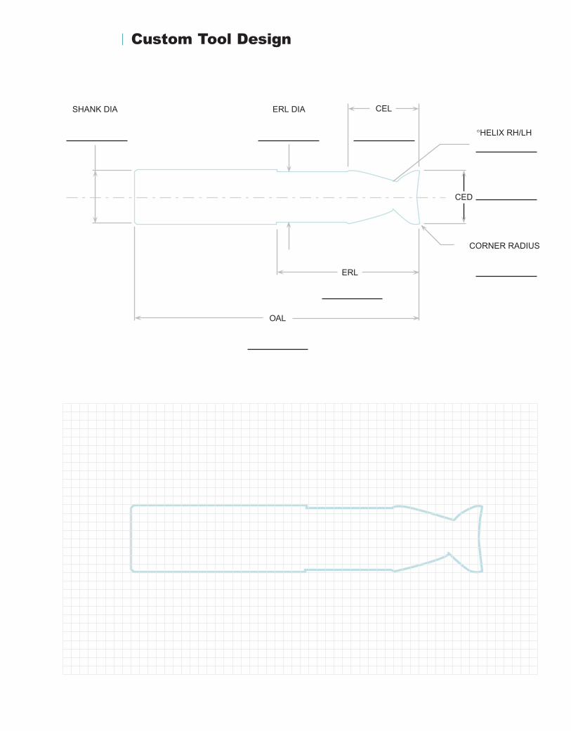
Custom Tool Design
ERL DIA
ERL
CEL
OAL
SHANK DIA
CORNER RADIUS
°HELIX RH/LH
CED

Leitz Metalworking Technology Group
ONSRUD CUTTER LP
800 Liberty Drive Libertyville, IL 60048 USA TOLL FREE: 800/234-1560
www.onsrud.comwww.plasticrouting.com
ISO 9001 Certified
Printed in USA / Catalog OC-06
Distributed By: