Memory Products Data Book - Micro-Semiconductor.com
172
© 2007 Microchip Technology Inc. DS00157E Memory Products Data Book
-
Upload
khangminh22 -
Category
Documents
-
view
1 -
download
0
Transcript of Memory Products Data Book - Micro-Semiconductor.com

© 2007 Microchip Technology Inc. DS00157E
Memory ProductsData Book

Note the following details of the code protection feature on Microchip devices:• Microchip products meet the specification contained in their particular Microchip Data Sheet.
• Microchip believes that its family of products is one of the most secure families of its kind on the market today, when used in the intended manner and under normal conditions.
• There are dishonest and possibly illegal methods used to breach the code protection feature. All of these methods, to our knowledge, require using the Microchip products in a manner outside the operating specifications contained in Microchip’s Data Sheets. Most likely, the person doing so is engaged in theft of intellectual property.
• Microchip is willing to work with the customer who is concerned about the integrity of their code.
• Neither Microchip nor any other semiconductor manufacturer can guarantee the security of their code. Code protection does not mean that we are guaranteeing the product as “unbreakable.”
Code protection is constantly evolving. We at Microchip are committed to continuously improving the code protection features of ourproducts. Attempts to break Microchip’s code protection feature may be a violation of the Digital Millennium Copyright Act. If such actsallow unauthorized access to your software or other copyrighted work, you may have a right to sue for relief under that Act.
Information contained in this publication regarding deviceapplications and the like is provided only for your convenienceand may be superseded by updates. It is your responsibility toensure that your application meets with your specifications.MICROCHIP MAKES NO REPRESENTATIONS ORWARRANTIES OF ANY KIND WHETHER EXPRESS ORIMPLIED, WRITTEN OR ORAL, STATUTORY OROTHERWISE, RELATED TO THE INFORMATION,INCLUDING BUT NOT LIMITED TO ITS CONDITION,QUALITY, PERFORMANCE, MERCHANTABILITY ORFITNESS FOR PURPOSE. Microchip disclaims all liabilityarising from this information and its use. Use of Microchipdevices in life support and/or safety applications is entirely atthe buyer’s risk, and the buyer agrees to defend, indemnify andhold harmless Microchip from any and all damages, claims,suits, or expenses resulting from such use. No licenses areconveyed, implicitly or otherwise, under any Microchipintellectual property rights.
DS00157E-page ii
Trademarks
The Microchip name and logo, the Microchip logo, Accuron, dsPIC, KEELOQ, KEELOQ logo, microID, MPLAB, PIC, PICmicro, PICSTART, PRO MATE, rfPIC and SmartShunt are registered trademarks of Microchip Technology Incorporated in the U.S.A. and other countries.
AmpLab, FilterLab, Linear Active Thermistor, Migratable Memory, MXDEV, MXLAB, SEEVAL, SmartSensor and The Embedded Control Solutions Company are registered trademarks of Microchip Technology Incorporated in the U.S.A.
Analog-for-the-Digital Age, Application Maestro, CodeGuard, dsPICDEM, dsPICDEM.net, dsPICworks, dsSPEAK, ECAN, ECONOMONITOR, FanSense, FlexROM, fuzzyLAB, In-Circuit Serial Programming, ICSP, ICEPIC, Mindi, MiWi, MPASM, MPLAB Certified logo, MPLIB, MPLINK, PICkit, PICDEM, PICDEM.net, PICLAB, PICtail, PowerCal, PowerInfo, PowerMate, PowerTool, REAL ICE, rfLAB, Select Mode, Smart Serial, SmartTel, Total Endurance, UNI/O, WiperLock and ZENA are trademarks of Microchip Technology Incorporated in the U.S.A. and other countries.
SQTP is a service mark of Microchip Technology Incorporated in the U.S.A.
All other trademarks mentioned herein are property of their respective companies.
© 2007, Microchip Technology Incorporated, Printed in the U.S.A., All Rights Reserved.
Printed on recycled paper.
© 2007 Microchip Technology Inc.
Microchip received ISO/TS-16949:2002 certification for its worldwide headquarters, design and wafer fabrication facilities in Chandler and Tempe, Arizona; Gresham, Oregon and design centers in California and India. The Company’s quality system processes and procedures are for its PIC® MCUs and dsPIC® DSCs, KEELOQ® code hopping devices, Serial EEPROMs, microperipherals, nonvolatile memory and analog products. In addition, Microchip’s quality system for the design and manufacture of development systems is ISO 9001:2000 certified.

M
PAGE
Table of Contents
SECTION 1 MICROCHIP TECHNOLOGY INC. INTRODUCTIONIntroduction ........................................................................................................................1-1
SECTION 2 SERIAL EEPROM SELECTION GUIDE AND CROSS REFERENCESerial EEPROM Selection Guide .......................................................................................2-1Competitor Part Numbering Guide .....................................................................................2-9
SECTION 3 FAMILY DATA SHEETSI2C™ Family Data Sheet ....................................................................................................3-1Microwire Family Data Sheet............................................................................................3-31SPI Family Data Sheet .....................................................................................................3-57Specialty Product References ..........................................................................................3-89
SECTION 4 APPLICATION NOTESAN1028 – Recommended Usage of Microchip I2C™ Serial EEPROM Devices ................4-1AN1029 – Recommended Usage of Microchip Microwire Serial EEPROM Devices..........4-9AN1040 – Recommended Usage of Microchip SPI Serial EEPROM Devices .................4-13
SECTION 5 PACKAGINGPackage Outline Drawings .................................................................................................5-1Product Tape and Reel Specifications .............................................................................5-11Solder Reflow Recommendation ......................................................................................5-19Overview of Microchip Die/Wafer Support........................................................................5-23
SECTION 6 DEVELOPMENT TOOLSTotal Endurance™ Software Model....................................................................................6-1SEEVAL® 32 Serial EEPROM Designer’s Kit.....................................................................6-2
© 2007 Microchip Technology Inc. DS00157E-page iii

M
DS00157E-page iv © 2007 Microchip Technology Inc.

1Introduction
1M
SECTION 1MICROCHIP TECHNOLOGY INC.
INTRODUCTION
Introduction ...............................................................................................................................................1-1
© 2007 Microchip Technology Inc. DS00157E-page 1-i

M
DS00157E-page 1-ii © 2007 Microchip Technology Inc.

1Introduction
1
MICROCHIP TECHNOLOGY INC.Section 1 - Introduction
1.0 INTRODUCTIONMicrochip Technology Inc. is a leading provider ofmicrocontrollers, analog and interface semiconductors,and serial nonvolatile memory. Based in Chandler,Arizona USA, Microchip owns its wafer fabricationfacilities in Tempe, Arizona and Gresham, Oregon, aswell as its own assembly and test facility in Thailand.One of the most solid and stable performers in thesemiconductor world, Microchip provides a broadproduct portfolio meeting the needs of the embeddedcontrol market, including:
• 8-bit PIC® microcontrollers• 16-bit PIC® microcontroller and dsPIC® digital
signal controllers• Complete line of Analog products including LDOs,
PORs, Voltage refs, ADCs, DACs, op amps, comparators, PGAs, thermal management and power management solutions
• Interface products supporting CAN, IRDA® standard, LIN and serial
• High-performance specialty and standard serial EEPROM devices compatible with all three popular buses: I2C™, Microwire and SPI
• Security devices (KEELOQ® products)
Please request a Microchip Product Line Card for alisting of the entire Microchip product offering. Thisliterature can be obtained from your local sales office ordownloaded from Microchip’s informative web site atwww.microchip.com.
1.1 Manual OverviewSerial EEPROM product requirements are provided inthree Family Data Sheets which have been groupedinto the specific I2C™, Microwire, and SPI bus types.As of the date of printing, all data sheets are currentand represent products that are in full production. Sincethis information is subject to change without notice, it isrecommended that the latest version of the data sheetshould be downloaded before finalizing any designs.Please check for the most recent revisions or productavailability by contacting your local Microchip salesoffice, Representative, Distributor or by visiting usonline at www.microchip.com/Memory.
All buses are compatible with de facto industrystandards, including I2C, Microwire and SPI. In mostcases the Microchip device can be used as a drop-inreplacement for competitor devices. And for newdesigns, Microchip’s value-added features can providesmaller footprint, lower power consumption, and fasterbus rates than many commodity devices.
Two useful sections are provided at the front of themanual:
• Serial EEPROM Selection Guide – every serial EEPROM in the Microchip offering is listed here, along with the most important AC/DC parameters and package options for quick comparison and selection. Full data sheets are provided in this manual for each device listed in the Selection Guide. For the most up-to-date information, be sure to check Microchip’s web site at www.microchip.com.
• Competitive Part Numbering Guide – this guide provides the basic part numbering schemes from several serial EEPROM manufacturers without having to search through endless versions of old data sheets for a part description. Since part numbers from each manufacturer contains unique codes for temperature, packaging and voltage, as well as other parameters, a single location with this information should be very useful when determining a Microchip replacement. Once the parameters from a competitive device are known, Microchip’s MAPS (Microchip Advanced Parts Selector) tool can be used to determine the cor-rect Microchip device to use. You can download MAPS at www.microchip.com/MAPS.
1.2 Key EEPROM ParametersI2C EEPROMS from the 24AAXX family of devices nowhave a wider operating voltage from 1.7V to 5.5V overthe entire density range from 128 bits to 1 Mbit. Thismeets the need for lower operating voltages to supportthe ever increasing number of battery operatedsystems. In addition, the higher speed 24FCXX familyof devices can also meet the requirements for 400 kHzoperation over the voltage range from 1.8V to 2.5V and1 MHz at voltages of 2.5V and above.
© 2007 Microchip Technology Inc. DS00157E-page 1-1

MICROCHIP TECHNOLOGY INC.
SPI EEPROMs from the 25LCXX family of devices nowhave higher operating speeds for all densities rangingfrom 1 Kbit up to 1 Mbit. This includes speeds up to 10MHz for densities up to 256 Kbits and 20 MHz for the512 Kbit and 1 Mbit devices. As an added bonus, the512K and 1 Mbit devices have been released asEEPROM/Flash devices. Designed as a robustEEPROM for high endurance, wide voltage range andbyte/page operations, they also respond to standardFlash commands and sector operations.1.3 Packaging: RoHS CompliantMicrochip serial EEPROMs are packaged atMicrochip’s own facilities and by authorizedsubcontractors. After packaging, whether in-house oroutside at a subcontractor, every device is 100% testedagain in a Microchip facility prior to shipment.
Microchip excels at micro-miniature packaging forserial EEPROMs, including the following:
• 8-lead SOIC – up to 1 Mbit• 8-lead MSOP – up to 256 Kbits• 8-lead TSSOP – up to 256 Kbits• 5-lead SOT23 – up to 16 Kbits• 6-lead SOT23 – up to 16 Kbits• 8-lead 5x6 DFN – up to 1 Mbit• 8-lead 2x3 DFN – up to 64 Kbits• Die and wafer packaging – all densities
All products use Pb-free plating, and all are RoHScompliant. A rigorous qualification and productionenvironment ensures high-temperature solderability,moisture sensitivity level, absence of whisker growth,and reliability of the new Pb-Free package family.
1.4 QualityMicrochip delivers the highest-quality serial EEPROMproducts in the world, with world-class line yields, well-designed processes, and rigorous Statistical ProcessControl (SPC) in each of its continuous-improvementfacilities. Outgoing quality level is close to 0 ppmacross nearly a billion serial EEPROMs shipped eachyear.
Each serial EEPROM is tested three times: first atwafer-level, where each individual die on the waferreceives 100% AC/DC testing of all data sheetparameters. At the end of that test, each die isprogrammed with data in each memory cell and thenbaked for five hours at 250°C to ensure data retentionspecs. Following the bake, every die on every wafer istested again, including AC/DC data sheet parametersand special tests of the data array to verify oxide qualityand to limit infant mortality. Finally, after packaging,every device receives a final functional test to screenout any potential assembly-related issues.
After final test, quality samples are taken continuously tomonitor reliability. The resulting data is available annuallyin a formal report available at www.microchip.com.
For Microchip, quality is not a side issue - it is integralto our culture, our systems and our products. It is, infact, our business model.
1.5 Development ToolsMicrochip provides some of the best serial EEPROMtools in the industry, including:
• SEEVAL® 32 Designer’s Kit – a feature-rich and easy-to-use programmer/data viewer supporting all Microchip Serial EEPROM products. This inexpensive tool can shorten time-to-market by weeks. Easy to set-up and use right out of the box, it can help solve a week’s worth of headaches in an afternoon. See the Development Tools section of this manual for more information.
• Total Endurance™ software – a powerful mathematical model for predicting Erase/Write endurance of your specific serial EEPROM in your specific application. All serial EEPROMs, from all manufacturers, eventually experience bit-failures after some number of erase/write cycles. Microchip’s serial EEPROM endurance is among the best in the world, and Total Endurance software is the only tool of its kind for modeling and predicting device lifetime. This can help designers to produce a robust design since trade-off analysis is so fast with this easy-to-use software modeling tool.
Any discussion of endurance must include theparameters of voltage, temperature, semiconductorprocess, cell design, array size, bytes per cycle,and cycles per day in order to understand what theendurance number means - and to predict how agiven device will perform in a particular application.Total Endurance software accepts your input ofeach of these parameters and outputs FIT rate orMTBF vs. time or vs. number of cycles. Download itfor FREE at www.microchip.com.
1.6 e-CommerceMicrochip serial EEPROMs are available from anyMicrochip distributor, sales representative or salesoffice and even from Microchip’s own e-commerce site,www.microchipDirect.com. They can also be sampledfor free from Microchip’s main web site www.micro-chip.com - and delivered fast. Just click the “Sample”button to order free samples or the “Buy Online” buttonto purchase serial EEPROMs using a credit card.
DS00157E-page 1-2 © 2007 Microchip Technology Inc.

MProduct SelectionC
ross Reference
2SECTION 2
SERIAL EEPROMSELECTION GUIDE AND CROSS REFERENCE
Serial EEPROM Selection Guide ..............................................................................................................2-1Competitor Part Numbering Guide ............................................................................................................2-9
© 2007 Microchip Technology Inc. DS00157E-page 2-i

M
DS00157E-page 2-ii © 2007 Microchip Technology Inc.

© 2007 M
icrochip Technology Inc.D
S00157E
-page 2-1
ProdCros 2
SERIA
L EEPRO
MS
I2C™ Compatible
Device VCCRange
WriteProtect
Page Size
Max Clock
WriteCycle Cascade Endurance Temp
Grade Packages DataSheet
128-bit I2C compatible24AA00 1.8-5.5 No N/A 400 kHz 4 ms No 1,000,000 I P, SN, ST, OT, MC DS21178
24 DS21178
24 DS21178
1K24 DS21711
24 DS21711
24 DS21201
24 DS21809
24 DS21809
24 DS21160
24 DS21161
2K24 DS21709
24 DS21709
24 DS21682
24 DS21202
24 DS21166
24 DS21166
24 DS21210
24 DS21210
24 DS21210
24 DS21210
Serial EE
PRO
M Selection G
uide
P = C = 2x3 mm DFNMo
I2C
uct Selections Reference
LC00 2.5-5.5 No N/A 400 kHz 4 ms No 1,000,000 I P, SN, ST, OT, MC
C00 4.5-5.5 No N/A 400 kHz 4 ms No 1,000,000 I, E P, SN, ST, OT, MC
bit I2C compatibleAA01 1.8-5.5 Yes 8 bytes 400 kHz 5 ms No 1,000,000 I P, SN, ST, MS, OT, MC
LC01B 2.5-5.5 Yes 8 bytes 400 kHz 5 ms No 1,000,000 I, E P, SN, ST, MS, OT, MC
C01C 4.5-5.5 Yes 16 bytes 400 kHz 1 ms 8 1,000,000 I, E P, SN, ST, MS, MC
AA014 1.8-5.5 Yes 16 bytes 400 kHz 10 ms 8 1,000,000 I P, SN, ST, MS, MC
LC014 2.5-5.5 Yes 16 bytes 400 kHz 10 ms 8 1,000,000 I P, SN, ST, MS, MC
LC21A 2.5-5.5 No 8 bytes 400 kHz 10 ms No 1,000,000 I P, SN
LCS21A 2.5-5.5 Yes 8 bytes 400 kHz 10 ms No 1,000,000 I P, SN
bit I2C compatibleAA02 1.8-5.5 Yes 8 bytes 400 kHz 5 ms No 1,000,000 I P, SN, ST, MS, OT, MC
LC02B 2.5-5.5 Yes 8 bytes 400 kHz 5 ms No 1,000,000 I, E P, SN, ST, MS, OT, MC
LCS22A 2.5-5.5 Yes 8 bytes 400 kHz 10 ms No 1,000,000 I P, SN
C02C 4.5-5.5 Yes 16 bytes 400 kHz 1 ms 8 1,000,000 I, E P, SN, ST, MS, MC
LCS52 2.5-5.5 Yes 16 bytes 400 kHz 5 ms 8 1,000,000 I P, SN, ST, MS, MC
AA52 1.8-5.5 Yes 16 bytes 400 kHz 5 ms 8 1,000,000 I P, SN, ST, MS, MC
AA024 1.8-5.5 Yes 16 bytes 400 kHz 10 ms 8 1,000,000 I P, SN, ST, MS, MC
LC024 2.5-5.5 Yes 16 bytes 400 kHz 10 ms 8 1,000,000 I, E P, SN, ST, MS, MC
AA025 1.8-5.5 No 16 bytes 400 kHz 10 ms 8 1,000,000 I P, SN, ST, MS, MC
LC025 2.5-5.5 No 16 bytes 400 kHz 10 ms 8 1,000,000 I, E P, SN, ST, MS, MC
8 PDIP, SN = 150 Mil SOIC, SM = 207 Mil SOIC, ST = 8 TSSOP, MS = 8 MSOP, OT = SOT-23, MF = 6x5 mm DFN, ST14 = 14 TSSOP, Mst devices also available in die and wafer form. Please contact Microchip sales office.
is a trademark of Philips Corporation.

SERIA
L EEPRO
MS
DS
00157E-page 2-2
© 2007 M
icrochip Technology Inc.
Packages DataSheet
P, SN, ST, MS, OT, MC DS21708
P, SN, ST, MS, OT, MC DS21708
P, SN, ST, MS, OT, MC DS21710
P, SN, ST, SM, OT, MC DS21710
P, SN, ST, MS, OT, MC DS21703
P, SN, ST, MS, OT, MC DS21703
P, SN, ST, MS, MC DS21713
P, SN, ST, MS, MC DS21713
P, SN, ST, MS, MC DS21189
P, SN, ST, MS, MC DS21189
P, SM DS21073
P, SM DS21073
P, SM DS21073
P, SN, ST, MS, MF DS21191
P, SN, ST, MS, MF DS21191
P, SN, ST, MS, MF DS21191
P, SN, ST, MS, MF DS21203
P, SN, ST, MS, MF DS21203
P, SN, ST, MS, MF DS21203
I2C Compatible
Device VCCRange
WriteProtect
Page Size
Max Clock
WriteCycle Cascade Endurance Temp
Grade
4Kbit I2C compatible24AA04 1.8-5.5 Yes 16 bytes 400 kHz 5 ms No 1,000,000 I
24LC04B 2.5-5.5 Yes 16 bytes 400 kHz 5 ms No 1,000,000 I, E
8Kbit I2C compatible24AA08 1.8-5.5 Yes 16 bytes 400 kHz 5 ms No 1,000,000 I
24LC08B 2.5-5.5 Yes 16 bytes 400 kHz 5 ms No 1,000,000 I, E
16Kbit I2C compatible24AA16 1.8-5.5 Yes 16 bytes 400 kHz 5 ms No 1,000,000 I
24LC16B 2.5-5.5 Yes 16 bytes 400 kHz 5 ms No 1,000,000 I, E
32Kbit I2C compatible24AA32A 1.8-5.5 Yes 32 bytes 400 kHz 5 ms 8 1,000,000 I
24LC32A 2.5-5.5 Yes 32 bytes 400 kHz 5 ms 8 1,000,000 I, E
64Kbit I2C compatible24AA64 1.8-5.5 Yes 32 bytes 400 kHz 5 ms 8 1,000,000 I
24LC64 2.5-5.5 Yes 32 bytes 400 kHz 5 ms 8 1,000,000 I, E
24AA65 1.8-5.5 Yes 64 bytes 400 kHz 2 ms 8 1M/10M O
24LC65 2.5-5.5 Yes 64 bytes 400 kHz 2 ms 8 1M/10M I
24C65 4.5-5.5 Yes 64 bytes 400 kHz 2 ms 8 1M/10M I
128Kbit I2C compatible24AA128 1.8-5.5 Yes 64 bytes 400 kHz 5 ms 8 1,000,000 I
24LC128 2.5-5.5 Yes 64 bytes 400 kHz 5 ms 8 1,000,000 I, E
24FC128 1.8-5.5 Yes 64 bytes 1 MHz 5 ms 8 1,000,000 I
256Kbit I2C compatible24AA256 1.8-5.5 Yes 64 bytes 400 kHz 5 ms 8 1,000,000 I
24LC256 2.5-5.5 Yes 64 bytes 400 kHz 5 ms 8 1,000,000 I, E
24FC256 1.8-5.5 Yes 64 bytes 1 MHz 5 ms 8 1,000,000 I

© 2007 M
icrochip Technology Inc.D
S00157E
-page 2-3
SERIA
L EEPRO
MS
ProdCros 2
5124 , SM, ST14, MF DS21754
24 , SM, ST14, MF DS21754
24 , SM, ST14, MF DS21754
24 P, SM DS21673
24 P, SM DS21673
24 P, SM DS21673
I2
Packages DataSheet
Mi
es DataSheet
1K93 , OT, MC DS21749
93 , OT, MC DS21749
93 , OT, MC DS21749
93 , OT, MC DS21749
93 , OT, MC DS21749
93 , OT, MC DS21749
93 S, MC DS21749
93 S, MC DS21749
93 S, MC DS21749
2K93 , OT, MC DS21794
93 , OT, MC DS21794P MC = 2x3 mm DFN
M
uct Selection s Reference
2Kbit I2C compatibleAA512 1.8-5.5 Yes 128 bytes 400 kHz 5 ms 8 1,000,000 I P
LC512 2.5-5.5 Yes 128 bytes 400 kHz 5 ms 8 1,000,000 I, E P
FC512 2.5-5.5 Yes 128 bytes 1 MHz 5 ms 8 1,000,000 I P
AA515 1.8-5.5 Yes 64 bytes 400 kHz 5 ms 4 1,000,000 I
LC515 2.5-5.5 Yes 64 bytes 400 kHz 5 ms 4 1,000,000 I
FC515 2.5-5.5 Yes 64 bytes 1 MHz 5 ms 4 1,000,000 I
C Compatible
Device VCCRange
WriteProtect
Page Size
Max Clock
WriteCycle Cascade Endurance Temp
Grade
crowire Compatible
Device VCC Range
ORGPin
WordSize
Max Clock
WriteCycle Endurance Temp
Grade Packag
bit Microwire compatibleAA46A 1.8-5.5 No 8-bit 2 MHz 6 ms 1,000,000 I P, SN, ST, MS
AA46B 1.8-5.5 No 16-bit 2 MHz 6 ms 1,000,000 I P, SN, ST, MS
LC46A 2.5-5.5 No 8-bit 2 MHz 6 ms 1,000,000 I, E P, SN, ST, MS
LC46B 2.5-5.5 No 16-bit 2 MHz 6 ms 1,000,000 I, E P, SN, ST, MS
C46A 4.5-5.5 No 8-bit 2 MHz 2 ms 1,000,000 I, E P, SN, ST, MS
C46B 4.5-5.5 No 16-bit 2 MHz 2 ms 1,000,000 I, E P, SN, ST, MS
AA46C 1.8-5.5 Yes 8- or 16-bit 3 MHz 6 ms 1,000,000 I P, SN, ST, M
LC46C 2.5-5.5 Yes 8- or 16-bit 3 MHz 6 ms 1,000,000 I, E P, SN, ST, M
C46C 4.5-5.5 Yes 8- or 16-bit 3 MHz 2 ms 1,000,000 I, E P, SN, ST, M
bit Microwire compatibleAA56A 1.8-5.5 No 8-bit 2 MHz 6 ms 1,000,000 I P, SN, ST, MS
AA56B 1.8-5.5 No 16-bit 2 MHz 6 ms 1,000,000 I P, SN, ST, MS= 8 PDIP, SN = 150 Mil SOIC, SM = 207 Mil SOIC, ST = 8 TSSOP, MS = 8 MSOP, OT = SOT-23, MF = 6x5 mm DFN, ST14 = 14 TSSOP,
ost devices also available in die and wafer form. Please contact Microchip sales office.

SERIA
L EEPRO
MS
DS
00157E-page 2-4
© 2007 M
icrochip Technology Inc.
, MS, OT, MC DS21794
, MS, OT, MC DS21794
, MS, OT, MC DS21794
, MS, OT, MC DS21794
ST, MS, MC DS21794
ST, MS, MC DS21794
ST, MS, MC DS21794
, MS, OT, MC DS21795
, MS, OT, MC DS21795
, MS, OT, MC DS21795
, MS, OT, MC DS21795
, MS, OT, MC DS21795
, MS, OT, MC DS21795
ST, MS, MC DS21795
ST, MS, MC DS21795
ST, MS, MC DS21795
OT DS21796
OT DS21796
OT DS21796
OT DS21796
OT DS21796
OT DS21796
ST, MS, MC DS21796
ST, MS, MC DS21796
ST, MS, MC DS21796
ckages DataSheet
2Kbit Microwire compatible (continued)93LC56A 2.5-5.5 No 8-bit 2 MHz 6 ms 1,000,000 I, E P, SN, ST
93LC56B 2.5-5.5 No 16-bit 2 MHz 6 ms 1,000,000 I, E P, SN, ST
93C56A 4.5-5.5 No 8-bit 2 MHz 2 ms 1,000,000 I, E P, SN, ST
93C56B 4.5-5.5 No 16-bit 2 MHz 2 ms 1,000,000 I, E P, SN, ST
93AA56C 1.8-5.5 Yes 8- or 16-bit 3 MHz 6 ms 1,000,000 I P, SN,
93LC56C 2.5-5.5 Yes 8- or 16-bit 3 MHz 6 ms 1,000,000 I, E P, SN,
93C56C 4.5-5.5 Yes 8- or 16-bit 3 MHz 2 ms 1,000,000 I, E P, SN,
4Kbit Microwire compatible93AA66A 1.8-5.5 No 8-bit 2 MHz 6 ms 1,000,000 I P, SN, ST
93AA66B 1.8-5.5 No 16-bit 2 MHz 6 ms 1,000,000 I P, SN, ST
93LC66A 2.5-5.5 No 8-bit 2 MHz 6 ms 1,000,000 I, E P, SN, ST
93LC66B 2.5-5.5 No 16-bit 2 MHz 6 ms 1,000,000 I, E P, SN, ST
93C66A 4.5-5.5 No 8-bit 2 MHz 2 ms 1,000,000 I, E P, SN, ST
93C66B 4.5-5.5 No 16-bit 2 MHz 2 ms 1,000,000 I, E P, SN, ST
93AA66C 1.8-5.5 Yes 8- or 16-bit 3 MHz 6 ms 1,000,000 I P, SN,
93LC66C 2.5-5.5 Yes 8- or 16-bit 3 MHz 6 ms 1,000,000 I, E P, SN,
93C66C 4.5-5.5 Yes 8- or 16-bit 3 MHz 2 ms 1,000,000 I, E P, SN,
8Kbit Microwire compatible93AA76A 1.8-5.5 No 8-bit 3 MHz 6 ms 1,000,000 I
93AA76B 1.8-5.5 No 16-bit 3 MHz 6 ms 1,000,000 I
93LC76A 2.5-5.5 No 8-bit 3 MHz 6 ms 1,000,000 I, E
93LC76B 2.5-5.5 No 16-bit 3 MHz 6 ms 1,000,000 I, E
93C76A 4.5-5.5 No 8-bit 3 MHz 2 ms 1,000,000 I, E
93C76B 4.5-5.5 No 16-bit 3 MHz 2 ms 1,000,000 I, E
93AA76C 1.8-5.5 Yes 8- or 16-bit 3 MHz 6 ms 1,000,000 I P, SN,
93LC76C 2.5-5.5 Yes 8- or 16-bit 3 MHz 6 ms 1,000,000 I, E P, SN,
93C76C 4.5-5.5 Yes 8- or 16-bit 3 MHz 2 ms 1,000,000 I, E P, SN,
Microwire Compatible
Device VCC Range
ORGPin
WordSize
Max Clock
WriteCycle Endurance Temp
Grade Pa

© 2007 M
icrochip Technology Inc.D
S00157E
-page 2-5
SERIA
L EEPRO
MS
ProdCros 2
1693 DS21797
93 DS21797
93 DS21797
93 DS21797
93 DS21797
93 DS21797
93 S, MC DS21797
93 S, MC DS21797
S
ges DataSheet
1K25 ST, MC DS21832
25 ST, MC DS21832
2K25 ST, MC DS21833
25 ST, MC DS21833
4K25 ST, MC DS21827
25 ST, MC DS21827
Mi
es DataSheet
uct Selection s Reference
Kbit Microwire compatibleAA86A 1.8-5.5 No 8-bit 3 MHz 6 ms 1,000,000 I OT
AA86B 1.8-5.5 No 16-bit 3 MHz 6 ms 1,000,000 I OT
LC86A 2.5-5.5 No 8-bit 3 MHz 6 ms 1,000,000 I, E OT
LC86B 2.5-5.5 No 16-bit 3 MHz 6 ms 1,000,000 I, E OT
C86A 4.5-5.5 No 8-bit 3 MHz 2 ms 1,000,000 I, E OT
C86B 4.5-5.5 No 16-bit 3 MHz 2 ms 1,000,000 I, E OT
AA86C 1.8-5.5 Yes 8- or 16-bit 3 MHz 6 ms 1,000,000 I P, SN, ST, M
LC86C 2.5-5.5 Yes 8- or 16-bit 3 MHz 6 ms 1,000,000 I, E P, SN, ST, M
PI Compatible Products
Device VCCRange
WriteProtect
PageSize
Max Clock
WriteCycle Endurance Temp
Grade Packa
bit SPI compatibleAA010A 1.8-5.5 Yes 16 byte 10 MHz 5 ms 1,000,000 I P, MS, SN,
LC010A 2.5-5.5 Yes 16 byte 10 MHz 5 ms 1,000,000 I, E P, MS, SN,
bit SPI compatibleAA020A 1.8-5.5 Yes 16 byte 10 MHz 5 ms 1,000,000 I P, MS, SN,
LC020A 2.5-5.5 Yes 16 byte 10 MHz 5 ms 1,000,000 I, E P, MS, SN,
bit SPI compatibleAA040A 1.8-5.5 Yes 16 byte 10 MHz 5 ms 1,000,000 I P, MS, SN,
LC040A 2.5-5.5 Yes 16 byte 10 MHz 5 ms 1,000,000 I, E P, MS, SN,
crowire Compatible
Device VCC Range
ORGPin
WordSize
Max Clock
WriteCycle Endurance Temp
Grade Packag

SERIA
L EEPRO
MS
DS
00157E-page 2-6
© 2007 M
icrochip Technology Inc.
, ST, MS DS21808
, ST, MS DS21808
, ST, MS DS21808
, ST, MS DS21808
, ST, MS DS21807
, ST, MS DS21807
, ST, MS DS21807
, ST, MS DS21807
, SN, ST DS21828
, SN, ST DS21828
, SN, ST DS21830
, SN, ST DS21830
, ST, MF DS21831
, ST, MF DS21831
, ST, MF DS21822
, ST, MF DS21822
SN, MF DS22021
SN, MF DS22021
ckages DataSheet
8Kbit SPI compatible25AA080A 1.8-5.5 Yes 16 byte 10 MHz 5 ms 1,000,000 I P, SN
25AA080B 1.8-5.5 Yes 32 byte 10 MHz 5 ms 1,000,000 I P, SN
25LC080A 2.5-5.5 Yes 16 byte 10 MHz 5 ms 1,000,000 I, E P, SN
25LC080B 2.5-5.5 Yes 32 byte 10 MHz 5 ms 1,000,000 I, E P, SN
16Kbit SPI compatible25AA160A 1.8-5.5 Yes 16 byte 10 MHz 5 ms 1,000,000 I P, SN
25AA160B 1.8-5.5 Yes 32 byte 10 MHz 5 ms 1,000,000 I P, SN
25LC160A 2.5-5.5 Yes 16 byte 10 MHz 5 ms 1,000,000 I, E P, SN
25LC160B 2.5-5.5 Yes 32 byte 10 MHz 5 ms 1,000,000 I, E P, SN
32Kbit SPI compatible25AA320A 1.8-5.5 Yes 32 byte 10 MHz 5 ms 1,000,000 I P, MS
25LC320A 2.5-5.5 Yes 32 byte 10 MHz 5 ms 1,000,000 I, E P, MS
64Kbit SPI compatible25AA640A 1.8-5.5 Yes 32 byte 10 MHz 5 ms 1,000,000 I P, MS
25LC640A 2.5-5.5 Yes 32 byte 10 MHz 5 ms 1,000,000 I, E P, MS
128Kbit SPI compatible25AA128 1.8-5.5 Yes 64 byte 10 MHz 5 ms 1,000,000 I P, SN
25LC128 2.5-5.5 Yes 64 byte 10 MHz 5 ms 1,000,000 I, E P, SN
256Kbit SPI compatible25AA256 1.8-5.5 Yes 64 byte 10 MHz 5 ms 1,000,000 I P, SN
25LC256 2.5-5.5 Yes 64 byte 10 MHz 5 ms 1,000,000 I, E P, SN
512Kbit SPI compatible25AA512 1.8-5.5 Yes 128 byte 20 MHz 5 ms 1,000,000 I P,
25LC512 2.5-5.5 Yes 128 byte 20 MHz 5 ms 1,000,000 I, E P,
SPI Compatible Products
Device VCCRange
WriteProtect
PageSize
Max Clock
WriteCycle Endurance Temp
Grade Pa

© 2007 M
icrochip Technology Inc.D
S00157E
-page 2-7
SERIA
L EEPRO
MS
ProdCros 2
Pl
1 25 MF DS21836
25 MF DS21836
S
ges DataSheet
Packages Data Sheet
Se24 , SN, ST, MS, MC DS21166
24 , SN, ST, MS, MC DS21166
24 , SN, ST, MS, MC DS21210
24 , SN, ST, MS, MC DS21210
S24 P, SN DS21160
24 P, SN DS21161
24 P, SN DS21682
34 , SN, ST, MS, MC DS22029
34 , SN, ST, MS, MC DS22029
34 , SN, ST, MS, MC DS22029
S24 , SN, ST, OT, MC DS21178
24 , SN, ST, OT, MC DS21178
24 , SN, ST, OT, MC DS21178P
M
uct Selection s Reference
ug-and-Play® and ID Products
Mbit SPI compatibleAA1024 1.8-5.5 Yes 256 byte 20 MHz 5 ms 1,000,000 I P, SM,
LC1024 2.5-5.5 Yes 256 byte 20 MHz 5 ms 1,000, 000 I, E P, SM,
PI Compatible Products
Device VCCRange
WriteProtect
PageSize
Max Clock
WriteCycle Endurance Temp
Grade Packa
Device Density VCCRange
WriteProtect
PageSize
MaxClock
WriteCycle Type Endurance Temp
Grade
rial EEPROMs for DRAM DIMM modulesLCS52 2Kbit 2.5-5.5 Yes 16 bytes 400 kHz 5 ms DDR 1,000,000 I P
AA52 2Kbit 1.8-5.5 Yes 16 bytes 400 kHz 5 ms DDR 1,000,000 I P
LC024 2Kbit 2.5-5.5 Yes 16 bytes 400 kHz 5 ms DDR 1,000,000 I, E P
LC025 2Kbit 2.5-5.5 No 16 bytes 400 kHz 5 ms DDR 1,000,000 I, E P
erial EEPROMs for VESA® monitors, projectors and flat panelsLC21A 1Kbit 2.5-5.5 No 8 bytes 400 kHz 10 ms — 1,000,000 I
LCS21A 1Kbit 2.5-5.5 Yes 8 bytes 400 kHz 10 ms — 1,000,000 I
LCS22A 2Kbit 2.5-5.5 Yes 8 bytes 400 kHz 10 ms — 1,000,000 I
LC02 2Kbit 2.5-5.5 Yes 16 bytes 400 kHz 5 ms DDR2/3 1,000,000 I/E P
AA02 2Kbit 1.7-5.5 Yes 16 bytes 400 kHz 5 ms DDR2/3 1,000,000 I P
LV02 2Kbit 1.5-5.5 Yes 16 bytes 400 kHz 5 ms DDR2/3 1,000,000 I P
erial EEPROMs for other ID applicationsAA00 128 bit 1.8-5.5 No N/A 400 kHz 4 ms — 1,000,000 I P
LC00 128 bit 2.5-5.5 No N/A 400 kHz 4 ms — 1,000,000 I P
C00 128 bit 4.5-5.5 No N/A 400 kHz 4 ms — 1,000,000 I, E P= 8 PDIP, SN = 150 Mil SOIC, SM = 207 Mil SOIC, ST = 8 TSSOP, MS = 8 MSOP, OT = SOT-23, MF = 8 DFN, ST14 = 14 TSSOP
ost devices also available in die and wafer form. Please contact Microchip sales office.

SERIA
L EEPRO
MS
DS
00157E-page 2-8
© 2007 M
icrochip Technology Inc.
Pb-FreeAvailable Data Sheet
N/A DS21748
N/A DS21748
N/A DS21747
N/A DS21747
N/A DS21745
N/A DS21745
N/A DS21746
N/A DS21746
N/A DS20093
N/A DS20093
N/A DS21723
N/A DS21723
N/A DS21716
N/A DS21716
N/A DS20095
N/A DS20095
N/A DS20094
N/A DS20094
N/A DS21785
N/A DS21785
Smart Card Devices
Device VCCRange
WriteProtect
PageSize
MaxClock
WriteCycle Endurance Temp
Grade Packages
Smart-Card devices (meet ISO 7816 bondout)24AA01SC 1.8-5.5 Yes 8 bytes 400 kHz 5 ms 1,000,000 I W, WF, S
24LC01SC 2.5-5.5 Yes 8 bytes 400 kHz 5 ms 1,000,000 I W, WF, S
24AA02SC 1.8-5.5 Yes 8 bytes 400 kHz 5 ms 1,000,000 I W, WF, S
24LC02SC 2.5-5.5 Yes 8 bytes 400 kHz 5 ms 1,000,000 I W, WF, S
24AA04SC 1.8-5.5 Yes 16 bytes 400 kHz 5 ms 1,000,000 I W, WF, S
24LC04SC 2.5-5.5 Yes 16 bytes 400 kHz 5 ms 1,000,000 I W, WF, S
24AA08SC 1.8-5.5 Yes 16 bytes 400 kHz 5 ms 1,000,000 I W, WF, S
24LC08SC 2.5-5.5 Yes 16 bytes 400 kHz 5 ms 1,000,000 I W, WF, S
24AA16SC 1.8-5.5 Yes 16 bytes 400 kHz 5 ms 1,000,000 I W, WF, S
24LC16SC 2.5-5.5 Yes 16 bytes 400 kHz 5 ms 1,000,000 I W, WF, S
24AA32ASC 1.8-5.5 Yes 32 bytes 400 kHz 5 ms 1,000,000 I W, WF, S
24LC32ASC 2.5-5.5 Yes 32 bytes 400 kHz 5 ms 1,000,000 I W, WF, S
24AA64SC 1.8-5.5 Yes 32 bytes 400 kHz 5 ms 1,000,000 I W, WF, S
24LC64SC 2.5-5.5 Yes 32 bytes 400 kHz 5 ms 1,000,000 I W, WF, S
24AA128SC 1.8-5.5 Yes 64 bytes 400 kHz 5 ms 1,000,000 I W, WF, S
24LC128SC 2.5-5.5 Yes 64 bytes 400 kHz 5 ms 1,000,000 I W, WF, S
24AA256SC 1.8-5.5 Yes 64 bytes 400 kHz 5 ms 1,000,000 I W, WF, S
24LC256SC 2.5-5.5 Yes 64 bytes 400 kHz 5 ms 1,000,000 I W, WF, S
24AA512SC 1.8-5.5 Yes 128 bytes 400 kHz 5 ms 1,000,000 I W, WF, S
24LC512SC 2.5-5.5 Yes 128 bytes 400 kHz 5 ms 1,000,000 I W, WF, SW = wafer, WF = wafer on frame, S = single die in waffle pack.
Standard backgrind thickness are 11 and 15 mil and unground (29 mils).

Product SelectionC
ross Reference
2
SERIAL EEPROMSCompetitor Part Numbering Guide
In order to cross-reference a competitor device to acompatible Microchip device, use Microchip’s powerfulMAPS tool available for free at www.microchip.com/MAPS. You can also decode the competitor partnumber here, where we have provided a means totranslate each code or character.
© 2007 Microchip Technology Inc. DS21621B-page 2-9

SERIA
L EEPRO
MS
DS
21621B-page 2-10
© 2007 M
icrochip Technology Inc.
ensity Comment
1 Kbit
2 Kbit
2 Kbit 1/2 array WP
2 Kbit DIMM serial presence detect, 1.7-3.6V
4 Kbit 1/2 array WP
16 Kbit Whole array WP, 1.8-3.6V
32 Kbit Whole array WP, 1.8-3.6V
64 Kbit Whole array WP, 1.8-3.6V
28 Kbit 1.8-3.6V
56 Kbit 1.8-3.6V
12 Kbit 1.8-3.6V
1 Mbit -1.8 version is maximum 3.6V; -2.7 max. is 5.5V
12 Kbit
1 Kbit x8 or x16
1 Kbit x16 (no ORG pin)
2B, 24HC02B and 24HC04B have maximum voltages of
y package code is not always used.as a 1.7-3.6V range.
Device Option Bus D
AT24C01B(1) I2C™
AT24C02(1) I2C
AT24HC02B(1) I2C
AT34C02C(3) I2C
AT24HC04B(1) I2C
AT24C16B I2C
AT24C32C I2C
AT24C64C I2C
AT24C128B I2C 1
AT24C256B I2C 2
AT24C512B I2C 5
AT24C1024B I2C
AT25512 SPI 5
AT93C46D Microwire
AT93C46E Microwire
Atmel Serial EEPROM Part Number Designations for Newer Products(See also the separate table for Older Atmel Products)
AT24C02B N- P U 25- T
Packing Medium
Voltage Range
Temperature andLead Finish
General PackageCode
Secondary PackageCode
Bus Type
Density and DeviceOption
T Tape and reel
B Bulk
25 2.5-3.6V (or 2.5-5.5V)(1)
Blank 1.83-3.6V (or 1.8-5.5V)(1)
I -40 to 85°C
E, A -40 to 125°C
H -40 to 85°C, Pb-free (NiPdAu)
P -40 to 125°C, Pb-free (NiPdAu)
J, U -40 to 85°C, Pb-free
Q -40 to 125°C, Pb-free
P PDIP
S SOIC
T TSSOP
TS SOT-23
Y DFN (2x3, 5x3, or 6x5 mm)
C DFN (8x5 mm)
U BGA
W Die
N SOIC (JEDEC, 150 mil)(2)
W SOIJ (EIAJ, 208 mil)
Y6 2x3 mm DFN
Y1 5x3 mm DFN
Y4, Y7 6x5 mm DFN
C1 8x5 mm DFN
U2, U3, U4 BGA
R Rotated pinout
Blank Other package
24 I2C™
25 SPI
93 Microwire
See table
Note 1: AT24C01B, 24C05.5V.
2: The “N” secondar3: The AT34C02C h

© 2007 M
icrochip Technology Inc.D
S21621B
-page 2-11
SERIA
L EEPRO
MS
Product SelectionCross Reference 2
Device Option Bus Density Comment
AT24C01, C11 I2C™ 1 Kbit No WP, no address pins
AT24C01A I2C 1 Kbit Whole array WP, 3 address pins
AT24C02 I2C 2 Kbit Whole array WP
AT24C02A I2C 2 Kbit 1/2 array WP
AT34C02/02B I2C 2 Kbit DIMM serial presence detect
AT24C04 I2C 4 Kbit Whole array WP
AT24C04A I2C 4 Kbit 1/2 array WP
AT24C08 I2C 8 Kbit No WP
AT24C08A I2C 8 Kbit Whole array WP
AT24C16 I2C 16 Kbit 1/2 array WP, no address pins
AT24C16A I2C 16 Kbit Whole array WP, no address pins
AT24C164 I2C 16 Kbit Whole array WP, 3 address pins
AT24C32 I2C 32 Kbit 1/4 array WP
AT24C32A I2C 32 Kbit Whole array WP
AT24C64/64B I2C 64 Kbit 1/4 array WP
AT24C64A I2C 64 Kbit Whole array WP
AT24C128(1)/CS128 I2C 128 Kbit -1.8 version is maximum 3.6V; -2.7 max is 5.5V
AT24C256(1) I2C 256 Kbit -1.8 version is maximum 3.6V; -2.7 max is 5.5V
AT24C512 I2C 512 Kbit -1.8 version is maximum 3.6V; -2.7 max is 5.5V
AT24C1024 I2C 1 Mbit
AT25010/010A SPI 1 Kbit
AT25020/020A SPI 2 Kbit
AT25040/040A SPI 4 Kbit
AT25080/080A SPI 8 Kbit
AT25160/160A SPI 16 Kbit
AT25320/320A SPI 32 Kbit
AT25640/640A SPI 64 Kbit
AT25128/128A SPI 128 Kbit
AT25256/256A SPI 256 Kbit
AT25HP256 SPI 256 Kbit
AT25HP512 SPI 512 Kbit
AT25P1024 SPI 1 Mbit
AT93C46/46D Microwire 1 Kbit
AT93C46A/46C/46E Microwire 1 Kbit x16 only (no ORG pin)
AT93C56/56A 2 Kbit
AT93C66/66A 4 Kbit
AT93C86A Microwire 16 Kbit
Atmel Serial EEPROM Part Number Designations for Older Products(See also the separate table for Newer Atmel Products)
AT24C32A N- 10 S U- 2.7 T
Packing Medium
Voltage Range
Temperature andLead Finish
General PackageCode
Secondary PackageCode
Bus Type
Density and DeviceOption
T Tape and reel
B Bulk
5.0 4.5-5.5V
2.7 2.7-5.5V
1.8 1.8-5.5V (or 1.8-3.6V)(1)
1.7 1.7-3.6V
I -40 to 85°C
E, A -40 to 125°C
J, U -40 to 85°C, Pb-free
H -40 to 85°C, Pb-free (NiPdAu)
Q -40 to 125°C, Pb-free
P PDIP
S SOIC
T TSSOP
TS SOT-23
Y DFN (2x3, 5x3, or 6x5 mm)
C DFN (8x5 mm)
U BGA
W Die
N SOIC (JEDEC, 150 mil)(2)
W SOIJ (EIAJ, 208 mil)
Y1 5x3 DFN
Y4 6x5 DFN
Y6 2x3 DFN
C1 8x5 DFN
U2, U3, U4 BGA
R Rotated pinout
Blank Other package
24 I2C™
25 SPI
93 Microwire
See table
Note 1: AT24C128-1.8, AT24CS128-1.8 and AT24C256-1.8 have voltage ranges of 1.8-3.6V.
2: The “N” secondary package code is not always used.

SERIA
L EEPRO
MS
DS
21621B-page 2-12
© 2007 M
icrochip Technology Inc.
Device Option Bus Density Comment
M24C01 I2C™ 1 Kbit
M24C02 I2C 2 Kbit
M34C02 I2C 2 Kbit DIMM serial presence detect
M34E02 I2C 2 Kbit DIMM serial presence detect
M34F04 I2C 4 Kbit 1/2 array WP
M24C04 I2C 4 Kbit
M24C08 I2C 8 Kbit
M24C16 I2C 16 Kbit
M24C32 I2C 32 Kbit
M24C64 I2C 64 Kbit
M34D64 I2C 64 Kbit 1/4 array write-protect
M24128-B I2C 128 Kbit
M24256-B I2C 128 Kbit
M24512 I2C 512 Kbit
M24M01 I2C 1 Mbit
M95010 SPI 1 Kbit
M95020 SPI 2 Kbit
M95040 SPI 4 Kbit
M95080 SPI 8 Kbit
M95160 SPI 16 Kbit
M95320 SPI 32 Kbit
M95640 SPI 64 Kbit
M95128 SPI 128 Kbit
M95256 SPI 256 Kbit
M95512 SPI 512 Kbit
M95M01 SPI 1 Mbit
M93C46 Microwire 1 Kbit
M93C56 Microwire 2 Kbit
M93C66 Microwire 4 Kbit
M93C76 Microwire 8 Kbit
M93C86 Microwire 16 Kbit
STMicroelectronics Serial EEPROM Part Number Designations
M24C32- R MN 6 T P /B
Process Designator
Packing Medium
Temperature Range
Package Code
Voltage Range
Bus Type
Density and DeviceOption
G, P Pb-free
Blank SnPb
T Tape and reel
Blank Bulk
1 0 to 70°C
3 -40 to 125°C
5 -20 to 85°C
6 -40 to 85°C
7 -40 to 105°C
BN PDIP
MN SOIC (JEDEC, 150 mil)
MW SOIC (EIAJ, 208 mil)
DW TSSOP
DS MSOP
MB 2x3 mm DFN
Blank 4.5-5.5V
W 2.5-5.5V
L 2.2-5.5V
R 1.8-5.5V
F 1.7-5.5V
24 I2C™
95 SPI
93 Microwire
See table
Lead Finish
(Optional)

© 2007 M
icrochip Technology Inc.D
S21621B
-page 2-13
SERIA
L EEPRO
MS
Product SelectionCross Reference 2
Device Option Bus Density Comment
CAT24C01 I2C™ 1 Kbit
CAT24C02 I2C 2 Kbit Full array WP
CAT34C02 I2C 2 Kbit DIMM serial presence detect; 1.7-5.5V
CAT24C03 I2C 2 Kbit 1/2 array WP
CAT24C04 I2C 4 Kbit Full array WP
CAT24C05 I2C 4 Kbit 1/2 array WP
CAT24C08 I2C 8 Kbit
CAT24C16 I2C 16 Kbit No address pins
CAT24C164 I2C 16 Kbit 3 address pins
CAT24C32 I2C 32 Kbit
CAT24C64 I2C 64 Kbit
CAT24C128 I2C 128 Kbit
CAT24C256 I2C 256 Kbit
CAT25010 SPI 1 Kbit
CAT25020 SPI 2 Kbit
CAT25040 SPI 4 Kbit
CAT25080 SPI 8 Kbit
CAT25160 SPI 16 Kbit
CAT25320 SPI 32 Kbit
CAT25640 SPI 64 Kbit
CAT93C46 Microwire 1 Kb
CAT93C46R Microwire 1 Kb
CAT93C66 Microwire 2 Kb Older die revs follow the “old” part number convention
CAT93C76 Microwire 8 Kb
Catalyst Serial EEPROM Part Number Designations for Newer Products
CAT24C16 L I- G T 3
Packing Medium
Lead Finish
Temperature
Package Code
Bus Type
Density and DeviceOption
2 2000/reel
3 3000/reel
T Tape and reel
G NiPdAu
Blank Matte tin
I -40 to 85°C
A, E -40 to 125°C
L PDIP
W2, V SOIC (JEDEC, 150 mil)
X SOIC (EIAJ, 208 mil)
Y TSSOP
Z MSOP
TD SOT-23
HU2 2x2 mm DFN
VP2 2x3 mm DFN
ZD4 3x3 mm DFN
ZD2 3x4.9 mm DFN
24 I2C™
25 SPI
93 Microwire
See table
Reel Quantity
(See also the separate table for Older Catalyst Products)
Range
Note 1: Voltage range for all parts is 1.8-5.5V.2: For 93-series products, package code “W” is an alternate, rotated pinout. “V” is the standard pinout.

SERIA
L EEPRO
MS
DS
21621B-page 2-14
© 2007 M
icrochip Technology Inc.
Bus Density Comment
I2C™ 128 bit
I2C 1 Kbit
I2C 1 Kbit
I2C 1 Kbit No WP
I2C 2 Kbit
I2C 4 Kbit
I2C 8 Kbit
I2C 16 Kbit
I2C 16 Kbit 3 address pins
I2C 16 Kbit 1/2 array WP
C32 I2C 32 Kbit
I2C 32 Kbit 1/4 array WP
I2C 64 Kbit
6(3) I2C 64 Kbit
I2C 64 Kbit
29(3) I2C 128 Kbit
I2C 256 Kbit
I2C 256 Kbit
SPI 1 Kbit
SPI 2 Kbit
SPI 4 Kbit
SPI 8 Kbit
SPI 16 Kbit
SPI 32 Kbit
SPI 64 Kbit
SPI 128 Kbit
SPI 256 Kbit
Microwire 1 Kbit
Microwire 2 Kbit
Microwire 4 Kbit
Microwire 16 Kbit
as a voltage range of 1.8 to 5.5V. products, package codes “W” and ”J” are alternate, ts. “V” and “S” are standard pinouts. part.
CAT24WC16 P I- 1.8- G TE13
Lead Finish
Voltage Range
Temperature
Package Code
Bus Type
Density and DeviceOption
Packing Medium
(See also the separate table for Newer Catalyst Products)
Range
Catalyst Serial EEPROM Part Number Designations for Older Products
TE13, T2, T3 Tape and Reel
Blank See package code below
G NiPdAu
3 3.0-5.5V
Blank 2.5-5.5V
1.8 1.8-5.5V
Blank 0 to 70°C
I -40 to 85°C
A -40 to 105°C
E -40 to 125°C
P PDIP
J2, S SOIC (JEDEC, 150 mil)
K SOIC (EIAJ, 208 mil)
U TSSOP
TP SOT-23
R MSOP
SP2 2x3 mm DFN
L, GL PDIP, Pb-free
TB, GTB SOT-23, Pb-free
W2, V, GW, GV SOIC (JEDEC, 150 mil), Pb-free
X, GX SOIC (EIAJ, 208 mil), Pb-free
Y, GY TSSOP, Pb-free
Z, GZ MSOP, Pb-free
VP2 2x3 mm DFN, Pb-free
24 I2C™
25 SPI
93 Microwire
See table
Device Option
CAT24C00(1, 3)
CAT24FC01(3)
CAT24WC01
CAT24C01B(3)
CAT24FC02(3)/WC02
CAT24WC04
CAT24WC08
CAT24WC16(3)
CAT24WC164(3)
CAT24FC17(3)
CAT24FC32(3)/FC32A(3)/W
CAT24WC33
CAT24FC64(3)/WC64
CAT24F65(3)/WC65(3)/FC6
CAT24WC66
CAT24WC128/AC128/WC1
CAT24FC256(3)
CAT24WC256/WC257(3)
CAT25C01(3)/C11(3)
CAT25C02(3)/C03(3)
CAT25C04(3)/C05(3)
CAT25C08/C09(3)
CAT25C16/C17(3)
CAT25C32/C33(3)
CAT25C64/C65(3)
CAT25C128
CAT25C256
93HC46(3)
93C56/C57
93C66
93C86
Note 1: CAT24C00 h2: For 93-series
rotated pinou3: Discontinued

© 2007 Microchip Technology Inc. DS00157E-page 3-i
MFam
ilyD
ata Sheets
3I2C™ Serial EEPROM Family Data Sheet .................................................................................................3-11K-16K Microwire Compatible Serial EEPROM Family Data Sheet .......................................................3-31SPI Serial EEPROM Family Data Sheet .................................................................................................3-57Speciality Product References ................................................................................................................3-89
SECTION 3FAMILY DATA SHEETS
I2C is a trademark of Philips Corporation.Smart Serial is a trademark of Microchip Technology Inc.

M
DS00157E-page 3-ii © 2007 Microchip Technology Inc.

Family
Data Sheets
3
24AA00/24LC00/24C00 24AA01/24LC01B24AA014/24LC014 24C01C24AA02/24LC02B 24C02C24AA024/24LC024 24AA025/24LC02524AA04/24LC04B 24AA08/24LC08B24AA16/24LC16B 24AA32A/24LC32A24AA64/24LC64/24FC64 24AA128/24LC128/24FC12824AA256/24LC256/24FC256 24AA512/24LC512/24FC512
I2C™ Serial EEPROM Family Data Sheet
Features:• 128-bit through 1024 Kbit Devices• Single Supply with Operation Down to 1.7V for
24AAXX Devices• Low-Power CMOS Technology:
- 1 mA active current, typical- 1 μA standby current, typical (I-temp)
• 2-Wire Serial Interface Bus, I2C™ Compatible• Schmitt Trigger Inputs for Noise Suppression• Output Slope Control to Eliminate Ground Bounce• 400 kHz (≥ 2.5V): 24LCXX and 24AAXX• 1 MHz (≥ 2.5V) and 400 kHz (1.7V): 24FCXX • Self-Timed Write Cycle (including Auto-Erase)• Page Write Buffer• Hardware Write-Protect Available on Most
Devices• Factory Programming (QTP) Available• ESD Protection >4,000V• 1 Million Erase/Write Cycles• Data Retention >200 years• 8-lead PDIP, SOIC, TSSOP and MSOP Packages• 5-lead SOT-23 Package (Most 1-16 Kbit Devices)• 8-lead 2x3mm and 5x6mm DFN Packages
Available• Pb-Free and RoHS Compliant• Available for Extended Temperature Ranges:
- Industrial (I): -40°C to +85°C- Automotive (E): -40°C to +125°C
Description:The Microchip Technology Inc. 24CXX, 24LCXX,24AAXX and 24FCXX (24XX*) devices are a family of128-bit through 1024 Kbit Electrically Erased PROMs.The devices are organized in blocks of x8-bit memorywith 2-wire serial interfaces. Low-voltage designpermits operation down to 1.7V (for 24AAXX devices),with standby and active currents of only 1 μA and 1mA, respectively. Devices 1 Kbit and larger have pagewrite capability. Parts having functional address linesallow connection of up to 8 devices on the same bus.The 24XX family is available in the standard 8-pinPDIP, surface mount SOIC, TSSOP and MSOP pack-ages. Most 128-bit through 16 Kbit devices are alsoavailable in the 5-lead SOT-23 package. DFNpackages (2x3mm or 5x6mm) are also available. Allpackages are Pb-free (Matte Tin) finish.
*24XX is used in this document as a generic partnumber for 24 series devices in this data sheet.24XX64, for example, represents all voltages of the 64Kbit device.
Package Types(1)
Note: This document is an overview. Fordetailed specifications, please consult theindividual product data sheet, available atwww.microchip.com.
A0
A1
A2
VSS
1
2
3
4
8
7
6
5
VCC
WP(3)
SCL
SDA
PDIP/SOIC
A0
A1
A2
VSS
1
2
3
4
8
7
6
5
VCC
WP(3)
SCL
SDA
TSSOP/MSOP(2)
1 5
43
SCL
VSS
SDA
VCC
NC
2
SOT-23-5(24XX00)
SOT-23-5
1 5
43
SCL
VSS
SDA
WP
VCC
2
(all except 24XX00)
A0
A1A2
VSS
WP(3)
SCL
SDA5
678
4
321 VCC
DFNNote 1: Pins A0, A1, A2 and WP are not used by some
devices (no internal connections). See Table 1-1,Device Selection Table, for details.
2: Pins A0 and A1 are no-connects for the 24XX128and 24XX256 MSOP devices.
3: Pin 7 is “not used” for 24XX00, 24XX025 and24C01C.
© 2007 Microchip Technology Inc. DS21930C-page 3-1

24AAXX/24LCXX/24FCXX
TABLE 1-1: DEVICE SELECTION TABLE
Part Number VCC Range
Max. Clock Frequency
Page Size
Write-Protect Array
Functional Address
Pins
Temp. Range Packages(5)
128-bit devices
24AA00 1.7-5.5V 400 kHz(1)
— None None
I P, SN, ST, OT, MC
24LC00 2.5-5.5V 400 kHz(1) I
24C00 4.5-5.5V 400 kHz I, E
1 Kb devices
24AA01 1.7-5.5V 400 kHz (2)8 bytes Entire Array None
I P, SN, ST, MS, OT, MC
24LC01B 2.5-5.5V 400 kHz I, E24AA014 1.7-5.5V 400 kHz(2)
16 bytes Entire Array A0, A1, A2I P, SN, ST, MS, MC
24LC014 2.5-5.5V 400 kHz I24AA01H(6) 1.7-5.5v 400 kHz(1) 16 bytes Upper Half A0, A1, A2 I P, SN, ST, MS, OT, MC24LC01H(6) 2.5-5.5v 400 kHz(1) 16 bytes Upper Half A0, A1, A2 I, E P, SN, ST, MS, OT, MC24C01C 4.5V-5.5V 400 kHz 16 bytes None A0, A1, A2 I, E P, SN, ST, MC2 Kb devices24AA02 1.7-5.5V 400 kHz (2)
8 bytes Entire Array NoneI P, SN, ST, MS, OT, MC
24LC02B 2.5-5.5V 400 kHz I, E24AA024 1.7-5.5V 400 kHz(2)
16 bytes Entire Array A0, A1, A2I P, SN, ST, MS, MC
24LC024 2.5-5.5V 400 kHz I24AA025 1.7-5.5V 400 kHz(2)
16 bytes None A0, A1, A2I P, SN, ST,MS, MC
24LC025 2.5-5.5V 400 kHz I24AA02H(6) 1.7-5.5v 400 kHz(1) 16 bytes Upper Half A0, A1, A2 I P, SN, ST, MS, OT, MC24LC02H(6) 2.5-5.5v 400 kHz(1) 16 bytes Upper Half A0, A1, A2 I, E P, SN, ST, MS, OT, MC
24C02C 4.5-5.5V 400 kHz 16 bytes Upper Half of Array
A0, A1, A2 I, E P, SN, ST, MC
4 Kb devices24AA04 1.7-5.5V 400 kHz (2) 16 bytes Entire Array None I P, SN, ST, MS, OT, MC24LC04B 2.5-5.5V 400 kHz I, E8 Kb devices24AA08 1.7-5.5V 400 kHz (2)
16 bytes Entire Array NoneI P, SN, ST, MS, OT, MC
24LC08B 2.5-5.5V 400 kHz I, E16 Kb devices24AA16 1.7-5.5V 400 kHz (2)
16 bytes Entire Array NoneI P, SN, ST, MS, OT, MC
24LC16B 2.5-5.5V 400 kHz I, E32 Kb devices24AA32A 1.7-5.5V 400 kHz (2)
32 bytes Entire Array A0, A1, A2I P, SN, SM, ST, MS, MC
24LC32A 2.5-5.5V 400 kHz I, ENote 1: 100 kHz for VCC <4.5V.
2: 100 kHz for VCC <2.5V.
3: 400 kHz for VCC <2.5V.
4: Pins A0 and A1 are no-connects for the 24XX128 and 24XX256 in the MSOP package.
5: P = 8-PDIP, SN = 8-SOIC (3.90 mm JEDEC), ST = 8-TSSOP, OT = 5 or 6-SOT23, MC = 2x3mm DFN,MS = 8-MSOP, SM = 8-SOIC (200 mil EIAJ), MF = 5x6mm DFN.
6: Available Q4 2007.
DS21930C-page 3-2 © 2007 Microchip Technology Inc.

24AAXX/24LCXX/24FCXXFam
ilyD
ata Sheets
3
64 Kb devices24AA64 1.7-5.5V 400 kHz (2)
32 bytes Entire Array A0, A1, A2I P, SN, SM, ST, MS, MC
24LC64 2.5-5.5V 400 kHz I, E24FC64 1.7-5.5V 1 MHz(3) I128 Kb devices24AA128 1.7-5.5V 400 kHz (2)
64 bytes Entire Array A0, A1, A2(4)
I P, SN, SM, ST, MS, MF24LC128 2.5-5.5V 400 kHz I, E24FC128 1.7-5.5V 1 MHz(3) I256 Kb devices24AA256 1.7-5.5V 400 kHz (2)
64 bytes Entire Array A0, A1, A2(4)
I P, SN, SM, ST, MS, MF24LC256 2.5-5.5V 400 kHz I, E24FC256 1.7-5.5V 1 MHz(3) I512 Kb devices24AA512 1.7-5.5V 400 kHz (2)
128 bytes Entire Array A0, A1, A2
I P, SM, MF,24LC512 2.5-5.5V 400 kHz I, E24FC512 1.7-5.5V(3) 1 MHz I1024 Kb devices24AA1025 1.7-5.5V 400 kHz (2)
128 bytes
I P, SM24LC1025 2.5-5.5V 400 kHz Entire Array A0, A1 I, E24FC1025 1.7-5.5V(3) 1 MHz I
TABLE 1-1: DEVICE SELECTION TABLE (CONTINUED)
Part Number VCC Range
Max. Clock Frequency
Page Size
Write-Protect Array
Functional Address
Pins
Temp. Range Packages(5)
Note 1: 100 kHz for VCC <4.5V.
2: 100 kHz for VCC <2.5V.
3: 400 kHz for VCC <2.5V.
4: Pins A0 and A1 are no-connects for the 24XX128 and 24XX256 in the MSOP package.
5: P = 8-PDIP, SN = 8-SOIC (3.90 mm JEDEC), ST = 8-TSSOP, OT = 5 or 6-SOT23, MC = 2x3mm DFN,MS = 8-MSOP, SM = 8-SOIC (200 mil EIAJ), MF = 5x6mm DFN.
6: Available Q4 2007.
© 2007 Microchip Technology Inc. DS21930C-page 3-3

24AAXX/24LCXX/24FCXX
2.0 ELECTRICAL CHARACTERISTICS
Absolute Maximum Ratings (†)
VCC.............................................................................................................................................................................6.5V
All inputs and outputs w.r.t. VSS ......................................................................................................... -0.6V to VCC +1.0V
Storage temperature ...............................................................................................................................-65°C to +150°C
Ambient temperature with power applied................................................................................................-40°C to +125°C
ESD protection on all pins ......................................................................................................................................................≥ 4 kV
TABLE 2-1: DC CHARACTERISTICS
† NOTICE: Stresses above those listed under “Absolute Maximum Ratings” may cause permanent damage tothe device. This is a stress rating only and functional operation of the device at those or any other conditionsabove those indicated in the operational listings of this specification is not implied. Exposure to maximum ratingconditions for extended periods may affect device reliability.
DC CHARACTERISTICSElectrical Characteristics:Industrial (I): VCC = +1.7V to 5.5V TA = -40°C to +85°CAutomotive (E): VCC = +2.5V to 5.5V TA = -40°C to 125°C
Param.No. Sym. Characteristic Min. Max. Units Conditions
D1 — A0, A1, A2, SCL, SDA and WP pins:
— — — —
D2 VIH High-level input voltage 0.7 VCC — V —D3 VIL Low-level input voltage — 0.3 VCC
0.2 VCCVV
VCC ≥ 2.5VVCC < 2.5V
D4 VHYS Hysteresis of Schmitt Trigger inputs (SDA, SCL pins)
0.05 VCC — V (Note 1)
D5 VOL Low-level output voltage — 0.40 V IOL = 3.0 mA @ VCC = 2.5VD6 ILI Input leakage current — ±1 μA VIN = VSS or VCC
D7 ILO Output leakage current — ±1 μA VOUT = VSS or VCC
D8 CIN, COUT
Pin capacitance (all inputs/outputs)
— 10 pF VCC = 5.0V (Note 1)TA = 25°C, FCLK = 1 MHz
D9 ICC Read Operating current — 5004001
μAμAmA
24XX102524XX128, 256, 512:All except 24XX128, 256, 512, 1025:
(VCC = 5.5V, SCL = 400 kHz)ICC Write — 3
5
mA
mA
All except 24XX512 and 24XX102524XX512 and 24XX1025 (VCC = 5.5V)
D10 ICCS Standby current ——
15
μAμA
All except 24XX102524XX1025
— 50 μA 24C01C and 24C02C only(TA = -40°C to +85°C)
— 5 μA All except 24XX1025(TA = -40°C to +125°C)SCL = SDA = VCC = 5.5VA0, A1, A2, WP = VSS or VCC
Note 1: This parameter is periodically sampled and not 100% tested.
DS21930C-page 3-4 © 2007 Microchip Technology Inc.

24AAXX/24LCXX/24FCXXFam
ilyD
ata Sheets
3
TABLE 2-2: AC CHARACTERISTICS – ALL EXCEPT 24XX00, 24C01C AND 24C02C
AC CHARACTERISTICSElectrical Characteristics:Industrial (I): VCC = +1.7V to 5.5V TA = -40°C to +85°CAutomotive (E): VCC = +2.5V to 5.5V TA = -40°C to 125°C
Param.No. Sym. Characteristic Min. Max. Units Conditions
1 FCLK Clock frequency ————
100400400
1000
kHz 1.7V ≤ VCC < 2.5V 2.5V ≤ VCC ≤ 5.5V1.7V ≤ VCC < 2.5V 24FCXXX2.5V ≤ VCC ≤ 5.5V 24FCXXX
2 THIGH Clock high time 4000600600500
————
ns 1.7V ≤ VCC < 2.5V 2.5V ≤ VCC ≤ 5.5V1.7V ≤ VCC < 2.5V 24FCXXX2.5V ≤ VCC ≤ 5.5V 24FCXXX
3 TLOW Clock low time 470013001300500
————
ns 1.7V ≤ VCC < 2.5V 2.5V ≤ VCC ≤ 5.5V1.7V ≤ VCC < 2.5V 24FCXXX2.5V ≤ VCC ≤ 5.5V 24FCXXX
4 TR SDA and SCL rise time(Note 1)
———
1000300300
ns 1.7V ≤ VCC < 2.5V 2.5V ≤ VCC ≤ 5.5V1.7V ≤ VCC ≤ 5.5V 24FCXXX
5 TF SDA and SCL fall time(Note 1)
——
300100
ns All except 24FCXXX1.7V ≤ VCC ≤ 5.5V 24FCXXX
6 THD:STA Start condition hold time 4000600600250
————
ns 1.7V ≤ VCC < 2.5V 2.5V ≤ VCC ≤ 5.5V1.7V ≤ VCC < 2.5V 24FCXXX2.5V ≤ VCC ≤ 5.5V 24FCXXX
7 TSU:STA Start condition setup time 4700600600250
————
ns 1.7V ≤ VCC < 2.5V 2.5V ≤ VCC ≤ 5.5V1.7V ≤ VCC < 2.5V 24FCXXX2.5V ≤ VCC ≤ 5.5V 24FCXXX
8 THD:DAT Data input hold time 0 — ns (Note 2)9 TSU:DAT Data input setup time 250
100100
———
ns 1.7V ≤ VCC < 2.5V 2.5V ≤ VCC ≤ 5.5V1.7V ≤ VCC ≤ 5.5V 24FCXXX
10 TSU:STO Stop condition setup time 4000600600250
————
ns 1.7 V ≤ VCC < 2.5V 2.5 V ≤ VCC ≤ 5.5V1.7V ≤ VCC < 2.5V 24FCXXX2.5 V ≤ VCC ≤ 5.5V 24FCXXX
11 TSU:WP WP setup time(32K and above only)
4000600600
———
ns 1.7V ≤ VCC < 2.5V 2.5V ≤ VCC ≤ 5.5V1.7V ≤ VCC ≤ 5.5V 24FCXXX
12 THD:WP WP hold time(32K and above only)
470013001300
———
ns 1.7V ≤ VCC < 2.5V 2.5V ≤ VCC ≤ 5.5V1.7V ≤ VCC ≤ 5.5V 24FCXXX
Note 1: Not 100% tested. CB = total capacitance of one bus line in pF.2: As a transmitter, the device must provide an internal minimum delay time to bridge the undefined region
(minimum 300 ns) of the falling edge of SCL to avoid unintended generation of Start or Stop conditions.3: This parameter is not tested but ensured by characterization. For endurance estimates in a specific
application, please consult the Total Endurance™ Model, which can be obtained from Microchip’s web site:www.microchip.com.
4: 24FCXXX denotes the 24FC64, 24FC128, 24FC256, 24FC512 and 24FC1025 devices.
© 2007 Microchip Technology Inc. DS21930C-page 3-5

24AAXX/24LCXX/24FCXX
13 TAA Output valid from clock(Note 2)
————
3500900900400
ns 1.7V ≤ VCC < 2.5V 2.5V ≤ VCC ≤ 5.5V1.7V ≤ VCC < 2.5V 24FCXXX2.5V ≤ VCC ≤ 5.5V 24FCXXX
14 TBUF Bus free time: Time the bus must be free before a new transmission can start
470013001300500
————
ns 1.7V ≤ VCC < 2.5V 2.5V ≤ VCC ≤ 5.5V1.7V ≤ VCC < 2.5V 24FCXXX2.5V ≤ VCC ≤ 5.5V 24FCXXX
15 TOF Output fall time from VIHminimum to VIL maximumCB ≤ 100 pF
10 + 0.1CB 250250
ns All except 24FCXXX (Note 1)24FCXXX (Note 1)
16 TSP Input filter spike suppression(SDA and SCL pins)
— 50 ns All except 24FCXXX (Note 1)
17 TWC Write cycle time (byte or page)
— 5 ms
18 — Endurance 1,000,000 — cycles 25°C (Note 3)
TABLE 2-2: AC CHARACTERISTICS – ALL EXCEPT 24XX00, 24C01C AND 24C02C (CONTINUED)
AC CHARACTERISTICSElectrical Characteristics:Industrial (I): VCC = +1.7V to 5.5V TA = -40°C to +85°CAutomotive (E): VCC = +2.5V to 5.5V TA = -40°C to 125°C
Param.No. Sym. Characteristic Min. Max. Units Conditions
Note 1: Not 100% tested. CB = total capacitance of one bus line in pF.2: As a transmitter, the device must provide an internal minimum delay time to bridge the undefined region
(minimum 300 ns) of the falling edge of SCL to avoid unintended generation of Start or Stop conditions.3: This parameter is not tested but ensured by characterization. For endurance estimates in a specific
application, please consult the Total Endurance™ Model, which can be obtained from Microchip’s web site:www.microchip.com.
4: 24FCXXX denotes the 24FC64, 24FC128, 24FC256, 24FC512 and 24FC1025 devices.
DS21930C-page 3-6 © 2007 Microchip Technology Inc.

24AAXX/24LCXX/24FCXXFam
ilyD
ata Sheets
3
TABLE 2-3: AC CHARACTERISTICS – 24XX00, 24C01C AND 24C02C
All Parameters apply across all recommended operating ranges unless otherwise noted
Industrial (I) : TA = -40°C to +85°C, VCC = 1.7V to 5.5VAutomotive (E): TA = -40°C to +125°C, VCC = 4.5V to 5.5V
Parameter Symbol Min. Max. Units Conditions
Clock frequency FCLK ———
100100400
kHz 4.5V ≤ Vcc ≤ 5.5V (E Temp range)1.7V ≤ Vcc ≤ 4.5V4.5V ≤ Vcc ≤ 5.5V
Clock high time THIGH 40004000600
———
ns 4.5V ≤ Vcc ≤ 5.5V (E Temp range)1.7V ≤ Vcc ≤ 4.5V 4.5V ≤ Vcc ≤ 5.5V
Clock low time TLOW 470047001300
———
ns 4.5V ≤ Vcc ≤ 5.5V (E Temp range)1.7V ≤ Vcc ≤ 4.5V 4.5V ≤ Vcc ≤ 5.5V
SDA and SCL rise time(Note 1)
TR ———
10001000300
ns 4.5V ≤ Vcc ≤ 5.5V (E Temp range)1.7V ≤ Vcc ≤ 4.5V 4.5V ≤ Vcc ≤ 5.5V
SDA and SCL fall time TF — 300 ns (Note 1)Start condition hold time THD:STA 4000
4000600
———
ns 4.5V ≤ Vcc ≤ 5.5V (E Temp range)1.7V ≤ Vcc ≤ 4.5V 4.5V ≤ Vcc ≤ 5.5V
Start condition setup time TSU:STA 47004700600
———
ns 4.5V ≤ Vcc ≤ 5.5V (E Temp range)1.7V ≤ Vcc ≤ 4.5V 4.5V ≤ Vcc ≤ 5.5V
Data input hold time THD:DAT 0 — ns (Note 2)Data input setup time TSU:DAT 250
250100
———
ns 4.5V ≤ Vcc ≤ 5.5V (E Temp range)1.7V ≤ Vcc ≤ 4.5V 4.5V ≤ Vcc ≤ 5.5V
Stop condition setup time TSU:STO 40004000600
———
ns 4.5V ≤ Vcc ≤ 5.5V (E Temp range)1.7V ≤ Vcc ≤ 4.5V 4.5V ≤ Vcc ≤ 5.5V
Output valid from clock(Note 2)
TAA ———
35003500900
ns 4.5V ≤ Vcc ≤ 5.5V (E Temp range)1.7V ≤ Vcc ≤ 4.5V 4.5V ≤ Vcc ≤ 5.5V
Bus free time: Time the bus must be free before a new transmis-sion can start
TBUF 470047001300
———
ns 4.5V ≤ Vcc ≤ 5.5V (E Temp range)1.7V ≤ Vcc ≤ 4.5V 4.5V ≤ Vcc ≤ 5.5V
Output fall time from VIHminimum to VIL maximum
TOF 20+0.1CB
250 ns (Note 1), CB ≤ 100 pF
Input filter spike suppression(SDA and SCL pins)
TSP — 50 ns (Note 1)
Write cycle time TWC — 41.5
ms 24XX0024C01C, 24C02C
Endurance 1,000,000 — cycles (Note 3)Note 1: Not 100% tested. CB = total capacitance of one bus line in pF.
2: As a transmitter, the device must provide an internal minimum delay time to bridge the undefined region (minimum 300 ns) of the falling edge of SCL to avoid unintended generation of Start or Stop conditions.
3: This parameter is not tested but ensured by characterization. For endurance estimates in a specific application, please consult the Total Endurance™ Model which can be obtained from Microchip’s web site: www.microchip.com.
© 2007 Microchip Technology Inc. DS21930C-page 3-7

24AAXX/24LCXX/24FCXX
FIGURE 2-1: EXAMPLE BUS TIMING DATA(unprotected)(protected)
SCL
SDAIN
SDAOUT
WP
5
7
6
16
3
2
8 9
13
D4 4
10
11 12
14
DS21930C-page 3-8 © 2007 Microchip Technology Inc.

24AAXX/24LCXX/24FCXXFam
ilyD
ata Sheets
3
3.0 PIN DESCRIPTIONSThe descriptions of the pins are listed in Table 3-1.
TABLE 3-1: PIN FUNCTION TABLE
3.1 A0, A1, A2 Chip Address InputsThe A0, A1 and A2 pins are not used by the 24XX01through 24XX16 devices.
The A0, A1 and A2 inputs are used by the 24C01C,24C02C, 24XX014, 24XX024, 24XX025 and the24XX32 through 24XX1025 for multiple device opera-tions. The levels on these inputs are compared with thecorresponding bits in the slave address. The chip isselected if the compare is true.
For the 24XX128 and 24XX256 in the MSOP packageonly, pins A0 and A1 are not connected.
Up to eight devices (two for the 24XX128 and24XX256 MSOP package) may be connected to thesame bus by using different Chip Select bitcombinations.
In most applications, the chip address inputs A0, A1and A2 are hard-wired to logic ‘0’ or logic ‘1’. Forapplications in which these pins are controlled by amicrocontroller or other programmable device, the chipaddress pins must be driven to logic ‘0’ or logic ‘1’before normal device operation can proceed.
3.2 Serial Data (SDA)This is a bidirectional pin used to transfer addressesand data into and out of the device. It is an open drainterminal. Therefore, the SDA bus requires a pull-upresistor to VCC (typical 10 kΩ for 100 kHz, 2 kΩ for400 kHz and 1 MHz).
For normal data transfer, SDA is allowed to changeonly during SCL low. Changes during SCL high arereserved for indicating the Start and Stop conditions.
3.3 Serial Clock (SCL)This input is used to synchronize the data transfer toand from the device.
3.4 Write-Protect (WP)This pin must be connected to either VSS or VCC. If tiedto VSS, write operations are enabled. If tied to VCC,write operations are inhibited but read operations arenot affected. See Table 1-1 for the write-protectscheme of each device.
3.5 Power Supply (VCC)A VCC threshold detect circuit is employed whichdisables the internal erase/write logic if VCC is below1.5V at nominal conditions. For the 24C00, 24C01Cand 24C02C devices, the erase/write logic is disabledbelow 3.8V at nominal conditions.
Pin Name 8-Pin PDIP and SOIC
8-Pin TSSOP and
MSOP
5-Pin SOT-23 24XX00
5-Pin SOT-23 All except
24XX00
8-Pin 5x6 DFN and
2x3 DFNFunction
A0 1 1(1) — — 1 User configurable Chip Select(3)(4)
A1 2 2(1) — — 2 User configurable Chip Select(3)(4)
A2 3 3 — — 3 User configurable Chip Select(3)(4)
VSS 4 4 2 2 4 GroundSDA 5 5 3 3 5 Serial DataSCL 6 6 1 1 6 Serial Clock(NC) — — 4 — — Not ConnectedWP 7(2) 7(2) — 5 7 Write-Protect InputVCC 8 8 5 4 8 Power SupplyNote 1: Pins 1 and 2 are not connected for the 24XX128 and 24XX256 MSOP packages.
2: Pin 7 is not used for 24XX00, 24XX025 and 24C01C.3: Pins A0, A1 and A2 are not used by some devices (no internal connections). See Table 1-1 for details.4: Pin A2 should be tied to a Logic High in the 24XX1025 for proper operation.
Note: In the 24XX1025, the A2 pin is not config-urable, it must be tied to VCC in order forthis device to operate properly.
© 2007 Microchip Technology Inc. DS21930C-page 3-9

24AAXX/24LCXX/24FCXX
4.0 FUNCTIONAL DESCRIPTIONEach 24XX device supports a bidirectional, 2-wire busand data transmission protocol. A device that sendsdata onto the bus is defined as a transmitter, while adevice receiving data is defined as a receiver. The bushas to be controlled by a master device which gener-ates the Serial Clock (SCL), controls the bus accessand generates the Start and Stop conditions, while the24XX works as slave. Both master and slave canoperate as transmitter or receiver, but the masterdevice determines which mode is activated.
Block DiagramHV Generator
EEPROM Array
Page Latches*
YDEC
XDEC
Sense Amp.R/W Control
MemoryControl
Logic
I/OControlLogic
I/O
A0*A1*A2*
SDA
SCL
VCC
VSS
WP*
* A0, A1, A2, WP and page latches are not used by somedevices.See Table 1-1, Device Selection Table, for details.
DS21930C-page 3-10 © 2007 Microchip Technology Inc.

24AAXX/24LCXX/24FCXXFam
ilyD
ata Sheets
3
5.0 BUS CHARACTERISTICSThe following bus protocol has been defined:
• Data transfer may be initiated only when the bus is not busy.
• During data transfer, the data line must remain stable whenever the clock line is high. Changes in the data line while the clock line is high will be interpreted as a Start or Stop condition.
Accordingly, the following bus conditions have beendefined (Figure 5-1).
5.1 Bus Not Busy (A)Both data and clock lines remain high.
5.2 Start Data Transfer (B)A high-to-low transition of the SDA line while the clock(SCL) is high determines a Start condition. Allcommands must be preceded by a Start condition.
5.3 Stop Data Transfer (C)A low-to-high transition of the SDA line while the clock(SCL) is high determines a Stop condition. Alloperations must be ended with a Stop condition.
5.4 Data Valid (D)The state of the data line represents valid data when,after a Start condition, the data line is stable for theduration of the high period of the clock signal.
The data on the line must be changed during the lowperiod of the clock signal. There is one clock pulse perbit of data.
Each data transfer is initiated with a Start condition andterminated with a Stop condition. The number of databytes transferred between Start and Stop conditions isdetermined by the master device.
© 2007 Microchip Technology Inc. DS21930C-page 3-11

24AAXX/24LCXX/24FCXX
5.5 AcknowledgeEach receiving device, when addressed, is obliged togenerate an acknowledge after the reception of eachbyte. The master device must generate an extra clockpulse which is associated with this Acknowledge bit.The device that acknowledges has to pull down theSDA line during the acknowledge clock pulse in such away that the SDA line is stable low during the highperiod of the acknowledge related clock pulse. Ofcourse, setup and hold times must be taken intoaccount. During reads, a master must signal an end-of-data to the slave by not generating an Acknowledge biton the last byte that has been clocked out of the slave.In this case, the slave (24XX) will leave the data linehigh to enable the master to generate the Stopcondition (Figure 5-2).
FIGURE 5-1: DATA TRANSFER SEQUENCE ON THE SERIAL BUS
FIGURE 5-2: ACKNOWLEDGE TIMING
Note: During a write cycle, the 24XX will notacknowledge commands.
SCL
SDA
(A) (B) (D) (D) (A)(C)
StartCondition
Address orAcknowledge
Valid
DataAllowed
to Change
StopCondition
SCL 987654321 1 2 3
Transmitter must release the SDA line at this point,allowing the Receiver to pull the SDA line low toacknowledge the previous eight bits of data.
Receiver must release the SDA lineat this point so the Transmitter cancontinue sending data.
Data from transmitterSDA
Acknowledgebit
Data from transmitter
DS21930C-page 3-12 © 2007 Microchip Technology Inc.

24AAXX/24LCXX/24FCXXFam
ilyD
ata Sheets
3
5.6 Device Addressing For Devices Without Functional Address Pins
A control byte is the first byte received following theStart condition from the master device (Figure 5-3).The control byte begins with a four-bit control code. Forthe 24XX, this is set as ‘1010’ binary for read and writeoperations. The next three bits of the control byte arethe block-select bits (B2, B1, B0). They are used by themaster device to select which of the 256-word blocks ofmemory are to be accessed. These bits are in effect thethree Most Significant bits of the word address. Notethat B2, B1 and B0 are “don’t care” for the 24XX00, the24XX01 and 24XX02. B2 and B1 are “don’t care” forthe 24XX04. B2 is “don’t care” for the 24XX08.
The last bit of the control byte defines the operation tobe performed. When set to ‘1’, a read operation isselected. When set to ‘0’ a write operation is selected.Following the Start condition, the 24XX monitors theSDA bus. Upon receiving a ‘1010’ code, the blockselect bits and the R/W bit, the slave device outputs anAcknowledge signal on the SDA line. The address bytefollows the acknowledge.
FIGURE 5-3: CONTROL AND ADDRESS BYTE ASSIGNMENTS FOR DEVICES WITHOUT ADDRESS PINS
S 1 0 1 0 x x x R/W ACKS 1 0 1 0 x x x R/W ACKS 1 0 1 0 x x x R/W ACKS 1 0 1 0 x x B0 R/W ACKS 1 0 1 0 x B1 B0 R/W ACKS 1 0 1 0 B2 B1 B0 R/W ACK
24XX01
24XX0224XX04
24XX0824XX016
x = “don’t care” bit
AcknowledgeControl CodeStart bit
Control Byte
Block Select bits
Address Byte
24XX00
Read/Write bit (Read = 1, Write = 0)
x x x x A3 . . A0x A6 . . . . . A0A7 . . . . . . A0A7 . . . . . . A0A7 . . . . . . A0A7 . . . . . . A0
bit
© 2007 Microchip Technology Inc. DS21930C-page 3-13

24AAXX/24LCXX/24FCXX
5.7 Device Addressing For DevicesWith Functional Address PinsA control byte is the first byte received following theStart condition from the master device (Figure 5-4).The control byte begins with a 4-bit control code. Forthe 24XX, this is set as ‘1010’ binary for read and writeoperations. The next three bits of the control byte arethe Chip Select bits (A2, A1, A0). The Chip Select bitsallow the use of up to eight 24XX devices on the samebus and are used to select which device is accessed.The Chip Select bits in the control byte must corre-spond to the logic levels on the corresponding A2, A1and A0 pins for the device to respond. These bits are,in effect, the three Most Significant bits of the wordaddress.
For 24XX128 and 24XX256 in the MSOP package, theA0 and A1 pins are not connected. During deviceaddressing, the A0 and A1 Chip Select bits (Figure 5-4)should be set to ‘0’. Only two 24XX128 or 24XX256MSOP packages can be connected to the same bus.
The last bit of the control byte defines the operation tobe performed. When set to a ‘1’, a read operation isselected. When set to a ‘0’, a write operation isselected.
For higher density devices (24XX32 through24XX1025), the next two bytes received define theaddress of the first data byte. Depending on the prod-uct density, not all bits in the address high byte areused. A15, A14, A13 and A12 are “don’t care” for24XX32. A15, A14 and A13 are “don’t care” for24XX64. A15 and A14 are “don’t care” for 24XX128.A15 is “don’t care” for 24XX256. All address bits areused for the 24XX512 and 24XX1025. The upperaddress bits are transferred first, followed by the LessSignificant bits.
Following the Start condition, the 24XX monitors theSDA bus. Upon receiving a ‘1010’ code, appropriatedevice select bits and the R/W bit, the slave device out-puts an Acknowledge signal on the SDA line. Theaddress byte(s) follow the acknowledge.
The 24XX1025 has an internal address boundarylimitation that is divided into two segments of 512 Kbits.Block select bit ‘B0’ is used to control access to eachsegment. Contiguous writes cannot be performedacross this boundary.
FIGURE 5-4: CONTROL AND ADDRESS BYTE ASSIGNMENTS FOR DEVICES WITH ADDRESS PINS
S 1 0 1 0 A2 A1 A0 R/W ACK
S 1 0 1 0 A2 A1 A0 R/W ACK
S 1 0 1 0 A2 A1 A0 R/W ACK
S 1 0 1 0 A2 A1 A0 R/W ACK
S 1 0 1 0 A2 A1 A0 R/W ACK
S 1 0 1 0 B0 A1 A0 R/W ACK
24XX64
24XX128
24XX256
24XX512
x = “don’t care” bit
AcknowledgeControl CodeStart bit
Control Byte
Chip Select bits*
Address High Byte
24XX32
Read/Write bit
x x x x A11 A10 A9 A8
x x x A12 A11 A10 A9 A8
x x A13 A12 A11 A10 A9 A8
x A14 A13 A12 A11 A10 A9 A8
A15 A14 A13 A12 A11 A10 A9 A8
A15 A14 A13 A12 A11 A10 A9 A8
bit
S 1 0 1 0 A2 A1 A0 R/W ACK
S 1 0 1 0 A2 A1 A0 R/W ACK
S 1 0 1 0 A2 A1 A0 R/W ACK
x A6 . . . . . A0
A7 . . . . . . A0
A7 . . . . . . A024XX024/025
24C02C
24C01C
Address Byte
A7 . . . . . . A0
A7 . . . . . . A0
A7 . . . . . . A0
A7 . . . . . . A0
A7 . . . . . . A0
A7 . . . . . . A0
Address Low Byte
* Chip Select bits A1 and A0 must be set to ‘0’ for 24XX128/256 devices in the MSOP package.
Control Byte
(Read = 1, Write = 0)
24XX1025
DS21930C-page 3-14 © 2007 Microchip Technology Inc.

24AAXX/24LCXX/24FCXXFam
ilyD
ata Sheets
3
5.7.1 CONTIGUOUS ADDRESSING ACROSS MULTIPLE DEVICES
Chip Select bits A2, A1 and A0 can be used to expandthe contiguous address space by adding up to eight24XXs on the same bus. Software can use the threeaddress bits of the control byte as the three MostSignificant bits of the address byte. For example, in the24XX32 devices, software can use A0 of the controlbyte as address bit A12; A1 as address bit A13; and A2as address bit A14 (Table 5-1). It is not possible tosequentially read across device boundaries.
TABLE 5-1: CONTROL BYTE ADDRESS BITS
Maximum Devices
Maximum Contiguous
Address Space
Chip Select Bit A2
Chip Select Bit A1
Chip Select Bit A0
1K (24C01C) 8 8 Kb A10 A9 A81K (24XX014) 8 8 Kb A10 A9 A82K (24C02C) 8 16 Kb A10 A9 A82K (24XX024/025) 8 16 Kb A10 A9 A832K (24XX32) 8 256 Kb A14 A13 A1264K (24XX64) 8 512 Kb A15 A14 A13128K (24XX128) 8(1) 1 Mb A16* A15* A14256K (24XX256) 8(1) 2 Mb A17* A16* A15512K (24XX512) 8 4 Mb A18 A17 A161024K (24XX1025) 4(2) 4 Mb B0(3) A17 A16Note 1: Up to two 24XX128 or 24XX256 devices in the MSOP package can be added for up to 256 kb or 512 kb of
address space, respectively. Bits A0 and A1 must be set to ‘0’.2: Using the block select bit ‘B0’, up to four 24XX1025 devices can be cascaded together.3: For proper operation of the 24XX1025 the A2 pin must be tied to a logic high. Software addressing uses
B0 to select between upper and lower 512 Kbit segments of memory.
© 2007 Microchip Technology Inc. DS21930C-page 3-15

24AAXX/24LCXX/24FCXX
6.0 WRITE OPERATIONS
6.1 Byte WriteA byte write operation begins with a Start conditionfrom the master followed by the four-bit control code(see Figure 6-1 and Figure 6-2). The next 3 bits areeither the Block Address bits (for devices withoutaddress pins) or the Chip Select bits (for devices withaddress pins). Then the master transmitter clocks theR/W bit (which is a logic low) onto the bus. The slavethen generates an Acknowledge bit during the ninthclock cycle.
The next byte transmitted by the master is the addressbyte (for 128-bit to 16 Kbit devices) or the high-orderaddress byte (for 32-1024 Kbit devices). For 32 through1024 Kbit devices, the high-order address byte isfollowed by the low-order address byte. In either case,each address byte is acknowledged by the 24XX andthe address bits are latched into the internal addresscounter of the 24XX.
For the 24XX00 devices, only the lower four addressbits are used by the device. The upper four bits are“don’t cares.”
After receiving the ACK from the 24XX acknowledgingthe final address byte, the master device transmits thedata word to be written into the addressed memorylocation. The 24XX acknowledges again and themaster generates a Stop condition, which initiates theinternal write cycle.
If an attempt is made to write to an array with the WPpin held high, the device will acknowledge thecommand, but no write cycle will occur, no data will bewritten, and the device will immediately accept a newcommand. After a byte Write command, the internaladdress counter will increment to the next addresslocation. During a write cycle, the 24XX will notacknowledge commands.
FIGURE 6-1: BYTE WRITE: 128-BIT TO 16 KBIT DEVICES
FIGURE 6-2: BYTE WRITE: 32 TO 1024 KBIT DEVICES
S P
Bus ActivityMaster
SDA Line
Bus Activity
START
STOP
ControlByte
AddressByte
Data
ACK
ACK
ACK
Byte
Bus ActivityMaster
SDA Line
Bus Activity
START
ControlByte
High OrderAddress Byte
Low OrderAddress Byte
Data STOP
ACK
ACK
ACK
ACK
S P
Byte
DS21930C-page 3-16 © 2007 Microchip Technology Inc.

24AAXX/24LCXX/24FCXXFam
ilyD
ata Sheets
3
6.2 Page WriteThe write control byte, word address byte(s), and thefirst data byte are transmitted to the 24XX in much thesame way as in a byte write (see Figure 6-3 andFigure 6-4). The exception is that instead of generatinga Stop condition, the master transmits up to one pageof bytes(1), which is temporarily stored in the on-chippage buffer. This data is then written into memory oncethe master has transmitted a Stop condition. Uponreceipt of each word, the internal address counter isincremented by one. If the master should transmit morethan one page of data prior to generating the Stop con-dition, the address counter will roll over and the previ-ously received data will be overwritten. As with the bytewrite operation, once the Stop condition is received, aninternal write cycle begins. During the write cycle, the24XX will not acknowledge commands.
Page writes can be any number of bytes within a page(up to the page size), starting at any address. Only thedata bytes being addressed will be changed within thepage.
If an attempt is made to write to the array with the WPpin held high, the device will acknowledge thecommand, but no write cycle will occur, no data will bewritten and the device will immediately accept a newcommand.
6.3 Write-ProtectionThe WP pin allows the user to write-protect the arraywhen the pin is tied to VCC. See Device SelectionTable 1-1 for the write-protect scheme of each device.If tied to VSS, the write protection is disabled. Pleaserefer to the product data sheet for complete details.
FIGURE 6-3: PAGE WRITE: 1 KB TO 16 KBIT DEVICES
FIGURE 6-4: PAGE WRITE: 32 TO 1024 KBIT DEVICES
* See Table 1-1 for maximum number of data bytes in a page.
Note 1: See Device Selection Table 1-1 for thepage size of each device.
Note: Page write operations are limited towriting bytes within a single physicalpage, regardless of the number ofbytes actually being written. Physicalpage boundaries start at addressesthat are integer multiples of the pagebuffer size (or ‘page size’) and end ataddresses that are integer multiples of[page size – 1]. If a Page Writecommand attempts to write across aphysical page boundary, the result isthat the data wraps around to thebeginning of the current page (over-writing data previously stored there),instead of being written to the nextpage, as might be expected. It is there-fore necessary for the application soft-ware to prevent page write operationsthat would attempt to cross a pageboundary.
S P
Bus ActivityMaster
SDA Line
Bus Activity
START
ControlByte
AddressByte
Initial Final STOP
ACK
ACK
ACK
ACK
ACK
SecondData Byte Data Byte Data Byte*
Bus ActivityMaster
SDA Line
Bus Activity
START
ControlByte
High OrderAddress Byte
Low OrderAddress Byte
Initial STOP
ACK
ACK
ACK
ACK
Final
ACK
S P
Data Byte Data Byte*
© 2007 Microchip Technology Inc. DS21930C-page 3-17

24AAXX/24LCXX/24FCXX
7.0 ACKNOWLEDGE POLLINGSince the device will not acknowledge commandsduring a write cycle, this can be used to determinewhen the cycle is complete (This feature can be usedto maximize bus throughput). Once the Stop conditionfor a Write command has been issued from the master,the device initiates the internally timed write cycle. ACKpolling can be initiated immediately. This involves themaster sending a Start condition, followed by the con-trol byte for a Write command (R/W = 0). If the deviceis still busy with the write cycle, then no ACK will bereturned. If no ACK is returned, the Start bit and controlbyte must be re-sent. If the cycle is complete, then thedevice will return the ACK and the master can then pro-ceed with the next Read or Write command. SeeFigure 7-1 for flow diagram.
FIGURE 7-1: ACKNOWLEDGE POLLING FLOW
SendWrite Command
Send StopCondition to
Initiate Write Cycle
Send Start
Send Control Bytewith R/W = 0
Did DeviceAcknowledge
(ACK = 0)?
NextOperation
No
Yes
DS21930C-page 3-18 © 2007 Microchip Technology Inc.

24AAXX/24LCXX/24FCXXFam
ilyD
ata Sheets
3
8.0 READ OPERATIONRead operations are initiated in much the same way aswrite operations with the exception that the R/W bit ofthe control byte is set to ‘1’. There are three basic typesof read operations: current address read, random readand sequential read.
8.1 Current Address ReadThe 24XX contains an address counter that maintainsthe address of the last byte accessed, internally incre-mented by ‘1’. Therefore, if the previous read or writeoperation was to address ‘n’ (n is any legal address),the next current address read operation would accessdata from address n + 1.
Upon receipt of the control byte with R/W bit set to ‘1’,the 24XX issues an acknowledge and transmits the8-bit data byte. The master will not acknowledge thetransfer, but does generate a Stop condition and the24XX discontinues transmission (Figure 8-1).
FIGURE 8-1: CURRENT ADDRESS READ
8.2 Random ReadRandom read operations allow the master to accessany memory location in a random manner. To performthis type of read operation, the byte address must firstbe set. This is done by sending the byte address to the24XX as part of a write operation (R/W bit set to ‘0’).Once the byte address is sent, the master generates aStart condition following the acknowledge. This termi-nates the write operation, but not before the internaladdress counter is set. The master then issues thecontrol byte again, but with the R/W bit set to a ‘1’. The24XX will then issue an acknowledge and transmit the8-bit data byte. The master will not acknowledge thetransfer but does generate a Stop condition, whichcauses the 24XX to discontinue transmission(Figure 8-2 and Figure 8-3). After a random Readcommand, the internal address counter will incrementto the next address location.
FIGURE 8-2: RANDOM READ: 128-BIT TO 16 KBIT DEVICES
FIGURE 8-3: RANDOM READ: 32 TO 1024 KBIT DEVICES
Bus ActivityMaster
SDA Line
Bus Activity
PS
STOP
ControlByte
START
Data
ACK
NOACK
Byte
S PS
Bus ActivityMaster
SDA Line
Bus Activity
START
STOP
ControlByte
ACK
AddressByte (n)
ControlByte
START
Data
ACK
ACK
NO
ACK
Byte
Bus ActivityMaster
SDA Line
Bus ActivityACK
NOACK
ACK
ACK
ACK
STOP
START
ControlByte
High OrderAddress Byte
Low OrderAddress Byte
ControlByte
DataByte
START
S S P
© 2007 Microchip Technology Inc. DS21930C-page 3-19

24AAXX/24LCXX/24FCXX
8.3 Sequential ReadSequential reads are initiated in the same way as arandom read except that after the 24XX transmits thefirst data byte, the master issues an acknowledge asopposed to the Stop condition used in a random read.This acknowledge directs the 24XX to transmit the nextsequentially addressed data byte (Figure 8-4). Follow-ing the final byte transmitted to the master, the masterwill NOT generate an acknowledge but will generate aStop condition. To provide sequential reads, the 24XXcontains an internal Address Pointer which is incre-mented by one at the completion of each operation.This Address Pointer allows the entire memory con-tents to be serially read during one operation. If the lastaddress byte in the array is acknowledged, the AddressPointer will roll over to address 0x00.FIGURE 8-4: SEQUENTIAL READ
Bus ActivityMaster
SDA Line
Bus Activity
ControlByte Data Byte Data Byte Data Byte Data Byte
NOACK
ACK
ACK
ACK
ACK
STOP
P
Initial Second Third Final
DS21930C-page 3-20 © 2007 Microchip Technology Inc.

24AAXX/24LCXX/24FCXXFam
ilyD
ata Sheets
3
APPENDIX A: REVISION HISTORY
Revision AOriginal release of document. Combined SerialEEPROM 24XXX device data sheets.
Revision B (02/2007)Change 1.8V to 1.7V; Removed 14-Lead TSSOPPackage; Replaced Package Drawings; RevisedProduct ID Section. Updates throughout.
Revision C (07/2007)Added 24AA1025/LC1025/FC1025 part; Updatesthroughout; Replaced Package Drawings (Rev. AP).
© 2007 Microchip Technology Inc. DS21930C-page 3-21

24AAXX/24LCXX/24FCXX
9.0 PACKAGING INFORMATION
9.1 Package Marking Information
XXXXXNNNXXXXXXXX
YYWW
8-Lead PDIP
I/P 1L724LC01B
0528
Example:
3e
8-Lead PDIP Package Marking
Device Line 1 Marking Device Line 1
Marking Device Line 1 Marking Device Line 1
Marking
24AA00 24AA00 24LC00 24LC00 24C00 24C0024AA01 24AA01 24LC01B 24LC01B24AA014 24AA014 24LC014 24LC014
24C01C 24C01C24AA02 24AA02 24LC02B 24LC02B24AA024 24AA024 24LC024 24LC02424AA025 24AA025 24LC025 24LC025
24C02C 24C02C24AA04 24AA04 24LC04B 24LC04B24AA08 24AA08 24LC08B 24LC08B24AA16 24AA16 24LC16B 24LC16B24AA32A 24AA32A 24LC32A 24LC32A24AA64 24AA64 24LC64 24LC64 24FC64 24FC6424AA128 24AA128 24LC128 24LC128 24FC128 24FC12824AA256 24AA256 24LC256 24LC256 24FC256 24FC25624AA512 24AA512 24LC512 24LC512 24FC512 24FC51224AA1025 24AA1025 24LC1025 24LC1025 24FC1025 24FC1025
Legend: XX...X Part number or part number codeY Year code (last digit of calendar year)YY Year code (last 2 digits of calendar year)WW Week code (week of January 1 is week ‘01’)NNN Alphanumeric traceability code (2 characters for small packages)
Pb-free JEDEC designator for Matte Tin (Sn) plated devices
Note: For very small packages with no room for the Pb-free JEDEC designator , the marking will only appear on the outer carton or reel label.
Note: In the event the full Microchip part number cannot be marked on one line, it willbe carried over to the next line, thus limiting the number of availablecharacters for customer-specific information.
3e
3e
Note: Please visit www.microchip.com/Pbfree for the latest information on Pb-free conversion.
DS21930C-page 3-22 © 2007 Microchip Technology Inc.

24AAXX/24LCXX/24FCXXFam
ilyD
ata Sheets
3
Note: T = Temperature range: I = Industrial, E = Extended
8-Lead SOIC
SN 052824LC01BI
1L7
Example:
3eXXXXXYYWWXXXXXXXX
NNN
8-Lead SOIC Package Marking
Device Line 1 Marking Device Line 1
Marking Device Line 1 Marking Device Line 1
Marking
24AA00 24AA00T 24LC00 24LC00T 24C00 24C00T24AA01 24AA01T 24LC01B 24LC01BT24AA014 24AA014T 24LC014 24LC014T
24C01C 24C01CT24AA02 24AA02T 24LC02B 24LC02BT24AA024 24AA024T 24LC024 24LC024T24AA025 24AA025T 24LC025 24LC025T
24C02C 24C02CT24AA04 24AA04T 24LC04B 24LC04BT24AA08 24AA08T 24LC08B 24LC08BT24AA16 24AA16T 24LC16B 24LC16BT24AA32A 24AA32AT 24LC32A 24LC32AT24AA64 24AA64T 24LC64 24LC64T 24FC64 24FC64T24AA128 24AA128T 24LC128 24LC128T 24FC128 24FC128T24AA256 24AA256T 24LC256 24LC256T 24FC256 24FC256T24AA512 24AA512T 24LC512 24LC512T 24FC512 24FC512T24AA1025 24AA1025 24LC1025 24LC1025 24FC1025 24FC1025
Note: Please visit www.microchip.com/Pbfree for the latest information on Pb-free conversion.
Legend: XX...X Part number or part number codeY Year code (last digit of calendar year)YY Year code (last 2 digits of calendar year)WW Week code (week of January 1 is week ‘01’)NNN Alphanumeric traceability code (2 characters for small packages)
Pb-free JEDEC designator for Matte Tin (Sn) plated devices
Note: For very small packages with no room for the Pb-free JEDEC designator , the marking will only appear on the outer carton or reel label.
Note: In the event the full Microchip part number cannot be marked on one line, it willbe carried over to the next line, thus limiting the number of availablecharacters for customer-specific information.
3e
3e
© 2007 Microchip Technology Inc. DS21930C-page 3-23

24AAXX/24LCXX/24FCXX
8-Lead 2x3 DFN Example:
244506L7
XXXYWWNN
8-Lead 2x3mm DFN Package Marking
DeviceIndustrial
Line 1 Marking
DeviceIndustrial
Line 1 Marking
E-Temp Line 1
MarkingDevice
Industrial Line 1
Marking
E-Temp Line 1
Marking
24AA00 201 24LC00 204 205 24C00 207 20824AA01 211 24LC01B 214 21524AA014 2N1 24LC014 2N4 2N5
24C01C 2N7 2N824AA02 221 24LC02B 224 22524AA024 2P1 24LC024 2P4 2P524AA025 2R1 24LC025 2R4 2R5
24C02C 2P7 2P824AA04 231 24LC04B 234 23524AA08 241 24LC08B 244 24524AA16 251 24LC16B 254 25524AA32A 261 24LC32A 264 26524AA64 271 24LC64 274 275 24FC64 27A 27B
Legend: XX...X Part number or part number codeY Year code (last digit of calendar year)YY Year code (last 2 digits of calendar year)WW Week code (week of January 1 is week ‘01’)NNN Alphanumeric traceability code (2 characters for small packages)
Pb-free JEDEC designator for Matte Tin (Sn) plated devices
Note: For very small packages with no room for the Pb-free JEDEC designator , the marking will only appear on the outer carton or reel label.
Note: In the event the full Microchip part number cannot be marked on one line, it willbe carried over to the next line, thus limiting the number of availablecharacters for customer-specific information.
3e
3e
DS21930C-page 3-24 © 2007 Microchip Technology Inc.

© 2007 Microchip Technology Inc. DS21930C-page 3-25
24AAXX/24LCXX/24FCXXFam
ilyD
ata Sheets
3
Note: Temperature range (T) listed on second line. I = Industrial, E = Extended
8-Lead DFN Example:
XXXXXXXT/XXXXXYYWW
24AA128I/MF
05281L7NNN
3e
8-Lead 5x6mm DFN Package Marking
Device Line 1 Marking Device Line 1
Marking Device Line 1 Marking
24AA128 24AA128 24LC128 24LC128 24FC128 24FC12824AA256 24AA256 24LC256 24LC256 24FC256 24FC25624AA512 24AA512 24LC512 24LC512 24FC512 24FC512
Legend: XX...X Part number or part number codeY Year code (last digit of calendar year)YY Year code (last 2 digits of calendar year)WW Week code (week of January 1 is week ‘01’)NNN Alphanumeric traceability code (2 characters for small packages)
Pb-free JEDEC designator for Matte Tin (Sn) plated devices
Note: For very small packages with no room for the Pb-free JEDEC designator , the marking will only appear on the outer carton or reel label.
Note: In the event the full Microchip part number cannot be marked on one line, it willbe carried over to the next line, thus limiting the number of availablecharacters for customer-specific information.
3e
3e

24AAXX/24LCXX/24FCXX
Example:5-Lead SOT-23
XXNN 5EL7
5-Lead SOT-23 Package Marking
Device Comm. Marking
Indust. Marking Device Comm.
MarkingIndust.
MarkingE-Temp Marking Device Comm.
MarkingIndust.
MarkingE-Temp Marking
24AA00 A0NN B0NN 24LC00 L0NN M0NN N0NN 24C00 C0NN D0NN E0NN24AA01 A1NN B1NN 24LC01B L1NN M1NN N1NN24AA02 A2NN B2NN 24LC02B L2NN M2NN N2NN24AA04 A3NN B3NN 24LC04B L3NN M3NN N3NN24AA08 A4NN B4NN 24LC08B L4NN M4NN N4NN24AA16 A5NN B5NN 24LC16B L5NN M5NN N5NN
Legend: XX...X Part number or part number codeY Year code (last digit of calendar year)YY Year code (last 2 digits of calendar year)WW Week code (week of January 1 is week ‘01’)NNN Alphanumeric traceability code (2 characters for small packages)
Pb-free JEDEC designator for Matte Tin (Sn) plated devices
Note: For very small packages with no room for the Pb-free JEDEC designator , the marking will only appear on the outer carton or reel label.
Note: In the event the full Microchip part number cannot be marked on one line, it willbe carried over to the next line, thus limiting the number of availablecharacters for customer-specific information.
3e
3e
DS21930C-page 3-26 © 2007 Microchip Technology Inc.

24AAXX/24LCXX/24FCXXFam
ilyD
ata Sheets
3
Note: T = Temperature range: I = Industrial, E = Extended
8-Lead MSOP (150 mil) Example:
XXXXXXTYWWNNN
4L8BI 2281L7
8-Lead MSOP Package Marking
Device Line 1 Marking Device Line 1
Marking Device Line 1 Marking Device Line 1
Marking
24AA01 4A01T 24LC01B 4L1BT24AA014 4A14T 24LC014 4L14T
24C01C 4C1CT24AA02 4A02T 24LC02B 4L2BT24AA024 4A24T 24LC024 4L24T24AA025 4A25T 24LC025 4L25T
24C02C 4C2CT24AA04 4A04T 24LC04B 4L4BT24AA08 4A08T 24LC08B 4L8BT24AA16 4A16T 24LC16B 4L16T24AA32A 4A32AT 24LC32A 4L32AT24AA64 4A64T 24LC64 4L64T 24FC64 4F64T24AA128 4A128T 24LC128 4L128T 24FC128 4F128T24AA256 4A256T 24LC256 4L256T 24FC256 4F256T
Legend: XX...X Part number or part number codeY Year code (last digit of calendar year)YY Year code (last 2 digits of calendar year)WW Week code (week of January 1 is week ‘01’)NNN Alphanumeric traceability code (2 characters for small packages)
Pb-free JEDEC designator for Matte Tin (Sn) plated devices
Note: For very small packages with no room for the Pb-free JEDEC designator , the marking will only appear on the outer carton or reel label.
Note: In the event the full Microchip part number cannot be marked on one line, it willbe carried over to the next line, thus limiting the number of availablecharacters for customer-specific information.
3e
3e
© 2007 Microchip Technology Inc. DS21930C-page 3-27

24AAXX/24LCXX/24FCXX
Note: T = Temperature range: I = Industrial, E = Extended
NNN
XXXXTYWW
8-Lead TSSOP
1L7
4L08I228
Example:
8-Lead TSSOP Package Marking
Device Line 1 Marking Device Line 1
Marking Device Line 1 Marking Device Line 1
Marking
24AA00 4A00 24LC00 4L00 24C00 4C0024AA01 4A01 24LC01B 4L1B24AA014 4A14 24LC014 4L14
24C01C 4C1C24AA02 4A02 24LC02B 4L0224AA024 4A24 24LC024 4L2424AA025 4A25 24LC025 4L25
24C02C 4C2C24AA04 4A04 24LC04B 4L0424AA08 4A08 24LC08B 4L0824AA16 4A16 24LC16B 4L1624AA32A 4AA 24LC32A 4LA24AA64 4AB 24LC64 4LB 24FC64 4FB24AA128 4AC 24LC128 4LC 24FC128 4FC24AA256 4AD 24LC256 4LD 24FC256 4FD
Legend: XX...X Part number or part number codeY Year code (last digit of calendar year)YY Year code (last 2 digits of calendar year)WW Week code (week of January 1 is week ‘01’)NNN Alphanumeric traceability code (2 characters for small packages)
Pb-free JEDEC designator for Matte Tin (Sn) plated devices
Note: For very small packages with no room for the Pb-free JEDEC designator , the marking will only appear on the outer carton or reel label.
Note: In the event the full Microchip part number cannot be marked on one line, it willbe carried over to the next line, thus limiting the number of availablecharacters for customer-specific information.
3e
3e
DS21930C-page 3-28 © 2007 Microchip Technology Inc.

24AAXX/24LCXX/24FCXXFam
ilyD
ata Sheets
3
PRODUCT IDENTIFICATION SYSTEM To order or obtain information, e.g., on pricing or delivery, refer to the factory or the listed sales office.
PART NO. X /XX
PackageTemperatureRange
Device PartExamples:
a) 24AA014-I/SN: 1 Kbit, IndustrialTemperature, 1.7V, SOIC package
b) 24AA02T-I/OT: 2 Kbit, IndustrialTemperature, 1.7V, SOT-23 package,Tape and Reel
c) 24LC16B-I/P: 16 Kbit, Industrial Tempera-ture, 2.5V, PDIP package
d) 24LC32A-E/MS: 32 Kbit, ExtendedTemperature, 2.5V, MSOP package
e) 24LC64T-I/MC: 64 Kbit, IndustrialTemperature, 2.5V 2x3 mm DFN package,Tape and Reel
f) 24FC512T-I/SM: 512 Kbit, IndustrialTemperature, 1 MHz, SOIC package,Tape and Reel
Device: See Table 1-1
TemperatureRange:
I = -40°C to +85°CE = -40°C to +125°C
Packaging Medium:
T = Tape and ReelBlank = Tube
Package: P = Plastic DIP (300 mil body), 8-leadSN = Plastic SOIC (3.90 mm body), 8-leadSM = Plastic SOIC (208 mil body), 8-leadST = Plastic TSSOP (4.4 mm), 8-leadMS = MSOP (3.0 mm), 8-leadOT = SOT-23, 5-lead (Tape and Reel only)MC = 2x3 mm DFN, 8-lead (Tape and Reel only)MF = 5x6 mm DFN, 8-lead
Number(Table 1-1)
X
PackagingMedium
© 2007 Microchip Technology Inc. DS21930C-page 3-29

24AAXX/24LCXX/24FCXX
NOTES:DS21930C-page 3-30 © 2007 Microchip Technology Inc.

Microw
ireC
ompatible
3
Family
Data Sheets
3
93AA46A/B/C, 93LC46A/B/C, 93C46A/B/C93AA56A/B/C, 93LC56A/B/C, 93C56A/B/C93AA66A/B/C, 93LC66A/B/C, 93C66A/B/C93AA76A/B/C, 93LC76A/B/C, 93C76A/B/C93AA86A/B/C, 93LC86A/B/C, 93C86A/B/C
1K-16K Microwire Compatible Serial EEPROMs
Features:• Densities from 1 Kbits through 16 Kbits• Low-Power CMOS Technology• Available With or Without ORG Function:
With ORG Function:
- ORG pin at Logic Low: 8-bit word- ORG pin at Logic High: 16-bit word
Without ORG Function:
- ‘A’ version: 8-bit word- ‘B’ version: 16-bit word
• Program Enable Pin:- Write-protect for entire array
(93XX76C and 93XX86C only)• Self-Timed Erase/Write Cycles
(including auto-erase)• Automatic ERAL Before WRAL• Power-On/Off Data Protection Circuitry• Industry Standard 3-Wire Serial I/O• Device Status Signal (Ready/Busy)• Sequential Read Function• 1,000,000 E/W Cycles• Data Retention > 200 Years• Pb-Free and RoHS Compliant• Temperature Ranges Supported:
Pin Function Table
Description:Microchip Technology Inc. supports the 3-wireMicrowire bus with low-voltage serial ElectricallyErasable PROMs (EEPROM) that range in densityfrom 1 Kbits up to 16 Kbits. Each density is availablewith and without the ORG functionality, and selectedby the part number ordered. Advanced CMOS technol-ogy makes these devices ideal for low-power, nonvol-atile memory applications. The entire series ofMicrowire devices are available in the standard 8-leadPDIP and SOIC packages, as well as the moreadvanced packaging such as the 8-lead MSOP, 8-leadTSSOP, 6-lead SOT-23, and 8-lead DFN (2x3). Allpackages are Pb-free.
Pin Diagrams (not to scale)
- Industrial (I) -40°C to +85°C- Automotive (E) -40°C to +125°C
Name Function
CS Chip Select
CLK Serial Data Clock
DI Serial Data Input
DO Serial Data Output
VSS Ground
PE Program Enable
ORG Memory Configuration
VCC Power Supply
Note: ORG and PE functionality not available inall products. See Table 1-1, DeviceSelection Table.
PDIP/SOIC(P, SN)
CS
CLK DI
DO
1
2
3
4
8
7
6
5
VCC
NC ORG
VSS
ROTATED SOIC(ex: 93LC46BX)
TSSOP/MSOP
CSCLK
DIDO
1234
8765
VCC
PE(2,3)
ORG(1,3)
VSS
(ST, MS)SOT-23
DO
VSS
DI
1
2
3
6
5
4
VCC
CS
CLK
(OT)
Note 1: ORG pin: Only on 93XX46C/56C/66C/76C/86C.2: PE pin: Only on 93XX76C/86C.3: ORG/PE: No internal connections on 93XXA/B.
DI
DO VSS
ORG
1
2
3
4
8
7
6
5
CLK
CS VCC
PE
(1,3)
(1,3)
(2,3)
DFN (MC)
1234 5
678CS
CLKDI
DO
VCC
PE(2,3)
ORG(1,3)
VSS
© 2007 Microchip Technology Inc. DS21929D-page 3-31

93XX46X/56X/66X/76X/86X
TABLE 1-1: DEVICE SELECTION TABLE
Part Number Density(Kbits)
VCC Range ORG Pin Organization
(Words) PE Pin Temp Range Packages
93XX46A/B/C93AA46A 1 1.8-5.5 No 128 x 8 bits No I P, SN, ST, MS, OT, MC93AA46B 1 1.8-5.5 No 64 x 16 bits No I P, SN, ST, MS, OT, MC93AA46C 1 1.8-5.5 Yes Selectable x8 or x16 No I P, SN, ST, MS, MC93LC46A 1 2.5-5.5 No 128 x 8 bits No I, E P, SN, ST, MS, OT, MC93LC46B 1 2.5-5.5 No 64 x 16 bits No I, E P, SN, ST, MS, OT, MC93LC46C 1 2.5-5.5 Yes Selectable x8 or x16 No I, E P, SN, ST, MS, MC93C46A 1 4.5-5.5 No 128 x 8 bits No I, E P, SN, ST, MS, OT, MC93C46B 1 4.5-5.5 No 64 x 16 bits No I, E P, SN, ST, MS, OT, MC93C46C 1 4.5-5.5 Yes Selectable x8 or x16 No I, E P, SN, ST, MS, MC93AA46AX/BX/CX, 93LC46AX/BX/CX, 93C46AX/BX/CX (Alternate pinout with die rotated 90°)93AA46AX 1 1.8-5.5 No 128 x 8 bits No I P, SN, ST, MS, OT, MC93AA46BX 1 1.8-5.5 No 64 x 16 bits No I P, SN, ST, MS, OT, MC93AA46CX 1 1.8-5.5 Yes Selectable x8 or x16 No I P, SN, ST, MS, MC93LC46AX 1 2.5-5.5 No 128 x 8 bits No I, E P, SN, ST, MS, OT, MC93LC46BX 1 2.5-5.5 No 64 x 16 bits No I, E P, SN, ST, MS, OT, MC93LC46CX 1 2.5-5.5 Yes Selectable x8 or x16 No I, E P, SN, ST, MS, MC93C46AX 1 4.5-5.5 No 128 x 8 bits No I, E P, SN, ST, MS, OT, MC93C46BX 1 4.5-5.5 No 64 x 16 bits No I, E P, SN, ST, MS, OT, MC93C46CX 1 4.5-5.5 Yes Selectable x8 or x16 No I, E P, SN, ST, MS, MC93XX56A/B/C93AA56A 2 1.8-5.5 No 256 x 8 bits No I P, SN, ST, MS, OT, MC93AA56B 2 1.8-5.5 No 128 x 16 bits No I P, SN, ST, MS, OT, MC93AA56C 2 1.8-5.5 Yes Selectable x8 or x16 No I P, SN, ST, MS, MC93LC56A 2 2.5-5.5 No 256 x 8 bits No I, E P, SN, ST, MS, OT, MC93LC56B 2 2.5-5.5 No 128 x 16 bits No I, E P, SN, ST, MS, OT, MC93LC56C 2 2.5-5.5 Yes Selectable x8 or x16 No I, E P, SN, ST, MS, MC93C56A 2 4.5-5.5 No 256 x 8 bits No I, E P, SN, ST, MS, OT, MC93C56B 2 4.5-5.5 No 128 x 16 bits No I, E P, SN, ST, MS, OT, MC93C56C 2 4.5-5.5 Yes Selectable x8 or x16 No I, E P, SN, ST, MS, MC93XX66A/B/C93AA66A 4 1.8-5.5 No 512 x 8 bits No I P, SN, ST, MS, OT, MC93AA66B 4 1.8-5.5 No 256 x 16 bits No I P, SN, ST, MS, OT, MC93AA66C 4 1.8-5.5 Yes Selectable x8 or x16 No I P, SN, ST, MS, MC93LC66A 4 2.5-5.5 No 512 x 8 bits No I, E P, SN, ST, MS, OT, MC93LC66B 4 2.5-5.5 No 256 x 16 bits No I, E P, SN, ST, MS, OT, MC93LC66C 4 2.5-5.5 Yes Selectable x8 or x16 No I, E P, SN, ST, MS, MC93C66A 4 4.5-5.5 No 512 x 8 bits No I, E P, SN, ST, MS, OT, MC93C66B 4 4.5-5.5 No 256 x 16 bits No I, E P, SN, ST, MS, OT, MC93C66C 4 4.5-5.5 Yes Selectable x8 or x16 No I, E P, SN, ST, MS, MC
DS21929D-page 3-32 © 2007 Microchip Technology Inc.

93XX46X/56X/66X/76X/86XFam
ilyD
ata Sheets
3
93XX76A/B/C93AA76A 8 1.8-5.5 No 1024 x 8 bits No I OT93AA76B 8 1.8-5.5 No 512 x 16 bits No I OT93AA76C 8 1.8-5.5 Yes Selectable x8 or x16 Yes I P, SN, ST, MS, MC93LC76A 8 2.5-5.5 No 1024 x 8 bits No I, E OT93LC76B 8 2.5-5.5 No 512 x 16 bits No I, E OT93LC76C 8 2.5-5.5 Yes Selectable x8 or x16 Yes I, E P, SN, ST, MS, MC93C76A 8 4.5-5.5 No 1024 x 8 bits No I, E OT93C76B 8 4.5-5.5 No 512 x 16 bits No I, E OT93C76C 8 4.5-5.5 Yes Selectable x8 or x16 Yes I, E P, SN, ST, MS, MC93XX86A/B/C93AA86A 16 1.8-5.5 No 2048 x 8 bits No I OT93AA86B 16 1.8-5.5 No 1024 x 16 bits No I OT93AA86C 16 1.8-5.5 Yes Selectable x8 or x16 Yes I P, SN, ST, MS, MC93LC86A 16 2.5-5.5 No 2048 x 8 bits No I, E OT93LC86B 16 2.5-5.5 No 1024 x 16 bits No I, E OT93LC86C 16 2.5-5.5 Yes Selectable x8 or x16 Yes I, E P, SN, ST, MS, MC93C86A 16 4.5-5.5 No 2048 x 8 bits No I, E OT93C86B 16 4.5-5.5 No 1024 x 16 bits No I, E OT93C86C 16 4.5-5.5 Yes Selectable x8 or x16 Yes I, E P, SN, ST, MS, MC
TABLE 1-1: DEVICE SELECTION TABLE (CONTINUED)
Part Number Density(Kbits)
VCC Range ORG Pin Organization
(Words) PE Pin Temp Range Packages
© 2007 Microchip Technology Inc. DS21929D-page 3-33

93XX46X/56X/66X/76X/86X
2.0 ELECTRICAL CHARACTERISTICS
Absolute Maximum Ratings(†)
VCC.............................................................................................................................................................................7.0V
All inputs and outputs w.r.t. VSS ......................................................................................................... -0.6V to VCC +1.0V
Storage temperature ...............................................................................................................................-65°C to +150°C
Ambient temperature with power applied................................................................................................-40°C to +125°C
ESD protection on all pins ......................................................................................................................................................≥ 4 kV
† NOTICE: Stresses above those listed under “Absolute Maximum Ratings” may cause permanent damage to thedevice. This is a stress rating only and functional operation of the device at those or any other conditions above thoseindicated in the operational listings of this specification is not implied. Exposure to maximum rating conditions forextended periods may affect device reliability.
TABLE 2-1: DC CHARACTERISTICS
All parameters apply over the specified ranges unless otherwise noted.
VCC = 1.8V to 5.5VIndustrial (I): TA = -40°C to +85°CAutomotive (E): TA = -40°C to +125°C
Param. No. Symbol Parameter Min. Typ. Max. Units Conditions
D1 VIH1VIH2
High-level input voltage 2.00.7 VCC
——
VCC +1VCC +1
VV
VCC ≥ 2.7VVCC < 2.7V
D2 VIL1VIL2
Low-level input voltage -0.3-0.3
——
0.80.2 VCC
VV
VCC ≥ 2.7VVCC < 2.7V
D3 VOL1VOL2
Low-level output voltage ——
——
0.40.2
VV
IOL = 2.1 mA, VCC = 4.5VIOL = 100 μA, VCC = 2.5V
D4 VOH1VOH2
High-level output voltage 2.4VCC-0.2
——
——
VV
IOH = -400 μA, VCC = 4.5VIOH = -100 μA, VCC = 2.5V
D5 ILI Input leakage current — — ±1 μA VIN = VSS to VCC
D6 ILO Output leakage current — — ±1 μA VOUT = VSS to VCC
D7 CIN, COUT
Pin capacitance (all inputs/outputs)
— — 7 pF VIN/VOUT = 0V (Note 1)TA = 25°C, FCLK = 1 MHz
D8 ICC write Write current — — 2 mA FCLK = 3 MHz, VCC = 5.5V (93XX46X/56X/66X)
—
—
—
500
3
—
mA
μA
FCLK = 3 MHz, VCC = 5.5V (93XX76X/86X)FCLK = 2 MHz, VCC = 2.5V
D9 ICC read Read current ———
——
100
1500—
mAμAμA
FCLK = 3 MHz, VCC = 5.5VFCLK = 2 MHz, VCC = 3.0VFCLK = 2 MHz, VCC = 2.5V
D10 ICCS Standby current ——
——
15
μAμA
I-Temp (Note 2, 3)E-TempCLK = Cs = 0VORG = DI = VSS or VCC
D11 VPOR VCC voltage detect ——
1.5V3.8V
——
VV
93AAX6A/B/C, 93LCX6A/B/C, 93CX6A/B/C (Note 1)
Note 1: This parameter is periodically sampled and not 100% tested.2: ORG and PE pins not available on ‘A’ or ‘B’ versions.3: Ready/Busy status must be cleared from DO, see Section 4.4 “Data Out (DO)”.
DS21929D-page 3-34 © 2007 Microchip Technology Inc.

93XX46X/56X/66X/76X/86XFam
ilyD
ata Sheets
3
TABLE 2-2: AC CHARACTERISTICS
All parameters apply over the specified ranges unless otherwise noted.
VCC = 1.8V to 5.5VIndustrial (I): TA = -40°C to +85°CAutomotive (E): TA = -40°C to +125°C
Param. No. Symbol Parameter Min. Max. Units Conditions
A1 FCLK Clock frequency — 321
MHzMHzMHz
4.5V ≤ VCC < 5.5V2.5V ≤ VCC < 4.5V1.8V ≤ VCC < 2.5V
A2 TCKH Clock high time 200250450
— nsnsns
4.5V ≤ VCC < 5.5V2.5V ≤ VCC < 4.5V1.8V ≤ VCC < 2.5V
A3 TCKL Clock low time 100200450
— nsnsns
4.5V ≤ VCC < 5.5V2.5V ≤ VCC < 4.5V1.8V ≤ VCC < 2.5V
A4 TCSS Chip Select setup time 50100250
— nsnsns
4.5V ≤ VCC < 5.5V2.5V ≤ VCC < 4.5V1.8V ≤ VCC < 2.5V
A5 TCSH Chip Select hold time 0 — ns 1.8V ≤ VCC < 5.5VA6 TCSL Chip Select low time 250 — ns 1.8V ≤ VCC < 5.5VA7 TDIS Data input setup time 50
100250
— nsnsns
4.5V ≤ VCC < 5.5V2.5V ≤ VCC < 4.5V1.8V ≤ VCC < 2.5V
A8 TDIH Data input hold time 50100250
— nsnsns
4.5V ≤ VCC < 5.5V2.5V ≤ VCC < 4.5V1.8V ≤ VCC < 2.5V
A9 TPD Data output delay time — 100 ns 4.5V ≤ VCC < 5.5V, CL = 100 pF (93C76X/86X)
— 200250400
nsnsns
4.5V ≤ VCC < 5.5V, CL = 100 pF2.5V ≤ VCC < 4.5V, CL = 100 pF1.8V ≤ VCC < 2.5V, CL = 100 pF
A10 TCZ Data output disable time — 100200
nsns
4.5V ≤ VCC < 5.5V, (Note 1)1.8V ≤ VCC < 4.5V, (Note 1)
A11 TSV Status valid time — 200300500
nsnsns
4.5V ≤ VCC < 5.5V, CL = 100 pF2.5V ≤ VCC < 4.5V, CL = 100 pF1.8V ≤ VCC < 2.5V, CL = 100 pF
A12 TWC Program cycle time — 5 ms Erase/Write mode93XX76X/86X (AA and LC versions)
— 6 ms 93XX46X/56X/66X (AA and LC versions)
A13 TWC — 2 ms 93C46X/56X/66X/76X/86XA14 TEC Program cycle time — 6 ms ERAL mode, 4.5V ≤ VCC ≤ 5.5V A15 TWL — 15 ms WRAL mode, 4.5V ≤ VCC ≤ 5.5V A16 — Endurance 1M — cycles 25°C, VCC = 5.0V, (Note 2)Note 1: This parameter is periodically sampled and not 100% tested.
2: This application is not tested but ensured by characterization. For endurance estimates in a specific application, please consult the Total Endurance™ Model which may be downloaded from Microchip’s web site at www.microchip.com.
© 2007 Microchip Technology Inc. DS21929D-page 3-35

93XX46X/56X/66X/76X/86X
FIGURE 2-1: SYNCHRONOUS DATA TIMINGCS VIH
VIL
VIH
VIL
VIH
VIL
VOH
VOL
VOH
VOL
CLK
DI
DO(Read)
DO(Program)
TCSS
TDIS
TCKH TCKL
TDIH
TPD
TCSH
TPD
TCZ
Status Valid
TSV
TCZ
Note: Status Valid Time (TSV) is relative to CS.
DS21929D-page 3-36 © 2007 Microchip Technology Inc.

93XX46X/56X/66X/76X/86XFam
ilyD
ata Sheets
3
TABLE 2-4: INSTRUCTION SET FOR 93XX56A/B/C
TABLE 2-3: INSTRUCTION SET FOR 93XX46A/B/C
Instruction SB Opcode Address Data In Data OutReq. CLK
Cycles
93XX46B OR 93XX46C WITH ORG = 1 (16-BIT WORD ORGANIZATION)ERASE 1 11 A5 A4 A3 A2 A1 A0 — (RDY/BSY) 9
ERAL 1 00 1 0 x x x x — (RDY/BSY) 9
EWDS 1 00 0 0 x x x x — High-Z 9
EWEN 1 00 1 1 x x x x — High-Z 9
READ 1 10 A5 A4 A3 A2 A1 A0 — D15-D0 25
WRITE 1 01 A5 A4 A3 A2 A1 A0 D15-D0 (RDY/BSY) 25
WRAL 1 00 0 1 x x x x D15-D0 (RDY/BSY) 25
93XX46A OR 93XX46C WITH ORG = 0 (8-BIT WORD ORGANIZATION)ERASE 1 11 A6 A5 A4 A3 A2 A1 A0 — (RDY/BSY) 10
ERAL 1 00 1 0 x x x x x — (RDY/BSY) 10
EWDS 1 00 0 0 x x x x x — High-Z 10
EWEN 1 00 1 1 x x x x x — High-Z 10
READ 1 10 A6 A5 A4 A3 A2 A1 A0 — D7-D0 18
WRITE 1 01 A6 A5 A4 A3 A2 A1 A0 D7-D0 (RDY/BSY) 18
WRAL 1 00 0 1 x x x x x D7-D0 (RDY/BSY) 18
Instruction SB Opcode Address Data In Data OutReq. CLK
Cycles
93XX56B OR 93XX56C WITH ORG = 1 (16-BIT WORD ORGANIZATION)ERASE 1 11 x A6 A5 A4 A3 A2 A1 A0 — (RDY/BSY) 11
ERAL 1 00 1 0 x x x x x x — (RDY/BSY) 11
EWDS 1 00 0 0 x x x x x x — High-Z 11
EWEN 1 00 1 1 x x x x x x — High-Z 11
READ 1 10 x A6 A5 A4 A3 S2 A1 A0 — D15-D0 27
WRITE 1 01 x A6 A5 A4 A3 S2 A1 A0 D15-D0 (RDY/BSY) 27
WRAL 1 00 0 1 x x x x x x D15-D0 (RDY/BSY) 27
93XX56A OR 93XX56C WITH ORG = 0 (8-BIT WORD ORGANIZATION)ERASE 1 11 x A7 A6 A5 A4 A3 A2 A1 A0 — (RDY/BSY) 12
ERAL 1 00 1 0 x x x x x x x — (RDY/BSY) 12
EWDS 1 00 0 0 x x x x x x x — High-Z 12
EWEN 1 00 1 1 x x x x x x x — High-Z 12
READ 1 10 x A7 A6 A5 A4 A3 A2 A1 A0 — D7-D0 20
WRITE 1 01 x A7 A6 A5 A4 A3 A2 A1 A0 D7-D0 (RDY/BSY) 20
WRAL 1 00 0 1 x x x x x x x D7-D0 (RDY/BSY) 20
© 2007 Microchip Technology Inc. DS21929D-page 3-37

93XX46X/56X/66X/76X/86X
TABLE 2-5: INSTRUCTION SET FOR 93XX66A/B/CTABLE 2-6: INSTRUCTION SET FOR 93XX76A/B/C
Instruction SB Opcode Address Data In Data OutReq. CLK
Cycles
93XX66B OR 93XX66C WITH ORG = 1 (16-BIT WORD ORGANIZATION)ERASE 1 11 A7 A6 A5 A4 A3 A2 A1 A0 — (RDY/BSY) 11
ERAL 1 00 1 0 x x x x x x — (RDY/BSY) 11
EWDS 1 00 0 0 x x x x x x — High-Z 11
EWEN 1 00 1 1 x x x x x x — High-Z 11
READ 1 10 A7 A6 A5 A4 A3 A2 A1 A0 — D15-D0 27
WRITE 1 01 A7 A6 A5 A4 A3 A2 A1 A0 D15-D0 (RDY/BSY) 27
WRAL 1 00 0 1 x x x x x x D15-D0 (RDY/BSY) 27
93XX66A OR 93XX66C WITH ORG = 0 (8-BIT WORD ORGANIZATION)ERASE 1 11 A8 A7 A6 A5 A4 A3 A2 A1 A0 — (RDY/BSY) 12
ERAL 1 00 1 0 x x x x x x x — (RDY/BSY) 12
EWDS 1 00 0 0 x x x x x x x — High-Z 12
EWEN 1 00 1 1 x x x x x x x — High-Z 12
READ 1 10 A8 A7 A6 A5 A4 A3 A2 A1 A0 — D7-D0 20
WRITE 1 01 A8 A7 A6 A5 A4 A3 A2 A1 A0 D7-D0 (RDY/BSY) 20
WRAL 1 00 0 1 x x x x x x x D7-D0 (RDY/BSY) 20
Instruction SB Opcode Address Data In Data OutReq. CLK
Cycles
93XX76B OR 93XX76C WITH ORG = 1 (16-BIT WORD ORGANIZATION)ERASE 1 11 x A8 A7 A6 A5 A4 A3 A2 A1 A0 — (RDY/BSY) 13
ERAL 1 00 1 0 x x x x x x x x — (RDY/BSY) 13
EWDS 1 00 0 0 x x x x x x x x — High-Z 13
EWEN 1 00 1 1 x x x x x x x x — High-Z 13
READ 1 10 x A8 A7 A6 A5 A4 A3 A2 A1 A0 — D15-D0 29
WRITE 1 01 x A8 A7 A6 A5 A4 A3 A2 A1 A0 D15-D0 (RDY/BSY) 29
WRAL 1 00 0 1 x x x x x x x x D15-D0 (RDY/BSY) 29
93XX76A OR 93XX76C WITH ORG = 0 (8-BIT WORD ORGANIZATION)ERASE 1 11 x A9 A8 A7 A6 A5 A4 A3 A2 A1 A0 — (RDY/BSY) 14
ERAL 1 00 1 0 x x x x x x x x x — (RDY/BSY) 14
EWDS 1 00 0 0 x x x x x x x x x — High-Z 14
EWEN 1 00 1 1 x x x x x x x x x — High-Z 14
READ 1 10 x A9 A8 A7 A6 A5 A4 A3 A2 A1 A0 — D7-D0 22
WRITE 1 01 x A9 A8 A7 A6 A5 A4 A3 A2 A1 A0 D7-D0 (RDY/BSY) 22
WRAL 1 00 0 1 x x x x x x x x x D7-D0 (RDY/BSY) 22
DS21929D-page 3-38 © 2007 Microchip Technology Inc.

93XX46X/56X/66X/76X/86XFam
ilyD
ata Sheets
3
TABLE 2-7: INSTRUCTION SET FOR 93XX86A/B/C
Instruction SB Opcode Address Data In Data OutReq. CLK
Cycles
93XX86B OR 93XX86C WITH ORG = 1 (16-BIT WORD ORGANIZATION)ERASE 1 11 A9 A8 A7 A6 A5 A4 A3 A2 A1 A0 — (RDY/BSY) 13
ERAL 1 00 1 0 x x x x x x x x — (RDY/BSY) 13
EWDS 1 00 0 0 x x x x x x x x — High-Z 13
EWEN 1 00 1 1 x x x x x x x x — High-Z 13
READ 1 10 A9 A8 A7 A6 A5 A4 A3 A2 A1 A0 — D15-D0 29
WRITE 1 01 A9 A8 A7 A6 A5 A4 A3 A2 A1 A0 D15-D0 (RDY/BSY) 29
WRAL 1 00 0 1 x x x x x x x x D15-D0 (RDY/BSY) 29
93XX86A OR 93XX86C WITH ORG = 0 (8-BIT WORD ORGANIZATION)ERASE 1 11 A10 A9 A8 A7 A6 A5 A4 A3 A2 A1 A0 — (RDY/BSY) 14
ERAL 1 00 1 0 x x x x x x x x x — (RDY/BSY) 14
EWDS 1 00 0 0 x x x x x x x x x — High-Z 14
EWEN 1 00 1 1 x x x x x x x x x — High-Z 14
READ 1 10 A10 A9 A8 A7 A6 A5 A4 A3 A2 A1 A0 — D7-D0 22
WRITE 1 01 A10 A9 A8 A7 A6 A5 A4 A3 A2 A1 A0 D7-D0 (RDY/BSY) 22
WRAL 1 00 0 1 x x x x x x x x x D7-D0 (RDY/BSY) 22
© 2007 Microchip Technology Inc. DS21929D-page 3-39

93XX46X/56X/66X/76X/86X
3.0 FUNCTIONAL DESCRIPTIONWhen the ORG pin is connected to VCC, the (x16)organization is selected. When it is connected toground, the (x8) organization is selected. Instruc-tions, addresses and write data are clocked into theDI pin on the rising edge of the clock (CLK). The DOpin is normally held in a High-Z state except whenreading data from the device, or when checking theReady/Busy status during a programming operation.The Ready/Busy status can be verified during anErase/Write operation by polling the DO pin; DO lowindicates that programming is still in progress, whileDO high indicates the device is ready. DO will enterthe High-Z state on the falling edge of CS.
3.1 Start ConditionThe Start bit is detected by the device if CS and DI areboth high with respect to the positive edge of CLK forthe first time.
Before a Start condition is detected, CS, CLK and DImay change in any combination (except to that of aStart condition), without resulting in any deviceoperation (Read, Write, Erase, EWEN, EWDS, ERALor WRAL). As soon as CS is high, the device is nolonger in Standby mode.
An instruction following a Start condition will only beexecuted if the required opcode, address and data bitsfor any particular instruction are clocked in.
3.2 Data In/Data Out (DI/DO)It is possible to connect the Data In and Data Out pinstogether. However, with this configuration it is possiblefor a “bus conflict” to occur during the “dummy zero”that precedes the read operation, if A0 is a logic highlevel. Under such a condition the voltage level seen atData Out is undefined and will depend upon the relativeimpedances of Data Out and the signal source drivingA0. The higher the current sourcing capability of thedriver, the higher the voltage at the Data Out pin. Inorder to limit this current, a resistor should beconnected between DI and DO.
3.3 Data ProtectionAll modes of operation are inhibited when VCC is belowa typical voltage of 1.5V for ‘93AAXX’ and ‘93LCXX’devices or 3.8V for ‘93CXX’ devices.
The EWEN and EWDS commands give additionalprotection against accidentally programming duringnormal operation.
After power-up, the device is automatically in theEWDS mode. Therefore, an EWEN instruction must beperformed before the initial ERASE or WRITE instructioncan be executed.
Block Diagram
Note: When preparing to transmit an instruction,either the CLK or DI signal levels must beat a logic low as CS is toggled active high.
Note: For added protection, an EWDS commandshould be performed after every writeoperation and an external 10 kΩ pull-downprotection resistor should be added to theCS pin.
Note: To prevent accidental writes to the array inthe 93XX76C/86C devices, set the PE pinto a logic low.
VCCVSS
HV Generator
EEPROMArrayI/O Control
Logic
MemoryControlLogic
X
DecByte Latches
Y Decoder
Sense Amp.R/W Control
DIDOCS
CLKORG(1)
PE(2)
Note 1: ORG pin: Only on 93XX46C/56C/66C/76C/86C.2: PE pin: Only on 93XX76C/86C.
DS21929D-page 3-40 © 2007 Microchip Technology Inc.

93XX46X/56X/66X/76X/86XFam
ilyD
ata Sheets
3
3.4 ERASEThe ERASE instruction forces all data bits of thespecified address to the logical ‘1’ state. CS is broughtlow following the loading of the last address bit. Thisfalling edge of the CS pin initiates the self-timedprogramming cycle, except on ‘93CXX’ devices wherethe rising edge of CLK before the last address bitinitiates the write cycle.
The DO pin indicates the Ready/Busy status of thedevice if CS is brought high after a minimum of 250 nslow (TCSL). DO at logical ‘0’ indicates that programmingis still in progress. DO at logical ‘1’ indicates that theregister at the specified address has been erased andthe device is ready for another instruction.
FIGURE 3-1: ERASE TIMING FOR 93AAXX AND 93LCXX DEVICES
FIGURE 3-2: ERASE TIMING FOR 93CXX DEVICES
Note: After the Erase cycle is complete, issuinga Start bit and then taking CS low will clearthe Ready/Busy status from DO.
CS
CLK
DI
DO
TCSL
Check Status
1 1 1 AN AN-1 AN-2 ••• A0
TSV TCZ
BUSY ReadyHigh-Z
TWC
High-Z
CS
CLK
DI
DO
TCSL
Check Status
1 1 1 AN AN-1 AN-2 ••• A0
TSV TCZ
Busy ReadyHigh-Z
TWC
High-Z
© 2007 Microchip Technology Inc. DS21929D-page 3-41

93XX46X/56X/66X/76X/86X
3.5 ERASE ALL (ERAL)The Erase All (ERAL) instruction will erase the entirememory array to the logical ‘1’ state. The ERAL cycleis identical to the Erase cycle, except for the differentopcode. The ERAL cycle is completely self-timed andcommences at the falling edge of the CS, except on‘93CXX’ devices where the rising edge of CLK beforethe last data bit initiates the write cycle. Clocking of theCLK pin is not necessary after the device has enteredthe ERAL cycle.The DO pin indicates the Ready/Busy status of thedevice, if CS is brought high after a minimum of 250 nslow (TCSL).
VCC must be ≥ 4.5V for proper operation of ERAL.
FIGURE 3-3: ERAL TIMING FOR 93AAXX AND 93LCXX DEVICES
FIGURE 3-4: ERAL TIMING FOR 93CXX DEVICES
Note: After the ERAL command is complete,issuing a Start bit and then taking CS lowwill clear the Ready/Busy status from DO.
CS
CLK
DI
DO
TCSL
Check Status
1 0 0 1 0 X ••• X
TSV TCZ
Busy ReadyHigh-Z
TEC
High-Z
Vcc must be ≥ 4.5V for proper operation of ERAL.
CS
CLK
DI
DO
TCSL
Check Status
1 0 0 1 0 X ••• X
TSV TCZ
Busy ReadyHigh-Z
TEC
High-Z
DS21929D-page 3-42 © 2007 Microchip Technology Inc.

93XX46X/56X/66X/76X/86XFam
ilyD
ata Sheets
3
3.6 ERASE/WRITE DISABLE And ENABLE (EWDS/EWEN)
The 93XX series devices power-up in the Erase/WriteDisable (EWDS) state. All programming modes mustbe preceded by an Erase/Write Enable (EWEN) instruc-tion. Once the EWEN instruction is executed, program-ming remains enabled until an EWDS instruction isexecuted or VCC is removed from the device.
To protect against accidental data disturbance, theEWDS instruction can be used to disable all Erase/Writefunctions and should follow all programmingoperations. Execution of a READ instruction isindependent of both the EWEN and EWDS instructions.
FIGURE 3-5: EWDS TIMING
FIGURE 3-6: EWEN TIMING
CS
CLK
DI 1 0 0 0 0 x ••• x
TCSL
1 x
CS
CLK
DI 0 0 1 1 x
TCSL
•••
© 2007 Microchip Technology Inc. DS21929D-page 3-43

93XX46X/56X/66X/76X/86X
3.7 READThe READ instruction outputs the serial data of theaddressed memory location on the DO pin. A dummyzero bit precedes the 8-bit (If ORG pin is low or A-versiondevices) or 16-bit (If ORG pin is high or B-versiondevices) output string. The output data bits will toggle onthe rising edge of the CLK and are stable after the spec-ified time delay (TPD). Sequential read is possible whenCS is held high. The memory data will automatically cycleto the next register and output sequentially.FIGURE 3-7: READ TIMING
CS
CLK
DI
DO
1 1 0 An ••• A0
High-Z 0 Dx ••• D0 Dx ••• D0 •••Dx D0
DS21929D-page 3-44 © 2007 Microchip Technology Inc.

93XX46X/56X/66X/76X/86XFam
ilyD
ata Sheets
3
3.8 WRITEThe WRITE instruction is followed by 8 bits (If ORG islow or A-version devices) or 16 bits (If ORG pin is highor B-version devices) of data which are written into thespecified address. For 93AAXX and 93LCXX devices,after the last data bit is clocked into DI, the falling edgeof CS initiates the self-timed auto-erase and program-ming cycle. For 93CXX devices, the self-timed auto-erase and programming cycle is initiated by the risingedge of CLK on the last data bit.
The DO pin indicates the Ready/Busy status of thedevice, if CS is brought high after a minimum of 250 nslow (TCSL). DO at logical ‘0’ indicates that programmingis still in progress. DO at logical ‘1’ indicates that theregister at the specified address has been written withthe data specified and the device is ready for anotherinstruction.
FIGURE 3-8: WRITE TIMING FOR 93AAXX AND 93LCXX DEVICES
FIGURE 3-9: WRITE TIMING FOR 93CXX DEVICES
Note: For devices with PE functionality such asthe 93XX76C or 93XX86C, the writesequence requires a logic high signal onthe PE pin prior to the rising edge of clockon the last data bit.
Note: After the Write cycle is complete, issuing aStart bit and then taking CS low will clearthe Ready/Busy status from DO.
CS
CLK
DI
DO
1 0 1 An ••• A0 Dx ••• D0
Busy Ready High-ZHigh-Z
Twc
TCSL
TCZTSV
CS
CLK
DI
DO
1 0 1 An ••• A0 Dx ••• D0
Busy Ready High-ZHigh-Z
Twc
TCSL
TCZTSV
© 2007 Microchip Technology Inc. DS21929D-page 3-45

93XX46X/56X/66X/76X/86X
3.9 WRITE ALL (WRAL)The Write All (WRAL) instruction will write the entirememory array with the data specified in the command.For 93AAXX and 93LCXX devices, after the last databit is clocked into DI, the falling edge of CS initiates theself-timed auto-erase and programming cycle. For93CXX devices, the self-timed auto-erase and pro-gramming cycle is initiated by the rising edge of CLK onthe last data bit. Clocking of the CLK pin is not neces-sary after the device has entered the WRAL cycle. TheWRAL command does include an automatic ERALcycle for the device. Therefore, the WRAL instructiondoes not require an ERAL instruction, but the chip mustbe in the EWEN status.The DO pin indicates the Ready/Busy status of thedevice if CS is brought high after a minimum of 250 nslow (TCSL).
VCC must be ≥ 4.5V for proper operation of WRAL.
FIGURE 3-10: WRAL TIMING FOR 93AAXX AND 93LCXX DEVICES
FIGURE 3-11: WRAL TIMING FOR 93CXX DEVICES
Note: For devices with PE functionality such asthe 93XX76C or 93XX86C, the writesequence requires a logic high signal onthe PE pin prior to the rising edge of clockon the last data bit.
Note: After the Write All cycle is complete,issuing a Start bit and then taking CS lowwill clear the Ready/Busy status from DO.
CS
CLK
DI
DOHIGH-Z
1 0 0 0 1 X ••• x Dx ••• D0
High-Z BusyReady
TWL
VCC must be ≥ 4.5V for proper operation of WRAL.
TCSL
TSV TCZ
CS
CLK
DI
DOHIGH-Z
1 0 0 0 1 X ••• x Dx ••• D0
High-Z Busy Ready
TWL
TCSL
TSV TCZ
DS21929D-page 3-46 © 2007 Microchip Technology Inc.

93XX46X/56X/66X/76X/86XFam
ilyD
ata Sheets
3
4.0 PIN DESCRIPTIONS
TABLE 4-1: PIN DESCRIPTIONS
4.1 Chip Select (CS)A high level selects the device; a low level deselectsthe device and forces it into Standby mode. However, aprogramming cycle which is already in progress will becompleted, regardless of the Chip Select (CS) inputsignal. If CS is brought low during a program cycle, thedevice will go into Standby mode as soon as theprogramming cycle is completed.
CS must be low for 250 ns minimum (TCSL) betweenconsecutive instructions. If CS is low, the internalcontrol logic is held in a Reset status.
4.2 Serial Clock (CLK)The Serial Clock is used to synchronize the communi-cation between a master device and the 93XX seriesdevice. Opcodes, address and data bits are clocked inon the positive edge of CLK. Data bits are also clockedout on the positive edge of CLK.
CLK can be stopped anywhere in the transmissionsequence (at high or low level) and can be continuedanytime with respect to Clock High Time (TCKH) andClock Low Time (TCKL). This gives the controlling mas-ter freedom in preparing opcode, address and data.
CLK is a “don’t care” if CS is low (device deselected). IfCS is high, but the Start condition has not beendetected (DI = 0), any number of clock cycles can bereceived by the device without changing its status (i.e.,waiting for a Start condition).
CLK cycles are not required during the self-timed Write(i.e., auto Erase/Write) cycle.
After detection of a Start condition the specified numberof clock cycles (respectively low-to-high transitions ofCLK) must be provided. These clock cycles arerequired to clock in all required opcode, address anddata bits before an instruction is executed. CLK and DIthen become “don’t care” inputs waiting for a new Startcondition to be detected.
4.3 Data In (DI)Data In (DI) is used to clock in a Start bit, opcode,address and data synchronously with the CLK input.
4.4 Data Out (DO)Data Out (DO) is used in the Read mode to output datasynchronously with the CLK input (TPD after thepositive edge of CLK).
This pin also provides Ready/Busy status informationduring Erase and Write cycles. Ready/Busy statusinformation is available on the DO pin if CS is broughthigh after being low for minimum Chip Select Low Time(TCSL) and an erase or write operation has beeninitiated.
The Status signal is not available on DO, if CS is heldlow during the entire Erase or Write cycle. In this case,DO is in the High-Z mode. If status is checked after theErase/Write cycle, the data line will be high to indicatethe device is ready.
Name SOIC/PDIP/MSOP/TSSOP/DFN SOT-23 Function
CS 1 5 Chip Select
CLK 2 4 Serial Clock
DI 3 3 Data In
DO 4 1 Data Out
VSS 5 2 Ground
ORG6 N/A
Organization (93XX46C/56C/66C/76C/86C)
NC(1) No connect on 93XXA/B devices
PE7 N/A
Program Enable (93XX76C/86C)
NC(1) No connect on 93XXA/B devices
VCC 8 6 Power Supply
Note 1: With no internal connection, logic levels on NC pins are “don’t cares.”
Note: After the Read cycle is complete, issuing aStart bit and then taking CS low will clearthe Ready/Busy status from DO.
© 2007 Microchip Technology Inc. DS21929D-page 3-47

93XX46X/56X/66X/76X/86X
4.5 Organization (ORG)When the ORG pin is connected to VCC or Logic HI, the(x16) memory organization is selected. When the ORGpin is tied to VSS or Logic LO, the (x8) memoryorganization is selected. For proper operation, ORGmust be tied to a valid logic level.For devices without the ORG functionality, there is nointernal connection to the ORG pin. In these devicesthe functionality has been set at the factory to supporta single word size.
‘A’ series devices – x8 organization
‘B’ series devices – x16 organization
4.6 Program Enable (PE)A logic level on the PE pin will enable or disable the abil-ity to write data to the memory array in only the 8-lead93XX76C and 93XX86C devices. For all other devicesthe PE function is not present and the PE pin is a noconnect. When driving the PE pin to a logic High, thedevice can be programmed, but when the PE pin isdriven Low, programming is inhibited. This pin is usedin parallel with the EWEN/EWDS latch to protect thememory array from inadvertent writes, as shown inTable 4-2.
In either the 93XX76C or 93XX86C devices, the PE pinmust be tied to a specific logic level and cannot befloated. In all other devices without the PE function, thePE pin has no internal connections and programming isalways enabled.
TABLE 4-2: WRITE PROTECTION SCHEMEEWEN/EWDS Latch PE Pin* Array WRITE
Enabled 1 YesDisabled 1 NoEnabled 0 NoDisabled 0 No
* PE pin level does not alter the state of the EWEN/EWDS latch.
Note: For devices with PE functionality such as 93XX76C or 93XX86C, the write sequence requires a logic highsignal on the PE pin prior to the rising edge of clock on the last data bit.
DS21929D-page 3-48 © 2007 Microchip Technology Inc.

93XX46X/56X/66X/76X/86XFam
ilyD
ata Sheets
3
APPENDIX A: REVISION HISTORY
Revision AOriginal release of document. Combined all the 93-SeriesMicrowire Serial EEPROM device data sheets.
Revision BRevised 2x3 (MC) DFN package drawing.
Revision CCorrection to Table 2-6, 93XX76A (EWDS).
Revision D (03/2007)Revised Description; Delete Pb-free notes; ReplacedPackage Drawings; Revised Product ID System.
© 2007 Microchip Technology Inc. DS21929D-page 3-49

93XX46X/56X/66X/76X/86X
5.0 PACKAGING INFORMATION
5.1 Package Marking Information
TXXXXNNNXXXXXXXX
YYWW
8-Lead PDIP
I/P IL793LC46A
0528
Example: Pb-free
3-Wire 8-Lead PDIP Package Marking
Part Line 1 Marking Part Line 1 Marking Part Line 1 Marking
93AA46A 93AA46A 93LC46A 93LC46A 93C46A 93C46A93AA46B 93AA46B 93LC46B 93LC46B 93C46B 93C46B93AA46C 93AA46C 93LC46C 93LC46C 93C46C 93C46C93AA56A 93AA56A 93LC56A 93LC56A 93C56A 93C56A93AA56B 93AA56B 93LC56B 93LC56B 93C56B 93C56B93AA56C 93AA56C 93LC56C 93LC56C 93C56C 93C56C93AA66A 93AA66A 93LC66A 93LC66A 93C66A 93C66A93AA66B 93AA66B 93LC66B 93LC66B 93C66B 93C66B93AA66C 93AA66C 93LC66C 93LC66C 93C66C 93C66C93AA76A 93AA76A 93LC76A 93LC76A 93C76A 93C76A93AA76B 93AA76B 93LC76B 93LC76B 93C76B 93C76B93AA76C 93AA76C 93LC76C 93LC76C 93C76C 93C76C93AA86A 93AA86A 93LC86A 93LC86A 93C86A 93C86A93AA86B 93AA86B 93LC86B 93LC86B 93C86B 93C86B93AA86C 93AA86C 93LC86C 93LC86C 93C86C 93C86C
Note: Temperature range on second line.
3e
Legend: XX...X Part number or part number codeT Temperature (I, E)Y Year code (last digit of calendar year)YY Year code (last 2 digits of calendar year)WW Week code (week of January 1 is week ‘01’)NNN Alphanumeric traceability code (2 characters for small packages)
Pb-free JEDEC designator for Matte Tin (Sn)
Note: For very small packages with no room for the Pb-free JEDEC designator , the marking will only appear on the outer carton or reel label.
Note: In the event the full Microchip part number cannot be marked on one line, it willbe carried over to the next line, thus limiting the number of availablecharacters for customer-specific information.
3e
3e
DS21929D-page 3-50 © 2007 Microchip Technology Inc.

93XX46X/56X/66X/76X/86XFam
ilyD
ata Sheets
3
8-Lead SOIC
XXXXYYWWXXXXXXXT
NNN
Example: Pb-free
SN 052893LC46AI
1L7
3-Wire 8-Lead SOIC (SN) Package Marking
Part Line 1 Marking Part Line 1 Marking Part Line 1 Marking
93AA46A 93AA46AT 93LC46A 93LC46AT 93C46A 93C46AT93AA46B 93AA46BT 93LC46B 93LC46BT 93C46B 93C46BT93AA46C 93AA46CT 93LC46C 93LC46CT 93C46C 93C46CT93AA56A 93AA56AT 93LC56A 93LC56AT 93C56A 93C56AT93AA56B 93AA56BT 93LC56B 93LC56BT 93C56B 93C56BT93AA56C 93AA56CT 93LC56C 93LC56CT 93C56C 93C56CT93AA66A 93AA66AT 93LC66A 93LC66AT 93C66A 93C66AT93AA66B 93AA66BT 93LC66B 93LC66BT 93C66B 93C66BT93AA66C 93AA66CT 93LC66C 93LC66CT 93C66C 93C66CT93AA76A 93AA76AT 93LC76A 93LC76AT 93C76A 93C76AT93AA76B 93AA76BT 93LC76B 93LC76BT 93C76B 93C76BT93AA76C 93AA76CT 93LC76C 93LC76CT 93C76C 93C76CT93AA86A 93AA86AT 93LC86A 93LC86AT 93C86A 93C86AT93AA86B 93AA86BT 93LC86B 93LC86BT 93C86B 93C86BT93AA86C 93AA86CT 93LC86C 93LC86CT 93C86C 93C86CT
Note: T = Temperature Range: I = Industrial, E = Extended
3e
Legend: XX...X Part number or part number codeT Temperature (I, E)Y Year code (last digit of calendar year)YY Year code (last 2 digits of calendar year)WW Week code (week of January 1 is week ‘01’)NNN Alphanumeric traceability code (2 characters for small packages)
Pb-free JEDEC designator for Matte Tin (Sn)
Note: For very small packages with no room for the Pb-free JEDEC designator , the marking will only appear on the outer carton or reel label.
Note: In the event the full Microchip part number cannot be marked on one line, it willbe carried over to the next line, thus limiting the number of availablecharacters for customer-specific information.
3e
3e
© 2007 Microchip Technology Inc. DS21929D-page 3-51

93XX46X/56X/66X/76X/86X
3-Wire 2x3 DFN Package Marking
PartIndustrial
Line 1 Marking
E-Temp Line 1
MarkingPart
Industrial Line 1
Marking
E-Temp Line 1
MarkingPart
Industrial Line 1
Marking
E-Temp Line 1
Marking
93AA46A 301 302 93LC46A 304 305 93C46A 307 30893AA46B 311 312 93LC46B 314 315 93C46B 317 31893AA46C 321 322 93LC46C 324 325 93C46C 327 328
93AA56A 331 332 93LC56A 334 335 93C56A 337 33893AA56B 341 342 93LC56B 344 345 93C56B 347 34893AA56C 351 352 93LC56C 354 355 93C56C 357 358
93AA66A 361 362 93LC66A 364 365 93C66A 367 36893AA66B 371 372 93LC66B 374 375 93C66B 377 37893AA66C 381 382 93LC66C 384 385 93C66C 387 388
93AA76C 3B1 3B2 93LC76C 3B4 3B5 93C76C 3B7 3B8
93AA86C 3E1 3E2 93LC86C 3E4 3E5 93C86C 3E7 3E8
8-Lead 2x3 DFN Example:
304506L7
XXXYWWNN
Legend: XX...X Part number or part number codeT Temperature (I, E)Y Year code (last digit of calendar year)YY Year code (last 2 digits of calendar year)WW Week code (week of January 1 is week ‘01’)NNN Alphanumeric traceability code (2 characters for small packages)
Pb-free JEDEC designator for Matte Tin (Sn)
Note: For very small packages with no room for the Pb-free JEDEC designator , the marking will only appear on the outer carton or reel label.
Note: In the event the full Microchip part number cannot be marked on one line, it willbe carried over to the next line, thus limiting the number of availablecharacters for customer-specific information.
3e
3e
DS21929D-page 3-52 © 2007 Microchip Technology Inc.

93XX46X/56X/66X/76X/86XFam
ilyD
ata Sheets
3
Example:6-Lead SOT-23
XXNN 1EL7
3-Wire 6-Lead SOT-23 Package Marking
PartIndustrial
Line 1 Marking
E-Temp Line 1
MarkingPart
Industrial Line 1
Marking
E-Temp Line 1
MarkingPart
Industrial Line 1
Marking
E-Temp Line 1
Marking
93AA46A 1BNN 1CNN 93LC46A 1ENN 1FNN 93C46A 1HNN 1JNN93AA46B 1LNN 1MNN 93LC46B 1PNN 1RNN 93C46B 1TNN 1UNN
93AA56A 2BNN 2CNN 93LC56A 2ENN 2FNN 93C56A 2HNN 2JNN93AA56B 2LNN 2MNN 93LC56B 2PNN 2RNN 93C56B 2TNN 2UNN
93AA66A 3BNN 3CNN 93LC66A 3ENN 3FNN 93C66A 3HNN 3JNN93AA66B 3LNN 3MNN 93LC66B 3PNN 3RNN 93C66B 3TNN 3UNN
93AA76A 4BNN 4CNN 93LC76A 4ENN 4FNN 93C76A 4HNN 4JNN93AA76B 4LNN 4MNN 93LC76B 4PNN 4RNN 93C76B 4TNN 4UNN
93AA86A 5BNN 5CNN 93LC86A 5ENN 5FNN 93C86A 5HNN 5JNN93AA86B 5LNN 5MNN 93LC86B 5PNN 5RNN 93C86B 5TNN 5UNN
Legend: XX...X Part number or part number codeT Temperature (I, E)Y Year code (last digit of calendar year)YY Year code (last 2 digits of calendar year)WW Week code (week of January 1 is week ‘01’)NNN Alphanumeric traceability code (2 characters for small packages)
Pb-free JEDEC designator for Matte Tin (Sn)
Note: For very small packages with no room for the Pb-free JEDEC designator , the marking will only appear on the outer carton or reel label.
Note: In the event the full Microchip part number cannot be marked on one line, it willbe carried over to the next line, thus limiting the number of availablecharacters for customer-specific information.
3e
3e
© 2007 Microchip Technology Inc. DS21929D-page 3-53

93XX46X/56X/66X/76X/86X
3-Wire 8-Lead MSOP Package Marking
Part Line 1 Marking Part Line 1 Marking Part Line 1 Marking
93AA46A 3A46AT 93LC46A 3L46AT 93C46A 3C46AT93AA46B 3A46BT 93LC46B 3L46BT 93C46B 3C46BT93AA46C 3A46CT 93LC46C 3L46CT 93C46C 3C46CT93AA56A 3A56AT 93LC56A 3L56AT 93C56A 3C56AT93AA56B 3A56BT 93LC56B 3L56BT 93C56B 3C56BT93AA56C 3A56CT 93LC56C 3L56CT 93C56C 3C56CT93AA66A 3A66AT 93LC66A 3L66AT 93C66A 3C66AT93AA66B 3A66BT 93LC66B 3L66BT 93C66B 3C66BT93AA66C 3A66CT 93LC66C 3L66CT 93C66C 3C66CT93AA76A 3A76AT 93LC76A 3L76AT 93C76A 3C76AT93AA76B 3A76BT 93LC76B 3L76BT 93C76B 3C76BT93AA76C 3A76CT 93LC76C 3L76CT 93C76C 3C76CT93AA86A 3A86AT 93LC86A 3L86AT 93C86A 3C86AT93AA86B 3A86BT 93LC86B 3L86BT 93C86B 3C86BT93AA86C 3A86CT 93LC86C 3L86CT 93C86C 3C86CT
Note: T = Temperature Range: I = Industrial, E = Extended
8-Lead MSOP (150 mil) Example:
XXXXXXTYWWNNN
3L46AI 5281L7
Legend: XX...X Part number or part number codeT Temperature (I, E)Y Year code (last digit of calendar year)YY Year code (last 2 digits of calendar year)WW Week code (week of January 1 is week ‘01’)NNN Alphanumeric traceability code (2 characters for small packages)
Pb-free JEDEC designator for Matte Tin (Sn)
Note: For very small packages with no room for the Pb-free JEDEC designator , the marking will only appear on the outer carton or reel label.
Note: In the event the full Microchip part number cannot be marked on one line, it willbe carried over to the next line, thus limiting the number of availablecharacters for customer-specific information.
3e
3e
DS21929D-page 3-54 © 2007 Microchip Technology Inc.

93XX46X/56X/66X/76X/86XFam
ilyD
ata Sheets
3
NNN
XXXXTYWW
8-Lead TSSOP
1L7
L46AI528
Example:
3-Wire 8-Lead TSSOP Package Marking
Part Line 1 Marking Part Line 1 Marking Part Line 1 Marking
93AA46A A46A 93LC46A L46A 93C46A C46A93AA46B A46B 93LC46B L46B 93C46B C46B93AA46C A46C 93LC46C L46C 93C46C C46C93AA56A A56A 93LC56A L56A 93C56A C56A93AA56B A56B 93LC56B L56B 93C56B C56B93AA56C A56C 93LC56C L56C 93C56C C56C93AA66A A66A 93LC66A L66A 93C66A C66A93AA66B A66B 93LC66B L66B 93C66B C66B93AA66C A66C 93LC66C L66C 93C66C C66C93AA76A A76A 93LC76A L76A 93C76A C76A93AA76B A76B 93LC76B L76B 93C76B C76B93AA76C A76C 93LC76C L76C 93C76C C76C93AA86A A86A 93LC86A L86A 93C86A C86A93AA86B A86B 93LC86B L86B 93C86B C86B93AA86C A86C 93LC86C L86C 93C86C C86C
Note: Temperature range on second line.
Legend: XX...X Part number or part number codeT Temperature (I, E)Y Year code (last digit of calendar year)YY Year code (last 2 digits of calendar year)WW Week code (week of January 1 is week ‘01’)NNN Alphanumeric traceability code (2 characters for small packages)
Pb-free JEDEC designator for Matte Tin (Sn)
Note: For very small packages with no room for the Pb-free JEDEC designator , the marking will only appear on the outer carton or reel label.
Note: In the event the full Microchip part number cannot be marked on one line, it willbe carried over to the next line, thus limiting the number of availablecharacters for customer-specific information.
3e
3e
© 2007 Microchip Technology Inc. DS21929D-page 3-55

93XX46X/56X/66X/76X/86X
PRODUCT IDENTIFICATION SYSTEMTo order or obtain information, e.g., on pricing or delivery, refer to the factory or the listed sales office.
Examples:a) 93AA46A-I/MS: 1K, 128x8 Serial EEPROM,
Industrial Temperature, MSOP package, 1.8Vb) 93AA46BT-I/OT: 1K, 64x16 Serial EEPROM,
SOT-23 package, tape and reel, 1.8Vc) 93AA46CT-I/MS: 1K, 128x8 or 64x16 Serial
EEPROM, MSOP package, tape and reel, 1.8Vd) 93AA46BX-I/SN: 1K, 128x8 Serial EEPROM,
Industrial temperature, SOIC package (alter-nate pinout), tape and reel package, 1.8V
e) 93LC66A-I/MS: 4K, 512x8 Serial EEPROM,MSOP package, 2.5V
f) 93LC66BT-I/OT: 4K, 256x16 Serial EEPROM,SOT-23 package, tape and reel, 2.5V
g) 93C86AT-I/OT: 16K, 2048x8 Serial EEPROM,SOT-23 package, tape and reel, 5.0V
h) 93C86BT-I/OT: 16K, 1024x16 Serial EEPROM,SOT-23 package, tape and reel, 5.0V
i) 93C86CT-I/MC: 16K, 2048x8 or 1024x16Serial EEPROM, DFN Industrial temperature,tape and reel package, 5.0V
EEPROMPackage
Tape &ReelSeries Voltage
93
Density SizeWord Temp
Range
AA = 1.8V-5.5VLC = 2.5V-5.5VC = 4.5V-5.5V
46 = 1 Kbit56 = 2 Kbit66 = 4 Kbit76 = 8 Kbit86 = 16 Kbit
A = x8 bitB = x16 bitC = Selectable
Blank = Std PkgT = Tape & Reel
I = -40°C to +85°CE = -40°C to +125°C
P = 8-Lead PDIPSN = 8-Lead SOIC (3.90 mm)MC = 8-Lead 2x3 DFN
CH or OT = 6-Lead SOT-23MS = 8-Lead MSOPST = 8-Lead TSSOP
DS21929D-page 3-56 © 2007 Microchip Technology Inc.

Family
Data Sheets
3
25AA010A/25LC010A 25AA320A/25LC320A25AA020A/25LC020A 25AA640A/25LC640A25AA040A/25LC040A 25AA128/25LC12825AA080A/25LC080A 25AA256/25LC25625AA080B/25LC080B 25AA512/25LC51225AA160A/25LC160A 25AA1024/25LC102425AA160B/25LC160B
SPI Serial EEPROM Family Data Sheet
Features:• Max Clock Speed
- 10 MHz (1K-256K)- 20 MHz (512K-1M)
• Byte and Page-level Write Operations• Low-power CMOS Technology
- Typical Write current: 5 mA - Typical Read current: 5 mA @ 10 MHz
7 mA @ 20 MHz- Typical Standby current: 1 μA
• Write Cycle Time: 5 ms max. 6 ms max. (25XX1024)
• Self-timed Erase and Write Cycles• Erase Functions (25XX512 and 25XX1024)
- Page Erase: 6 ms max.- Sector Erase: 15 ms max.- Chip Erase: 15 ms max.
• Built-in Write Protection- Power on/off data protection circuitry- Write enable latch- Write-protect pin
• Block/Sector Write Protection- Protect none, 1/4, 1/2 or all of array
• Sequential Read• High Reliability
- Data retention: > 200 years- ESD protection: > 4000V- Endurance > 1M Erase/Write Cycles
• Available in Standard 8-pin and 6-pin Packages• Temperature Ranges Supported:
- Industrial (I): -40°C to +85°C- Automotive (E): -40°C to +125°C
Pin Function Table
Description:Microchip Technology Inc. supports the Serial Periph-eral Interface (SPI) compatible serial bus architecturewith low-voltage serial Electrically Erasable PROMs(EEPROM) that range in density from 1 Kbits up to 1Mbits. Byte-level and page-level functions are sup-ported, but the higher density 512 Kbit and 1 Mbitdevices also feature Sector and Chip erase functionstypically associated with Flash-based products.
The bus signals required are a clock input (SCK) plusseparate data in (SI) and data out (SO) lines. Access tothe device is controlled through a Chip Select (CS)input.
Communication to the device can be paused via thehold pin (HOLD). While the device is paused, transi-tions on its inputs will be ignored, with the exception ofChip Select, allowing the host to service higher priorityinterrupts.
The entire series of SPI compatible devices are avail-able in the standard 8-lead PDIP and SOIC pack-ages, as well as the more advanced packages suchas the 8-lead TSSOP, MSOP, 2x3 DFN, 5x6 DFN and6-lead SOT-23. All packages are RoHS compliantwith a Pb-free (Matte Tin) finish.
Pin Diagrams (not to scale)
Name Function
CS Chip SelectSO Serial Data OutputWP Write-ProtectVSS GroundSI Serial Data InputSCK Serial Clock InputHOLD Hold InputVCC Supply Voltage
DFN
CS
SO
WP
VSS
HOLD
SCK
SI5
6
7
8
4
3
2
1 VCC
(MF)
CSSOWPVSS
1234
8765
VCC
HOLDSCKSI
(P, SN, SM)
CSSOWPVSS
1234
8765
VCCHOLDSCKSI
PDIP/SOIC
VSS
1
2
3 4
6
5VDD
CSSO
(OT)SOT-23
SCK
SI
CSSO
WPVSS
1234
8765
VCC
HOLDSCKSI
(MC)DFN
TSSOP/MSOP(ST, MS)
© 2007 Microchip Technology Inc. DS22040C-page 3-57

25AAXXXX/25LCXXXX
DEVICE SELECTION TABLEPart
NumberDensity
(bits) Organization VCC Range
Max Speed(MHz)
Page Size(Bytes)
Temp. Range Packages
25LC010A 1K 128 x 8 2.5-5.5V 10 16 I, E P, MS, SN, ST, MC, OT25AA010A 1K 128 x 8 1.8-5.5V 10 16 I P, MS, SN, ST, MC, OT25LC020A 2K 256 x 8 2.5-5.5V 10 16 I, E P, MS, SN, ST, MC, OT25AA020A 2K 256 x 8 1.8-5.5V 10 16 I P, MS, SN, ST, MC, OT25LC040A 4K 512 x 8 2.5-5.5V 10 16 I, E P, MS, SN, ST, MC, OT25AA040A 4K 512 x 8 1.8-5.5V 10 16 I P, MS, SN, ST, MC, OT25LC080A 8K 1024 x 8 2.5-5.5V 10 16 I, E P, MS, SN, ST25AA080A 8K 1024 x 8 1.8-5.5V 10 16 I P, MS, SN, ST25LC080B 8K 1024 x 8 2.5-5.5V 10 32 I, E P, MS, SN, ST25AA080B 8K 1024 x 8 1.8-5.5V 10 32 I P, MS, SN, ST25LC160A 16K 2048 x 8 2.5-5.5V 10 16 I, E P, MS, SN, ST25AA160A 16K 2048 x 8 1.8-5.5V 10 16 I P, MS, SN, ST25LC160B 16K 2048 x 8 2.5-5.5V 10 32 I, E P, MS, SN, ST25AA160B 16K 2048 x 8 1.8-5.5V 10 32 I P, MS, SN, ST25LC320A 32K 4096 x 8 2.5-5.5V 10 32 I, E P, MS, SN, ST25AA320A 32K 4096 x 8 1.8-5.5V 10 32 I P, MS, SN, ST25LC640A 64K 8192 x 8 2.5-5.5V 10 32 I, E P, MS, SN, ST25AA640A 64K 8192 x 8 1.8-5.5V 10 32 I P, MS, SN, ST25LC128 128K 16,384 x 8 2.5-5.5V 10 64 I, E P, SN, SM, ST, MF25AA128 128K 16,384 x 8 1.8-5.5V 10 64 I P, SN, SM, ST, MF25LC256 256K 32,768 x 8 2.5-5.5V 10 64 I, E P, SN, SM, ST, MF25AA256 256K 32,768 x 8 1.8-5.5V 10 64 I P, SN, SM, ST, MF25LC512 512K 65,536 x 8 2.5-5.5V 20 128 I, E P, SM, MF25AA512 512K 65,536 x 8 1.8-5.5V 20 128 I P, SM, MF25LC1024 1024K 131,072 x 8 2.5-5.5V 20 256 I, E P, SM, MF25AA1024 1024K 131,072 x 8 1.8-5.5V 20 256 I P, SM, MF
DS22040C-page 3-58 © 2007 Microchip Technology Inc.

25AAXXXX/25LCXXXXFam
ilyD
ata Sheets
3
1.0 ELECTRICAL CHARACTERISTICS
Absolute Maximum Ratings (†)
VCC.............................................................................................................................................................................6.5V
All inputs and outputs w.r.t. VSS ..........................................................................................................-0.6V to VCC +1.0V
Storage temperature ............................................................................................................................... -65°C to +150°C
Ambient temperature under bias............................................................................................................. -40°C to +125°C
ESD protection on all pins.......................................................................................................................................... 4 kV
TABLE 1-1: DC CHARACTERISTICS
† NOTICE: Stresses above those listed under “Absolute Maximum Ratings” may cause permanent damage tothe device. This is a stress rating only and functional operation of the device at those or any other conditionsabove those indicated in the operational listings of this specification is not implied. Exposure to maximum ratingconditions for extended periods may affect device reliability.
Note: This is an overview of AC and DC Characteristics. Please refer to the device data sheet for productionspecs.
DC CHARACTERISTICSElectrical Characteristics:Industrial (I): VCC = +1.8V to 5.5V TA = -40°C to +85°CAutomotive (E): VCC = +2.5V to 5.5V TA = -40°C to 125°C
Param.No. Sym. Characteristic Min. Max. Units Test Conditions Densities
D001 VIH High-level input voltage .7 VCC VCC + 1 V AllD002 VIL Low-level input voltage -0.3 0.3 VCC V VCC ≥ 2.7V (Note 1) AllD003 VIL -0.3 0.2 VCC V VCC ≥ 2.7V (Note 1) AllD004 VOL Low-level output voltage — 0.4 V IOL = 2.1 mA, VCC = 4.5V AllD005 VOL — 0.2 V IOL = 1.0 mA, VCC = 2.5V AllD006 VOH High-level output voltage VCC -0.5 — V IOH = -400 μA AllD007 ILI Input leakage current — ±1 μA CS = VCC, VIN = VSS or VCC AllD008 ILO Output leakage current — ±1 μA CS = VCC, VOUT = VSS or VCC AllD009 CINT Internal capacitance (all
inputs and outputs)— 7 pF TA = 25°C, CLK = 1.0 MHZ,
VCC = 5.0V (NOTE 1)All
D010 ICCRead
Operating current
— 105
mA VCC = 5.5V; FCLK = 20.0 MHz; Vcc = 2.5V; FCLK = 10.0 MHz
512K and 1M
2.50.5
62.5
mA VCC = 5.5V; FCLK = 10.0 MHz;Vcc = 2.5V; FCLK = 5.0 MHz
1K-256K
D011 ICCWRITE
— 75
mA VCC = 5.5VVcc = 2.5V
512K and 1M
0.160.15
53
mA VCC = 5.5VVCC = 2.5V
1K-256K
D012 ICCS Standby current — 2012
μA CS = VCC = 5.5V, 125°C CS = VCC = 5.5V, 85°C(Inputs tied to VCC or VSS)
512K and 1M
— 51
μA CS = VCC = 5.5V, 125°CCS = VCC = 5.5V, 85°C(Inputs tied to VCC or VSS)
1K-256K
D13 ICCSPD Deep power-down current — 1 μA CS = VCC = 5.5V(Inputs tied to VCC or VSS)
512K and 1M
Note 1: This parameter is periodically sampled and not 100% tested.
© 2007 Microchip Technology Inc. DS22040C-page 3-59

25AAXXXX/25LCXXXX
TABLE 1-2: AC CHARACTERISTICSAC CHARACTERISTICSElectrical Characteristics:Industrial (I): VCC = +1.8V to 5.5V TA = -40°C to +85°CAutomotive (E): VCC = +2.5V to 5.5V TA = -40°C to 125°C
Param.No. Sym. Characteristic Min. Max. Units Conditions Densities
1 FCLK Clock frequency ———
20102
MHz 4.5 ≤ VCC ≤ 5.52.5 ≤ VCC < 4.5 1.8 ≤ VCC < 2.5
512K and 1M
———
1053
MHz 4.5 ≤ VCC ≤ 5.52.5 ≤ VCC < 4.51.8 ≤ VCC < 2.5
1K-256K
2 TCSS CS setup time 2550
250—
nsnsns
4.5 ≤ VCC ≤ 5.52.5 ≤ VCC < 4.5 1.8 ≤ VCC < 2.5
512K and 1M
50100150
—nsnsns
4.5 ≤ VCC ≤ 5.52.5 ≤ VCC < 4.51.8 ≤ VCC < 2.5
1K-256K
3 TCSH CS hold time (Note 3)
50100150
—nsnsns
4.5 ≤ VCC ≤ 5.52.5 ≤ VCC < 4.5 1.8 ≤ VCC < 2.5
512K and 1M
100200250
—nsnsns
4.5 ≤ VCC ≤ 5.52.5 ≤ VCC < 4.5 1.8 ≤ VCC < 2.5
1K-256K
4 TCSD CS disable time 50 — ns 1K-256K5 TSU Data setup time 5
1050
— nsnsns
4.5 ≤ VCC ≤ 5.52.5 ≤ VCC < 4.5 1.8 ≤ VCC < 2.5
512K and 1M
102030
— nsnsns
4.5 ≤ VCC ≤ 5.52.5 ≤ VCC < 4.51.8 ≤ VCC < 2.5
1K-256K
6 THD Data hold time 1020
100—
nsnsns
4.5 ≤ VCC ≤ 5.52.5 ≤ VCC < 4.5 1.8 ≤ VCC < 2.5
512K and 1M
204050
—nsnsns
4.5 ≤ VCC ≤ 5.52.5 ≤ VCC < 4.5 1.8 ≤ VCC < 2.5
1K-256K
7 TR CLK rise time (Note 1)
— 20 ns 512K and 1M— 100 ns 128K and 256K— 500 ns 8K and 16K— 2000 ns 1K-4K, 32K-64K
8 TF CLK fall time (Note 1)
— 20 ns 512K and 1M— 100 ns 128K and 256K— 500 ns 8K and 16K— 2000 ns 1K-4K, 32K-64K
Note 1: This parameter is periodically sampled and not 100% tested.
2: This parameter is not tested but established by characterization and qualification. Forendurance estimates in a specific application, please consult the Total Endurance™Model, which can be obtained from Microchip’s web site: www.microchip.com.
3: Includes THI time.
DS22040C-page 3-60 © 2007 Microchip Technology Inc.

25AAXXXX/25LCXXXXFam
ilyD
ata Sheets
3
9 THI Clock high time 2550
250—
nsnsns
4.5 ≤ VCC ≤ 5.52.5 ≤ VCC < 4.51.8 ≤ VCC < 2.5
512K and 1M
50100150
—nsnsns
4.5 ≤ VCC ≤ 5.52.5 ≤ VCC < 4.5 1.8 ≤ VCC < 2.5
1K-256K
10 TLO Clock low time 2550
250—
nsnsns
4.5 ≤ VCC ≤ 5.52.5 ≤ VCC < 4.51.8 ≤ VCC < 2.5
512K and 1M
50100150
—nsnsns
4.5 ≤ VCC ≤ 5.52.5 ≤ VCC < 4.51.8 ≤ VCC < 2.5
1K-256K
11 TCLD Clock delay time 50 — ns All12 TCLE Clock enable time 50 — ns All13 TV Output valid from
clock low— 25
50250
nsnsns
4.5 ≤ VCC ≤ 5.52.5 ≤ VCC < 4.5 1.8 ≤ VCC < 2.5
512K and 1M
— 50100160
nsnsns
4.5 ≤ VCC ≤ 5.52.5 ≤ VCC < 4.5 1.8 ≤ VCC < 2.5
1K-256K
14 THO Output hold time (Note 1)
0 — ns
15 TDIS Output disable time (Note 1)
— 2550
250
nsnsns
4.5 ≤ VCC ≤ 5.5 2.5 ≤ VCC < 4.5 1.8 ≤ VCC < 2.5
512K and 1M
— 4080
160
nsnsns
4.5 ≤ VCC ≤ 5.5 2.5 ≤ VCC < 4.5 1.8 ≤ VCC < 2.5
1K-256K
16 THS HOLD setup time 1020
100—
nsnsns
4.5 ≤ VCC ≤ 5.5 2.5 ≤ VCC < 4.5 1.8 ≤ VCC < 2.5
512K and 1M
204080
—nsnsns
4.5 ≤ VCC ≤ 5.52.5 ≤ VCC < 4.5 1.8 ≤ VCC < 2.5
1K-256K
17 THH HOLD Hold time 1020
100—
nsnsns
4.5 ≤ VCC ≤ 5.5 2.5 ≤ VCC < 4.5 1.8 ≤ VCC < 2.5
512K and 1M
204080
—nsnsns
4.5 ≤ VCC ≤ 5.52.5 ≤ VCC < 4.5 1.8 ≤ VCC < 2.5
1K-256K
TABLE 1-2: AC CHARACTERISTICS (CONTINUED)
AC CHARACTERISTICSElectrical Characteristics:Industrial (I): VCC = +1.8V to 5.5V TA = -40°C to +85°CAutomotive (E): VCC = +2.5V to 5.5V TA = -40°C to 125°C
Param.No. Sym. Characteristic Min. Max. Units Conditions Densities
Note 1: This parameter is periodically sampled and not 100% tested.
2: This parameter is not tested but established by characterization and qualification. Forendurance estimates in a specific application, please consult the Total Endurance™Model, which can be obtained from Microchip’s web site: www.microchip.com.
3: Includes THI time.
© 2007 Microchip Technology Inc. DS22040C-page 3-61

25AAXXXX/25LCXXXX
18 THZ HOLD low to output High-Z (Note 1)
1530
150—
nsnsns
4.5 ≤ VCC ≤ 5.5 2.5 ≤ VCC < 4.5 1.8 ≤ VCC < 2.5
512K and 1M
3060
160—
nsnsns
4.5 ≤ VCC ≤ 5.52.5 ≤ VCC < 4.51.8 ≤ VCC < 2.5
1K-256K
19 THV HOLD high to output valid
1530
150—
nsnsns
4.5 ≤ VCC ≤ 5.5 2.5 ≤ VCC < 4.5 1.8 ≤ VCC < 2.5
512K and 1M
3060
160—
nsnsns
4.5 ≤ VCC ≤ 5.5 2.5 ≤ VCC < 4.5 1.8 ≤ VCC < 2.5
1K-256K
20 TREL CS high to Standby mode
— 100 μs 1.8V ≤ VCC ≥ 5.5V 512K and 1M
21 TPD CS high to Deep power-down
— 100 μs 1.8V ≤ VCC ≥ 5.5V 512K and 1M
22 TCE Chip erase cycle time
— 15 ms 1.8V ≤ VCC ≥ 5.5V 512K and 1M
23 TSE Sector erase cycle time
— 15 ms 1.8V ≤ VCC ≥ 5.5V 512K and 1M
24 TWC Internal write cycle time
— 6 ms Byte or Page mode and Page Erase 512K and 1M
— 5 ms Byte or Page mode 1K-256K25 — Endurance
(Note 2)> 1M — E/W
CyclesPer Page 512K and 1MPer Byte 1K-256K
TABLE 1-2: AC CHARACTERISTICS (CONTINUED)
AC CHARACTERISTICSElectrical Characteristics:Industrial (I): VCC = +1.8V to 5.5V TA = -40°C to +85°CAutomotive (E): VCC = +2.5V to 5.5V TA = -40°C to 125°C
Param.No. Sym. Characteristic Min. Max. Units Conditions Densities
Note 1: This parameter is periodically sampled and not 100% tested.
2: This parameter is not tested but established by characterization and qualification. Forendurance estimates in a specific application, please consult the Total Endurance™Model, which can be obtained from Microchip’s web site: www.microchip.com.
3: Includes THI time.
TABLE 1-3: AC TEST CONDITIONSAC Waveform:VLO = 0.2V —VHI = VCC - 0.2V (Note 1)VHI = 4.0V (Note 2)CL = 30 pF —Timing Measurement Reference LevelInputOutput
0.5 VCC0.5 VCC
Note 1: For VCC ≤ 4.0V.2: For VCC > 4.0V.
DS22040C-page 3-62 © 2007 Microchip Technology Inc.

25AAXXXX/25LCXXXXFam
ilyD
ata Sheets
3
FIGURE 1-1: HOLD TIMING
FIGURE 1-2: SERIAL INPUT TIMING
FIGURE 1-3: SERIAL OUTPUT TIMING
CS
SCK
SO
SI
HOLD
1716 16
17
1918
Don’t Care 5
High-Impedancen + 2 n + 1 n n - 1n
n + 2 n + 1 n n n - 1
CS
SCK
SI
SO
65
87 11
3
LSB inMSB in
High-Impedance
12
Mode 1,1
Mode 0,0
2
4
CS
SCK
SO
109
13
MSB out LSB out
3
15
Don’t CareSI
Mode 1,1
Mode 0,0
14
© 2007 Microchip Technology Inc. DS22040C-page 3-63

25AAXXXX/25LCXXXX
2.0 FUNCTIONAL DESCRIPTION
2.1 Principles of OperationThe 25-Series of Serial EEPROMs is designed to inter-face directly with the Serial Peripheral Interface (SPI)port of many of today's popular microcontroller families,including Microchip's PIC® microcontrollers. It mayalso interface with microcontrollers that do not have abuilt-in SPI port by using discrete I/O lines programmedproperly in firmware to match the SPI protocol.
This family of EEPROMs contains an 8-bit instructionregister. The device is accessed via the SI pin, withdata being clocked in on the rising edge of SCK. TheCS pin must be low and the HOLD pin must be high forthe entire operation.
Table 2-1 contains a list of the possible instructionbytes and format for device operation. All instructions,addresses and data are transferred MSB first, LSB last.
Data (SI) is sampled on the first rising edge of SCKafter CS goes low. If the clock line is shared with otherperipheral devices on the SPI bus, the user can assertthe HOLD input and place the EEPROM in ‘HOLD’mode. After releasing the HOLD pin, operation willresume from the point when the HOLD was asserted.
Block Diagram
TABLE 2-1: INSTRUCTION SET
2.2 Read SequenceThe device is selected by pulling CS low. The 8-bitREAD instruction is transmitted to the EEPROMfollowed by the address. After the correct READ instruc-tion and address are sent, the data stored in the mem-ory at the selected address is shifted out on the SO pin.The data stored in the memory at the next address canbe read sequentially by continuing to provide clockpulses.
The internal Address Pointer is automatically incre-mented to the next higher address after each byte ofdata is shifted out. When the highest address isreached, the address counter rolls over to address00000h, allowing the read cycle to be continued indefi-nitely. The read operation is terminated by raising theCS pin. See Figure 2-1A/B/C for byte read.
SISO
SCKCS
HOLDWP
STATUSRegister
I/O Control MemoryControlLogic
X
Dec
HV Generator
EEPROMArray
Page Latches
Y Decoder
Sense Amp.R/W Control
Logic
VCCVSS
Instruction Name Instruction Format Description
Instructions for all devices.READ 0000 0011 Read data from memory array beginning at selected address WRITE 0000 0010 Write data to memory array beginning at selected address WREN 0000 0110 Set the write enable latch (enable write operations) WRDI 0000 0100 Reset the write enable latch (disable write operations) RDSR 0000 0101 Read STATUS register WRSR 0000 0001 Write STATUS register
Additional Instructions for 25XX512 and 25XX1024PE 0100 0010 Page Erase – erase one page in memory arraySE 1101 1000 Sector Erase – erase one sector in memory arrayCE 1100 0111 Chip Erase – erase all sectors in memory arrayRDID 1010 1011 Release from Deep power-down and read electronic signatureDPD 1011 1001 Deep Power-Down mode
DS22040C-page 3-64 © 2007 Microchip Technology Inc.

25AAXXXX/25LCXXXXFam
ilyD
ata Sheets
3
TABLE 2-2: READ/WRITE SEQUENCE ADDRESSING
FIGURE 2-1A: READ SEQUENCE WITH EITHER 8-BIT OR 9-BIT ADDRESSING
FIGURE 2-1B: READ SEQUENCE WITH 16-BIT ADDRESSING
Density Address Bits
Highest Address Page Size
1K 7 007F 16 Bytes2K 8 00FF 16 Bytes4K 9 01FF 16 Bytes8K 10 03FF 16 or 32
Bytes*16K 11 07FF 16 or 32
Bytes*32K 12 0FFF 32 Bytes64K 12 1FFF 32 Bytes128K 14 3FFF 64 Bytes256K 15 7FFF 64 Bytes512K 16 FFFF 256 Bytes1024K 17 1FFFF 256 Bytes
Note: Version A – 16 BytesVersion B – 32 Bytes
SO
SI
SCK
CS
0 2 3 4 5 6 7 8 9 10 111
0 1A8*0000 1 A7 A6 A5 A4 A1 A0
7 6 5 4 3 2 1 0
Data OutHigh-Impedance
A3 A2
Lower Address Byte
12 13 14 15 16 17 18 19 20 21 22 23
Instruction+Address MSb
* A8 is a don’t care for 1K and 2K upper address bit.
SO
SI
SCK
CS
0 2 3 4 5 6 7 8 9 10 11 21 22 23 24 25 26 27 28 29 30 311
0 100000 1 A15 A14 A13 A12 A2 A1 A0
7 6 5 4 3 2 1 0
Instruction 16-bit Address
Data OutHigh-Impedance
© 2007 Microchip Technology Inc. DS22040C-page 3-65

25AAXXXX/25LCXXXX
FIGURE 2-1C: READ SEQUENCE WITH 24-BIT ADDRESSING2.3 Write SequencePrior to any attempt to write data to the EEPROM, thewrite enable latch must be set by issuing the WRENinstruction (Figure 2-4). This is done by setting CS lowand then clocking out the proper instruction into theEEPROM. After all eight bits of the instruction aretransmitted, CS must be brought high to set the writeenable latch. If the write operation is initiated immedi-ately after the WREN instruction without CS beingbrought high, the data will not be written to the arraybecause the write enable latch will not have beenproperly set.
A write sequence includes an automatic, self timederase cycle. It is not required to erase any portion of thememory prior to issuing a Write command.
Once the Write Enable Latch is set, the user may pro-ceed by setting CS low, issuing a WRITE instruction,followed by the address and then the data to be written.Depending upon the density, a page of data that rangesfrom 16 bytes to 256 bytes can be sent to the devicebefore a write cycle is necessary. The only restriction isthat all of the bytes must reside in the same page. SeeTable 2-2 for information on page sizes.
In the 24XX512 and 24XX1024 devices, the entirepage is always refreshed regardless of whether theentire page is written. For this reason, endurance forthese devices is specified per page.
SO
SI
SCK
CS
0 2 3 4 5 6 7 8 9 10 11 29 30 31 32 33 34 35 36 37 38 391
0 100000 1 A23 A22 A21 A20 A2 A1 A0
7 6 5 4 3 2 1 0
Instruction 24-bit Address
Data OutHigh-Impedance
Note: Page write operations are limited to writingbytes within a single physical page,regardless of the number of bytes actuallybeing written. Physical page boundariesstart at addresses that are integer multi-ples of the page buffer size (or ‘pagesize’), and end at addresses that are inte-ger multiples of page size – 1. If a PageWrite command attempts to write across aphysical page boundary, the result is thatthe data wraps around to the beginning ofthe current page (overwriting data previ-ously stored there), instead of being writ-ten to the next page as might be expected.It is therefore necessary for the applicationsoftware to prevent page write operationsthat would attempt to cross a pageboundary.
DS22040C-page 3-66 © 2007 Microchip Technology Inc.

25AAXXXX/25LCXXXXFam
ilyD
ata Sheets
3
For the data to be actually written to the array, CS mustbe brought high after the Least Significant bit (D0) ofthe nth data byte has been clocked in. If CS is broughthigh at any other time, the write operation will not becompleted. Refer to Figure 2-2A/B/C and Figure 2-3A/B/C/D for more detailed illustrations on the byte writesequence and the page write sequence, respectively.While the write is in progress, the STATUS register
may be read to check the status of the WIP and WELbits (Figure 2-6). A read attempt of a memory arraylocation will not be possible during a write cycle. Whenthe write cycle is completed, the write enable latch isreset.
FIGURE 2-2A: BYTE WRITE SEQUENCE WITH EITHER 8-BIT OR 9-BIT ADDRESSING
FIGURE 2-2B: BYTE WRITE SEQUENCE WITH 16-BIT ADDRESSING
FIGURE 2-2C: BYTE WRITE SEQUENCE WITH 24-BIT ADDRESSING
SI
CS
9 10 11
0 0A8*0000 1 7 6 5 4 3 2 1 0Data Byte
SCK0 2 3 4 5 6 71 8
Instruction+Address MSb Lower Address Byte
A7 A6 A5 A4 A3 A1 A0A2
12 13 14 15 16 17 18 19 20 21 22 23Twc
SOHigh-Impedance
* Upper address bit A8 is a don’t care for 1K and 2K.
SO
SI
CS
9 10 11 21 22 23 24 25 26 27 28 29 30 31
0 000000 1 A15 A14 A13A12 A2 A1 A0 7 6 5 4 3 2 1 0Instruction 16-bit Address Data Byte
High-Impedance
SCK0 2 3 4 5 6 71 8
Twc
SO
SI
CS
9 10 11 29 30 31 32 33 34 35 36 37 38 39
0 000000 1 A23 A22 A21 A20 A2 A1 A0 7 6 5 4 3 2 1 0Instruction 24-bit Address Data Byte
High-Impedance
SCK0 2 3 4 5 6 71 8
Twc
© 2007 Microchip Technology Inc. DS22040C-page 3-67

25AAXXXX/25LCXXXX
FIGURE 2-3A: PAGE WRITE SEQUENCE WITH EITHER 8-BIT OR 9-BIT ADDRESSINGFIGURE 2-3B: PAGE WRITE SEQUENCE WITH 16-BIT ADDRESSING
SI
CS
9 10 11
0 0A8*0000 1 7 6 5 4 3 2 1 0Data Byte 1
SCK0 2 3 4 5 6 71 8
SI
CS
33 34 35 38 39
7 6 5 4 3 2 1 0Data Byte n (16 max)
SCK24 26 27 28 29 30 3125 32
7 6 5 4 3 2 1 0Data Byte 3
7 6 5 4 3 2 1 0Data Byte 2
36 37
Instruction Address Byte
A7 A6 A5 A4 A3 A1 A0A2
12 13 14 15 16 17 18 19 20 21 22 23
* Upper address bit A8 is a don’t care for 1K and 2K.
SI
CS
9 10 11 21 22 23 24 25 26 27 28 29 30 31
0 000000 1 A15 A14 A13 A12 A2 A1 A0 7 6 5 4 3 2 1 0Instruction 16-bit Address Data Byte 1
SCK0 2 3 4 5 6 71 8
SI
CS
41 42 43 46 47
7 6 5 4 3 2 1 0Data Byte n (16/32 max)
SCK32 34 35 36 37 38 3933 40
7 6 5 4 3 2 1 0Data Byte 3
7 6 5 4 3 2 1 0Data Byte 2
44 45
DS22040C-page 3-68 © 2007 Microchip Technology Inc.

25AAXXXX/25LCXXXXFam
ilyD
ata Sheets
3
FIGURE 2-3C: PAGE WRITE SEQUENCE WITH 24-BIT ADDRESSING
2.4 Write Enable (WREN) and Write Disable (WRDI)
The EEPROM contains a write enable latch. SeeTable 2-4 for the Write-Protect Functionality Matrix.This latch must be set before any write operation will becompleted internally. The WREN instruction will set thelatch, and the WRDI will reset the latch.
The following is a list of conditions under which thewrite enable latch will be reset:
• Power-up• WRDI instruction successfully executed• WRSR instruction successfully executed• WRITE instruction successfully executed• WP pin is brought low (1K, 2K, 4K only)
Additional instructions available on 25XX512 and25XX1024:
• PE instruction successfully executed• SE instruction successfully executed• CE instruction successfully executed
FIGURE 2-4: WRITE ENABLE SEQUENCE (WREN)
SI
CS
9 10 11 29 30 31 32 33 34 35 36 37 38 39
0 000000 1 A23 A22 A21 A20 A2 A1 A0 7 6 5 4 3 2 1 0Instruction 24-bit Address Data Byte 1
SCK0 2 3 4 5 6 71 8
SI
CS
49 50 51 54 55
7 6 5 4 3 2 1 0Data Byte n (256 max)
SCK40 42 43 44 45 46 4741 48
7 6 5 4 3 2 1 0Data Byte 3
7 6 5 4 3 2 1 0Data Byte 2
52 53
SCK
0 2 3 4 5 6 71
SI
High-ImpedanceSO
CS
0 10 0 0 0 01
© 2007 Microchip Technology Inc. DS22040C-page 3-69

25AAXXXX/25LCXXXX
FIGURE 2-5: WRITE DISABLE SEQUENCE (WRDI)2.5 Read Status Register Instruction (RDSR)
The Read Status Register instruction (RDSR) providesaccess to the STATUS register. The STATUS registermay be read at any time, even during a write cycle. TheSTATUS register is formatted as follows:
TABLE 2-3: STATUS REGISTER
The Write-In-Process (WIP) bit indicates whether theEEPROM is busy with a write operation. When set to a‘1’, a write is in progress, when set to a ‘0’, no write isin progress. This bit is read-only.
The Write Enable Latch (WEL) bit indicates the statusof the write enable latch and is read-only. When set toa ‘1’, the latch allows writes to the array, when set to a‘0’, the latch prohibits writes to the array. The state ofthis bit can always be updated via the WREN or WRDIcommands regardless of the state of write protectionon the STATUS register. These commands are shownin Figure 2-4 and Figure 2-5.
The Block Protection (BP0 and BP1) bits indicate whichblocks are currently write-protected. These bits are setby the user issuing the WRSR instruction. These bits arenonvolatile and are shown in Table 2-4. See Figure 2-6for the RDSR timing sequence.
FIGURE 2-6: READ STATUS REGISTER TIMING SEQUENCE (RDSR)
SCK
0 2 3 4 5 6 71
SI
High-ImpedanceSO
CS
0 10 0 0 0 010
7 6 5 4 3 2 1 0W/R — — — W/R W/R R RWPEN X X X BP1 BP0 WEL WIPW/R = writable/readable. R = read-only.
Note: WPEN bit not available in 24XX010A,24XX020A and 24XX040A devices.
SO
SI
CS
9 10 11 12 13 14 15
1 100000 0
7 6 5 4 2 1 0
Instruction
Data from STATUS registerHigh-Impedance
SCK
0 2 3 4 5 6 71 8
3
DS22040C-page 3-70 © 2007 Microchip Technology Inc.

25AAXXXX/25LCXXXXFam
ilyD
ata Sheets
3
2.6 Write Status Register Instruction (WRSR)
The Write Status Register instruction (WRSR) allows theuser to write to the nonvolatile bits in the STATUS reg-ister as shown in Table 2-3. The user is able to selectone of four levels of protection for the array by writingto the appropriate bits in the STATUS register. Thearray is divided up into four segments. The user has theability to write-protect none, one, two, or all four of thesegments of the array. The partitioning is controlled asis shown in Table 2-4.
In EEPROM densities starting at 8 Kbits and higher, theWrite-Protect Enable (WPEN) bit is a nonvolatile bitthat is available as an enable bit for the WP pin. TheWrite-Protect (WP) pin and the Write-Protect Enable(WPEN) bit in the STATUS register control the pro-grammable hardware write-protect feature. Hardwarewrite protection is enabled when WP pin is low and theWPEN bit is high. Hardware write protection is disabledwhen either the WP pin is high or the WPEN bit is low.When the chip is hardware write-protected, only writesto nonvolatile bits in the STATUS register are disabled.See Table 2-6 for a matrix of functionality on the WPENbit. See Figure 2-7 for the WRSR timing sequence.
TABLE 2-4: ARRAY PROTECTION
TABLE 2-5: ARRAY PROTECTED ADDRESS LOCATIONS
FIGURE 2-7: WRITE STATUS REGISTER TIMING SEQUENCE (WRSR)
BP1 BP0 Array Addresses Write-Protected Array Addresses Unprotected
0 0 none All (Sectors 0, 1, 2 and 3)0 1 Upper 1/4 (Sector 3) Lower 3/4 (Sectors 0, 1 and 2)1 0 Upper 1/2 (Sectors 2 and 3) Lower 1/2 (Sectors 0 and 1)1 1 All (Sectors 0, 1, 2 and 3) none
Density Upper 1/4(Sector 3)
Upper 1/2(Sectors 2 and 3) All Sectors
1K 60h-7Fh 40h-7Fh 00h-7Fh2K C0h-FFh 80h-FFh 00h-FFh4K 180h-1FFh 100h-1FFh 000h-1FFh8K 300h-3FFh 200h-3FFh 000h-3FFh16K 600h-7FFh 400h-7FFh 000h-7FFh32K C00h-FFFh 800h-FFFh 000h-FFFh64K 1800h-1FFFh 1000h-1FFFh 0000h-1FFFh128K 3000h-3FFFh 2000h-3FFFh 0000h-3FFFh256K 6000h-7FFFh 4000h-7FFFh 0000h-7FFFh512K C000h-FFFFh 8000h-FFFFh 0000h-FFFFh1024K 18000h-1FFFFh 10000h-1FFFFh 00000h-1FFFFh
SO
SI
CS
9 10 11 12 13 14 15
0 100000 0 7 6 5 4 2 1 0
Instruction Data to STATUS register
High-Impedance
SCK
0 2 3 4 5 6 71 8
3
© 2007 Microchip Technology Inc. DS22040C-page 3-71

25AAXXXX/25LCXXXX
2.7 Data ProtectionThe following protection has been implemented toprevent inadvertent writes to the array:• The write enable latch is reset on power-up• A write enable instruction must be issued to set
the write enable latch• After a byte write, page write or STATUS register
write, the write enable latch is reset• CS must be set high after the proper number of
clock cycles to start an internal write cycle
• Access to the array during an internal write cycle is ignored and programming is continued
2.8 Power-On StateThe Serial EEPROM powers on in the following state:
• The device is in low-power Standby mode (CS = 1)• The write enable latch is reset• SO is in high-impedance state• A high-to-low-level transition on CS is required to
enter active State
TABLE 2-6: WRITE-PROTECT FUNCTIONALITY MATRIX
2.9 Page EraseThe Page Erase is a typical Flash function that hasbeen implemented only on the 512 Kbit and 1024 KbitSerial EEPROMs. This function is used to erase all bits(FFh) inside a given page. A Write Enable (WREN)instruction must be given prior to attempting a PageErase. This is done by setting CS low and then clockingout the proper instruction into the EEPROM. After alleight bits of the instruction are transmitted, the CS mustbe brought high to set the write enable latch.
The Page Erase function is entered by driving CS low,followed by the instruction code (Figure 2-8A/B) andtwo or three address bytes. Any address inside thepage to be erased is a valid address.
CS must then be driven high after the last bit if theaddress or the Page Erase will not execute. Once theCS is driven high, the self-timed Page Erase cycle isstarted. The WIP bit in the STATUS register can beread to determine when the Page Erase cycle iscomplete.
If a Page Erase function is given to an address that hasbeen protected by the Block Protect bits (BP0, BP1)then the sequence will be aborted and no erase willoccur.
FIGURE 2-8A: PAGE ERASE SEQUENCE WITH 24-BIT ADDRESSING
WEL (SR bit 1) WPEN (SR bit 7) * WP (pin 3) Protected Blocks
Unprotected Blocks STATUS Register
0 X X Protected Protected Protected1 0 X Protected Writable Writable1 1 0 (low) Protected Writable Protected1 1 1 (high) Protected Writable Writable
X = Don’t Care* = WPEN bit is not available on 24XX010A/020A/040A.
SO
SI
SCK
CS
0 2 3 4 5 6 7 8 9 10 11 29 30 311
0 000010 1 A23 A22 A21 A20 A2 A1 A0
Instruction 24-bit Address
High-Impedance
DS22040C-page 3-72 © 2007 Microchip Technology Inc.

25AAXXXX/25LCXXXXFam
ilyD
ata Sheets
3
FIGURE 2-8B: PAGE ERASE SEQUENCE WITH 16-BIT ADDRESSING
2.10 Sector EraseThe Sector Erase is a typical Flash function that hasbeen implemented only on the 512 Kbit and 1024 KbitSerial EEPROMs. This function is used to erase all bits(FFh) inside a given sector. A Write Enable (WREN)instruction must be given prior to attempting a SectorErase. This is done by setting CS low and then clockingout the proper instruction into the EEPROM. After alleight bits of the instruction are transmitted, the CS mustbe brought high to set the write enable latch.
The Sector Erase function is entered by driving CS low,followed by the instruction code (Figure 2-9A/B), andtwo or three address bytes. Any address inside thesector to be erased is a valid address.
CS must then be driven high after the last bit if theaddress or the Sector Erase will not execute. Once theCS is driven high, the self-timed Sector Erase cycle isstarted. The WIP bit in the STATUS register can beread to determine when the Sector Erase cycle iscomplete.
If a SECTOR ERASE instruction is given to an addressthat has been protected by the Block Protect bits (BP0,BP1) then the sequence will be aborted and no erasewill occur.
See Table 2-2 and Table 2-3 for Sector Addressing.
FIGURE 2-9A: SECTOR ERASE SEQUENCE WITH 24-BIT ADDRESSING
SO
SI
SCK
CS
0 2 3 4 5 6 7 8 9 10 11 21 22 231
0 000010 1 A15 A14 A13 A12 A2 A1 A0
Instruction 16-bit Address
High-Impedance
SO
SI
SCK
CS
0 2 3 4 5 6 7 8 9 10 11 29 30 311
0 011011 0 A23 A22 A21 A20 A2 A1 A0
Instruction 24-bit Address
High-Impedance
© 2007 Microchip Technology Inc. DS22040C-page 3-73

25AAXXXX/25LCXXXX
FIGURE 2-9B: SECTOR ERASE SEQUENCE WITH 16-BIT ADDRESSING2.11 Chip EraseThe Chip Erase function will erase all bits (FFh) in thearray. A Write Enable (WREN) instruction must be givenprior to executing a Chip Erase. This is done by settingCS low and then clocking out the proper instruction intothe EEPROM. After all eight bits of the instruction aretransmitted, the CS must be brought high to set thewrite enable latch. The Chip Erase function is enteredby driving the CS low, followed by the instruction code(Figure 2-10) onto the SI line.
The CS pin must be driven high after the eighth bit ofthe instruction code has been given or the Chip Erasefunction will not be executed. Once the CS pin is drivenhigh, the self-timed Chip Erase function begins. Whilethe device is executing the Chip Erase function the WIPbit in the STATUS register can be read to determinewhen the Chip Erase function is complete. The ChipErase function is ignored if either of the Block Protectbits (BP0, BP1) are not ‘0’, meaning ¼, ½, or all of thearray is protected.
FIGURE 2-10: CHIP ERASE SEQUENCE
2.12 Deep Power-Down ModeDeep Power-Down mode is available on the high-density25XX512 and 25XX1024 Serial EEPROMs and is thelowest power consumption state for these devices. Whilein the Deep Power-Down mode, these devices will notrespond to any of the Read or Write commands, andtherefore it can be used as an additional software writeprotection feature.
The Deep Power-Down mode is entered by driving CSlow, followed by the instruction code (Figure 2-11) ontothe SI line, followed by driving CS high.
If the CS pin is not driven high after the eighth bit of theinstruction code has been given, the device will notexecute Deep power-down. Once the CS line is drivenhigh, there is a delay (TDP) before the current settles toits lowest consumption.
All instructions given during Deep Power-Down modeare ignored except the Read Electronic SignatureCommand (RDID). The RDID command will releasethe device from Deep power-down and outputs theelectronic signature on the SO pin, and then returns thedevice to Standby mode after delay (TREL).
SO
SI
SCK
CS
0 2 3 4 5 6 7 8 9 10 11 21 22 231
0 011011 0 A15 A14 A13 A12 A2 A1 A0
Instruction 16-bit Address
High-Impedance
SCK
0 2 3 4 5 6 71
SI
High-ImpedanceSO
CS
1 11 0 0 0 11
DS22040C-page 3-74 © 2007 Microchip Technology Inc.

25AAXXXX/25LCXXXXFam
ilyD
ata Sheets
3
Deep Power-Down mode automatically releases atdevice power-down. Once power is restored to thedevice, it will power-up in the Standby mode.
FIGURE 2-11: DEEP POWER-DOWN SEQUENCE
SCK
0 2 3 4 5 6 71
SI
High-ImpedanceSO
CS
1 00 1 1 1 10
© 2007 Microchip Technology Inc. DS22040C-page 3-75

25AAXXXX/25LCXXXX
2.13 Release from Deep Power-Downand Read Electronic SignatureOnce a device has entered Deep Power-Down modeall instructions are ignored except the Release fromDeep Power-down and Read Electronic Signaturecommand. This command can also be used when thedevice is not in Deep Power-down, to read theelectronic signature out on the SO pin unless anothercommand is being executed such as Erase, Programor Write STATUS register.
Release from Deep Power-Down mode and ReadElectronic Signature is entered by driving CS low,followed by the RDID instruction code (Figure 2-12A/B).Then a dummy address of 24 bits (A23-A0) for the25XX1024 and 16 bits (A15-A0) for the 25XX512 canbe sent. After the last bit of the dummy address isclocked in, the 8-bit Electronic signature is clocked outon the SO pin. After the signature has been read out atleast once, the sequence can be terminated by drivingCS high. The device will then return to Standby modeand will wait to be selected so it can be given newinstructions. If additional clock cycles are sent after theelectronic signature has been read once, it will continueto output the signature on the SO line until thesequence is terminated.
FIGURE 2-12A: RELEASE FROM DEEP POWER-DOWN AND READ ELECTRONIC SIGNATURE (24-BITS)
FIGURE 2-12B: RELEASE FROM DEEP POWER-DOWN AND READ ELECTRONIC SIGNATURE (16-BITS)
Driving CS high after the 8-bit RDID command, butbefore the Electronic Signature has been transmitted,will still ensure the device will be taken out of Deep
Power-Down mode. However, there is a delay TRELthat occurs before the device returns to Standby mode(ICCS), as shown in Figure 2-13.
SO
SI
SCK
CS
0 2 3 4 5 6 7 8 9 10 11 29 30 31 32 33 34 35 36 37 38 391
0 110101 1 A23 A22 A21 A20 A2 A1 A0
7 6 5 4 3 2 1 0
Instruction 24-bit Address
Electronic Signature OutHigh-Impedance
0 1 0 1 0 0 10
Manufacturers ID 0x29
TREL
SO
SI
SCK
CS
0 2 3 4 5 6 7 8 9 10 11 21 22 23 24 25 26 27 28 28 30 311
0 110101 1 A15 A14 A13 A12 A2 A1 A0
7 6 5 4 3 2 1 0
Instruction 16-bit Address
Electronic Signature OutHigh-Impedance
0 1 0 1 0 0 10
Manufacturers ID 0x29
TREL
DS22040C-page 3-76 © 2007 Microchip Technology Inc.

25AAXXXX/25LCXXXXFam
ilyD
ata Sheets
3
FIGURE 2-13: RELEASE FROM DEEP POWER-DOWN
SO
SI
SCK
CS
0 2 3 4 5 6 71
0 110101 1
Instruction
High-Impedance
TREL
© 2007 Microchip Technology Inc. DS22040C-page 3-77

25AAXXXX/25LCXXXX
3.0 PIN DESCRIPTIONSThe descriptions of the pins are listed in Table 3-1.
TABLE 3-1: PIN FUNCTION TABLE
3.1 Chip Select (CS)A low level on this pin selects the device. A high leveldeselects the device and forces it into Standby mode.However, a programming cycle which is already initi-ated or in progress will be completed, regardless of theCS input signal. If CS is brought high during a programcycle, the device will go into Standby mode as soon asthe programming cycle is complete. When the device isdeselected, SO goes to the high-impedance state,allowing multiple parts to share the same SPI bus. Alow-to-high transition on CS after a valid writesequence initiates an internal write cycle. After power-up, a low level on CS is required prior to any sequencebeing initiated.
3.2 Serial Output (SO)The SO pin is used to transfer data out of theEEPROM. During a read cycle, data is shifted out onthis pin after the falling edge of the serial clock.
3.3 Write-Protect (WP)The WP pin is a hardware write-protect input pin. In thelower densities of 4 Kbits and below, a logic low on thispin will reset the write enable latch and programmingwill be inhibited. However, if a write cycle is already inprogress, WP going low will not change or disable thewrite cycle. See Table 2-4 for the Write-ProtectFunctionality Matrix.
In densities of 8 Kbits and higher the WP pin is used inconjunction with the WPEN bit in the STATUS registerto prohibit writes to the nonvolatile bits in the STATUSregister. When WP is low and WPEN is high, writing tothe nonvolatile bits in the STATUS register are dis-abled. All other operations will function normally. WhenWP is set to a logic high, all functions, including writesto the nonvolatile bits in the STATUS register will oper-ate normally. If the WPEN bit is set, a logic low on theWP pin during a STATUS register write sequence willdisable writing to the STATUS register. If an internalwrite cycle has already begun, WP going low will haveno effect on the write in progress.
The WP pin function is blocked when the WPEN bit inthe STATUS register is low. This allows the user toinstall the EEPROM in a system with WP pin groundedand still be able to write to the STATUS register. TheWP pin functions will be enabled when the WPEN bit isset to a logic high.
3.4 Serial Input (SI)The SI pin is used to transfer data into the device. Itreceives instructions, addresses and data. Data islatched on the rising edge of the serial clock
3.5 Serial Clock (SCK)The SCK is used to synchronize the communicationbetween a master and the EEPROM. Instructions,addresses or data present on the SI pin are latched onthe rising edge of the clock input, while data on the SOpin is updated after the falling edge of the clock input.
3.6 Hold (HOLD)The HOLD pin is used to suspend transmission to theEEPROM while in the middle of a serial sequence with-out having to retransmit the entire sequence again. Itmust be held high any time this function is not beingused. Once the device is selected and a serialsequence is underway, the HOLD pin may be pulledlow to pause further serial communication withoutresetting the serial sequence. The HOLD pin must bebrought low while SCK is low, otherwise the HOLDfunction will not be invoked until the next SCK high-to-low transition. The EEPROM must remain selectedduring this sequence. The SI, SCK and SO pins are ina high-impedance state during the time the device ispaused and transitions on these pins will be ignored. Toresume serial communication, HOLD must be broughthigh while the SCK pin is low, otherwise serial commu-nication will not resume. Pulling the HOLD line low atany time will tri-state the SO line.
Name Pin Number Function
CS 1 Chip Select InputSO 2 Serial Data OutputWP 3 Write-Protect PinVSS 4 GroundSI 5 Serial Data InputSCK 6 Serial Clock InputHOLD 7 Hold InputVCC 8 Supply voltage
DS22040C-page 3-78 © 2007 Microchip Technology Inc.

25AAXXXX/25LCXXXXFam
ilyD
ata Sheets
3
APPENDIX A: REVISION HISTORY
Revision A (05/2007)Original release of document.(Package Drawings Rev. AP)
Revision B (06/2007)• Updated the 6-Lead SOT-23 packaging
information• Updated the Product Identification System
information• Minor corrections throughout document
Revision C (08/2007)Removed “Preliminary” status for 512, 640A and 1024devices.
© 2007 Microchip Technology Inc. DS22040C-page 3-79

25AAXXXX/25LCXXXX
4.0 PACKAGING INFORMATION
4.1 Package Marking Information
XXXXXNNNXXXXXXXX
YYWW
8-Lead PDIP
I/P 1L725LC080A
0628
Example: Pb-Free
3e
8-Lead PDIP Package Marking (Pb-Free)
Device Line 1 Marking Device Line 1 Marking
25AA010A 25AA010A 25LC010A 25LC010A25AA020A 25AA020A 25LC020A 25LC020A25AA040A 25AA040A 25LC040A 25LC040A25AA080A 25AA080A 25LC080A 25LC080A25AA080B 25AA080B 25LC080B 25LC080B25AA160A 25AA160A 25LC160A 25LC160A25AA160B 25AA160B 25LC160B 25LC160B25AA320A 25AA320A 25LC320A 25LC320A25AA640A 25AA640A 25LC640A 25LC640A25AA128 25AA128 25LC128 25LC12825AA256 25AA256 25LC256 25LC25625AA512 25AA512 25LC512 25LC512
25AA1024 25AA1024 25LC1024 25LC1024Note: T = Temperature Grade (I, E).
Legend: XX...X Part number or part number codeY Year code (last digit of calendar year)YY Year code (last 2 digits of calendar year)WW Week code (week of January 1 is week ‘01’)NNN Alphanumeric traceability code (2 characters for small packages)
Pb-free JEDEC designator for Matte Tin (Sn) plated devices
Note: For very small packages with no room for the Pb-free JEDEC designator , the marking will only appear on the outer carton or reel label.
Note: In the event the full Microchip part number cannot be marked on one line, it willbe carried over to the next line, thus limiting the number of availablecharacters for customer-specific information.
3e
3e
DS22040C-page 3-80 © 2007 Microchip Technology Inc.

25AAXXXX/25LCXXXXFam
ilyD
ata Sheets
3
XXXXYYWWXXXXXXXT
NNN
8-Lead SOIC
SN 062825L080AI
1L7
Example: Pb-Free
3e
8-Lead SOIC Package Marking (Pb-Free)
Device Line 1 Marking Device Line 1 Marking
25AA010A 25AA01AT 25LC010A 25LC01AT25AA020A 25AA02AT 25LC020A 25LC02AT25AA040A 25AA04AT 25LC040A 25LC04AT25AA080A 25A080AT 25LC080A 25L080AT25AA080B 25A080BT 25LC080B 25L080BT25AA160A 25A160AT 25LC160A 25L160AT25AA160B 25A160BT 25LC160B 25L160BT25AA320A 25AA32AT 25LC320A 25LC32AT25AA640A 25AA64AT 25LC640A 25LC64AT25AA128(2) 25AA128T 25LC128 25LC128T25AA256(2) 25AA256T 25LC256 25LC256T25AA512(2) 25AA512T 25LC512 25LC512T
25AA1024(3) 25AA1024 25LC1024 25LC1024Note 1: T = Temperature Grade (I, E).
2: Density available in SN and SM versions.3: Density only available in SM.
Legend: XX...X Part number or part number codeY Year code (last digit of calendar year)YY Year code (last 2 digits of calendar year)WW Week code (week of January 1 is week ‘01’)NNN Alphanumeric traceability code (2 characters for small packages)
Pb-free JEDEC designator for Matte Tin (Sn) plated devices
Note: For very small packages with no room for the Pb-free JEDEC designator , the marking will only appear on the outer carton or reel label.
Note: In the event the full Microchip part number cannot be marked on one line, it willbe carried over to the next line, thus limiting the number of availablecharacters for customer-specific information.
3e
3e
© 2007 Microchip Technology Inc. DS22040C-page 3-81
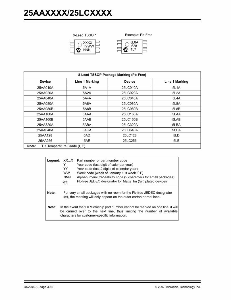
25AAXXXX/25LCXXXX
8-Lead TSSOP Package Marking (Pb-Free)
Device Line 1 Marking Device Line 1 Marking
25AA010A 5A1A 25LC010A 5L1A25AA020A 5A2A 25LC020A 5L2A25AA040A 5A4A 25LC040A 5L4A25AA080A 5A8A 25LC080A 5L8A25AA080B 5A8B 25LC080B 5L8B25AA160A 5AAA 25LC160A 5LAA25AA160B 5AAB 25LC160B 5LAB25AA320A 5ABA 25LC320A 5LBA25AA640A 5ACA 25LC640A 5LCA25AA128 5AD 25LC128 5LD25AA256 5AE 25LC256 5LE
Note: T = Temperature Grade (I, E).
NNN
XXXXTYWW
8-Lead TSSOP
1L7
5L8AI628
Example: Pb-Free
Legend: XX...X Part number or part number codeY Year code (last digit of calendar year)YY Year code (last 2 digits of calendar year)WW Week code (week of January 1 is week ‘01’)NNN Alphanumeric traceability code (2 characters for small packages)
Pb-free JEDEC designator for Matte Tin (Sn) plated devices
Note: For very small packages with no room for the Pb-free JEDEC designator , the marking will only appear on the outer carton or reel label.
Note: In the event the full Microchip part number cannot be marked on one line, it willbe carried over to the next line, thus limiting the number of availablecharacters for customer-specific information.
3e
3e
DS22040C-page 3-82 © 2007 Microchip Technology Inc.

25AAXXXX/25LCXXXXFam
ilyD
ata Sheets
3
8-Lead MSOP Package Marking (Pb-Free)
Device Line 1 Marking Device Line 1 Marking
25AA010A 5A1AT 25LC010A 5L1AT25AA020A 5A2AT 25LC020A 5L2AT25AA040A 5A4AT 25LC040A 5L4AT25AA080A 5A8AT 25LC080A 5L8AT25AA080B 5A8BT 25LC080B 5L8BT25AA160A 5AAAT 25LC160A 5LAAT25AA160B 5AABT 25LC160B 5LABT25AA320A 5ABAT 25LC320A 5LBAT25AA640A 5ACAT 25LC640A 5LCAT
Note: T = Temperature Grade (I, E).
8-Lead MSOP Example: Pb-Free
XXXXXXTYWWNNN
5L8AI 6281L7
Legend: XX...X Part number or part number codeY Year code (last digit of calendar year)YY Year code (last 2 digits of calendar year)WW Week code (week of January 1 is week ‘01’)NNN Alphanumeric traceability code (2 characters for small packages)
Pb-free JEDEC designator for Matte Tin (Sn) plated devices
Note: For very small packages with no room for the Pb-free JEDEC designator , the marking will only appear on the outer carton or reel label.
Note: In the event the full Microchip part number cannot be marked on one line, it willbe carried over to the next line, thus limiting the number of availablecharacters for customer-specific information.
3e
3e
© 2007 Microchip Technology Inc. DS22040C-page 3-83

25AAXXXX/25LCXXXX
6-Lead SOT-23 Package Marking (Pb-Free)
Device I-Temp Marking Device I-Temp Marking E-Temp Marking
25AA010A 12NN 25LC010A 15NN 16NN25AA020A 22NN 25LC020A 25NN 26NN25AA040A 32NN 25LC040A 35NN 36NN
6-Lead SOT-23
XXNN
Example: Pb-Free
32L7
Legend: XX...X Part number or part number codeY Year code (last digit of calendar year)YY Year code (last 2 digits of calendar year)WW Week code (week of January 1 is week ‘01’)NNN Alphanumeric traceability code (2 characters for small packages)
Pb-free JEDEC designator for Matte Tin (Sn) plated devices
Note: For very small packages with no room for the Pb-free JEDEC designator , the marking will only appear on the outer carton or reel label.
Note: In the event the full Microchip part number cannot be marked on one line, it willbe carried over to the next line, thus limiting the number of availablecharacters for customer-specific information.
3e
3e
DS22040C-page 3-84 © 2007 Microchip Technology Inc.

25AAXXXX/25LCXXXXFam
ilyD
ata Sheets
3
8-Lead 2x3 DFN Package Marking (Pb-Free)
Device I-Temp Marking Device I-Temp Marking E-Temp Marking
25AA010A 401 25LC010A 404 40525AA020A 411 25LC020A 414 41525AA040A 421 25LC040A 424 425
Note: NN = Alphanumeric Traceability Code.
8-Lead 2x3 DFN Example: Pb-Free
421627L7
XXXYWWNN
Legend: XX...X Part number or part number codeY Year code (last digit of calendar year)YY Year code (last 2 digits of calendar year)WW Week code (week of January 1 is week ‘01’)NNN Alphanumeric traceability code (2 characters for small packages)
Pb-free JEDEC designator for Matte Tin (Sn) plated devices
Note: For very small packages with no room for the Pb-free JEDEC designator , the marking will only appear on the outer carton or reel label.
Note: In the event the full Microchip part number cannot be marked on one line, it willbe carried over to the next line, thus limiting the number of availablecharacters for customer-specific information.
3e
3e
© 2007 Microchip Technology Inc. DS22040C-page 3-85

25AAXXXX/25LCXXXX
8-Lead 6x5 DFN-S Package Marking (Pb-Free)
Device Line 1 Marking Device Line 1 Marking
25AA128 25AA128 25LC128 25LC12825AA256 25AA256 25LC256 25LC25625AA512 25AA512 25LC512 25LC51225AA1024 25AA1024 25LC1024 25LC1024
Note: T = Temperature Grade (I, E)
8-Lead 6x5 DFN-S Example: Pb-Free
XXXXXXXXXXXXXXXXYYWW
NNN
25AA128XXX-I/
MF0610017
Legend: XX...X Part number or part number codeY Year code (last digit of calendar year)YY Year code (last 2 digits of calendar year)WW Week code (week of January 1 is week ‘01’)NNN Alphanumeric traceability code (2 characters for small packages)
Pb-free JEDEC designator for Matte Tin (Sn) plated devices
Note: For very small packages with no room for the Pb-free JEDEC designator , the marking will only appear on the outer carton or reel label.
Note: In the event the full Microchip part number cannot be marked on one line, it willbe carried over to the next line, thus limiting the number of availablecharacters for customer-specific information.
3e
3e
DS22040C-page 3-86 © 2007 Microchip Technology Inc.

25AAXXXX/25LCXXXXFam
ilyD
ata Sheets
3
PRODUCT IDENTIFICATION SYSTEMTo order or obtain information, e.g., on pricing or delivery, refer to the factory or the listed sales office.
PART NO. X /XX
PackageTemperatureRange
Device PartExamples:
a) 25AA010A-I/SN: 1Kb) 25AA040A-I/MS: 4Kc) 25LC040AT-I/OT: 4Kd) 25LC1024-I/SM: 1Me) 25LC040AT-I/MC
Device: EEPROM Series – 25Voltage – AA = 1.8V-5.5V
LC = 2.5V-5.5VDensity: 010A = 1 Kbit
020A = 2 Kbit040A = 4 Kbit080A = 8 Kbit080B = 8 Kbit160A = 16 Kbit160B = 16 Kbit320A = 32 Kbit640A = 64 Kbit128 = 128 Kbit256 = 256 Kbit512 = 512 Kbit1024 = 1024 Kbit (1Mbit)
TemperatureRange:
I = -40°C to +85°CE = -40°C to +125°C
Packaging Medium:
T = Tape and Reel (T/R)Blank = Std. Pkg.
Package: P = 8-lead Plastic DIP (300 mil body)SN = 8-lead Plastic SOIC (3.90 mm body)SM = 8-lead Plastic SOIC (5.28 mm body)ST = 8-lead Plastic TSSOP (4.4 mm)MS = 8-lead Plastic MSOP (3.0 mm)MC = 8-lead 2x3 mm DFN (T/R only)MF = 8-lead 6x5 mm DFNOT = 6-lead SOT-23 (T/R only)
Number
X
PackagingMedium
© 2007 Microchip Technology Inc. DS22040C-page 3-87

25AAXXXX/25LCXXXX
NOTES:DS22040C-page 3-88 © 2007 Microchip Technology Inc.

Microw
ireC
ompatible
3
Family
Data Sheets
3
Specialty Product References
In addition to a broad general purpose serial EEPROMproduct line, Microchip also offers several application-specific devices listed in the table below. Data sheetsfor these devices are not included in this data book butare available at Microchip’s EEPROM web page:www.microchip.com/memory.
Application Specific Devices
Application Part Number Data Sheet Number
DIMM serial presence detect DDR 24LCS52, 24AA52 DS21166
DIMM serial presence detect DDR 24LC024, 24AA024, 24LC025, 24AA025
DS21210
DIMM serial presence detect DDR2, DDR3 34LC02, 34AA02, 34LV02 DS22029
VESA® “Plug and Play” 24LCS21A DS21161
VESA® “Plug and Play” 24LCS22A DS21682
Ultra-high endurance Smart Serial™ EEPROM 24C65, 24LC65, 24AA65 DS21073
© 2007 Microchip Technology Inc. DS00157E-page 3-89

NOTES:
DS00157E-page 3-90 © 2007 Microchip Technology Inc.

MA
pplicationN
otes
4
SECTION 4APPLICATION NOTES
AN1028 Recommended Usage of Microchip I2C™ Serial EEPROM Devices .................4-1AN1029 Recommended Usage of Microchip Microwire Serial EEPROM Devices...........4-9AN1040 Recommended Usage of Microchip SPI Serial EEPROM Devices ..................4-13
© 2007 Microchip Technology Inc. DS00157E-page 4-i

M
DS00157E-page 4-ii © 2007 Microchip Technology Inc.

Application
Notes
4
AN1028Recommended Usage of Microchip I2C™ Serial EEPROM Devices
INTRODUCTIONThe majority of embedded control systems requirenonvolatile memory. Because of their small footprint,byte level flexibility, low I/O pin requirement, low-powerconsumption, and low cost, serial EEPROMs are apopular choice for nonvolatile storage. MicrochipTechnology has addressed this need by offering a fullline of serial EEPROMs covering industry standardserial communication protocols for two-wire (I2C™),three-wire (Microwire), and SPI communication. SerialEEPROM devices are available in a variety ofdensities, operational voltage ranges, and packagingoptions.
In order to achieve a highly robust application whenutilizing serial EEPROMs, the designer must considermore than just the data sheet specifications.
There are a number of conditions which could poten-tially result in nonstandard operation. The details ofsuch conditions depend greatly upon the serial protocolbeing used.
This application note provides assistance andguidance with the use of Microchip I2C serialEEPROMs. These recommendations are not meant asrequirements; however, their adoption will lead to amore robust overall design. The following topics arediscussed:
• Chip Address Inputs• Write-Protect Feature• Power Supply• Checking for Acknowledge• Acknowledge Polling• Increasing Data Throughput• Bus Pull-up Resistors• Software Reset Sequence
Figure 1 shows the suggested connections for usingMicrochip I2C serial EEPROMs. The basis for theseconnections will be explained in the sections whichfollow.
FIGURE 1: RECOMMENDED CONNECTIONS FOR 24XXXX SERIES DEVICES
Author: Chris ParrisMicrochip Technology Inc.
Note
A0(1)
A1(1)
A2(1)
VSS
Vcc
WP
SCL
SDA
1
2
3
4
8
7
6
5
VCC
24X
XXXX
To Master(2)
2: A decoupling capacitor (typically 0.1 μF) should be used to help filter out small ripples on VCC.Pins A0, A1 and A2 are not internally connected in some devices.1:
© 2007 Microchip Technology Inc. DS01028B-page 4-1

AN1028
CHIP ADDRESS INPUTSThe Chip Address input pins (A0, A1 and A2) are usedon a number of devices to support multiple device oper-ation. On devices with this feature, the levels on theseinputs are compared with the corresponding bits in theslave address, and the device is selected if the compar-ison is true. Note that the Chip Address pins are notinternally connected on some devices. Refer to theappropriate device data sheet for more details.
For devices with internally connected Chip Addresspins, these inputs must be hard-wired to either logic ‘0’or logic ‘1’. That is, they cannot be left floating, other-wise the device will not operate correctly. Note that the24XX515 and 24XX1025 devices require that the A2pin always be held at logic ‘1’ for proper operation.
In some applications, the Chip Address inputs arecontrolled by a microcontroller or other programmabledevice. In such instances, the inputs must be driven toeither logic ‘0’ or logic ‘1’ before normal deviceoperation can proceed.
WRITE-PROTECT FEATUREFor devices with write-protect functionality, the WP pinprovides a hardware write-protect feature which allowsthe user to protect the entire array when the pin is tiedto VCC. If tied to VSS, the write protection is disabled.
A pull-up resistor connected to the WP pin can be usedto ensure the device remains write-protected duringpower-up/power-down and any other time the pin is notbeing driven explicitly. This helps to guard againstunwanted writes which may occur due to noise on theSDA/SCL lines or for other reasons. In order for a writecycle to be initiated, the WP pin must be driven to logic‘0’, otherwise the write cycle will not execute.
If the designer chooses not to control the WP pin, butrather to always disable write protection, the pin mustbe hard-wired to logic ‘0’. As with the Chip Addressinputs, this pin cannot be left floating, otherwise thedevice will not operate correctly.
Note that some devices do not support write-protectfunctionality.
POWER SUPPLYMicrochip serial EEPROMs feature a high amount ofprotection from unintentional writes and data corruptionwhile power is within normal operating levels. Butcertain considerations should be made regardingpower-up and power-down conditions to ensure thesame level of protection during those times whenpower is not within normal operating levels.
As shown in Figure 1, a decoupling capacitor (typically0.1 μF) should be used to help filter out small ripples onVCC.
Power-UpOn power-up, VCC should always begin at 0V and risestraight to its normal operating level to ensure a properPower-on Reset. VCC should not linger at anambiguous level (i.e., below the minimum operatingvoltage).
Brown-Out ConditionsFor added protection, Microchip serial EEPROMsfeature a Brown-out Reset circuit. However, if VCChappens to fall below the minimum operating voltagefor the serial EEPROM, it is recommended that VCC bebrought down fully to 0V before returning to normaloperating level. This will help to ensure that the deviceis reset properly.
Furthermore, if the microcontroller features a Brown-out Reset with a threshold higher than that of the serialEEPROM, bringing VCC down to 0V will allow bothdevices to be reset together. Otherwise, the microcon-troller may reset during communication while theEEPROM keeps its current state. In this case, asoftware Reset sequence would be required beforebeginning further communication.
Power Failure During a Write CycleDuring a write cycle, VCC must remain above theminimum operating voltage for the entire duration of thecycle (typically 5 ms max. for most devices). If VCC fallsbelow this minimum voltage at any point for any lengthof time, data integrity cannot be ensured. It will result inmarginally programmed data that may or may not becorrect. Furthermore, because the EEPROM cellswere not able to be fully programmed, the device willhave shorter data retention time than specified in thedata sheet.
CHECKING FOR ACKNOWLEDGEOne of the many benefits of I2C communication is theAcknowledge bit transmitted after every byte isreceived. Except during write cycles, Microchip serialEEPROMs will always transmit this bit low after receiv-ing each byte, assuming a valid Start bit and controlbyte were already received. Due to this, the master canmonitor the ACK bit received throughout an operationto detect any errors that may occur. It is always goodpractice to check if a logic ‘1’ is received for the ACKduring transmission, which would indicate that theEEPROM did not respond. At that point, an error-han-dling routine would be required to determine why thedevice did not respond and, if necessary, to perform asoftware Reset sequence.
DS01028B-page 4-2 © 2007 Microchip Technology Inc.

AN1028A
pplicationN
otes
4
ACKNOWLEDGE POLLINGWrite operations on serial EEPROMs require that awrite cycle time be observed after initiating the write,allowing the device time to store the data. During thistime, normal device operation is disabled, and anyattempts by the master to access the device will beignored. Therefore, it is important that the master waitfor the write cycle to end before attempting to accessthe EEPROM again.
Each device has a specified worst-case write cycletime, typically listed as TWC. A simple method forensuring that the write cycle time is observed is to per-form a delay for the amount of time specified beforeaccessing the EEPROM again. However, it is notuncommon for a device to complete a write cycle inless than the maximum specified time. As such, usingthe previously shown delay method results in a periodof time in which the EEPROM has finished writing, butthe master is still waiting.
In order to eliminate this extra period of time, and there-fore operate more efficiently, it is highly recommendedto take advantage of the Acknowledge Polling feature.Since Microchip’s I2C serial EEPROM devices will notacknowledge during a write cycle, the device can con-tinuously be polled until an ACK bit is received, thusindicating that the write is complete. This is done afterthe Stop condition takes place to initiate the internalwrite cycle of the device.
ProcedureOnce the Stop condition for a Write command has beenissued from the master, the device initiates the inter-nally timed write cycle, and ACK polling can be initiatedimmediately. This involves the master sending a Startcondition followed by the control byte for a Write com-mand (R/W = 0). If the device is still busy with the writecycle, then no ACK will be returned. If no ACK isreturned, then the Start bit and control byte must besent again. If the cycle is complete, the device willreturn the ACK and the master can then proceed withthe next Read or Write command. See Figure 2 fordetails.
FIGURE 2: ACKNOWLEDGE POLLING FLOW
SendWrite Command
Send StopCondition to
Initiate Write Cycle
Send Start
Send Control Bytewith R/W = 0
Did DeviceAcknowledge
(ACK = 0)?
NextOperation
NO
YES
© 2007 Microchip Technology Inc. DS01028B-page 4-3

AN1028
INCREASING DATA THROUGHPUT
Page WritesMost Microchip I2C serial EEPROMs feature a pagebuffer for use during write operations. This allows theuser to write any number of bytes from one to the max-imum page size in a single operation. This can providefor a significant decrease in the total write time whenwriting a large number of bytes.
Page write operations are limited to writing within a sin-gle physical page, regardless of the number of bytesactually being written. This is because the memoryarray is physically stored as a two-dimensional array,as shown in Figure 3. When the word address is givenat the beginning of a write operation, both the row and
column Address Pointers are set. The row AddressPointer selects which row, or page, is accessed,whereas the column Address Pointer selects whichbyte from the chosen page is accessed first. Upontransmission of each data byte, the column AddressPointer is automatically incremented. However, duringa write operation, the page Address Pointer is notincremented, which means that attempting to cross apage boundary during a page write operation will resultin the data being looped back to the beginning of thepage.
Note that physical page boundaries start at addressesthat are multiples of the page size. For example, the24XX512 features a 128-byte page size, which meansthat physical pages on the device begin at addresses0x0000, 0x0080, 0x0100, and so on.
FIGURE 3: PAGE BUFFER BLOCK DIAGRAM
ProcedureThe write control byte, word address, and the first databyte are transmitted to the device in the same way asin a byte write operation. But instead of generating aStop condition, the master continues transmitting addi-tional data bytes, which are temporarily stored in theon-chip page buffer, up to the maximum page size ofthe device. As with the byte write operation, once theStop condition is received, an internal write cycle willbegin during which all bytes stored in the page bufferwill be written.
Write Time ComparisonsIn order to accurately calculate the full period of timerequired to write a particular amount of data to a device,two things must be considered.
• Load time is the amount of time needed to com-plete all bus operations. This includes generating Start and Stop conditions, as well as transmitting the control, address, and data bytes (including ACKs). This amount of time is dependent on the bus clock speed, the number of data bytes to be written, and the addressing scheme of the particu-lar device (some devices utilize a 1-byte address, whereas others use a 2-byte address).
ColumnAddressPointer
Byte 0 Byte 2 Byte 3 Byte n-2Byte 1 Byte n-3 Byte n-1 Byte n
Note: n is equal to the page size - 1
RowAddressPointer
Page Buffer
Memory Array
DS01028B-page 4-4 © 2007 Microchip Technology Inc.

AN1028A
pplicationN
otes
4
• Write cycle time is the time during which the device is executing its internal write cycle. As described in the previous section (“Acknowledge Polling”), there is a specified maximum write cycle time for each device. However, the internal write cycle typically completes in less time than speci-fied. As such, both worst-case (5 ms) and typical (3 ms at TAMB = 25 °C) calculations are provided in Table 1.
The following equations were used to calculate thevalues for Table 1:
EQUATION 1: WRITE TIME EQUATIONS
TABLE 1: WRITE TIME COMPARISONS
From these examples, it is clear that both page writesand Acknowledge polling can provide significant timesavings. Writing 128 bytes to the 24LC512 via bytewrites at 400 kHz requires roughly 652 ms worst-case.Switching to Acknowledge polling brings that down toroughly 396 ms (assuming typical conditions), nearly a40% decrease. Additionally, changing to page writesfurther lowers the time to an impressive 5.95 ms, adecrease of over 98%. Overall, the two techniquesprovide a combined time savings of nearly 646 ms,increasing the total data throughput a staggering 109times over.
TLOAD9 1 # address bytes # data bytes+ +( ) 1+⋅
FCLK------------------------------------------------------------------------------------------------------=
TTOTAL TLOAD TWC+( ) # write operations⋅=
Device Page Size(bytes)
# of Bytes to Write
Write Mode(1)
Clock Speed (kHz)
Load Time Per Operation (ms)
Total Time (ms)Worst-Case(2)
Total Time (ms)Typical(3)
24LC01B 8 1 Byte 100 0.28 5.28 3.288 Byte 100 0.28 42.24 26.248 Page 100 0.91 5.91 3.911 Byte 400 0.07 5.07 3.078 Byte 400 0.07 40.56 24.568 Page 400 0.23 5.23 3.23
24LC16B 16 1 Byte 100 0.28 5.28 3.2816 Byte 100 0.28 84.48 52.4816 Page 100 1.63 6.63 4.631 Byte 400 0.07 5.07 3.07
16 Byte 400 0.07 81.12 49.1216 Page 400 0.41 5.41 3.41
24LC512 128 1 Byte 100 0.37 5.37 3.37128 Byte 100 0.37 687.36 431.36128 Page 100 11.80 16.80 14.80
1 Byte 400 0.09 5.09 3.09128 Byte 400 0.09 651.84 395.84128 Page 400 2.95 7.95 5.95
Note 1: Byte Write mode signifies that only 1 byte is written during a single write operation.Page Write mode signifies that a full page is written during a single write operation.
2: Worst-case calculations assume a 5 ms timed delay is used.3: Typical calculations assume Acknowledge polling is used, with typical TWC = 3 ms, TAMB = 25 °C.
© 2007 Microchip Technology Inc. DS01028B-page 4-5

AN1028
BUS PULL-UP RESISTORSFor proper operation, pull-up resistors are required forboth SCL and SDA buses. However, the resistor valuechosen can have a vast impact on the performance ofthe system. Specifically, three limiting factors must beconsidered when selecting pull-up resistor (RP) values:
• Supply voltage (VCC)• Total Bus Capacitance (CBUS)• Total High-Level Input Current (IIH)
Supply Voltage (VCC)Supply voltage limits the minimum RP value due tomaximum low-level output voltage (VOL) specifications.Meaning that, for a given VCC level, a smaller pull-upresistor will result in a higher output voltage. For Micro-chip I2C devices, the VOL specification is a maximum of0.4V at 3 mA. In other words, if there is a voltage dropacross RP of VCC-0.4V, it cannot be sourcing more than3 mA. Applying Ohm’s Law yields Equation 2.
EQUATION 2: MINIMUM RP VALUE
Total Bus Capacitance (CBUS)Bus capacitance includes all pin, connection, and wirecapacitance on the bus. Due to the RC time constant,higher bus capacitance requires a smaller pull-up resis-tor to meet a particular rise time, and therefore, clockspeed. This is an important consideration for designsconsisting of many devices on a single bus.
Equation 3 is the general equation used to characterizecharging of a capacitive load as a function of time. Thisallows for calculation of the amount of time required forthe bus voltage to rise to a particular value for a specificpull-up resistance and bus capacitance.
EQUATION 3: CAPACITOR CHARGING
Bus rise time (TR) is defined as the amount of timerequired for the voltage to rise from VIL to VIH.Equation 3 is applied to calculate the bus rise time forVIL=0.3*VCC and VIH=0.7*VCC, and the result is shownin Equation 4. Note that because VIL and VIH are
specified as functions of VCC, the final equation isindependent of VCC, as long as the VIL specificationdoes not change.
EQUATION 4: BUS RISE TIME
Equation 4 can be quite useful in calculating bus risetime; however, such a parameter is already specified inthe data sheet for different bus speeds. As such, theequation must be rearranged to be of any use in deter-mining the maximum value of RP as limited by bus risetime. This results in Equation 5.
EQUATION 5: MAX. RP DUE TO RISE TIME
Total High-Level Input Current (IIH)The total high-level input current for a line is the totalamount of current which will be flowing through the pull-up resistor when there are no contentions and the lineis allowed to be pulled up by the resistor. This currentconsists of the sum of the input leakage currents for alldevices connected to the bus, as well as any othercurrent being sunk by the devices through the input pin.
Because some current will always exist through thepull-up resistor even without bus contention, the effec-tive voltage seen at the pin will be lower than VCC dueto the voltage drop across the resistor. This voltagedrop must be small enough that the voltage at the pinwill still be considered a high by the device. That is, thevoltage at the pin must be higher than VIH combinedwith the high-level input noise margin (VHMAR).Applying Ohm’s Law once again results in Equation 6.
EQUATION 6: MAX. RP DUE TO CURRENT
RPMINVCC VOL–
IOL---------------------------
VCC 0.4V–3 mA-----------------------------= =
V t( ) V0 1 e t– RC( )§–( )=
t–⇒ RC( ) 1 V t( )V0
-----------–⎝ ⎠⎛ ⎞ln=
T1– RC( ) 1VILVCC-----------–⎝ ⎠
⎛ ⎞ln RC( ) 1 0.3–( )ln= =
T2– RC( ) 1VIHVCC-----------–⎝ ⎠
⎛ ⎞ln RC( ) 1 0.7–( )ln= =
TR T2 T1– 0.847298 RC⋅= =
T1⇒ 0.356675= RC⋅
T2⇒ 1.20397= RC⋅
RPMAXTR
0.847298 CBUS⋅----------------------------------------=
RPMAXVCC VIH VHMAR+( )–
IIH--------------------------------------------------------=
DS01028B-page 4-6 © 2007 Microchip Technology Inc.

AN1028A
pplicationN
otes
4
Example Resistor Value CalculationHere is an example of how to use the previous equa-tions to select the appropriate pull-up resistor value.The following parameters will be used:
TABLE 2: EXAMPLE PARAMETERS
By applying Equation 2, Equation 5 and Equation 6,the following resistor value limits were calculated:
TABLE 3: RESISTOR VALUE LIMITS
Although the input current is small enough that, at thespecified VCC level, a 50 kΩ resistor would not createtoo large of a voltage drop, such a large resistor wouldbe far too slow for the specified bus capacitance.Therefore, the range of acceptable resistor values isfrom 1.533 kΩ to 3.541 kΩ. It is recommended tochoose a value near the middle of the range to provideas much guard banding as possible. For this example,a 2.2 kΩ pull-up resistor would be ideal.
Bus Speed vs. Power ConsumptionIn order to reach a given bus speed, larger bus capac-itance requires smaller pull-up resistors. For instance,in the above example, the calculated value for RPMAXdue to bus capacitance was 3.541 kΩ at 100 pF. How-ever, if the bus capacitance were increased to roughly231 pF, the new RPMAX value would be 1.533 kΩ. Thissmaller resistor would, in turn, allow more current to bedrawn when a device pulls down the bus. Specifically,a maximum of 3.26 mA at 1.533 kΩ versus 1.41 mA at3.541 kΩ.
Larger currents due to smaller pull-up resistors canhave a considerable effect on power consumption andbattery life. As such, it is recommended that the slow-est bus speed tolerable by the design be chosen. In theexample above, simply decreasing to 100 kHz (1000 nsrise time) allows for a 5.109 kΩ pull-up resistor to beused, at 231 pF. This lowers the maximum current to0.979 mA.
SOFTWARE RESET SEQUENCEAt times it may become necessary to perform asoftware Reset sequence to ensure the serialEEPROM is in a correct and known state. This could beuseful, for example, if the EEPROM has powered upinto an incorrect state (due to excessive bus noise,etc.), or if the microcontroller is reset during communi-cation. The following sequence can be sent in order toensure that the serial EEPROM device is properlyreset:
• Start bit• Clock in nine bits of ‘1’• Start bit• Stop bit
FIGURE 4: SOFTWARE RESET SEQUENCE
The first Start bit will cause the device to reset from astate in which it is expecting to receive data from themicrocontroller. In this mode, the device is monitoringthe data bus in Receive mode and can detect the Startbit which forces an internal Reset.
The nine bits of ‘1’ are used to force a Reset of thosedevices that could not be reset by the previous Start bit.This occurs only if the device is in a mode where it iseither driving an acknowledge on the bus (low), or is inan Output mode and is driving a data bit of ‘0’ out onthe bus. In both of these cases the previous Start bit(defined as SDA going low while SCL is high) could notbe generated due to the device holding the bus low. Bysending nine bits of ‘1’ it is ensured that the device willsee a NACK (i.e., the microcontroller does not drive thebus low to acknowledge data sent by the EEPROM),which also forces an internal Reset.
Parameter Value Units
VCC 5.0 VTR 3001 ns
CBUS 100 pFVIH 3.52 V
VHMAR 1.03 VIIH 10 μA
Note 1: TR based on desired clock speed of 400 kHz.
2: VIH derived from 0.7*VCC spec.3: VHMAR derived from 0.2*VCC spec.
Limit Value Limiting Factor
RPMIN 1.533 kΩ Supply VoltageRPMAX 3.541 kΩ Bus CapacitanceRPMAX 50 kΩ Input Current
S P
Bus
SDA
STOP
Nine bits of ‘1’
START
S
START
Activity
© 2007 Microchip Technology Inc. DS01028B-page 4-7

AN1028
The second Start bit is sent to guard against the rarepossibility of an erroneous write that could occur if themicrocontroller was reset while sending a Write com-mand to the EEPROM, and, the EEPROM was drivingan ACK on the bus when the first Start bit was sent. Inthis special case, if this second Start bit was not sent,and instead the Stop bit was sent, the device could ini-tiate a write cycle. This potential for an erroneous writeoccurs only in the event of the microcontroller beingreset while sending a Write command to the EEPROM.The final Stop bit terminates bus activity and puts theEEPROM in Standby mode.
This sequence does not affect any other I2C deviceswhich may be on the bus as they will simply disregardit as an invalid command.
In situations where the software Reset sequence isneeded, a bus conflict is likely to occur. When using theMSSP module, this will cause the Bus Collision Flag(BCLIF) to be set and, therefore, will block any furtherbus transactions. In order to issue a software Reset,the module will need to be disabled and the softwareReset sequence will need to be bit-banged. Once thesoftware Reset sequence is complete, the module canbe re-enabled, the Bus Collision Flag cleared, and theMSSP module will be ready for normal bus operations.
SUMMARYThis application note illustrates recommendedtechniques for increasing design robustness whenusing Microchip I2C serial EEPROMs. These recom-mendations fall directly in line with how Microchipdesigns, manufactures, qualifies, and tests its serialEEPROMs and will allow the devices to operate withinthe data sheet parameters. It is suggested that the con-cepts detailed in this application note be incorporatedinto any system which utilizes an I2C serial EEPROM.
DS01028B-page 4-8 © 2007 Microchip Technology Inc.

Application
Notes
4
AN1029Recommended Usage of Microchip Microwire Serial EEPROM Devices
INTRODUCTIONThe majority of embedded control systems requirenonvolatile memory. Because of their small footprint,byte level flexibility, low I/O pin requirement, low-powerconsumption, and low cost, serial EEPROMs are apopular choice for nonvolatile storage. Microchip Tech-nology has addressed this need by offering a full line ofserial EEPROMs covering industry standard serialcommunication protocols for two-wire (I2C™), three-wire (Microwire), and SPI communication. SerialEEPROM devices are available in a variety ofdensities, operational voltage ranges, and packagingoptions.
In order to achieve a highly robust application whenutilizing serial EEPROMs, the designer must considermore than just the data sheet specifications.
There are a number of conditions which couldpotentially result in nonstandard operation. The detailsof such conditions depend greatly upon the serialprotocol being used.
This application note provides assistance andguidance with the use of Microchip Microwire serialEEPROMs. These recommendations are not meant asrequirements; however, their adoption will lead to amore robust overall design. The following topics arediscussed:
• Chip Select and Program Enable Inputs• Proper Write Sequence• Resetting the State Machine• Using a Hardware SPI port for Microwire commu-
nication• Tying DI and DO together• Power-up/Power-down
Figure 1 shows the suggested connections for usingMicrochip Microwire serial EEPROMs. The basis forthese connections will be explained in the sectionswhich follow.
FIGURE 1: RECOMMENDED CONNECTIONS FOR 93XXXX SERIES DEVICES
Author: Martin KvasnickaMicrochip Technology Inc.
Note 1: PE pins exist on only the 93XX76X and 93XX86X devices (8K and 16K devices).Note 2: ORG is in x8 configuration when tied to VSS. For x16 operation, this pin needs to be tied to VCC.Note 3: Devices with A or B suffix will not have an ORG pin.
CS
CLK
DI
DO
VCC
PE(1)
ORG(2,3)
VSS
1
2
3
4
8
7
6
5
VCC
93X
XXXX
To Master
To Master
To M
aste
r
10 KΩ
10 KΩ
0.1 μF
© 2006 Microchip Technology Inc. DS01029A-page 4-9

AN1029
CHIP SELECT AND PROGRAM ENABLE INPUTSDuring power-up and power-down routines, mostmicrocontrollers have a period of time in which theyfloat I/O lines before the processor is fully initialized. Itis during this time that any external device controlled bythe microcontroller may be able to recognize and reactto spurious commands or line noise. Therefore, a pull-down resistor should be used on the CS line to keep theEEPROM de-selected during power-up/power-downcycles or any event where the EEPROM is not intendedto be selected. Furthermore, a pull-down resistorshould be used on the PE pin of the 93XX76X and93XX86X devices to prevent any unwanted writesduring similar power-up/power-down events.
PROPER WRITE SEQUENCEMicrowire serial EEPROMs do not give you the abilityto monitor whether or not the device is enabled forwrites. Also, the 1-4K Microwire devices do not have aProgram Enable pin to allow hardware to control whenwrites are allowed. It is up to the user to control exactlywhen the device is able to be written to and also protectthe device after a write has been completed. Therefore,a Write command should not be considered completeuntil the Erase/Write Disable (EWDS) command hasbeen issued following a Write command. So, all Writecommands should begin with an Erase/Write Enable(EWEN), followed by the desired write sequence, andend with an Erase/Write Disable (EWDS). The EWDScommand cannot be issued during the write cycle, anycommands issued while a write is in progress will beignored by the device.
This practice has two benefits. First, it protects thedevice further against unwanted writes in the event ofa Reset or other system interruption. Second, byissuing a Start bit at the beginning of the Erase/WriteDisable command, the device will reset the Ready/busystatus on the DO line and return the device to a trueStandby mode where the device will consume its leastamount of current.
RESETTING THE STATE MACHINEA Reset of the state machine can be accomplished bydeselecting the device as long as the required numberof clock cycles for a given command has not beenreached. However, once the required clock cycles havebeen met, the command will execute upon completionof that command even if additional clocks are given
after a valid command. Any additional clocks given tothe device after a valid command are treated as “don’tcares”.
Additionally, if the device is suspected of having anytype of power loss (POR or BOR) event, then once VCCis restored, it is recommended that the CS line be tog-gled Low (inactive), High (Active), Low (inactive). Thiswill allow for the state machine to have a better Resetand possibly be able to recover from a short or spuriouspower interruption. See Power-up/Power-down sectionfor further details on POR/BOR events.
USING A HARDWARE SPI PORT FOR MICROWIRE COMMUNICATIONMany of today’s popular Microcontrollers offer a modulethat can be used to send SPI commands. The Microwirestructure is set up in such a manner that many of thesehardware protocol ports can be used to control theMicrowire protocol by setting up the module correctly.The particulars of how to set up the port depend greatlyon manufacturer, individual data sheets should be refer-enced for details. Microchip has Application Notes avail-able on how to set this up for PIC® Microcontrollers.
THEORY OF OPERATIONTo use an SPI port (MSSP) to communicate withMicrochip’s Microwire Serial EEPROMs, the bytes tobe output to the 93XXX must be aligned such that theLSB of the address is the 8th bit (LSB) of a byte to beoutput. From there the bits should fill the byte from rightto left consecutively. If more that 8 bits are required,then two bytes will be required to be output. This samemethod will work for any 93XXX series device but thedata sheet must be referenced for these because den-sity and organization will change the number of bitssent for each command. We will use the 93LC66Corganized in x16 format as an example below. Sincemore than 8 bits are required to control a 93LC66C, twoconsecutive bytes are required as shown in Figure 2.
High Byte (Where the Start bit, opcode bits andaddress MSb reside)
The High Byte is configured in the following format: SBis the Start bit. OP1 is the MSb of the op code and OP0is the opcode LSb. The CS line can be set before thebyte is output because the leading 0’s output to the93XXX prevent a Start bit from being recognized by the93XXX until the first high bit is sent.
Low Byte (8 Address bits)
The Low Byte contains A7-A0, which are the addressbits required to access 256 bytes in x16 mode.
FIGURE 2: COMMAND ALIGNMENT
High Byte Low Byte0 0 0 0 0 SB OP1 OP0 A7 A6 A5 A4 A3 A2 A1 A0
DS01029A-page 4-10 © 2006 Microchip Technology Inc.

AN1029A
pplicationN
otes
4
TYING DI AND DO TOGETHERMany customers inquire about making the Microwireprotocol truly 3-wire by tying the DI and DO linestogether. However, a potential for bus contention existsif the microcontroller attempts to drive the DI pin whilethe memory is driving DO. This is especially true whenusing an SPI port on the microcontroller and you rely ondummy zeros to be driven on the bus before the Startbit gets issued (since DO drives high for Ready until thenext Start bit). To prevent this bus contention issue, it isnecessary to use a series resistor (~10K Ohm) on theDO line from the DI line instead of a direct connection,as shown in Figure 3.
Another potential problem with tying DI and DOtogether occurs as CS is brought high after the writecycle has been initiated and valid clock transitionsoccur on the CLK line during the write cycle. This cancause the device to see an inadvertent Start conditionwhen the write cycle ends (and the DO line drives highto signal the Ready state). This is caused by the factthat the TWC of the device is variable (depending onprocess, voltage and temperature) and, therefore,causes the write cycle to end in an asynchronous fash-ion with respect to the clock. For example, if CS is highwhen the write cycle ends and DO goes high (therebypulling DI high), then a low-to-high transition on theCLK will be seen as a valid Start condition when it maynot have been intended to be a Start condition.
FIGURE 3: Tying DI and DO Together
Note 1: PE pins exist on only the 93XX76X and 93XX86X devices.Note 2: ORG is in x8 configuration when tied to VSS. For x16 operation, this pin needs to be tied to VCC.Note 3: Devices with A or B suffix will not have an ORG pin.
CS
CLK
DI
DO
VCC
PE(1)
ORG(2,3)
VSS
1
2
3
4
8
7
6
5
VCC 9
3XXX
XX
To Master
To Master
To M
aste
r
.1 μF
10 KΩ
10 KΩ
10 KΩ
© 2006 Microchip Technology Inc. DS01029A-page 4-11

AN1029
POWER-UP/POWER-DOWNMicrochip serial EEPROMs feature a high amount ofprotection from unintentional writes and data corruptionwhile power is within normal operating levels. Butcertain considerations should be made regardingpower-up and power-down conditions to ensure thesame level of protection during those times whenpower is not within normal operating levels.
Power Failure During a Write CycleDuring a write cycle, VCC must remain above the mini-mum operating voltage for the entire duration of thecycle (typically 5 ms max. for most devices). If VCC fallsbelow this minimum at any point for any length of time,data integrity cannot be ensured. It will result in margin-ally programmed data that may or may not be correct.Furthermore, because the EEPROM cells were notable to be fully programmed, the device will haveshorter data retention time than specified in the datasheet.
Power-UpOn power-up, VCC should always begin at 0V and risestraight to its normal operating level to ensure a properPower-on Reset. VCC should not linger at anambiguous level (i.e., below the minimum operatingvoltage).
Brown-Out ConditionsIf VCC happens to fall below the minimum operatingvoltage for the serial EEPROM, it is recommended thatVCC be brought down fully to 0V before returning tonormal operating level. This will help to ensure that thedevice is reset properly.
Furthermore, if the microcontroller features a Brown-out Reset with a threshold higher than that of the serialEEPROM, bringing VCC down to 0V will allow bothdevices to be reset together. Otherwise, the microcon-troller may reset during communication while theEEPROM keeps its current state. In this case, asoftware Reset sequence would be required beforebeginning further communication.
CONCLUSIONAlthough not required for operation, utilizing theserecommendations on Microwire Serial EEPROMdesigns will result in a more robust overall design.These recommendations fall directly in line with howMicrochip designs, manufactures, qualifies and tests itsSerial EEPROMs and will allow the devices to operatefully within the data sheet parameters.
QUESTION AND ANSWERQ: What would happen if I inadvertently sent either toomany or too few clocks during a Write command.
A: If you send too many clocks to the device and thendrop the CS line to initiate the write cycle, the extraclocks will be ignored but the command will execute. Ifyou do not send enough clocks and then drop the CSline, then the command will abort and no write will takeplace.
Q: I am using a 93LC56C device in my application andI am having problems getting it to work correctly. Theread sequence seems to work fine, but I am unable towrite any data to the part.
A: First, make sure you are issuing an EWENcommand prior to attempting a write. But a problemsuch as this is usually caused by either not giving thepart the required number of bits for the commandbefore dropping the CS line or by not dropping the CSline at all. The Write command will not commence untilthe CS line is brought low.
Q: I am confused, do I have to toggle the CS line lowin-between every command?
A: Yes, the CS line must go low for at least 250 nsbetween each command. If you are doing a Writecommand and you bring CS low to activate the DataPolling mode, you must toggle CS low again after theReady signal has been given by the device before thenext Start bit can be sent.
Q: If VCC drops during a write cycle will other data in thearray be corrupted, or just the data being written?
A: Only the data being written will be corrupted if VCCgoes away during a write cycle. Other data bytes will beunaffected.
DS01029A-page 4-12 © 2006 Microchip Technology Inc.

Application
Notes
4
AN1040Recommended Usage of Microchip SPI Serial EEPROM Devices
INTRODUCTIONThe majority of embedded control systems requirenonvolatile memory. Because of their small footprint,byte level flexibility, low I/O pin requirement, low-powerconsumption and low cost, serial EEPROMs are apopular choice for nonvolatile storage. MicrochipTechnology has addressed this need by offering a fullline of serial EEPROMs covering industry standardserial communication protocols for two-wire (I2C™),three-wire (Microwire), and SPI communication. SerialEEPROM devices are available in a variety ofdensities, operational voltage ranges and packagingoptions.
In order to achieve a highly robust application whenutilizing serial EEPROMs, the designer must considermore than just the data sheet specifications.
There are a number of conditions which could poten-tially result in nonstandard operation. The details ofsuch conditions depend greatly upon the serial protocolbeing used.
This application note provides assistance andguidance with the use of Microchip SPI serialEEPROMs. These recommendations are not meant asrequirements; however, their adoption will lead to amore robust overall design. The following topics arediscussed:
• Input Considerations• Write-Protection Features• Power Supply• Write Enable and Disable• WIP Polling• Increasing Data Throughput
Figure 1 shows the suggested connections for usingMicrochip SPI serial EEPROMs. The basis for theseconnections will be explained in the sections whichfollow.
FIGURE 1: RECOMMENDED CONNECTIONS FOR 25XXXX SERIES DEVICES
Author: Chris ParrisMicrochip Technology Inc.
Note
CS
SO
WP
VSS
VCC
HOLD
SCK
SI
1
2
3
4
8
7
6
5
VCC
25X
XXXX
To Master(1)
A decoupling capacitor (typically 0.1 μF) should be used on VCC.1:
To Master
VCC
© 2006 Microchip Technology Inc. DS01040A-page 4-13

AN1040
INPUT CONSIDERATIONSIt is never good practice to leave an input pin floating.This can cause high standby current as well asundesired functionality. If a pin is left floating, it caneither float low or high. Which direction the signal goesis dependant upon a number of factors, including noisein the system and capacitive coupling. Because of this,the level seen by the input circuitry is relatively randomand likely to change during operation.
Such unpredictable input levels can have devastatingeffects on device operation. For example, Microchip’sSPI serial EEPROMs feature a HOLD pin which allowsthe user to suspend the clock mid-stream. If this pinwere to float low (active), the device would no longerreact to any clock pulses received and communicationwould be disrupted.
Therefore, any unused input pins should always be tiedto a proper level, such as high for an active-low input.Moreover, it is recommended that, if the microcontrollerhas extra, tri-state I/O pins available, connections bemade to these unused inputs along with a pull-down/pull-up resistor, as shown in Figure 1. This will allow forthe inputs to be used at a later date simply by modifyingfirmware.
Although the CS pin should always be driven by themicrocontroller during normal operation, it has potentialfor floating during power-down/power-up. As such, thispin should also have a pull-up resistor to avoid undes-ired commands due to noise during these conditions.
WRITE PROTECTION FEATURESThere are two different write protection schemesfeatured in Microchip’s SPI serial EEPROM family ofdevices. One for the 4 Kb and smaller devices, and onefor 8 Kb and larger devices.
For the 25XX010A to 25XX040A, the WP pin acts as anormal hardware write-protect pin. That is, if the WPpin is low (active), the Write Enable Latch (WEL) iscleared and cannot be set until the pin is brought high(inactive). This means that any attempted writes toeither the array or the STATUS register will be blocked.Note that bringing the WP pin high does not set theWEL again. Another WREN instruction is required inorder to do this.
For the 25XX080A/B and up, the WP pin acts in con-junction with the Write-Protect Enable (WPEN) bit inthe STATUS register. If the WPEN bit is cleared, theWP pin is a don’t care. If the WPEN bit is set, the WPpin can be used to block attempted STATUS registerwrites. Note that for these devices, the WP pin has noeffect on array writes, regardless of the state of theWPEN bit. Only the Block Protect (BP) bits can blockan attempted write to the array on these devices. Oncethe BP bits have been set, however, the WP pin can beused with the WPEN bit to prevent them from beingcleared, thus preventing writes to the array as well.
POWER SUPPLYMicrochip serial EEPROMs feature a high amount ofprotection from unintentional writes and data corruptionwhile power is within normal operating levels. Butcertain considerations should be made regardingpower-up and power-down conditions to ensure thesame level of protection during those times whenpower is not within normal operating levels.
As shown in Figure 1, a decoupling capacitor (typically0.1 μF) should be used to help filter out small ripples onVCC.
Power-UpOn power-up, VCC should always begin at 0V and risestraight to its normal operating level to ensure a properPower-on Reset. VCC should not linger at anambiguous level (i.e., below the minimum operatingvoltage).
Brown-Out ConditionsFor added protection, Microchip serial EEPROMsfeature a Brown-out Reset circuit. However, if VCChappens to fall below the minimum operating voltagefor the serial EEPROM, it is recommended that VCC bebrought down fully to 0V before returning to normaloperating level. This will help to ensure that the deviceis reset properly.
Furthermore, if the microcontroller features a Brown-out Reset with a threshold higher than that of the serialEEPROM, bringing VCC down to 0V will allow bothdevices to be reset together. Otherwise, the microcon-troller may reset during communication while theEEPROM keeps its current state. In this case, asoftware Reset sequence would be required beforebeginning further communication.
Power Failure During a Write CycleDuring a write cycle, VCC must remain above theminimum operating voltage for the entire duration of thecycle (typically 5 ms max. for most devices). If VCC fallsbelow this minimum voltage at any point for any lengthof time, data integrity cannot be ensured. It will result inmarginally programmed data that may or may not becorrect. Furthermore, because the EEPROM cellswere not able to be fully programmed, the device willhave shorter data retention time than specified in thedata sheet.
DS01040A-page 4-14 © 2006 Microchip Technology Inc.

AN1040A
pplicationN
otes
4
WRITE ENABLE AND DISABLEMicrochip SPI serial EEPROMs feature a Write EnableLatch (WEL) as bit 1 of the STATUS register. This latchis used to allow write operations to occur to the array orSTATUS register. When set to a ‘1’, writes are enabled.When set to a ‘0’, all writes are blocked. The WEL canonly be set by issuing a valid Write Enable (WREN)instruction, but can be reset upon a number ofconditions:
• Power-up• Write Disable (WRDI) instruction successfully
executed• Write STATUS register (WRSR) instruction
successfully executed• Write instruction successfully executed
And on the 25XX010A-25XX040A only:
• WP pin is brought low (active)
Note that for the Write, WRSR, and WRDI instructions,the WEL is only reset if the instruction is executedsuccessfully. This means that if, for some reason, theinstruction is not valid, the WEL will not be reset. Forexample, if a write is attempted in an area of the arrayprotected by the Block Protect (BP) bits, then theinstruction will not succeed and the WEL will remainset.
For Write and WRSR instructions, the WEL is cleared atthe end of the write cycle.
It is highly recommended that the WEL only be setimmediately before issuing a Write or WRSR instructionin order to minimize the chance of an undesired writeoperation.
WIP POLLINGWrite operations on serial EEPROMs require that awrite cycle time be observed after initiating the write,allowing the device time to store the data. During thistime, normal device operation is disabled and anyattempts by the master to access the memory array onthe device will be ignored. Therefore, it is important thatthe master wait for the write cycle to end beforeattempting to access the EEPROM again.
Each device has a specified worst-case write cycletime, typically listed as TWC. A simple method forensuring that the write cycle time is observed is to per-form a delay for the amount of time specified beforeaccessing the EEPROM again. However, it is notuncommon for a device to complete a write cycle inless than the maximum specified time. As such, usingthe previously shown delay method results in a periodof time in which the EEPROM has finished writing, butthe master is still waiting.
In order to eliminate this extra period of time, and there-fore operate more efficiently, it is highly recommendedto take advantage of the WIP Polling feature.
During both an array write and a STATUS register write,the STATUS register in Microchip’s SPI serialEEPROMs can still be read. This allows the user tocheck the state of the Write-In-Progress (WIP) bit. Thisis a read-only bit, set only while a write operation is inprogress. Once the operation completes, the WIP (andthe WEL) are cleared. Therefore, the STATUS registercan continue to be read in order to monitor the value ofthe WIP bit to determine when the write cyclecompletes.
ProcedureOnce CS is brought high at the end of the Write instruc-tion, the device initiates the internally timed write cycle,and WIP polling can begin immediately. This involvesperforming a Read STATUS register (RDSR) instructionand checking the value read for the WIP bit. If it is high,the device is still writing. If it is low, the write cycle iscomplete and the master can proceed with the nextinstruction. See Figure 2 for details.
FIGURE 2: WIP POLLING FLOW
PerformWrite Instruction
Bring CSHigh to Initiate
Write Cycle
Perform RDSR
Is WriteComplete(WIP = 0)?
NextOperation
NO
YES
Instruction
© 2006 Microchip Technology Inc. DS01040A-page 4-15

AN1040
INCREASING DATA THROUGHPUT
Page WritesAll Microchip SPI serial EEPROMs feature a pagebuffer for use during write operations. This allows theuser to write any number of bytes from one to the max-imum page size in a single operation. This can providefor a significant decrease in the total write time whenwriting a large number of bytes.
Page write operations are limited to writing within a sin-gle physical page, regardless of the number of bytesactually being written. This is because the memoryarray is physically stored as a two-dimensional array,as shown in Figure 3. When the word address is givenat the beginning of a write operation, both the row and
column Address Pointers are set. The row AddressPointer selects which row, or page, is accessed,whereas the column Address Pointer selects whichbyte from the chosen page is accessed first. Upontransmission of each data byte, the column AddressPointer is automatically incremented. However, duringa write operation, the page Address Pointer is notincremented, which means that attempting to cross apage boundary during a page write operation will resultin the data being looped back to the beginning of thepage.
Note that physical page boundaries start at addressesthat are multiples of the page size. For example, the25XX256 features a 64-byte page size, which meansthat physical pages on the device begin at addresses0x0000, 0x0040, 0x0080, and so on.
FIGURE 3: PAGE BUFFER BLOCK DIAGRAM
ProcedureAfter enabling writes by issuing a WREN command, thewrite instruction, word address, and the first data byteare transmitted to the device in the same way as in abyte write operation. But instead of toggling CS high,the master continues transmitting additional data bytes,which are temporarily stored in the on-chip page buffer,up to the maximum page size of the device (with carebeing taken not to wrap around the page). As with thebyte write operation, once CS is toggled high, aninternal write cycle will begin during which all bytesstored in the page buffer will be written.
Write Time ComparisonsIn order to accurately calculate the full period of timerequired to write a particular amount of data to a device,two things must be considered.
• Load time is the amount of time needed to com-plete all bus operations. This includes all CS-related timings, issuing the necessary WREN instructions, as well as transmitting the Write instruction, address and data bytes. This amount of time is dependent on the bus clock speed, the number of data bytes to be written, and the addressing scheme of the particular device (some devices utilize a 1-byte address, whereas others use a 2-byte address).
ColumnAddressPointer
Byte 0 Byte 2 Byte 3 Byte n-2Byte 1 Byte n-3 Byte n-1 Byte n
Note: n is equal to the page size - 1
RowAddressPointer
Page Buffer
Memory Array
DS01040A-page 4-16 © 2006 Microchip Technology Inc.

AN1040A
pplicationN
otes
4
• Write cycle time is the time during which the device is executing its internal write cycle. As described in the previous section (“WIP Polling”), there is a specified maximum write cycle time for each device. However, the internal write cycle typically completes in less time than specified. As such, both worst-case (5 ms) and typical (3 ms at TAMB = 25 °C) calculations are provided in Table 1.
The following equations were used to calculate thevalues for Table 1:
EQUATION 1: WRITE TIME EQUATIONS
TABLE 1: WRITE TIME COMPARISONS
From these examples, it is clear that both page writesand WIP polling can provide significant time savings.Writing 64 bytes to the 25LC256 via byte writes at1 MHz requires roughly 320 ms worst-case. Switchingto WIP polling brings that down to roughly 192 ms(assuming typical conditions), nearly a 40% decrease.Additionally, changing to page writes further lowers thetime to an impressive 3.05 ms, a decrease of over 98%.Overall, the two techniques provide a combined timesavings of over 317 ms, increasing the total datathroughput a staggering 105 times over.
SUMMARYThis application note illustrates recommendedtechniques for increasing design robustness whenusing Microchip SPI serial EEPROMs. These recom-mendations fall directly in line with how Microchipdesigns, manufactures, qualifies and tests its serialEEPROMs and will allow the devices to operate withinthe data sheet parameters. It is suggested that the con-cepts detailed in this application note be incorporatedinto any system which utilizes an SPI serial EEPROM.
TLOAD8 2 # addr bytes # data bytes+ +( )⋅
FCLK-------------------------------------------------------------------------------------- 150 ns+=
TTOTAL TLOAD TWC+( ) # write operations⋅=
Device Page Size(bytes)
# of Bytes to Write
Write Mode(1)
Clock Speed (MHz)
Load Time Per Operation (μs)
Total Time (ms)Worst-Case(2)
Total Time (ms)Typical(3)
25LC010A 16 1 Byte 1 32.15 5.03 3.0316 Byte 1 32.15 80.51 48.5116 Page 1 152.15 5.15 3.151 Byte 10 3.35 5.00 3.00
16 Byte 10 3.35 80.05 48.0516 Page 10 15.35 5.02 3.02
25LC160B 32 1 Byte 1 40.15 5.04 3.0432 Byte 1 40.15 161.28 97.2832 Page 1 288.15 5.29 3.291 Byte 10 4.15 5.00 3.00
32 Byte 10 4.15 160.13 96.1332 Page 10 28.95 5.03 3.03
25LC256 64 1 Byte 1 40.15 5.04 3.0464 Byte 1 40.15 322.57 194.5764 Page 1 544.15 5.54 3.541 Byte 10 4.15 5.00 3.00
64 Byte 10 4.15 320.27 192.2764 Page 10 54.55 5.05 3.05
Note 1: Byte Write mode signifies that only 1 byte is written during a single write operation.Page Write mode signifies that a full page is written during a single write operation.
2: Worst-case calculations assume a 5 ms timed delay is used.3: Typical calculations assume WIP polling is used, with typical TWC = 3 ms, TAMB = 25 °C.
© 2006 Microchip Technology Inc. DS01040A-page 4-17

AN1040
NOTES:DS01040A-page 4-18 © 2006 Microchip Technology Inc.

MPackaging
5
SECTION 5PACKAGING
Package Outline Drawings ........................................................................................................................5-1Product Tape and Reel Specifications ....................................................................................................5-11Solder Reflow Recommendation.............................................................................................................5-19Overview of Microchip Die/Wafer Support ..............................................................................................5-23
© 2007 Microchip Technology Inc. DS00157E-page 5-i

M
DS00157E-page 5-ii © 2007 Microchip Technology Inc.

Packaging
5
PACKAGINGPackage Outline Drawings
8-Lead Plastic Dual Flat, No Lead Package (MC) – 2x3x0.9 mm Body [DFN]
Notes:1. Pin 1 visual index feature may vary, but must be located within the hatched area.2. Package may have one or more exposed tie bars at ends.3. Package is saw singulated.4. Dimensioning and tolerancing per ASME Y14.5M.
BSC: Basic Dimension. Theoretically exact value shown without tolerances.REF: Reference Dimension, usually without tolerance, for information purposes only.
Note: For the most current package drawings, please see the Microchip Packaging Specification located at http://www.microchip.com/packaging
Units MILLIMETERS
Dimension Limits MIN NOM MAX
Number of Pins N 8
Pitch e 0.50 BSC
Overall Height A 0.80 0.90 1.00
Standoff A1 0.00 0.02 0.05
Contact Thickness A3 0.20 REF
Overall Length D 2.00 BSC
Overall Width E 3.00 BSC
Exposed Pad Length D2 1.30 – 1.75
Exposed Pad Width E2 1.50 – 1.90
Contact Width b 0.18 0.25 0.30
Contact Length L 0.30 0.40 0.50
Contact-to-Exposed Pad K 0.20 – –
D
N
E
NOTE 1
1 2
EXPOSED PAD
NOTE 1
2 1
D2
K
L
E2
N
e
b
A3 A1
A
NOTE 2
BOTTOM VIEWTOP VIEW
Microchip Technology Drawing C04-123B
© 2007 Microchip Technology Inc. DS00157E-page 5-1

PACKAGING
8-Lead Plastic Dual Flat, No Lead Package (MF) – 6x5 mm Body [DFN-S] PUNCH SINGULATED
Notes:1. Pin 1 visual index feature may vary, but must be located within the hatched area.2. Package may have one or more exposed tie bars at ends.3. Dimensioning and tolerancing per ASME Y14.5M.
BSC: Basic Dimension. Theoretically exact value shown without tolerances.REF: Reference Dimension, usually without tolerance, for information purposes only.
Note: For the most current package drawings, please see the Microchip Packaging Specification located at http://www.microchip.com/packaging
Units MILLIMETERS
Dimension Limits MIN NOM MAX
Number of Pins N 8
Pitch e 1.27 BSC
Overall Height A – 0.85 1.00
Molded Package Thickness A2 – 0.65 0.80
Standoff A1 0.00 0.01 0.05
Base Thickness A3 0.20 REF
Overall Length D 4.92 BSC
Molded Package Length D1 4.67 BSC
Exposed Pad Length D2 3.85 4.00 4.15
Overall Width E 5.99 BSC
Molded Package Width E1 5.74 BSC
Exposed Pad Width E2 2.16 2.31 2.46
Contact Width b 0.35 0.40 0.47
Contact Length L 0.50 0.60 0.75
Contact-to-Exposed Pad K 0.20 – –
Model Draft Angle Top φ – – 12°
φ
NOTE 2
A3
A2
A1
A
NOTE 1NOTE 1
EXPOSED
PAD
BOTTOM VIEW
1 2
D2
2 1
E2
K
L
N
e
b
E
E1
D
D1
N
TOP VIEW
Microchip Technology Drawing C04-113B
DS00157E-page 5-2 © 2007 Microchip Technology Inc.

PACKAGINGPackaging
5
8-Lead Plastic Micro Small Outline Package (MS) [MSOP]
Notes:1. Pin 1 visual index feature may vary, but must be located within the hatched area.2. Dimensions D and E1 do not include mold flash or protrusions. Mold flash or protrusions shall not exceed 0.15 mm per side.3. Dimensioning and tolerancing per ASME Y14.5M.
BSC: Basic Dimension. Theoretically exact value shown without tolerances.REF: Reference Dimension, usually without tolerance, for information purposes only.
Note: For the most current package drawings, please see the Microchip Packaging Specification located at http://www.microchip.com/packaging
Units MILLIMETERS
Dimension Limits MIN NOM MAX
Number of Pins N 8
Pitch e 0.65 BSC
Overall Height A – – 1.10
Molded Package Thickness A2 0.75 0.85 0.95
Standoff A1 0.00 – 0.15
Overall Width E 4.90 BSC
Molded Package Width E1 3.00 BSC
Overall Length D 3.00 BSC
Foot Length L 0.40 0.60 0.80
Footprint L1 0.95 REF
Foot Angle φ 0° – 8°
Lead Thickness c 0.08 – 0.23
Lead Width b 0.22 – 0.40
D
N
E
E1
NOTE 1
1 2
e
b
A
A1
A2c
L1 L
φ
Microchip Technology Drawing C04-111B
© 2007 Microchip Technology Inc. DS00157E-page 5-3

PACKAGING
8-Lead Plastic Dual In-Line (P) – 300 mil Body [PDIP]
Notes:1. Pin 1 visual index feature may vary, but must be located with the hatched area.2. § Significant Characteristic.3. Dimensions D and E1 do not include mold flash or protrusions. Mold flash or protrusions shall not exceed .010" per side.4. Dimensioning and tolerancing per ASME Y14.5M.
BSC: Basic Dimension. Theoretically exact value shown without tolerances.
Note: For the most current package drawings, please see the Microchip Packaging Specification located at http://www.microchip.com/packaging
Units INCHES
Dimension Limits MIN NOM MAX
Number of Pins N 8
Pitch e .100 BSC
Top to Seating Plane A – – .210
Molded Package Thickness A2 .115 .130 .195
Base to Seating Plane A1 .015 – –
Shoulder to Shoulder Width E .290 .310 .325
Molded Package Width E1 .240 .250 .280
Overall Length D .348 .365 .400
Tip to Seating Plane L .115 .130 .150
Lead Thickness c .008 .010 .015
Upper Lead Width b1 .040 .060 .070
Lower Lead Width b .014 .018 .022
Overall Row Spacing § eB – – .430
N
E1
NOTE 1
D
1 2 3
A
A1
A2
L
b1
b
e
E
eB
c
Microchip Technology Drawing C04-018B
DS00157E-page 5-4 © 2007 Microchip Technology Inc.

PACKAGINGPackaging
5
8-Lead Plastic Small Outline (SN) – Narrow, 3.90 mm Body [SOIC]
Notes:1. Pin 1 visual index feature may vary, but must be located within the hatched area.2. § Significant Characteristic.3. Dimensions D and E1 do not include mold flash or protrusions. Mold flash or protrusions shall not exceed 0.15 mm per side.4. Dimensioning and tolerancing per ASME Y14.5M.
BSC: Basic Dimension. Theoretically exact value shown without tolerances.REF: Reference Dimension, usually without tolerance, for information purposes only.
Note: For the most current package drawings, please see the Microchip Packaging Specification located at http://www.microchip.com/packaging
Units MILLIMETERS
Dimension Limits MIN NOM MAX
Number of Pins N 8
Pitch e 1.27 BSC
Overall Height A – – 1.75
Molded Package Thickness A2 1.25 – –
Standoff § A1 0.10 – 0.25
Overall Width E 6.00 BSC
Molded Package Width E1 3.90 BSC
Overall Length D 4.90 BSC
Chamfer (optional) h 0.25 – 0.50
Foot Length L 0.40 – 1.27
Footprint L1 1.04 REF
Foot Angle φ 0° – 8°
Lead Thickness c 0.17 – 0.25
Lead Width b 0.31 – 0.51
Mold Draft Angle Top α 5° – 15°
Mold Draft Angle Bottom β 5° – 15°
D
N
e
E
E1
NOTE 1
1 2 3
b
A
A1
A2
L
L1
c
h
h
φ
β
α
Microchip Technology Drawing C04-057B
© 2007 Microchip Technology Inc. DS00157E-page 5-5

PACKAGING
8-Lead Plastic Small Outline (SM) – Medium, 5.28 mm Body [SOIJ]
Notes:1. SOIJ, JEITA/EIAJ Standard, formerly called SOIC.2. § Significant Characteristic.3. Dimensions D and E1 do not include mold flash or protrusions. Mold flash or protrusions shall not exceed 0.25 mm per side.
Note: For the most current package drawings, please see the Microchip Packaging Specification located at http://www.microchip.com/packaging
Units MILLIMETERS
Dimension Limits MIN NOM MAX
Number of Pins N 8
Pitch e 1.27 BSC
Overall Height A 1.77 – 2.03
Molded Package Thickness A2 1.75 – 1.98
Standoff § A1 0.05 – 0.25
Overall Width E 7.62 – 8.26
Molded Package Width E1 5.11 – 5.38
Overall Length D 5.13 – 5.33
Foot Length L 0.51 – 0.76
Foot Angle φ 0° – 8°
Lead Thickness c 0.15 – 0.25
Lead Width b 0.36 – 0.51
Mold Draft Angle Top α – – 15°
Mold Draft Angle Bottom β – – 15°
φ
β
α
L
c
A2
A1
A
b
1 2
e
E
E1
N
D
Microchip Technology Drawing C04-056B
DS00157E-page 5-6 © 2007 Microchip Technology Inc.

PACKAGINGPackaging
5
5-Lead Plastic Small Outline Transistor (OT) [SOT-23]
Notes:1. Dimensions D and E1 do not include mold flash or protrusions. Mold flash or protrusions shall not exceed 0.127 mm per side.2. Dimensioning and tolerancing per ASME Y14.5M.
BSC: Basic Dimension. Theoretically exact value shown without tolerances.
Note: For the most current package drawings, please see the Microchip Packaging Specification located at http://www.microchip.com/packaging
Units MILLIMETERS
Dimension Limits MIN NOM MAX
Number of Pins N 5
Lead Pitch e 0.95 BSC
Outside Lead Pitch e1 1.90 BSC
Overall Height A 0.90 – 1.45
Molded Package Thickness A2 0.89 – 1.30
Standoff A1 0.00 – 0.15
Overall Width E 2.20 – 3.20
Molded Package Width E1 1.30 – 1.80
Overall Length D 2.70 – 3.10
Foot Length L 0.10 – 0.60
Footprint L1 0.35 – 0.80
Foot Angle φ 0° – 30°
Lead Thickness c 0.08 – 0.26
Lead Width b 0.20 – 0.51
φ
N
b
E
E1
D
1 2 3
e
e1
A
A1
A2 c
L
L1
Microchip Technology Drawing C04-091B
© 2007 Microchip Technology Inc. DS00157E-page 5-7

PACKAGING
6-Lead Plastic Small Outline Transistor (OT) [SOT-23]
Notes:1. Dimensions D and E1 do not include mold flash or protrusions. Mold flash or protrusions shall not exceed 0.127 mm per side.2. Dimensioning and tolerancing per ASME Y14.5M.
BSC: Basic Dimension. Theoretically exact value shown without tolerances.
Note: For the most current package drawings, please see the Microchip Packaging Specification located at http://www.microchip.com/packaging
Units MILLIMETERS
Dimension Limits MIN NOM MAX
Number of Pins N 6
Pitch e 0.95 BSC
Outside Lead Pitch e1 1.90 BSC
Overall Height A 0.90 – 1.45
Molded Package Thickness A2 0.89 – 1.30
Standoff A1 0.00 – 0.15
Overall Width E 2.20 – 3.20
Molded Package Width E1 1.30 – 1.80
Overall Length D 2.70 – 3.10
Foot Length L 0.10 – 0.60
Footprint L1 0.35 – 0.80
Foot Angle φ 0° – 30°
Lead Thickness c 0.08 – 0.26
Lead Width b 0.20 – 0.51
b
E
4N
E1
PIN 1 ID BY
LASER MARK
D
1 2 3
e
e1
A
A1
A2c
L
L1
φ
Microchip Technology Drawing C04-028B
DS00157E-page 5-8 © 2007 Microchip Technology Inc.

PACKAGINGPackaging
5
8-Lead Plastic Thin Shrink Small Outline (ST) – 4.4 mm Body [TSSOP]
Notes:1. Pin 1 visual index feature may vary, but must be located within the hatched area.2. Dimensions D and E1 do not include mold flash or protrusions. Mold flash or protrusions shall not exceed 0.15 mm per side.3. Dimensioning and tolerancing per ASME Y14.5M.
BSC: Basic Dimension. Theoretically exact value shown without tolerances.REF: Reference Dimension, usually without tolerance, for information purposes only.
Note: For the most current package drawings, please see the Microchip Packaging Specification located at http://www.microchip.com/packaging
Units MILLIMETERS
Dimension Limits MIN NOM MAX
Number of Pins N 8
Pitch e 0.65 BSC
Overall Height A – – 1.20
Molded Package Thickness A2 0.80 1.00 1.05
Standoff A1 0.05 – 0.15
Overall Width E 6.40 BSC
Molded Package Width E1 4.30 4.40 4.50
Molded Package Length D 2.90 3.00 3.10
Foot Length L 0.45 0.60 0.75
Footprint L1 1.00 REF
Foot Angle φ 0° – 8°
Lead Thickness c 0.09 – 0.20
Lead Width b 0.19 – 0.30
D
N
E
E1
NOTE 1
1 2
b
e
c
A
A1
A2
L1 L
φ
Microchip Technology Drawing C04-086B
© 2007 Microchip Technology Inc. DS00157E-page 5-9

PACKAGING
NOTES:DS00157E-page 5-10 © 2007 Microchip Technology Inc.

Packaging
5
PACKAGINGProduct Tape and Reel Specifications
FIGURE 1: EMBOSSED CARRIER DIMENSIONS (8, 12, 16, AND 24 MM TAPE ONLY)
TopCoverTape
K0
P
W
B0
A0
TABLE 1: CARRIER TAPE/CAVITY DIMENSIONS
CaseOutline
Package Type
CarrierDimensions
CavityDimensions Output
QuantityUnits
ReelDiameter in
mmWmm
Pmm
A0mm
B0mm
K0mm
SN SOIC .150” 8L 12 8 6.4 5.2 2.1 3300 330
SO SOIC .300” 16L 16 12 10.9 10.7 3.0 1000 330SO SOIC .300” 18L 24
241216
10.911.1
13.312.0
3.02.8
16001100
330330
SO SOIC .300” 20L 24 12 10.9 13.3 3.0 1600 330SO SOIC .300” 24L 24 12 10.9 16.0 3.0 1000 330SO SOIC .300” 28L 24
241212
10.911.1
18.318.5
3.03.0
16001600
330330
L PLCC 28L 24 16 13.0 13.0 4.9 750 330L PLCC 32L 24 16 13.1 15.5 3.9 900 330L PLCC 44L 32
322424
18.018.0
18.018.0
4.95.0
500500
330
L PLCC 68L 44 32 25.6 25.6 5.8 300 330L PLCC 84L 44 36 30.7 30.7 5.8 200 330
SM SOIC .208” 8L 16 12 8.3 5.7 2.3 2100 330SL SOIC .150” 14L 16 8 6.5 9.5 2.1 2600 330SL SOIC .150” 16L 16 8 6.5 10.3 2.1 2600 330TS TSOP 28L/32L 32 16 8.6 20.6 2.1 1500 330SS SSOP 20L 16 12 8.4 7.7 2.5 1600 330SS SSOP 28L 24 12 8.4 10.9 2.4 2100 330PQ MQFP 44L 24 24 14.2 14.2 2.8 900 330PT TQFP 44L/64L 24 16 12.4 12.4 2.2 1200 330VS VSOP 28L 24 12 8.7 13.9 2.1 2500 330
© 2007 Microchip Technology Inc. DS00151D-page 5-11

PACKAGING
FIGURE 2: SOP, SOIC, MSOP, QSOP DEVICES
FIGURE 3: 3L SOT-23/SC-70 DEVICES
ST TSSOP 8L 12 8 7.0 3.6 1.6 2500 330ST TSSOP 14L 16 8 6.8 5.4 1.6 2500 330ST TSSOP 20L 16 8 6.8 6.9 1.6 2500 330TT SOT-23 3L 8 4 3.15 2.77 1.22 3000 180OT SOT-23 5L/6L 8 4 3.2 3.2 1.4 3000 180MS MSOP 8L/10L 12 8 5.3 3.6 1.4 2500 330LT SC-70 5L 8 4 2.24 2.34 1.22 3000 180MF DFN 3x3 12 8 3.3 3.3 1.1 3300 330MF DFN 5x6 12 8 5.3 6.3 1.2 3300 330ML QFN 6x6 16 12 6.3 6.3 1.1 1600 330ML QFN 8x8 16 12 8.3 8.3 1.1 1600 330
TABLE 1: CARRIER TAPE/CAVITY DIMENSIONS (CONTINUED)
CaseOutline
Package Type
CarrierDimensions
CavityDimensions Output
QuantityUnits
ReelDiameter in
mmWmm
Pmm
A0mm
B0mm
K0mm
User Direction of Feed
P, Pitch
Pin 1
Pin 1
Reverse Reel Component Orientation
W, Width
of Carrier
Tape
Standard Reel Component Orientation
User Direction of Feed
P, Pitch
Standard Reel Component Orientation Reverse Reel Component Orientation
W, Width
of Carrier
Tape
Pin 1
Pin 1
DeviceMarking
DeviceMarking
DS00151D-page 5-12 © 2007 Microchip Technology Inc.

PACKAGINGPackaging
5
FIGURE 4: 5L SOT-23/SC-70 DEVICES
FIGURE 5: 6L SOT-23 DEVICES
User Direction of Feed
P, Pitch
Standard Reel Component Orientation Reverse Reel Component Orientation
W, Width
of Carrier
Tape
Pin 1
Pin 1
DeviceMarking
Pin 1
User Direction of Feed
Standard Reel Component Orientation Reverse Reel Component Orientation
W, Width
of Carrier
Tape
Pin 1
DeviceMarking
P, Pitch
© 2007 Microchip Technology Inc. DS00151D-page 5-13

PACKAGING
FIGURE 6: 3L SOT-223 DEVICESFIGURE 7: PLCC DEVICES
Pin 1
User Direction of Feed
P, Pitch
Standard Reel Component Orientation Reverse Reel Component Orientation
W, Width
of CarrierTape
Pin 1
DeviceMarking
User Direction of Feed
P, Pitch
Standard Reel Component Orientation Reverse Reel Component Orientation
W, Width
of CarrierTape
Pin 1
Pin 1
DS00151D-page 5-14 © 2007 Microchip Technology Inc.

PACKAGINGPackaging
5
FIGURE 8: MQFP DEVICES
FIGURE 9: 4L SOT-143 DEVICES
User Direction of Feed
P, Pitch
Standard Reel Component Orientation Reverse Reel Component Orientation
W, Width
of Carrier
TapePin 1
Pin 1
DeviceMarking
P, Pitch
W, Width
of Carrier
Tape
User Direction of Feed
Pin 1
Standard Reel Component Orientation Reverse Reel Component Orientation
Pin 1
© 2007 Microchip Technology Inc. DS00151D-page 5-15

PACKAGING
FIGURE 10: 3L/5L/7L DDPAK AND 3L DPAK DEVICESFIGURE 11: SOT-89 DEVICES
FIGURE 12: DFN/QFN DEVICES
P, Pitch
Standard Reel Component Orientation Reverse Reel Component Orientation
Leaded
side should
be placed
toward
sprocket
hole Leaded side
should be placed
opposite to
sprocket hole
User Direction of Feed
W, Width
of Carrier
Tape
Device
Marking
Pin 1
User Direction of Feed
P, Pitch
Standard Reel Component Orientation Reverse Reel Component Orientation
W, Width
of Carrier
TapePin 1
User Direction of Feed
Pin 1
DS00151D-page 5-16 © 2007 Microchip Technology Inc.

PACKAGINGPackaging
5
FIGURE 13: TO-92 DEVICES
3 LEAD
TO-92
2 LEAD
TO-92
Device
Marking
Device
Marking
P, Pitch
W, Width of
Carrier Tape
W, Width of
Carrier Tape
Standard Reel
Component Orientation
Reverse Reel
Component Orientation
W6
F
P1F2
P2
F1D
H1
HH0
© 2007 Microchip Technology Inc. DS00151D-page 5-17

PACKAGING
DIMENSIONS AND TOLERANCESAll component taping diagrams, dimensions, tolerances,and component positioning requirements are thosewhich are specified per EIA Standard EIA-481, currentrevision.
For the 8-lead SOIC EIAJ Type II Package and 16 mmCarrier Tape width, the component taping diagrams,dimensions, and tolerances, and component position-ing requirements are those which are specified perEIAJ Standard RC-1009B, current revision.
DS00151D-page 5-18 © 2007 Microchip Technology Inc.

Packaging
5
AN233Solder Reflow Recommendation
INTRODUCTIONThe electronic manufacturing industry is movingtowards lead-free, environmentally safe assemblyprocesses. Factors that should be considered whenswitching to lead-free soldering materials include:
• circuit board thickness• fabrication complexity• surface finish• assembly process compatibility
This Application Note focuses on solder reflowrecommendation for packages with Matte Tin and Tin/Lead finishes.
BASICS OF THE REFLOW PROCESSLead-free soldering techniques have been available forsome years. However, they do not always meet thesame physical criteria for attachments as alloyscontaining lead. In the past, the most common alloy forjoining electronic components was the mixture of 63%tin and 37% lead. This composition of tin and leadprovided excellent bonding strength as well as enoughelasticity to withstand the thermal stresses in theproduct’s operating environment. As electronic manu-facturers move away from this longtime standard PbSnalloy toward Pb-free solder alloys such as tin-silver-copper (Sn-Ag-Cu), melting and eutectic temperaturesalso change, requiring modification to the solder reflowprofile.
As a starting point for a review of the basics of thereflow process, a typical thermal reflow profile is shownin Figure 1. The process typically undergoes fivedistinct transitions, as seen in the diagram.
FIGURE 1: Sn/Pb TYPICAL REFLOW PROFILE
Author: Ravi SharmaMicrochip Technology Inc.
183°C
225
200
175
150
125
100
75
50
25
00 20 40 60 80 100 120 140 160 180 200 220 240 260 280 300 320
TIME [SECONDS]
TEM
PER
ATU
RE
[°C
]
250
275
300
340 360 380 400 420
PreheatFlux Activation/
Thermal Equalization Reflow Cooling
Wetting Time
© 2004 Microchip Technology Inc. DS00233D-page 5-19

AN233
The five transition periods for the typical reflow processare:1. Preheat – Brings the assembly from 25°C to80-150°C and evaporates solvents from thesolder paste.
2. Flux Activation – Dried solder paste is heatedto a temperature in which the flux will react withthe oxide and contaminants on the surfaces tobe joined.
3. Thermal Equalization – Achieves temperatureequalization approximately 25-50°C below thereflow temperature. Actual time and tempera-ture will depend on the mass and materialsused.
4. Reflow – In this stage, the assembly is broughtto the temperature sufficient to produce reflow ofthe solder. Note the “wetting time” is shown asthe time the solder is in a liquid state around183°C on the curve.
5. Cool Down – This is the final stage in theprocess where gradual cooling should be used.Slower cool down produces a finer grainstructure in the solder joint, which will yield amore fatigue-resistant solder joint.
FIGURE 2: JEDEC REFLOW PROFILES FOR Sn-Pb AND Pb-FREE ASSEMBLIES
TABLE 1: TIME AND TEMPERATURE PARAMETRICSSym. Min. Max. Units Test Conditions
Ts(1) 150 200 °C Pb-FreeTs(2) 100 150 °C Sn-Pbts(1) 60 180 Sec Pb-Freets(2) 60 120 Sec Sn-Pbtl(1) 60 150 Sec Pb-Freetl(2) 60 150 Sec Sn-Pb
Tp(1) 245 260 °C Pb-FreeTp(2) 225 240 °C Sn-Pb
For reference, reflow conditions from IPC/JEDEC J-STD-020C are reproduced in Figure 2 and Table 1.
225
200
175
150
125
100
75
50
25
00 20 40 60 80 100 120 140 160 180 200 220 240 260 280 300 320
TIME [SECONDS]
TEM
PE
RA
TUR
E [°
C]
250
275
300
340 360 380 400 420
260°C (Pb-FREE)
240°C (Sn-Pb)TP(1)
TP(2)
tS(2)
TS(2)
tL(1)
tL(2)
tS(1)
TS(1)
RAMP-UP 3°C/SEC MAX
RAMP-DOWN (6°C/SEC MAX)
DS00233D-page 5-20 © 2004 Microchip Technology Inc.

AN233Packaging
5
Solder Reflow Recommendations Figure 3 shows Microchip’s recommended profiles forPb-free devices. These devices are plated with matteTin (Pure Sn) and contain no lead. They can be used instandard tin-lead (SnPb) applications, using a profilethat is equal to or above the lower line in the plot, or inPb-free solder such as Tin-Silver-Copper (Sn-Ag-Cu)with profiles up to and including the upper line on theplot.
Figure 4 shows Microchips’s recommended profiles forstandard devices with 63%/37% tin-lead (Sn-Pb) solderfinish. The reflow profile for these devices can be any-where between the upper and lower curves shown inFigure 4. Please note that the peak temperature islower than that of the Pb-free devices.
FIGURE 3: REFLOW PROFILE RECOMMENDATION (Pb-FREE)
FIGURE 4: REFLOW PROFILE RECOMMENDATION (Sn/Pb)
225
200
175
150
125
100
75
50
25
00 20 40 60 80 100 120 140 160 180 200 220 240 260 280 300 320
TIME [SECONDS]
TEM
PER
ATU
RE
[°C
]
250
275
300
340 360 380 400 420
Max = 260°C
Min = 225°C
225
200
175
150
125
100
75
50
25
00 20 40 60 80 100 120 140 160 180 200 220 240 260 280 300 320
TIME [SECONDS]
TEM
PER
ATU
RE
[°C
]
250
275
300
340 360 380 400 420
Max = 240°C
Min = 225°C
© 2004 Microchip Technology Inc. DS00233D-page 5-21

AN233
CONCLUSIONSMany new lead-free alloy compositions are beingreleased. When testing the alternative solder composi-tions the user must consider several issues:
• Is the material selected going to be compatible with the plating on the component leads or the finish specified on the circuit board?
• Will the material chosen compromise product performance, reliability or manufacturability?
• What is the residual effect of the higher tempera-ture required for soldering lead-free alloys on the semiconductor packages, the passive compo-nents, and the board itself?
This Application Note addresses the use of Matte Tinand Tin/Lead finishes, and recommends staying withinthe limits shown in Figure 3 and Figure 4. However,factors such as circuit board thickness, size, packagetype, and reflow equipment may affect the total profiletime.
DS00233D-page 5-22 © 2004 Microchip Technology Inc.

Packaging
5
Overview of Microchip Die/Wafer Support
INTRODUCTIONIn addition to packaged devices, Microchip TechnologyInc. devices are available in wafer and die form. Allproducts sold in die or wafers have been characterizedand qualified according to the requirements of Micro-chip Technology Inc. Specifications SPI-41014, “Char-acterization and Qualification of Integrated Circuits”and QCI-39000, “Worldwide Quality ConformanceRequirements”.
PRODUCT INTEGRITYProduct supplied in die or wafer form is fully tested andcharacterized. Die and wafers are inspected to Micro-chip Technology Inc. Specification, QCI-30014.
PACKAGING OPTIONSDie/wafer products are available as individual Die inWaffle Pack, Whole Wafers or as Sawn Wafer onFrame. As a standard, all die on a wafer are tested andInk Dots are used to indicate the bad die on a wafer.Inkless wafers with electronic wafer maps are alsoavailable upon request. To acquire individual electronicwafer maps, customers can request a password-pro-tected account on a Microchip FTP site where theirwafer maps are stored and easily downloaded.
Various wafer thicknesses are available, which include8, 11, 15 and 29 mils for unground wafers. Standardwafer thickness varies from product to product, socontact your Microchip Sales Office for details.
ORDERING INFORMATIONDie sales must be initiated by contacting your Microchip Sales Office. To order or to obtain information (on pricing ordelivery) for a specific device, use one of the following part numbers.
DEVICE_NUMBER is the base part number of the device that you require, the S specifies Die in Waffle Pack, a W spec-ifies a Whole Wafer and WF specifies Sawn Wafer on Frame. Whole wafers specified as NBG are shipped as inkedwafers with no backgrind (29 mils) and those specified as NBI are shipped with no backgrind and without Ink.
As further clarification, the manufacturing process is sometimes indicated with a three digit suffix added at the end ofthe part number. For example, a wafer from the 160K process will use the suffix 16K, one from the 150K process willuse 15K and one from the 121K process will use 12K.
CAUTIONSome EEPROM devices use EPROM cells fordevice configuration. Exposure to ultraviolet lightmust be avoided. Exposure to ultraviolet light maycause the device to operate improperly.Extreme care is urged in the handling and assemblyof these products since they are susceptible todamage from electro-static discharge.
Standard Thickness Die/Wafer EEPROM ExamplesDEVICE_NUMBER/S Die in Waffle Pack 24LC01B-I/SDEVICE_NUMBER/W Whole Wafers 24LC01B-I/WDEVICE_NUMBER/WF Sawn Wafer on Frame 24LC01B-I/WF
No Backgrind WafersDEVICE_NUMBER/WNBG Whole Wafers with Ink 24LC01B-I/WNBGDEVICE_NUMBER/WNBI Whole Wafers without Ink 24LC01B-I/WNBI
Standard Die/Wafers with Manufacturing Process Included in Part NumberDEVICE_NUMBER/SXXX Die in Waffle Pack 24LC01B-I/S15KDEVICE_NUMBER/WXXX Whole Wafers 24LC01B-I/W15KDEVICE_NUMBER/WFXXX Sawn Wafer on Frame 24LC01B-I/WF15K
© 2007 Microchip Technology Inc. DS00049AP-page 5-23

PACKAGING
ELECTRICAL SPECIFICATIONSThe functional and electrical specifications of Microchipdevices in die form are identical to those of a packagedversion. Please refer to individual data sheets for complete details.
DIE MECHANICAL SPECIFICATIONSRefer to the individual data sheet for thesespecifications.
BOND PAD COORDINATESThe die figures have associated bond pad coordinates.These coordinates assist in the attaching of the bondwire to the die. All the dimensions of these coordinatesare in micrometers (μm) unless otherwise specified.The origin for the coordinates is the center of the die,as shown in Figure 1. Refer to the specific die datasheet for each device for openings and pitch.
FIGURE 1: DIE COORDINATE ORIGIN
The die is capable of thermosonic gold or ultrasonicwire bonding. Die meet the minimum conditions ofMIL-STD 883, Method 2011 on “Bond Strength(Destructive Bond Pull Test)”. The Bond Pad metallization is silicon doped aluminum.
SUBSTRATE BONDINGSubstrate bonding may be required on certain productfamilies. For more information, refer to the specific diedata sheet for that product.
SHIPPING OPTIONSDie Form (/S)Microchip product in die form can be shipped in wafflepack. The waffle pack has sufficient cavity area torestrain the die, while maintaining their orientation. Lintfree paper inserts are placed over the waffle packs, andeach pack is secured with a plastic locking clip. Groupsof waffle packs are assembled into sets for shipment. Alabel with lot number, quantity and part number isattached.
These waffle packs are hermetically sealed in bags.
Wafer Form (/W)Products may also be shipped in wafer form (see order-ing information). Wafers are uncut and shipped in awafer tub. The tub is padded with non-conductive foam.Lint free paper inserts are placed around each wafer. Alabel with lot number, quantity and part number isattached.
Sawn Wafer on Frames (/WF)Products may also be shipped on wafer frames. Wafersare mounted on plastic frames and 100% sawnthrough. Sawn wafer on frames may be shipped in bulk(25 wafers per carrier) or as a single wafer in a carrier.A label with lot number, quantity and part number isattached with each shipment.
Storage ProceduresTemperature and humidity greatly affect the storage lifeof die. It is recommended that the die be used as soonas possible after receipt.
Upon receipt, the sealed bags should be stored in acool and dry environment (25°C and 25% relativehumidity). In these conditions, sealed bags have a shelflife of 12 months. Temperatures or humidities greaterthan these will reduce the storage life.
Once a bag containing waffle packs has been opened,the devices should be assembled and encapsulatedwithin 48 hours (assuming 25°C and 25% humidity).
Origin (0,0)
DIE
Bottom Left(x,y) † Top Right
(x,y) †† All dimensions in μm unless specified otherwise.
DS00049AP-page 5-24 © 2007 Microchip Technology Inc.

MD
evelopment
Tools
6SECTION 6
DEVELOPMENT TOOLS
Total Endurance™ Software Model ..........................................................................................................6-1SEEVAL® 32 Serial EEPROM Designer’s Kit ...........................................................................................6-2
© 2007 Microchip Technology Inc. DS00157E-page 6-i

M
DS00157E-page 6-ii © 2007 Microchip Technology Inc.

© 2007 Microchip Technology Inc. DS00157E-page 6-1
Developm
entTools
6
DEVELOPMENT TOOLS
Microchip’s revolutionary Total Endurance SoftwareModel provides electronic system designers withunprecedented visibility into Serial EEPROM-basedapplications. This advanced software model (with avery friendly user interface) eliminates time and guess-work from Serial EEPROM-based designs byaccurately predicting the device’s performance andreliability within a user-defined application environ-ment. Design trade-off analysis which formerlyconsumed days or weeks can now be performed inminutes – with a level of accuracy that delivers a trulyrobust design.
With Microchip’s Total Endurance Software Model,users may input the following application parameters:
• Serial EEPROM device type• Bytes to be written per cycle• Cycling mode – byte or page• Data pattern type – random or worst-cast• Temperature in °C• Erase/Write cycles per day• Application lifetime or target PPM level
The model will respond with FIT rate, PPM level,application life and plot of the PPM level versus numberof cycles. The model is compatible with Windows® XP,Windows ME, Windows 2000, Windows NT® andWindows 98.
FEATURES• Automatic or manual recalculation• Real-time update of data• Full-screen or windowed graphical view• Hypertext on-screen help• Key or slide-bar entry of parameters• On-screen editing of parameters• Single-click copy of plot to clipboard• Numeric export to delimited text file• Copy into Excel spreadsheet• Built-in update feature• On-disk Endurance Tutorial
Ordering Part Number:Available on the Microchip web site at:
www.microchip.com (Free download).
Total Endurance™ Software Model

DS00157E-page 6-2 © 2007 Microchip Technology Inc.
DEVELOPMENT TOOLS
Microchip’s SEEVAL 32 Serial EEPROM Evaluationand Programming System supports all Microchip SerialEEPROMs including future devices. Through the use ofa ZIF socket, standard DIP packages are directlysupported; other packages such as 8-lead SOIC,TSSOP, MSOP, DFN and 5-lead SOT-23 can also besupported by using separate third-party adapters. TheSEEVAL 32 system gives the designer or systemintegrator the ability to read, write or erase any byte,page or the entire array, and to display, save or load thisdata as a file. Supports all the current Windows®
operating systems, including: Windows XP, WindowsME, Windows 2000, Windows NT® 4.0 and alsoWindows 95/98.
The SEEVAL 32 system provides advanced features toaid in system integration and debug. Through the useof test pins on each system an oscilloscope or othertest equipment can be easily connected to evaluatetiming and voltage levels. Through the SEEVAL hostsoftware, serial EEPROMs can be tested by readingand writing data in the EEPROM under test. Erase/Write Endurance can also be tested by selecting acontinuous loop mode to repeatedly read/write/erasethe EEPROM.
SEEVAL 32 kits also include the Total EnduranceSoftware Model, a powerful tool which can predict theerase/write endurance of any given serial EEPROMbased upon its application parameters: temperature,voltage, cycles per day and bytes per cycle.
Ordering Part Number:DV243002 SEEVAL 32 Serial EEPROM DevelopmentKit
SEEVAL 32 Serial EEPROMDesigner’s Kit Contents
• Total Endurance Software Model• SEEVAL 32 Evaluation and Programming
System• Serial EEPROM Sample Pack• SEEVAL 32 Software• RS-232 Interface Cable• Power Supply
SEEVAL® 32 Serial EEPROM Designer’s Kit

SYSTEM SUPPORT
THE MICROCHIP WEB SITEMicrochip provides online support via our WWW site atwww.microchip.com. This web site is used as a meansto make files and information easily available tocustomers. Accessible by using your favorite Internetbrowser, the web site contains the followinginformation:
• Product Support – Data sheets and errata, application notes and sample programs, design resources, user’s guides and hardware support documents, latest software releases and archived software
• General Technical Support – Frequently Asked Questions (FAQ), technical support requests, online discussion groups, Microchip consultant program member listing
• Business of Microchip – Product selector and ordering guides, latest Microchip press releases, listing of seminars and events, listings of Microchip sales offices, distributors and factory representatives
CUSTOMER CHANGE NOTIFICATION SERVICEMicrochip’s customer notification service helps keepcustomers current on Microchip products. Subscriberswill receive e-mail notification whenever there arechanges, updates, revisions or errata related to aspecified product family or development tool of interest.
To register, access the Microchip web site atwww.microchip.com, click on Customer ChangeNotification and follow the registration instructions.
CUSTOMER SUPPORTUsers of Microchip products can receive assistancethrough several channels:
• Distributor or Representative• Local Sales Office• Field Application Engineer (FAE)• Technical Support• Development Systems Information Line
Customers should contact their distributor,representative or field application engineer (FAE) forsupport. Local sales offices are also available to helpcustomers. A listing of sales offices and locations isincluded in the back of this document.
Technical support is available through the web siteat: http://support.microchip.com
© 2007 Microchip Technology Inc. DS00157E-page 6-3

SYSTEM SUPPORT
READER RESPONSEIt is our intention to provide you with the best documentation possible to ensure successful use of your Microchip prod-uct. If you wish to provide your comments on organization, clarity, subject matter, and ways in which our documentationcan better serve you, please FAX your comments to the Technical Publications Manager at (480) 792-4150.
Please list the following information, and use this outline to provide us with your comments about this document.
To: Technical Publications Manager
RE: Reader ResponseTotal Pages Sent ________
From: Name
CompanyAddressCity / State / ZIP / Country
Telephone: (_______) _________ - _________
Application (optional):
Would you like a reply? Y N
Device: Literature Number:
Questions:
FAX: (______) _________ - _________
DS00157ESystem Support
1. What are the best features of this document?
2. How does this document meet your hardware and software development needs?
3. Do you find the organization of this document easy to follow? If not, why?
4. What additions to the document do you think would enhance the structure and subject?
5. What deletions from the document could be made without affecting the overall usefulness?
6. Is there any incorrect or misleading information (what and where)?
7. How would you improve this document?
DS00157E-page 6-4 © 2007 Microchip Technology Inc.

© 2007 Microchip Technology Inc. DS00157E-page 6-5
SYSTEM SUPPORTNOTES:

SYSTEM SUPPORT
DS00157E-page 6-6 © 2007 Microchip Technology Inc.
NOTES:

© 2007 Microchip Technology Inc. DS00157E-page 6-7
SYSTEM SUPPORTNOTES:

DS00157E-page 6-8 © 2007 Microchip Technology Inc.
AMERICASCorporate Office2355 West Chandler Blvd.Chandler, AZ 85224-6199Tel: 480-792-7200 Fax: 480-792-7277Technical Support: http://support.microchip.comWeb Address: www.microchip.comAtlantaDuluth, GA Tel: 678-957-9614 Fax: 678-957-1455BostonWestborough, MA Tel: 774-760-0087 Fax: 774-760-0088ChicagoItasca, IL Tel: 630-285-0071 Fax: 630-285-0075DallasAddison, TX Tel: 972-818-7423 Fax: 972-818-2924DetroitFarmington Hills, MI Tel: 248-538-2250Fax: 248-538-2260KokomoKokomo, IN Tel: 765-864-8360Fax: 765-864-8387Los AngelesMission Viejo, CA Tel: 949-462-9523 Fax: 949-462-9608Santa ClaraSanta Clara, CA Tel: 408-961-6444Fax: 408-961-6445TorontoMississauga, Ontario, CanadaTel: 905-673-0699 Fax: 905-673-6509
ASIA/PACIFICAsia Pacific OfficeSuites 3707-14, 37th FloorTower 6, The GatewayHarbour City, KowloonHong KongTel: 852-2401-1200Fax: 852-2401-3431Australia - SydneyTel: 61-2-9868-6733Fax: 61-2-9868-6755China - BeijingTel: 86-10-8528-2100 Fax: 86-10-8528-2104China - ChengduTel: 86-28-8665-5511Fax: 86-28-8665-7889China - FuzhouTel: 86-591-8750-3506 Fax: 86-591-8750-3521China - Hong Kong SARTel: 852-2401-1200 Fax: 852-2401-3431China - QingdaoTel: 86-532-8502-7355Fax: 86-532-8502-7205China - ShanghaiTel: 86-21-5407-5533 Fax: 86-21-5407-5066China - ShenyangTel: 86-24-2334-2829Fax: 86-24-2334-2393China - ShenzhenTel: 86-755-8203-2660 Fax: 86-755-8203-1760China - ShundeTel: 86-757-2839-5507 Fax: 86-757-2839-5571China - WuhanTel: 86-27-5980-5300Fax: 86-27-5980-5118China - XianTel: 86-29-8833-7252Fax: 86-29-8833-7256
ASIA/PACIFICIndia - BangaloreTel: 91-80-4182-8400 Fax: 91-80-4182-8422India - New DelhiTel: 91-11-4160-8631Fax: 91-11-4160-8632India - PuneTel: 91-20-2566-1512Fax: 91-20-2566-1513Japan - YokohamaTel: 81-45-471- 6166 Fax: 81-45-471-6122Korea - DaeguTel: 82-53-744-4301Fax: 82-53-744-4302Korea - SeoulTel: 82-2-554-7200Fax: 82-2-558-5932 or 82-2-558-5934Malaysia - PenangTel: 60-4-646-8870Fax: 60-4-646-5086Philippines - ManilaTel: 63-2-634-9065Fax: 63-2-634-9069SingaporeTel: 65-6334-8870Fax: 65-6334-8850Taiwan - Hsin ChuTel: 886-3-572-9526Fax: 886-3-572-6459Taiwan - KaohsiungTel: 886-7-536-4818Fax: 886-7-536-4803Taiwan - TaipeiTel: 886-2-2500-6610 Fax: 886-2-2508-0102Thailand - BangkokTel: 66-2-694-1351Fax: 66-2-694-1350
EUROPEAustria - WelsTel: 43-7242-2244-39Fax: 43-7242-2244-393Denmark - CopenhagenTel: 45-4450-2828 Fax: 45-4485-2829France - ParisTel: 33-1-69-53-63-20 Fax: 33-1-69-30-90-79Germany - MunichTel: 49-89-627-144-0 Fax: 49-89-627-144-44Italy - Milan Tel: 39-0331-742611 Fax: 39-0331-466781Netherlands - DrunenTel: 31-416-690399 Fax: 31-416-690340Spain - MadridTel: 34-91-708-08-90Fax: 34-91-708-08-91UK - WokinghamTel: 44-118-921-5869Fax: 44-118-921-5820
WORLDWIDE SALES AND SERVICE
06/25/07