Membrane Remodeling Induced by the Dynamin-Related Protein Drp1 Stimulates Bax Oligomerization
Upload
khangminh22Category
view
0download
0
HAL Id: tel-00766694https://tel.archives-ouvertes.fr/tel-00766694
Submitted on 18 Dec 2012
HAL is a multi-disciplinary open accessarchive for the deposit and dissemination of sci-entific research documents, whether they are pub-lished or not. The documents may come fromteaching and research institutions in France orabroad, or from public or private research centers.
L’archive ouverte pluridisciplinaire HAL, estdestinée au dépôt et à la diffusion de documentsscientifiques de niveau recherche, publiés ou non,émanant des établissements d’enseignement et derecherche français ou étrangers, des laboratoirespublics ou privés.
DYNAMIN-MEDIATED MEMBRANE FISSIONSandrine Morlot
To cite this version:Sandrine Morlot. DYNAMIN-MEDIATED MEMBRANE FISSION. Biological Physics [physics.bio-ph]. University of Geneva; Université Paris-Diderot - Paris VII, 2012. English. tel-00766694
Faculte des Sciences Matiere Condensee et Interfaces
Departement de Biochimie ED 518
Dynamin-Mediated Membrane Fission
THESE
presentee et soutenue publiquement le 11 juin 2012
pour l’obtention du
Doctorat de l’Universite Paris Diderot - PARIS 7Doctorat de l’Universite de Geneve
( specialites Physique et Biochimie)
par
Sandrine MORLOT
Composition du jury
President : Marcos GONZALEZ-GAITAN
Rapporteurs : Pierre SENSDavid TARESTE
Examinateurs : Francois GALLETHarvey McMAHON
Directeurs de These : Patricia BASSEREAUAurelien ROUX
PhysicoChimie Curie, UMR 168

Résumé
La cellule eucaryote est organisée en plusieurs compartiments appelés organelles. Ces organelleset la cellule elle-même sont délimités par des membranes lipidiques qui assurent leur intégrité.Les échanges spéciques entre organelles requièrent de déformer les membranes pour générerdes intermédiaires de transport. La formation de ces intermédiaires à la membrane plasmique,enveloppe de la cellule, s'appelle l'endocytose dont un exemple classique est l'endocytose médiéepar la Clathrine. La membrane plasmique est déformée localement en bourgeons par des pro-téines. Ces bourgeons sont séparés de la membrane plasmique par une étape de ssion, quiconsiste en la rupture du cou des bourgeons. La ssion membranaire est donc une étape cléde l'endocytose pendant laquelle se produit un changement topologique de la surface ferméede membrane. La Dynamine est une protéine dont la fonction a été reliée génétiquement etbiochimiquement à la ssion membranaire pendant l'endocytose. Des expériences de micro-scopie électronique ont montré que la Dynamine est capable de déformer les membranes ennanotubes en polymérisant en hélice droite autour de ces tubes. Le rayon externe de l'hélicemesure 50 nm et son pas 13 nm. L'hydrolyse de guanosine triphosphate (GTP) par la Dynamineinduit une réduction du rayon (40 nm) et du pas de l'hélice (9 nm), mettant en évidence unmécanisme de constriction. Cette activité est observable en temps réel in vitro : en attachantune microbille au polymère de Dynamine, un mouvement de rotation de la bille autour du tubelipidique est observable après injection de GTP et consécutivement à la torsion produite par laconstriction. Cependant la constriction générée par la Dynamine ne sut pas pour produire dela ssion. En eet des reconstructions 3D de l'hélice de Dynamine ont montré que le tube demembrane reste stable aprés constriction. L'objet de cette thèse est d'étudier les paramètresmécaniques et énergétiques de l'activité de la Dynamine conduisant à la ssion membranaire.
Dans un premier temps, la dynamique de la constriction générée par la Dynamine est étudiéeen suivant la rotation de plusieurs billes attachées le long d'un même tube membranaire recou-vert de Dynamine. Ces expériences nous ont permis de quantier précisemment l'activité detorsion le long du polymère de Dynamine. Le nombre de rotations est linéaire avec la positionsur l'hélice. La vitesse de rotation diminue de manière exponentielle. Le prol des vitesses derotation le long du tube est sinusoidal. Le temps caractéristique d'amortissement de la vitessede rotations augmente avec la racine carée de la longueur du tube. Ces mesures expérimentalessont en accord avec un modèle hydrodynamique décrivant la dynamique des déformations detubes de membrane décorés de Dynamine. En eet, il a été prédit qu'à des échelles de tempsobservables, la dynamique de la constriction générée par la Dynamine est dominée par la frictionentre la membrane lipidique et l'hélice protéique. Le comportement diusif attendu est bienvérié expérimentalement. Cette étude permet de donner une description quantitative de ladynamique de constriction de la Dynamine. En particulier, il est démontré que la constrictionse déroule à l'échelle de 100 ms alors que les événements de ssion prennent 1 à 10 s. Ceconstat nous a menés à étudier le mécanisme de ssion membranaire plus en détails.

iv
Dans un second temps, la localisation et la cinétique du processus de ssion membranaire ontété étudiées à l'aide d'un montage expérimental combinant pince optique, micropipettes etmicroscopie confocale. Une vésicule géante unilamellaire (GUV) est maintenue dans une mi-cropipette xant ainsi sa tension membranaire. Un nanotube de lipides est extrait de la GUVà l'aide d'une bille micrométrique piégée dans une pince optique. Le rayon du nanotube estcalculé à partir de la tension de membrane et de la force exercée pour maintenir le tube. Lesrayons obtenus varient de 10 à 100 nm. Une seconde micropipette injecte localement près dutube de la Dynamine et du GTP. La polymérisation de la Dynamine sur le tube de membraneest suivie par imagerie confocale de uorescence. La ssion du tube est observée quelquessecondes après le début de la polymérisation en présence de GTP. En absence de GTP ou enprésence d'un analogue non hydrolysable (par exemple GTPγS), la Dynamine polymérise maisne casse pas le tube, conrmant ainsi que la ssion membranaire requiert l'hydrolyse de GTP.J'ai constaté que le taux de ssion est plus élevé dans les régions membranaires les plus cour-bées: aux interfaces bille-tube et tube-GUV. Plus précisemment, la ssion du tube se produità l'interface entre le polymère de Dynamine et la portion libre du tube de membrane. Cettelocalisation suggère que la ssion est favorisée par l'énergie élastique liée à la diérence decourbure entre la partie recouverte de Dynamine et la partie libre. Un modèle à une barrièred'énergie a été déduit de ce constat. La barriére energétique de ssion est calculée comme ladiérence d'energie élastique entre un état intermédiaire d'hémission et un état initial où letube est partiellement recouvert de Dynamine. Ce modéle prédit la dépendance du temps dession avec les paramètres élastiques de la membrane (tension et rigidité). Ces prédictions ontété vériées expérimentalement: le temps de ssion moyen décroit quand la tension augmente(in vitro et in cellulo) et quand la rigidité diminue. Ce modèle prend également en compte lecouple exercé par la Dynamine pour contraindre le tube. Ce couple, évalué entre 730 et 1100pN.nm à l'aide de pinces magnétiques, réduit la barrière énergétique de ssion, évaluée autourde 70 kBT .
Ce travail de thèse a permis d'élaborer un modèle de ssion membranaire. La constrictiongénérée par la Dynamine permet de réduire la barrière énergétique de la ssion membranairemais ne sut pas à elle seule pour provoquer la rupture du tube. En eet il faut réunir plusieursparamètres pour assurer la ssion. Les propriétés élastiques de la membrane jouent notammentun rôle primordial dans le mécanisme de ssion. Ces prérequis pour la ssion concordent avecles observations faîtes dans la cellule et peuvent être généralisés à d'autres mécanismes dession.

Abstract
The eucaryotic cell is organized in several compartments named organelles. These organellesand the cell itself are delimited by lipid membranes. The ssion of these membranes is requiredfor the vesicular trac between organelles. Endocytosis is the mechanism of vesicular tracfrom the plasma membrane towards other organelles inside the cell. Dynamin is a guanosinetriphosphatase implicated in vesicle scission during Clathrin-mediated endocytosis. It poly-merizes into a helix at the neck of endocytic buds. Upon guanosine triphosphate hydrolysis(GTP), conformational changes modify the helical structure: the inner radius of the Dynamin-coated tube decreases from 10 to 5 nm and the helical pitch reduces from 13 to 9 nm. Thesemodications show that ssion proceeds through a constriction mechanism. The dynamics ofDynamin constriction is investigated by attaching microbeads along Dynamin-coated tubes andby monitoring the beads' rotations after GTP addition. I found that the deformation of Dy-namin helices is highly concerted and damped by the friction between membrane and Dynamin.However constriction is not enough to trigger ssion. To further understand the ssion reac-tion, Dynamin polymerization and ssion are studied on lipid nanotubes extruded from GiantUnilamellar Vesicles. My work shows that ssion occurs at the edge of the Dynamin helix,where the membrane is strongly curved. A statistical analysis of ssion time reveals that thession reaction can be modelled by a single step rate-limiting energy barrier. The ssion timedependence on membrane tension, membrane rigidity and torque is established theoreticallyand validated experimentally. Dynamin torque is evaluated between 730 and 1100 pN.nm. Therelevance of the tension dependence is conrmed in vivo. This work allows to give a quanti-tative picture of the energy landscape of Dynamin-mediated ssion: the height of the energybarrier of ssion is estimated around 70 kBT .


Remerciements
Au cours de cette thèse, j'ai eu la chance de côtoyer deux mondes bien diérents: les physiciensde la montagne Sainte Geneviève et les biologistes des Alpes suisses. Un déménagement enmilieu de thèse est souvent une épreuve dicile. En ce qui me concerne, le bilan est plus quepositif. Ce fut l'occasion de rencontres enrichissantes tant sur le plan scientique qu'humain.
Je remercie en premier lieu mes deux directeurs de thèse: Aurélien Roux et Patricia Bassereau.Vous avez tout mis en oeuvre pour que ma thèse se déroule au mieux malgré la ”séparation”.Patricia, tu as suivi mon travail en me donnant toujours de bons conseils. Partager ton bureauaura été une expérience très instructive! Aurélien, tu m'a coné un beau projet avec le justedosage entre encadrement et liberté. Tu as su rendre contagieux ton enthousiasme et ta passionpour la recherche. Merci également à vous deux pour m'avoir envoyée vers des destinations derêves lors de conférences et de collaborations scientiques: l'Utah, l'Australie, la Corse, la côteest des Etats-Unis, la Californie, la Suisse!
Cette thèse n'aurait pas abouti sans l'aide des théoriciens qui ont su donner du sens à mesexpériences. Martin Lenz m'a accompagnée dès le début dans l'aventure de la Dynamine.Luis Dinis nous a rejoint en route. Tous les deux ont fortement contribué à me faire franchirla barrière énergétique de la thèse. Je remercie également Jean-François Joanny et JacquesProst pour leur fructueuse participation. J'ai également eu le plaisir d'intéragir avec MariusKlein et Giovanni Cappello qui ont développé avec brio un montage expérimental permettantde mesurer le couple de la Dynamine. Je tire mon chapeau à John Manzi et Frédéric Hum-bert pour m'avoir fourni en protéines avec une grande ecacité (je parle de Dynamine bien sûr).
Je remercie les membres du jury pour avoir pris le temps d'évaluer mon travail et s'être déplacéspour assister à ma soutenance: Marcos Gonzalez-Gaitan, François Gallet, Harvey McMahon,Pierre Sens et David Tareste.
Les collègues de labo aussi bien à Paris qu'à Genève furent une deuxième famille pour moi.Je dois beaucoup à Benoit Sorre et Nicolas Chiaruttini pour leur expertise en microscopieet surtout leur amitié, aligner des miroirs dans le noir, c'est plus sympa avec des copains!Nico, merci aussi pour avoir relu ce manuscrit. Merci Mahassine et Sophie pour les longuesdiscussions aux Pantalon/Mayower/Bombardier et les séances de stepmania. Mon éternellegratitude revient à Sylvain qui fut l'un des premiers à m'accueillir sur Suisse. Double big up àLudwig qui connaît les deux faces de mon doctorat. Ah Alice ma chère voisine, que serais-jesans toi? Je tiens aussi à rendre hommage à l'ADIC, en particulier à Ana, Aurèle et Maximeavec qui j'ai partagé beaucoup de bons momments pour préparer les congrès YRLS, la retraiteen Angleterre et les soirées! Et un grand merci à Gil, Pierre, Saleem, Darius, Bidisha, Clé-ment, Alessia, Thomas, Alice, Coline, Ayako, François, Matthias, Karine, Valentina, Alejandro,Guillaume, Manu, Sabine, Carole, Sarah, Charlotte, Chrystelle, Laurent, Auxi, Aurélie, Natasha.
viii
Enn je remercie les amis et la famille qui m'ont soutenue pendant ces quatre années. Toutd'abord, un grand merci à toute la bande de Nogent: Juliette, Célie, Malo, Keke, Tino, Vin-cent, Guillaume, Annabelle, Emilie, Romary... merci pour les fabuleux weekends à la campagne,les bons repas, les concerts, et surtout les cours de ski, maintenant j'impressionne presque lesSuisses (euh en fait non...). Pour David, Résistance! Jess et Tibo, vous êtes maintenantpresqu'autant experts que moi en Dynamine mais préparez-vous pour mon prochain thème!Arrivent ensuite les amis suisses et savoyards en particuliers les grimpeurs, les nageurs duRhone et les plongeurs, vous m'avez fait prendre l'air (et l'eau) quand j'en avais grandementbesoin. Pour terminer, je remercie Evelyne, Marc-Antoine et mes parents, cette thèse vous estdédiée.


Contents
Résumé iii
Abstract v
Remerciements vii
Contents xii
List of Notations xiii
1 General Introduction 1
2 Biological Membranes 3
2.1 Lipids: The Building Block Of Membranes . . . . . . . . . . . . . . . . . . . . 32.1.1 Glycerophospholipids . . . . . . . . . . . . . . . . . . . . . . . . . . . 32.1.2 Sphingolipids . . . . . . . . . . . . . . . . . . . . . . . . . . . . . . . . 42.1.3 Sterols . . . . . . . . . . . . . . . . . . . . . . . . . . . . . . . . . . . 4
2.2 Vesicular Trac . . . . . . . . . . . . . . . . . . . . . . . . . . . . . . . . . . 42.2.1 General Features Of Vesicular Transport . . . . . . . . . . . . . . . . . 52.2.2 Clathrin-Mediated Endocytosis . . . . . . . . . . . . . . . . . . . . . . 62.2.3 Synaptic Vesicle Recycling . . . . . . . . . . . . . . . . . . . . . . . . 9
3 Physics Of Membrane 11
3.1 Theoretical Description Of A Membrane . . . . . . . . . . . . . . . . . . . . . 113.1.1 Stretching . . . . . . . . . . . . . . . . . . . . . . . . . . . . . . . . . 123.1.2 Shearing . . . . . . . . . . . . . . . . . . . . . . . . . . . . . . . . . . 123.1.3 Bending . . . . . . . . . . . . . . . . . . . . . . . . . . . . . . . . . . 123.1.4 Canham-Helfrich Theory . . . . . . . . . . . . . . . . . . . . . . . . . 133.1.5 Membrane Tension . . . . . . . . . . . . . . . . . . . . . . . . . . . . 13
3.2 Experimental Studies Of Membrane Mechanics . . . . . . . . . . . . . . . . . . 153.2.1 Control Of Membrane Tension With A Micropipette . . . . . . . . . . . 153.2.2 Nanotube Extrusion . . . . . . . . . . . . . . . . . . . . . . . . . . . . 16
3.3 Physics Of Membrane Fission . . . . . . . . . . . . . . . . . . . . . . . . . . . 203.3.1 Role Of Bending Energy In Fission . . . . . . . . . . . . . . . . . . . . 213.3.2 Fission Induced By Lipid Phase-Separation . . . . . . . . . . . . . . . . 22
4 The Dynamin Protein 25
4.1 Discovery Of A Membrane-Remodelling GTPase . . . . . . . . . . . . . . . . . 254.1.1 Discovery . . . . . . . . . . . . . . . . . . . . . . . . . . . . . . . . . 254.1.2 Role In Clathrin-Mediated Endocytosis . . . . . . . . . . . . . . . . . . 26
4.1.3 Dynamin Is Implicated In Several Membrane-Remodelling Processes . . 284.1.4 Dynamin-Related Proteins . . . . . . . . . . . . . . . . . . . . . . . . . 28
4.2 Dynamin Structure: From Monomer to Helix . . . . . . . . . . . . . . . . . . . 284.2.1 Monomer . . . . . . . . . . . . . . . . . . . . . . . . . . . . . . . . . 284.2.2 The Helix . . . . . . . . . . . . . . . . . . . . . . . . . . . . . . . . . 29
4.3 Interplay Between GTPase Activity And Polymerization . . . . . . . . . . . . . 304.3.1 Dynamin Is An Atypical GTPase . . . . . . . . . . . . . . . . . . . . . 304.3.2 Polymerization Stimulates GTPase Activity . . . . . . . . . . . . . . . . 324.3.3 GTPase Activity Modies The Helical Structure . . . . . . . . . . . . . 32
4.4 Fission Mechanism(s) . . . . . . . . . . . . . . . . . . . . . . . . . . . . . . . 344.4.1 Spring Or Garrote? . . . . . . . . . . . . . . . . . . . . . . . . . . . . 344.4.2 Is Constriction Leading to Fission? . . . . . . . . . . . . . . . . . . . . 354.4.3 Does Dynamin Depolymerize Before Fission? . . . . . . . . . . . . . . . 354.4.4 How Does Membrane Elasticity Inuence Dynamin-Mediated Fission? . 36
5 Dynamin Constriction Is Concerted And Damped by Membrane Friction 475.1 Introduction To Article 1 . . . . . . . . . . . . . . . . . . . . . . . . . . . . . 475.2 Article 1:
Deformation of Dynamin Helices Damped by Membrane Friction. . . . . . . . 495.3 Summary of Article 1 . . . . . . . . . . . . . . . . . . . . . . . . . . . . . . . 66
6 Fission is Regulated by Membrane Shape 676.1 Introduction to Article 2 . . . . . . . . . . . . . . . . . . . . . . . . . . . . . . 676.2 Article 2: Membrane Shape at the Edge of the Dynamin Helix Sets Location
and Duration of Fission . . . . . . . . . . . . . . . . . . . . . . . . . . . . . . 676.3 Complementary Experiments . . . . . . . . . . . . . . . . . . . . . . . . . . . 114
6.3.1 Constriction Radius . . . . . . . . . . . . . . . . . . . . . . . . . . . . 1146.3.2 Dynamin Mutant Experiments . . . . . . . . . . . . . . . . . . . . . . 1166.3.3 Dynamin Depolymerization . . . . . . . . . . . . . . . . . . . . . . . . 117
6.4 Summary of Article 2 . . . . . . . . . . . . . . . . . . . . . . . . . . . . . . . 119
7 Discussion 1217.1 Dynamin: a Molecular Motor . . . . . . . . . . . . . . . . . . . . . . . . . . . 1217.2 Dierent Fission Mechanisms? . . . . . . . . . . . . . . . . . . . . . . . . . . 123
7.2.1 Common Features Between Phase Separation-Induced and Dynamin-Mediated Fission . . . . . . . . . . . . . . . . . . . . . . . . . . . . . . 123
7.2.2 Predictions For Other Fission Machineries . . . . . . . . . . . . . . . . 1247.3 Fission Versus Fusion . . . . . . . . . . . . . . . . . . . . . . . . . . . . . . . 1267.4 In Vitro Fission Versus In Vivo Fission . . . . . . . . . . . . . . . . . . . . . . 129
7.4.1 In Vitro Helix Versus In Vivo Helix . . . . . . . . . . . . . . . . . . . . 1297.4.2 Membrane Requirements For Fission In Vivo . . . . . . . . . . . . . . . 130
8 Conclusion 133
Bibliographie 135

List of Notations
ATP adenosine triphosphateBSE bundle signalling elementCME clathrin-mediated endocytosisDIC dierential interference contrastDRP dynamin-related proteinsGED guanosine triphosphatase eector domainGTP guanosine triphosphateGTPγS guanosine 5'-O-(gamma-thio)triphosphateGUV giant unilamellar vesicleΓ torque (in N.m)J mean curvatureK Gaussian curvatureκ bending rigidity modulus (in J or kBT )kB Boltzmann constant, kB = 1.38 10−23J.K−1
ld liquid-disorderedlo liquid-orderedNFA-GalCer non-hydroxylated fatty acid galactoceramideP pressure (in Pa)PC phosphatidylcholinePH pleckstrin homologyPIP2 phosphatidylinositol 4,5-bisphosphatePRD prolin rich domainPS phosphatidylserineRc radius of the constricted Dynamin-coated tubeRi tube radius of the hemission stateRu radius of the unconstricted Dynamin-coated tubeσ membrane tension (in N.m−1)SM sphingomyelinT temperature (in K)τf ssion time (in s)TGN Trans-Golgi Networkω rotation speed (in rad .s−1)

Chapter 1
General Introduction
Lipid membranes are essential to the eucaryotic cell since they delimit the cellular compart-ments, named organelles, and ensure their specicity. Membranes are auto-sealable, thus theirrupture is unfavourable energetically. However communication between organelles is necessaryfor the cell survival and requires specic exchanges of materials. Membrane ssion is a manda-tory step to generate vesicles during intracellular trac. Dynamin is a guanosine triphosphataseimplicated in membrane ssion in many cellular processes. In particular, Dynamin is requiredfor vesicle release during Clathrin-mediated endocytosis. It polymerizes into a helix at the neckof endocytic bud. Structural data show a constriction of the helix upon GTP hydrolysis. Itsuggests that Dynamin converts the chemical energy of GTP hydrolysis into mechanical workwhich would lead eventually to ssion. The details of this mechanism remain largely unravelledso far and have been investigated during this thesis.
The rst three chapters (chapters 2 to 4) constitute an introduction to the eld of Dynamin-mediated ssion. In chapter 2, two fundamental properties of biological membranes are intro-duced: self-assembling and their ability to deform. I will at the same time describe the Clathrin-mediated endocytosis: a Dynamin-dependent cellular mechanisms which requires membraneremodelling at dierent stages. A physical model of membrane is then explained in chapter 3.The theory developed by Canham and Helfrich allows to correlate the energy of a membraneto its shape. Experiments testing this theory will be detailed: the micropipette aspiration andthe nanotube extrusion. Chapter 4 reviews the main properties of Dynamin. Finally, I presenta review we published in FEBS Letters in 2009 to summarize the current knowledge aboutmembrane ssion and underline what remains not understood in this mechanism.
Chapters 5 and 6 detail the results obtained during this thesis. A quantitative description ofDynamin constriction is presented in chapter 5. Chapter 6 explains how the membrane shaperegulates Dynamin-mediated ssion. In particular our experiments demonstrate that ssionoccurs at a precise location: at the edge of the Dynamin polymer. A model of ssion is de-duced from this observation and predicts how the ssion time depends on membrane tension,membrane rigidity and Dynamin torque. These predictions have been tested experimentally.
2 General Introduction
Finally in Chapter 7 the results of this thesis are discussed under four perspectives. FirstDynamin mechanochemical properties are analysed under the light of the studies of classi-cal molecular motors. Dynamin-mediated ssion is then compared to the ssion induced byphase-separation. From this comparison, some general features of the ssion mechanism areemphasized. Then the similarities and dierences between ssion and fusion will be highlighted.Finally the results obtained from the in vitro study of ssion will be confronted to in vivo data.

Chapter 2
Biological Membranes
Eucaryotic cells are organized in several specialized compartments named organelles. Theseorganelles as well as the cell itself are delimited by membranes. In this chapter, I will describethese biological membranes. They constitute barriers to solutes thanks to the self-assemblingproperty of lipids, the major structural components of biological membranes1 which will beintroduced in the part 2.1 of this chapter. Biological membranes are also very dynamic. Dueto the fact that they isolate cellular compartments from each other, membranes participate ina mechanism of intense and specic exchanges between organelles, called vesicular trac thatwill be detailed in section 2.2. Emphasis will be put on a mechanism which requires Dynamin,the Clathrin-mediated endocytosis, and on its specic role during synaptic vesicles recycling.
2.1 Lipids: The Building Block Of Membranes
Biological membranes are made of lipids which are amphiphilic molecules containing a hy-drophilic head and a hydrophobic backbone. In aqueous environment, amphiphilic moleculestend to self-assemble to minimize interactions between hydrophobic groups and water molecules,leading to structures like micelles or bilayers. The thickness of these bilayers is around 4-5 nmfor pure lipid membranes and up to 7 nm for biological membranes due to protein insertions.The main lipid constituants of eucaryotic biological membranes are glycerophospholipids, sph-ingolipids and sterols.
2.1.1 Glycerophospholipids
Glycerophospholipids are lipids with two hydrocarbon tails and a polar head composed of aglycerol, a phosphate group and a polar group. Usually one of the hydrophobic tail is saturated
1It is worth noticing that proteins are also present in large amount in membranes: from 25% to 75% (inmass) in the specic case of mitochondrial membranes. Plasma membranes contain around 50% (in mass) ofproteins [3]. Ion channels, pumps, transporters and ligand-receptors are examples of transmembrane proteins.They will not be described in this study as they do not participate in membrane ssion.

4 Biological Membranes
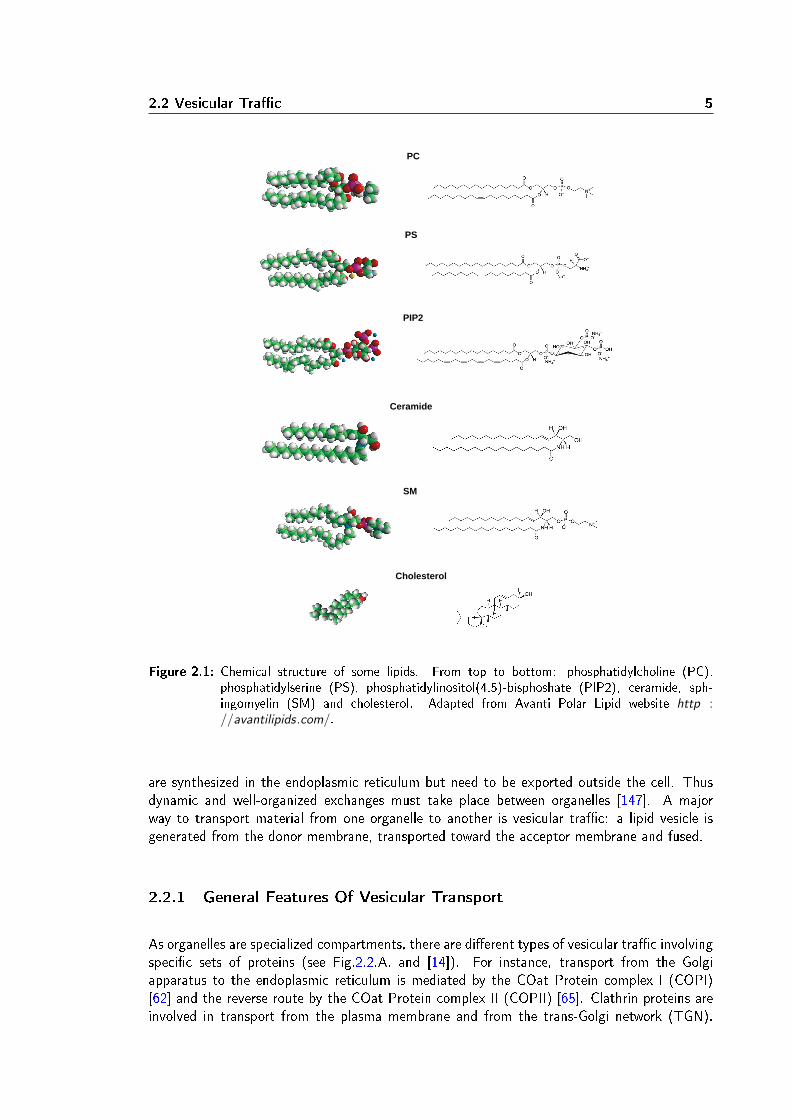
whereas the other one has at least one cis-double bond. The length of the tail varies from 14to 24 carbon atoms. Phosphatidylcholine (PC) is the major component of most eucaryotic cel-lular membranes. Its headgroup is a choline (see Fig.2.1. PC). It self-organizes into uid planarbilayer. Whereas PC is globally neutral, phosphatidylserine (PS) has a net negative charge dueto the serine group at its polar head (see Fig.2.1. PS). This lipid is restricted to the cytoso-lic leaet of membranes. Phosphatidylinositols (PtdIns) and its phosphorylated derivates likephosphatidylinositol 4,5-bisphosphate (PIP2) (see Fig.2.1. PIP2), although present in limitedamount in membranes (below 1% of the total phospholipids), constitute an interesting class ofglycerophospholipids as their metabolism (phosphorylation and dephosphorylation) is involvedin signalling pathways and membrane trac [27].
2.1.2 Sphingolipids
Sphingolipids derivate from ceramides (see Fig.2.1. Ceramide). They have two saturated ortrans-unsaturated hydrocarbon tails which make their hydrophobic core more rigid. Comparedto glycerophospholipids, sphingolipids are longer and thus thicken membranes.Sphingomyelin (SM) is the most abundant sphingolipid in mammalian cells. Like PC, SM car-ries a choline at its hydrophilic head (see Fig.2.1. SM). The plasma membrane, boundary ofthe cell, is particularly rich in sphingomyelin. For instance in red blood cell, around 18% of thetotal lipid weight is due to sphingomyelin [3, 147].
2.1.3 Sterols
Sterols are non polar lipids with a single hydrocarbon tail. They do not form bilayers by them-selves but insert within membranes at the upper part region of hydrophobic chains. Cholesterol(see Fig.2.1. Cholesterol) is the major sterol in mammalian cells. Like sphingomyelin, choles-terol is enriched in plasma membranes. It represents 23% of the total lipid weight in red bloodcell plasma membranes.
Membranes are not only structural elements of the cell. Indeed as membranes are impermeableto solutes, selective exchanges through the membrane and between organelles must take placevia specic mechanisms. Exchanges through the membrane occur via transmembrane proteinslike channels and pumps. Exchanges between organelles are enabled by vesicular trac.
2.2 Vesicular Trac
Cellular compartments are not static. Indeed lipids and proteins are synthesized in a placesometimes distant from their target location. For example, sphingolipids are synthesized inthe Golgi apparatus but the plasma membrane is enriched in these lipids. Secretory proteins
2.2 Vesicular Trac 5
PC
PS
PIP2
SM
Cholesterol
Ceramide
Figure 2.1: Chemical structure of some lipids. From top to bottom: phosphatidylcholine (PC),phosphatidylserine (PS), phosphatidylinositol(4,5)-bisphoshate (PIP2), ceramide, sph-ingomyelin (SM) and cholesterol. Adapted from Avanti Polar Lipid website http ://avantilipids.com/.
are synthesized in the endoplasmic reticulum but need to be exported outside the cell. Thusdynamic and well-organized exchanges must take place between organelles [147]. A majorway to transport material from one organelle to another is vesicular trac: a lipid vesicle isgenerated from the donor membrane, transported toward the acceptor membrane and fused.
2.2.1 General Features Of Vesicular Transport
As organelles are specialized compartments, there are dierent types of vesicular trac involvingspecic sets of proteins (see Fig.2.2.A. and [14]). For instance, transport from the Golgiapparatus to the endoplasmic reticulum is mediated by the COat Protein complex I (COPI)[62] and the reverse route by the COat Protein complex II (COPII) [65]. Clathrin proteins areinvolved in transport from the plasma membrane and from the trans-Golgi network (TGN).
6 Biological Membranes
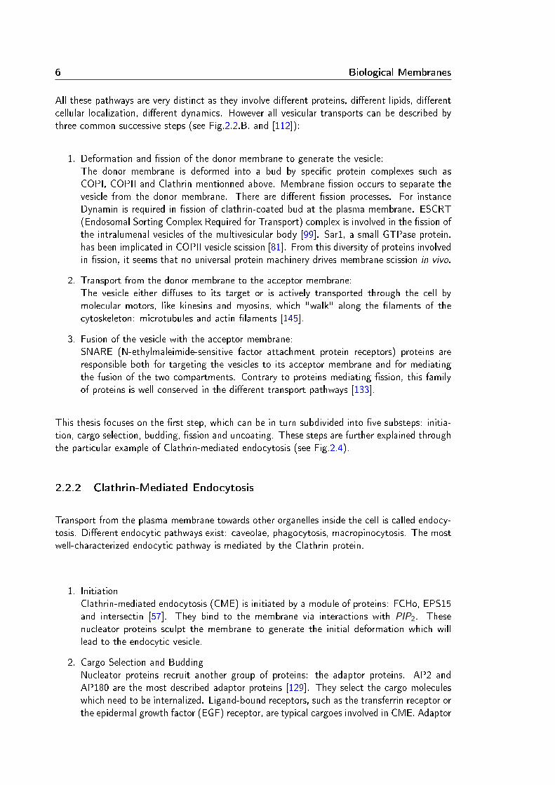
All these pathways are very distinct as they involve dierent proteins, dierent lipids, dierentcellular localization, dierent dynamics. However all vesicular transports can be described bythree common successive steps (see Fig.2.2.B. and [112]):
1. Deformation and ssion of the donor membrane to generate the vesicle:The donor membrane is deformed into a bud by specic protein complexes such asCOPI, COPII and Clathrin mentionned above. Membrane ssion occurs to separate thevesicle from the donor membrane. There are dierent ssion processes. For instanceDynamin is required in ssion of clathrin-coated bud at the plasma membrane. ESCRT(Endosomal Sorting Complex Required for Transport) complex is involved in the ssion ofthe intralumenal vesicles of the multivesicular body [99]. Sar1, a small GTPase protein,has been implicated in COPII vesicle scission [81]. From this diversity of proteins involvedin ssion, it seems that no universal protein machinery drives membrane scission in vivo.
2. Transport from the donor membrane to the acceptor membrane:The vesicle either diuses to its target or is actively transported through the cell bymolecular motors, like kinesins and myosins, which "walk" along the laments of thecytoskeleton: microtubules and actin laments [145].
3. Fusion of the vesicle with the acceptor membrane:SNARE (N-ethylmaleimide-sensitive factor attachment protein receptors) proteins areresponsible both for targeting the vesicles to its acceptor membrane and for mediatingthe fusion of the two compartments. Contrary to proteins mediating ssion, this familyof proteins is well conserved in the dierent transport pathways [133].
This thesis focuses on the rst step, which can be in turn subdivided into ve substeps: initia-tion, cargo selection, budding, ssion and uncoating. These steps are further explained throughthe particular example of Clathrin-mediated endocytosis (see Fig.2.4).
2.2.2 Clathrin-Mediated Endocytosis
Transport from the plasma membrane towards other organelles inside the cell is called endocy-tosis. Dierent endocytic pathways exist: caveolae, phagocytosis, macropinocytosis. The mostwell-characterized endocytic pathway is mediated by the Clathrin protein.
1. InitiationClathrin-mediated endocytosis (CME) is initiated by a module of proteins: FCHo, EPS15and intersectin [57]. They bind to the membrane via interactions with PIP2. Thesenucleator proteins sculpt the membrane to generate the initial deformation which willlead to the endocytic vesicle.
2. Cargo Selection and BuddingNucleator proteins recruit another group of proteins: the adaptor proteins. AP2 andAP180 are the most described adaptor proteins [129]. They select the cargo moleculeswhich need to be internalized. Ligand-bound receptors, such as the transferrin receptor orthe epidermal growth factor (EGF) receptor, are typical cargoes involved in CME. Adaptor

2.2 Vesicular Trac 7
A
B
1 2 3
Figure 2.2: A. Sketch representing the main tracking pathways in eucaryotic cells. Arrows indicatethe directions of vesicular transport from the donor organelle to the acceptor organelle. Inblue, red and yellow, specic localization of (respectively) COPII-, COPI- and Clathrin-mediated pathways. From Bonifacio and Glick, Cell 2004. B. Sketch of the three mainsteps during vesicular trac: 1. membrane budding initiated by coat proteins (red) andvesicle scission triggered by ssion proteins (purple) 2. vesicle transport by molecularmotors along cytoskeleton structures 3. specic targeting and fusion of the vesicle withthe acceptor membrane mediated by SNARE proteins (green). From Roux et al, Pour laScience 2007
proteins also directly interact with the plasma membrane especially with PIP2. Adaptorproteins recruit Clathrin at the plasma membrane. Clathrin is a large protein composed ofthree heavy chains and three light chains forming together a triskelion. Clathrin triskeliapolymerize into pentagons and hexagonal structures which in turn assemble into a latticeforming a spherical cage [44] (see Fig.2.3). Clathrin assembly allows to deform themembrane into a spherical bud while concentrating cargoes in the bud (through theirmutual interactions with adaptor proteins). The size of this Clathrin-coated bud varies,depending on cargoes' sizes, from 35 to 200 nm outer diameter [90]. The neck linking thebud to the plasma membrane is then covered by proteins containing a Bin-Amphiphysin-Rvs (BAR) domain: Amphiphysin [152] and Endophilin [110]. Like the nucleator proteinsin the initial step of CME, Amphiphysin and Endophilin bind and deform the membrane.They enable the formation of a thin membrane tube linking the Clathrin-coated bud tothe plasma membrane.
3. Fission

8 Biological Membranes
Figure 2.3: Structure of a Clathrin triskelion (bottom) and of a cage of Clathrin (top). From ProteinData Bank, April 2007 Molecule of the Month by Graham T. Johnson and David Goodsell
The release of the vesicle from the plasma membrane is mediated by the Dynamin proteinwhich has been proposed to be recruited to the neck by Amphiphysin [153]. The crucialstep of Dynamin-mediated membrane ssion constitutes the main interest of the workpresented in this thesis. This mechanism will be detailed in the following chapters.
4. UncoatingWhen the vesicle is detached from the plasma membrane, Clathrin rapidly depolymerizeswith the help of other proteins: the ATPase Heat Shock Cognate protein 70 (Hsc70) [118]and Auxilin [144]. Auxilin proteins rst bind to the vesicle within the Clathrin lattice andthereby destabilize the cage. Then they recruit Hsc70 which fully depolymerize Clathrinupon ATP hydrolysis [43]. In addition to Auxilin and Hsc70 activity, the dephosphorylationof PIP2 lipids also participates in Clathrin removal [27, 69]. Indeed Synaptojanin, aphosphoinositide phosphatase, is recruited by Endophilin at late stage of CCP maturation[100]. As this phosphatase hydrolyzes PIP2, the level of PIP2 decreases only after ssionwhen the released vesicle is no more connected to the plasma membrane which containsa reservoir of PIP2. The depletion of PIP2 would promote the dissociation of the coatproteins from the membrane and help recruiting Auxilin.
During CME, several protein-protein and protein-lipid interactions must by coordinated at theright time and the right location. This well orchestrated sequence of proteins recruitments andmembrane deformations [139, 90] takes place in every eucaryotic cells in a constitutive manner.In some specialized cells, CME plays also an essential role such as in neurons where a highlydynamic endocytic activity is required to recycle synaptic vesicles.

2.2 Vesicular Trac 9
Figure 2.4: Sketch of the ve steps of Clathrin-mediated endocytosis with the main proteins involvedin the process. From McMahon and Boucrot, Nature Reviews Molecular Cell Biology 2011
2.2.3 Synaptic Vesicle Recycling
The synapse is the junction between a presynaptic neuron and a postsynaptic neuron (seeFig.2.5). At this connection, chemical signals are transmitted via neurotransmitters molecules(glutamate, acetylcholine, Gamma-AminoButyric Acid (GABA)...). At the presynaptic neuron,neurotransmitters are conned inside vesicles. These synaptic vesicles are then released in thesynapse by exocytosis, a process where vesicles fuse with the plasma membrane and releasetheir contents outside the cell. The released neurotransmitters then bind to specic receptorslocated at the plasma membrane of the postsynaptic neurons. In the presynaptic region, theexocytic machinery like the SNARE proteins involved in fusion and the excess membrane addedto the plasma membrane during exocytosis are recycled through CME [59]. This recycling isvery intense as there can be up to thousands synaptic vesicles in a presynaptic neuron. IndeedCME in neurons occurs within 10 to 25 s [156, 66] which is faster than in non neuronal cells(around 1 minute [139]).
Figure 2.5: Sketch illustrating synaptic vesicles recycling. From McMahon and Boucrot 2011, NatureReviews Molecular Cell Biology
Clathrin-mediated endocytosis and its specic role during synaptic vesicles recycling are good

10 Biological Membranes
examples highlighting the spatial and temporal coordination of dierent cellular mechanismsremodelling the membrane. Thus biological membranes conciliate two important mechanicalproperties: self-assembling to ensure the organelle's integrity and a propensity to deform underexternal forces to enable dynamic vesicular transport. To better understand their mechanicalproperties, biological membranes have been studied by physicists.

Chapter 3
Physics Of Membrane
In this chapter, I will explain how membranes have been modelled by physicists. The shape ofa membrane determines its energy as it will be explained in 3.1. Thus deforming a membranechanges its energy. Experiments modifying the membrane shape, such as micropipette aspira-tion and nanotube extrusion, have been designed to probe membrane mechanics and will bedetailed in 3.2. Finally I will give energetic considerations about membrane ssion in the lastpart of this chapter 3.3.
3.1 Theoretical Description Of A Membrane
Membranes are traditionally modelled as homogeneous uid thin sheets. In most cases, theirthickness (a few nm) is negligible compared to the length scale of their surface (a few µm). Ifthis approximation is satised, any membrane deformation can be decomposed into three ele-mentary deformations: stretching, shearing and bending as depicted in Fig.3.1 [37]. Describingthese deformations enables to calculate the elastic energy of the membrane.
A B C
Figure 3.1: Sketch of the three independent modes of membrane deformations: A. stretching, B.shearing, C. bending. Arrows represent deformation directions. From Evans and Needham,1987.

12 Physics Of Membrane
3.1.1 Stretching
Stretching is a deformation which modies the area A of a membrane by either extending orcompressing it (Fig.3.1.A.). The stretching energy per unit area of a membrane undergoing arelative change in area ∆A
A is:
Estretching =1
2χ(
∆A
A)2
where χ is the compressibility modulus. To understand the stretching energy, the concept ofmembrane tension must be introduced. A membrane with a surface area A and a free energy
F has a tension σ =∂F
∂A. The precise relationship between stretching and tension will be
explained later in 3.1.5.
3.1.2 Shearing
Shearing a membrane is equivalent to applying coplanar forces in opposite directions on twopoints of the membrane while maintaining the surface area (Fig.3.1.B.). The shearing energyper unit area is:
Eshearing =1
2µ(λ2 + λ−2 − 2)
where µ is the shear modulus and λ the lateral extension rate: λ = L+∆LL . In uid lipid bilayers,
shearing deformations are negligible compared to stretching and bending and will be ignoredafterwards.
3.1.3 Bending
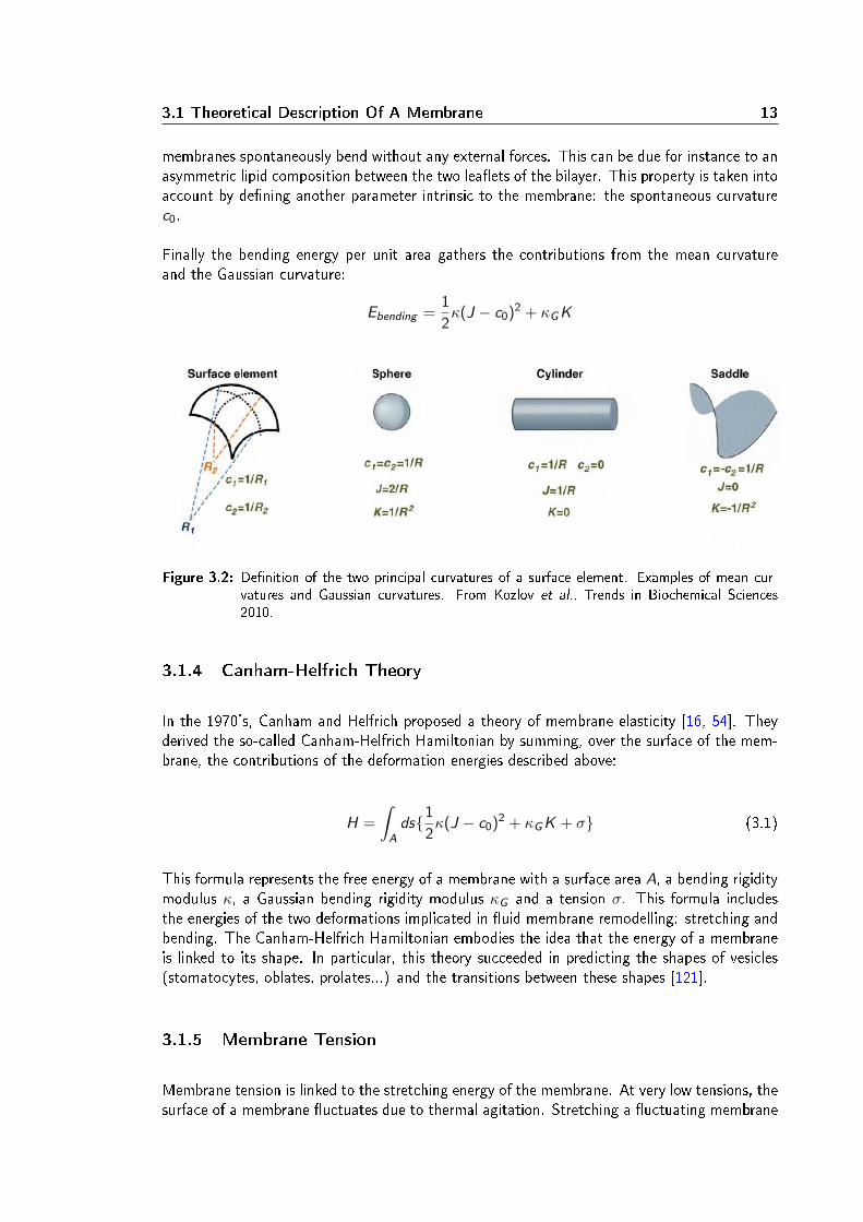
The last deformation category corresponds to bending the membrane at constant area (Fig.3.1.C.).The bending energy derives from the curvature of the membrane. At a given point of a surface,one can dene two radii of curvature R1 and R2 (see Fig.3.2). The inverse of these radii arethe two principal curvatures C1 and C2
1 . The sum of the principal curvatures is the meancurvature J = C1 + C2. The product of the principal curvatures is the Gaussian curvatureK = C1.C2.
For instance on every point of a sphere of radius R, the mean curvature is2
Rand the Gaussian
curvature is1
R2. An innite cylinder of radius R has a mean curvature
1
Rand a null Gaussian
curvature on every points of its surface. A saddle point has the particularity to have two prin-cipal curvatures of opposite sign and thus a negative Gaussian curvature (Fig.3.2 [74]). J andK are local parameters which completely describe the shape of the membrane.To describe the propensity of a membrane to bend, we dene two intrinsic parameters: thebending rigidity modulus κ and the Gaussian bending rigidity modulus κG . κ and κG repre-sent the energetic cost to generate principal curvature (increasing J) and Gaussian curvature(increasing K ) respectively. They both depend on the composition of the membrane. Some
1More precisely the principal curvatures at a given point are the maximum and minimum values of thecurvature. They are the eigenvalues of the shape operator.
3.1 Theoretical Description Of A Membrane 13
membranes spontaneously bend without any external forces. This can be due for instance to anasymmetric lipid composition between the two leaets of the bilayer. This property is taken intoaccount by dening another parameter intrinsic to the membrane: the spontaneous curvaturec0.
Finally the bending energy per unit area gathers the contributions from the mean curvatureand the Gaussian curvature:
Ebending =1
2κ(J − c0)2 + κG K
Figure 3.2: Denition of the two principal curvatures of a surface element. Examples of mean cur-vatures and Gaussian curvatures. From Kozlov et al., Trends in Biochemical Sciences2010.
3.1.4 Canham-Helfrich Theory
In the 1970's, Canham and Helfrich proposed a theory of membrane elasticity [16, 54]. Theyderived the so-called Canham-Helfrich Hamiltonian by summing, over the surface of the mem-brane, the contributions of the deformation energies described above:
H =
∫
Ads1
2κ(J − c0)2 + κG K + σ (3.1)
This formula represents the free energy of a membrane with a surface area A, a bending rigiditymodulus κ, a Gaussian bending rigidity modulus κG and a tension σ. This formula includesthe energies of the two deformations implicated in uid membrane remodelling: stretching andbending. The Canham-Helfrich Hamiltonian embodies the idea that the energy of a membraneis linked to its shape. In particular, this theory succeeded in predicting the shapes of vesicles(stomatocytes, oblates, prolates...) and the transitions between these shapes [121].
3.1.5 Membrane Tension
Membrane tension is linked to the stretching energy of the membrane. At very low tensions, thesurface of a membrane uctuates due to thermal agitation. Stretching a uctuating membrane
14 Physics Of Membrane
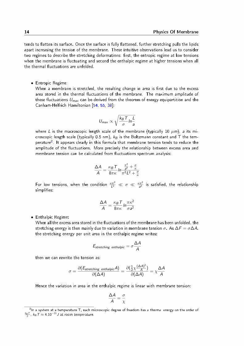
tends to atten its surface. Once the surface is fully attened, further stretching pulls the lipidsapart increasing the tension of the membrane. These intuitive observations lead us to considertwo regimes to describe the stretching deformations: rst, the entropic regime at low tensionswhen the membrane is uctuating and second the enthalpic regime at higher tensions when allthe thermal uctuations are unfolded.
• Entropic Regime:When a membrane is stretched, the resulting change in area is rst due to the excessarea stored in the thermal uctuations of the membrane. The maximum amplitude ofthese uctuations Umax can be derived from the theorem of energy equipartition and theCanham-Helfrich Hamiltonian [54, 55, 38]:
Umax ∝√
kBT
σln
L
a
where L is the macroscopic length scale of the membrane (typically 10 µm), a its mi-croscopic length scale (typically 0.5 nm), kB is the Boltzmann constant and T the tem-perature2. It appears clearly in this formula that membrane tension tends to reduce theamplitude of the uctuations. More precisely the relationship between excess area andmembrane tension can be calculated from uctuations spectrum analysis:
∆A
A=κBT
8πκln
π2
a2 + σκ
π2L2 + σκ
For low tensions, when the condition κπ2
L2 σ κπ2
a2 is satised, the relationshipsimplies:
∆A
A=κBT
8πκlnπκ2
σa2
• Enthalpic Regime:When all the excess area stored in the uctuations of the membrane has been unfolded, thestretching energy is then mainly due to variation in membrane tension σ. As ∆F = σ∆A,the stretching energy per unit area in the enthalpic regime writes:
Estretching enthalpic = σ∆A
A
then we can rewrite the tension as:
σ =∂(Estretching enthalpic A)
∂(∆A)=∂( 1
2χ(∆A)2
A )
∂(∆A)= χ
∆A
A
Hence the variation in area in the enthalpic regime is linear with membrane tension:
∆A
A=σ
χ
2In a system at a temperature T, each microscopic degree of freedom has a thermal energy on the order ofkB T
2, kBT ≈ 4.10−21J at room temperature.
3.2 Experimental Studies Of Membrane Mechanics 15
Finally the relative change in area due to stretching deformations is the sum of two contributions:the entropic regime (non linear with tension) and the enthalpic regime (linear with tension)[38]:
∆A
A=κBT
8πκlnπκ2
σa2+σ
χ(3.2)
3.2 Experimental Studies Of Membrane Mechanics
In this section, I will describe how the theoretical description of membranes has been vali-dated experimentally. Two techniques, which we used to study Dynamin, will be detailed: themicropipette aspiration and the nanotube extrusion. They both enable to test the Canham-Helfrich theory. To study membrane mechanics, many model membrane systems have beendesigned since they are less complex than living organisms' membranes (for a review see [8]).For instance the Giant Unilamellar Vesicles (GUVs) are articial spherical lipid bilayers with typi-cal radii of a few tens of micrometers. GUVs are good templates to study membrane mechanics.They can be observed by light microscopy. GUVs can be prepared easily by electroformation[7, 89]. This technique also allows to make multicomponent membranes, for instance GUVscontaining PIP2 [17], which were widely used during this thesis.
3.2.1 Control Of Membrane Tension With A Micropipette
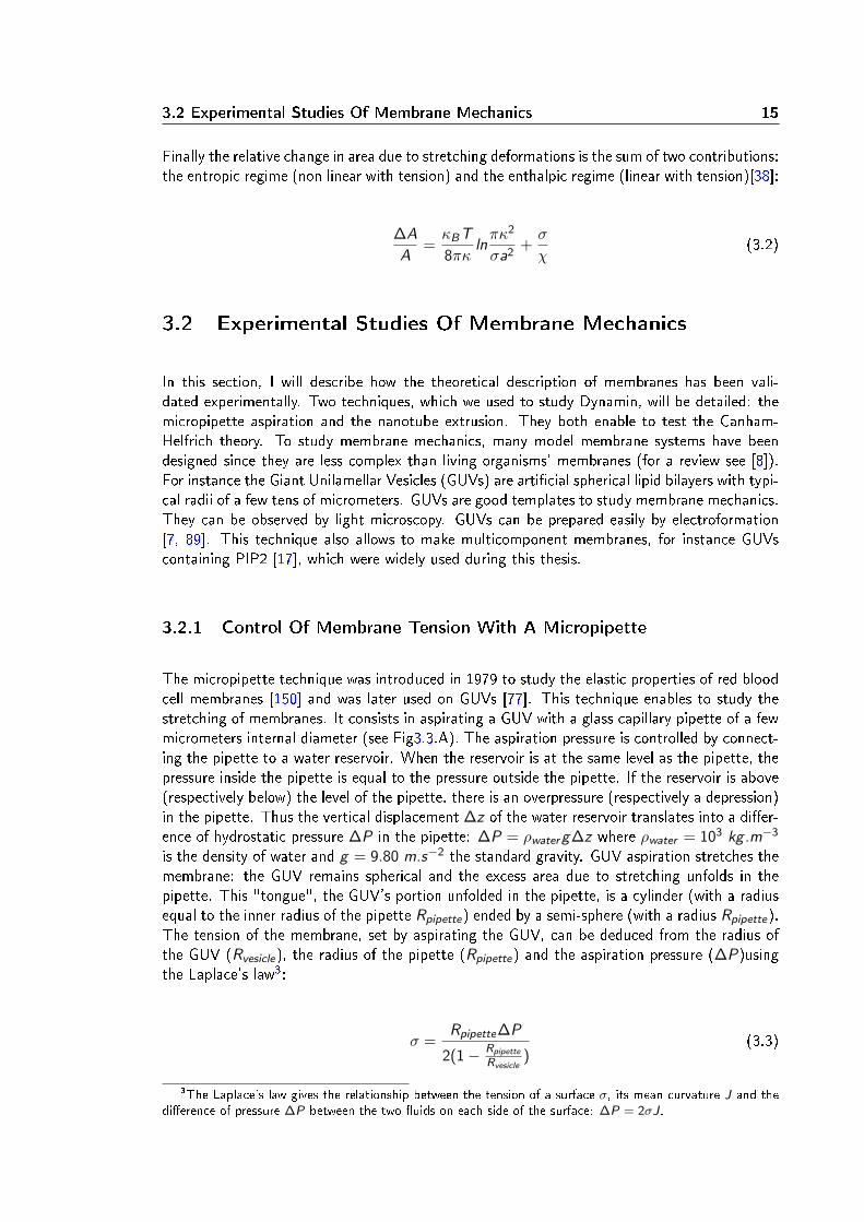
The micropipette technique was introduced in 1979 to study the elastic properties of red bloodcell membranes [150] and was later used on GUVs [77]. This technique enables to study thestretching of membranes. It consists in aspirating a GUV with a glass capillary pipette of a fewmicrometers internal diameter (see Fig3.3.A). The aspiration pressure is controlled by connect-ing the pipette to a water reservoir. When the reservoir is at the same level as the pipette, thepressure inside the pipette is equal to the pressure outside the pipette. If the reservoir is above(respectively below) the level of the pipette, there is an overpressure (respectively a depression)in the pipette. Thus the vertical displacement ∆z of the water reservoir translates into a dier-ence of hydrostatic pressure ∆P in the pipette: ∆P = ρwater g∆z where ρwater = 103 kg .m−3
is the density of water and g = 9.80 m.s−2 the standard gravity. GUV aspiration stretches themembrane: the GUV remains spherical and the excess area due to stretching unfolds in thepipette. This "tongue", the GUV's portion unfolded in the pipette, is a cylinder (with a radiusequal to the inner radius of the pipette Rpipette) ended by a semi-sphere (with a radius Rpipette).The tension of the membrane, set by aspirating the GUV, can be deduced from the radius ofthe GUV (Rvesicle), the radius of the pipette (Rpipette) and the aspiration pressure (∆P)usingthe Laplace's law3:
σ =Rpipette∆P
2(1− Rpipette
Rvesicle)
(3.3)
3The Laplace's law gives the relationship between the tension of a surface σ, its mean curvature J and thedierence of pressure ∆P between the two uids on each side of the surface: ∆P = 2σJ.

16 Physics Of Membrane
The micropipette technique was used to test experimentally the relationship between the changein area due to stretching and the membrane tension. When the aspiration pressure is modied(by vertically displacing the water reservoir), it results in a modication of the tongue length∆L (see Fig.3.3A). Thus the experimental change in area ( ∆A
A )exp can be deduced from thechange in the GUV's shape [77]:
(∆A
A)exp =
(Rpipette
Rvesicle)2 − (
Rpipette
Rvesicle)3
2Rpipette∆L (3.4)
We mentioned above (formula 3.2) a theoretical prediction for the relationship between thechange in area ( ∆A
A )theory and the membrane tension σ. The experimental change in area( ∆A
A )exp does not take into account all the uctuations so that:
(∆A
A)exp = (
∆A
A)theory 0 − (
∆A
A)theorypipette
(3.5)
where ( ∆AA )theory 0 is the total excess area stored in the uctuations of the GUV before aspiration
when the tension is σ0 and ( ∆AA )theorypipette
is the total excess area when the GUV is aspiratedin a pipette with a tension σ. Combining 3.5 with 3.2, we obtain:
(∆A
A)exp =
κBT
8πκlnσ
σ0+σ
χ(3.6)
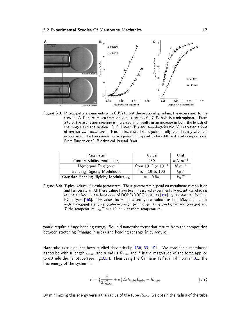
Evans' group performed experiments to verify the relationship 3.6. They did observe tworegimes [38, 108]. For lower deformations, tension depends logarithmically with the change inarea as predicted by the entropic regime and for higher deformations, tension increases linearlyin good agreement with the enthalpic regime (Fig.3.3.B and C.). These results validate theCanham-Helfrich theory. These experiments also allow to measure the elastic parameters ofmembranes such as the bending rigidity modulus κ and the compressibility modulus χ and howthese parameters depend on membrane composition [38, 108, 95, 88, 109]. These experimentalmeasurements of elastic parameters are summarized in the table 3.4.
3.2.2 Nanotube Extrusion
General Concept Of Nanotube Extrusion
Nanotube extrusion is another way to probe the membrane mechanics. When a point force isexerted on a membrane, a lipid nanotube is formed. This deformation is very typical of uidbilayers. By comparison, if a pulling force is exerted locally on a solid elastic surface, suchas a rubber balloon, the whole object deforms into a conical shape. For uid membranes, asstretching increases tension, the energy of the system is minimized by reducing the surface ofthe deformation. The minimal surface would be a straight line perpendicular to the plane ofthe membrane. However deforming a membrane into a line, which has an innite curvature,
3.2 Experimental Studies Of Membrane Mechanics 17
A B C
Figure 3.3: Micropipette experiments with GUVs to test the relationship linking the excess area to thetension. A. Pictures taken from video microscopy of a GUV hold in a micropipette. Froma to b, the aspiration pressure is increased and results in an increase in both the length ofthe tongue and the tension. B. C. Linear (B.) and semi-logarithmic (C.) representationsof tension vs. excess area. Tension increases rst logarithmically then linearly with theexcess area. The two curves in each panel correspond to two dierent lipid compositions.From Rawicz et al., Biophysical Journal 2000.
Parameter Value UnitCompressibility modulus χ 250 mN.m−1
Membrane Tension σ from 10−7 to 10−3 N.m−1
Bending Rigidity Modulus κ from 10 to 100 kBT
Gaussian Bending Rigidity Modulus κG ≈ −0.8κ kBT
Figure 3.4: Typical values of elastic parameters. These parameters depend on membrane compositionand temperature. All these values have been measured experimentally except κG which isestimated from phase behaviour of DOPE/DOPC mixtures [126]. χ is measured for uidPC bilayers [108]. The values for σ and κ are typical values for uid bilayers obtainedwith micropipette and nanotube extrusion techniques. kB is the Boltzmann constant andT the temperature. kB T ≈ 4.10−21 J at room temperature.
would require a huge bending energy. So lipid nanotube formation results from the competitionbetween stretching (change in area) and bending (change in curvature).
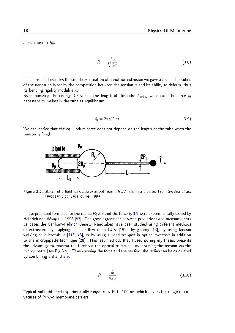
Nanotube extrusion has been studied theoretically [136, 33, 101]. We consider a membranenanotube with a length Ltube and a radius Rtube and f is the magnitude of the force appliedto extrude the nanotube (see Fig.3.5.). Then using the Canham-Helfrich Halmitonian 3.1, thefree energy of the system is:
F = κ
2R2tube
+ σ2πRtubeLtube − fLtube (3.7)
By minimizing this energy versus the radius of the tube Rtube , we obtain the radius of the tube
18 Physics Of Membrane
at equilibrium R0:
R0 =
√κ
2σ(3.8)
This formula illustrates the simple explanation of nanotube extrusion we gave above. The radiusof the nanotube is set by the competition between the tension σ and its ability to deform, thusits bending rigidity modulus κ.By minimizing the energy 3.7 versus the length of the tube Ltube , we obtain the force f0
necessary to maintain the tube at equilibrium:
f0 = 2π√
2κσ (3.9)
We can notice that the equilibrium force does not depend on the length of the tube when thetension is xed.
Figure 3.5: Sketch of a lipid nanotube extruded from a GUV hold in a pipette. From Svetina et al.,European biophysics journal 1998.
These predicted formulas for the radius R0 3.8 and the force f0 3.9 were experimentally tested byHeinrich and Waugh in 1996 [53]. The good agreement between predictions and measurementsvalidates the Canham-Helfrich theory. Nanotubes have been studied using dierent methodsof extrusion: by applying a shear ow on a GUV [151], by gravity [13], by using kinesinwalking on microtubule [113, 73], or by using a bead trapped in optical tweezers in additionto the micropipette technique [28]. This last method, that I used during my thesis, presentsthe advantage to monitor the force via the optical trap while maintaining the tension via themicropipette (see Fig.3.5). Thus knowing the force and the tension, the radius can be calculatedby combining 3.8 and 3.9:
R0 =f0
4πσ(3.10)
Typical radii obtained experimentally range from 10 to 100 nm which covers the range of cur-vatures of in vivo membrane carriers.

3.2 Experimental Studies Of Membrane Mechanics 19
Beyond the Canham-Helfrich theory: applications Of Nanotube Extrusion
The nanotube extrusion technique has been combined to uorescent microscopy to study lipidsorting [130, 142]. Fluorescent probes incorporated in GUVs allow to visualize precisely lipidnanotubes with confocal microscopy (see Fig.3.6.C and D.). Some probes, such as BodipyFL-GM1, mix homogeneously in the membrane (see Fig.3.6.B). Other probes, such as TexasRed-DHPE, are sensitive to the order of the membrane (see Fig.3.6.A). The order of the membranerepresents its organization state: the more ordered a membrane is, the more well packed arethe lipids in the bilayer. This order depends on external parameters, like temperature, andon internal parameters, like membrane composition. Liquid-ordered (lo) and liquid-disordered(ld) phases are two examples of uid phases. In lo-phases, the distance between lipids is onaverage smaller than in ld-phases. Lo-phase membranes are also thicker and stier [109]. Aslo-phases are more organized than ld-phases, lipid diusion is usually slower in lo-phases[67].It is possible to observe coexisting phases in vitro. For example, a ternary lipid mixture ofsphingomyelin, phosphatidylcholine and cholesterol can segregate in two phases (lo and ld)depending on the proportions of each component. The diagram of phase separation for thisternary mixture is well-known [32, 8]. The dierent phases can be observed with phase-sensitiveuorescent dyes such as TexasRed-DHPE which segregates preferentially in ld phase. Sorre et
al. extruded nanotubes from GUV prepared from this ternary mixture complemented withTexasRed-DHPE and BodipyFL-GM1. It is important to mention that they use compositionsgiving homogenous uid membranes as it is a requirement to measure tension and radius bynanotube extrusion. They quantied the ratio of uorescence of the two probes along thenanotube relatively to the same ratio in the GUV. They observed that for compositions close tophase separation, the thinner the tube, the more enriched in TexasRed-DHPE (see Fi.3.6.D).This indicates that membrane curvature can induce lipid sorting when the lipid compositionis close to phase separation. Lipid sorting is a good example showing the limitations of theCanham-Helfrich theory. Indeed the force formula 3.9 is valid only for homogeneous membranes,as soon as sorting occurs a deviation in the force curve is observed. Thus the Canham-HelfrichHamiltonian must be corrected with a Flory-Huggins mixing free energy to describe properlylipid sorting [130].
Nanotube extrusion via optical tweezers has also been useful for studying:
• lipid and protein lateral diusion in bilayers and its dependency on curvature [35];Quantum dots were attached to lipids or voltage-gated channels (KvAP) reconstitutedin GUVs [2]. Diusion coecients were measured by following individual uorescentparticles along nanotubes with controlled radii. This study validated the Saman andDelbrück theory [117] predicting that the diusion coecient depends logarithmically onthe inverse of the protein size and on the nanotube radius.
• protein-membrane interactions;The membrane-interacting properties of certain proteins have been shown to depend oncurvature. For instance ArfGAP1 proteins, implicated in COPI tracking, bind speci-cally to nanotubes and not to the at membrane of GUVs. ArfGAP1 binding is reducedfor tubes with radii thinner than 35 nm [5]. Dynamin polymerization around lipid nan-otubes is also curvature-dependent [115] as we will explain in the next chapter. Recentwork on Amphiphysin [131] showed that the protein density on the nanotube is a criticalparameter to precisely distinguish two binding regimes: curvature-sensing and curvature-generator. At low density of Amphiphysin, the properties of the protein-bound membrane

20 Physics Of Membrane
Figure 3.6: A. and B. confocal pictures of a phase-separated GUV containing sphingomyelin, DOPC,cholesterol TexasRed-DHPE (red) and BodipyFL-GM1 (green). In A. partitioning ofTexasRed-DHPE in ld phase. In B. BodipyFL-GM1 present in both phases. C. Confo-cal pictures of a nanotube extruded from a homogeneous GUV with the same componentsas in A. and B. (but in dierent proportions to avoid phase separation). D. Left: confocalpictures of a tube. Top: radius is 70 nm. Bottom: radius is 20 nm. Right: uorescenceintensity prole of TexasRed-DHPE and BodipyFL-GM1 from the tubes shown at left.TexasRed-DHPE is enriched in the thinner tube. From Sorre et al., PNAS 2009
dier slightly from the ones of a pure lipid membrane so that the tube radius and the forcestill depend on tension and rigidity. Whereas at high density, the radius is independentof the tension because Amphiphysin forms a scaold around the nanotube. These stud-ies constitute a second example showing the limitations of the Canham-Helfrich theory.When proteins bind to the nanotube, the radius formula 3.10 is no more satised.
• membrane tension variation in live cells;The Canham-Helfrich theory is not valid a priori in live systems as they are out of equi-librium. Nevertheless, nanotube extrusion from live cells enables to monitor in real timethe variation of the plasma membrane tension. Probing membrane tension in live cells ischallenging as biological membranes are submitted to many external processes: interac-tions with the cytoskeleton, endocytosis, exocytosis... When nanotubes are extruded fromlive cells, the force remains constant as the tube length increases until a certain lengththreshold. Above this length, the force necessary to maintain the tube becomes toohigh which triggers the tube retraction [107]. This indicates that the plasma membranecontains a reservoir. It has been recently demonstrated that a part of this membranereservoir is constituted by caveolae [128].
3.3 Physics Of Membrane Fission
As we have seen in Chapter 2, vesicular trac involves membrane deformations that have beenmodelled by physicists. The formation of a vesicle requires also a nal step: membrane ssionwhich separates the vesicle from the donor membrane. More generally ssion is the processby which one initially closed surface split into two closed surfaces. This process modies the
3.3 Physics Of Membrane Fission 21
topology of the membrane and thus is strongly unfavourable energetically due to the membrane'sself-sealing properties.
3.3.1 Role Of Bending Energy In Fission
To better understand the implications of ssion for the energy of the membrane, let us doa simple calculation. We consider a at membrane with a surface area A in the initial stateand the nal state resulting from ssion: a vesicle of radius R and a at membrane of surfacearea A − 4πR2. We can estimate the energy of these two states using the Canham-HelfrichHamiltonian 3.1. As at surfaces have null curvatures (J = 0, K = 0), the initial state has anenergy equal to
∫A dsσ = σA. The nal state's energy is the sum of the vesicle energy and
the at membrane energy:
∫
vesicleds1
2κ(
1
2R)2 +
κG
R2+ σvesicle+
∫
flat membranedsσflat
= 4π(κ
8+ κG ) + σvesicle4πR2 + σflat(A− 4πR2)
If we consider that tension remains constant during the process: σvesicle = σflat = σ, thedierence of energy between the two states, which is the minimal bending energy required toform a vesicle, is 4π(
κ
8+ κG ) 4 . Note that this energy is independent of the vesicle radius
and depends only on the bending rigidity modulus κ and the Gaussian bending rigidity modulusκG highlighting that membrane elastic properties must play an important role in the ssionmechanism. It is interesting to note that the energetic term depending on κG in the Canham-Helfrich Hamiltonian stays constant during the whole deformation of membrane and varies onlywhen topological changes occur. This comes from the Gauss-Bonnet theorem which stipulatesthat the integral of the the Gaussian curvature depends only on the topology of the surface:∫
S dsK = 4π(1 − g) where g is called the genus of the surface and intuitively represents thenumber of "holes", for instance g = 0 for a sphere, g = 1 for a torus. Thus the energy ofGaussian curvature due to ssion is 4πκG regardless of the vesicle shape. This draws attentionto the Gaussian bending rigidity modulus κG which might be an interesting parameter for thession mechanism. Gaussian bending rigidity modulus has never been direclty measured andis estimated to be negative with its absolute value similar to κ [127]. The signicant role ofthis parameter has already been underlined in the study of fusion [126], the reverse topologicalchange.
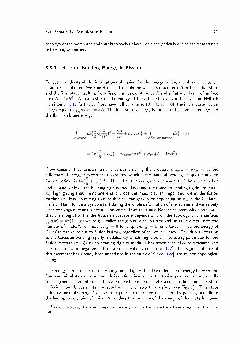
The energy barrier of ssion is certainly much higher than the dierence of energy between thenal and initial states. Membrane deformations involved in the ssion process lead supposedlyto the generation an intermediate state named hemission state similar to the hemifusion statein fusion: two bilayers interconnected via a local structural defect (see Fig3.7). This stateis highly unstable energetically as it requires to rearrange the leaets by packing and tiltingthe hydrophobic chains of lipids. An underestimate value of the energy of this state has been
4For κ = −0.8κG , this term is negative, meaning that the nal state has a lower energy than the initialstate.
22 Physics Of Membrane
calculated around 78 kBT using the Canham-Helfrich Hamiltonian [76]. However as ssionoccurs very locally, the membrane cannot be modelled as a thin surface and the elastic energyderived from The Canham-Helfrich Hamiltonian might not be valid. So far very few resultshave been established about the energy landscape of ssion.
Figure 3.7: Sketch of the hemission intermediate. Adapted from Chernomordik and Kozlov, Cell2005
3.3.2 Fission Induced By Lipid Phase-Separation
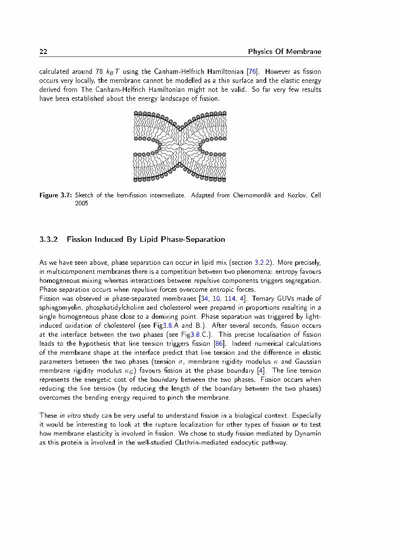
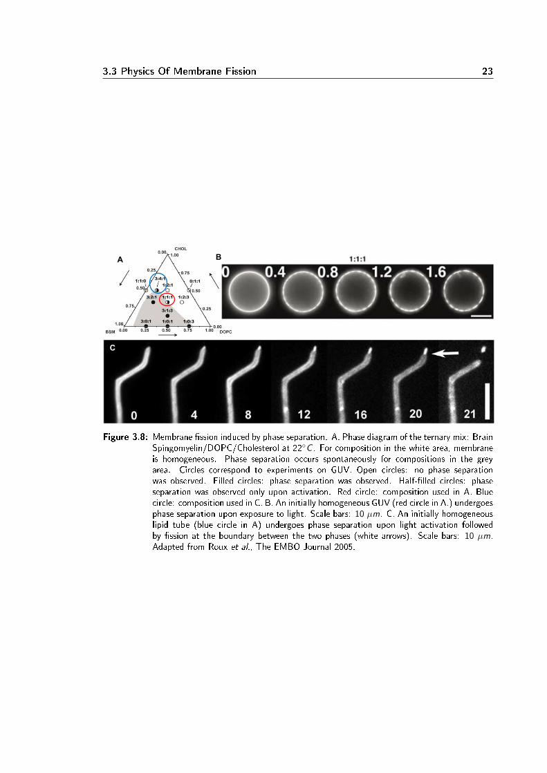
As we have seen above, phase separation can occur in lipid mix (section 3.2.2). More precisely,in multicomponent membranes there is a competition between two phenomena: entropy favourshomogeneous mixing whereas interactions between repulsive components triggers segregation.Phase separation occurs when repulsive forces overcome entropic forces.Fission was observed in phase-separated membranes [34, 10, 114, 4]. Ternary GUVs made ofsphingomyelin, phosphatidylcholine and cholesterol were prepared in proportions resulting in asingle homogeneous phase close to a demixing point. Phase separation was triggered by light-induced oxidation of cholesterol (see Fig3.8.A and B.). After several seconds, ssion occursat the interface between the two phases (see Fig3.8.C.). This precise localisation of ssionleads to the hypothesis that line tension triggers ssion [86]. Indeed numerical calculationsof the membrane shape at the interface predict that line tension and the dierence in elasticparameters between the two phases (tension σ, membrane rigidity modulus κ and Gaussianmembrane rigidity modulus κG ) favours ssion at the phase boundary [4]. The line tensionrepresents the energetic cost of the boundary between the two phases. Fission occurs whenreducing the line tension (by reducing the length of the boundary between the two phases)overcomes the bending energy required to pinch the membrane.
These in vitro study can be very useful to understand ssion in a biological context. Especiallyit would be interesting to look at the rupture localization for other types of ssion or to testhow membrane elasticity is involved in ssion. We chose to study ssion mediated by Dynaminas this protein is involved in the well-studied Clathrin-mediated endocytic pathway.
3.3 Physics Of Membrane Fission 23
A B
C
Figure 3.8: Membrane ssion induced by phase separation. A. Phase diagram of the ternary mix: BrainSpingomyelin/DOPC/Cholesterol at 22C . For composition in the white area, membraneis homogeneous. Phase separation occurs spontaneously for compositions in the greyarea. Circles correspond to experiments on GUV. Open circles: no phase separationwas observed. Filled circles: phase separation was observed. Half-lled circles: phaseseparation was observed only upon activation. Red circle: composition used in A. Bluecircle: composition used in C. B. An initially homogeneous GUV (red circle in A.) undergoesphase separation upon exposure to light. Scale bars: 10 µm. C. An initially homogeneouslipid tube (blue circle in A) undergoes phase separation upon light activation followedby ssion at the boundary between the two phases (white arrows). Scale bars: 10 µm.Adapted from Roux et al., The EMBO Journal 2005.


Chapter 4
The Dynamin Protein
This chapter gives a review on Dynamin. Discovered during Tubulin purication, Dynaminwas then identied as a mechanochemical enzyme involved in membrane ssion. This proteinhas two major features: it hydrolyses GTP and polymerizes into a helix. The properties of thispolymer will be described, especially the conformational changes observed upon GTP hydrolysis.The interplay between polymerization and GTPase activity gives rise to several models of ssionthat will be detailed.
4.1 Discovery Of A Membrane-Remodelling GTPase
4.1.1 Discovery
Dynamin was identied in 1989 as a protein copuried with Tubulin [124]. Like Dynein andKinesin, this protein exhibited a nucleotide hydrolysis activity stimulated by microtubules [125].Thus Dynamin was rst considered as a microtubule-associated molecular motor. It was hy-pothesized that Dynamin would bundle microtubules and make them slide along one anotherupon nucleotide hydrolysis.However in 1991, Dynamin was associated to vesicular trac when sequencing showed thatDrosophila Shibire gene encodes for a protein homologous to rat Dynamin [146]. The Shibiremutant was well known among neurobiologists as a thermosensitive mutant: at 19C Shibireies presented a normal phenotype whereas at 29C they became reversibly paralyzed. Thisparalysis was due to a defect in synaptic vesicles recycling [71]. Electron microscopy on Shibiremutant synapses showed a depletion of synaptic vesicles and invaginations in the plasma mem-brane with an electron-dense collar at their neck (see Fig.4.1). Immunogold-labelling laterconrmed that this collar indeed contained Dynamin proteins [30].

26 The Dynamin Protein
Figure 4.1: Electron micrographs of Shibire mutant synapses at 19 C in A. and after 8 min at29 C in B. In A, many synaptic vesicles (sv) are present in the presynaptic neuron. InB, there are no synaptic vesicles but some plasma membrane invaginations (arrowheads).Thin arrows indicate large invaginations with their neck out of the sectioning plane. InA. and B.: m means mitochondria, db presynaptic dense body. Thick arrows indicatesite of neurotransmitter release. Scale bar: 1 µm. From Koenig and Ikeda, Journal ofNeuroscience 1989.
4.1.2 Role In Clathrin-Mediated Endocytosis
Since then the role of Dynamin in vesicular trac was further investigated. Clathrin-mediatedendocytosis (CME) was shown to be blocked in cells overexpressing a mutant defective in GT-Pase activity [30]. Live-cell imaging showed that Dynamin colocalizes transiently with Clathrin-coated pits [93] (see Fig.4.2). Precise study of endocytic protein recruitment at the plasmamembrane by dual color total internal reection uorescence (TIRF) microscopy has revealedthat Dynamin is present at low levels at early stages of Clathrin-coated pit maturation then aburst of Dynamin appears 2 to 4 s before vesicle scission [139] 1. Experiments on genome-editedmammalians cells, where uorescent Dynamin is expressed at endogenous level, have conrmedthis transient recruitment [36]. These assays demonstrated that Dynamin is massively recruitedto Clathrin-coated structures just before ssion.
To further understand the role of Dynamin in CME, knockout mice have been generated. InMammals, there are three isoforms of Dynamin: Dynamin 1 is expressed at high levels in neu-ronal tissue specically, Dynamin 2 is ubiquitous and Dynamin 3 is enriched in testis, lung andneurons (but at a lower level than Dynamin 1). Dynamin 2 knockout is lethal during the earlyembryonic development. Dynamin 1 knockout mice are normal at birth but fail to thrive anddie within two weeks [40]. Dynamin 3 mice have no obvious phenotype. However Dynamin 1and 3 double knockout leads to a more severe phenotype than Dynamin 1 knockout [105].In this thesis, we will focus on the Dynamin 1 isoform, one of the most abundant protein inneurons. According to knockout experiments, this isoform is not essential to prenatal develop-ment nor to synaptic vesicle recycling at basal neuronal activity since synaptic transmission isreduced but not suppressed in this case. A Dynamin-independent endocytic pathway is thought
1In this study, vesicle scission was detected by imposing cycles of extracellular pH and by following a pH-sensitive uorescent probe attached to an endocytic cargo. When ssion occurs, the cargo is no more accessibleby extracellular medium so that the pH-sensitive probe is not aected by the pulses of pH.

4.1 Discovery Of A Membrane-Remodelling GTPase 27
Figure 4.2: Transient colocalisation of Dynamin and Clathrin in live cells. a: Dual color total internalreection videomicroscopy pictures of a Clathrin-coated structure in a 3T3 cell stably ex-pressing Clathrin-light-chain-a-DsRed and transfected with Dynamin1-EGFP. Top picturescorrespond to red channel (Clathrin) and bottom channel to green (Dynamin). b. Fluo-rescence intensities of Dynamin1-EGFP (open circles) and Clathrin-DsRed (lled circles)corresponding to the observation shown in a. Dynamin uorescence bursts few secondsbefore Clathrin structure moves away from the surface. From Merrield et al., Nature CellBiology 2002.
to rescue Dynamin 1 knockout phenotype in non-stimulated neurons. Nevertheless Dynamin 1is required for ecient synaptic vesicle recycling at high level of activity: when neurons arestimulated in knockout mice, synaptic vesicle recycling is severly impaired. Electron tomog-raphy on stimulated neurons of Dynamin 1 knockout mice reveals branched structures in theplasma membrane of presynaptic neurons [52] (see Fig.4.3). Clathrin-coated pits are formedproperly but fail to detach from the plasma membrane. These studies put in evidence theprimordial role of Dynamin in synaptic vesicle recycling at the ssion step.
Figure 4.3: A. 3D reconstruction from 432 tomographic slices of a Dynamin 1 KO synapse. Largetubulo-vesicular structures connected to the plasma membrane are coloured in green.Synaptic vesicles are indicated in blue, the plasma membrane in green curves, post-synapticmembranes in red. B. Slice no 245 from the tomogram showed in A. Scale bars: 100 nm.From Hayashi et al., PNAS 2008.
28 The Dynamin Protein
4.1.3 Dynamin Is Implicated In Several Membrane-Remodelling Processes
In addition to CME, it has been shown that Dynamin is involved in other endocytic pathwayslike in caveolae [56] and in phagocytosis [48] but also in other biological functions (see clas-sical Dynamin in Fig4.4). For instance, Dynamin 2 has been implicated in cytokinesis whereit allows membrane trac at the cleavage furow [141, 72, 24]. Several studies argues fordirect and indirect interactions between Dynamin and Actin [80, 64, 49]. However there isno consensus about the relationship between Dynamin and the cytoskeleton dynamics. Morerecently, Dynamin has been linked to fusion [6]: Dynamin GTPase activity regulates the dy-namics of fusion pore expansion. Although Dynamin mechanism(s) is(are) still not understoodfor these diverse biological functions, they all require membrane deformations. Thus Dynaminis a membrane-remodelling protein.
4.1.4 Dynamin-Related Proteins
Some proteins share a similar sequence with Dynamin. These proteins are named Dynamin-Related Proteins (DRP). DRPs are involved in diverse biological functions (see Fig.4.4, [102]).For instance, Dynamin-related protein 1(Drp1) mediates ssion of mitochondriae in mammaliancells [134]. The reverse process, the fusion of mitochondria, also involves DRPs: Optic atro-phy 1 (Opa 1) [94] and Mitofusin 1 [26]. Chloroplast division in plant cells requires ARC5[45]. Vacuolar protein sorting 1 (Vps 1) participates to intracelluar trac at the Golgi appa-ratus in yeast [154]. Mx proteins are DRPs with an antiviral activity [51]. Although DRPscover a broad range of functions, they do share some functional similarities. They are GTPasesinvolved in membrane remodelling, they are also structurally similar and they self-assemble.Indeed oligomerization, that is described in the following section, is a key property of Dynamin.
4.2 Dynamin Structure: From Monomer to Helix
4.2.1 Monomer
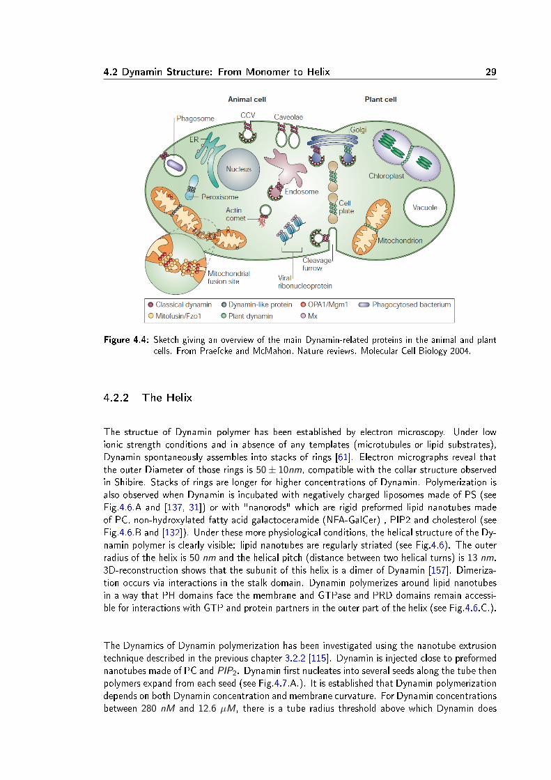
Dynamin is a 100 kDa multidomain protein. Its ve domains, from the amino- to the carboxyl-terminal, are: GTPase, Middle, PH, GED, PRD (see Fig.4.5.a and [60, 102, 41]). The GTPasedomain binds and hydrolyses guanosine triphosphate (GTP). The middle domain is involved inDynamin self-assembly. The Pleckstrin Homology (PH) domain binds non specically to neg-atively charged lipids (like PS membranes) and interacts specically with PIP2. The GTPaseEector Domain (GED) is involved in Dynamin self-assembly and stimulates GTPase activity.The Prolin Rich Domain (PRD) is a coil-coiled region interacting with proteins containing aSH3 domain, such as Amphiphysin, Endophilin, Cortactin, Prolin.The structure of the Dynamin monomer has been recently solved (see Fig.4.5.b and [39, 42]).The Middle and GED domains form together a stalk linking the GTPase domain to the PHdomain. A Bundle Signalling Element (BSE) split in three parts (in the GTPase, the Middle andthe GED domains) forms a domain which modulates the activity of self-assembled Dynamin [20].
4.2 Dynamin Structure: From Monomer to Helix 29
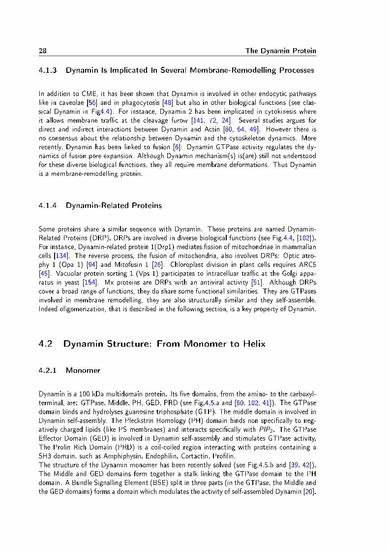
Figure 4.4: Sketch giving an overview of the main Dynamin-related proteins in the animal and plantcells. From Praefcke and McMahon, Nature reviews. Molecular Cell Biology 2004.
4.2.2 The Helix
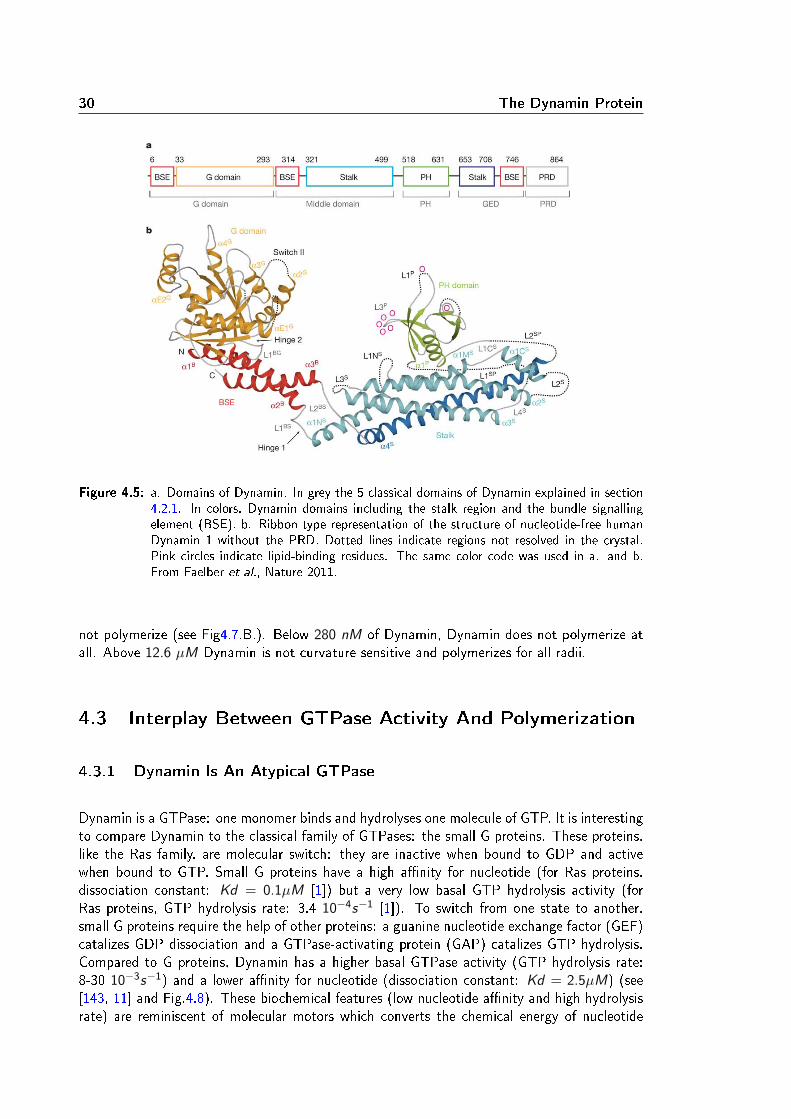
The structue of Dynamin polymer has been established by electron microscopy. Under lowionic strength conditions and in absence of any templates (microtubules or lipid substrates),Dynamin spontaneously assembles into stacks of rings [61]. Electron micrographs reveal thatthe outer Diameter of those rings is 50± 10nm, compatible with the collar structure observedin Shibire. Stacks of rings are longer for higher concentrations of Dynamin. Polymerization isalso observed when Dynamin is incubated with negatively charged liposomes made of PS (seeFig.4.6.A and [137, 31]) or with "nanorods" which are rigid preformed lipid nanotubes madeof PC, non-hydroxylated fatty acid galactoceramide (NFA-GalCer) , PIP2 and cholesterol (seeFig.4.6.B and [132]). Under these more physiological conditions, the helical structure of the Dy-namin polymer is clearly visible: lipid nanotubes are regularly striated (see Fig.4.6). The outerradius of the helix is 50 nm and the helical pitch (distance between two helical turns) is 13 nm.3D-reconstruction shows that the subunit of this helix is a dimer of Dynamin [157]. Dimeriza-tion occurs via interactions in the stalk domain. Dynamin polymerizes around lipid nanotubesin a way that PH domains face the membrane and GTPase and PRD domains remain accessi-ble for interactions with GTP and protein partners in the outer part of the helix (see Fig.4.6.C.).
The Dynamics of Dynamin polymerization has been investigated using the nanotube extrusiontechnique described in the previous chapter 3.2.2 [115]. Dynamin is injected close to preformednanotubes made of PC and PIP2. Dynamin rst nucleates into several seeds along the tube thenpolymers expand from each seed (see Fig.4.7.A.). It is established that Dynamin polymerizationdepends on both Dynamin concentration and membrane curvature. For Dynamin concentrationsbetween 280 nM and 12.6 µM, there is a tube radius threshold above which Dynamin does
30 The Dynamin Protein
Figure 4.5: a. Domains of Dynamin. In grey the 5 classical domains of Dynamin explained in section4.2.1. In colors, Dynamin domains including the stalk region and the bundle signallingelement (BSE). b. Ribbon type representation of the structure of nucleotide-free humanDynamin 1 without the PRD. Dotted lines indicate regions not resolved in the crystal.Pink circles indicate lipid-binding residues. The same color code was used in a. and b.From Faelber et al., Nature 2011.
not polymerize (see Fig4.7.B.). Below 280 nM of Dynamin, Dynamin does not polymerize atall. Above 12.6 µM Dynamin is not curvature sensitive and polymerizes for all radii.
4.3 Interplay Between GTPase Activity And Polymerization
4.3.1 Dynamin Is An Atypical GTPase
Dynamin is a GTPase: one monomer binds and hydrolyses one molecule of GTP. It is interestingto compare Dynamin to the classical family of GTPases: the small G proteins. These proteins,like the Ras family, are molecular switch: they are inactive when bound to GDP and activewhen bound to GTP. Small G proteins have a high anity for nucleotide (for Ras proteins,dissociation constant: Kd = 0.1µM [1]) but a very low basal GTP hydrolysis activity (forRas proteins, GTP hydrolysis rate: 3.4 10−4s−1 [1]). To switch from one state to another,small G proteins require the help of other proteins: a guanine nucleotide exchange factor (GEF)catalizes GDP dissociation and a GTPase-activating protein (GAP) catalizes GTP hydrolysis.Compared to G proteins, Dynamin has a higher basal GTPase activity (GTP hydrolysis rate:8-30 10−3s−1) and a lower anity for nucleotide (dissociation constant: Kd = 2.5µM) (see[143, 11] and Fig.4.8). These biochemical features (low nucleotide anity and high hydrolysisrate) are reminiscent of molecular motors which converts the chemical energy of nucleotide
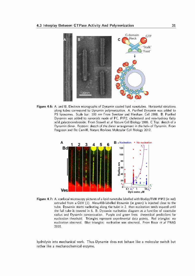
4.3 Interplay Between GTPase Activity And Polymerization 31
A B C
Figure 4.6: A. and B. Electron micrographs of Dynamin-coated lipid nanotubes. Horizontal striationsalong tubes correspond to Dynamin polymerization. A. Puried Dynamin was added toPS liposomes. Scale bar: 100 nm From Sweitzer and Hinshaw, Cell 1998. B. PuriedDynamin was added to nanorods made of PC, PIP2, cholesterol and non-hydroxy fattyacid galactocerebroside. From Stowell et al Nature Cell Biology 1999. C Top: sketch of aDynamin dimer. Bottom: sketch of the dimer arrangement in the helix of Dynamin. FromFerguson and De Camilli, Nature Reviews Molecular Cell Biology 2012.
A B
Figure 4.7: A. confocal microscopy pictures of a lipid nanotube labelled with BodipyTMR-PIP2 (in red)extruded from a GUV (1). Alexa488-labelled Dynamin (in green) is injected close to thetube. Dynamin starts nucleating along the tube in 2. then nucleation seeds expand untilthe full tube is covered in 6. B. Dynamin nucleation diagram as a function of nanotuberadius and Dynamin concentration. Purple and green lines: theoretical predictions fornucleation threshold. Triangles represent experimental data points. Red triangles: nonucleation observed. Blue triangles: nucleation was observed. From Roux et al PNAS2010.
hydrolysis into mechanical work. Thus Dynamin does not behave like a molecular switch butrather like a mechanochemical enzyme.

32 The Dynamin Protein
Figure 4.8: Sketches of GTPase cycles foe Dynamin (left) and Ras (right). Times indicated on arrowsare half-times for the corresponding step at a basal level (in absence of cofactors). FromSever et al., Trac 2000.
4.3.2 Polymerization Stimulates GTPase Activity
Dynamin polymerization stimulates GTPase activity [143, 149]. GTPase rate increases up to10-fold in conditions favoring spontaneous self-assembly: low ionic strength and high concen-tration of dynamin [149]. When Dynamin polymerizes on a lipid templates, the GTPase rateeven increases up to 100-fold [84]. Structurally the BSE is thought to enhance the GTPase rateby inducing conformational changes upon dimerization [19]. However the precise mechanismby which polymerization stimulates GTPase activity is still not understood.
4.3.3 GTPase Activity Modies The Helical Structure
GTP is not required for self-assembly. Indeed Dynamin mutant K44A, which has a very lowGTPase activity, self-assembles like wild type [61] and Dynamin polymerization was observedin absence of nucleotide in nanotube extrusion experiments [115]. However GTPase activitymodies Dynamin helical structure. Electron microscopy experiments have revealed two typesof structural modications:
• increase of the helical pitch at constant radius;When dynamin polymerizes on nanorods, the helical pitch increases from 11 ± 2 to20 ± 3 nm upon nucleotide treatment while the radius remains constant (40 ± 2.5 nm)(see Fig.4.9.A and [132, 87]).
• decrease of both pitch and radius;For Dynamin polymers prepared on negatively charged liposomes made of pure PS, uponnucleotide treatment it was observed that the outer radius decreases from 50 to 40 nm,the helical pitch decreases from 13 to 9 nm and the number of dimers by helical turngoes from 14 to 13 (see Fig.4.9.B and [137, 31, 23]).
It is likely that these dierent observations of helical structures result from dierent lipid tem-plates for Dynamin polymerization. Indeed membrane properties, for instance the bendingrigidity modulus κ, could inuence Dynamin GTPase activity; exactly like membrane curvatureinuences Dynamin polymerization. It is also interesting to note that ssion never occurs in

4.3 Interplay Between GTPase Activity And Polymerization 33
the case of nanorods whereas it does for pure PS liposomes under certain conditions discussedlater in section 4.4.2.
A
B
Figure 4.9: A. Electron micrographs of Dynamin-coated nanorods under dierent nucleotides treat-ment. Puried Dynamin was added to nanorods in the presence of 100 µM GTPγS orduring the hydrolysis of 500 µM GTP. From Marks et al. Nature 2001 B. CryoEM-picturesof Dynamin-coated lipid nanotubes. Puried Dynamin was added to liposomes made ofPS only. Left: no GTP. Right: after 5 s of GTP treatment. White arrows point at un-decorated membrane bulge. Scale bar: 100 nm. From Danino et al., Journal of structuralbiology 2004.

34 The Dynamin Protein
4.4 Fission Mechanism(s)
Fission of Clathrin-coated pits is defective in Dynamin mutants but the maturation of thepits remains normal [146, 40, 52]. More precisely Dynamin GTPase activity is required totrigger ssion as GTPγS (a non-hydrolizable analogue of GTP) treatment in neurons leadsto an impairement in vesicle recycling and to the formation of long Dynamin-coated tubules[138]. Moreover K142A strongly inhibits endocytosis. K142A is a Dynamin mutant with analmost normal GTPase activity but for which no conformational change is observed [87]. Thisindicates that ssion is triggered by the GTP-dependent conformational changes of Dynaminhelix. However inconsistencies emerge from in vitro experiments and give rise to several models.
4.4.1 Spring Or Garrote?
The rst models of ssion were deduced from structural data. As two types of structuralchanges were observed, it led to two models of ssion: Dynamin would act like a "spring" orlike a "garrote" [122].
• Spring model:this model was inferred from the observation of an increased pitch at a constant radiusupon GTP hydrolysis (nanorods templates). The Dynamin helix would push away thevesicle from the plasma membrane in a "spring-like" mechanism (see Fig.4.10.A).
• Garrote model:a decrease in both radius and pitch, the other structural change observed (PS liposomestemplates), led to the garrote model. In this case, the helix tightens upon GTP hydrolysis.This strongly suggests a mechanism where the Dynamin helix constricts the tube untilssion occurs (see Fig.4.10.B).
A B Figure 4.10: Two models of Dynamin-mediated membrane ssion deduced from structural observa-
tions. A: spring model. B. garrote model. Adapted from Sever et al., Trac 2000.
A theoretical model manages to reconcile these apparently contradictory structural data. Thiscoarse-grain model calculates membrane deformations resulting from Dynamin conformationalchanges. If we consider Dynamin mechanochemical action as equivalent to applying a torqueand a force on the tube, then the dierent helical structures observed experimentally can beexplained by the dierence in membrane rigidities [83]. Indeed nanorods are rigid structures dueto the presence of cholesterol and NFA-GalCer whereas PS liposomes are soft membranes easierto deform. Thus the same conformational changes occur at the Dynamin monomer level butresult in two dierent helices because of membrane rigidity. This demonstrates that membraneelastic properties play an important role in Dynamin-mediated ssion.
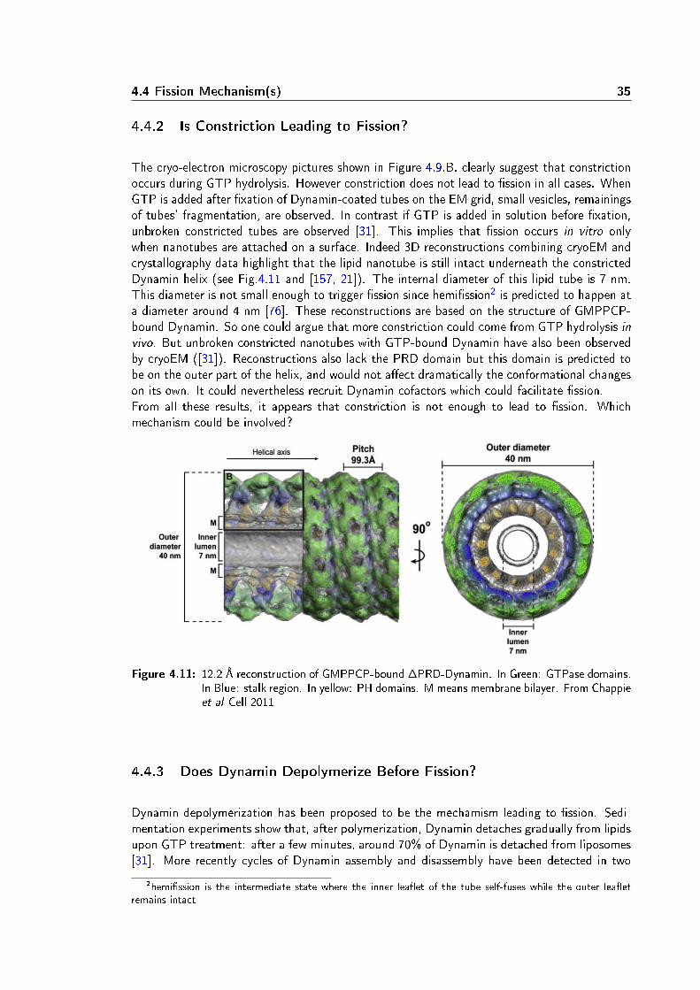
4.4 Fission Mechanism(s) 35
4.4.2 Is Constriction Leading to Fission?
The cryo-electron microscopy pictures shown in Figure 4.9.B. clearly suggest that constrictionoccurs during GTP hydrolysis. However constriction does not lead to ssion in all cases. WhenGTP is added after xation of Dynamin-coated tubes on the EM grid, small vesicles, remainingsof tubes' fragmentation, are observed. In contrast if GTP is added in solution before xation,unbroken constricted tubes are observed [31]. This implies that ssion occurs in vitro onlywhen nanotubes are attached on a surface. Indeed 3D reconstructions combining cryoEM andcrystallography data highlight that the lipid nanotube is still intact underneath the constrictedDynamin helix (see Fig.4.11 and [157, 21]). The internal diameter of this lipid tube is 7 nm.This diameter is not small enough to trigger ssion since hemission2 is predicted to happen ata diameter around 4 nm [76]. These reconstructions are based on the structure of GMPPCP-bound Dynamin. So one could argue that more constriction could come from GTP hydrolysis invivo. But unbroken constricted nanotubes with GTP-bound Dynamin have also been observedby cryoEM ([31]). Reconstructions also lack the PRD domain but this domain is predicted tobe on the outer part of the helix, and would not aect dramatically the conformational changeson its own. It could nevertheless recruit Dynamin cofactors which could facilitate ssion.From all these results, it appears that constriction is not enough to lead to ssion. Whichmechanism could be involved?
Figure 4.11: 12.2 Å reconstruction of GMPPCP-bound ∆PRD-Dynamin. In Green: GTPase domains.In Blue: stalk region. In yellow: PH domains. M means membrane bilayer. From Chappieet al Cell 2011
4.4.3 Does Dynamin Depolymerize Before Fission?
Dynamin depolymerization has been proposed to be the mechamism leading to ssion. Sedi-mentation experiments show that, after polymerization, Dynamin detaches gradually from lipidsupon GTP treatment: after a few minutes, around 70% of Dynamin is detached from liposomes[31]. More recently cycles of Dynamin assembly and disassembly have been detected in two
2hemission is the intermediate state where the inner leaet of the tube self-fuses while the outer leaetremains intact
36 The Dynamin Protein
types of experiments.
• SUPER templates:SUPER templates are SUPported bilayers with Excess membrane Reservoir. They aremade by incubating silica beads with liposomes [104]. Membrane budding is observedwhen Dynamin and GTP are injected on these SUPER templates. A patch of Dynamincan be detected by uorescence at the neck of membrane buds. Fluorescence uctuationsin this patch have been measured (see Fig.4.12.A. and B. and [103]). These uctuationsare interpreted as cycles of polymerization and depolymerization.
• patch clamp:Patch clamp experiments on supported bilayers have been designed to measure the radiusof a lipid nanotube by conductance measurement (see Fig.4.12.C.). After injection ofDynamin and GTP, uctuations in the conductance were monitored followed by an abruptdrop corresponding to the tube break. These uctuations are interpreted as uctuationsof the tube radius corresponding to cycles of Dynamin assembly and disassembly (seeFig.4.12.D. and [9]).
A challenging model has arisen from these results: Dynamin polymerization would stabilize thelipid tube in a state close to hemifusion, GTP hydrolysis would trigger Dynamin disassemblywhich would destabilize the lipid tube leading to ssion. This model raises the issue of ssionkinetic. To trigger ssion, depolymerization should occur rapidly so that the tube does nothave time to equilibrate and collapse into hemifusion. Considering the membrane viscosity,the typical tube radius and the membrane rigidity modulus, a typical timescale for membraneequilibration is 1 s3. In vitro Dynamin depolymerization takes more than 10 s. Some otherproteins might facilitate Dynamin depolymerization in vivo. But as Dynamin and GTP aresucent to generate ssion in vitro [116, 103] there must exist a mechanism which does notrequire the help of other proteins.
4.4.4 How Does Membrane Elasticity Inuence Dynamin-Mediated Fission?
We mentioned that membrane elasticity inuences Dynamin polymerization (section 4.2.2)and the GTP-dependent conformational changes (section 4.4.1). Thus it seems logical thatmembrane properties would also aect ssion.In elctron microscopy experiments, ssion occurs only when lipid nanotubes are attached on asubstrate. When GTP is added on tubes freely diusing in buer, long unbroken constrictedtubes are visible [31]. This observation suggests that maintaining the tube under tensionis required for ssion. This hypothesis was conrmed by Dierential Interference Contrast(DIC) microscopy experiments. Dynamin was rst injected on membrane sheets4 where itspontaneously tubulates the membrane. GTP was then injected on the Dynamin-coated tubes.Fission was observed only for tubes mechanically attached at both ends (see Fig4.13.A). Free
3t = η Rκwhere η is the viscosity, R the radius and κ the bending rigidity modulus.
4Membrane sheets constitute a way to obtain easily planar lamellar sheets of membrane. Lipids are driedon a glass coverslide in a vacuum oven for at least one hour and then rehydrated with the appropriate buer.This assay has been used to test the activity of membrane binding and/or remodelling proteins such as BARand F-BAR proteins [64], and dynamin [116].

4.4 Fission Mechanism(s) 37
A
C D
B
Figure 4.12: Evidence for cycles of Dynamin assembly and disassembly. A. Fluroescence microscopyimages of lipid SUPER templates treated with uorescent Dynamin and GTP. Yellowarrows indicate the bud attached to the bead, red arrows the patch of dynamin at theneck of the bud, black arrows the bead, white arrows regions with a strong Dynaminsignal, green arrow the detached vesicle. B. Fluorescence intensity proles of Dynaminat the bud (blue) and at the neck (red). From Pucadyil et al., Cell 2008. C. Sketch ofthe patch clamp experiment. A lipid nanotube is extruded from supported bilayers with apipette. Conductance is determined by measuring the current resulting from applicationof a constant potential between measuring and ground electrodes. A second pipetteis used to inject Dynamin. D. Conductance curves. In balck: Dynamin and GTP areinjected on a tube, there are oscillations in the conductance signal. In blue: nothing isinjected, the conductance curve remains stable. From Bashkirov et al., Cell 2008
tubes did not break but retracted (see Fig4.13.B). Other experiments show that ssion stilloccurs at very low tensions [103]. Fluctuating (signature of a low tension) lipid nanotubesbreak after treatment with Dynamin and GTP (see Fig4.13.C). In this case, ssion occursafter 20s, which is longer than the ssion time measured for tubes under tension (1 s). Lowmembrane tension might delay ssion. These results raises the question of the role of membranetension in ssion mechanism.
Conclusion
Regarding all the studies on Dynamin, the mechanism of membrane ssion is still poorly under-stood. Does GTP hydrolysis trigger constriction and/or depolymerization? Which mechanismdrives ssion? What is the precise role of membrane tension and rigidity? What is the energyof ssion? These are the questions addressed in this thesis.
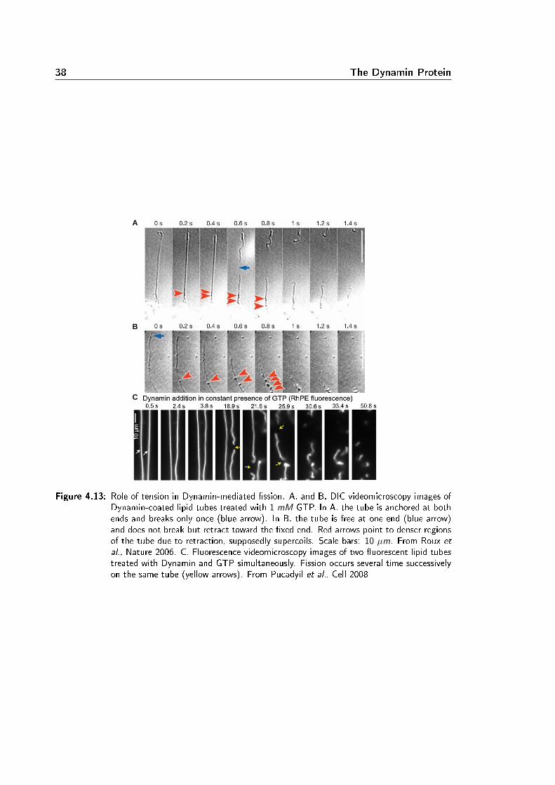
38 The Dynamin Protein
A
B
C
Figure 4.13: Role of tension in Dynamin-mediated ssion. A. and B. DIC videomicroscopy images ofDynamin-coated lipid tubes treated with 1 mM GTP. In A. the tube is anchored at bothends and breaks only once (blue arrow). In B. the tube is free at one end (blue arrow)and does not break but retract toward the xed end. Red arrows point to denser regionsof the tube due to retraction, supposedly supercoils. Scale bars: 10 µm. From Roux et
al., Nature 2006. C. Fluorescence videomicroscopy images of two uorescent lipid tubestreated with Dynamin and GTP simultaneously. Fission occurs several time successivelyon the same tube (yellow arrows). From Pucadyil et al., Cell 2008
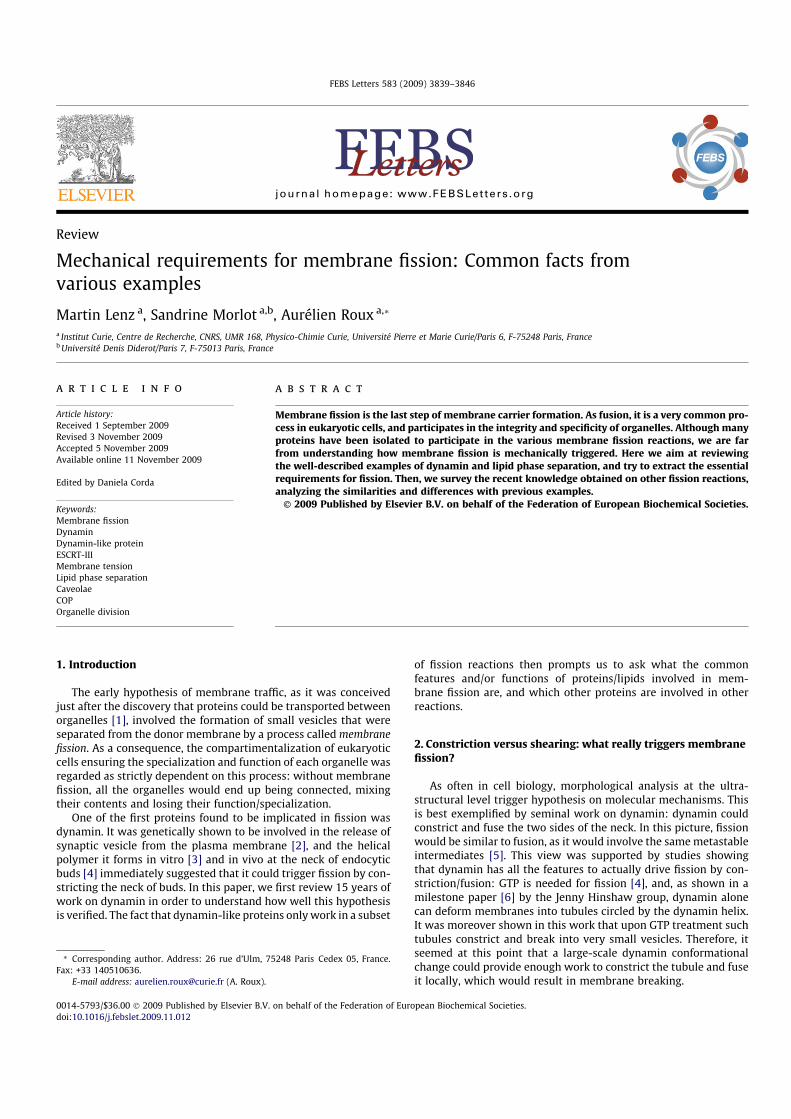
Review
Mechanical requirements for membrane fission: Common facts fromvarious examples
Martin Lenz a, Sandrine Morlot a,b, Aurélien Roux a,*
a Institut Curie, Centre de Recherche, CNRS, UMR 168, Physico-Chimie Curie, Université Pierre et Marie Curie/Paris 6, F-75248 Paris, Franceb Université Denis Diderot/Paris 7, F-75013 Paris, France
a r t i c l e i n f o
Article history:Received 1 September 2009Revised 3 November 2009Accepted 5 November 2009Available online 11 November 2009
Edited by Daniela Corda
Keywords:Membrane fissionDynaminDynamin-like proteinESCRT-IIIMembrane tensionLipid phase separationCaveolaeCOPOrganelle division
a b s t r a c t
Membrane fission is the last step of membrane carrier formation. As fusion, it is a very common pro-cess in eukaryotic cells, and participates in the integrity and specificity of organelles. Although manyproteins have been isolated to participate in the various membrane fission reactions, we are farfrom understanding how membrane fission is mechanically triggered. Here we aim at reviewingthe well-described examples of dynamin and lipid phase separation, and try to extract the essentialrequirements for fission. Then, we survey the recent knowledge obtained on other fission reactions,analyzing the similarities and differences with previous examples.
2009 Published by Elsevier B.V. on behalf of the Federation of European Biochemical Societies.
1. Introduction
The early hypothesis of membrane traffic, as it was conceivedjust after the discovery that proteins could be transported betweenorganelles [1], involved the formation of small vesicles that wereseparated from the donor membrane by a process called membranefission. As a consequence, the compartimentalization of eukaryoticcells ensuring the specialization and function of each organelle wasregarded as strictly dependent on this process: without membranefission, all the organelles would end up being connected, mixingtheir contents and losing their function/specialization.
One of the first proteins found to be implicated in fission wasdynamin. It was genetically shown to be involved in the release ofsynaptic vesicle from the plasma membrane [2], and the helicalpolymer it forms in vitro [3] and in vivo at the neck of endocyticbuds [4] immediately suggested that it could trigger fission by con-stricting the neck of buds. In this paper, we first review 15 years ofwork on dynamin in order to understand how well this hypothesisis verified. The fact that dynamin-like proteins only work in a subset
of fission reactions then prompts us to ask what the commonfeatures and/or functions of proteins/lipids involved in mem-brane fission are, and which other proteins are involved in otherreactions.
2. Constriction versus shearing: what really triggers membranefission?
As often in cell biology, morphological analysis at the ultra-structural level trigger hypothesis on molecular mechanisms. Thisis best exemplified by seminal work on dynamin: dynamin couldconstrict and fuse the two sides of the neck. In this picture, fissionwould be similar to fusion, as it would involve the same metastableintermediates [5]. This view was supported by studies showingthat dynamin has all the features to actually drive fission by con-striction/fusion: GTP is needed for fission [4], and, as shown in amilestone paper [6] by the Jenny Hinshaw group, dynamin alonecan deform membranes into tubules circled by the dynamin helix.It was moreover shown in this work that upon GTP treatment suchtubules constrict and break into very small vesicles. Therefore, itseemed at this point that a large-scale dynamin conformationalchange could provide enough work to constrict the tubule and fuseit locally, which would result in membrane breaking.
0014-5793/$36.00 2009 Published by Elsevier B.V. on behalf of the Federation of European Biochemical Societies.doi:10.1016/j.febslet.2009.11.012
* Corresponding author. Address: 26 rue d’Ulm, 75248 Paris Cedex 05, France.Fax: +33 140510636.
E-mail address: [email protected] (A. Roux).
FEBS Letters 583 (2009) 3839–3846
journal homepage: www.FEBSLetters .org

2.1. Dynamin: the paradigm of constriction
Several questions were brought about by the work of Hinshawand co-workers: where does the constriction come from? Does theconformational change of the helical polymer induce torsion, sim-ilar to the wringing of linen fiber? Or does each individual mono-mer constrict, causing the helix to shrink in size, without reallychanging shape?
Early evidence of a linen-like conformational change came froma careful study of the biochemical interactions between differentdynamin domains [7]. The strongest interactions were observedbetween hetero-domains and proposed to be in the continuity ofthe helical turn. They remained unchanged when the nucleotideload was modified, whereas the interactions between homo-do-mains were weaker in the presence of GTP and proposed to be be-tween contiguous helical turns. This suggested that during thehydrolytic cycle of GTP, dynamin oligomers could undergo a cycleof binding/unbinding between adjacent helical rings. The authorsof this study thus favored a mechanism by which sliding of adja-cent helical turns would cause constriction.
The 3D structures [8] obtained by cryo-EM before and after con-striction yielded a more detailed picture of this complex situation:as the dynamin polymer went from its non-constricted to its con-stricted state upon incubation with GMP–PCP, the number of di-mers per turn went from 14 to 13, while constriction andbending of each dimer was also observed. This is a direct proof thatsome of the constriction actually occurs by torsion. The huge in-ward bending of each dimer however also has a dramatic influenceon the membrane, and constricts it even more.
At the structural level, it thus seems that dynamin constrictioncomes from the combination of a global (torsion of the helical poly-mer) and a local (compaction of the monomers) conformationalchange. On the functional level, the structural studies of the Hin-shaw group [8] have a remarkable feature: they show that long,continuous constricted tubules can be isolated, which is not at allexpected in a situation where constriction alone induces tubulebreaking. Pointing this out, the Hinshaw group also showed a strik-ing difference between dynamin-coated tubules treated by GTPwhen observed by negative stain or by cryo-EM. When performingnegative stain [6], which involves attaching the tubules to a sub-strate before GTP treatment, they observed a large amount of fis-sion. On the other hand, when cryo-EM was used, which impliestreating dynamin-coated tubules with GTP in bulk, no obvious fis-sion occurred [9]. As a matter of fact, in the 3D constricted struc-ture of Ref. [8], whole membrane tubules (as opposed to hemi-fission intermediates) are seen. It should however be noted thatthe tubules in this last reference were not treated with GTP, butwith GMP–PCP, and that the comparison might therefore not standas fission is observed with GTP only.
In a nutshell, there is compelling data supporting the earlyhypothesis that in addition to being required for fission, dynaminconstricts membrane tubules upon GTP hydrolysis. Still, the essen-tial question of whether this constriction is sufficient to inducemembrane fission on its own was still open at this point.
2.2. What triggers membrane fission?
Recent studies have used live imaging and sensitive measure-ments to directly visualize dynamin-mediated membrane fission,and try to isolate the minimal requirements for dynamin-mediatedmembrane fission [10–12]. As membrane fission is a very transientevent, the strength of these studies was the ability to follow amembrane template in real time while it is being broken by dyn-amin. Using dynamin-coated tubules grown from planar mem-brane sheets, a first study showed that rapid twisting of thedynamin helix occurred upon GTP treatment [10]. This twisting
activity was further evidenced by the formation of supercoils,which also caused the long dynamin-coated tubules to retract. Sur-prisingly, tubules anchored only at one end never broke, while tu-bules anchored at both extremities ruptured after experiencinglongitudinal tension, probably generated by the torsional activityof dynamin through the formation of supercoils. On top of confirm-ing that part of the constriction comes from torsion, this studystresses the role of mechanical forces in dynamin-mediated mem-brane breaking. Such mechanical forces could be provided by theactin cytoskeleton, which would account for its known involve-ment in this process [13,14].
The fact that torsion occurs very rapidly led to the hypothesisthat dynamin could break membranes by shearing/tearing (BrunoAntonny, private communication). Indeed, although a membranesheared on long time scales will tend to flow, applying a torquevery quickly to the membrane tubule could tear the membrane(see Fig. 1). An interesting feature of this mechanism is that its effi-ciency is crucially dependent on the velocity associated with tor-sion. If torsion is slower than membrane’s viscoelastic time(defined as its viscosity over its stretching modulus and thus of or-der 108 s), dynamin will just crawl on the liquid membrane,which will be drained out by the squeezing action of the helix. Ifit is faster, shearing-induced breakage could occur. On those shorttime scales, the tube is expected to behave like a piece of rubber,and thus to collapse on itself under shear (see Fig. 1C). This collapseshould occur in the early stages of the shearing (i.e. prior to tear-ing), meaning that membrane breakage will immediately be fol-lowed be self-sealing of the two resulting pieces into twoseparate tubules. Membrane breakage through shearing/tearingshould thus be a non-leaky process. A recent theoretical descrip-tion of dynamin’s helical torsion/constriction [15] showed thatthe propagation of the helix’ strain along the axis of very long heli-cal polymers should follow a diffusive dynamics. It also predictsthat on experimentally observable time scales, the rate of this
Fig. 1. Membrane tube fission by dynamin. (A and B) Dynamin breaks tubules byconstriction. The conformational change (A) of the helix constricts the tubule untilit hemi-fission is reached (B), and full fission is obtained when dynamin depoly-merizes. (C and D) Dynamin breaks tubules by shearing. The conformational change(C) generates enough torsion to shear the membrane and either tear it (not shown)or fuse it. (D) Fission leads to dynamin depolymerization by removal of themembrane.
3840 M. Lenz et al. / FEBS Letters 583 (2009) 3839–3846
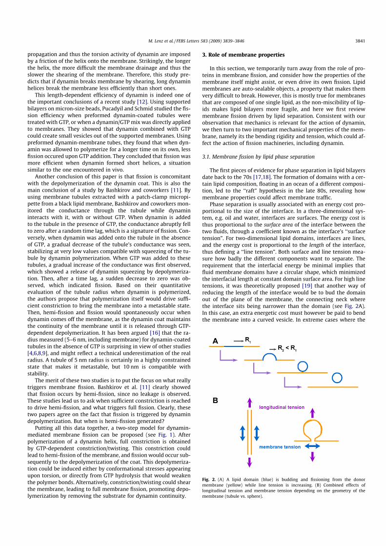
propagation and thus the torsion activity of dynamin are imposedby a friction of the helix onto the membrane. Strikingly, the longerthe helix, the more difficult the membrane drainage and thus theslower the shearing of the membrane. Therefore, this study pre-dicts that if dynamin breaks membrane by shearing, long dynaminhelices break the membrane less efficiently than short ones.
This length-dependent efficiency of dynamin is indeed one ofthe important conclusions of a recent study [12]. Using supportedbilayers on micron-size beads, Pucadyil and Schmid studied the fis-sion efficiency when preformed dynamin-coated tubules weretreated with GTP, or when a dynamin/GTP mix was directly appliedto membranes. They showed that dynamin combined with GTPcould create small vesicles out of the supported membranes. Usingpreformed dynamin-membrane tubes, they found that when dyn-amin was allowed to polymerize for a longer time on its own, lessfission occured upon GTP addition. They concluded that fission wasmore efficient when dynamin formed short helices, a situationsimilar to the one encountered in vivo.
Another conclusion of this paper is that fission is concomitantwith the depolymerization of the dynamin coat. This is also themain conclusion of a study by Bashkirov and coworkers [11]. Byusing membrane tubules extracted with a patch-clamp micropi-pette from a black lipid membrane, Bashkirov and coworkers mon-itored the conductance through the tubule while dynamininteracts with it, with or without GTP. When dynamin is addedto the tubule in the presence of GTP, the conductance abruptly fellto zero after a random time lag, which is a signature of fission. Con-versely, when dynamin was added onto the tubule in the absenceof GTP, a gradual decrease of the tubule’s conductance was seen,stabilizing at very low values compatible with squeezing of the tu-bule by dynamin polymerization. When GTP was added to thesetubules, a gradual increase of the conductance was first observed,which showed a release of dynamin squeezing by depolymeriza-tion. Then, after a time lag, a sudden decrease to zero was ob-served, which indicated fission. Based on their quantitativeevaluation of the tubule radius when dynamin is polymerized,the authors propose that polymerization itself would drive suffi-cient constriction to bring the membrane into a metastable state.Then, hemi-fission and fission would spontaneously occur whendynamin comes off the membrane, as the dynamin coat maintainsthe continuity of the membrane until it is released through GTP-dependent depolymerization. It has been argued [16] that the ra-dius measured (5–6 nm, including membrane) for dynamin-coatedtubules in the absence of GTP is surprising in view of other studies[4,6,8,9], and might reflect a technical underestimation of the realradius. A tubule of 5 nm radius is certainly in a highly constrainedstate that makes it metastable, but 10 nm is compatible withstability.
The merit of these two studies is to put the focus on what reallytriggers membrane fission. Bashkirov et al. [11] clearly showedthat fission occurs by hemi-fission, since no leakage is observed.These studies lead us to ask when sufficient constriction is reachedto drive hemi-fission, and what triggers full fission. Clearly, thesetwo papers agree on the fact that fission is triggered by dynamindepolymerization. But when is hemi-fission generated?
Putting all this data together, a two-step model for dynamin-mediated membrane fission can be proposed (see Fig. 1). Afterpolymerization of a dynamin helix, full constriction is obtainedby GTP-dependent constriction/twisting. This constriction couldlead to hemi-fission of the membrane, and fission would occur sub-sequently to the depolymerization of the coat. This depolymeriza-tion could be induced either by conformational stresses appearingupon torsion, or directly from GTP hydrolysis that would weakenthe polymer bonds. Alternatively, constriction/twisting could shearthe membrane, leading to full membrane fission, promoting depo-lymerization by removing the substrate for dynamin continuity.
3. Role of membrane properties
In this section, we temporarily turn away from the role of pro-teins in membrane fission, and consider how the properties of themembrane itself might assist, or even drive its own fission. Lipidmembranes are auto-sealable objects, a property that makes themvery difficult to break. However, this is mostly true for membranesthat are composed of one single lipid, as the non-miscibility of lip-ids makes lipid bilayers more fragile, and here we first reviewmembrane fission driven by lipid separation. Consistent with ourobservation that mechanics is relevant for the action of dynamin,we then turn to two important mechanical properties of the mem-brane, namely its the bending rigidity and tension, which could af-fect the action of fission machineries, including dynamin.
3.1. Membrane fission by lipid phase separation
The first pieces of evidence for phase separation in lipid bilayersdate back to the 70s [17,18]. The formation of domains with a cer-tain lipid composition, floating in an ocean of a different composi-tion, led to the ‘‘raft” hypothesis in the late 80s, revealing howmembrane properties could affect membrane traffic.
Phase separation is usually associated with an energy cost pro-portional to the size of the interface. In a three-dimensional sys-tem, e.g. oil and water, interfaces are surfaces. The energy cost isthus proportional to the surface area of the interface between thetwo fluids, through a coefficient known as the interface’s ‘‘surfacetension”. For two-dimensional lipid domains, interfaces are lines,and the energy cost is proportional to the length of the interface,thus defining a ‘‘line tension”. Both surface and line tension mea-sure how badly the different components want to separate. Therequirement that the interfacial energy be minimal implies thatfluid membrane domains have a circular shape, which minimizedthe interfacial length at constant domain surface area. For high linetensions, it was theoretically proposed [19] that another way ofreducing the length of the interface would be to bud the domainout of the plane of the membrane, the connecting neck wherethe interface sits being narrower than the domain (see Fig. 2A).In this case, an extra energetic cost must however be paid to bendthe membrane into a curved vesicle. In extreme cases where the
Fig. 2. (A) A lipid domain (blue) is budding and fissioning from the donormembrane (yellow) while line tension is increasing. (B) Combined effects oflongitudinal tension and membrane tension depending on the geometry of themembrane (tubule vs. sphere).
M. Lenz et al. / FEBS Letters 583 (2009) 3839–3846 3841

line tension is high enough to override this bending cost [20], itwas proposed that the constriction generated by phase separationat the neck of these buds would be sufficient to break the mem-brane. Deformation of membranes by lipid phase separation hasbeen studied experimentally quite recently [21], and led to the firstdirect measurement of line tension between lipid domains, close to1 piconewton (pN). In some case, the authors of this work observedthe complete disappearance of the neck, suggesting fission, whichwas confirmed by other studies (see for example [22]). Similarly,lipid phase separation induced along membrane tubules formedby kinesins in vitro leads to fission [23] at the boundary betweendomains.
3.2. Role of membrane tension
In the instances of phase separation-driven membrane breaking,the membrane geometry and tension play an important role incrossing the energy barrier for fission. For instance, highly tensemembrane tubules formed by kinesins (tension larger than5 105 N/m) break less than 1s after induction of phase separa-tion, whereas tubules formed at a low tension (smaller than106 N/m) take up to 20 s to break ([24] and unpublished data).The role of membrane tension in facilitating tubule fission is two-fold: first, as the radius of the tubule is dependent on membranetension (radius ¼
ffiffiffiffij2r
p, where j is the membrane bending rigidity
and r is the membrane tension [25]), an increase in membrane ten-sion drives the radius down, which takes the membrane closer to afissioned state; second, surface tension (expressed in N/m) is con-comitant with the tubule’s longitudinal tension (in N), which is de-fined as the externally applied force required to prevent thetubule from retracting. This longitudinal tension could help fissionby maintaining the structure during the operation of the fissionmachinery. As discussed previously, longitudinal tension facilitatesdynamin-mediated fission. This is analogous to the case of a rubberband that needs to be slightly extended in order to be cut by scissors.
To further clarify the relationship between surface tension andlongitudinal tension, we note that they may either act in the samedirection or have antagonistic effects depending on geometry. Asmentioned above, tubules are an example of a synergetic effect be-tween membrane tension and longitudinal tension, as both are co-axial with the tubule (see Fig. 2B). In the case of a spherical bud, onthe other hand, longitudinal tension (pulling on the bud) favors fis-sion by facilitating the detachment of the bud, whereas membranetension has an opposite effect (see Fig. 2B): it tends to flatten themembrane, and therefore to the collapse the bud into a flat mem-brane. By counteracting constriction, membrane tension couldtherefore hinder fission. In vivo, it was actually shown that an in-creased membrane tension can block endocytosis [26], whereas adecreased membrane tension tends to increase the endocytosisrate [27].
3.3. Conclusion
Dynamin and lipid phase separation are two examples of howtubular membrane structures can be broken. Beyond the specificsof these two examples, we are interested in extracting some basicprinciples of how membrane fission is mediated, which could helpunderstand other fission machineries. In the case of lipid phaseseparation, fission occurs by constriction, as the domains are fluidand no torsion occurs [23,24]. Membrane parameters can cruciallyup- or down-regulate the energy barrier to be crossed for fission tooccur. A theoretical model [28] shows how the combined actions ofactin pulling on an endocytic bud and constriction generated by li-pid phase separation could promote fission in systems lacking theactive role of dynamin. The main lessons from studies on pure lipidmembranes are: (1) fission by a pure constriction mechanism can
occur; (2) membrane tension, depending on the geometry of themembrane (a neck between two vesicles or a tubule) can either re-duce or enhance the energy barrier to fission and (3) applyingexternal stresses on the constriction neck can help overcome theenergy barrier.
However, it is not clear yet how small the radius has to be madein order to lead to fission. The structure of the dynamin helix pro-vides some information about this threshold constriction radius.Dynamin does drive constriction on two occasions: (1) when itpolymerizes, and (2) when it undergoes a conformational changewhile hydrolyzing GTP. Most probably, polymerization does notprovide enough constriction to reach fission, as the internal radiusis larger than 10 nm after polymerization, a tubule size compatiblewith membrane stability, as tubules of this size are experimentallyobserved. After GTP hydrolysis, internal radius was measured to bein the range of 4–5 nm by cryo-EM [9]. This is larger than the thick-ness of a bilayer (3 nm). However, it is smaller than the thicknessof a bilayer plus the threshold radius (3 nm) that was proposedto spontaneously lead to membrane hemi-fission intermediates[29]. It is thus difficult to conclude on the state of the membraneinside the coat after GTP treatment. These data however indicatethat the threshold radius for fission must be smaller than 5 nm.
4. Other examples in the light of these principles
As far as we know, most of the fission events happening withina cell are dynamin-independent. Although the fission mechanismsunderlying most of these events are still largely unknown, the in-sight gained from the examples of dynamin and lipid phase sepa-ration may help understand the mechanisms at work in othersystems involving fission.
In this section, we consider other fission machineries in thelight of the systems described above. This discussion is not in-tended as an exhaustive review, but rather as an attempt to extractsimilarities and divergences between various biological solutionsto the membrane fission problem.
4.1. Other dynamin-like proteins
Many homologues of dynamin have been identified and most ofthem are involved in membrane remodeling [30]. Several examplescome from the fission machinery of mitochondria and chloroplasts.The protein Dnm1/Drp1 (yeast and mammalian, respectively) isthe most characterized member of the dynamin superfamily, otherthan dynamin [31]. It is the main player of mitochondria division,which is mediated by a single fission machinery to break the twomitochondrial membranes in a single event. In chloroplast division,ARC5, another dynamin-like protein, forms the ring necessary forconstriction. ARC5 is a cytosolic protein that binds to the outermembrane of the plast, and ARC6 is involved in the alignment ofthis ring with the matricial collar of FtsZ [32]. Chloroplasts havekept the prokaryotic division machinery through evolution (theFtsZ ring) and its positioning system (the Min proteins). ARC5was shown to participate in a GTP-dependent constriction of puri-fied chloroplast rings [33], and the amazing supercoiling of theserings could be reminiscent of a twisting activity as described fordynamin constriction [10].
Dnm1 forms helices much wider than those formed by dynamin(55 nm compared to 25 nm, outer radii) that fit the thickness of adouble membrane [34]. By analogy, one could expect that ARC5is structurally similar to Dnm1, and that Dnm1 is able to mediateconstriction in a similar GTP-dependent way than ARC5. They alsoboth bind to the outer membrane of the organelle through bindingto trans-membrane proteins (PDV1 for ARC5 and Fis1 for Dnm1through a cytosolic linker called Mdv1, [31,35]).
3842 M. Lenz et al. / FEBS Letters 583 (2009) 3839–3846

All these similarities suggest that the mitochondrial and plastidfission machineries work in a very similar way to dynamin itself.However, as we discussed above, if dynamin fission occurs by con-striction only, it requires a very tight constriction (radius < 5 nm).Although two membranes are present in mitochondria, Dnm1has to reach the same final constriction to break the last mem-brane. Thus, the larger size of these rings that fits the fission inter-mediates observed in vivo is required for assembly on a largerstructure, but would need to constrict to the same radius to com-plete fission. Increasing the starting size of the helix requires a big-ger conformational change to complete fission: dynamin outerradius goes from 25 nm to 20 nm during constriction, an alreadyconsiderable conformational change. For a similar constrictionmechanism to occur in the case of Dnm1/drp1, the radius of the tu-bules it forms would need to go from 55 nm to 20 nm, and to breaktwo membranes: this would be a formidable constriction, andwould probably cause breaks in the polymer. Disruption of theDnm1 spiral was actually seen when treated with GTP [34]. If dyn-amin-mediated fission is conducted through a shearing mecha-nism, the break in the membrane does not depend on the finalradius of the tube, but rather on how fast the torsion is applied.Thus, shearing can in principle break thick membrane necks, butprobably with leaks. The larger size of Dnm1/drp1 spirals may bethe indirect indication that membrane is broken by shearing. An-other explanation could account for this larger size. Indeed, thelarge radius of Dnm1/drp1 might just be required to accommodatethe cytosolic domain of the transmembrane receptor (Fis1 forDnm1) and the cytosolic linker (Mdv1). In this case, after assemblyof the three components, the space left in the helical coat for themembrane must be much smaller than when Dnm1/drp1 is alone.In other words, the thickness of the coat containing Dnm1/drp1,the cytosolic linker and the transmembrane receptor would bemuch bigger than for Dnm1/drp1 alone. Thus, the membranewould already be more constricted by assembled coats and thusa smaller conformational constriction would be required to com-plete fission. Indeed, a recent study showed that Mdv1 enhancesthe ability of Dnm1 to self-assemble on liposomes in the presenceof nucleotides [36]. The thickness of the coat is enhanced in thepresence of Mdv1, even though the size of the helix is unchanged.However, the human equivalent of Dnm1, Dlp1, induces the forma-tion of tubules both in vitro and in vivo [37], but their size is verysimilar to that of classical dynamin-coated tubules.
Surprisingly, almost all other dynamin-like proteins have beenimplicated in fusion instead of fission, and have either a trans-membrane domain or a highly hydrophobic region that suggest adeep insertion in the membrane: whether there is a connection be-tween these properties, which diverge from the classical dynamins,is still unknown.
A recent study of Atlastin, a GTPase located at the ER, showsthat it is critical for homotypic fusion of the ER, maintaining adense, highly connected network [38]. Atlastin, besides having se-quence and structural homology with dynamin [30], was recentlyshown to form tubules in vitro [39]. Also, the fusion of mitochon-dria is a two-steps mechanism as it involves two membrane fu-sions and therefore two fusion machineries, one for eachmembrane. Both of these machineries have dynamin-like proteins,the mitofusins 1 and 2 and Fzo1 for the outer membrane, andMgm1/OPA1 for the inner membrane.
The fact that dynamin-like proteins (DLPs) are involved in fu-sion reactions supports the idea that fission is mediated througha fusion-like mechanism. In this interpretation, fusion would bemediated by the generation of high curvature, as in the case of syn-aptotagmin [40]. The tip of DLP-coated tubules would be a highlyfusogenic point if sufficient curvature is reached. Even thoughnothing is known about oligomers formed by these specific pro-teins, one can expect that highly curved tubules and destabiliza-
tion of the bilayer due to the deep insertion of their hydrophobicparts in the lipids would drive fusion. A consistent biochemical factwith this fusion activity is that they share low GTP hydrolysis ratescompared to DLPs involved in fission [41]. It means that fusogenicDLPs would live longer in a GTP bound state, more favorable forpolymerization and tubule formation. Long-life tubules would bethen more favorable for fusion, having time to connect and fusewith the acceptor membrane.
Based on this assumption, one would predict that the recentlydescribed Epsin-Homology Domain (EHD) family of proteins [42]would belong to the fusogenic class of dynamin-like proteins. Pro-teins of this family are able to polymerize and form tubules coatedby a helix. They hydrolyze ATP instead of GTP, but are otherwiseboth structurally and functionally very similar to other dynamin-like proteins. These proteins are implicated in membrane remodel-ing, but have no clear fission activity, at least in in vitro assays usedfor dynamin. They might thus just constitute another type of fuso-genic dynamin-like protein.
4.2. Caveolae fission
Caveolae were shown to fission the plasma membrane by a dyn-amin-mediated process [43]. However, the lipid composition en-riched in sphingolipids and cholesterol of caveolae led to thehypothesis that caveolin, the main component of caveolae, coulddrive lipid phase separation by locally increasing the cholesterolconcentration in the membrane [44], as it binds cholesterol. Thislipid phase separation could help/drive both the budding and thefission reaction of caveolae. A theoretical study [45] also proposedthat not only the lipid phase separation, but the specific ordering ofchiral and tilted lipids in the caveolin-coated phase could drivebudding, fission and the formation of the surprising proteic pat-terns observed in vivo [46]. This lipid chirality-induced phenome-non was first proposed to explain the formation of endocytictubular carriers driven by the binding of a toxin cargo to specificlipids [47].
It thus seems that caveolae are an endocytic route where all theknown factors to drive fission are present, but nevertheless theirtime lapse at the plasma membrane is very long, arguing for alow fission rate. Experimental evidence suggests that caveolaecould be endocytic structures blocked at the fission step [48]. Ithas been proposed that caveolin actually stabilizes raft endocyto-sis, probably by blocking fission [49]. One can speculate that therole of caveolin, if inhibiting fission, would be to reduce line ten-sion at the boundary between caveolae and the plasma membrane,thus preventing their fission. This function is analogous to that ofdetergents, which can stabilize oil/water emulsions (i.e. very smalldroplets of oil in water) by reducing the surface tension of the oil–water interface. This would ensure good sorting of lipids and pro-teins by lipid phase separation without promoting fission. Fissionwould still be tightly regulated by the recruitment of dynamin,or by direct removal of the caveolin coat, which would enhanceline tension and thus drive fission.
4.3. Golgi COPs
COPs I and II are coat proteins forming spherical carriers in-volved in trafficking between the ER and the Golgi. It is one ofthe most studied systems in membrane trafficking, and their sort-ing, assembly process and regulation are very well characterized.There is however only little knowledge about the fission reactionin these trafficking pathways. It has been proposed that the poly-merization of the coat could drive fission by closing on itself as asphere. This hypothesis is however in conflict with the fact thatnon-fissioned buds can be isolated in semi-reconstituted systems[50], and with the one that no obvious fission is seen in an assay
M. Lenz et al. / FEBS Letters 583 (2009) 3839–3846 3843
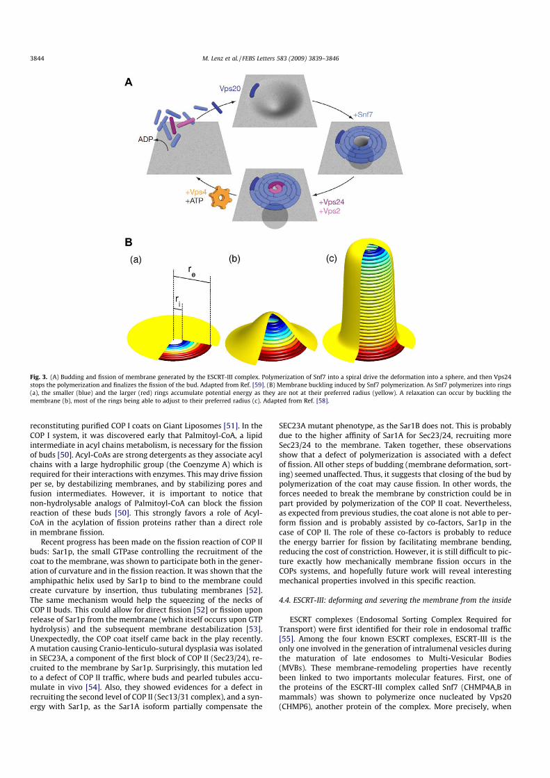
reconstituting purified COP I coats on Giant Liposomes [51]. In theCOP I system, it was discovered early that Palmitoyl-CoA, a lipidintermediate in acyl chains metabolism, is necessary for the fissionof buds [50]. Acyl-CoAs are strong detergents as they associate acylchains with a large hydrophilic group (the Coenzyme A) which isrequired for their interactions with enzymes. This may drive fissionper se, by destabilizing membranes, and by stabilizing pores andfusion intermediates. However, it is important to notice thatnon-hydrolysable analogs of Palmitoyl-CoA can block the fissionreaction of these buds [50]. This strongly favors a role of Acyl-CoA in the acylation of fission proteins rather than a direct rolein membrane fission.
Recent progress has been made on the fission reaction of COP IIbuds: Sar1p, the small GTPase controlling the recruitment of thecoat to the membrane, was shown to participate both in the gener-ation of curvature and in the fission reaction. It was shown that theamphipathic helix used by Sar1p to bind to the membrane couldcreate curvature by insertion, thus tubulating membranes [52].The same mechanism would help the squeezing of the necks ofCOP II buds. This could allow for direct fission [52] or fission uponrelease of Sar1p from the membrane (which itself occurs upon GTPhydrolysis) and the subsequent membrane destabilization [53].Unexpectedly, the COP coat itself came back in the play recently.A mutation causing Cranio-lenticulo-sutural dysplasia was isolatedin SEC23A, a component of the first block of COP II (Sec23/24), re-cruited to the membrane by Sar1p. Surprisingly, this mutation ledto a defect of COP II traffic, where buds and pearled tubules accu-mulate in vivo [54]. Also, they showed evidences for a defect inrecruiting the second level of COP II (Sec13/31 complex), and a syn-ergy with Sar1p, as the Sar1A isoform partially compensate the
SEC23A mutant phenotype, as the Sar1B does not. This is probablydue to the higher affinity of Sar1A for Sec23/24, recruiting moreSec23/24 to the membrane. Taken together, these observationsshow that a defect of polymerization is associated with a defectof fission. All other steps of budding (membrane deformation, sort-ing) seemed unaffected. Thus, it suggests that closing of the bud bypolymerization of the coat may cause fission. In other words, theforces needed to break the membrane by constriction could be inpart provided by polymerization of the COP II coat. Nevertheless,as expected from previous studies, the coat alone is not able to per-form fission and is probably assisted by co-factors, Sar1p in thecase of COP II. The role of these co-factors is probably to reducethe energy barrier for fission by facilitating membrane bending,reducing the cost of constriction. However, it is still difficult to pic-ture exactly how mechanically membrane fission occurs in theCOPs systems, and hopefully future work will reveal interestingmechanical properties involved in this specific reaction.
4.4. ESCRT-III: deforming and severing the membrane from the inside
ESCRT complexes (Endosomal Sorting Complex Required forTransport) were first identified for their role in endosomal traffic[55]. Among the four known ESCRT complexes, ESCRT-III is theonly one involved in the generation of intralumenal vesicles duringthe maturation of late endosomes to Multi-Vesicular Bodies(MVBs). These membrane-remodeling properties have recentlybeen linked to two importants molecular features. First, one ofthe proteins of the ESCRT-III complex called Snf7 (CHMP4A,B inmammals) was shown to polymerize once nucleated by Vps20(CHMP6), another protein of the complex. More precisely, when
Fig. 3. (A) Budding and fission of membrane generated by the ESCRT-III complex. Polymerization of Snf7 into a spiral drive the deformation into a sphere, and then Vps24stops the polymerization and finalizes the fission of the bud. Adapted from Ref. [59]. (B) Membrane buckling induced by Snf7 polymerization. As Snf7 polymerizes into rings(a), the smaller (blue) and the larger (red) rings accumulate potential energy as they are not at their preferred radius (yellow). A relaxation can occur by buckling themembrane (b), most of the rings being able to adjust to their preferred radius (c). Adapted from Ref. [58].
3844 M. Lenz et al. / FEBS Letters 583 (2009) 3839–3846

overexpressed in cells, Snf7/CHMP4 binds at the plasma mem-brane, polymerizing into spirals that can form elongated tubulespointing out of the cell [56]. Two different explanations have beenproposed for this membrane deforming activity: It was first pro-posed that the oligomerization of Snf7/CHMP4 would form a las-so-like structure, and that its depolymerization would cause theloop of the lasso to shrink in size, forcing the membrane enclosedby the polymer to curve in order to adjust the reducing size of theloop [57]. Based on morphological images obtained in Snf7/CHMP4overexpressing cells, a recent theoretical study [58] proposed an-other, more intuitive explanation: it assumes that Snf7/CHMP4 fil-aments have a preferred radius of curvature and bind to each otheras well as to the membrane, which accounts for the formation oftubular structures. Also, Snf7/CHMP4 has a strong affinity for themembrane. Therefore, in the presence of a membrane, the proteinforms planar spirals covering the membrane, as observed experi-mentally [56]. In this configuration, the spiral rings smaller thanthe preferred radius of polymerization (the radius of helical poly-mers in the absence of membrane) are compressed, and spiral ringslarger than the preferred radius are extended (see Fig. 3). This frus-tration of the polymer can be released by buckling the membranein the center of the spiral, forming a tubule that allows most of therings to adjust to their desired radius, as well as the binding of alarger number of filaments (see Fig. 3). This buckling mechanismresembles the spiral spring of a watch that pushes the frame outwhen overloaded.
Further discussions are required to understand how fission ismediated in this system. In order to tackle this question, we firstnote that the vesicles in the MVBs are budding inside the endo-some, and that proteins or lipids involved in fission are insidethe neck of the bud, which is the exact opposite of dynamin-med-iated fission. This geometry seems incompatible with externalforces applied to the membrane to squeeze it as in the case ofdynamin. Thus, it was proposed that fission could be caused bydepolymerization of Snf7/CHMP4, as it required ATP and Vps4for completion. In the ‘‘lasso” hypothesis, fission would be trig-gered when the loop closes on itself. However, a recent study[59] showed that fission occurs when polymerization is stoppedby Vps24. Vps4 and ATP, which are required for the disassemblyof the complex, are actually required to resolubilize the proteinsand to allow for several cycles of membrane deformation/fission,but not for fission itself. The authors of this last reference proposethat the Snf7 spirals could curve the membrane in a similar waythan in the ‘‘lasso” hypothesis, but with the difference that thereduction of the radius enclosed by the first ring of Snf7 is madeby polymerization inside the first ring, forming a spiral (seeFig. 3). At the end, the spiral is closed by addition of Vps24, whichcompletes fission.
Surprisingly, in this case, fission occurs without the need of anenergy source. ATP and Vps4 are only required for depolymerizingboth Snf7/CHMP4 and Vps24, Vps2 (CHMP3 and CHMP3 resp.)polymers. This means that the energy needed for fission comesfrom another source. Clearly, ESCRT-III generates membrane defor-mation and fission in a coupled manner. Vps24, which is the pro-tein completing fission, when combined to its partner Vps2 isable to deform membranes into tubules and make a specialdome-like structure that could participate in this fission event[60]. It also participates in the recruitment of Vps4 and Vps2 tothe ESCRT-III complex and could be localized at the inner tip ofthe spirals generated by Snf7/CHMP4. One can speculate that theconstriction needed for fission may arise from the tight associationof the membrane on this dome-like structure. Then, depolymeriza-tion of ESCRT-III structures could occur at the tip/dome-like struc-ture after fission has occurred. Because it challenges our views onmembrane fission, ESCRT-III is obviously a system of choice tostudy membrane fission.
5. General conclusion
Membrane fission is an important topological change in theorganization of cellular membranes. Here we have briefly de-scribed general principles of membrane fission mediated by lipidphase separation and by dynamin. The common principle of thesetwo fission reactions seems to be a mechanism by which constric-tion brings the two sides of the membrane into close contact untilthey fuse, which is an energetically costly step. The differences inthe origin of this energy in the examples presented here illustratesthe diversity and richness of the field of membrane fission: at oneend of the spectrum, the energy required for lipid phase separationoriginates in the physical interactions between different lipids,which manifest themselves as a line tension; on the other, dynam-in-mediated fission is protein-driven and draws its energy from anactive mechanism: nucleotide hydrolysis. Although the molecularingredients involved in membrane fission are very diverse, emerg-ing quantitative approaches taking into account physical parame-ters might provide a unified framework to study it. A first step inthat direction could be a more precise determination of the ener-gies it requires.
References
[1] Palade, G. (1975) Intracellular aspects of the process of protein synthesis.Science 189, 347–358.
[2] Koenig, J.H. and Ikeda, K. (1989) Disappearance and reformation of synapticvesicle membrane upon transmitter release observed under reversibleblockage of membrane retrieval. J. Neurosci. 9, 3844–3860.
[3] Hinshaw, J.E. and Schmid, S.L. (1995) Dynamin self-assembles into ringssuggesting a mechanism for coated vesicle budding. Nature 374, 190–192.
[4] Takei, K., McPherson, P.S., Schmid, S.L. and De Camilli, P. (1995) Tubularmembrane invaginations coated by dynamin rings are induced by GTP-gammaS in nerve terminals. Nature 374, 186–190.
[5] Kozlov, M.M. and Chernomordik, L.V. (2002) The protein coat in membranefusion: lessons from fission. Traffic 3, 256–267.
[6] Sweitzer, S.M. and Hinshaw, J.E. (1998) Dynamin undergoes a GTP-dependentconformational change causing vesiculation. Cell 93, 1021–1029.
[7] Smirnova, E., Shurland, D.L., Newman-Smith, E.D., Pishvaee, B. and van derBliek, A.M. (1999) A model for dynamin self-assembly based on bindingbetween three different protein domains. J. Biol. Chem. 274, 14942–14947.
[8] Chen, Y., Zhang, P., Egelman, E. and Hinshaw, J.E. (2004) The stalk region ofdynamin drives the constriction of dynamin tubes. Nat. Struct. Mol. Biol. v11,574–575.
[9] Danino, D., Moon, K.H. and Hinshaw, J.E. (2004) Rapid constriction of lipidbilayers by the mechanochemical enzyme dynamin. J. Struct. Biol. 147, 259–267.
[10] Roux, A., Uyhazi, K., Frost, A. and De Camilli, P. (2006) GTP-dependent twistingof dynamin implicates constriction and tension in membrane fission. Nature441, 528–531.
[11] Bashkirov, P.V., Akimov, S.A., Evseev, A.I., Schmid, S.L., Zimmerberg, J. andFrolov, V.A. (2008) GTPase cycle of dynamin is coupled to membrane squeezeand release, leading to spontaneous fission. Cell 135, 1276–1286.
[12] Pucadyil, T.J. and Schmid, S.L. (2008) Real-time visualization of dynamin-catalyzed membrane fission and vesicle release. Cell 135, 1263–1275.
[13] Itoh, T., Erdmann, K.S., Roux, A., Habermann, B., Werner, H. and De Camilli, P.(2005) Dynamin and the actin cytoskeleton cooperatively regulate plasmamembrane invagination by BAR and F-BAR proteins. Dev. Cell 9, 791–804.
[14] Merrifield, C.J., Perrais, D. and Zenisek, D. (2005) Coupling between clathrin-coated-pit invagination, cortactin recruitment, and membrane scissionobserved in live cells. Cell 121, 593–606.
[15] Lenz, M., Prost, J. and Joanny, J.F. (2008) Mechanochemical action of thedynamin protein. Phys. Rev. E Stat. Nonlinear Soft Mat. Phys. 78, 011911.
[16] Roux, A. and Antonny, B. (2008) The long and short of membrane fission. Cell135, 1163–1165.
[17] Jain, M.K. and White 3rd, H.B. (1977) Long-range order in biomembranes. Adv.Lipid Res. 15, 1–60.
[18] Klausner, R.D., Kleinfeld, A.M., Hoover, R.L. and Karnovsky, M.J. (1980) Lipiddomains in membranes. Evidence derived from structural perturbationsinduced by free fatty acids and lifetime heterogeneity analysis. J. Biol. Chem.255, 1286–1295.
[19] Jülicher, F. and Lipowsky, R. (1993) Domain-induced budding of vesicles. Phys.Rev. Lett. 70, 2964–2967.
[20] Jülicher, F. and Lipowsky, R. (1996) Shape transformations of vesicles withintramembrane domains. Phys. Rev. E Stat. Phys. Plasmas Fluids Rel.Interdisciplin. Top. 53, 2670–2683.
[21] Baumgart, T., Hess, S.T. and Webb, W.W. (2003) Imaging coexisting fluiddomains in biomembrane models coupling curvature and line tension. Nature425, 821–824.
M. Lenz et al. / FEBS Letters 583 (2009) 3839–3846 3845
[22] Bacia, K., Schwille, P. and Kurzchalia, T. (2005) Sterol structure determines theseparation of phases and the curvature of the liquid-ordered phase in modelmembranes. Proc. Natl. Acad. Sci. USA 102, 3272–3277.
[23] Roux, A., Cuvelier, D., Nassoy, P., Prost, J., Bassereau, P. and Goud, B. (2005)Role of curvature and phase transition in lipid sorting and fission of membranetubules. EMBO J. 24, 1537–1545.
[24] Allain, J.M., Storm, C., Roux, A., Ben Amar, M. and Joanny, J.F. (2004) Fission of amultiphase membrane tube. Phys. Rev. Lett. 93, 158104.
[25] Derényi, I., Jülicher, F. and Prost, J. (2002) Formation and interaction ofmembrane tubes. Phys. Rev. Lett. 88, 238101.
[26] Dai, J., Ting-Beall, H.P. and Sheetz, M.P. (1997) The secretion-coupledendocytosis correlates with membrane tension changes in RBL 2H3 cells. J.Gen. Physiol. 110, 1–10.
[27] Raucher, D. and Sheetz, M.P. (1999) Membrane expansion increasesendocytosis rate during mitosis. J. Cell Biol. 144, 497–506.
[28] Liu, J., Kaksonen, M., Drubin, D. and Oster, G. (2006) Endocytic vesicle scissionby lipid phase boundary forces. Proc. Natl. Acad. Sci. USA 103, 10277–10282.
[29] Kozlovsky, Y. and Kozlov, M.M. (2003) Membrane fission: model forintermediate structures. Biophys. J. 85, 85–96.
[30] Praefcke, G. and Mcmahon, H. (2004) The dynamin superfamily: universalmembrane tubulation and fission molecules? Nat. Rev. Mol. Cell. Biol. 5, 133–147.
[31] Hoppins, S., Lackner, L. and Nunnari, J. (2007) The machines that divide andfuse mitochondria. Annu. Rev. Biochem. 76, 751–780.
[32] Glynn, J.M., Miyagishima, S.Y., Yoder, D.W., Osteryoung, K.W. and Vitha, S.(2007) Chloroplast division. Traffic 8, 451–461.
[33] Yoshida, Y. et al. (2006) Isolated chloroplast division machinery can activelyconstrict after stretching. Science 313, 1435–1438.
[34] Ingerman, E. (2005) Dnm1 forms spirals that are structurally tailored to fitmitochondria. J. Cell Biol. 170, 1021–1027.
[35] Osteryoung, K.W. and Nunnari, J. (2003) The division of endosymbioticorganelles. Science 302, 1698–1704.
[36] Lackner, L.L., Horner, J.S. and Nunnari, J. (2009) Mechanistic analysis of adynamin effector. Science 325, 874–877.
[37] Yoon, Y., Pitts, K.R. and McNiven, M.A. (2001) Mammalian dynamin-likeprotein DLP1 tubulates membranes. Mol. Biol. Cell 12, 2894–2905.
[38] Orso, G. et al. (2009) Homotypic fusion of ER membranes requires thedynamin-like GTPase Atlastin. Nature 460, 978–983.
[39] Muriel, M.P., Dauphin, A., Namekawa, M., Gervais, A., Brice, A. and Ruberg, M.(2009) Atlastin-1, the dynamin-like GTPase responsible for spastic paraplegiaSPG3A, remodels lipid membranes and may form tubules and vesicles in theendoplasmic reticulum. J. Neurochem. 110, 1607–1616.
[40] Martens, S., Kozlov, M.M. and McMahon, H.T. (2007) How synaptotagminpromotes membrane fusion. Science 316, 1205–1208.
[41] Hoppins, S. and Nunnari, J. (2009) The molecular mechanism of mitochondrialfusion. Biochim. Biophys. Acta 1793, 20–26.
[42] Daumke, O., Lundmark, R., Vallis, Y., Martens, S., Butler, P. and Mcmahon, H.(2007) Architectural and mechanistic insights into an EHD ATPase involved inmembrane remodelling. Nature 449, 923–927.
[43] Oh, P., McIntosh, D.P. and Schnitzer, J.E. (1998) Dynamin at the neck ofcaveolae mediates their budding to form transport vesicles by GTP-drivenfission from the plasma membrane of endothelium. J. Cell Biol. 141, 101–114.
[44] Anderson, R.G. and Jacobson, K. (2002) A role for lipid shells in targetingproteins to caveolae, rafts, and other lipid domains. Science 296, 1821–1825.
[45] Sarasij, R., Mayor, S. and Rao, M. (2007) Chirality-induced budding: a raft-mediated mechanism for endocytosis and morphology of caveolae? Biophys. J.92, 3140–3158.
[46] Rothberg, K.G., Heuser, J.E., Donzell, W.C., Ying, Y.S., Glenney, J.R. andAnderson, R.G. (1992) Caveolin, a protein component of caveolae membranecoats. Cell 68, 673–682.
[47] Römer, W. et al. (2007) Shiga toxin induces tubular membrane invaginationsfor its uptake into cells. Nature 450, 670–675.
[48] Hommelgaard, A., Roepstorff, K., Vilhardt, F., Torgersen, M., Sandvig, K. andVan Deurs, B. (2005) Caveolae: stable membrane domains with a potential forinternalization. Traffic 6, 720–724.
[49] Nabi, I. (2003) Caveolae/raft-dependent endocytosis. J. Cell Biol. 161, 673–677.[50] Pfanner, N., Orci, L., Glick, B.S., Amherdt, M., Arden, S.R., Malhotra, V. and
Rothman, J.E. (1989) Fatty acyl-coenzyme A is required for budding oftransport vesicles from Golgi cisternae. Cell 59, 95–102.
[51] Manneville, J.B. et al. (2008) COPI coat assembly occurs on liquid-disordereddomains and the associated membrane deformations are limited bymembrane tension. Proc. Natl. Acad. Sci. USA 105, 16946–16951.
[52] Lee, M.C., Orci, L., Hamamoto, S., Futai, E., Ravazzola, M. and Schekman, R.(2005) Sar1p N-terminal helix initiates membrane curvature and completesthe fission of a COPII vesicle. Cell 122, 605–617.
[53] Antonny, B. (2006) Membrane deformation by protein coats. Curr. Opin. CellBiol. 18, 386–394.
[54] Fromme, J.C. et al. (2007) The genetic basis of a craniofacial disease providesinsight into COPII coat assembly. Dev. Cell 13, 623–634.
[55] Hurley, J.H. (2008) ESCRT complexes and the biogenesis of multivesicularbodies. Curr. Opin. Cell Biol. 20, 4–11.
[56] Hanson, P.I., Roth, R., Lin, Y. and Heuser, J.E. (2008) Plasma membranedeformation by circular arrays of ESCRT-III protein filaments. J. Cell Biol. 180,389–402.
[57] Saksena, S., Wahlman, J., Teis, D., Johnson, A.E. and Emr, S.D. (2009) Functionalreconstitution of ESCRT-III assembly and disassembly. Cell 136, 97–109.
[58] Lenz, M., Crow, D.J. and Joanny, J.F. (2009) Membrane buckling induced bycurved filaments. Phys. Rev. Lett. 103, 038101.
[59] Wollert, T., Wunder, C., Lippincott-Schwartz, J. and Hurley, J.H. (2009)Membrane scission by the ESCRT-III complex. Nature 458, 172–177.
[60] Lata, S., Schoehn, G., Jain, A., Pires, R., Piehler, J., Gottlinger, H.G. andWeissenhorn, W. (2008) Helical structures of ESCRT-III are disassembled byVPS4. Science 321, 1354–1357.
3846 M. Lenz et al. / FEBS Letters 583 (2009) 3839–3846
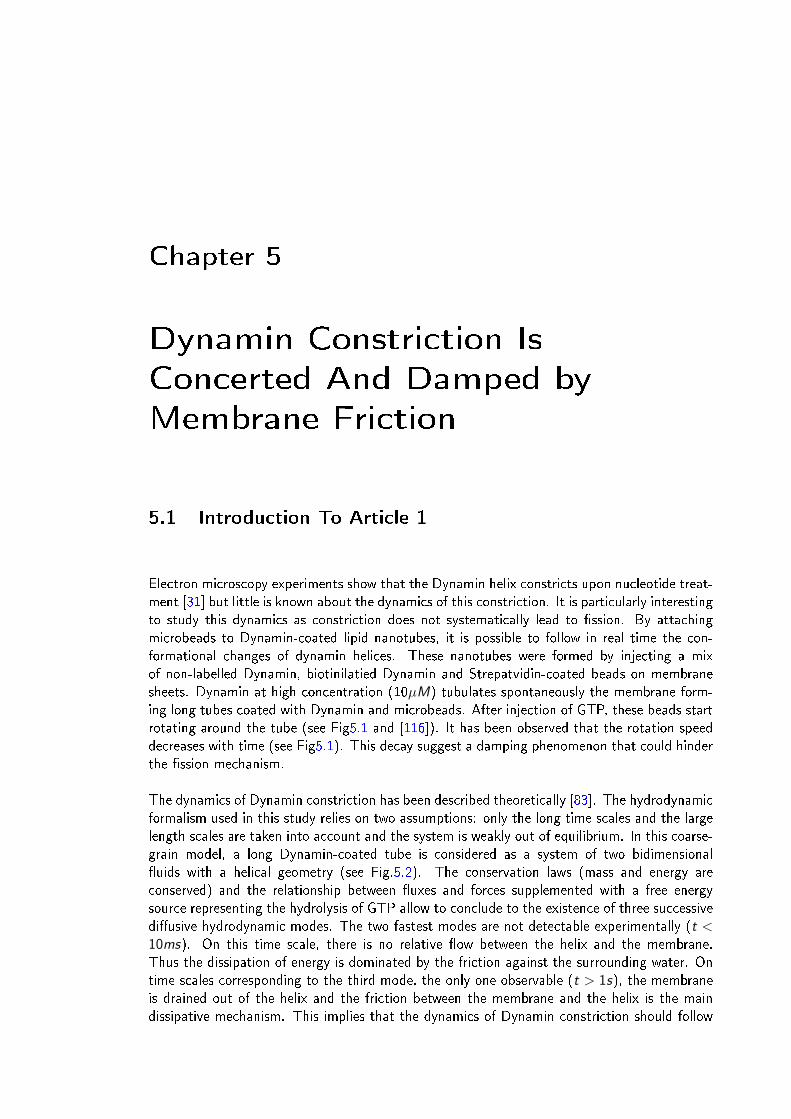
Chapter 5
Dynamin Constriction Is
Concerted And Damped by
Membrane Friction
5.1 Introduction To Article 1
Electron microscopy experiments show that the Dynamin helix constricts upon nucleotide treat-ment [31] but little is known about the dynamics of this constriction. It is particularly interestingto study this dynamics as constriction does not systematically lead to ssion. By attachingmicrobeads to Dynamin-coated lipid nanotubes, it is possible to follow in real time the con-formational changes of dynamin helices. These nanotubes were formed by injecting a mixof non-labelled Dynamin, biotinilatied Dynamin and Strepatvidin-coated beads on membranesheets. Dynamin at high concentration (10µM) tubulates spontaneously the membrane form-ing long tubes coated with Dynamin and microbeads. After injection of GTP, these beads startrotating around the tube (see Fig5.1 and [116]). It has been observed that the rotation speeddecreases with time (see Fig5.1). This decay suggest a damping phenomenon that could hinderthe ssion mechanism.
The dynamics of Dynamin constriction has been described theoretically [83]. The hydrodynamicformalism used in this study relies on two assumptions: only the long time scales and the largelength scales are taken into account and the system is weakly out of equilibrium. In this coarse-grain model, a long Dynamin-coated tube is considered as a system of two bidimensionaluids with a helical geometry (see Fig.5.2). The conservation laws (mass and energy areconserved) and the relationship between uxes and forces supplemented with a free energysource representing the hydrolysis of GTP allow to conclude to the existence of three successivediusive hydrodynamic modes. The two fastest modes are not detectable experimentally (t <10ms). On this time scale, there is no relative ow between the helix and the membrane.Thus the dissipation of energy is dominated by the friction against the surrounding water. Ontime scales corresponding to the third mode, the only one observable (t > 1s), the membraneis drained out of the helix and the friction between the membrane and the helix is the maindissipative mechanism. This implies that the dynamics of Dynamin constriction should follow
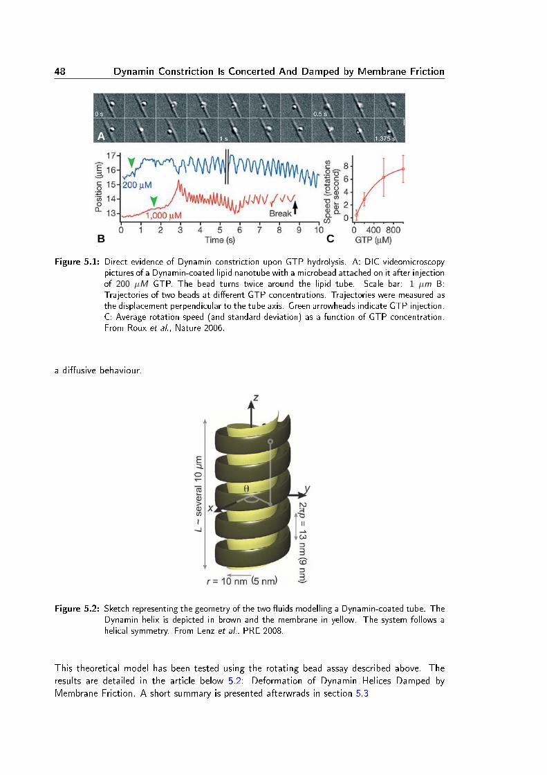
48 Dynamin Constriction Is Concerted And Damped by Membrane Friction
A
B C
Figure 5.1: Direct evidence of Dynamin constriction upon GTP hydrolysis. A: DIC videomicroscopypictures of a Dynamin-coated lipid nanotube with a microbead attached on it after injectionof 200 µM GTP. The bead turns twice around the lipid tube. Scale bar: 1 µm B:Trajectories of two beads at dierent GTP concentrations. Trajectories were measured asthe displacement perpendicular to the tube axis. Green arrowheads indicate GTP injection.C: Average rotation speed (and standard deviation) as a function of GTP concentration.From Roux et al., Nature 2006.
a diusive behaviour.
Figure 5.2: Sketch representing the geometry of the two uids modelling a Dynamin-coated tube. TheDynamin helix is depicted in brown and the membrane in yellow. The system follows ahelical symmetry. From Lenz et al., PRE 2008.
This theoretical model has been tested using the rotating bead assay described above. Theresults are detailed in the article below 5.2: Deformation of Dynamin Helices Damped byMembrane Friction. A short summary is presented afterwrads in section 5.3
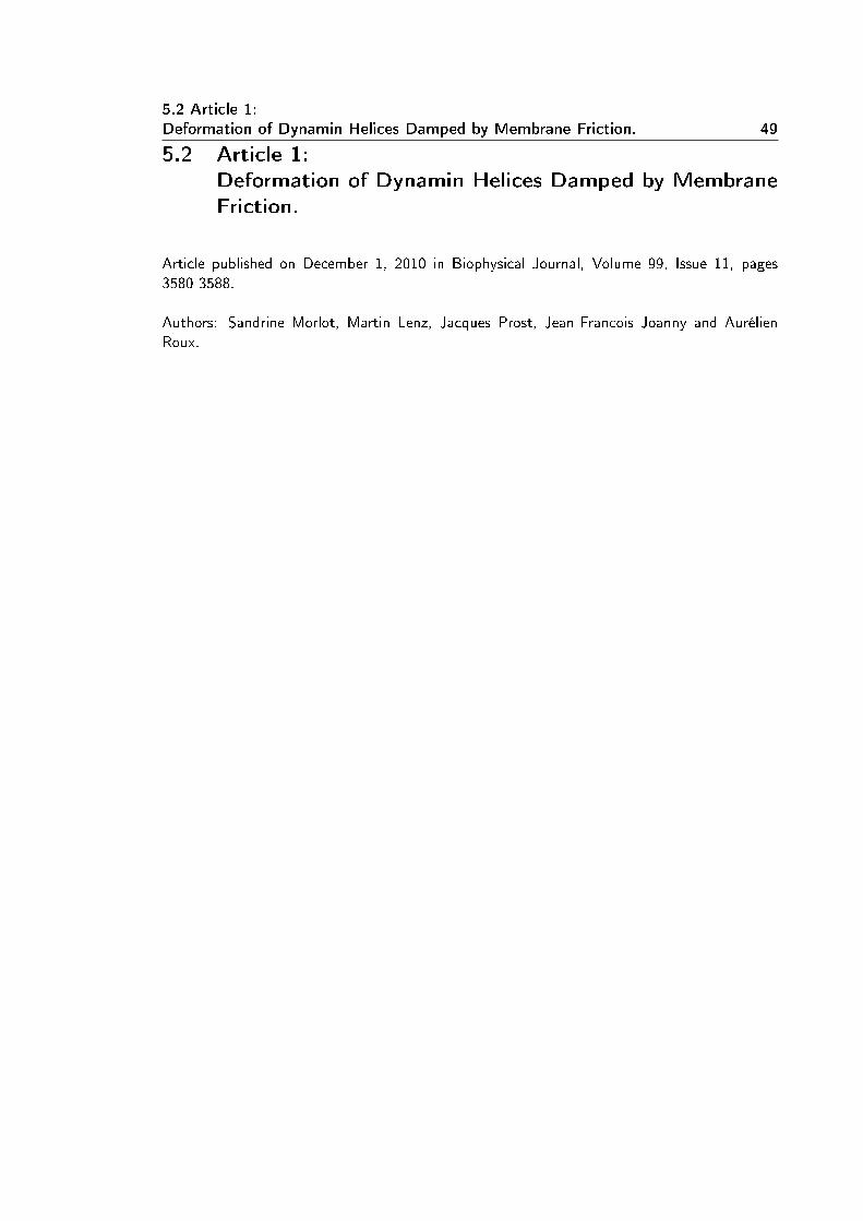
5.2 Article 1:Deformation of Dynamin Helices Damped by Membrane Friction. 49
5.2 Article 1:Deformation of Dynamin Helices Damped by MembraneFriction.
Article published on December 1, 2010 in Biophysical Journal, Volume 99, Issue 11, pages3580-3588.
Authors: Sandrine Morlot, Martin Lenz, Jacques Prost, Jean-Francois Joanny and AurélienRoux.
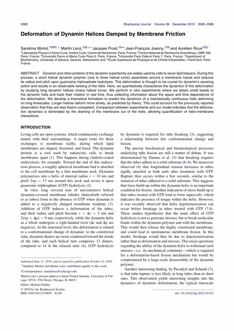
Deformation of Dynamin Helices Damped by Membrane Friction
Sandrine Morlot,†‡§k6 Martin Lenz,†‡§6* Jacques Prost,†‡** Jean-Francois Joanny,†‡§ and Aurelien Roux†‡§k†Laboratoire Physico-Chimie Curie, Institut Curie, Centre de Recherche, Paris, France; ‡Centre National de Recherche Scientifique, UMR 168,Paris, France; §Universite Pierre et Marie Curie Paris 6, Paris, France; Universite Paris Diderot Paris 7, Paris, France; kDepartment ofBiochemistry, University of Geneva, Geneva, Switzerland; and **Ecole Superieure de Physique et de Chimie Industrielles—ParisTech, Paris,France
ABSTRACT Dynamin and other proteins of the dynamin superfamily are widely used by cells to sever lipid bilayers. During thisprocess, a short helical dynamin polymer (one to three helical turns) assembles around a membrane tubule and reducesits radius and pitch upon guanosine triphosphate hydrolysis. This deformation is thought to be crucial for dynamin’s severingaction and results in an observable twisting of the helix. Here, we quantitatively characterize the dynamics of this deformationby studying long dynamin helices (many helical turns). We perform in vitro experiments where we attach small beads tothe dynamin helix and track their rotation in real time, thus collecting information about the space and time dependence ofthe deformation. We develop a theoretical formalism to predict the dynamics of a mechanically continuous helix deformingon long timescales. Longer helices deform more slowly, as predicted by theory. This could account for the previously reportedobservation that they are less fission-competent. Comparison between experiments and our model indicates that the deforma-tion dynamics is dominated by the draining of the membrane out of the helix, allowing quantification of helix-membraneinteractions.
INTRODUCTION
Living cells are open systems, which continuously exchangematter with their surroundings. A major route for theseexchanges is membrane traffic, during which lipidmembranes are shaped, fissioned, and fused. The dynaminprotein is a tool used by eukaryotic cells to breakmembranes apart (1). This happens during clathrin-coatedendocytosis, for example. Toward the end of this endocy-tosis process, a roughly spherical membrane bud is attachedto the cell membrane by a thin membrane neck. Dynaminpolymerizes into a helix of internal radius r ¼ 10 nm andpitch 2pp ¼ 13 nm around this neck and severs it uponguanosine triphosphate (GTP) hydrolysis (2).
In vitro, long (several tens of micrometers) helicaldynamin-covered membrane tubules (henceforth referredto as tubes) form in the absence of GTP when dynamin isadded to a negatively charged membrane template (3).Addition of GTP induces a deformation of the tubes,and their radius and pitch become r þ Dr ¼ 5 nm and2p(p þ Dp) ¼ 9 nm, respectively, while the dynamin helixas a whole undergoes a right-handed twist (Dr and Dp arenegative). At the structural level, this deformation is relatedto a conformational change of dynamin: in the constrictedstate, dynamin dimers are more condensed toward the insideof the tube, and each helical turn comprises 13 dimers,compared to 14 in the relaxed state (4). GTP hydrolysis
by dynamin is required for tube breaking (3), suggestinga relationship between this conformational change andfission.
The precise biochemical and biomechanical processesunderlying tube fission are still a matter of debate. It wasdemonstrated by Danino et al. (5) that breaking requiresthat the tubes adhere to a solid substrate (6–8). We moreoverobserved (6) that longitudinal tension increases in tubesrigidly attached at both ends after treatment with GTP.Rupture then occurs within a few seconds, similar to thesituation of tubes adhered to a solid substrate. This suggeststhat force build-up within the dynamin helix is an importantcondition for fission. Another indication of stress build-up isthat tubes treated with GTP tend to form supercoils, whichindicates the presence of torque within the helix. However,it was recently observed that helix depolymerization canoccur before breakage in tubes treated with GTP (7,8).These studies hypothesize that the main effect of GTPhydrolysis is not to generate stresses, but to break molecularbonds within the dynamin polymer and with the membrane.This would then release the highly constricted membrane,and could lead to spontaneous membrane fission. In thismodel, breakage would thus be due to depolymerizationrather than to deformation and stresses. This raises questionsregarding the ability of the dynamin helix to withstand suchstresses—i.e., its mechanical continuity—which is requiredfor a deformation-based fission mechanism but would becompromised by a large-scale disassembly of the dynaminpolymer.
Another interesting finding, by Pucadyil and Schmid (7),is that tube rupture is less likely in long tubes than in shortones. This observation yields interesting insights into thedynamics of dynamin deformation, the typical timescale
Submitted June 11, 2010, and accepted for publication October 13, 2010.6Sandrine Morlot and Martin Lenz contributed equally to this work.
*Correspondence: [email protected]
Martin Lenz’s present address is James Franck Institute, University of Chi-
cago, 929 E. 57th Street, Chicago, IL 60637.
Editor: Michael Edidin.
2010 by the Biophysical Society
0006-3495/10/12/3580/9 $2.00 doi: 10.1016/j.bpj.2010.10.015
3580 Biophysical Journal Volume 99 December 2010 3580–3588

of which, it has been suggested (9), is imposed by the damp-ing of tube constriction, torsion, and contraction by frictionagainst the surrounding medium and the membrane. As sucheffects are more pronounced in longer tubes, they could leadto a slower tube deformation there and therefore hinderfission, as hypothesized previously (10).
In this article, we tackle these issues through a quantitativestudy of the dynamics of the GTP-induced deformation ofdynamin. A good understanding of this phenomenon onthe timescales over which fission occurs is an importantstep toward the characterization of the dynamin severingaction and the role of deformation therein. Using a jointexperimental and theoretical approach, we clarify thephysics of this process.
We first present experiments in which the space-depen-dent twisting of long tubes is monitored by tracking smallpolystyrene beads attached to the dynamin coat. This meth-odology allows us to record the tube rotation velocity andnumber of turns in several locations as a function of time.A theoretical analysis of the deformation is then proposed,which yields detailed predictions regarding this beadmotion. We then combine the results of the two approaches,and show that upon GTP hydrolysis, long dynamin coatsare able to withhold stresses as a consequence of theircontinuity or through viscous coupling over small gapsseparating essentially continuous adjacent helices. Onobservable timescales, which coincide with the timescalesimplicated in dynamin-mediated fission (6), the rate-limiting step for the dynamics of this deformation is thedrainage of the membrane out of the helix. We also gainsome geometrical insight into the successive steps involvedin the deformation. Finally, we discuss the implications ofour findings for dynamin’s membrane-severing action, andtheir potential impact on previously proposed models ofdynamin-mediated membrane fission.
MATERIALS AND METHODS
Lipids
All lipids were purchased from Avanti Polar Lipids (Alabaster, AL). We use
a synthetic lipid mixture composed of 30% brain phosphatidylethanolamine
(PE), 5% liver phosphoinositides (PIs), 30% palmitoyl-oleoyl phosphati-
dylserine (POPS), and 35% palmitoyl-oleoyl phosphatidylcholine (POPC)
and supplement it with 15% (m/m) cholesterol and 5% (m/m) final
phosphatidylinositol-4,5-bisphosphate (PtdIns(4,5)P2). This composition
mimics a commercial porcine brain polar lipid extract (141101, Avanti)
without the 30% unknown lipids. Nucleotides are obtained from Roche
Biosciences (Palo Alto, CA).
Dynamin purification and labeling
Dynamin is purified from six rat brains using the GST-tagged SH3 domain
of rat amphiphysin 2 as an affinity ligand (6). After elution with low pH and
salt, the two fractions most enriched in dynamin are pooled (2 ml total),
dialyzed against storage buffer (20 mM HEPES, pH 7.4, 100 mM NaCl,
50% v/v glycerol—final volume ~0.5 ml, typical concentration ~2 mg/ml),
flash-frozen in liquid nitrogen, and stored at 80C. For conjugation to
biotin, DSB-X biotin C2-iodoacetamide (D-30753, Invitrogen, Carlsbad,
CA) is dissolved into dimethyl sulfoxide (DMSO) at a 10 mg/ml stock.
Dynamin is labeled for a few minutes by adding a 10 molar excess of
DSB-X. Labeled dynamin is dialyzed against storage buffer, aliquoted,
flash-frozen, and stored at 80C. Thiol-reactive biotin DSB-X ensures
good functionality of dynamin after labeling.
Formation of membrane sheets
Glass coverslips 22 40 mm in size are cleaned by sonication (5 min) in
1% Decon 90 (Modec, Houston , TX) in distilled water, followed by thor-
ough washing and sonication (5 min) in distilled water to remove any trace
of detergent and a final wash with 100% ethanol before storage in ethanol.
Coverslips are dried under a N2 flux, and 1-ml droplets of lipid solution
(10 mg/ml in pure chloroform) are deposited and allowed to dry on the
coverslip. Typically, two drops are deposited at different sites on the
same coverslip. The use of pure chloroform is essential to allow lipid
droplet drying in a way that is optimal for the subsequent formation of
membrane sheets upon hydration. Coverslips are then dried again under
vacuum (0.2 millitorr) for at least 1 h and kept up to several days under
vacuum.
Tube preparation
Before use, coverslips are placed for 20–30 min in a wet incubator (37C,100% humidity) to allow partial hydration of the lipids. Next, a small
chamber (~15-ml volume) is built by placing the coverslip onto a glass slide
with lipids facing the glass slide, using a double-sided Scotch (3M, St. Paul,
MN) tape as a spacer. The lipids are fully rehydrated by applying to the side
of the chamber 15–20 ml of GTPase buffer (20 mM HEPES, pH 7.4,
100 mM NaCl, 1 mMMgCl2), which is taken up into the chamber by capil-
larity. Lipid deposits then transform into membrane sheets. The glass slide
is placed on the stage of an Axiovert 150 microscope (Zeiss, Oberkochen,
Germany) for observation with a JAI Pulnix (San Jose, CA) TMR-1405L
camera and Streampix software for video acquisition (Norpix, Montreal,
Quebec, Canada). A dynamin-containing solution (5 ml) is applied to one
side of the chamber and the deformation of membrane sheets produced
by its diffusion into the chamber is recorded at normal video rate (30 fps)
with high resolution (1300 1024) imaging under differential interference
contrast (DIC) settings. Nucleotide-containing GTPase buffer (5 ml) is
added after formation of the tubes.
Bead labeling and observation
In experiments involving streptavidin-coated polystyrene beads (190-nm
diameter, Bangs Labs, Fishers, IN), biotinylated dynamin is used, and the
dynamin solution also contains beads at an ~500- to 1000-fold dilution rela-
tive to the commercial stock solution. For the experiments, only tubes
adherent to the glass surface at their ends but not throughout their length
are selected for observation.
Movie processing and compression
Uncompressed DIC movies (AVI files) are resized, contrasted, and acceler-
ated using the VirtualDub freeware (www.virtualdub.org). Raw movies are
compressed using the DivX codec (San Diego, CA) to ensure good quality
compression for data storage. For the analysis of bead movement, movies
are contrasted using VirtualDub, and transformed to 8-bit grayscale stack
(.stk) files using the ImageJ (National Institutes of Health, Bethesda,
MD) freeware. The spinning beads are tracked using the optional Tracking
function of the Metamorph software (Molecular Devices, Silicon Valley,
CA), which detects the beads on each frame by pixel thresholding and re-
turns the center of mass of the selected pixels. The bead trajectories are then
Biophysical Journal 99(11) 3580–3588
Dynamin Deformation Damped by Membrane 3581
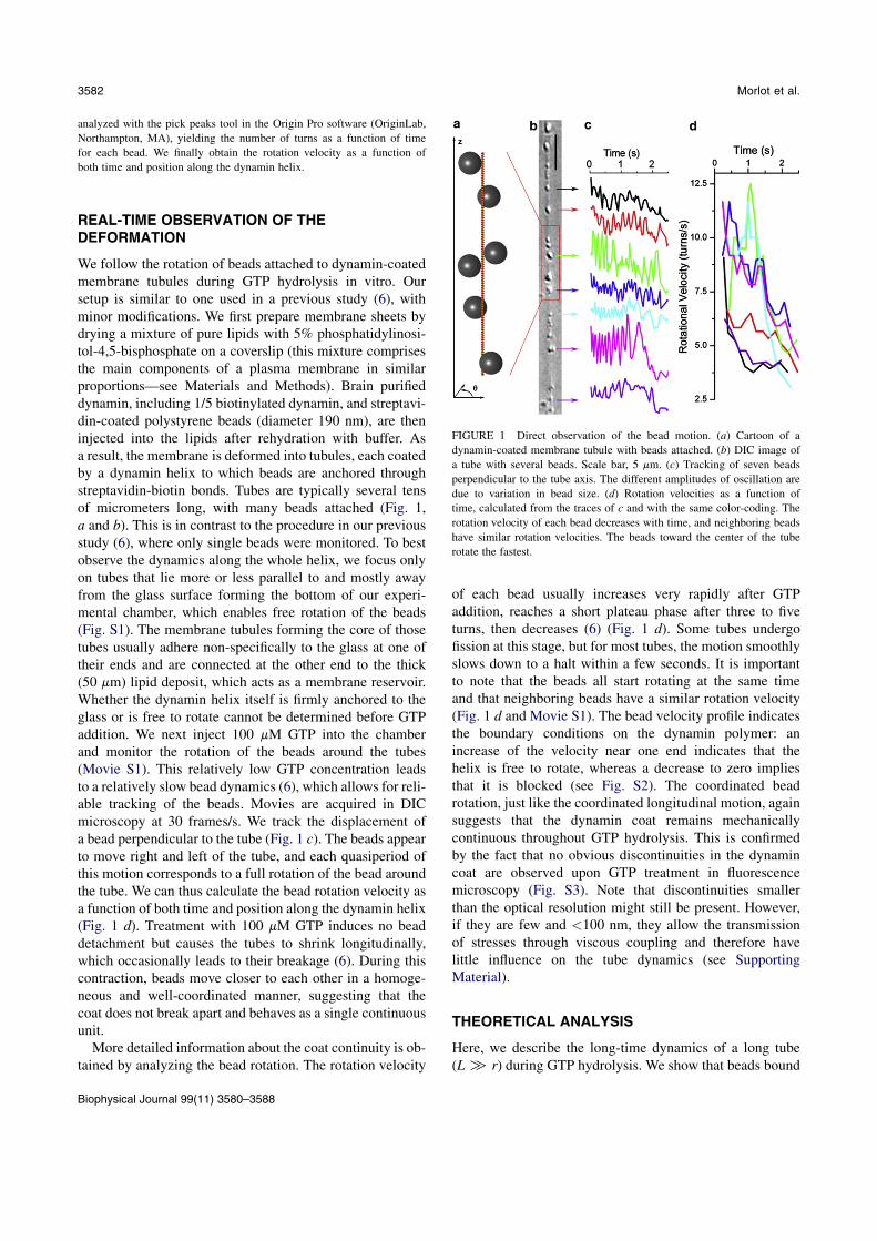
analyzed with the pick peaks tool in the Origin Pro software (OriginLab,
Northampton, MA), yielding the number of turns as a function of time
for each bead. We finally obtain the rotation velocity as a function of
both time and position along the dynamin helix.
REAL-TIME OBSERVATION OF THEDEFORMATION
We follow the rotation of beads attached to dynamin-coatedmembrane tubules during GTP hydrolysis in vitro. Oursetup is similar to one used in a previous study (6), withminor modifications. We first prepare membrane sheets bydrying a mixture of pure lipids with 5% phosphatidylinosi-tol-4,5-bisphosphate on a coverslip (this mixture comprisesthe main components of a plasma membrane in similarproportions—see Materials and Methods). Brain purifieddynamin, including 1/5 biotinylated dynamin, and streptavi-din-coated polystyrene beads (diameter 190 nm), are theninjected into the lipids after rehydration with buffer. Asa result, the membrane is deformed into tubules, each coatedby a dynamin helix to which beads are anchored throughstreptavidin-biotin bonds. Tubes are typically several tensof micrometers long, with many beads attached (Fig. 1,a and b). This is in contrast to the procedure in our previousstudy (6), where only single beads were monitored. To bestobserve the dynamics along the whole helix, we focus onlyon tubes that lie more or less parallel to and mostly awayfrom the glass surface forming the bottom of our experi-mental chamber, which enables free rotation of the beads(Fig. S1). The membrane tubules forming the core of thosetubes usually adhere non-specifically to the glass at one oftheir ends and are connected at the other end to the thick(50 mm) lipid deposit, which acts as a membrane reservoir.Whether the dynamin helix itself is firmly anchored to theglass or is free to rotate cannot be determined before GTPaddition. We next inject 100 mM GTP into the chamberand monitor the rotation of the beads around the tubes(Movie S1). This relatively low GTP concentration leadsto a relatively slow bead dynamics (6), which allows for reli-able tracking of the beads. Movies are acquired in DICmicroscopy at 30 frames/s. We track the displacement ofa bead perpendicular to the tube (Fig. 1 c). The beads appearto move right and left of the tube, and each quasiperiod ofthis motion corresponds to a full rotation of the bead aroundthe tube. We can thus calculate the bead rotation velocity asa function of both time and position along the dynamin helix(Fig. 1 d). Treatment with 100 mM GTP induces no beaddetachment but causes the tubes to shrink longitudinally,which occasionally leads to their breakage (6). During thiscontraction, beads move closer to each other in a homoge-neous and well-coordinated manner, suggesting that thecoat does not break apart and behaves as a single continuousunit.
More detailed information about the coat continuity is ob-tained by analyzing the bead rotation. The rotation velocity
of each bead usually increases very rapidly after GTPaddition, reaches a short plateau phase after three to fiveturns, then decreases (6) (Fig. 1 d). Some tubes undergofission at this stage, but for most tubes, the motion smoothlyslows down to a halt within a few seconds. It is importantto note that the beads all start rotating at the same timeand that neighboring beads have a similar rotation velocity(Fig. 1 d and Movie S1). The bead velocity profile indicatesthe boundary conditions on the dynamin polymer: anincrease of the velocity near one end indicates that thehelix is free to rotate, whereas a decrease to zero impliesthat it is blocked (see Fig. S2). The coordinated beadrotation, just like the coordinated longitudinal motion, againsuggests that the dynamin coat remains mechanicallycontinuous throughout GTP hydrolysis. This is confirmedby the fact that no obvious discontinuities in the dynamincoat are observed upon GTP treatment in fluorescencemicroscopy (Fig. S3). Note that discontinuities smallerthan the optical resolution might still be present. However,if they are few and <100 nm, they allow the transmissionof stresses through viscous coupling and therefore havelittle influence on the tube dynamics (see SupportingMaterial).
THEORETICAL ANALYSIS
Here, we describe the long-time dynamics of a long tube(L[ r) during GTP hydrolysis. We show that beads bound
FIGURE 1 Direct observation of the bead motion. (a) Cartoon of a
dynamin-coated membrane tubule with beads attached. (b) DIC image of
a tube with several beads. Scale bar, 5 mm. (c) Tracking of seven beads
perpendicular to the tube axis. The different amplitudes of oscillation are
due to variation in bead size. (d) Rotation velocities as a function of
time, calculated from the traces of c and with the same color-coding. The
rotation velocity of each bead decreases with time, and neighboring beads
have similar rotation velocities. The beads toward the center of the tube
rotate the fastest.
Biophysical Journal 99(11) 3580–3588
3582 Morlot et al.
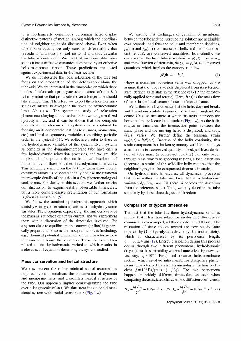
to a mechanically continuous deforming helix displaydistinctive patterns of motion, among which the coordina-tion of neighboring beads discussed above. Even whentube fission occurs, we only consider deformations thatprecede it (and possibly lead up to it) and thus describethe tube as continuous. We find that on observable time-scales it has a diffusive dynamics dominated by an effectivehelix-membrane friction. These predictions are testedagainst experimental data in the next section.
We do not describe the local relaxation of the tube butfocus on the propagation of the deformation along thetube axis. We are interested in the timescales on which thesemodes of deformation propagate over distances of order L. Itis fairly intuitive that propagation over a longer tube shouldtake a longer time. Therefore, we expect the relaxation time-scales of interest to diverge in the so-called hydrodynamiclimit L/r/þN. The systematic study of relaxationphenomena obeying this criterion is known as generalizedhydrodynamics, and it can be shown that the completehydrodynamic behavior of a system can be captured byfocusing on its conserved quantities (e.g., mass, momentum,etc.) and broken symmetry variables (describing periodicorder in the system) (11). We collectively refer to these asthe hydrodynamic variables of the system. Even systemsas complex as the dynamin-membrane tube have only afew hydrodynamic relaxation processes, and we are ableto give a simple, yet complete mathematical description ofits dynamics on those so-called hydrodynamic timescales.This simplicity stems from the fact that generalized hydro-dynamics allows us to systematically enclose the unknownmicroscopic details of the tube in a few phenomenologicalcoefficients. For clarity in this section, we further restrictour discussion to experimentally observable timescales,but a more comprehensive presentation of our formalismis given in Lenz et al. (9).
We follow the standard hydrodynamic approach, whichstarts bywriting conservation equations for the hydrodynamicvariables. These equations express, e.g., the time derivative ofthe mass as a function of a mass current, and we supplementthem with a discussion of the timescales involved. Fora system close to equilibrium, this current (or flux) is generi-cally proportional to some thermodynamic forces (including,e.g., chemical potential gradients), which characterize howfar from equilibrium the system is. These forces are thenrelated to the hydrodynamic variables, which results ina closed set of equations describing the system studied.
Mass conservation and helical structure
We now present the rather minimal set of assumptionsrequired by our formalism: the conservation of dynaminand membrane mass, and a seamless helical structure ofthe tube. Our approach implies coarse-graining the tubeover a lengthscale of zr. We thus treat it as a one-dimen-sional system with spatial coordinate z (Fig. 1 a).
We assume that exchanges of dynamin or membranebetween the tube and the surrounding solution are negligibleover seconds, and thus the helix and membrane densities,rh(z,t) and rm(z,t) (i.e., masses of helix and membrane perunit length), are conserved quantities. Equivalently, wecan consider the local tube mass density, r(z,t) ¼ rh þ rm,and mass fraction of dynamin, F(z,t) ¼ rh/r, as conservedquantities, which implies the conservation law
rvtF ¼ vzJ; (1)
where a nonlinear advection term was dropped, as weassume that the tube is weakly displaced from its referencestate (defined as its state in the absence of GTP and of exter-nally applied force and torque). Here, J(z,t) is the mass flowof helix in the local center-of-mass reference frame.
We furthermore hypothesize that the helix does not break,and thus retains a solid-like periodic structure throughout.Wedefine qðz; tÞ as the angle at which the helix intersects thehorizontal plane located at altitude z (Fig. 1 a). As the helixrotates or translates, the intersection point between thestatic plane and the moving helix is displaced, and thus,qðz; tÞ varies. We further define the torsional strainuzqðz; tÞ ¼ vzqðz; tÞ. Because of the helix continuity, thisstrain component is a broken-symmetry variable, i.e., playsa similar role to a conservedquantity. Indeed, just like a deple-tion of tube mass (a conserved quantity) can only occurthrough mass flow to neighboring regions, a local extension(decrease in strain) of the solid-like helix requires that theneighboring regions be compressed (increase in strain).
On hydrodynamic timescales, all dynamical processesthat occur within the tube are slaved to the hydrodynamicvariables dr, duzq, and dF (here, d denotes the deviationfrom the reference state). Thus, we may describe the tubestate only by these three degrees of freedom.
Comparison of typical timescales
The fact that the tube has three hydrodynamic variablesimplies that it has three relaxation modes (11). Because itsdynamics is overdamped, all three modes are diffusive. Therelaxation of these modes toward the new steady stateimposed by GTP hydrolysis is driven by the tube elasticity,which is characterized by its persistence length,‘p ¼ 3754 mm (12). Energy dissipation during this processoccurs through two different phenomena: hydrodynamicdrag against the surroundingwater (characterizedby thewaterviscosity, hx103 Pa$s) and relative helix-membranemotion, which involves intra-membrane dissipative pheno-mena (characterized by an inter-monolayer friction coeffi-cient bz108 Pa=ðm$s1Þ (13)). The two phenomenahappen on widely different timescales, as seen whencomparing the associated characteristic diffusion coefficients:
DwzkBT‘phr2
z106mm2$s1[DmzkBT‘pbr3
z103mm2$s1: (2)
Biophysical Journal 99(11) 3580–3588
Dynamin Deformation Damped by Membrane 3583

Since we are concerned with describing experimentalsystems with lengths of order 10 mm over timescales oforder 1 s, we are only interested in phenomena characterizedby diffusion coefficients of order 102 mm2$s–1, i.e., only inthose involving helix-membrane friction. The hydrody-namic drag of water is thus neglected in the followinganalysis, so that no external forces are applied to the tubeexcept at its ends. Using sðz; tÞ and tðz; tÞ to denote the localinternal longitudinal tension of the tube and its local internaltorque, respectively, this implies that s and t are indepen-dent of z. They are thus equal to the force and torqueimposed at the ends of the tube, which we assume to beconstant.
Internal forces governing tube relaxation
The relaxation of the tube is driven by the reactive forcesconjugate to its hydrodynamic variables: the longitudinalpressure, dpðz; tÞ (which has units of force in a one-dimensional system); the elastic torque, dhðz; tÞ; and thehelix-membrane exchange chemical potential, dmeðz; tÞ. Allof these vanish in the reference state. They are defined interms of derivatives of the tube free energy per unit length,f ðz; tÞ, and for small deviations from the reference statethey are linearly related to the hydrodynamic variables:0
@ dpdhdme
1A ¼
0@ r2vrðf =rÞjuzq;F
vuzq f jr;Fr1vFf jr;uzq
1A ¼ c
0@ dr
duzqdF
1A; (3)
where the 3 3 susceptibility matrix c expresses this linearrelation. This matrix characterizes the tube elasticity. Thederivatives in Eq. 3 are taken in the tube reference state.
Dissipative processes, including GTP hydrolysis
Whereas the conservative (reactive) part of the tubedynamics close to equilibrium is captured by Eq. 3, dissipa-tive phenomena are described by the flux-force relations inan isothermal tube:
s dp dh=p ¼ ~xzDm (4a)
t þ dh ¼ ~xqDm (4b)
J ¼ ~lvzdme ~avzdh: (4c)
The left-hand sides of Eqs. 4a, 4b, and 4c are equal to thedissipative fluxes of linear momentum (dissipative force),angular momentum (dissipative torque), and helix mass(diffusion flux), respectively. Those fluxes are linearlyrelated to thermodynamic forces Dm (representing the freeenergy liberated byGTP hydrolysis), vzdme, and vzdh throughthe phenomenological transport coefficients ~xz, ~xq, ~l, and ~a.
Although the values of these coefficients are a prioriunknown, only certain couplings are allowed by symme-tries. In agreement with structural data (4,14,15), we assumethat the tube is nonpolar, i.e., invariant under up-downsymmetry. As a consequence, Eqs. 4a and 4b (where thefluxes are even under this transformation), but not Eq. 4c(where the fluxes are odd), involve the chemical potentialdifference, Dm, between GTP and its hydrolysis products(which is even). Therefore, GTP hydrolysis plays thesame role in the tube dynamics as an externally appliedforce and torque, as seen in Eq. 4. Note that viscousterms are omitted from Eqs. 4a and 4b, as they are subdom-inant compared to ~xzDm and ~xqDm in the hydrodynamiclimit.
The coefficient ~l relates the amount of helix-membranemotion (characterized by J) to the force, dme, that drivesthis motion. It is therefore essentially a helix-membranefriction coefficient. Here, we consider that helix-membranefriction stems from intra-membrane dissipative phenomena,and thus involves the membrane viscosity. To be able toquantitatively test this hypothesis, we consider thesimplistic model described in our previous article (9), wherethe helix is rigidly attached to the membrane’s outer mono-layer, which itself drags against the inner monolayer. Thismodel yields the estimate ~l ¼ F2ð1FÞ
2pr2
rbx1026 kg$m1$s,which is compared to experimental measurements in thenext section. Note that in this formula ~l is related to b andthus characterizes the dominant formof dissipation discussedabove (see Eq. 2).
Tube behavior on observable timescales
Combining Eqs. 1, 3, and 4, and using the fact that s and tare constants, we find that the hydrodynamic behavior onobservable timescales is given by the diffusion equation
vtduzq ¼ Dmv2zduzq; where Dm ¼
~l
r
detc
c1;1c2;2 c1;2c2;1
:
(5)
The associated relaxation timescale is set by the friction ofthe helix against the membrane. In a previous article (9), wecomputed c using an elastic model of the tube (see alsoFig. 3) and predicted Dmx2:2 102 mm2$s1.
TUBE DYNAMICS CONTROLLED BY MEMBRANEFRICTION
The previous section characterizes the dynamics of long(L [ r) unbroken dynamin helices. In this section, wecompare its predictions to data from the experimentsdescribed in Real-Time Observation of the Deformation.We find that they are indeed compatible, and argue thatthis can only be accounted for by the fact that helices inour experiments are mostly unbroken. We then discuss thephysics underlying the relaxation.
Biophysical Journal 99(11) 3580–3588
3584 Morlot et al.

We find that the longest relaxation timescale of the tubeapparently diverges with its length, which indicates a hydro-dynamic relaxation process. According to our theoreticalreasoning, only two types of relaxation processes arecompatible with this behavior: 1) friction against water,and 2) friction between the helix and the membrane. Ac-cording to the estimate of Eq. 2, the timescales involvedin 1), are of the order of DwL
2z100 ms. The longestrelaxation time of the tube is observed to be of the orderof 1 s (Fig. 1 d), i.e., much longer than this. This allowsus to rule out friction against water as a major influence inthe relaxation process on observable timescales. On theother hand, we show below that the relaxation timescaleinvolved in 2), and predicted using our estimate of thefriction coefficient ~l is indeed compatible with the experi-ments. This supports our hypothesis that helix-membranefriction is mostly due to effects related to the membraneviscosity.
Final state of the tube
Let us consider an unbroken helix stuck to the glass at z ¼ 0
(thus imposing q(0, t)¼ 0) and free to rotate at its other end,z ¼ L, and discuss the motion of a bead located at altitude z.As a consequence of the helix continuity, the piece of helixbetween 0 and z cannot rotate without dragging along thepiece between z and L in its rotation. Each turn of helix even-tually undergoes an identical twisting deformation and thusrotates the portion of the helix above it by a fixed quantity.As these elementary rotations add up, the total number ofrotations of a bead increases linearly with increasing z.This reads DqðzÞ ¼ Duzqz, where Duzq is a constant. Morespecifically, this is due to the up-down symmetry of thetube, which imposes that GTP hydrolysis acts as a forceand torque and thus imposes a constant strain on the helix.
In Fig. 2 a, we present two experiments where the tubesdo not break after addition of 100 mM GTP, which allowsus to count the total number of turns of each bead betweenGTP injection and the end of the deformation. As expected,these data display a linear relationship between bead posi-tion z and the total amount of rotation, Dq, withDuzq ¼ 2:8 rad$mm1 (open circles) and 1:5 rad$mm1
(solid circles). This is to be compared with the structuraldata of Zhang and colleagues (14,15), where it is statedthat the helix goes from 14.2 to 13.2 dimers/helical turn,which corresponds to Duzq ¼ 7:9 rad$mm1. Although thesenumbers are in order-of-magnitude agreement, our measure-ments yield noticeably smaller values, meaning that tubessubmitted to 100 mM GTP (as opposed to the nucleotideconcentration of 1 mM used in Zhang and Hinshaw (14))only reach a partially constricted state.
These observations are consistent with structuralevidence of the up-down symmetry of the helix (14,15).More important, they constitute strong evidence of itsmechanical continuity, meaning that if gaps in the helix
are present, they are few and significantly smaller than100 nm. Indeed, larger gaps would spoil the linear relation-ship observed here (see discussion above and the SupportingMaterial). Note that large, optically resolvable gaps areobserved when multiple dynamin polymers nucleate on apreformed membrane tubule (16), but not when tubes aregrown from a flat membrane, as is the case here. The datapresented in Fig. 2 a also show that bead rotation in ourexperiments is not due to the unbraiding of two tubes, aswas suggested previously (7) (see Supporting Material).
Bead rotation dynamics
The diffusive dynamics of Eq. 5 predicts the long-timerelaxation of bead rotation as a function of space and
FIGURE 2 Experimental data validate the predictions from our hydrody-
namic formalism, implying that dynamin deforms as a mechanically contin-
uous entity and that this process is damped by an internal friction. (a) Linear
relationship between Dq(z) and z, where Dq(z) is determined by counting
the final number of rotations in a trace similar to those presented in
Fig. 1 c for the bead located in z. Open and solid circles represent data
from two independent experiments. For each of these, the Dq values are
divided by the value of Duzq indicated in the main text to collapse the
data onto a line. (b) Exponential relaxation of bead rotation on long
timescales. As the rotation velocity U ¼ vtq (measured as in Fig. 1 d)
decreases, tracking becomes increasingly difficult and no data are collected
for qT200 rad. (c) Velocity profiles for two independent experiments, each
involving a single tube. TheU values of the experiment represented by open
circles and solid circles were divided by U0 ¼ 5:2 rad$s1 and
U0 ¼ 9:2 rad$s1, respectively, and the bead positions, z, were scaled by
the independently measured L ¼ 31 mm and L ¼ 47mm, respectively, to
collapse the data onto a sinusoidal master curve. (d) Dependence of the
largest relaxation time (fit procedure described in Fig. S4) on the largest
wavelength compatible with the tube boundary conditions. Horizontal error
bars represent the estimated uncertainty regarding the length of each tube,
and vertical error bars stand for the fit uncertainty as calculated by the
Origin software.
Biophysical Journal 99(11) 3580–3588
Dynamin Deformation Damped by Membrane 3585
time. At long times, the strain duzq is dominated by itslongest-lived Fourier mode, i.e., the one with the largestwavelength lmax compatible with the boundary conditions.This yields
qðz; t ¼ þNÞ qðz; tÞ ft/þN
et=tmax sin
2pz
lmax
: (6)
In this paragraph, we focus our attention on the time depen-dence of this relaxation, which decays exponentially withtime constant
tmax ¼ l2max
4p2Dm
: (7)
This can be equivalently expressed as
Uðz; tÞ ¼ vtqðz; tÞ ¼ t1max½qðz; tÞ qðz; t ¼ þNÞ: (8)
In Fig. 2 b, we test this linear relationship between q and therotation velocity, U, in an experiment where a 1 mM GTPconcentration is used, which allows for the observation ofmany turns of the bead and therefore provides a stringenttest of Eq. 8. The agreement is very good, and the slopeof the linear fit yields tmax ¼ 3:7 s. In this experiment, weevaluate the length of the tube to be Lx100 mmzlmax=2,which yields Dmx3:0 102 mm2$s1. This is in goodorder-of-magnitude agreement with our theoreticalprediction.
Long-time bead velocity profile
Now turning to the spatial profile described in Eq. 6, weexpect U to have a sinusoidal dependence in the coordinatez. In Fig. 2 c, we plot the value of the velocities of beadsattached to two different tubes as a function of their scaledpositions and after addition of 100 mM GTP. The motion ofneighboring beads is clearly coordinated, as expected fromour continuous helix model.
Relation between length and relaxation time
Using sinusoidal fits similar to those seen in Fig. 2 c, weestablish that lmax ¼ 4L for tubes attached at only oneend, whereas lmax ¼ 2L for tubes attached at both ends(see Fig. S2; the possibility for a tube attached at bothends to rotate is discussed in the Supporting Material).Therefore, Eq. 7 predicts that long tubes have a slowerlong-time dynamics than short ones. We test this bymeasuring tmax for several tubes with either one or twoends attached (fit procedure described in Fig. S4). Thesedata are plotted against lmax in Fig. 2 d.
A quadratic fit corresponding to Eq. 7 is represented bya line in Fig. 2 d and yields Dm ¼ 2:0 102 mm2$s1, inagreement with our prediction. Note that the experimentalrelaxation times are larger than predicted by theory for short
tubes (lmax(40 mm). This is likely due to the injection ofGTP into the experimental chamber, which takes a fewtenths of a second and could interfere with the relaxationof the tube on this timescale: as the amount of availableGTP increases with time over this period, the bead rotationtends to accelerate, and the predicted slowing down is notobserved until after the end of GTP injection. This leadsto an experimental overestimation of tmax that is mostapparent in short tubes. Another possible cause for thisdelay is the inherent timescale associated with GTP hydro-lysis by dynamin, which is also of the order of a fewhundreds of milliseconds (14). These timescales are negli-gible in the hydrodynamic limit L=r/þN, where ourformalism is valid. Indeed, Fig. 2 d clearly shows that thelongest relaxation time of the tubes is an increasing functionof their length, which retrospectively justifies our focusingon hydrodynamic timescales. This is further evidence ofthe mechanical continuity of the tubes used in our experi-ments, as we would expect a broken long tube to behavesimilarly to a collection of small tubes (e.g., have thesame relaxation time as short tubes), which is not observedhere. Finally, the reasonable agreement between the valuesof Dm inferred from Fig. 2 b (where ½GTP ¼ 1 mM) andthe value fitted in Fig. 2 d (½GTP ¼ 100 mM) confirmsour prediction that the tube relaxation timescale does notdepend on GTP concentration (see Eq. 5).
Full predictions for the deformation dynamics
The good agreement of our theoretical analysis with exper-imental results suggests that it may also give a reasonabledescription of dynamin-coated membrane tubes on shorterlength- and timescales. In Fig. 3, we present predictionsfrom a detailed analysis of our hydrodynamic formalism(9) (see also Supporting Material) in the case where thetube reaches its full deformation, as when treated with1 mM GTP (5).
This analysis is based on the changes of pitch and radiusof the helix observed by Danino et al. (5), which allow usto infer the active force and torque ~xzDm and ~xqDmdescribing GTP hydrolysis. We also assume that the helixelastic properties are similar to those of a spring with persis-tence length ‘p ¼ 3754 mm (12). This somewhat coarseassumption implies that the details of the deformationdescribed in Fig. 3 are speculative to some extent, althoughplausible and thermodynamically consistent. A more refinedcharacterization of the matrix c could be obtained throughadditional mechanical measurements (e.g., of the compres-sional elasticity of the helix). We allow membrane bendingand stretching and assume that the corresponding modulihave the typical values 10 kBT and 0:25 N$m1 (9). Thisallows us to evaluate the elastic susceptibility matrix c.As discussed previously, the tube dynamics can bedecomposed into three chronologically well-separateddiffusive modes, and we evaluate the associated diffusion
Biophysical Journal 99(11) 3580–3588
3586 Morlot et al.
coefficients, D1zDw[D2zDw[Dm, as well as theamplitude of the deformations, as pictured in Fig. 3.
On short (although hydrodynamic) timescales(t1zL2=D1z100 ms), the tube undergoes an almost imper-ceptible retraction in the vertical direction, without rotationor relative helix-membranemotion—longitudinal friction onthe surrounding medium is the dominant dissipative mecha-nism. On intermediate timescales t2zL2=D2z10 ms, thetube radius decreases. Both longitudinal friction andthe dissipation associated with the flux of water inside thetube are negligible (9). Rotational friction against wateris the dominant dissipative mechanism, and no relativehelix-membrane flux occurs (helix and membrane extendlongitudinally at the same rate). Only on timescales of ordertmaxzL2=Dmz1 s is membrane expelled from the helix tothe membrane reservoirs at its boundaries. Fig. 3 showsthat this process involves a decrease in tube pitch, which isconsistent with the notion that membrane is being squeezedout of the helix.
DISCUSSION
This article describes the deformation dynamics of longdynamin-coated membrane tubules upon GTP hydrolysisas essentially governed by dynamin flow, membrane flow,and the winding of the dynamin helix. Combining experi-mental data and theoretical analysis, we show that onobservable timescales this dynamics essentially consists inthe drainage of the membrane out of the mechanicallycontinuous helix by nucleotide-induced effective force and
torque. The numerical value of the relevant friction coeffi-cient suggests that dissipation occurs mostly within the lipidbilayer, possibly as strongly dynamin-bound lipids moverelative to and exert friction against the surrounding non-bound lipids. As a consequence, short tubes deform moreslowly than long ones.
Although our study focuses on long tubes, our resultsreveal the stability of the dynamin helix throughout GTPhydrolysis, as well as the nature of the out-of-equilibriuminteractions between dynamin and membrane. These find-ings can readily be transposed to short helices such as thoseencountered in vivo, and are therefore of interest for thestudy of dynamin in a biological context. Note, however,that the separation of timescales between microscopic andhydrodynamic relaxation processes does not hold in suchshort helices; for instance, Fig. 2 d shows that dynamin-membrane friction dominates the dynamics only in tubeslonger than a few microns. It is therefore likely that otherrelaxation phenomena also have an influence on thedynamics of short tubes, and it is thus not obvious whatmechanisms set the timescale for their breaking.
Our approach also allows us to use macroscopic informa-tion from in vitro experiments to predict the shape anddynamics of the helix on small (z10 nm) lengthscaleswithout need of further structural studies (Fig. 3). Thisprovides a qualitative picture of the microscopic dynamicsof the tube.
Our results have implications for the mechanism of dyna-min-mediated membrane fission and shed new light onseveral previous models. A first possibility is that dynamindrives fission purely by constricting the membrane. As indi-cated in Fig. 3, we expect this type of deformation to takeplace on timescales of the order of 10 ms after GTP injec-tion. After having been brought into close proximity byconstriction, the two sides of the membrane would presum-ably fuse together to complete fission. This step implicatesan energy barrier of several kBT, and may thus take a longtime to complete. In our in vitro experiments and in aprevious article (6), fission typically occurs a few secondsafter GTP injection, and another study (7) reports fissiontimes of several tens of seconds. Since we predict that theradius of the tube shrinks on a much shorter timescale(Fig. 3), we may interpret these fission times as dominatedby the barrier crossing step, which could provide insightinto the energetics of the membrane fusion process.However, the observation made in other studies (5,6) thatanchoring of the tube to the substrate is required forbreaking is not accounted for by this mechanism. Pureconstriction might thus not be able to account for the dyna-min-mediated fission observed in those experiments.
Another proposal is that helix constriction plays a negli-gible role in membrane fission, whereas an increase inthe helix pitch would drive a dramatic thinning of themembrane tubule on short timescales. This would fuse theopposite sides of the tubule (18), leading to breakage. Our
FIGURE 3 Illustration of the time-dependent deformation as predicted
by the full hydrodynamic formalism of Lenz et al. (9). (See the Supporting
Material for a proper description of the membrane reservoir.) The images in
this figure represent the tube state during the lag phases between the relax-
ation of the three well-separated diffusive relaxation modes of the tube. See
Movie S2 for an animated version. Note that our model allows for both
stretching and bending of the membrane, but in practice, the membrane
area per polar head varies by <1.5% and the inhomogeneities in membrane
radius due to bending are always <7%—they are thus hardly discernible in
this figure.
Biophysical Journal 99(11) 3580–3588
Dynamin Deformation Damped by Membrane 3587

predictions of the tube dynamics on timescales ranging froma few hundreds of microseconds (17) to seconds (Fig. 3)suggest that neither this nor dramatic membrane stretchingoccur on hydrodynamic length- and timescales. If correct,this scenario is therefore likely to apply only to short dyna-min helices, such as those observed in vivo.
Our results also allow a discussion of results from morerecent studies (7,8), where it is reported that dynamin disas-sembles from the membrane during GTP hydrolysis. Theauthors suggest that long dynamin coats are quickly releasedfrom the membrane upon GTP addition and are promptlyreplaced by smaller, more fission-competent coats. Thiswould imply that helix depolymerization is the central eventof dynamin-mediated membrane fission, and therefore thatdynamin deformation is secondary, if not irrelevant, to itssevering action. Our results concerning the mechanicalcontinuity of the dynamin helix upon GTP hydrolysis donot support this picture and indeed suggest that in ourexperimental system, the mechanochemical action ofdynamin is central to its severing action.
Lenz et al. (19) propose that deformation on a time-scale shorter than the membrane viscoelastic timescalemight lead to a tear in the membrane, possibly throughshearing, which could initiate tube fission. We estimatethis viscoelastic timescale, tve, as the ratio of a typical lipidsurface viscosity, z5 109 kg$s--1 (20), to a typicalmembrane stretching modulus,z0:25 N$m--1 (21), yieldingtvez108 s. Here, we report that the tube dynamics isslower for longer tubes, which could imply a less efficienttearing action for tubes where tmax[tve, i.e., in tubeslonger than
ffiffiffiffiffiffiffiffiffiffiffiffiDmtve
p, which is a few nanometers. This is
compatible with the observation made by Pucadyil andSchmid (7) that long dynamin-covered membrane tubulesare less likely to break than short ones. More broadly, thismodel puts forward the interesting notion that the stronghelix-membrane interactions characterized in this articlemay participate in the destabilization of the bilayer duringfission. Such interactions have indeed been shown to beessential for the membrane fission activity of dynamin(22). This finding and our new theoretical insight intodynamin deformation pave the way for further quantitativestudies of dynamin-mediated fission.
SUPPORTING MATERIAL
Supporting theoretical text, four figures, and two movies are available at
http://www.biophysj.org/biophysj/supplemental/S0006-3495(10)01265-8.
We thank Timo Betz, Pierre Nassoy, and Gilman Toombes for inspiring
discussions and critical reading of this manuscript, and Patricia Bassereau
for her support and scientific interest in this project.
This work was supported by the Centre National de la Recherche Scienti-
fique (‘‘Interface Physique Chimie Biologie: soutien a la prise de risque’’)
(A.R.), the Agence Nationale de la Recherche (Young Investigator
Program, No. JC08_317536) (A.R.), and the Human Frontier Science
Program Career Development Award (No. 0061/2008 to A.R.).
REFERENCES
1. Praefcke, G. J. K., and H. T. McMahon. 2004. The dynamin super-
family: universal membrane tubulation and fission molecules? Nat.
Rev. Mol. Cell Biol. 5:133–147.
2. Takei, K., P. S. McPherson,., P. De Camilli. 1995. Tubular membrane
invaginations coated by dynamin rings are induced by GTP-g S in
nerve terminals. Nature. 374:186–190.
3. Sweitzer, S. M., and J. E. Hinshaw. 1998. Dynamin undergoes a
GTP-dependent conformational change causing vesiculation. Cell.
93:1021–1029.
4. Mears, J. A., P. Ray, and J. E. Hinshaw. 2007. A corkscrew model for
dynamin constriction. Structure. 15:1190–1202.
5. Danino, D., K.-H. Moon, and J. E. Hinshaw. 2004. Rapid constriction
of lipid bilayers by the mechanochemical enzyme dynamin. J. Struct.
Biol. 147:259–267.
6. Roux, A., K. Uyhazi,., P. De Camilli. 2006. GTP-dependent twisting
of dynamin implicates constriction and tension in membrane fission.
Nature. 441:528–531.
7. Pucadyil, T. J., and S. L. Schmid. 2008. Real-time visualization of
dynamin-catalyzed membrane fission and vesicle release. Cell.
135:1263–1275.
8. Bashkirov, P. V., S. A. Akimov,., V. A. Frolov. 2008. GTPase cycle of
dynamin is coupled to membrane squeeze and release, leading to spon-
taneous fission. Cell. 135:1276–1286.
9. Lenz, M., J. Prost, and J.-F. Joanny. 2008. Mechanochemical action of
the dynamin protein. Phys. Rev. E Stat. Nonlin. Soft Matter Phys.
78:011911.
10. Roux, A., and B. Antonny. 2008. The long and short of membrane
fission. Cell. 135:1163–1165.
11. Chaikin, P. M., and T. C. Lubensky. 1995. Principles of Condensed
Matter Physics. Cambridge University Press, Cambridge.
12. Frost, A., R. Perera, ., V. M. Unger. 2008. Structural basis of
membrane invagination by F-BAR domains. Cell. 132:807–817.
13. Evans, E., and A. Yeung. 1994. Hidden dynamics in rapid changes of
bilayer shape. Chem. Phys. Lipids. 73:39–56.
14. Zhang, P., and J. E. Hinshaw. 2001. Three-dimensional reconstruction
of dynamin in the constricted state. Nat. Cell Biol. 3:922–926.
15. Chen, Y.-J., P. Zhang, ., J. E. Hinshaw. 2004. The stalk region of
dynamin drives the constriction of dynamin tubes. Nat. Struct. Mol.
Biol. 11:574–575.
16. Roux, A., G. Koster, ., P. Bassereau. 2010. Membrane curvature
controls dynamin polymerization. Proc. Natl. Acad. Sci. USA.
107:4141–4146.
17. Stowell, M. H. B., B. Marks, ., H. T. McMahon. 1999. Nucleotide-
dependent conformational changes in dynamin: evidence for a mecha-
nochemical molecular spring. Nat. Cell Biol. 1:27–32.
18. Kozlov, M. M. 1999. Dynamin: possible mechanism of ‘‘Pinchase’’
action. Biophys. J. 77:604–616.
19. Lenz, M., S. Morlot, and A. Roux. 2009. Mechanical requirements for
membrane fission: common facts from various examples. FEBS Lett.
583:3839–3846.
20. Dimova, R., B. Pouligny, and C. Dietrich. 2000. Pretransitional effects
in dimyristoylphosphatidylcholine vesicle membranes: optical dyna-
mometry study. Biophys. J. 79:340–356.
21. Rawicz, W., K. C. Olbrich, ., E. Evans. 2000. Effect of chain length
and unsaturation on elasticity of lipid bilayers. Biophys. J. 79:328–339.
22. Ramachandran, R., T. J. Pucadyil, ., S. L. Schmid. 2009. Membrane
insertion of the pleckstrin homology domain variable loop 1 is critical
for dynamin-catalyzed vesicle scission.Mol. Biol. Cell. 20:4630–4639.
Biophysical Journal 99(11) 3580–3588
3588 Morlot et al.
Deformation of dynamin helices damped by membrane friction
Supporting Material
S1 Supporting theoretical analysis
S1.1 Screening of rotation by bare membrane sections
Here we discuss the consequences of the presence of a hypothetical break in the helix. If the breakis very short, the resulting bare membrane region is still able to transmit torques thanks to itsmembrane viscosity, and therefore the break is not evident in the measurements presented in Fig. 2of the main text. Longer breaks, however, result in a mechanical discontinuity of the tube andwould therefore have noticeable consequences on bead rotation.
Let us consider a tube with a dynamin coat disassembled between two altitudes z1 and z2.In that case, it is difficult for the piece of helix between 0 and z1 to drag the piece between z2
and L along, as the mechanical connection between the two is only realized through a section ofbare membrane tubule. In order to assess the range of this mechanical connection, we consider aninfinite membrane tubule covered by dynamin only up to the altitude z1. We denoting by Ω(z) therotation velocity of the membrane tubule and the water it encloses at altitude z ∈ [z1,+∞]. It iseasily shown that the upward flux of angular momentum transmitted through the water within thetubule at altitude z is equal to π
2 ηr4∂zΩ. The angular momentum transmitted by the membrane
is 2πr3ηm∂zΩ, where ηm ' 10−9kg.m−1.s−1 is a typical membrane viscosity (1). Meanwhile, thesurrounding fluid exerts a friction on the tubule. It thus acts as a momentum drain and sucksan amount 2πηr2Ω of angular momentum per unit length per unit time (this expression assumesthat the length scale ` over which Ω varies is much larger than r). Writing the conservation ofangular momentum along the membrane tubule, we conclude that its rotational velocity decays as
Ω(z) = Ω(z1) exp [−(z − z1)/`], where ` = r2
√1 + 4ηmηr '
√rηmη ' 100 nm r. Therefore, friction
of the membrane with the surrounding fluid screens the tube’s rotation over length scales of order`. This means that disassembling the helix over a patch of size ≈ 100 nm would be enough to spoilthe linear relationship observed in Fig. 2(a), as well as the sinusoidal profile of Fig. 2(c). From thiswe deduce that if any helix discontinuities are present in our experiments, they must be few andmuch smaller than 100 nm.
S1.2 Bead rotation is not due to unbraiding
It has been suggested in Ref. (2) that bead rotation in experiments similar to ours (3) is due to theunwinding of a braid formed by two tubes attached at z = 0 and z = L respectively—here we referto those as tubes 1 and 2. Within this hypothesis, a bead attached to tube 1 in the vicinity of z = 0should rotate by only a modest amount, as it is close to the tube attachment point. Statistically,about half of the beads in this region should be bound to tube 2. These are expected to rotate bya large amount, comparable to those located in z = L in Fig. 2(a) of the main text. That no suchdispersion is observed in our data is proof that we monitor the rotation of a single tube.
1
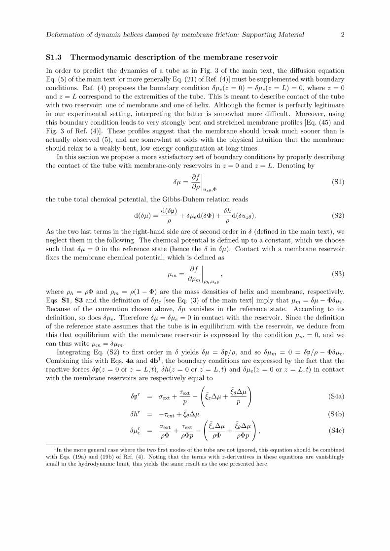
Deformation of dynamin helices damped by membrane friction: Supporting Material 2
S1.3 Thermodynamic description of the membrane reservoir
In order to predict the dynamics of a tube as in Fig. 3 of the main text, the diffusion equationEq. (5) of the main text [or more generally Eq. (21) of Ref. (4)] must be supplemented with boundaryconditions. Ref. (4) proposes the boundary condition δµe(z = 0) = δµe(z = L) = 0, where z = 0and z = L correspond to the extremities of the tube. This is meant to describe contact of the tubewith two reservoir: one of membrane and one of helix. Although the former is perfectly legitimatein our experimental setting, interpreting the latter is somewhat more difficult. Moreover, usingthis boundary condition leads to very strongly bent and stretched membrane profiles [Eq. (45) andFig. 3 of Ref. (4)]. These profiles suggest that the membrane should break much sooner than isactually observed (5), and are somewhat at odds with the physical intuition that the membraneshould relax to a weakly bent, low-energy configuration at long times.
In this section we propose a more satisfactory set of boundary conditions by properly describingthe contact of the tube with membrane-only reservoirs in z = 0 and z = L. Denoting by
δµ =∂f
∂ρ
∣∣∣∣uzθ,Φ
(S1)
the tube total chemical potential, the Gibbs-Duhem relation reads
d(δµ) =d(δp)
ρ+ δµed(δΦ) +
δh
ρd(δuzθ). (S2)
As the two last terms in the right-hand side are of second order in δ (defined in the main text), weneglect them in the following. The chemical potential is defined up to a constant, which we choosesuch that δµ = 0 in the reference state (hence the δ in δµ). Contact with a membrane reservoirfixes the membrane chemical potential, which is defined as
µm =∂f
∂ρm
∣∣∣∣ρh,uzθ
, (S3)
where ρh = ρΦ and ρm = ρ(1 − Φ) are the mass densities of helix and membrane, respectively.Eqs. S1, S3 and the definition of δµe [see Eq. (3) of the main text] imply that µm = δµ − Φδµe.Because of the convention chosen above, δµ vanishes in the reference state. According to itsdefinition, so does δµe. Therefore δµ = δµe = 0 in contact with the reservoir. Since the definitionof the reference state assumes that the tube is in equilibrium with the reservoir, we deduce fromthis that equilibrium with the membrane reservoir is expressed by the condition µm = 0, and wecan thus write µm = δµm.
Integrating Eq. (S2) to first order in δ yields δµ = δp/ρ, and so δµm = 0 = δp/ρ − Φδµe.Combining this with Eqs. 4a and 4b1, the boundary conditions are expressed by the fact that thereactive forces δp(z = 0 or z = L, t), δh(z = 0 or z = L, t) and δµe(z = 0 or z = L, t) in contactwith the membrane reservoirs are respectively equal to
δpr = σext +τext
p−(ξz∆µ+
ξθ∆µ
p
)(S4a)
δhr = −τext + ξθ∆µ (S4b)
δµre =σext
ρΦ+τext
ρΦp−(ξz∆µ
ρΦ+ξθ∆µ
ρΦp
), (S4c)
1In the more general case where the two first modes of the tube are not ignored, this equation should be combinedwith Eqs. (19a) and (19b) of Ref. (4). Noting that the terms with z-derivatives in these equations are vanishinglysmall in the hydrodynamic limit, this yields the same result as the one presented here.
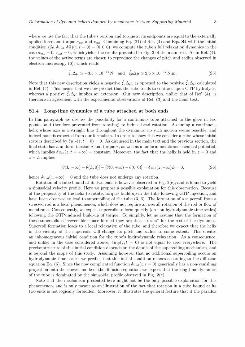
Deformation of dynamin helices damped by membrane friction: Supporting Material 3
where we use the fact that the tube’s tension and torque at its endpoints are equal to the externallyapplied force and torque σext and τext. Combining Eq. (21) of Ref. (4) and Eqs. S4 with the initialcondition (δρ, δuzθ, δΦ)(z, t = 0) = (0, 0, 0), we compute the tube’s full relaxation dynamics in thecase σext = 0, τext = 0, which yields the results presented in Fig. 3 of the main text. As in Ref. (4),the values of the active terms are chosen to reproduce the changes of pitch and radius observed inelectron microscopy (6), which reads
ξz∆µ ' −3.5× 10⁻¹¹ N and ξθ∆µ ' 2.6× 10⁻¹⁷ N.m. (S5)
Note that this new description yields a negative ξz∆µ, as opposed to the positive ξz∆µ calculatedin Ref. (4). This means that we now predict that the tube tends to contract upon GTP hydrolysis,whereas a positive ξz∆µ implies an extension. Our new description, unlike that of Ref. (4), istherefore in agreement with the experimental observations of Ref. (3) and the main text.
S1.4 Long-time dynamics of a tube attached at both ends
In this paragraph we discuss the possibility for a continuous tube attached to the glass in twopoints (and therefore prevented from rotating) to induce bead rotation. Assuming a continuoushelix whose axis is a straight line throughout the dynamics, no such motion seems possible, andindeed none is expected from our formalism. In order to show this we consider a tube whose initialstate is described by δuzθ(z, t = 0) = 0. As discussed in the main text and the previous section, thefinal state has a uniform tension σ and torque τ , as well as a uniform membrane chemical potential,which implies δuzθ(z, t = +∞) = constant. Moreover, the fact that the helix is held in z = 0 andz = L implies
[θ(L,+∞)− θ(L, 0)]− [θ(0,+∞)− θ(0, 0)] = δuzθ(z,+∞)L = 0, (S6)
hence δuzθ(z,+∞) = 0 and the tube does not undergo any rotation.Rotation of a tube bound at its two ends is however observed in Fig. 2(c), and is found to yield
a sinusoidal velocity profile. Here we propose a possible explanation for this observation. Becauseof the propensity of the helix to rotate, torques build up in the tube following GTP injection, andhave been observed to lead to supercoiling of the tube (3, 6). The formation of a supercoil from astressed rod is a local phenomenon, which does not require an overall rotation of the rod or flow ofmembrane. Consequently, we expect supercoils to form quickly (on non-hydrodynamic time scales)following the GTP-induced build-up of torque. To simplify, let us assume that the formation ofthese supercoils is irreversible—once formed they are thus “frozen” for the rest of the dynamics.Supercoil formation leads to a local relaxation of the tube, and therefore we expect that the helixin the vicinity of the supercoils will change its pitch and radius to some extent. This createsan inhomogeneous initial condition for the tube’s hydrodynamic relaxation. As a consequence,and unlike in the case considered above, δuzθ(z, t = 0) is not equal to zero everywhere. Theprecise structure of this initial condition depends on the details of the supercoiling mechanism, andis beyond the scope of this study. Assuming however that no additional supercoiling occurs onhydrodynamic time scales, we predict that this initial condition relaxes according to the diffusionequation Eq. (5). Since the now complicated function δuzθ(z, t = 0) generically has a non-vanishingprojection onto the slowest mode of the diffusion equation, we expect that the long-time dynamicsof the tube is dominated by the sinusoidal profile observed in Fig. 2(c).
Note that the mechanism presented here might not be the only possible explanation for thisphenomenon, and is only meant as an illustration of the fact that rotation in a tube bound at itstwo ends is not logically forbidden. Moreover, it illustrates the general feature that if the paradox

Deformation of dynamin helices damped by membrane friction: Supporting Material 4
proposed here is indeed resolved through local, microscopic relaxation processes, then the form oflong-time relaxation of the tube is not affected and we expect our hydrodynamic predictions tohold.
References
1. Dimova, R., B. Pouligny, and C. Dietrich, 2000. Pretransitional effects in dimyristoylphos-phatidylcholine vesicle membranes: optical dynamometry study. Biophys. J. 79:340–356.
2. Pucadyil, T. J., and S. L. Schmid, 2008. Real-time visualization of dynamin-catalyzed membranefission and vesicle release. Cell 135:1263–1275.
3. Roux, A., K. Uyhazi, A. Frost, and P. De Camilli, 2006. GTP-dependent twisting of dynaminimplicates constriction and tension in membrane fission. Nature (London) 441:528–531.
4. Lenz, M., J. Prost, and J.-F. Joanny, 2008. Mechanochemical action of the dynamin protein.Phys. Rev. E 78:011911.
5. Kozlov, M. M., 1999. Dynamin: Possible mechanism of “pinchase” action. Biophys. J. 77:604–616.
6. Danino, D., K.-H. Moon, and J. E. Hinshaw, 2004. Rapid constriction of lipid bilayers by themechanochemical enzyme dynamin. J. Struct. Biol. 147:259–267.
S2 Supporting movies—legends
S2.1 Supporting movie 1
Experimental movie corresponding to Fig. 1(b). See main text for legend.
S2.2 Supporting movie 2
Illustration of the dynamics presented in Fig. 3 of the main text. Only a few helical turns areshown, and in this small region the deformation looks spatially homogeneous—it however hasa more complicated spatial structure on larger length scales, as discussed in the main text andin Ref. (4). The movie displays the asymptotically exponential relaxation of the helix’s threehydrodynamic modes. The relaxation times involved in a real system are well separated and rangefrom hundreds of microseconds to seconds (see Fig. 3). Here these time scales are modified foreasier visualization. Each of the three modes therefore appears to have a relaxation time equalto 0.4 s. Note that the amplitude of the first mode is very small compared to the next two andmight therefore escape the reader’s attention on first viewing. Finally, the model used allows forboth bending and stretching of the membrane (4). Although its amplitude is small, the formerinduces some bulging of the membrane visible in this movie. The membrane is represented as asemi-transparent surface, and its transparency is proportional to its stretching ratio.
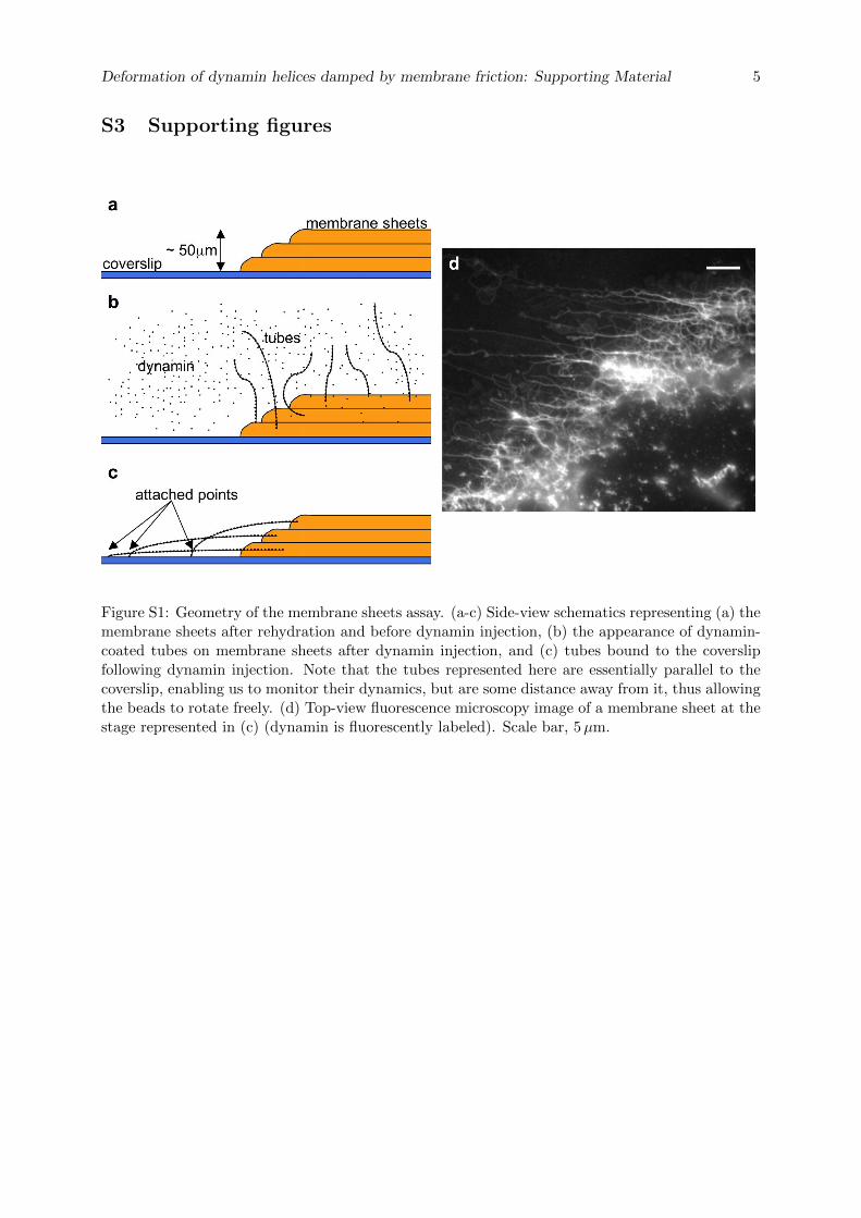
Deformation of dynamin helices damped by membrane friction: Supporting Material 5
S3 Supporting figures
Figure S1: Geometry of the membrane sheets assay. (a-c) Side-view schematics representing (a) themembrane sheets after rehydration and before dynamin injection, (b) the appearance of dynamin-coated tubes on membrane sheets after dynamin injection, and (c) tubes bound to the coverslipfollowing dynamin injection. Note that the tubes represented here are essentially parallel to thecoverslip, enabling us to monitor their dynamics, but are some distance away from it, thus allowingthe beads to rotate freely. (d) Top-view fluorescence microscopy image of a membrane sheet at thestage represented in (c) (dynamin is fluorescently labeled). Scale bar, 5µm.
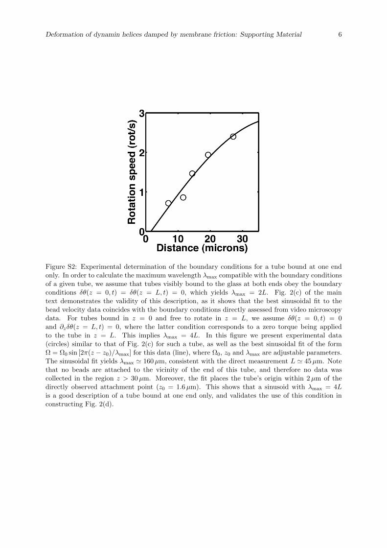
Deformation of dynamin helices damped by membrane friction: Supporting Material 6
Figure S2: Experimental determination of the boundary conditions for a tube bound at one endonly. In order to calculate the maximum wavelength λmax compatible with the boundary conditionsof a given tube, we assume that tubes visibly bound to the glass at both ends obey the boundaryconditions δθ(z = 0, t) = δθ(z = L, t) = 0, which yields λmax = 2L. Fig. 2(c) of the maintext demonstrates the validity of this description, as it shows that the best sinusoidal fit to thebead velocity data coincides with the boundary conditions directly assessed from video microscopydata. For tubes bound in z = 0 and free to rotate in z = L, we assume δθ(z = 0, t) = 0and ∂zδθ(z = L, t) = 0, where the latter condition corresponds to a zero torque being appliedto the tube in z = L. This implies λmax = 4L. In this figure we present experimental data(circles) similar to that of Fig. 2(c) for such a tube, as well as the best sinusoidal fit of the formΩ = Ω0 sin [2π(z − z0)/λmax] for this data (line), where Ω0, z0 and λmax are adjustable parameters.The sinusoidal fit yields λmax ' 160µm, consistent with the direct measurement L ' 45µm. Notethat no beads are attached to the vicinity of the end of this tube, and therefore no data wascollected in the region z > 30µm. Moreover, the fit places the tube’s origin within 2µm of thedirectly observed attachment point (z0 = 1.6µm). This shows that a sinusoid with λmax = 4Lis a good description of a tube bound at one end only, and validates the use of this condition inconstructing Fig. 2(d).
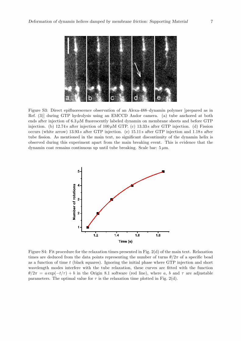
Deformation of dynamin helices damped by membrane friction: Supporting Material 7
Figure S3: Direct epifluorescence observation of an Alexa-488–dynamin polymer [prepared as inRef. (3)] during GTP hydrolysis using an EMCCD Andor camera. (a) tube anchored at bothends after injection of 6.3µM fluorescently labeled dynamin on membrane sheets and before GTPinjection. (b) 12.74 s after injection of 100µM GTP. (c) 13.33 s after GTP injection. (d) Fissionoccurs (white arrow) 13.93 s after GTP injection. (e) 15.11 s after GTP injection and 1.18 s aftertube fission. As mentioned in the main text, no significant discontinuity of the dynamin helix isobserved during this experiment apart from the main breaking event. This is evidence that thedynamin coat remains continuous up until tube breaking. Scale bar: 5µm.
Figure S4: Fit procedure for the relaxation times presented in Fig. 2(d) of the main text. Relaxationtimes are deduced from the data points representing the number of turns θ/2π of a specific beadas a function of time t (black squares). Ignoring the initial phase where GTP injection and shortwavelength modes interfere with the tube relaxation, these curves are fitted with the functionθ/2π = a exp(−t/τ) + b in the Origin 8.1 software (red line), where a, b and τ are adjustableparameters. The optimal value for τ is the relaxation time plotted in Fig. 2(d).
66 Dynamin Constriction Is Concerted And Damped by Membrane Friction
5.3 Summary of Article 1
The goal of this study is to quantify spatially and temporally Dynamin constriction to test atheoretical model predicting the diusing behaviour of long Dynamin-coated tubes upon GTPtreatment. We follow simultaneously several beads attached to a single Dynamin-coated tube.After injection of 100 µM GTP, the beads start rotating at the same time. The rotations ofeach bead are tracked as functions of time and of their position on the tube. Four observationsare made:
1. The total number of rotations measured at several positions z along a single tube is linearwith the position z on the tube (Fig.2.a). The strain is around 2rad .µm−1, in agreementwith previous structural data.
2. The rotation speed of a bead decays exponentially (Fig.2.b). The typical time of decayis 3.7 s.
3. The rotation speed prole along a tube is sinusoidal (Fig.2.c).
4. The decay time increases with the square root of the tube length (Fig.2.d). This rela-tionship yields a diusion coecient Dm = 2 102 µm2.s−1
These experimental quantications are then confronted to theory. The rst observation con-rms that Dynamin is a non polar polymer and shows that the helix remains continuous duringconstriction. The three other observations show that the propagation of constriction is diu-sive. These results validate the hydrodynamic model. This study demonstrates that Dynaminconformational change is highly concerted and that the relaxation of the helix constriction isdriven by the internal friction between Dynamin and membrane.
Confronting experiments and theory allows to make a full prediction of the dynamics of mem-brane deformations induced by Dynamin. Constriction occurs within 100 ms. However ssionhappens on the time scale of seconds. This means that Dynamin-mediated constriction is notenough to trigger ssion. Thus it would be interesting to study the kinetics of the ssionprocess.
Chapter 6
Fission is Regulated by Membrane
Shape
6.1 Introduction to Article 2
In chapter 6, I conclude that constriction is not enough to trigger ssion. So what mechanismcontrols ssion? To better understand ssion, it would be useful to follow the dynamics of thefull ssion process not only constriction. It was highlighted in chapter 4 that tension and rigiditycould play a crucial role in membrane ssion. So It would also be interesting to control theelastic parameters of membrane while monitoring ssion events. Thus the nanotube extrusiontechnique seems well adapted to study Dynamin polymerization and ssion.
6.2 Article 2: Membrane Shape at the Edge of the DynaminHelix Sets Location and Duration of Fission
Article submitted
Authors: Sandrine Morlot, Valentina Galli, Marius Klein, John Manzi, Frédéric Humbert, LuisDinis, Martin Lenz, Giovanni Cappello and Aurélien Roux.
Membrane shape at the edge of the Dynamin helix sets
location and duration of the fission reaction.
Sandrine MORLOT1,3, Valentina GALLI1, Marius KLEIN3, John MANZI3, Frédéric
HUMBERT1, Luìs DINIS4, Martin LENZ5, Giovanni CAPPELLO3, Aurélien ROUX1,2.
1Biochemistry Department, University of Geneva, CH-1211 Geneva, Switzerland.
2Swiss National Centre for Competence in Research Programme Chemical Biology, CH-1211 Geneva,
Switzerland.
3Institut Curie, Centre de Recherche; CNRS, UMR 168, Physico-Chimie Curie; Université Pierre et Marie Curie,
F-75248 Paris, France.
4Departamento de Fìsica Atòmica, Molecular y Nuclear, Facultad de Ciencas Fìsicas, Universidad
Complutense de Madrid, ES-28040, Madrid, Spain.
5James Franck Institute, University of Chicago, IL-60637 Chicago, U.S.A.
SUMMARY
The GTPase Dynamin polymerizes into a helical coat that constricts membrane
necks of Clathrin-coated pits to promote their fission. However minimal
requirements for fission are still debated as Dynamin constriction is necessary
but not sufficient for fission. Here we show that fission occurs at the interface
between the Dynamin coat and the uncoated membrane. At this location, the
considerable change in membrane curvature increases locally membrane elastic
energy, reducing the energy barrier for fission. Fission kinetics depends on
tension, bending rigidity and the Dynamin constriction torque. Indeed, we
experimentally find that the time it takes for fission depends on membrane
tension in vitro and during Clathrin-mediated endocytosis in vivo. By i) estimating
the energy barrier from the increased elastic energy at the edge of the Dynamin
coat, and ii) measuring the Dynamin torque, we show that the mechanical energy
spent in Dynamin constriction can reduce sufficiently the energy barrier for
fission to promote spontaneous fission.
INTRODUCTION
Membrane fission is an essential step in membrane traffic as it separates membrane
cargoes from donor compartments. It is the inverse reaction to fusion. In many of the
various fusion events in cells, a single type of machinery, the SNAREs, mediate the
collapse of membranes. The general principle of the SNAREs mechanism is that the
energy spent in the assembly of the SNARE complex overcomes the energy barrier to
fusion by generating a hemi-fusion intermediate, also called the “stalk intermediate”
(Kozlovsky and Kozlov, 2008b). The stalk intermediate is a structure where the cytosolic
leaflets of the two membrane compartments are fused into one, whereas the lumenal
leaflets are still separated. In the case of fission, different machineries mediate the
separation of two compartments depending on the cellular context: Dynamin during
endocytosis, Endosomal Sorting Complex in Retrograde Transport-III (ESCRT-III) in
multivesicular body biogenesis, cytokinesis and viral budding. Small GTPases (Sar1,
Arf1) involved in the initiation of the COat Proteins (COPs) dependent Golgi trafficking,
have also been recently implicated in the fission reaction of the COPs. However in all
these fission reactions, it is not known whether the different machineries mediate
fission on the basis on the same principle, mostly because physical understanding of
how fission is mediated is lacking. By analogy to fusion, it has been however suggested
that they operate through a similar stalk intermediate (Kozlovsky and Kozlov, 2008a).
Here, we focused on the physics of membrane fission taking the Dynamin system as a
model in which the biochemistry is arguably better characterized than in other systems.

Dynamin has been biochemically and genetically implicated in fission of endocytic
vesicles (Ferguson and De Camilli, 2012). It is a GTPase that polymerizes into helical
collars at the neck of Clathrin-coated pits (CCPs). The helical structure of Dynamin
immediately suggested that fission could be driven by a constriction of the helix.
When assembled in absence of GTP, the non-constricted Dynamin helix surrounds a
membrane tube with radius Ru = 10 nm (Chen et al., 2004; Danino et al., 2004). Upon
GTP hydrolysis, a conformational change of Dynamin at the dimer and the polymer
levels (Chappie et al., 2011; Faelber et al., 2011; Ford et al., 2011), constricts the
membrane (Danino et al., 2004; Sweitzer and Hinshaw, 1998). Constriction correlates
with a reduction of the helix radius, itself reflected by a reduction of the number of
dimers per helix turn from 14 to 13 (Chappie et al., 2011) and torsion. This torsion of
the entire helical polymer can be monitored by live imaging (Roux et al., 2006). Early
models (Hinshaw and Schmid, 1995; Takei et al., 1995) proposed that constriction was
sufficient to break the neck, as constriction would proceed until fission is fully
completed. More recent data has modified our understanding of the possible role of
constriction in Dynamin-mediated membrane fission: i)- Dynamin cryo-electron
microscopy images and 3D reconstruction showed that the polymer can constrict down
to a constriction radius Rc of 4-5nm (Danino et al., 2004), filled with a tubular membrane
(2nm thick) which surrounds a water lumen (2-3nm) (Chappie et al., 2011). These
structural data support the idea that Dynamin does not reach the hemi-fission state by
constriction. ii)-GTP-mediated constriction (Danino et al., 2004) and torsion (Roux et al.,
2006) do not lead to fission unless the tube is both attached to the substrate (Danino et
al., 2004) and subjected to longitudinal tension (Roux et al., 2006). These results showed
that membrane constriction is not sufficient for fission, and also suggested that
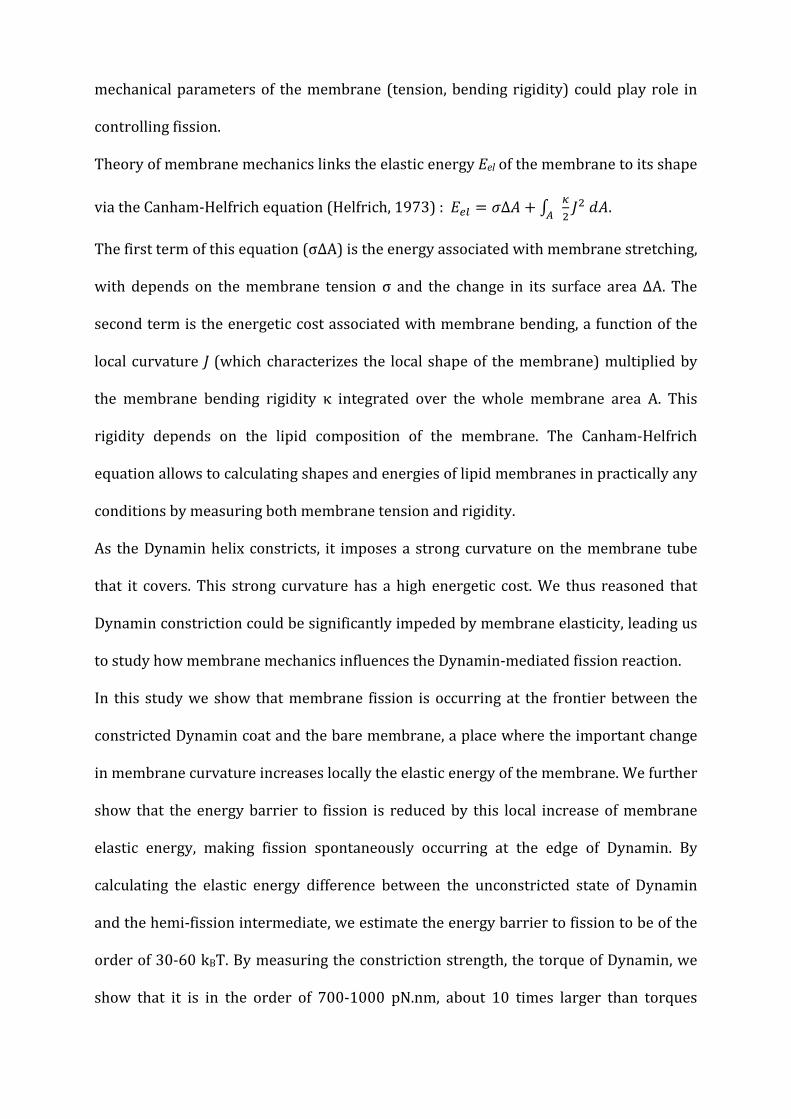
mechanical parameters of the membrane (tension, bending rigidity) could play role in
controlling fission.
Theory of membrane mechanics links the elastic energy Eel of the membrane to its shape
via the Canham-Helfrich equation (Helfrich, 1973) : 𝐸𝑒𝑙 = 𝜎Δ𝐴 + ∫ 𝜅2𝐽2 𝑑𝐴𝐴 .
The first term of this equation (σΔA) is the energy associated with membrane stretching,
with depends on the membrane tension σ and the change in its surface area ΔΑ. The
second term is the energetic cost associated with membrane bending, a function of the
local curvature J (which characterizes the local shape of the membrane) multiplied by
the membrane bending rigidity κ integrated over the whole membrane area A. This
rigidity depends on the lipid composition of the membrane. The Canham-Helfrich
equation allows to calculating shapes and energies of lipid membranes in practically any
conditions by measuring both membrane tension and rigidity.
As the Dynamin helix constricts, it imposes a strong curvature on the membrane tube
that it covers. This strong curvature has a high energetic cost. We thus reasoned that
Dynamin constriction could be significantly impeded by membrane elasticity, leading us
to study how membrane mechanics influences the Dynamin-mediated fission reaction.
In this study we show that membrane fission is occurring at the frontier between the
constricted Dynamin coat and the bare membrane, a place where the important change
in membrane curvature increases locally the elastic energy of the membrane. We further
show that the energy barrier to fission is reduced by this local increase of membrane
elastic energy, making fission spontaneously occurring at the edge of Dynamin. By
calculating the elastic energy difference between the unconstricted state of Dynamin
and the hemi-fission intermediate, we estimate the energy barrier to fission to be of the
order of 30-60 kBT. By measuring the constriction strength, the torque of Dynamin, we
show that it is in the order of 700-1000 pN.nm, about 10 times larger than torques
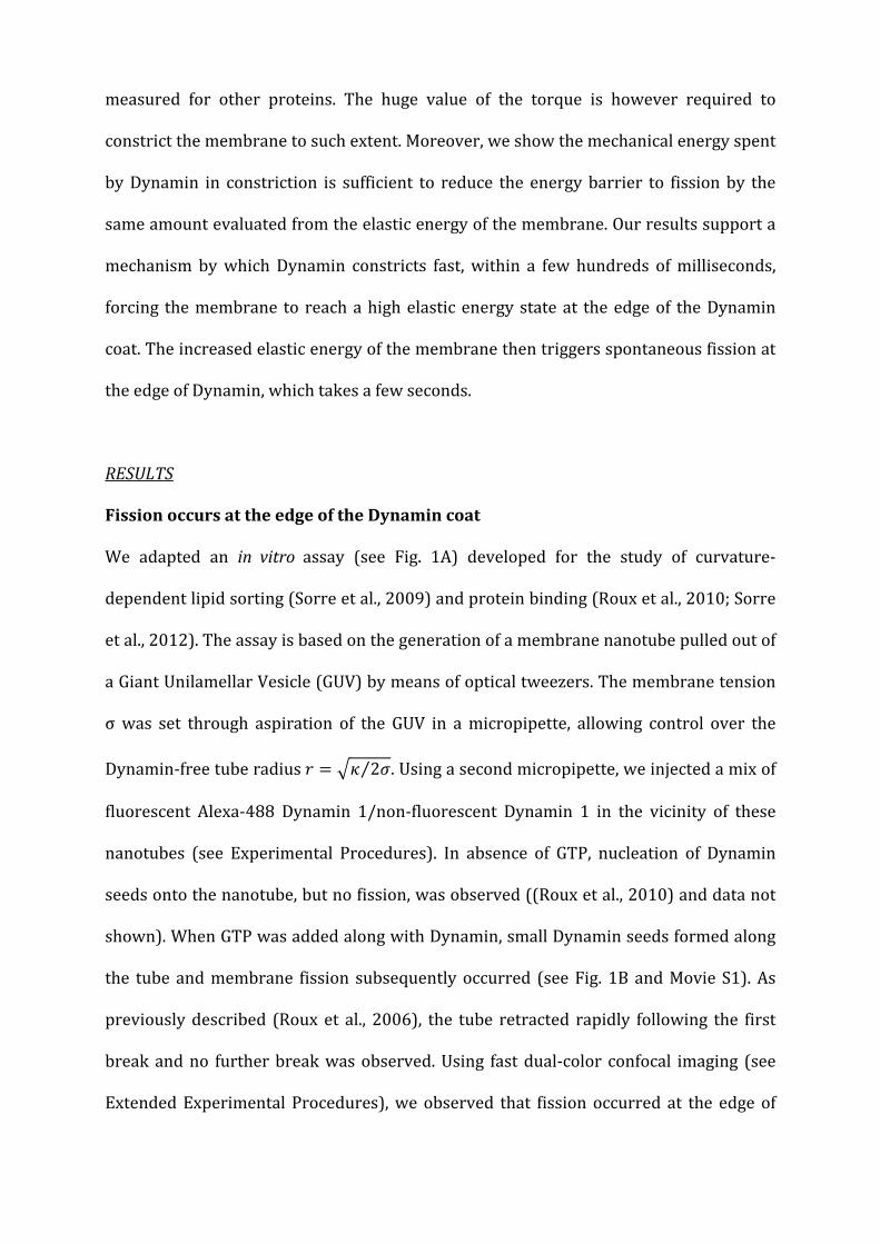
measured for other proteins. The huge value of the torque is however required to
constrict the membrane to such extent. Moreover, we show the mechanical energy spent
by Dynamin in constriction is sufficient to reduce the energy barrier to fission by the
same amount evaluated from the elastic energy of the membrane. Our results support a
mechanism by which Dynamin constricts fast, within a few hundreds of milliseconds,
forcing the membrane to reach a high elastic energy state at the edge of the Dynamin
coat. The increased elastic energy of the membrane then triggers spontaneous fission at
the edge of Dynamin, which takes a few seconds.
RESULTS
Fission occurs at the edge of the Dynamin coat
We adapted an in vitro assay (see Fig. 1A) developed for the study of curvature-
dependent lipid sorting (Sorre et al., 2009) and protein binding (Roux et al., 2010; Sorre
et al., 2012). The assay is based on the generation of a membrane nanotube pulled out of
a Giant Unilamellar Vesicle (GUV) by means of optical tweezers. The membrane tension
σ was set through aspiration of the GUV in a micropipette, allowing control over the
Dynamin-free tube radius 𝑟 = 𝜅 2𝜎⁄ . Using a second micropipette, we injected a mix of
fluorescent Alexa-488 Dynamin 1/non-fluorescent Dynamin 1 in the vicinity of these
nanotubes (see Experimental Procedures). In absence of GTP, nucleation of Dynamin
seeds onto the nanotube, but no fission, was observed ((Roux et al., 2010) and data not
shown). When GTP was added along with Dynamin, small Dynamin seeds formed along
the tube and membrane fission subsequently occurred (see Fig. 1B and Movie S1). As
previously described (Roux et al., 2006), the tube retracted rapidly following the first
break and no further break was observed. Using fast dual-color confocal imaging (see
Extended Experimental Procedures), we observed that fission occurred at the edge of

Dynamin domain in 90% (N=10) of the events (see Fig. 1C, Movie S2 and Fig. S1).
Indeed, after fission, one extremity of the broken tube was covered with Dynamin
whereas the other one was not (Figs. 1C and S1 and Movie S2). No fission was observed
in the uncoated regions of the tube.
We hypothesized that the considerable change of curvature from the highly constricted
Dynamin-coated part to the less curved bare tube could favor fission. We were thus
prompted to look at the efficiency of fission at the connection between the tube and the
GUV, where the change in curvature is even more dramatic. Indeed, most of the fission
events occurred at the boundary between the tube and the GUV (38%) or at the
boundary between the tube and the bead (36%) (N=44, Figs. 1D-E and Movie S3). It is
worth noting that shapes of the membrane at both connections are similar as the
membrane-bead adhesion patch is much larger (several hundreds of nm) than the size
of the tube in this assay (Koster et al., 2005). Dynamin nucleation was homogeneous
along the tube axis (Fig. 1D blue curve), indicating that this higher probability of fission
was not due to preferential nucleation of Dynamin at the bead, at the GUV or on the
parts of the nanotube adjacent to them, but consistent with an influence of the local
membrane shape (Fig. 1F).
The membrane shape at the Dynamin-membrane edge facilitates fission
We then calculated the shape of the membrane at the edge of the constricted Dynamin
tube (called “Dynamin-membrane edge” in the following). By setting the constriction
radius Rc, σ and κ (see Extended Experimental Procedures) and numerically minimizing
the elastic energy of the membrane, we can calculate the shape of the Dynamin-
membrane edge (Figs. 1F and 1G). The funnel shape of the Dynamin-membrane edge is
associated with a local increase in elastic energy that can be estimated numerically (Fig.
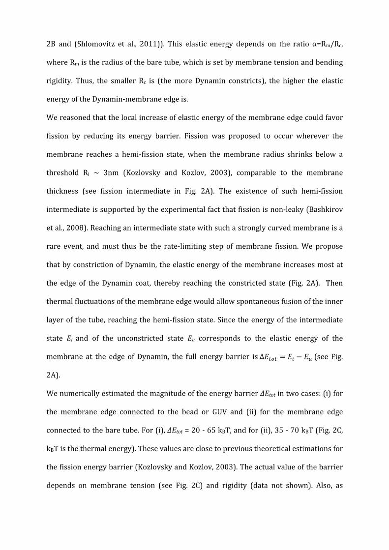
2B and (Shlomovitz et al., 2011)). This elastic energy depends on the ratio α=Rm/Rc,
where Rm is the radius of the bare tube, which is set by membrane tension and bending
rigidity. Thus, the smaller Rc is (the more Dynamin constricts), the higher the elastic
energy of the Dynamin-membrane edge is.
We reasoned that the local increase of elastic energy of the membrane edge could favor
fission by reducing its energy barrier. Fission was proposed to occur wherever the
membrane reaches a hemi-fission state, when the membrane radius shrinks below a
threshold Ri ~ 3nm (Kozlovsky and Kozlov, 2003), comparable to the membrane
thickness (see fission intermediate in Fig. 2A). The existence of such hemi-fission
intermediate is supported by the experimental fact that fission is non-leaky (Bashkirov
et al., 2008). Reaching an intermediate state with such a strongly curved membrane is a
rare event, and must thus be the rate-limiting step of membrane fission. We propose
that by constriction of Dynamin, the elastic energy of the membrane increases most at
the edge of the Dynamin coat, thereby reaching the constricted state (Fig. 2A). Then
thermal fluctuations of the membrane edge would allow spontaneous fusion of the inner
layer of the tube, reaching the hemi-fission state. Since the energy of the intermediate
state Ei and of the unconstricted state Eu corresponds to the elastic energy of the
membrane at the edge of Dynamin, the full energy barrier is ∆𝐸𝑡𝑜𝑡 = 𝐸𝑖 − 𝐸𝑢 (see Fig.
2A).
We numerically estimated the magnitude of the energy barrier ∆Etot in two cases: (i) for
the membrane edge connected to the bead or GUV and (ii) for the membrane edge
connected to the bare tube. For (i), ∆Etot = 20 - 65 kBT, and for (ii), 35 - 70 kBT (Fig. 2C,
kBT is the thermal energy). These values are close to previous theoretical estimations for
the fission energy barrier (Kozlovsky and Kozlov, 2003). The actual value of the barrier
depends on membrane tension (see Fig. 2C) and rigidity (data not shown). Also, as
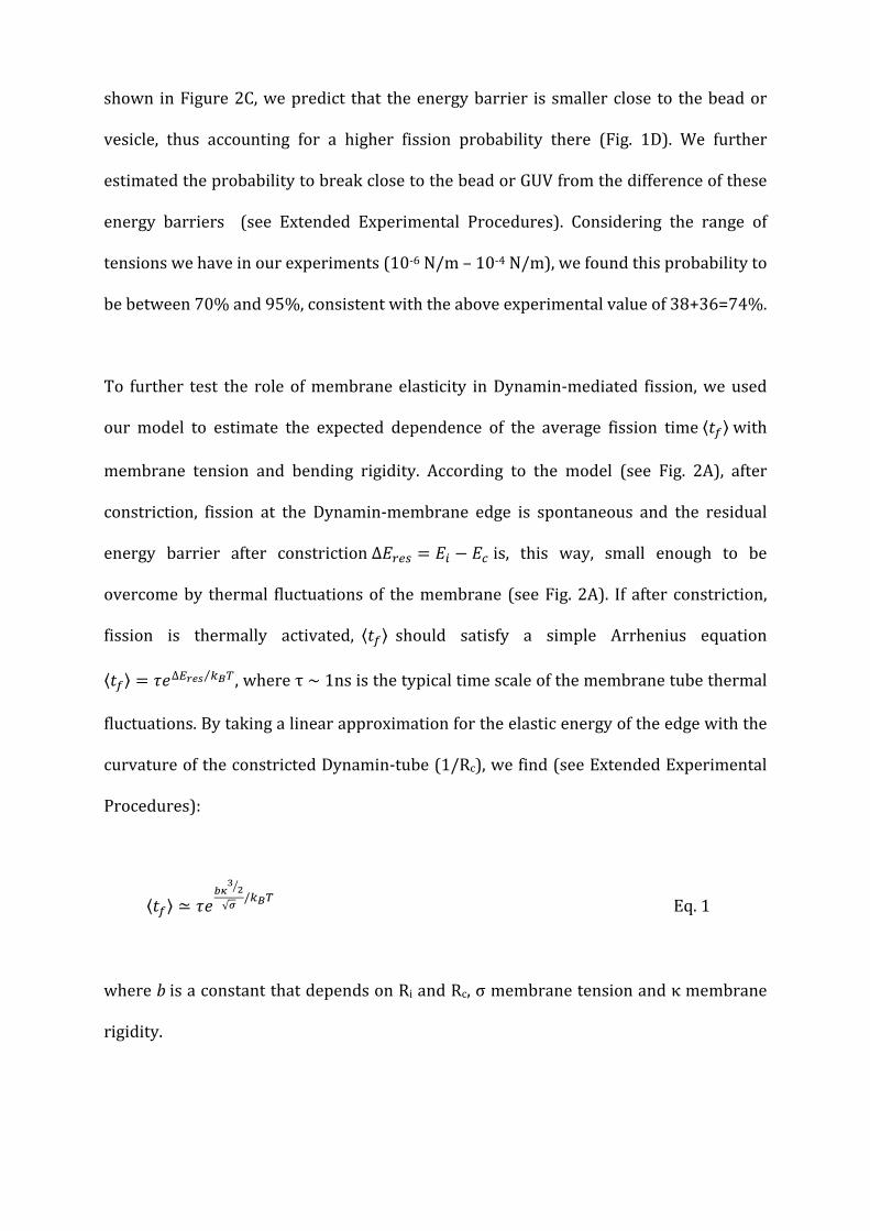
shown in Figure 2C, we predict that the energy barrier is smaller close to the bead or
vesicle, thus accounting for a higher fission probability there (Fig. 1D). We further
estimated the probability to break close to the bead or GUV from the difference of these
energy barriers (see Extended Experimental Procedures). Considering the range of
tensions we have in our experiments (10-6 N/m – 10-4 N/m), we found this probability to
be between 70% and 95%, consistent with the above experimental value of 38+36=74%.
To further test the role of membrane elasticity in Dynamin-mediated fission, we used
our model to estimate the expected dependence of the average fission time ⟨𝑡𝑓⟩ with
membrane tension and bending rigidity. According to the model (see Fig. 2A), after
constriction, fission at the Dynamin-membrane edge is spontaneous and the residual
energy barrier after constriction ∆𝐸𝑟𝑒𝑠 = 𝐸𝑖 − 𝐸𝑐 is, this way, small enough to be
overcome by thermal fluctuations of the membrane (see Fig. 2A). If after constriction,
fission is thermally activated, ⟨𝑡𝑓⟩ should satisfy a simple Arrhenius equation
⟨𝑡𝑓⟩ = 𝜏𝑒∆𝐸𝑟𝑒𝑠 𝑘𝐵𝑇⁄ , where τ ~ 1ns is the typical time scale of the membrane tube thermal
fluctuations. By taking a linear approximation for the elastic energy of the edge with the
curvature of the constricted Dynamin-tube (1/Rc), we find (see Extended Experimental
Procedures):
⟨𝑡𝑓⟩ ≃ 𝜏𝑒𝑏𝜅
32
√𝜎/𝑘𝐵𝑇 Eq. 1
where b is a constant that depends on Ri and Rc, σ membrane tension and κ membrane
rigidity.
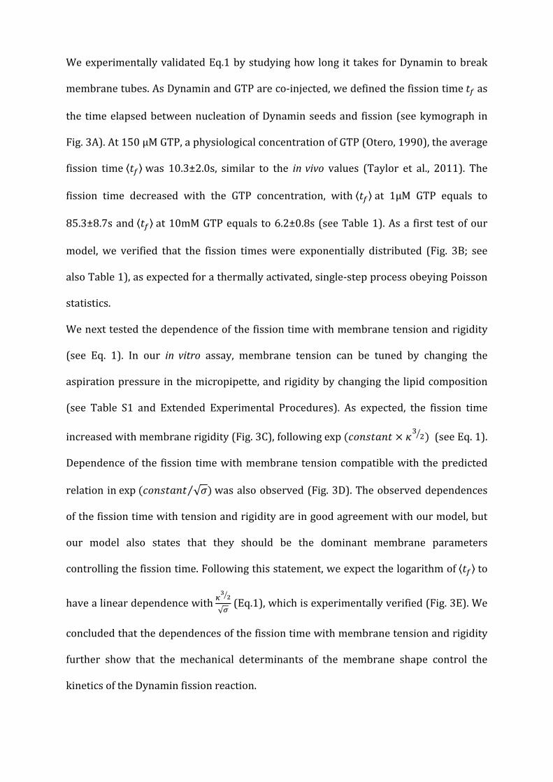
We experimentally validated Eq.1 by studying how long it takes for Dynamin to break
membrane tubes. As Dynamin and GTP are co-injected, we defined the fission time 𝑡𝑓 as
the time elapsed between nucleation of Dynamin seeds and fission (see kymograph in
Fig. 3A). At 150 μM GTP, a physiological concentration of GTP (Otero, 1990), the average
fission time ⟨𝑡𝑓⟩ was 10.3±2.0s, similar to the in vivo values (Taylor et al., 2011). The
fission time decreased with the GTP concentration, with ⟨𝑡𝑓⟩ at 1µM GTP equals to
85.3±8.7s and ⟨𝑡𝑓⟩ at 10mM GTP equals to 6.2±0.8s (see Table 1). As a first test of our
model, we verified that the fission times were exponentially distributed (Fig. 3B; see
also Table 1), as expected for a thermally activated, single-step process obeying Poisson
statistics.
We next tested the dependence of the fission time with membrane tension and rigidity
(see Eq. 1). In our in vitro assay, membrane tension can be tuned by changing the
aspiration pressure in the micropipette, and rigidity by changing the lipid composition
(see Table S1 and Extended Experimental Procedures). As expected, the fission time
increased with membrane rigidity (Fig. 3C), following exp (𝑐𝑜𝑛𝑠𝑡𝑎𝑛𝑡 × 𝜅3 2 ) (see Eq. 1).
Dependence of the fission time with membrane tension compatible with the predicted
relation in exp (𝑐𝑜𝑛𝑠𝑡𝑎𝑛𝑡 √𝜎⁄ ) was also observed (Fig. 3D). The observed dependences
of the fission time with tension and rigidity are in good agreement with our model, but
our model also states that they should be the dominant membrane parameters
controlling the fission time. Following this statement, we expect the logarithm of ⟨𝑡𝑓⟩ to
have a linear dependence with 𝜅32
√𝜎 (Eq.1), which is experimentally verified (Fig. 3E). We
concluded that the dependences of the fission time with membrane tension and rigidity
further show that the mechanical determinants of the membrane shape control the
kinetics of the Dynamin fission reaction.

The Dynamin torque is sufficient for constriction
The mechanism proposed above for Dynamin-mediated fission reaction is strongly
dependent on the ability of Dynamin to constrict. We thus wondered if the constriction
strength of Dynamin was sufficient to constrict such membrane necks. As Dynamin
undergoes torsion during constriction, it generates a torque (see Figs. S2C, 4A and Movie
S4). Thus, the constriction torque of Dynamin must be strong enough to counteract
membrane bending elasticity that widens the tube. In order to verify this, we measured
the torque Γ exerted by Dynamin during constriction by monitoring the position of
beads of radius r attached to the Dynamin coat. The beads rotated following GTP
addition, allowing us to track the torsion of the Dynamin coat (Morlot et al., 2010; Roux
et al., 2006). Because of this fast motion, the beads incurred a viscous drag, which
counteracted the torque generated by Dynamin, which limits the maximal angular
speed. The viscous drag acting on a bead of radius r spinning around a linear axis is:
Γ𝑣𝑖𝑠𝑐 = 14πη𝑟3ω, where ω is the angular velocity of the bead and η the viscosity of
water. We used beads of 675 nm radius, and measured an average angular speed
ω=15.8±5 rad/s at 2 mM GTP (Fig. 4B), corresponding to an average torque of 214±74
pN.nm. These beads are significantly slower than beads of 95-180nm radii used in
previous studies (approx. 55 rad/s, see (Morlot et al., 2010; Roux et al., 2006))
indicating that the viscous torque acting on the 675nm beads is of the same order of the
Dynamin torque. Because the beads are rotating, the torque of Dynamin is larger than
the measured viscous torque. The highest value of the viscous torque (730 pN.nm, see
Fig. 4C) obtained for the fastest bead is thus a closer underestimate of the Dynamin
torque. Γ =730 pN.nm is 20 times larger than the torque developed by proteins twisting

DNA (10-20 pN.nm such as the recombinase RecA (Lipfert et al., 2010)) or the rotational
motor F1 ATPase, which usually generate torques of 40 pN.nm (Yasuda et al., 1998).
We measured the maximum torque of Dynamin (stall torque Γs) by attaching magnetic
beads to Dynamin-coated tubules, and blocking their rotation with a magnetic field.
After calibration of the set-up (see Extended Experimental Procedures and Figs. S2A, B
and D), magnetic fields were translated into the magnetic torque experienced by the
bead in the magnetic field. We found that beads stopped to rotate when magnetic
torques exceeded 1300 pN.nm at 1mM GTP. Rotational movement started again upon
switching off the magnetic field (Fig. S2E and Movie S5), confirming that abrupt stop was
due to magnetic field. We observed that the angular velocity of the bead decreased
linearly with increasing intensities of the magnetic field (Figs. 4D and 4E). Linear fits
(Fig. 4E) gave an average value of the stall torque of Dynamin of 1100±340 pN.nm.
From the free energy of a Dynamin constricted tube (see Extended Experimental
Procedures), we calculated that Rc is related to the Dynamin torque by 𝑅𝑐 =
𝑅𝑢 1 + Γ𝑅𝑢2𝜋𝜅ℎ
, where h=13nm is the Dynamin pitch. According to this relation,
constriction from Ru=10nm to Rc=5nm radius would require a torque of approx. 500
pN.nm. We concluded that the large value of the Dynamin torque measured above was
necessary and sufficient for constriction of membrane necks.
Dynamin mechanical work reduces the energy barrier to fission
The mechanical work of Dynamin is partially spent in reducing the energy barrier to
fission. If our model is valid, this fraction of the mechanical work is still required to
reduce significantly the energy barrier. The residual barrier ΔEres should be in the range
of a few kBT. Thus we expect the Dynamin work to be of the same order of the full
barrier ΔEtot estimated from the elastic energy of the membrane (see above).

Theoretically, the fraction of the Dynamin work can be subtracted from the energy
barrier (see Extended Experimental Procedures), with ∆𝐸𝑟𝑒𝑠 = ∆𝐸𝑡𝑜𝑡 − 𝑐Γ𝜃, where Γθ is
the Dynamin work (Fig. S2C, and below). The fission time expression is then:
⟨𝑡𝑓⟩ ≃ 𝜏𝑒(𝛥𝐸𝑡𝑜𝑡−𝑐Γθ)/𝑘𝐵𝑇 Eq.2
where c is a constant and θ is the angle by which the helix rotates for each GTP it
hydrolyses (Fig. S2C). According to this definition, we can identify Γθ as the work
performed by the helix per hydrolysed GTP. According to Eq. 2, for each amount Γθ of
mechanical work performed per GTP, ΔEtot is lowered by an amount cΓθ. Thus c
characterizes the efficiency with which mechanical work is used to lower the fission
barrier. The work performed by Dynamin upon the hydrolysis of one GTP is
proportional to the difference in chemical potential between GTP and its hydrolysis
products. Thus for experimental concentrations of GTP, we expect:
Γθ = ξ𝑘𝐵𝑇𝑙𝑛([𝐺𝑇𝑃]) + 𝑐𝑜𝑛𝑠𝑡𝑎𝑛𝑡 Eq. 3
where the dimensionless number ξ is the yield of the conversion of chemical energy into
work. As a consequence, the product cξ characterizes the efficiency with which Dynamin
uses chemical energy to lower the barrier to fission. Inserting Eq. 3 into Eq. 2, we finally
find:
𝑙𝑛(⟨tf⟩) = cξ𝑙𝑛([𝐺𝑇𝑃]) + 𝑐𝑜𝑛𝑠𝑡𝑎𝑛𝑡 Eq. 4
To validate this extended mechano-chemical framework experimentally, we sought to
verify the predicted GTP-dependences and to characterize the efficiency cξ. We first
showed (Fig. 4B) that the torque Γ depended linearly on 𝑙𝑛([𝐺𝑇𝑃]), as expected from Eq.
3. The slope allows us to estimate ξ/θ=18.5. Knowing the full constriction angle 𝜃𝑓𝑢𝑙𝑙
from structural data ((Mears et al., 2007), 1/14 of a turn leads to 𝜃𝑓𝑢𝑙𝑙 = 2𝜋/14 ≈ 0.45
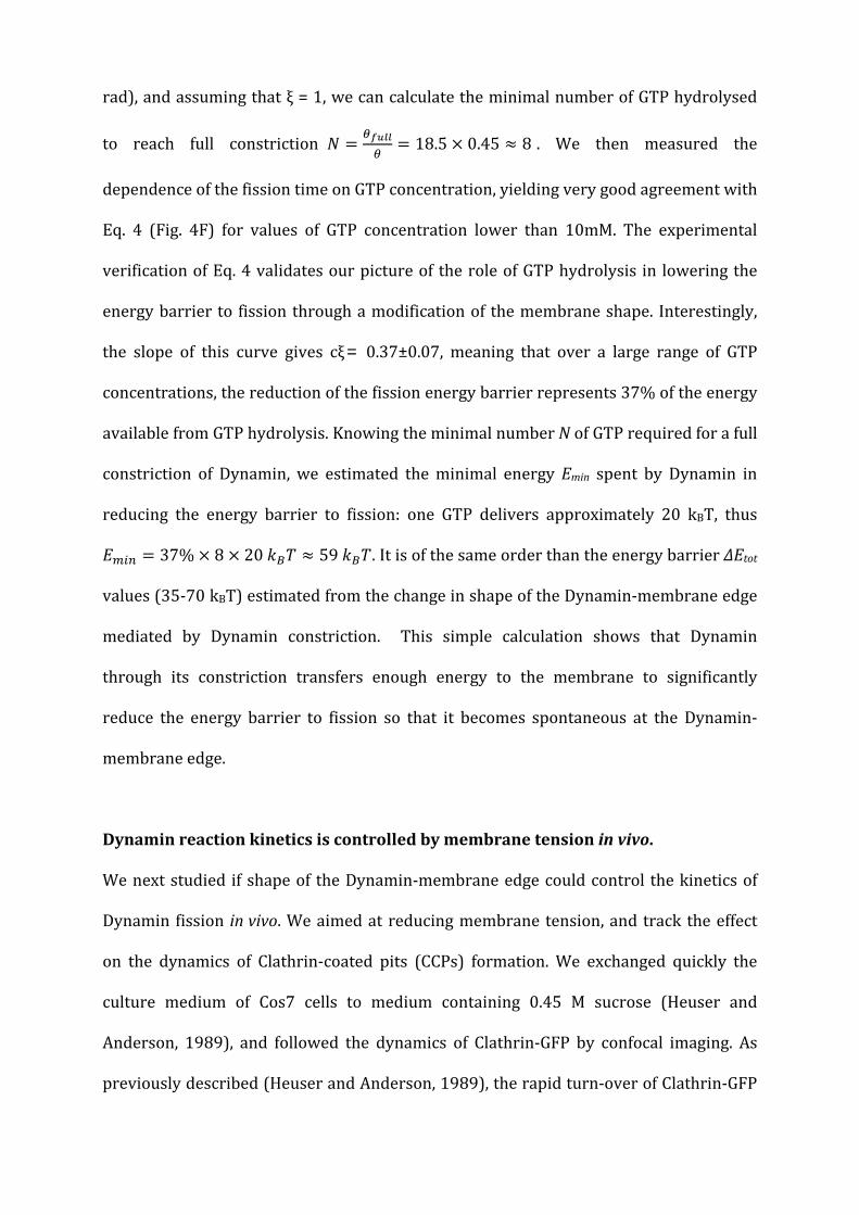
rad), and assuming that ξ = 1, we can calculate the minimal number of GTP hydrolysed
to reach full constriction 𝑁 = 𝜃𝑓𝑢𝑙𝑙𝜃
= 18.5 × 0.45 ≈ 8 . We then measured the
dependence of the fission time on GTP concentration, yielding very good agreement with
Eq. 4 (Fig. 4F) for values of GTP concentration lower than 10mM. The experimental
verification of Eq. 4 validates our picture of the role of GTP hydrolysis in lowering the
energy barrier to fission through a modification of the membrane shape. Interestingly,
the slope of this curve gives cξ = 0.37±0.07, meaning that over a large range of GTP
concentrations, the reduction of the fission energy barrier represents 37% of the energy
available from GTP hydrolysis. Knowing the minimal number N of GTP required for a full
constriction of Dynamin, we estimated the minimal energy Emin spent by Dynamin in
reducing the energy barrier to fission: one GTP delivers approximately 20 kBT, thus
𝐸𝑚𝑖𝑛 = 37% × 8 × 20 𝑘𝐵𝑇 ≈ 59 𝑘𝐵𝑇. It is of the same order than the energy barrier ΔEtot
values (35-70 kBT) estimated from the change in shape of the Dynamin-membrane edge
mediated by Dynamin constriction. This simple calculation shows that Dynamin
through its constriction transfers enough energy to the membrane to significantly
reduce the energy barrier to fission so that it becomes spontaneous at the Dynamin-
membrane edge.
Dynamin reaction kinetics is controlled by membrane tension in vivo.
We next studied if shape of the Dynamin-membrane edge could control the kinetics of
Dynamin fission in vivo. We aimed at reducing membrane tension, and track the effect
on the dynamics of Clathrin-coated pits (CCPs) formation. We exchanged quickly the
culture medium of Cos7 cells to medium containing 0.45 M sucrose (Heuser and
Anderson, 1989), and followed the dynamics of Clathrin-GFP by confocal imaging. As
previously described (Heuser and Anderson, 1989), the rapid turn-over of Clathrin-GFP

dots at the plasma membrane in Cos7 cells stopped within seconds after the shock (Fig.
5A and Movie S6). The number of Clathrin-GFP dots increased after the shock. These
Clathrin-GFP structures seemed to stay attached to the plasma membrane, suggesting a
block of the Clathrin-coated pits at the fission level. Consistently, Dynamin-GFP followed
the same behavior: more dots were seen after the shock (Fig. 5B and Movie S6), without
turnover (see kymograph). Moreover, the Clathrin-RFP structures perfectly colocalized
with Dynamin-GFP dots after the shock (approx. 85%, see Fig. 5C), showing that Clathrin
structures were blocked at the stage of Dynamin ring formation. As the dynamics of
Clathrin bud are altered by overexpression of endocytic proteins, we tested the effect of
hypertonic shock on genome-edited SKML-2 cells, where Clathrin-RFP and Dynamin-
GFP are expressed at the same level than endogenous proteins (Doyon et al., 2011).
When hypertonic medium was applied to these cells, the number of Clathrin/Dynamin
dots increased and their dynamic exchange was blocked (data not shown). As in Cos7
cells, clathrin-RFP dots colocalized with Dynamin-GFP dots (see Fig. S3).
We next verified that the Clathrin dots blocked at the fission step were fully assembled
CCPs. They indeed partially colocalized with transferrin, showing that cargo were
present in these structures (see Fig 5D). As well, the plasma membrane lipophilic dye
MASK (Invitrogen Inc.) showed a slightly increased signal in Clathrin structures,
reflecting the curved membrane of the bud (see Fig 5E). Taken together, these results
strongly support the idea that many of the Clathrin coated dots frozen at the plasma
membrane are fully assembled CCPs, blocked at the assembled Dynamin stage, unable to
break the membrane. These in vivo results are consistent with our in vitro results: they
show that a membrane tension decrease blocks Dynamin-dependent endocytosis at the
fission step, in a similar way than reduced membrane tension strongly delayed fission in
vitro. Moreover, as previously reported (Boulant et al., 2011), we find that hypo-osmotic

shock delays CCPs formation, but does not alter Dynamin dynamics in the first few
minutes after the shock (data not shown).
DISCUSSION
In this study, we first showed that Dynamin-mediated fission occurs at the edge of the
Dynamin coat. Consistently, in mitochondrial fission, breakage was often observed at the
boundary between the DNM1 ring and the rest of the mitochondria (Bleazard et al.,
1999). We then showed that fission was facilitated at the Dynamin-membrane edge
because of the local membrane elastic energy increase due to considerable change in
curvature. We next showed that not only the location, but also the kinetics of the
reaction is set by the shape of the membrane connecting the constricted tube to the bare
part of the membrane. The constriction torque of Dynamin and membrane elasticity
parameters such as tension and bending rigidity that control the membrane edge shape
thus act directly on the kinetics of Dynamin-mediated membrane fission. Moreover, we
showed in this study that the calculation of the energy barrier estimated either from the
shape of the membrane (from which we can estimate the elastic energy of the
membrane) or from the mechanical work generated by Dynamin during constriction
gave similar values (in the range of 50-70 kBT). Importantly, the contributions of the
Dynamin work, tension and rigidity to the kinetics of the fission reaction are different: -
measured GTPase rate of Dynamin in the assembled form (Praefcke and Mcmahon,
2004)) suggests that the minimal amount of GTP required for full constriction is
hydrolysed within hundreds of milliseconds. Our previous study of the dynamics of
Dynamin constriction (Morlot et al., 2010) consistently showed that constriction should
also happen within a few hundreds of milliseconds. As for non-limiting GTP
concentrations, fission takes a few seconds at least, our results are compatible with i)

first, a fast constriction of Dynamin, and ii) then, a long delay to spontaneous fission of
the constricted neck. Thus, at non-limiting GTP concentrations (closer to in vivo
situation), the kinetics of Dynamin-membrane fission are expected to be primarily
regulated by the elasticity of the membrane. Indeed, we showed that, in vivo, Clathrin-
mediated endocytosis is blocked by reducing membrane tension, consistently with our
in vitro results. Also, in vivo and in vitro typical fission times (a few seconds) are similar.
These observations strengthen the idea that fission kinetics is controlled by elasticity of
the membrane in vivo.
Recent studies (Bashkirov et al., 2008; Pucadyil and Schmid, 2008) have been taken to
suggest that Dynamin-mediated fission could be triggered by GTP-induced
depolymerization instead of constriction. Our result showing that fission occurs at the
edge of the Dynamin coat indicate that it requires partial coating of the membrane,
which can be achieved either by partial polymerization of a bare membrane, or partial
depolymerization of a fully coated membrane. However, in our experiments, we never
observed depolymerization of the Dynamin coat prior (see Fig. 3A) or after (see Fig. 1C,
t=2.5s) fission. As in our experiments the optical resolution limit is above the size of a
Dynamin turn, we cannot exclude depolymerization restricted to a few turns. In the
hypothesis that fission is mediated through depolymerization, it was predicted that long
coats would have a reduced fission efficiency (Pucadyil and Schmid, 2008), as they
would require more time to be fully depolymerized. In our experiments, we saw no
dependence of the fission time with length of single Dynamin seeds, from 150 nm to 10
microns (see Fig. S1B). Also, GTP energy was proposed to be spent in depolymerization
rather than constriction (Bashkirov et al., 2008). The good agreement between
energetics of membrane constriction and Dynamin torque work favors the hypothesis
that GTP energy is primarily spent in constriction, rather than in depolymerization.

In a broader perspective, the model presented here to explain the mechanism by which
Dynamin performs fission may be valid for all fission reactions mediated by the
constriction of a narrow membrane neck, as it is proposed for ESCRT-III mediated
fission (Fabrikant et al., 2009), and as it is the case in lipid phase separation (Roux et al.,
2005).
EXPERIMENTAL PROCEDURES
A full description of the methods is in the Extended Experimental Procedures.
Nanotube Pulling From GUV
Giant Unilamellar Vesicles (GUVs) were made by a modified protocol of the
electroformation technique (Angelova et al., 1992; Roux et al., 2010). The aspiration of a
GUV of radius RGUV within a micropipette of radius Rpipette allowed to set membrane
tension: 𝜎 = 12𝑅𝑝𝑖𝑝𝑒𝑡𝑡𝑒𝛥𝑃
1−𝑅𝑝𝑖𝑝𝑒𝑡𝑡𝑒𝑅𝐺𝑈𝑉
(Evans and Rawicz, 1990). A lipid nanotube was extruded from a
micropipette-aspirated GUV containing 0.03% mol/mol of a biotinylated lipid (DSPE-
PEG2000-Biotin, Avanti Polar Lipids, Alabaster, Alabama, USA) by moving away the
pipette from an optically trapped, 3 microns diameter Streptavidin-coated bead
(Spherotec, Lake Forest, Illinois, USA) attached to the GUV prior to pulling. The fixed
optical trap was custom-made and calibrated (see extended experimental procedures,
stiffness k=360pN.μm-1.W-1). A mix of baculovirus purified human Dynamin 1 (see
extended experimental procedures for purification details) and Guanosine Tri-
Phosphate (GTP, Roche Applied Science, Indianapolis, IN, USA) was injected in the
vicinity of the lipid tube via a second micropipette. 2 color time-lapse acquisitions were

performed with either a confocal microscopy (Eclipse C1 Nikon, Tokyo, Japan) or a
spinning disk confocal (Intelligent Imaging Innovations, Denver, Colorado, USA).
Torque Measurement by Viscous Drag and Magnetic Field
Streptavidin beads (1.35 μm diameter Streptavidin-coated, polystyrene beads,
Spherotec, Lake Forest, Illinois, USA) are grafted onto biotinylated Dynamin tubules
formed from membrane sheets (see extended experimental procedures and (Morlot et
al., 2010; Roux et al., 2006)). The beads rotate following GTP addition and resulting
constriction of the Dynamin coat (Morlot et al., 2010; Roux et al., 2006), experiencing a
viscous torque Γ𝑣 = 14πη(R + r)3 ω = ξω (Happel J. and Brenner H. 1983), where η is
the viscosity of the surrounding fluid, R the radius of the bead, r the radius of the tubule
and 𝜔 is the angular spinning velocity. Differential Interference Contrast (DIC) and
computer-based live recording of the rotating beads with a GUPPY camera (Allied Vision
Technologies, Stadtroda, Germany) allowed direct measure of the angular spinning
velocity and estimation the viscous torque from the formula above.
The stall torque ΓS was measured by using magnetic beads (1.31 μm diameter
Streptavidin-coated, paramagnetic beads, Spherotec, Lake Forest, Illinois, USA), to which
is applied an external torque via a variable electro-magnetic field. This magnetic field
was calibrated by two independent methods detailed in the extended experimental
procedures.
Cell transfections, plasma membrane staining, Transferrin uptake and hypertonic
shock

COS-7 cells were transfected using FuGENE-6 (Roche Applied Science, Indianapolis,
Indiana, USA) with Dynamin 2 fused to Green Fluorescent Protein (GFP) (kindly
provided by P. De Camilli; HHMI, Yale University) or mouse Clathrin-Light-Chain fused
to mCherry or GFP (kindly provided by C. Merrifield, Cambridge and by P. De Camilli,
HHMI, Yale University). Cells were imaged 18 to 24 hours post transfection in Leibovitz
medium (Gibco, Life Technologies Ltd, Paisley, UK). While imaging, the medium was
changed with a hypertonic solution of 0.25M sucrose in Leibovitz medium. Cell
membrane staining was achieved by incubating cells for 5’ at 37°C with deep red Cell
Mask (Molecular Probes, Life Technologies Ltd, Paisley, UK) before imaging. For
Transferrin uptake assays, cells were starved in serum deprived DMEM-F12 medium for
30’ on ice, then incubated with 5 µg/ml Alexa-fluor 594 Transferrin (Invitrogen, Grand
Island, NY, USA) in hypertonic medium (0.25M sucrose Leibovitz medium) for 3’ at RT.
Cells were washed with hypertonic buffer before imaging.
SUPPLEMENTAL INFORMATION
Supplemental Information includes Extended Experimental Procedures, three figures
and six movies.
ACKNOWLEDGMENTS
We thank Marcos Gonzalez-Gaitàn, for inspiring discussions and critical reading of this
manuscript. We thank Pietro De Camilli, Jacques Prost and Jean-François Joanny for
thoughtful comments on this study.
This work was supported by the Agence Nationale de la Recherche (France, Young
Investigator Program, No JC08_317536 to A.R. and G.C.), the Human Frontier Science

Program Career Development Award (No 0061/2008 to A.R.), and Young Investigator
Research Grant (N° RGY0076/2009-C to A.R.), the Swiss National Fund for Research
grant (N° 31003A_130520/1 to A.R.), the Société Académique de Genève, and the Swiss
National Centre for Competence in Research Programme Chemical Biology.

REFERENCES:
Angelova, M.I., Soléau, S., Méléard, P., Faucon, J.F., and Bothorel, P. (1992). Preparation of giant vesicles by external AC electric fields. Kinetics and applications. Prog Colloid Polym Sci 89, 127-131. Bashkirov, P.V., Akimov, S.A., Evseev, A.I., Schmid, S.L., Zimmerberg, J., and Frolov, V.A. (2008). GTPase Cycle of Dynamin Is Coupled to Membrane Squeeze and Release, Leading to Spontaneous Fission. Cell 135, 1276-1286. Bleazard, W., McCaffery, J.M., King, E.J., Bale, S., Mozdy, A., Tieu, Q., Nunnari, J., and Shaw, J.M. (1999). The dynamin-related GTPase Dnm1 regulates mitochondrial fission in yeast. Nat Cell Biol 1, 298-304. Boulant, S., Kural, C., Zeeh, J.-C., Ubelmann, F., and Kirchhausen, T. (2011). Actin dynamics counteract membrane tension during clathrin-mediated endocytosis. Nature cell biology 13, 1-10. Chappie, J.S., Mears, J.A., Fang, S., Leonard, M., Schmid, S.L., Milligan, R.A., Hinshaw, J.E., and Dyda, F. (2011). A pseudoatomic model of the dynamin polymer identifies a hydrolysis-dependent powerstroke. Cell 147, 209-222. Chen, Y., Zhang, P., Egelman, E., and Hinshaw, J.E. (2004). The stalk region of dynamin drives the constriction of dynamin tubes. Nat Struct Mol Biol v11, 574-575. Danino, D., Moon, K.H., and Hinshaw, J.E. (2004). Rapid constriction of lipid bilayers by the mechanochemical enzyme dynamin. J Struct Biol 147, 259-267. Doyon, J.B., Zeitler, B., Cheng, J., Cheng, A.T., Cherone, J.M., Santiago, Y., Lee, A.H., Vo, T.D., Doyon, Y., Miller, J.C., et al. (2011). Rapid and efficient clathrin-mediated endocytosis revealed in genome-edited mammalian cells. Nature cell biology 13, 331-337. Evans, E., and Rawicz, W. (1990). Entropy-driven tension and bending elasticity in condensed-fluid membranes. Phys Rev Lett 64, 2094. Fabrikant, G., Lata, S., Riches, J., Briggs, J., Weissenhorn, W., and Kozlov, M. (2009). Computational model of membrane fission catalyzed by ESCRT-III. PLoS Comput Biol 5. Faelber, K., Posor, Y., Gao, S., Held, M., Roske, Y., Schulze, D., Haucke, V., Noe, F., and Daumke, O. (2011). Crystal structure of nucleotide-free dynamin. Nature 477, 556-560. Ferguson, S.M., and De Camilli, P. (2012). Dynamin, a membrane-remodelling GTPase. Nature reviews Molecular cell biology. Ford, M.G., Jenni, S., and Nunnari, J. (2011). The crystal structure of dynamin. Nature 477, 561-566. Helfrich, W. (1973). Elastic properties of lipid bilayers : theory and possible experiments. Zur Naturforschung 28c, 693-703. Heuser, J.E., and Anderson, R.G. (1989). Hypertonic media inhibit receptor-mediated endocytosis by blocking clathrin-coated pit formation. The Journal of cell biology 108, 389-400. Hinshaw, J.E., and Schmid, S.L. (1995). Dynamin self-assembles into rings suggesting a mechanism for coated vesicle budding. Nature 374, 190-192. Koster, G., Cacciuto, A., Derenyi, I., Frenkel, D., and Dogterom, M. (2005). Force barriers for membrane tube formation. Phys Rev Lett 94, 068101. Kozlovsky, Y., and Kozlov, M.M. (2003). Membrane fission: model for intermediate structures. Biophys J 85, 85-96. Kozlovsky, Y., and Kozlov, M.M. (2008a). Membrane Fission: Model for Intermediate Structures. Biophysical Journal 85, 85-96. Kozlovsky, Y., and Kozlov, M.M. (2008b). Stalk Model of Membrane Fusion: Solution of Energy Crisis. Biophysical Journal 82, 882-895.

Lipfert, J., Kerssemakers, J.W., Jager, T., and Dekker, N.H. (2010). Magnetic torque tweezers: measuring torsional stiffness in DNA and RecA-DNA filaments. Nat Methods 7, 977-980. Mears, J.A., Ray, P., and Hinshaw, J.E. (2007). A corkscrew model for dynamin constriction. Structure 15, 1190-1202. Morlot, S., Lenz, M., Prost, J., Joanny, J.F., and Roux, A. (2010). Deformation of dynamin helices damped by membrane friction. Biophys J 99, 3580-3588. Otero, A.D. (1990). Transphosphorylation and G protein activation. Biochem Pharmacol 39, 1399-1404. Praefcke, G., and Mcmahon, H. (2004). The dynamin superfamily: universal membrane tubulation and fission molecules? Nat Rev Mol Cell Biol 5, 133-147. Pucadyil, T.J., and Schmid, S.L. (2008). Real-time visualization of dynamin-catalyzed membrane fission and vesicle release. Cell 135, 1263-1275. Roux, A., Cuvelier, D., Nassoy, P., Prost, J., Bassereau, P., and Goud, B. (2005). Role of curvature and phase transition in lipid sorting and fission of membrane tubules. EMBO J 24, 1537-1545. Roux, A., Koster, G., Lenz, M., Sorre, B., Manneville, J.-B., Nassoy, P., and Bassereau, P. (2010). Membrane curvature controls dynamin polymerization. Proc Natl Acad Sci USA 107, 4141-4146. Roux, A., Uyhazi, K., Frost, A., and De Camilli, P. (2006). GTP-dependent twisting of dynamin implicates constriction and tension in membrane fission. Nature 441, 528-531. Shlomovitz, R., Gov, N., and Roux, A. (2011). membrane-mediated interactions and the dynamics of dynamin oligomers on membrane tubes. New Journal of Physics 13, 065008. Sorre, B., Callan-Jones, A., Manneville, J.B., Nassoy, P., Joanny, J.F., Prost, J., Goud, B., and Bassereau, P. (2009). Curvature-driven lipid sorting needs proximity to a demixing point and is aided by proteins. Proc Natl Acad Sci U S A 106, 5622-5626. Sorre, B., Callan-Jones, A., Manzi, J., Goud, B., Prost, J., Bassereau, P., and Roux, A. (2012). Nature of curvature coupling of amphiphysin with membranes depends on its bound density. Proceedings of the National Academy of Sciences of the United States of America 109, 173-178. Sweitzer, S.M., and Hinshaw, J.E. (1998). Dynamin undergoes a GTP-dependent conformational change causing vesiculation. Cell 93, 1021-1029. Takei, K., McPherson, P.S., Schmid, S.L., and De Camilli, P. (1995). Tubular membrane invaginations coated by dynamin rings are induced by GTP-gamma S in nerve terminals. Nature 374, 186-190. Taylor, M.J., Perrais, D., and Merrifield, C.J. (2011). A high precision survey of the molecular dynamics of Mammalian clathrin-mediated endocytosis. PLoS biology 9, e1000604. Yasuda, R., Noji, H., Kinosita, K., and Yoshida, M. (1998). F1-ATPase is a highly efficient molecular motor that rotates with discrete 120 degree steps. Cell 93, 1117-1124.

FIGURES:
Fig. 1. Localisation of fission events at Dynamin-membrane edges. A- Schematic drawing of the experimental setup. A micropipette (right) set the GUV’s tension. A membrane nanotube is extracted from the GUV via a microbead trapped in optical tweezers (red cones). A second micropipette (left) injects locally Dynamin and GTP. B- Confocal pictures of a GUV labeled with BodipyTMR-PI(4,5)P2 (red channel) and Dynamin labeled with Alexa 488 (green channel), see also Movie S1. Top: membrane nanotube before injection of Dynamin+GTP. Middle: nanotube partially coated with Dynamin after injection of Dynamin+GTP. Bottom: fission 56s after start of polymerisation. Remaining tube is still attached to the bead (white arrow). C-Images from dual-color spinning disk confocal microscopy. Top: tube before fission. Middle:

same tube 58ms after fission. Bottom: same tube 2.5s after fission. After fission, extremity of the left stump is covered with green Dynamin, whereas the right stump is uncoated, showing that fission occured at the edge between a seed of Dynamin (white arrows) and the Dynamin-free membrane nanotube (see also Figure S1). D- Frequency of Dynamin-nucleation (blue) and fission (red) along the nanotube. Position is normalized so that 0 and 1 are respectively the bead boundary and the connection between the tube and the GUV. N=44 tubes. E- Confocal pictures of a GUV and a Dynamin-coated nanotube as shown in B (see also Movie S2). No remaining of the tube is seen on the GUV, showing that fission occurred at the connection between the tube and the GUV (white arrow). F- Fluorescence image of a membrane tube constricted by Dynamin in presence of GTP (TMR-PE). G-Calculated shape a single Dynamin-membrane edge by simulations. Scale bars. (B) (C) (E) and (F) 5 µm.

Fig. 2. Energy landscape of Dynamin-mediated fission. A- Mechanism and associated energy landscape for Dynamin-mediated fission reaction. B- Energy of the neck joining the bare membrane tube with the Dynamin-coated tube (blue) and energy of the neck joining a GUV or bead to a Dynamin-coated tube (green) as a function of α=Rm/Rc with Rm the radius of the Dynamin free tube and Rc the radius of the constricted Dynamin-coated tube. C- Energy barrier for fission within the lipid tube (blue) or in the GUV-Dynamin or bead-Dynamin edge (green) as a function of tension for κ = 16kbT and Ri = 3nm, Rd = 10nm.
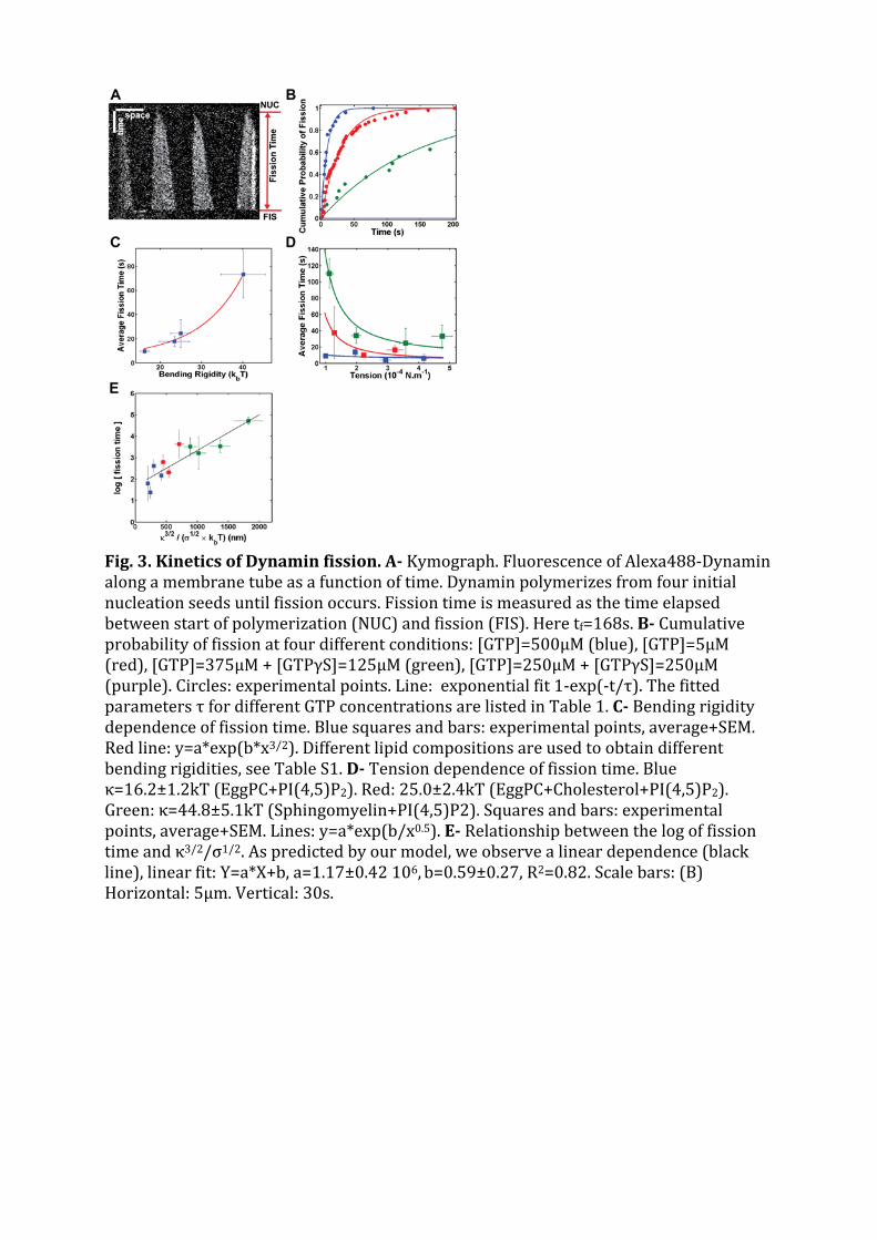
Fig. 3. Kinetics of Dynamin fission. A- Kymograph. Fluorescence of Alexa488-Dynamin along a membrane tube as a function of time. Dynamin polymerizes from four initial nucleation seeds until fission occurs. Fission time is measured as the time elapsed between start of polymerization (NUC) and fission (FIS). Here tf=168s. B- Cumulative probability of fission at four different conditions: [GTP]=500µM (blue), [GTP]=5µM (red), [GTP]=375µM + [GTPγS]=125µM (green), [GTP]=250µM + [GTPγS]=250µM (purple). Circles: experimental points. Line: exponential fit 1-exp(-t/τ). The fitted parameters τ for different GTP concentrations are listed in Table 1. C- Bending rigidity dependence of fission time. Blue squares and bars: experimental points, average+SEM. Red line: y=a*exp(b*x3/2). Different lipid compositions are used to obtain different bending rigidities, see Table S1. D- Tension dependence of fission time. Blue κ=16.2±1.2kT (EggPC+PI(4,5)P2). Red: 25.0±2.4kT (EggPC+Cholesterol+PI(4,5)P2). Green: κ=44.8±5.1kT (Sphingomyelin+PI(4,5)P2). Squares and bars: experimental points, average+SEM. Lines: y=a*exp(b/x0.5). E- Relationship between the log of fission time and κ3/2/σ1/2. As predicted by our model, we observe a linear dependence (black line), linear fit: Y=a*X+b, a=1.17±0.42 106, b=0.59±0.27, R2=0.82. Scale bars: (B) Horizontal: 5µm. Vertical: 30s.

Figure 4 : Torque measurements : A-Top: Y-position trace (red) and corresponding angular velocity values (blue) of a bead rotating around a membrane tube induced through Dynamin twisting upon GTP hydrolysis. Bottom: sequence of ten frames of the bead performing exactly one rotation corresponding to the black rectangle. B- Linear dependence of the viscous torque with the log of the GTP concentration. Red line: linear fit, y=a*x+b, a=1.43±1.00 10-19, b=9.80±3.70 10-20, R2=0.95. C- Histogram of viscous torques measured from the fastest bead as shown in movie S4. D- Position relative to the axis of the tube of a magnetic, 695nm radius Streptavidin bead rotating after addition of 1mM GTP, and under the magnetic torque (blue, see text for explanations) generated by a magnetic field. The bead slows down as magnetic torque increases, see also Figure S2. E- velocity of a rotating bead as the function of the magnetic torque. Bead stops at 1.1 nN.nm. F- [GTP]-dependence of fission time. Blue squares and bars: experimental points, average + SEM. Red line: linear fit, y=a*x+b, a=-0.37±0.07, b=4.51±0.27, R2=0.9805.

Fig. 5: Block of fission of Clathrin-coated pits by hypertonic shock. A- COS-7 cells transfected with mCTLA-mCherry before and after hypertonic shock; resulting kymograph that follows the time course before and after hypertonic shock. B- COS-7 cells transfected with DNM2-GFP before and after hypertonic shock; resulting kymograph that follows the time course before and after hypertonic shock (scale bar: 5 µm; timescale 5 sec.). C- Co-localization of mCTLA-mCherry (red) and DNM2-GFP (green) in COS-7 cells after hypertonic shock. D- Colocalization of mCTLA-GFP (green) and transferrin (red) in COS-7 cells after hypertonic shock. E- Colocalization of mCTLA-GFP (green) and plasma membrane (red) in COS-7 cells after hypertonic shock (scale bar: 1 µm).
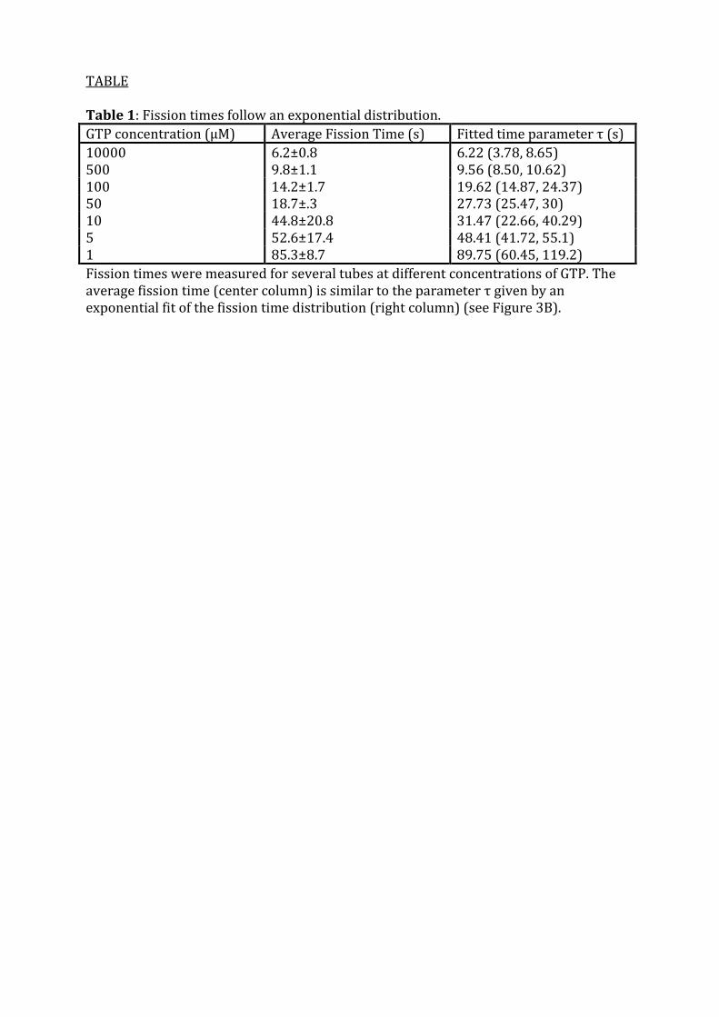
TABLE Table 1: Fission times follow an exponential distribution. GTP concentration (μM) Average Fission Time (s) Fitted time parameter τ (s) 10000 500
6.2±0.8 9.8±1.1
6.22 (3.78, 8.65) 9.56 (8.50, 10.62)
100 14.2±1.7 19.62 (14.87, 24.37) 50 18.7±.3 27.73 (25.47, 30) 10 44.8±20.8 31.47 (22.66, 40.29) 5 52.6±17.4 48.41 (41.72, 55.1) 1 85.3±8.7 89.75 (60.45, 119.2) Fission times were measured for several tubes at different concentrations of GTP. The average fission time (center column) is similar to the parameter τ given by an exponential fit of the fission time distribution (right column) (see Figure 3B).
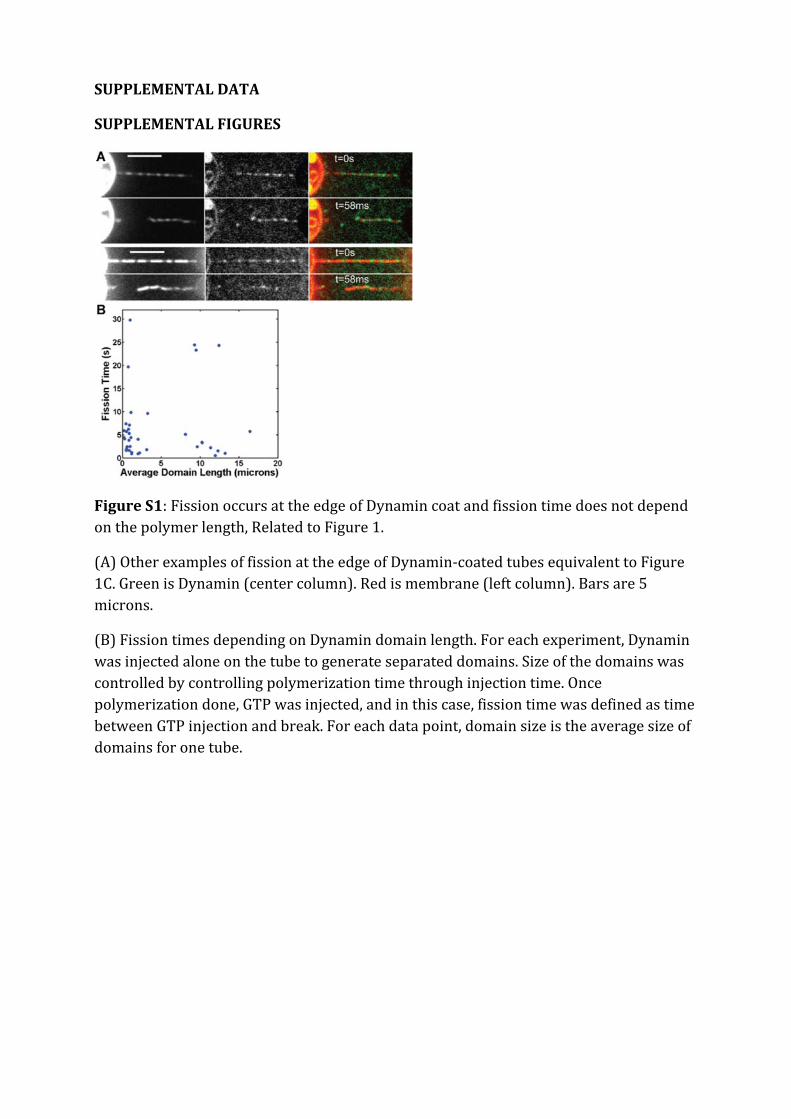
SUPPLEMENTAL DATA
SUPPLEMENTAL FIGURES
Figure S1: Fission occurs at the edge of Dynamin coat and fission time does not depend on the polymer length, Related to Figure 1.
(A) Other examples of fission at the edge of Dynamin-coated tubes equivalent to Figure 1C. Green is Dynamin (center column). Red is membrane (left column). Bars are 5 microns.
(B) Fission times depending on Dynamin domain length. For each experiment, Dynamin was injected alone on the tube to generate separated domains. Size of the domains was controlled by controlling polymerization time through injection time. Once polymerization done, GTP was injected, and in this case, fission time was defined as time between GTP injection and break. For each data point, domain size is the average size of domains for one tube.

Figure S2: Dynamin torque counteracted by an external torque generated by a magnetic field, Related to Figure 4.
(A) Schematic view of the observation chamber made of a coverslip, a glass slide and two-sided tape as a spacer. Lipids are spotted on the coverslip. The fluids are placed

on one side with a pipette and withdrawn using a syringe pump from the other side of the chamber. The observation chamber is surrounded by two electromagnets EM 1 and EM 2 (dark gray) to impose a controlled magnetic field.
(B) Left: EM 1 is about 1 mm thick and consists of a coil of insulated copper wire wrapped around a mu-metal core. Right: EM 2 consists of a coil of insulated copper wire wrapped around an iron tube (1 cm diameter) with a tip to focus the magnetic field.
(C) Sketch representing Dynamin torque and constriction angle.
(D) Sketch of the magnetic bead bound to the tube.
(E) Right – a schematic view of the magnetic bead bound to the membrane tube (in black). When the magnets polarity is switched, the bead passes from one side of the tube to the other. The maximum angular speed of the bead is proportional to the maximum value of the applied torque. Left – typical magnetic field profile used for torque calibration.
(F) Y-position trace (red curve) of a magnetic bead attached to a Dynamin-coated tube (see Movie S5) upon GTP hydrolysis manipulated with magnetic tweezers illustrated by the blue rectangular function where the lower line marks the state of zero field (“off”) and the upper line the state of an applied constant field of 4 mT (“on”).

Figure S3: Dynamin and Clathrin colocalize in live cells, Related to Figure 5.
Colocalization of Clathrin –RFP and Dynamin-GFP in genome edited SKML-2 cells. Scale bar: 1 micron.
SUPPLEMENTAL TABLE
Table S1: Cholesterol and Sphingomyelin rigidify membranes, Related to Figure 3.
Lipid Composition Bending Rigidity
(kBT)
80% EggPC + 20% PI(4,5)P2 16.2 ± 1.2
70% EggPC + 10%BSM + 20 %PI(4,5)P2, 40% Cholesterol 23.5 ± 3.7
80% EggPC + 20% PI(4,5)P2, 50% Cholesterol 25 ± 2.4
80% BSM + 20% PI(4,5)P2, 50% Cholesterol 40.2 ± 5.4
Average bending rigidity and SEM for different lipid compositions. The bending rigidity of a GUV was calculated from the relationship between force and tension. The proportions of PIP2 is the same for all compositions. These four lipid compositions were used to test the dependence of fission time on bending rigidity (see Figure3C).
LEGENDS OF SUPPLEMENTAL MOVIES
Movie S1: Real-time observation of Dynamin-mediated membrane fission, Related to Figure 1.
Observation of Dynamin polymerization and fission by dual-color confocal videomicroscopy. Same field as Figure 1B. Accelerated 24 times, real frame rate: 1fps. Green channel corresponds to Alexa488-Dynamin signal, red channel to BodipyTMR-PIP2.
Movie S2: Fission at the edge between Dynamin free and Dynamin-coated membranes, Related to Figure 1.

Observation of fission at the edge of Dynamin coat by dual-color spinning disk confocal videomicroscopy. Same field as Figure 1C. 17 fps, real acquisition time . Green channel corresponds to Alexa488-Dynamin signal, red channel to BodipyTMR-PIP2.
Movie S3: Fission at the edge between the GUV and the Dynamin-coated tube, Related to Figure 1.
Observation of fission at the edge between the GUV and Dynamin-coated tube by dual-color confocal videomicroscopy. Same field as Figure 1E. Accelerated 24 times, real frame rate: 1fps. Green channel corresponds to Alexa488-Dynamin signal, red channel to BodipyTMR-PIP2.
Movie S4: Rotations of a microbead attached to a Dynamin-coated tube after injection of GTP, Related to Figure 4.
Observation of a rotating microbead attached to a Dynamin-coated tube by DIC videomicroscopy. Non-labelled Dynamin, biotinylated Dynamin and streptavidin beads were injected on membrane sheets. The beads measure 1.31 μm diameter. After injection of 250 μM GTP, the bead starts rotating around the nanotube due to Dynamin conformational changes. Measuring the rotation speed of these beads allows to calculate the viscous torque encountered by the beads as it is represented in Fig4B.
Movie S5: Dynamin torque counteracted by magnetic torque, Related to Figure 4.
Observation of rotating magnetic microbeads attached to Dynamin-coated tubes by videomicroscopy like in Movie S4. Beads rotations were blocked by switching on a magnetic field (red arrowhead). Rotations resume when magnetic field is switched off. This experiment and the calibration of the magnetic field allow to estimate the stall torque of Dynamin as it is shown in Fig4E.
Movie S6: Hypertonic shock slows down the dynamics of Clathrin and Dynamin structures in live cells, Related to Figure 5.
Observation of COS-7 cells cotransfected with mCLAT-mCherry (red) and DNM2-GFP (green) by dual-color spinning disk confocal videomicroscopy. A hyperosmotic shock is made at frame 105. Same Field as in Fig5A and Fig5B. Accelereted 10X. Real frame rate: 1.8 fps.

EXTENDED EXPERIMENTAL PROCEDURES
Materials
Egg L-α-phosphatidylcholine (EPC), brain sphingomyelin (BSM), L-α-phosphatidylinositol-4,5-bisphosphate (PIP2), di-stearoyl phosphatidyl ethanolamine-PEG(2000)-Biotin (DSPE-PEG2000-Biotin) and cholesterol were purchased from Avanti Polar Lipids, Alabaster, Alabama, USA. BodipyTMR-PIP2 (RedPIP2) was purchased from Echelon Bioscience, Salt Lake City, Utah, USA, and Guanosine Triphosphate (GTP) from Roche Applied Science, Indianapolis, Indiana, USA. Four lipid preparations were used (molar percentage): 80% EPC + 19%PIP2 + 1%RedPIP2; 70% EPC + 10% BSM + 19%PIP2 + 1%RedPIP2 supplemented with 40% cholesterol; 80% EPC + 19%PIP2 + 1%RedPIP2 supplemented with 50% cholesterol; 80% BSM + 19%PIP2 + 1%RedPIP2 supplemented with 50% cholesterol. These four mixtures also contained 0.03% DSPE-PEG2000-Biotin.
Protein purification
Recombinant human Dynamin 1 was purified from Sf9 cells infected with recombinant baculovirus using the BD baculogold expressing system (BD Biosciences, Franklin Lakes, NJ USA). Dynamin was purified from cell lysate with the GST-tagged SH3 domain of rat Amphiphysin 1 as an affinity ligand as previously described (Stowell et al., 1999). Briefly, cells from twenty 150cm2 flasks were resuspended in 20 mL of Buffer A (20 mM Hepes pH 7.4, 100 mM NaCl, 1mM EGTA, 1 mM DTT, 1% Triton-X100) supplemented with the protease inhibitor cocktail (cOmplete ULTRA Tablets, Roche Applied Science, Indianapolis, Indiana, USA) and homogenized with a 60 ml dounce. The lysate was centrifuged at 40krpm on a Ti70 rotor (Beckman-Coulter inc., Brea, CA USA), and the supernatant was incubated for 2 hours with glutathione beads to which 3-5 mg of purified GST-SH3 domain of rat Amphiphysin 1 were attached. Next, the beads were batch-washed with 150 ml of Buffer A without Triton-X100. Elution was done with high salt (20 mM Hepes, pH 7.4, 1.2 M NaCl, 1 mM MgCl2). Unlabeled Dynamin was dialyzed against storage buffer (20mM Hepes, pH 7.4, 100mM NaCl, 1 mM MgCl2), concentrated using Amicon (50kDa CO), aliquoted, flash-frozen in liquid N2 and stored at -80ºC.
To fluorescently label Dynamin, we dialyzed Dynamin against PBS 50% glycerol. The labeling reaction was conducted using standard procedures (Alexa-488 protein labeling kit from Invitrogen, cat# A-10235). In some case, Dynamin 1 was labeled with Alexa Fluor 488 C5 maleimide (Molecular Probes, Life Technologies Ltd, Paisley, UK). To attach Streptavidin-coated microbeads to Dynamin polymers, Dynamin was conjugated to DSB-X Biotin C2-iodoacetamide (Molecular Probes, Life Technologies Ltd, Paisley, UK). Labeled Dynamins were dialysed against storage buffer, aliquoted and kept at -80°C.

Nanotube pulling from GUV
Lipid mix (0.5mg/ml) was deposited on indium-tin oxide coated glass slides and dried 1h at 55°C to remove all solvents. GUVs were electroformed (1V, 10Hz) (Angelova et al., 1992; Stowell et al., 1999) for 1h at 55°C in a 200mM sucrose solution then transferred in an observation chamber pretreated with Casein solution (2mg/ml). GUVs were aspirated in a micropipette controlled with a motorized micromanipulator (MP-225, Sutter Instrument, Novato, California, USA) and a custom-made hydraulic system to control aspiration pressure ΔP and to set the tension: 𝜎 = 1
2𝑅𝑝𝑖𝑝𝑒𝑡𝑡𝑒𝛥𝑃
1−𝑅𝑝𝑖𝑝𝑒𝑡𝑡𝑒𝑅𝐺𝑈𝑉
where Rpipette and
RGUV are the radii of the pipette and the GUV respectively (Evans and Rawicz, 1990). A membrane nanotube was formed by pulling away a micropipette aspirated GUV whose membrane was attached to a Streptavidin-coated bead (3.05μm diameter, Spherotec, Lake Forest, Illinois, USA) hold in a fixed optical trap. The custom-made optical trap was made by focusing an ytterbium fiber laser (IPG laser, Burbach, Germany) through a 100X 1.3 NA oil immersion objective (Nikon, Tokyo, Japan). The force F exerted on the bead was calculated from the Hooke’s law: F= k*Δx where k is the stiffness of the trap (k=360pN.μm-1.W-1) calibrated by viscous drag method (Neuman and Block, 2004) and Δx the displacement of the bead from its equilibrium position in the optical trap. Video-rate movies and displacement measurements were done via a C-MOS Camera (Pixelink, Ottawa, Canada) with a user-made video recorder and bead tracking software under Matlab.
Dynamin and GTP were injected closed to the nanotube with a second micropipette of typical radius 10μm controlled with a hydraulic micromanipulator (Narishige Inc., Tokyo, Japan). Nanotubes were observed simultaneously by bright field imaging and by dual-color confocal microscopy (λ1=488nm and λ2=543nm) on a Nikon eclipse Ti inverted microscope (Nikon, Tokyo, Japan). For fast 2-colors confocal experiments, a spinning disk (Intelligent Imaging Innovations, Denver, Colorado, U.S.A.) and a two-channel simultaneous-imaging system (Dual-View, Photometrics, Tucson, Arizona, USA) were used instead of standard confocal microscopy (Eclipse C1 Confocal, Nikon, Tokyo, Japan).
Membrane sheets and Dynamin tubules formation
To form membrane sheets, 22x40 mm glass coverslips were first cleaned by sonication (5 min) in 1% Decon 90, Modec Inc., USA, in distilled water. After thorough washing and sonication (5 min) in distilled water to remove any trace of detergent, coverslips were finally washed with 100% ethanol prior to storage in ethanol. Coverslip were dried under a N2 flux, and 1µl droplets of lipid solution (10 mg/ml in pure chloroform) were deposited and allowed to dry on the coverslip. Typically, two drops were deposited at different sites on a same coverslips. The use of pure chloroform was essential to allow lipid droplet drying in a way that was optimal for the subsequent formation of

membrane sheets upon hydration. Coverslips were then dried again under vacuum (0.2 milli-torr) for at least one hour, and kept up to several days under vacuum.
Before use, coverslips were placed for 20-30 min in a wet incubator (37°C, 100% humidity) to allow partial hydration of the lipids. Next, a small chamber (approximately 15 µl volume) was built by placing the coverslip onto a glass slide, with the lipids facing the glass slide, using a double-sided Scotch (3M) tape as a spacer. The lipids were fully rehydrated by applying to the side of the chamber 15-20 µl of GTPase buffer (20 mM HEPES pH 7.4, 100 mM NaCl, 1 mM MgCl2) containing 0.1 mg/ml casein (C7078, Sigma, USA)(casein buffer) which were taken up into the chamber by capillarity. Lipid deposits then transformed into membrane sheets. Dynamin solution, typically 0.5-1 mg/ml was then added to the side of the chamber, and transferred into the chamber by capillarity. Membrane sheets were then deformed into Dynamin-coated tubules visible by DIC (Morlot et al., 2010; Roux et al., 2006).
Torque measurement by viscous drag
Streptavidin beads (1.35 μm diameter Streptavidin-coated, polystyrene beads, Spherotec, Lake Forest, Illinois, USA) were grafted onto biotinylated Dynamin tubules formed from membrane sheets (Morlot et al., 2010; Roux et al., 2006) by adding them to the chamber after tubule growth. The beads rotate following GTP addition and resulting constriction of the Dynamin coat (Morlot et al., 2010; Roux et al., 2006), experiencing a viscous torque Γ𝑣 = 14πη(R + r)3 ω = ξω (Happel J. and Brenner H. 1983), where η is the viscosity of the surrounding fluid, R the radius of the bead, r the radius of the tubule and 𝜔 is the angular spinning velocity. Differential Interference Contrast (DIC) and computer-based live recording of the rotating beads with a GUPPY camera (Allied Vision Technologies, Stadtroda, Germany) allowed direct measure of the angular spinning velocity and estimation of the viscous torque from the formula above.
Stall torque measurement by magnetic field
To measure the stall torque ΓS that arrests the constriction of the membrane tube, we use a magnetic bead, to which an external torque via a variable magnetic field. The observation chamber (Figure S2A) is placed on the stage of an Axiovert 100 microscope (Zeiss, Oberkochen, Germany) equipped with a differential interference contrast (DIC), a fluorescence lamp and a UI-2220SE charge-coupled-device (CCD camera - IDS, Obersulm, Germany). The magnetic field to manipulate the magnetic beads is generated by two homemade electromagnets (see FigureS2B). Both the electromagnets are controlled using a NI USB-6211 multifunction data acquisition card (National Instruments, Austin, Texas, USA) and a homemade power supply. Magnets are calibrated using a DC magnetometer (AlphaLab, West Salt Lake City, Utah, USA). The bead motion is recorded and tracked using user-developed procedure under MATLAB.
To calibrate the torque induced by the magnetic field, the bead is attached to a Dynamin-lipid nanotube and oriented with a magnetic field parallel to the coverslip (position ‘1’ in
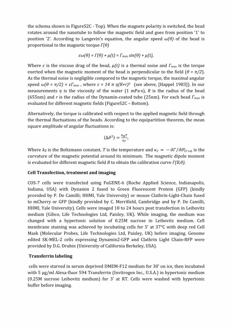
the schema shown in FigureS2C - Top). When the magnets polarity is switched, the bead rotates around the nanotube to follow the magnetic field and goes from position ‘1’ to position ‘2’. According to Langevin’s equation, the angular speed ω(θ) of the bead is proportional to the magnetic torque Γ(θ)
εω(θ) = Γ(θ) + µ(t) = Γmax sin(θ) + µ(t),
Where ε is the viscous drag of the bead, µ(t) is a thermal noise and Γmax is the torque exerted when the magnetic moment of the bead is perpendicular to the field (θ = π/2). As the thermal noise is negligible compared to the magnetic torque, the maximal angular speed ω(θ = π/2) = εΓmax , where ε = 14 π η(R+r)3 (see above, [Happel 1983]). In our measurements η is the viscosity of the water (1 mPa·s), R is the radius of the bead (655nm) and r is the radius of the Dynamin-coated tube (25nm). For each bead Γmax is evaluated for different magnetic fields (FigureS2C – Bottom).
Alternatively, the torque is calibrated with respect to the applied magnetic field through the thermal fluctuations of the beads. According to the equipartition theorem, the mean square amplitude of angular fluctuations is:
⟨∆𝜗2⟩ = 𝑘𝐵𝑇𝜅𝛤
,
Where kB is the Boltzmann constant, T is the temperature and 𝜅𝛤 = − 𝜕𝛤 𝜕𝜗⁄ |𝛤=0 is the curvature of the magnetic potential around its minimum. The magnetic dipole moment is evaluated for different magnetic field B to obtain the calibration curve Γ(B,θ).
Cell Transfection, treatment and imaging
COS-7 cells were transfected using FuGENE-6 (Roche Applied Science, Indianapolis, Indiana, USA) with Dynamin 2 fused to Green Fluorescent Protein (GFP) (kindly provided by P. De Camilli; HHMI, Yale University) or mouse Clathrin-Light-Chain fused to mCherry or GFP (kindly provided by C. Merrifield, Cambridge and by P. De Camilli, HHMI, Yale University). Cells were imaged 18 to 24 hours post transfection in Leibovitz medium (Gibco, Life Technologies Ltd, Paisley, UK). While imaging, the medium was changed with a hypertonic solution of 0.25M sucrose in Leibovitz medium. Cell membrane staining was achieved by incubating cells for 5’ at 37°C with deep red Cell Mask (Molecular Probes, Life Technologies Ltd, Paisley, UK) before imaging. Genome edited SK-MEL-2 cells expressing Dynamin2-GFP and Clathrin Light Chain-RFP were provided by D.G. Drubin (University of California Berkeley, USA).
Transferrin labeling
cells were starved in serum deprived DMEM-F12 medium for 30’ on ice, then incubated with 5 µg/ml Alexa-fluor 594 Transferrin (Invitrogen Inc., U.S.A.) in hypertonic medium (0.25M sucrose Leibovitz medium) for 3’ at RT. Cells were washed with hypertonic buffer before imaging.
Image analysis
Images were analyzed and processed with ImageJ. Kymographs were made with Multiple Kymograph plugin (J. Rietdorf; A. Seitz). Fits were made with the curve fitting toolbox in Matlab.
Membrane shape computation
In this section we first derive the equilibrium equation for the shape of the membrane from Canham-Helfrich Hamiltonian and express the shape computation as a boundary value problem suitable for solution with Matlab’s bvp4c.
Canham-Helfrich Hamiltonian gives the energy of the membrane as a function of its shape:
𝐸 = 𝜎𝑑𝐴 +𝜅2𝐽2 𝑑𝐴
The first term is related to the energy cost of stretching the membrane and 𝜎 is the membrane tension which can be controlled in the experiment. The second term represents the energy cost of bending which is given by the integral of membrane curvature 𝐽 over the surface. The bending modulus 𝜅 depends on the composition of the membrane.
Considering the axial symmetry of the experiment we will restrict ourselves to axisymmetric shapes. For an axisymmetric surface with an axial coordinate 𝑧, and angle 𝜑 around the 𝑧-axis, and a radius 𝑟(𝑧), curvature can be expressed as:
𝐽 =𝑟(𝑧)𝑟′′(𝑧) − 𝑟′(𝑧)2 − 1𝑟(𝑧)(1 + 𝑟′(𝑧)2)3/2
Writing the area element in the same coordinates 𝑑𝐴 = 𝑟(𝑧)𝑟′(𝑧)2 + 1 𝑑𝑧𝑑𝜑, the integral in the angle 𝜑 can be directly performed and the energy can be cast in the following form:
𝐸 = (𝜎 +𝜅2𝐽2)𝑟(𝑧)𝑟′(𝑧)2 + 1 𝑑𝑧𝑑𝜑 = 2𝜋 (𝜎 +
𝜅2𝐽2)𝑟(𝑧)𝑟′(𝑧)2 + 1 𝑑𝑧
It will be convenient for numerical solution of the equations to adimensionalize the
Hamiltonian using the bare membrane radius 𝑅𝑚 = 𝜅2𝜎
to rescale all lengths, and 𝜋𝜅 to
rescale the energy:
𝑒 = (1 + 𝑗2)𝜌(𝜃)(𝜃)2 + 1 𝑑𝜃 = ℓ𝜌(𝜃), (𝜃), (𝜃)𝑑𝜃
where
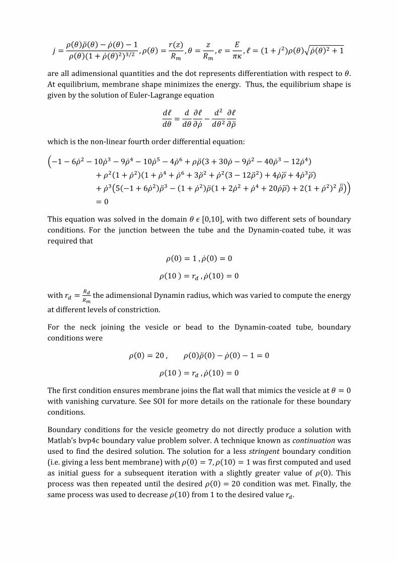
𝑗 =𝜌(𝜃)(𝜃) − (𝜃) − 1𝜌(𝜃)(1 + (𝜃)2)3/2 , 𝜌(𝜃) =
𝑟(𝑧)𝑅𝑚
,𝜃 =𝑧𝑅𝑚
, 𝑒 =𝐸𝜋𝜅
, ℓ = (1 + 𝑗2)𝜌(𝜃)(𝜃)2 + 1
are all adimensional quantities and the dot represents differentiation with respect to 𝜃. At equilibrium, membrane shape minimizes the energy. Thus, the equilibrium shape is given by the solution of Euler-Lagrange equation
𝑑ℓ𝑑𝜃
=𝑑𝑑𝜃
𝜕ℓ𝜕
−𝑑2
𝑑𝜃2𝜕ℓ𝜕
which is the non-linear fourth order differential equation:
−1 − 62 − 103 − 94 − 105 − 46 + 𝜌(3 + 30 − 92 − 403 − 124)
+ 𝜌2(1 + 2)(1 + 4 + 6 + 32 + 2(3 − 122) + 4𝜌 + 43𝜌)
+ 35(−1 + 62)3 − (1 + 2)(1 + 22 + 4 + 20𝜌) + 2(1 + 2)2
= 0
This equation was solved in the domain 𝜃 𝜖 [0,10], with two different sets of boundary conditions. For the junction between the tube and the Dynamin-coated tube, it was required that
𝜌(0) = 1 , (0) = 0
𝜌(10 ) = 𝑟𝑑 , (10) = 0
with 𝑟𝑑 = 𝑅𝑑𝑅𝑚
the adimensional Dynamin radius, which was varied to compute the energy
at different levels of constriction.
For the neck joining the vesicle or bead to the Dynamin-coated tube, boundary conditions were
𝜌(0) = 20 , 𝜌(0)(0) − (0) − 1 = 0
𝜌(10 ) = 𝑟𝑑 , (10) = 0
The first condition ensures membrane joins the flat wall that mimics the vesicle at 𝜃 = 0 with vanishing curvature. See SOI for more details on the rationale for these boundary conditions.
Boundary conditions for the vesicle geometry do not directly produce a solution with Matlab’s bvp4c boundary value problem solver. A technique known as continuation was used to find the desired solution. The solution for a less stringent boundary condition (i.e. giving a less bent membrane) with 𝜌(0) = 7,𝜌(10) = 1 was first computed and used as initial guess for a subsequent iteration with a slightly greater value of 𝜌(0). This process was then repeated until the desired 𝜌(0) = 20 condition was met. Finally, the same process was used to decrease 𝜌(10) from 1 to the desired value 𝑟𝑑.

Once membrane shapes were computed, we calculated the corresponding energy by numerical integration of Canham-Helfrich Hamiltonian.
Theory for reduced fission energy barrier at the Dynamin-membrane edge
We model membrane fission as a one-step rate reaction thermally activated with a single energy barrier, biased by the GTP hydrolysis driven constriction force. The constriction radius Rd, that is, the radius of the Dynamin-coated membrane, constitutes the reaction coordinate. In this analogy, the radius Rd is a brownian degree of freedom that may overcome a fission energy barrier by thermal fluctuations. GTP hydrolysis by Dynamin generates a constriction force which in our model would operate as a force on the Rd degree of freedom, tilting the energy landscape and decreasing the total energy barrier ΔEtot to a smaller value ΔEres, biasing the transition towards the fission state (see Figure 2A in main text). The energy barrier originates from differences in elastic and surface energy of the membrane neck that joins the edge of the Dynamin-coated part to the bare tube with radius Rd, set by tension and bending rigidity.
After constriction, the residual barrier can be overcome by thermal fluctuations of the constricted radius, at a rate
𝑟 = 𝜏−1𝑒−ΔEres/kb𝑇
where τ is a molecular characteristic time of reaction, kb is the Boltzmann constant, 𝑇 the temperature. A constant rate of reaction yields an average fission time
< 𝑡𝑓 > = 𝜏𝑒ΔEres/kb𝑇
A process with just one constant rate of reaction r gives an exponential distribution of reaction times
𝜌𝑡𝑓 = 𝑟𝑒−𝑟𝑡𝑓
and consequently a cumulative probability of reaction
𝐹𝑡𝑓 = 𝜌(𝑥)𝑑𝑥 = 1 − 𝑒−𝑟 𝑡𝑓𝑡𝑓
0
Our experiments both present an exponential distribution of fission times (not shown) and the corresponding cumulative probability is well fit by 1 − 𝑒−𝑟 𝑡𝑓 as shown in Figure3B in the main text.
To compute the bending and surface energy of the membrane we numerically solved the non-linear shape equation that arises from Canham-Helfrich Hamiltonian minimization (see above) for the neck joining a bare membrane tube with a Dynamin-coated one (see figure 1G in the main text). This implies boundary conditions where the radius matches the bare tube radius Rm on one side and Rd, the radius of the Dynamin-coated part, on the other. In both ends, the derivative of the radius with respect to the axial coordinate
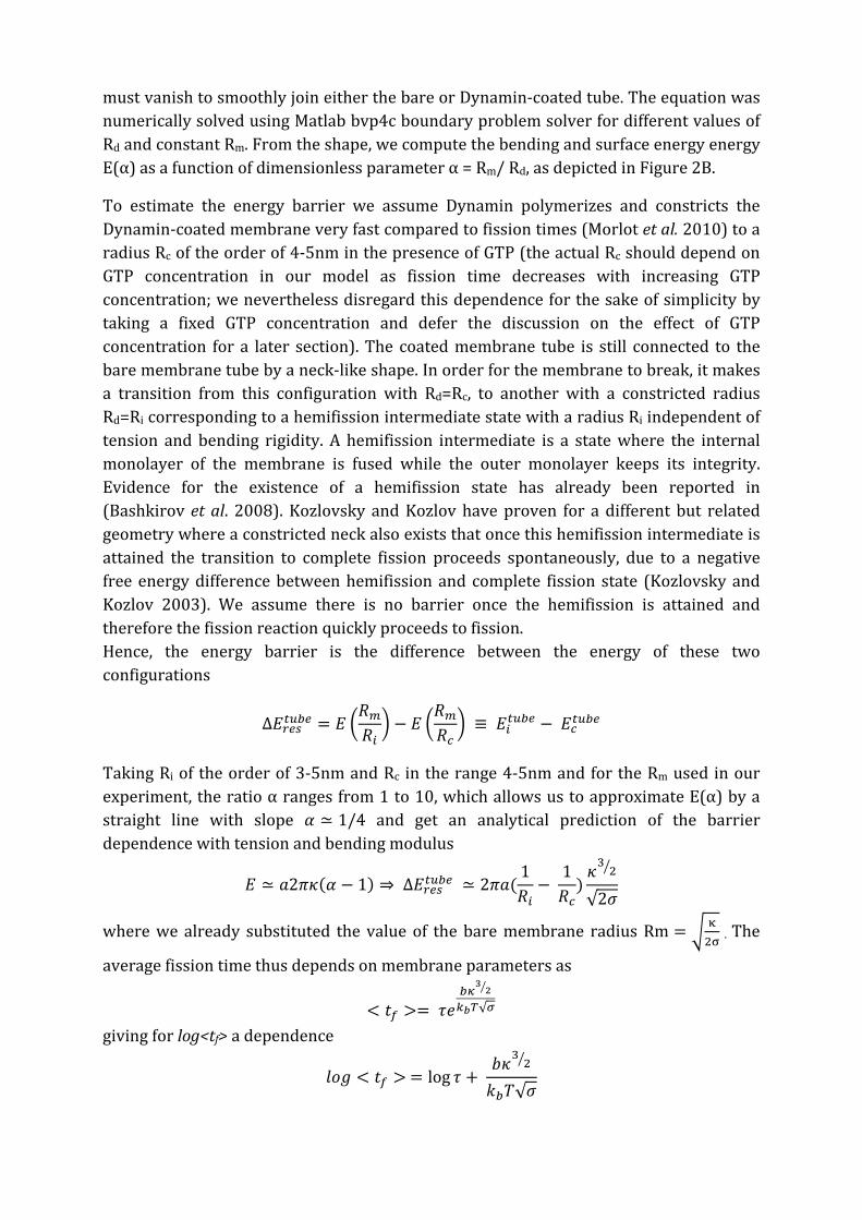
must vanish to smoothly join either the bare or Dynamin-coated tube. The equation was numerically solved using Matlab bvp4c boundary problem solver for different values of Rd and constant Rm. From the shape, we compute the bending and surface energy energy E(α) as a function of dimensionless parameter α = Rm/ Rd, as depicted in Figure 2B.
To estimate the energy barrier we assume Dynamin polymerizes and constricts the Dynamin-coated membrane very fast compared to fission times (Morlot et al. 2010) to a radius Rc of the order of 4-5nm in the presence of GTP (the actual Rc should depend on GTP concentration in our model as fission time decreases with increasing GTP concentration; we nevertheless disregard this dependence for the sake of simplicity by taking a fixed GTP concentration and defer the discussion on the effect of GTP concentration for a later section). The coated membrane tube is still connected to the bare membrane tube by a neck-like shape. In order for the membrane to break, it makes a transition from this configuration with Rd=Rc, to another with a constricted radius Rd=Ri corresponding to a hemifission intermediate state with a radius Ri independent of tension and bending rigidity. A hemifission intermediate is a state where the internal monolayer of the membrane is fused while the outer monolayer keeps its integrity. Evidence for the existence of a hemifission state has already been reported in (Bashkirov et al. 2008). Kozlovsky and Kozlov have proven for a different but related geometry where a constricted neck also exists that once this hemifission intermediate is attained the transition to complete fission proceeds spontaneously, due to a negative free energy difference between hemifission and complete fission state (Kozlovsky and Kozlov 2003). We assume there is no barrier once the hemifission is attained and therefore the fission reaction quickly proceeds to fission. Hence, the energy barrier is the difference between the energy of these two configurations
∆𝐸𝑟𝑒𝑠𝑡𝑢𝑏𝑒 = 𝐸 𝑅𝑚𝑅𝑖 − 𝐸
𝑅𝑚𝑅𝑐 ≡ 𝐸𝑖𝑡𝑢𝑏𝑒 − 𝐸𝑐𝑡𝑢𝑏𝑒
Taking Ri of the order of 3-5nm and Rc in the range 4-5nm and for the Rm used in our experiment, the ratio α ranges from 1 to 10, which allows us to approximate E(α) by a straight line with slope 𝛼 ≃ 1/4 and get an analytical prediction of the barrier dependence with tension and bending modulus
𝐸 ≃ 𝑎2𝜋𝜅(𝛼 − 1) ⇒ ∆𝐸𝑟𝑒𝑠𝑡𝑢𝑏𝑒 ≃ 2𝜋𝑎(1𝑅𝑖−
1𝑅𝑐
)𝜅3 2
√2𝜎
where we already substituted the value of the bare membrane radius Rm = κ2σ . The
average fission time thus depends on membrane parameters as
< 𝑡𝑓 >= 𝜏𝑒𝑏𝜅
32
𝑘𝑏𝑇√𝜎 giving for log<tf> a dependence
𝑙𝑜𝑔 < 𝑡𝑓 > = log 𝜏 + 𝑏𝜅3 2
𝑘𝑏𝑇√𝜎
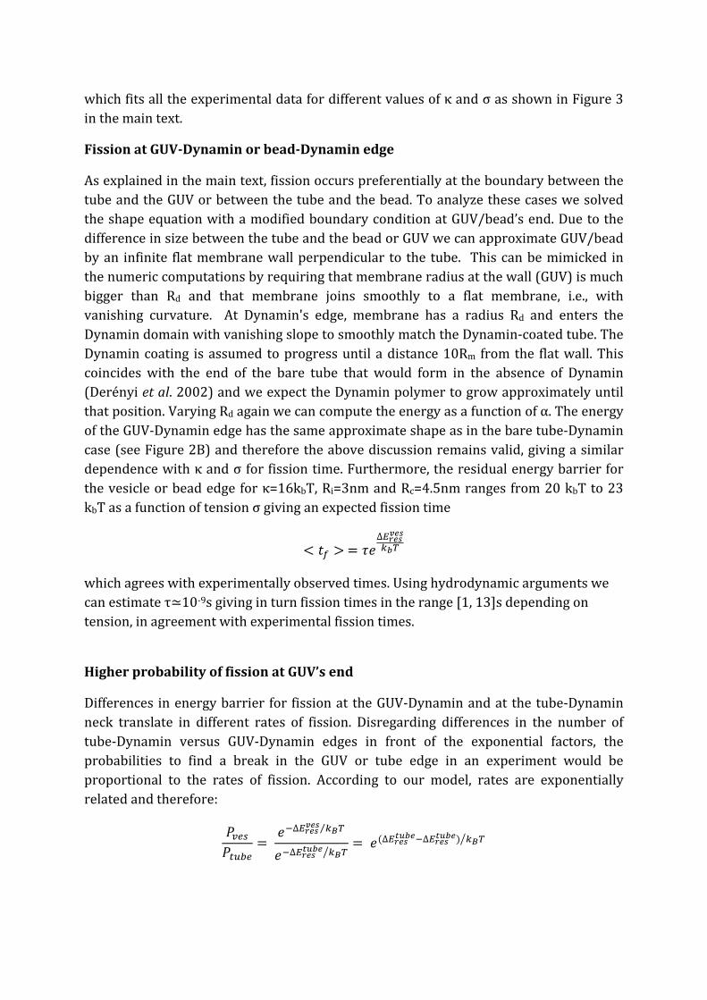
which fits all the experimental data for different values of κ and σ as shown in Figure 3 in the main text.
Fission at GUV-Dynamin or bead-Dynamin edge
As explained in the main text, fission occurs preferentially at the boundary between the tube and the GUV or between the tube and the bead. To analyze these cases we solved the shape equation with a modified boundary condition at GUV/bead’s end. Due to the difference in size between the tube and the bead or GUV we can approximate GUV/bead by an infinite flat membrane wall perpendicular to the tube. This can be mimicked in the numeric computations by requiring that membrane radius at the wall (GUV) is much bigger than Rd and that membrane joins smoothly to a flat membrane, i.e., with vanishing curvature. At Dynamin's edge, membrane has a radius Rd and enters the Dynamin domain with vanishing slope to smoothly match the Dynamin-coated tube. The Dynamin coating is assumed to progress until a distance 10Rm from the flat wall. This coincides with the end of the bare tube that would form in the absence of Dynamin (Derényi et al. 2002) and we expect the Dynamin polymer to grow approximately until that position. Varying Rd again we can compute the energy as a function of α. The energy of the GUV-Dynamin edge has the same approximate shape as in the bare tube-Dynamin case (see Figure 2B) and therefore the above discussion remains valid, giving a similar dependence with κ and σ for fission time. Furthermore, the residual energy barrier for the vesicle or bead edge for κ=16kbT, Ri=3nm and Rc=4.5nm ranges from 20 kbT to 23 kbT as a function of tension σ giving an expected fission time
< 𝑡𝑓 > = 𝜏𝑒∆𝐸𝑟𝑒𝑠𝑣𝑒𝑠
𝑘𝑏𝑇
which agrees with experimentally observed times. Using hydrodynamic arguments we can estimate τ≃10-9s giving in turn fission times in the range [1, 13]s depending on tension, in agreement with experimental fission times.
Higher probability of fission at GUV’s end
Differences in energy barrier for fission at the GUV-Dynamin and at the tube-Dynamin neck translate in different rates of fission. Disregarding differences in the number of tube-Dynamin versus GUV-Dynamin edges in front of the exponential factors, the probabilities to find a break in the GUV or tube edge in an experiment would be proportional to the rates of fission. According to our model, rates are exponentially related and therefore:
𝑃𝑣𝑒𝑠𝑃𝑡𝑢𝑏𝑒
= 𝑒−∆𝐸𝑟𝑒𝑠𝑣𝑒𝑠 𝑘𝐵𝑇⁄
𝑒−∆𝐸𝑟𝑒𝑠𝑡𝑢𝑏𝑒 𝑘𝐵𝑇= 𝑒(∆𝐸𝑟𝑒𝑠𝑡𝑢𝑏𝑒−∆𝐸𝑟𝑒𝑠𝑡𝑢𝑏𝑒) 𝑘𝐵𝑇

with ∆𝐸𝑟𝑒𝑠𝑡𝑢𝑏𝑒 and ∆𝐸𝑟𝑒𝑠𝑣𝑒𝑠 the barriers for fission at the tube or vesicle respectively. Using normalization 𝑃𝑣𝑒𝑠 + 𝑃𝑡𝑢𝑏𝑒 = 1 we find
𝑃𝑣𝑒𝑠 =1
1 + 𝑒(∆𝐸𝑟𝑒𝑠𝑡𝑢𝑏𝑒−∆𝐸𝑟𝑒𝑠𝑡𝑢𝑏𝑒) 𝑘𝐵𝑇
Taking Ri=3nm, Rc=4.5nm and κ=16kbT, the numerical computation of the barriers from the surface and bending energy shows that the energy barrier at the vesicle edge is always smaller than the barrier corresponding to the tube, at least for the values of tension used in the experiment, as shown in Figure2C. For tensions used in experiments from σ ≃ 1⨉10−4 N. m−1 to σ ≃ 5⨉10−4N. m−1, the difference in energy barriers ∆𝐸𝑟𝑒𝑠𝑡𝑢𝑏𝑒 − ∆𝐸𝑟𝑒𝑠𝑡𝑢𝑏𝑒 is in the range [1, 3]⨉kbT, which in turn gives probabilities of fission in the vesicle 𝑃𝑣𝑒𝑠 = [0.75, 0.93] in accordance with 75% of the breaks occurring in the vesicle observed in experiment (see Figure1D).
Effect of GTP concentration
The presence of GTP in the system, which entails Dynamin contraction, is equivalent, at least for small deformations of the helix, to applying a homogeneous constriction force or pressure and a torque to the membrane in the Dynamin domain proportional to Δμ, the GTP hydrolysis chemical potential difference (Lenz et al. 2008). In our model, that would mean that a constant force is applied to the radius variable, which can be seen as a tilt in the energy landscape proportional to Δμ. Thus, the total energy barrier decreases in an amount proportional to Δμ with a constant d that is related to the position of the intermediate state in the reaction path:
ΔEres = ∆Etot − d∆µ = ΔEtot − cΓθ
where we used the proportionality between Δμ and Dynamin induced torque upon hydrolysis Γ, which is derived assuming the energy for constriction is coming from GTP hydrolysis and thus work done by Dynamin should be 𝛤𝜃𝜉𝛥𝜇 where Δμ is the variation of chemical potential in the hydrolysis and ξ can be thought of as an efficiency of Dynamin in the sense of how much energy is converted into work. This gives for fission time
< 𝑡𝑓 > = 𝜏𝑒∆𝐸𝑡𝑜𝑡𝑘𝑏𝑇
−𝑐 𝛤𝜃𝑘𝑏𝑇
Finally, assuming an ideal dynamin solution, ∆𝜇 = 𝜉𝑘𝑏𝑇𝑙𝑜𝑔[𝐺𝑇𝑃] and therefore
< 𝑡𝑓 > = 𝜏𝑒∆𝐸𝑡𝑜𝑡𝑘𝑏𝑇
−𝑐𝜉𝑙𝑜𝑔[𝐺𝑇𝑃]
Experiments indeed show the expected dependence: 𝑙𝑜𝑔 < 𝑡𝑓 > = 𝑐𝑜𝑛𝑠𝑡𝑎𝑛𝑡 −𝑐𝜉log [𝐺𝑇𝑃] as shown in Figure 4F of the main text.
Torque and final helix radius
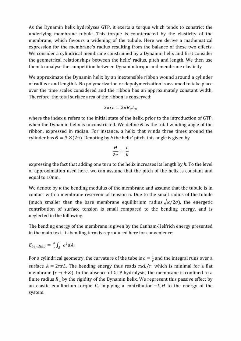
As the Dynamin helix hydrolyses GTP, it exerts a torque which tends to constrict the underlying membrane tubule. This torque is counteracted by the elasticity of the membrane, which favours a widening of the tubule. Here we derive a mathematical expression for the membrane's radius resulting from the balance of these two effects. We consider a cylindrical membrane constrained by a Dynamin helix and first consider the geometrical relationships between the helix' radius, pitch and length. We then use them to analyse the competition between Dynamin torque and membrane elasticity
We approximate the Dynamin helix by an inextensible ribbon wound around a cylinder of radius r and length L. No polymerization or depolymerization is assumed to take place over the time scales considered and the ribbon has an approximately constant width. Therefore, the total surface area of the ribbon is conserved:
2𝜋𝑟𝐿 = 2𝜋𝑅𝑢𝐿𝑢
where the index u refers to the initial state of the helix, prior to the introduction of GTP, when the Dynamin helix is unconstricted. We define Θ as the total winding angle of the ribbon, expressed in radian. For instance, a helix that winds three times around the cylinder has 𝛩 = 3 ⨉(2π). Denoting by h the helix' pitch, this angle is given by
𝛩2𝜋
= 𝐿ℎ
expressing the fact that adding one turn to the helix increases its length by h. To the level of approximation used here, we can assume that the pitch of the helix is constant and equal to 10nm.
We denote by κ the bending modulus of the membrane and assume that the tubule is in contact with a membrane reservoir of tension σ. Due to the small radius of the tubule (much smaller than the bare membrane equilibrium radius 𝜅 2𝜎⁄ ), the energetic contribution of surface tension is small compared to the bending energy, and is neglected in the following.
The bending energy of the membrane is given by the Canham-Helfrich energy presented in the main text. Its bending term is reproduced here for convenience:
𝐸𝑏𝑒𝑛𝑑𝑖𝑛𝑔 = 𝜅2 ∫ 𝑐2𝑑𝐴𝐴 .
For a cylindrical geometry, the curvature of the tube is 𝑐 = 1𝑟 and the integral runs over a
surface 𝐴 = 2π𝑟𝐿. The bending energy thus reads 𝜋𝜅𝐿 𝑟⁄ , which is minimal for a flat membrane (𝑟 → +∞). In the absence of GTP hydrolysis, the membrane is confined to a finite radius 𝑅𝑢 by the rigidity of the Dynamin helix. We represent this passive effect by an elastic equilibrium torque 𝛤𝑢 implying a contribution −𝛤𝑢𝛩 to the energy of the system.

For the purpose of determining the membrane shape, the internal, active torque induced by the Dynamin polymer upon GTP hydrolysis is equivalent to an additional external torque Γ imposed on the passive helix. Therefore, Dynamin activity can be described as a further lowering of the energy of the system by an amount equal to the work ΓΘ of this torque. Summing all the contributions to the energy, we find
𝐸 = −(𝛤𝑢 + 𝛤)𝛩 + 𝜋𝜅𝐿𝑟
= −(𝛤𝑢 + 𝛤)𝐿𝑢𝑅𝑢ℎ𝑟
+ 𝜋𝜅𝐿𝑢𝑅𝑢𝑟2
Minimizing E with respect to r, we find that
𝑟 = 2𝜋𝜅ℎ𝛤𝑢 + 𝛤
While the passive torque 𝛤𝑢 has been left unspecified until this point, it must satisfy the condition that r goes to 𝑅𝑢 as goes to zero. This implies that 𝛤𝑢 = 2𝜋𝜅ℎ 𝑅𝑢⁄ , and therefore
𝑟 = 𝑅𝑢
1 + 𝛤𝑅𝑢2𝜋𝜅ℎ
Using κ = 20 kbT = 8 ⨉ 10 − 20 J, we can thus compute the torque required to obtain a constricted radius r = Rc = 5 nm to be 𝛤 ≃ 500 pN. nm. This value is compatible with the experimental measurements presented in the main text (see Figure 4), thus validating our assessment of the role of the competition between Dynamin torque and membrane bending rigidity.
SUPPLEMENTAL REFERENCES
Derényi, I., Jülicher, F. and Prost, J. (2002) Formation and Interaction of Membrane Tubes. Phys. Rev. Lett. 88, 238101
Neuman, K.C. and Block, S.M. (2004) Rev. Sci. Instrum. 75:2787-2809
Stowell, M.H., Marks, B., Wigge, P., and McMahon, H.T. (1999). Nucleotide-dependent conformational changes in dynamin: evidence for a mechanochemical molecular spring. Nat. Cell. Biol. 1, 27-32.

114 Fission is Regulated by Membrane Shape
6.3 Complementary Experiments
6.3.1 Constriction Radius
The radius of a constricted Dynamin-coated nanotube Rc plays an important role in the modelwe propose. CryoEM data have shown that upon GMPPCP treatment, the Dynamin helixconstricts the lipid tube until it reaches a lumen of 7nm diameter. However GTP hydrolysiscould lead to a more constricted state. We were thus prompted to measure this constrictedradius with the nanotube extrusion technique.
Calibration Of Radius Fluorescence
The radius formula R0 =√
κ2σ is valid only for bare membrane tubes at equilibrium and cannot
be used for measuring the radius of a Dynamin-coated tube. Thus we used the uorescencesignal of the nanotube to measure its radius. Two uorescent lipid dyes were incorporatedin GUVs: BodipyTMR − PIP2 that was used in all our experiments and BodipyFL − HPC .We use a second lipid probe because Dynamin interacts with PIP2. Dynamin polymerizationcould induce a local enrichment in PIP2 and would bias the measurement. BodipyFL − HPCis a uorescent lipid which does not interact with Dynamin and incorporates homogeneouslyin GUVs. We established a calibration curve to correlate the radius of a bare membranenanotube to its average uorescence intensity. For dierent aspiration pressures, we recordedthe corresponding force and took a picture of the uorescent nanotube (see Fig.6.1.A). For eachpressure step, the radius was calculated from the force and the tension values. The averageuorescence intensity along the tube was measured for both uorescent lipids. We obtaineda linear relationship between the radius and its uorescence intensity for BodipyFL − HPCand BodipyTMR −PIP2 (see Fid6.1.B). This linear relationship and the fact that we observedsimilar slopes for the two dyes show that there is no lipid sorting: PIP2 is not sensitive tocurvature in the lipid composition we used (PC + PIP2). This calibration curve was establishedfor each nanotube individually before injection of Dynamin.
Radius Measurement Without GTP
We rst measured the radius of Dynamin-coated tubes in absence of nucleotide. Non-labelledDynamin was injected close to the tube. We could not use uorescent Dynamin as the lipid tubewas already labelled in green and red. Full coverage of the tube by Dynamin was thus noticedby a typical force drop [115]: when the tube was fully covered, the Dynamin coat "pushed" onthe bead. Polymerization was also conrmed at the end of the measurements by switching othe optical tweezers, polymerized tubes did not retract whereas bare tubes retracted rapidly.From the measurement of the nanotube uorescence intensity and the radius-uorescence in-tensity calibration curve, we inferred the radius of the Dynamin-coated nanotube in absenceof nucleotide: 10.3 ± 2 nm from the green signal and 10.2 ± 2.8 nm from the red signal.These results give two interesting pieces of information. First the radius values are in goodagreement with structural data, which validates this technique of measurement. Second we
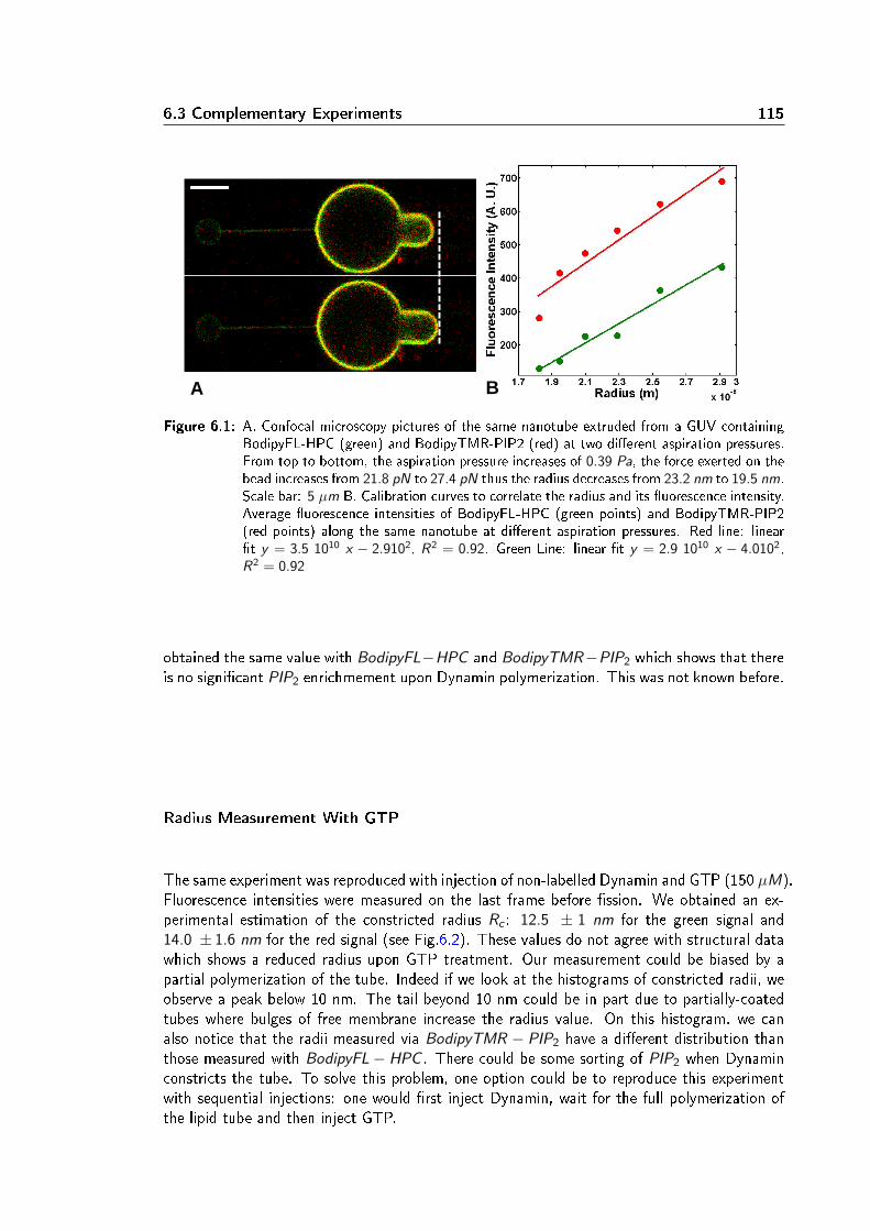
6.3 Complementary Experiments 115
A B
Figure 6.1: A. Confocal microscopy pictures of the same nanotube extruded from a GUV containingBodipyFL-HPC (green) and BodipyTMR-PIP2 (red) at two dierent aspiration pressures.From top to bottom, the aspiration pressure increases of 0.39 Pa, the force exerted on thebead increases from 21.8 pN to 27.4 pN thus the radius decreases from 23.2 nm to 19.5 nm.Scale bar: 5 µm B. Calibration curves to correlate the radius and its uorescence intensity.Average uorescence intensities of BodipyFL-HPC (green points) and BodipyTMR-PIP2(red points) along the same nanotube at dierent aspiration pressures. Red line: lineart y = 3.5 1010 x − 2.9102, R2 = 0.92. Green Line: linear t y = 2.9 1010 x − 4.0102,R2 = 0.92
obtained the same value with BodipyFL−HPC and BodipyTMR−PIP2 which shows that thereis no signicant PIP2 enrichmement upon Dynamin polymerization. This was not known before.
Radius Measurement With GTP
The same experiment was reproduced with injection of non-labelled Dynamin and GTP (150 µM).Fluorescence intensities were measured on the last frame before ssion. We obtained an ex-perimental estimation of the constricted radius Rc : 12.5 ± 1 nm for the green signal and14.0 ± 1.6 nm for the red signal (see Fig.6.2). These values do not agree with structural datawhich shows a reduced radius upon GTP treatment. Our measurement could be biased by apartial polymerization of the tube. Indeed if we look at the histograms of constricted radii, weobserve a peak below 10 nm. The tail beyond 10 nm could be in part due to partially-coatedtubes where bulges of free membrane increase the radius value. On this histogram, we canalso notice that the radii measured via BodipyTMR − PIP2 have a dierent distribution thanthose measured with BodipyFL− HPC . There could be some sorting of PIP2 when Dynaminconstricts the tube. To solve this problem, one option could be to reproduce this experimentwith sequential injections: one would rst inject Dynamin, wait for the full polymerization ofthe lipid tube and then inject GTP.

116 Fission is Regulated by Membrane Shape
A B
Figure 6.2: A.Radii of nanotubes after injection deduced from the calibration curves with the uo-rescence intensity value. Control: no polymerization, no ssion after injection. N = 7.Dynamin: injection of Dynamin leads to polymerization detected by a force drop. N = 7.Dynamin + GTP: injection of Dynamin and GTP simultaneously. Fluorescence intensitywas measured on the last frame before ssion. N = 20. Green: uorescence of BodipyFL-HPC. Red: uorescence of BodipyTMR-PIP2. B. Histogram of constricted radii. Green:BodipyFL-HPC. Red: BodipyTMR-PIP2.
6.3.2 Dynamin Mutant Experiments
To better understand Dynamin GTPase activity, we took advantages of two well-known mu-tants: K44A and K142A. They both have a single point mutation in the GTPase domain and adominant-negative eect on endocytosis. K44A has a lower GTPase activity due to a decreasedanity for GTP[30]. K142A has an almost normal GTPase activity but is defective in changingconformation [87].We rst tested these two mutants individually. When a mix of non labelled K44A, Alexa488-labelled K44A and GTP (150 µM) was injected near lipid nanotubes, we observed polymer-ization followed by the ssion of the tube. However ssion was considerably slower and couldtake several minutes (see Fig6.3.B blue data points). When we injected non-labelled K142A,Alexa488-labelled K142A and GTP (1mM), the mutant polymerized around the tube but wenever observed any ssion event (see Fig6.3.B red line). These results are in good agreementwith previous observations. We show in addition that K142A is completely inecient for ssionwhereas K44A is slower.We then decided to test hybrid polymers wildtype + K 142A. We injected near the tubea mix of non-labelled WT, non-labelled K142A, Alexa488-labelled K142 and GTP (150 µM).We observed polymerization followed by ssion for several ratios of mutants and wild type:50%wt +50%K 142A, 20%wt +80%K 142A and 90%wt +10%K 142A. These three pro-portions always lead to ssion with a cumulative probability close the wild type's (see Fig6.3.Borange data points). The fact that we observed uorescently homogeneous polymerizationproves that K142A (the only uorescent protein in this experiment) incorporates well withinthe wild type polymer. These results indicate that few functional Dynamin dimers are requiredwithin the polymer to trigger ssion. Further experiments need to be performed to conrmthis interesting result. In particular we should quantify precisely how well the Dynamin mutantand wild type polymerize together. There could be a segregation between the two polymers:
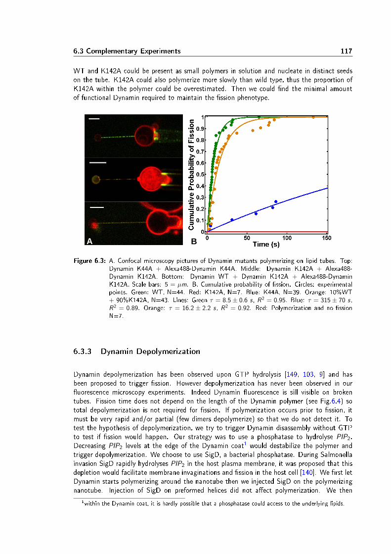
6.3 Complementary Experiments 117
WT and K142A could be present as small polymers in solution and nucleate in distinct seedson the tube. K142A could also polymerize more slowly than wild type, thus the proportion ofK142A within the polymer could be overestimated. Then we could nd the minimal amountof functional Dynamin required to maintain the ssion phenotype.
A B
Figure 6.3: A. Confocal microscopy pictures of Dynamin mutants polymerizing on lipid tubes. Top:Dynamin K44A + Alexa488-Dynamin K44A. Middle: Dynamin K142A + Alexa488-Dynamin K142A. Bottom: Dynamin WT + Dynamin K142A + Alexa488-DynaminK142A. Scale bars: 5 = µm. B. Cumulative probability of ssion. Circles: experimentalpoints. Green: WT, N=44. Red: K142A, N=7. Blue: K44A, N=39. Orange: 10%WT+ 90%K142A, N=43. Lines: Green τ = 8.5 ± 0.6 s, R2 = 0.95. Blue: τ = 315 ± 70 s,R2 = 0.89. Orange: τ = 16.2 ± 2.2 s, R2 = 0.92. Red: Polymerization and no ssionN=7.
6.3.3 Dynamin Depolymerization
Dynamin depolymerization has been observed upon GTP hydrolysis [149, 103, 9] and hasbeen proposed to trigger ssion. However depolymerization has never been observed in ouruorescence microscopy experiments. Indeed Dynamin uorescence is sill visible on brokentubes. Fission time does not depend on the length of the Dynamin polymer (see Fig.6.4) sototal depolymerization is not required for ssion. If polymerization occurs prior to ssion, itmust be very rapid and/or partial (few dimers depolymerize) so that we do not detect it. Totest the hypothesis of depolymerization, we try to trigger Dynamin disassembly without GTPto test if ssion would happen. Our strategy was to use a phosphatase to hydrolyse PIP2.Decreasing PIP2 levels at the edge of the Dynamin coat1 would destabilize the polymer andtrigger depolymerization. We choose to use SigD, a bacterial phosphatase. During Salmonellainvasion SigD rapidly hydrolyses PIP2 in the host plasma membrane, it was proposed that thisdepletion would facilitate membrane invaginations and ssion in the host cell [140]. We rst letDynamin starts polymerizing around the nanotube then we injected SigD on the polymerizingnanotube. Injection of SigD on preformed helices did not aect polymerization. We then
1within the Dynamin coat, it is hardly possible that a phosphatase could access to the underlying lipids.
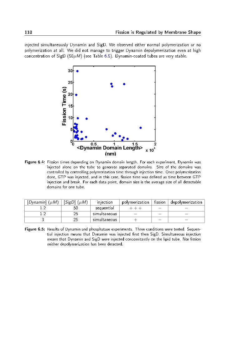
118 Fission is Regulated by Membrane Shape
injected simultaneously Dynamin and SigD. We observed either normal polymerization or nopolymerization at all. We did not manage to trigger Dynamin depolymerization even at highconcentration of SigD (50µM) (see Table 6.5). Dynamin-coated tubes are very stable.
Figure 6.4: Fission times depending on Dynamin domain length. For each experiment, Dynamin wasinjected alone on the tube to generate separated domains. Size of the domains wascontrolled by controlling polymerization time through injection time. Once polymerizationdone, GTP was injected, and in this case, ssion time was dened as time between GTPinjection and break. For each data point, domain size is the average size of all detectabledomains for one tube.
[Dynamin] (µM) [SigD] (µM) injection polymerization ssion depolymerization1.2 50 sequential + + + − −1.2 25 simultaneous − − −3 25 simultaneous + − −
Figure 6.5: Results of Dynamin and phosphatase experiments. Three conditions were tested. Sequen-tial injection means that Dynamin was injected rst then SigD. Simultaneous injectionmeans that Dynamin and SigD were injected concomitantly on the lipid tube. Nor ssionneither depolymerization has been detected.

6.4 Summary of Article 2 119
6.4 Summary of Article 2
The objective of the article is to probe the localization and the kinetics of Dynamin-mediatedmembrane ssion. Dynamin polymerization and tube breaking are observed with the nanotubeextrusion technique. Whereas Dynamin polymerization does not require the presence of anynucleotide, ssion is observed only with GTP. Dynamin-mediated ssion takes 10 s at 150 µMof GTP consistently with in vivo data. It is observed that ssion takes place preferentiallyat the curved regions of the membrane such as the neck linking an extruded nanotube to aGUV. More precisely, by combining the nanotube extrusion technique to spinning disk confocalmicroscopy, ssion events are precisely localized at the edge of the Dynamin polymer. At theseboundaries, the membrane is stressed by the mismatching curvatures imposed by Dynamin onone side and by the membrane elasticity on the other side. The energetic cost of this stress isproposed to trigger ssion. This hypothesis leads to formulate a model of the ssion reactionwith a single energy barrier. The histogram of ssion times follows an exponential distribution ingood agreement with a rate-limiting single energy barrier. Moreover the proposed model givespredictions for the ssion time dependence on membrane tension and rigidity. These predictionshave been validated experimentally: the average ssion time increases with increasing bendingrigidities and decreasing tensions. Furthermore the single energy barrier model takes intoaccount the torque exerted by Dynamin during constriction. It is predicted that the mechanicalwork due to the torque exerted by Dynamin is proportional to the energy released during GTPhydrolysis. The stall torque is measured by counteracting Dynamin torque with magnetic beadsattached to the helix and trapped by magnetic tweezers. An underestimate of Dynamin torque iscalculated from the viscous drag exerted on these magnetic beads during GTP-driven rotations.Thus the torque exerted by Dynamin is estimated to be in the range of 730 - 1100 pN.nm.The viscous torque inferred from the rotating magnetic beads is measured at dierent GTPconcentrations and the prediction from the model is validated. The eciency of Dynamin toconvert chemical energy into a reduction of energy barrier is estimated at 37%. Finally therelevance of these in vitro experiments is tested. Plasma membrane tension is modied throughosmotic shocks. Dynamin activity is blocked when tension is decreased (hyperosmotic shocks)which is consistent with the model. In conclusion, this article presents a model of the ssionreaction which is tested experimentally both in vitro and in vivo. It demonstrates that thekinetics and location of membrane ssion is regulated mainly through membrane elasticity.Complementary experiments attempt to measure the radius of constriction and the minimalamount of functional Dynamin dimers required for ssion. The hypothesis of depolymerizationwas tested but no clear conclusion can be stated.


Chapter 7
Discussion
In this chapter, I will discuss the results detailed in Chapters 5 and 6 under four perspectives.First I will comment in section 7.1 the mechanochemical properties of Dynamin in analogy withthe classical molecular motors. In section 7.2, some general features of the ssion mechanismwill be extrapolated from the particular case of Dynamin and applied to other ssion machiner-ies. Fission will be then compared in section 7.3 to its reverse reaction: fusion. Finally in vivo
and in vitro data will confronted in section 7.4.
7.1 Dynamin: a Molecular Motor
Dynamin is a mechanochemical enzyme with a nucleotide hydrolysis activity reminiscent of amolecular motor's activity as we underlined in Chapter 4.3.1. To decipher the mechanochemicalcoupling of Dynamin, I performed experiments which took inspiration from molecular motorstudies.For instance in vitro experiments have unravelled the mechanism of Kinesin, a molecular motorwhich hydrolyses ATP to transport cargo along microtubules. Optically-trapped microbeads at-tached to Kinesins are tracked during the motor displacement along microtubules (see Fig.7.1.A)and a stepping behaviour is observed. The statistical analysis of the dwell time between Kinesinsteps gives an exponential distribution. In the case of Dynamin, histograms of ssion times alsoshow an exponential distribution. These results indicate that both mechanisms are stochasticand can be treated as rate-limited thermally-activated barriers. By limiting the amount of ATP,the elementary step of kinesin was resolved: one Kinesin makes a step of 8 nm by hydrolysingone ATP [120]. Similarly I quantied Dynamin activity as a function of GTP concentration. Iobtained that Dynamin-mediated ssion rate depends on GTP concentration as a power low,with an exponent equal to 0.37. This exponent is interpreted as the mechanochemical eciencyof Dynamin. However there are strong dierences between Kinesin and Dynamin studies. Ki-nesin was investigated in single molecule conditions but not Dynamin since its ssion activityrelies on polymerization. Thus I could not directly measure how much GTP is consumed perDynamin monomer during ssion. Another interesting dierence between the two motors isthat Kinesin activity is more tighlty coupled to nucleotide hydrolysis than in the Dynamin case.This indicates that the energy landscapes of the two reactions are dierent. Indeed we estab-
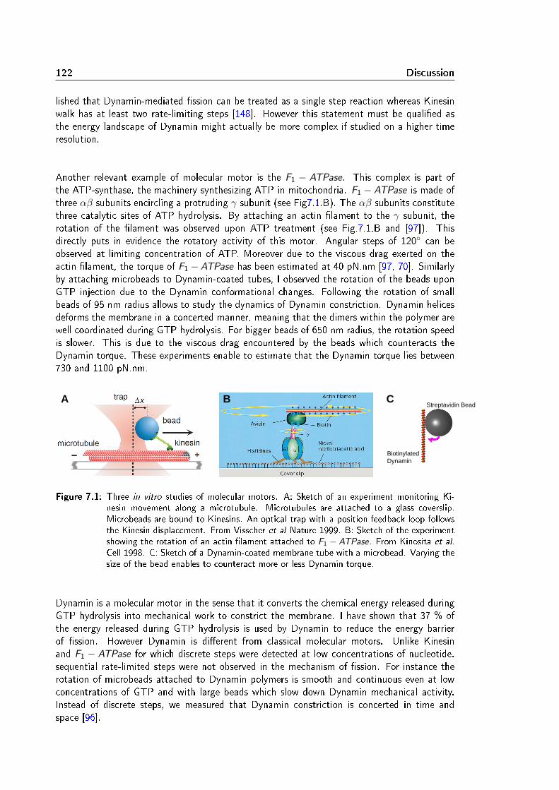
122 Discussion
lished that Dynamin-mediated ssion can be treated as a single step reaction whereas Kinesinwalk has at least two rate-limiting steps [148]. However this statement must be qualied asthe energy landscape of Dynamin might actually be more complex if studied on a higher timeresolution.
Another relevant example of molecular motor is the F1 − ATPase. This complex is part ofthe ATP-synthase, the machinery synthesizing ATP in mitochondria. F1 − ATPase is made ofthree αβ subunits encircling a protruding γ subunit (see Fig7.1.B). The αβ subunits constitutethree catalytic sites of ATP hydrolysis. By attaching an actin lament to the γ subunit, therotation of the lament was observed upon ATP treatment (see Fig.7.1.B and [97]). Thisdirectly puts in evidence the rotatory activity of this motor. Angular steps of 120 can beobserved at limiting concentration of ATP. Moreover due to the viscous drag exerted on theactin lament, the torque of F1 −ATPase has been estimated at 40 pN.nm [97, 70]. Similarlyby attaching microbeads to Dynamin-coated tubes, I observed the rotation of the beads uponGTP injection due to the Dynamin conformational changes. Following the rotation of smallbeads of 95 nm radius allows to study the dynamics of Dynamin constriction. Dynamin helicesdeforms the membrane in a concerted manner, meaning that the dimers within the polymer arewell coordinated during GTP hydrolysis. For bigger beads of 650 nm radius, the rotation speedis slower. This is due to the viscous drag encountered by the beads which counteracts theDynamin torque. These experiments enable to estimate that the Dynamin torque lies between730 and 1100 pN.nm.
Biotinylated Dynamin
Streptavidin Bead A B C
Figure 7.1: Three in vitro studies of molecular motors. A: Sketch of an experiment monitoring Ki-nesin movement along a microtubule. Microtubules are attached to a glass coverslip.Microbeads are bound to Kinesins. An optical trap with a position feedback loop followsthe Kinesin displacement. From Visscher et al Nature 1999. B: Sketch of the experimentshowing the rotation of an actin lament attached to F1 − ATPase. From Kinosita et al.
Cell 1998. C: Sketch of a Dynamin-coated membrane tube with a microbead. Varying thesize of the bead enables to counteract more or less Dynamin torque.
Dynamin is a molecular motor in the sense that it converts the chemical energy released duringGTP hydrolysis into mechanical work to constrict the membrane. I have shown that 37 % ofthe energy released during GTP hydrolysis is used by Dynamin to reduce the energy barrierof ssion. However Dynamin is dierent from classical molecular motors. Unlike Kinesinand F1 − ATPase for which discrete steps were detected at low concentrations of nucleotide,sequential rate-limited steps were not observed in the mechanism of ssion. For instance therotation of microbeads attached to Dynamin polymers is smooth and continuous even at lowconcentrations of GTP and with large beads which slow down Dynamin mechanical activity.Instead of discrete steps, we measured that Dynamin constriction is concerted in time andspace [96].

7.2 Dierent Fission Mechanisms? 123
Motor Step Size Maximum Force or Torque EciencyKinesin 8 nm 5 pN 50 %
F1 − ATPase 120 40 pN.nm 100 %Dynamin not detected 730-1100 pN.nm 37 %
Figure 7.2: Main properties of three molecular motors. Kinesin and F1 − ATPase data come fromKinosita et al Cell 1998.
7.2 Dierent Fission Mechanisms?
Dynamin mechanochemical activity triggers membrane ssion. In this section, I will explainhow the particular case of Dynamin can be useful to understand the mechanism of ssion ingeneral. For this purpose, Dynamin-mediated ssion will be compared to the ssion inducedby phase-separation. Some general features of the ssion mechanism can be inferred fromthis comparison. These features will be then applied to less-understood mechanisms of ssion:Dnm1- and ESCRT-III-mediated ssions.
7.2.1 Common Features Between Phase Separation-Induced and Dynamin-Mediated Fission
In section 3.3.2, we introduced the mechanism of ssion induced by phase separation. Wehighlighted that ssion occurs at the interface between the two phases. Interestingly, in thecase of Dynamin, we found that ssion also occurs at an interface: at the edge betweenthe Dynamin-coated tube and the free membrane. In both mechanisms, ssion localizes atan interface between two pre-dened domains. Phase separation generates two domains ofmembrane with dierent lipid compositions, for instance lo and ld phases. Dynamin activitycreates also two domains: a portion of the tube is coated with Dynamin and the other one isfree of protein. In both case the boundary between the two domains has an energetic cost: theline tension for phase separation and for Dynamin the elastic energy of the membrane due to themismatching curvatures of the two domains. The energetic cost of creating a boundary helpsssion. Line tension has been estimated around λ ≈ 1 pN for ternary composition made ofsphingomyelin, PC and cholesterol segregating into lo and ld phases [10]. For a tube of 20 nmradius, this corresponds to an energy of line tension Eline tension ≈ 120 pN.nm ≈ 30 kBT . Inthe case of Dynamin-mediated ssion, the edge energy depends on the bending rigidity modulusκ and on the ratio of the radii: Rm
Rcwhere Rm is the radius of the protein-free tube portion
and Rc the radius of the tube portion constricted by Dynamin [123]. For instance for a radiiratio of 5 and a rigidity κ = 16kBT , we calculate an elastic energy around Eelastic ≈ 70 kBT(see Supplementary Figure 3 Chapter 6). These "boundary" energies contribute to reduce theenergy barrier of ssion that we estimated to be around 80 kBT . The boundary energy couldbe a common feature of all ssion mechanisms.However generating a boundary is not enough for ssion. Indeed Dynamin constriction doesnot trigger ssion in all conditions. Similarly phase separation does not lead necessary tossion as stable phase-separated domains can be observed in vitro [10]. In both processes,membrane elastic parameters (tension, rigidity) must help ssion. Indeed we nd that hightension increases ssion rate and this was also observed for phase-separation ssion: 1s for

124 Discussion
tensed tubules pulled by Kinesins and 20s for tubules with lower tensions [114]. Thus a secondrequirement for ecient ssion is to regulate membrane tension and rigidity.
7.2.2 Predictions For Other Fission Machineries
Dynamin is not the unique ssion machinery in the cell. For instance, Dnm1 is a DRP involvedin mitochondrial ssion in yeast [12]. ESCRT-III has been implicated in membrane scission inthe multivesicular body, during viral budding and in membrane abscission during cytokinesis[63, 119, 50]. In the following sections, I will propose some predictions for the ssion activityof these two proteins based on the current knowledge of Dynamin.
Dynamin-Related Proteins
Dnm1 is a DRP required for the ssion of mitochondrial membranes. Recent cryo-electronmicroscopy experiments show that Dnm1 has an helical structure and a conformational changevery similar to the Dynamin ones [91]. Thus Dynamin and Dnm1 are expected to follow asimilar ssion mechanism. However they do dier at some points.Dnm1 helices have a larger radius than Dynamin polymers. In the non-constricted state, Dnm1inner lumen diameter is 89 nm (17 nm for Dynamin), its pitch is around 28.8 nm (10.6 nm forDynamin). Upon GTP treatment, Dnm1 inner lumen diameter decreases to 25 nm (7 nm forDynamin) while the pitch remains constant (it decreases to 9.4 nm for Dynamin) (see Fig.7.3).Like in the case of Dynamin, Dnm1-mediated ssion involves a constriction mechanism. How-ever Dnm1 constricts much more than Dynamin. Indeed the ratio of the unconstricted radiusover the constricted radius is 3.6 for Dnm1 and 2.4 for Dynamin. It means that the torque gen-erated by Dnm1 is more important than the one exerted by Dynamin. It would be interestingto measure this torque with the rotating bead technique and compare its value with Dynamin.
A B C
Figure 7.3: Cryo-EM pictures of Dnm1-coated lipid tubes. A: in absence of nucleotide. B: in thepresence of GMP-PCP. C: after addition of 1 mM GTP. Scale bar: 50 nm. From Mearset al 2011.
Another striking dierence between Dnm1 and Dynamin comes from the interactions betweenthe helical polymer and the lipid bilayer. Dynamin inserts within the outer leaet of themembrane via its PH domain [106] whereas Dnm1 helix stays apart from the lipid bilayer [91].Dynamin constriction is damped by the friction between the helix and the membrane [96].One would expect a dierent dynamics of constriction for Dnm1 resulting from its dierentinteraction with the membrane. Dnm1 constriction might be less damped by membrane-protein
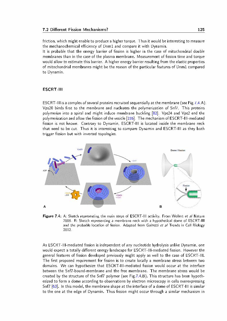
7.2 Dierent Fission Mechanisms? 125
friction, which might enable to produce a higher torque. Thus it would be interesting to measurethe mechanochemical eciency of Dnm1 and compare it with Dynamin.It is probable that the energy barrier of ssion is higher in the case of mitochondrial doublemembranes than in the case of the plasma membrane. Measurement of ssion time and torquewould allow to estimate this barrier. A higher energy barrier resulting from the elastic propertiesof mitochondrial membranes might be the reason of the particular features of Dnm1 comparedto Dynamin.
ESCRT-III
ESCRT-III is a complex of several proteins recruited sequentially at the membrane (see Fig.7.4.A).Vps20 binds rst to the membrane and nucleates the polymerization of Snf7. This proteinspolymerize into a spiral and might induce membrane buckling [82]. Vps24 and Vps2 end thepolymerization and allow the ssion of the vesicle [155]. The mechanism of ESCRT-III-mediatedssion is not known. Contrary to Dynamin, ESCRT-III is located inside the membrane neckthat need to be cut. Thus it is interesting to compare Dynamin and ESCRT-III as they bothtrigger ssion but with inverted topologies.
A B
Figure 7.4: A: Sketch representing the main steps of ESCRT-III activity. From Wollert et al Nature2009. B: Sketch representing a membrane neck with a hypothetical dome of ESCRT-IIIand the probable location of ssion. Adapted from Guizetti et al Trends in Cell Biology2012.
As ESCRT-III-mediated ssion is independent of any nucleotide hydrolysis unlike Dynamin, onewould expect a totally dierent energy landscape for ESCRT-III-mediated ssion. However thegeneral features of ssion developed previously might apply as well to the case of ESCRT-III.The rst proposed requirement for ssion is to create locally a membrane stress between twodomains. We can hypothesize that ESCRT-III-mediated ssion would occur at the interfacebetween the Snf7-bound-membrane and the free membrane. The membrane stress would becreated by the structure of the Snf7 polymer (see Fig.7.4.B). This structure has been hypoth-esized to form a dome according to observations by electron microscopy in cells overexpressingSnf7 [63]. In this model, the membrane shape at the interface of a dome of ESCRT-III is similarto the one at the edge of Dynamin. Thus ssion might occur through a similar mechanism in

126 Discussion
both cases. As we noticed for Dynamin and phase separation, membrane tension and rigidityshould also aect ESCRT-III-mediated ssion. It would be interesting to perform in vitro ex-periments similar to the ones we did for Dynamin to investigate the ssion rate mediated byESCRT-III as a function of the membrane elastic parameters. We could compare Dynamin andESCRT-III and nd which one is more ecient under which conditions. In addition to theirtopological specicity, they might each have their own range of rigidities and tensions wherethey are the most ssion-competent.
7.3 Fission Versus Fusion
Fission and fusion are two biological mechanisms where membrane deformations lead to atopological change. They are also the reverse process of each other. Fission splits one membraneinto two distinct membranes, while fusion merges two separate compartments into a single one.Thus it is interesting to compare these two complementary mechanisms.
As we mentioned in section 2.2.1, SNARE proteins are involved in fusion during vesicular trac.Two types of SNARE proteins are required for fusion: v-SNAREs and t-SNAREs. v-SNAREs areanchored in the membrane of the vesicle. t-SNAREs are bound to the target membrane. Afterdocking of the vesicle at the target membrane via RAB proteins, the two membranes are broughtcloser through interactions between cognate v-SNAREs and t-SNAREs. These interactionsoccurs in a "zipper"-like mode leading to the formation of a four-α-helix bundle. The tightbinding between v-SNARE and t-SNARE forms a complex called a SNAREpin. Fusion of thetwo membranes occurs upon complete "zipping" of the SNAREpin. After fusion, the remainingSNAREpin complex becomes the cis-SNARE complex which is very stable and requires the helpof other proteins to disassemble (see Fig.7.5).
B D C A
Figure 7.5: Sketch representing the main steps of SNARE-mediated fusion. A: initiation of fusion,cognate v-SNARE and t-SNARE (both represented in green) start to assemble. B: zippingof the SNAREpin brings the membranes closer to each other and facilitates the formationof the hemifusion intermediate. C: complete formation of the SNAREpin leads to fusionand generates a fusion pore. D: expansion of the fusion pore, the cis-SNARE complexremains embedded in the membrane. From Roux et al Pour la Science 2007.
Strikingly, although Dynamin and SNAREs are two distinct families of proteins, some DRPsare implicated in intracellular fusion processes especially for mitochondria and chloroplast. Thefusion of these organelles is more complex as they are delimited by two membranes. Forinstance Mitofusins and OPA1, two DRPs, mediate fusion of the outer and inner mitochondrial

7.3 Fission Versus Fusion 127
membranes respectively [92]. The mechanism of fusion for these DRPs is not known so farand might be dierent from the mechanism of Dynamin-medited ssion. Dynamin has alsobeen linked to fusion. It has been proposed that Dynamin regulates the expansion of the fusionpore [6]. The implication of Dynamins in both ssion and fusion prompts us to look for thesimilarities and dierences between the two processes.
Fission and fusion share the same intermediate state: the hemission/hemfusion stalk. Theproximal membrane leaets merge their lipid content while the distal leaets are still separated(see Fig.7.6). The stalk intermediate enables both non-leaky fusion and non-leaky ssion whichare necessary for ecient transport. This state has been detected during the fusion processby observing the mixing of two uorescent membranes while the content of the two compart-ments remains separated [47]. Evidence for a non-leaky intermediate has been found also forthe Dynamin-mediated ssion mechanism in patch clamp experiments [9]. Interestingly bothmechanisms use the same strategy to reach the stalk intermediate: to reduce the distancebetween bilayers. Zipping of the SNAREpin and Dynamin constriction both bring the bilayercloser to each other. Thus one would expect that the energies involved in both processes havethe same order of magnitude. Indeed the energy of the stalk has been estimated in ssion andfusion. For SNAREs-mediated fusion, the hemifusion energy has been calculated around 40-50kBT [75]. For ssion mediated by coat proteins, a calculation based on the Canham-Helfrichtheory gives an underestimate of 78 kBT for the hemission state energy [76]. Thus energyinput is required to reach the stalk. In vivo this energy barrier is crossed with the help of specicprotein machineries. In fusion, the energy released during the assembly of the SNAREpin com-plex contribute to generate hemifusion. The energy of a single SNAREpin assembly has beenmeasured at 35 kBT [85]. Although several SNAREpin complexes per fusion site are proposedto be required for rapid fusion [68], it seems that one complex is energetically sucient. Inssion, Dynamin constriction reduces the energy barrier and facilitate ssion. We estimate thisconstriction energy around 80 kBT .
distal leaflet
proximal leaflet
Figure 7.6: Sketch of the stalk: intermediate of ssion and fusion. The proximal leaets are mergedwhile the distal leaets remain separated. The red line indicates where the rupture mustoccur to complete the process. Adapetd from Chernomordik and Kozlov, Cell 2005.

128 Discussion
Although ssion and fusion share the same intermediate, these mechanisms have dierentsource of energy: Dynamin-mediated ssion is fuelled by nucleotide hydrolysis while SNAREs-mediated fusion relies on structural anity1. This dierence could be due to the fact thatreaching the stalk state is more costly from the hemission side (more than 78 kBT ) than fromthe hemifusion side (40-50 kBT ). Once the stalk intermediate has been reached, rupture withinthe structure must occur along the red line as depicted in Fig.7.6. This step is spontaneousin the case of ssion [76]. For the fusion process, this step is energetically more costly as itrequires at least to expand the fusion pore. Thus the energy landscape of ssion and fusionshould be dierent.
These dierent energetic signatures of ssion and fusion translate into dierent membraneproperties requirements. As we calculated in paragraph 3.3.1, the energy dierence betweenthe initial and the nal state of ssion is
∆Efission = 4π(κ
8+ κG )
As fusion is the reverse process, we expect:
∆Efusion = −∆Efission
∆Efusion = −4π(κ
8+ κG )
This implies that increasing the bending rigidity modulus κ and the Gaussian bending rigiditymodulus κG should favour fusion and inhibit ssion. Indeed we have found that stier mem-branes are less ssion competent (see Fig.1 Chapter 5). Consistently, SNARE proteins havebeen shown to localize at cholesterol-rich regions where membrane is more rigid [79, 78]. Theseclusters are thought to enhance exocytosis by locally concentrating the fusion machinery butthe rigidity of the membrane by itself could favour fusion. To test this hypothesis, it would beinteresting to measure in vitro how the fusion rate depends on the membrane rigidity modulus.
Although membrane rigidity controls dierently ssion and fusion, it seems that membranetension regulates similarly both processes. In nanotube extrusion experiments, I show thatdecreasing tension delays ssion. Hyperosmotic shocks on live cells, which decrease membranetension, conrm that Dynamin-mediated ssion is impaired at low tensions. Concerning fusionit is showed that an increase in plasma membrane tension activates exocytosis [46]. Theoreticalworks also predict that increasing tension is critical for the fusion pore expansion [25]. So highermembrane tension stimulates both ssion and fusion. In vivo the regulations of membranetension is believed to be achieved in part by the cytoskeleton. Actin laments might helpssion by pulling on the bud [15]. Local disassembly of the cortex might facilitate the fusionpore expansion and thus favour fusion [22]. It would be interesting to further address thisquestion in vivo: how is membrane tension regulated by the cytoskeleton (or by another way)to activate preferentially ssion or fusion?
1It is interesting to note that ESCRT-III-mediated ssion does not require nucleotide hydrolysis.
7.4 In Vitro Fission Versus In Vivo Fission 129
7.4 In Vitro Fission Versus In Vivo Fission
During my thesis, I studied Dynamin mainly through in vitro experiments: puried Dynaminand articial membranes were used in order to control precisely membrane elastic parameterssuch as tension and rigidity. In this section, I will analyse to which extent the in vitro resultsgive information about Dynamin activity in vivo. First the characteristics of the Dynamin helixin vitro will be confronted to in vivo observations. Then I will discuss what are the requirementsfor a biological membrane to ensure ecient ssion in vivo.
7.4.1 In Vitro Helix Versus In Vivo Helix
In vivo Dynamin polymerizes into short helices (supposedly 2 or 3 helical turns) whereas mostin vitro experiments, such as electron microscopy or nanotube extrusion experiments, studylong Dynamin helices (several µm which correspond to several hundreds of helical turns). Thisraises questions about the physiological relevance of long Dynamin polymers [103, 9, 111]. Ithas been proposed that pre-assembled long Dynamin helices are kinetically non active [103].During my thesis, I have measured that Dynamin constriction is damped by internal frictionbetween the membrane and the helix, which could explain why long polymers are less ssioncompetent. Moreover I have identied a precise localization of ssion events: the edge of theDynamin polymer. This could explain why fewer ssion events are observed on long polymerscompared to short helices. When Dynamin is pre-assembled without GTP, continuous and longpolymers are generated, thus the number of edges is low, which results in a low ssion rate. Onthe contrary, when Dynamin polymerizes in presence of GTP, its constriction activity leads tossion at an early stage and limits the length of the polymers. Thus long polymers of Dynaminare still relevant to study ssion mechanism since ssion is localized at the interface betweenthe edge of the polymer and the free membrane.
In vivo Dynamin interacts with other proteins via its PRD domain. These proteins couldmodulate the Dynamin helix. For instance during CME, Dynamin colocalizes transiently withAmphiphysin, Endophilin and FBP17 [139]. These proteins are involved in membrane remod-elling but they could also regulate Dynamin activity. Indeed it has been shown in vitro thatDynamin-coated tubes have a thinner radius when they are prepared in presence of FBP17 [64]or Endophilin [135]. These proteins could help Dynamin to further constrict lipid nanotubes.Thus It would be interesting to test how the ssion rate is modied in presence of Dynaminpartners. These proteins could also recruit Dynamin at a precise location within the neck ofthe bud and thus indirectly control where ssion would happen. These hypothesis could beinvestigate in vitro with the nanotube extrusion technique.
It has also been proposed that ssion would result from Dynamin depolymerization [103, 9].This hypothesis remains an open question. I was not able to detect any Dynamin disassemblybefore ssion by uorescence microscopy. Even after ssion, Dynamin was still present onthe broken tubules. In vivo as well, it is not clear if Dynamin depolymerization precedes andtriggers ssion. It would require a higher temporal resolution (2s in [139]) to detect in vivo
both Dynamin disappearance and vesicle scission. The model proposed in Chapter 6 doesnot require Dynamin depolymerization prior to ssion but it does not exclude it neither. Inparticular, an uncoated part on the lipid tube is necessary for ssion in our model. To test if
130 Discussion
depolymerization of Dynamin is required for ssion, one should observe if ssion still occurswhen depolymerization is prevented for instance by crosslinking Dynamin within the polymer.
7.4.2 Membrane Requirements For Fission In Vivo
The results linking Dynamin activity to membrane elasticity were obtained for homogeneousmembranes at equilibrium and with simple lipid compositions. However biological membranesare more complex. Thus it is interesting to confront in vitro data with in vivo studies.
Membrane rigidity is an important parameter of the ssion mechanism. In vitro the aver-age ssion time increases almost ten times when the bending rigidity increases from 16.2 to35.5 kBT . This could indicate a cellular mechanism controlling the timing of ssion events. Invivo the dynamics of ssion could be regulated by modifying locally the lipid composition of themembrane. Indeed PIP2 hydrolysis by Synaptojanin has already been correlated to Dynamin-mediated ssion [18]. It would be interesting to know how cholesterol and sphingolipids behavewithin Clathrin-coated structures as these lipids greatly contribute to the rigidity of the mem-brane. It would also be newsworthy to correlate membrane lipid compositions and endocytosisrates for dierent cellular types. It is expected that membranes undergoing a high endocyticactivity are less rigid. This would test the consistency of the observation that rigidity slowsdown ssion.
In addition to membrane rigidity, membrane tension plays a role in ssion. In vitro, ssion time isaected by membrane tension, especially for membranes containing cholesterol and sphingolipid,(lipids in which the plasma membrane is particularly enriched) (see Fig.1 in Chapter 5). Fortension lower than 10−4 N.m−1, ssion is drastically slower. Plasma membrane tension hasbeen estimated around 10−3 N.m−1 by nanotube extrusion on blebbing cells [29]. Thus itappears that the plasma membrane tension is in a range where Dynamin-mediated ssion isecient. Moreover it has been shown that Clathrin-coated pits are blocked when loweringplasma membrane tension [58]. This correlates also with our in vivo data (see Fig. 4 inChapter 5). Hyperosmotic shocks on live cells block Dynamin structures which colocalize withClathrin-coated pits. These experiments show that the defective CME after a hyperosmoticshock is not due to the precipitation of Clathrin, as it was believed so far, but is really due tothe reduced activity of Dynamin. One would expect an enhanced ssion rate after hypoosmoticshocks. But hypoosmotic shocks delays the formation of clathrin-coated pits making it dicultto probe Dynamin activity. However long tubules of Dynamin are observed to polymerize atthe plasma membrane after hypoosmotic shocks, which indicates that Dynamin is still active.Membrane tension regulates Dynamin-mediated ssion. But what controls membrane tensionin vivo? The cytoskeleton is a good candidate for membrane tension regulation. Some studiesshow an interplay between actin, membrane elastic properties and endocytosis. On one hand,plasma membrane tubulation is facilitated by cytoskeleton disruption [64]. On the other hand,actin cytoskeleton is required for proper endocytosis at location of high membrane tensions [15].The precise mechanism coordinating membrane elasticity, cytoskeleton dynamics and ssion isstill not understood.
An interesting membrane parameter which was not tested during this thesis is the asymmetryin the lipid bilayer. The plasma membrane is especially intriguing as the exoplasmic leaet isenriched in sphingomyelin while the cytoplasmic leaet contains a higher level of PS. During
7.4 In Vitro Fission Versus In Vivo Fission 131
endocytosis, in the stalk structure, the proximal leaet is enriched in SM, and is thus lessdeformable than the distal leaet. Asymmetric leaets generate spontaneous curvature whichcould inuence the ssion mechanism. This hypothesis could be investigated in vitro. Forinstance, ssion rate could be measured with asymmetric bilayers prepared with the invertedemulsion technique [98]. These in vitro experiments might help to understand how the asym-metry of biological membranes inuence ssion during endocytosis.

Chapter 8
Conclusion
During this thesis, a model of Dynamin-mediated membrane ssion has been proposed basedon the observation that ssion occurs at Dynamin edges. It leads to the formulation of theenergy barrier of ssion:
∆E ' a(1
Ri− 1
Ru)κ3/2
√σ
= a(1
Ri− 1
Rc)κ3/2
√σ
+ cΓθ
where Ri is the tube radius of the intermediate state, Rc the radius of the constricted Dynamin-coated tube, Ru the radius of the unconstricted Dynamin-coated tube, κ the bending rigiditymodulus of the membrane, σ the membrane tension, Γ the torque delivered during constriction,θ the angle by which the helix rotates per hydrolysed GTP, a and c are two constants. Thebarrier is estimated from 30 to 70 kBT depending on membrane tension and rigidity. In vitro
and in vivo experiments allow to test this model. We calculate theoretically and validateexperimentally how the ssion time depends on membrane rigidity, membrane tension andDynamin torque. Statistical analysis shows that ssion time follows an exponential distributionin agreement with a single energy barrier reaction. Torque measurements demonstrate thatthe energy delivered by Dynamin torque is proportional to the energy released during GTPhydrolysis and reduces the energy barrier of ssion. From these experiments, the eciency ofDynamin is estimated at 37%.The validations of our model gives a quantitative analysis of the energy landscape of ssion.Although constriction is not enough to proceed to ssion, it supplies energy to reduce the energybarrier. This barrier can be crossed by thermal uctuations when the membrane satises specicconditions of tension and rigidity.
In vivo the energy barrier of Dynamin-mediated ssion is probably modied by other proteins,like Endophilin or Amphiphysin. Membrane tensions and rigidities are certainly actively reg-ulated. Thus it would be interesting to perform further experiments to complete the energylandscape depicted in Fig. 8.1 and integrate it into to the full mechanism of endocytosis.
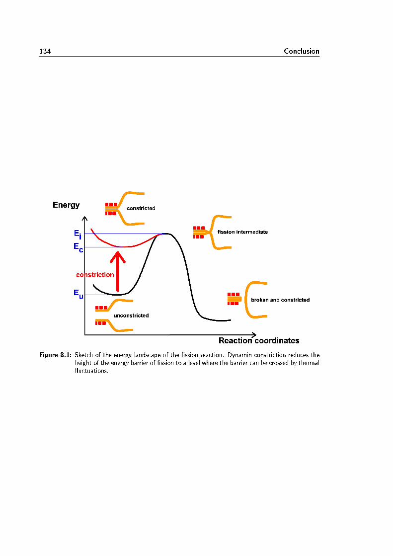
134 Conclusion
Figure 8.1: Sketch of the energy landscape of the ssion reaction. Dynamin constriction reduces theheight of the energy barrier of ssion to a level where the barrier can be crossed by thermaluctuations.
Bibliography
[1] M. R. Ahmadian, U. Homann, R. S. Goody, and A. Wittinghofer. Individual rateconstants for the interaction of ras proteins with gtpase-activating proteins determinedby uorescence spectroscopy. Biochemistry, 36:45354541, 1997. 30
[2] S. Aimon, J. Manzi, D. Schmidt, J. A. Poveda Larrosa, P. Bassereau, and G. E. S.Toombes. Functional reconstitution of a voltage-gated potassium channel in giant unil-amellar vesicles. PLoS One, 6(10):e25529, 2011. 19
[3] Bruce Alberts, Dennis Bray, Alexander Johnson, Julian Lewis, Martin Ra, Keith Roberts,and Peter Walter. Essential Cell Biology. Garland Publishing Inc., New-York, London,1998. 3, 4
[4] J.-M. Allain, C. Storm, A. Roux, M. Ben Amar, and J.-F. Joanny. Fission of a multiphasemembrane tube. Physical Review Letters, 93(15):14, 2004. 22
[5] E. Ambroggio, B. Sorre, P. Bassereau, B. Goud, J.-B. Manneville, and B. Antonny.Arfgap1 generates an arf1 gradient on continuous lipid membranes displaying at andcurved regions. The EMBO Journal, 29:292303, 2010. 19
[6] A. Anantharam, M. A. Bittner, R. L. Aikman, E. L. Stuenkel, S. L. Schmid, D. Axelrod,and R. W. Holz. A new role for the dynamin gtpase in the regulation of fusion poreexpansion. The EMBO Journal, 22(11):19071918, 2011. 28, 127
[7] M. I. Angelova, S. Soléau, Ph. Méléard, F. Faucon, and O. Bothorel. Preparation ofgiant vesicles by external ac electric elds. kinetic and applications. Progress in Colloid
and Polymer Science, 88:127131, 1992. 15
[8] L. Bagatolli and P. B. Sunil Kumar. Phase behavior of multicomponent membranes:Experimental and computational techniques. Soft Matter, 5:32343248, 2009. 15, 19
[9] P. V. Bashkirov, S. A. Akimov, A. I. Evseev, S. L. Schmid, J. Zimmerberg, and V. A.Frolov. Gtpase cycle of dynamin is couple to membrane squeeze and release, leading tospontaneous ssion. Cell, 135:12761286, 2008. 36, 117, 127, 129
[10] T. Baumgart, S. T. Hess, and W. W. Webb. Imaging coexisting uid domains in biomem-brane models coupling curvature and line tension. Nature, 425:821824, 2003. 22, 123
[11] D. D. Binns, B. Barylko, N. Grichine, M. A. L. Atkinson, M. K. Helms, D. M. Jameson,J. F. Eccleston, and J. P. Albanesi. Correlation between self-association modes andgtpase activation of dynamin. Journal of Protein Chemistry, 18(3):277290, 1999. 30

136 BIBLIOGRAPHY
[12] W. Bleazard, J. M. McCaery, E. J. King, S. Bale, A. Mozdy, Q. Tieu, J. Nunnari, andJ. M. Shaw. The dynamin-related gtpase dnm1 regulates mitochondrial ssion in yeast.Nature Cell Biology, 1:298304, 1999. 124
[13] L. Bo and R. E. Waugh. Determination of bilayer membrane bending stiness by tetherformation from giant, thin-walled vesicles. Biophysical Journal, 55(3):509 517, 1989.18
[14] J. S. Bonifacino and B. S. Glick. The mechanisms of vesicle budding and fusion. Cell,116:2153166, 2004. 5
[15] S. Boulant, C. Kural, J.-C. Zeeh, F. Ubelmann, and T. Kirchhausen. Actin dynamicscounteract membrane tension during clathrin-mediated endocytosis. Nature Cell Biology,13:110, 2011. 128, 130
[16] P. B. Canham. The minimum energy of bending as a possible explanation of the biconcaveshape of the human red blood cell. Journal of Theoretical Biology, 26(1):6176, 1970.13
[17] K. Carvalho, L. Ramos, C. Roy, and C. Picart. Giant unilamellar vesicles containingphosphatidylinositol(4,5)bisphosphate: Characterization and functionality. Biophysical
Journal, 95:43484360, 2008. 15
[18] B. Chang-Ileto, S. G. Frere, R. B. Chan, S. V. Voronov, A. Roux, and G. Di Paolo.Synaptojanin 1-mediated pi(4,5)p(2) hydrolysis is modulated by membrane curvatureand facilitates membrane ssion. Developmental Cell, 20(2):205218, 2011. 130
[19] J. S. Chappie, S. Acharya, M. Leonard, S. L. Schmid, and F. Dyda. G domain dimerizationcontrols dynamin's assembly-stimulated gtpase activity. Nature, 465:435440, 2010. 32
[20] J. S. Chappie, S. Acharya, Y.-W. Liu, M. Leonard, T. J. Pucadyil, and S. L. Schmid. Anintramolecular signaling element that modulates dynamin function in vitro and in vivo.Molecular Biology of the Cell, 20:35613571, 2009. 28
[21] J. S. Chappie, J. A. Mears, S. Fang, M. Leonard, S. L. Schmid, R. A. Milligan, J. E.Hinshaw, and F. Dyda. A pseudoatomic model of the dynamin polymer identies ahydrolysis-dependent powerstroke. Cell, 147:209222, 2011. 35
[22] A. Chen, E. Leikina, K. Melikov, B. Podbilewicz, M. M. Kozlov, and L. V. Chernomordik.Fusion-pore expansion during syncytium formation is restricted by an actin network.Journal of Cell Science, 121:36193628, 2008. 128
[23] Y.-J. Chen, P. Zhang, E. H. Egelman, and J. E. Hinshaw. The stalk region of dynamindrives the constriction of dynamin tubes. Nature Structural and Molecular Biology,11(6):574575, 2004. 32
[24] M. Chircop, B. Sarcevic, M. R. Larsen, C. S. Malladi, N. Chau, M. Zavortink, C. M.Smith, A. Quan, V. Anggono, P. G. Hains, M. E. Graham, and P. J. Robinson. Phos-phorylation of dynamin ii at serine-764 is associated with cytokinesis. Biochimica et
Biophysica Acta (BBA) - Molecular Cell Research, 1813(10):1689 1699, 2011. 28
[25] Y. A. Chizmadzhev, P. I. Kuzmin, D. A. Kumenko, J. Zimmerberg, and F. S. Cohen. Dy-namics of fusion pores connecting membranes of dierent tensions. Biophysical Journal,78(5):2241 2256, 2000. 128
BIBLIOGRAPHY 137
[26] S. Cipolat, O. Martins de Brito, B. Dal Zilio, and L. Scorrano. Opa1 requires mitofusin1 to promote mitochondrial fusion. PNAS, 101(45):1592715932, 2004. 28
[27] O. Cremona, G. Di Paolo, M. R. Wenk, A. LÃ14 thi, W. T. Kim, K. Takei, L. Daniell,
Y. Nemoto, S. B. Shears, R. A. Flavell, D. A. McCormick, and P. De Camilli. Essentialrole of phosphoinositide metabolism in synaptic vesicle recycling. Cell, 99(2):179 188,1999. 4, 8
[28] D. Cuvelier, P. Chiaruttini, P. Bassereau, and P. Nassoy. Pulling long tubes from rmlyadhered vesicles. Europhysics Letters, 71(6):10151021, 2005. 18
[29] J. Dai and M Sheetz. Membrane tether formation from blebbing cells. Biophysical
Journal, 77(6):33633370, 1999. 130
[30] H. Damke, T. Baba, D. E. Warnock, and S. L. Schmid. Induction of mutant dynaminspecically blocks endocytic coated vesicle formation. The Journal of Cell Biology,127:915934, 1994. 25, 26, 116
[31] D. Danino, K.-H. Moon, and J. E. Hinshaw. Rapid constriction of lipid bilayers by themechanochemical enzyme dynamin. J. Struct. Biol., 147:259267, 2004. 29, 32, 35, 36,47
[32] R. F. M. de Almeida, A. Fedorov, and M. Prieto. Sphin-gomyelin/phosphatidylcholine/cholesterol phase diagram: Boundaries and compositionof lipid rafts. Biophysical Journal, 85(4):2406 2416, 2003. 19
[33] I. Derényi, F. Jülicher, and J. Prost. Formation and interaction of membrane tubes.Physical Review Letters, 88(88):238101, 2002. 17
[34] H.G. Döbereiner, J. Käs, D. Noppl, I. Sprenger, and E. Sackmann. Budding and ssionof vesicles. Biophysical Journal, 65(4):1396 1403, 1993. 22
[35] Y. A. Domanov, S. Aimon, G. E. S. Toombes, M. Renner, F. Quemeneur, A. Triller,M. S. Turner, and P. Bassereau. Mobility in geometrically conned membranes. PNAS,108(31):1260512610, 2011. 19
[36] J. B. Doyon, B. Zeitler, J. Cheng, A. T. Cheng, J. M. Cherone, Y. Santiago, A. H. Lee,T. D. Vo, Y. Doyon, J. C. Miller, D. E. Paschon, L. Zhang, E. J. Rebar, P. D. Gregory,F. D. Urnov, and D. G. Drubin. Rapid and ecient clathrin-mediated endocytosis revealedin genome-edited mammalian cells. Nature Cell Biology, 13(3):331337, 2011. 26
[37] E. Evans and D. Needham. Physical properties of surfactant bilayer membranes: thermaltransitions, elasticity, rigidity, cohesion and colloidal interactions. The Journal of PhysicalChemistry, 91(16):42194228, 1987. 11
[38] E. Evans and W. Rawicz. Entropy-driven tension and bending elasticity in condensed-uidmembranes. Phys. Rev. Lett., 64:20942097, Apr 1990. 14, 15, 16
[39] K. Faelber, Y. Posor, S. Gao, M. Held, Y. Roske, D. Schulze, V. Haucke, F. Noà c©, andO. Daumke. Crystal structure of nucleotide-free dynamin. Nature, 477:556560, 2011.28
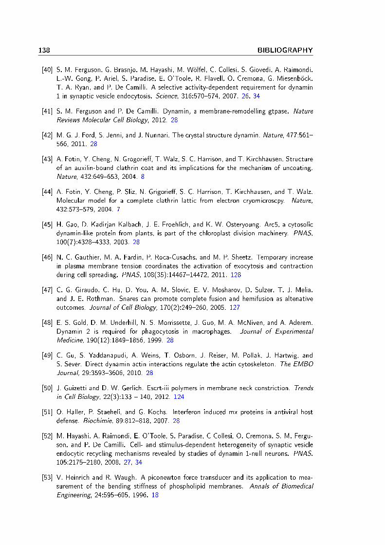
138 BIBLIOGRAPHY
[40] S. M. Ferguson, G. Brasnjo, M. Hayashi, M. Wölfel, C. Collesi, S. Giovedi, A. Raimondi,L.-W. Gong, P. Ariel, S. Paradise, E. O'Toole, R. Flavell, O. Cremona, G. Miesenböck,T. A. Ryan, and P. De Camilli. A selective activity-dependent requirement for dynamin1 in synaptic vesicle endocytosis. Science, 316:570574, 2007. 26, 34
[41] S. M. Ferguson and P. De Camilli. Dynamin, a membrane-remodelling gtpase. Nature
Reviews Molecular Cell Biology, 2012. 28
[42] M. G. J. Ford, S. Jenni, and J. Nunnari. The crystal structure dynamin. Nature, 477:561566, 2011. 28
[43] A. Fotin, Y. Cheng, N. Grogorie, T. Walz, S. C. Harrison, and T. Kirchhausen. Structureof an auxilin-bound clathrin coat and its implications for the mechanism of uncoating.Nature, 432:649653, 2004. 8
[44] A. Fotin, Y. Cheng, P. Sliz, N. Grigorie, S. C. Harrison, T. Kirchhausen, and T. Walz.Molecular model for a complete clathrin lattic from electron cryomicroscpy. Nature,432:573579, 2004. 7
[45] H. Gao, D. Kadirjan Kalbach, J. E. Froehlich, and K. W. Osteryoung. Arc5, a cytosolicdynamin-like protein from plants, is part of the chloroplast division machinery. PNAS,100(7):43284333, 2003. 28
[46] N. C. Gauthier, M. A. Fardin, P. Roca-Cusachs, and M. P. Sheetz. Temporary increasein plasma membrane tension coordinates the activation of exocytosis and contractionduring cell spreading. PNAS, 108(35):1446714472, 2011. 128
[47] C. G. Giraudo, C. Hu, D. You, A. M. Slovic, E. V. Mosharov, D. Sulzer, T. J. Melia,and J. E. Rothman. Snares can promote complete fusion and hemifusion as altenativeoutcomes. Journal of Cell Biology, 170(2):249260, 2005. 127
[48] E. S. Gold, D. M. Underhill, N. S. Morrissette, J. Guo, M. A. McNiven, and A. Aderem.Dynamin 2 is required for phagocytosis in macrophages. Journal of Experimental
Medicine, 190(12):18491856, 1999. 28
[49] C. Gu, S. Yaddanapudi, A. Weins, T. Osborn, J. Reiser, M. Pollak, J. Hartwig, andS. Sever. Direct dynamin actin interactions regulate the actin cytoskeleton. The EMBO
Journal, 29:35933606, 2010. 28
[50] J. Guizetti and D. W. Gerlich. Escrt-iii polymers in membrane neck constriction. Trendsin Cell Biology, 22(3):133 140, 2012. 124
[51] O. Haller, P. Staeheli, and G. Kochs. Interferon induced mx proteins in antiviral hostdefense. Biochimie, 89:812818, 2007. 28
[52] M. Hayashi, A. Raimondi, E. O'Toole, S. Paradise, C Collesi, O. Cremona, S. M. Fergu-son, and P. De Camilli. Cell- and stimulus-dependent heterogeneity of synaptic vesicleendocytic recycling mechanisms revealed by studies of dynamin 1-null neurons. PNAS,105:21752180, 2008. 27, 34
[53] V. Heinrich and R. Waugh. A piconewton force transducer and its application to mea-surement of the bending stiness of phospholipid membranes. Annals of Biomedical
Engineering, 24:595605, 1996. 18

BIBLIOGRAPHY 139
[54] W. Helfrich. Elastic properties of lipid bilayers - theory and possible experiments. Zur
Naturforchung, 28:6937034, 1973. 13, 14
[55] W. Helfrich and R. M. Servuss. Undulations, steric interaction and cohesion of uidmembranes. Nuovo Cimento, 3D:137151, 1984. 14
[56] J. R. Henley, E. W. A. Krueger, B. J. Oswald, and M. A. McNivem. Dynamin-mediatedinternalization of caveolae. Journal of Cell Biology, 141:8599, 1998. 28
[57] W. M. Henne, E. Boucrot, M. Meinecke, E. Evergren, Y. Vallis, R. Mittal, and H. T.McMahon. Fcho proteins are nucleators of clathrin-mediated endocytosis. Science,328:12811284, 2010. 6
[58] J. E. Heuser and R. G. W. Anderson. Hypertonic media inhibit receptor-mediated endo-cytosis by blocking clathrin-coated pit formation. Journal of Cell Biology, 108:389400,1989. 130
[59] J. E. Heuser and T. S. Reese. Structural changes after transmitter release at the frogneuromuscular junction. Journal of Cell Biology, 88:564580, 1981. 9
[60] J. E. Hinshaw. Dynamin and its role in membrane ssion. Annual Review of Cell and
Developmental Biology, 12:737519, 2000. 28
[61] J. E. Hinshaw and S. L. Schmid. Dynamin self-assembles into rings suggesting a mech-anism for coated vesicle budding. Nature, 374(6518):190192, 1995. 29, 32
[62] V. W. Hsu and J.-S. Yang. Mechanisms of cop1 vesicle formation. FEBS Letters,583(23):3758 3763, 2009. 5
[63] J. H. Hurley and P. I. Hanson. Membrane budding and scission by the escrt machinery:it's all in the neck. Nature, 11:556566, 2010. 124, 125
[64] T. Itoh, K. S. Erdmann, A. Roux, B. Habermann, H. Werner, and P. De Camilli. Dynaminand the actin cytoskeleton cooperatively regulate plasma membrane invagination by barand f-bar proteins. Developmental Cell, 9:791804, 2005. 28, 36, 129, 130
[65] D. Jensen and R. Schekman. Copii-mediated vesicle formation at a glance. Journal of
Cell Science, 124:14, 2011. 5
[66] W. J. Jockusch, G. J. K. Praefcke, H. T. McMahon, and L. Lagnado. Clathrin-dependentand clathrin-independent retrieval of synaptic vesicles in retinal bipolar cells. Neuron,46(6):869878, 2005. 9
[67] N. Kahya, D. Scherfeld, K. Bacia, B. Poolman, and P. Schwille. Probing lipid mobolityof raft-exhibiting model membranes by uorescence correlation spectroscopy. Journal ofBiological Chemistry, 278(30):2810928115, 2003. 19
[68] E. Karatekin, J. Di Giovanni, C. Iborra, J. Coleman, B. O'Shaughnessy, M. Seagar, andJ. E. Rothman. A fast, single-vesicle fusion assay mimics physiological snare requirements.PNAS, 107(8):35173521, 2010. 127
[69] W. T. Kim, S. Chang, L. Daniell, O. Cremona, G. Di Paolo, and P. De Camilli. Delayedreentry of recycling vesicles into the fusion-competent synaptic vesicle pool in synapto-janin 1 knockout mice. PNAS, 99(26):1714317148, 2002. 8
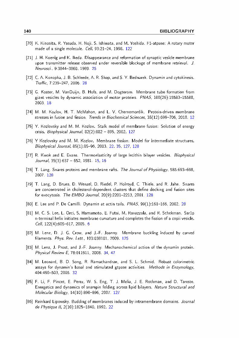
140 BIBLIOGRAPHY
[70] K. Kinosita, R. Yasuda, H. Noji, S. Ishiwata, and M. Yoshida. F1-atpase: A rotary motormade of a single molecule. Cell, 93:2124, 1998. 122
[71] J. H. Koenig and K. Ikeda. Disappearance and reformation of synaptic vesicle membraneupon transmitter release observed under reversible blockage of membrane retrieval. J.
Neurosci., 9:38443860, 1989. 25
[72] C. A. Konopka, J. B. Schleede, A. R. Skop, and S. Y. Bednarek. Dynamin and cytokinesis.Trac, 7:239247, 2006. 28
[73] G. Koster, M. VanDuijn, B. Hofs, and M. Dogterom. Membrane tube formation fromgiant vesicles by dynamic association of motor proteins. PNAS, 100(26):1558315588,2003. 18
[74] M. M. Kozlov, H. T. McMahon, and L. V. Chernomordik. Protein-driven membranestresses in fusion and ssion. Trends in Biochemical Sciences, 35(12):699706, 2010. 12
[75] Y. Kozlovsky and M. M. Kozlov. Stalk model of membrane fusion: Solution of energycrisis. Biophysical Journal, 82(2):882 895, 2002. 127
[76] Y Kozlovsky and M. M. Kozlov. Membrane ssion: Model for intermediate structures.Biophysical Journal, 85(1):8596, 2003. 22, 35, 127, 128
[77] R. Kwok and E. Evans. Thermoelasticity of large lecithin bilayer vesicles. Biophysical
Journal, 35(3):637 652, 1981. 15, 16
[78] T. Lang. Snares proteins and membrane rafts. The Journal of Physiology, 585:693698,2007. 128
[79] T. Lang, D. Bruns, D. Wenzel, D. Riedel, P. Holroyd, C. Thiele, and R. Jahn. Snaresare concentrated in cholesterol-dependent clusters that dene docking and fusion sitesfor exocytosis. The EMBO Journal, 20(9):22012213, 2001. 128
[80] E. Lee and P. De Camilli. Dynamin at actin tails. PNAS, 99(1):161166, 2002. 28
[81] M. C. S. Lee, L. Orci, S. Hamamoto, E. Futai, M. Ravazzola, and R. Schekman. Sar1pn-terminal helix initiates membrane curvature and completes the ssion of a copii vesicle.Cell, 122(4):605617, 2005. 6
[82] M. Lenz, D. J. G. Crow, and J.-F. Joanny. Membrane buckling induced by curvedlaments. Phys. Rev. Lett., 103:038101, 2009. 125
[83] M. Lenz, J. Prost, and J.-F. Joanny. Mechanochemical action of the dynamin protein.Physical Review E, 78:011911, 2008. 34, 47
[84] M. Leonard, B. D. Song, R. Ramachandran, and S. L. Schmid. Robust colorimetricassays for dynamin's basal and stimulated gtpase activities. Methods in Enzymology,404:490503, 2005. 32
[85] F. Li, F. Pincet, E. Perez, W. S. Eng, T. J. Melia, J. E. Rothman, and D. Tareste.Energetics and dynamics of snarepin folding across lipid bilayers. Nature Structural and
Molecular Biology, 14(10):890896, 2007. 127
[86] Reinhard Lipowsky. Budding of membranes induced by intramembrane domains. Journalde Physique II, 2(10):18251840, 1992. 22

BIBLIOGRAPHY 141
[87] B. Marks, M. H. B. Stowell, Y. Vallis, I. G. Mills, A. Gibson, C. R. Hopkins, and H. T.McMahon. Gtpase activity of dynamin and resulting conformation change are essentialfor endocytosis. Nature, 410:231235, 2001. 32, 34, 116
[88] D. Marsh. Elastic curvature constants of lipid monolayers and bilayers. Chemistry and
Physics of Lipids, 144:146159, 2006. 16
[89] L. Mathivet, S. Cribier, and P. F. Devaux. Shape change and physical properties of giantphospholipid vesicles prepared in the presence of an ac electric eld. Biophysical Journal,70:11121121, 1996. 15
[90] H. T. McMahon and E. Boucrot. Molecular mechanism and physiological functions ofclathrin-mediated endocytosis. Nature Reviews, Molecular Cell Biology, 12(8):517533,2011. 7, 8
[91] J. A. Mears, L. L. Lackner, S. Fang, E. Ingermann, J. Nunnari, and J. E. Hinshaw.Conformational changes in dnm1 support a contractile mechanism for mitochondrialssion. Nature Structural and Molecular Biology, 18(1):2027, 2011. 124
[92] S. Meeusen, J. M. McCaery, and J. Nunnari. Mitochondrial fusion intermediates revealedin vitro. Science, 305:17471752, 2004. 127
[93] C. J. Merrield, M. E. Feldman, L. Wan, and W. Almers. Imaging actin and dy-namin recruitment during invagination of single clathrin-coated pits. Nature Cell Biology,4(9):691698, 2002. 26
[94] T. Misaka, T. Miyashita, and Y. Kubo. Primary structure of a dynamin-related mousemitochondrial gtpase and its distribution in brain, subcellular localization, and eect onmitochondrial morphology. Journal of Biological Chemistry, 277:1583415842, 2002. 28
[95] N. Mohandas and E. Evans. Mechanical properties of the red cell membrane in relation tomolecular structure and genetic defects. Annual Review of Biophysics and Biomolecular
Structure, 23:787818, 1994. 16
[96] S. Morlot, M. Lenz, J. Prost, J.-F. Joanny, and A. Roux. Deformation of dynamin helicesdamped by membrane friction. Biophysical Journal, 99(11):35803588, 2010. 122, 124
[97] H. Noji, R. Yasuda, M. Yoshida, and K. Kinosita. Direct observation of the rotation off1 atpase. Nature, 386:299302, 1997. 122
[98] S. Pautot, B. J. Frisken, and D. A. Weitz. Engineering asymmetric vesicles. PNAS,100(19):1071810721, 2003. 131
[99] S. Peel, P. Macheboeuf, N. Martinelli, and W. Weissenhorn. Divergent pathways lead toescrt-iii-catalyzed membrane ssion. Trends in Biochemical Sciences, 36(4):199 210,2011. 6
[100] R. M. Perera, R. Zoncu, L. Lucast, P. De Camilli, and D. Toomre. Two synaptojanin 1isoforms are recruited to clathrin-coated pits at dierent stages. PNAS, 103(51):1933219337, 2006. 8
[101] T. R. Powers, G. Huber, and R. E. Goldstein. Fluid-membrane tethers: Minimal surfacesand elastic boundary layers. Phys. Rev. E, 65:041901, Mar 2002. 17
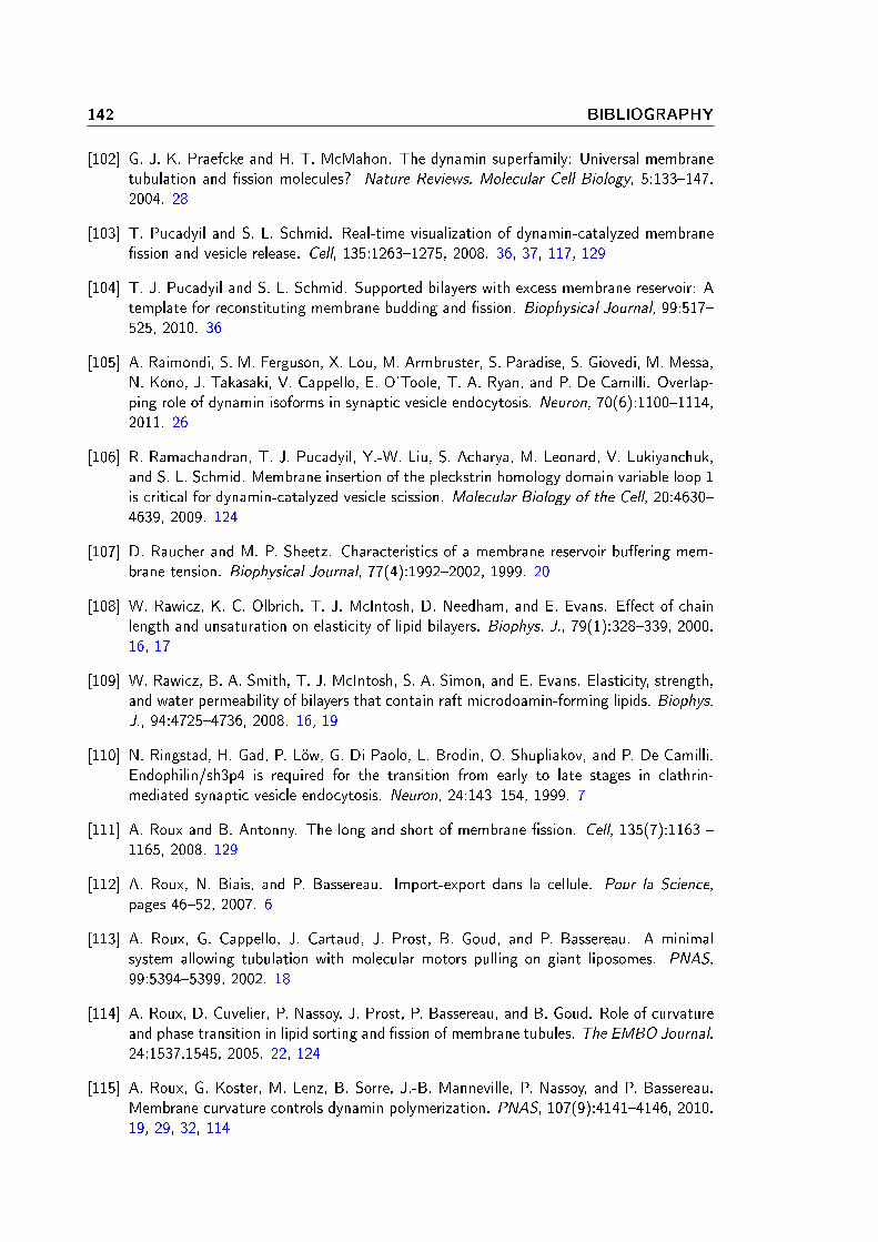
142 BIBLIOGRAPHY
[102] G. J. K. Praefcke and H. T. McMahon. The dynamin superfamily: Universal membranetubulation and ssion molecules? Nature Reviews. Molecular Cell Biology, 5:133147,2004. 28
[103] T. Pucadyil and S. L. Schmid. Real-time visualization of dynamin-catalyzed membranession and vesicle release. Cell, 135:12631275, 2008. 36, 37, 117, 129
[104] T. J. Pucadyil and S. L. Schmid. Supported bilayers with excess membrane reservoir: Atemplate for reconstituting membrane budding and ssion. Biophysical Journal, 99:517525, 2010. 36
[105] A. Raimondi, S. M. Ferguson, X. Lou, M. Armbruster, S. Paradise, S. Giovedi, M. Messa,N. Kono, J. Takasaki, V. Cappello, E. O'Toole, T. A. Ryan, and P. De Camilli. Overlap-ping role of dynamin isoforms in synaptic vesicle endocytosis. Neuron, 70(6):11001114,2011. 26
[106] R. Ramachandran, T. J. Pucadyil, Y.-W. Liu, S. Acharya, M. Leonard, V. Lukiyanchuk,and S. L. Schmid. Membrane insertion of the pleckstrin homology domain variable loop 1is critical for dynamin-catalyzed vesicle scission. Molecular Biology of the Cell, 20:46304639, 2009. 124
[107] D. Raucher and M. P. Sheetz. Characteristics of a membrane reservoir buering mem-brane tension. Biophysical Journal, 77(4):19922002, 1999. 20
[108] W. Rawicz, K. C. Olbrich, T. J. McIntosh, D. Needham, and E. Evans. Eect of chainlength and unsaturation on elasticity of lipid bilayers. Biophys. J., 79(1):328339, 2000.16, 17
[109] W. Rawicz, B. A. Smith, T. J. McIntosh, S. A. Simon, and E. Evans. Elasticity, strength,and water permeability of bilayers that contain raft microdoamin-forming lipids. Biophys.J., 94:47254736, 2008. 16, 19
[110] N. Ringstad, H. Gad, P. Löw, G. Di Paolo, L. Brodin, O. Shupliakov, and P. De Camilli.Endophilin/sh3p4 is required for the transition from early to late stages in clathrin-mediated synaptic vesicle endocytosis. Neuron, 24:143154, 1999. 7
[111] A. Roux and B. Antonny. The long and short of membrane ssion. Cell, 135(7):1163 1165, 2008. 129
[112] A. Roux, N. Biais, and P. Bassereau. Import-export dans la cellule. Pour la Science,pages 4652, 2007. 6
[113] A. Roux, G. Cappello, J. Cartaud, J. Prost, B. Goud, and P. Bassereau. A minimalsystem allowing tubulation with molecular motors pulling on giant liposomes. PNAS,99:53945399, 2002. 18
[114] A. Roux, D. Cuvelier, P. Nassoy, J. Prost, P. Bassereau, and B. Goud. Role of curvatureand phase transition in lipid sorting and ssion of membrane tubules. The EMBO Journal,24:1537.1545, 2005. 22, 124
[115] A. Roux, G. Koster, M. Lenz, B. Sorre, J.-B. Manneville, P. Nassoy, and P. Bassereau.Membrane curvature controls dynamin polymerization. PNAS, 107(9):41414146, 2010.19, 29, 32, 114
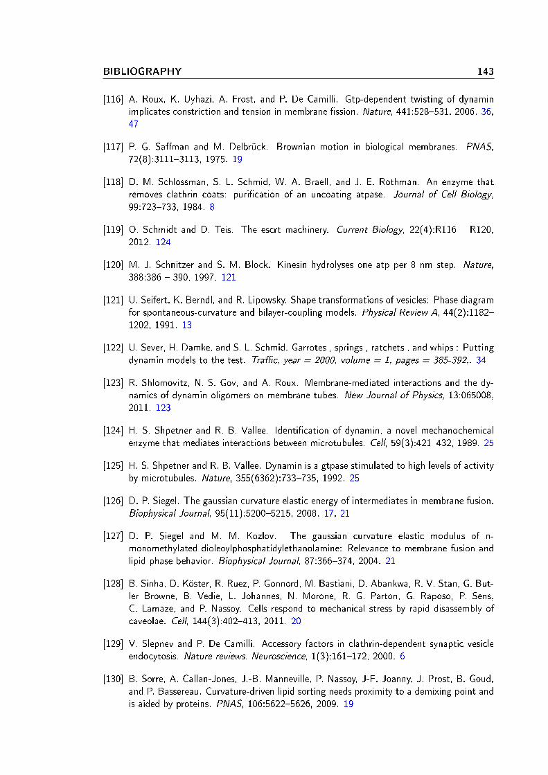
BIBLIOGRAPHY 143
[116] A. Roux, K. Uyhazi, A. Frost, and P. De Camilli. Gtp-dependent twisting of dynaminimplicates constriction and tension in membrane ssion. Nature, 441:528531, 2006. 36,47
[117] P. G. Saman and M. Delbrück. Brownian motion in biological membranes. PNAS,72(8):31113113, 1975. 19
[118] D. M. Schlossman, S. L. Schmid, W. A. Braell, and J. E. Rothman. An enzyme thatremoves clathrin coats: purication of an uncoating atpase. Journal of Cell Biology,99:723733, 1984. 8
[119] O. Schmidt and D. Teis. The escrt machinery. Current Biology, 22(4):R116 R120,2012. 124
[120] M. J. Schnitzer and S. M. Block. Kinesin hydrolyses one atp per 8 nm step. Nature,388:386 390, 1997. 121
[121] U. Seifert, K. Berndl, and R. Lipowsky. Shape transformations of vesicles: Phase diagramfor spontaneous-curvature and bilayer-coupling models. Physical Review A, 44(2):11821202, 1991. 13
[122] U. Sever, H. Damke, and S. L. Schmid. Garrotes , springs , ratchets , and whips : Puttingdynamin models to the test. Trac, year = 2000, volume = 1, pages = 385-392,. 34
[123] R. Shlomovitz, N. S. Gov, and A. Roux. Membrane-mediated interactions and the dy-namics of dynamin oligomers on membrane tubes. New Journal of Physics, 13:065008,2011. 123
[124] H. S. Shpetner and R. B. Vallee. Identication of dynamin, a novel mechanochemicalenzyme that mediates interactions between microtubules. Cell, 59(3):421432, 1989. 25
[125] H. S. Shpetner and R. B. Vallee. Dynamin is a gtpase stimulated to high levels of activityby microtubules. Nature, 355(6362):733735, 1992. 25
[126] D. P. Siegel. The gaussian curvature elastic energy of intermediates in membrane fusion.Biophysical Journal, 95(11):52005215, 2008. 17, 21
[127] D. P. Siegel and M. M. Kozlov. The gaussian curvature elastic modulus of n-monomethylated dioleoylphosphatidylethanolamine: Relevance to membrane fusion andlipid phase behavior. Biophysical Journal, 87:366374, 2004. 21
[128] B. Sinha, D. Köster, R. Ruez, P. Gonnord, M. Bastiani, D. Abankwa, R. V. Stan, G. But-ler Browne, B. Vedie, L. Johannes, N. Morone, R. G. Parton, G. Raposo, P. Sens,C. Lamaze, and P. Nassoy. Cells respond to mechanical stress by rapid disassembly ofcaveolae. Cell, 144(3):402413, 2011. 20
[129] V. Slepnev and P. De Camilli. Accessory factors in clathrin-dependent synaptic vesicleendocytosis. Nature reviews. Neuroscience, 1(3):161172, 2000. 6
[130] B. Sorre, A. Callan-Jones, J.-B. Manneville, P. Nassoy, J-F. Joanny, J. Prost, B. Goud,and P. Bassereau. Curvature-driven lipid sorting needs proximity to a demixing point andis aided by proteins. PNAS, 106:56225626, 2009. 19
144 BIBLIOGRAPHY
[131] B. Sorre, A. Callan-Jones, J. Manzi, B. Goud, J. Prost, P. Bassereau, and A. Roux.Nature of curvature coupling of amphiphysin with membranes depends on its bounddensity. PNAS, 109:173178, 2011. 19
[132] M. H. B. Stowell, B. Marks, P. Wigge, and H. T. McMahon. Nucleotide-dependentconformational changes in dynamin: evidence for a mechanochemical molecular spring.Nat. Cell. Biol., 1:2732, 1999. 29, 32
[133] T. C. Südhof and J. E. Rothman. Membrane fusion: Grappling with snare and smproteins. Science, 323:474477, 2009. 6
[134] D. Suen, K. Norris, and R. Youle. Mitochondrial dynamics and apoptosis. Genes and
Development, 22:15771590, 2008. 28
[135] A. Sundborger, C. Soderblom, O. Vorontsova, E. Evergren, J. E. Hinshaw, and O. Shu-pliakov. An endophilin-dynamin complex promotes budding of clathrin-coated vesiclesduring synaptic vesicle recycling. Journal of Cell Science, 124:133143, 2010. 129
[136] S. Svetina, B. Zeks, R. E. Waugh, and R. M. Raphael. Theoretical analysis of the eectof the transbilayer movement of phospholipid molecules on the dynamic behavior of amicrotube pulled out of an aspirated vesicle. European Biophysics Journal, 27:197209,1998. 17
[137] Sharon M Sweitzer and Jenny E Hinshaw. Dynamin undergoes a gtp-dependent confor-mational change causing vesiculation. Cell, 93(6):10211029, 1998. 29, 32
[138] K. Takei, P. S. McPherson, S. L. Schmid, and P. De Camilli. Tubular membrane in-vaginations coated by dynamin rings are induced by gtpγs in nerve terminals. Nature,374:186190, 1995. 34
[139] M. J. Taylor, D. Perrais, and C. J. Merrield. A high precision survey of the moleculardynamics of mammalian clathrin-mediated endocytosis. PLoS Biology, 9:e1000604, 2011.8, 9, 26, 129
[140] M. R. Terebiznik, O. V. Vieira, S. L. Marcus, A. Salde, C. M. Yip, W. S. Trimble,T. Meyer, B. B. Finlay, and S. Grinstein. Elimination of host cell ptdins(4,5)p(2) bybacterial sigd promotes membrane ssion during invasion by salmonella. Nature Cell
Biology, 4(10):166113, 2002. 117
[141] H. M. Thompson, A. R. Skop, U. Euteneuer, B. J. Meyer, and M. A. McNiven. Thelarge gtpase dynamin associates with the spindle midzone and is required for cytokinesis.Current Biology, 12(24):2111 2117, 2002. 28
[142] A. Tian and T. Baumgart. Sorting of lipids and proteins in membrane curvature gradients.Biophysical Journal, 96(7):26762688, 2009. 19
[143] P. L. Tuma and C. A. Colins. Activation of dynamin gtpase is a result of positivecooperativity. Journal of Biological Chemistry, 269(49):3084230847, 1994. 30, 32
[144] E. Ungewickell, H. Ungewickell, S. E. H. Holstein, R. Lindner, K. Prasad, W. Barouch,B. Martini, L. E. Greene, and E. Eisenberg. Role of auxilin in uncoating clathrin-coatedvesicles. Nature, 378:632635, 1995. 8
[145] R. D. Vale. The molecular motor toolbox for intracellular transport. Cell, 112(4):467 480, 2003. 6
BIBLIOGRAPHY 145
[146] A. M. van der Bliek and E. M. Meyerowitz. Dynamin-like protein encoded by thedrosophila shibire gene associated with vesicular trac. Nature, 351:411414, 1991.25, 34
[147] G. van Meer, D. Voelker, and G. Feigenson. Membrane lipids: where they are and howthey behave. Nature reviews. Molecular cell biology, 9(2):11224, 2008. 4, 5
[148] K. Visscher, M. J. Schnitzer, and S. M. Block. Single kinesin molecules studied with amolecular force slamp. Nature, 400(6740):184189, 1999. 122
[149] D. E. Warnock, J. E. Hinshaw, and S. L. Schmid. Dynamin self-assembly stimulates itsgtpase activity. The Journal of Biological Chemistry, 271(37):2231022314, 1996. 32,117
[150] R. Waugh and E.A. Evans. Thermoelasticity of red blood cell membrane. Biophysical
Journal, 26(1):115 131, 1979. 15
[151] R E Waugh. Surface viscosity measurements from large bilayer vesicle tether formation.ii. experiments. Biophys. J., 38(1):2937, April 1982. 18
[152] P. Wigge and H. T. McMahon. The amphiphysin family of proteins and their role inendocytosis at the synapse. Trends in Neurosciences, 21(8):339 344, 1998. 7
[153] P. Wigge, Y. Vallis, and H. T. McMahon. Inhibition of receptor-mediated endocytosisby the amphiphysin sh3 domain. Current Biology, 7(8):554560, 1997. 8
[154] K. Wilsbach and G. S. Payne. Vps1p, a member of the dynamin gtpase family, is necessaryfor golgi membrane protein retention in saccharomyces cerevisiae. The EMBO Journal,12(8):30493059, 1993. 28
[155] T. Wollert, C. Wunder, J. Lippincott-Schwartz, and J. H. Hurley. Membrane scission bythe escrt-iii complex. Nature, 458(7235):172177, 2009. 125
[156] T. Yamashita, T. Hige, and T. Takahashi. Vesicle endocytosis requires dynamin-dependent gtp hydrolysis at a fast cns synapse. The Journal of Biological Chemistry,271(37):2231022314, 1996. 9
[157] P. Zhang and J. Hinshaw. Three-dimensional reconstruction of dynamin in the constrictedstate. Nature Cell Biology, 3(10):922926, 2001. 29, 35

Copyright © 2022 FDOKUMEN