Calculation code system for fission and spallation products
19
ICANS-Xl International Collaboration on AdvancedNeutronSourcb KEK, Tsukuba, October 22-26.1990 Calculation code system for fissionand spallation products T. -Nishida, H. Takada,Y. Nakahara, I. Kanno, T. Tsutsui, Y. Kaneko Japan Atomic Energy Research Institute, Tokai Establishment Tokai-mura, Naka-gun, Ibaraki-ken, Japan ABSTRACT It is important to use computer codes with high precision for analyzing the physical process in the intense neutron source induced by the high energy proton beam. A brief description is given for the spallation and fission reactions and the particle transport codes which have been developed and upgraded at JAERI. The simulation code for lligh Energy Nuclear Reaction Process in the energy range of 15 MeV to 3 GeV. NMTC/JAERL, is a JAERI version of NMTC which was developed at ORNL and revised later at LANL and BNL. In this version the high energy fission reaction can be calculated, using the statistical model, in competition with the particle evaporation reaction. The mass number A of nuclides which can be dealt in the spallation calculation has been extended from [ A=1;8< A< 239 I to [ A=l; 6~ A c 250 I. A simulation code NUCLEUS for the spallation reaction of one nucleus without taking into account the internuclear cascade, was also developed to evaluate the computational model for spallation reaction and analyze effectively the data measured in thin foil experiments. For the whole energy range less than 3 GeV, two simulation code systems had been developed by connecting NMTC/JAERI with the neutron transport codes MORSE-DD and TWOTRAN- B respectively. The code SPCIIAIN for calculating the time evolution process of spallation products has been developed on the base of the depletion code DCUAINP, which had been made for the calculations of decay and built-up of fission products in a nuclear reactor. The new nuclear data have been compiled in SPCIIAIN data file for about 1100 nuclides needed for TRU spallation calculation. These codes are used to calculate reaction products measured in the spallation experiment using 500 MeV protons in the booster facility of the synchrotron at KKKand to perform the conceputual design study of TRU transmutation system driven by an intense proton accelerator.
-
Upload
khangminh22 -
Category
Documents
-
view
0 -
download
0
Transcript of Calculation code system for fission and spallation products

ICANS-Xl International Collaboration on Advanced Neutron Sourcb KEK, Tsukuba, October 22-26.1990
Calculation code system for fission and spallation products
T. -Nishida, H. Takada, Y. Nakahara, I. Kanno,
T. Tsutsui, Y. Kaneko
Japan Atomic Energy Research Institute, Tokai Establishment
Tokai-mura, Naka-gun, Ibaraki-ken, Japan
ABSTRACT
It is important to use computer codes with high precision for
analyzing the physical process in the intense neutron source
induced by the high energy proton beam. A brief description is
given for the spallation and fission reactions and the particle
transport codes which have been developed and upgraded at JAERI.
The simulation code for lligh Energy Nuclear Reaction Process
in the energy range of 15 MeV to 3 GeV. NMTC/JAERL, is a JAERI
version of NMTC which was developed at ORNL and revised later at
LANL and BNL. In this version the high energy fission reaction
can be calculated, using the statistical model, in competition
with the particle evaporation reaction. The mass number A of
nuclides which can be dealt in the spallation calculation has
been extended from [ A=1;8< A< 239 I to [ A=l; 6~ A c 250 I. A
simulation code NUCLEUS for the spallation reaction of one
nucleus without taking into account the internuclear cascade, was
also developed to evaluate the computational model for spallation
reaction and analyze effectively the data measured in thin foil
experiments. For the whole energy range less than 3 GeV, two
simulation code systems had been developed by connecting
NMTC/JAERI with the neutron transport codes MORSE-DD and TWOTRAN-
B respectively. The code SPCIIAIN for calculating the time
evolution process of spallation products has been developed on the base of the depletion code DCUAINP, which had been made for the calculations of decay and built-up of fission products in a
nuclear reactor. The new nuclear data have been compiled in
SPCIIAIN data file for about 1100 nuclides needed for TRU
spallation calculation. These codes are used to calculate
reaction products measured in the spallation experiment using 500
MeV protons in the booster facility of the synchrotron at KKK and
to perform the conceputual design study of TRU transmutation
system driven by an intense proton accelerator.

I. INTRODUCTION
It is important to use computer codes with high precision for
analyzing the physical processes in an intense neutron-source
induced by the high energy proton beam., In this report.brief
descriptions are given for the spallation reaction and.the
particle transport codes,~ which have been developed or upgraded
at JAERI and,some results computed by using these codes are
presented. Our main purposes-are to perform the design study of
transuranium nuclides (TRU) transmutation target-core system
driven by a proton accelerator and analyze the data measured-in
spallation experiments.’ Analyses of the beam window on the :
spallation target and accelerator strucutral materials irradiated
by high energy particle beam will be also carried out.
II. SPALLATION ANALYSIS AND TRANSMUTATION SYSTEM DESIGNING CODE
SYSTEMS DEVELOPED AND UPGRADED AT JAERI
As well known, the high energy protons injecting on a target
cause more compl@ate nuclear reactions than neutrons
transporting in a reactor core. Figure 1 shows the schematic.
illustration of nuclear reactions and particle transport
processes in a heavy metal-target irradiated by the high.energy
proton beam. In the energy range above -15 MeV, the
intranuclear and internuclear cascades with the spallation
(particle knock-on), evaporation and high energy fission
reactions are induced by the proton bombardment; Through these
processes many neutrons and some light particles such as proton,
deuteron, triton, helium-3; a particle are emitted. Most of
these spallation neutrons, which have the energy spectrum similar.
to one in .a fast reactor, transport in the target after slowing
down into the energy range lower than -15 MeV. As nuclear
reaction simulation codes, NMTC/JAERI - NMTA and NUCLEUS codes
are prepared for the energy range above 15 MeVand MORSE-DD ,
SP-ACE and TWOTRAN-II’ codes for the range below 15 MeV at JAERI.
ORIGEN-2 and SPCHAIN calculate the time evolution process of TRU
transmutation products in the lower and upper energy ranges,
respectively. The flow chart in Fig.2 shows.the mutual relations
among the simulation code- systems prepared at JAERI. The High s
Energy Nuclear Reactions and Nucleon-Meson Transport Code
3'01

NMTC/JAERI is the main code in this code system. The codes
included in the left side of this figure simulate the high energy
nuclear reaction process above 15 MeV and ones in the other side
carry out the neutron’transport calculation below 15 MeV.
(1) NMTC/JAERI”
The code NMTC/JAERI is used for the Monte Carlo simulations
of nuclear spallation induced by incident particles( proton,
neutron, pion ) from an external source in a heterogeneous medium.
The subsequent internuclear transport processes is also
calculated in the energy range of 15 MeV to 3 GeV. In the JAERI
version, the fission process has been incorporated as a competing
process with particle evaporation. The range of mass number A of
nuclides in the target has been extended from] A=1;8< A< 2391 to
[ A=l; 6~ A < 250 1. The major part of NMTC is almost the same
as the old version of HETC. The detailed descriptions about
NMTC/JAERI had been given by Nakahara at the former conference
ICANS- N . =’ So in this report only two graphs computed using
NMTC/JAERI for the analysis of transmutation system are presented.
Figure 3 shows the dependence of the number of spallated
nuclides on the incident proton energy when the 237Np target(20
cm in diameter, 60 cm in length] is bombarded by protons. The
number of nuclides transmutated by one proton with 1.5 GeV in
energy is about 5 but it is too small to manage TRU wastes in the
commercial base. It must be noted that several tens of neutrons
of hard energy spectrum are emitted in the spallation reaction.
The computer simulation results show that the number of
spallation neutrons generated in the targets of actinides.such as
U, Np and Am, and heavy elements such as Pb and W increases
monotonously when the proton energy increases up, as seen in Fig.
4. For the case of 237Np target( 20 cm in diameter, 37 cm in
length) bombarded by a 1.5 GeV proton the neutron number is -40.
The application of these neutrons to the transmutation system is
described later.
( 2 ) NMTA/ JAER13’
In the improved version of NMTA, which is named to the
statistical routines analyzing the Monte Carlo events in the
NMTWJAERI computation, the new subroutine HEATDP has been installed. HEATDP was developed at JAERI to calculate the energy
302

deposition and its spatial distribution for each component such
as ionization loss energy and recoiling energy of fission and
spallation products without 7 -ray heating of excited residual ,_
nuclei in the high energy range. ,Figure 5 represents the.
dependece of total heat deposition in a metal target ( 20 cm in
diameter, 60 cm in length) as a function of the injected proton
enenrgy . HuTand Hv * denote total heat deposition and ionization
loss energy in a natural uranium-target, respectively and HpbT is
total heat deposition in a lead target. The difference between
Hu7 and Hv* corresponds to the deposition of heat generated from
the high energy fisson. The fraction of proton energy lost
through the inonization decreases when the incident proton energy
increases. The ionization loss becomes - 50 % of total heat
deposition at 900 MeV. Figure 6 (a) and (b) shows the spatial
distributions due to ionization loss energy and recoiling energy
of SPs and FPs, respectively, for the 900 MeV proton injecting on
the uranium target with 20 cm diameter and 36 cm length.
( 3 ) NUCLEUS4’ l a’ ’ a)
The code NUCLEUS has been also developed at JAERI by
modifying and combining the Monte Carlo codes NMTC/JAERI and a
routine in NMTA/JAERI. The NUCLEUS can simulate the nuclear
spallation reaction between a single target nucleus and a
projectile without the internuclear nucleon transport process, in
order to make direct evaluations of physical and computational
models efficiently. The results computed by this code can also
be compared directly with the data of thin foil spallation
experiment, in which the-internuclear multiple scattering have ‘.
little effects. In NUCLEUS the counting region of reaction ‘-
products was extended to avoid the count loss due to the
dimension limitation in the computer program. As for a.mass
formula the Uno &:Yamada’ mass formula7’ has been optionally
adopted to upgrade the particle evaporation calculation. New several plotter routines were also provided for rapid processing
of a huge amount of output data. Figure 7 compares the original
calculational data with the upgraded ones for mass number
distributions of reaction products with Z from 92 to 82 from a .‘,
uranium nucleus spallated by a 1 GeV proton. In the central case
with the extended counting region, the counting loss is recovered,
303

and the left tail of peaks appears in the reasonable form in
comparison to the left figure for the original region. By the
usesof Uno & Yamada’s mass formula, the corrected peaks in the
right figure have become wider than the central case.
On the other hand the-NUCLEUS computation presents the
important, basic data for researching the feasibility of TRU
transmutation induced by the spallation process.. In Fig. 8 the
bird eye’s views of yields of products are drawn in log scale for
the cases of 1 GeV proton impinging on a) uranium and b) lead
nuclei. The yield consists of three components, namely, the hill
of spallation products, the spire of evaporated particles and the
valley of high energy fission product between them. It is
apparent that the yield of SP is greater than FP .by two orders.
Table 1 summarizes the number of produced light particle such as
proton, neutron, deutron, triton, helium 3 and alpha. They are
emitted from a uranium target nucleus bombarded by protons with
the energy of 380 MeV to 2.9 GeV. The number of emitted particles
has the maximum value around 2 GeV, where the neutrons more than
17 are emitted from one uranium nucleus. The result suggests.
that the incident proton energy has the optimum value around 2
GeV for neutron production. Figure 9 shows the histogram of half
life distributions of products when a 2 GeV proton bombarding on
237Np and 241Am target nuclei. The shaded portions in the half
life classifications of 7 and 9 represent tritons and deuterons &
heliums respectively. The nuclides included in the
classification 8 are a few. These nuclides are considered to be
most harmful from the hazardous point of view. Most of SP in
this case have the halflife shorter than one year. (4) SPCHAIN, SPD
The composition and amount of residual nuclides accumulated
in the target spallated by the proton beam is very improtant for
the feasibility study of proton-induced TRU transmutation.
Actually, however, it is almost impossible to obtain exactly the
time evolution of yields of all the nuclides in the target due to
enormous computing time. A code for calculating approximately
the process of spallation products, SPCHAIN, has been made on the
base of the depletion code DCHAINB , 8’ which was developed for the
calculations of decay and build up of fission products in a
304

nuclear reactor. We have modified the one point:depletion
equation to include the transmutation, decay and build up
processes of TRU and spallation products In the:following,
dXt(t)/dt = x Ii. J k J&(t) + c ki. J @ 0 o,-J&(t) i,. :.
.-( Ai+ Q, Q o. i Bitt) + ,7 rFtt)
.. + % a 1.J @PO e,JXJ(t),- @POX%. iXi(t), .-I
where the last two terms due to the spallation have newly been _
added to four ariginal terms used for the reactor burnup ’
calculation. a,asand 0,~ represent the production rate of SP, the spallation cross section and high energy particle flux, _.
respectively. The equation can be solved analytically by the ..
Bateman method. As shown in Figure 10, some necessary data are
feeded from the surrounding codes. When the halflife time of a
nuclide was not obtained in the prepared data,.it was calculated
by using the B decay calculation program- SPD@ or guessed from
the trend of data of nuclides, which are located in the neighbor
of the nuclide in the Nuclear Chart. The production rate a of.
SP was computed by using the code NUCLEUS. The spallation cross.
section has been interpolated or extrapolated from the measured
datalO> given for proton energy and target nucleus. The new data
of decay types, decay constants, branching ratios and decay,
schemes have been compiled in the SPCHAIN data library for .about
1100 nuclides.“) The the preliminary result in SPCHAIN
calculations is shown. Figure 11 shows the activity rate
distribution of residual elements in a 24’Am.target after one
year cooling after 10 hours irradiation of 1 GeV protons with 10
mA. The high activity peaks around 2 = 80 just after irradiation
disappear due to the short halflives of SP and the activities
buildup to Au, OS and Lu isotopes, whereas the higher actinide
activity such as Np and Pu increases. So they should be
transmuted through the continued spallation process. Activi-tie.s
due to fission products are a few.
(6) Other codes 1 ACCEL’“‘, SP-ACE ) A simulation code system ACCEL had been developed. by
connecting NMTC/JAERI with the neutron transport Sn code TWCTRAN-
II through the neutron source .file, accompanying the nuclear
305

data files. This system can calculate all the reaction processes
occured in the target for the whole energy range less than 3 GeV
as one computing job as shown in Fig. 12.
The SP-ACE code system is being developed for designing the
transmutation -core system driven by proton accelerator in the
energy range below 15 MeV in reasonable computing time and
precision. The neutron transport code RABBLE-THERMOS computes
the region-wise neutron flux, using ultra fine energy group
constants and the distribution of spallation neutron source,
which can be obtained from Monte Carlo calculation in NMTC/JAERI.
These fluxes and nuclear data are utilized to calculate the yield
of products, heat generation and gamma ray intensity in each
region by the burnup code COMRAD.
HI. CONCEPUTUAL DESIGN STUDY OF ACCELERATOR TRANSMUTATION SYSTEM
We have been promoting the conceptual studies on the TRU
transmutation in the target-core system driven by an accelerated
proton beam. 13’* 14’ l la’ For the reaction below 15MeV the Monte
Carlo neutron transport code MORSE-DD Ia’ was used with 52
neutron group constants edited from JENDL-2 and ENDF-B4, where
spallation neutrons calculated by NMTC/JAERI code were treated as
the source.
The basic conditions for the system design are (1)
transmutation of 260 kg of TRU in a year, which is produced from
ten commercial reactors of 1GWe and (2) good energy balance, in
which it can generate enough electricity to operate the
accelerator at least. Here total amount of TRU produced per year
from 1 GWe PWR is about 26 kg/y, 56 % of which is 237Np. Figure
13 is the target-core configuration of hybrid transmutation
system driven by high power proton beam with the energy of 1.5
GeV and the current of several tens of mA. The tungsten target
is installed in an TRU-fueled subcritical core surrounded by the
HT-9 steel container. The system has dimensions given in the
figure. A beam window is located at a depth of 0.7 m from the
front face. The heat generated in the TRU fuel is removed by the forced circulation of liquid metal coolants Na/Pb-Bi. The core
consists of metallic alloy fuel of TRU and provides considerably
harder neutron spectrum than the other types of fuels. The fuel
306

pin cell geometry.;is .shown. inFig. with .a di-ameter’ of A mm
cladded with HT-$. steel. I .‘ ‘: i .,. - / .’ G .:. . .
Profiles of the. two-dimensional power distr_ibut.ion for four
cases ,of ‘the. system cooled.by -Na and- Pb-Bi.; with :and without the
tungsten .target,‘,were calculated BS shown in: Figures 15 (a) to
(d), respectively. It is apparent that the power peaking which
occurs just-ibehind the .beam window .is lower -in the system with
the tungsten target than in the one without.. i-t due to- .the
flattening effect fork cases of both coolants. The flattened
power distribution- allows higher beam .current and increases the
average number of transmuted*nuclides. The system performance
for these cases’.was summarized in -Table 2. .In the case: ‘of Na
cooling and -the tungsten target the maximum thermal power Js 691
MW and the thermal power is.suffici.ently large to supply .the
electric power to the accelerator while the beam current required
for the power is 22.6 mA. Without tungsten target the thermal.
power is 405 MW with the maximum and average power densities of
776 W/cc and 159 ,W/cc and its peaking factor is larger. by a
fatter of 1.7 than the case with the tungsten-target. The
maximum powers- of Pb-Bi cooled core are considerably lower than
those of Na cooled one, while the beam current required. is less
than .% mA. The maximum .trans_mutation rate, 202 kg/year can be
achieved for the core with the target cooled by Na. The changes of concentrations of some-minor actinides.with burn-up days in
the r.eference system(.-Na cooling, with, tungsten target ) have
been also calculated, as shown in Fig.16, using the-burnup code-
ORIGENB . The amounts of n7Np and *41Am at 1500 burning days
become one half of their initial -inventrkes, while 23ePu and
242Cm build .up, which are not contaIned in the -initial .loading.’ .’ I
IV. SUMMARY.
Finaly we summarize the outline of- the present report as
following items, .i .-
(1) Developments of NUCLEUS and SPCHAIN codes and-upgrade of
simulatin codes, i .;
(2) Analysis of the spallation reaction & cascade process in
the high energy range for TRU transmutation. and.
(3) Conceputual design study of hybrid transmuta-tion system (
307

7 TRU alloy fuelled core type ) driven by an intense proton
accelerator. In the present design concept the amount of
TRU produced from about 8 units of 1GWe PWR can be
transmuted for the case of the core with the tungusten
: target cooled by Na and with the proton beam of energy1.5
’ GeV and current 23 mA.
Furthermore we have the research items in the near future‘as
(a) Evaluation and upgrades of simulation codes based on new
evaluated data and data measured in the spallation
experiments which are being carried at KEK,
(b) Conceputual design study of hybrid transmutation system
( TRU molten salt fuelled core type ) ,and
(c) Analyses of irradiation tests for accelerator structural
materials and the beam window in the target-core.
REFERENCES
1) Y. Nakahara, T. Tsutsui: JAERI-M 82-198 (1982) (in Japanese). 2) Y. Nakahara : ICANS-IV, Proc. (1980).
3) T. Nishida, Y. Nakahara, T. Tsutsui : JAERI-M 84-154 (1984)
(in Japanese).
4) T. Nishida, Y. Nakahara, T. Tsutsui : JAERI-M 86-116 (1986)
(.in Japanese.) .
5) T. Nishida, Y. Nakahara : Kerntechnik, 50, 193 (1987).
6) T; Nishida, Y. Nakahara : Kerntechnik, 55, No.3, 147(1990):
7) M. Uno, M. Yamada : Prog. Theor. Phys., 65, No.4, 1322(1981).
8) K: Tasaka : JAERI-M 8727 (1980).
9) T. Yoshida-: JAERI-M 6313 (1975).
10) W. Schimmerling et al. : Physical Review C 1, 248 (1973).
11) Table of Isotope (7th version).
12) Y. Nakahara, T. Tsutsui, Y. Taji : JAERI-memo 9502
(in Japanese, internal report).
13) H. Takano, T. Mukaiyama :” Nuclear Characteristic Analysis
of TRU Burner Reactors”, JAERI-M 89-072 (1989)(in Japanese).
14) T.Takizuka, I. Kanno, H. Takada, T. Ogawa, T. Nishida, Y. Kaneko : w A Study on Incineration Target System,” Proc.
ICENES (1989)(Karlsruhe).
15) Y. Kaneko : w THE INTENSE PROTON ACCELERATOR PROGRAM,” Proc.
308

2nd fnt. Symp.-on Advanced :Nuclear Energy Research - Evolution
-by Accelearator -, (1990)(Mito) ..I. ’ *
16) M. Nakagawa, et al., W MORSE-DD A Monte Carlo Code-Using
Multi Group Double Differential Form Cross Sections,”
JAERI-M 84-126 ‘(1984). 1’
388
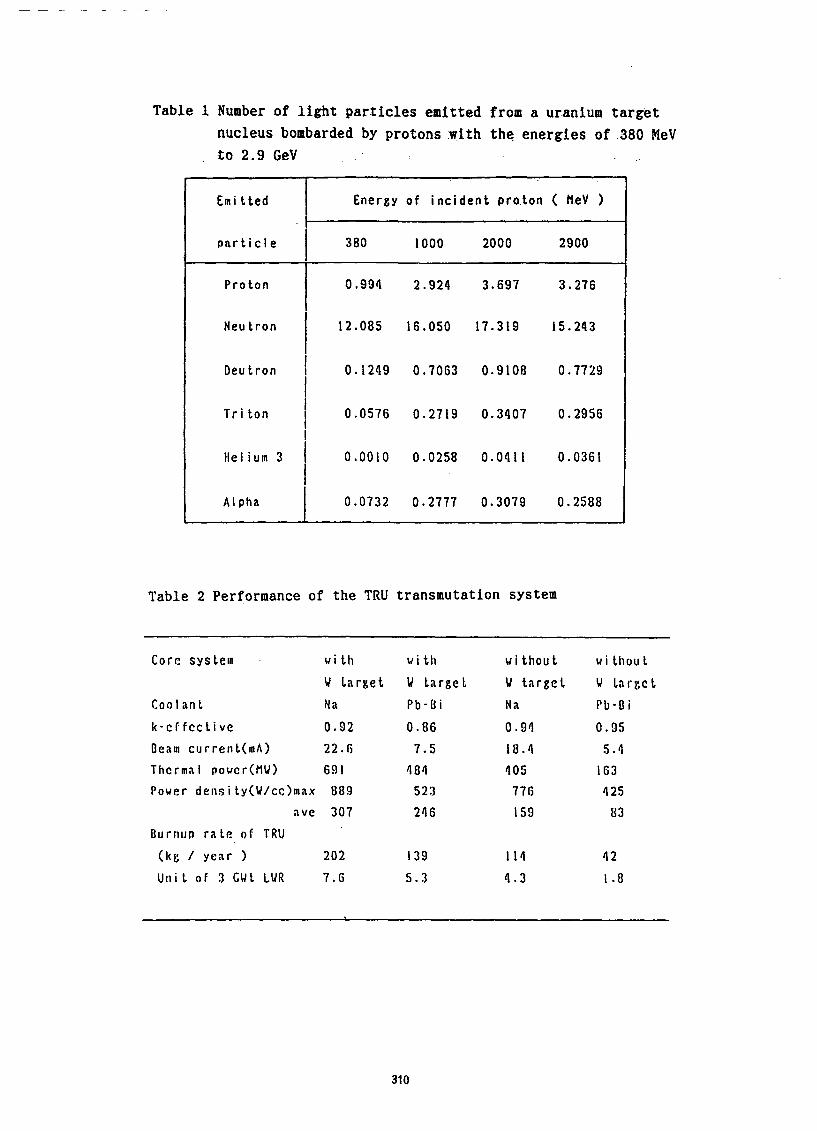
Table 1 Number of light particles emitted from a uranium target
nucleus bombarded by protons :with the energies of 380 MeV
to 2.9 GeV :
I
Emitted Energy of incident pro.ton ( ti.eV )
particle 1 380 1000 2000 2900
Proton 0.994 2.924 3.697 3.276
Neutron I 12.085 16.050 17.319 15.243
Oeutron I 0.1249 0.7063 0.9108 0.7729
I
Triton I 0.0576 0.2719 0.3407 0.2956
f
Helium 3 1 0.0010 0.0258 0.0411 0.0361
1
Alpha 0.0732 0.2777 0.3079 0.2588
Table 2 Performance of the TRU transmutation system
Core system with
U larget
Coolant Na
k-cffcctive 0.92
Ceam current 22.G
Thermal poucr(MU) 691
Power density(W/cc)max 889
ilve 307
Uurnup rate of TRU
(kg / year > 202
Unil of 3 GWt LWR 7.6
with
u ta
Pb-[l
0.86
7.5
484
523
246
without ui thout
rgct rget U target u lil
i Na Fb-u i
0.94 0.95
18.4 5.4
405 163
776 425
159 83
139 114 42
5.3 4.3 1.8
310

P$koko,mesor
hcident porlicie 1
NMTC/JAERI
NMTA/JAERI
Cut off energy(l5MeV)~
Neutron trampor!
TWOTRAN--II
MORSE-DD
::
Fig. 1 Schematic illustration of nuclear reaction and nucleon
transport process in a heavy metal target irradiated by
the high energy proton beam.
Nuclear data file e’
ENDF B-N JENDL-2,3 I i NM'WjAERI NUCLEUS
1-1-j I
Data process i ng Neutron source
codes data file
I
1
SP-ACE TiOTRAN-II MORSE-DO-'
leokogc
leokcqe
,:-i,h
Fig. 2 JAERI code system for the spallatfon transmutation
311

0.0 - OlS I II5 I t
0.0 1.0 2.0 2.5 3.0
PROTON ENERGY (&VI
Fig. 3 Dependence of number of nuclei destructed due to
spallation reaction on the incident proton energy
Am VJ
Pb
I
i
O r t 1 I t
0 “‘I , t I I1 t t-l
’ 2’. ‘3 4
PROTON ENE.RGY (CeV 1
Fig. 4 Dependence of ‘number of neutron generated in
spallation reaction on the incident proton energy
312

(a>
I I I I I
300 500 700 900 1100 EI
U&V 1
Fig. 5 Variation of total heat deposition as a function of the injected
proton enenrgy
(b)
2 co. . 6.
Fig. 6 Spatial distributions due to (a) ionization loss energy
and (b) recoiling energy of SPs and FPs for the 900 MeV proton injecting on the uranium target

0).
lo-* -
a \
v)
% .-
0 3 :
10'
lo-
a \ cn’
Gi .- u 2
16
1.
2_
-5L
b)
I I I I
180 200 220 240 A
IO-
16
Q \
z u .- 0
2
16
‘r
I’ 2_
.5i
- z=92:u - Z=90:Th - Z=BB:Ra a-.-+ Z = 86 : Rn
*-.-I Z,= 84 : PO
cl - Z=82:Pb
I I I I
180 200 220 240
A
Fig. 7 Mass number,distributions of products with 2 from 92 to
82 from a uranium nucleus spallated by 1 GeV protons for
cases -of a) original version, b) extended region and
c) extended region & Uno Yamada mass formula
Fig-. -8 Bird eye’s views of
yields of products
for the cases of 1
GeV proton impinging
on a) uranium and
b) lead nuclei

0
!3Qp
0) = f:+ :%?
& .:::::.: .i.i:.
’ ,; o $;$
.:.:.::: :::pL:
$$ .:.:.>.
.I- L..... j-l- I:;:?>. :
4 . . . . .
,I
-I : jsg: . . . . . . .
I I-,
.__.__~! i . ,i. J ;
-I23456789 123456789
24tArn -_ -
HALF LlFE HALF LIFE
Clossilicalion by Half -Lite Tit2
I : OS- < T1/2 < 10% - 6 : 5d < T1r2’ ly
P : IO-$.c Tvt < I s 7 : ly cT1/2< IOOy 3. : I~‘cTtn c ‘Im j 6 ‘: 100~ iT112< Ix IO’y
4 : lmufvt < Ifi 9 :-Stable Nuclides
5 : i h C Ttr2 e 5 d
Fig. ,9 Histogr-am of half-life dis~trihuti0n.s of products when .2
GeV protons bombards on:. a37Np -and 24~‘A,m target nuclei
NMTC/JAERI
Fig. 10 Codes surrouding Xhe SPCHAIN code
316

0
tlTOHlt NUHOER I 2 I
Fig. 11 Activity rate distrfbution,of residual elements in a
=*‘Am target at the time stage of one year cooling after
irradiation of ten hours of 1 GeV protons
Fig. 12 ACCEL code system
TWOTRAN- IT
316

Oimcnsions in m
Fig. 13 Target-core configuration of hybrid transw.itati.on. system
Clad'
..: . . . . .._...
1 9.5-l2mm j
Fig. 14 TRU fuel pin geometry
317

Fig. 15 Power distributions : (a) Na cooled , tungsten-loaded
target, (b) Pb-Bi cooled , tungsten-loaded target,
(c) Na cooled, TRU alloy target, (d) Pb-Bi cooled, TRU
alloy target
2
t
Np- 237 ‘O- SO
E 2
1 :; -.;_ Gil-244
c3 ~*p,---X-._* -. -x.. An-2SI
$ 10-5 ; -xx.
‘X.. -X--._x
Fig. 16 Change of trans-uranium
inventory with burn-up
in the system
3.0
6URN - UP (00~s 1 (x103 I
318