Calculation PRA-QNT-007, "Calculation of Regulatory Guide ...
20
Enclosure 4 to AEP-NRC-2016-83 DONALD C. COOK NUCLEAR PLANT Calculation PRA-QNT-007, Calculation of Regulatory Guide 1.177 Risk Parameters for Potential One-Time Emergency Technical Specification Completion Time Change for Unit 1 and Unit 2 Train B Reserve Feed
-
Upload
khangminh22 -
Category
Documents
-
view
4 -
download
0
Transcript of Calculation PRA-QNT-007, "Calculation of Regulatory Guide ...

Enclosure 4 to AEP-NRC-2016-83
DONALD C. COOK NUCLEAR PLANT
Calculation PRA-QNT-007, Calculation of Regulatory Guide 1.177 Risk Parameters for Potential One-Time Emergency Technical Specification Completion Time Change for Unit 1 and Unit 2
Train B Reserve Feed

D. C. COOK NUCLEAR PLANT =AMERICAN'
El.ECTlllC CALCULATION/REPORT COVER SHEET POWER AEP:d111crlcd.r Enng;• ltlrlner·
Document No. PRA-QNT-007 Rev No. 0 [81 Full Rev 0 Addendum
· 0 Status Change
Title: Calculation of Regulatory Guide 1.177 Risk Parameters for Potential One-Time Emergency Technical· Specification Completion Time Change for Unit 1 and Unit 2 Train B Reserve Feed
STATUS: [81 Approved 0 Superseded 0 Voided I 0 Information Only
Document Type/Class: I !8l Calculation 0 Report I 0 Class 1 0 Class 2 [81 Class 3
QUALITY SYSTEM UNIT COMPUTER REVIEW METHOD: CLASSIFICATION: CODE: NO.: MEDIA: [81 Detailed Review 0 Safety-Related [81 Yes 0 Alternate Calculation 0 Non-Safety Related with
NAPL 1 0No 0 Other
Special Requirements 0 N/ A - Status/Class Change Only [81 Non-Safety Related
Do any assumptions require later verification? 0Yes [81 No I If yes, AI No.
Description: This calculation documents the PRA quantitative risk impact and allowed outage time associated with MODE 1 full power operation of CNP Unit 1 during U2C23 with Unit 1 and Unit 2 Train B Reserve Feed out of service for a potential one-time extended TS CT.
If the Reviewer is the Preparer's supervisor, the supervisor review is needed and is approved: [81 NIA
Supervisor's Manager's Name Title Signature Date
Qualification Matrix Verification
* The responsible Engineering Supervisor/Manager approval signature also serves to signify that the qualifications of the individual(s) assigned as Preparer(s) and Reviewer(s) and Indep~ndent Design Verifier(s) were verified in the Plant Qualification Matrix.
Preparation & Review PREPARED BY: REVIEWED BY: *APPROVED BY:
Name: James M. Heyeck Samuel J. Falvo Amanda Salliotte
Title: PRA Engineer PRA Engineer Supervis_or
Organization: Engineering Programs/PRA Jensen Hughes Engineering Programs
Signature: /1/1/J\P-'f ~_f~# ~),<;/}~.) Date:
v ...., fo.fl-~f(,. l5- // -?_CJ/ h Jo/ 11 JI~
D Sign-offs for additional Preparer(s) and Reviewer(s) on next page
I This document includes the following pages: 1-19 (19 Pages total) I Page 1

I Calculation No. PRA-QNT-007, Rev. 0 Page2 )
Table of Contents
1 Purpose ................................................................................................................. 5 2 Method ...................................... .-.......................................................................... 6 3 Inputs ................................................................................................................... 7 4 Assumptions ......................................................................................................... 8 5 Calculations .................................. ~ ...................................................................... 9
5.1 Modifications to the Fire PRA model .............................................................................. 9 5.2 Quantification of Unit 1 and Unit 2 Train B Reserve Feed Outage ................................. 9 5.3 CDF and LERF Results .................................................................................................. 11 5.4 Analysis of Results ......................................................................................................... 11
5.4.1 , Internal Events Model Results Analysis .................................................................................. 11 5.4.2 Fire PRA Model Results Analysis ....................................... '. ................................................... 15
6 Conclusions ........................................................................................................ 1 7 7 References ......................................... : ................................................................ 18

I Calculation No. PRA-QNT-007, Rev. 0 Page 3 I
List of Tables
Table 1 - Fire PRA IIFEs Modified .......................................................................................................... ." ................... 9 Table 2 - FPIE Basic Event Settings for Unit 1 and Unit 2 Train B Reserve Feed Outage ........................................ 10 Table.3 -Fire PRA Basic Event Settings for Unit 1 and Unit 2 Train B Reserve Feed Outage ................................. 10 Table 4 - FPIE PRA Model Results ............................................................................................................................ 11 Table 5 - Fire PRA Model Results .................................... , ......................................................................................... 11 Table 6 - Total CDF and LERF Results ...................................................................................................................... 11 Table 7 - FPIE CDF Top Operator Actions ................................................................................................................ 13 Table 8 - .FPIE LERF Top Operator Actions ............................................................................................................... 13 Table 9 - FPIE Risk-Significant Equipment (CDF RA W) .......................................................................................... 14 Table 10 - Fire CDF Top Operator Actions ................................................................................................................ 15 Table 11 - Fire LERF Top Operator Actions .............................................................................................................. 15 Table 12 - Fire CDF Top Fire Scenarios .......................................................................................................... , .......... 15 Table 13 - Fire LERF Top Fire Scenarios ................................................................................................................... 15
List of Figures
Figure 1 -Additional Risk by Initiating Event for FPIE Model (CDF) ....................................................................... 12 Figure 2 -Additional Risk by Initiating Event for FPIE Model (LERF) ..................................................................... 12
List of Attachments Attachment 1 - Files on CD ....................................................................................................................................... 21

Calculation No. PRA-QNT-007, Rev. 0 Page4 I
List of Abbreviations
AFW Auxiliary Feedwater AMSAC ATWS Mitigating System Actuation Circuitry ATWS Anticipated Transient Without Scram CCP Centrifugal Charging Pump CDF Core Damage Frequency CST Condensate Storage Tank CRDM Control Rod Drive Mechanism CT Completion Time CTS Containment Spray system CVCS Chemical and Volume Control System ECCS Emergency Core Cooling System EDG Emergency Diesel Generator EOP Emergency Operating Procedure ESF AS Engineered Safety Features Actuation System ESW Essential Service Water FW Feedwater F-V Fussell-Vesely HEP Human Error Probability HFE Human Failure Event HLR High Level Requirement HSS High Safety Significant ICCDP Integrated Conditional Core Damage Probability ICLERP Integrated Conditional Large Early Release Probability IE Internal Events LERF Large Early Release Frequency LOCA Loss of Coolant Accident LSS Low Safety Significant MAAP Modular Accident Analysis Program MDAFP Motor-Driven Auxiliary Feedwater Pump MOR or MORW Model of Record MTI Maintenance Technical - Instrument and Control NRC Nuclear Regulatory Commission oos· Out of service or Unavailable PAC Plant Air Compressor PORV Power-Operated Relief Valve PRA Probabilistic Risk Assessment PDS Plant Damage State PRM Plant Response Model RAW Risk Achievement Worth RCP Reactor Coolant Pump RCS Reactor Coolant System RHR Residual Heat Removal RWST Refueling Water Storage Tank SDG Supplemental Diesel Generator SBO Station Blackout SG Steam Generator SR Supporting Requirement SSPS Solid State Protection System SI Safety Injection SIP Safety Injection Pump TDAFP Turbine-Driven Auxiliary Feedwater Pump TS Technical Specification

I Calculation No. PRA-QNT-007, Rev. 0 Page 5 I
1 Purpose
This calculation documents the PRA quantitative risk impact and allowed outage time associated with MODE 1 full power operation of CNP Unit 1 during U2C23 with Unit 1 and Unit 2 Train B Reserve Feed out of service for a potential one-time extended TS CT. It contains information in a format that is readily usable in the Emergent Technical Specification Change request for continued unit operation if the unavailability of the Unit 1 and Unit 2 Train B Reserve Feed exceeds plant TS CT time limits.

Calculation No. PRA-QNT-007, Rev. 0 Page 6 I
2 Method
The PRA risk impact of operation with Unit 1 and Unit 2 Train B Reserve Feed unavailable will be estimated using the PRA Model (Input 3.1) and an updated Fire PRA model (rllput 3.2), modified for this application as described in this document. Truncation limits for the model are identical to the truncation limits used in the associated model documentation that is demonstrated to be convergent. Regulatory Guide 1.177 (Reference 7. 7) risk parameters are calculated using the following general equations:
ACDF = CDFinst - CDFbase
where CDFinst= the Unit 1 CDF value when only Train B Reserve Feed is unavailable, with appropriate
allowances for the operation and maintenance restrictions described below (Assumption 4.1) are in place
CDFbase =the Unit 1 "base case" nominal maintenance CDF value
ALERF = LERFnew - LERFbase
where LERFinst= the Unit 1 LERF value when only Train B Reserve Feed is unavailable, with appropriate
allowances for the operation and maintenance restrictions described below (Assumption 4.1) are in place
LERFave =the Unit 1 "base case" nominal maintenance LERF value
ICCDP = (ACDF)*(Duration (days) I 365 days/year)
ICLERP = (ALERF)*(Duration (days) /365 days/year)
The Westinghouse Generation III SHIELD seal (referred to as the Shutdown Seal or SDS) has been installed in both units. The updated FPIE model credits the capability of this seal based on the guidance in PWROG-14001 (Reference 7.4). The Fire PRA model does not currently credit the SDS and will not credit it for this analysis.
Two risk cases in both the FPIE and Fire PRA models are quantified for this analysis:
1. A baseline CDF and LERF value with nominal test and maintenance. 2. CDF and LERF values with Unit 1 and Unit 2 Train B Reserve Feed failed, with zero maintenance other
than the exceptions listed in Assumption 4.1.
The FPIE model is a CAFTA two-top (CDF and LERF) fault tree model and the two risk cases are quantified using PRAQuant and fault tree solver FTREX. The model is solved at the truncation levels demonstrated for convergence
. in the FPIE quantification notebook (Reference 7 .1 ).
The Fire PRA model is a WinNUPRA two-top (CDF and LERF) fault tree model and the two risk cases are · quantified using the WinNUPRA software package. The model is solved at the truncation levels demonstrated for convergence in the Fire PRA working model notebook (Reference 7 .2).
Calculation No. PRA-QNT-007, Rev. 0 Page 7 I
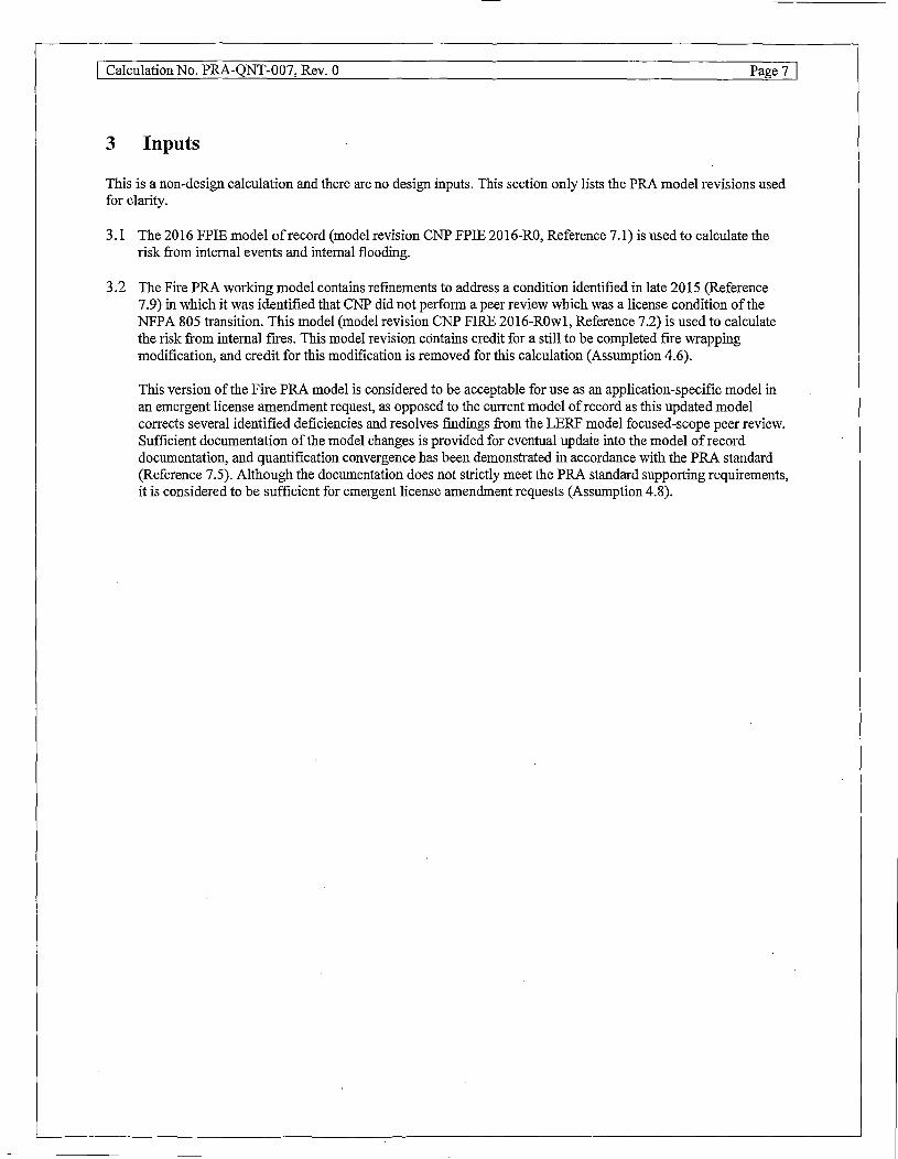
3 Inputs
This is a non-design calculation and there are no design inputs. This section only lists the PRA model revisions used for clarity.
3.1 The 2016 FPIE model ofrecord (model revision CNP FPIE 2016-RO, Reference 7.1) is used to calculate the risk from internal events and internal flooding.
3.2 The Fire PRA working model contains refmements to address a condition identified in late 2015 (Reference 7.9) in which it was identified that CNP did not perform a peer review which was a license condition of the NFPA 805 transition. This model (model revision CNP FIRE 2016-ROwl, Reference 7.2) is used to calculate the risk from internal fires. This model revision contains credit for a still to be completed fire wrapping modification, and credit for this modification is removed for this calculation (Assumption 4.6).
This version of the Fire PRA model is considered to be acceptable for use as an application-specific model in an emergent license amendment request, as opposed to the current model of record as this updated model corrects several identified deficiencies and resolves findings from the LERF model focused-scope peer review. Sufficient documentation of the model changes is provided for eventual update into the model ofrecord documentation, and quantification convergence has been demonstrated in accordance with the PRA standard (Reference 7 .5). Although the documentation does not strictly meet the PRA standard supporting requirements, it is considered to be sufficient for emergent license amendment requests (Assumption 4.8).
Calculation No. PRA-QNT-007, Rev. 0 Page 8 I
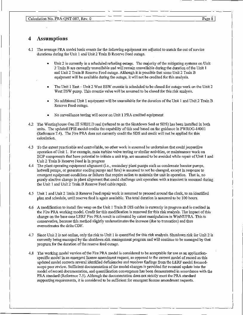
4 Assumptions
4.1 The average PRA model basic events for the following equipment are adjusted to match the out of service durations during the Unit 1 and Unit 2 Train B Reserve Feed outage.
• Unit 2 is currently in a scheduled refueling outage. The majority of the mitigating systems on Unit 2 Train Bare currently unavailable and will remain unavailable during the duration of the Unit 1 and Unit 2 Train B Reserve Feed outage. Although it is possible that some Unit 2 Train B equipment will be available during the outage, it will not be credited for this analysis.
• The Unit 1 East - Unit 2 West ESW crosstie is scheduled to be closed for outage work on the Unit 2 West ESW pump. This crosstie valve will be assumed to be closed for this risk analysis.
• No additional Unit 1 equipment will be unavailable for the duration of the Unit 1 and Unit 2 Train B Reserve Feed outage.
• No surveillance testing will occur on Unit 1 PRA credited equipment
4.2 The Westinghouse Gen III SHIELD seal (referred to as the Shutdown Seal or SDS) has been installed in both units. The updated FPIE model credits the capability of this seal based on the guidance in PWROG-14001 (Reference 7.4). The Fire PRA does not currently credit the SDS and credit will not be applied for this calculation.
4.3 To the extent practicable and controllable, no other work is assumed be undertaken that could jeopardize operation ofUnit 1. For example, main turbine valve testing or similar activities, or maintenance work on BOP components that have potential to initiate a unit trip, are assumed to be avoided while repair of Unit 1 and Unit 2 Train B Reserve Feed is in progress
4.4 The plant operating equipment alignment (i.e., secondary plant pumps such as condensate booster pumps, hotwell pumps, or generator cooling pumps and fans) is assumed to not be changed, except in response to emergent equipment conditions or failures that require action to maintain the unit in operation. That is, no purely elective change in plant alignment that could challenge unit operation with a transient is assumed during the Unit 1 and Unit 2 Train B Reserve Feed cable repair.
4.5 Unit 1 and Unit 2 Train B Reserve Feed repair work is assumed to proceed around the clock, to an identified plan and schedule, until reserve feed is again available. The total duration is assumed to be 100 hours.
4.6 A modification to install fire wrap on the Unit 1 Train B DIS cables is currently in progress and is credited in the Fire PRA working model. Credit for this modification is removed for this risk analysis. The impact of this change on the base case LERF Fire PRA result is estimated by cutset manipulation in WinNUPRA. This is conservative, because this method slightly underestimates the increase (due to truncation) and thus overestimates the delta CDF.
4.7 Since Unit 2 is not online, only the risk to Unit 1 is quantified for this risk analysis. Shutdown risk for Unit 2 is currently being managed by the shutdown risk management program and will continue to be managed by that program for the duration of the reserve feed outage.
4.8 The working model version of the Fire PRA model is considered to be acceptable fqr use as an applicationspecific model in an emergent license amendment request, as opposed to the current model ofrecord as this updated model corrects several identified deficiencies and resolves findings from the LERF model focusedscope peer review. Sufficient documentation of the model changes is provided for eventual update into the model ofrecord documentation, and quantification convergence has been demonstrated in accordance with the PRA standard (Reference 7 .5). Although the documentation does not strictly meet the PRA standard supporting requirements, it is considered to be sufficient for emergent license amendment requests.

I Calculation No. PRA-QNT-007, Rev. 0 Page 9 I
5 Calculations
5.1 Modifications to the Fire PRA model
As discussed in Assumption 4.6, the Fire PRA currently credits a modification to install fire wrap on the Unit 1 Train B DI~ cables in the turbine building (Reference 7.2). Credit for this modification is removed by setting the HFEs to restore power to DIS in the turbine building to logically true (always failed). The following basic events are set to failed: ·
Table 1 - Fire PRA HFEs Modified
Basic Event Name Basic Event Description
1Z--ALTPWR3A-OMA ALT SOURCE OF PWR TO H2 IGNITER NOAFW/480GPMIDELAY
1Z--ALTPWR3B-OMA ALT SOURCE OF PWR TO H2 IGNITER AFW/480GPMIDELAY
1Z--ALTPWR3C-OMA ALT SOURCE OF PWR TO H2 IGNITER NOAFW/<480GPM/DELAY
1Z--ALTPWR3D-OMA ALT SOURCE OF PWR TO H2 IGNITER AFW /<480GPM/DELA Y
5.2 Quantification of Unit 1 and Unit 2 Train B Reserve Feed Outage
One case of the FPIE and Fire PRA models are run consistent with the cases developed in Section 2. The baseline CDF and LERF values
The FPIE model is solved using the PRAQuant file (DCl-OSP.qnt) at a 5E-l l truncation for CDF and 5E-13 truncation for LERF, consistent with the truncation used for the base model quantification (Reference 7 .1 ). Flag files are used as described below to modify the model for quantification.
The Fire PRA model is solved using a CCDP/CLERP truncation of lE-10, and a concatenation truncation of lE-1 O for CDF and lE-11 for LERF. The quantification process used is described in the working model notebook (Reference 7 .2). Basic event data files are used as described below to modify the model for quantification.
l. A baseline CDF and LERF value with nominal test and maintenance values
a. For the FPIE Model, these values are taken from the quantification notebook (Reference 7.1)
b. For the Fire PRA model, this is taken from the working model notebook (Reference 7 .2). The LERF value is estimated by using the WinNUPRA sensitivity module which manipulates cutsets. This is conservative, because this method slightly underestimates the increase (due to truncation) and thus overestimates the delta CDF. The basic events modified in Table 1 are set to 1.0 and the
. higher LERF value is reported as the basecase.
2. CDF and LERF values with Unit 1 and Unit 2 Train B Reserve Feed failed, with zero maintenance other than the exceptions listed in Assumption 4.1. Since the FPIE model uses CAFT A and the Fire PRA uses WinNUPRA, the modified basic events and process are different but accomplish the same thing.
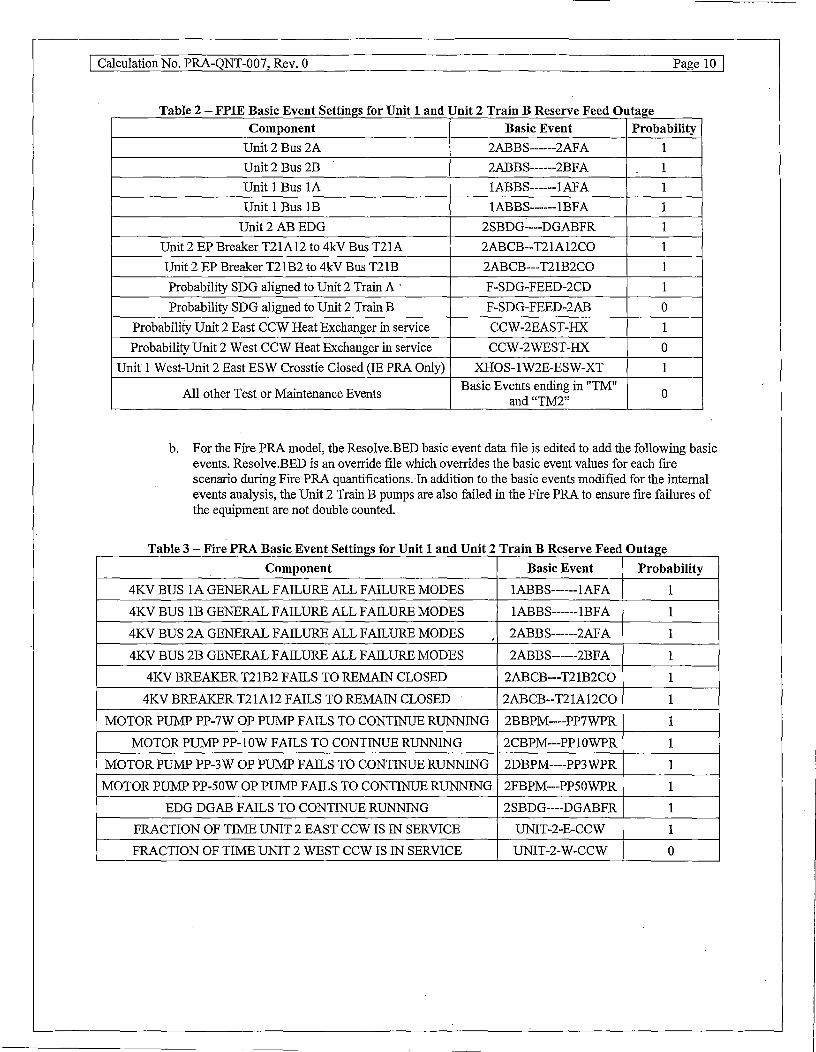
a. For the FPIE model, a CAFTA flag file is used (DC1-U2C23-TR-B-OSP.flg) to modify the following basic events.
The 4kV bus basic events represent failure ofreserve feed, since other power sources are incapable of powering that bus. The Unit 2 Train B EDG and EP breakers are also failed to ensure the train is fully unpowered. SDG, CCW heat exchanger, and ESW crosstie alignments are set in accordance with operating practices during the Unit 2 Train B outage.
I Calculation No. PRA-QNT-007, Rev. 0 Page 10 \
T bl 2 FPIE B . E t S tf £ U 't 1 d U 't 2 T . B R a e - as1c ven e mgs or Ill an Ill ram eserve F dO t ee u age
Component Basic Event Probability
Unit2 Bus 2A 2ABBS------2AF A 1
Unit2 Bus 2B 2ABBS------2BF A 1
Unit 1 Bus IA lABBS------lAF A 1
Unit 1Bus1B lABBS------lBF A 1
Unit2ABEDG 2SBDG----DGABFR 1
Unit 2 EP Breaker T21Al2 to 4kV Bus T21A 2ABCB--T21A 12CO 1
Unit 2 EP Breaker T21B2 to 4kV Bus T21B 2ABCB---T21B2CO 1
Probability SDG aligned to Unit 2 Train A · F-SDG-FEED-2CD 1
Probability SDG aligned to Unit 2 Train B F-SDG-FEED-2AB 0
Probability Unit 2 East CCW Heat Exchanger in service CCW-2EAST-HX 1
Probability Unit 2 West CCW Heat Exchanger in service CCW-2WEST-HX 0
Unit 1West-Unit2 East ESW Crosstie Closed (IE PRA Only) XHOS-1W2E-ESW-XT 1
All other Test or Maintenance Events Basic Events ending in "TM"
0 and "TM2"
b. For the Fire PRA model, the Resolve.BED basic event data file is edited to add the following basic events. Resolve.BED is an override file which overrides the basic event values for each fire scenario during Fire PRA quantifications. In addition to the basic events modified for the internal events analysis, the Unit 2 Train B pumps are also failed in the Fire PRA to ensure fire failures of the equipment are not double counted.
T bl 3 F" PRA B . E t S tf £ U 't 1 d U 't 2 T . BR a e - ire as1c ven e mgs or Ill an Ill ram F dO t eserve ee u age
Component Basic Event Probability
4KV BUS lA GENERAL FAILURE ALL FAILURE MODES lABBS------lAF A 1
4KV BUS 1B GENERAL FAILURE ALL FAILURE MODES lABBS------ lBF A 1
4KV BUS 2A GENERAL FAILURE ALL FAILURE MODES '
2ABBS------2AF A 1
4KV BUS 2B GENERAL FAILURE ALL FAILURE MODES 2ABBS------2BF A 1
4KV BREAKER T21B2 FAILS TO REMAIN CLOSED 2ABCB---T21B2CO 1
4KV BREAKER T21Al2 FAILS TO REMAIN CLOSED 2ABCB--T21A12CO 1
MOTOR PUMP PP-7W OP PUMP FAILS TO CONTINUE RUNNING 2BBPM----PP7WPR 1
MOTOR PUMP PP-1 OW FAILS TO CONTINUE RUNNING 2CBPM---PP10WPR 1
MOTOR PUMP PP-3W OP PUMP FAILS TO CONTINUE RUNNING 2DBPM----PP3WPR 1
MOTOR PUMP PP-SOW OP PUMP FAILS TO CONTINUE RUNNING 2FBPM---PP50WPR 1
EDG DGAB FAILS TO CONTINUE RUNNING 2SBDG----DGABFR 1
FRACTION OF TIME UNIT 2 EAST CCW IS IN SERVICE UNIT-2-E-CCW 1
FRACTION OF TIME UNIT 2 WEST CCW IS IN SERVICE UNIT-2-W-CCW 0

I Calculation No. PRA-QNT-007, Rev. 0 Page 11
5.3 CDF and LERF Results
The final results are presented in the tables below. ICCDP and ICLERP results are calculated assuming a total duration of 100 hours using the equations from Section 2.
Table 4 - FPIE PRA Model Results
'·' FPIE <;::ase ..
FPIE Base Case Unit 1 and Unit 2 Train B Reserve Feed
Current Outage Configuration
Internal. , , Inter11al Events CDF Events LERF
'(!yr) , , (/yr) · . 2.0E-05 2.7E-06
3.0E-05 4.IE-06
Table 5 - Fire PRA Model Results
· Fire PRA Case . Fire PRA Base Case
Unit 1 and Unit 2 Train B Reserve Feed Current Outage Configuration _
. Fire CDF 0 •
(iyr) ~ 5.4E-05
l.5E-04
FireLERF (/yr)
4.0E-06
1.4E-05
Table 6 - Total CDF and LERF Results
IC:CDP
l.IE-07
ICCDP
l:IE-06
Case, . . . .. ·fCCDJ>. '.I CL ERP "
FPIE l.lE-07 l.6E-08 Fire PRA l.IE-06 l.IE-07
Total l.2E-06 l.3E-07
5.4 Analysis of Results
.•. J~LERJ>,
l.6E-08
•. ICLERP·':
l.IE-07
This section presents an analysis of the Internal Events and Fire PRA model results. Importance analyses and cutsets from risk-significant sequences are analyzed for risk insights.
5.4.1 Internal Events Model Results Analysis
The additional risk from internal initiating events from CDF and LERF is provided in Figure 1 and Figure 2. The top operator actions are shown in Table 7 and Table 8. To produce these importance rankings, the CAFTA cutset files from the configuration case is delete-termed against the base case, to produce a cutset file that has only changed cutsets in it. This process is done for both CDF and LERF. The contribution of cutsets containing the listed events
· (F-V importance expressed as a percentage) is also provided.

I Calculation No. PRA-QNT-007, Rev. 0
Bus
5%
Loss of ESW
11%
Loss of DC Power
14%
Other 14%
Loss of CCW
56%
Figure 1 - Additional Risk by Initiating Event for FPIE Model (CDF)
6%
Medium LOCA
14%
Loss of Offsite
Power
13%
Other
23%
Loss of DC
32%
Figure 2 - Additional Risk by Initiating Event for FPIE Model (LERF)
Page 12 I
I Calculation No. PRA-QNT-007, Rev. 0 Page 13 I
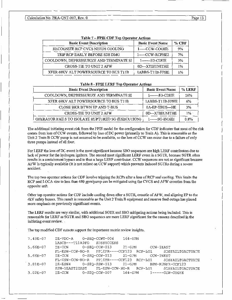
T bl 7 FPIE CDF T 0 a e - op 1perator Actmns
Basic Event Description Basic Event Name %CDF
RECOGNIZE RCP eves NEEDS COOLING 1-----CCW-COGHE 9%
TRIP RCP EARLY BEFORE SDS DMG l-----CCW-RCPHE2 7%
COOLDOWN, DEPRESSURIZE AND TERMINATE SI l-------E3-CDHE 3%
CROSS-TIE TO UNIT 2 AFW OD---XTIEUNITHE 1%
XFER 69KV ALT POWERSOURCE TO BUS Tl 1B lABBS-Tl lB-EPHE 1%
T bl 8 FPIE LERF T 0 A . a e - op 1perator ctions
Basic Event Description Basic Event Name %LERF
COOLDOWN, DEPRESSURIZE AND TERMINATE SI l-------E3-CDHE 16%
XFER 69KV ALT POWERSOURCE TO BUS Tl lB lABBS-Tl lB-EPHE 6%
CLOSE BKR BTWN EP AND T-BUS OA-EP-TBUS---HE 3%
CROSS-TIE TO UNIT 2 AFW OD---XTIEUNITHE 1%
OPERATOR FAILS TO ISOLATE RUPTURED SG (EXECUTION) 1------SG-ISOHE 0.8%
The additional initiating event risk from the FPIE model for the configuration for CDF indicates that most of the risk comes from loss of CCW events, followed by loss of DC power (primarily to Train A). This is reasonable as the Unit 2 Train B CCW pump is not assumed to be available, so the loss of CCW can occur due to a failure of only three pumps instead of all four.
For LERF the loss of DC event is the most significant because SBO sequences are high LERF contributors due to lack of power for the hydrogen igniters. The second most significant LERF event is a SGTR, because SGTR often results in a containment bypass and is thus a large LERF contributor. CCW sequences are not as significant because AFW is typically available (it is not reliant on CCW support) which prevents induced SGTRs during a severe accident.
The top two operator actions for CDF involve tripping the RCPs after a loss ofRCP seal cooling. This limits the RCP seal LOCA size to less than 480 gpm/pump can be mitigated using the CVCS and AFW crossties from the opposite unit.
Other top operator actions for CDF include cooling down after a SGTR, crosstie of AFW, and aligning EP to the 4kV safety busses. This result is reasonable as the Unit 2 Train B equipment and reserve feed outage has placed more emphasis on previously significant events.
The LERF results are very similar, with additional SGTR and SBO mitigating actions being included. This is reasonable for LERF as SGTR and SBO sequences are more LERF significant for the reasons described in the initiating event review. .
The top modified CDF cutsets support the importance metric review insights.
7.49E-07 IE-VDC-A 0-SEQ-CCWT-006 164-GPM lABCB---TllA9FO SDSSUCCESS
5.66E-07 IE-CCW 0-SEQ-CCW-013 21-GPM CCW-lEAST FL-ESW-CCW-NO-R PP10PR----CCF123 RCP-LOl SDSFAILTOACTUATE
5.66E-07 IE-CCW 0-SEQ-CCW-013 21-GPM CCW-lWEST FL-ESW-CCW-NO-R PP10PR----CCF123 RCP-LOl SDSFAILTOACTUATE
3.81E-07 IE-ESW4 0-SEQ-ESW-013 21-GPM BPM-RUNFR-CCF123 ESW-1EAST2EAST FL-ESW-CCW-NO-R RCP-LOl SDSFAILTOACTUATE
3.02E-07 IE-CCW 0-SEQ-CCW-007 164-GPM 1-----CCW-COGHE

I Calculation No. PRA-QNT-007, Rev. 0 Page 14 I
CCW-lEAST FL-ESW-CCW-NO-R PP10PR----CCF123 SDSSUCCESS ·
The top changed cutset is a loss of Unit 1 Train A DC initiating event, followed by failure to disconnect 4kV bus Tl IA from the RCP bus, resulting in inability to close the EDG breaker due to electrical interlocks. The loss of DC prevents any large breakers on the Unit 1 Train A electrical system from being aligned, which results in an unrecoverable SBO and eventually core damage.
The next 4 changed cutsets all involve a loss of CCW or ESW initiating event, which is the result of a common cause failure of all three CCW or ESW pumps that are available. This cutset appears because the Unit 2 Train B pumps are initially unavailable.
The importance analysis was also reviewed for a list of important equipment to confirm the fmdings from the cutset review. When ranked by RAW, the following components were indicated to be the most important (CDF ranking is shown, LERF ranking offers similar insights). The ranking indicates that the most important equipment is the Train B DC system (both long term and short term mission times are shown). This is due to the high importance of the loss of Train A DC in the initiating events analysis. The second most important equipment is the Unit 1 East CCW train.
T bl 9 FPIER" ks· E a e - 1s - 1gmficant ;qmprnent (CDFRA W) Basic Event Description Basic Event Name RAW BATTERY BANK AB FAILURE IN 1 HR MISSION TIME lRBBY--BANKABF Al 2764 DISTRIB PANEL TDAB GENERAL FAILURE IN IRR MISSION TIME lRBDP----TDABF Al 2574 MOTOR PUMP PP-1 OE FAILS TO CONTINUE RUNNING lCAPM---PPlOEPR 1171 HEAT EXCH HE-15E PLUGGING 1CAHE---HEl5EPL 1037 BATTERY BANK AB FAILURE lRBBY--BANKABF A 690 DISTRIB PANEL TDAB GENERAL FAILURE lRBDP----TDABF A 655
Based on a review of the results, risk management actions should focus on protecting the Unit 2 Train A equipment, and the Unit 1 ESW and CCW systems. Operators should focus on the most risk-significant actions related to a loss of CCW or ESW and the potential for loss of power due to only one train ofreserve feed remaining. Equipment protection for electrical systems and CCW and ESW are of particular importance. Although SGTR was identified as a contributor, the additional risk from this event is primarily due to the potential for loss of power, so an emphasis on protecting equipment is appropriate.

I Calcµlation No. PRA-QNT-007, Rev. 0 Page 15 I
5.4.2 Fire PRA Model Results Analysis
The top operator actions and fire scenarios from the Fire PRA quantification are presented in Table 10 through Table 13. The contribution ofcutsets containing the event to CDF and LERF (F-V importance expressed as a percentage) is used to rank the importance values.
Table 10 - Fire CDF Top Operator Actions
Basic Event Description Basic Event Name %CDF
OPERATOR FAILS TO MAN. OPEN ONE BIT OUT 1--SY-BITOUT-OMA 21%
VLVS
OPERA TOR FAILS TO TRIP RCP (FIRE) 1-----CCW-RCPHEF 14%
OPERA TOR FAILS eves CROSSTIE (COGNITION) lF--COG-CVCS-OMA 3%
OPERATOR FAILS AFW CROSSTIE OD---XTIEUNITHEF 2%
(MANIPULATION)
OPERA TOR FAILS TO CLOSE EP BREAKER lAOBS-Tl lAD--HEF 1%
Table 11 - Fire LERF Top Operator Actions
Basic Event Description Basic Event Name %LERF
OPERATOR FAILS TO MAN. OPEN ONE BIT OUT VLVS 1--SY-BITOUT-OMA 22%
OPERA TOR FAILS TO TRIP RCP (FIRE) 1-----CCW-RCPHEF 15% OPERA TOR FAILS TO ENERGIZE HYDROGEN
IGNITERS (EXECUTION) lZ-------8-EHHE 13% OPERA TOR FAILS TO ENERGIZE HYDROGEN
IGNITERS (EXECUTION) lZ-BS-- lA-COGHE 8% OPERA TOR FAILS TO CLOSE EP BREAKER OD---XTIEUNITHEF 3%
Table 12 - Fire CDF Top Fire Scenarios
Fire Scenario Description Fire Scenario %CDF
Fire in Unit 1 Turbine Building El' 609, Unit 1 Plant Air Compressor IE-90Z-36 19%
Fire in Unit 1 Turbine Building El' 609, Unit 1 Control Air Compressor IE-90Z-37 19%
All Fixed Fire Sources in Screenhouse (ESW) MCC Room for ESW IE-FZ29G-F 5%
All Transient Fire Sources in Screenhouse MCC Room for ESW IE-FZ29G-T 5%
Transient Fire in Unit 1 Containment Piping Annulus IE-66-1 3%
Unit 1 ESW MCCs "
IE-FZ29E-T 3%
Tabie 13 - Fire LERF Top Fire Scenarios
Fire Scenario Description Fire Scenario %LERF
Unit 1 Turbine Generator Severe Lube Oil Fire IE-2A-1S 17%
Unit 1 Turbine Generator Hydrogen System Fire IE-90Z-49S 17%
Fire in Unit 1 Turbine Building El' 609, Unit 1 Plant Air Compressor IE-90Z-36 8%
Fire in Unit 1 Turbine Building El' 609, Unit 1 Control Air Compressor IE-90Z-37 8%
Fixed Fire of 4kV Safety Bus Tl lD IE-40B-Tl 1D 4%
Fixed Fire of 4kV Safety Bus Tl 1 C IE-40B-Tl 1 C 3%
Transient Fire in Unit 1 Containment Piping Annulus IE-66-1 3%
The top operator actions include crosstie ofCVCS following an RCP seal LOCA and failing to crosstie AFW. This is a logical result as the unavailability of the Unit 2 Train B ESW and CCW systems has increased the importance of

I Calculation No. PRA-QNT-007, Rev. 0 Page 16 I
sequences involving RCP seal LOCAs. RCP seal LOCAs less than 480 gpm/pump can be mitigated using the CVCS and AFW crossties from the opposite unit.
The top actions also include an operator action to trip the RCPs. This limits the RCP seal LOCA size to less than 480 gpm/pump can be mitigated using the CVCS and AFW crossties from the opposite unit.
Also included are actions to energize the hydrogen igniters (for LERF) and to close in EP to the Unit 1 Safety Busses ifthe EDGs fail. These actions have highlighted importance because of the unavailability ofa train of reserve feed.
The top fire scenarios include fire scenarios in the turbine building (Fire Zones 90-93) and the ESW pump areas (29E and 29G). These frre scenarios have increased importance because they fail both of the affected unit's ESW pumps leaving only one ESW pump (the Unit 2 East ESW pump) available to supply flow to both units. Since one pump is not always sufficient for Fire PRA success (because of the need to supply flow to both units), this is assumed to result in an RCP seal LOCA and require mitigation via the unit crossties. The top cutsets for scenario IE-90Z-36 confirm this analysis, and similar cutsets appear in other top scenarios. Although the turbine generator frres are also noted as significant, turbine generator fires are quick to develop and no qualitative benefit can be gained by establishing fire watches. The containment piping annulus is also generally not accessed at power and fire watches would provide limited benefit in this area.
1. 3.583e-003 l--LT480GPMPPSLF 1--SY-BITOUT-OMA IE-FIRE UNIT-1-E-CCW
2. 2.390e-003 1-----CCW-RCPHEF IE-FIRE UNIT-1-E-CCW 3. 1. 250e-003 1---480GPMPP-SLF IE-FIRE UNIT-1-E-CCW 4. 1.178e-003 1--LT480GPMPPSLF 2BAPM----PP7EPS IE-FIRE
UNIT-1-E-CCW 5. 5.888e-004 l--LT480GPMPPSLF 2FAPM---PP50EPS IE-FIRE
UNIT-1-E-CCW 6. 4.990e-004 1--LT480GPMPPSLF lF--COG-CVCS-OMA IE-FIRE
UNIT-1-E-CCW 7. 3.977e-004 l--LT480GPMPPSLF 2CAPM---PP10EPS IE-FIRE
UNIT-1-E-CCW
The top cutsets (except cutsets 2 and 3, which result in a greater than 480 gpm/pump seal LOCA which cannot be mitigated), all include an RCP seal LOCA, less than 480 gpm/pump, along with failure of crosstie to the other unit. These failures include failure of the operator action to crosstie CVCS, or hardware failures of the Unit 2 East ESW, CCW, or charging pumps.
Due to the nature of the Fire PRA, risk-significant equipment review does not provide the same insights as it does for the FPIE model, because it can be masked by the fact that many fires damage the risk significant equipment and thus it does not show up in a review of equipment importance. The insights from the fire scenario review provide a better overall picture of the important areas to protect from fires.
Based on the review of the results, risk management actions should focus on maintaining the Unit 2 Train A equipment as available, and establishing hourly fire watches in areas identified as risk significant Operator action review should focus on the crosstie ofCVCS and tripping the RCPs to mitigate an RCP seal LOCA.

I Calculation No. PRA-QNT-007, Rev. 0 Page 17 I
6 Conclusions
This calculation analyzes the risk impact with MODE 1 full power .operation of Cook Unit 1 with the Unit 1 and 2 Train B Reserve Feed out of service. The calculated values of 1.2E-06 ICCDP and 1.3E-7 ICLERP of are within the Regulatory Guide 1.177 acceptance guidelines ofless than lE-5 ICCDP and lE-6 ICLERP for one time TS completion time changes, given a total TS completion time of 100 hours (Reference 7.7). This one-time TS completion time change is therefore considered acceptable with appropriate compensatory actions in place to reduce risk.
A configuration document impact assessment is not performed because this calculation is a one-time calculation intended to support a potential Exigent TS change, so it is known that no other documents are impacted by this calculation.
; !
I

I Calculation No. PRA-QNT-007, Rev. 0 Page 18 I
7 References
7.1 PRA-NB-QU, Internal Events Quantification Notebook, Revision 2, 9/1/2016
7.2 PRA-FIRE-NB-W, Fire PRA Working Model Notebook, Revision 1, 9/30/2016
7.3 PRA-FIRE-17663-005-LAR, DC Cook Fire PRA Fire-Induced Risk Model, Rev. 1, 11/5/2014
7.4 PWROG-14001-P, PRA Model for the Generation III Westinghouse Shutdown Seal, Rev. 1, July 2014
7.5 ASME/ANS RA-Sa-2009, Addenda to ASME/ANS RA-S-2008, Standard for Level I/Large Early Release Frequency Probabilistic Risk Assessment for Nuclear Power Plants, 2/2/2009
7.6 Regulatory Guide 1.200, AN APPROACH FOR DETERMINING THE TECHNICAL ADEQUACY OF PROBABILISTIC RISK ASSESSMENT RESULTS FOR RISK-INFORMED ACTIVITIES, Rev. 2, March 2009
7.7 Regulatory Guide 1.177, AN APPROACH FOR PLANT-SPECIFIC, RISK-INFORMED DECISIONMAKING: TECHNICAL SPECIFICATIONS, Rev. 1, May2011
7 .8 Regulatory Guide 1.174, AN APPROACH FOR USING PROBABILISTIC RISK ASSESSMENT IN RISKINFORMED DECISIONS ON PLANTSPECIFIC CHANGES TO THE LICENSING BASIS Rev. 2 May 2011
7.9 AR 2015-13810, Quality of Resolution ofNFPA 805 License Condition

I Calculation No. PRA-QNT-007, Rev. 0
Attachment 1 - Files on CD
The following files are _critical to this calculation and are included in the attached CD:
Date Time 10/11/2016 09:06 AM 10/09/2016 05:38 PM 10/09/2016 04:09 PM 10/10/2016 08:24 PM 10/09/2016 04:09 PM 10/09/2016 05:42 PM 10/09/2016 04:28 PM 10/10/2016 08:24 PM 10/09/2016 04:54 PM 10/09/2016 03:50 PM 10/07/2016 11:33 AM 10/09/2016 03:45 PM 10/10/2016 04:07 PM 10/09/2016 03:13 PM 10/09/2016 03:13 PM 10/09/2016 03:14 PM 10/09/2016 03:14 PM 10/10/2016 08:25 PM 10/10/2016 08:24 PM 10/10/2016 08:25 PM 10/09/2016 09:56 PM
Size 42,581,603
72,036 656,428 86,750
1,753,196 112,614
5,549,038 122,194
10,325,444 321 271 29
267,989 68,379
2,183,415 65,915 16,019
1,313,608 235,019 242,742 239,818
Filename CNP FIRE 2016-ROwl-OSP.7z DCl-CDF-BASE-ZTM-Imp.xlsx DCl-CDF-BASE-ZTM.CUT DC1-CDF-U2C23-TR-B-OSP-Imp.xlsx DC1-CDF-U2C23-TR-B-OSP.CUT DCl-LERF-BASE-ZTM-Imp.xlsx DCl-LERF-BASE-ZTM.CUT DC1-LERF-U2C23-TR-B-OSP-Imp.xlsx DC1-LERF-U2C23-TR-B-OSP.CUT DC1-U2C23-TR-B-OSP.flg DC1-U2C23-U2TB.flg DCl-ZTM.flg DELTA-INI-HFE-IMP.xlsx FIRE-HEP .BED FIREBASE.BED MCR-HEP.bed Resolve.Bed Ul CDF BASE ZTM FPRA IMP.xlsx Ul CDF U2C23 TRB OSP FPRA IMP.xlsx Ul LERF BASE ZTM FPRA IMP.xlsx Ul LERF U2C23 TR B OSP FPRA IMP.xlsx
Page 19 I