IR 05000272-06-007, 05000311-06-007 on 03/13 - 31/2006, Salem ...
30
May 23, 2006 Mr. William Levis Senior Vice President and Chief Nuclear Officer PSEG LLC - N09 P. O. Box 236 Hancocks Bridge, NJ 08038 SUBJECT: SALEM NUCLEAR GENERATING STATION - NRC TRIENNIAL FIRE PROTECTION INSPECTION REPORT 05000272/2006007, 05000311/2006007 Dear Mr. Levis: On March 31, 2006, the NRC completed a triennial fire protection team inspection at your Salem Nuclear Generating Station. The enclosed report documents the inspection results which were discussed at an initial meeting on March 31, 2006, and a telephone conference call exit meeting to update the initial findings on April 10, 2006, with Mr. T. Joyce and other members of your staff. The inspection examined activities conducted under your license as they relate to safety and compliance with the Commission’s rules and regulations and with the conditions of your license. The inspectors reviewed selected procedures and records, observed activities, and interviewed personnel. Based on the results of this inspection, the NRC identified one finding of very low safety significance (Green) that was a violation of NRC requirements. However, because of the very low safety significance and because it is entered into your corrective action program, the NRC is treating this finding as a non-cited violation (NCV) consistent with Section VI.A.1 of the NRC Enforcement Policy. Additionally, a licensee-identified violation which was determined to be of very low significance is documented in this report. If you contest the NCV in this report, you should provide a response within 30 days of the date of this inspection report, with the basis for your denial, to the Nuclear Regulatory Commission, ATTN: Document Control Desk, Washington, DC 20555-0001 with copies to the Regional Administrator Region I, the Director, Office of Enforcement, United States Nuclear Regulatory Commission, Washington, DC 20555- 0001, and the NRC Resident Inspector at the Salem Nuclear Generating Station.
-
Upload
khangminh22 -
Category
Documents
-
view
0 -
download
0
Transcript of IR 05000272-06-007, 05000311-06-007 on 03/13 - 31/2006, Salem ...
May 23, 2006
Mr. William Levis Senior Vice President and Chief Nuclear OfficerPSEG LLC - N09P. O. Box 236Hancocks Bridge, NJ 08038
SUBJECT: SALEM NUCLEAR GENERATING STATION - NRC TRIENNIAL FIREPROTECTION INSPECTION REPORT 05000272/2006007, 05000311/2006007
Dear Mr. Levis:
On March 31, 2006, the NRC completed a triennial fire protection team inspection at yourSalem Nuclear Generating Station. The enclosed report documents the inspection resultswhich were discussed at an initial meeting on March 31, 2006, and a telephone conference callexit meeting to update the initial findings on April 10, 2006, with Mr. T. Joyce and othermembers of your staff.
The inspection examined activities conducted under your license as they relate to safety andcompliance with the Commission’s rules and regulations and with the conditions of your license.The inspectors reviewed selected procedures and records, observed activities, and interviewedpersonnel.
Based on the results of this inspection, the NRC identified one finding of very low safetysignificance (Green) that was a violation of NRC requirements. However, because of the verylow safety significance and because it is entered into your corrective action program, the NRCis treating this finding as a non-cited violation (NCV) consistent with Section VI.A.1 of the NRCEnforcement Policy. Additionally, a licensee-identified violation which was determined to be ofvery low significance is documented in this report. If you contest the NCV in this report, youshould provide a response within 30 days of the date of this inspection report, with the basis foryour denial, to the Nuclear Regulatory Commission, ATTN: Document Control Desk,Washington, DC 20555-0001 with copies to the Regional Administrator Region I, the Director,Office of Enforcement, United States Nuclear Regulatory Commission, Washington, DC 20555-0001, and the NRC Resident Inspector at the Salem Nuclear Generating Station.
Mr. William Levis 2
In accordance with 10 CFR 2.390 of the NRC's "Rules of Practice," a copy of this letter, itsenclosure, and your response (if any) will be available electronically for public inspection in theNRC Public Document Room or from the Publicly Available Records (PARS) component ofNRC’s document system (ADAMS). ADAMS is accessible from the NRC Web site at http://www.nrc.gov/reading-rm/ADAMS.html (the Public Electronic Reading Room).
Sincerely,
/RA/
John F. Rogge, ChiefEngineering Branch 3Division of Reactor Safety
Docket Nos. 50-272, 50-311License Nos. DPR-70, DPR-75
Enclosure: NRC Inspection Report 05000272/2006007, 05000311/2006007
cc w/encl:T. Joyce, Site Vice President - SalemD. Winchester, Vice President Nuclear AssessmentsW. F. Sperry, Director Business SupportD. Benyak, Director - Regulatory AssuranceC. J. Fricker, Salem Plant ManagerJ. J. Keenan, EsquireM. Wetterhahn, EsquireF. Pompper, Chief of Police and Emergency Management CoordinatorP. Baldauf, Assistant Director, Radiation Protection and Release Prevention, State of New JerseyK. Tosch, Chief, Bureau of Nuclear Engineering, NJ Dept. of Environmental ProtectionH. Otto, Ph.D., DNREC Division of Water Resources, State of DelawareConsumer Advocate, Office of Consumer AdvocateN. Cohen, Coordinator - Unplug Salem CampaignW. Costanzo, Technical Advisor - Jersey Shore Nuclear WatchE. Zobian, Coordinator - Jersey Shore Anti Nuclear Alliance
Mr. William Levis 3
Distribution w/encl:S. Collins, RAM. Dapas, DRAM. Gray, DRPB. Welling, DRPD. Orr, DRP, Senior Resident InspectorH. Balian, DRP, Resident InspectorK. Venuto, DRP, Resident OAB. Sosa, RI OEDO D. Roberts, NRRD. Collins, NRRS. Bailey, NRRT. Valentine, NRRRegion I Docket Room (with concurrences)[email protected]
DOCUMENT NAME: g:\drs\engineering branch 3\cheung\salemfp06-07Report.wpd
SUNSI Review Complete: JFR (Reviewer’s Initials)After declaring this document “An Official Agency Record” it will be released to the Public.To receive a copy of this document, indicate in the box: "C" = Copy without attachment/enclosure "E" = Copy with attachment/enclosure "N" = No copy
OFFICE RI:DRS RI:DRS RI:DRS RI:DRP
NAME LCheung/LSC JRogge/JFR SRA/WAC MGray/MKGDATE 04/26/06 05/22/06 05/22/06 05/16/06
OFFICIAL RECORD COPY
Enclosure
U.S. NUCLEAR REGULATORY COMMISSION
REGION I
Docket Nos. 50-272, 50-311
License Nos. DPR-70, DPR-75
Report No. 05000272/2006007, 05000311/2006007
Licensee: Public Service Enterprise Group Nuclear LLC
Facility: Salem Nuclear Generating Station, Units 1 and 2
Location: P. O. Box 236Hancocks Bridge, NJ 08038
Dates: March 13 - 31, 2006
Inspectors: L. Cheung, Senior Reactor Inspector, DRSP. Finney, Reactor Inspector, DRSM. Patel, Reactor Inspector, DRST. Sicola, Reactor Inspector, DRS
Approved by: John F. Rogge, ChiefEngineering Branch 3 Division of Reactor Safety
Enclosureii
SUMMARY OF FINDINGS
IR 05000272/2006007, 05000311/2006007 on 03/13 - 31/ 2006, Salem Nuclear GeneratingStation, Units 1 and 2; Triennial Fire Protection Team Inspection, Fire Protection.
This report covered a two-week triennial fire protection team inspection by four Region Ispecialist inspectors. One Green NCV was identified. The significance of most findings isindicated by their color (Green, White, Yellow, Red) using Inspection Manual Chapter (IMC)0609, “Significance Determination Process” (SDP). Findings for which the SDP does not applymay be Green or be assigned a severity level after NRC management review. The NRC’sprogram for overseeing the safe operation of commercial nuclear power reactors is described inNUREG-1649, “Reactor Oversight Process,” Revision 3, dated July 2000.
A. NRC-Identified Findings
Cornerstone: Mitigating Systems
• Green. The team identified a non-cited violation (NCV) for failure to maintainequipment required for cold shutdown (CSD) repairs in the designated location. Specifically, procedure SC.MD-AB.ZZ-0001, Installation of Temporary 4KVPower Cables to CCW and RHR Motors, states that “All equipment required toinstall jumpers, cooling fans and make cable terminations are located in theSalem Safe Shutdown Equipment Storage Area.” Salem Safe ShutdownEquipment Storage Area is located in the Northwest area of the Hope Creek Unit2 reactor building. An inventory of the designated area in response to inspectorinquiries revealed that a significant number of CSD repair materials was foundmissing. The licensee generated a notification and restocked the missing repairmaterials.
The finding is more than minor because it is associated with the MitigatingSystems cornerstones attribute objective to ensure the availability of the post-firecold shutdown system that responds to initiating events to prevent undesirableconsequences. Under Manual Chapter 0609 Appendix F, Fire Protection, thefinding was evaluated as representing a medium degradation. However,because the equipment involved only effects Cold Shutdown, the finding wasdetermined to be of very low safety significance in accordance with the FireProtection Significance Determination Process. The performance deficiency hada problem identification and resolution cross-cutting aspect because there was aprevious case where cold shutdown repair equipment were found missing andwhere the corrective actions were ineffective to prevent recurrence. (Section1R10)
B. Licensee-Identified Violations
A violation of very low safety significance, which was identified by the licensee has beenreviewed by the inspectors. Corrective actions taken or planned by the licensee havebeen entered into the licensee’s corrective action program. This violation and itsassociated corrective action tracking number are listed in Section 4OA7 of this report.
Enclosure
REPORT DETAILS
Background
This report presents the results of a triennial fire protection inspection conducted in accordancewith NRC Inspection Procedure (IP) 71111.05T, “Fire Protection.” The objective of theinspection was to assess whether PSEG, LLC, has implemented an adequate fire protectionprogram and that post-fire safe shutdown capabilities have been established and are beingproperly maintained at the Salem Nuclear Generating Station, Units 1 and 2. Five plant areasthat included the following fire areas (FAs), were selected for detailed review based on riskinsights from the Salem Individual Plant Examination of External Events (IPEEE):
C Fire Area 12FA-AB-122A,C Fire Area 1FA-AB-84B, C Fire Area 1FA-EP-100G, C Fire Area 2FA-AB-84B, C Fire Area 2FA-EP-100G.
The inspection team evaluated PSEG’s fire protection program (FPP) against applicablerequirements which include plant Technical Specifications, Operating License Conditions 2.C.5(Unit 1) and 2.C.10 (Unit 2), NRC Safety Evaluations, 10 CFR 50.48 and 10 CFR 50 AppendixR. The team also reviewed related documents that include the Updated Final Safety AnalysisReport (UFSAR), Section 9.5.1, the Salem Fire Hazards Analysis (FHA) and Post-Fire SafeShutdown Analysis (SSA).
Specific documents reviewed by the team are listed in the attachment.
2. REACTOR SAFETY
Cornerstones: Initiating Events, Mitigating Systems
1R05 Fire Protection
.01 Post-Fire Safe Shutdown From Outside Main Control Room (Alternative Shutdown) andNormal Shutdown
a. Inspection Scope
Methodology
The team reviewed the safe shutdown analysis, operating procedures, piping andinstrumentation drawings (P&IDs), electrical drawings, the UFSAR and other supportingdocuments to verify that hot and cold shutdown could be achieved and maintained fromoutside the control room for fires that rely on shutdown from outside the control room. This review included verification that shutdown from outside the control room could beperformed both with and without the availability of offsite power. Plant walkdowns were
2
Enclosure
also performed to verify that the plant configuration was consistent with that described inthe FHAR. These inspection activities focused on ensuring the adequacy of systemsselected for reactivity control, reactor coolant makeup, reactor decay heat removal,process monitoring instrumentation and support systems functions. The team verifiedthat the systems and components credited for use during this shutdown method wouldremain free from fire damage. The team verified that the transfer of control from thecontrol room to the alternative shutdown location(s) would not be affected by fire-induced circuit faults (e.g., by the provision of separate fuses and power supplies foralternative shutdown control circuits).
Similarly, for fire areas that utilize shutdown from the control room, the team alsoverified that the shutdown methodology properly identified the components and systemsnecessary to achieve and maintain safe shutdown conditions.
Operational Implementation
The team verified that the training program for licensed and non-licensed operatorsincluded alternative shutdown capability. The team also verified that personnel requiredfor safe shutdown using the normal or alternative shutdown systems and procedures aretrained and available onsite at all times, exclusive of those assigned as fire brigademembers.
The team reviewed the adequacy of procedures utilized for post-fire shutdown andperformed an independent walk through of procedure steps to ensure theimplementation and human factors adequacy of the procedures. The team also verifiedthat the operators could be reasonably expected to perform specific actions within thetime required to maintain plant parameters within specified limits. Time critical actionswhich were verified included restoration of AC electrical power, establishing the remoteshutdown panel, and establishing decay heat removal.
Specific procedures reviewed for alternative shutdown, including shutdown from outsidethe control room included the following:
C S1.OP-AB.CR-0002(Q), Control Room Evacuation Due To Fire In The ControlRoom, Relay Room, 460/230V Switchgear Room, or 4KV Switchgear Room;
C S2.OP-AB.CR-0002(Q), Control Room Evacuation Due To Fire In The ControlRoom, Relay Room, 460/230V Switchgear Room, or 4KV Switchgear Room;
C S1.OP-AB.FIRE-0001(Q), Control Room Fire Response;C S2.OP-AB.FIRE-0001(Q), Control Room Fire Response;C S1.OP-AB.FIRE-0002(Q), Fire Damage Mitigation;C S2.OP-AB.FIRE-0002(Q), Fire Damage Mitigation;C SC.MD-AB.ZZ-0001(Q), Installation Of Temporary 4KV Power Cables to CCW
and RHR Motors.
The team reviewed manual actions to ensure that they had been properly reviewed andapproved and that the actions could be implemented in accordance with plantprocedures in the time necessary to support the safe shutdown method for each fire
3
Enclosure
area. The team also reviewed the periodic testing of the alternative shutdown transfercapability and instrumentation and control functions to ensure the tests are adequate toensure the functionality of the alternative shutdown capability.
b. Findings
Introduction. The team identified an unresolved item concerning the ability of operators to perform the activities specified in alternate safe shutdown procedure S1.OP-AB.CR-0002(Q) Revision 18, and S2.OP-AB.CR-0002(Q) Revision 21, “Control RoomEvacuation Due To Fire In The Control Room, Relay Room, 460/230V SwitchgearRoom, or 4KV Switchgear Room.” Specifically, the procedure requires operators toenter the Turbine-Driven Auxiliary Feed Pump (TDAFP) Enclosure and the Outer PipingPenetration Area (OPPA) to perform manual actions during post-fire alternate shutdown(ASD). Environmental conditions due to losses of air-conditioning and steam flowthrough piping in these areas may cause temperatures to rise such that personnel wouldnot be able to either enter or stay in the area to perform required tasks. This issue willremain unresolved pending further NRC review of temperature modeling of the areasunder consideration and analysis of the results.
Description. Following review and walkdown of Attachments 4,5,7 and 9 of S2.OP-AB.CR-0002(Q) Revision 21, the team noted the following:
1) Attachment 7, actions for the #2 Nuclear Equipment Operator (NEO) require theoperator to enter the Outer Piping Penetration Area (OPPA) to manually closetwo main steam power operated relief valves (22/24 MS10) and two Main SteamIsolation Valve (MSIV) bypass valves (22/24 MS 18). The Operator then stays inthe area, maintaining communications with the Control Room Supervisor viasound-powered phones.
2) Attachment 5, actions for the Plant Operator (PO) require the operator to enterthe Turbine-Driven Auxiliary Feed Pump (TDAFP) Enclosure to manually controlthe Steam Generator Auxiliary Feedwater Inlet Valves. The procedure thenrequires the operator to “Adjust AF11 valves to maintain all Steam Generatorlevels between 15% and 33% narrow range...” which may require the operator toenter the enclosure as necessary to maintain these levels.
After performing the walkdowns of the areas, the team questioned whether habitabilityconcerns were accounted for during the development of the procedures, or if anystudies were performed to determine temperature levels in the areas of concern duringalternate shutdown conditions. The team was provided with Calculation S-C-AUX-MDC00737, Loss of Ventilation During Station Blackout, Revision 2, which indicated thatduring certain conditions, temperature in the TDAFP enclosure could reachtemperatures between 177 EF and 256 EF. Additionally, the report indicated that theOPPA temperature could reach 211.5 EF. The licensee stated that the calculationswere performed for a Station Blackout (SBO) condition, but conceded that enoughsimilarities between the SBO and ASD scenarios existed to warrant further evaluation.
4
Enclosure
The team’s review of Calculation S-C-ABV-MEE-1472, Revision 0, Effect of the Loss ofAuxiliary Building Ventilation on Appendix R Safe Shutdown Electrical Equipment andthe Heat Stress Effect on the Capability to Perform Manual Actions, indicated that thetemperature in the TDAFP enclosure could reach 149 degrees with the door closed. This document continues to state “no manual actions are required to be performedinside of this room.” The team’s walkdown of Attachment 5 to Procedure S2.OP-AB.CR-0002(Q), Revision 21, indicates this to be an incorrect assumption.
While the licensee has procedures to evaluate stay times for heat stress concerns asdescribed in NC.IS-TM.ZZ-0001(Z), Revision 8, Nuclear Department Safety Manual, itappears that the ASD procedures were not evaluated for heat stress concerns duringoperator manual actions.
The team concluded that the identified issue concerning potential effects of temperatureon personnel ability to perform alternate safe shutdown is an unresolved item pendingfurther NRC review of licensee’s corrective actions. (URI 05000272/2006007-01,05000311/2006007-01, Temperature Habitability Effects on the Ability to PerformAlternate Shut Down Manual Actions)
.02 Protection of Safe Shutdown Capabilities
a. Inspection Scope
The team reviewed the fire hazards analysis, safe shutdown analyses and supportingdrawings and documentation to verify that safe shutdown capabilities were properlyprotected. The team ensured that separation requirements of Section III.G of 10 CFR50, Appendix R were maintained for the credited safe shutdown equipment and theirsupporting power, control and instrumentation cables. This review included anassessment of the adequacy of the selected systems for reactivity control, reactorcoolant makeup, reactor heat removal, process monitoring, and associated supportsystem functions.
The team reviewed PSEG’s procedures and programs for the control of ignition sourcesand transient combustibles to assess their effectiveness in preventing fires and incontrolling combustible loading within limits established in the Fire Hazard Analysis(FHA). A sample of hot work and transient combustible control permits were alsoreviewed. The team performed plant walkdowns to verify that protective features werebeing properly maintained and administrative controls were being implemented.
The team also reviewed PSEG’s design control procedures to ensure that the processincluded appropriate reviews and controls to assess plant changes for any potentialadverse impact on the fire protection program and/or post-fire safe shutdown analysisand procedures.
5
Enclosure
b. Findings
Introduction. The team identified an unresolved item concerning the adequacy ofEvaluation S-CAV-C-MDC-1583, Revision 4, Salem Generating Station - CompensatoryActions for Appendix R & IEEE Loss of Ventilation Scenarios. Specifically, theevaluation considers compensatory actions taken for a loss of air conditioning to theControl Area Relay Room (CARR) and subsequent heat up. This issue remainsunresolved pending further NRC review of licensee’s calculations of the temperatureprofile in the area under consideration, and the analysis of the results.
Description. Following review of Procedures S2.OP-SO.CAV-0001(Q), Revision 34, andS1.OP-SO.CAV-0001(Q), Revision 31, Control Room Area Ventilation Operation,Procedure S1.OP-AB.CAV-0001(Q), Revision 1, Loss of Unit 1 Control Area HVAC, anda walkdown of the Units 1 and 2 CARR areas, the team questioned if the actions takenfor a loss of area HVAC (heating, ventilating, and air conditioning) would allow enoughcooling to maintain the temperature-sensitive safety equipment at or below levels whichwould cause the equipment to be inoperable.
The two CARRs are separated by a common corridor. ProcedureS1.OP-AB.CAV-0001(Q), Revision 1, calls for fire doors 102-1 (a single door betweenUnit 1 CARR and the corridor) and 102-2 (between Unit 2 CARR and the corridor) to beopened within 10 minutes of loss of HVAC, and fire doors 107-1 (a double door betweenUnit 1 CARR and the corridor) and 107-2 (between Unit 2 CARR and the corridor) to beopened at the 2-hour point. Opening of these doors would allow the cool air from theCARR of the unaffected Unit to cool, through the corridor, the components in the CARRof the affected Unit.
Evaluation S-C-CAV-MDC-1583, Revision 4, uses a computer based temperature modelto determine the temperature profiles in the affected CARR following the loss of HVACscenarios. The evaluation calculates an average or ‘bulk temperature’ for the roomwithout considering the following:
1) Important electrical equipment required for safe shutdown and their operabletemperature ranges,
2) Ventilation flow paths and cooling-air movement mechanisms in the CARR,3) Locations of these safe shutdown equipment with regards to ventilation flows,4) Flow restrictions (due to various electrical cabinets) throughout the CARR,5) Localized temperatures in the areas where the important safe shutdown
equipment are mounted.
After discussing the concerns with licensee system engineers, it was determined thatthe evaluation needed to be revised to address the team’s concerns. The licensee hasagreed to revise the analysis to more accurately model the conditions in the CARRsduring this scenario and reassess the procedures based on the new computer model.
6
Enclosure
To ensure that the localized temperature does not exceed the operable temperaturerange of the safe shutdown equipment, the team concluded that the identified issue isan unresolved item (URI) pending further NRC review of licensee’s revised calculation.(URI 05000272/2006007-02, 05000311/2006007-02, Localized Temperatures in theCARR Not to Exceed Safe Shutdown Equipment Operable Temperature During aLoss of HVAC Event)
.03 Passive Fire Protection
a. Inspection Scope
The team walked down accessible portions of the selected fire areas to observe materialcondition and the adequacy of design of fire area boundaries (including walls, fire doorsand fire dampers) to ensure they were appropriate for the fire hazards in the area. The team reviewed installation/repair and qualification records for a sample ofpenetration seals to ensure the fill material was of the appropriate fire rating and that theinstallation met the engineering design.
b. Findings
No findings of significance were identified.
.04 Active Fire Protection
a. Inspection Scope
The team reviewed the design, maintenance, testing and operation of the fire detectionand suppression systems in the selected plant fire areas. This included verification that the manual and automatic detection and suppression systems were installed, tested andmaintained in accordance with the National Fire Protection Association (NFPA) code ofrecord, or as NRC approved deviations, and that they would control and/or extinguishfires associated with the hazards in the selected areas. A review of the design capabilityof suppression agent delivery systems was verified to meet the code requirements forthe fire hazards involved. The team also performed a walkdown of accessible portionsof the detection and suppressions systems in the selected areas as well as a walkdownof major system support equipment in other areas (e.g., fire protection pumps, CarbonDioxide (CO2) storage tanks and supply system) and assess the material condition ofthe systems and components.
The team reviewed electric and diesel fire pump flow and pressure tests to ensure thatthe pumps were meeting their design requirements. The team also reviewed the firemain loop flow tests to ensure that the flow distribution circuits were able to meet thedesign requirements.
7
Enclosure
The team also assessed the fire brigade capabilities by reviewing training andqualification records, and drill critique records. The team also reviewed pre-fire plansand smoke removal plans for the selected fire areas to determine if appropriateinformation was provided to fire brigade members and plant operators to identify safeshutdown equipment and instrumentation, and to facilitate suppression of a fire thatcould impact post-fire safe shutdown. In addition, the team inspected the fire brigade’sprotective ensembles, self-contained breathing apparatus (SCBA), and various firebrigade equipment (including smoke removal equipment) to determine operationalreadiness for fire fighting.
b. Findings
No findings of significance were identified.
.05 Protection From Damage From Fire Suppression Activities
a. Inspection Scope
The team performed document reviews and plant walkdowns to verify that redundanttrains of systems required for hot shutdown are not subject to damage from firesuppression activities or from the rupture or inadvertent operation of fire suppressionsystems. Specifically, the team verified that:
C A fire in one of the selected fire areas would not directly, through production ofsmoke, heat or hot gases, cause activation of suppression systems that couldpotentially damage all redundant trains.
C A fire in one of the selected fire areas (or the inadvertent actuation or rupture ofa fire suppression system) would not directly cause damage to all redundanttrains (e.g., sprinkler caused flooding of other than the locally affected train).
C Adequate drainage is provided in areas protected by water suppression systems.
b. Findings
No findings of significance were identified.
.06 Alternative Shutdown Capability
a. Inspection Scope
Alternative shutdown capability for the areas selected for inspection utilizes shutdownfrom outside the control room and is discussed in Section 1R05.01 of this report.
8
Enclosure
.07 Circuit Analyses
a. Inspection Scope
The team verified that the licensee performed a post-fire safe shutdown analysis for theselected fire areas and that the analysis appropriately identified the structures, systemsand components important to achieving and maintaining post-fire safe shutdown. Additionally, the team verified that PSEG’s analysis ensured that necessary electricalcircuits were properly protected and that circuits that could adversely impact safeshutdown due to hot shorts, shorts to ground or other failures were identified, evaluatedand dispositioned to ensure spurious actuations would not prevent safe shutdown.
The team’s review considered fire and cable attributes, potential undesirableconsequences and common power supply/bus concerns. Specific items included thecredibility of the fire threat, cable insulation attributes, cable failure modes, spuriousactuations, actuations resulting in flow diversion or loss of coolant events.The team also reviewed wiring diagrams and routing lists for a sample of componentsrequired for post-fire safe shutdown to verify that cables were routed as described in thecable routing matrices.
Cable failure modes were reviewed for the following components:
C Emergency Diesel Generators 1B and 2B,C Pressurizer Power Relief Valves 1PR 6 and 1PR 7C Volume Control Tank First Discharge Stop Valve 1CV 40C Pressurizer Level Instruments 1LT 460 B,C Pressurizer Pressure Instruments 1PT 1648,C Steam Generator Level Instruments (narrow range) 1LT 1640,C Steam Generator Pressure Instruments 1PT 1644.
The team reviewed circuit breaker coordination studies to ensure equipment needed toconduct post-fire safe shutdown activities would not be impacted due to a lack ofcoordination. The team confirmed that coordination studies had addressed multiplefaults due to fire. Additionally, the team reviewed a sample of circuit breakermaintenance and records to verify that circuit breakers for components required forpost-fire safe shutdown were properly maintained in accordance with proceduralrequirements.
b. Findings
No findings of significance were identified.
9
Enclosure
.08 Communications
a. Inspection Scope
The team reviewed safe shutdown procedures, the post-fire safe shutdown analysis andassociated documents to verify an adequate method of communications would beavailable to plant operators following a fire. During this review, the team considered theeffects of ambient noise levels, clarity of reception, reliability and coverage patterns. The team also inspected the designated emergency storage lockers to verify theavailability of portable radios for the fire brigade. The team verified that communicationsequipment such as repeaters, transmitters, etc. would not be affected by a fire.
b. Findings
No findings of significance were identified.
.09 Emergency Lighting
a. Inspection Scope
The team observed the placement and coverage area of eight-hour emergency lights,and in specified locations permanent essential lighting, throughout the selected fireareas to evaluate their adequacy for illuminating access and egress pathways and anyequipment requiring local operation and/or instrumentation monitoring for post-fire safeshutdown. The team also verified that the battery power supplies were rated for at leastan 8-hour capacity. Preventive maintenance procedures and various documents,including the completed surveillance tests were reviewed to ensure adequatesurveillance testing and periodic battery replacements were in place to ensure reliableoperation of the eight-hour emergency lights and that the emergency lighting units werebeing maintained consistent with the manufacturer’s recommendations and acceptedindustry practices.
b. Findings
No findings of significance were identified.
.10 Cold Shutdown Repairs
a. Inspection Scope
The team verified that PSEG had dedicated repair procedures, equipment, andmaterials to accomplish repairs of components required for cold shutdown, within thetime frames specified in their design and licensing bases. The team verified that therepair equipment, components, tools and materials (e.g., precut cables with preparedattachment lugs) were available and accessible onsite.
10
Enclosure
b. Findings
Introduction. The team identified a Green NCV regarding the maintaining of repaircomponents necessary to achieve Cold Shutdown in a specified location as required bythe station procedure for installing temporary power cables to the component coolingwater (CCW) and residual heat removal (RHR) pump motors.
Description. While conducting an inspection of the alternate and safe shutdownprocedures, the team requested an inventory the Salem Safe Shutdown EquipmentStorage Area described in procedure SC.MD-AB.ZZ-0001 (Q) Installation of Temporary4KV Power Cables to CCW and RHR Motors. In response to this request, the licenseeconducted a preliminary inspection of the storage area and concluded that substantialrepair equipment was missing. A notification was prepared, and the inventory list fromProcedure SC.MD-AB.ZZ-0001 (Q) was compared to the library copy of the inventory toverify accuracy. While there were some minor discrepancies between the administrativeequipment lists, in either case a significant portion of the required equipment wasmissing. The licensee generated a notification and restocked the missing repairmaterials.
Per Salem USFAR, Salem is committed to 10 CFR 50 Appendix R section III.G.1b whichstates: “Systems necessary to achieve and maintain cold shutdown from either thecontrol room or emergency control station(s) can be repaired within 72 hours.” To meetthis requirement, the licensee developed a procedure (SC.MD-AB.ZZ-0001 (Q)) toprovide power to the Unit 1 or 2 Residual Heat Removal (RHR) pumps and/or theComponent Cooling Water (CCW) pumps via electrical jumpers from the other Unitshould a fire in the 4kV power supplies disable this equipment. The procedure specifiesthat “All equipment required to install jumpers, cooling fans and make cable terminationsare located in the Salem Safe Shutdown Equipment Storage Area. Salem SafeShutdown Equipment Storage Area is located in the Northwest area of Hope Creek Unit2 reactor building 102’ elevation.” Contrary to this procedure, on March 30, 2006, not allequipment required to install jumpers was found in this specified area. As described in notification 20277307, the following equipment was missing:
SC.MD-AB.ZZ-0001 Inventory
- 3/C-2/0 AWG cable in 85', 125' and 170' lengths (1 each required, all present but improperly labeled.)- Cable Reel Strands (none found)- Raychem Kits (9 required, 5 found)- Electrical insulating tape (none found)- Electrical rubber tape (none found)- A50H119 electrical putty (none found)- D50H109 contact compound (none found)- Storage bags and tags (none found)- Socket Wrench (none found)- Safety Flags (none found)
11
Enclosure
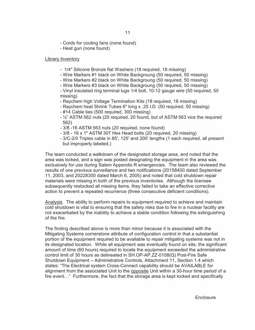
- Cords for cooling fans (none found)- Heat gun (none found)
Library Inventory
- 1/4" Silicone Bronze flat Washers (18 required, 18 missing)- Wire Markers #1 black on White Backgroung (50 required, 50 missing)- Wire Markers #2 black on White Backgroung (50 required, 50 missing)- Wire Markers #3 black on White Backgroung (50 required, 50 missing)- Vinyl insulated ring terminal lugs 1/4 bolt, 10-12 gauge wire (50 required, 50 missing)- Raychem high Voltage Termination Kits (18 required, 18 missing)- Raychem heat Shrink Tubes 6" long x .25 I.D. (50 required, 50 missing)- #14 Cable ties (500 required, 300 missing)- ½” ASTM 562 nuts (20 required, 20 found, but of ASTM 563 vice the required 562)
- 3/8 -16 ASTM 563 nuts (20 required, none found)- 3/8 - 16 x 1" ASTM 307 Hex Head bolts (20 required, 20 missing) - 3/C-2/0 Triplex cable in 85', 125' and 200' lengths (1 each required, all present but improperly labeled.)
The team conducted a walkdown of the designated storage area, and noted that thearea was locked, and a sign was posted designating the equipment in the area wasexclusively for use during Salem Appendix R emergencies. The team also reviewed theresults of one previous surveillance and two notifications (20158400 dated September11, 2003, and 20228300 dated March 6, 2005) and noted that cold shutdown repairmaterials were missing in both of the previous inventories. Although the licenseesubsequently restocked all missing items, they failed to take an effective correctiveaction to prevent a repeated recurrence (three consecutive deficient conditions).
Analysis. The ability to perform repairs to equipment required to achieve and maintaincold shutdown is vital to ensuring that the safety risks due to fire in a nuclear facility arenot exacerbated by the inability to achieve a stable condition following the extinguishingof the fire.
The finding described above is more than minor because it is associated with theMitigating Systems cornerstone attribute of configuration control in that a substantialportion of the equipment required to be available to repair mitigating systems was not inits designated location. While all equipment was eventually found on site, the significantamount of time (60 hours) required to locate the equipment exceeded the administrativecontrol limit of 30 hours as delineated in SH.OP-AP.ZZ-0108(Q) Post-Fire SafeShutdown Equipment – Administrative Controls, Attachment 11, Section 1.4 whichstates: “The Electrical system Cross-Connect capability should be AVAILABLE foralignment from the associated Unit to the opposite Unit within a 30-hour time period of afire event…” Furthermore, the fact that the storage area is kept locked and specifically
12
Enclosure
posted as for use under specific circumstances indicates inadequate administrativepolicies and/or procedural adherence.
The finding was determined to be of very low safety significance (Green, as describedbelow) because the likelihood of a scenario where a fire damages the equipmentserviced by the repair equipment in the discussed storage area, is very low. ManualChapter 0609 Appendix F, the Fire Protection Significance Determination Process(SDP), states if a finding only affects the ability to reach and maintain a cold-shutdowncondition, the finding screens to Green with no further analysis required.
This finding is a performance deficiency and has a problem identification and resolutioncross-cutting aspect because the licensee failed to take an effective corrective action toprevent recurrence after they identified cold shutdown repair materials were missing inMarch 2005.
Enforcement. License conditions 2.C.5 (for Unit 1) and 2.C.10 (for Unit 2) require thatPSEG Nuclear implement and maintain in effect all provisions of the Fire ProtectionProgram as described in the Updated Final Safety Analysis Report (UFSAR). Section9.5.1.1.5 of the UFSAR identified that the Quality Assurance (QA) Program for FireProtection assures that the requirements for administrative controls for the fireprotection program for safety related areas must be satisfied. This section of theUFSAR also identified the fire protection procedures to be an element of the QAprogram. Section 4.0 of Salem fire protection procedure for post-fire cold shutdownrepair, SC.MD-AB.ZZ-0001(Q), states, "All equipment required to install jumpers,cooling fans and make cable terminations are located in the Salem Safe ShutdownEquipment Storage Area." Contrary to the above, on March 30, 2006, the NRCidentified that many of the materials required for cold shutdown repair were missing. The licensee issued a notification 20277307 and entered this deficiency into theircorrective action program. This violation is being treated as a Non-Cited Violation(NCV), consistent with Section VI.A.1 of the NRC Enforcement Policy. (NCV05000272/2006007-03, 05000311/2006007-03, Failure to Comply with Station ColdShutdown Repair Procedures)
.11 Compensatory Measures
a. Inspection Scope
The team verified that compensatory measures were in place for out-of-service,degraded or inoperable fire protection and post-fire safe shutdown equipment, systems,or features (e.g., detection and suppression systems and equipment, passive firebarriers, pumps, valves or electrical devices providing safe shutdown functions orcapabilities). The team also verified that the short term compensatory measurescompensated for the degraded function or feature until appropriate corrective actioncould be taken and that PSEG was effective in returning the equipment to service in areasonable period of time.
13
Enclosure
b. Findings
No findings of significance were identified.
4. OTHER ACTIVITIES
4OA2 Identification and Resolution of Problems
.01 Corrective Actions for Fire Protection Deficiencies
a. Inspection Scope
The team verified that the licensee was identifying fire protection and post-fire safeshutdown issues at an appropriate threshold and entering them into the corrective actionprogram. The team also reviewed a sample of selected issues to verify that the licenseehad taken or planned appropriate corrective actions.
b. Findings
No findings of significance were identified.
4OA5 Other Activities
.1 (Closed) URI 05000272,05000311/200500311 CO2 Migration on Remote ShutdownOperations.
In January 2005, PSEG determined through preliminary results of an engineering
assessment that upon discharge of carbon dioxide (CO2) in some areas of the plant dueto fire, hazardous levels of CO2 concentration could exist in areas required to beaccessible during safe shutdown events. On April 25, 2005, the licensee reportedthough revision 1 to the Licensee Event Report (LER) 2005-001 that the cause of thecarbon dioxide system migration was due to insufficient system design. This issueremained unresolved pending further analysis of the condition and followup inspection toassess the significance of the condition and the adequacy of licensee’s associatedcorrective actions.
In June 2005, PSEG completed the root cause evaluation on the timeliness of correctiveactions for the CO2 migration issue documented in notification 20223951. The teamreviewed PSEG’s root cause evaluation and noted that the evaluation had determinedPSEG’s failure to identify and to rectify the CO2 migration issue in a timely manner wasa condition adverse to quality.
During this inspection, the team reviewed and discussed the engineering assessmentresults with the licensee. The results from Framatone engineering assessmentconcluded that in the event of a CO2 system actuation due to a fire in the 4160 volt or460 volt Switchgear Rooms, or Lower Electrical Penetration Areas, CO2 migration would
14
Enclosure
result in some of the adjacent areas having concentration levels that would require theuse of self-contained breathing apparatus (SCBAs) for entry or would be restricted totransit activities only. On January 26, 2005, PSEG isolated the carbon dioxidesuppression systems for Salem Units 1 and 2, and placed appropriate compensatorymeasures in accordance with the Salem Fire Protection Program. The team evaluatedPSEG’s long-term resolution strategy, which included eliminating CO2 in these fire areasand converting to either an alternate, non-hazardous gaseous system or a water basedsuppression system. On March 10, 2006, PSEG’s Plant Health Committee (PHC)approved the recommendation to initiate a project to complete conceptual designs,material estimates, and implementation of replacing the existing CO2 fire suppressionsystem with an interlocked preaction water suppression system. This unresolved item isclosed. See Section 4OA7 of this report for the detailed risk assessment of this licenseeidentified finding.
.2 (Closed) URI 05000272,05000311/2003002-01 Fire Induced Spurious Opening of MS10Valves
Inspection Report 05000272,311/2003002 documented a potential finding that for threefire areas (inner piping penetration area, outer penetration area, and 1(2)FA-TGA-88inthe turbine building), the licensee has not protected a full train of equipment necessaryto achieve and maintain hot shutdown. For each unit, there are four steam generatorpower operated relief valves (MS10), which discharge the steam to the atmospherewhen open. These are 6" air operated valves which fail close when the pilot solenoidvalves are de-energized or when the instrument air is lost. The control circuit for eachsolenoid valve is located in an instrument panel and a fire-induced hot short can causethe solenoid valve to be energized and the associated MS10 valve to open inadvertently. The pilot solenoid valves for two MS10 valves are located in one fire area, but thepanels are separated by 12 feet.
The licensee completed an analysis, S-C-MS-MEE-1533, Loss of Main Steam IsolationComponents due to an Appendix R Fire in 1(2)FA-PP-92K or 1(2)FA-PP-1000H toevaluate two concerns: 1) reactivity addition due to excessive cool down rate, and, 2)maintaining heat sink available. The analysis showed that with one MS10 valveinadvertently open, the initial steam flow rate (575,710 lbm/hr for a short duration) iswithin the analyzed condition (1,100.000 lbm/hr in USFAR Section 15.2.13). If twoMS10s open simultaneously (beginning at the same moment), the excess cool downrate will be slightly outside the analyzed condition. The licensee stated that multiplespurious actuations (hot shorts) were outside their licensing basis. The above analysisalso showed that maintaining heat sink was acceptable as the other two MS10 valves (inanother fire area) were not affected. However, the affected MS10 valves must beclosed manually to prevent steam generators from boiling dry. The licenseeincorporated manual actions to close the potentially affected MS10 valves if a fire occursin the identified fire areas. The licensee also completed another analysis, S-C-FP-FEE-1746, Acceptable Response Times to Appendix R Failures, which showed that (in Table4), for the spurious opening of a single MS10, the cool down rate for the first hour is79.2 EF, which is also within the allowed cooling rate of 100 EF per hour.
15
Enclosure
Salem’s licensing basis only assumes a single fire-induced spurious action, and theinadvertent opening of a single MS 10 valve was determined to be within the analyzedcondition. Therefore this unresolved item is closed.
4OA6 Meetings, Including Exit
Exit Meeting Summary
The team presented their preliminary inspection results to Mr. T. Joyce, Vice President,and other members of the site staff at an initial meeting on March 31, 2006, and atelephone conference call exit meeting to update the initial findings on April 10, 2006. No proprietary information was included in this inspection report.
4OA7 Licensee-Identified Violation
The following violation of very low safety significance (Green) was identified by thelicensee and is a violation of NRC requirements which meet the criteria of Section VI ofthe Enforcement Policy, NUREG-1600, for being dispositioned as NCVs.
•. License conditions 2.C.5 (for Unit 1) and 2.C.10 (for Unit 2) require that PSEGNuclear implement and maintain in effect all provisions of the Fire ProtectionProgram as described in the Updated Final Safety Analysis Report (UFSAR). UFSAR Section 9.5.1.1.5 requires corrective action measures to be establishedto ensure that conditions adverse to fire protection are promptly identified,reported, and corrected. Contrary to the above, as of January 25, 2005, PSEGfailed to promptly identify, report and correct the CO2 migration issue, althoughPSEG had received the final calculation from Framatome on December 3, 2003,which showed that the potential CO2 leakage to the work control area (next tothe control room) could reach an unacceptable level (up to 12.6% CO2concentration). The CO2 migration issue is a condition adverse to fire protection. PSEG documented this issue in LER 2005-001 and in Notification 20223951.
This finding is more than minor because it had a potential to impact the ability tosafely shutdown Salem Unit 1 and 2 in the event of fire in the 4160 volt and 460volt Switchgear Rooms. The finding affects the Mitigating Systems Cornerstoneand was evaluated using Inspection Manual Chapter (IMC) 0609, Appendix F,and was determined to represent a potential fire protection risk of very low safetysignificance (green). The Phase 2 risk assessment result by the NRC inspectorswas formulated using conservative assumption. Based upon the limitation ofAppendix F in characterizing the risk of fire scenarios impacting the control roomand potentially resulting in a control room evacuation, the licensee performed amore detailed Phase 3 risk assessment. The licensee’s detailed analysisconfirmed the inspectors’ Phase 2 result. This analysis was independentlyreviewed by the Region I Senior Reactor Analyst who agreed with themethodology and resulting characterization.
A-1
Attachment
SUPPLEMENTAL INFORMATION
KEY POINTS OF CONTACT
PSEG Personnel
J. Balcita, Engineer, Design EngineeringD. Benyak, Director, Regulatory AssuranceW. Buirch, Supt, Fire Protection OperationsM. Ewirtz, DPS Support Manager, Salem OperationsA. Fakhar, Senior Manager, Design EngineeringC. Fricker, Plant Manager, SalemT. Joyce, Site Vice President, SalemS. Mannon, Manager Regulatory AssuranceK. Mathur, Engineer, Mechanical Design EngineeringW. Mattinely, Manager, Salem Nuclear OversightM. Mog, Shift Supervisor, Salem OperationT. Moore, director, Project ManagementA. Robert III, Manager, Engineering ProgramS. Robitzski, Director, EngineeringD. Shumaker, Engineer, Program EngineeringJ. Stone, Director, Salem MaintenanceR. Wegner, Director, Salem Work ManagementJ. Wearne, Engineer, Salem Licensing
Exelon Corporation
W. Lewis, Manager, EngineeringC. Pragman, Manager, Corporate Fire Protection Program
New Jersey Department of Environmental Protection
E. Rosenfeld, Engineer
NRC
D. Orr, Senior Resident Inspector, Salem Units 1 and 2J. Rogge, Chief, Engineering Branch 3, Division of Reactor Safety
A-2
Attachment
LIST OF ITEMS OPENED, CLOSED, AND DISCUSSED
Opened
05000272, 05000311/2006007-01 URI Temperature Habitability Effects on the Ability toPerform Alternate Shut Down Manual Actions
05000272,05000311/2006007-02 URI Localized Temperatures in the CARR Not toExceed Safe Shutdown Equipment OperableTemperature During a Loss of HVAC Event
Open and Closed
05000272, 05000311/2006007-03 NCV Failure to Comply with Station Cold ShutdownRepair Procedures (Section 1R05)
Closed
05000272,05000311/2005003-11 URI CO2 Migration on Remote Shutdown Operations
05000272,05000311/2003002-01 URI Fire Induced Spurious Opening of MS10 Valves
Discussed
None
A-3
Attachment
LIST OF DOCUMENTS REVIEWED
Fire Protection Licensing Documents
C Amendment No. 2 to Facility Operating License No. DPR-70. NRC letter dated 11/20/79to Mr. P. Librizzi, General Manager
C June 17, 1983, Letter to PSE&G, Salem Nuclear Generating Station, Unit No. 1, FireProtection – Request for Exemption from Requirements of Appendix R to 10 CFR 50,Section III.G
C July 15, 1988, Letter to NRC, Revised Exemption Requests Fire Protection – 10 CFRAppendix R, Salem Generating Station Unit Nos. 1 and 2
C July 20, 1989, Letter to PSE&G, Exemption from the Requirements of 10 CFR 50,Appendix R (Fire Protection)
C June 24, 2003, Letter to PSE&G, Salem Nuclear Generating Station, Unit Nos. 1 and 2,Exemption from the Requirements of 10 CFR 50, Appendix R, Sections III.G.3 andIII.L.3, for Fire Areas 1(2)FA-AB-64B, 1(2)FA-AB-84B and 1(2)FA-AB-84C
C January 7, 2004, Letter to PSE&G, Salem Nuclear Generating Station, Unit No. 2,Issuance of Amendment Re: Request for Changes to License Conditions 2.C.(10)
C Safety Evaluation Report, Exemptions from 10 CFR 50, Appendix R, Salem GeneratingStation, Units 1 and 2, response to letter dtd 07/15/88
C Information Notice 2002-24, Potential Problems with Heat Collectors on Fire ProtectionSprinklers, 07/19/02
Calculations/Engineering Evaluation Reports
S-C-CAV-MDC-1583 Salem Generating Station – Compensatory Actions forAppendix R & IEEE Loss of Ventilation Scenarios,Revision 4.
S-O-FP-MEE-0756 Salem Generating Station, Units 1 & 2 Fire Pump Piping(As-Built) Configuration Justification, Revision 3
S-C-FBW-FEE-1609 Evaluation of the Fire Resistance Capability of VentilationConfiguration in 3 Hour Structural Barriers, Revision 0
S-C-FP-FEE-1663 Fire Suppression System Performance CapabilityEvaluation - 1(2)FA-AB-84B, Revision 1
S-C-FP-FEE-1659 Evaluation of Fire Detection System Capabilities - FireArea 1(2)FA-AB-84B (SGS), Revision 0
S-C-FP-FEE-1667 Generic Letter 86.10 Engineering Evaluation for Fire Area1(2)FA-AB-84B, demonstrating adequate separation existsbetween "A", "B", & "C" Service Water Channels Revision0
S-C-FP-FEE-1746 Acceptable Operator Response Times to Appendix RFailures, Revision 0
S-C-FP-FEE-1748 CO2 System Operability in Switchgear Rooms and LowerElectrical Penetration Areas, Revision 0
S-C-FP-FEE-1802 CO2 Migration Evaluation for SPAV Areas, Revision 0
A-4
Attachment
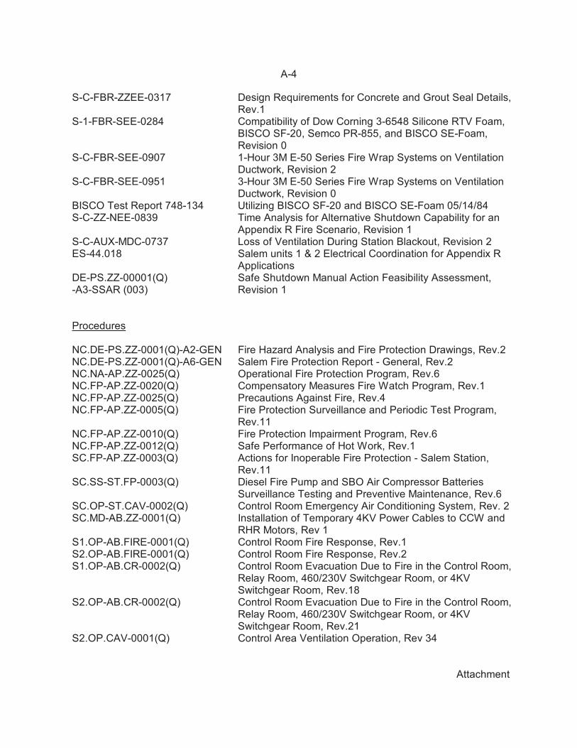
S-C-FBR-ZZEE-0317 Design Requirements for Concrete and Grout Seal Details,Rev.1
S-1-FBR-SEE-0284 Compatibility of Dow Corning 3-6548 Silicone RTV Foam,BISCO SF-20, Semco PR-855, and BISCO SE-Foam,Revision 0
S-C-FBR-SEE-0907 1-Hour 3M E-50 Series Fire Wrap Systems on VentilationDuctwork, Revision 2
S-C-FBR-SEE-0951 3-Hour 3M E-50 Series Fire Wrap Systems on VentilationDuctwork, Revision 0
BISCO Test Report 748-134 Utilizing BISCO SF-20 and BISCO SE-Foam 05/14/84S-C-ZZ-NEE-0839 Time Analysis for Alternative Shutdown Capability for an
Appendix R Fire Scenario, Revision 1S-C-AUX-MDC-0737 Loss of Ventilation During Station Blackout, Revision 2ES-44.018 Salem units 1 & 2 Electrical Coordination for Appendix R
ApplicationsDE-PS.ZZ-00001(Q) Safe Shutdown Manual Action Feasibility Assessment,-A3-SSAR (003) Revision 1
Procedures
NC.DE-PS.ZZ-0001(Q)-A2-GEN Fire Hazard Analysis and Fire Protection Drawings, Rev.2NC.DE-PS.ZZ-0001(Q)-A6-GEN Salem Fire Protection Report - General, Rev.2NC.NA-AP.ZZ-0025(Q) Operational Fire Protection Program, Rev.6NC.FP-AP.ZZ-0020(Q) Compensatory Measures Fire Watch Program, Rev.1NC.FP-AP.ZZ-0025(Q) Precautions Against Fire, Rev.4NC.FP-AP.ZZ-0005(Q) Fire Protection Surveillance and Periodic Test Program,
Rev.11NC.FP-AP.ZZ-0010(Q) Fire Protection Impairment Program, Rev.6NC.FP-AP.ZZ-0012(Q) Safe Performance of Hot Work, Rev.1SC.FP-AP.ZZ-0003(Q) Actions for Inoperable Fire Protection - Salem Station,
Rev.11SC.SS-ST.FP-0003(Q) Diesel Fire Pump and SBO Air Compressor Batteries
Surveillance Testing and Preventive Maintenance, Rev.6SC.OP-ST.CAV-0002(Q) Control Room Emergency Air Conditioning System, Rev. 2SC.MD-AB.ZZ-0001(Q) Installation of Temporary 4KV Power Cables to CCW and
RHR Motors, Rev 1S1.OP-AB.FIRE-0001(Q) Control Room Fire Response, Rev.1S2.OP-AB.FIRE-0001(Q) Control Room Fire Response, Rev.2S1.OP-AB.CR-0002(Q) Control Room Evacuation Due to Fire in the Control Room,
Relay Room, 460/230V Switchgear Room, or 4KVSwitchgear Room, Rev.18
S2.OP-AB.CR-0002(Q) Control Room Evacuation Due to Fire in the Control Room,Relay Room, 460/230V Switchgear Room, or 4KVSwitchgear Room, Rev.21
S2.OP.CAV-0001(Q) Control Area Ventilation Operation, Rev 34
A-5
Attachment
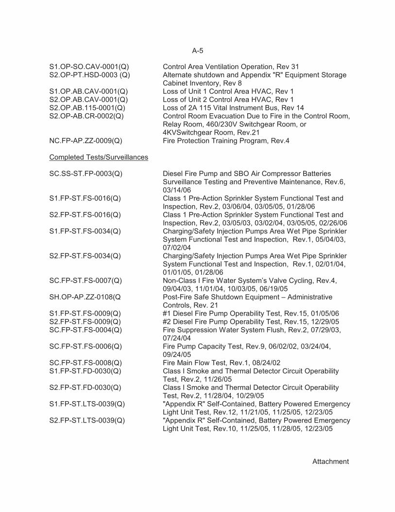
S1.OP-SO.CAV-0001(Q) Control Area Ventilation Operation, Rev 31S2.OP-PT.HSD-0003 (Q) Alternate shutdown and Appendix "R" Equipment Storage
Cabinet Inventory, Rev 8S1.OP.AB.CAV-0001(Q) Loss of Unit 1 Control Area HVAC, Rev 1S2.OP.AB.CAV-0001(Q) Loss of Unit 2 Control Area HVAC, Rev 1S2.OP.AB.115-0001(Q) Loss of 2A 115 Vital Instrument Bus, Rev 14S2.OP-AB.CR-0002(Q) Control Room Evacuation Due to Fire in the Control Room,
Relay Room, 460/230V Switchgear Room, or4KVSwitchgear Room, Rev.21
NC.FP-AP.ZZ-0009(Q) Fire Protection Training Program, Rev.4
Completed Tests/Surveillances
SC.SS-ST.FP-0003(Q) Diesel Fire Pump and SBO Air Compressor BatteriesSurveillance Testing and Preventive Maintenance, Rev.6,03/14/06
S1.FP-ST.FS-0016(Q) Class 1 Pre-Action Sprinkler System Functional Test andInspection, Rev.2, 03/06/04, 03/05/05, 01/28/06
S2.FP-ST.FS-0016(Q) Class 1 Pre-Action Sprinkler System Functional Test andInspection, Rev.2, 03/05/03, 03/02/04, 03/05/05, 02/26/06
S1.FP-ST.FS-0034(Q) Charging/Safety Injection Pumps Area Wet Pipe SprinklerSystem Functional Test and Inspection, Rev.1, 05/04/03,07/02/04
S2.FP-ST.FS-0034(Q) Charging/Safety Injection Pumps Area Wet Pipe SprinklerSystem Functional Test and Inspection, Rev.1, 02/01/04,01/01/05, 01/28/06
SC.FP-ST.FS-0007(Q) Non-Class I Fire Water System’s Valve Cycling, Rev.4,09/04/03, 11/01/04, 10/03/05, 06/19/05
SH.OP-AP.ZZ-0108(Q Post-Fire Safe Shutdown Equipment – AdministrativeControls, Rev. 21
S1.FP-ST.FS-0009(Q) #1 Diesel Fire Pump Operability Test, Rev.15, 01/05/06S2.FP-ST.FS-0009(Q) #2 Diesel Fire Pump Operability Test, Rev.15, 12/29/05SC.FP-ST.FS-0004(Q) Fire Suppression Water System Flush, Rev.2, 07/29/03,
07/24/04SC.FP-ST.FS-0006(Q) Fire Pump Capacity Test, Rev.9, 06/02/02, 03/24/04,
09/24/05SC.FP-ST.FS-0008(Q) Fire Main Flow Test, Rev.1, 08/24/02S1.FP-ST.FD-0030(Q) Class I Smoke and Thermal Detector Circuit Operability
Test, Rev.2, 11/26/05S2.FP-ST.FD-0030(Q) Class I Smoke and Thermal Detector Circuit Operability
Test, Rev.2, 11/28/04, 10/29/05S1.FP-ST.LTS-0039(Q) "Appendix R" Self-Contained, Battery Powered Emergency
Light Unit Test, Rev.12, 11/21/05, 11/25/05, 12/23/05S2.FP-ST.LTS-0039(Q) "Appendix R" Self-Contained, Battery Powered Emergency
Light Unit Test, Rev.10, 11/25/05, 11/28/05, 12/23/05
A-6
Attachment
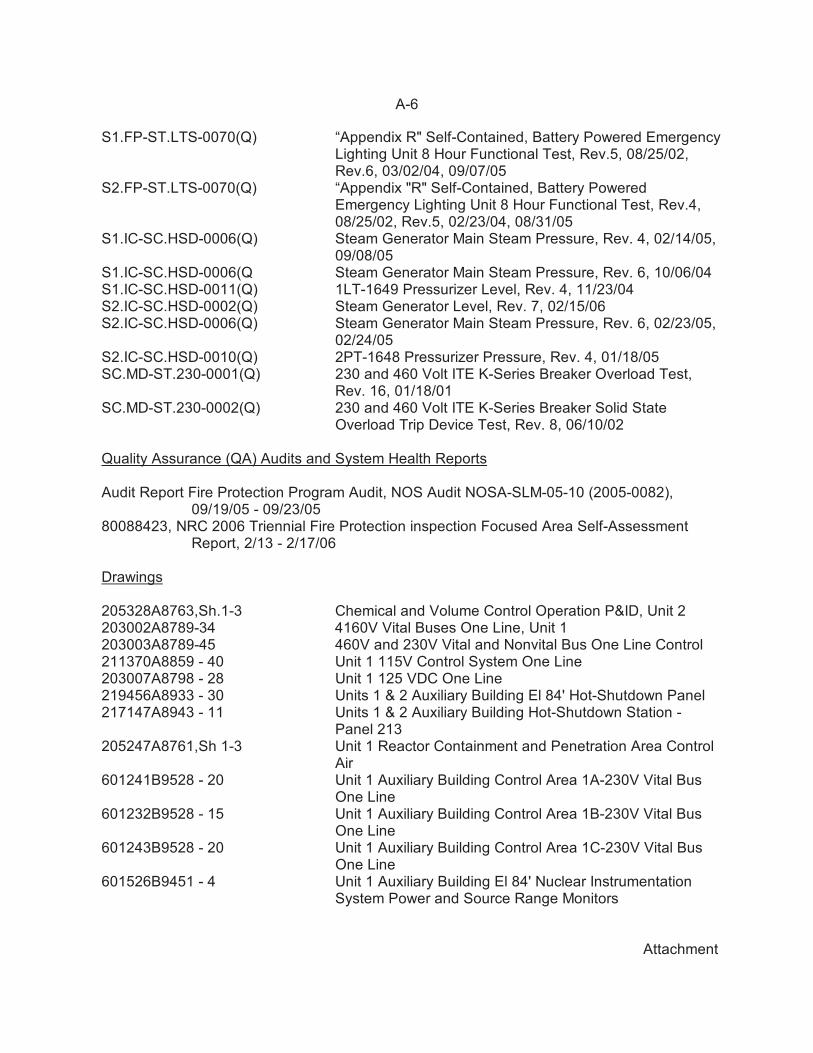
S1.FP-ST.LTS-0070(Q) “Appendix R" Self-Contained, Battery Powered EmergencyLighting Unit 8 Hour Functional Test, Rev.5, 08/25/02,Rev.6, 03/02/04, 09/07/05
S2.FP-ST.LTS-0070(Q) “Appendix "R" Self-Contained, Battery PoweredEmergency Lighting Unit 8 Hour Functional Test, Rev.4,08/25/02, Rev.5, 02/23/04, 08/31/05
S1.IC-SC.HSD-0006(Q) Steam Generator Main Steam Pressure, Rev. 4, 02/14/05,09/08/05
S1.IC-SC.HSD-0006(Q Steam Generator Main Steam Pressure, Rev. 6, 10/06/04S1.IC-SC.HSD-0011(Q) 1LT-1649 Pressurizer Level, Rev. 4, 11/23/04S2.IC-SC.HSD-0002(Q) Steam Generator Level, Rev. 7, 02/15/06S2.IC-SC.HSD-0006(Q) Steam Generator Main Steam Pressure, Rev. 6, 02/23/05,
02/24/05S2.IC-SC.HSD-0010(Q) 2PT-1648 Pressurizer Pressure, Rev. 4, 01/18/05SC.MD-ST.230-0001(Q) 230 and 460 Volt ITE K-Series Breaker Overload Test,
Rev. 16, 01/18/01SC.MD-ST.230-0002(Q) 230 and 460 Volt ITE K-Series Breaker Solid State
Overload Trip Device Test, Rev. 8, 06/10/02
Quality Assurance (QA) Audits and System Health Reports
Audit Report Fire Protection Program Audit, NOS Audit NOSA-SLM-05-10 (2005-0082), 09/19/05 - 09/23/05
80088423, NRC 2006 Triennial Fire Protection inspection Focused Area Self-Assessment Report, 2/13 - 2/17/06
Drawings
205328A8763,Sh.1-3 Chemical and Volume Control Operation P&ID, Unit 2203002A8789-34 4160V Vital Buses One Line, Unit 1203003A8789-45 460V and 230V Vital and Nonvital Bus One Line Control211370A8859 - 40 Unit 1 115V Control System One Line203007A8798 - 28 Unit 1 125 VDC One Line219456A8933 - 30 Units 1 & 2 Auxiliary Building El 84' Hot-Shutdown Panel217147A8943 - 11 Units 1 & 2 Auxiliary Building Hot-Shutdown Station -
Panel 213205247A8761,Sh 1-3 Unit 1 Reactor Containment and Penetration Area Control
Air601241B9528 - 20 Unit 1 Auxiliary Building Control Area 1A-230V Vital Bus
One Line601232B9528 - 15 Unit 1 Auxiliary Building Control Area 1B-230V Vital Bus
One Line601243B9528 - 20 Unit 1 Auxiliary Building Control Area 1C-230V Vital Bus
One Line601526B9451 - 4 Unit 1 Auxiliary Building El 84' Nuclear Instrumentation
System Power and Source Range Monitors
A-7
Attachment
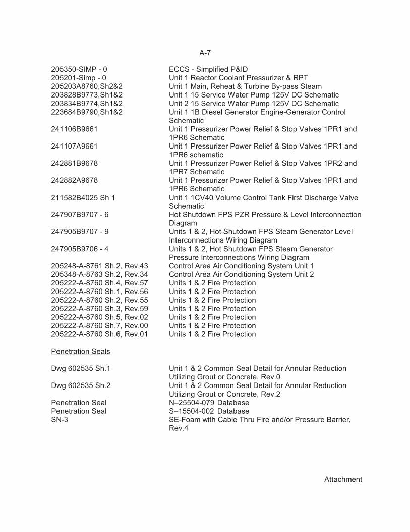
205350-SIMP - 0 ECCS - Simplified P&ID205201-Simp - 0 Unit 1 Reactor Coolant Pressurizer & RPT205203A8760,Sh2&2 Unit 1 Main, Reheat & Turbine By-pass Steam203828B9773,Sh1&2 Unit 1 15 Service Water Pump 125V DC Schematic203834B9774,Sh1&2 Unit 2 15 Service Water Pump 125V DC Schematic223684B9790,Sh1&2 Unit 1 1B Diesel Generator Engine-Generator Control
Schematic241106B9661 Unit 1 Pressurizer Power Relief & Stop Valves 1PR1 and
1PR6 Schematic241107A9661 Unit 1 Pressurizer Power Relief & Stop Valves 1PR1 and
1PR6 schematic242881B9678 Unit 1 Pressurizer Power Relief & Stop Valves 1PR2 and
1PR7 Schematic242882A9678 Unit 1 Pressurizer Power Relief & Stop Valves 1PR1 and
1PR6 Schematic211582B4025 Sh 1 Unit 1 1CV40 Volume Control Tank First Discharge Valve
Schematic247907B9707 - 6 Hot Shutdown FPS PZR Pressure & Level Interconnection
Diagram247905B9707 - 9 Units 1 & 2, Hot Shutdown FPS Steam Generator Level
Interconnections Wiring Diagram247905B9706 - 4 Units 1 & 2, Hot Shutdown FPS Steam Generator
Pressure Interconnections Wiring Diagram205248-A-8761 Sh.2, Rev.43 Control Area Air Conditioning System Unit 1205348-A-8763 Sh.2, Rev.34 Control Area Air Conditioning System Unit 2205222-A-8760 Sh.4, Rev.57 Units 1 & 2 Fire Protection205222-A-8760 Sh.1, Rev.56 Units 1 & 2 Fire Protection205222-A-8760 Sh.2, Rev.55 Units 1 & 2 Fire Protection205222-A-8760 Sh.3, Rev.59 Units 1 & 2 Fire Protection205222-A-8760 Sh.5, Rev.02 Units 1 & 2 Fire Protection205222-A-8760 Sh.7, Rev.00 Units 1 & 2 Fire Protection205222-A-8760 Sh.6, Rev.01 Units 1 & 2 Fire Protection
Penetration Seals
Dwg 602535 Sh.1 Unit 1 & 2 Common Seal Detail for Annular ReductionUtilizing Grout or Concrete, Rev.0
Dwg 602535 Sh.2 Unit 1 & 2 Common Seal Detail for Annular ReductionUtilizing Grout or Concrete, Rev.2
Penetration Seal N–25504-079 DatabasePenetration Seal S–15504-002 DatabaseSN-3 SE-Foam with Cable Thru Fire and/or Pressure Barrier,
Rev.4
A-8
Attachment
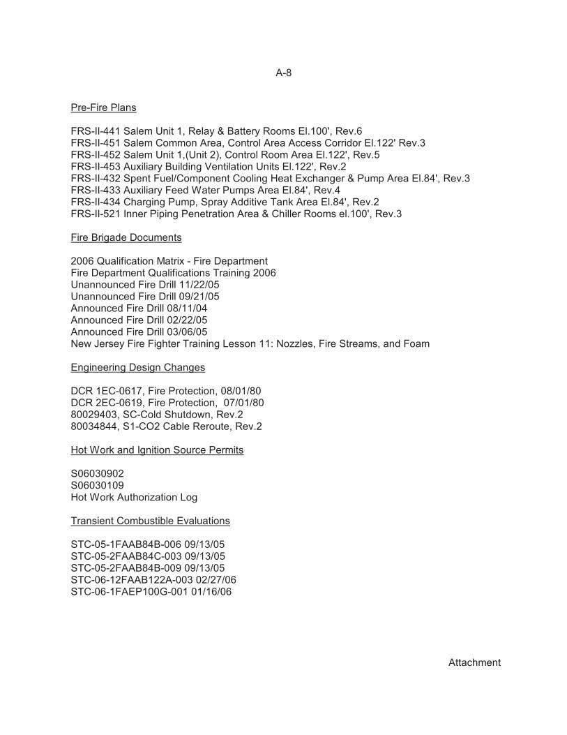
Pre-Fire Plans
FRS-II-441 Salem Unit 1, Relay & Battery Rooms El.100', Rev.6FRS-II-451 Salem Common Area, Control Area Access Corridor El.122' Rev.3FRS-II-452 Salem Unit 1,(Unit 2), Control Room Area El.122', Rev.5FRS-II-453 Auxiliary Building Ventilation Units El.122', Rev.2FRS-II-432 Spent Fuel/Component Cooling Heat Exchanger & Pump Area El.84', Rev.3FRS-II-433 Auxiliary Feed Water Pumps Area El.84', Rev.4FRS-II-434 Charging Pump, Spray Additive Tank Area El.84', Rev.2FRS-II-521 Inner Piping Penetration Area & Chiller Rooms el.100', Rev.3
Fire Brigade Documents
2006 Qualification Matrix - Fire DepartmentFire Department Qualifications Training 2006Unannounced Fire Drill 11/22/05Unannounced Fire Drill 09/21/05Announced Fire Drill 08/11/04Announced Fire Drill 02/22/05Announced Fire Drill 03/06/05New Jersey Fire Fighter Training Lesson 11: Nozzles, Fire Streams, and Foam
Engineering Design Changes
DCR 1EC-0617, Fire Protection, 08/01/80DCR 2EC-0619, Fire Protection, 07/01/8080029403, SC-Cold Shutdown, Rev.280034844, S1-CO2 Cable Reroute, Rev.2
Hot Work and Ignition Source Permits
S06030902S06030109Hot Work Authorization Log
Transient Combustible Evaluations
STC-05-1FAAB84B-006 09/13/05STC-05-2FAAB84C-003 09/13/05STC-05-2FAAB84B-009 09/13/05STC-06-12FAAB122A-003 02/27/06STC-06-1FAEP100G-001 01/16/06
A-9
Attachment
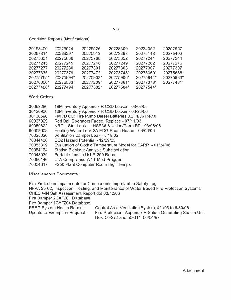
Condition Reports (Notifications)
20158400 20225524 20225526 20228300 20234352 2025295720257314 20269297 20270913 20273398 20275148 2027540220275631 20275636 20275768 20275852 20277244 2027724420277245 20277245 20277248 20277249 20277262 2027727620277277 20277280 20277301 20277303 20277307 2027730720277335 20277379 20277472 20273748* 20275369* 20275686*20275765* 20275894* 20275903* 20275906* 20275944* 20275986*20276006* 20276533* 20277209* 20277361* 20277373* 20277481*20277488* 20277494* 20277502* 20277504* 20277544*
Work Orders
30093280 18M Inventory Appendix R CSD Locker - 03/06/0530120936 18M Inventory Appendix R CSD Locker - 03/28/0630136590 PM 7D CD: Fire Pump Diesel Batteries 03/14/06 Rev.060037929 Red Ball Operators Faded, Replace - 07/11/0360059822 NRC – Stm Leak – 1HSE36 & Union/Perm RP - 03/06/0660059608 Heating Water Leak 2A EDG Room Heater - 03/06/0670025026 Ventilation Damper Leak - 5/18/0270044438 CO2 Hazard Potential - 12/29/0570053399 Evaluation of Gothic Temperature Model for CARR - 01/24/06 70054164 Station Blackout Analysis Substantiation 70048939 Portable fans in U/1 P-250 Room70050146 LTA Compliance W/ T-Mod Program70034817 P250 Plant Computer Room High Temps
Miscellaneous Documents
Fire Protection Impairments for Components Important to Safety LogNFPA 25-02, Inspection, Testing, and Maintenance of Water-Based Fire Protection SystemsCHECK-IN Self Assessment Report dtd 03/12/06Fire Damper 2CAF201 DatabaseFire Damper 1CAF204 DatabasePSEG System Health Report - Control Area Ventilation System, 4/1/05 to 6/30/06Update to Exemption Request - Fire Protection, Appendix R Salem Generating Station Unit
Nos. 50-272 and 50-311, 06/04/97
A-10
Attachment
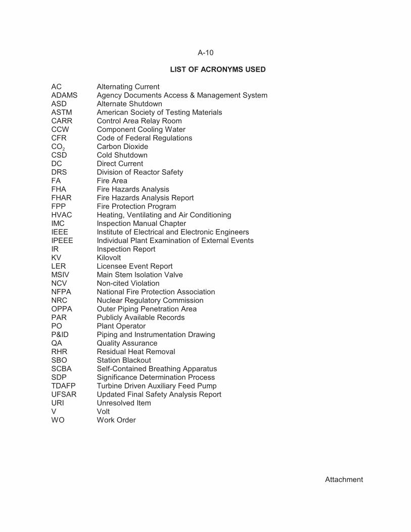
LIST OF ACRONYMS USED
AC Alternating CurrentADAMS Agency Documents Access & Management SystemASD Alternate ShutdownASTM American Society of Testing MaterialsCARR Control Area Relay RoomCCW Component Cooling WaterCFR Code of Federal RegulationsCO2 Carbon DioxideCSD Cold ShutdownDC Direct CurrentDRS Division of Reactor SafetyFA Fire AreaFHA Fire Hazards AnalysisFHAR Fire Hazards Analysis ReportFPP Fire Protection ProgramHVAC Heating, Ventilating and Air ConditioningIMC Inspection Manual ChapterIEEE Institute of Electrical and Electronic EngineersIPEEE Individual Plant Examination of External EventsIR Inspection ReportKV KilovoltLER Licensee Event ReportMSIV Main Stem Isolation ValveNCV Non-cited ViolationNFPA National Fire Protection AssociationNRC Nuclear Regulatory CommissionOPPA Outer Piping Penetration AreaPAR Publicly Available RecordsPO Plant OperatorP&ID Piping and Instrumentation DrawingQA Quality AssuranceRHR Residual Heat RemovalSBO Station BlackoutSCBA Self-Contained Breathing ApparatusSDP Significance Determination ProcessTDAFP Turbine Driven Auxiliary Feed PumpUFSAR Updated Final Safety Analysis ReportURI Unresolved ItemV VoltWO Work Order