A note on Feynmanʼs calculation of reflection amplitudes for radiation striking a glass surface
Upload
khangminh22Category
view
5download
0
PROJECT: BUILDING WITH TWO LEVELS BY : SOGEIB LTD
STRUCTURE CALCULATION NOTE
November 27
2018
CONSTRUCTION OF A BUILDING WITH
TWO LEVELS (G + TWO ON PLOT NUMBER
502 / UPI 3/03/04/02/502 LOCATED AT
RUBAVU – GISENYI. BUGOYI
OWNER : NDURUMA ELIZABETH CHUCHU

1
PROJECT: Building with two levels BY: Eng. Augustine HABINSHUTI
Contents I. LIST OF SYMBOLS ........................................................................................................................................... 3
1. DESIGN INFORMATION ................................................................................................................................. 5
1.1. Code of practice used ................................................................................................................................... 5
1.2. Units ............................................................................................................................................................. 5
1.3. Values of loads ............................................................................................................................................. 5
1.3.1. Dead loads (Self weight of materials of construction). ............................................................................ 5
1.3.2. Live loads................................................................................................................................................. 5
1.4 Characteristics of used materials .................................................................................................................. 6
1.4.1 The concrete. ................................................................................................................................................ 6
1.4.2 The reinforcement .................................................................................................................................... 6
2. ESTIMATION OF STRUCTURAL ELEMENTS DIMENSIONS. .................................................................... 6
2.1 Estimation of slab dimensions...................................................................................................................... 6
2.2 Estimation of beam dimensions. .................................................................................................................. 6
2.3 Estimation of stair dimensions. .................................................................................................................... 6
3 ANALYSIS AND DESIGN OF SLAB ............................................................................................................... 7
3.1.1 Calculation and design ............................................................................................................................. 7
4 CALCULATION AND DESIGN OF BEAM .................................................................................................. 11
4.1 Calculation and design of inner beam ........................................................................................................ 11
4.1.1 Predesigned flanged section beam(T-beam section) .............................................................................. 11
4.1.2 Computation of uniformly distributed loading on the beam .................................................................. 12
On span3 n3=n1= 49.406KN/m ............................................................................................................................. 12
4.2 Calculation and design of outer beam ........................................................................................................ 19
4.2.1 Predesigned flanged section beam (T-beam section) ............................................................................. 19
4.2.2 Computation of uniformly distributed loading on the beam .................................................................. 20
4.3 Calculation and design of the Ring Beam .................................................................................................. 23
5. CALCULATION AND DESIGN OF COLUMNS .......................................................................................... 24
5.1 Influence area on the column ..................................................................................................................... 24
5.2 Loads take down ........................................................................................................................................ 25
5.3 Calculation and design ............................................................................................................................... 26
5.3.1 Hypotheses ............................................................................................................................................. 26
5.3.2 Reinforcement in the column ................................................................................................................. 26
................................................................................................................................................................................. 31
6. CALCULATION AND DESIGN OF FOUNDATION ................................................................................... 32
6.1 Calculation and design of foundation group1 ............................................................................................ 32
a) Hypothesis .................................................................................................................................................. 32
b) Punching shear ........................................................................................................................................... 33
c) Check for shear force ................................................................................................................................. 34
6.2. Moment Steel ............................................................................................................................................. 34

2
PROJECT: Building with two levels BY: Eng. Augustine HABINSHUTI
6.3 Design Sketch ............................................................................................ Error! Bookmark not defined.
6.2 Calculation and design of foundation group2 ............................................................................................ 34
d) Hypothesis .................................................................................................. Error! Bookmark not defined.
e) Punching shear ........................................................................................... Error! Bookmark not defined.
f) Check for shear force ................................................................................. Error! Bookmark not defined.
6.3. Moment Steel ............................................................................................. Error! Bookmark not defined.
6.4 Design Sketch ............................................................................................ Error! Bookmark not defined.
6.3 Calculation and design of foundation group3 ............................................ Error! Bookmark not defined.
g) Hypothesis .................................................................................................................................................. 34
h) Punching shear ........................................................................................................................................... 35
6.4. Moment Steel ............................................................................................. Error! Bookmark not defined.
6.5 Design Sketch ............................................................................................ Error! Bookmark not defined.
7 STAIRS DESIGN .............................................................................................. Error! Bookmark not defined.
8 RESULTS PRESENTATION ........................................................................................................................... 37
3
PROJECT: Building with two levels BY: Eng. Augustine HABINSHUTI
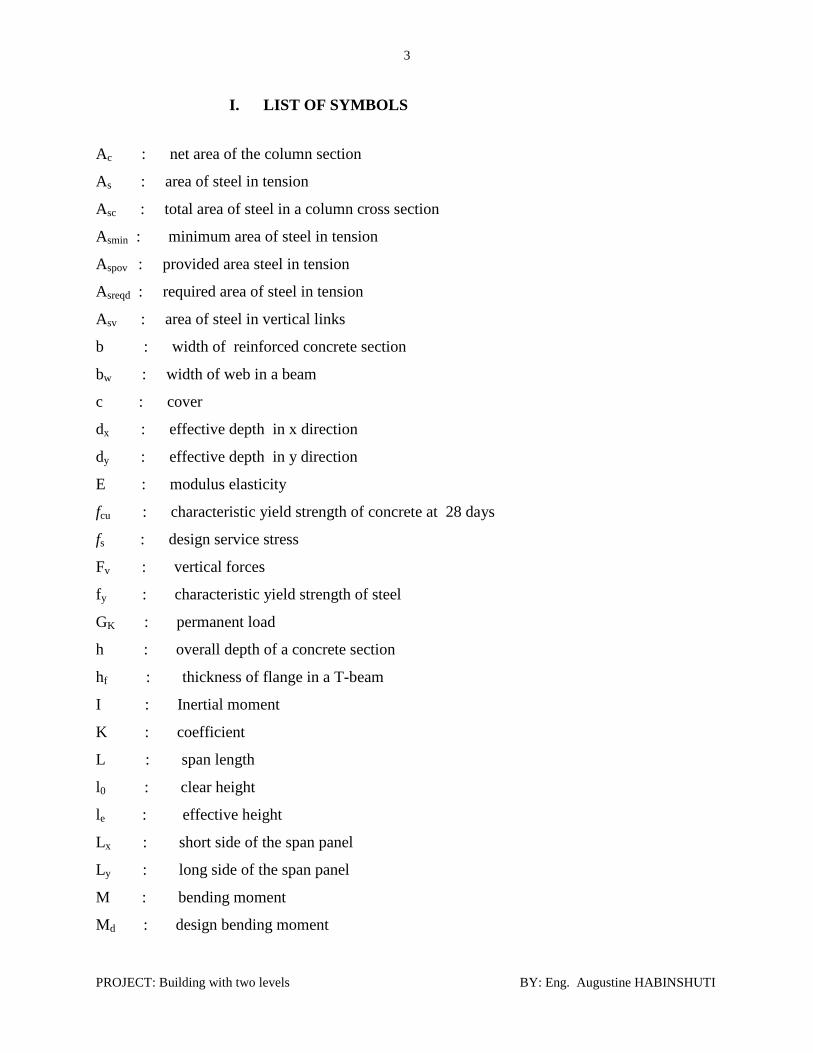
I. LIST OF SYMBOLS
Ac : net area of the column section
As : area of steel in tension
Asc : total area of steel in a column cross section
Asmin : minimum area of steel in tension
Aspov : provided area steel in tension
Asreqd : required area of steel in tension
Asv : area of steel in vertical links
b : width of reinforced concrete section
bw : width of web in a beam
c : cover
dx : effective depth in x direction
dy : effective depth in y direction
E : modulus elasticity
fcu : characteristic yield strength of concrete at 28 days
fs : design service stress
Fv : vertical forces
fy : characteristic yield strength of steel
GK : permanent load
h : overall depth of a concrete section
hf : thickness of flange in a T-beam
I : Inertial moment
K : coefficient
L : span length
l0 : clear height
le : effective height
Lx : short side of the span panel
Ly : long side of the span panel
M : bending moment
Md : design bending moment

4
PROJECT: Building with two levels BY: Eng. Augustine HABINSHUTI
Mmax : maximum bending moment
Msx : bending moment in x direction
Msy : bending moment in y direction
Mu : ultimate bending moment
Nd : axial load on column
Nd : axial load on the column
Nu : ultimate design load
Nuz : design ultimate capacity of a section subjected to axial load only
Ø : diameter of reinforcement
P : pressure of pad foundation
Pcr : critical perimeter
Px, Py : percentage of reinforcement
Qadm : admissible bearing pressure of soil
Qk : imposed load
S : spacing
Scr : critical surface
Sv : spacing of vertical links
V : shear force in concrete section
νc : design concrete shear strength
νsx, vsy : design shear capacity of shear reinforcement
x : depth of neutral axis from compression face
y : diameter of steel
z : depth of lever arm
βb : ration of redistributed moment over elastic analysis moment
βɣ : factor governing moment of resistance of concrete T-section
βsx , βsy : bending moment coefficient
βvx, βvy : shear force coefficient

5
PROJECT: Building with two levels BY: Eng. Augustine HABINSHUTI
1. DESIGN INFORMATION
1.1. Code of practice used
In order to design the building, the sections of reinforcements of different elements of the
structure will be determined according to British Standards BS 8110.
1.2. Units
Unit Weight: kN/m3
Uniformly distributed load: kN/m2
Linear distributed load: kN/m
Concentrated load: kN
1.3. Values of loads
1.3.1. Dead loads (Self weight of materials of construction).
-Roof load: 1kN/m2
-Floor finishes: 1kN/m2
-Tiling: 0.38kN/m2
-Masonry in bricks: 22kN/m3
-Concrete: 25kN/m3
-Bearing capacity of the soil 350kN/m2
1.3.2. Live loads
The building being residential building the BS ‘Code of practice’ stipulates that live load to be
used should be equal to 2.5KN/m2 for normal slabs and 3KN/m
2 for stair slabs. We are going to
use 3KN/m2 for all slabs in our design.

6
PROJECT: Building with two levels BY: Eng. Augustine HABINSHUTI
1.4 Characteristics of used materials
1.4.1 The concrete.
The concrete to be used will have a resistance in compression fcu = 25N/mm2 for slabs and beams
and fcu = 30 N/mm2 for columns and foundations.
1.4.2 The reinforcement
The reinforcements to be used will be of the grade of 460N/mm2.
2. ESTIMATION OF STRUCTURAL ELEMENTS DIMENSIONS.
2.1 Estimation of slab dimensions.
Since , the slab will be reinforced in two ways.
The estimated thickness h of the slab is between
, let us take h=15 cm
The thickness h of the slab is 15cm made of reinforced concrete.
2.2 Estimation of beam dimensions.
For the continuous beam:
with l: the length of the considered span and h: the overall
depth of the beam.
We adopt h = 550mm including the depth of the slab.
For this project we will design the overloaded continuous beams (inner beams) and side beams.
2.3 Estimation of stair dimensions.
R: Riser of the stairs
G: Going
C: Slab waist

7
PROJECT: Building with two levels BY: Eng. Augustine HABINSHUTI
The Blonder formula: 2R + G = 60 to 66 cm.
For this project we adopt 2R+G = 64 cm.
Private Common
Riser R
Going G
Slope
No of steps in flight
< 220mm
>220mm
<42o
-
<190mm
>230mm
<38o
<16
Adopt R = 160 mm
Breakaway = 4200mm/3 = 1400 mm
First breakaway @ 1400mm
Second breakaway @ 2800mm
Number of risers = (1400/160)-1 = 8 risers
(2* 160) + G = 640(mm)
Adopt G = 300 mm
We adopt slab waist C = 20cm.
3 ANALYSIS AND DESIGN OF SLAB
In this project, we shall use slab made of reinforced concrete. The figure below shows how our
slab is divided into panels.
3.1.1 Calculation and design
Given that the imposed loads are the same on all panels; our calculations are limited on a panel
which is more loaded (P3)
3.1.2 Hypotheses
Characteristic material strengths:
Concrete 2/30 mmNf
Steel 2/460 mmNf y
Self-weight of concrete 3/25 mKN
8
PROJECT: Building with two levels BY: Eng. Augustine HABINSHUTI
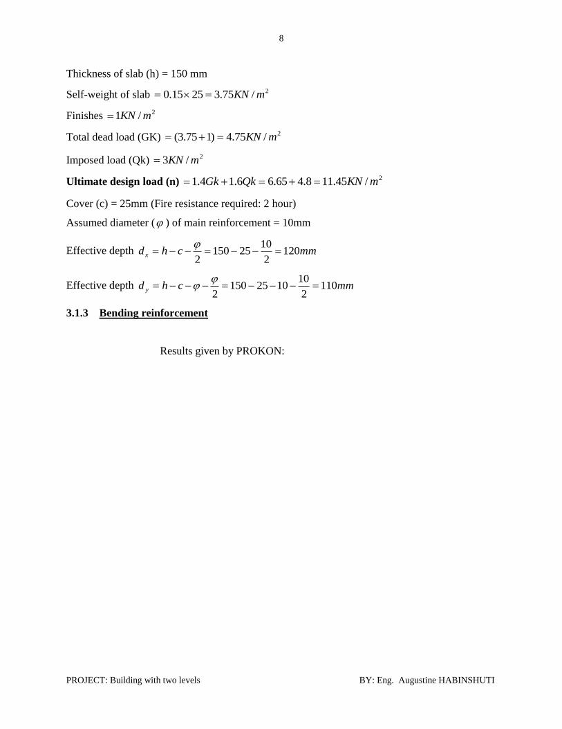
Thickness of slab (h) = 150 mm
Self-weight of slab 2/75.32515.0 mKN
Finishes 2/1 mKN
Total dead load (GK) 2/75.4)175.3( mKN
Imposed load (Qk) 2/3 mKN
Ultimate design load (n)
2/45.118.465.66.14.1 mKNQkGk
Cover (c) = 25mm (Fire resistance required: 2 hour)
Assumed diameter ( ) of main reinforcement = 10mm
Effective depth mmchd x 1202
1025150
2
Effective depth mmchd y 1102
101025150
2
3.1.3 Bending reinforcement
Results given by PROKON:

9
PROJECT: Building with two levels BY: Eng. Augustine HABINSHUTI
Interpretation of results:
In the direction of short span(x) we provide:
Y10@200mm in the span
And Y12@200mm on the support
In the direction of long span(y) we provide:
Y10@200mm in the span
And Y12@200mm on the support
5.3
m
Y12@180
Y1
0 @
20
0
A
Y1
2@
18
00
Y10@200 Y
12
@1
80
A
Y12@1800
4.0m
A A
4000 mm
150 mm
Y12@180 mm Y12@180 mm
Y10 @ 180 mm
150 mm
Y

10
PROJECT: Building with two levels BY: Eng. Augustine HABINSHUTI
Section A-A
a) Check for deflection
For deflection we use the maximum span moment
M = 13.1KNm
6.41120
102.4 3
dx
Lx
Basic span/ effective depth ratio = 26
bprovAs
reqdAsffs y
1
8
2.4
2/8.27218.252
88.239460
8
5mmNfs
84.0
1251000
101.132
6
2
bd
M Modification factor =1.5 (from BS8110)
Modified span/effective depth ratio = 26X1.5 = 39 > 32.8
The slab is adequate, and there is no deflection.
b) Check for crack
BS8110 states that the maximum spacing of bars in tension is given by 3d = 3X120 = 360mm
Since all the spacing is less than 360mm, there is no cracking required.
Since Vc>Vx and Vy no shear reinforcement required (from PROKON).
11
PROJECT: Building with two levels BY: Eng. Augustine HABINSHUTI
4 CALCULATION AND DESIGN OF BEAM
4.1 Calculation and design of inner beam
To design a beam, we considered a continuous beam which is highly loaded as it is shown by a
figure below: To see beam 4.
Beam 4-4
Influence area of slab on the beam
A1= 12.125m2
A3= 17.500m2
A5= 1.020m2
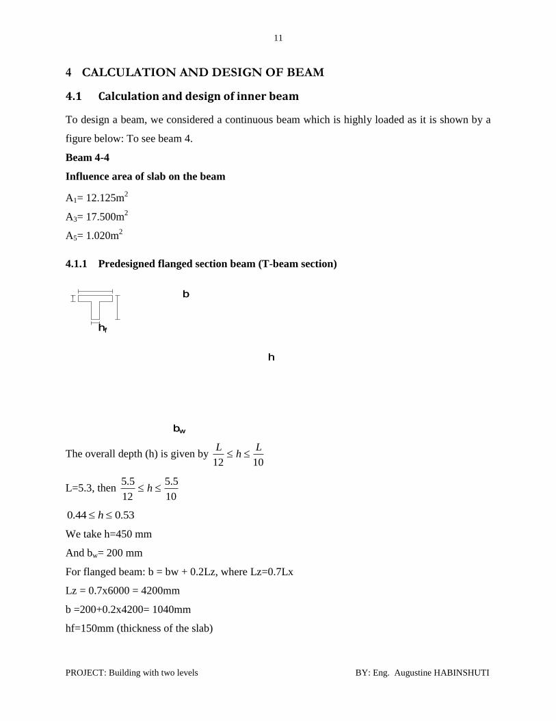
4.1.1 Predesigned flanged section beam (T-beam section)
The overall depth (h) is given by 1012
Lh
L
L=5.3, then 10
5.5
12
5.5 h
53.044.0 h
We take h=450 mm
And bw= 200 mm
For flanged beam: b = bw + 0.2Lz, where Lz=0.7Lx
Lz = 0.7x6000 = 4200mm
b =200+0.2x4200= 1040mm
hf=150mm (thickness of the slab)
b
h
bw
hf
b
h
bw
hf

12
PROJECT: Building with two levels BY: Eng. Augustine HABINSHUTI
4.1.2 Computation of uniformly distributed loading on the beam
a) Dead load
Self-weight of the slab =25x0.15=3.75KN/ 2m
Finishes =1KN/ 2m
Uniformly distributed load on span1 of the beam is given by mKN /31.85.3
125.675.4
Uniformly distributed load on span2 of the beam is given by mKN /85.136
5.1775.4
Uniformly distributed load on span3 is equal to 8.31KN/m
Uniformly distributed load on span4 of the beam is given by mKN /375.22
175.4
Self-weight of the beam =25x0.2x0.40= 2KN/m
Self-weight of the wall = 22x0.2x4.2=18.48KN/m
On span1 we have:
Total dead load (Gk) =8.31+2+18.48
Gk=29.29KN/m
Imposed load (Qk) = 5.3
6.1253
Qk=5.25 mKN /
mKNxxQkGkn /406.49)25.56.1()29.294.1(6.14.11
On span2 we have:
Total dead load (Gk)=13.85+2+18.48=34.83KN/m
Imposed load (Qk)= mKN /75.86
5.173
mKNxxQkGkn /762.62)75.86.1()83.344.1(6.14.12
On span3 n3=n1= 49.406KN/m
On span4 we have:
Total dead load (Gk)=2.375+2+18.48= 23.355KN/m

13
PROJECT: Building with two levels BY: Eng. Augustine HABINSHUTI
Imposed load (Qk)= mKN /5.12
13
mKNxxQkGkn /097.35)5.16.1()355.234.1(6.14.14
b) Calculation of bending moment and shear force
Hypotheses:
Characteristic material strengths:
Concrete 2/30 mmNf
Steel 2/460 mmNf y (for main reinforcement)
2/250 mmNf yv (for shear reinforcement)
Cover (c) = 25mm (Fire resistance required: 2 hours)
Effective width b=1040mm
Thickness of the slab hf=150mm
Overall depth h = 450mm
Thickness of the beam bw = 200mm
Proposed size of reinforcement:
Y16 for bending moment and
Y8 for shear reinforcement
Effective depth mmchd 509162555082
16

14
PROJECT: Building with two levels BY: Eng. Augustine HABINSHUTI
c) Shear reinforcement
Maximum shear V=214KN computed by PROKON
The maximum shear stress is given by:
23
/7.1509200
10214mmN
bwd
V
The beam section is well designed if fcu8.0
4.4308.0 OK
84.0509200
780100100
bwd
As
From BS8110, we find =0.65N/mm2
( ) OK
( )
( )
Assume mm8 for rings with two legs
22
5.1004
828 mmAsv
mmAsv
SvmmS
As28.61
64.1
5.100
64.164.1
We take Sv=100mm
We provide R8@100mm
01.0509200
5.942
bwd
As
015.0460
3023.023.0
fy
fb

15
PROJECT: Building with two levels BY: Eng. Augustine HABINSHUTI
Since b , the beam section is adequate
009.0509200
5.942
bwd
As
015.0460
3023.023.0
fy
fb
Since b , the beam section is adequate

16
PROJECT: Building with two levels BY: Eng. Augustine HABINSHUTI

17
PROJECT: Building with two levels BY: Eng. Augustine HABINSHUTI
(Section A-A, C-C, E-E, G-G) (Section B-B, D-D, F-F)
Reinforcement in the beam

18
PROJECT: Building with two levels BY: Eng. Augustine HABINSHUTI
200 200
35
0
15
0
26 R8 @ 100mm
15
0
35
0
R8@100mm
2Y1
2Y14
SECTION B-B SECTION A-A
2Y12
3Y16 A
2Y14
R8@100
B
3Y16 A
3Y16
3Y16
2Y16
2Y16
B
1
50
R8 @ 100 mm 26 R8 @ 100mm
15
0
6m
R8@180
2Y16
SECTION B-B SECTION A-A
3 A
R8@100
B
A
B

19
PROJECT: Building with two levels BY: Eng. Augustine HABINSHUTI
4.2 Calculation and design of outer beam
Beam F-F
Influence area of slab on the beam, to see beam 5
A1= 9.688m2
A2= 5.688m2
A3= 5.688m2
A4= 5.688m2
4.2.1 Predesigned flanged section beam (T-beam section)
The overall depth (h) is given by 1012
Lh
L
L=5.3, then 10
5.5
12
5.5 h
53.044.0 h
We take h=550mm
And bw= 200mm
For flanged beam: b = bw + 0.2Lz, where Lz=0.7Lx
Lz = 0.7x5000 = 3500mm
b =250+0.2x3500= 900mm
hf=150mm (thickness of the slab)
b
h
bw
hf
b
h
bw
hf

20
PROJECT: Building with two levels BY: Eng. Augustine HABINSHUTI
4.2.2 Computation of uniformly distributed loading on the beam
b) Dead load
Self-weight of the slab =25x0.15=3.75KN/ 2m
Finishes =1KN/ 2m
Uniformly distributed load on span1 of the beam is given by mKN /40.55
688.575.4
Uniformly distributed load on span2 and 4 is equal to 5.40KN/m
Uniformly distributed load on span3 of the beam is given by mKN /20.95
688.975.4
Self-weight of the beam =25x0.2x0.4= 2KN/m
Self-weight of the wall = 22x0.2x4.2=18.48KN/m
On span1 we have:
Total dead load (Gk) =5.40+2+18.48
Gk=25.75KN/m
Imposed load (Qk) = 5
5.6883
Qk=3.41 mKN /
mKNxxQkGkn /506.41)41.36.1()75.254.1(6.14.11
On span2 and 4 we have: n2=n4=n1=41.506KN/m
On span3 we have:
Total dead load (Gk)=9.20+1.87+18.48= 29.55KN/m
Imposed load (Qk)= mKN /81.55
688.93
mKNxxQkGkn /66.50)81.56.1()55.294.1(6.14.14
d) Calculation of bending moment and shear force
Hypotheses:
Characteristic material strengths:

21
PROJECT: Building with two levels BY: Eng. Augustine HABINSHUTI
Concrete 2/30 mmNf
Steel 2/460 mmNf y (for main reinforcement)
2/250 mmNf yv (for shear reinforcement)
Cover (c) = 25mm (Fire resistance required: 2 hours)
Effective width b=900mm
Thickness of the slab hf=150mm
Overall depth h=550mm
Thickness of the beam bw=200mm
Proposed size of reinforcement:
Y16 for bending moment and
Y8 for shear reinforcement
Effective depth mmchd 509162555082
16

22
PROJECT: Building with two levels BY: Eng. Augustine HABINSHUTI
(Section A-A, C-C, E-E, G-G) (Section B-B, D-D, F-F)

23
PROJECT: Building with two levels BY: Eng. Augustine HABINSHUTI
4.3 Calculation and design of the Ring Beam
The maximum span of the Ring Beam is 6m, n= 62.762KN/m
Let take h= 400mm and b= 400mmd

24
PROJECT: Building with two levels BY: Eng. Augustine HABINSHUTI
Section A-A
5. CALCULATION AND DESIGN OF COLUMNS
The design is done on a highly loaded column as it is shown on the figure below:
5.1 Influence area on the column
2Y12
25
PROJECT: Building with two levels BY: Eng. Augustine HABINSHUTI
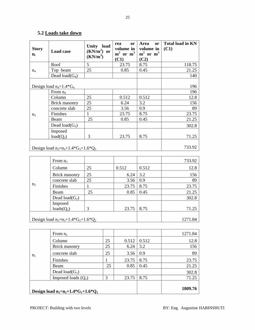
5.2 Loads take down
Story
ni Load case
Unity load
(KN/m2) or
(KN/m3)
rea or
volume in
m2 or m
3
(C1)
Area or
volume in
m2 or m
3
(C2)
Total load in KN
(C1)
n4
Roof 5 23.75 8.75 118.75
Top beam 25 0.85 0.45 21.25
Dead load(G4)
140
Design load n4=1.4*G4
196
n3
From n4 196
Column 25 0.512 0.512 12.8
Brick masonry 25 6.24 3.2 156
concrete slab 25 3.56 0.9 89
Finishes 1 23.75 8.75 23.75
Beam 25 0.85 0.45 21.25
Dead load(G3)
302.8
Imposed
load(Q3) 3 23.75 8.75 71.25
Design load n3=n4+1.4*G3+1.6*Q3
733.92
n2
From n3
733.92
Column 25 0.512 0.512 12.8
Brick masonry 25 6.24 3.2 156
concrete slab 25 3.56 0.9 89
Finishes 1 23.75 8.75 23.75
Beam 25 0.85 0.45 21.25
Dead load(G2)
302.8
Imposed
loads(Q2) 3 23.75 8.75 71.25
Design load n2=n3+1.4*G2+1.6*Q2
1271.84
n1
From n2 1271.84
Column 25 0.512 0.512 12.8
Brick masonry 25 6.24 3.2 156
concrete slab 25 3.56 0.9 89
Finishes 1 23.75 8.75 23.75
Beam 25 0.85 0.45 21.25
Dead load(G1)
302.8
Imposed loads (Q1) 3 23.75 8.75 71.25
Design load n1=n2+1.4*G1+1.6*Q1
1809.76

26
PROJECT: Building with two levels BY: Eng. Augustine HABINSHUTI
5.3 Calculation and design
5.3.1 Hypotheses
The design load from load take down is KNNd 76.1809
Characteristic material strength:
Concrete 2/30 mmNf
Steel: 2/460 mmNf y (for longitudinal reinforcement)
2/250 mmNf yv (For ring)
Cover (c) = 25mm
Size: h= 400mm b= 400mm
L0 = 4.20m for the Ground Floor Column
L0 = 3.20 for the remaining Columns
5.3.2 Reinforcement in the column
5.3.2.1 Ground floor column
a) Design Column Section

27
PROJECT: Building with two levels BY: Eng. Augustine HABINSHUTI

28
PROJECT: Building with two levels BY: Eng. Augustine HABINSHUTI
b) Design Sketch
Figure 1

29
PROJECT: Building with two levels BY: Eng. Augustine HABINSHUTI
c) Check slenderness of column
The effective height of the column is given by:
lole
Where le -effective height
-coefficient used to determine effective height of the column: 0.75< <1
lo -clear height
mle 96.27.38.0
1586.93.0
96.2
h
le
158.142.0
96.2
b
le
Since the ratios above are all less than 15, we have the short column, therefore there is no
buckling.
d) Check for crushing
The crushing is caused by:
scy AfAcfNuz 87.045.0
3573546087.0600003045.0 Nuz
KNNKNNuz d 46.16841.2240 no crushing required.
e) Check for cracking
BS8110: part 1: 1985 states that if the design load on the column (Nd) is greater than Acf2.0 ,
there is no cracking of the column.
KNNAcf 360360000460302.02.0
3602.046.1684 AcfSinN d , there is no cracking required.
f) Shear reinforcement
BS8110 states that the diameter of ring ring is equal to ¼ of the bigger longitudinal bar, and
this must be greater or equal to 6mm.

30
PROJECT: Building with two levels BY: Eng. Augustine HABINSHUTI
mm25.6254
1ring , we take ring=8mm
The maximum spacing S is equal to 12 times the diameter of the smaller longitudinal bar.
S=12X20=240mm, we take S=200mm
g) Check the percentage of reinforcement
The maximum area of reinforcement should not exceed 6%:
69.560000
3.3573100100
Ac
Asc
The percentage of reinforcement is adequate
5.3.2.2 First floor column
31
PROJECT: Building with two levels BY: Eng. Augustine HABINSHUTI
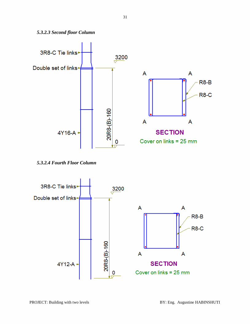
5.3.2.3 Second floor Column
5.3.2.4 Fourth Floor Column

32
PROJECT: Building with two levels BY: Eng. Augustine HABINSHUTI
6. CALCULATION AND DESIGN OF FOUNDATION
The bearing pressure of the soil 2/90.180 mKNadm and we adopt the square isolated pad
foundation.
6.1 Calculation and design of foundation group1- inner foundations
a) Hypothesis
Bearing pressure of soil 2/90.180 mKNadm
Gk = 1048.4KN and Qk=213.75KN
The self-weight of the isolated pad foundation (w) is between 10% and 20% of the design load of
the column.
KNW 181100
1076.1809
For Serviceability limit states, the axial design load is given by:
QkWGkNd 0.1)(0.1
KNNd 15.144375.2130.1)1814.1048(0.1
The area of square pad foundation is given by:
2197.790.180
15.1443m
Qadm
Nd
We make the base of 2.2mx2.2m; B=L=2.20m
For ultimate serviceability limit states, the ultimate design load on the column is given by:
QkGkNu 6.14.1
KNNu 46.168475.2136.176.18094.1
The pressure of pad foundation on the soil is given by:
2/51.2692.22.2
46.1684mKN
LB
NuP
P<Qadm OK
Assume:
Overall depth of pad foundation h=400mm
Concrete 2/30 mmNf

33
PROJECT: Building with two levels BY: Eng. Augustine HABINSHUTI
2/460 mmNf y (For longitudinal reinforcement)
Diameter of reinforcement = 16mm
Cover (c) = 40mm
The effective depth is given by 2
-c-h=d
d=350-40-8=302mm
The shear stress at the column c is less than the minimum value of f8.0 and 5KN
2
3
/4.48.006.33024004002
1046.1684mmNf
dPc
Nuc
Where Pc-perimeter of the column.
b) Punching shear
The critical perimeter of pad foundation is given by:
Pcr=Pc+8x1.5d
Pcr=2x(400+400)=8x1.5x302=7600mm
The critical surface is given by :
Scr=(400+2x1.5d)x(400+2x1.5d)=3607500mm2
Scr=3607500 22 61.3 mmm
The punching shear force is given by:
V=P(BxL-Scr) where P-pressure of foundation
V=269.51(2.2x2.2-3.61)=711.51KN
The punching shear stress is given by:
23
/17.03027600
1051.711mmN
dPcr
Vv
We provide Y16@150mm with Approve.=2243
Check the percentage of reinforcement
418.03502200
224310010013.0
bh
As
The percentage of reinforcement is adequate.
Final check for punching

34
PROJECT: Building with two levels BY: Eng. Augustine HABINSHUTI
16.03022200
2243100100
bd
As
From BS8110, and after interpolation, we find 20.36N/mm=Vc
The punching shear stress v = 0.17 2N/mm
Since v = 0.17< Vc = 0.36; the overall depth (h=600mm) is adequate, therefore there is no
punching of pad foundation.
c) Check for shear force
The shear force is given by
V=269.51X2X0.35= 188.7KN
The shear stress is given by
223
/36.0/25.05502200
107.188mmNVcmmN
bd
Vv
Since v = 0.25< Vc = 0.36, the section is adequate for shear force.
6.2. Moment Steel.
Reinforcement in pad foundation
6.2 Calculation and design of foundation group2-outer foundation
d) Hypothesis
Bearing pressure of soil 2/80.190 mKNadm
Gk = 538.9KN and Qk=78.75KN
The self-weight of the isolated pad foundation (w) is between 10% and 20% of the design load of
the column.
KNW 1.80100
1086.800
For Serviceability limit states, the axial design load is given by:
QkWGkNd 0.1)(0.1
KNNd 75.69775.780.1)1.809.538(0.1
The area of square pad foundation is given by:

35
PROJECT: Building with two levels BY: Eng. Augustine HABINSHUTI
29.390.180
75.697m
Qadm
N d
We make the base of 1.8mx1.8m; B=L=1.80m
For ultimate serviceability limit states, the ultimate design load on the column is given by:
QkGkNu 6.14.1
KNNu 96.80075.785.19.5384.1
The pressure of pad foundation on the soil is given by:
2/3145.15.1
86.800mKN
LB
NuP
P<Qadm OK
Assume:
Overall depth of pad foundation h=350mm
Concrete 2/30 mmNf
2/460 mmNf y (For longitudinal reinforcement)
Diameter of reinforcement = 16mm
Cover (c) = 40mm
The effective depth is given by 2
-c-h=d
d=300-40-8=252mm
The shear stress at the column c is less than the minimum value of f8.0 and 5KN
2
3
/4.48.008.32524004002
1046.1684mmNf
dPc
Nuc
Where Pc-perimeter of the column.
e) Punching shear
The critical perimeter of pad foundation is given by:
Pcr = Pc+8x1.5d
Pcr = 2x(400+400)=8x1.5x452=7600mm
The critical surface is given by :
Scr = (400+2x1.5d)x(400+2x1.5d)=3607500mm2

36
PROJECT: Building with two levels BY: Eng. Augustine HABINSHUTI
Scr = 3607500 22 61.3 mmm
The punching shear force is given by:
V=P(BxL-Scr) where P-pressure of foundation
V=269.51(1.5x1.5-3.61)=711.51KN
The punching shear stress is given by:
23
/18.02527600
1051.711mmN
dPcr
Vv

37
PROJECT: Building with two levels BY: Eng. Augustine HABINSHUTI
7.RESULTS PRESENTATION
The results obtained are given in a table below:
Project: CONSTRUCTION OF A BUILDING WITH TWO LEVELS (G + 2 ).
CALCULATIONS BY: CHECKED BY: Eng. A.H
SOGEIB Ltd
Table Reinforcement for each structural member
Elements
Materials
Concrete Steel
Longitudinal steel Transversal Steel
1 Slab fcu=30N/mm2 Y10@180
Supports: Y12@180
Y10@180
Supports: Y12@180
2 Inner Beams
fcu=30N/mm2
Spans: 3Y16
Supports: 3Y16 + 2Y14 Y8@180
3 Outer Beams
fcu=30N/mm2
Spans: 2Y16 +2Y14
Supports: 3Y16
Y8@180
4 Ring Beam
fcu=30N/mm2
4Y16 + 2Y12 Y8@180
5 Column ground
floor fcu=30N/mm
2 8Y16 Y8@180
6 Column all floors fcu=30N/mm
2
8Y16 Y8@180
9 Inner Foundation all
groups
fcu=30N/m
m2
Y16@180 Y16@180
10 Outer Foundation all
groups
fcu=30N/m
m2
Y16@180 Y16@180
10 Stairs fcu=30N/mm2 Y12@180 Y10@180
Done at Kigali, on November 28, 2018.
By SOGEIB LTD
Copyright © 2022 FDOKUMEN