
Alignment Calculation Tool - Theseus
36
Alignment Calculation Tool Jouni Hakkola Degree Thesis for Bachelor of Engineering Degree Programme in Electrical Engineering and Automation Vaasa 2021
-
Upload
khangminh22 -
Category
Documents
-
view
1 -
download
0
Transcript of Alignment Calculation Tool - Theseus
Alignment Calculation Tool
Jouni Hakkola
Degree Thesis for Bachelor of Engineering
Degree Programme in Electrical Engineering and Automation
Vaasa 2021
BACHELOR’S THESIS
Author: Jouni Hakkola
Degree Programme: Electrical Engineering, Vaasa
Specialization: Information Technology
Supervisors: Susanne Österholm, Tomas Södö
Title: Alignment Calculation Tool
_________________________________________________________________________
Date: 27.5.2021 Number of pages: 31 _________________________________________________________________________
Abstract
The goal of this thesis was to analyse the alignment calculation process and to develop a
complete solution for performing alignment calculations as a part of the marine delivery
projects at Wärtsilä Finland Oy.
The current solution for alignment calculations is an existing tool developed in Microsoft
Excel. The current solution does not contain all the needed features, for example the direct
connection to an existing database used for marine delivery projects. In order to
streamline the alignment calculation process and add the wanted features, a custom
solution in the form of a desktop application for performing all the steps in the process was
needed.
The theoretical part of this thesis describes alignment calculation in general, the specific
alignment calculations performed for marine delivery projects and the tools and methods
used for the development process of the application. The practical part of this thesis
describes the analysis of the alignment calculation process and development of the
application for the alignment calculation process as well as the testing procedure before
implementation into workflow for marine delivery projects.
The result of this thesis is a new solution for the steps in the alignment calculation process
developed in Visual Studio 2019 using the C# programming language.
_________________________________________________________________________
Language: English Key words: alignment calculation, shaft alignment, C# _________________________________________________________________________
EXAMENSARBETE
Författare: Jouni Hakkola
Utbildning och ort: El- och automationsteknik, Vasa
Inriktningsalternativ: Informationsteknik
Handledare: Susanne Österholm, Tomas Södö
Titel: Verktyg för linjeringsuträkningar
_________________________________________________________________________
Datum: 27.5.2021 Sidantal: 31 _________________________________________________________________________
Abstrakt
Målet med detta examensarbete var att analysera samt att utveckla en komplett lösning
för hela processen för linjeringsuträkningar som utförs som en del av marinprojekt vid
Wärtsilä Finland Oy.
Den nuvarande lösningen för linjeringsuträkningarna är ett verktyg utvecklat I Microsoft
Excel. Denna lösning innehåller inte alla funktioner som krävs för linjeringsuträkningarna,
till exempel automatisk sparande av data till en databas som används för marinprojekten.
En skräddarsydd lösning i form av ett datorprogram krävdes för att uppfylla alla krav för
uträkningsprocessen och implementationen av nya funktioner.
Den teoretiska delen i detta examensarbete beskriver linjeringsuträkningar i allmänhet,
mera detaljerat de uträkningar som utförs för marinprojekt samt de metoder och verktyg
som användes i utvecklingen av applikationen för linjeringsuträkningarna. I den praktiska
delen beskrivs analyseringen av kraven, utvecklingsprocessen för den utvecklade
applikationen och testningen av applikationen före implementationen i arbetsflödet för
marinprojekt.
Resultatet av detta examensarbete är en skrivbordsapplikation utvecklad med Visual
Studio 2019 i programmeringsspråket C# för utförandet av processen för
linjeringsuträkningar.
_________________________________________________________________________
Språk: engelska Nyckelord: linjeringsuträkning, linjering av drivaxlar, C# _________________________________________________________________________
OPINNÄYTETYÖ
Tekijä: Jouni Hakkola
Koulutus ja paikkakunta: Sähkö- ja automaatiotekniikka, Vaasa
Suuntautumisvaihtoehto: Tietotekniikka
Ohjaajat: Susanne Österholm, Tomas Södö
Nimike: Työkalu linjauslaskelmia varten
_________________________________________________________________________
Päivämäärä: 27.5.2021 Sivumäärä: 31 _________________________________________________________________________
Tiivistelmä
Tämän opinnäytetyön tavoitteena oli analysoida vetoakselien linjausta varten
suoritettavia laskelmia sekä kehittää ratkaisu koko laskelmaprosessille, joka suoritetaan
osana Wärtsilä Finland Oy:n merenkulkuprojekteja.
Nykyinen ratkaisu vetoakselien linjaukseen tarvittavalle laskelmaprosessille on Microsoft
Excel -ohjelmassa kehitetty työkalu. Tämä työkalu ei sisällä kaikkia vaadittuja
ominaisuuksia, esimerkiksi laskelmien tulosten automatisoitua tallentamista olemassa
olevaan tietokantaan. Ratkaisu kaikille vaadituille ominaisuuksille on mukautettu sovellus,
joka kykenee suorittamaan vaaditut laskelmat sekä kommunikoimaan
merenkulkuprojekteissa käytettävän tietokannan kanssa.
Opinnäytetyön teoriaosa kuvailee vetoakseleiden linjausta yleisesti,
merenkulkuprojektien linjausta varten suoritettavia laskelmia sekä ratkaisuksi kehitetyn
sovelluksen kehityksessä käytettäviä työkaluja ja menetelmiä. Käytännön osa kertoo
linjausta varten suoritettavien laskelmien analysoimisesta ja mukautetun sovelluksen
kehitysprosessista sekä sovelluksen testauksesta ennen käyttöönottoa osaksi
merenkulkuprojektien työnkulkua.
Tämän opinnäytetyön tulos on työpöytäsovellus vetoakselien linjausta varten
suoritettavalle laskelmaprosessille. Sovellus on kehitetty Visual Studio 2019 -
ohjelmointiympäristöä ja C#-ohjelmointikieltä käyttäen.
_________________________________________________________________________
Kieli: Englanti Avainsanat: linjauslaskelmat, vetoakselien linjaus, C# _________________________________________________________________________
Table of Contents
1 Introduction ................................................................................................................... 1
1.1 Employer ................................................................................................................. 1
1.2 Background ............................................................................................................. 1
1.3 Purpose and scope ................................................................................................... 2
2 Alignment calculations .................................................................................................. 2
2.1 Shaft alignment ....................................................................................................... 2
2.2 Thermal expansion .................................................................................................. 4
2.3 Creep ....................................................................................................................... 4
2.4 Torque ..................................................................................................................... 5
3 Alignment calculations for marine delivery projects .................................................... 5
3.1 Cold Alignment Calculator ..................................................................................... 6
3.2 Requirements .......................................................................................................... 6
3.3 Performed calculations ........................................................................................... 7
3.3.1 Creep compensation ........................................................................................ 7
3.3.2 Vertical thermal expansion offset .................................................................... 9
3.3.3 Torque compensation offset .......................................................................... 11
3.4 Calculation results ................................................................................................. 12
4 Tools and methods for software development ............................................................. 13
4.1 IDE ........................................................................................................................ 14
4.2 Version control ..................................................................................................... 14
4.3 Programming language and frameworks .............................................................. 15
4.4 API, DLL and NuGet ............................................................................................ 15
5 Development and testing ............................................................................................. 16
5.1 Solutions for alignment calculation ...................................................................... 17
5.2 Requirements ........................................................................................................ 17
5.3 Planning ................................................................................................................ 18
5.4 Project creation and Git setup ............................................................................... 19
5.5 Main GUI .............................................................................................................. 20
5.6 Modules ................................................................................................................ 21
5.7 Performed alignment calculations ........................................................................ 26
5.8 Testing .................................................................................................................. 26
6 Result ........................................................................................................................... 27
7 Future development ..................................................................................................... 28
8 Discussion .................................................................................................................... 28
9 References ................................................................................................................... 30
1
1 Introduction
This thesis work was done for the Marine Power Project Engineering department at Wärtsilä
Finland Oy. The work consists of exploring existing solutions as well as the development
and implementation of a new solution for performing alignment calculations specific to
marine delivery projects and handling the resulting data in a controlled way.
1.1 Employer
Wärtsilä is a leading company in energy and marine markets with offerings such as smart
technologies and complete lifecycle solutions. The company consists as of 2020 of Marine
Power, Marine Systems, Voyage and Energy business units. Wärtsilä has operations in over
70 countries in more than 200 different locations with around 18 000 employees in the year
2020. [1]
Wärtsilä Marine Power business unit is focused on engines, propulsion machinery, hybrid
technologies and more for the marine business with safety, reliability and environment in
mind. Wärtsilä has a global network of maritime experience and offers lifecycle solutions
and performance-based agreements for the marine industry. [2]
1.2 Background
Alignment calculations are performed as a part of marine delivery projects in the Project
Engineering department at Wärtsilä Marine Power. These calculations are done to ensure the
correct installation of all machinery included in delivery projects such as engines, gearboxes
and generators.
The current solution for performing these calculations is based on a tool developed in
Microsoft Excel. This tool uses user input in combination of predefined values to calculate
the needed results and generate reports of these results in Microsoft Word using existing
report templates. This tool is missing vital features for automatically saving these results to
an existing database used for marine delivery projects as well as the loading of existing
values from the database.
2
1.3 Purpose and scope
The purpose of this thesis is to find a suitable way for performing all needed steps for
alignment calculations. These steps include calculating the needed values and saving the
results to a database. This thesis includes exploring existing solutions for performing all
steps, automation of parts of the alignment calculation process, the development of a new
tool capable of preforming all the needed steps and the implementation of the developed tool
as a part of the engineering work at the Project Engineering department. The main focus of
the alignment calculations in this thesis is for the vertical alignment of machinery.
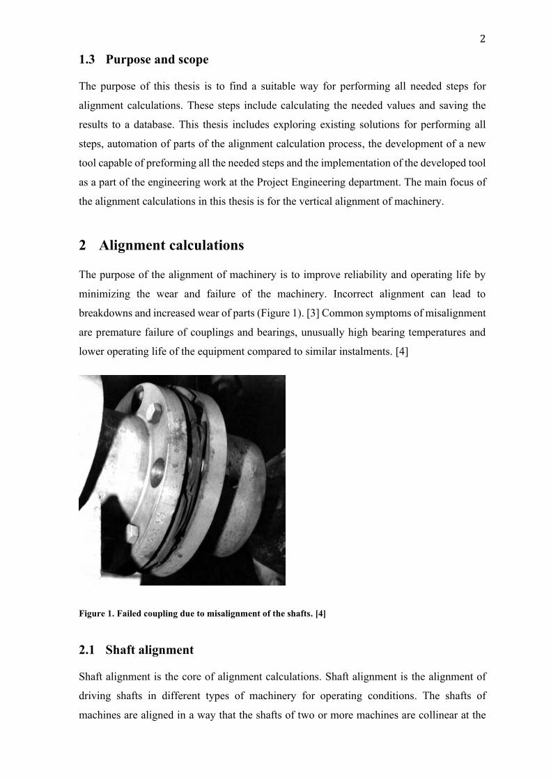
2 Alignment calculations
The purpose of the alignment of machinery is to improve reliability and operating life by
minimizing the wear and failure of the machinery. Incorrect alignment can lead to
breakdowns and increased wear of parts (Figure 1). [3] Common symptoms of misalignment
are premature failure of couplings and bearings, unusually high bearing temperatures and
lower operating life of the equipment compared to similar instalments. [4]
Figure 1. Failed coupling due to misalignment of the shafts. [4]
2.1 Shaft alignment
Shaft alignment is the core of alignment calculations. Shaft alignment is the alignment of
driving shafts in different types of machinery for operating conditions. The shafts of
machines are aligned in a way that the shafts of two or more machines are collinear at the
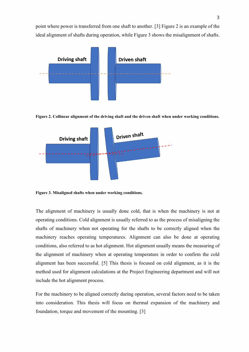
3
point where power is transferred from one shaft to another. [3] Figure 2 is an example of the
ideal alignment of shafts during operation, while Figure 3 shows the misalignment of shafts.
Figure 2. Collinear alignment of the driving shaft and the driven shaft when under working conditions.
Figure 3. Misaligned shafts when under working conditions.
The alignment of machinery is usually done cold, that is when the machinery is not at
operating conditions. Cold alignment is usually referred to as the process of misaligning the
shafts of machinery when not operating for the shafts to be correctly aligned when the
machinery reaches operating temperatures. Alignment can also be done at operating
conditions, also referred to as hot alignment. Hot alignment usually means the measuring of
the alignment of machinery when at operating temperature in order to confirm the cold
alignment has been successful. [5] This thesis is focused on cold alignment, as it is the
method used for alignment calculations at the Project Engineering department and will not
include the hot alignment process.
For the machinery to be aligned correctly during operation, several factors need to be taken
into consideration. This thesis will focus on thermal expansion of the machinery and
foundation, torque and movement of the mounting. [3]
4
2.2 Thermal expansion
The temperatures of machinery changes depending on the state of the machinery. When
running the machinery is at a higher temperature compared to the off state of the machinery.
The formula for calculating the thermal expansion, or thermal growth, of a machine can be
referred to as the T x L x C formula. The T in this formula means the difference in
temperature of the machinery when not operating and during operation. The L represents the
length of the material and the C the thermal coefficient of the material the machine is
manufactured from. [6]
Let us say we have a machine where the length of the material, or the height from the bottom
of the machine to the centre of the shaft, is 1000 mm and the machine is made from cast iron
with the thermal coefficient of 0.00001 1/C. The off-state temperature of this machine is 20
°C and the operating temperature is 70 °C.
Thermal expansion = (70 °C – 20 °C) * 1000 mm * 0.00001 1/°C = 0.5 mm
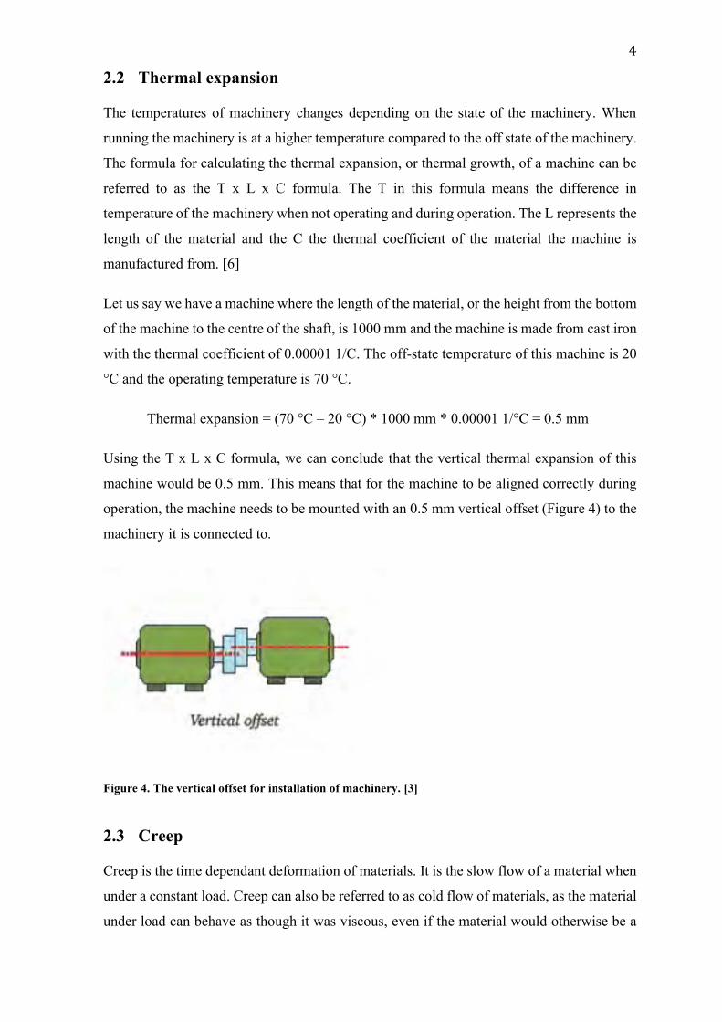
Using the T x L x C formula, we can conclude that the vertical thermal expansion of this
machine would be 0.5 mm. This means that for the machine to be aligned correctly during
operation, the machine needs to be mounted with an 0.5 mm vertical offset (Figure 4) to the
machinery it is connected to.
Figure 4. The vertical offset for installation of machinery. [3]
2.3 Creep
Creep is the time dependant deformation of materials. It is the slow flow of a material when
under a constant load. Creep can also be referred to as cold flow of materials, as the material
under load can behave as though it was viscous, even if the material would otherwise be a
5
solid. While creep can occur at temperatures above zero kelvin, the rate of creep will
differentiate depending on the material and temperature. In iron creep will need to be
considered when temperatures reach above 600 °C, while lead is subject to creep at room
temperatures. The creep in polymers and glasses are very dependent on the temperature, as
these materials will change to a rubberier consistency when subjected to temperatures over
the materials glass transition temperature, the temperature when the material changes from
a solid to a more viscous state. [7]
Creep in alignment calculations is usually the deformation of the resilient materials used for
mounting systems of the machinery. These materials are often different types of rubber that
will deform at ambient temperatures under the load from heavy machinery. The creep of the
materials used for the machinery itself is not considered as the operating temperatures are
not high enough to cause creep in metals.
2.4 Torque
Torque can be described as the rotational equivalent of linear force. Torque is not the same
as force, it is the combination of the magnitude of forces and the moment arms of the forces.
The unit for torque is newton meters (Nm), force times length. [8] The impact of torque in
alignment calculations is considered when the torque of the driving engine influences the
alignment due to the deformation on resilient mounting systems. This thesis does not go into
detail how the compensation for torque is calculated in alignment calculations.
3 Alignment calculations for marine delivery projects
In the case of the marine delivery projects at the Project Engineering department the aligned
machinery consists of Wärtsilä engines, gearboxes and generators. The alignment points
where power is transferred from one shaft to another can be for example engine to gearbox
or gearbox to generator. The different machinery is aligned vertically, horizontally and
transversally to the engine using calculated offsets from the alignment calculation results in
order for the machinery to be correctly aligned during operation. [9]
6
3.1 Cold Alignment Calculator
The current solution for performing the needed alignment calculations is a tool developed in
Microsoft Excel called Cold Alignment Calculator. This tool can perform calculations and
create result reports in Microsoft Word using template files.
The problems with the current solution are that it is not able to access the database used for
marine delivery projects directly in any way to get required data and it relies completely on
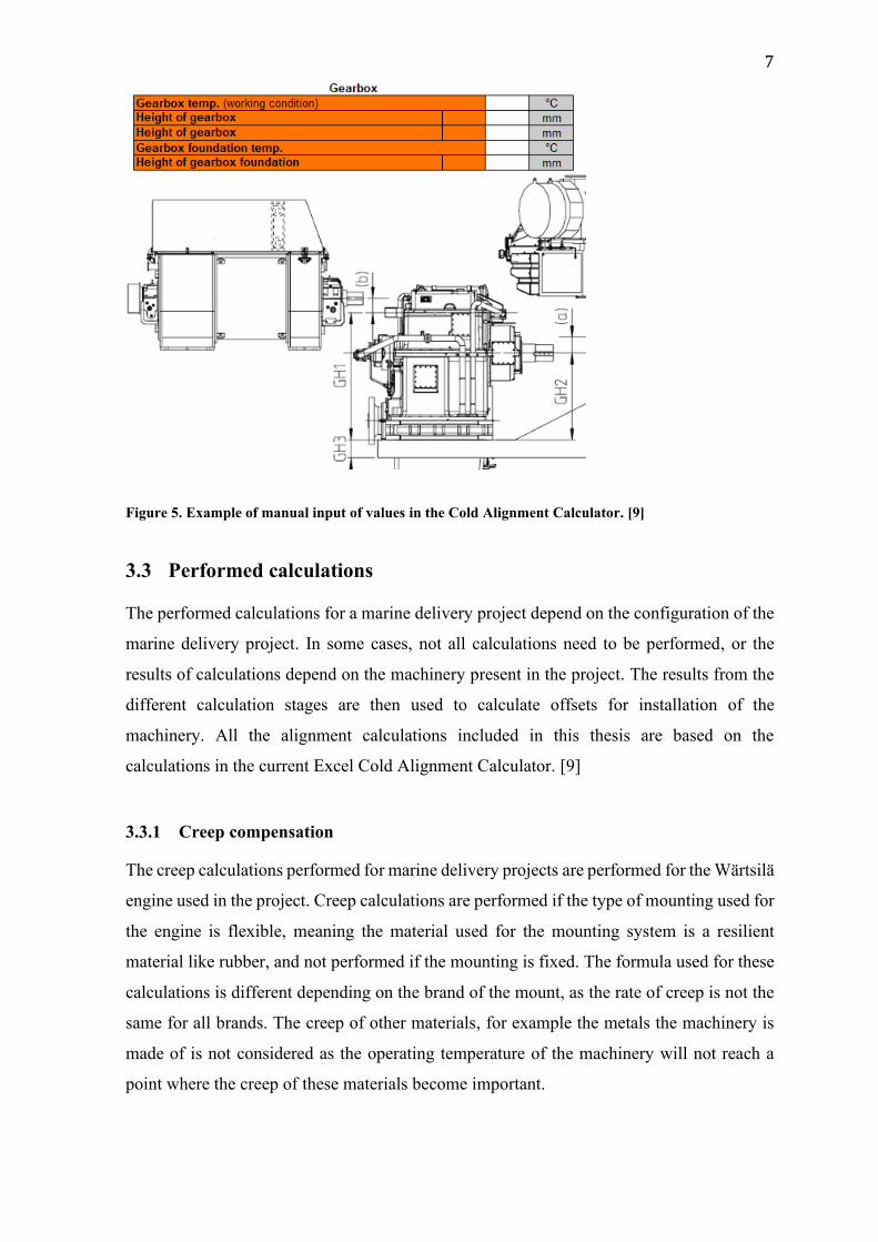
the user to manually input the needed data. Figure 5 shows an example of values that need
manual input needed for alignment calculations. It is also not able to save these results
directly into the database. The results need to be manually saved to the database using
internally developed software used to access the database for marine projects. [9]
3.2 Requirements
The values needed for the alignment calculations are for example dimensions, temperatures
of the machinery when in working conditions, ambient temperatures at installation and the
thermal coefficients of the materials the machinery is manufactured from.
To calculate the needed values using the existing alignment calculation tool the user needs
to manually input certain values based on the configuration of the marine delivery project.
Depending on the configuration some values linked to machinery not present in the current
project do need to be filled in. In Figure 5 we can see an example of the values needed for
the alignment calculations for the alignment of a gearbox connected to an engine when using
the current Excel tool. [9]
7
Figure 5. Example of manual input of values in the Cold Alignment Calculator. [9]
3.3 Performed calculations
The performed calculations for a marine delivery project depend on the configuration of the
marine delivery project. In some cases, not all calculations need to be performed, or the
results of calculations depend on the machinery present in the project. The results from the
different calculation stages are then used to calculate offsets for installation of the
machinery. All the alignment calculations included in this thesis are based on the
calculations in the current Excel Cold Alignment Calculator. [9]
3.3.1 Creep compensation
The creep calculations performed for marine delivery projects are performed for the Wärtsilä
engine used in the project. Creep calculations are performed if the type of mounting used for
the engine is flexible, meaning the material used for the mounting system is a resilient
material like rubber, and not performed if the mounting is fixed. The formula used for these
calculations is different depending on the brand of the mount, as the rate of creep is not the
same for all brands. The creep of other materials, for example the metals the machinery is
made of is not considered as the operating temperature of the machinery will not reach a
point where the creep of these materials become important.
8
There are several values that need to be calculated in order to get the main result of the creep
calculation needed for later calculation stages. The following values are needed to calculate
the needed creep compensation result.
1. The creep rate percentage for the mounting system used.
2. The average value of the measured static deflection values for each corner of the
engine.
3. The time in days from the installation of the engine to the time of alignment.
4. The time in days from the installation of the engine to the time of verifying the
alignment values.
The creep rate of the mount is a predefined value. This value is different for each mount
supplier and the type, or model, of mount used for the mounting of the engine in the marine
project. The static deflection of the engine is a measurement needed for the creep
calculations. These measurements show how much the weight of the engine displaces the
mounts at the time of installation. The average value of the measurements from each corner
is used in the calculation of the creep compensation.
The calculated values used to get the creep compensation are deflection at alignment,
deflection at check after installation, creep at alignment, creep at check after installation and
the total creep from static deflection. Depending on the supplier of the mount used for the
engine, the formulas for calculating these values are different. This thesis will not go into
detail how the deflection at alignment and deflection at check after installation are calculated
for each supplier.
Using the calculated deflection at alignment for the specific mount, the creep at the time of
alignment can be calculated by subtracting the average of the measured static deflection at
installation from the deflection at alignment:
Creep at alignment = deflection at alignment-average static deflection at installation
The creep at check after installation can be calculated by subtracting the deflection at
alignment from the deflection at check after installation:
Creep at check after installation = deflection at check after installation-deflection at
alignment
9
The total creep from static deflection is the combined value of creep at alignment and creep
at check after installation:
Total creep from static deflection = creep at alignment + creep at check after
installation
All these values are documented in the database used for marine projects, but the main result
of these calculations is the total creep compensation needed for the results of the alignment
calculation process. The creep compensation value is the difference between the total creep
from static deflection and the creep at alignment:
Creep compensation = total creep from static deflection-creep at alignment
The creep compensation is used in the calculation of the total offset for the alignment of the
engine driving shaft and the shaft of the machinery connected to it.
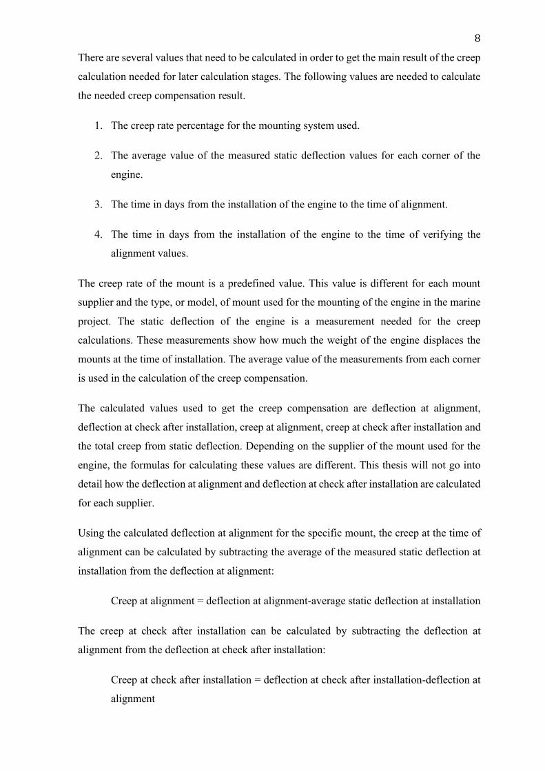
Figure 6 show a graph from the Excel Cold Alignment Calculator of the calculated amount
of creep that occurs under the period of 370 days after installation. This graph gives a visual
representation of the expected creep of then mounting system over a longer period. [9]
Figure 6. Visual representation of the calculated creep over 370 days. [9]
3.3.2 Vertical thermal expansion offset
The vertical thermal expansion offset is calculated for all machinery in the marine delivery
project relevant to the alignment process. These machines include the engine, gearboxes
10
connected to the engine and generators connected to the engine or a gearbox. The thermal
expansion of all machinery needs to be taken into consideration as the machinery is installed
cold, meaning at lower temperatures than the operating temperature.
The vertical thermal expansion calculations for machinery include the thermal expansion of
the machine itself as well as the thermal expansion of the machine foundation. In most
projects the machine and foundation are made from different materials, the machine from
cast iron and the foundation from steel. This needs to be considered as the calculations need
to be performed using different thermal coefficients.
To calculate the vertical thermal expansion of the foundation or the machine itself, the
following values and dimensions are required.
1. The thermal coefficient of the material used.
2. The height of the foundation or the height of the machine from the foundation to the
driving shaft.
3. The temperature of the engine room at installation (ambient).
4. The operating temperature of the foundation or machine.
The formula used for calculating the vertical thermal expansion is:
Thermal expansion = thermal coefficient * height * (operating temperature -
ambient)
As an example, let us say that the foundation of an engine is made from steel with the thermal
coefficient of 0.000012. It has the height 900 mm, operating temperature 45 °C and the
ambient temperature 25 °C during installation.
Thermal expansion = 0.000012 * 900 * (45 – 25) = 0.216
Using the formula above we can conclude that the vertical thermal expansion of the
foundation is 0.216 mm.
The thermal expansion of machinery follows the same principle. The required values for
calculation are mostly the same, with the differences being the height used in the calculations
is the height is a different dimension, usually the height from the foundation to the driving
shaft. If the aligned machinery is an engine, the height used is the height of the engine block.
11
Some additional thermal expansion calculations might also need to be considered depending
on the type of the engine used and the engine configuration. These additional calculations
include the thermal expansion of the engine oil tank if included.
Let us say we have an engine with the engine block height 650 mm, the operating
temperature 75 °C and the ambient temperature 25 °C during installation. The engine is made
from cast iron with the thermal coefficient 0.00001.
Thermal expansion = 0.00001 * 650 * (75 - 25) = 0.325
This means that the vertical thermal expansion of the engine block is 0.325 mm. This value
can in combination with the vertical thermal expansion be added up to the total vertical
thermal expansion of the engine and foundation.
Total thermal expansion = foundation thermal expansion + machine thermal
expansion
Total thermal expansion = 0.216 mm + 0.325 mm = 0.541 mm
The total thermal expansion is used to calculate the results for the alignment between two
machines. [9]
3.3.3 Torque compensation offset
The torque compensation used for marine delivery projects is at this moment a predefined
value in millimetres. Torque compensation is relevant when the alignment calculations are
performed for an engine with a flexible mounting system, as the torque from the engine will
cause displacement due to the flexibility of the mounting system. This value is different
depending on the model of Wärtsilä engine used in the marine delivery project. In the current
Cold Alignment Calculator these values are predefined and the correct value for the engine
model present in the delivery project is used in the calculation of the final installation offsets.
The direction of this offset depends on the rotation of the engine, either clockwise or
counterclockwise. If the engine rotation is clockwise when looking at the flywheel of the
engine, the engine output needs to be installed to the right of the input of the connected
machinery, in most cases a gearbox, at the predefined torque offset. If the rotation is
counterclockwise, the engine output is installed to the left of the input of the machinery.
The calculation of the torque offset is not a part of the current Cold Alignment Calculator
and will not be implemented in the developed tool as a part of this thesis. In the future this
12
offset is planned to be calculated for each marine delivery project either by adding the needed
functionality to the developed tool or by calculating the offset by other means. [9]
3.4 Calculation results
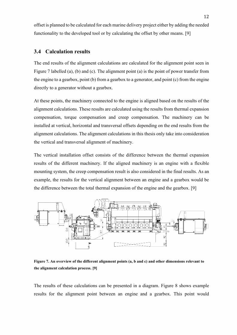
The end results of the alignment calculations are calculated for the alignment point seen in
Figure 7 labelled (a), (b) and (c). The alignment point (a) is the point of power transfer from
the engine to a gearbox, point (b) from a gearbox to a generator, and point (c) from the engine
directly to a generator without a gearbox.
At these points, the machinery connected to the engine is aligned based on the results of the
alignment calculations. These results are calculated using the results from thermal expansion
compensation, torque compensation and creep compensation. The machinery can be
installed at vertical, horizontal and transversal offsets depending on the end results from the
alignment calculations. The alignment calculations in this thesis only take into consideration
the vertical and transversal alignment of machinery.
The vertical installation offset consists of the difference between the thermal expansion
results of the different machinery. If the aligned machinery is an engine with a flexible
mounting system, the creep compensation result is also considered in the final results. As an
example, the results for the vertical alignment between an engine and a gearbox would be
the difference between the total thermal expansion of the engine and the gearbox. [9]
Figure 7. An overview of the different alignment points (a, b and c) and other dimensions relevant to
the alignment calculation process. [9]
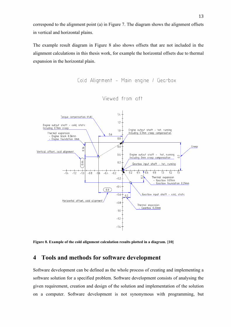
The results of these calculations can be presented in a diagram. Figure 8 shows example
results for the alignment point between an engine and a gearbox. This point would
13
correspond to the alignment point (a) in Figure 7. The diagram shows the alignment offsets
in vertical and horizontal plains.
The example result diagram in Figure 8 also shows offsets that are not included in the
alignment calculations in this thesis work, for example the horizontal offsets due to thermal
expansion in the horizontal plain.
Figure 8. Example of the cold alignment calculation results plotted in a diagram. [10]
4 Tools and methods for software development
Software development can be defined as the whole process of creating and implementing a
software solution for a specified problem. Software development consists of analysing the
given requirement, creation and design of the solution and implementation of the solution
on a computer. Software development is not synonymous with programming, but
14
programming is a part of the development process. Programming usually means the creation
and implementation section of the development of the solution. [11]
The tools and methods used in the development of the application for alignment calculation,
AlignmentTool, were chosen by Wärtsilä. These tools and methods have been used in
previous projects at the Project Engineering department for development of tools used to
perform tasks that include accessing the database for marine delivery projects. The choice
of tools and methods keep the development consistent and allow easier future development
of the AlignmentTool.
4.1 IDE
IDE is an acronym for Integrated Development Environment, a program used for software
development. An IDE usually includes basic features like a code editor and a form of
debugger with more advanced IDEs having more features for software development, for
example compilers and graphical designers. [12]
The chosen IDE for the development of the application was Visual Studio, an IDE developed
by Microsoft. The reason Visual Studio 2019 was chosen as the IDE was that Visual Studio
is the preferred environment for development of tool projects at the Project Engineering
department.
4.2 Version control
Version control or source control is tracking different versions of a developed software and
managing the changes. Version control software uses a database to track the changes made
to the code and gives the option to revert changes with minimal interference to the
development of the software. [13]
Git is a source code manager (SCM) originally created by Linus Torvalds for the
development of the Linux kernel. Git allows the tracking of different versions of a developed
software. The model Git uses for creation of separate lines of development within a project
is called branching (Figure 9). A branch allows the development of a software project in
multiple directions concurrently from one another with the possibility to merge efforts from
separate branches into one. [14] [15]
15
Figure 9. Example of several development branches. [15]
SourceTree is a free Git client with a GUI, graphical user interface developed by Atlassian.
[16]. It was chosen to be used for version control in the development of AlignmentTool as
it is the preferred application used for other tool projects and it includes a GUI for easy use.
4.3 Programming language and frameworks
Previous tool projects at the Project Engineering department have been developed using
either the C# or the Visual Basic programming language. Out of the two previously used
languages, C# was the preferred choice due to it being the programming language used for
most recent tool projects.
Windows Forms, also called WinForms, is a framework for creating desktop client apps for
Microsoft Windows [17]. The GUI for the AlignmentTool as well as other tool projects
created at the Project Engineering department are developed using Windows Forms.
4.4 API, DLL and NuGet
API stands for Application Programming Interface. It is a piece of software that allows
interaction between applications. An API defines what kind of calls can be made, how the
calls are made and what data formats to use. The calls from one application to another must
be valid to be sent to the receiving application. The response is then sent via the API to the
original application. In Figure 10 we can see an example of how an application can
communicate with a database through an API. APIs can offer increased security thanks to
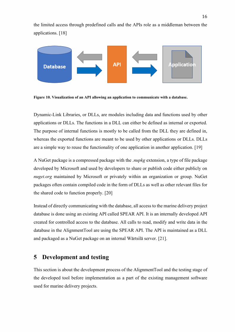
16
the limited access through predefined calls and the APIs role as a middleman between the
applications. [18]
Figure 10. Visualization of an API allowing an application to communicate with a database.
Dynamic-Link Libraries, or DLLs, are modules including data and functions used by other
applications or DLLs. The functions in a DLL can either be defined as internal or exported.
The purpose of internal functions is mostly to be called from the DLL they are defined in,
whereas the exported functions are meant to be used by other applications or DLLs. DLLs
are a simple way to reuse the functionality of one application in another application. [19]
A NuGet package is a compressed package with the .nupkg extension, a type of file package
developed by Microsoft and used by developers to share or publish code either publicly on
nuget.org maintained by Microsoft or privately within an organization or group. NuGet
packages often contain compiled code in the form of DLLs as well as other relevant files for
the shared code to function properly. [20]
Instead of directly communicating with the database, all access to the marine delivery project
database is done using an existing API called SPEAR API. It is an internally developed API
created for controlled access to the database. All calls to read, modify and write data in the
database in the AlignmentTool are using the SPEAR API. The API is maintained as a DLL
and packaged as a NuGet package on an internal Wärtsilä server. [21].
5 Development and testing
This section is about the development process of the AlignmentTool and the testing stage of
the developed tool before implementation as a part of the existing management software
used for marine delivery projects.
17
5.1 Solutions for alignment calculation
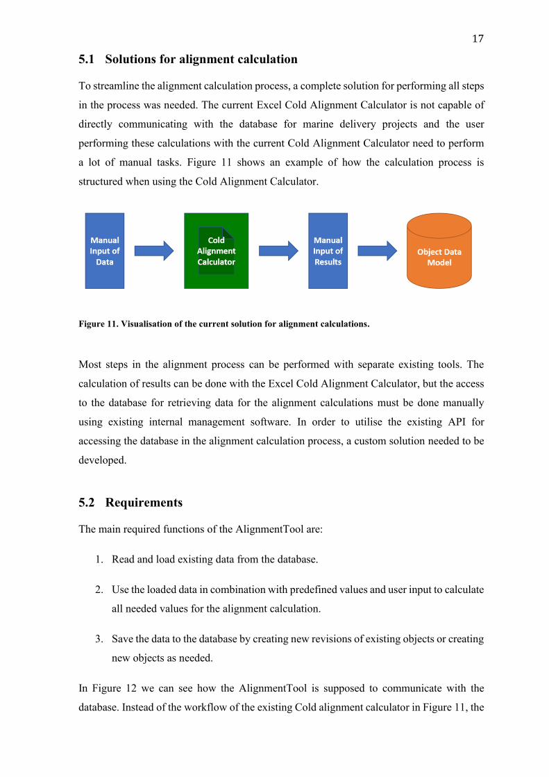
To streamline the alignment calculation process, a complete solution for performing all steps
in the process was needed. The current Excel Cold Alignment Calculator is not capable of
directly communicating with the database for marine delivery projects and the user
performing these calculations with the current Cold Alignment Calculator need to perform
a lot of manual tasks. Figure 11 shows an example of how the calculation process is
structured when using the Cold Alignment Calculator.
Figure 11. Visualisation of the current solution for alignment calculations.
Most steps in the alignment process can be performed with separate existing tools. The
calculation of results can be done with the Excel Cold Alignment Calculator, but the access
to the database for retrieving data for the alignment calculations must be done manually
using existing internal management software. In order to utilise the existing API for
accessing the database in the alignment calculation process, a custom solution needed to be
developed.
5.2 Requirements
The main required functions of the AlignmentTool are:
1. Read and load existing data from the database.
2. Use the loaded data in combination with predefined values and user input to calculate
all needed values for the alignment calculation.
3. Save the data to the database by creating new revisions of existing objects or creating
new objects as needed.
In Figure 12 we can see how the AlignmentTool is supposed to communicate with the
database. Instead of the workflow of the existing Cold alignment calculator in Figure 11, the
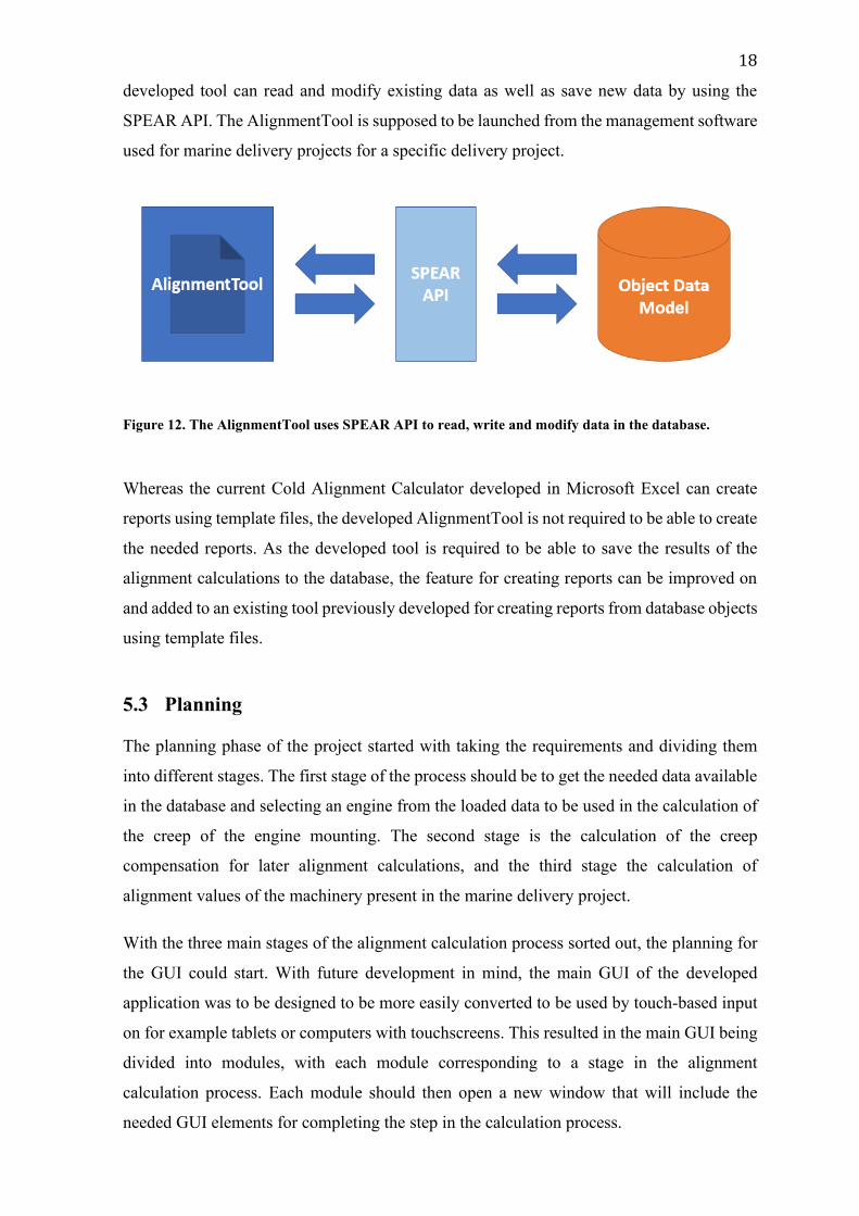
18
developed tool can read and modify existing data as well as save new data by using the
SPEAR API. The AlignmentTool is supposed to be launched from the management software
used for marine delivery projects for a specific delivery project.
Figure 12. The AlignmentTool uses SPEAR API to read, write and modify data in the database.
Whereas the current Cold Alignment Calculator developed in Microsoft Excel can create
reports using template files, the developed AlignmentTool is not required to be able to create
the needed reports. As the developed tool is required to be able to save the results of the
alignment calculations to the database, the feature for creating reports can be improved on
and added to an existing tool previously developed for creating reports from database objects
using template files.
5.3 Planning
The planning phase of the project started with taking the requirements and dividing them
into different stages. The first stage of the process should be to get the needed data available
in the database and selecting an engine from the loaded data to be used in the calculation of
the creep of the engine mounting. The second stage is the calculation of the creep
compensation for later alignment calculations, and the third stage the calculation of
alignment values of the machinery present in the marine delivery project.
With the three main stages of the alignment calculation process sorted out, the planning for
the GUI could start. With future development in mind, the main GUI of the developed
application was to be designed to be more easily converted to be used by touch-based input
on for example tablets or computers with touchscreens. This resulted in the main GUI being
divided into modules, with each module corresponding to a stage in the alignment
calculation process. Each module should then open a new window that will include the
needed GUI elements for completing the step in the calculation process.
19
The planning of the GUI and needed features of the different stages in the calculation process
were not completely thought out at the start of the project and were planned more in detail
when the development of the previous step was mostly complete.
5.4 Project creation and Git setup
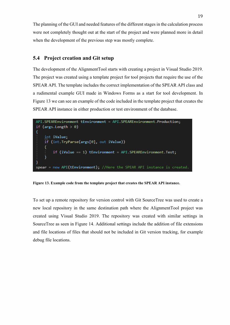
The development of the AlignmentTool starts with creating a project in Visual Studio 2019.
The project was created using a template project for tool projects that require the use of the
SPEAR API. The template includes the correct implementation of the SPEAR API class and
a rudimental example GUI made in Windows Forms as a start for tool development. In
Figure 13 we can see an example of the code included in the template project that creates the
SPEAR API instance in either production or test environment of the database.
Figure 13. Example code from the template project that creates the SPEAR API instance.
To set up a remote repository for version control with Git SourceTree was used to create a
new local repository in the same destination path where the AlignmentTool project was
created using Visual Studio 2019. The repository was created with similar settings in
SourceTree as seen in Figure 14. Additional settings include the addition of file extensions
and file locations of files that should not be included in Git version tracking, for example
debug file locations.
20
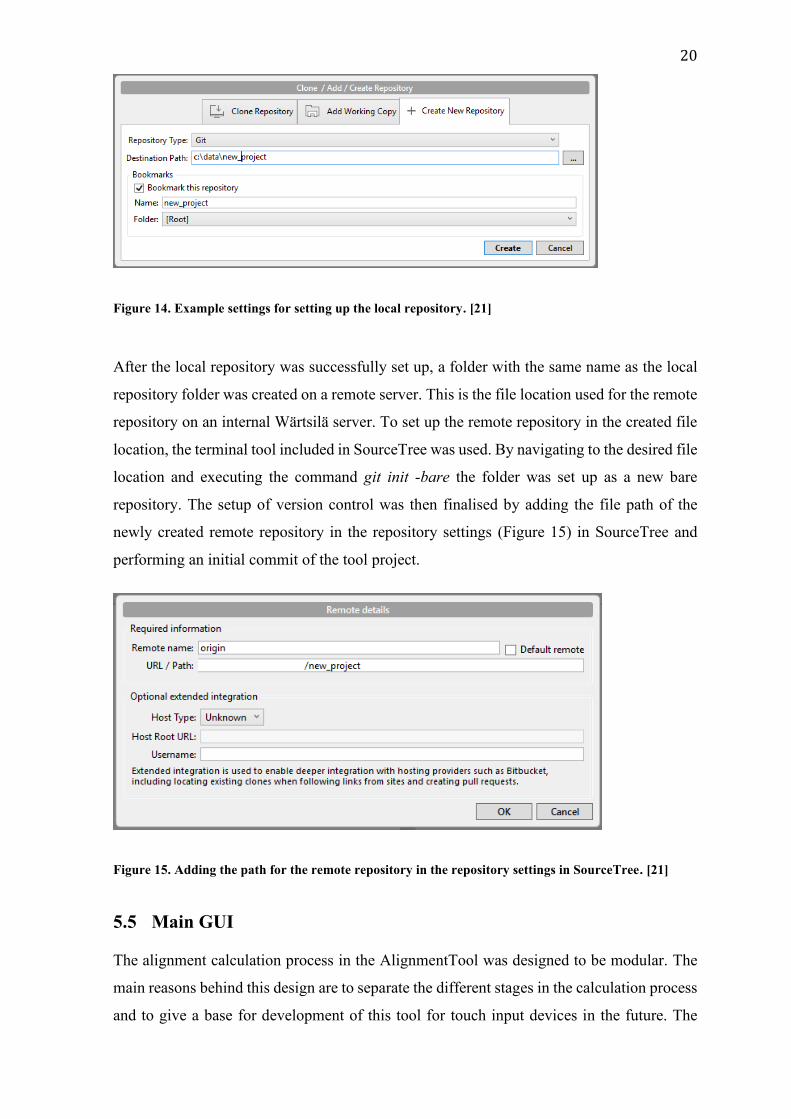
Figure 14. Example settings for setting up the local repository. [21]
After the local repository was successfully set up, a folder with the same name as the local
repository folder was created on a remote server. This is the file location used for the remote
repository on an internal Wärtsilä server. To set up the remote repository in the created file
location, the terminal tool included in SourceTree was used. By navigating to the desired file
location and executing the command git init -bare the folder was set up as a new bare
repository. The setup of version control was then finalised by adding the file path of the
newly created remote repository in the repository settings (Figure 15) in SourceTree and
performing an initial commit of the tool project.
Figure 15. Adding the path for the remote repository in the repository settings in SourceTree. [21]
5.5 Main GUI
The alignment calculation process in the AlignmentTool was designed to be modular. The
main reasons behind this design are to separate the different stages in the calculation process
and to give a base for development of this tool for touch input devices in the future. The
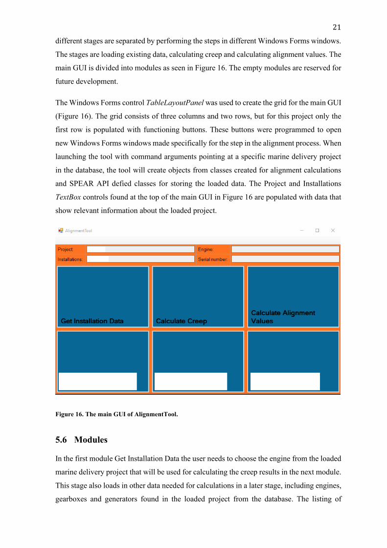
21
different stages are separated by performing the steps in different Windows Forms windows.
The stages are loading existing data, calculating creep and calculating alignment values. The
main GUI is divided into modules as seen in Figure 16. The empty modules are reserved for
future development.
The Windows Forms control TableLayoutPanel was used to create the grid for the main GUI
(Figure 16). The grid consists of three columns and two rows, but for this project only the
first row is populated with functioning buttons. These buttons were programmed to open
new Windows Forms windows made specifically for the step in the alignment process. When
launching the tool with command arguments pointing at a specific marine delivery project
in the database, the tool will create objects from classes created for alignment calculations
and SPEAR API defied classes for storing the loaded data. The Project and Installations
TextBox controls found at the top of the main GUI in Figure 16 are populated with data that
show relevant information about the loaded project.
Figure 16. The main GUI of AlignmentTool.
5.6 Modules
In the first module Get Installation Data the user needs to choose the engine from the loaded
marine delivery project that will be used for calculating the creep results in the next module.
This stage also loads in other data needed for calculations in a later stage, including engines,
gearboxes and generators found in the loaded project from the database. The listing of
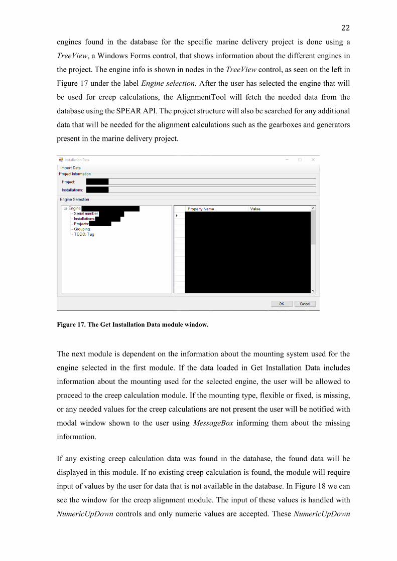
22
engines found in the database for the specific marine delivery project is done using a
TreeView, a Windows Forms control, that shows information about the different engines in
the project. The engine info is shown in nodes in the TreeView control, as seen on the left in
Figure 17 under the label Engine selection. After the user has selected the engine that will
be used for creep calculations, the AlignmentTool will fetch the needed data from the
database using the SPEAR API. The project structure will also be searched for any additional
data that will be needed for the alignment calculations such as the gearboxes and generators
present in the marine delivery project.
Figure 17. The Get Installation Data module window.
The next module is dependent on the information about the mounting system used for the
engine selected in the first module. If the data loaded in Get Installation Data includes
information about the mounting used for the selected engine, the user will be allowed to
proceed to the creep calculation module. If the mounting type, flexible or fixed, is missing,
or any needed values for the creep calculations are not present the user will be notified with
modal window shown to the user using MessageBox informing them about the missing
information.
If any existing creep calculation data was found in the database, the found data will be
displayed in this module. If no existing creep calculation is found, the module will require
input of values by the user for data that is not available in the database. In Figure 18 we can
see the window for the creep alignment module. The input of these values is handled with
NumericUpDown controls and only numeric values are accepted. These NumericUpDown
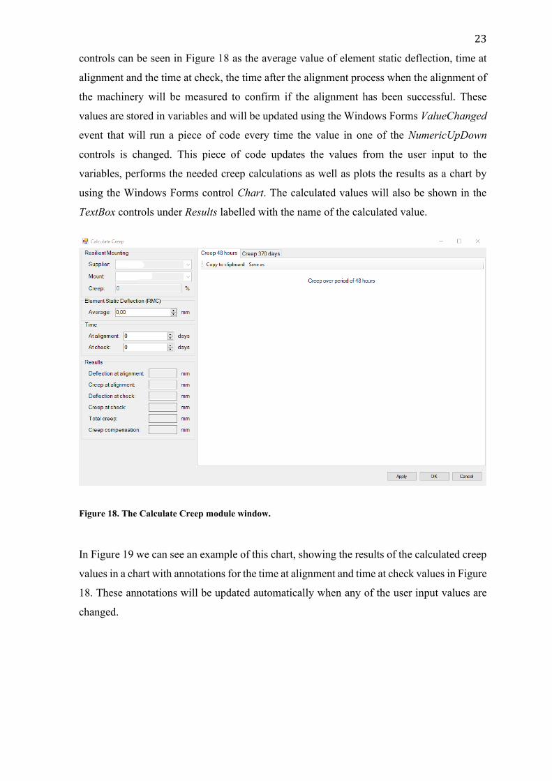
23
controls can be seen in Figure 18 as the average value of element static deflection, time at
alignment and the time at check, the time after the alignment process when the alignment of
the machinery will be measured to confirm if the alignment has been successful. These
values are stored in variables and will be updated using the Windows Forms ValueChanged
event that will run a piece of code every time the value in one of the NumericUpDown
controls is changed. This piece of code updates the values from the user input to the
variables, performs the needed creep calculations as well as plots the results as a chart by
using the Windows Forms control Chart. The calculated values will also be shown in the
TextBox controls under Results labelled with the name of the calculated value.
Figure 18. The Calculate Creep module window.
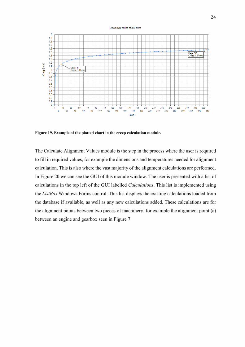
In Figure 19 we can see an example of this chart, showing the results of the calculated creep
values in a chart with annotations for the time at alignment and time at check values in Figure
18. These annotations will be updated automatically when any of the user input values are
changed.
24
Figure 19. Example of the plotted chart in the creep calculation module.
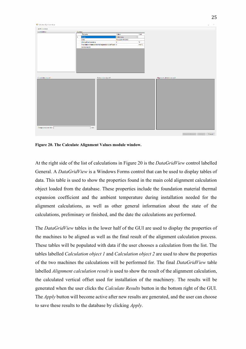
The Calculate Alignment Values module is the step in the process where the user is required
to fill in required values, for example the dimensions and temperatures needed for alignment
calculation. This is also where the vast majority of the alignment calculations are performed.
In Figure 20 we can see the GUI of this module window. The user is presented with a list of
calculations in the top left of the GUI labelled Calculations. This list is implemented using
the ListBox Windows Forms control. This list displays the existing calculations loaded from
the database if available, as well as any new calculations added. These calculations are for
the alignment points between two pieces of machinery, for example the alignment point (a)
between an engine and gearbox seen in Figure 7.
25
Figure 20. The Calculate Alignment Values module window.
At the right side of the list of calculations in Figure 20 is the DataGridView control labelled
General. A DataGridView is a Windows Forms control that can be used to display tables of
data. This table is used to show the properties found in the main cold alignment calculation
object loaded from the database. These properties include the foundation material thermal
expansion coefficient and the ambient temperature during installation needed for the
alignment calculations, as well as other general information about the state of the
calculations, preliminary or finished, and the date the calculations are performed.
The DataGridView tables in the lower half of the GUI are used to display the properties of
the machines to be aligned as well as the final result of the alignment calculation process.
These tables will be populated with data if the user chooses a calculation from the list. The
tables labelled Calculation object 1 and Calculation object 2 are used to show the properties
of the two machines the calculations will be performed for. The final DataGridView table
labelled Alignment calculation result is used to show the result of the alignment calculation,
the calculated vertical offset used for installation of the machinery. The results will be
generated when the user clicks the Calculate Results button in the bottom right of the GUI.
The Apply button will become active after new results are generated, and the user can choose
to save these results to the database by clicking Apply.
26
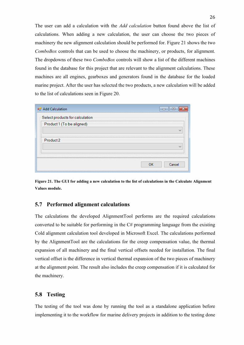
The user can add a calculation with the Add calculation button found above the list of
calculations. When adding a new calculation, the user can choose the two pieces of
machinery the new alignment calculation should be performed for. Figure 21 shows the two
ComboBox controls that can be used to choose the machinery, or products, for alignment.
The dropdowns of these two ComboBox controls will show a list of the different machines
found in the database for this project that are relevant to the alignment calculations. These
machines are all engines, gearboxes and generators found in the database for the loaded
marine project. After the user has selected the two products, a new calculation will be added
to the list of calculations seen in Figure 20.
Figure 21. The GUI for adding a new calculation to the list of calculations in the Calculate Alignment
Values module.
5.7 Performed alignment calculations
The calculations the developed AlignmentTool performs are the required calculations
converted to be suitable for performing in the C# programming language from the existing
Cold alignment calculation tool developed in Microsoft Excel. The calculations performed
by the AlignmentTool are the calculations for the creep compensation value, the thermal
expansion of all machinery and the final vertical offsets needed for installation. The final
vertical offset is the difference in vertical thermal expansion of the two pieces of machinery
at the alignment point. The result also includes the creep compensation if it is calculated for
the machinery.
5.8 Testing
The testing of the tool was done by running the tool as a standalone application before
implementing it to the workflow for marine delivery projects in addition to the testing done
27
in debug mode during development. When running the tool in debug mode in Visual Studio
2019, the project to be loaded was chosen in advance by adding the id of the object in the
database to the command line arguments for the AlignmentTool. By doing this the chosen
object in the marine delivery project was automatically loaded when the tool was run. For
running in standalone mode, as a separate executable file outside of the IDE, a button was
added to the main GUI that allows the user to search the database using a simple search
window included in the base template used for the AlignmentTool. The search function will
only show the user objects in the database that meet certain requirements, in this case the
specific type of objects in the database that the tool will be run for when implemented into
the management software used for marine delivery projects.
The application was tested by loading projects with existing data and projects with no saved
data. When loading a project with existing data, the tested features of the tool were its ability
to load and display existing data, modify the loaded data, and save the modified values to
the database by creating new revisions of objects.
The testing done both in debug mode and standalone mode resulted in changes to the user
interface as well as some additional features in the different stages of development.
6 Result
This thesis work was one of many tool projects developed to modernise and streamline parts
of the engineering work done at the Project Engineering Department. The goal of this thesis
was to create a complete solution for handling all the steps in the alignment calculation
process for marine delivery projects at the Project Engineering department at Wärtsilä.
The developed AlignmentTool can at the time of writing perform most of the required
calculations set at the start of the project and can load existing results and save new data.
The application works as a base for future development of additional features already present
in the previous Excel tool as well as completely new features.
The developed application is close to being finished and tested to be implemented into the
management software used for marine projects. The code for some calculations is not
finished and tested and will need more work before release.
28
7 Future development
The next step in the development of the AlignmentTool would be to finalise the features
developed in this thesis and implement the application as a part of the management software
used for marine delivery projects. The developed tool in this project is the foundation for the
migration of features from the Excel Cold Alignment Calculator tool as well as completely
new features not available in the current Excel tool. This thesis was mainly focused on the
vertical alignment calculations from the current tool. Other features planned to be added to
the AlignmentTool are the calculation of transversal and axial thermal expansion, and the
calculation of the impact of centrifugal force on the alignment of machinery.
8 Discussion
Before starting this project, I had previous experience with working with Visual Studio 2019
and the C# programming language from working with similar methods and tools at Wärtsilä
Finland Oy. This experience was valuable when using the SPEAR API to access the
database, as I was familiar with how the API can be used to load, save, and handle database
objects. This helped me to get the programming stage of the development started and to
minimise the needed time to learn to use the development methods and tools.
The alignment calculation process was something I was not at all familiar with before the
start of this thesis work. I have learned the importance of the alignment for marine project
machinery as a part of the engineering work to ensure the longevity of the Wärtsilä
machinery in marine delivery projects.
This thesis work has taught me that having a comprehensive plan at the beginning of a project
is very important. When developing this tool, I felt that the planning done at the start was
not detailed enough, which led to the scope of the project to change during the programming
and testing stage of the development. Some wanted features were added to the requirements
during the programming stage, with some features even added during the testing of the
application.
The most challenging and time-consuming part of the development process was to find and
convert the needed calculations from the Excel tool to be performed using C#. These
challenges included dealing with the way C# performs calculations when using specific
variable types, and how to perform these calculations in the most effective way.

29
I would like to thank Wärtsilä Finland Oy and my supervisor Tomas Södö for this thesis
work opportunity.
30
9 References
[1] Wärtsilä Corporation, “About Wärtsilä,” [Online]. Available:
https://www.wartsila.com/about. [Accessed 9 January 2021].
[2] Wärtsilä Corporation, “Wärtsilä businesses in brief,” [Online]. Available:
https://www.wartsila.com/media/businesses-in-brief. [Accessed 9 January 2021].
[3] Pruftechnik Ltd, “A Practical Guide To Shaft Alignment,” 2002. [Online].
Available:
https://www.plantservices.com/assets/knowledge_centers/ludeca/assets/A_Practical
_Guide_to_Shaft_Alignment.pdf. [Accessed 18 February 2021].
[4] J. Piotrowski, Shaft Alignment Handbook, Boca Raton, FL: CRC Press, 2006.
[5] C. Jackson, “https://oaktrust.library.tamu.edu,” 1990. [Online]. Available:
https://oaktrust.library.tamu.edu/bitstream/handle/1969.1/164269/P727-38.pdf.
[Accessed 18 March 2021].
[6] LaBour Pump Company, “Understanding Shaft Alignment: Thermal Growth,”
January 2003. [Online]. Available:
https://www.labourtaber.com/Alignment%20Shaft%20Thermal%20Growth.pdf.
[Accessed 18 February 2021].
[7] M. Meyers and K. Chawla, Mechanical Behavior of Materials, Cambridge
University Press, 2008.
[8] R. Serway and J. Jewett, Physics for Scientists & Engineers with Modern Physics,
9th Edition, Cengage Learning, 2014.
[9] “Cold Alignment Calculator,” [Online]. Available: Wärtsilä internal document.
[10] “Cold alignment diagram - example,” [Online]. Available: Wärtsilä internal
document.
[11] J. Dooley, Software Development and Professional Practice, Paul Manning, 2011.
[12] Microsoft Corporation, “Overview of Visual Studio | Microsoft Docs,” 2019.
[Online]. Available: https://docs.microsoft.com/fi-fi/visualstudio/get-started/visual-
studio-ide?view=vs-2019. [Accessed 14 April 2021].
[13] Atlassian, “What is version control | Atlassian Git Tutorial,” [Online]. Available:
https://www.atlassian.com/git/tutorials/what-is-version-control. [Accessed 14 April
2021].
[14] J. Loeliger and M. McCullough, “Version Control with Git,” Sebastopol, O'Reilly
Media, Inc., 2012, pp. 1, 89.
[15] “About - Git,” [Online]. Available: https://git-scm.com/about. [Accessed 12 April
2021].
31
[16] Atlassian, “Sourcetree | Free Git GUI for Mac and Windows,” [Online]. Available:
https://www.sourcetreeapp.com/. [Accessed 12 April 2021].
[17] Microsoft Corporation, “What is Windows Forms - Windows Forms .NET |
Microsoft Docs,” 2020. [Online]. Available: https://docs.microsoft.com/en-
us/dotnet/desktop/winforms/overview/?view=netdesktop-5.0. [Accessed 14 April
2021].
[18] HubSpire, “Application Programming Interface,” [Online]. Available:
https://www.hubspire.com/resources/general/application-programming-interface/.
[Accessed 12 April 2021].
[19] Microsoft Corporation, “Dynamic-Link Libraries (Dynamic-Link Libraries) - Win32
apps | Microsoft Docs,” 31 May 2018. [Online]. Available:
https://docs.microsoft.com/en-us/windows/win32/dlls/dynamic-link-libraries.
[Accessed 8 May 2021].
[20] Microsoft Corporation, “What is NuGet and what does it do? | Microsoft Docs,” 24
May 2019. [Online]. Available: https://docs.microsoft.com/en-us/nuget/what-is-
nuget. [Accessed 8 May 2021].
[21] “Object Data Model - Tool development,” [Online]. Available: Wärtsilä internal
document.