appendix 2-1 - Nuclear Regulatory Commission
160
Big Rock Point Reactor Vessel Package Safety Analysis Report (BRP RVP SAR) SL-5444, Rev. 0 Project 10525-040 APPENDIX 2-1
-
Upload
khangminh22 -
Category
Documents
-
view
0 -
download
0
Transcript of appendix 2-1 - Nuclear Regulatory Commission

Big Rock Point Reactor Vessel Package Safety Analysis Report(BRP RVP SAR)
SL-5444, Rev. 0Project 10525-040
APPENDIX 2-1

ISSUE SUMMARYForm SOP-0402-03. Revision 2
DESIGN CONTROL SUMMARYCLIENT: BNFL Inc. UNIT NO.:
PROJECT NAME: Big Rock Point MajorComponent Removal
PROJECT NO.: 10525-020 El NUCLEAR SAFETY-RELATED
CALC. NO.: S-1 0525-020-012 [1 NOT NUCLEAR SAFETY-RELATED QA
TITLE: Reactor Vessel Transport Cask El IMPORTANT TO SAFETY SERIAL
Stress Analysis CATEGORY AEQUIPMENT NO.: NO.
IDENTIFICATION OF PAGES ADDED/REVISED/SUPERSEDEDNOIDED & REVIEW METHOD
Initial Issue: 951 pages issued as Revision 0.
INPUTS ASSUMPTIONS
09 VERIFIED
El UNVERIFIED
REVIEW METHOD: Detailed Review REV. 0STATUS: Approved 4 DATE FOR REV.: 6 APREPARER P. H. Hoang Nlt DATE: 30, O_)REVIEWER * C. W. Mak f-E{g 2/J; DATE:
APPROVER B. B. Sli`< p c DATE: C>-4- 2 c,_I
IDENTIFICATION OF PAGES ADDED/REVIStEd6UPERSEDED[VOIDED & REVIEW METHOD
INPUTS/ASSUMPTIONS
El VERIFIED
El UNVERIFIED
REVIEW METHOD: REV.STATUS: DATE FOR REV.:PREPARER DATE:
REVIEWER* DATE:
APPROVER DATE:
IDENTIFICATION OF PAGES ADDED/REVISED/SUPERSEDEDNOIDED & REVIEW METHOD
INPUTS/ASSUMPTIONS
E| VERIFIED
El UNVERIFIED
REVIEW METHOD: REV.
STATUS: DATE FOR REV.:PREPARER DATE:
REVIEWER* DATE:
APPROVER DATE:
* The reviewer's signature indicates compliance with S&L procedure SOP-0402 and the verification of, as a minimum, the followingitems: correctness of mathematics for manual calculations, appropriateness of input data, appropriateness of assumptions, andappropriateness of the calculation method.
NOTE: PRINT AND SIGN IN THE SIGNATURE AREAS
cask-cover.DOCRev. Date: 05/02/01Eff. Date:
Page 1 of 948
Calc For Reactor Vessel Transport Cask Stress Analysis Calc. No. S-10525-020-012
.i Rev. 0 | Date:* Important to Safety Non-Safety-Related Page 2
Client BNFL, Inc. I Prepared by: P. H. Hoan
Project Big Rock Point Major Component Removal | Reviewed by: C. W. Mak
Proj. No. 10525-020 Equip. No. Approved by:
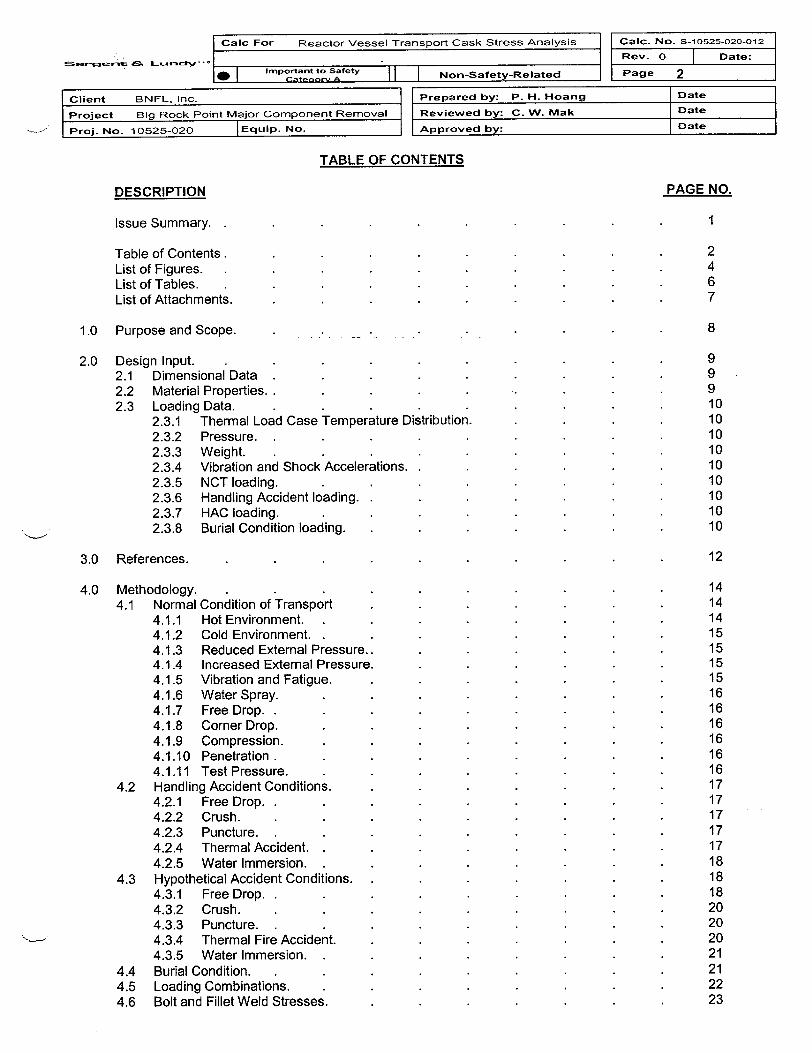
TABLE OF CONTENTS
DESCRIPTION
Issue Summary.
Table of Contents.List of Figures.
List of Tables.List of Attachments.
1.0 Purpose and Scope.
2.0 Design Input.2.1 Dimensional Data2.2 Material Properties. .2.3 Loading Data.
2.3.1 Thermal Load Case Temperature Distribution.2.3.2 Pressure. .
2.3.3 Weight.2.3.4 Vibration and Shock Accelerations. .
2.3.5 NCT loading.2.3.6 Handling Accident loading.2.3.7 HAC loading.2.3.8 Burial Condition loading.
3.0 References.
4.0 Methodology.4.1 Normal Condition of Transport
4.1.1 Hot Environment.4.1.2 Cold Environment.4.1.3 Reduced External Pressure..4.1.4 Increased External Pressure.4.1.5 Vibration and Fatigue.4.1.6 Water Spray.4.1.7 Free Drop.4.1.8 Corner Drop.4.1.9 Compression.4.1.10 Penetration .4.1.11 Test Pressure.
4.2 Handling Accident Conditions.4.2.1 Free Drop.4.2.2 Crush.
4.2.3 Puncture. .
4.2.4 Thermal Accident.4.2.5 Water Immersion.
4.3 Hypothetical Accident Conditions.4.3.1 Free Drop. .
4.3.2 Crush.4.3.3 Puncture. .
4.3.4 Thermal Fire Accident.4.3.5 Water Immersion.
4.4 Burial Condition.4.5 Loading Combinations.4.6 Bolt and Fillet Weld Stresses.
Date
Date
Date
PAGE NO.
1
2467
8
999101010101010101010
12
14141415151515161616161616171717171718181820202021212223

-- -I Calc For Reactor Vessel Transport Cask Stress Analysis Calic. No. S-10525-020-012 I
Rev. 0 | Date:
Important to Safety Non-Safety-Related Page 3
Client BNFL, Inc. Prepared by: P. H. Hoang Date
Project Big Rock Point Major Component Removal Reviewed by: C. W. Mak Date
Proj. No. 10525-020 IEquip. No. Approved by: Date
4.6.1 Bolt Stress.. . . . . . . .. 234.6.2 Shield Plate and Ring Plate Fillet Weld Stresses. . . . . 234.6.3 Donut Plate and Stiffener Fillet Weld Stresses . . . . 23
5.0 Acceptance Criteria . . . . . . . . . 245.1 Allowable Stresses for Linear Elastic Analyses . . . . . 24
5.1.1 For the NCT and Final Burial Conditions . . . . . 245.1.2 For the Handling Accident Conditions. . . . . . 24
5.2 Acceptance Criteria for Nonlinear Elastic Plastic Analyses . . . . 255.3 Buckling Check . . . . . . . . . 265.4 Fracture Toughness Criteria. . . . . . . . 26
6.0 Assumptions and Limitations . . . . . . . . 27
7.0 Calculations and Results . . . . . . . . . 297.1 Description of the RVTS Cask Finite Element Models and Element Types. . . 297.2 Thermal Analyses. . . . . . . . . . 337.3 Normal Conditions of Transport. . . . . . . . 37
7.3.1 Hot Environment. . . . . . . . . 377.3.2 Cold Environment. . . . . . . . . 377.3.3 Increased External Pressure. . . . . . . 377.3.4 Reduced External Pressure. . . . . . . 377.3.5 Vibration and Shock. . . . . . . . 387.3.6 Penetration. . . . . . . . . 417.3.7 One-Foot Free Drop. . . . . . . . 427.3.8 Test Pressure. . . . . . . . . 427.3.9 Fillet Weld Evaluation. . . . . . . . 427.3.10 RV Flange Stud & Nut Evaluation. . . .. . . . 42
7.4 Handling Accident Conditions. . . . . . . . 507.4.1 Free Drop Lumped Parameter Dynamic Model for Five-Foot Drop Analysis. . 517.4.2 Five-Foot Free Drop Stress Analyses. . . . . . 567.4.3 Fillet Weld Evaluation . . . . . . . 587.4.4 RV Flange Stud & Nut Evaluation. . . . . . . 58
7.5 Hypothetical Accident Conditions. . . . . . . . 627.5.1 Thirty-Foot Free Drop Analyses. . . . . . . 62
7.5.1.1 Vertical Drop on the Cask Bottom Plate. . . . . 637.5.1.2 Horizontal Drop. . . . . . .. 677.5.1.3 Corner Drop on the Cask CG. . . . . . 727.5.1.4 Flap Down Drop Analyses. . . . . . 77
7.5.1.4.1 Flap Down Drop - Maximum Vertical Velocity . . 787.5.1.4.2 Flap Down Drop - Maximum Horizontal Velocity. . 84
7.5.2 Result Verification for 30-Foot Drop Analyses. . . . . 897.5.2.1 Energy Conservation Check. . . . . . 897.5.2.2 Effect of the PCG Solver Convergence Tolerance . . . 907.5.2.3 Performance Benchmark Analysis of Shell 181 Element. . . 91
7.5.3 Puncture Stress Analyses. . . . . . . . 937.5.3.1 Puncture Drop near Mid Shell. . . . . . 937.5.3.2 Puncture Drop near Top Shell. . . . . . 97
7.5.4 Thermal Fire Accident. . . . . . . . 1017.5.5 Water Immersion. . . . . . . . . 1067.5.6 Shield Plate and Ring Plate Weld Check. . . . . . 107
7.6 Burial Condition. . . . . . . . . . 1097.7 Brittle Fracture Protection Evaluation. . . . . . 109
8.0 Conclusion 110

Calc For Reactor Vessel Transport Cask Stress Analysis Calc. No. S-10525-020-012
Rev. 0 Date:
Iot t SAfetNon-Safety-Relate PagI Important to Safety 9 _ o-aeyRltd Page 4.
Client BNFL, Inc. Prepared by: P. H. Hoang
Project Big Rock Point Major Component Removal- Reviewed by: C. W. Mak
Proj. No. 10525-020 | Equip. No. Approved by:
Date
Date
Date
LIST OF FIGURESFigure Title Page
2.17.1.17.1.27.1.37.1.47.1.57.2.17.2.27.2.37.3.17.3.27.3.37.3.47.3.5.17.3.5.27.3.5.37.3.5.47.3.5.57.3.5.67.3.7.17.3.7.27.3.8.17.3.8.27.4.1.17.4.1.27.4.14.37.4.1.4a7.4.1 .4b7.4.1 .4c7.4.1.4d7.4.2.17.4.2.27.4.2.3a7.4.2.3b7.4.2.4a7.4.2.4b7.5.17.5.1.1 a7.5.1 .1 b7.5.1.1 c7.5.1.1 d7.5.1.1 e7.5.1 .1f7.5.1.1 g7.5. 1.1 h7.5.1.2a7.5.1 .2b7.5.1 .2c7.5.1.2d7.5.1 .2e7.5.1 .2f7.5.1.2g7.5.1 .2h
RVTS Cask.Donut Support Ring Segments.Cask Model Dimensional Input.RVTS with Saddle Supports.RVTS with Tie-Down Cables.RVTS Cask Model.1000F Ambient, Max Insolation, Max Decay Heat.-400F Ambient, Zero Insolation, Zero Decay Heat.-200F Ambient, Zero Insolation, Zero Decay Heat.Hot Envir. Primary Plus Secondary Stress.-40'F Cold Envir. Primary Plus Secondary Stress.Increased External Pressure Primary Plus Secondary Stress.Minimum External Pressure Primary Plus Secondary Stress. .Max P, Hot, Vertical Shock, Pm+Pb+Q Stress.Min P, Cold, Vertical Shock, Pm+Pb+Q Stress.Max P, Hot, Lateral Shock, Pm+Pb+Q Stress.Min P, Cold, Lateral Shock, Pm+Pb+Q Stress.Max P, Hot, Longitudinal Shock, Pm+Pb+Q Stress.Min P, Cold, Longitudinal Shock, Pm+Pb+Q Stress.1' Horizontal Drop, Hot, Max Pressure, Pm+Pb+Q Stress.1' Horizontal Drop, Cold, Min Pressure, Pm+Pb+Q Stress.Test Pressure Primary Plus Secondary Stress (Hot Condition).Test Pressure Primary Plus Secondary Stress (Cold Condition).Horizontal Drop Beam Model.Oblique Drop Beam Model. .
5' Horizontal Drop Displacement and Acceleration5' Oblique Drop Vertical Displacement and Acceleration5' Oblique Drop Horizontal Displacement and Acceleration5' Oblique Drop Mean Vertical and Horizontal Acceleration5' Oblique Drop Angular Acceleration5' Horizontal Drop, Hot, Max Pressure, Pm+Pb+Q Stress.5' Horizontal Drop, Cold, Min Pressure, Pm+Pb+Q Stress.5' Oblique First Drop, Hot, Max Pressure, Pm+Pb+Q Stress.5' Oblique Second Drop, Hot, Max Pressure, Pm+Pb+Q Stress.5' Oblique First Drop, Cold, Min Pressure, Pm+Pb+Q Stress..5' Oblique Second Drop, Cold, Min Pressure, Pm+Pb+Q Stress.Key Locations of the RVTS Analysis Output. .VD1 Vertical Displacement Time History.VD2 Vertical Displacement Time History.VD1 Maximum Principal Stress Time History.VD2 Maximum Principal Stress Time History.VD1 Maximum Principal Stress Contours.VD2 Vertical Displacement Contours.VD1 Horizontal Displacement Contours.VD1 Bolt Stress Intensity Time History.HD1 Vertical Displacement Time History.HD2 Vertical Displacement Time History.HD1 Top Plate Maximum Principal Stress Time History.HD2 Top Plate Maximum Principal Stress Time History.HD1 Maximum Principal Stress Contours.HDI Vertical Displacement Contours.HD1 Horizontal Displacement Contours.HD1 Bolt Stress Intensity Time History.
1130313132323435364343444445454646474748484949525253545455555959606061616263646465656666676868696970707171

...
Calc For Reactor Vessel Transport Cask Stress Analysis Calc. No. s-10525-020-012
Rev. 0 | Date:
Important to Safety N P 5O I C~t-W Av I I I Non-Safety-Related _Page 5
II Oi;-r+ P RNJ P Inc I I Preoared by: P. H. Hoang | Date
ProjectProj. No.
Do Ms ;, |l
Big Rock Point Major Component Removal Reviewed by: C. W. Mak
10525-020 IEquip. No. I Approved by:
Date
7.5.1 .3a7.5.1 .3b7.5.1 .3c7.5.1 .3d7.5.1 .3e7.5.1.3f7.5.1 .3g7.5.1 .3h7.5.1.47.5.1 .4.1 a7.5.1.4.1 b7.5.1 .4.1c7.5.1.4.1 d7.5.1.4.1 e7.5.1 .4.1f7.5.1 .4.1 g7.5.1 .4.1 h7.5.1.4.1 i7.5.1 .4.2a7.5.1 .4.2b7.5.1 .4.2c7.5.1 .4.2d7.5.1 .4.2e7.5.1 .4.2f7.5.1.4.2g7.5.1 .4.2h7.5.1 .4.2i7.5.2.17.5.2.3a7.5.2.3b7.5.3.1a7.5.3.1 b7.5.3.1c7.5.3.1 d7.5.3.1 e7.5.3.1f7.5.3.1 g7.5.3.1 h7.5.3.2a7.5.3.2b7.5.3.2c7.5.3.2d7.5.3.2e7.5.3.2f7.5.4a7.5.4b7.5.4c7.5.4d7.5.4e7.5.4f7.5.4g7.5.4h7.5.4i7.5.6
001 Vertical Displacement Time History. 72CD2 Vertical Displacement Time History. . . . . . . 73CDi Maximum Principal Stress Time History. . . . . . 73CD2 Maximum Principal Stress Time History. . . . . . 74CD2 Maximum Principal Stress Contours. . . . . . . 74CD2 Vertical Displacement Contours. . . . . . . 75CD2 Horizontal Displacement Contours. . . . . . . 75CD1 Bolt Stress Intensity Time History. . . . . . . 76Spring Force Deflection Curve. . . . . . . . 77FDP1 1 Vertical Displacement Time History. . . . . . . 79FDP12 Vertical Displacement Time History. . . . . . . 80FDP1 1 Maximum Principal Stress Time History. . . . . . 80FDP12 Maximum Principal Stress Time History. . . . . . 81FDP12 Maximum Principal Stress Contours.. . . .. . 81FDP1 1 Maximum Principal Stress Contours.. . . . . . 82FDP12 Vertical Displacement Contours. . . . . . . 82FDP1 1 Horizontal Displacement Contours. . . . . . . 83FDP1 1 Bolt Stress Intensity Time History. . . . . . . 83FDP21 Vertical Displacement Time History . . . . .. 84FDP22 Vertical Displacement Time History. . . . . . . 85FDP21 Maximum Principal Stress Time History. . . . . . 85FDP22 Maximum Principal Stress Time History. . . . . . 86FDP21 Maximum Principal StressContours.. . . . . 86FDP22 Maximum Principal Stress Contours. . . . . 87FDP21 Vertical Displacement Contours. . . . . . . 87FDP22 Horizontal Displacement Contours. . . . . . . 88FDP21 Bolt Stress Intensity Time History. . . . . . . 88Cask Drop Verification Problem - Energy Conservation Check. . . . 90Kinetic Energy and the Cumulative Plastic Work in an Impacting Bar Model using SHELL181. 92Kinetic Energy and the Cumulative Plastic Work in an Impacting Bar Model using VISCO1 06. 92PMD1 Vertical Displacement Time History. . . . . . . 93PMD2 Vertical Displacement Time History. . . . . . . 94PMD1 Maximum Principal Stress Time History. . . . . . 94PMD2 Maximum Principal Stress Time History. . . . . . 95PMD2 Maximum Principal Stress Contours . . . . .. 95PMD1 Maximum Principal Stress Near the Puncture Location. . . . 96PMD2 Vertical Displacement Contours. . . . . . . 96PMD2 Horizontal Displacement Contours. . . . . . . 97PTD1 Vertical Displacement Time History. . . . . . . 98PTD2 Vertical Displacement Time History. . . . . . . 98PTD1 Maximum Principal Stress Time History. . . . . . 99PTD2 Maximum Principal Stress Time History. . . . . . 99PTD1 Maximum Principal Stress Contours. . . . . . . 100PTD1 Vertical Displacement Contours. . . . . . . 100THACC1 - Temperature Distribution After 30 Minutes. . . . . 102THACC2 - Temperature Distribution After 30 Minutes. . . . . 102THACC1 - Vertical Displacement During Fire Accident. . . . . 103THACC1 - Bolt Stress Intensity During Fire Accident. . . . . 103THACC2 - Maximum Principal Stress During Fire Accident . . . . 104THACC1 - Stress Intensity Contours. . . . . . . 104THACC2 - Stress Intensity Contours. . . . . . . 105THACC1 - Vertical Displacement Contours . . . .. . 105THACC2 - Horizontal Displacement Contours. . . . . . 106VD1 Vertical Displacement Time Histories of the Shield Plate and the Ring Plate . 108

Calc For Reactor Vessel Transport Cask Stress Analysis Calc. No. S-10525-020-012
Rev. 0 Date:
* Important to Safety Non-Safety-Related Page 6
Client BNFL, Inc. Prepared by: P. H. Hoang Date
Project Big Rock Point Major Component Removal Reviewed by: C. W. Mak Date
Proj. No. 10525-020 Equip. No. Approved by: Date
LIST OF TABLESTable Title Page
2.1 RVTS Cask Shell and RV Dimensional Data.. . . . . . 92.2 Vibration and Shock Accelerations. . . . . . . . 104.5 Load Combinations with Applicable Initial Conditions. . . . . 226.1 Dimensional Tolerances. . . . . . . . . 287.3.1 Stress Intensity Summary for Normal Conditions of Transport. . . . 407.3.2 Stress Intensity Range for Normal Conditions of Transport. . . . . 417.4.1 Stress Intensity Summary for Handling Accident Conditions . . . 577.4.2 Extreme Stress Intensity Range for Handling Accident Conditions.. . . 577.4.3 Fillet Weld Check for NCT/Handling Accident Conditions. . . . . 587.5.1 .4a Flap Down Velocities for Various Oblique Angles. . . . . . 777.5.1.4b Flap Down Velocities Used in the Analyses . . . . .. 787.5.2.2a Extreme Values from RUNID FDP1 1 with PCG Convergence Value of 1 E-3. . . 907.5.2.2b Extreme Values from RUNID FDP11 a with PCG Convergence Value of 1 E-8.. . 917.5.2.3 Benchmark Results. . . . . . . . 917.5.6 Axial Loads on Shield Plate and Ring Plate Fillet Welds under HAC Conditions. . 107

Caic For Reactor Vessel Transport Cask Stress Analysis Calc. No. S-10525-020-012
Rev. 0 j Date:
important to Safety Non-Safety-Related Page 7
Client BNFL, Inc. Prepared by: P. H. Hoang Date
Project Big Rock Point Major Component Removal Reviewed by: C. W. Mak Date
Proj. No. 10525-020 lEquip. No. Approved by: Date
LIST OF ATTACHMENTS
A Material Properties . . . . . . . . . 6 pages
B Temperature Distribution. . . . . . . . . 6 pages
C. Concrete Contact Stiffness Calculation. . . . . . . . 8 pages
D. Beam Model Properties Calculation. . . . . . . . 7 pages
E. Penetration Load Evaluation. . . . . . . . . 4 pages
F. RV Flange Bolt Load Evaluation. 9. . . . . . . pages
G. Finite Element Analysis (FEA) Input Files. . . . . . . 212 pages
H. Finite Element Analysis (FEA) Postprocessor Output Files.. . . . . 581 pages
I. Corner Drop Local Stiffness Calculation. . . . . . . . 3 pages
J. Element Performance Benchmark Analysis Input and Output Files. . . . 5 pages

Caic For Reactor Vessel Transport Cask Stress Analysis Calc. No. S-10525-020-012
Rev. 0 Date:
m | Iportant to Safety l l-| Non-Safety-Related Page 8
Client BNFL, Inc. Prepared by: P. H. Hoang Date
Project Big Rock Point Major Component Removal Reviewed by: C. W. Mak Date
- Proj. No. 10525-020 - Equip. No. Approved by: Date
1.0 Purpose and Scope
A major stage of the Big Rock Point decommissioning project involves removing the Reactor Vessel (RV)from its cavity in the Reactor Building and placing it in a cylindrical steel package for transport. Onceassembled and filled with low-density cellular concrete (LDCC), the transport package is a single, welded,integral container, which provides adequate radiological shielding and containment of radioactive waste,and is here after referred to as the Reactor Vessel Transport System (RVTS) cask in this report. To ensuresafe structural behavior of the RVTS while transporting radioactive material, the shipping cask must bedesigned to withstand specific load conditions that encompass the static, dynamic and thermal loading thatmay be experienced by the cask during transport and burial conditions. The design of the RVTS Cask is inaccordance with the requirements of Part 71, Title 10 of the Code of Federal Regulations, Subpart E, Parts41, 43 and 51. The RVTS cask is a Type B package and is therefore designed to withstand the loadingconditions outlined in 10 CFR 71, Subpart F, Parts 71 and 73, which are the Normal Condition of Transport(NCT) and the Hypothetical Accident Conditions (HAC).
The purpose of this calculation is to document the structural evaluation of the Big Rock Point RVTS Cask.The calculation demonstrates that the RVTS Cask design meets the requirements of 10 CFR 71.35,"Package Evaluation", which states that packages used to transport radioactive materials must demonstrateadequacy for the NCT and HAC specified in Subparts E and F of 10 CFR 71. The evaluation will alsocomply with Regulatory Guide 7.6, "Design Criteria for the Structural Analysis of Shipping CaskContainment Vessels", for linear elastic analyses, Regulatory Guide 7.8, "Load Combinations for theStructural Analysis of Shipping Casks for Radioactive Material", and Regulatory Guide 7.11, "FractureToughness Criteria of Base Material for Ferritic Steel Shipping Cask Containment Vessels with a MaximumWall Thickness of 4 Inches". In addition, the RVTS cask is designed to sustain the vertical, lateral andlongitudinal accelerations given by both the guidelines of the Association of American Railroads (AAR) setforth in Part 1 of the "Open Top Loading Rules Manual" and the ANSI N1 4.2 (Draft) "Tie-down for TruckTransport of Radioactive Materials". Finally, the RVTS Cask is designed to withstand the constant pressureresulting from the burial conditions given by the disposal facility at Barnwell, SC.
It should be noted that the lifting devices utilized to remove the RV from the Reactor Cavity and down-endthe RVTS before it is loaded onto the hydraulic transporter (i.e. lifting lugs and trunnions) will be removedprior to the RVTS Cask transport. The lifting devices are evaluated in separate calculations, References3.6.4 and 3.6.5. The tie-down devices utilized to secure the RVTS Cask to the hydraulic transporter andrailcar (support saddles, ties, bumpers, etc.) are evaluated in separate calculations, Reference 3.6.6, 3.6.7and 3.6.8.

Calc For Reactor Vessel Transport Cask Stress Analysis Caic. No. S-10525-020-012
. T Rev. 0 | Date:
* Important to Safety Non-Safety-Related Page 9r_1,tj~j&A _f Pag
Client BNFL. Inc. | Prepared by: P. H. Hoang Date
I Project Big Rock Point Major Component Removal Reviewed by: C. W. Mak Date
Proj. No. 10525-020 IEquip. No. Approved by: Date
2.0 Design Input
2.1 Dimensional Data
The RVTS components with their respective geometries are shown in Figure 2.1. The dimensional datagiven in Table 2.1 is obtained from the indicated references.
Table 2.1 RVTS Cask Shell and RV Dimensional Data
Parameter Value Reference
Reactor Vessel Thickness with cladding 5.25" + 5/32" 3.12.1Height (from top of flange to 282.375" 3.12.1inside surface of dome)Inside Radius 53.063" 3.12.1
Flange Thickness 14" 3.12.1Bolt Circle Diameter 128" 3.12.1
RV Shell and Flange Material SA-302 Gr. B 3.12.2RV Flange Bolt Size 4 1/2" - 8N - 2A 3.3.1
Material A193 Conforms AISI-4340 3.3.1
RV Flange Nut Size 4 1/2" - 8N - 2B 3.3.1
Material SA 105 or SA-266 Grade 2 3.3.1
RVTS Cask Shell Thickness 3" 3.3.1
Height 299.5" 3.3.1Material SA-516 Gr. 70 3.3.1
RVTS Cask Top and Thickness 4" 3.3.1Bottom Plate Material SA-516 Gr. 70 3.3.1
Donut-shape RV Base Plate Thickness 4" 3.3.1Support Stiffener Thickness 2" 3.3.1
Distance from center of RVTS 25" 3.3.1bottom plate to center ofDonut plateMaterial SA-516 Gr. 70 3.3.1
RVTS Cask Shield Thickness 4" 3.3.1
Plate Width 96" 3.3.1
Material SA-516 Gr. 70 3.3.1
Trunnion Reinforcing Thickness 3" 3.3.1
Ring Plate Width 40" 3.3.1
Material SA-516 Gr. 70 3.3.1
Saddle Support Width 18" 3.3.2Saddle Center to Center 59" 3.3.2Spacing
2.2 Material Properties
Temperature dependent material properties are obtained from the ASME Code, Section II, Part D, and arelisted in Attachment A.

Of:_ C1 ,.r sa n y ..
Caic For Reactor Vessel Transport Cask Stress Analysis Calc. No. S-10525-020-012
Rev. 0 Date:
Important to Safetyle iteor A II I Non-Safety-Related IIpage 10_ t Newt so- * _
_
Client
Project
Proj. No.
RNFI Inc 1 [Prenared by: P. H. Hoang I Date
Big Rock Point Major Component Removal Reviewed by: C. W. Mak
10525-020 | Equip. No. I Approved by:
Date
ID ate
2.3 Loading Data
2.3.1 Thermal Load Case Temperature Distribution
The RVTS Cask temperature distribution for the NCT and HAC per Reference 3.6.1 are used as theboundary conditions for thermal heat transfer and thermal structural analyses.
2.3.2 Pressure
The RVTS Cask internal pressure under the ambient temperatures of 100 0F with maximum insolation and-20 OF without insolation, as stipulated in 10 CFR 71.71(c)(1) has been determined in Reference 3.6.2. Themaximum and minimum internal pressures are 20 psig and -3 psig, respectively. Internal pressure for-40 OF ambient temperature load case is -3.3 psig. The test pressure is 1.5 times the maximum normaloperating pressure per 10CFR71.85(b). The maximum HAC fire accident pressure is 95 psig per Reference3.6.2.
2.3.3 Weight
The total weight of the RVTS assembly (excluding the lifting lug and trunnions, which will not be attachedduring transport) is 564.3 kips per reference 3.6.3.
2.3.4 Vibration and Shock Accelerations
Shock loads produced by coupling, switching, etc., in rail transport and by bumps, potholes, etc., in trucktransport are considered to be bounded by the governing inertial loads specified for the tie-down componentdesign. The enveloped vertical, lateral, and longitudinal accelerations given per the governing ANSI N14.2,"Tie-down for Truck Transport of Radioactive Materials", Reference 3.14, and Association of AmericanRailroads (AAR) guidelines set forth in Part 1 of the "Open Top Loading Rules Manual" Reference 3.11, arelisted in Table 2.2.
Table 2.2 Vibration and Shock AccelerationsDirection Inertial LoadVertical 2.0
Longitudinal (in direction of travel) 3.0Lateral (perpendicular to direction of travel) 2.0
2.3.5 NCT Loading
Refer individual section in section 4.1 for detail description.
2.3.6 Handling Accident Loading
Refer individual section in section 4.2 for detail description.
2.3.7 HAC Loading
Refer individual section in section 4.3 for detail description.
2.3.8 Burial Condition Loading
Refer individual section in section 4.4 for detail description.

I Caic For Reactor Vessel Transport Cask Stress Analysis | |eic. No. S-10525.020-012
:4.
aFiI I Rev. 0 | Date:
lemportant to 5t-yCmpl "nto A I I Non-Satety-Related I I page II
v 9 B *E _ _
Client BNFL. Inc. Prepared by: P. H. Hoang
Project Big Rock Point Major Component Removal Reviewed by: C. .WMak
*, Prol. No. 10525-020 |Equip. No. Approved by:
FIGURE WITHHELD UNDER 10 CFR 2.390
Date
DateDate

l
_E_ L---.=tV II -
CaIc For Reactor Vessel Transport Cask Stress Analysis Calc. No- S-10525-020-012
I _ I Rev. 0 Date:I I Important to Safety I I I Ncnn-Snfetv-Related I Page 12
I IC tp f, I I----__
Client BNFL, Inc. Prepared by: P. H. Hoang Date
Project Big Rock Point Major Component Removal Reviewed by: C. W. Mak Date
- Proj. No. 10525-020 Equip. No. Approved by: Date
3.0 References
3.1 ASME Boiler and Pressure Vessel, Section II, Part D, "Properties", and Section 1II, Subsection NA, NB, NFand Appendices, 1995 Edition.
3.2 United States Nuclear Regulatory Commission Rules and Regulations, Title 10, Part 71, "Packaging andTransportation of Radioactive Materials", January 30, 1998.
3.3 S&L Design Drawings:3.3.1 SD-10525-020-001, Rev. 1.3.3.2 SD-10525-020-002, Rev. 1.
3.4 ASTM Standards:3.4.1 ASTM A 193/A 193M - 00.3.4.2 ASTM A 516/A 516M - 90.3.4.3 ASTM A 302/A 302M - 97.3.4.4 ASTM A 105/A 105M - 98.3.4.5 ASTM A 266/A 266M - 99.
3.5 Intentionally blank .
3.6 S&L Calculations:3.6.1 S&L Calculation No. M-1 0525-020-001, "Thermal Response of Reactor Vessel Transport System",
Rev. 1.3.6.2 S&L Calculation No. M-10525-020-002,"Bounding Normal Operating Pressure for RVTS", Rev. 2.3.6.3 S&L Calculation No. S-10525-020-002, "Volume and Weight of Reactor Vessel Transport System",
Rev. 2.3.6.4 S&L Calculation No. S-10525-020-003, "Structural Evaluation of RVTS Lifting Lug Assembly",
Rev. 2.3.6.5 S&L Calculation No. S-10525-020-004, "Structural Evaluation of RVTS Trunnion Assembly", Rev. 1.3.6.6 S&L Calculation No. S-10525-020-006, "Structural Evaluation of RVTS Tie-Down System - Cable
Tie Assembly", Rev. 2.3.6.7 S&L Calculation No. S-1 0525-020-007, "Structural Evaluation of RVTS Tie-Down System - Center
Box Beam and Bumper Assembly", Rev. 1.3.6.8 S&L Calculation No. S-1 0525-020-008, "Structural Evaluation of RVTS Tie-Down System - Saddle
Assembly", Rev. 1.3.6.9 S&L Calculation No. S-1 0525-020-009, "RVTS Brittle Fracture Protection Criteria", Rev. 0.3.6.10 S&L Calculation No. N-10525-041-001, "Breach of Containment', Rev. 2.3.6.11 S&L Calculation No. S-1 0525-020-013, "Top Plate Dimple Evaluation", Rev. 0.
3.7 Computer Software:3.7.1 Finite Element Program ANSYS, Version 5.6, Sargent and Lundy Validated Program Number
ANSYS 03.7.596.3.7.2 Mathcad 8 Professional, Sargent and Lundy Program No. 03.7.548-8.03o. (PC# 5485, Windows NT
Version 4.0)
3.8 Mark's Standard Handbook for Mechanical Engineers, 8th Edition.
3.9 Roark R.J., "Formulas for Stress and Strain", 5th Edition, Table 33, Case 4.
3.10 AISC, "Manual of Steel Construction", 9 th Edition.
3.11 Association of American Railroads (AAR), "Open Top Loading Rules Manual", Part 1, dated March 1, 2000.
3.12 Combustion Engineering Drawings:

Calc For Reactor Vessel Transport Cask Stress Analysis Caic. No. S-10525-020-012 |
e w- . j Rev. 0 | Date: l
gmportanttosafety Non-Safety-Related Page 13 l
ent
Prject
Pro . No.
BNFL. Inc. Prepared by: P. H. Hoan
Big Rock Point Major Component Removal Reviewed by: C. W. Mak
10525-020 |Equip. No. Approved by:
ngDate
Q Date
Date ]3.12.13.12.23.12.3
F-230-791-2, "General Arrangement - Reactor Vessel", Rev. 2.E-201-806-4, "Closure Head Forming & Welding - Reactor Vessel", Rev. 4.E-201-805-5, "Stud, Nut, Washers & O-Ring Details", for Reactor Vessel - General Electric Co- BWR- Consumers Power, 8/15/1960.
3.13 ASCE Manual, "Structural Analysis and Design of Nuclear Plant Facilities", 1980 Edition.
3.14 ANSI N14.2, "Tie-down for Truck Transport of Radioactive Materials", Draft.
3.15 Regulatory Guides:3.15.1 Regulatory Guide 7.6, "Design Criteria for the Structural Analysis of Shipping Cask Containment
Vessels", Rev. 1, March 1978.
3.15.2 Regulatory Guide 7.8, "Load Combinations for the Structural Analysis of Shipping Casks forRadioactive Material". Rev. 1, March 1989.
3.15.3 Regulatory Guide 7.11, "Fracture Toughness Criteria of Base Material for Ferritic Steel ShippingCask Containment Vessels with a Maximum Wall Thickness of 4 Inches", Rev. 0, June 1991.
3.16 NUREGs:
3.16.1 NUREG/CR-1815, "Recommendations for Protecting Against Failure by Brittle Fracture in FerriticSteel Shipping Containers Up to Four Inches Thick", August 1981.
3.16.2 NUREG/CR-3966, "Methods for Impact Analysis of Shipping Containers", November, 1987.
3.16.3 NUREG/CR-0128, "Shock and Vibration Environments For A Large Shipping Container DuringTruck Transport (Part II)", May, 1978.
3.17 CHEM-NUCLEAR SYSTEMS Letter No. 44053-001, "Big Rock Point RPV-Design Basis for DisposalVaults", dated 1-21-2000.
3.18 Machinery's Handbook, 23rd Edition.
3.19 Blodgett O.W., "Design of Welded Structures", 1966.
3.20 ASCE Manuals and Reports on Engineering Practice No. 78, "Structural Fire Protection".

Calc For Reactor Vessel Transport Cask Stress Analysis Caic. No. S-10525-020-012
oraReSfet y o. n Date:Important to Safety
0 rCstnc-- A d I I o-aet-ea Page 14
ent
rect
r No.
BNFL, Inc. Prepared by: P. H. Hoang
Big Rock Point Major Component Removal Reviewed by: C. W. Mak
1025-020 I Equip. No. Approved by:
Date
Date
Date
4.0 Methodologv
The RVTS cask is designed to meet the approval standards identified in 10 CFR 71 Subpart E and the caskcomplies with the standards identified in 10 CFR71.41. The RVTS cask is a Type B package and musttherefore be evaluated for the loads resulting from both the NCT and the HAC per 10 CFR 71.71 and 10CFR 71.73, respectively. The design criteria for the RVTS cask structural analysis meets the requirement of10 CFR 71.35, "Package Evaluation", which states that packages used to transport radioactive materialsmust demonstrate adequacy for the NCT and HAC specified in Subparts E and F of 10 CFR 71. Theseconditions and acceptance criteria are described in the following sections. Analytical methodology for eachcase is also discussed.
The associated initial conditions required per 10 CFR 71 and stipulated in Table I of Reg. Guide 7.8 areused for the structural analysis. The applicable initial conditions for the analysis are:
* Maximum and minimum ambient temperatures of -200 F and 1000 F for the evaluation of each NCT andHAC except for cold environment described in Section 4.1.2.
* Maximum insolation at 400 g cal/cm2 on its horizontal curved surfaces, and 200 g cal/cm2 on the topand bottom vertical, flat surfaces for a duration of 12 hours.
* Maximum decay heat generated by the radioactive material. For Big Rock RVTS Cask, a total of 485BTU/hr maximum decay heat was used in the thermal heat transfer analysis, References 3.6.1.
* The maximum or the minimum normal operating pressure that is consistent with the ambienttemperature, insolation and decay heat.
• Fabrication stresses caused by interference fits and the shrinkage of bonded concrete are negligible forthe Big Rock Point RVTS Cask design. Bolt load is the only assembly stress which is required to beevaluated. Per the design drawings, References 3.3.1 and 3.3.2, the flange bolts and the trunnion boltsare snug tight; therefore, the RVTS Cask bolt assembly stresses are negligible. Note that the residualstresses due to plate formation and welding are not considered to be fabrication stresses as noted inRegulatory Guide 7.8.
4.1 Normal Conditions of Transport
4.1.1 Hot Environment
Per 10 CFR 71.71 (c)(1), the effect of an ambient temperature of 100 OF in still air, maximuminsolation, maximum decay heat and maximum internal normal operating pressure are consideredin the design of the cask.
Thermal response and internal pressure of the RVTS cask due to the aforementioned conditionsare evaluated in References 3.6.1 and 3.6.2, respectively. Based on the temperature distributiondetermined in Reference 3.6.1, the temperatures at the mid span of the cask shell, top and bottomplate, and RV wall are used as boundary conditions for a heat transfer analysis that determinestemperature distribution throughout the rest of the model. Structural thermal analyses are thenperformed and combined with other primary loads. The RVTS Cask maximum and minimuminternal pressures determined in Reference 3.6.2 are 20 psig and -3 psig, respectively. The cask isinitially resting on its saddle supports and is subjected to the normal primary loading condition(normal weight and maximum pressure). The cask is then analyzed for a primary plus secondaryloading condition that includes 1 00F ambient temperature, maximum insolation and maximumdecay heat. The Finite Element Analysis Program ANSYS, Reference 3.7.1, is utilized to analyzethe RVTS cask for these loading conditions. Element type SHELL181, which is a 3-D shell elementwith both bending and membrane capabilities, is used to represent the cask shell, top and bottomplates, donut support, shield plate and trunnion reinforced ring plate. The weight of the LDCC isincluded in the model; however, the concrete structural stiffness is negligible and is not consideredin this analysis.

Calc For Reactor Vessel Transport Cask Stress Analysis Calc. No. S-10525-020-012
= L Rev. 0 T Date:* Important to Safety Non-Safety-Related Page 15
Client BNFL. Inc. Prepared by: P. H. Hoang Date
Project Big Rock Point Major Component Removal Reviewed by: C. W. Mak Date
Proj. No. 10525-020 IEquip. No. Approved by: Date
4.1.2 Cold Environment
Per 10 CFR71.71 (c)(2), the effect of an ambient temperature of -40 OF in still air and shade isconsidered in the design of the cask. The analysis is similar to the analysis for the Hot condition inSection 4.1.1 except that the RVTS is subjected to a minimum pressure of -3.3 Ibf/in2 (fromReference 3.6.2), zero decay heat, zero insolation and an ambient temperature of -40 OF (fromReference 3.6.1).
4.1.3 Reduced External Pressure
Per 10 CFR 71.71 (c)(3), the cask is designed for the effects of an external absolute pressure of 3.5lbf/in2. The analysis is similar to the analysis for the Hot condition in Section 4.1.1 except that theRVTS is subjected to an external absolute pressure of 3.5 lbf/in2 combined with the cask maximuminternal pressure of 20 psig, corresponding to the initial ambient temperature of 1000 F andincluding the effects of insolation and decay heat (Reference 3.15.2, Table 1).
4.1.4 Increased External Pressure
Per 10 CFR 71.71 (c)(4), the cask is designed for the effects of an external absolute pressure of 20Ibf/in . The analysis is similar to the analysis for the Hot condition in Section 4.1.1 except that theRVTS is subjected to an external absolute pressure of 20 Ibf/in combined with the cask minimuminternal pressure of -3 psig, corresponding to the initial ambient temperature of -200 F, notincluding the effects of insolation or decay heat (Reference 3.15.2, Table 1). Buckling of the caskshell under external pressure is checked using the maximum allowable external pressure perASME Section III, Article NB-3133 (Reference 3.1).
4.1.5 Vibration and Fatigue
The RVTS is evaluated for vibration and shocks normally incident to transport as required by 10CFR 71.71 (c)(5). Shock loads produced by coupling, switching, etc., in rail transport and bybumps, potholes, etc., in truck transport are considered to be bounded by the governing inertialloads specified for the tie-down component design. The enveloped vertical, lateral, and longitudinalaccelerations given per the ANSI N14.2, "Tie-down for Truck Transport of Radioactive Materials",Reference 3.14, and Association of American Railroads (AAR) guidelines set forth in Part 1 of the"Open Top Loading Rules Manual", Reference 3.11, are:
* Vertical direction: 2.Og* Transverse direction: 2.Og* Longitudinal direction: 3.Og
These shock accelerations are conservative since the cask is being transported by a hydraulic roadtransporter and a special use rail car.
The RVTS is evaluated for shock normally incident to transport under two extreme thermalconditions, per Reference 3.15.1, Table 1. First, the RVTS is evaluated for the effects of vibrationat an ambient temperature of 1000 F, considering maximum insolation and decay heat along withcorresponding maximum internal pressure. Next, the RVTS is evaluated for the effects of vibrationat an ambient temperature of -200 F, considering zero insolation, zero decay heat, and thecorresponding minimum internal pressure. Fatigue evaluation of the cask is conservatively basedon these two bounding conditions assuming one cycle of shocks per mile during the 1500-mile tripto the burial site (Assumption 6.1). The total number of cycles of shock per lifetime is 1500.

Caic For Reactor Vessel Transport Cask Stress Analysis Calc. No. S-10525-020-012
Rev. 0 Date:
v Important to SafetY Non-Safety-Related Page 16
Client BNFL, Inc. Prepared by: P. H. Hoang Date
Project Big Rock Point Major Component Removal Reviewed by: C. W. Mak Date
- Proj. No. 10525-020 Equip. No. Approved by: Date
The number of normal vibration cycles is expected to be much higher than the number of shockcycles. The normal vibration stress will be shown to be less than the material endurance limit suchthat an infinite number of cycles of normal vibration is acceptable. The vibration stress calculation isbased on the vibratory motion data produced by small excitations to the cask-vehicle system, whichis reported in NUREG/CR-0128, Reference 3.16.3, for cask weights more than 50,000 lbs and atravel speed of less than 55 mph. The maximum zero-to-peak accelerations are:
* Vertical direction: 0.52g* Transverse direction: 0.19g* Longitudinal direction: 0.27g
4.1.6 Water Spray
10 CFR 71.71 (c)(6) requires an evaluation of the cask for water spray that simulates exposure to arainfall of approximately two inches per hour for at least one hour. The RVTS is a sealed steelstructure with no openings; therefore, the water spray test condition has no effect on the cask.
4.1.7 Free Drop
Per 10 CFR 71.71 (c)(7), a free drop test of the cask through a distance of one foot onto a flat,essentially unyielding, horizontal surface is required. Considering the cask orientation and positionduring transportation and loading operations, the size of the cask, as well as the stress margins ofthe horizontal five-foot drop and the primary oblique five-foot drop for the handing accidentcondition documented in Table 7.4.1, the governing one-foot drop orientation to be analyzed for theNCT is horizontal.
4.1.8 Corner Drop
Per 10 CFR 71.71 (c)(8), the corner drop test condition is not applicable because the RVTS is notconstructed of fiberboard or wood and does not contain fissile material.
4.1.9 Compression
Per 10 CFR 71.71 (c)(9), the compression test condition does not apply since the RVTS weighsmore than 11,000 lbs.
4.1.10 Penetration
Per 10 CFR 71.71 (c)(1 0), the RVTS is evaluated for the impact of a vertical hemispherical endsteel cylinder with a 1.25" diameter and a mass of 13 Ibs dropped from a height of 40" onto theexposed surface of the cask that is expected to be most vulnerable to puncture. The recommendedminimum design thickness per the Ballistic Research Laboratory given in Reference 3.13, is used tocheck the thickness of the shipping cask for puncture drop requirements.
4.1.11 Test Pressure
Per 10 CFR 71.85 (b), the RVTS is evaluated for a test pressure of 30 psig, which is 1.5 times themaximum normal operating pressure.

Calc For Reactor Vessel Transport Cask Stress Analysis Caic. No. S-10525-020-012
Rev. 0 | Date:
* Important to Safety l l | Non-Safety-Related Page 17
I Client BNFL, Inc. | | Prepared by: P. H. Hoang | Date
i rjctI Big Rock Point Major Component Removal Reviewed by: C. W. Mak
10525-020 Equip. No. I Approved by:
I Date
I Date
4.2 Handling Accident Conditions
In addition to the Hypothetical Accident Conditions (HAC) described in Section 4.3, the following handlingaccident conditions are evaluated using linear elastic acceptance criteria as outlined in Section 5.0. Theinitial temperature and pressure conditions associated with the handling accident evaluations are the sameas those listed for the evaluations of NCT.
4.2.1 Free Drop
After the RV is loaded into the RVTS and the top closure plate is welded to the cask, the RVTS willbe moved into a horizontal position via the lifting lug on the top closure plate, the trunnions, and theA-frame pivot device. Once the cask is ready for shipment, it will be tied down to the saddlesupport system by cables to ensure it remains in place during transportation. The RVTS cask willbe transferred by jacking from the road transporter to the rail car and will not be lifted duringtransport to the Barnwell (Dunbarton) site. Considering that the above handling scenario will becarried out in a controlled environment, the potential handling accidents consists of dropping thecask from the road transporter or the rail car to the ground. Therefore, based on the maximumheight of the transport flatbed of 4'-1 0", a five-foot free drop of the RVTS cask is considered in thisanalysis as a credible handling accident condition.
As noted above, the RVTS will remain in a horizontal position during handling. Therefore, two freedrop orientations are considered: a horizontal drop for which the entire cask shell will strike the flathorizontal surface, and an oblique drop where one end strikes the ground while the other endremains supported on the transporter. Under the oblique drop scenario, the effect of free bodyrotation and the secondary impact of the other end are also considered.
In the handling accident conditions, the flat, horizontal ground surface for the drop analyses isconsidered to be an infinitely thick concrete slab with a maximum compression strength of 4000 psi(see Assumption 6.4). Lumped parameter dynamic analysis methodology per NUREG/CR -3966,Reference 3.16.2, is employed to calculate the maximum dynamic responses of the cask lumpedparameter models for the limiting free drop orientations discussed above. The maximum impactaccelerations at the cask Center of Gravity (CG) in both the vertical and the horizontal directionsand rotational acceleration are then applied to the RVTS three-dimensional finite element analysis(FEA) model for stress recovery analysis and structural buckling analysis. Since the lumpedparameter dynamic analysis captures the maximum structural dynamic responses and the effects offree body motion and rotations, no additional dynamic load factor is needed for the stress analysis.The stress is performed with various initial conditions per Table 1 of Reg. Guide 7.8 as discussed inSection 4.1 of this report.
4.2.2 Crush
The dynamic crush test, per 10 CFR 71.73 (c)(2), is not required for casks weighing more than1 100 lbs.
4.2.3 Puncture
The puncture drop analysis, per 10 CFR 71 .73(c)(3), is not required for the handling accidentconditions.
4.2.4 Thermal Accident
The thermal accident, per 10 CFR 71 .73(c)(4), is not required for the handling accident conditions.

Calc For Reactor Vessel Transport Cask Stress Analysis CaIc. No. S-10525-020-012
Rev. 0 Date:
Cimportant to Safety Non-Safety-Related Page 18
Client BNFL, Inc. Prepared by: P. H. Hoang Date
Project Big Rock Point Major Component Removal Reviewed by: C. W. Mak Date
Proj. No. 10525-020 IEquip. No. Approved by: Date
4.2.5 Water Immersion
Immersion under 50 feet of water (21.7 psig), per 10 CFR 71.73 (c)(6), is not required for thehandling accident conditions.
4.3 Hypothetical Accident Conditions
Reference 3.2, 10 CFR 71.73, outlines the HAC to be considered during the design of the RVTS. The initialtemperature and pressure conditions associated with the HAC evaluations are the same as those listed forthe evaluations of the NCT.
The following tests and conditions are to be applied in the order noted to determine the cumulative effect onthe RVTS cask (with the exception of the final test, water immersion, which may be evaluatedindependently):
4.3.1 Free Drop
10 CFR 71 .73(c)(1) requires a free drop test of the cask specimen through a distance of 30 feetonto a flat, essentially unyielding, horizontal surface, striking the surface in a position for whichmaximum damage is expected. The maximum damage is limited such that the maximum potentialradiation activity meets the limitations for shipping casks per Section 71.51 of 10 CFR Part 71.Reference 3.6.10 provides limitations of damage at several locations of the cask so that therequirements in Section 71.51 of 10 CFR Part 71 are satisfied.
The assessment of cask damage resulting from a 30-foot drop onto an essentially unyieldingsurface is performed by finite element non-linear elastic plastic dynamic impact analyses. The FEAmodel consists of the RV, which is supported by the top plate and the donut support at the bottom,and the cask shell with the stiffener ring plate and the shield ring plate. The connection of the RVtop flange to the top plate is modeled using short beam elements that represent the RV flangebolts. Several contact surfaces between the cask and the essentially unyielding horizontal surfaceare modeled depending on the drop orientations. Potential contacts between the RV and the caskshell interior surface are also modeled at some local locations as described in each individual droporientation. A damping ratio of 1% is used in the dynamic analyses
The cask stresses are monitored for failure. Failure is considered to occur at any element at whichthe maximum principal stress exceeds the material tensile strength. The failed elements areeffectively removed and the process is continued until the cask displacements reach theirmaximum. Several drop orientations and potential damage are discussed as follows:
Vertical drop on the cask bottom plate:The RV bottom head is supported by the donut support. A vertical drop on the bottom platemay fail the donut support and the RV bottom head may come into contact with the bottomplate. The RV mass would crush the donut support, pull the top plate down, and thus compressthe cask shell. In a vertical drop on the top plate, the RV mass is in direct contact with the topplate. Therefore, the damage of a vertical drop on the cask bottom plate is more severe thanthe damage due to the vertical drop on the top plate. The drop on the bottom plate could causea buckling failure in the donut support and the cask shell. The effect of the cask shell bucklingcould cause longitudinal cracks or circumferential cracks on the cask shell. In the vertical dropanalysis, the cask FEA model is in the vertical position and the bottom plate is in full contactwith the essentially unyielding horizontal surface. Potential local contact between the RVbottom head and the bottom plate is included in the model. The initial conditions include the

Calc For Reactor Vessel Transport Cask Stress Analysis Calc. No. S-10525-020-012
e A: r .. Rev. 0 Date:
* | mportanttoSafety Non-Safety-Related Page 19
Client BNFL, Inc. Prepared by: P. H. Hoang Date
Project Big Rock Point Major Component Removal Reviewed by: C. W. Mak Date
Proj. No. 10525-020 IEquip. No. Approved by: Date
temperatures and pressures described in 10 CFR 71 and an initial impact velocity of 527.4in/sec, which is the impact velocity resulting from a 30-foot free drop.
* Horizontal drop:The damage to the shipping cask in a horizontal drop is expected to be concentrated at the twoends where the top plate and the bottom plate impact the essentially unyielding, horizontalsurface. The bottom plate and the donut plate share the impact load at the bottom end whilethe impact load at the top end is taken by only the top plate. Local buckling failure is expectedin the ligament of the top plate located between the RV bolt circle and the top plate corner.Potential local contact between the RV flange and the cask shell is included in the model.Some bolts may also fail, which will cause the RV flange to drop down and come into contactwith the cask shell. In such cases, the failed bolts are removed by reducing the bolt strength toa negligible value. The shipping cask FEA model is in the horizontal position, and the caskcylindrical shell is in contact with the essentially unyielding horizontal surface along thelongitudinal direction. The initial conditions include the temperatures and pressures describedin 10 CFR 71 and an initial impact velocity of 527.4 in/sec, which is the velocity at contactresulting from a 30-foot free drop.
* Corner drop through the cask center of gravity (CG drop):Local crushing at the impact corner is the potential damage mechanism of a corner dropthrough the cask CG. The damage due to a CG drop on a bottom corner is more critical thanthe damage due to a CG drop on a top plate corner because of the distance between the RVand the point of impact. Therefore, a CG drop on the bottom corner is considered. The shippingcask FEA model is in an oblique position in which the CG is on top of the impact corner of thebottom plate. The oblique angle is about 60 degrees from the horizontal plane. The modelincludes contact of an essentially unyielding horizontal surface with both of the bottom plateand the cask shell areas which are adjacent to the impact corner. The initial conditions includethe temperatures and pressures described in 10 CFR 71 and an initial impact velocity of 527.4in/sec. Under the corner drop scenario, the effect of free body rotation and the secondaryimpact at the top end, which is referred to as flap down drop, are also considered in thefollowing cases.
* Flap-down drops:The dynamic responses of the RVTS cask in several oblique drop orientations are investigatedusing the lumped parameter dynamic analysis methodology per NUREG/CR -3966, Reference3.16.2. The cask lumped parameter model is a beam which has the same distributed mass,lumped masses and cross sectional moment of inertia as the RVTS. The thirty-foot dropdynamic impact analyses of the lumped parameter model are performed for several obliquedrop angles ranging from 60 degrees to 5 degrees off the horizontal plane. The beam isdropped onto a spring which represents the local stiffness of the cask corner. The spring rate isdetermined from the force-displacement curve of the cask end plate in the corner drop analysisof the 3-dimensional plate model. The vertical and horizontal velocities of the two ends of thebeam are calculated at the time the other end strikes the ground. The results are shown inTable 7.5.1.4a and b. The maximum vertical flap-down velocity at the cask top platecorresponds to a primary 10 degree oblique drop. The maximum horizontal flap-down velocityof the top plate corresponds to a primary 50-degree oblique drop. In these limiting cases, thecask flaps down onto the horizontal surface with a linearly distributed velocity in both verticaland horizontal directions. The damage of a flap-down secondary drop is expected to be themost critical among all drop positions because of a higher impact velocity combined with ahorizontal impact velocity. The analyses will determine the potential breaches of the caskcontainment boundary. The acceptability of the breach of containment is determined in thecalculation N-10525-041-001, Reference 3.6.10 as stated in the acceptance criteria stated insection 5.2 of this report.

Calc For Reactor Vessel Transport Cask Stress Analysis Calc. No. S-10525-020-012
s c; d . .Rev. 0 Date:
C* Importantto Safety Non-Safety-Related Page 20
Client BNFL, Inc. Prepared by: P. H. Hoang Date
Project Big Rock Point Major Component Removal Reviewed by: C. W. Mak Date
Proj. No. 10525-020 Equip. No. Approved by: Date
4.3.2 Crush
The dynamic crush test, per 10 CFR 71.73 (c)(2), is not required for casks weighing more than1100 lbs.
4.3.3 Puncture
10 CFR 71.73(c)(3) requires that the RVTS cask be dropped through a distance of 40 inches ontothe upper end of a solid, vertical, 6" OD steel bar mounted on an essentially unyielding, horizontalsurface. During this test, the position of the RVTS is such that maximum damage is expected.
Local punching shear damage resulting in a 6-inch diameter hole through the RVTS cask wall iswithin the limitation of the acceptance criteria stated in Section 5.2 of this report. However, theeffects of the puncture drop on the existing damaged cask resulting from a 30-foot drop are themain concern of the puncture drop analysis. The damaged elements in the 30-foot flap-down dropFEA model are removed prior to initializing the puncture drop. The greatest effect on the existingdamage is expected to occur from a horizontal cask drop onto a steel bar near the damagedlocation at the top plate corner. The 6" OD steel bar is assumed to be a rigid, circular, flat platelocated 8 inches above the essentially unyielding horizontal surface. In addition, a second puncturelocation near the middle of the cask shell between the shield ring and the top plate is considered.
4.3.4 Thermal Fire Accident
10 CFR 71.73(c)(4) requires that the entire RVTS cask be subjected to a 30 minute fire at atemperature of 14750 F with an emissivity coefficient of 0.9. The surface absorption coefficient ofthe cask is considered to be 0.8. The structural response of the cask to these conditions isconsidered up to the time when the temperature distributions reach a steady state.
The thermal heat transfer analysis for the thermal exposure accident condition is performed anddocumented in Reference 3.6.1. From this analysis, the maximum thermal gradient distribution atseveral key locations is applied as the thermal boundary conditions for the evaluation of the cask'sstructural response during this HAC. Per Reference 3.6.1, the RVTS cask bottom platetemperature reaches the maximum flame temperature of 14450 F while the temperature of theReactor Vessel (RV) inside the RVTS cask remains several hundred degrees lower during the 30minute fire exposure. Figure 7.2.4 shows the RVTS temperature distribution after the fire.
During the 30-minute fire, differential thermal expansion occurs between the RVTS cask and theRV in both longitudinal and radial directions. This differential thermal expansion may cause a gapbetween the base of the RV and the internal donut ring support. Therefore, the RV could potentiallybecome a cantilevered beam supported only by the damaged cask top plate through the RV flangeconnection. Although the LDCC between the annulus of the RVTS cask could provide compressivesupport during this scenario, the effect of the LDCC is conservatively neglected in the structuralanalysis to ensure that the cumulative damage of the cask remains within the limit of theacceptance criteria.
A maximum internal pressure of 95 psi (Reference 3.6.2) is conservatively applied to the damagedRVTS cask during the HAC fire accident analysis. The damaged elements in the top plate resultingfrom the thirty-foot drop are removed. The connection between the RV bottom head and the donutsupport is removed. Temperature dependent material properties per the ASME Code, Reference3.1, are used in the analysis to account for a strength reduction at high temperature. Fortemperature above 1 000F, a correlation of strength vs. temperature from Reference 3.20 is used.

~L--Calc For Reactor Vessel Transport Cask Stress Analysis Calc. No. 5-10525-020-012
I Rev. 0 Date:
. I Important to Safety PageI I Isnr Non-Safety-Related Pag 21
Client BNFL. Inc. Prepared by: P. H. Hoang Date
I Project Big Rock Point Major Component Removal Reviewed by: C. W. Mak Date
Proj. No. 10525-020 IEquip. No. I I Approved by: Date
4.3.5 Water Immersion
The RVTS cask is subjected to an external pressure equivalent to immersion under 50 feet of water(21.7 psig) per 10 CFR 71.73 (c)(6). This HAC is evaluated independently of the other accidentconditions. The vessel buckling effects are checked by combining the minimum internal pressure
(resulting from initial temperature condition of -200 F) with the above immersion pressure tomaximize the total pressure effect. The resulting pressure is compared to the maximum allowableexternal pressure determined using ASME Section III, Reference 3.1, Article NB-3133.
4.4 Burial Condition
Once the RVTS reaches Barnwell, SC, its final destination, it will be placed in a burial trench. The RVTScask will then be buried under a column of soil 40 feet deep with a density of 120 pcf, Reference 3.17.Therefore, the RVTS is designed to withstand the constant pressure of 33 psig resulting from these burialconditions. The resulting pressure is compared to the maximum allowable external pressure determinedusing ASME Section III, Reference 3.1, Article NB-3133.

Calc For Reactor Vessel Transport Cask Stress Analysis Caic. No. S-10525-020-012
Irc- a * I Rev. 0 1 Date:
Important to Safety _ Non-Safety-Related Page 22
Client BNFL, Inc. Prepared by: P. H. Hoang
Project Big Rock Point Major Component Removal Reviewed by: C. W. Mak
Proj. No. 10525-020 | Equip. No. Approved by:
Date
Date
Date
4.5 Load Combinations
Load combinations applicable to the analysis for the NCT and HAC will be taken from Regulatory Guide 7.8.Evaluations for the HAC will be taken in the order as noted in Table 4.5 to determine the cumulative effecton the cask. The final test, water immersion, is evaluated independently and is not shown in Table 4.5. Theload combinations with the initial condition for all applicable cases as discussed in Sections 4.1 and 4.3 areshown in table 4.5. The load combination and the initial condition for all applicable cases in handlingaccident conditions as discussed in Sections 4.2 are considered to be the same as the corresponding casesin HAC.
Table 4.5: Load Combinations with Applicable Initial Conditions
Applicable Initial ConditionsConditions Load Ambient Insolation Decay Internal Fabrica
Case Tempera- Heat Pressure -tionNo. ture Stress
Section Description 100 -20 Max Zero Max Zero Max MinOF OF
NCT 4.1.1 Hot 100 OF ambient temp. N1 l 44.1.2 Cold -40 OF ambient temp. N2 4
4.1.4 Increased 20 psia external N3 4_____ ressure _ _ _
4.1.3 3.5 psia external pressure N4 4 l l
4.1.5 Shock normally incident to N5 l 4 4 ltransport in the vertical, N6 _ 4 4transverse and longitudinal N7 4 4 4directions N8 4 l 4 4 4
N9 4 l 4 4N10 4 4 4 4 4
4.1.7 1-foot drop N11 4 4 4N12 4 4 4 4
4.1.10 Steel cylinder drop onto Hand 44444cask Calc. 4 4 4
HAC 4.3.1 Vertical free drop VD1 4VD2 - 4 4 4 4
Horizontal free drop HD1 4 4 4 4HD2 4 4 4 4 4
Corner free drop CD1 4 4CD2 4 4 4 4
Flap down drop FD11, FD21 4 4
FD12, FD22 4 4 4 4 4
4.3.3 Puncture drop PTD1,PMD1 4 4 4 4 4onto steel bar PTD2,PMD2 4 4
4.3.4 Thermal fire THACC1 4 4accident THACC2 4 4 4 4 4

Calc For Reactor Vessel Transport Cask Stress Analysis Calc. No. S-10525-020-012
Crt-rU A. ,e e . Rev. 0 | Date:
a Important to Safety -Related Page 23
Client BNFL, Inc. Prepared by: P. H. Hoang Date
Project Big Rock Point Major Component Removal Reviewed by: C. W. Mak Date
Proj. No. 10525-020 IEquip. No. Approved by: Date
4.6 Bolt and Fillet Weld Stresses4.6.1 Bolt Stress
The existing RV Flange studs will be cut and rethreaded to fit the RVTS design. The bolt materialspecification is A-193 with a minimum yield strength of 120 ksi and a minimum tensile strength of 140ksi as specified in Ref. 3.12.3. The nominal bolt diameter would be reduced to 4.5", which is a 1/4 inchless than the OD of bolts in current analyses. Since the bolt strengths are significantly higher than thestrengths of the bolt material used in the analysis (SA-193 Grade B7), the current analyses areconservative and remain valid.
The nut minimum engagement length is determined such that the threads are sufficient to carry thefull load necessary to break the bolt without stripping the threads. The minimum engagement lengthcalculation methodology is given in Ref. 3.18.
Nodal forces are extracted from the ANSYS POST1 processor output for all NCT and handlingaccident condition loading combinations. The average resultant shear force and the maximum tensionload are used to calculate bolt stresses in accordance with ASME B&PV Section III, NB-3232 andAppendix F, F-1335. For HAC loading, the bolts are modeled using ANSYS plastic pipe elementPIPE20. Bolt stress intensity is calculated by ANSYS POST26 processor and is a part of the ANSYSoutput.
4.6.2 Shield Plate and Ring Plate Fillet Weld Stresses
The shield plate and the ring plate are welded continuously around the circumference of caskcylindrical shell interior surface. The fillet welds are modeled in the cask FEA by degree of freedom(DOF) couplings with the connecting cask shell nodes. The fillet welds are designed to support theshield plate and the ring plate from axial sliding. Thus, the total axial force of the DOF coupled nodesare used to calculate the average shear stress in the shield plate fillet welds and the ring plate filletwelds. For the HAC 30-foot drop dynamic time history analyses, the axial force on the shield platefillet weld is calculated as the product of the impact acceleration times the mass of the shield plate.The same impact acceleration is used for the axial force on the ring plate fillet weld.
4.6.3 Donut Plate and Stiffener Fillet Weld Stresses
The junctures of the donut plate, stiffener plates, cask shell and the bottom plate are modeled as rigidlinks in all six DOFs. That means the double fillet welds are transmitting all forces and momentsacross the junctions. However, loads on the donut support structure are predominantly incompression. Compressive forces are transmitted directly by contact between the plates. Therefore,fillet welds are not directly on the main load paths for all loading conditions. Moment loading resultingfrom plate distortion can be resisted by the fillet welds because the cross sectional modulus per unitlength, Z,, (b= 1") of the double fillet welds is greater than the plate section modulus per unit length,Zp, as calculated below:
* For 4" thick donut plate with 1" double fillet welds: b = 1 in h = 4 in t, = 1 in
z P = 2.667Oin 3
P 6
Z :=.707t [b(.h l 1 ZW= 2.946oin3W WO.~y. (.s5-h-t-t ).]
* For 2" thick stiffener plate with 1" double fillet welds: b = 1 in h = 2 in t, = I in
Z = 0.667-in3 Z W = 1.59 Ioin3
Therefore, the double fillet weld is considered to be as strong as the connecting plates, and the weldstress is approximately the same as the stress in the plate at the junctures.

Caic For Reactor Vessel Transport Cask Stress Analysis Calc. No. S-10525-020-012
<=euew=Ev aedo s.Rev. ° Date:| Important to Safety i Non-Safety-Related Page 24
Client BNFL, Inc. Prepared by: P. H. Hoang Date
Project Big Rock Point Major Component Removal Reviewed by: C. W. Mak Date
Proj. No. 10525-020 Equip. No. Approved by: Date
5.0 Acceptance Criteria
The design of the Big Rock Point RVTS Cask consists of criteria for both linear elastic analyses andnonlinear plastic failure analyses.
The Big Rock Point RVTS linear elastic design criteria conforms to the guidance provided in RegulatoryGuide 7.6, Reference 3.15.1, for meeting the structural requirements for shipping casks in Section 71.35 of10 CFR Part 71. Per the Reg. Guide, material properties, design stress intensity (Sm) and design fatiguecurves for Class 1 components given in Subsection NA of Section III of ASME Boiler and Pressure VesselCode (Reference 3.1) should be used. Creeping and thermal ratcheting are not considered for the RVTSdesign for all loading conditions as discussed in Regulatory Guide 7.8, Reference 3.15.2.
The criteria for Big Rock Point RVTS nonlinear plastic analyses are established to assess the extent of thelocal failures of the cask when subjected to the HAC, and to meet the radiation activity requirements forshipping casks set forth in Section 71.51 of 10 CFR Part 71. Calculation N-10525-041-001, Reference3.6.10, sets the limits for breaches of the containment that satisfy the requirements of Section 71.51 of 10CFR Part 71.
5.1 Allowable Stresses for Linear Elastic Analyses
5.1.1 For the NCT and Final Burial Conditions:
RVTS Cask Shell, Top Closure and Bottom Plate (SA-516 Gr. 70)
The allowable primary membrane stress is Sm per Section NB-3221.1 (Reference 3.1).The allowable primary membrane plus bending stress is 1.5Sm per Section NB-3221.3 (Reference3.1).The allowable primary plus secondary stress is 3Sm per Section NB-3222.2 (Reference 3.1).At a temperature of less than 2000F, Sm = 23.1 ksi for SA-516 Gr. 70 (See Attachment A)
Top Plate Closure Studs
The allowable average stress is 2Sm per Section NB-3232.1 (Reference 3.1).The allowable maximum stress is 3Sm per Section NB-3232.2 (Reference 3.1).At a temperature of less than 2000F, Sm = 23.3 ksi for SA-193 Gr. B7 (See Attachment A)
Top Closure Plate Full Penetration Weld
The allowable stress value for the full penetration weld is the same as the base material.
Fillet Weld
The allowable shear stress on the effective area is 0.3 times nominal tensile strength of the weldmaterial per Section NF-3226.2 (Reference 3.1).
Fatigue stress analysis for stresses under the NCT shall be performed in accordance with thecumulative damage given in Article NB-3222.4 of ASME B&PV Code, Section III and the guidelinesgiven in Regulatory Guide 7.8.
5.1.2 For the Handling Accident Conditions:
RVTS Cask Shell, Top Closure and Bottom Plate (SA-516 Gr. 70)
Allowable primary membrane stress intensity is the lesser of 2.4Sm or 0.7Su, where Su denotes theUltimate Tensile Strength of the material (Reference 3.1).

Calc For Reactor Vessel Transport Cask Stress Analysis Calc. No. S-10525-020-012
4- - IRev. 0 Date:Important to Safety N
I I:tP . I I I Non-Safety-Related Page 25
Client BNFL, Inc. Prepared by: P. H. Hoang Date
Project Big Rock Point Major Component Removal Reviewed by: C. W. Mak Date
Proj. No. 10525-020 FEquip. No. Approved by: Date
Allowable primary membrane plus primary bending stress Intensity is the lesser of 3.6Sm or Su.(Reference 3.1).At a temperature of less than 2000F, Su = 70.0 ksi for SA-516 Gr. 70 (seeAttachment A).
In the linear elastic drop analyses for the handling accident conditions, the maximum compressivestress (principal stress S3) occurs near the contact area. Thus, the compressive stress at theselocations is a contact stress and is considered as a self-limiting secondary stress. Therefore, thestress intensity at the maximum compressive stress is checked against the acceptance criteria forextreme stress (Regulatory Guide 7.8, Reference 3.15.2). The extreme total stress intensity rangebetween the initial state, the fabrication state, the normal conditions and the accident conditionsshould be less than two times Sa at 10 cycles, given in the applicable design fatigue curve. Inaddition, the compressive stress is checked for shell buckling, as stated in Section 5.3. The stressintensity at the location with the maximum principal stress S1, however, is checked against theprimary stress allowable.
Top Plate Closure Studs Per ASME Section 1I1, Appendix F, F-1335 (Reference 3.1)
The allowable average stress is the smaller of 0.7 Su and Sy.The allowable maximum stress, excluding stress concentration, is Su.The allowable sheer stress is the smaller of 0.42 Su and 0.6Sy.At a temperature of less than 2000F, Su = 102 ksi, Sy= 69.9 ksi for SA-197 Gr. B7 (see Attachment A).
Top Closure Plate Full Penetration Weld
The allowable stress value for the full penetration weld is the same as the base material.
Fillet Weld
The allowable shear stress for on the effective area is 0.45 times the nominal tensile strength of theweld material per NF-3226.2 (Reference 3.1).
5.2 Acceptance Criteria For Nonlinear Elastic Plastic Analyses
In the nonlinear dynamic impact analyses of the cask, the element maximum principal stress is monitoredinteractively. If the maximum principal stress at any element exceeds the Code specified ultimate tensilestress, Su, a local failure is assumed at that element. The structural stiffness of the failed element iseffectively removed from the analysis so that load is transferred to the adjacent elements. The process iscontinued until the impact velocity diminishes. The cumulative local damage, or the total failed elementarea, is then considered to be the total opening area of the cask after the HAC.
The total damaged area of the cask during the HAC shall be less than any of the following limits provided inReference 3.6.10 to satisfy the radiation activity requirements for shipping casks in Section 71.51 of 10 CFRPart 71.
- A horizontal 1 inch wide segment of the RV and insulation is unshielded around the circumference ofthe vessel at the core mid-plane.
- A vertical 1 inch wide by 48 inch long segment of the RV and insulation is unshielded, centered on thecore mid-plane.
- A 6 inch diameter segment of the RV and insulation is unshielded, centered on the core mid-plane.
- The entire top shield plate is removed.

Calc For Reactor Vessel Transport Cask Stress Analysis Ca c. No. S-10525-020-012
Rev. 0 Date:
Importantto Safety l Non-Safety-Related Page 26
Client BNFL. Inc. Prepared by: P. H. Hoang Date
Project Big Rock Point Major Component Removal Reviewed by: C. W. Mak Date
Proj. No. 10525-020 Equip. No. Approved by: Date
As stated above, creeping and thermal ratcheting are not considered in the RVTS design for all the loadingconditions as discussed in the Regulatory Guide 7.8. However, for the HAC fire condition, temperaturedependent material properties with reduced strength values at elevated temperatures are considered toassess the cumulative damage. The values of E, Su and Sy at temperatures can be found in Attachment A.
Under impact, local stresses at contact areas are primarily compressive. Compressive contact yielding willincrease the local contact area and would not cause a gross structural failure. Potential buckling of thestructure under a compressive load is included in the analysis by utilizing the large deformation feature ofthe FEA as discussed in Section 5.3. Therefore, the failure criterion, based on the maximum principalstress, is justified for the cask 30-feet drop analyses.
5.3 Buckling Check
Structural buckling of the RVTS is checked for NCT and HAC. Buckling of the cask shell under externalpressure is checked using maximum allowable external pressure per the ASME Section III, Reference 3.1,Article NB-3133. Buckling of the cask shell under HAC impact loading is checked by using the largedeformation option in ANSYS Finite Element Analysis (FEA) Program. With large deformation occurring inthe FEA, load is applied and updated gradually in the deformed configuration to ensure that the deformedstructure is stable and can sustain the maximum applied load.
-a 5.4 Fracture Toughness Criteria
10 CFR Part 71 requires that casks used to transport radioactive material must be designed consideringthat the NCT and HAC might occur at the lowest service temperature (LST = -20'F).
The provisions of Regulatory Guide 7.11, " Fracture Toughness Criteria of Base Material for Ferritic SteelShipping Cask Containment Vessels With a Maximum Wall Thickness of Four Inches", and NUREG/CR-1815, "Recommendations for Protecting Against Failure by Brittle Fracture in Ferritic Steel ShippingContainers Up to Four Inches Thick", are used in the measurement and determination of the Nil DuctilityTransition (NDT) temperature for the cask plate material to meet the 10 CFR 71 requirements.

_ ee --- ... pu e
Calc For Reactor Vessel Transport Cask Stress Analysis Caic. No. S-10525-020-012
Rev. 0 Date:
Importanttoafety Non-Safety-Related Page 27
Client BNFL, Inc.
Project Big Rock Point Major Component Removal
Proj. No. 10525-020 IEquip. No.
Prepared by: P. H. Hoang Date
Reviewed by: C. W. Mak Date
Anproved by: Date
6.0 Assumptions and Limitations
6.1 The RVTS Cask is designed to sustain shock and vibration during transportation. The maximum shockaccelerations per the AAR guidelines, Reference 3.11, which envelop the shock accelerations given byANSI N14.2, Reference 3.14, are used in the cask shock stress analysis and fatigue evaluation. Thesemaximum shock loads are produced by coupling, switching, etc., in rail transport and by bumps, potholes,etc., in truck transport; thus, the number of shock incidents should be limited. One cycle of full magnitudeshock per mile is a reasonable assumption. Therefore, 1500 cycles of shock is assumed for the whole tripto the disposal site at Barnwell, SC. A higher number of cycles is expected for vibrations of a lessermagnitude produced by small excitations of the flat bed rail car or road transporter during transportation.This high cycle fatigue loading is evaluated using the material fatigue endurance limit. No verification isrequired.
6.2 No friction is assumed at the saddle support for the longitudinal shock analysis. This assumption is validsince the longitudinal bumpers will be designed to take all loads. No verification is required.
6.3 A nominal normal and tangential contact stiffness of 1.OE+8 lbf/in is used at all nodes of the saddlesupports. This nominal stiffness is required for solution convergence of contact elements and does notaffect the analysis results. No verification is required.
6.4 In the handling accident drop analyses, the ground surface is considered as an infinitely thick concrete slabwith a maximum compressive strength of 4000 psi. The assumed impact surface is conservative for allfeasible ground conditions during the cask handling condition. The assumed concrete compressive strengthis at the high end of the typical concrete strength range of 2500 psi to 4000 psi, Reference 3.8. Noverification is required.
6.5 The compressive strength of the Low Density Cellular Concrete (LDCC), which fills the voids in the RV andCask/RV annulus, has a negligible contribution to the RVTS structural stiffness. Therefore, the LDCC is notincluded in the model. No verification is required.
6.6 For the HAC 30-feet drop analyses, bi-linear elastic plastic material stress-strain curves are constructedfrom the ASME Code elastic modulus (E), yield strength (Sy), ultimate strength (Su) and the elongationfrom the ASTM Code. The Code elastic modulus, yield strength and ultimate strength do not vary in thetemperature range of -200F to 1000F; therefore, the constructed stress-strain curves at room temperatureare applicable for a lowest service temperature of -20 0F. The material stress-strain curves used in theanalyses are conservative since they are constructed from the Code specified engineering stress-strainvalues. In addition, the effect of the strain rate on material strengths, which typically increases the materialstrength by 20%, is conservatively not considered in the drop analyses
6.7 Rough and bonded contact between the cask and the essentially unyielding surface is modeled for the dropanalyses. This means that once the RVTS contacts the essentially unyielding surfaces, no sliding orseparation will occur between the contact surfaces. This modeling technique is conservative since no lossof impact energy occurs from sliding and separation.
6.8 Even though there are 14 bolts connecting the top closure plate to the RV flange, only 12 RV bolts areincluded in the HAC analyses due to the existing nodal spacing of the top plate mesh. The discrepancy hasa minor and conservative effect on the results, considering that the actual total bolt area is actually higher,and less bolt deformation would result.
6.9 There is a possibility that local shielding on the cask exterior surface may be required depending on thefinal dose rate survey. The local shielding is a half inch thick plate with a rounded edge that is rolled to fit,and it is tack welded to locations on the cask exterior surface as required. A total of 800 lbs of localshielding weight is judged to have no significant effect on the structural analysis results because of the

Calc For Reactor Vessel Transport Cask Stress Analysis Caic. No. s-10525-020-012
s : Be d Rev. 0 | Date:
Important to Safety Non-Safety-Related Page 28
Client BNFL, Inc. Prepared by: P. H. Hoang Date
Project Big Rock Point Major Component Removal Reviewed by: C. W. Mak Date
Proj. No. 10525-020 Equip. No. Approved by: Date
following reasons:
- The additional weight is only 0.15% of the cask weight.
- Increased localized stress due to the additional fillet weld on the cask shell is not a concern since astress riser of 4 is used in the cask fatigue evaluation.
- The additional 0.5-inch thickness on the cask exterior surface may cause an additional local 0.5 inchdent on the cask shell but would not cause a gross structural failure. In the puncture drop on a 6-inchOD steel rod, the cask shell is locally dented 8 inches without a gross structural failure.
6.10 Per Reference 3.3, the following dimensional tolerances are used to fabricate the RVTS cask components:
Table 6.1 Dimensional Tolerances
Component size Tolerance (inch)
0 to less than 2 inch ± 1/16
2 inch to less than 3 ft ± 1/8
3 ft to less than 10 ft + 3/16
10 ft and over ± 1/4
Cask shell height of 24'-1 1 1/2 + 1/2, - 0
In addition, a maximum gap size of 1/16" will be provided for the inner shield plate fit-up. The dimensional
tolerances and gap are small and do not have any significant effect on the current stress analysis.
6.11 Fourteen of the existing RV bolts will be reused to secure the RV flange to the top plate. The remaining 28
bolts will be removed by cutting off at as close as possible to the RV flange surface. It is possible that some
bolts may remain extending beyond the flange surface and interference with the top plate. It is estimatedthat the cut-off bolt will not extend more than ¼ of an inch beyond the RV flange surface. To avoidinterference the top plate will be locally ground to form 28 dimples along the bolt circle. The effects of the
dimples on the structural strength of the top plate have been evaluated in Ref 3.6.11, and the result showsthat the dimples have no effect on the structural strength of the top plate. Therefore, the dimples are not
considered in the FEA models of this calculation.

Calc For Reactor Vessel Transport Cask Stress Analysis Caic. No. S-10525-020-012
5 a , B f Rev. 0 | Date:* Important to Safety Non-Safety-Related Page 29
Client BNFL, Inc. Prepared by: P. H. Hoang Date
Project Big Rock Point Major Component Removal Reviewed by: C. W. Mak Date
Proj. No. 10525-020 Equip. No. Approved by: Date
7.0 Calculations and Results
7.1 Description of the RVTS Cask Finite Element Models and Element Types
The RVTS Cask analyses are performed using ANSYS, a finite element analysis (FEA) program, Reference
3.3.1. The program validation and installation verification are in accordance with the Sargent & Lundy
Quality Assurance Standards. The ANSYS element type SHELL181, a 3-D 4-node shell element, is used to
model the RVTS Cask shell and plates. The element is well suited for linear elastic and elastic plastic
materials, large strain, and large deformation applications. The element has 5 integration points through the
element thickness, and has both in-plane and out-of-plane bending and membrane loading capabilities. The
SHELL181 element, with full integration option KEYOPT(2)=2, is highly accurate even with coarse meshes.
A benchmark analysis documented in Section 7.5.2, shows good comparison to experimental results for the
SHELL181 element in an analysis of a bar impacting a rigid wall. A result verification was also performed to
verify that the RVTS cask FEA model is adequate for assessing the structural plastic deformation under a
30-foot drop impact loading The verification documented in Section 7.5.2 is based on the principle of energy
conservation. The verification shows that the total impact energy of 1/2 mv2 is transformed into the total
plastic work done at the final load step of the analyses.. Thus, the FEA model is adequate and suitable for
the purpose of the analyses.
The SHELL181 element does not support the "birth and death feature", which is convenient for removing
the failed elements to simulate a local structural failure behavior. The ANSYS solution processors, however,
allow modifying the material properties of individual elements between load steps. Thus, any failed element
can be effectively removed from the model by reducing the material strength to a very small fraction of the
original value.
The detailed description for each analysis model is provided in the corresponding calculations. These
analyses share the same RVTS Cask base model, which includes the cask cylindrical shell, cask top and
bottom plates, Reactor Vessel (RV), donut supports, shield plate and ring plate. The nodal spacing of the
cask cylindrical shell matches the saddle support locations as shown in Figure 7.1.2 and 7.1.3. Figure 7.1.4
shows half of the model with tie-down cables. Figure 7.1.5 shows the element mesh of the vertical drop
model.
Connections between the RVTS Cask components are described as follows:
* The bolt/nut connection between the RV flange and the cask top plate is modeled as translational rigid
links in all linear elastic analyses. The bolt loads are then extracted from nodal loads and are qualified
by hand calculation in Attachment F. In elastic plastic analyses for HAC, potential failures of bolts are
considered; therefore, bolts are modeled explicitly using the plastic beam element, PIPE20. If the stress
intensity of a bolt exceeds the material ultimate tensile strength, Su, the failed bolt is removed by
reducing the element stiffness to a very small value. The normal contact of the top plate and the RV
flange is modeled by axial links. Due to element spacing, only 12 bolts out of the total 14 bolts are
included in the model. This deficiency is judged to have a minimal effect on the analysis results (see
Section 6.8).
* The RV hemispherical bottom is supported by contact at the donut ring plate. Therefore, the connection
between the two components depends on the loading conditions. To accommodate various loading
conditions, the contact circle between the RV hemispherical bottom and the donut ring support plate is
divided into four segments as shown in Figure 7.1.1. Depending on the loading direction, the
appropriate directional links of nodes on each segment will be activated. For example, the radial links of
the nodes on segments 3 & 4 are established for vertical support of RV weight load in the Z direction.
Similarly, radial links of the nodes on segments 1 & 4 are established for lateral support of the RV under
inertial load in the X direction. Longitudinal (Y direction) links for all four segments are activated during
the cold condition, where the thermal contraction of the cask shell is constrained by the RV.

Calc For Reactor Vessel Transport Cask Stress Analysis Calc. No. S-10525-020-012
I .Rev. 0 1 Date:
Important to Safety Non-Safety-Related Page 30
Client BNFL, Inc. Prepared by: P. H. Hoang Date
Project Big Rock Point Major Component Removal Reviewed by: C. W. Mak Date
Proj. No. 10525-020 |Equip. No. Approved by: Date
Segment 1Donut-shape Support
Ring Plate \
Segment 2 AV
x
Segment 3 Segment 4rz
Figure 7.1.1 Donut Support Ring Segments

-
i1 : w u 6:1--e ...
I Cic ror Reactor Vessel 'Transport Cask Stress Analysis | | CeIc. No. s.¶o025.020-012
I I ,IRev. 0
Page. . 3| Date:__
It I Important to Safety II I Fon.Satetv.Reloted I__ t-n A I -2 * _ - .
Client BNFL, Inc. I Prepared by: P. H. Hoang
Project 819 Rock Point Malor Component Removal Reviewed by: C. W. Mak
Pro]. No. 10525-020 Equip. No. Approved by:
t Data
Date
Date
FIGURE WITHHELD UNDER 10 CFR 2.390

FCaic For Reactor Vessel Transport Cask Stress Analysis
*NW-Gaeer��40, L�"Ctv-
p
] Calc. No. S-10525-020-012
Rev. 0 | Date: -
P page 32ftI Important to Safety II I Non-Safety-Related
Client BNFL, Inc. Prepared by: P. H. Hoanq Date
Project Big Rock Point Major Component Removal Reviewed by: C. W. Mak Date
Pro. No. 10525-020 JEqulp. No. Approved by: Date
AN
Tie-Down;1\; _Dr KCable
L7
Fig. 7.1.4 RVTS with Tie-Do~wn Cables
_ _ .
AN
4l6
-
Fig. 7.1.5 RVTS Caek Model

Calc For Reactor Vessel Transport Cask Stress Analysis | Calc. No. S-10525-020-012
5S~ .S. L incus Rev. 0 Date:
Importantto Safety llNon-Safety-Related Page 33
Client BNFL, Inc Prepared by: P. H. Hoang Date
Project Big Rock Point Major Component Removal | Reviewed by: C. W. Mak Date
Proj. No. 10525-020 |Equip. No. Approved by: Date
* Rigid links are used to model the fillet welds of the shield plate and the ring stiffener plate to the insideof the cask shell. These plates are modeled at the center of the cask cylindrical shell. The final designlength of the shield plate is a little longer than the length used in the model. Therefore, an equivalentdensity of the final shield plate design is used so that the correct weight is modeled in the analyses.
* The weight of the RV internals and LDCC are included in the model. However, the LDCC structuralstiffness is negligible and is not considered in the analyses.
* The RV flange thickness is reduced such that the flange elements are centered at the bolt circle andmaintaining the true gap between the flange and the cask shell. An equivalent density is used so thatthe correct RV flange weight is modeled in the analyses.
Depending on the boundary conditions of the analyzed loading, additional element types are used asfollows:
* For weight and shock analysis of the RVTS Cask during transportation, saddle supports are modeledas contact elements in the radial direction using the ANSYS CONTAC52 element. Figure 7.1.3 showsthe points of location of the saddle supports.
* Tie-down cables are modeled for the longitudinal shock analysis as tension only link elements using theANSYS LINK10 element. The link elements are placed on the shell nodes where the cables contact thecask. The cables connect to the support structure with an offset angle of 6 degrees from the verticaldirection. Figure 7.1.4 show the RVTS Cask with tie-down cables.
* BEAM3 and MASS21 are used for the lumped parameter dynamic model of the RVTS Cask dropanalyses. A nonlinear load-deflection spring element, COMBIN39, is used to model the contact stiffnessof the flat concrete surface.
* Surface contact element, CONTAC1 73, and target surface element, TARGET1 71, are also used tomodel the contacts of several portions of the cask elastic-plastic model with the unyielding, horizontalsurface.
The output stresses are the stress intensities taken at the integration points and at the top, bottom andmiddle layer of the shell element. Stress at the middle shell layer is membrane stress (Pm). Stress at theshell top and bottom layers are membrane plus bending stress (Pm+Pb). Stress due to thermal expansion,localized stresses at the impact surface, and stresses at the junction of the cylindrical shell and the flathead, are classified as self-limiting secondary stresses (Pm+Pb+Q). All load carrying welds such as the topand bottom plate corner welds and the cask seam welds are ASME Section III, Subsection NB fullpenetration welds and therefore, are qualified as base metal. The double fillet welds on the donut-shapesupport plate and stiffeners are considered to be as strong as the connecting plate, per discussion inSection 4.6.3. The fillet welds between the cask shell and the shield plate and stiffener ring plate arequalified in Section 7.4.3 for both NCT and handling accident conditions. Loads on these fillet welds due toHAC loading are addressed in Section 7.5.6. No calculation is required for other non-load-carrying welds.
7.2 Thermal Analyses
Thermal response of the RVTS package due to the aforementioned conditions has been evaluated inReference 3.6.1. Based on the temperature distribution determined in that calculation, the temperatures atthe mid span of the cask shell, top and bottom plates and RV wall are used as boundary conditions forperforming heat transfer analyses. The resulting temperature distribution of the RVTS Cask is then used for

Cale For Reactor Vessel Transport Cask Stress Analysis Caic. No. S-10525-020-012
Rev. 0 Date-
_ __ Imptnt to Sat ty | Non-Safety-Related I I Page 34 i
Client BNFL, Inc. Prepared by: P. H. Hoang Date
Project Big Rock Point Major Component Removal Reviewed by: C. W. Mak Date
Prol. No. 10525-020 IEquip. No. Approved by: Date
the structural thermal analyses. The following five thermal heat transfer and thermal structural analysis load
cases are performed:
* T1 = Hot Condition, 100 OF Ambient, Max Decay Heat, Max Insolation* T2 = Cold Condition, -40 OF Ambient, Zero Decay Heat, Zero Insolation* T3 = Cold Condition,-20 OF Ambient, Zero Decay Heat, Zero Insolation* T4 = Fire Condition, 100 OF Ambient, Zero Decay Heat, Zero Insolation* T5 = Fire Condition, -20 OF Ambient, Zero Decay Heat, Zero Insolation
Note that the T4 thermal load case (initial ambient temperature of 100 OF) for the hypothetical fire accidentwas analyzed with zero decay heat and zero insolation conditions instead of the maximum decay heat and
the maximum insolation conditions. This yields a slightly conservative temperature gradient across the
RVTS section, and therefore, this discrepancy has no impact on the analysis results. The RVTStemperature distributions are shown in Figures 7.2.1 through 7.2.3 for thermal load cases T1 through T3
and Figures 7.5.4a through 7.5.4b for thermal load cases T4 through T5, respectively. Due to differences in
nodal and element numbering of the linear elastic analyses and elastic plastic analyses, two separatethermal analysis models are generated for use in the NCT and HAC analyses.
Since the RVTS support system components, such as saddles, tie-down cables and bumpers, are exposed
to the same thermal conditions as the RVTS Cask, only the cask rigid body motions are constrained in the
thermal structural analyses. The secondary thermal load cases are then combined with the primary loadcases as required to calculate the stress ranges among the various loading conditions.
ANSYS 5.6.2MAR 12 200111 02 43PLOT NO. INODAL SOLUTIONSTEP-1SUB =1TIME-ITEMP (AVC)RSYS=OPt warCr a.p hi ccsEFACET=1A V REGMatSMN =156SMX =191
EJ156159.889E 16:3.778
167.667
175.444179.3:33
- 191
FIG. 7.2.1 1OOF Ambient, Max In o1tILon, Nax Decay Heat

I Calc For Reactor Vessel Transport Cask Stress Analysis I
ldtI moratto Safety IIINon-Satetv-Related
Calc. No. s-10525-020-012
Rev. 0 | Date:
Page 35. I C Sa p O
Client BNFL, Inc. I Prepared by: P. H. Hoang Date
Project Big Rock Point Major Component Removal Reviewed by: C. W. Mak Date
Pro). No. 10525-020 |Equip. No. Approved by: Date
ANSYS 5.6.2MAR 12 20011.1. 02 46PLOT NO. 2NODAL SOLUTIONSTEP-2SUB =1TIME-2TEMP (AtVC)RG~YS=O
. l _ P o we r GraXp h i c 6EFACET=1AVREG=Ma~t
NM =-39
SMX =-32_ _ -39
-38.222
-36.F667-35 .889-35. 111-34,333
-32.778-32
IFIG. 7. 2.2 -40 F Aib i e nt Ze ro In eo Iati o n, Zro De cay He at

Calc For Reactor Vessel Transport Cask Stress Analysis
n�. a WnrOts'�'
Cal. No. S-10526-020-012
Rev. 0 | Date:.I -Ir o mportant to safety _ Non-Satety-Related I Page 36
Client BNFL, Inc. I Prepared by: P. H. Hoang Date
Project Big Rock Point Major Component Removal Reviewed by: C. W. Mak Date
Prol. No. 10525-020 |Equip. No. Approved by: Date
ANSYS 5.6.2MAR 12 200111: 02 47PLDT NO. 3NODAL SOLUTIONSTEP =3SUB =1TIME=3TEMP (AVC)RSYS=OPo werGr'.p hi c sEFACET=1AVREG=MatSMN =-19SMX =-12
I -19
__-18.222
-17.444___ -16.667
-15.889-15.111-14.333-13.556
_ -12.778-12
N
FIG. 7.2.3 -20 F Ambient, Zero In olatifon, Zero Deoiay H(

I Caic For Reactor Vessel Transport Cask Stress Analysis I [Caic. No. S-10525-020-012I
I~-~rt d ' s Rev. 0 |Date:- | Important to Safety Non-Safety-Related Page 37
Client BNFL, Inc. Prepared by: P. H. Hoang Date
Project Big Rock Point Major Component Removal Reviewed by: C. W. Mak Date
Proj. No. 10525-020 I Equip. No. Approved by: Date
7.3 Normal Conditions of Transport
The following analyses are performed using the static dead weight of the RVTS with various pressureloading conditions:
* P1 = Maximum Internal Pressure plus RVTS Weight
* P2= Minimum Internal Pressure plus RVTS Weight
* P3= Increased External Pressure plus RVTS Weight
* P4= Decreased External Pressure plus RVTS Weight
* P5= Internal Test Pressure plus RVTS Weight
The calculation of the center of gravity (CG) of the RVTS cask is performed and documented inAttachment H. The CG is located 150.05" + 2" = 152.05" from the bottom of the cask with a half-modeltotal mass of 730.38 lbf-sec2 /in.
7.3.1 Hot Environment (Load Case N1)
The primary weight load (1 g inertial load in the Z direction) and maximum internal pressure (20psig) are applied on the cask during transport as load case P1. The cask is positioned on saddles,and the donut support ring, segment Nos. 3 and 4, supports the RV hemispherical bottom in theradial direction. Load case P1 is then combined with the load case T1 (100 OF ambient) to form thenormal hot condition, load case N1. The 20 highest stress intensity values are shown in AttachmentH. The maximum primary membrane stress intensity (Pm), primary membrane plus bending stressintensity (Pm+ Pb), and primary plus secondary stress intensity (Pm+Pb+Q) for load case NI aresummarized in Table 7.3.1. Figure 7.3.1 shows the stress contour of the Pm+Pb+Q stress intensityfor load case N1.
7.3.2 Cold Environment (Load Case N2)
The primary weight load (1g inertial load in the Z direction) and the minimum internal pressure (-3psig) are applied on the cask during transport as load case P2. The cask is positioned on saddlesand the donut support ring, segment Nos. 3 and 4, supports the RV hemispherical bottom in theradial direction. Load case P2 is then combined with load case T2 (-40 OF ambient) to form thenormal cold condition, load case N2. The 20 highest stress intensity values are shown inAttachment H. Figure 7.3.2 shows the stress contour of the Pm+Pb+Q stress intensity for load caseN2. Since the internal pressure for load case T2 (-40 0F ambient) is -3.3 psig which is 10% higherthan the analyzed pressure of -3 psig, a factor of 1.1 is used to adjust the stress intensities for loadcase N2. The adjusted stress intensity Pm, Pm+ Pb, and Pm+Pb+Q for load case N2 aresummarized in Table 7.3.1.
7.3.3 Increased External Pressure (Load Case N3)
The primary weight load (1 g inertial load in the Z direction), the minimum internal pressure (-3 psig)and an external pressure of 20 psia are applied on the cask during transport as load case P3. Thecask is positioned on saddles, and the donut support ring, segment Nos. 3 and 4, supports the RVhemispherical bottom in the radial direction. Load case P3 is then combined with load case T3 (-20OF ambient) to form the increased external pressure condition, load case N3. The 20 highest stressintensity values are shown in Attachment H. The stress intensity Pm, Pm+ Pb, and Pm+Pb+Q forload case N3 are summarized in Table 7.3.1. Figure 7.3.3 shows the stress contour of thePm+Pb+Q stress intensity for load case N3.
7.3.4 Reduced External Pressure (Load Case N4)
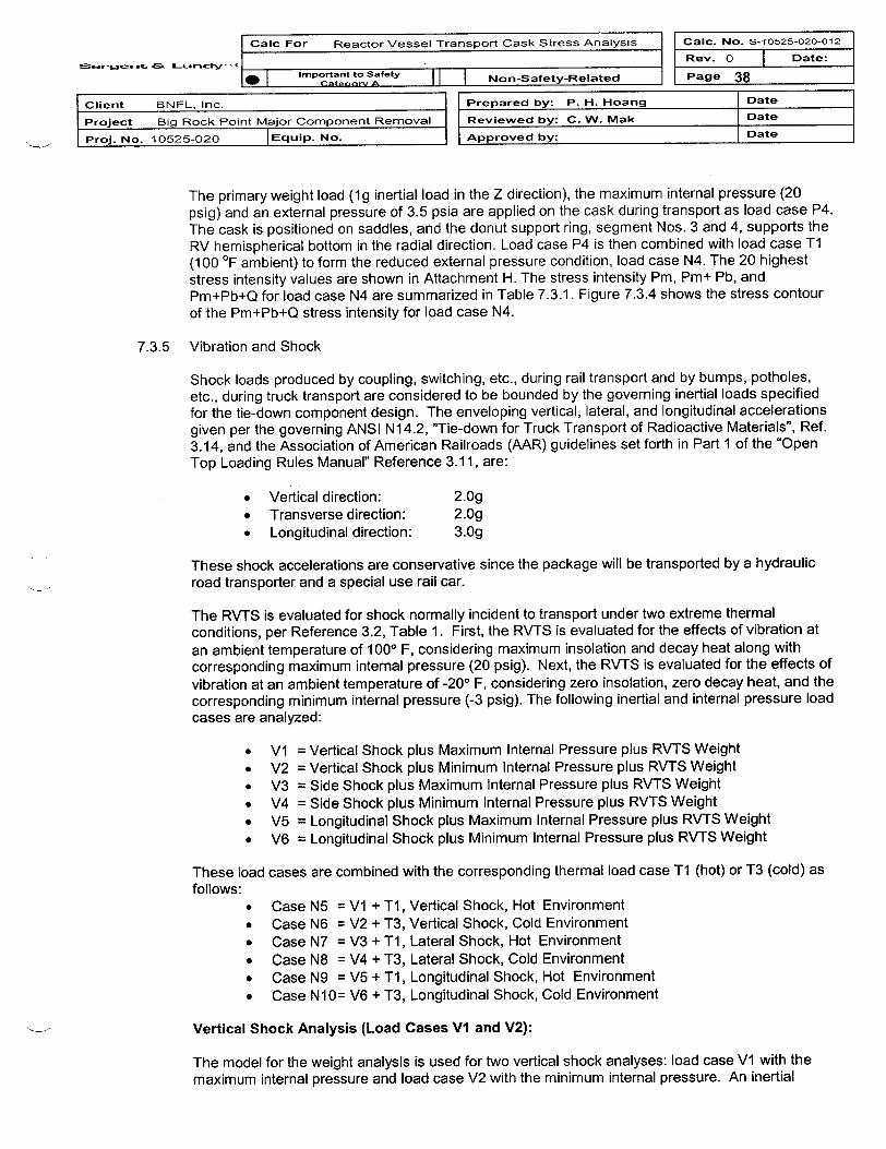
Calc For Reactor Vessel Transport Cask Stress Analysis Caic. No. S-io525-020-012
s . Rev. 0 Date:Importantto Safety ll|Non-Safety-Related Page 38
Client BNFL, Inc. Prepared by: P. H. Hoang Date
Project Big Rock Point Major Component Removal Reviewed by: C. W. Mak Date
Proj. No. 10525-020 Equip. No. Approved by: Date
The primary weight load (1g inertial load in the Z direction), the maximum internal pressure (20psig) and an external pressure of 3.5 psia are applied on the cask during transport as load case P4.The cask is positioned on saddles, and the donut support ring, segment Nos. 3 and 4, supports theRV hemispherical bottom in the radial direction. Load case P4 is then combined with load case T1(100 'F ambient) to form the reduced external pressure condition, load case N4. The 20 higheststress intensity values are shown in Attachment H. The stress intensity Pm, Pm+ Pb, andPm+Pb+Q for load case N4 are summarized in Table 7.3.1. Figure 7.3.4 shows the stress contourof the Pm+Pb+Q stress intensity for load case N4.
7.3.5 Vibration and Shock
Shock loads produced by coupling, switching, etc., during rail transport and by bumps, potholes,etc., during truck transport are considered to be bounded by the governing inertial loads specifiedfor the tie-down component design. The enveloping vertical, lateral, and longitudinal accelerationsgiven per the governing ANSI N14.2, "Tie-down for Truck Transport of Radioactive Materials", Ref.3.14, and the Association of American Railroads (AAR) guidelines set forth in Part 1 of the "OpenTop Loading Rules Manual" Reference 3.1 1, are:
* Vertical direction: 2.Og* Transverse direction: 2.Og* Longitudinal direction: 3.Og
These shock accelerations are conservative since the package will be transported by a hydraulicroad transporter and a special use rail car.
The RVTS is evaluated for shock normally incident to transport under two extreme thermalconditions, per Reference 3.2, Table 1. First, the RVTS is evaluated for the effects of vibration at
an ambient temperature of 1000 F, considering maximum insolation and decay heat along withcorresponding maximum internal pressure (20 psig). Next, the RVTS is evaluated for the effects ofvibration at an ambient temperature of -200 F, considering zero insolation, zero decay heat, and thecorresponding minimum internal pressure (-3 psig). The following inertial and internal pressure loadcases are analyzed:
* V1 = Vertical Shock plus Maximum Internal Pressure plus RVTS Weight* V2 = Vertical Shock plus Minimum Internal Pressure plus RVTS Weight* V3 = Side Shock plus Maximum Internal Pressure plus RVTS Weight* V4 = Side Shock plus Minimum Internal Pressure plus RVTS Weight* V5 = Longitudinal Shock plus Maximum Internal Pressure plus RVTS Weight* V6 = Longitudinal Shock plus Minimum Internal Pressure plus RVTS Weight
These load cases are combined with the corresponding thermal load case Ti (hot) or T3 (cold) asfollows:
* Case N5 = V1 + T1, Vertical Shock, Hot Environment* Case N6 = V2 + T3, Vertical Shock, Cold Environment* Case N7 = V3 + T1, Lateral Shock, Hot Environment* Case N8 = V4 + T3, Lateral Shock, Cold Environment* Case N9 = V5 + T1, Longitudinal Shock, Hot Environment* Case N10= V6 + T3, Longitudinal Shock, Cold Environment
Vertical Shock Analysis (Load Cases V1 and V2):
The model for the weight analysis is used for two vertical shock analyses: load case V1 with themaximum internal pressure and load case V2 with the minimum internal pressure. An inertial

I Calc For Reactor Vessel Transport Cask Stress Analysis I I Calc. No. S-10525-020-012 I
.e r K Rev. 0 Date:K Important to Safety Non-Safety-Related lPage 39
Client BNFL, Inc. Prepared by: P. H. Hoang Date
Project Big Rock Point Major Component Removal Reviewed by: C. W. Mak Date
Proj. No. 10525-020 |Equip. No. Approved by: Date
acceleration of 2g is applied to the cask vertical, downward direction. The vertical upward shock isrestrained by ten tie-down wire rope cables. The tie-down cables are qualified in a separatecalculation, Reference 3.6.6. Stress on the cask due to the vertical upward shock is bounded by thevertical downward shock load case and is not calculated in this report. The cask is positioned onthe saddles, and the donut support ring, segment Nos. 3 and 4, support the RV hemisphericalbottom in the radial direction.
Load case VI is combined with load case T1 (hot condition) to form load case N5. The 20 higheststress intensity values are shown in Attachment H. The stress intensity Pm, Pm+ Pb, andPm+Pb+Q for load case N5 are summarized in Table 7.3.1. Figure 7.3.5.1 shows the stress contourof the Pm+Pb+Q stress intensity for load case N5. Load case V2 is combined with load case T3(cold condition) to form load case N6. The 20 highest stress intensity values are shown inAttachment H. The stress intensity Pm, Pm+ Pb, and Pm+Pb+Q for load case N6 are summarizedin Table 7.3.1. Figure 7.3.5.2 shows the stress contour of the Pm+Pb+Q stress intensity for loadcase N6.
Lateral Shock Analysis (Load Cases V3 and V4):
The model for weight analysis is used for two lateral shock analyses: load case V3 with themaximum pressure and load case V4 with the minimum pressure. An inertial acceleration of 2g isapplied to the cask lateral direction, and 1g is applied in the vertical downward direction. Tie-downcables, which restrain vertical upward motion, are not modeled in the lateral shock analysis. Frictionis considered at the saddle supports to restrain the cask free body axial rotation. The cask ispositioned on saddles, and the donut support ring, segment Nos. 1 and 4, supports the RVhemispherical bottom in the radial direction.
Load case V3 is combined with load case T1 (hot condition) to form the reduced external pressurecondition load case N7. The 20 highest stress intensity values are shown in Attachment H. Thestress intensity Pm, Pm+ Pb, and Pm+Pb+Q for load case N7 are summarized in Table 7.3.1.Figure 7.3.5.3 shows the stress contour of the Pm+Pb+Q stress intensity for load case N7. Loadcase V4 is combined with load case T3 (cold condition) to form load case N8. The 20 highest stressintensity values are shown in Attachment H. The stress intensity Pm, Pm+ Pb, and Pm+Pb+Q forload case N8 are summarized in Table 7.3.1. Figure 7.3.5.4 shows the stress contour of thePm+Pb+Q stress intensity for load case N8.
Longitudinal Shock Analysis (Load Cases V5 and V6):
Due to the model and loading symmetry, half the model is used for the weight analysis during thetwo longitudinal shock analyses: load case V5 with the maximum pressure and load case V6 withthe minimum pressure. An inertial acceleration of 3g is applied to the cask longitudinal direction,and 1g is applied in the vertical downward direction. The longitudinal bumpers are located belowthe RVTS center of gravity; therefore, the tie-down cables are modeled to restrain the up-liftdisplacement resulting from the cask rotation around the bumper. The cask is positioned onsaddles, and the donut support ring, segment Nos. 1 and 2, supports the RV hemispherical bottomin the radial direction.
Load case V5 is combined with load case Ti (hot condition) to form the reduced external pressurecondition, load case N9. The 20 highest stress intensity values are shown in Attachment H. Thestress intensity Pm, Pm+ Pb, and Pm+Pb+Q for load case N9 are summarized in Table 7.3.1.Figure 7.3.5.5 shows the stress contour of the Pm+Pb+Q stress intensity for load case N9.Load case V6 is combined with load case T3 (cold condition) to form load case N10. The 20
highest stress intensity values are shown in Attachment H. The stress intensity Pm, Pm+ Pb, andPm+Pb+Q for load case N10 are summarized in Table 7.3.1. Figure 7.3.5.6 shows the stresscontour of the Pm+Pb+Q stress intensity for load case N1 0.

=
Calc For Reactor Vessel Transport Cask Stress Analysis Calc. No. S-10525-020-012
5rS~rwc Cog L-- =* ...o z* L I Rev. 0
Page 40
| Date:
I I Important to Safety I I INon-Safetv-RelatedI I U-ter1Orv- I- -I w - - - v
Client BNFL, Inc. Prepared by: P. H. Hoang Date
Project Big Rock Point Major Component Removal Reviewed by: C. W. Mak Date
Proj. No. 10525-020 Equip. No. Approved by: Date
Table 7.3.1 Stress Intensity Summary for Normal Conditions of Transport
Normal Conditions Load Primary Membrane Primary Membrane Primary Plusof Transport Case Stress plus Bending Stress Secondary Stress
No. Pm Pm+Pb Pm+Pb+Q
Node Sm Node 1.5 Node 3m MinimumNo. ksi ksi No. ksi Sm No. ksi Sm Stress
MarginHot 100 OF ambient N1 10304 1.85 23.1 966 5.41 34.65 968 7.29 69.3 6.4temp.Cold -40 OF N2 10304 2.0 23.1 3082 6.52 34.65 3082 6.4 69.3 5.4ambient temp.Increased 20 psia N3 10304 1.81 23.1 3082 6.20 34.65 3082 6.11 69.3 5.6external pressureMinimum 3.5 psia N4 3802 2.77 23.1 966 7.51 34.65 968 9.70 69.3 4.6external pressureVertical Hot N5 10304 4.62 23.1 3082 9.82 34.65 3082 9.81 69.3 3.5Shock Cold N6 10304 4.11 23.1 3082 9.36 34.65 3082 9.28 69.3 3.7Lateral Hot N7 3838 4.84 23.1 3302 18.3 34.65 3302 18.3 69.3 1.9Shock Cold N8 3838 5.20 23.1 3302 17.6 34.65 3302 17.5 69.3 2.0
Longitudinal Hot N9 10304 9.93 23.1 3082 14.9 34.65 1085 16.0 69.3 2.3Shock Cold N10 10304 9.96 23.1 3082 15.5 34.65 3082 15.4 69.3 2.21' Free Drop Hot Nil 3853 19.3 23.1 3853 19.7 34.65 3853 22.4 69.3 1.2
Cold N12 3853 19.2 23.1 3853 19.7 34.65 3853 18.5 69.3 1.2
Test Hot TP1 3802 2.67 23.1 966 7.27 34.65 968 9.44 69.3 4.8Pressure Cold TP2 3802 2.67 23.1 966 7.27 34.65 10446 6.97 69.3 4.8
Vibration Fatigue:
Vibratory motion data produced by small excitations in the cask-vehicle system is reported inNUREG/CR-0128, Reference 3.16.3, for packages that weigh more than 50,000 lbs and for travelspeeds less than 55 mph. The maximum zero-to-peak accelerations are:
* Vertical direction:* Transverse direction:* Longitudinal direction:
0.52g0.19g0.27g
These maximum accelerations are considered to be the bounding values for both road and railtransports. Based on the results of load cases N5 through N10, the maximum stress intensity,Pm+Pb, in the cask due to the above vibratory accelerations are approximated as follows:
* Vertical direction:* Transverse direction:* Longitudinal direction:
0.52g * ( 9.82 /2g ) = 2.55 ksi0.19g * (18.3 /2g ) = 1.74 ksi0.27g * (16.0 /3g ) = 1.44 psi
These stresses are the local contact stresses at the saddle support (see the stress contour for loadcases Vl through V6) that include local stress concentration. Additionally, the above contactstresses are the full range vibratory stress, which is two times the Salt stress. A peak stress index ofK = 4 is considered to envelop the stress concentration at the threaded holes for the LDCC plugsand the trunnion bolts. Hence, the maximum vibratory stress Salt is 0.5 x 4 x 2.55 = 5.1 ksi. Basedon the fatigue curve Figure 1.9.1, ASME Section III, Appendix I, at 1.OE+6 cycles, Su < 80 ksi, andE = 30E+06 psi, the endurance limit of carbon steel material is 12.5 ksi. Since the maximum

Calc For Reactor Vessel Transport Cask Stress Analysis CalIc. No. S-10525-020-012
C ms.. Lr Rev. o | Date:Important to Safety Non-Safety-Related Page 41
_ Date
r cL
BNFL, Inc. Prepared by: P. H. Hoang
Big Rock Point Major Component Removal Reviewed by: C. W. Mak
10525-020 I Eauip. No. Approved by:
Date
Date
.
- - - - - - - - . . .
vibratory stress Salt is less than the endurance limit, vibration would not have a significantcontribution in the normal condition fatigue evaluation.
The normal condition shock fatigue evaluation of the cask is conservatively based on the envelopedstress intensity range of the normal condition load cases N1 through N10. Longitudinal shock loadcases N9 and N10 are the two highest stress load cases for the normal transport shock loading. Asdiscussed above, these are the maximum local contact stresses at the saddle supports, which are2Sat stress. Stress range, 2 Sait, for the following load cases F1 through F5 are calculated based on
the alternating stress intensity definition given in Reg. Guide 7.6. (Combination rule is based onprinciple stress). These stress ranges are listed in the ANSYS Post Processing Resultsdocumented in Attachment H. The results of five extreme alternating stress ranges are as follows:
Table 7.3.2 Stress Intensity Range for Normal Conditions of Transport
Load Load Case I Load Case J Stress Range Node No.(*)Range 2 Salt (ksi)
F1 Longitudinal shock, Inc. ext. pressure, 13.5 942hot, Pmax, (N9) cold, (N3).
F2 Longitudinal shock, Min. ext. pressure, 12.3 3082cold, Pmin (N10) hot, (N4).
F3 Longitudinal shock, Vert. shock, cold, 13.0 942hot, Pmax, (N9) Pmin, (N8)
F4 Longitudinal shock, Vert. shock, hot, 12.6 10304cold, Pmin (N10) Pmax, (N7)
F5 Longitudinal shock, Zero stress state 17.3 3082hot, Pmax, (N9)
(*) Saddle Support
The maximum stress intensity range, 2Salt, is equal to 17.3 ksi, which includes the local stress atthe saddle support. This stress is less than 3Sm = 69.3 ksi. The RVTS Cask shell has four 3" ODthreaded holes, which are used to fill the RVTS with LDCC and several bolt holes at the trunnionlocations. These holes are not located near the high fatigue stress area. However, a local stressconcentration factor, K = 4 (the maximum concentration factor suggested by Reg. Guide 7.6) isused as a bounding peak stress index for fatigue evaluation. The enveloped peak stress range,which is calculated from the maximum local stress range, and the bounding stress concentration, is4 x 17.3 ksi = 69.2 ksi. The maximum alternating stress, Salt = 0.5 x 69.2 = 34.6 ksi, from which theallowable number of cycles determined from the fatigue curve shown in Figure 1.9.1, ASME SectionIll, Appendix I, Su < 80 ksi, and E = 30E+06 psi, is 1.38E+04 cycles. The number of allowablefatigue cycles is greater than the conservatively assumed number of shocks equal to 1500 cycles.The cumulative fatigue usage factor is 0.109, which is less than the allowable of 1 per Section NB-3222.4 of ASME B&PV Code, Reference 3.1. Since the fatigue usage factor is several times lessthan the allowable of 1, the shipping distance can be extended to at least twice of the of assumedvalue of 1500 miles if needed.
7.3.6 Penetration
A hand calculation, documented in Attachment E, determines the required cask shell thickness toprevent puncture caused by a vertical, steel cylinder with a hemispherical end and a diameter of1.25" weighing 13 lbs that is dropped from a height of 40" onto the exposed surface of the RVTScask. The recommended minimum design thickness calculated from the Ballistic ResearchLaboratory formula and Modified Stanford Equation, Reference 3.13, is 0.55 inch. Since the

Calc For Reactor Vessel Transport Cask Stress Analysis Calc. No. S-10525-020-012
: : __ -- ra I Ift Rev. 0 N Date:Ior~tant to Safety Non-Safety-Related Page 42
Client BNFL, Inc. Prepared by: P. H. Hoang
Project Big Rock Point Major Component Removal Reviewed by: C. W. Mak
Proj. No. 10525-020 Equip. No. Approved by:
Date
Date
Date
minimum thickness of the cask is 3", the cask shell thickness is adequate for resisting the requiredpuncture loading.
7.3.7 One-Foot Free Drop
The one-foot free drop, load cases NI 1 and N12, stresses are obtained by applying a linear scaleto the stress results for the five-foot horizontal drop, load cases 11 and 12 (documented in Section7.4.2). The linear scale is based on the ratio of the impact velocity of one-foot drop vs. five-footdrop.
For 5' free drop, the impact velocity is: V5 = 4(2*32.2*5) = 17.92 ft/s
For 1' free drop, the impact velocity is: VI = 4(2*32.2*1) = 8.01 ft/s
Therefore, the scale factor is 8.01/17.92 = 0.45.
The 20 highest stress intensity values are shown in Attachment H. The maximum primarymembrane stress intensity (Pm), primary membrane plus bending stress intensity (Pm+ Pb), andthe primary plus secondary stress intensity (Pm+Pb+Q) for load cases N11 and N12 aresummarized in Table 7.3.1. Figures 7.3.7.1 and 7.3.7.2 show the stress contour of the Pm+Pb+Qstress intensity for load cases N 11 and N 12, respectively.
7.3.8 Test Pressure
The primary weight load (1g inertial load in the Z direction) and test pressure of 30 psig are appliedon the cask as load case P5. The cask is considered in horizontal position, and the donut supportring, segment Nos. 3 and 4, support the RV hemispherical bottom in the radial direction. Load caseP5 is then combined with the thermal load cases T1 (Hot Condition,100 0F ambient) and T2 (ColdCondition, -40 OF Ambient) to form load cases TPI and TP2, respectively. The 20 highest stressintensity values are shown in Attachment H. The maximum primary membrane stress intensity(Pm), primary membrane plus bending stress intensity (Pm+ Pb), and the primary plus secondarystress intensity (Pm+Pb+Q) for load cases TP1 and TP2 are summarized in Table 7.3.1. Figures7.3.8.1 and 7.3.8.2 show the stress contour of the Pm+Pb+Q stress intensity for load cases TP1and TP2, respectively.
7.3.9 Fillet Weld Evaluation
Evaluation has been performed in section 7.4.3 to determine the adequacy of the 1 inch fillet weldbetween the shield plate and cask shell, and the 0.5" fillet weld at reinforced ring plate.
Since the weld stresses due to Handling Accident Condition loading are within the NCT stressallowable, the aforementioned weld sizes are adequate for NCT loadings.
7.3.10 RV Flange Stud & Nut Evaluation
The RV flange stud and nut evaluation for NCT is documented in the Attachment F of this report.The maximum stresses in the bolts are:
Criteria Stress (psi) Allowable Stress (psi)Tensile Stress 11,320 46,600Shear Stress 11,510 46,600
The nut minimum engagement length is 6 inches such that threads are sufficient to carry the fullload necessary to break the bolt without stripping the threads

:3-fa >:~
Calc For Reactor Vessel Transport Cask Stress Analysis
* _ I Important to Safety I I I Nnn-Satety-Related
Ca1c. No. S-10525-020-012
Rev. 0 1 Date:
Page 43
|Client BNFL, Inc.
Project Big Rock Poi
Prol. No. t10525-020
IR I C +- .or A f I I s B ~-- - _.
Prepared by: P. H. Hoang Date
nt Major Component Removal I Reviewed by: C. W. Mak Date
|Equip. No. Approved by: Date
ANSYS 5.6.2MAR 6 200108: 1 1 20PLOT NO. 2NODAL SOLUTIONSTEP-9999SINT (AVG)BOTTOMDMX =.242393SMN =10.726SMX =7289
10.726__ 2x19.403
16282437
EJ 13245r1 ,4054
= 486356716480
- 7281
ANSYS 5.6.2MAR 6 200108 11 23PLOT NO. 3NODAL SOLUTIONSTEP-9999SINT (AVC)TOPDMX -. 186586SMN =29.862SMX =5821EDn 29.862
673.338ED 1317__1960
__2604
ED3247__ 3891
453451785821
Fig.7.3.1 Hot EnviP. PrImary Flus Seoondary Streas
-IX
Fig.7.3.2 - 40 F Cold Envir.- Primaery Plus Secondary Stre

Calc For Reactor Vessel Transport Cask Stress Analysis1: 0.
L�"Cgv,-- . _
_ CaIc. No. S-10525-020-012
Rev. 0 | Date:
Page 44Important to Satety_h I Importntnt to SnTt-y II I Non-ate-Related
N I c- A *an-v I I I -
Client BNFL, Inc. Prepared by: P. H. Hoang Date
Prolect Big Rock Point Major Component Removal Reviewed by: C. W. Mak Date
Proj. No. 10525-020 |Equlp. No. Approved by: Date
ANSYS 5.6.2MAR 6 200108'11:26PLOT NO. SNODAL SOLUTIONSTEP-9999SINT (AVC)roPDMX -. 154449SMN =29.475SMX =6112
__29.475
705.315__ 1381
___ 2057__2733
340940854760
6112
dory Strese
ANSYS 5.6.2MAR 6 200108!11!29PLOT NO. 8NODAL SOLUTIONSTEP-9999SINT (AVC)BOTTOMDMX -. 275008SMN =11.542SMX =9700__ W11.542
__1088
2165E 3241
4318
=3 53946471754786249700
Plue SeoorFi .7,3.3 Inoreaeed External Preaeure Primomry
Fig.7.3.4 Minimum External Preaeure Primary Flus Seoondr ry Strese

Galc For Reactor Vessel Transport Cask Stress Analysis Calc. No. S-10525-020-012
ar-n ;r a ws- . Rev. 0 j Date:
* | Impotant to Stety | Non-Safety-Related Page 45
Client BNFL, Inc. Prepared by: P. H. Hoang Date
Project Big Rock Point Major Component Removal Reviewed by: C. W. Mak Date
Prol. No. 10525-020 |Equlp. No. Approved by: Date
ANSYS 5.6.2MAR 6 200108:11 31PLOT NO. 9NODAL SOLUTIONSTEP-9999SINT (AVG)TOPOMX -. 233414SMN =22.812SMX =9809
__22.812
1110-~ ___2198
__3285
__4372
_ U 5460__ 6547
M -7634
-. ~ '~-~r *~< ~8722
FIQ.7.3.5.1 Max P, Hot, Vartioal Shook, Pn+Pb~0 Street
ANSYS 5.6.2MAR 6 200108:11: 34PLOT NO. 11NODAL SOLUTIONSTEP-9999SINT (AMO)TOP
62007
72288256
M _ *~ iM 9284
F1g.7.3.5.2 Min P, Cold, Vertioal Shook, Pm+Pb+Q SPresn

Swor-ega ~ab LtanaV-
Calc For Reactor Vessel Transport Cask Stress Analysis
. . _.
Calc. No. S-1052-020-012
Rev. 0 | Date:
IPage 46a I Important to Safety II I Non-Safety-Related1W I < Cat nnr', I __
Client BNFL, Inc. Prepared by: P. H. Hoang Date
Project Big Rock Point Major Component Removal Reviewed by: C. W. MNak Date
Prol. No. 10525-020 |Equip. No. Approved by: Date
,_X
Streso
ANSYS 5.6.2MAR 6 200108:11: 37PLOT NO. 13NODAL SOLUTIONSTEP-9999SINT (AVO)roPDMX -. 235329SMN =82.38SSMX =18328
22.388__2110
___ 4137
___ 616481921021912246142731630118328
ANSYS 5.6.2MAR 6 200108:11:40PLOT NO. 15NODAL SOLUTIONSTEP-9999SINT (AVG)TOPDMX -.160299SMN =76.519SMX =17513
__ 76.519__2014
3951~,52899
7226976311701136381557617513
Fia.7.3.5.3 Max P, Hot, Lateral Shook, Pm+Pb+O
FIQ,7.3.5.4 Min P, Cold, Lateral Shook, Pn+Pb'Q Stress

[caic For Reactor Vessel Transport Cask Stress Analysis
Oreen a~s L~~~' ' .E Imoortant to SaNely I I I *... et.... fl..**.J
J Calc. No. S-10525-020-012
Rev. 0 Date:1-I
- I Important to Satety I I I ..-- ^ t, r l^ ^ I I Pane A7II S I Catanni a 11 I Ihr-oa~etyneavt. = - -
Client BNFL, Inc. Prepared by: P. H. Hoang Date
Project Big Rock Point Major Component Removal Reviewed by: C. W. Mak Date
Pro]. No. 10525-020 |EquIp. No. Approved by: Date
,MS
Fig.7.3.5.5 Max P, Hot, Longitudinal Shook, Fr+Pb+Q Stre
ANSYS 5.6.2MAR 6 200108:11:43PLOT NO. 17NODAL SOLUTIONSTEP-9999SINT (AVG)TOPOMX =.3019SMN =29.06SMX =15965
29.061800
__3570
___ 5341C__ 7112___ 8882
_ 1065312424
- 1419415965
84
ANSYS 5.6.2MAR 6 200108:11:45PLOT NO. 19NODAL SOLUTIONSTEP-9999SINT (AVC)TOPDMX -. 180877SMN =31.164SMX =15377
31.164___ 1736
3441___ 5146
6852___ 8557
__ 1026211967
_ 1367215377
rX
FI.9.7.3.5.6 Min P, Cold, Lonoitudinal Shook, Pm+Pb+Q SW 0e0

I Cale For Reactor Vessel Transport Cask Stress Analysis
.Sk ADs, v z-iic I . .I.p.r. c tO _ .t I I I
Cale. No. S-10525-020-012
Rev. 0 | Date:
Page 48I_ I Important to sal-Ty 11I I Non-SaQtftv-Rea~ftad|lw II I I -__
Client BNFL, Inc. Prepared by: P. H. Hoang Date
Prolect Big Rock Point Major Component Removal Reviewed by: C. W. Mak Date
Proj. No. 10525-020 |EquIp. No. Approved by: Date
ANSYS 5.6.2MAR 6 20010811:49PLOT NO. 22NODAL SOLUTIONSTEP-9999SINT (AVC}BOTTOMDMX -. 223133SMN =135.259SMX =53867
135.259610512076
__ 18046ED24016
ED2 29986359564192647897
- 53867
b+Q Stress
ANSYS 5.6.2MAR 6 200108:11:52PLOT NO. 24NODAL SOLUTIONSTEP-9999SINT (AVC)BOTTOMDMX -. 170105SMN =190.698SMX =54412
190.698ED 6215ED 12240EJ 18265ED 24289
303314ED] 36338
42363- 48388
54412
Fig.7.3.7.1 1' Horizontal Drop, Hot, Max Preosure, Pm-F+,
Fig.7.3.7.2 1' Hor izontal Drop, Cold, Min Preosure, PMA +Pb+Q Stress

JEL--jM- AN H: ~ .
Calc For Reactor Vessel Transport Cask Stress Analysis
Important to Safety | Nn-Satety-Relatedel rt..- A -- I NnSft-eae
Calc. No. S-10525-020-012
Rev. 0 1 Date:
Page 49
Client BNFL, Inc.
Prolect Big Rock Point Major Component Removal
Pro]. No. 10525-020 |Equip. No.
.- - 4I i h P H 4on I Date
IRevewed by: C. W. Mak Date
Approved by: Date
T xt"X
Fi .7. 3.8.1 Teat Press ure- Pr i ar ; PI us Se condary $IreesF
ANSYS 5.6.2MAR 6 200108:11:54PLOT NO. 26NODAL SOLUTIONSTEP-9999SINT (AtVCBOTTOMDMX -. 271513SMN =15.99SSMX =9442___ 15.998
10632111
___ 3158,- _ 4205
525363007347
_ 83S59442
(Hot Condition)
ANSYS 5.6.2MAR 6 200108:11:57PLOT NO. 28NODAL SOLUTIONSTEP-9999SINT (AVG)BOTTOMDMX -. 188167SMN =33.496SMX =6973
33.496804.5251576234731183889
___ 46605431
- 62026973
Fig.7.3.8.2 Teat Pressure Prinary Plus Seonodary Stress (Cold Condition)

Calc For Reactor Vessel Transport Cask Stress Analysis Calc. No. S-10525-020-012
Rse. v. 0 Date:CImortant to Safety Non-Safety-Related Page 50
Client BNFL, Inc. Prepared by: P. H. Hoang Date
Project Big Rock Point Major Component Removal Reviewed by: C. W. Mak Date
Proj. No. 10525-020 Equip. No. Approved by: Date
7.4 Handling Accident Conditions
As discussed in Section 4.2, the RVTS is evaluated for several handling accident load cases with thefollowing two initial conditions:
* A hot environment with an ambient temperature of 1000 F, considering maximum insolation anddecay heat along with the corresponding maximum internal pressure (20 psig).
* A cold environment with an ambient temperature of -200 F, considering zero insolation, zero decayheat, and the corresponding minimum internal pressure (-3 psig).
* 11 = 5' Horizontal Drop with Maximum Internal Pressure* 12 = 5' Horizontal Drop with Minimum Internal Pressure* 13a = 5' Oblique Drop First Impact with Maximum Internal Pressure* 14a = 5' Oblique Drop First Impact with Minimum Internal Pressure* 13b = 5' Oblique Drop Second Impact with Maximum Internal Pressure* 14b = 5' Oblique Drop Second Impact with Minimum Internal Pressure
These load cases are combined with the corresponding thermal load cases Ti (hot) and T3 (cold) asfollows:
* Case Al = 11 + T1, 5' Horizontal Drop, Hot Environment* Case A2 = 12 + T3, 5' Horizontal Drop, Cold Environment* Case A3a = 13a + TI, 5' Oblique Drop First Impact, Hot Environment* Case A4a = 14a + T3, 5' Oblique Drop First Impact, Cold Environment* Case A3b = 13b + TI, 5' Oblique Drop Second Impact, Hot Environment* Case A4b = 14b + T3, 5' Oblique Drop Second Impact, Cold Environment
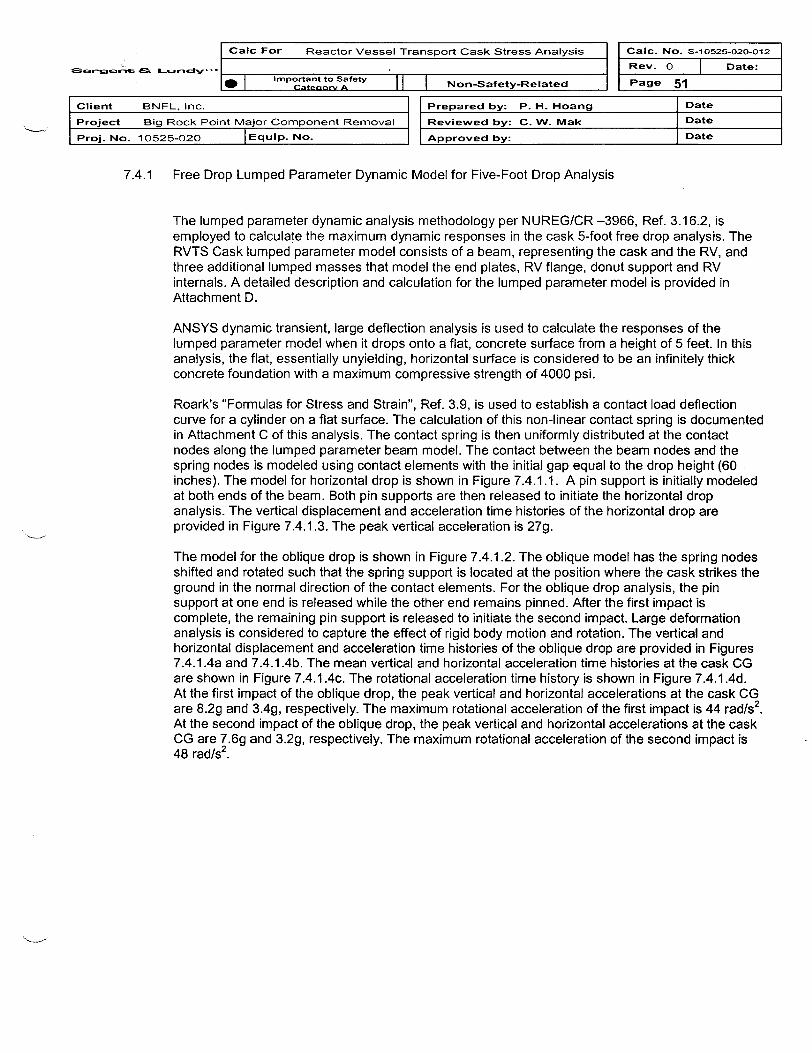
Caic For Reactor Vessel Transport Cask Stress Analysis Caic. No. S-10525-020-012
j .. 0 .~.,..-Rev. 0 Date:5mportan to Ska-ty,'' I.Impotantto Safety ll|Non-Safety-Related Page 51
Client BNFL. Inc. Prepared by: P. H. Hoang Date
Project Big Rock Point Major Component Removal Reviewed by: C. W. Mak Date
Proj. No. 10525-020 IEquip. No. Approved by: Date
7.4.1 Free Drop Lumped Parameter Dynamic Model for Five-Foot Drop Analysis
The lumped parameter dynamic analysis methodology per NUREG/CR -3966, Ref. 3.16.2, isemployed to calculate the maximum dynamic responses in the cask 5-foot free drop analysis. TheRVTS Cask lumped parameter model consists of a beam, representing the cask and the RV, andthree additional lumped masses that model the end plates, RV flange, donut support and RVinternals. A detailed description and calculation for the lumped parameter model is provided inAttachment D.
ANSYS dynamic transient, large deflection analysis is used to calculate the responses of thelumped parameter model when it drops onto a flat, concrete surface from a height of 5 feet. In thisanalysis, the flat, essentially unyielding, horizontal surface is considered to be an infinitely thickconcrete foundation with a maximum compressive strength of 4000 psi.
Roark's "Formulas for Stress and Strain", Ref. 3.9, is used to establish a contact load deflectioncurve for a cylinder on a flat surface. The calculation of this non-linear contact spring is documentedin Attachment C of this analysis. The contact spring is then uniformly distributed at the contactnodes along the lumped parameter beam model. The contact between the beam nodes and thespring nodes is modeled using contact elements with the initial gap equal to the drop height (60inches). The model for horizontal drop is shown in Figure 7.4.1.1. A pin support is initially modeledat both ends of the beam. Both pin supports are then released to initiate the horizontal dropanalysis. The vertical displacement and acceleration time histories of the horizontal drop areprovided in Figure 7.4.1.3. The peak vertical acceleration is 27g.
The model for the oblique drop is shown in Figure 7.4.1.2. The oblique model has the spring nodesshifted and rotated such that the spring support is located at the position where the cask strikes theground in the normal direction of the contact elements. For the oblique drop analysis, the pinsupport at one end is released while the other end remains pinned. After the first impact iscomplete, the remaining pin support is released to initiate the second impact. Large deformationanalysis is considered to capture the effect of rigid body motion and rotation. The vertical andhorizontal displacement and acceleration time histories of the oblique drop are provided in Figures7.4.1.4a and 7.4.1.4b. The mean vertical and horizontal acceleration time histories at the cask CGare shown in Figure 7.4.1.4c. The rotational acceleration time history is shown in Figure 7.4.1.4d.At the first impact of the oblique drop, the peak vertical and horizontal accelerations at the cask CGare 8.2g and 3.4g, respectively. The maximum rotational acceleration of the first impact is 44 rad/s2.At the second impact of the oblique drop, the peak vertical and horizontal accelerations at the caskCG are 7.6g and 3.2g, respectively. The maximum rotational acceleration of the second impact is48 rad/s2.

I1 Caic. No. S-10525-020-012
Sto- Wic _ LA-dst --
| Calc For Reactor Vessel Transport Cask Stress Analysis---- 4'
I Rev. 0
lpage!
I Date:_ I Important to Safety I I I - -,o -v Ro -4
Client BNFL, Inc.
Project Big Rock Poi
P rol . No . 1 05 2 5-020
_I I I ' -- -
Prepared by: P. H. Hoang Date
nt Major Component Removal IReviewed by: C. W. Mak Date
IEquip. No. Approved by: Date
Figure 7.4.1.1: Horizontal Drop Beam Model
Top
60"
Figure 7.4.1.2: Oblique Drop Beam Model

Sarerat a La" *n
Calc For Reactor Vessel Transport Cask Stress Analysis
a I Important to Satety I I Non-Safte-Related
Calc. No. S-10525-020-012
Rev. 0 Date:
Page 53
Client BNFL, Inc.
Prolect Big Rock Point Major Component Removal
Proj. No. 10525-020 Equlp. No.
, . . # y . . , - . . _ .-- . _
Prepared by: P. H. Hoang Date
Reviewed by: C. W. Mak Date
Approved by: Date
N
30-16>
20-1
C
0
L.a)
I"a)
V
0
Lo
C
(O
10-
0-
-10-
-20
-30-
-40-
AccTop
ZAecc-Mid
UyBot
UyMid-50-
-60-
-70 (x1O**-1)
0 1.5
21.5
I i I i3 4 5
2.5 3.5 4.5TIME (sec)
65.5 6.5
Figure 7.4.1.3 5' HorizDntal Drop Displacement and Acceleration
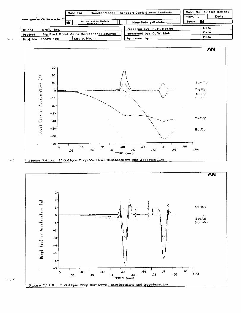
I Calc For Reactor Vessel Transport Cask Stress Analysis
L�-c*Wll-
L�T
_ Caic. No. S-10526-020-012
Rev. 0 Date:
Page 54mpra - .I0 I IImportant to tia-Tey II I Nmn-Safetv-Related
I I CIt I ___.
Client BNFL, Inc. Prepared by: P. H. Hoang Date
Prolect Big Rock Point Major Component Removal Reviewed by: C. W. Mak Date
Prol. No. 10525-020 |Equip. No. Approved by: Date--
AN
30-
1020 -
00
___ TopAy
-10-
*<C -20
-30
- -0MidUy.Z -40
_ \-0 BotUy
-60-
. -70 I I
0 .16 .32 A8 .64 .8 .96.08 .24 .4 .56 .72 .88 1.04
TIME (sec)
Figure 7.4.1.4a 5' Oblique Drop Vertical Displacement and Acceleration
AN
3--
2-
=I Mi dAx
-2 Bo-tjx
_ -|A
O -5
.16 .32 A8 .64 .8 .96.08 .24 .4 .56 .72 .88 1.04
TIME (sec)
Figure 7A.1.4b 5' Oblique Drop Horizontal Displacement and Acceleration

Oalc For Reactor Vessel Transport Cask Stress Analysis
Srfleflt a& L~a-snalr* i . . . .. - l. l
Calc. No. S-10625-020-012
Rev. 0 | Date:
Page 55Ia I Important to SaoTy II I Nnn-Satetv-RelatedI -nr I | | | ,, ,. . _ .__ - __---I- --
Client BNFL, Inc. Prepared by: P. H. Hoang Date
Project Big Rock Point Major Component Removal Reviewed by: C. W. Mak Date
Prol. No. 10525-020 IEquip. No. Approved by: Date
AN
8.75
__. 7.5
=6-25
2.5
1.250
.- 3.750
Cz 2.5
° 1.25. Medans
-3.750 .16 .32 .48 .64 .8 .96
.08 .24 .4 .56 .72 .88 1.04TIME (sea)
Figure 7.4.1.4c 5' oblique Drop Mean Vertical and Horizontal Acceleration
NA
04 5
40
N 30-
20
°2 10
0
41" -10-
'- -20-
-30-
-40
-50
0 .16 .32 A8 .64 .8 .96.08 24 A .56 .72 .88 1.04
TIME (sec)
Figure 7.4.1.4d 5' Oblique Drop Angular Acceleration

Calc For Reactor Vessel Transport Cask Stress Analysis Caic. No. S-10525-020-012
52v~erc. v~rd^A. 0 | -Date:_- Important to Safety Page 56
s O~lteory A _ |Non-Safety-RelatedPae 5
Client BNFL, Inc. Prepared by: P. H. Hoang Date
Project Big Rock Point Major Component Removal Reviewed by: C. W. Mak Date
Proj. No. 10525-020 Equip. No. Approved by: Date
7.4.2 Five-foot Free Drop Stress Analyses
The peak impact accelerations in both the vertical and horizontal directions are applied to the RVTSthree-dimensional finite element model for stress recovery and structural buckling analyses. Sincethe lumped parameter dynamic analysis captures the maximum structural dynamic responses andthe effects of free body motion and rotation, no dynamic load factor is applied in the stress recoveryanalyses. Due to loading and geometric symmetry, only a half model of the cask is used. The RVbottom radial support at the donut ring are activated. Rigid supports are modeled for nodes thatcontact with the flat horizontal surface. The large deformation analysis option is used to checkbuckling of the RVTS Cask shell.
An impact acceleration of 27g is applied in the vertical direction for the horizontal drop analysis forboth the maximum and minimum internal pressure conditions. These analyses are labeled as 11, 12and are combined with thermal load cases Ti (hot) and T3 (cold) to form the accident conditionload cases Al and A2, respectively. The 20 highest stress intensity values are shown in AttachmentH. The stress intensity Pm and Pm+ Pb, for load cases Al and A2, are summarized in Table 7.4.1.Figures 7.4.2.1 and 7.4.2.2 show the stress contours of the Pm+Pb+Q stress intensity for loadcases Al and A2, respectively.
For the oblique drop analyses, the model is kept the same in the global coordinates, but the impactsurface and the impact acceleration directions are rotated an angle of 11.54 degrees (arcsin of60/300). Pin supports are modeled at the flat surface contact nodes of the top and the bottomplates. For the oblique drop first impact analysis, the top plate strikes the horizontal surface with animpact of 8.2g in the vertical direction and 3.4 g in the horizontal direction. The angular accelerationis 44 rad/s2 , and the center of the angular acceleration is the pin support at the cask bottom plate.The 20 highest stress intensity values are shown in Attachment H. The stress intensity Pm andPm+ Pb, for load cases A3a and A4a, are summarized in Table 7.4.1. Figures 7.4.2.3a and7.4.2.4a show the stress contours of the Pm+Pb+Q stress intensity for load cases A3a and A4a,respectively.
For the oblique drop second impact analysis, the bottom plate strikes the horizontal surface with animpact of 7.6g in the vertical direction and 3.2 g in the horizontal direction. The angular accelerationis 48 rad/s2, and the center of the angular acceleration is the pin support at the cask top plate. The20 highest stress intensity values are shown in Attachment H. The stress intensity Pm and Pm+ Pb,for load cases A3b and A4b, are summarized in Table 7.4.1. Figures 7.4.2.3b and 7.4.2.4b showthe stress contours of the Pm+Pb+Q stress intensity for load cases A3b and A4b, respectively.
The local stress occurring directly on the flat end plates of the impact contact area is consideredsecondary stress. Yielding due to high local bearing stress will increase the contact area, thus,reducing the average bearing stress. Therefore, the local stress intensity directly at the contact areawill be checked under the provisions of the Regulatory Position No. 7, Reg. Guide 7.6, for theextreme total stress range. The extreme handling accident stress intensity range of the RVTS isshown in Table 7.4.2.
For both the horizontal and the oblique drop analyses, the cask remains stable. No buckling occursas indicated by the convergence of the solution under the impact load.

I Calc For Reactor Vessel Transport Cask Stress Analysis i I Calc. No. S-10525-020-012
--- L---.;tV ... I _ Rev. 0Paae
I Date:1*m I Important to Safety II I I -R f -R It- 57I I (fte prIf I I p . I
Client BNFL, Inc. Prepared by: P. H. Hoang Date
Project Big Rock Point Major Component Removal Reviewed by: C. W. Mak Date
Proj. No. 10525-020 |Equip. No. Approved by: Date
Table 7.4.1 Stress Intensity Summary for Handling Accident Conditions
Handling Accident Load Primary Membrane Stress Primary Membrane plusConditions Case Intensity(*) Bendin Stress Intensity (*)
No. Node No. Pm Lesser of Node No. Pm+Pb Lesser of Minimumksi 2.4Sm ksi 3.6Sm Stress
Or Or Su Margin0.7Su ksi
ksi
5 Ft Horizontal Hot Al 3853 42.81 49 3853 43.88 70 1.14Drop Cold A2 3853 42.75 49 3853 43.79 70 1.15
5 Ft First Hot A3a 1117 30.99 49 968 53.58 70 1.31Oblique Drop Cold A4a 1117 31.00 49 968 51.68 70 1.355 Ft Second Hot A3b 3802 46.99 49 3802 46.99 70 1.04Oblique Drop Cold A4b 3802 45.12 49 3802 45.12 70 1.09
(*) Maximum stress intensity at the maximum principal stress locations.
Pm+Pb stress intensity at the maximum compression stress due to impact contact stress is bearing stress, and isevaluated in the extreme alternating stress range.
The results of four extreme alternating stress ranges are as follows:
Table 7.4.2 Extreme Stress Intensity Range for Handling Accident Conditions
Load Load Case I Load Case J Node 2 x Alternating Half Peak Allowable StressRange No. Stress Stress Stress Sa Margin(I -J) 2Sa1t (ksi) Intensity(*) ksi
KSait (ksi) |_ llF6 5 Ft Horizontal Drop, Cold -40 'F, (N2) 1073 121.90 243.80 580 2.38
hot, Pmax, (Al)_F7 5 Ft Horizontal Drop, Hot 100 'F, (Ni) 1073 119.14 238.28 580 2.43
cold, Pmin (A2) _ _ _
F8 5 Ft Horizontal Drop, Longitudinal Shock, 1073 114.59 229.18 580 2.53hot, Pmax, (Al) Cold, (NlG)___
F9 5 Ft Horizontal Drop, Zero Stress State 1073 123.24 246.48 580 2.35hot, Pmax, (Al) _ _ _
Note: 1. (*) Conservatively include a peak stress index of K = 4.2. Table 7.4.2 is also applicable for NCT cases since stresses resulted from Handling Accident Conditions
envelope stresses from NCT and the allowable stress Sa is the same for both conditions.

~15_g- L~srdotv IX -
Calc For Reactor Vessel Transport Cask Stress Analysis Caic. No. S-10525-020-012
Rev. 0 Date:Important to Safety Non-Safety-Related Page 58
Client BNFL, Inc. I Prepared by: P. H. Hoang I Date
i Project Big Rock Point Major Component Removal Reviewed by: C. W. Mak Date
IProj. No. 10525-020 _ Eqip. No Approved by: Date
7.4.3 Fillet Weld Evaluation
For evaluating the adequacy of the fillet weld sizes between:
1. Shield Plate and Cask Shell, and
2. Reinforced Ring Plate and Cask Shell,
the resultant stresses acting on the subject welds are calculated and then compared to theallowable weld stress. By inspecting the stress level summarized in Table 7.4.1, the loads from loadcase Al (Horizontal, Hot), A4a (Oblique Drop First Impact, Cold) and A3b (Oblique Drop SecondImpact, Hot) are chosen as the governing load cases for evaluation. The physical properties of thewelds are listed as follows:
Location, i Weld Size, Wi Weld Length, Li Number of(inch) (inch) Weld, Ni
Shielding Plate, A 1 75 * 3.1416 = 235.62 2Reinforced Ring Plate, B 1 75 * 3.1416 = 235.62 2
The resultant stresses in the welds are calculated as follows:
4( Fx2 + Fyz + FzL)Sw=
0.707 * Wi * Li * Ni
where Fx is the axial force and Fy and Fz are the shear forces in the local cylindrical coordinate andobtained from ANSYS output (Weld1.out) documented in Attachment H.
Table 7.4.3 Fillet Weld Check for NCT/Handling Accident Condition
Location Load case Fx Fy Fz Sw(Ibs) (Ibs) (Ibs) (psi)
Shield Plate Al 18,723 986,330 173 2,961A4a 6,572 767,910 174,000 2,363A3b 62,215 782,570 276,090 2,497
Reinforced Ring Al 19,567 290,940 188 1,750Plate A4a 7,240 143,980 54,769 925
A3b 57,259 354,990 86,774 2,220
Since all calculated weld stresses as shown in Table 7.4.3 are below the NCT stress allowable of0.3*70,000 = 21,000 psi, the aforementioned weld sizes are adequate for all NCT and HandlingAccident Condition loadings.
7.4.4 RV Flange Stud and Nut Evaluation
The RV flange stud and nut evaluation for handling accident events is documented in theAttachment F of this report. The maximum stresses in the bolts are:
Criteria Stress (psi) Allowable Stress (psi)Tensile Stress 39,580 70,000Shear Stress 28,920 42,000
Interaction Ratio 0.79 1
The nut minimum engagement length is 6 inches such that threads are sufficient to carry the fullload necessary to break the bolt without stripping the threads

Smwan"w~ As Lamnrvc .
Calc For Reactor Vessel Transport Cask Stress Analysis
.* Important to Safety Non-Safety-Related_~,,, A_.T -- -o -S ft-ea
Calc. No. s-10525-020-012
Rev. 0 | Date:
Page 59
Client BNFL, Inc. Prepared by: P. H. Hoang Date
Project Big Rock Point Major Component Removal Reviewed by: C. W. Mak Date
Prol. No. 10525-020 |Equip. No. Approved by: Date
ANSYS 5.6.2MAR 6 200108: 13:13PLOT NO. 40NODAL SOLUTIONSTEP-9999SINT (AVQ)BOTTOMDMX -.273176SMN =425.02SMX =120374
__425.02
1375327080
93719107046120374
FiQ.7.4.2.1 5' Horizontal Drop, Hot, Max Pressure, Pm+ b+O Stress
ANSYS 5.6.2MAR 6 200108: 13: 15PLOT NO. 42NODAL SOLUTIONSTEP-9999SINT C AVC)BOTTOMDMX -. 222496SMN =541.889SMX =120287_ 3-541,899
ED27152ED40457ED53762
67067803U7293677106,982120287
FiQ.7.4.2.2 5' Horizontal Drop, Cold, Min Pressure Pm+F b+O Stress

I r |
Calc For Reactor Vessel Transport Cask Stress Analysis
L,.n;w
- i | Calc. No. S-10525-020-012
.. Important to Safety Non-Safety-Related
Rev. 0
Page
I Date:
60
Client BNFL, Inc.
Project Big Rock Point Major Component Removal |
Prol. No. 10525-020 |Equip. No.
Prepared by: P. H. Hoang Date
Reviewed by: C. W. Mak Date
Approved by: Date
ANSYS 5.6.2MAR 6 200108: 1318PLOT NO. 44NODAL 6OLUIIONSTEP-9999SINT (AVG)BOTTOMDMX -. 379384SMN =254.651SMX =90561
254.651___ 10289
20323303574039150425604597049380527
M 90561
m+Pb+Q Streoe
ANSYS 5.6.2MAR 6 200108: 13:23PLOT NO. 47NODAL SOLUTIONSTEP-9999SrNT (AVG)TOPDMX -. 279SMN =321.822SMX =78704
321.828903117740
_ 26449351584386752576
__61285
69S9578704
Fig.7.4.2.3o 5' ObIque Firet Drop, Hot, Max PreOeuro F
VPr-eotupr Pm+Pb+Q StreeeFig.7,4.2.3b 5' Oblique Second Drop, Hot, Max

I Calc For Reactor Vessel Transport Cask Stress Analysis I |- ICal. No. S-10525-020-012
._~ aLrwdstv .. r 1ortant to Safety
. Non-Safety-RelatedPage
I Date:
61
Client BNFL, Inc.
Project Big Rock Point Major Component Removal
Prol. No. 10525-020 |Equip. No.
. .
Prepared by: P. H. Hoang Date
Reviewed by: C. W. Mak Date
Approved by: Date
Fig.7.4.2.4a 5' Oblique Firet Drop, Cold, Mln Preeaure
ANSYS 5.6.2MAR 6 200108 13: 20PLOT NO. 46NODAL SOLUTIONSTEP=9999SINT (AVC)BOTTOMDMX - . 192874SMN =233.313SMX =90687
233.31310284
___ 20334
30384___ 40435___ 50485
60536705868063690687
Pm+Pb+Q Strees
ANSYS 5.6.2MAR 6 200108: 13 26PLOT NO. 49NODAL SOLUTIONSTEP-9999SINT (AVG)roPDMX - .39363SMN =256.624SMX =79008
256.6249007
E___ 17757
__ 2650735257
__ 44007__52758
615087025879008
Flg.7.4.2.4b 5' Oblique Second Drop, Cold, Mln Pre eu r m SPm+Fb+O Stress
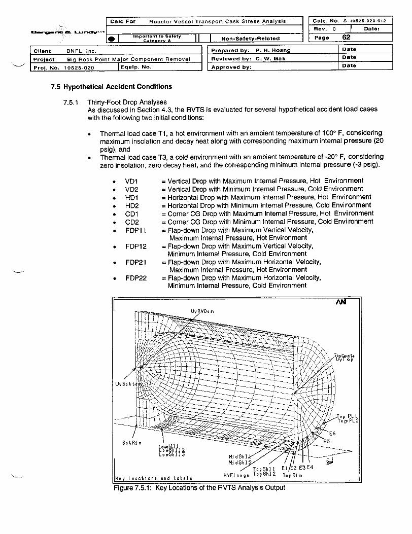
-
I Calc For Reactor Vessel Transport Cask Stress Analysis
Mr- -W ... .FI Calic. No. s-10626-020-012
Rev. 0 D Date:
Page 62Important to Safety Non-Safety-Related-
Client BNFL, Inc. Prepared by: P. H. Hoang Date
Project Big Rock Point Major Component Removal Reviewed by: C. W. Mak Date
Prol. No. 10525-020 |Equlp. No. Approved by: Date
7.5 Hypothetical Accident Conditions
7.5.1 Thirty-Foot Drop AnalysesAs discussed in Section 4.3, the RVTS is evaluated for several hypothetical accident load caseswith the following two initial conditions:
* Thermal load case T1, a hot environment with an ambient temperature of 1000 F, consideringmaximum insolation and decay heat along with corresponding maximum internal pressure (20psig), and
* Thermal load case T3, a cold environment with an ambient temperature of -200 F, consideringzero insolation, zero decay heat, and the corresponding minimum internal pressure (-3 psig).
* VD1 = Vertical Drop with Maximum Internal Pressure, Hot Environment* VD2 = Vertical Drop with Minimum Internal Pressure, Cold Environment* HD1 = Horizontal Drop with Maximum Internal Pressure, Hot Environment* HD2 = Horizontal Drop with Minimum Internal Pressure, Cold Environment* CD1 = Corner CG Drop with Maximum Internal Pressure, Hot Environment* CD2 = Corner CG Drop with Minimum Internal Pressure, Cold Environment* FDP1 1 = Flap-down Drop with Maximum Vertical Velocity,
Maximum Internal Pressure, Hot Environment* FDP12 = Flap-down Drop with Maximum Vertical Velocity,
Minimum Internal Pressure, Cold Environment* FDP21 = Flap-down Drop with Maximum Horizontal Velocity,
Maximum Internal Pressure, Hot Environment* FDP22 = Flap-down Drop with Maximum Horizontal Velocity,
Minimum Internal Pressure, Cold Environment
7.5.1: Key Locations of the RVTS Analysis Output

Calc For Reactor Vessel Transport Cask Stress Analysis Calc. No. S-10525-020-012
i. KRev. 0 Date:8 Important to Safety Non-Safety-Related Page 63
Client BNFL, Inc. | Prepared by: P. H. Hoang Date
Project Big Rock Point Major Component Removal Reviewed by: C. W. Mak Date
Prol. No. 10525-020 JEquip. No. Approved by: Date
7.5.1.1 Vertical Drop on the Cask Bottom Plate (Cases VD1 and VD2)
The initial conditions for the VD analyses include nodal temperatures from thermal load cases T1and T3, pressures of 20 psi and -3 psi as described in 10 CFR 71, and an initial vertical impactvelocity of 527.4 in/sec, which is the impact velocity of a 30-feet drop. Contact between the bottomplate and the essentially unyielding, horizontal surface are modeled along with the contact betweenthe RV head and the bottom plate. The output files, VDPlWeld.out and VDP2Weld.out, aredocumented in Appendix H. The RV bottom head reaches its maximum vertical displacement of -4.314 inches (Figure 7.5.1.1a for VD1) and contacts the bottom plate. The maximum displacementat the center of top plate is - 1 0.06inches (Figure 7.5.1.1 b for VD2). The expected high stresslocations are at the center of the top plate, the top plate rim and the lower shell junction to the donutplate. The maximum principal stress time histories at these locations are shown in Figures 7.5.1.1cand 7.5.1 .ld. During the impact duration, the peak value of the maximum principal stress is Si =50ksi at time T = 0.005312 second, case VD2. This is less than the material tensile strength of 70 ksi.Typical Si stress contours are shown in Figure 7.5.1.1e. The cask gross structure remains intactafter the impact. Therefore, no containment failure and no gross buckling failure in the RRVTS caskresult from the 30-foot vertical drop. The maximum bolt stress intensity is 93.7 ksi which is less thanSu =100 ksi. Typical Si stress contours are shown in Figure 7.5.1.1.e. The maximum vertical andhorizontal displacements are shown in the following figures:
AN
.2
UyBottom
-2.
UyRVDo me
;108-21
0 .25 .5 .75 1 1,25 1.5.L25 .3715 .626 .870 1.125 1,375 1.625
TIME (seo)
30-ft Vet1loal Drop - Hot Conditlon
Figure 7.5.1.1 a: VD1 Vertical Displacement Time History

v3e-1_ f FS ~V4 .Calc For Reactor Vessel Tre
11F
ansport Cask Stress Analysis Caic. No. 5-10625-020-012
Rev. 0 F Date:
I Non-Safety-Related Page 64_, |Important to Safety1W I -- A - I
Client BNFL, Inc. IProject Big Rock Point Major Component Removal
Pro]. No. 10525-020 |Equip. No.
Prepared by: P. H. Hoang Date
Reviewed by: C. W. Mak Date
Approved by: Date
AN
2.2
I
0.
0
-1_21
iI
Uysottom
UyRVDo me
-2.1
-3.7
-6.2T
-7.t
-s. 7
-IC
-I1, -I , , l
0 .25 .5.125 .375
.7fi
.625 .875
TIME (sec)
( .1084-2)
I 1. 25 1.51.125 1.375 1.625
.i0-et v. et .-1 Ton n - CId Condi tIon- . . � � . . . . - . - - - I - - - -
Figure 7.5.1 .lb: VD2 Vertical Displacement Time History
AN
(XIOW*)500(450
I Topcentn400(4
o 35 .
TopRim2
E 2M
200( Lowshl 1 2
0 515 7 12 1
.0 25 376 .625 1.125 1.375 1.625
TIME (eeo)
30-fl Vertloal Drop - Hot Condition
Figure 7.5.1.1c: VD1 Maximum Principal StressTime History

I Calc For Reactor Vessel Transport Cask Stress Analysis '1:3-&W f Mr:: ,w rI- I
Calc. No. S-10525-020-012
Rev. 0 | Date:
Page 65.g | Important to Safety Non-Safety-Related
Client BNFL, Inc. Prepared by: P. H. Hoang Date
Project Big Rock Point Major Component Removal I Reviewed by: C. W. Mak Date
Prol. No. 10525-020 |Equip. No. Approved by: Date
AN
(x0*
° 80C0
- 720(
no 640
: 480
E 400
Jl)
E
e.
02
320
240
201
80'
TopRim2
LVIw I 1TopCenlt
0 25 F .75 1 1 25 1.5.125 637 .625 .870 1.120 1.370 1.620
2
t
TIME (*oo)
30-f't VertloI1 DPOD - Cold Conditlon
Figure 7.5.1.1d: VD2 Maximum Principal StressTime History
ANSYS 5.6.2MAR 1-3 200117: 24: 15PLOT NO. 4NODAL SOLUTIONTIME- .015967iS (AVC)TOPOMX -8.902SMX =-52846
__5972
1174417615
4 11024697452846
::%X
Vertloel Drop On Bottoin Plate - Hot Condition
Figure 7.5.1.1e: VD1 Maximum Principal Stress Contours

Caic For Reactor Vessel Transport Cask Stress Analysis Caic. No. S-10525-020-012
8 o - Rev. 0 | Date:
* Important to Safety Non-Safety-Related Page 66
Client BNFL, Inc.
Project Big Rock Point Major Component Removal
Prol. No. 10525-020 |Equip. No.
Prepared by: P. H. Hoang Date
Reviewed by: C. W. Mak Date
Approved by: Date
ANSYS 5.6.2MAR 13 200117: 25:08PLOT NO. 6NODAL SOLUTIONTIME-.016UY (AMCRSYS-0PowerCrop hi coEFACET=IAVRES=MotDMX =9.746SMN =-9.746SMX =.015724
-9.746-8.661
cl -7.576Cl -6.492
-5.407Go -4.323
-3.238E - 2 153
.015724
ANSYS 5.6.2MAR 13 2001[7:24:18PLOT NO. 7NODAL SOLUTIONTIME- .015967UZ (AVC)RSYS-0PowerCrophi csEFACET=IAVRES=MatDMX =8.902SMN =-1.143SMX =1.163go -1'143
- .886621go - .630369_ -. 374117_ -. 117866
.138386
.394638
.65089.9071421.163
VertIcal Oro On Botton Plate - ColId CondiIion
Figure 7.5.1.1f: VD2 Vertical Displacement Contours
IN
;:. C
Vertiool Drop On Bottom Plate - Hot Condition
Figure 7.5.1.1 g: VD1 Horizontal Displacement Contours

I Caic For Reactor Vessel Transport Cask Stress Analysis
,, r f La..r s .1 .rCalc. No. S-10525-020-012
Rev. 0 | Date:
Page 67Important to Safety N ae- t.1 I Category A I I I Non-Safety-Related
Client BNFL, Inc.
Project Big Rock Point Major Component Removal
Proj. No. 10525-020 lEqulp. No.
Prepared by: P. H. Hoang Date
Reviewed by: C. W. Mak Date
Approved by: Date
AN
(x lOtt2) b oI t5100 l
b el t 2
9 t .
70
100
o~~~~ L IlO t -21
0 .25 . 75 I 1.26 1.5.375 .62 75 187 1.125 1 .375 1. 625
TIME (teo)
30-ft Vertloal Drop - Hot Condit-lon
Figure 7.5.1.1 h: VD1 Bolt Stress Intensity Time History
7.5.1.2 Horizontal Drop (Cases HD1 and HD2)
The initial conditions for the HD analyses include nodal temperatures from thermal load cases T1and T3, pressures of 20 psi and -3 psi as described in 10 CFR 71, and an initial vertical impactvelocity of 527.4 in/sec, which is the impact velocity of a 30-foot drop. Contact between the caskshell and the essentially unyielding, horizontal surface is modeled along with the contact betweenthe RV flange and the cask shell. The center of top plate reaches its maximum verticaldisplacement of -6.878 inches at time 0.01 995 second (Figure 7.5.1.2b - Case HD2). Themaximum principal stress time histories at the top plate rim near the impact location are shown inFigures 7.5.1 .2c and 7.5.1.2d. During the impact duration, the peak value of the maximum principalstress is S1 = 67.95 ksi at time 0.01843 second, case HD1. This is less than the material tensilestrength of 70 ksi. The cask gross structure remains intact after the impact. Therefore, nocontainment failure and no gross buckling failure in the RVTS cask result from the 30-foothorizontal drop. The maximum bolt stress intensity is 91.85 ksi which is less than Su =100 ksi.Typical results at the time when the RV head reaches peak vertical displacement are shown in thefollowing figures:

::-2 ~ " L-v~ .
Calc For Reactor Vessel Transport Cask Stress Analysis
- I Important to Safety I I 1 1
Calc. No.
Rev. 0
Page
S-10525-020-012
I Date:
68I I ctt.grUv A
Client BNFL, Inc.
Project Big Rock Point Major Component Removal
Prol. No. 10525-020 |Equp. No.
I lma- vy - --- zw
Prepared by: P. H. Hoang Date
Reviewed by: C. W. Mak Date
Approved by: Date
AN
0-
@E--2.
o -3. __Uysotto mUyRVDome
-4.
-S.
-6.
-7.2 . j 1044Ir , . <xl~ -210 .4 a8 1.2 1.6 ' 2 2.4'.2 .6 1 1.4 1.8 2.2 2.6
TIME (Ieo)
30-Ft Horizontal Drop - Hot Condition
Figure 7.5.1 .2a: HD1 Vertical Displacement Time History
CI
r -2.~a
a - 4.
-4.
-5.
-6.
-7.0 .4 .8 1.2
.2 .6 1 1.4
TIME (Ieo)
30-FI Horizontal Drop - Cold Conditlon
UyBottoomUyRVDome
I I 4 CI x 1"*-2)2 2.4
1.8 2.2 2.6
Figure 7.5.1 .2b: HD2 Vertical Displacement Time History

a3wa C S; r-J d ' ' '
I Calc For Reactor Vessel Transport Cask Stress Analysis
.1
1 Calc. No. S-10526-020-012
Rev. 0 Date:
_ Page 69Im I Important to Safety I I Non-Sate-IRelatdII I agoryA II I . -----
Client BNFL, Inc.
Project Big Rock Point Major Component Removal
Proj. No. 10525-020 JEquip. No.
Prepared by: P. H. Hoang Date
Reviewed by: C. W. Mak Date
Approved by: Date
AN
( (x Ottl).800
720
w 640
480 I JXE22E
E \ 00l/E_ _ -' E34 32
240
Iw
0 .4 .8 1.2 1.6 2 2.4.2 .6 1 1.4 1.8 2.2 2.6
TIME (seo)
30-Ft Horizontal Drop - Hot Condltlon
Figure 7.5.1 .2c: HD1 Top Plate Maximum Principal Stress Time History
1: (XY loti 3)
(0
0 450
i8 400(a, 350
._ _300(
E 22
- 20d
Im
aI i
0. 50. iI - I .
AN
I' E2
E5
E3
C I 1 0*-212.4
2.2 2.i60 .4 .* 1.2 1.6 2
.2 .6 1 1.4 1.8TIME (seo)
30-Ft Horizontal Drop - Cold Con~dlion
Figure 7.5.1.2d: HD2 Top Plate Maximum Principal Stress Time History

Calc For Reactor Vessel Transport Cask Stress Analysis Calc. No. S-10525-020-012
Rev. 0 T Date:8 Important to Safety Non-Safety-Related Page 70
Client BNFL, Inc. Prepared by: P. H. Hoang Date
Project Big Rock Point Major Component Removal Reviewed by: C. W. Mak Date
Prol. No. 10525-020 EqUIp. No. Approved by: Date
ANSYS 5.6.2MAR 7 200121:00:30PLOT NO. 4NODAL SOLUTIONTIME- .02043GI (AVG)
DMX -7.319
54676_ SMX =26 14
lOOF aGmblent, MaxK Itcol'ition, Max Deoay Hect, Horizontcl Drop
Figure 7.5.1 .2e: HD1 Maximum Principal Stress Contours
ANSYS 5.6.2MAR 7 200121 0033
NODAL SOLUTIONTrME- .02043UY ( AViC)R SYS-OPo w r Cr d p hI cctEFhCET=lAVRES=MdtSMHN =-7 1 7SM1X .4 144
- -1.561-.076012
.04124
-X
[lOQF amIblent, Ma-x Ineolatlon, Max Decay Heat, HorDlPint lI Drop
Figure 7.5.1.2f: HD1 Maximum Vertical Displacement Contours

-- - IICac For Reactor Vessel Transport Cask Stress AaliCalic. No. S-10525-020-012
.1 Rev. 0 Date:I Important to Safety -ff | Non-Safety-Related Page 71
Client BNFL, Inc. Prepared by: P. H. Hoang Date
Project Big Rock Point Major Component Removal Reviewed by: C. W. Mak Date
Prol. No. 10525-020 |Equip. No. Approved by: Date
ANSYS 5.6.2MAR 7 200121:00:33PLDT NO. 7NODAL SOLUTIONTIME- .02043UZ (AVC)RSYS-OPowerCraphiccEFhCET= IAVRES=MotDMX =7.319SMN =-2.498SMX =.626695
n Fll 2.498
{ t-s~e6- .. ,'X E-1.804
¾ £ ___ -. 41485-_067668
.626695
IOOF aMbIent, M(Lx Ins o tion , Max DeoaLY Heat, Hor IzontiJ Drop
Figure 7.5.1.2g: HD1 Maximum Horizontal Displacement Contours
ANN
Ix 1O*t2)
bI t 3
80. .4 t8 2. . .
7OX
40k bolt5
z x10*$-2)
.2 .6 1 1.4 1.8 2.2 2.6
TIME (oeeo)
30-Ft Horizontal Drop - Hot Condition
Figure 7.5.1 .2h: HD1 Bolt Stress Intensity Time History

i. �
I Calc For Reactor Vessel Transport Cask Stress Analysis | |Caic. No. S-10525-020-012
I I I Rev. 0 | Date:
Important to Safety Non-Satety-Related Page 72
Client BNFL, Inc. Prepared by: P. H. Hoang Date
Project Big Rock Point Major Component Removal Reviewed by: C. W. Mak Date
Proj. No. 10525-020 TEquip. No. Approved by: Date
7.5.1.3 Corner Drop On The Cask CG (Cases CD1 and CD2)
The initial conditions for the CD analyses include nodal temperatures from thermal load cases T1and T3, pressures of 20 psi and -3 psi as described in 10 CFR 71, and an initial vertical impactvelocity of 527.4 in/sec, which is the impact velocity of a 30-foot drop. Contact between a comer ofthe bottom plate and the essentially unyielding, horizontal surface is modeled for the CD dropcases. In the CD1 drop case, the RV bottom head reaches its maximum vertical displacement of-10.18 inches at time 0.03595 second (Figure 7.5.1.3a, Case CD1). The run time is extended to0.040 second for Case CD2 in which the RV bottom head reaches its maximum verticaldisplacement of. -10.55 inches at time 0.03829 second. Since the displacement has reached aplateau, the run times for both analyses are considered to be adequate. The maximum principalstress time histories at the highest deformation locations are shown in Figures 7.5.1.3c and7.5.1.3d. The highest stress location occurs at the lower shell junction to the donut support plate.During the impact duration, the peak value of the maximum principal stress is S1 = 71.10 ksi at time0.03745 second, case CD2. This is slightly greater than the material tensile strength of 70 ksi. Acrack initiation may occur at the outer surface layer of the lower shell junction to the donut supportplate. However, a local failure is not postulated (failed element removal) because the end of theimpact duration has been reached, and the stress at this location has decreased substantially asshown in Figure 7.5.1.3d. The cask gross structure remains intact after the impact. Therefore, nocontainment failure and no gross buckling failure in the RVTS cask result from the 30-foot verticaldrop. The maximum bolt stress intensity is 95.36 ksi, which is less than Su =100 ksi. Typical resultsat the time when the RV head reaches its peak vertical displacement are shown in the followingfigures:
AN
,2.
^ -1.6 24
- -2.
sEIM (3t'oo)
C -6 .2 ; P
-7.t< UyRVDo me
-8.7i UyBotto m
-] ] .2 I > 1 1O20$-2I0 .8 1.6 2.4 3.2 4 4.8
.4 1.2 2 2.8 3.6 4.4 b.2
TIME ( #eo)
Corner Or>> Through The Center of Grcst~1Y
Figure 7.5.1.3a: CD1 Vertical Displacement Time History

I Calc For Reactor Vessel Transport Cask Stress Analysis
IEN... 41!L wdfz ....... I
Calc. No. S-10525-020-012
Rev. 0 | Date:
Page 73le I Important to Safetyo Catr-nr A II I Non-Satety-Related
_ A [ z tS V . F . .
Client BNFL, Inc.
Project Big Rock Point Major Component Removal
> Prol. No. 10525-020 iEquip. No.
Prepared by: P. H. Hoang Date I
Reviewed by: C. W. Mak Date
Approved by: Date
AN
1.2
0-
a
o -5
0 -6.
-7.
-8. UyRVDomeUyBottom
-le
- 10*8-21
0 1.6 2.4 3.2 4 4.8.4 1.2 2 2.8 3.6 4.4 i.2
TIME (seo)
Corner Drop Through The Center of GravitY
Figure 7.5.1.3b: CD2 Vertical Displacement Time History
AN
*Z (XlOtt )° 800(
- 720(
i% 640(
0 !5
0.'4M4
240
a- o0C .-
X 2
IO I
Q.
a-
Lowshl 1 2
TopCent eTop Rim
i i 10**-214 4.8
3.6 4.4 0.2
00 .a 1.6 2.4
.4 1.2 2 2.8
TIME ( sec)
Corner Droo Through The Centsr of Gravity
Figure 7.5.1.3c: CD1 Maximum Principal Stress Time History

- -
v j[
Calc For Reactor Vessel Transport Cask Stress Analysis I1Caic. No. s-1
Rev. 0 |
Page 74
0526-020-012
Date:
_ I Important to Safety I I I IW I C-teg-yA I I
Client BNFL, Inc. IProject Big Rock Point Major Component Removal
Prol. No. 10525-020 |Equlp. No.
I , x I - - -le -n ---
Prepared by: P. H. Hoang Date
Reviewed by: C. W. Mak Date
Approved by: Date
Figure 7.5.1.3d: CD2 Maximum Principal Stress Time History
ANSYS 5.6.2MAR 6 200123:30:33PLOT NO. 4NODAL SOLUTIONTIME- .03462Si (AVC)TOPDMX -10.746SMX =64712
71901438021571
= 28761= 35951= 43141= 50332
9 5752264712
Corner Dro p Through The Centor of Gravity - Hot CondItI llon
Figure 7.5.1.3e: CD2 Maximum Principal Stress Contours

r
Calc For Reactor Vessel Transport Cask Stress Analysis
9MON-GI-t. Mr. I I
Calc. No. S-14
Rev. 0 |
Page 75
3526-020-012
Date:l Important to Safety Non-Safety-Related
Client BNFL, Inc. Prepared by: P. H. Hoang Date
Project Big Rock Point Major Component Removal Reviewed by: C. W. Mak Date
Prol. No. 10525-020 Equip. No. Approved by: Date
ANSYS 5.6.2MAR 6 200123 30:35PLOT NO. 6NODAL SOLUTIONTIME-. 03462UY (AVG)RSYS-0PowerCrXphi csEFhCET= IAVRES=MotDHX =10.746SMN =-10.327
__-10.327
_ _ -9.18__-8.032
-6.885___ -5.737
__ 4.59-3.442-2.295-1,147
~0
Co PnerP Dr op ThrPo u gh The Can I r P f GP vI' ly -Ho t Co nd i on
Figure 7.5.1.3f: CD2 Vertical Displacement Contours
ANSYS 5.6.2MAR 6 200123 30:36PLOT NO. 7NODAL SOLUTIONTIME-. 03462UZ (AVC)RSY'S-0Po we r rp h i cEFNCET= IAVRES=McotDMX =10.746SMN =-3.615GMX =5. 107__ -3.615
__-2.646
-1.677
:-:.707591
.261461__ .2312.2
-3.1694.1385. 107
Corner Droo Throsiah The Center of Gravity- Hot Condit on
Figure 7.5.1.3g: CD2 Horizontal Displacement Contours
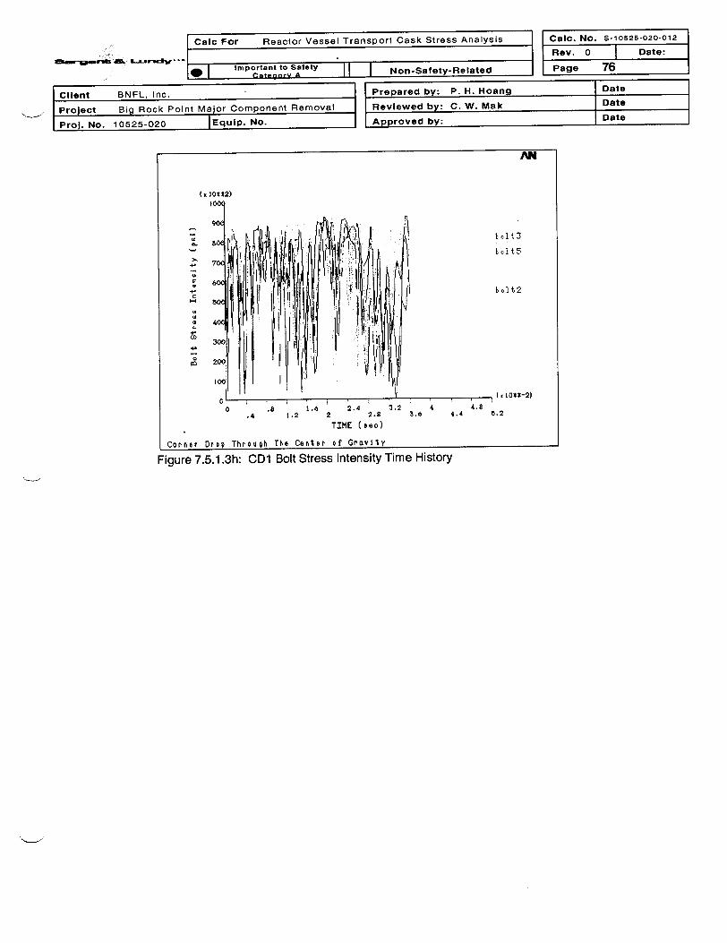
:I,: ~| Calc For Reactor Vessel Transport Cask Stress Analysis I Calic. No. S-10625-020-012
Rev. 0 | Date:
Page 761 I Important to Salety II I Non-Safety-Related I~ ~1 -- -aenr A
Client BNFL, Inc. Prepared by: P. H. Hoang Date
Project Big Rock Point Major Component Removal Reviewed by: C. W. Mak Date
Proj. No. 10525-020 Equip. No. Approved by: Date
AN
(x 2o*t2)
H
.-
I
bolt3
bl] t5
I*OU-2)
TIME (*sec)
Corn er Drop Thtrough The CenI r of Gravity
Figure 7.5.1 .3h: CD1 Bolt Stress Intensity Time History

Calc
41, . ~ c~ -
For Reactor Vessel Transport Cask Stress Analysis Calc. No. S-10626-020-012
Rev. 0Dt
Page 77Important to Safetyt Oa H I Non-Safety-Related
_ I- .
ClIent BNFL, Inc. Prepared by: P. H. Hoang
Project Big Rock Point Major Component Removal Reviewed by: C. W. Mak
Date
Date
DateI Prol. No. 10525-020 lEquilp. No. I I A---A IvI I -uv~ y.
7.5.1.4 Flap Down Drop Analyses
The lumped parameter dynamic analysis methodology per NUREG/CR -3966, Ref. 3.16.2, isemployed to investigate the maximum dynamic responses of the cask flap down drops with variousoblique angles. The cask lumped parameter model is a beam which has the same distributed mass,lumped masses and cross sectional moment of inertia as of the RVTS. Detailed description andcalculations for the lumped parameter model are provided in Attachment D. The beam is droppedonto a spring that represents the cask stiffness at the impact corner. The spring force deflectioncurve is fitted from the impact force and deflection time histories of the bottom plate center(Attachment I). The spring force deflection curve is shown in Figure 7.5.1.4.
,2.423 107, 5 2107
2 -107
0iy
000P( zz)
Is 107
5 -6
J.725 106,
12
A.01 L X,zzVertical Displacement (inch)
12
DOD FEA Result
- Curve Fitting Data
Figure 7.5.1.4 Spring Force Deflection Curve
The flap down velocities for various oblique angles off the horizontal plane are shown in the Table7.5.1.4a.
Table 7.5.1.4a Flap Down Velocities for Various Oblique AnglesOblique Top Plate Vertical Vel city (in/s) Horizontal Velocity (in/s)Angle Vertical Top Plate Bottom Plate Top Plate Bottom Plate(Degree Displ (in)
5 26.1 -793 192 8 1210 52.1 -798 172 35 4515 77.6 -793 157 51 8120 102.6 -781 144 65 11330 150 -732 124 101 17340 192.8 -648 91 143 23150 229.8 -538 13 204 27660 259.8 -481 -118 237 247

Caic For Reactor Vessel Transport Cask Stress Analysis Caic. No. S-10525-020-012
Rev. 0 Date:
IfllP|Imotat to Saety |Non-Safety-Related Page 78
Client BNFL, Inc. Prepared by: P. H. Hoang Date
Project Big Rock Point Major Component Removal Reviewed by: C. W. Mak Date
Proj. No. 10525-020 IEquip. No. Approved by: Date
A negative vertical velocity indicates movement toward the target surface, and a positive horizontalvelocity indicates movement toward the top plate. The maximum flap down vertical impact velocitydoes not change significantly for an oblique angle of less than 20 degree from the horizontalsurface. The maximum vertical flap-down velocity is corresponding to the 10-degree oblique dropangle. The maximum flap down horizontal impact velocity corresponds to the 50-degree obliquedrop angle. Table 7.5.1.4b shows the impact velocities for the Cases FDP1 and FDP2 analyses,which are higher than the bounding velocity listed in Table 7.5.1.4.a. Flap down analyses areperformed with the following initial velocity distributions:
Case FDP1: Flap down drop with maximum vertical velocity (in/sec)FDP1 1 and FDP12 are the subsets of FDP1 with different thermal and pressure conditions.
Case FDP2: Flap down drop with maximum horizontal velocity (in/sec)FDP21 and FDP22 are the subsets of FDP2 with different thermal and pressure conditions.
Table 7.5.1.4.b Flap Down Velocities Used in the AnalysesCase Top Plate Bottom Plate Top Plate Bottom Plate
Vertical Velocity Vertical Velocity Horizontal Velocity Horizontal VelocityFDP1 -810 194 46 46FDP2 -547.5 34.2 276 276
The model for the FD analyses is similar to the model for the HD analyses except with a linearlydistributed initial impact velocity. The initial linearly distributed velocity is modeled by divi ding thecask model into 30 velocity zones along the axial direction. All nodes within a zone have the samevelocity, which is linearly calculated from the velocities of the top and the bottom plates. Thehorizontal velocity of the entire cask is assumed to be a constant that is equal to the higher of thetop plate and the bottom plate horizontal velocities.
7.5.1.4.1 Flap Down Drop - Maximum Vertical Velocity (Cases FDP1 1 and FDP12)
The FDP1 analyses are performed with two initial conditions for thermal load cases Ti and T3, andpressures of 20 psi and -3 psi as described in 10 CFR 71. Preliminary analyses indicate that atapproximately 0.024 second a failure occurs in the elements located at the top plate ligamentbetween the RV flange and the top plate rim. A total of six elements within a 22.5 degree arc of thetop plate rim near the impact location of the cask half model, are then removed and the analysiscontinues until the top plate has reached the maximum displacement. Stress at locations El, E2,E3 and E4 of Figures 7.5.1.4.1c and 7.5.1.4.ld are the stresses for selected nodes of the failed
elements.
Figures 7.5.1.4.1 a and 7.5.1.4.1 b show the time histories of the vertical and horizontaldisplacements of the top plate center, the bottom plate center and the top of the RV bottom head upto the maximum impact duration of 0.028 second. Both vertical and horizontal displacements reachthe maximum values within the given duration.
The top plate CG reaches its maximum vertical displacement of -7.225 inches at time 0.01 979second in the FDP12 drop case. The top plate center reaches its maximum horizontal displacementof -2.545 inches at time 0.02665 second in the FDP1 1 drop case.
As shown in Figures 7.5.1.4.1c and Figure 7.5.1.4.1d, the maximum principal stress at locations El,E2, E3 and E4 reach the material tensile strength Su=70 ksi at approximately 0.024 second. Theelement stiffness at these locations is removed, thus the element stresses reduce to zero after0.024 second. The adjacent elements at locations E5 and E6 continue to take load until the end ofimpact duration without additional failures. The cask gross structure remains intact after the impact.The maximum bolt stress intensity is 97.73 ksi, which is less than Su =100 ksi. Typical results at the

..
Calc For Reactor Vessel Transport Cask Stress Analysis
I Important to Safety N Se Ra* ~ ', .. Ctgry A 17 | Non-Safety-Related
] Calc. No. S-10525-020-012
Rev. 0 Date:
Page 79
IPlian-- 1 I Prepared by: P. H. Hoang I DateOKrI- Ina,I -1~ -lur -, AfI.- 1 1 - _--
I Project Big Rock Point Major Component Removal
rPr;. No.
I Reviewed by: C. W. Mak
Approved by:
Date
Date10525-020 JEquip. No.
time when the top plate center reaches peak vertical/horizontal displacements are shown in thefollowing figures:
AN-
I
I0E
-
-J.
-3.:
-A
UyBotto m
UyRVDo me
UzBotto m
m I x 1O**-2)
3.25
-6.
_. ... .-7 .
0 .5 1.25 .75
:30 FT Flap Down DfoP - Maxi mum
i I1 . 2
1.2t 1.75 2.2
TIME (seo)
Veirtioul Veloolty
I2.5 3'8 2.75
.Figure 7.5.1.4.1a: FDP11 Vertical Displacement Time History

l
II Calc For Reactor Vessel Transport Cask Stress Analysis
J_ ,ICalc. No. s-1i
Rev. 0 |
Page 80
0526-020-012
Date:
C. A _ .. _ .. _ II I Non-Satety-Related, , ,
Client BNFL, Inc. , Prepared by: P. H. Hoang Date
Prolect Big Rock Point Major Component Removal 7 Reviewed by: C. W. Mak Date
Proj. No. 10525-020 |Equip. No. Approved by: Date
AN
2
.20
0*
-1-
-2
-3
-4
UyBottomUyRVDome
UBoctt, m
- ( x 10d*-21
3.2b
-7
-s
0 .5 1.25 .75
1 .51.25 1.75TIME (seo)
2 .
2 2.5 3
30 FT Flap Down Drop - Maxlmum Yert0Uoal Veloolty
Figure 7.5.1 .4.1b: FDP12 Vertical Displacement Time History
AN
E5
E3E2
.. .... I 1o -2 ).5 3
2.7g 3.2b
TIME (eeo)
30 FT Flip Down Drop - Maximum Yertloal Veloolty
Figure 7.5.1.4.1c: FDP1 1 Maximum Principal Stress Time History

- -
Calc For Reactor Vessel Transoort Cask Stress Analysis I
- LA ...
. I CP Ate I I I Non-Safety-Related
Calc. No. S-10525-020-012
Rev. O I Date:
Page 81
Client BNFL, Inc.
Project Big Rock Point Major Component Removal
Pro). No. 10525-020 |Equip. No.
.
Prepared by: P. H. Hoang Date
Reviewed by: C. W. Mak Date
Approved by: Date
AN
720(
4
400
0 -, . 2. I10. -22
0 2 .715 1 1.26 ie 1.75 2.25 25 2.715 3.25
TIME (aeo)
30 FT FlcD Down Drop - Maximum Vertlicl Yeloolty
Figure 7.5.1.4.1d: FDP12 Maximum Principal Stress Time History
ANSYS 5.6.2MAR 9 200103:24: 11PLOT NO. 4NODAL GOLUTIONTIME- .026987SI (AVC)TOPOMX -7.642CMX =52533
583711674
__17511
23348__29185
350224085946696
4
Flac Down Drop with Macimum Vertloel Velocity - Cold CoiI id I ti on
Figure 7.5.1.4.1e: FDP12 Maximum Principal Stress Contours

'_:rn.vgaJ; f&r rwI.L
Calc For Reactor Vessel Transport Cask Stress Analysis
. portat to Sae t | Non-Safety-Related
Calc. No. S-10525-020-012
Rev. 0 Date:
Page 82
Client BNFL, Inc.
Project Big Rock Point Major Component Removal
ProJ. No. 10525-020 |EquIp. No.
Prepared by: P. H. Hoang Date
Reviewed by: C. W. Mak Date
Approved by: Date
Flap Down Drop with MCt Inum Vort I l Veloolty - Hot Con J
Figure 7.5.1.4.1f: FDP11 Maximum Principal Stress Coni
ANSYS 5.6.2MAR 8 200121 51 54PLOT NO. 4NODAL SOLUTIONTIME- .02664761 (AYVCTOPOMX -7.814SMX =51325
r-_ 570311406
=3 171082281128514
___ 34217- 39920-45622
51325
Ition
tours
ANSYS 5.6.2MAR 8 200121:51:56PLOT NO. 6NODAL SOLUIIONTIME- .026647UY (AVC)RSYS-0PowarCro~phi ccEFACET= IAVRES=Ma tDMX =7.814SMN =-6.995SMX =.424531
-6.995-6.171-5.347
, _ -4.522__-3.698
___ -2.873-2.049
- -1.224_ -. 399911
.424531
1tion
DM.. -X
Flap Down Drop with Mcxdmum Yentlodl Voloolly - Hot Cond
Figure 7.5.1.4.19: FDP12 Vertical Displacement Contours

8-- _ eAdsL
Calc For Reactor Vessel Transport Cask Stress Analysis
. _* Imprortant to Satety _ Non-Satety-Related
Calc. No. S-10525-020-012
Rev. 0 Date:
_ Page 83
Client BNFL, Inc. Prepared by: P. H. Hoang Date
Project Big Rock Point Major Component Removal I Reviewed by: C. W. Mak Date
Prol. No. 10525-020 |Equip. No. Approved by: Date
ANSYS 5.6.2MAR 8 200221:51:57PLOT NO. 7NODAL SOLUIIONTIME-.026647UZ (AVC)RSYSGOPowerCraphi ccEFhCET= IAVRES=MatDMX -7 814SMN -3.637SMX =172276
-_3.637
-2367_ _ _ 1 94 4
-1,097
Flap Down Drop with Maxlmum Verllocl Velooity - Hot Con Ition
Figure 7.5.1.4.1 h: FDP11 Horizontal Displacement Contours
AN
t x 10Xt2)200q
b o l t 3
4._
C
u
H
a
10
e
CD
bolt2
bolt5
- I e1 0$*-2)
3.25
o , ,l
0 .5 1 1.5 2.215 .75 1.25 1.75 2.2
TIME ( eso)
Dowwn Droo - Maximum Vertloal Veloolty
2,5 32t 2.75
30 FT Flco, . . . . . ............................... . . . .
Figure 7.5.1.4.1 k: FDP1 1 Bolt Stress Intensity Time History

rIs For- =- atn - V.- %/ l 7-.-nnt C..sk qtrs.s Annlvsiq-
I I CaIc. No. S-10625-020-012
Rev. 0 Date:
Important to Satety l Non-Safety-Related Page 84
Client BNFL, Inc. Prepared by: P. H. Hoang Date
Project Big Rock Point Major Component Removal Reviewed by: C. W. Mak Date
Prol. No. 10525-020 JEquip. No. Approved by: Date
7.5.1.4.2 Flap Down Drop - Maximum Horizontal Velocity (Cases FDP21 and FDP22)
The initial conditions for the FDP2 analyses include nodal temperatures from thermal load cases Tiand T3, pressures of 20 psi and -3 psi as described in 10 CFR 71, and the linear distributed initialvertical impact velocity and horizontal velocity listed in Table 7.5.1.4b for FDP2. Contacts betweenthe cask shell and the essential unyielding, horizontal surface is modeled along with the contactbetween the RV flange and the cask shell.
At time 0.012 second a failure occurs in elements located at the top plate ligament between the RVflange and the impact comer. Four elements that extend over an arc of 15 degrees of the cask halfmodel (Locations El, E2 and E3 of Figures 7.5.1.4.2c and 7.5.1.4.2d) are then removed and theinteractive analysis continues until the top plate has reached the maximum vertical and horizontaldisplacements without additional failures.
The top plate CG reaches its maximum vertical displacement of -7.740 inches at time 0.02562second in the FDP22 drop case. The top plate center reaches its maximum horizontal displacementof -9.207 inches at time 0.02595 second in the FDP21 drop case.
As shown in Figures 7.5.1.4.2c and 7.5.1.4.2d, the maximum principal stress at location Elapproaches the material tensile strength, Su, at approximately 0.012 second. The element stiffnessat this location is removed, thus the element stress reduces to zero after 0.012 second. Theadjacent elements at locations E4, E5 and E6 continue to take load through the end of impactduration without failure. The cask gross structure remains intact after the impact. The maximum boltstress intensity is 96.37 ksi, which is less than Su =100 ksi. Typical results at the time when the topplate center reaches peak vertical/horizontal displacements are shown in the following figures:
AN
1. Uysottom
12 UyRVDo mQ
-2.A
Uz Bo tt om
-2.
C -3 7
.. -6. 2 -
-8.7
IX: I , | l;1O*t-2l0 .5 I 1t. 2 2,.5 3
.26 .75 1.25 1.7X 2.25 2.7t 3.26
TIME (seo)
30 FT Flap Down Drop - Maximum Horizontal Veloolty
Figure 7.5.1.4.2a: FDP21 Vertical Displacement Time History

Cm -8d:I ...
Calc For Reactor Vessel Transport Cask Stress Analysis
. Important to Safety Non-Safety-Related
Calc. No. S-10525-020-012
Rev. 0 | Date:
Page 85
Client BNFL, Inc. Prepared by: P. H. Hoang Date
Project Big Rock Point Major Component Removal Reviewed by: C. W. Mak Date
Proj. No. 10525-020 |Equlp. No. Approved by: Date
AN
C
E
a
II
0
0-
-t
-2-
-3
-4
UyBottom
UyRVDo me
UzBottom
-7
-I ( l10$-21
3.25
_ ; I I i I r i0 .5 1 I.8 2
.25 .75 1.26 1.78 2.28
TIME (tso)
30 FT FIGp Down Drop - Maximua HorIzontal aVeooity
2.8I 32.75
Figure 7.5.1 .4.2b: FDP22 Vertical Displacement Time History
0.8
< 7M
8 64(
- 3M
12 11 1: .
E5E35E2
. ( K 103*-2)
3.25
A
Sl.IO J.'LN '..w ;-' .. ..
0 .5 13 .0 X6 I IA 2 2.25 .75 1.26 178 2.2Y
TIME (oeo)
30 FT Flap Down Drop - Maximum Horizontal Volooity
1.8 32. 7Z
Figure 7.5.1.4.2c: FDP21 Maximum Principal Stress Time History

Calc For Reactor Vessel Transport Cask Stress Analysis II| Calc. No. S- 10626-020-01 2
Mr. 0 -: ...I
- - . - . - i
Rev. 0 1 Date:
Page 86l_ I Important to Safety II I Non-Satftv-ReIated II' I Catsoorv A 11 I g
ClIent BNFL, Inc.
Project Big Rock Point Major Component Removal
Prol. No. 10525-020 IEquIp. No.
Prepared by: P. H. Hoang Date
Reviewed by: C. W. Mak Date
Approved by: Date
AN
1Z, ( X 30** )=. 800
- 72
i8 640
0- 560(
,480
SE 400(
- 3201
2
X l i
00
215
//
I 11Z 2 2.Z 3.7 1 1.2Z 1.70 2.20 2.75
TIME (seo)
laximum Horizontel Veloolty
E3E2
, ( lo*1-21
3.25
[UO FT Flop Down Drop -I-
Figure 7.5.1.4.2d: FDP22 Maximum Principal Stress Time History
ANSYS 5.6. 2MAR 9 200109:00:22PLOT NO. 4NODAL SOLUTIONTIME-.025953Si (AVC)TOPDMX -11.98SMX =52927
,_ C58811176217642
=__ 23523=_ 29404
35285= 41166- 47047M 52927
130 FT Flop Down Drop - Maxlmum Horizontol Veloolty
Figure 7.5.1.4.2e: FDP21 Maximum Principal Stress Contours

va-1920-SUAM
Calc For Reactor Vessel Transport Cask Stress Analysis
* Important to Safety Non-Safety-Related
Caic. No. S-10525-020-012
Rev. 0 Date:
Page 87
Client BNFL, Inc. Prepared by: P. H. Hoang Date
Project Big Rock Point Major Component Removal Reviewed by: C. W. Mak Date
ProJ. No. 10525-020 [Equip. No. Approved by: Date
ANSYS 5.6.2MAR 9 200115:00:06PLOT NO. 4NODAL SOLUTIONTIME- .026953Si (AVC)TOPDMX -11.06SMX =52952
__11767
__17651
23534_ 29418
__35301
- 411854706852952
30 FT F1ap Down Drop - Maximum Horizontl VYeloolty
Figure 7.5.1.4.2f: FDP22 Maximum Principal Stress Contours
ANSYS 5.6.2MAR 9 200109 00:24PLOT NO. 6NODAL SOLUTIONTIME-.025953UYTOPRSYS-0DMX =11.98SMN =-7.975SMX =.685991__ -7.975
-7.012-6.05
__-5.088
-4.126___ -3.163
__-2.201
~- -1.239-. 276394.685891
ICX
30 FT Flop Down Drop - Maximum Horizonlaol Velooity
Figure 7.5.1.4.2g: FDP21 Vertical Displacement Contours

R3-%Mrf M.L£ Cv
Calc For Reactor Vessel Transport Cask Stress Analysis
. Important to Safety Non-Satety-Related
Ca1c. No. S-10525-020-012
Rev. 0 | Date:
Page 88
Client BNFL, Inc. j Prepared by: P. H. Hoang Date
Project Big Rock Point Major Component Removal Reviewed by: C. W. Mak Date
Prol. No. 10525-020 |Equip. No. Approved by: Date
ANSYS 5.6.2MAR 9 200109 00 24PLOT NO. 7NODAL SOLUTIONTIME- .025953uzTOPRSYS-ODMX =11.98SMN =-9.207
-92046
-_ -7.161
-1.0920
30 FT Flap Down Drop - Moaximum Horizontal Voloolty
Figure 7.5.1.4.2h: FDP22 Horizontal Displacement Contours
AN
H
I
10at
bolt2
_ ( 10*-21
3. 250 .5 1 1.5 2
.25 .76 1.25 1.75 2.25
TIME (too)
30 FT FlaP Down Drop - Maximu HorIzontal eloolty
i2.15 32 .76
Figure 7.5.1.4.2k: FDP21 Bolt Stress Intensity Time History

Calc For Reactor Vessel Transport Cask Stress Analysis Calc. No. S-10626-020-012
M i. Rev. 0 Date:
* | moctant to Safety Non-Safety-Related Page 89
Client BNFL, Inc. Prepared by: P. H. Hoang Date
Project Big Rock Point Major Component Removal Reviewed by: C. W. Mak Date
Proj. No. 10525-020 TEquip. No. Approved by: Date
7.5.2 Result Verification for 30-foot Drop Analyses
7.5.2.1 Energy Conservation Check
The results of the 30-foot drop dynamic impact analyses are verified using the principal of energyconservation. The total instantaneous strain energy, kinetic energy and the cumulative plastic workshould be approximately equal to the initial impact energy, KE = 1/2 mV2, where m is the total RVTSmass and v = 527.4 in/s is the impact velocity of a 30-foot drop. A horizontal 30' drop analysis isperformed without the initial thermal and pressure conditions for the purpose of checking theprincipal of conservative energy. The analysis RUNID is HDEnergy.
The calculated mass of the model (half of the RVTS), per Section 7.3, is 730.38 Ibf-sec2/in.
KE =1/2 mv2 = .5*(730.38)*(527.4)2 = 101.58E+06 in-lbf
The ANSYS results include the instantaneous strain energy (StrainE), cumulative plastic work(PlastE) and kinetic energy (KinE). These energy values are calculated and integrated over themodel volume from the element data tables for all output load steps. The plots of the instantaneousstrain energy, cumulative plastic work and kinetic energy are shown in Figure 7.5.2.1. At the end ofthe first load step, the FEA calculated initial kinetic energy is 101.298E+06 in-lbf, and the strainenergy is 0.4025E+6 in-lbf. Thus the total initial energy calculated by ANSYS is 101.7E+06 in-lbf,which is essentially the same as the input impact energy KE. At the end of the impact period, theinstantaneous strain energy (StrainE) and kinetic energy (KinE) are diminishing, and the cumulativeplastic work (PlastE) reaches a plateau value of 11 8.382E+06 in-lbf. The FEA calculated plasticwork is conservatively over-estimated by about 18% of the total impact energy.
The ANSYS calculated plastic work for the element type VISCO1 06 is documented in the ANSYSTheory Manual. The usage of the ANSYS calculated plastic work for the element type SHELL181 isjustified by the benchmark analyses documented in Section 7.5.2.3. The calculated cumulativeplastic work for both elements is essentially the same as the input kinetic energy.
Based on the result of the verification problem, it is concluded that the calculated damages of thethirty-foot drop calculations are reasonably conservative, and are suitable for estimating an upper-bound damage of a potential HAC breach of containment of the RVTS cask.

Caic For Reactor Vessel Transport Cask Stress Analysis
631111w�llft AS, LI',-AV - - -I.
Calc. No.
Rev. O
Page
I Date:
S-10525-020-012
lo Importantto Safety II I Non-Safety-Related90
Client BNFL, Inc. IPrepared by: P. H. Hoang I Date
Project Big Rock Point Major Component Removal Reviewed by: C. W. Mak Date
Pro]. No. 10525-020 |Equlp. No. Approved by: Date
AN
Cx lOt*S)
PI P tE
- /
62\
W
250 kineticE
0 / , (xl O**-2
1
0 .4 .8 1.2 1.6 2 2.4.2 .6 1 1.4 1.8 2.2 2.6
TIME (aeo)
HorIzontfl Drop - Impacl Energy Cheok
Figure 7.5.2.1 Cask Drop Verification Problem - Energy Conservation Check
7.5.2.2 Effect of the PCG Solver Convergence Tolerance
The purpose of the analysis FDP1 1 a is to investigate the effect of the PCG solver convergencetolerance. A convergence tolerance of 1 E-08 is used in FDP1 1 a in lieu of 1 E-03 in FDP1 1. Asshown in Tables 7.5.2.2a and 7.5.2.2b, the differences in the peak S1 values and displacements ofthe two analyses are less than 0.1%. Therefore, the PCG solver convergence tolerance value hasno significant effect on the results of the 30-Foot drop analyses.
Table 7.5.2.2a: Extreme Values of FDP1 1 Analysis with PCG Convergence Value of 1 E-3.
VARI TYPE NODE IDENTIFIERS NAME MINIMUM AT TIME MAXIMUM AT TIME
2 ESOL 4732 S1 El 0 2.OOE-05 5.04E+04 2.40E-02
3 ESOL 4731 S1 E2 0 2.OOE-05 7.18E+04 2.40E-02
4 ESOL 4735 Si E3 0 2.OOE-05 5.92E+04 2.40E-02
5 ESOL 4739 S1 E4 0 2.OOE-05 3.83E+04 3.17E-03
6 ESOL 4743 S1 E5 0 2.00E-05 5.99E+04 2.53E-02
7 ESOL 4747 Si E6 0 2.OOE-05 4.38E+04 3.50E-03
8 NSOL 1106 UY UyTop -7.17 1.96E-02 -1.62E-02 2.00E-05
9 NSOL 3315 UY UyBottom 3.88E-03 2.OOE-05 0.4857 2.80E-02
10 NSOL 50 UY UyRVDome -1.41E-02 1.33E-02 0.2857 2.80E-02
11 NSOL 1106 UZ UzTop -2.545 2.67E-02 0.2565 1.1 3E-02
12 NSOL 3315 UZ UzBottom -1.424 1.56E-02 0.2951 3.83E-03
13 NSOL 50 UZ UzRVDome -1.636 2.67E-02 0.3788 2.33E-03

eSwe"f Mr., i'
Calc For Reactor Vessel Transport Cask Stress Analysis Cabc. No. S-10525-020-012
Rev. 0 Date:
* I important to Safety Non-Saety-Related Page 91
Client BNFL, Inc. Prepared by: P. H. Hoang
I Project Big Rock Point Major Component Removal Reviewed by: C. W. Mak-~L II I
Date
Date
Date-
PI rol. No. 10525-020 I Equip. No. I A ,~~oFI I - FF,. - . __ - .
Table 7.5.2.2b: Extreme Values of FDP1 la Analysis with PCG Convergence Value of 1 E-8.
VARI TYPE NODE IDENTIFIERS NAME MINIMUM AT TIME MAXIMUM AT TIME
2 ESOL 4732 Si El 0 2.OOE-05 5.02E+04 2.40E-02
3 ESOL 4731 Si E2 0 2.OOE-05 7.18E+04 2.40E-02
4 ESOL 4735 Si E3 0 2.00E-05 5.90E+04 2.40E-02
5 ESOL 4739 Si E4 0 2.00E-05 3.83E+04 3.17E-03
6 ESOL 4743 Si E5 0 2.00E-05 5.98E+04 2.53E-02
7 ESOL 4747 Si E6 0 2.OOE-05 4.38E+04 3.50E-03
8 NSOL 1106 UY UyTop -7.169 1.96E-02 -1.62E-02 2.00E-05
9 NSOL 3315 UY UyBottom 3.88E-03 2.OOE-05 0.4852 2.80E-02
10 NSOL 50 UY UyRVDome -1.41E-02 1.33E-02 0.2856 2.80E-02
11 NSOL 1106 UZ UzTop -2.562 2.67E-02 0.2565 1 .1 3E-02
12 NSOL 3315 UZ UzBottom -1.425 1.56E-02 0.2952 3.83E-03
13 NSOL 50 UZ UzRVDome -1.639 2.67E-02 0.3788 2.33E-03
7.5.2.3 Performance Benchmark Analysis of SHELL181 Element
Problem C8, a benchmark problem in ANSYS Verification Manual, tests the performance of various3-D solid elements in dynamic impact analysis. The test compares the final deformed length of acylindrical aluminum bar impacting on a rigid wall with an experimental result.
The same benchmark problem is performed using SHELL181 element to test the performance ofthis element due to an in-plane impact loading. Since the cylindrical bar cannot be modeled using ashell element, the benchmark model is a square bar, which has a side equal to the diameter of thecylindrical test bar. The bar length, the impact velocity and the material properties are the same asthe test case. The benchmark analysis uses the ANSYS PCG solver with a convergence toleranceof le-03. The input and output files are documented Appendix J. For a purpose of testing theANSYS's cumulative plastic work calculation for SHELL181 element, a benchmark problem is alsoanalyzed using VISCO106 element, a time dependent plasticity 2D plate element. The cumulativeplastic work calculation for VISCO106 element is documented in the ANSYS Theory Manual.
The comparison of the final deformed bar length resulted from benchmark analyses using various3-D solid elements as in ANSYS Verification Manual and SHELL181 element in this calculation isshown in Table 7.5.2.3.
Table 7.5.2.3: Benchmark ResultsTest Deformed Length (cm) Ratio
Experiment 1.319 1SHELL181 1.392 1.055VISCO1 06 1.398 1.060SOLID45 1.397 1.059SOLID95 1.408 1.067
VISCO1 07 1.406 1.066
The deformed bar length from the benchmark analysis using SHELL181 is within 5.5% of theexperimental value. The performance of SHELL181 is excellent in comparison with the otherANSYS solid elements. Thus SHELL1 81 is suitable for nonlinear dynamic impact analysis.
Figures 7.5.2.3a and 7.5.2.3b show the time history of the kinetic energy and the cumulative plasticwork in the impacting bar model using SHELL181 element and VISC0106 element. The calculated
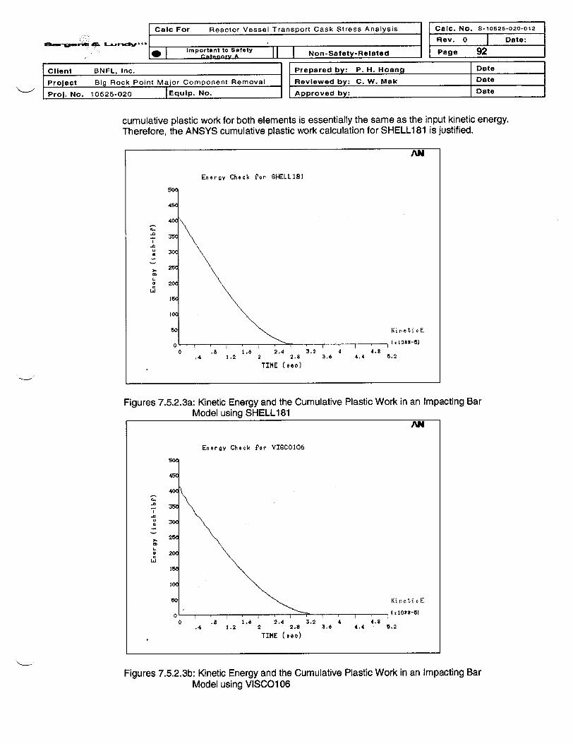
I Cailc For Reactor Vessel Transport Cask Stress Analysis
L . I .r]Calic. No. S-10525-020-012
Rev. 0 j Date:
J Page 92@ Im~~ortant to Saftty ~ NnSft-eae
Client BNFL, Inc.IProject Big Rock Point Major component Removal
Proj. No. 10525-020 IE qui~p. N.
Prepared by: P. H. Hoang
Reviewed by: C. W. Mak
Approved by:
IDate
IDateIDate
cumulative plastic work for both elements is essentially the same as the input kinetic energy.Therefore, the ANSYS cumulative plastic work calculation for SHELLi 81 is justified.
AN
Energy Check P'or SHELL381
45
400
G - ,
.4 3. 23 . 44 .
TIME (seo)
Figures 7.5.2.3a: Kinetic Energy and the Cumulative Plastic Work in an impacting BarModel using SHELL181
AN
Energy Check Por VIGCO106
45
40C
.0 0
250
M
Ki netic E
I ( 10**-51
.4 1.2
Figures 7.5.2.3b: Kinetic Energy and the Cumulative Plastic Work in an Impacting BarModel using VISC0l 06

-
9BL-161"am 4M L�Wwt*v...
Calc For Reactor Vessel Transport Cask Stress Analysis I TI C8. No. S-10626-020-012
1 Rev. 0 7 Date:
Page 93* Important to Safety Non-Safety-Related
Client BNFL, Inc. Prepared by: P. H. Hoang Date
Project Big Rock Point Major Component Removal Reviewed by: C. W. Mak Date
Proj. No. 10525-020 |Equip. No. Approved by: Date
7.5.3 Puncture Stress Analyses
The RVTS cask shell is analyzed for a 40" puncture drop on a 6" OD steel rod. The 8-inch longsteel rod is standing vertically on an essentially unyielding, horizontal surface. The rod isconservatively assumed to be rigid and remains in the vertical position. Local punching sheardamage creating a 6-inch diameter hole is within the limitation of the design criteria in Section 5.0.However, the effect of the puncture drop on the existing damage from the 30-foot drop is the mainconcern of the puncture drop analysis. Since local puncture stress is not analyzed, refining the localmesh at the puncture location is not necessary. The most limiting damage to the cask from the 30-ftdrop analyses occurs at the top rim. The total damage in a 45-degree arc of the top plate rim isconsidered for the subsequent HAC evaluation. The damaged elements are removed prior to thebeginning of the puncture drop. Two- puncture locations are considered. One location is near themid-shell between the top plate and the shield plate. The second location is on the top shell next tothe damaged top plate rim.
7.5.3.1 Puncture Drop near Mid Shell (Load Cases PMD1 and PMD2)
The initial conditions for the PMD analyses include nodal temperatures from thermal load cases T1and T3, pressures of 20 psi and -3 psi as described in 10 CFR 71, and an initial vertical impactvelocity of 176 in/sec from a 40" free fall. Contact between the cask shell and the essentiallyunyielding, horizontal surface is modeled along with the contact between the RV flange and thecask shell.
After an impact duration of 0.080 second, the rims of the top plate and the bottom plate havereached the ground. The mid-shell has deformed and could be penetrated by the steel rod but themaximum principal stress, S1, around the damaged 45-degree arc rim remains within the materialtensile strength. As shown in Figures 7.5.3.1c and 7.5.3.1.d, S1 at locations "TopPlI", "TopPl2","TopShll" and "TopShl2" located near the end of the damaged rim, remains less than 45 ksi.Therefore, a 40" puncture drop on a steel rod near the mid-shell will not increase the existingdamage from the 30' drop.
-2.!
-3.~
o -6 a
J -6.Zi
-7.t
UYBotRi m-8.7;
-10 UyFl on ge
.16 .32 .48 .64 .8 .96.08 .24 .4 .A6 .72 .88 1.04
TIhE ( H no)
40" Dr op o n 6"OD St eel Rod Near Mld Shell - Hot Condition
Figure 7.5.3.1 a: PMD1 Vertical Displacement Time History

Calc For Reactor Vessel Transport Cask Stress Analysis
.1w.
Caic. No. S-10525-020-012
Rev. 0 Date:
Page 94* Important to Safety-Related
Client BNFL, Inc.
Project Big Rock Point Major Component Removal |
Proj. No. 10525-020 JEquip. No.
Prepared by: P. H. Hoang Date
Reviewed by: C. W. Mak Date
Approved by: Date
-
AN
<U UYI t Ri m_ \ _ UyFIan ge
_Is ~ ~ ~~~~ . K IM(1$-11
t2.16 .32 .64 .96.08 .24 .4 tr6 .72 .88 1.04
. ~TIME- ( aeo)
40" DrOP on 6"0D Steel Rod Near Mld Shell - Cold Conditlon
Figure 7.5.3.1 b: PMD2 Vertical Displacement Time History
L: (X lOt* I1)
a
4.i $0
C 6
800480
4 320t
aS 5w
240W
1 .14'd
0-
0
40" Dr op o n 6"
AN
Mtd~hl I
TopShl I
TopPL2
I.( K 1044-1l
I .oC
OD Steel Rod Near Mid Shell - Hot Condition.
Figure 7.5.3.1c: PMD1 Maximum Principal Stress Tlime History
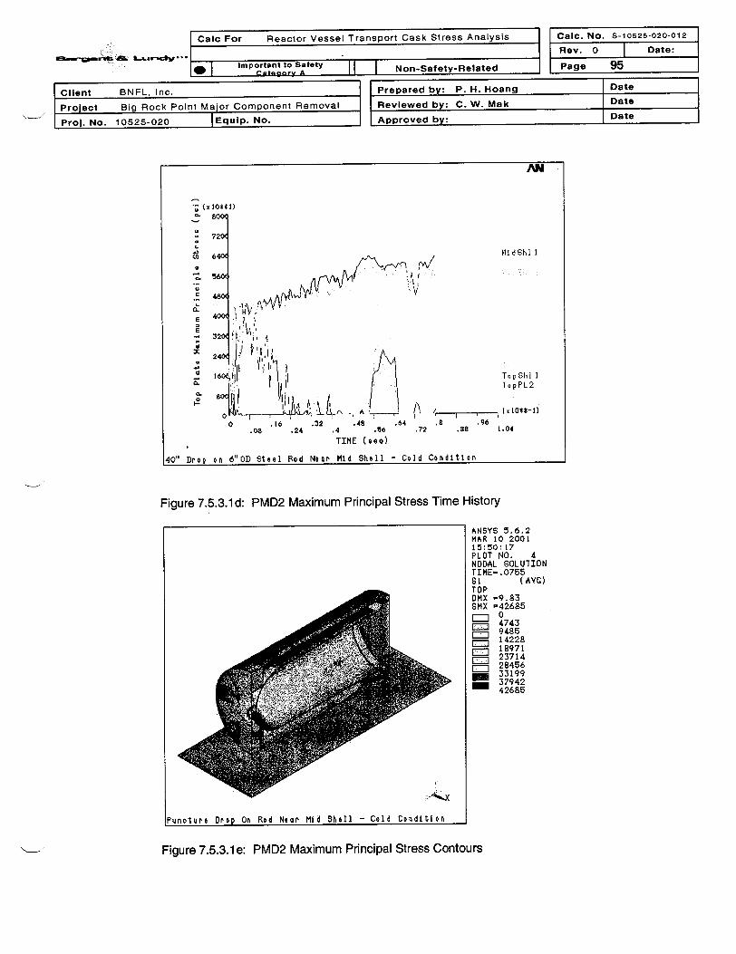
Calc For Reactor Vessel Transport Cask Stress Analysis I Calc. No. S-10525-020-012
*: ... i-
_AM I Important to 258ety I I I Nnn-qaftetv-Rellatad I
Rev. 0 | Date:
Page 9511 I Ctaenorv A I I I ---- -rI
Client BNFL, Inc. Prepared by: P. H. Hoang Date
Project Big Rock Point Major Component Removal Reviewed by: C. W. Mak Date
Prol. No. 10525-020 |Equip. No. Approved by: Date
AN
{Z XIO441)
L
cn
Co
8.
0.
r-
40" Dr o p
lIdShl I
TopShl 1TopPL2
> k.LL , ., A0 .16 .32 .48 .64 .8
.08 .24 .4 .06 .72 .88
TIME (teo)
6"nn Sttel Rod Neor Mid Shell - Cold Conditlon
I K10*-1
961.04
on' . _ . .
Figure 7.5.3.1d: PMD2 Maximum Principal Stress Time History
ANSYS 5.6.2MAR 10 200115:50 :17PLOT NO. 4NODAL SOLUIIONTIME-. 0755S1 (AVC)TOPDMX -9.83SMX =42685
47439485
__14228
__12971
__23714
__28456-33199.. ~379?42
42685
i - CI
Pun olu Pe Dropo On Rod No or Mid Shell - Colod Con di tIon
Figure 7.5.3.1e: PMD2 Maximum Principal Stress Contours

Calc For Reactor Vessel Transport Cask Stress Analysis Calc. No. S-10625-020-012
-~w~3..n.gJRev. 0 Date:Important to Safety Non-Satety-Related Page 9
Client BNFL, Inc. Prepared by: P. H. Hoang Date
Project Big Rock Point Major Component Removal Reviewed by: C. W. Mak Date
Prol. No. 10525-020 |Equlp. No. Approved by: Date
ANSYS 5.6.2MAR 10 200106 45 52PLOT NO. 5NODAL SOLUTIONTIME- .077217GI (AVG)BOTTOMOMX -10.327SMX =68656
7628__15257
__22885
3051438142
- .- ___ 45771
ff i F ~ 61028
Punoture Drop On Rod Neor Mid Shell - Hot Cond~lbon
Figure 7.5.3.1 f: PMD1 Maximum Principal Stress Near the Puncture Location
ANSYS 5.6.2MAR 10 2001I5:50: 18PLOT NO. 6NODAL SOLUTIONTIME- .0755UYTOPR S YS-0OMX =9.83SMN =-9.797SMX =.639414
__-9.797
_. -8.637
X 9rF : 6'3718-3.q99-2.839
-1.68-. 520132
.639414
. ~.. AX
Puncture Orop On Rod Necn Mid Shell - CoId Condition
Figure 7.5.3.1g: PMD2 Vertical Displacement Contours

11316,11 ......
Calc For Reactor Vessel Transport Cask Stress Analysis Caic. No. S-10525-020-012
Rev. 0 | Date:
a ImpI rL!2S sfty II I Non-Safety-Related Page 97_, . - .eX,0. -
Client BNFL, Inc.
Project Big Rock Point Major Component Removal
Prol. No. 10525-020 JEquip. No.
Prepared by: P. H. Hoang Date
Reviewed by: C. W. Mak Date
Approved by: Date
ANSYS 5.6.2MAR 10 200115 50: 19PLOT NO. 7NODAL GOLUTIONTrME- .0755uzTOPRSYS-0DMX =9.8:3SMN =-.698329GMX =.298285__. - .698329
- .587595
-.25539
.076815- .18755
.298285
Puncture Drop On Rod Near Mid Shell - Cold Condition
Figure 7.5.3.1h: PMD2 Horizontal Displacement Contours
7.5.3.2 Puncture Drop near Top Shell (Load Cases PTD1 and PTD2)
The initial conditions for the PTD analyses include nodal temperatures from thermal load cases T1and T3, pressures of 20 psi and -3 psi as described in 10 CFR 71, and an initial vertical impactvelocity of 176 in/sec from a 40" free fall. Contact between the cask shell and the essentiallyunyielding, horizontal surface is modeled between the RV flange and the cask shell.
After an impact duration of 0.060 second, the RV flange has reached the cask shell at the damagedrim. The puncture location at the top-shell has deformed and could be penetrated by the steel rodbut the maximum principal stress, S1 at anywhere else remain less than the material tensilestrength. As shown in Figures 7.5.3.1c and 7.5.3.1.d, S1 at locations "TopPl1", 'TopPl2", 'MidShll"and "MidShl2" located near the end of the damaged rim, remains less than 45 ksi. Therefore, a 40"puncture drop on a steel rod near the top shell will not increase the existing damage from the 30'drop.

Calic For Reactor Vessel Transport Cask Stress Analysis Calc. No. S-10525-020-012
.1 Rev. 0 I Date:s S d!C. .
:M::Important to Safety l Non-Safety-Related Page 98
,- I neor
Client BNFL, Inc.
Project Big Rock Point Major Component Removal
Proj. No. 10525-020 |Equip. No.
Prepared by: P. H. Hoang Date
Reviewed by: C. W. Mak Date
Approved by: Date
AN
0-
.a ; 4V
C-3
E
o -4
a -6
-7 UyF an ge
UYBO tRi m
_ I ! 0!*sleO -210 1 2 3 4 5 6
.5 1.5 2. 3.r 4. 5.a5 6.5
TIME (so)
40-Inch Drop on 6'OD Steel Rod Neor Top Shell - Hot Condttion
Figure 7.5.3.2a: PTD1 Vertical Displacement Time History
AN
-I
z -3E
U -4
-4 o
-8
0 L 2 3456.5 1 5 2.5 3.5 4.5 5.5 6.
TIME (coo)
40-Iciohe Drop on 6'0D Steel Rod Near Top Shell - Cold Condition
UyFI an ge
UY~o t Ri m
K 10*4-21
Figure 7.5.3.2b: PTD2 Vertical Displacement Time History

l
Calc For Reactor Vessel Transport Cask Stress Analysis
C=il -MD e Ctsw _
I Caic. No.
Rev. 0
_ Page
S-10525-020-01 2
I Date:
99la I Important to Safety II I Non-Safety-Related_
I
{:ntonnrY
_, aeurrS ''.
Client BNFL, Inc.
Project Big Rock Point Major Component Removal
Proj. No. 10525-020 |EquIp. No.
Prepared by: P. H. Hoang Date
Reviewed by: C. W. Mak Date
Approved by: Date
AN
- SOu x1'~ttl)
0800
- 720(
c3 640
0
C 4W560
E 400O
320
M
240(
0 160(2L q1
Q. 800,,
TopShl I
1idShI I
TopPL2
-1 l 10*t-21
6.53 4 5 6
2.5 3.5 4.5 5.5
TIME ( aeo)
Near Top Shell - Hot Conditlon40-In o h DroD on 6OD Steel Rod
Figure 7.5.3.2c: PTD1 Maximum Principal Stress Time History
AN
- (xo*t*1)800
-720
560
TopKShl I
32X
TopPL2^ 0 xiol0t,-2)
0 1 2 3 A 5 6.5 1.5 2.5 3., 4.5 5.5 6.6
TIME O T h C o
40-Irohe Drop on 000O Steel Rod Near Top Shell - Cold Condition
Figure 7.5.3.2d: PTD2 Maximum Principal Stress Time History

Calc For Reactor Vessel Transport Cask Stress Analysis Calc. No. S-10526-020-012
; - Rev. 0 | Date:
* Important to Satety Non-Satety-Related Page 100
Client BNFL, Inc. Prepared by: P. H. Hoang Date
Project Big Rock Point Major Component Removal Reviewed by: C. W. Mak Date
Prol. No. 10525-020 |Equip. No. Approved by: Date
ANSYS 5.6.2MAR 10 200121:23:21PLOT NO. 4NODAL SOLUTIONTIME-.058S1 (AVG)
i i TOP
,.SllR rSMX =51333
42228
Punoture Drop On Rod Neor' Top Corner - Hot Conditlon
Figure 7.5.3.2e: PTD1 Maximum Principal Stress Contours
ANSYS 5.6.2MAR 10 200121:23:22PLOT NO. 6NODAL SOLUIIONTIME-.058UYTOPRSYS-0DMX =8.905SMN =-8.902SMX =.299052
__-8.902
-7.879-6.857
__-5.835
__-4.812
__-3.79
_ -2°768* 174
Funoture Drop On Rod Near Top Corner - Hot Condition
Figure 7.5.3.2f: PTD1 Vertical Displacement Contours

Calc For Reactor Vessel Transport Cask Stress Analysis Calc. No. S-10o25-020-012
e a 7 Rev. 0 Date:
. ImportanttoSaety |||Non-Safety-Related Page 101
Client BNFL, Inc. Prepared by: P. H. Hoang Date
Project Big Rock Point Major Component Removal Reviewed by: C. W. Mak Date
Proj. No. 10525-020 |Equip. No. Approved by: Date
7.5.4 Thermal Fire Accident
During the 30-minute hypothetical fire accident, differential thermal expansion occurs between theRVTS cask and the RV in both longitudinal and radial directions. This differential thermalexpansion may cause a gap between the base of the RV and the internal donut ring support.Therefore, the RV could potentially become a cantilevered beam supported only by the cask topclosure plate through the RV flange bolts. Although the LDCC between the annulus of the RVTScask could provide compressive support during this scenario, the effect of the LDCC isconservatively neglected in the structural analysis to ensure that the RV flange bolts and the casktop closure plate can adequately support the weight of the RV during and after the 30-minutethermal exposure.
A nonlinear weight analysis is performed without support on the RV hemispherical bottom at thedonut plate. The analysis includes the maximum HAC pressure of 95 psi along with the fireaccidents considering with two initial thermal conditions. These two thermal load cases, T4 and T5analyzed in Section 7.2, are:
* T4 = Fire condition, Initial 1000F Ambient, Zero Decay Heat and Zero Insolation.* T5 = Fire condition, Initial -200F Ambient, Zero Decay Heat and Zero Insolation.
Nodal temperatures of load cases T4 and T5 are shown in Figures 7.5.4a and Figure 7.5.4b,respectively. These temperature distributions are the limiting temperature gradient that the RVTSwould experience during a 30-minute fire. Temperature dependent material properties listed inAttachment A are modeled. All loads are gradually increased in multiple sub-steps. Note that thetime variable in the graphs is the sub-step and not the actual time duration.
Figure 7.5.4c shows the THACC1 vertical displacement of the top plate center and the RV bottomhead with respect to the load steps. The RV bottom head moves up to about 0.298' and then dropsdown to about 0.1" due to weight load and reduced strength as the temperature rises.
Bolt stress intensity increases to 40 ksi as the temperature rises to 9500F. The load is thenredistributed to the other bolts. At the highest bolt temperature of 12500F, the stress intensity in allstuds is 31.7 ksi, which is less than the bolt tensile strength of 46 ksi at 12500F
The maximum stress intensity in the cask reaches 31.5 ksi at a location near the damaged topcover plate rim as the temperature rises to about 450 OF. The maximum stress intensity is less thanthe material tensile strength of 70 ksi at temperature not greater than 7000F. The maximum stressintensity is then reduced to 18 ksi at the highest temperature of 1400 OF, which is less than thematerial tensile strength of 23 ksi for the cask material at a temperature of 14000F.

Calc For Reactor Vessel Transport Cask Stress Analysis
* E Important to Safety _e_L: CalaziaY A - I_ Non-Satety-Related
Calc. No. S-10525-020-012
Rev. 0 | Date:
Page 102
Client BNFL, Inc.
Project Big Rock Point Major Component Removal
ProJ. No. 10525-020 |Equip. No.
Prepared by: P. H. Hoang Date
Reviewed by: C. W. Mak Date
Approved by: Date
IlOOF LmlbIen1, Malx Inso atloh , MLx Deoay Heat, Flre Ao1c4
Figure 7.5.4a: THACC1 - Temperature Distribution After
ANSYS 5.6.2MAR 9 200116:43:50PLOT NO. SNODAL SOLUIIONSTEP-ISUB -202TIME- ISFETEMP (AVC)TOPOMX =4.11SMN =108SMX =1445
108256.556
___ 405.111___ 553.667__ 702.222
850.778999.333
_ _ 1148_ 1296
1445
ent
30 Minutes
ANSYS 5.6.2MAR 9 200119:28:36PLOT NO. 8NODAL SOLUTIONSTEP-1SUB -202TIME-IBFETEMP (AVC)RSYS=OPo we r Craphi c aEFACET=IAVRES=Ma~tOMX =4.065SMN =-12SMX =1445
-12___ 149.889
__311,778
___ 473.667635.556
___ 797.4449__ S59.3331121
_ 12831445
1-20 F InitIel, ZePc Ino Iation, Zero Deoay Heat, HAC FLde.
Figure 7.5.4b: THACC2 - Temperature Distribution After 30 Minutes

ALa L-rscv ..
Calc For Reactor Vessel Transport Cask Stress Analysis
. Important to Safety Non-Safety-Related
Caic. No. S-10525-020-012
Rev. 0 Date:
Page 103
Client BNFL, Inc.
Project Big Rock Point Major Component Removal
Proj. No. 10525-020 |Equip. No.
Prepared by: P. H. Hoang Date
Reviewed by: C. W. Mak Date
Approved by: Date
AN
t x 10*t-1)a
E0
M
In
4
2-
I- UyRVDome
_ , , r-
o [ , t .v I I
0 .16.08 .24
I .I.32 .48
.4 .66
TIME (oeo)
I . I ,.64 .8 .96
.72 .88 1.04
Pi-e A-eldfnt - Tn 1t ,nlI Hot Co ndIt Ion
Figure 7.5.4c: THACC1 - Vertical Displacement During Fire Accident
AN
(xO*4)soo
4W
.40.
350/ bolt2
H 2 bolt5
*200
O
Im
WC
0 ~ 16 .32 .48 .64 .8 .96.0 .24 .4 *8 6 .72 .88 1.04
TIME (eeo)
Fire Actident - Initial. Hot Condition
Figure 7.5.4d: THACC1 - Bolt Stress Intensity During Fire Accident

I Calc For Reactor Vessel Transport Cask Stress Analysis 1 Calc. No. S-10525-020-012
8C0 * L tr''I r =1 I Rev. 0
Page
4 Date:
104* Important to Safety Non-Safety-Related
Client BNFL, Inc. Prepared by: P. H. Hoang Date
Project Big Rock Point Major Component Removal Reviewed by: C. W. Mak Date
Prol. No. 10525-020 |Equip. No. Approved by: Date
a-
25C
- 225
to
ImE 20
E
a-
X 7U
_
W(
0._ M
0 .
0
Fire Accident,
AN
>,~ MidShl I
TopGhl 1
TopPL2
88 1.04
I I I i I I I i :.16 .32 .48 .64 .8
.08 .24 .4 .X6 .72
TIME (9eo)
- Initial Hot Condition
Figure 7.5.4e: THACC2 -Maximum Principal Stress During Fire Accident
ANSYS 5.6.2MAR 28 200111Y50 18PLOT NO. INODAL SOLUTIONSTEP-ISUB -60TIME- .2915SINT (AVC)Po werCrap h cEFACET= IA VRES=MatDMX =.848932SMN =60.036SMX =3q95q
60.0363493
_ 69261036013793
__17226
=3 20659F 24092
2752530959
ant
S
IOOF tnbeant, Max Insoliation, Max Deocay Heat, Fire Aooi
Figure 7.5.4f: THACC1 - Stress Intensity Contours

.
I Calc For Reactor Vessel Transport Cask Stress Analysis
am-.e .f t AI L~-z .-II Calc. No. S-10626-020-012
I-. I Important to Safety N-eRa0 I cat ... ry A I I I Non-Safety-Related I
Rev. 0 Date:
Page 105
Client BNFL, Inc.
Project Big Rock Point Major Component Removal
Prol. No. 10525-020 |Equip. No.
Prepared by: P. H. Hoang Date
Reviewed by: C. W. Mak Date
Approved by: Date
ANSYS 5.6.2MAR 28 200111:53:09PLOT NO. INODAL SOLUTIONSTEP-ISUB -60TIME- .2915SINT (AVC)PowerCraphi ccEFhCET=IAVRES=MalDMX =.S39385SMN =64.955SMX =31860
64.955__ 3598
__7130
=_ 1066314196
C_ 1772921262-247942832731860
-20 F Init1.a, Zero Insolation, Zero Decay Heal, HAC Fir e
Figure 7.5.4g: THACC2 - Stress Intensity Contours
ANSYS 5.6.2MAR 9 200116:43:49PLOT NO. 6NODAL SOLUTIONSTEP-ISUB -202TIME-IUYTOPRSYS=0DMX =4.11SMN =-.400066SMX =1.685
- .400066-. 168359.063348
_ .295056E:3 .526763
.75847
.990178_ 1.222_ 1.454
1.685
IlOOF aMbeiont, MGoX IneolatIon, MGX Deoay Heat, FirOe Aoai ont
Figure 7.5.4h: THACC1 - Vertical Displacement Contours

Cac For Reactor Vessel Transport Cask Stress Analysis Cabc. No. S-10525-020-012
-sore dvn-Rev. 0 Date:
* Important to Safety Non-Safety-Related Page 106
Client BNFL, Inc. Prepared by: P. H. Hoang Date
Project Big Rock Point Major Component Removal I Reviewed by: C. W. Mak Date
Proj. No. 10525-020 JEquip. No. Approved by: Date
ANSYS 5.6.2MAR 9 200116:43:50PLOT NO. 7NODAL SOLUTIONSTEP-lSUB -202TIME-lUzTOPRSYS=OOMX -4.11SMN =-4.0S4
g S M X -=.1137I-4.084
-2.685_ -2 218
-1.752-1.286
- -81909- 352649.113792
IQOF ambient, Mix Insolotlon, Max Deocay Heat, Fire Anti ent
Figure 7.5.4i: THACC2 - Horizontal Displacement
7.5.5 Water Immersion
The RVTS cask is subjected to an external pressure equivalent to immersion under 50 feet of water(21.7 psig) per 10 CFR 71.73 (c)(6). The vessel buckling effects are checked by combining theminimum internal pressure -3 psig (resulting from the initial temperature condition of -200 F) withthe above immersion pressure to maximize the total pressure effect. Therefore, an equivalentexternal pressure of 21.7+3 = 24.7 psig will be used for the water immersion analysis. Themaximum allowable external pressure determined using ASME Section III, Reference 3.1, ArticleNB-3133.3 is calculated as follows:
= 2 Cask length L =300 inches and Do =156 inches
Do°= 52 Cask thickness T = 3 inches
T
From Figure G, ASME Section II, Part D, Subpart 3, the A factor for the above parameter is
A = 0.002
From Figure CS-2, ASME Section II, Part D, Subpart 3, for carbon steel with a yield strengthbetween 30 ksi to 38 ksi and at a temperature less than 300 OF, factor B for the external pressurecalculation is
B = 15000 psi

-
a m -".- .
| Calc For Reactor Vessel Transport Cask Stress Analysis J I cal1c. No. S-10526-020-012
.1 IJ Rev. 0
Page
7 Date:
107I Important to Safety Non-Satety-Related
Client BNFL, Inc. Prepared by: P. H. Hoang Date
Project Big Rock Point Major Component Removal IReviewed by: C. W. Mak Date
Prol. No. 10525-020 TEquip. No. Approved by: | Date
The allowable external pressure Pa per NB-3133.3 is
P 4 Ba 3D /T Pa = 385psi
Water immersion external pressure is 24.7 psig This is less than the allowable external pressure,Pa. Therefore, the RVTS Cask meets the 10 CFR 71.73(c)(6) requirements for the water immersioncondition. The safety margin is 15.
7.5.6 Shield Plate and Ring Plate Weld Check
The shield plate and the ring plate are welded continuously around the circumference of caskcylindrical shell interior surface. The fillet welds are designed to support the shield plate and the ringplate from axial sliding. The vertical drop load case is expected to be the worst loading case for thefillet welds because of the direction and the duration of the impact. The impact direction of the verticaldrop is the same as the axial direction of the cask. The vertical drop case has the smallest impactduration. The smaller impact duration, the higher impact acceleration would be resulted. As shown inTable 7.5.6, the VD1 load case has the highest the axial load on the fillet weld at the time of the peakvertical or horizontal displacements of the selected key locations. Therefore, the VD1 load case isselected for weld stress calculation.
Table 7.5.6 Axial Loads on Shield Plate and Ring Plate Fillet Welds under HAC Conditions
Load Case Post 1 Weld Axial ForceOutput File Location On Half Model
(Ibs)
VD1 VDP1Weld.out Shield Plate 3397700
VDP1Weld.out Ring Plate 2677900
VD2 VDP2Weld.out Shield Plate 2229300
VDP2Weld.out Ring Plate 1832300
HD1 HDP1Weld.out Shield Plate 724370
HDP1Weld.out Ring Plate 347480
HD2 HDP2Weld.out Shield Plate 1419600
HDP2Weld.out Ring Plate 248480
CD1 CDP1Weld.out Shield Plate 1340900
CDPlWeld.out Ring Plate 12574
CD2 CDP2Weld.out Shield Plate 1293800
CDP2Weld.out Ring Plate 155270
FDP11 FDP11Weld.out Shield Plate 1653500
FDP11Weld.out Ring Plate 208510
FDP12 FDP12Weld.out Shield Plate 808960
FDP12Weld.out Ring Plate 183170
FDP21 FDP21Weld.out Shield Plate 387780
FDP21Weld.out Ring Plate 631060
FDP22 FDP22Weld.out Shield Plate 1459200
FDP22Weld.out Ring Plate 333450

I
ma--o-s rbdst'-
I Calc For Reactor Vessel Transport Cask Stress Analysis
I. . . - - --- -- I. .I Caic. No. S-10626-020-012
I Rev. 0 I Date:I __
I | I Important to sarety I I I NonnSanftv-RelatAd I I Page 108IW I ct. - A -. ._
I Client BNFL, Inc. I Prepared by: P. H. Hoang Date
Project Big Rock Point Major Component Removal IReviewed by: C. W. Mak Date I' Prol. No. 10525-020 |Equip. No. Approved by: Date
The displacement time histories of the shield plate and the ring plate in Figure 7.5.6 show that thetime it takes the initial velocity of 527.4 in/sec to reduce to zero is 0.00625 seconds. Thus theimpact acceleration is:
G = 527.4 / (0.00625* 386.4) = 218 g
AN
. I
01
-I.
-2.
_Rin gUY
-1. I , 1O*$-21.25 .1 .765 1 1.25 1.
.A25 .375 .625 .875 1.125 1.37t 1.625
TIME (eeo)
Shield Plate and Rino Flate Vertilol Dieslaoement Tine History
Figure 7.5.6: VD1 Vertical Displacement Time Histories of the Shield Plate andthe Ring Plate
The weight of the shield plate is SPWT = 0.284 * (3.14*75*2) * 4 * 96 = 51, 370 IbsThe weight of the ring plate is RPWT = 0.284 * (3.14*75*2) * 3 * 40 = 16, 050 lbs
The axial force on the shield plate is Fs = SPWT * G = 51,370 * 218 = 11.22 E+6 lbsThe axial force on the ring plate is Fr = RPWT * G = 16,050 * 218 = 3.05E+6 lbs
Shear area of the shield plate 1" fillet welds As =2 *(3.14*75*2)* 1 * 0.707 =666 n'2Shear area of the ring plate 0.5" fillet welds Ar = 2 * (3.14*75*2) * 0 5* 0.707 = 333 in2
Shear stress in the shield plate weld = Fs /As = 11.22E+6 / 666 = 16,680 psiShear stress in the ring plate weld = Fr /Ar = 3.05E+6 / 333 = 10,530 psi
The allowable shear stress on the effective area per NF-3226.2 is 0.45 times nominal tensilestrength (70 ksi) of the weld material or 31,500 psi
Therefore, the shield plate and the ring plate remain intact in HAC events.

Ca c For Reactor Vessel Transport Cask Stress Analysis Calic. No. S-10626-020-012
8 Ld Rev. 0 Date:
Important to Safety Non-Safety-Related Page 109
Client BNFL, Inc. Prepared by: P. H. Hoang Date
Project Big Rock Point Major Component Removal Reviewed by: C. W. Mak Date
Prol. No. 10525-020 Equip. No. Approved by: Date
7.6 Burial Condition
Once the RVTS reaches Barnwell, SC, its final destination, it will be moved in a horizontal positionand placed in a burial trench. The cask will then be buried under a 40 feet deep column of soil witha density of 120 pcf, per Reference 3.17. Therefore, the RVTS is designed to withstand theconstant pressure of 33 psig resulting from these burial conditions. Per the calculation in 7.5.5, thecask allowable external pressure is 385 psi. Therefore, the RVTS Cask has a safety factor of 11under the final burial condition.
7.7 Brittle Fracture Protection Evaluation
10 CFR Part 71 requires that casks used to transport radioactive material be designed withconsideration of NCT and HAC that might occur at -200F, the lowest service temperature (LST = -
200F). The provisions of Regulatory Guide 7.11, " Fracture Toughness Criteria of Base Material forFerritic Steel Shipping Cask Containment Vessels With a Maximum Wall Thickness of Four Inches"and NUREG/CR-1815, "Recommendations for Protecting Against Failure by Brittle Fracture inFerritic Steel Shipping Containers Up to Four Inches Thick", are used in the measurement anddetermination of NDT (Nil Ductility Transition) temperature for the RVTS plate material to meet theabove 10 CFR 71 requirements.
The Big Rock Point RVTS is a Type B, Category II cask. Therefore, the required NDT temperatureis determined by using a value of P=0.6 in accordance with the methodology provided in Section5.2 of NUREG/CR-1 815.
For a cask shell thickness of 3 inches, SA-516 Grade 70 carbon steel plate with a yield strengthless than 60 ksi, the NDT temperature requirement determined from Section 5.2.1, Figure 6 ofNUREG/CR-1 815 is:LST- AOF = -20 OF - 00F = -20 OF.
For the end plate, fabricated from 4-inch SA-516 Grade 70 carbon steel plate with a yield strengthless than 60 ksi, the shifted temperature, A0F, from Figure 6 of NUREG/CR-1815 is 15 OF.Therefore, the required NDT temperature is:LST- A0F = -20 OF - 150F = -35 OF.
Therefore, the specified NDT temperature is -35 OF for the RVTS cask material to meet the 10 CFR71 requirement (LST=-200F) for shipping of a Type B, Category II cask.
Alternatively, a NDT temperature of -20 OF is acceptable to protect the RVTS from brittle fracture,provided that the lowest service temperature, LST, is limited to:
LST=NDT+ A°F = -20 °F+150F = -50F

I t.1- =- 0-1- %1--l 7--" r..L, Qt-c I I cair- No. S-10625-020-012Il tor n l line WasI Yrs o n>c nn aI Cod Ft v n c *m n 1u v v Cno No A||C}V. s- 05502-1
8 LdV''- .Rev. 0 | Date:| Important to Safety Non-Safety-Related Page 110/ Final
Client BNFL, Inc. Prepared by: P. H. Hoang Date
Project Big Rock Point Major Component Removal Reviewed by: C. W. Mak Date
Prol. No. 10525-020 JEquip. No. Approved by: Date
8.0 Conclusion
The structural evaluation of the Big Rock Point RVTS demonstrates that the RVTS design meets the criteriain 10 CFR 71.35, "Package Evaluation", which requires casks used to transport radioactive materials todemonstrate adequacy for the NCT and HAC specified in Subparts E and F of 10 CFR Part 71. Theevaluation complies with Regulatory Guide 7.6, "Design Criteria for the Structural Analysis of Shipping CaskContainment Vessels" for linear elastic analyses. Load combinations of the structural evaluation are inaccordance with Regulatory Guide 7.8, "Load Combinations for the Structural Analysis of Shipping Casksfor Radioactive Material". Material toughness requirements and the lowest service temperature, LST,determination are per Regulatory Guide 7.11, "Fracture Toughness Criteria of Base Material for FerriticSteel Shipping Cask Containment Vessels with a Maximum Wall Thickness of 4 Inches". In addition, theRVTS cask also meets the design vibration and shock accelerations given by both the guidelines of theAssociation of American Railroads (AAR) and the ANSI N14.2 (Draft). Finally, the RVTS cask meets thedesign requirements of the burial conditions given by the disposal facility at Barnwell, SC.
The minimum stress margin factors for the NCT is 1.2, which is the minimum margin for 1-foot drop load.For shock and vibration loads during transport, the minimum load margin is 1.9. A minimum margin of 4.6 ispresent for all other NCT loads. The NCT fatigue usage factor is 0.109. Since the fatigue usage factor isseveral times less than the allowable of 1, the shipping distance can be extended to at least twice of theassumed value of 1500 miles if needed. The 5-foot drop linear elastic analyses indicate a minimum stressmargin of 1.04 for handling accident conditions. The extreme stress range that envelops all NCT andHandling Accident Condition meets the Reg. Guide 7.6, Position 7 criteria with a stress margin factor of2.38.
Among the 30-foot drop analyses for HAC, the most limiting load case is the secondary flap down dropresulting from a 10 degree oblique corner drop. The nonlinear dynamic impact analysis results showpotential for local damage that extends over a 45-degree arc along the cask top plate rim. Local damage isalso expected for the other flap down drops, especially the 50-degree oblique drop, which has the maximumhorizontal velocity. This flap down drop causes local damage on a 30-degree arc of the top plate rim. Nolocal failure is predicted in the vertical drop, horizontal drop and the corner drop on the cask CG. In all 30-foot drops, the RVTS cask remains a stable structure and sustains no structural failure that exceeds thedamage limits set forth in Reference 3.6.10, Calculation N-10525-041-001, "Breach of Containment". Thefillet welds of the shield plate and ring plate are well within the weld shear stress allowable per Section 5.0.Bolt stress intensity remains less than the Code minimum specified material tensile strength. No bolt failureis predicted. However, even if all bolts fail, the RV flange would drop down and come into contact with thecask shell, which is directly supported by the essentially unyielding, horizontal surface. Thus, bolt failurewould not result in a significant contribution to the cask 30-foot drop damages. Based on the results of the30-foot drop analyses, it is concluded that the maximum damage would not extend more than a quarter ofthe top plate circumference.
In the subsequent HAC analyses, failure in a quarter of the RVTS top plate circumference is assumed priorto the 40-inch puncture drop and fire accident analyses. The puncture drop on a 6-inch OD steel rod wouldpunch a hole on the cask shell but would not extend the existing cask damage. The fire accident analysisdemonstrates that the damaged cask remains a stable structure under the weight load and HAC fireaccident pressure at the elevated temperature.
The required NDT temperature is -35 OF for the RVTS cask material to meet the 1 0 CFR 71 requirement forshipping a Type B, Category II cask at the lowest service temperature of -200F. However, a NDTtemperature of -20 OF is acceptable to protect the RVTS from brittle fracture, provided that the lowestservice temperature, LST, is limited to -50F.
A total weight of 800 lbs for the 0.5" thick steel plates with rounded edge can be welded on the RVTSexterior surface to provide local shielding if required.

Calc For Reactor Vessel Transport Cask Stress Analysis Calc. No. S-10525-020-012
- . . . IRev. 0 | Date:Lvergsy-Important to Safety l N
* I CategoryA I I I Non-Safety-Related Page Al
Client BNFL, Inc. Prepared by: P. H. Hoang Date
Project Big Rock Point Major Component Removal Reviewed by: C. W. Mak Date
Proj. No. 10525-020 |Equip. No. Approved by: Date
ATTACHMENT A
MATERIAL PROPERTIES

06-26-01 09:12am From-SARGENT & LUNDY 3122697313 T-547 P 02/03 F-176I Camc. No. S-.OS25-02"12
_ Rev. 0 Date;
Tne following thermal properties are obtained from ASME Code, 1995 Eaition, Section 11, Part D, Subpart 2, TaDIes
TE-1 and TCD:
Temperaure oefficient of Therma Nominal Coefficient of ThermalOF Expansion.QCncutviyT
X106 /ain Btug nr-ft- F
SA-516 Gr. 70 SA-302 Gr. B SA-516 Gr. 70 SA-302 Gr. B
C-Mn-Si ln-'AMo C-Mn-Si Mn-'/2Mo
7 54 7.02 23.6 23.3236
100150
5.53_-
7.167.165.71 24.2 24.
24.4 24.41 oI 7 C
200250
r, RG / Z-:* .vJ ._ 01 A A
I _I__ _ _ _ _ _ _ _ _ _ ..v
6.09 7.347.43 244
24.7_
6.26F l300 6.26
350 6.43 7.50 24.3
400 6.61 7.58 24.2
450 6.77 7.63 _3.9
500 6.91 7.70 23.7
550 7.06 7.77 23.4
600 7.17 7.83 23.1
650 7.30 7.90 22.7
700 7.41 7.94 22.4
750 7.50 8.00 22.0
800 7.59 8.05 21.7
850 7.9 8.1 21 2
900 7.9 8.1 20.g
950 8.0 8.2 20.5
1000 8.1 8.2 200
1050 8.1 8.3 19.6
24.724.7
24.6
24.4
24.223.923.5
23.222.8
22.4
22.0
21.621.2
20.8
20.4
19.9
19.5
1 9.0
18.6
18.117.617.0
16 1
15.3
15.5
1100
1150
8.2 8s.3~5.38.3 8.3
-1200 8.3 8.4
1250 8.4 8.4_. 4
1300 8.4 0.4+
18.718.217.5
16.7
15.8
15315.115.1
I-
- I ____________
1350
1400
1450
1500
8.585
t
8.5
8.5
8.S

06-26-01 09:12am From-SARGENT & LUNDY 3122697313 T-547 P.03/03 F-176
Calc For Reactor Vessel Transport CasK Stress Analysis Calc. No. S-10525-020-012
Rev. 0 Date::Swrsq" ': 4S tdov-%y' -I ,T
a i po-an toSaTy | I Non-Safety-Related Page A3
Client aINFL. Inc.
Project Biq Rock Point M jor Componeni Removal
Prepared ty: P. H. Hoang
Reviewed by: C. W. Mak
Date
DateII Prei No 10525-020 I Equip. No. I I Anoraved by: Date
I . .-1. I--- . ____ ____ i
Tne following mechanical properties are obtained from ASME Code, 1995 Edition, Section II, Part D.Subpart 1, Table 2A and Subpart 2, Table TM-1i
Temperature Modulus of Elasticity, E Design Stress intensity. Sm°F X106 (psi) X1i0 (psi)
SA-516 Gr. 70 SA-302 Gr. B SA-516 Gr 70 SA-302 Gr. BC-Mn-Si Mn-AMo C-Mn-Si Mn-1/aMo
-100 30 2 29.9
-20 23.3 26 7
70 29.5 29.2 23.3 26.7
100 29.34w 29.0- 23.3 26.7
200 28.8 28.5 23.1 26 7
300 28.3 28.0 22.5 26.7
400 27.7 27.4 21.7 26.7
500 27.3 27.0 20.5 26.7
600 26.7 26.4 18.7 26.7
650 18.4 26 7
700 25.5 25.3 18.3 26.7
800 24.2 23.9 --
900 22.4 22.2
- Per Interpolation

LLJ ricI''
Calc For Reactor Vessel Transport Cask Stress Analysis Calc. No. S-10525-020-012
Rev. 0 | Date:* | Important to Safety Non-Safety-Related Page A4
Client BNFL, Inc. Prepared by: P. H. Hoang Date
Project Big Rock Point Major Component Removal Reviewed by: C. W. Mak Date
Proj. No. 10525-020 |Equip. No. Approved by: Date
The following mechanical properties are obtained from ASME Code, 1995 Edition, Section II, Part D,Subpart 1, Tables U and Y-1:
Temperature Tensile Strength, Su Yield Strength, SyOFX10 (psi) X10 3 (psi)
SA-516 Gr. 70 SA-302 Gr. B SA-516 Gr. 70 SA-302 Gr. BC-Mn-Si Mn-1 2Mo C-Mn-Si Mn-4/2Mo
70 70.0 80.0 38.0 50.0
100 70.0 80.0 38.0 50.0
150 -- -- 35.7 48.6
200 70.0 80.0 34.6 47.2
250 -- -- 34.2 46.2
300 70.0 80.0 33.7 45.3
400 70.0 80.0 32.6 44.5
500 70.0 80.0 30.7 43.2
600 70.0 80.0 28.1 42.0
650 70.0 80.0 27.6 41.4
700 70.0 80.0 27.4 40.6
750 69.3 80.0 26.5 40.0
800 64.3 80.0 25.3 38.8
850 58.6 76.6 24.4 37.2
900 52.0 72.7 24.1 34.9
950 46.2 67.3 23.2 31.9
1000 40.3 62.2 21.1 28.4
Per Reference 3.8, the typical concrete compressive strength at 28 days is between 2500 and 4000 psi

I - I *.~Y RI A I I
Client BNFL, Inc.
Project Big Rock Point Major Component Removal
Proj. No. 10525-020 Equip. No.
Prepared by: P. H. Hoang Date
Reviewed by: C. W. Mak Date
Approved by: Date
The following mechanical properties are obtained from ASME Code, 1995 Edition, Section II, Part D,Subpart 1, Tables 4 and Y-3 for SA-193 B7 (1Cr-1/5Mo) with bolt diameter > 4". It should be noted thatonly the minimum tensile strength Su of 102,000 psi is available from the above Reference.
Temperature Design Stress Intensity, Sm Yield Strength, Sy RemarkOF X103 (psi) X103 (psi)
-20 to 100 25.0 75.0 Sy/Sm = 3
200 23.3 69.9 Sy/Sm = 3
300 22.4 67.2 Sy/Sm = 3
400 21.8 65.4 Sy/Sm = 3
500 21.0 63.2 Sy/Sm = 3
600 20.3 60.9 Sy/Sm = 3
650 19.7 59.2 Sy/Sm = 3
700 19.2 57.5 Sy/Sm = 3
750 18.5 55.4 Sy/Sm = 3
800 17.5 52.7 Sy/Sm = 3
For HAC fire accident analyses, the material yield strength at elevated temperature is calculated from thetemperature trend curve (European Convention for Constructional Steelwork), given in Ref. 3.20, ASCEManual No. 78, "Structural Fire Protection", page 22, as follows
Sy = Syo*(1 +C/(767*ln(C/1 750)))
Sy = Syo*(1 08 -C/1 000)/(C-440)
for 0"C < C < 6000 C
for 600 C < C < 1000 0 C
(Al)
(A2)
Where, Syo is the material yield strength at room temperatureC is the material temperature in °C. The same temperature trend curve is assumed for the material tensilestrength.
Yield Strength, and Tensile Strength,At Elevated Temperatures
Temperature SA-516 Gr. 70 SA-302 Gr. B SA-193 B7°F C-Mn-Si Mn-Y2Mo (lCr-1/5Mo)
Sy (ksi) Su (ksi) Sy (ksi) Su (ksi) Sy (ksi) Su (ksi)
1200 19.529 35.974 25.696 41.113 38.544 52.419
1250 17.232 31.744 22.674 36.278 34.011 46.255
1300 15.418 28.402 20.287 32.459 30.430 41.385
1350 13.949 25.695 18.354 29.366 27.531 37.442
1400 12.735 23.459 16.756 26.810 25.134 34.183
1450 11.715 21.579 15.414 24.662 23.121 31.444
The same temperature trend curve is assumed for the material plastic modulus. This assumption is basedon the plastic slopes of the stress strain curves of ASTM A36 material at various temperatures as shown inFigure 2.8 of Ref. 3.20.

Client BNFL, Inc. Prepared by: P. H. Hoang
Project Big Rock Point Major Component Removal Reviewed by: C. W. Mak
Proj. No. 10525-020 Equip. No. Approved by:
I Date
I Date
I Date
Material plastic modulus Ep, the slope of stress strain curve between Sy and Su, can be calculated fromthe material Sy, Su and elongation as follows:
Ep = (Su - Sy) / Elongation
The tangent modulus Et per Eq. 4-1-48 of the ANSYS Theory Manual is:
Et = Ep * E /( Ep + E)
At room temperature, the material tangent modulus is:
SA-516 Gr. 70 SA-302 Gr. B SA-193 B7C-Mn-Si Mn-V2Mo (lCr-1/5Mo)
Elongation 0.20 0.20 0.18Elastic Modulus (psi) 29.5E+06 29.2E+06 29.7E+06
Tangent Modulus (psi) 160E+03 166E+03 139E+03
At temperature, the material tangent modulus (psi) is calculated using Equations Al and A2 as follows:
Temperature SA-516 Gr. 70 SA-302 Gr. B SA-193 B7OF C-Mn-Si Mn-1/2Mo (lCr-1/5Mo)
400 140 E+03 145 E+03 122 E+03600 121 E+03 126 E+03 106 E+03800 97E+03 100E+03 84E+031000 65E+03 67E+03 56E+031450 49E+03 51E+03 43E+03

Calic For Reactor Vessel Transport Cask Stress Analysis Calc. No. S-10525-020-012
S G. LU ~ Rev. 0 Date:* Important to Safety | Non-Safety-Related Page B1
I Client BNFL, Inc. Prepared by: P. H. Hoang I Date I
Project Big Rock Point Major Component Removal I Reviewed by: C. W. Mak
Proj. No. 10525-020 IEquip. No. I Approved by:
I Date
Date- I
ATTACHMENT B
TEMPERATURE DISTRIBUTION

Srent L-Lzt TrIde
Calc For Reactor Vessel Transport Cask Stress Analysis Caic. No. S-10525-020-012
Rev. 0 Date:
* Importantto Safety Non-Safety-Related Page B2
Client
Project
Proj. No. '
BNFL, Inc. Prepared by: P. H. Hoang
Big Rock Point Major Component Removal Reviewed by: C. W. Mak
10525-020 I Equip. No. Approved by:
Date
Date
Date
Based on the RVTS Cask temperature distribution for Normal Conditions of Transport and the HypotheticalAccident Conditions calculated in reference 3.6.1, the following temperature at the selected locations will be usedas the boundary conditions for thermal heat transfer analysis.
Location Temperature (OFCase 2a Case 3a Case 3b Case 4a Case 4b
100 OF with -40 OF without -20 OF without 100 OF -20 OF withoutInsolation Insolation Insolation without Insolation
Insolation1 Top Plate Center 156 -39 -19 1405 1404
2 Top Plate Circumference 175 -39 -19 1418 1417
3 Bottom Plate Center 157 -39 -19 1414 1413
4 Bottom Plate Circumference 172 -39 -19 1445 1445
5 Cask Shell Wall @ El. 12.45' 191 -39 -19 1162 1147
6 RV Wall @ El. 12.45' 181 -32 -12 108 -12
Location 1Location 2
El. 24.94'
Location 6
/r Location 5
El. 12.45'
Location 4
Location 3

BNLIlo aICacl . M-10525A'Q 'I
Rock aInc. T Copnet eovlV. 1
Big RcPon, rCmoetRmv Tabular Results of HEATING MvIo emperature Distributions P 45
~Case 2a:,Steady-State Temperature Distributlon
Elev. (ft)179 1795746
249 I5.~" 156.41 157.42 159.22 162.04 164.12 164.67 165.2 165.25 166.126 167.29 168.25 169.33 170.51 171.79 17.77.9 j.5.3' 1754.6
24.6 .I 156.51 157.52 159.34 162.2 164.39 165.08 165.88 165.91 166.33 167.49 168.48 169.58 170.81 172.2 1 73.53 175.11 1753 154
22.57 165.74 165.96 166.55 167.5 168.76 169.51 169.7 169.89 169.89 169.91 178.76 179.87 181 182.17 183.36 184.38 185.42 185.44 185.48
20.53 171.5 171.64 171.94 172.39 172.92 173.22 , 173.2-9 173.36 173.36 173.37 182.85 184 185.13 186.24 187.33 188.24 189.13 189.14 189.16
18.49 175.51 175.65 175.87 176.14 176.38 176.47 176.49 176.51 176.51 176.52 185.1 186.13 187.13 188.09 189.02 189.78 190.51 190.52 190.52
16.45 178.7 178.97 179.39 179.95 180.37 179.93 179.72 179.44 179.44 179.45 187.28 188.23 189.17 190.09 191 191.03 191.04 191.04 191.04
16.11 179.15 179.44 179.94 180.79 182.24 181.9 181.88 179.92 179.92 179.91 187.49 188.41 189.31 190.19 191.05 191.05 191.06 191.06 191.07
15.45 179.96 180.29 180.96 182.54 190.48 183.64 183.22 180.84 180.84 180.8 187.82 188.67 189.5 190.31 191.09 191.1 191.1 191.11 191.11
15.36 180.05 180.39 181.06 182.67 190.35 183.38 183.09 180.93 180.93 ~J8-0. S9 187.85 188.7 189.52 190.32 191.1 191.1 191.11 191.11 191.12
18_9_8_8 819 1_1_ 3 81 53 8 181.37 181.3 181.3 188.08 188.89 189.67 190.43 191.17 191.17 191.17 Olf~191.18
111 114 8.6 116 8.3 115 8.1 1151 181.4 181.4 -1 .1 188.1 188.91 189.69 190.44 191.17 191.18 19.8 9.8' 9iI
10.18 181.07 181.11 181.14 181.15 181.12 181.12 181.12 181.01 181.01 I181.0 1 187.94 188.78 189.58 190.37. 191.12 191.13 191.13 191.14 191.14
8.45 179.91 179.95 180 180.07 180.16 180.28 180.28 180.13 180.13 180.13 187.53 188.43 189.3 190.16 191 191.01 191.02 191.02 191.03
6 177.52 177.56 177.64 177.76 177.92 178.01 178.03 178.06 178.06 178.06 185.5 186.4 187.27 188.12 188.94 189.61 190.27 190.27 190.28
3.55 174.49 174.55 174.71 174.96 175.27 175.46 175.51 175.56 175.56 175.56 182.74 183.62 184.51 185.4 186.29 187.05 187.81 187.82 187.85
1.1 170.02 170.14 170.47 171.02 171.78 172.28 172.43 172.61 172.62 172.67 175.2 175.63 176.23 177 177.91 178.77 179.71 179.74 179.82
0.67 169.97 170.08 170.42 170.97 171.72 172.19 172.29 172.38 172.39 172.47 170.62 171.02 171.74 172.7 173.87 175 176.29 176.34 176.45
0.33 156.58 156.78 157.41 158.54 160.34 161.72 162.12 162.56 162.6 164.28 165.39 166.38 167.46 168.65 169.99 171.27 172.81 173.33 173.59
0 A564s 156.65 157.26 158.39 160.17 161.54 161.94 162.37 162.42 164.07 165.18 166.16 167.22 168.37 169.6 170.64 171.59 "f72.07 172.33
.- -- ---- ...... . .... -- - - --.----.... .....----- .....----- ..........
0 0.92 1.83 2.75 3.67 4.17 4.29 4.42 4.43 4.87 5.12 5.32 5.52 .7 2 5.92 6.08 6.25 6.38 6.5
Radius (feet)
Case 2b: Steady-State Temperature Distribution ?
Elev. (ft)
24.94 156.45 156.79 157.83 159.7 162.64 164.81 165.37 165.92 165.97 166.96 167.89 168.79 169.8 170.93 172.16 173.24 174.26 174.74 174.99
24.6 156.55 156.89 157.94 159.84 162.81 165.09 165.81 166.65 166.68 167.1 168.1 169.02 170.06 171.23 172.57 173.85 175.39 175.58 175.73
22.57 167.29 167.51 168.15 169.17 170.53 171.36 171.56 171.77 171.77 171.79 174.39 176.39 178.34 180.26 182.17 183.76 185.35 185.37 185.41
20.53 173.94 174.09 174.43 174.93 175.54 175.9 175.98 176.08 176.08 176.09 178.63 180.57 182.45 184.27 186.05 187.51 188.95 188.96 188.98
18.49 178.6 178.75 178.99 179.3 179.6 179.74 179.77 179.8 179.8 179.81 181.93 183.54 185.09 186.59 188.03 189.19 190.33 190.33 190.34
16.45 182.24 182.51 182.95 183.55 184.02 183.6 183.39 183.12 183.12 183.13 185.06 186.55 188 189.42. 190.82 190.85 190.87 190.87 190.88
16.11 182.74 183.03 183.55 184.44 185.95 185.69 185.67 183.65 183.65 183.64 185.47 186.88 188.24 189.57 190.87 190.88 190.89 190.9 190.9
15.45 183.65 183.98 184.67 186.28 194.27 187.45 187.03 184.64 184.64 184.61 186.19 187.42 188.62 189.79 190.93 190.94 190.94 190.95 190.96
15.36 183.75 184.09 184.78 186.43 194.14 187.19 186.9 184.74 184.74 184.7 186.26 187.48 188.66 189.82 190.94 190.94 190.95 190.96 190.96 . c--13.64 185.07 185.24 185.46 185.71 185.83 185.47 185.46 185.31 185.31 185.31 186.77 187.88 188.96 190.01 191.02 191.03 191.03 191.04 191.04 -'
11.91 185.41 185.48 185.55 1 85.58 185.54 185.51 185.51 185.41 185.41 185.41 186.85 187.95 189.01 190.04 191.04 191.04 191.05 191.05 191.06 (O <CD - C
10.18 184.98 185.03 185.07 185.09 185.1 185.12 185.12 185.01 185.01 185.02 186.55 187.71 188.84 189.93 190.99 190.99 191 191 191.01 z
8.5 183.73 183.77 183.84 183.94 184.07 184.23 184.23 184.07 184.07 184.07 185.79 187.11 188.39 189.64 190.86 190.87 190.88 190.89 190.89 w. 9 z
6 181.04 181.09 181.19 181.35 181.55 181.67 181.7 181.73 181.73 181.74 183.42 184.7 185.94 187.13 188.29 189.23 190.15 190.15 190.169
35 17.1 175 7. 1706 178.44 178.67 178.73 178.79 178.79 178.8 180.52 181.84 183.13 184.39 185.65 186.69 187.73 187.74 187.77
1.1 172.24 172.37 172.75 173.37 174.23 174.82 175 175.21 175.21 175.27 175.57 175.95 176.49 177.19 178.05 178.87 179.77 179.8 179.87
0.67 172.17 172.3 172.69 173.31 174.17 174.7 174.82 174.92 174.93 175.01 172.45 172.01 172.31 173.05 174.09 175.15 176.38 176.43 176.54 PO. r"
0.33 157.01 157.21 157.82 158.93 160.7 162.05 162.44 162.87 162.91 164.54 165.63 166.59 167.65 168.82 170.14 171.4 172.93 173.44 173.7 -T
0 156.87 157.06 157.67 158.77 160.52 161.86 162.24 162.67 162.71 164.33 165.41 166.36 174 685 19.74 170.78 171.72 172.19 172.45 N3 "
0 0.92 1.83 2.75 3.67 4.17 4.29 4.42 4.43 4.87 5.12 5.32 5.52 5.72 5.92 6.08 6.25 6.38 6.5 6Radius (feet)
results-revl xIs Temp Data for All Cases

BNFL Inc' Tab! C'ualm t~Big Rock Poi~, j r Component Removal Tabular Results of HEATING M6 emperature Distributions ,46
Project No. 10525-020
Case 3a: Steady-State Temperature Distribution 7
24.94 C 3.4 -85 3.8 -835 .82 3.3 -82 3.2 .38.24 -38.34 -38.41 -38.48 -38.55 -38.6 -38.65 -38.68 -38.69 -38.7
24.6 .38.66 .38.63 -38.57 .38.48 -38.34 -38.24 -38.21 -38.17 -38.17 -38.18 .38.32 -38.4 -38.47 .38.54 -38.6 -38.65 -38.71 -38.71 -38.72
22.57 -37.2 -37.17 .37.13 -37.08 -37.03 .37 -36.99 -36.98 -36.98 -36.99 -38.25 .38.41 -38.56 -38.71 -38.85 -38.98 -39.09 -39.1 -39.1
20.53 -35.86 .35.82, -35.77 -35,75 .35.74 -35.74 .35.74 .35.74 -35.74 .35.75 -37.89 -38.15 .38.4 -38.64 -38.88 -39.07 -39.26 .39.26 -39.26
18.49 .34.47 -34.37 .34.29 -34.24 -34.27 .34.34 -34.37 -34.39 .34.39 .34.39 -37.43 -37.8 -38.15 .38.49 -38.8 -39.06 -39.31 -39.31 -39.31
16.45 .32.93 .32.69 -32.36 -31.94 .31.73 -32.29 -32.52 -32.8 -32.8 -32.81 -37.21 .37.74 -38.26 .38.77 .39.26 -39.27 -39.29 -39.29 -39.29
16.11 -32.69 -32.42 -32 -31.29 -30.04 .30.7 -30.72 -32.49 .32.49 -32.51 .37.14 -37.7 -38.24 -38.76 -39.27 .39.27 -39.28 -39.28 .39.28
15.45 -32.24 -31.92 .31.32 -29.82 -21.72 .28.94 -29.39 -31.87 -31.88 -31.92 -36.98 -37.59 -38.17 -38.73 -39.27 .39.27 -39.28 -39.28 .39.28
15.36 -32.18 -31.86 -31.25 -29.72 -21.87 -29.23 -29.53 .31.81 -31.82 .J? -36.97 .37.58 -38.17 -38.73 -39.27 .39.27 -39.28 -.39.281. .39.28
13.64 -31.64 -31.48 -31.33 .31.2 -31.25 -31.73 .31.73 -31.92 -31.92 A.l 93~ -36 97 -37.57 -38.16 .38.72 .39.27 -39.27 .39.27 -39.28 -39.28
1.1 -31.65 -31.59 -31.59 -31.68 .31.89 .32.02 -32.02 -32.15 -32.15 ,-32.16 .37.04 .37.63 -38.2 -38.75 -39.28 -39.28 -39.28 --39.28. -39.28
10.18 .32.04 -32.02 .32.05 .32.16 -32.33 -32.42 -32.42 .32.54 -32.54 -32.55 -37.17 -37.73 -38.27 .38.79 -39.29 .39.29 -39.29 .39.29 -39.3
8.45 -32.87 -327.86 .32.88 -32.93 -33.01 .33.01 -33.01 -33.16 -33.16 -33.17 -37.36 -37.87 -38.36 -38.84 -39.3 -39.31 -39.31 -39.31 .39.31
6 -34.19 .34.18 -34.18 .34.2 -34.23 -34.25 -34.26 -34.26 -34.26 -34.27 -37.41 -37.79 -38.16 .38.51 -38.84 .39.11 -39.37 .39.37 -39.38
3.55 .35.31 -35.3 -35.28 -35.25 -35.22 -35.21 -35.21 -35.21 -35.21 -35.21 -37.76 -38.07 -38.36 .38.65 -38.93 -39.16 -39.38 -39.38 -39.38
1.1 -36.55 -36.52 .36.46 -36.36 .36.22 .36.11 -36.08 -36.04 -36.04 -36.03 -38.07 -38.32 -38.56 -38.78 .38.98 -39.14 -39.3 -39.3 -39.3
0.67 -36.56 -36.53 -36.47 -36.37 -36.23 -36.14 -36.12 -36.1 -36.1 -36.09 -38.05 -38.48 .38.75 .38.93 .39.07 -39.17 .39.27 .39.27 -39.27
0.33 871 .38.72 .38.74 -38.79 -38.86 .38.91 -38.93 -38.95 .38.95 .39.02 -39.06 -39.1 -39.13 -39.16 -39.19 -39.21 -39.23 .39.24 .39.24
0 c~-38.72 .~.38.73 .38.75 -38.8 -38.87 -38.93 -38.94 -38.96 -38.96 -39.03 -39.07 -39.1 -39.13 .39.16 -39.19 -39.21 -39.22 -39.23 -39.23…... …... .....---- … -- .-...... ..... ----. ....….… -- - -- - … … … … … ……----- ... .... ....- .--..------ …-
0 0.92 1.83 2.75 3.67 4.17 4.29 4.42 4.43 4.87 5.12 5.32 5.52 5.72 5.92 6.08 6.25 6.38 6.5
Radius (feet)
Case 3b: Steady,-State Temperature Distribution .
Elev. (1t)2.94 ~-87> -18.74 .18.69 .18.59 -18.45 -18.36 -18.34 -18.321 -18.32 .18.35 -18.44 -18.51 -18.58 .18.65 -1.1 187 -878 -. 9 -88
24.6 -18.76 -18.74 -18.68 -18.58 .18.45 .18.35 -18.31 -18.2 7 .18.27 -18.28 -18.42 -18.5 -18.58 .18.64 -18.71 .18.76 -18.81 -1 8.81 .18.82
22.57 -17.3 .17.27 -17.2-3 -17.18 -17.13 .17.1 -17.09 -17.08 .17.08 .17.0.9 .18.34 .18.5 -18.65 -18.8 -18.95 .19.07 -19.19 -19.19 .19.19
20.53 .15.96 -15.91 -15.87 -15.84 .15.83 -15.84 -15.84 -15.84 -15.84 -15.84 .17.97 -18.23 -18.49 -18.73 .18.96 -19.16 -19.34 -19.34 -19.35
18.49 -14.56 -14.46 -14.38 -14.33 -14.36 -14.44 .14.46 -14.48 -14.48 .14.48 -17.51 .17.88 -18.23 .18.56 -18.88 -19.14 .19.39 -19.39 -19.39
16.45 -13.02 -12.78 .12.45 -12.03 -11.82 -12.38 -12.61 -12.89 -12.89 -12.9 .17.29 -17.82 .18.34 .18.84 -19.33 -19.35 -19.36 .19.36 -19.36
16.11 -12.78 -12.51 .12.09 -11.38 -10.13 .10.79 -10.81 -12.58 -12.58 -12. 6 -17.22 -17.77 -18.32 -18.84 -19.34 -19.35 .19.35 -19.35 -19.36
15.45 -12.32 -121.01 .11.4 -9.91 -1.81 -9.03 .9.48 -11.96 -11.96 -12.01 .17.06 .17.67 -18.25 -18.81 .19.34 -19.35 -19.35 -19.35 .19.35
15.36 -12.27 .11.95 -11.34 -9.81 .1.96 -9.32 -9.62 -11.9 -11.9 .1 1.96 -17.05 -17.66 .18.24 -18.8 -19.34 -19.35 -19.35 -19.35 -19.35 -
13.64 .11.72 -11.57 .11.42 -11.29 -11.34 -11.82 -11.82 .~-12 -12 .4I2.02 -17.04 .17.65 -18.23 -18.8 .19.34 -19.34 -19.35 .19.35 -19.35 0 DU
119 1.3 -11.68 -11.68 .11.77 -11.97 -12.1 -12.1 -12.23 .12.23 .1224 -17.11 .17.7 -18.27 -18.82 -19.35 -19.35 .19.35 .19.35 -19.36 CD 0 D
10.18 -12.13 -12. 1 -12.14 -12.24 -12.41 -12.5 -12.5 -12.63 -12.63 -12.64 -17.24 -17.8 .18.34 -18.86 -19.36 -19.36 -19.36 -19.37 .19.37 CD Z 2-8.45 .12.95 .12.94 -12.96 -13.02 -13.1 -13.09 -13.09 .13.24 -13.25 -13.25 .17.43 -17.94 -18.43 -18.91 -19.37 .19.38 -19.38 -19.38 -19.38 9
6 -14.27 -14.26 .14.26 -14.28 -14.31 -14.33 -14.34 .14.34 -14.34 -14.35 .17.49 -17.87 .18.23 -18.58 .18.91 .19.18 -19.44 -19.44 -19.44 (/30
3.55 .15.39 -15.38 -15.36 .15.33 -15.31 .15.29 -15.29 -15.29 .15.29 .15.29 -17.83 -18.14 -18.44 -18.72 -19 -19.23 .19.45 .19.45 .19.45 0C
1.1 .16.63 -16.6 .16.54 .16.44 -16.3 -16.19 -16.16 -16.12 -16.12 -16.11 -18.15 -18.4 -18.63 .18.85 -19.05 -19.22 -19.37 .19.37 -19.37 01
0.67 .16.64 .16.61 -16.55 -16.45 -16.31 .16.22 .16.2 .16.18 -16.18 .16.17 -18.13 -18.56 -18 .82 -19 .19.14 .19.24 .19.34 -19.34 -19.34 ~JC..0.33 .18.8 -18.8 -18.83 -18.87 -18.94 -18.99 .19.01 -19.03 -19.03 -19.09 -19.14 -19.17 -19.21 -19.23 -19.26 -19.28 .19.3 .19.31 .19.31 6 6
0 j.188 -18.81 .18.84 .18.88 -18.95 -19.01 -19.02 -19.04 .19.04 .19.11 -19.15 -19.18 .19.21 -19.24 -19.26 .19.28 -19.3 .19.3 .19.31 N
0 0.92 1.83 2.75 3.67 4.17 4.29 4.42 4.43 4.87 5.12 5.32 5.52 5.72 5.92 6.06 6.25 6.38 6.5 CD
Radius (feet) N
results-revl Ads Temp Data for All Cams

BNFL Inc. (Big Rock Point ..._,or Component RemovalProject No. 10525-020
Tab(Tabular Results of HEATING Mo . emperature Distributions
Calc~i No. M-1 05f ,41-001-:q !V. 1
~PL- .0-A8
",Case 4a:, Transient Temperature Disl
Elev. (ft)24.94 '405.4 3 1405.43 1405.43 1405.38 1403.95 1389.9
24.6 1136.76 1136.77 1136.76 1136.43 1125.75 1012.83
22.57 103.89 103.92 103.96 104.01 104.06 104.1120.53 103.58 103.63 103.67 103.7 103.71 103.71
18.49 104.99 105.09 105.17 105.22 105.19 105.1116.45 106.54 106.77 107.1 107.51 107.71 107.1616.11 106.78 107.04 107.45 108.16 109.38 108.7415.45 107.23 107.55 108.14 109.6 117.54 110.46
15.36 107.29 107.6 108.2 109.7 117.4 110.18
13.64 107.84 108 108.14 108.27 108.22 107.74
.91 107.85 107.9 107.9 107.81 107.6 107.4710.18 107.47 107.49 107.45 107.35 107.18 107.09
8.45 106.65 106.67 106.65 106.59 106.51 106.516 105.35 105.36 105.36 105.35 105.32 105.29
3.55 104.24 104.26 104.28 104.31 104.33 104.351.1 106.88 106.91 106.97 107.07 107.16 106.77
0.67 111.32 111.34 111.4 111.5 111.61 111.54
0.33 1202.15 1202.15 1202.15 1202.15 1202.14 1202.14o ~44,4.l3j 1414.13 1414.13 1414.13 1414.13 1414.13
0 0.92 1.83 2.75 3.67 4.17Radius (feet)
tributlon at Time Equal 0.50 Hours
1376.83 1360.62 1359.5889.04 701.18 695.54106.49 12045 120.51
103.75 1 04.04 104.014
10.09 105.08 105.08
106.94 106.67 106.67108.73 106.98 106.97110.02 107.59 107.59109.88 107.65 107.65107.74 107.56 107.56107.47 107.35 107.35107.09 106.97 106.96106.51 106.36 106.36105.29 105.28 105.28104.35 104.37 104.37106.21 105.26 105.22111.52 111.55 111.57
1202.15 1202.16 1202.161414.13 1414.13 1414.13
1360.13 1385.27705.04 971.08120.94 102.94104.05 101.65105.07 102.12106.66 102.38106.96 102.46107.54 102.62107.59 102.63
i07.5 5 102.64.107.34 102.58106.95 102.45106.35 102.27105.28 102.2104.37 101.86105.11 101.95113.4 170.05
1202.35 1203.151414.16 1414.27
1393.831043.46
102.54101.4101.77
102.1102.21102.32102.32102.34102.29
102.2102.09101.83101.56
101.63157.09
1204.931414.53
1397.851075.33
102.51101.26101.55106.23107.13107.12107.11107.12107.09107.04107.44101.59101.38
101.5155.99
1209.471415.2
1401.181100.89104.45103.08103.36171.05179.61178.14177.99177.89177.87
178.08185.3
103.38103.15103.34158.29
1220:281416.82
1406.811144.68
133.54132.06132.85
783.1821.26803.15801.51800.18800.2
802.71871.29132.74132.09132.35187.37
1243.911420.46
1414.551215.49359.21357.92358.53916.82881.67856.92855.09853.78
853.8856.34952.99358.32357.92358.2
403.981281.5
1426.48
1418.15 1is8.14 1443.991336.03 1368.82 1427.19
1354.91 1379.53 1430.511355.02 1379.62 1430.541354.19 1378.98 1430.321231.01 1302.06 1408.041033.12 1187.92 1380.94999.68 1163.69 1375.49997.72 1162.29 1375.18996.62 . 1161.57 1375.02996.64 '161 .5 1375.02
998.96 1163.13 1375.36
1152.84 1255.24 1396.271354 1378.83 1430.27
1355.02 1379.62 1430.54
1355.07 1379.66 1430.551354.46 1379.41 1430.491341.28 1377.S 1430.651436.37 q4445.36. 1457.55
.. . ..... .......
6.25 6.38 6.54..29 4. 4.43 4--.87.-4.29 4.42 4.43 4.87
5.2 5 . . ...... 5 ........ . .......
5.12 5.32 5.52 5.72 5.92 6.08
Case 4a: Translent Temperature Distribution at Time Equal 0.75 Hours
Elev. (ft)24.94
24.622.5720.5318.4916.4516.1115.4515.3613.6411.9110.18
8.45
6
3.55
1.1
0.670.33
0
1 161.2
1187.6
105.21103.59104.99106.54106.78107.23107.29107.84107.85107.47106.65105.35104.25110.85115.94
1229.651189.55
1161.21187.6105.23103.63105.09106.77107.04107.55107.6
10S107.9
107.49106.67105.36104.261 10.88115.96
1229.651189.55
1161.171187.57
105.28103.67105.17
107.1107.45108.14
108.2108.14
107.9107.45106.65105.36104.28110.93116.02
1229.651189.55
1160.531186.6S
105.32103.7
105.22107.51108.16109.6109.7108.27107.81107.35106.59105.35104.31111.02116.11
1229.651189.55
1146.691166.91
105.36103.71105.19107.71109.38117.54117.4
108.22107.6
107.18106.51105.32104.34110.96116.08
1229.651189.55
1051.271023.47
105.81103.73105.11107.16108.74
110.46110.18107.74107.47107.09106.51105.29104.35109.83115.53
1229.661189.56
998.76926.37
112.2103.89
105.1106.94108.73110.02109.88107.74107.47107.09106.51105.29104.36108.85115.34
1229.681189.58
946.01
806.51
137.09
104.72
105.09
106.67
106.98
107.59
107.65
107.56
107.35
106.97
106.36
105.28
104.42
107.32
115.24
1 229.73
1189.6
942.09803.63137.17104.72105.09106.67106.97107.59107.65107.56
107.35106.96106.36105.28104.42107.25115.24
1229.741189.61
940.16
807.27
137.64
104.74
105.09
106.66
106.96
107.54
107.59
107.55
107.34
106.95
106.35
105.28
104.41
107
117.28
1230.24
1189.93
1037.39998.48104.57101.67102.13102.51102.61102.76102.78102.79102.72
102.6102.43
102.2101.86102.64213.8
1231.851190.89
1092.191085.21103.77101.43101.81103.17103.41
103.5103.51103.52103.47103.38103.38101.87
101.6102.26196.641234.6
1192.68
I 1 25.521133.21
104.19101.75102.06117.25118.98118.75118.721l8.71118.68118.67
120.16102.1
101.87102.55194.S8
1240.271196.32
1150.48
1168.42110.82
108.24
108.73244.67254.22250.88250.55250.25250.24250.75264.74
108.7108.31109.07201.651250.8
1202.81
1179.021209.58
172.49169.87171.36964.15977.03949.52947.11
944.6944.64948.33
1031.53171.07
169.9170.7
260.351266.751211.72
1209.7
1250.49
475.49
473.49
474.48
1039.95
1001.1
966.76
964.04
961.45
961.49
965.32
1066.83
474.13
473.49
474.14
541.29
1278.74
1216.01
1244.56
1274.29
1280.33
1280.46
1279
1162.29
1038.69
993.34
990.12
987.48
987.52
991.44
1118.17
1278.82
1280.47
1280.45
1279.21
1275.04
1206.64
1247.03 1202.791256.46 1206.131264.39 1213.381264.52 1213.51263.12 1212.291159.54 1123.691044.87 1022.18997.84 978.17994.53 975.06991.98 972.69992.01 972.73995.78 976.2
1116.27 1085.07
1262.95 1212.141264.53 1213.511264.51 1213.491262.81 1211.851252.41 1201.281181.26 1136.86
0) O -( 0 <
co °
NC)0 C
cn).
o
_.- _ - _- - _ _ - -.. --- _ ... .. ... _ ._ . . _ -.
0 0.92 1.83 2.75 3.67 4.17 4.29 4.42 4.43 4.87 5.12
Radius (feet)
5.32 5.52 5.72 5.92 6.08 6.25 6.38
results-revl.xIs Temp Data for All Cases

BNLIc a(Calc~vatiQn No. M-1 O~' '0-01ResultofnHE TIN M~ e prtr itiuin ev.I
Big Rock P.( Jjor Component Removal Tabular -u.SNET~ Te praue isrbuln No.51
Case 4b: Transient Temperature Distribution at Time Equal 0.50 HoursElcv. (ft)
24.94 jo.S713.7 10.7 10.2 10.8 18.8 17.5 1559 35.43 1356.1 1382.36 1391.3 1395.55 1399.08 1404.99 1413.06 1416.84 1.416.74 1443.41
24.6 i f-21'§?9 1122.94 1122.94 1122.56 1110.87 989.81 858.92 660.39 654.31 664.41 945.7 1022.77 1057.08 1084.63 1131.13 1205.44 1331.37 1365.48 1426.12
22.57 -15.44 .15.41 -15.37 -15.32 .15.28 .15.21 .12.38 4.06 4.14 4.64 .16.44 .16.88 -16.89 .14.72 17.56 266.02, 1351 1376.71 1429.57
20.53 -15.96 -15.91 -15.87 .15.84 .15.83 -15.83 -15.78 .15.44 -15.44 .15.43 .17.97 .18.23 -18.35 -16.31 15.86 264.55 1351.12 1376.81 1429.6
18.49 -14.56 .14.46 -14.38 -14.33 .14.36 -14.44 -14.46 -14.47 .14.47 -14.48 .17.51 -17.87 .18.09 -16.04 16.71 265.22 1350.22 1376.12 1429.37
16.4-5 -13.02 -12.78 .12.45 .12.03 -11.82 -12.38 -12.61 .12.89 -12.89 -12.9 -17.27 -17.52 -12.72 61.07 746.96 888.82 1219.69 1294.45 1406.02
16.11 -12.78 -12.51 -12.09 -11.38 -10.13 .10.79 .10.81 -12.58 -12.58 -12.6 -17.19 -17.4 -11.66 71.03 789.76 853.5 1012.26 1174.74 1378.02
15.415 -12.32 -12.01 -11.4 -9.91 -1.81 -9.03 -9.48 -11.96 -11.96 -12.01 -17.03 -17.3 -11.67 69.51 770.78 827.54 977.07 1149.22 1372.36
1,5.36 -12.27 -11.95 -11.34 -9.81 -1.96 -9.32 -9.62 -11.9 -11.9 -11.96 -17.02 -17.29 -11.68 69.35 769.05 825.6 975 1147.74 1372.04
13.64 -11.72 -11.57 -11.42 -11.29 .11.34 -11.82 -11.82 -1~2 -12 .42.02 -17.02 -17.28 -11.68 .. 69.23 767.57 824.15 973.79 i1146.05 1371.87
119 -17 -11I'.68 -11.68 -11.77 -1 1.97' .12.1 .12.1 -12.23 -12.23 -.12.24 -17.09 -17.34 -11.71 69.21 767.6 824.18 973.82 .1.146.96. 1371.87
10.18 -12.13 -12.1 -12.14 -12.24 -12.41 -12.5 -12.5 -12.63 -12.63 .12.64 -17.22 -17.43 -11.76 69.4 5 770.36 826.96 976.34 1148.63 1372.23
8.451 -12.95 -12.94 -12.96 -13.02 -13.1 -13.09 -13.09 -13.24 .13.25 -13. 2)5 .17.4 -17.55 -11.34 77.17 843.52 929.33 1138.43 1245.7 1393.94
6 -14.27 .14.26 -14.26 -14.28 -14.31 -14.33 -14.34 -14.34 .14.34 .14.35 -17.49 -17.86 -18.09 .16.07 16.54 264.95 1350.02 1375.96 1429.32
3.55 -15.39 -15.38 -15.36 .15.33 -15.3 -15.29 -15.29 .15.26 -15.26 .15.27 -17.83 -18.13 -18.31 -16.3 15.82 264.5 1351.11 1376.81 1429.6
1.1 -12.21 -12.19 -12.13 .12.03 -11.94 -12.41 -13.04 -14.12 .14.17 -14.3 -17.67 -18.01 -18.13 -16.05 16.15 264.83 1351.16 1376.85 1429.61
0.67 -7.22 .7.19 -7.13 -7.04 -6.93 .7.02 -7.06 -7.02 -7.01 -4.95 58.28 43.73 42.5 45.06 77.25 315.51 1350.51 1376.55 1429.54
0.33 1192.54 1192.54 1192.54 1192.54 1192.53 1192.53 1192,54 1192.55 1192.55 1192.76 1193.65 1195.57 1200.37 1211.65 1236.15 1275.09 1337.06 137.5.05 1429.7
0 .~427$1412.73 1412.73 1412.73 1412.73 1412.73 1412.73 1412.73 1412.74 1412.76 1412.89 1413.17 1413.87 1415.55 1419.28 1425.44 1435.57 .1444.76 1457.26
0 0.92 1.83 2.75 3.67 4.17 4.29 4.42 4.43 4.87 5.12 5.32 5.52 5.72 5.92 6.08 6.25, 6.38 6.5
Radius (feet)
Case 4b: Transient Temperature Distribution at Time Equal 0.75 HoursElcv. (1t)24.94 1152.14 1152.15 1152.12 1151.41 1136.31 1033.28 977.11 92-0.83 916.65 914.55 1018.56 1077.55 1113.54 1140.33 1170.59 1202.88 1239.34 1242.52 1198.29
24.6 1177.47 1177.47 1177.44 1176.46 1155.06 1001.93 8909.34 7 72. 9 769.79 773.61 975.68 1067.87 1119.16 1156.67 1200.09 1243.27 1269.65 1251.98 1201.52
22.57 -14 -13.97 -13.93 -13.88 .13.85 .13.29 .5.72 23.73 23.82 24.4 -14.59 -15.51 .15.04 .7.69 60.29 392.7 1275.77 1260.09 1208.97
20.53 .15.95 .15.91 -15.87 -15.84 -15.83 -15.81 -15.61 -14.64 -14.64 -14.61 .17.94 -18.18 -17.81 -10.6 57.34 390.45 1275.9 1260.23 1209.1
18.49 -14.56 -14.46 -14.38 .14.33 .14.36 -14.44 -14.45 -14.45 -14.45 .14.46 -17.51 -17.83 -17.52 -10.11 58.98 391.55 1274.34 1258.74 1207.81
16.45 -13.02 -12.78 -12.45 -12.03 -11.82 -12.38 -12.61 .12.89 -12.89 -12.9 -17.12 -16.3 -0.29 142.85 940.26 1020.59 1150.45 1148.65 1113.44
16.11 -12.78 -12.51 -12.09 -11.38 -10.13 -10.79 -10.81 -12.58 -12.58 -12.6 -17.02 -16.03 1.73 153.87 955.37 980.62 1020.19 1027.69 1006.03
15.454 -12.32 -12.01 -11.4 -9.91 -1.81 -9.03 -9.48 -11.96 -11.96 -12.01 -16.87 .15.94 1.49 150.43 926.7 944.66 972.37 977.89 959.22
15.36 -12.27 -11.95 -11.34 .9.81 -1.96 -9.32 -9.62 -11.9 -11.9 -11.96 .16.85 -15.93 1.46 150.08 92~4.1 8 941.8 968.97 974.38 955.9 X C)t13.64 -11.72 -11.57 .11.42 -11.29 -11.34 -11.82 -11.82 .12 -12 -12.02 -16.85 -15.93 1.44 149.75 921.46 938.99 966.11 971.59 953.32 <o ~ -0.
11.91 -11.73 -11.68 -11.68 -11.77 -11.97 .12.1 -12.1 -12.23 -12.23 -12.24 .16.92 -15.98 1.4 149.74 921.51 939.04 966.15 971.63 953.36 CD C D
10.18 .12.13 -12.1 -12.14 .12.24 .12.41 -12.5 .12.5 -12.63 -12.63 -12.64 -17.05 -16.08 1.4 150.3 9215.49 943.17 970.39 975.72 957.13 co z
8.45 .12.95 -12.94 -12.96 -13.02 .13.1 -13.09 -13.09 -13.24 -13.24 -13.25 .17.22 -16.07 2.98 165.12 1012.9 1050.11 1104.42 1103.48 1073 0
6 -14.27 .14.26 -14.26 -14.28 .14.31 .14.33 -14.34 .14.34 -14,34 .14.35 .17.48 -17.82 .17.53 -10.18 58.61 391.13 1274.16 1258.56 1207.65 -n O
3. 5 5 -15.39 .15.37 -15.35 -15.33 -15.3 -15.28 -15.27 -15.21 -15.21 .15.21 -17.82 -18.09 -17.77 -10.6 57.31 390.41 1275.91 1260.24 1209.1 a)__
1.1 -7.73 -7.71 -7.65 -7.57 -7.66 -8.95 -10.07 -11.79 -11.86 -12.15 -16.9 -17.31 -16.96 -9.72 58.23 391.15 1275.89 1260.22 1209.08 Ut 0
0.67 .2.03 -2.01 -1.95 -1.87 -1.92 -2.57 .2.78 .2.91 .2.9 -0.64 106.43 87.16 85.16 92.62 157.21 465.15 1274.69 1258.52 1207.43 C7 Ut
0.33 1221.84 1221.84 1221.84 1221.84 1221.84 1221.85 1221.88 1221.93 1221.93 1222.49 1224.2 1227.09 1233.01 1243.98 1260.61 1273.39 1270.53 1248.03 1196.75 6 60 18.3 1833 18.3 18.3 18.3 18.4 1182.35 1182.39 1182.39 1182.74 1183.77 1185.66 1189.48 1196.28 1205.62 1210.31 1201.24 1175.83 1131.24 C: CD
0 0.92 1.83 2.75 3.67 4.17 4.29 4.42 4.43 4.87 5.12 5 32 5.52 5.72 5.92 6.08 6.25 6.38 6.5
Radius (fedt)
results-revl.xs Temp Data for All Cases

Calc For Reactor Vessel Transport Cask Stress Analysis Calc. No. S-10525-020-012
La uncIys Rev. 0 Date:A Importanttosafetr Non-Safety-Related Page C1
Client BNFL, Inc. Prepared by: P. H. Hoang Date
Project Big Rock Point Major Component Removal Reviewed by: C. W. Mak Date
Proj. No. 10525-020 Equip. No. Approved by: Date
ATTACHMENT C
Contact Stiffness Calculation

LLiruty�
Calc For Reactor Vessel Transport Cask Stress Analysis Calc. No. S-10525-020-012Rev 0 ate
I | Important to Safety N ae- t*| Catenorv I I I Non-Safety-Related
Rev. 0 C Date:
I Page C2-
... I Client I I Prmnard be: P. H. Hoana | DateRNFL Inc_- ,- .~--
Project Big Rock Point Major Component Removal
Proj. No. 10525-020 Equip. No.
Reviewed by: C. W. Mak Date
Approved by: Date
Purpose:
To determine the the force-displacement relationship at contact between the RVTC and a flat, semi-finiteconcrete block.
Reference:
1. Roark R. J., 'Formulas for Stress and Strain", 5th Edition. Table 33, Case 4 Formulas for stress and straindue to pressure on or between elastic bodies
2. Ferguson, P.M., "Reinforced Concrete Fundamentals", John Willey and Son, NY, 1965.
3. Baumeister T. 'Marks' Standard Handbook for Mechanical Engineers'. Eighth Edition, McGraw-Hill
Assumption:
A compressive strength of 4000 psi for the concrete is conservatively used since a high crushing strength
provides a conservative load-displacement curve for impact analysis.
Methodology:
Stress and strain due to contact pressure between two elastic bodies from Case 4, Table 33,Roark's Handbook, Reference 1 are used to calculate the force-displacement relationship atcontact between the RVTC and a flat, semi-finite concrete block.
Applied force and the total compressive contact pressure between the two bodies are inequilibrium. As contact stress exceeds the crushing strength of the concrete, the concretestrength decreases and the contact area increases to maintain the equilibrium. Therefore, astrength reduction factor k is included in the concrete elastic modulus to model the crushingeffect. The strength reduction factor k is determined such that the maximum compressivestress in concrete remains to be less than the crushing strength.
Typical concrete compressive strength at 28 day is in the range of 2650 psi to 4000 psi (Page 6-188,Mark's Handbook, Ref. 3). In this calculation, a compressive strength of 4000 psi is conservatively used
since a high crushing strength provides a conservative load-displacement curve for impact analysis.
fcr :=4000 psi
The elastic modulus of concrete, per Ref. 2, is:
E c := 57400 -.,7r E C=3.63 *1 6 psi

f�-F-O�rm'r- L�"Ctv-
Client BNFL, Inc.
Project Big Rock Point Major Component Removal
Proj. No. 10525-020 Equip. No.
Prepared by: P. H. Hoang Date
Reviewed by: C. W. Mak Date
Approved by: Date
Calculation:
General case of two bodies in contact
P
Planeof R2
I
Notation file Provides an explanation of Table 33 in Reference 1 and the notation used.
At point of contact, minimum and maximum radii of curvatureare R1 and R'1 for body 1, and R2 and R'2 for body 2. Then1/R1 and 1/R'1 are principal curvatures of body 1, and 1/R2 and1/R'2 of body 2; and in each body the principal curvatures aremutually perpendicular. The radii are positive if the center ofcurvature lies within the given body, i.e., the surface is convex,and negative otherwise. The plane containing curvature 1/R1 inbody 1 makes the angle 4 with the plane containing curvature1/R2 in body 2.
Input dimensions, properties and loading for horizontal drop position:
All units are in lbf, in and psi
Minimum radius of curvaturefor body 1, the radius of thecask:
R :=136
Maximum radius of curvaturefor body 1, a large number forstraight line:
RI 1 := 1OOO R I
Poisson's ratio for body 1, steel cask:
Modulus of elasticity for body 1, steel cask: E I := (28. 1 06)

I Calc For Reactor Vessel Transport Cask Stress Analysis l-r- L_":: I
e* I Imporantto Saf | I I Non-Safety-Related I
Calc. No. S-10525-020-012
Rev. 0 Date:
Page C4
Client BNFL, Inc.
Project Big Rock Point Major Ca
Proj. No. 10525-020 IEquil
Prepared by: P. H. Hoang
)mponent Removal Reviewed by: C. W. Mak
p. No. Approved by:
Angle between planes:
Minimum radius of curvature Rfor body 2, flat conretefoundation:
Maximum radius of curvature R'for body 2, flat surface:
Poisson's ratio for body 2, concrete: v
Modulus of elasticity for body 2, concrete: E.
Set initial value of acceleration to g=1
Total loading as a function of g: P(
I Date
Date
Date
:= 0 deg
2 := l000-R I
2 := 1OOR 1
2 =0.2
2 C
g := I
(g) := 540000-g
Constants:K 1.5
KD - I I I I \ KD= 116,65
RI1 R2 Rt1 R'21
The elastic modulus of crushed concrete is reduced by a factor k. Thefactor k will be deternined such that the compressive stress is less than orequal to fc
1-v 1 1 -v 2
C E(k) := E+2 k
.= [ KD || 1 _ I/ / 1 2 1 1 1 1 os(2 4)
1.5I R 1 R' l R2 R' 2 R 1 R' R2 R' 2 ,
r := cos(O)
r = 0.996

~rgcr~t -Lti"Ody.
Calc For Reactor Vessel Transport Cask Stress Analysis Calc. No. S-10525-020-012
Rev. 0 Date:
O I Important to Safety Non-Safety-Related Page C5. Catdn.rv A _ .
Client BNFL, Inc.
Project Big Rock Point Major Component Removal
Proj. No. 10525-020 IEquip. No.
Prepared by: P. H. Hoang
Reviewed by: C. W. Mak
Approved by:
Date
Date
Date
Table values:
a, b, and I are given by the following table:
v holds table values for cos(q)
v:=(0 .10 .20 .30 .40 .50 .60 .70 .75 .80 .85 .90 .92 .94 .96 .98 T
a :=(1 1.07 1.15 1.242 1.351 1.486 1.661 1.905 2.072 2.292 2.6 3.093 3.396 3.824 4.508 5.937 7.774)T
P :=(1 .936 .878 .822 .769 .717 .664 .608 .578 .544 .507 .461 .438 .412 .378 .328 .287 T
X :=(.750 .748 .743 .734 .721 .703 .678 .644 .622 .594 .559 .510 .484 .452 .410 .345 .288 )T
a :=linterp(v,a,r)
p := linterp( v, J, r)
a = 8.878
p = 0.262
x :=linterp(v,X,r) A = 0.254

Calc For Reactor Vessel Transport Cask Stress Analysis Caic. No. S-10525-020-012
G-~6 L"ct- .Rev. 0 Date:* Importantto Saety Non-Safety-Related Page C6
_
I Client I I Prepared by: P. H. Hoang DateBNFL. Inc.
Project Big Rock Point Major Component Removal Reviewed by: C. W. Mak
Pro;. No. 10525-020 Equip. No. Approved by:
Date
Date
Length of contact area for horizontal dropis the cask length: LI :=300
Half width of the contact area, Ref. 1, as a function of g and k:
d(g,k) :=p.(P(g)K D 3CE(k))
Relative displacement along the axis of loading, Ref. 1, as afunction of g and k::
iP(g)2 c E(k)2\y(g, k) := l. i
KD
Compression Stress
Cc 21 I.5.P(g)2.LI-d(g,k)
Concrete Crushing strength: fcr 4-103 psi
Crushing occurs as stress reaches fcr
At a given acceleration g, the reduced factor k for crushed concrete isdetermined by solving the following equation:
Guess value of k is x := 0.1
k(g) := roof[ ( C( g' x) - f cr) x] k(2) = 2.575
The crushing depth cr(g) as a function of g is
cr(g) := x* 0.001
k- roof (C c(g' x) - fcr) ,x]
k- if(k> I , 1 , k)
y(g,k)

-
Calc For Reactor Vessel Transport Cask Stress Analysis Calc. No. S-10525-020-012_L~ I_
i'.rtQ~L~rd _ Rev. 0 | Date:-
_ .
_0 I Important to Safety* Pt~nruA II I Non-Safety-Related I I Page C7
.
Client BNFL, Inc.
Project Big Rock Point Major Component Removal
Proj. No. 10525-020 | Equip. No.
.
Prepared by: P. H. Hoang Date
Reviewed by: C. W. Mak Date
Approved by: Date
Therefore, for acceleration in the range of: g 10, 20.. 120
The force-displacement curve of the contact are:
5 107
4 107
0 3 10
DO
1 2.107U
0
Crushing Displacement (in)
P(g) =5.4-106
1.08.107
1.62-107
2.16-107
2.7-107
3.24-107
3.78-107
4.32-107
4.86-107
5.4.107
5.94-107
6.48-107
cr(g) =
0.36
1.44
3.24
5.76
8.999
12.959
17.639
23.038
29.158
35.997
43.557
51.836

er-gern: & LBrady "
Cn.ln
. I Client BNFL, Inc. I I Prepared by: P. H. Hoang I DateI - -
Project Big Rock Point Major Component Removal Reviewed by: C. W. Mak
Proj. No. 10525-020 |Equip. No. Approved by:
I Date
IDate
Conclusion:
The above calculated force-displacement relationship at contact between the RVTC and a flat,semi-finite concrete block will be used in the Finite Element Analysis for the drop cases.

l
LA "JV
[ Calc For Reactor Vessel Transport Cask Stress Analysis Calc. No.
.1 Rev. 0
S-10525-020-012
Date:
*. Important to et Non-Safety-Related _ I Page DI
Client BNFL, Inc.
Project Big Rock Point Major Component Removal
Proj. No. 10525-020 |Equip. No.
, ,
Prepared by: P. H. Hoang Date
Reviewed by: C. W. Mak Date
Approved by: Date
ATTACHMENT D
Beam Model Properties Calculation

Serera AS *% *"sT y-
Client BNFL, Inc. Prepared by: P. H. Hoang Date
Project Big Rock Point Major Component Removal Reviewed by: C. W. Mak Date
Proj. No. 10525-020 Equip. No. Approved by: Date
Purpose:
To determine the properties of Beam Model for Lumped Parameter Dynamic ImpactAnalysis.
Reference:
1. United States Nuclear Regulatory Commission Rules and Regulations, Title 10, Part 71,"Packaging and Transportation of Radioactive Materials", January 30, 1998.
2. S&L Calculation No.: S-1 0525-020-002, "Volume and Weight of Reactor Vessel TransportSystem", Rev. 2.
3. NUREG/CR-3966.
Assumption:
The weight of the stiffener plate and plate support will be uniformly distributed as beam model.This will not significantly affect the stiffness of the beam model.
Methodology:
Lumped Parameter Dynamic Analysis is an acceptable methodology for RV transport cask(RVTC) drop analyses per NUREG/CR-3966, Reference 3. In this approach, the RV transportcask is modeled as a beam with distributed mass and concentrated masses. Dynamic impactanalysis is then performed per the requirements of 10 CFR 71.73(c)(1). The beam responsesto the drop analyses are then input into the detailed RVTC model for stress calculation andbuckling check. The purpose of this attachment is to calculate the beam and mass propertiesof the lumped parameter model of the RVTC.
Per the cask geometry, dimensions and component weights from Calc. S-1 0525-020-002,Ref.2, the cask can be model as 3 equal length beams and 3 lump masses as described below:
Mass 1 Mass 2 Mass 3
a I I a
Beam 1 Beam 2 Beam 3Beam 2 Beam 3I U�I 141 3

S3avue~rJt Lunclyllp
Calc For Reactor Vessel Transport Cask Stress Analysis Calc. No. S-10525-020-012
Rev. 0 Date:
* | Important to Safety Non-Safety-Related Page D3
Client
Project
Proj. No. '
BNFL, Inc. Prepared by: P. H. Hoang
Big Rock Point Major Component Removal Reviewed by: C. W. Mak
10525-020 | Equip. No. Approved by:
Date
Date
Date
Concentrated Mass:
Mass 1: Bottom Cask Plate+Donut Plate + Internals (Core Plate, Baffes)
Mass 2: RV Thermal Shield+ Top Guide Plate +Retainer and Seals
Mass 3: Top Cask Plate + RV Flange +Steam Baffes and Sparger
Distributed Mass:
Beam 1: 3" cask shell + 3" (Trunion Ring + Stiffening Plates)+ 5.25" RV Shell + concrete/insulation
Beam 2: 3" cask shell + 4" Cask Shield Plates+ 5.25" RV Shell + concrete/insulation
Beam 3: 3" cask shell + 5.25" RV Shell + concrete/insulation
Calculation:
Data from S-10525-020-002, Reference 2:
Steel density
Y t:=490 WS ft
MI Calculation
Cask Base Plate Volume V base :=44.2-ft3
Donut Ring Volume Vrng :=27.2-ft 3
WT(Core Plate + Baffles + Diffusers) WT t := 5100-lbf
M I :=Y St (Ving-- Vbase) + WTint
M I = 4.009.104olbf
M2 Calculation
RV Thermal Shield+ Top Guide Plate +Retainer and Seals
M 2 :=(1.07+ 5.08+ 13+.55+.813)-1000-Ibf
M 2 = 2.051 -I 4o1bf

Sarg it ds. LLtriclyl
Calc For Reactor Vessel Transport Cask Stress Analysis Calc. No. S-10525-020-012
Rev. 0 | Date:
* ImpoanttoSaety A | Non-Safety-Related Page D4
Client BNFL, Inc. Prepared by: P. H. Hoang Date
Project Big Rock Point Major Component Removal Reviewed by: C. W. Mak Date
Proj. No. 10525-020 |Equip. No. Approved by: Date
M3 Calculation
Cask Top Plate:
RV Flange:
Steam Baffes and Sparger
Vtp :=44.2 ft3
Vflg:=48.1 ft3
WTSBS :=( 1.64+.13) 1000l1bf
M 3 =(Vtop+ Vflg)Y st+ WTSBS
M 3 = 4.7-104 lbf
t :=3-inCask Shell Thickness:
1312-in t
Cask Shell Mean Radius 2 2
Cask Length (excludes top and bottom plates) L :=in (24-12 + 11.5 - 4.2)
Cross Section Area A cask := 7cr2*R-t A cask = 1.442- I03-in2
3 6 4Cross Section Moment of Inertia ICcask:=, R t Icask = 4.219.10 *in
Total WT WT cask := A cask L y st WT cask = 1.192-105olbf
RV Thickness: t rv (5 +-+-in4 32~
RV Mean Radius:
RV Length (exclude top flange)
t ryR v:= 53.1 in +-
2
L r:=(215.2-j- 53.1 )*in t tv L rv = 273.706 *in
Cross Section Area
Cross Section Moment of Inertia
Total RV WT (exclude top flange)
A :=n*2*R rvtrv A = 1.896. 103 in2
I :=ntR 3 t I v = 2.951 1064in
3 5WT ry:= (61. 2 + 235.9) ft .7S WT ry= 1.456- 10 olbf

Calc For Reactor Vessel Transport Cask Stress Analysis - Calc. No. S-10525-020-012
Rev. Date:
i* |Aportntto Safey Non-Safety-Related Page D5
Client BNFL, Inc.
Project Big Rock Point Major Component Removal
Proj. No. 10525-020 1Equip. No.
Prepared by: P. H. Hoang Date
Reviewed by: C. W. Mak Date
Approved by: Date
Cask Shield Plate thickness t t = 4 in
Cask Shield Plate Mean Radius
Cask Shield Plate Length
- Cross Section Area
Cross Section Moment of Inertia
Total WT
(t + t ts)
2
L ts := 96-in
A ts := n2 R t ts
3Its :=7 tsA tts
WT ts := A tS L tsY Sts
R ts = 73oin
Ats= 1.835 10 3in2
I ts = 4.889- 106-in4
6.4WT ts = 4.994. 1 0 Ibf
Trunion Reinforced Ring Thickness ttr:=3 in
(t + t tr)Rtr: R - 2
L tr =40-in
Trunion Reinforced Ring Mean Radius
Trunion Reinforced Ring Length
Rtr = 73.5-in
A =,r. R .t A - 1 IRS-l(13cin2Cross Section Area A r -tr - .I V
3 6.4CrossSection Momentof Inertia I tr:=7 Rtr ttr It= 3.74210 0in
RingWT WTtr :=A .Ltry 5 t WT = 1.571-104-it
WT of 8 Donut Stiffening Plates WT dp :=6.4.ft3 y st WTdp = 3.136 103 1
WT of the above components
WT:=M I + M 2 + M 3 + WTcask+ WTrv+ WTts+ WT tr WTdp
WT = 4.412-105oIbf
The total RVTC WT is 564300 lbf per Reference 2, therefore, the balanced WT whichconsists of filled concrete, insulation and others, can be approximated as
WT conc := 564300-lbf- WT WT = 1.231l105olbf
.bf
Properties of Beam Models for lumped parameter dynamic analysis:
The method of composite beam per NUREG/CR-3966 is used in the following beamproperties calculation:
Total beam length: L cask:= (2 4 -12 + 11.5) in

Calc For Reactor Vessel Transport Cask Stress Analysis Calc. No. S-10525-020-012
Rev. 0 | Date:* ImPrtanttoSafety Non-Safety-Related Page D6
| Client BNFL, Inc. I I Prevared by: P. H. Hoanq T DateI I - -
I Project Big Rock Point Major Component Removal I Reviewed by: C. W. Mak | Date
Proj. No. 10525-020 |Equip. No. Approved by: Date
Beam 1: 3" cask shell + 3" (Trunion Ring + Stiffening Plates)+ 5.25" RV Shell + concrete/insulation
CombinedArea AI :=Acask+Arv+Atr AI = 4.723 10 3in2
Combined Moment of Inertia II :=lcask+lrv+ltr 1I = 1.09I.10 7 -in4
Beam 1 length L , L cask L I 99.833-in
3Distributed WT per unit length
(WTtr+ WTdp') WTcask WT WT conc 3 lbfL I L cask L cask L cask in
w I L I = 1.482. 1 05 obf
Beam 2: 3" cask shell + 4" Cask Shield Plates+ 5.25" RV Shell + concrete/insulation
CombinedArea A2 :=Acask+A rv+Ats A2 = 5.172*10 3in2
Combined Moment of Inertia 12 :=Icask+ Irv+ Its 12 = 1.206.107"in4
Beam 2 length L L cask L 2 = 99.833 -in
3Distributed WT per unit length
(WT ts) WT cask WT rv WT conc 3 Ibfw2 = -++ = 1.795-10 o _
L2 L cask L cask L cask in
Beam 3: 3" cask shell + 5.25" RV Shell + concrete/insulation
CombinedArea A 3 :=A cask+Arv A 3 =3.338-10 3in2
Combined Moment of Inertia I 3 :=Icask+ Irv 13 = 7.171 106-in4
Beam 2 length L = L cask L 3 = 99.833-in
3Distributed WT per unit length
WT cask WT rv WT conc 3w c3 :=+s+ w 3 1.295 1a0 os
L cask L cask L cask in
Check: TotalWT:=MI+M2+M3+w,-Ll+w2L2+w3L3
TotalWT = 5.643. 105"lbf OK

Calc For Reactor Vessel Transport Cask Stress Analysis _
.ge" re cIV-
CaIc. No. S-10525-020-012
Rev. 0 Date:. I---- Important to Safety o S e R aCateaoryA I I I Non-Safety-Related Page D71 Final
Client BNFL, Inc. Prepared by: P. H. Hoang Date
Project Big Rock Point Major Component Removal Reviewed by: C. W. Mak Date
Proj. No. 10525-020 [Equip. No. Approved by: Date
Conclusion:
The above calculated weight and geometric properties, namely M1, M2, M3, A1, A2, A3, 11,12, 13, w1, w2 andW3, will be used in the Beam Model Finite Element Analysis.

L-Lridy''
Calc For Reactor Vessel Transport Cask Stress Analysis
* I Important to Safety N o SafetyRelated
Caic. No. S-10525-020-012
Rev. 0 | Date:
Page El
'--Client BNFL, Inc. I
Project Big Rock Point Major Component Removal
Proj. No. 10525-020 |Equip. No.
Prepared by: P. H. Hoang
Reviewed by: C. W. Mak
Approved by:
I Date
I Date
Date
ATTACHMENT E
Penetration Load Evaluation

I
E~-L-i viclV II
Calc For Reactor Vessel Transport Cask Stress Analysis
l
I Calc. No. S-10525-020-012
Rev. 0 | Date:
a. Important to 'Safety I I I Non-Safety-Related I I Page E2� | C:tonnrv
Client BNFL, Inc.
Project Big Rock Point Major Component Removal
Proj. No. 10525-020 |Equip. No.
Prepared by: P. H. Hoang Date
Reviewed by: C. W. Mak Date
Approved by: Date
Purpose:
To determine the adequacy of the cask thickness due to the loading from puncture event specified in1 OCFR71.71 (c)1 0, Reference 1. During this event, a vertical hemispherical-end steel cylinder of 1.25" diameterand 13 lbs is dropped from a height of 40" onto the exposed surface of the RVTS cask.
Reference:
1. United States Nuclear Regulatory Commission Rules and Regulations, Title 10, Part 71,"Packaging and Transportation of Radioactive Materials", January 30, 1998.
2. ASCE Manual, "Structural Analysis and Design of Nuclear Plant Facilities", 1980 Edition.
3. Design Sketch Drawing No. SD-10525-020-001, Rev. 0.SD-10525-020-002, Rev. 0.
4. "Bounding Normal Operating Pressure for RVTS", Calc. No. M-10525-020-002, Rev. 0.
Assumption:
The cask is transported under normal condition with internal pressure range of -3 psig to 20 psig andtemperature range of -20 OF to 195 OF and it is well supported by 5 equally spaced saddles. Although theexisting bilateral tensile stresses in the target shell under this condition are considered negligible compared tothe ultimate strength of 70000 psi while the projectile dropping on the cask, it will be assumed to be 10000 psifor conservatism.
Methodology:
The following Ballistic Research Laboratory Formula from ASCE Manual, Reference 2, will be utilized to determinethe perforation thickness, e, of the steel target caused by an impacting non-deformable steel projectile.
(e/d)3 12 = D*Vo2 f(1 .12*106*Ks2 )
Alternately, the Modified Stanford Formula as shown below from the same reference will be used for comparing theresult.
(e/d) 2 + 3*F/128*(e/d) = 0.0452*D*Vo2/Ss
The miminum required design thickness per reference 2 will be 1.25 times the calculated perforation thickness. Thisthickness will be compared with the actual thickness to determine its adequacy.

L-iur-vc1V"1
Calc For Reactor Vessel Transport Cask Stress Analysis
.1~Caic. No. S-10525-020-012
Rev. 0 | Date:
Page E3Important to Safety Non-Safety-Related
Client BNFL, Inc. Prepared by: P. H. Hoan
Project Big Rock Point Major Component Removal Reviewed by: C. W. Mak
| Proj. No. 10525-020 I Equip. No. I I Approved by:
Calculation:
Dc:= 1.25 in
w:=13 lbs
h :=40 in
g:=386 in/s 2
Ks :=I
B := 5.625 in
Projectile Diameter, Ref. 1
Projectile Weight, Ref. 1
Drop Height, Ref. 1
Gravitational Constant
Steel penetrability constant, Ref. 2
Minimum width of plate between rigid supports, TargetRef. 3
Ultimate tensile stress of target plate,SA 516 Gr. 70, Ref. 3.
Existing bilateral tensile stresses, see assumption section.
I4 Dc
Missile
lDC/2
\ / _--
d
Su :=70000psi
St := 10000 psi
Impact velocity: Vo:27 Vo= 176 in/s
Diameter of Contact Area:. �Dc N2 I) _ Dc -e
d(e) :=2. 2 ff �21
Density: D(e) :=_wd(e)'
Per Ballistic Research Laboratory Formula, 2
Perforation thickness: f() / D(e)Vo2 d(e)6 21.12.10 *Ks
Initially set e to be a small value: e := .001
Therefore, perforation thickness: e :=root(f(e)- e,e) e = 0.426 in
minimum design thickness: td := 1.25 e
td = 0.53 in < Minimum cask shell plate thickness of 3" per Ref. 3

Calc For Reactor Vessel Transport Cask Stress Analysis
Important to Safety Non-Safety-Related
Caic. No. S-10525-020-012
Rev. 0 | Date:
Page E4/ Final
Client BNFL, Inc. I I| Project Big Rock Point Major Component Removal
I Proj. No. 10525-020 IEquip. No.
Prepared by: P. H. Hoang Date
Reviewed by: C. W. Mak Date
Approved by: Date
Per Modified Stanford Formula:
(e/d)2 + 3*F/128*(e/d) = 0.0452*D*Vo 2/Ss
where Ss :=Su- St
F = B/d, except F < 8, and F < 100*(e/d), whichever is lower.Therefore the following two cases will be investigated.
Case 1: Fl(e):= Bd(e)
Ie ' e ,2 (t3 FI(e) e ) 0.0452.D(e).Vo2
\d(e)) \ 128 d(e) Ss
Case 2: F2(e) =100ed(e)
r2 (e) :=(..e...+(3 F2(e) de) 0.0452-D(e) Vo2
Ss
Initially set e to be a small value: e :=.001
Therefore, for case 1, perforation thickness: e :=root(rl(e),e)
minimum design thickness: td := 1.25-e
td = 0.55 in
e = 0.441 in FI(e) = 4.708
< Minimum cask shell plate thickness of 3" per Ref. 3
Initially set e to be a small value: e :=.001
Therefore, for case 2, perforation thickness: e := root(r2(e), e) e = 0.292 inF2(e) = 27.615
Since F1 (e) < F2(e), case 1 is applicable.
Conclusion:
Based on the above evaluation, it can be concluded that the minimum design thicknesses calculated using twodifferent approach are similar and well smaller than the actual minimum cask plate thickness. Therefore the caskshell thickness of 3" per Reference 3 is adequate for the purpose of taking the punching load during puncture eventspecified in 10CFR71.71(c)10, Reference 1.

Client BNFL, Inc. Prepared by: P. H. Hoang Date
Project Big Rock Point Major Component Removal Reviewed by: C. W. Mak Date
Proj. No. 10525-020 |Equip. No. Approved by: Date
ATTACHMENT F
RV FLANGE BOLT LOAD EVALUATION

L-L*,,Cly"
Calc For Reactor Vessel Transport Cask Stress Analysis
* Importantto Safet I Non-Safety-Related
Caic. No. S-10525-020-012
Rev. 0 Date:
_ Page F2
Client BNFL, Inc. Prepared by: P. H. Hoang Date
Project Big Rock Point Major Component Removal Reviewed by: C. W. Mak Date
Proj. No. 10525-020 Equip. No. Approved by: Date
Purpose:
The purpose of the attachment is to evaluate the RV Flange Bolts and Nuts for NCT and HAC loading. Theevaluation is based on the following design options of bolt and nut:
Option 1: New SA-193, Grade B7, 4.75" OD bolts with the existing high strength nuts.Option 2: Modified existing high strength bolts with new designed low strength nuts.
Reference:
1. ANSYS Analysis Output: Bolt.out 3/06/012. ASME B&PV, Section III, Subsection NB, NF and Appendices, 1995 Edition3. Combustion Engineering Drawing E-201-805-5, "Stud, Nut, Washers & O-Ring Details" for Reactor Vessel -
General Electric Co. - BWR- Consumers Power, 8/15/1960.4. Oberg E., Jones D.F. and Horton L.H., "Machinery's Handbook", 23rd Edition, Industrial Press Inc.5. ASME B1.1, 1989 Edition.
Input:
Description Option I Option 2Bolt nominal OD (inch) 4.75 4.5
Bolt Material SA-193 grade B7 A-193 special orderBolt Yield Strength (ksi) 70 120
Bolt Tensile Strength (ksi) 100 140Nut Material A-194 special order SA-105 or SA-266 Class 2
Nut Yield Strength (ksi)(*) 36Nut Tensile Strength (ksi)( ) 70
(*) see Assumption 1
Assumption:
1. Per Ref. 3, the nut and stud bolts material chemical composition conforms to AISI-4340 steel, a high strengthcarbon steel alloy. Therefore, the nut material yield strength and tensile strength are assumed to be the sameas the strengths of the stud bolts.
Methodology:
1. Since the strength of the bolt material in Option 1 is bounded by the strength of bolts in Option 2, the boltevaluation will be based on Option 1. The new designed nuts in Option 2 have lower strengths than the existingnuts; therefore; the evaluation of nuts is based on Option 2.
2. The existing bolt material specification is A-1 93 with a minimum yield strength of 120 ksi and a minimum tensilestrength of 140 ksi as specified in Ref. 3. The existing bolts will be cut and rethreaded. The nominal boltdiameter would be reduced to 4.5", which is a 1/4 inch less than the OD of bolts in Option 1. The reduced boltsize will be used in this calculation.
3. Bolts were modeled as coupling nodes in the linear elastic FEA performed for NCT and handling accidentcondition. The bolt-axial force is the Fz force and the shear forces are the Fx and Fy in the ANSYS FEA outputin the local cylindrical coordinate (Reference 1). The maximum axial load and the average shear load will beused to calculate the bolt stresses for the NTC and handling accident condition.

-
L. LAM-%dy
Calc For Reactor Vessel Transport Cask Stress Analysis Caic. No. S-10525-020-012
¢J Rev. 0 Date:
* I Important to Safety I I I Non-Safety-Related Page F3
I Client BNFL. Inc. I I Prepared by: P. H. Hoang | Date
- I Project Big Rock Point Major Component Removal I I Reviewed by: C. W. Mak | Date
Proj. No. 10525-020 Equip. No. Approved by: Date
4. Bolts were modeled explicitly in the nonlinear impact FEA for HAC drops and fire accident. Bolt stress intensitytime histories are plotted in the main report and the extreme values are listed in the ANSYS output. No handcalculation is required for bolts in HAC. Option 1 was used in the HAC analyses. Tensile strength of boltmaterial in Option 2 is twice as that of Option 1. Therefore, a small change in bolt OD will not reduce thestructural capacity of the bolts.
5. The nut minimum engagement length is determined such that the threads are sufficient to carry the full loadnecessary to break the bolt without stripping the threads. The method of minimum engagement lengthcalculation is given in Ref. 4.
Acceptance Criteria:
For A193 Gr. B7 material, Reference 2:
at 200 OF: Design Stress Intensity, Sm = 23,300 psiYield Strength, Sy = 70,000 psiTensile Strength, Su = 100,000 psi
For NCT:
Per NB-3232, Reference 2, bolt stress allowable Fb is:Fb = 2*Sm = 46,600 psi
For the Handling Accident Condition:
Per Appendix F, F-1335.1, Reference 2, the allowable are:1. Allowable Tensile Stress: Ftb = smaller of 0.7 Su or Sy = 70,000 psi2. Allowable Shear Stress: Fvb = smaller of 0.42 Su or 0.6 Sy = 42,000 psi3. Interaction Ratio: IR = ((FtIFtb) 2+ (FvIFvb)2) < 1
Calculation:
Dimensions for 41/2"-8N-2A bolt:
Reference: ASME B1i.1-1989 Diameter (in) Pitch Diameter (in)
Bolt Major: Dsmin = 4.4822 Esmin = 4.4066
Nut Minor: Knmax = 4.39 Enmax = 4.4310
For steels of over 100 ksi tensile strength, the bolt tensile area is
At= 3.1416 (Esmin 0.16238)22
At = 15 in2
Bolt Stress Area, Ab = 16.8 in2for 43/4" OD bolt was used in the "Bolt Stress Detailed Calculation" section, therefore,1- - a factor of (16.8 / 15) = 1.12 will be used to adjust the stress in 41/2" OD bolt.
NCT and Handling Accident Condition Bolt Stresses:

I Calc For Reactor Vessel Transport Cask Stress Analysis I Calc. No. S-10525-020-012
Rev. 0 | Date:I_| [e Important to Safety II I Non-Safety-Related I Page F4s [eUL Or | w
Client BNFL, Inc. Prepared by: P. H. Hoang Date
Project Big Rock Point Major Component Removal Reviewed by: C. W. Mak Date
Proj. No. 10525-020 IEquip. No. Approved by: Date
Shear Force Fs= (FX2 + Fy2)112
Tensile Stress, Ft = Maximum Axial Force I Ab
Shear Stress Fv = Sum of Shear Force / (7 * Ab)
Based on the result summary at the end of the "Bolt Stress Detailed Calculation" section, the bolt tensile and shearstresses are calculated for each NCT and Handling Accident loading case, adjusted for reduced bolt OD, andcompared with the allowable as shown as below:
Condition Load Case Criteria Stress (psi) or Allowable Stress (psi) orIR IR
NTC N9 Tensile Stress 11,320 46,600N11 Shear Stress 11,510 46,600
Handling Accident A3a Tensile Stress 39,580 70,000Condition A3a Shear Stress 28,920 42,000
A3a Interaction Ratio 0.79 1(*) See the main report for load case definition.
Minimum engagement length:
Adjustment factor for relative strength of bolt and nut: (Ref. 4)
ic n-Knmax _ + 0.57735( Esmin - Knmax )]2 n aext
r
xt nDsmin| - + 0.57735( Dsmin - Enmax )]2. n I
Where n = 8, number of thread per inch
C ext and a int are the tensile strengths of bolt and nut respectively.
J = 1.58
The required engagement length Le:
2. AtLe = 2Ati
ir .Knmax.[_ + 0.57735 n'( Esmin - Knmax)]2
Le = 5.8 inches or rounded of to 6 inches
Conclusion:
All bolt stresses are within the allowable. The minimum engagement for the new design low strength nut is 6 inches.

Srge n: &LurLyctV-
Calc For Reactor Vessel Transport Cask Stress Analysis Calc. No. S-10525-020-012
Rev. 0 | Date:
* Important to Safety Non-Safety-Related Page F5
Client BNFL, Inc. Prepared by: P. H. Hoang Date
Project Big Rock Point Major Component Removal Reviewed by: C. W. Mak Date
Proj. No. 10525-020 IEquip. No. Approved by: Date
Bolt Stress Detailed Calculations:
Load Case 31, N1= P1 + T1,NODE
103151031710339104251042710446
FX139870141900138180143210148340141590
Hot Environment, Max P.
FY FZ-10010 -963-19412 -10-2775 1733-8635 -12612-877 12177-24838 -327
Tensile Stress =Shear Stress =
FS140227143221138207143470148342143752
751 psi < 46,6007,289 psi < 46,600
psi
psi
Load CaseNODE103151031710339104251042710446
32, N2= P2 + T2,FX-125860-122700-127810-122210-116530-122990
Cold Environment, Min P.
FY FZ FS
-1047S
-19151-2819-7699-1504-2359'
-478 1262953140 124185
-351 127841
-15179 12245211289 1165391577 125232
Tensile Stress = 904 psi < 46,600
Shear Stress = 6,314 psi < 46,600
psi
psi
Load Case 33, N3= P3 + T3,NODE FX10315 -10641010317 -10317010339 -10829010425 -10271010427 -9676710446 -103470
Load Case 34, N4= P4 + Ti,NODE FX10315 148700
10317 15040010339 146970
10425 15188010427 156570
10446 150080
Increased External Pressure
FY FZ-10434 -393-18971 3128-2849 -125-7594 -15724-1571 11777-23522 1336
Tensile Stress = 9
Shear Stress = 5,3:
Minimum External Pressure
FY FZ-10062 -1216
-19860 -482-2733 1665
FS10692010489910832710299096779106109
36 psi < 46,60023 psi < 46,600
FS149040151705146995152134156571152174
88 psi < 46,60026 psi < 46,600
psipsi
psipsi
-8792-565-25162
-1134311556
2 -183Tensile Stress =Shear Stress =
677, 7:

Calc For Reactor Vessel Transport Cask Stress Analysis
ar-4e~rr E; L- t cfVtII
* Important to Safety Non-Safety-Related
CaIc. No. S-10525-020-012
Rev. 0 l Date:
_ Page F6
Client BNFL, Inc. Prepared by: P. H. Hoang Date
Project Big Rock Point Major Component Removal Reviewed by: C. W. Mak Date
Proj. No. 10525-020 IEquip. No. Approved by: Date
Load CaseNODE103151031710339104251042710446
35, N5= V1 + Ti,
FX
132820
135980
131960
152410
147810
136750
Vertical Shock, Hot Environment.
FY FZ FS
-21026 -14548 134473
-38865 -12551 141425
-6679 -4294 132128
-15925 43478 153239
7311 3793 147990
-57091 -15879 148188
Tensile Stress = 2,588 psi < 46,600
Shear Stress = 7,291 psi < 46,600
psi
psi
Load Case 36, N6= V2 + T3,
NODE FX
10315 -101490
10317 -95803
10339 -101860
10425 -99226
10427 -84457
10446 -95635
Vertical Shock, Cold Environment.
FY FZ FS
-22906 2680 104042
-38862 7244 103385
-7388 12599 102127
-18629 -53530 100959
-8474 24365 84880
-42216 6641 104538
Tensile Stress =
Shear Stress =
3,186 psi <
5,101 psi <
46,600 psi
46,600 psi
Load Case 37,
NODE
10315
10317
10339
10425
10427
10446
N7= V3 + Ti,
FX
149730
148110
140430
155220
143270
134530
Lateral Shock, Hot Environment.
FY FZ FS
-33354 -7708 153400
-42724 -2284 154148
-24670 -3918 142580
35207 100940 159162
75021 -2093 161723
-60487 -29890 147502
Tensile Stress = 6,008 psi < 46,600
Shear Stress = 7,811 psi < 46,600
Load CaseNODE103151031710339104251042710446
38, N8= V4
FX
-88296
-86127
-95893
-104820
-90896
-98597
+ T3, Lateral Shock, Cold Environment.
FY FZ FS
-36803 3567 95659
-45041 12695 97193
-25248 6923 99161
34553 -54785 110368
55293 14528 106392
-39312 -8109 106145
Tensile Stress = 3,261 psi < 46,600
Shear Stress = 5,229 psi < 46,600
psi
psi
psi
psi

Lt L Lsrcty L
Calc For Reactor Vessel Transport Cask Stress Analysis Caic. No. S-10525-020-012
Rev. 0 | Date:
mporant toSafety I Non-Safety-Related Page F7
Client BNFL. Inc.
Project Big Rock Point Major Component Removal
Proj. No. 10525-020 IEquip. No.
Prepared by: P. H. Hoang Date
Reviewed by: C. W. Mak Date
Approved by: Date
Load Case
NODE
10315
10317
10339
10425
10427
10446
39, N9= V5 + T1, Longitudinal Shock, Hot Environment.
FX FY FZ FS
166650 -6145 53344 166763
173230 -17642 60938 174126
160270 -875 52879 160272
168470 -2244 -157 168484
195980 -3022 169770 196003
167860 -27941 53281 170169
Tensile Stress = 10,105 psi < 46,600
Shear Stress = 8,808 psi < 46,600
Load Case 40, N10= V6 + T3, Longitudinal Shock, Cold Environment.
NODE
10315
10317
10339
10425
10427
10446
FX
-73092
-65822
-79418
-70113
-46736
-70478
FY
-5474
-16975
-375
700
-217
-27355
FZ
58411
; 67818
55953
6340
142030
59505
Tensile Stress =
Shear Stress =
FS
73296
67975
79418
70116
46736
75602
8,454 psi < 46,600
3,513 psi < 46,600
psi
psi
psi
psi
Load CaseNODE103151031710339104251042710446
41, Nl1= I1*0.45
FX
57746
121820
20985
226500
266800
189690
+ TI, 1' Horizontal Drop, Hot Environment.
FY FZ FS
-94219 -36215 110507
-126660 -15473 175735
-36259 -40949 41893
-122370 22965 257442
-279930 69128 386707
-140690 194 236169
Tensile Stress = 4,115 psi < 46,600
Shear Stress = 10,276 psi < 46,600
psi
psi
Load Case
NODE
10315
10317
10339
10425
10427
10446
42, N12= I2*0.45
FX
-169730
-105060
-206720
-363
39664
-36937
+ T3, 1' Horizontal Drop, Cold Environment.
FY FZ FS
-94561 -36213 194293
-126910 -13516 164753
-36214 -42634 209868
-121230 23543 121230
-280370 66552 283161
-139750 2269 144548
Tensile Stress = 3,961 psi < 46,600 psi
Shear Stress = 9,506 psi < 46,600 psi

l
Calc For Reactor Vessel Transport Cask Stress Analysis I Calc. No. S-10525-020-012_ I
- Important to Safety*Categnnry A I_ Non-Safety-Related
Rev. 0 | Date:
Page F8
Client BNFL, Inc.
Project Big Rock Point Major Component Removal
Proj. No. 10525-020 |Equip. No.
Prepared by: P. H. Hoang Date
Reviewed by: C. W. Mak Date
Approved by: Date
Load CaseNODE103151031710339104251042710446
Load CaseNODE103151031710339104251042710446
Load CaseNODE
103151031710339104251042710446
51, A1= II
FX
-23965
118740
-106010
351040
440240
269570
+ Ti, 5' Horizontal Drop, Hot Environment.
FY FZ FS
-209840 -80466 211204
-281900 -32804 305886
-80539 -92579 133133
-271460 51043 443756
-622100 152050 762115
-312210 1985 412484
Tensile Stress = 9,051 < 70,000
Shear Stress = 19,291 < 42,000
Bolt Stress Interaction Ratio = .23
+ T3, 5' Horizontal Drop, Cold Environment.
FY FZ FS
-210020 -80475 330917
-281800 -30851 303318
-80496 -93934 347326
-269510 52320 295278
-623020 148690 657348
-310790 4249 313249
Tensile Stress = 8,851 < 70,000
Shear Stress = 19,111 < 42,000
Bolt Stress Interaction Ratio = .22
52, A2= I2
FX
-255730
-112210
-337870
120640
209650
39176
53, A3a= I'
FX
-41126
170910
-169890
552360
866830
412670
psi
psi
< 1
psi
psi
<1
psipsi
< 1
3a + Tl, 5' Oblique First Drop, Hot Environment.
FY FZ FS
-259660 -24081 262896
-311650 67534 355437
-101200 -85996 197747
-193860 215140 585391
-727170 593630 1131446
-288420 144760 503470
Tensile Stress = 35,335 < 70,000
Shear Stress = 25,820 < 42,000
Bolt Stress Interaction Ratio = .63
Load Case 54, A4a= I4a +
NODE
10315
10317
10339
10425
10427
10446
FX
-284170
-71471
-412950
309510
623160
170430
T3, 5' Oblique First Drop, Cold Environment.
FY FZ FS
-260230 -24496 385320
-312380 69808 320451
-101180 -88801 425164
-193330 216750 364928
-727040 589940 957557
-288170 147760 334795
Tensile Stress = 35,115 < 70,000 psi
Shear Stress = 23,709 < 42,000 psi
Bolt Stress Interaction Ratio = .57 < 1

Calc For Reactor Vessel Transport Cask Stress Analysis Caic. No. S-10525-020-012I I
SrgeaLA"4=11v" I
I Rev. 0 | Date:
Page F9 / FinalImportant to SafetyIs I ------- r II I Non-Safety-Related
|Client BNFL, Inc.
Project Big Rock Point Major Component Removal
Proj. No. 10525-020 IEquip. No.
Prepared by: P. H. Hoang Date
Reviewed by: C. W. Mak Date
Approved by: Date
Load CaseNODE103151031710339104251042710446
55, A3b= I3b
FX
-61594
14672
-107230
150190
198530
102340
+ Ti, 5' Oblique Second Drop, Hot Environment.
FY FZ FS
-138890 -288260 151935
-194910 -250990 195461
-49687 -310800 118182
-159310 -183340 218944
-282510 -198570 345291
-208130 -213570 231930
Tensile Stress = 18,500 < 70,000 psi
Shear Stress = 10,729 < 42,000 psi
Bolt Stress Interaction Ratio = .14 < 1
Load Case 56, A4b= I4b
NODE FX
10315 -303600
10317 -226600
10339 -349300
10425 -91510
10427 -43900
10446 -138750
+ T3, 5' Oblique Second Drop, Cold Environment.
FY FZ FS
-139430 -288060 334086
-195540 -248490 299304
-49666 -312740 352813
-158950 -182150 183409
-282910 -201170 286295
-207780 -210760 249848
Tensile Stress = 18,615 < 70,000 psi
Shear Stress = 14,505 < 42,000 psi
Bolt Stress Interaction Ratio = .19 < 1
Result summary
Condition Load Case Criteria Stress (psi) or Allowable Stress (psi) orIR IR
NTC 39 (N9) Tensile Stress 10,105 46,60041 (N11) Shear Stress 10,276 46,600
Handling Accident 53 (A3a) Tensile Stress 35,335 70,000Condition 53 (A3a) Shear Stress 25,820 42,000
53 (A3a) IR 0.63 1

CALCULATION S-10525-020-012
REVISION 0
ATTACHMENTS "G" AND "H" NOT INCLUDED

Calc For Reactor Vessel Transport Cask Stress Analysis Calc. No. S-10525-020-012
~S- -e LrtG. y X I s] Rev. 0 | Date:
I I Page 11I* I Important to Safety* | CaeacrvA I I I Non-Safety-Related
.e ...... - - -
Client BNFL, Inc.
Project Big Rock Point Major Component Removal
Proj. No. 10525-020 IEquip. No.
Prepared by: P. H. Hoang Date
Reviewed by: C. W. Mak Date
Approved by: Date
ATTACHMENT I
Corner Drop Local Stiffness Calculation

~I~rt~ ~LA.3c:V-
Client BNFL, Inc. Prepared by: P. H. Hoang Date
Project Big Rock Point Major Component Removal Reviewed by: C. W. Mak Date
Proj. No. 10525-020 Equip. No. Approved by: Date
Purpose:
To determine the local force-displacement relationship at contact between the RVTC and an unyield flatsurface block during a 30 ft corner drop event.
Reference:
1. ANSYS analysis Output: CD2-disp.out dated 3/07/012. ANSYS analysis Input: obqbeam-7.txt dated 3/07/01
Methodology:
Based on the analytical result of the 30 ft corner drop analysis(Reference 1), simple log curve fitting technique isused to determine the local force-displacement relationship at contact between the RVTC and an unyield flatsurface. This stiffness is then used in the Finite Element beam model (Reference 2) to stimulate the rigid bodymotion for determining the impact velocity.
Calculation:
The force-displacement data from Reference 1 are read into a matrix array called "data". The force data Y ismultiplied by a factor of 2 since only half model is used in the 30 ft corner drop analysis.
data:= READPRN('CD2-disp.out")
Displacement: X := (-data)<0 >
Force: Y := data<I> 2
This data is then fit to a simple log curve model function Y = a ln(x) + b, where a and b are unknown.
F(x) := [ln(x)]
Let S := linfit(X, Y, F)
The following function is defined such that it uses these newly found parameter values in thelogarithmic model. Also, a range variable is defined over which to graph the function.
p(x) := SO ln(x) + Si
f(x) := F(x) S
z:= .5,1.. 12
A graph of the model function with the newly found parameter values and the original data pointsreveals a good fit and is shown as follows:

OWWQve;Lr LaUrsaw~l[
Calc For Reactor Vessel Transport Cask Stress Analysis J ICal. No. S-1052-020-012
_ Rev. 0 1 Date:-
&I Important to Safety II I Non-Safety-Related _ I Page 13/ Final~~~ I-- -aer AGus g _ | . ,
Client BNFL, Inc.
I Project Big Rock Point Major Component Removal IPrepared by: P. H. Hoang Date
Reviewed by: C. W. Mak Date
Approved by: DatePro;. No. 10525-020 |Equip. No.
2.516
2.107
£= 1.5-107
i 1.107
a 5.10O
1.5
-22.5
-33.5l
-44.5
5
5.5
6
6.5
-7
7.5
-88.5
9
9.5
1010.5
11
11.5
12
P(Z) =1.044.107
1.347-107
1.524-1071.649-107
1.747-107
1.826.107
1.894-1071.952.107
2.003-107
2.049-107
2.091.107
2.129-1 02.164-107
2.196-107
2.226-107
2.255.1072.281 .107
2.306-107
2.33.107
2.352-1072.373-107
2.394-1072.413-107
2.432-107
0 2 4 6 8 10 12
Vertical Displacement (inch)0 c 03 FEA Result
- Curve Fitting Data
Conclusion:
The above calculated force-displacement relationship , p(z), at contact between the RVTC and anunyield surface concrete block will be used in the Finite Element Beam Model Analysis (Reference 2) forthe 30 ft oblique drop cases.

LL"ricly11
Calc For Reactor Vessel Transport Cask Stress Analysis Calc. No. S-10525-020-012
.Rev. 0 | Date: ._ I Important to Safety N edev J D
| Catagorry _ |- Non-Safety-Related Page J1
Client
Project
Proj. No. 1
BNFL, Inc. Prepared by: P. H. Hoang
Big Rock Point Major Component Removal Reviewed by: C. W. Mak
10525-020 I Equip. No. Approved by:
Date
Date
Date
ATTACHMENT J
ELEMENT PERFORMANCE
BENCHMARK ANALYSIS INPUT AND OUTPUT FILES

e g e & -LA I IctiV
Client BNFL, Inc. Prepared by: P. H. Hoang Date
Project Big Rock Point Major Component Removal Reviewed by: C. W. Mak Date
Proj. No. 10525-020 |Equip. No. Approved by: Date
Input Filename: ib.txt dated 03-02-01
/BATCH/COM,ANSYS RELEASE 5.409:24:37 02/28/2001/input,menust,tmp/GRA,POWER/GST,ON/PREP7
ET, 1, SHELL181!*
KEYOPT,1,3,2
KEYOPT,1,4,0KEYOPT,1,5,0KEYOPT,1,9,0KEYOPT,1,10,0
!*
R,1,.762e-2 . . . ..!R,l,.le-2 . . . . .
UP19971021
FINISH
/SOLU!*
ANTYPE,4NLGEOM,1
OUTRES,ALL,50EQSLV,PCG,1E-3! RESCONTRL,DEFINE,ALL,LAST,3CUTCONTROL,PLSLIMIT,.15! EQSLV,FRONTRESCONTRL,DEFINE,ALL,5,1
NROPT,FULLDL, 4, ,SYMMFLST,2,2,1,ORDE,2FITEM,2,20FITEM,2,164!*
/GOD,PSlX, ,, , , ,UY,UZ, . . .RMORE . . . . . ..
!*
L=2.347e-2
d=.762e-2
e=70e9et=lOOe6sy=420e6
dens=2700g=9.81RECTNG,0,1,0,d,!*
UIMP,1,EX, , ,e,UIMP,l,DENS, , ,dens,UIMP,1,ALPX, . . .UIMP,1,REFT,UIMP,1,NUXY, ,
TB,BISO,1,1, .
TBMODIF,2,1,SyTBMODIF,3,1,ETTYPE, 1MAT, 1REAL, 1ESYS, 0
IC,ALL,UX, ,-478,
SAVETIMINT,ONOUTPR,ALL,50TIME,le-8AUTOTS,ONKBC,lNSUBST,100,100 ,50 ,ONSOLVETIMINT,ON
TIME, le-6AUTOTS,ONKBC,0NSUBST,2500,2500 ,250 ,ONSOLVETIME,5e-6AUTOTS,ONKBC,0NSUBST,2500,2500 ,500 ,ONSOLVE
TIME,le-5SOLVE
TIME,2e-5SOLVETIME,3e-5SOLVETIME,4e-5SOLVETIME,5e-5SOLVE
FINISH
/POST26!*
!*
LESIZE, ALL,
CM,_Y,AREAASEL, . . .
CM,_Yl,AREACHKMSH,'AREA'
CMSEL,S,_Y!*
MSHKEY,l
AMESH,_Y1MSHKEY,0!*
CMDELE, _YCMDELE,_Y1CMDELE, _Y2!*
,12, ,1, , ,1,
1
NSOL,2,20,U,X,!*
PLVAR,2 . . . . . . . . .21*
!*

17'~rot LLAJ cly-
Client BNFL, Inc.
Project Big Rock Point Major Component Removal
Proj. No. 10525-020 |Equip. No.
Prepared by: P. H. Hoang Date
Reviewed by: C. W. Mak Date
Approved by: Date
Input Filename: energy.txt dated 03-13-01
/POST1*DIM,energy,ARRAY,100,4,1,
SET,FIRST!IRLISTETA3LE, ,SENE,
!*
ETABLE, ,KENE,ETABLE, ,NL,PLWK
ETABLE,vol,VOLU,
SSUM*DO,i,1,76,1
!SET. ,.,1, ,.001*i,SET, , ,1,, , i,
ETABLE,REFLSMULT,PlasticE,NLPLWK,VOL,1,1,
SSUM*GET,tse,SSUM, ,ITEM,SENE
*GET,tke,SSUM, ,ITEM,KENE
*GET,tpe,SSUM, ,ITEM,PlasticE
VARNAM,5,KineticEVARNAM,6,TotalE!*
!*
/SHOW,JPEGJPEG,QUAL,100,JPEG,ORIENT,HORIZJPEG,COLOR,2JPEG,TMOD,0/GFILE,500,/dev,font,l,Courier*New,400,,-15,0,0,,,!/dev,font,l,Times*New*Roman,400,,-15,0,1,,,
/ANNO,TMOD,0/GTHK,AXIS,1/ANUM ,0, 1,-0.75 ,-0.55 [Annotation StartLocation/TSPEC, 15, 1.0, 1, 90, 0
/RGB,INDEX,100,100,100, 0/RGB,INDEX, 80, 80, 80,13/RGB,INDEX, 60, 60, 60,14/RGB,INDEX, 0, 0, 0,15
energy(i,l)=tseenergy(i,2)=tpeenergy(i,3)=tke!energy(i,4)=tse+tke*enddo
*CREATE,ansuitmp*CFOPEN,enlist-ib,txt,*VWRITE,energy(l,l),energy(1,2),energy(1,3),,
(fl5.1,fl5.1,fl5.1)
*CFCLOS*END/INPUT,ansuitmp
FINISH/POST26
/AXLAB,X,TIME (sec)/AXLAB,Y,/TLAB,-0.75,-0.60, Energy (inch-lbf)
/TSPEC, 15, 1.0, 1, 0, 0/ANUM ,0, 1, 0.065, 0.75/TLAB,-0.35, 0.75,Energy Check for SHELL181
PLVAR,4,5 . . . . . . ..
/ANNO,DELE/RESET
/SHOW,file,grph,
/SHOW,term/RESET
FINISH/POST1/OUTPUT, ib-disp,out!*
Set,Last*GET,Dx2O,NODE,20,U,XDL=L+Dx2O !negative disp
*MSG,INFO,LOriginal Length L =G
*MSG,INFO,DLDeformed Length DL =9G
/OUTPUT, TERM
!*
!*
NSOL,2,20,U,Y,uy!*
VPUT,energy(1,1),3, ,
VPUT,energy(1,2),4, ,VPUT,energy(1,3),5, ,VARNAM,3,StrainEVARNAM,4,PlastE
!*

Calc For Reactor Vessel Transport Cask Stress Analysis-
J I Calc. No. S-10525-020-012 _
vs~-arvngL~rvctiy, .I --1I Important to Safety N S y l*i category A I I I Non-Safety-Related l
] Rev. 0 | Date:
I Page J4
Client BNFL, Inc.
Project Big Rock Point Major Component Removal
Proj. No. 10525-020 Equip. No.
Prepared by: P. H. Hoang Date
Reviewed by: C. W. Mak Date
Approved by: Date
Output Filename: ib-disp.out dated 03-13-01 for SHELL181 element model
USE LAST SUBSTEP ON RESULT FILE FOR LOAD CASE 0
SET COMMAND GOT LOAD STEP= 8 SUBSTEP= 501 CUMULATIVE ITERATION= 8743TIME/FREQUENCY= 0.50000E-04
TITLE=
*GET Dx2O FROM NODE 20 ITEM=U
PARAMETER DL = 0.1392292E-01Original Length L = 2.347E-02.Deformed Length DL = 1.392291744E-02.
X VALUE=-0.954708256E--02
Output Filename: ibv-disp.out dated 03-13-01 for VISCO106 element model
USE LAST SUBSTEP ON RESULT FILE FOR LOAD CASE 0
SET COMMAND GOT LOAD STEP= 8 SUBSTEP= 501
TIME/FREQUENCY= 0.50000E-04
TITLE=
*GET Dx2O FROM NODE 20 ITEM=U X
PARAMETER DL = 0.1398354E-01
Original Length L = 2.347E-02.Deformed Length DL = 1.398353581E-02.
CUMULATIVE ITERATION= 6663
VALUE=-0.948646419E-02
ANSYS 5.6.2MAR 7 200109:15:49PLOT NO. INODAL SOLUTIONSTEP=8SUB =501TIME= .500E-04UX (AVG)RSYS=oPowerGrophhieEFACET=1AVRES=MatDMX = .009551SMN =-.009551
ZV =1kDIST=.013284I:XF =.011516
YF =.003571Z-BUFFER_ - .009551j
-. 00849_ - .007428
- .006367-. 005306- .004245- .003184- .002122-.0010610
l l l ll l l l
W I
A 0.02347 b
Deflected Shape of the Impact Bar modeled with SHELL181 element.

Client BNFL, Inc. Prepared by: P. H. Hoang Date
Project Big Rock Point Major Component Removal Reviewed by: C. W. Mak Date
Proj. No. 10525-020 |Equip. No. Approved by: Date
AN
Energy Check Por SHELLISI
50q
45
40\
35 \-C
o 30 \
S>,1 2"
g- 20CLi
be KineticE
1> :~ ,K {.$-O1
o u 1.6 2.4.4 1.2 2 2.8
TIME (eec)
wN
Energy Check for VISCOO6
50q
45(
0L-
L
40(
35(
30(
M5
M0
100
Ki neti cE
, Ix 10**-Oj4 4.8
4. 4 5.2
I . . , I
0 .8 1.6 2.4 3.2. 1.2 2 2.8 3.6
TIME (eec)