RF MEMS Integrated Frequency Reconfigurable Annular Slot Antenna
Upload
independentCategory
view
0download
0
A kinetic model for capillary flows in MEMSPaolo Barbante, Aldo Frezzotti, Livio Gibelli, Paolo Legrenzi, Alberto Corigliano et al. Citation: AIP Conf. Proc. 1501, 713 (2012); doi: 10.1063/1.4769612 View online: http://dx.doi.org/10.1063/1.4769612 View Table of Contents: http://proceedings.aip.org/dbt/dbt.jsp?KEY=APCPCS&Volume=1501&Issue=1 Published by the American Institute of Physics. Additional information on AIP Conf. Proc.Journal Homepage: http://proceedings.aip.org/ Journal Information: http://proceedings.aip.org/about/about_the_proceedings Top downloads: http://proceedings.aip.org/dbt/most_downloaded.jsp?KEY=APCPCS Information for Authors: http://proceedings.aip.org/authors/information_for_authors
Downloaded 18 Dec 2012 to 131.175.154.248. Redistribution subject to AIP license or copyright; see http://proceedings.aip.org/about/rights_permissions

A Kinetic Model for Capillary Flows in MEMSPaolo Barbante∗, Aldo Frezzotti∗, Livio Gibelli∗, Paolo Legrenzi†, Alberto
Corigliano† and Attilio Frangi†
∗Dipartimento di Matematica del Politecnico di Milano - Piazza Leonardo da Vinci 32 - Milan - Italy†Dipartimento di Ingegneria Strutturale del Politecnico di Milano - Piazza Leonardo da Vinci 32 - Milan - Italy
Abstract. A kinetic model for the study of capillary flows in micromechanical devices has been presented. The model isbased on the Enskog-Vlasov kinetic equation and provides a reasonable description of two-phase flows and of fluid-surfaceinteraction. The structure of liquid menisci between two hydrophilic walls has been studied and our results agree fairly wellwith the Laplace-Kelvin equation. Meniscus breakage has been computed and a possible explanation of the phenomenon hasbeen given.
Keywords: MEMS, Capillary flows, Enskog-Vlasov equation, DSMCPACS: 47.55.Ca,47.55.nb,05.10.-a
INTRODUCTION
Micro and nano electromechanical systems (MEMS and NEMS) are complex devices which include electronic andmechanical parts, at the micro and nano scale. Such structures are produced by means of surface micromachining, awidespread technology which extends the benefits of microelectronic fabrication to sensing and actuating functions [1].MEMS operate on the basis of multiple physical principles: electrostatic, thermomechanics, electromagnetism, piezo-electrical effects. Their small dimensions create specific difficulties since models and computing techniques, whichallow to predict with high precision the mechanical behaviour of macroscopic structures, do not necessarily apply atthe micro and nano scale. The reliability of MEMS is often limited by phenomena of spontaneous adhesion betweenparts which should maintain the capability of relative motion [2]. The issues of catastrophic adhesion, but also ofdangerous increments of friction, are often referred to in the literature with the term "stiction", contraction of "staticfriction". Although the mechanisms leading to spontaneous adhesion are still under investigation, some tribologicalmodels [3] propose a description based on the combined actions of surface roughness, intermolecular forces andcapillary forces. In particular a continuum model [10], based on a finite element formulation, is capable of describingthe equilibrium shape of a liquid meniscus in a microchannel, but it is not able to predict its breakage. In order toprovide information on the dynamical behaviour of a liquid meniscus, the present work studies the capillary flowbetween two solid surfaces by a mathematical and numerical model based on Enskog-Vlasov kinetic equation [4, 5],in two dimensional and axisymmetric geometries. In spite of a simplified treatment of pair correlations, the modelprovides a reasonably accurate description of two-phase flows, automatically tracking the formation of vapor-liquidand solid-liquid interfaces. The spontaneous breakage of a liquid meniscus linking two close wet solid surfaces isstudied and discussed as a function of the problem physical parameters.
MATHEMATICAL FORMULATION
Following Refs. [4], we consider a system composed by a monoatonic fluid interacting with solid walls. Fluidmolecules have mass m1 and nominal diameter σ1, whereas m2 and σ2 are the mass and nominal diameter of wallmolecules, respectively. Fluid-fluid and fluid-wall interaction forces are obtained from the potentials φ (11)(ρ) andφ (12)(ρ) given by the following expressions:
φ (11)(ρ) =
{+∞ ρ < σ1
ψ(11)(ρ) ρ ≥ σ1, φ (12)(ρ) =
{+∞ ρ < σ12
ψ(12)(ρ) ρ ≥ σ12. (1)
28th International Symposium on Rarefied Gas Dynamics 2012AIP Conf. Proc. 1501, 713-719 (2012); doi: 10.1063/1.4769612
© 2012 American Institute of Physics 978-0-7354-1115-9/$30.00
713
Downloaded 18 Dec 2012 to 131.175.154.248. Redistribution subject to AIP license or copyright; see http://proceedings.aip.org/about/rights_permissions
As shown above, φ (11) and φ (12) are obtained by superposing the soft tails, ψ(11)(ρ) and ψ(12)(ρ), to hard spherepotential determined by the hard sphere diameters σ1 and σ12 = (σ1+σ2)/2, respectively. The adoption of simplifyingassumptions about pair correlations [4], allows the derivation of the following kinetic equation for the one-particledistribution function f (r,v|t) of fluid molecules:
∂ f
∂ t+v◦ ∂ f
∂r+
F(r|t)m1
◦ ∂ f
∂v=C(11)( f , f )+C(12)( fw, f ). (2)
The terms C(11)( f , f ) and C(12)( fw, f ) represent the hard sphere collision integrals defined by the expression
C(11)( f , f ) = σ21
∫ {χ(11)(r,r+σ1k) f (r+σ1k,v∗1|t) f (r,v∗|t)−
χ(11)(r,r−σ1k) f (r−σ1k,v1|t) f (r,v|t)}(vr ◦ k)+dv1d2k. (3)
C(12)( fw, f ) = σ212
∫ {χ(12)(r,r+σ12k) fw(r+σ12k,v∗1|t) f (r,v∗|t)−
χ(12)(r,r−σ12k) fw(r−σ12k,v1|t) f (r,v|t)}(vr ◦ k)+dv1d2k. (4)
where fw is the distribution function of wall molecules. The contact values of the correlation function are representedby χ(11), for pairs formed by two fluid molecules, and by χ(12), for pairs formed by one gas and one wall molecule.The self-consistent force field F(r|t) is defined as
F(r|t) = F(11)(r|t)+F(12)(r). (5)
F(11)(r|t) =∫‖r1−r‖>σ1
dφ (11)
dρr1− r‖r1− r‖n(r1|t)dr1, F(12)(r) =
∫‖r1−r‖>σ12
dφ (12)
dρr1− r‖r1− r‖nw(r1)dr1. (6)
being F(11)(r|t) and F(12)(r) the contributions of fluid-fluid and fluid-wall long range interaction. In absence oflong range spatial correlations, F(11)(r|t) and F(12)(r) are linear functionals of the fluid number density n(r|t) andwall number density nw(r), respectively. It is worth stressing that, in the framework of the present model, fluid-wallinteraction is not present in the form of a boundary condition, but it is taken into account through an explicit, althoughapproximate, microscopic model. In particular, it is assumed that the motion of a gas atom in the vicinity of the wallis determined by the stationary force field F(12)(r) generated by the long range potential tails of wall atoms, when thedistance ρ exceeds σ12. At shorter distances, the effect of intense repulsive forces is added by the collision integralC(12)( f , fw) which describes binary elastic collisions between gas and wall molecules. It is therefore assumed thatrepulsion on a gas molecule is caused just by the closest wall molecule. However, the collective effect of nearby wallmolecules on the frequency of binary encounters is felt through χ(12). Although no explicit assumption is made aboutthe interaction among wall atoms, it is assumed that walls are in a prescribed state of equilibrium which is not alteredby the interaction with the gas phase. Hence, the velocity distribution function fw will take the following form
fw(r,v) =nw(r)
[2πR2Tw(r)]3/2 exp{− [v−uw(r)]2
2R2Tw(r)
}. (7)
being nw(r), Tw(r) and uw(r) the wall atoms number density, temperature and mean velocity, respectively. The gasconstant R2 is defined as kB/m2, where kB is the Boltzmann constant. Although good approximations are available forthe computation of χ(11), the calculation of the fluid-wall pair correlation function is more problematic. For the sakeof simplicity, it has been assumed that excluded volume effects are determined solely by wall molecules through amodified number density nw. The specific form of χ(12)(nw) is taken from an approximate expression for the contactvalue of the pair correlation function of a single component hard sphere gas in uniform equilibrium [6]:
χ(12)(nw) =12
2− η12
(1− η12)3 , η12 =π6
nwσ312. (8)
where η12 is the modified volume fraction occupied by hard sphere cores. Eq. (8) provides a very accurate approx-imation of the contact value of the uniform equilibrium pair correlation function in a single component hard spheregas, but its use in the present context is questionable. However, the physical consequences of the above assumptionare quite reasonable. Actually, it is easily shown that, in the presence of a wall density gradient, the hard sphere termproduces a net repulsive force proportional to χ(12)(nw) and strong enough to confine the fluid [4].
714
Downloaded 18 Dec 2012 to 131.175.154.248. Redistribution subject to AIP license or copyright; see http://proceedings.aip.org/about/rights_permissions

NUMERICAL METHOD
The complex mathematical structure of the hard sphere collision integrals C(11) and C(12) requires the numericaltreatment of Eq. 2, which can be efficiently solved by an extension of the classical direct simulation Monte Carlo(DSMC) particle scheme to dense fluids [4]. In the simulation of a two-dimensional flow-field, the number Np ofcomputational particles can always be made equal to the number of real molecules by a proper choice of the heightLz of the computational domain along the homogeneity direction z. In the axisymmetric simulations such a choice isnot possible and therefore a weight is introduced, equal to the ratio of the number of real to the number of simulationparticles. In that way Np is no more equal to the real number of particles present in the physical domain. The weightcan be seen as the inverse of the number of similar real systems that are simulated to obtain good statistics.
A main point of the numerical codes that solve the two-dimensional or axisymmetric version of Eq. (2) is thecomputation of the self-consistent fluid-fluid force field, F(11)(r|t). Unlike the one-dimensional case [4], it is notpossible to find an analytic expression of the force field for a generic potential. Therefore F(11)(r|t) has been computedby numerical integration. In principle, each particle feels the force field generated by all the particles in the domain.Hence, if Nc is the total number of physical cells, the computation of the force field would have a computational costof the order of N2
c . In practice, to reduce the problem to a feasible size, we introduce a cut-off distance and include inthe computation of the force field only the contribution of the cells inside the cut-off region. A parallelization, withinthe OpenMP framework, of the computation of the self-consistent force field and of the free-streaming step allows afurther gain in computational time.
RESULTS AND DISCUSSION
The fluid-wall force field F(12)(r) has been derived by the exponential tail
ψ(12)(ρ) =−φ (12) exp [−(ρ−σ12)/λ12] . (9)
whereas the algebraic tail
ψ(11)(ρ) =−φ (11)(
ρσ1
)−γ(11)
. (10)
has been used to model long range fluid-fluid interaction. In Eqs. (9)-(10), φ (12) and φ (11) are the depths of the potentialwells. The parameters λ12 and γ(11) tune the potential ranges. In all the computations shown below γ(11) has been setequal to 6 in order to match the attractive tail of the Lennard-Jones potential. The remaining model parameters havebeen set as follows: φ (11)
/kBT0 = 1.0, σ2/σ1 = 1.0, m2/m1 = 2, nwπσ 312/6 = 0.7, nwπσ 3
12/6 = 0.57, λ12 = 0.22,Tw = 0.66Tcr where Tcr is the critical temperature of the hard sphere dense gas [9]. The computational parameters areset as: the computational cell side is 0.1σ1, the number of particles per cell is approximately 10, the time step 0.005,averages are computed over a time interval Δt = 50. The cut-off distance for the force-field computation has been setequal to 4σ1.
In capillary flows inside microchannels the interaction between the fluid and the wall plays a major role: usually thefluid-wall interaction promotes inhomogeneity in the fluid and thus it affects the equilibrium and dynamic behaviourof the fluid itself [7]. In our model the gas-surface interaction is characterized by the parameters: σ2/σ1, m2/m1,nw, λ12, φ (12)
/kBT0. The first four parameters are constant and assume the values written above for all the resultsshown here and we assessed the effect of the potential well depth φ (12) on the fluid-surface interaction. A parameterthat macroscopically encompasses the fine details of fluid-surface interaction is the contact angle θ between the solidsurface and the tangent to the liquid surface at contact with the solid [8].
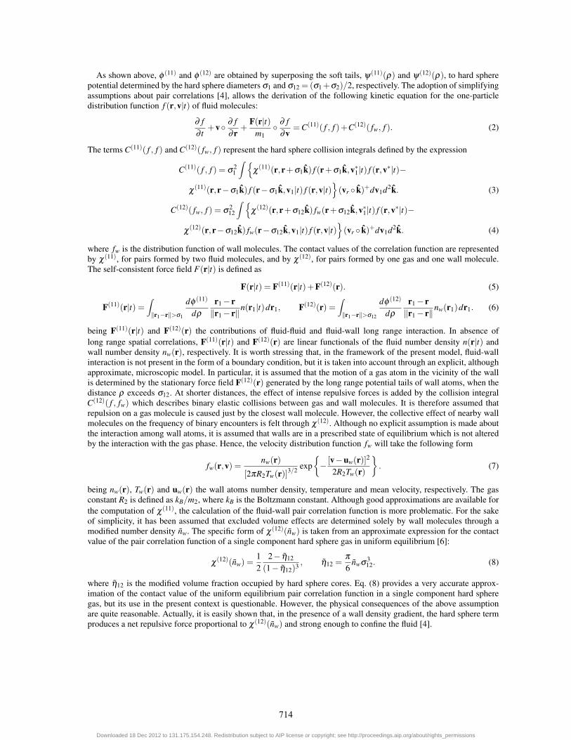
The meniscus formed between the walls of a microchannel was computed over a range of the parameter φ (12)/kBT0
from 1 to 1.5. The walls are set at a distance 8σ1 apart from each other. In Fig. 1 the contour plot of the reduced densityη of an axisymmetric meniscus is shown for φ (12)
/kBT0 = 1 (left panel) and φ (12)/kBT0 = 1.375 (right panel).
A more quantitative information is provided in Fig. 2 where the contact angle formed by the meniscus with thewalls of the microchannel is plotted. The solid circles refer to the contact angle formed by an axisymmetric meniscusand the solid triangle to the contact angle formed by a two dimensional meniscus. It is evident that a contact angle ofπ/2 is attained for φ (12)
/kBT0 = 1 and a contact angle very close to 0 is attained for φ (12)/kBT0 = 1.5. As a further
715
Downloaded 18 Dec 2012 to 131.175.154.248. Redistribution subject to AIP license or copyright; see http://proceedings.aip.org/about/rights_permissions
-10 -5 0 5 10
5
100.600.520.440.360.290.210.130.05
-10 -5 0 5 10
5
10
etamed0.600.520.440.360.290.210.130.05
FIGURE 1. Reduced density of axisymmetric liquid menisci in a microchannel. Left φ (12)/kBT0 = 1. Right φ (12)
/kBT0 = 1.375.
0.9 1 1.1 1.2 1.3 1.4 1.5 1.6
φ(12)/kBT0
0
20
40
60
80
100
θ
FIGURE 2. Contact angle of axisymmetric and two dimensional meniscus.
confirmation, numerical simulations not reported here show that the contact angle that an isolated drop forms withthe wall is practically zero when we choose φ (12)
/kBT0 ≥ 1.45, i.e. the drop is fully spread over the wall. This caseis of technological interest because the wall surface of many micro and nano electromechanical systems is siliconbased and is therefore totally hydrophilic with respect to water. Such an observation justifies the choice of keepingφ (12)
/kBT0 = 1.5 for all the results shown below.The capability of the kinetic model to deal with dense capillary flows is further supported by studying, in the two
dimensional case, the structure of a meniscus between two hydrophilic walls. At equilibrium the relation between thegas phase pressure, p, and the meniscus mean curvature, K, is given by the Laplace-Kelvin equation:
ln(
p
ps
)=
γ Vl
RTK. (11)
where Vl is the liquid phase molar volume, ps is the saturation gas phase pressure, R the universal gas constant, T thetemperature, γ the surface tension of the liquid-gas interface. The ratio p/ps is usually called the relative humidity anddenoted by RH. The mean curvature K is linked to the two principal radii of meniscus surface by: K = 1/R1 +1/R2;in the two dimensional case one of the two radii tends to infinity and the mean curvature K is equal to d/2 when thecontact angle is equal to zero. The computations have been carried out for values of the distance between the two wallsin the range: d = 5σ1, d = 25σ1. At time t = 0 a vertical strip of liquid, surrounded by the gas phase, is placed in themiddle of the microchannel. The strip spans the entire distance between the two walls and can have different initialwidths; this initial configuration evolves in time until a steady state is reached. When the initial width is too narrowthe strip separates into two parts that wet the upper and lower wall, otherwise it forms a meniscus between the twowalls. In Fig. 3 the solid circles are the computed values of RH versus the wall distance for an initial strip of width12σ1, the solid diamonds are values of RH for an initial strip of width 16σ1, the solid line is Eq. (11). In principle,in a two dimensional configuration, the meniscus width should not affect the value of RH, whereas, between the two
716
Downloaded 18 Dec 2012 to 131.175.154.248. Redistribution subject to AIP license or copyright; see http://proceedings.aip.org/about/rights_permissions

menisci, we notice a slight difference that is within 1.7% in the worst case (excluding, as we explain below, the casefor d = 5σ1). It is worth to further investigate the reason for such a discrepancy, although it could simply be due tothe numerical method discretization errors. The values of RH computed for d ≥ 8σ1 agree reasonably well with thevalues predicted by the Laplace-Kelvin equation, a non negligible discrepancy can be noticed for d = 5σ1. For thisvalue of wall distance, the interaction with the wall dominates the flow and it is not possible any more to identify abulk for the gas phase, a requirement on which Eq. (11) is based. From Fig. 4, which shows the contour plot of reduceddensity (for d = 5σ1 and d = 16σ1), we remark that a gas phase bulk can in principle exists for |x| ≥ 7. Fig 5 reportsthe reduced density profile along a vertical section at abscissa x = −10 from the middle of the channel. In the rightpanel of Fig. 5, which refers to d = 16σ1, the existence of the uniform gas phase bulk is evident for |y| < 3, whereasin the left panel, which refers to d = 5σ1, the gas phase bulk disappears and the Laplace-Kelvin formula does not fitany more our results.
0.8 0.9 1 1.1RH
0
4
8
12
16
20
24
28d
FIGURE 3. Relative humidity versus microchannel wall distance.
-10 -5 0 5 10
-5
0
5
10
15
0.600.520.440.360.290.210.130.05
-10 -5 0 5 10
-10
-5
0
5
100.600.520.440.360.290.210.130.05
FIGURE 4. Reduced density contour plot. Left d = 5σ1. Right d = 16σ1.
An important requirement for the kinetic model is the capability to predict the dynamic behaviour of meniscusformation and destruction. In the discussion of the results of Figs. 3, 4 and 5 we have already shown the ability of themodel to follow the formation of a meniscus. The initial condition is indeed quite artificial, but nothing prevents toinitialize the computations with more realistic conditions.
Meniscus destruction is studied, in the present state, with a simple procedure. We start with a stable meniscus andremove a strip of particles from its central zone, thus effectively reducing its width; this procedure introduces also aninitial perturbation. The newly formed meniscus is then evolved in time until either a stable configuration is reachedor the meniscus breaks down. The procedure has been applied to the meniscus formed by an initial strip of width16σ1 between two walls set at a distance d = 25σ1 from each other. In Fig. 6 we plot the reduced density acrossthe horizontal channel section placed at y = 0, i.e. corresponding to the meniscus throat. The solid line (meniscus 1)
717
Downloaded 18 Dec 2012 to 131.175.154.248. Redistribution subject to AIP license or copyright; see http://proceedings.aip.org/about/rights_permissions

-4 -2 0 2 4y
0
0.1
0.2
0.3
0.4
0.5
0.6
η
-10 -8 -6 -4 -2 0 2 4 6 8 10y
0
0.1
0.2
0.3
0.4
0.5
0.6
η
FIGURE 5. Reduced density plot at x =−10. Left d = 5σ1. Right d = 16σ1.
corresponds to the meniscus formed by an initial strip of width 16σ1, the dashed line (meniscus 2) to the meniscusformed by removing a strip of width 4σ1 to meniscus 1. The dashed-dotted line (meniscus 3) corresponds to themeniscus obtained by removing a strip of width 2σ1 to meniscus 2, this configuration is still stable. The doubleddashed-dotted line (meniscus 4) corresponds to the meniscus obtained by removing again a strip of width 2σ1 frommeniscus 3. This final configuration is unstable and breaks down at the throat; its reduced density profile is extractedfrom an average over a time interval Δt = 25, before the meniscus starts to break. A possible explanation of thebreakage process is the following. The fluid-fluid force field, F(11)(r|t), created over the transition zone betweenthe gas phase and the liquid phase, tends to squeeze the meniscus, but its action is counteracted by the repulsivecontribution of collisions. However, when the width of the liquid phase in the throat drops below a critical value, thatfrom our computations seems to be around 4.5σ1, there are not enough collisions to counteract the fluid-fluid forcefield and the meniscus collapses.
-10 -8 -6 -4 -2 0 2 4 6 8 10x
0
0.1
0.2
0.3
0.4
η
FIGURE 6. Reduced density plot at y = 0, d = 25σ1.
718
Downloaded 18 Dec 2012 to 131.175.154.248. Redistribution subject to AIP license or copyright; see http://proceedings.aip.org/about/rights_permissions
CONCLUSIONS
In the present work, a kinetic model for the study of capillary flows in micromechanical devices has been presented.The model is based on the Enskog-Vlasov kinetic equation and provides a reasonable description of two-phase flowsand of fluid-surface interaction, automatically tracking the formation of vapour-liquid and solid-liquid interfaces. In thelatter case it is possible to simulate the full range of contact angles between the liquid and the solid, from hydrophobicsurfaces to hydrophilic ones. Moreover, it can be solved with a modified DSMC technique with a computational costthat is negligible with respect to molecular dynamic simulations. The structure of a meniscus between two hydrophilicwalls has been studied and our results agree fairly well with the Laplace-Kelvin equation. Meniscus destruction hasbeen computed and a possible explanation of the phenomenon has been given.
Future developments will include the computation of capillarity forces exerted by the fluid over the walls of themicrochannel and a full parallelization of the solution procedure in order to further reduce the computational cost.
ACKNOWLEDGMENTS
The authors gratefully acknowledge the financial support received from Fondazione Cariplo within the framework ofthe project “Surface Interactions in Micro and Nano Devices”.
REFERENCES
1. S. D. Senturia, Microsystem Design, Kluwer Ac. Publ., Dordrecht, 2001.2. R. Maboudian, and R. T. Howe, J. Vac. Sci. Technol. B 15, 1-20 (1997).3. A. Hariri et al., J. Microelectromech. Syst. 16, 1276-1285 (2007).4. A. Frezzotti, and L. Gibelli, JMES 222, 787-795 (2008).5. P. Barbante, A. Frezzotti, L. Gibelli, and D. Giordano, "A kinetic model for collisional effects in dense adsorbed gas layers",
in 27th International Symposium on Rarefied Gas Dynamics, 2010, edited by D. A. Levin, I. J. Wysong and A. L. Garcia, AIPConference Proceedings 1333, American Institute of Physics, New York, 2011, pp. 458–463.
6. N. F. Carnahan, and K. E. Starling, J. Chem. Phys. 51, 635-636 (1969).7. Z. Guo, T. S. Zhao, and Y. Shi, Phys. Rev. E 71, 035301(R) (2005).8. J. S. Rowlinson, and B. Widom, Molecular theory of capillarity, Dover, 2002.9. A. Frezzotti, L. Gibelli, and S. Lorenzani, Phys. Fluids 17, 012102 (2005).10. R. Ardito, A. Corigliano, and A. Frangi, Mecanique Industries 11, 177-182 (2010).
719
Downloaded 18 Dec 2012 to 131.175.154.248. Redistribution subject to AIP license or copyright; see http://proceedings.aip.org/about/rights_permissions
Copyright © 2022 FDOKUMEN