Some generic capillary-driven flows
15
Some generic capillary-driven flows W. Villanueva * , G. Amberg Department of Mechanics, Royal Institute of Technology, SE-100 44 Stockholm, Sweden Received 16 July 2005; received in revised form 7 May 2006 Abstract This paper deals with numerical simulations of some capillary-driven flows. The focus is on the wetting phenomenon in sintering-like flows and in the imbibition of liquids into a porous medium. The wetting phenomenon is modeled using the coupled Cahn–Hilliard/Navier–Stokes system. The Cahn–Hilliard equation is treated as a system where the chemical potential is solved first followed by the composition. The equations are discretised in space using piecewise linear functions. Adaptive finite element method is implemented with an ad hoc error criterion that ensures mesh resolution along the vicin- ity of the interface. In the 3D case we use parallel adaptive finite element method. First, a basic wetting of a liquid drop on a solid surface is shown and is established the independence of the dynamic contact angle on the interface width. In addi- tion, the dependence of the dynamic contact angle on the Capillary number is matched with experimental data. Next, some generic sintering-like flows with a fixed matrix is presented. Different geometries in 2D and 3D are considered. We observed rapid wetting, precursor films, coalescence, breakup of melt drops as well as pore migration and elimination that are all microstructural characteristics of a liquid phase sintering. Finally, the effect of equilibrium contact angles on imbi- bition of liquid into a porous medium is studied. Ó 2006 Elsevier Ltd. All rights reserved. Keywords: Capillary-driven flow; Wetting; Cahn–Hilliard/Navier–Stokes system; Sintering; Imbibition 1. Introduction Capillary-driven flows involve two immiscible liquids or a liquid and air separated by a deformable inter- face in which the dynamics of the interface is largely influenced by capillary forces. A contact of these fluids with a third phase, usually a solid surface, gives rise to a phenomenon called wetting. The wetting phenom- enon is pertinent to numerous processes such as penetration of liquids into porous rock, rise of sap in plants, and many others. The goal of this paper is to investigate numerically the wetting phenomenon in liquid phase sintering and in the imbibition of liquids into a porous medium. Liquid phase sintering is a technological process that combines a particulate solid and a softer powder that acts as a binder, melts at a lower temperature and enhances material movement during the sintering 0301-9322/$ - see front matter Ó 2006 Elsevier Ltd. All rights reserved. doi:10.1016/j.ijmultiphaseflow.2006.05.003 * Corresponding author. Tel.: +46 8 790 6871; fax: +46 8 796 9850. E-mail addresses: [email protected] (W. Villanueva), [email protected] (G. Amberg). International Journal of Multiphase Flow 32 (2006) 1072–1086 www.elsevier.com/locate/ijmulflow
-
Upload
independent -
Category
Documents
-
view
0 -
download
0
Transcript of Some generic capillary-driven flows

International Journal of Multiphase Flow 32 (2006) 1072–1086
www.elsevier.com/locate/ijmulflow
Some generic capillary-driven flows
W. Villanueva *, G. Amberg
Department of Mechanics, Royal Institute of Technology, SE-100 44 Stockholm, Sweden
Received 16 July 2005; received in revised form 7 May 2006
Abstract
This paper deals with numerical simulations of some capillary-driven flows. The focus is on the wetting phenomenon insintering-like flows and in the imbibition of liquids into a porous medium. The wetting phenomenon is modeled using thecoupled Cahn–Hilliard/Navier–Stokes system. The Cahn–Hilliard equation is treated as a system where the chemicalpotential is solved first followed by the composition. The equations are discretised in space using piecewise linear functions.Adaptive finite element method is implemented with an ad hoc error criterion that ensures mesh resolution along the vicin-ity of the interface. In the 3D case we use parallel adaptive finite element method. First, a basic wetting of a liquid drop ona solid surface is shown and is established the independence of the dynamic contact angle on the interface width. In addi-tion, the dependence of the dynamic contact angle on the Capillary number is matched with experimental data. Next, somegeneric sintering-like flows with a fixed matrix is presented. Different geometries in 2D and 3D are considered. Weobserved rapid wetting, precursor films, coalescence, breakup of melt drops as well as pore migration and elimination thatare all microstructural characteristics of a liquid phase sintering. Finally, the effect of equilibrium contact angles on imbi-bition of liquid into a porous medium is studied.� 2006 Elsevier Ltd. All rights reserved.
Keywords: Capillary-driven flow; Wetting; Cahn–Hilliard/Navier–Stokes system; Sintering; Imbibition
1. Introduction
Capillary-driven flows involve two immiscible liquids or a liquid and air separated by a deformable inter-face in which the dynamics of the interface is largely influenced by capillary forces. A contact of these fluidswith a third phase, usually a solid surface, gives rise to a phenomenon called wetting. The wetting phenom-enon is pertinent to numerous processes such as penetration of liquids into porous rock, rise of sap in plants,and many others. The goal of this paper is to investigate numerically the wetting phenomenon in liquid phasesintering and in the imbibition of liquids into a porous medium.
Liquid phase sintering is a technological process that combines a particulate solid and a softer powderthat acts as a binder, melts at a lower temperature and enhances material movement during the sintering
0301-9322/$ - see front matter � 2006 Elsevier Ltd. All rights reserved.
doi:10.1016/j.ijmultiphaseflow.2006.05.003
* Corresponding author. Tel.: +46 8 790 6871; fax: +46 8 796 9850.E-mail addresses: [email protected] (W. Villanueva), [email protected] (G. Amberg).

W. Villanueva, G. Amberg / International Journal of Multiphase Flow 32 (2006) 1072–1086 1073
process. One of the oldest and most successful liquid phase systems is a cemented tungsten carbide withcobalt additive used for cutting and machining tools. Tungsten carbide is known to be hard and brittle whilecobalt is relatively soft and ductile. The two metal powders which has typical fine grade sizes of about 1–10 lm in diameter are mixed and pressed, then heated until the cobalt binder melts. The liquid cobalt wetsthe solid grains and due to capillary forces, the microstructure undergoes rearrangement. Simultaneously,mass diffusion is present as well as grain growth that all contribute to pore elimination leading to densifica-tion. Some important factors influence the densification of the compact microstructure such as the amountof liquid present, particle size, solubility of the solid in liquid, contact angle, dihedral angle, etc. (German,1985).
Wettability is the most significant phenomenon in liquid phase sintering, as stressed out by German (1985)and in experiments carried out by Motta et al. (2004) and Taguchi et al. (2004). However, this area has notbeen explored much using simulations. Some factors affecting wettability include contact angle, particle size,particle shape, and particle arrangement.
The wetting of a liquid on a solid can be characterized into two types: total wetting, when the liquid spreadscompletely; and partial wetting, when the liquid at equilibrium rests on the solid with a contact angle he
(de Gennes et al., 2004). Both are characterized by the spreading parameter S = rSO � (rSL + r) where ther’s are surface tensions at the solid/air, solid/liquid, liquid/air interfaces, respectively. S > 0 corresponds tototal wetting and S < 0 corresponds to partial wetting. High-energy surfaces such as metallic surfaces hashigher rSO values, thus increases S, compared to low-energy surfaces like plastics. Wettability can also be con-trolled through surface roughness and surface coatings. Surface roughness enhances wetting when the surfaceis hydrophilic and the opposite if the surface is hydrophobic.
The wetting phenomena can be viewed as a free interface problem where the interface between the twoimmiscible fluids are deformable and free to change their shape in order to minimize their surface energy.The problem can be modeled with sharp interface or diffuse-interface methods. Diffuse-interface methodsconsider the interface between the two fluids to have a non-zero thickness endowed with physical propertiessuch as surface tension. For a review of the development of diffuse-interface models applied to different inter-facial phenomena, see Anderson et al. (1998). Phase-field models are particular type of diffuse-interface modelsthat are based on fluid free energy, an idea that can be traced to van der Waals (1893). One notable feature ofsuch models is that the force singularity arising in the classical model of moving contact lines as pointed out byHuh and Scriven (1971) is no longer present due to mass transfer across the interface, for details see Seppecher(1996). Moving contact line dynamics has also been studied computationally by Jacqmin (1999) using thecoupled Cahn–Hilliard/Navier–Stokes system. The convective Cahn–Hilliard equation is a continuum modelof phase separation in a binary mixture. The equation takes into account creation, evolution, and dissolutionof interfaces. The interface evolves through convection or diffusion driven by chemical potential gradients.
In Section 2, we formulate the Cahn–Hilliard equation with the boundary conditions followed by theNavier–Stokes equations for the fluid motion. Then a dimensionless system is derived and dimensionlessparameters are identified. A numerical treatment of the system of equations is discussed. The results startingfrom a basic wetting phenomena of a liquid drop on a solid surface is shown in Section 3. We first establish theindependence of the wetting contact angle on interface width. Wettability on different matrix of solid particlesis presented. We observe that the particle size, shape, and arrangement of the solid particles has an effect in thedensification of the compact microstructure. Finally, the effect of the equilibrium contact angle on wettabilityis considered. We will show that the smaller the contact angle the more liquid is imbibed into the porous med-ium leading to higher densification.
2. Mathematical formulation
2.1. The phase-field method
Consider the case of an isothermal, viscous, incompressible binary fluid consisting of two components, Aand B. We can introduce an order parameter, a phase-field C, to characterize the two different phases and isanalogous to the relative concentration between the two. In each bulk phases, C assumes a distinct constantvalue and changes rapidly but smoothly in the interfacial region. For example, component A assumes the

1074 W. Villanueva, G. Amberg / International Journal of Multiphase Flow 32 (2006) 1072–1086
value CA = �1 while component B takes the value CB = 1 and the transition from CA to CB describes theinterfacial region. van der Waals (1893) modeled the system by introducing a free energy density f of the form:
f ¼ 1
2aðrCÞ2 þ bWðCÞ ð1Þ
that is the sum of the gradient energy 12aðrCÞ2 and the bulk energy bW(C). The function W is a double-well
positive function that has two minima corresponding to the two stable phases. A simple example of such func-tion is (C + 1)2(C � 1)2 which has minima at CA,B = ±1 and a peak of high energy at C = 0. The constantparameters a and b are used to control the surface tension and the interface thickness which will be shownlater.
Equilibrium interface profiles can be obtained by minimizing the free energy F ¼R
f dV . The chemicalpotential, /, of the liquid mixture is the rate of change of F with respect to C
/ ¼ dFdC¼ bW0ðCÞ � ar2C: ð2Þ
The equilibrium profiles are the solutions of the equation / = bW 0(C) � a$2C � constant. Two stable uniformsolutions exist, CA,B = ±1, that corresponds to the two bulk phases and a one-dimensional (say, along thex-direction) nonuniform solution exists and was first obtained by van der Waals (1893),
C0ðxÞ ¼ tanhxffiffiffi2p
n
� �; ð3Þ
where n ¼ffiffiffiffiffiffiffiffia=b
pis the mean-field thickness. The equilibrium interface thickness � is defined to be the distance
from C = �0.9 to C = 0.9 and this width contains 98.5% of the surface tension stress (Jacqmin, 2000). WithEq. (3), � ¼ 2
ffiffiffi2p
ntanh�1ð0:9Þ ¼ 4:164n. The equilibrium surface tension r of a plane interface can be found byintegrating the free energy density along the interface,
r ¼ aZ 1
�1
dC0
dx
� �2
dx ¼ 2ffiffiffi2p
3a1=2b1=2: ð4Þ
Note that the interface thickness � and the surface tension r can be controlled using the positive parameters aand b.
Cahn extended van der Waals model to time-dependent problems (Cahn, 1961) by approximating interfa-cial diffusion to be proportional to chemical potential gradients. The Cahn–Hilliard equation, modified toaccount for fluid motion is given by
oCotþ ðu � rÞC ¼ jr2/ ¼ jr2ðbW0ðCÞ � ar2CÞ in X; ð5Þ
where u is the velocity field and j is the mobility. The Cahn–Hilliard equation models the creation, evolution,and dissolution of diffusively controlled phase-field interfaces (Bates and Fife, 1993).
Two boundary conditions are set for C. First, the no-flux condition
n � r/ ¼ 0; ð6Þ
where n is the unit vector normal to the wall. Following Jacqmin (1999), the second boundary condition de-pends on the interface at the wall being at or near local equilibrium. The wall free energy is postulated to be ofthe form:Fw ¼Z
cgðCÞdA; ð7Þ
where c is the jump in solid/fluid surface energies from CA to CB. The function g(C) is a local surface energyand is set to 0.75C–0.25C3 in this formulation. The resulting boundary condition is then
an � rC þ cg0ðCÞ ¼ 0 ð8Þ

W. Villanueva, G. Amberg / International Journal of Multiphase Flow 32 (2006) 1072–1086 1075
that corresponds to a diffusively controlled local equilibrium at the wall. We define the wetting coefficient k,
k ¼ rSO � rSL
r¼ S
rþ 1: ð9Þ
It can be shown that the normal gradient of the composition C is directly proportional to the wettingcoefficient,
n � rC ¼ � kCn
g0ðCÞ: ð10Þ
Cn is a dimensionless numerical parameter that will be discussed more in detail later.We can also define the Young’s relation (Probstein, 2003) which is only valid when S < 0,
cos he ¼ k ¼ Srþ 1; ð11Þ
where he is the static equilibrium angle taken to be the same as the dynamic contact angle right at the wall. Eq.(8) can also be extended to non-equilibrium situations by taking into account wall velocities.
2.2. The equations of fluid motion
The calculations in this paper are restricted to two phases having the same viscosity and mobility. The bin-ary fluid motion is governed by the incompressible Navier–Stokes equations with phase-dependent surfacetension forcing in its potential form, �C$/,
q0
ou
otþ ðu � rÞu
� �¼ �rp þ lr2u� Cr/;
r � u ¼ 0;
ð12Þ
where p enforces incompressibility and is related to the pressure, q0 is the mean density, and l is the viscosity.When the stress form of the surface tension force is used, p becomes the true pressure (Jacqmin, 1999).
2.3. Nondimensionalization
Define the dimensionless variables,
x0 ¼ xLc
; u0 ¼ uU c
; t0 ¼ tU c
Lc
; p0 ¼ pLc
lU c
; ð13Þ
where Lc is the characteristic length taken to be the domain size and Uc is the characteristic velocity. Droppingthe primes, the dimensionless forms of Eqs. (5) and (12) are
oCotþ ðu � rÞC ¼ 1
Per2/ ¼ 1
Per2ðW0ðCÞ � Cn2r2CÞ;
Reou
otþ ðu � rÞu
� �¼ �rp þr2u� 1
Ca � CnCr/;
r � u ¼ 0:
ð14Þ
The dimensionless physical parameters are the Reynolds number Re, Capillary number Ca, and Peclet numberPe given by
Re ¼ q0U cLc
l; Ca ¼ 2
ffiffiffi2p
lU c
3r; Pe ¼ 2
ffiffiffi2p
LcU cn3jr
: ð15Þ
The Reynolds number is the ratio between the inertial and viscous forces. The Capillary number gives the ratiobetween the viscous and surface tension forces. The bulk phase chemical diffusivity is given by n�1rjW00(CA,B).Accordingly, the Peclet number is the ratio between the convective and diffusive mass transport. The Cahnnumber Cn = n/Lc is a dimensionless numerical parameter that provides a measure of the ratio between the

1076 W. Villanueva, G. Amberg / International Journal of Multiphase Flow 32 (2006) 1072–1086
mean-field thickness n and the characteristic length Lc. For example, Cn = 0.01 means that for a 1 lm diam-eter droplet, the mean-field thickness is 0.01 lm. The choice of Cn is influenced, at least, by numerical accu-racy, efficiency, and stability. Thick interfaces does not accurately describe the dynamics of the interface suchas coalescences and breakups. Thin interfaces on the other hand reduces the length scale since the interfaceneeds to be resolved. And for a flow problem, smaller length scale requires smaller time-step to achieve numer-ical stability and also given the fact that the Cahn–Hilliard equation has a biharmonic term which sets a severetime-step restriction. Moreover, without the use of mesh adaptivity, the small length scale is uniform allthroughout the domain (assuming that interfacial dynamics almost covers the whole domain) thereby increas-ing the number of mesh points significantly which requires much longer computation time. In this paper, weconsider capillary-driven laminar flows, so our values for the Reynolds number Re and Capillary number Ca
are both small. We also consider problems where the convective mass transport is much higher than thediffusive mass transport, so the Peclet number Pe chosen is large.
It is important to note that the convective Cahn–Hilliard equation conserves mass. Using the divergencetheorem in Eq. (14a) integrated over the domain X we have
ZXCt dxþ
ZoXðn � uÞC dS ¼ 1
Pe
ZoX
n � r/dS: ð16Þ
And given that n Æ u = 0 and n Æ $/ = 0,
0 ¼Z
XCt dx ¼ 1
dt
ZX
CðxÞdx ð17Þ
which implies that the rate of change of the composition C with respect to time over the entire domain is zero.
2.4. Numerical treatment
The numerical simulations were carried out using FemLego (Amberg et al., 1999), a symbolic tool to solvepartial differential equations with adaptive finite element method. The partial differential equations, boundaryconditions, initial conditions, and the method of solving each equation are all specified in a Maple worksheet(www.maplesoft.com). The Cahn–Hilliard equation is treated as a system where the chemical potential / iscomputed first followed by the composition C (see Eq. (14a)) in which the right hand side of the equation isthe Laplacian of the chemical potential. Both chemical potential and composition equations are discretised inspace using piecewise linear functions. Moreover, an explicit Euler scheme is used to discretise the composi-tion equation in time. The resulting linear systems of both equations are solved using conjugate gradientmethod. Since the model requires the interface to be resolved with at least 3-node points, the use of adaptivityis essential. An ad hoc error criterion is used to ensure mesh resolution along the vicinity of the interface (seeFig. 1c). The mesh adaptivity is implemented as follows: at each mesh refinement step, an element K ismarked for refinement if the element size h > hmin (the minimum h allowed), and does not satisfy the follow-ing the error criterion:
kHða� jCðx; tÞjÞkL1ðKÞ 6 TOL; ð18Þ
where H( Æ ) is the Heaviside step function, a is a constant (here we used a = 0.99), and TOL is a given toler-ance. If an element satisfies the error criterion, it is marked for derefinement unless it is an original element. Atthe next refinement step, elements containing hanging nodes are marked for refinement. The refinement/dere-finement stops if and only if no element is marked for refinement/derefinement. The interface moves quite slowso the adaptivity is implemented at every 10th to 20th time-step.
The Navier–Stokes equations are solved using a projection method by Guermond and Quartapelle (1995)with an added pressure stabilization term. The Navier–Stokes equations are also discretised in space usingpiecewise linear functions and the linear systems are solved using conjugate gradient method. Typical meshsize in 2D with the mesh adaptivity ranges from 2000 to 6000 nodes depending on the dynamics of the inter-face. The 2D simulation on a single Linux PC takes between 5 and 10 h or more depending on the choice ofparameters and extent of computation but with the average of 166 time-steps/min. In the 3D simulation, thenumber of nodes and elements increases dramatically so the use of parallel adaptive computation is necessary.

Fig. 1. Wetting of a liquid droplet on a solid surface. Concentration field at nondimensional time t = 0,1,10,200 with Ca = 1.0, Re = 1.0,Pe = 1.5 · 104, Cn = 0.01 and k = 0.9063 (he � 25�). The mesh and velocity field are superimposed in (c) and (d), respectively.
W. Villanueva, G. Amberg / International Journal of Multiphase Flow 32 (2006) 1072–1086 1077
An extended version of FemLego that run on distributed memory has been used (Do-Quang et al., submittedfor publication). The 3D computation was done on a Linux PC-cluster with 16 processors. Until the final timeconsidered which is about 22,000 time-steps with a million elements and 200,000 nodes, the computation tookabout 52 h with seven equations to be solved or with a rate of 7 time-steps/min.
3. Results
We present wetting flows in different geometries. We start by showing a basic wetting phenomena of aliquid drop on a solid surface and show that the dynamic contact angle is fairly independent of the interfacewidth. Next, some generic sintering flows with a fixed matrix will be shown where coalescence and breakup canbe observed. The effect of particle size, shape, and arrangement to wettability is also discussed. And finally, westudy the effect of static contact angles to impregnation or imbibition. We find that the smaller the contactangle the more liquid is imbibed into the porous medium leading to higher densification. In all simulations,we neglect the effect of gravity and consider only capillary effects as the driving force in the fluid motion.
3.1. Basic wetting phenomena
First, consider a 2D drop lying on a solid surface, see Fig. 1a with Ca = 1.0, Re = 1.0, Pe = 104, andCn = 0.01. The wetting coefficient is k = 0.9063 and using Eq. (9), S < 0, thus we have partial wetting andthe equilibrium contact angle is he � 25�. The drop is surrounded by another liquid with density similar tothe drop. Consequently, the capillary length which can be estimated by relating the Laplace pressure to thehydrostatic pressure, increases and gravity can be neglected. Thus the liquid is considered to be in a zero-grav-ity environment where capillary effects dominate (de Gennes et al., 2004). In Fig. 1a, the drop is in contactwith the surface at 158� apparent contact angle. Then the drop starts to spread and wets the surface,Fig. 1b, with a 141� apparent contact angle. In Fig. 1c, the drop spreads further with 77� apparent contactangle. The adaptive mesh is superimposed and shows fine resolution along the vicinity of the interface. Finally,the drop closely reaches the equilibrium contact angle of he � 25� in Fig. 1d. The spreading is fast in the firststage and then slowly reach the equilibrium static contact angle. The velocity field is also superimposed andgives a symmetric profile with two vortices.
As mentioned earlier, the use of adaptivity is essential especially in larger systems since we need toresolve the interfaces. In this wetting case with Cn = 0.01, the minimum mesh spacing hmin = 0.0056 and
1078 W. Villanueva, G. Amberg / International Journal of Multiphase Flow 32 (2006) 1072–1086
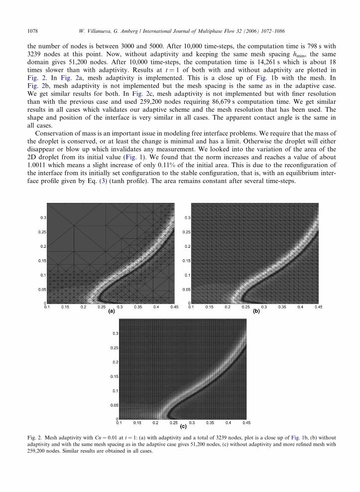
the number of nodes is between 3000 and 5000. After 10,000 time-steps, the computation time is 798 s with3239 nodes at this point. Now, without adaptivity and keeping the same mesh spacing hmin, the samedomain gives 51,200 nodes. After 10,000 time-steps, the computation time is 14,261 s which is about 18times slower than with adaptivity. Results at t = 1 of both with and without adaptivity are plotted inFig. 2. In Fig. 2a, mesh adaptivity is implemented. This is a close up of Fig. 1b with the mesh. InFig. 2b, mesh adaptivity is not implemented but the mesh spacing is the same as in the adaptive case.We get similar results for both. In Fig. 2c, mesh adaptivity is not implemented but with finer resolutionthan with the previous case and used 259,200 nodes requiring 86,679 s computation time. We get similarresults in all cases which validates our adaptive scheme and the mesh resolution that has been used. Theshape and position of the interface is very similar in all cases. The apparent contact angle is the same inall cases.
Conservation of mass is an important issue in modeling free interface problems. We require that the mass ofthe droplet is conserved, or at least the change is minimal and has a limit. Otherwise the droplet will eitherdisappear or blow up which invalidates any measurement. We looked into the variation of the area of the2D droplet from its initial value (Fig. 1). We found that the norm increases and reaches a value of about1.0011 which means a slight increase of only 0.11% of the initial area. This is due to the reconfiguration ofthe interface from its initially set configuration to the stable configuration, that is, with an equilibrium inter-face profile given by Eq. (3) (tanh profile). The area remains constant after several time-steps.
Fig. 2. Mesh adaptivity with Cn = 0.01 at t = 1: (a) with adaptivity and a total of 3239 nodes, plot is a close up of Fig. 1b, (b) withoutadaptivity and with the same mesh spacing as in the adaptive case gives 51,200 nodes, (c) without adaptivity and more refined mesh with259,200 nodes. Similar results are obtained in all cases.

W. Villanueva, G. Amberg / International Journal of Multiphase Flow 32 (2006) 1072–1086 1079
The apparent contact angle versus dimensionless time is plotted in Fig. 3. The figure suggests that the firststage of wetting is fast where the apparent contact angle decreases rapidly and then slows down upon reachingthe equilibrium contact angle. In the final time considered, we measured an apparent contact angle of 26�, onedegree higher than the theoretically set value of 25�. The apparent contact angle is also plotted versus theCapillary number for different interface thicknesses in Fig. 4. The apparent contact angle is fairly independentof the interface thickness. Moreover, the values taken on the dependence of the contact angle on the Capillarynumber is fairly close to the values taken experimentally by Hoffman (1975) using silicone oils. The valuesmatched closer when the Capillary number approaches zero.
The values for Cn used for the computations in Fig. 3 were chosen to give interface widths less than relevantradii of curvature, while at the same time allowing reasonably quick results. The limited scatter that is presentin Fig. 3 is attributed to uncertainites in determining the apparent contact angle. As demonstrated in Fig. 3,the increase or decrease of interface width by a factor of 2 has little consequence for the dependency of appar-ent contact angle on capillary number (or advancing speed). There is a fundamental reason for why this is
Fig. 3. Apparent contact angle versus dimensionless time for a liquid droplet.
Fig. 4. Dependence of the contact angle on the Capillary number: (s), (�), and (h) with different Cahn number Cn and (*) with data fromHoffman’s experiment using silicone oils (Hoffman, 1975).

1080 W. Villanueva, G. Amberg / International Journal of Multiphase Flow 32 (2006) 1072–1086
expected, i.e., that the predicted dynamic wetting properties become independent of the interface width, whenthe interface width is less than the length scales for the interface geometry, i.e., the relevant radii of curvature.
In order to see this we will briefly discuss the fluid dynamics of the contact point, i.e., the fluid flow in aregion of length scale interface width, around the apparent contact point. In the close up in Fig. 2(Cn = 0.01), the contact point region would be an area of a cross-section of a few interface widths, say0.05 around the apparent contact point. In this region the essential driving force for fluid motion is the cap-illary action on the highly curved interface near the wall, where the apparent contact angle is adjusted to thestatic one (which must always hold right at the wall). This change happens over the length scale of the interfacewidth, which thus also sets the local radius of curvature. This corresponds thus to a driving pressure of theorder (surface tension)/(interface width).
The flow resistance (assuming this to be small enough that a local Reynolds number is less than unity)scales with the viscous friction corresponding to a finite flow speed at one interface width from the wall.The flow resistance that balances the driving force is thus (viscosity)(speed)/(interface width). Both the drivingforce and the flow resistance are thus inversely proportional to the interface width, and the value of this willcancel, and not influence the result. Expressed differently we could say that the contact region is self similar,and that the actual value of the length scale of the region will not influence the resulting speed. Furthermore,we expect the Cahn–Hilliard system to describe the correct physics on length scales corresponding to realinterface widths. Since we also observe above that the predicted dynamic wetting does not depend on thelength scale as such, it is not surprising that good results can be obtained also with interfaces that are muchthicker than the physical ones.
3.2. Some sintering-like flows
In this section, we show some examples of sintering-like flows. The binder powders are modeled with dropsthat melts and spreads through the solid grains, see Figs. 5 and 6. However, with the present model, the solidgrains are rendered immobile. Nevertheless, the model captures qualitatively the most important phenomenonin liquid phase sintering which is wettability and how this is affected by contact angle, particle size and shape,and particle arrangement. The model also captures important microstructural behaviors in liquid phasesintering such as phase deformation, coalescence, breakup, pore migration, and pore elimination. In the sim-ulations that follow, we observe coalescence through the collision of precursor films. Precursor films spreadfaster than the bulk fluid and feel no bounds unless the property of the surface changes in which S changessign, or the film collides with another fluid of the same phase that initiates coalescence. Coalescence alsooccurs when two droplets collide and the separation length between the interfaces falls below a critical value.Experimentally, the critical length cannot be measured directly but the length is known to be comparable tothe distance where van der Waals forces become important.
Fig. 5a shows nine liquid drops distributed over a fixed matrix of six solid particles with irregular shapesand sizes. The sizes of the drops are smaller than the solid particles. The parameters used are Ca = 1.0,Re = 10, Pe = 105, and Cn = 0.01. The wetting coefficient is k = 1 which corresponds to S = 0, a wetting tran-sition. In this case, the equilibrium contact angle he = 0�. The droplets melt and rapidly wet the surface of thesolid grains, and eight pores are formed (Fig. 5b). The melted drops continue to spread forming precursorfilms and coalesce with other droplets (Fig. 5c). The pores move towards the center of the compact and com-bine with other pores. The lower portion of the compact shows the breakup of a liquid melt when two poresare joining (Fig. 5c and d). Since we are dealing with two-phase flow, this is a situation where the coalescenceof one phase is the breakup of the other. At this point, the dynamics of the compact slows down. Pores con-tinue to move initiating coalescence, then subsequently shrink and disappear due to diffusion which is thedominating process at this later stage (Fig. 5e and f).
A different matrix of solid grains is used in Fig. 6 with the same physical parameters. In Fig. 6a, droplets arecombined with grains of same shapes and sizes and arranged uniformly. In this case the solid grains are mod-eled with squares and the droplets with circles. The drops when melted then start to spread and wet the solidgrains, see Fig. 6b. Coalescence takes place and pores are formed. Precursor films developed (which are evi-dent in Fig. 6c) and are the result of having a zero static contact angle. In this example, no pores disappeareduntil the final time considered and no significant change can be observed from Fig. 6c and d.

Fig. 5. Generic sintering flow with a fixed matrix of solid particles of irregular shapes and sizes. Concentration field att = 0,2,16,18,220,500 with Ca = 1.0, Re = 10, Pe = 105, Cn = 0.01, and k = 1.
W. Villanueva, G. Amberg / International Journal of Multiphase Flow 32 (2006) 1072–1086 1081
The average velocity of both cases with square and irregular particles are plotted in Fig. 7. The case withsquare particles starts from 0 and reaches 0.237 at t = 1 then rapidly drops to 0.1 level until t = 18. The rapidincrease in velocity is due to fast wetting and rapid change in the configuration of the pores from irregular tocircular shapes which is a consequence of the minimization of the free energy. The 0.1 level corresponds tospreading of the precursor films and further reconfiguration of the pores. After this stage, the dynamics of

Fig. 6. Generic sintering flow with a fixed matrix of solid particles of same shapes and sizes. Concentration field at t = 0,1,20,200 withCa = 1.0, Re = 10, Pe = 105, Cn = 0.01, and k = 1.
Fig. 7. Average velocity versus dimensionless time of two different matrix of solid particles.
1082 W. Villanueva, G. Amberg / International Journal of Multiphase Flow 32 (2006) 1072–1086
the microstructure slows down and the diffusion process dominates in which the average velocity decreasesupto two orders of magnitude. The case with irregular shape particles gives a slightly different behavior.

Fig. 8. Three-dimensional generic sintering with a fixed matrix of solid particles (larger spheres). Isosurface at t = 0,2,11 with Ca = 0.1,Re = 0.1 and Pe = 104.
W. Villanueva, G. Amberg / International Journal of Multiphase Flow 32 (2006) 1072–1086 1083
The average velocity rapidly increases to 0.292 which is higher than the previous case and this rapid increase isalso attributed to fast wetting and pore filling that results to rapid change in the configuration of the poresfrom irregular to circular shapes. The second peak in the average velocity is due to coalescences of poresand reconfiguration of the resulting pore into a circular shape (see Fig. 5d). Similar to the previous case,the dynamics of the compact slows down with diffusion process starting to dominate that aids in pore elim-ination. Even without rearrangement in our model, the rapid increase and decrease in velocity is consistentwith the actual liquid phase sintering process where the first stage is considered to be fast and the secondto be very much slower.
An extension of the 2D generic sintering in 3D is shown in Fig. 8. The compact microstructure consists ofsix solid particles (larger spheres) and 13 melt drops that are evenly distributed. The drops melt and spreadover the solid grains. Similar to the 2D case, coalescence, pore migration and elimination take place.
3.3. Imbibition
In this section, we look into the effect of equilibrium contact angle on wetting. Fig. 9a shows a fixed matrixof solid particles which can be thought of as a porous medium partially submerged in a pool of liquid. The no-slip boundary condition is used on the left and right edges of the domain including the inner edges while thetop and lower edges allow fluid to pass through, i.e., fluid gets in from below and the other fluid is pushed outof the domain. The parameters used in this case are Ca = 1.0, Re = 0.1, Pe = 105, and the wetting coefficientk = 1 or he = 0�. With a zero equilibrium contact angle the liquid rapidly spreads over the surface of the solidgrains forming precursor films (Fig. 9b). In reality, precursor films have thickness comparable to the thicknessof the interface and can be detected by electrical means (de Gennes, 1992). The liquid continues to spread anda bulk of liquid is drawn into the porous medium (Fig. 9c and d).
For the case with a higher equilibrium contact angle, he = 60�, the wetting behavior is quite different as canbe seen in Fig. 10. In Fig. 10a, a porous medium has its end dip into a pool of liquid. The parameters used isthe same as in the previous case, Ca = 1.0, Re = 0.1, Pe = 105. The liquid starts to spread and wet the surfaceof the solid grains but no precursor films can be observed unlike in the previous case. Due to capillary forces,the liquid continues to penetrate into the porous medium (Fig. 10c and d). The interface tries to find its equi-librium state, that is, the profile that minimizes the free energy of the system. In Fig. 10c, there are three chan-nels in the lower part of the medium and two of them located on the sides have similar shapes which narrowsup while the one in the middle broadens. We observed from Fig. 10d that the liquid in the two side channelsrise up higher than the one in the middle. Actually, the liquid in the middle channel only risen up a bit and oneend of the interface got stuck at a corner of the middle channel.
The amount of liquid that is imbibed into the porous medium with respect to time is plotted in Fig. 11 forthe two cases. The case with he = 0� draws in more liquid than with he = 60� which implies that the lower thecontact angle the better the wettability of the system. In both cases, the advancement of the liquid starts outrapidly and then subsequently slows down.

Fig. 9. Imbibition of a liquid into a porous medium. Concentration field at t = 0,2,40,500 with Ca = 1.0, Re = 0.1, Pe = 105, Cn = 0.01,and he = 0�.
1084 W. Villanueva, G. Amberg / International Journal of Multiphase Flow 32 (2006) 1072–1086
Darcy’s law is a macroscopic description of flow in porous media in the presence of gravity. It relates thevolumetric flow rate to the pressure gradients, bulk viscosity, and permeability (Batchelor, 1967). It wasderived from simplifications made to the Navier–Stokes equations and is only valid for slow and viscous flow.It does not describe microscopically the movement of liquid fronts, specifically, how it behaves given a wettingcondition and geometrical configuration of the system, i.e., particle size and shape, particle arrangement, androughness. A more specific description of how liquid fronts move in a column, or simply put, in the presence ofgravity, a fluid with density q rises at a height H in a column of radius R that is given by the Jurin’s height (deGennes, 1992), H = 2rcoshe/qgR. Note the dependence of the height to the equilibrium contact angle. This isonly valid, however, when the radius of the capillary is much smaller than its height. Moreover, this law takesinto account cylindrical geometries or two parallel plates close to each other (with some modification to theconstant factor) but not converging or diverging tubes or plates. In many porous media, they have compli-cated structure and connectivity of pores, as well as roughness which significantly affects the wetting conditionof the system especially with microstructural systems. In general, liquid fronts tries to find its equilibrium statethat is the state where the free energy is minimum. In a channel that narrows up with 0 < he < 90� and neglect-ing the effect of gravity, the liquid will rise up to the top because it minimizes the free energy by doing so unlikein a channel that broadens up, it requires more energy to rise up since it has to increase its surface area, justlike what we observe in Fig. 10. For he = 0 in the absence of gravity, the liquid rises or penetrates the channelto its end without any regard of the channel’s topological structure.

Fig. 10. Imbibition of a liquid into a porous medium. Concentration field at t = 0,2,40,500 with Ca = 1.0, Re = 0.1, Pe = 105, Cn = 0.01,and he = 60�.
0 50 100 150 200 250 300 350 400 450 5000
5
10
15
20
25
30
35
40
time
% im
bibe
θe = 0o
θe = 60o
Fig. 11. Effect of equilibrium contact angle to imbibition of liquid into a porous medium.
W. Villanueva, G. Amberg / International Journal of Multiphase Flow 32 (2006) 1072–1086 1085
1086 W. Villanueva, G. Amberg / International Journal of Multiphase Flow 32 (2006) 1072–1086
4. Conclusion
We have investigated numerically the wetting phenomena in some capillary-driven flows. First, we showeda basic wetting phenomenon of a liquid drop on a solid surface and established the independence of thedynamic contact angle on the interface width. The values taken on the dependence of the contact angle onthe Capillary number was compared with experimental values and they are in good agreement especially whenthe Capillary number approaches 0. We also presented successful simulations of some generic sintering flowswith a fixed matrix in 2D and 3D. The model captured qualitatively the most important phenomenon in liquidphase sintering which is wettability. We have also investigated how wettability is affected by contact angle,particle size and shape, and particle arrangement. Interestingly, the model also captured important micro-structural behaviors in liquid phase sintering such as phase deformation, coalescence, breakup, pore migra-tion, and pore elimination. Finally, the effect of equilibrium contact angles on imbibition of liquid intoporous medium is studied. We found that the smaller the equilibrium contact angle the more liquid is imbibeinto the porous medium. In addition, the structure of the channel also affects the imbibition of liquid.
The next step of our simulation is to allow the solid particles to move. In that case, the model has to beextended by adding one stiff phase-field variable that corresponds to the solid particles with the ability to coarsen,also called Ostwald ripening. In addition, our representation of the interface is too thick, giving us only a qual-itative picture of the coalescences and breakups. A molecular dynamics simulation of the interaction between themolecules of the different phases can be coupled with the present model to give a more accurate description of thecoalescence and breakup of the melt. Moreover, a molecular dynamics simulation can also supply input param-eters in the present model such as the wetting coefficient k(t) of the given system and the surface tension r of thefluid interface in cases where no experimental data are available for the system under investigation.
Acknowledgements
The authors gratefully appreciate the valuable discussions with the members of the Computational PhaseTransformation Research Group, KTH. This work was financially supported by the Swedish Foundation forStrategic Research (SSF).
References
Amberg, G., Tonhardt, R., Winkler, C., 1999. Finite element simulations using symbolic computing. Math. Comput. Simulat. 49, 257–274.
Anderson, D.M., McFadden, G.B., Wheeler, A.A., 1998. Diffuse-interface methods in fluid mechanics. Annu. Rev. Fluid Mech. 30, 139–165.
Batchelor, G.K., 1967. An Introduction to Fluid Dynamics. Cambridge University Press.Bates, P.W., Fife, P.C., 1993. The dynamics of nucleation for the Cahn–Hilliard equation. SIAM J. Appl. Math. 53, 990–1008.Cahn, J.W., 1961. On spinodal decomposition. Acta Metall. 9, 795–801.de Gennes, P.G., 1992. Simple Views on Condensed Matter. World Scientific Publishing Co. Pte. Ltd.de Gennes, P.G., Brochard-Wyart, F., Quere, D., 2004. Capillarity and Wetting Phenomena. Springer-Verlag, Inc., NY.Do-Quang, M., Singer-Loginova, I., Villanueva, W., Amberg, G., submitted for publication. Problem solving environment for parallel
adaptive computation. Comput. Methods Appl. Mech. Engrg.German, R., 1985. Liquid Phase Sintering. Plenum Press, NY.Guermond, J.L., Quartapelle, L., 1995. Unconditionally stable finite-element method for the unsteady Navier–Stokes equations. In: Proc.
Int. Conf. Finite Elements in Fluids, Venezia, 15–21 October.Hoffman, R., 1975. A study of the advancing interface. J. Colloid Interface Sci. 50, 228–241.Huh, C., Scriven, L.E., 1971. Hydrodynamic model of steady movement of a solid/liquid/fluid contact line. J. Colloid Interface Sci. 35, 85–
101.Jacqmin, D., 1999. Calculation of two-phase Navier–Stokes flows using phase-field modeling. J. Comput. Phys. 155, 96–127.Jacqmin, D., 2000. Contact-line dynamics of a diffuse fluid interface. J. Fluid Mech. 402, 57–88.Motta, F.V., Balestra, R.M., Ribeiro, S., Taguchi, S.P., 2004. Wetting behaviour of SiC ceramics, Part I. Mater. Lett. 58, 2805–2809.Probstein, R.F., 2003. Physicochemical Hydrodynamics, An Introduction. John Wiley and Sons, Inc.Seppecher, P., 1996. Moving contact lines in the Cahn–Hilliard theory. Int. J. Eng. Sci. 34, 977–992.Taguchi, S.P., Motta, F.V., Balestra, R.M., Ribeiro, S., 2004. Wetting behaviour of SiC ceramics, Part II. Mater. Lett. 58, 2810–2814.van der Waals, J.D., 1893. The thermodynamic theory of capillarity under the hypothesis of a continuous variation of density. Verhandel.
Konink. Akad. Weten. 1 (J. Stat. Phys.) 20, 1979 (in English).