mm25 mems microphone high snr trimmable - Knowles
6
APPLICATION NOTE AN-19 MM25 MEMS MICROPHONE HIGH SNR TRIMMABLE knowles.com | AN-19 MM25 MEMS Microphone Rev B ©2019, Knowles Electronics, LLC, Itasca, IL, USA, All Rights Reserved. 1 Knowles and the logo are trademarks of Knowles Electronics, LLC. The MM25 is a uniquely trimmable microphone. Using Knowles’ proven ultralow noise MEMS technology, the MM25 consists of an acoustic sensor, a low noise input buffer, and an output amplifier. These devices are suitable for applications where excellent matching is required. PRODUCT FEATURES Trimmable Sensitivity, Phase and Current Small Package / Bottom Port High SNR Extended Dynamic Range Maximum RF Protection Ultra-Stable Performance Standard SMD Reflow Omnidirectional SENSITIVITY AND PHASE MATCHING The MM25 has trimmed sensitivity with part to part variation no more than +/-1 dB. Phase at low frequency is also trimmable (e.g., 200Hz). This feature allows use of more aggressive algorithms such as beam forming. Tight microphone matching reduces the range of calibration at the final device level. The MM25 has adjustable high and low pass filters for tight control of LFRO and for adjusting peak amplitude per customer requirements (see Figure). NOISE Noise levels depend on choice of audio port size, gain and filter settings. POWER SUPPLY REJECTION -80 -75 -70 -65 -60 -55 -50 -45 -40 1000 10000 Sensitivity (dB V/0.1 Pa) Frequency (Hz) 0.45mm Acoustic Port 0.25mm Acoustic Port 0 2 4 6 8 10 12 14 16 18 20 22 24 26 28 30 100 125 160 200 250 315 400 500 630 800 1000 1250 1600 2000 2500 3150 4000 5000 6300 8000 10000 Equivalent Noise (dB SPL) 1/3 Octave Band (Hz) 0.45mm AP, LFRO=60Hz 0.25mm AP, LFRO=50Hz -50 -48 -46 -44 -42 -40 -38 -36 -34 -32 -30 100 1000 10000 PSRR (dB) Frequency (Hz)
-
Upload
khangminh22 -
Category
Documents
-
view
3 -
download
0
Transcript of mm25 mems microphone high snr trimmable - Knowles
APPLICATION NOTE AN-19
MM25 MEMS MICROPHONE HIGH SNR TRIMMABLE
knowles.com | AN-19 MM25 MEMS Microphone Rev B
©2019, Knowles Electronics, LLC, Itasca, IL, USA, All Rights Reserved.
1 Knowles and the logo are trademarks of Knowles Electronics, LLC.
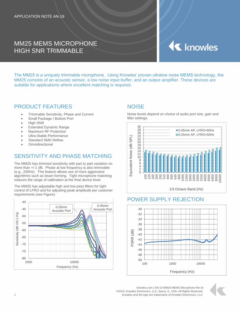
The MM25 is a uniquely trimmable microphone. Using Knowles’ proven ultralow noise MEMS technology, the MM25 consists of an acoustic sensor, a low noise input buffer, and an output amplifier. These devices are suitable for applications where excellent matching is required.
PRODUCT FEATURES
Trimmable Sensitivity, Phase and Current
Small Package / Bottom Port
High SNR
Extended Dynamic Range
Maximum RF Protection
Ultra-Stable Performance
Standard SMD Reflow
Omnidirectional
SENSITIVITY AND PHASE MATCHING
The MM25 has trimmed sensitivity with part to part variation no more than +/-1 dB. Phase at low frequency is also trimmable (e.g., 200Hz). This feature allows use of more aggressive algorithms such as beam forming. Tight microphone matching reduces the range of calibration at the final device level.
The MM25 has adjustable high and low pass filters for tight control of LFRO and for adjusting peak amplitude per customer requirements (see Figure).
NOISE
Noise levels depend on choice of audio port size, gain and filter settings.
POWER SUPPLY REJECTION
-80
-75
-70
-65
-60
-55
-50
-45
-40
1000 10000
Sensitiv
ity (
dB
V/0
.1 P
a)
Frequency (Hz)
0.45mm Acoustic Port
0.25mm Acoustic Port
02468
1012141618202224262830
10
0
12
5
16
0
20
0
25
0
31
5
40
0
50
0
63
0
80
0
100
0
125
0
160
0
200
0
250
0
315
0
400
0
500
0
630
0
800
0
100
00Equiv
ale
nt
Nois
e (
dB
SP
L)
1/3 Octave Band (Hz)
0.45mm AP, LFRO=60Hz
0.25mm AP, LFRO=50Hz
-50
-48
-46
-44
-42
-40
-38
-36
-34
-32
-30
100 1000 10000
PS
RR
(dB
)
Frequency (Hz)
MM25 MEMS MICROPHONE
knowles.com | AN-19 MM25 MEMS Microphone Rev B
©2019, Knowles Electronics, LLC, Itasca, IL, USA, All Rights Reserved.
2 Knowles and the logo are trademarks of Knowles Electronics, LLC.
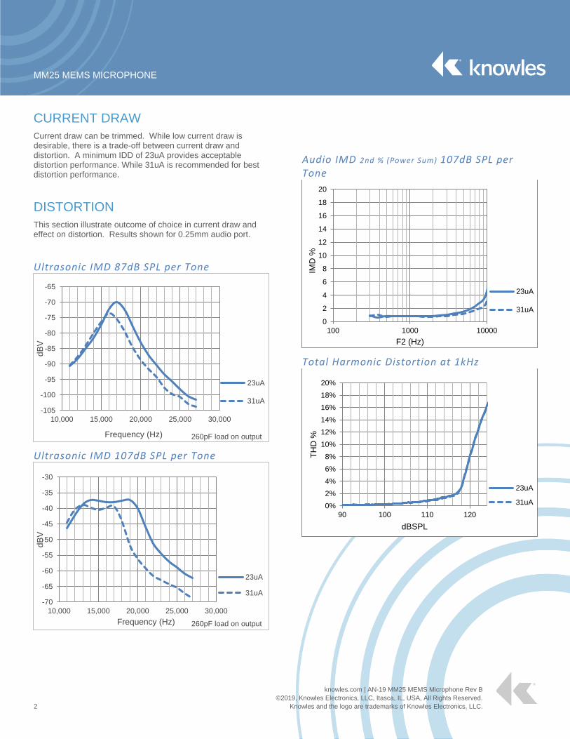
CURRENT DRAW
Current draw can be trimmed. While low current draw is desirable, there is a trade-off between current draw and distortion. A minimum IDD of 23uA provides acceptable distortion performance. While 31uA is recommended for best distortion performance.
DISTORTION
This section illustrate outcome of choice in current draw and effect on distortion. Results shown for 0.25mm audio port.
Ultrasonic IMD 87dB SPL per Tone
Ultrasonic IMD 107dB SPL per Tone
Audio IMD 2nd % (Power Sum) 107dB SPL per Tone
Total Harmonic Distortion at 1kHz
-105
-100
-95
-90
-85
-80
-75
-70
-65
10,000 15,000 20,000 25,000 30,000
dB
V
Frequency (Hz)
23uA
31uA
260pF load on output
-70
-65
-60
-55
-50
-45
-40
-35
-30
10,000 15,000 20,000 25,000 30,000
dB
V
Frequency (Hz)
23uA
31uA
260pF load on output
0
2
4
6
8
10
12
14
16
18
20
100 1000 10000
IMD
%
F2 (Hz)
23uA
31uA
0%
2%
4%
6%
8%
10%
12%
14%
16%
18%
20%
90 100 110 120
TH
D %
dBSPL
23uA
31uA
MM25 MEMS MICROPHONE
knowles.com | AN-19 MM25 MEMS Microphone Rev B
©2019, Knowles Electronics, LLC, Itasca, IL, USA, All Rights Reserved.
3 Knowles and the logo are trademarks of Knowles Electronics, LLC.
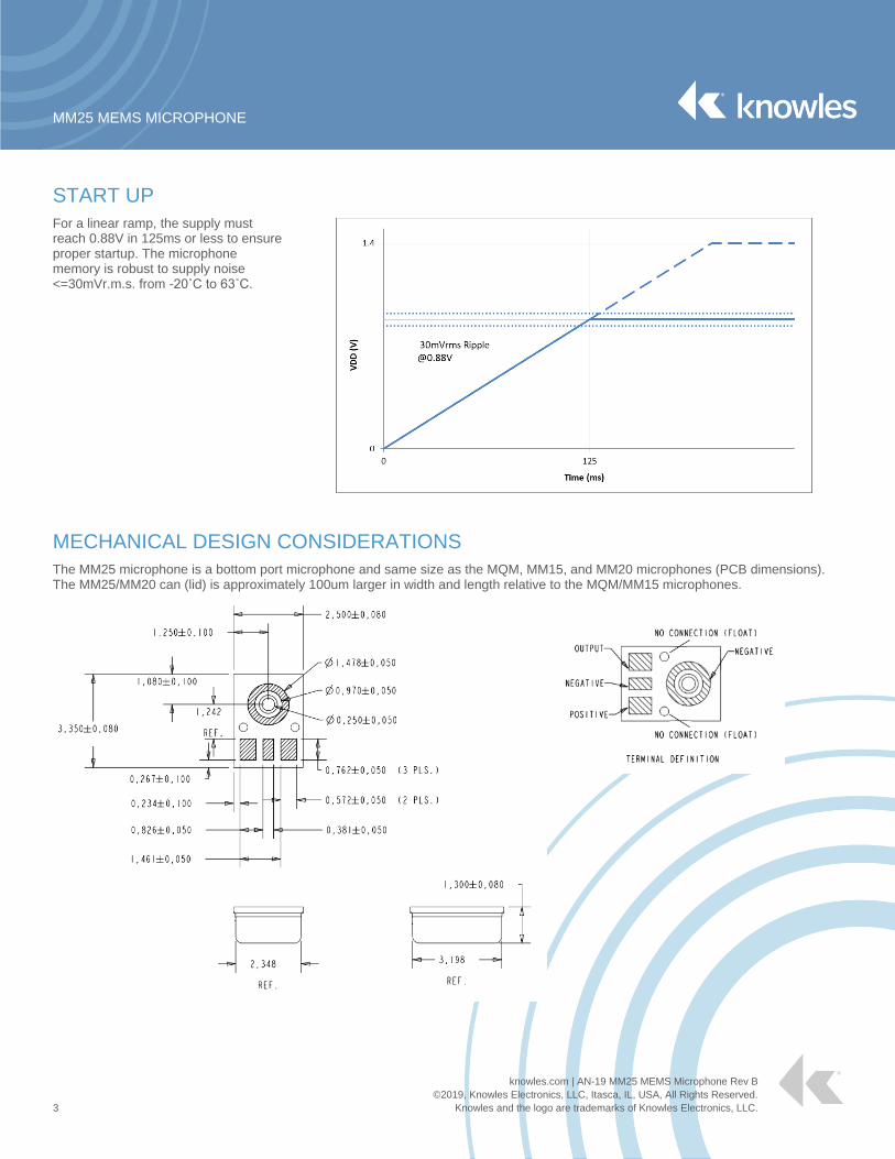
START UP
For a linear ramp, the supply must reach 0.88V in 125ms or less to ensure proper startup. The microphone memory is robust to supply noise <=30mVr.m.s. from -20˚C to 63˚C.
MECHANICAL DESIGN CONSIDERATIONS
The MM25 microphone is a bottom port microphone and same size as the MQM, MM15, and MM20 microphones (PCB dimensions). The MM25/MM20 can (lid) is approximately 100um larger in width and length relative to the MQM/MM15 microphones.
MM25 MEMS MICROPHONE
knowles.com | AN-19 MM25 MEMS Microphone Rev B
©2019, Knowles Electronics, LLC, Itasca, IL, USA, All Rights Reserved.
4 Knowles and the logo are trademarks of Knowles Electronics, LLC.
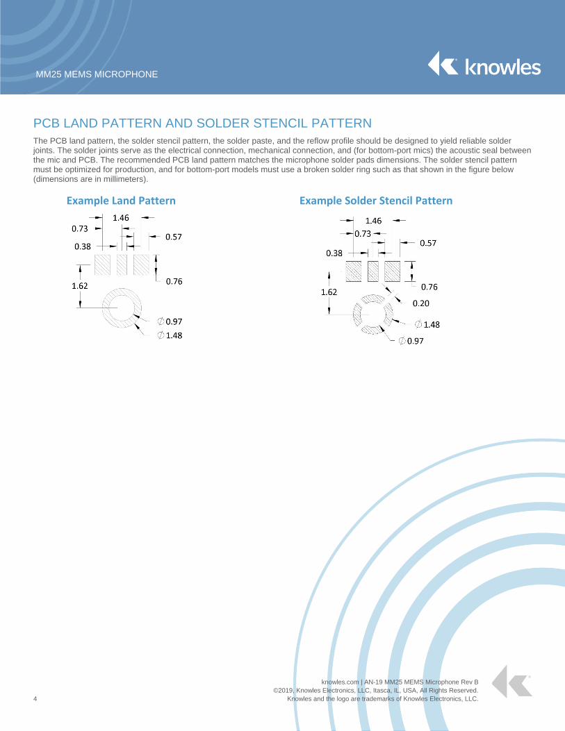
PCB LAND PATTERN AND SOLDER STENCIL PATTERN
The PCB land pattern, the solder stencil pattern, the solder paste, and the reflow profile should be designed to yield reliable solder joints. The solder joints serve as the electrical connection, mechanical connection, and (for bottom-port mics) the acoustic seal between the mic and PCB. The recommended PCB land pattern matches the microphone solder pads dimensions. The solder stencil pattern must be optimized for production, and for bottom-port models must use a broken solder ring such as that shown in the figure below (dimensions are in millimeters).
Example Land Pattern
Example Solder Stencil Pattern
MM25 MEMS MICROPHONE
knowles.com | AN-19 MM25 MEMS Microphone Rev B
©2019, Knowles Electronics, LLC, Itasca, IL, USA, All Rights Reserved.
5 Knowles and the logo are trademarks of Knowles Electronics, LLC.
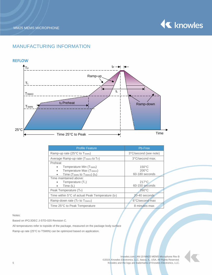
MANUFACTURING INFORMATION
REFLOW
Profile Feature Pb-Free
Ramp-up rate (25°C to TSMIN) 3°C/second (see note)
Average Ramp-up rate (TSMAX to TP) 3°C/second max.
Preheat
Temperature Min (TSMIN)
Temperature Max (TSMAX)
Time (TSMIN to TSMAX) (tS)
150°C 200°C
60-180 seconds
Time maintained above:
Temperature (TL)
Time (tL)
217°C
60-150 seconds
Peak Temperature (TP) 260°C
Time within 5°C of actual Peak Temperature (tP) 20-40 seconds
Ramp-down rate (TP to TSMAX) 6°C/second max
Time 25°C to Peak Temperature 8 minutes max
Notes:
Based on IPC/JDEC J-STD-020 Revision C.
All temperatures refer to topside of the package, measured on the package body surface
Ramp-up rate (25°C to TSMIN) can be optimized based on application.
Time 25°C to Peak
Ramp-down
Ramp-up
TSMIN
TSMAX
TL
TP
tL
tP
tS Preheat
Time 25°C
MM25 MEMS MICROPHONE
6
Knowles Corporation
1151 Maplewood Drive
Itasca, Illinois 60143
Phone: 1 (630) 250-5100
Fax: 1 (630) 250-0575
Model/Reference Number:
AN-19 MM25 MEMS Microphone Rev B
© 2019, Knowles Electronics, LLC.
Form 05.29-01 Version 1.
HANDLING AND STORAGE MSL (moisture sensitivity level) Class 1.
Maximum of 3 reflow cycles is recommended.
In order to minimize device damage:
o Do not board wash or clean after the reflow process.
o Do not brush board with or without solvents after the reflow process.
o Do not directly expose to ultrasonic processing, welding, or cleaning.
o Do not insert any object in port hole of device at any time.
o Do not apply over 30 psi of air pressure into the port hole.
o Do not pull a vacuum over port hole of the microphone.
o Do not apply a vacuum when repacking into sealed bags at a rate faster than 0.5 atm/sec.
PICK-AND-PLACE Knowles microphones come in various size reels for use in auto pick-and-place machines. The bottom-port models may be picked anywhere on the lid. Exact packaging information, including pocket size, spacing and pick-and-place area, is shown in each model’s datasheet.
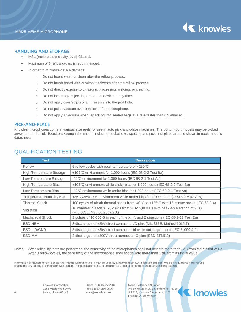
QUALIFICATION TESTING
Test Description
Reflow 5 reflow cycles with peak temperature of +260°C
High Temperature Storage +105°C environment for 1,000 hours (IEC 68-2-2 Test Ba)
Low Temperature Storage -40°C environment for 1,000 hours (IEC 68-2-1 Test Aa)
High Temperature Bias +105°C environment while under bias for 1,000 hours (IEC 68-2-2 Test Ba)
Low Temperature Bias -40°C environment while under bias for 1,000 hours (IEC 68-2-1 Test Aa)
Temperature/Humidity Bias +85°C/85% R.H. environment while under bias for 1,000 hours (JESD22-A101A-B)
Thermal Shock 100 cycles of air-air thermal shock from -40°C to +125°C with 15 minute soaks (IEC 68-2-4)
Vibration 16 minutes in each X, Y, Z axis from 20 to 2,000 Hz with peak acceleration of 20 G (MIL 883E, Method 2007.2,A)
Mechanical Shock 3 pulses of 10,000 G in each of the X, Y, and Z directions (IEC 68-2-27 Test Ea)
ESD-HBM 3 discharges of ±2kV direct contact to I/O pins (MIL 883E, Method 3015.7)
ESD-LID/GND 3 discharges of ±8kV direct contact to lid while unit is grounded (IEC 61000-4-2)
ESD-MM 3 discharges of ±200V direct contact to IO pins (ESD STM5.2)
Notes: After reliability tests are performed, the sensitivity of the microphones shall not deviate more than 3dB from their initial value. After 3 reflow cycles, the sensitivity of the microphones shall not deviate more than 1 dB from its initial value.
Information contained herein is subject to change without notice. It may be used by a party at their own discretion and risk. We do not guarantee any results or assume any liability in connection with its use. This publication is not to be taken as a license to operate under any existing patents