Nonlinear model and system identification of a capacitive dual-backplate MEMS microphone
18
This article was published in an Elsevier journal. The attached copy is furnished to the author for non-commercial research and education use, including for instruction at the author’s institution, sharing with colleagues and providing to institution administration. Other uses, including reproduction and distribution, or selling or licensing copies, or posting to personal, institutional or third party websites are prohibited. In most cases authors are permitted to post their version of the article (e.g. in Word or Tex form) to their personal website or institutional repository. Authors requiring further information regarding Elsevier’s archiving and manuscript policies are encouraged to visit: http://www.elsevier.com/copyright
Transcript of Nonlinear model and system identification of a capacitive dual-backplate MEMS microphone
This article was published in an Elsevier journal. The attached copyis furnished to the author for non-commercial research and
education use, including for instruction at the author’s institution,sharing with colleagues and providing to institution administration.
Other uses, including reproduction and distribution, or selling orlicensing copies, or posting to personal, institutional or third party
websites are prohibited.
In most cases authors are permitted to post their version of thearticle (e.g. in Word or Tex form) to their personal website orinstitutional repository. Authors requiring further information
regarding Elsevier’s archiving and manuscript policies areencouraged to visit:
http://www.elsevier.com/copyright
Author's personal copy
JOURNAL OFSOUND ANDVIBRATION
Journal of Sound and Vibration 309 (2008) 276–292
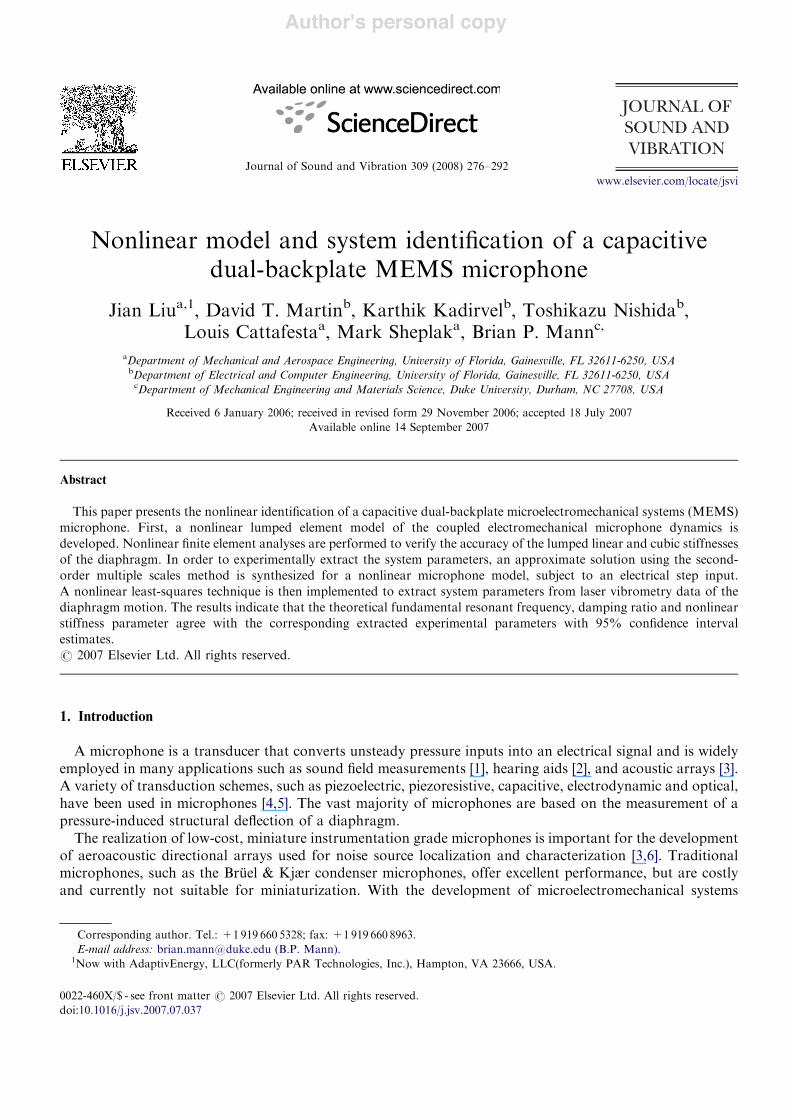
Nonlinear model and system identification of a capacitivedual-backplate MEMS microphone
Jian Liua,1, David T. Martinb, Karthik Kadirvelb, Toshikazu Nishidab,Louis Cattafestaa, Mark Sheplaka, Brian P. Mannc,!
aDepartment of Mechanical and Aerospace Engineering, University of Florida, Gainesville, FL 32611-6250, USAbDepartment of Electrical and Computer Engineering, University of Florida, Gainesville, FL 32611-6250, USAcDepartment of Mechanical Engineering and Materials Science, Duke University, Durham, NC 27708, USA
Received 6 January 2006; received in revised form 29 November 2006; accepted 18 July 2007Available online 14 September 2007
Abstract
This paper presents the nonlinear identification of a capacitive dual-backplate microelectromechanical systems (MEMS)microphone. First, a nonlinear lumped element model of the coupled electromechanical microphone dynamics isdeveloped. Nonlinear finite element analyses are performed to verify the accuracy of the lumped linear and cubic stiffnessesof the diaphragm. In order to experimentally extract the system parameters, an approximate solution using the second-order multiple scales method is synthesized for a nonlinear microphone model, subject to an electrical step input.A nonlinear least-squares technique is then implemented to extract system parameters from laser vibrometry data of thediaphragm motion. The results indicate that the theoretical fundamental resonant frequency, damping ratio and nonlinearstiffness parameter agree with the corresponding extracted experimental parameters with 95% confidence intervalestimates.r 2007 Elsevier Ltd. All rights reserved.
1. Introduction
A microphone is a transducer that converts unsteady pressure inputs into an electrical signal and is widelyemployed in many applications such as sound field measurements [1], hearing aids [2], and acoustic arrays [3].A variety of transduction schemes, such as piezoelectric, piezoresistive, capacitive, electrodynamic and optical,have been used in microphones [4,5]. The vast majority of microphones are based on the measurement of apressure-induced structural deflection of a diaphragm.
The realization of low-cost, miniature instrumentation grade microphones is important for the developmentof aeroacoustic directional arrays used for noise source localization and characterization [3,6]. Traditionalmicrophones, such as the Bruel & Kjær condenser microphones, offer excellent performance, but are costlyand currently not suitable for miniaturization. With the development of microelectromechanical systems
ARTICLE IN PRESS
www.elsevier.com/locate/jsvi
0022-460X/$ - see front matter r 2007 Elsevier Ltd. All rights reserved.doi:10.1016/j.jsv.2007.07.037
!Corresponding author. Tel.: +1 919 660 5328; fax: +1 919 660 8963.E-mail address: [email protected] (B.P. Mann).
1Now with AdaptivEnergy, LLC(formerly PAR Technologies, Inc.), Hampton, VA 23666, USA.
Author's personal copy
(MEMS) technology, hundreds or thousands of devices can be fabricated together on a single silicon wafer.This provides the opportunity to produce MEMS microphones that can approach the performance oftraditional microphones with lower cost and smaller size [7].
One of the key performance metrics of an aeroacoustic microphone is the bandwidth, which should at leastrange from 45Hz to 90 kHz to accommodate 1/8th-scale testing [6]. During the past decade, many researchteams have developed or demonstrated capacitive MEMS microphones targeted at audio applications[2,8–14]. Audio applications, however, require lower maximum sound pressure levels (o120 dB, ref. 20 mPa),and the bandwidths are limited to 20 kHz. The development of capacitive MEMS microphones for theaeroacoustic applications presents several challenges. First, scaling capacitive transduction schemes to themicroscale requires that the backplate is located in very close proximity to the diaphragm [4]. This closespacing may result in unacceptably high viscous damping loses, thus limiting the bandwidth of themicrophone. Also, pull-in instabilities can be a potential issue [4,15]. A dual-backplate structure, thatpossesses porous electrodes or backplates on either side of the diaphragm (Fig. 1(a)), may be able to mitigatethese challenges. Specifically, dual-backplate capacitive microphones offer the potential of smaller size, highersensitivity, larger dynamic range and broader bandwidth over single-backplate capacitive microphones [2,4].The dual-backplate capacitive MEMS microphone studied here has been fabricated using the SUMMiT Vprocess at Sandia National Laboratories as well as facilities at the University of Florida for post-processing[16]. The microphone has a fundamental resonant frequency of over 218 kHz [17]. The overall performance ofthis microphone is expected to be further improved via the implementation of a force feedback controller [18].
The development of such a controller requires an accurate nonlinear model for the microphone system. Themicrophone system must be designed such that it is not operated in regions of pull-in instabilities that typicallyresult in device structural failure. In addition, the stable operating range of the microphone can be potentiallyexpanded by leveraging the mechanical nonlinearity. Therefore, a thorough understanding of nonlineardynamics of the microphone is vital.
The remainder of this paper is organized as follows. First, a nonlinear governing equation for themicrophone is developed by lumped element modeling in Section 2. Nonlinear finite element analyses areperformed to verify the accuracy of the lumped linear and cubic stiffnesses of the diaphragm in Section 3.Nonlinear equations to identify system parameters of the microphone from the experiments are provided inSection 4. An approximate solution for the nonlinear oscillations of the diaphragm via the method of multipletime scales is discussed in Section 5. Section 6 presents the detailed experimental study, and an uncertaintyanalysis is conducted in Section 7. Conclusions are provided in Section 8.
2. Microphone model
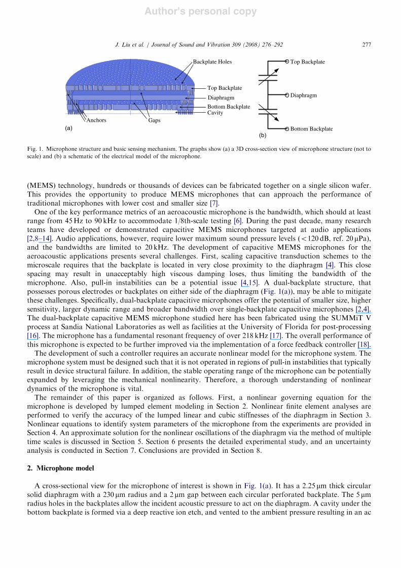
A cross-sectional view for the microphone of interest is shown in Fig. 1(a). It has a 2.25 mm thick circularsolid diaphragm with a 230 mm radius and a 2 mm gap between each circular perforated backplate. The 5 mmradius holes in the backplates allow the incident acoustic pressure to act on the diaphragm. A cavity under thebottom backplate is formed via a deep reactive ion etch, and vented to the ambient pressure resulting in an ac
ARTICLE IN PRESS
Bottom Backplate
Top Backplate
Diaphragm
Cavity
Backplate Holes
Gaps
Top Backplate
Bottom Backplate
Diaphragm
Anchors
(b)(a)
Fig. 1. Microphone structure and basic sensing mechanism. The graphs show (a) a 3D cross-section view of microphone structure (not toscale) and (b) a schematic of the electrical model of the microphone.
J. Liu et al. / Journal of Sound and Vibration 309 (2008) 276–292 277
Author's personal copy
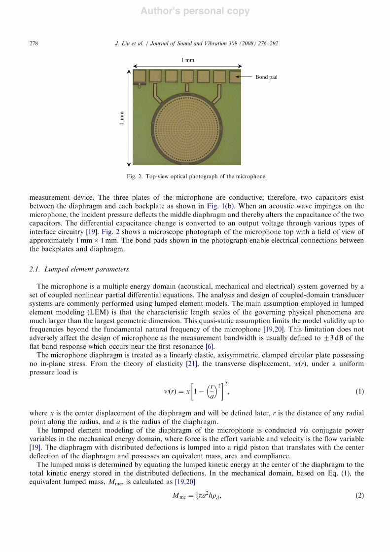
measurement device. The three plates of the microphone are conductive; therefore, two capacitors existbetween the diaphragm and each backplate as shown in Fig. 1(b). When an acoustic wave impinges on themicrophone, the incident pressure deflects the middle diaphragm and thereby alters the capacitance of the twocapacitors. The differential capacitance change is converted to an output voltage through various types ofinterface circuitry [19]. Fig. 2 shows a microscope photograph of the microphone top with a field of view ofapproximately 1mm! 1mm. The bond pads shown in the photograph enable electrical connections betweenthe backplates and diaphragm.
2.1. Lumped element parameters
The microphone is a multiple energy domain (acoustical, mechanical and electrical) system governed by aset of coupled nonlinear partial differential equations. The analysis and design of coupled-domain transducersystems are commonly performed using lumped element models. The main assumption employed in lumpedelement modeling (LEM) is that the characteristic length scales of the governing physical phenomena aremuch larger than the largest geometric dimension. This quasi-static assumption limits the model validity up tofrequencies beyond the fundamental natural frequency of the microphone [19,20]. This limitation does notadversely affect the design of microphone as the measurement bandwidth is usually defined to 73 dB of theflat band response which occurs near the first resonance [6].
The microphone diaphragm is treated as a linearly elastic, axisymmetric, clamped circular plate possessingno in-plane stress. From the theory of elasticity [21], the transverse displacement, w(r), under a uniformpressure load is
w"r# $ x 1%r
a
! "2# $2
, (1)
where x is the center displacement of the diaphragm and will be defined later, r is the distance of any radialpoint along the radius, and a is the radius of the diaphragm.
The lumped element modeling of the diaphragm of the microphone is conducted via conjugate powervariables in the mechanical energy domain, where force is the effort variable and velocity is the flow variable[19]. The diaphragm with distributed deflections is lumped into a rigid piston that translates with the centerdeflection of the diaphragm and possesses an equivalent mass, area and compliance.
The lumped mass is determined by equating the lumped kinetic energy at the center of the diaphragm to thetotal kinetic energy stored in the distributed deflections. In the mechanical domain, based on Eq. (1), theequivalent lumped mass, Mme, is calculated as [19,20]
Mme $ 15pa
2hrd , (2)
ARTICLE IN PRESS
Bond pad
1 mm
1 m
m
Fig. 2. Top-view optical photograph of the microphone.
J. Liu et al. / Journal of Sound and Vibration 309 (2008) 276–292278
Author's personal copy
where h is the thickness of the diaphragm and rd is the density of the diaphragm. Physically, in order toconserve the kinetic energy, a rigid piston with a mass that is 1/5 that of the actual diaphragm isused. Similarly, the effective area of the diaphragm, Ame, is determined by enforcing continuity of volumevelocity [19,20],
Ame $ 13pa
2. (3)
The center displacement of the diaphragm, under a large transverse uniform pressure load, is given by thefollowing expression when using an energy-based analytical approach [21]
x $pa4
64D
1
1& 0:4708x2%h2
, (4)
where p is the applied acoustic pressure, and D is the flexural rigidity of the diaphragm defined as
D $Eh3
12 "1% n2#, (5)
where n and E are the Poisson’s ratio and Young’s modulus for the polysilicon diaphragm, respectively.The factor 0.4708 x2/h2 in Eq. (4) represents a geometric nonlinearity due to the effect of in-plane stretching,
which is significant and cannot be neglected when large displacements occur. If the center displacement ismuch smaller than the thickness of the diaphragm, it follows that Eq. (4) is reduced to its linear counterpart[21]. A more rigorous theory of the nonlinear mechanics of transducer diaphragms including the effects ofin-plane stress is given in Ref. [22].
Eq. (4) indicates that the diaphragm behaves like a Duffing’s hardening spring when large displacementsoccur. Based on the lumped element model, the Duffing’s hardening spring model is written as
pAme $ k1x& k3x3, (6)
where k1 and k3 are linear and cubic stiffnesses of the diaphragm, respectively. By comparing Eq. (6) withEq. (4), k1 and k3 are obtained as
k1 $64Dp3a2
(7)
and
k3 $10:044Dp
a2h2. (8)
The shallow cavity of the microphone impedes the motion of the diaphragm by storing potential energy,analogous to a spring. This process is considered isentropic since the adiabatic and inviscid assumptions arevalid for the microphone operating frequency range. Based on the lumped element assumption, the equivalentmechanical stiffness, kc, is calculated as follows [19,20,23]:
kc $rac20pa2cdc
"pa2c#2 $
prac20a2c
dc, (9)
where c0 is the isentropic speed of sound in air, ra is the density of air, ac and dc are the radius and depth of thecavity cylinder, respectively. "pa2c#
2 is used to convert the acoustical stiffness into the mechanical stiffness.When the diaphragm vibrates, the gas flow between the diaphragm and backplate is divided into two parts;
the horizontal gas flow between the two parallel plates and the vertical gas flow through the circular backplateholes. Viscous damping caused by the horizontal gas flow in the gaps is often referred to as squeeze-filmdamping, its lumped damping coefficient, bs, is given by [24,25]
bs $4mpa4
3nbpd30
f "Abp# &4mpa4
3ntpd30
f "Atp#, (10)
where m is the dynamic viscosity of air, d0 is the nominal gap between backplates and diaphragm, ntp and nbpare total number of holes in the top and bottom backplates, respectively. The porosity of the top and bottom
ARTICLE IN PRESSJ. Liu et al. / Journal of Sound and Vibration 309 (2008) 276–292 279
Author's personal copy
backplates is given by Atp and Abp, respectively, and f( ) is a function with the following form:
f "X # $1
4ln
1
X
& '%
3
8&
1
2X %
1
8X 2. (11)
When the thickness of the backplate is comparable to the gap, the viscous damping due to the vertical gasflow through the backplate holes becomes important. By modeling the motion in the holes as a pressure-drivenPoiseuille flow in a pipe, the lumped damping coefficient, bh, is given by [25]
bh $8mphtpntp
A2tp
&8mphbpnbp
A2bp
; (12)
where htp and hbp are the thicknesses of the top and bottom backplates, respectively. Therefore, the totallumped viscous damping, b, is given by
b $ bs & bh. (13)
2.2. Nonlinear dynamic model
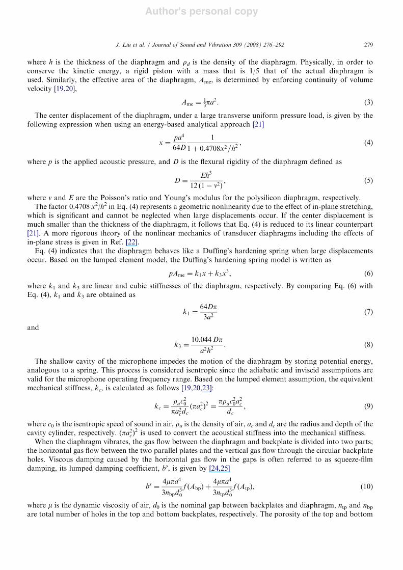
Once all the lumped parameters are obtained, the microphone is represented by a single-degree-of-freedomsecond-order nonlinear ordinary differential equation with simplified dynamics appropriate for theoreticalstudy. Fig. 3 shows a schematic of the dynamic model of the microphone. The top and bottom backplates areassumed to be rigid and have equal areas as the diaphragm. In general, if the top and bottom backplates arebiased with respect to the middle diaphragm by two electrical signals (7V(t)) with equal magnitudes andopposite polarity, the dynamic equation of motion is [26]
Mme !x& b _x& "k1 & kc#x& k3x3
$ %!0Ame
2
V "t#2
"d0 & x#2%
V "t#2
"d0 % x#2
# $% pAme, "14#
where an upward motion of the diaphragm is assumed to be positive, and a parallel-plate assumption is usedwhen determining the electrostatic forces. Eq. (14) represents a nonlinear dynamic system with coupled cubic
ARTICLE IN PRESS
k1, k3b
Mme, Ame
Pressure p
kcV(t)
!V(t)
x = 0
d0
d0
Top backplate
Bottom backplate
x
Diaphragm
Fig. 3. Nonlinear dynamic model of a dual-backplate MEMS microphone.
J. Liu et al. / Journal of Sound and Vibration 309 (2008) 276–292280
Author's personal copy
mechanical and electrostatic nonlinearities,
!x& 2 xo0 _x& o20x& bx3
$ %!0G2
V "t#2
"d0 & x#2%
V "t#2
"d0 % x#2
# $% pG, "15#
where o0 $(((((((((((((((((((((((((((((("k1 & kc#=Mme
pis the fundamental resonant frequency, x $ b/(2Mmeo0) is the damping ratio,
b $ k3/Mme is the nonlinear stiffness parameter and G $ Ame/Mme is the ratio of lumped area over lumpedmass.
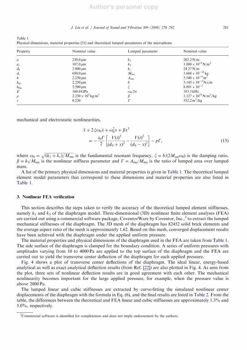
A list of the primary physical dimensions and material properties is given in Table 1. The theoretical lumpedelement model parameters that correspond to these dimensions and material properties are also listed inTable 1.
3. Nonlinear FEA verification
This section describes the steps taken to verify the accuracy of the theoretical lumped element stiffnesses,namely k1 and k3 of the diaphragm model. Three-dimensional (3D) nonlinear finite element analyses (FEA)are carried out using a commercial software package, CoventorWare by Coventor, Inc.,2 to extract the lumpedmechanical stiffnesses of the diaphragm. The 3D mesh of the diaphragm has 82452 solid brick elements andthe average aspect ratio of the mesh is approximately 1.62. Based on this mesh, converged displacement resultshave been achieved with the diaphragm under the applied uniform pressure.
The material properties and physical dimensions of the diaphragm used in the FEA are taken from Table 1.The side surface of the diaphragm is clamped for the boundary condition. A series of uniform pressures withamplitudes varying from 10 to 4000 Pa are applied to the top surface of the diaphragm and the FEA arecarried out to yield the transverse center deflection of the diaphragm for each applied pressure.
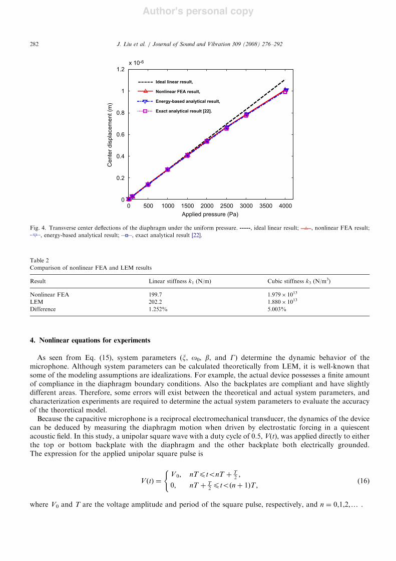
Fig. 4 shows a plot of transverse center deflections of the diaphragm. The ideal linear, energy-basedanalytical as well as exact analytical deflection results (from Ref. [22]) are also plotted in Fig. 4. As seen fromthe plot, three sets of nonlinear deflection results are in good agreement with each other. The mechanicalnonlinearity becomes important for the large applied pressure, for example, when the pressure value isabove 2000 Pa.
The lumped linear and cubic stiffnesses are extracted by curve-fitting the simulated nonlinear centerdisplacements of the diaphragm with the formula in Eq. (6), and the final results are listed in Table 2. From thetable, the differences between the theoretical and FEA linear and cubic stiffnesses are approximately 1.3% and5.0%, respectively.
ARTICLE IN PRESS
Table 1Physical dimensions, material properties [31] and theoretical lumped parameters of the microphone
Property Nominal value Lumped parameter Nominal value
a 230.0mm k1 202.2N/mac 187.0mm k3 1.880! 1013N/m3
d0 2.000mm kc 24.27N/mdc 650.0mm Mme 1.668! 10%10 kgh 2.250mm Ame 5.540! 10%8m2
htp 2.250mm b 3.145! 10%5N s/mhbp 2.500mm x 8.091! 10%2
E 160.0GPa o0/2p 185.5 kHzr 2.230! 103 kg/m3 b 1.127! 1023N/m3/kgn 0.220 G 332.2m2/kg
2Commercial software is identified for completeness and does not imply endorsement by the authors.
J. Liu et al. / Journal of Sound and Vibration 309 (2008) 276–292 281
Author's personal copy
4. Nonlinear equations for experiments
As seen from Eq. (15), system parameters (x, o0, b, and G) determine the dynamic behavior of themicrophone. Although system parameters can be calculated theoretically from LEM, it is well-known thatsome of the modeling assumptions are idealizations. For example, the actual device possesses a finite amountof compliance in the diaphragm boundary conditions. Also the backplates are compliant and have slightlydifferent areas. Therefore, some errors will exist between the theoretical and actual system parameters, andcharacterization experiments are required to determine the actual system parameters to evaluate the accuracyof the theoretical model.
Because the capacitive microphone is a reciprocal electromechanical transducer, the dynamics of the devicecan be deduced by measuring the diaphragm motion when driven by electrostatic forcing in a quiescentacoustic field. In this study, a unipolar square wave with a duty cycle of 0.5, V(t), was applied directly to eitherthe top or bottom backplate with the diaphragm and the other backplate both electrically grounded.The expression for the applied unipolar square pulse is
V "t# $V 0; nTptonT & T
2 ;
0; nT & T2 pto"n& 1#T ;
(
(16)
where V0 and T are the voltage amplitude and period of the square pulse, respectively, and n $ 0,1,2,y .
ARTICLE IN PRESS
0 500 1000 1500 2000 2500 3000 3500 40000
0.2
0.4
0.6
0.8
1
x 10-6
Applied pressure (Pa)
Ideal linear result,
Nonlinear FEA result,
Energy-based analytical result,
Exact analytical result [22].
1.2
Cente
r dis
pla
cem
ent (m
)
Fig. 4. Transverse center deflections of the diaphragm under the uniform pressure. , ideal linear result; , nonlinear FEA result;, energy-based analytical result; , exact analytical result [22].
Table 2Comparison of nonlinear FEA and LEM results
Result Linear stiffness k1 (N/m) Cubic stiffness k3 (N/m3)
Nonlinear FEA 199.7 1.979! 1013
LEM 202.2 1.880! 1013
Difference 1.252% 5.003%
J. Liu et al. / Journal of Sound and Vibration 309 (2008) 276–292282
Author's personal copy
During the time nT+T/2pto(n+1), no electrostatic force acts on the diaphragm, the governing equationfor the free vibration of diaphragm is
!x& 2xo0 _x& o20x& bx3 $ 0. (17)
During the time nTptonT+T/2, an electrostatic force acts on the diaphragm and forces it to vibrate. Thebackplates are assumed to be symmetric about the diaphragm. Therefore, only the governing equation for thecase in which the square pulse is applied to the top backplate is considered in the following analysis:
!x& 2xo0 _x& o20x& bx3 $
!0G2
V20
"d0 % x#2. (18)
The above electrostatic force has a singularity at x $ d0. For |x|od0, a Taylor’s series expansion for thenonlinear electrostatic force, about x $ 0 and up to the third order, results in a convenient polynomialexpression:
!0G2
V20
"d0 % x#2'
!0GV 20
2d20
1& 2x
d0& 3
x
d0
& '2
& 4x
d0
& '3" #
. (19)
As seen from Eq. (19), a spring softening effect is introduced by the nonlinear electrostatic force. It followsthat Eq. (18) is written as
!x& a1 _x& a2x& a3x2 & a4x3 $ a5, (20)
where
a1 $ 2xo0, (21)
a2 $ o20 %
!0GV 20
d30
, (22)
a3 $ %3!0GV 2
0
2d40
, (23)
a4 $ b%2!0GV 2
0
d50
, (24)
and
a5 $!0GV2
0
2d20
. (25)
Eq. (20) represents a general damped second-order system with both quadratic and cubic nonlinearities and anon-zero external step load, and its approximate analytical solution is obtained in the following section.
5. Approximate solution by multiple time scales
Since there is no closed form solution to Eq. (20), a multiple time scales approach [26,27] is used to obtainthe approximate solution. The approximate solution of Eq. (20) is assumed as a second-order expansion interms of a small positive parameter e, which is a measure of the amplitude of the motion,
x"t0; t1; t2; !# $ x0"t0; t1; t2# & !x1"t0; t1; t2# & !2x2"t0; t1; t2#, (26)
where x0, x1, and x2 are three unknown functions, and the multiple independent time scales are defined as
t0 $ t; t1 $ !t and t2 $ !2t. (27)
The coefficients in Eq. (20) are further ordered to show up in the O(e2) by performing the followingsubstitution:
a1 $ !2m1; a2 $ o2; a3 $ !2m3 and a4 $ !2m4. (28)
ARTICLE IN PRESSJ. Liu et al. / Journal of Sound and Vibration 309 (2008) 276–292 283
Author's personal copy
Eqs. (26)–(28) are then substituted into Eq. (20) and the coefficients of the O(e) are collected to arrive a seriesof equations. The result of the solution process, which is detailed in Appendix A, gives the followingapproximate solution to Eq. (20):
x"t# $a5a2
& R0e%1=2a1t cos o&
2a2a3a5 & 3a4a252oa22
& 't
#%3a4R2
0
8oa1e%a1t & f0
$. (29)
If an initial displacement w0 is imposed and the system starts from rest, the resulting transient displacementbecomes
x"t# $a5a2
& w_0e
%1=2a1t cos o&2a2a3a5 & 3a4a25
2oa22
& 't
#%3a4w
_2
0
8oa1"e%a1t % 1#
#
, (30)
where
w_0 $ w0 %
a5a2
. (31)
If there is no external step loading and quadratic nonlinearity in the system (a3 $ 0 and a5 $ 0), whichoccurs for the experimental case of transients about a zero equilibrium position, Eq. (30) is then reduced into
x"t# $ w0e%1=2a1t cos ot%
3a4w208oa1
"e%a1t % 1## $
. (32)
Eq. (32) is easily applied to Eq. (17) to yield the following solution:
x"t# $ w0e%xot cos ot%
3bw2016xo2
"e%2xot % 1## $
. (33)
Once a1, a2, a3, a4, and a5 are estimated by a nonlinear least-squares curve-fitting technique based on thetime history of experimental transient displacement, system parameters x, o0, b, G, and d0 are then identifiedby solving Eqs. (21)–(25) simultaneously as follows:
d0 $((((((((((((%3
a5a3
r, (34)
G $2d2
0a5!0V 2
0
, (35)
o0 $
((((((((((((((((((((((((
a2 &!0V 2
0Gd30
s
, (36)
x $a12o0
(37)
and
b $ a4 &2!0V2
0Gd50
. (38)
6. Experimental study
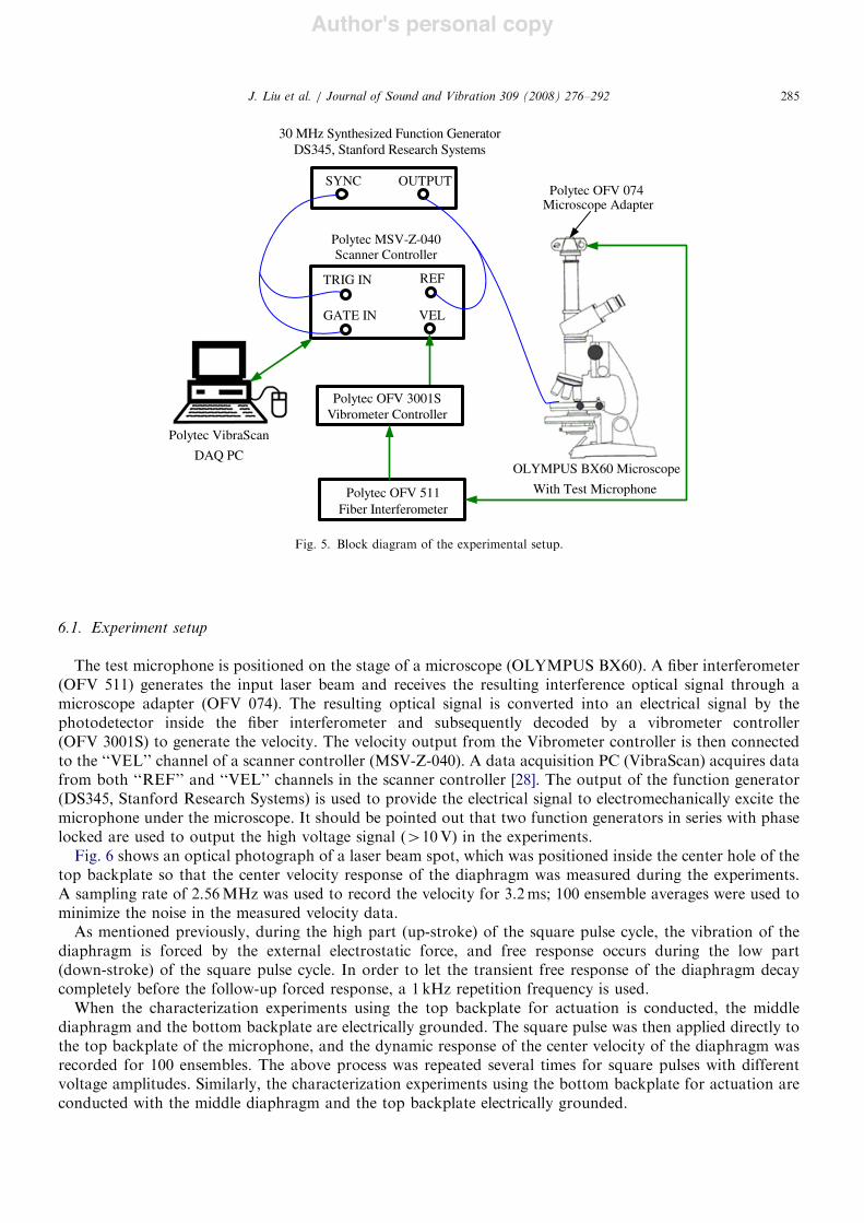
The characterization experiment of the microphone was conducted using the scanning laser Dopplervibrometer (Polytec MSV 300). The block diagram of the experiment setup is shown in Fig. 5 and is discussedfurther below.
ARTICLE IN PRESSJ. Liu et al. / Journal of Sound and Vibration 309 (2008) 276–292284
Author's personal copy
6.1. Experiment setup
The test microphone is positioned on the stage of a microscope (OLYMPUS BX60). A fiber interferometer(OFV 511) generates the input laser beam and receives the resulting interference optical signal through amicroscope adapter (OFV 074). The resulting optical signal is converted into an electrical signal by thephotodetector inside the fiber interferometer and subsequently decoded by a vibrometer controller(OFV 3001S) to generate the velocity. The velocity output from the Vibrometer controller is then connectedto the ‘‘VEL’’ channel of a scanner controller (MSV-Z-040). A data acquisition PC (VibraScan) acquires datafrom both ‘‘REF’’ and ‘‘VEL’’ channels in the scanner controller [28]. The output of the function generator(DS345, Stanford Research Systems) is used to provide the electrical signal to electromechanically excite themicrophone under the microscope. It should be pointed out that two function generators in series with phaselocked are used to output the high voltage signal (410V) in the experiments.
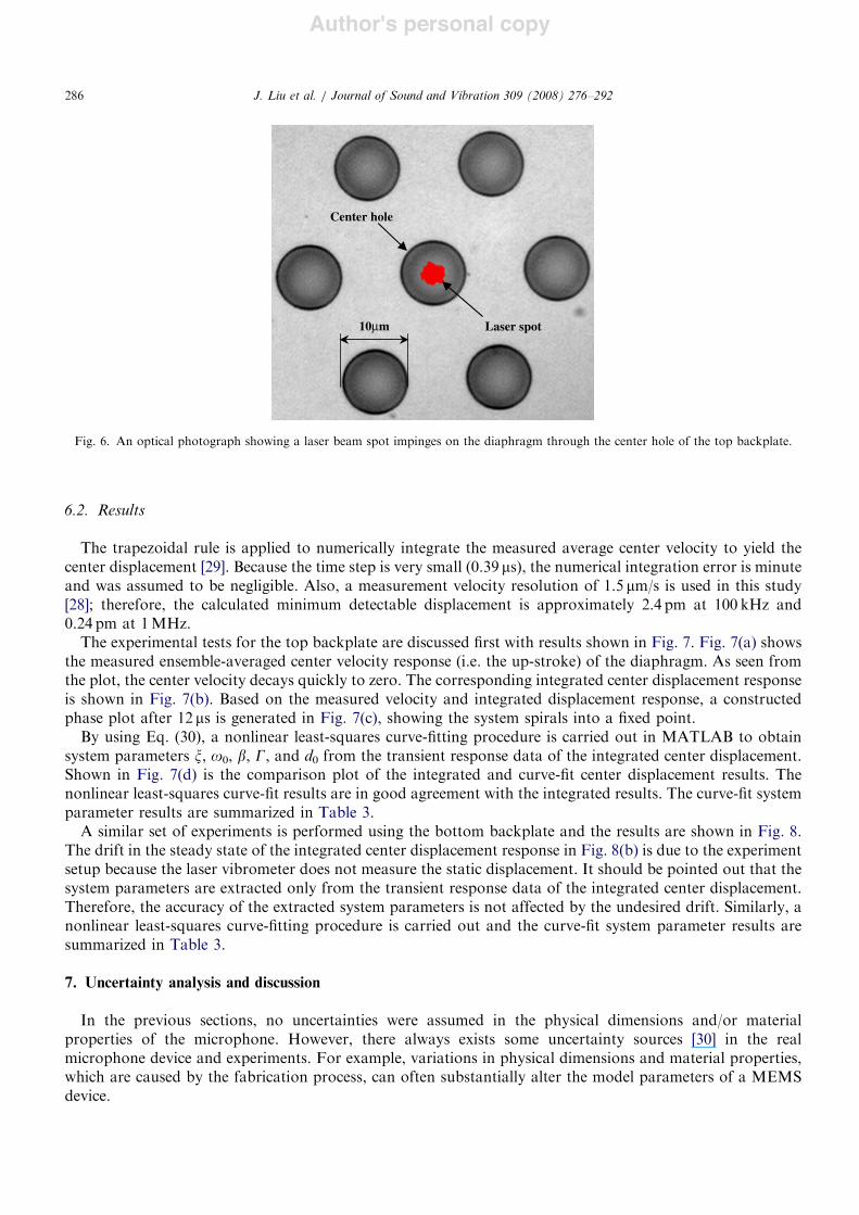
Fig. 6 shows an optical photograph of a laser beam spot, which was positioned inside the center hole of thetop backplate so that the center velocity response of the diaphragm was measured during the experiments.A sampling rate of 2.56MHz was used to record the velocity for 3.2ms; 100 ensemble averages were used tominimize the noise in the measured velocity data.
As mentioned previously, during the high part (up-stroke) of the square pulse cycle, the vibration of thediaphragm is forced by the external electrostatic force, and free response occurs during the low part(down-stroke) of the square pulse cycle. In order to let the transient free response of the diaphragm decaycompletely before the follow-up forced response, a 1 kHz repetition frequency is used.
When the characterization experiments using the top backplate for actuation is conducted, the middlediaphragm and the bottom backplate are electrically grounded. The square pulse was then applied directly tothe top backplate of the microphone, and the dynamic response of the center velocity of the diaphragm wasrecorded for 100 ensembles. The above process was repeated several times for square pulses with differentvoltage amplitudes. Similarly, the characterization experiments using the bottom backplate for actuation areconducted with the middle diaphragm and the top backplate electrically grounded.
ARTICLE IN PRESS
Polytec OFV 074 Microscope Adapter
OLYMPUS BX60 Microscope
With Test Microphone
30 MHz Synthesized Function GeneratorDS345, Stanford Research Systems
OUTPUTSYNC
Polytec MSV-Z-040 Scanner Controller
TRIG IN
GATE IN
REF
VEL
Polytec OFV 3001SVibrometer Controller
Polytec OFV 511Fiber Interferometer
Polytec VibraScan
DAQ PC
Fig. 5. Block diagram of the experimental setup.
J. Liu et al. / Journal of Sound and Vibration 309 (2008) 276–292 285
Author's personal copy
6.2. Results
The trapezoidal rule is applied to numerically integrate the measured average center velocity to yield thecenter displacement [29]. Because the time step is very small (0.39 ms), the numerical integration error is minuteand was assumed to be negligible. Also, a measurement velocity resolution of 1.5 mm/s is used in this study[28]; therefore, the calculated minimum detectable displacement is approximately 2.4 pm at 100 kHz and0.24 pm at 1MHz.
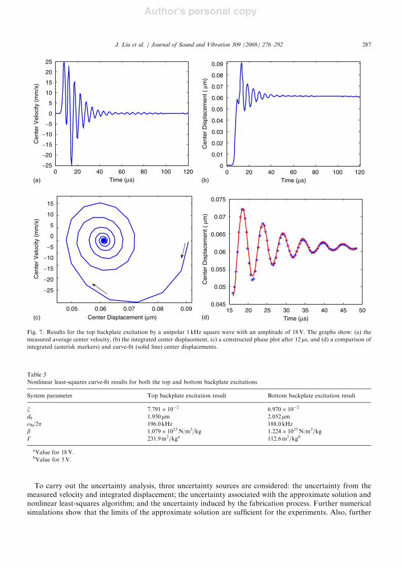
The experimental tests for the top backplate are discussed first with results shown in Fig. 7. Fig. 7(a) showsthe measured ensemble-averaged center velocity response (i.e. the up-stroke) of the diaphragm. As seen fromthe plot, the center velocity decays quickly to zero. The corresponding integrated center displacement responseis shown in Fig. 7(b). Based on the measured velocity and integrated displacement response, a constructedphase plot after 12 ms is generated in Fig. 7(c), showing the system spirals into a fixed point.
By using Eq. (30), a nonlinear least-squares curve-fitting procedure is carried out in MATLAB to obtainsystem parameters x, o0, b, G, and d0 from the transient response data of the integrated center displacement.Shown in Fig. 7(d) is the comparison plot of the integrated and curve-fit center displacement results. Thenonlinear least-squares curve-fit results are in good agreement with the integrated results. The curve-fit systemparameter results are summarized in Table 3.
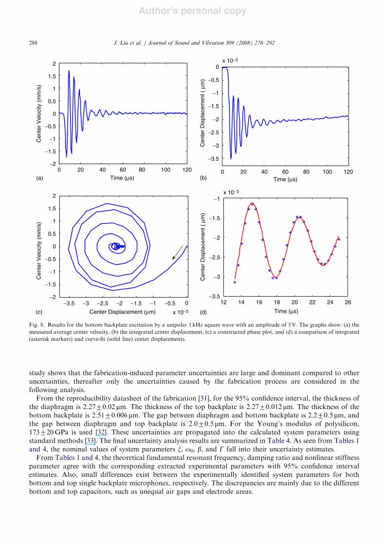
A similar set of experiments is performed using the bottom backplate and the results are shown in Fig. 8.The drift in the steady state of the integrated center displacement response in Fig. 8(b) is due to the experimentsetup because the laser vibrometer does not measure the static displacement. It should be pointed out that thesystem parameters are extracted only from the transient response data of the integrated center displacement.Therefore, the accuracy of the extracted system parameters is not affected by the undesired drift. Similarly, anonlinear least-squares curve-fitting procedure is carried out and the curve-fit system parameter results aresummarized in Table 3.
7. Uncertainty analysis and discussion
In the previous sections, no uncertainties were assumed in the physical dimensions and/or materialproperties of the microphone. However, there always exists some uncertainty sources [30] in the realmicrophone device and experiments. For example, variations in physical dimensions and material properties,which are caused by the fabrication process, can often substantially alter the model parameters of a MEMSdevice.
ARTICLE IN PRESS
Laser spot
Center hole
10µm
Fig. 6. An optical photograph showing a laser beam spot impinges on the diaphragm through the center hole of the top backplate.
J. Liu et al. / Journal of Sound and Vibration 309 (2008) 276–292286
Author's personal copy
To carry out the uncertainty analysis, three uncertainty sources are considered: the uncertainty from themeasured velocity and integrated displacement; the uncertainty associated with the approximate solution andnonlinear least-squares algorithm; and the uncertainty induced by the fabrication process. Further numericalsimulations show that the limits of the approximate solution are sufficient for the experiments. Also, further
ARTICLE IN PRESS
0 120
!25
!20
!15
!10
!5
0
5
10
15
!25
!20
!15
!10
!5
0
5
10
15
20
25
0
50
Cen
ter
Vel
ocity
(m
m/s
)
10080604020Time (µs)
0 12010080604020Time (µs)(a)
Cen
ter
Vel
ocity
(m
m/s
)
Center Displacement (µm)0.05 0.090.080.070.06
(c) (d)
(b)
Cen
ter
Dis
plac
emen
t ( µ
m)
0.09
0.08
0.07
0.06
0.05
0.04
0.03
0.02
0.01
0.04515
0.05
0.055
0.06
0.065
0.07
0.075C
ente
r D
ispl
acem
ent (
µm
)
454035302520Time (µs)
Fig. 7. Results for the top backplate excitation by a unipolar 1 kHz square wave with an amplitude of 18V. The graphs show: (a) themeasured average center velocity, (b) the integrated center displacement, (c) a constructed phase plot after 12 ms, and (d) a comparison ofintegrated (asterisk markers) and curve-fit (solid line) center displacements.
Table 3Nonlinear least-squares curve-fit results for both the top and bottom backplate excitations
System parameter Top backplate excitation result Bottom backplate excitation result
x 7.791! 10%2 6.970! 10%2
d0 1.950mm 2.052mmo0/2p 196.0 kHz 188.0 kHzb 1.079! 1023N/m3/kg 1.224! 1023N/m3/kgG 231.9m2/kga 112.6m2/kgb
aValue for 18V.bValue for 5V.
J. Liu et al. / Journal of Sound and Vibration 309 (2008) 276–292 287
Author's personal copy
study shows that the fabrication-induced parameter uncertainties are large and dominant compared to otheruncertainties, thereafter only the uncertainties caused by the fabrication process are considered in thefollowing analysis.
From the reproducibility datasheet of the fabrication [31], for the 95% confidence interval, the thickness ofthe diaphragm is 2.2770.02 mm. The thickness of the top backplate is 2.2770.012 mm. The thickness of thebottom backplate is 2.5170.006 mm. The gap between diaphragm and bottom backplate is 2.270.5 mm, andthe gap between diaphragm and top backplate is 2.070.5 mm. For the Young’s modulus of polysilicon,173720GPa is used [32]. These uncertainties are propagated into the calculated system parameters usingstandard methods [33]. The final uncertainty analysis results are summarized in Table 4. As seen from Tables 1and 4, the nominal values of system parameters x, o0, b, and G fall into their uncertainty estimates.
From Tables 1 and 4, the theoretical fundamental resonant frequency, damping ratio and nonlinear stiffnessparameter agree with the corresponding extracted experimental parameters with 95% confidence intervalestimates. Also, small differences exist between the experimentally identified system parameters for bothbottom and top single backplate microphones, respectively. The discrepancies are mainly due to the differentbottom and top capacitors, such as unequal air gaps and electrode areas.
ARTICLE IN PRESS
0 120
0
1
2
0
0
0
1
2
Cen
ter
Vel
ocity
(m
m/s
)
0.5
1.5
!0.5
!1.5
!1
!210080604020
Time (µs)(a)
(c) (d)
(b) Time (µs)12010080604020
x 10!3
!0.5
!1
Cen
ter
Dis
plac
emen
t ( µ
m)
!1.5
!2
!2.5
!3
!3.5
x 10!3
Cen
ter
Dis
plac
emen
t ( µ
m)
!1
!1.5
!2
!2.5
!3
!3.5262422
Time (µs)
18 20161412
x 10!3
!0.5!1!1.5!2!2.5!3!3.5Center Displacement (µm)
Cen
ter
Vel
ocity
(m
m/s
)
!1.5
!2
!1
!0.5
0
0.5
1.5
Fig. 8. Results for the bottom backplate excitation by a unipolar 1 kHz square wave with an amplitude of 5V. The graphs show: (a) themeasured average center velocity, (b) the integrated center displacement, (c) a constructed phase plot, and (d) a comparison of integrated(asterisk markers) and curve-fit (solid line) center displacements.
J. Liu et al. / Journal of Sound and Vibration 309 (2008) 276–292288

Author's personal copy
It is shown that G is a constant from the lumped element model based on a simple equal-area parallel plateassumption. However, experimental results of G indicate that it is a function of the applied voltage; whichmeans that the equivalent area for calculating electrostatic forces depends on the applied voltage (assumingthe lumped mass is fixed). The changing experimental behavior of G could be due to several reasons. In theactual physical device, the area of the top compliant backplate is larger than the area of the diaphragm, whichis larger than the area of the bottom compliant backplate. Therefore, the equal-area assumption is notaccurate in practice [34]. The overlapping area could change due to the different bending shapes of the plateswhen different voltages are applied between the perforated backplate and diaphragm.
8. Conclusions
This paper presents the development of a nonlinear model and the experimental characterization of a dual-backplate MEMS microphone that was fabricated for high-frequency aeroacoustic applications. LEM is usedto estimate system parameters for a nonlinear dynamic model in which the microphone is governed by asecond-order ordinary differential equation with electrostatic and cubic mechanical nonlinearities. Nonlinearfinite element analyses show that the differences between the theoretical and FEA linear and cubic stiffnessesof the diaphragm are approximately 1.3% and 5.0%, respectively. The approximate solution to the nonlinearmicrophone model, subjected to a unipolar square wave, is explored by the second-order multiple time scalesmethod. Based on the approximate solution, a nonlinear least-squares algorithm is implemented to extractsystem parameters from the experimental data. An uncertainty analysis shows that the theoreticalfundamental resonant frequency, damping ratio and nonlinear stiffness parameter agree with thecorresponding extracted experimental parameters with 95% confidence interval estimates. Experimentalresults of the ratio of lumped area over lumped mass (G) suggest that it is a function of the applied voltage,and the discrepancy between its theoretical and experimental values is likely due to the inaccurate assumptionof equal-area parallel plates when the electrostatic force is calculated.
Acknowledgments
Financial support was provided by a National Science Foundation Grant (ECS-0097636), a CAREERAward (CMS-0636641), and Sandia National Laboratories.
Appendix A. Derivation of the approximate solution to Eq. (20)
The details for the approximate solution to Eq. (20) are provided in this appendix. Since the multipleindependent time scales are defined in Eq. (27), the time derivatives with respect to t become the followingexpansion terms of the partial derivatives with respect to the corresponding time scales:
d
dt$ D0 & !D1 & !2D2 (A.1)
and
d2
dt2$ D2
0 & 2!D0D1 & 2!2D0D2 & !2D21, (A.2)
ARTICLE IN PRESS
Table 4Mean values and uncertainties of system parameters for a given 95% confidence level
System parameter Mean Uncertainty
x 7.272! 10%2 1.337! 10%2
o0/2p (kHz) 193.5 10.20b (N/m3/kg) 1.219! 1023 0.1409! 1023
G (m2/kg) 329.2 2.901
J. Liu et al. / Journal of Sound and Vibration 309 (2008) 276–292 289
Author's personal copy
where
D0 $d
dt0;D1 $
d
dt1and D2 $
d
dt2. (A.3)
Substitution of Eqs. (26)–(28), (A.1)–(A.3) into Eq. (20) results in the following expressions after separatinginto the O(e):
O"!0# : D20x0 & o2x0 $ a5, (A.4)
O"!1# : D20x1 & o2x1 $ %2D0D1x0 (A.5)
and
O"!2# : D20x2 & o2x2 $ %2D0D1x1 % 2D0D2x0 %D2
1x0 % m1D0x0 % m3x20 % m4x
30. (A.6)
The general solution to Eq. (A.4) is
x0 $a5a2
& A"t1; t2#eiot0 & A"t1; t2#e%iot0 , (A.7)
where A(t1,t2) and A"t1; t2# are complex conjugates. The following expression is obtained by substitutingEq. (A.7) into Eq. (A.5):
D20x1 & o2x1 $ %2io eiot0D1A"t1; t2# % e%iot0D1A"t1; t2#
) *. (A.8)
The elimination of the secular terms from Eq. (A.8) requires that D1A(t1,t2) and D1A"t1; t2# are zero, whichmeans that A and A are only functions of t2.
Therefore, the solution for Eq. (A.8) is written as
x1 $ B"t1; t2#eiot0 & B"t1; t2#e%iot0 , (A.9)
where B(t1,t2) and B"t1; t2# are complex conjugates. Substituting Eqs. (A.7) and (A.9) into Eq. (A.6) yields
D20x2 & o2x2 $ %2io"D1B# % 2io"D2A# % 2m3
a5a2
A
#
%im1oA% 3m4a25a22
& Aj j2& '
A
$eiot0 &O:H:T:, "A:10#
where O.H.T. are other harmonic terms that are neglected in the following analysis.The elimination of the secular terms in Eq. (A.10) requires
%2io"D1B# % 2io"D2A# % im1oA% 2m3a5a2
A% 3m4a25a22
& Aj j2& '
A $ 0. (A.11)
It follows that B is only a function of t2 [27], therefore
%2ioD2A% im1oA% 2m3a5a2
& 3m4a25a22
& 'A% 3m4A Aj j2 $ 0. (A.12)
The polar form for the A(t2) is written as
A"t2# $ 12R"t2#e
if"t2#, (A.13)
where R is the amplitude of x0 and f is the phase angle. Substituting Eq. (A.13) into (A.12) and separatinginto real and imaginary components results in
dR
dt2&
1
2m1R $ 0 (A.14)
and
dfdt2
%2m3a5a2 & 3m4a25
2oa22%
3m48o
R2 $ 0. (A.15)
ARTICLE IN PRESSJ. Liu et al. / Journal of Sound and Vibration 309 (2008) 276–292290
Author's personal copy
The solutions for R and f are
R"t2# $ R0e%1=2m1t2 (A.16)
and
f t2" # $2m3a5a2 & 3m4a25
2oa22t2 %
3m4R20
8om1e%m1t2 & f0, (A.17)
where R0 and f0 are constants determined by initial conditions. Combining Eqs. (26), (A.7), (A.13), (A.16),and (A.17), the approximate solution is
x"t0; t1; t2# 'a5a2
& R0e%1=2m1t2 cos ot0 &
2m3a5a2 & 3m4a252oa22
t2
&%3m4R
20
8om1e%m1t2 & f0
'. (A.18)
Using Eqs. (27) and (28), Eq. (A.18) is further simplified as
x"t# $a5a2
& R0e%1=2a1t cos o&
2a2a3a5 & 3a4a252oa22
& 't
#%3a4R2
0
8oa1e%a1t & f0
$. (A.19)
References
[1] P.R. Scheeper, B. Nordstrand, J.O. Gullov, B. Liu, T. Clausen, L. Midjord, T. Storgaard-Larsen, A new measurement microphonebased on MEMS technology, Journal of Microelectromechanical Systems 12 (2003) 880–891.
[2] J. Bay, O. Hansen, S. Bouwstra, Design of a silicon microphone with differential read-out of a sealed double parallel-plate capacitor,Sensors and Actuators A 53 (1996) 232–236.
[3] D.P. Arnold, T. Nishida, L.N. Cattafesta, M. Sheplak, A directional acoustic array using silicon micromachined piezoresistivemicrophones, Journal of the Acoustical Society of America 113 (1) (2003) 289–298.
[4] P.R. Scheeper, A.G.H. van der Donk, W. Olthuis, P. Bergveld, A review of silicon microphones, Sensors and Actuators A 44 (1994)1–11.
[5] N.A. Hall, B. Bicen, M.K. Jeelani, W. Lee, S. Qureshi, F.L. Degertekin, Micromachined microphone with diffraction-based opticaldisplacement detection, Journal of the Acoustical Society of America 118 (5) (2005) 3000–3009.
[6] T.J. Mueller, Aeroacoustic Measurements, Springer, Berlin, Heidelberg, 2002.[7] S. Bouwstra, T. Storgaard-Larsen, P.R. Scheeper, J.O. Gullov, J. Bay, M. Mullenborg, P. Rombach, Silicon microphones—a Danish
perspective, Journal of Micromechanics and Microengineering 8 (1998) 64–68.[8] T. Bourouina, S. Spirkovitch, F. Baillieu, C. Vauge, A new silicon condenser microphone with a p+ silicon membrane, Sensors and
Actuators A 31 (1992) 149–152.[9] Q. Zou, Z. Liu, L. Liu, Theoretical and experimental studies of single-chip-processed miniature silicon condenser microphone with
corrugated diaphragm, Sensors and Actuators A 63 (1997) 209–215.[10] D. Schafer, S. Shoaf, P. Loeppert, Micromachined condenser microphone for hearing aid use, Proceedings of Solid-State Sensors,
Acutators, and Microsystems Workshop, Hilton Head Island, SC, 1998, pp. 27–30.[11] A. Torkkeli, O. Rusanen, J. Saarilahti, H. Seppa, H. Sipola, J. Hietanen, Capacitive microphone with low-stress polysilicon
backplate, Sensors and Actuators A 85 (2000) 116–123.[12] P. Rombach, M. Mullenborn, U. Klein, K. Rasmussen, The first low voltage, low noise differential silicon microphone, technology
development and measurement results, Sensors and Actuators A 95 (2002) 196–201.[13] P.V. Loeppert, S.B. Lee, SiSonicTM—the first commercialized MEMS microphone, Proceedings of Solid-State Sensors, Actuators, and
Microsystems Workshop, Hilton Head Island, SC, 2006, pp. 27–30.[14] Y. Iguchi, M. Goto, M. Iwaki, A. Ando, K. Tanioka, T. Tajima, F. Takeshi, S. Matsunaga, Y. Yasuno, Silicon microphone with wide
frequency range and high linearity, Sensors and Actuators A 135 (2) (2007) 420–425.[15] F.V. Hunt, Electroacoustics: the Analysis of Transduction and its Historical Background, Acoustical Society of America, New York,
1954.[16] D.T. Martin, K. Kadirvel, J. Liu, R.M. Fox, M. Sheplak, T. Nishida, Surface and bulk micromachined dual back-plate condenser
microphone, Proceedings of the 18th IEEE International Conference on Microelectromechanical Systems (MEMS’05), Miami, FL,January 2005, pp. 319–322.
[17] J. Liu, D.T. Martin, K. Kadirvel, T. Nishida, L.N. Cattafesta, M. Sheplak, B.P. Mann, Nonlinear system identification of a MEMSdual-backplate capacitive microphone by harmonic balance method, Proceedings of ASME International Mechanical EngineeringCongress and Exposition (IMECE’05), Orlando, FL, November 2005, paper no. IMECE2005-82880.
[18] R.P. van Kampen, M.J. Vellekoop, P.M. Sarro, R.F. Wolffenbuttel, Application of electrostatic feedback to critical damping of anintegrated silicon capacitive accelerometer, Sensors and Actuators A 43 (1994) 100–106.
ARTICLE IN PRESSJ. Liu et al. / Journal of Sound and Vibration 309 (2008) 276–292 291
Author's personal copy
[19] S.D. Senturia, Microsystems Design, Kluwer Academic Publishers, Boston, MA, 2001.[20] M. Rossi, Acoustics and Electroacoustics, Artech House, Norwood, MA, 1988.[21] S. Timoshenko, S.W. Krieger, Theory of Plates and Shells, McGraw-Hill, New York, 1959.[22] M. Sheplak, J. Dugundji, Large deflections of clamped circular plates under tension and transitions to membrane behavior, Journal of
Applied Mechanics 65 (1) (1998) 107–115.[23] D.T. Blackstock, Fundamentals of Physical Acoustics, Wiley, New York, 2000.[24] Z. Skvor, On the acoustical resistance due to viscous losses in the air gap of electrostatic transducers, Acustica 19 (1967) 295–299.[25] D. Homentcovschi, R.N. Miles, Modeling of viscous damping of perforated planar microstructures applications in acoustics, Journal
of Acoustical Society of America 116 (2004) 2939–2947.[26] J. Liu, D.T. Martin, K. Kadirvel, T. Nishida, M. Sheplak, B.P. Mann, Nonlinear identification of a capacitive dual-backplate
MEMS microphone, Proceedings of ASME International Design Engineering Technical Conferences (IDETC’05), Long Beach, CA,September 2005, paper no. DETC2005-84591.
[27] A.H. Nayfeh, D.T. Mook, Nonlinear Oscillations, Wiley, New York, 1979.[28] User Manual: Laser Doppler Vibrometer, Polytec PI, Inc., Auburn, MA, USA.[29] S.C. Chapra, R.P. Canale, Numerical Methods for Engineers: with Software and Programming Applications, McGraw-Hill, New York,
2002.[30] H.W. Coleman, W.G. Steele, Experimentation and Uncertainty Analysis for Engineers, Wiley, New York, 1999.[31] MEMS Advanced Design Short Course Notes, Sandia National Laboratories, Albuquerque, NM, July 23–25, 2002.[32] W.N. Sharpe, K.M. Jackson, K.J. Hemker, Z. Xie, Effect of specimen size on Young’s modulus and fracture strength of polysilicon,
Journal of Microelectromechanical Systems 10 (2001) 317–326.[33] International Organization for Standardization, Guide to the Expression of Uncertainty in Measurement, ISO, Geneva, 1993,
ISBN 92-67-10188-9.[34] S. Chowdhury, M. Ahmadi, W.C. Miller, Nonlinear effects in MEMS capacitive microphone design, Proceedings of the 2003
International Conference on MEMS, NANO and Smart Systems (ICMENS’03), Baniff, Alberta, Canada, July 2003, pp. 297–302.
ARTICLE IN PRESSJ. Liu et al. / Journal of Sound and Vibration 309 (2008) 276–292292