MEMS project resonators
27
Contents Introduction....................................................... 3 1- What is a Resonator?............................................3 1.1- Quartz Crystal Resonators...................................3 1.1.1- Importance of quartz.....................................3 1.1.2- Why quartz is important?.................................3 1.2- Types of Quartz Crystal Resonator Modes.....................4 1.3- Working Principle of a Quartz resonator.....................5 2- MEMS Resonators.................................................6 2.1- Working Principle of MEMS Resonator.........................6 2.1.1- Electrostatic Actuation..................................6 2.1.2- Thermal Actuation........................................6 2.1.3- Magnetic Actuation.......................................6 2.1.4- Piezoelectric Actuation..................................6 3- MEMS Resonators vs Quartz Resonators............................7 4- Resonator Modeling..............................................8 4.1- Electrical Modeling......................................... 8 5- Different shape design of Silicon and quartz Resonators.........9 5.1- Disk resonator.............................................. 9 5.2- Wine-glass disk............................................ 10 5.3- Radial-contour disk........................................10 5.4- Square plate............................................... 11 5.5- Clamped-clamped beam (flexural mode).......................11 5.6- Comb drive................................................. 12 6- Resonator Parameters (Analytical Part).........................13 6.1- Quality factor of a resonator..............................13 6.2- Resonance frequency........................................14 6.3- Frequency Tuning........................................... 14 6.4- Motional resistance........................................15 6.5- Collapsing Voltage......................................... 15
Transcript of MEMS project resonators
ContentsIntroduction.......................................................3
1- What is a Resonator?............................................31.1- Quartz Crystal Resonators...................................3
1.1.1- Importance of quartz.....................................31.1.2- Why quartz is important?.................................3
1.2- Types of Quartz Crystal Resonator Modes.....................41.3- Working Principle of a Quartz resonator.....................5
2- MEMS Resonators.................................................62.1- Working Principle of MEMS Resonator.........................6
2.1.1- Electrostatic Actuation..................................62.1.2- Thermal Actuation........................................6
2.1.3- Magnetic Actuation.......................................62.1.4- Piezoelectric Actuation..................................6
3- MEMS Resonators vs Quartz Resonators............................74- Resonator Modeling..............................................8
4.1- Electrical Modeling.........................................85- Different shape design of Silicon and quartz Resonators.........9
5.1- Disk resonator..............................................95.2- Wine-glass disk............................................10
5.3- Radial-contour disk........................................105.4- Square plate...............................................11
5.5- Clamped-clamped beam (flexural mode).......................115.6- Comb drive.................................................12
6- Resonator Parameters (Analytical Part).........................136.1- Quality factor of a resonator..............................13
6.2- Resonance frequency........................................146.3- Frequency Tuning...........................................14
6.4- Motional resistance........................................156.5- Collapsing Voltage.........................................15

6.6- Allan Varience.............................................15
7- Companies working on Resonators and their products.............168.1- Murata.....................................................16
8.2- Silabs.....................................................178.3- SiTime.....................................................17
8- Some of the applications of quartz crystal and MEMS resonators. 179.1- MEMS Resonators for Bio-Chemical and Mass Sensing..........18
9.2- MEMS Resonators for Motion Sensing.........................189.3- MEMS Resonators Based Oscillators..........................18
9.4- SAW Filters................................................189.5- Digitally Controlled MEMS Oscillators (DCXO)...............19
9.6- Oven controlled crystal Oscillators (DCXO).................19Conclusion........................................................19
9- References.....................................................19

Introduction The aim of this project is to explain how quartz and silicon resonators work. The working principle of resonators and the modelling is presented in detailed. The applications of quartz and silicon resonators and also the companies working on the productionof resonators are mentioned. The Allan varience of a resonator is calculated using matlab and the related graph is added in the Resonator parameters(Analytical) part.
1-What is a Resonator?Resonators are known as, where in the resonance happens inmechanical domain but sensing and actuation in electrical domain. Aresonator consist of vibrating mechanical structure, inputtransducer for converting from electrical domain to mechanicaldomain and an output transducer for converting back from mechanicalto electrical domain. The phenomenon that results in resonance isthe formation of one or more standing waves within the mechanicalstructure. The characteristics of the resonance such as frequency ,amplitude and phase depend on the geometry of the device andmaterial property of the device [1]. There are two main materialsare used to produce resonators; Quartz Crystal and Silicon.
1.1- Quartz Crystal Resonators
1.1.1- Importance of quartzThe technical formula is SiO2 and it is composed of two elements,silicon and Oxygen. In its amorphos form SiO2 is the majorconstituent in many rocks and sand. The crystalline form of SiO2 orquartz crystal is relatively abundant in nature, but in the highlypure form required for the manufacture of quartz crystal unit.
Quartz crystals are an indispensable component of modern electronictechnology. They are used to generate frequencies to control andmanage virtually all communication systems. They provide theisochronous element in most clocks, watches, computers andmicroprocessors [2]. The quartz crystal is product of the phenomenonof piezo-electricity discovered by the Curie Brothers in France in1880. Quartz exhibit piezoelectric effect. Piezoelectric materialsin general react to any mechanical stresses by producing anelectrical charge. In a piezoelectric medium the strain ordisplacement depends linearly on both the stress and the field. Theconverse effect is also exists, whereby a mechanical strain isproduced in the crystal by a polarising electric field. This is thebasic effect which produces the vibration of a quartz crystal.
1.1.2- Why quartz is important?Quartz resonators consist of a piece of piezoelectric materialprecisely dimensioned and orientated with respect to thecrystallographic axes. When an electric field is applied thepiezoelectrici effect excites the wafer into mechanical vibration.Compared to other resonators LC circuit, mechanical resonators,ceramic resonators and single crystal materials, the quartzresonator has proved to be superior by having unique combination ofproperties. The material properties of quartz crystal are bothextremely stable and highly repeatable. The acoustic loss orinternal friction of quartz is particularly low, which results in aquartz resontor having an extremely high Q factor. The intrinsic Qof quartz is 107 at 1 MHz[3]. The second key property is itsfrequency stability with respect to temperature variations. Due toits unique properties, quartz crystal is used in many areas such asmilitary&aerospace, industrial, research and metrology, automotiveand consumer . Currently the world market of quartz crystalelectronic components of a total demand about 5.5 billion dollar,with an annual growth rate of 10% [4].
1.2- Types of Quartz Crystal Resonator ModesThere are different cuts of quartz. The cutting procedure changesthe characteristics of quartz crystal.

Figure 1: Different cuts of Quartz Crystal adapted from [2]
Shown below are the bulk acoustic wave (BAW) modes of motion. Forexample, AT-cut and SC-cut resonators vibrate in the thickness shearmode. Above 100 MHz, overtone units that operate at a selectedharmonic mode of vibration are often used (e.g., third overtone or5th overtone). Higher than 100 MHz fundamental mode units can bemanufactured by, e.g., chemical polishing (diffusion controlled wetetching), plasma etching, and ion milling techniques. Below 1 MHz,tuning forks, X-Y and NT bars (flexure mode), +5° X-cuts(extensional mode), or CT-cut and DT-cut units (face shear mode) canbe used. Tuning forks have become the dominant type of low-frequencyunits due to their small size and low cost [2].
Figure 2: Different modes of Quartz Crystal resonators, adapted from [2]

This mode represents the formation of transverse standing waves. Thedominant stress is the bending stress. The structure vibratesorthogonal to the bending stress. Flexural mode resonators havehigher surface to volume ratio and hence are more prone to lossesfrom surface effects [5]. The flexural mode of Figure above providesthe lowest possible frequencies (down to a few kHz). In the 60’s,the first wrist watches had this type of quartz crystals with afrequency of 8kHz. The flexural quartz crystal resonators can besplit up to two bars which is called tuning fork resonator. This isthe resonator that is used in modern wristwatches with a verydistinct resonance frequency of 32768 Hz [6].
Force shear mode quartz resonators are obtained by a plate whichoscillates within its own plane. Resonance frequencies are higherthan that of flexural and extentional mode. It can be obtained by GTcut of quartz crystal. Since this type of cuts requires a veryprecise control of the dimensions of the plate it is very expensive[7].
Thickness shear mode is the mode that the highest frequencies isobtained amoung the other frequency modes. the frequency isinversely proportional to the thickness of the plate therefore bythinning the plate high frequencies can be obtained [8].
1.3- Working Principle of a Quartz resonatorThe active component of the crystal resonator is a mechanicallyvibrating plate ( crystal element ) cut from mono-crystalline quartzwith a precise orientation to the crystallographic axes. Theresonator is plated under high vacuum with aluminum, silver or goldelectrodes and hermetically sealed into a suitable enclosure eitherwith a cold weld or resistance weld process. The physical dimensionsof the element and its orientation to the axes will determine inparticular the resonance frequency, its initial accuracy, itselectrical properties and the temperature coefficient. AT- and SC-Cut crystals (and others), providing a frequency range from 800kHzup to 300MHz and excellent frequency-temperature characteristics.The frequency of crystals is inversely proportional to the thicknessof the element. For mechanical processing, this results in an upperfrequency limit of about 50MHz for crystals operating on thefundamental mode [9].

2-MEMS Resonators The MEMS resonators are becoming the most preferred choices forsensing and high frequency applications like oscillators, filtersand mixers because of the inherent advantages associated with MEMS.MEMS resonators are defined as micro-machined mechanical structuresthat vibrate at their natural resonant frequency when excited by anexternal force. A single structure may have several differentmechanical mode shapes or frequencies, and the drive force may arisefrom electrostatic, piezoelectric, optical, mechanical vibration, ormagnetic stimuli.
2.1- Working Principle of MEMS ResonatorSeveral techniques are used to actuate and detect the resonancestate of resonators such as electrostatic, thermal, electromagnetic,electromotive and piezoelectric.
2.1.1- Electrostatic ActuationThe electrostatic actuation and capacitive sensing is the mostcommonly used transduction principle in MEMS resonators. As theinput and output signals are electrical, the resonators can be usedin purely electrical environment such as RF transceivers. Theseresonators comprise of a vibrating mechanical structure and twoelectrodes, one for actuation and another for sensing. The Fig. 2shows a electrostatically actuated MEMS cantilever beam resonator.To excite the device a time varying voltage signal is applied to theactuation electrode while maintaining the resonator (mechanicalstructure) at fixed DC bias. This potential difference between theactuation electrode and beam creates a force between the two. Whenthe frequency of the applied time varying voltage signal approachesbeam's natural frequency, the beam begins to vibrate in a directionperpendicular to the substrate. This creates a DC biased timevarying capacitor between the beam and the output electrode which inturn results in the production of output motional current at theoutput electrode[10]. Some of the inherent advantages ofelectrostatic actuation are simplicity of design, fast response andlow power consumption.
2.1.2- Thermal ActuationAlthough electrostatic and piezoelectric actuations are the mostcommonly used transduction principles, both of the techniques sufferfrom some limitations. The piezoelectric actuation requires usage of

piezoelectric substrate or deposition of piezoelectric thin films.The electrostatic actuation requires the presence of air gap betweenthe structure and the electrodes which may lead to squeezed filmdamping. The thermal actuation principle is another commonly usedactuation mechanism for microscale devices [11] . In thermallyactuated resonators heat pads are used on the two sides of themechanical structure. A combination of AC and DC current passedthrough the heat pads results in the fluctuating ohmic loses in thestructure. Most of the heat is generated in the thin pillers in themiddle of the structure. The fluctuating heating power actuates theresonators [12]
2.1.3- Magnetic ActuationThis is contactless technique used for actuation of resonator. Amagnetic field is generated around the mechanical structure and analternating current is made to flow through the structure. Theinteraction of the magnetic field with eddy current drives themechanical structure into resonance. The major drawback of thistechnique is that large magnetic fields are required[13].
2.1.4- Piezoelectric ActuationThe resonators use piezoelectric materials like single-crystallinequartz, Lead Zirconate-Titanate etc. The piezoelectric resonatorswork on electromechanical coupling of piezoelectric material. Theresonator is actuated by applying alternating voltage to thepiezoelectric material placed on the resonator. Even though theelectrostatically actuated MEMS resonator same most widely used,their power handling capability is low because of small size andnonlinear effects in the material properties. Compared tocapabilities and provides more linear transduction. Piezoelectrictransduction also has the advantage of lower impedance. Thepiezoelectrically actuated resonators do not require any biasvoltage as in case of electrostatically actuated resonators. Theyalso not require any electrode gap. The major drawback of thistechnique is that most of the piezoelectric materials are notcompatible with CMOS technology electrostatically actuatedresonators, the piezoelectric actuated MEMS resonator show betterpower handling capabilities and provides more linear transduction.Piezoelectric transduction also has the advantage of lowerimpedance. The piezoelectrically actuated resonators do not requireany bias voltage as in case of electrostatically actuated
resonators. They also not require any electrode gap. The majordrawback of this technique is that most of the piezoelectricmaterials are not compatible with CMOS technology [14].
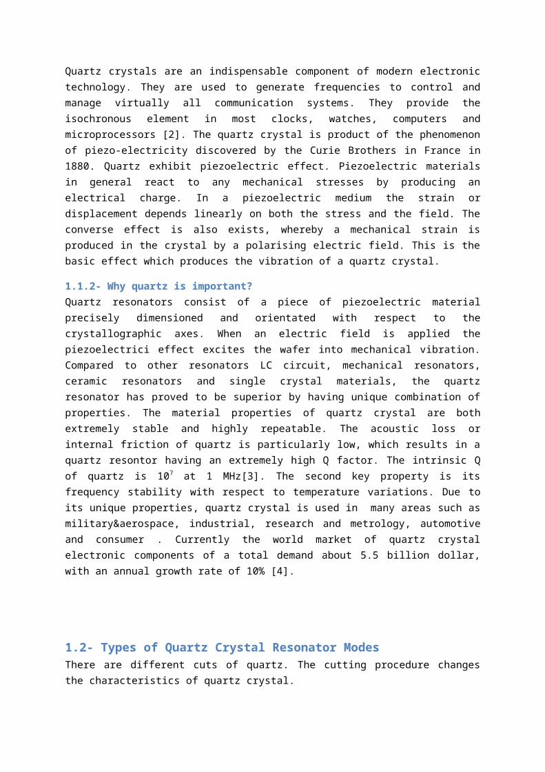
3-MEMS Resonators vs Quartz Resonators MEMS resonators, the electromechanical structures of micron size,are exhibiting high potential of replacing these conventionalelectromechanical resonators due to their extremely highminiaturization possibilities, ready integrability with conventionalICs and low manufacturing cost as they can be manufactured using theconventional CMOS IC manufacturing process. However, quartz crystalresonators are more stable than silicon counterparts. Silicon ishighly affected by temperature so they are not suitable for manyapplications. Also, noise performance of quartz resonators isbetter. Moreover, power consumption of quartz resonators are lessthan silicon resonators[15]. However, The MEMS resonators have highpotential of replacing conventional frequency reference devices likequartz crystal and SAW resonators. Particularly in wirelessapplications, where miniaturization and portability are twoessential requirements.
Figure 3: Comparison of quartz crystal resonator and MEMS silicon resonator. Leftpicture shows the temperature stability of resonators. Right picture shows the sizecomparison of MEMS silicon and quartz crystal resonators, adapted from [16]
4-Resonator ModelingMechanical Modeling: Irrespective of the structure, the resonatorcan be mechanically modeled using a mass, spring and damper system.as shown in Fig. 4.

Figure 4: Mechanical model of a resonator, adapted from [1]
If the mass is subjected to an external force, it oscillates. If themass is driven at its natural frequency, it vibrates with largeramplitude of displacement. The resonant frequency of the system interms of spring constant k and mass m is given by equation below.
fτ=12π √km
When the system is driven at a frequency above or below the resonantfrequency, the amplitude of displacement is smaller. Resonators withhigher Q have larger response when driven at resonant frequency.From the equation of resonant frequency, it is obvious thatreduction in size which in turn results in the reduction of mass andstiffening of spring leads to increase in the resonant frequency[17].
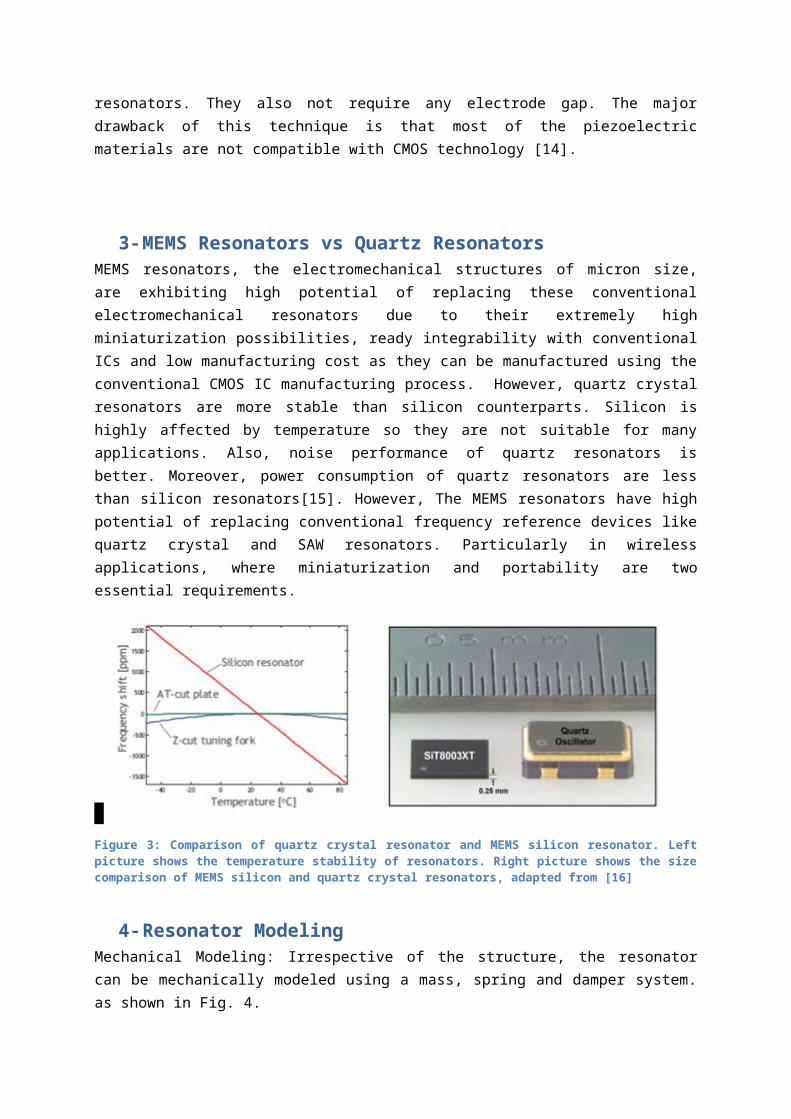
4.1- Electrical ModelingTraditionally the resonators are electrically modeled usingButterworth- Van Dyke model as shown in Fig 5. The electricalequivalent of the resonator can be represented using a RLC circuit.The resonance behavior of the resonator is modeled by the electricalresonance arising from Lx and Cx . The energy dissipation occurringin the structure through various means is modeled by the electricaldissipation through Rs. Co represents the feed through capacitancebetween two terminals and Cl1 and Cl2 represents the capacitancebetween each contact to ground[18].
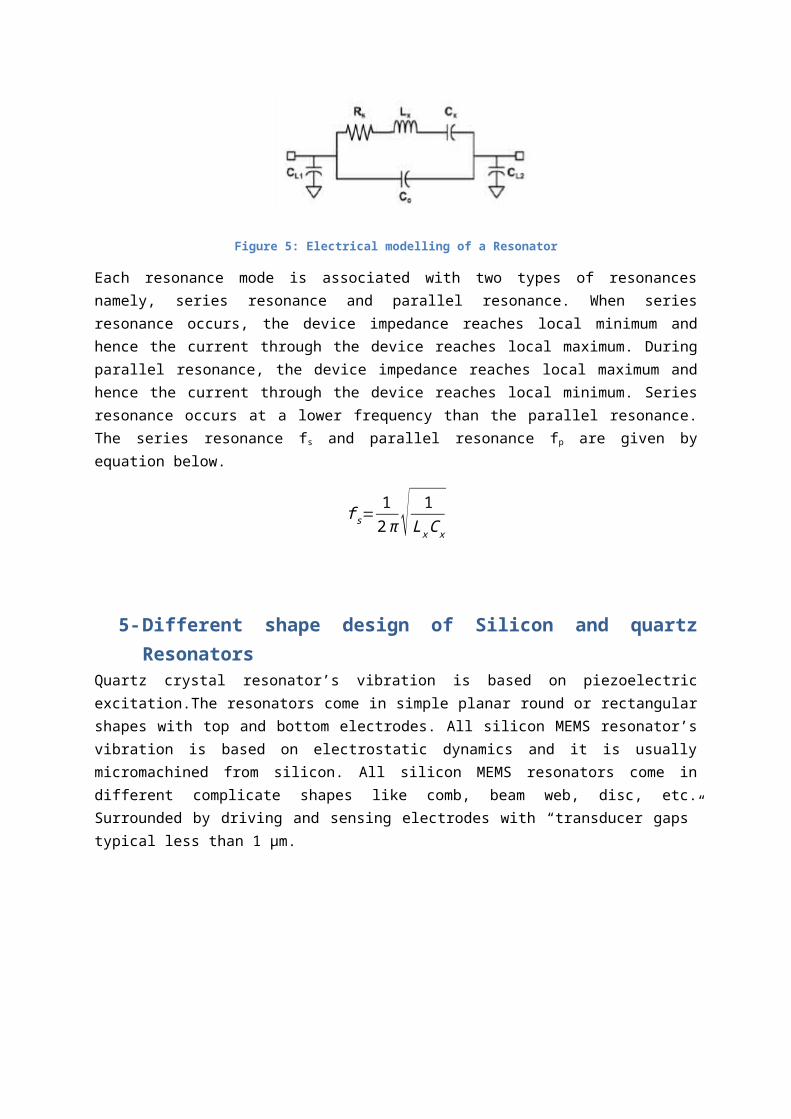
Figure 5: Electrical modelling of a Resonator
Each resonance mode is associated with two types of resonancesnamely, series resonance and parallel resonance. When seriesresonance occurs, the device impedance reaches local minimum andhence the current through the device reaches local maximum. Duringparallel resonance, the device impedance reaches local maximum andhence the current through the device reaches local minimum. Seriesresonance occurs at a lower frequency than the parallel resonance.The series resonance fs and parallel resonance fp are given byequation below.
fs=12π √ 1
LxCx
5-Different shape design of Silicon and quartzResonators
Quartz crystal resonator’s vibration is based on piezoelectricexcitation.The resonators come in simple planar round or rectangularshapes with top and bottom electrodes. All silicon MEMS resonator’svibration is based on electrostatic dynamics and it is usuallymicromachined from silicon. All silicon MEMS resonators come indifferent complicate shapes like comb, beam web, disc, etc.Surrounded by driving and sensing electrodes with “transducer gaps”typical less than 1 μm.
5.1- Disk resonator
Figure 6: MEMS disc resonator, adapted from [19]
Disk resonator’s structure comprises of a circular disk, supportedat the center by a stem. It is made of poly-Silicon. The deviceoperates in two modes namely, radial mode and wine glass mode andexhibits high motional resistance[19].
5.2- Wine-glass disk
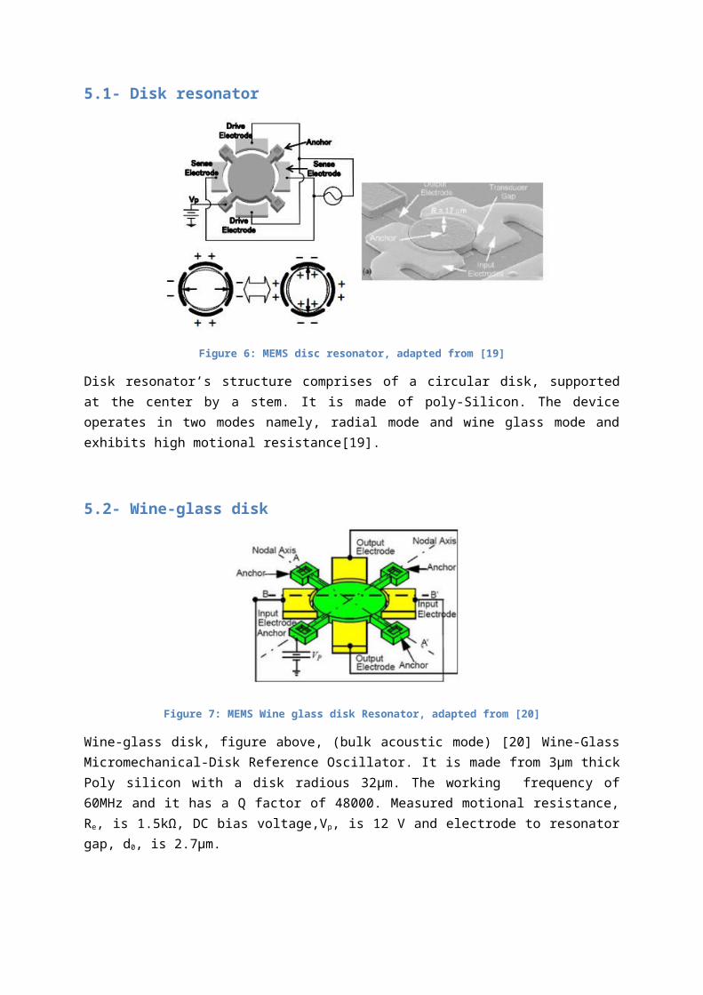
Figure 7: MEMS Wine glass disk Resonator, adapted from [20]
Wine-glass disk, figure above, (bulk acoustic mode) [20] Wine-GlassMicromechanical-Disk Reference Oscillator. It is made from 3µm thickPoly silicon with a disk radious 32µm. The working frequency of60MHz and it has a Q factor of 48000. Measured motional resistance,Re, is 1.5kΩ, DC bias voltage,Vp, is 12 V and electrode to resonatorgap, d0, is 2.7µm.
5.3- Radial-contour disk
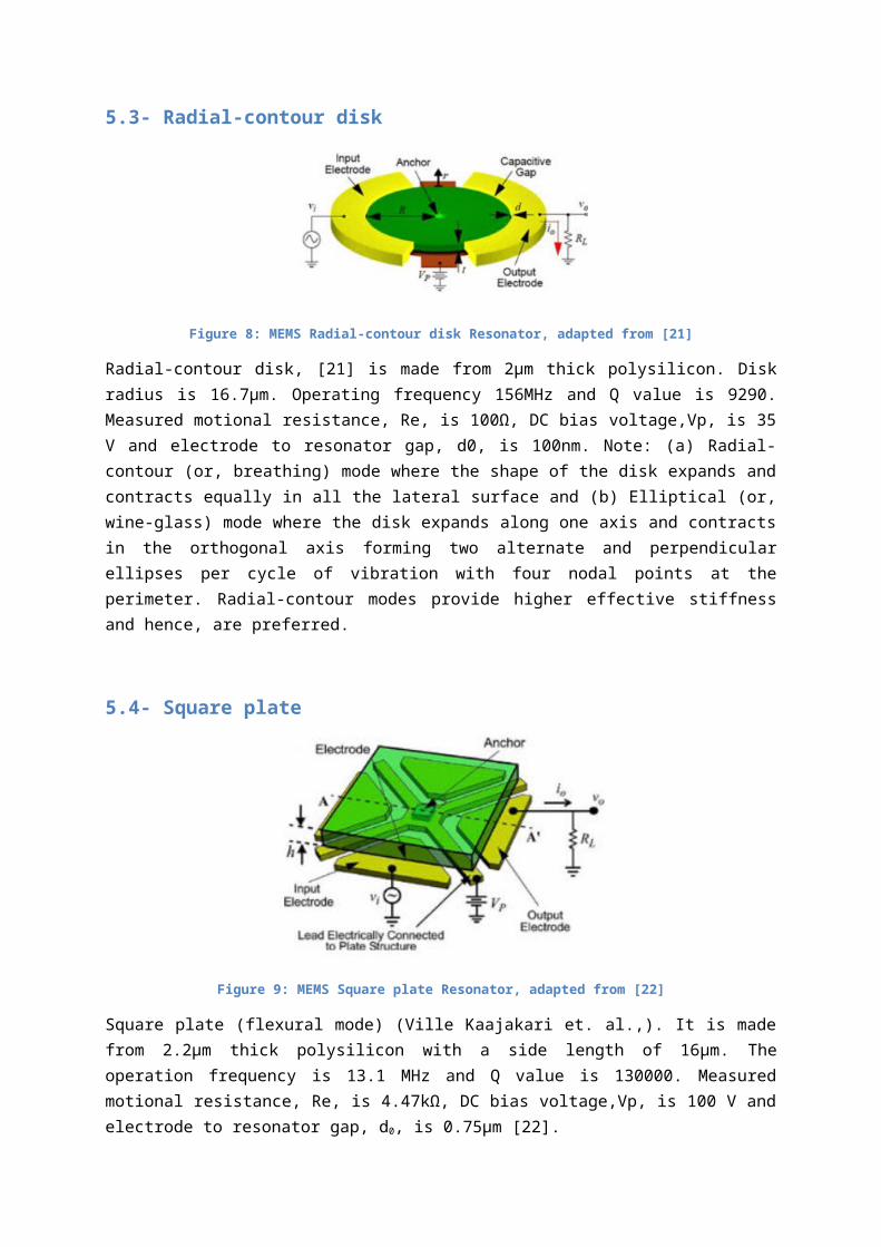
Figure 8: MEMS Radial-contour disk Resonator, adapted from [21]
Radial-contour disk, [21] is made from 2µm thick polysilicon. Diskradius is 16.7µm. Operating frequency 156MHz and Q value is 9290.Measured motional resistance, Re, is 100Ω, DC bias voltage,Vp, is 35V and electrode to resonator gap, d0, is 100nm. Note: (a) Radial-contour (or, breathing) mode where the shape of the disk expands andcontracts equally in all the lateral surface and (b) Elliptical (or,wine-glass) mode where the disk expands along one axis and contractsin the orthogonal axis forming two alternate and perpendicularellipses per cycle of vibration with four nodal points at theperimeter. Radial-contour modes provide higher effective stiffnessand hence, are preferred.
5.4- Square plate
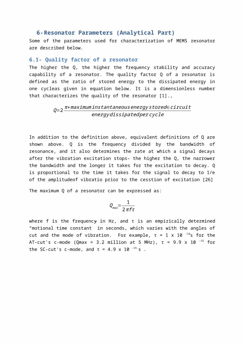
Figure 9: MEMS Square plate Resonator, adapted from [22]
Square plate (flexural mode) (Ville Kaajakari et. al.,). It is madefrom 2.2µm thick polysilicon with a side length of 16µm. Theoperation frequency is 13.1 MHz and Q value is 130000. Measuredmotional resistance, Re, is 4.47kΩ, DC bias voltage,Vp, is 100 V andelectrode to resonator gap, d0, is 0.75µm [22].

5.5- Clamped-clamped beam (flexural mode)
Figure 10: MEMS Clamped-clamped beam resonator (Lin et al.,), adapted from [23]
Clamped-clamped beam (flexural mode) (Lin et al, 2004b). It is madeof 2µm polysilicon. The beam lenght is 40µm and the width is 8µm.The operating frequency is 9.34MHz with a Q value of 3100. Measuredmotional resistance, Re, is 8.27kΩ, DC bias voltage,Vp, is 8 V andelectrode to resonator gap, d0, is 100nm. The device comprises of abeam rigidly clamped at both ends. It can be used in flexural aswell as lateral mode. The structure can provide high resonancefrequency. These structures suffer from anchor loss which putslimitation on achievable Q [23].
Figure 11: MEMS Clamped-clamped beam Resonator (Pourkamali et al.,),
Clamped-clamped beam (flexural mode) (Pourkamali et al. 2003). It ismade of 20µm thick single poly silicon. The beam length is 700µmwith a width 6µm. The operating frequency is 80kHz with a Q value of74000. The gap is 80 nm.

5.6- Comb drive
Figure 12: MEMS Comb Drive, adapted from [24]
Comb drive (flexural mode) (Ciofi and Hsu 2005). It is made of 30µmthick single crystal silicon. Number of fingers is 500. The fingerlength is 10µm and overlap is 4µm. Structure is develeped atUniversty of Clifornia, Berkeley. Comprises of laterally vibratinginterdigitated finger comb-drive structure. Structure exhibits largemass and relatively low spring constant. It is suitable for lowfrequency applications(below 500 kHz). The quality factor as high as50000 is reported for the comb drive structure [24]
As it is mentioned previously, Quartz crystal resonators have asimple planar round or rectangular shapes. Also, compared to MEMSsilicon resonators they have quite large in area. This is the maindrawback about the quartz resonators.
Figure 13: Quartz Crystal Resonators inside a mobile phone, adapted from [25]
6-Resonator Parameters (Analytical Part)Some of the parameters used for characterization of MEMS resonatorare described below.
6.1- Quality factor of a resonatorThe higher the Q, the higher the frequency stability and accuracycapability of a resonator. The quality factor Q of a resonator isdefined as the ratio of stored energy to the dissipated energy inone cycleas given in equation below. It is a dimensionless numberthat characterizes the quality of the resonator [1].,
Q=2 π∗maximuminstantaneousenergystored∈circuitenergydissipatedpercycle
In addition to the definition above, equivalent definitions of Q areshown above. Q is the frequency divided by the bandwidth ofresonance, and it also determines the rate at which a signal decaysafter the vibration excitation stops- the higher the Q, the narrowerthe bandwidth and the longer it takes for the excitation to decay. Qis proportional to the time it takes for the signal to decay to 1/eof the amplitudeof vibratio prior to the cesstion of excitation [26]
The maximum Q of a resonator can be expressed as:
Qmax=1
2πfτ
where f is the frequency in Hz, and τ is an empirically determined“motional time constant” in seconds, which varies with the angles ofcut and the mode of vibration. For example, τ = 1 x 10 -14s for theAT-cut's c-mode (Qmax = 3.2 million at 5 MHz), τ = 9.9 x 10 -15 forthe SC-cut's c-mode, and τ = 4.9 x 10 -15 s .
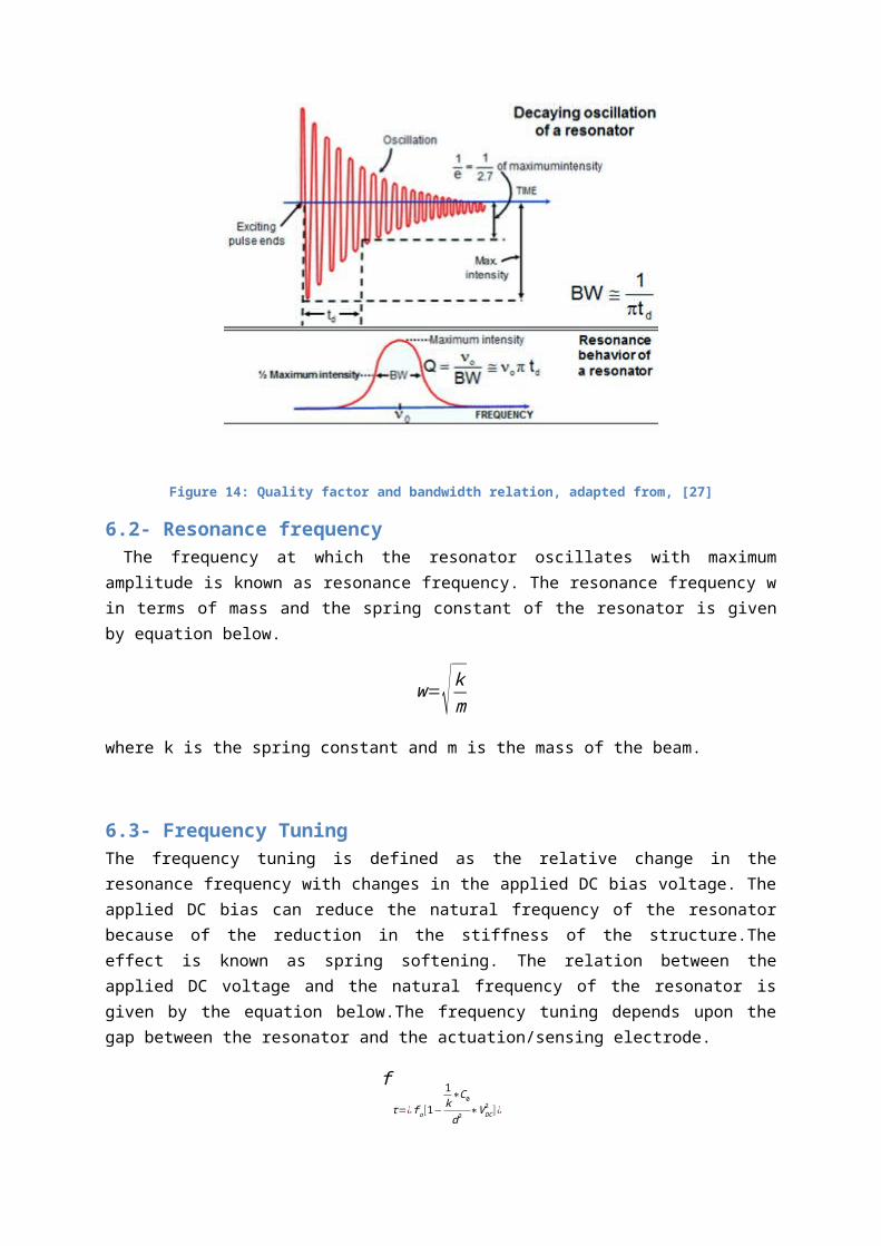
Figure 14: Quality factor and bandwidth relation, adapted from, [27]
6.2- Resonance frequency The frequency at which the resonator oscillates with maximumamplitude is known as resonance frequency. The resonance frequency win terms of mass and the spring constant of the resonator is givenby equation below.
w=√kmwhere k is the spring constant and m is the mass of the beam.
6.3- Frequency TuningThe frequency tuning is defined as the relative change in theresonance frequency with changes in the applied DC bias voltage. Theapplied DC bias can reduce the natural frequency of the resonatorbecause of the reduction in the stiffness of the structure.Theeffect is known as spring softening. The relation between theapplied DC voltage and the natural frequency of the resonator isgiven by the equation below.The frequency tuning depends upon thegap between the resonator and the actuation/sensing electrode.
fτ=¿fo[1−
1k∗C0
d2 ∗VDC2 ] ¿

where ft is the resonance frequency, f0 is the natural frequency, k isthe elastic constant, C0 is the capacitance when the beam isstationary and VDC is the DC bias voltage. Based on the relation(above), the frequency tuning FT is defined below.
FT=
−ϵAd3 ∗1
k
6.4- Motional resistanceMotional resistance refers to the impedance of the resonator. Sometime it is also referred as series resistance. The motionalresistance depends upon factors such as air gap between theresonator and electrodes, the coupling area, the DC bias voltage andk value. This parameter is of prime importance in RF applicationswhere impedance matching as low as 50Ω is required. Equation (below)gives the motional resistance of capacitively transduced MEMSresonator [28].
R=kd4
wnQV2ϵ2A2
where k is spring constant, d is the electrode to resonator gap, wN
is the resonance frequency, Q is the quality factor, V representsthe bias voltage, ϵ is the permittivity and A represents the overlaparea. A lower motional resistance can be achieved by reducing thegap between the resonator and the electrodes and by having largeresonator structures which increases the coupling area. However,there is a limitation imposed by the fabrication process on the gapbetween resonator and electrodes. Also by increasing the resonatordimension, the resonator becomes more susceptible to collapse.
6.5- Collapsing VoltageThis is an important parameter for in-plane resonator withelectrostatic excitation. The parameter describes the stickingeffect where the mechanical structure sticks to the electrode orsubstrate. The collapsing voltage is defined as the maximum voltagethat can be appliedto the resonator to prevent vertical sticking ofmovable structure. The collapsing voltage is given by equation
(below)[29].
VC=√nEt3d3ϵL4
where E is the Young's modulus, t is the thickness of the structure,d is the distance between substrate and the structure, L is thelength of the structure and n is the constant that depends on thestructure of the resonator.
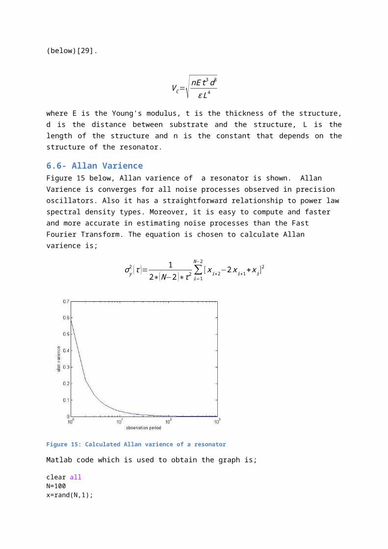
6.6- Allan VarienceFigure 15 below, Allan varience of a resonator is shown. Allan Varience is converges for all noise processes observed in precision oscillators. Also it has a straightforward relationship to power lawspectral density types. Moreover, it is easy to compute and faster and more accurate in estimating noise processes than the Fast Fourier Transform. The equation is chosen to calculate Allan varience is;
σy2 (τ )= 1
2∗(N−2 )∗τ2 ∑i=1
N−2[xi+2−2xi+1+xi]
2
Figure 15: Calculated Allan varience of a resonator
Matlab code which is used to obtain the graph is;
clear allN=100x=rand(N,1);

sum=0;t=0:1000for i=1:length(t) for j=1:(N-2) sum1=sum+(x(j+2)-2.*x(j+1)+x(j)).^2; sum=sum1; end gammasq(i)=sum./(2*(N-2).*t(i).^2)endsemilogx(t,gammasq)xlabel('observation period')ylabel('alan varience')
7-Companies working on Resonators and theirproducts
8.1- MurataThe devices range from very low power consumption to very low phasejitter, sub-200fs performance. They are highly precise and achieveexceptional stability over a wide range of temperatures. Developerscan select from various output standards to match their systemrequirements.
Products
Ultra-Low Jitter Crystal Oscillators High Performance MEMS Oscillators Ceramic Resonators SAW filters Actuators
[30]
8.2- SilabsSilicon Labs is a leading provider of silicon, software and systemsolutions for the Internet of Things, Internet infrastructure,industrial control, consumer and automotive markets. They solve theelectronics industry's toughest problems, providing customers withsignificant advantages in performance, energy savings, connectivityand design simplicity., Silicon Labs empowers developers with thetools.
Products

Oscillators Silicon oscillators Crystal oscillators MEMS Oscillators Jitter Arrenuating clocks Sensors
[31]
8.3- SiTimeSiTime offers the broadest portfolio of MEMS-based silicon timingsolutions in the industry. They are the only timing products companyoffering all three major timing components; Resonators, Oscillators,Clock Generators.
Products
Ultra performance Oscillators (SiT8209,SiT8225,SiT8256) Low power Oscillators (Cost effective low power, general
purpose low power, high frequency low power, kHz frequency,ultra thin)
High Temperature Oscillators (-40 to 125 C and -55 to 125 C) TCXO/VCTCXO (Temperature compensated crystal oscillator) VCXO ( Voltage controlled crystal oscillator)
[32]
8-Some of the applications of quartz crystal andMEMS resonators
MEMS and quartz crystal resonators have found applications inseveral diverse fields like mass sensing, bio-chemical sensing,motion sensing, communication etc. This section presents someselected applications of resonators.
9.1- MEMS Resonators for Bio-Chemical and Mass Sensing The resonance frequency dependence of the resonator on the mass ofthe structure makes the resonators suitable for mass sensingapplications particularly in bio-chemical field. Exposure of theresonator to an environment consisting some bio-chemical species canmake the the species get attached(absorbed or adsorbed) to the

resonator. This in turn results in change in the spring constant andmass of the structure, which ultimately causes a shift in theresonant frequency of the resonator. The shift in the resonantfrequency will be proportional to the mass of the attached speciesand hence can be used to determine the mass of the species[33].
9.2- MEMS Resonators for Motion Sensing The most common application of MEMS resonators in the field ofmotion sensing can be found in gyroscopes used for measuring ormaintaining the orientation based on the principle of angularmomentum. The gyroscopes have a wide applications in the field ofavionics, automotive, handheld consumer appliances, industrialrobotics etc.The resonators of different shapes are used in a classof gyroscopes known as Coriolis Vibratory Gyroscope. The basicprinciple used here is that a vibrating structure will tend tovibrate in the same plane even when its supports rotate. In [34] alaterally driven symmetric microresonator with self tuningcapability is presented. The resonator structures which areinherently symmetric such as disks and hemispheres are preferredchoices for gyroscopic applications. Another most widely usedapplication of MEMS resonator is in accelerometers
9.3- MEMS Resonators Based Oscillators One of the most exciting application of the MEMS resonator is thatthey act as time-base generators in MEMS based oscillators. The MEMSresonators can be easily integrated with the supporting electroniccircuitry and PLL on the same silicon substrate to act as anoscillator.Paper [35] reports 32KHz MEMS based oscillator for lowpower applications which uses a comb drive flexural mode resonatorof single crystal silicon with 500 fingers of finger length 10µm andfinger overlap of 4µm. The resonant frequency was 32KHz and theresonator demonstrated a quality factor of 50000. The describedoscillator operates over a wide range of operating voltage of 1.5Vto 3.6V and temperature of -40 to 125oC. The power consumption ofthe oscillator is less than 1µW similar to quartz crystal basedoscillator. In [36] a first ever fully differential RF MEMSresonator made of silicon carbide is reported. The resonantfrequency was 173MHz and the resonator demonstrated a quality factorof 9300.

9.4- SAW FiltersIn Surface Acoustic Wave devices, a surface acoustic wave travels onthe surface of the piezoelectric materials is used. Piezoelectricmaterials are used for as electrical signals need to be transformedinto the surface acoustic wave. Piezoelectric materials becomedeformed when an electrical field is applied. With this effect,waves can be generated by forming comb-shaped electrodes (describedbelow as Inter Digital Transducers (IDT)), and applying signals tothem. The acoustic wave velocity depends to some extent on the typesof substrates or the kind of the waves utilized. The frequency ofthe generated waves can be changed by controlling the pitch of theIDT electrodes. Similarly, when SAWs arrive at the IDT, if the pitchof the IDT and SAWs match, an electrical signal is generated betweenthe IDT electrodes. The basic components of SAW devices are IDTs, aswe stated before, and gratings.To reflect a surface acoustic wavewith a wavelengh of λ, a large reflection rate can be obtained byaligning a number of reflection sources such as electrodes by thepitch of λ/2 or other methods as a whole. Resonance can be generatedby placing a grating at the propagation direction of a SAW excitedby IDT[37]
9.5- Digitally Controlled MEMS Oscillators (DCXO)Digitally Controlled MEMS Oscillators (DCXO) with 0.1% pull rangelinearity are the most flexible, highest performance solution fortelecom, wireless, networking, video, audio, instrumentation andFPGA applications. These oscillators eliminate the need for anexternal DAC used in traditional VCXO designs to allow thedevelopment of completely linear and low-noise solutions. Instead ofusing an external voltage to control the frequency, DCXO familyenables users to control output frequency up to ±1600 PPM by simplyshifting a few bits into the device resulting in a more accurate androbust design[32].
9.6- Oven controlled crystal Oscillators (DCXO)In an OCXO, the crystal and other temperature sensitive componentsare placed in an ovenized enclosure where a temperature sensor, aheating element, and the oven control circuitry provide atemperature stabilized environment, thus isolating the crystal fromexternal temperature variations. Keeping the crystal at a constant
temperature greatly improves the oscillator performance andfrequency accuracy [38].
ConclusionSilicon resonators have a high potential of replacing quartzresonators. Particularly the applications where miniaturization andportability are essential requirements. However, the stabilityproblem of silicon resonators must be addressed. Researh is requiredin this regard to design and develop silicon resonators having morestable frequency.
9-References1- Manjula Sutagundar, B.G. Sheeparamatti, D.S.Jangamshetti,
Research Issues in MEMS Resonators, International Journal ofEngineering And Science Vol.4, Issue 8 (August 2014), PP 29-39
2- http://www.jauch.de/ablage 3- C. Lu, A.W. Czanderna, Applications of Piezoelectric Quartz
Crystal Microbalance, Elsevier4- www.bjjiffy.com/news 5- Joydeep Basu and Tarun Kanti Bhattacharyya,
Microelectromechanical Resonators for Radio FrequencyCommunication Applications" , Microsystem Technologies, Oct2011, vol. 17(10–11), pp. 1557–1580
6- Hirofumi Kawashima, Vibration Analysis of Coupled FlexuralTorsional Mode Tuning Fork Type Quartz Crystal Resonator, IEEE,1988, J.M. Friedta and É. Carryb ,Introduction to the quartztuning fork ,Am. J. Phys. 75 5, May 2007
7- Eric A. Vittoz, Low-Power Crystal and MEMS Oscillators: TheExperience of Watch Developments, Springer, London, 2010
8- Errol P. EerNisse, and Robert B. Wiggins, Review of Thickness-Shear Mode Quartz Resonator Sensors for Temperature andPressure, IEEE SENSORS JOURNAL, VOL. 1, NO. 1, JUNE 2001
9- Online source, Dr. N. Gufflet , Quartz Crystal Resonators,https://escies.org
10- Joydeep Basu, Subha Chakraborty, Anirban Bhattacharya,Tarun Kanti Bhattacharyya "A Comparative Study BetweenMicromechanical Cantilever Resonator and MEMS-based Passivesfor Bandpass Filtering Application", Proceedings of the IEEETechSym Conference, Kharagpur, India, pp. 247–252, Jan. 2011
11- B.G. Sheeparamatti, J.S. Kadadevarmath, S.A. Angadi,Rajeshwari Sheeparamatti, "Neuro- Genetic Optimization ofElectroThermal Microactuator, IEEE Industrial Conference,Melbourne, Australia, 7th to 10th Nov 2011
12- Amir Rahafrooz, Arash Hajjam and Siavash Pourkamali,"Thermally Actuated High Frequency Dimple MEMS Resonator",IEEEInternational Frequency Control Symposium, 2012
13- Ando, B.; Baglio, S.; Bau, M.; Ferrari, V.; Sardini, E.;Savalli, N.; Serpelloni, M.; Trigona, C., "Contactlesselectromagnetic interrogation of a MEMS-based microresonatorused as passive sensing element," Solid-State Sensors,Actuators and Microsystems Conference, 2009. TRANSDUCERS 2009.International , vol., no., pp.1429,1432, 21-25 June 2009
14- Chengjie Zuo, Matteo Rinaldi, and Gianluca Piazza. "PowerHandling and Related Frequency Scaling Advantages inPiezoelectric AlN Contour-Mode MEMS Resonators" 2009 IEEEInternational Ultrasonics Symposium (IUS 2009) (2009): 1187-1190
15- http://www.eea.epson.com/portal 16- http://www.sitime.com/support2/documents/
AN10010_MEMS_Replacing_Quartz_Oscillators_2.pdf quartz vesit800
17- Nadim Maluf, Kirt Williams, "An Introduction toMicroelectromechanical System Engineering", Artech HousePublisher, Boston,London
18- John Haeseon Lee, "An On-Chip Test Circuit ForCharacterization of MEMS Resonator", A Master of Science Thesissubmitted to Department of Electrical Engineering and ComputerScience, Massachusetts Institute of technology
19- J. Wang, Z. Ren, and C. T.-C. Nguyen, “Self-aligned 1.14-GHz vibrating radial-mode disk resonators,” Dig. of Tech.Papers, the 12th Int. Conf. on Solid-Stat Sensors & Actuators(Transducers’03), Boston, Massachussets, June 8-12, 2003, pp.947-950
20- Yu-Wei Lin, Seungbae Lee, Sheng-Shian Li, Yuan Xie, ZeyingRen, Clark T.-C. Nguyen, 60-MHz, IEEE, 2004
21- John R. Clark, Mohamed A. Abdelmoneum, and Clark T.-C.Nguyen, UHF High-Order Radial-Contour-Mode Disk Resonators,IEEE, 2003

22- Ville Kaajakari, Tomi Mattila, Member, Aarne Oja, JyrkiKiihamäki, and Heikki Seppä ,Square-Extensional Mode Single-Crystal Silicon Micromechanical Resonator for Low-Phase-NoiseOscillator Applications, IEEE Electron device letters,2004
23- Yu-Wei Lin, Seungbae Lee, Sheng-Shian Li, Yuan Xie, ZeyingRen, Clark T.-C. Nguyen,"Series Resonant VHF MicromechanicalResonator Reference Oscillators", IEEE Journal Of Solid-StateCircuits, Vol. 39, No. 12, December 2004
24- Cioffi KR, Hsu WT , "32 KHz MEMS-based oscillator for low-power applications", 2005 IEEE International Frequency ControlSymposium and Exposition, Vancouver, BC, Aug 2005, pp. 551–558
25- C.S. Lam, A Review of the Recent Development of MEMS andCrystal Oscillators and Their Impacts on the Frequency ControlProducts Industry, IEEE, 2008
26- H. Hellwig, "Frequency Standards and Clocks: A TutorialIntroduction," NBS Technical Note 616, 1977, Time and FrequencyDivision, NIST, Boulder, CO 80303
27- Online Source, John R. Vig, Quartz Resonator & OscillatorTutorial
28- Wen-Chien Chen; Ming-Huang Li; Weileun Fang; Sheng-ShianLi, "Realizing deep- submicron gap spacing for CMOS-MEMSresonators with frequency tuning capability via modulatedboundary conditions," Micro Electro Mechanical Systems(MEMS),2010 IEEE 23rd International Conference on , vol., no.,pp.735,738, 24-28 Jan. 2010
29- Kidong Park; Namjung Kim; Morisette, D.T.; Aluru, N.R.;Bashir, R., "Resonant MEMS Mass Sensors for Measurement ofMicrodroplet Evaporation," Microelectromechanical Systems,Journal of , vol.21, no.3, pp.702,711, June 2012
30- www.murata.com 31- www.silabs.com 32- www.sitime.com 33- Kidong Park; [Namjung Kim, Morisette, D.T Aluru, N.R.,
Bashir, R., Resonant MEMS Mass Sensors for Measurement ofMicrodroplet Evaporation," Microelectromechanical Systems,Journal of , vol.21, no.3, pp.702,711, June 2012
34- Yoon Shik Hong, Jong Hyun Lee and Soo Hyun Kim, " Alaterally driven symmetric micro-resonator for gyroscopicapplications",J. Micromech. Microeng. 10 (2000) 452–458.
35- Cioffi KR, Hsu WT , "32 KHz MEMS-based oscillator for low-power applications", 2005 IEEE International Frequency ControlSymposium and Exposition, Vancouver, BC, Aug 2005, pp. 551–558
36- Di G, Maboudian R, Howe RT, "Fully-differential poly-SiCLame mode resonator and checkerboard filter", 18th IEEEInternational Conference on Micro Electro Mechanical Systems,Miami, Florida, Jan–Feb 2005, pp. 223–226
37- Clemens C.W. Ruppel, Senior Member, IEEE, Roland Dill,Alice Fischerauer,., SAW Devices for Consumer CommunicationApplications, IEEE transacrıons on ultrasonıcs, ferroelectrıcs,and frequency control, vol. 40. n0.5 , september 1993
38- https://www.yuden.co.jp/productdata/navigator/en/004/E- SP2_101013.pdf