The Electrothermal Instability on Pulsed Power Ablations of ...
Upload
independentCategory
view
4download
0
1184 JOURNAL OF MICROELECTROMECHANICAL SYSTEMS, VOL. 18, NO. 6, DECEMBER 2009
A Parylene MEMS Electrothermal ValvePo-Ying Li, Member, IEEE, Member, ASME, Tina K. Givrad, Member, ASME, Daniel P. Holschneider,
Jean-Michel I. Maarek, and Ellis Meng, Senior Member, IEEE
Abstract—The first microelectromechanical-system normallyclosed electrothermal valve constructed using Parylene C is de-scribed, which enables both low power (in milliwatts) and rapidoperation (in milliseconds). This low-power valve is well suitedfor applications in wirelessly controlled implantable drug-deliverysystems. The simple design was analyzed using both theory andmodeling and then characterized in benchtop experiments. Oper-ation in air (constant current) and water (current ramping) wasdemonstrated. Valve-opening powers of 22 mW in air and 33 mWin water were obtained. Following integration of the valve withcatheters, our valve was applied in a wirelessly operated microbo-lus infusion pump, and the in vivo functionality for the appropri-ateness of use of this pump for future brain mapping applicationsin small animals was demonstrated. [2008-0322]
Index Terms—Drug delivery, electrothermal valve, Parylene C,wireless operation.
I. INTRODUCTION
IN THE PAST decade, the use of Parylene [poly(p-xylylene)]as a structural material in microelectromechanical systems
(MEMS) devices has attracted significant attention, particu-larly for implantable drug-delivery systems that integrate sens-ing, pumping, and valving [1]–[3]. Parylene C, known forits biocompatibility, is widely used in implantable medicaldevices. Parylene C is also compatible with MEMS microfab-rication processes. Advanced drug-delivery systems can ben-efit from the excellent mechanical and electrical properties ofParylene C.
Electrothermal valves are critical flow-regulating elements inmany microfabricated drug-delivery devices (Table I) [4]–[10].Valve operation is analogous to that of electrical fuses, and theprimary component is a resistive metallic element (typicallyplatinum or gold). The electrothermal valve is normally closedand single use. The valve-membrane blocks the flow pathuntil it is activated, at which point it is thermally removed. Inearlier work, metal, silicon, or silicon nitride composites were
Manuscript received December 30, 2008; revised May 21, 2009. Firstpublished October 20, 2009; current version published December 1, 2009. Thiswork was supported in part by the National Institute of Neurologic Disordersand Stroke under Grant 1 R01 NS050171. Subject Editor R. Ghodssi.
P.-Y. Li is with the Department of Electrical Engineering, University ofSouthern California, Los Angeles, CA 90089 USA (e-mail: [email protected]).
T. K. Givrad and J.-M. I. Maarek are with the Department of BiomedicalEngineering, University of Southern California, Los Angeles, CA 90089 USA(e-mail: [email protected]; [email protected]).
D. P. Holschneider is with the Departments of Psychiatry and BehavioralSciences, Neurology, Cell and Neurobiology, and Biomedical Engineering,University of Southern California, Los Angeles, CA 90033 USA (e-mail:[email protected]).
E. Meng is with the Departments of Biomedical and Electrical Engineering,University of Southern California, Los Angeles, CA 90089 USA (e-mail:[email protected]).
Color versions of one or more of the figures in this paper are available onlineat http://ieeexplore.ieee.org.
Digital Object Identifier 10.1109/JMEMS.2009.2031689
investigated as electrothermal membrane materials [4]–[6].When electrical power was applied, the resistive element meltedthe thin-film membrane of the valve to open the flow path.However, significant power was required to generate the melt-ing temperature for these materials. By substituting with alow-melting-temperature polymer, power consumption is sig-nificantly decreased to improve valve performance. A fewelectrothermal valves employing polymer membranes, such asuncross-linked SU-8, polyethylene/polyethylene terephthalate,polydimethylsiloxane, and polymethylmethacrylate, were re-ported [7]–[10]. These polymer valves tend to take longer toopen compared to nonpolymer valves [4]–[6]. By decreasingthe thickness, the valve activation time for polymer valvescan be reduced. For implantable drug-delivery applications,valves must be biocompatible [11]. Only one existing valvehad biocompatible construction. However, due to the metallicmembrane construction (Pt or Ti), the valve also had high powerconsumption (2.25 W) [4].
Here, Parylene C (a biocompatible polymer [2], [3], [12]) isselected as the heater-supporting membrane material. Parylenecan be thermally oxidized, degraded (between 125 ◦C and200 ◦C) [13], or melted (290 ◦C) [14] at lower temperaturesthan previously used polymers and enables a low-power valvethat is suitable for wireless implants. Our electrothermal valvemembrane consists of a thin-film Pt element sandwiched inParylene (with thickness < 10 μm to improve both powerconsumption and valve-opening speed). The valve is placed inthe fluid flow path of a catheter and is opened by thermal degra-dation or melting following the application of electrical current(Fig. 1). The theory, finite-element modeling (FEM), design,fabrication, and testing of our valve are presented. The applica-tion of our Parylene electrothermal valve in a wireless poweredmicro infusion pump [1], [15]–[17] is also discussed. Thisimplantable pump stores radioactive solution for on-demandinjection into animals for neuroimaging of cerebral blood flow.A biocompatible and low-power valve allowing rapid and wire-lessly activated release of the radioactive drug is required forthis application. Thus, our valve enables, for the first time, anew functional neuroimaging paradigm for understanding be-havior in freely moving untethered mice.
II. DESIGN
The electrothermal drug-delivery valve consists of anelectron-beam-evaporated thin-film Pt resistive element embed-ded in a flexible Parylene membrane (10 μm) (Fig. 2). Thecenter portion of the Pt resistive element corresponds to theactive area of the valve. Parylene C (Specialty Coating Systems,Inc., Indianapolis, IN) was selected as the membrane materialfor its mechanical strength (Young’s modulus of 2.76 GPa [14]),
1057-7157/$26.00 © 2009 IEEE

LI et al.: PARYLENE MEMS ELECTROTHERMAL VALVE 1185
TABLE ICOMPARISON OF THE PARYLENE ELECTROTHERMAL VALVE WITH THE VALVES REPORTED IN RESEARCH LITERATURE
Fig. 1. Parylene electrothermal valve. (a) Schematic diagram (cross-sectionalview) illustrating the components of the valve. (b) Illustration of the operationprinciple of the valve in which wireless power transfer is used.
biocompatibility, and ease of integration. It is recognized bythe United States Pharmacopeia as a Class VI material that issuitable for the construction of implants, and furthermore, itis well established as a MEMS material [12]. Parylene furthersimplifies the valve design by obviating the need for an etchedsilicon membrane support.
Three different serpentine geometries for the resistive el-ements were selected, each having a different occupied cir-cular area and element linewidth (Table II). The serpentineshape maximizes the total resistance of the element within thedesignated valve footprint. Two contact pads extending fromthe electrothermal element provide a convenient location forexternal electrical connections.
The valve is situated in the fluid flow path, which, in theimplementation described here, is the lumen of a catheter. Fig. 1
Fig. 2. (a) Illustrations of the electrothermal valve layout in both top andcross-sectional views. (b) Photograph of a single valve. (c) Close-up of a valveelement. Both (b) and (c) are reprints of Fig. 1(a) and (b) in [16], reprinted withthe permission of the Chemical and Biological Microsystems Society.
shows a wireless implementation of the electrothermal valve, inwhich the valve is triggered when the connected secondary coilis activated by an external primary coil. The power transmittedto the secondary coil allows current to pass through the resis-tive element and initiates Joule heating to thermally degradeor melt the Parylene membrane surrounding the element.When the electrical (Pt element) and mechanical connections(Parylene membrane) of the valve are broken, the valve opensand allows pressurized fluids to pass. The catheter implemen-tation facilitates incorporation of the valve with commercially

1186 JOURNAL OF MICROELECTROMECHANICAL SYSTEMS, VOL. 18, NO. 6, DECEMBER 2009
TABLE IIVALVE-DESIGN PARAMETERS
available tubing having circular cross sections. This simplesingle-use low-power valve is easily modified to accommodateother geometries commonly encountered in microfabricatedmicrofluidic systems.
III. THEORY AND MODELING
A. Mechanical Modeling
The Parylene electrothermal valve prevents flow from apressurized source prior to activation. To ensure that the Ptelement can survive the typical peak pressure from a fluidreservoir [1 atm (101.3 kPa)], the mechanical robustness of themembrane was verified using both large-deflection approxima-tion and nonlinear FEM. First, a simplified nonlinear isotropichomogeneous circular clamped thin film (Parylene only) wasmodeled under uniformed applied pressure. Due to the com-plex composite structure of the electrothermal valve membrane(Parylene/Pt), this idealized analytical model may deviate fromthe actual mechanical response. Thus, a more realistic valvemodel using a nonlinear FEM model was also examined.
1) Large-Deflection Theory: In large-deflection theory [18],[19], the nonlinear strain-displacement relations resulting frombending and stretching of a plate can be expressed as
εx =∂u
∂x+
12
(∂w
∂x
)2
εy =∂v
∂y+
12
(∂w
∂y
)2
γz =∂v
∂x+
∂u
∂y+
∂w
∂x
∂w
∂y(1)
where εx, εy , and γz are the strains and u, v, and w arethe displacements in x-, y-, and z-directions, respectively. Thecorresponding governing differential equations of the plate are
∂4φ
∂x4+ 2
∂4φ
∂x2∂y2+
∂4φ
∂y4= E
[(∂2w
∂x∂y
)2
− ∂2w
∂x2
∂2w
∂y2
]
∂4w
∂x4+ 2
∂4w
∂x2∂y2+
∂4w
∂y4
=t
D
[p
t+
∂2φ
∂y2
∂2w
∂x2+
∂2φ
∂x2
∂2w
∂y2− 2
∂2φ
∂x∂y
∂2w
∂x∂y
](2)
Fig. 3. Finite-element analysis using COSMOSWorks. (a) Nonlinear andtransient FEM model and its corresponding coordinate system. (b) Stressdistribution (1 atm).
where φ is the stress function, E is Young’s modulus, t isthe thickness of the plate, D is the flexural rigidity, and pis the applied pressure. By using the minimum-strain-energymethod, the solution for a clamped thin circular plate subject toa uniform load (p0) is
p0a4
64Dt= 0.488
(wmax
t
)3
. (3)
2) Finite-Element Simulation: Nonlinear static simulationof the electrothermal valve was also performed using FEM(COSMOSWorks 2007, SolidWorks Company, Concord, MA)(Fig. 3). The mechanical properties of the materials and applied
LI et al.: PARYLENE MEMS ELECTROTHERMAL VALVE 1187
TABLE IIIMATERIAL MECHANICAL PROPERTIES AND PARAMETERS USED IN FEM
loads used in this FEM study are listed in Table III. Severalcritical stress points were identified [Fig. 3(b)]. The resultsindicated that the maximum stress of the Pt element under1-atm applied pressure is 1.53 GPa, which is less than thetensile strength of the Pt thin film (4.8 GPa). Thus, the electricalconnections are expected to survive pressurized conditions thatarise during radiotracer loading.
B. Temperature of the Pt Element
The temperature of the thin-film Pt element can be predictedby a conventional calibration method commonly used in ther-mal anemometry [2]. This method includes determination ofthe temperature coefficient of resistivity (TCR) and overheattemperature (OHT) for the thin-film metal resistor. TCR is animportant parameter to predict Pt element resistance at differenttemperatures. The temperature dependence of Pt is approxi-mately linear over the range of interest and can be expressed as
R(T ) = R(T0) [1 + α(T − T0)] (4)
where R(T ) is the resistance at temperature T , T0 is an ap-propriate reference temperature, and α is the TCR. In addition,the OHT allows the temperature of the resistive element tobe calculated from its resistance. Pt element resistances fordifferent applied currents were obtained. Then, the temperatureof the valve Pt element was estimated by using the followingequation and the experimentally determined TCR:
T = T0 +R(T ) − R(T0)
αR(T0). (5)
C. Thermal Modeling
The valve-opening process is dependent on the heat transferfrom the resistive heating element to the valve-membrane ma-terial. Therefore, thermal modeling was performed to evaluateheat transfer in the electrothermal valve system. First, a 1-Dsteady-state heat-transfer analysis was used to model the tem-perature of the valve under constant applied electrical power.Due to the nonuniform geometry of the valve, this idealizedanalytical model is limited but provides some information
regarding the valve-opening mechanism. A transient finite-element simulation was also performed using a more realisticvalve model.
1) Analytical Modeling: A 1-D steady-state heat-transferanalysis uses a uniform simplified thermal resistance model todiscuss the temperature of the valve (Fig. 4). Only the top halfof the valve model is used in the analysis due to symmetry.Assuming steady-state conditions, the heat-transfer rate isexpressed as
q
2=
T2 − T∞RParallel
=T2 − T∞
11
Rair+ 1
Rglass
=T2 − T∞
1
hairAair+kglassAglass
Lglass
(6)
where q is the heat generated by the Pt thermal element, T2 isthe Parylene temperature at the Parylene–air boundary, T∞ isthe ambient temperature, RParallel denotes the combined paral-lel thermal resistances of the glass and air, Rair is the thermalresistance of the air, Rglass is the thermal resistance of the glasstubing, hair is the convective heat-transfer coefficient of theair, kglass is the thermal conductivity of the glass tubing, Aair
is the contact area of the air and Parylene membrane, Aglass isthe contact area of the glass catheter and Parylene membrane,and Lglass is the thickness of the glass catheter. Therefore,the boundary temperature of the Parylene and air can be ex-pressed as
T2 = T∞ +q
21
hairAair + kglassAglassLglass
. (7)
Similarly, if the membrane is in contact with water instead ofair, hair and Aair can simply be substituted with hwater andAwater. The thermal properties used in the calculations arelisted in Table IV. The calculated temperatures for 9 mA ofapplied current (corresponding to 40.5 mW) at the air–Paryleneand water–Parylene boundaries are 474.0 ◦C and 126.6 ◦C,respectively. In the case of air operation, the boundary temper-ature exceeds the Parylene melting temperature (290 ◦C), andvalve opening is expected. However, to open the valve in water,T2 must exceed 290 ◦C corresponding to a minimum appliedpower of 105.6 mW. For a 500-Ω Pt thermal element, thecorresponding minimum opening current is 14.5 mA.
This simplified 1-D thermal resistance model can only pre-dict the temperature of a uniform, homogeneous, and layeredstructure. However, multiple heat propagation routes exist, andthe Pt thermal element possesses complex geometry. Using FEM,the valve-opening mechanism can be examined in more detail.
2) Finite-Element Simulation: The steady-state and tran-sient temperature profiles of the electrothermal valve were mod-eled using FEM (COSMOSWorks 2007, SolidWorks Company,Concord, MA). The same model [Fig. 3(a)] used in mechanicalFEM modeling was again applied in valve thermal FEM analy-sis. The heat-diffusion equation governs the thermal behaviorof the system and is expressed as
∇ · (k∇T )+q=ρcp∂T
∂t,
∂T
∂t=0, at steady state (8)
where k is the thermal conductivity, T is the temperature, qis the energy generated inside the system, ρ is the density,

1188 JOURNAL OF MICROELECTROMECHANICAL SYSTEMS, VOL. 18, NO. 6, DECEMBER 2009
Fig. 4. (a) Schematic showing a 1-D heat-transfer model of the Parylene electrothermal valve. (b) and (c) Final model representing only the top half of the valvedue to symmetry.
TABLE IVMATERIAL THERMAL PROPERTIES AND PARAMETERS USED
IN ANALYTICAL AND FEM
and cp is the specific heat. A cylindrical coordinate system isused with two basic assumptions: 1) k is constant, and 2) ax-isymmetric geometry exists. Therefore, the governing equationbecomes
k
[∂2T
∂r2+
1r
∂T
∂r+
∂2T
∂z2
]+
I2R
V= ρcp
∂T
∂t(9)
where I is the applied current, R is the resistance of the Ptelement, and V is the volume of the Pt element. The boundaryconditions at the interface between the Parylene and top andbottom air interfaces are
−kParylene∂T
∂z
∣∣∣∣z=0
=q
2(10)
−kParylene∂T
∂z
∣∣∣∣z=
LParylene2
= hair
(T∞−T
z=LParylene
2
)(11)
where LParylene is the thickness of the Parylene membrane.Similarly, if the membrane is in contact with water instead ofair, hair can simply be substituted with hwater.
At the center of the Pt element, due to the axial symmetry ofthe temperature distribution along the r– z plane, the boundarycondition is
∂T
∂r
∣∣∣∣r=0
= 0. (12)
At the edge of the Parylene membrane, the boundary conditionis (assuming adiabatic conditions and no heat dissipation)
∂T
∂r
∣∣∣∣r=a
= 0 (13)
where a is the radius of the Parylene membrane.The initial condition at t = 0 is
T (r, z, t = 0) = 25 ◦C. (14)
The governing equation (9), the boundary conditions (10)–(13),and the initial condition (14) are then used in the steady-state and transient FEM models to solve for the temperaturedistributions of the valve at different time increments.
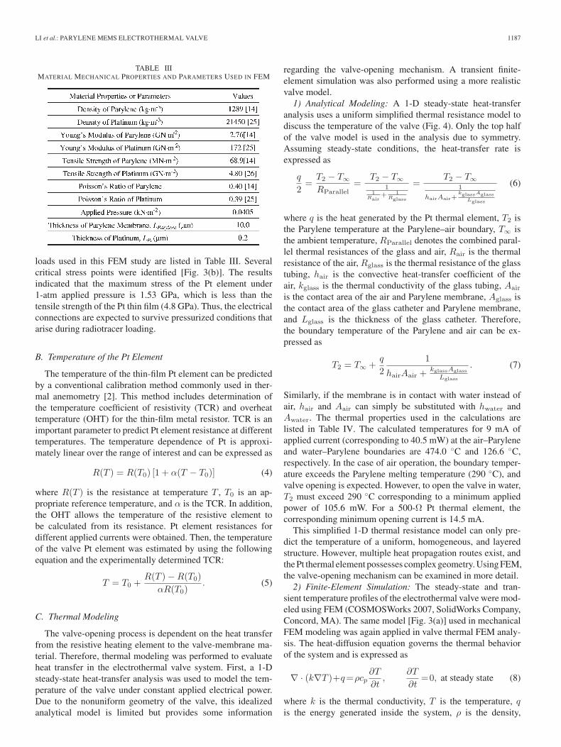
The thermal properties listed in Table IV were used in bothsteady-state and time-dependent thermal simulations. First,steady-state FEM was performed with air as the fluid medium.The maximum temperature of the valve calculated by steady-state FEM was 499.6 ◦C and in close agreement with the 1-Danalytical value of 474.0 ◦C. Transient FEM temperature pro-files are shown in Fig. 5. A 40.5-mW power was applied to thePt thermal resistive element. Convective cooling was appliedon the Parylene membrane and air boundary. By 133 ms, themajority of the valve area reached over 125 ◦C, which isthe thermal oxidation initiation temperature of Parylene C. TheParylene melting temperature of 290 ◦C was reached in thecentral region at 266 ms. By 400 ms, most of the valve area
LI et al.: PARYLENE MEMS ELECTROTHERMAL VALVE 1189
Fig. 5. Finite-element analysis using COSMOSWorks: The results of transientthermal FEM modeling showing the temperature distribution of the valve atthree time steps. This figure is a reprint of Fig. 2(d) in [16], reprinted with thepermission of the Chemical and Biological Microsystems Society.
exceeded the Parylene melting temperature, at which point anear-complete opening of the valve is expected. By 2.66 s(2660 ms), the maximum temperature of the valve reached499.4 ◦C, which was close to the steady-state FEM result(499.6 ◦C). Complete valve opening is defined as completethermal removal of the valve membrane in the flow path. Inthe simulations, the temperature at the center of the valve washigher than at the edge due to the geometrical arrangement ofthe Pt element. Therefore, it is expected that thermal degrada-tion will start from the center and expand toward the edges.
IV. FABRICATION
A. Valve-Membrane Fabrication
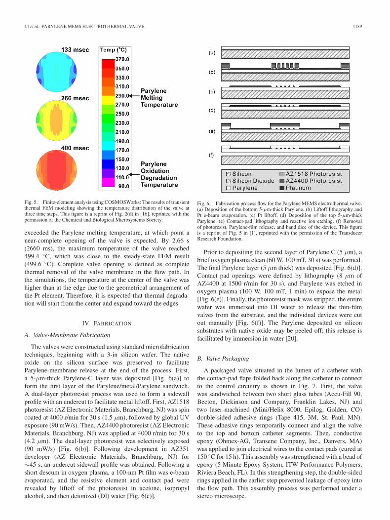
The valves were constructed using standard microfabricationtechniques, beginning with a 3-in silicon wafer. The nativeoxide on the silicon surface was preserved to facilitateParylene-membrane release at the end of the process. First,a 5-μm-thick Parylene-C layer was deposited [Fig. 6(a)] toform the first layer of the Parylene/metal/Parylene sandwich.A dual-layer photoresist process was used to form a sidewallprofile with an undercut to facilitate metal liftoff. First, AZ1518photoresist (AZ Electronic Materials, Branchburg, NJ) was spincoated at 4000 r/min for 30 s (1.5 μm), followed by global UVexposure (90 mW/s). Then, AZ4400 photoresist (AZ ElectronicMaterials, Branchburg, NJ) was applied at 4000 r/min for 30 s(4.2 μm). The dual-layer photoresist was selectively exposed(90 mW/s) [Fig. 6(b)]. Following development in AZ351developer (AZ Electronic Materials, Branchburg, NJ) for∼45 s, an undercut sidewall profile was obtained. Following ashort descum in oxygen plasma, a 100-nm Pt film was e-beamevaporated, and the resistive element and contact pad wererevealed by liftoff of the photoresist in acetone, isopropylalcohol, and then deionized (DI) water [Fig. 6(c)].
Fig. 6. Fabrication process flow for the Parylene MEMS electrothermal valve.(a) Deposition of the bottom 5-μm-thick Parylene. (b) Liftoff lithography andPt e-beam evaporation. (c) Pt liftoff. (d) Deposition of the top 5-μm-thickParylene. (e) Contact-pad lithography and reactive ion etching. (f) Removalof photoresist, Parylene-film release, and hand dice of the device. This figureis a reprint of Fig. 5 in [1], reprinted with the permission of the TransducerResearch Foundation.
Prior to depositing the second layer of Parylene C (5 μm), abrief oxygen plasma clean (60 W, 100 mT, 30 s) was performed.The final Parylene layer (5 μm thick) was deposited [Fig. 6(d)].Contact pad openings were defined by lithography (8 μm ofAZ4400 at 1500 r/min for 30 s), and Parylene was etched inoxygen plasma (100 W, 100 mT, 1 min) to expose the metal[Fig. 6(e)]. Finally, the photoresist mask was stripped, the entirewafer was immersed into DI water to release the thin-filmvalves from the substrate, and the individual devices were cutout manually [Fig. 6(f)]. The Parylene deposited on siliconsubstrates with native oxide may be peeled off; this release isfacilitated by immersion in water [20].
B. Valve Packaging
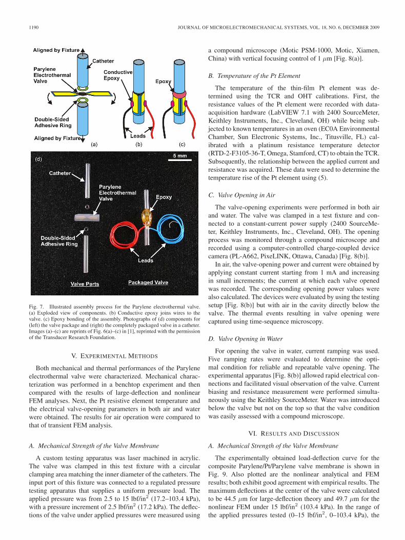
A packaged valve situated in the lumen of a catheter withthe contact-pad flaps folded back along the catheter to connectto the control circuitry is shown in Fig. 7. First, the valvewas sandwiched between two short glass tubes (Accu-Fill 90,Becton, Dickinson and Company, Franklin Lakes, NJ) andtwo laser-machined (Mini/Helix 8000, Epilog, Golden, CO)double-sided adhesive rings (Tape 415, 3M, St. Paul, MN).These adhesive rings temporarily connect and align the valveto the top and bottom catheter segments. Then, conductiveepoxy (Ohmex-AG, Transene Company, Inc., Danvers, MA)was applied to join electrical wires to the contact pads (cured at150 ◦C for 15 h). This assembly was strengthened with a bead ofepoxy (5 Minute Epoxy System, ITW Performance Polymers,Riviera Beach, FL). In this strengthening step, the double-sidedrings applied in the earlier step prevented leakage of epoxy intothe flow path. This assembly process was performed under astereo microscope.
1190 JOURNAL OF MICROELECTROMECHANICAL SYSTEMS, VOL. 18, NO. 6, DECEMBER 2009
Fig. 7. Illustrated assembly process for the Parylene electrothermal valve.(a) Exploded view of components. (b) Conductive epoxy joins wires to thevalve. (c) Epoxy bonding of the assembly. Photographs of (d) components for(left) the valve package and (right) the completely packaged valve in a catheter.Images (a)–(c) are reprints of Fig. 6(a)–(c) in [1], reprinted with the permissionof the Transducer Research Foundation.
V. EXPERIMENTAL METHODS
Both mechanical and thermal performances of the Paryleneelectrothermal valve were characterized. Mechanical charac-terization was performed in a benchtop experiment and thencompared with the results of large-deflection and nonlinearFEM analyses. Next, the Pt resistive element temperature andthe electrical valve-opening parameters in both air and waterwere obtained. The results for air operation were compared tothat of transient FEM analysis.
A. Mechanical Strength of the Valve Membrane
A custom testing apparatus was laser machined in acrylic.The valve was clamped in this test fixture with a circularclamping area matching the inner diameter of the catheters. Theinput port of this fixture was connected to a regulated pressuretesting apparatus that supplies a uniform pressure load. Theapplied pressure was from 2.5 to 15 lbf/in2 (17.2–103.4 kPa),with a pressure increment of 2.5 lbf/in2 (17.2 kPa). The deflec-tions of the valve under applied pressures were measured using
a compound microscope (Motic PSM-1000, Motic, Xiamen,China) with vertical focusing control of 1 μm [Fig. 8(a)].
B. Temperature of the Pt Element
The temperature of the thin-film Pt element was de-termined using the TCR and OHT calibrations. First, theresistance values of the Pt element were recorded with data-acquisition hardware (LabVIEW 7.1 with 2400 SourceMeter,Keithley Instruments, Inc., Cleveland, OH) while being sub-jected to known temperatures in an oven (EC0A EnvironmentalChamber, Sun Electronic Systems, Inc., Titusville, FL) cal-ibrated with a platinum resistance temperature detector(RTD-2-F3105-36-T, Omega, Stamford, CT) to obtain the TCR.Subsequently, the relationship between the applied current andresistance was acquired. These data were used to determine thetemperature rise of the Pt element using (5).
C. Valve Opening in Air
The valve-opening experiments were performed in both airand water. The valve was clamped in a test fixture and con-nected to a constant-current power supply (2400 SourceMe-ter, Keithley Instruments, Inc., Cleveland, OH). The openingprocess was monitored through a compound microscope andrecorded using a computer-controlled charge-coupled devicecamera (PL-A662, PixeLINK, Ottawa, Canada) [Fig. 8(b)].
In air, the valve-opening power and current were obtained byapplying constant current starting from 1 mA and increasingin small increments; the current at which each valve openedwas recorded. The corresponding opening power values werealso calculated. The devices were evaluated by using the testingsetup [Fig. 8(b)] but with air in the cavity directly below thevalve. The thermal events resulting in valve opening werecaptured using time-sequence microscopy.
D. Valve Opening in Water
For opening the valve in water, current ramping was used.Five ramping rates were evaluated to determine the opti-mal condition for reliable and repeatable valve opening. Theexperimental apparatus [Fig. 8(b)] allowed rapid electrical con-nections and facilitated visual observation of the valve. Currentbiasing and resistance measurement were performed simulta-neously using the Keithley SourceMeter. Water was introducedbelow the valve but not on the top so that the valve conditionwas easily assessed with a compound microscope.
VI. RESULTS AND DISCUSSION
A. Mechanical Strength of the Valve Membrane
The experimentally obtained load-deflection curve for thecomposite Parylene/Pt/Parylene valve membrane is shown inFig. 9. Also plotted are the nonlinear analytical and FEMresults; both exhibit good agreement with empirical results. Themaximum deflections at the center of the valve were calculatedto be 44.5 μm for large-deflection theory and 49.7 μm for thenonlinear FEM under 15 lbf/in2 (103.4 kPa). In the range ofthe applied pressures tested (0–15 lbf/in2, 0–103.4 kPa), the

LI et al.: PARYLENE MEMS ELECTROTHERMAL VALVE 1191
Fig. 8. Schematic diagrams of the experimental apparatus for (a) load-deflection testing and (b) electromechanical testing that allow for visual observation ofthe electrothermal valve.
Fig. 9. Comparison of the experimental data with the nonlinear FEM modeland large-deflection approximation. This figure is a reprint in Fig. 4[1] reprintedwith the permission of the Transducer Research Foundation.
composite membrane had a maximum deflection of 49.2 μmand did not undergo plastic deformation, and no obvious resis-tance change was measured after pressure application.
B. Temperature of the Pt Element
A representative TCR calibration is shown in Fig. 10, and atypical TCR value for our e-beam-deposited thin-film Pt was1.40 × 10−3/K (or 0.14%/K). As expected, the TCR valueof the thin-film Pt is lower than that of the bulk material
Fig. 10. Representative TCR calibration curve for an electrothermal valve.The slope of the curve corresponds to the empirically obtained TCR (α).
Fig. 11. Representative OHT calibration curve showing (open square) theresistance and (open circle) OHT as a function of the applied current.
(3.92 × 10⁻³/K) [2]. This TCR value and (5) were used topredict the Pt element temperature for different applied currentsin the OHT calibration (Fig. 11). To prevent destructive thermal

1192 JOURNAL OF MICROELECTROMECHANICAL SYSTEMS, VOL. 18, NO. 6, DECEMBER 2009
Fig. 12. Results for valve opening in air. (a) Open valve (15 mA). (b) Magnified view of the edge of the valve orifice. (c) Valve-opening-current- and power-to-resistance relationship. This figure is a reprint of Fig. 8 in [1], reprinted with the permission of the Transducer Research Foundation.
degradation of the device under test, the OHT experiments wereperformed at currents that were far below those resulting invalve opening (maximum applied current of 2.5 mA), and theresults were extrapolated to higher current ranges by using asecond-order polynomial curve fit. For a device with an initialresistance of 617 Ω, the valve-opening current that was higherthan 4.6 mA was expected, given that the Parylene-C meltingtemperature is 290 ◦C Note that this current setting correspondsto the temperature of the Pt element in air. However, completevalve opening requires elevation of the Parylene-membranetemperature in addition to that of the adjacent Pt trace abovethe Parylene melting temperature. Thus, opening currents thatresult in complete valve opening whereby the flow path wascompletely unobstructed was expected to occur at currents thatwere greater than 4.6 mA.
C. Valve Opening in Air
Valves were successfully opened in air under constant ap-plied current (Fig. 12). Fig. 12(a) shows the breach in theParylene membrane left by an opened valve (15 mA), andFig. 12(b) shows a magnified view of the edge of melted valveopening. Different valves having resistances ranging from 617to 125 Ω (for the three different resistive element designs,each having only a small resistance deviation between identical
devices) were successfully opened in air under constant appliedcurrents ranging from 7 to 20 mA, respectively [Fig. 12(c)]. Thecorresponding valve-opening powers are from 22 to 50 mW.Fig. 12(c) also shows that the valve-opening current and powerdecreased with increasing valve element resistance. The open-ing currents here are the minimum values that are necessary toachieve valve opening. The typical opening time at the mini-mum opening current is a few seconds and can be reduced byapplying higher current. However, faster opening is achieved ata cost of higher power consumption. In addition, the increasedthermal stress may result in breakage of the thin Pt trace priorto complete valve opening.
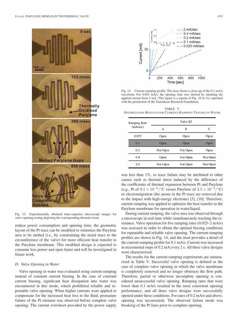
Valve opening is the result of a sequence of thermal events(Fig. 13). At 133 ms, a thermally oxidized Parylene region inthe valve area was visually apparent. At 266 ms, the Parylenemembrane began melting, resulting in small openings betweenthe windings of the serpentine Pt trace. By 400 ms, large gaps inthe valve membrane have formed, and valve opening is nearlycomplete. These experimental data corroborate the transientFEM results (Fig. 5). More specifically, the simulations enableprediction of valve-opening time, visualization of the heat-transfer paths, and determination of the temperature distributionacross the valve over time. Note that, in this valve design,complete valve opening requires that the majority of the valvearea must exceed the Parylene melting temperature. To further
LI et al.: PARYLENE MEMS ELECTROTHERMAL VALVE 1193
Fig. 13. Experimentally obtained time-sequence microscope images forvalve-opening testing depicting the corresponding thermal events.
reduce power consumption and opening time, the geometriclayout of the Pt trace can be modified to minimize the Parylenearea to be melted (i.e., by constraining the metal trace to thecircumference of the valve) for more efficient heat transfer tothe Parylene membrane. This modified design is expected toconsume less power and open faster and will be investigated infuture work.
D. Valve Opening in Water
Valve opening in water was evaluated using current rampinginstead of constant current biasing. In the case of constantcurrent biasing, significant heat dissipation into water wasencountered in this mode, which prohibited reliable and re-peatable valve opening. When higher currents were applied tocompensate for the increased heat loss to the fluid, prematurefailure of the Pt element was observed before complete valveopening. The current overshoot provided by the power supply
Fig. 14. Current-ramping profile. The inset shows a close-up of the 0.1-mA/swaveform. For 0.025 mA/s, the opening time was shorted by initiating theapplied current from 5 mA. This figure is a reprint of Fig. 10 in [1], reprintedwith the permission of the Transducer Research Foundation.
TABLE VOPTIMIZATION RESULTS FOR CURRENT-RAMPING TESTING IN WATER
was less than 1%, so trace failure may be attributed to othercauses such as thermal stress induced by the difference ofthe coefficients of thermal expansion between Pt and Parylene(e.g., Pt of 9.1 × 10⁻⁶/◦C versus Parylene of 3.5 × 10⁻⁵/◦C)or electromigration (the atoms in the Pt trace are removed dueto the impact with high-energy electrons) [5], [10]. Therefore,current ramping was applied to optimize the heat transfer to theParylene membrane for operation in water/liquid.
During current ramping, the valve area was observed througha microscope in real time while simultaneously tracking the re-sistance. Valve operation for five ramping rates (0.025–2 mA/s)was assessed in order to obtain the optimal biasing conditionsfor repeatable and reliable valve opening. The current-rampingprofiles are shown in Fig. 14, and the inset provides a detail ofthe current-ramping profile for 0.1 mA/s. Current was increasedin incremental steps of 0.2 mA every 2 s. All three valve designswere characterized.
The results for the current-ramping experiments are summa-rized in Table V. Successful valve opening is defined as thecase of complete valve opening in which the valve membraneis completely removed and no longer obstructs the flow path.Therefore, partial or otherwise incomplete opening is con-sidered unsuccessful valve opening. Ramping rates that werelower than 0.1 mA/s resulted in the most consistent openingperformance, and all three valve designs were successfullyopened under these conditions. For rates of 0.2 mA/s and above,opening was inconsistent. The observed failure mode wasbreaking of the Pt lines prior to complete opening.

1194 JOURNAL OF MICROELECTROMECHANICAL SYSTEMS, VOL. 18, NO. 6, DECEMBER 2009
Fig. 15. Representative results for valve opening in water. (Left column) Real-time resistance monitoring of the valve. (Right column) Time-lapse images ofvalve opening corresponding to resistance-measurement events in the left column plots. (a)–(c) Valve-opening testing results corresponding to three valve designsA, B, and C, respectively. Fig. 15(a) is a reprint of Fig. 9 in [1], reprinted with the permission of the Transducer Research Foundation.
Representative examples of the valve-opening process foreach of the three valve designs are shown in Fig. 15. Theresistance during valve opening was monitored, and the cor-responding resistance change to observable opening events wasrecorded. These events include the onset of membrane melting,breaking of the metal element, and opening of the valve. Inone example shown (valve design C), the Pt element line didnot break during valve opening due to the increased linewidth(40 μm compared to 20 μm for the other two designs). Notethat current ramping involves nonuniform dynamic heat transferand, as a result, was not modeled, given the limitations of theFEM software package. However, experimental results do sug-gest that current ramping preserves traces, allowing sufficient
time for heat transfer to occur and fully open valves in thepresence of water.
The valve-opening currents were higher for water than foroperation in air. This is expected, given the higher rate ofheat transfer into water than air and thus necessitates a higheropening current due to the unwanted heat loss. When practi-cal, an air bubble may be introduced between the water andvalve to reduce the opening current and increase the openingspeed. For example, opening times of 150 s were typical for0.1 mA/s in water compared to a few seconds in air. Thisapproach, however, may not be practical for all applications.As previously mentioned, the layout of the Pt trace may beoptimized to reduce power consumption and limit thermal

LI et al.: PARYLENE MEMS ELECTROTHERMAL VALVE 1195
loss to the surrounding fluid. Thus, valve-layout improvementswill be pursued to avoid the long opening times and complexcircuitry associated with the use of current ramping. Prelim-inary experiments with valves having traces limited to theperiphery of the valve-membrane area suggest that the desiredperformance improvements are possible by following this lineof investigation.
Our Parylene- and Pt-based electrothermal valve possessesmany advantages compared to the previous electrothermalvalves listed in Table I. First, the Parylene/Pt membrane isbiocompatible and thus suitable for implantation. Parylene canbe melted at lower temperature compared to metal or silicon;therefore, our valve has lower power consumption, which isdesirable in implantable devices. The selection of Paryleneas a valve-membrane material also has other implications.Parylene’s mechanical strength allows mechanically robust thinfilms that can withstand pressure gradients without plasticdeformation. Compared to nonpolymer valves, our Parylenevalves were fabricated using simple processes and can eas-ily be integrated with a variety of microfluidic systems. Thefastest valves are nonpolymer valves; however, in some cases,Parylene can offer better power consumption. Having a thinnerParylene valve membrane compared to other polymer valvesimproves both power consumption (∼60 times) and openingtime (∼10 times). Meanwhile, a thin Parylene membrane wasmicrofabricated (10 μm) and offered better power consumptionand opening time to other polymer valves. This thin Parylenevalve can withstand higher pressure compared to other polymervalves due to its much higher mechanical strength.
VII. IN VIVO APPLICATION
Previously, a microbolus infusion pump (MIP) for rapid andwireless drug delivery in freely moving untethered rats was de-scribed for the specific purpose of functional neuroimaging ofbehavior [21]–[23]. This imaging paradigm involves the rapidintravenous delivery of a radiotracer, followed by lethal injec-tion, brain removal, slicing, and autoradiographic processing oflabeled tissue slices to obtain a statistical parametric mapping.This 3-D reconstruction of the brain details changes in brain ac-tivation patterns captured by labeling cerebral blood flow [24].
A critical enabler in this imaging paradigm is the rapiddelivery of radiotracer and euthanasia agent to preserve thetime resolution of behavioral events and to prevent nonspecificdiffusion associated with slow infusion methods. A miniaturesolenoid valve provided rapid opening to allow delivery froma pressurized reservoir. However, the size and bulk of thesolenoid valve prohibits its use in a MIP that is suitable fortransgenic mice (32-g pump compared to a typical 40-g mouse).To our knowledge, there are no commercial valves that meetthe requirements for a mouse-compatible MIP. Our Paryleneelectrothermal valve meets all requirements for this application,including low weight, low power, and rapid opening.
The Parylene electrothermal valve was integrated into animplantable MIP that is suitable for use in mice [Fig. 16(a)][1]. The pump consists of a reservoir, valve, catheter, secondarycoil, and tuning capacitors. The total weight of the system is lessthan 10% of the animal weight (4 g). In benchtop experiments,
Fig. 16. Neuroimaging application of Parylene electrothermal valve. (a) MIP.(b) In vivo testing setup. (c) Photograph comparing the MIP and a mouse.Fig. 16(a) and (c) are reprints of Fig. 11(a) and (b) in [1], reprinted with thepermission of the Transducer Research Foundation.
wireless activation of the valve was successfully demonstratedusing the mouse emitter coil cage (primary coil) [Fig. 16(b)].
In vivo valve triggering was also demonstrated. First, themouse was cannulated, and the pump reservoir was loadedwith pentobarbital (50 mg/kg)/potassium chloride (3 mol/L).The pump was implanted subcutaneously in the dorsum of themouse and sutured. To observe the valve triggering, the catheterwas left outside the mouse. After energizing the primary coilaround the mouse cage, euthanasia solution flowed out of thecatheter due to successful triggering of the electrothermal valve.Fig. 16(c) compares the dimensions of the MIP and a mouse.Detailed experiments in mice using this new MIP enabled byour MEMS valve are under way.
VIII. CONCLUSION
We have successfully developed a disposable low-powerParylene-C MEMS electrothermal valve that is suitable fordrug-delivery applications. The design, modeling, fabrication,

1196 JOURNAL OF MICROELECTROMECHANICAL SYSTEMS, VOL. 18, NO. 6, DECEMBER 2009
in vitro benchtop characterization, and preliminary in vivotesting have been described. The TCR and OHT experimentshave allowed prediction of the temperature of the Pt elementand determination of the appropriate current to apply to openthe valve. Opening powers of 22–50 mW have been obtainedin air, and reliable valve opening in water using a current-ramping rate of 0.1 mA/s has been achieved. Further reductionin power consumption and optimization of valve performanceare planned. Also, additional experiments will evaluate theperformance of the valve in the presence of the radiotracer agentand in vivo functional neuroimaging experiments.
ACKNOWLEDGMENT
The authors would like to thank Dr. D. Zhu, Dr. T. Hoang,N. Sardesai, and the members of the Biomedical MicrosystemsLaboratory, Department of Biomedical Engineering, Universityof Southern California, for their contributions to this paper.
REFERENCES
[1] P.-Y. Li, T. K. Givrad, D. P. Holschneider, J.-M. I. Maarek, andE. Meng, “A wirelessly-activated Parylene electrothermal valve formapping brain function in freely moving subjects,” presented at theSolid-State Sensors, Actuators, Microsystems Workshop, Hilton HeadIsland, SC, 2008.
[2] E. Meng, P.-Y. Li, and Y.-C. Tai, “A biocompatible Parylene thermalflow sensing array,” Sens. Actuators A, Phys., vol. 144, no. 1, pp. 18–28,May 2008.
[3] P.-Y. Li, J. Shih, R. Lo, S. Saati, R. Agrawal, M. S. Humayun, Y.-C. Tai,and E. Meng, “An electrochemical intraocular drug delivery device,” Sens.Actuators A, Phys., vol. 143, no. 1, pp. 41–48, May 2008.
[4] J. M. Maloney, S. A. Uhland, B. F. Polito, N. F. Sheppard, Jr.,C. M. Pelta, and J. T. Santini, Jr., “Electrothermally activated microchipsfor implantable drug delivery and biosensing,” J. Control. Release,vol. 109, no. 1–3, pp. 244–255, Dec. 2005.
[5] A. M. Cardenas-Valencia, J. Dlutowski, J. Bumgarner, C. Munoz,W. Wang, R. Popuri, and L. Langebrake, “Development of various designsof low-power MEMS valves for fluidic applications,” Sens. Actuators A,Phys., vol. 136, no. 1, pp. 374–384, May 2007.
[6] J. Mueller, E.-H. Yang, A. Green, V. White, I. Chakraborty, andR. Reinicke, “Design and fabrication of MEMS-based micropropulsiondevices at JPL,” in Proc. SPIE, San Francisco, CA, 2001, pp. 57–71.
[7] C.-C. Hong, J.-W. Choi, and C. H. Ahn, “Disposable air-bursting detona-tors as an alternative on-chip power source,” in Proc. 15th IEEE Int. Conf.Micro Electro Mech. Syst., Las Vegas, NV, 2002, pp. 240–243.
[8] L. J. Guerin, O. Dubochet, J. F. Zeberli, P. A. C. P. Clot, andP. A. R. P. Renaud, “Miniature one-shot valve,” in Proc. 11th IEEEInt. Conf. Micro Electro Mech. Syst., Heidelberg, Germany, 1998,pp. 425–428.
[9] J. C. McDonald, S. J. Metallo, and G. M. Whitesides, “Fabrication ofa configurable, single-use microfluidic device,” Anal. Chem., vol. 73,no. 23, pp. 5645–5650, Dec. 2001.
[10] C. Luo, X. Liu, R. Poddar, J. Garra, A. P. Gadre, E. V. Keuren,T. Schneider, R. White, J. Currie, and M. Paranjape, “Thermal ablation ofPMMA for water release using a microheater,” J. Micromech. Microeng.,vol. 16, no. 3, pp. 580–588, Mar. 2006.
[11] K. K. Jain, “Drug delivery system,” in Methods in Molecular Biology,vol. 437, J. M. Walker, Ed. Totowa, NJ: Humana Press, 2008.
[12] E. Meng, P.-Y. Li, and Y.-C. Tai, “Plasma removal of Parylene C,”J. Micromech. Microeng., vol. 18, no. 4, p. 045004, Apr. 2008.
[13] D. W. Grattan and M. Bilz, “The thermal aging of Parylene and the effectof antioxidant,” Stud. Conserv., vol. 36, pp. 44–52, 1991.
[14] SCS Parylene Properties2008. [Online]. Available: http://www.scscoatings.com/docs/coatspec.pdf
[15] P.-Y. Li, D. P. Holschneider, J.-M. I. Maarek, and E. Meng, “Paryleneelectrothermal MEMS drug delivery valve,” in Proc. Spring Nat. MeetingACS, New Orleans, LA, 2008, pp. 941–942.
[16] P.-Y. Li, T. K. Givrad, D. P. Holschneider, J.-M. I. Maarek, andE. Meng, “Mechanical and thermal modeling of a Parylene electrothermalvalve for mapping brain function in freely moving subjects,” in Proc.
12th Int. Conf. Miniaturized Syst. Chem. Life Sci., San Diego, CA, 2008,pp. 1105–1107.
[17] P.-Y. Li, D. P. Holschneider, J.-M. I. Maarek, and E. Meng, “Paryleneelectrothermal valve for rapid in vivo drug delivery,” presented at theAmerican Vacuum Society (AVS) 55th Int. Symp. Exhibition, Boston,MA, 2008.
[18] T. von Karman, “Festigkeitsprobleme in Machinenbau,” in Encyklopadieder Mathematischen Wissenschaften, vol. 4. Leipzig, Germany: Teubner,1910, pp. 348–352.
[19] A. C. Ugural, Stress in Plate and Shells., 2nd ed. New York: McGraw-Hill, 1999.
[20] D. C. Rodger, A. J. Fong, W. Li, H. Ameri, A. K. Ahuja, C. Gutierrez,I. Lavrov, H. Zhong, P. R. Menon, E. Meng, J. W. Burdick, R. R. Roy,V. R. Edgerton, J. D. Weiland, M. S. Humayun, and Y.-C. Tai, “FlexibleParylene-based multielectrode array technology for high-density neuralstimulation and recording,” Sens. Actuators B, Chem., vol. 132, no. 2,pp. 449–460, Jun. 2008.
[21] D. P. Holschneider, J.-M. I. Maarek, J. Harimoto, J. Yang, andO. U. Scremin, “An implantable bolus infusion pump for use in freelymoving, nontethered rats,” Amer. J. Physiol. Heart Circ. Physiol.,vol. 283, no. 4, pp. H1 713–H1 719, Oct. 2002.
[22] D. P. Holschneider, J. Yang, T. R. Sadler, P. T. Nguyen, T. K. Givrad, andJ.-M. I. Maarek, “Mapping cerebral blood flow changes during auditory-cued conditioned fear in the nontethered, nonrestrained rat,” NeuroImage,vol. 29, no. 4, pp. 1344–1358, Feb. 2006.
[23] W. H. Moore, D. P. Holschneider, T. K. Givrad, and J.-M. I. Maarek,“Transcutaneous RF-powered implantable minipump driven by a class-Etransmitter,” IEEE Trans. Biomed. Eng., vol. 53, no. 8, pp. 1705–1708,Aug. 2006.
[24] D. P. Holschneider and J.-M. I. Maarek, “Brain maps on the go: Functionalimaging during motor challenge in animals,” Methods, vol. 45, no. 4,pp. 255–261, Aug. 2008.
[25] “Physical properties of the platinum metals,” Platin. Met. Rev., vol. 16,no. 2, p. 59, Apr. 1972.
[26] K. Wang, K. Yao, and S. J. Chua, “Titanium diffusion and residual stressof platinum thin films on Ti/SiO2/Si substrate,” J. Appl. Phys., vol. 98,no. 1, p. 013538, Jul. 2005.
[27] A. J. de Mello, M. Habgood, N. L. Lancaster, T. Welton, andR. C. R. Wootton, “Precise temperature control in microfluidic devicesusing Joule heating of ionic liquids,” Lab Chip, vol. 4, no. 5, pp. 417–419,Oct. 2004.
[28] Z. Liu, H. Chan, W. J. Li, Z. Dong, and Y. Wang, “Finite element modelingof a thermally actuated polymer micro robotic gripper,” in Proc. Int. Conf.Inf. Acquis., 2004, pp. 88–91.
Po-Ying (Brian) Li (M’07) received the B.S. degreein mechanical engineering from Tatung Institute ofTechnology, Taipei, Taiwan, in 1996, the M.S. de-gree in mechanical engineering from National TsingHua University, Hsinchu, Taiwan, in 2001, and theM.S. degree in materials science from the Universityof Southern California, Los Angeles, in 2004. Hereceived the Ph.D. degree in electrical engineeringin 2009.
He was a Research Assistant in the CompositeStructure Laboratory, National Tsing Hua University,
from 1999 to 2001. He is currently a Member of the Biomedical MicrosystemsLaboratory, Department of Biomedical Engineering, University of SouthernCalifornia. His research is focused on the characterization of the mechanicalproperties of carbon-fiber-reinforced composite-laminate materials.
Mr. Li is a member of the American Society of Mechanical Engineers, theAmerican Chemical Society, and the American Vacuum Society.

LI et al.: PARYLENE MEMS ELECTROTHERMAL VALVE 1197
Tina K. Givrad received the B.S. degree in electricalengineering from Islamic Azad University, Tehran,Iran, in 1992, the M.S. degree in electrical engineer-ing from California State University, Los Angeles(CSULA), in 1996, and the Ph.D. degree in bio-medical engineering from the University of SouthernCalifornia, Los Angeles, in 2007.
Following her graduation from CSULA, she beganworking for the Boeing North American DefenseGroup. She is currently a Postdoctoral ResearchAssociate with the Department of Biomedical Engi-
neering, USC. Her research focus has been on the design and fabrication ofmicrobolus pumps for rapid drug infusion used for functional neuroimagingapplications in small animals.
Dr. Givrad is a member of the American Society of Mechanical Engineers,the Biomedical Engineering Society, and the Society for Neuroscience.
Daniel P. Holschneider received the B.A. degreein chemistry from The Johns Hopkins University,Baltimore, MD, in 1984, the M.D. degree from theUniversity of North Carolina at Chapel Hill in 1988,and training in clinical psychiatry at the Universityof California, Los Angeles, in 1993.
He is currently an Associate Professor in the De-partments of Psychiatry and Behavioral Sciences,Neurology, Cell and Neurobiology, and Biomed-ical Engineering, University of Southern California,Los Angeles. His research focus has been on animal
models, functional brain mapping in freely moving animals, physiologic mon-itoring, and technology development (implantable infusion pumps and cardiacoutput monitoring).
Jean-Michel I. Maarek received the engineeringdegree (Diplome d’Ingénieur Civil des Mines) inchemical engineering from the Ecole des Mines,Nancy, France, in 1980, the Doctorat Ingénieur de-gree in biomedical engineering from the UniversitéParis Val-de-Marne, Créteil, France, in 1984, andthe M.S. degree in education from the University ofSouthern California, Los Angeles, in 1997.
He is currently an Associate Professor of engi-neering practice with the Department of Biomed-ical Engineering, University of Southern California,
where he is also a Principal Investigator with the Alfred E. Mann Institute forBiomedical Engineering for the Cardiac Output Monitor Project. His researchinterests are in physiologic monitoring of cardiovascular function, medicaldevice development, and biomedical signal analysis.
Ellis Meng (M’02–SM’09) received the B.S. degreein engineering and applied science and the M.S.and Ph.D. degrees in electrical engineering from theCalifornia Institute of Technology (Caltech),Pasadena, in 1997, 1998, and 2003, respectively.
She joined the Department of BiomedicalEngineering, University of Southern California,Los Angeles, in 2004, as an Assistant Professor,where she currently holds a joint appointmentin the Ming Hsieh Department of ElectricalEngineering. She holds the Viterbi Early Career
Chair in the Viterbi School of Engineering. She is also currently the ThrustLeader for Interface Technology, the Associate Director of Education, and aStudent Diversity Researcher at the National Science Foundation BiomimeticMicroElectronic Systems Engineering Research Center. Her research interestsinclude bio-MEMS, implantable biomedical microdevices, microfluidics,multimodality integrated microsystems, and packaging.
Dr. Meng was a recipient of the Intel Women in Science and EngineeringScholarship, the Caltech Alumni Association Donald S. Clark Award, the NSFCAREER Award, the Wallace H. Coulter Foundation Early Career Transla-tional Research Award, and the Caltech Special Institute Fellowship. She wasrecently recognized as a Technology Review (TR) 35 Young Innovator Under35. She is a member of Tau Beta Pi, the Biomedical Engineering Society,the Society of Women Engineers, and the American Society for EngineeringEducation.
Copyright © 2022 FDOKUMEN