Improving response of a MEMS capacitive microphone filtering shock noise
8
Improving response of a MEMS capacitive microphone filtering shock noise Armin Saeedi Vahdat a , Ghader Rezazadeh a,n , Saeid Afrang b a Mechanical Engineering Department, Urmia University, Urmia, Iran b Electrical Engineering Department, Urmia University, Urmia, Iran article info Article history: Received 21 December 2010 Received in revised form 4 March 2011 Accepted 9 March 2011 Keywords: Capacitive microphone MEMS Mechanical shock Pull-in instability Frequency response abstract This paper deals with the effects of mechanical shock loads on the stability and dynamic response of a MEMS circular capacitive microphone. As results demonstrate, mechanical shock loads affect the dynamic response and the stability region of the capacitive microphone. The results show that the mechanical shock loads can induce considerable noise in the response of the microphone. Therefore, noise filtering is an important issue to eliminate the output response distortions. To achieve this aim we propose a structure for the capacitive microphone with an electrical circuit in order to eliminate the shock noise. In addition the effect of a delay in shock application is also studied, and it is illustrated that a delay in shock application plays an important role in the stability of the capacitive microphone. & 2011 Elsevier Ltd. All rights reserved. 1. Introduction A microphone is a transducer that converts acoustic energy into electrical energy. The microphones are widely employed in many applications such as cell phones, personal computers, car navigation systems, home-use robots, voice communications devices, hearing-aids, surveillance and military aims, and noise and vibration control [1–3]. Generally microphones can be divided into three types: dynamic microphones, condenser micro- phones and optical microphones [1]. A condenser or capacitive microphone couples acoustical, mechanical and electrical domains. To date because of high sensitivity and low noise levels capacitive microphones are the most common type of silicon microphone [2]. A condenser microphone conceptually consists of a thin vibrating diaphragm and a rigid ground plate that are separated by a small air gap. The relative movement of the diaphragm to the ground plate is solely due to the applied acoustic pressure on the diaphragm, so that the ground plate has no movement as the reference. It means that the ground plate should be thick enough not to move [4]. Capacitive microphones usually need a dc biasing voltage to obtain an ac output if the sensing capacitance changes due to the sound pressure [5]. Traditional microphones, such as Br ¨ uel and Kjær condenser microphones, offer excellent performance, but are costly and currently not suitable for miniaturization [6]. Microelectrome- chanical systems (MEMS) technology has been rapidly growing since its beginning in the 1980s. With the development of MEMS technology, hundreds or thousands of devices can be fabricated together on a single silicon wafer. This leads to the production of MEMS microphones that can approach the performance of tradi- tional microphones with lower cost and smaller size [6]. Currently, commercialization of MEMS devices is a major focus for engineers. One of the most critical issues affecting the commercialization of MEMS devices such as MEMS microphones is their reliability under mechanical shock and impact. MEMS capacitive microphones can be exposed to shock during fabrica- tion, deployment, and operation. Since mechanical shock can induce considerable dynamic loads, it can cause some problems such as chipping, cracking and fracture in the structures [7]. Severe motions and dropping on hard surfaces can induce highly dynamic loads in the MEMS capacitive microphones, which may lead to mechanical and/or electrical failure. Mechanical shock loads can cause capacitive microphones diaphragm to hit the stationary ground plate underneath it, causing stiction [8] and short circuit problems [9] and hence it’s failure. Since the majority of microstructures are fabricated of silicon or polysilicon, they are very tough against bending stresses induced from shock accel- eration. Therefore, failure through stiction and electric short circuits due to contacts between movable and stationary electro- des is more possible than the failure through direct breaking due to contact stresses [7]. A shock can be defined as a force applied suddenly over a short period of time relative to the natural period of the structure [10]. A shock pulse can be characterized by its maximum value, Contents lists available at ScienceDirect journal homepage: www.elsevier.com/locate/mejo Microelectronics Journal 0026-2692/$ - see front matter & 2011 Elsevier Ltd. All rights reserved. doi:10.1016/j.mejo.2011.03.007 n Corresponding author. E-mail addresses: [email protected], [email protected] (G. Rezazadeh). Microelectronics Journal 42 (2011) 614–621
Transcript of Improving response of a MEMS capacitive microphone filtering shock noise
Microelectronics Journal 42 (2011) 614–621
Contents lists available at ScienceDirect
Microelectronics Journal
0026-26
doi:10.1
n Corr
E-m
g.rezaza
journal homepage: www.elsevier.com/locate/mejo
Improving response of a MEMS capacitive microphone filtering shock noise
Armin Saeedi Vahdat a, Ghader Rezazadeh a,n, Saeid Afrang b
a Mechanical Engineering Department, Urmia University, Urmia, Iranb Electrical Engineering Department, Urmia University, Urmia, Iran
a r t i c l e i n f o
Article history:
Received 21 December 2010
Received in revised form
4 March 2011
Accepted 9 March 2011
Keywords:
Capacitive microphone
MEMS
Mechanical shock
Pull-in instability
Frequency response
92/$ - see front matter & 2011 Elsevier Ltd. A
016/j.mejo.2011.03.007
esponding author.
ail addresses: [email protected],
[email protected] (G. Rezazadeh).
a b s t r a c t
This paper deals with the effects of mechanical shock loads on the stability and dynamic response of a
MEMS circular capacitive microphone. As results demonstrate, mechanical shock loads affect the
dynamic response and the stability region of the capacitive microphone. The results show that the
mechanical shock loads can induce considerable noise in the response of the microphone. Therefore,
noise filtering is an important issue to eliminate the output response distortions. To achieve this aim we
propose a structure for the capacitive microphone with an electrical circuit in order to eliminate the
shock noise. In addition the effect of a delay in shock application is also studied, and it is illustrated that
a delay in shock application plays an important role in the stability of the capacitive microphone.
& 2011 Elsevier Ltd. All rights reserved.
1. Introduction
A microphone is a transducer that converts acoustic energyinto electrical energy. The microphones are widely employed inmany applications such as cell phones, personal computers, carnavigation systems, home-use robots, voice communicationsdevices, hearing-aids, surveillance and military aims, and noiseand vibration control [1–3]. Generally microphones can bedivided into three types: dynamic microphones, condenser micro-phones and optical microphones [1].
A condenser or capacitive microphone couples acoustical,mechanical and electrical domains. To date because of highsensitivity and low noise levels capacitive microphones are themost common type of silicon microphone [2]. A condensermicrophone conceptually consists of a thin vibrating diaphragmand a rigid ground plate that are separated by a small air gap. Therelative movement of the diaphragm to the ground plate is solelydue to the applied acoustic pressure on the diaphragm, so that theground plate has no movement as the reference. It means that theground plate should be thick enough not to move [4]. Capacitivemicrophones usually need a dc biasing voltage to obtain an acoutput if the sensing capacitance changes due to the soundpressure [5].
Traditional microphones, such as Bruel and Kjær condensermicrophones, offer excellent performance, but are costly and
ll rights reserved.
currently not suitable for miniaturization [6]. Microelectrome-chanical systems (MEMS) technology has been rapidly growingsince its beginning in the 1980s. With the development of MEMStechnology, hundreds or thousands of devices can be fabricatedtogether on a single silicon wafer. This leads to the production ofMEMS microphones that can approach the performance of tradi-tional microphones with lower cost and smaller size [6].
Currently, commercialization of MEMS devices is a major focusfor engineers. One of the most critical issues affecting thecommercialization of MEMS devices such as MEMS microphonesis their reliability under mechanical shock and impact. MEMScapacitive microphones can be exposed to shock during fabrica-tion, deployment, and operation. Since mechanical shock caninduce considerable dynamic loads, it can cause some problemssuch as chipping, cracking and fracture in the structures [7].Severe motions and dropping on hard surfaces can induce highlydynamic loads in the MEMS capacitive microphones, which maylead to mechanical and/or electrical failure. Mechanical shockloads can cause capacitive microphones diaphragm to hit thestationary ground plate underneath it, causing stiction [8] andshort circuit problems [9] and hence it’s failure. Since the majorityof microstructures are fabricated of silicon or polysilicon, they arevery tough against bending stresses induced from shock accel-eration. Therefore, failure through stiction and electric shortcircuits due to contacts between movable and stationary electro-des is more possible than the failure through direct breaking dueto contact stresses [7].
A shock can be defined as a force applied suddenly over a shortperiod of time relative to the natural period of the structure [10].A shock pulse can be characterized by its maximum value,
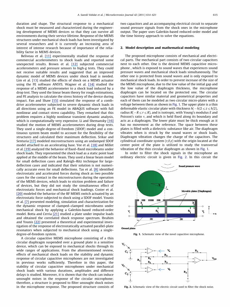
Fig. 1. Schematic view of the novel capacitive microphone.
Fig. 2. Schematic view of the electric circuit used to filter the shock noise.
A. Saeedi Vahdat et al. / Microelectronics Journal 42 (2011) 614–621 615
duration and shape. The structural response to a mechanicalshock must be measured and characterized during the engineer-ing development of MEMS devices so that they can survive allenvironments during their service lifetime. Response of the MEMSstructures under mechanical shock loads has been investigated byseveral researchers and it is currently an increasing area ofinterest of intense research because of importance of the relia-bility factor in MEMS devices.
Beliveau et al. [11] experimentally studied the response ofcommercial accelerometers to shock loads and reported someunexpected results. Brown et al. [12] subjected commercialaccelerometers and pressure sensors to high-g tests. They couldnot receive suitable results and suggested that an improveddynamic model of MEMS devices under shock load is needed.Lim et al. [13] studied the effects of shock on a MEMS actuatorusing the FE software ANSYS. Wagner et al. [14] studied theresponse of a MEMS accelerometer to a shock load induced by adrop test. They used the linear beam theory for rough estimations,and FE analysis to calculate the stress history of the device duringimpact. Fan and Shaw [15] simulated the response of a comb-drive accelerometer subjected to severe dynamic shock loads inall directions using an FE model in ABAQUS software with fullnonlinear and contact stress capability. They remarked that thisproblem requires a highly nonlinear transient dynamic analysis,which is computationally very expensive. Li and Shemansky [16]studied the motion of MEMS accelerometers during drop tests.They used a single-degree-of-freedom (SDOF) model and a con-tinuous system beam model to account for the flexibility of thestructures and calculated their maximum deflection. Srikar andSenturia [17] modeled microstructures using an undamped SDOFmodel attached to an accelerating base. Yee et al. [18] and Milletet al. [19] analyzed the behavior of fixed–fixed microbeams undershock loads. They represented the shock load as a static point loadapplied at the middle of the beam. They used a linear beam modelfor small deflection cases and Raleigh–Ritz technique for large-deflection cases and indicated that their solution is not numeri-cally accurate even for small deflections. Tas et al. [8] identifiedelectrostatic and accelerated forces during shock as two possiblecases for the contact in the microstructures during the operationof the MEMS devices, which leads to stiction problem and failureof devices, but they did not study the simultaneous effect ofelectrostatic forces and mechanical shock loadings. Coster et al.[20] modeled the behavior of the RF MEMS switch actuated by anelectrostatic force subjected to shock using a SDOF model. Youniset al. [7] presented modeling, simulation and characterization forthe dynamic response of clamped–clamped microbeams undermechanical shock by applying a Galerkin-based reduced-ordermodel. Botta and Cerria [21] studied a plate under impulse loadsand obtained the correlated shock response spectrum. Ibrahimand Younis [22] presented a theoretical and experimental inves-tigation of the response of electrostatically actuated parallel-plateresonators when subjected to mechanical shock using a single-degree-of-freedom system.
A circular capacitive MEMS microphone consisting of a thincircular diaphragm suspended over a ground plate is a sensitivedevice, which can be exposed to mechanical shocks through itswide ranges of applications. From the aforementioned review,effects of mechanical shock loads on the stability and dynamicresponse of circular capacitive microphones are not investigatedin previous works sufficiently. Therefore in this paper, thestability of circular capacitive microphones under mechanicalshock loads with various durations, amplitudes and differentdelays is studied. Moreover, it is shown that the shock can induceunsought noises in the response of the circular microphone;therefore, a structure is proposed to filter unsought shock noisesin the microphone response. The proposed structure consists of
two capacitors and an accompanying electrical circuit to separatesound pressure signals from the shock ones in the microphoneoutput. The paper uses Galerkin-based reduced-order model andthe time history approach to solve the equations.
2. Model description and mathematical modeling
The proposed microphone consists of mechanical and electri-cal parts. The mechanical part consists of two circular capacitorsnext to each other. One is the desired MEMS capacitive micro-phone , which is exposed to sound waves that experiences soundpressure waves and mechanical shock loads simultaneously. Theother one is protected from sound waves and is only exposed tomechanical shock loads. In order to prevent increase of the size ofthe MEMS microphone, due to the low value of the initial gap andthe low value of the diaphragm thickness, the microphonediaphragm can be located on the protected one. The circularcapacitors have similar material and geometrical properties andeach of them can be modeled as two circular micro-plates with avoltage between them as shown in Fig. 1. The upper plate is a thindeformable elastic circular plate with thickness h(�h/2rzrh/2),radius R(�RrrrR), and is isotropic, with Young’s modulus E andPoisson’s ratio n, and which is held fixed along its boundary andacts as a diaphragm. The lower plate must be thick enough as ithas no movement as the reference. The space between theseplates is filled with a dielectric substance like air. The diaphragmvibrates when is struck by the sound waves or shock loads.Diaphragm vibration changes the charge of the capacitors. Thecylindrical coordinate system (r,y,z) with the origin located at thecenter point of the plate is utilized to study the transversalvibration of the thin circular diaphragm as shown in Fig. 1.
In order to filter the shock signals in the microphone anordinary electric circuit is given in Fig. 2. In this circuit the
A. Saeedi Vahdat et al. / Microelectronics Journal 42 (2011) 614–621616
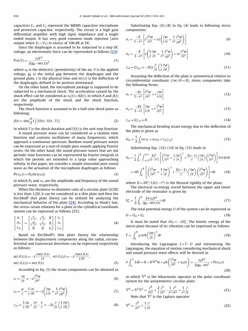
capacitors C1 and C2 represent the MEMS capacitive microphoneand protected capacitor, respectively. The circuit is a high gaindifferential amplifier with high input impedance and a singleended output. It has very good common mode rejection (zerooutput when V1¼V2) in excess of 100 dB at DC.
Since the diaphragm is assumed to be subjected to a step DCvoltage, an electrostatic force can be represented as follows [23]:
Fðw,VÞ ¼e0V2
2ðg0�wðr,tÞÞ2ð1Þ
where e0 is the dielectric (permittivity) of the air, V is the appliedvoltage, g0 is the initial gap between the diaphragm and theground plate, t is the physical time and w(r,t) is the deflection ofthe diaphragm, defined to be positive downward.
On the other hand, the microphone package is supposed to besubjected to a mechanical shock. The acceleration caused by theshock effect can be considered as as(t)¼Ab(t), in which A and b(t)are the amplitude of the shock and the shock function,respectively.
The shock function is assumed to be a half-sine shock pulse asfollowing:
bðtÞ ¼ sinpT
t� �
U tð Þ�Uðt�TÞ� �
ð2Þ
in which T is the shock duration and U(t) is the unit step function.A sound pressure wave can be considered as a random time
function and contains oscillations of many frequencies, whichapproach a continuous spectrum. Random sound pressure wavescan be expressed as a sum of simple pure sounds applying Fourierseries. On the other hand, the sound pressure waves that are notperiodic time functions can be represented by Fourier integrals inwhich the periods are extended to a large value approachinginfinity. In this paper, we consider a simple sinusoidal pure soundwave as the actuation of the microphone diaphragm as follows
Pðos,tÞ ¼ P0 sin ½ost� ð3Þ
in which P0 and os are the amplitude and frequency of the soundpressure wave, respectively.
When the thickness-to-diameter ratio of a circular plate (h/2R)is less than 1/20, it can be considered as a thin plate and then theKirchhoff thin plate theory can be utilized for analyzing themechanical behavior of the plate [24]. According to Hook’s law,the stress–strain relations for a plate in the cylindrical coordinatesystem can be expressed as follows [25]:
sr
sy
try
264
375¼
E1�n2
nE1�n2 0
nE1�n2
E1�n2 0
0 0 G
264
375
er
eygry
264
375 ð4Þ
Based on Kirchhoff’s thin plate theory the relationshipbetween the displacement components along the radial, circum-ferential and transversal directions can be expressed respectivelyas follows:
uðr,y,z,tÞ ¼�z@wðr,y,tÞ
@r, vðr,y,z,tÞ ¼�z
@wðr,y,tÞ
r@y,
wðr,y,z,tÞ ¼wðr,y,tÞ ð5Þ
According to Eq. (5) the strain components can be obtained as
er ¼@u
@r¼�z
@2w
@r2ð6Þ
ey ¼u
rþ
1
r
@v
@y¼�z
@w
r@rþ
1
r2
@2w
@y2
!ð7Þ
gry ¼1
r
@u
@yþ@v
@r�
v
r¼�2z
@
@r
1
r
@w
@y
� �ð8Þ
Substituting Eqs. (6)–(8) in Eq. (4) leads to following stresscomponents:
sr ¼�E
1�n2z@2w
@r2þnz
@w
r@rþ
1
r2
@2w
@y2
!" #ð9Þ
sy ¼�E
1�n2z
1
r
@w
@rþ
1
r2
@2w
@y2
!þnz
@2w
@r2
" #ð10Þ
try ¼ Ggry ¼�2Gz@
@r
1
r
@w
@y
� �ð11Þ
Assuming the deflection of the plate is symmetrical relative tocircumferential coordinate (@w=@y¼ 0), stress components takethe following forms:
sr ¼�Ez
1�n2
@2w
@r2þn @w
r@r
" #ð12Þ
sy ¼�Ez
1�n2
@w
r@rþn @
2w
@r2
" #ð13Þ
try ¼ Ggry ¼ 0 ð14Þ
The mechanical bending strain energy due to the deflection ofthe plate is given as
Um ¼1
2
ZVðsrerþsyeyþtrygryÞ ð15Þ
Substituting Eqs. (12)–(14) in Eq. (15) leads to
Um ¼1
2
Z R
0
Z h=2
�h=2
Ez2
ð1�n2Þ
@2w
@r2þ
1
r
@w
@r
!2
þ2 n�1ð Þ
r
@w
@r
� �@2w
@r2
!24
352pr dzdr
¼ pD
Z R
0
@2w
@r2þ
1
r
@w
@r
!2
þ2ðn�1Þ
r
@w
@r
� �@2w
@r2
!24
35rdr ð16Þ
where D¼ Eh3=12ð1�n2Þ is the flexural rigidity of the plane.The electrical co-energy stored between the upper and lower
electrode of the resonator is given by
U�e ¼1
2
Z R
0
2pe0V2
ðg0�wðr,tÞÞr dr ð17Þ
The total potential energy U of the system can be expressed as
U ¼UmþUe ð18Þ
It must be noted that dUe ¼�dU�e . The kinetic energy of themicro-plate because of its vibration can be expressed as follows
T ¼
Z R
0rprh
@w
@t
� �2
dr ð19Þ
Introducing the Lagrangian L¼T�U and extremizing theLagrangian, the equation of motion considering mechanical shockand sound pressure wave effects will be derived as
dZ t1
t0
Ldt¼ 0-Dr4wþrh@2w
@t2þasðtÞ
!¼
e0V2
2ðg0�wÞ2þPðos,tÞ
ð20Þ
in which r4 is the biharmonic operator in the polar coordinatesystem for the axisymmetric circular plate:
r4¼r
2r
2¼
@4
@r4þ
2
r
@3
@r3�
1
r2
@2
@r2þ
1
r3
@
@rð21Þ
Note that r2 is the Laplace operator
r2¼
@2
@r2þ
1
r
@
@rð22Þ
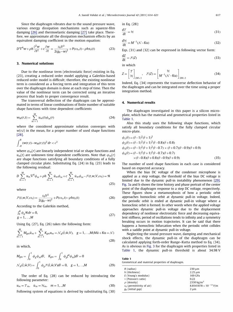
Table 1Geometrical and material properties of diaphragm.
R (radius) 230 mm
h (thickness) 2.25 mm
E (Young’s modulus) 169 GPa
n (Poisson’s ratio) 0.22
r (density) 2330 kg/m3
e0 (permittivity of air) 8.8541878�10�12 F/m
g0 (initial gap) 2 mm
A. Saeedi Vahdat et al. / Microelectronics Journal 42 (2011) 614–621 617
Since the diaphragm vibrates due to the sound pressure wave,various energy dissipation mechanisms such as squeeze-filmdamping [26] and thermoelastic damping [27] take place. There-fore, we approximate all the dissipation mechanism effects by anequivalent damping coefficient in the motion equation:
Dr4wþrh@2w
@t2þc
@w
@t¼
e0V2
2ðg0�wÞ2þPðos,tÞ�rhasðtÞ ð23Þ
3. Numerical solutions
Due to the nonlinear term (electrostatic force) existing in Eq.(23), creating a reduced order model applying a Galerkin-basedreduced order model is difficult; therefore, the existing nonlinearterm is considered as a forcing term and integration of this termover the diaphragm domain is done at each step of time. Then thevalue of the nonlinear term can be corrected using an iterativeprocess that leads to proper convergence result.
The transversal deflection of the diaphragm can be approxi-mated in terms of linear combinations of finite number of suitableshape functions with time dependent coefficients
wMðr,tÞ ¼XM
m ¼ 1
umðtÞfmðrÞ ð24Þ
where the considered approximate solution converges withw(r,t) in the mean, for a proper number of used shape functions[28].Z R
�Rðwðr,tÞ�wMðr,tÞÞ2 droE2
where jm(r) are linearly independent trial or shape functions andum(t) are unknown time dependent coefficients. Note that jm(r)are shape functions satisfying all boundary conditions of a fullyclamped circular plate. Substituting Eq. (24) in Eq. (23) leads tothe following residual:
DXM
m ¼ 1
umr4fmþrh
XMm ¼ 1
€umfmþcXM
m ¼ 1
_umfm�F ðt,w,V ,osÞ ¼R
ð25Þ
where
F ðt,w,V ,osÞ ¼e0V2
2ðg0�wÞ2þPðos,tÞ�rhasðtÞ ð26Þ
According to the Galerkin method,R R0 fgRdr¼ 0,
g ¼ 1,. . .,Mð27Þ
Using Eq. (27), Eq. (26) takes the following form:
XMm ¼ 1
Mgm €umþXM
m ¼ 1
Kgmum ¼N gðt,w,VÞ, g ¼ 1,. . .,MðM €uþKu¼N Þ
ð28Þ
in which,
Mgm ¼
Z 1
0fgfmdr, Kgm ¼
Z 1
0fg ½
4fm�dr¼ 0
N gðt,w,VÞ ¼
Z 1
0fgF ðt,w,VÞdr¼ 0, g ¼ 1,. . .,M ð29Þ
The order of Eq. (28) can be reduced by introducing thefollowing parameter:
um ¼ T m, _um ¼Hm, m¼ 1,::,M ð30Þ
Following system of equations is derived by substituting Eq. (30)
in Eq. (28):
dTdt¼H ð31Þ
dHdt¼M�1
ðN�KuÞ ð32Þ
Eqs. (31) and (32) can be expressed in following vector form:
dZ
dt¼F ðZÞ ð33Þ
in which
Z ¼TH
" #2M�1
, F ðZÞ ¼H
M�1ðN�KuÞ
" #2M�1
ð34Þ
Indeed, Eq. (34) represents the transverse deflection behavior ofthe diaphragm and can be integrated over the time using a properintegration method.
4. Numerical results
The diaphragm investigated in this paper is a silicon micro-plate, which has the material and geometrical properties listed inTable 1.
Also this study uses the following shape functions, whichsatisfy all boundary conditions for the fully clamped circularmicro-plate.
f1ðrÞ ¼ ðr�1Þ2ðrþ1Þ2
f2ðrÞ ¼ ðr�1Þ2ðrþ1Þ2ðr�0:8Þðrþ0:8Þ
f3ðrÞ ¼ ðr�1Þ2ðrþ1Þ2ðr�0:7Þ � ðrþ0:7Þðr�0:9Þðrþ0:9Þ
f4ðrÞ ¼ ðr�1Þ2ðrþ1Þ2ðr�0:7Þðrþ0:7Þ
�ðr�0:8Þðrþ0:8Þðr�0:9Þðrþ0:9Þ ð35Þ
The number of used shape functions in each case is consideredbased on expected accuracy.
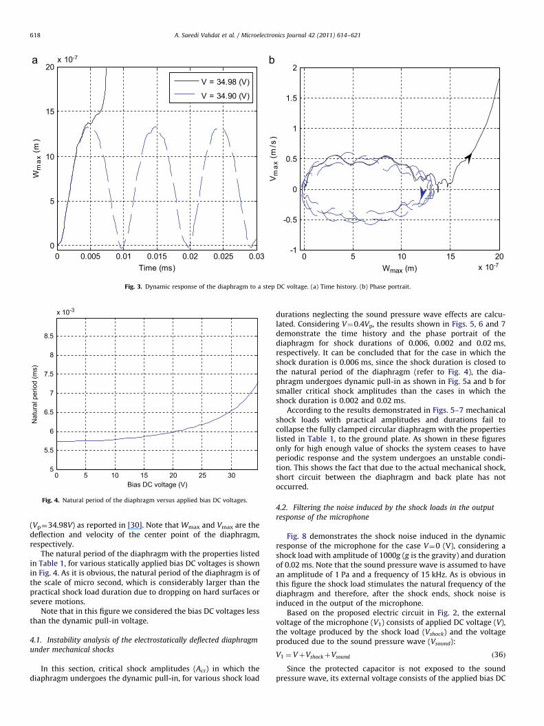
When the bias DC voltage of the condenser microphone isapplied as a step voltage, the threshold of the bias DC voltage islimited due to the dynamic pull-in instability phenomenon [29].Fig. 3a and b shows the time history and phase portrait of the centerpoint of the diaphragm response to a step DC voltage, respectively.These figures show a metamorphosis of how a periodic orbitapproaches homoclinic orbit at dynamic pull-in voltage. Indeed,the periodic orbit is ended at dynamic pull-in voltage where ahomoclinic orbit is formed. In other words when the applied voltageapproaches dynamic pull-in voltage due to the displacementdependency of nonlinear electrostatic force and decreasing equiva-lent stiffness, period of oscillations tends to infinity and a symmetrybreaking occurs in motion trajectories. It can be said that therehappens a homoclinic bifurcation when the periodic orbit collideswith a saddle point at dynamic pull-in voltage.
Neglecting the sound pressure wave, damping and mechanicalshock effects, the dynamic pull-in of the diaphragm can becalculated applying forth-order Runge–Kutta method to Eq. (34).As is obvious in Fig. 3 for the diaphragm with properties listed inTable 1, the dynamic pull-in threshold is about 34.98 V
0 5 10 15 20 25 305
5.5
6
6.5
7
7.5
8
8.5
x 10-3
Bias DC voltage (V)
Nat
ural
per
iod
(ms)
Fig. 4. Natural period of the diaphragm versus applied bias DC voltages.
0 0.005 0.01 0.015 0.02 0.025 0.030
5
10
15
20
Time (ms)
Wm
ax (
m)
0 5 10 15 20x 10-7
x 10-7
-1
-0.5
0
0.5
1
1.5
2
Wmax (m)V
max
(m
/s)
V = 34.98 (V)
V = 34.90 (V)
Fig. 3. Dynamic response of the diaphragm to a step DC voltage. (a) Time history. (b) Phase portrait.
A. Saeedi Vahdat et al. / Microelectronics Journal 42 (2011) 614–621618
(Vp¼34.98V) as reported in [30]. Note that Wmax and Vmax are thedeflection and velocity of the center point of the diaphragm,respectively.
The natural period of the diaphragm with the properties listedin Table 1, for various statically applied bias DC voltages is shownin Fig. 4. As it is obvious, the natural period of the diaphragm is ofthe scale of micro second, which is considerably larger than thepractical shock load duration due to dropping on hard surfaces orsevere motions.
Note that in this figure we considered the bias DC voltages lessthan the dynamic pull-in voltage.
4.1. Instability analysis of the electrostatically deflected diaphragm
under mechanical shocks
In this section, critical shock amplitudes (Acr) in which thediaphragm undergoes the dynamic pull-in, for various shock load
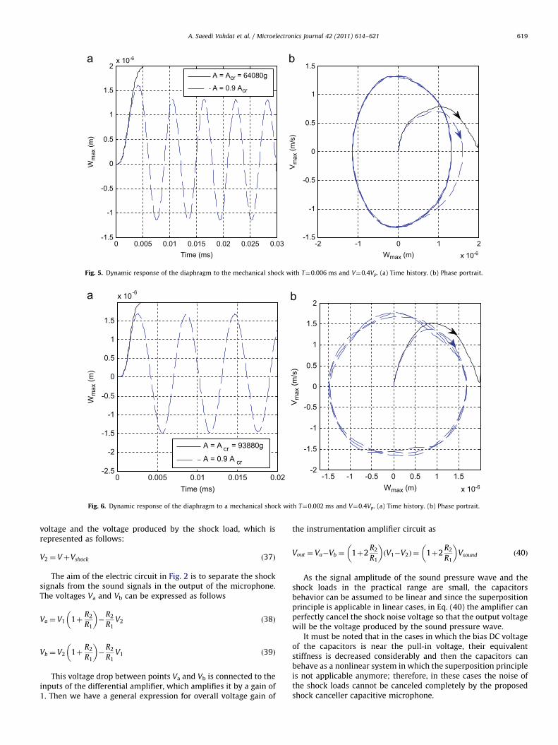
durations neglecting the sound pressure wave effects are calcu-lated. Considering V¼0.4Vp, the results shown in Figs. 5, 6 and 7demonstrate the time history and the phase portrait of thediaphragm for shock durations of 0.006, 0.002 and 0.02 ms,respectively. It can be concluded that for the case in which theshock duration is 0.006 ms, since the shock duration is closed tothe natural period of the diaphragm (refer to Fig. 4), the dia-phragm undergoes dynamic pull-in as shown in Fig. 5a and b forsmaller critical shock amplitudes than the cases in which theshock duration is 0.002 and 0.02 ms.
According to the results demonstrated in Figs. 5–7 mechanicalshock loads with practical amplitudes and durations fail tocollapse the fully clamped circular diaphragm with the propertieslisted in Table 1, to the ground plate. As shown in these figuresonly for high enough value of shocks the system ceases to haveperiodic response and the system undergoes an unstable condi-tion. This shows the fact that due to the actual mechanical shock,short circuit between the diaphragm and back plate has notoccurred.
4.2. Filtering the noise induced by the shock loads in the output
response of the microphone
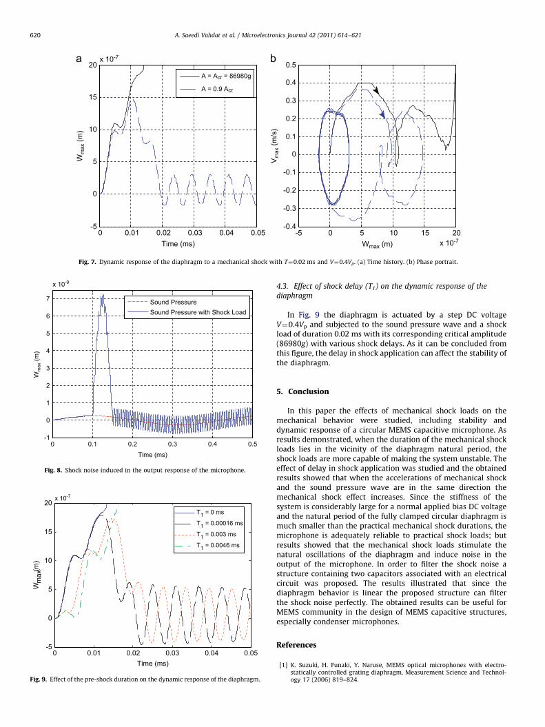
Fig. 8 demonstrates the shock noise induced in the dynamicresponse of the microphone for the case V¼0 (V), considering ashock load with amplitude of 1000g (g is the gravity) and durationof 0.02 ms. Note that the sound pressure wave is assumed to havean amplitude of 1 Pa and a frequency of 15 kHz. As is obvious inthis figure the shock load stimulates the natural frequency of thediaphragm and therefore, after the shock ends, shock noise isinduced in the output of the microphone.
Based on the proposed electric circuit in Fig. 2, the externalvoltage of the microphone (V1) consists of applied DC voltage (V),the voltage produced by the shock load (Vshock) and the voltageproduced due to the sound pressure wave (Vsound):
V1 ¼ VþVshockþVsound ð36Þ
Since the protected capacitor is not exposed to the soundpressure wave, its external voltage consists of the applied bias DC
0 0.005 0.01 0.015 0.02 0.025 0.03-1.5
-1
-0.5
0
0.5
1
1.5
2x 10⁻⁶
Time (ms)
Wm
ax (m
)
-2 -1 0 1 2-1.5
-1
-0.5
0
0.5
1
1.5
Wmax (m)
Vm
ax (m
/s)
A = Acr = 64080g
A = 0.9 Acr
x 10-6
Fig. 5. Dynamic response of the diaphragm to the mechanical shock with T¼0.006 ms and V¼0.4Vp. (a) Time history. (b) Phase portrait.
0 0.005 0.01 0.015 0.02-2.5
-2
-1.5
-1
-0.5
0
0.5
1
1.5
x 10-6
Time (ms)
Wm
ax (m
)
-1.5 -1 -0.5 0 0.5 1 1.5
x 10-6
-2
-1.5
-1
-0.5
0
0.5
1
1.5
2
Wmax (m)
Vm
ax (m
/s)
A = A cr = 93880g
A = 0.9 A cr
Fig. 6. Dynamic response of the diaphragm to a mechanical shock with T¼0.002 ms and V¼0.4Vp. (a) Time history. (b) Phase portrait.
A. Saeedi Vahdat et al. / Microelectronics Journal 42 (2011) 614–621 619
voltage and the voltage produced by the shock load, which isrepresented as follows:
V2 ¼ VþVshock ð37Þ
The aim of the electric circuit in Fig. 2 is to separate the shocksignals from the sound signals in the output of the microphone.The voltages Va and Vb can be expressed as follows
Va ¼ V1 1þR2
R1
� ��
R2
R1V2 ð38Þ
Vb ¼ V2 1þR2
R1
� ��
R2
R1V1 ð39Þ
This voltage drop between points Va and Vb is connected to theinputs of the differential amplifier, which amplifies it by a gain of1. Then we have a general expression for overall voltage gain of
the instrumentation amplifier circuit as
Vout ¼ Va�Vb ¼ 1þ2R2
R1
� �ðV1�V2Þ ¼ 1þ2
R2
R1
� �Vsound ð40Þ
As the signal amplitude of the sound pressure wave and theshock loads in the practical range are small, the capacitorsbehavior can be assumed to be linear and since the superpositionprinciple is applicable in linear cases, in Eq. (40) the amplifier canperfectly cancel the shock noise voltage so that the output voltagewill be the voltage produced by the sound pressure wave.
It must be noted that in the cases in which the bias DC voltageof the capacitors is near the pull-in voltage, their equivalentstiffness is decreased considerably and then the capacitors canbehave as a nonlinear system in which the superposition principleis not applicable anymore; therefore, in these cases the noise ofthe shock loads cannot be canceled completely by the proposedshock canceller capacitive microphone.
0 0.01 0.02 0.03 0.04 0.05-5
0
5
10
15
20x 10-7
Time (ms)
Wm
ax (m
)
-5 0 5 10 15 20x 10-7
-0.4
-0.3
-0.2
-0.1
0
0.1
0.2
0.3
0.4
0.5
Wmax (m)
Vm
ax (m
/s)
A = Acr = 86980g
A = 0.9 Acr
Fig. 7. Dynamic response of the diaphragm to a mechanical shock with T¼0.02 ms and V¼0.4Vp. (a) Time history. (b) Phase portrait.
0 0.1 0.2 0.3 0.4 0.5-1
0
1
2
3
4
5
6
7
x 10-9
Time (ms)
Wm
ax (m
)
Sound PressureSound Pressure with Shock Load
Fig. 8. Shock noise induced in the output response of the microphone.
0 0.01 0.02 0.03 0.04 0.05-5
0
5
10
15
20x 10-7
Time (ms)
Wm
ax (m
)
T1 = 0 ms
T1 = 0.00016 ms
T1 = 0.003 ms
T1 = 0.0046 ms
Fig. 9. Effect of the pre-shock duration on the dynamic response of the diaphragm.
A. Saeedi Vahdat et al. / Microelectronics Journal 42 (2011) 614–621620
4.3. Effect of shock delay (T1) on the dynamic response of the
diaphragm
In Fig. 9 the diaphragm is actuated by a step DC voltageV¼0.4Vp and subjected to the sound pressure wave and a shockload of duration 0.02 ms with its corresponding critical amplitude(86980g) with various shock delays. As it can be concluded fromthis figure, the delay in shock application can affect the stability ofthe diaphragm.
5. Conclusion
In this paper the effects of mechanical shock loads on themechanical behavior were studied, including stability anddynamic response of a circular MEMS capacitive microphone. Asresults demonstrated, when the duration of the mechanical shockloads lies in the vicinity of the diaphragm natural period, theshock loads are more capable of making the system unstable. Theeffect of delay in shock application was studied and the obtainedresults showed that when the accelerations of mechanical shockand the sound pressure wave are in the same direction themechanical shock effect increases. Since the stiffness of thesystem is considerably large for a normal applied bias DC voltageand the natural period of the fully clamped circular diaphragm ismuch smaller than the practical mechanical shock durations, themicrophone is adequately reliable to practical shock loads; butresults showed that the mechanical shock loads stimulate thenatural oscillations of the diaphragm and induce noise in theoutput of the microphone. In order to filter the shock noise astructure containing two capacitors associated with an electricalcircuit was proposed. The results illustrated that since thediaphragm behavior is linear the proposed structure can filterthe shock noise perfectly. The obtained results can be useful forMEMS community in the design of MEMS capacitive structures,especially condenser microphones.
References
[1] K. Suzuki, H. Funaki, Y. Naruse, MEMS optical microphones with electro-statically controlled grating diaphragm, Measurement Science and Technol-ogy 17 (2006) 819–824.
A. Saeedi Vahdat et al. / Microelectronics Journal 42 (2011) 614–621 621
[2] J. Miao, R. Lin, L. Chen, Q. Zou, S.Y. Lim, S.H. Seah, Design consideration inmicromachined silicon microphones, Microelectronics Journal 33 (2002)21–28.
[3] B. Azizollah Ganji, B. Yeop Majlis, Design and fabrication of a new MEMScapacitive microphone using a perforated aluminum diaphragm, Sensors andActuators A 149 (2009) 29–37.
[4] H.S. Kwon, H. Funaki, K.C. Lee, Double-chip condenser microphone for rigidbackplate using DRIE and wafer bonding technology, Sensors and Actuators A138 (2007) 81–86.
[5] J.Y. Chen, Y.C. Hsu, S.S. Lee, T. Mukherjee, G.K. Fedder, Modeling andsimulation of a condenser microphone, Sensors and Actuators A 145–146(2008) 224–230.
[6] J. Liu, D.T. Martinn, K. Kardirvel, T. Nishida, L. Cattafesta, M. Sheplak,B.P. Mann, Nonlinear model and system identification of a capacitive dual-backplate MEMS microphone, Journal of Sound and Vibration 309 (2008)276–292.
[7] M.I. Younis, F. Alsaleem, D. Jordy, The response of clamped–clampedmicrobeams under mechanical shock, International Journal of Non-LinearMechanics 42 (2007) 643–657.
[8] N. Tas, T. Sonnenberg, H. Jansen, R. Legtenberg, M. Elwenspoek, Stiction insurface micromachining, Journal of Micromechanics and Microengineering 6(1996) 385–397.
[9] D.M. Tanner, J.A. Walraven, K. Helgesen, L.W. Irwin, N.F. Smith, N. Masters, in:Proceedings of the IEEE International Reliability Physics Symposium, SanJose, CA, 2000, pp. 129–138.
[10] L. Meirovitch, Fundamentals of vibrations, McGraw-Hill, Boston, 2001.[11] A. Beliveau, G.T. Spencer, K.A. Thomas, S.L. Roberson, Evaluation of MEMS
capacitive accelerometers, Design Test Computer 16 (1999) 48–56.[12] T.G. Brown, B. Davis, D. Hepner, J. Faust, C. Myers, P. Muller, T. Harkins,
M. Hollis, C. Miller, B. Placzankis, Strapdown microelectromechanical(MEMS) sensors for high-G munition application, IEEE Transactions onMagnetics 37 (2001) 336–342.
[13] B.B. Lim, J.P. Yang, S.X. Chen, J.Q. Mou, Y. Lu, Shock analysis of MEMS actuatorintegrated with HGA for operational and non-operational HDD, in: Proceed-ings of the Digest of Asia-Pacific Magnetic Recording Conference, 2002,pp. WE-P-18-01–WE-P-18-02.
[14] U. Wagner, M. Schweiker, W. Bernhard, R. Muller-Fiedler, B. Michel, O. Paul,Mechanical reliability of MEMS-structures under shock load, Microelectro-nics Reliability 41 (2001) 1657–1662.
[15] M.S. Fan, H.C. Shaw, Dynamic response assessment for the MEMS acceler-ometer under severe shock loads, in: Proceedings of the National Aeronauticsand Space Administration NASA, Washington DC, 2001, TP-2001-20997.
[16] G.X. Li, J.R. Shemansky, Drop test and analysis on micro-machined structures,Sensors Actuators A 85 (2000) 280–286.
[17] V.T. Srikar, S.D. Senturia, The reliability of microelectromechanical systems(MEMS) in shock environment, Journal of Microelectromechanical Systems11 (2002) 206–214.
[18] J.K. Yee, H.H. Yang, J.W. Judy, Shock resistance of ferromagnetic microme-chanical magnetometers, Sensors Actuators A 103 (2003) 242–252.
[19] O. Millet, D. Collard, L. Buchaillot, Reliability of packaged MEMS in shockenvironment. crack and stiction modeling, in: Proceedings of the Design,Test, Integration and Packaging of MEMS/MOEMS Conference, Cannes, 2002,pp. 697–703.
[20] J.D. Coster, H.C. Tilmans, J.T.M. Van Beek, T.G.S.M. Rijks, R. Puers, Theinfluence of mechanical shock on the operation of electrostatically drivenRF-MEMS switches, Journal of Micromechanical Microengineering 14 (2004)549–554.
[21] F. Botta, G. Cerria, Shock response spectrum in plates under impulse loads,Journal of Sound and Vibration 308 (2007) 563–578.
[22] M.I. Ibrahim, M.I. Younis, The dynamic response of electrostatically drivenresonators under mechanical shock, Journal of Micromechanics and Micro-engineering 20 (2010) 1–9.
[23] G. Rezazadeh, A. Tahmasebi, M. Zubstov, Application of piezoelectric layers inelectrostatic MEM actuators: controlling of pull-in voltage, MicrosystemTechnologies 12 (2006) 1163–1170.
[24] A. Nabian, G. Rezazadeh, M. Haddad-derafshi, A. Tahmasebi, Mechanicalbehavior of a circular micro plate subjected to uniform hydrostatic and non-uniform electrostatic pressure, Microsystem Technologies 14 (2007) 235–240.
[25] A.W. Weisa, Vibration of Plates, National Aeronautics and Space Administra-tion, Washington, DC, 1969.
[26] H. Yagubizade, M. Fathalilou, G. Rezazadeh, S. Talebian, Squeeze-film damp-ing effect on dynamic pull-in voltage of an electrostatically-actuatedmicrobeam, Sensors and Transducers Journal 103 (4) (2009) 96–101.
[27] G. Rezazadeh, A. Saeedi-vahdat, S. Pesteii, B. Farzi, Study of thermoelasticdamping in capacitive micro-beam resonators using hyperbolic heat con-duction model, Sensors and Transducers Journal 108 (2009) 54–72.
[28] C. Baker, H.L. Porteous, Linear Algebra and Differential Equation, Ellis Hor-wood, New York, 1990.
[29] A.H. Nayfe, M.I. Younis, E.M. Abdel-Rahman, Dynamic pull-in phenomenon inMEMS resonators, Nonlinear Dynamics 48 (2007) 153–163.
[30] A. Saeedivahdat, F. Abdolkarimzadeh, A. Feyzi, G. Rezazadeh, S. Tarverdilo,Effect of thermal stresses on stability and frequency response of acapacitive microphone, Microelectronics Journal (2010). doi:10.1016/j.mejo.2010.07.013.