Highly Sensitive Capacitive Sensor Based on Injection Locked ...
Upload
khangminh22Category
view
0download
0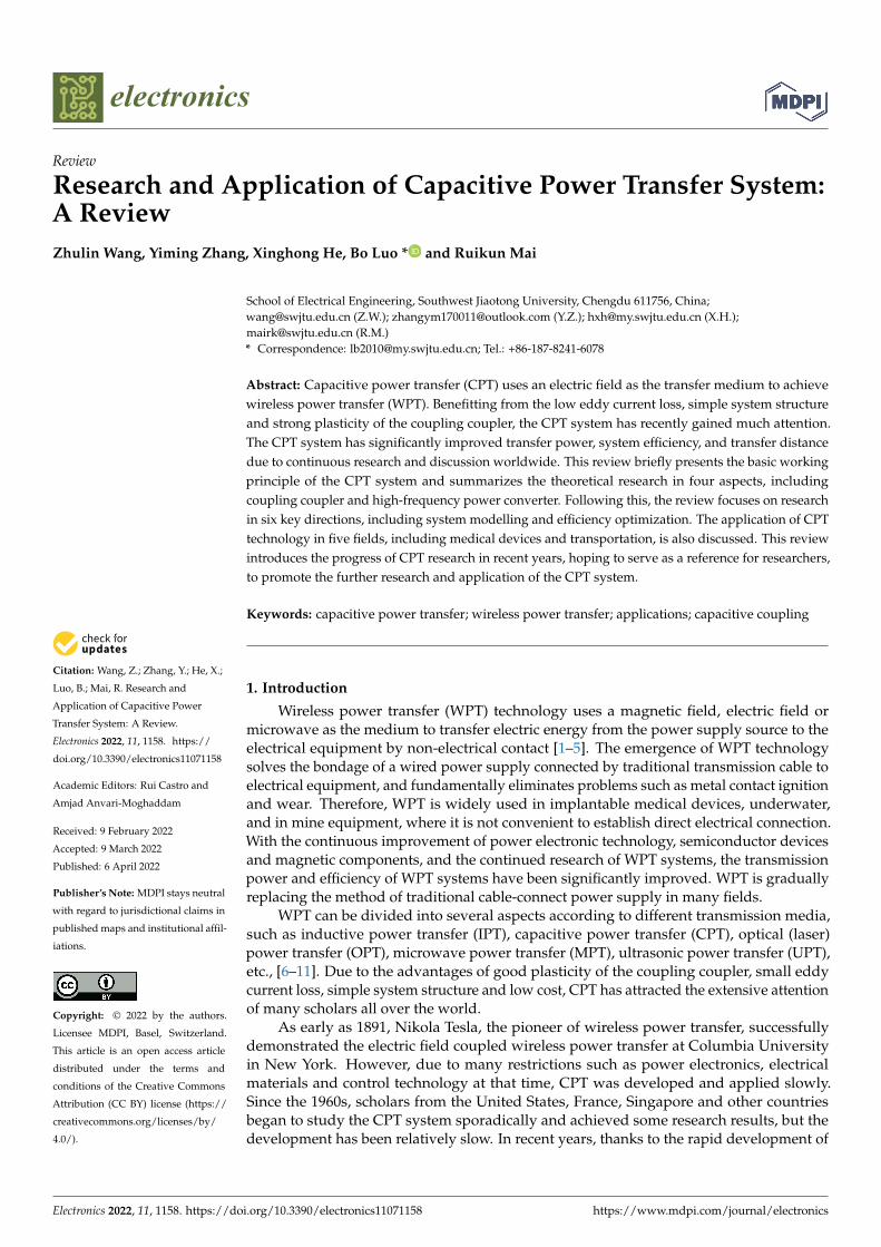
Citation: Wang, Z.; Zhang, Y.; He, X.;
Luo, B.; Mai, R. Research and
Application of Capacitive Power
Transfer System: A Review.
Electronics 2022, 11, 1158. https://
doi.org/10.3390/electronics11071158
Academic Editors: Rui Castro and
Amjad Anvari-Moghaddam
Received: 9 February 2022
Accepted: 9 March 2022
Published: 6 April 2022
Publisher’s Note: MDPI stays neutral
with regard to jurisdictional claims in
published maps and institutional affil-
iations.
Copyright: © 2022 by the authors.
Licensee MDPI, Basel, Switzerland.
This article is an open access article
distributed under the terms and
conditions of the Creative Commons
Attribution (CC BY) license (https://
creativecommons.org/licenses/by/
4.0/).
electronics
Review
Research and Application of Capacitive Power Transfer System:A ReviewZhulin Wang, Yiming Zhang, Xinghong He, Bo Luo * and Ruikun Mai
School of Electrical Engineering, Southwest Jiaotong University, Chengdu 611756, China;[email protected] (Z.W.); [email protected] (Y.Z.); [email protected] (X.H.);[email protected] (R.M.)* Correspondence: [email protected]; Tel.: +86-187-8241-6078
Abstract: Capacitive power transfer (CPT) uses an electric field as the transfer medium to achievewireless power transfer (WPT). Benefitting from the low eddy current loss, simple system structureand strong plasticity of the coupling coupler, the CPT system has recently gained much attention.The CPT system has significantly improved transfer power, system efficiency, and transfer distancedue to continuous research and discussion worldwide. This review briefly presents the basic workingprinciple of the CPT system and summarizes the theoretical research in four aspects, includingcoupling coupler and high-frequency power converter. Following this, the review focuses on researchin six key directions, including system modelling and efficiency optimization. The application of CPTtechnology in five fields, including medical devices and transportation, is also discussed. This reviewintroduces the progress of CPT research in recent years, hoping to serve as a reference for researchers,to promote the further research and application of the CPT system.
Keywords: capacitive power transfer; wireless power transfer; applications; capacitive coupling
1. Introduction
Wireless power transfer (WPT) technology uses a magnetic field, electric field ormicrowave as the medium to transfer electric energy from the power supply source to theelectrical equipment by non-electrical contact [1–5]. The emergence of WPT technologysolves the bondage of a wired power supply connected by traditional transmission cable toelectrical equipment, and fundamentally eliminates problems such as metal contact ignitionand wear. Therefore, WPT is widely used in implantable medical devices, underwater,and in mine equipment, where it is not convenient to establish direct electrical connection.With the continuous improvement of power electronic technology, semiconductor devicesand magnetic components, and the continued research of WPT systems, the transmissionpower and efficiency of WPT systems have been significantly improved. WPT is graduallyreplacing the method of traditional cable-connect power supply in many fields.
WPT can be divided into several aspects according to different transmission media,such as inductive power transfer (IPT), capacitive power transfer (CPT), optical (laser)power transfer (OPT), microwave power transfer (MPT), ultrasonic power transfer (UPT),etc., [6–11]. Due to the advantages of good plasticity of the coupling coupler, small eddycurrent loss, simple system structure and low cost, CPT has attracted the extensive attentionof many scholars all over the world.
As early as 1891, Nikola Tesla, the pioneer of wireless power transfer, successfullydemonstrated the electric field coupled wireless power transfer at Columbia Universityin New York. However, due to many restrictions such as power electronics, electricalmaterials and control technology at that time, CPT was developed and applied slowly.Since the 1960s, scholars from the United States, France, Singapore and other countriesbegan to study the CPT system sporadically and achieved some research results, but thedevelopment has been relatively slow. In recent years, thanks to the rapid development of
Electronics 2022, 11, 1158. https://doi.org/10.3390/electronics11071158 https://www.mdpi.com/journal/electronics
Electronics 2022, 11, 1158 2 of 23
power electronics, the research and application of CPT are also increasing sharply. Afterdecades of development, the CPT system has greatly improved in transfer power, systemefficiency and transfer distance. At present, the CPT system can meet some charging needsfor many WPT applications.
This review firstly introduces the basic principle of the CPT system and compares itwith the main characteristics of the IPT system, and then comprehensively expounds onthe research progress of the CPT system in four aspects: system coupler, high-frequencypower converter, compensation topology and control method. Then this review presentsthe research results in six key research directions, namely, system modelling, efficiencyoptimization, single-capacitor CPT system, hybrid WPT system, charging method andsystem safety. Finally, the application of the CPT system in medical devices, transportation,online monitoring equipment power supply, underwater charging and rotating mechanismare introduced. The development and application of CPT technology in the future arealso prospected.
This review not only combines the past achievements of CPT system, but also presentsthe newest results in basic research and applications, hoping to give a comprehensivesummary of the research and development of the CPT system.
2. Basic Principle of CPT System
Research on the CPT system started relatively late compared with that of the IPTsystem. Unlike IPT, which uses a magnetic field as the transmission medium, CPT adoptsan electric field to achieve power transfer [12,13]. IPT and CPT are dual relationships. Thebasic principle of the CPT system is similar to IPT. A general circuit of the CPT systemis shown in Figure 1, where two pairs of metal plates are connected in series, forming aCPT coupler.
Electronics 2022, 11, x FOR PEER REVIEW 2 of 23
to study the CPT system sporadically and achieved some research results, but the devel-
opment has been relatively slow. In recent years, thanks to the rapid development of
power electronics, the research and application of CPT are also increasing sharply. After
decades of development, the CPT system has greatly improved in transfer power, system
efficiency and transfer distance. At present, the CPT system can meet some charging needs
for many WPT applications.
This review firstly introduces the basic principle of the CPT system and compares it
with the main characteristics of the IPT system, and then comprehensively expounds on
the research progress of the CPT system in four aspects: system coupler, high-frequency
power converter, compensation topology and control method. Then this review presents
the research results in six key research directions, namely, system modelling, efficiency
optimization, single-capacitor CPT system, hybrid WPT system, charging method and
system safety. Finally, the application of the CPT system in medical devices, transporta-
tion, online monitoring equipment power supply, underwater charging and rotating
mechanism are introduced. The development and application of CPT technology in the
future are also prospected.
This review not only combines the past achievements of CPT system, but also pre-
sents the newest results in basic research and applications, hoping to give a comprehen-
sive summary of the research and development of the CPT system.
2. Basic Principle of CPT System
Research on the CPT system started relatively late compared with that of the IPT system.
Unlike IPT, which uses a magnetic field as the transmission medium, CPT adopts an electric
field to achieve power transfer [12,13]. IPT and CPT are dual relationships. The basic principle
of the CPT system is similar to IPT. A general circuit of the CPT system is shown in Figure 1,
where two pairs of metal plates are connected in series, forming a CPT coupler.
P1 P3i
lS
D
CPT coupler
P2 P4
RL
UIN
Figure 1. General CPT circuit with a simplified coupling coupler.
The coupling coupler is generally composed of the aluminum plate or copper plate
as a channel for wireless power transfer. According to Maxwell’s full current theorem:
∫ 𝐻𝑑𝑙𝑙
= ∫ 𝐽𝑑𝑆𝑆
+ ∫𝜕𝐷
𝜕𝑡𝑑𝑆
𝑆
(1)
The line integral of the magnetic field intensity H along any closed curve l is equal to
the total current passing through the area S surrounded by the path. The first term on the
right of Equation (1) is the conduction current flowing through the conductor, and J is the
conduction current density. The second term of Equation (1) is the displacement current,
which is equal to the conduction current of the simultaneous circuit. 𝜕𝐷
𝜕𝑡 is the displace-
ment current density, which is equal to the change rate of the electric flux density D. The
differential form of the full current theorem is:
Figure 1. General CPT circuit with a simplified coupling coupler.
The coupling coupler is generally composed of the aluminum plate or copper plate asa channel for wireless power transfer. According to Maxwell’s full current theorem:∫
lHdl =
∫S
JdS +∫
S
∂D∂t
dS (1)
The line integral of the magnetic field intensity H along any closed curve l is equalto the total current passing through the area S surrounded by the path. The first term onthe right of Equation (1) is the conduction current flowing through the conductor, and Jis the conduction current density. The second term of Equation (1) is the displacementcurrent, which is equal to the conduction current of the simultaneous circuit. ∂D
∂t is the
Electronics 2022, 11, 1158 3 of 23
displacement current density, which is equal to the change rate of the electric flux density D.The differential form of the full current theorem is:
∇× H = J +∂D∂t
(2)
Equations (1) and (2) not only explain the problem of discontinuous capacitive currentfrom the micro perspective, but also provide an effective functional equation for the CPTsystem to quantitatively describe how power is transmitted from plate P1 to P3. When thealternating voltage excitation is stressed on the electrode plates, the electric flux densitybetween the electrode plates changes to form a displacement current and achieves a wirelesspower transfer based on the CPT system.
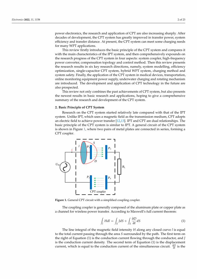
Figure 2 shows a typical structure of a CPT system, which is composed of a DC powersupply, high-frequency inverter, transmitter compensation topology, coupling coupler,receiver compensation topology, rectifier and load. The DC power supply provides energyfor the CPT system. The inverter inverts the DC source into high-frequency AC of hundredsof kHz to MHz. Then, under the action of compensation topology, the output voltage levelof high-frequency AC becomes suitable without high-order harmonic voltage excitation.The coupling mechanism is a channel for wireless energy transmission. Similar to thetransmitter compensation topology, the receiver compensation topology also plays the roleof voltage regulation and tuning. The rectifier forms a dual relationship with the inverterto convert AC into DC and provide DC source for the load.
Electronics 2022, 11, x FOR PEER REVIEW 3 of 23
∇ × 𝐻 = 𝐽 +𝜕𝐷
𝜕𝑡 (2)
Equations (1) and (2) not only explain the problem of discontinuous capacitive cur-
rent from the micro perspective, but also provide an effective functional equation for the
CPT system to quantitatively describe how power is transmitted from plate P1 to P3. When
the alternating voltage excitation is stressed on the electrode plates, the electric flux den-
sity between the electrode plates changes to form a displacement current and achieves a
wireless power transfer based on the CPT system.
Figure 2 shows a typical structure of a CPT system, which is composed of a DC power
supply, high-frequency inverter, transmitter compensation topology, coupling coupler,
receiver compensation topology, rectifier and load. The DC power supply provides en-
ergy for the CPT system. The inverter inverts the DC source into high-frequency AC of
hundreds of kHz to MHz. Then, under the action of compensation topology, the output
voltage level of high-frequency AC becomes suitable without high-order harmonic volt-
age excitation. The coupling mechanism is a channel for wireless energy transmission.
Similar to the transmitter compensation topology, the receiver compensation topology
also plays the role of voltage regulation and tuning. The rectifier forms a dual relationship
with the inverter to convert AC into DC and provide DC source for the load.
DC
AC DC
AC
Input
source
InverterCompensation
networkCoupler
Load
P1
P2
P3
P4
Compensation
network Rectifier
Figure 2. Structure diagram of CPT system.
In order to intuitively describe the working principle of the CPT coupler, a coupler
model with two capacitors connected in series, as shown in Figure 3, is used to analyze
the transfer capability. The cross-coupling effect between the plates in Figure 2 is ignored.
C1 and C2 denote the coupling capacitance of the coupler. Voltage V1 and V2 are the input
and output voltage on the transmitter and receiver sides, respectively. I is the current
flowing through the CPT coupler. ω is the switching angular frequency. Assuming that V1
is the reference voltage, V2 and V1 are out of phase by θ.
IC1
P2 P4
P1 P3
V1 V2
C2
Figure 3. Coupler model by two capacitors connected in series.
According to the fundamental theorem of KCL and KVL, the current I can be pre-
sented as:
𝐼 = j𝜔 (𝐶1𝐶2
𝐶1+𝐶2 ) (𝑉1 − 𝑉2 ) (3)
Figure 2. Structure diagram of CPT system.
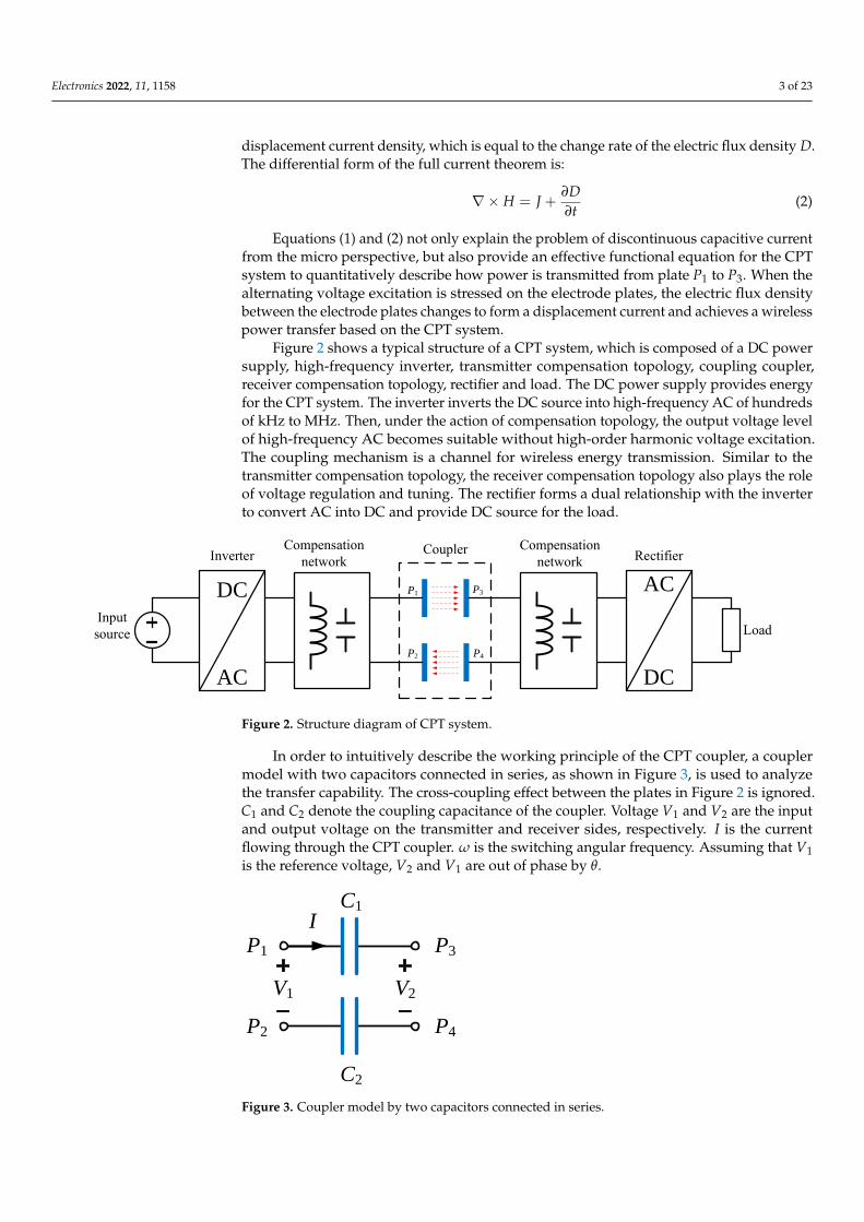
In order to intuitively describe the working principle of the CPT coupler, a couplermodel with two capacitors connected in series, as shown in Figure 3, is used to analyzethe transfer capability. The cross-coupling effect between the plates in Figure 2 is ignored.C1 and C2 denote the coupling capacitance of the coupler. Voltage V1 and V2 are the inputand output voltage on the transmitter and receiver sides, respectively. I is the currentflowing through the CPT coupler. ω is the switching angular frequency. Assuming that V1is the reference voltage, V2 and V1 are out of phase by θ.
Electronics 2022, 11, x FOR PEER REVIEW 3 of 23
∇ × 𝐻 = 𝐽 +𝜕𝐷
𝜕𝑡 (2)
Equations (1) and (2) not only explain the problem of discontinuous capacitive cur-
rent from the micro perspective, but also provide an effective functional equation for the
CPT system to quantitatively describe how power is transmitted from plate P1 to P3. When
the alternating voltage excitation is stressed on the electrode plates, the electric flux den-
sity between the electrode plates changes to form a displacement current and achieves a
wireless power transfer based on the CPT system.
Figure 2 shows a typical structure of a CPT system, which is composed of a DC power
supply, high-frequency inverter, transmitter compensation topology, coupling coupler,
receiver compensation topology, rectifier and load. The DC power supply provides en-
ergy for the CPT system. The inverter inverts the DC source into high-frequency AC of
hundreds of kHz to MHz. Then, under the action of compensation topology, the output
voltage level of high-frequency AC becomes suitable without high-order harmonic volt-
age excitation. The coupling mechanism is a channel for wireless energy transmission.
Similar to the transmitter compensation topology, the receiver compensation topology
also plays the role of voltage regulation and tuning. The rectifier forms a dual relationship
with the inverter to convert AC into DC and provide DC source for the load.
DC
AC DC
AC
Input
source
InverterCompensation
networkCoupler
Load
P1
P2
P3
P4
Compensation
network Rectifier
Figure 2. Structure diagram of CPT system.
In order to intuitively describe the working principle of the CPT coupler, a coupler
model with two capacitors connected in series, as shown in Figure 3, is used to analyze
the transfer capability. The cross-coupling effect between the plates in Figure 2 is ignored.
C1 and C2 denote the coupling capacitance of the coupler. Voltage V1 and V2 are the input
and output voltage on the transmitter and receiver sides, respectively. I is the current
flowing through the CPT coupler. ω is the switching angular frequency. Assuming that V1
is the reference voltage, V2 and V1 are out of phase by θ.
IC1
P2 P4
P1 P3
V1 V2
C2
Figure 3. Coupler model by two capacitors connected in series.
According to the fundamental theorem of KCL and KVL, the current I can be pre-
sented as:
𝐼 = j𝜔 (𝐶1𝐶2
𝐶1+𝐶2 ) (𝑉1 − 𝑉2 ) (3)
Figure 3. Coupler model by two capacitors connected in series.
Electronics 2022, 11, 1158 4 of 23
According to the fundamental theorem of KCL and KVL, the current I can be presented as:
I = jω(
C1C2
C1 + C2
)(V1 −V2 ) (3)
To simplify the system analysis, the active power consumed on the coupler is ignored.Therefore, the active power transmitted by the transmitter is equal to the active powerreceived by the receiver and equal to the transfer power PC.
PC = Re(V1(I)∗
)= Re
(V2(−I)∗
)= Re(V1(−jωCMV1 − jωCMV2(− cos(θ) + jω sin(θ))))
= Re(V2(cos(θ) + jω sin(θ)(jωCMV1 − jωCMV2(cos(θ)− jω sin(θ))))) = ωCMV1V2 sin(θ)(4)
As shown in Equation (4), the active power PC transmitted through the couplingmechanism is positively related to the mutual capacitance, system operating angularfrequency, coupler excitation voltage and voltage phase angle. As the mutual capacitance ofthe coupling mechanism is generally in pF to nF, the working frequency of the CPT systemis higher than that of the IPT system, which can usually be up to several hundred kHz oreven MHz. For the kW CPT system, the coupler voltages are also improved to kV level,which is required to consider the components’ masteries and system design, in order toavoid break down risks [14].
3. Theoretical Research on CPT System
Throughout the theoretical research of the CPT system, scholars have mainly focusedon the coupler design, high-frequency converter, compensation network, control method,etc. The following section will present the theoretical research results of the CPT systemfrom these aspects.
3.1. CPT Coupler Design
The coupling mechanism of the CPT system is usually composed of multiple metalplates. The transferability of the CPT system largely depends on the value of the couplingcapacitor. The coupling capacitor is closely related to the structure of the coupling mech-anism, transfer distance, dielectric constant of the transfer medium and other factors. Inthis review, the coupling mechanism of the CPT system is classified according to threecriteria: the number of metal plates, the space layout of the plates, and the shape of theplates. Regarding the number of metal plates, the coupling mechanism can be dividedinto a two-plate structure [15], four-plate structure [16–21], six-plate structure [22,23], etc.The four-plate structure is most commonly used to form a current loop for the capacitivepower transfer.
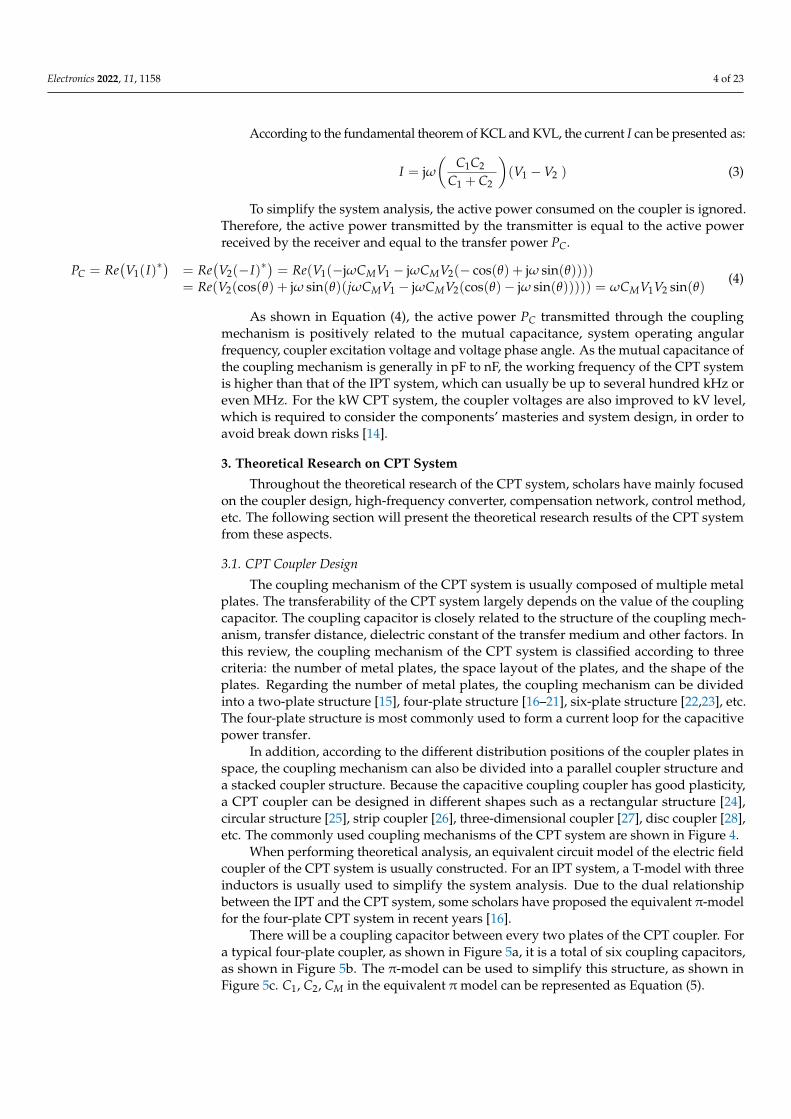
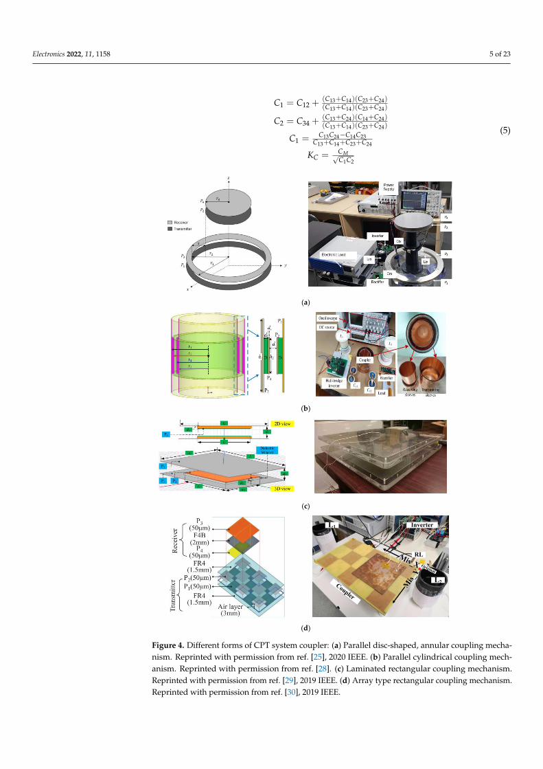
In addition, according to the different distribution positions of the coupler plates inspace, the coupling mechanism can also be divided into a parallel coupler structure anda stacked coupler structure. Because the capacitive coupling coupler has good plasticity,a CPT coupler can be designed in different shapes such as a rectangular structure [24],circular structure [25], strip coupler [26], three-dimensional coupler [27], disc coupler [28],etc. The commonly used coupling mechanisms of the CPT system are shown in Figure 4.
When performing theoretical analysis, an equivalent circuit model of the electric fieldcoupler of the CPT system is usually constructed. For an IPT system, a T-model with threeinductors is usually used to simplify the system analysis. Due to the dual relationshipbetween the IPT and the CPT system, some scholars have proposed the equivalent π-modelfor the four-plate CPT system in recent years [16].
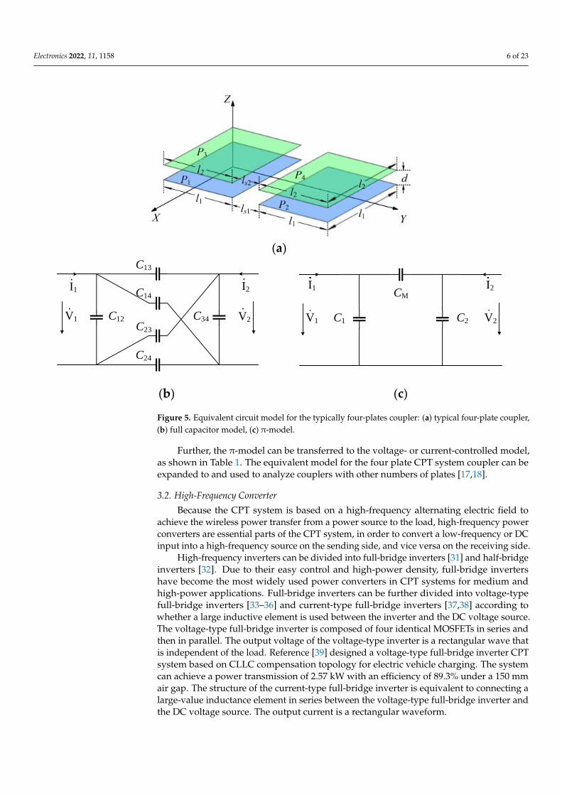
There will be a coupling capacitor between every two plates of the CPT coupler. Fora typical four-plate coupler, as shown in Figure 5a, it is a total of six coupling capacitors,as shown in Figure 5b. The π-model can be used to simplify this structure, as shown inFigure 5c. C1, C2, CM in the equivalent π model can be represented as Equation (5).
Electronics 2022, 11, 1158 5 of 23
C1 = C12 +(C13+C14)(C23+C24)(C13+C14)(C23+C24)
C2 = C34 +(C13+C24)(C14+C24)(C13+C14)(C23+C24)
C1 = C13C24−C14C23C13+C14+C23+C24
KC = CM√C1C2
(5)Electronics 2022, 11, x FOR PEER REVIEW 5 of 23
(a)
(b)
(c)
(d)
Figure 4. Different forms of CPT system coupler: (a) Parallel disc-shaped, annular coupling mecha-
nism. Reprinted with permission from ref. [25], 2020 IEEE. (b) Parallel cylindrical coupling mecha-
nism. Reprinted with permission from ref. [28]. (c) Laminated rectangular coupling mechanism. Re-
printed with permission from ref. [29], 2019 IEEE. (d) Array type rectangular coupling mechanism.
Reprinted with permission from ref. [29], 2019 IEEE.
There will be a coupling capacitor between every two plates of the CPT coupler. For
a typical four-plate coupler, as shown in Figure 5a, it is a total of six coupling capacitors,
as shown in Figure 5b. The π-model can be used to simplify this structure, as shown in
Figure 5c. C1, C2, CM in the equivalent π model can be represented as Equation (5).
Figure 4. Different forms of CPT system coupler: (a) Parallel disc-shaped, annular coupling mecha-nism. Reprinted with permission from ref. [25], 2020 IEEE. (b) Parallel cylindrical coupling mech-anism. Reprinted with permission from ref. [28]. (c) Laminated rectangular coupling mechanism.Reprinted with permission from ref. [29], 2019 IEEE. (d) Array type rectangular coupling mechanism.Reprinted with permission from ref. [30], 2019 IEEE.
Electronics 2022, 11, 1158 6 of 23Electronics 2022, 11, x FOR PEER REVIEW 6 of 23
(a)
V1 V2
CM
C2
I2I1
C1C12
C13
C14
C23
C24
C34V1 V2
I1 I2
(b) (c)
Figure 5. Equivalent circuit model for the typically four-plates coupler: (a) typical four-plate cou-
pler, (b) full capacitor model, (c) π-model.
𝐶1 = 𝐶12 +(𝐶13 + 𝐶14)(𝐶23 + 𝐶24)
(𝐶13 + 𝐶14)(𝐶23 + 𝐶24)
𝐶2 = 𝐶34 +(𝐶13 + 𝐶24)(𝐶14 + 𝐶24)
(𝐶13 + 𝐶14)(𝐶23 + 𝐶24)
𝐶1 =𝐶13𝐶24 − 𝐶14𝐶23
𝐶13 + 𝐶14 + 𝐶23 + 𝐶24
𝐾𝐶 =𝐶𝑀
√𝐶1𝐶2
(5)
Further, the π-model can be transferred to the voltage- or current-controlled model,
as shown in Table 1. The equivalent model for the four plate CPT system coupler can be
expanded to and used to analyze couplers with other numbers of plates [17,18].
Figure 5. Equivalent circuit model for the typically four-plates coupler: (a) typical four-plate coupler,(b) full capacitor model, (c) π-model.
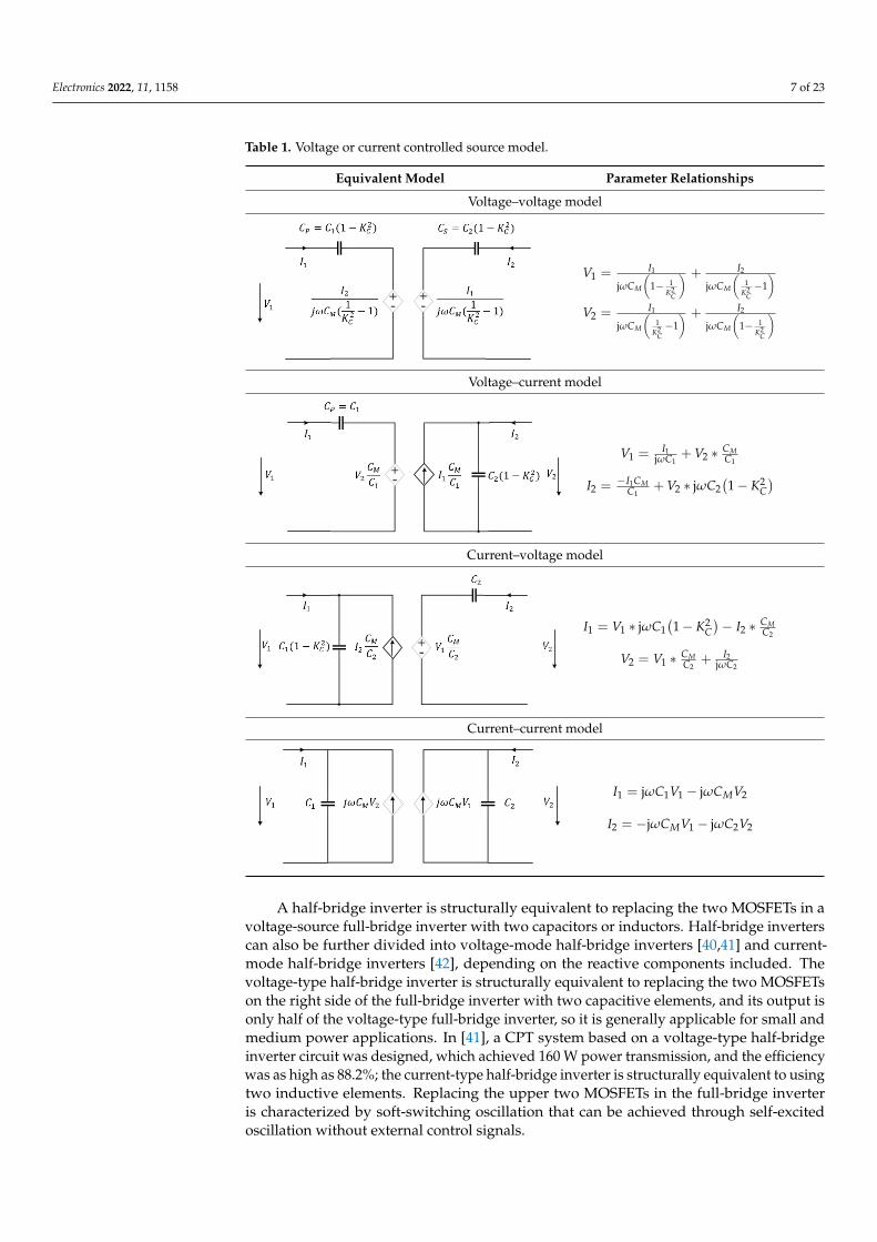
Further, the π-model can be transferred to the voltage- or current-controlled model,as shown in Table 1. The equivalent model for the four plate CPT system coupler can beexpanded to and used to analyze couplers with other numbers of plates [17,18].
3.2. High-Frequency Converter
Because the CPT system is based on a high-frequency alternating electric field toachieve the wireless power transfer from a power source to the load, high-frequency powerconverters are essential parts of the CPT system, in order to convert a low-frequency or DCinput into a high-frequency source on the sending side, and vice versa on the receiving side.
High-frequency inverters can be divided into full-bridge inverters [31] and half-bridgeinverters [32]. Due to their easy control and high-power density, full-bridge invertershave become the most widely used power converters in CPT systems for medium andhigh-power applications. Full-bridge inverters can be further divided into voltage-typefull-bridge inverters [33–36] and current-type full-bridge inverters [37,38] according towhether a large inductive element is used between the inverter and the DC voltage source.The voltage-type full-bridge inverter is composed of four identical MOSFETs in series andthen in parallel. The output voltage of the voltage-type inverter is a rectangular wave thatis independent of the load. Reference [39] designed a voltage-type full-bridge inverter CPTsystem based on CLLC compensation topology for electric vehicle charging. The systemcan achieve a power transmission of 2.57 kW with an efficiency of 89.3% under a 150 mmair gap. The structure of the current-type full-bridge inverter is equivalent to connecting alarge-value inductance element in series between the voltage-type full-bridge inverter andthe DC voltage source. The output current is a rectangular waveform.
Electronics 2022, 11, 1158 7 of 23
Table 1. Voltage or current controlled source model.
Equivalent Model Parameter Relationships
Voltage–voltage model
Electronics 2022, 11, x FOR PEER REVIEW 7 of 23
Table 1. Voltage or current controlled source model.
Equivalent Model Parameter Relationships
Voltage–voltage model
+ +- -
𝑉1 =𝐼1
j𝜔𝐶𝑀 (1 −1
𝐾𝐶2)
+𝐼2
j𝜔𝐶𝑀 (1
𝐾𝐶2 − 1)
𝑉2 =𝐼1
j𝜔𝐶𝑀 (1
𝐾𝐶2 − 1)
+𝐼2
j𝜔𝐶𝑀 (1 −1
𝐾𝐶2)
Voltage–current model
+-
𝑉1 =𝐼1
j𝜔𝐶1+ 𝑉2 ∗
𝐶𝑀
𝐶1
𝐼2 =−𝐼1𝐶𝑀
𝐶1+ 𝑉2 ∗ j𝜔𝐶2(1 − 𝐾𝐶
2)
Current–voltage model
+-
𝐼1 = 𝑉1 ∗ j𝜔𝐶1(1 − 𝐾𝐶2) − 𝐼2 ∗
𝐶𝑀
𝐶2
𝑉2 = 𝑉1 ∗𝐶𝑀
𝐶2+
𝐼2
j𝜔𝐶2
Current–current model
𝐼1 = j𝜔𝐶1𝑉1 − j𝜔𝐶𝑀𝑉2
𝐼2 = −j𝜔𝐶𝑀𝑉1 − j𝜔𝐶2𝑉2
3.2. High-Frequency Converter
Because the CPT system is based on a high-frequency alternating electric field to
achieve the wireless power transfer from a power source to the load, high-frequency
power converters are essential parts of the CPT system, in order to convert a low-fre-
quency or DC input into a high-frequency source on the sending side, and vice versa on
the receiving side.
High-frequency inverters can be divided into full-bridge inverters [31] and half-
bridge inverters [32]. Due to their easy control and high-power density, full-bridge invert-
ers have become the most widely used power converters in CPT systems for medium and
high-power applications. Full-bridge inverters can be further divided into voltage-type
full-bridge inverters [33–36] and current-type full-bridge inverters [37,38] according to
whether a large inductive element is used between the inverter and the DC voltage source.
The voltage-type full-bridge inverter is composed of four identical MOSFETs in series and
then in parallel. The output voltage of the voltage-type inverter is a rectangular wave that
V1 = I1
jωCM
(1− 1
K2C
) + I2
jωCM
(1
K2C−1)
V2 = I1
jωCM
(1
K2C−1) + I2
jωCM
(1− 1
K2C
)
Voltage–current model
Electronics 2022, 11, x FOR PEER REVIEW 7 of 23
Table 1. Voltage or current controlled source model.
Equivalent Model Parameter Relationships
Voltage–voltage model
+ +- -
𝑉1 =𝐼1
j𝜔𝐶𝑀 (1 −1
𝐾𝐶2)
+𝐼2
j𝜔𝐶𝑀 (1
𝐾𝐶2 − 1)
𝑉2 =𝐼1
j𝜔𝐶𝑀 (1
𝐾𝐶2 − 1)
+𝐼2
j𝜔𝐶𝑀 (1 −1
𝐾𝐶2)
Voltage–current model
+-
𝑉1 =𝐼1
j𝜔𝐶1+ 𝑉2 ∗
𝐶𝑀
𝐶1
𝐼2 =−𝐼1𝐶𝑀
𝐶1+ 𝑉2 ∗ j𝜔𝐶2(1 − 𝐾𝐶
2)
Current–voltage model
+-
𝐼1 = 𝑉1 ∗ j𝜔𝐶1(1 − 𝐾𝐶2) − 𝐼2 ∗
𝐶𝑀
𝐶2
𝑉2 = 𝑉1 ∗𝐶𝑀
𝐶2+
𝐼2
j𝜔𝐶2
Current–current model
𝐼1 = j𝜔𝐶1𝑉1 − j𝜔𝐶𝑀𝑉2
𝐼2 = −j𝜔𝐶𝑀𝑉1 − j𝜔𝐶2𝑉2
3.2. High-Frequency Converter
Because the CPT system is based on a high-frequency alternating electric field to
achieve the wireless power transfer from a power source to the load, high-frequency
power converters are essential parts of the CPT system, in order to convert a low-fre-
quency or DC input into a high-frequency source on the sending side, and vice versa on
the receiving side.
High-frequency inverters can be divided into full-bridge inverters [31] and half-
bridge inverters [32]. Due to their easy control and high-power density, full-bridge invert-
ers have become the most widely used power converters in CPT systems for medium and
high-power applications. Full-bridge inverters can be further divided into voltage-type
full-bridge inverters [33–36] and current-type full-bridge inverters [37,38] according to
whether a large inductive element is used between the inverter and the DC voltage source.
The voltage-type full-bridge inverter is composed of four identical MOSFETs in series and
then in parallel. The output voltage of the voltage-type inverter is a rectangular wave that
V1 = I1jωC1
+ V2 ∗ CMC1
I2 = −I1CMC1
+ V2 ∗ jωC2(1− K2
C)
Current–voltage model
Electronics 2022, 11, x FOR PEER REVIEW 7 of 23
Table 1. Voltage or current controlled source model.
Equivalent Model Parameter Relationships
Voltage–voltage model
+ +- -
𝑉1 =𝐼1
j𝜔𝐶𝑀 (1 −1
𝐾𝐶2)
+𝐼2
j𝜔𝐶𝑀 (1
𝐾𝐶2 − 1)
𝑉2 =𝐼1
j𝜔𝐶𝑀 (1
𝐾𝐶2 − 1)
+𝐼2
j𝜔𝐶𝑀 (1 −1
𝐾𝐶2)
Voltage–current model
+-
𝑉1 =𝐼1
j𝜔𝐶1+ 𝑉2 ∗
𝐶𝑀
𝐶1
𝐼2 =−𝐼1𝐶𝑀
𝐶1+ 𝑉2 ∗ j𝜔𝐶2(1 − 𝐾𝐶
2)
Current–voltage model
+-
𝐼1 = 𝑉1 ∗ j𝜔𝐶1(1 − 𝐾𝐶2) − 𝐼2 ∗
𝐶𝑀
𝐶2
𝑉2 = 𝑉1 ∗𝐶𝑀
𝐶2+
𝐼2
j𝜔𝐶2
Current–current model
𝐼1 = j𝜔𝐶1𝑉1 − j𝜔𝐶𝑀𝑉2
𝐼2 = −j𝜔𝐶𝑀𝑉1 − j𝜔𝐶2𝑉2
3.2. High-Frequency Converter
Because the CPT system is based on a high-frequency alternating electric field to
achieve the wireless power transfer from a power source to the load, high-frequency
power converters are essential parts of the CPT system, in order to convert a low-fre-
quency or DC input into a high-frequency source on the sending side, and vice versa on
the receiving side.
High-frequency inverters can be divided into full-bridge inverters [31] and half-
bridge inverters [32]. Due to their easy control and high-power density, full-bridge invert-
ers have become the most widely used power converters in CPT systems for medium and
high-power applications. Full-bridge inverters can be further divided into voltage-type
full-bridge inverters [33–36] and current-type full-bridge inverters [37,38] according to
whether a large inductive element is used between the inverter and the DC voltage source.
The voltage-type full-bridge inverter is composed of four identical MOSFETs in series and
then in parallel. The output voltage of the voltage-type inverter is a rectangular wave that
I1 = V1 ∗ jωC1(1− K2
C)− I2 ∗ CM
C2
V2 = V1 ∗ CMC2
+ I2jωC2
Current–current model
Electronics 2022, 11, x FOR PEER REVIEW 7 of 23
Table 1. Voltage or current controlled source model.
Equivalent Model Parameter Relationships
Voltage–voltage model
+ +- -
𝑉1 =𝐼1
j𝜔𝐶𝑀 (1 −1
𝐾𝐶2)
+𝐼2
j𝜔𝐶𝑀 (1
𝐾𝐶2 − 1)
𝑉2 =𝐼1
j𝜔𝐶𝑀 (1
𝐾𝐶2 − 1)
+𝐼2
j𝜔𝐶𝑀 (1 −1
𝐾𝐶2)
Voltage–current model
+-
𝑉1 =𝐼1
j𝜔𝐶1+ 𝑉2 ∗
𝐶𝑀
𝐶1
𝐼2 =−𝐼1𝐶𝑀
𝐶1+ 𝑉2 ∗ j𝜔𝐶2(1 − 𝐾𝐶
2)
Current–voltage model
+-
𝐼1 = 𝑉1 ∗ j𝜔𝐶1(1 − 𝐾𝐶2) − 𝐼2 ∗
𝐶𝑀
𝐶2
𝑉2 = 𝑉1 ∗𝐶𝑀
𝐶2+
𝐼2
j𝜔𝐶2
Current–current model
𝐼1 = j𝜔𝐶1𝑉1 − j𝜔𝐶𝑀𝑉2
𝐼2 = −j𝜔𝐶𝑀𝑉1 − j𝜔𝐶2𝑉2
3.2. High-Frequency Converter
Because the CPT system is based on a high-frequency alternating electric field to
achieve the wireless power transfer from a power source to the load, high-frequency
power converters are essential parts of the CPT system, in order to convert a low-fre-
quency or DC input into a high-frequency source on the sending side, and vice versa on
the receiving side.
High-frequency inverters can be divided into full-bridge inverters [31] and half-
bridge inverters [32]. Due to their easy control and high-power density, full-bridge invert-
ers have become the most widely used power converters in CPT systems for medium and
high-power applications. Full-bridge inverters can be further divided into voltage-type
full-bridge inverters [33–36] and current-type full-bridge inverters [37,38] according to
whether a large inductive element is used between the inverter and the DC voltage source.
The voltage-type full-bridge inverter is composed of four identical MOSFETs in series and
then in parallel. The output voltage of the voltage-type inverter is a rectangular wave that
I1 = jωC1V1 − jωCMV2
I2 = −jωCMV1 − jωC2V2
A half-bridge inverter is structurally equivalent to replacing the two MOSFETs in avoltage-source full-bridge inverter with two capacitors or inductors. Half-bridge inverterscan also be further divided into voltage-mode half-bridge inverters [40,41] and current-mode half-bridge inverters [42], depending on the reactive components included. Thevoltage-type half-bridge inverter is structurally equivalent to replacing the two MOSFETson the right side of the full-bridge inverter with two capacitive elements, and its output isonly half of the voltage-type full-bridge inverter, so it is generally applicable for small andmedium power applications. In [41], a CPT system based on a voltage-type half-bridgeinverter circuit was designed, which achieved 160 W power transmission, and the efficiencywas as high as 88.2%; the current-type half-bridge inverter is structurally equivalent to usingtwo inductive elements. Replacing the upper two MOSFETs in the full-bridge inverteris characterized by soft-switching oscillation that can be achieved through self-excitedoscillation without external control signals.
Electronics 2022, 11, 1158 8 of 23
In addition to common bridge-type inverters, power amplifiers such as class D, class E,class E2, and class φ can also achieve a high-frequency conversion [43–50] that also can beused in CPT systems. Class E amplifiers have remarkable features such as high frequency,high efficiency, and simple structure, and can be soft-switched to reduce switching lossesand improve system efficiency. However, the conditions for soft switching of class Eamplifiers are very strict, and the switching stress is very high. Reference [43] proposeda CPT system based on class E. Reference [49] designed a CPT system based on class E2
amplifier. The power transmission of 330 W was achieved, and the efficiency reached 90%.In general, the CPT system still generally uses the full-bridge inverter circuit, especially inhigh-power applications.
At present, uncontrolled rectifiers in the CPT system are usually utilized, and thereis little literature about the controlled rectification of the CPT system. The coupling ca-pacitance of the CPT system is small, which makes the operating frequency of the CPTsystem much higher than that of the IPT system. Therefore, when designing the powerconverter for the CPT system, it must consider the influence of parasitic capacitance andparasitic inductance in semiconductor switching devices on the circuit at high-frequencyworking conditions.
3.3. Compensation Network
The CPT system adopts different compensation topologies based on the convertersused. In general, the compensation topology of the CPT system can be divided into twocategories: resonant compensation and non-resonant compensation.
For CPT systems using bridge inverters, resonant compensation topologies are usuallyadopted. The resonant compensation topology plays an important role in improvingthe system performance by: (1) filtering out the high-order harmonics generated by theinverter; (2) increasing the coupler voltage to improve the transfer capacity for high powerapplications; (3) tuning the capacitive coupler to achieve soft switching for switches andincrease system efficiency; and, (4) matching the system impedance to provide the requiredvoltage/current for the system load.
Currently, there are many different topologies applied to CPT systems, such as double-sided LC [51–54], double-sided LCC [55,56], double-sided LCLC [57,58], double-sidedLCL [16,59], double-sided CLLC [39,60,61], LCLC-LC [62], LC-CLC [63], LCL-L [34], double-T resonant topology [64], multi-resonance topology [65], etc. Among them, LC-type is thebasic form used to form those topologies, and the multi-stage LC structure can be used toachieve different purposes, such as boosting voltage, improving transmission efficiency, etc.
In addition to the above resonant compensation topology, some non-resonant com-pensation topologies, such as PWM converter, are also used to achieve capacitive powertransfer. The coupler for those topologies can be regarded as an energy storage capaci-tor. Such common structures include Buck-Boost, Cuk, Sepic, and Zeta. By controllingthe switching duty cycle, the desired output power can be achieved through capacitivepower transfer. Reference [66] proposed a single active switch CPT topology based on aDC chopper circuit, which achieved a power transmission of 1 kW with a transmissionefficiency greater than 90%. This kind of CPT system based on a DC chopper circuit has theadvantages of simple structure and low parameter sensitivity, but requires a large mutualcapacitor which is usually at nF level, which limits the application scenarios.
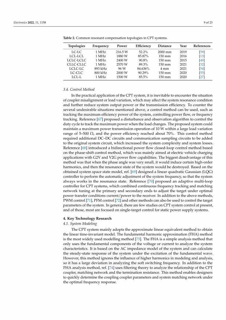
Table 2 summarizes common resonant compensation topologies in CPT systems andtheir related performances. Different compensation topologies can be chosen and designedbased on the needs of actual application scenarios.
When designing and selecting the compensation topology for the specified CPT system,it is usually necessary to use circuit software such as MATLAB Simulink, Proteus, andMultisim, to simulate the overall circuit topology to calculate the system performance oftransmission power and system efficiency under the used compensation topology.
Electronics 2022, 11, 1158 9 of 23
Table 2. Common resonant compensation topologies in CPT systems.
Topologies Frequency Power Efficiency Distance Year References
LC-LC 1 MHz 216.5 W 52.2% 2000 mm 2019 [59]LCL-LCL 1 MHz 1880 W 85.87% 150 mm 2016 [13]
LCLC-LCLC 1 MHz 2400 W 90.8% 150 mm 2015 [49]CLLC-CLLC 1 MHz 2570 W 89.3% 150 mm 2021 [32]
LCLC-LC 893 kHz 96 W 84.636% 4 mm 2021 [54]LC-CLC 800 kHz 2000 W 90.29% 150 mm 2020 [55]LCL-L 1 MHz 1500 W 85.5% 150 mm 2020 [27]
3.4. Control Method
In the practical application of the CPT system, it is inevitable to encounter the situationof coupler misalignment or load variation, which may affect the system resonance conditionand further reduce system output power or the transmission efficiency. To counter theseveral undesirable situations mentioned above, a control method can be used, such astracking the maximum efficiency power of the system, controlling power flow, or frequencytracking. Reference [67] proposed a disturbance and observation algorithm to control theduty cycle to track the maximum power when the load changes. The proposed system couldmaintain a maximum power transmission operation of 10 W within a large load variationrange of 5–500 Ω, and the power efficiency reached about 70%. This control methodrequired additional DC–DC circuits and communication sampling circuits to be addedto the original system circuit, which increased the system complexity and system losses.Reference [68] introduced a bidirectional power flow closed-loop control method basedon the phase-shift control method, which was mainly aimed at electric vehicle chargingapplications with G2V and V2G power flow capabilities. The biggest disadvantage of thismethod was that when the phase angle was very small, it would induce certain high-orderharmonics, and then the resonance state of the system would be destroyed. Based on theobtained system space state model, ref. [69] designed a linear quadratic Gaussian (LQG)controller to perform the automatic adjustment of the system frequency, so that the systemalways works in the resonance state. Reference [70] proposed an adaptive multi-loopcontroller for CPT systems, which combined continuous frequency tracking and matchingnetwork tuning at the primary and secondary ends to adjust the target under optimalpower transfer conditions current/power to the receiver. In addition to the above methods,PWM control [71], PFM control [72] and other methods can also be used to control the targetparameters of the system. In general, there are few studies on CPT system control at present,and of those, most are focused on single-target control for static power supply systems.
4. Key Technology Research4.1. System Modeling
The CPT system mainly adopts the approximate linear equivalent method to obtainthe linear time-invariant model. The fundamental harmonic approximation (FHA) methodis the most widely used modelling method [73]. The FHA is a simple analysis method thatonly uses the fundamental components of the voltage or current to analyze the systemcharacteristics. It is based on the AC impedance model of the system and can calculatethe steady-state response of the system under the excitation of the fundamental wave.However, this method ignores the influence of higher harmonics in modeling and analysis,so it has a large deviation in analyzing the soft switching frequency. In addition to theFHA analysis method, ref. [74] uses filtering theory to analyze the relationship of the CPTcoupler, matching network and the termination resistance. This method enables designersto quickly determine the coupling coupler parameters and system matching network underthe optimal frequency response.
Electronics 2022, 11, 1158 10 of 23
In addition to the above mentioned methods, the generalized space average method [75],the coupled mode theory [76], the vibration theory [77], and the fractional order theory [78]can also be used to model and analyze the CPT system.
4.2. System Efficiency Optimization
System efficiency is an important factor in designing and applying the CPT system, andhow to optimize system transmission efficiency is important to research work. Althoughresearchers have conducted a large amount of work to improve system performance,optimization of the transmission efficiency of the CPT system has just begun. At present,most of the efficiency optimization methods in CPT systems can be concluded as: (1) Tooptimize the design of system parameters, ref. [79] considered the ratio of reactive powerin the compensation network to the transmission power as the optimization goal, andproposed a two-stage optimization method. A CPT system with a coupling capacitance of16 pF was built under an operating frequency of 1 MHz. The built system could achieve a3 kW power transmission with an efficiency of 95.7% under the gap distance of 100 mm;(2) Tracking the optimal load. Reference [80] verified the existence of the optimal load ofthe CPT system by both experiment and theory. In the case of the optimal load, when thesystem transmission power was 10 W, the efficiency was up to 89.3%. When the systemtransmission power was 100 W, the efficiency was 93.02%. To keep high efficiency underthe variation of the load, ref. [81] proposed a state feedback control model using a linearquadratic regulator (LQR) and sum-pole configuration method.
In general, the optimization of CPT system efficiency is a hot research topic, whichhas attracted the attention of scholars in recent years, and the research results are relativelyrich. However, a much work is needed to improve the system efficiency. It is generallybelieved that the system loss mainly derives from the parasitic resistance of compensationcomponents in the system network, including compensation inductors, capacitors andswitch devices, while ignoring the loss of the coupling mechanism. Research on the lossmodel of the coupling mechanism will be a direction worthy of attention in the future.
4.3. Single-Capacitor CPT System
In essence, CPT technology uses the coupling capacitor formed by the couplingmechanism to construct a complete electrical circuit to achieve wireless power transfer.Therefore, a CPT system coupler usually requires four or more plates. When there is morethan one pair of coupling plates in the transfer system, the cross-coupling of multiplecoupling plates will increase the complexity of the system design and affect the powerproperty. Contrary to the traditional mutual-plates CPT system, the single-capacitor CPTsystem, or is named, a two-plates CPT system, uses ground working with one pair of patesto form a capacitor to form a complete electrical circuit.
The analysis method suitable for the traditional CPT system cannot be directly appliedto model and analyze the single-capacitor CPT system. Reference [15] established a modelof a single-capacitor system CPT system and revealed its power transmission property ofstrong coupling to the ground. Reference [82] proposed a new mid-range air-gap single-capacitor CPT system in which two metal blocks were used to form a virtual capacitorreturn route. Therefore, the traditional four-plate structure was simplified to a two-platestructure. Reference [83] designed and built an experimental circuit of a single-capacitorCPT system with an achieved power transfer of 3.8 W. Reference [84] proposed a two-plateCPT system for electric vehicle charging applications. The experimental setup achieved apower transmission of 350 W with a DC-DC efficiency of 74.1% when the air gap distancewas 110 mm.
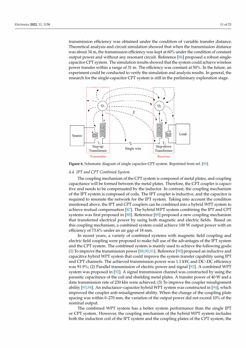
For the traditional CPT system, the transmission power and efficiency of the systemwill be greatly reduced with the increase in the transfer distance. Therefore, the transmissiondistance of current CPT systems is mostly in centimeters. Based on coupled-mode theory,ref. [85] proposed a nonlinear isochronous symmetric model as shown in Figure 6. Ahigh-time-symmetric model for the single-capacitor CPT system is achieved and constant
Electronics 2022, 11, 1158 11 of 23
transmission efficiency was obtained under the condition of variable transfer distance.Theoretical analysis and circuit simulation showed that when the transmission distancewas about 34 m, the transmission efficiency was kept at 60% under the condition of constantoutput power and without any resonant circuit. Reference [86] proposed a robust single-capacitor CPT system. The simulation results showed that the system could achieve wirelesspower transfer within a range of 31 m. The efficiency was constant at 50%. In the future, anexperiment could be conducted to verify the simulation and analysis results. In general, theresearch for the single-capacitor CPT system is still in the preliminary exploration stage.
Electronics 2022, 11, x FOR PEER REVIEW 11 of 23
Therefore, a CPT system coupler usually requires four or more plates. When there is more than one pair of coupling plates in the transfer system, the cross-coupling of multiple cou-pling plates will increase the complexity of the system design and affect the power prop-erty. Contrary to the traditional mutual-plates CPT system, the single-capacitor CPT sys-tem, or is named, a two-plates CPT system, uses ground working with one pair of pates to form a capacitor to form a complete electrical circuit.
The analysis method suitable for the traditional CPT system cannot be directly ap-plied to model and analyze the single-capacitor CPT system. Reference [15] established a model of a single-capacitor system CPT system and revealed its power transmission prop-erty of strong coupling to the ground. Reference [81] proposed a new mid-range air-gap single-capacitor CPT system in which two metal blocks were used to form a virtual capac-itor return route. Therefore, the traditional four-plate structure was simplified to a two-plate structure. Reference [83] designed and built an experimental circuit of a single-ca-pacitor CPT system with an achieved power transfer of 3.8 W. Reference [84] proposed a two-plate CPT system for electric vehicle charging applications. The experimental setup achieved a power transmission of 350 W with a DC-DC efficiency of 74.1% when the air gap distance was 110 mm.
For the traditional CPT system, the transmission power and efficiency of the system will be greatly reduced with the increase in the transfer distance. Therefore, the transmis-sion distance of current CPT systems is mostly in centimeters. Based on coupled-mode theory, [85] proposed a nonlinear isochronous symmetric model as shown in Figure 6. A high-time-symmetric model for the single-capacitor CPT system is achieved and constant transmission efficiency was obtained under the condition of variable transfer distance. Theoretical analysis and circuit simulation showed that when the transmission distance was about 34 m, the transmission efficiency was kept at 60% under the condition of con-stant output power and without any resonant circuit. Reference [86] proposed a robust single-capacitor CPT system. The simulation results showed that the system could achieve wireless power transfer within a range of 31 m. The efficiency was constant at 50%. In the future, an experiment could be conducted to verify the simulation and analysis results. In general, the research for the single-capacitor CPT system is still in the preliminary explo-ration stage.
Figure 6. Schematic diagram of single capacitor CPT system. Reprinted from ref. [85].
4.4. IPT and CPT Combined System The coupling mechanism of the CPT system is composed of metal plates, and cou-
pling capacitance will be formed between the metal plates. Therefore, the CPT coupler is capacitive and needs to be compensated by the inductor. In contrast, the coupling mech-anism of the IPT system is composed of coils. The IPT coupler is inductive, and the capac-itor is required to resonate the network for the IPT system. Taking into account the condi-tion mentioned above, the IPT and CPT couplers can be combined into a hybrid WPT system to achieve mutual compensation [87]. The hybrid WPT system combining the IPT and CPT systems was first proposed in [88]. Reference [89] proposed a new coupling
Figure 6. Schematic diagram of single capacitor CPT system. Reprinted from ref. [85].
4.4. IPT and CPT Combined System
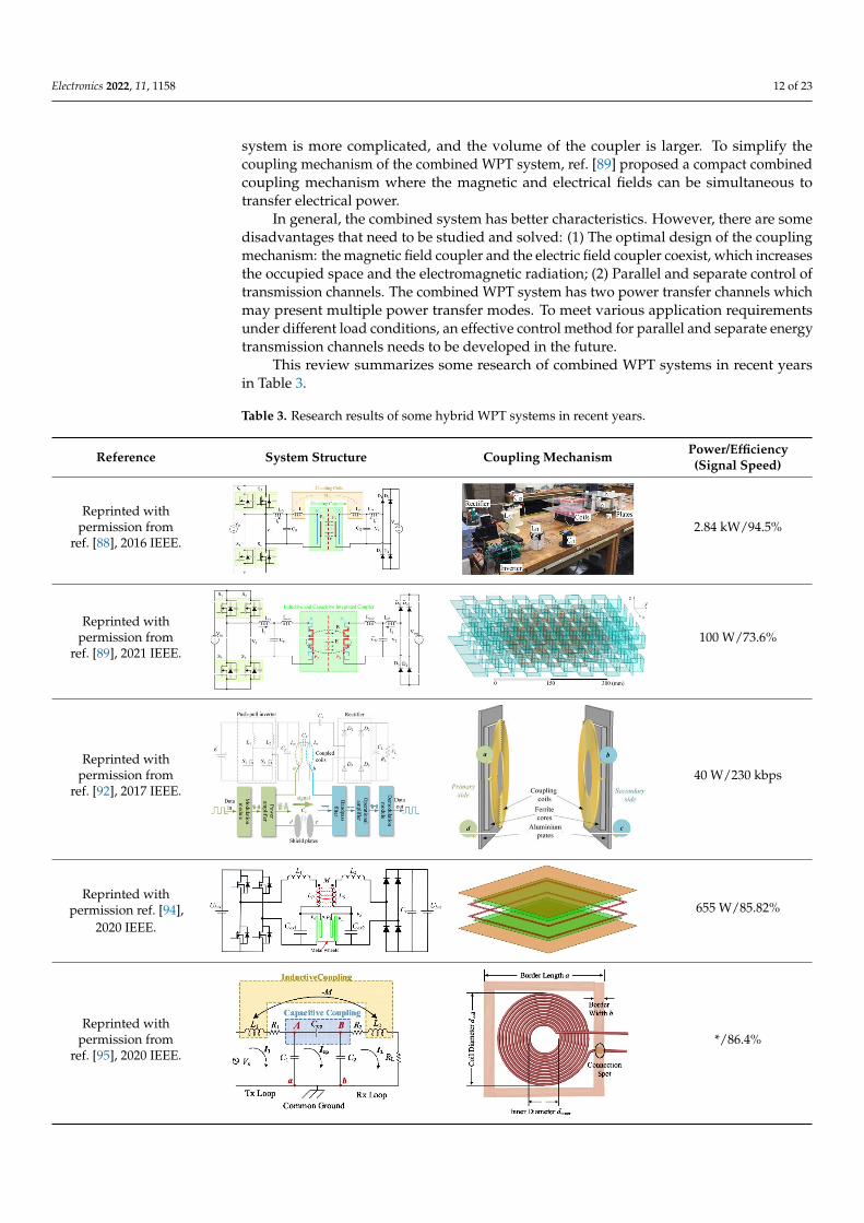
The coupling mechanism of the CPT system is composed of metal plates, and couplingcapacitance will be formed between the metal plates. Therefore, the CPT coupler is capaci-tive and needs to be compensated by the inductor. In contrast, the coupling mechanismof the IPT system is composed of coils. The IPT coupler is inductive, and the capacitor isrequired to resonate the network for the IPT system. Taking into account the conditionmentioned above, the IPT and CPT couplers can be combined into a hybrid WPT system toachieve mutual compensation [87]. The hybrid WPT system combining the IPT and CPTsystems was first proposed in [88]. Reference [89] proposed a new coupling mechanismthat transferred electrical power by using both magnetic and electric fields. Based onthis coupling mechanism, a combined system could achieve 100 W output power with anefficiency of 73.6% under an air gap of 18 mm.
In recent years, a variety of combined systems with magnetic field coupling andelectric field coupling were proposed to make full use of the advantages of the IPT systemand the CPT system. The combined system is mainly used to achieve the following goals:(1) To improve the transmission power [88,90,91]. Reference [90] proposed an inductive andcapacitive hybrid WPT system that could improve the system transfer capability using IPTand CPT channels. The achieved transmission power was 1.1 kW, and DC–DC efficiencywas 91.9%; (2) Parallel transmission of electric power and signal [92]. A combined WPTsystem was proposed in [92]. A signal transmission channel was constructed by using theparasitic capacitance of the coil and shielding metal plates. A transfer power of 40 W and adata transmission rate of 230 kbs were achieved; (3) To improve the coupler misalignmentability [93,94]. An inductance–capacitor hybrid WPT system was constructed in [94], whichimproved the coupler anti-misalignment ability. When the change of the coupling platespacing was within 0–270 mm, the variation of the output power did not exceed 10% of thenominal output.
The combined WPT system has a better system performance than the single IPTor CPT system. However, the coupling mechanism of the hybrid WPT system includesboth the induction coil of the IPT system and the coupling plates of the CPT system, the
Electronics 2022, 11, 1158 12 of 23
system is more complicated, and the volume of the coupler is larger. To simplify thecoupling mechanism of the combined WPT system, ref. [89] proposed a compact combinedcoupling mechanism where the magnetic and electrical fields can be simultaneous totransfer electrical power.
In general, the combined system has better characteristics. However, there are somedisadvantages that need to be studied and solved: (1) The optimal design of the couplingmechanism: the magnetic field coupler and the electric field coupler coexist, which increasesthe occupied space and the electromagnetic radiation; (2) Parallel and separate control oftransmission channels. The combined WPT system has two power transfer channels whichmay present multiple power transfer modes. To meet various application requirementsunder different load conditions, an effective control method for parallel and separate energytransmission channels needs to be developed in the future.
This review summarizes some research of combined WPT systems in recent yearsin Table 3.
Table 3. Research results of some hybrid WPT systems in recent years.
Reference System Structure Coupling Mechanism Power/Efficiency(Signal Speed)
Reprinted withpermission from
ref. [88], 2016 IEEE.
Electronics 2022, 11, x FOR PEER REVIEW 12 of 23
mechanism that transferred electrical power by using both magnetic and electric fields. Based on this coupling mechanism, a combined system could achieve 100 W output power with an efficiency of 73.6% under an air gap of 18 mm.
In recent years, a variety of combined systems with magnetic field coupling and elec-tric field coupling were proposed to make full use of the advantages of the IPT system and the CPT system. The combined system is mainly used to achieve the following goals: (1) To improve the transmission power [88,90,91]. Reference [90] proposed an inductive and capacitive hybrid WPT system that could improve the system transfer capability us-ing IPT and CPT channels. The achieved transmission power was 1.1 kW, and DC–DC efficiency was 91.9%; (2) Parallel transmission of electric power and signal [92]. A com-bined WPT system was proposed in [92]. A signal transmission channel was constructed by using the parasitic capacitance of the coil and shielding metal plates. A transfer power of 40 W and a data transmission rate of 230 kbs were achieved; (3) To improve the coupler misalignment ability [93,94]. An inductance–capacitor hybrid WPT system was con-structed in [94], which improved the coupler anti-misalignment ability. When the change of the coupling plate spacing was within 0–270 mm, the variation of the output power did not exceed 10% of the nominal output.
The combined WPT system has a better system performance than the single IPT or CPT system. However, the coupling mechanism of the hybrid WPT system includes both the induction coil of the IPT system and the coupling plates of the CPT system, the system is more complicated, and the volume of the coupler is larger. To simplify the coupling mechanism of the combined WPT system, [89] proposed a compact combined coupling mechanism where the magnetic and electrical fields can be simultaneous to transfer elec-trical power.
In general, the combined system has better characteristics. However, there are some disadvantages that need to be studied and solved: (1) The optimal design of the coupling mechanism: the magnetic field coupler and the electric field coupler coexist, which in-creases the occupied space and the electromagnetic radiation; (2) Parallel and separate control of transmission channels. The combined WPT system has two power transfer channels which may present multiple power transfer modes. To meet various application requirements under different load conditions, an effective control method for parallel and separate energy transmission channels needs to be developed in the future.
This review summarizes some research of combined WPT systems in recent years in Table 3.
Table 3. Research results of some hybrid WPT systems in recent years.
Reference System Structure Coupling Mechanism Power/Efficiency (Signal Speed)
Reprinted with permission from ref.
[88], 2016 IEEE.
2.84 kW/94.5%
Reprinted with permission from ref.
[89], 2021 IEEE.
100 W/73.6%
2.84 kW/94.5%
Reprinted withpermission from
ref. [89], 2021 IEEE.
Electronics 2022, 11, x FOR PEER REVIEW 12 of 23
mechanism that transferred electrical power by using both magnetic and electric fields. Based on this coupling mechanism, a combined system could achieve 100 W output power with an efficiency of 73.6% under an air gap of 18 mm.
In recent years, a variety of combined systems with magnetic field coupling and elec-tric field coupling were proposed to make full use of the advantages of the IPT system and the CPT system. The combined system is mainly used to achieve the following goals: (1) To improve the transmission power [88,90,91]. Reference [90] proposed an inductive and capacitive hybrid WPT system that could improve the system transfer capability us-ing IPT and CPT channels. The achieved transmission power was 1.1 kW, and DC–DC efficiency was 91.9%; (2) Parallel transmission of electric power and signal [92]. A com-bined WPT system was proposed in [92]. A signal transmission channel was constructed by using the parasitic capacitance of the coil and shielding metal plates. A transfer power of 40 W and a data transmission rate of 230 kbs were achieved; (3) To improve the coupler misalignment ability [93,94]. An inductance–capacitor hybrid WPT system was con-structed in [94], which improved the coupler anti-misalignment ability. When the change of the coupling plate spacing was within 0–270 mm, the variation of the output power did not exceed 10% of the nominal output.
The combined WPT system has a better system performance than the single IPT or CPT system. However, the coupling mechanism of the hybrid WPT system includes both the induction coil of the IPT system and the coupling plates of the CPT system, the system is more complicated, and the volume of the coupler is larger. To simplify the coupling mechanism of the combined WPT system, [89] proposed a compact combined coupling mechanism where the magnetic and electrical fields can be simultaneous to transfer elec-trical power.
In general, the combined system has better characteristics. However, there are some disadvantages that need to be studied and solved: (1) The optimal design of the coupling mechanism: the magnetic field coupler and the electric field coupler coexist, which in-creases the occupied space and the electromagnetic radiation; (2) Parallel and separate control of transmission channels. The combined WPT system has two power transfer channels which may present multiple power transfer modes. To meet various application requirements under different load conditions, an effective control method for parallel and separate energy transmission channels needs to be developed in the future.
This review summarizes some research of combined WPT systems in recent years in Table 3.
Table 3. Research results of some hybrid WPT systems in recent years.
Reference System Structure Coupling Mechanism Power/Efficiency (Signal Speed)
Reprinted with permission from ref.
[88], 2016 IEEE.
2.84 kW/94.5%
Reprinted with permission from ref.
[89], 2021 IEEE.
100 W/73.6%
Electronics 2022, 11, x FOR PEER REVIEW 12 of 23
mechanism that transferred electrical power by using both magnetic and electric fields. Based on this coupling mechanism, a combined system could achieve 100 W output power with an efficiency of 73.6% under an air gap of 18 mm.
In recent years, a variety of combined systems with magnetic field coupling and elec-tric field coupling were proposed to make full use of the advantages of the IPT system and the CPT system. The combined system is mainly used to achieve the following goals: (1) To improve the transmission power [88,90,91]. Reference [90] proposed an inductive and capacitive hybrid WPT system that could improve the system transfer capability us-ing IPT and CPT channels. The achieved transmission power was 1.1 kW, and DC–DC efficiency was 91.9%; (2) Parallel transmission of electric power and signal [92]. A com-bined WPT system was proposed in [92]. A signal transmission channel was constructed by using the parasitic capacitance of the coil and shielding metal plates. A transfer power of 40 W and a data transmission rate of 230 kbs were achieved; (3) To improve the coupler misalignment ability [93,94]. An inductance–capacitor hybrid WPT system was con-structed in [94], which improved the coupler anti-misalignment ability. When the change of the coupling plate spacing was within 0–270 mm, the variation of the output power did not exceed 10% of the nominal output.
The combined WPT system has a better system performance than the single IPT or CPT system. However, the coupling mechanism of the hybrid WPT system includes both the induction coil of the IPT system and the coupling plates of the CPT system, the system is more complicated, and the volume of the coupler is larger. To simplify the coupling mechanism of the combined WPT system, [89] proposed a compact combined coupling mechanism where the magnetic and electrical fields can be simultaneous to transfer elec-trical power.
In general, the combined system has better characteristics. However, there are some disadvantages that need to be studied and solved: (1) The optimal design of the coupling mechanism: the magnetic field coupler and the electric field coupler coexist, which in-creases the occupied space and the electromagnetic radiation; (2) Parallel and separate control of transmission channels. The combined WPT system has two power transfer channels which may present multiple power transfer modes. To meet various application requirements under different load conditions, an effective control method for parallel and separate energy transmission channels needs to be developed in the future.
This review summarizes some research of combined WPT systems in recent years in Table 3.
Table 3. Research results of some hybrid WPT systems in recent years.
Reference System Structure Coupling Mechanism Power/Efficiency (Signal Speed)
Reprinted with permission from ref.
[88], 2016 IEEE.
2.84 kW/94.5%
Reprinted with permission from ref.
[89], 2021 IEEE.
100 W/73.6% 100 W/73.6%
Reprinted withpermission from
ref. [92], 2017 IEEE.
Electronics 2022, 11, x FOR PEER REVIEW 13 of 23
Reprinted with permission from ref.
[92], 2017 IEEE.
40 W/230 kbps
Reprinted with permission ref. [94],
2020 IEEE.
655 W/85.82%
Reprinted with permission from ref.
[95], 2020 IEEE.
*/86.4%
4.5. Constant Current/Voltage Charging The battery charging process includes two stages of constant current (CC) and con-
stant voltage (CV) charging. When the CPT system is used to supply power to charge the battery load, constant voltage/current output should be considered. Much work has been undertaken to achieve CC or CV output.
For charging a single battery with a single transmitter, [96] proposed a constant volt-age output system. The resonance network was used to convert the current source input voltage source into a constant current and then to the constant voltage output for charging the battery, ignoring the variation of coupling capacitance and load. Reference [52] de-signed a single-input single-output CPT system based on double-sided LC compensation, which achieved a constant current output under variable load. Reference [61] proposed a resonant network for the CPT system. Different resonant frequencies could be adopted to generate a constant current and constant voltage output. Reference [97] proposed an im-pedance matching network to generate a constant voltage output to charge a dynamic load. Reference [97] summarized different compensation topologies and proposed a spe-cific design method for a constant current and voltage output with zero-voltage switching.
In the application of multiple load charging, [99] proposed a mixed-resonant topol-ogy for constant-current multiple-pickup applications such as LED drivers, welding ma-chines and batteries. Reference [100] proposed a multi-load capacitive power transfer (CPT) system with an SP-CL isolation compensation topology. Receivers function solely as power consumers in the proposed system, and each receiver not only supplies power to the connected load but transfers power wirelessly to the next receiver. The proposed system could achieve constant voltage output. Reference [101] designed a multi-load CPT system based on repeaters in which L compensation topology was used to compensate input and output relays, and LCL compensation topology was used to compensate relay relays. The proposed system could achieve a multi-load constant current output.
Research on the method of generating a constant voltage or current output for CPT systems has always been a hot topic in the research of CPT systems. Generally speaking, current research on the method for generating constant voltage or current output of CPT
40 W/230 kbps
Reprinted withpermission ref. [94],
2020 IEEE.
Electronics 2022, 11, x FOR PEER REVIEW 13 of 23
Reprinted with permission from ref.
[92], 2017 IEEE.
40 W/230 kbps
Reprinted with permission ref. [94],
2020 IEEE.
655 W/85.82%
Reprinted with permission from ref.
[95], 2020 IEEE.
*/86.4%
4.5. Constant Current/Voltage Charging The battery charging process includes two stages of constant current (CC) and con-
stant voltage (CV) charging. When the CPT system is used to supply power to charge the battery load, constant voltage/current output should be considered. Much work has been undertaken to achieve CC or CV output.
For charging a single battery with a single transmitter, [96] proposed a constant volt-age output system. The resonance network was used to convert the current source input voltage source into a constant current and then to the constant voltage output for charging the battery, ignoring the variation of coupling capacitance and load. Reference [52] de-signed a single-input single-output CPT system based on double-sided LC compensation, which achieved a constant current output under variable load. Reference [61] proposed a resonant network for the CPT system. Different resonant frequencies could be adopted to generate a constant current and constant voltage output. Reference [97] proposed an im-pedance matching network to generate a constant voltage output to charge a dynamic load. Reference [97] summarized different compensation topologies and proposed a spe-cific design method for a constant current and voltage output with zero-voltage switching.
In the application of multiple load charging, [99] proposed a mixed-resonant topol-ogy for constant-current multiple-pickup applications such as LED drivers, welding ma-chines and batteries. Reference [100] proposed a multi-load capacitive power transfer (CPT) system with an SP-CL isolation compensation topology. Receivers function solely as power consumers in the proposed system, and each receiver not only supplies power to the connected load but transfers power wirelessly to the next receiver. The proposed system could achieve constant voltage output. Reference [101] designed a multi-load CPT system based on repeaters in which L compensation topology was used to compensate input and output relays, and LCL compensation topology was used to compensate relay relays. The proposed system could achieve a multi-load constant current output.
Research on the method of generating a constant voltage or current output for CPT systems has always been a hot topic in the research of CPT systems. Generally speaking, current research on the method for generating constant voltage or current output of CPT
655 W/85.82%
Reprinted withpermission from
ref. [95], 2020 IEEE.
Electronics 2022, 11, x FOR PEER REVIEW 13 of 23
Reprinted with permission from ref.
[92], 2017 IEEE.
40 W/230 kbps
Reprinted with permission ref. [94],
2020 IEEE.
655 W/85.82%
Reprinted with permission from ref.
[95], 2020 IEEE.
*/86.4%
4.5. Constant Current/Voltage Charging The battery charging process includes two stages of constant current (CC) and con-
stant voltage (CV) charging. When the CPT system is used to supply power to charge the battery load, constant voltage/current output should be considered. Much work has been undertaken to achieve CC or CV output.
For charging a single battery with a single transmitter, [96] proposed a constant volt-age output system. The resonance network was used to convert the current source input voltage source into a constant current and then to the constant voltage output for charging the battery, ignoring the variation of coupling capacitance and load. Reference [52] de-signed a single-input single-output CPT system based on double-sided LC compensation, which achieved a constant current output under variable load. Reference [61] proposed a resonant network for the CPT system. Different resonant frequencies could be adopted to generate a constant current and constant voltage output. Reference [97] proposed an im-pedance matching network to generate a constant voltage output to charge a dynamic load. Reference [97] summarized different compensation topologies and proposed a spe-cific design method for a constant current and voltage output with zero-voltage switching.
In the application of multiple load charging, [99] proposed a mixed-resonant topol-ogy for constant-current multiple-pickup applications such as LED drivers, welding ma-chines and batteries. Reference [100] proposed a multi-load capacitive power transfer (CPT) system with an SP-CL isolation compensation topology. Receivers function solely as power consumers in the proposed system, and each receiver not only supplies power to the connected load but transfers power wirelessly to the next receiver. The proposed system could achieve constant voltage output. Reference [101] designed a multi-load CPT system based on repeaters in which L compensation topology was used to compensate input and output relays, and LCL compensation topology was used to compensate relay relays. The proposed system could achieve a multi-load constant current output.
Research on the method of generating a constant voltage or current output for CPT systems has always been a hot topic in the research of CPT systems. Generally speaking, current research on the method for generating constant voltage or current output of CPT
*/86.4%
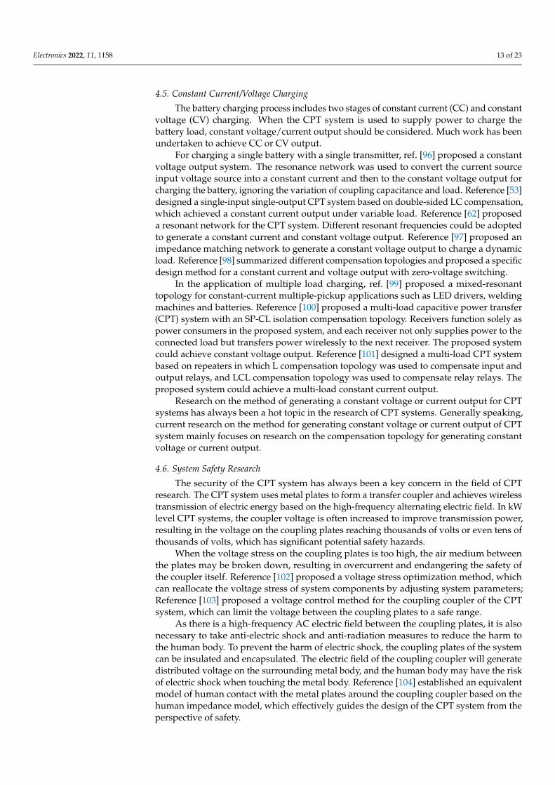
Electronics 2022, 11, 1158 13 of 23
4.5. Constant Current/Voltage Charging
The battery charging process includes two stages of constant current (CC) and constantvoltage (CV) charging. When the CPT system is used to supply power to charge thebattery load, constant voltage/current output should be considered. Much work has beenundertaken to achieve CC or CV output.
For charging a single battery with a single transmitter, ref. [96] proposed a constantvoltage output system. The resonance network was used to convert the current sourceinput voltage source into a constant current and then to the constant voltage output forcharging the battery, ignoring the variation of coupling capacitance and load. Reference [53]designed a single-input single-output CPT system based on double-sided LC compensation,which achieved a constant current output under variable load. Reference [62] proposeda resonant network for the CPT system. Different resonant frequencies could be adoptedto generate a constant current and constant voltage output. Reference [97] proposed animpedance matching network to generate a constant voltage output to charge a dynamicload. Reference [98] summarized different compensation topologies and proposed a specificdesign method for a constant current and voltage output with zero-voltage switching.
In the application of multiple load charging, ref. [99] proposed a mixed-resonanttopology for constant-current multiple-pickup applications such as LED drivers, weldingmachines and batteries. Reference [100] proposed a multi-load capacitive power transfer(CPT) system with an SP-CL isolation compensation topology. Receivers function solely aspower consumers in the proposed system, and each receiver not only supplies power to theconnected load but transfers power wirelessly to the next receiver. The proposed systemcould achieve constant voltage output. Reference [101] designed a multi-load CPT systembased on repeaters in which L compensation topology was used to compensate input andoutput relays, and LCL compensation topology was used to compensate relay relays. Theproposed system could achieve a multi-load constant current output.
Research on the method of generating a constant voltage or current output for CPTsystems has always been a hot topic in the research of CPT systems. Generally speaking,current research on the method for generating constant voltage or current output of CPTsystem mainly focuses on research on the compensation topology for generating constantvoltage or current output.
4.6. System Safety Research
The security of the CPT system has always been a key concern in the field of CPTresearch. The CPT system uses metal plates to form a transfer coupler and achieves wirelesstransmission of electric energy based on the high-frequency alternating electric field. In kWlevel CPT systems, the coupler voltage is often increased to improve transmission power,resulting in the voltage on the coupling plates reaching thousands of volts or even tens ofthousands of volts, which has significant potential safety hazards.
When the voltage stress on the coupling plates is too high, the air medium betweenthe plates may be broken down, resulting in overcurrent and endangering the safety ofthe coupler itself. Reference [102] proposed a voltage stress optimization method, whichcan reallocate the voltage stress of system components by adjusting system parameters;Reference [103] proposed a voltage control method for the coupling coupler of the CPTsystem, which can limit the voltage between the coupling plates to a safe range.
As there is a high-frequency AC electric field between the coupling plates, it is alsonecessary to take anti-electric shock and anti-radiation measures to reduce the harm tothe human body. To prevent the harm of electric shock, the coupling plates of the systemcan be insulated and encapsulated. The electric field of the coupling coupler will generatedistributed voltage on the surrounding metal body, and the human body may have the riskof electric shock when touching the metal body. Reference [104] established an equivalentmodel of human contact with the metal plates around the coupling coupler based on thehuman impedance model, which effectively guides the design of the CPT system from theperspective of safety.
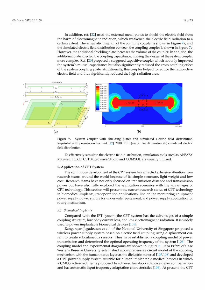
Electronics 2022, 11, 1158 14 of 23
In addition, ref. [22] used the external metal plates to shield the electric field fromthe harm of electromagnetic radiation, which weakened the electric field radiation to acertain extent. The schematic diagram of the coupling coupler is shown in Figure 7a, andthe simulated electric field distribution between the coupling coupler is shown in Figure 7b.However, the additional shielding plate increases the volume of the coupler. In addition, theadditional plate affected the coupling capacitance, making the design of the system couplermore complex; Ref. [20] proposed a staggered capacitive coupler which not only improvedthe system’s mutual capacitance but also significantly reduced the cross-coupling effectof the system coupling plate. Additionally, this coupler helped to reduce the radioactiveelectric field and thus significantly reduced the high radiation area.
Electronics 2022, 11, x FOR PEER REVIEW 14 of 23
system mainly focuses on research on the compensation topology for generating constant
voltage or current output.
4.6. System Safety Research
The security of the CPT system has always been a key concern in the field of CPT
research. The CPT system uses metal plates to form a transfer coupler and achieves wire-
less transmission of electric energy based on the high-frequency alternating electric field.
In kW level CPT systems, the coupler voltage is often increased to improve transmission
power, resulting in the voltage on the coupling plates reaching thousands of volts or even
tens of thousands of volts, which has significant potential safety hazards.
When the voltage stress on the coupling plates is too high, the air medium between
the plates may be broken down, resulting in overcurrent and endangering the safety of
the coupler itself. Reference [102] proposed a voltage stress optimization method, which
can reallocate the voltage stress of system components by adjusting system parameters;
Reference [103] proposed a voltage control method for the coupling coupler of the CPT
system, which can limit the voltage between the coupling plates to a safe range.
As there is a high-frequency AC electric field between the coupling plates, it is also
necessary to take anti-electric shock and anti-radiation measures to reduce the harm to the
human body. To prevent the harm of electric shock, the coupling plates of the system can
be insulated and encapsulated. The electric field of the coupling coupler will generate dis-
tributed voltage on the surrounding metal body, and the human body may have the risk
of electric shock when touching the metal body. Reference [104] established an equivalent
model of human contact with the metal plates around the coupling coupler based on the
human impedance model, which effectively guides the design of the CPT system from the
perspective of safety.
In addition, [22] used the external metal plates to shield the electric field from the harm
of electromagnetic radiation, which weakened the electric field radiation to a certain extent.
The schematic diagram of the coupling coupler is shown in Figure 7a, and the simulated
electric field distribution between the coupling coupler is shown in Figure 7b. However, the
additional shielding plate increases the volume of the coupler. In addition, the additional
plate affected the coupling capacitance, making the design of the system coupler more
complex; [20] proposed a staggered capacitive coupler which not only improved the sys-
tem’s mutual capacitance but also significantly reduced the cross-coupling effect of the
system coupling plate. Additionally, this coupler helped to reduce the radioactive electric
field and thus significantly reduced the high radiation area.
To effectively simulate the electric field distribution, simulation tools such as AN-
SYSY Maxwell, FEKO, CST Microwave Studio and COMSOL are usually utilized.
(a) (b)
Figure 7. System coupler with shielding plates and simulated electric field distribution. Reprinted
with permission from ref. [22], 2018 IEEE: (a) coupler dimension; (b) simulated electric field distri-
bution.
Figure 7. System coupler with shielding plates and simulated electric field distribution.Reprinted with permission from ref. [22], 2018 IEEE: (a) coupler dimension; (b) simulated electricfield distribution.
To effectively simulate the electric field distribution, simulation tools such as ANSYSYMaxwell, FEKO, CST Microwave Studio and COMSOL are usually utilized.
5. Application of CPT System
The continuous development of the CPT system has attracted extensive attention fromresearch teams around the world because of its simple structure, light weight and lowcost. Research teams have not only focused on transmission distance and transmissionpower but have also fully explored the application scenarios with the advantages ofCPT technology. This section will present the current research status of CPT technologyin biomedical implants, transportation applications, line online monitoring equipmentpower supply, power supply for underwater equipment, and power supply application forrotary mechanism.
5.1. Biomedical Implants
Compared with the IPT system, the CPT system has the advantages of a simplecoupling structure, low eddy current loss, and low electromagnetic radiation. It is widelyused to power implantable biomedical devices [105].
Rangarajan Jegadeesan et al. of the National University of Singapore proposed awireless power supply system based on electric field coupling using displacement cur-rent to create subcutaneous sensors. They have established a coupling model of powertransmission and determined the optimal operating frequency of the system [106]. Thecoupling model and experimental diagrams are shown in Figure 8. Reza Erfani of CaseWestern Reserve University established a comprehensive circuit model of the couplingmechanism with the human tissue layer as the dielectric material [107,108] and developeda CPT power supply system suitable for human implantable medical devices in whicha CMOS active rectifier is proposed to achieve dual-loop adaptive delay compensationand has automatic input frequency adaptation characteristics [109]. At present, the CPT
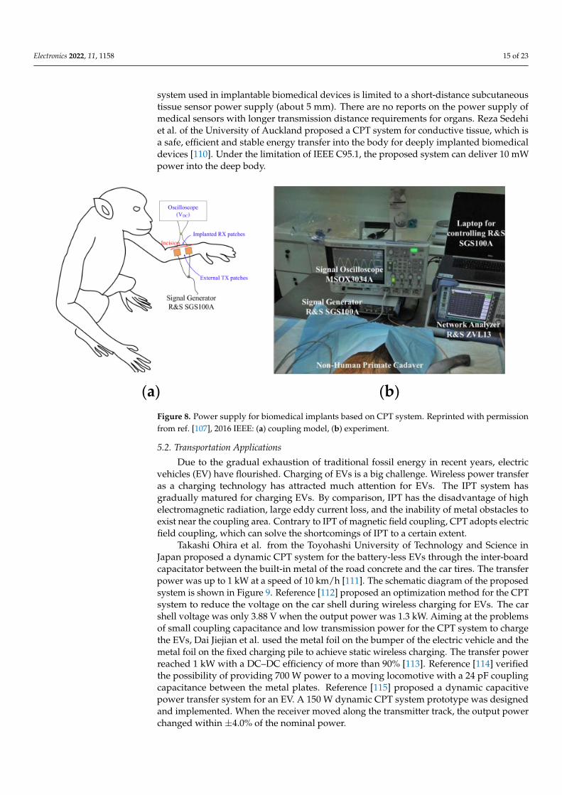
Electronics 2022, 11, 1158 15 of 23
system used in implantable biomedical devices is limited to a short-distance subcutaneoustissue sensor power supply (about 5 mm). There are no reports on the power supply ofmedical sensors with longer transmission distance requirements for organs. Reza Sedehiet al. of the University of Auckland proposed a CPT system for conductive tissue, which isa safe, efficient and stable energy transfer into the body for deeply implanted biomedicaldevices [110]. Under the limitation of IEEE C95.1, the proposed system can deliver 10 mWpower into the deep body.
Electronics 2022, 11, x FOR PEER REVIEW 15 of 23
5. Application of CPT System
The continuous development of the CPT system has attracted extensive attention
from research teams around the world because of its simple structure, light weight and
low cost. Research teams have not only focused on transmission distance and transmis-
sion power but have also fully explored the application scenarios with the advantages of
CPT technology. This section will present the current research status of CPT technology
in biomedical implants, transportation applications, line online monitoring equipment
power supply, power supply for underwater equipment, and power supply application
for rotary mechanism.
5.1. Biomedical Implants
Compared with the IPT system, the CPT system has the advantages of a simple cou-
pling structure, low eddy current loss, and low electromagnetic radiation. It is widely
used to power implantable biomedical devices [105].
Rangarajan Jegadeesan et al. of the National University of Singapore proposed a
wireless power supply system based on electric field coupling using displacement current
to create subcutaneous sensors. They have established a coupling model of power trans-
mission and determined the optimal operating frequency of the system [106]. The cou-
pling model and experimental diagrams are shown in Figure 8. Reza Erfani of Case West-
ern Reserve University established a comprehensive circuit model of the coupling mech-
anism with the human tissue layer as the dielectric material [107,108] and developed a
CPT power supply system suitable for human implantable medical devices in which a
CMOS active rectifier is proposed to achieve dual-loop adaptive delay compensation and
has automatic input frequency adaptation characteristics [109]. At present, the CPT sys-
tem used in implantable biomedical devices is limited to a short-distance subcutaneous
tissue sensor power supply (about 5 mm). There are no reports on the power supply of
medical sensors with longer transmission distance requirements for organs. Reza Sedehi
et al. of the University of Auckland proposed a CPT system for conductive tissue, which
is a safe, efficient and stable energy transfer into the body for deeply implanted biomedi-
cal devices [110]. Under the limitation of IEEE C95.1, the proposed system can deliver 10
mW power into the deep body.
(a) (b)
Figure 8. Power supply for biomedical implants based on CPT system. Reprinted with permission
from ref. [107], 2016 IEEE: (a) coupling model, (b) experiment.
5.2. Transportation Applications
Due to the gradual exhaustion of traditional fossil energy in recent years, electric ve-
hicles (EV) have flourished. Charging of EVs is a big challenge. Wireless power transfer
as a charging technology has attracted much attention for EVs. The IPT system has grad-
ually matured for charging EVs. By comparison, IPT has the disadvantage of high electro-
magnetic radiation, large eddy current loss, and the inability of metal obstacles to exist
Figure 8. Power supply for biomedical implants based on CPT system. Reprinted with permissionfrom ref. [107], 2016 IEEE: (a) coupling model, (b) experiment.
5.2. Transportation Applications
Due to the gradual exhaustion of traditional fossil energy in recent years, electricvehicles (EV) have flourished. Charging of EVs is a big challenge. Wireless power transferas a charging technology has attracted much attention for EVs. The IPT system hasgradually matured for charging EVs. By comparison, IPT has the disadvantage of highelectromagnetic radiation, large eddy current loss, and the inability of metal obstacles toexist near the coupling area. Contrary to IPT of magnetic field coupling, CPT adopts electricfield coupling, which can solve the shortcomings of IPT to a certain extent.
Takashi Ohira et al. from the Toyohashi University of Technology and Science inJapan proposed a dynamic CPT system for the battery-less EVs through the inter-boardcapacitator between the built-in metal of the road concrete and the car tires. The transferpower was up to 1 kW at a speed of 10 km/h [111]. The schematic diagram of the proposedsystem is shown in Figure 9. Reference [112] proposed an optimization method for the CPTsystem to reduce the voltage on the car shell during wireless charging for EVs. The carshell voltage was only 3.88 V when the output power was 1.3 kW. Aiming at the problemsof small coupling capacitance and low transmission power for the CPT system to chargethe EVs, Dai Jiejian et al. used the metal foil on the bumper of the electric vehicle and themetal foil on the fixed charging pile to achieve static wireless charging. The transfer powerreached 1 kW with a DC–DC efficiency of more than 90% [113]. Reference [114] verifiedthe possibility of providing 700 W power to a moving locomotive with a 24 pF couplingcapacitance between the metal plates. Reference [115] proposed a dynamic capacitivepower transfer system for an EV. A 150 W dynamic CPT system prototype was designedand implemented. When the receiver moved along the transmitter track, the output powerchanged within ±4.0% of the nominal power.
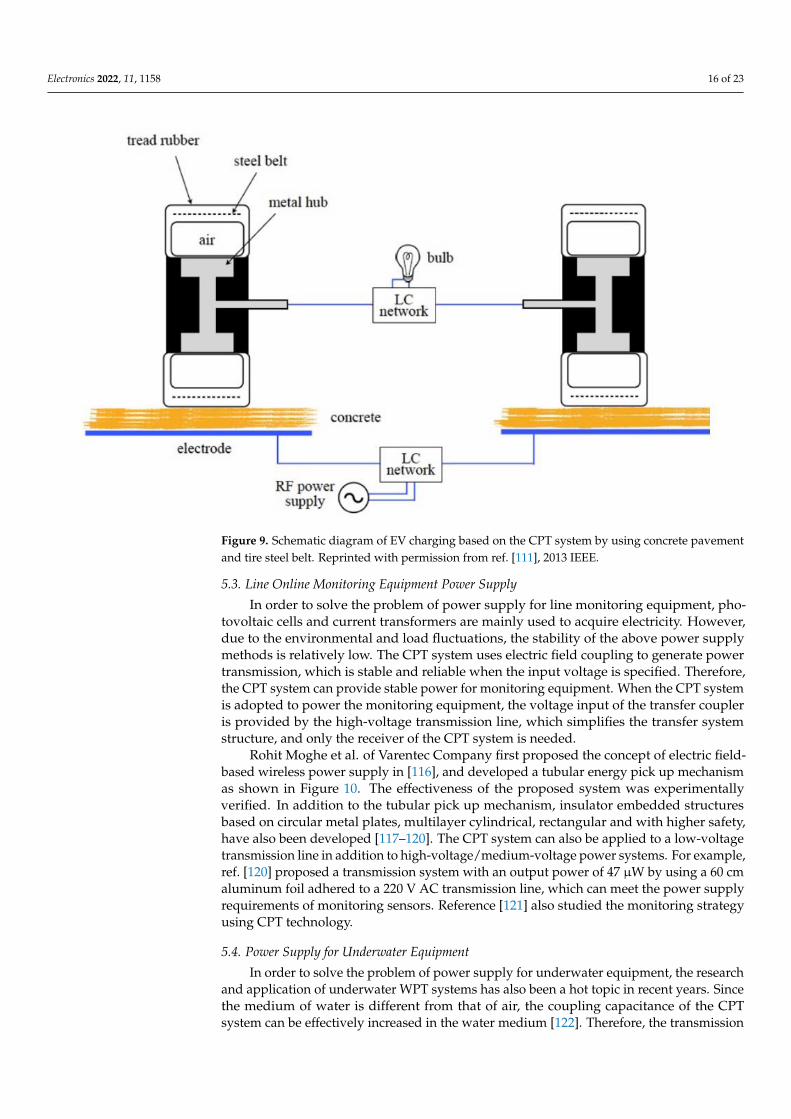
Electronics 2022, 11, 1158 16 of 23
Electronics 2022, 11, x FOR PEER REVIEW 16 of 23
near the coupling area. Contrary to IPT of magnetic field coupling, CPT adopts electric
field coupling, which can solve the shortcomings of IPT to a certain extent.
Takashi Ohira et al. from the Toyohashi University of Technology and Science in Ja-
pan proposed a dynamic CPT system for the battery-less EVs through the inter-board ca-
pacitator between the built-in metal of the road concrete and the car tires. The transfer
power was up to 1 kW at a speed of 10 km/h [111]. The schematic diagram of the proposed
system is shown in Figure 9. Reference [111] proposed an optimization method for the
CPT system to reduce the voltage on the car shell during wireless charging for EVs. The
car shell voltage was only 3.88 V when the output power was 1.3 kW. Aiming at the prob-
lems of small coupling capacitance and low transmission power for the CPT system to
charge the EVs, Dai Jiejian et al. used the metal foil on the bumper of the electric vehicle
and the metal foil on the fixed charging pile to achieve static wireless charging. The trans-
fer power reached 1 kW with a DC–DC efficiency of more than 90% [113]. Reference [114]
verified the possibility of providing 700 W power to a moving locomotive with a 24 pF
coupling capacitance between the metal plates. Reference [115] proposed a dynamic ca-
pacitive power transfer system for an EV. A 150 W dynamic CPT system prototype was
designed and implemented. When the receiver moved along the transmitter track, the
output power changed within ±4.0% of the nominal power.
Figure 9. Schematic diagram of EV charging based on the CPT system by using concrete pavement
and tire steel belt. Reprinted with permission from ref. [111], 2013 IEEE.
5.3. Line Online Monitoring Equipment Power Supply
In order to solve the problem of power supply for line monitoring equipment, pho-
tovoltaic cells and current transformers are mainly used to acquire electricity. However,
due to the environmental and load fluctuations, the stability of the above power supply
methods is relatively low. The CPT system uses electric field coupling to generate power
transmission, which is stable and reliable when the input voltage is specified. Therefore,
the CPT system can provide stable power for monitoring equipment. When the CPT sys-
tem is adopted to power the monitoring equipment, the voltage input of the transfer cou-
pler is provided by the high-voltage transmission line, which simplifies the transfer sys-
tem structure, and only the receiver of the CPT system is needed.
Rohit Moghe et al. of Varentec Company first proposed the concept of electric field-
based wireless power supply in [115], and developed a tubular energy pick up mechanism
as shown in Figure 10. The effectiveness of the proposed system was experimentally ver-
ified. In addition to the tubular pick up mechanism, insulator embedded structures based
on circular metal plates, multilayer cylindrical, rectangular and with higher safety, have
also been developed [116–120]. The CPT system can also be applied to a low-voltage trans-
mission line in addition to high-voltage/medium-voltage power systems. For example,
[120] proposed a transmission system with an output power of 47 μW by using a 60 cm
Figure 9. Schematic diagram of EV charging based on the CPT system by using concrete pavementand tire steel belt. Reprinted with permission from ref. [111], 2013 IEEE.
5.3. Line Online Monitoring Equipment Power Supply
In order to solve the problem of power supply for line monitoring equipment, pho-tovoltaic cells and current transformers are mainly used to acquire electricity. However,due to the environmental and load fluctuations, the stability of the above power supplymethods is relatively low. The CPT system uses electric field coupling to generate powertransmission, which is stable and reliable when the input voltage is specified. Therefore,the CPT system can provide stable power for monitoring equipment. When the CPT systemis adopted to power the monitoring equipment, the voltage input of the transfer coupleris provided by the high-voltage transmission line, which simplifies the transfer systemstructure, and only the receiver of the CPT system is needed.
Rohit Moghe et al. of Varentec Company first proposed the concept of electric field-based wireless power supply in [116], and developed a tubular energy pick up mechanismas shown in Figure 10. The effectiveness of the proposed system was experimentallyverified. In addition to the tubular pick up mechanism, insulator embedded structuresbased on circular metal plates, multilayer cylindrical, rectangular and with higher safety,have also been developed [117–120]. The CPT system can also be applied to a low-voltagetransmission line in addition to high-voltage/medium-voltage power systems. For example,ref. [120] proposed a transmission system with an output power of 47 µW by using a 60 cmaluminum foil adhered to a 220 V AC transmission line, which can meet the power supplyrequirements of monitoring sensors. Reference [121] also studied the monitoring strategyusing CPT technology.
5.4. Power Supply for Underwater Equipment
In order to solve the problem of power supply for underwater equipment, the researchand application of underwater WPT systems has also been a hot topic in recent years. Sincethe medium of water is different from that of air, the coupling capacitance of the CPTsystem can be effectively increased in the water medium [122]. Therefore, the transmission
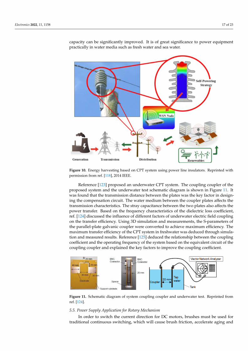
Electronics 2022, 11, 1158 17 of 23
capacity can be significantly improved. It is of great significance to power equipmentpractically in water media such as fresh water and sea water.
Electronics 2022, 11, x FOR PEER REVIEW 17 of 23
aluminum foil adhered to a 220 V AC transmission line, which can meet the power supply
requirements of monitoring sensors. Reference [121] also studied the monitoring strategy
using CPT technology.
Figure 10. Energy harvesting based on CPT system using power line insulators. Reprinted with
permission from ref. [118], 2014 IEEE.
5.4. Power Supply for Underwater Equipment
In order to solve the problem of power supply for underwater equipment, the re-
search and application of underwater WPT systems has also been a hot topic in recent
years. Since the medium of water is different from that of air, the coupling capacitance of
the CPT system can be effectively increased in the water medium [122]. Therefore, the
transmission capacity can be significantly improved. It is of great significance to power
equipment practically in water media such as fresh water and sea water.
Reference [123] proposed an underwater CPT system. The coupling coupler of the
proposed system and the underwater test schematic diagram is shown in Figure 11. It was
found that the transmission distance between the plates was the key factor in designing
the compensation circuit. The water medium between the coupler plates affects the trans-
mission characteristics. The stray capacitance between the two plates also affects the
power transfer. Based on the frequency characteristics of the dielectric loss coefficient,
[124] discussed the influence of different factors of underwater electric field coupling on
the transfer efficiency. Using 3D simulation and measurements, the S-parameters of the
parallel-plate galvanic coupler were converted to achieve maximum efficiency. The max-
imum transfer efficiency of the CPT system in freshwater was deduced through simula-
tion and measured results. Reference [124] deduced the relationship between the coupling
coefficient and the operating frequency of the system based on the equivalent circuit of the
coupling coupler and explained the key factors to improve the coupling coefficient.
Figure 11. Schematic diagram of system coupling coupler and underwater test. Reprinted from ref.
[124].
Figure 10. Energy harvesting based on CPT system using power line insulators. Reprinted withpermission from ref. [118], 2014 IEEE.
Reference [123] proposed an underwater CPT system. The coupling coupler of theproposed system and the underwater test schematic diagram is shown in Figure 11. Itwas found that the transmission distance between the plates was the key factor in design-ing the compensation circuit. The water medium between the coupler plates affects thetransmission characteristics. The stray capacitance between the two plates also affects thepower transfer. Based on the frequency characteristics of the dielectric loss coefficient,ref. [124] discussed the influence of different factors of underwater electric field couplingon the transfer efficiency. Using 3D simulation and measurements, the S-parameters ofthe parallel-plate galvanic coupler were converted to achieve maximum efficiency. Themaximum transfer efficiency of the CPT system in freshwater was deduced through simula-tion and measured results. Reference [125] deduced the relationship between the couplingcoefficient and the operating frequency of the system based on the equivalent circuit of thecoupling coupler and explained the key factors to improve the coupling coefficient.
Electronics 2022, 11, x FOR PEER REVIEW 17 of 23
aluminum foil adhered to a 220 V AC transmission line, which can meet the power supply
requirements of monitoring sensors. Reference [121] also studied the monitoring strategy
using CPT technology.
Figure 10. Energy harvesting based on CPT system using power line insulators. Reprinted with
permission from ref. [118], 2014 IEEE.
5.4. Power Supply for Underwater Equipment
In order to solve the problem of power supply for underwater equipment, the re-
search and application of underwater WPT systems has also been a hot topic in recent
years. Since the medium of water is different from that of air, the coupling capacitance of
the CPT system can be effectively increased in the water medium [122]. Therefore, the
transmission capacity can be significantly improved. It is of great significance to power
equipment practically in water media such as fresh water and sea water.
Reference [123] proposed an underwater CPT system. The coupling coupler of the
proposed system and the underwater test schematic diagram is shown in Figure 11. It was
found that the transmission distance between the plates was the key factor in designing
the compensation circuit. The water medium between the coupler plates affects the trans-
mission characteristics. The stray capacitance between the two plates also affects the
power transfer. Based on the frequency characteristics of the dielectric loss coefficient,
[124] discussed the influence of different factors of underwater electric field coupling on
the transfer efficiency. Using 3D simulation and measurements, the S-parameters of the
parallel-plate galvanic coupler were converted to achieve maximum efficiency. The max-
imum transfer efficiency of the CPT system in freshwater was deduced through simula-
tion and measured results. Reference [124] deduced the relationship between the coupling
coefficient and the operating frequency of the system based on the equivalent circuit of the
coupling coupler and explained the key factors to improve the coupling coefficient.
Figure 11. Schematic diagram of system coupling coupler and underwater test. Reprinted from ref.
[124].
Figure 11. Schematic diagram of system coupling coupler and underwater test. Reprinted fromref. [124].
5.5. Power Supply Application for Rotary Mechanism
In order to switch the current direction for DC motors, brushes must be used fortraditional continuous switching, which will cause brush friction, accelerate aging and
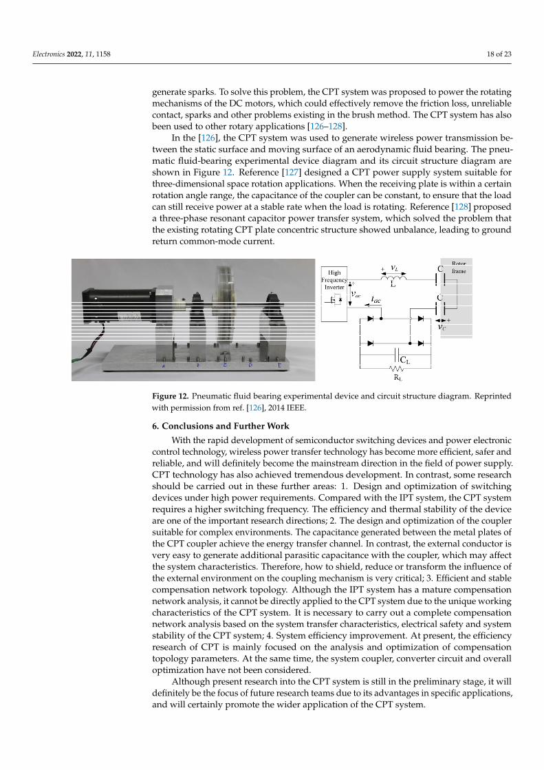
Electronics 2022, 11, 1158 18 of 23
generate sparks. To solve this problem, the CPT system was proposed to power the rotatingmechanisms of the DC motors, which could effectively remove the friction loss, unreliablecontact, sparks and other problems existing in the brush method. The CPT system has alsobeen used to other rotary applications [126–128].
In the [126], the CPT system was used to generate wireless power transmission be-tween the static surface and moving surface of an aerodynamic fluid bearing. The pneu-matic fluid-bearing experimental device diagram and its circuit structure diagram areshown in Figure 12. Reference [127] designed a CPT power supply system suitable forthree-dimensional space rotation applications. When the receiving plate is within a certainrotation angle range, the capacitance of the coupler can be constant, to ensure that the loadcan still receive power at a stable rate when the load is rotating. Reference [128] proposeda three-phase resonant capacitor power transfer system, which solved the problem thatthe existing rotating CPT plate concentric structure showed unbalance, leading to groundreturn common-mode current.
Electronics 2022, 11, x FOR PEER REVIEW 18 of 23
5.5. Power Supply Application for Rotary Mechanism In order to switch the current direction for DC motors, brushes must be used for tra-
ditional continuous switching, which will cause brush friction, accelerate aging and gen-erate sparks. To solve this problem, the CPT system was proposed to power the rotating mechanisms of the DC motors, which could effectively remove the friction loss, unreliable contact, sparks and other problems existing in the brush method. The CPT system has also been used to other rotary applications [125–128].
In the [125], the CPT system was used to generate wireless power transmission be-tween the static surface and moving surface of an aerodynamic fluid bearing. The pneu-matic fluid-bearing experimental device diagram and its circuit structure diagram are shown in Figure 12. Reference [127] designed a CPT power supply system suitable for three-dimensional space rotation applications. When the receiving plate is within a certain rotation angle range, the capacitance of the coupler can be constant, to ensure that the load can still receive power at a stable rate when the load is rotating. Reference [128] proposed a three-phase resonant capacitor power transfer system, which solved the problem that the existing rotating CPT plate concentric structure showed unbalance, leading to ground return common-mode current.
Figure 12. Pneumatic fluid bearing experimental device and circuit structure diagram. Reprinted with permission from ref. [125], 2014 IEEE.
6. Conclusions and Further Work With the rapid development of semiconductor switching devices and power elec-
tronic control technology, wireless power transfer technology has become more efficient, safer and reliable, and will definitely become the mainstream direction in the field of power supply. CPT technology has also achieved tremendous development. In contrast, some research should be carried out in these further areas: 1. Design and optimization of switching devices under high power requirements. Compared with the IPT system, the CPT system requires a higher switching frequency. The efficiency and thermal stability of the device are one of the important research directions; 2. The design and optimization of the coupler suitable for complex environments. The capacitance generated between the metal plates of the CPT coupler achieve the energy transfer channel. In contrast, the ex-ternal conductor is very easy to generate additional parasitic capacitance with the coupler, which may affect the system characteristics. Therefore, how to shield, reduce or transform the influence of the external environment on the coupling mechanism is very critical; 3. Efficient and stable compensation network topology. Although the IPT system has a ma-ture compensation network analysis, it cannot be directly applied to the CPT system due to the unique working characteristics of the CPT system. It is necessary to carry out a complete compensation network analysis based on the system transfer characteristics, electrical safety and system stability of the CPT system; 4. System efficiency improvement. At present, the efficiency research of CPT is mainly focused on the analysis and optimiza-tion of compensation topology parameters. At the same time, the system coupler, con-verter circuit and overall optimization have not been considered.
Figure 12. Pneumatic fluid bearing experimental device and circuit structure diagram. Reprintedwith permission from ref. [126], 2014 IEEE.
6. Conclusions and Further Work
With the rapid development of semiconductor switching devices and power electroniccontrol technology, wireless power transfer technology has become more efficient, safer andreliable, and will definitely become the mainstream direction in the field of power supply.CPT technology has also achieved tremendous development. In contrast, some researchshould be carried out in these further areas: 1. Design and optimization of switchingdevices under high power requirements. Compared with the IPT system, the CPT systemrequires a higher switching frequency. The efficiency and thermal stability of the deviceare one of the important research directions; 2. The design and optimization of the couplersuitable for complex environments. The capacitance generated between the metal plates ofthe CPT coupler achieve the energy transfer channel. In contrast, the external conductor isvery easy to generate additional parasitic capacitance with the coupler, which may affectthe system characteristics. Therefore, how to shield, reduce or transform the influence ofthe external environment on the coupling mechanism is very critical; 3. Efficient and stablecompensation network topology. Although the IPT system has a mature compensationnetwork analysis, it cannot be directly applied to the CPT system due to the unique workingcharacteristics of the CPT system. It is necessary to carry out a complete compensationnetwork analysis based on the system transfer characteristics, electrical safety and systemstability of the CPT system; 4. System efficiency improvement. At present, the efficiencyresearch of CPT is mainly focused on the analysis and optimization of compensationtopology parameters. At the same time, the system coupler, converter circuit and overalloptimization have not been considered.
Although present research into the CPT system is still in the preliminary stage, it willdefinitely be the focus of future research teams due to its advantages in specific applications,and will certainly promote the wider application of the CPT system.

Electronics 2022, 11, 1158 19 of 23
Author Contributions: Conceptualization, B.L.; methodology, Z.W.; software and hardware prepara-tion, Y.Z.; validation, X.H.; writing—original draft preparation, Z.W.; writing—review and editing,Z.W.; supervision, R.M. All authors have read and agreed to the published version of the manuscript.
Funding: This research received no external funding.
Conflicts of Interest: The authors declare no conflict of interest.
References1. Zhang, Z.; Pang, H.; Georgiadis, A.; Cecati, C. Wireless Power Transfer—An Overview. IEEE Trans. Ind. Electron. 2019, 66,
1044–1058. [CrossRef]2. Patil, D.; McDonough, M.K.; Miller, J.M.; Fahimi, B.; Balsara, P.T. Wireless Power Transfer for Vehicular Applications: Overview
and Challenges. IEEE Trans. Transp. Electrif. 2018, 4, 3–37. [CrossRef]3. Hui, S.Y.R.; Zhong, W.; Lee, C.K. A Critical Review of Recent Progress in Mid-Range Wireless Power Transfer. IEEE Trans. Power
Electron. 2014, 29, 4500–4511. [CrossRef]4. Kazmierkowski, M.; Moradewicz, A. Unplugged But Connected: Review of Contactless Energy Transfer Systems. IEEE Ind.
Electron. Mag. 2012, 6, 47–55. [CrossRef]5. Minnaert, B.; Stevens, N. Optimal Analytical Solution for a Capacitive Wireless Power Transfer System with One Transmitter and
Two Receivers. Energies 2017, 10, 1444. [CrossRef]6. Lu, F.; Zhang, H.; Mi, C. A Review on the Recent Development of Capacitive Wireless Power Transfer Technology. Energies 2017,
10, 1752. [CrossRef]7. Dai, J.; Ludois, D.C. A Survey of Wireless Power Transfer and a Critical Comparison of Inductive and Capacitive Coupling for
Small Gap Applications. IEEE Trans. Power Electron. 2015, 30, 6017–6029. [CrossRef]8. Leung, H.F.; Hu, A.P. Modeling the Contact Interface of Ultrasonic Power Transfer System Based on Mechanical and Electrical
Equivalence. IEEE J. Emerg. Sel. Top. Power Electron. 2018, 6, 800–811. [CrossRef]9. Zhang, K.; Du, H.; Luo, B.; Mai, R.; Song, B.; Hu, A.P. Optimal Load Determination of Capacitor–Inductor Compensated
Capacitive Power Transfer System with Curved-Edge Shielding Layer. Electronics 2021, 10, 2961. [CrossRef]10. Jin, K.; Zhou, W. Wireless Laser Power Transmission: A Review of Recent Progress. IEEE Trans. Power Electron. 2019, 34, 3842–3859.
[CrossRef]11. Krasnok, A. Coherently Driven and Super directive Antennas. Electronics 2019, 8, 845. [CrossRef]12. Kracek, J.; Svanda, M. Analysis of Capacitive Wireless Power Transfer. IEEE Access 2019, 7, 26678–26683. [CrossRef]13. Wang, Y.; Zhang, H.; Lu, F. Review, Analysis, and Design of Four Basic CPT Topologies and the Application of High-Order
Compensation Networks. IEEE Trans. Power Electron. 2022, 37, 6181–6193. [CrossRef]14. Luo, B.; Hu, A.P.; Munir, H.; Zhu, Q.; Mai, R.; He, Z. Compensation Network Design of CPT Systems for Achieving Maximum
Power Transfer Under Coupling Voltage Constraints. IEEE J. Emerg. Sel. Top. Power Electron. 2022, 10, 138–148. [CrossRef]15. Zou, L.J.; Zhu, Q.; Van Neste, C.W.; Hu, A.P. Modeling Single-Wire Capacitive Power Transfer System with Strong Coupling to
Ground. IEEE J. Emerg. Sel. Top. Power Electron. 2021, 9, 2295–2302. [CrossRef]16. Zhang, H.; Lu, F.; Hofmann, H.; Liu, W.; Mi, C. A 4-Plate Compact Capacitive Coupler Design and LCL-Compensated Topology
for Capacitive Power Transfer in Electric Vehicle Charging Applications. IEEE Trans. Power Electron. 2016, 31, 8541–8551.[CrossRef]
17. Dias Fernandes, R.; Matos, J.N.; Borges Carvalho, N. Resonant Electrical Coupling: Circuit Model and First Experimental Results.IEEE Trans. Microw. Theory Tech. 2015, 63, 2983–2990. [CrossRef]
18. Huang, L.; Hu, A.P. Defining the mutual coupling of capacitive power transfer for wireless power transfer. Electron. Lett. 2015, 51,1806–1807. [CrossRef]
19. Huang, L.; Hu, A.P.; Swain, A.K.; Su, Y. Z-Impedance Compensation for Wireless Power Transfer Based on Electric Field. IEEETrans. Power Electron. 2016, 31, 7556–7563. [CrossRef]
20. Liu, Y.; Wu, T.; Fu, M. Interleaved Capacitive Coupler for Wireless Power Transfer. IEEE Trans. Power Electron. 2021, 36,13526–13535. [CrossRef]
21. Wu, X.; Su, Y.; Hu, A.P.; Qing, X.; Hou, X. Multiobjective Parameter Optimization of a Four-Plate Capacitive Power TransferSystem. IEEE J. Emerg. Sel. Top. Power Electron. 2021, 9, 2328–2342. [CrossRef]
22. Zhang, H.; Lu, F.; Hofmann, H.; Liu, W.; Mi, C.C. Six-Plate Capacitive Coupler to Reduce Electric Field Emission in Large Air-GapCapacitive Power Transfer. IEEE Trans. Power Electron. 2018, 33, 665–675. [CrossRef]
23. Behnamfar, M.; Javadi, H.; Afjei, E. A dynamic CPT system L.C. Compensated with a six-plate capacitive coupler for wirelesscharging of electric vehicle in motion. In Proceedings of the 2020 28th Iranian Conference on Electrical Engineering (ICEE), Tabriz,Iran, 4–6 August 2020; pp. 1–6.
24. Wu, X.; Su, Y.; Hou, X.; Qing, X.; Dai, X. Study on load adaptation of capacitive power transfer system with a four-plate compactcapacitive coupler. Electr. Eng. 2019, 101, 733–742. [CrossRef]
25. Park, C.; Park, J.; Shin, Y.; Kim, J.; Huh, S.; Kim, D.; Park, S.; Ahn, S. Separated Circular Capacitive Coupler for ReducingCross-Coupling Capacitance in Drone Wireless Power Transfer System. IEEE Trans. Microw. Theory Tech. 2020, 68, 3978–3985.[CrossRef]
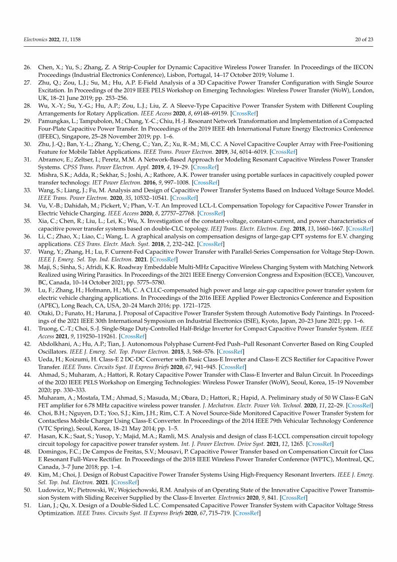
Electronics 2022, 11, 1158 20 of 23
26. Chen, X.; Yu, S.; Zhang, Z. A Strip-Coupler for Dynamic Capacitive Wireless Power Transfer. In Proceedings of the IECONProceedings (Industrial Electronics Conference), Lisbon, Portugal, 14–17 October 2019; Volume 1.
27. Zhu, Q.; Zou, L.J.; Su, M.; Hu, A.P. E-Field Analysis of a 3D Capacitive Power Transfer Configuration with Single SourceExcitation. In Proceedings of the 2019 IEEE PELS Workshop on Emerging Technologies: Wireless Power Transfer (WoW), London,UK, 18–21 June 2019; pp. 253–256.
28. Wu, X.-Y.; Su, Y.-G.; Hu, A.P.; Zou, L.J.; Liu, Z. A Sleeve-Type Capacitive Power Transfer System with Different CouplingArrangements for Rotary Application. IEEE Access 2020, 8, 69148–69159. [CrossRef]
29. Pamungkas, L.; Tampubolon, M.; Chang, Y.-C.; Chiu, H.-J. Resonant Network Transformation and Implementation of a CompactedFour-Plate Capacitive Power Transfer. In Proceedings of the 2019 IEEE 4th International Future Energy Electronics Conference(IFEEC), Singapore, 25–28 November 2019; pp. 1–6.
30. Zhu, J.-Q.; Ban, Y.-L.; Zhang, Y.; Cheng, C.; Yan, Z.; Xu, R.-M.; Mi, C.C. A Novel Capacitive Coupler Array with Free-PositioningFeature for Mobile Tablet Applications. IEEE Trans. Power Electron. 2019, 34, 6014–6019. [CrossRef]
31. Abramov, E.; Zeltser, I.; Peretz, M.M. A Network-Based Approach for Modeling Resonant Capacitive Wireless Power TransferSystems. CPSS Trans. Power Electron. Appl. 2019, 4, 19–29. [CrossRef]
32. Mishra, S.K.; Adda, R.; Sekhar, S.; Joshi, A.; Rathore, A.K. Power transfer using portable surfaces in capacitively coupled powertransfer technology. IET Power Electron. 2016, 9, 997–1008. [CrossRef]
33. Wang, S.; Liang, J.; Fu, M. Analysis and Design of Capacitive Power Transfer Systems Based on Induced Voltage Source Model.IEEE Trans. Power Electron. 2020, 35, 10532–10541. [CrossRef]
34. Vu, V.-B.; Dahidah, M.; Pickert, V.; Phan, V.-T. An Improved LCL-L Compensation Topology for Capacitive Power Transfer inElectric Vehicle Charging. IEEE Access 2020, 8, 27757–27768. [CrossRef]
35. Xia, C.; Chen, R.; Liu, L.; Lei, K.; Wu, X. Investigation of the constant-voltage, constant-current, and power characteristics ofcapacitive power transfer systems based on double-CLC topology. IEEJ Trans. Electr. Electron. Eng. 2018, 13, 1660–1667. [CrossRef]
36. Li, C.; Zhao, X.; Liao, C.; Wang, L. A graphical analysis on compensation designs of large-gap CPT systems for E.V. chargingapplications. CES Trans. Electr. Mach. Syst. 2018, 2, 232–242. [CrossRef]
37. Wang, Y.; Zhang, H.; Lu, F. Current-Fed Capacitive Power Transfer with Parallel-Series Compensation for Voltage Step-Down.IEEE J. Emerg. Sel. Top. Ind. Electron. 2021. [CrossRef]
38. Maji, S.; Sinha, S.; Afridi, K.K. Roadway Embeddable Multi-MHz Capacitive Wireless Charging System with Matching NetworkRealized using Wiring Parasitics. In Proceedings of the 2021 IEEE Energy Conversion Congress and Exposition (ECCE), Vancouver,BC, Canada, 10–14 October 2021; pp. 5775–5780.
39. Lu, F.; Zhang, H.; Hofmann, H.; Mi, C. A CLLC-compensated high power and large air-gap capacitive power transfer system forelectric vehicle charging applications. In Proceedings of the 2016 IEEE Applied Power Electronics Conference and Exposition(APEC), Long Beach, CA, USA, 20–24 March 2016; pp. 1721–1725.
40. Otaki, D.; Funato, H.; Haruna, J. Proposal of Capacitive Power Transfer System through Automotive Body Paintings. In Proceed-ings of the 2021 IEEE 30th International Symposium on Industrial Electronics (ISIE), Kyoto, Japan, 20–23 June 2021; pp. 1–6.
41. Truong, C.-T.; Choi, S.-J. Single-Stage Duty-Controlled Half-Bridge Inverter for Compact Capacitive Power Transfer System. IEEEAccess 2021, 9, 119250–119261. [CrossRef]
42. Abdolkhani, A.; Hu, A.P.; Tian, J. Autonomous Polyphase Current-Fed Push–Pull Resonant Converter Based on Ring CoupledOscillators. IEEE J. Emerg. Sel. Top. Power Electron. 2015, 3, 568–576. [CrossRef]
43. Ueda, H.; Koizumi, H. Class-E 2 DC-DC Converter with Basic Class-E Inverter and Class-E ZCS Rectifier for Capacitive PowerTransfer. IEEE Trans. Circuits Syst. II Express Briefs 2020, 67, 941–945. [CrossRef]
44. Ahmad, S.; Muharam, A.; Hattori, R. Rotary Capacitive Power Transfer with Class-E Inverter and Balun Circuit. In Proceedingsof the 2020 IEEE PELS Workshop on Emerging Technologies: Wireless Power Transfer (WoW), Seoul, Korea, 15–19 November2020; pp. 330–333.
45. Muharam, A.; Mostafa, T.M.; Ahmad, S.; Masuda, M.; Obara, D.; Hattori, R.; Hapid, A. Preliminary study of 50 W Class-E GaNFET amplifier for 6.78 MHz capacitive wireless power transfer. J. Mechatron. Electr. Power Veh. Technol. 2020, 11, 22–29. [CrossRef]
46. Choi, B.H.; Nguyen, D.T.; Yoo, S.J.; Kim, J.H.; Rim, C.T. A Novel Source-Side Monitored Capacitive Power Transfer System forContactless Mobile Charger Using Class-E Converter. In Proceedings of the 2014 IEEE 79th Vehicular Technology Conference(VTC Spring), Seoul, Korea, 18–21 May 2014; pp. 1–5.
47. Hasan, K.K.; Saat, S.; Yusop, Y.; Majid, M.A.; Ramli, M.S. Analysis and design of class E-LCCL compensation circuit topologycircuit topology for capacitive power transfer system. Int. J. Power Electron. Drive Syst. 2021, 12, 1265. [CrossRef]
48. Domingos, F.C.; De Campos de Freitas, S.V.; Mousavi, P. Capacitive Power Transfer based on Compensation Circuit for ClassE Resonant Full-Wave Rectifier. In Proceedings of the 2018 IEEE Wireless Power Transfer Conference (WPTC), Montreal, QC,Canada, 3–7 June 2018; pp. 1–4.
49. Kim, M.; Choi, J. Design of Robust Capacitive Power Transfer Systems Using High-Frequency Resonant Inverters. IEEE J. Emerg.Sel. Top. Ind. Electron. 2021. [CrossRef]
50. Ludowicz, W.; Pietrowski, W.; Wojciechowski, R.M. Analysis of an Operating State of the Innovative Capacitive Power Transmis-sion System with Sliding Receiver Supplied by the Class-E Inverter. Electronics 2020, 9, 841. [CrossRef]
51. Lian, J.; Qu, X. Design of a Double-Sided L.C. Compensated Capacitive Power Transfer System with Capacitor Voltage StressOptimization. IEEE Trans. Circuits Syst. II Express Briefs 2020, 67, 715–719. [CrossRef]

Electronics 2022, 11, 1158 21 of 23
52. Lian, J.; Qu, X. A High-Performance Double-Sided L.C. Compensated CPT System with Load-Independent Constant CurrentOutput. In Proceedings of the 2019 IEEE PELS Workshop on Emerging Technologies: Wireless Power Transfer (WoW), London,UK, 18–21 June 2019; pp. 341–345.
53. Lu, F.; Zhang, H.; Hofmann, H.; Mi, C.C. A Double-Sided LC-Compensation Circuit for Loosely Coupled Capacitive PowerTransfer. IEEE Trans. Power Electron. 2018, 33, 1633–1643. [CrossRef]
54. Xin, D.; Min, S. Generalized Hamiltonian Energy Modeling Method for Wireless Power Transfer System. In Proceedings of the2020 8th International Conference on Power Electronics Systems and Applications (PESA), Hong Kong, China, 7–10 December2020; pp. 1–5.
55. Deng, J.; Lu, F.; Li, S.; Nguyen, T.-D.; Mi, C. Development of a high efficiency primary side controlled 7kW wireless power charger.In Proceedings of the 2014 IEEE International Electric Vehicle Conference (IEVC), Florence, Italy, 17–19 December 2014; pp. 1–6.
56. Yao, Y.; Wang, Y.; Liu, X.; Cheng, H.; Liu, M.; Xu, D. Analysis, Design, and Implementation of a Wireless Power and DataTransmission System Using Capacitive Coupling and Double-Sided LCC Compensation Topology. IEEE Trans. Ind. Appl. 2019, 55,541–551. [CrossRef]
57. Lu, F.; Zhang, H.; Hofmann, H.; Mi, C. A Double-Sided LCLC-Compensated Capacitive Power Transfer System for ElectricVehicle Charging. IEEE Trans. Power Electron. 2015, 30, 6011–6014. [CrossRef]
58. Suarez, C.; Kalmes, M.; Suffeleers, J.; Martinez, W. Frequency Splitting in an LCLC Capacitive Wireless Power Transfer Systemfor Electric Vehicle Charging. In Proceedings of the IECON 2020 the 46th Annual Conference of the IEEE Industrial ElectronicsSociety, Singapore, 18–21 October 2020; pp. 3622–3627.
59. Atiyah, N.Q.; Atilla, D.C.; Aydin, C.; Mukhlif, Y.A. The Analysis of Variation in Plate Geometry for Capacitive Power TransferPads Utilized in Electric Vehicles. In Proceedings of the 2018 18th Mediterranean Microwave Symposium (MMS), Istanbul, Turkey,31 October–2 November 2018; pp. 291–294.
60. Vishnu, P.J.; Tummuru, N.R. A Phase Shift Control Strategy for Bidirectional Power Flow in Capacitive Wireless Power TransferSystem Using LCLC Compensation. In Proceedings of the 2020 IEEE International Conference on Power Electronics, Smart Gridand Renewable Energy (PESGRE2020), Cochin, India, 2–4 January 2020; pp. 1–6.
61. Hu, Z.; Goodall, M.; Zhao, L.; Zhu, Q.; Hu, A.P. A Comparative Study of Different Compensation Topologies for CapacitivePower Transfer. In Proceedings of the 2020 IEEE PELS Workshop on Emerging Technologies: Wireless Power Transfer (WoW),Seoul, Korea, 15–19 November 2020; pp. 389–394.
62. Lian, J.; Qu, X. An LCLC-LC-Compensated Capacitive Power Transferred Battery Charger with Near-Unity Power Factor andConfigurable Charging Profile. IEEE Trans. Ind. Appl. 2022, 58, 1053–1060. [CrossRef]
63. Luo, B.; Xu, L.; Long, T.; Xu, Y.; Mai, R.; He, Z. An LC-CLC Compensated CPT System to Achieve the Maximum Power Transferfor High Power Applications. In Proceedings of the 2020 IEEE Applied Power Electronics Conference and Exposition (APEC),New Orleans, LA, USA, 15–19 March 2020; pp. 3186–3189.
64. Liu, Z.; Su, Y.; Zhao, Y.; Hu, A.P.; Dai, X. Capacitive Power Transfer System with Double T-type Resonant Network for MobileDevices Charging/Supply. IEEE Trans. Power Electron. 2021, 37, 2394–2403. [CrossRef]
65. Encarnacion, E.S.E.; Hernandez-Gonzalez, L.; Garcia, J.C.S.; Ramirez-Hernandez, J.; Juarez-Sandoval, O.U. Modified ResonantZ Circuit Analysis by Capacitive Power Transfer. In Proceedings of the 2020 IEEE International Autumn Meeting on Power,Electronics and Computing (ROPEC), Ixtapa, Mexico, 4–6 November 2020; pp. 1–6.
66. Dai, J.; Ludois, D.C. Single Active Switch Power Electronics for Kilowatt Scale Capacitive Power Transfer. IEEE J. Emerg. Sel. Top.Power Electron. 2015, 3, 315–323.
67. Bui, D.; Mostafa, T.M.; Hu, A.P.; Hattori, R. DC-DC Converter Based Impedance Matching for Maximum Power Transfer ofCPT System with High Efficiency. In Proceedings of the 2018 IEEE PELS Workshop on Emerging Technologies: Wireless PowerTransfer (Wow), Montreal, QC, Canada, 3–7 June 2018; pp. 1–5.
68. Liu, C.; Hu, A.P. Power flow control of a capacitively coupled contactless power transfer system. In Proceedings of the 2009 35thAnnual Conference of IEEE Industrial Electronics, Porto, Portugal, 3–5 November 2009; pp. 743–747.
69. Lu, K.; Nguang, S.K. LQG control of capacitive power transfer system. In Proceedings of the 2017 IEEE PELS Workshop onEmerging Technologies: Wireless Power Transfer (WoW), Chongqing, China, 20–22 May 2017; pp. 128–132.
70. Abramov, E.; Peretz, M.M. Multi-Loop Control for Power Transfer Regulation in Capacitive Wireless Systems by Means ofVariable Matching Networks. IEEE J. Emerg. Sel. Top. Power Electron. 2020, 8, 2095–2110. [CrossRef]
71. Jeong, C.-H.; Choi, H.-S.; Choi, S.-J. Single-Stage PWM Converter for Dual-Mode Control of Capacitive Wireless Power Transmis-sion. In Proceedings of the 2018 IEEE PELS Workshop on Emerging Technologies: Wireless Power Transfer (Wow), Montreal, QC,Canada, 3–7 June 2018; pp. 1–5.
72. Erfani, R.; Marefat, F.; Mohseni, P. A Dual-Output Single-Stage Regulating Rectifier with PWM and Dual-Mode PFM Control forWireless Powering of Biomedical Implants. IEEE Trans. Biomed. Circuits Syst. 2020, 14, 1195–1206. [CrossRef]
73. Zhang, H.; Lu, F.; Hofmann, H.; Liu, W.; Mi, C.C. An LC-Compensated Electric Field Repeater for Long-Distance CapacitivePower Transfer. IEEE Trans. Ind. Appl. 2017, 53, 4914–4922. [CrossRef]
74. Ahmadi, M.; Markley, L.; Johnson, T. A Filter Theory Approach to the Synthesis of Capacitive Power Transfer Systems. IEEE J.Emerg. Sel. Top. Power Electron. 2022, 10, 91–103. [CrossRef]
75. Azer, P.; Emadi, A. Generalized State Space Average Model for Multi-Phase Interleaved Buck, Boost and Buck-Boost DC-DCConverters: Transient, Steady-State and Switching Dynamics. IEEE Access 2020, 8, 77735–77745. [CrossRef]

Electronics 2022, 11, 1158 22 of 23
76. Leng, X.; Yam, S.S.-H. Analytical Model for Abrupt Tapered Mach–Zehnder Interferometer Based on Coupled Mode Theory.IEEE Photonics Technol. Lett. 2019, 31, 1600–1603. [CrossRef]
77. Liao, Z.-J.; Sun, Y.; Ye, Z.-H.; Tang, C.-S.; Wang, P.-Y. Resonant Analysis of Magnetic Coupling Wireless Power Transfer Systems.IEEE Trans. Power Electron. 2019, 34, 5513–5523. [CrossRef]
78. Varghese, V.; Bhoyar, S.; Khalsa, L. Thermoelastic response of a nonhomogeneous elliptic plate in the framework of fractionalorder theory. Arch. Appl. Mech. 2021, 91, 3223–3246. [CrossRef]
79. Xia, J.; Yuan, X.; Lu, S.; Li, J.; Luo, S.; Li, S. A Two-Stage Parameter Optimization Method for Capacitive Power Transfer Systems.IEEE Trans. Power Electron. 2022, 37, 1102–1117. [CrossRef]
80. Wu, Y.; Chen, Q.; Ren, X.; Zhang, Z. Efficiency Optimization Based Parameter Design Method for the Capacitive Power TransferSystem. IEEE Trans. Power Electron. 2021, 36, 8774–8785. [CrossRef]
81. Awadh, Y.; Saat, S. State Feedback Controller Design for Capacitive Power Transfer System. In Proceedings of the 2021International Congress of Advanced Technology and Engineering (ICOTEN), Taiz, Yemen, 4–5 July 2021; pp. 1–6.
82. Gao, X.; Zhou, H.; Hu, W.; Deng, Q.; Liu, G.; Lai, J. Capacitive power transfer through virtual self-capacitance route. IET PowerElectron. 2018, 11, 1110–1118. [CrossRef]
83. Zou, L.J.; Hu, A.P.; Su, Y. A single-wire capacitive power transfer system with large coupling alignment tolerance. In Proceedingsof the 2017 IEEE PELS Workshop on Emerging Technologies: Wireless Power Transfer (WoW), Chongqing, China, 20–22 May2017; pp. 93–98.
84. Lu, F.; Zhang, H.; Mi, C. A Two-Plate Capacitive Wireless Power Transfer System for Electric Vehicle Charging Applications. IEEETrans. Power Electron. 2018, 33, 964–969. [CrossRef]
85. Shu, X.; Zhang, B. Single-Wire Electric-Field Coupling Power Transmission Using Nonlinear Parity-Time-Symmetric Model withCoupled-Mode Theory. Energies 2018, 11, 532. [CrossRef]
86. Liu, G.; Zhang, B. Analytical Model of a 25–50 m Robust Single-Wire Electric-Field Coupling Power Transfer System Using aLimiter. IEEE Trans. Circuits Syst. II Express Briefs 2019, 66, 978–982. [CrossRef]
87. Chen, X.; Yu, S.; Zhang, Z. A Receiver-Controlled Coupler for Multiple Output Wireless Power Transfer Applications. IEEE Trans.Circuits Syst. I Regul. Pap. 2019, 66, 4542–4552. [CrossRef]
88. Lu, F.; Zhang, H.; Hofmann, H.; Mi, C.C. An Inductive and Capacitive Combined Wireless Power Transfer System withLC-Compensated Topology. IEEE Trans. Power Electron. 2016, 31, 8471–8482. [CrossRef]
89. Lu, F.; Zhang, H.; Hofmann, H.; Mi, C.C. An Inductive and Capacitive Integrated Coupler and Its LCL Compensation CircuitDesign for Wireless Power Transfer. IEEE Trans. Ind. Appl. 2017, 53, 4903–4913. [CrossRef]
90. Luo, B.; Long, T.; Mai, R.; Dai, R.; He, Z.; Li, W. Analysis and design of hybrid inductive and capacitive wireless power transferfor high-power applications. IET Power Electron. 2018, 11, 2263–2270. [CrossRef]
91. Zhou, W.; Gao, Q.; Xiang, L. Inductive–capacitive combined power transfer system and its power superposition characteristic forrail transit inspection vehicle charging. Measurement 2021, 185, 110022. [CrossRef]
92. Li, X.; Tang, C.; Dai, X.; Deng, P.; Su, Y. An Inductive and Capacitive Combined Parallel Transmission of Power and Data forWireless Power Transfer Systems. IEEE Trans. Power Electron. 2018, 33, 4980–4991. [CrossRef]
93. Luo, B.; Zhou, X.; Long, T.; Mai, R.; He, Z. Misalignment tolerance wireless power transfer system combining inductive andcapacitive coupling. IET Electr. Power Appl. 2020, 14, 1925–1932. [CrossRef]
94. Luo, B.; Long, T.; Guo, L.; Dai, R.; Mai, R.; He, Z. Analysis and Design of Inductive and Capacitive Hybrid Wireless PowerTransfer System for Railway Application. IEEE Trans. Ind. Appl. 2020, 56, 3034–3042. [CrossRef]
95. Gao, X.; Liu, C.; Zhou, H.; Hu, W.; Huang, Y.; Xiao, Y.; Lei, Z.; Chen, J. Design and Analysis of a New Hybrid Wireless PowerTransfer System with a Space-Saving Coupler Structure. IEEE Trans. Power Electron. 2021, 36, 5069–5081. [CrossRef]
96. Luo, B.; Mai, R.; Guo, L.; Wu, D.; He, Z. LC–CLC compensation topology for capacitive power transfer system to improvemisalignment performance. IET Power Electron. 2019, 12, 2626–2633. [CrossRef]
97. Jing, G.; Li, Y.; Zhang, Z.; Qian, C.; Gong, Q.; Jing, Y. Capacitive Coupling Wireless Energy Transmission Constant VoltageSystem Based On Composite Network Resonance. In Proceedings of the 2021 IEEE 16th Conference on Industrial Electronics andApplications (ICIEA), Chengdu, China, 1–4 August 2021; pp. 797–802.
98. Li, L.; Wang, Z.; Gao, F.; Wang, S.; Deng, J. A family of compensation topologies for capacitive power transfer converters forwireless electric vehicle charger. Appl. Energy 2020, 260, 114156. [CrossRef]
99. Su, Y.-G.; Xie, S.-Y.; Hu, A.P.; Tang, C.-S.; Zhou, W.; Huang, L. Capacitive Power Transfer System with a Mixed-Resonant Topologyfor Constant-Current Multiple-Pickup Applications. IEEE Trans. Power Electron. 2017, 32, 8778–8786. [CrossRef]
100. Liu, W.; Luo, B.; Xu, Y.; Pan, S.; Zhou, W.; Jiang, C.; Mai, R. A Multi-Load Capacitive Power Transfer System with Load-Independent Characteristic for Reefer Container Application. IEEE Trans. Power Electron. 2022, 37, 6194–6205. [CrossRef]
101. Chen, T.; Cheng, C.; Cheng, H.; Wang, C.; Mi, C. A Multi-Load Capacitive Power Relay System with Load-Independent ConstantCurrent Outputs. IEEE Trans. Power Electron. 2022, 37, 6144–6155. [CrossRef]
102. Mai, R.; Luo, B.; Chen, Y.; He, Z. Double-sided CL compensation topology based component voltage stress optimization methodfor capacitive power transfer charging system. IET Power Electron. 2018, 11, 1153–1160. [CrossRef]
103. Liang, J.; Wu, D.; Yu, J. A Design Method of Compensation Circuit for High-Power Dynamic Capacitive Power Transfer SystemConsidering Coupler Voltage Distribution for Railway Applications. Electronics 2021, 10, 153. [CrossRef]

Electronics 2022, 11, 1158 23 of 23
104. Su, Y.-G.; Ma, J.-H.; Xie, S.-Y.; Zhao, Y.-M.; Dai, X. Analysis on safety issues of capacitive power transfer system. Int. J. Appl.Electromagn. Mech. 2017, 53, 673–684. [CrossRef]
105. Al-Kalbani, A.I.; Yuce, M.R.; Redoute, J.-M. A Biosafety Comparison between Capacitive and Inductive Coupling in BiomedicalImplants. IEEE Antennas Wirel. Propag. Lett. 2014, 13, 1168–1171. [CrossRef]
106. Jegadeesan, R.; Agarwal, K.; Guo, Y.-X.; Yen, S.-C.; Thakor, N.V. Wireless Power Delivery to Flexible Subcutaneous ImplantsUsing Capacitive Coupling. IEEE Trans. Microw. Theory Tech. 2017, 65, 280–292. [CrossRef]
107. Erfani, R.; Marefat, F.; Sodagar, A.M.; Mohseni, P. Modeling and Experimental Validation of a Capacitive Link for Wireless PowerTransfer to Biomedical Implants. IEEE Trans. Circuits Syst. II Express Briefs 2018, 65, 923–927. [CrossRef]
108. Erfani, R.; Marefat, F.; Sodagar, A.M.; Mohseni, P. Modeling and Characterization of Capacitive Elements with Tissue as DielectricMaterial for Wireless Powering of Neural Implants. IEEE Trans. Neural Syst. Rehabil. Eng. 2018, 26, 1093–1099. [CrossRef]
109. Erfani, R.; Marefat, F.; Nag, S.; Mohseni, P. A 1–10-MHz Frequency-Aware CMOS Active Rectifier with Dual-Loop AdaptiveDelay Compensation and >230-mW Output Power for Capacitively Powered Biomedical Implants. IEEE J. Solid-State Circuits2020, 55, 756–766. [CrossRef]
110. Sedehi, R.; Budgett, D.; Jiang, J.; Ziyi, X.; Dai, X.; Hu, A.P.; McCormick, D. A Wireless Power Method for Deeply ImplantedBiomedical Devices via Capacitively Coupled Conductive Power Transfer. IEEE Trans. Power Electron. 2021, 36, 1870–1882.[CrossRef]
111. Ohira, T. Via-wheel power transfer to vehicles in motion. In Proceedings of the 2013 IEEE Wireless Power Transfer (WPT), Perugia,Italy, 15–16 May 2013; pp. 242–246.
112. Guo, L.; Luo, B.; Mai, R. Voltage Optimization Method for Wireless Charging of Electric Vehicles Based on Capacitive PowerTransfer. Diangong Jishu Xuebao/Trans. China Electrotech. Soc. 2020, 35, 19–27.
113. Dai, J.; Ludois, D.C. Capacitive Power Transfer through a Conformal Bumper for Electric Vehicle Charging. IEEE J. Emerg. Sel.Top. Power Electron. 2016, 4, 1015–1025. [CrossRef]
114. Li, S.; Liu, Z.; Zhao, H.; Zhu, L.; Shuai, C.; Chen, Z. Wireless Power Transfer by Electric Field Resonance and Its Application inDynamic Charging. IEEE Trans. Ind. Electron. 2016, 63, 6602–6612. [CrossRef]
115. Lu, F.; Zhang, H.; Hofmann, H.; Mei, Y.; Mi, C. A dynamic capacitive power transfer system with reduced power pulsation. InProceedings of the 2016 IEEE PELS Workshop on Emerging Technologies: Wireless Power Transfer (WoW), Knoxville, TN, USA,4–6 October 2016; pp. 60–64.
116. Moghe, R.; Yang, Y.; Lambert, F.; Divan, D. A scoping study of electric and magnetic field energy harvesting for wireless sensornetworks in power system applications. In Proceedings of the 2009 IEEE Energy Conversion Congress and Exposition, San Jose,CA, USA, 20–24 September 2009; pp. 3550–3557.
117. Keutel, T.; Zhao, X.; Kanoun, O. C6.2—Energy Scavenging for Monitoring of Overhead Power Line Networks. In ProceedingsSENSOR 2009 Volume II; AMA Service GmbH: Wunstorf, Germany, 2009; pp. 207–212.
118. Rodriguez, J.C.; Holmes, D.G.; McGrath, B.P.; Wilkinson, R.H. Maximum energy harvesting from medium voltage electric-fieldenergy using power line insulators. In Proceedings of the 2014 Australasian Universities Power Engineering Conference (AUPEC),Perth, WA, Australia, 28 September–1 October 2014; pp. 1–6.
119. Moghe, R.; Iyer, A.; Lambert, F.C.; Divan, D. A Low-Cost Electric Field Energy Harvester for an MV/HV Asset-Monitoring SmartSensor. IEEE Trans. Ind. Appl. 2015, 51, 1828–1836. [CrossRef]
120. Chang, K.-S.; Kang, S.-M.; Park, K.-J.; Shin, S.-H.; Kim, H.-S.; Kim, H.-S. Electric Field Energy Harvesting Powered WirelessSensors for Smart Grid. J. Electr. Eng. Technol. 2012, 7, 75–80. [CrossRef]
121. Li, Z.; Mei, H.; Wang, L. A Power Supply Technology for a Low-Power Online Monitoring Sensor Based on Electric FieldInduction. Sensors 2019, 19, 2169. [CrossRef]
122. Zhang, H.; Lu, F. Insulated Coupler Structure Design for the Long-Distance Freshwater Capacitive Power Transfer. IEEE Trans.Ind. Inform. 2020, 16, 5191–5201. [CrossRef]
123. Tamura, M.; Naka, Y.; Murai, K.; Nakata, T. Design of a Capacitive Wireless Power Transfer System for Operation in Fresh Water.IEEE Trans. Microw. Theory Tech. 2018, 66, 5873–5884. [CrossRef]
124. Naka, Y.; Yamamoto, K.; Nakata, T.; Tamura, M.; Masuda, M. Verification efficiency of electric coupling wireless power transfer inwater. In Proceedings of the 2017 IEEE MTT-S International Conference on Microwaves for Intelligent Mobility (ICMIM), Nagoya,Japan, 19–21 March 2017; pp. 83–86.
125. Tamura, M.; Naka, Y.; Murai, K. Design of Capacitive Coupler for Wireless Power Transfer under Fresh Water Focusing on kQProduct. In Proceedings of the 2018 IEEE/MTT-S International Microwave Symposium—IMS, Philadelphia, PA, USA, 10–15 June2018; pp. 1257–1260.
126. Ludois, D.C.; Erickson, M.J.; Reed, J.K. Aerodynamic Fluid Bearings for Translational and Rotating Capacitors in NoncontactCapacitive Power Transfer Systems. IEEE Trans. Ind. Appl. 2014, 50, 1025–1033. [CrossRef]
127. Liang, H.W.R.; Lee, C.-K.; Hui, S.Y.R. Design, Analysis, and Experimental Verification of a Ball-Joint Structure with ConstantCoupling for Capacitive Wireless Power Transfer. IEEE J. Emerg. Sel. Top. Power Electron. 2020, 8, 3582–3591. [CrossRef]
128. Rouse, C.D.; Cove, S.R.; Salami, Y.; Arsenault, P.; Bartlett, A. Three-Phase Resonant Capacitive Power Transfer for RotaryApplications. IEEE J. Emerg. Sel. Top. Power Electron. 2022, 10, 160–169. [CrossRef]
Copyright © 2022 FDOKUMEN