Optical properties of photonic crystal fibers with the strain
20
Progress In Electromagnetics Research, Vol. 105, 193–212, 2010 OPTICAL PROPERTIES OF PHOTONIC CRYSTAL FIBERS WITH A FIBER CORE OF ARRAYS OF SUB- WAVELENGTH CIRCULAR AIR HOLES: BIREFRIN- GENCE AND DISPERSION D. Chen † Institute of Information Optics Zhejiang Normal University Jinhua 321004, China M.-L. V. Tse and H. Y. Tam Photonics Research Centre Department of Electrical Engineering The Hong Kong Polytechnic University Hung Hom, Kowloon, Hong Kong SAR, China Abstract—We propose a kind of novel photonic crystal fibers (PCFs) based on a fiber core with arrays of subwavelength circular air holes, achieving the flexible control of the birefringence or the dispersion property of the PCFs. A highly birefringent (HB) PCF is achieved by employing arrays of subwavelength circular air hole pairs in the fiber core, which are arranged as a conventional hexagonal lattice structure with a subwavelength lattice constant. The HB-PCF is with uniform and ultrahigh birefringence (up to the order of 0.01) in a wavelength region from 1.25 μm to 1.75 μm or even a larger region, which, to the best of our knowledge, is the best birefringence property of the PCFs. A dispersion-flattened (DF) PCF with near-zero dispersion is achieved by employing arrays of subwavelength circular air holes in the fiber core arranged as a conventional hexagonal lattice structure with a subwavelength lattice constant, which contributes negative waveguide dispersion to the PCF. The proposed design of the DF-PCF provides an alternate approach for the dispersion control of the PCF. Besides the high birefringence and the flattened near-zero dispersion, the proposed PCFs with a fiber core of arrays of subwavelength circular air holes have the potential to achieve a large mode area single mode PCF. Corresponding author: D. Chen ([email protected]). † Also with Photonics Research Centre, Department of Electrical Engineering, The Hong Kong Polytechnic University, Hung Hom, Kowloon, Hong Kong SAR, China.
-
Upload
universidaddelvallecolombia -
Category
Documents
-
view
0 -
download
0
Transcript of Optical properties of photonic crystal fibers with the strain

Progress In Electromagnetics Research, Vol. 105, 193–212, 2010
OPTICAL PROPERTIES OF PHOTONIC CRYSTALFIBERS WITH A FIBER CORE OF ARRAYS OF SUB-WAVELENGTH CIRCULAR AIR HOLES: BIREFRIN-GENCE AND DISPERSION
D. Chen †
Institute of Information OpticsZhejiang Normal UniversityJinhua 321004, China
M.-L. V. Tse and H. Y. Tam
Photonics Research CentreDepartment of Electrical EngineeringThe Hong Kong Polytechnic UniversityHung Hom, Kowloon, Hong Kong SAR, China
Abstract—We propose a kind of novel photonic crystal fibers (PCFs)based on a fiber core with arrays of subwavelength circular air holes,achieving the flexible control of the birefringence or the dispersionproperty of the PCFs. A highly birefringent (HB) PCF is achieved byemploying arrays of subwavelength circular air hole pairs in the fibercore, which are arranged as a conventional hexagonal lattice structurewith a subwavelength lattice constant. The HB-PCF is with uniformand ultrahigh birefringence (up to the order of 0.01) in a wavelengthregion from 1.25µm to 1.75µm or even a larger region, which, to thebest of our knowledge, is the best birefringence property of the PCFs.A dispersion-flattened (DF) PCF with near-zero dispersion is achievedby employing arrays of subwavelength circular air holes in the fibercore arranged as a conventional hexagonal lattice structure with asubwavelength lattice constant, which contributes negative waveguidedispersion to the PCF. The proposed design of the DF-PCF provides analternate approach for the dispersion control of the PCF. Besides thehigh birefringence and the flattened near-zero dispersion, the proposedPCFs with a fiber core of arrays of subwavelength circular air holeshave the potential to achieve a large mode area single mode PCF.
Corresponding author: D. Chen ([email protected]).† Also with Photonics Research Centre, Department of Electrical Engineering, The HongKong Polytechnic University, Hung Hom, Kowloon, Hong Kong SAR, China.

194 Chen, Tse, and Tam
1. INTRODUCTION
Thanks to the flexibility for the cross section design, photoniccrystal fibers (PCFs) [1–9] have achieved excellent properties inbirefringence [10–19], dispersion [20–29], single polarization singlemode [30–32], nonlinearity [33], and effective mode area [34–36], andalso excellent performances in the applications of fiber sensors [37, 38],fiber lasers [39–41] and nonlinear optics [42–45] over the past severalyears. Large numbers of research papers have highlighted some opticalproperties of the PCFs such as ultrahigh birefringence and uniquechromatic dispersion, which are almost impossible for the conventionaloptical fibers. Optical fibers with high birefringence can find importantapplications in optical fiber communications, fiber filters, fiber sensors,fiber lasers and so on. So far, several highly birefringent (HB) PCFshave been demonstrated to achieve high birefringence up to the orderof 0.001, which is one order of magnitude higher than that of theconventional polarization-maintaining fibers (PMFs). Most HB-PCFsare achieved based on the large index contrast of the silica and theair by introducing an asymmetric solid fiber core surrounded by airholes (e.g., using a fiber core with double defect or triple defectof the photonic crystal structure [12–15]). Several research papershave also shown that the ultrahigh birefringence (up to the orderof 0.01) can be achieved by employing elliptical air holes in thefiber cladding [15–18]. For these so-called elliptical-hole PCFs, highbirefringence is achieved when a large part of the mode power is inthe fiber cladding. Thus, the high birefringence is often accompaniedwith poor light confinement (i.e., resulting in a large confinementloss). To overcome the problem of the poor light confinement of theelliptical-hole PCFs, we have proposed a PCF with both ultrahighbirefringence and ultralow confinement loss based on a fiber corewith a structure of sub-wavelength elliptical air hole array [19].However, it is almost impossible to accurately fabricate PCFs withdifferent kinds of noncircular air holes (elliptical air holes) using thecurrent fabrication techniques available. Moreover, compared withconventional optical fibers, PCFs have also shown their advantagesin the control of chromatic dispersion which is very important forpractical applications to optical communication systems, dispersioncompensation, and nonlinear optics. Up to now, control techniquesof the chromatic dispersion of PCFs are very attractive, and variousPCFs with specific dispersion properties such as dispersion-flattened(DF) PCFs [22–25] and large negative dispersion PCFs [26–29] havebeen reported.
A PCF with a single subwavelength circular air hole in the fibercore has been reported [46], which indicates the large potential to

Progress In Electromagnetics Research, Vol. 105, 2010 195
achieve PCFs with a relatively complex structure not only in thefiber cladding but also in the fiber core in the near future. In thispaper, we proposed a kind of novel PCF based on the design of a fibercore with arrays of subwavelength circular air holes, at the same time,introducing approaches to achieve the ultrahigh birefringence and tocontrol the dispersion property of PCFs. We investigate in detail twoexamples of the proposed PCFs, one HB-PCF design with arrays ofsubwavelength circular air hole pairs in the fiber core and one DF-PCF with arrays of subwavelength circular air holes in the fiber core.The proposed HB-PCF is with uniform and ultrahigh birefringence(up to the order of 0.01) which, to the best of our knowledge, is thebest birefringence property of the any PCF designs, and is also withlow confinement loss in a large wavelength region from 1.25µm to1.75µm or even a larger region. By introducing the design of theDF-PCF with a zero dispersion wavelength around 1.55µm, we alsoprovide a dispersion control technique based on the negative waveguidedispersion property of the fundamental space-filling mode (FSM) of thefiber core with arrays of subwavelength circular air holes.
2. HIGHLY BIREFRINGENT PHOTONIC CRYSTALFIBER
For a birefringent optical fiber, the modal birefringence is definedas [32]
∆n = neff -y − neff -x, (1)
where neff -y and neff -x are effective indexes of the Y -polarizedfundamental mode and X-polarized fundamental mode of the opticalfiber, respectively. The confinement loss of the fundamental modes canbe deduced from the value (imaginary part) of the complex effectiveindex (neff -c) of the fundamental mode of the optical fiber, which isgiven by [11]
α = 8.686× Im(
2π
λneff -c
), (2)
where λ is the operation wavelength. We employ a full-vectorfinite-element method (FEM) to calculate the effective index of thefundamental mode of the PCF in this paper.
Since the bulk fused silica is an isotropic medium, most HB-PCFsare achieved based on the asymmetric geometrical structure designsof the fiber core or the fiber cladding for the cross section of thePCFs. This leads to a difference in the effective indexes of the X-/Y -polarized guiding modes of PCFs. Quite different from the designprinciple of these HB-PCFs, here we design an equivalently anisotropic

196 Chen, Tse, and Tam
medium [19] by employing subwavelength circular air hole pairs inthe fused silica with a conventional hexagonal lattice structure, whichintrinsically results in different effective indexes for the guiding lightwith different polarization. Since most mode power of the fundamentalmode of the PCF locates in the fiber core, introducing the equivalentlyanisotropic medium in the fiber core can provide sufficient and flexiblecontrol of the birefringence of the PCF. In what follows we show anHB-PCF based on the new design concept.
Figure 1 shows the cross section of the proposed HB-PCF with afiber core of subwavelength circular air hole pair array. Five rings ofrelatively large circular air holes with the radius (R) are employed inthe fiber cladding forming a conventional hexagonal lattice structurewith a lattice constant (Λ) (i.e., center-to-center distance between thetwo adjacent circular air holes). In the fiber core of the proposed HB-PCF, three rings of relatively small circular air hole pairs (includingthe central one) are also arranged in a hexagonal lattice but with amuch shorter lattice constant (Λ′). Each circular air hole pair consistsof two circular air holes with a distance (d) which are arranged in aline in Y -direction. The circular air holes in the fiber core are with thesubwavelength size and the radius (r) is less than 100 nm for the HB-PCF considered in this paper. Note that the fiber core with arrays ofthe subwavelength circular air hole pairs in the fused silica acts as theequivalently anisotropic medium. We studied the HB-PCF by settingΛ = 2 µm, Λ′ = 0.5µm and d = 0.2µm, and varied R and r. Therefractive index of the air is assumed to be 1.0 and the refractive indexof the fused silica is given by the following Sellmeier-type dispersionformula [47]
n2−1 =0.6961663λ2
λ2 − (0.0684043)2+
0.4079426λ2
λ2 − (0.1162414)20.8974794λ2
λ2 − (9.896161)2(3)
where the unit of λ is µm.For the proposed HB-PCF with the parameters of Λ = 2µm, R =
0.8µm, Λ′ = 0.5µm, r = 0.08µm and d = 0.2µm, we calculated the
Figure 1. Cross section of the proposed HB-PCF with a fiber core ofarrays of subwavelength circular air hole pairs.

Progress In Electromagnetics Research, Vol. 105, 2010 197
effective index (neff , real part of neff -c) of the X-polarized fundamentalmode and the Y -polarized fundamental mode of the HB-PCF inthe wavelength region from 1.25µm to 1.75µm, which are shown inFigure 2 as black curve with rectangles and red curve with triangles,respectively. The effective index of the Y -polarized fundamental modeis much larger than that of the X-polarized fundamental mode for anywavelength from 1.25µm to 1.75µm. The large gap of the two effectiveindex curves which are almost parallel with each other, indicates thatthe proposed HB-PCF exhibits uniform and ultrahigh birefringence asdiscussed hereinafter. Note that the effective index of the proposed HB-PCF became lower compared with the convetional PCF with a solidfiber core, because of the existence of the small air holes in the fibercore. Note for example, the effective index of the X- (Y -) polarizedfundamental mode of the proposed HB-PCF is 1.3096 (1.3170) and theeffective index of the PCF with a solid fiber core (but with the sameparameters of Λ = 2µm, R = 0.8µm as the HB-PCF) is 1.3935 atthe wavelength of λ = 1.5µm. The left bottom inset and the right topinset of Figure 2 show the electric field distributions of the X-polarizedfundamental mode and the Y -polarized fundamental mode of theproposed HB-PCF at the wavelength of λ = 1.5µm, respectively. Themode area of the X-polarized fundamental mode and the Y -polarized
Figure 2. Effective index of the X-polarized and Y -polarizedfundamental mode of the proposed HB-PCF with the parametersof Λ = 2µm, R = 0.8µm, Λ′ = 0.5 µm, r = 0.08µm and d =0.2µm. Insets shows the electric field distributions of the X-polarizedfundamental mode (left bottom) and the Y -polarized fundamentalmode (right top) at the wavelength of λ = 1.5µm.

198 Chen, Tse, and Tam
fundamental mode of the proposed HB-PCF is Aeff -x = 4.4008µm2
and Aeff -y = 4.4986µm2, respectively, corresponding to the mode areaof Aeff = 3.7968µm2 for the fundamental mode of the PCF with asolid fiber core at the wavelength of λ = 1.5µm. These results showthat although the subwavelength air holes in the fiber core results inrelatively low effective index, the HB-PCF has its fundamental modeprofile just like the PCF with a solid fiber core. Figure 3 shows theeffective mode area and the dispersion of the X-polarized and theY -polarized fundamental modes of the proposed HB-PCF with theparameters of Λ = 2µm, R = 0.8µm, Λ′ = 0.5µm, r = 0.08µm andd = 0.2µm. The dispersion discussed here is the chromatic dispersion(including the waveguide dispersion and the material dispersion),which can be calculated by the following formula [11]
D = −λ
c
∂2neff
∂λ2(4)
where c is the velocity of light in free space.Next we investigated the birefringence property of the proposed
HB-PCF. Figure 4 shows the birefringence of the proposed HB-PCFsin cases of (R = 0.8 µm, r = 0.08 µm, d = 0.2µm: black solidcurve), (R = 0.8 µm, r = 0.09µm, d = 0.2µm: red dotted curve),(R = 0.75µm, r = 0.08µm, d = 0.2µm: green dotted curve), and
Figure 3. Effective mode area and dispersion of the X-polarized andthe Y -polarized fundamental modes of the proposed HB-PCF with theparameters of Λ = 2µm, R = 0.8µm, Λ′ = 0.5µm, r = 0.08µm andd = 0.2µm.

Progress In Electromagnetics Research, Vol. 105, 2010 199
(a)
(c)
(b)
Figure 4. Birefringence of the proposed HB-PCFs in cases of (R =0.8µm, r = 0.08µm, d = 0.2µm: black solid curve), (R = 0.8µm, r =0.09µm, d = 0.2µm: red dotted curve), (R = 0.75 µm, r = 0.08 µm,d = 0.2µm: green dotted curve), and (R = 0.8µm, r = 0.08 µm,d = 0.18µm: blue dotted curve). Note that other parameters of theHB-PCFs remain the same (Λ = 2µm and Λ′ = 0.5µm).
(R = 0.8µm, r = 0.08µm, d = 0.18µm: blue dotted curve). FromFigure 4, the birefringence property of the proposed HB-PCF can besummarized as follows: 1) The birefringence of the proposed HB-PCFcan reach a high level up to the order of 0.01. The perturbation of thebirefringence in the calculated wavelength region is very small (within3%), which shows the proposed HB-PCF exhibits uniform birefringencein the large wavelength region. 3) The birefringence increases as thesize of the circular air hole in the fiber core increases, due to theenhancement of anisotropy of equivalently anisotropic medium in thefiber core. 4) The birefringence increases as the size of the circular airhole in the fiber cladding increases, due to the enhancement of lightconfinement (i.e., more mode power locates in the fiber core). 5) Thebirefringence depends on the distance (d) of the two subwavelengthcircular air holes of one pair. Figure 4(c) shows the birefringenceincreases as the distance (d) decreases. Our calculated results show
200 Chen, Tse, and Tam
that the uniform and high birefringence property can be achieved basedon our design and the proposed HB-PCF exhibits a flexible control ofthe birefringence by designing the structures of both the fiber claddingand the fiber core with suitable parameters.
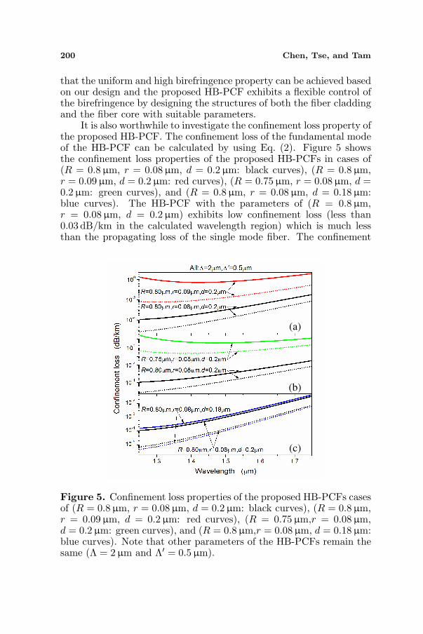
It is also worthwhile to investigate the confinement loss property ofthe proposed HB-PCF. The confinement loss of the fundamental modeof the HB-PCF can be calculated by using Eq. (2). Figure 5 showsthe confinement loss properties of the proposed HB-PCFs in cases of(R = 0.8µm, r = 0.08 µm, d = 0.2µm: black curves), (R = 0.8µm,r = 0.09 µm, d = 0.2µm: red curves), (R = 0.75 µm, r = 0.08µm, d =0.2µm: green curves), and (R = 0.8µm, r = 0.08 µm, d = 0.18 µm:blue curves). The HB-PCF with the parameters of (R = 0.8µm,r = 0.08 µm, d = 0.2µm) exhibits low confinement loss (less than0.03 dB/km in the calculated wavelength region) which is much lessthan the propagating loss of the single mode fiber. The confinement
(a)
(c)
(b)
Figure 5. Confinement loss properties of the proposed HB-PCFs casesof (R = 0.8µm, r = 0.08µm, d = 0.2µm: black curves), (R = 0.8µm,r = 0.09µm, d = 0.2µm: red curves), (R = 0.75µm,r = 0.08 µm,d = 0.2µm: green curves), and (R = 0.8µm,r = 0.08µm, d = 0.18 µm:blue curves). Note that other parameters of the HB-PCFs remain thesame (Λ = 2µm and Λ′ = 0.5µm).

Progress In Electromagnetics Research, Vol. 105, 2010 201
loss of the HB-PCF with parameters of (R = 0.8 µm, r = 0.09 µm,d = 0.2 µm) becomes larger since the larger circular air holes in thefiber core results in the lower effective index of the fiber core and morepoor confinement of the guiding light. Similarly, the HB-PCF withparameters of (R = 0.75 µm, r = 0.08µm, d = 0.2 µm) also has thelarger confinement loss due to the higher effective index of the fibercladding because of the smaller circular air holes in the fiber cladding.The HB-PCF with the parameters of (R = 0.8µm, r = 0.08 µm,d = 0.18 µm) has the similar low confinement loss as the HB-PCFwith the parameters of (R = 0.8µm, r = 0.08µm, d = 0.2µm) buthas higher difference of the confinement loss for the X-polarized andthe Y -polarized fundamental modes. Thus, one can conclude that theparameters of the circular air holes in the fiber cladding or the fiber coreplays a critical role to control the effective index of the fiber claddingor the fiber core and consequently determine the confinement loss ofthe proposed HB-PCF, which provide flexibility to design or controlthe confinement loss of the proposed HB-PCF. We can also add morerings of circular air holes in the fiber cladding to further reduce theconfinement loss, which will not affect the birefringence of the PCFs.
3. DISPERSION-FLATTENED PHOTONIC CRYSTALFIBER
In the above section, we have shown that high birefringence can beachieved by employing the equivalently anisotropic medium formedby arrays of subwavelength circular air hole pairs in the fiber core.Naturally other property such as the dispersion of the PCF will alsodepend on the structure of the fiber core, since most mode power ofthe fundamental mode of the PCF locates in the fiber core. In thissection, we will show the dispersion control technique of the PCF byintroducing arrays of subwavelength circular air holes in the fiber core,where a DF-PCF is taken as an example.
Figure 6. Cross section of the proposed DF-PCF with a fiber core ofarrays of subwavelength air holes.
202 Chen, Tse, and Tam
Figure 6 shows the cross section of the proposed DF-PCF witha fiber core of arrays of subwavelength circular air holes. The crosssection of the DF-PCF is almost the same as that of the above-mentioned HB-PCF except that the fiber core of the DF-PCF isformed by arrays of the subwavelength circular air holes instead ofthe subwavelength circular air hole pairs. Note that the fiber coreof the DF-PCF with arrays of subwavelength circular air holes inthe fused silica acts as the equivalently isotropic medium here, whichindicates the birefringence of the DF-PCF is almost zero and will notbe discussed in this section. For the ease of calculation, we have setΛ = 2 µm, R = 0.8µm and Λ′ = 0.5µm. Different values of theradius (r) of the circular air holes in the fiber core are consideredin this section to show the dispersion contribution of the fiber corestructure. The refractive index of the air also is assumed to be 1.0 andthe refractive index of the fused silica is given by the Eq. (3), whichmeans material dispersion is also included in our calculations.
First, we investigated the waveguide dispersion of the hexagonallattice structure with arrays of circular air holes in the fused silica. Thishelped us to understand what role the fiber core of the DF-PCF playsfor the dispersion property of the DF-PCF. A plane-wave expansionmethod [48] is used to calculate the effective indexes for the light wavepropagating along the Z-direction in the fiber core area of the DF-PCFwith the hexagonal lattice structure (i.e., the effective indexes of thefundamental space-filling mode (FSM) of the fiber core). The latticeconstant and the radius of the air hole are assumed to be Λ′ = 1 µmand r = 0.25µm, respectively. The refractive index of the fused silicais fixed to be 1.45 here, since we only consider the waveguide dispersionof the structure. Figure 7 shows calculated effective refractive indexas a function of wavelength for the hexagonal lattice structure in awavelength region from 0 to 2.2 µm. The effective index curve can beseparated into two sections in two wavelength regions of [0–0.485µm]and [0.485µm–2.2µm], corresponding to a convex function and aconcave function, respectively. According to Eq. (4) we can calculatethe dispersion as shown in the inset of the Figure 7, where positivedispersion and negative dispersion are found in the wavelength regionsof [0–0.485µm] and [0.485µm–2.2µm], respectively. Thus, we knowthe fiber core of the present DF-PCF with arrays of the subwavelengthcircular air holes will contribute negative dispersion for the PCF whenonly waveguide dispersion of the fiber core is considered.
Figure 8(a) shows the effective index of three types of PCFs,Type-I PCF with a solid fiber without air hole (black solid curve),Type-II PCF with a fiber core with arrays of circular air holes ofΛ′ = 0.5µm and r = 0.1µm (red dashed curve), and Type-III PCF

Progress In Electromagnetics Research, Vol. 105, 2010 203
Figure 7. Calculated effective index (as a function of wavelength) forthe hexagonal lattice structure (i.e., the FSM of the fiber core) of Λ′ =1µm and r = 0.25 µm. Inset shows the calculated dispersion of theFSM of the hexagonal lattice structure. Note that the effective index isa convex function (corresponding to positive dispersion) or a concavefunction (corresponding to negative dispersion) versus wavelength inthe wavelength regions of [0–0.485µm] or [0.485µm–2.2µm].
with a fiber core with arrays of circular air holes of Λ′ = 0.5µm andr = 0.12 µm (green dotted curve). Figure 8(b) shows the dispersionof the fundamental modes of Type-I PCF (black solid curve), Type-II PCF (red dashed curve), Type-III PCF (green dotted curve), andthe FSMs of the hexagonal lattice structures in cases of (Λ′ = 0.5µm,r = 0.1µm) (yellow dotted curve) and (Λ′ = 0.5 µm, r = 0.12 µm)(blue dashed curve). Note that the dispersion of FSMs of the hexagonallattice structures is calculated by employing the plane-wave expansionmethod and the fused silica is assumed to be 1.45. Type-I PCFis actually a conventional PCF with the positive dispersion in thecalculated wavelength region, which includes the waveguide dispersiondue to the cross section structure and the material dispersion of thefused silica. When arrays of the subwavelength circular air holes areintroduced in the fiber core, the dispersion of the PCFs (such asType-II PCF and Type-III PCF) is reduced due to the fact that thehexagonal lattice structure with arrays of the subwavelength circularair holes in the fused silica have the negative waveguide dispersionas discussed above. Since the negative waveguide dispersion of thehexagonal lattice structure in the fiber core can be designed by choosingsuitable parameters of the air hole size and the lattice constant, the

204 Chen, Tse, and Tam
dispersion property of the PCF can be flexibly controlled and theflattened near-zero dispersion can be achieved. Type-III PCF is a DF-PCF with flattened dispersion in the wavelength region from 1.5 µm to
(a)
(b)
Figure 8. (a) Effective index of the fundamental modes of the PCFwith a solid fiber core (black solid curve), the PCF with a fiber corein case of (Λ′ = 0.5µm, r = 0.1 µm) (red dashed curve) and the PCFwith a fiber core in case of (Λ′ = 0.5µm, r = 0.12µm) (green dottedcurve). (b) Dispersion of the fundamental modes of the PCF withsolid fiber core (black solid curve), the PCF with a fiber core in caseof (Λ′ = 0.5µm, r = 0.1µm) (red dashed curve) and the PCF with afiber core in case of (Λ′ = 0.5µm, r = 0.12 µm) (green dotted curve)and the FSMs of the fiber cores in cases of (Λ′ = 0.5µm, r = 0.1µm)(yellow dotted curve) and (Λ′ = 0.5µm, r = 0.12µm) (blue dashedcurve).

Progress In Electromagnetics Research, Vol. 105, 2010 205
Figure 9. Effective mode area and confinement loss of thefundamental modes of the PCF with a fiber core in case of (Λ′ =0.5µm, r = 0.12µm).
1.6µm (the fiber optical communication window) and a zero-dispersionwavelength around 1.55µm. Figure 9 shows the effective mode areaand the confinement loss of the fundamental modes of the PCF with afiber core in case of (Λ′ = 0.5µm, r = 0.12µm), where the confinementloss is very low in the calculated wavelength region.
4. DISCUSSION AND CONCLUSION
It is well known that PCFs’ excellent properties in birefringence,dispersion, nonlinearity, and effective mode area are mainly due tothe flexibility for the cross section design. Knight has concluded thereare four types of PCFs which are with solid fiber cores (silica) or hollowfiber cores (air) [5]. So far, most designs for PCFs are focusing on thefiber cladding structure. In general, we introduce the designs of PCFswith fiber cores of relative complex structure, which provide additionaldegree of freedom for PCF designs to achieve excellent properties suchas high birefringence, flattened dispersion or large effective mode areawhere the former two have been demonstrated in this paper. For theHB-PCF, we employ arrays of subwavelength circular air hole pairs inthe fiber core which acts as equivalently anisotropic medium and resultin uniform and ultrahigh birefringence. The equivalently anisotropicmedium is mainly due to the effect of the two Y -direction-arrangedcircular air holes which form the basic cell of the air hole pair. Similarly,as shown in Figure 10 we can also use three air holes or four air holes

206 Chen, Tse, and Tam
(a) (b)
Figure 10. Cross sections of the fiber core of HB-PCFs based on(a) three-hole super-lattice structure and (b) four-hole super-latticestructure.
to form the basic cell of the structure in the fiber core to introducehigh birefringence of the PCF, which benefit from the design conceptof super-lattice structure in our recent paper [49]. Note that we canalso use X-direction-arranged circular air holes in the fiber core toachieve the HB-PCF. For the DF-PCF, we observe that the waveguidedispersion of the fiber core structure plays an important role in thedispersion of the PCF. Thus, the fiber core structure design providesan additional approach to control the dispersion of the PCF. Besidesthe method we adjust the size of the subwavelength air hole in thefiber core to achieve the dispersion control, we can also adjust thehole pitch of the subwavelength air hole in the fiber core or the size ofthe big air hole in the fiber cladding of the PCF. It is worthwhile tonote that the effective index of the fiber core can be flexibly controlledby adjusting the parameters such as the hole size in the fiber core,which indicates the index difference between the fiber core and thefiber cladding can be well controlled. This is extremely important fora single mode design and a large mode area design of the PCFs. Byemploying arrays of subwavelength air holes with suitable parametersin the fiber core of the PCF we can achieve very small differencebetween the effective indexes of the fiber core and the fiber cladding,which allows a vary large diameter of the fiber core when consider thesingle mode condition. Thus, the proposed design by employing arraysof subwavelength circular air holes in the fiber core has a big potentialto achieve a large mode area single mode PCF.
For the proposed PCFs with a fiber core of arrays of subwavelengthcircular air holes, excellent properties in the birefringence and thedispersion are introduced due to the fact that most mode power locatesin the fiber core region. As shown in Figure 11(a), it is better to designa large fiber core region (red part) which ensures that most modepower locates in the fiber core region with arrays of subwavelength
Progress In Electromagnetics Research, Vol. 105, 2010 207
(a) (b)
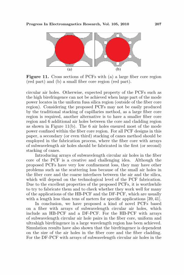
Figure 11. Cross sections of PCFs with (a) a large fiber core region(red part) and (b) a small fiber core region (red part).
circular air holes. Otherwise, expected property of the PCFs such asthe high birefringence can not be achieved when large part of the modepower locates in the uniform fusa silica region (outside of the fiber coreregion). Considering the proposed PCFs may not be easily producedby the traditional stacking of capillaries method, as a large fiber coreregion is required, another alternative is to have a smaller fiber coreregion and 6 additional air holes between the core and cladding regionas shown in Figure 11(b). The 6 air holes ensured most of the modepower confined within the fiber core region. For all PCF designs in thispaper, a secondary (or even third) stacking of canes method should beemployed in the fabrication process, where the fiber core with arraysof subwavelength air holes should be fabricated in the first (or second)stacking of canes.
Introducing arrays of subwavelength circular air holes in the fibercore of the PCF is a creative and challenging idea. Although theproposed PCFs have very low confinement loss, they may have otherproblems such as the scattering loss because of the small air holes inthe fiber core and the coarse interfaces between the air and the silica,which will depend on the technological level of the PCF fabrication.Due to the excellent properties of the proposed PCFs, it is worthwhileto try to fabricate them and to check whether they work well for manyof the applications of the HB-PCF and the DF-PCF, which are usuallywith a length less than tens of meters for specific applications [39, 41].
In conclusion, we have proposed a kind of novel PCFs basedon a fiber with arrays of subwavelength circular air holes, whichinclude an HB-PCF and a DF-PCF. For the HB-PCF with arraysof subwavelength circular air hole pairs in the fiber core, uniform andultrahigh birefringence in a large wavelength region has been achieved.Simulation results have also shown that the birefringence is dependenton the size of the air holes in the fiber core and the fiber cladding.For the DF-PCF with arrays of subwavelength circular air holes in the

208 Chen, Tse, and Tam
fiber core, fattened near-zero dispersion is achieved where the negativewaveguide dispersion of the fiber core structure is introduced. Wehave also investigated the waveguide dispersion of the hexagonal latticestructure with arrays of circular air holes in the fused silica. Simulationresults have shown that the designs of the fiber core with arrays ofcircular air holes can provide an additional approach for the dispersioncontrol of the PCF.
ACKNOWLEDGMENT
This work is supported partially by Program for Science andTechnology Innovative Research Team in Zhejiang Normal Universityand the Central Research Grant of The Hong Kong PolytechnicUniversity under the Postdoctoral Fellowship (Project No. G-YX2D).
REFERENCES
1. Knight, J. C., T. A. Birks, P. S. J. Russell, and D. M. Atkin, “All-silica single-mode optical fiber with photonic crystal cladding,”Opt. Lett., Vol. 21, 1547–1549, 1996.
2. Birks, T. A., J. C. Knight, and P. S. J. Russel, “Endlessly single-mode photonic crystal fiber,” Opt. Lett., Vol. 22, 961–963, 1997.
3. Knight, J. C., J. Broeng, T. A. Birks, and P. S. J. Russell,“Photonic band gap guidance in optical fibers,” Science, Vol. 282,1476–1478, 1998.
4. Knight, J. C. and P. S. J. Russell, “Photonic crystal fibers: Newway to guide light,” Science, Vol. 296, 276–277, 2002.
5. Knight, J. C. “Photonic crystal fibers,” Nature, Vol. 424, 847–851,2003.
6. Shen G.-F., X.-M. Zhang, H. Chi, and X.-F. Jin,“Microwave/millimeter-wave generation using multi-wavelengthphotonic crystal fiber brillouin laser,” Progress In Electromagnet-ics Research, Vol. 80, 307–320, 2008.
7. Nozhat N. and N. Granpayeh, “Specialty fibers designedby photonic crystals,” Progress In Electromagnetics Research,Vol. 99, 225–244, 2009.
8. Wu J.-J., D. Chen, K.-L. Liao, T.-J. Yang, and W.-L. Ouyang,“The optical properties of bragg fiber with a fiber core of 2-dimension elliptical-hole photonic crystal structure,” Progress InElectromagnetics Research Letters, Vol. 10, 87–95, 2009.
9. Chau Y.-F., C.-Y. Liu, H.-H. Yeh, and D. P. Tsai, “A comparativestudy of high birefringence and low confinement loss photonic

Progress In Electromagnetics Research, Vol. 105, 2010 209
crystal fiber employing elliptical air holes in fiber cladding withtetragonal lattice,” Progress In Electromagnetics Research B,Vol. 22, 39–52, 2010.
10. Ortigosa-Blanch, A., J. C. Knight, W. J. Wadsworth, J. Arriaga,B. J. Mangan, T. A. Birks, and P. S. J. Russel, “Highlybirefringent photonic crystal fibers,” Opt. Lett., Vol. 25, 1325–1327, 2000.
11. Ademgil, H. and S. Haxha, “Highly birefringent photonic crystalfibers with ultralow chromatic dispersion and low confinementlosses,” J. Lightwave Technol., Vol. 26, 441–448, 2008.
12. Hansen, T. P., J. Broeng, S. E. B. Libori, E. Knudsen, A. Bjarklev,J. R. Jensen, and H. Simonsen, “Highly birefringent index-guidingphotonic crystal fibers,” IEEE Photon. Technol. Lett., Vol. 13,588–590, 2001.
13. Sapulak, M., G. Statkiewicz, J. Olszewski, T. Martynkien,W. Urbanczyk, J. Wojcik, M. Makara, J. Klimek, T. Nasilowski,F. Berghmans, and H. Thienpont, “Experimental and theoreticalinvestigations of birefringent holey fibers with a triple defect,”Appl. Opt., Vol. 44, 2652–2658, 2005.
14. Anthkowiak, M., R. Kotynski, T. Nasilowski, P. Lesiak, J. Wojcik,W. Urbanczyk, F. Berghmans, and H. Thienpont, “Phase andgroup modal birefringence of triple-defect photonic crystal fibres,”J. Opt. A: Pure Appl. Opt., Vol. 7, 763–766, 2005.
15. Chen, D. and L. Shen, “Highly birefringent elliptical-hole photoniccrystal fibers with double defect,” J. Lightw. Technol., Vol. 25,2700–2705, 2007.
16. Steel, M. J. and R. M. Osgood, “Elliptical-hole photonic crystalfibers,” Opt. Lett., Vol. 26, 229–231, 2001.
17. Steel, M. J. and R. M. Osgood, “Polarization and dispersiveproperties of elliptical-hole photonics crystal fibers,” J. LightwaveTechnol., Vol. 19, 495–503, 2001.
18. Yue, Y., G. Kai, Z. Wang, T. Sun, L. Jin, Y. Lu, C. Zhang,J. Liu, Y. Li, Y. Liu, S. Yuan, and X. Dong, “Highly birefringentelliptical-hole photonic crystal fiber with squeezed hexagonallattice,” Opt. Lett., Vol. 32, 469–471, 2007.
19. Chen, D. and L. Shen, “Ultrahigh birefringent photonic crystalfiber with ultralow confinement loss,” IEEE Photon. Technol.Lett., Vol. 19, 185–187, 2007.
20. Agrawal, A., N. Kejalakshmy, J. Chen, B. M. A. Rahman,and K. T. V. Grattan, “Golden spiral photonic crystal fiber:Polarization and dispersion properties,” Opt. Lett., Vol. 33, 2716–

210 Chen, Tse, and Tam
2718, 2008.21. Shen, L. P., W. P. Huang, and S. S. Jian, “Design of photonic
crystal fibers for dispersion-related applications,” J. LightwaveTechnol., Vol. 21, 1644–1651, 2003.
22. Ferrando, A., E. Silvestre, J. J. Miret, and P. Andres, “Nearly zeroultraflattened dispersion in photonic crystal fibers,” Opt. Lett.,Vol. 25, 790–792, 2000.
23. Ferrando, A., E. Silvestre, P. Andres, J. Miret, and M. Andres,“Designing the properties of dispersion-flattened photonic crystalfibers,” Opt. Express, Vol. 9, 687–697, 2001.
24. Saitoh, K., M. Koshiba, T. Hasegawa, and E. Sasaoka, “Chromaticdispersion control in photonic crystal fibers: Application to ultra-flattened dispersion,” Opt. Express, Vol. 11, 843-852, 2003.
25. Poletti F., V. Finazzi, T. M. Monro, N. G. R. Broderick, V. Tse,and D. J. Richardson, “Inverse design and fabrication tolerancesof ultra-flattened dispersion holey fibers,” Opt. Express, Vol. 13,3728–3736, 2005.
26. Gerome, F., J.-L. Auguste, and J.-M. Blondy, “Design ofdispersion-compensating fibers based on a dual-concentric-corephotonic crystal fiber,” Opt. Lett., Vol. 29, 2725–2727, 2004.
27. Huttunen, A. and P. Torma, “Optimization of dual-core andmicrostructure fiber geometries for dispersion compensation andlarge mode area,” Opt. Express, Vol. 13, 627–635, 2005.
28. Varshney, S. K., T. Fujisawa, K. Saitoh, and M. Koshiba, “Designand analysis of a broadband dispersion compensating photoniccrystal fiber Raman amplifier operating in S-band,” Opt. Express,Vol. 14, 3528–3540, 2006.
29. Yang, S., Y. Zhang, X. Peng, Y. Lu, S. Xie, J. Li, W. Chen,Z. Jiang, J. Peng, and H. Li, “Theoretical study and experimentalfabrication of high negative dispersion photonic crystal fiber withlarge area mode field,” Opt. Express, Vol. 14, 3015–3023, 2006.
30. Ju, J., W. Jin, and M. S. Demokan, “Design of single-polarizationsingle mode photonics crystal fibers,” J. Lightwave Technol.,Vol. 24, 825–830, 2001.
31. Saitoh, K. and M. Koshiba, “Single-polarization single-modephotonic crystal fibers,” IEEE Photon. Technol. Lett., Vol. 15,1384–1340, 2003.
32. Kubota, H., S. Kawanishi, S. Koyanagi, M. Tanaka, andS. Yamaguchi, “Absolutely single polarization photonic crystalfiber,” IEEE Photon. Technol. Lett., Vol. 16, 182–184, 2004.
33. Knight, J. C. and D. V. Skryabin, “Nonlinear waveguide optics

Progress In Electromagnetics Research, Vol. 105, 2010 211
and photonic crystal fibers,” Opt. Express, Vol. 15, 15365–15376,2007.
34. Mortensen, N. A., M. D. Nielsen, J. R. Folkenberg, A. Petersson,and H. R. Simonsen, “Improved large-mode-area endlessly single-mode photonic crystal fibers,” Opt. Lett., Vol. 28, 393–395, 2003.
35. Limpert, J., T. Schreiber, S. Nolte, H. Zellmer, T. Tunnermann,R. Iliew, F. Lederer, J. Broeng, G. Vienne, A. Petersson,and C. Jakobsen, “High-power air-clad large-mode-area photoniccrystal fiber laser,” Opt. Express, Vol. 11, 818–823, 2003.
36. Folkenberg, J., M. Nielsen, N. Mortensen, C. Jakobsen, andH. Simonsen, “Polarization maintaining large mode area photoniccrystal fiber,” Opt. Express, Vol. 12, 956–960, 2004.
37. Dobb, H., K. Kalli, and D. J. Webb, “Temperature-insensitivelong period grating sensors in photonic crystal fibre,” Eletron.Lett., Vol. 40, 657–658, 2004.
38. Dong, X. and H. Y. Tam, “Temperature-insensitive strain sensorwith polarization-maintaining photonic crystal fiber based onSagnac interferometer,” Appl. Phys. Lett., Vol. 90, 151113, 2007.
39. Wadsworth, W. J., J. C. Knight, W. H. Reewes, P. S. J. Russell,and J. Arriaga, “Yb3+-doped photonic crystal fibre laser,”Eletron. Lett., Vol. 36, 1452–1253, 2000.
40. Liu, X., X. Zhou, X. Tang, J. Ng, J. Hao, T. Chai, E. Leong,and C. Lu, “Swithable and tunable multiwavelength erbium-dopedfiber laser with fiber Bragg grating and photonic crystal fiber,”IEEE Photon. Technol. Lett., Vol. 17, 1626–1628, 2005.
41. Chen, D., “Stable multi-wavelength erbium-doped fiber laserbased on photonic crystal fiber Sagnac loop filter,” Laser Phys.Lett., Vol. 4, 437–439, 2007.
42. Broderick, N. G. R., T. M. Monro, P. J. Bennett, andD. J. Richardson, “Nonlinearity in holey optical fibers: Measure-ment and future opportunities,” Opt. Lett., Vol. 24, 1395–1397,1999.
43. Zhu, Z. and T. G. Brown, “Experimental studies of polarizationproperties of supercontinua generated in a birefringent photoniccrystal fiber,” Opt. Express, Vol. 12, 791–796, 2004.
44. Zhu, Z. and T. G. Brown, “Polarization properties ofsupercontinuum spectra generated in birefringent photonic crystalfibers,” J. Opt. Soc. Am. B, Vol. 21, 249–257, 2004.
45. Dudley, J. M. and J. R. Taylor, “Ten years of nonlinear optics inphotonic crystal fibre,” Nature Photonics, Vol. 3, 85–90, 2009.
46. Wiederhecher, G. S., C. M. B. Cordeiro, F. Couny, F. Benabid,

212 Chen, Tse, and Tam
S. A. Maier, J. C. Knight, C. H. B. Cruz, and H. L. Fragnito,“Field enhancement within an optical fibre with a subwavelengthair core,” Nature Photonics, Vol. 1, 115–118, 2007.
47. Klocek, P., Handbook of Infrared Optical Materials, MarcelDekker, New York, NY, 1991.
48. Meade, R. D., A. M. Rappe, K. D. Brommer, J. D. Joannopoulos,and O. L. Alerhand, “Accurate theoretical analysis of photonicband-gap matetrials,” Phys. Rev. B, Vol. 48, 8434–8437, 1993.
49. Chen, D., M.-L. Vincent Tse, and H. Y. Tam, “Super-latticestructure photonic crystal fiber,” Progress In ElectromagneticsResearch M, Vol. 11, 53–64, 2010.