Kilowatt-level narrow-linewidth capable fibers and lasers
10
Kilowatt-level, narrow-linewidth capable fibers and lasers Donnell Walton, Stuart Gray, Ji Wang, Ming-Jun Li, Xin Chen, Anping Liu, Luis Zenteno and Alana Crowley Science and Technology Division Corning Incorporated SP-AR-1-1, Corning, NY 14831 ABSTRACT High power fiber lasers have been recently demonstrated at the kilowatt level. The spectral linewidths of these lasers oscillators can exceed 20 nm. Whereas, such broad spectra are fine for many applications, such as materials processing where raw power is the primary requirement, other applications, including coherent beam combination, harmonic generation, or gravitational wave detection, require high powers beams with much narrower linewidths. Amplification of narrow linewidth signals in optical fibers is limited by stimulated Brillouin scattering (SBS). We discuss novel fiber designs that limit SBS allowing the amplification of narrow linewidth signals to kilowatt power levels. Introduction In recent years, single transverse mode fiber lasers have been demonstrated with output powers in the kilowatt regime [1-3]. In such lasers, linewidths of 10-20 nm are common. This broad linewidth poses no problems for many materials processing applications, such as cutting or welding, where raw power in a high quality beam is all that is required. However some applications, such as beam combining, ladar and gravitational wave detection require high power operation combined with a narrow linewidth. High spectral purity can be achieved by switching from an oscillator to a master-oscillator, power amplifier (MOPA) configuration. In a MOPA, a low power single frequency oscillator is amplified to the desired power level by means of a multistage fiber amplifier. In a fiber geometry, the primary limitation to achieving high power in a narrow linewidth signal is the onset of stimulated Brillouin scattering (SBS). SBS results from the interaction between the intense incident light and the resultant acoustic wave. Large mode area (LMA) fibers have been used to reduce optical nonlinearities in fibers by increasing the effective mode area. The use of large mode area fibers raises the SBS threshold but the maximum output power is still limited to around 100 Watts [4]. Recently, this limit has been pushed to 500 Watts through the combination of an LMA fiber and a pump induced thermal gradient [5]. In this paper, we describe SBS suppression in high power fiber amplifiers through fiber profile design. Invited Paper Fiber Lasers IV: Technology, Systems, and Applications, edited by Donald J. Harter, Andreas Tünnermann, Jes Broeng, Clifford Headley III Proc. of SPIE Vol. 6453, 645314, (2007) · 0277-786X/07/$15 · doi: 10.1117/12.714284 Proc. of SPIE Vol. 6453 645314-1 Downloaded From: http://proceedings.spiedigitallibrary.org/ on 08/05/2014 Terms of Use: http://spiedl.org/terms
-
Upload
independent -
Category
Documents
-
view
1 -
download
0
Transcript of Kilowatt-level narrow-linewidth capable fibers and lasers
Kilowatt-level, narrow-linewidth capable fibers and lasers
Donnell Walton, Stuart Gray, Ji Wang, Ming-Jun Li, Xin Chen, Anping Liu, Luis Zenteno and Alana Crowley
Science and Technology Division
Corning Incorporated SP-AR-1-1, Corning, NY 14831
ABSTRACT
High power fiber lasers have been recently demonstrated at the kilowatt level. The spectral linewidths of these lasers oscillators can exceed 20 nm. Whereas, such broad spectra are fine for many applications, such as materials processing where raw power is the primary requirement, other applications, including coherent beam combination, harmonic generation, or gravitational wave detection, require high powers beams with much narrower linewidths. Amplification of narrow linewidth signals in optical fibers is limited by stimulated Brillouin scattering (SBS). We discuss novel fiber designs that limit SBS allowing the amplification of narrow linewidth signals to kilowatt power levels.
Introduction
In recent years, single transverse mode fiber lasers have been demonstrated with output powers in the kilowatt regime [1-3]. In such lasers, linewidths of 10-20 nm are common. This broad linewidth poses no problems for many materials processing applications, such as cutting or welding, where raw power in a high quality beam is all that is required. However some applications, such as beam combining, ladar and gravitational wave detection require high power operation combined with a narrow linewidth. High spectral purity can be achieved by switching from an oscillator to a master-oscillator, power amplifier (MOPA) configuration. In a MOPA, a low power single frequency oscillator is amplified to the desired power level by means of a multistage fiber amplifier. In a fiber geometry, the primary limitation to achieving high power in a narrow linewidth signal is the onset of stimulated Brillouin scattering (SBS). SBS results from the interaction between the intense incident light and the resultant acoustic wave. Large mode area (LMA) fibers have been used to reduce optical nonlinearities in fibers by increasing the effective mode area. The use of large mode area fibers raises the SBS threshold but the maximum output power is still limited to around 100 Watts [4]. Recently, this limit has been pushed to 500 Watts through the combination of an LMA fiber and a pump induced thermal gradient [5]. In this paper, we describe SBS suppression in high power fiber amplifiers through fiber profile design.
Invited Paper
Fiber Lasers IV: Technology, Systems, and Applications, edited by Donald J. Harter, Andreas Tünnermann, Jes Broeng, Clifford Headley III
Proc. of SPIE Vol. 6453, 645314, (2007) · 0277-786X/07/$15 · doi: 10.1117/12.714284
Proc. of SPIE Vol. 6453 645314-1
Downloaded From: http://proceedings.spiedigitallibrary.org/ on 08/05/2014 Terms of Use: http://spiedl.org/terms

Methodology
SBS occurs in a fiber amplifier when the amplified light induces a density grating in the fiber core through electrostriction. The signal light is then backscattered towards the source from this acoustic grating resulting in a loss of forward output power. Because of this effect, fiber laser amplifiers have been limited to output powers of only a few hundred watts, even with LMA fibers. We address this limitation by altering the interaction of the propagating optical and acoustic waves. The SBS effect can be analyzed through nonlinear wave equations that govern the evolution of the optical and acoustic fields in the fiber [6]. This analysis shows that the threshold for SBS obeys the following relationship:
aou
ueffth ILG
KAP
),( maxνα
∝ , (1)
where K is the polarization factor, αu is the acoustic attenuation coefficient for the acoustic mode of order u, Aeff is optical effective area, G(νmax,L) is the Brillouin gain at the peak frequency for a fiber of length L and ao
uI is the normalized overlap integral between the electric and acoustic fields. This expression can be used to understand ways to mitigate SBS in fibers. Equation 1 indicates that the SBS threshold can be increased by increasing the effective area, polarization factor, and acoustic loss or by decreasing the overlap integral and the maximum gain coefficient. Among all the factors that affect the SBS, the effective area and the overlap integral can be controlled by fiber refractive index profile design and acoustic velocity profile design. The acoustic loss, αu, can be changed by glass composition design. The gain coefficient can be lowered by creating a longitudinal non-uniform Brillouin gain spectrum through distributed glass dopant concentration profile, temperature or stress profile along the fiber. The interaction length can be reduced by increasing the ytterbium concentration or increasing the core/cladding ratio in double clad fiber. Finally the polarization factor can be increased through polarization control. In this work we are concerned with increasing the SBS threshold by designing the fiber core to reduce the spatial overlap between the propagating optical and acoustic modes. This can be accomplished by selecting the right dopant species and dopant distribution in the core region of the fiber. Table 1 lists the effects on optical and acoustic properties of some common dopants used in silica-based fibers [7]. Table 1 Trend of optical and acoustic refractive index change of different dopants in silica
GeO2 P2O5 TiO2 B2O3 F2 Al2O3 Optical Refractive Index Acoustic Refractive Index
Proc. of SPIE Vol. 6453 645314-2
Downloaded From: http://proceedings.spiedigitallibrary.org/ on 08/05/2014 Terms of Use: http://spiedl.org/terms
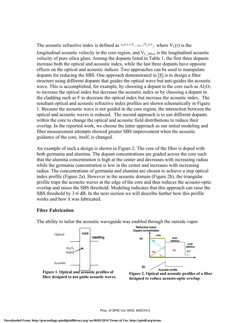
The acoustic refractive index is defined as )()( _ rVVrn LSilicaLa = , where VL(r) is the longitudinal acoustic velocity in the core region, and VL_Silica is the longitudinal acoustic velocity of pure silica glass. Among the dopants listed in Table 1, the first three dopants increase both the optical and acoustic index, while the last three dopants have opposite effects on the optical and acoustic indices. Two approaches can be used to manipulate dopants for reducing the SBS. One approach demonstrated in [8] is to design a fiber structure using different dopants that guides the optical wave but anti-guides the acoustic wave. This is accomplished, for example, by choosing a dopant in the core such as Al2O3 to increase the optical index but decrease the acoustic index or by choosing a dopant in the cladding such as F to decrease the optical index but increase the acoustic index. The resultant optical and acoustic refractive index profiles are shown schematically in Figure 1. Because the acoustic wave is not guided in the core region, the interaction between the optical and acoustic waves is reduced. The second approach is to use different dopants within the core to change the optical and acoustic field distributions to reduce their overlap. In the reported work, we choose the latter approach as our initial modeling and fiber measurement attempts showed greater SBS improvement when the acoustic guidance of the core, itself, is changed. An example of such a design is shown in Figure 2. The core of the fiber is doped with both germania and alumina. The dopant concentrations are graded across the core such that the alumina concentration is high at the center and decreases with increasing radius while the germania concentration is low in the center and increases with increasing radius. The concentrations of germania and alumina are chosen to achieve a step optical index profile (Figure 2a). However in the acoustic domain (Figure 2b), the triangular profile traps the acoustic waves at the edge of the core and thus reduces the acousto-optic overlap and raises the SBS threshold. Modeling indicates that this approach can raise the SBS threshold by 3-6 dB. In the next section we will describe further how this profile works and how it was fabricated. Fiber Fabrication The ability to tailor the acoustic waveguide was enabled through the outside vapor
Figure 1. Optical and acoustic profiles of fiber designed to not guide acoustic waves.
coreinner
claddingouter
cladding
Al
Ge Ge B/FYb
Refractive index/Dopant concentration
Acoustic profile
(a)
(b)
coreinner
claddingouter
cladding
Al
Ge Ge B/FYb
Refractive index/Dopant concentration
Acoustic profile
(a)
(b)
Optical
Acoustic
Al2O3doped
corecladding
Optical
Acoustic
Al2O3doped
corecladding
Figure 2. Optical and acoustic profiles of a fiber designed to reduce acousto-optic overlap
Proc. of SPIE Vol. 6453 645314-3
Downloaded From: http://proceedings.spiedigitallibrary.org/ on 08/05/2014 Terms of Use: http://spiedl.org/terms

deposition process. Ideally, a segmented core with alumina in the center region surrounded by a germania region would be adequate to reduce the acousto-optic overlap and suppress SBS. A perfect match in optical-index between the different compositional sections in the core region is in practice difficult to accomplish. An optical interface was undesirably generated within the core as the result. Strong light scattering occurring at the layer interface induced very high background loss. All fibers made with the abrupt vertical interface have presented the same characteristically wavelength-independent high scattering loss of about 4-5dB/km, regardless of the improvement made towards the flat optical index profile. This loss value is more than an order of magnitude higher than those of the typical singly doped, Ge-doped core SMF, which is typically ~0.18-0.2dB/km, and Al-doped core SMF, for which the loss can range from 0.35-0.4 dB/km. This layer-scattering effect can be expected to be much more intense in LMA double-clad fibers due primarily to the low numerical aperture core requirement and the relatively higher loss conventionally associated with high Yb doping. Furthermore, this intensely-scattered light is particularly detrimental to the high-power fiber laser operation as it directs part of the scattered-energy toward the outer polymer coating of the double-clad fiber. This additional heat problem, an extra burden to bear, poses considerable concern in the operation and the reliability of high-power fiber lasers in general. To overcome this difficulty for achieving low optical-loss SBS fiber through the same ‘reduced optical/acoustic overlap’ concept, we have developed a new ‘interface-free’ core composition design. The key issue in our earlier multilayer core approach lay essentially in the manufacturing difficulty in realizing a true optically flat index profile among the different core composition layers. With the low-NA (~0.06) core requirement for the overall double-clad fiber design, it makes the task even harder in practice. To avoid the optical layer-interface, while still managing a ‘reduced-overlap’ between the acoustic and the optical field distribution in the fiber core profile design, a new ‘interface-free’ Al/Ge counter-graded fiber-core composition profile has been proposed as shown in Figure 2a. Figure 2 shows the schematic of the new Al/Ge counter-graded core profile design applied to the Yb-doped all-glass double-clad fiber. This Al/Ge-counter-graded composition profile design eliminates the physical interface within the core, thus overcomes the limitation of our initially-attempted multilayer fiber-core composition approach. In fiber fabrication, the flat optical-index profile can be conveniently achieved by up-doping Germania-content and at the same time down-grading Alumina-concentration in a manner that they compensate one another in optical refractive-index contribution. The slope of the Germania up-doping is about ~30% greater than that of Alumina down-doping due to the latter’s higher refractive index contribution in silica. The linear dependence of optical index on the Al or Ge doping concentration facilitates this in practice. On the other hand, linearly down-grading Alumina and up-grading Germania from the center of the core causes the acoustic wave to be primarily guided or distributed towards the edge of the core. Contrary to a flat optical-index profile, the
Proc. of SPIE Vol. 6453 645314-4
Downloaded From: http://proceedings.spiedigitallibrary.org/ on 08/05/2014 Terms of Use: http://spiedl.org/terms
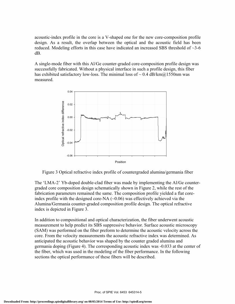
acoustic-index profile in the core is a V-shaped one for the new core-composition profile design. As a result, the overlap between the optical and the acoustic field has been reduced. Modeling efforts in this case have indicated an increased SBS threshold of ~3-6 dB. A single-mode fiber with this Al/Ge counter-graded core-composition profile design was successfully fabricated. Without a physical interface in such a profile design, this fiber has exhibited satisfactory low-loss. The minimal loss of ~ 0.4 dB/km@1550nm was measured.
Position
Opt
ical
refra
ctiv
e in
dex
diffe
renc
e
-0.06
-0.04
-0.02
0.00
0.02
0.04
Figure 3 Optical refractive index profile of countergraded alumina/germania fiber
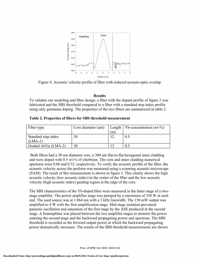
The ‘LMA-2’ Yb-doped double-clad fiber was made by implementing the Al/Ge counter-graded core composition design schematically shown in Figure 2, while the rest of the fabrication parameters remained the same. The composition profile yielded a flat core-index profile with the designed core-NA (~0.06) was effectively achieved via the Alumina/Germania counter-graded composition profile design. The optical refractive index is depicted in Figure 3. In addition to compositional and optical characterization, the fiber underwent acoustic measurement to help predict its SBS suppressive behavior. Surface acoustic microscopy (SAM) was performed on the fiber preform to determine the acoustic velocity across the core. From the velocity measurements the acoustic refractive index was determined. As anticipated the acoustic behavior was shaped by the counter graded alumina and germania doping (Figure 4). The corresponding acoustic index was -0.033 at the center of the fiber, which was used in the modeling of the fiber performance. In the following sections the optical performance of these fibers will be described.
Proc. of SPIE Vol. 6453 645314-5
Downloaded From: http://proceedings.spiedigitallibrary.org/ on 08/05/2014 Terms of Use: http://spiedl.org/terms
Position (mm)
-5 -4 -3 -2 -1 0 1 2 3 4 5
Aco
ustic
vel
ocity
(m/s
)5600
5650
5700
5750
5800
5850
5900
CoreCladding
Figure 4. Acoustic velocity profile of fiber with reduced acousto-optic overlap
Results To validate our modeling and fiber design, a fiber with the dopant profile of figure 2 was fabricated and the SBS threshold compared to a fiber with a standard step index profile using only germania doping. The properties of the two fibers are summarized in table 2. Table 2. Properties of fibers for SBS threshold measurement
Fiber type Core diameter (um) Length (m)
Yb-concentration (wt-%)
Standard step index (LMA-1)
30 12 0.5
Graded Al/Ge (LMA-2) 30 12 0.5 Both fibers had a 30 um diameter core, a 300 um flat-to-flat hexagonal inner cladding and were doped with 0.5 wt-% of ytterbium. The core and inner cladding numerical apertures were 0.06 and 0.32, respectively. To verify the acoustic profile of the fiber, the acoustic velocity across the preform was measured using a scanning acoustic microscope (SAM). The result of this measurement is shown in figure 3. This clearly shows the high acoustic velocity (low acoustic index) in the center of the fiber and the low acoustic velocity (high acoustic index) guiding region at the edge of the core. The SBS characteristics of the Yb-doped fiber were measured in the latter stage of a two-stage amplifier. The power amplifier stage was pumped by a maximum of 350 W at each end. The seed source was at 1.064 nm with a 3 kHz linewidth. The 150 mW output was amplified to 4 W with the first amplification stage. Mid-stage isolation prevented parasitic oscillation and saturation of the first stage by the ASE produced in the second stage. A beamsplitter was placed between the two amplifier stages to monitor the power entering the second stage and the backward propagating power and spectrum. The SBS threshold is recorded as the forward output power at which the backward propagating power dramatically increases. The results of the SBS threshold measurements are shown
Proc. of SPIE Vol. 6453 645314-6
Downloaded From: http://proceedings.spiedigitallibrary.org/ on 08/05/2014 Terms of Use: http://spiedl.org/terms
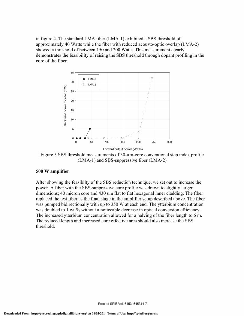
in figure 4. The standard LMA fiber (LMA-1) exhibited a SBS threshold of approximately 40 Watts while the fiber with reduced acousto-optic overlap (LMA-2) showed a threshold of between 150 and 200 Watts. This measurement clearly demonstrates the feasibility of raising the SBS threshold through dopant profiling in the core of the fiber.
Forward output power (Watts)
0 50 100 150 200 250 300
Bac
kwar
d po
wer
mon
itor (
mW
)
0
5
10
15
20
25
30
35
LMA-1
LMA-2
Figure 5 SBS threshold measurements of 30-µm-core conventional step index profile
(LMA-1) and SBS-suppressive fiber (LMA-2) 500 W amplifier After showing the feasibilty of the SBS reduction technique, we set out to increase the power. A fiber with the SBS-suppressive core profile was drawn to slightly larger dimensions; 40 micron core and 430 um flat to flat hexagonal inner cladding. The fiber replaced the test fiber as the final stage in the amplifier setup described above. The fiber was pumped bidirectionally with up to 350 W at each end. The ytterbium concentration was doubled to 1 wt-% without a noticeable decrease in optical conversion efficiency. The increased ytterbium concentration allowed for a halving of the fiber length to 6 m. The reduced length and increased core effective area should also increase the SBS threshold.
Proc. of SPIE Vol. 6453 645314-7
Downloaded From: http://proceedings.spiedigitallibrary.org/ on 08/05/2014 Terms of Use: http://spiedl.org/terms

Figure 6 Output power versus incident pump power for 500 W amplifier
Figure 7 Beam quality for 500 W beam. M2 < 1.3 The maximum output power of the amplifier was 500 W. There was no evidence of SBS either in the intensity or spectrum of the backward propagating light. When the fiber was coiled to a 51-mm diameter, the beam quality was good with an M2 of 1.3. The output power and beam quality are shown in Figures 6 and 7, respectively. The 500 W output power was limited by available pump power and not by SBS. In order to achieve higher power, an alternative pump was required.
0
100
200
300
400
500
600
0 100 200 300 400 500 600 700 800 900
Incident pump power (W)
Out
put P
ower
(W)
Proc. of SPIE Vol. 6453 645314-8
Downloaded From: http://proceedings.spiedigitallibrary.org/ on 08/05/2014 Terms of Use: http://spiedl.org/terms

1000 W amplifier In order to demonstrate a 1000 W amplifier, additional pump power was needed. We combined the outputs of 7 of the 400 micron core delivery fiber using an all-glass tapered pump combiner. The combiner was capable of delivery up to 2200 W out of a collapsed and tapered output end. The output end of the pump combiner was optically matched to an 850-micron 0.32-NA inner clad version of the SBS-suppressive double clad fiber. The fiber was 6 meters long with a 50 micron diameter core. The total output power and absorbed pump power were 1000 W and 2000 W, respectively (Figure 8). The backward propagating spectrum showed no evidence of SBS. The M2 was ~4.5, so the output beam profile was not single mode.
Figure 8 Output power versus incident pump power for 1 kW amplfier.
Discussion We have demonstrated the feasibility to reduce SBS by tailoring the core dopant species and distribution in an amplifying fiber. By amplifying a 3 kHz linewidth source to the kW level, the onset of SBS would be assured in the absence of mitigation. Noteworthy is that the 500 W, single mode result was bidirectionally pumped in contrast to the previous 500 W amplifier which relied on a pump-induced pump gradient to suppress SBS. The 1000 W output power result exhibited an M2 of 4.5 even for the smallest bending radii. Since our fiber outer diameter was 1 mm, we were limited by how tightly we could bend the fiber. The large M2 value is attributed to an unintentional refractive index depression that circumscribes the core. The effect of the moat is to increase the effective
Fiber amplifier output power
0
200
400
600
800
1000
1200
0 500 1000 1500 2000 2500
Incident pump power (W)
Out
put p
ower
(W)
Proc. of SPIE Vol. 6453 645314-9
Downloaded From: http://proceedings.spiedigitallibrary.org/ on 08/05/2014 Terms of Use: http://spiedl.org/terms
NA of the core beyond the nominal 0.06 value. The larger NA results in the presence of more higher order modes and makes it more difficult to strip them away through bending. We have made preforms without the index moat and are currently drawing them into fibers. Work is underway to improve the beam quality of the 1000 W result and to further increase the output power. This work was supported by DARPA/TTO through MDA972-02-3-0004.
Conclusion
In conclusion, we have demonstrated the ability to increase the SBS threshold in high power fiber laser amplifiers by using different dopants to control the acoustic index of the fiber core. Increasing the SBS threshold to kilowatt power levels requires further enhancements to the fiber design. Current work is focused on raising the Yb-concentration to allow the use of shorter fiber lengths and increasing the core diameter from 30 um to 50 um to further increase the effective area. These improvements are expected to realize a fiber capable of amplifying a narrow linewidth signal to power levels exceeding 1 kilowatt. Latest results will be presented at the conference.
References 1. Reichel, V., et al. Fiber-laser power scaling beyond the 1-kilowatt level by Nd:Yb co-doping. 2005. Prague, Czech Republic: International Society for Optical Engineering, Bellingham WA, WA 98227-0010, United States. 2. Y. Jeong, J.K.S., D.N. Payne, J. Nilsson, Ytterbium-doped large-core fiber laser with 1 kW of continuous-wave output power. Electronics Letters, 2004. 40: p. 470. 3. Information from <http://www.ipgphotonics.com>. 4. A. Liem, J.L., H. Zellmer, A. Tunnermann, 100-W single-frequency master-oscillator fiber power amplifier. Optics Letters, 2003. 28(17): p. 1537-1539. 5. Payne, D.N., et al. Kilowatt-class single-frequency fiber sources. 2005. San Jose, CA, United States: International Society for Optical Engineering, Bellingham, WA 98227-0010, United States. 6. M.J. Li, S.L., D.A. Nolan. New Dispersion Decreasing Fiber with High SBS Threshold for Nonlinear Signal Processing. in OFCNFOEC. 2005. 7. C.K. Jen, J.E.B.O., N. Goto, K. Abe, Role of guided acoustic wave properties in single-mode optical fiber design. Electronics Letters, 1988. 24: p. 1419-1420. 8. P.D. Dragic, C.H.L., G.C. Papen, A. Galvanauskas. Optical Fiber With an Acoustic Guiding Layer for Stimulated Brillouin Scattering Suppression. in CLEO. 2005.
Proc. of SPIE Vol. 6453 645314-10
Downloaded From: http://proceedings.spiedigitallibrary.org/ on 08/05/2014 Terms of Use: http://spiedl.org/terms