
Oblique Angle Sputtering of Chalcogenide Thin Absorbing Film
Upload
independentCategory
view
1download
0
An oblique arc capable patient positioning systemfor sequential tomotherapy
Bill J. Saltera)
Department of Radiation Oncology, University of Texas Health Science Center at San Antonio, San Antonio,Texas 78229-9769
James M. Hevezi and Amir SadeghiCancer Therapy and Research Center, San Antonio, Texas 78229-9769
Martin Fuss and Terence S. HermanDepartment of Radiation Oncology, University of Texas Health Science Center at San Antonio, San Antonio,Texas 78229-9769
~Received 27 December 2000; accepted for publication 19 September 2001!
A new patient positioning system has been designed and manufactured, allowing for the accuratedelivery of obliquely oriented intensity modulated treatment arcs via a commercially availableIMRT system. The ability to deliver such obliquely oriented intensity modulated arcs allows thecommercial system to more closely approach a 4p pencil beam delivery geometry which, in turn,allows for significant improvements in conformality for many tumor geometries. While the IMRTsystem delivered to this institution in the fall of 1996 was capable of planning for nonparallel planedelivery schemes, it proved incapable of delivering such treatments with acceptable accuracy.Because our early clinical experience revealed that certain patients could benefit significantly fromsuch a delivery scheme we endeavored to design and manufacture an alternative treatment couch/patient positioning system~Xlator! which could overcome the limitations of the vendor suppliedsystem. We present our initial evidence for the benefits of obliquely oriented intensity modulatedtreatment arcs, along with data demonstrating the inability of the original vendor supplied system todeliver such treatments with acceptable accuracy. The design of our new system is presented, aswell as data demonstrating its ability to accurately deliver obliquely oriented intensity-modulatedarcs. A detailed comparison of the performance of the Xlator and the vendor-supplied system ispresented with regard to match line repeatability and hysteresis. Finally, the ability of the Xlator todeliver multiple couch angle sequential tomotherapy with spatial accuracy necessary to radiosurgi-cal applications is demonstrated via a AAPM Report 54,TG-42 hidden target test. Readers note: TheXlator patient positioning system designed and patented here has recently come to be commerciallyavailable, and is currently marketed by the vendor under the name Crane II. ©2001 AmericanAssociation of Physicists in Medicine.@DOI: 10.1118/1.1418240#
Key words: IMRT, oblique arc, tomotherapy, IMRS
aA
a-cu
-duc
a-o
rsucrinTo
ueetical
250ent
atre-
anyncee-
n-lelBe-tem,ue
I. INTRODUCTIONÕBACKGROUND
On September 26, 1996 the Cancer Therapy and ReseCenter/University of Texas Health Science Center at Santonio ~CTRC/UTHSCSA! accepted delivery of a pre-FDAapproval NOMOS Peacock/MIMIC Intensity Modulated Rdiation Therapy System. As delivered, the system waspable of performing treatment planning for intensity modlated, nonparallel plane couch angles~i.e., for intensitymodulated arcs utilizing a ‘‘kicked’’ couch!. Because we believed the delivery of such nonaxial, or obliquely orienteintensity modulated arcs was extremely important to proding treatment plans of maximum benefit to the patient~seeappendix! we initiated testing and commissioning of this feture of the planning/delivery system soon thereafter. Upcloser inspection it was determined that while the inveplanning system was indeed capable of planning for streatments, the delivery system was not capable of delivethese oblique arc treatments with acceptable accuracy.inaccuracy in delivery was due to the inability of the vend
2475 Med. Phys. 28 „12…, December 2001 0094-2405 Õ2001Õ28
rchn-
a--
,-
nehgher
supplied couch/patient positioning system~CRANE I! to ac-curately position the couch/patient when rotated to obliqcouch angles. As Fig. 1~a! shows the original Crane devicwas designed as a floor based system, consisting of a vercolumn with two treatment table attachment arms@Fig. 1~b!#,all attached to a heavy tri-legged base of approximatelypounds. The device was designed to stabilize the treatmcouch from any inherent ‘‘play’’ in the gear system thmight be present, and to accurately index the couch asquired by the sequential tomotherapy paradigm. The mthousands of IMRT treatments successfully delivered siare testament to the device’s functionality for delivering squential arc tomotherapy at nonoblique couch angles~i.e.,arcs delivered at 180° Varian or 0° IEC!.
As mentioned previously, however, our testing of the vedor supplied Crane I device for the delivery of nonparalplane, intensity modulated arcs revealed new problems.cause the CRANE I was designed as a floor based systhe vendor recommended method of delivery of obliq
2475„12…Õ2475Õ14Õ$18.00 © 2001 Am. Assoc. Phys. Med.

athesnuraatn-e
vethths
uc
erit
pobeicthang
in
u-onvftyao
echenal
e
willthetheed
arech.ns-of
orengentn-
plyghndhella-heentintoingiveto
de-asebe
r-pa-bil-
hlyice
e-be
adead-
wn -f the
2476 Salter et al. : Capable patient positioning system 2476
couch angle treatments required that the Crane be elevonto built in wheels, and rotated along side the couch tonew oblique couch angle; and herein lay the problem. Ting revealed that the process of elevating the Crane I owheels, and then dragging or pushing it along side the coimposed stresses and strains on the arm system of the cThis in turn resulted in deformations of the arm and trement couch rail clamp systems supporting the electrodigital readout system@Fig. 1~b!#. In the end, these deformations resulted in a change in the spatial relationships betwthe treatment couch and Crane, leading to a ‘‘corruption9 ofthe defined isocenter coordinates. Simply put, we obserthat after elevating the Crane onto its wheels and rotatingcouch and Crane to a new, non-nominal couch anglecoordinates defining isocenter were no longer valid. Potioning errors as large as 11 mm were observed for ssituations and these were deemed unacceptable.
Because it was apparent to us that the difficulties expenced by the CRANE I system were in large part due tofloor based design, we believed that the majority of thesitioning problems experienced by the CRANE I couldovercome by designing a patient positioning system whwas integral to the treatment couch. This would eliminatestresses and strains imposed by the floor on the devicetheoretically, allow for accurate couch/patient positionithat was independent of the couch angle.
Additional features deemed desirable during the plannphase of the design were the following.
~1! Improved Left/Right and In/Out translational accracy: While the CRANE I provided acceptable translatiaccuracy for the two directions it was designed to mo~In/Out along the longitudinal axis of the couch, and LeRight across the patient! it was believed that the accuraccould be improved upon. The Crane I was essentiallyadapted version of a photographic equipment suppstand. While the device had obviously proven quite efftive at nonoblique arc treatment delivery it was, nevertless, believed that incorporation of machinist-grade tralational tables could dramatically improve positionaccuracy and, therefore, match line quality.
~2! Elimination of the need to align the device to th
FIG. 1. ~a! Original vendor supplied couch/patient-positioning device knoas Crane~or Crane I!. Note the floor-based design.~b! Adjustable arms ofthe Crane I, used for grasping the table.
Medical Physics, Vol. 28, No. 12, December 2001
tedet-tochne.-ic
en
deei-h
i-s-
hend,
g
e/
nrt--
s-
couch each time it was attached: Users of the Crane Ino doubt attest to the need to very carefully adjustalignment of the Crane I each time it is attached tocouch. This often-tedious alignment process is performto ensure that the axes of translation of the Crane Ico-aligned and parallel with those of the treatment couThis in turn assures, for instance, that 5.00 mm of tralation of the In/Out crane arm equates to 5.00 mmIn/Out movement of the treatment couch, and therefthe patient. We believed that if the patient positionidevice was designed to mount to the side of the treatmcouch via a high precision bracket, a one time only aligment would be necessary. From that point forward, simmounting the new device onto the couch via the hiprecision bracket would ensure proper alignment, atherefore extremely accurate patient positioning. Tbracket should, of course, facilitate fast and easy instation and removal of the device. Note: The fact that thigh precision positioning device would be an attachmto the treatment couch, as opposed to being integratedit, was also deemed beneficial in that the fine positiongears of the device need not be worn out from excessuse during routine, and frequent couch position movesfacilitate patient loading and unloading. Therefore, thevice should posses the ability to quickly and easily releits grip on the treatment couch rail, without the need toremoved from the couch.
~3! Ability to upgrade the device to a motorized vesion: Because of the need to translate the couch andtient between each arc of sequential tomotherapy, the aity to automate this process was believed to be higdesirable in terms of patient throughput. The devshould accommodate future motorization.
II. METHOD AND MATERIALS
A. Xlator „pronounced translator … design
The Xlator couch/patient positioning and indexation dvice developed here is shown in Fig. 2. The device canseen to consist of two orthogonally mounted machinist-grtranslational tables with attached high precision digital re
FIG. 2. Xlator ~pronounced translator! couch/patient-positioning device developed by the authors. The device was designed to mount to the side ocouch, as opposed to the floor based design of the Crane I.

hi
poorvidthdemleicrc
ayb
enorr
ecinhchthlon
hns
nothbforcuo
ao
ea-nhocu
riao
heerast
I in
nlmde-betheausetheoci-to
ryns
ICheof
stchaatof
mscu-herlines-per-
ex-is-ift
in aer-ohehat
-the
tiveichria-toge-e
2477 Salter et al. : Capable patient positioning system 2477
out devices for each of the two directions of translation. Tstraight-line run-out accuracy of the translational tables0.000 08 mm/mm, and the optical encoder readouts reposition to 0.01-mm resolution. Upon upgrading to motized movement a linear encoder feedback loop can promicrometer resolution positional feedback. As opposed toCrane I device where the resolution of the optical encoposition sensing system exceeded the resolution of thechanical positioning system, the Xlator's translational tabare actually capable of greater resolution than the optencoding positioning sensors. The device does not onlyport its position in 0.01-mm increments, it is capable of acurately positioning with this resolution. The device malso be seen to be integrally mounted to the treatment tain this case a Varian 600C3 with VEO baseframe~Fig. 2!.The position on the couch allows for unrestricted movemof the couch top in the vertical direction without need freleasing vertical locks to avoid damaging the device, asquired for the Crane I. The device attaches to a high prsion bracket as described previously, allowing for quickstallation and removal without need for realignment. Tdisk shaped knurled knobs at the end of the two rail attament arms allow a quick release of the device's hold ontreatment table and the device can be freely rotated awith the couch to couch angles other than the nominal. TT-shaped knobs at the base of the rail attachment arms caloosened to allow for longitudinal repositioning of the arm
B. Xlator acceptance testing
The performance criteria deemed suf®cient for acceptaof the new device as a replacement for the Crane I had tdetermined. Characterization of the problem revealedthere existed two categories of functionality that shouldprovided by the Xlator if it was to serve as a replacementthe Crane I. Category I consisted of patient positioning cteria for nonoblique couch angles; namely, match line acracy and hysteresis. The second category consisted of ptioning criteria related to oblique couch angles.
Category 1: Match line positioning for non-obliquecouch angles
As mentioned, the ®rst category of functionality that hto be acceptably provided by the Xlator device was thataccurately positioning the couch/patient for the match linor sequential arcs, required by the sequential tomothermethod of delivery. Carolet al.1 had reported that positioning errors as small as 1-mm could increase target dose imogeneity by as much as 10% at the match line and Let al.2 have further af®rmed the need for indexing accuraBecause the Crane I was the accepted device in clinicalfor couch/patient positioning of IMRT treatments, the criteused for ascertaining the acceptability, or lack thereof,Xlator performance was that of direct comparison with tCrane I's performance. The rationale was that if the Cranrepresented the standard of care for sequential tomotheIMRT patient positioning, then it would serve as the mological baseline for comparison. The Xlator was required
Medical Physics, Vol. 28, No. 12, December 2001
esrt
-eere-sale--
le,
t
e-i--e-
egebe
.
cebeater
i--si-
df
s,py
o-wy.se
f
Ipyto
meet or exceed the match line performance of the Craneall relevant categories if it was to be accepted.
a. Match line ®lms.Figure 3 demonstrates what is oftereferred to by Peacock users as a `̀ match line ®lm.'' The ®represents the manufacturer's recommended method fortermining the distance that the couch/patient shouldshifted between arcs to ensure an accurate `̀ match'' ofadjacent, or abutting, ®elds of each sequential arc. Becthis match must be performed very accurately to avoidpreviously mentioned increase in dose heterogeneity assated with patient indexing errors, each user is instructedperform this measurement for their particular MIMIC binaMLC device. This requirement is due to minor variatioinherent to the manufacturing process, causing each MIMdevice to have a slightly different open ®eld length. Trange of typical variations is on the order of a few tenthsa millimeter but, as Carolet al.1 reported, such small errorcan still lead to signi®cant variations in dose at the maline. The match line ®lm is typically obtained by tapingsheet of Kodak XV radiographic ®lm to the couch topisocenter, under a thin sheet of buildup material. All vanesthe MIMIC binary MLC are opened creating, for the 1 cmode, a ®eld of approximately 20 cm3 1.7 cm. Because, amentioned previously, the length of the ®eld for one partilar user might be 16.55 mm, for instance, and for anot16.74 mm, the user determines their particular matchshift by systematically experimenting with varying shift ditances. The ®lm is exposed by a downwardly orientedpendicular gantry~e.g., 180É Varian! producing nominal 203 1.7 cm strips of approximately 1.0 optical density~OD!darkening on the ®lm. By then using the couch/patient indation device to shift the couch and ®lm slightly varying dtances of approximately 1.7 cm the optimal match line shdistance is determined. That shift distance which resultsmatch line appearing uniform in darkness, with no `̀ undlap'' indicated by a `̀ light'' strip at the match line, and n`̀ overlap'' indicated by a dark, twice-exposed strip at tmatch line, is the appropriate match line distance for tparticular MIMIC. An acceptable match line makes it dif®cult to see that the match line even exists because ofuniform darkness at the junction. The test is quite sensidue to the logarithmic ampli®cation properties of ®lm, whresult in small variations of dose appearing as larger vations in optical density. A poor match line is quite apparentthe naked eye. It should be noted that any dose inhomoneity visible on this single gantry angle test ®lm will b
FIG. 3. Peacock match line ®lm.


ehis
f alica-
There-to
, asn-re-s-
e, inob-hasentnts
keyenth athehal-ar-itat
rei
e9.a
eldenrrgste
elyTheeter-is
d as
2486 Salter et al. : Capable patient positioning system 2486
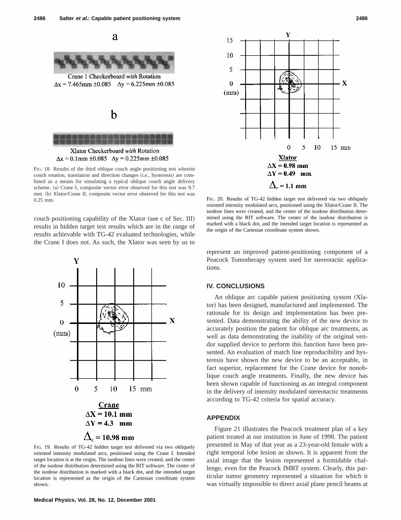
couch positioning capability of the Xlator~see c of Sec. III!results in hidden target test results which are in the rangresults achievable with TG-42 evaluated technologies, wthe Crane I does not. As such, the Xlator was seen by u
FIG. 18. Results of the third oblique couch angle positioning test whecouch rotation, translation and direction changes~i.e., hysteresis! are com-bined as a means for simulating a typical oblique couch angle delivscheme.~a! Crane I, composite vector error observed for this test wasmm. ~b! Xlator/Crane II, composite vector error observed for this test w0.25 mm.
FIG. 19. Results of TG-42 hidden target test delivered via two obliquoriented intensity modulated arcs, positioned using the Crane I. Intentarget location is at the origin. The isodose lines were created, and the cof the isodose distribution determined using the RIT software. The centethe isodose distribution is marked with a black dot, and the intended talocation is represented as the origin of the Cartesian coordinate syshown.
Medical Physics, Vol. 28, No. 12, December 2001
ofleto
represent an improved patient-positioning component oPeacock Tomotherapy system used for stereotactic apptions.
IV. CONCLUSIONS
An oblique arc capable patient positioning system~Xla-tor! has been designed, manufactured and implemented.rationale for its design and implementation has been psented. Data demonstrating the ability of the new deviceaccurately position the patient for oblique arc treatmentswell as data demonstrating the inability of the original vedor supplied device to perform this function have been psented. An evaluation of match line reproducibility and hyteresis have shown the new device to be an acceptablfact superior, replacement for the Crane device for nonlique couch angle treatments. Finally, the new devicebeen shown capable of functioning as an integral componin the delivery of intensity modulated stereotactic treatmeaccording to TG-42 criteria for spatial accuracy.
APPENDIX
Figure 21 illustrates the Peacock treatment plan of apatient treated at our institution in June of 1998. The patipresented in May of that year as a 23-year-old female witright temporal lobe lesion as shown. It is apparent fromaxial image that the lesion represented a formidable clenge, even for the Peacock IMRT system. Clearly, this pticular tumor geometry represented a situation for whichwas virtually impossible to direct axial plane pencil beams
n
ry7s
yedterofetm
FIG. 20. Results of TG-42 hidden target test delivered via two obliquoriented intensity modulated arcs, positioned using the Xlator/Crane II.isodose lines were created, and the center of the isodose distribution dmined using the RIT software. The center of the isodose distributionmarked with a black dot, and the intended target location is representethe origin of the Cartesian coordinate system shown.

ast
raont
octath0sosmugethaily
ifi-by
elyr-
istoa
d
fvecs,ionthecil
tionuch
n-wein-ea-nce.en-t-an
ni-has
tola-hes to
t ooti
o
on-used.uch
2487 Salter et al. : Capable patient positioning system 2487
the target volume without entering or exiting through at leone critical structure~i.e., left and right lenses, left and righeye balls, left and right optic nerves, optic chiasma, and bstem!. The effects of this significant geometric challengethe inverse planning system are apparent by observing6000 cGy prescription isodose line in Fig. 22. The Peacinverse treatment plan is clearly lacking coverage of theget in the region nearest the brain stem indicated byarrow. This was, no doubt, a byproduct of the requisite 50cGy planning limit placed on the brain stem, and its cloproximity to the target. Figure 23 demonstrates the isoddistribution that we obtained in June of that year for the sapatient by developing a Peacock inverse treatment planlizing two couch angles; 180° and 270° Varian scale. Tarcoverage can be seen to be significantly improved intarget volume region nearest the brain stem, while mainting the 5000 cGy limit on the brain stem. It was immediate
FIG. 21. Peacock treatment plan of a very challenging patient treated afacility in June of 1998. This particular patient was the source of our mvation to develop oblique couch angle IMRT capabilities.
FIG. 22. Enlarged axial view of treatment plan from Fig. 12. Note the lackmedial coverage of target when oblique couch angles are not used.
Medical Physics, Vol. 28, No. 12, December 2001
t
in
hekr-e0eeeti-te
n-
clear to us that such tumor geometries could benefit signcantly from the increased degrees of freedom affordedallowing the pencil beam delivery geometry to more closapproach 4p and that, in fact, there were quite likely numeous target geometries for which a nearer to 4p delivery ge-ometry would afford improved conformality. It was at thtime, and in fact because of this patient and our inabilitytreat her with an oblique couch angle, that we initiateddirected effort to develop our own solution to the limitedelivery geometry of the initial Peacock system.
FUTURE WORK: Since our clinical implementation othe Xlator device on August 7, 1998 multiple patients habeen treated at this institution with obliquely oriented arthe first of which being treated August 23, 1998. The notof obliquely oriented arcs and the relationship betweenconformality improvements afforded by increasing the penbeam solid angle of approach and the conformality reducdue to the reduced arc length imposed by such oblique coangles is a topic we believe worthy of future work. Additioally, on December 12, 1998 this institution treated whatbelieve to be the first ever multiple oblique-couch-angle,tensity modulated radiosurgery patient with the Nomos Pcock system. Multiple such patients have been treated siWe believe this method of radiosurgery to hold great pottial for improving the overall quality of RadioSurgical treament, and intend to present data in support of this inupcoming paper.
Note: The Nomos Corporation has requested, and the Uversity of Texas Health Science Center at San Antoniogranted the Nomos Corporation an exclusive licensemanufacture, market and distribute the aforementioned Xtor device under the Nomos product name Crane II. TNomos Corporation has subsequently announced its plan
ur-
f
FIG. 23. Enlarged axial view of treatment geometry from Fig. 12 demstrating the treatment plan achievable when oblique couch angles areNote the much-improved medial coverage of target when oblique coangles are used.

o
.in
ma
.hen
A.a-
dy,eat-
ek,temosi-
o-42,
2488 Salter et al. : Capable patient positioning system 2488
supply the Xlator device developed here with all future Nmos MIMIC systems under the name Crane II.
Financial disclosure: As inventor of the Xlator device, DrSalter receives royalties from the aforementioned licensagreement.
a!Author to whom correspondence should be addressed. [email protected]. P. Carol, W. H. Grant, A. R. Bleir, A. A. Kania, H. Targovnik, BButler, and S. Woo, ‘‘The field-matching problem as it applies to tPeacock three-dimensional conformal system for intensity modulatioInt. J. Radiat. Oncol., Biol., Phys.34, 183–187~1996!.
Medical Physics, Vol. 28, No. 12, December 2001
-
g
il:
,’’
2D. A. Low, S. Mutic, J. F. Dempsey, J. Markman, M. Goddu, and J.Purdy, ‘‘Abutment region dosimetry for serial tomotherapy,’’ Int. J. Rdiat. Oncol., Biol., Phys.45, 193–203~1999!.
3D. A. Low, K. S. Chao, S. Mutic, R. Gerber, C. A. Perez, and J. A. Pur‘‘Quality assurance of serial tomotherapy for head and neck patient trments,’’ Int. J. Radiat. Oncol., Biol., Phys.42, 681–692~1998!.
4B. J. Salter, M. Fuss, D. G. Vollmer, A. Sadeghi, C. A. Bogaev, D. CheT. Herman, and J. M. Hevezi,‘‘The Talon™ removable headframe sysfor stereotactic radiosurgery/radiotherapy: Measurement of the reptioning accuracy,’’ Int. J. Radiat. Oncol., Biol., Phys.~in press!.
5American Association of Physicists in Medicine Report #54, ‘‘Steretactic Radiosurgery,’’ Radiation Therapy Committee Task Group #1995.
Copyright © 2022 FDOKUMEN