Results of a two-year quality control program for a helical tomotherapy unit
11
Tomotherapy Results of a two-year quality control program for a helical tomotherapy unit Sara Broggi a, * , Giovanni Mauro Cattaneo a , Silvia Molinelli a , Eleonora Maggiulli a , Antonella Del Vecchio a , Barbara Longobardi a , Lucia Perna a , Ferruccio Fazio b,c , Riccardo Calandrino a a Medical Physics, and b Radiation Oncology, Scientific Institute San Raffaele, Milan, Italy, c IBFM-CNR, Milan, Italy Abstract Background and purpose: Image-guided helical tomotherapy (HT) is a new modality for delivering intensity modulated radiation therapy (IMRT) with helical irradiation: the slip ring continuously rotates while the couch moves into the bore. The radiation source (Linac, 6 MV) is collimated into a fan beam and modulated by means of a binary multileaf collimator (MLC). A xenon detector array, opposite the radiation source, allows a megavoltage-CT (MVCT) acquisition of patient images for set-up verification. The aim of this paper is to report the results of a two-year quality control (QC) program for the physical and dosimetric characterization of an HT unit installed at our Institute and clinically activated in November 2004, in order to monitor and verify the stability and the reliability of this promising radiation treatment unit. Materials and methods: Conventional Linac acceptance protocols (ATP) and QC protocols were adapted to HT with the addition of specific items reflecting important differences between the two irradiation modalities. QC tests can be summarized as: (a) mechanical and geometrical characterization of the system’s components: evaluation of alignment among radiation source–gantry rotation plan–jaws–MLC–MVCT; (b) treatment beam configuration in static condition: depth dose curves (PDD) and profiles, output factors, output reproducibility and linearity; (c) dynamic component characterization: accuracy and reproducibility of MLC positioning; rotational output reproducibility and linearity, leaf latency, couch movement constancy; (d) gantry–couch and MLC–gantry synchronization; and (e) MVCT image quality. Peculiar periodicity specific tolerance and action levels were defined. Ionization chambers (Exradin A1SL 0.056 cc), films (XOmat-V/EDR2), water and solid water phantoms were used to perform quality assurance measurements. Results: Over a two-year period the final average output variation after possible beam output adjustment was 0.2 ± 1% for the static condition and equal to 0 ± 1% for the rotational condition: around 98% of the collected output data was within the action level compared to 94% if no beam output adjustment was considered. An average energy variation of 0.4 ± 0.4% was found. The daily absolute dose verification of IMRT plans showed a dose reproducibility of 0.5 ± 1.2% and 0.4 ± 2.2%, for low and high dose gradient regions, respectively. Source–jaws–MLC and MVCT alignment results and jaw and leaf positioning accuracy were 6±1 mm. Couch–gantry–MLC synchrony tests showed good stability level (6±2 mm). Conclusions: QC results indicated good reproducibility of all HT mechanical–dosimetric performance. c 2007 Elsevier Ireland Ltd. All rights reserved. Radiotherapy and Oncology 86 (2008) 231–241. Keywords: Helical tomotherapy; Quality control program Helical tomotherapy (HT) is a modality for the delivery of inverse planned intensity modulated radiation therapy (IMRT), together with a highly integrated image-guided ap- proach. It combines the main characteristics of a linear accelerator and a CT scanner [5,12,15,16,28]. Most com- mercial IMRT systems evolved from conventional linear accelerators equipped with multileaf collimators (MLC), whereas helical tomotherapy was specifically designed as an IMRT machine with many unique features. A linear accel- erator is mounted on a ring gantry that continuously rotates while the patient is translated along the gantry rotation axis during treatment delivery. The fan beam is subdivided into beamlets by means of a 64 leaf binary collimator, which provides a time modulation of the treatment beam. The same radiation source, combined with a detector array, al- lows the acquisition of 3D megavoltage images [18,21,22]. Thanks to the capability of reducing uncertainty in pa- tient set-up and the ability to produce extremely high dose gradients and rapid dose fall off outside the target, this unit can provide better dose conformation around the target vol- Radiotherapy and Oncology 86 (2008) 231–241 www.thegreenjournal.com 0167-8140/$ - see front matter c 2007 Elsevier Ireland Ltd. All rights reserved. doi:10.1016/j.radonc.2007.11.005
-
Upload
independent -
Category
Documents
-
view
1 -
download
0
Transcript of Results of a two-year quality control program for a helical tomotherapy unit
Radiotherapy and Oncology 86 (2008) 231–241www.thegreenjournal.com
Tomotherapy
Results of a two-year quality control programfor a helical tomotherapy unit
Sara Broggia,*, Giovanni Mauro Cattaneoa, Silvia Molinellia, Eleonora Maggiullia,Antonella Del Vecchioa, Barbara Longobardia, Lucia Pernaa,
Ferruccio Faziob,c, Riccardo Calandrinoa
aMedical Physics, and bRadiation Oncology, Scientific Institute San Raffaele, Milan, Italy, cIBFM-CNR, Milan, Italy
Abstract
Background and purpose: Image-guided helical tomotherapy (HT) is a new modality for delivering intensity modulatedradiation therapy (IMRT) with helical irradiation: the slip ring continuously rotates while the couch moves into the bore.The radiation source (Linac, 6 MV) is collimated into a fan beam and modulated by means of a binary multileaf collimator(MLC). A xenon detector array, opposite the radiation source, allows a megavoltage-CT (MVCT) acquisition of patientimages for set-up verification. The aim of this paper is to report the results of a two-year quality control (QC) program forthe physical and dosimetric characterization of an HT unit installed at our Institute and clinically activated in November2004, in order to monitor and verify the stability and the reliability of this promising radiation treatment unit.Materials and methods: Conventional Linac acceptance protocols (ATP) and QC protocols were adapted to HT with the
addition of specific items reflecting important differences between the two irradiation modalities. QC tests can besummarized as: (a) mechanical and geometrical characterization of the system’s components: evaluation of alignmentamong radiation source–gantry rotation plan–jaws–MLC–MVCT; (b) treatment beam configuration in static condition:depth dose curves (PDD) and profiles, output factors, output reproducibility and linearity; (c) dynamic componentcharacterization: accuracy and reproducibility of MLC positioning; rotational output reproducibility and linearity, leaflatency, couch movement constancy; (d) gantry–couch and MLC–gantry synchronization; and (e) MVCT image quality.Peculiar periodicity specific tolerance and action levels were defined. Ionization chambers (Exradin A1SL 0.056 cc), films(XOmat-V/EDR2), water and solid water phantoms were used to perform quality assurance measurements.Results: Over a two-year period the final average output variation after possible beam output adjustment was�0.2 ± 1% for the static condition and equal to 0 ± 1% for the rotational condition: around 98% of the collected outputdata was within the action level compared to 94% if no beam output adjustment was considered. An average energyvariation of �0.4 ± 0.4% was found. The daily absolute dose verification of IMRT plans showed a dose reproducibility of�0.5 ± 1.2% and �0.4 ± 2.2%, for low and high dose gradient regions, respectively. Source–jaws–MLC and MVCTalignment results and jaw and leaf positioning accuracy were 6±1 mm. Couch–gantry–MLC synchrony tests showed goodstability level (6±2 mm).Conclusions: QC results indicated good reproducibility of all HT mechanical–dosimetric performance.
�c 2007 Elsevier Ireland Ltd. All rights reserved. Radiotherapy and Oncology 86 (2008) 231–241.
Keywords: Helical tomotherapy; Quality control program
Helical tomotherapy (HT) is a modality for the delivery ofinverse planned intensity modulated radiation therapy(IMRT), together with a highly integrated image-guided ap-proach. It combines the main characteristics of a linearaccelerator and a CT scanner [5,12,15,16,28]. Most com-mercial IMRT systems evolved from conventional linearaccelerators equipped with multileaf collimators (MLC),whereas helical tomotherapy was specifically designed asan IMRT machine with many unique features. A linear accel-erator is mounted on a ring gantry that continuously rotates
0167-8140/$ - see front matter �c 2007 Elsevier Ireland Ltd. All rights re
while the patient is translated along the gantry rotation axisduring treatment delivery. The fan beam is subdivided intobeamlets by means of a 64 leaf binary collimator, whichprovides a time modulation of the treatment beam. Thesame radiation source, combined with a detector array, al-lows the acquisition of 3D megavoltage images [18,21,22].
Thanks to the capability of reducing uncertainty in pa-tient set-up and the ability to produce extremely high dosegradients and rapid dose fall off outside the target, this unitcan provide better dose conformation around the target vol-
served. doi:10.1016/j.radonc.2007.11.005
232 Quality control program for a helical tomotherapy unit
ume, together with a corresponding dose reduction to nor-mal tissue.
A specific accuracy verification program for these highlycomplex plans must be developed to ensure confidence inclinical treatment delivery. The definition of a quality con-trol (QC) protocol for an HT unit presents quite differentchallenges from those related to conventional Linacs[1,9,10,14,25]. Some similarities may be found with thesequential tomotherapy technique [27], where the mainsources of treatment accuracy can be correlated to theproper alignment of the MIMiC collimator (Multivane Inten-sity Modulating Collimator) relative to the radiation beamand the collimator rotation, and to the correct and preciseindexing of the patient table.
Several papers in the literature report the definition ofspecific tests for a correct and complete helical tomother-apy delivery characterization. Balog et al. have proposedspecific beam alignment [2] and dosimetric tests [3] forthe characterization of the helical tomotherapy unit. Morerecently the same authors [4] proposed and developed adaily and monthly QC program in order to test most ofthe inherent features of the tomotherapy device, includingmegavoltage image quality, spatial and temporal resolu-tion accuracy of the dynamic delivery properties and moretraditional beam output characteristics. Fenwick et al.[11], in addition to providing a detailed description ofthe design and components of the machine, developed aQC program with experimental details for its implementa-tion. However, no results and considerations regarding thestability and the accuracy of the system’s performancewere reported.
The output and energy stability of the HT unit has beendescribed only by Mahan et al. [17] on a daily basis over aperiod of 20 weeks. Recently, transversal beam profile con-stancy was investigated by Langen et al. [13] over a sevenweek period, but the aim of their work was to investigatethe use of a commercial diode array for the cone shapemonitoring.
The aim of this paper is to report the results of a two-year QC program for the physical and dosimetric character-ization of an HT unit installed at our Institute and clinicallyactivated in November 2004, in order to monitor and verifythe stability and the reliability of this promising radiationtreatment unit. A brief description of the QC programimplemented in our department, along with technical de-tails concerning the implementation procedure, is also pro-vided. This paper will focus on the treatment machine, notconsidering any control correlated with the integratedtreatment planning system and with the patient qualitycontrol.
Materials and methodsHelical tomotherapy unit characterization
Helical tomotherapy (Hi-Art 2, TomoTherapy, Inc.) is amodality for delivering intensity modulated radiation ther-apy (IMRT) based on a helical irradiation pattern, obtainedwith a continuous rotation of the gantry while the couchtranslates through the bore of the machine. The machineuses a 6 MV Linac, without flattening filter, mounted on a
ring gantry at a source-axis distance (SAD) of 85 cm. Thelongitudinal field width (slice thickness) is defined by a pairof moveable jaws, able to define a maximum open field sizeequal to 40 cm · 5 cm. For patient treatments, the desiredfield size has to be fixed to one of the commissioned fieldsizes (in general approximately 1, 2.5 and 5 cm; in our caseonly 2.5 and 5 cm). In the lateral direction, the beam ismodulated by a binary MLC, with a leaf isocentre width of6.25 mm. Intensity modulation is accomplished by varyingthe aperture time of each leaf; the modulation patterncan change with the gantry angle and is defined over thecourse of a ‘‘projection’’, which corresponds to a gantryrotation of just 7�, giving a total of 51 projections per rota-tion [5,12,15,16,28]. The unit not only represents a newIMRT modality, but is also a completely integrated image-guided system [IGRT]. The same radiation source, detunedto a nominal energy of 3.5 MeV, is also used for megavoltageimage acquisition. A 738 xenon detector array mounted onthe rotating slip ring, opposed to the radiation source, al-lows the 3D tomographic reconstruction of body structuresin order to check and, if appropriate, correct, patient set-up prior to treatment irradiation [18,21,22].
The HT unit is able to deliver highly dynamic treatments,the accuracy of which depends on the overall mechanical,geometrical and dosimetric performance of all thecomponents.
A complete and exhaustive characterization of the sys-tem unit should consider various aspects: a mechanical,geometrical and dosimetric description of all system com-ponents, both in static and rotational conditions; an accu-rate verification of the synchronization of the dynamiccomponents and, finally, a description of the imagingsystem.
The mechanical and geometrical characterization of atomotherapy unit, as for a conventional Linac, deals basi-cally with the alignment of all of the system’s components:lasers, source, moveable jaws, multileaf collimator (MLC),detector array. The impact of these parameters is similarto that of a conventional Linac with some specific differ-ences, mainly related to the accuracy of laser alignment.The room in which the tomotherapy unit is located isequipped with seven lasers: two fixed green lasers able todefine a ‘‘Virtual Isocentre’’ set outside the bore at a fixeddistance of 70 cm from the ‘‘Real’’ radiation isocentre, andfive moveable red lasers used to define patient set-up priorto treatment. Accuracy of the Virtual Isocentre position rel-ative to the radiation isocentre inside the bore, togetherwith the correct movement of the red lasers in relation tothe fixed green ones, are fundamental prerequisites for cor-rect and precise patient positioning and treatment.
The dosimetric beam configuration includes traditionalmeasurements such as beam output, energy, lateral andlongitudinal profiles, output reproducibility and linearity,but with some small differences. The output calibration isdefined, differently from a conventional Linear Accelerator,in terms of a reference dose-rate (cGy/min) at one refer-ence geometrical condition and not based on a defined mon-itor unit (MU) number, irradiation time being the primarymonitor of a tomotherapy unit. The main difference, whencompared to a conventional Linac, is the cone shape of thelateral profile, due to the absence of the flattening filter.
S. Broggi et al. / Radiotherapy and Oncology 86 (2008) 231–241 233
Classical quality index of transversal dose profiles such asflatness and symmetry is not common for this type of sys-tem. On the other hand, the helical nature of the irradiationdelivery renders the periodical acquisition and monitoringof the longitudinal profiles crucial, in order to avoid un-planned treatment overdose or underdose situations.
The most distinctive feature of the tomotherapy unit isthe capability of providing IMRT helical irradiation patterns,thanks to the concomitant and synchronized continuousgantry rotation, couch translation and opening/closingMLC leaf movement. For this reason, a precise characteriza-tion of the synchronized components is necessary, togetherwith an accurate check of couch speed and couch move-ment. With the HT system, the patient is positioned outsidethe gantry bore; after MVCT–KVCT registration the couchautomatically shifts to correct for possible set-up errors.Once the positioning procedure is terminated, for dosedelivery, the couch translates from the virtual to the realradiation isocentre inside the bore and then translates con-tinuously during irradiation along the total length of thetarget.
HT, a highly integrated image-guided system, allows theacquisition of 3D CT images using the same treatment radi-ation source. A more accurate image quality assurance pro-gram could be useful in cases where not only bonestructures but also soft tissues are to be considered duringthe KVCT–MVCT matching.
QC program implementationIn Table 1 the current QC protocol for the tomotherapy
unit implemented at our Hospital was summarized withthe corresponding tolerance (TL) and action levels (AL).The implemented QC protocol was designed to systemati-cally assess the parameters reported in the previous session.Conventional Linac QC protocols were adapted to the heli-cal tomotherapy unit with additional items reflecting impor-tant differences between the two irradiation modalities. Ademanding QC program was initially defined to betterunderstand the mechanical and dosimetric performance ofthis new machine; based on the reported results, differentperiodicity and different tests can be proposed.
Kodak XOmat-V films, scanned with a Vidar VXR16 filmdigitizer, and on-board MVCT imaging detectors were usedfor mechanical and geometric tests. For relative and abso-lute dose measurements, Standard Imaging A1SL ion cham-bers were used (volume 0.056 cc), calibrated in water andconnected to two different electrometers: an eight channelElectrometer (TomoElectrometer) and a monochannel PTWUnidos. For absolute dose determination we followed themethod proposed in the Thomas’s paper [24] to derive thequality conversion factor Kq for the Exradin A1SL ion cham-ber under helical tomotherapy reference conditions.
Daily checksApart from a visual check of the fixed laser alignment
with the reference position, daily QC tests were definedto verify the constancy and the reproducibility of the fol-lowing dosimetric parameters: beam output in static androtational conditions, beam energy, shape constancy ofthe cone profile and output reproducibility in a fully inten-
sity modulated treatment plan, in both low and high dosegradient regions.
Output and energy constancy are measured for a static40 cm · 5 cm maximum open field at gantry 0� with 70 s ofbeam-on time with the first 10 s delivered with all leavesclosed to reach a stable output delivery. The dose is mea-sured with a cylindrical ionization chamber (A1SL, StandardImaging) placed at dmax (1.5 cm depth), 10 and 20 cm fromthe surface of a slab solid water phantom set atSSD = 85 cm. Energy constancy is defined by the ratio be-tween the dose at 20 and 10 cm depths, both normalizedto the maximum dose depth (1.5 cm), to take the outputvariation into account.
Rotational output constancy and lateral profile shape aremonitored through the acquisition, respectively, of the unitdose chamber signal and the MVCT detector array signal fora rotational irradiation with an open field of 40 cm · 1 cm.The daily output pulse signal and the daily cone shape arethen compared with their reference counterparts definedduring the system commissioning.
To monitor the combined impact of jaw width, couchspeed, leaf latency and MLC–gantry–couch synchrony, thedose is measured daily for a fully intensity modulated treat-ment plan, by using two ionization chambers (A1SL, Stan-dard Imaging) inserted in a cylindrical homogeneousphantom (Cheese phantom). Two different measurementspoints are checked: one in a high dose/low dose gradient re-gion and the other in a low dose/high dose gradient region.
The total time for daily tests, performed by physics, isapproximately 45 min, including phantom positioning, elec-trometer warm-up, chamber measurements and output andcone shape analysis.
Monthly checksIn addition to the dosimetric tests already proposed for
daily QC, the program of monthly checks aims at monitoringthe correct alignment of the all system components: fixedand moveable lasers, the virtual isocentre position relativeto the radiation isocentre, jaw twist, field aperture symme-try and gantry angle accuracy. To monitor these compo-nents the film tests and analysis proposed by Balog et al.[2] were implemented.
To check the overhead cross-hair’s alignment relative tothe radiation beam, a film positioned at the virtual isocen-tre and automatically moved to the radiation isocentre(nominal distance equal to 70 cm) is statically irradiatedwith an open field and the analysis of the performed imageallows to check both if the laser is parallel to the radiationbeam and also if the centre of the irradiated image (virtualisocentre) corresponds to the radiation beam centre. Themoveable lasers should then correspond to the fixed lasersat the ‘‘home’’ position and exactly move based on prede-fined values with respect the fixed ones.
The moveable collimating jaws must be aligned with thegantry rotation plane; a double exposure slit beam can beapplied to a film placed at the isocentre, for gantry 0� and180� with two different jaw settings. Two longitudinal pro-files scanned from the field edge should match and the anglejaw/gantry plane can be related to the centre peak distancedifference estimated by considering the 75% dose penumbra
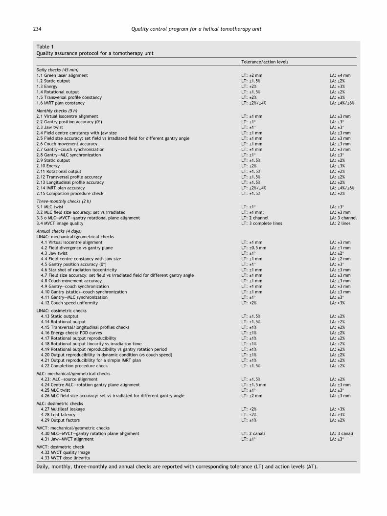
Table 1Quality assurance protocol for a tomotherapy unit
Tolerance/action levels
Daily checks (45 min)1.1 Green laser alignment LT: ±2 mm LA: ±4 mm1.2 Static output LT: ±1.5% LA: ±2%1.3 Energy LT: ±2% LA: ±3%1.4 Rotational output LT: ±1.5% LA: ±2%1.5 Transversal profile constancy LT: ±2% LA: ±3%1.6 IMRT plan constancy LT: ±2%/±4% LA: ±4%/±6%
Monthly checks (5 h)2.1 Virtual isocentre alignment LT: ±1 mm LA: ±3 mm2.2 Gantry position accuracy (0�) LT: ±1� LA: ±3�2.3 Jaw twist LT: ±1� LA: ±3�2.4 Field centre constancy with jaw size LT: ±1 mm LA: ±3 mm2.5 Field size accuracy: set field vs irradiated field for different gantry angle LT: ±1 mm LA: ±3 mm2.6 Couch movement accuracy LT: ±1 mm LA: ±3 mm2.7 Gantry–couch synchronization LT: ±1 mm LA: ±3 mm2.8 Gantry–MLC synchronization LT: ±1� LA: ±3�2.9 Static output LT: ±1.5% LA: ±2%2.10 Energy LT: ±2% LA: ±3%2.11 Rotational output LT: ±1.5% LA: ±2%2.12 Transversal profile accuracy LT: ±1.5% LA: ±2%2.13 Longitudinal profile accuracy LT: ±1.5% LA: ±2%2.14 IMRT plan accuracy LT: ±2%/±4% LA: ±4%/±6%2.15 Completion procedure check LT: ±1.5% LA: ±2%
Three-monthly checks (2 h)3.1 MLC twist LT: ±1� LA: ±3�3.2 MLC field size accuracy: set vs irradiated LT: ±1 mm; LA: ±3 mm3.3 o MLC–MVCT–gantry rotational plane alignment LT: 2 channel LA: 3 channel3.4 MVCT image quality LT: 3 complete lines LA: 2 lines
Annual checks (4 days)LINAC: mechanical/geometrical checks4.1 Virtual isocentre alignment LT: ±1 mm LA: ±3 mm4.2 Field divergence vs gantry plane LT: ±0.5 mm LA: ±1 mm4.3 Jaw twist LT: ±1� LA: ±2�4.4 Field centre constancy with jaw size LT: ±1 mm LA: ±2 mm4.5 Gantry position accuracy (0�) LT: ±1� LA: ±3�4.6 Star shot of radiation isocentricity LT: ±1 mm LA: ±3 mm4.7 Field size accuracy: set field vs irradiated field for different gantry angle LT: ±1 mm LA: ±3 mm4.8 Couch movement accuracy LT: ±1 mm LA: ±3 mm4.9 Gantry–couch synchronization LT: ±1 mm LA: ±3 mm4.10 Gantry (static)–couch synchronization LT: ±1 mm LA: ±3 mm4.11 Gantry–MLC synchronization LT: ±1� LA: ±3�4.12 Couch speed uniformity LT: <2% LA: >3%
LINAC: dosimetric checks4.13 Static outptut LT: ±1.5% LA: ±2%4.14 Rotational output LT: ±1.5% LA: ±2%4.15 Transversal/longitudinal profiles checks LT: ±1% LA: ±2%4.16 Energy check: PDD curves LT: ±1% LA: ±2%4.17 Rotational output reproducibility LT: ±1% LA: ±2%4.18 Rotational output linearity vs irradiation time LT: ±1% LA: ±2%4.19 Rotational output reproducibility vs gantry rotation period LT: ±1% LA: ±2%4.20 Output reproducibility in dynamic condition (vs couch speed) LT: ±1% LA: ±2%4.21 Output reproducibility for a simple IMRT plan LT: ±1% LA: ±2%4.22 Completion procedure check LT: ±1.5% LA: ±2%
MLC: mechanical/geometrical checks4.23: MLC–source alignment LT: ±1.5% LA: ±2%4.24 Centre MLC–rotation gantry plane alignment LT: ±1.5 mm LA: ±3 mm4.25 MLC twist LT: ±1� LA: ±3�4.26 MLC field size accuracy: set vs irradiated for different gantry angle LT: ±2 mm LA: ±3 mm
MLC: dosimetric checks4.27 Multileaf leakage LT: <2% LA: >3%4.28 Leaf latency LT: <2% LA: >3%4.29 Output factors LT: ±1% LA: ±2%
MVCT: mechanical/geometric checks4.30 MLC–MVCT–gantry rotation plane alignment LT: 2 canali LA: 3 canali4.31 Jaw–MVCT alignment LT: ±1� LA: ±3�
MVCT: dosimetric check4.32 MVCT quality image4.33 MVCT dose linearity
Daily, monthly, three-monthly and annual checks are reported with corresponding tolerance (LT) and action levels (AT).
234 Quality control program for a helical tomotherapy unit
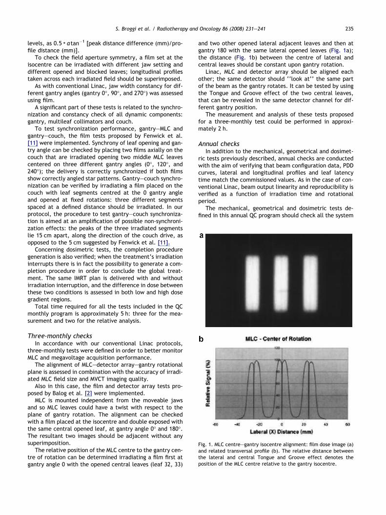
Fig. 1. MLC centre–gantry isocentre alignment: film dose image (a)and related transversal profile (b). The relative distance betweenthe lateral and central Tongue and Groove effect denotes theposition of the MLC centre relative to the gantry isocentre.
S. Broggi et al. / Radiotherapy and Oncology 86 (2008) 231–241 235
levels, as 0.5 * a tan�1 [peak distance difference (mm)/pro-
file distance (mm)].To check the field aperture symmetry, a film set at the
isocentre can be irradiated with different jaw setting anddifferent opened and blocked leaves; longitudinal profilestaken across each irradiated field should be superimposed.
As with conventional Linac, jaw width constancy for dif-ferent gantry angles (gantry 0�, 90�, and 270�) was assessedusing film.
A significant part of these tests is related to the synchro-nization and constancy check of all dynamic components:gantry, multileaf collimators and couch.
To test synchronization performance, gantry–MLC andgantry–couch, the film tests proposed by Fenwick et al.[11] were implemented. Synchrony of leaf opening and gan-try angle can be checked by placing two films axially on thecouch that are irradiated opening two middle MLC leavescentered on three different gantry angles (0�, 120�, and240�); the delivery is correctly synchronized if both filmsshow correctly angled star patterns. Gantry–couch synchro-nization can be verified by irradiating a film placed on thecouch with leaf segments centred at the 0 gantry angleand opened at fixed rotations: three different segmentsspaced at a defined distance should be irradiated. In ourprotocol, the procedure to test gantry–couch synchroniza-tion is aimed at an amplification of possible non-synchroni-zation effects: the peaks of the three irradiated segmentslie 15 cm apart, along the direction of the couch drive, asopposed to the 5 cm suggested by Fenwick et al. [11].
Concerning dosimetric tests, the completion proceduregeneration is also verified; when the treatment’s irradiationinterrupts there is in fact the possibility to generate a com-pletion procedure in order to conclude the global treat-ment. The same IMRT plan is delivered with and withoutirradiation interruption, and the difference in dose betweenthese two conditions is assessed in both low and high dosegradient regions.
Total time required for all the tests included in the QCmonthly program is approximately 5 h: three for the mea-surement and two for the relative analysis.
Three-monthly checksIn accordance with our conventional Linac protocols,
three-monthly tests were defined in order to better monitorMLC and megavoltage acquisition performance.
The alignment of MLC–detector array–gantry rotationalplane is assessed in combination with the accuracy of irradi-ated MLC field size and MVCT imaging quality.
Also in this case, the film and detector array tests pro-posed by Balog et al. [2] were implemented.
MLC is mounted independent from the moveable jawsand so MLC leaves could have a twist with respect to theplane of gantry rotation. The alignment can be checkedwith a film placed at the isocentre and double exposed withthe same central opened leaf, at gantry angle 0� and 180�.The resultant two images should be adjacent without anysuperimposition.
The relative position of the MLC centre to the gantry cen-tre of rotation can be determined irradiating a film first atgantry angle 0 with the opened central leaves (leaf 32, 33)
and two other opened lateral adjacent leaves and then atgantry 180 with the same lateral opened leaves (Fig. 1a);the distance (Fig. 1b) between the centre of lateral andcentral leaves should be constant upon gantry rotation.
Linac, MLC and detector array should be aligned eachother; the same detector should ‘‘look at’’ the same partof the beam as the gantry rotates. It can be tested by usingthe Tongue and Groove effect of the two central leaves,that can be revealed in the same detector channel for dif-ferent gantry position.
The measurement and analysis of these tests proposedfor a three-monthly test could be performed in approxi-mately 2 h.
Annual checksIn addition to the mechanical, geometrical and dosimet-
ric tests previously described, annual checks are conductedwith the aim of verifying that beam configuration data, PDDcurves, lateral and longitudinal profiles and leaf latencytime match the commissioned values. As in the case of con-ventional Linac, beam output linearity and reproducibility isverified as a function of irradiation time and rotationalperiod.
The mechanical, geometrical and dosimetric tests de-fined in this annual QC program should check all the system
236 Quality control program for a helical tomotherapy unit
unit components (as in machine commissioning); the totalnecessary time could be estimated at approximately fourdays.
ResultsThe results of a QC program over the period November
2004–December 2006 are reported in the following part ofthis work. Attention has been focused on our daily checks,due to both their very high number and the fact that theyreflect most of the specific dosimetric aspects of the treat-ment unit.
Daily checksA quick visual check of the fixed virtual isocentre lasers
always indicated good alignment, within 2 mm, relative tothe reference position.
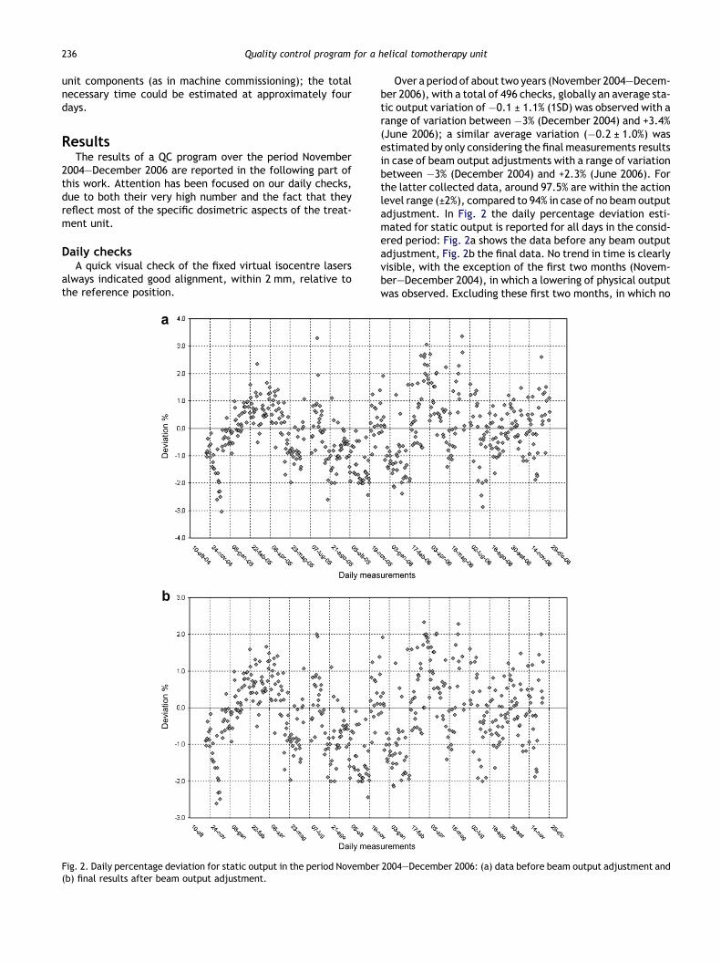
Fig. 2. Daily percentage deviation for static output in the period November(b) final results after beam output adjustment.
Over a period of about two years (November 2004–Decem-ber 2006), with a total of 496 checks, globally an average sta-tic output variation of�0.1 ± 1.1% (1SD) was observed with arange of variation between �3% (December 2004) and +3.4%(June 2006); a similar average variation (�0.2 ± 1.0%) wasestimated by only considering the final measurements resultsin case of beam output adjustments with a range of variationbetween �3% (December 2004) and +2.3% (June 2006). Forthe latter collected data, around 97.5% are within the actionlevel range (±2%), compared to 94% in case of no beam outputadjustment. In Fig. 2 the daily percentage deviation esti-mated for static output is reported for all days in the consid-ered period: Fig. 2a shows the data before any beam outputadjustment, Fig. 2b the final data. No trend in time is clearlyvisible, with the exception of the first two months (Novem-ber–December 2004), in which a lowering of physical outputwas observed. Excluding these first two months, in which no
2004–December 2006: (a) data before beam output adjustment and
S. Broggi et al. / Radiotherapy and Oncology 86 (2008) 231–241 237
beam output adjustment was implemented, an average out-put variation of�0.1 ± 1.0% (1SD) was estimatedwith a rangeof variation between �2.4% (November 2005) and +2.3%(March and June 2006), with 98.5% of the data within ±2%and 85% within ±1.5.
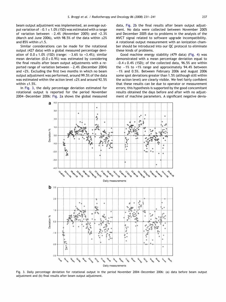
Similar considerations can be made for the rotationaloutput (427 data) with a global measured percentage devi-ation of 0.0 ± 1.0% (1SD) (range: �3.6% to +3.4%); similarmean deviation (0.0 ± 0.9%) was estimated by consideringthe final results after beam output adjustments with a re-ported range of variation between �2.4% (December 2004)and +2%. Excluding the first two months in which no beamoutput adjustment was performed, around 99.5% of the datawas estimated within the action level ±2% and around 92.5%within ±1.5%.
In Fig. 3, the daily percentage deviation estimated forrotational output is reported for the period November2004–December 2006: Fig. 2a shows the global measured
Fig. 3. Daily percentage deviation for rotational output in the periodadjustment and (b) final results after beam output adjustment.
data, Fig. 2b the final results after beam output adjust-ment. No data were collected between November 2005and December 2005 due to problems in the analysis of theMVCT signal related to software upgrade incompatibility.A rotational output measurement with an ionization cham-ber should be introduced into our QC protocol to eliminatethese kinds of problems.
Good machine energy stability (479 data) (Fig. 4) wasdemonstrated with a mean percentage deviation equal to�0.4 ± 0.4% (1SD); of the collected data, 96.5% are withinthe �1% to +1% range and approximately 94.4% between�1% and 0.5%. Between February 2006 and August 2006some spot deviations greater than 1.5% (although still withinthe action level) are clearly visible. We feel fairly confidentthat these results can be due to operator or measurementerrors; this hypothesis is supported by the good concomitantresults obtained the days before and after with no adjust-ment of machine parameters. A significant negative devia-
November 2004–December 2006: (a) data before beam output
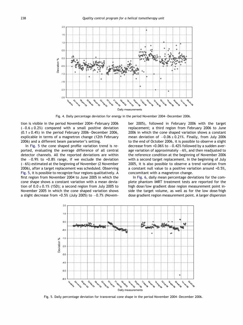
Fig. 4. Daily percentage deviation for energy in the period November 2004–December 2006.
238 Quality control program for a helical tomotherapy unit
tion is visible in the period November 2004–February 2006(�0.6 ± 0.2%) compared with a small positive deviation(0.1 ± 0.4%) in the period February 2006–December 2006,explicable in terms of a magnetron change (12th February2006) and a different beam parameter’s setting.
In Fig. 5 the cone shaped profile variation trend is re-ported, evaluating the average difference of all centraldetector channels. All the reported deviations are withinthe �0.9% to +0.8% range, if we exclude the deviation(�6%) estimated at the beginning of November (2 November2006), after a target replacement was scheduled. ObservingFig. 5, it is possible to recognize four regions qualitatively. Afirst region from November 2004 to June 2005 in which thecone shape shows a constant variation with a mean devia-tion of 0.0 ± 0.1% (1SD); a second region from July 2005 toNovember 2005 in which the cone shaped variation showsa slight decrease from +0.5% (July 2005) to �0.7% (Novem-
Fig. 5. Daily percentage deviation for transversal cone sh
ber 2005), followed in February 2006 with the targetreplacement; a third region from February 2006 to June2006 in which the cone shaped variation shows a constantmean deviation of �0.06 ± 0.21%. Finally, from July 2006to the end of October 2006, it is possible to observe a slightdecrease from +0.06% to �0.42% followed by a sudden aver-age variation of approximately �6%, and then readjusted tothe reference condition at the beginning of November 2006with a second target replacement. In the beginning of July2005, it is also possible to observe a trend variation froma constant null value to a positive variation around +0.5%,concomitant with a magnetron change.
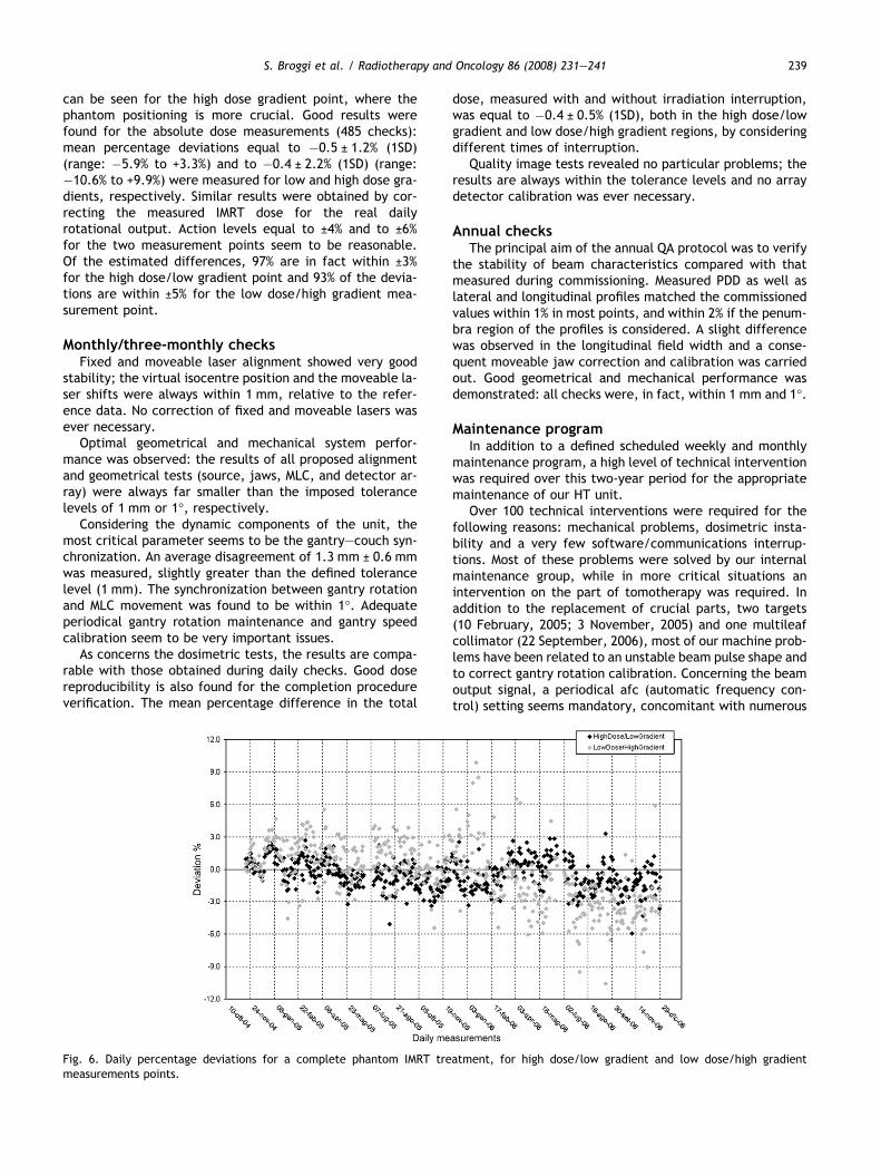
In Fig. 6, daily mean percentage deviations for the com-plete phantom IMRT treatment tests are reported for thehigh dose/low gradient dose region measurement point in-side the target volume, as well as for the low dose/highdose gradient region measurement point. A larger dispersion
ape in the period November 2004–December 2006.
S. Broggi et al. / Radiotherapy and Oncology 86 (2008) 231–241 239
can be seen for the high dose gradient point, where thephantom positioning is more crucial. Good results werefound for the absolute dose measurements (485 checks):mean percentage deviations equal to �0.5 ± 1.2% (1SD)(range: �5.9% to +3.3%) and to �0.4 ± 2.2% (1SD) (range:�10.6% to +9.9%) were measured for low and high dose gra-dients, respectively. Similar results were obtained by cor-recting the measured IMRT dose for the real dailyrotational output. Action levels equal to ±4% and to ±6%for the two measurement points seem to be reasonable.Of the estimated differences, 97% are in fact within ±3%for the high dose/low gradient point and 93% of the devia-tions are within ±5% for the low dose/high gradient mea-surement point.
Monthly/three-monthly checksFixed and moveable laser alignment showed very good
stability; the virtual isocentre position and the moveable la-ser shifts were always within 1 mm, relative to the refer-ence data. No correction of fixed and moveable lasers wasever necessary.
Optimal geometrical and mechanical system perfor-mance was observed: the results of all proposed alignmentand geometrical tests (source, jaws, MLC, and detector ar-ray) were always far smaller than the imposed tolerancelevels of 1 mm or 1�, respectively.
Considering the dynamic components of the unit, themost critical parameter seems to be the gantry–couch syn-chronization. An average disagreement of 1.3 mm ± 0.6 mmwas measured, slightly greater than the defined tolerancelevel (1 mm). The synchronization between gantry rotationand MLC movement was found to be within 1�. Adequateperiodical gantry rotation maintenance and gantry speedcalibration seem to be very important issues.
As concerns the dosimetric tests, the results are compa-rable with those obtained during daily checks. Good dosereproducibility is also found for the completion procedureverification. The mean percentage difference in the total
Fig. 6. Daily percentage deviations for a complete phantom IMRT tremeasurements points.
dose, measured with and without irradiation interruption,was equal to �0.4 ± 0.5% (1SD), both in the high dose/lowgradient and low dose/high gradient regions, by consideringdifferent times of interruption.
Quality image tests revealed no particular problems; theresults are always within the tolerance levels and no arraydetector calibration was ever necessary.
Annual checksThe principal aim of the annual QA protocol was to verify
the stability of beam characteristics compared with thatmeasured during commissioning. Measured PDD as well aslateral and longitudinal profiles matched the commissionedvalues within 1% in most points, and within 2% if the penum-bra region of the profiles is considered. A slight differencewas observed in the longitudinal field width and a conse-quent moveable jaw correction and calibration was carriedout. Good geometrical and mechanical performance wasdemonstrated: all checks were, in fact, within 1 mm and 1�.
Maintenance programIn addition to a defined scheduled weekly and monthly
maintenance program, a high level of technical interventionwas required over this two-year period for the appropriatemaintenance of our HT unit.
Over 100 technical interventions were required for thefollowing reasons: mechanical problems, dosimetric insta-bility and a very few software/communications interrup-tions. Most of these problems were solved by our internalmaintenance group, while in more critical situations anintervention on the part of tomotherapy was required. Inaddition to the replacement of crucial parts, two targets(10 February, 2005; 3 November, 2005) and one multileafcollimator (22 September, 2006), most of our machine prob-lems have been related to an unstable beam pulse shape andto correct gantry rotation calibration. Concerning the beamoutput signal, a periodical afc (automatic frequency con-trol) setting seems mandatory, concomitant with numerous
atment, for high dose/low gradient and low dose/high gradient
240 Quality control program for a helical tomotherapy unit
pulse shaper changes (4 times) and magnetron replacements(22 November, 2005; 13 February, 2006; 13 March, 2006; 8May, 2006; 8 September, 2006; 21 December, 2006). Forcorrect gantry rotation calibration a periodical greasingand speed recalibration were required. Furthermore, sev-eral error messages are correlated to the couch movement;in our experience in only one case has the problem beeneffectively solved by means of the replacement of couchparts, and recalibration.
Obviously parts of these technical interventions shouldbe followed by an opportune QA program. We suggest thata target change should be checked by the mechanical anddosimetric tests able to verify the correct position:source–primary collimator alignment, beam centre–gantryrotation plane alignment, source–MLC alignment, coneshaped profile and topographic profiles’ constancy, energyand output check and finally some IMRT plans checks. Thetests to be performed after a magnetron change could be:output and energy constancy, cone shaped profile constancyand IMRT plan verification. A MLC change should be checkedby considering all the alignment tests relative to source,gantry rotation plane, radiation beam centre and arraydetectors. Based on these technical reports, the downtimefor our tomotherapy unit was considerably greater than thatexpected for a conventional Linac accelerator. We estimatea downtime of around 9.3% for 2005 and around 11% for2006, expressed as the ratio between the hours in whichthe machine does not work during the patients’ treatmenttime and the scheduled patients’ treatment time, consider-ing 5.5 days a week and a daily patients’ treatment time of8 h in 2005 and of 9.5 h in 2006.
Discussion and conclusionsSeveral papers in the literature have attempted to define
different tests and experimental methodologies to verify allthe mechanical, geometrical and dosimetric system compo-nents [2–4,11,13,17,27], by presenting their sensitivity topossible beam and delivery variations. However, few ofthese papers have investigated the time constancy and sta-bility for overall Hi-Art performance.
In this work, the results of a two-year QC program for atomotherapy unit system are reported.
All the geometrical and mechanical tests showed verygood time stability and constancy; moreover, defined toler-ance and action levels, similar to the reference levels sug-gested by Fenwick et al. [11], seem consistent with theresults found in our department. Geometrical and mechan-ical accuracy within 1 mm and within 1� was obtained, butno comparison could be made with other clinical experi-ence. The optimum alignment observed among all the unitsystem components (source–moveable jaws–MLC) permit-ted a reduction in the frequency of these tests, e.g.three-monthly frequency for monthly tests 2.1–2.4.
A wider comparison was possible with other clinical expe-rience concerning dosimetric performance.
Mahan et al. [17] investigated the output and energy sta-bility of a tomotherapy unit over the initial 20 week period:differences within ±2% and ±1.5% were reported for static/rotational output and for beam energy, respectively. In ouranalysis, higher stability and reproducibility variations were
observed, with discrepancies up to ±3% for static and rota-tional output, while beam energy showed similar behaviour.Based on our results, output stability seems slightly inferiorcompared with a conventional Linac: only 94% of the initialcollected data were in fact within the defined action level,if no beam output adjustment was performed. Aside from abeam parameter’s setting and adjustment concomitant withsystem parts’ replacement (target, magnetron, pulse sha-per), in our two-year experience the machine required abeam output tuning in approximately 20 days (around4.5%), in order to report the measured output within the de-fined action level of ±2% [7,8]. Although the values reportedin the literature for beam output constancy were relative toconventional Linacs that work in static conditions, we de-fined and maintained the same action level also for the heli-cal irradiation modality of a tomotherapy system in order tosatisfy the acceptance criteria reported and suggested inthe literature for the global accuracy required in the dosedelivery to a patient in a radiation treatment [6,19,20,26].
With regard to energy stability, the high level of repro-ducibility (1SD = 0.4%) demonstrated here should reducethe frequency of this test: it is felt that this parametercould be checked on a monthly basis, and every time aftera beam output adjustment. The reported results seem toshow neither any time trend variation nor any correlationwith parts’ deterioration. As described in the results para-graph, the only correlation can be observed in Fig. 4, aroundthe middle of February 2006 (12 February, 2006), where adifferent beam parameter’s setting concomitant with amagnetron change brought about a positive energy variationcompared with the negative deviation estimated in the firstperiod. No energy correlation was, however, observed forthe other magnetron and/or target change.
In agreement with the experience reported by Langenet al. [13], a slight decrease of the off-axis beam ratiowas useful in diagnosing a thinning of the target, althoughthe magnitude of the recorded decrease was less than thatreported in the cited paper. As reported in Fig. 5, two targetreplacements have been scheduled in the course of ourexperience: the first one in February 2006 (9th) and the sec-ond one in November 2006 (3rd), both anticipated from aslight decrease in the cone shape variation in the twomonths before the change, respectively, estimated with amean deviation equal to �0.53% (1SD = 0.13%) and �0.31%(1SD = 0.23%). However, the existence of a strict correlationbetween target degradation degree and decrease in the off-axis beam ratio seems not to have been demonstrated.
To monitor the combined impact of all the system unitcomponents, e.g. jaw width, couch speed, leaf latency,MLC–gantry–couch synchrony, the dose was checked dailyfor a fully intensity modulated treatment plan in two differ-ent measurement points: one in a high dose/low dose gradi-ent region and the other in a low dose/high dose gradientregion. Over the period studied, very good results were ob-tained, slightly better than those reported by Thomas et al.[23], where point dose measurements were performed forthe verification of 10 patient treatments. The authors re-ported a mean percentage discrepancy for point dose mea-surements equal to �0.5 ± 1.1%, �2.4 ± 3.7% and�1.1 ± 7.3% for high dose, low dose and critical structurepoints, respectively. In our report comparable results
S. Broggi et al. / Radiotherapy and Oncology 86 (2008) 231–241 241
(�0.5 ± 1.2%) were found for the high dose/low gradient re-gion, while better agreement and reproducibility werefound for the low dose/high dose gradient region(�0.4 ± 2.2%).
All tolerance and action levels defined in our QC protocolwere consistent with the results of periodical checks over aperiod of two years. Only the gantry–couch synchronizationtolerance level was found to be too strict: a mean value ofaround 1.5 mm was in fact found, as opposed to the 1 mmdefined as the tolerance level; this result could make thetolerance level equal to 2 mm, and the action level equalto 4 mm. Fenwick et al. [11] defined a lower action level(1 mm) for the same procedure; a possible explanation forthis discrepancy can be found in the more extreme condi-tion used in our protocol, where the overall couch drive dis-tance is 30 cm, compared with 10 cm distance.
In the two papers by Balog [4] and Langen [13] reportedin the literature, great attention is devoted to the analysisof specific parameters and how their variation can be re-vealed by the measurements methods implemented. Theaim of this study was simply to report the overall perfor-mance of the unit without proposing any particular mea-surement techniques. However, in agreement with Langenet al. [13], and based upon two years experience, we be-lieve that certain independent measurement methods couldbe usefully introduced into our protocol, such as specifictechniques for the measurement of the transversal coneshape (e.g. diode array), the rotational output (e.g. ioniza-tion chamber) based not solely on the internal monitorchamber signal and, above all, an independent measure-ment of the transversal cone shape.
In conclusion, after two years of experience, thanks tothe comprehensive QC protocol implemented, we can dem-onstrate and report optimal mechanical and geometricalperformance of the system delivery; from a dosimetricpoint of view a high level of agreement was observed be-tween calculated and measured dose distributions, althoughhigher output stability could be desirable.
* Corresponding author. Sara Broggi, Health Physics Depart-ment, Servizio di Fisica Sanitaria, IRCCS San Raffaele, via Olgettina60, 20132 Milano, Italy. E-mail address: [email protected]
Received 11 July 2007; received in revised form 31 October 2007;accepted 2 November 2007; Available online 3 December 2007
References[1] Aspradakis MM, Lambert GD, Steele A. Elements of commis-
sioning step and shoot IMRT: delivery equipment and planningsystem issue posed by small segment dimensions and smallmonitor units. Med Dos 2005;30:233–42.
[2] Balog J, Mackie TR, Pearson D, Hui S, Paliwal B, Jeraj R.Benchmarking beam alignment for a clinical helical tomother-apy device. Med Phys 2003;30:1118–27.
[3] Balog J, Olivera G, Kapatoes J. Clinical helical tomotherapycommissioning dosimetry. Med Phys 2003;30:3097–106.
[4] Balog J, Holmes T, Vaden R. Helical tomotherapy dynamicquality assurance. Med Phys 2006;33:3939–50.
[5] Beavis AW. Is tomotherapy the future of IMRT? Br J Radiol2004;7:285–95.
[6] Brahame A, Chavaudra J, Landberg T, et al. Accuracy require-ments and quality assurance of external beam therapy withphotons and electrons. Acta Oncol 1988:27.
[7] Comprehensive QA for radiation oncology: report of AAPMRadiation Therapy Committee Task Group 40. Med Phys1994;21:581–618.
[8] Decreto Legislativo 19 agosto 2005, n�187.[9] Esser M, de Langen M, Dirkx MLP, Heijmen BJM. Commissioning
of a commercial available system for intensity-modulatedradiotherapy dose delivery with dynamic multileaf collima-tion. Radiother Oncol 2001;60:215–24.
[10] Ezzel GA, Galvin JM, Low DA, et al. Guidance documenton delivery, treatment planning, and clinical implemen-tation of IMRT: report of the IMRT subcommittee of theAAPM radiation therapy committee. Med Phys 2003;30:2089–115.
[11] Fenwick JD, Tome WA, Jaradat HA, et al. Quality assurance ofa helical tomotherapy machine. Phys Med Biol2004;49:2933–53.
[12] Jeraj R, Mackie TR, Balog J, et al. Radiation characteristics ofhelical tomotherapy. Med Phys 2004;31:396–404.
[13] Langen KM, Meeks SL, Poole DO, et al. Evaluation of a diodearray (Tomo Dose) for QA measurements on a helical tomo-therapy unit. Med Phys 2005;32:3424–30.
[14] Low D. Quality assurance of intensity-modulated radiotherapy.Semin Radiat Oncol 2002;12:219–28.
[15] Mackie TR, Holmes T, Swerdloff S, et al. Tomotherapy: a newconcept for the delivery of dynamic conformal radiotherapy.Med Phys 1993;20:1709–19.
[16] Mackie TR, Balog J, Ruchala K, et al. Tomotherapy. SeminRadiat Oncol 1999;9:108–17.
[17] Mahan SL, Chase DJ, Ramsey CR. Technical note:output and energy fluctuations of the tomotherapyHiÆArt helical tomotherapy system. Med Phys 2004;31:2119–20.
[18] Meeks SL, Harmon JF, Langen KM, et al. Performance char-acterization of megavoltage computed tomography imaging ona helical tomotherapy unit. Med Phys 2005;32:2673–81.
[19] Mijnheer B, Battermann J, Wambersie A. What degree ofaccuracy is required and can be achieved in photon andneutron therapy. Radiother Oncol 1987;8:237–52.
[20] Quality assurance of treatment planning system-practicalexamples for non-imrt photons beams, booklet n� 7, ESTRO,Brussels; 2004.
[21] Ruchala KJ, Olivera GH, Schloesser EA, Mackie TR. Megavolt-age CT on a tomotherapy system. Phys Med Biol1999;44:2597–621.
[22] Ruchala KJ, Olivera GH, Kapatoes JM, et al. MVCT imagereconstruction during tomotherapy. Phys Med Biol2000;45:3545–62.
[23] Thomas SD, Mackenzie M, Field GC, et al. Patient specifictreatment verifications for helical tomotherapy treatmentplans. Med Phys 2005;32:3793–800.
[24] Thomas SD, Mackenzie M, Rogers DW, et al. A Monte Carloderived TG-51 equivalent calibration for helical tomotherapy.Med Phys 2005;32:1346–53.
[25] Van Esch A, Huyskens DP, Bohsung J, et al. Acceptance testsand QA procedures for the clinical implementation of IMRTusing inverse planning and the sliding window technique:experience from five radiotherapy departments. RadiotherOncol 2002;65:53–70.
[26] Venselaar J, Welleweerd H, Mijnheer B. Tolerances for theaccuracy of photon beam dose calculation of treatmentplanning systems. Radiother Oncol 2001;60:203–14.
[27] Woo SY, Grant W, McGary JE, Teh BS, Butler EB. The evolutionof quality assurance for intensity-modulated radiation therapy(IMRT): sequential tomotherapy. Int J Radiat Oncol Biol Phys2003;56:274–86.
[28] Yang JN, Mackie TR, Reckwerdt P, et al. An investigation oftomotherapy beam delivery. Med Phys 1997;24:425–36.