Uplift Capacity of - Helical Anchors - Foundation Technologies
Upload
khangminh22Category
view
2download
0
P a g e 1 | 32
Twisted Helical shaped Graphene Nano-Ribbons: Role of Symmetries
and Passivation
Rajesh Thakur*$, P. K. Ahluwalia$, Ashok Kumar&, Munish Sharma and Raman
Sharma$
$Department of Physics, Himachal Pradesh University, Summer Hill, Shimla 171005
Himachal Pradesh (INDIA) &Department of Physical Sciences, School of Basic and Applied Sciences, Central University
of Punjab, Bathinda, 151001 Punjab (INDIA) #Department of Physics, School of Basic and Applied Sciences, Maharaja Agrasen
University, Atal Shiksha Kunj, Barotiwala, 174103, Himachal Pradesh (INDIA)
*Corresponding author: Email: [email protected]

P a g e 2 | 32
Abstract
The Hydrogen and Fluorine planar armchairs graphene nanoribbons (H & F AGNRs),
subjected to twist deformation within fixed periodic boundary conditions, eventually morph
to a helical conformations are investigated at few tractable points. Unlike structural
properties, no effect of symmetries on mechanical properties is observed, though passivation
does have a significant effect on mechanical as well as on electrical properties. Hooke’s law
for severely twisted AGNRs indicates the high elasticity of H-AGNRs whereas the F-
AGNRs shows plasticity after threshold torsional strain. Torsional stress(𝑬𝜽) is
approximated from the variation in total energy(𝜟𝑬) with square of torsional strain(𝜽𝟒𝜮𝟒).
Further, the effect of passivation on the electronic properties of helical conformations with
different torsional strain is decisive in metal-to-semimetal and semimetal-to-metal
transition. The band gap response of narrow GNRs 𝑵=6, 7 & 8, within a fixed cell under
sever twisting arranged itself in two group as (𝑖) monotonously increasing for 𝒒 = 0,2 and
(𝑖𝑖) decreasing for 𝒒 = 1, here 𝒒 = 𝑚𝑜𝑑(𝑵, 3) in effective strain space(𝜽𝟐𝜮𝟐). This trend
has also been observed for Fluorine passivated AGNRs, though band gap of 𝑵=7 F-AGNRs
drops from 𝑬𝒈≃0.95eV to 𝑬𝒈≃0.05eV at extreme torsional strain forming Dirac cone at±𝑲
allows dissipation less transport to charge carriers of high kinetic energy at low bias.

P a g e 3 | 32
1. Introduction
The strain engineering is one of the most efficient way to tune the electronic properties of
nanostructures. The various ways to apply strain in graphene nanoribbons (GNRs) including
bending[1,2], twisting[3] and intrinsic rippling[4] can be used to develop materials with
tunable interaction of core and edge regions beyond simple straintronics[5,6]. One can also
anticipate possible influence on the electronic properties of GNRs by applying an asymmetric
strain along the width of ribbons. Furthermore, bending and twisting break the mirror and
inversion symmetry[7], hence, numerous desirable properties of GNRs which are likely to be
influenced still remain unexplored under such conditions, which may have new possibilities
and applications in various technologies and devices[8]. Moreover, the chemistry at the
periphery atoms of the GNRs is most influential in modulating the band gap of narrow GNRs
which has prompted experimentalist to demonstrate that these GNRs can be used as molecular
wires which exhibit metallic behavior even at room temperature[9] leading to their usage as
ideal interconnects in molecular scale electronic circuitry.
The developments of GNR-based nano-electronics[10] needs further impetus to bring it out
of its seemingly saturated possibilities and this provides us a strong motivation to investigate
the topologically helical shaped soft conformations of GNRs from symmetry perspective. Note
that helical conformations can either be self-assembled or be fabricated by several growth and
fabrication techniques that have been successfully used to produce different chiral systems[11–
13]. Recently, a range of synthesis methods has been developed to obtain twisted GNRs[14–
17], which opens up a new possible route to potential applications of chiral systems including
THz generation[18–21], stretchable electronics[22,23], non-linear electronics[24–26] and spin
selectivity[27–31].

P a g e 4 | 32
Figure 1: Categorization of structural topology of untwisted AGNRs. The nanoribbons are identified
according to the type of (a) zigzag’ termination having inversion & mirror symmetry and (b) zigzag
termination having only mirror symmetry respectively. Widths that correspond to value of number of
dimer (N) along the lateral direction are labeled from “1” to “N”. Schematics of AGNR unit cell
structures are shown with hydrogen (Fluorine) passivation. The unit cell of each structure that is
commensurate with the termination is indicated by the bold black vertical lines.
The mechanical and electronic properties of Armchair graphene nanoribbons (AGNRs) are
sensitive not only to their width and edge chemistry but also to the morphology. Therefore, in
this paper, we study the effect of twisting and passivation of Hydrogen and Fluorine on
structural, mechanical and electronic properties of a twisted helical of AGNRs[3,32–34] within
the fixed boundary condition making translational symmetry tractable for a few discrete twist
angles values (𝜽), which have not been explored to the best of our knowledge. AGNRs with
zigzagꞌ type termination with 𝑵=odd (Figure 1(a)) have both mirror and inversion symmetry,
however, AGNRs with 𝑵=even (Figure 1(b)) have only mirror symmetry. The reason to
investigate the GNRs of narrow width is that it favors twists and forms the helical shaped
morphologies with small size. It is to be mentioned that the use of periodic boundary condition
(PBC) for helical shaped GNRs allows only discrete torsional deformations compatible with
the translational symmetry along Z-direction, opens up novel route to inquire and extract the
physics of 1D twisted ribbons in the nature.
In this work we have introduced a novel way to define a lattice constant of super cell of
helical AGNRs which formed on twisting a one dimensional (1D) untwisted super cell and

P a g e 5 | 32
applicable for all 1D systems. After computational details (Section 2), we will find the answer
of following questions in the rest of the article:
(A)In section (3.1): How does symmetry effect the super cell lattice of helical AGNRs? (B)
In section (3.2): What would be the response of GNRs’ mechanical properties to twist and what
if we passivate the AGNRs with different type of atoms? What could be the possible reason
which alters its mechanical properties? Is there any mathematical model that can relates the
mechanics of AGNRs passivated with different atoms with their elasticity? (C) In section (3.3):
What happened to the electronic band gap when we twist the helical AGNRs with different
torsional angle? Is there any effect on band gap if we change the edge environment by changing
the passivated atom? How can we define the dependence of band gap with torsional angle or
torsional strain mathematically? Does the curvature of AGNRs influences the capacity to hold
the electron density of AGNRs? (D) In Section (3.4) we have made comparison of our results
with the previous studies and finally in Section (4) we give the summary of the work we have
done.
2. Computational details
All the calculations presented in this work are performed using spin-polarized first
principles method by using Spanish Initiative for Electronic Simulations with Thousands of
Atoms (SIESTA)[35] simulation package. Normconserving Troullier Martin pseudopotential
in fully separable Kleinman and Bylander form has been used to treat the electron-ion
interactions[36]. The exchange and correlation energies have been treated within GGA-PBE
functional[37]. The Kohn Sham orbitals were expanded as a linear combination of numerical
pseudo atomic orbitals using a split-valence double zeta basis set with polarization functions
(DZP). The convergence for energy is chosen as 10−5𝑒𝑉 between two electronic steps.
P a g e 6 | 32
Throughout geometry optimization, the confinement energy of numerical pseudo-atomic
orbitals is taken as 0.01Ry. Minimization of energy was carried out using standard conjugate-
gradient (CG) technique. Converged values of sampling for the 𝒌-mesh grid ~10−2Å−1 have
been used according to Monkhorst-Pack scheme[38] to sample Brillioun zone.
Furthermore, without allowing the axial relaxation of cell the helical structures were relaxed
until the force on each atom was less than10−2𝑒𝑉Å−1, it provides an effective way to explore
both axial and torsional deformation simultaneously. The spacing of the real space used to
calculate the Hartree exchange and correlation contribution of the total energy and Hamiltonian
was 800Ry for untwisted AGNRs. The converged values were taken in a range between
1300Ry to 1450Ry for twisted AGNR. Vacuum region of about ~12Å along X and Y-direction
was used in calculations to prevent the superficial interactions between the periodic images.
To check the reliability and the accuracy of numerical orbitals basis sets, a test calculations
for untwisted N=4 GNR along zigzag direction using plane wave basis sets code VASP[39,40]
are performed (See Figure S1) for comparison, which are in very good agreements in terms of
curvature matching of bands.
3. Results and Discussion
The calculated lattice parameters for hydrogen passivated AGNRs (H-AGNRs) unit cells
are found to be in good agreement with the previously reported values obtained using density
functional theory (Table 1&2). The lattice constants for 𝑵=6 H-AGNRs, N=7 H-AGNRs and
N=8 H-AGNRs are found to be 4.33Å, 4.32Å and 4.31Å, respectively (Figure S2(a)). We
multiply the unit cell to form a super cell and twist the AGNRs mechanically by 𝝅-rad to form
helical morphologies. Because of inverse Poynting effect[41], a significant stress was found
along the AGNRs axis. In this study we restrict ourselves only on those helical shaped systems

P a g e 7 | 32
whose lattice constants are described by symmetry with fixed end results in axial strain, hence,
experiencing torsional and tensile strain simultaneously.
Similarly the calculated lattice constant of fluorine passivated AGNRs (F-AGNRs) for 𝑵=6,
7 and 8 is 𝑳𝒐=4.44 Å, 4.42 Å and 4.41Å, respectively (Figure S2(b)).
3.1. Structural Properties
We classified different helical conformations by four parameters: lattice constant (𝑳𝑀),
torsional angle(𝜽), width (𝑾), torsional strain (𝜸𝒎𝒂𝒙) that depends on width of AGNRs as
given in the Table 1 for 𝑵=even and Table 2 for 𝑵=odd. The subscript 𝑴 of lattice constant
𝑳𝑴 is the number of times unit cell get repeated or multiplied to have required twisted super
cell. To obtain the helical configuration, the system is subjected to a mechanical force to
artificially twist the ribbon from the flat configuration into a helical conformation as described
in Figure 2((a) to (c)). In order to incorporate boundary conditions the torsional angle is
calculated in a way that the positions of atoms do not lose their periodicity and always coincide
with the positions of atoms in the next super cell even after 180º rotation. Thus the lattice
constants for twisted unit cell follow the relation:
𝑳𝑴 = 𝑴 ∗ 𝑳𝟎 (1)
Here 𝑴 is the multiplicity factor defined as 𝑴 = 𝑰 +𝑺
𝟐 as 𝑰 is any integer and for 𝑵=odd
AGNRs the 𝑺=0 which do not possess inversion symmetry and for 𝑵=even AGNRs the 𝑺=1
which do possess inversion symmetry as depicted in Figure 1. Therefore, we may classify the
helical conformations in two groups 𝑺 = 𝑚𝑜𝑑(𝑵, 2) is defined by the inversion symmetry
results into half-integral and integral multiplication of unit cell to form a periodic super cell of
1D helical conformations.
P a g e 8 | 32
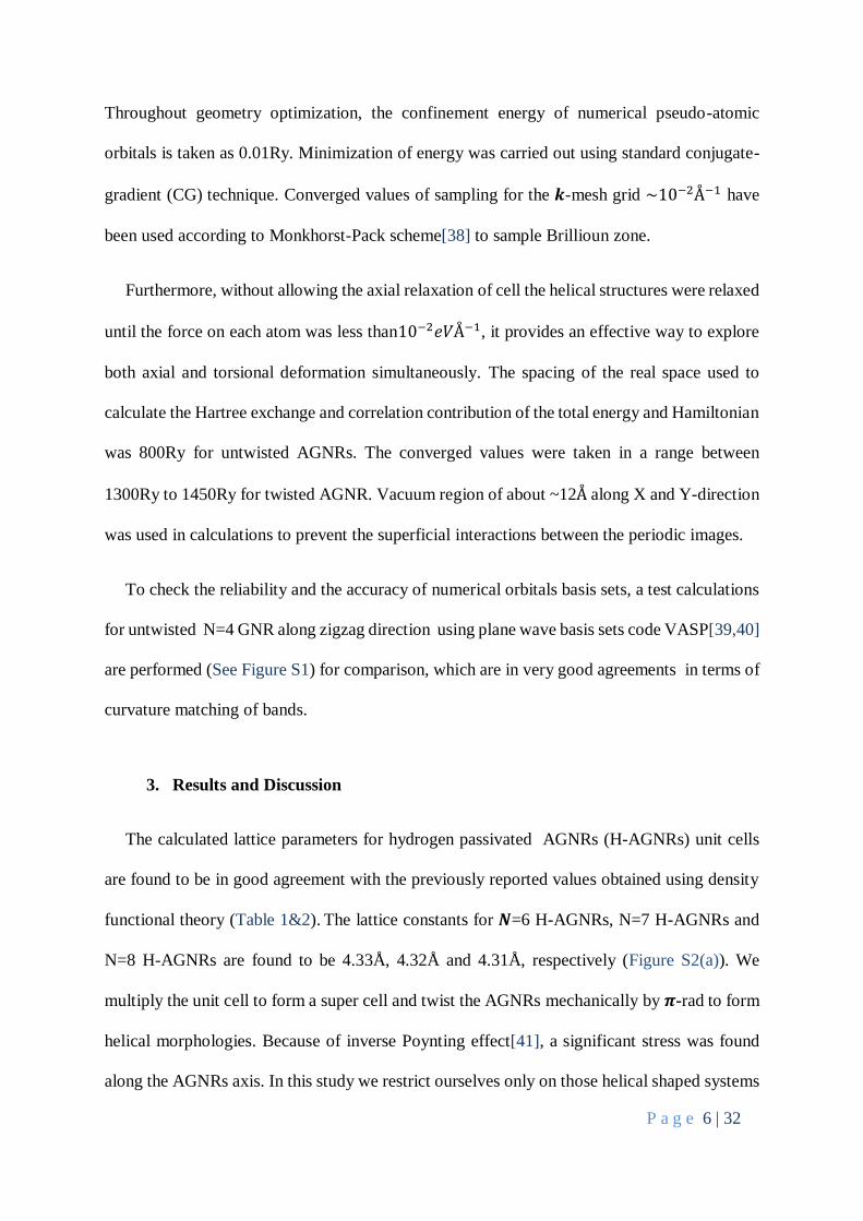
Figure 2: Schematic description of the mechanics of twisting that has been applied to an infinitely
long (a) planar N=8 AGNR having minimum primitive lattice constant 𝑳𝑴=4.32Å and torsional angle
𝜽=zero that morphs it into (b) helical shaped infinitely long twisted AGNR, now with increased value
of lattice constant 𝑳𝑴=37.21Å and torsional angle 𝜽=0.121rad that was further twisted to (c) a helical
of smaller lattice constant 𝑳𝑴 and larger torsional angle 𝜽. Torsional angle increased in ascending
order as for fig(a) < fig(b) < fig(c). In this way we have the few tractable arrangements of twisted
ribbon that meet with the translational symmetry constraints. (d) 𝜸𝒎𝒂𝒙 is the angle made by the
tangent of edge atoms with helical axis 𝜽 (green arrow pointing outward to the plane of paper). (e)
The misalignment of 𝑷𝒁 Orbitals of two adjoining C-C atoms bonds under twisting.
We are interested in studying the non-uniform planar tension situation which arises in the
twisted AGNR and is different for different values of torsional angle. Cylindrical coordinates
are chosen as these are most appropriate to study the torsional effect. If we take Z-axis as a
AGNRs axis then the torsional strain (𝜸) along that actually gets induced, as a result of torsional
angle (𝜽) coincident with AGNRs axis, can be expressed as:
𝜸 = 𝝆
𝒅𝜽
𝒅𝒛 ; 𝟎 ≤ 𝝆 ≤ 𝑾/𝟐
(2)
The 𝝆 is a distance of a point from the axis of rotation perpendicular to Z-axis, 𝑾 is the width
of ribbon, 𝒅𝜽 is the torsional angle and 𝝆𝒎𝒂𝒙 = 𝑾/𝟐 for twisted AGNR. For any twisted
AGNR, the 𝒅𝒛 equals 𝑳𝑴 and 𝒅𝜽 equals 𝝅 rad. The value of shear strain is maximum at the
peripheral position of ribbon which can be expressed as,
𝜸𝒎𝒂𝒙 = 𝝆𝒎𝒂𝒙
𝒅𝜽
𝒅𝒛 (3)

P a g e 9 | 32
This equation gives rise to the monotonous increasing strain towards the edges from the axis
of the center of rotation and leads to a maximum strain along the peripheral position of GNRs
and no strain along the AGNRs axis.
Figure 3: Twisted N=8 H-AGNRs with multiplicity 𝑴, torsional angle (𝜽) and lattice constant for
(a) 4.5, 0.09rad & 36.72Å (b) 5.5, 0.10rad & 32.33Å (c) 6.5, 0.11rad & 28.02Å (d) 7.5, 0.13rad &
23.71Å and (e) 8.5, 0.16rad & 19.40Å, respectively. Black dashed lines are the periodic boundary
condition for the twisted AGNR super cell. In (e) we elaborated the value of 𝑴 = 𝑺/𝟐 + 𝑰 for 𝑰=8
twisted 8-AGNR, that comes out to be 8.5 and written as a subscript for each lattice constant value
in Table 1. (f) Depicts N=7 H-AGNRs for 𝑴=4.0, with each triad point is a C atom and lines joining
these points are C-C bonds. Colors represent the strain linearly depends on the distance from axis of
AGNR (Equation 2). Yellow triad points lies on the axis of twisted ribbon. Gray solid lines are the
lattice constant 𝑳𝑴.
3.1.1. N=even Twisted AGNRs
Even twisted (𝑵=6 and 8) AGNRs have even number of dimer lines; therefore, these two
do not have inversion symmetry Figure 1(b). For further elaboration we take 𝑵=8 H & F
AGNRs. The lattice constant 𝑳𝑀 of H and F AGNRs for minimum multiplicity value 𝑴=4.5
and S=1 is 19.40Å &19.85Å , respectively, which corresponds to the most twisted nanoribbons
within a fix periodic boundary as shown in Figure 3(a). Hence, these have maximum torsional
angle 𝜃=0.16𝑟𝑎𝑑Å−1 for both, torsional strain 𝜸max=0.68𝑟𝑎𝑑 & 0.66𝑟𝑎𝑑 for H & F AGNRs,
respectively, and the narrowest width 8.42Å & 8.35Å, respectively, among all the twisted 8-
AGNRs we have studied. Figure 3(a-to-e) represent a ball and stick model for twisted 𝑵=8 H-
P a g e 10 | 32
Table 1 Calculated structural parameters for the edge passivated N=even AGNRs for different values
of torsional angle(𝜽). The 𝑳𝑴 is a lattice constant of the cell and the subscript 𝑴 of lattice constant
𝑳𝑴is the number of times unit cell get multiplied to have required twisted super cell, 𝜸𝒎𝒂𝒙 is the
maximum torsional strain and the width of AGNRs is denoted by 𝑾. Theoretical [42]@, [43]# and
[44]$
System 𝑳𝑴(Å) 𝜽(𝒓𝒂𝒅Å−𝟏) 𝜸𝒎𝒂𝒙(𝒓𝒂𝒅) 𝑾(Å)
6HAGNR
4.331.0 Zero Zero 6.15, 6.15#, 6.19$
32.447.5 0.10 0.30 6.13
28.116.5 0.11 0.34 6.12
23.795.5 0.13 0.40 6.11
19.464.5 0.16 0.49 6.09
15.143.5 0.21 0.63 6.03
8HAGNR 4.311.0, 4.35@ Zero Zero 8.63, 8.67#, 8.66$
36.728.5 0.09 0.37 8.57
32.337.5 0.10 0.42 8.56
28.026.5 0.11 0.48 8.54
23.715.5 0.13 0.56 8.49
19.404.5 0.16 0.68 8.42
6FAGNR 4.441.0 Zero Zero 6.07
33.327.5 0.09 0.29 6.06
28.886.5 0.11 0.33 6.05
24.445.5 0.13 0.39 6.05
19.994.5 0.16 0.47 6.02
15.553.5 0.20 0.60 5.97
8FAGNR 4.411.0 Zero Zero 8.54
37.498.5 0.08 0.36 8.51
33.087.5 0.10 0.40 8.49
28.676.5 0.11 0.46 8.47
24.265.5 0.13 0.55 8.42
19.854.5 0.16 0.66 8.35
AGNRs having value of torsional strain (𝜽) in descending order and 𝑴 is in ascending order
from (a) 𝑴=4.5 < (b) 𝑴=5.5 < (c) 𝑴=6.5 < (d) 𝑴=7.5 and (e) 𝑴=8.5. In Table 1 we have

P a g e 11 | 32
given the calculated lattice parameters for 𝑵=6 and 8 (i.e. even) for H & F passivated AGNRs.
Because of the absence of inversion symmetry the value of multiplicity factor (𝑴) comes out
to be half integral as explained pictorially in Figure 3(e). Torsional strain is in ascending order
from 𝑴=8.5 to 𝑴=4.5, thus Beyond 𝑴=4.5 the AGNRs broke off and hence were not
considered for the present study (See Figure S3).
3.1.2. N=odd Twisted AGNRs
In the case of odd twisted AGNRs, due to inversion symmetry (Figure 1(a)), the 𝑺=0 and the
values of 𝑴 = 4 ≤ 𝑴 ≤ 8 in Equation (1) gives the value of lattice constant of twisted helical
H-AGNRs within periodic super cell. The lattice constant of most twisted 𝑵=7 H & F AGNRs
is 𝑳𝑴=17.26Å & 17.68Å and the width (𝑾) of the ribbons is 7.13Å & 7.04Å, respectively. The
value of torsional angle(𝜽) and maximum torsional strain 𝜸𝐦𝐚𝐱 keeps on increasing as the
value goes from 𝑴=8 to 𝑴=4 as given in the Table 2. Figure 3(f) shows the wire-straw model
for twisted 𝑵=7 AGNRs, with each triad point representing C atom and the lines connecting
these atoms are C-C bonds. Strain depends linearly on the distance of dimer lines from AGNRs
axis (Equation 2) is differentiated by color code as it increased in ascending order as Yellow <
Magenta < Blue < Red. Because of odd number of dimer lines yellow triad points lies on the
axis of twisted ribbon. In Table 2 the lattice parameters for remaining torsional angle for helical
shaped AGNRs unit cell for 𝑵=7 H & F AGNRs are listed.
From above discussion, we can conclude that for bipartite AGNRs the symmetry has
played a decisive role in defining the unit cell lattice parameters of helical shaped AGNRs. On
application of torsional strain the mirror and inversion symmetry get broken. Note that only
within fixed end the AGNRs’ width kept decreasing and eventually get broken. Narrower

P a g e 12 | 32
AGNRs were twisted up to higher torsional angle than wider AGNRs because of strain
experienced by the edge atoms was higher in case of wider AGNRs.
Table 2 Calculated structural parameters for the edge passivated N=7 (i.e. odd) AGNRs for
different values of torsional angle(𝜽). The 𝑳𝑴 is a lattice constant of the cell and the subscript
𝑴 of lattice constant 𝑳𝑴is the number of times unit cell get multiplied to have required twisted
super cell, 𝜸𝒎𝒂𝒙 is the maximum torsional strain and the width of AGNRs is denoted by 𝑾.
Theoretical [43]# and [44]$; Experimental [45]&
System 𝑳(Å) 𝜽(𝒓𝒂𝒅Å−𝟏) 𝜸𝒎𝒂𝒙(𝒓𝒂𝒅) 𝑾(Å)
7HAGNR
4.321.0, 4.2& Zero Zero 7.37, 7.31#,
7.34$, 7.4&
34.538.0 0.09 0.33 7.32
30.217.0 0.10 0.38 7.31
25.896.0 0.12 0.44 7.27
21.585.0 0.15 0.53 7.22
17.264.0 0.18 0.65 7.13
7FAGNR
4.421.0 Zero Zero 7.26
35.378.0 0.09 0.32 7.24
30.957.0 0.10 0.37 7.22
26.536.0 0.12 0.43 7.19
22.115.0 0.14 0.51 7.14
17.684.0 0.18 0.63 7.04
3.2. Mechanical Properties: Twist and Tension on GNRs
It has been reported previously that inverse Poynting effect[41] (shrinking of
nanoribbons on twisting along AGNRs axis) triggered by an axial tensile stress 𝝈 (along Z-
direction) is associated with the twist-induced inhomogeneous tensile strain. Since we are
considering twisting within the fixed end, the resultant strain in AGNR axis induces Poynting
Stress, expressed in Voigt tensor form (Table S1) which has only one non-zero component out

P a g e 13 | 32
of six: [σx, σy, σz, σxy, σxz, σyz] ⇒ [0, 0, σz, 0, 0, 0] and this was calculated for all considered
systems. Positive Poynting stress value shows the tensile strain that been experienced by the
twisted H & F AGNRs, and it confirms the case of inverse Poynting vector of these systems.
Figure 4: (a) and (b) Computed axial Poynting Stress (𝝈𝒛) versus 𝜮𝟐𝜽𝟐 under fixed boundary
condition for H & F AGNRs, respectively. Calculated total energy change per unit primitive cell 𝜟𝑬
versus 𝜮𝟒𝜽𝟒 validated the approximation even for severely twisted (c) H-AGNRs and (d) F-AGNRs.
The stress under the induced effective tensile strain 𝜺𝒏 is obtained with Hooke’s law as
𝜺𝒏 proportional to 𝝈𝒛. Furthermore, within the elastic approximation 𝝈𝒛 ∝ 𝜺𝒏 where 𝜺𝒏 =
𝟏
𝟐𝜽𝟐𝜮𝟐 i.e. effective tensile strain associated with the twist angle induces misalignment angle
(See Figure 2(e)) in the adjoining C-C bonds. Here we propose the 𝜮𝒎 = 𝟐 ∫ 𝝆𝒎−𝟏𝒅𝝆𝑾/𝟐
𝟎,
where the width (𝑾) of the ribbons at each twist is given in Table 1&2. Range of limit dictates
the symmetry that arises from the coincidence of torsional strain and AGNRs axis. The tensile
component of energy (𝑬𝒔) follows from relation
𝐸𝑠 ≃1
2
𝐶
(1−𝜈2)𝜺𝑛
2 as:
𝐸𝑠 ≃
1
8
𝐶
(1 − 𝜈2)𝜃4∑4
(4)
Here 𝑪 is the stiffness constant and 𝝂 is the Poisson’s ratio, and 𝜽 is the torsional angle. The
analysis of the stress-strain relation behavior for severe torsional strain has been done by
plotting 𝝈𝒛 (axial Poynting stress) versus 𝜽𝟐𝜮𝟐 in Figure 4(a&b) for H & F passivized AGNRs,

P a g e 14 | 32
respectively. The linear dependence of 𝝈𝒛 on 𝜽𝟐𝜮𝟐 corresponds to the elastic deformation. In
case of F-AGNRs the higher order terms account for both nonlinear elastic deformation and
strain softening[46]. The 𝝈𝒛 − 𝜮𝟐𝜽𝟐 curves shows linear variation for H-passivated AGNR
indicating unusually high flexibility (i.e. the linear nature of stress and strain dependence)
prevails even for higher torsional strain. In contrast, F-AGNRs at lower range of 𝜽 taken
between 0.00 < 𝜽 < 0.110, 𝝈𝒛 is a linear function of 𝜮𝟐𝜽𝟐 while the higher order terms of
Taylor’s series are neglected. Therefore, in this range the variation can be regarded as
Harmonic in nature for all F-AGNRs. On further increase in torsional strain, the contribution
of nonlinear terms is indicating the inharmonic variation implies that the deformation is plastic
in this region.
The loss of linear behavior for higher torsional strain values in F-AGNRs indicating some
threshold for the extent of elongation of C-C bonds. Note that misalignment angle between the
two π-orbitals located on two connected C atoms along the AGNR axis depends on 𝜽 (See
Figure 2(e)). Figure 4(b), the loss of linear behavior for higher torsional strain values in F-
AGNRs indicating some threshold for the extent of elongation of C-C bonds. Note that
misalignment angle between the two π-orbitals located on two connected C atoms along the
AGNR axis depends on 𝜽 (See Figure 2(e)). Within elastic linear behavior for lower torsional
angle 𝜽, the stiffness i.e. slope of lines, is comparatively higher than H-AGNRs and therefore,
loss in its elastic nature for severely twisted deformation, though both behave in flexible
manner in the same range of induced stress.
In order to get further insights into the deformation of AGNRs, we decompose 𝜟𝑬 energy
as a sum of tensile strains energy and torsional strain energy as 𝜟𝑬 = 𝑬𝒔 + 𝑬𝜽. Interestingly,
in Figure 4(c & d), we found a linear correspondence between the changes in energy per unit
cell (𝜟𝑬) and 𝜽𝟒𝜮𝟒 showing almost linear character for all H & F AGNRs. The linear character
P a g e 15 | 32
support the domination of the tensile energy component 𝑬𝒔 and the slight deviation comes from
torsional strain components 𝑬𝜽 for most twisted AGNRs.
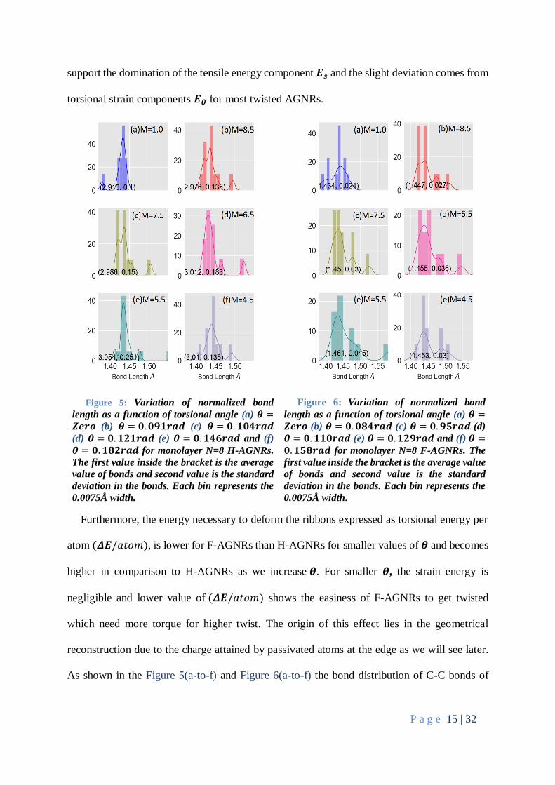
Figure 5: Variation of normalized bond
length as a function of torsional angle (a) 𝜽 =𝒁𝒆𝒓𝒐 (b) 𝜽 = 𝟎. 𝟎𝟗𝟏𝒓𝒂𝒅 (c) 𝜽 = 𝟎. 𝟏𝟎𝟒𝒓𝒂𝒅
(d) 𝜽 = 𝟎. 𝟏𝟐𝟏𝒓𝒂𝒅 (e) 𝜽 = 𝟎. 𝟏𝟒𝟔𝒓𝒂𝒅 and (f)
𝜽 = 𝟎. 𝟏𝟖𝟐𝒓𝒂𝒅 for monolayer N=8 H-AGNRs.
The first value inside the bracket is the average
value of bonds and second value is the standard
deviation in the bonds. Each bin represents the
0.0075Å width.
Figure 6: Variation of normalized bond
length as a function of torsional angle (a) 𝜽 =𝒁𝒆𝒓𝒐 (b) 𝜽 = 𝟎. 𝟎𝟖𝟒𝒓𝒂𝒅 (c) 𝜽 = 𝟎. 𝟗𝟓𝒓𝒂𝒅 (d)
𝜽 = 𝟎. 𝟏𝟏𝟎𝒓𝒂𝒅 (e) 𝜽 = 𝟎. 𝟏𝟐𝟗𝒓𝒂𝒅 and (f) 𝜽 =𝟎. 𝟏𝟓𝟖𝒓𝒂𝒅 for monolayer N=8 F-AGNRs. The
first value inside the bracket is the average value
of bonds and second value is the standard
deviation in the bonds. Each bin represents the
0.0075Å width.
Furthermore, the energy necessary to deform the ribbons expressed as torsional energy per
atom (𝜟𝑬/𝑎𝑡𝑜𝑚), is lower for F-AGNRs than H-AGNRs for smaller values of 𝜽 and becomes
higher in comparison to H-AGNRs as we increase 𝜽. For smaller 𝜽, the strain energy is
negligible and lower value of (𝜟𝑬/𝑎𝑡𝑜𝑚) shows the easiness of F-AGNRs to get twisted
which need more torque for higher twist. The origin of this effect lies in the geometrical
reconstruction due to the charge attained by passivated atoms at the edge as we will see later.
As shown in the Figure 5(a-to-f) and Figure 6(a-to-f) the bond distribution of C-C bonds of

P a g e 16 | 32
various helical conformation that C-C bonds are not elongated homogenously for 𝑵=8 H & F
passivized AGNRs as torsional strain increased in ascending order for (a) 𝑴=1.0 < (b) 𝑴=8.5
<(c) 𝑴=7.5 <(d) 𝑴=6.5 <(e) 𝑴=5.5 <(f) 𝑴=4.5, behavior which has also been reported in
earlier studies[23,41,47,48].
Furthermore, the plasticity can be explained from the change of bond angles rather than
bond lengths, therefore, the nonlinear variation can be explained by the bond angle alteration
of benzo-rings. For comparison of bonds length response to torsional strain we can
parameterize the effect of twisting on the bonds length of C-C of AGNRs as change in the
mean value of C-C bonds length (��) and standard deviation in the C-C bonds (𝜟𝒓) due to the
elongations of C-C bonds. The 𝜟𝒓 parameter for infinite graphene sheet must be equal to zero,
however, (𝜟𝒓) for pristine untwisted H & F passivated AGNR are not equal to zero because
of slightly shorter bonds at edges[47] (but still AGNRs are bipartite and have very small value
of 𝜟𝒓) as represented by the left most bin in Figure 5(a) and Figure 6(a). The bond distribution
histogram shown in Figure 5(a-to-f) and Figure 6(a-to-f) for H & F passivated AGNRs shows
us the marked upward shift of the shortest bonds that belongs to the edges, to left (longer
region). This implies that, except most twisted (𝑴=4.5) (Figure 5(f) and Figure 6(f)), for H &
F passivated 8-AGNRs having 𝑴=1.0 to 𝑴=5.5, the peripheral C-C bonds experienced
maximum stretch demonstrating an uneven distribution of strain evident from the successive
increments of (��) and (𝜟𝒓) as shown in Figure 7 (See Table S1). However, in case of most
twisted system 𝜽=0.162𝑟𝑎𝑑Å−1 of 8-HAGNR and 𝜽=0.158𝑟𝑎𝑑Å−1 of 8-FAGNR (𝑴=4.5 for
both cases) (��) still observed to increase but (𝜟𝒓) drops significantly implying the evenly
distributed bond lengths to some extent. In this most rolled-up AGNRs because of high tensile
strain and torsional strain the extent of overlapping between of the sp2 orbitals get reduced and
lower the stiffness of C-C bonds which is also reported in the nanotubes of smaller radii[47].

P a g e 17 | 32
We can conclude that at extreme curvature (i.e. high value of 𝜃) AGNRs the C-C bonds are
showing lesser stiffness are most likely unaffected from the passivation effect.
Figure 7: Showing the effect of twisting on the average value of C-C bond length (solid circular
marks) and the standard deviation in the distribution of bonds (vertical cap lines) of (a) H-AGNRs
and (b) F-AGNRs.
Furthermore, it is interesting to note that distribution curves of C-C bond length for H-
AGRNs Figure 5(a-to-f) are narrower and its peak values go up to almost twice the value of
the peak of much broader C-C bond distribution curve of F-AGNRs Figure 6(a-to-f),
respectively. Broader distribution of peak and nonlinear 𝝈𝒛 − 𝜮𝟐𝜽𝟐 curves response for higher
torsional strain implies the smoothness of bond angle alternation in case of twisted F-AGNRs.
The response could be understood qualitatively in terms of the tradeoff between the orbital
overlap that corresponds to 𝑬𝜽 and the stiffness of C-C bonds. We can assume 𝜟𝑬 ≃ Ʊ𝜽𝟒𝜮𝟒,
where Ʊ is proportionality constant defined as rate of change of total energy w.r.t. the square
of tensile strain. Furthermore, Hooke’s Law may be written as 𝑬𝒔 ≃∁
𝟏−𝝂𝟐 𝜽𝟐𝜮𝟐, where ∁ and 𝝂
is stiffness constant and Poisson’s constant respectively then 𝜟𝑬 = 𝑬𝒔 + 𝑬𝜽, leads to equation:
𝐸𝜃 ≃ Ʊ (𝜃2𝛴2 − ∁
2Ʊ(1 − 𝜈2)⁄ )2
− ∁2 ⁄ 4Ʊ(1 − 𝜈2)2 (5)

P a g e 18 | 32
Energetic analysis given in Equation (5) of twisted GNRs with open edges shows the torsional
stress energy 𝑬𝜽 relation as a mechanical response of strain 𝜽𝟐𝜮𝟐 and may be applied even for
wider AGNRs.
3.3. Electronic properties
We now consider electronic properties of these AGNRs. Note that the band gaps hierarchy
for the known three families of planar AGNRs (defined by 𝒒 = 𝑚𝑜𝑑 (𝑵, 3)) depends on the
width scaled as 𝑬𝒈≈𝜷𝑾−𝟏 , where 𝑵 is the numbers of dimers lines and 𝑾 is width[43,49].
Furthermore, in case of wider AGNRs the three families are barely distinguishable when
subjected to torsional strain, but substantial changes occur only for the narrowest ribbons with
𝑾< 1nm[50], therefore, has been taken in present study. Also, the sinusoidal response of band
gap to the applied tensile strain[51] limits the control on strained engineered applications in
nano-electronics[52,53]. In contrast, Figure 8(a) for AGNRs for 𝑵=6, 7 and 8 shows non-
sinusoidal response of the band gap to torsional angle 𝜽. The trend for widening or narrowing
the gap for q-dependent families defined as 𝒒 = 𝑚𝑜𝑑(𝑵, 3) which is associated with the
number of dimers lines of AGNRs for 𝑵=6, 7 and 8. Although, the exception occurs for the
widest 𝑵=8 HAGNR which as a quadratic fitting of parameters suggest narrowing of the gap
for initial small values of 𝜽.
Except 𝑵=6 F-AGNRs, passivation does not change the trend actually but does change the
zero order term significantly for different values of 𝑵 that shift the band lines downward. We
can compare gentle bends in armchair ribbons that has been reported to cause significant
widening or narrowing of energy gaps as 𝛥𝐸𝑔 ∝ (−1)𝑞𝜣2 for 𝒒=0 and 1 (here 𝜣 is the
magnitude of small bending)[2]. In our study, the energy gaps for 𝒒 = 0 and 1, H-AGNRs
depends in 𝜽 space as 𝛥𝐸𝑔 ∝ (−1)𝑞(𝜽𝛿 + 𝜽22𝑞𝜂) + 𝑂(𝜽) with 𝜹 = 2.7 & 𝜼 = 6.8, though,

P a g e 19 | 32
small 𝜽𝟐 makes quadratic contribution very small leading to almost linear dependence. For
𝒒=2, H-AGNRs the energy gap 𝐸𝑔 ∝ (−1)𝒒−1(𝜽𝛿) + (−1)𝑞𝜽𝟐𝜂 + 𝑂(𝜽) with 𝜹 = 2.7 again
and 𝜼 = 44.2 now 𝜼 is no longer insignificant for small values of 𝜽 and narrows the gap for
smaller values of 𝜽 (dotted blue line in Figure 8(a)). Because of ambiguous dependence (i.e.
non-sinusoidal but also non-monotonous) of 𝒒 in torsional angle space we transformed our
current space to effective tensile strain space in search for better relation.
Figure 8: (a) Non-linear response of band gap 𝑬𝒈 to torsional angle (θ). N=8 HAGNR (blue
dotted line) also showing non-monotonous response. (b) Linear as well as monotonous behavior of
band gap 𝑬𝒈 in effective tensile strain (𝜽𝟐𝜮𝟐) space.
So next, as a response of the effective torsional strain (𝜽𝟐𝜮𝟐) experienced by the AGNRs
in Figure 8(b) shows the trend of band gap as 𝒒 = 𝑚𝑜𝑑 (𝑵, 3) dependent which is governed
by:
𝛥𝐸𝑔 ∝ (−1)𝑞−1𝛿(𝜽𝟐𝜮𝟐) + 𝛽𝑂(𝜽𝟐𝜮𝟐) (6)
where 𝑂(𝜽𝟐𝜮𝟐) is the second order values which is insignificant for 𝑵=7 and 8 leads to
the linear response of band gap i.e. the monotonous linear increase for 𝑵=7 (𝒒=1) and
monotonous linear decrease for 𝑵=8 (𝒒=2) for both types of AGNRs (H-AGNRs and F-
AGNRs) subject to 𝒒 dependence in tensile strain space. In case of 𝑵=6 (𝒒=0) H-AGNRs, the
second order term has a small effect though the band gap response remains monotonically

P a g e 20 | 32
increasing. Whereas, in case of 𝑵=6 F-AGNRs, it remains true for lower values of torsional
strain (𝜽𝟐𝜮𝟐) but deviates for higher values because its tendency for homogeneous distribution
of strain amongst C-C bonds that reduced the inverse Poynting stress Figure 4(b). However, in
case of twisted AGNRs we have not found any DFT study for comparison with our results
except the study done by Zhang et al[41] using density functional tight binding method in
which the band gap response for H-AGNRs to effective strain came out to be strictly linear in
contrast to our study which shows it’s not always the case. But for sake of relevancy we present
a comparison of our study in Table 3 with other available experimental and theoretical studies
for untwisted H-AGNRs as we will discuss it later.
Because the response of band gap follow an identical trend, the Equation (6) for 𝜟𝑬𝒈
described response for 𝑵=7 H-AGNR and 𝑵=8 H-AGNR remains the same for 𝑵=7 F-AGNR
and 𝑵=8 F-AGNRs, respectively, except the shift in zero order term is required. Gap 𝑬𝒈
remains least responsive for 𝜽 in case of 𝑵=6 F-AGNR. Because of electronegative nature of
F atom the charge shifted from narrow width AGNR strip to F atoms significantly depletes the
electron density form whole ribbon, but does the distortion in shape of AGNRs change the
retaining capacity of electron of AGNR? To answer this question we have applied the Hirshfeld
method[54] to calculated the net charge accumulated on the H & F passivated atoms which is
respectively 𝜟𝑸= +0.02e and 𝜟𝑸= -0.03e that does not vary on twisting and insignificantly
vary (≃|0.002|) on varying dimer number 𝑵. Interestingly, in comparison to 𝑵=7 H-AGNRs,
Figure 8(a) (red dashed line) the 𝑵=7 F-AGNRs, Figure 8(a) (pink dashed line) shows the
passivation effect markedly, where the gap get narrowed down close to the 0.05eV for F-
AGNRs forming a Dirac cone at ±𝑲 (Figure S4) as 𝜽 goes to its extreme, allowing ballistic
transport of electrons of high kinetic energy at low bias.

P a g e 21 | 32
3.4. Comparison of Present Study with Other Studies
It is evident from the Table 3 that theoretical and experimental band gap values of
untwisted AGNRs for some cases differ significantly. Here we discuss the reasons for such
differences and what the present study points to and the predictions it makes.
Table 3 Measured and Calculated band gaps (in eV) for the untwisted pristine N=6, 7
and 8AGNRs.
6-HGNARs 7-HGNARs 8-HGNARs
1.11 1.66 0.43 ref[55] PBE
1.12 - 0.20 ref[42] PBE
1.34*, 1.02# 1.27*, 1.57# 0.01*, 0.25# ref[43], TB*, LDA#
- 2.3 - ref[56]TDFT-PBE0
1.12*, 2.68# 1.62*,3.81# 0.30*, 1.15# ref[44] LDA*, GW#
- 1.6 - ref[45] Exp.
- 2.5±0.1 - ref[57] Exp.
- 2.3±0.1*, 3.7# - ref[58] Exp.*, GW#
- 2.7 - ref[59] Exp.
- 2.62*, 1.67# - ref[60]Exp.*, PBE#
1.14 1.49 0.20 Our Results PBE
Let us consider experiment versus experiment variation first. The band gap of 7-HAGNRs
deposited on Au[111] substrate measured in ref [45] is 1.6eV which is significantly smaller
than the later reported values 2.5eV, 2.6eV and 2.7eV in ref [57] , ref[58] and ref[59]
respectively. This variation in the band gap is likely to be there because of the difference in
the reported apparent height of AGNRs which is 1.8Å in ref [45], 2.1 ± 0.1Å ref [57] , 3.15Å
in ref [58]and 1.85 ± 0.12 Å in ref [59]. Height of AGNR from surface is a crucial factor that
has been studied theoretically in ref [56] which decides the electron-electron interaction at the
interface. Furthermore, the length of synthesized AGNRs, details of which have not been given
explicitly in any experimental study, can also be the reason for the variation as Zdetsis. at. el.

P a g e 22 | 32
suggested theoretically[56]. Besides the variation in apparent height and AGNRs’ length the
slight charge transfer to substrate can also alter the band gap drastically[61].
In theoretical findings the band gap values calculated at GGA-PBE level of theory as
in our study, are in excellent agreements with earlier study in ref [42,55]. However, as shown
in Table 3 the band gap of 7-HAGNRs calculated using GW functional is ~2.5 times higher
than the band gap calculated by using PBE functional. The band gap of 7-HAGNRs calculated
using GW functional is overestimated by ~42%[44,57–59] and the band gap value calculated
by using PBE functional is underestimated by ~40%[43,55,60] from the experimental band
gap. As mentioned earlier, Zdetsis. at. el. demonstrated theoretically that besides the width, the
length and the length-variation is an important factor and has been overlooked in previous
literature[56].
In order to check substrate effect on AGNRs, further experimental as well as theoretical
studies with different substrates need to be done. The possibility of the effect of the substrate
is strongly suggested by theoretical study in which Romaner et. al. have observed the class of
π-conjugated molecules (3,4,9,10-perylene-tetracarboxylic acid dianhydride (PTCDA))
adsorbed on the Ag(111), Au(111) or Cu(111) surfaces, shows not only the characteristic trends
for work-function modification but also a net metal-to-molecule electron transfer[61]. Note
that in our study, a strong sensitivity of band gap to the polarization due to the charge transfer
to edges atoms has been observed.
Our calculations, despite underestimations of the band gap, still hold relevance for
understanding the behavior and trend of band gap response to effective torsional strain and the
mechanical properties of free standing long AGNRs or staircase AGNRs which have been
synthesized with bottom-up approach. In this study we have also parameterized the effect of

P a g e 23 | 32
strain on the structure of helical shaped AGNRs that add up to the details of system and can be
compared quantitatively with any future study.
4. Summary
In summary, we have performed DFT based calculations to demonstrate the symmetry
and torsional strain effect on the severely twisted helical morphologies of H-AGNRs and F-
AGNRs with fixed end configuration.
In the induced tensile strain-stress space, the linearity of tensile strain to axial tensile
stress shows super elasticity in the case of H-AGNRs even at high torsional strain, while F-
AGNRs shows plastic deformation at higher strain because of higher torque required to twist
the ribbon after some threshold value of torsional strain is reached. System under the non-
elastic region shows softening and enter in a plastic state, which may be easily destroyed by
vacancy defects, long wavelength perturbations and high temperature effects[62]. This plastic
deformation is understandable as a benzo-ring deformation due to the bond angle alternation
and also as a tradeoff for orbital misalignment along the axial C-C bonds with its stiffness. Not
much effect of symmetry is observed for mechanical properties on twisted ribbons.
Furthermore, the 𝒒 dependence of AGNRs on the electronic properties of helical
conformations of narrow AGNRs for 𝑵=6, 7 and 8 can further divided in two groups for
severely twisted and strained helical conformations as 𝒒=1 & 2 and 𝒒=1, in effective tensile
strain 𝜽𝟐𝜮𝟐 space. Band gap is linearly and monotonously increasing for 𝒒=0 & 2 or decreasing
for 𝒒=1 as a response against effective tensile strain. This trend remains unchanged for F-
AGNRs, though because of zero order downward shift the band gap drops more to 𝑬𝒈 ≃
0.05𝑒𝑉 at torsional strain 𝜽=0.178𝒓𝒂𝒅Å−𝟏 forming Dirac cone at ±K. Also, net charge on the
passivated atoms remains unaltered on twisting or increasing the number of dimers. Hence, we

P a g e 24 | 32
propose a 𝒒 dependent monotonous and linear trend of electronic gap for twisted and strained
helical conformations of bipartite lattice of narrow 𝑵=6, 7 & 8 H-AGNRs and F-AGNRs.
Acknowledgements
High performance computing facility of Centre for Development of Advanced Computing (C-
DAC), Pune and CVRAMAN, high performance computing cluster, at Himachal Pradesh
University, Shimla has been used in obtaining the results presented in this paper. Author
acknowledge the SIESTA TEAM for providing code under free licence. RT acknowledge
special thanks to Professor Ahluwalia for proofreading and critique of this paper.

P a g e 25 | 32
References
[1] J. van der Lit, P.H. Jacobse, D. Vanmaekelbergh, I. Swart, Bending and buckling of
narrow armchair graphene nanoribbons via STM manipulation, New J. Phys. 17 (2015)
053013. doi:10.1088/1367-2630/17/5/053013.
[2] P. Koskinen, Graphene nanoribbons subject to gentle bends, Phys. Rev. B - Condens.
Matter Mater. Phys. 85 (2012) 1–5. doi:10.1103/PhysRevB.85.205429.
[3] D. Gunlycke, J. Li, J.W. Mintmire, C.T. White, Edges Bring New Dimension to
Graphene Nanoribbons, Nano Lett. 10 (2010) 3638–3642. doi:10.1021/nl102034c.
[4] N.M. Al-Aqtash, R.F. Sabirianov, Spin density waves in periodically strained graphene
nanoribbons, Nanoscale. 6 (2014) 4285–4291. doi:10.1039/c3nr06199j.
[5] L. Sun, Q. Li, H. Ren, H. Su, Q.W. Shi, J. Yang, Strain effect on electronic structures
of graphene nanoribbons: A first-principles study, J. Chem. Phys. 129 (2008) 074704.
doi:10.1063/1.2958285.
[6] C. Si, Z. Sun, F. Liu, Strain engineering of graphene: A review, Nanoscale. 8 (2016)
3207–3217. doi:10.1039/c5nr07755a.
[7] T. Cao, F. Zhao, S.G. Louie, Topological Phases in Graphene Nanoribbons: Junction
States, Spin Centers, and Quantum Spin Chains, Phys. Rev. Lett. 119 (2017) 076401.
doi:10.1103/PhysRevLett.119.076401.
[8] K.S. Novoselov, V.I. Fal′ko, L. Colombo, P.R. Gellert, M.G. Schwab, K. Kim, A
roadmap for graphene, Nature. 490 (2012) 192–200. doi:10.1038/nature11458.
[9] A. Kimouche, M.M. Ervasti, R. Drost, S. Halonen, A. Harju, P.M. Joensuu, J. Sainio,
P. Liljeroth, E. Al., Ultra-narrow metallic armchair graphene nanoribbons, Nat.

P a g e 26 | 32
Commun. 6 (2015) 10177. doi:10.1038/ncomms10177.
[10] A.K. Geim, K.S. Novoselov, The rise of graphene, Nat. Mater. 6 (2007) 183–191.
doi:10.1038/nmat1849.
[11] G. Zhang, X. Jiang, E. Wang, Self-assembly of carbon nanohelices: Characteristics
and field electron emission properties, Appl. Phys. Lett. 84 (2004) 2646–2648.
doi:10.1063/1.1695198.
[12] Z. Ren, P.-X. Gao, A review of helical nanostructures: growth theories, synthesis
strategies and properties, Nanoscale. 6 (2014) 9366. doi:10.1039/C4NR00330F.
[13] S. Amelinckx, X.B. Zhang, D. Bernaerts, X.F. Zhang, V. Ivanov, J.B. Nagy, A
formation mechanism for catalytically grown helix-shaped graphite nanotubes.,
Science. 265 (1994) 635–9. doi:10.1126/science.265.5172.635.
[14] A.L. Elias, A.R. Botello-Mendez, D. Meneses-Rodriguez, V. Jehova Gonzalez, D.
Ramirez-Gonzalez, L. Ci, E. Munoz-Sandoval, P.M. Ajayan, H. Terrones, M.
Terrones, Longitudinal Cutting of Pure and Doped Carbon Nanotubes to Form
Graphitic Nanoribbons Using Metal Clusters as Nanoscalpels, Nano Lett. 10 (2010)
366–372. doi:10.1021/nl901631z.
[15] A.N. Khlobystov, Carbon Nanotubes: From Nano Test Tube to Nano-Reactor, ACS
Nano. 5 (2011) 9306–9312. doi:10.1021/nn204596p.
[16] T.W. Chamberlain, J. Biskupek, G.A. Rance, A. Chuvilin, T.J. Alexander, E.
Bichoutskaia, U. Kaiser, A.N. Khlobystov, Size, Structure, and Helical Twist of
Graphene Nanoribbons Controlled by Confinement in Carbon Nanotubes, ACS Nano.
6 (2012) 3943–3953. doi:10.1021/nn300137j.

P a g e 27 | 32
[17] L. Zhang, X. Wang, Atomistic insights into the nanohelix of hydrogenated graphene:
formation, characterization and application, Phys. Chem. Chem. Phys. 16 (2014) 2981.
doi:10.1039/c3cp53978d.
[18] O. V. Kibis, M.R. da Costa, M.E. Portnoi, Generation of Terahertz Radiation by Hot
Electrons in Carbon Nanotubes, (2007). doi:10.1021/NL0718418.
[19] M.E. Portnoi, O.V. Kibis, M. Rosenau da Costa, Terahertz applications of carbon
nanotubes, Superlattices Microstruct. 43 (2008) 399–407.
doi:10.1016/j.spmi.2007.07.026.
[20] M. Rosenau da Costa, O.V. Kibis, M.E. Portnoi, Carbon nanotubes as a basis for
terahertz emitters and detectors, Microelectronics J. 40 (2009) 776–778.
doi:10.1016/j.mejo.2008.11.016.
[21] O. V. Kibis, P.P. Kuzhir, M.R. da Costa, M.E. Portnoi, Terahertz processes in carbon
nanotubes, J. Nanophotonics. 4 (2010) 041665. doi:10.1117/1.3436585.
[22] F. Xu, W. Lu, Y. Zhu, Controlled 3D Buckling of Silicon Nanowires for Stretchable
Electronics, ACS Nano. 5 (2011) 672–678. doi:10.1021/nn103189z.
[23] D. Xia, Q. Li, Q. Xue, C. Liang, M. Dong, Super flexibility and stability of graphene
nanoribbons under severe twist, Phys. Chem. Chem. Phys. 18 (2016) 18406–18413.
doi:10.1039/c6cp02580c.
[24] C. Jiang, X.-F. Wang, M.-X. Zhai, Spin negative differential resistance in edge doped
zigzag graphene nanoribbons, Carbon N. Y. 68 (2014) 406–412.
doi:10.1016/J.CARBON.2013.11.017.
[25] Y. Zhang, P. Kim, M.Y. Han, O. Barbaros, B. Özyilmaz, Y. Zhang, P. Kim, Energy

P a g e 28 | 32
Band-Gap Engineering of Graphene Nanoribbons, Phys. Rev. Lett. 98 (2007).
doi:10.1103/PhysRevLett.98.206805.
[26] M. Saiz-Bretín, F. Domínguez-Adame, A.V. V. Malyshev, Twisted graphene
nanoribbons as nonlinear nanoelectronic devices, Carbon N. Y. 149 (2019) 587–593.
doi:10.1016/j.carbon.2019.04.069.
[27] M. Slota, A. Keerthi, W. Myers, E. Tretyakov, M. Baumgarten, A. Ardavan, H.
Sadeghi, C. Lambert, A. Narita, K. Müllen, L. Bogani, Magnetic edge states, spin
dynamics and coherent manipulation of molecular graphene nanoribbons, Nature. 557
(2017) 691–695. doi:10.1038/s41586-018-0154-7.
[28] N. Gorjizadeh, A.A. Farajian, K. Esfarjani, Y. Kawazoe, Spin and band-gap
engineering in doped graphene nanoribbons, (2008) 1–6.
doi:10.1103/PhysRevB.78.155427.
[29] S.-Y. Yue, Q.-B. Yan, Z.-G. Zhu, H.-J. Cui, Q.-R. Zheng, G. Su, First-principles study
on electronic and magnetic properties of twisted graphene nanoribbon and Möbius
strips, Carbon N. Y. 71 (2014) 150–158. doi:10.1016/J.CARBON.2014.01.023.
[30] L. Song, S. Jin, P. Jiang, H. Hao, X. Zheng, L. Zhang, Realizing robust half-metallic
transport with chemically modified graphene nanoribbons, Carbon N. Y. 141 (2019)
676–684. doi:10.1016/j.carbon.2018.10.015.
[31] F. Luis, E. Coronado, Spinning on the edge of graphene, Nature(News and Views).
(2018) 645–646.
[32] K. V Bets, B.I. Yakobson, Spontaneous Twist and Intrinsic Instabilities of Pristine
Graphene Nanoribbons, Nano Lett. 2 (2009) 161–166. doi:10.1007/s12274-009-9015-

P a g e 29 | 32
x.
[33] A. Shahabi, H. Wang, M. Upmanyu, Shaping van der Waals nanoribbons via torsional
constraints: Scrolls, folds and supercoils, Sci. Rep. (2014) 1–6. doi:10.1038/srep07004.
[34] T.W. Chamberlain, J. Biskupek, G.A. Rance, A. Chuvilin, T.J. Alexander, E.
Bichoutskaia, U. Kaiser, A.N. Khlobystov, Size , Structure , and Helical Twist of
Graphene Nanoribbons Controlled by Con fi nement in Carbon Nanotubes, ACS Nano.
6 (2012) 3943–3953. doi:10.1021/nn300137j.
[35] J.M. Soler, E. Artacho, J.D. Gale, A. García, J. Junquera, P. Ordejón, D. Sánchez-
Portal, The SIESTA method for ab initio order- N materials simulation, J. Phys.
Condens. Matter. 14 (2002) 2745–2779. doi:10.1088/0953-8984/14/11/302.
[36] N. Troullier, J.L. Martins, Efficient pseudopotentials for plane-wave calculations,
Phys. Rev. B. 43 (1991) 1993–2006. doi:10.1103/PhysRevB.43.1993.
[37] J.P. Perdew, K. Burke, M. Ernzerhof, Generalized Gradient Approximation Made
Simple [Phys. Rev. Lett. 77, 3865 (1996)], Phys. Rev. Lett. 78 (1997) 1396–1396.
doi:10.1103/PhysRevLett.78.1396.
[38] H.J. Monkhorst, J.D. Pack, Special points for Brillouin-zone integrations, Phys. Rev.
B. 13 (1976) 5188–5192. doi:10.1103/PhysRevB.13.5188.
[39] G. Kresse, J. Hafner, Ab initio molecular dynamics for liquid metals, Phys. Rev. B. 47
(1993) 558–561. doi:10.1103/PhysRevB.47.558.
[40] G. Kresse, J. Furthmüller, Efficient iterative schemes for ab initio total-energy
calculations using a plane-wave basis set, Phys. Rev. B - Condens. Matter Mater. Phys.
54 (1996) 11169–11186. doi:10.1103/PhysRevB.54.11169.

P a g e 30 | 32
[41] D.B. Zhang, T. Dumitric, Role of effective tensile strain in electromechanical response
of helical graphene nanoribbons with open and closed armchair edges, Phys. Rev. B -
Condens. Matter Mater. Phys. 85 (2012) 1–5. doi:10.1103/PhysRevB.85.035445.
[42] M. Topsakal, V.M.K. Bagci, S. Ciraci, Current-voltage (I-V) characteristics of
armchair graphene nanoribbons under uniaxial strain, Phys. Rev. B. 81 (2010) 1–5.
doi:10.1103/PhysRevB.81.205437.
[43] Y.-W.Y.-W. Son, M.L. Cohen, S.G. Louie, Energy gaps in graphene nanoribbons.,
Phys. Rev. Lett. 97 (2006) 216803. doi:10.1103/PhysRevLett.97.216803.
[44] L. Yang, C.H. Park, Y.W. Son, M.L. Cohen, S.G. Louie, Quasiparticle energies and
band gaps in graphene nanoribbons, Phys. Rev. Lett. 99 (2007) 6–9.
doi:10.1103/PhysRevLett.99.186801.
[45] J. Cai, P. Ruffieux, R. Jaafar, M. Bieri, T. Braun, S. Blankenburg, M. Muoth, A.P.
Seitsonen, M. Saleh, X. Feng, K. Müllen, R. Fasel, Atomically precise bottom-up
fabrication of graphene nanoribbons, Nature. 466 (2010) 470–473.
doi:10.1038/nature09211.
[46] X. Zhang, M. Zhao, Strain-induced phase transition and electron spin-polarization in
graphene spirals, Sci. Rep. 4 (2014) 1–6. doi:10.1038/srep05699.
[47] R. Faccio, P.A. Denis, H. Pardo, C. Goyenola, Á.W. Mombrú, Mechanical properties
of graphene nanoribbons, J. Phys. Condens. Matter. 21 (2009) 285304.
doi:10.1088/0953-8984/21/28/285304.
[48] Y. Li, Twist-enhanced stretchability of graphene nanoribbons: A molecular dynamics
study, J. Phys. D. Appl. Phys. 43 (2010). doi:10.1088/0022-3727/43/49/495405.

P a g e 31 | 32
[49] O. Hod, G.E. Scuseria, Electronic Structure and Stability of Semiconducting Graphene
Nanoribbons, Nano Lett. 6 (2006) 2748–2754. doi:10.1021/nl0617033.
[50] P. Koskinen, Electromechanics of twisted graphene nanoribbons, Appl. Phys. Lett. 99
(2011). doi:10.1063/1.3607956.
[51] Y. Lu, J. Guo, Band Gap of Strained Graphene Nanoribbons, Nano Res. 3 (2010) 189–
199. doi:10.1007/s12274-010-1022-4.
[52] J. Jia, D. Shi, X. Feng, G. Chen, Electromechanical properties of armchair graphene
nanoribbons under local torsion, Carbon N. Y. 76 (2014) 54–63.
doi:10.1016/J.CARBON.2014.04.048.
[53] N. Al-Aqtash, H. Li, L. Wang, W.-N.N. Mei, R.F.F. Sabirianov, Electromechanical
switching in graphene nanoribbons, Carbon N. Y. 51 (2013) 102–109.
doi:10.1016/j.carbon.2012.08.018.
[54] F.L. Hirshfeld, Bonded-atom fragments for describing molecular charge densities,
Theor. Chim. Acta. 44 (1977) 129–138. doi:10.1007/BF00549096.
[55] F. Ma, Z. Guo, K. Xu, P.K. Chu, First-principle study of energy band structure of
armchair graphene nanoribbons, Solid State Commun. 152 (2012) 1089–1093.
doi:10.1016/j.ssc.2012.04.058.
[56] A.D. Zdetsis, E.N. Economou, Rationalizing and reconciling energy gaps and quantum
confinement in narrow atomically precise armchair graphene nanoribbons, Carbon N.
Y. 116 (2017) 422–434. doi:10.1016/j.carbon.2017.02.006.
[57] Y.-C. Chen, D.G. de Oteyza, Z. Pedramrazi, C. Chen, F.R. Fischer, M.F. Crommie,
Tuning the band gap of graphene nanoribbons synthesized from molecular precursors,

P a g e 32 | 32
ACS Nano. 7 (2013) 6123–6128. doi:10.1021/nn401948e.
[58] P. Ruffieux, J. Cai, N.C. Plumb, L. Patthey, D. Prezzi, A. Ferretti, E. Molinari, X.
Feng, K. Mu, C.A. Pignedoli, R. Fasel, Electronic Structure of Atomically Precise
Graphene Nanoribbons, ACS Nano. 6 (2012) 6930–6935. doi:10.1021/nn3021376.
[59] M. Koch, F. Ample, C. Joachim, L. Grill, Voltage-dependent conductance of a single
graphene nanoribbon, Nat. Nanotechnol. 7 (2012) 713–717.
doi:10.1038/nnano.2012.169.
[60] C. Ma, L. Liang, Z. Xiao, A.A. Puretzky, K. Hong, W. Lu, V. Meunier, J. Bernholc,
A.P. Li, Seamless Staircase Electrical Contact to Semiconducting Graphene
Nanoribbons, Nano Lett. 17 (2017) 6241–6247. doi:10.1021/acs.nanolett.7b02938.
[61] L. Romaner, D. Nabok, P. Puschnig, E. Zojer, C. Ambrosch-Draxl, Theoretical study
of PTCDA adsorbed on the coinage metal surfaces, Ag(111), Au(111) and Cu(111),
New J. Phys. 11 (2009) 053010. doi:10.1088/1367-2630/11/5/053010.
[62] J. Guo, D. Gunlycke, C.T. White, Field effect on spin-polarized transport in graphene
nanoribbons, Appl. Phys. Lett. 92 (2008) 163109. doi:10.1063/1.2908207.
Copyright © 2022 FDOKUMEN