Calculation and experiment of spiral bevel gear by duplex ...
Upload
khangminh22Category
view
0download
0
Drive Technology \ Drive Automation \ System Integration \ Services
Operating Instructions
Explosion-Proof Industrial Gear Units:Helical and Bevel-Helical Gear UnitsX.. Series
Edition 05/2009 16690419 / EN

SEW-EURODRIVE—Driving the world

Operating Instructions – Explosion-Proof Helical and Bevel-Helical Gear Units X.. Series 3
Content
Content1 General Information ............................................................................................ 6
1.1 How to use the operating instructions......................................................... 61.2 Structure of the safety notes ....................................................................... 61.3 Rights to claim under warranty ................................................................... 71.4 Exclusion of liability..................................................................................... 71.5 Copyright..................................................................................................... 7
2 Safety Notes ........................................................................................................ 82.1 Preliminary remark...................................................................................... 82.2 General information .................................................................................... 82.3 Designated use ........................................................................................... 92.4 Other applicable documentation ................................................................. 92.5 Target group ............................................................................................... 92.6 Disposal .................................................................................................... 102.7 Stickers on the gear unit ........................................................................... 102.8 Symbols on the packaging........................................................................ 122.9 Transport................................................................................................... 122.10 Storage and transport conditions .............................................................. 17
3 Basic Gear Unit Structure ................................................................................ 193.1 Unit designations ...................................................................................... 193.2 Nameplate................................................................................................. 223.3 Mounting position...................................................................................... 233.4 Mounting surfaces..................................................................................... 243.5 Shaft position ............................................................................................ 253.6 Mounting and standard mounting surface................................................. 263.7 Pivoted mounting positions and variable mounting positions ................... 283.8 Corresponding directions of rotation ......................................................... 293.9 Housing..................................................................................................... 313.10 Gearing and shafts.................................................................................... 313.11 Input and output shaft ............................................................................... 323.12 Sealing systems........................................................................................ 363.13 Coating and surface protection systems................................................... 393.14 Lubrication ................................................................................................ 403.15 Accessories............................................................................................... 41
4 Design of Options and Accessories................................................................ 454.1 Torque arm /T ........................................................................................... 454.2 Mounting flange /F .................................................................................... 464.3 Backstop /BS ............................................................................................ 474.4 Motor adapters /MA .................................................................................. 484.5 V-belt drives /VBD..................................................................................... 494.6 Drive packages on steel frame ................................................................. 504.7 Cooling types ............................................................................................ 524.8 Fan /FAN................................................................................................... 534.9 Built-in cooling – water cooling cover /CCV .............................................. 55

4 Operating Instructions – Explosion-Proof Helical and Bevel-Helical Gear Units X.. Series
Content
4.10 Built-in cooling – water cooling cartridge /CCT ......................................... 564.11 Circulation cooling oil/water cooler with motor pump /OWC ..................... 584.12 Circulation cooling oil/air cooler with motor pump /OAC........................... 604.13 Oil heater /OH ........................................................................................... 624.14 Pressure switch /PS.................................................................................. 634.15 Temperature sensor /PT100 ..................................................................... 634.16 Temperature switch /NTB ......................................................................... 634.17 Temperature switch /TSK ......................................................................... 63
5 Checklist ............................................................................................................ 645.1 Before startup ........................................................................................... 645.2 During startup ........................................................................................... 65
6 Assembly/Installation ....................................................................................... 666.1 Required tools/resources .......................................................................... 666.2 Tightening torques .................................................................................... 666.3 Gear unit mounting ................................................................................... 676.4 Tolerances ................................................................................................ 676.5 Notes on installation/mounting.................................................................. 686.6 Preliminary work ....................................................................................... 696.7 Installing the gear unit ............................................................................... 706.8 Gear unit mounting in potentially-explosive atmospheres ........................ 716.9 Gear units and gearmotors in category II2GD .......................................... 716.10 Oil filling ................................................................................................... 736.11 Gear units with solid shaft ......................................................................... 776.12 Couplings .................................................................................................. 786.13 Gear unit with hollow shaft and keyed connection.................................... 926.14 Gear unit with hollow shaft and shrink disk............................................. 1006.15 Gear unit with hollow shaft and splining.................................................. 1096.16 Torque arm /T ......................................................................................... 1176.17 Motor adapters /MA ................................................................................ 1196.18 V-belt drives /VBD................................................................................... 1226.19 Base frame /BF ....................................................................................... 1266.20 Swing base /SB....................................................................................... 1266.21 Fan /FAN................................................................................................. 1276.22 Built-in cooling – water cooling cover /CCV ............................................ 1276.23 Built-in cooling – water cooling cartridge /CCT ....................................... 1286.24 Circulation cooling – oil/water cooler with motor pump /OWC ................ 1296.25 Circulation cooling oil/air cooler with motor pump / OAC........................ 1316.26 Oil heater /OH ......................................................................................... 1366.27 Pressure switch /PS................................................................................ 1386.28 Temperature sensor /PT100 ................................................................... 1406.29 Temperature switch /NTB ....................................................................... 1426.30 Temperature switch /TSK ....................................................................... 144

Operating Instructions – Explosion-Proof Helical and Bevel-Helical Gear Units X.. Series 5
Content
7 Startup.............................................................................................................. 1467.1 Important notes on startup ...................................................................... 1467.2 Starting up gear units in potentially explosive areas............................... 1477.3 Gear units with pressure lubrication........................................................ 1477.4 Run-in period .......................................................................................... 1487.5 Backstop /BS .......................................................................................... 1497.6 Starting up the gear unit at lower ambient temperatures ........................ 1497.7 Measuring the surface and oil temperatures........................................... 1497.8 Decommissioning gear units................................................................... 1507.9 Gear unit shutdown/conservation ........................................................... 151
8 Inspection/Maintenance ................................................................................. 1538.1 Preliminary work for inspection and maintenance .................................. 1538.2 Inspection and maintenance intervals..................................................... 1548.3 Lubricant change intervals ...................................................................... 1558.4 Checking the oil level .............................................................................. 1568.5 Checking the oil consistency................................................................... 1588.6 Changing the oil ...................................................................................... 1588.7 Checking and cleaning the breather plug ............................................... 1608.8 Refilling grease ....................................................................................... 1608.9 Relubricating bearings with a Drywell sealing system ............................ 1618.10 Fan /FAN................................................................................................. 1628.11 Built-in cooling – water cooling cover /CCV ............................................ 1628.12 Built-in cooling – water cooling cartridge /CCT ....................................... 1628.13 Oil heater /OH ......................................................................................... 1638.14 Split housing ........................................................................................... 163
9 Malfunctions .................................................................................................... 1649.1 Troubleshooting information ................................................................... 1649.2 Customer service .................................................................................... 1649.3 Possible gear unit malfunctions ............................................................. 164
10 Lubricants........................................................................................................ 16610.1 Lubricant selection .................................................................................. 16610.2 Approved lubricants ................................................................................ 16710.3 Lubricant fill quantities for horizontal gear units ..................................... 16810.4 Lubricant fill quantities for vertical gear units ......................................... 16910.5 Lubricating grease .................................................................................. 172
11 Declaration of Conformity .............................................................................. 173
12 Address List .................................................................................................... 175
Index................................................................................................................. 184

6 Operating Instructions – Explosion-Proof Helical and Bevel-Helical Gear Units X.. Series
1 How to use the operating instructionsGeneral Information
1 General Information1.1 How to use the operating instructions
The operating instructions are an integral part of the product and contain important in-formation for operation and service. The operating instructions are written for all employ-ees who assemble, install, startup, and service this product.
The operating instructions must be legible and accessible at all times. Make sure thatstaff responsible for the plant and its operation, as well as persons who work indepen-dently on the unit, have read the operating instructions carefully and understood them.If you are unclear about any of the information in this documentation, or if you requirefurther information, contact SEW-EURODRIVE.
1.2 Structure of the safety notesThe safety notes in these operating instructions are designed as follows:
Pictogram SIGNAL WORDType and source of danger.
Possible consequence(s) if the safety notes are disregarded.• Measure(s) to prevent the danger.
Pictogram Signal word Meaning Consequences if disregarded
Example:
General danger
Specific danger,e.g. electric shock
DANGER Imminent danger Severe or fatal injuries
WARNING Possible dangerous situation Severe or fatal injuries
CAUTION Possible dangerous situation Minor injuries
NOTICE Possible damage to property Damage to the drive system or its environ-ment
NOTE ON EXPLO-SION PROTECTION
Important note on explosion pro-tection
Suspension of explosion protection and resulting hazards
TIP Useful information or tip.Simplifies the handling of the drive system.

Operating Instructions – Explosion-Proof Helical and Bevel-Helical Gear Units X.. Series 7
1Rights to claim under warrantyGeneral Information
1.3 Rights to claim under warrantyA requirement of fault-free operation and fulfillment of any rights to claim under limitedwarranty is that you adhere to the information in the operating instructions. Therefore,read the operating instructions before you start working with the unit
1.4 Exclusion of liabilityYou must comply with the information contained in these operating instructions to en-sure safe operation of the X series gear units and to achieve the specified product char-acteristics and performance requirements. SEW-EURODRIVE does not assume liabilityfor injury to persons or damage to equipment or property resulting from non-observanceof these operating instructions. In such cases, any liability for defects is excluded.
1.5 Copyright© <2009> SEW-EURODRIVE. All rights reserved.
Unauthorized duplication, modification, distribution or any other use of the whole or anypart of this documentation is strictly prohibited.

8 Operating Instructions – Explosion-Proof Helical and Bevel-Helical Gear Units X.. Series
2 Preliminary remarkSafety Notes
2 Safety Notes2.1 Preliminary remark
The following safety notes are primarily concerned with the use of gear units. If usinggearmotors, also refer to the safety notes for motors in the corresponding operating in-structions.
Also observe the supplementary safety notes in the individual sections of these operat-ing instructions.
2.2 General information
NOTE ON EXPLOSION PROTECTIONNever install or start up damaged products. Submit a complaint to the shipping com-pany immediately in the event of damage.
Explosive gas mixtures or concentrations of dust can lead to severe or fatal injuries inconjunction with hot, live and moving parts of electrical machinery.
All work related to transportation, storage, setup/mounting, connection, startup, main-tenance and repair may only be carried out by qualified personnel, in strict observationof:• The relevant detailed operating instructions • The warning and safety signs on the motor/gearmotor• All other project planning documents, operating instructions and wiring diagrams
related to the drive• The specific regulations and requirements for the system• The national/regional regulations governing safety and the prevention of accidents
Removing covers without authorization, improper use as well as incorrect installationor operation may result in severe injuries to persons or damage to property.
Refer to the documentation for additional information.

Operating Instructions – Explosion-Proof Helical and Bevel-Helical Gear Units X.. Series 9
2Designated useSafety Notes
2.3 Designated useThe gear units are intended for industrial systems and may only be used in accordancewith the information provided in SEW-EURODRIVE's technical documentation and theinformation given on the nameplate. They meet the requirements set forth in Directive94/9EC and comply with applicable standards and regulations.
2.4 Other applicable documentationThe following publications and documents have to be observed as well:
• "AC motors" operating instructions
• Operating instructions of any attached options
2.5 Target groupAny mechanical work may only be performed by adequately qualified personnel. Quali-fied personnel in this context are persons who are familiar with the setup, mechanicalinstallation, trouble shooting and maintenance for this product. Further, they are quali-fied as follows:
• Training in mechanical engineering, e.g. as a mechanic or mechatronics technician(final examinations must have been passed).
• They are familiar with these operating instructions.
Any electronic work may only be performed by adequately qualified electricians. Quali-fied electricians in this context are persons who are familiar with the electronic installa-tion, startup, trouble shooting and maintenance for this product. Further, they are qual-ified as follows:
• Training in electrical engineering, e.g. as an electrician or mechatronics technician(final examinations must have been passed).
• They are familiar with these operating instructions.
All work in further areas of transportation, storage, operation and waste disposal may becarried out only by persons who are trained appropriately.
NOTE ON EXPLOSION PROTECTION• A drive motor connected to the gear unit may only be operated under the condi-
tions described in the "Starting up gear units in potentially explosive atmospheres" section.
• Operate any gear unit connected to the motor on the frequency inverter only if the data on the gear unit nameplate is met!
• A motor mounted to a gear unit by means of an adapter or belt may only be oper-ated if the data on the gear unit nameplate is met!
• There may be no aggressive substances in the vicinity that could damage the paint and seals.

10 Operating Instructions – Explosion-Proof Helical and Bevel-Helical Gear Units X.. Series
2 DisposalSafety Notes
2.6 Disposal• Housing parts, gears, shafts and roller bearings of the gear units must be disposed
of as steel scrap. This also applies to gray-cast iron parts if there is no specialcollection.
• Collect waste oil and dispose of it according to the regulations in force.
2.7 Stickers on the gear unitThe stickers on the gear unit must be observed. They have the following meaning:
Sticker Meaning
Oil fill plug
Oil drain
Oil level glass
Oil dipstick
Oil sight glass
Breather plug
Regreasing point
Air outlet screw
Water supply
Water return
Oil supply
Oil return
Oil
Oil
Oil
Oil
Oil
H2O
H2O
Oil
Oil

Operating Instructions – Explosion-Proof Helical and Bevel-Helical Gear Units X.. Series 11
2Stickers on the gear unitSafety Notes
Temperature sensor
Direction of rotation
Sticker
Sticker Meaning
°C
Gear unit is delivered without oil.
Potential damage to property!
• Prior to startup, fill in oil according to operating instructions.
Oil
NOTICE
Gear unit with VCI corrosion protection. Do not open!
Potential damage to property!
• Prior to startup, perform preliminary work according to operating instructions.• No open flames!
VCI
NOTICE
STOP
NOTICE
Removing the oil dipstick during operation can damage the gear unit.
Potential damage to property!
• Do not open while the gear unit is running.
The brake has not been set at the factory
Potential damage to property!
• Prior to startup, set the brake according to the operating instructions.
X
NOTICE
Risk of injuries due to rotating
parts.
Fatal injuries!
• Cover input and output components
with a touch guard.
• Never remove the guard while the
gear unit is runnig.
WARNING

12 Operating Instructions – Explosion-Proof Helical and Bevel-Helical Gear Units X.. Series
2 Symbols on the packagingSafety Notes
2.8 Symbols on the packagingThe symbols on the packaging must be observed. They mean the following:
2.9 Transport2.9.1 Notes on transport
Sticker
WARNINGDanger of burns due to hot
gear unit. Fatal injuries!
• Let the gear unit cool down before
you begin working on it.
Danger of burns due to hot
gear unit oil.
Fatal injuries!
• Let the gear unit cool down before
you begin working on it.
• Be careful when opening the oil
drain!
Oil
WARNING
1811486091Up Keep dry Center of gravity
Fragile Protect from heat
Fasten here
Hand hooksprohibited
DANGERSuspended loads can fall.
Severe or fatal injuries.• Do not stand under the suspended load.• Secure the danger zone.

Operating Instructions – Explosion-Proof Helical and Bevel-Helical Gear Units X.. Series 13
2TransportSafety Notes
• Inspect the shipment for any damage that may have occurred in transit as soon asyou receive the delivery. Inform the shipping company immediately. It may be neces-sary to preclude startup.
• The weight of the gear unit is indicated on the nameplate or the dimension sheet. Ob-serve the loads and specifications given on the nameplate.
• Use suitable, sufficiently rated handling equipment.
• The gear unit must be transported in a manner that prevents damage to the gear unit.For example, impacts against exposed shaft ends can damage the gear unit.
• Do only use the provided eyebolts to transport the gear unit [1]. The load suspen-sions of the motor or mount-on components are for stabilization purposes only.
The following figures are to illustrate how you can transport the gear unit.
• Remove securing devices used for transportation prior to startup.
NOTICEImproper transport may result in damages to the gear unit.
Possible damage to property!• Observe the following notes.
[1]

14 Operating Instructions – Explosion-Proof Helical and Bevel-Helical Gear Units X.. Series
2 TransportSafety Notes
2.9.2 Gear units with motor adapter
Gear units with motor adapters may only be transported using lifting cables/chains [2] orlifting straps [1] at an angle from 90° (vertical) up to 70° from the horizontal. The eyeboltson the motor may not be used for transport.
9007199434617355
90°-70°[1]
[2]
<70°[1]
[2]
[2] [2]

Operating Instructions – Explosion-Proof Helical and Bevel-Helical Gear Units X.. Series 15
2TransportSafety Notes
2.9.3 Gear units on swing base/base frame
Gear units on a swing base/base frame may only be transported using vertically ten-sioned lifting cables [1] or chains.
181714571
90°90°
[1]
[1] [1]

16 Operating Instructions – Explosion-Proof Helical and Bevel-Helical Gear Units X.. Series
2 TransportSafety Notes
2.9.4 Gear units with V-belt drive
Gear units with a V-belt drive must only be transported using lifting straps [1] and cables[2] at an angle of 90° (vertical). The eyebolts on the motor may not be used for transport.
370067595
[1]
[1]
[2]
90° 90°
[2][1]
[2]
[2][1]

Operating Instructions – Explosion-Proof Helical and Bevel-Helical Gear Units X.. Series 17
2Storage and transport conditionsSafety Notes
2.10 Storage and transport conditionsThe gear units can be provided with the following protection and packaging types de-pending on the storage and transportation conditions.
2.10.1 Internal corrosion protectionStandard corrosion protection
After the test run, the test oil fill is drained out of the gear unit. The remaining oil film pro-tects the gear unit against corrosion for a limited period of time.
Long-term corrosion protection:
After the test run, the test oil fill is drained out of the gear unit and the interior space isfilled will a vapor phase inhibitor. The breather filter is replaced by a screw plug and en-closed with the gear unit.
2.10.2 Exterior corrosion protectionThe following measures are generally taken for exterior corrosion protection:
• Corrosion protection is applied to bare, non-painted functional surfaces of shafts,flanges, mounting and foot surfaces on the gear unit. Remove it only using anappropriate solvent which is not harmful to the oil seal.
• Small spare parts and loose pieces, such as bolts, nuts, etc., are packed in corrosionprotection plastic bags (VCI corrosion protection bags).
• Threaded holes and blind holes are covered by plastic plugs.
2.10.3 PackagingStandard packaging
The gear unit is delivered on a pallet without cover.
Application: Land transport
Long-term packaging
The gear unit is delivered in a wooden box that is also appropriate for sea transport.
Application: Sea transport and/or for long-term storage
TIP• If the gear unit elevator drive is stored longer than six months, you must check the
protective coating of unpainted areas as well as the paint coating regularly. Areas with protective coating and/or paint that has been removed may have to be repainted.

18 Operating Instructions – Explosion-Proof Helical and Bevel-Helical Gear Units X.. Series
2 Storage and transport conditionsSafety Notes
2.10.4 Storage conditions
NOTICEImproper storage may result in damages to the gear unit.
Possible damage to property!• During storage up to startup, the gear unit must be stored in a shock-free manner
in order to prevent damage to the anti-friction bearing races.• The output shaft must be rotated at least one full rotation every six months so that
the position of the roller elements in the bearings of the input and output shafts changes.
TIPThe gear units are delivered without an oil fill; different protection systems are requireddepending on the storage period and storage conditions as shown in the table below.
Corrosion protection + pack-aging Storage location Storage duration
Standard corrosion protection+
Standard packaging
Under roof, enclosed at constant temperature and atmospheric humidity (5 °C < ϑ < 60 °C, < 50 % relative humidity).
No sudden temperature fluctuations. Controlled ventilation with filter (free from dust and dirt). Protected against aggressive
vapors and shocks.
Max. 6 months with intact surface corrosion protection
Long-term corrosion protection:
+Standard packaging
Under roof, enclosed at constant temperature and atmospheric humidity (5 °C < ϑ < 60 °C, < 50 % relative humidity).
No sudden temperature fluctuations. Controlled ventilation with filter (free from dust and dirt). Protected against aggressive
vapors and shocks.
Max. 3 years with regular inspection and checking for intactness.
Long-term corrosion protection:
+Long-term packaging
Under roof, protected against rain, no shock loads. Max. 3 years with regular inspection and checking for intactness.
TIPIf stored in tropical zones, provide for sufficient protection against insect damage. Con-tact SEW-EURODRIVE for differing specifications.

Operating Instructions – Explosion-Proof Helical and Bevel-Helical Gear Units X.. Series 19
3Unit designationsBasic Gear Unit Structure
3 Basic Gear Unit Structure3.1 Unit designations3.1.1 Gear units
The designation of the gear unit is set up as follows:
X 3 K S B 260 / HH /BGear unit mounting:/B = Foot mounting/T = Torque arm/F = Flange mounting
Housing design as of size 260:/HH = Horizontal housing/HU = Universal housing
Gear unit size:180...320
Application:B = Bucket elevator drive
Type of output shaft:S = Solid shaft with keyR = Smooth solid shaftL = Splined solid shaftA = Hollow shaft with keywayH = Hollow shaft with shrink diskV = Splined hollow shaft
Gear unit type:F = Helical gear unitK = Helical-bevel gear unit
Number of gear stages:2 = 2 stages3 = 3 stages4 = 4 stages
Industrial gear unit series
Pi
fkVA
Hz
n
Pi
fkVA
Hz
n

20 Operating Instructions – Explosion-Proof Helical and Bevel-Helical Gear Units X.. Series
3 Unit designationsBasic Gear Unit Structure
3.1.2 Oil supply systems
The gear unit can be fitted with an oil supply system for cooling and lubrication purposes.The following diagram describes the structure of the unit designation.
3.1.3 Flange couplingsThe following diagram describes the unit designation of flange couplings. The type codeof a coupling half is composed as follows:
O W C 020 -0 /MMounting type:M = mounted to the gear unitS = for separate installation
Variant:0 ... 4
Size:010 ... 070
Type:C = circulation coolingP = pressure lubrication
Cooling medium:A = AirW = WaterN = None
Oil supply system
FC 530 / 175 S MType of centering:M = External centeringF = Internal centering
Shaft/hub connection type:S = Cylindrical interference fitK = Keyed connectionT = Conical interference fit
Bore diameter
Outer flange diameter
Flange coupling
Pi
fkVA
Hz
n
Pi
fkVA
Hz
n

Operating Instructions – Explosion-Proof Helical and Bevel-Helical Gear Units X.. Series 21
3Unit designationsBasic Gear Unit Structure
3.1.4 Abbreviations for optional accessories
The table shows the abbreviations used and what they mean.
All options except for mounting flange, torque arm, horizontal and universal housing arenot part of the unit designation.
Abbreviation Meaning
/BF Base frame
/BS Backstop
/BSL Torque-limited backstop
/CCV Water cooling cover
/CCT Water cooling cartridge
/F Mounting flange
/FC Flange coupling
/FAN Fan
/FAN-ADV Fan version Advanced
/ET Oil expansion tank
/ HH Horizontal housing
/HU Universal housing
/HSST Through-going input shaft
/LSST Through-going output shaft
/MA Motor adapter
/SB Swing base
/SEP shaft end pump
/T Torque arm
/OAC Circulation cooling oil/air cooler with motor pump
/OD Oil dipstick
/ODV Oil drain valve
/OH Oil heater
/OWC Circulation cooling oil/water cooler with motor pump
/VBD V-belt drives
Pi
fkVA
Hz
n
Pi
fkVA
Hz
n

22 Operating Instructions – Explosion-Proof Helical and Bevel-Helical Gear Units X.. Series
3 NameplateBasic Gear Unit Structure
3.2 Nameplate3.2.1 Sample unit
18014399140032139
Type Unit designation
No. 1 Serial number
PK1 [kW] Operating power on the input shaft (HSS)
MK2 [Nm] Gear unit output torque
n1 [rpm] Input speed (HSS)
n2 [rpm] Output speed (LSS)
norm. Standard operating point
min. Operating point at minimum speed
max Operating point at maximum speed
i Exact gear unit reduction ratio
FS Service factor
FR1 [N] Actual overhung load acting on the input shaft
FR2 [N] Actual overhung load acting on the output shaft
FA1 [N] Actual axial load acting on the input shaft
FA2 [N] Actual axial load acting on the output shaft
Mass [kg] Weight of the gear unit
Number of greasing points
Number of relubrication points
Fans Number of installed fans
Oil grade and viscosity class/oil quantity
Year Year of construction
IM Mounting position and mounting surface
SEW-EURODRIVESEW-EURODRIVE Bruchsal / Germany
Type
Nr. 1
PK1
norm. min. max.
MK2
n1
n2
Operation instruction have to be observed!Made in Germany
i
FS
FR1
FR2
FA1
1 :
[N]
[N]
[N]
[N]FA2
[kg]
Year
Mass
[kW]
[Nm]
[1/min]
[1/min]
Qty of greasing points Fans
X3KS190/B
180
43300
1480
37.9
36
43300
296
7.6
180
43300
1480
37.9
2
CLP HC460 - Synthetic Oil - 79 ltr.
2008
1340
0
0
0
0
1,5
01.1101687801.0001.06 / 66.1234567812
0
40.61
1457
7739
.10
II2GD c,k T4/T120 °C IP65
IM:M1-F1 // Tu = 0 - 30 °C // FSA GmbH EUCode0588
NOTE ON EXPLOSION PROTECTIONIn some cases, SEW gear units must only be operated in compliance with special mea-sures. These cases are indicated by an "X" on the nameplate (in the text field, e.g.
). These special measures may be necessary due to various reasons(e.g. intermittent operation only, etc.). The customer has been informed about the re-quired special measures on the initial distribution of the gear unit. The customer isobliged to ensure the compliance with these special measures.
II2GD c,k T4/T120 °C X IP65
Pi
fkVA
Hz
n
Pi
fkVA
Hz
n

Operating Instructions – Explosion-Proof Helical and Bevel-Helical Gear Units X.. Series 23
3Mounting positionBasic Gear Unit Structure
3.3 Mounting positionThe mounting position defines the spatial orientation of the gear unit housing and is des-ignated M1...M6.
The table below shows the mounting positions.
For alternative mounting positions, there might be limitations regarding certain options.Contact SEW-EURODRIVE in this case
Standard mounting position Alternative mounting position
Horizontal gear unit M1 M3
Vertical gear unit M5 M6
Upright mounting position M4 M2
1337048075
M1
M6 M2
M3
M4
X.F
X.K / X.T
M5
M1
M2
M5
M4
M3
M6
Pi
fkVA
Hz
n
Pi
fkVA
Hz
n

24 Operating Instructions – Explosion-Proof Helical and Bevel-Helical Gear Units X.. Series
3 Mounting surfacesBasic Gear Unit Structure
3.4 Mounting surfacesThe mounting surface is defined as the surface of a gear unit with
• foot mounting (X.... /B) or
• flange mounting (X.... /F)
on which the gear unit is mounted.
6 different mounting surfaces are defined (designation F1…F6).
179879691
F1
F2
F4
F6
F5
F3
Pi
fkVA
Hz
n
Pi
fkVA
Hz
n

Operating Instructions – Explosion-Proof Helical and Bevel-Helical Gear Units X.. Series 25
3Shaft positionBasic Gear Unit Structure
3.5 Shaft position
3.5.1 X.F..
3.5.2 X.K..
3.5.3 X.T..
TIPThe shaft positions (0 - 6) shown in the following figures apply to solid and hollow outputshafts. For other shaft positions or gear units with backstop, contact SEW-EURO-DRIVE.
Shaft positions X.FS.. Shaft positions X.FH.. / X.FA..
315325708 315325836
Shaft position X.KS.. Shaft position X.KH.. / X.KA..
315328908 315329036
Shaft position X.TS.. Shaft position X.TH.. / X.TA..
1288251531 1288255883
4
1
2
3
4
1
2
3
4
3
0
4
3
0
4
3
4
3
4
3
5
6
5
6
4
4
3
Pi
fkVA
Hz
n
Pi
fkVA
Hz
n

26 Operating Instructions – Explosion-Proof Helical and Bevel-Helical Gear Units X.. Series
3 Mounting and standard mounting surfaceBasic Gear Unit Structure
3.6 Mounting and standard mounting surfaceA certain standard mounting surface is assigned to each mounting position:
TIP• The mounting position and/or mounting surface may not differ from the order.• A ± 1° deviation is permitted.• Other mounting surfaces are possible in combination with a certain mounting
position. Refer to the order-specific dimension drawing.
1337746571
M1
M6M2
M3
M5
M4
X.F
X.K
F14
4
4
3
4
4
1
1
1
1
2
1
2
2
2
2
1
2
3
3
0
0
0
0
0
0
3
34
3
M1
F14
3
F6
M2
4
3
F6
F3
M5
4
3
F3
F2
M33
4
F2
F3
M6
4
3
F3
F6
M4
4
3
F6
Pi
fkVA
Hz
n
Pi
fkVA
Hz
n

Operating Instructions – Explosion-Proof Helical and Bevel-Helical Gear Units X.. Series 27
3Mounting and standard mounting surfaceBasic Gear Unit Structure
1424627339
F6
M1
M3
Baugröße < 210
4
4
4
4
4
3
3
3
4
6
6
6
M2
M4
M4
M6
M6
M5
F3
3
3
3
6
6
F2
F6
4
4
43
3
3
5
5
5
5
F2
M1
4
3
3
6
F1F6
M2 F6
F3
F3
F3
M3
M5
3
4
5
5F1
X.T
Baugröße > 220
4
Pi
fkVA
Hz
n
Pi
fkVA
Hz
n

28 Operating Instructions – Explosion-Proof Helical and Bevel-Helical Gear Units X.. Series
3 Pivoted mounting positions and variable mounting positionsBasic Gear Unit Structure
3.7 Pivoted mounting positions and variable mounting positionsMounting positions differing from standard mounting positions are referred to as pivotedor variable mounting positions.
Gear units with pivoted mounting position have a fixed mounting position that differsfrom the standard.
Gear units with variable mounting position can change the mounting position variablywithin the specified range.
The designation of pivoted and variable mounting positions is set up as follows:
All final positions have to be specified if the mounting position of the gear unit deviatesfrom standard mounting positions in several directions. Combinations of fixed and vari-able final positions are possible.
Example of a gear unit that – based on M1 – is tilted by ±20° around the drive shaft dur-ing operation and is mounted in a fixed 30° angle around the longitudinal axis:
M1 – M2/20°/V – M4/20°/V – M5/30°/F
[1] Initial mounting position
[2] Desired mounting position
[3] Pivoting angle
[4] F = Fixed final position; V = Variable final position
M1 - M2/20°/V
[1] [2] [3] [4]
M1
M2
M1 - M2/20°/V
20°
M4
M1- M4/20°/F
0° - 20°
TIPPivoted and variable mounting positions may involve restrictions concerning accesso-ries and technical data. Also, delivery times might be longer. Consult SEW-EURODRIVE.
Pi
fkVA
Hz
n
Pi
fkVA
Hz
n

Operating Instructions – Explosion-Proof Helical and Bevel-Helical Gear Units X.. Series 29
3Corresponding directions of rotationBasic Gear Unit Structure
3.8 Corresponding directions of rotation
The following table shows the direction of rotation dependencies between the input andoutput shaft. The gear units as well as the position of the backstop are schematicallyshown as the solid shaft version.
3.8.1 X.F..
TIPThe gear unit can be operated in both directions of rotation. An exception are gear unitswith backstop.
= Position of the backstop
= Alternative backstop position (depending on size and gear ratio)
* = Consult SEW-EURODRIVE when using a backstop
1) Note the restrictions regarding external forces on the LSS
134 243 213 * 124 * 1234 *
3 4 4 3 3
Shaftposition 14 23 13 24
End gearposition
End gearposition 3 4 3 4
X2F...
X3F...
X4F...
Shaft position
X2F...
X3F...
X4F...
1) 1)
1) 1) 1)
Pi
fkVA
Hz
n
Pi
fkVA
Hz
n

30 Operating Instructions – Explosion-Proof Helical and Bevel-Helical Gear Units X.. Series
3 Corresponding directions of rotationBasic Gear Unit Structure
3.8.2 X.K... / X.T...Standard
Direction of rota-tion reversal
03 04 034
End wheel pos. 4 3 3
X2K...
X3K...
X4K...
Shaft position 1)043
1)
4
X3T...
X4T...
= Position of the backstop
= Alternative backstop position (depending on size and gear ratio)
* = Consult SEW-EURODRIVE when using a backstop
03 04
End gear pos. 3 4
X2K...
X3K...
X4K...
1) 1)Shaft position
X3T...
X4T...
Pi
fkVA
Hz
n
Pi
fkVA
Hz
n

Operating Instructions – Explosion-Proof Helical and Bevel-Helical Gear Units X.. Series 31
3HousingBasic Gear Unit Structure
3.9 HousingThe gear unit housings are made of sturdy gray cast iron, with either single- or two-piecehousings with horizontal parting lines.
3.9.1 Single-piece housingSingle-piece housing up to size 210
3.9.2 Two-piece housingTwo-piece housing size 220 and larger
3.10 Gearing and shaftsThe hardened and ground gearing is made from hardened steels. The output shafts aremade of tough quenched and tempered steel.
1) Note the restrictions regarding external forces on the LSS
441828619
441826955
Pi
fkVA
Hz
n
Pi
fkVA
Hz
n

32 Operating Instructions – Explosion-Proof Helical and Bevel-Helical Gear Units X.. Series
3 Input and output shaftBasic Gear Unit Structure
3.11 Input and output shaftThere are two types of shafts:
• High-speed shaft (HSS), normally an input shaft
• Low-speed shaft (LSS), normally an output shaft
3.11.1 Input shaftThe input shaft is provided with a closed keyway (according to DIN 6885/T1) and centerbore (according to DIN 332) The matching key according to DIN 6885/T1 - form A is in-cluded in the scope of delivery.
3.11.2 Output shaft as a solid shaft with keyThe output shaft is provided with a closed keyway (according to DIN 6885/T1) and cen-ter bore (according to DIN 332) The scope of delivery includes a key according to DIN6885/T1 - form B. In order to simplify the mounting of output elements, such as a cou-pling hub, the shaft has an insertion area with a reduced diameter.
HSS
LSS
X.F.. X.K..
LSS
HSS
X.T..
LSS
HSS
9007199578779659
324237835
Pi
fkVA
Hz
n
Pi
fkVA
Hz
n

Operating Instructions – Explosion-Proof Helical and Bevel-Helical Gear Units X.. Series 33
3Input and output shaftBasic Gear Unit Structure
3.11.3 Smooth output shaftThe gear units are available with a smooth output shaft in order to be able to install non-positive output elements such as flange couplings with a cylindrical interference fit. Theshaft's face has a center bore according to DIN 332. The insertion area with reduceddiameter facilitates the mounting of output elements.
3.11.4 Output shaft as splined solid shaftThe output shaft is a splined shaft according to DIN 5480. In order to improve the guideof the output element, there is a centering in front of and behind the splined shaft. Thereare 2 threads for mounting an endplate at the front of the shaft.
1501490827
744267019
Pi
fkVA
Hz
n
Pi
fkVA
Hz
n

34 Operating Instructions – Explosion-Proof Helical and Bevel-Helical Gear Units X.. Series
3 Input and output shaftBasic Gear Unit Structure
3.11.5 Output shaft as a hollow shaft with keyway
The hollow shaft is equipped with a keyway according to DIN 6885/T1.
Included in the scope of delivery:
End plate with retaining screws [1] and protection guard [2.]
The protection guard is dust-proof. The standard sealing system is, therefore, normallyused on the protection guard side.
3.11.6 Output shaft as hollow shaft with shrink diskThe shrink disk is positioned on the side opposite to the machine shaft.
Included in the scope of delivery:
End plate with retaining screws [1], shrink disk [2], protection guard [3]
The protection guard is dust-proof. The standard sealing system is, therefore, normallyused on the protection guard side.
324297995
[1]
[2]
324304523[1]
[2]
[3]
Pi
fkVA
Hz
n
Pi
fkVA
Hz
n

Operating Instructions – Explosion-Proof Helical and Bevel-Helical Gear Units X.. Series 35
3Input and output shaftBasic Gear Unit Structure
3.11.7 Splined hollow shaft as output shaft
The output shaft is a splined shaft according to DIN 5480.
Included in the scope of delivery:
End plate with bolts [1], protection guard [2]
3.11.8 Gear unit mounting for hollow shaft gear units
744267019[1]
[2]
NOTICEDue to the rigid connection between the machine shaft and hollow shaft of the gear unit,constraining forces can occur on the output shaft bearing. This may result in damagesto the output shaft bearing and increased fretting corrosion in the connection betweenthe machine and the hollow shaft of the gear unit.
Possible damage to property! • The gear unit is usually foot or flange-mounted and used as bearing point when the
machine shaft has no individual bearing or merely provides one bearing point. You have to provide for an accurate coaxial alignment with the bearing point.
• If the machine shaft has at least two bearing points, the gear unit should be connected merely to the machine shaft and supported with a torque arm. Avoid foot or flange-mounted gear units in order not to overdimension the bearing.
Pi
fkVA
Hz
n
Pi
fkVA
Hz
n

36 Operating Instructions – Explosion-Proof Helical and Bevel-Helical Gear Units X.. Series
3 Sealing systemsBasic Gear Unit Structure
3.12 Sealing systems3.12.1 Input shaft
3.12.2 Output shaft
Standard Dust-proof Dust-proofRegreasable
Radial labyrinth seal(Taconite)
Regreasable
Single oil seal with dust pro-tection lip
Single lip seal with dust protec-tion cover
Double lip seal with dust protec-tion cover
Single lip seal with radial labyrinth seal
• Normal environment • Medium dust load with abrasive particles
• High dust load with abrasive particles
• Very high dust load with abrasive particles
308250636 308250764 308250892 308251020
Standard Dust-proof Dust-proofRegreasable
Radial labyrinth seal(Taconite)
Regreasable
Single oil seal with dust pro-tection lip
Single lip seal with dust protec-tion cover
Double lip seal with dust protec-tion cover
Single lip seal with radial labyrinth seal
• Normal environment • Medium dust load with abrasive particles
• High dust load with abrasive particles
• Very high dust load with abrasive particles
308254092 308254220 308254348 308254476
Pi
fkVA
Hz
n
Pi
fkVA
Hz
n

Operating Instructions – Explosion-Proof Helical and Bevel-Helical Gear Units X.. Series 37
3Sealing systemsBasic Gear Unit Structure
3.12.3 Position of lubrication pointsGrease nipple on inspection cover (standard)
Regreasable sealing systems are usually equipped with taper greasing nipples accord-ing to DIN 71412 A R1/8. Regreasing should be carried out at regular intervals. The lu-brication points are located near the input and output shafts. Observe section 8.2 "Main-tenance and inspection work".
Example
Grease nipple on the top side of the gear unit (option)
When installed in a restricted space, the lubrication points can be relocated to the topside of the gear unit. Flat greasing nipples according to DIN 3404 A G1/8 are used. Re-greasing should be carried out at regular intervals. Observe section 8.2 "Maintenanceand inspection work".
Note the following points:
• This option is normally used on drives with fans, motor adapters, or V-belt drives.
• The option applies to both drive and output shaft(s)
Example
TIPMake sure that the gear unit shaft is rotating during the relubrication process.
Pi
fkVA
Hz
n
Pi
fkVA
Hz
n

38 Operating Instructions – Explosion-Proof Helical and Bevel-Helical Gear Units X.. Series
3 Sealing systemsBasic Gear Unit Structure
3.12.4 Drywell sealing system
In addition to the usual sealing, vertical gear units with output shaft pointing downwardsmay be equipped with a Drywell sealing system. The lower bearing of the output shaftis separated from the oil chamber via an integrated tube [1]. The bearing is grease-lu-bricated and has to be relubricated in regular intervals (DIN 3404 A G1/8 flat grease nip-ple). The oil level is lower than the upper end of the tube, thus no oil [2] can leak outthere. In order to ensure a sufficient lubrication of the upper bearing and the gearing,each gear unit is equipped with a Drywell sealing system with pressure lubrication (shaftend pump or motor pump).
9007199961031563
[1]
[2]
TIPThe Drywell sealing system requires a dust-proof sealing system on the output shaft.
For gear units from size 220, the Drywell sealing system is possible only in combinationwith a standard bearing on the output shaft.
Due to the lowered oil level, the gear unit might have to be equipped with an additionaloil tank.
This depends on the following factors:• Gear unit size, gear ratio• Input speed, input power• Pump size, pump capacity• Ambient temperature during startupConsult SEW-EURODRIVE for further details.
Pi
fkVA
Hz
n
Pi
fkVA
Hz
n

Operating Instructions – Explosion-Proof Helical and Bevel-Helical Gear Units X.. Series 39
3Coating and surface protection systemsBasic Gear Unit Structure
3.13 Coating and surface protection systems
SEW design OS 1Low environmental impact
OS 2Medium environmental impact
OS 3High environmental impact
Use as surface protec-tion with typical ambi-ent conditions Corrosion categories DIN EN ISO 12944-2
Unheated buildings where con-densation can build up.Atmospheres with low contamina-tion levels, mostly rural areas.
Production spaces with high humidity levels and low air con-tamination.City and industrial atmospheres, medium contamination with sulfur dioxide(NPP, dairies).
Chemical processing plants, swimming pools, boat houses above sea water.Industrial areas and coastal areas with moderate salt load.
C2 (low) C3 (moderate) C4 (high)
Condensation testISO 6270 120 h 120 h 240 h
Salt spray test ISO 7253 – 240 h 480 h
NDFT on concrete base1)
1) NDFT (nominal dry film thickness) = standard layer thickness; minimum layer thickness = 80% NDFT; maximum layer thickness = 3xNDFT (DIN EN ISO 12944-5)
150 µm 210 µm 270 µm
Color top coat2)
2) Standard color
RAL 7031 RAL 7031 RAL 7031
Color according to RAL yes yes yes
Uncoated parts: shaft end/flange Coat with hand perspiration and water repellent anticorrosion agent for external preservation
Pi
fkVA
Hz
n
Pi
fkVA
Hz
n

40 Operating Instructions – Explosion-Proof Helical and Bevel-Helical Gear Units X.. Series
3 LubricationBasic Gear Unit Structure
3.14 Lubrication3.14.1 Lubrication typesSplash lubrication The oil level is low; gearing and bearing parts that are not immersed in the oil bath are
lubricated by splashing oil. Standard lubrication type for horizontal mounting positions(M1 or M3).
Bath lubrication The gear unit is (almost) completely filled with oil; all gearing and bearing positions areeither completely or partly submerged in the oil bath.
• Standard lubrication type with oil expansion tank for:
• Swiveling mounting positions with horizontal gear units beyond a certaininclination angle (depending on type of gear unit, version and size)
• Vertical gear units (mounting position M5)
• Upright mounting position (M4) with X.K gear units
• Standard lubrication type without oil expansion tank for:
• Upright mounting position (M4) with X.F / X.T.. gear units
Pressure lubrica-tion
The gear unit is equipped with a pump (shaft end pump or motor pump). The oil level islow and may even be reduced when compared to splash lubrication. The gearing andbearing parts that are not immersed in the oil bath are lubricated by oil through lubrica-tion lines.
Pressure lubrication is used when:
• Splash lubrication is not possible (see the relevant mounting positions and variantsunder "Bath lubrication"),
• Instead of bath lubrication if it is not desired and/or is not thermally advantageous,
• Drywell sealing system is desired (only vertical LSS downwards),
• High input speeds are present and the speed limit for the other types of lubrication isexceeded (dependant on the gear unit size, version, and number of stages),
Pi
fkVA
Hz
n
Pi
fkVA
Hz
n

Operating Instructions – Explosion-Proof Helical and Bevel-Helical Gear Units X.. Series 41
3AccessoriesBasic Gear Unit Structure
3.15 AccessoriesThe following section describes the accessories for the several types of lubrication.
3.15.1 General accessories The following figure shows the general accessories.
Visual oil level check
In the M1 mounting position in connection with splash lubrication, the gear unit isequipped with an oil level glass as standard. An oil dipstick is available as option.
As a standard, for other mounting positions and types of lubrication, the gear unit isequipped with an oil dipstick.
Gear units for operation in either the M1 or M3 mounting position, are delivered with twooil dip sticks (one per mounting position).
Breather When a gear unit is vented, non-permitted pressures, which arise from heating duringoperation, are avoided. The gear units are normally equipped with a high-qualitybreather filter with a filter mesh of 2 µm.
Oil drain The gear unit is equipped with an oil drain plug as standard. An oil drain valve may beprovided as option. This allows for a drain pipe to be easily attached when changing thegear unit oil.
TIPThe position of accessories may vary depending on gear unit type and size.
9007199621403787
[1][2]
Oil dipstick (optional)Breather
[3][4]
Oil level glassOil drain
[2]
[1]
[3]
[4]
Pi
fkVA
Hz
n
Pi
fkVA
Hz
n

42 Operating Instructions – Explosion-Proof Helical and Bevel-Helical Gear Units X.. Series
3 AccessoriesBasic Gear Unit Structure
3.15.2 Additional bath lubrication accessories
The following figure shows the accessories for M4 and M5.
Oil expansion tank
Gear units with bath lubrication are usually equipped with an oil expansion tank. The oilexpands without pressure when the temperature of the gear unit increases during oper-ation.
Position of the oil expansion tank
The figure shows the standard design of the oil expansion tank in M4 and M5.
1528875531
[1] [2]
[3]
[4]
[1][2]
[4]
[3]
[1][2]
BreatherOil dipstick
[3][4]
Oil drain Oil expansion tank
Pi
fkVA
Hz
n
Pi
fkVA
Hz
n

Operating Instructions – Explosion-Proof Helical and Bevel-Helical Gear Units X.. Series 43
3AccessoriesBasic Gear Unit Structure
3.15.3 Additional pressure lubrication accessories
The following figure shows the accessories for M5.
Shaft end pump A shaft end pump (direction-independent) supplies all bearing points and gearing out-side the oil sump with oil via a tube system.
The pump is mounted externally to the gear unit and is driven by the input shaft or inter-mediate shaft of the gear unit. A high reliability of the pump function is ensured in thisway.
The shaft end pump can be provided with 4 different flow rates. The adequate pump sizedepends on the following factors:
• Oil quantity required to supply the lubrication points
• Pump position (connected to input shaft or intermediate shaft)
• Gear unit reduction ratio
• Speed range of the gear unit
707667339
[1][2][3]
BreatherOil dipstickOil drain
[5][6]
shaft end pumpPressure switch
[1]
[2]
[3][5]
[6]
TIP• The flawless function of the shaft end pump is monitored via the connected pressure
switch. Refer to section 6.27 "Pressure switches" for information.• Consult SEW-EURODRIVE for information on the pump size selection.
TIPA minimum input speed is required for the shaft end pump to operate properly. If you usevariable input speeds (e.g. inverter-controlled drives) or if you intend to change the inputspeed of a gear unit equipped with a shaft end pump, it is essential that you contact SEW-EURODRIVE.
Pi
fkVA
Hz
n
Pi
fkVA
Hz
n

44 Operating Instructions – Explosion-Proof Helical and Bevel-Helical Gear Units X.. Series
3 AccessoriesBasic Gear Unit Structure
Position of the shaft end pumpX.F.. For helical gear units, the shaft end pump is located opposite the input shaft.
X.K.. / X.T..X2K / X4K / X4T For X2K/X4K/X4T bevel-helical gear units, the shaft end pump is located opposite the
output shaft.
X3K / X3T For X3K/X3T gear units, the shaft end pump is located on the output shaft side.
707748235
1389824907
1389828619
Pi
fkVA
Hz
n
Pi
fkVA
Hz
n

Operating Instructions – Explosion-Proof Helical and Bevel-Helical Gear Units X.. Series 45
4Torque arm /TDesign of Options and Accessories
4 Design of Options and Accessories4.1 Torque arm /T
A torque arm is available to support the reaction torque of hollow shaft gear units in theshaft-mounted version.
The torque arm can bear tensile stress as well as thrust loads.
The length of the torque arm can be adjusted within a certain range.
The torque arm consists of a yoke with bolt [1], a threaded bolt [2], a maintenance-freejoint head, and a yoke plate with bolt [4]. The design using the joint head allows for thecompensation of assembly tolerances and operational displacements. Constrainingforces on the output shaft are avoided in this way.
359126795
0°
1°
±1°
90°+5
°
-5°
[3]
[4]
[2]
[1]
[1][2][3][4]
Yoke with boltThreaded bolt with nutJoint headYoke plate with bolt
TIPThe X.K.. Advanced fan design cannot be used together with a torque arm because thefan guard is mounted to the attachment point of the torque arm.
Pi
fkVA
Hz
n
Pi
fkVA
Hz
n

46 Operating Instructions – Explosion-Proof Helical and Bevel-Helical Gear Units X.. Series
4 Mounting flange /FDesign of Options and Accessories
4.2 Mounting flange /FAs an alternative to foot mounting, a mounting flange is available for gear units up to size210.
Here a B14 flange is standard, which is fitted with external centering and retainingthreads for connection to the customer machine.
674164491
TIPThe mounting flange can be combined with all output shaft types, but is not possible inconnection with the standard sealing system.
Observe the limitations for hollow-shaft gear units in section "Gear unit mounting forhollow shaft gear units".
Pi
fkVA
Hz
n
Pi
fkVA
Hz
n

Operating Instructions – Explosion-Proof Helical and Bevel-Helical Gear Units X.. Series 47
4Backstop /BSDesign of Options and Accessories
4.3 Backstop /BSThe purpose of a backstop is to prevent undesirable reverse rotation. During operation,the backstop permits rotation in one specified direction of rotation only.
The backstop functions by using centrifugal lift-off sprags. Once the lift-off speed isreached, the sprags completely lift off from the contact surface of the outer ring. Thebackstop is lubricated with gear oil.
The direction of rotation is determined with a view to the output shaft (LSS).
• CW = Clockwise
• CCW = Counterclockwise
The permitted direction of rotation [1] is indicated on the housing.
When operated below the lift-off speed, wear can occur in the backstop.
Consult SEW-EURODRIVE for defining the maintenance intervals for:
• Input speed rates n1 < 1000 rpm
• Design X4K180-250 i ≥ 200
or any of the following designs:
199930635
[1]
[1]
CWCCW
TIPIf the drive has a through-going output shaft, the direction of rotation of the backstopshould be given as viewed towards shaft position 3.
Input speed [rpm]
Size n1 < 1400 n1 < 1200
X2K.. - X2K180...230 iN ≥ 10
X3K.. X3K180...320 iN ≥ 63 X3K180...320 iN ≥ 50
X4K.. X4K260...300 iN ≥ 200 X4K180 iN ≥ 80 X4K190 iN ≥ 90 X4K260...320 iN ≥ 200
Pi
fkVA
Hz
n
Pi
fkVA
Hz
n

48 Operating Instructions – Explosion-Proof Helical and Bevel-Helical Gear Units X.. Series
4 Motor adapters /MADesign of Options and Accessories
4.4 Motor adapters /MAMotor adapters [1] are available for mounting:
• IEC (B5) motors sizes 100 to 355
• NEMA ("C" face) motors sizes 182 to 449
All motor adapters can be equipped with a fan for 2- and 3-stage gear units.
An elastic claw coupling is included in the scope of delivery of the motor adapter.
The following figures show motor adapters connected to the gear unit:
1397425803
[1] Motor adapter
X.K..
X.F..[1]
[1]
X.T..[1]
Pi
fkVA
Hz
n
Pi
fkVA
Hz
n

Operating Instructions – Explosion-Proof Helical and Bevel-Helical Gear Units X.. Series 49
4V-belt drives /VBDDesign of Options and Accessories
4.5 V-belt drives /VBDV-belt drives are used wherever you need to adjust the total ratio or wherever the instal-lation space dictates a certain motor configuration.
The standard scope of delivery comprises motor scoop, belt pulleys, V-belt, and protec-tive cover for the V-belt. As an alternative, the drive can be supplied as completelymounted unit with motor.
The following figures show the basic design of a gear unit with V-belt drive.
953104395
X.K..X.F..
WARNINGObserve the maximum circumferential according to the respective manufacturer speci-fications.
Fatal injuries.• Belt pulley may be destroyed due to excessive speed rates.
TIPIn standard design, V-belt drives cannot be combined with a mounting flange or a fan,as these options would collide with the V-belt drive.
Pi
fkVA
Hz
n
Pi
fkVA
Hz
n

50 Operating Instructions – Explosion-Proof Helical and Bevel-Helical Gear Units X.. Series
4 Drive packages on steel frameDesign of Options and Accessories
4.6 Drive packages on steel frameFor gear units in a horizontal mounting position, complete pre-assembled drive pack-ages on a steel frame (swing base or base frame) are available.
4.6.1 Swing base /SBA swing base is a steel frame [1] that accommodates the gear unit, (hydro) coupling andmotor (and brake, if required), including protection devices, such as a guard, etc. Aswing base is normally used for:
• hollow shaft gear units or
• solid shaft gear units with flange coupling on the output shaft.
The steel frame [1] is supported by a torque arm [2].
Example: Swing base with coupling
216568971
[1] Swing base[2] Torque arm (optional)[3] Bevel-helical gear unit[4] Coupling with protection cover[5] Motor
[1]
[2]
[4] [3][5]
Pi
fkVA
Hz
n
Pi
fkVA
Hz
n

Operating Instructions – Explosion-Proof Helical and Bevel-Helical Gear Units X.. Series 51
4Drive packages on steel frameDesign of Options and Accessories
4.6.2 Base frame /BF
For gear units in a horizontal mounting position, complete pre-assembled drive pack-ages on a base frame are available from.
A base frame is a steel frame [1] that accommodates the gear unit, (hydro) coupling andmotor (and brake, if required), including protection devices, such as guards, etc. Thesteel frame is supported by several foot mountings [2]. Such a frame is usually used forsolid shaft gear units with elastic coupling on the output shaft.
Example: Base frame with cou-pling
219858571
[1] Base frame[2] Foot mounting[3] Bevel-helical gear unit[4] Protection cover for coupling[5] Motor
[1][2]
[4] [3][5]
Pi
fkVA
Hz
n
Pi
fkVA
Hz
n

52 Operating Instructions – Explosion-Proof Helical and Bevel-Helical Gear Units X.. Series
4 Cooling typesDesign of Options and Accessories
4.7 Cooling types4.7.1 Natural cooling
The gear unit is cooled by natural convection.
4.7.2 Fan coolingA fan is installed on the gear unit input shaft; its airflow improves the transmission of heatfrom the gear unit surface to the environment. Refer to section "Fan" for further informa-tion.
4.7.3 Built-in coolingThis refers to cooling systems installed directly in the gear unit housing or mounted veryclose to it, e.g. a water cooling cover or a water cooling cartridge.
4.7.4 Circulation coolingThe gear unit oil is pumped out of the gear unit to an external heat exchanger by a pump(motor pump or shaft end pump). This normally involves oil supply systems with oil/wateror oil/air heat exchangers.
Pi
fkVA
Hz
n
Pi
fkVA
Hz
n

Operating Instructions – Explosion-Proof Helical and Bevel-Helical Gear Units X.. Series 53
4Fan /FANDesign of Options and Accessories
4.8 Fan /FANTo raise the thermal rating or when the ambient conditions change after gear unitstartup, a fan may be retrofitted. The direction of rotation of the gear unit does not influ-ence the operation of the fan.
The following fan designs are available:
4.8.1 X.F.. Fan (standard) /FAN
4.8.2 X.K.. Fan (standard) /FAN
674444299
[1] Air intake that should be kept clear
[1]
[1]
30°
674450059[1] Air intake to remain clear
[1]
[1]
30°
Pi
fkVA
Hz
n
Pi
fkVA
Hz
n

54 Operating Instructions – Explosion-Proof Helical and Bevel-Helical Gear Units X.. Series
4 Fan /FANDesign of Options and Accessories
4.8.3 X.K.. Advanced (option) /FAN-ADV
When the X3K Advanced version is used, the connection element (e.g. hydraulic cen-trifugal coupling) can be mounted flush on the fan guard.
The air intake that must be kept clear is integrated into the fan guard.
674455435
[1] Air intake that should be kept clear
[1]
[1]
30°
TIPThe X.K.. Advanced fan design cannot be used together with a torque arm because thefan guard is mounted to the attachment point of the torque arm.
Pi
fkVA
Hz
n
Pi
fkVA
Hz
n

Operating Instructions – Explosion-Proof Helical and Bevel-Helical Gear Units X.. Series 55
4Built-in cooling – water cooling cover /CCVDesign of Options and Accessories
4.9 Built-in cooling – water cooling cover /CCVThe water cooling cover is located on the gear unit's assembly opening and is providedwith cooling water through a water connection. The customer is to provide for the waterconnection.
The amount of heat that can be removed depends on the intake temperature and thevolume flow of the cooling medium that flows through the unit. The data given in thetechnical specifications must be observed.
4.9.1 StructureThe water cooling cover [1] is made of a corrosion-resistant aluminum alloy.
Two bores (G1/2") with pipe threads are available to connect to the cooling circuit. Thepiping is not included in the scope of delivery.
Gear units in the water cooling cover version are delivered completely assembled.
A water cooling cover may be retrofitted; consult SEW-EURODRIVE.
4.9.2 Notes on connection and operationA cooling water volume flow (water inflow temperature 15 °C) depending on the gearunit size is necessary according to the following table to achieve the thermal rating givenin the catalog. The cooling capacity of the water cooling cover changes when the coolingwater quantity or temperature changes or when specific cooling media are used. It maybe necessary to contact SEW-EURODRIVE.
TIPConsult SEW-EURODRIVE if you use chemically aggressive cooling media such asbrackish water or salt water.
313740683
[1][2][3]
Water cooling coverSupplyReturn
[1][1][2] [3]
Size Cooling water volume flow [l]
180-190 8
200-210 11
Pi
fkVA
Hz
n
Pi
fkVA
Hz
n

56 Operating Instructions – Explosion-Proof Helical and Bevel-Helical Gear Units X.. Series
4 Built-in cooling – water cooling cartridge /CCTDesign of Options and Accessories
4.10 Built-in cooling – water cooling cartridge /CCTThe water cooling cartridge is mounted in the gear unit's oil sump and is provided withcooling water through a water connection. The customer is to provide for the water con-nection.
The amount of heat that can be removed depends on the intake temperature and thevolume flow of the cooling medium that flows through the unit. See the technical speci-fications to determine the number of water cooling cartridges required.
4.10.1 StructureThe water cooling cartridge consists of two basic parts:
• Cooling pipes (CuNi alloy)
• Connection piece (brass)
Two bores (G1/2") with pipe threads are available to connect to the cooling circuit. Thepiping is not included in the scope of delivery.
Gear units in the water cooling cartridge version are delivered completely assembled.
Water cooling cartridges may be retrofitted; consult SEW-EURODRIVE.
TIPConsult SEW-EURODRIVE if you use chemically aggressive cooling media such asbrackish water or salt water.
313751819
[1][2][3][4]
Cooling pipes Connection pieceReturnSupply
[2][1][3] [4][4] [3]
TIPThe cooling circuit must be connected in parallel for gear units with two water coolingcartridges. Observe chapter "Installation".
Pi
fkVA
Hz
n
Pi
fkVA
Hz
n

Operating Instructions – Explosion-Proof Helical and Bevel-Helical Gear Units X.. Series 57
4Built-in cooling – water cooling cartridge /CCTDesign of Options and Accessories
4.10.2 Notes on connection and operation
A cooling water volume flow (water inflow temperature 15 °C) depending on the gearunit size is necessary according to the following table to achieve the thermal rating givenin the selection tables.
The cooling capacity of the water cooling cartridge changes when the cooling waterquantity or temperature changes or when specific cooling media are used. It may benecessary to contact SEW-EURODRIVE.
The cooling water quantity has to be dimensioned individually for each cooling cartridge.
Cooling water volume flow [l]
Size X2F / X2K / X3F / X3K X4F / X4K
180-210 9 4
220- 50 12 4
260-270 22 8
280-300 24 10
310-320 28 13
Pi
fkVA
Hz
n
Pi
fkVA
Hz
n

58 Operating Instructions – Explosion-Proof Helical and Bevel-Helical Gear Units X.. Series
4 Circulation cooling oil/water cooler with motor pump /OWCDesign of Options and Accessories
4.11 Circulation cooling oil/water cooler with motor pump /OWCAn oil/water cooling system may be used if the thermal rating of the naturally cooled gearunit or cooling using a fan on the input shaft is not sufficient. The prerequisite for usingan oil/water cooling system is that appropriate cooling water is available on-site.
4.11.1 StructureThe standard design of this cooling system (variant 0) comprises:
• Pump with directly mounted asynchronous motor
• Oil/water heat exchanger
• Temperature switch with 2 switching points for
• Controlled startup of the motor pump with an oil temperature > 40 °C
• Monitoring of the cooling group, i.e. warning or gear unit shutdown when theoil temperature is > 90 °C
The cooling system is delivered as a complete unit, but without electrical connections.The following designs are available:
• Directly mounted on the gear unit, including cooling circuit piping, or
• on the mounting frame, for separate installation, but without piping to the gear unit
TIP• Consult SEW-EURODRIVE if you use chemically aggressive cooling media such
as brackish water or salt water.• The following versions apply for gear units with splash lubrication. The cooling sys-
tem with a motor pump only cools the gear unit oil.
TIPThe customer is responsible for establishing the connection between the temperatureswitch and the motor.
M
[1]
[2]
[3]
[1]
[3] [2] [4]
[5][6]/[7]
[4] [5]
[6]
[7]
[1] Pump with motor [5] Pressure pipe[2] Oil/water heat exchanger [6] Cooling water supply[3] Temperature switch with two switching points [7] Cooling water return[4] Suction pipe
Pi
fkVA
Hz
n
Pi
fkVA
Hz
n

Operating Instructions – Explosion-Proof Helical and Bevel-Helical Gear Units X.. Series 59
4Circulation cooling oil/water cooler with motor pump /OWCDesign of Options and Accessories
4.11.2 Size, cooling capacity and selection
The power data of the standardized cooling systems is summarized in the following ta-ble.
The cooling capacities given in the table apply to a cooling water temperature of 30 °C,an oil temperature of 70 °C, equivalent volume flow of oil and cooling water, and 50 Hzline frequency.
SizeCooling system
Cooling capacityCooling system
[kW]
Flow volumeCooling system
[l/min]
Connection powerPump motor
[kW]
OWC 010 5 10 0.75
OWC 020 9 21 1.1
OWC 030 14 28 1.5
OWC 040 22 53 2.2
OWC 050 30 77 3.0
OWC 060 45 91 4.0
OWC 070 70 144 5.5
Pi
fkVA
Hz
n
Pi
fkVA
Hz
n

60 Operating Instructions – Explosion-Proof Helical and Bevel-Helical Gear Units X.. Series
4 Circulation cooling oil/air cooler with motor pump /OACDesign of Options and Accessories
4.12 Circulation cooling oil/air cooler with motor pump /OACAn oil/air cooling system may be used if the thermal rating of the naturally cooled gearunit or cooling using a fan on the input shaft is not sufficient.
4.12.1 StructureThe standard design of this cooling system (variant 0) comprises:
• Pump with directly mounted asynchronous motor
• Oil/air heat exchanger
• Temperature switch with two switching points for
• Controlled startup of the motor pump with an oil temperature > 40 °C
• Monitoring of the cooling group, i.e. warning or gear unit shutdown when the oiltemperature is > 90 °C.
The cooling system is delivered as a complete unit on a mounting frame but withoutelectrical connections and piping.
Provide for a low-vibration installation location and a maximum distance to the gear unitof about 1 meter.
TIPThe following versions apply for gear units with splash lubrication. The cooling systemwith a motor pump only cools the gear unit oil.
TIPThe connection between temperature switch and cooling system has to be establishedby the customer.
762404619
M
[1]
[2]
[3]
[4] [5]
M
[4]
[5]
[3]
[5]
[2]
[4]
[1] Pump with motor [4] Suction pipe connection[2] Oil/air heat exchanger [5] Pressure pipe connection[3] Temperature switch with two switching points
Pi
fkVA
Hz
n
Pi
fkVA
Hz
n

Operating Instructions – Explosion-Proof Helical and Bevel-Helical Gear Units X.. Series 61
4Circulation cooling oil/air cooler with motor pump /OACDesign of Options and Accessories
4.12.2 Size, cooling capacity and selection
The power data of the available cooling systems is summarized in the following table.
The specified cooling capacity levels apply to an air temperature of 40 °C and an oil tem-perature of 70 °C and a supply system frequency of 50 Hz.
SizeCooling system
Cooling capacityCooling system
[kW]
Oil flow volumeCooling system
[l/min]
Connection powerPump motor
[kW]
OAC 010 5 28 0.75
OAC 020 9 28 0.75
OAC 030 14 58 2.2
OAC 040 22 58 2.2
Pi
fkVA
Hz
n
Pi
fkVA
Hz
n

62 Operating Instructions – Explosion-Proof Helical and Bevel-Helical Gear Units X.. Series
4 Oil heater /OHDesign of Options and Accessories
4.13 Oil heater /OHAn oil heater may be required to ensure lubrication during a cold gear unit startup whenthe ambient temperature is low.
4.13.1 StructureThe oil heating consists of two main parts:
1. Resistor in the oil sump ("oil heater") with terminal box
2. Temperature sensor with thermostat
181714571
[1] Oil heater[2] Temperature sensor with thermostat
[2]
[1]
TIPThe position of the heater, the thermostat and the temperature sensor varies with de-sign and mounting position of the gear unit.
Pi
fkVA
Hz
n
Pi
fkVA
Hz
n

Operating Instructions – Explosion-Proof Helical and Bevel-Helical Gear Units X.. Series 63
4Pressure switch /PSDesign of Options and Accessories
4.14 Pressure switch /PSAll gear units with pressure lubrication are equipped with a pressure switch for functionmonitoring.
The pressure switch is to be connected and integrate into the system so that the gearunit can only be operated with the oil pump building up pressure. A short-term compen-sation (max 10 sec.) during startup is permitted.
Customers are responsible for the electrical connection and the evaluation of the signal.
4.15 Temperature sensor /PT100The PT100 temperature sensor can be used to measure the temperature of the oil in thegear unit.
The temperature sensor is located in the gear unit's oil sump. The exact position de-pends on the gear unit version and position of the shaft.
4.16 Temperature switch /NTBA temperature switch with fixed switching temperatures of 70 C, 80 C, 90 C or 100 °Cis used for monitoring the gear unit oil temperature.
The temperature switch is normally used for the following functions:
• Early warning at 70 °C or 80 °C,
• Stopping the main motor of the gear unit at 90 °C or 100 °C.
To guarantee a long service life and functioning under all conditions, using a relay in thepower circuit instead of a direct connection through the temperature switch is recom-mended.
The temperature switch is located in the gear unit's oil sump. The exact position de-pends on the gear unit version and position of the shaft.
4.17 Temperature switch /TSKthe TSK temperature switch is used in conjunction with oil supply systems for circulationcooling. It is provided with two fixed switching points (40 °C and 90 °C) for controllingand monitoring the system.
The temperature switch is integrated in the oil supply system circuit as follows
• The cooling system is activated when the oil temperature reaches 40 °C
• Warning signal or disconnection of the gear unit when the oil temperature exceeds90 °C (usually an indication of a malfunction of the oil supply system)
To guarantee a long service life and functioning under all conditions, using a relay in thepower circuit instead of a direct connection through the temperature switch is recom-mended.
The temperature switch is located in the gear unit's oil sump. The exact position de-pends on the gear unit version and position of the shaft.
Pi
fkVA
Hz
n
Pi
fkVA
Hz
n

64 Operating Instructions – Explosion-Proof Helical and Bevel-Helical Gear Units X.. Series
5 Before startupChecklist
5 Checklist5.1 Before startup
This checklist contains an overview of all of the points that must be checked beforestartup of a gear unit in a potentially explosive area in accordance with Directive 94/9/EC.
Check the following points before starting up a gear unit in a potentially explosive area Check Information in section ...
Inspect the shipment for any damage that may have occurred in transit as soon as you receive the delivery. Inform the shipping company immediately. Startup may have to be precluded. Remove transportation safety fixtures prior to startup.
2.7
Compare the data on the nameplate of the drive with the specifications for operation in a potentially explo-sive area on location:• Equipment group• Explosion protection category• Explosion protection zone• Temperature class• Maximum surface temperature
6.9 and 7.2
Have arrangements been made to prevent explosive atmospheres, oils, acids, gases, vapors or radiation during installation of the gear unit? 6.6
Does the ambient temperature comply with the specifications (nameplate and order confirmation)? 6.9
Have measures been taken to ensure that the gear units are sufficiently ventilated and that they are not heated by an external heat source (e.g. the coupling)? The cooling air may not exceed a temperature of 40 °C.
4 and 6
Does the mounting position correspond to the specification on the nameplate?Please note: Contact SEW-EURODRIVE before you change the mounting position. Otherwise, the ATEX certification may no longer be valid.
3.6
Does the oil level for this mounting position comply with the information on the nameplate? 8.4
Do you have ready access to all oil filling and oil draining screws and the breather plug and ventilation? 6.5 and 6.6.3
Do all installed drives and drive components have ATEX certification? 6
Have you checked that the values on the nameplate of the gear unit are not exceeded? 7.2
When installing gear units with hollow shaft:• Was the protective cover mounted according to the instructions (dust-proof)?
3.11 / 6.13 / 6.14 / 6.15
When installing a motor to the input shaft using a V-belt drive:• Does the belt have sufficient attenuation resistance (< 109 Ω) between the input shaft and the motor
shaft?• Before installing a protective cover: Has the manufacturer of the protective cover performed a risk
analysis to prove that no sources of ignition or combustion (e.g. risk of sparks from contact between the protective cover and rotating parts) can occur? (If you are not using the protective cover from SEW-EURODRIVE).
6.5
For motors operated on the supply system:• Check that the data specified on the nameplate of the gear unit and the motor corresponds to real
conditions at the location where the drive is to be installed.7.2

Operating Instructions – Explosion-Proof Helical and Bevel-Helical Gear Units X.. Series 65
5During startupChecklist
5.2 During startupThis checklist includes all activities that will have to be executed during startup of agear unit according to Directive 94/9/EC for operation in potentially explosive atmo-spheres.
Check the following points during gear unit start up in a potentially explosive area Check Information in section ...
Measure the surface temperature after approx. 6 hours. The temperature may not differ from the ambient temperature by more than 70 K. If the value is > 70 K, switch the drive off immediately and contact SEW-EURODRIVE.
7.7
Measure the oil temperature. Base the oil change intervals on this value (see section 8.3). 7.7

66 Operating Instructions – Explosion-Proof Helical and Bevel-Helical Gear Units X.. Series
6 Required tools/resourcesAssembly/Installation
6 Assembly/Installation6.1 Required tools/resources
Not included in the scope of delivery:
• Set of wrenches
• Torque wrench
• Mounting device
• Compensation elements (shims, spacing rings)
• Fasteners for input and output elements
• Lubricant (e.g. NOCO® fluid from SEW-EURODRIVE)
• For hollow shaft gear units → aids for assembly/disassembly onto the machine shaft
• Securing components for the gear unit base
6.2 Tightening torques
Screw/nutTightening torque Strength class 8.8
[Nm]
M6 11
M8 25
M10 48
M12 86
M16 210
M20 410
M24 710
M30 1450
M36 2500
M42 4000
M48 6000
M56 9600
TIPThe bolts must not be lubricated during assembly.

Operating Instructions – Explosion-Proof Helical and Bevel-Helical Gear Units X.. Series 67
6Gear unit mountingAssembly/Installation
6.3 Gear unit mountingThe following table shows the thread sizes and the tightening torques of the individualgear unit sizes (foot mounting).
6.4 Tolerances6.4.1 Shaft ends
Diameter tolerance in accordance with DIN 748:
Center bores according to DIN 332, part 2 (type D..):
Keys according to DIN 6885 (domed type)
6.4.2 Hollow shaftDiameter tolerance:
6.4.3 Mounting flangeCentering shoulder tolerance: ISO f7
Size Screw/nutTightening torque Strength class 8.8
[Nm]
180-190 M36 2500
200-230 M42 4000
240-280 M48 6000
290-320 M56 9600
TIPThe bolts must not be lubricated during assembly.
Ø ≤ 50 mm → ISO k6Ø > 50 mm → ISO m6
Ø > 16...21 mm → M6 Ø > 50...85 mm → M20Ø > 21...24 mm → M8 Ø > 85...130 mm → M24Ø > 24...30 mm → M10 Ø > 130...225 mm1)
1) Dimensions not according to DIN 332; the thread depth including the counterbore is at least twicethat of the rated thread diameter
→ M30Ø > 30...38 mm → M12 Ø > 225...320 mm1) → M36Ø > 38...50 mm → M16 Ø > 320...500 mm1) → M42
Ø → ISO H7 for hollow shafts for shrink disk
Ø → ISO H8 for hollow shafts with keyway

68 Operating Instructions – Explosion-Proof Helical and Bevel-Helical Gear Units X.. Series
6 Notes on installation/mountingAssembly/Installation
6.5 Notes on installation/mounting
• Work on the gear unit only when the machine is not in use. Secure the drive unitagainst unintentional power-up.
• The most important technical data is included on the nameplate. Additional data rel-evant for operation is available in drawings, order confirmations or any order-specificdocumentation.
• You must not modify the gear unit or the mount-on components without prior consul-tation with SEW-EURODRIVE.
• Protect rotating drive parts, such as couplings, gears, or belt drives using suitable de-vices that protect from contact.
• Install/mount the gear unit only in the specified mounting position on a level, vibra-tion-damping, and torsionally rigid support structure. Do not twist housing legs andmounting flanges against each other!
• Make sure that the oil level and oil drain plugs, as well as the breather plugs are freelyaccessible!
• Use plastic inserts if there is a risk of electrochemical corrosion between the gear unitand the driven machine (connection between different metals such as cast iron andhigh-grade steel). Also install the bolts with plastic washers. Always ground the gearunit housing.
• Only authorized personnel may assemble gear head units with motors and adapters.Consult SEW-EURODRIVE.
• Do not weld anywhere on the drive. Do not use the drive as a ground point for weldingwork. Welding may destroy gearing parts and bearings.
• Units installed outdoors must be protected from the sun. Suitable protective devicesare required, such as covers or roofs. Avoid any heat accumulation. The operatormust ensure that foreign objects do not impair the function of the gear unit (e.g., byfalling objects or coverings).
• Protect the gear unit from direct cold air currents. Condensation may cause water toaccumulate in the oil.
• Gear units are supplied with a coating suitable for use in damp areas or in the openair. Repair any damage to the paint work (e.g. on the breather valve).
• Do not modify the existing piping.
• Strictly observe the safety notes in the individual chapters.
NOTICEImproper installation and mounting may result in damages to the gear unit.
Possible damage to property!• Note the following:

Operating Instructions – Explosion-Proof Helical and Bevel-Helical Gear Units X.. Series 69
6Preliminary workAssembly/Installation
6.6 Preliminary workCheck that the following conditions have been met:
• The information on the motor's nameplate matches the voltage supply system.
• The drive has not been damaged during transportation or storage.
• Ambient temperature according to the nameplate.
6.6.1 Extended storageImportant: The service life of the lubricant in the bearings is reduced if the unit is storedfor ≥ 1 year (only applies to bearings with grease lubrication).
Replace the provided breather filter with the screw plug.
NOTE ON EXPLOSION PROTECTION• The gear units are delivered without oil. Refer to the information on the nameplate.• The mounting position may only be changed after consultation with SEW-EURO-
DRIVE. Warranty as well as ATEX approval will become void without prior consul-tation.
• Customers may not use their own spacers in addition.• Make sure that the gear unit housing is grounded. Electrical mount-on compo-
nents, such as motors, frequency inverters, etc., must be grounded separately.• Use belts with sufficient electrical bleeder resistance < 109 Ω only.
• These have to meet the requirements set forth in IEC 60695-11-10, category FV-0.
• Power transmission elements should be balanced after fitting and must not give rise to any impermissible radial or axial forces (see the "Gearmotors" or "Explo-sion-Proof Drives" catalog for permitted values).
• Follow the instructions in the sections "Mechanical installation" / "Installing the gear unit"
NOTE ON EXPLOSION PROTECTION• The drive must not be assembled in the following ambient conditions:
– Potentially explosive area– Oils– Acids– Gases– Vapors– Radiation

70 Operating Instructions – Explosion-Proof Helical and Bevel-Helical Gear Units X.. Series
6 Installing the gear unitAssembly/Installation
6.7 Installing the gear unit
6.7.1 foundationTo ensure quick and successful mounting, the type of foundation should be correctly se-lected and the mounting carefully planned in advance. Foundation drawings with all nec-essary construction and dimension details should be available.
To avoid harmful vibrations and oscillations, adequate rigidity must be ensured whenmounting the gear unit on a steel construction. The foundation must be dimensioned ac-cording to weight and torque of the gear unit by taking into account the forces acting onthe gear unit.
Tighten retaining screws or nuts to the specified torque. Use the screws and tighteningtorques specified in section 6.3 "Gear unit mounting".
6.7.2 Aligning the shaft axis
The service life of the shafts, bearings and couplings depends on the precision of thealignment of the shaft axes with each other.
Always try to achieve zero deviation. When doing so, you should also consult the specialoperating instructions regarding the requirements of the couplings, for example.
NOTE ON EXPLOSION PROTECTIONProcesses that cause strong electrical charge due to fast moving particles on the coat-ing must be excluded (e.g. due to fluid liquids and solids)!
NOTICEAn improper foundation may result in damages to the gear unit.
Possible damage to property!• The foundation must be level and flat, the gear unit may not be deformed when the
retaining screws are tightened. Unevenness must be leveled out appropriately.
DANGER
Shafts may break if shaft axes are not aligned exactly.
Severe or fatal injuries.• Refer to the separate operation instructions regarding the requirements of the
couplings.

Operating Instructions – Explosion-Proof Helical and Bevel-Helical Gear Units X.. Series 71
6Gear unit mounting in potentially-explosive atmospheresAssembly/Installation
6.8 Gear unit mounting in potentially-explosive atmospheres
6.9 Gear units and gearmotors in category II2GD
6.9.1 Ambient temperatureGear units in category II2D, II2G, II3D and II3G may be operated at ambient tempera-tures of –20 °C to +40 °C only.
6.9.2 Temperature classGear units in categories II2G and II3G (potentially explosive gas atmosphere) are ap-proved for temperature classes T3 to T6 depending on their speed, reduction ratio, andmounting position. The category and temperature class of the gear unit is indicated onthe nameplate.
6.9.3 Surface temperatureThe maximum surface temperature of gear units in categories II2D and II3D is 120 °Cor 140 °C, depending on the speed, gear unit reduction ratio and mounting position.Higher surface temperatures are only permitted after consultation with SEW-EURO-DRIVE. The category and maximum surface temperature must be indicated on thenameplate. The system operator must ensure that the accumulation of dust does not ex-ceed a maximum thickness of 5 mm in accordance with EN 50281-1-2.
NOTE ON EXPLOSION PROTECTIONMake sure to observe the safety notes listed in section 2 when installing the gear unitin a potentially explosive atmosphere!
NOTE ON EXPLOSION PROTECTIONExplosion-proof X series gear units comply with the design requirements for group II,categories 2G or 3G (potentially explosive gas atmosphere) and 2D or 3D (potentiallyexplosive dust atmosphere). These gear units are intended for use in zones 1 and 21or zones 2 and 22.
NOTE ON EXPLOSION PROTECTIONAny ambient temperatures deviating from this range have to be listed on the name-plate.

72 Operating Instructions – Explosion-Proof Helical and Bevel-Helical Gear Units X.. Series
6 Gear units and gearmotors in category II2GDAssembly/Installation
6.9.4 Degree of protection
The IP number on the nameplate indicates the degree of protection.
6.9.5 Ambient conditionsProvide for sufficient ventilation for the gear units and prevent external heat generation(e.g. via couplings).
6.9.6 Output power and output torqueEnsure that the output torque, speed and permitted overhung and axial loads are main-tained according to the data given on the nameplate.
6.9.7 Special designsSpecial designs (e.g. modified output shaft) may only be operated in potentially explo-sive atmospheres after prior approval by SEW-EURODRIVE.

Operating Instructions – Explosion-Proof Helical and Bevel-Helical Gear Units X.. Series 73
6Oil fillingAssembly/Installation
6.10 Oil filling Observe the general notes on the oil filling process.
• Carry out the oil filling process with the gear unit in the intended mounting position.
• Make sure that the oil has room temperature for the filling process.
• For gear units with external supply pipes, e.g oil/air cooler, establish the connectionsprior to the filling process.
• Observe the additional notes depending on the lubrication type in the following sec-tions.
6.10.1 Gear units with splash lubrication or bath lubrication without oil expansion tankNote the following:
• The oil type and oil quantity must correspond to the nameplate data and theinformation given in section 8.6 "Changing the oil".
• Check the oil level via the oil level glass, the oil dipstick or the oil sight glass. Referto section 8.5 "Checking the oil level".
DANGER
Risk of crushing if the drive starts up unintentionally.
Severe or fatal injuries.• De-energize the motor before you start working on the unit.• Secure the motor against unintended power-up.
NOTICEImproper oil filling may result in damages to the gear unit.
Possible damage to property!• Note the following:
NOTE ON EXPLOSION PROTECTION• The plugs for checking and draining oil and the breather valves must be freely
accessible.• Check the correct oil fill specified for the relevant mounting position prior to startup.
(Data on the nameplate).

74 Operating Instructions – Explosion-Proof Helical and Bevel-Helical Gear Units X.. Series
6 Oil fillingAssembly/Installation
6.10.2 Gear units with bath lubrication and oil expansion tank
Proceed as follows:
1. Open all upper screw plugs [1] of the gear unit. In some designs, the breather pipe[4] is equipped with a T piece [7]. In this case, open the screw plug [6] of the T-piece[7] as well.
2. The type and quantity of oil is stated on the nameplate.
NOTE ON EXPLOSION PROTECTIONInadequate filling may result in a damage to the upper bearing due to insufficient lubri-cation.
Possible damage to property!• Perform the oil filling process for gear units with oil expansion tank with utmost
caution.
TIPPrior to the filling process, make sure that the breather pipe [4] between bearing pointsand oil expansion tank are not blocked.
This is the only way to ensure a flawless venting of the bearing points.
1529626379
[2/3]
[5]
[1] [1]
[2]
[5]
[4]
[7]
[6]
[1] Screw plugs [4] Breather pipe [7] T piece[2] Oil filling hole [5] Oil expansion tank[3] Oil dipstick [6] T-piece screw plug

Operating Instructions – Explosion-Proof Helical and Bevel-Helical Gear Units X.. Series 75
6Oil fillingAssembly/Installation
3. Fill in the oil via the oil filling hole [2] or via one of the screw plug holes [1]. Whenfilling via the oil filling hole [2], make sure that the oil level stays below the connectionfor the breather pipe [4] at the oil expansion tank [5] so that it is not clogged!
4. As soon as the oil reaches the holes of the screw plugs [1], screw the respectivescrew plug back into the housing. This is how you prevent air pockets.
5. For designs equipped with a T-piece [7] in the breather pipe [4] fill in the oil until thereis oil leaking from the T-piece [7]. This is when the gear unit is completely filled withoil. Reinsert the screw plugs [6] of the T-piece [7].
6. Check the oil level via the oil dipstick [3].
7. Due to air pockets in the gear unit, the oil level may drop after the filling process. Thisis why you should check whether the oil level drops regularly during the first few op-erating hours. Check the oil level after the gear unit has cooled down to the ambienttemperature.

76 Operating Instructions – Explosion-Proof Helical and Bevel-Helical Gear Units X.. Series
6 Oil fillingAssembly/Installation
6.10.3 Gear units with pressure lubrication
Note the following:
• The oil type and oil quantity must correspond to the nameplate data and theinformation given in section 8.6 "Changing the oil".
• Check the oil level at the oil level glass, oil dipstick or oil sight glass. See section 8.5for more information.
• If the pump is installed above the oil level, the pump might not suck and thus the gearunit would not be lubricated sufficiently. If this is the case, fill the shaft end pump viathe screw plug [1]. Fill the pump just before startup.
Connecting the pressure switch
All gear units with pressure lubrication are equipped with a pressure switch for functionmonitoring.
The pressure switch is to be connected and integrate into the system so that the gearunit can only be operated with the oil pump building up pressure. A short-term compen-sation (max 10 sec.) during startup is permitted. Observe section 4.14 "Pressureswitch".
9007199985208459
[1]

Operating Instructions – Explosion-Proof Helical and Bevel-Helical Gear Units X.. Series 77
6Gear units with solid shaftAssembly/Installation
6.11 Gear units with solid shaft6.11.1 Mounting input and output components
The following figure shows a mounting device for installing couplings or hubs on gearunit or motor shaft ends. It may be possible to dispense with the thrust bearing on themounting device.
Avoid impermissibly high overhung loads: Install the gear or chain sprocket accordingto figure B.
NOTICEBearing, hosing or shaft may be damaged due to improper assembly.
Possible damage to property!• Only use a mounting device for installing input and output elements. Use the center
bore and the thread on the shaft end for positioning.• Never force belt pulleys, couplings, pinions, etc. onto the shaft end by hitting them
with a hammer. This may damage the bearing, the housing and the shaft.• In the case of belt pulleys, make sure the belt is tensioned correctly in accordance
with the manufacturer's instructions.
NOTE ON EXPLOSION PROTECTIONOnly use input and output elements with ATEX certification, if these are subject to Di-rective 94/9/EC.
356867979 651876363
[1] shaft end A Incorrect[2] Thrust bearing B Correct[3] Coupling hub[4] Hub
[1][2]
[3]
[4] [4]
X1 X1
FX1FX1
A B
TIPMounting is easier if you first apply lubricant to the output element and/or heat it upbriefly (to 80 ... 100 ˚C).

78 Operating Instructions – Explosion-Proof Helical and Bevel-Helical Gear Units X.. Series
6 CouplingsAssembly/Installation
6.12 Couplings
6.12.1 Mounting tolerancesAdjust the following misalignments according to the coupling manufacturer's specifica-tions when mounting couplings.
a) Maximum and minimum clearance
b) Axial offset
c) Angular offset
NOTE ON EXPLOSION PROTECTION• Couplings must be identified for use in potentially explosive atmospheres.• Also adhere to the special operating instructions given by the respective coupling
manufacturer.
211395595
a) b) c)

Operating Instructions – Explosion-Proof Helical and Bevel-Helical Gear Units X.. Series 79
6CouplingsAssembly/Installation
The following table shows various methods for measuring the differing tolerances.
Measuring instruments
Angular offset Axis offset
Feeler gauge
This method only achieves an accurate result when the deviation of the coupling faces is eliminated by turning both coupling halves by 180° and then calculating the average value from the difference (a1 – a2).
The following illustration shows the measurement of axial mis-alignment using a straight-edge. Permissible values for eccentric-ity are usually so small that the best measurement results can be achieved with a micrometer dial. If you rotate one coupling half together with the micrometer dial and divide the deviation by two, the deviation displayed on the micrometer dial indicates the mis-alignment (dimension "b") that includes the axial misalignment of the other coupling half.
Micrometer dial
A prerequisite for this measuring method is that there is no axial play in the shaft bearings when the shafts rotate. If this condition is not fulfilled, the axial play between the faces of the coupling halves must be eliminated. As an alternative, you can use two micrometer dials positioned on the opposite sides of the coupling (to calculate the dif-ference of the two micrometer dials when rotating the coupling).
The following figure shows the how to measure axial misalign-ment using a more accurate measuring method, as described above. The coupling halves are rotated together without letting the point of the micrometer dial slide onto the measuring surface. The axial misalignment is obtained by dividing the deviation displayed on the micrometer dial (dimension "b").
a1
a2
a
Da
b
f2 f1
a1
a2
a
Da
f2 f1
b
f2 f1

80 Operating Instructions – Explosion-Proof Helical and Bevel-Helical Gear Units X.. Series
6 CouplingsAssembly/Installation
6.12.2 ROTEX coupling
The low-maintenance, elastic ROTEX coupling is capable of compensating for a radialdislocation as well as an angular misalignment. Careful and exact alignment of theshafts ensures long service life of the coupling.
ROTEX coupling – mounting dimen-sions
358469515
Coupling sizeMounting dimensions Set screw
E[mm]
s[mm]
Ø dH[mm]
G Tightening torque[Nm]
14 13 1.5 10 M4 2.4
19 16 2 18 M5 4.8
24 18 2 27 M5 4.8
28 20 2.5 30 M6 8.3
38 24 3 38 M8 20
42 26 3 46 M8 20
48 28 3.5 51 M8 20
55 30 4 60 M10 40
65 35 4.5 68 M10 40
75 40 5 80 M10 40
90 45 5.5 100 M12 69
100 50 6 113 M12 69
110 55 6.5 127 M16 195
125 60 7 147 M16 195
140 65 7.5 165 M20 201
160 75 9 190 M20 201
180 85 10.5 220 M20 201
s s
G
E
Ød
H
TIPDuring the mounting process, observe distance "E" in order to allow for the axial playof the coupling.

Operating Instructions – Explosion-Proof Helical and Bevel-Helical Gear Units X.. Series 81
6CouplingsAssembly/Installation
6.12.3 Nor-Mex coupling, type E and G
The low-maintenance Nor-Mex couplings type E and G are torsionally flexible couplingscapable of compensating axial, angular, and radial misalignments. The design of theNor-Mex coupling type G allows to replace the elastic element without movement of theshafts.
When mounting the two coupling halves, ensure that the recommended play (dimensionS2 for type G, dimension S1 for type E) and the overall length (dimension LG for type Gand dimension LE for type E) corresponds with the dimensions given in the following ta-bles. Accurate alignment of the coupling ensures long service life.
Mounting dimen-sions of the Nor-Mex E coupling
898339339
Nor-Mex ECoupling size
Mounting dimensions
lE[mm]
LE[mm]
S1[mm]
Weight[kg]
67 30 62.5 2.5 ±0.5 0.93
82 40 83 3 ±1 1.76
97 50 103 3 ±1 3.46
112 60 123.5 3.5 ±1 5
128 70 143.5 3.5 ±1 7.9
148 80 163.5 3.5 ±1.5 12.3
168 90 183.5 3. 5±1.5 18.4
194 100 203.5 3.5 ±1.5 26.3
214 110 224 4 ±2 35.7
240 120 244 4 ±2 46.7
265 140 285.5 5.5 ±2.5 66.3
295 150 308 8 ±2.5 84.8
330 160 328 8 ±2.5 121.3
370 180 368 8 ±2.5 169.5
415 200 408 8 ±2.5 237
480 220 448 8 ±2.5 320
575 240 488 8 ±2.5 457
IE IE
LE
S1

82 Operating Instructions – Explosion-Proof Helical and Bevel-Helical Gear Units X.. Series
6 CouplingsAssembly/Installation
Mounting instruc-tions, mounting dimensions for Nor-Mex G cou-pling
898331659
Nor-Mex GCoupling size
Mounting dimensions
lE[mm]
lG[mm]
LG[mm]
S2[mm]
Weight[kg]
82 40 40 92 12 ±1 1.85
97 50 49 113 14 ±1 3.8
112 60 58 133 15 ±1 5
128 70 68 154 16 ±1 7.9
148 80 78 176 18 ±1 12.3
168 90 87 198 21 ±1.5 18.3
194 100 97 221 24 ±1.5 26.7
214 110 107 243 26 ±2 35.5
240 120 117 267 30 ±2 45.6
265 140 137 310 33 ±2.5 65.7
295 150 147 334 37 ±2.5 83.9
330 160 156 356 40 ±2.5 125.5
370 180 176 399 43 ±2.5 177.2
415 200 196 441 45 ±2.5 249.2
480 220 220 485 45 ±2.5 352.9
575 240 240 525 45 ±2.5 517.2
IE IG
LG
S2

Operating Instructions – Explosion-Proof Helical and Bevel-Helical Gear Units X.. Series 83
6CouplingsAssembly/Installation
6.12.4 Flange couplings with cylindrical interference fit /FC
Flange couplings [1] are rigid couplings for connecting two shafts [2].
They are suitable for operation in both directions of rotation, but cannot compensate anyshaft misalignments.
Torque between the shaft and the coupling is transmitted via a cylindrical interferencefit. Both coupling halves are mounted together at their flanges. The couplings areequipped with several disassembly bores [3] for disassembling the interference fit hy-draulically.
9007200206609291
[2] [2][1]
[3]

84 Operating Instructions – Explosion-Proof Helical and Bevel-Helical Gear Units X.. Series
6 CouplingsAssembly/Installation
Dimensions of the machine shaft
Mounting the cou-pling onto the shaft
1. Clean the shaft and bore of the flange coupling thoroughly and remove any grease.The disassembly bores of the coupling must also be free from dirt.
TIPEnsure that the dimensions of the machine shaft correspond to SEW specifications.
1658359563
ø D35 ø D36 ø D37 FA K15 L DIN 332 D.M.. DIN 509
X..R180 FC530 175h9 175v6 180 3 14 253 M30 E2.5x0.4
X..R190 FC530 175h9 175v6 180 3 14 253 M30 E2.5x0.4
X..R200 FC600 195h9 195v6 200 3 14 283 M30 E2.5x0.4
X..R210 FC600 195h9 195v6 200 3 14 283 M30 E2.5x0.4
X..R220 FC655 235h9 235v6 240 3 14 298 M36 E2.5x0.4
X..R230 FC655 235h9 235v6 240 3 14 298 M36 E2.5x0.4
X..R240 FC775 275h9 275v6 280 4 14 318 M36 E2.5x0.4
X..R250 FC775 275h9 275v6 280 4 14 318 M36 E2.5x0.4
X..R260 FC775 275h9 275v6 280 4 14 318 M36 E2.5x0.4
X..R270 FC815 295h9 295v6 300 4 19 343 M36 E2.5x0.4
X..R280 FC815 295h9 295v6 300 4 19 343 M36 E2.5x0.4
X..R290 FC870 315h9 315v6 320 4 19 373 M36 E2.5x0.4
X..R300 FC870 315h9 315v6 320 4 19 373 M36 E2.5x0.4
X..R310 FC950 355h9 355v6 360 4 19 413 M42 E2.5x0.4
X..R320 FC950 355h9 355v6 360 4 19 413 M42 E2.5x0.4
NOTICEImproper assembly may damage the coupling.
Possible damage to property!• Make sure that the shaft and bore are completely free from grease to ensure
proper functioning of the interference fit. Do not use assembly paste during assembly.

Operating Instructions – Explosion-Proof Helical and Bevel-Helical Gear Units X.. Series 85
6CouplingsAssembly/Installation
2. Heat the flange coupling to a joining temperature of 230°C as long as no special join-ing temperature is specified for the order..
3. Mount the flange coupling quickly onto the shaft up against the shaft shoulder.
1153862283
CAUTIONThe required assembly clearance is achieved only by heating the coupling.
Important: Danger of burns during the entire assembly process!• Make sure that hot parts cannot be touched unintentionally!
NOTICERadiant heat from the flange coupling can damage adjacent elements.
Possible damage to property!• Protect adjacent elements (e.g. oil seals) with suitable heat shields.
1153865867
TIP• Prepare mounting tools and the process carefully, so that the coupling can be fitted
to the shaft quickly. During the cooling process, the coupling must be secured on the shaft.
• Once the coupling has cooled down, fill the disassembly bores with clean mineral oil of viscosity class ISO-VG 150 and close them using the supplied screw plugs.

86 Operating Instructions – Explosion-Proof Helical and Bevel-Helical Gear Units X.. Series
6 CouplingsAssembly/Installation
Mounting the flange connection
1. Clean the flange surfaces [1] of the coupling halves [2].
2. Align the bore patterns of the two coupling halves [2] and join the flange coupling.
NOTICEImproper assembly may damage the coupling.
Possible damage to property!• Note that the flange coupling cannot compensate shaft misalignments.
992697355
992700555
[1][2]
[2]

Operating Instructions – Explosion-Proof Helical and Bevel-Helical Gear Units X.. Series 87
6CouplingsAssembly/Installation
3. Mount the bolts [3] and tighten them in diametrically opposite sequence with the tight-ening torques in the following table.
992703755
Size Bolt sizeTightening torque
Strength class 10.9 [Nm]
180-190 M36 3500
200-230 M42 5600
240-280 M48 8500
290-320 M56 13600
1
2 127
11
3
10
5916
8
15
4
14
613
1
9 87
6
5
4
3
21615
14
13
12
1110
[3]
TIPDo not lubricate the bolts [3] during assembly.

88 Operating Instructions – Explosion-Proof Helical and Bevel-Helical Gear Units X.. Series
6 CouplingsAssembly/Installation
Removing the coupling from the shaftNotes
To remove the coupling [1], the interference fit must first be widened hydraulically. Theremaining holding force must then be overcome with an extractor [2]. The following fig-ure shows an exemplary design of a hydraulic extractor.
For disassembling the coupling, one oil pump is required per disassembly bore.
The data required for the extractor is listed in the following table.
CAUTIONRisk of jamming and crushing due to improper removal of heavy components.
Risk of injury• Disassemble the flange coupling properly. • Observe the following instructions for disassembly.
1071755147
[2]
[1]
SizeOil pressure required for
disassembly[bar]
Number of disassembly bores/number of required
oil pumps
Fitting of the pressure oil bores in the flange cou-
pling
Required axial force of the extractor
[kN]
180-190
1600 3 G 1/4"
220
200-210 280
220-230 360
240-260 420
270-280 490
290-300 550
310-320 670

Operating Instructions – Explosion-Proof Helical and Bevel-Helical Gear Units X.. Series 89
6CouplingsAssembly/Installation
Procedure 1. Loosen the bolts [1] and separate the flange coupling. Remove the screw plugs [2]of the disassembly bores.
2. Connect the first oil pump [3] to the disassembly bore closest to the flange [4] andapply pressure until oil comes out of the second disassembly bore [5]. Depending onthe size, these bores may also be located on the front end of the coupling flange sur-face.
1105822859
TIPPrepare disassembly tools and the process carefully, so that the coupling can be re-moved from the shaft quickly.
[1]
[2]
1000632331
[3]
[5]
[4]
[4]
TIPIt is essential that you observe the safety notes of the manufacturers of the hydraulicdevices during the disassembly process.

90 Operating Instructions – Explosion-Proof Helical and Bevel-Helical Gear Units X.. Series
6 CouplingsAssembly/Installation
3. Connect the next oil pump [6] to this bore [5] and press in oil until it comes out at thenext disassembly bore [7].
4. Repeat this process until all disassembly bores are connected to an oil pump andpressure is applied. At the last disassembly bore [7], the pressure must be increaseduntil at both front faces of the coupling [8] oil comes out in the shape of a ring.
1002542475
1002549387
[7][6]
[5]
[8]
[7]
TIP• The coupling can also be disassembled with only one oil pump. In this case, the
individual disassembly bores must be blocked after pressure has been applied. The pressure in the system must be held constant through regular re-pumping dur-ing the entire disassembly process.
• Before removing the coupling, keep the oil pressure constant for 30 minutes to created a evenly distributed oil film inside the interference fit. The pressure must be kept constant during this time and the remaining disassembly process at all bores.

Operating Instructions – Explosion-Proof Helical and Bevel-Helical Gear Units X.. Series 91
6CouplingsAssembly/Installation
5. Install the extractor [3]. Remove the coupling from the shaft. Since the oil pressurebreaks down after the last disassembly bore has been reached, the required forcefor removing the coupling is significantly higher at the end.
6. Check the condition of the shaft and the coupling bore after the disassembly process.Damaged parts must be replaced.
1000624651
[3]
[4]

92 Operating Instructions – Explosion-Proof Helical and Bevel-Helical Gear Units X.. Series
6 Gear unit with hollow shaft and keyed connectionAssembly/Installation
6.13 Gear unit with hollow shaft and keyed connection
6.13.1 General informationThe material of the machine shaft as well as the keyed connection should be dimen-sioned by the customer according to the loads that will occur. The shaft material shouldhave a yield point of at least 320 N/mm2.
The minimum key length given in the dimension sheets (see next page) must be ob-served. If a longer key is used, it should be aligned symmetrically to the hollow shaft.
With a through-going machine shaft or axial forces, SEW-EURODRIVE recommendsthat the machine shaft be designed with a contact shoulder. In order to prevent the re-taining screw of the machine shaft from loosening upon a reversing load direction, itshould be secured with a suitable thread locker. If necessary, two eccentric retainingscrews may be used.
6.13.2 Thread sizes/tightening torquesSEW-EURODRIVE recommends the following thread sizes and tightening torques:
NOTE ON EXPLOSION PROTECTIONOnly drive components with ATEX certification are permitted, assuming that thesecomponents are covered by Directive 94/9/EC.
Recommended thread size
Size Ejector screw [8]1)
(threads in the end plate)
• Threaded rod [2]1)
• Nut (DIN 934) [5]1)
• Retaining screw [6]1) Strength class 8.8
Tightening torque [Nm] Retaining screw [6]1)
Strength class 8.8
X..A180-230 M36 M30 1450
X..A240-300 M42 M36 2500
X..A310-320 M48 M42 4600
1) See following pages
Tightening torque
SizeThread size for
6 x retaining screws [3]1)
Strength class 10.9Assembly/operating status [Nm] Disassembly [Nm]
X..A180-190 M10x30 48 Apply hand pressure
X..A200-230 M12x30 86 Apply hand pressure
X..A240-300 M16x40 210 Apply hand pressure
X..A310-320 M20x50 410 Apply hand pressure
1) See following pages

Operating Instructions – Explosion-Proof Helical and Bevel-Helical Gear Units X.. Series 93
6Gear unit with hollow shaft and keyed connectionAssembly/Installation
6.13.3 Dimensions of the machine shaft
651643019
C1 ø D2 ø D14 ø D15 FA K1 K2 K3 L14 N OA Rmax S6 T2 T3 U2 U3 DIN 332 D.M..
X..A180 36 165H8 165h11 165js7 3 565 109 128 300 423 292 2 M36 174.4 174 40JS9 40h9 M301)
X..A190 36 165H8 165h11 165js7 3 565 109 128 300 423 292 2 M36 174.4 174 40JS9 40h9 M301)
X..A200 36 180H8 180h11 180js7 3 620 130 149 320 460.5 319.5 2 M36 190.4 190 45JS9 45h9 M301)
X..A210 36 190H8 190h11 190js7 3 620 130 149 320 460.5 319.5 2 M36 200.4 200 45JS9 45h9 M301)
X..A220 36 210H8 210h11 210js7 3 686 133 152 370 518.5 352.5 2.5 M36 221.4 221 50JS9 50h9 M301)
X..A230 36 210H8 210h11 210js7 3 686 133 152 370 518.5 352.5 2.5 M36 221.4 221 50JS9 50h9 M301)
X..A240 45 230H8 230h11 230js7 3 778 147 170 370 562.5 400.5 2.5 M42 241.4 241 50JS9 50h9 M361)
X..A250 45 240H8 240h11 240js7 3 778 147 170 370 562.5 400.5 2.5 M42 252.4 252 56JS9 50h9 M361)
X..A260 45 240H8 240h11 240js7 3 851 143 166 450 639 437 2.5 M42 252.4 252 56JS9 56h9 M361)
X..A270 45 275H8 275h11 275js7 4 877 158 181 450 652 450 5 M42 287.4 287 63JS9 63h9 M361)
X..A280 45 275H8 275h11 275js7 4 877 158 181 500 677 450 5 M42 287.4 287 63JS9 63h9 M361)
X..A290 45 290H8 290h11 290js7 4 961 160 183 500 719 492 5 M42 302.4 302 63JS9 63h9 M361)
X..A300 45 290H8 290h11 290js7 4 961 160 183 500 719 492 5 M42 302.4 302 63JS9 63h9 M361)
X..A310 55 320H8 320h11 320js7 4 1030 170 197 560 781.5 528.5 5 M48 334.4 334 70JS9 70h9 M421)
X..A320 55 320H8 320h11 320js7 4 1030 170 197 560 781.5 528.5 5 M48 334.4 334 70JS9 70h9 M421)
1) Dimensions not according to DIN 332; the thread depth including the counterbore is at least twice that of the rated thread diameter

94 Operating Instructions – Explosion-Proof Helical and Bevel-Helical Gear Units X.. Series
6 Gear unit with hollow shaft and keyed connectionAssembly/Installation
6.13.4 Mounting the gear unit onto the machine shaft
1. Apply NOCO® fluid to the hollow shaft [7] and the shaft end of the machine shaft [1].
2. Use the retaining screws [3] to attach the end plate [4] to the hollow shaft [7] andscrew the threaded rod [2] onto the machine shaft [1]. Observe the tightening torquesin section 6.13.2 "Thread size/tightening torques".
TIP• Included in the scope of delivery:
– Retaining screws [3] and end plate [4]• Not included in the scope of delivery:
– Threaded rod [2], nut [5], retaining screw [6], ejector screw [8]
310347915
[1] Machine shaft [7] Hollow shaft
310352011
[1] Machine shaft[2] Threaded rod
[3] Retaining screws[4] End plate[7] Hollow shaft
NO
CO
FLUID
®
NO
CO
FLUID
®
[1]
[7]
[1]
[2]
[7]
[3]
[4]
TIPApplying lubricant to the threaded rod and nut prior to assembly makes the job easier.

Operating Instructions – Explosion-Proof Helical and Bevel-Helical Gear Units X.. Series 95
6Gear unit with hollow shaft and keyed connectionAssembly/Installation
3. Tighten the machine shaft [1] with the nut [5] until the shaft end of the machine shaft[1] and the end plate [4] meet.
4. Loosen the nut [5]. Screw the threaded rod [2] out.
310407307
[1] Machine shaft[4] End plate[5] Nut
310655244
[2] Threaded rod[5] Nut
[1][4] [5]
0mm
[2]
[5]

96 Operating Instructions – Explosion-Proof Helical and Bevel-Helical Gear Units X.. Series
6 Gear unit with hollow shaft and keyed connectionAssembly/Installation
5. Secure the machine shaft [1] with the retaining screw [6]. The retaining screw shouldalso be locked with a suitable thread locker. Observe the tightening torques in sec-tion 6.13.2 "Thread size/tightening torques".
310415883
[1] Machine shaft[6] Retaining screw
[6]
[1]
CAUTIONImproper assembly may result in risk of injury due to rotating parts. Dust and dirt maydamage the sealing system of the gear unit.
Potential injury to persons and damage to property.• Be sure to properly attach the protection cover after completing assembly (dust
proof).
NOTE ON EXPLOSION PROTECTIONWhilst mounting the protection cover, ensure that the protection cover (see sections3.11.5 and 3.11.6) covers the entire extent of the seal in order to guarantee it is dust-proof.
If the gear unit is subject to increased vibrations during operation, additionally securethe screws against loosening (e.g. Loctite®).
NOTE ON EXPLOSION PROTECTIONCovers can be omitted if they cannot be mounted due to special designs, such asthrough shafts. In this case, the machine or system manufacturer must deliver suitableaccessories that offer a degree of protection stipulated in DIN EN 13463.
If special maintenance work is necessary for this, it must be described in the operatinginstructions corresponding to the machine or components.

Operating Instructions – Explosion-Proof Helical and Bevel-Helical Gear Units X.. Series 97
6Gear unit with hollow shaft and keyed connectionAssembly/Installation
6.13.5 Disassembling the gear unit from the machine shaft
1. Loosen the retaining screw [6].
2. Remove the retaining screws [3] and the end plate [4].
NOTICEImproper disassembly may damage bearings and other components.
Possible damage to property!• You may only use the hollow shaft as a support for disassembly. Note that support-
ing on any other parts of the gear unit may damage the material.
310460043
[6] Retaining screw
310464523
[3] Retaining screw[4] End plate
[6]
[3]
[4]

98 Operating Instructions – Explosion-Proof Helical and Bevel-Helical Gear Units X.. Series
6 Gear unit with hollow shaft and keyed connectionAssembly/Installation
3. To protect the center bore, screw the retaining screw [6] into the machine shaft [1].
4. To disassemble the gear unit, flip the end plate [4] over and use the retaining screws[3] to reattach it to the hollow shaft [7]. The retaining screws [3] should be tightenedhand-tight.
310470027
[1] Machine shaft[6] Retaining screw
310474123
[4] End plate[3] Retaining screw[7] Hollow shaft
[1][6]
[7]
[3]
[4]

Operating Instructions – Explosion-Proof Helical and Bevel-Helical Gear Units X.. Series 99
6Gear unit with hollow shaft and keyed connectionAssembly/Installation
5. Thread the ejector screw [8] into the end plate [4] to remove the gear unit from themachine shaft [1].
TIPApplying lubricant to the ejector screw and to the threads in the end plate prior to dis-assembly makes the job easier.
310478219
[1] Machine shaft[4] End plate[8] Ejector screw
[1]
[8]
[4]

100 Operating Instructions – Explosion-Proof Helical and Bevel-Helical Gear Units X.. Series
6 Gear unit with hollow shaft and shrink diskAssembly/Installation
6.14 Gear unit with hollow shaft and shrink disk
6.14.1 General informationThe material of the machine shaft should be dimensioned by the customer according tothe loads that will occur. The shaft material should have a yield point of at least 320 N/mm².
6.14.2 Thread sizes/tightening torquesSEW-EURODRIVE recommends the following thread sizes and tightening torques:
NOTE ON EXPLOSION PROTECTIONOnly drive components with ATEX certification are permitted, assuming that thesecomponents are covered by Directive 94/9/EC.
Recommended thread size
Size Ejector screw [8]1)
(threads in the end plate)
• Threaded rod [2]1)
• Nut (DIN 934) [5]1)
• Retaining screw [6]1) Strength class 8.8
Tightening torque [Nm] Retaining screw [6]1)
Strength class 8.8
X..H180-230 M36 M30 1450
X..H240-300 M42 M36 2500
X..H310-320 M48 M42 4600
1) See following pages
Tightening torque
SizeThread size for
6 x retaining screws [3]1)
Strength class 10.9Assembly/operating status [Nm] Disassembly [Nm]
X..H180-190 M10x30 48 Apply hand pressure
X..H200-230 M12x30 86 Apply hand pressure
X..H240-300 M16x40 210 Apply hand pressure
X..H310-320 M20x50 410 Apply hand pressure
1) See following pages

Operating Instructions – Explosion-Proof Helical and Bevel-Helical Gear Units X.. Series 101
6Gear unit with hollow shaft and shrink diskAssembly/Installation
6.14.3 Dimensions of the machine shaft
651648779
C1 ø D5 ø D6 ø D17 ø D18 ø D19 ø D20 FA K4 K5 K6 MD OH R S6 DIN 332 D.M..
X..H180 36 165H7 166H9 165g6 165h11 166m6 180 3 672 -1 83 83 -1 400 292 4 M36 M301)
X..H190 36 165H7 166H9 165g6 165h11 166m6 180 3 672 -1 83 83 -1 400 292 4 M36 M301)
X..H200 36 180H7 181H9 180g6 180h11 181m6 195 3 750 -1 101 83 -1 450.5 319.5 4 M36 M301)
X..H210 36 190H7 191H9 190g6 190h11 191m6 205 3 753 -1 106 83 -1 453.5 319.5 4 M36 M301)
X..H220 36 210H7 211H9 210g6 210h11 211m6 230 3 830 -1 118 108 -1 497.5 352.5 5 M36 M301)
X..H230 36 210H7 211H9 210g6 210h11 211m6 230 3 830 -1 118 108 -1 497.5 352.5 5 M36 M301)
X..H240 45 230H7 231H9 230g6 230h11 231m6 250 3 948 -1 140 108 -1 571.5 400.5 5 M42 M361)
X..H250 45 240H7 241H9 240g6 240h11 241m6 260 3 948 -1 140 108 -1 571.5 400.5 5 M42 M361)
X..H260 45 250H7 255H9 250g6 250h11 255m6 280 4 1021 -1 140 108 -1 608 437 5 M42 M361)
X..H270 45 280H7 285H9 280g6 280h11 285m6 310 4 1056 -1 146 143 -1 630 450 5 M42 M361)
X..H280 45 280H7 285H9 280g6 280h11 285m6 310 4 1056 -1 146 143 -1 630 450 5 M42 M361)
X..H290 45 300H7 305H9 300g6 300h11 305m6 330 4 1147 -1 152 143 -1 679 492 5 M42 M361)
X..H300 45 300H7 305H9 300g6 300h11 305m6 330 4 1147 -1 152 143 -1 679 492 5 M42 M361)
X..H310 55 320H7 325H9 320g6 320h11 325m6 350 4 1241 -1 165 143 -1 740.5 528.5 5 M48 M421)
X..H320 55 320H7 325H9 320g6 320h11 325m6 350 4 1241 -1 165 143 -1 740.5 528.5 5 M48 M421)
1) Dimensions not according to DIN 332; the thread depth including the counterbore is at least twice that of the rated thread diameter

102 Operating Instructions – Explosion-Proof Helical and Bevel-Helical Gear Units X.. Series
6 Gear unit with hollow shaft and shrink diskAssembly/Installation
6.14.4 Mounting the gear unit onto the machine shaft
1. Before assembling the gear unit, degrease the hollow shaft [7] and the machine shaft[1] and apply some NOCO® Fluid to the machine shaft [1] in the socket area [11].
TIPEnsure that the dimensions of the machine shaft correspond to SEW specifications →see previous page.
TIP• Included in the scope of delivery:
– Retaining screws [3] and end plate [4].• Not included in the scope of delivery:
– Threaded rod [2], nut [5], retaining screw [6], ejector screw [8].
356508044
[1]
[7][1]
[7]
[11]
NO
CO
FLUID
®
[1] Machine shaft[7] Hollow shaft[11] Bushing
NOTICENever apply NOCO® fluid directly to the bushing [11] since the paste may get into theclamping area of the shrink disk when the input shaft is connected.
Possible damage to property!• The clamping area of the shrink disk between the machine shaft [1] and the hollow
shaft [7] must remain absolutely free of any grease.

Operating Instructions – Explosion-Proof Helical and Bevel-Helical Gear Units X.. Series 103
6Gear unit with hollow shaft and shrink diskAssembly/Installation
2. Use the retaining screws [3] to attach the end plate [4] to the hollow shaft [7] andscrew the threaded rod [2] onto the machine shaft [1]. Observe the tightening torquesin section 6.14.2 "Thread size/tightening torques"..
3. Tighten the machine shaft [1] with the nut [5] until the shoulders of the machine shaftand the hollow shaft [7] meet.
4. Loosen the nut [5]. Screw the threaded rod [2] out.
356508428
[1]
[2]
[7]
[3]
[4]
[1] Machine shaft[2] Threaded rod[3] Retaining screws
[4] End plate[7] Hollow shaft
310501387
[1] Machine shaft[5] Nut
[7] Hollow shaft
310506251
[2] Threaded rod [5] Nut
[7]
[5]
[1]
0mm
[2]
[5]

104 Operating Instructions – Explosion-Proof Helical and Bevel-Helical Gear Units X.. Series
6 Gear unit with hollow shaft and shrink diskAssembly/Installation
5. Secure the machine shaft [1] with the retaining screw [6]. The retaining screw shouldalso be locked with a suitable thread locker. Observe the tightening torques in sec-tion 6.14.2 "Thread size/tightening torques"..
6. Slide the shrink disk [9] with untightened screws onto the hollow shaft [7] and positionthe inner ring of the shrink disk [9b] with measurement A.
310510731
[1] Machine shaft[6] Retaining screw
[6]
[1]
NOTICETightening the screws without installed shaft may result in the hollow shaft being de-formed.
Possible damage to property!• Do never tighten the screws without the shaft installed
449699468
[9a]
[9b]
[9]
[7]
A
[7] Hollow shaft[9] Shrink disk
[9a] Bevel (outer ring)[9b] Taper bushing (inner ring)
Size A [mm] Size A [mm]
XH180-190 37 XH270-280 49
XH200-210 38 XH290-300 49
XH220-230 39 XH310-320 60
XH240-260 48

Operating Instructions – Explosion-Proof Helical and Bevel-Helical Gear Units X.. Series 105
6Gear unit with hollow shaft and shrink diskAssembly/Installation
7. Tighten the retaining screws [10] hand-tight. In doing so, align the bevel (outer ring)[9a] parallel to the taper bushing (inner ring) [9b]. Successively tighten the retainingscrews [10] in a clockwise direction (not in a diametrically opposite sequence), eachwith a quarter turn. Do not tighten the retaining screws [10] in a diametrically oppositesequence.
8. Working around the ring in several stages, evenly tighten the retaining screws by ¼turns until the bevel (outer ring) [9a] and the taper bushing (inner ring) [9b] align onthe face that holds the screws as is shown in the illustration below.
TIPFor shrink disks with a slotted taper bushing (inner ring) [9b], tighten the retainingscrews [10] to the left and right of the slot one after another, and then, in several stages,tighten the remaining screws at evenly spaced intervals.
[9a] Bevel (outer ring)[9b] Taper bushing (inner ring)
[10] Locking screws
[9a] [9b][10]
16
2
34
5
[9a]
[10]
S = 0
[L2]
[9b]
[10]
S > 0
[L1]
90°
16
2
34
5
[9a] Bevel (outer ring)[9b] Taper bushing (inner ring)[10] Locking screws
[L1] Condition at the time of shipment (pre-assembled)[L2] Finished assembly (ready for operation)
TIPIf the taper (outer ring) and the taper bushing (inner ring) cannot be aligned on the facethat holds the screws, disassemble the shrink disk again and carefully clean/lubricateit as is presented in the next section.

106 Operating Instructions – Explosion-Proof Helical and Bevel-Helical Gear Units X.. Series
6 Gear unit with hollow shaft and shrink diskAssembly/Installation
CAUTIONImproper assembly may result in risk of injury due to rotating parts. Dust and dirt maydamage the sealing system of the gear unit.
Potential injury to persons and damage to property.• Be sure to properly attach the protection cover after completing assembly (dust
proof).
NOTE ON EXPLOSION PROTECTIONWhile mounting the protection cover, ensure that the protection cover (see sections3.11.5 and 3.11.6) covers the entire extent of the seal in order to guarantee it is dust-proof.
If the gear unit is subject to increased vibrations during operation, additionally securethe screws against loosening (e.g. Loctite®).
NOTE ON EXPLOSION PROTECTIONCovers can be omitted if they cannot be mounted due to special designs, such asthrough shafts. In this case, the machine or system manufacturer must deliver suitableaccessories that offer a degree of protection stipulated in DIN EN 13463.
If special maintenance work is necessary for this, it must be described in the operatinginstructions corresponding to the machine or components.

Operating Instructions – Explosion-Proof Helical and Bevel-Helical Gear Units X.. Series 107
6Gear unit with hollow shaft and shrink diskAssembly/Installation
6.14.5 Disassembling the gear unit from the machine shaft
1. Loosen the locking screws [10] by a quarter turn one after the other to avoid strainingthe connecting surface.
2. Remove the shrink disk from the hollow shaft. Disassemble the gear unit from themachine shaft as described in section "Disassembling the gear unit from the machineshaft" (see page 97).
NOTICEImproper disassembly may damage bearings and other components.
Possible damage to property!• You may only use the hollow shaft as a support for disassembly. Note that support-
ing on any other parts of the gear unit may damage the material.• Remove the shrink disk correctly. Never completely unscrew the retaining screws
because the shrink disk might jump off and cause an accident.• Shrink disks and corresponding parts of different gear units must not be swapped.
419020555
[9a]
[10][9b]
[10]
[9a] Bevel (outer ring)[9b] Taper bushing (inner ring)[10] Locking screws
TIPIf the bevel (outer ring) [9a] and the taper bushing (inner ring) [9b] do not separate bythemselves:
Take the necessary number of retaining screws and screw them into the removal boresevenly. Tighten the retaining screws in several steps until the tapered bushing sepa-rates from the bevel ring.

108 Operating Instructions – Explosion-Proof Helical and Bevel-Helical Gear Units X.. Series
6 Gear unit with hollow shaft and shrink diskAssembly/Installation
Cleaning and lubri-cating the shrink disk
Before re-assembly, you have to clean and lubricate the shrink disk.
1. Thoroughly clean the shrink disk from dirt and any remaining lubricants after disas-sembly.
2. Lubricate the retaining screws [10] on the threads and under the head with an MoS2compound, e.g. "gleitmo 100" from FUCHS LUBRITECH (www.fuchs-lubritech.com).
3. Also evenly lubricate the tapered surface of the taper (outer ring) [9a] with a thin layerof an MoS2 compound, e.g. "gleitmo 100" from FUCHS LUBRITECH (www.fuchs-lu-britech.com).
TIP• You must perform the following steps carefully in order to ensure that the shrink
disk functions perfectly. Use only products that are comparable to the lubricant that is given.
• If the tapered surfaces of the shrink disk are damaged, the shrink disk can no longer be used and must be replaced.
1526385163
[9a] Bevel (outer ring)[10] Locking screws
[9a][10]

Operating Instructions – Explosion-Proof Helical and Bevel-Helical Gear Units X.. Series 109
6Gear unit with hollow shaft and spliningAssembly/Installation
6.15 Gear unit with hollow shaft and splining6.15.1 General information
The material of the machine shaft should be dimensioned by the customer according tothe loads that will occur. The shaft material should have a yield point of at least 320 N/mm².
6.15.2 Thread sizes/tightening torquesSEW-EURODRIVE recommends the following thread sizes and tightening torques:
Recommended thread size
Size Ejector screw [8]1)
(threads in the end plate)
Threaded rod [2]1)
• Nut (DIN 934) [5]1)
• Retaining screw [6]1) Strength class 8.8
Tightening torque [Nm] Retaining screw [6]1)
Strength class 8.8
X..V180-230 M36 M30 1450
X..V240-300 M42 M36 2500
X..V310-320 M48 M42 4600
1) See following pages
Tightening torque
SizeThread size for
6 x retaining screws [3]1)
Strength class 10.9Assembly/operating status [Nm] Disassembly [Nm]
X..V180-190 M10x30 48 Apply hand pressure
X..V200-230 M12x30 86 Apply hand pressure
X..V240-300 M16x40 210 Apply hand pressure
X..V310-320 M20x50 410 Apply hand pressure
1) See following pages

110 Operating Instructions – Explosion-Proof Helical and Bevel-Helical Gear Units X.. Series
6 Gear unit with hollow shaft and spliningAssembly/Installation
6.15.3 Dimensions of the machine shaft
763095435
C1 øD25 øD26 øD27 øD28 øD29 Dm FA K7 K8 K9 Me OV R S6 DIN 332 DIN 5480
180 36 166H9 159h10 158 166m6 180 10 5 564 -1 166 83 -1 292 4 M36 M30W 160x5x30x30x8fN 160x5x30x30x9H
190 36 166H9 159h10 158 166m6 180 10 5 564 -1 166 83 -1 292 4 M36 M30W 160x5x30x30x8fN 160x5x30x30x9H
200 36 191H9 179h10 178 191m6 205 10 5 619 -1 176 83 -1 319.5 4 M36 M30W 180x5x30x34x8fN 180x5x30x34x9H
210 36 191H9 179h10 178 191m6 205 10 5 619 -1 176 83 -1 319.5 4 M36 M30W 180x5x30x34x8fN 180x5x30x34x9H
220 36 211H9 199h10 198 211m6 230 10 5 685 -1 201 108 -1 352.5 5 M36 M30W 200x5x30x38x8fN 200x5x30x38x9H
230 36 211H9 199h10 198 211m6 230 10 5 685 -1 201 108 -1 352.5 5 M36 M30W 200x5x30x38x8fN 200x5x30x38x9H
240 45 231H9 219h10 218 231m6 250 10 5 777 -1 216 108 -1 400.5 5 M42 M36W 220x5x30x42x8fN 220x5x30x42x9H
250 45 241H9 219h10 218 241m6 260 10 5 777 -1 216 108 -1 400.5 5 M42 M36W 220x5x30x42x8fN 220x5x30x42x9H
260 45 255H9 239h10 238 255m6 275 10 5 850 -1 216 108 -1 437 5 M42 M36W 240x5x30x46x8fN 240x5x30x46x9H
270 45 285H9 258.4h10 258 285m6 305 16 8 876 -1 248 143 -1 450 5 M42 M36W 260x8x30x31x8fN 260x8x30x31x9H
280 45 285H9 258.4h10 258 285m6 305 16 8 876 -1 248 143 -1 450 5 M42 M36W 260x8x30x31x8fN 260x8x30x31x9H
290 45 305H9 278.4h10 278 305m6 325 16 8 960 -1 268 143 -1 492 5 M42 M36W 280x8x30x34x8fN 280x8x30x34x9H
300 45 305H9 278.4h10 278 305m6 325 16 8 960 -1 268 143 -1 492 5 M42 M36W 280x8x30x34x8fN 280x8x30x34x9H
310 55 325H9 298.4h10 298 325m6 345 16 8 1029 -1 318 143 -1 528.5 5 M48 M42W 300x8x30x36x8fN 300x8x30x36x9H
320 55 325H9 298.4h10 298 325m6 345 16 8 1029 -1 318 143 -1 528.5 5 M48 M42W 300x8x30x36x8fN 300x8x30x36x9H
FA
K7
K9
30°DIN5480
W..
DIN332
D.M..
K8
C1
45°
S6
D2
5
D2
9
D2
8
OVOV
D2
7
DIN5480
N..
D2
6
R
170.009
-0.152
-0.086
170.009
-0.152
-0.086
190.090
-0.155
-0.087
190.090
-0.155
-0.087
210.158
-0.157
-0.088
210.158
-0.157
-0.088
230.215
-0.179
-0.102
230.215
-0.179
-0.102
250.264
-0.180
-0.102
276.230
-0.177
-0.101
276.230
-0.177
-0.101
297.014
-0.184
-0.105
297.014
-0.184
-0.105
316.655
-0.180
-0.102
316.655
-0.180
-0.102

Operating Instructions – Explosion-Proof Helical and Bevel-Helical Gear Units X.. Series 111
6Gear unit with hollow shaft and spliningAssembly/Installation
6.15.4 Mounting the gear unit onto the machine shaft
1. Apply some NOCO® Fluid on the bushing [11] and the splining on the machine shaft[1].
TIPEnsure that the dimensions of the machine shaft correspond to SEW specifications →see previous page.
TIP• Included in the scope of delivery:
– Retaining screws [3] and end plate [4].• Not included in the scope of delivery:
– Threaded rod [2], nut [5], retaining screw [6], ejector screw [8].
771686923
[1] Machine shaft[11] Bushing
[1]
[11]
NO
CO
FLUID
®
NO
CO
FLUID
®

112 Operating Instructions – Explosion-Proof Helical and Bevel-Helical Gear Units X.. Series
6 Gear unit with hollow shaft and spliningAssembly/Installation
2. Push the gear unit onto the machine shaft. The splining of the hollow shaft mustmesh with the splining of the machine shaft.
Use the retaining screws [3] to attach the end plate [4] to the hollow shaft [7] andscrew the threaded rod [2] onto the machine shaft [1]. Observe the tightening torquesin section 6.15.2 "Thread size/tightening torques".
3. Tighten the machine shaft [1] with the nut [5] until the shoulders of the machine shaftand the hollow shaft [7] meet.
771692555
[1]
[3]
[4]
[2]
[7][1]
[1] Machine shaft[2] Threaded rod[3] Retaining screws[4] End plate[7] Hollow shaft
771696651
[1] Machine shaft[5] Nut[7] Hollow shaft
[5]
0mm
[1]
[7]

Operating Instructions – Explosion-Proof Helical and Bevel-Helical Gear Units X.. Series 113
6Gear unit with hollow shaft and spliningAssembly/Installation
4. Loosen the nut [5]. Screw the threaded rod [2] out.
5. Secure the machine shaft [1] with the retaining screw [6]. The retaining screw shouldalso be locked with a suitable thread locker. Observe the tightening torques in sec-tion 6.15.2 "Thread size/tightening torques"..
771752587
[2] Threaded rod[5] Nut
771756683
[1] Machine shaft[6] Retaining screw
[5]
[2]
[6]
[1]
CAUTIONImproper assembly may result in risk of injury due to rotating parts. Dust and dirt maydamage the sealing system of the gear unit.
Potential injury to persons and damage to property.• Be sure to properly attach the protection cover after completing assembly (dust
proof).

114 Operating Instructions – Explosion-Proof Helical and Bevel-Helical Gear Units X.. Series
6 Gear unit with hollow shaft and spliningAssembly/Installation
6.15.5 Disassembling the gear unit from the machine shaft
1. Loosen the retaining screw [6].
2. Remove the retaining screws [3] and the end plate [4].
NOTICEImproper disassembly may damage bearings and other components.
Possible damage to property!• You may only use the hollow shaft as a support for disassembly. Note that support-
ing on any other parts of the gear unit may damage the material.
773031947
[6] Retaining screw
773036683
[3] Retaining screw[4] End plate
[6]
[3]
[4]

Operating Instructions – Explosion-Proof Helical and Bevel-Helical Gear Units X.. Series 115
6Gear unit with hollow shaft and spliningAssembly/Installation
3. To protect the center bore, screw the retaining screw [6] into the machine shaft [1].
4. To disassemble the gear unit, flip the end plate [4] over and use the retaining screws[3] to reattach it to the hollow shaft [7]. The retaining screws [3] should be tightenedhand-tight.
823630091
[1] Machine shaft[6] Retaining screw
823628427
[4] End plate[3] Retaining screw[7] Hollow shaft
[6][1]
[7]
[3]
[4]

116 Operating Instructions – Explosion-Proof Helical and Bevel-Helical Gear Units X.. Series
6 Gear unit with hollow shaft and spliningAssembly/Installation
5. Thread the ejector screw [8] into the end plate [4] to remove the gear unit from themachine shaft [1].
TIPApplying lubricant to the ejector screw and to the threads in the end plate prior to dis-assembly makes the job easier.
823631755
[1] Machine shaft[4] End plate[8] Ejector screw
[8]
[4]
[1]

Operating Instructions – Explosion-Proof Helical and Bevel-Helical Gear Units X.. Series 117
6Torque arm /TAssembly/Installation
6.16 Torque arm /T
1. To keep the flexural torque on the machine shaft as low as possible, the torque armmust always be mounted on the same side as the machine that is driven. The torquearm can be mounted on the top or bottom of the gear unit.
2. Align the gear unit horizontally over the threaded bolts and the nuts of the torque arm.
NOTICEDeforming the torque arm leads to constraining forces on the output shaft, which maynegatively influence the service life of the output shaft bearings.
Potential damage to property• Do not deform the torque arm.
359130891
359126795
0°
1°
±1°
90°+5
°
-5°
[3]
[4]
[2]
[1]
[1][2][3][4]
Yoke with boltThreaded bolt with nutsJoint headYoke plate with bolt

118 Operating Instructions – Explosion-Proof Helical and Bevel-Helical Gear Units X.. Series
6 Torque arm /TAssembly/Installation
3. After the alignment process, tighten the nuts with the tightening torques listed in thefollowing table. Secure them with a suitable thread locker.
NOTICEMake sure that the stud bolt [2] is screwed evenly into the yoke [1] and the joint head[3].
Potential damage to property• The stud bolt [2] must be screwed evenly into the yoke [1] and the joint head [3],
covering a length of at least 1 x the bolt's cross section on both sides.
1154061707
[1][2][3]
Yoke with boltThreaded bolt with nutsJoint head
Size Screw/nutTightening torque
[Nm]
180-190 M36 200
200-230 M42 350
240-280 M48 500
290-320 M56 700
[3]
[2]
[1]
Ø min. = Ø

Operating Instructions – Explosion-Proof Helical and Bevel-Helical Gear Units X.. Series 119
6Motor adapters /MAAssembly/Installation
6.17 Motor adapters /MA6.17.1 Maximum permitted motor weight
Two criteria are to be checked before mounting a motor to the gear unit.
1. Maximum motor weight depends on gear unit design and mounting type
2. Maximum motor weight depends on motor adapter size
1. Maximum motor weight depends on gear unit design and mounting type
The following applies to all tables:
GM = Motor weight
GG = Gear unit weight
Horizontal gear units
Vertical gear units
TIPThe motor weight must not exceed any of the two criteria.
TIPThe table only applies to stationary applications. For mobile applications (e.g. traveldrives), consult SEW-EURODRIVE.
Type of mounting
Gear unit design
X.F.. X.K..
Foot-mounted design X../ B GM ? 1.5 GG GM ? 1.75 GG
Shaft-mounted design X../ T GM ? 0.5 GG GM ? 1.5 GG
Flange-mounted design X../ F GM ? 0.5 GG GM ? 0.5 GG
Type of mounting
Gear unit design
X.F.. X.K..
M5/F3 M5/F4 M5/F3 M5/F4
Foot-mounted design X../ B GM ? 2.0 GG GM ? 1.75 GG GM ? 1.5 GG GM ? 1.5 GG
Flange-mounted design X../ F GM ? 1.5 GG GM ? 1.25 GG GM ? 0.75 GG GM ? 0.75 GG

120 Operating Instructions – Explosion-Proof Helical and Bevel-Helical Gear Units X.. Series
6 Motor adapters /MAAssembly/Installation
2. Maximum motor weight depends on motor adapter size
The following maximum loads on the motor adapter must not be exceeded.
The maximum permitted weight GM must be linearly reduced if the centroidal distanceX is increased. GM cannot be increased if the centroidal distance is reduced.
356530827
[1] Center of gravity of the motor[2] Motor adapterX = Distance from the center of gravityGM = Weight of the motor that is mounted
X
GM
[1]
[2]
TIPThe table only applies to stationary applications. For mobile applications (e.g. traveldrives), consult SEW-EURODRIVE.
Motor adapter GM X
IEC NEMA [kg] [mm]
100/112 182/184 60 190
132 213/215 110 230
160/180 254/286 220 310
200 324 280 340
225 326 400 420
225/280 364 - 405 820 480
315S-L 444 - 449 1450 680
315 2000 740
355 2500 740

Operating Instructions – Explosion-Proof Helical and Bevel-Helical Gear Units X.. Series 121
6Motor adapters /MAAssembly/Installation
6.17.2 Attaching the motor to the motor adapter
1. Clean the motor shaft and flange surfaces of the motor and the motor adapter.
2. Push the coupling half onto the motor shaft and position it. When doing this, observethe information in section 6.12 and the figure below. The coupling size and type areindicated on the coupling.
→ XM = XA – E
3. Secure the coupling halves using the setscrew.
4. Install the motor onto the adapter, making sure that the claws of the coupling engageeach another.
TIPTo avoid contact corrosion, we recommend applying NOCO® fluid to the motor shaftbefore mounting the coupling half.
450994699
[1] Motor adapter XA = Distance between the coupling and the motor adapter flange surfaceE = Mounting dimension XM = Distance between the coupling and the motor flange surface
XM
E
XA
[1]

122 Operating Instructions – Explosion-Proof Helical and Bevel-Helical Gear Units X.. Series
6 V-belt drives /VBDAssembly/Installation
6.18 V-belt drives /VBD
6.18.1 Maximum permitted motor weightWhen selecting a motor, observe the permitted motor weight, the gear unit version andthe type of gear unit mounting according to the following table.
The table only applies to stationary applications. For mobile applications (e.g. traveldrives), consult SEW-EURODRIVE.
In this table:
GM = Motor weight
GG = Gear unit weight
6.18.2 Assembling the V-belt drive1. Mount the motor [1] to the base plate [2] (mounting screws are not included in the
scope of delivery).
2. Clean and degrease the shafts [4], the taper bushings [5] and the belt pulleys [6].
NOTE ON EXPLOSION PROTECTIONUsing a V-belt drive is permitted after consultation with SEW-EURODRIVE.
If belt pulleys, belts and protective covers are not included in the scope of delivery, ob-serve the following:
Use belts with sufficient electrical bleeder resistor (< 109 Ω).• Before a protection cover can be installed, a risk analysis must demonstrate that
no sources of ignition (e.g. impact sparks from contact between the protective cover and rotating parts) can occur. The manufacturer of the protection cover must perform the risk analysis.
Type of mountingGear unit design
X.F.. X.K..
Foot-mounted design X../ B GM ≤ 1.75 GG GM ≤ 1.75 GG
Shaft-mounted design X../ T GM ≤ 1.5 GG GM ≤ 1.5 GG
1022665099
[5]
[4]
[6]

Operating Instructions – Explosion-Proof Helical and Bevel-Helical Gear Units X.. Series 123
6V-belt drives /VBDAssembly/Installation
3. Install the belt guard [3] using the provided fixtures. Take into account the room re-quired for applying and tightening the belts, as well as the desired direction in whichthe cover will be opened.
4. Mount the belt pulleys with the taper bushings [6] on the gear unit and motor shaft[4]. Apply some grease to the screws of the taper bushings and fill the remainingboreholes with grease. Tighten the locking screws of the taper bushings [5] evenly.While tightening the screws, apply some light strokes to the hub in order to make theconnection fit properly.
1022661259
1022699787
[1]
[2]
[3]
[6]
[6]
[4]
[4]
[5]

124 Operating Instructions – Explosion-Proof Helical and Bevel-Helical Gear Units X.. Series
6 V-belt drives /VBDAssembly/Installation
5. Position the belt pulleys [7] as close to the shaft shoulder as possible [8]. If the re-spective rim widths differ, you will have to take this into account accordingly for thepositioning. Check the alignment of the belt pulleys before and after you have tight-ened the taper bushings using a straightedge [9] or a suitable alignment tool. The fol-lowing table lists the maximum permitted misalignment values for individual diame-ters.
For other diameter values, you have to interpolate the intermediate values for X1, X2.
6. Apply the V-belts [8] to the belt pulleys and tighten them by adjusting the base platevia the threaded rods [9].
Pulley diameter D1, D2 [mm] Maximum permitted distance X1, X2
112 0.5
224 1.0
450 2.0
630 3.0
1022707083
X1
D1
D2
X2
[8]
[8]
[9]
[7]
[7]
[8]
[9]

Operating Instructions – Explosion-Proof Helical and Bevel-Helical Gear Units X.. Series 125
6V-belt drives /VBDAssembly/Installation
7. Check the tension of the belts using a suitable measuring device. If there are no spe-cial measuring devices available, you may as well roughly check the pretension asfollows.
• Refer to the following table to determine the test force [f] required to deflect thebelt by a specific distance [Ea] in the middle of the free belt length if the belt hasthe correct tension.
• Compare the measured values to the values from the table. Adjust the tension ofthe belt until the measured values correspond to the values from the table.
1068875787
Motor size V-belt profile Test force f [N]
Distance Eaafter initial assem-
bly [mm]
Distance Eaused belts
[mm]
132M SPZ 25 12 14
160M SPA 50 20 22
160L SPA 50 18 20
180M SPA 50 20 23
180L SPA 50 18 23
200L SPA 50 21 24
225S SPA 50 19 22
225M SPB 75 21 27
250M SPB 75 19 26
280S SPB 75 22 28
280M SPB 75 18 25
315S SPB 75 22 28
315S RP-II-SPB1)
1) Optibelt Red Power II
75 15 20
315M SPB 75 19 26
315M RP-II-SPB1) 75 12 17
315L (160) SPC 125 21 25
315L (160) RP-II-SPC1) 125 17 22
L
L2
Sa
Ea
β°
Tru
mf

126 Operating Instructions – Explosion-Proof Helical and Bevel-Helical Gear Units X.. Series
6 Base frame /BFAssembly/Installation
8. Tighten all the screws and nuts and once again check the alignment of the belt pul-leys as well as the tension of the belt.
9. Check the fastening of the belt guard. Close and bolt it correctly using the designatedbores.
10.Check the tension of the belt after about 24 hours of operation in order to compen-sate the initial tension of the V-belts. Do also check the taper bushings and the re-spective locking screws.
6.19 Base frame /BFNote the following:
• The support structure of the foot mounting must be rigid and adequately dimen-sioned.
• The base plate must only be bolted onto the gear unit foundation at the mounting holepositions that are provided for that purpose. It is important that the base frame is notdeformed (hazard of damage to gear unit and coupling),
• Do not twist the base frame by misaligning the gear unit output shaft to the machineshaft.
6.20 Swing base /SBNote the following:
• The system must be adequately dimensioned in order to be able to absorb the torqueof the torque arm.
• Do not twist the swing base during assembly (hazard of damage to gear unit andcoupling).
NOTE ON EXPLOSION PROTECTIONMake sure that the protection cover has a minimum distance of 8 mm to all rotatingparts.
NOTE ON EXPLOSION PROTECTIONObserve the special installation instructions for the base plate.
NOTE ON EXPLOSION PROTECTIONObserve the special installation instructions for the swing base.

Operating Instructions – Explosion-Proof Helical and Bevel-Helical Gear Units X.. Series 127
6Fan /FANAssembly/Installation
6.21 Fan /FANNote the following:
• When protective devices for couplings or similar are installed on gear units equippedwith a fan, sufficient distance for the cooling air intake must be provided.
See the dimension drawing in the catalog or the order documents for the required dis-tance.
• Never operate the gear unit without the protective housing.
• Protect the fan guard from external damage.
• Make sure that the fan air intake vents are not blocked or covered.
6.22 Built-in cooling – water cooling cover /CCV
Note the following:
• Connect the water cooling cover to the existing cooling circuit. The direction of flowdoes not matter.
• Refer to section 6.24.3 "Cooling media" to determine the permitted cooling media.
• Cooling water temperature and volume flow according to the order documents.
• Make sure that the cooling water pressure does not exceed 6 bar.
• In the event of temperature levels below 0 °C and longer downtimes, drain thecooling water from the circuit. Use compressed air to remove any remaining water.
NOTE ON EXPLOSION PROTECTIONA water cooling cover may only be used in connection with a temperature monitoringdevice on the gear unit.
NOTE ON EXPLOSION PROTECTIONMake sure that the connection to the cooling circuit complies with ATEX requirements.If connections with a limited service life (e.g. rubber hoses) are used, the operator mustbe informed about the relevant maintenance and service measures. The connectionmust ensure permanent operational capability of the cooling system.

128 Operating Instructions – Explosion-Proof Helical and Bevel-Helical Gear Units X.. Series
6 Built-in cooling – water cooling cartridge /CCTAssembly/Installation
6.23 Built-in cooling – water cooling cartridge /CCT
Note the following:
• Connect the water cooling cartridge to the existing cooling circuit. The direction offlow does not matter.
• Refer to section 6.24.3 "Cooling media" to determine the permitted cooling media.
• Cooling water temperature and volume flow according to the order documents.
• Make sure that the cooling water pressure does not exceed 6 bar.
• In the event of temperature levels below 0 °C and longer downtimes, drain thecooling water from the circuit. Use compressed air to remove any remaining water.
• For gear units with 2 water cooling cartridges, connect the cooling circuit in parallel.
Connect two water cooling cartridges as shown below:
NOTE ON EXPLOSION PROTECTIONWater cooling cartridges may only be used in connection with a temperature monitoringdevice on the gear unit.
370075915
Supply (cold water)Return (warm water discharge)
NOTE ON EXPLOSION PROTECTIONMake sure that the connection to the cooling circuit complies with ATEX requirements.If connections with a limited service life (e.g. rubber hoses) are used, the operator mustbe informed about the relevant maintenance and service measures. The connectionmust ensure permanent operational capability of the cooling system.

Operating Instructions – Explosion-Proof Helical and Bevel-Helical Gear Units X.. Series 129
6Circulation cooling – oil/water cooler with motor pump /OWCAssembly/Installation
6.24 Circulation cooling – oil/water cooler with motor pump /OWC
6.24.1 Mechanical connection Observing local regulations, connect the heat exchanger to the cooling circuit accordingto the identifying markings.
In this respect, observe the following:
• A reduction in the indicated cable cross section is not allowed.
• It is important that you choose the correct wall thickness and material when selectingpipes, hoses and screw fittings. Preferably, use composite material seals.
Use a seamless steel tube. Clean the tube prior to installation.
6.24.2 Electrical connectionMake the electrical connections for the pump and the temperature switch according tolocal regulations.
• Ensure that the pump rotates in the correct direction when making the connection.
• The temperature switch should be integrated into the circuit in such a manner that:
• The motor pump of the oil/water cooler is switched on at the first switching point(at 40 °C oil temperature).
• Either a warning signal is activated or the main drive is switched off at the secondswitching point (at 90 °C oil temperature).
NOTE ON EXPLOSION PROTECTIONUsing an an oil/water cooler with motor pump is only permitted after consultation withSEW-EURODRIVE. Read the manufacturer documentation prior to starting up thecooling system.

130 Operating Instructions – Explosion-Proof Helical and Bevel-Helical Gear Units X.. Series
6 Circulation cooling – oil/water cooler with motor pump /OWCAssembly/Installation
6.24.3 Cooling media
Permitted cooling media
• Water, water/glycol cooling liquids, HFC refrigerants
• Cooling water temperature and volume flow of oil and cooling water according toorder documents.
Dirt The quantity of suspended solids (ball-shaped, particle size < 0.6 mm) should be lessthan 10 mg/l. Threadlike contaminants increase the risk of pressure loss.
Corrosion Limit values: free chlorine < 0.5 ppm, chlorine ions < 200 ppm, sulfate < 100 ppm, am-monia < 10 ppm, free CO < 10 ppm, pH 7-10.
The following ions do not have a corrosive effect under normal conditions: phosphate,nitrate, nitrite, iron, manganese, sodium, potassium.
TIP• Note that the service life, the efficiency, and the maintenance intervals of the heat
exchanger depend to a great degree on the quality and contents of the cooling medium.
• Special procedures are required when sea and brackish water are used. Consult SEW-EURODRIVE.
TIPObserve the additional manufacturer's documentation.

Operating Instructions – Explosion-Proof Helical and Bevel-Helical Gear Units X.. Series 131
6Circulation cooling oil/air cooler with motor pump / OACAssembly/Installation
6.24.4 Installation and connection information for separate installation
The cooling system is delivered as a complete unit on a mounting frame but withoutelectrical connections and piping. Provide for a low-vibration installation location max. 1meter from the gear unit. Install the cooling system at the same level or lower than thegear unit. If this is not possible, contact SEW-EURODRIVE.
Adhere to the following basic conditions when connecting the cooling system:
• A reduction in the indicated cable cross section is not allowed.
• It is important that you choose the correct wall thickness and material when selectingpipes, hoses and screw fittings. Preferably, use composite material seals.
SEW-EURODRIVE recommends the following cable cross sections for connecting thecooling system to the gear unit and the cooling circuit.
6.25 Circulation cooling oil/air cooler with motor pump / OAC
6.25.1 Mechanical connection Provide for a low-vibration installation location max. 1 meter from the gear unit. Install
SizeCooling sys-
tem
Pump suction connection1) Suction pipe2) Cooler pressure
connection1) Pressure pipe3)Cooler cool-
ing water con-nection
Cooling water pipe inside Ø
OWC 010 GE22-LR 1/2” DN20 / Ø 22 GE18-LR 1“ DN16 / Ø 18 G1/2“ Ø 13
OWC 020 GE35-LR 1 1/4” DN32 / Ø 35 GE28-LR 1 1/2“ DN25 / Ø 28 G1/2“ Ø 19
OWC 030 GE35-LR 1 1/4” DN32 / Ø 35 GE28-LR 1 1/2“ DN25 / Ø 28 G1“ Ø 25
OWC 040 GE42-LR 1 1/2” DN40 / Ø 42 GE35-LR 1 1/2“ DN32 / Ø 35 G3/4“ Ø 25
OWC 050 GE42-LR 1 1/2” DN40 / Ø 42 GE35-LR 1 1/2“ DN32 / Ø 35 G1 1/4“ Ø 32
OWC 060 SAE 2“ SFL DN50 / Ø 2” GE42-LR 1 1/2” DN40 / Ø 42 G1 1/2” Ø 38
OWC 070 SAE 2 1/2“ SFL DN50 / Ø 2” GE42-LR 1 1/2” DN40 / Ø 42 G1“ Ø 38
1) GE threaded connection is included in the scope of delivery2) Max. length 1.5 m3) Max. length 2.5 m
TIPFor the dimensions of the oil/water cooler with motor pump, refer to the catalog. Furtherdetails regarding the technical data of the several cooling systems are available fromSEW-EURODRIVE on request.
NOTICEImproper assembly may result in damages to the gear unit.
Possible damage to property!• Install the cooler in such a way that input and output air can flow unobstructedly.
Provide for sufficient ventilation and protection against dirt.
NOTE ON EXPLOSION PROTECTIONUsing an an oil/air cooler with motor pump is only permitted after consultation withSEW-EURODRIVE. Read the manufacturer documentation prior to starting up thecooling system.

132 Operating Instructions – Explosion-Proof Helical and Bevel-Helical Gear Units X.. Series
6 Circulation cooling oil/air cooler with motor pump / OACAssembly/Installation
the cooling system at the same level or lower than the gear unit. If this is not possible,contact SEW-EURODRIVE.
The cooler must be installed in such a way that input and output air can flow unobstruct-edly. You have to provide for sufficient ventilation and protection against dirt.
Connect the suction and pressure pipes to the gear unit according to the designationsobserving the country-specific regulations.
In this respect, observe the following:
• Avoid a short circuit in the cooling circuit. The suction and pressure lines must beinstalled on the gear unit as far apart as possible.
• A reduction in the indicated cable cross section is not allowed.
• It is important that you choose the correct wall thickness and material when selectingpipes, hoses and screw fittings. Preferably, use composite material seals.
Use a seamless steel tube. Clean the tube prior to installation.
SEW recommends the following cross sections:
SizeCooling sys-
tem
Pump suction con-nection Suction pipe1)
1) Maximum length 1.5 m
Cooler pressure connection Pressure pipe2)
2) Maximum length 2.5 m
OAC 010 1 1/4" DN32 1" DN25
OAC 020 1 1/4" DN32 1" DN25
OAC 030 1 1/2" DN40 1 1/4" DN32
OAC 040 1 1/2" DN40 1 1/4" DN32

Operating Instructions – Explosion-Proof Helical and Bevel-Helical Gear Units X.. Series 133
6Circulation cooling oil/air cooler with motor pump / OACAssembly/Installation
6.25.2 Electrical connection
Make the electrical connections for the pump and the temperature switch according tolocal regulations.
• Ensure that the pump rotates in the correct direction when making the connection.
• The temperature switch should be integrated into the circuit in such a manner that:
• The motor pump of the oil/air cooler is switched on at the first switching point (at40 °C oil temperature).
• Either a warning signal is activated or the main drive is switched off at the secondswitching point (at 90 °C oil temperature).
6.25.3 Modifying the cooling system connectionsSuction and pressure connections should point towards the gear unit in order to avoidextensive pipe lengths. The connections can be moved to the other side if required.
1. Disassemble the connection pipe [1] at the pump head [2] and register [7].
DANGERRisk of crushing if the drive starts up unintentionally.
Severe or fatal injuries.• De-energize the motor before you start working on the unit.• Secure the motor against unintended power-up.
806427147
[1]
[7]
[2]

134 Operating Instructions – Explosion-Proof Helical and Bevel-Helical Gear Units X.. Series
6 Circulation cooling oil/air cooler with motor pump / OACAssembly/Installation
2. Loosen the four screws [4] of the pump head [2] ad turn it by 180°. Then, mount thepump head [2] back on the motor [5] again.
3. Loosen the four screws [6] of the register [7] ad turn it by 180°. Then, mount the theregister [7] back on the oil/air cooling system [3] again.
806431883
806437643
[4]
180°
[2]
[5]
180°
[7]
[6]
[3]

Operating Instructions – Explosion-Proof Helical and Bevel-Helical Gear Units X.. Series 135
6Circulation cooling oil/air cooler with motor pump / OACAssembly/Installation
4. Reconnect the connection pipe [1] at the pump head [2] and register [7].
806442251
[1]
[7]
[2]

136 Operating Instructions – Explosion-Proof Helical and Bevel-Helical Gear Units X.. Series
6 Oil heater /OHAssembly/Installation
6.26 Oil heater /OH
6.26.1 Notes regarding the function of the oil heater
• The switching point of the oil heater thermostat is factory-set to a temperature ofabout 5 K above the respective limit temperature. The thermostat turns off the oilheater at this temperature. Only then, the gear unit may be started up. The thermo-stat activates the oil heater again once the temperatures is about 5 K below theswitching point.
• Thermostat and oil heater are installed and ready for operation. Establish the wiringand the connection to the power supply prior to startup.
• Consult SEW-EURODRIVE if a differing oil viscosity class is used or if ambienttemperatures fall below the identified limit temperature.
• During installation, check the thermostat setting according to the following tables.
NOTE ON EXPLOSION PROTECTIONUsing an oil heater is only permitted after consultation with SEW-EURODRIVE. Referalso to the separate operating instructions.
NOTICEImproper assembly may result in damages to the gear unit.
Possible damage to property!• Make sure that all the heating elements are fully immersed in the oil bath in order
to avoid any damage.
TIPThe electrical connection of the heating elements and the thermostat may only be es-tablished by qualified personnel according to the on-site power supply conditions. Ob-serve the supply voltage and the switching capacity of the thermostat. Improper or in-correct cabling can damage the electrical components.

Operating Instructions – Explosion-Proof Helical and Bevel-Helical Gear Units X.. Series 137
6Oil heater /OHAssembly/Installation
6.26.2 Limit temperature for startup
The minimum permissible ambient temperature for gear unit startup depends on the vis-cosity of the oil that is used and of the lubrication type of the gear unit.
The following tables show the limit temperatures (minimum ambient temperatures) forgear unit startup without and with oil heater.
Mineral oil
Synthetic oil
NOTICEStarting up the gear unit below the permitted minimum temperature may damage theunit.
Possible damage to property!• Important: Before startup, the oil must be heated up to the temperature
specified under "Without heating" (see following table).
Type of lubrication Variant ISO VG320 ISO VG220 ISO VG150
Splash lubrication,Bath lubrication
without heater(minimum permitted ambient/oil bath temperature)
–12 °C –16 °C –21 °C
Pressure lubrica-tionWith Shaft end pump
Without heater(minimum permitted ambient/oil bath temperature) +6 °C +1 °C –4 °C
Pressure lubrica-tionWith Motor pump
Without heater(minimum permitted ambient/oil bath temperature) +15 °C +10 °C +5 °C
Type of lubrication Variant ISO VG320 ISO VG220 ISO VG150
Splash lubrication,Bath lubrication
Without heater(minimum permitted ambient/oil bath temperature)
–25 °C –29 °C –33 °C
Pressure lubrica-tionWith Shaft end pump
Without heater(minimum permitted ambient/oil bath temperature) –4 °C –8 °C –14 °C
Pressure lubrica-tionWith Motor pump
Without heater(minimum permitted ambient/oil bath temperature) +8 °C +3 °C –3 °C
TIPThe temperatures specified refer to the average values of the permitted lubricantsbased on the lubricant table (see section 10.2). In borderline cases, the permitted tem-perature of the lubricant that is actually being used must be verified. When planning themotor, observe the increased starting torque at low temperatures. It may be necessaryto contact SEW-EURODRIVE.

138 Operating Instructions – Explosion-Proof Helical and Bevel-Helical Gear Units X.. Series
6 Pressure switch /PSAssembly/Installation
6.27 Pressure switch /PS
6.27.1 Dimensions
TIPAll gear units with pressure lubrication are equipped with a pressure switch for functionmonitoring.
The pressure switch is to be connected and integrate into the system so that the gearunit can only be operated with the oil pump building up pressure. A short-term compen-sation (max 10 sec.) during startup is permitted.
NOTE ON EXPLOSION PROTECTIONThe pressure switch must be used with an isolating switch amplifier that enables intrin-sically safe switching operations. The isolating switch amplifier must be located outsidethe potentially explosive atmosphere.
899198347
Pressure switch
Explosive atmosphere
Non-explosive atmosphere
Isolating switch amplifier
Ex
42P
1
721994635
92
9
Ø 3
4.4
51
50
.7 33
.5
SW
27
G 1/4"

Operating Instructions – Explosion-Proof Helical and Bevel-Helical Gear Units X.. Series 139
6Pressure switch /PSAssembly/Installation
6.27.2 Electrical connection
6.27.3 Technical data
• Pressure 0.5 ± 0.2 bar
• Maximum switching capacity 4 A - VAC 250; 4 A - VDC 24
• Plug connector DIN EN 175301-803
• The tightening torque for the retaining screw in the back of the plug connector forelectrical connection is 0.25 Nm.
722003723
[1] [2] NC contact [1] [4] NO contact
42
P
1

140 Operating Instructions – Explosion-Proof Helical and Bevel-Helical Gear Units X.. Series
6 Temperature sensor /PT100Assembly/Installation
6.28 Temperature sensor /PT100
6.28.1 Dimensions
NOTE ON EXPLOSION PROTECTIONTo ensure intrinsically safe wiring, the temperature sensor must be used with a diodesafety barrier whose current consumption enables correct measuring operation.
The diode safety barrier must be located outside the potentially explosive atmosphere.
615251339
Temperature sensor
(PT100)
Ex area
Non-Ex area
Zener barrier
Ex
32 1
359154443
24
Ø8
150
G1/2"
35PG9, PG11
34

Operating Instructions – Explosion-Proof Helical and Bevel-Helical Gear Units X.. Series 141
6Temperature sensor /PT100Assembly/Installation
6.28.2 Electrical connection
6.28.3 Technical data
• Design with thermometer pocket and changeable measuring bit
• Sensor tolerance [K] ± (0.3 + 0.005 x T), (corresponds to DIN IEC 751 class B),
T = Oil temperature [°C]
• Plug connector: DIN EN 175301-803 PG9 (IP65)
• The tightening torque for the retaining screw in the back of the plug connector forelectrical connection is 0.25 Nm.
359158539
[1] [2] Resistor element connection
32 1

142 Operating Instructions – Explosion-Proof Helical and Bevel-Helical Gear Units X.. Series
6 Temperature switch /NTBAssembly/Installation
6.29 Temperature switch /NTB
6.29.1 Dimensions
NOTE ON EXPLOSION PROTECTIONThe temperature switch must be used with an isolating switch amplifier that enables in-trinsically safe switching operations. The isolating switch amplifier must be located out-side the potentially explosive atmosphere.
615315595
Temperature switch(NTB)
Explosive atmosphere
Non-explosive atmosphere
Isolating switch amplifier
Ex
366524939
51
60
171.5
Ø 2
6.8
14
G1/2"

Operating Instructions – Explosion-Proof Helical and Bevel-Helical Gear Units X.. Series 143
6Temperature switch /NTBAssembly/Installation
6.29.2 Electrical connection
To guarantee a long service life and trouble-free functioning, we recommend that youuse a relay in the power circuit instead of a direct connection through the temperatureswitch.
6.29.3 Technical data
• Trigger temperature: 70 °C, 80 °C, 90 °C, 100 °C ± 5 °C
• Contact capacity: 10 A - AC 240 V
• Plug connector: DIN EN 175301-803 PG9 (IP65)
• The tightening torque for the retaining screw in the back of the plug connector forelectrical connection is 0.25 Nm.
366532491
[1] [3] NC contact (without vacuum)[2] Grounding terminal 6.3 x 0.8
[1]
[2]
[3]

144 Operating Instructions – Explosion-Proof Helical and Bevel-Helical Gear Units X.. Series
6 Temperature switch /TSKAssembly/Installation
6.30 Temperature switch /TSK
6.30.1 Dimensions
NOTE ON EXPLOSION PROTECTIONThe temperature switch must be used with an isolating switch amplifier that enables in-trinsically safe switching operations. The isolating switch amplifier must be located out-side the potentially explosive atmosphere.
899312907
Temperature switch(TSK)
Explosive atmosphere
Non-explosive atmosphere
Isolating switch amplifier
Ex
TKS - 40 °C
12
3
PE
TKÖ - 90 °C
893872779
57
16
L=80
Ø20
G3
/4
SW36

Operating Instructions – Explosion-Proof Helical and Bevel-Helical Gear Units X.. Series 145
6Temperature switch /TSKAssembly/Installation
6.30.2 Electrical connection
To guarantee a long service life and trouble-free functioning, we recommend that youuse a relay in the power circuit instead of a direct connection through the temperatureswitch.
6.30.3 Technical data
• Switching temperatures: 40 °C and 90 °C
• Contact capacity: 2 A - AC 240 V
• Plug connector: DIN EN 175301-803 PG11 (IP65)
• The tightening torque for the retaining screw in the back of the plug connector forelectrical connection is 0,25 Nm.
893878155
[1] [2] Switch 40 °C NO contact[1] [3] Switch 90 °C NC contactPE Grounding terminal
TKS 40 °C
1 2
3
PE
TKÖ 90 °C

146 Operating Instructions – Explosion-Proof Helical and Bevel-Helical Gear Units X.. Series
7 Important notes on startupStartup
7 Startup7.1 Important notes on startup
• Before startup, check that the oil level is correct. Refer to the unit's nameplate for thelubricant volumes.
• The most important technical data is included on the nameplate. Additional data rel-evant for operation is available in drawings, order confirmations or any order-specificdocumentation.
• Note that the gear unit cannot be operated below the minimum speed listed on thenameplate.
• Prior to startup, make sure that the monitoring devices (pressure switch, temperatureswitch etc.) are fully operational.
• As of size X..220 and X2F...180 to 210, avoid a no-load operation as operation witha load below the minimum load may damage the rolling bearing of the gear unit.
• After the gear unit has been installed, ensure that all retaining screws are tight.
• Make sure that the orientation has not changed after tightening the mounting ele-ments.
• Ensure that rotating shafts as well as couplings are equipped with suitable protectivecovers.
• If there are any oil drain valves, ensure that they cannot be opened unintentionally.
• If an oil level glass is used for checking the oil level, ensure that it is protected againstdamage.
• It is essential that there is no open fire or risk of sparks when working on the gear unit.
• Protect the gear unit from falling objects.
• If the gear unit is equipped with a fan on the input shaft, check for free air intake withinthe specified angle.
• Be sure that the external coolant supply is guaranteed for gear units with circulationcooling, water cooling covers and water cooling cartridges.
• When operated in areas with low ambient temperatures, be sure that the gear unit isnot below the limit temperature given in section 6.26.5 upon startup. Allow for suffi-cient warm-up time.
• Gear units with pressure lubrication may only be operated with the pressure switchconnected.
• For gear units with long-term protection: Replace the screw plug at the location indi-cated on the gear unit with a breather plug (position → see order documents).
• Strictly observe the safety notes in the individual chapters.
NOTICEImproper startup may result in damages to the gear unit.
Possible damage to property!• Note the following:
00
I

Operating Instructions – Explosion-Proof Helical and Bevel-Helical Gear Units X.. Series 147
7Starting up gear units in potentially explosive areasStartup
7.2 Starting up gear units in potentially explosive areas
7.3 Gear units with pressure lubrication
7.3.1 Gear unit with oil pump above the oil level
If the oil pump does not pump oil immediately after the main motor has been started up,you will have to fill the pump with oil. Fill the pump with oil via the provided screw plugs[1] with the gear unit in standstill. Make sure to properly close the screw plugs after fill-ing.
In addition you must vent the oil pump on the pressure side during startup. Note the fol-
NOTE ON EXPLOSION PROTECTION• Define measures to ensure that the values indicated on the nameplate are not
exceeded. Never overload the gear unit.Ensure that the data on the nameplate of the gear unit fulfill the actual conditions on site.
• If the project planning documents require the use of an oil temperature monitor, the gear unit may only be started up with an installed oil temperature monitor.
• Check the effectiveness of the monitoring system prior to startup.
NOTICEImproper startup may damages the gear unit.
Possible damage to property!• Do not start up the gear unit if the pressure switch is not connected.• It is essential that the gear unit is sufficiently lubricated from the very beginning.
Consult SEW-EURODRIVE if the pump does not build up pressure within 10 sec-onds after the gear unit has been started up.
• Observe the notes in section 6.10 "Oil filling process".
9007199985208459
[1]
00
I

148 Operating Instructions – Explosion-Proof Helical and Bevel-Helical Gear Units X.. Series
7 Run-in periodStartup
lowing:
This procedure is particularly important if the gear unit has been standing for a long pe-riod of time and there is air in the pipes and oil pump.
7.4 Run-in periodSEW-EURODRIVE recommends running-in the gear unit as the first phase of startup.Increase load and revolutions up to maximum level in 2 to 3 steps. The run-in phasetakes approx. 10 hours.
Note the following during the running-in phase:
• Verify the power values specified on the nameplate because their frequency may bea decisive factor for the service life of the gear unit.
• Does the gear unit run smoothly?
• Are there vibrations or unusual running noises?
• Are there signs of leakage (lubricants) on the gear unit?
• Check to be sure that the additional devices (such as oil pump, cooler, etc.) afunctioning properly.
NOTICEDanger due to leaking and squirting gear unit oil.
Possible damage to property!• You must wear safety goggles.• Be very careful when you vent the gear unit.• Slightly loosen the screw plug of one of the pressure connections ("P" marking)
while the main motor is started up.• Loosen the screw plug only enough for air to escape so that no oil can leak out. Do
not unscrew it too far or even completely.• Tighten the screw plug immediately after the air has escaped.
TIPFor further information and troubleshooting measures, refer to section 9 "Malfunctions".
00
I

Operating Instructions – Explosion-Proof Helical and Bevel-Helical Gear Units X.. Series 149
7Backstop /BSStartup
7.5 Backstop /BS
The direction of rotation is specified as viewed onto the output shaft (LSS):
• Clockwise (CW)
• Counterclockwise (CCW)
The permitted direction of rotation [1] is indicated on the housing.
7.6 Starting up the gear unit at lower ambient temperatures
7.7 Measuring the surface and oil temperatures
NOTICEOperating the motor in the blocking direction could destroy the backstop.
Possible damage to property!• Do not start up the motor in the blocking direction. Make sure that the motor power
supply is correctly attached so that the motor rotates in the required direction. Operating the motor in the blocking direction could destroy the backstop.
• Observe the "Addendum to the operating instructions" when you change the blocking direction.
199930635
[1]
[1]
CWCCW
NOTICEStarting up the gear unit below the permitted minimum temperature may damage theunit.
Possible damage to property!• Prior to startup, make sure that the oil heater heats up the oil to the
temperature specified for "without oil heater" in chapter 6.26.
NOTE ON EXPLOSION PROTECTIONThe nameplate data on maximum surface temperature is based on measurementsmade under standard environmental and startup conditions.
Even slight changes in these conditions (such as limited installation space) can have asignificant impact on the temperature profile.
00
I

150 Operating Instructions – Explosion-Proof Helical and Bevel-Helical Gear Units X.. Series
7 Decommissioning gear unitsStartup
7.8 Decommissioning gear units
If the gear unit will not be operated for an extended period of time, you must activate itregularly at intervals of approx. 2-3 weeks.
Additional corrosion protection is required the gear unit will not operated for a period lon-ger than 9 months.
• Internal conservation:
• Fill the gear unit up to the breather plug with the oil grade specified on thenameplate.
• Set the gear unit in no-load running operation for a short period of time atregular intervals.
• Exterior corrosion protection:
• Clean the surfaces.
• Grease the shaft near the sealing lip to separate the sealing lip of the oil sealand the corrosion protectant.
• Apply a wax-based protective coating to shaft ends and unpainted surfaces asexternal corrosion protection.
DANGERRisk of crushing if the drive starts up unintentionally.
Severe or fatal injuries.• De-energize the motor before you start working on the unit.• Secure the motor against unintended power-up.
TIPWhen working on gear units with a cooling coil or an oil/water cooler, close the coolingwater inflow and return shutoff valves. Drain the water from the cooling coil or the oil/water cooler.
TIPIf this method of corrosion protection is not possible, the interior of the gear unit shouldbe sealed and protected with a suitable corrosion protectant. Consult with the respec-tive supplier regarding the compatibility with the oil that is used and the length of cor-rosion protection for your particular gear unit version.
TIPRefer to the "Startup" section before re-starting the gear unit.
00
I

Operating Instructions – Explosion-Proof Helical and Bevel-Helical Gear Units X.. Series 151
7Gear unit shutdown/conservationStartup
7.9 Gear unit shutdown/conservation
Additional conservation measures are required if the gear unit is to be shut-down for alonger period. Depending on the location, the ambient conditions, and the lubricationstate, even a few weeks of downtime might require conservation measures.
7.9.1 Internal conservation
• New or hardly used gear units:
• For internal conservation, SEW-EURODRIVE recommends the VCIconservation method.
• Apply the required amount of VCI anti-corrosion agent to the inside of the gearunit (e.g. FUCHS LUBRITECH Anticorit VCI UNI IP-40, www.fuchs-lubritech.com). The amount depends on the free space inside the gear unit.Usually any existing oil may remain in the drive.
• Replace the breather filter with a screw plug and close the gear unit so that itis air tight. Prior to startup, re-install the breather filter.
• After longer use:
• As, after longer operating periods, the oil might be contaminated (oil sludge,water, ...), drain the oil and thoroughly rinse the inside of the gear unit with newoil prior to conservation. Observe the information in section "Changing the oil"in the corresponding operating instructions. Then the inside of the gear unitmay be conserved as described above.
DANGERRisk of crushing if the drive starts up unintentionally.
Severe or fatal injuries.• De-energize the motor before you start working on the unit.• Secure the motor against unintended power-up.
TIPGear units with water cooling system: disrupt the cooling water supply and drain thewater from the cooling circuit. Gear units with oil supply system: Please contact SEW-EURODRIVE.
00
I

152 Operating Instructions – Explosion-Proof Helical and Bevel-Helical Gear Units X.. Series
7 Gear unit shutdown/conservationStartup
7.9.2 External conservation
• Clean the respective surfaces
• Grease the shaft near the sealing lip to separate the sealing lip of the oil seal and theanti-corrosion agent.
• Apply a wax-based protective coating to shaft ends and unpainted surfaces asexternal corrosion protection (e.g. Herm Hölterhoff Hölterol MF 1424,www.hoelterhoff.de).
TIPFor gear units with contactless sealing systems, consult SEW-EURODRIVE.
For gear units without contactless sealing systems, you may also use the oil type indi-cated on the nameplate to perform the conservation. In this case, the gear unit must becompletely filled with clean oil. Replace the breather filter with a screw plug and fill inthe oil from the highest point of the gear unit. In order to provide for sufficient conser-vation, all the gearing and bearing components must be completely covered in oil.
Prior to startup, re-install the breather filter. Observe the information on the nameplateregarding the oil type and quantity.
TIPConsult with the respective supplier regarding the compatibility with the oil that is usedand the length of corrosion protection for your particular gear unit version.
Observe the information in section "Storage and Transport Conditions" in the corre-sponding operating instructions. This section provides information on the possible stor-age periods in conjunction with adequate packaging – depending on the storage loca-tion.
Prior to re-startup, observe section "Startup" in the corresponding operating instruc-tions.
00
I

Operating Instructions – Explosion-Proof Helical and Bevel-Helical Gear Units X.. Series 153
8Preliminary work for inspection and maintenanceInspection/Maintenance
8 Inspection/Maintenance8.1 Preliminary work for inspection and maintenance
Observe the following notes before you start with the inspection/maintenance work.
• Strict adherence to the inspection and maintenance intervals is absolutely necessaryto ensure safe working conditions.
• When using primary gearmotors, also observe the maintenance notes for motors andprimary gear units in the accompanying operating instructions.
• Observe section 6.2 "Tightening torques".
• Use only original spare parts according to the delivered spare and wearing parts lists.
• If you remove the inspection cover, you must apply new sealing compound to thesealing surface. Otherwise, the sealing properties of the gear unit might be impaired.Consult SEW-EURODRIVE.
• Prevent foreign bodies from entering into the gear unit during the maintenance/in-spection work.
• Do not clean the gear unit with a high-pressure cleaning system. If one is used, watermay enter into the gear unit and the seals may be damaged.
• Perform safety and function tests following all maintenance and repair work.
• Strictly observe the safety notes in the individual chapters.
DANGERRisk of crushing if the drive starts up unintentionally and the shaft/driveline is underload.
Severe or fatal injuries.• De-energize the motor before you start working on the unit.• Secure the motor against unintended power-up.• Before releasing shaft connections, be sure that there are no active torsional
moments present (tensions within the system).
WARNINGDanger of burns due to hot gear unit and hot gear unit oil.
Fatal injuries.• Let the gear unit cool down before you start working on it.
NOTICEImproper inspection and maintenance may damage the gear unit.
Possible damage to property!• Note the following:

154 Operating Instructions – Explosion-Proof Helical and Bevel-Helical Gear Units X.. Series
8 Inspection and maintenance intervalsInspection/Maintenance
8.2 Inspection and maintenance intervalsAdhere to the following inspection and maintenance intervals.
Time interval Required maintenance/inspection steps
• Daily • Check the housing temperature:• synthetic oil: max. 100 ˚C• mineral oil: max. 85 °C
• Check gear unit noise
• Monthly • Check gear unit for signs of leakage• Check the oil level (section 8.4)
• After 500 hours of operation • First oil change after initial startup (section 8.6)
• Every 3000 operating hours, at least every 6 months
• Check the oil consistency (section 8.5)• Fill regreasable sealing systems with grease (section 8.8).• For V-belt drives: Check the belt tension and the state of the
belt pulleys (section 6.18).
• Depending on the operating conditions, at least every 12 months
• Check whether retaining screws are tightly secured• Check the condition of the oil/water cooling system• Clean oil filter, replace filter element if necessary• Check the breather valve, replace it if required
(section 8.7)• Check the alignment of the input and output shaft (chapter
6)• Check all rubber hoses for their condition and any leaks
(aging)• Check all screw fittings and pipes for any leaks
• Every 3 years at the latest • Change the V-belt
• At least every 5 years, depending on the operating conditions (see figure on next page)
• Change synthetic oil• Change the mineral oil
• Varying (depending on external factors)
• Clean the gear unit housing surface and fan• Touch up or renew the surfaces/anticorrosion coating• Replace backstop
The backstop may wear off especially during operation below lift-off speed. This is why you should consult SEW-EURODRIVE for defining the maintenance intervals for: • Input speed rates < 1400 rpm• X4K.. design with itot ≥ 200
• Check built-in coolers (such as water cooling covers/cartridges) for deposits (sections 8.11/8.12)
• Check oil heater (at same time as oil change)• Are all connection cables and terminals tightened
securely and free from corrosion?• Clean encrusted heating elements, replace if needed
(section 8.13)

Operating Instructions – Explosion-Proof Helical and Bevel-Helical Gear Units X.. Series 155
8Lubricant change intervalsInspection/Maintenance
8.3 Lubricant change intervalsChange the oil more frequently when using special designs subject to more severe/ag-gressive ambient conditions.
TIPMineral CLP lubricants and synthetic polyalphaolefin-based (PAO) lubricants are usedfor lubrication. The synthetic lubricant CLP HC (according to DIN 51502) shown in thefollowing illustration corresponds to the PAO oils.
[1] Operating hours[2] Sustained oil bath temperature[A] Average value per oil type at 70 °C
CLP HC
CLP
30000
25000
20000
15000
10000
5000
070 80 90 100 110 120
[2]
[1]
[h]
[°C]
[A]
[A]
TIPIn order to optimize the lubrication change intervals, SEW-EURODRIVE recommendsthat the gear unit oil be analyzed regularly (see section 8.5).
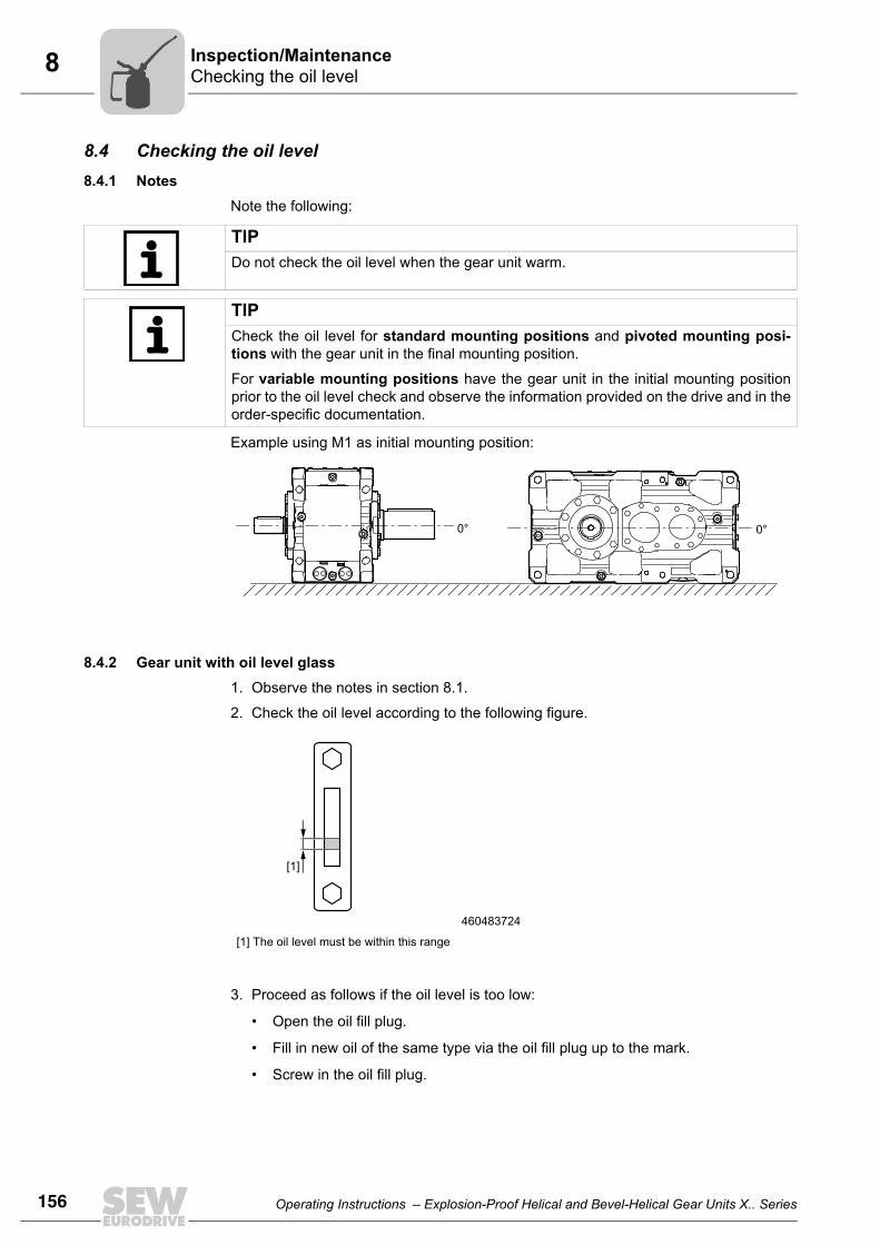
156 Operating Instructions – Explosion-Proof Helical and Bevel-Helical Gear Units X.. Series
8 Checking the oil levelInspection/Maintenance
8.4 Checking the oil level8.4.1 Notes
Note the following:
Example using M1 as initial mounting position:
8.4.2 Gear unit with oil level glass1. Observe the notes in section 8.1.
2. Check the oil level according to the following figure.
3. Proceed as follows if the oil level is too low:
• Open the oil fill plug.
• Fill in new oil of the same type via the oil fill plug up to the mark.
• Screw in the oil fill plug.
TIPDo not check the oil level when the gear unit warm.
TIPCheck the oil level for standard mounting positions and pivoted mounting posi-tions with the gear unit in the final mounting position.
For variable mounting positions have the gear unit in the initial mounting positionprior to the oil level check and observe the information provided on the drive and in theorder-specific documentation.
0° 0°
460483724
[1] The oil level must be within this range
[1]

Operating Instructions – Explosion-Proof Helical and Bevel-Helical Gear Units X.. Series 157
8Checking the oil levelInspection/Maintenance
8.4.3 Gear units with oil dipstick
1. Observe the notes in section 8.1.
2. Unscrew the oil dipstick and remove it.
3. Clean the oil dipstick and re-insert it by turning it hand-tight into the gear unit up tothe stop.
4. Remove the oil dipstick and check the oil level.
5. Proceed as follows if the oil level is too low:
• Open the oil fill plug.
• Fill in new oil of the same type via the oil fill plug up to the mark.
• Screw in the oil fill plug.
6. Insert the oil dipstick.
8.4.4 Gear unit with oil sight glass1. Observe the notes in section 8.1.
2. Check the oil level according to the following figure.
3. Proceed as follows if the oil level is too low:
• Open the oil fill plug.
• Fill in new oil of the same type via the oil fill plug up to the mark.
• Screw in the oil fill plug.
460483852
[1] The oil level must be within this range
[1]
460483980
[1] The oil level must be within this range
[1]

158 Operating Instructions – Explosion-Proof Helical and Bevel-Helical Gear Units X.. Series
8 Checking the oil consistencyInspection/Maintenance
8.5 Checking the oil consistency1. Observe the notes in section 8.1 "Preliminary work regarding inspection/mainte-
nance".
2. Determine the position of the oil drain plug and place a container underneath.
3. Unscrew the oil drain plug slowly and take an oil sample.
4. Re-insert the oil drain plug.
5. Check the oil consistency:
• For more detailed information on checking the oil for water content and viscosity,contact your lubricant manufacturer.
• If you can see that the oil is heavily contaminated, change the oil even if this isoutside of the specified oil change intervals.
8.6 Changing the oil8.6.1 Notes
• Do always refill the gear unit with the grade of oil that was used before. Mixing oils ofdifferent grades and/or manufacturers is not permitted. Especially synthetic oils maynot be mixed with mineral oils or other synthetic oils. Flush the gear unit with the newoil grade thoroughly when switching from mineral oil and/or when switching from syn-thetic oil of one basis to synthetic oil of a different basis.
• Refer to section "Lubrication table" (see page 167) to determine which oils from thevarious lubricant manufacturers can be used.
• Information such as the oil grade, oil viscosity and required oil quantity is listed onthe nameplate of the gear unit. The oil quantity specified on the nameplate is an ap-proximate quantity. The mark on the oil level glass or stick is the decisive indicator ofthe correct oil level.
• Only change the oil when the gear unit is warm.
• When changing the oil, flush the gear unit interior thoroughly with oil to remove oilsludge, oil residue, and abrasion products. Use the same grade of oil that is used tooperate the gear unit. Fill with fresh oil only after all residues have been removed.
• For the position of the oil level plug, oil drain plug and the breather valve, refer to theorder documents.
• Dispose of the used oil in accordance with applicable regulations.
NOTICEImproper oil change may result in damages to the gear unit.
Possible damage to property!• Note the following:

Operating Instructions – Explosion-Proof Helical and Bevel-Helical Gear Units X.. Series 159
8Changing the oilInspection/Maintenance
8.6.2 Procedure
1. Observe the notes in section "Preliminary work regarding inspection/maintenance"(see page ).
2. Place a container underneath the oil drain plug.
3. Remove the oil fill plug and the oil drain plug.
4. Drain all the oil.
5. Re-insert the oil drain plug.
6. Fill in new oil of the same type via the oil fill plug (otherwise consult the customer ser-vice).
• Use a funnel to fill the oil (filter mesh max. 25 µm).
• Fill the oil according to the quantity specified on the nameplate. The oil quantityspecified on the nameplate is an approximate value.
• Check the oil level.
7. Clean the oil filter, replace the filter element if necessary (when using an external oil/air or oil/water cooling system).
WARNINGDanger of burns due to hot gear unit and hot gear unit oil.
Fatal injuries.• Let the gear unit cool down before you begin with your work.• However, the gear unit must still be warm otherwise the high viscosity of
excessively cold oil will make it harder to drain the oil correctly.
TIPRemove any dripping oil immediately with an oil binding agent.

160 Operating Instructions – Explosion-Proof Helical and Bevel-Helical Gear Units X.. Series
8 Checking and cleaning the breather plugInspection/Maintenance
8.7 Checking and cleaning the breather plug
1. Remove any deposits located near the breather valve.
2. Replace clogged breather valves with new ones.
8.8 Refilling greaseRegreasable sealing systems may be refilled with lithium-soap grease (section 10.5).Use moderate pressure to force about 30 g of grease into each lubrication point untilnew grease leaks out of the sealing gap.
Used grease, including contaminants and sand, is thus pressed out of the sealing gap.
NOTICEImproper cleaning of the breather plug may damage the gear unit.
Potential damage to property• Prevent foreign bodies from entering into the gear unit during the following work.
NOTE ON EXPLOSION PROTECTIONMake sure that the old grease cannot escape uncontrolled (preventing explosions, e.g.chemical reactions).

Operating Instructions – Explosion-Proof Helical and Bevel-Helical Gear Units X.. Series 161
8Relubricating bearings with a Drywell sealing systemInspection/Maintenance
8.9 Relubricating bearings with a Drywell sealing system
1. Open the grease draining pipe [1] so that old excess grease can escape.
2. Fill in the grease via the flat grease nipple (DIN 3404 A G1/8) [2].
Amount of lubricant according to the following table:
3. Close the grease draining pipe [1].
NOTICEHigh pressure presses out the grease between the sealing lip and the shaft. The seal-ing lip may be damaged or slip, grease may seep into the workflow.
Possible damage to property!• Fill the grease while the gear unit is running by carefully pressing in the required
quantity.
738458635
Size Grease quantity [g] Size Grease quantity [g]
180-190 80 270-280 250
200-210 120 290-300 300
220-230 150 310-320 400
240-260 200
[2]
[1]
NOTE ON EXPLOSION PROTECTIONMake sure that the old grease cannot escape uncontrolled (preventing explosions, e.g.chemical reactions).

162 Operating Instructions – Explosion-Proof Helical and Bevel-Helical Gear Units X.. Series
8 Fan /FANInspection/Maintenance
8.10 Fan /FANObserve the notes in section 8.1.
Check the fan inlets and outlets regularly. The opening must be kept clear; clean the fanguard if necessary.
Before restarting the fan, be sure the fan guard is mounted properly. The fan must nottouch against the fan guard.
8.11 Built-in cooling – water cooling cover /CCV1. Observe the notes in section 8.1.
2. Remove the cooling water inflow and return pipes from the water cooling cover.
3. Check the water cooling cover for deposits.
Clean off light dirt on the water cooling cover with a suitable cleaning agent. If heavilysoiled, replace the ware cooling cover with a new one. Consult SEW-EURODRIVE.
4. Re-connect the water cooling inflow and return pipes to the water cooling cover.
8.12 Built-in cooling – water cooling cartridge /CCT1. Observe the notes in section 8.1.
2. Remove the cooling water inflow and return pipes from the water cooling cartridge.
3. Drain all the oil prior to disassembly.
4. Check the water cooling cartridges for deposits.
Clean off light dirt on the water cooling cartridges with a suitable cleaning agent. Ifheavily soiled, replace the water cooling cartridges. Consult SEW-EURODRIVE.
5. Re-connect the cooling water supply and return pipes to the water cooling cartridges.

Operating Instructions – Explosion-Proof Helical and Bevel-Helical Gear Units X.. Series 163
8Oil heater /OHInspection/Maintenance
8.13 Oil heater /OH
1. Observe the notes in section 8.1.
2. Before disassembling the oil heating, drain the oil completely.
3. Remove the oil heating.
4. Clean the tubular heating elements with solvent, replace defective heating elements.
5. Re-install the oil heating.
8.14 Split housingIf the split gear unit housing is divided during maintenance, be sure that:
• the parting lines are sealed again carefully, and
• the screw connections are re-tightened using the tightening torques given in section"tightening torques" (see page 66).
DANGERDanger of electric shock!
Severe or fatal injuries.• De-energize the oil heater before you start working on the unit.• Secure the oil heater against unintended power-up.
NOTE ON EXPLOSION PROTECTIONDeactivate the heating resistor before you drain the oil. The heating resistor can causethe evaporating oil to explode.
NOTICEImproper cleaning may damage the heating elements.
Possible damage to property!• Do not destroy the heating elements by scratching or scraping.

164 Operating Instructions – Explosion-Proof Helical and Bevel-Helical Gear Units X.. Series
9 Troubleshooting informationMalfunctions
9 Malfunctions9.1 Troubleshooting information
Read the following notes before you proceed.
9.2 Customer servicePlease have the following information available if you require customer serviceassistance:
• Complete nameplate data
• Type and extent of the problem
• Time the problem occurred and any accompanying circumstances
• Assumed cause
• A digital photograph if possible
9.3 Possible gear unit malfunctions
DANGERRisk of crushing if the drive starts up unintentionally.
Severe or fatal injuries.• De-energize the motor before you start working on the unit.• Secure the motor against unintended power-up.
WARNINGDanger of burns due to hot gear unit and hot gear unit oil.
Fatal injuries.• Let the gear unit cool down before you start working on it.
NOTICEImproper handling of the gear unit and the motor may lead to damages.
Possible damage to property!• Any repair work on SEW drives may be performed by qualified personnel only. • Only qualified personnel is permitted to separate drive and motor.• Consult the SEW-EURODRIVE customer service.
Malfunction Possible cause Remedy
Unusual, regular running noise
• Meshing/grinding noise: Bearing damage• Knocking noise: Irregularity in the gearing• Deformation of the housing upon
tightening• Noise generation caused by insufficient
rigidity of the gear unit foundation
• Check oil (see chapter 8.4), replace bearings• Contact customer service• Check the gear unit mounting for possible
deformation and correct if needed• Reinforce the gear unit foundation
Unusual, irregular running noise
• Foreign objects in the oil • Check oil (see chapter 8.4)• Stop the drive, contact customer service
Unusual noise in the area of the gear unit mounting
• Gear unit mounting has loosened • Tighten retaining screws and nuts to the specified torque
• Replace the damaged / defective retaining screws or nuts

Operating Instructions – Explosion-Proof Helical and Bevel-Helical Gear Units X.. Series 165
9Possible gear unit malfunctionsMalfunctions
Operating temperature too high
• Too much oil• Oil too old• The oil is heavily contaminated• Ambient temperature is too high• Gear units with fan: Air intake opening/
gear unit housing very dirty• For gear units with built-in cooling: Cooling
liquid flow rate too low Cooling liquid temperature too high Deposits in cooling system
• Malfunctions of oil/air or oil/water cooling system
• Check the oil level, correct if necessary (see section 8.4/8.6)
• Check when the oil was last changed; change the oil if necessary (see chapter 8.4/8.6)
• Protect from external heat sources (e.g. provide shade)
• Check the air intake opening and clean if necessary, clean gear unit housing
• Observe the separate operating instructions of the oil/water and oil/air cooling system.
Bearing point temperatures too high
• Not enough oil• Oil too old• Bearing damaged
• Check the oil level, correct if necessary (see section 8.4/8.6)
• Check when the oil was last changed; change the oil if necessary (see chapter 8.6)
• Check bearing and replace if necessary, contact customer service
Operating temperature at backstop too high No block-ing function
• Damaged/defective backstop • Check backstop; replace if necessary• Contact customer service
Oil leaking1)
• From cover plate• From inspection cover• From bearing cover• From mounting flange• From input/output side oil
seal
• Gasket on cover plate / inspection cover / bearing cover / mounting flange leaking
• Sealing lip of the oil seal turned up• Oil seal damaged/worn
• Tighten the bolts on the respective cover plate and observe the gear unit. If oil still leaks: Contact customer service
• Vent the gear unit, observe the gear unit. If oil still leaks: Contact customer service
• Check oil seals; replace if necessary• Contact customer service
Oil leaking• From oil drain plug• From breather plug
• Too much oil• Drive installed in incorrect mounting
position• Frequent cold starts (oil foams) and/or
high oil level
• Correct oil quantity (see section 8.4)• Mount the breather plug correctly and correct the
oil level (see nameplate, "Lubricants" section)
Heavy wear of V-belts
• Belt pulleys inadequately aligned• Harmful ambient conditions (e.g. abrasive
particles, chemical substances)• V-belt overloaded
• Check belt pulley alignment and pretension of the belts
• Protect V-belt drive from environmental influences, however, you must ensure sufficient ventilation
• Replace V-belt if necessary, consult customer service
No oil pump suctionPressure switch not switch-ing
• Air in the suction pipe of the oil pump• Oil pump defective• Pressure switch defective
• Fill the suction line and oil pump with oil • Vent the pump on the pressure side• Replace pressure switch• Contact customer service
Malfunctions of oil/air or oil/water cooling system
• Observe the separate operating instructions of the oil/water and oil/air cooling system.
Gear unit does not reach cold start temperature
• Oil heating defective or connected incorrectly
• Heat dissipation too great due to unfavorable climactic conditions
• Check that oil heating is connected and functioning correctly, replace if needed
• Protect the gear unit from cooling off during the warm-up phase
1) During the run-in phase (24-hour run time), it is normal for (small amounts of) oil/grease to leak from the oil seal (see also DIN 3761).
Malfunction Possible cause Remedy

166 Operating Instructions – Explosion-Proof Helical and Bevel-Helical Gear Units X.. Series
10 Lubricant selectionLubricants
10 Lubricants10.1 Lubricant selection
• The oil viscosity and type (mineral/synthetic) that are to be used are determined bySEW-EURODRIVE specifically for each order. This information is noted in the orderconfirmation and on the gear unit's nameplate.
You must contact SEW-EURODRIVE in case of a deviation from this specification.
This lubricant recommendation in no way represents a guarantee as to the quality ofthe lubricant delivered by each respective supplier. Each lubricant manufacturer isresponsible for the quality of its product.
• Ensure that the gear unit is filled with the correct oil grade and quantity before startup.You can obtain the corresponding information from the gear unit nameplate and thelubricant table in the following section.
• Do not mix different synthetic lubricants.
NOTE ON EXPLOSION PROTECTIONContact SEW-EURODRIVE before changing the mounting position. Otherwise, theATEX certification is not valid.
NOTICESelecting improper lubricants may damage the gear unit.
Possible damage to property!• Observe the following notes.

Operating Instructions – Explosion-Proof Helical and Bevel-Helical Gear Units X.. Series 167
10Approved lubricantsLubricants
10.2 Approved lubricants10.2.1 General information
The lubricant table on the following page shows the permitted lubricants for gear units.Observe the following legend with regards to the lubricant table.
10.2.2 Key to the lubricant tableAbbreviations, meaning of shading and notes:
10.2.3 Notes on the lubricant table
10.2.4 Lubricant table
CLP HC = Synthetic polyalphaolefin
= Synthetic lubricant
NOTICESelecting improper lubricants may damage the gear unit.
Possible damage to property!• Contact SEW-EURODRIVE if you operate the unit under extreme conditions, such
as cold, heat, or there if the operating conditions have changed since project planning.
OilOilOil
Mobilgear SHC XMP150
DIN (ISO)
ISO VG class
CLP HC
CLP HC
CLP HC
CLP HC
Mobil®
VG 150Degol
PAS 150BP Enersyn EP-XF 150 ELGreco 150
ELGreco 220
ELGreco 320
ELGreco 460
KlüberGEM4-150N
Renolin Unisyn CLP 150
Carter SH 150
Degol PAS 220
BP Enersyn EP-XF 220
Optigear Synthetic X 150
Tribol 1710/150
Tribol 1510/150
Optigear Synthetic X 220
Optigear Synthetic A 220
Tribol 1710/220
Tribol 1510/220
Optigear Synthetic X 460
Optigear Synthetic A 320
Tribol 1710/ 460
Tribol 1510/ 460
Optigear Synthetic X 320
Tribol 1710/ 320
Tribol 1510/ 320
Pinnacle WM 150
Pinnacle WM 220
Shell Omala Oil HD 220
Mobilgear SHC XMP220
KlüberGEM4-220N
Renolin Unisyn CLP 220
Carter SH 220
Degol PAS 320
BP Enersyn EP-XF 320
Pinnacle EP 320
Shell Omala Oil HD 320
Mobilgear SHC XMP320
Mobil SHC 632
KlüberGEM4-320N
Renolin Unisyn CLP 320
Carter SH 320
VG 220
Degol PAS 460
BP Enersyn EP -XF 460
Pinnacle WM 460
Shell Omala Oil HD 460
Mobilgear SHC XMP460
Mobil SHC 634
Klüber GEM4-460N
Renolin Unisyn CLP 460
Carter SH 460
TO T A LO T A L
Q8
VG 460
VG 320
47 0490 106
X.F.. / X.K.. / X.T..

168 Operating Instructions – Explosion-Proof Helical and Bevel-Helical Gear Units X.. Series
10 Lubricant fill quantities for horizontal gear unitsLubricants
10.3 Lubricant fill quantities for horizontal gear units The listed fill quantities are guide values for mounting position M1. The precise valuesvary depending on the number of stages and gear ratios.
The markings on the oil level glass or dipstick are the decisive indicators for the quantityof oil used to fill the unit.
10.3.1 X.F..
10.3.2 X.K..
X2F.. ltr. X3F.. ltr. X4F.. ltr.
X2F180 74 X3F180 77 X4F180 70
X2F190 75 X3F190 77 X4F190 71
X2F200 102 X3F200 105 X4F200 95
X2F210 102 X3F210 105 X4F210 95
X2F220 137 X3F220 145 X4F220 140
X2F230 137 X3F230 145 X4F230 140
X2F240 165 X3F240 176 X4F240 175
X2F250 170 X3F250 176 X4F250 175
X2F260 275 X3F260 270 X4F260 280
X2F270 275 X3F270 270 X4F270 280
X2F280 330 X3F280 335 X4F280 340
X2F290 405 X3F290 400 X4F290 415
X2F300 405 X3F300 400 X4F300 415
X2F310 550 X3F310 540 X4F310 540
X2F320 550 X3F320 540 X4F320 540
X2K.. ltr. X3K.. ltr. X4K.. ltr.
X2K180 60 X3K180 74 X4K180 77
X2K190 60 X3K190 75 X4K190 71
X2K200 85 X3K200 105 X4K200 95
X2K210 85 X3K210 105 X4K210 95
X2K220 130 X3K220 145 X4K220 140
X2K230 130 X3K230 145 X4K230 140
X2K240 165 X3K240 176 X4K240 175
X2K250 165 X3K250 176 X4K250 175
X3K260 255 X4K260 270
X3K270 255 X4K270 270
X3K280 325 X4K280 330
X3K290 400 X4K290 410
X3K300 400 X4K300 410
X3K310 535 X4K310 540
X3K320 535 X4K320 540

Operating Instructions – Explosion-Proof Helical and Bevel-Helical Gear Units X.. Series 169
10Lubricant fill quantities for vertical gear unitsLubricants
10.4 Lubricant fill quantities for vertical gear units The listed fill quantities are guide values for mounting position M5. The precise valuesvary depending on the number of stages and gear ratios, and the lubrication type.
The markings on the oil level glass or dipstick are the decisive indicators for the quantityof oil used to fill the unit.
10.4.1 Bath lubricationXF..
XK..
XT..
X2F.. ltr. X3F.. ltr. X4F.. ltr.
X2F180 173 X3F180 170 X4F180 160
X2F190 173 X3F190 170 X4F190 160
X2F200 233 X3F200 231 X4F200 220
X2F210 233 X3F210 231 X4F210 220
X2F220 310 X3F220 307 X4F220 305
X2F230 310 X3F230 307 X4F230 305
X2F240 385 X3F240 375 X4F240 382
X2F250 385 X3F250 375 X4F250 382
X2K.. ltr. X3K.. ltr. X4K.. ltr.
X2K180 137 X3K180 162 X4K180 165
X2K190 137 X3K190 162 X4K190 165
X2K200 188 X3K200 220 X4K200 230
X2K210 188 X3K210 220 X4K210 230
X2K220 306 X3K220 290 X4K220 305
X2K230 306 X3K230 290 X4K230 305
X2K240 382 X3K240 375 X4K240 387
X2K250 382 X3K250 375 X4K250 387
X3K.. ltr. X4K.. ltr.
X3T180 162 X4T180 165
X3T190 162 X4T190 165
X3T200 220 X4T200 230
X3T210 220 X4T210 230
X3T220 290 X4T220 305
X3T230 290 X4T230 305
X3T240 375 X4T240 387
X3T250 375 X4T250 387

170 Operating Instructions – Explosion-Proof Helical and Bevel-Helical Gear Units X.. Series
10 Lubricant fill quantities for vertical gear unitsLubricants
10.4.2 Pressure lubricationXF..
XK..
X2F.. ltr. X3F.. ltr. X4F.. ltr.
X2F180 71 X3F180 69 X4F180 65
X2F190 71 X3F190 69 X4F190 65
X2F200 104 X3F200 103 X4F200 96
X2F210 104 X3F210 103 X4F210 96
X2F220 122 X3F220 120 X4F220 148
X2F230 122 X3F230 120 X4F230 148
X2F240 151 X3F240 144 X4F240 183
X2F250 151 X3F250 144 X4F250 183
X2K.. ltr. X3K.. ltr. X4K.. ltr.
X2K180 57 X3K180 68 X4K180 81
X2K190 57 X3K190 68 X4K190 81
X2K200 85 X3K200 96 X4K200 109
X2K210 85 X3K210 96 X4K210 109
X2K220 129 X3K220 115 X4K220 148
X2K230 129 X3K230 115 X4K230 148
X2K240 155 X3K240 143 X4K240 186
X2K250 155 X3K250 143 X4K250 186

Operating Instructions – Explosion-Proof Helical and Bevel-Helical Gear Units X.. Series 171
10Lubricant fill quantities for vertical gear unitsLubricants
10.4.3 Pressure lubrication with Drywell sealing systemXF..
XK..
X2F.. ltr. X3F.. ltr. X4F.. ltr.
X2F180 54 X3F180 53 X4F180 49
X2F190 54 X3F190 53 X4F190 49
X2F200 74 X3F200 73 X4F200 68
X2F210 74 X3F210 73 X4F210 68
X2F220 94 X3F220 92 X4F220 93
X2F230 94 X3F230 92 X4F230 93
X2F240 120 X3F240 115 X4F240 117
X2F250 120 X3F250 115 X4F250 117
X2K.. ltr. X3K.. ltr. X4K.. ltr.
X2K180 43 X3K180 52 X4K180 53
X2K190 43 X3K190 52 X4K190 53
X2K200 59 X3K200 69 X4K200 73
X2K210 59 X3K210 69 X4K210 73
X2K220 132 X3K220 88 X4K220 92
X2K230 132 X3K230 88 X4K230 92
X2K240 137 X3K240 115 X4K240 118
X2K250 137 X3K250 115 X4K250 118

172 Operating Instructions – Explosion-Proof Helical and Bevel-Helical Gear Units X.. Series
10 Lubricating greaseLubricants
10.5 Lubricating greaseThe following overview shows the greases recommended by SEW-EURODRIVE.
Vendor Sealing grease
Aral Aralub HLP2
BP Energrease LS-EPS
Castrol Spheerol EPL2
Chevron Dura-Lith EP2
Elf Epexa EP2
Esso Beacon EP2
Exxon Beacon EP2
Fuchs Renolit CX-TOM15
Gulf Gulf crown Grease 2
Klüber Centoplex EP2
Kuwait Q8 Rembrandt EP2
Mobil Mobilux EP2
Molub Alloy BRB-572
Neste Allrex EP2
Optimol Olista Longtime 2
Shell Alvania EP2
Texaco Multifak EP2
Total Multis EP2
Tribol Tribol 3030-2

Operating Instructions – Explosion-Proof Helical and Bevel-Helical Gear Units X.. Series 173
11Declaration of Conformity
11 Declaration of Conformity
EG-KonformitätserklärungEC Declaration of ConformityDéclaration CE de conformité
Nr./No./N°
Ort/Datum Geschäftsführer Vertrieb und MarketingPlace/date / Lieu et date Managing Director Sales and Marketing
Directeur général international commercial et marketing
Bruchsal,H. Sondermann
900530207
01.04.09
im Sinne der Richtlinie 94/9/EG, Anhang VIIIaccording to Directive 94/9/EC, Appendix VIIIau sens de la directive 94/9/CE, Annexe VIII
SEW EURODRIVE GmbH & Co KGErnst-Blickle-Straße 42, D-76646 Bruchsalerklärt in alleiniger Verantwortung die Konformität der folgenden Produktedeclares under sole responsibility conformity of the following productsdéclare, sous sa seule responsabilité, que les produits suivants
Industriegetriebe der Baureihen:Industrial gear units of the series:Réducteurs industriels des séries :
X180 - X250X260 - X320
Kategorie:category: / Catégories :
II 2GD
mit derwith the / respectent la
RichtlinieDirective / Directive
94/9 EG94/9 EC / 94/9/CE
angewandte harmonisierte Normen:Applied harmonized standards: / Normes harmonisées appliquées :
EN 1127-1:2007EN 13463-1:2001EN 13463-5:2003EN 13463-8:2003EN 60529:2000
SEW-EURODRIVE hinterlegt die gemäß 94/9EG, Anhang VIII gefordertenUnterlagen bei benannter Stelle: FSA GmbH, EU - Kennnummer: 0588
SEW-EURODRIVE will archive the documents required according to 94/9/EC,Appendix VIII at the following location: FSA GmbH, EU Code 0588
SEW-EURODRIVE tient à disposition la documentation spécifiée dans la directive94/9/CE , annexe VIII pour consultation à l’endroit désigné : FSA GmbH , code UE0588

174 Operating Instructions – Explosion-Proof Helical and Bevel-Helical Gear Units X.. Series
11 Declaration of Conformity
EG-KonformitätserklärungEC Declaration of ConformityDéclaration CE de conformité
Nr./No./N°
Ort/Datum Geschäftsführer Vertrieb und MarketingPlace/date / Lieu et date Managing Director Sales and Marketing
Directeur général international commercial et marketing
Bruchsal,H. Sondermann
900520107
01.04.09
im Sinne der Richtlinie 94/9/EG, Anhang VIIIaccording to Directive 94/9/EC, Appendix VIIIau sens de la directive 94/9/CE, Annexe VIII
SEW EURODRIVE GmbH & Co KGErnst-Blickle-Straße 42, D-76646 Bruchsalerklärt in alleiniger Verantwortung die Konformität der folgenden Produktedeclares under sole responsibility conformity of the following productsdéclare, sous sa seule responsabilité, que les produits suivants
Industriegetriebe der Baureihen:Industrial gear units of the series:Réducteurs industriels des séries :
X180 - X250X260 - X320
Kategorie:category: / Catégories :
II 3GD
mit derwith the / respectent la
RichtlinieDirective / Directive
94/9 EG94/9 EC / 94/9/CE
angewandte harmonisierte Normen:Applied harmonized standards: / Normes harmonisées appliquées :
EN 1127-1:2007EN 13463-1:2001EN 13463-5:2003EN 13463-8:2003EN 60529:2000
SEW-EURODRIVE hinterlegt die gemäß 94/9EG, Anhang VIII gefordertenUnterlagen bei benannter Stelle: FSA GmbH, EU - Kennnummer: 0588
SEW-EURODRIVE will archive the documents required according to 94/9/EC,Appendix VIII at the following location: FSA GmbH, EU Code 0588
SEW-EURODRIVE tient à disposition la documentation spécifiée dans la directive94/9/CE , annexe VIII pour consultation à l’endroit désigné : FSA GmbH , code UE0588

Operating Instructions – Explosion-Proof Helical and Bevel-Helical Gear Units X.. Series 175
12Address List
12 Address List
Germany
HeadquartersProductionSales
Bruchsal SEW-EURODRIVE GmbH & Co KGErnst-Blickle-Straße 42 D-76646 BruchsalP.O. BoxPostfach 3023 • D-76642 Bruchsal
Tel. +49 7251 75-0Fax +49 7251 75-1970http://[email protected]
Service Compe-tence Center
Central SEW-EURODRIVE GmbH & Co KGErnst-Blickle-Straße 1 D-76676 Graben-Neudorf
Tel. +49 7251 75-1710Fax +49 7251 [email protected]
North SEW-EURODRIVE GmbH & Co KGAlte Ricklinger Straße 40-42 D-30823 Garbsen (near Hannover)
Tel. +49 5137 8798-30Fax +49 5137 [email protected]
East SEW-EURODRIVE GmbH & Co KGDänkritzer Weg 1D-08393 Meerane (near Zwickau)
Tel. +49 3764 7606-0Fax +49 3764 [email protected]
South SEW-EURODRIVE GmbH & Co KGDomagkstraße 5D-85551 Kirchheim (near München)
Tel. +49 89 909552-10Fax +49 89 [email protected]
West SEW-EURODRIVE GmbH & Co KGSiemensstraße 1D-40764 Langenfeld (near Düsseldorf)
Tel. +49 2173 8507-30Fax +49 2173 [email protected]
Electronics SEW-EURODRIVE GmbH & Co KGErnst-Blickle-Straße 42 D-76646 Bruchsal
Tel. +49 7251 75-1780Fax +49 7251 [email protected]
Drive Service Hotline / 24 Hour Service +49 180 5 SEWHELP+49 180 5 7394357
Additional addresses for service in Germany provided on request!
France
ProductionSalesService
Haguenau SEW-USOCOME 48-54, route de Soufflenheim B. P. 20185F-67506 Haguenau Cedex
Tel. +33 3 88 73 67 00 Fax +33 3 88 73 66 00http://[email protected]
Production Forbach SEW-EUROCOME Zone Industrielle Technopôle Forbach SudB. P. 30269F-57604 Forbach Cedex
Tel. +33 3 87 29 38 00
AssemblySalesService
Bordeaux SEW-USOCOME Parc d'activités de Magellan62, avenue de Magellan - B. P. 182F-33607 Pessac Cedex
Tel. +33 5 57 26 39 00Fax +33 5 57 26 39 09
Lyon SEW-USOCOME Parc d'Affaires RooseveltRue Jacques TatiF-69120 Vaulx en Velin
Tel. +33 4 72 15 37 00Fax +33 4 72 15 37 15
Paris SEW-USOCOME Zone industrielle 2, rue Denis Papin F-77390 Verneuil I'Etang
Tel. +33 1 64 42 40 80Fax +33 1 64 42 40 88
Additional addresses for service in France provided on request!

176 Operating Instructions – Explosion-Proof Helical and Bevel-Helical Gear Units X.. Series
12 Address List
Algeria
Sales Alger Réducom 16, rue des Frères ZaghnounBellevue El-Harrach16200 Alger
Tel. +213 21 8222-84Fax +213 21 [email protected]
Argentina
AssemblySalesService
Buenos Aires SEW EURODRIVE ARGENTINA S.A.Centro Industrial Garin, Lote 35Ruta Panamericana Km 37,51619 Garin
Tel. +54 3327 4572-84Fax +54 3327 [email protected]://www.sew-eurodrive.com.ar
Australia
AssemblySalesService
Melbourne SEW-EURODRIVE PTY. LTD.27 Beverage DriveTullamarine, Victoria 3043
Tel. +61 3 9933-1000Fax +61 3 9933-1003http://[email protected]
Sydney SEW-EURODRIVE PTY. LTD.9, Sleigh Place, Wetherill Park New South Wales, 2164
Tel. +61 2 9725-9900Fax +61 2 [email protected]
Austria
AssemblySalesService
Wien SEW-EURODRIVE Ges.m.b.H. Richard-Strauss-Strasse 24A-1230 Wien
Tel. +43 1 617 55 00-0Fax +43 1 617 55 00-30http://[email protected]
Belarus
Sales Minsk SEW-EURODRIVE BYRybalkoStr. 26BY-220033 Minsk
Tel.+375 (17) 298 38 50Fax +375 (17) 29838 [email protected]
Belgium
AssemblySalesService
Brüssel SEW Caron-VectorAvenue Eiffel 5B-1300 Wavre
Tel. +32 10 231-311Fax +32 10 231-336http://[email protected]
Service Compe-tence Center
Industrial Gears SEW Caron-VectorRue de Parc Industriel, 31BE-6900 Marche-en-Famenne
Tel. +32 84 219-878Fax +32 84 219-879http://[email protected]
Antwerp SEW Caron-VectorGlasstraat, 19BE-2170 Merksem
Tel. +32 3 64 19 333Fax +32 3 64 19 336http://[email protected]
Brazil
ProductionSalesService
Sao Paulo SEW-EURODRIVE Brasil Ltda.Avenida Amâncio Gaiolli, 152 - Rodovia Presi-dente Dutra Km 208Guarulhos - 07251-250 - SPSAT - SEW ATENDE - 0800 7700496
Tel. +55 11 2489-9133Fax +55 11 2480-3328http://[email protected]
Additional addresses for service in Brazil provided on request!
Bulgaria
Sales Sofia BEVER-DRIVE GmbHBogdanovetz Str.1BG-1606 Sofia
Tel. +359 2 9151160Fax +359 2 [email protected]

Operating Instructions – Explosion-Proof Helical and Bevel-Helical Gear Units X.. Series 177
12Address List
Cameroon
Sales Douala Electro-ServicesRue Drouot AkwaB.P. 2024Douala
Tel. +237 33 431137Fax +237 33 431137
Canada
AssemblySalesService
Toronto SEW-EURODRIVE CO. OF CANADA LTD. 210 Walker Drive Bramalea, Ontario L6T3W1
Tel. +1 905 791-1553Fax +1 905 791-2999http://[email protected]
Vancouver SEW-EURODRIVE CO. OF CANADA LTD.7188 Honeyman Street Delta. B.C. V4G 1 E2
Tel. +1 604 946-5535Fax +1 604 [email protected]
Montreal SEW-EURODRIVE CO. OF CANADA LTD.2555 Rue Leger LaSalle, Quebec H8N 2V9
Tel. +1 514 367-1124Fax +1 514 [email protected]
Additional addresses for service in Canada provided on request!
Chile
AssemblySalesService
Santiago de Chile
SEW-EURODRIVE CHILE LTDA.Las Encinas 1295Parque Industrial Valle GrandeLAMPARCH-Santiago de ChileP.O. BoxCasilla 23 Correo Quilicura - Santiago - Chile
Tel. +56 2 75770-00Fax +56 2 75770-01http://[email protected]
China
ProductionAssemblySalesService
Tianjin SEW-EURODRIVE (Tianjin) Co., Ltd.No. 46, 7th Avenue, TEDATianjin 300457
Tel. +86 22 25322612Fax +86 22 [email protected]://www.sew-eurodrive.cn
AssemblySalesService
Suzhou SEW-EURODRIVE (Suzhou) Co., Ltd.333, Suhong Middle RoadSuzhou Industrial ParkJiangsu Province, 215021
Tel. +86 512 62581781Fax +86 512 [email protected]
Guangzhou SEW-EURODRIVE (Guangzhou) Co., Ltd.No. 9, JunDa RoadEast Section of GETDDGuangzhou 510530
Tel. +86 20 82267890Fax +86 20 [email protected]
Shenyang SEW-EURODRIVE (Shenyang) Co., Ltd.10A-2, 6th RoadShenyang Economic Technological Develop-ment AreaShenyang, 110141
Tel. +86 24 25382538Fax +86 24 [email protected]
Wuhan SEW-EURODRIVE (Wuhan) Co., Ltd.10A-2, 6th RoadNo. 59, the 4th Quanli Road, WEDA430056 Wuhan
Tel. +86 27 84478398Fax +86 27 84478388
Additional addresses for service in China provided on request!
Colombia
AssemblySalesService
Bogotá SEW-EURODRIVE COLOMBIA LTDA. Calle 22 No. 132-60Bodega 6, Manzana BSantafé de Bogotá
Tel. +57 1 54750-50Fax +57 1 54750-44http://[email protected]

178 Operating Instructions – Explosion-Proof Helical and Bevel-Helical Gear Units X.. Series
12 Address List
Croatia
SalesService
Zagreb KOMPEKS d. o. o.PIT Erdödy 4 IIHR 10 000 Zagreb
Tel. +385 1 4613-158Fax +385 1 [email protected]
Czech Republic
Sales Praha SEW-EURODRIVE CZ S.R.O.Business Centrum Praha Lužná 591CZ-16000 Praha 6 - Vokovice
Tel. +420 255 709 601Fax +420 220 121 237http://[email protected]
Denmark
AssemblySalesService
Kopenhagen SEW-EURODRIVEA/SGeminivej 28-30DK-2670 Greve
Tel. +45 43 9585-00Fax +45 43 9585-09http://[email protected]
Egypt
SalesService
Cairo Copam Egypt for Engineering & Agencies33 EI Hegaz ST, Heliopolis, Cairo
Tel. +20 2 22566-299 + 1 23143088Fax +20 2 22594-757http://www.copam-egypt.com/ [email protected]
Estonia
Sales Tallin ALAS-KUUL ASReti tee 4EE-75301 Peetri küla, Rae vald, Harjumaa
Tel. +372 6593230Fax +372 [email protected]
Finland
AssemblySalesService
Lahti SEW-EURODRIVE OYVesimäentie 4FIN-15860 Hollola 2
Tel. +358 201 589-300Fax +358 3 [email protected]://www.sew-eurodrive.fi
ProductionAssemblyService
Karkkila SEW Industrial Gears OyValurinkatu 6FIN-03600 Karkkila
Tel. +358 201 589-300Fax +358 201 [email protected]://www.sew-eurodrive.fi
Gabon
Sales Libreville Electro-ServicesB.P. 1889Libreville
Tel. +241 7340-11Fax +241 7340-12
Great Britain
AssemblySalesService
Normanton SEW-EURODRIVE Ltd.Beckbridge Industrial Estate P.O. Box No.1GB-Normanton, West- Yorkshire WF6 1QR
Tel. +44 1924 893-855Fax +44 1924 893-702http://[email protected]
Greece
SalesService
Athen Christ. Boznos & Son S.A.12, Mavromichali StreetP.O. Box 80136, GR-18545 Piraeus
Tel. +30 2 1042 251-34 Fax +30 2 1042 251-59http://[email protected]

Operating Instructions – Explosion-Proof Helical and Bevel-Helical Gear Units X.. Series 179
12Address List
Hong Kong
AssemblySalesService
Hong Kong SEW-EURODRIVE LTD.Unit No. 801-806, 8th FloorHong Leong Industrial ComplexNo. 4, Wang Kwong Road Kowloon, Hong Kong
Tel. +852 36902200Fax +852 [email protected]
Hungary
SalesService
Budapest SEW-EURODRIVE Kft.H-1037 BudapestKunigunda u. 18
Tel. +36 1 437 06-58Fax +36 1 437 [email protected]
India
AssemblySalesService
Vadodara SEW-EURODRIVE India Private LimitedPlot No. 4, GIDCPOR Ramangamdi • Vadodara - 391 243Gujarat
Tel. +91 265 2831086Fax +91 265 2831087http://[email protected]@seweurodriveindia.com
Ireland
SalesService
Dublin Alperton Engineering Ltd. 48 Moyle RoadDublin Industrial EstateGlasnevin, Dublin 11
Tel. +353 1 830-6277Fax +353 1 [email protected]://www.alperton.ie
Israel
Sales Tel-Aviv Liraz Handasa Ltd. Ahofer Str 34B / 22858858 Holon
Tel. +972 3 5599511Fax +972 3 5599512http://[email protected]
Italy
AssemblySalesService
Milano SEW-EURODRIVE di R. Blickle & Co.s.a.s.Via Bernini,14 I-20020 Solaro (Milano)
Tel. +39 02 96 9801Fax +39 02 96 799781http://[email protected]
Ivory Coast
Sales Abidjan SICASte industrielle et commerciale pour l'Afrique165, Bld de MarseilleB.P. 2323, Abidjan 08
Tel. +225 2579-44Fax +225 2584-36
Japan
AssemblySalesService
Iwata SEW-EURODRIVE JAPAN CO., LTD 250-1, Shimoman-no,IwataShizuoka 438-0818
Tel. +81 538 373811Fax +81 538 373814http://[email protected]
Korea
AssemblySalesService
Ansan-City SEW-EURODRIVE KOREA CO., LTD. B 601-4, Banweol Industrial Estate 1048-4, Shingil-DongAnsan 425-120
Tel. +82 31 492-8051Fax +82 31 492-8056http://[email protected]
Busan SEW-EURODRIVE KOREA Co., Ltd.No. 1720 - 11, Songjeong - dongGangseo-kuBusan 618-270
Tel. +82 51 832-0204Fax +82 51 [email protected]

180 Operating Instructions – Explosion-Proof Helical and Bevel-Helical Gear Units X.. Series
12 Address List
Latvia
Sales Riga SIA Alas-KuulKatlakalna 11CLV-1073 Riga
Tel. +371 7139253Fax +371 7139386http://[email protected]
Lebanon
Sales Beirut Gabriel Acar & Fils sarlB. P. 80484Bourj Hammoud, Beirut
Tel. +961 1 4947-86 +961 1 4982-72+961 3 2745-39Fax +961 1 4949-71 [email protected]
Lithuania
Sales Alytus UAB IrsevaNaujoji 19LT-62175 Alytus
Tel. +370 315 79204Fax +370 315 [email protected]://www.sew-eurodrive.lt
Luxembourg
AssemblySalesService
Brüssel CARON-VECTOR S.A.Avenue Eiffel 5B-1300 Wavre
Tel. +32 10 231-311Fax +32 10 231-336http://[email protected]
Malaysia
AssemblySalesService
Johore SEW-EURODRIVE SDN BHD No. 95, Jalan Seroja 39, Taman Johor Jaya81000 Johor Bahru, JohorWest Malaysia
Tel. +60 7 3549409Fax +60 7 [email protected]
Mexico
AssemblySalesService
Quéretaro SEW-EURODRIVE MEXICO SA DE CVSEM-981118-M93Tequisquiapan No. 102Parque Industrial QuéretaroC.P. 76220Quéretaro, México
Tel. +52 442 1030-300Fax +52 442 1030-301http://[email protected]
Morocco
Sales Casablanca Afit5, rue Emir AbdelkaderMA 20300 Casablanca
Tel. +212 22618372Fax +212 [email protected]
Netherlands
AssemblySalesService
Rotterdam VECTOR Aandrijftechniek B.V. Industrieweg 175 NL-3044 AS RotterdamPostbus 10085NL-3004 AB Rotterdam
Tel. +31 10 4463-700Fax +31 10 4155-552http://[email protected]
New Zealand
AssemblySalesService
Auckland SEW-EURODRIVE NEW ZEALAND LTD. P.O. Box 58-428 82 Greenmount driveEast Tamaki Auckland
Tel. +64 9 2745627Fax +64 9 2740165http://[email protected]
Christchurch SEW-EURODRIVE NEW ZEALAND LTD. 10 Settlers Crescent, FerrymeadChristchurch
Tel. +64 3 384-6251Fax +64 3 [email protected]

Operating Instructions – Explosion-Proof Helical and Bevel-Helical Gear Units X.. Series 181
12Address List
Norway
AssemblySalesService
Moss SEW-EURODRIVE A/SSolgaard skog 71N-1599 Moss
Tel. +47 69 24 10 20Fax +47 69 24 10 40http://[email protected]
Peru
AssemblySalesService
Lima SEW DEL PERU MOTORES REDUCTORES S.A.C.Los Calderos, 120-124Urbanizacion Industrial Vulcano, ATE, Lima
Tel. +51 1 3495280Fax +51 1 3493002http://[email protected]
Poland
AssemblySalesService
Lodz SEW-EURODRIVE Polska Sp.z.o.o.ul. Techniczna 5 PL-92-518 Łódź
Tel. +48 42 67710-90Fax +48 42 67710-99http://[email protected]
24 Hour Service Tel. +48 602 739 739(+48 602 SEW SEW)
Portugal
AssemblySalesService
Coimbra SEW-EURODRIVE, LDA.Apartado 15 P-3050-901 Mealhada
Tel. +351 231 20 9670Fax +351 231 20 3685http://[email protected]
Romania
SalesService
Bucureşti Sialco Trading SRL str. Madrid nr.4 011785 Bucuresti
Tel. +40 21 230-1328Fax +40 21 230-7170 [email protected]
Russia
AssemblySalesService
St. Petersburg ZAO SEW-EURODRIVE P.O. Box 36 195220 St. Petersburg Russia
Tel. +7 812 3332522 +7 812 5357142Fax +7 812 3332523http://[email protected]
Senegal
Sales Dakar SENEMECA Mécanique GénéraleKm 8, Route de Rufisque B.P. 3251, Dakar
Tel. +221 338 494 770Fax +221 338 494 [email protected]
Serbia
Sales Beograd DIPAR d.o.o.Ustanicka 128aPC Košum, IV floorSCG-11000 Beograd
Tel. +381 11 347 3244 / +381 11 288 0393Fax +381 11 347 [email protected]
Singapore
AssemblySalesService
Singapore SEW-EURODRIVE PTE. LTD. No 9, Tuas Drive 2 Jurong Industrial Estate Singapore 638644
Tel. +65 68621701Fax +65 68612827http://[email protected]

182 Operating Instructions – Explosion-Proof Helical and Bevel-Helical Gear Units X.. Series
12 Address List
Slovakia
Sales Bratislava SEW-Eurodrive SK s.r.o.Rybničná 40SK-831 06 Bratislava
Tel. +421 2 33595 202Fax +421 2 33595 [email protected]://www.sew-eurodrive.sk
Žilina SEW-Eurodrive SK s.r.o.Industry Park - PChZulica M.R.Štefánika 71SK-010 01 Žilina
Tel. +421 41 700 2513Fax +421 41 700 [email protected]
Banská Bystrica SEW-Eurodrive SK s.r.o.Rudlovská cesta 85SK-974 11 Banská Bystrica
Tel. +421 48 414 6564Fax +421 48 414 [email protected]
Košice SEW-Eurodrive SK s.r.o.Slovenská ulica 26SK-040 01 Košice
Tel. +421 55 671 2245Fax +421 55 671 [email protected]
Slovenia
SalesService
Celje Pakman - Pogonska Tehnika d.o.o.UI. XIV. divizije 14SLO - 3000 Celje
Tel. +386 3 490 83-20Fax +386 3 490 [email protected]
South Africa
AssemblySalesService
Johannesburg SEW-EURODRIVE (PROPRIETARY) LIMITEDEurodrive House Cnr. Adcock Ingram and Aerodrome RoadsAeroton Ext. 2Johannesburg 2013P.O.Box 90004Bertsham 2013
Tel. +27 11 248-7000Fax +27 11 494-3104http://[email protected]
Cape Town SEW-EURODRIVE (PROPRIETARY) LIMITED Rainbow ParkCnr. Racecourse & Omuramba RoadMontague GardensCape TownP.O.Box 36556Chempet 7442 Cape Town
Tel. +27 21 552-9820Fax +27 21 552-9830Telex 576 [email protected]
Durban SEW-EURODRIVE (PROPRIETARY) LIMITED2 Monaceo PlacePinetownDurbanP.O. Box 10433, Ashwood 3605
Tel. +27 31 700-3451Fax +27 31 [email protected]
Spain
AssemblySalesService
Bilbao SEW-EURODRIVE ESPAÑA, S.L. Parque Tecnológico, Edificio, 302E-48170 Zamudio (Vizcaya)
Tel. +34 94 43184-70Fax +34 94 43184-71http://[email protected]
Sweden
AssemblySalesService
Jönköping SEW-EURODRIVE ABGnejsvägen 6-8S-55303 JönköpingBox 3100 S-55003 Jönköping
Tel. +46 36 3442 00Fax +46 36 3442 80http://[email protected]

Operating Instructions – Explosion-Proof Helical and Bevel-Helical Gear Units X.. Series 183
12Address List
Switzerland
AssemblySalesService
Basel Alfred lmhof A.G.Jurastrasse 10 CH-4142 Münchenstein bei Basel
Tel. +41 61 417 1717Fax +41 61 417 1700http://[email protected]
Thailand
AssemblySalesService
Chonburi SEW-EURODRIVE (Thailand) Ltd.700/456, Moo.7, DonhuarohMuang Chonburi 20000
Tel. +66 38 454281Fax +66 38 [email protected]
Tunisia
Sales Tunis T. M.S. Technic Marketing ServiceZone Industrielle Mghira 2Lot No. 392082 Fouchana
Tel. +216 71 4340-64 + 71 4320-29Fax +216 71 [email protected]
Turkey
AssemblySalesService
Istanbul SEW-EURODRIVE Hareket Sistemleri San. ve Tic. Ltd. Sti. Bagdat Cad. Koruma Cikmazi No. 3 TR-34846 Maltepe ISTANBUL
Tel. +90 216 4419164, 3838014, 3738015Fax +90 216 3055867http://[email protected]
Ukraine
SalesService
Dnepropetrovsk SEW-EURODRIVEStr. Rabochaja 23-B, Office 40949008 Dnepropetrovsk
Tel. +380 56 370 3211Fax +380 56 372 2078http://[email protected]
USA
ProductionAssemblySalesServiceCooporate Offices
Southeast Region
SEW-EURODRIVE INC. 1295 Old Spartanburg Highway P.O. Box 518Lyman, S.C. 29365
Tel. +1 864 439-7537Fax Sales +1 864 439-7830Fax Manufacturing +1 864 439-9948Fax Assembly +1 864 439-0566Fax Confidential/HR +1 864 949-5557http://[email protected]
AssemblySalesService
Northeast Region
SEW-EURODRIVE INC. Pureland Ind. Complex 2107 High Hill Road, P.O. Box 481Bridgeport, New Jersey 08014
Tel. +1 856 467-2277Fax +1 856 [email protected]
Midwest Region SEW-EURODRIVE INC.2001 West Main Street Troy, Ohio 45373
Tel. +1 937 335-0036Fax +1 937 [email protected]
Southwest Region
SEW-EURODRIVE INC.3950 Platinum Way Dallas, Texas 75237
Tel. +1 214 330-4824Fax +1 214 [email protected]
Western Region SEW-EURODRIVE INC. 30599 San Antonio St.Hayward, CA 94544
Tel. +1 510 487-3560Fax +1 510 [email protected]
Additional addresses for service in the USA provided on request!
Venezuela
AssemblySalesService
Valencia SEW-EURODRIVE Venezuela S.A.Av. Norte Sur No. 3, Galpon 84-319Zona Industrial Municipal NorteValencia, Estado Carabobo
Tel. +58 241 832-9804Fax +58 241 838-6275http://[email protected]@cantv.net

184 Operating Instructions – Explosion-Proof Helical and Bevel-Helical Gear Units X.. Series
Index
Index
AAbbreviations for accessories ................................21Accessories, abbreviations ....................................21Assembly
Water cooling cartridge ....................................128Water cooling cover .........................................127
BBackstop ................................................................47Base frame.....................................................51, 126Bath lubrication ......................................................40Bath lubrication accessories ..................................42Breather .................................................................41Built-in cooling........................................................52
CCCW ......................................................................47Changing the oil ...................................................158Checking and cleaning the breather plug.............160Checking the oil consistency................................158Checking the oil level ...........................................156Circulation cooling..................................................52Cooling types .........................................................52Copyright..................................................................7Corresponding directions of rotation ......................29Couplings ...............................................................78
Mounting tolerances...........................................78Coupling, Nor-Mex .................................................81Coupling, ROTEX ..................................................80Customer service .................................................164CW .........................................................................47
DDecommissioning gear units ................................150Disposal .................................................................10Drive packages on steel frame...............................50Drywell sealing system...........................38, 161, 171Dust protection lip ..................................................36
EExterior corrosion protection ..................................17
FFan.........................................................................53
Assembly .........................................................127
Maintenance ....................................................162X.F.. Fan (standard)...........................................53X.K.. Advanced (option).....................................54X.K.. Fan (standard) ..........................................53
Fan cooling ............................................................52Flange coupling .....................................................83
Mounting onto the shaft .....................................84Mounting the flange connection.........................86Removal.............................................................88
GGear unit mounting ................................................67Gear unit shutdown..............................................151Gearing and shafts ................................................31Grease nipple on inspection cover ........................37
HHollow shaft and keyed connection .......................92Hollow shaft and shrink disk ................................100Hollow shaft with splining.....................................109Housing..................................................................31
IIEC.........................................................................48Input shaft ..............................................................32Inspection intervals ..............................................154Internal corrosion protection ..................................17
KKeyed hollow shaft.................................................92Keyway ..................................................................34
LLabyrinth seal ........................................................36Lubricant change intervals...................................155Lubricant table .....................................................167Lubricants ............................................................166Lubrication .............................................................40Lubrication points...................................................37Lubrication types....................................................40

Operating Instructions – Explosion-Proof Helical and Bevel-Helical Gear Units X.. Series 185
Index
MMaintenance
Fan...................................................................162Water cooling cartridge ....................................162Water cooling cover .........................................162
Maintenance intervals ..........................................154Modifying the cooling system...............................133Motor adapter.........................................................48Mounting position...................................................23Mounting position and standard mounting surface 26Mounting surface ...................................................24
NNameplate..............................................................22NEMA.....................................................................48Nor-Mex coupling...................................................81NTB........................................................................63
OOil expansion tank .................................................42Oil filling process – pressure lubrication.................76Oil heater ...............................................................62
Limit temperature for startup............................137Maintenance ....................................................163Notes regarding the function............................136Structure ............................................................62
Oil pump...............................................................147Oil seal ...................................................................36Oil/air cooler
Cooling capacity.................................................61Electrical connection ........................................133Mechanical connection ....................................131Modification......................................................133Structure ............................................................60
Oil/water coolerCooling capacity.................................................59Cooling media ..................................................130Electrical connection ........................................129Mechanical connection ....................................129Structure ............................................................58
Oil/water cooler with motor pump.........................129Output shaft ...........................................................32
PPackaging ..............................................................17Pictograms on the gear unit ...................................10Preliminary work ....................................................69Pressure lubrication ...................................40, 43, 76Pressure lubrication accessories ...........................43Pressure switch .......................................63, 76, 138PT100 ....................................................................63
RRefilling grease ....................................................160ROTEX coupling ....................................................80Run-in period .......................................................148
SSafety notes.............................................................8
.............................................................................6Sealing grease.....................................................172Sealing systems.....................................................36Shaft end pump .....................................................43Shaft position .........................................................25Shrink disk .....................................................34, 100Splash lubrication ..................................................40Splined solid shaft..................................................33Splining ................................................................109Split housing ........................................................163Starting up the gear unit at lower ambient temperatures........................................................149Stickers on the gear unit ........................................10Storage conditions ...........................................17, 18Structure of the safety notes....................................6Swing base ....................................................50, 126Symbols on the gear unit .......................................10
TTaconite .................................................................36Temperature sensor
PT100 ................................................................63Temperature sensor PT100
Dimensions ......................................................140Electrical connection........................................141Technical data .................................................141
Temperature switchNTB....................................................................63TSK....................................................................63

186 Operating Instructions – Explosion-Proof Helical and Bevel-Helical Gear Units X.. Series
Index
Temperature switch NTBDimensions ......................................................142Electrical connection ........................................143Technical data..................................................143
Temperature switch TSKDimensions ......................................................144Electrical connection ........................................145Technical data..................................................145
Tightening torques .................................................66Tolerances .............................................................67Torque arm ....................................................45, 117Transport................................................................12Transport conditions ..............................................17TSK ........................................................................63
UUnit designation
Oil supply system...............................................20Unit designations for gear units..............................19Used oil ..................................................................10
VV-belt drive
Assembly .........................................................122Maximum permitted motor weight....................122
V-belt drives ...........................................................49Visual oil level check..............................................41
WWarning notes on the gear unit ..............................10Water cooling cartridge ..........................................56
Assembly .........................................................128Maintenance ....................................................162
Water cooling cover ...............................................55Assembly .........................................................127Maintenance ....................................................162


SEW-EURODRIVE—Driving the world
SEW-EURODRIVEDriving the world
www.sew-eurodrive.com
SEW-EURODRIVE GmbH & Co KGP.O. Box 3023D-76642 Bruchsal/GermanyPhone +49 7251 75-0Fax +49 7251 [email protected]
Copyright © 2022 FDOKUMEN