Quasi-Static and Dynamic Behaviors of Helical Gear System ...
9
Yuan et al. Chin. J. Mech. Eng. (2018) 31:30 https://doi.org/10.1186/s10033-018-0238-1 ORIGINAL ARTICLE Quasi-Static and Dynamic Behaviors of Helical Gear System with Manufacturing Errors Bing Yuan 1 , Shan Chang 1,2 , Geng Liu 1* and Li‑Yan Wu 1 Abstract Time‑varying mesh stiffness (TVMS) and gear errors include short‑term and long‑term components are the two main internal dynamic excitations for gear transmission. The coupling relationship between the two factors is usually neglected in the traditional quasi‑static and dynamic behaviors analysis of gear system. This paper investigates the influence of short‑term and long‑term components of manufacturing errors on quasi‑static and dynamic behaviors of helical gear system considering the coupling relationship between TVMS and gear errors. The TVMS, loaded static transmission error (LSTE) and loaded composite mesh error (LCMS) are determined using an improved loaded tooth contact analysis (LTCA) model. Considering the structure of shaft, as well as the direction of power flow and bearing location, a precise generalized finite element dynamic model of helical gear system is developed, and the dynamic responses of the system are obtained by numerical integration method. The results suggest that lighter loading con‑ ditions result in smaller mesh stiffness and stronger vibration, and the corresponding resonance speeds of the system become lower. Long‑term components of manufacturing errors lead to the appearance of sideband frequency com‑ ponents in frequency spectrum of dynamic responses. The sideband frequency components are predominant under light loading conditions. With the increase of output torque, the mesh frequency and its harmonics components tend to be enhanced relative to sideband frequency components. This study can provide effective reference for low noise design of gear transmission. Keywords: Manufacturing error, Mesh stiffness, Transmission error, Loaded composite mesh error, Vibration acceleration, Sideband frequency © The Author(s) 2018. This article is distributed under the terms of the Creative Commons Attribution 4.0 International License (http://creativecommons.org/licenses/by/4.0/), which permits unrestricted use, distribution, and reproduction in any medium, provided you give appropriate credit to the original author(s) and the source, provide a link to the Creative Commons license, and indicate if changes were made. 1 Introduction Gear transmission systems are widely used in many industry applications. e prediction and control of gear vibration and noise are always important considerations in recent years. Due to manufacturing and heat treatment process, it is inevitable that gears contain manufacturing errors with different types and magnitudes. As the same as mesh stiffness, manufacturing errors are also one of the two main internal excitations that generate unwanted vibration in gear transmission. To accurately predict vibration of gear system, it is crucial to investigate the coupling relationships between mesh stiffness and manu- facturing errors. As the existence of manufacturing errors, the quasi- static engagement process of mating gear teeth will be not identical with the ideal one. e contact regions will come into contact earlier or later, and overloading or contact loss of mating gear teeth will occur in some engagement positions, which will affect mesh stiffness significantly in different loading conditions, and influ- ence the dynamic behaviors of gear system. Manufacturing errors include short-term and long- term components. e short-term components mainly refer to profile deviation, helix deviation, as well as pitch deviation and tooth surface modification. Conry and Seireg [1] proposed an evaluation method of load distribution and optimal modifications for cylindrical Open Access Chinese Journal of Mechanical Engineering *Correspondence: [email protected] 1 Shaanxi Engineering Laboratory for Transmissions and Controls, School of Mechanical Engineering, Northwestern Polytechnical University, Xi’an 710072, China Full list of author information is available at the end of the article
-
Upload
khangminh22 -
Category
Documents
-
view
0 -
download
0
Transcript of Quasi-Static and Dynamic Behaviors of Helical Gear System ...

Yuan et al. Chin. J. Mech. Eng. (2018) 31:30 https://doi.org/10.1186/s10033-018-0238-1
ORIGINAL ARTICLE
Quasi-Static and Dynamic Behaviors of Helical Gear System with Manufacturing ErrorsBing Yuan1 , Shan Chang1,2, Geng Liu1* and Li‑Yan Wu1
Abstract
Time‑varying mesh stiffness (TVMS) and gear errors include short‑term and long‑term components are the two main internal dynamic excitations for gear transmission. The coupling relationship between the two factors is usually neglected in the traditional quasi‑static and dynamic behaviors analysis of gear system. This paper investigates the influence of short‑term and long‑term components of manufacturing errors on quasi‑static and dynamic behaviors of helical gear system considering the coupling relationship between TVMS and gear errors. The TVMS, loaded static transmission error (LSTE) and loaded composite mesh error (LCMS) are determined using an improved loaded tooth contact analysis (LTCA) model. Considering the structure of shaft, as well as the direction of power flow and bearing location, a precise generalized finite element dynamic model of helical gear system is developed, and the dynamic responses of the system are obtained by numerical integration method. The results suggest that lighter loading con‑ditions result in smaller mesh stiffness and stronger vibration, and the corresponding resonance speeds of the system become lower. Long‑term components of manufacturing errors lead to the appearance of sideband frequency com‑ponents in frequency spectrum of dynamic responses. The sideband frequency components are predominant under light loading conditions. With the increase of output torque, the mesh frequency and its harmonics components tend to be enhanced relative to sideband frequency components. This study can provide effective reference for low noise design of gear transmission.
Keywords: Manufacturing error, Mesh stiffness, Transmission error, Loaded composite mesh error, Vibration acceleration, Sideband frequency
© The Author(s) 2018. This article is distributed under the terms of the Creative Commons Attribution 4.0 International License (http://creativecommons.org/licenses/by/4.0/), which permits unrestricted use, distribution, and reproduction in any medium, provided you give appropriate credit to the original author(s) and the source, provide a link to the Creative Commons license, and indicate if changes were made.
1 IntroductionGear transmission systems are widely used in many industry applications. The prediction and control of gear vibration and noise are always important considerations in recent years. Due to manufacturing and heat treatment process, it is inevitable that gears contain manufacturing errors with different types and magnitudes. As the same as mesh stiffness, manufacturing errors are also one of the two main internal excitations that generate unwanted vibration in gear transmission. To accurately predict vibration of gear system, it is crucial to investigate the
coupling relationships between mesh stiffness and manu-facturing errors.
As the existence of manufacturing errors, the quasi-static engagement process of mating gear teeth will be not identical with the ideal one. The contact regions will come into contact earlier or later, and overloading or contact loss of mating gear teeth will occur in some engagement positions, which will affect mesh stiffness significantly in different loading conditions, and influ-ence the dynamic behaviors of gear system.
Manufacturing errors include short-term and long-term components. The short-term components mainly refer to profile deviation, helix deviation, as well as pitch deviation and tooth surface modification. Conry and Seireg [1] proposed an evaluation method of load distribution and optimal modifications for cylindrical
Open Access
Chinese Journal of Mechanical Engineering
*Correspondence: [email protected] 1 Shaanxi Engineering Laboratory for Transmissions and Controls, School of Mechanical Engineering, Northwestern Polytechnical University, Xi’an 710072, ChinaFull list of author information is available at the end of the article

Page 2 of 9Yuan et al. Chin. J. Mech. Eng. (2018) 31:30
gears based on flexibility analysis method and elastic contact theory. Kubo and Kiyono [2] investigated the effects of different kinds of tooth form errors on vibra-tion of spur and helical gear system, and found that con-vex tooth form error leads to minimum vibration, but concave and waving tooth form error result in relatively stronger vibration. Later, Kubo et al. [3] investigated the relationship between tooth contact pattern and transmis-sion error of gears having errors, and developed the fast calculation method through observing the actual tooth contact pattern. Umezawa et al. [4, 5] developed a tor-sional dynamic model of spur gear system and analyzed the effects of pressure angle error, normal pitch error, and waved form error on vibration of gear system. It is found that the influences of gear errors on system vibra-tion are significant. Vedmar and Andersson [6] devel-oped a dynamic contact model to investigate the dynamic contact characteristics and vibration of spur and helical gears. Mattar and Velex [7, 8] presented an analytical model for calculating mesh stiffness of cylindrical gear using length of contact line, and developed a dynamic contact model to investigate the effects of shape devia-tions on quasi-static and dynamic behaviors of narrow-faced helical gears. Matsumura et al. [9] developed a torsional dynamic model of helical gear system, and studied the gear errors on system vibration under lighter loading condition. The results showed that the partial contact loss due to gear errors in light loading condition has significant effect on system vibration. Munro et al. [10] presented an approximate formula of transmission error considering corner contact due to manufacturing and assembly errors. Ogawa et al. [11] performed the theoretical and experimental investigations about the dynamic behaviors of a spur gear pair having helix devia-tion. The results showed that helix deviation will result in decreased mesh stiffness and lead to lower resonance speed. Wei et al. [12] employed the finite element method to analyze the effects of five types of flank deviation on load distribution of helical gears, and found the superpo-sition property of the influences of individual flank devia-tion on load distribution. Fernández-del-Rincón et al. [13, 14] used a global finite element model and a partial finite element model to develop the TVMS calculation model of spur gears based on flexibility analysis method, and investigated the effects of tooth profile deviation and support flexibility on the dynamic behaviors of spur gear system. Wang et al. [15] employed the thin slice theory and potential energy method to develop the TVMS and contact stress calculation method for helical gears hav-ing tooth profile errors. Li [16] developed a finite element method programs to investigate the influences of manu-facturing errors, gear misalignment, as well as assembly
errors and gear modifications on TVMS of a spur gear pair. Lin and He [17] used the finite element method to determine the static transmission error of a spur gear pair with machining errors, assembly errors and modi-fications, and then established a bending-torsional-axial coupling dynamic model to calculate the dynamic trans-mission error.
Long-term components of manufacturing errors mainly include eccentricity and accumulative pitch error. Yu et al. [18] employed a dynamic model of cylindrical geared rotor system to investigate the dynamic coupling behavior of transverse and rotational motions of gears subjected to gear eccentricities. The results indicated that the dynamic coupling behavior will become apparent in the low speed range when the resonances are excited by TVMS or profile errors. Wang et al. [19] presented the-oretical formulas of no loaded static transmission error and time-varying backlash due to gear eccentricity, and developed a calculation method of dynamic transmission error for spur gears in consideration of gear eccentricities based on LS-DYNA3D. Xiang and Gao [20] studied the coupled torsion-bending vibration of a gear-rotor- bear-ing system in consideration of TVMS, gear eccentricity and nonlinear bearing force. The results suggested that the eccentricity has more significant effects on system vibration when the rotational speed is relatively lower. Umezawa and Sato [21] investigated the effect of accu-mulative pitch error on vibration acceleration of a spur gear pair, and drew the influence chart related with speed and contact ratio when accumulative pitch error is com-bined with other errors. Fernández-del-Rincón et al. [22] studied the loaded transmission error, pressure angle, as well as meshing force and bearing force of spur gears hav-ing index and run out errors under several transmitted torques. The results indicated that index errors will influ-ence vibration behavior of the system and result in high overloads. Index errors will bring higher amplitude at the rotation frequency of shaft but run out errors will lead to lower values. Handschuh et al. [23], Talbot et al. [24] and Inalpolat et al. [25] performed numerical simulations and experiments to investigate the effect of tooth spacing errors on the root stress, dynamic factors and dynamic transmission error of a spur gear pair, respectively. The results suggested that tooth spacing errors have a direct impact on the root stress and significantly alter the base-line dynamic response. Meanwhile, the frequency spectra of dynamic response are enriched due to amplitude and frequency modulation.
As aforementioned published works, some of them neglected the nonlinear relationship between TVMS and manufacturing errors, which may be not accurate enough for predicting the vibration of gear system, especially in

Page 3 of 9Yuan et al. Chin. J. Mech. Eng. (2018) 31:30
light loading condition. Some models of TVMS and man-ufacturing errors are too complicated to be widely used, for instance, the contact finite element model. Also, few researches were done on the effect of accumulate pitch error on quasi-static and dynamic behaviors of gear sys-tem, and most of them focused on spur gear system.
This study presents an improved LTCA model based on sub-structure technique and elastic contact theory to determine TVMS, LSTE and LCMS of helical gears hav-ing manufacturing errors. This model provides sufficient precision and high computation efficiency. Considering the structure of shaft, as well as the direction of power flow and bearing location, a precise generalized finite element dynamic model of helical gear system is devel-oped to obtain the dynamic responses. In order to find out how the manufacturing errors affect the loaded tooth contact characteristics and dynamic behaviors of helical gear system, quasi-static and dynamic behaviors analysis are performed in consideration of short-term and long-term components of gear errors (Additional file 1).
2 Time‑Varying Mesh Stiffness and Loaded Composite Mesh Error
2.1 Improved LTCA ModelThe generation process of plane of action for a heli-cal gear pair is shown in Figure 1. The three lines on the plane of action are the contact lines in the same engage-ment position. βb is the helix angle of base circle. B1B2 and N1N2 are the theoretical and actual line of action in the transverse plane. rb1 and rb2 refer to the radius of base circle of driving and driven gear. ω1 and ω2 denote the rotational speed of the driving and driven gear.
The contact process of mating gear teeth after loading for helical gears can be considered as a three-dimensional line contact problem. All of the continuous contact lines can be discretized into several contact points, as shown in Figure 1. Gear errors, as well as tooth modification and misalignment can be regarded as the initial clear-ance of each contact point pair, the contact condition of all potential contact points for each engagement position can be written as
where [λ]Global is the flexibility matrix of global deforma-tion of potential contact point pairs, {F} is the external load vector, {u}Local is the contact deformation vector of potential contact point pairs, {d} is the odd clearance vector of potential contact points, {ε} is the initial clear-ance vector of potential contact points. ξ is the rigid body approach, it denotes the LSTE for a gear pair.
The deformation of mating gears consist of global and local contact deformation. The first one is linearly related to applied force, but the second one is nonlinearly related to applied force. A global finite element model and a par-tial finite element model are used to obtain the global flexibility matrix of potential contact points in the same engagement position based on the sub-structure method [26]. Considering the nonlinear relationship between local contact deformation and applied force, the local contact deformation of interested contact point can be calculated using the analytical formula [27]. The load dis-tribution F and LSTE can be obtained using the iteration algorithm to solve the nonlinear matrix equation [26].
2.2 Loaded Composite Mesh ErrorThe contact process for single contact point pair i can be described as in the Figure 2. Fi is the force applied on the contact point pair i, εi is the initial clearance before
(1)
− [�]Global{F} − {u}Local + ξ + {d} = {ε},
n�
i=1
Fi = {I}{F} = P,
If Fi > 0, di = 0,
If Fi = 0, di > 0,
Figure 1 Plane of action of a helical gear pair
Figure 2 Contact process for single contact point pair

Page 4 of 9Yuan et al. Chin. J. Mech. Eng. (2018) 31:30
loading, ci and ki are the deformation and stiffness of the contact point pair i, respectively.
The mesh stiffness of a helical gear pair with manufac-turing errors in one engagement position can be deter-mined as
According to the deformation compatibility condi-tion, the static load balance equation for one engagement position can be written as
where N denotes the number of potential contact points in the same engagement position.
Divide the left and right side of Eq. (3) by km, the fol-lowing equation can be obtained
Hence, the LCMS of a helical gear pair can be defined as
Therefore, Eq. (3) can be rewritten as
It can be observed that the LCMS is related to TVMS, distribution of gear errors and applied force.
3 Finite Element Dynamic ModelA helical gear-rotor-bearing system can be divided into three elements that include shaft element, mesh element and bearing element. The dynamic model of shaft ele-ment is established using Timoshenko beam element with 2 nodes and 12 degrees of freedom. The dynamic model of mesh element is developed using spring-damping-error model. The stiffness matrix theory of bearing is employed to establish the dynamic model of bearing element. Assembling all of the dynamic models of these elements based on the finite element method, the global dynamic model of system can be obtained [28]. The matrix form of global motion equation of the system can be written as
(2)km =
N∑
i=1
ki =
N∑
i=1
Fi
ξ − εi.
(3)
N∑
i=1
ki(ξ − εi) =
N∑
i=1
kiξ −
N∑
i=1
kiεi
= kmξ −
N∑
i=1
kiεi = P,
(4)ξ −1
km
N∑
i=1
kiεi =P
km.
(5)em =1
km
N∑
i=1
kiεi.
(6)km(ξ − em) = P.
where M is the global mass matrix, C is the global damp-ing matrix, K(t) is the global stiffness matrix, x(t) is the generalized coordinates of finite element nodes, e(t) refers to the LCMS vector. F is the external force vector.
Hence, the static balance equation of system can be written as
where xs(t) is the static displacement vector.
4 Numerical Results and DiscussionThe schematic diagram of a helical gear-rotor-bearing system and the corresponding finite element dynamic model are shown in Figure 3. The power inflow from the left side of shaft 1, and outflow from the right side of shaft 2. The finite element model of system include three types of nodes which are shaft nodes, bearing nodes and power nodes. The driving and driven gear are coupled using TVMS and LCMS. The basic parameters of driving and driven gear are given in Table 1.
(7)Mx(t)+ Cx(t)+ K (t)[x(t)− e(t)] = F ,
(8)K (t)[xs(t)− e(t)] = F ,
Figure 3 Schematic diagram of a helical gear‑rotor‑bearing system and corresponding finite element dynamic model
Table 1 Parameters of the driving and driven gear
Parameter Driving gear Driven gear
Tooth number 20 20
Normal module (mm) 10 10
Normal pressure angle (°) 20 20
Helix angle (°) 25 − 25
Addendum coefficient 1 1
Bottom clearance coefficient 0.25 0.25
Tooth width (mm) 60 60
Page 5 of 9Yuan et al. Chin. J. Mech. Eng. (2018) 31:30
4.1 Short‑term Components of Gear Errors4.1.1 Description of Gear ErrorsThe short-term components of gear errors, which include profile deviation, helix deviation and pitch deviation, are considered in this section. It is assumed that profile
deviation are distributed along the tooth profile as a par-abolic curve. As the inevitable shaft deformation and mounting errors can be regarded as helix deviation, it is defined that helix deviation is distributed along the gear width as a straight line. Neglecting the indexing errors, the pitch deviation alters positive and negative.
As the same as the calculation method of dynamic fac-tor in ISO6336, only the deviations of driving gear are introduced into the LTCA model in this section. Gear errors on the plane of action are shown in Figure 4. The amplitude of gear errors is 26.71 μm when the accuracy of driving gear is sixth grade.
4.1.2 Quasi‑Static AnalysisTVMS and LSTE at different output torques are shown in Figure 5 and Figure 6, respectively. It can be observed that the mesh stiffness at low torque is smaller than that at high torque and the shapes of curves are very differ-ent from each other at low torques. That is because light loading condition result in the appearance of contact loss in some theoretical contact regions. When the out-put torque is higher than 1500 Nm, the curves of mesh stiffness will be identical with each other. In these load-ing conditions, the actual contact region extend to full tooth surface. Due to local contact deformation nonlin-early related to applied force, with the increase of output torque, the mesh stiffness tend to slightly increase at high torques. The increase of output torque will also result in increase of LSTE. The amplitude of LSTE at 100 Nm out-put torque is larger than that at other loading conditions.
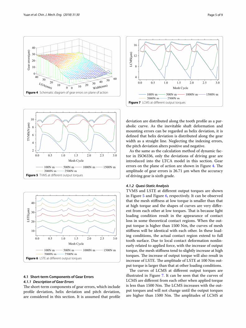
The curves of LCMS at different output torques are illustrated in Figure 7. It can be seen that the curves of LCMS are different from each other when applied torque is less than 1500 Nm. The LCMS increases with the out-put torques and will not change until the output torques are higher than 1500 Nm. The amplitudes of LCMS at
Figure 4 Schematic diagram of gear errors on plane of action
Figure 5 TVMS at different output torques
Figure 6 LSTE at different output torques
Figure 7 LCMS at different output torques

Page 6 of 9Yuan et al. Chin. J. Mech. Eng. (2018) 31:30
low torques are much larger than that at high torques. Obviously, the amplitudes of LCMS are always far smaller than the original amplitude of gear errors at all output torque levels.
4.1.3 Dynamic AnalysisFigure 8 shows the root mean square (RMS) of dynamic transmission error (DTE) at different output torques and speeds of driving gear. It can be observed that the resonance speed of the system become lower due to the reduction of mesh stiffness at light loading conditions.
When the output torque is higher than 1500 Nm, the resonance speed will not change anymore. It also can be found that lower output torque will bring stronger vibra-tion compared with higher output torque. This is because the fluctuation of LSTE and LCMS are larger in light loading conditions.
4.2 Long‑term Components of Gear Grrors4.2.1 Description of Gear ErrorsThe schematic diagram of accumulative pitch error for a helical gear is shown as Figure 9, where, fpt denotes the pitch deviation, Pbt refers to the theoretical tooth pitch. k × Pbt is the theoretical tooth pitch of k teeth, and Fpk is the accumulative pitch error of k teeth. Because the gear errors which are introduced into LTCA model are meas-ured along the line of action, the gear error values of heli-cal gears must be converted to the normal direction as follows:
where fpbn is the pitch deviation in the direction of line of action. αt is the transverse pressure angle, βb is the helix angle of base circle of helical gear.
The accumulative pitch error typically has a sine wave distribution over a rotational cycle of shaft. The sine function is employed to simulate the accumulative pitch error or long-term component of transmission error excitation in some published works [22, 29]. Therefore, it is assumed that the accumulative pitch error is distrib-uted as a sine wave in this study, as shown in Figure 10.
4.2.2 Quasi‑Static AnalysisFigures 11, 12, 13 shows four cases of TVMS, LSTE and LCMS of a helical gear pair at different output torques. The output torque is from 100 Nm to 600 Nm with step of 100 Nm. It can be observed that the accumulative
(9)fpbn = fpt cosαt cosβb,
Figure 8 RMS of DTE at different output torques and speeds of driving gear
Figure 9 End‑side of a helical gear with accumulative pitch error
Figure 10 Schematic diagram of accumulative pitch error
Figure 11 TVMS at different output torques

Page 7 of 9Yuan et al. Chin. J. Mech. Eng. (2018) 31:30
pitch error has great influence on TVMS and LSTE in some mesh cycles when output torque is less than 400 Nm. This is because the partial contact loss in mating
gear teeth occurs in this loading condition. As a result of the increase of output torque, the partial contact loss region become smaller. The contact pattern extend to full tooth surface when output torque is higher than 400 Nm.
4.2.3 Dynamic AnalysisThe time domain and frequency domain of DTE of heli-cal gear system with accumulative pitch error at 300 Nm and 2500 Nm output torque are shown in Figure 14 and Figure 15, respectively. The operating speed of driv-ing gear is 5000 r/min. It can be observed that shaft fre-quency component is the predominant component and the sideband frequency components at the two sides of mesh frequency and its harmonics appear in frequency domain of dynamic transmission error of the system. The amplitude of mesh frequency component is less than the sideband frequency component when the output torque is 300 Nm, and the amplitude of mesh frequency compo-nent will relatively increase when output torque is 2500 Nm.
The time domain and frequency domain of the vibra-tion acceleration of bearing 1 in y direction at 300 Nm and 2500 Nm output torque are given in Figure 16 and Figure 17, respectively. Different with the frequency domain of dynamic transmission error, the predominant frequency component of vibration acceleration of bearing 1 is not the shaft frequency which is very weak. As the same as the frequency domain of dynamic transmission error, the sideband components around mesh frequency and its harmonics are observed, and the amplitudes of mesh frequency and its harmonics will increase with the increase of output torque. The predominant frequency component is sideband frequency when output torque is 300 Nm, and the mesh frequency and its harmonics
Figure 12 LSTE at different output torques
Figure 13 LCMS at different output torques
Figure 14 DTE of helical gear system with accumulative pitch error at 300 Nm output torque
Figure 15 DTE of helical gear system with accumulative pitch error at 2500 Nm output torque

Page 8 of 9Yuan et al. Chin. J. Mech. Eng. (2018) 31:30
components will be enhanced significantly when the out-put torque is 2500 Nm.
5 ConclusionsIn this paper, the effects of manufacturing errors include short-term and long-term components on quasi-static and dynamic behaviors of helical gear system have been studied. The TVMS, LSTE and LCMS are determined using the improved LTCA model which was established based on the sub-structure technique and elastic contact theory. The dynamic responses of helical gear system are obtained by solving the generalized finite element dynamic model of the system which was developed based on the finite element method and Timoshenko beam the-ory. The main conclusions are summarized as follows.
(1) Both short-term and long-term components of manufacturing errors have notable influence on TVMS, LSTE and LCMS of helical gears. Lighter loading conditions lead to smaller mesh stiffness and stronger vibration. The corresponding reso-nance speed of the system become lower.
(2) Long-term components of manufacturing errors lead to the appearance of sideband frequency com-ponents in dynamic responses of the system. The sideband frequency components are predominant under lighter loading condition. The increase of output torque result in the increase of mesh fre-quency and its harmonics components.
Authors’ ContributionsSC was in charge of the whole trial; BY wrote the manuscript; GL and LYW assisted with sampling and laboratory analyses. All authors read and approved the final manuscript.
Author details1 Shaanxi Engineering Laboratory for Transmissions and Controls, School of Mechanical Engineering, Northwestern Polytechnical University, Xi’an 710072, China. 2 China Shipbuilding Industry Corporation 703 Institute, Harbin 150078, China.
Authors’ InformationBing Yuan, born in 1987, is currently a PhD candidate at Northwestern Polytech-nical University (NWPU), China. He received his bachelor degree from Central South University, China, in 2010. His research interests include gear dynamics, vibration and control. Tel: +86–15389359689; E‑mail: [email protected].
Shan Chang, born in 1965, is currently a professor and supervisor of PhD candidates and director of the Institute for Shaanxi Engineering Laboratory for Transmissions and Controls, Northwestern Polytechnical University (NWPU), China. He received his MS and PhD degrees from Harbin Institute of Technology, China. His research interests include gear modification, gear dynamic and load carry‑ing capacity of gears. E‑mail: [email protected].
Geng Liu, born in 1961, is currently a professor and supervisor of PhD candidates and director of Shaanxi Engineering Laboratory for Transmissions and Controls, Northwestern Polytechnical University (NWPU), China. He received his MS degree from NWPU and PhD degree from Xi’an Jiao Tong University. His research interests include mechanical dynamic design, mechanical systems dynamics, simulation and virtual prototype design, tribology, contact mechan‑ics and numerical methods. Tel: +86–13891999032; E‑mail: [email protected].
Li‑Yan Wu, born in 1958, is currently a professor at Shaanxi Engineering Lab-oratory for Transmissions and Controls at Northwestern Polytechnical University (NWPU), China. He received his BS degree from NWPU. His research interests include mechanical design and mechanical reliability. E‑mail: [email protected].
Competing InterestsThe authors declare that they have no competing interests.
Ethics Approval and Consent to ParticipateNot applicable.
FundingSupported by Key Project of National Natural Science Foundation of China (Grant No. 51535009) and 111 Project (Grant No. B13044).
Additional file
Additional file 1. Brief introduction of paper.Figure 16 Vibration acceleration of bearing 1 of helical gear system with accumulative pitch error along x axis at 300 Nm output torque
Figure 17 Vibration acceleration of bearing 1 of helical gear system with accumulative pitch error along x axis at 2500 Nm output torque

Page 9 of 9Yuan et al. Chin. J. Mech. Eng. (2018) 31:30
Publisher’s NoteSpringer Nature remains neutral with regard to jurisdictional claims in pub‑lished maps and institutional affiliations.
Received: 23 June 2017 Accepted: 16 April 2018
References [1] T F Conry, A Seireg. A mathematical programming technique for the
evaluation of load distribution and optimal modifications for gear sys‑tems. Journal of Engineering for Industry, 1973, 95(4): 1115–1122.
[2] A Kubo, S Kiyono. Vibrational excitation of cylindrical involute gears due to tooth form error. Bulletin of the JSME, 1980, 23(183), 1536–1543.
[3] A Kubo, T Kuboki, T Nonaka. Estimation of transmission error of cylindrical involute gears by tooth contact pattern. JSME International Journal, Series III, 1991, 34(2): 252–259.
[4] K Umezawa, T Sato, K Kohno. Influence of gear errors on rotational vibra‑tion of power transmission spur gears (1st Report, pressure angle error and normal pitch error). Bulletin of the JSME, 1984, 27(225): 569–575.
[5] K Umezawa, T Sato. Influence of gear errors on rotational vibration of power transmission spur gear (3rd Report, accumulative pitch error). Bul-letin of the JSME, 1985, 28(246): 3018–3024.
[6] L Vedmar. A Andersson. A method to determine dynamic loads on spur gear teeth and on bearings. Journal of Sound and Vibration, 2003, 267(5): 1065–1084.
[7] M Maatar, P Velex. An analytical expression for the time‑varying contact length in perfect cylindrical gears: some possible applications in gear dynamics. Journal of Mechanical Design, 1996, 118(4): 586–589.
[8] P Velex, M Maatar. A mathematical model for analyzing the influence of shape deviations and mounting errors on gear dynamic behaviour. Journal of Sound and Vibration, 1996, 191(5): 629–660.
[9] S Matsumura, K Umezawa, H Houjoh. Rotational vibration of a helical gear pair having tooth surface deviation during transmission of light load. JSME International Journal, Series C, 1996, 39(3): 614–620.
[10] R G Munro, L Morrish, D Palmer. Gear transmission error outside the normal path of contact due to corner and top contact. Proceedings of the Institution of Mechanical Engineers, Part C: Journal of Mechanical Engineer-ing Science, 1999, 213(4): 389–400.
[11] Y Ogawa, S Matsumura, H Houjoh. Rotational vibration of a spur gear pair considering tooth helix deviation (Development of simulator and verification). JSME International Journal, Series C, 2000, 43(2): 423–431.
[12] J Wei, W Sun, L C Wang. Effects of flank deviation on load distributions for helical gear. Journal of Mechanical Science and Technology, 2011, 25(7): 1781–1789.
[13] A Fernández, F Viadero, M Iglesias, et al. A model for the study of meshing stiffness in spur gear transmissions. Mechanism and Machine Theory, 2013, 61(61): 30–58.
[14] A Fernández, M Iglesias, A de‑Juan, et al. Gear transmission dynamic: Effects of tooth profile deviations and support flexibility. Applied Acous-tics, 2014, 77(3): 138–149.
[15] Q B Wang, Y M Zhang. A model for analyzing stiffness and stress in a helical gear pair with tooth profile errors. Journal of Vibration and Control, 2015, 23(2): 272–289.
[16] S L Li. Effects of misalignment error, tooth modifications and transmitted torque on tooth engagements of a pair of spur gears. Mechanism and Machine Theory, 2015, 83(83): 125–136.
[17] T J Lin, Z Y He. Analytical method for coupled transmission error of helical gear system with machining errors, assembly errors and tooth modifica‑tions. Mechanical Systems and Signal Processing, 2017, 91: 167–182.
[18] W N Yu, C K Mechefske, M Timusk. The dynamic coupling behaviour of a cylindrical geared rotor system subjected to gear eccentricities. Mecha-nism and Machine Theory, 2017, 107: 105–122.
[19] G J Wang, L Chen, S D Zou. Research on the dynamic transmission error of a spur gear pair with eccentricities by finite element method. Mecha-nism and Machine Theory, 2017, 109: 1–13.
[20] L Xiang, N Gao. Coupled torsion‑bending dynamic analysis of gear‑rotor‑bearing system with eccentricity fluctuation. Applied Mathematical Modelling, 2017, 50: 569–584.
[21] K Umezawa, T Sato. Influence of gear error on rotational vibration of power transmission spur gear (3rd report accumulative pitch error). Bul-letin of JSME, 1985, 28(246): 3018–3024.
[22] A Fernández‑del‑Rincón, M Iglesias, A De‑Juan, et al. Gear transmission dynamics: Effects of index and run out errors. Applied Acoustics, 2016, 108(1–2): 63–83.
[23] M J Handschuh, A Kahraman, M R Milliren. Impact of tooth spacing errors on the root stresses of spur gear pairs. Journal of Mechanical Design, 2014, 136(6): 061010.
[24] D Talbot, A Sum, A Kahraman. Impact of tooth indexing errors on dynamic factors of spur gears: experiments and model simulations. Journal of Mechanical Design, 2016, 138(9): 093302.
[25] M Inalpolat, M Handschuh, A Kahraman. Influence of indexing errors on dynamic response of spur gear pairs. Mechanical Systems and Signal Processing, 2015, 60–61: 391–405.
[26] L H Chang, G Liu, L Y Wu. A robust model for determining the mesh stiffness of cylindrical gears. Mechanism and Machine Theory, 2015, 87: 93–114.
[27] P Sainsot, P Velex. Contribution of gear body to tooth deflections‑a new bidimensional analytical formula. Journal of Mechanical Design, 2004, 126(4): 748–752.
[28] L H Chang, Z X He, G Liu. Dynamic modeling of parallel shaft gear trans‑missions using finite element method. Journal of Vibration and Shock, 2016, 35(20): 47–53. (in Chinese)
[29] Z H Hu, J Y Tang, J Zhong, et al. Effects of tooth profile modification on dynamic responses of a high speed gear‑rotor‑bearing system. Mechani-cal Systems and Signal Processing, 2016, 76–77: 294–318.