Eco-friendly processes for the synthesis of amorphous calcium ...
Upload
independentCategory
view
0download
0
ARTICLE IN PRESS
Journal of Magnetism and Magnetic Materials 322 (2010) 1497–1504
Contents lists available at ScienceDirect
Journal of Magnetism and Magnetic Materials
0304-88
doi:10.1
� Corr
E-m
journal homepage: www.elsevier.com/locate/jmmm
Magnetic properties of soft ferrites and amorphous ribbonsup to radiofrequencies
F. Fiorillo a, E. Ferrara a, M. Coısson a, C. Beatrice a,�, N. Banu b
a Istituto Nazionale di Ricerca Metrologica (INRIM), Strada delle Cacce 91, 10135 Torino, Italyb Dipartimento di Ingegneria Elettrica, Politecnico di Torino, C.so Duca degli Abruzzi 24, 10129 Torino, Italy
a r t i c l e i n f o
Available online 22 September 2009
Keywords:
Magnetic loss
Amorphous alloy
Soft ferrite
Landau–Lifshitz–Gilbert
53/$ - see front matter & 2009 Elsevier B.V. A
016/j.jmmm.2009.09.038
esponding author. Tel.: +39 0113919857; fax
ail address: [email protected] (C. Beatrice).
a b s t r a c t
Significant results are reported concerning the magnetic behavior of sintered soft ferrites and very thin
Co-based amorphous ribbons up to 1 GHz. Conveniently field-annealed amorphous tapes can exhibit, in
spite of their metallic character, superior combination of magnetic loss and permeability properties at
all frequencies. Such properties are phenomenologically assessed through a physical approach based on
the statistical theory of losses and the generalization of the related concept of loss separation, which
takes into account different dissipation mechanisms and discriminates between domain wall and
rotational processes. The latter, in particular, are described in ferrites in association with spin precession
and damping and are given a formulation based on the Landau–Lifshitz–Gilbert equation and the
assumption of distributed effective anisotropy fields.
& 2009 Elsevier B.V. All rights reserved.
1. Introduction
Soft magnetic cores with good wideband properties areconveniently obtained with Mn–Zn and Ni–Zn spinel ferrites,which combine low magnetocrystalline anisotropy with very highelectrical resistivity. As alternative materials for applications up tothe MHz range, the very soft near-zero magnetostriction amor-phous and nanocrystalline ribbons are also envisaged [1,2],because their properties can be steered towards excellent high-frequency behavior by specific field annealing treatments and theeddy currents can be restrained preparing very thin laminations[3]. They can therefore exhibit higher permeability and lowerlosses, together with better heat dissipation, than soft ferrites[1–5], besides being susceptible to integration in printed circuitboards [6]. Given the quite different nature and structure ofsoft ferrites and rapidly solidified alloys, a comprehensivecomparative interpretation of their loss and permeability beha-viors upon the many-decade frequency band encompassingvarious types of applications is not easy and it is not available atpresent time. Soft ferrites have actually been intensely investi-gated in the literature and many attempts have been made toassess their magnetic phenomenology and its dependence onfrequency [7–11]. A common drawback of these studies is thatthey often rely on experiments made on a relatively narrowfrequency band (typically one or two decades), making the loss
ll rights reserved.
: +39 0113919834.
analysis incomplete. This is generally the case with the Mn–Znferrites, where a substantial contribution by eddy currents toenergy dissipation is often inferred from the response of thematerial to compositional and structural modifications [11–15].The insofar reported calculations do not support, however, thegeneral idea that eddy currents play an important role in ferrites,while not providing, at the same time, any definite assessment ofthe loss dependence on frequency and the related complexpermeability properties [8,12]. The latter are sometimes describedby means of empirical formulas with abundant number of fittingparameters [10,16]. Experimental limitations thus compound withlack of quantitative modelling. This problem has been addressedin recent times only [17] and will be discussed in the following.Little analysis is also available on the loss and permeabilityproperties of the amorphous and nanocrystalline ribbons at highfrequencies [18,19], where they might favorably compare with theproperties of Mn–Zn and Ni–Zn ferrites. In this paper we presentand compare a few basic results obtained on soft Mn–Zn and Ni–Zn sintered ferrites and thinned near-zero magnetostriction Co-based amorphous ribbons, investigated over a frequency range,extending from quasi-static excitation to 1 GHz. The metallicalloys, suitably thinned and heat treated under a transversesaturating field, appear to display an overall advantage withrespect to ferrites in terms of permeability and loss behavior. It isshown that an appropriate frame of interpretation of all theexperimental results can be found in the concept of lossseparation, as implemented by the statistical theory of losses[20], and its extension from the original context of eddy-currentprocesses to dissipation by spin damping mechanisms. To this

ARTICLE IN PRESS
F. Fiorillo et al. / Journal of Magnetism and Magnetic Materials 322 (2010) 1497–15041498
end, the contributions by domain wall (d.w.) displacements androtations are singled out, with the latter always found topredominate at high frequencies. Once the hysteresis energy losscomponent Wh is experimentally obtained by suitable extrapola-tion of the total loss versus frequency W(f) to f=0 (the oftenoverlooked low-frequency measurements revealing to this endindispensable), the dynamic loss contribution directly associatedwith the d.w. processes (the so-called excess loss Wexc) isidentified starting from the equation for the damped motion ofthe 1801 d.w., driven by the difference between the applied Ha andcoercive Hc fields
2m0MsðHa � HcÞ ¼ b _x; ð1Þ
where m0 is the magnetic constant, Ms the saturation magnetiza-tion, and the damping coefficient b can describe both therestraining action of the eddy currents and the viscous precessionof the spins inside the moving d.w.s. Remarkably, in fact, Eq. (1)applies both to conducting and non-conducting materials, asshown by the classical experiments on picture-frame singlecrystals of Fe–Si (resistivity r=45�10�8Om) by Williams,Shockley, and Kittel [21] and of Mn ferrite (resistivity 45�102Om) by Dillon and Earl [22]. The loss analysis shows that of thesetwo frictional mechanisms the former largely prevails in themetallic ribbons and the latter in the near-insulating ferrites. Weapply to both of them the general idea that the d.w. motion buildsup through the correlated superposition of the Barkhausen (B.)discontinuities, the events leading to the hysteresis loss term Wh
in the limit f-0. This idea justifies, on the one hand, the conceptof loss separation, by associating the excess loss Wexc with a cross-correlation term in the B. discontinuities [23], and, on the otherhand, brings to light the existence of a connection between Wh
and Wexc [20]. It is predicted that Wexc will tend to disappeareither with an infinitely dense d.w. structure or under dominantrotational processes. These, occurring on a far larger scale than thed.w. processes, can be considered as homogeneous and theirdissipative effects are incorporated into the classical loss termwhen they are associated with eddy currents. If damping of thespin precession becomes instead an important loss route, asactually is the case with semiconducting and insulating materials,one may appropriately treat the rotations, under the approxima-tion of small oscillations, through the Landau–Lifshitz–Gilbert(LLG) equation and its solution in terms of real and imaginarycomponents of the magnetic permeability. It is here concludedthat the energy loss behavior in the amorphous alloys can bedescribed, up to 1 GHz, in terms of the conventional eddy-currentbased loss separation approach, with W(f) coalescing into theclassical component Wcl(f) in the upper frequency range. Thesame analysis performed in the soft ferrites calls for themechanism of spin damping, as lumped in the Landau–Lifshitzparameter aLL. This conclusion relies on the assessment of the roleof eddy currents in the Mn–Zn ferrites, a subject often discussedbut not clarified so far in the literature [7–16].
2. Experimental procedure
Experiments have been carried out on Mn–Zn andNi–Zn sintered ferrites and thinned near-zero-magnetostrictiveCo67Fe4B14.5Si14.5 amorphous ribbons. Different types of commer-cial ferrite ring samples (Mn–Zn T38, N30, N87, and Ni–Zn 4A11)with outside diameters ranging between 25.3 and 10 mm andtapewound toroidal specimens, obtained by encasing the amor-phous ribbon into a 19 mm diameter boron nitride holder, wereinvestigated. The dc resistivities of the ferrites, measured with afour-point method, were around 105Om in the Ni–Zn ferrite andranged between 0.09 and 6.5Om in the Mn–Zn types. The latter
decreased monotonically with frequency, to reach a plateau abovea few MHz, where they stabilized in all cases between 0.04 and0.07Om. The amorphous alloys were prepared in the laboratoryby planar flow casting as 14.5mm thick 10 mm wide ribbons,subsequently thinned by chemical etching (diluted H3PO4+HNO3+CH3COOH solution), down to minimum 5.1mm thickness.The tapewound ring samples were subjected to stress-relaxation(2 h at 360 1C), followed by annealing at 280 1C and very slowcooling under saturating transverse field. The resulting majordc hysteresis loop (saturation polarization Js=0.62 T) had thesheared quasi-linear appearance (coercive field Hc=0.8–1 A/m,remanence Js�0.04 T�0.05 T, maximum relative permeability25�104–40�104) expected to derive from a transversallyinduced anisotropy of the order of few J/m3. The hysteresis loopand losses were measured in all materials, after demagnetization,for sinusoidal induction and defined values of the peak polariza-tion Jp, from quasi-static conditions to 10 MHz using a dedicatedsensitive digital hysteresisgraph-wattmeter. This is designed tocover a many-decade frequency range and is syntheticallydescribed in Ref. [24]. The dc characterization included the initialmagnetization curve and the determination of the Rayleighparameters. The wideband measurements were typically per-formed for Jp values ranging between 1 and 100 mT. The upper Jp
limit was imposed by constraints in the available power in theMHz range and permissible heating of the sample, the latter beingalso one main reason for working at low induction level in mosthigh-frequency applications. In any case, the sample temperaturewas controlled during the measurements and always kept around23 1C. Under these conditions, the hysteresis loop shape can bereasonably described at all frequencies by an ellipsoidal locus andwe can provide meaning to the concept of complex permeability,whose imaginary m00and real m0 components are then derived atany frequency from the loop parameters according to theequations
m00 ¼W=ðpH2pÞ m0 ¼
ffiffiffiffiffiffiffiffiffiffiffiffiffiffiffiffiffiffiffiffiffiffiffiffiffiffiffiffiffiffiffiðJp=HpÞ
2� m002
qð2Þ
where Hp is the peak field value and W the energy loss per unitvolume.
The complex permeability was also measured from a fewhundred kHz to 1 GHz by means of a transmission line method.The ring sample under test was placed against the short-circuitedbottom of a 50O coaxial line energized by an Agilent 8753Anetwork analyzer and the complex scattering parameterS11 ¼ S11
0 þ jS1100 was measured at the sample plane. The related
impedance Zin=Z0(1+S11)/(1�S11), with Z0=50O, was then calcu-lated. Measurement and calculation were repeated with theempty line and the real and imaginary parts of the resultingdifference DZin could eventually be related to m00 and m0,respectively [25]. Applying then Eq. (2) in reverse we obtainedthe specific energy loss at given Jp as
W ¼ pJ2pm00=ðm02þm002Þ ½J=m3� ð3Þ
Since the meaningful assessment of the energy loss versusfrequency requires that it is measured at a given Jp value, the samerequirement would apply, according to Eq. (2), to the independentdetermination of m00 and m0 by the transmission line method. Thiscontrasts somewhat with the usual approach to the measurementof the initial permeability versus frequency, where no control ismade on the impressed induction swing. There is point in that,since keeping Jp at a defined value may be out of reach of mostnetwork analyzers. However, even in this case we can providemeaning to the measurement of m00 and m0, because theexperiments show that these quantities become independent ofJp at sufficiently high frequencies. The energy loss can thencorrespondingly be calculated, within the previously stated upper
ARTICLE IN PRESS
103 104 105 106 107 108 109
0
200
400
600
10 mT
1 mT
µ''
µ'
Ni-Zn 4A11
µ 'r , µ '
' r
Frequency (Hz)
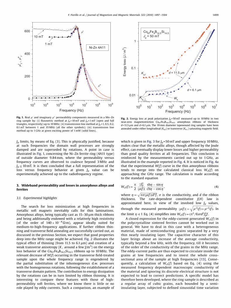
Fig. 1. Real m0 and imaginary m00 permeability components measured in a Mn–Zn
ring sample by: (i) fluxmetric method at Jp=10 mT and Jp=1 mT (open and full
triangles, respectively) up to 10 MHz; (ii) transmission line method at Jp=1, 0.5, 0.2,
0.1 mT between 1 and 35 MHz (all the other symbols); (iii) transmission line
method up to 1 GHz at given exciting power of 1 mW (solid lines).
100 101 102 103 104 105 106 107
0.01
0.1
1
Wh
d = 6.1 µm
d = 11.5 µm
Co67Fe4B14.5Si14.5Jp = 50 mT
Ku//
Ku_|_
Ener
gy lo
ss (J
/ m
3 )
Frequency (Hz)
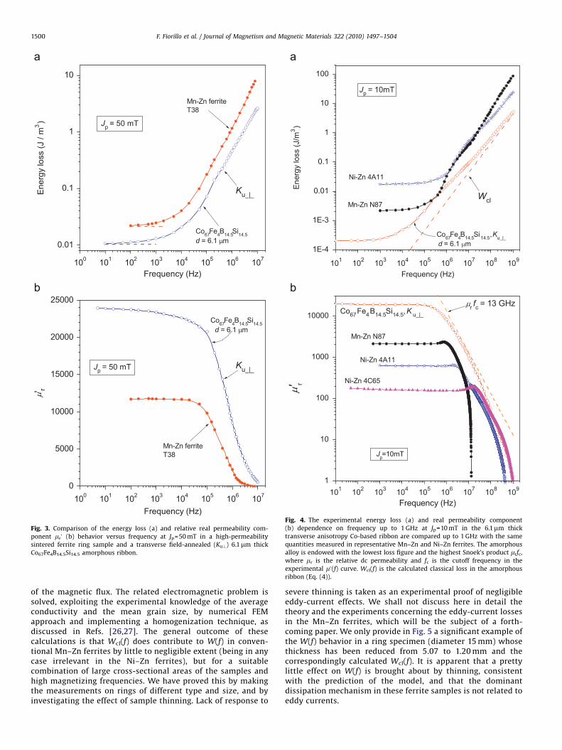
Fig. 2. Energy loss at peak polarization Jp=50 mT measured up to 10 MHz in two
near-zero magnetostriction Co67Fe4B14.5Si14.5 amorphous ribbons of thickness
d=11.5mm and d=6.1mm. The 19 mm diameter tapewound ring samples have been
annealed under either longitudinal (Ku//) or transverse (Ku?) saturating magnetic field.
F. Fiorillo et al. / Journal of Magnetism and Magnetic Materials 322 (2010) 1497–1504 1499
Jp limits, by means of Eq. (3). This is physically justified, becauseat such frequencies the domain wall processes are stronglydamped and are superseded by rotations. A point in case isillustrated in Fig. 1, concerning the Ni–Zn ferrite ring (4A11 type)of outside diameter 9.84 mm, where the permeability versusfrequency curves are observed to coalesce beyond 3 MHz andJpr10 mT. It is then concluded that a full representation of theloss versus frequency behavior at given Jp value can beexperimentally achieved up to the radiofrequency regime.
3. Wideband permeability and losses in amorphous alloys andferrites
3.1. Experimental highlights
The search for loss minimization at high frequencies inmetallic soft magnets inevitably calls for thin laminations.Amorphous alloys, being typically cast as 15–30mm thick ribbonsand being additionally endowed with a relatively high resistivity(of the order of 140�10�8Om), appear ideally suited formedium-to-high-frequency applications. If further ribbon thin-ning and transverse field annealing are successfully carried out, asdiscussed in the previous Section, we expect that good propertiesdeep into the MHz range might be achieved. Fig. 2 illustrates thetypical effect of thinning (from 11.5 to 6.1mm) and creation of aweak transverse anisotropy (K? around a few J/m3) on the energyloss behavior of the Co67Fe4B14.5Si14.5 ribbons up to 10 MHz. Therelevant decrease of W(f) occurring in the transverse field-treatedsample upon the whole frequency range is engendered bythe partial substitution of the inhomogeneous d.w. processeswith the homogeneous rotations, following the establishment of atransverse domain pattern. The contribution to energy dissipationby the rotations can be in turn limited by ribbon thinning. It isinteresting to compare these features with those of high-permeability soft ferrites, where we know there is little or norole played by eddy currents. Such a comparison, an example of
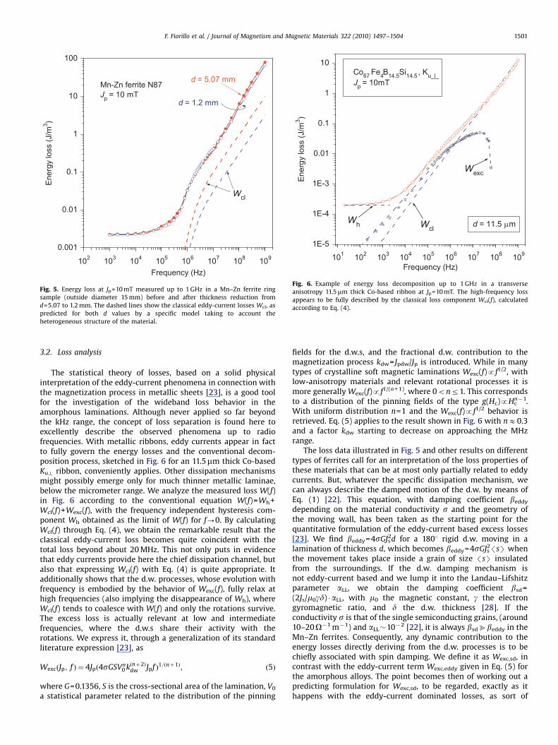
which is given in Fig. 3 for Jp=50 mT and upper frequency 10 MHz,makes clear that the metallic alloys, though affected by the Jouleeffect, can eventually display lower losses and higher permeabilitythan good quality ferrites at all frequencies. This conclusion isreinforced by the measurements carried out up to 1 GHz, asillustrated in the example reported in Fig. 4. It is noticed in Fig. 4athat the experimental W(f) curve in the thin amorphous ribbonstends to merge into the calculated classical loss Wcl(f) onapproaching the GHz range. The calculation is made accordingto the standard equation
Wclðf Þ ¼p2
gJ2p
jmðf ÞjshZ� sinZchZ� cosZ ; ð4Þ
where Z¼ffiffiffiffiffiffiffiffiffiffiffiffiffiffiffiffiffiffiffiffiffiffiffiffiffipsjmðf Þjd2f
p, s is the conductivity, and d the ribbon
thickness. The rate-dependent constitutive J(H) law isapproximated here, in view of the involved low Jp values,
through the measured permeability jmðf Þj ¼ffiffiffiffiffiffiffiffiffiffiffiffiffiffiffiffiffiffiffiffiffiffiffiffiffiffiffiffiffiffim02ðf Þþm002ðf Þ
q. In
the limit Z51 Eq. (4) simplifies into Wclðf Þ ¼ ðp2=6Þsd2J2pf .
A closed expression for the eddy-current generated Wcl(f) inthe polycrystalline sintered ferrites cannot be worked out ingeneral. We have to deal in this case with a heterogeneousmaterial, made of semiconducting grains separated by a verythin nearly insulating layer. The capacitive character of thislayer brings about an increase of the average conductivity,typically beyond a few kHz, with the frequency, till it becomesof the order of the conductivity of the grains in the MHz range.The eddy-current paths are thus expected to circulate inside thegrains at low frequencies and to invest the whole cross-sectional area of the sample at high frequencies [13]. Conse-quently, a calculation of Wcl(f) based on Eq. (4) using themeasured frequency dependent macroscopic conductivity ofthe material and ignoring its discrete electrical structure is notexpected to lead to correct predictions. A specific model hastherefore been developed, where the ring sample is described asa regular array of cubic grains, each bounded by a semi-insulating layer, subjected to defined sinusoidal time variation
ARTICLE IN PRESS
100 101 102 103 104 105 106 107
0.01
0.1
1
10
Mn-Zn ferriteT38
Co67Fe4B14.5Si14.5d = 6.1 µm
Jp = 50 mT
Ku_|_Ener
gy lo
ss (J
/ m
3)
Frequency (Hz)
100 101 102 103 104 105 106 1070
5000
10000
15000
20000
25000
Mn-Zn ferriteT38
Co67Fe4B14.5Si14.5d = 6.1 µm
Jp = 50 mT Ku_|_
µ'r
Frequency (Hz)
Fig. 3. Comparison of the energy loss (a) and relative real permeability com-
ponent mr0 (b) behavior versus frequency at Jp=50 mT in a high-permeability
sintered ferrite ring sample and a transverse field-annealed (Ku?) 6.1mm thick
Co67Fe4B14.5Si14.5 amorphous ribbon.
101 102 103 104 105 106 107 108 109
1E-4
1E-3
0.01
0.1
1
10
100
Mn-Zn N87
Ni-Zn 4A11
Co67Fe4B14.5Si 14.5,Ku_|_d = 6.1 µm
Wcl
Jp = 10mT
Ener
gy lo
ss (J
/m3 )
Frequency (Hz)
101 102 103 104 105 106 107 108 1091
10
100
1000
10000µr fc = 13 GHz
Ni-Zn 4C65
Co67Fe4B14.5Si14.5,K u_|_
Mn-Zn N87
Ni-Zn 4A11
Jp=10mT
µ 'r
Frequency (Hz)
Fig. 4. The experimental energy loss (a) and real permeability component
(b) dependence on frequency up to 1 GHz at Jp=10 mT in the 6.1mm thick
transverse anisotropy Co-based ribbon are compared up to 1 GHz with the same
quantities measured in representative Mn–Zn and Ni–Zn ferrites. The amorphous
alloy is endowed with the lowest loss figure and the highest Snoek’s product mrfc,
where mr is the relative dc permeability and fc is the cutoff frequency in the
experimental m0(f) curve. Wcl(f) is the calculated classical loss in the amorphous
ribbon (Eq. (4)).
F. Fiorillo et al. / Journal of Magnetism and Magnetic Materials 322 (2010) 1497–15041500
of the magnetic flux. The related electromagnetic problem issolved, exploiting the experimental knowledge of the averageconductivity and the mean grain size, by numerical FEMapproach and implementing a homogenization technique, asdiscussed in Refs. [26,27]. The general outcome of thesecalculations is that Wcl(f) does contribute to W(f) in conven-tional Mn–Zn ferrites by little to negligible extent (being in anycase irrelevant in the Ni–Zn ferrites), but for a suitablecombination of large cross-sectional areas of the samples andhigh magnetizing frequencies. We have proved this by makingthe measurements on rings of different type and size, and byinvestigating the effect of sample thinning. Lack of response to
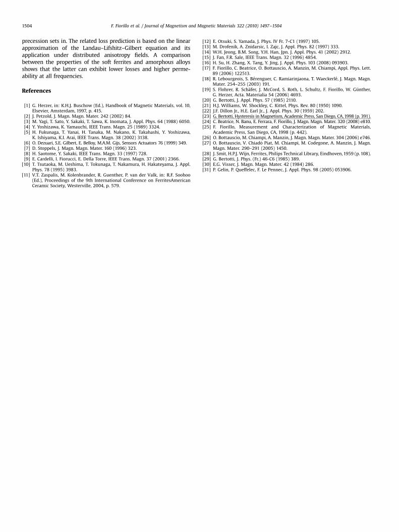
severe thinning is taken as an experimental proof of negligibleeddy-current effects. We shall not discuss here in detail thetheory and the experiments concerning the eddy-current lossesin the Mn–Zn ferrites, which will be the subject of a forth-coming paper. We only provide in Fig. 5 a significant example ofthe W(f) behavior in a ring specimen (diameter 15 mm) whosethickness has been reduced from 5.07 to 1.20 mm and thecorrespondingly calculated Wcl(f). It is apparent that a prettylittle effect on W(f) is brought about by thinning, consistentwith the prediction of the model, and that the dominantdissipation mechanism in these ferrite samples is not related toeddy currents.
ARTICLE IN PRESS
102 103 104 105 106 107 108 109
0.001
0.01
0.1
1
10
100
d = 1.2 mm
Wcl
d = 5.07 mmMn-Zn ferrite N87Jp = 10 mT
Ene
rgy
loss
(J/m
3 )
Frequency (Hz)
Fig. 5. Energy loss at Jp=10 mT measured up to 1 GHz in a Mn–Zn ferrite ring
sample (outside diameter 15 mm) before and after thickness reduction from
d=5.07 to 1.2 mm. The dashed lines show the classical eddy-current losses Wcl, as
predicted for both d values by a specific model taking to account the
heterogeneous structure of the material.
101 102 103 104 105 106 107 108 1091E-5
1E-4
1E-3
0.01
0.1
1
10
d = 11.5 µm
Wexc
WclWh
Co67 Fe4B14.5Si14.5 , Ku_|_Jp = 10mT
Ene
rgy
loss
(J/m
3 )
Frequency (Hz)
Fig. 6. Example of energy loss decomposition up to 1 GHz in a transverse
anisotropy 11.5mm thick Co-based ribbon at Jp=10 mT. The high-frequency loss
appears to be fully described by the classical loss component Wcl(f), calculated
according to Eq. (4).
F. Fiorillo et al. / Journal of Magnetism and Magnetic Materials 322 (2010) 1497–1504 1501
3.2. Loss analysis
The statistical theory of losses, based on a solid physicalinterpretation of the eddy-current phenomena in connection withthe magnetization process in metallic sheets [23], is a good toolfor the investigation of the wideband loss behavior in theamorphous laminations. Although never applied so far beyondthe kHz range, the concept of loss separation is found here toexcellently describe the observed phenomena up to radiofrequencies. With metallic ribbons, eddy currents appear in factto fully govern the energy losses and the conventional decom-position process, sketched in Fig. 6 for an 11.5mm thick Co-basedKu? ribbon, conveniently applies. Other dissipation mechanismsmight possibly emerge only for much thinner metallic laminae,below the micrometer range. We analyze the measured loss W(f)in Fig. 6 according to the conventional equation W(f)=Wh+Wcl(f)+Wexc(f), with the frequency independent hysteresis com-ponent Wh obtained as the limit of W(f) for f-0. By calculatingWcl(f) through Eq. (4), we obtain the remarkable result that theclassical eddy-current loss becomes quite coincident with thetotal loss beyond about 20 MHz. This not only puts in evidencethat eddy currents provide here the chief dissipation channel, butalso that expressing Wcl(f) with Eq. (4) is quite appropriate. Itadditionally shows that the d.w. processes, whose evolution withfrequency is embodied by the behavior of Wexc(f), fully relax athigh frequencies (also implying the disappearance of Wh), whereWcl(f) tends to coalesce with W(f) and only the rotations survive.The excess loss is actually relevant at low and intermediatefrequencies, where the d.w.s share their activity with therotations. We express it, through a generalization of its standardliterature expression [23], as
WexcðJp; f Þ ¼ 4Jpð4sGSVn0 kðnþ2Þ
dw Jpf Þ1=ðnþ1Þ; ð5Þ
where G=0.1356, S is the cross-sectional area of the lamination, V0
a statistical parameter related to the distribution of the pinning
fields for the d.w.s, and the fractional d.w. contribution to themagnetization process kdw= Jpdw/Jp is introduced. While in manytypes of crystalline soft magnetic laminations Wexc(f)pf1/2, withlow-anisotropy materials and relevant rotational processes it ismore generally Wexc(f)pf1/(n +1), where 0onr1. This correspondsto a distribution of the pinning fields of the type g(Hc)pHc
n�1.With uniform distribution n=1 and the Wexc(f)pf1/2 behavior isretrieved. Eq. (5) applies to the result shown in Fig. 6 with nE0.3and a factor kdw starting to decrease on approaching the MHzrange.
The loss data illustrated in Fig. 5 and other results on differenttypes of ferrites call for an interpretation of the loss properties ofthese materials that can be at most only partially related to eddycurrents. But, whatever the specific dissipation mechanism, wecan always describe the damped motion of the d.w. by means ofEq. (1) [22]. This equation, with damping coefficient beddy
depending on the material conductivity s and the geometry ofthe moving wall, has been taken as the starting point for thequantitative formulation of the eddy-current based excess losses[23]. We find beddy=4sGJs
2d for a 1801 rigid d.w. moving in alamination of thickness d, which becomes beddy=4sGJs
2/sS whenthe movement takes place inside a grain of size /sS insulatedfrom the surroundings. If the d.w. damping mechanism isnot eddy-current based and we lump it into the Landau–Lifshitzparameter aLL, we obtain the damping coefficient bsd=(2Js/m0gd) �aLL, with m0 the magnetic constant, g the electrongyromagnetic ratio, and d the d.w. thickness [28]. If theconductivity s is that of the single semiconducting grains, (around10–20O�1 m�1) and aLL�10�2 [22], it is always bsdbbeddy in theMn–Zn ferrites. Consequently, any dynamic contribution to theenergy losses directly deriving from the d.w. processes is to bechiefly associated with spin damping. We define it as Wexc,sd, incontrast with the eddy-current term Wexc,eddy given in Eq. (5) forthe amorphous alloys. The point becomes then of working out apredicting formulation for Wexc,sd, to be regarded, exactly as ithappens with the eddy-current dominated losses, as sort of

ARTICLE IN PRESS
103 104 105 106 10710-4
10-3
10-2
10-1
Wdyn
Wexc,eddy
Wcl
WhWexc,sd
Mn-Zn ferrite ringJp = 10 mT
Ene
rgy
loss
(J/m
3 )
Frequency (Hz)
Fig. 7. The experimental energy loss W(f) (full dots) in a 15 mm outside diameter
Mn–Zn ferrite ring is decomposed into hysteresis Wh (horizontal line) and dynamic
Wdyn (open symbols) components. In the lower range of frequencies Wdyn is
generated by the d.w. relaxation processes and the related mechanism is spin
damping, as illustrated by the behavior of the calculated component Wexc,sd
(Eq. (7)). A very small contribution by the eddy-current term Wexc,eddy is predicted
by Eq. (5).
F. Fiorillo et al. / Journal of Magnetism and Magnetic Materials 322 (2010) 1497–15041502
dynamic continuation of the hysteresis losses [20]. The connec-tion between Wh and Wexc comes out clearly in the statisticaltheory of losses, where the discrete nature of the magnetizationprocess and its progressive homogenization with the increase ofthe magnetizing frequency have been associated with thedistribution of the local coercive fields. Based on this concept,an expression was obtained that directly relates Wh and Wexc,eddy
in a polycrystalline magnetic lamination [29]. Such an expression,re-worked in terms of the damping coefficient beddy, can bewritten for such a material as
Wexc; eddyðJp; f Þ ¼ 4½beddy ðWhðJpÞÞn/sS ðJp=JsÞf �
1=ðnþ1Þ: ð6Þ
By virtue of Eq. (1), we can introduce the coefficient bsd inplace of beddy in Eq. (6) when dealing with ferrites and, byconsidering further that Wh is associated with the irreversible d.w.processes only, we get
Wexc; sdðJp; f Þ ¼ 4½bsd ðWhðJpÞÞn/sSkirr ðJp=JsÞf �
1=ðnþ1Þ; ð7Þ
where kirr= Jp,irr/Jp is the irreversibly accomplished fraction of themagnetization reversal. This quantity is directly obtained from theexperimental initial magnetization curve (i.e. the Rayleigh con-stants). Fig. 7 provides an example of the measured W(f) behaviorin a Mn–Zn ring sample at Jp=10 mT, where the dynamic lossWdyn(f) is compared with the calculated quantities Wcl, Wexc,eddy,and Wexc,sd. We focus our attention on the frequency dependenceof the losses up to 10 MHz, the frequency range where thesematerials bear chief interest for applications. It is observed thatonly the component Wexc,sd(f), as calculated with Eq. (7), canprovide a reasonable prediction of Wdyn(f), though limited to thelower range of frequencies. Wcl and Wexc,eddy play a negligible role.The measured Wh value and the experimental quantities/sS=17mm and kirr=0.096 have been introduced in Eq. (7). Thedamping coefficient bsd has been obtained for a d.w. thicknessd¼ p
ffiffiffiffiffiffiffiffiffiA=K
p�1.1mm, calculated for a stiffness constant
A=0.5�10�11 J/m and an anisotropy constant, estimated from
the upper portion of the initial magnetization curve, K=38 J/m3. Itis assumed aLL=0.04 and n=0.4. Fig. 7 shows that the high-frequency portion of W(f) cannot be predicted neither by the d.w.term Wexc,sd(f) nor by the classical eddy-current contributionWcl(f). But we know that, under the action of the exciting ac fieldand the resisting torque provided by the effective anisotropy field,the spins in the bulk are bound to precess and release energy tothe lattice through the same mechanism involved with thefrictional response of the d.w.s. But, while the d.w. dynamics isassociated with pure relaxation [30], resonant phenomena areexpected to occur with rotations. Soft ferrites are very low-anisotropy materials and a wide distribution of the anisotropyfields (i.e. resonance frequencies), fluctuating from grain to grain,is envisaged [31]. Thanks to the quasi-linear approximation, wecan describe the viscous rotational response of a magnetic domainto an exciting field at a frequency o by means of the LLG equation.The related solution provides, for an effective anisotropy fieldHk, the expressions for the real and imaginary rotationalsusceptibility components
wrot0 ðoÞ ¼
oJoH½o2H �o2ð1� aLLÞ
2�
½o2H �o2ð1þa2
LLÞ�2þ4a2
LLo2Ho2
ð8aÞ
wrot00 ðoÞ ¼
ooJaLL½o2Hþo2ð1þa2
LL�
½o2H �o2ð1þa2
LLÞ�2þ4a2
LLo2Ho2
; ð8bÞ
where o=2pf, oJ=gJs, and oH=gm0Hk. The assumed distribution ofthe Hk values reflects into a continuous spectrum of resonancefrequencies oH. For the material shown in Fig. 7, we take for Hk thegamma distribution function G(Hk)=AHk
b exp(�Hk/H0), with A anormalization constant, b=2.3, and H0 related to the average value/HkSE2/KS/Js. While the gamma function provides best fitting ofthe experimental results, quite similar predictions are obtainedusing different kinds of distribution (Gaussian, Sawada, Maxwell,etc.). The relative rotational permeabilities are consequentlyobtained as mrot; r
0 ðf Þ ¼ 1þowrot0 4 and mrot; r
00 ðf Þ ¼ owrot0 4 , with
the brackets implying double averaging over G(Hk) and an assumedspatially isotropic distribution of the effective easy axes. To bestressed again that the magnetization oscillates around thedemagnetized state, making natural the choice of isotropicdistribution. To note also that the off-diagonal elements of thesusceptibility matrix, as derived from the LLG equation at the scaleof single domains, average out to zero on the experimentalmacroscopic scale. mrot
0 ðf Þ and mrot00 ðf Þ combine with the d.w.
contributions mdw0 ðf Þ and mdw
00 ðf Þ. These are calculated exploitingthe relationship existing between the d.w. losses and the relatedcomplex permeability. Based on Eq. (2) and the previousdiscussion on the excess loss we write mdw
00 ðf Þ ¼Wexc; sdðf Þ=
ðpH2pðf ÞÞ. mdw
00 ðf Þ is thus obtained at a given Jp by taking theexperimental Hp(f) value. The resulting mdw
00 ðf Þ curve is, as shownby the example in Fig. 8b, approximated by the relaxationequation
mdw00 ðf Þ ¼ mdwð0Þ ðf=f1Þ=ð1þðf=f1Þ
2Þ; ð9Þ
where f1 is the relaxation frequency and mdw(0) the dc d.w.permeability. Under this approximation, the real component mdw
0
is derived from mdw00 as m0ðf Þ ¼ 2mdw
00 ðf1Þ=ð1þðf=f1Þ2Þ. As shown in
Fig. 8b, the so estimated relative dc d.w. permeability ismdw,r(0)�500, pretty lower than the rotational permeability.mdw,r(0) can be evaluated also by means of a direct experiment,where the initial magnetization curves are measured andcompared in the Rayleigh range starting from the demagnetizedstate and the remanence, respectively. The observed differencesare entirely ascribed to different d.w. populations, i.e., to thevariation of mdw,r(0). For the case shown in Fig. 8, it is obtained, forJp=10 mT, mdw,r(0)�650. Combining the predicted rotational and

ARTICLE IN PRESS
102 103 104 105 106 107
0.001
0.01
0.1
Wdw
Wrot
T = 100 °C
T = 23 °C
Mn-Zn ferriteJp = 10 mT
Ene
rgy
loss
(J/m
3 )
Frequency (Hz)
Fig. 9. Example of energy loss versus frequency at two temperatures in a Mn–Zn
ferrite. Symbols: experimental values. The dashed and dash-dotted lines represent
the predicted contributions Wdw(Jp, f) and Wrot(Jp, f), whose combination leads to
the solid fitting lines.
103 104 105 106 10710-3
10-2
10-1
Wrot
Wdw
Mn-Zn ferrite ringJp = 10 mT
Ene
rgy
loss
(J/m
3)
Frequency (Hz)
103 104 105 106 107
0
500
1000
1500
2000
2500
Mn-Zn ferrite ringJp = 10 mT
µ''dw
µ'dw
µ''
µ'
µ' r, µ'
' r
Frequency (Hz)
Fig. 8. (a) The experimental energy loss W(f) shown in Fig. 7 is separated into the
predicted d.w. Wdw(f)=Wh+Wexc,sd(f) (Eq. (7)) and rotational Wrot(f) (Eq. (10))
contributions. The sum Wth(f)=Wdw(f)+Wrot(f) is shown by the thick solid line.
(b) Associated behavior of the real (m0) and imaginary (m00) permeabilities. The
separate d.w. (dashed lines) and rotational contributions are calculated by means
of Eqs. (9) and (8), respectively. Symbols: experiments. Solid line: theoretical
permeability obtained as the sum of the calculated d.w. and rotational
permeabilities.
F. Fiorillo et al. / Journal of Magnetism and Magnetic Materials 322 (2010) 1497–1504 1503
d.w. permeabilities we get the total permeability componentsm0ðf Þ ¼ mdw
0 ðf Þþmrot0 ðf Þ and m00ðf Þ ¼ mdw
00 ðf Þþmrot00 ðf Þ. These
quantities are shown in Fig. 8b, in comparison with theexperimental results, as solid fitting lines. We are thus in aposition to achieve the energy loss generated by the rotationalprocesses at a given Jp, according to the equation
WrotðJp; f Þ ¼ pJ2p
mrot00 ðf Þ
m02ðf Þþm002ðf Þð10Þ
In Fig. 8a the d.w. Wdw(Jp, f)=Wh(Jp)+Wexc,sd(Jp, f) and rotationalWrot(Jp, f) energy losses, calculated for the case of the Mn–Zn
ferrite ring presented in Fig. 7, are shown as dashed lines. Theirsum W(Jp, f)=Wdw(Jp, f)+Wrot(Jp, f) provides a good description ofthe experimental energy loss behavior. Another example of lossversus frequency prediction in a Mn–Zn ferrite is shown in Fig. 9,where it is noticed the remarkable softening of the low-frequencyproperties engendered by the increase of the temperature from23 to 100 1C. It is apparent from the loss decomposition shownin figure that the decrease with temperature of themagnetocrystalline anisotropy has somewhat opposite effects onthe d.w. Wdw and rotational Wrot loss components. The decrease ofWdw with temperature is the natural result of the decrease of thed.w. energy. On the other hand, the Hk distribution iscorrespondingly expected to shift towards lower values, whichimplies a shift of the resonance frequencies and the relatedabsorption of energy.
4. Conclusions
The wideband magnetic properties of soft ferrites and thin near-zero magnetostriction amorphous laminations are interpreted bymaking general the physical concept of loss separation. The approachdiscussed in this paper, overcoming previous limitations in theliterature, highlights the distinct features of the domain wall androtational magnetization processes and their behavior underincreasing magnetizing frequencies. Starting from the standardequation for the damped motion of the domain wall and exploitingthe physical framework offered by the statistical theory of losses, thedifferent components of the energy loss and their frequencydependence are identified, both in the conducting amorphousribbons and in the semi-insulating soft ferrites. It is verified that athigh frequencies, where d.w. contribution is relaxed and themagnetization process is dominated by the rotations, pretty differentloss features are displayed by the conducting and the non-conducting materials. On overcoming the MHz range, the energylosses in the amorphous ribbons tend to reach the limit predicted bythe classical eddy-current formulation, while in ferrites the resonantabsorption of energy involved with the damping of the spin
ARTICLE IN PRESS
F. Fiorillo et al. / Journal of Magnetism and Magnetic Materials 322 (2010) 1497–15041504
precession sets in. The related loss prediction is based on the linearapproximation of the Landau–Lifshitz–Gilbert equation and itsapplication under distributed anisotropy fields. A comparisonbetween the properties of the soft ferrites and amorphous alloysshows that the latter can exhibit lower losses and higher perme-ability at all frequencies.
References
[1] G. Herzer, in: K.H.J. Buschow (Ed.), Handbook of Magnetic Materials, vol. 10,Elsevier, Amsterdam, 1997, p. 415.
[2] J. Petzold, J. Magn. Magn. Mater. 242 (2002) 84.[3] M. Yagi, T. Sato, Y. Sakaki, T. Sawa, K. Inomata, J. Appl. Phys. 64 (1988) 6050.[4] Y. Yoshizawa, K. Yamauchi, IEEE Trans. Magn. 25 (1989) 3324.[5] H. Fukunaga, T. Yanai, H. Tanaka, M. Nakano, K. Takahashi, Y. Yoshizawa,
K. Ishiyama, K.I. Arai, IEEE Trans. Magn. 38 (2002) 3138.[6] O. Dezuari, S.E. Gilbert, E. Belloy, M.A.M. Gijs, Sensors Actuators 76 (1999) 349.[7] D. Stoppels, J. Magn. Magn. Mater. 160 (1996) 323.[8] H. Saotome, Y. Sakaki, IEEE Trans. Magn. 33 (1997) 728.[9] E. Cardelli, l. Fiorucci, E. Della Torre, IEEE Trans. Magn. 37 (2001) 2366.
[10] T. Tsutaoka, M. Ueshima, T. Tokunaga, T. Nakamura, H. Hakateyama, J. Appl.Phys. 78 (1995) 3983.
[11] V.T. Zaspalis, M. Kolenbrander, R. Guenther, P. van der Valk, in: R.F. Soohoo(Ed.), Proceedings of the 9th International Conference on FerritesAmericanCeramic Society, Westerville, 2004, p. 579.
[12] E. Otsuki, S. Yamada, J. Phys. IV Fr. 7-C1 (1997) 105.[13] M. Drofenik, A. Znidarsic, I. Zajc, J. Appl. Phys. 82 (1997) 333.[14] W.H. Jeong, B.M. Song, Y.H. Han, Jpn. J. Appl. Phys. 41 (2002) 2912.[15] J. Fan, F.R. Sale, IEEE Trans. Magn. 32 (1996) 4854.[16] H. Su, H. Zhang, X. Tang, Y. Jing, J. Appl. Phys. 103 (2008) 093903.[17] F. Fiorillo, C. Beatrice, O. Bottauscio, A. Manzin, M. Chiampi, Appl. Phys. Lett.
89 (2006) 122513.[18] R. Lebourgeois, S. Berenguer, C. Ramiarinjaona, T. Waeckerle, J. Magn. Magn.
Mater. 254–255 (2003) 191.[19] S. Flohrer, R. Schafer, J. McCord, S. Roth, L. Schultz, F. Fiorillo, W. Gunther,
G. Herzer, Acta. Materialia 54 (2006) 4693.[20] G. Bertotti, J. Appl. Phys. 57 (1985) 2110.[21] H.J. Williams, W. Shockley, C. Kittel, Phys. Rev. 80 (1950) 1090.[22] J.F. Dillon Jr., H.E. Earl Jr., J. Appl. Phys. 30 (1959) 202.[23] G. Bertotti, Hysteresis in Magnetism, Academic Press, San Diego, CA, 1998 (p. 391).[24] C. Beatrice, N. Banu, E. Ferrara, F. Fiorillo, J. Magn. Magn. Mater. 320 (2008) e810.[25] F. Fiorillo, Measurement and Characterization of Magnetic Materials,
Academic Press, San Diego, CA, 1998 (p. 442).[26] O. Bottauscio, M. Chiampi, A. Manzin, J. Magn. Magn. Mater. 304 (2006) e746.[27] O. Bottauscio, V. Chiad �o Piat, M. Chiampi, M. Codegone, A. Manzin, J. Magn.
Magn. Mater. 290–291 (2005) 1450.[28] J. Smit, H.P.J. Wijn, Ferrites, Philips Technical Library, Eindhoven, 1959 (p. 108).[29] G. Bertotti, J. Phys. (Fr.) 46-C6 (1985) 389.[30] E.G. Visser, J. Magn. Magn. Mater. 42 (1984) 286.[31] P. Gelin, P. Queffelec, F. Le Pennec, J. Appl. Phys. 98 (2005) 053906.
Copyright © 2022 FDOKUMEN