Climate-change and mass mortality events in overwintering monarch butterflies
Upload
khangminh22Category
view
0download
0
Laser Photonics Rev. 5, No. 1, 27–51 (2011) / DOI 10.1002/lpor.200900018
LASER & PHOTONICSREVIEWS
Abstract Nature began developing photonic nanoarchitecturesmillions of years before humankind. Often, in the living world,color is a communication channel that may influence the chanceof the individual surviving as well as the chance to reproduce.Therefore, natural color-generating structures are highly opti-mized by many millennia of evolution. In this review, a survey ispresented of the development of natural photonic crystal-typenanoarchitectures occurring in butterflies and beetles from thestandpoint of physics and materials science, covering the pastten years. One-, two-, and three-dimensional structures are re-viewed, emphasizing the role that disorder, or irregularity, mayplay in natural nanoarchitectures to achieve certain visual effects.The characterization, modeling methods, and rapidly growingnumber of bioinspired or biomimetic applications are discussed.
Photonic nanoarchitectures in butterflies and beetles:valuable sources for bioinspiration
Laszlo Peter Biro1,* and Jean-Pol Vigneron2
1. Introduction and brief overview
Photonic crystals (PhCs), or photonic band gap (PBG) ma-terials, introduced to the physics and materials science com-munities only twenty years ago by Yablonovitch [1] andJohn [2], have been present in the living world for millionsof years. The occurrence of PBG materials extends fromanimals living deep in the sea [3] to butterflies and birdsflying high in the sky [4]. For a long time, studies focusingon these photonic nanoarchitectures were regarded as exoticand primarily for biologists with an affinity for physics, orquite early on, for prestigious scientists in optics, interestedin light propagation and color, like Hooke [5], Newton [6],and Rayleigh [7].
The vigorous development of nanoscience and nanotech-nology, together with the fast convergence of physics andmaterials science with biology, has renewed interest in nat-urally occurring photonic nanoarchitectures (Fig. 1). Themotivation of industry is to be able to manufacture productswith attractive aesthetics and convenient properties [8]. Thebenefit of basic science is the extraction of new bioinspiredconstruction principles for the production of manmade PhCsand PBG materials.
An organism’s visual aspect, or optical communication,has played a very important role in the evolution of most
of day-living animals [9]. Animals use their colors for sex-ual communication [10–12], for cryptic behavior [13–16],and for warning predators [17]. Color is subjected to strongevolutionary pressure, leading to the development of highlysophisticated photonic nanoarchitectures. Sometimes thesenanoarchitectures may combine various types of PBG mate-rials with fluorescence [18] and microfluidics [19] to achievethe desired optical effects. For example, the Panamaniantortoise beetle (Charidotella egregia) [19], when disturbed,can change color from shiny golden to mat red in a matter ofminutes (Fig. 2). Clever ways may be found to emit highlydirectional signals [18]. These photonic natural nanoarchi-tectures constitute an invaluable library of ‘blueprints’.
The extensive research effort into photonic nanoarchi-tectures of biological origin that has taken place over recentyears (Fig. 1) has largely been motivated by their poten-tial in a diverse array of applications. These applicationsinclude the direct use of the biologically evolved nanoar-chitectures [20, 21] as templates for producing artificialphotonic nanostructures [22–24] or mixed natural-artificialsystems [23, 25], and the extraction of the basic construc-tion principles from biological examples in order to designnew types of bioinspired artificial structures [26–30]. As anexample, work is currently underway for using the cells mak-ing up the scales of Morpho butterflies in order to achieve
1 Research Institute for Technical Physics and Materials Science, POB 49, 1525 Budapest, Hungary 2 Facultes UniversitairesNotre-Dame de la Paix, Rue de Bruxelles 61, 5000 Namur, Belgium* Corresponding author: e-mail: [email protected], Phone: +36 1 3922681, Fax: +36 1 3922226
© 2011 by WILEY-VCH Verlag GmbH & Co. KGaA, Weinheim

28
LASER & PHOTONICSREVIEWS
L. P. Biro and J. P. Vigneron: Photonic nanoarchitectures in butterflies and beetles
Figure 1 (online color at: www.lpr-journal.org) a) Number of publishedpapers in the field of structural colorof biological origin, and b) numberof citations in each year of papersdealing with this topic. c) Selection ofpapers restricted to structural colorsin butterflies and beetles, and d) num-ber of citations of these paper in eachyear. (Source: search in the Web ofScience database as of 6 February2009.)
Figure 2 (online color at: www.lpr-journal.org) The Panamanian tortoise beetle before disturbance (left) and after disturbance (right).The two images are separated in time by a few minutes. The color change is fully reversible.
the production of the scales in vitro [31]. A very differentapproach to produce artificial Morpho-like colors is basedon a substrate, with the carefully chosen combination ofregular and random structures at the nanometer scale [32].
At this point, it is useful to clarify the difference be-tween biomimetic and bioinspired approaches. Biomimeticapproaches tend to reproduce the natural structure with thehighest possible degree of fidelity, while bioinspired ap-proaches extract new principles from structures found in theliving world and implement those using different materialsand different structural solutions [26, 27, 32].
Extensive studies have been published on butterfly wingcoloration, which is frequently attributable to pigments [33],
a topic not discussed in this review. Ghiradella carried outpioneering work in the field of structural colors of butter-flies [34–38]. A butterfly wing is a flat, double plate ofcuticle covered by a dense tapestry of scales with roughdimensions of approximately 50–100 μm by 15–50 μm [36].There are typically two layers of scales: larger cover scalesand smaller ground scales arranged alternately in rows. Thecover scales are architecturally more specialized and, withsome exceptions, are generally responsible for the wingcolor [36]. The scales are primarily composed of chitin andhave a shape of an elongated and flattened sack. Photonicnanoarchitectures may occupy the volume of this sack, orthey may exist as a part of various structural elements such
© 2011 by WILEY-VCH Verlag GmbH & Co. KGaA, Weinheim www.lpr-journal.org
Laser Photonics Rev. 5, No. 1 (2011)
REVIEWARTICLE
29
Figure 3 Schematic structure of a butterfly scale (adaptedfrom [38]). The lower membrane is usually unstructured, whilethe upper membrane has a complex nanoarchitecture in the caseof scales with structural color. The very general elements of thisstructure are the ridges running parallel with the longer axis of thescale, the cross ribs joining them, and windows formed, throughwhich one can see the interior of the scale. The nanostructuresresponsible for color can be located in the ridges, in the cross ribs,or the volume of the scale. The elongated beads in the volume arepigment granules, which are most frequently absent from scaleshaving structural color.
as ridges running parallel with the longer axis of the scales,or cross ribs connecting the ridges. Fig. 3 shows schemati-cally the structure of a butterfly scale. The scale arrangementresembles that of tiles on a roof, such that even wings ofbutterflies that appear to be only one color are in fact com-prised of a ‘mosaic’, with the macroscopic appearance aresult of the interaction of light with many individual scales.Moreover, the natural nanoarchitectures combine regularityand irregularity in clever ways, giving interesting opticaleffects that would not be possible with a completely regu-lar structure [39].
A review of the physical colors of beetles, emphasizingthe biological aspect, but including an attempt to incorpo-
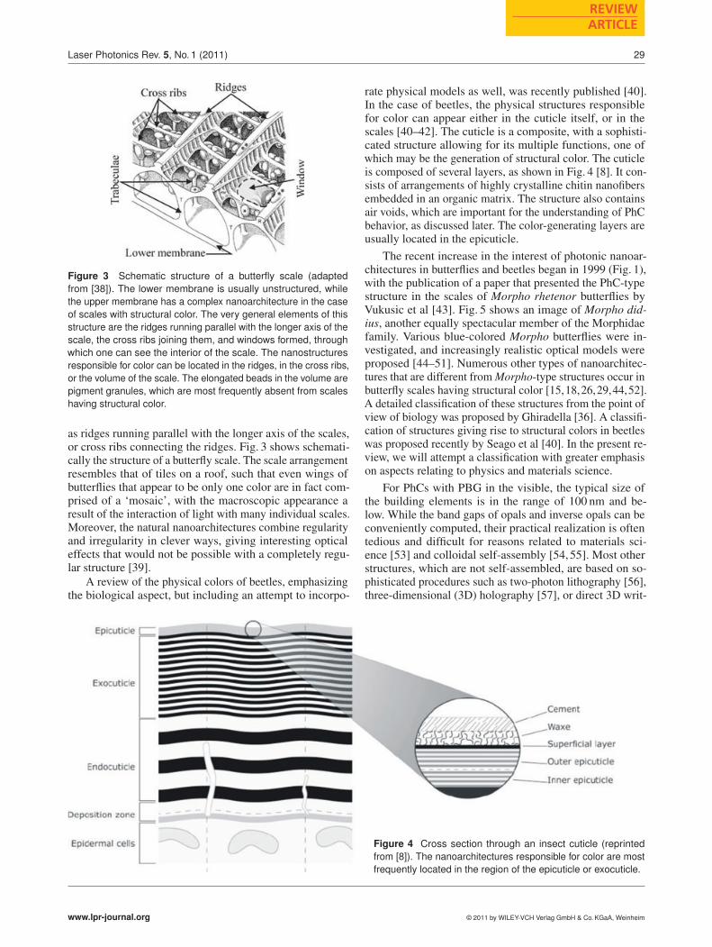
rate physical models as well, was recently published [40].In the case of beetles, the physical structures responsiblefor color can appear either in the cuticle itself, or in thescales [40–42]. The cuticle is a composite, with a sophisti-cated structure allowing for its multiple functions, one ofwhich may be the generation of structural color. The cuticleis composed of several layers, as shown in Fig. 4 [8]. It con-sists of arrangements of highly crystalline chitin nanofibersembedded in an organic matrix. The structure also containsair voids, which are important for the understanding of PhCbehavior, as discussed later. The color-generating layers areusually located in the epicuticle.
The recent increase in the interest of photonic nanoar-chitectures in butterflies and beetles began in 1999 (Fig. 1),with the publication of a paper that presented the PhC-typestructure in the scales of Morpho rhetenor butterflies byVukusic et al [43]. Fig. 5 shows an image of Morpho did-ius, another equally spectacular member of the Morphidaefamily. Various blue-colored Morpho butterflies were in-vestigated, and increasingly realistic optical models wereproposed [44–51]. Numerous other types of nanoarchitec-tures that are different from Morpho-type structures occur inbutterfly scales having structural color [15,18,26,29,44,52].A detailed classification of these structures from the point ofview of biology was proposed by Ghiradella [36]. A classifi-cation of structures giving rise to structural colors in beetleswas proposed recently by Seago et al [40]. In the present re-view, we will attempt a classification with greater emphasison aspects relating to physics and materials science.
For PhCs with PBG in the visible, the typical size ofthe building elements is in the range of 100 nm and be-low. While the band gaps of opals and inverse opals can beconveniently computed, their practical realization is oftentedious and difficult for reasons related to materials sci-ence [53] and colloidal self-assembly [54,55]. Most otherstructures, which are not self-assembled, are based on so-phisticated procedures such as two-photon lithography [56],three-dimensional (3D) holography [57], or direct 3D writ-
Figure 4 Cross section through an insect cuticle (reprintedfrom [8]). The nanoarchitectures responsible for color are mostfrequently located in the region of the epicuticle or exocuticle.
www.lpr-journal.org © 2011 by WILEY-VCH Verlag GmbH & Co. KGaA, Weinheim

30
LASER & PHOTONICSREVIEWS
L. P. Biro and J. P. Vigneron: Photonic nanoarchitectures in butterflies and beetles
Figure 5 (online color at: www.lpr-journal.org) Morpho didiusbutterfly (top left: close to normal artificial illumination; top right,diffuse, natural illumination). Bottom left: SEM image of a brokenscale of M. rhetenor (adapted from [46]) showing the Christmas-tree-like cross section of the ridges. Bottom right: schematic rep-resentation of the transverse cross section of the PhC constitutedby chitinous material in parallel ridges and air (adapted from [45]).
ing [58], which presently cannot be carried out over largesurfaces at practical cost levels.
A systematic analysis of technical and biological de-signs [59] (see Fig. 6 in [59]) shows that in biological de-signs, the structure dominates, while in technical designs theenergy input and material complexity dominate. In biologi-cal structures, the natural variability and absence of perfectordering is a relevant factor. Recent theoretical calculationsshow that in a diamond-type PhC, completely disorderingthe bond orientations while conserving the average particle-to-particle distance has only a slight effect on the PBG [60].There are many examples of photonic nanoarchitectures ofbiological origin with various degrees of order: the rigor-ously ordered single-crystalline dorsal shiny metallic blueside of Cyanophrys remus [15], the polycrystalline struc-tures on the mat green ventral side of the very same butterfly,and the highly disordered mat blue of the Albulina metallicabutterfly [61] (Fig. 8).
These butterflies will be discussed in more detail later.
2. Photonic crystals and photonic bandgap materials
2.1. General concepts
The concept of a ‘photonic crystal’ is often understood ina restricted sense [62, 63]. The most general concept, cov-ering all cases, is the graded-index periodic optical struc-ture, which can be defined as any non-absorbing mediumwhich is invariant under the translations of a crystal lat-tice. Graded-index materials were most likely first inves-tigated by Rayleigh, who studied acoustic waves on astring whose properties were modified by a longitudinal
Figure 6 (online color at: www.lpr-journal.org) Schematic show-ing photonic crystals of a) one, b) two, and c) three dimensions(adapted from: http://ab-initio.mit.edu/photons/tutorial/ by S. G.Johnson). Other photonic nanoarchitectures occurring in beetlesand butterflies are d) chirped multilayer, e) perforated multilayer-type structure, and f) Bouligand or plywood structure.
standing-wave deformation [64]. The only requirement im-plied by the above definition is that the refractive indexn��r� is real and position dependent, in such a way that atranslation of the whole structure along any of the vectors�l � n1�a1 � n2�a2 � n3�a3 (built with integer coefficients n1,n2, n3 on the primitive translation vectors�a1,�a2,�a3) brings
no change in the optical density distribution: n��r��l� � n��r�.With two totally invariant directions and a discrete period-icity in one direction (such as along the z-axis), the systemis a one-dimensional graded-index periodic optical struc-ture (Fig. 6a). These structures are called multilayers. Inthe discretely periodic direction with period a, the wavevec-tor conservation is weakened by the possible addition tothe corresponding component, kz, of any integer multipleof the quantity 2π�a. This simple albeit important result,from group theory, drives most of the properties of wavesin periodic media and will be the foundation of most of thearguments explaining structural colorations in living organ-isms.
When there is one totally invariant direction andtwo discretely invariant directions, the medium is a two-dimensional graded-index periodic optical structure, whichis a structure made essentially of parallel fibers (Fig. 6b).In that case, only one component of the wave is strictlyconserved, with the others weakly conserved (except for theaddition of any of the two-dimensional (2D) reciprocal lat-tice vectors associated with the discrete periodicity). Finally,the full three-dimensional graded-index periodic opticalstructure shows discrete periodicity in all three dimensionsof space (Fig. 6c). In this kind of structure, any incident
wave with a wavevector�k aggregates 3D reciprocal lattice
© 2011 by WILEY-VCH Verlag GmbH & Co. KGaA, Weinheim www.lpr-journal.org

Laser Photonics Rev. 5, No. 1 (2011)
REVIEWARTICLE
31
vectors �G while propagating in the periodic medium. This
diffraction phenomenon leads to wavevectors�k� �G.In many cases, the graded medium consists of just two
different materials separated by a sharp interface. The in-terfacial periodic optical structure can be, one-, two-, orthree-dimensional. One-dimensional interfacial periodicoptical structures define the materials from which interfer-ential optical filters are mainly designed. The properties ofmultilayer stacks have been known for a long time [65, 66]and these structures are incorporated in many industrialapplications today.
The properties of PhCs are related to the possible exis-tence of a PBG, a range of frequencies where no propagationof electromagnetic waves is allowed for any polarization ordirection. PBG materials have been found theoretically [67]and experimentally [68] in face-centered cubic 3D interfa-cial periodic optical structures [69]. Two-dimensional struc-tures, though unable to produce a complete band gap, arealso generally categorized as ‘photonic crystals’.
Many coloration structures are based on one-dimen-sional (1D) stacks, with small values of refractive index,typically not exceeding the refractive index of 1.8 of gua-nine (a material found in brightly reflecting fish scales).It is, therefore, very unlikely that a 3D complete gap willbe found in biology. Despite this limitation, evolution hasdriven the coloring structures of animals to effectively useone-, two- and three-dimensional periodic structures for thecommon purpose of producing visual or thermal effects. Themechanism of light interference is constant and ubiquitous,and the choice to build one structure or another lies verydeep in the history of animal evolution. In reality, there isno reason to look at a 1D structure with a different eye thanwe look at 2D or 3D structures. Likewise, there is no reasonto distinguish between different regimes of refractive indexvalues. In the context of the present review, a ‘photoniccrystal’ is simply a short expression to designate one of thebasic one-, two-, or three-dimensional interfacial periodicoptical structures.
The photonic structure itself is most of the time confinedto a thick layer, making a PhC film. Even if we ignore dis-order for the moment, the height limitation of the structurecomplicates analysis. The optical functions performed bythese structures can be investigated in two successive steps:the first step is to determine the dominant color producedby a given model structure and the second is to calculate thedetailed reflectance spectra. Tools exist for these tasks, andwe will review these in the next section.
2.2. Dominant reflected color:first guess formulas
Let us first consider the case of a 1D PhC with low indexcontrasts, along the z-direction. The multilayer film (Fig. 6a)is a repetition (a few times) of the same 1D refractive indexprofile. One can easily predict the location of the frequencygaps that lead to high-reflectance bands if we idealize thefilm by considering an infinite periodic structure and lookfor the occurrences of electromagnetic stop-bands. At (or
near) normal incidence (z-direction), the gap in a multilayeroccurs at frequencies such that the averaged linear lightdispersion line ω � kzc�n meets the (extended) Brillouinzone boundaries of the 1D periodic structure. The openingof the gaps occurs at the zone boundaries; these are theonly wavenumbers that can hybridize in a periodic struc-ture, since they are separated by an integer number of 2π�a(where a is the multilayer period). The wavelength of thereflectance bands, at normal incidence, matches the gap fre-quencies when the following relationship is satisfied [27]:
λ �2nam
� (1)
In this simple equation, n is the average refractive index inthe period (obtained by spatially averaging the dielectricconstant over the whole PhC film) and m is an integer cho-sen so that the reflected wavelength λ lies in the spectralinterval of interest (usually, the visible range). The refrac-tive index contrast does not influence the dominant reflectedwavelength: at this level of approximation, modifying therefractive index contrast will only impact the width of thereflection band, slightly changing the saturation of the dom-inant color.
When the incidence is far from normal, the result mustbe somewhat modified in order to account for the angle-dependent relationship between the normal wavevector kzand the frequency of light. In order to remain at the Brillouinzone boundary, the frequency must be larger than under nor-mal incidence, in order to account for the contribution ofthe lateral wavevector. When the incidence angle increases,the corresponding wavelength is shifted to the blue. Trans-lated into vacuum wavelengths, this gives the ‘iridescencerule’ [70]:
λ �2a�
n2� sin2 θ
m� (2)
This formula is general, and it defines the wavelengths thatmust be totally reflected by an infinite multilayer, for anyincidence angle, assuming weak refractive index contrasts.This change of color, typically from red to green, is foundin many insects with a multilayer epicuticle (for instance,the ventral side of the abdomen of Chrysochroa raja thai-landica).
If the incidence medium is not vacuum (air), but has afinite refractive index n0, Eq. (2) is modified as follows:
λ �2a�
n2�n2
0 sin2 θ
m� (3)
This formula can be applied, for instance, to marine animalswith a PhC structure causing iridescence. An example ofsuch an organism is the ctenophore Beroe cucumis [71].According to the modified rule, the range of accessiblecolors is significantly larger for structures in water thanin vacuum.
When the structures consist of a combination of multi-layers with a weak periodic refractive index and inhomo-geneity in the lateral directions (parallel to the interfaces), asimple formula can also be developed that accounts for the
www.lpr-journal.org © 2011 by WILEY-VCH Verlag GmbH & Co. KGaA, Weinheim
32
LASER & PHOTONICSREVIEWS
L. P. Biro and J. P. Vigneron: Photonic nanoarchitectures in butterflies and beetles
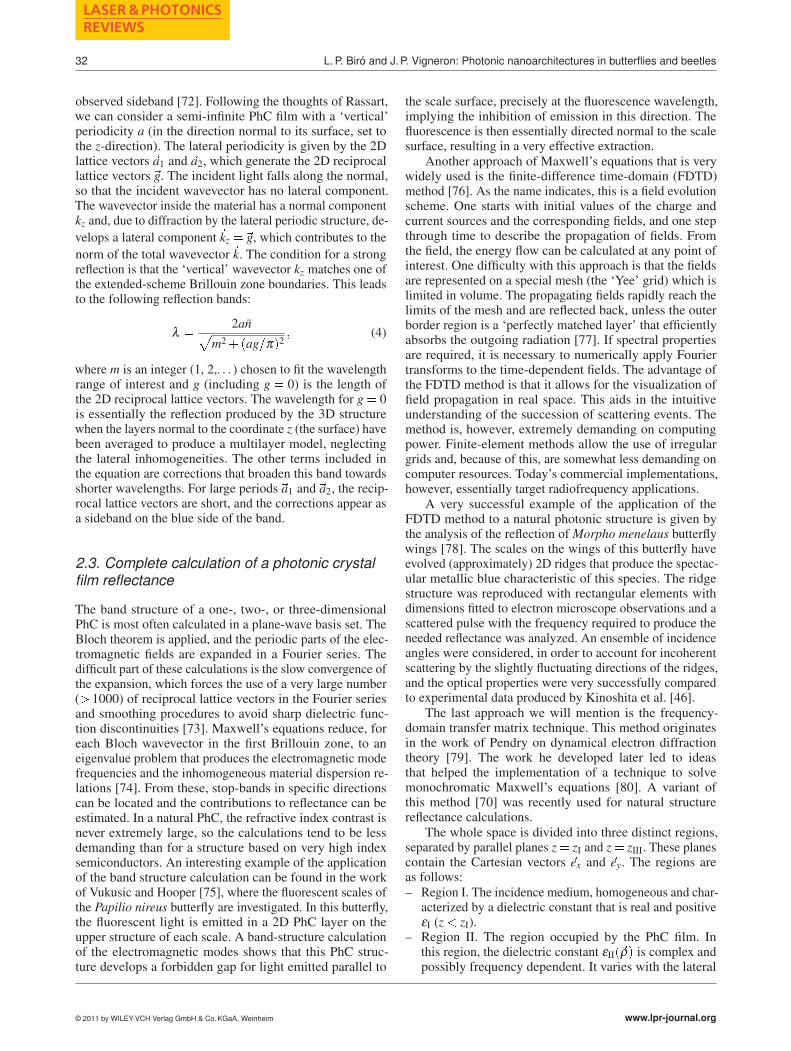
observed sideband [72]. Following the thoughts of Rassart,we can consider a semi-infinite PhC film with a ‘vertical’periodicity a (in the direction normal to its surface, set tothe z-direction). The lateral periodicity is given by the 2Dlattice vectors�a1 and�a2, which generate the 2D reciprocallattice vectors �g. The incident light falls along the normal,so that the incident wavevector has no lateral component.The wavevector inside the material has a normal componentkz and, due to diffraction by the lateral periodic structure, de-
velops a lateral component�kz ��g, which contributes to the
norm of the total wavevector�k. The condition for a strongreflection is that the ‘vertical’ wavevector kz matches one ofthe extended-scheme Brillouin zone boundaries. This leadsto the following reflection bands:
λ �2an
�m2��ag�π�2
� (4)
where m is an integer (1, 2,. . . ) chosen to fit the wavelengthrange of interest and g (including g � 0) is the length ofthe 2D reciprocal lattice vectors. The wavelength for g � 0is essentially the reflection produced by the 3D structurewhen the layers normal to the coordinate z (the surface) havebeen averaged to produce a multilayer model, neglectingthe lateral inhomogeneities. The other terms included inthe equation are corrections that broaden this band towardsshorter wavelengths. For large periods�a1 and�a2, the recip-rocal lattice vectors are short, and the corrections appear asa sideband on the blue side of the band.
2.3. Complete calculation of a photonic crystalfilm reflectance
The band structure of a one-, two-, or three-dimensionalPhC is most often calculated in a plane-wave basis set. TheBloch theorem is applied, and the periodic parts of the elec-tromagnetic fields are expanded in a Fourier series. Thedifficult part of these calculations is the slow convergence ofthe expansion, which forces the use of a very large number(� 1000) of reciprocal lattice vectors in the Fourier seriesand smoothing procedures to avoid sharp dielectric func-tion discontinuities [73]. Maxwell’s equations reduce, foreach Bloch wavevector in the first Brillouin zone, to aneigenvalue problem that produces the electromagnetic modefrequencies and the inhomogeneous material dispersion re-lations [74]. From these, stop-bands in specific directionscan be located and the contributions to reflectance can beestimated. In a natural PhC, the refractive index contrast isnever extremely large, so the calculations tend to be lessdemanding than for a structure based on very high indexsemiconductors. An interesting example of the applicationof the band structure calculation can be found in the workof Vukusic and Hooper [75], where the fluorescent scales ofthe Papilio nireus butterfly are investigated. In this butterfly,the fluorescent light is emitted in a 2D PhC layer on theupper structure of each scale. A band-structure calculationof the electromagnetic modes shows that this PhC struc-ture develops a forbidden gap for light emitted parallel to
the scale surface, precisely at the fluorescence wavelength,implying the inhibition of emission in this direction. Thefluorescence is then essentially directed normal to the scalesurface, resulting in a very effective extraction.
Another approach of Maxwell’s equations that is verywidely used is the finite-difference time-domain (FDTD)method [76]. As the name indicates, this is a field evolutionscheme. One starts with initial values of the charge andcurrent sources and the corresponding fields, and one stepthrough time to describe the propagation of fields. Fromthe field, the energy flow can be calculated at any point ofinterest. One difficulty with this approach is that the fieldsare represented on a special mesh (the ‘Yee’ grid) which islimited in volume. The propagating fields rapidly reach thelimits of the mesh and are reflected back, unless the outerborder region is a ‘perfectly matched layer’ that efficientlyabsorbs the outgoing radiation [77]. If spectral propertiesare required, it is necessary to numerically apply Fouriertransforms to the time-dependent fields. The advantage ofthe FDTD method is that it allows for the visualization offield propagation in real space. This aids in the intuitiveunderstanding of the succession of scattering events. Themethod is, however, extremely demanding on computingpower. Finite-element methods allow the use of irregulargrids and, because of this, are somewhat less demanding oncomputer resources. Today’s commercial implementations,however, essentially target radiofrequency applications.
A very successful example of the application of theFDTD method to a natural photonic structure is given bythe analysis of the reflection of Morpho menelaus butterflywings [78]. The scales on the wings of this butterfly haveevolved (approximately) 2D ridges that produce the spectac-ular metallic blue characteristic of this species. The ridgestructure was reproduced with rectangular elements withdimensions fitted to electron microscope observations and ascattered pulse with the frequency required to produce theneeded reflectance was analyzed. An ensemble of incidenceangles were considered, in order to account for incoherentscattering by the slightly fluctuating directions of the ridges,and the optical properties were very successfully comparedto experimental data produced by Kinoshita et al. [46].
The last approach we will mention is the frequency-domain transfer matrix technique. This method originatesin the work of Pendry on dynamical electron diffractiontheory [79]. The work he developed later led to ideasthat helped the implementation of a technique to solvemonochromatic Maxwell’s equations [80]. A variant ofthis method [70] was recently used for natural structurereflectance calculations.
The whole space is divided into three distinct regions,separated by parallel planes z� zI and z� zIII. These planescontain the Cartesian vectors �ex and �ey. The regions areas follows:– Region I. The incidence medium, homogeneous and char-
acterized by a dielectric constant that is real and positiveεI (z � zI).
– Region II. The region occupied by the PhC film. Inthis region, the dielectric constant εII��ρ� is complex andpossibly frequency dependent. It varies with the lateral
© 2011 by WILEY-VCH Verlag GmbH & Co. KGaA, Weinheim www.lpr-journal.org

Laser Photonics Rev. 5, No. 1 (2011)
REVIEWARTICLE
33
coordinates (�ρ � x�ex � y�ey and with the depth coordi-nate z� but remains invariant under the translations of a2D lattice, given by the vectors �a1 � a1x�ex� a1y�ey and�a2 � a2x�ex�a2y�ey (zI � z� zIII�.
– Region III. The emergence region, or the substrate, is ho-mogeneous and characterized by the complex dielectricconstant εIII (z� zIII).
The objective is to evaluate the fraction of the incident en-ergy which is reflected by the junction layer, after the infinitenumber of scattering events encountered within the junctionlayer. In order to represent the scattered field more effec-tively, the assumption is made, with little loss of generality,that the junction layer exhibits a 2D periodic symmetry. Thismay be the case when the system under study is actuallyperiodic, but can also be used for a less restricted geometry,by defining the actual structure in a large supercell, whichwill ultimately be reproduced periodically. In this latter case,a convergence study must be carried out in order to deter-mine whether the size of the supercell is large enough toovercome intercell interactions.
The technique involves first the construction of a T ma-trix. On each side of the inhomogeneous film, the propaga-tion media are homogeneous and the solution is a collectionof plane waves. On the incidence side, the wave is madeup of all the scattered waves that are compatible with theincident waves. A ‘compatible’ wave is defined as a wavehaving retained the same frequency and the same 2D Blochwavevector as the incident wave. This actually makes aquadruple infinity of field components, one for each polar-ization and one for each direction of propagation along thenormal z-axis. The infinite numbers of beams are labeledby the reciprocal lattice vectors that we decide to keep inthe problem. Maxwell’s equations, in a Fourier transformrepresentation, easily propagate the fields from one sideof the film to the other side. The T matrix serves to relatelinearly the amplitudes of the quadruple infinity of the waveamplitudes in the emergence region to the quadruple infinityof the wave amplitudes in the incidence region. But if the Tmatrix is easily deduced from Maxwell’s equations, it doesnot solve the scattering problem, which seeks the outgoingwaves, on each side of the film, from the ingoing waves.The matrix needed for this is called the S matrix, which canbe deduced from the T matrix. However, the transformationof a T matrix into an S matrix cannot be done numericallyunless the PhC film is extremely thin. Because of this, thePhC film must be cut into very thin inhomogeneous parallellayers, and an S matrix is calculated for each of these thinlayers. If the assembly of T matrices is easy (this is just theproduct of thin-film T matrices), the assembly of S matricesis slightly more complicated, but feasible. These assemblyformulas were obtained long ago by Pendry. With this tool,many types of structures in one, two, and three dimensionscan be probed by simulation.
An example of an application of this technique can befound in an early paper on the Polyommatus daphnis butter-fly, where the ‘pepper-pot’ structure was modelled using a3D PhC film [81]. In spite of the idealization of the structure,the calculated reflectance spectrum accounts for the mainfeatures of the measured reflectance that was obtained ex-
perimentally in the same work. In this case, the calculationhelped to prove that the diffuse blue colouration found onthis butterfly originated from the pepper-pot structure, whichwas lacking in a related species, Polyommatus marcidus.
3. Order and disorder
It is very unlikely that optical engineers will learn frombeetles or butterflies how to make more perfect multilayers,better dielectric or chirped mirrors. In contrast, the disorderused to achieve certain functions may be a source of inspira-tion.
Figure 7 (online colorat: www.lpr-journal.org)Schematic of the kind ofcomplexity characteristicfor artificial and biolog-ical structures and theopportunities offered bybioinspiration.
The concept of a perfect PhC, with its infinite regularorder, is an idealization. Natural structures are often farfrom ideal, but these irregular structures remain very effi-cient. Moreover, there are several reasons to believe thatthe disorder is actually necessary. One of these reasons isthe robustness of the functionality. Inaccuracies in the exactlocation of the scatterers do not strongly perturb the re-flectance spectrum. This can be shown by perturbation [82]and it has actually been a historical argument, raised byDebye [83], that X-ray diffraction would give undisturbeddiffraction directions, in spite of the disorder in atom loca-tions induced by their thermal motion. The visual effectsof slightly disordered systems tend to be more robust thanthose generated by perfect, ideal PhCs and this, in nature,tends to be an advantage, as variability in reproduction isone of the important features of a living organism’s evolu-tion strategy.
Strong topological disorder also has advantages, includ-ing its influence on visual effects. Weevils and longhorns,for instance, have scales filled with scatterers that are ar-ranged with various degrees of disorder, from nearly single-crystalline arrangements, all the way to amorphous configu-rations. Intermediate structures are generally polycrystalline,and the range of visual effects produced is even greater [40].White scales (as on the weevil Eupholus albofasciatus) aregenerally composed of amorphous accumulations of spher-ical scatterers, while multicoloured, diamond-like scales(such as those on the weevil Entimus imperialis) rely onlarge single crystals. In between, photonic polycrystals pro-duce metallic or mat, iridescent or stable, colorations ac-cording to the degree of disorder or the size of the PhCgrains. An important point to keep in mind is that these
www.lpr-journal.org © 2011 by WILEY-VCH Verlag GmbH & Co. KGaA, Weinheim

34
LASER & PHOTONICSREVIEWS
L. P. Biro and J. P. Vigneron: Photonic nanoarchitectures in butterflies and beetles
visual effects are reproduced from generation to generationand are well-defined traits that contribute to the characteri-zation of an insect species. The degree of disorder is thensomehow written in the genetic information attached to aspecies, most likely in the fabrication plan of the scales.
The disorder present in most biological nanoarchitec-tures is often mentioned, but generally does not receive theconsideration it deserves. For example, beetle elytra haveseveral components in the light reflected from them: a per-fectly specular component and an often more significantnon-specular component arising from irregularities in thestructure. An example that illustrates this point is shownin Fig. 9. Both kinds of multilayers, in one case a regularmultilayer (the buprestid beetle) and in the other case achirped multilayer (Chrysina chrysagyrea) [40], behave inthe same way. The central part of the elytra appears darkin the photograph (this indicates the absence, or negligibleintensity, of diffuse illumination as compared with the directlight from light sources), and the spots where the light fromthe illumination sources falls under specular reflection con-ditions appear very bright and colorless, almost mirror-like.Large areas of the elytra, which under strictly specular con-ditions should appear dark, exhibit a saturated color in thecase of the multilayer, or an unsaturated wideband reflec-tion in the case of the chirped multilayer. In this later case,the silvery color indicates that the non-specular behavioris equally present for all wavelengths of the visible spec-trum. The presence of color under non-specular conditionsis often found in beetles, clearly indicating that the structureof the reflectors deviate significantly from those of regularor chirped multilayers. This deviation is not a secondaryeffect: if it were not present, the beetle would have a com-pletely different appearance. It is worth noting that in mostmanmade structures, efforts are made to avoid disorder andirregularity. Biological examples show us that disorder canbe useful to achieve certain optical effects, such as colorvisibility under non-specular conditions. A practical demon-stration of this was achieved by producing a bioinspiredmultilayer on a sand-blasted glass substrate [27]. This veryclearly demonstrates that irregularity, due to features suchas substrate roughness, is not necessarily detrimental forcertain applications, as beetles discovered many millenniaago (for a more detailed discussion, see Section 5.1, the caseof Crysochroa vittata).
Similar to beetles, butterflies also have structure withdisorder and irregularity that is not accidental, but insteadeconomically adapted to the habitat of the species. For exam-ple, in the case of the forest-dwelling South American but-terfly Cyanophrys remus, a very efficient single-crystallinePhC-based reflector is found on the scales of the dorsalside (blue, metallic color) (Fig. 8). Light is very scarce un-der the forest canopy, so a very efficient reflector [15] isneeded for sexual communication. This butterfly usuallyrests on leaves with closed wings. The dorsal sides of itswings are covered by scales with randomly oriented, inverseopal-type PhCs, 5–10 μm in size. Within each grain, a per-fect crystalline structure is found. Different facets of thisopal structure reflect blue, green, and yellow [15]. Due tothe random orientation of the grains, a mat green texture
Figure 8 (online color at: www.lpr-journal.org) Comparison oftwo Lycaenid butterflies with blue dorsal color. Top: the shiny blueof Cyanophrys remus; bottom: the mat blue of Albulina mettalica.The scales of C. remus have single-crystalline structure, while thecolor of A. metallica originates from amorphous PBG material.
is produced, which additionally does not reflect light as ex-pected from a regular rough surface in a cone around thespecular direction corresponding to the surface. Spectrogo-nimetric measurements revealed that most of the light isbackscattered along the incident direction [15] (discussed inmore detail in the next section). Another butterfly, Albulinametallica, realizes in some sense the ‘mirrored’ effects, matblue dorsal color (Fig. 8) and the shiny green-gold ventralcolor, arising from a quasiordered layer with no long-rangetranslational order [61]. (This will be discussed in moredetail in Section 5.2.) This butterfly lives in an open, highHimalayan habitat, where it has plenty of light during thedaytime, so a reflector with moderate reflectivity providesadequate sexual communication. However, due to the abun-dant dew in the morning hours, the grass sparkles in thesun. Against this shiny background, a mat green colorationwould make the butterfly easily noticeable, so the butterflyevolved with a more appropriate, shiny color. It is worth
© 2011 by WILEY-VCH Verlag GmbH & Co. KGaA, Weinheim www.lpr-journal.org

Laser Photonics Rev. 5, No. 1 (2011)
REVIEWARTICLE
35
Figure 9 (online color at: www.lpr-journal.org) Non-specularbehavior of insect reflectors. Left: a buprestid beetle; center:Chrysina chrysagyrea (adapted from [40]). The regions where thespecularity conditions between the light sources used and the ob-jective of the camera are fulfilled are delineated in red. The centralregion of the elytra, delineated in yellow, appears dark becausein that region the light is scattered under angles (beam labeled3) that do not enter the objective of the camera (L). Accordingto the schematic at right, if the elytra are considered specularobjects, due to the curvature of the elytra, the light from regionsother than those delineated in red should not enter the objectiveof the camera (e.g. beam labeled 1). For the buprestid beetle, theregion outside of the second yellow delineation should appearblack, not blue, if the elytrum behaves as a regular multilayer.
emphasizing that, to a certain degree, similar colors and sim-ilar visual effects are achieved with very different structures.This is one of the great advantages of biological evolution:it exploits random variations and their ‘fitness test’ by theenvironment in which the species lives. Nature can reachsolutions that a rational engineer may reach only with greatdifficulty. Indeed, recent computer modeling of evolution-ary algorithms and the way they act on the formation ofphotonic devices [84, 85] proves their superiority.
For a more detailed treatment of the question of regular-ity and irregularity in natural structural color, we refer thereader to the dedicated review on this topic by Kinoshitaand Yoshioka [39].
4. Principles of microscopic and opticcharacterization
The PBG materials generating color in the visible rangeare typically composed from building elements with dimen-sions in the 100 nm size range, or below, in one, two, or threedimensions. The most appropriate tool for characterizingrelevant structural information is the electron microscope.Both scanning (SEM) and transmission electron microscopy(TEM) are very useful for providing elements of the neededstructural information, but neither of them is able to providecomplete structural information. Often, as in the case of3D structures, even a combination of information providedby SEM and TEM images may not be straightforward [15].SEM provides information at the surface of a specimen,revealing a topography of ridges and cross ribs (see Fig. 3).With luck, specimens can be skillfully broken in a way toprobe the fractured surface with SEM, revealing informa-tion about the cross section [46, 47]. A more reliable way
Figure 10 (online color at: www.lpr-journal.org) Schematic repre-sentation of the difficulties arising when examining one particularsection of a simple model structure. Sectioned object in brownand yellow; section in green and yellow. a) Section parallel withthe face of the cube (100 plane); b) section parallel with the maindiagonal of the cube (111 plane); c) alternative sections parallelwith the plane passing through the diagonal of the top face and ofthe base (110 plane).
of obtaining cross-sectional information is by using thin,ultramicrotomed sections with TEM. For this, the speci-men is carefully incorporated into an epoxy block, fromwhich thin sections are cut using a sharp, diamond knife.Unfortunately, in this procedure the precise orientation ofthe sectioning plane cannot be controlled, due to the verynature of preparing using a ultramicrotome thin enough sec-tions (typically of the order of 100 nm thickness, or below)transparent for electrons.
One of the major difficulties in combining SEM andTEM data is illustrated schematically in Fig. 10. Even in thecase of a very simple 3D structure such as a cube built ofsmall cubes, and the section plane coincident with planesof high symmetry, it is not easy to deduce the complete3D structure from information in two orthogonal planes.The reconstruction of the 3D structure is increasingly dif-ficult for more realistic structures that are more complexand less regular. Therefore, in the case of butterfly scales,which may have rather complex geometries, using infor-mation obtained from only SEM or TEM data (and thusrestricting the sampling of the object to a single plane) maybe misleading [15].
One recently developed technique that has the potentialto resolve the problem of characterizing a 3D structure iselectron tomography. Electron tomography is a sophisticatedcombination of TEM imaging and computation allowingone to render an entire 3D nanostructure from a slightlythicker ultramicrotomed specimen [86]. Argyros and co-workers used this technique to obtain 3D structural informa-tion on the PhC material occurring in the green scales of theTeinopalpus imperialis butterfly. The technique uses thickerultramicrotomed sections of 100, 200 and 500 nm, whichare tilted inside the TEM instrument in several positions inincrements of 2.5� over a range of 70� or 120�. In each po-
www.lpr-journal.org © 2011 by WILEY-VCH Verlag GmbH & Co. KGaA, Weinheim

36
LASER & PHOTONICSREVIEWS
L. P. Biro and J. P. Vigneron: Photonic nanoarchitectures in butterflies and beetles
Figure 11 (online color at: www.lpr-journal.org) Electron mi-croscope images of the dorsal cover scale of Cyanophris remus.a) SEM image. The inset shows a magnified detail, in which thetriangular hole pattern can be clearly seen through the windows.b) Cross-sectional TEM image, showing the PhC-type materialinside the scale. c) Detail of one ridge. d) Fourier power spectrumcomputed from a square cut from a). The hexagon indicates theorientation of the triangular lattice of holes in a). The ridges in a)are running along the direction defined by 2–0–5. Numbers 1 to 6correspond to maxima labeled in similar way in Fig. 12f. (Adaptedfrom [15].)
sition, the image is recorded and dedicated software is usedto build the 3D image. Experimental and computed imageswere compared and found to be in good agreement [86].Unfortunately, this technique is still relatively rare and ex-pensive.
In particular cases, when the scale can be treated asa single crystal with long-range translational order, suchas the dorsal side of Cyanophrys remus, it may be possi-ble to accurately reconstruct the structure from SEM andTEM images (Fig. 5 in [87]), which can subsequently becrosschecked by computer simulations to see if leads tothe observed optical effects [15]. Prior to attempting thereconstruction, one has to make sure that the scales are in-deed of single-crystalline character. This can be achievedby calculating the Fourier power spectrum of the electronmicrographs [15]. However, the interpretation of the Fourierspectrum of complex images is typically not straightforward.In Fig. 11, experimental SEM and TEM images are shown,together with the Fourier spectrum of the SEM image. Thereconstruction of the Fourier power spectrum is shown inFig. 12, and the reconstruction procedure itself is discussedin detail in [15]. Comparing Fig. 11d with Fig. 12f confirmsthat the Fourier power spectrum obtained from the exper-imental SEM image is a result of the convolution of theelementary structures presented in Figs. 12a and b. In otherwords, the triangular pattern of small holes that can be seenthrough the rounded, rectangular windows do in fact possesssingle-crystalline, long-range order.
Fourier analysis is a very convenient tool when struc-tures exhibiting long-range order are present. A methodusing a different approach, but also using the Fourier powerspectrum interpretation of cross-sectional TEM images, hasbeen applied by Prum et al. to butterfly scales [88]. Theyhad previously used a similar method to correlate structuraland spectral data of quasiordered PhC-type structures inavian [89] and mammalian skin [90]. The extension of thiscolor-generation mechanism from insects to birds and mam-mals indicates that the mechanism was ‘rediscovered’ byevolution in several different cases.
The optical characterization of butterfly scales and bee-tle elytra should be carried out with caution. As can be easilydeduced from Fig. 3, the individual butterfly scale is itself acomplex enough object to behave non-specularly. Moreover,
Figure 12 (online color at:www.lpr-journal.org) Reconstructionof the Fourier power spectrum fromFig. 11d. a) Triangular hole pattern(seen through the windows in the in-set of Fig. 11a); b) the pattern de-fined by the windows; c) structuresresulting from overlapping b) and a);d) Fourier power spectrum of a); e)Fourier power spectrum of b); (d)Fourier power spectrum of c). (Re-produced from [15].)
© 2011 by WILEY-VCH Verlag GmbH & Co. KGaA, Weinheim www.lpr-journal.org

Laser Photonics Rev. 5, No. 1 (2011)
REVIEWARTICLE
37
Figure 13 (online color at: www.lpr-journal.org) Light scattered by blue Morpho wings. a) Morpho rhetenor wing; b) Morpho didiuswing; c) schematic representation of the experimental setup used (adapted from [92]). One can clearly notice the non-specular characterof the light scattered from the wings. The scattering patterns are different and characteristic for the two butterflies.
even the ridges within one scale, in scales with ordered as-pect, like in the case of Morpho butterflies, may behave asindividual optical objects [39]. This is accentuated by thefact that a butterfly wing is composed of several layers ofscales and these scales are oriented at a certain angle withrespect to the wing membrane [91]. In the case of beetles,the deviation from specular behavior also frequently hasto be taken into account, as demonstrated by Fig. 9. Thelack of specular behavior means that characterization usingstandard reflectance measurements may be misleading. Thisis very convincingly demonstrated by a simple scatteringexperiment reported by Yoshioka and Kinoshita [92]. Theyused a white screen with a small hole to observe the angu-lar spread of the light scattered by a Morpho wing and asingle scale (Fig. 13). If an experimental setup only allowsspecularly reflected light to enter the detector, it will miss asignificant fraction of the reflected light.
Another, more quantitative way of handling non-specularbehavior is to use a spectrogoniometric setup as shown inFig. 14. A simple spectrogoniometer is built from a commer-cial fiber optic spectrometer and a gonimetric stage, whichallows the precise positioning in the upper hemisphere ofthe illumination and pick-up fibers with respect to the spec-imen. The detailed spectral characterization of the dorsaland ventral side of the Cyanophrys remus wing using such aspectrogonimeter is reported in [15]. Another useful instru-ment developed recently by Stavenga and co-workers is theimaging scatterometer. This instrument allows one to obtaina photographic representation of the characteristic scatteringpattern for a butterfly wing [52]. As C. remus and C. rubi areknown to have similar nanostructures in their ventral coverscales [15, 35] and the macroscopic aspect of the wingsas well as low-magnification optical micrographs are verysimilar [15, 52], they offer a perfect opportunity to compareresults obtained using the imaging scatterometer [52] andspectrogoniometer [15] (Fig. 15). Both techniques reveal a
Figure 14 (online color at: www.lpr-journal.org) A simple spec-trogoniometric setup using a commercial fiber optic spectrometer(not shown) and a goniometric stage: A, illumination fiber; B, pick-up fiber; G, gonimetric stage; W, piece of framed butterfly wing.The arcs supporting fibers A and B can be rotated 360�.
strongly non-specular behavior. According to the spectrogo-niometric measurement, under a 45� incidence on the wingplane, the intensity of the specularly reflected light is ofthe order of 15%, regardless of the azimuthal rotation angle(the azimuthal rotation gives the variation of the incidentplane with respect to the direction ridges in the plane ofthe wing). The intensity of the backscattered light is around70%. The imaging scatterometer shows that the illuminationfalling close to normal onto the wing is uniformly scatteredin all directions around the incident direction in a cone withan opening exceeding 60�, while the spectral position ofthe maximum is not changed [52]. The same imaging scat-terometer was used to investigate the light reflected from
www.lpr-journal.org © 2011 by WILEY-VCH Verlag GmbH & Co. KGaA, Weinheim

38
LASER & PHOTONICSREVIEWS
L. P. Biro and J. P. Vigneron: Photonic nanoarchitectures in butterflies and beetles
Figure 15 (online color at:www.lpr-journal.org) Microstruc-ture and light scattering fromthe polycrystalline, inverse opalstructure of Cyanoprys remusand Callophrys rubi, known tohave similar microstructures. a)SEM micrograph of a ventral(mat green) cover scale of C.remus; b) scatterometer imageof light scattered from a ven-tral scale of C. rubi (adaptedfrom [52]); c) light scattered inspecular direction under a 45�
angle of incidence from the ven-tral side of C. remus wing; d)light backscattered under a 45�
angle of incidence from the ven-tral side of C. remus wing.
individual scales and wing pieces of Morpho aega. In ac-cordance with earlier results [43, 92], it was found that theangle of scattering is moderate in a plane parallel with theridges of the scale and strong scattering occurs in a planenormal to the ridges.
These experimental data show that a suitable appara-tus for detailed optical investigation of naturally occurringPhCs and for their artificial counterparts would be an opti-cal instrument similar to the X-ray diffraction instruments,but operating with tunable lasers. Of course, integrationspheres can be used to collect light that is scattered undernon-specular angles [61, 93]. Unfortunately, when usingsuch a sphere, valuable information regarding the angleof scattering is lost. In addition, components of multiplediffuse reflections from internal surfaces of the sphere aredirected back at the sample at a range of different angles.This leads to a convoluted reflection from the sample, com-prising components of many different angles [94].
5. Examples of naturalphotonic nanoarchitectures
5.1. One-dimensional structures
One-dimensional structures, or multilayers, if understood ina wide sense, are the most widespread photonic nanoarchi-tectures occurring in the living world. They are responsiblefor the colors of many beetles and butterflies. However, re-alistically, none of these biological nanoarchitectures areactually 1D structures in the strict sense of the word. Rigor-ously speaking, a 1D structure should behave in a perfectly
specular way, as do artificial multilayers. On the other hand,if a color is used for communication in the living world, itcould be rendered useless by such a limited viewing angle.Therefore, imperfect natural nanoarchitectures benefit formthe color selection mechanism of 1D structures, but alsomodulate the angular spread and the intensity of the signalwith disorder. As discussed above in some detail, the Mor-pho-type scales exhibit a very different magnitude of theangular spread in the plane parallel or perpendicular to theplane of the scale’s ridges. Morpho didius, for example, hasspecial transparent cover scales, which widen the angularspread of the color generated, opposite to the usual way bythe ground scales [47]. Nevertheless, most groups modelMorpho-type scales with 1D structures [43, 46–48, 95]. Amore complex treatment of the color generation of Morpho-type scales was given by Gralak et al [45]. They modeledthe scale structure with the help of a rigorous lamellar grat-ing electromagnetic theory. In this way, they were able todetermine the colors reflected by the wing under variousillumination conditions. Recent modeling and experimentalwork by Plattner [49] showed that in fact the investigatedMorpho-type scales show efficient low-pass filter behaviorfor all angles of incidence and polarizations, with near-complete transmission at wavelengths above a threshold of550 nm. The angular spread of the backscattered light wasfound to be organized in lobes with total extinction of thespecular reflection for all conditions of incidence. Retro-reflector behavior was also observed for angles of incidenceof 30� and above. All of these findings, in accordance withearlier [43, 96] and more recent results [32, 52], show that,in fact, the behavior of Morpho-type scales is much morecomplex than a simple multilayer theory predicts. Neverthe-
© 2011 by WILEY-VCH Verlag GmbH & Co. KGaA, Weinheim www.lpr-journal.org

Laser Photonics Rev. 5, No. 1 (2011)
REVIEWARTICLE
39
Figure 16 (online color at:www.lpr-journal.org) SEM im-ages of male Hoplia coeruleahead, covered by scales (left)and the interior of a fracturedscale (right). The inset showsH. coerulea male on a greenleaf. (Adapted from [99].)
less, the color selection rules can be satisfactorily deducedwith 1D multilayer theory.
The shiny, metallic color, silver, or gold aspect ofmany beetles can be attributed to 1D photonic struc-tures [27, 40, 94, 97–101]. In a simple, but very convincingexperiment, Hariyama et al [98] proved in the case of vari-ous colored Plateumaris sericea beetles that although boththe epicuticle and the exocuticle have a multilayer structure,with the number of layers significantly higher in the exo-cuticle region, only the epicuticle contributes to the color.When the epicuticle was mechanically removed, all beetles,regardless of the initial color, appeared black.
Vigneron et al [99] investigated Hoplia coerulea, whichsimilarly to butterflies has scales that generate the blue-violet color of the beetle. Inside these scales is a multilayer-type structure. The blue iridescence is shown to originatefrom the structure of the squamae within scales, shown inFig. 16. The internal structure of the scales shows a stackof planar sheets, separated by a well-organized networkof spacers, a structure that belongs to the family of themultilayer (1D) PhCs. In this case the multilayer is con-stituted of filled chitin layers and layers filled partially bychitin and partially by air. Such a structure, after infiltra-tion and sectioning for cross-sectional TEM preparation,should have ‘electron absorbing’ layers (originally chitin)alternating with ‘less electron absorbing’ layers (originallyair and chitin). The presence of spacers will be unambigu-ously visible. The blue iridescence is explained by a planarmultilayer approximation model, which is deduced fromthe observed 3D structure, and idealized as a 1D multilayer.First, a simplified model is applied to estimate the color ofthe multilayer at normal incidence [99]: using Eq. (1), witha period a� 160 nm as determined from SEM images andan average refractive index n� 1�4 calculated from the fill-ing of layers, and m� 1, one gets a wavelength of 448 nm,which is in good agreement with naked eye observationand reflectance measurements. More detailed computationswere carried out using a transfer matrix approach confirmingthe validity of the simple model.
Another somewhat unusual multilayer structure wasfound in the cuticle of Chrysochroa vittata [27] (Fig. 17a).Careful SEM investigation revealed that the cuticle is builtof chitin layers 204 nm in width, separated by layers of airand irregular corrugations on the sides of the bulk chitinlayer with a height of 10 nm. The amplitude of these irregu-larities determines the air spacing between the chitin sheets.
The size and shape of this separation layer contributes to thereflectance bandwidth, and not to the dominant wavelength.This multilayer structure is rather different from the usualartificial structures where equal or at least comparable layerwidths are used for the high and low refractive index layers.This unusual structure will have a role in the production ofa bioinspired artificial layer, discussed in more detail later.Using Block’s theorem, it is possible to derive a formulafor describing the wave propagation through such a struc-ture constituted of layers of very unequal thickness [27].Using Eq. (2), only m� 1 gives rise to a visible reflectionband, which occurs at the wavelength λ � 627 nm. A redcoloration is indeed observed at normal incidence on theventral side of Chrysochroa vittata, from which the cuti-cle sample was taken. At a grazing incidence of θ � 75�
as in the experiment, the model leads to a dominant wave-length of 488 nm for transverse electric (TE) polarizationand 472 nm for transverse magnetic (TM) polarization. Thisshift is easily observed when looking at the insect fromthe side or rear: the ventral side of the insect’s abdomendisplays, to the naked eye, a bluish-green coloration. Moreexact results can be obtained by computing the reflectancespectra of the chitin/air multilayer, calculated from an ex-act solution of Maxwell’s equations by a transfer matrixmethod [27] (Fig. 17).
Certainly, a critical issue in modeling and computingthe optical properties of beetle elytra is the question of therefractive indices to use. Recently, Noyes et al [94] useddetailed optical measurements and modeling to propose that,in the case of the buprestid beetle Chrysochroa raja, thecomplex refractive indices of both layer types (high indexand low index) are: n � 1�68, k � 0�03 and n � 1�55, k �0�14. The n values of the two layers are surprisingly similar.Layer thicknesses were measured from TEM images aftera staining procedure. Possible deviation of the sectioningplane from the plane normal to the multilayer, or sampledeformation during ultramicrotoming cannot be excluded.Another possibility is that C. raja also has corrugated chitinlayers like C. vittata, in which case the TEM sections may bedifficult to evaluate precisely. Noyes et al [94] give a criticaloverview of refractive index values used by other authors.
A rather intriguing case is that of Charidotella egre-gia [100], a tortoise beetle that is able to change its goldenstructural color to red when disturbed (Fig. 2). The beetlecan typically perform this color change in about a minute.Optical and other physical measurements, in combination
www.lpr-journal.org © 2011 by WILEY-VCH Verlag GmbH & Co. KGaA, Weinheim

40
LASER & PHOTONICSREVIEWS
L. P. Biro and J. P. Vigneron: Photonic nanoarchitectures in butterflies and beetles
Figure 17 (online color at: www.lpr-journal.org) Crysochroa vittata on anartificial bioinspired multilayer. a) Sand-blasted glass plate with a multilayer pro-duced according to the blueprint of C.vitatta cuticle. Note the correspondingcolors of the insect and the artificial mul-tilayer. b) Experimental reflectance of theinsect cuticle. c) Computed reflectanceof the multilayer structure revealed bySEM in the cuticle. (Adapted from [27].)
with modeling and computer simulation, revealed [100]that the color change is made possible by a chirped mul-tilayer (Fig. 6d) in which one of the constituting layers isporous. The insect can pump body liquid in and out of theporous layers. In the filled condition, the porous layers arean optically homogeneous, transparent medium, with aneffective refractive index different from the solid layers,and thus building up a chirped multilayer. In this status,the epicuticle appears shiny and golden, as it reflects allvisible wavelengths with the exception of the blue range.When the pumping is stopped, the porous layers lose theliquid, and they become an optically diffusive medium thatdisrupts the chirped multilayer. The red pigment color lyingdeeper in the structure becomes visible. Chirped multilay-ers, rather than switchable ones, with silver or gold aspectare reported in the beetles Chrysina chrysagyrea [40] andAnoplognathus parvulus [97], and in the pupa of the Ideealeucone butterfly [39].
5.2. Two-dimensional structures
At our present level of knowledge, 2D nanostructures, asdepicted in Fig. 6b, occur less frequently in the color gener-ation of beetles and butterflies than their 1D and 3D coun-terparts. A very nice case of a 2D structure is presentedby Yoshida [102]: a regular-hexagonal array of conicallyshaped protuberances in the scales and transparent wingsof Cephonodes hylas (Fig. 18). However, this structure doesnot generate color, but instead acts as an antireflection layer,akin to an optical ‘index matching’ layer with a continuousincrease in the effective refractive index as the filled fractionincreases towards the wing membrane. Mechanically crush-ing the dot matrix increased the wing’s measured reflectanceby between two and three times [102].
Figure 18 Protuberance array in the Cephonodes hylas wing.A) SEM micrograph of the upper view of the wing (scale bar:1 μm). B) SEM micrograph of the oblique view of the wing, cutwith scissors (scale bar: 1 μm). (Reproduced from [102].)
© 2011 by WILEY-VCH Verlag GmbH & Co. KGaA, Weinheim www.lpr-journal.org

Laser Photonics Rev. 5, No. 1 (2011)
REVIEWARTICLE
41
Figure 19 (online color at: www.lpr-journal.org) Color and scalestructure of the Ancyluris meliboeus butterfly. a) A. meliboeus pho-tographed in natural light. The butterfly is pinned to a thin plastictube to facilitate manipulation. b) Scale structure as revealed bySEM (scale bar: 3 μm) and c) structural model of a single lamellarridge (reproduced from [103]).
In a broader sense, several 2D structures occur in butter-fly scales that can be equally regarded as 2D PBG materialsor 2D diffraction gratings (bi-gratings). For example, thescale structure of the South American Ancyluris meliboeusbutterfly can be regarded as a 2D structure [103]. The ridgesrunning along the longer axis of the scale have a lamellarstructure, as shown in Fig. 19. In a rather unusual way, inthe case of this butterfly the ventral side of the wing exhibitsa very bright iridescent color composed of different hues ofblue, green, and yellow. Due to the slanted orientation ofthe lamellae in the ridges at 60� with respect to the planeof the scale, the iridescence is visible in a limited angularrange, which happens to be different on the left-right andfore-hind wings. Therefore, the photographic rendering ofthe full beauty of this butterfly is not possible. The visualeffects were explained by Vukusic et al [103] as diffrac-tion occurring concurrently with interference. They used abi-periodic model in real space in which the cross sectionthrough the ridges of the scales was represented as a sectionof a 2D photonic crystal. This structure produced brightstructural color in a limited angular region over the ventralwing surface, enabling a remarkably strong flicker and colorcontrast with minimal wing movement. The visibility effectsassociated with its color, in terms of bright and dark zonesof the observation hemisphere over the wing surface, weredescribed. The observed colors were successfully modeledusing a double diffraction grating model and Ewald sphereapproach, commonly used in the modeling X-ray diffractionin crystals [103].
In a certain sense, a similar structure was revealed inthe scales of the Troides magellanus butterfly [18, 104] that
Figure 20 (online color at: www.lpr-journal.org) Troides magel-lanus butterfly and glancing angle view, and scale nanoarchitec-tures. a) Diffuse daylight illumination image of T. magellanus (top)and glancing angle view photograph taken with flash illumination(bottom). The whitish-blue color is due to combined diffractionand fluorescence. b) SEM image of ridges with slanted lamellae.c) Cross-sectional TEM image of triangular ridges. The lamel-lae are visible as small protrusions on the sides of the ridges.(Reproduced from [18].)
lives in a very restricted region in Indonesia and a smallisland southeast of Taiwan. The scales of T. magellanus alsohave ridges with lamellae positioned at a 60� slant [18, 104](Fig. 20). The triangular body of the ridge is filled withpapilliochrome II, giving the wings their yellow color. Thisfluorescent pigment has an important role in the opticalaspect of the butterfly. Two, slightly different descriptionsof the diffraction have been given: Lawrence et al [104]use a bi-grating model, while Vigneron et al. use a blazeddiffraction grating model [18]. The latter model is able toaccount for the enhancement effect in the fluorescence ofthe yellow pigment observed under diffraction conditions.
An unusual optical effect arises from two independentdiffraction gratings in the cover scales of the hind wings ofthe males of the Lamprolenis nitida butterfly. Two differentpatterns of iridescence are visible from opposite directions:a bright red to green iridescence is seen anteriorly, whilea weaker, violet to ultraviolet reflection is visible posteri-orly [105]. The cross ribs of the scales have a lamellar shapeand are oriented at an angle of 30� with respect to the scaleplane, while a second diffraction grating is formed by theflutes on the sides of the ridges. While the cross ribs giverise to a red-green iridescent color, the flutes produce theviolet-UV color.
The diffraction grating-type structures in beetles havebeen reviewed recently, and we refer the reader to Seago etal [40] for more information.
Two other cases of color-generating nanoarchitecturescan be included in the category of 2D structures: the sculptedmultilayer structures that occur in beetles [29,106–109] andthe various kinds of perforated multilayers that occur inbutterfly scales [61,81,109–111], in particular Lycaenid but-terflies. Neither of these is a 2D structure in the strict senseof Fig. 6. Comparing Figs. 6b and e shows that the structurein Fig. 6e can be regarded as a transition between a 2D and
www.lpr-journal.org © 2011 by WILEY-VCH Verlag GmbH & Co. KGaA, Weinheim

42
LASER & PHOTONICSREVIEWS
L. P. Biro and J. P. Vigneron: Photonic nanoarchitectures in butterflies and beetles
Figure 21 (online color at: www.lpr-journal.org) Lycaenid butterflies withperforated multilayers in their scales.a) Photograph, b) scattering pat-tern, c) SEM micrograph, and d) re-flectance and transmittance data forCelastrina argiolus (top) and Poly-ommatus icarus (bottom). Note thevery different scattering patterns ofthe scales, looking similar in the SEMimages. (Reproduced from [110].)Albulina metallica e) dorsal and f)ventral view; g, i) SEM and h, j)TEM micrographs of the scales (g,h, dorsal side; i, j, ventral side).The scales exhibiting similar nanos-tructures generate different colors.(Adapted from [61].)
a 3D structure. Recently, Stavenga and co-workers [110]carried out a systematic investigation of several Lycaenidbutterflies with a simplified version of the imaging scat-terometer mentioned previously [52]. An illumination spot10 μm in diameter was used on single scales; the light thatis backscattered from the scale is focused in the secondfocal point of an ellipsoid mirror, which coincides with thefocal point of a camera objective lens. The far-field radi-ation pattern of the object thus emerges in the back focalplane of the lens. This plane is subsequently imaged on thephotosensitive chip of a digital camera. The obtained imageslightly deviates from a polar diagram [110], but very clearlyshows that most of the investigated nanoarchitectures havea non-specular scattering pattern. The light incident alongthe surface normal was most frequently scattered at anglesexceeding 30�, in patterns of varying shape. As seen fromSEM images and as discussed in more detail by Stavengaand co-workers, the scales consist of layers with differentdegrees of perforation. However, as pointed out earlier, theSEM images give information only about the structure ofthe topmost layer. As one can observe in Figs. 21a–d, thetwo kinds of nanoarchitectures look similar in the SEM im-ages and have similarly placed reflectance maxima in thespectra, but give very different scattering patterns. On theother hand, Albulina metallica, also a Lycaenid butterflywith scales of similar nanomorphology, generates a bluecolor on the dorsal and a green color on the ventral sides ofits wings. SEM and TEM micrographs (Figs. 21h and j) bothshow that the blue and green scales of A. metallica are com-posed of several layers with a quasiordered distribution ofperforations. Using a direct space averaging technique [26],it was shown that in the topmost layer of the blue and greenscales the average hole distance correlates with the positionof the reflectance maximum. These experimental data show
that the color selection of the nanoarchitectures in the scalesof the Lycaenid butterflies discussed can be regarded as 2D.On the other hand, important properties like the directionand angular spread of the scattered light and its intensitymay be influenced by the structure and scattering of deeperlying layers as well. The work of Prum et al [88] in which a2D Fourier power spectrum was used to show correlationbetween the distribution of holes in cross-sectional TEMimages of butterfly scales and their measured color supportsthis interpretation. In other words, there are clear signs thatthe optical behavior of this type of scale is decided by thestructure of the scale in more than one relevant dimension.Further experiments may be needed to decide if the behavioris closer to 2D or 3D. A model that is closer to a 3D structurewas used to reproduce the color of Polyommatus daphnisbutterflies [81]. This model is constituted of layers of par-allelepipedic voids, separated by a rectangular network ofchitin walls. The specific dimensions were extracted fromSEM images. The individual layers are shifted by one halfperiod with respect to the upper and lower neighboring lay-ers. The calculation of the reflectance of this layer has beenperformed using a transfer-matrix approach, both for thesquare-shaped air boxes and for a structure in which therectangular voids have been replaced by hollow ellipsoids.Both calculations yielded a reflectance maximum at 470 nm,in good agreement with experimental value of 490 nm [81].The shape of the cavities affected the reflectance in thespectral range of 550–700 nm.
The sculpted multilayers differ from the 1D structuresdiscussed previously (Section 5.1) by the presence of ‘dim-ples’ in the color-generating multilayer. The topography ofthe multilayer structure (with 1D periodicity on the 100 nmscale) follows the profile of these dimples (with distances onthe micrometer scale), as shown in Fig. 22. This is equivalent
© 2011 by WILEY-VCH Verlag GmbH & Co. KGaA, Weinheim www.lpr-journal.org

Laser Photonics Rev. 5, No. 1 (2011)
REVIEWARTICLE
43
Figure 22 Schematic structure of the cuticle of tigerbeetles as proposed in [88]: D, endo- or mesocuti-cle; C, inner exocuticle; B, outer exocuticle; A, xxx.(Reproduced from [106].)
to a 2D modulation of the multilayer, but the characteristiclength scale of the 2D modulation is much larger than thelayer periodicity, which is responsible for the color selec-tion of 1D structures. For this reason, such a structure is notconsidered to be a 2D structure in the strict sense. As theangle of incidence is significantly different in the deepestregion of the dimple and on the sides of the dimple, the mul-tilayer periodicity encountered by incoming light will alsobe different. On the sides of the dimple, the blue-shift of thereflected wavelength found in 1D structures at shallow inci-dence will be present. This may be used in many ways: forbetter crypsis [40], for inconspicuous appearance [107], etc.Similar structures with similar behavior were also reportedin butterfly scales [29, 112, 113].
5.3. Three-dimensional structures
Two examples of the 3D nanoarchitectures occurring in but-terfly scales have been discussed above: the blue and greencover scales of the male Cyanophrys remus [15]. While thenanoarchitecture of the dorsal blue scales is less frequentlydescribed in recent papers – Berthier et al. report a possiblysimilar structure in Suneve coronata scales [29] – the in-verse opal-type polycrystalline structure of the ventral greenscales is fairly often encountered [35, 37, 86, 88, 114, 115].Scales of this structure have been reviewed recently underthe generic name of gyroid structures [116]. It is worthnoting that to date, all reported cases of the inverse opaltype-structures in butterfly scales are associated with agreen color: Cyanophrys remus, ventral scales [15], Paridessesostris [88, 114, 116], Mitoura gryneus [37, 39, 88], Cal-lophrys rubi [35, 88, 116], Teinopalpus imperialis [86, 115],Troides priamus [88], Thecla imperialis [115], and Udarablackburnii [115]. This may be linked to the value of the re-fractive index contrast between chitin and air. Interestinglyenough, theoretical modeling has shown from photonic band
and electric field power profile investigations in inverseopals that feasible PhC-based devices using low index ma-terials could result in larger full PBGs in the visible [117].On the other hand, even an incomplete gap is perfectly suffi-cient for the color generation of living organisms. Anothersimple explanation may be that because it is well known thatgreen pigments are absent in butterfly scales, green-coloredbutterflies were preferentially examined.
The nanoarchitectures that occur in beetles and clearlybelong to the 3D group are most frequently also of a directopal, or inverse opal, type. An opal analogue was reportedin the scales of the weevil Pachyrhynchus argus by Parker etal [118]. Later Welch and Vigneron showed a full ‘spectralrange’ of weevils from blue to red [119]. In the scales ofthe Pachyrrhynchus congestus pavonius weevil (Fig. 24),an inverse opal-type polycrystalline nanoarchitecture wasfound, giving an orange color [120].
Recently, in another weevil, Lamprocyphus augustus,a diamond-type 3D lattice was found using focused ionbeam milling and model calculations [121]. As in the otherweevils discussed previously, weevil scales have a polycrys-talline structure and produce a green color with little angulardependence. SEM images reveal a diamond-type structure,one of the more general gyroid-type structures [116].
5.4. Bouligand-type structures
A special case of 3D structures is the Bouligand, or plywood-type, structure (Fig. 6f) that is frequently found in scarabbeetles (Coleoptera: Rutelidae, Cetoniidae). It is composedof fibrils arranged in layers in such a way that the fibril orien-tation changes circularly from layer to layer. A pitch p canbe defined as the distance in a direction normal to the layersafter which the same orientation of the fibrils is found again.Such structures were described quite early on by Nevilleand Caveney [122], and were compared to the cholesteric
www.lpr-journal.org © 2011 by WILEY-VCH Verlag GmbH & Co. KGaA, Weinheim

44
LASER & PHOTONICSREVIEWS
L. P. Biro and J. P. Vigneron: Photonic nanoarchitectures in butterflies and beetles
Figure 23 (online color at: www.lpr-journal.org) African shield-backed bug Calidea panaethiopica. Top: macroscopic view; centre:microscopic view; bottom: ray tracing scheme of light incident inthe center and on the sides of the dimple. (Reprinted from [108].)
Figure 24 (online color at: www.lpr-journal.org) Left: weevilPachyrrhynchus congestus pavonius; right: polycrystalline grainsof inverse opal occurring in the scales of the weevil (adaptedfrom [120]).
liquid crystals. Their optical properties depend primarilyon the pitch of their helicoidal architecture. These types ofbeetle cuticles most frequently reflect left-handed circularlypolarized light, while right-handed circularly polarized lightis transmitted [122]. This means that a maximum of 50%of the natural unpolarized light can be reflected. The colorselection rule is Bragg’s law, and so in this respect the Bouli-gand structure behaves like a 1D photonic nanoarchitecturewith the pitch value taken as the period. Light is selectivelyreflected when the wavelength λ0 matches the pitch p ofthe helix, such that λ0 � npcosθ , where n is the effectiverefractive index and θ is the angle between the light prop-agation direction and the helix axis. This type of structurefrequently occurs in nature [123, 124], but not necessarilyfor producing optical effects: its mechanical resistance isalso exceptional. A very detailed investigation of polariza-tion and color effects in the light reflected from the cuticleof Chrysophora chrysochlora, Plusiotis resplendens, andCetonischema jousselini was recently reported by Hegeduset al [125]. Circular polarization effects were reported in thecase of manuka beetles (Pyronota festiva), which may havevarious colors. The most frequent color is green, but othercolors such as purple, blue, orange, red, or brown are alsoencountered [126]. Surprisingly, the structure revealed byTEM micrographs does not show a Bouligand-type struc-ture, but, instead, a ‘dimpled’ multilayer [126], as discussedin the case of tiger beetles. The difference lies in the factthat the distance of neighboring dimples is on the microm-eter scale, while in the case of tiger beetles this distanceis closer to the 10 micrometer scale. The dimples of themanuka beetles are filled by a transparent medium.
5.5. Intercalated structures
Naturally occurring structures may be combinations of pho-tonic nanoarchitectures of one, two, or three dimensions,as was already discussed in the case of Lycaenid butterflyscales. The combination may be achieved by interpenetrat-ing the elementary nanoarchitectures in Figs. 6a–c, whichwe refer to as intercalated nanoarchitectures. An examplewas reported recently in the hercules beetle, Dynastes her-cules. The beetle appears khaki-green in a dry atmosphereand turns black passively under high humidity levels [72].SEM images, spectrophotometric measurements and phys-ical modeling were used to unveil the mechanism of thiscolor switch. The greenish color that is visible in the drystate originates from a widely open porous layer located3 μm below the cuticle surface. As revealed by SEM, theexternal wax layer exhibits frequent cracks, which allowfor the penetration of water into deeper layers. The struc-ture responsible for the dry color is 3D [72] (Fig. 25b).Unexpectedly, diffraction plays a significant role in thebroadband coloration of the cuticle in the dry state. Thebackscattering caused by the layered structure disappearswhen water infiltrates the structure and weakens the refrac-tive index contrast. The model structure shown in Fig. 25ccan be regarded as the structures in Figs. 6a and b, interca-lated into each other. The structure observed in SEM images
© 2011 by WILEY-VCH Verlag GmbH & Co. KGaA, Weinheim www.lpr-journal.org

Laser Photonics Rev. 5, No. 1 (2011)
REVIEWARTICLE
45
Figure 25 (online color at: www.lpr-journal.org) SEM micro-graphs and model structure of the cuticle of the Dynastes her-cules beetle. a) There is an external wax layer with a number ofcracks that allow water to penetrate into the structure. b) Imageused to obtain the parameter of the structure for the modeling. c)Intercalated model structure. (Reproduced from [72].)
is more complex and disordered than a simple multilayer.The coloring layer is an array of strong vertical columns, per-pendicular to the cuticle surface, which supports a layerednetwork of horizontal filaments, forming thin permeableplates. The separation between the vertical columns is notmuch larger than the separation between the horizontal fil-amentary layers, so that this criss-crossed structure shouldbe classified as a 3D PhC, when disorder is disregarded.Further evidence that this structure is at the origin of thecolor change is provided by the fact that a strong mechanicalstress applied on the elytra causes the green region to be-come black. This suggests that the stress drastically reducesthe layer spacing, creating an almost continuous mediumand effectively destroying the reflector without any wetting.Detailed, full 3D calculations of the structure in the dryand wet states were carried out on the basis of the model inFig. 25c and fully reproduced the experimentally observedvisual effects [72].
6. Bioinspired and biomimetic applications
6.1. Artificial, bioinspired structures
As emphasized above, the naturally evolved photonicnanoarchitectures may constitute a valuable source of in-spiration for designing and manufacturing new types ofartificial photonic nanoarchitectures with various applica-tions.
The unusual multilayer structure of Chrysochroa vit-tata [27] has been successfully reproduced. As shown in
Fig. 17, the artificial structure generates the visual effectseen on the insect. Only the principle of construction ofthe multilayer (for details, see Section 5.1) was extractedfrom the biological structure; very different materials wereused to realize its artificial counterpart. The chitin plate(refractive index of 1.56) was replaced by a layer of sili-con oxide (SiO; refractive index of 1.9). To maintain thedominant wavelength reflected by the structure, a reductionof the multilayer period to 180 nm was required, with theSiO layers 170 nm thick. The periodically repeated air layerwith spacers was considered much too complicated, as itwould require separate production of every period slab, withone surface appropriately etched to define the spacers. Thepurpose of this irregular interlayer is simply to produce aperiodic perturbation and open the 1D photonic gaps. Thelocation (primarily, the spacing) of these perturbing planesis crucial to define the location of the spectral gap, but theexact nature of the perturbation is not essential, as long asit does not change the average refractive index in a verysignificant way. The process was simplified by replacing theroughly planar air gaps of the insect’s structure by a verythin layer of metal occupying the same positions. This per-turbation defined the required periodic dielectric response,adequately contrasting with the SiO response. Nickel waschosen as the metal spacer, in the form of thin layers approx-imately 10 nm thick. As shown in Fig. 17, the bioinspiredapproach was completely successful in reproducing the de-sired visual effects. A detailed analysis of the possibilitiesoffered by such a bioinspired approach was conducted byDeparis et al [101, 127]. They designed and fabricated pe-riodic TiO2/SiO2 multilayer films in order to demonstratethe concept of structurally tuned iridescent surfaces [101].Two structures were designed in which the period and theTiO2/SiO2 layer thickness ratio were varied in such waysthat the films displayed radically different iridescent aspects:one had a reddish-to-greenish changing hue (Chrysochravittata [27]) while the other had a stable bluish hue (Hopilacoerula [99]). In comparison to the Chrysochroa’s design,the Hoplia’s design involves a lower index contrast and amore balanced distribution between the thicknesses of high-and low-index layers. The design of the films was carriedout following an original theoretical approach for predictingthe dominant reflected wavelength of periodically layeredmaterials [127]. The concept of spectral richness was intro-duced, which is defined as the spectral shift of the dominantreflected wavelength as the angle is increased from normalto grazing incidence: δλθ � λθ�0�λθ . The iridescence ofthe 1D PhC was expressed in terms of the dominant reflectedwavelength (λθ�0) and the spectral richness (δλθ ). Calcu-lated maps of these quantities were used to precisely tunethe parameters of the artificial structures to reproduce the be-havior of the biological blueprints. The fabricated sampleswere characterized by specular reflectance/transmittancemeasurements, and it was found that they reproduced thebehavior of the biological models with high fidelity.
The quasiordered, perforated layer-type nanoarchitec-tures found in the scales of Lycaenid butterflies (see Section5.2) were reproduced by the deposition of well-separatedindium (In) nanoparticles with near-spherical shape and
www.lpr-journal.org © 2011 by WILEY-VCH Verlag GmbH & Co. KGaA, Weinheim

46
LASER & PHOTONICSREVIEWS
L. P. Biro and J. P. Vigneron: Photonic nanoarchitectures in butterflies and beetles
diameters close to 50 nm on SiO. The mixed SiO–In lay-ers were separated by pure SiO layers [26]. This choicewas motivated by the possibility of oxidizing In under rel-atively mild conditions, while the SiO layer is unaffectedat such conditions (in air at 300 �C). In2O3 has a refractiveindex of n� 1�9, close to that of SiO, so that the oxidationcan be regarded as a procedure to tailor the size of In par-ticles, without inducing major modifications in the otheroptical components of the system. Initially, five consecutivelayer pairs (SiO/SiO–In) were deposited, and the samplewas characterized by normal-incidence reflectance measure-ments. Then, the In nanoparticles were partially convertedto In2O3 via controlled oxidation. The conversion processwas monitored by X-ray diffraction. The experiment aimedto model the behavior of the scales of Albulina metallica(Figs. 21e–j). The reflectance measurement was repeated af-ter the oxidation treatment, and it was found that the spectralmaximum was shifted towards shorter wavelengths by ap-proximately 100 nm, in accordance with model calculationsbased on the Maxwell-Garnett theory. The experimentaldata confirmed that, indeed, the size and distance of theperforations, distributed in a quasiordered way in the Ly-caenid scales, can determine the wavelength of the scatteredlight. Similar composites may lead to inexpensive ways ofproducing bioinspired coatings with tunable properties.
Another field in which bioinspired photonic nanoarchi-tectures may find application is in the increasingly complextechnologies used to prevent counterfeiting. For example,the polarization effects found in the curved scales of themale Suneve coronata butterfly may be of use in protectingbanknotes against counterfeiting [29]. As revealed by SEMmicrographs, the cover scales of these butterflies have across section similar to those of the dorsal (blue) side ofCyanophrys remus (Fig. 11). As opposed to the very flatscales of C. remus, the scales of S. coronata have a strongcurvature. It is this curvature that is the cause of the specialpolarization effects that appear under TM and TE polariza-tion conditions. The TM conditions are realized when theelectric field oscillates normal to the ridges of the scale,while the TE conditions are achieved when the electric fieldoscillates parallel with the ridges [29]. Berthier et al. showedthat, by using a properly structured multilayer, color changesof patterns can be achieved, which may be applied in thefield of anti-counterfeiting [29].
6.2. Nanoimprint lithography
Nanoimprint lithography [128] is an increasingly popu-lar method for generating complex 3D patterns on thenanoscale. Recently, this technique was used to produce aphotonic waveguide in silicon [129]. Frequently, the bottle-neck is the manufacturing of the master stamp [130], whichcan then be replicated at low cost using nanoimprint lithog-raphy. Butterfly scales serve as a naturally occurring moldfor producing nanoscale features and have been used byseveral groups to reproduce the nanoarchitectures occurringin scales.
Ordered lead lanthanum zirconate titanate (PLZT) struc-tures with micrometer and submicrometer periods werecreated by an impression-based sol-gel process, in whichPLZT was used as the ceramic precursor and various but-terfly wings were used as biological templates [131]. Thebutterfly wing templates were impressed on the wet PLZTsol layer fabricated by the spin-coating method, and liq-uid PLZT sol was used to fill the interstices of the butter-fly wing templates through capillary action. Finally, thewing templates were removed by calcination. This is anexample of a simple, inexpensive, and photo- and electronbeam lithography-free method for the fabrication of 2D or-dered microstructures using natural biological templates.The nanostructures produced can be used to study the effectof periodic submicrometer dimension and PBG propertiesof functional ceramics [131].
Although it is not exactly related to the reproductionof color-generating biological nanoarchitectures, the suc-cessful use of cicada wings as bio-stamps [130] is worthmentioning here. In this case, a biological template wasagain successfully transferred to various substrates. Usingthese natural stamps, nanowell arrays (negative structuresof cicada wings) have been fabricated on a polymer support.Furthermore, the nanowell arrays can be transferred to a sil-icon substrate by reactive ion etching, thus achieving an an-tireflective property. Using patterned poly(methyl methacry-late) as a mold, hexagonal gold-pillar arrays similar to thesurface of cicada wings can also be obtained via thermode-position [130]. In another replication experiment that alsoused cicada wings, substrates for surface-enhanced Ramanscattering (SERS) were prepared by depositing gold or silveron the wings [132]. The dimensions of the pillars are com-parable to the roughness scale of SERS substrates. SERSmeasurements performed on silver- and gold-coated wingsdisplayed enhancement factors of approximately 106, withno apparent background contribution from the wing [132].
Nanocasts consisting of red-light-emitting cubicY2O3:Eu phosphors were made from butterfly wing scalebiotemplates [133]. The casts faithfully reproduced the finesubmicrometer-size detail of the scales, as evidenced byboth SEM and cathodoluminescent images collected fromthe same sample areas. Precursor Y2O3:Eu3� phosphor so-lutions were used to prepare filled and inverse butterflyY2O3:Eu3� phosphor structures. A whole butterfly wing(approximately 2 cm by 3 cm) was placed between twoquartz plates containing a film of precursor Y2O3:Eu3�
phosphor solution, and the slides were then pressed togetherand dried. When the precursor solution became opaque, itwas placed in a furnace and gradually heated to 700 �C,removing the original scale by calcination. Cathodolumines-cent images and high-resolution SEM images were collectedfrom the same area of the nanocasts, revealing valuable in-formation regarding the nature of the internal structure ofthe casts [133].
Butterfly scales were used to generate more efficientlight-harvesting surfaces for dye-sensitized solar cells, orGratzel cells [30]. Various novel photoanode structureswith potential application in dye-sensitized solar cells wereproduced using butterfly wings as biotemplates. Quasi-
© 2011 by WILEY-VCH Verlag GmbH & Co. KGaA, Weinheim www.lpr-journal.org

Laser Photonics Rev. 5, No. 1 (2011)
REVIEWARTICLE
47
honeycomb-like structures, shallow concavity structures,and cross-ribbing structures were made out of fluorine-doped tin oxide-coated glass, using the scales of Papilioparis and Thaumantis diores. The butterfly wings were pre-treated in advance to remove salts and proteins. The pre-treated butterfly wings were then immersed in a titanium sul-fate precursor solution, maintained at constant temperatureover 60 �C for 24 h or more. On removal from the precursorsolution, the wings were rinsed thoroughly with alcohol,placed on the layer of the colloidal TiO2 and covered bypiece of glass. The specimen was then placed into an oven,and the temperature was ramped up to 500 �C using a slowheating rate of 1 �C/min in air and kept at that temperaturefor 2 h. This resulted in the complete removal of the chiti-nous material. The morphologies of the photoanodes, whichwere patterned from the original butterfly wings, exhibited ahigher light-harvesting efficiency than a normal titania pho-toanode without biotemplates due to the special nano- andmicrostructures. It is proposed that this can lead to an im-provement in overall solar cell efficiency [30]. This findingmay be related to the observation that the structural blackof Papilio ulysses jorea is a deeper black than pigmentalblacks because of the specialized nanoarchitectures [134],which capture light with a very high efficiency.
6.3. Organic/inorganic composites built onnatural nanoarchitectures
Another way of using biotemplates is to coat biologicalnanoarchitectures using different methods of thin-film depo-sition. After deposition, the organic template may or maynot be removed. For example, the scales of the Morphopeleides butterfly were covered with conformal, thin layersof Al2O3 using atomic layer deposition (ALD) [135]. InALD, the precursor materials are introduced sequentially.The first material is introduced and allowed to adsorb on thesurface, and then the excess material is evacuated. Follow-ing that evacuation, the second precursor is introduced andallowed to react with the first, and this process is repeatedcyclically. The two precursors used for Al2O3 depositionwere Al(CH3�3 and deionized water. During the replication,the thickness of the Al2O3 layer can be controlled very ac-curately by varying the number of deposition cycles. Thegrowth rate was 1 A per cycle at a reaction temperatureof 100 �C [135]. It was shown by optical microscopy thatwith an increase in alumina layer thickness, the originalblue color of the scales shifts through green (10 nm), yellow(20 nm), pink (30 nm), and violet (40 nm). After applyingthe Al2O3 layer, the original butterfly template can then becompletely removed by annealing the sample at 800 �C for3 h in ambient atmosphere. Examination with TEM revealedperfect replication: the calcinated alumina replicas showedthe same reflectance maximum as the original wing [135].
Recently, low-temperature ALD at 100 �C was used toreproduce the nanoarchitectures in the scales of the Papilioblumei butterfly with TiO2 [136]. Depending on the struc-tural integrity of an initially sealed scale, it was possiblenot only to replicate the outer, but also the inner and more
complex surfaces of the structure, each resulting in distinctmulticolor optical behavior as revealed by experimental andtheoretical data. The P. blumei scale has a closed structure,so that on a complete scale, the TiO2 layer will be depositedonly in the exterior. As a consequence, the optical behaviorin the long-wavelength side of the visible is continuouslyshifted with the increase of the layer thickness from 10 to50 nm, but the position of the original reflectance maximumis maintained [136]. When the TiO2 was deposited in theinterior of a cracked scale, a shift of the original reflectancemaximum was also observed.
Another conformal coating method, which can be usedto convert organic templates unable to withstand high tem-peratures or corrosive chemical processes into more resis-tant mineralized structures, is conformal evaporated film-by-rotation (CEFR). The CEFR technique has recently beendevised to fabricate accurate replicas of different biotem-plates, with features on the microscale and nanoscale dis-tributed over a curved surface [137]. The CEFR techniqueis particularly well suited for biomimetization, since thetemperatures involved are sufficiently low and the replica-tion process occurs in a non-corrosive environment, therebyavoiding damage and distortion of the carbon-, hydrogen-,and oxygen-based organic skeletons. Chalcogenide GeSbSeglasses were used for the replication. These glasses werechosen due to their good optical properties as well as theirgood mechanical properties. These glasses are characterizedby their large values of refractive index, within the visibleand infrared ranges. Furthermore, they are of great tech-nological importance because of their high transmittancein the infrared range and the possibility of modifying theiroptical band gap and refractive index by illumination [137].The wings of the Battus philenor butterfly were successfullyreproduced using a commercial chalcogenide glass of nomi-nal composition Ge28Sb12Ge60, depositing an amorphousGeSbSe thin film on the butterfly wing having a typicalthickness of 500 nm. SEM and reflectance measurementsshowed that the original wing and the replica have similarstructure and optical behavior.
6.4. Direct applications ofnatural nanoarchitectures
Recently, butterfly wings and wing pieces were successfullyapplied in a new field: selective chemical sensing [20, 21].This application is based on the small but measurable alter-ation of the refractive index of air in the presence of variousgases and vapors. Potyrailo et al [20] used the wings ofone butterfly species (Morpho sulkowskyi) and sophisticateddata analysis software to demonstrate selective chemicalsensitivity of the reflectance measured on the wings of M.sulkowskyi. Using a different approach, Biro et al [21] usedseveral different butterfly wings with a simple experimentalsetup and white light illumination and demonstrated thatdifferent butterflies possessing structural colors give differ-ent signals in the presence of organic solvent vapors. Theyfound that the wing of Chrysiridia rypheus, an extremely
www.lpr-journal.org © 2011 by WILEY-VCH Verlag GmbH & Co. KGaA, Weinheim

48
LASER & PHOTONICSREVIEWS
L. P. Biro and J. P. Vigneron: Photonic nanoarchitectures in butterflies and beetles
colorful moth also known as the sunset moth, gives dis-tinct signals for seven different organic solvent vapors. Thescales of this butterfly have been investigated in detail byYoshioka and Kinoshita [138]. The chemical selectivity ofthe optical response of the butterfly wings possessing struc-tural color offers the possibility to use them in chemicallyselective detectors. These detectors, when combined withcomputer-aided data processing, are able to recognize vari-ous gases or vapors in a few seconds. The sensing principlewas demonstrated using carbon nanotubes with chemicalfunctionalizations that induced a chemically selective re-sponse in their electrical resistance, reacting to the composi-tion of the surrounding atmosphere [139]. Using butterflywings as sensors may have several advantages, including thepossibility of optical readout without wiring (for examplein explosion risk environments) and the very low cost andenvironmentally friendly production of the nanostructuredsensor element.
6.5. Special applications
A few special application possibilities will be briefly ad-dressed in this section. It was shown that, under artificialillumination, the presence of the PBG material in the scalesof the Polyommatus daphnis butterfly causes the maximumwing temperature to be approximately 5 C lower than inthe case of the Polyommatus marcidus, a related species thatlives at high altitudes [81] and has no structural colors [140].This example demonstrates that photonic nanoarchitecturesmay have a role in thermal management: properly designed,multilayer nanoarchitectures may be able to reflect wideranges of solar radiation. Moreover, if combined with mi-crofluidics, such as in the tortoise beetle (Charidotella egre-gia [100]), such reflectors could even be switchable.
Another application that may seem unusual is the iden-tification of butterfly species by non-experts. Lepidopteristexperts use the often complex patterns on the wings ofbutterflies to identify species that live sintopically and syn-chronously, such as blue Lycaenids. On the other hand, itis highly unlikely that the butterflies themselves, with thelimited processing capacity of their brains (due to size), usethe same recognition mechanism in flight. More likely, theirvision allows them to distinguish the different spectral signa-tures of superficially similar looking species. Spectroscopicmeasurements confirm that related, but different specieshave characteristic spectral signatures [141, 142].
7. Perspectives
In this review nanoarchitectures utilized in color-generationmechanisms of butterflies and beetles have been presented,e.g. the ‘purposeful’ use of disorder to achieve certain visualeffects and the usefulness of relatively mild refractive indexcontrast of alternating layers offering large spectral richnessto various structures. From these finding new technical appli-cations may arise. Investigations of the structure and opticalproperties of the white filaments in the bracts of edelweiss
(Leontopodium nivale) [143] revealed that this plant pro-tects itself from the harmful UV radiation by nanostructuredfilaments. The filaments are able to selectively absorb UVradiation, while visible light crosses the nanofilaments withvery little loss. Subsequently, a group working in the fieldof polymer chemistry successfully reproduced the structureof these filaments for UV protection [144]. In addition toalready accomplished achievements, also new and very inter-esting directions may be opened by the recently discoveredfluorescence enhancement of the papilliochrome pigmentin the ridges of Troides magellanus [18]. To date, little isknown about new phenomena that may arise in geometri-cally confined fluorescent structures.
Biomimetic and bioinspired approaches will find in-creasing applications in many scientific disciplines. Thestrong convergence of biology, physics, chemistry, and ma-terials science in the range of nanoscale dimensions willvery likely affect many of the ways we see and understandthe world, and the ways we produce goods. Nature has givenus a great repository of photonic nanostructures that waitto be discovered. However, keeping in mind that due to hu-man intervention many species will disappear forever in thecoming decades, this should be further impetus to study andunderstand these living creatures while they are still existentand can be studied in their natural habitats.
Acknowledgements. The authors wish to thank Dr. Ing. OlivierDeparis (FUNDP) for critically reading the manuscript and foruseful comments. L. P. B. gratefully acknowledges financial sup-port for mobility from the CGRI-TeT and the FNRS-HAS. Manyof the results reviewed within this paper were made possible byfinancial support within EU6 NEST/PATHFINDER/BioPhot-12915.The work in Hungary benefited from the support of OTKA-NKTHgrant 67793. The authors acknowledge the use of the NamurInteruniversity Scientific Computing Facility (Namur-ISCF).
Received: 1 March 2009, Revised: 4 December 2009,Accepted: 4 December 2009
Published online: 18 January 2010
Key words: Photonic crystal, photonic band gap, color, nanoar-chitectures, butterfly, beetle, scale, elytra, bioinspired, biomimetic.
Laszlo Peter Biro is the head of theNanostructures Department in the Re-search Institute for Technical Physicsand Materials Science of the HungarianAcademy of Sciences. He received hisPh. D. degree in 1997 from the Techni-cal University of Budapest after contribut-ing to STM and AFM investigation of sur-face nanostructures produced by ion irra-diation. In 2005, he became a Doctor of
the Hungarian Academy of Sciences for his work on carbonnanotube-type nanostructures. Currently, he is interested inphotonic nanoarchitectures of biological origin and bioinspira-tion.
© 2011 by WILEY-VCH Verlag GmbH & Co. KGaA, Weinheim www.lpr-journal.org

Laser Photonics Rev. 5, No. 1 (2011)
REVIEWARTICLE
49
Jean-Pol Vigneron is a professor ofphysics at the University of Namur, Bel-gium, and a member of the RoyalAcademy for Sciences, Letters and Artsof Belgium. He received his Ph. D. de-gree from the University of Liege in 1979.While working at IBM at the ThomasWatson Research Center in YorktownHeights, he developed computer modelsfor shallow- and deep-level impurities in
semiconductors. Back in Belgium, he worked on the interpre-tation of local-probe images, electron energy loss and opticalspectra of solids. Currently, his interest has evolved to theinvestigation of the physical origin of visual effects developedby living organisms.
References
[1] E. Yablonovitch, Phys. Rev. Lett. 58, 2059 (1987).[2] S. John, Phys. Rev. Lett. 58, 2486 (1987).[3] A. R. Parker, J. Exp. Biol. 201, 2343 (1998).[4] M. Srinivasarao, Chem. Rev. 99, 1935 (1999).[5] R. Hooke, Micrographia: Or Some Physiological Descrip-
tions of Minute Bodies made by Magnifying Glasses with
Observations and Inquiries thereupon (1665) (Dover, New
York, 1961).[6] I. Newton, Opticks: Or, a Treatise of the Reflections, Refrac-
tions, Inflections and Colours of Light (1704) (Dover, New
York, 1952).[7] Lord Rayleigh, Phil. Mag. 37, 98 (1919).[8] T. Lenau and M. Barfoed, Adv. Eng. Mater. 10, 299 (2008).[9] A. R. Parker, Proc. R. Soc. Lond. B 265, 967 (1998).
[10] D. J. Kemp, Proc. R. Soc. B 274, 1043 (2007).[11] D. J. Kemp, Behav. Ecol. 19, 1 (2008).[12] A. Loyau, D. Gomez, B. Moureau, M. Thery, N. S. Hart,
M. Saint Jalme, A. T. D. Bennett, and G. Sorci, Behav. Ecol.
18, 1123 (2007).[13] W. H. Wente and J. B. Phillips, Am. Naturalist 162, 461
(2003).[14] S. Merilaita, J. Tuomi, and V. Jormalainen, Biol. J. Linnean
Soc. 67, 151 (1999).[15] K. Kertesz, Zs. Balint, Z. Vertesy, G. I. Mark, V. Lousse,
J. P. Vigneron, M. Rassart, and L. P. Biro, Phys. Rev. E 74,
021922 (2006).[16] A. B. Bond and A. C. Kamil, Nature 415, 609 (2002).[17] D. G. Ruxton, T. N. Sherratt, and M. P. Speed, Avoiding At-
tack: the Evolutionary Ecology of Crypsis, Warning Signals
and Mimicry (Oxford University Press, Oxford, 2004).[18] J. P. Vigneron, K. Kertesz, Z. Vertesy, M. Rassart, V. Lousse,
Zs. Balint, and L. P. Biro, Phys. Rev. E 78, 021903 (2008).[19] J. P. Vigneron, J. M. Pasteels, D. M. Windsor, Z. Vertesy,
M. Rassart, T. Seldrum, J. Dumont, O. Deparis, V. Lousse,
L. P. Biro, D. Ertz, and V. Welch, Phys. Rev. E 76, 031907
(2007).[20] R. A. Potyrailo, H. Ghiradella, A. Vertiatchikh, K. Dovidenko,
J. R. Cournoyer, and E. Olson, Nature Photon. 1, 123 (2007).[21] L. P. Biro, K. Kertesz, Z. Vertesy, and Zs. Balint, Proc. SPIE
7057, 705706 (2008).[22] G. Zhang, J. Zhang, G. Xie, Z. Liu, and H. Shao, Small 2,
1440 (2006).
[23] J. Huang, X. Wang, and Z. L. Wang, Nano Lett. 6, 2325
(2006).
[24] J. Silver, R. Withnall, T. G. Ireland, G. R. Fern, and S. Zhang,
Nanotechnology 19, 095302 (2008).
[25] S. Zhu, D. Zhang, Z. Li, H. Furukawa, and Z. Chen, Langmuir
24, 6292 (2008).
[26] K. Kertesz, G. Molnar, Z. Vertesy, A. A. Koos, Z. E. Horvath,
G. I. Mark, L. Tapaszto, Zs. Balint, I. Tamaska, O. Deparis,
J. P. Vigneron, and L. P. Biro, Mater. Sci. Eng. B 149, 259
(2008).
[27] J. P. Vigneron, M. Rassart, C. Vandenbem, V. Lousse, O. De-
paris, L. P. Biro, D. Dedouaire, A. Cornet, and P. Defrance,
Phys. Rev. E 73, 041905 (2006).
[28] J. Wang, J. Liang, H. Wu, W. Yuan, Y. Wen, Y. Song, and
L. Jiang, Polym. Int. 57, 509 (2007).
[29] S. Berthier, J. Boulenguez, and Z. Balint, Appl. Phys. A 86,
123 (2007).
[30] W. Zhang, D. Zhang, T. Fan, J. Gu, J. Ding, H. Wang, Q. Guo,
and H. Ogawa, Chem. Mater. 21, 33 (2009).
[31] A. R. Parker and H. E. Townley, Nature Nanotechnol. 2, 347
(2007).
[32] A. Saito, Y. Miyamura, Y. Ishikawa, J. Murase, M. Akai-
Kasaya, and Y. Kuwahara, Proc. SPIE 7205, 720506 (2009).
[33] H. F. Nijhout, The Development and Evolution of Butterfly
Wing Patterns (Smithsonian Institution Press, 1991).
[34] H. Ghiradella, J. Morphol. 150, 279 (1975).
[35] H. Ghiradella, Ann. Entomol. Soc. Am. 77, 637 (1984).
[36] H. Ghiradella, in: Microscopic Anatomy of Invertebrates,
Vol. 11A, Insecta, edited by F. N. Harrison and M. Locke
(Wiley-Liss, New York, 1998), p. 257.
[37] H. Ghiradella, J. Morphol. 202, 69 (1989).
[38] H. Ghiradella, Appl. Opt. 30, 3492 (1991).
[39] S. Kinoshita and S. Yoshioka, Chem. Phys. Chem. 6, 1442
(2005).
[40] A. E. Seago, P. Brady, J.-P. Vigneron, and T. D. Schultz, J. R.
Soc. Interf. 6 (Suppl. 2), S165 (2009).
[41] V. Welch, V. Lousse, O. Deparis, A. Parker, and J. P. Vigneron,
Phys. Rev. E 75, 041919 (2007).
[42] J. F. V. Vincent and U. G. K. Wegst, Arthropod Struct Devel
33, 187 (2004).
[43] P. Vukusic, J. R. Sambles, C. R. Lawrence, and R. J. Wootton,
Proc. R. Soc. Lond. B 266, 1403 (1999).
[44] S. Berthier, Iridescences: les Couleurs Physiques des Insects
(Springer, Paris, 2003). English edition: Iridescences: the
Physical Colors of Insects (Springer, Berlin, 2007).
[45] B. Gralak, G. Tayeb, and S. Enoch, Opt. Express 9, 567
(2001).
[46] S. Kinoshita, S. Yoshioka, Y. Fujii, and N. Okamoto, Forma
17, 103 (2002).
[47] S. Kinoshita, S. Yoshioka, and K. Kawagoe, Proc. R. Soc.
Lond. B 269, 1417 (2002).
[48] S. Berthier, E. Charron, and A. Da Silva, Opt. Commun. 228,
349 (2003).
[49] L. Plattner, J. R. Soc. Interf. 1, 49 (2004).
[50] S. Berthier, Photonique des Morphos (Morpho photonics) (in
press).
[51] D. J. Kemp, Trends Ecol. Evol. 17, 298 (2002).
[52] D. G. Stavenga, H. L. Leertouwer, P. Pirih, and M. F. Wehling,
Opt. Express 17, 193 (2009).
[53] C. Lopez, Adv. Mater. 15, 1679 (2003).
[54] D. J. Norris and Y. A. Vlasov, Adv. Mater. 13, 371 (2001).
[55] A. Hartsuiker and W. L. Vos, Langmuir 24, 4670 (2008).
www.lpr-journal.org © 2011 by WILEY-VCH Verlag GmbH & Co. KGaA, Weinheim

50
LASER & PHOTONICSREVIEWS
L. P. Biro and J. P. Vigneron: Photonic nanoarchitectures in butterflies and beetles
[56] H.-B. Su and S. Kawata, Two-Photon Photopolymer-
ization and 3D Lithographic Microfabrication (Springer,
Berlin/Heidelberg, 2004).
[57] E. R. Dedman, D. N. Sharp, A. J. Turberfield, C. F. Blanford,
and R. G. Denning, Photon. Nanostruct. 3, 79 (2005).
[58] G. M. Gratson, M. Xu, and J. A. Lewis, Nature 428, 386
(2004).
[59] J. F. V. Vincent, O. A. Bogatyreva, N. R. Bogatyrev,
A. Bowyer, and A.-K. Pahl, J. R. Soc. Interf. 3, 471 (2006).
[60] K. Edagawa, S. Kanoko, and M. Notomi, Phys. Rev. Lett.
100, 013901 (2008).
[61] L. P. Biro, K. Kertesz, Z. Vertesy, G. I. Mark, Zs. Balint,
V. Lousse, and J.-P. Vigneron, Mater. Sci. Eng. C 27, 941
(2007).
[62] E. Yablonovitch, J. Opt. Soc. Am. B 10, 283 (1993).
[63] E. Yablonovitch, Opt. Photonics News 18, 12 (2007).
[64] Lord Rayleigh, Phil. Mag. 24, 145 (1887).
[65] F. Abeles, Ann. Phys. (France) 12, 504 (1948).
[66] P. Yeh, A. Yariv, and C. S. Hong, J. Opt. Soc. Am. 67, 423
(1977).
[67] K. M. Ho, C. T. Chan, and C. M. Soukoulis, Phys. Rev. Lett.
65, 3152 (1990).
[68] E. Yablonovitch, T. J. Mitter, and K. M. Leung, Phys. Rev.
Lett. 67, 2295 (1991).
[69] E. Yablonovitch and T. J. Gmitter, Phys. Rev. Lett. 63, 1950
(1989).
[70] J. P. Vigneron and V. Lousse, Proc. SPIE 6128, 61281G
(2006).
[71] V. L. Welch, J. P. Vigneron, and A. R. Parker, Curr. Biol. 15,
R985 (2005).
[72] M. Rassart, J.-F. Colomer, T. Tabarrant, and J. P. Vigneron,
New J. Phys. 10, 033014 (2008).
[73] H. S. Sozuer, J. W. Haus, and R. Inguva, Phys. Rev. B 45,
13962 (1992).
[74] Z. Bai, J. Demmel, J. Dongarra, A. Ruhe, and
H. Van Der Vorst, eds., Templates for the Solution of
Algebraic Eigenvalue Problems: A Practical Guide (SIAM,
Philadelphia, PA, 2000).
[75] P. Vukusic and I. Hooper, Science 310, 1151 (2005).
[76] A. Taflove and S. C. Hagness, Computational Electrodynam-
ics: The Finite-Difference Time-Domain Method, 3rd edn.
(Artech House, Boston, MA, 2005).
[77] J. P. Berenger, J. Comput. Phys. 114, 185 (1994).
[78] R. T. Lee and G. S. Smith, in: Proceedings of the 2007 IEEE
Antennas and Propagation Society International Symposion,
Honolulu, HI (IEEE, 2008), pp. 4352–4355.
[79] J. B. Pendry, Low Energy Electron Diffraction (Academic
Press, London, 1974).
[80] P. M. Bell and J. B. Pendry, L. Martın-Moreno, and
A. J. Ward, Comput. Phys. Commun. 85, 306 (1995).
[81] L. P. Biro, Zs. Balint, K. Kertesz, Z. Vertesy, G. I. Mark,
Z. E. Horvath, J. Balazs, D. Mehn, I. Kiricsi, V. Lousse, and
J.-P. Vigneron, Phys. Rev. E 67, 021907 (2003).
[82] J. P. Vigneron, V. M. Lousse, L. P. Biro, Z. Vertesy, and
Zs. Balint, Proc. SPIE 5733, 308 (2005).
[83] P. Debye, Ann. Phys. 348, 49 (1913).
[84] S. Preble, M. Lipson, and H. Lipson, Appl. Phys. Lett. 86,
061111 (2005).
[85] A. Gondarenko, S. Preble, J. Robinson, L. Chen, H. Lipson,
and M. Lipson, Phys. Rev. Lett. 96, 143904 (2006).
[86] A. Argyros, S. Manos, M. C. J. Large, and D. R. McKenzie,
G. C.Cox, and D. M. Dwarte, Micron 33, 483 (2002).
[87] L. P. Biro, Zs. Balint, Z. Vertesy, K. Kertesz, G. I. Mark,
V. Lousse, and J.-P. Vigneron, Nanopages 1, 195 (2006).
[88] R. O. Prum, T. Quinn, and R. H. Torres, J. Exp. Biol. 209,
748 (2006).
[89] R. O. Prum and R. Torres, J. Exp. Biol. 206, 2409 (2003).
[90] R. O. Prum and R. H. Torres, J. Exp. Biol. 207, 2157 (2004).
[91] D. G. Stavenga, M. A. Giraldo, and B. J. Hoenders, Opt. Ex-
press 14, 4880 (2006).
[92] S. Yoshioka and S. Kinoshita, Proc. R. Soc. Lond. B 271, 581
(2004).
[93] Ch. Lawrence, P. Vukusic, and R. Sambles, Appl. Opt. 41,
437 (2002).
[94] J. A. Noyes, P. Vukusic, and I. R. Hooper, Opt Express 15,
4351 (2007).
[95] J. Boulenguez, S. Berthier, and J. P. Vigneron, Physica B 394,
217 (2007).
[96] K. Kertesz, Zs. Balint, Z. Vertesy, G. I. Mark, V. Lousse, J.-
P. Vigneron, and L. P. Biro, Curr. Appl. Phys. 6, 252 (2006).
[97] A. R. Parker, D. R. Mckenzie, and M. C. J. Large, J. Exp. Biol.
201, 1307 (1998).
[98] T. Hariyama, Y. Takaku, M. Hironaka, H. Horiguchi,
Y. Komiya, and M. Kurachi, Forma 17, 123 (2002).
[99] J. P. Vigneron, J.-F. Colomer, N. Vigneron, and V. Lousse,
Phys. Rev. E 72, 061904 (2005).
[100] J. P. Vigneron, J. M. Pasteels, D. M. Windsor, Z. Vertesy,
M. Rassart, Th. Seldrum, J. Dumont, O. Deparis, V. Lousse,
L. P. Biro, D. Ertz, and V. Welch, Phys. Rev. E 76, 031907
(2007).
[101] O. Deparis, M. Rassart, C. Vandenbem, V. Welch, J. P. Vi-
gneron, and S. Lucas, New J. Phys. 10, 013032 (2008).
[102] A. Yoshida, Forma 17, 75 (2002).
[103] P. Vukusic, J. R. Sambles, C. R. Lawrence, and R. J. Woot-
ton, Proc. R. Soc. Lond. B 269, 7 (2002).
[104] Ch. Lawrence, P. Vukusic, and R. Sambles, Appl. Opt. 41,
437 (2002).
[105] A. L. Ingram, V. Lousse, A. R. Parker, and J. P. Vigneron, J.
R. Soc. Interf. 5, 1387 (2008).
[106] T. D. Schultz and M. A. Rankin, J. Exp. Biol. 117, 87
(1985).
[107] F. Liu, H. Yin, B. Dong, Y. Qing, L. Zhao, S. Meyer, X. Liu,
J. Zi, and B. Chen, Phys. Rev. E 77, 012901 (2008).
[108] J. P. Vigneron, M. Ouedraogo, J.-F. Colomer, and M. Ras-
sart, Phys. Rev. E 79, 021907 (2009).
[109] S. Berthier, J. Boulenguez, and Z. Balint, Appl. Phys. A 86,
123 (2007).
[110] B. D. Wilts, H. L. Leertouwer, and D. G. Stavenga, J. R. Soc.
Interf. 6 (Suppl. 2), S185 (2009).
[111] Z. Vertesy, Zs. Balint, K. Kertesz, J. P. Vigneron, V. Lousse,
and L. P. Biro, J. Microsc. 224, 108 (2006).
[112] P. Vukusic, R. Sambles, Ch. Lawrence, and G. Wakely, Appl.
Opt. 40, 1116 (2001).
[113] P. Vukusic, J. R. Sambles, and C. R. Lawrence, Nature 404,
457 (2000).
[114] P. Vukusic and J. R. Sambles, Nature 424, 852 (2003).
[115] A. L. Ingram and A. R. Parker, Phil. Trans. R. Soc. B 363,
2465 (2008).
[116] K. Michielsen and D. G. Stavenga, J. R. Soc. Interf. 5, 85
(2008).
[117] D. Gaillot, T. Yamashita, and C. J. Summers, Phys. Rev. B
72, 205109 (2005).
[118] A. R. Parker, V. L. Welch, D. Driver, and N. Martini, Nature
426, 786 (2003).
© 2011 by WILEY-VCH Verlag GmbH & Co. KGaA, Weinheim www.lpr-journal.org

Laser Photonics Rev. 5, No. 1 (2011)
REVIEWARTICLE
51
[119] V. L. Welch and J.-P. Vigneron, Opt. Quantum Electron. 39,
295 (2007).
[120] V. Welch, V. Lousse, O. Deparis, A. Parker, and J. P. Vi-
gneron, Phys. Rev. E 75, 041919 (2007).
[121] J. W. Galusha, L. R. Richey, J. S. Gardner, J. N. Cha, and
M. H. Bartl, Phys. Rev. E 77, 050904(R) (2008).
[122] A. C. Neville and S. Caveney, Biol. Rev. 44, 531 (1969).
[123] M.-M. Giraud-Guille, Curr. Opin. Solid State Mater. Sci. 3,
221 (1998).
[124] M. Mitov and N. Dessaud, Nature Mater. 5, 361 (2006).
[125] R. Hegedus, G. Szel, and G. Horvath, Vision Res. 46, 2786
(2006).
[126] L. De Silva, I. Hodgkinson, P. Murray, Q. H. Wu, M. Arnold,
J. Leader, and A. McNaughton, Electromagnetics 25, 391
(2005).
[127] O. Deparis, C. Vandenbem, M. Rassart, V. L. Welch, and
J.-P. Vigneron, Opt. Express 14, 3547 (2006).
[128] L. J. Guo, Adv. Mater. 19, 495 (2007).
[129] Ch. M. Bruinink, M. Burresi, M. J. de Boer, F. B. Segerink,
H. V. Jansen, E. Berenschot, D. N. Reinhoudt, J. Huskens,
and L. Kuipers, Nano Lett. 9, 2872 (2008).
[130] G. Zhang, J. Zhang, G. Xie, Z. Liu, and H. Shao, Small 2,
1440 (2006).
[131] B. Li, J. Zhou, R. Zong, M. Fu, Y. Bai, L. Li, and Q. Li, J.
Am. Ceram. Soc. 89, 2298 (2006).
[132] P. R. Stoddart, P. J. Cadusch, T. M. Boyce, R. M. Erasmus,
and J. D. Comins, Nanotechnology 17, 680 (2006).
[133] J. Silver, R. Withnall, T. G. Ireland, G. R. Fern, and S. Zhang,
Nanotechnology 19, 095302 (2008).
[134] P. Vukusic, J. R. Sambles, and C. R. Lawrence, Proc. R. Soc.
Lond. B 271 (Suppl.), S237 (2004).
[135] J. Huang, X. Wang, and Z. L. Wang, Nano Lett. 6, 2325
(2006).
[136] D. P. Gaillot, O. Deparis, V. Welch, B. K. Wagner, J. P. Vi-
gneron, and Ch. J. Summers, Phys. Rev. E 78, 031922 (2008).
[137] R. J. Martın-Palma, C. G. Pantano, and A. Lakhtakia, Appl.
Phys. Lett. 93, 083901 (2008).
[138] S. Yoshioka and S. Kinoshita, Opt. Express 15, 2691 (2007).
[139] Z. E. Horvath, A. A. Koos, K. Kertesz, G. Molnar,
G. Vertesy, M. C. Bein, T. Frigyes, Z. Meszaros, J. Gyulai,
and L. P. Biro, Appl. Phys. A 93, 495 (2008).
[140] Zs. Balint and K. Johnson, Neue Entomol. Nachr. (Mark-
tleuthen) 68, 4 (1997).
[141] Zs. Balint, P. Boyer, K. Kertesz, and L. P. Biro, J. Nat. Hist.
42, 1793 (2008).
[142] Zs. Balint, A. Moser, K. Kertesz, L. P. Biro, and A. R. Parker,
Ann. Hist.-Natur. Mus. Nat. Hung. 101, 63 (2009).
[143] J. P. Vigneron, M. Rassart, Z. Vertesy, K. Kertesz, M. Sar-
razin, L. P. Biro, D. Ertz, and V. Lousse, Phys. Rev. E 71,
011906 (2005).
[144] J. Wang, J. Liang, H. Wu, W. Yuan, Y. Wen, Y. Song, and
L. Jiang, Polym. Int. 57, 509 (2007).
www.lpr-journal.org © 2011 by WILEY-VCH Verlag GmbH & Co. KGaA, Weinheim
Copyright © 2022 FDOKUMEN