GETTING FIBERS INTO SHAPE - Mareintex
56
DRAW FRAMES GETTING FIBERS INTO SHAPE
-
Upload
khangminh22 -
Category
Documents
-
view
7 -
download
0
Transcript of GETTING FIBERS INTO SHAPE - Mareintex

DRAW FRAMESGETTING FIBERS INTO SHAPE

36 Can changer
38 SERVO CREEL
40 Operation
42 T-DATA
44 Technical dataEQUIPMENT AND OPTIONS ........................ 46
TWIN DRAW FRAME TD 9T .......................... 48
BREAKER DRAW FRAME TD 9 ...................... 49
BREAKER DRAW FRAME TD 7 ...................... 50
AUTOLEVELLER DRAW FRAME TD 8 .............. 50
INTEGRATED DRAW FRAME IDF 2 ................. 52
CAN CHANGER ......................................... 53
4 it´s true
6 Technology
10 Drafting system
12 Breaker draw frames TWIN DRAW FRAME TD 9T .......................... 12
BREAKER DRAW FRAME TD 9 ...................... 15
BREAKER DRAW FRAME TD 7 ...................... 16
18 Autoleveller draw frames AUTOLEVELLER DRAW FRAME TD 8 ............... 18
AUTOLEVELLER DRAW FRAME TD 8C ............. 24
INTEGRATED DRAW FRAME IDF 2 ................. 26
32 JUMBO CANS 1,200 mm
DRAW FRAMES
Experience interactive added values with our Truetzschler Spinning app
1. Download the app You can use the Truetzschler Spinning app with Android devices as well as iPhone and iPad. Download the app free-of-charge from the Google Play Store (≥ Android Version 4.1) or the Apple App Store (≥ iOS Version 8).
2. Use the Smartview function Open the Truetzschler Spinning app and activate Smartview in the drop-down side menu.
3. Scanning and viewing additional information Scan the entire page that contains the scan icon with the Smartview function. Touch the screen to play the video. Get started.
www.truetzschler.com/apps
SCAN

4 Draw frames
FARSIGHTED AND RESPON SIBLE ACTIONWe want you to be successful with the help of our technologies and services. However, our actions are not limited to economic aspects. As family enterprise, we have experienced, accompanied and shaped the business and its specifics for decades. Thus we know that success is more than just numbers.
/ it’s true
Always innovativeOur actions, which are based on long-term success,
ensure that you have a partner that is always availa-
ble. But also the security to continuously profit from
technical innovations that can only be provided by
Truetzschler in this quality.
In short: Truetzschler attaches importance to com-
mercial success, but even more to long-term part-
nerships.
Business partner, with emphasis on partnerThose who choose Truetzschler will receive added
values that cannot be taken for granted in view of
the increasingly fierce competition. But in our opin-
ion they are imperative.
Reliable and closeFor four generations we have demonstrated that our
word carries the same weight as a contract else-
where. Though business numbers are taken serious-
ly by us, we will not bow to them. Instead, we rely
on real customer proximity in the textile markets of
this world through our international production and
service network.

5Draw frames
FARSIGHTED AND RESPON SIBLE ACTION
it’s true /
Customer benefits, with emphasis on benefitsWhat constitutes a good production installation?
Definitely a low TCO (Total Cost of Ownership). The
only response of some machine manufacturers is
to lower investment costs. We use a different ap-
proach.
Compact and secureThe small footprint of our machine technology and its
high safety level are good for nature and user. One
results in lower building and operating costs, and the
other protects the operator during his work.
Long-term efficiencyOur installations convince in terms of a well-known
long service life and low energy consumption. At
the same time they make the best possible use of
valuable raw materials. Our intelligent technologies
retrieve additional good fibers even from alleged pro-
duction waste. The beauty of this particular type of
environment protection and resource conservation
lies in the fact that it benefits nature and your pro-
duction equally.
Anyone who expects sustained added value from an
installation throughout the entire production process
is demanding - and a Truetzschler customer.

6 Draw frames
THE RIGHT DRAW FRAME F OR EVERY APPLICATIONThe Truetzschler draw frame types are as diverse as their applications. The one thing all Truetzschler draw frames have in common is a drafting system concept with optimized
1) Post combing2) OE rotor spinning
1,000m/min
600m/min
700m/min
TD 8-6001
TD 8-600C1
(COMPACT)
TD 8C(COMPACT)
IDF 22
(Integrated)TD 8
TD 7TD 9
TD 9T(TWIN)
/ Technology
Au t o
l ev e l l
e r d r a
w f
r am
es
Can- 400 – 600 mm
Can- 450/1,000 mm
Br e
a k e r d r a w f r
a m e s
Can
- 5
00 –
600
mm
Can-
1,000 – 1,200 mm
Can-Ø 400 – 600 mm
Max. delivery speed
Max. delivery speed

7Draw frames
THE RIGHT DRAW FRAME F OR EVERY APPLICATION
The special autoleveller Draw Frame TD 8-600 for combingThis version of the TD 8 was developed for use post
combing. Optimization of the control algorithms to
the typical application range of 450 – 550 m/min im-
proves sliver quality. Selecting drives for a delivery
speed of maximum 600 m/min reduces power con-
sumption.
The Integrated Draw Frame IDF 2 for rotor spinningFor rotor spinning, especially when processing cot-
ton and any type of waste and secondary raw mate-
rials, there is no better solution than direct coupling
of the Integrated Draw Frame IDF 2 with the card.
Yarn quality and economic efficiency outperform any
conventional process.
The new breaker Draw Frame TD 9TThe Truetzschler Draw Frame TD 9T is a twin draw
frame with focus on reduced space requirement and
efficient production. If required, it is also available
as single TD 9 version. Thus, each even and uneven
number of drafting heads is implemented.
The Truetzschler breaker Draw Frame TD 9T stands
for efficiency and reliability. For the first time a new
can format is introduced to short staple spinning.
Cans with 1,200 mm diameter reduce the number of
can transports and significantly improve the efficien-
cy of the downstream machines. This holds true for
the Superlap as well as the autoleveller draw frame.
The reliable breaker Draw Frame TD 7If the operational organisation does not permit the
use of large cans, the reliable Truetzschler breaker
Draw Frame TD 7 is employed. Featuring a large can
magazine, it is ideal for a space saving solution for
cans with 500 or 600 mm diameter.
The successful autoleveller Draw Frame TD 8The best autoleveller draw frame of all times convinc-
es with consistently good sliver quality and excellent
running behaviour. This draw frame is characterised
by simple, intuitive operation and sophisticated opti-
mization tools.
drives and pneumatically loaded top rolls, which are of great technological importance. Colour touch screens allow for simple and secure operation and maintenance by the user.
Technology /

8 Draw frames
DISCOVERING TECHNOLOGY
It is the task of the Truetzschler draw frames to optimize the sliver after carding and before spinning. There is a matching machine type for every application: The autoleveller Draw Frame TD 8 is ideal for high productions up to 1,000 m/min. The TD 8-600 (600 m/min) was designed for combing mills. Due to their low energy consumption, breaker Draw Frame TD 7 without levelling and the newly developed TWIN Draw Frame TD 9T operate particularly economical. The advantages of the Integrated Draw Frame IDF 2 are low space requirement and a high level of efficiency.
/ Technology

Principle of the OPTI SET self-optimizing function
Starting point
Ideal main drafting point
9Draw frames
DISCOVERING TECHNOLOGY
The DISC LEVELLER impresses with maintenance-free bearings, precision sensing and groove rolls, as well as simple, user-friendly adaptation to the respective application.Page 22
The single-handed opening and closing of the drafting system are a sign of an effective practical approach. The top rolls remain safely in the top roll supports.Page 10
Integrated Draw Frame IDF 2 for rotor spinningPage 26
The standard self optimization function OPTI SET automatically determines the optimum value for the main drafting point. Page 21
The display of the autoleveller draw frame is swivel-mounted and located in the direct working area of the operatorPage 40
AUTO DRAFT controls the fully automatic optimization of the break draft of the autoleveller draw frame. Page 20
Self-adjusting lap monitoring integrated in the top roll supportsPage 10
The digital, direct servo drives of the drafting cylinders allow higher precision at reduced energy consumption. They eliminate the use of gears.Page 22
Due to its individual drive, the SERVO CREEL contributes to dynamic levelling.Page 38
The new breaker Draw Frame TD 9T has been developed for the new JUMBO CANS 1,200 mm.Page 12
New, space-saving installation concept COMPACT.Page 24
Hydro polished tubes for gentle sliver coiling
Newly developed can changers with different can feed variants ensure a controlled can transport. Page 36
The Quality Sensor DISC MONITOR reliably determines the quality data. Page 41
Technology /

10 Draw frames
Drafting system technology With sliver evenness in mind
All Truetzschler draw frame types TD 7, TD 8 and TD 9
are equipped with the same reliable drafting system.
In the main draft area of the 4-over-3 drafting sys-
tem, the adjustable pressure bar provides controlled
guidance of even short fibers. At the delivery side of
the drafting system, the 4th top roll ensures an ever
more careful sliver deflection.
Pneumatic top roll loadThe load of each of the four top rolls allows infinite-
ly variable setting. Thus, an adjustment to the fiber
mass in the drafting system, the draft force and the
roll coatings can easily be performed. This is only
possible with the Truetzschler system of pneumatic
top roll load. Another advantage of the system com-
pared to conventional spring load is the automatic
relief during standstill of the draw frame. This is a re-
liable prevention of pressure marks on the top rolls.
Six-fold increase of service lifeSince the cleaning bars can be used in six positions,
they offer a six-fold longer service life compared to
conventional solutions. The bearings of the top rolls
are lubricated for life. In connection with a low heat
development, they provide optimal running proper-
ties and an extended service life of the coatings, thus
effectively preventing lap formation.
Precision setting of suction capacityEffective suction ensures excellent dedusting of the
sliver. When readjusting the drafting system, the
suction hoods are automatically adjusted as well,
thus maintaining optimum geometry to the rolls.
Special strippers for the bottom rolls are integrated.
Gentle sliver guidance
These controllers allow easy and reproducible settings of the top roll loads. A special sensor monitors the pressure.
/ Drafting system
The video shows how easy it is to perform precision setting of the individual top roll load.
Scan page with Smartview.
SCAN

11Draw frames
The drafting zone width can be simply and quickly adjusted since top rolls, top roll supports and drafting cylinders form a unit that is automatically adjusted as well.
Drafting system /

12 Draw frames
The Truetzschler TWIN Draw Frame TD 9T in the typical Truetzschler design is the space-saving solution and brilliantly easy to operate.
/ Breaker draw frames
TWIN Draw Frame TD 9T "Think twice" for twice the benefit

13Draw frames
Due to its intelligent concept, the TWIN version is compact and requires little space.
Breaker draw frames /
The TWIN-concept is based on independent draw frame modules with common elements Only elements without a negative influence on effi-
ciency, such as control cabinet, control, screen, oper-
ator platform and filter, are shared.
No efficiency coupling by means of separate drive technologyConventional double head draw frames have a very
poor efficiency. A standstill on one side stops the
production on the other side as well. This is not the
case with the Truetzschler TWIN-concept. Here the
fault-free side continues with regular production.
On a conventional draw frame with a single effi-
ciency of 85 %, only 72 % are actually realised. The
single efficiency factors must be multiplied:
Depending on the size of the installation, one to two
drafting heads can thus be eliminated.
The strict separation of the drives permits a very flex-
ible use. Thus it is possible to process two different
materials or two different sliver counts side by side
on one machine without any problem.
The breaker draw frame with the elements of a modern autoleveller draw frameThe Truetzschler breaker Draw Frames TD 9 and
TD 9T share a variety of technologically important
elements with the reliable Truetzschler autoleveller
Draw Frame TD 8:
• 4-over-3 drafting system with pressure bar
• Pneumatic load, separately controllable for each
top roll
• Pneumatic threading aid
• Self-adjusting lap monitoring
• All creel versions
• Coiler plate with hydro polished tube
Truetzschler has developed a new concept for breaker draw frames. Thus, traditional classifications into single head and double head machines are outdated. The Truetzschler Draw Frame TD 9T is a twin draw frame that is also available as single version if required. Thus, each even and uneven number of drafting heads can be implemented.
On the Truetzschler TWIN Draw Frame TD 9T, the single efficiency – as in this example 85 % – is fully maintained.

14 Draw frames
The new linear changer with safe, three-sided can guide during the change process
Even with 1,200 mm diameter cans, the new breaker draw frames use up no more installation width than the card group.
New can changer for the new draw frameTo ensure that the full potential of the space-saving
TWIN-design is maintained, a new can changer was
developed. The space it requires is little more than
for two cans. The cans are moved by functionally
reliable pneumatics.
Developed for the new Truetzschler can formatNaturally, both TD 9 versions are also available for
the new 1,200 mm JUMBO CANS. These cans with
43 % more content compared to cans with 1,000 mm
diameter show their advantages in the creels of the
downstream leveller draw frames or Superlaps. As
standard, the can changer is installed under floor, but
a version for above floor is also available.
Space-saving integration into modern linesThe strong increase in card production during the last
few years has changed the ratio of number of cards
to number of draw frames. The installation width
of the TD 9 and TD 9T is adapted to the reduced
number of cards.
New can changerPrecise and easy can change in the smallest space
Can diameter 1,000 mm to autoleveller draw frame
Can diameter 1,200 mm to autoleveller draw frame
/ Breaker draw frames

TD 9T
15Draw frames
Sophisticated operating and control conceptDue to the size of the draw frames, can changers
and creels, the operators have to cover long distanc-
es. This is at the expense of time and effectiveness.
With the breaker Draw Frame TD 9T, both sides are
operated from the middle of a shared platform. The
operating elements of the drafting heads are there-
fore mirrored. From the platform, the creel as well
as the can changer can be reached with just a few
steps. The operator does not need to walk around
the machines. Compared to competition, the dis-
tances are reduced by approx. 50 % for the operator.
Both drafting system units have a joint display with
coloured touch screen. The assignment of the ma-
chine sides is clear and unmistakable, thus simplify-
ing operation. The machine status or the behaviour
in the event of fault is shown by means of simple
symbols and graphics.
As is customary with Truetzschler, all service aids
such as logbook functions, lot data or sensor over-
views are integrated. The left and right machine side
can be operated independent of each other. This also
applies to maintenance work and settings. However,
optionally a synchronous setting of both sides can
also be selected. For safety reasons, the emergency
stop applies to both sides simultaneously.
Operation becomes more transparent by using one touch screen for both sides.
Complete equipment for safe operation at high efficiencyFrequently, breaker draw frames are only equipped
with the basics. Truetzschler can provide everything
that increases operational safety, simplifies opera-
tion, promotes quality and increases economic effi-
ciency.
In addition to the elements already described, this
includes:
• Infinitely variable delivery speed
• High-performance drafting system
• Individual sliver monitoring in the creel
• High-volume filter or connection to a central suc-
tion system
• Very good accessibility to the control sections
• Safety panels for the protection of the operators
• Under floor can changer for easy can handling
• Coiler plate with hydro polished tube
The single Draw Frame TD 9If an uneven number of drafting heads is required, a
single draw frame can be added to the TWIN draw
frames. This reduces investment and operating
costs compared to a conventionally required addi-
tional double head draw frame.
Truetzschler breaker Draw Frame TD 9 (single version)
The space requirement of the Truetzschler breaker Draw Frame TD 9 is reduced to the minimum.
Breaker draw frames /
16 Draw frames
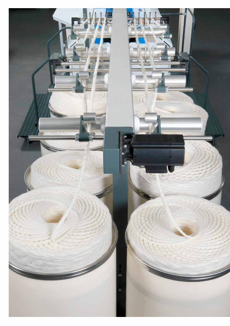
Breaker Draw Frame TD 7Combination of economic efficiency and quality
Breaker draw frames in the first passage are often
underestimated in terms of technology. Howev-
er, these draw frames also contribute to a consist-
ent and reproducible yarn quality. For this reason,
Truetzschler has decided not to make any compro-
mises concerning technology and quality. Thus, the
TD 7 is also equipped with the high-end drafting sys-
tem of the autoleveller Draw Frame TD 8 with all its
advantages:
• 4-over-3 drafting system geometry
• Pneumatically loaded top rolls, separately control-
lable
• Speed-controlled drives
• Pressure bar in main draft area
• Pneumatic web threading
The two-in-one space concept The drafting system is positioned directly on the can
changer. Thus, the installation width required for the
breaker Draw Frame TD 7 is not more than the can
changer itself.
Reduced energy consumption The concept for energy optimization starts in the
most effective key areas:
• The perfect continuous suction works at a low,
energy-saving negative suction pressure.
• Energy-intensive mechanical gears have been
completely eliminated on the TD 7.
• The coiler plate is equipped with an individual drive
and the main drive is infinitely variable.
/ Breaker draw frames

17Draw frames
Less maintenance – more productive time Each hour spent on maintenance is an hour lost for
production. Due to individual drives and elimination
of complex gears, maintenance and cleaning have
been reduced to a minimum. Cleaning work is
facilitated by the opening of only a few large-space
panels without the use of tools:
Convenient and simple operationAs is common with Truetzschler, the Truetzschler
breaker Draw Frame TD 7 is equipped with its own
microcomputer control. Operation takes place on the
colour touch screen. This is also the place where, for
instance, the drive speeds are set. The tension draft
to the draw frame can be optimized in a very sen-
sitive manner due to the individual SERVO CREEL
drive. This also applies to the optimization of the sliv-
er coiling geometry in the can, since the can plate
features a separate drive as well.
The TD 7 is equipped with individual sliver monitoring in the feed area of the draw frame.
Breaker draw frames /
As with the TD 8, operation takes place from the
side. The drafting system opens up to the back from
the position of the operator. The operator has optimal
access to an unobstructed and ergonomic working
area.

18 Draw frames / Autoleveller draw frames
Autoleveller Draw Frame TD 8 A draw frame that optimizes itself

19Draw framesAutoleveller draw frames /
As quality filter of the spinning mill, the draw frame has an important function: preventing errors in the sliver which inevitably lead to yarn defects. Because quality can no longer be improved after the draw frame.
The decisive factor is the sliver quality after the
last draw frame passage. Precisely this is the key
strength of the Truetzschler autoleveller Draw Frame
TD 8. It is available in two versions:
1. For the high-production area up to 1,000 m/min,
the TD 8 is the perfect solution.
2. For combing mills with a delivery speed up to
600 m/min, the TD 8-600 is ideal.
Both are specialists in their respective application
and are appropriately equipped.
Less errors mean more productivityThe groove and sensing roll unit DISC LEVELLER
integrated into the Truetzschler autoleveller Draw
Frame TD 8 sets a new quality standard: a draw
frame sliver CV1m of 0.4 % or less and a yarn count
variation clearly below 1% are the realistic goal set
by modern spinning mills.
The total draft is specified in the spinning plan. The
break draft is material-related and quality-relevant.
An incorrect setting can result, for instance, in an
unnecessarily large number of imperfections and re-
duced yarn strength, as well as lower efficiency at
the spinning machine.
The optionally available self-optimizing function
AUTO DRAFT ensures that the break draft on the
Truetzschler autoleveller Draw Frame TD 8 is always
perfectly set. The ideal main drafting point is auto-
matically determined by the standard self-optimizing
function OPTI SET.
DISC LEVELLER grooved roll and sensing roll unit

20 Draw frames
AUTO DRAFT Self-adjusting perfection
The break draft of the autoleveller draw frame is op-
timized fully automatically. Within one minute the
optional AUTO DRAFT module automatically recom-
mends the ideal, material-specific distribution of the
entire draft between break draft and main draft. The
degree of the break draft has a major influence on
evenness and strength of yarn, number of imperfec-
tions and running properties of the spinning machine.
Self adjustment at the touch of a buttonAt the touch of a button, the draft force is measured
along the entire draft zone. Within 60 seconds, AUTO
DRAFT has collected all the necessary information
and determined the ideal degree of the break draft.
As soon as the operator acknowledges this value on
the screen, the optimization is finished.
Suitable for all materials AUTO DRAFT is basically suitable for all materials
since it takes all major factors into account:
• Fed fiber mass
• Fiber characteristics (e.g. crimping)
• Fiber-fiber friction
• Fiber-metal friction
• Machine settings
• Ambient atmosphere, etc.
The optimization potential of AUTO DRAFT is particu-
larly high when drawing man-made fibers.
Trouble free lot change When a spinning mill produces only one material it is
sufficient to equip only one individual draw frame as
"pilot machine" with AUTO DRAFT. This draw frame
is used to determine the optimum break draft and
to subsequently transfer it to the other machines. In
highly flexible installations with different materials
that are subject to frequent change it is practical to
equip all draw frames with AUTO DRAFT.
Result of the automatic break draft determination
The ideal point is calculated from a
large number of single measurements
Start of the automatic break draft determination
Ideal point for break draft
Break draft
The principle of self-adjustment AUTO DRAFT optimizes the break draft for the autoleveller draw frame fully automatically. In less than one minute the system, which can be optionally integrated into the Draw Frame TD 8, makes an automatic recommendation for the ideal material-specific break draft.
Duration of optimization: 60 secMaterial supply: 600 m sliver length
Bre
ak d
raft
for
ce
1.0
0.9
0.8
0.7
0.6
0.5
0.4
0.3
0.2
0.1
0
1,0 1,1 1,2 1,3 1,4 1,5 1,6 1,7 1,8
The video shows an animation of the AUTO DRAFT function.
Scan page with Smartview.
SCAN
/ Autoleveller draw frames

21Draw frames
OPTI SET The main drafting point determines the quality
In the past, lengthy laboratory test runs with slivers
were required to accurately establish the extremely
important main drafting point. With the Truetzschler
autoleveller Draw Frame TD 8, this is not necessary.
The self optimizing function OPTI SET automatically
determines the optimum value by considering ma-
chine settings, material characteristics and ambient
atmosphere.
A sensor scans the fed slivers and initiates a corre-
sponding time-delayed levelling action as soon as the
material has reached the main draft zone. This time
delay between measurement and levelling action de-
The distance between sensor and main drafting zone is approx. 1,000 mm
Principle of the OPTI SET self-optimizing functionAfter input by the operator, the draw frame starts with a standard value and successively checks slightly deviating values. Parallel to this process, the CV values of the fed slivers and the CV values of the delivered draw frame sliver are measured and compared.
The thus determined optimal main drafting point is recommended to the operator who acknowledges the setting on the screen. This completes the setting process extremely fast, and the otherwise common sliver and laboratory tests are no longer necessary.
termines the main drafting point. Its exact position
depends, among other things, on machine settings,
material and ambient atmosphere.
Starting point
1,000 1,001 999 998 999 998
Ideal main drafting point
CV
valu
e
Autoleveller draw frames /

22 Draw frames
SERVO DRAFT Extremely short correction lengths for optimized sliver quality
Deviations from the target sliver weight have a se-
rious impact on product quality, and thus on the
economic efficiency within the process chain. The
Truetzschler autolevelling system SERVO DRAFT
provides highly dynamic compensation of deviations
from the target weight. This degree of short-term lev-
elling cannot be realised with conventional concepts.
SERVO DRAFT allows reliable optimization of sliver
quality at this high level since it links mechanical and
electrical components with "expert knowledge" in an
intelligent way.
DISC LEVELLER sets a benchmark in qualityWith the groove and sensing roll unit DISC LEVELLER
it is possible to reach a draw frame CV1m of 0.4% or
less and a yarn count variation clearly below 1.0 CV%!
Thus, the quality objectives of modern spinning mills
are achieved in a reproducible way. The sensor is
based on friction-free, fiber-friendly measurement.
The high contact pressure ensures that deviations
in material thickness are put on the same level
as actual mass deviations. The signals of the
DISC LEVELLER are translated by SERVO DRAFT
after a delay into draft changes: the result is a
perfectly levelled sliver and consistent sliver count
stability. During lot changes with changed sliver
masses, the groove and sensing rolls can be quickly
and easily exchanged.
Values and knowledge for increased evennessThe levelling of Draw Frame TD 8 combines precise
measured values with "expert knowledge": empirical
values integrated into the software. This results in a
significantly increased sliver evenness. For applica-
tions below 600 m/min in combing, the TD 8-600 of-
fers fine-tuning of the levelling software with adapt-
ed motors.
Levelling also during can changeShort-term levelling with SERVO DRAFT works relia-
bly even at changing draw frame speeds, which typ-
ically occur before and after can change. The draw
frame control permanently processes the incoming
signals and directly controls the servo motors. Thus,
every metre of draw frame sliver is of optimal quality.
This, in contrast, cannot be achieved by draw frames
with unregulated main motors.
TD 8 with AUTO DRAFT option, with three servo
motors
Third servo motor when equipped with AUTO DRAFT
Servo motor 1 Servo motor 2The video shows an animation of the DISC LEVELLER function.
SCAN
DISC LEVELLER grooved roll and sensing roll unit
Scan page with Smartview.
/ Autoleveller draw frames

23Draw frames
Digital Truetzschler servo motorsIncreased precision, reduced use of energy and maintenance
The direct, infinitely variable drive by means of ser-
vo motors and the elimination of differential gears or
change wheels have a positive impact on the current
consumption of the draw frame. Depending on ap-
plication, the power consumption is between 0.020
and 0.030 kWh per kg of produced draw frame sliver.
Speed and sliver count easy to set In contrast to other draw frames, parameter changes
such as draft can easily be performed on the TD 8
on the touch screen, without replacement of change
wheels. Another advantage in terms of user comfort
and quality are the storable and always retrievable
settings for every material processed.
Lowering maintenance – increasing productivityThe concept of our draw frames is largely mainte-
nance free. This, among other things, is ensured by
maintenance-free motors, permanently lubricated
bearings and easy access of components without
tools. The drafting system is easily accessible by
simply opening a flap on the operator side. The top
rolls can be removed from the load supports at the
touch of a button. Threading is reliably performed
with the help of pneumatics. The high-capacity filter
box without troublesome mechanism must seldom
be emptied. Smooth, shape-optimized components
prevent fiber build-up and contaminations. Mainte-
nance times are drastically reduced.
SERVO CREEL
Servo motor 5
DISC LEVELLER
Servo motor 2
Servo motor 1
Servo motor 3
AUTODRAFT
Can coiler plate
DISC MONITOR
Motor 4
The drafting cylinders are directly powered by digital servo drives. The diagram shows autoleveller Draw Frame TD 8 with AUTO DRAFT option
Autoleveller draw frames /

24 Draw frames
Autoleveller Draw Frame "COMPACT" TD 8C Compact dimensions, bundled performance
The COMPACT installation means shorter distances for the operator. The installation width of the installation shown here with creel in two rows for cans with 1,200 mm diameter corresponds to the one of the breaker Draw Frames TD 9T with a delivery to JUMBO CANS.
The autoleveller Draw Frame "COMPACT" TD 8C is the Truetzschler solution for minimal space requirement. The identifier C = COMPACT characterises the installation solution for this machine.
/ Autoleveller draw frames

25Draw frames
Single head or double head draw frames Concerning autoleveller draw frames, there is no uni-
form response to this decision. For the most part,
autoleveller draw frames require independent units
and have only a few components that can be shared.
The only thing in favour of double head draw frames
is reduced space requirement.
Reduced space requirement and short distances for the operatorThe draw frames are directly next to each other,
without any space in between. The left operator plat-
form of one draw frame is the right operator platform
of the other draw frame. There is sufficient operator
space between the can rows in the creel.
Why decide between single head and double head draw frames? To form compact units, the COMPACT concept
also allows the combination of more than two draw
frames. If, for instance, five draw frames are re-
quired according to spinning plan, six heads must be
installed when using double head draw frames.
With Truetzschler COMPACT draw frames it is pos-
sible to combine three or more draw frame heads,
e.g. five.
The most flexible installation conceptIn general, Truetzschler draw frames offer all variants
necessary for the respective application-oriented re-
quirements:
• Creel in one or two rows
• Creel for 6-fold or 8-fold doubling
• Creel for 600, 1,000 mm cans and
JUMBO CANS 1,200 mm
• Creel adjustable in height to the selected can hight
• SERVO CREEL or feed creel
• Can changer with active or passive can supply
• Can changer for cans with rolls or transfer to a
can carriage
All advantages also available in combingThe COMPACT installation concept is of course also
available for the draw frame version TD 8-600C, the
special draw frame after the comber.
The economic advantage of the larger can format can
also be used for this draw frame. The Truetzschler
Comber TCO 12 can be equipped with can changers
for 1,000 mm and 1,200 mm can diameters.
Space-saving installation of autoleveller Draw Frame TD 8C
Autoleveller draw frames /

26 Draw frames
Integrated Draw Frame IDF 2More economic efficiency in rotor spinning
Only the Truetzschler card/draw frame linking combine all the
advantages of the Card TC 15 with reliable and successful draw frame
technology. Thus, in addition to economic advantages, quality is also
measurably improved.
The 1 zone drafting system of the IDF 2 provides an excellent sliver
evenness and a significantly better yarn evenness. The better quality
is evident in the uniform fabric appearance.
Also shorter spinning processThere is no shorter spinning process than feeding the card sliver
directly on the OE rotor spinning machine. This requirement is also
perfectly met by the Integrated Draw Frame IDF 2.
Multidimensional advantages from fewer process steps: Reducing investments, lowering workload, eliminating errors, saving space. Particularly in the spinning mill with its many machines, reduced installation space quickly multiplies into large economic advantages. The Integrated Draw Frame IDF 2 achieves this by direct linking to the Truetzschler Card TC 15 in the rotor spinning mill.
/ Autoleveller draw frames

27Draw framesAutoleveller draw frames /

28 Draw frames
Economic advantages in production:
• Significantly lower space requirement
• Less cans required
• Simplified can transport
• Lower current consumption
• Reduced personnel and operating costs
These advantages are made possible by the intel-
ligent design of the IDF 2 system: Since the draw
frame unit is positioned above the can changer, the
IDF 2 requires no more space than a regular can
changer.
The integrated draw frame IDF 2 with
automatic can changer
Compared to other draw frame slivers, the increased
sliver adhesion and adapted fiber orientation results
in a better running behaviour during further process-
ing.
The IDF 2 allows processing of all fibers common
in rotor spinning. This solution features improved
yarn quality and increased economic efficiency.
Integrated Draw Frame IDF 2Improved quality and optimized economic efficiency
OpeningCleaningBlending
Rotor spinning
Card TC 15 with Integrated Draw Frame IDF 2
OpeningCleaningBlending
Card TC 15 Draw Frame TD 9 Draw Frame TD 8
Truetzschler OE-line
Conventional line
/ Autoleveller draw frames

TC 15 + IDF 2 TC 15 + TD 7 TC 15 + TD 7 + TD 8
60
50
40
30
20
10
0TC 15 + IDF 2 TC 15 + TD 7 TC 15 + TD 7 + TD 8
TC 15 + IDF 2 TC 15 + TD 7 TC 15 + TD 7 + TD 8
TC 15 + IDF 2 TC 15 + TD 7 TC 15 + TD 7 + TD 8
È
323,936
239,187
29Draw frames
Fully automatic synchronisation of the delivery speed with the card by regulating the sliver sagging between the machines by means of light barriers.
Comparisons of direct spinning IDF 2 with one and two draw frame passages for OE yarn NE 20 cotton
Yarn count variations
Yarn evenness
Energy costs
Yarn imperfections
Yarn strength
Automatic sliver separation during can changingThe can changer for the IDF 2 is largely identical
to the one of Draw Frame TD 8 and is designed
for the standard can diameters. The can height
ranges between 900 and 1,500 mm. The sliv-
er is automatically separated during can change.
84,000 US$. and more savings in energy costs (per card 180 kg/h, 8,400 production hours/year.Calculated card, filter and building costs)
14.4
14.0
13.6
13.2
12.8
12.4
12.0
Neps +280 %Thick places + 50 %Thin places – 50 %
13.8
13.6
13.4
13.2
13.0
12.8
12.6
4.0
3.6
3.2
2.8
2.4
2.0
1.6
1.2
0.8
0.4
0.0
The low value has a positive impact on the fabric appearance, particularly on knitted fabrics
360,000
240,000
120,000
0
Ener
gy c
osts
US$
/ye
ar
other spinning mill with autoleveller draw frame
Example spinning mill with TC 15 and IDF 2
180 kg/h – 8,400 h/year – 0.112 US$ / kWh
cN/
tex
1/ km
CV
%C
Vm%
10
m
it's true
Autoleveller draw frames /

540 m2 280 m2
540 m2 280 m2
30 Draw frames
The Integrated Draw Frame IDF 2 is directly connect-
ed to the card. Due to this concept the draw frames
are eliminated; as a result, the space otherwise re-
quired for the draw frames with reserve can storage
is not needed.
Advantages of direct card and draw frame combination:• Less tied up capital due to significantly smaller
material buffer
• Shorter throughput times
• Reduced operating work
• Reduced building area
Sensor to determine sliver count (top) and quality sensor (bottom)
Levelling quality without compromises Before being fed into the drafting system, the card
sliver is scanned directly by the tried and tested
Truetzschler sliver sensor; then it is levelled via the
drafting system. The close physical proximity of
measuring point and drafting system allows reliable
levelling of the draft. To ensure that every metre in
the can has the desired quality, the sliver is perma-
nently checked by a second sensor positioned imme-
diately behind the drafting system.
Simple and clear operation via the card displayThe installation space required at same output is dramatically reduced.
Combination IDF 2 and TC 15Working together for more economic efficiency
48% less space requirement due to Integrated Draw Frame IDF 2
/ Autoleveller draw frames

31Draw frames
Truetzschler combined the compactness of a simple
drafting system with the performance of a fully-
fledged autoleveller draw frame to ensure a high
level of quality.
The advantages:
• Maintenance-free, digitally controlled servo drives
• Low mass inertia for high levelling dynamics
• Draft up to 3-fold
• Delivery speeds up to 700 m/min
• Controlled material storage for trouble-free can
changing
• Truetzschler quality sensors in the feed and deliv-
ery area
• Permanent monitoring of sliver quality
The drafting system is integrated in the production
flow / sliver run and consists of reliable Truetzschler
components. This includes also technical highlights,
like for instance the pneumatic load of the top rolls.
Top roll coatings with twice the service life Savings are also achieved with the top roll coatings
in the new IDF 2. On the one hand, the top rolls are
now in an asymmetric position in the drafting sys-
tem, while at the same time the loading cylinders
are symmetrical arranged in the proven way. This
facilitates easy turning of the top rolls by 180° after
the coatings wear off, thus doubling their service life.
The drafting system was also modified to a 1-zone
drafting system to improve sliver quality. In addition,
the optimization effort and thus the service costs are
lowered by extremely simple settings.
Top rolls in open drafting system
Top rolls (beige) can be turned by 180° after wear of the top roll coatings (wear shown in red).
Increased dynamics in levelling Due to a more powerful, maintenance-free levelling
motor and reduced masses in the drafting system,
the Integrated Draw Frame IDF 2 features increased
dynamics and a faster response.
Very good accessibility The casing of the IDF 2 can be opened quickly and
without tools. For operation and maintenance pur-
poses, it is simply flipped open in front and back.
This ensures that service work can be performed in a
quick and uncomplicated manner.
Drafting system and motors allow quick and easy access
Complete autoleveller draw frame Advantage: space-saving design
Autoleveller draw frames /

32 Draw frames
JUMBO CANS 1,200 mmThe new economic efficiency – exclusively at Truetzschler
The larger the cans, the greater the efficiency of the downstream machine. Greatest economic advantage: 43% longer runtime in the creel results in reduced downtimes on autoleveller draw frame or Superlap. In practice, efficiencies can be increased by 1.5 - 2%.
The filling quantity in the cans is determined by a
number of factors. Larger can dimensions have a
positive influence on:
• Efficiency
- unwinding in the creel of the downstream
machine
- filling of the cans
• Number of
- can transports
- cans required
• Lower personnel costs
• Quality improvement
43 % more draw frame sliver per canCompared to a can with 1,000 mm diameter, a
JUMBO CAN with the new 1,200 mm diameter for-
mat holds 43 % more draw frame sliver. The logical
consequence is a reduction of downtimes of up to
43 % for the can change. The result is an improved
overall draw frame efficiency.
Can transports reduced by 30 %The full cans must be transported from the break-
er draw frame to the autoleveller draw frame. In a
spinning mill with an annual production of 10,000 t
this means more than 190,000 transports per year
or approx. 24 per hour. With the new can format,
only 17 can transports per hour are required.
Even at a weight of 76 kg card sliver (23 kg more than
in 1,000 mm cans), the 1,200 mm JUMBO CANS can
easily be moved across the flat hall floor by means of
smooth-running ball castors.
Less cans at same material bufferTo ensure trouble-free operation, material buffers be-
tween the production steps are practical. Thanks to
the new can concept, less cans are needed for the
same amount of material in the buffer.
43 %
more draw frame sliver in the new Truetzschler JUMBO CANS
Cans and space required for 1,000 kg material buffer
19 cans with 1,000 mm, space required: approx. 20 m2
13 cans with 1,200 mm, space required: approx. 20 m2
/ JUMBO CANS 1,200 mm
it's true

33Draw frames
The JUMBO CANS 1,200 mm are easy to move
JUMBO CANS 1,200 mm /

34 Draw frames
Less personnel requiredLess can transports and less can changes in the creel
reduce personnel requirements or increase person-
nel efficiency: One person can operate more draw
frames.
Reduced sliver piecings improve the qualityOf course, 30 % less can changes in the creel also
mean 30 % less sliver piecings and thus 30 % less
potential error locations. In our spinning mill example
58,000less sliver piecings/year significantly improve the quality.
with a production of 10,000 t per year, 58,000 fewer
sliver piecings are required at the autoleveller draw
frame.
If JUMBO CANS 1,200 mm are not feasible for op-
erational reasons, 1,000 mm cans with an increased
height of 1,500 mm provide an alternative. They hold
approx. 25 % more draw frame sliver. This solution is
also exclusively offered by Truetzschler.
400,000
300,000
200,000
100,000
Effic
ienc
y in
%
Sliv
er p
ieci
ngs/
year
1,000 mm 1,000 mmCan- in creel of autoleveller draw frame Can- in creel of autoleveller draw frame
600 mm 600 mm1,200 mm 1,200 mm
Production 10.000 t/year
The efficiency of the draw frame increases with larger can formats Less sliver piecings reduce yarn imperfections
100
90
85
80
75
70
it's true
/ JUMBO CANS 1,200 mm

+ 14%
+ 25 %
+ 192 %
+ 43%
+ 43%
+ 77%
+ 73 % + 104 %
+ 9 %+ 9 %
+ 15 % + 13 %
35Draw frames
Up to 1,200 mm diameter, up to 1,500 mm height – these new can dimensions are only available from Truetzschler. The result is a significantly higher capacity and even higher economic efficiency.
15 kg /3,000 m
58 kg /11,600 m
23 kg / 4,600 m
13 kg /2,600 m
83 kg /16,600 m
53 kg /10,600 m 26 kg / 5,200 m 76 kg /15,200 m
66 kg /13,200 m
HEIGHT
1,070 mm
HEIGHT 1,300 mm
HEIGHT 1,200 mm
HEIGHT 1,500 mm
EXCLUSIVELY AT TRUETZSCHLER
DIAMETER 1,200 mm
EXCLUSIVELY AT TRUETZSCHLER
JUMBO CANS
DIAMETER 450 mm
DIAMETER 600 mm
DIAMETER 1,000 mm
JUMBO CANS 1,200 mm /

36 Draw frames
Automatic can changerFlexibility and high efficiency
New, universal and highly flexibleThe can changer for cans ranging from 400 to 600 mm
diameter has been newly designed and adjusted to
the breaker Draw Frame TD 7, the autoleveller Draw
Frame TD 8 and the Integrated Draw Frame IDF 2
and the Truetzschler cards. These can changers func-
tion on the principle of rotation.
The can changers can be adapted to the respective
requirements with greatest precision:
• Cans with or without balls castors
• Cans with 400, 450, 500 or 600 mm diameter
• Can heights 900 to 1,500 mm
• Under floor or above floor
• Passive or active empty can feeding
• Delivery of full cans to a delivery ramp, directly
onto the floor or onto a can carriage.
Above floor or under floor?If the structural conditions permit, the advantages of
the under floor version should be used. The empty
cans must not be lifted as high, and the full cans can
be delivered directly onto the floor. The entire can
handling is simplified.
If the hall floor does not allow this version, Truetzschler
also offers an above floor version.
/ Can changer
CAN TRACK or SERVO TRACK? Truetzschler offers two versions of empty can feed-
ing. With CAN TRACK, the cans slide by gravitational
force on an inclined roller track into the change posi-
tion. This version is possible above and under floor.
When using the SERVO TRACK version, the trans-
port of the empty cans is handled by driven belts.
This comfort gain is only practical under floor to pro-
vide the operator with ground-level feeding of empty
cans.
Delivery onto the floor or can carriage?When using the under floor version, the cans are de-
livered directly onto the floor. In case of an above
floor version, the cans are delivered onto an inclined
outlet track. An interface for transfer onto a can car-
riage is also possible.
Maintenance-free sliver separation the intelligent wayWith autoleveller draw frames, sliver separation is
performed automatically during can change by apply-
ing a brilliantly simple solution: The drafting system
motors produce a short thin sliver section that simply
breaks during can changing. In contrast to conven-
tional draw frames with high-maintenance mechan-
ical sliver separation, the typical advantages of the
Truetzschler technology are evident here as well.
The under floor can changer with delivery at floor level is easier to operate
Can changer floor group, above floorCAN TRACK
SERVO TRACK

37Draw framesCan changer /
The simple setting by means of the individual can changer drive allows perfect setting of the coiling geometry.
Automatic can changer for breaker Draw Frames TD 7 and TD 8 as well as IDF 2 (here an above floor version)
Perfect coiling geometry ensures quality for downstream production The sliver coiling geometry of the Truetzschler auto-
leveller draw frames is such that the slivers can be
removed without trouble in further processing. Since
the can plates have a separate drive, they allow in-
finitely variable adjustment. These parts of coiling are
also controlled via the touch screen.

38 Draw frames
SERVO CREEL The new perfection of the creel
/ SERVO CREEL
To ensure an optimal quality base already during sliv-
er feeding into the draw frame area, the separately
driven sliver feed SERVO CREEL was developed – a
typical Truetzschler innovation.
Separate drive: Advantages for increased qualityFor the first time, a creel is equipped with a separat-
ed drive. Due to the lack of a mechanical connection
between creel and draw frame, the tension draft to
the draw frame and thus the running behaviour can
be continuously optimized in a very sensitive man-
ner on the touch screen. In addition, a higher level-
ling dynamics is achieved since the levelling motor
is no longer strained by permanent acceleration and
braking of the creel. The result is a clearly improved
levelling quality. Besides the quality advantages, the
SERVO CREEL is superior to conventional creels also
from an economic perspective.
One idea makes the difference: separate drive with convincing advantages.
The classic alternativeOf course, it is also possible to use a feed creel. The
supports are height adjustable and can be fitted to
the corresponding can height on both versions.

39Draw framesSERVO CREEL /
The drafting system of the breaker Draw Frame TD 7 is mounted onto the can changer, requiring only little space. To maintain the good accessibility to the drafting system, the creel is slightly angled.
Application-oriented creel versions• Feed creel or SERVO CREEL
• 6-fold or 8-fold doubling
• Can set-up in one or two rows
• Can heights 900 to 1,500 mm
• Sliver monitoring:
– Light barriers
– Individual sliver monitoring
The creel versions are configured and provided
according to application.
The video shows how to set the tension draft between creel and draw frame.
Scan page with Smartview.
SCAN

40 Draw frames
OperationIntuitive menu navigation via touch screen
Operation of the draw frames is conveniently per-
formed largely via language-independent symbols or
graphics. Individual operating functions can be dis-
played depending on the situation. Only the displays
and menus that are necessary or practical in the par-
ticular situation appear.
In the event of a machine malfunction, the display
not only shows the point of failure, but also an ac-
cordingly marked detailed picture or diagram of the
fault.
/ Operation
The operator receives all important information via the screen.
All important parameters are clearly displayed with numbers and symbols on the main screen.The video shows the
simple operation on the touch screen.
Scan page with Smartview.
SCAN
41Draw frames
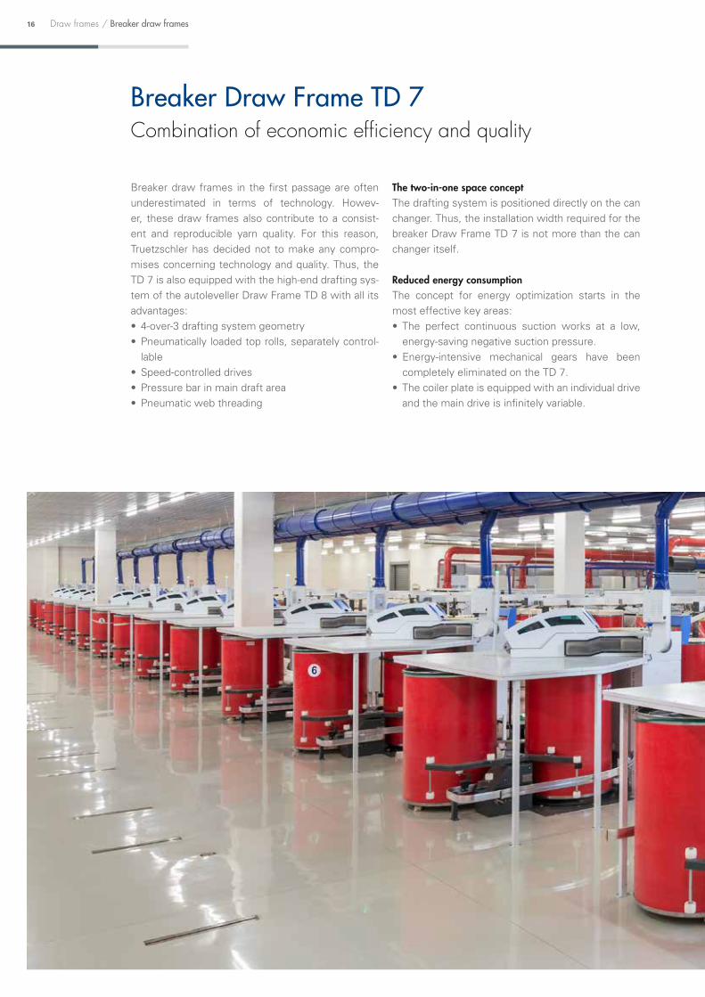
Integrated quality monitoringStandard for Truetzschler
DISC MONITOR: Assurance for consistent sliver countThe robust and reliable quality sensor does not miss
anything: it measures each centimetre of the contin-
uous sliver produced. The permanent quality moni-
toring results in a significant reduction of the other-
wise common laboratory tests.
In the event of irregular of faulty sliver, the
DISC MONITOR sends a warning or shuts down the
draw frame. When and how it responds to specific
causes can be individually configured.
Spectrogram monitoring as standardIf there are deviations from a defined quality limit in
the Spectrogram, quality monitoring reliably shuts
down the autoleveller draw frame. Following this,
the troubleshooting process is shortened by the re-
spective display information: Once an error appears
in the spectrogram, the possible failure source is
marked on the gearing diagram. Thus, quality man-
agement is actively supported.
Operation /
Error display
In the event of a fault, the operator is informed about the type and location of the fault.
Spectrogram
The sensor DISC MONITOR also supplies the data for the Spectrogram. At the touch of a button an error is analysed and the possible causes indicated.
Sliver evenness
The visualisation of the quality data also takes place on the screen.
Log book
The logbook function is only one example of the supporting maintenance and service functions.
The sensor DISC MONITOR permanently monitors the sliver quality

42 Draw frames / T-DATA
T-DATAGETTING FIBERS INTO SHAPE
Watch the My Production
app video on YouTube.
www.myproduction-app.com
M Y P R O D U C T I O N
M Y S U C C E S SThe new My Production app for T-DATA users
T-DATA Recognising great potential in small details
All important data in view at all timesThe Truetzschler Online Data Monitoring System
T-DATA gathers all current production and quality
data. Due to its modern web architecture, these data
are also available while on the road. No matter where
you are, Smartphones or tablets allow access to all
important data and error statistics of the machines
connected, individually and also as overview.
Optimization of productionTrends in production can be detected at an early
stage and malfunctions and faults dealt with faster.
This allows a measurable reduction of downtimes
and optimization of machine settings for higher pro-
duction rates. T-DATA makes sure that every metre
of sliver in the can has been checked.
Individual data viewEach customer decides which data is of interest and
how it is to be displayed. The Web interface with
intuitive operation can easily be adapted to individual
requirements. The options range from basic settings
to highly sophisticated functions.
Data can be selected from clearly arranged graphics
or tables over a freely definable period, and com-
pared with each other.
The right sensors at the right places Truetzschler sensors measure where they are need-
ed. Thus, all important quality and production data
that are required for the optimal control of production
are determined. The DISC MONITOR, for example,
permanently monitors the current draw frame pro-
duction and issues a warning as soon as irregularities
occur in the draw frame sliver.
Integration into existing systemsT-DATA can easily be integrated into an existing
ERP or control system. In addition to current data,
it is also possible to transmit and compare past
production data and fault messages via an external
interface. This allows easy use of synergy effects.
For more information, see
the brochure "T-DATA".

Data of the individual machines, for instance, can be read on a tablet PC.
43Draw framesT-DATA /
Comparing two draw frames reveals a sliver fault on one draw frame (in orange).
Watch the film T-DATA with the Truetzschler Spinning App.
Scan page with Smartview.
SCAN

44 Draw frames / Technical data
Breaker draw frames Autoleveller draw framesTD 7 TD 9 TD 9T TD 8 TD 8-600 TD 8C TD 8-600C IDF 2
Maximum delivery speed m/min 1,000 1,000 1,000 1,000 600 1,000 600 700
Can diameter mm 600 1,000 + 1,200 1,000 + 1,200 400 – 600 400 – 600 400 – 600 400 – 600 400 – 600
Can height mm 1,000 - 1,500 1,200 - 1,500 1,200 - 1,500 900 – 1,500 900 – 1,500 900 – 1,500 900 – 1,500 900 – 1,500
Cans without ball castors • – – • • • • •
Cans with ball castors • • • • • • • •
Material: Fibers up to 60 mm • • • • • • • •
Material feed ktex 15 - 50 15 - 50 15 - 50 15 - 50 15 - 50 15 - 50 15 - 50 6 - 10
Draft fold 4 - 10 4 - 10 4 - 10 4 - 11 4 - 11 4 - 11 4 - 11 1 - 3
Air volume of suction m³/h 600 600 1,200 800 800 800 800 350
Negative pressure of suction: -Pa 400 400 480 450 450 450 450 450
Installed draw frame power kW 5.0 5.25 10.5 9.8 6.9 9.8 6.9 4.6
Installed can changer power kW 0.5 0.25 0.5 0.5 0.5 0.5 0.5 0.5
Installed filter power kW 0.9 0.9 0.9 0.9 0.9 0.9 0.9 –
Installed power SERVO CREEL kW 0.6 0.6 1.2 0.6 0.6 0.6 0.6 –
Installed power SERVO TRACK kW 0.3 – – 0.3 0.3 0.3 0.3 0.3
Continuous power consumption depending on application, approx. 0.020 –- 0.030 kWh/kg depending on application, approx. 0.020 –- 0.030 kWh 2.5 kW
Compressed air requirement Nl/h 240 280 560 240 240 240 240 2,800
Noise level dB(A) 84 84 84 84 79 84 79 79
Technical data
DISC LEVELLERIntegrated Draw Frame IDF 2

45Draw framesTechnical data /
Breaker draw frames Autoleveller draw framesTD 7 TD 9 TD 9T TD 8 TD 8-600 TD 8C TD 8-600C IDF 2
Maximum delivery speed m/min 1,000 1,000 1,000 1,000 600 1,000 600 700
Can diameter mm 600 1,000 + 1,200 1,000 + 1,200 400 – 600 400 – 600 400 – 600 400 – 600 400 – 600
Can height mm 1,000 - 1,500 1,200 - 1,500 1,200 - 1,500 900 – 1,500 900 – 1,500 900 – 1,500 900 – 1,500 900 – 1,500
Cans without ball castors • – – • • • • •
Cans with ball castors • • • • • • • •
Material: Fibers up to 60 mm • • • • • • • •
Material feed ktex 15 - 50 15 - 50 15 - 50 15 - 50 15 - 50 15 - 50 15 - 50 6 - 10
Draft fold 4 - 10 4 - 10 4 - 10 4 - 11 4 - 11 4 - 11 4 - 11 1 - 3
Air volume of suction m³/h 600 600 1,200 800 800 800 800 350
Negative pressure of suction: -Pa 400 400 480 450 450 450 450 450
Installed draw frame power kW 5.0 5.25 10.5 9.8 6.9 9.8 6.9 4.6
Installed can changer power kW 0.5 0.25 0.5 0.5 0.5 0.5 0.5 0.5
Installed filter power kW 0.9 0.9 0.9 0.9 0.9 0.9 0.9 –
Installed power SERVO CREEL kW 0.6 0.6 1.2 0.6 0.6 0.6 0.6 –
Installed power SERVO TRACK kW 0.3 – – 0.3 0.3 0.3 0.3 0.3
Continuous power consumption depending on application, approx. 0.020 –- 0.030 kWh/kg depending on application, approx. 0.020 –- 0.030 kWh 2.5 kW
Compressed air requirement Nl/h 240 280 560 240 240 240 240 2,800
Noise level dB(A) 84 84 84 84 79 84 79 79
4-over-3 drafting system technology Individual sliver monitoring in the feed area of the draw frame

46 Draw frames / Equipment and options
1) Automatic synchronisation with the card 2) via the card or card control3) with different sensor
Equipment and options
Equipment and options
Breaker draw frames Autoleveller draw frames
TD 7 TD 9 TD 9T TD 8/ TD 8C TD 8-600/ TD 8-600C IDF 2
Single head version • • – • • •TWIN version – – • – – –Good accessibility to all maintenance and cleaning points • • • • • •Safety panels • • • • • •Modern, energy-saving drives • • • • • •Infinitely variable setting of the delivery speed • • • • • 1)
Individual drive for infinitely variable setting of sliver count and draft – – – • • •Individual can plate drive for optimized sliver coiling • • • • • •4-over-3 drafting system with pressure bar • • • • • –Individual sliver drafting system 2-over-2 – – – – – •Pneumatic load of top roll, individually adjustable • • • • • •Quick relief during standstill • • • • • •Coiler plate with hydro polished tube prevents deposits • • • • • •Integrated suction in drafting system • • • • • •Microcomputer control • • • • • 2)
Data transmission interface to T-DATA ° ° ° ° ° ° 2)
Colour touch screen for operation, maintenance and service • • • • • 2)
Short-term leveller SERVO DRAFT – – – • • •Input sensor DISC LEVELLER – – – • • –Input sensor measuring funnel – – – – – •Automatic sliver count monitoring DISC MONITOR – – – • • 2) 3)
Optimization package TD-OS – Separately driven servo drive for middle drafting system cylinder – Software package AUTO DRAFT for self optimization of draft
– – – ° – –
OPTI SET for perfect levelling quality – – – • •Integrated quality monitoring (sliver count, sliver evenness, integrated spectrogram analysis) – – – • • • 2)
Maintenance management • • • • • • 2)
Feed creel, double-row for up to 8-fold doubling • • • • • –Separately driven SERVO CREEL TD-SC single row for up to 8-fold doubling – ° ° – – –Separately driven SERVO CREEL TD-SC two rows for up to 8-fold doubling ° ° ° ° ° –Automatic rotary can changer under floor • – – • • •Automatic rotary can changer above floor ° – – ° ° °Automatic linear changer under floor – • • – – –Automatic linear changer above floor – ° ° – – –Can magazine CAN TRACK for empty cans • – – • • •Driven can magazine SERVO TRACK for empty cans (only under floor) ° – – ° ° °Interface full can transfer onto can transport carriage (transport carriage provided by customer) – – – ° ° °Continuous suction with monitoring of negative pressure (above and underfloor) • • • • • • 2)
Integrated filter TD-FB with fan, large filter surface and high-volume collecting container ° ° ° ° ° –
• = Series ° = Option

47Draw framesEquipment and options /
Equipment and options
Breaker draw frames Autoleveller draw frames
TD 7 TD 9 TD 9T TD 8/ TD 8C TD 8-600/ TD 8-600C IDF 2
Single head version • • – • • •TWIN version – – • – – –Good accessibility to all maintenance and cleaning points • • • • • •Safety panels • • • • • •Modern, energy-saving drives • • • • • •Infinitely variable setting of the delivery speed • • • • • 1)
Individual drive for infinitely variable setting of sliver count and draft – – – • • •Individual can plate drive for optimized sliver coiling • • • • • •4-over-3 drafting system with pressure bar • • • • • –Individual sliver drafting system 2-over-2 – – – – – •Pneumatic load of top roll, individually adjustable • • • • • •Quick relief during standstill • • • • • •Coiler plate with hydro polished tube prevents deposits • • • • • •Integrated suction in drafting system • • • • • •Microcomputer control • • • • • 2)
Data transmission interface to T-DATA ° ° ° ° ° ° 2)
Colour touch screen for operation, maintenance and service • • • • • 2)
Short-term leveller SERVO DRAFT – – – • • •Input sensor DISC LEVELLER – – – • • –Input sensor measuring funnel – – – – – •Automatic sliver count monitoring DISC MONITOR – – – • • 2) 3)
Optimization package TD-OS – Separately driven servo drive for middle drafting system cylinder – Software package AUTO DRAFT for self optimization of draft
– – – ° – –
OPTI SET for perfect levelling quality – – – • •Integrated quality monitoring (sliver count, sliver evenness, integrated spectrogram analysis) – – – • • • 2)
Maintenance management • • • • • • 2)
Feed creel, double-row for up to 8-fold doubling • • • • • –Separately driven SERVO CREEL TD-SC single row for up to 8-fold doubling – ° ° – – –Separately driven SERVO CREEL TD-SC two rows for up to 8-fold doubling ° ° ° ° ° –Automatic rotary can changer under floor • – – • • •Automatic rotary can changer above floor ° – – ° ° °Automatic linear changer under floor – • • – – –Automatic linear changer above floor – ° ° – – –Can magazine CAN TRACK for empty cans • – – • • •Driven can magazine SERVO TRACK for empty cans (only under floor) ° – – ° ° °Interface full can transfer onto can transport carriage (transport carriage provided by customer) – – – ° ° °Continuous suction with monitoring of negative pressure (above and underfloor) • • • • • • 2)
Integrated filter TD-FB with fan, large filter surface and high-volume collecting container ° ° ° ° ° –

H2
H1
2990
299061
033
00
600
1350
L2
L4
B2
B4
L2
L4
B2
B4
48 Draw frames / TWIN Draw Frame TD 9T
TWIN Draw Frame TD 9T
TD 9TDimensions Can delivery 1,000 or 1,200 mm
Can height H1 mm 1,075 1,100 1,200 1,225 1,300 1,500
Total height H2 1) mm 1,790 1,815 1,915 1,940 2,015 2,215
1) Above floor versions minus 80 mm
Creel dimensions Can- 1,000 mm Can- 1,200 mm
Creel, 1 rowsTotal length L2 mm 12,055 13,653
Total width B2 mm 3,300 3,700
Creel, 2 rowsTotal length L4 mm 7,805 8,703
Total width B4 mm 4,600 5,400

L1
L2
B1
B2
L1
L2
B1
B2
H2
H1
2990
2990
610
3300
600
1350
49Draw framesTWIN Draw Frame TD 9 /
Breaker Draw Frame TD 9
TD 9Dimensions Can delivery 1,000 or 1,200 mm
Total can height H1 mm 1,075 1,100 1,200 1,225 1,300 1,500
Total height H2 1) mm 1,790 1,815 1,915 1,940 2,015 2,215
1) Above floor versions minus 80 mm
Creel dimensions Can- 1,000 mm Can- 1,200 mm
Creel, 1 rowsTotal length L1 mm 12,055 13,655
Total width B1 mm 1,950 2,150
Creel, 2 rowsTotal length L2 mm 7,805 8,705
Total width B2 mm 2,300 2,400

max
. 210
0
H2
H1
2448
13565
2070
- 35
10
610
H2
max
. 210
0
13565
1475
H1
50 Draw frames / Breaker Draw Frame TD 7
Breaker Draw Frame TD 7
Autoleveller Draw Frames TD 8 and TD 8-600
Dimensions TD 8 + TD 8-600Can height H1 mm 900 1,000 1,070 1,100 1,200 1,300 1,400 1,500
Total height H2 mm 1,675 1,775 1,845 1,875 1,975 2,075 2,175 2,275
Dimensions TD 7Can height H1 mm 1,050 1,100 1,200 1,300 1,400 1,500 1,525
Total height H2 1) mm 1,855 1,905 2,005 2,105 2,205 2,305 2,330

L1
G
L2
B2
B1
610
H2
1475
max
. 210
0
H1
13565
B261
0
H2
1475
max
. 210
0
H1
13565
B2
51Draw framesAutoleveller Draw Frames TD 8 /
Autoleveller Draw Frames TD 8C and TD 8-600C
Creel dimensions Can- 1,000 mm Can- 1,200 mm
Creel, 1 rowsTotal length L1 mm 11,390 12,890
Total width B1 mm 3,020 3,420
Creel, 2 rowsTotal length L2 mm 7,190 7,890
Total width B2 mm 4,600 5,400
Dimensions TD 8C + TD 8-600CCan height H1 mm 900 1,000 1,070 1,100 1,200 1,300 1,400 1,500
Total height H2 1) mm 1,675 1,775 1,845 1,875 1,975 2,075 2,175 2,275
1) plus adjustment (max. 100 mm)

LLM
580
P
HBM
B
LLM
580
H
BMB
P
LLM
580
H
BMB
P
52 Draw frames / Integrated Draw Frame IDF 2
Dimensions Can- 400-600 mm Can- 1,000 mmHeight of bottom plate P mm 65 95
Width without platform B mm 2,110 2,750
Total width BM mm 2,427 2,897
Length without platform L mm 1,850 2,250
Total length LM mm 2,140 – 2,390 2,475 – 2,737
Height H mm 935 – 1,510 950 – 1,575
Under floor
Integrated Draw Frame IDF 2

L2 2090 680
L1
B
196 H
1
65L2 2090 680
L1
B
196 H
1
65
L2 2090 680
L1
B
131H1
65L2 2260
L1
B
H1
65
53Draw framesCan changer /
Dimensions Can changer versionsInner can diameter mm 400 450 500 600
Total can height H1 mm 900 – 1,500
L1 mm 3,690 3,750 3,770 3,840
L2 mm 930 965 1,000 1,070
B mm 1,250 1,300 1,400 1,600
Under floor SERVO TRACK Under floor CAN TRACK
Above floor CAN TRACK delivery track Above floor CAN TRACK can carriage
Can changer versions TD 7, TD 8, IDF 2

voluntary certification
www.machines-for-textiles.com/blue-competence
54 Draw frames
Truetzschler GmbH & Co. KG TextilmaschinenfabrikPostfach 410164 · 41241 Moenchengladbach, GermanyDuvenstr. 82-92 · 41199 Moenchengladbach, GermanyTelephone: +49 (0)2166 607-0 · Fax: +49 (0)2166 607-405e-mail: [email protected] · www.truetzschler.com

Draw frames 55
Legal disclaimer:The brochure has been compiled to the best of our knowledge and in good faith with the utmost care. However, it may be subject to type errors or technical changes for which we assume no liability. The photos and illustrations are purely informative in nature and in part show special equipment options which do not feature in the standard scope of delivery. We provide no guarantee as to the current nature, correctness, completeness or quality of the information provided. Warranty claims for material or immaterial damage against us or the respective author based on the use or forwarding of the information provided, even if the information is incorrect or incomplete, cannot be asserted. Our provided data is non-binding.
Print No.: 18027-07/18-en · Agentur Brinkmann GmbH, Krefeld

w w w . t r u e t z s c h l e r . c o m
Fiber preparat ion ins tal lat ions: Bale openers · Mixers · Cleaners/Openers
Foreign par t separators · Dust separators · Tuf t blenders
Waste c leaners | Cards | Draw frames | Combing machines
Bale openers/Mixers | Card feeders | Cards/Cross lappers | Wet laying l ines
Hydroentangl ing, needl ing, thermo- and chemical bonding l ines
Finishing, dr ying, winding, s l i t t ing machiner y
Fi lament l ines: Carpet yarns (BCF) · Industr ia l yarns
Metal l ic wires: Cards · Cards long s taple · Cards nonwovens · Open-end spinning
Flat tops | Fi l le ts
Carding segments | Ser vice machines | Ser vice 24/7
G E T T I N G F I B E R S I N T O S H A P E – S I N C E 18 8 8