Infiltrated Photonic Crystal Fibers for Sensing Applications
32
sensors Review Infiltrated Photonic Crystal Fibers for Sensing Applications José Francisco Algorri 1,* , Dimitrios C. Zografopoulos 2 , Alberto Tapetado 1 , David Poudereux 3 and José Manuel Sánchez-Pena 1 1 GDAF-UC3M, Displays and Photonics Applications Group, Electronic Technology Department, Carlos III University of Madrid, Leganés, 28911 Madrid, Spain; [email protected] (A.T.); [email protected] (J.M.S.-P.) 2 Consiglio Nazionale delle Ricerche, Istituto per la Microelettronica e Microsistemi, 00133 Rome, Italy; [email protected] 3 Alter Technoology TÜV Nord S.A.U. C/La Majada 3, 28760 Tres Cantos, Madrid, Spain; [email protected] * Correspondence: [email protected]; Tel.: +34-916-245-964 Received: 31 October 2018; Accepted: 28 November 2018; Published: 4 December 2018 Abstract: Photonic crystal fibers (PCFs) are a special class of optical fibers with a periodic arrangement of microstructured holes located in the fiber’s cladding. Light confinement is achieved by means of either index-guiding, or the photonic bandgap effect in a low-index core. Ever since PCFs were first demonstrated in 1995, their special characteristics, such as potentially high birefringence, very small or high nonlinearity, low propagation losses, and controllable dispersion parameters, have rendered them unique for many applications, such as sensors, high-power pulse transmission, and biomedical studies. When the holes of PCFs are filled with solids, liquids or gases, unprecedented opportunities for applications emerge. These include, but are not limited in, supercontinuum generation, propulsion of atoms through a hollow fiber core, fiber-loaded Bose–Einstein condensates, as well as enhanced sensing and measurement devices. For this reason, infiltrated PCF have been the focus of intensive research in recent years. In this review, the fundamentals and fabrication of PCF infiltrated with different materials are discussed. In addition, potential applications of infiltrated PCF sensors are reviewed, identifying the challenges and limitations to scale up and commercialize this novel technology. Keywords: photonic crystal fibers; optical fiber sensors; optofluidics; plasmonic sensors; liquid crystals 1. Introduction Over the past several decades, the advances in optical fiber technology have undoubtedly improved and reshaped the field of telecommunication technologies [1–4]. In parallel, breakthroughs in optical fiber manufacturing and photonics science have driven the use of fiber-optic components in applications beyond their traditional market. A sector that has significantly benefited from these advances is that of optical fiber sensors [5]. Optical fibers offer the potential for small and lightweight sensors, which are easily multiplexed and exhibit immunity to electromagnetic fields [6]. Nevertheless, despite these advantages, fiber-optic sensing technology had not proven to be an advantageous alternative to traditional sensors for a long time. This lack of success was due to the high cost and complexity of the interrogation techniques [7–12], which largely limited the use of fiber-optic sensors as low-cost components in sensing applications. This trend changed with the ability to engineer the refractive index profile of optical fibers. In 1991, Phillip Russell conceived the idea of a special optical fiber combining the properties of photonic crystals Sensors 2018, 18, 4263; doi:10.3390/s18124263 www.mdpi.com/journal/sensors
-
Upload
khangminh22 -
Category
Documents
-
view
1 -
download
0
Transcript of Infiltrated Photonic Crystal Fibers for Sensing Applications

sensors
Review
Infiltrated Photonic Crystal Fibers forSensing Applications
José Francisco Algorri 1,∗ , Dimitrios C. Zografopoulos 2 , Alberto Tapetado 1 ,David Poudereux 3 and José Manuel Sánchez-Pena 1
1 GDAF-UC3M, Displays and Photonics Applications Group, Electronic Technology Department,Carlos III University of Madrid, Leganés, 28911 Madrid, Spain; [email protected] (A.T.);[email protected] (J.M.S.-P.)
2 Consiglio Nazionale delle Ricerche, Istituto per la Microelettronica e Microsistemi, 00133 Rome, Italy;[email protected]
3 Alter Technoology TÜV Nord S.A.U. C/La Majada 3, 28760 Tres Cantos, Madrid, Spain;[email protected]
* Correspondence: [email protected]; Tel.: +34-916-245-964
Received: 31 October 2018; Accepted: 28 November 2018; Published: 4 December 2018�����������������
Abstract: Photonic crystal fibers (PCFs) are a special class of optical fibers with a periodic arrangementof microstructured holes located in the fiber’s cladding. Light confinement is achieved by meansof either index-guiding, or the photonic bandgap effect in a low-index core. Ever since PCFswere first demonstrated in 1995, their special characteristics, such as potentially high birefringence,very small or high nonlinearity, low propagation losses, and controllable dispersion parameters,have rendered them unique for many applications, such as sensors, high-power pulse transmission,and biomedical studies. When the holes of PCFs are filled with solids, liquids or gases, unprecedentedopportunities for applications emerge. These include, but are not limited in, supercontinuumgeneration, propulsion of atoms through a hollow fiber core, fiber-loaded Bose–Einstein condensates,as well as enhanced sensing and measurement devices. For this reason, infiltrated PCF have been thefocus of intensive research in recent years. In this review, the fundamentals and fabrication of PCFinfiltrated with different materials are discussed. In addition, potential applications of infiltrated PCFsensors are reviewed, identifying the challenges and limitations to scale up and commercialize thisnovel technology.
Keywords: photonic crystal fibers; optical fiber sensors; optofluidics; plasmonic sensors; liquid crystals
1. Introduction
Over the past several decades, the advances in optical fiber technology have undoubtedlyimproved and reshaped the field of telecommunication technologies [1–4]. In parallel, breakthroughsin optical fiber manufacturing and photonics science have driven the use of fiber-optic componentsin applications beyond their traditional market. A sector that has significantly benefited from theseadvances is that of optical fiber sensors [5].
Optical fibers offer the potential for small and lightweight sensors, which are easily multiplexedand exhibit immunity to electromagnetic fields [6]. Nevertheless, despite these advantages, fiber-opticsensing technology had not proven to be an advantageous alternative to traditional sensors for a longtime. This lack of success was due to the high cost and complexity of the interrogation techniques [7–12],which largely limited the use of fiber-optic sensors as low-cost components in sensing applications.
This trend changed with the ability to engineer the refractive index profile of optical fibers. In 1991,Phillip Russell conceived the idea of a special optical fiber combining the properties of photonic crystals
Sensors 2018, 18, 4263; doi:10.3390/s18124263 www.mdpi.com/journal/sensors

Sensors 2018, 18, 4263 2 of 32
(PC) with conventional optical fibers [13]. In 1995, his group suggested the possibility to guide lightby a PC arrangement of microcapillaries running along the fiber axis [14], thus paving the way fora new kind of microstructured fibers called photonic crystal fibers (PCF). PCF broadly extended theoperating field of optical fibers thanks to the high versatility in engineering their optical parametersand the possibility to infiltrate them with gaseous, liquid, or even solid materials.
Photonic crystals are periodic structures that affect the motion of photons in a similar way thatcrystalline lattices affect ions in solids. The periodic structure of PC can extend in one, two or threedimensions. The main PC property is the appearance of photonic bandgaps (PBG), namely forbiddenranges of wavelengths, equivalent to the electronic bandgaps of semiconductors, in which light cannotpropagate through the structure and is therefore reflected. If a low-index or even hollow-core (HC)fiber is surrounded by a 2D photonic crystal, then the bandgap-guiding (BG) mechanism is able toefficiently guide the light in the fiber core. Since the PBG wavelengths cannot cross through theperiodic cladding, light is forced to travel through the central air channel as, for instance, in the PCFshown in Figure 1G.
Figure 1. An assortment of optical (OM) and scanning electron (SEM) micrographs of PCF structures.(A) SEM of an endlessly single-mode solid core PCF; (B) far-field optical pattern produced by the fiberin (A) when excited by red and green laser light; (C) SEM of a recent birefringent PCF; (D) SEM of asmall (800 nm) core PCF with ultrahigh nonlinearity and a zero chromatic dispersion at a wavelengthof 560 nm; (E) SEM of the first photonic bandgap PCF, its core formed by an additional air hole in agraphite lattice of air holes; (F) near-field OM of the six-leaved blue mode that appears when the fibershown in (E) is excited by white light; (G) SEM of a hollow-core photonic bandgap fiber; (H) near-fieldOM of a red mode in hollow-core PCF (white light is launched into the core); (I) OM of a hollow-corePCF with a Kagome cladding lattice, guiding white light, reprinted with permission from [13].
The first performing PCF was manufactured in November 1995. It featured a hexagonalclose-packed array of small air channels and was free of major imperfections or defects [14]. Althoughit turned out that the PCF was a guiding light via the index-guiding (IG) mechanism, from thestructural point of view, it was the first fiber-photonic equivalent of a pure dopant- and defect-freesemiconductor crystal. Most importantly, it demonstrated that the periodicity of the microcapillaries

Sensors 2018, 18, 4263 3 of 32
can be intentionally disrupted by introducing defects, which in the following years led to the designand fabrication of a very broad range of different PCF, as shown in Figure 1.
That first index-guiding PCF consisted of an array of approximately 300 nm air holes spacedby 2.3 µm around a central solid core [15]. It had the property to be single-mode no matter howshort the light wavelength. This can be understood by viewing the array of holes in the cladding asa modal filter. The effective refractive index of the composite glass-air cladding is higher for shorterwavelengths, reducing the index difference between the cladding and the index-guiding solid PCF coreand thus limiting the number of guided modes. A proper selection of the PCF geometry guaranteesthat only the fundamental mode is guided. More detailed studies show that this occurs for d/Λ < 0.4,where d is the capillary diameter and Λ the pitch of the cladding’s hexagonal lattice [16]. By exploitingthis property, very large mode-area fibers were designed offering big improvements in high-powerdelivery, amplifiers, and lasers [17]. Additionally, capillaries with different sizes and shapes can beintroduced in the cladding so as to deliberately break the PCF symmetry and induce very high valuesof birefringence, unachievable by standard optical fibers [18].
Overall, index-guiding PCF are similar to conventional fibers in the sense that their core hasa larger refractive index than that of the cladding. Although standard PCF are made entirely ofsilica, the composite air-hole cladding has a lower effective refractive index than that of the solidcore (Figure 2a), which shows strong wavelength-dispersion. The modes of all single-material,index-guiding PCF are leaky modes because the core refractive index is the same as that beyondthe finite holey cladding. When the latter is composed of a small number of capillary rings, significantconfinement losses may arise [19], also known as geometric losses [20]. As the guided modes areessentially leaky, the decay of the fields is exponential along the direction of propagation. Furthermore,the continuum of radiative modes still exists and the range of propagation constants associated withradiative modes is not disjoint from those of the leaky modes. This complicates the task of identifyingthe leaky guided modes, since a leaky mode can be “lost” within a continuum of radiative solutionsto the wave equations. As a general remark, the complex structure of PCF renders difficult theirmathematical study, and the well-known field of standard optical fibers is of little help, such that inmost cases Maxwell’s equations must be numerically solved [21,22].
Figure 2. Guiding mechanisms in a PCF: (a) index-guiding. (b) bandgap-guiding through the photonicbandgap effect.
When a PCF has a hollow core or, generelly, a lower refractive index in the core than in thecladding, the light is guided by the photonic bandgap effect. The cladding is built by a periodicmicrostructure that forms a two-dimensional photonic crystal in the transverse plane, whose dielectricproperties are characterized by photonic bandgaps. The periodic structure inside the PCF is locallybroken, by creating the lower-index core usually by omitting one or more glass capillaries duringfabrication. By proper geometrical design, it is possible to achieve light guidance in the hollow coreof the PCF at those wavelengths for which transverse leakage through the cladding is forbidden bycorresponding bandgaps (Figure 2b). As a result, light can be guided in a mostly empty core withan effective modal index close to unity. Indeed, photonic crystals with two- or three-dimensionalperiodicity can be seen as generalizations of Bragg mirrors [10]. The simple approach that employsreflection and transmission matrices cannot be applied analytically. The aim of using periodicity

Sensors 2018, 18, 4263 4 of 32
in two dimensions, in the PCF cladding, is to achieve an omnidirectional bandgap. Bandgaps canexist for all directions of propagation in the plane of periodicity, and propagation of light in anytransverse direction can be forbidden. When a bandgap exists regardless of the propagation directionand polarization, the photonic bandgap is complete. Inserting a defect in the middle of the structurepermits the existence of a propagating mode in the perturbed crystal. If the propagation constant ofthis mode coincides with a bandgap in the transverse plane, then the mode will be confined in thelocality of the defect, namely the PCF core.
Hollow-core PBG guidance had to wait until the technology could afford larger air-filling fractionsessential to achieve a photonic bandgap. The first fiber had a triangular lattice of holes and a relativebig hollow core [23]. The main advantage of hollow-core PCF is its capability to guide almost100% of the optical power in air, leading to very low nonlinearities, high power thresholds, exoticdispersion properties and relatively low propagation loss. An attenuation of 1.2 dB/km at 1620 nm wasdemonstrated in 2005 [24]. Recently, a hollow-core PCF was reported, which provides a combinationof low losses (3.5 dB/km) and wide bandwidth (160 nm), employed to transmit 37× 40 Gbps channelsat 0.2904 m/ns, i.e., 1.54 ns/km faster than a conventional fiber. This represents the first experimentaldemonstration of fiber-based wavelength-division multiplexing data transmission at a speed closeto (99.7%) that of light in a vacuum [25]. Moreover, it has been demonstrated that by proper designPCF can guide light by both index- and bandgap-guiding simultaneously, in what is termed ashybrid-guiding (HG). The PCF transmission zone is deeply widened and consists of the juxtapositionof bandgap- and index-guiding zones [26]. The properties of such specialty fibers make them goodcandidates for new applications as low-loss guidance and high power delivery.
The presence of a microstructured cladding with capillaries running along the fiber axis boostsPCF with features unachievable by their conventional counterparts. Apart from providing a meansto tailor the PCF properties, the microholes in the PCF cladding provide a natural platform for theirinfiltration with various sorts of materials, which can significantly enhance their performance orenable new functionalities. Moreover, thanks to the wavelength dispersion of the effective claddingindex, the infiltrated material can strongly interact with guided light via evanescent-field effects in alab-on-a-fiber platform, not achievable in all-solid optical fibers.
Infiltrated PCF have been used in, for instance, supercontinuum generation [27–29], guiding atomsthrough hollow core PCF [30–33] and even loading Bose–Einstein condensates into the fiber [34,35].As another example, increasing attention is focused on PCF infiltrated with liquid crystals (LC) in whathas been termed as photonic liquid crystal fibers (PLCF), where the high versatility of PCF is combinedwith the active properties of LC. For instance, following the first demonstration by Larsen et al. [36],PLCF with thermally [37], electrically [38,39], polarization [40] and optically tunable properties [41]have been demonstrated.
This review focuses on infiltrated photonic crystal fibers for sensing applications. Dependingon the PCF type, geometry and the infiltrated material, numerous PCF sensors have been thus fardemonstrating targeting sensing of temperature, refractive index, electric and magnetic fields, gases,and pressure among others. The structure of this work is based on the type of infiltrated material,highlighting the particular opportunities and challenges associated with each category.
In particular, Section 2 presents experimental protocols that enable PCF infiltration with gaseous,liquid, or solid materials, discussing the particular techniques, which apply in each of the three cases.Section 3 provides a thorough review of infiltrated PCF sensors, divided in subsections according to theinfiltrated material: (i) gases, (ii) liquids, (iii) liquid crystalline materials, (iv) solids and (v) metals andmetallic nanoparticles in plasmonic PCF configurations. This way, the possibilities and performancemetrics provided by each case are presented and the comparative advantages of using infiltrated PCFas to conventional fiber sensors are evidenced. In each subsection, the key properties of the mostperforming PCF sensors are presented in a table format, allowing for a direct comparison among thevarious approaches. Section 4 provides an overview of infiltrated PCF sensors, identifies the challengesto scale up and commercialize this novel technology, and draws some concluding remarks.

Sensors 2018, 18, 4263 5 of 32
2. Infiltration of Photonic Crystal Fibers
Different materials have dissimilar properties and characteristics, such that when it comes totheir infiltration in PCFs, material-specific protocols have to be followed. In the case of solids,the combination of the PCF with, e.g., the common case of metallic wires, can be done during orafter the drawing process in a post-fabrication step by infiltration with melted metal or by deposition.
In the case of liquids, the viscosity of the filling material or mixture to is one of the most criticalparameters to be considered. The infiltration time depends strongly on the viscosity and on the capillaryforces. For instance, the viscous properties are totally different for LC and polymers, dependingstrongly on temperature and curing. Capillary forces are sometimes sufficiently strong to fill the PCFmicrocapillaries, whereas in other cases applying pressure becomes necessary using vacuum chambers.Finally, for gases, there is no need for any kind of material-specific infiltration process, although thereare techniques that considerably help. Details on the available infiltration techniques for all three casesare provided in the following subsections.
2.1. Photonic Crystal Fiber Infiltration with Gases
The identification of chemical species, including gases, is a very important field in sensingapplications. Each chemical compound has a particular absorption spectrum, which can be usedin order to identify them. The most common measurement technique is the open-path technique.It consists of measuring the absorption of radiation of the sample within a cell of specific length. In thecase of PCF, the interaction between light and gas occurs in the evanescent field region. PCF infiltrationwith gases does not require any kind of material-specific infiltration process. Nevertheless, the mainproblem of simply letting the gas fill the fiber by itself is the slow diffusion speed. This can lead tolong required times for gas filling and venting the fibers (hours in some cases). The diffusion timedepends on the type of PCF, as it will be discussed in Section 3.4. For some applications, an accelerationof infiltration times was demonstrated by increasing the pressure and temperature [42]. However,this option is not suitable for practical implementations of sensor applications, where devices haveto be exposed to different samples usually at random temperatures and pressures. Furthermore,temperature control requires additional equipment and it is generally not an easy task to preciselycontrol the temperature inside a PCF, which is necessary so as to take into account changes in thegas properties.
For sensing applications, different approaches for improving the response time have beenreported. One simple way is butt-coupling the open end of a PCF to a multi-mode fiber (MMF)using a V-groove [43] fixed into a vacuum chamber [44]. Another option has been reported in [45],using multiple segments of HC-PBF with coupling gaps. Holes were machined into the sides of someglass capillaries and subsequently they were used as couplers between HC-PBGF. Some drawbacksof this approach are high coupling losses and reduced structural stability. Side micromachining onthe PCF itself can also be employed for gas infiltration/detection (Figure 3). Although index-guidingin the core is reduced, a sufficient amount of light is guided in lossy modes within the structure.This technique has been demonstrated as one of the best solutions. The main drawback is that thehigher the number of holes along the PCF, the greater the fabrication difficulty. This also depends onthe PCF type, for example, making holes in index-guiding PCF is considerably easier than in HC-PBF,since the solid core is much more robust than the hollow-core microstructure.
Using the fs-laser micromachining technique, fast-response gas sensors based on multiplemicro-channels have been reported (see Section 3.4). Response times in the order of seconds canbe achieved. Among all the PCF structures, suspended-core fibers (SCF) offer one of the best solutions,providing high sensitivities and relatively easy channel microfabrication.

Sensors 2018, 18, 4263 6 of 32
(a) (b)
Figure 3. (a) SEM image of a micro-channel fabricated in a hollow-core photonic bandgao fiber: arrowsindicate damage caused by laser “scoring” (inset shows channel and “scoring” lines on uncoated fibersurface, prior to cleaving); (b) optical microscope image showing the cross section of a microchannelfabricated in a SCF, reprinted with permission from [46].
2.2. Photonic Crystal Fiber Infiltration with Liquids
The first and more intuitive way to fill a PCF with a liquid is by capillarity. One fiber end isdipped into the fluid while the other is left open at room pressure. The necessary condition for theinfiltration of the liquid through the holes is the affinity with the PCF material, namely the cohesiveforces between the molecules of the liquid must be lower than the adhesion forces of the liquid withthe channel material. Extra care is needed in cases where the inner surfaces of the microcapillarieshave to be functionalized by coatings or alignment layers, as in liquid-crystal PCF.
Often the selected liquid for infiltration in a PCF can have an excessive viscosity or the timenecessary to infiltrate by capillary is too long. In other cases, one end of the PCF is blocked due tosplicing to a standard fiber. Under such circumstances, it is necessary to apply an external positive ornegative pressure to fill the fiber in. When combined with infiltration in vacuum, these methodsbecome very efficient and enable the infiltration of viscous materials such as liquid crystals orpolydimethylsiloxane (PDMS) [47].
When the infiltration of only a certain pattern of microcapillaries is needed, most employedmethods rely on the selective blocking of the holes. This can be achieved by directly blocking one byone the selected holes with some other material, such as a polymerizable glue [48,49], or by millinga microchannel into the end facet of a PCF [50]. Another commonly used method is by selectivelycollapsing the smaller holes with a fusion splicer [51]. The energy density varies with the squareof the current density and the temperature of the discharge is proportional to the energy density.The temperature at the midpoint between electrodes falls to a minimum along the electrode’s axis.For this reason, the temperature in the inner cladding is lower and hence the outer cladding holescollapse before. This technique is particularly relevant when only one bigger capillary, e.g., in thecentral defect core, has to be infiltrated.
Another approach takes advantage of the difference in infiltration speed by capillary actionamong holes with different diameter [52,53]. As the bigger holes are infiltrated faster than the smaller,the difference between the infiltrated lengths for holes of different size increases with time, creatingtwo fronts of infiltrated material within the PCF. By cleaving the fiber at a distance between the twofronts only the bigger holes remain infiltrated with the liquid, as schematically depicted in Figure 4.This technique is simpler, but it is limited by the geometry of the PCF and hence does not allow forarbitrary infiltration patterns.

Sensors 2018, 18, 4263 7 of 32
Figure 4. (a) Schematic flowchart on selective filling of photonic crystal fibers. The images (b,c) areoptical microscope images of the fiber cross sections at the cleave positions I and II. The light regionscorrespond to the holes filled with polymer, reprinted with permission from [52].
More advanced methods were also developed, e.g., carving a side-access or using micromachiningwith a femtosecond laser to expose their inner holes for material infiltration [50,54]. This last methodonly allows for a limited number of infiltration patterns, contrary to the unrestricted, but more timeconsuming method of blocking the capillaries one by one.
2.3. Photonic Crystal Fiber Infiltration with Solids
Different mechanisms have been developed to create hybrid optical fibers with solid materials.PCF infiltration with metals [55–57], semiconductors [58] or glasses [59,60] has been thus far reported.Among the different techniques, radio-frequency sputtering, thermal evaporation methods, electrolessplating, wet-chemistry, and chemical vapor deposition (CVD) are the most common. The mainproblem is the surface roughness that appears after fabrication. In addition, some of these methodsinvolve complex organometallic chemistry [61,62]. A technique that overcomes such drawbacks isthe pressure-assisted method (Figure 5). It consists of melting the material and introducing it in theholes of the fiber in the liquid state by using high pressure. Successful examples of this techniquewere demonstrated in [55,57,58]. One of the main difficulties of the pressure-assisted technique is theintroduction of the material inside the holes due to the anticapillary force. This effect is considerablein the case of metals that have a high surface tension. As it can be deduced, the bigger the holesare, the smaller the required pressure. An improvement was made in [56] by using fiber splicingat high temperature. Compared to the pressure-cell filling technique, the splice-filling technique ismore flexible and safe, requires only small quantities of material, and it is easier to adapt for selectivechannel filling.

Sensors 2018, 18, 4263 8 of 32
Figure 5. The spliced-fiber pressure-filling technique. (a) a gold wire is inserted into a silica capillary;(b) the wire is pushed into the capillary using a tungsten wire and the capillary end cleaved off;(c) capillary with wire is spliced to a silica fiber with hollow channels; (d) the spliced section is heatedto the melting point of gold and high pressure argon gas is applied; (e) the filled structure. Reprintedwith permission from [56].
Other processes to manufacture hybrid fibers include the codrawing method, which combinesthe Taylor wire technique [63] with the stack-and-draw procedure, commonly used for silica PCFand poly-methylmethacrylate (PMMA) fibers. The preform is designed by stacking a set of hollowfused silica capillaries around a central silica rod (solid or hollow). Some of these capillaries canbeen replaced by other material rods as copper [64]. The stack is then slowly introduced in a hightemperature furnace while the far end is quickly extracted, as shown in Figure 6. The diameter of thestructure is thus controllably reduced and the fiber can be drawn at large lengths without significantvariations in its transverse cross-section. In one such example, the material of the extra rods of thepreform was indium-filled PMMA, which showed plasmonic response in the THz spectrum [65].
Figure 6. (a) schematic of a metal-dielectric preform, drawn into a metamaterial via heating; (b) SEMmicrograph of a fabricated 590 µm indium-filled PMMA fiber cross-section, reprinted with permissionfrom [65].
Sensors 2018, 18, 4263 9 of 32
3. Sensing Applications
In this section, infiltrated PCF sensors are reviewed based on the type of infiltrated material,namely gases, liquids, liquid crystals, solids, and plasmonic PCF based on metallic layers ornanoparticles. In each subsection, a table summarizes the most relevant results in terms of thesensor type and its key properties. Emphasis is put on the unique sensing opportunities enabledby PCF.
3.1. Photonic Crystal Fibers Infiltrated with Gas
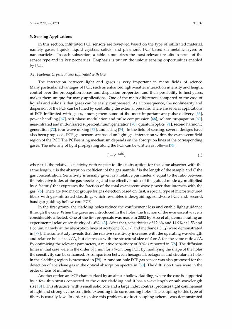
The interaction between light and gases is very important in many fields of science.Many particular advantages of PCF, such as enhanced light–matter interaction intensity and length,control over the propagation losses and dispersion properties, and their possibility to host gases,makes them unique for many applications. One of the main differences compared to the case ofliquids and solids is that gases can be easily compressed. As a consequence, the nonlinearity anddispersion of the PCF can be tuned by controlling the external pressure. There are several applicationsof PCF infiltrated with gases, among them some of the most important are pulse delivery [66],power handling [67], self-phase modulation and pulse compression [68], soliton propagation [69],near-infrared and mid-infrared supercontinuum generation [70], quantum optics [71], second harmonicgeneration [72], four wave mixing [73], and lasing [74]. In the field of sensing, several designs havealso been proposed. PCF gas sensors are based on light–gas interaction within the evanescent fieldregion of the PCF. The PCF-sensing mechanism depends on the absorption lines of the correspondinggases. The intensity of light propagating along the PCF can be written as follows [75]:
I = e−rαlC, (1)
where r is the relative sensitivity with respect to direct absorption for the same absorber with thesame length, α is the absorption coefficient of the gas sample, l is the length of the sample and C thegas concentration. Sensitivity is usually given as a relative parameter r, equal to the ratio betweenthe refractive index of the gas species ng and the effective index of the guided mode nm multipliedby a factor f that expresses the fraction of the total evanescent wave power that interacts with thegas [76]. There are two major groups for gas detection based on, first, a special type of microstructuredfibers with gas-infiltrated cladding, which resembles index-guiding, solid-core PCF, and, second,bandgap-guiding, hollow-core PCF.
In the first group, the cladding holes reduce the confinement loss and enable light guidancethrough the core. When the gases are introduced in the holes, the fraction of the evanescent wave isconsiderably affected. One of the first proposals was made in 2002 by Hoo et al., demonstrating anexperimental relative sensitivity of ∼6% [43]. After that, sensitivities of 12.6% and 14.9% at 1.53 and1.65 µm, namely at the absorption lines of acetylene (C2H2) and methane (CH4) were demonstratedin [77]. The same study reveals that the relative sensitivity increases with the operating wavelengthand relative hole size d/Λ, but decreases with the structural size of d or Λ for the same ratio d/Λ.By optimizing the relevant parameters, a relative sensitivity of 30% is reported in [78]. The diffusiontimes in that case were in the order of 1 min for a 7-cm long PCF. By modifying the shape of the holesthe sensitivity can be enhanced. A comparison between hexagonal, octagonal and circular air holesin the cladding region is presented in [79]. A random-hole PCF gas sensor was also proposed for thedetection of acetylene gas in the optical absorption spectra in [80]. The diffusion times were in theorder of tens of minutes.
Another option are SCF characterized by an almost hollow cladding, where the core is supportedby a few thin struts connected to the outer cladding and it has a wavelength or sub-wavelengthsize [81]. This structure, with a small solid core and a large index contrast produces tight confinementof light and strong evanescent field extending into surrounding holes. The coupling to this type offibers is usually low. In order to solve this problem, a direct coupling scheme was demonstrated

Sensors 2018, 18, 4263 10 of 32
between the source and the SCF in [82], by using a vertical-cavity surface-emitting laser (VCSEL),measuring CH4 and CO2 with a maximum coupling efficiency of 15%. Another option is using anintermediate fiber, showing a total measured loss for the two splices of 0.8 dB [83]. Despite the bigholes, the problem of low diffusion rates is still present. In [84], a time of several hours in order tofill completely C2H2 in a SCF is reported. The main advantage with respect to bandgap-guidingPCF is the ease of making channels to get access to the evanescent field [46]. Even the core can becompletely exposed to the external medium [85–87] when one of the cladding holes is laterally opened.The exposed-core geometry serves as a versatile platform for real-time evanescent field absorption orfluorescence spectroscopy, with capacity for fast infiltration and quick response to kinetic changes ofthe analyte [87].
The second group, based on hollow-core PCF, allows for confining both the optical mode andthe gas within the central hole. This produces a strong light–gas interaction over distances muchlonger than other structures used to this end. Since the light–gas interaction is enhanced in the opticalpower-guiding core, the sensitivity is significantly increased. A typical HC-PBGF operating at 1550 nmhas a transmission window of 200 nm and covers the absorption bands of many important gasessuch as CO, CO2, NH3, H2S, C2H2, and CH4. One of the first examples was demonstrated in 2004,measuring acetylene (C2H2) [88]. The same year, Ritari et al. demonstrated a high-sensitivity sensor forC2H2, HCN, CH4 and NH3 gases in [44]. They also concluded that the use of higher pressure reducesthe filling and evacuation time. These effects are studied in detail in [89]. In [90], a big central holesurrounded by a ring of holes was employed. The diffusion times and sensitivity were considerablyincreased, obtaining a relative sensitivity of 41% at the absorption line of acetylene at 1530.3 nm.The inclusion of channels into the core was reported to improve the gas sensing capabilities [91].A similar approach was based on introducing a channel in the input of the PCF and closing it witha micromirror [92]. Another example employed femtosecond laser drilling to produce a variablepressure fiber gas cell. Six evenly spaced holes were used over a 2-mm section of a 33-cm long PCFfor measuring acetylene. Based on this technique, a fast response PCF methane sensor is proposedin [93]. A diffusion limited response time of ∼3 s and a sensitivity of ∼647 ppm is demonstratedfor a 7-cm sensing fiber with seven side-holes separated by 1 cm along the fiber. By modifying thePCF structure, several sensors have been proposed. Two different structures are compared in [94],the results showing a better sensitivity (2.22 times higher) for hexagonal PCF (with six holes in the firstring) compared to an octagonal PCF (with eight holes in the first ring). When the central hole acquiresa particular microstructure, different responses are obtained. This technique was introduced in [95],where methylene blue dye was measured with a relative sensitivity of 4.28%. Furthermore, operationin the near-infrared region with considerably improved sensitivity was reported in [96]. In thatcase, the structure contained five air-hole rings in the cladding and a hexagonal-type microstructurecore, and exhibited a relative sensitivity of 42.27%, which is larger than any PCF gas sensor basedon interaction with evanescent waves. The confinement loss of the fiber was 4.78 × 10⁻⁶ dB/m.A slotted-core PCF for gas sensing was recently reported in [97]. Numerical results reveal a maximumrelative sensitivity of 48.26%. A micro-core PCF-based gas sensor based on elliptical-shaped holes wasreported in [98]. According to numerical results, a relative sensitivity of 53.07% can be obtained at1.33 µm. A different technique employed several segments of HC-PCF to measure methane [45,99],although presenting some drawbacks, mainly the losses between different PCF sections and thedifficulty in accurately controlling their junctions.
In addition, several proposals have been made to overcome the limitations of traditionalindex-guiding and hollow-core PCF. An example are index-guiding PCF with an air core. A relativesensitivity of more than 30% at the methane-relevant wavelength of 1.33 µm was demonstrated in [100].It was observed that the larger the central hole, the higher the relative sensitivity, although the corehad to be small enough to meet the index-guided condition. The sensitivity was found also to increaseby reducing the pitch of the PCF lattice. An experimental demonstration of a pure silica defected-corePCF with air core was proposed in [101], showing a relative sensitivity of 4.79% and confinement

Sensors 2018, 18, 4263 11 of 32
loss of 32.4 dB/m. A hollow high index ring defect that consists of the central air hole surroundedby a high index GeO2 doped SiO2 glass ring is introduced in [102]. The proposed PCF provided arelative sensitivity of 5.09%, and a confinement loss of 1.25 dB/m. A similar approach was followedin [103], yielding a relative sensitivity of about 27.58% at the absorption line of methane and hydrogenfluoride, with confinement losses of 1.76× 10⁻⁸ dB/m. An optimized structure was proposed in [104]by increasing the hole size in the outermost part of the cladding. A relative sensitivity of 32.99% and aconfinement loss of 2.59145× 10⁻⁵ dB/m was reported. A similar approach to [102], but improvingthe sensitivity, is reported in [105]. By using optimized parameters, a relative sensitivity of 13.23% anda confinement loss to 3.77× 10⁻⁶ dB/m at the wavelength of 1.33 µm was achieved.
To summarize, PCF are an excellent platform for compact all-fiber gas sensors. The possibilityof gas–light interaction over long distances offers high sensitivity in gas detection. One of the maindrawbacks is the long diffusion time, which produces slow responses due to time needed for gas fillingand venting the fibers. Different approaches for improving the response time have been reported.By using pressure or increased temperature, the filling times are considerably reduced [42], althoughthis solution is not suitable for a practical or commercial device. Introducing side-openings has beendemonstrated as an efficient alternative. Still, as the number of channels is increased, the fabricationcan become extremely difficult. Moreover, such channels can introduce mode or polarization coupling,thus increasing the noise. Wavelength or phase modulation and advanced digital signal processingmay be used to minimize the effect, but more work is needed to prove the effectiveness of suchmethods [106]. Among all the commented structures, SCFs are the best candidates to achieve highsensitivity and fast response, the fabrication of channels is easier than other configurations and alsohave the possibility of exposing the core. In addition, both index-guiding PCF and SCF have broadlow-loss transmission windows, which makes them suitable for detect multiple gas species. Table 1provides an overview of the key properties of the most relevant gas-infiltrated PCF sensors.
Table 1. Properties of most relevant gas-infiltrated PCF sensors.
Application PCF Type Wavelength (nm) Sensitivity Ref.
Gases IG-PCF NA 6% [43]
Acetylene (C2H2)Methane (CH4) IG-PCF
15301650
12.6%14.9% [77]
Gases IG-PCF750
1750 30% [78]
Oxygen (O2)Methane (CH4)
Carbon dioxide (CO2)SCF
76316742004
7%13%27%
[82]
Acetylene (C2H2) HC-PBF 1530 41% [90]
Methane (CH4)Hydrogen fluoride (HF) HC-PBF 1330 42.27% [96]
Gases HC-PBF NA 48.26% [97]
Methane (CH4) HC-PBF 1330 53.07% [98]
Methane (CH4) IG-PCF (air core) 1330 30% [100]
Methane (CH4)Hydrogen fluoride (HF) IG-PCF (air core) 1330 27.58% [103]
Gases IG-PCF (air core) NA 32.99% [104]
3.2. Photonic Crystal Fibers Infiltrated with Liquids
The microcapillaries in the PCF cladding provide a natural platform for their full or selectiveinfiltration with optical liquids, which extends by far the degrees of freedom in terms of engineering thefiber’s key properties. Optical liquids have demonstrated their capacity of boosting PCF performance

Sensors 2018, 18, 4263 12 of 32
in numerous applications, such as in the design of tunable polarizing notch filters [107], nonlineardiffraction and supercontinuum generation [28,108], or dispersion engineering [109,110]. The refractiveindex (RI) of readily available optical liquids ranges between 1.3 and 2.3 and it can be controlledwith very high precision as, e.g., in the commercially available series of refractive index liquids byCargille-Sacher Laboratories Inc., Cedar Grove (NJ), USA. Such versatility allows for the engineeringof both index- and bandgap-guiding PCF with fine-tuned properties, not achievable in solid PCF.Furthermore, the thermo-optic coefficient (TOC) of standard optical liquids is in the range of−5× 10⁻⁴ RIU/◦C (where RIU stands for refractive index units), namely more than one order ofmagnitude higher than that of silica, which makes them ideal candidates for the design of tunablefiber components or temperature sensors. Finally, apart from controlling the refractive index of theinfiltrated capillaries, liquids can serve as the basis for solutions of nanoparticles or biomolecules,which, combined with the long light–matter interaction lengths, enable advanced functionalities,e.g., sensing of magnetic field or biomolecules.
The performance of PCF sensors is mainly characterized by their sensitivity S and detectionlimit [111]. The former in most cases refers to the wavelength shift of some feature in the PCFtransmission spectrum, with respect to the measured quantity, such as temperature, refractive index,strain, or bent radius. Various approaches have been implemented in this respect, including theshifting of the central or edge wavelength of a bandgap or the minima of an interference patternin multimode/multicore PCF. The detection limit depends on the resolution of the measuringequipment but also on the sharpness of the interrogated spectral feature, for instance, the full-widthat half-maximum (FWHM) of a Lorentzian-type resonance. Furthermore, PCF sensors have greatlybenefited from already established techniques in standard optical fiber sensors based on the shifting ofresonances stemming from fiber Bragg or long-period gratings (LPG) [112,113], which rely on the phasematching and coupling between the fundamental guided mode and counter-propagating or claddingmodes, respectively. Various types of grating-based sensors have been consolidated in conventionaloptical fibers for, e.g., temperature [114,115], strain [115], or humidity [116] measurements. Boostedby advances in optical fiber and material engineering, fiber grating sensors were also demonstratedin polymer optical fibers [117,118] and, finally, PCF [119–125], using a variety of techniques, such asdirect laser writing, electric arc discharge, or by mechanical pressure for LPG [126–128].
Table 2. Properties of most relevant liquid-infiltrated PCF sensors.
Application PCF Type Wavelength (nm) Sensitivity Resolution Ref.
Refractive index IG-PCF 1050 1500 nm/RIU 2× 10⁻⁵ [129]Refractive index IG-PCF 1420 240 nm/RIU 4.1× 10⁻⁵ [130]Refractive index BG-PCF 1350–1550 32,400 nm/RIU 3.8× 10⁻⁶ [131]Refractive index IG-PCF 1500 30,100 nm/RIU 4.6× 10⁻⁷ [48]
Temperature BG-PCF 1200–1250 1.58 nm/◦C NA [132]Temperature IG-PCF 1250 1.83 nm/◦C NA [133]Temperature IG-PCF 1550 8.8 nm/◦C NA [134]Temperature IG-PCF 1550 54.3 nm/◦C NA [135]Temperature IG-PCF 1550 1 dB/◦C NA [136]Bend radius IG-PCF 1580 −1.2 nm/m−1 NA [137]Bend radius IG-PCF 1545 4.86 nm/m−1 NA [138]
Strain IG-PCF 650–950 701.2 pm/µε NA [139]Strain IG-PCF 1500 13.01 pm/µε NA [140]Strain IG-PCF 1520 25 pm/µε NA [141]
Magnetic field IG-PCF 1560 24.2 pm/Oe NA [142]Magnetic field BG-PCF 1040–1100 1.56 nm/Oe 0.0064 Oe [143]Magnetic field HC-MOF 1535 81 pm/Oe NA [144]Magnetic field IG-PCF 960 −0.01991 dB/Oe NA [145]Fluorescence HC-PCF 570 NA 10−10 M [146]
Biolayer thickness IG-PCF 835 1.4 nm/nm 10−4 RIU [147]
Sensors 2018, 18, 4263 13 of 32
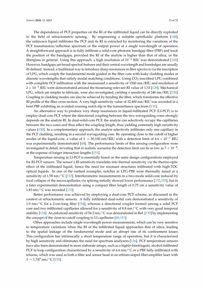
The dependence of PCF properties on the RI of the infiltrated liquid can be directly exploitedin the field of refractometric sensing. By engineering a suitable optofluidic platform [148],the unknown liquid infiltrates the PCF and its RI is extracted by monitoring the variations of thePCF transmission/reflection spectrum or the output power at a single wavelength of operation.A straightforward approach is to fully infiltrate a solid-core photonic bandgap fiber (PBF) and trackthe position of the bandgaps, provided the RI of the analyte is higher than that of silica, or thefiberglass in general. Using this approach, a high resolution of 10−6 RIU was demonstrated [149].However, bandgaps are broad spectral features and their central wavelength and bandedges are usuallyill-defined. Instead, a traditional way to introduce sharp resonances in fiber spectra is via the inscriptionof LPG, which couple the fundamental mode guided in the fiber core with leaky cladding modes atdiscrete wavelengths that satisfy modal matching conditions. Using CO2-inscribed LPG combinedwith complete PCF infiltration with the measurand a sensitivity of 1500 nm/RIU and resolution of2× 10−5 RIU were demonstrated around the biosensing-relevant RI value of 1.33 [129]. MechanicalLPG, which are simpler to fabricate, were also investigated, yielding a sensitivity of 240 nm/RIU [130].Coupling to cladding modes can also be achieved by bending the fiber, which transforms the effectiveRI profile at the fiber cross-section. A very high sensitivity value of 32,400 nm/RIU was recorded in abent PBF exhibiting an avoided-crossing notch dip in the transmittance spectrum [131].
An alternative way to produce very sharp resonances in liquid-infiltrated PCF (LI-PCF) is toemploy dual-core PCF where the directional coupling between the two waveguiding cores stronglydepends on the analyte RI. In dual-solid-core PCF, the analyte can selectively occupy the capillariesbetween the two cores and thus affect the coupling length, thus yielding extremely high sensitivityvalues [150]. In a complementary approach, the analyte selectively infiltrates only one capillary inthe PCF cladding, resulting in a second waveguiding core. By operating close to the cutoff of highermodes of the liquid-core, a value of S = 30,100 nm/RIU with a detection limit of 4.6× 10⁻⁷ RIUwas experimentally demonstrated [48]. The performance limits of this sensing configuration wereinvestigated in detail, revealing that in realistic scenarios the detection limit can be as low as 7× 10⁻⁸,at the expense of longer interaction lengths [151].
Temperature sensing in LI-PCF is essentially based on the same design configurations employedfor RI-PCF sensors. The sensor’s RI sensitivity translates into thermal sensitivity via the thermo-opticeffect of the infiltrated liquid, hence the need for resonant structures infiltrated with high-TOCoptical liquids. In one of the earliest examples, notches in LPG-PBF were thermally tuned at asensitivity of 1.58 nm/◦C [132]. Interferometric measurements in a two-mode solid-core induced bylocal collapse of the microcapillaries via splicing initially showed lower performance [152,153], but ina later experimental demonstration using a compact fiber length of 0.75 cm a sensitivity value of1.83 nm/◦C was recorded [133].
Better performance was achieved by employing a dual-core PCF scheme, as discussed in thecontext of refractometric sensors. A fully infiltrated dual-solid core demonstrated a sensitivity of1.9 nm/◦C for a 2-cm-long fiber [154], whereas a directional coupler formed among a solid PCFcore and two infiltrated capillaries allowed for a sensitivity of 8.8 nm/◦C with very good temporalstability [134]. An enhanced sensitivity of 54.3 nm/◦C was demonstrated in Ref. [135] by implementingthe concept of the close-to-cutoff coupling to LI capillaries [48,151].
Other approaches include single-wavelength power measurements, which can be very sensitiveto temperature variations when the RI of the infiltrated liquid approaches that of silica, leadingto the spatial leakage of the fundamental mode and an abrupt rise of its confinement losses.This configuration has intrinsically a short temperature range of operation, but it is characterizedby high sensitivity and eliminates the need for spectrum analyzers [136]. PCF temperature sensorshave also been demonstrated in more elaborate setups, such as a highly-birefringent, alcohol-infiltratedPCF in loop configuration characterized by a sensitivity of 6.6 nm/◦C or a PBF fully-infiltrated withtoluene, which was used as both a filter and sensor head in an erbium-doped fiber-amplifier laser withS = 1.747 nm/◦C [155].

Sensors 2018, 18, 4263 14 of 32
It has been mentioned that a means of increasing the RI/temperature sensitivity of LI-PCF is bybending the fiber and thus inducing light coupling from the core towards cladding modes. Similarly,one can design LI-PCF bend sensors based on the same physical principles, e.g., the bent-sensitivecoupling between core mode and a single-capillary in a LI-PCF, which showed a linear sensitivityresponse of −1.2 nm/m−1 for a bend-radius up to 10.7 −1, albeit with high thermal sensitivity [137].The latter issue was eliminated in a self-referenced ARROW grapefruit-type microstructured opticalfiber (MOF) selectively infiltrated with two different optical liquids in order to minimize thermaland strain cross-talk, while maintaining a high sensitivity value of 4.86 nm/m−1 [138]. Furthermore,measurement of not only the bend radius, but the direction of deformation as well, was demonstratedin a commercial PCF (LMA-10) selectively infiltrated with a Cargille optical liquid in such a way thatstrong geometrical birefringence was induced [156].
By taking advantage of the photoelastic effect in silica PCF, namely the reduction of the silica RIwhen a strain is axially loaded along the fiber, LI-PCF strain sensors have also been demonstrated.By monitoring the coupling properties between the PCF core and a selectively infiltrated capillary,high sensitivity values of 22 pm/µε were achieved, but suffering from high thermal crosstalk as aresult of the highly sensitive coupling [157]. By further optimizing the PCF geometry and materialselection both strain and temperature sensitivities can be significantly increased to 701.2 pm/µε and290 nm/◦C, respectively [139]. The thermal crosstalk can be mitigated by employing multi-core LI-PCFfor simultaneous strain (S = 13.01 pm/µε) and temperature (S = 14.72 nm/◦C) measurements [140],or highly-birefringent PCF in Sagnac loop interferometric configuration with S = 25 pm/µε [141].
In a different context, PCF provide an excellent platform for the design of magnetic field sensors,where the infiltrated liquid is a magnetic fluid (MF), i.e., a stable suspension of ferromagneticnanoparticles, usually iron oxide (Fe3O4), in a liquid carrier. In the presence of a magnetic field,the fluid is magnetized and its RI is modified according to a Langevin function, which in turnmodulates the PCF optical properties. A sensitivity of 24.2 pm/Oe for a 0.6 mg/mL concentration ofFe3O4 nanoparticles was demonstrated by exploiting the magnetic-field dependent beating betweenthe two polarizations of the fundamental mode in a highly-birefringent MF-PCF [142]. By using ahigh-index MF and monitoring the bandgap shift, a linear sensitivity of 1.56 nm/Oe was reported inRef. [143]. Other approaches comprise the excitation of whispering gallery modes in the outer claddingof an MF-PCF [158] or a self-referenced ARROW-type MOF selectively infiltrated with both MF andethanol along the lines of [140], which yielded S = 81 pm/Oe [144]. Recently, a magnetic-ionic-liquidwas used as the MF in a selectively-infiltrated PCF in a compact sensor with an almost linear responsein the range from 0 to 440 Oe [145].
Finally, LI-PCF have also demonstrated their potential as biochemical sensors, thanks to theenhanced light–matter interaction they offer and the possibility to functionalize the PCF capillariesand/or infiltrate them with biological solutions. In such an experiment, evanescent wave detection oflabeled biomolecules in water was demonstrated by exciting cladding-guided modes which overlappedwith the infiltrated capillaries [159]. Higher sensitivity can be achieved by allowing light to beguided in the infiltrated PCF parts, such as in a hollow-core PCF infiltrated with dye solutionthat featured a resolution in dye concentration of 10−10 M in fluorescence measurements using a10-cm PCF [146]. Pushing further the capabilities of LI-PCF in biochemical sensing, the thicknessof monolayers of poly-L-lysine and double-stranded DNA was measured in PCF with tunable-LPG,by properly functionalizing the capillary walls of the microstructured cladding [147]. Table 2 providesan overview of the key properties of the most relevant liquid-infiltrated PCF sensors.
3.3. Photonic Crystal Fibers Infiltrated with Liquid Crystals
Liquid crystals (LC) are a special class of fluid organic materials that show high intrinsicoptical birefringence, stemming from their molecular orientational and/or positional order, which isreminiscent of solid crystalline materials. In addition, their molecular/optical axis reorientates in thepresence of applied electric or magnetic fields, which makes them an excellent electro-optic material

Sensors 2018, 18, 4263 15 of 32
in a broad range of tunable photonic devices [160–177], including numerous examples of LC-PCF foroptical switching, tunable filtering and polarization control [178–181].
Table 3. Properties of most relevant liquid-crystal-infiltrated PCF sensors.
Application PCF Type Wavelength (nm) Sensitivity Ref.
Temperature BG-PCF 400–800 7 nm/◦C [37]Temperature BG-PCF 1550 27 nm/◦C [182]Temperature BG-PCF 1200–1550 105 nm/◦C [183]Temperature HG-PCF 1400–1600 4.91 nm/◦C [184]Temperature IG-PCF 1400–2600 up to 438.1 nm/◦C [185]Electric field IG-PCF 1550 20 dB/kVrms/mm [186]
Magnetic field IG-PCF 1550 −6.186 pm/Oe [187]Bend radius IG-PCF 1550 0.11 nm/m−1 [188]
Hydrostatic pressure BG-PCF 600–670 0.18 rad/m/MPa [189]
LC-PCF infiltration and handling techniques are similar to isotropic LI-PCF, although someextra care is needed in order to ensure the desired LC molecular orientation in the non-biased case,i.e., when there is no applied control field. However, LC offer additional options for sensing, a firstexample being their use as ultrahigh sensitive temperature sensors. Nematic LC show extremely highTOC of their two indices, particularly the extraordinary one, in the temperature range approachingthe clearing point Tc, namely the transition from anisotropic nematic to the isotropic liquid state.Moreover, via molecular engineering, it is possible to shift the clearing point from room temperature toTc > 100 ◦C. By exploiting such physical properties, bandedge shift-based temperature LC-PCF sensorshave been demonstrated with sensitivities ranging from 7 nm/◦C in one of the early examples [37]to 27 nm/◦C for a specially engineered LC for room temperature operation [182] and up to theextreme value of 105 nm/◦C, albeit at a very narrow range near the clearing point and with a strongnonlinear response [183]. Linearity and broad temperature range can be restored, at the expense oflower sensitivities, as demonstrated in a thermally-sensitive notch filter in PBG [190]. Apart frombandedge shifting, other approaches have been recently proposed for LC-PCF temperature sensors,such as the use of an interferometric dual-core PCF selectively-infiltrated with the common nematicLC material 5CB (4-cyano-4′-pentylbiphenyl) with sensitivity up to 4.91 nm/◦C [184], or a LPG-baseddesign theoretically exhibiting an average sensitivity of 13.79 nm/◦C in the range of 27 to 50 ◦C,which increases up to 438.1 nm/◦C near the clearing temperature for the common nematic mixture E7at Tc = 58 ◦C [185].
Moreover, owing to their electro-optic response, LC-PCF are prime candidates for compact,all-in-fiber electric field sensors, which minimally disturb the measured field and are immuneto electromagnetic interference. Their potential has been demonstrated in various prototypesfor polarimetric electric field sensing by optimizing the infiltration length and LC materials.Linear response in compact lengths below 1 mm, sensitivity of 20 dB/kVrms/mm and estimatedresolution of 0.005 kVrms/mm have been reported [186,191]. Operation both in transmission andreflection is possible, using standard commercially available PCF and without the need for selectiveinfiltration [192].
Magnetic field sensing has also been demonstrated using whispering-gallery modes (WGM) ina fiber micro-resonator infiltrated with ferronematic liquid crystal, magnetic field sensitivity up to−6.186 pm/Oe [187]. Other LC-PCF sensing applications include bend sensors based in Bragg gratingsinscribed on PCF infiltrated with polymer-dispersed LC showing sensitivity of 0.11 nm/m−1 [188]and hydrostatic pressure sensors based on the changes of the capillary diameter and hence bandgappositions and polarization state [189]. Table 3 provides an overview of the key properties of the mostrelevant liquid-crystal–infiltrated PCF sensors.

Sensors 2018, 18, 4263 16 of 32
3.4. Photonic Crystal Fibers Infiltrated with Solids
Infiltrating PCF with solid materials provides an alternative way towards the design andimplementation of in-fiber sensors. In many aspects, the properties of solid-infiltrated PCF (SI-PCF) aresimilar to their LI counterparts, since the PCF capillaries are selectively or fully filled with an isotropicmaterial, as in the most widespread variant of polymer-infiltrated PCF. Nevertheless, SI-PCF canprovide wider thermal operation ranges and are easier to handle, e.g., splicing with SCF or empty PCF.On the other hand, they lack some of the versatility of LI-PCF, e.g., the possibility of refractometricsensing in SI-PCF is naturally ruled out, as the PCF capillaries are permanently sealed.
In one of the earliest examples, a grapefruit-type polymer microstructured fiber was selectivelyinfiltrated with a UV curable polymer with a high negative TOC in order to thermally tune the fiber’sbirefringence [193]. By inverting the principle of operation, the fiber showed capacity for polarimetrictemperature sensing with a sensitivity of 0.15 rad/◦C/cm. Higher values of 0.37 rad/◦C/cm werereported for a 1.4-cm-long highly-birefringent PCF infiltrated with poly-dimethylsiloxane (PDMS) [194].PDMS, which has a lower index than silica, was also used to measure temperature by recording thethermally-tunable modal confinement and bending losses of an index-guiding PCF [47]. Being anelastic material, PDMS also shows potential for the design of PCF strain sensors.
Highly-sensitive thermal sensors based on the bandedge-shift effect have been demonstratedby infiltrating PCF with silicone oil [49] and optical adhesives (NOA65) [195], exhibiting absolutesensitivities of 1.35 and 4.034 nm/◦C, respectively. In a different approach, the thermo-optic mismatchbetween two arms of a Mach–Zehnder interferometer formed in a two-core PCF selectively infiltratedwith a low-index polymer yielded a sensitivity of 1.595 nm/◦C, in terms of the minima dips in theoutput interferometric spectrum, although requiring a rather large interaction length [196]. A lesssensitive (0.18 nm/◦C), but very compact (0.8 mm) and having a wide range thermal sensor wasdemonstrated in a selectively infiltrated PCF with Ge [58]. In general, semiconductors can be infiltratedin PCF at high pressure, provided their melting point is relatively low compared to that of silica,which makes Ge a promising candidate. Using a similar approach, it is also possible to fill PCF withmetals, which gives rise to plasmonic effects and novel sensing configurations, which are revised inthe dedicated Section 3.5.
More specific applications include in-fiber humidity sensors, based on PCF infiltration withhydroscopic polymer in hydrogel (Agarose), which features a linear change of refractive index overa wide humidity range. By employing an interferometric configuration based on the excitation ofcore and cladding modes in a PCF via microhole collapsing, a compact (1 mm) fiber sensor headworking in reflection was demonstrated [197]. Thanks to its stability, sub-second response, low thermalsensitivity and all-in-fiber approach, this type of humidity sensor can be exploited as a breathing sensorfor patients during magnetic resonance imaging [198] or be integrated in larger setups, combined,for instance, with FBG [199], for simultaneous measurement of temperature and humidity. Table 4provides an overview of the key properties of the most relevant solid-infiltrated PCF sensors.
A particular type of SI-PCF comprises PCF infiltrated with metallic layers/coatings or metallicnanoparticles inside the PCF microcapillaries, which support plasmonic resonances. Given theincreased amount of research dedicated in this kind of PCF and their technology, we review thefield of plasmonic PCF-based sensors separately in the following subsection.

Sensors 2018, 18, 4263 17 of 32
Table 4. Properties of most relevant solid-infiltrated PCF sensors.
Application PCF Type Wavelength (nm) Sensitivity Ref.
Temperature IG-MOF 1550 0.15 rad/◦C/cm [193]Temperature IG-PCF 633 0.37 rad/◦C/cm [194]Temperature BG-PCF 680–740 1.35 nm/◦C [49]Temperature BG-PCF 1000–1600 4.034 nm/◦C [195]Temperature IG-PCF 1550 1.595 nm/◦C [196]Temperature IG-PCF 1390 0.18 nm/◦C [58]
Relative humidity IG-PCF 1550 0.6 dB/%RH [197]
3.5. Plasmonic Photonic Crystal Fibers
Materials that possess a small positive imaginary and a negative real dielectric constant such asnoble metals in the visible/infrared (VIS/IR) spectrum are capable of supporting surface plasmonresonances, i.e., coherent oscillations of the surface conduction electrons excited by electromagneticradiation. In certain cases, such resonances, termed as surface plasmon polaritons (SPP), can bepropagating along a metal-dielectric interface, for distances in the order of tens to hundredsmicrometers, while decaying evanescently in the plane transverse to the direction of propagation.SPP sensors have attracted much attention in the last few decades thanks to their high sensitivity andbroad range of sensing applications. The special characteristics of PCF enable overcoming typicaldrawbacks of conventional prism and standard optical fiber-based SPP sensors. The great flexibilityin the geometry design allows for the control of the core-guided leaky mode propagation. By usingdifferent types of structures, the profile of the evanescent field can be optimized. The core-claddingdiameter and position can be tuned to obtain single mode propagation, thus increasing the sensitivityand full scale of the sensor. In the case of PCF-SPP sensors, various designs have been proposed inorder to simplify the process of introducing metallic layers in the holes, as shown in Figure 7 [200].
Several designs where a plasmonic layer is infiltrated inside the holes have been thus far proposed.These designs aim to improve the detection resolution by increasing the phase matching betweenthe core and plasmonic modes. Figure 7a shows a PCF consisting of two rings of hexagonal holes,where the metallic layer is infiltrated in the second ring, resulting in a metal-coated surface inside themicrocapillaries. The central air hole and the presence of the infiltrated fluid in the second ring servethe purpose of phase matching. The interference of the guided modes produces three resonant peaksand the sensor resolution is 3× 10⁻⁵ RIU [201]. A similar structure, but using graphene and silveras coating layer, is presented in [202]. The graphene layer solves the problem of silver oxidation andincreases the adsorption of molecules. A sensitivity of 2520 nm/RIU and a resolution of 3.97× 10⁻⁵ RIUis demonstrated. Moreover, it has been shown that the use of only one hole for sensing can produceinteresting results [203]. In particular, a sensitivity of 9000 nm/RIU between 1.33 and 1.53 is achieved,corresponding to a resolution of 1.11× 10⁻⁵ RIU.
In Figure 7b, the coating of the central hole and the selectively filled analyte channels induce anintense evanescent field that results in strong coupling between the core-guided mode and the SPPmode [204]. Figure 7b (ii) shows the electric field distribution for an analyte RI of 1.46. The range ofthe resonant wavelength shift is from 1040 to 1070 nm for a change of analyte RI from 1.46 to 1.47,yielding an RI sensitivity of 3000 nm/RIU [204]. Figure 7b (iii) shows the dispersion relation of thecore-guided mode for na = 1.47 (solid lines) and na = 1.49 (dashed lines). By increasing the refractiveindex of the analyte, the energy transfer from the core-guided mode to the SPP mode is reduced.The inclusion of the coating layer in the two big holes instead of the center hole was demonstratedin [205]. The average sensitivity was 7040 nm/RIU (gold layer) from 1.40 to 1.42 with high linearity.Another similar deign to Figure 7b, but using six big holes surrounding the core instead of two, wasproposed in [206]. The results were sensitives both positive and negative, 3600 nm/RIU for a range of1.45–1.46 and −5500 nm/RIU for a range of 1.50–1.53, respectively. The use of only the central corewas proposed in [207]. A sensitivity of 10, 448.5 nm/RIU in the RI range 1.33–1.45 was demonstrated.

Sensors 2018, 18, 4263 18 of 32
A similar approach was followed in [208], but combining graphene with silver, as a biosensor with asensitivity of 10.000 nm/RIU in the range between 1.43 and 1.46 and a high resolution of 10−6 RIU.The configuration of Figure 7c can also produce both positive and negative sensitivity, by placing themetallic coating in the holes surrounding the core. Thanks to this design, a minimum loss value of80 dB/cm is obtained for an analyte with RI of 1.485 [209].
Another approach is based on studying the effect of oxides in the coating. In the PCF shownin Figure 7d, the inclusion of a gold-TiO2 layer and liquid infiltrated inside the holes improves thesensing performance. A refractive-index resolution of 2.7× 10⁻⁵ (sensitivity S ' 370/RIU) for theliquid analyte and a minimum loss value of 58 dB/cm is demonstrated. Moreover, it can operate atnear-infrared wavelengths due to high refractive index of TiO2 [210]. A different option exploits theuse of indium tin oxide (ITO) [211]. The resonance is around the telecommunication window and itcan be tuned by varying the ITO thickness or intrinsic properties. The sensor shows a refractive indexsensitivity as high as 2000 nm/RIU and resolution of 5× 10⁻⁵ RIU. Structures diverging from theclassical PCF have also been proposed. A novel diamond ring fiber (DRF)-based sensor for refractiveindex sensing was designed and fabricated [212], yielding a sensitivity of 6000 nm/RIU in the RI rangeof 1.33–1.39. The sensing resolution was 1.67× 10⁻⁵ and 1.97× 10⁻⁵ RIU by following the wavelengthand amplitude interrogation methods, respectively.
Figure 7. Metal coating-based plasmonic PCF sensors. (a) gold coated in the second ring (dc = 0.45Λ,d1 = 0.6Λ, d2 = 0.8Λ, Λ = 2 µm and gold layer thickness equal to 40 nm); (b) (i) selectively silverdeposited core (dc = 0.8Λ, d1 = 0.6Λ, d2 = 0.8Λ, Λ = 2 µm and silver layer thickness equal to 40 nm),(ii) field distribution with phase matching phenomena; and (iii) phase matching phenomena shiftedwith varying analyte RI. (c) Selectively gold-coated with liquid-filled core (dc = 0.8Λ, d1 = 0.5Λ,d2 = 0.8Λ, Λ = 2 µm and gold layer thickness, t = 40 nm); (d) multiple holes coated with gold-TiO2
layer (rc = 3.5 µm, r = 6 µm, Λ = 13 µm, gold layer thickness equal to 30 nm and TiO2 layer thicknessequal to 75 nm); (e) liquid and silver nanowire filled temperature sensor; (f) hollow-core filled withliquid and silver nanowires and (g) silver-wire filled HC-PBF, reprinted with permission from [200].

Sensors 2018, 18, 4263 19 of 32
One of the main problems of these techniques is the complexity of the fabrication processes.The fabrication process is simplified in [213], by coating two open-ring channels on the outer regionof the PCF, where the analyte can penetrate the channels easily. An average spectral sensitivity of5500 nm/RIU and a maximum sensing resolution of 7.69× 10⁻⁶ RIU is demonstrated. Other techniquesuse wires instead of metallic layers. In the case depicted in Figure 7e, silver nanowires are embedded inthe first ring of the PCF, which was used to measure temperature with a sensitivity of 2.7 nm/◦C [214].A different example employing nanowires is reported in [215], demonstrating a refractive index sensorwith resolution of 5× 10⁻⁵ RIU and maximum loss of 22 dB/cm, better than in the case of similarstructures coated with metal film. A different structure is used in Figure 7f, where the nanowiresare embedded in the hollow core of the PCF, resulting in a refractive index sensor with sensitivityof 14,240 nm/RIU [216]. In Figure 7g, the hollow core is infiltrated with the analyte, achieving amaximum sensitivity of 2151 nm/RIU [217]. By using only one wire, a sensitivity of 5500 nm/RIUis demonstrated. More complex structures have also been proposed. A triangular lattice and fourlarge-size channels based on surface plasmon resonance was investigated in [218]. In such a sensor,two gold wires obtained by chemical reaction are filled in two air holes between the upper and lowerchannels. The results show a sensitivity of 3233 nm/RIU for RI from 1.63 to 1.79. Finally, it wasdemonstrated in [219] that the maximum sensitivity of the sensor is relatively stable for randomlyfilled nanowires, which is very convenient in terms of fabrication and application of the sensor.
Table 5. Properties of most relevant plasmonic PCF sensors.
Application PCF Type Wavelength (nm) Sensitivity Resolution Ref.
Refractive index IG-PCF 500 to 1500 873 dB/RIU 3× 10⁻⁵ RIU [201]Refractive index IG-PCF 750 to 1750 2520 nm/RIU 3.97× 10⁻⁵ RIU [202]Refractive index IG-PCF 500 to 1010 9000 nm/RIU 1.11× 10⁻⁵ RIU [203]Refractive index IG-PCF 900 to 1200 10,000 nm/RIU 10−6 RIU [203]Refractive index HC-PBF 560 to 610 14,240 nm/RIU 7.02× 10⁻⁵ RIU [216]Refractive index HC-PBF 1330 5500 nm/RIU NA [98]Refractive index SCF 400 to 700 227 nm/RIU NA [220]Refractive index SCF 1550 8360 rad/RIU 2.1× 10⁻⁶ RIU [221]
Temperature IG-PCF 400–500 2.7 nm/◦C NA [214]Temperature IG-PCF 800–1100 5 nm/◦C NA [219]Temperature IG-PCF 1550 0.315 dB/◦C NA [222]Temperature HC-PBF NA 0.72 nm/◦C 1.39× 10⁻² ◦C [223]Temperature HC-PBF 550–900 3.08 nm/◦C 1.325× 10⁻² ◦C [224]Temperature HC-PBF NA 2.8× 10⁻⁵ RIU [225]
Pressure IG-PCF 400–800 32.89 nm/N NA [226]Biolayer thickness IG-PCF 600–750 2.3 nm/nm 0.044 nm [227]
On the other hand, localized surface plasmon resonances (LSPR) are produced when thereis a confinement of a surface plasmon in a particle with size smaller than incident wavelength.As LSPR cannot propagate, the impinging light excites the nanoparticle collective electron oscillationsthat enhance the near-field amplitude while decaying rapidly with distance from the nanoparticle.The electric field near the surface is enhanced and the optical absorption is maximized at the plasmonresonant frequency. Recent technological achievements, allowing the fabrication of nanoparticleshaving different sizes and shapes, have boosted the study of the interaction between light andthese nanosystems. When the material employed for filling the PCF holes is doped with metallicnanoparticles, LSRP can be generated upon excitation with external light of a given wavelength. Unlikethe case of SPP, LSPR can be excited directly without any complex wavevector matching conditions.On the other hand, they are more sensitive to the environment than the SPP.
Gold nanoshells, consisting of silica cores coated with thin gold shells, were infiltrated in a PCFin [228]. Only the first layer of air holes was designed to be the sensing channels by infiltratingthem with the gold nanoshells. A sensitivity of 4111.4 nm/RIU and resolution of 2.45× 10⁻⁵ RIU

Sensors 2018, 18, 4263 20 of 32
for 1.33–1.38 were observed. The most common way to manipulate nanoparticles is by means of ahost material. In practice, it is difficult to obtain homogeneous samples of dispersed nanoparticles.Common host materials are PDMS [229] or LC [230]. In the case of LC, the most common NP foruse with LC are magnetic (FexOy), insulating (ZnO, TiO2, Si3N4), ferroelectric (e.g., BaTiO3) andmetallic (e.g., plasmonic Au or Ag) nanoparticles, as well as semiconductor quantum dots (CdS, CdSe,CdTe) [231]. For example, a mixture of gold nanoparticles and LC was proposed as a temperaturesensor in a polymer optical fiber, with a maximum sensitivity of 64× 10−2 dB/◦C when metallic NPare used [232]. In addition, the PCF thermo-optical response studied in [233,234] shows a big variationin the properties of transmitted light in small temperature variations. These effects could be used inhigh-resolution temperature sensors. In [235], a nanoparticle-doped PDMS sample is proposed to beinfiltrated in a PCF. It produces a highly birefringent optical response and could be used as temperaturesensor with a sensitivity of 0.053 nm/◦C. Table 5 provides an overview of the key properties of themost relevant plasmonic PCF sensors.
It is important to note that PCF-SPP sensors have some important considerations. As it wasmentioned in Section 2, the inclusion of a metallic layer or wires is experimentally difficult. Placingthese materials close to the core causes losses related to the enhancement of the fields at the lossymetallic surfaces. In the case of LSPR sensors, the lack of experimental works demonstrate the extremedifficulty to obtain nanoparticle samples that can be readily infiltrated in PCF. These drawbacks limitthe practical realization of this type of sensors. The technology has to be improved considerable inorder to have commercial sensors based on plasmonic effects.
4. Discussion
A comprehensive review on infiltrated PCF has been presented in the previous sections,highlighting the fundamentals and fabrication of PCF infiltrated with different materials. In the case ofsolid materials, different mechanisms have been developed to fabricate infiltrated PCF. Among them,RF sputtering, thermal evaporation methods, electroless plating, wet-chemistry, and chemical vapordeposition are the most common. Despite this, pressure-assisted splice-filling has been demonstrated tobe the most straightforward and reliable technique. In the case of liquids, the methods to infiltrate thePCF are similar to infiltration of melted metals, with the advantage that temperatures and viscositiesare usually easier to handle. For gases, there is no need of any specific mechanism, but high pressureand temperature always helps with the process.
It has been demonstrated how the infiltration of PCF microcapillaries with various types ofmaterials provides new opportunities for practical applications, among which, sensors are themost relevant and with the most commercial potential. The review of infiltrated PCF sensors hasbeen presented in terms of the type of infiltrated material, namely solids, plasmonic coatings andnanoparticles, isotropic liquids, liquid crystals, and gases. The microcapillaries in the PCF claddingprovide a natural platform for their full or selective infiltration with optical liquids, which extends byfar the degrees of freedom in terms of engineering the fiber’s key properties. Various approaches havebeen implemented in this respect, including the shifting of the central or edge wavelength of a bandgap,resonances stemming from fiber Bragg gratings or LPG, or the minima of an interference pattern inmultimode/multicore PCF. The dependence of PCF properties on the RI of the infiltrated liquid can bedirectly exploited in the field of refractometric sensing. In addition, temperature sensing in LI-PCF isessentially based on the same design configurations employed for RI-PCF sensors. By taking advantageof the photoelastic effect in silica PCF, namely the reduction of the silica RI when a strain is axiallyloaded along the fiber, LI-PCF strain sensors have also been demonstrated. In a different context,PCF provides an excellent platform for the design of magnetic field sensors, where the infiltrated liquidis a magnetic fluid. Finally, LI-PCF have also demonstrated their potential as biochemical sensors,thanks to the enhanced light–matter interaction they offer and the possibility to functionalize the PCFcapillaries and/or infiltrate them with biological solutions. LC-infiltrated PCF with liquid crystalsshare some common features with their counterparts infiltrated with liquid isotropic materials, but also

Sensors 2018, 18, 4263 21 of 32
provide unique capabilities, such as electric-field sensing via the LC electro-optic effect, much largerTOC for temperature sensing and polarization-dependent interrogation schemes.
Infiltrating PCF with solid materials provides an alternative way towards the design andimplementation of in-fiber sensors. Again, in many aspects, the properties of solid-infiltrated PCFare similar to those of liquid-infiltrated PCF, since the capillaries are selectively or fully filled with anisotropic material, as in the most widespread variant of polymer-infiltrated PCF. Nevertheless, SI-PCFcan provide wider thermal operation ranges and are easier to handle, e.g., splicing with standardsingle-mode fibers or empty PCF. On the other hand, they lack some of the versatility of LI-PCF,e.g., the possibility of refractometric sensing in SI-PCF is naturally ruled out, as the PCF capillaries arepermanently sealed. Most important applications are highly-sensitive thermal sensors and in-fiberhumidity sensors.
When gases are introduced in the PCF holes, the optical response can be used to identify the typeof gas. These fibers can be used to make compact all-fiber gas sensors. The possibility of gas–lightinteraction over long distances produce high sensitivities in gas detection. One of the main drawbacksis the long diffusion time, which produce slow responses due to time taken for gas filling and ventingthe fibers. Different approaches for improving the response time have been reported. The mostpromising is the inclusion of side-openings along the PCF. SCFs are the best candidates for achievinghigh sensitivity and fast responses; the fabrication of channels is easier than other configurations andalso has the possibility to expose the core. In addition, both index-guiding PCF and SCF have broadlow-loss transmission windows, which make them suitable for detecting multiple gas species. Finally,loading PCF with plasmonic metallic coatings or nanoparticles has also been proposed as a promisingway to boost their sensing performance, such as in refractometry, provided the induced dampinglosses can be efficiently tamed.
Overall, infiltrated PCF emerged as a promising and competitive sensing technology.Their capacity to measure numerous physical quantities, such as temperature, pressure, or strain,detect and to quantify the presence chemical compounds and even biological matter has beendemonstrated in numerous experiments. Some techniques are still at their youth, for example,plasmonic PCF, where the majority of this kind of sensors are based on theoretical results.Their fabrication relies on still immature technologies, making it difficult to obtain repetitively thetarget performance. Despite this, the reported results show a huge potential to improve actualgas and biochemical sensors. Infiltrated IG-PCF and HC-PCF can be considered in a much moremature technological stage, as significant advances in chemical sensing, gas-based nonlinear optics,high power delivery, pulse compression have been demonstrated. Problems such as cross-sensitivitycan be addressed, taking advantage of the versatility of PCF as a platform for selective infiltration.
Thanks to such demonstrated capabilities, the research field of infiltrated PCF sensors has grownexponentially in the last years, even if commercial devices are not yet available. Nevertheless,when looking at the number of patents, the perspectives are highly optimistic. For instance, a searchin Google’s patent database on infiltrated PCF gas, temperature, strain or pressure sensor returnsthousands of results. Although such data serve more as a general indicator, e.g., in many cases, patentsoverlap as the same PCF sensor can measure several parameters, there is a constant increase in thenumber of patents every year. This clearly demonstrates the trend and the potential of infiltrated PCFto develop commercial all-fiber sensors in the near future in several key technological fields, such asenvironmental and biochemical sensing, medical diagnostics, food safety, and security.
Author Contributions: Conceptualization, J.F.A. and D.C.Z.; Investigation, J.F.A., D.C.Z., A.T., D.P.;Writing-Original Draft Preparation, J.F.A., D.C.Z., A.T., D.P.; Writing-Review & Editing, all authors; Supervision,J.M.S.-P.; Project Administration, J.M.S.-P.; Funding Acquisition, J.M.S.-P.
Funding: This work was supported by the Research and Development Program through the Comunidadde Madrid (SINFOTON S2013/MIT-2790), the Ministerio de Economía y Competitividad of Spain(TEC2013-47342-C2-2-R) and the mobility programs of Carlos III University and “José Castillejo” of the Ministeriode Educación, Cultura y Deporte of Spain.

Sensors 2018, 18, 4263 22 of 32
Conflicts of Interest: The authors declare no conflict of interest.
References
1. Kashyap, R.; Wyatt, R.; McKee, P.F. Wavelength flattened saturated erbium amplifier using multiple side-tapBragg gratings. Electron. Lett. 1993, 29, 1025–1026. [CrossRef]
2. Shigehara, M.; Satoh, T.; Inoue, A.; Hattori, Y. Optical fiber identification system using fiber Bragg gratings.Opt. Fiber Commun. 1996, 162–163.
3. Hill, K.O.; Malo, B.; Bilodeau, F.; Thériault, S.; Johnson, D.C.; Albert, J. Variable-spectral-response opticalwaveguide Bragg grating filters for optical signal processing. Opt. Lett. 1995, 20, 1438–1440. [CrossRef]
4. Hill, K.O. Aperiodic distributed-parameter waveguides for integrated optics. Appl. Opt. 1974, 13, 1853–1856.[CrossRef] [PubMed]
5. Udd, E. An overview of fiber-optic sensors. Rev. Sci. Instrum. 1995, 66, 4015–4030. [CrossRef]6. Zubia, J.; Arrue, J. Plastic optical fibers: An introduction to their technological processes and applications.
Opt. Fiber Technol. 2001, 7, 101–140. [CrossRef]7. Sano, Y.; Yoshino, T. Fast optical wavelength interrogator employing arrayed waveguide grating for
distributed fiber Bragg grating sensors. J. Lightwave Technol. 2003, 21, 132–139. [CrossRef]8. Koo, K.P.; Kersey, A.D. Bragg grating-based laser sensors systems with interferometric interrogation and
wavelength division multiplexing. J. Lightwave Technol. 1995, 13, 1243–1249. [CrossRef]9. Ashoori, R. Time domain multiplexing for a Bragg grating strain measurement sensor network. In Proceedings
of the 13th International Conference on Optical Fiber Sensors, Kyongju, Korea, 12–16 April 1999; p. 374614.10. Moraleda, A.T.; Montero, D.S.; Webb, D.; García, C.V. A self-referenced optical intensity sensor network
using POFBGs for biomedical applications. Sensors 2014, 14, 24029–24045. [CrossRef] [PubMed]11. Montalvo, J.; Tapetado, A.; Montero, D.S.; Vázquez, C. WDM-PON preventive optical monitoring system
with colourless reflectors. In Proceedings of the 2016 Optical Fiber Communications Conference andExhibition (OFC), Anaheim, CA, USA, 20–24 March 2016; p. W2A.57.
12. Pinzón, P.J.; Montero, D.S.; Tapetado, A.; Torres, J.C.; Vázquez, C. Dual-wavelength speckle-based SI-POFsensor for frequency detection and localization of remote vibrations. In Proceedings of the Sixth EuropeanWorkshop on Optical Fibre Sensors, Limerick, Ireland, 31 May–3 June 2016; p. 99161Z.
13. Russell, P. Photonic crystal fibers. Science 2003, 299, 358–362. [CrossRef] [PubMed]14. Knight, J.C.; Birks, T.A.; Russell, P.S.J.; Atkin, D.M. All-silica single-mode optical fiber with photonic crystal
cladding. Opt. Lett. 1996, 21, 1547–1549. [CrossRef] [PubMed]15. Birks, T.A.; Knight, J.C.; Russell, P.S.J. Endlessly single-mode photonic crystal fiber. Opt. Lett. 1997,
22, 961–963. [CrossRef] [PubMed]16. Birks, T.A.; Knight, J.C.; Mangan, B.J.; Russell, P.S.J. Photonic crystal fibres: An endless variety. IEICE Trans.
Electron. 2001, E84-C, 585–592.17. Knight, J.C.; Birks, T.A.; Cregan, R.F.; Russell, P.S.J.; de Sandro, J.P. Large mode area photonic crystal fibre.
Electron. Lett. 1998, 34, 1347–1348. [CrossRef]18. Ortigosa-Blanch, A.; Knight, J.C.; Wadsworth, W.J.; Arriaga, J.; Mangan, B.J.; Birks, T.A.; Russell, P.S.J.
Highly birefringent photonic crystal fibers. Opt. Lett. 2000, 25, 1325–1327. [CrossRef] [PubMed]19. Dakin, J.P.; Brown, R.G.W. (Eds.) Handbook of Optoelectronics (Two-Volume Set); Series in Optics and
Optoelectronics; CRC Press: Boca Raton, FL, USA, 2006.20. Zolla, F.; Renversez, G.; Nicolet, A.; Kuhlmey, B.; Guenneau, S.; Felbacq, D.; Argyros, A.; Leon-Saval, S.
Foundations of Photonic Crystal Fibres; Imperial College Press: London, UK, 2011.21. Mogilevtsev, D.; Birks, T.; Russell, P. Localized function method for modeling defect modes in 2-D photonic
crystals. J. Lightwave Technol. 1999, 17, 2078–2081. [CrossRef]22. Ferrando, A.; Silvestre, E.; Miret, J.J.; Andrés, P.; Andrés, M.V. Full-vector analysis of a realistic photonic
crystal fiber. Opt. Lett. 1999, 24, 276–278. [CrossRef]23. Cregan, R.F. Single-mode photonic band gap guidance of light in air. Science 1999, 285, 1537–1539. [CrossRef]24. Roberts, P.J.; Couny, F.; Sabert, H.; Mangan, B.J.; Williams, D.P.; Farr, L.; Mason, M.W.; Tomlinson, A.;
Birks, T.A.; Knight, J.C.; et al. Ultimate low loss of hollow-core photonic crystal fibres. Opt. Express 2005,13, 236–244. [CrossRef]

Sensors 2018, 18, 4263 23 of 32
25. Poletti, F.; Wheeler, N.V.; Petrovich, M.N.; Baddela, N.; Fokoua, E.N.; Hayes, J.R.; Gray, D.R.; Li, Z.;Slavík, R.; Richardson, D.J. Towards high-capacity fibre-optic communications at the speed of light invacuum. Nat. Photonics 2013, 7, 279–284. [CrossRef]
26. Perrin, M.; Quiquempois, Y.; Bouwmans, G.; Douay, M. Coexistence of total internal reflexion and bandgapmodes in solid core photonic bandgap fibre with intersticial air holes. Opt. Express 2007, 15, 13783–13795.[CrossRef] [PubMed]
27. Ranka, J.K.; Windeler, R.S.; Stentz, A.J. Efficient visible continuum generation in air-silica microstructureoptical fibers with anomalous dispersion at 800 nm. In Proceedings of the IEEE Conference on Lasers andElectro-Optics, Baltimore, MD, USA, 8–11 November 1999; p. CPD8.
28. Zhang, R.; Teipel, J.; Giessen, H. Theoretical design of a liquid-core photonic crystal fiber for supercontinuumgeneration. Opt. Express 2006, 14, 6800–6812. [CrossRef]
29. Bozolan, A.; de Matos, C.J.; Cordeiro, C.M.B.; dos Santos, E.M.; Travers, J. Supercontinuum generation in awater-core photonic crystal fiber. Opt. Express 2008, 16, 9671–9676. [CrossRef] [PubMed]
30. Renn, M.J.; Montgomery, D.; Vdovin, O.; Anderson, D.Z.; Wieman, C.E.; Cornell, E.A. Laser-guided atomsin hollow-core optical fibers. Phys. Rev. Lett. 1995, 75, 3253–3256. [CrossRef] [PubMed]
31. Ito, H.; Nakata, T.; Sakaki, K.; Ohtsu, M.; Lee, K.I.; Jhe, W. Laser apectroscopy of atoms guided by evanescentwaves in micron-sized hollow optical fibers. Phys. Rev. Lett. 1996, 76, 4500–4503. [CrossRef]
32. Dall, R.G.; Hoogerland, M.D.; Baldwin, K.G.H.; Buckman, S.J. Guiding of metastable helium atoms throughhollow optical fibres. J. Opt. B Quant. Semiclass. Opt. 1999, 1, 396–401. [CrossRef]
33. Müller, D.; Cornell, E.A.; Anderson, D.Z.; Abraham, E.R.I. Guiding laser-cooled atoms in hollow-core fibers.Phys. Rev. A 2000, 61, 033411. [CrossRef]
34. Christensen, C.A.; Will, S.; Saba, M.; Jo, G.B.; Shin, Y.I.; Ketterle, W.; Pritchard, D. Trapping of ultracoldatoms in a hollow-core photonic crystal fiber. Phys. Rev. A 2008, 78, 033429. [CrossRef]
35. Krauss, T.F. Why do we need slow light? Nat. Photonics 2008, 2, 448–450. [CrossRef]36. Larsen, T.; Bjarklev, A.; Hermann, D.; Broeng, J. Optical devices based on liquid crystal photonic bandgap
fibres. Opt. Express 2003, 11, 2589–2596. [CrossRef]37. Wolinski, T.R.; Szaniawska, K.; Ertman, S.; Lesiak, P.; Domanski, A.W.; Dabrowski, R.;
Nowinowski-Kruszelnicki, E.; Wojcik, J. Influence of temperature and electrical fields on propagationproperties of photonic liquid-crystal fibres. Meas. Sci. Technol. 2006, 17, 985–991. [CrossRef]
38. Du, F.; Lu, Y.Q.; Wu, S.T. Electrically tunable liquid-crystal photonic crystal fiber. Appl. Phys. Lett. 2004,85, 2181–2183. [CrossRef]
39. Haakestad, M.W.; Alkeskjold, T.T.; Nielsen, M.D.; Scolari, L.; Riishede, J.; Engan, H.E.; Bjarklev, A. Electricallytunable photonic bandgap guidance in a liquid-crystal-filled photonic crystal fiber. IEEE Photonics Technol.Lett. 2005, 17, 819–821. [CrossRef]
40. Wolinski, T.R.; Szaniawska, K.; Bondarczuk, K.; Lesiak, P.; Domanski, A.W.; Dabrowski, R.;Nowinowski-Kruszelnicki, E.; Wójcik, J. Propagation properties of photonic crystal fibers filled withnematic liquid crystals. Opto-Electron. Rev. 2005, 13, 177–182.
41. Alkeskjold, T.T.; Lægsgaard, J.; Bjarklev, A.; Hermann, D.S.; Anawati, A.; Broeng, J.; Li, J.; Wu, S.T. All-opticalmodulation in dye-doped nematic liquid crystal photonic bandgap fibers. Opt. Express 2004, 12, 5857–5871.[CrossRef]
42. Wynne, R.M.; Barabadi, B.; Creedon, K.J.; Ortega, A. Sub-minute response time of a hollow-core photonicbandgap fiber gas sensor. J. Lightwave Technol. 2009, 27, 1590–1596. [CrossRef]
43. Hoo, Y.L. Evanescent-wave gas sensing using microstructure fiber. Opt. Eng. 2002, 41, 8–9. [CrossRef]44. Ritari, T.; Tuominen, J.; Ludvigsen, H.; Petersen, J.C.; Sørensen, T.; Hansen, T.P.; Simonsen, H.R. Gas sensing
using air-guiding photonic bandgap fibers. Opt. Express 2004, 12, 4080–4087. [CrossRef]45. Parry, J.P.; Griffiths, B.C.; Gayraud, N.; McNaghten, E.D.; Parkes, A.M.; MacPherson, W.N.; Hand, D.P.
Towards practical gas sensing with micro-structured fibres. Meas. Sci. Technol. 2009, 20, 075301. [CrossRef]46. Van Brakel, A.; Grivas, C.; Petrovich, M.N.; Richardson, D.J. Micro-channels machined in microstructured
optical fibers by femtosecond laser. Opt. Express 2007, 15, 8731–8736. [CrossRef]47. Markos, C.; Vlachos, K.; Kakarantzas, G. Bending loss and thermo-optic effect of a hybrid PDMS/silica
photonic crystal fiber. Opt. Express 2010, 18, 24344–24351. [CrossRef] [PubMed]48. Wu, D.K.C.; Kuhlmey, B.T.; Eggleton, B.J. Ultrasensitive photonic crystal fiber refractive index sensor.
Opt. Lett. 2009, 34, 322–324. [CrossRef] [PubMed]

Sensors 2018, 18, 4263 24 of 32
49. Milenko, K.; Rutkowska, K.A.; Wolinski, T.R. Numerical and experimental analysis of photonic crystal fiberselectively infiltrated with silicon oil. Acta Phys. Pol. A 2013, 124, 589–591. [CrossRef]
50. Wang, F.; Yuan, W.; Hansen, O.; Bang, O. Selective filling of photonic crystal fibers using focused ion beammilled microchannels. Opt. Express 2011, 19, 17585–17590. [CrossRef] [PubMed]
51. Xiao, L.; Jin, W.; Demokan, M.S.; Ho, H.L.; Hoo, Y.L.; Zhao, C. Fabrication of selective injectionmicrostructured optical fibers with a conventional fusion splicer. Opt. Express 2005, 13, 9014–9022. [CrossRef]
52. Huang, Y.; Xu, Y.; Yariv, A. Fabrication of functional microstructured optical fibers through a selective-fillingtechnique. Appl. Phys. Lett. 2004, 85, 5182–5184. [CrossRef]
53. Nielsen, K.; Noordegraaf, D.; Sørensen, T.; Bjarklev, A.; Hansen, T.P. Selective filling of photonic crystalfibres. J. Opt. A Pure Appl. Opt. 2005, 7, L13–L20. [CrossRef]
54. Martelli, C.; Olivero, P.; Canning, J.; Groothoff, N.; Gibson, B.; Huntington, S. Micromachining structuredoptical fibers using focused ion beam milling. Opt. Lett. 2007, 32, 1575–1577. [CrossRef]
55. Lee, H.W.; Schmidt, M.A.; Tyagi, H.K.; Sempere, L.P.; Russell, P.S.J. Polarization-dependent coupling to plasmonmodes on submicron gold wire in photonic crystal fiber. Appl. Phys. Lett. 2008, 93, 111102. [CrossRef]
56. Lee, H.W.; Schmidt, M.A.; Russell, R.F.; Joly, N.Y.; Tyagi, H.K.; Uebel, P.; Russell, P.S.J. Pressure-assistedmelt-filling and optical characterization of Au nano-wires in microstructured fibers. Opt. Express 2011,19, 12180–12189. [CrossRef]
57. Schmidt, M.A.; Sempere, L.N.P.; Tyagi, H.K.; Poulton, C.G.; Russell, P.S.J. Waveguiding and plasmonresonances in two-dimensional photonic lattices of gold and silver nanowires. Phys. Rev. B 2008, 77, 033417.[CrossRef]
58. Tyagi, H.K.; Schmidt, M.A.; Sempere, L.P.; Russell, P.S. Optical properties of photonic crystal fiber withintegral micron-sized Ge wire. Opt. Express 2008, 16, 17227–17236. [CrossRef] [PubMed]
59. Markos, C.; Yannopoulos, S.N.; Vlachos, K. Chalcogenide glass layers in silica photonic crystal fibers.Opt. Express 2012, 20, 14814–14824. [CrossRef] [PubMed]
60. Schmidt, M.A.; Granzow, N.; Da, N.; Peng, M.; Wondraczek, L.; Russell, P.S.J. All-solid bandgap guiding intellurite-filled silica photonic crystal fibers. Opt. Lett. 2009, 34, 1946–1948. [CrossRef] [PubMed]
61. Takeyasu, N.; Tanaka, T.; Kawata, S. Metal deposition deep into microstructure by electroless plating. Jpn. J.Appl. Phys. 2005, 44, L1134–L1137. [CrossRef]
62. Sazio, P.J.A. Microstructured optical fibers as high-pressure microfluidic reactors. Science 2006, 311, 1583–1586.[CrossRef] [PubMed]
63. Donald, I.W.; Metcalfe, B.L. The preparation, properties and applications of some glass-coated metalfilaments prepared by the Taylor-wire process. J. Mater. Sci. 1996, 31, 1139–1149. [CrossRef]
64. Hou, J.; Bird, D.; George, A.; Maier, S.; Kuhlmey, B.; Knight, J.C. Metallic mode confinement inmicrostructured fibres. Opt. Express 2008, 16, 5983–5990. [CrossRef]
65. Tuniz, A.; Kuhlmey, B.T.; Lwin, R.; Wang, A.; Anthony, J.; Leonhardt, R.; Fleming, S.C. Drawn metamaterialswith plasmonic response at terahertz frequencies. Appl. Phys. Lett. 2010, 96, 191101. [CrossRef]
66. Michieletto, M.; Lyngsø, J.K.; Jakobsen, C.; Lægsgaard, J.; Bang, O.; Alkeskjold, T.T. Hollow-core fibers forhigh power pulse delivery. Opt. Express 2016, 24, 7103–7119. [CrossRef]
67. Hädrich, S.; Rothhardt, J.; Demmler, S.; Tschernajew, M.; Hoffmann, A.; Krebs, M.; Liem, A.; de Vries, O.;Plötner, M.; Fabian, S.; et al. Scalability of components for kW-level average power few-cycle lasers.Appl. Opt. 2016, 55, 1636–1640. [CrossRef] [PubMed]
68. Heckl, O.H.; Saraceno, C.J.; Baer, C.R.E.; Südmeyer, T.; Wang, Y.Y.; Cheng, Y.; Benabid, F.; Keller, U. Temporalpulse compression in a xenon-filled Kagome-type hollow-core photonic crystal fiber at high average power.Opt. Express 2011, 19, 19142–19149. [CrossRef] [PubMed]
69. Ouzounov, D.G. Generation of megawatt optical solitons in hollow-core photonic band-gap fibers. Science2003, 301, 1702–1704. [CrossRef] [PubMed]
70. Cassataro, M.; Novoa, D.; Günendi, M.C.; Edavalath, N.N.; Frosz, M.H.; Travers, J.C.; Russell, P.S.J.Generation of broadband mid-IR and UV light in gas-filled single-ring hollow-core PCF. Opt. Express2017, 25, 7637–7644. [CrossRef] [PubMed]
71. Finger, M.A.; Iskhakov, T.S.; Joly, N.Y.; Chekhova, M.V.; Russell, P.S.J. Raman-free, noble-gas-filledphotonic-crystal fiber source for ultrafast, very bright twin-beam squeezed vacuum. Phys. Rev. Lett. 2015,115, 143602. [CrossRef] [PubMed]

Sensors 2018, 18, 4263 25 of 32
72. Ménard, J.M.; Köttig, F.; Russell, P.S.J. Broadband electric-field-induced LP_01 and LP_02 second harmonicgeneration in Xe-filled hollow-core PCF. Opt. Lett. 2016, 41, 3795–3798. [CrossRef] [PubMed]
73. Konorov, S.O.; Fedotov, A.B.; Zheltikov, A.M. Enhanced four-wave mixing in a hollow-core photonic-crystalfiber. Opt. Lett. 2003, 28, 1448–1450. [CrossRef]
74. Jones, A.M.; Nampoothiri, A.V.V.; Ratanavis, A.; Fiedler, T.; Wheeler, N.V.; Couny, F.; Kadel, R.; Benabid, F.;Washburn, B.R.; Corwin, K.L.; et al. Mid-infrared gas filled photonic crystal fiber laser based on populationinversion. Opt. Express 2011, 19, 2309–2316. [CrossRef]
75. Ruddy, V. An effective attenuation coefficient for evanescent wave spectroscopy using multimode fiber.Fiber Integr. Opt. 1990, 9, 143–151. [CrossRef]
76. Stewart, G.; Norris, J.; Clark, D.F.; Culshaw, B. Evanescent-wave chemical sensors: A theoretical evaluation.Int. J. Optoelectron. 1991, 6, 227–238.
77. Hoo, Y.L.; Jin, W.; Shi, C.; Ho, H.L.; Wang, D.N.; Ruan, S.C. Design and modeling of a photonic crystal fibergas sensor. Appl. Opt. 2003, 42, 3509–3515. [CrossRef] [PubMed]
78. Ho, H.L.; Hoo, Y.L.; Jin, W.; Ju, J.; Wang, D.N.; Windeler, R.S.; Li, Q. Optimizing microstructured opticalfibers for evanescent wave gas sensing. Sens. Actuators B 2007, 122, 289–294. [CrossRef]
79. Asaduzzaman, S.; Ahmed, K.; Arif, M.F.H.; Morshed, M. Application of microarray-core based modifiedphotonic crystal fiber in chemical sensing. In Proceedings of the 2015 International Conference on Electrical& Electronic Engineering, Jinan, China, 29–31 May 2015.
80. Pickrell, G.; Peng, W.; Wang, A. Random-hole optical fiber evanescent-wave gas sensing. Opt. Lett. 2004,29, 1476–1478. [CrossRef] [PubMed]
81. Kaiser, P.; Astle, H.W. Low-loss single-material fibers made from pure fused silica. Bell Syst. Tech. J. 1974,53, 1021–1039. [CrossRef]
82. Chen, J.; Hangauer, A.; Strzoda, R.; Euser, T.G.; Chen, J.S.Y.; Scharrer, M.; Russell, P.S.J.; Amann, M.C.Sensitivity limits for near-infrared gas sensing with suspended-core PCFs directly coupled with VCSELs.In Proceedings of the Conference on Lasers and Electro-Optics, San Jose, CA, USA, 16–21 May 2010.
83. Dong, L.; Thomas, B.K.; Fu, L. Highly nonlinear silica suspended core fibers. Opt. Express 2008, 16, 16423–16430.[CrossRef] [PubMed]
84. Webb, A.S. Suspended-core holey fiber for evanescent-field sensing. Opt. Eng. 2007, 46, 010503. [CrossRef]85. Cox, F.M.; Lwin, R.; Large, M.C.J.; Cordeiro, C.M.B. Opening up optical fibres. Opt. Express 2007, 15,
11843–11848. [CrossRef] [PubMed]86. Warren-Smith, S.C.; Ebendorff-Heidepriem, H.; Foo, T.C.; Moore, R.; Davis, C.; Monro, T.M. Exposed-core
microstructured optical fibers for real-time fluorescence sensing. Opt. Express 2009, 17, 18533–18542.[CrossRef]
87. Kostecki, R.; Ebendorff-Heidepriem, H.; Davis, C.; McAdam, G.; Warren-Smith, S.C.; Monro, T.M.Silica exposed-core microstructured optical fibers. Opt. Mater. Express 2012, 2, 1538–1547. [CrossRef]
88. Hoo, Y.L.; Jin, W.; Ho, H.L.; Ju, J.; Wang, D.N. Gas diffusion measurement using hollow-core photonicbandgap fiber. Sens. Actuators B 2005, 105, 183–186. [CrossRef]
89. Henningsen, J.; Hald, J. Dynamics of gas flow in hollow core photonic bandgap fibers. Appl. Opt. 2008,47, 2790–2797. [CrossRef] [PubMed]
90. Kassani, S.H.; Khazaeinezhad, R.; Jung, Y.; Kobelke, J.; Oh, K. Suspended Ring-Core Photonic Crystal FiberGas Sensor With High Sensitivity and Fast Response. IEEE Photonics J. 2015, 7, 2700409. [CrossRef]
91. Li, X.; Pawłat, J.; Liang, J.; Xu, G.; Ueda, T. Fabrication of photonic bandgap fiber gas cell using focused ionbeam cutting. Jpn. J. Appl. Phys. 2009, 48, 06FK05. [CrossRef]
92. Li, X.; Liang, J.; Oigawa, H.; Ueda, T. Doubled optical path length for photonic bandgap fiber gas cell usingmicromirror. Jpn. J. Appl. Phys. 2011, 50, 06GM01. [CrossRef]
93. Jin, W.; Qi, L.F.; Ho, H.L.; Cao, Y.C. Gas detection with micro and nano-engineered optical fibers.In Proceedings of the Conference on Optical Sensors 2012, Micro and Nano-Engineered Sensors, Monterey,CA, USA, 24–28 June 2012; p. STu4F.3.
94. Das, S.; Jayaraman, V. SnO2: A comprehensive review on structures and gas sensors. Prog. Mater. Sci. 2014,66, 112–255. [CrossRef]
95. Cordeiro, C.M.B.; Franco, M.A.R.; Chesini, G.; Barretto, E.C.S.; Lwin, R.; Cruz, C.H.B.; Large, M.C.J.Microstructured-core optical fibre for evanescent sensing applications. Opt. Express 2006, 14, 13056–13066.[CrossRef]

Sensors 2018, 18, 4263 26 of 32
96. Morshed, M.; Hassan, M.I.; Roy, T.K.; Uddin, M.S.; Razzak, S.M.A. Microstructure core photonic crystal fiberfor gas sensing applications. Appl. Opt. 2015, 54, 8637–8643. [CrossRef]
97. Asaduzzaman, S.; Ahmed, K.; Paul, B.K. Slotted-core photonic crystal fiber in gas-sensing application.In Advanced Sensor Systems and Applications VII; Liu, T., Jiang, S., Landgraf, R., Eds.; SPIE: Beijing, China,2016; p. 100250O.
98. Asaduzzaman, S.; Ahmed, K. Proposal of a gas sensor with high sensitivity, birefringence and nonlinearityfor air pollution monitoring. Sens. Bio-Sens. Res. 2016, 10, 20–26. [CrossRef]
99. Carvalho, J.P.; Lehmann, H.; Bartelt, H.; Magalhães, F.; Amezcua-Correa, R.; Santos, J.L.; Van Roosbroeck, J.;Araújo, F.M.; Ferreira, L.A.; Knight, J.C. Remote system for detection of low-levels of methane based onphotonic crystal fibres and wavelength modulation spectroscopy. J. Sens. 2009, 2009, 398403. [CrossRef]
100. Zhang, Z.; Zhang, F.; Zhang, M.; Ye, P. Gas sensing properties of index-guided PCF with air-core.Opt. Laser Technol. 2008, 40, 167–174.
101. Yu, X.; Sun, Y.; Ren, G.B.; Shum, P.; Ngo, N.Q.; Kwok, Y.C. Evanescent field absorption sensor using apure-silica defected-core photonic crystal fiber. IEEE Photonic Technol. Lett. 2008, 20, 336–338. [CrossRef]
102. Park, J.; Lee, S.; Kim, S.; Oh, K. Enhancement of chemical sensing capability in a photonic crystal fiber with ahollow high index ring defect at the center. Opt. Express 2011, 19, 1921–1929. [CrossRef] [PubMed]
103. Morshed, M.; Hasan, M.I.; Razzak, S.M.A. Enhancement of the sensitivity of gas sensor based onmicrostructure optical fiber. Photonic Sens. 2015, 5, 312–320. [CrossRef]
104. Olyaee, S.; Naraghi, A. Design and optimization of index-guiding photonic crystal fiber gas sensor.Photonic Sens. 2013, 3, 131–136. [CrossRef]
105. Olyaee, S.; Naraghi, A.; Ahmadi, V. High sensitivity evanescent-field gas sensor based on modifiedphotonic crystal fiber for gas condensate and air pollution monitoring. Optik Int. J. Light Electron Opt. 2014,125, 596–600. [CrossRef]
106. Jin, W.; Ho, H.L.; Cao, Y.C.; Ju, J.; Qi, L.F. Gas detection with micro- and nano-engineered optical fibers.Opt. Fiber Technol. 2013, 19, 741–759. [CrossRef]
107. Zografopoulos, D.C.; Kriezis, E.E. Tunable optical fiber polarization elements based on long-period gratingsinscribed in birefringent microstructured fibers. J. Opt. Soc. Am. B 2007, 25, 111–118. [CrossRef]
108. Rosberg, C.R.; Bennet, F.H.; Neshev, D.N.; Rasmussen, P.D.; Bang, O.; Krolikowski, W.; Bjarklev, A.; Kivshar,Y.S. Tunable diffraction and self-defocusing in liquid-filled photonic crystal fibers. Opt. Express 2007,15, 12145–12150. [CrossRef]
109. Gundu, K.M.; Kolesik, M.; Moloney, J.V.; Lee, K.S. Ultra-flattened-dispersion selectively liquid-filled photoniccrystal fibers. Opt. Express 2006, 14, 6870–6878. [CrossRef]
110. Zografopoulos, D.C.; Vázquez, C.; Kriezis, E.E.; Yioultsis, T.V. Dual-core photonic crystal fibers for tunablepolarization mode dispersion compensation. Opt. Express 2011, 19, 21680–21691. [CrossRef]
111. Kuhlmey, B.T.; Eggleton, B.J.; Wu, D.K.C. Fluid-filled solid-core photonic bandgap fibers. J. Lightwave Technol.2009, 27, 1617–1630. [CrossRef]
112. Kersey, A.D.; Davis, M.A.; Patrick, H.J.; LeBlanc, M.; Koo, K.P.; Askins, C.G.; Putnam, M.A.; Friebele, E.J.Fiber grating sensors. J. Lightwave Technol. 1997, 15, 1442–1463. [CrossRef]
113. Bhatia, V.; Vengsarkar, A.M. Optical fiber long-period grating sensors. Opt. Lett. 1996, 21, 692–694. [CrossRef][PubMed]
114. Djambova, T.V.; Mizunami, T. Simultaneous sensing of temperature and displacement using a multimodefiber Bragg grating. Jpn. J. Appl. Phys. 2000, 39, 1566–1570. [CrossRef]
115. Lim, J.; Yang, Q.; Jones, B.E.; Jackson, P.R. Strain and temperature sensors using multimode optical fiberBragg gratings and correlation signal processing. IEEE Trans. Instrum. Meas. 2002, 51, 622–627.
116. Kronenberg, P.; Rastogi, P.K.; Giaccari, P.; Limberger, H.G. Relative humidity sensor with optical fiber Bragggratings. Opt. Lett. 2002, 27, 1385–1387. [CrossRef] [PubMed]
117. Yuan, W.; Stefani, A.; Bache, M.; Jacobsen, T.; Rose, B.; Herholdt-Rasmussen, N.; Nielsen, F.K.; Andresen, S.;Sørensen, O.B.; Hansen, K.S.; et al. Improved thermal and strain performance of annealed polymer opticalfiber Bragg gratings. Opt. Commun. 2011, 284, 176–182. [CrossRef]
118. Woyessa, G.; Fasano, A.; Stefani, A.; Markos, C.; Nielsen, K.; Rasmussen, H.K.; Bang, O. Single modestep-index polymer optical fiber for humidity insensitive high temperature fiber Bragg grating sensors.Opt. Express 2016, 24, 1253–1260. [CrossRef]

Sensors 2018, 18, 4263 27 of 32
119. Frazão, O.; Santos, J.L.; Araújo, F.M.; Ferreira, L.A. Optical sensing with photonic crystal fibers.Laser Photonics Rev. 2008, 2, 449–459. [CrossRef]
120. Martelli, C.; Canning, J.; Groothoff, N.; Lyytikainen, K. Strain and temperature characterization of photoniccrystal fiber Bragg gratings. Opt. Lett. 2005, 30, 1785–1787. [CrossRef]
121. Chen, G.; Liu, L.; Jia, H.; Yu, J.; Xu, L.; Wang, W. Simultaneous pressure and temperature measurementusing Hi-Bi fiber Bragg gratings. Opt. Commun. 2003, 228, 99–105. [CrossRef]
122. Geernaert, T.; Luyckx, G.; Voet, E.; Nasilowski, T.; Chah, K.; Becker, M.; Bartelt, H.; Urbanczyk, W.; Wojcik, J.;Waele, W.D.; et al. Transversal load sensing with fiber Bragg gratings in microstructured optical fibers.IEEE Photonics Technol. Lett. 2009, 21, 6–8. [CrossRef]
123. Bhatia, V.; Campbell, D.; Claus, R.O.; Vengsarkar, A.M. Simultaneous strain and temperature measurementwith long-period gratings. Opt. Lett. 1997, 22, 648–650. [CrossRef] [PubMed]
124. Venugopalan, T.; Sun, T.; Grattan, K.T.V. Long period grating-based humidity sensor for potential structuralhealth monitoring. Sens. Actuators A 2008, 148, 57–62. [CrossRef]
125. Ju, J.; Jin, W. Long period gratings in photonic crystal fibers. Photonic Sens. 2011, 2, 65–70. [CrossRef]126. Chiavaioli, F.; Baldini, F.; Tombelli, S.; Trono, C.; Giannetti, A. Biosensing with optical fiber gratings.
Nanophotonics 2017, 6, 663–679. [CrossRef]127. Jeong, Y.; Yang, B.; Lee, B.; Seo, H.S.; Choi, S.; Oh, K. Electrically controllable long-period liquid crystal fiber
gratings. IEEE Photonics Technol. Lett. 2000, 12, 519–521. [CrossRef]128. Noordegraaf, D.; Scolari, L.; Lægsgaard, J.; Rindorf, L.; Alkeskjold, T.T. Electrically and mechanically
induced long period gratings in liquid crystal photonic bandgap fibers. Opt. Express 2007, 15, 7901–7912.[CrossRef]
129. Rindorf, L.; Bang, O. Highly sensitive refractometer with a photonic-crystal-fiber long-period grating.Opt. Lett. 2008, 33, 563–565. [CrossRef]
130. Yu, X.; Shum, P.; Ren, G.B. Highly sensitive photonic crystal fiber-based refractive index sensing usingmechanical long-period grating. IEEE Photonics Technol. Lett. 2008, 20, 1688–1690. [CrossRef]
131. Han, T.; Liu, Y.G.; Wang, Z.; Zou, B.; Tai, B.; Liu, B. Avoided-crossing-based ultrasensitive photonic crystalfiber refractive index sensor. Opt. Lett. 2010, 35, 2061–2063. [CrossRef] [PubMed]
132. Steinvurzel, P.; Moore, E.D.; Mägi, E.C.; Eggleton, B.J. Tuning properties of long period gratings in photonicbandgap fibers. Opt. Lett. 2006, 31, 2103–2105. [CrossRef]
133. Geng, Y.; Li, X.; Tan, X.; Deng, Y.; Hong, X. Compact and ultrasensitive temperature sensor with a fullyliquid-filled photonic crystal fiber Mach–Zehnder interferometer. IEEE Sens. J. 2014, 14, 167–170. [CrossRef]
134. Yang, M.; Wang, D.N. Photonic crystal fiber with two infiltrated air holes for temperature sensing withexcellent temporal stability. J. Lightwave Technol. 2012, 30, 3407–3412. [CrossRef]
135. Wang, Y.; Yang, M.; Wang, D.N.; Liao, C.R. Selectively infiltrated photonic crystal fiber with ultrahightemperature sensitivity. IEEE Photonics Technol. Lett. 2011, 23, 1520–1522. [CrossRef]
136. Wang, R.; Yao, J.; Miao, Y.; Lu, Y.; Xu, D.; Luan, N.; Musideke, M.; Duan, L.; Hao, C. A reflective photoniccrystal fiber temperature sensor probe based on infiltration with liquid mixtures. Sensors 2013, 13, 7916–7925.[CrossRef] [PubMed]
137. Chen, H.F.; Wang, Y.; Wang, D.N. Selectively infiltrated PCF for directional bend sensing with large bendingrange. IEEE Photonics Technol. Lett. 2015, 27, 502–505. [CrossRef]
138. Gao, R.; Lu, D.; Cheng, J.; Meiqi, Z. Self-referenced antiresonant reflecting guidance mechanism fordirectional bending sensing with low temperature and strain crosstalk. Opt. Express 2017, 25, 18081–18091.[CrossRef]
139. Luo, M.; Liu, Y.G.; Wang, Z.; Han, T.; Wu, Z.; Guo, J.; Huang, W. Twin-resonance-coupling and highsensitivity sensing characteristics of a selectively fluid-filled microstructured optical fiber. Opt. Express 2013,21, 30911–30917. [CrossRef]
140. Lin, C.; Wang, Y.; Huang, Y.; Liao, C.; Bai, Z.; Hou, M.; Li, Z.; Wang, Y. Liquid modified photonic crystalfiber for simultaneous temperature and strain measurement. Photonics Res. 2017, 5, 129–133. [CrossRef]
141. Han, T.; Liu, Y.G.; Wang, Z.; Guo, J.; Yu, J. A high sensitivity strain sensor based on the zero-group-birefringence effect in a selective-filling high birefringent photonic crystal fiber. IEEE Photonics J. 2018,10, 1–9. [CrossRef]
142. Thakur, H.V.; Nalawade, S.M.; Gupta, S.; Kitture, R.; Kale, S.N. Photonic crystal fiber injected with Fe3O4
nanofluid for magnetic field detection. Appl. Phys. Lett. 2011, 99, 161101. [CrossRef]

Sensors 2018, 18, 4263 28 of 32
143. Zu, P.; Chan, C.C.; Gong, T.; Jin, Y.; Wong, W.C.; Dong, X. Magneto-optical fiber sensor based on bandgapeffect of photonic crystal fiber infiltrated with magnetic fluid. Appl. Phys. Lett. 2012, 101, 241118. [CrossRef]
144. Gao, R.; Lu, D.F.; Cheng, J.; Jiang, Y.; mei Qi, Z. Temperature-compensated fibre optic magnetic field sensorbased on a self-referenced anti-resonant reflecting optical waveguide. Appl. Phys. Lett. 2017, 110, 131903.[CrossRef]
145. Liang, H.; Liu, Y.; Li, H.; Han, S.; Zhang, H.; Wu, Y.; Wang, Z. Magnetic-ionic-liquid-functionalized photoniccrystal fiber for magnetic field detection. IEEE Photonics Technol. Lett. 2018, 30, 359–362. [CrossRef]
146. Smolka, S.; Barth, M.; Benson, O. Highly efficient fluorescence sensing with hollow core photonic crystalfibers. Opt. Express 2007, 15, 12783–12791. [CrossRef] [PubMed]
147. Rindorf, L.; Jensen, J.B.; Dufva, M.; Pedersen, L.H.; Høiby, P.E.; Bang, O. Photonic crystal fiber long-periodgratings for biochemical sensing. Opt. Express 2006, 14, 8224–8231. [CrossRef]
148. Yong, D.; Ng, W.L.; Yu, X.; Chan, C.C. A compact opto-fluidic platform for chemical sensing with photoniccrystal fibers. Sens. Actuators A 2013, 191, 22–26. [CrossRef]
149. Yu, X.; Shum, P.; Ren, G.B.; Ngo, N.Q. Photonic crystal fibers with high index infiltrations for refractiveindex sensing. Opt. Commun. 2008, 281, 4555–4559. [CrossRef]
150. Town, G.E.; Yuan, W.; McCosker, R.; Bang, O. Microstructured optical fiber refractive index sensor. Opt. Lett.2010, 35, 856–858. [CrossRef]
151. Wu, D.K.C.; Lee, K.J.; Pureur, V.; Kuhlmey, B.T. Performance of refractive index sensors based on directionalcouplers in photonic crystal fibers. J. Lightwave Technol. 2013, 31, 3500–3510. [CrossRef]
152. Qiu, S.J.; Chen, Y.; Xu, F.; Lu, Y.Q. Temperature sensor based on an isopropanol-sealed photonic crystal fiberin-line interferometer with enhanced refractive index sensitivity. Opt. Lett. 2012, 37, 863–865. [CrossRef]
153. Wang, S.; Liu, Y.G.; Wang, Z.; Han, T.; Xu, W.; Wang, Y.; Wang, S. Intermodal interferometer based ona fluid-filled two-mode photonic crystal fiber for sensing applications. Appl. Opt. 2013, 52, 3166–3171.[CrossRef] [PubMed]
154. Du, J.; Liu, Y.; Wang, Z.; Liu, Z.; Zou, B.; Jin, L.; Liu, B.; Kai, G.; Dong, X. Thermally tunable dual-core photonicbandgap fiber based on the infusion of a temperature-responsive liquid. Opt. Express 2008, 16, 4263–4269.[CrossRef] [PubMed]
155. Yang, X.; Lu, Y.; Liu, B.; Yao, J. Fiber ring laser temperature sensor based on liquid-filled photonic crystalfiber. IEEE Sens. J. 2017, 17, 6948–6952. [CrossRef]
156. Wang, Y.; Tan, X.; Jin, W.; Liu, S.; Ying, D.; Hoo, Y.L. Improved bending property of half-filled photoniccrystal fiber. Opt. Express 2010, 18, 12197–12202. [CrossRef]
157. Wang, Y.; Liao, C.R.; Wang, D.N. Embedded coupler based on selectively infiltrated photonic crystal fiberfor strain measurement. Opt. Lett. 2012, 37, 4747–4749. [CrossRef]
158. Mahmood, A.; Kavungal, V.; Ahmed, S.S.; Farrell, G.; Semenova, Y. Magnetic-field sensor based onwhispering-gallery modes in a photonic crystal fiber infiltrated with magnetic fluid. Opt. Lett. 2015, 40,4983–4986. [CrossRef]
159. Jensen, J.B.; Pedersen, L.H.; Hoiby, P.E.; Nielsen, L.B.; Hansen, T.P.; Folkenberg, J.R.; Riishede, J.;Noordegraaf, D.; Nielsen, K.; Carlsen, A.; et al. Photonic crystal fiber based evanescent-wave sensorfor detection of biomolecules in aqueous solutions. Opt. Lett. 2004, 29, 1974–1976. [CrossRef]
160. D’Alessandro, A.; Asquini, R.; Bellini, R.P.; Donisi, D.; Beccherelli, R. Integrated optic devices using liquidcrystals: Design and fabrication issues. In Proceedings of the 49th SPIE Annual Meeting and InternationalSymposium on Optical Science and Technology, Denver, CO, USA, 2–6 August 2004.
161. Bellini, B.; Larchanché, J.F.; Vilcot, J.P.; Decoster, D.; Beccherelli, R.; d’Alessandro, A. Photonic devices basedon preferential etching. Appl. Opt. 2005, 44, 7181–7186. [CrossRef]
162. D’Alessandro, A.; Donisi, B.D.; Beccherelli, R.; Asquini, R. Nematic liquid crystal optical channel waveguideson silicon. IEEE J. Quant. Electron. 2006, 42, 1084–1090. [CrossRef]
163. Bellini, B.; d’Alessandro, A.; Beccherelli, R. A method for butt-coupling optical fibres to liquid crystal planarwaveguides. Opt. Mater. 2007, 29, 1019–1022. [CrossRef]
164. D’Alessandro, A.; Donisi, D.; Sio, L.D.; Beccherelli, R.; Asquini, R.; Caputo, R.; Umeton, C. Tunable integratedoptical filter made of a glass ion-exchanged waveguide and an electro-optic composite holographic grating.Opt. Express 2008, 16, 9254–9260. [CrossRef] [PubMed]

Sensors 2018, 18, 4263 29 of 32
165. Gilardi, G.; Sio, L.D.; Beccherelli, R.; Asquini, R.; d’Alessandro, A.; Umeton, C. Observation of tunable opticalfiltering in photosensitive composite structures containing liquid crystals. Opt. Lett. 2011, 36, 4755–4757.[CrossRef] [PubMed]
166. Infusino, M.; Ferraro, A.; Luca, A.D.; Caputo, R.; Umeton, C. POLYCRYPS visible curing for spatial lightmodulator based holography. J. Opt. Soc. Am. B 2012, 29, 3170–3176. [CrossRef]
167. Zografopoulos, D.C.; Asquini, R.; Kriezis, E.E.; d’Alessandro, A.; Beccherelli, R. Guided-wave liquid-crystalphotonics. Lab Chip 2012, 12, 3598–3610. [CrossRef] [PubMed]
168. Zografopoulos, D.C.; Beccherelli, R. Plasmonic variable optical attenuator based on liquid-crystal tunablestripe waveguides. Plasmonics 2012, 8, 599–604. [CrossRef]
169. Zografopoulos, D.C.; Beccherelli, R. Liquid-crystal-tunable metal–insulator–metal plasmonic waveguidesand Bragg resonators. J. Opt. 2013, 15, 055009. [CrossRef]
170. Zografopoulos, D.C.; Beccherelli, R. Design of a vertically coupled liquid-crystal long-range plasmonicoptical switch. Appl. Phys. Lett. 2013, 102, 101103. [CrossRef]
171. Algorri, J.F.; Urruchi, V.; Bennis, N.; Sánchez-Pena, J.M. Modal liquid crystal microaxicon array. Opt. Lett.2014, 39, 3476–3479. [CrossRef] [PubMed]
172. Algorri, J.F.; del Pozo, V.U.; Sanchez-Pena, J.M.; Oton, J.M. An autostereoscopic device for mobile applicationsbased on a liquid crystal microlens array and an OLED display. J. Disp. Technol. 2014, 10, 713–720. [CrossRef]
173. Algorri, J.F.; Lallana, P.C.; Urruchi, V.; Sanchez-Pena, J.M. Liquid crystal temperature sensor based on threeelectrodes and a high-resistivity layer. IEEE Sens. J. 2015, 15, 5222–5227. [CrossRef]
174. Algorri, J.F.; Urruchi, V.; Bennis, N.; Morawiak, P.; Sanchez-Pena, J.M.; Oton, J.M. Integral imaging capturesystem with tunable field of view based on liquid crystal microlenses. IEEE Photonics Technol. Lett. 2016,28, 1854–1857. [CrossRef]
175. Algorri, J.F.; Bennis, N.; Herman, J.; Kula, P.; Urruchi, V.; Sánchez-Pena, J.M. Low aberration and fastswitching microlenses based on a novel liquid crystal mixture. Opt. Express 2017, 25, 14795–14808. [CrossRef][PubMed]
176. Algorri, J.F.; Urruchi, V.; Bennis, N.; Morawiak, P.; Sánchez-Pena, J.M.; Otón, J.M. Liquid crystal sphericalmicrolens array with high fill factor and optical power. Opt. Express 2017, 25, 605–614. [CrossRef] [PubMed]
177. Algorri, J.F.; Bennis, N.; Urruchi, V.; Morawiak, P.; Sánchez-Pena, J.M.; Jaroszewicz, L.R. Tunable liquidcrystal multifocal microlens array. Sci. Rep. 2017, 7, 17318. [CrossRef] [PubMed]
178. Zografopoulos, D.C.; Pitilakis, A.; Kriezis, E.E. Liquid crystal-infiltrated photonic crystal fibres for switchingapplications. In Optofluidics, Sensors and Actuators in Microstructured Optical Fibers; Elsevier WoodheadPublishing: Cambridge, UK, 2015; Chapter 3, pp. 55–83.
179. Zografopoulos, D.C.; Kriezis, E.E. Tunable polarization properties of hybrid-guiding liquid-crystal photoniccrystal fibers. J. Lightwave Technol. 2009, 27, 773–779. [CrossRef]
180. Pitilakis, A.K.; Zografopoulos, D.C.; Kriezis, E.E. In-line polarization controller based on liquid-crystalphotonic crystal fibers. J. Lightwave Technol. 2011, 29, 2560–2569. [CrossRef]
181. Zografopoulos, D.C.; Pitilakis, A.K.; Kriezis, E.E. Dual-band electro-optic polarization switch based ondual-core liquid-crystal photonic crystal fibers. Appl. Opt. 2013, 52, 6439–6444. [CrossRef]
182. Alkeskjold, T.T.; Lægsgaard, J.; Bjarklev, A.; Hermann, D.S.; Broeng, J.; Li, J.; Gauza, S.; Wu, S.T. Highlytunable large-core single-mode liquid-crystal photonic bandgap fiber. Appl. Opt. 2006, 45, 2261–2264.[CrossRef]
183. Sun, B.; Huang, Y.; Wang, C.; He, J.; Liao, C.; Yin, G.; Zhou, J.; Liu, S.; Zhao, J.; Wang, Y. Ultra-sensitivetemperature sensor based on liquid crystal infiltrated photonic crystal fibers. In Proceedings of the FifthAsia-Pacific Optical Sensors Conference, Jeju, Korea, 20–22 May 2015; Volume 9655, p. 96551W.
184. Xu, Z.; Li, B.; Hu, D.J.J.; Wu, Z.; Ertman, S.; Wolinski, T.; Tong, W.; Shum, P.P. Hybrid photonic crystal fiberfor highly sensitive temperature measurement. J. Opt. 2018, 20, 075801. [CrossRef]
185. Du, C.; Wang, Q.; Zhao, Y. Electrically tunable long period gratings temperature sensor based on liquidcrystal infiltrated photonic crystal fibers. Sens. Actuators A 2018, 278, 78–84. [CrossRef]
186. Mathews, S.; Farrell, G.; Semenova, Y. All-fiber polarimetric electric field sensing using liquid crystalinfiltrated photonic crystal fibers. Sens. Actuators A 2011, 167, 54–59. [CrossRef]
187. Mahmood, A.; Kavungal, V.; Ahmed, S.S.; Kopcansky, P.; Zavisova, V.; Farrell, G.; Semenova, Y. Magneticfield sensing using whispering-gallery modes in a cylindrical microresonator infiltrated with ferronematicliquid crystal. Opt. Express 2017, 25, 12195–12202. [CrossRef] [PubMed]
Sensors 2018, 18, 4263 30 of 32
188. Zito, G.; Pissadakis, S. Holographic polymer-dispersed liquid crystal Bragg grating integrated inside a solidcore photonic crystal fiber. Opt. Lett. 2013, 38, 3253–3256. [CrossRef] [PubMed]
189. Wolinski, T.R.; Czapla, A.; Ertman, S.; Tefelska, M.; Domanski, A.W.; Wojcik, J.; Nowinowski-Kruszelnicki, E.;Dabrowski, R. Photonic liquid crystal fibers for sensing applications. IEEE Trans. Instrum. Meas. 2008,57, 1796–1802. [CrossRef]
190. Noordegraaf, D.; Scolari, L.; Lægsgaard, J.; Alkeskjold, T.T.; Tartarini, G.; Borelli, E.; Bassi, P.; Li, J.; Wu, S.T.Avoided-crossing-based liquid-crystal photonic-bandgap notch filter. Opt. Lett. 2008, 33, 986–988. [CrossRef]
191. Mathews, S.; Farrell, G.; Semenova, Y. Directional electric field sensitivity of a liquid crystal infiltratedphotonic crystal fiber. IEEE Photonics Technol. Lett. 2011, 23, 408–410. [CrossRef]
192. Mathews, S.; Farrell, G.; Semenova, Y. Liquid crystal infiltrated photonic crystal fibers for electric fieldintensity measurements. Appl. Opt. 2011, 50, 2628–2635. [CrossRef]
193. Kerbage, C.; Steinvurzel, P.; Reyes, P.; Westbrook, P.S.; Windeler, R.S.; Hale, A.; Eggleton, B.J. Highly tunablebirefringent microstructured optical fiber. Opt. Lett. 2002, 27, 842–844. [CrossRef]
194. Markos, C.; Vlachos, K.; Kakarantzas, G. Guiding and birefringent properties of a hybrid PDMS/silicaphotonic crystal fiber. SPIE 2011, 7914, 791427.
195. Sun, B.; Wei, W.; Wang, C.; Liao, C.; Xu, J.; Wan, H.; Zhang, L.; Zhang, Z.; Wang, Y. Solid optical fiber withtunable bandgaps based on curable polymer infiltrated photonic crystal fiber. J. Lightwave Technol. 2016,34, 5616–5619. [CrossRef]
196. Naeem, K.; Kim, B.H.; Kim, B.; Chung, Y. High-sensitivity temperature sensor based on a selectively-polymer-filled two-core photonic crystal fiber in-line interferometer. IEEE Sens. J. 2015, 15, 3998–4003. [CrossRef]
197. Mathew, J.; Semenova, Y.; Farrell, G. Relative humidity sensor based on an agarose-infiltrated photoniccrystal fiber interferometer. IEEE J. Sel. Top. Quantum Electron. 2012, 18, 1553–1559. [CrossRef]
198. Mathew, J.; Semenova, Y.; Farrell, G. A miniature optical breathing sensor. Biomed. Opt. Express 2012,3, 3325–3331. [CrossRef] [PubMed]
199. Mathew, J.; Semenova, Y.; Farrell, G. Fiber optic hybrid device for simultaneous measurement of humidityand temperature. IEEE Sens. J. 2013, 13, 1632–1636. [CrossRef]
200. Rifat, A.A.; Ahmed, R.; Yetisen, A.K.; Butt, H.; Sabouri, A.; Mahdiraji, G.A.; Yun, S.H.; Adikan, F.R.M.Photonic crystal fiber based plasmonic sensors. Sens. Actuators B 2017, 243, 311–325. [CrossRef]
201. Hassani, A.; Skorobogatiy, M. Design of the microstructured optical fiber-based surface plasmon resonancesensors with enhanced microfluidics. Opt. Express 2006, 14, 11616–11621. [CrossRef]
202. Yang, X.; Lu, Y.; Liu, B.; Yao, J. Analysis of graphene-based photonic crystal fiber sensor using birefringenceand surface plasmon resonance. Plasmonics 2016, 12, 489–496. [CrossRef]
203. Wang, F.; Sun, Z.; Liu, C.; Sun, T.; Chu, P.K. A high-sensitivity photonic crystal fiber (PCF) based on thesurface plasmon resonance (SPR) biosensor for detection of density alteration in non-physiological cells(DANCE). Opto-Electron. Rev. 2018, 26, 50–56. [CrossRef]
204. Rifat, A.; Mahdiraji, G.; Chow, D.; Shee, Y.; Ahmed, R.; Adikan, F. Photonic crystal fiber-based surfaceplasmon resonance sensor with selective analyte channels and graphene-silver deposited core. Sensors 2015,15, 11499–11510. [CrossRef] [PubMed]
205. Fan, Z.; Li, S.; Liu, Q.; An, G.; Chen, H.; Li, J.; Chao, D.; Li, H.; Zi, J.; Tian, W. High sensitivity of refractiveindex sensor based on analyte-filled photonic crystal fiber with surface plasmon resonance. IEEE Photonics J.2015, 7, 4800809. [CrossRef]
206. Shuai, B.; Xia, L.; Liu, D. Coexistence of positive and negative refractive index sensitivity in the liquid-corephotonic crystal fiber based plasmonic sensor. Opt. Express 2012, 20, 25858–25866. [CrossRef] [PubMed]
207. Qin, W.; Li, S.G.; Xue, J.R.; Xin, X.J.; Zhang, L. Numerical analysis of a photonic crystal fiber based on twopolarized modes for biosensing applications. Chin. Phys. B 2013, 22, 074213. [CrossRef]
208. Wang, F.; Sun, Z.; Liu, C.; Sun, T.; Chu, P.K. A highly sensitive dual-core photonic crystal fiber based on asurface plasmon resonance biosensor with silver-graphene layer. Plasmonics 2016, 12, 1847–1853. [CrossRef]
209. Qin, W.; Li, S.; Yao, Y.; Xin, X.; Xue, J. Analyte-filled core self-calibration microstructured optical fiberbased plasmonic sensor for detecting high refractive index aqueous analyte. Opt. Lasers Eng. 2014, 58, 1–8.[CrossRef]
210. Gao, D.; Guan, C.; Wen, Y.; Zhong, X.; Yuan, L. Multi-hole fiber based surface plasmon resonance sensoroperated at near-infrared wavelengths. Opt. Commun. 2014, 313, 94–98. [CrossRef]
Sensors 2018, 18, 4263 31 of 32
211. Dash, J.N.; Jha, R. SPR biosensor based on polymer PCF coated with conducting metal oxide. IEEE PhotonicsTechnol. Lett. 2014, 26, 595–598. [CrossRef]
212. Ng, W.L.; Rifat, A.A.; Wong, W.R.; Mahdiraji, G.A.; Adikan, F.R.M. A novel diamond ring fiber-based surfaceplasmon resonance sensor. Plasmonics 2017, 13, 1165–1170. [CrossRef]
213. Liu, C.; Yang, L.; Lu, X.; Liu, Q.; Wang, F.; Lv, J.; Sun, T.; Mu, H.; Chu, P.K. Mid-infrared surface plasmonresonance sensor based on photonic crystal fibers. Opt. Express 2017, 25, 14227–14237. [CrossRef]
214. Lu, Y.; Wang, M.T.; Hao, C.J.; Zhao, Z.Q.; Yao, J.Q. Temperature sensing using photonic crystal fiber filledwith silver nanowires and liquid. IEEE Photonics J. 2014, 6, 6801307. [CrossRef]
215. Fu, X.; Lu, Y.; Huang, X.; Hao, C.; Wu, B.; Yao, J. Surface plasmon resonance sensor based on photonic crystalfiber filled with silver nanowires. Opt. Appl. 2011, 41, 941–951.
216. Lu, Y.; Yao, J.; Yang, X.; Wang, M. Surface plasmon resonance sensor based on hollow-core PCFs filled withsilver nanowires. Electron. Lett. 2015, 51, 1675–1677. [CrossRef]
217. Biswas, T.; Chattopadhyay, R.; Bhadra, S.K. Plasmonic hollow-core photonic band gap fiber for efficientsensing of biofluids. J. Opt. 2014, 16, 045001. [CrossRef]
218. An, G.; Li, S.; Yan, X.; Zhang, X.; Yuan, Z.; Wang, H.; Zhang, Y.; Hao, X.; Shao, Y.; Han, Z. Extra-broad photoniccrystal fiber refractive index sensor based on surface plasmon resonance. Plasmonics 2016, 12, 465–471.[CrossRef]
219. Luan, N.; Wang, R.; Lv, W.; Lu, Y.; Yao, J. Surface plasmon resonance temperature sensor based on photoniccrystal fibers randomly filled with silver nanowires. Sensors 2014, 14, 16035–16045. [CrossRef] [PubMed]
220. Schroder, K.; Csaki, A.; Schwuchow, A.; Jahn, F.; Strelau, K.; Latka, I.; Henkel, T.; Malsch, D.; Schuster, K.;Weber, K.; et al. Functionalization of microstructured optical fibers by internal nanoparticle mono-layers forplasmonic biosensor applications. IEEE Sens. J. 2012, 12, 218–224. [CrossRef]
221. Wang, G.; Liu, J.; Zheng, Z.; Yang, Y.; Xiao, J.; Li, S.; Bian, Y. Fluidic sensor based on the side-opened andsuspended dual-core fiber. Appl. Opt. 2012, 51, 3096–3103. [CrossRef]
222. Yu, Y.; Li, X.; Hong, X.; Deng, Y.; Song, K.; Geng, Y.; Wei, H.; Tong, W. Some features of the photonic crystalfiber temperature sensor with liquid ethanol filling. Opt. Express 2010, 18, 15383–15388. [CrossRef]
223. Peng, Y.; Hou, J.; Huang, Z.; Lu, Q. Temperature sensor based on surface plasmon resonance withinselectively coated photonic crystal fiber. Appl. Opt. 2012, 51, 6361–6367. [CrossRef]
224. Liu, C.; Wang, F.; Lv, J.; Sun, T.; Liu, Q.; Fu, C.; Mu, H.; Chu, P.K. A highly temperature-sensitive photoniccrystal fiber based on surface plasmon resonance. Opt. Commun. 2016, 359, 378–382. [CrossRef]
225. Bing, P.B.; Li, Z.Y.; Yao, J.Q.; Lu, Y.; Di, Z.G. A photonic crystal fiber based on surface plasmon resonancetemperature sensor with liquid core. Mod. Phys. Lett. B 2012, 26, 1250082. [CrossRef]
226. Zhang, S.; Yu, X.; Shum, P.; Zhang, Y.; Ho, H.P.; Liu, D. Highly sensitive pressure-induced plasmon resonancebirefringence in a silver-coated photonic crystal fiber. J. Phys. Conf. Ser. 2011, 276, 012102. [CrossRef]
227. Hassani, A.; Skorobogatiy, M. Photonic crystal fiber-based plasmonic sensors for the detection of biolayerthickness. J. Opt. Soc. Am. B 2009, 26, 1550–1557. [CrossRef]
228. Liu, B.; Lu, Y.; Yang, X.; Yao, J. Tunable surface plasmon resonance sensor based on photonic crystal fiberfilled with gold nanoshells. Plasmonics 2017, 13, 763–770. [CrossRef]
229. Algorri, J.F.; Poudereux, D.; García-Cámara, B.; Urruchi, V.; Sánchez-Pena, J.M.; Vergaz, R.; Caño-García, M.;Quintana, X.; Geday, M.A.; Otón, J.M. Metal nanoparticles-PDMS nanocomposites for tunable optical filtersand sensors. Opt. Data Process. Storage 2016, 2, 1–6. [CrossRef]
230. Budaszewski, D.; Siarkowska, A.; Chychłowski, M.; Jankiewicz, B.; Bartosewicz, B.; Dabrowski, R.;Wolinski, T.R. Nanoparticles-enhanced photonic liquid crystal fibers. J. Mol. Liq. 2018, 267, 271–278.[CrossRef]
231. Wolinski, T.R.; Siarkowska, A.; Budaszewski, D.; Chychłowski, M.; Czapla, A.; Ertman, S.; Lesiak, P.;Rutkowska, K.A.; Orzechowski, K.; Sala-Tefelska, M.; et al. Recent advances in liquid-crystal fiber opticsand photonics. Proc. SPIE 2017, 10125, 101250W.
232. Algorri, J.F.; Garcia-Camara, B.; Garcia-Garcia, A.; Urruchi, V.; Sanchez-Pena, J.M. Fiber optic temperaturesensor based on amplitude modulation of metallic and semiconductor nanoparticles in a liquid crystalmixture. J. Lightwave Technol. 2015, 33, 2451–2455. [CrossRef]
233. Siarkowska, A.; Chychłowski, M.; Wolinski, T.R.; Dybko, A. Titanium nanoparticles doping of 5CB infiltratedmicrostructured optical fibers. Photonics Lett. Pol. 2016, 8, 29–31. [CrossRef]

Sensors 2018, 18, 4263 32 of 32
234. Siarkowska, A.; Chychłowski, M.; Budaszewski, D.; Jankiewicz, B.; Bartosewicz, B.; Wolinski, T.R.Thermo- and electro-optical properties of photonic liquid crystal fibers doped with gold nanoparticles.Beilstein J. Nanotechnol. 2017, 8, 2790–2801. [CrossRef] [PubMed]
235. Poudereux, D.; Caño-García, M.; Algorri, J.F.; García-Cámara, B.; Sánchez-Pena, J.M.; Quintana, X.;Geday, M.A.; Otón, J.M. Thermally tunable polarization by nanoparticle plasmonic resonance in photoniccrystal fibers. Opt. Express 2015, 23, 28935–28944. [CrossRef] [PubMed]
© 2018 by the authors. Licensee MDPI, Basel, Switzerland. This article is an open accessarticle distributed under the terms and conditions of the Creative Commons Attribution(CC BY) license (http://creativecommons.org/licenses/by/4.0/).