Hybrid photonic-bandgap accelerating cavities
13
arXiv:0908.0281v2 [physics.acc-ph] 2 Oct 2009 Hybrid photonic-bandgap accelerating cavities E. Di Gennaro 1 , C. Zannini 2 , S. Savo 2 , A. Andreone 2 , M. R. Masullo 3 , G. Castaldi 4 , I. Gallina 4 , and V. Galdi 4 1 CNISM and Department of Physics, University of Naples “Federico II,” Naples, Italy 2 CNR-INFM “Coherentia” and Department of Physics, University of Naples “Federico II,” Naples, Italy 3 INFN – Naples Unit, Naples, Italy 4 Waves Group, Department of Engineering, University of Sannio, Benevento, Italy E-mail: [email protected] Abstract. In a recent investigation, we studied two-dimensional point-defected photonic bandgap cavities composed of dielectric rods arranged according to various representative periodic and aperiodic lattices, with special emphasis on possible applications to particle acceleration (along the longitudinal axis). In this paper, we present a new study aimed at highlighting the possible advantages of using hybrid structures based on the above dielectric configurations, but featuring metallic rods in the outermost regions, for the design of extremely-high quality factor, bandgap- based, accelerating resonators. In this framework, we consider diverse configurations, with different (periodic and aperiodic) lattice geometries, sizes, and dielectric/metal fractions. Moreover, we also explore possible improvements attainable via the use of superconducting plates to confine the electromagnetic field in the longitudinal direction. Results from our comparative studies, based on numerical full-wave simulations backed by experimental validations (at room and cryogenic temperatures) in the microwave region, identify the candidate parametric configurations capable of yielding the highest quality factor. PACS numbers: 42.70.Qs, 42.60.Da, 29.20.-c Submitted to: New J. Phys.
Transcript of Hybrid photonic-bandgap accelerating cavities

arX
iv:0
908.
0281
v2 [
phys
ics.
acc-
ph]
2 O
ct 2
009
Hybrid photonic-bandgap accelerating cavities
E. Di Gennaro1, C. Zannini2, S. Savo2, A. Andreone2, M. R.
Masullo3, G. Castaldi4, I. Gallina4, and V. Galdi4
1 CNISM and Department of Physics, University of Naples “Federico II,” Naples,
Italy2 CNR-INFM “Coherentia” and Department of Physics, University of Naples
“Federico II,” Naples, Italy3 INFN – Naples Unit, Naples, Italy4 Waves Group, Department of Engineering, University of Sannio, Benevento, Italy
E-mail: [email protected]
Abstract. In a recent investigation, we studied two-dimensional point-defected
photonic bandgap cavities composed of dielectric rods arranged according to various
representative periodic and aperiodic lattices, with special emphasis on possible
applications to particle acceleration (along the longitudinal axis). In this paper, we
present a new study aimed at highlighting the possible advantages of using hybrid
structures based on the above dielectric configurations, but featuring metallic rods
in the outermost regions, for the design of extremely-high quality factor, bandgap-
based, accelerating resonators. In this framework, we consider diverse configurations,
with different (periodic and aperiodic) lattice geometries, sizes, and dielectric/metal
fractions. Moreover, we also explore possible improvements attainable via the use
of superconducting plates to confine the electromagnetic field in the longitudinal
direction. Results from our comparative studies, based on numerical full-wave
simulations backed by experimental validations (at room and cryogenic temperatures)
in the microwave region, identify the candidate parametric configurations capable of
yielding the highest quality factor.
PACS numbers: 42.70.Qs, 42.60.Da, 29.20.-c
Submitted to: New J. Phys.

Hybrid photonic-bandgap accelerating cavities 2
1. Introduction and background
The next-generation colliders (which require large-current and high-energy beams) and
the needs of medical and industrial applications of accelerators (which ask for compact
and easy-to-fabricate structures) constitute a pressing demand for the development of
resonators based on novel, unconventional concepts. Amongst a number of problems
that the design of new accelerators has to face, the most important is probably the
suppression of higher-order modes (HOMs) in the resonant accelerating cavities, which
may produce beam instabilities or power losses.
Due to the energy transfer between the bunched beam, which is traveling through,
and the cavity, the amplitude and the distribution of the electromagnetic (EM) field
inside the cavity will be different from the case in the absence of particles. The harmonic
content of the bunched beam is the driving source of this transfer. Moreover, the use
of high-intensity beams, generally associated with short bunches, implies an increase of
the higher-order harmonics. The energy transfer between the beam and the cavity will
be effective only if the high-order harmonics are synchronous with the cavity modes.
In this case, a fraction of the excited EM field will remain in the resonant cavity until
it is naturally damped. Such phenomenon, called “beam loading” of the accelerating
cavity, gives rise to both transverse and longitudinal coupled-bunch instabilities, and
increases linearly with the beam intensity. As a consequence, the particle current is
severely limited if the instability growth rate is larger than the natural damping. The
fundamental mode can be compensated by varying the amplitude and phase of the
feeding voltage, but the detrimental HOMs need to be detuned. Possible solutions to
this problem (at no expense to the accelerator performance) are based on connecting to
the cavity a number of waveguides with various cut-off frequencies. Such HOM-removal
mechanism works very well at relatively low operational frequencies, but becomes rather
cumbersome as the frequency increases.
Within this context, it is presently a real challenge to design and build a compact,
HOM-free, accelerating structure, able at the same time to efficiently couple the EM
field to the particle beam.
Periodic photonic crystals (PCs) have been proposed in the past as candidates
for accelerating cells in microwave or laser-driven particle accelerators [1]. The key
concept underlying these structures is the presence of a photonic bandgap (PBG),
typical of dispersive media, which prevents, within a specific frequency band, the EM
propagation along the periodicity directions of the PC. In such structures, a PBG
cavity (or waveguide) can be realized by introducing one or more localized lattice
defects, thereby producing “field trapping” nearby the defect zone within the forbidden
frequency window. This mechanism therefore allows to design a frequency-selective
structure for the EM propagation, acting, e.g., as a perfectly “reflecting wall” at a
certain frequency, while exhibiting a transparent response in the remaining part of
the spectrum. By adequately shaping the geometry around the defect, the trapped
mode can be optimized so as to work as the operating accelerating mode. Metallic

Hybrid photonic-bandgap accelerating cavities 3
PC structures have already been used to realize a new kind of large-gradient accelerator
with an effective suppression of HOM wakefields [2]. Prototypes of fully-metallic (super-
and normal-conducting) mono-modal PC cavities have been constructed and tested at
different working frequencies [3].
Previous (numerical and experimental) studies have also demonstrated that all-
dielectric structures can be used to confine the desired excited mode, eliminating or
reducing the characteristic metallic losses at the frequency of operation. Dielectric
materials may also be beneficial in order to cope with radio-frequency (RF) breakdown
phenomena that may easily occur in structures where large accelerating field gradients
need to be achieved.
Moreover, the existence of PBG and related phenomena is not restricted to
periodic crystals. In fact, a large body of numerical and experimental studies have
demonstrated the possibility of obtaining similar effects also in aperiodically-ordered
structures, typically referred to as “photonic quasicrystals” (PQCs) (see, e.g., [4, 5, 6]
for recent reviews of the subject). PQC structures are receiving a growing attention
in a variety of fields and application scenarios (see, e.g., [7]), mainly driven by the
higher level of (weak) symmetry achievable and the extra degrees of freedom available,
as compared to their periodic counterparts. In particular, experimental studies on PQC-
based optical microcavities have demonstrated the possibility of obtaining high quality
factors and small modal volumes [8], thereby providing further degrees of freedom in
tailoring the mode confinement. In this framework, it is also worth mentioning possible
alternative strategies based on brute-force numerical optimization of the spatial lattice
geometry [9]. For the case of dielectric structures, by comparison with a periodic lattice
exhibiting comparable performance, this strategy may allow a considerable saving in
the number of rods, although it is not entirely clear how this sparsification translates
into a reduction of the overall structure size.
In a recent investigation [10], we explored the possible application of 2-D point-
defected PQC cavities composed of dielectric rods arranged according to various
representative aperiodic (Penrose and dodecagonal) geometries, and terminated by two
metallic plates in order to confine the field along the longitudinal direction. More
specifically, we carried out a parametric study of the confinement properties as a function
of the structure size, filling fraction, and losses, so as to identify the best performing
configurations, and we compared them with a reference periodic counterpart. Although
the results were very encouraging, we found that the major limitation in the development
of compact, intrinsically mono-modal (and hence HOM-free), high-quality-factor cavities
arises from the conduction losses due to the metallic plates, irrespective of the geometry
considered. A possible device to overcome this limitation amounts to replacing copper
with a superconducting material, thereby rendering the in-plane radiation the dominant
loss mechanism. In this framework, a systematic study needs to be pursued in order
to assess to what extent the actual improvements in the cavity performance might
justify the higher complexity introduced by the necessity of operating at cryogenic
temperatures.

Hybrid photonic-bandgap accelerating cavities 4
This paper, following up on our previous work, is aimed at highlighting the
possible advantages of using metallic rods in the outermost regions of (periodic and
aperiodic) dielectric structures, for the design and fabrication of PBG-based hybrid
(normal metallo-dielectric and superconducting metallo-dielectric) high-quality-factor
accelerating resonators. The basic underlying idea is to find out a suitable trade-
off between dielectric and metal content, so as to improve the in-plane confinement
without significantly increasing the conduction losses. To this aim, we compare different
configurations of these hybrid structures, with diverse sizes, lattice geometries, and
dielectric/metal fractions.
Accordingly, the rest of the paper is laid out as follows. In Sec. 2, we present the
results of our numerical full-wave studies, first on dielectric-rod structures (focusing on
the effects of the metallic plates), and subsequently on hybrid structures consisting of
dielectric and metallic rods. In Sec. 3, we validate the above results via experimental
measurements at room and cryogenic temperatures. Finally, in Sec. 4, we provide some
concluding remarks and hints for future research.
2. Numerical studies
Our numerical full-wave studies of the EM response of the structures of interest are
based on the combined use of the 3-D commercial software CST Microwave Studio [11]
(for modeling volumetric and surface losses) and an in-house 2-D simulator based on the
finite-difference-time-domain (FDTD) technique [12] (for modeling the radiative losses
not accounted for in the 3-D simulator).
2.1. Dielectric PBG cavities
The dielectric structures of interest are composed of sapphire cylindrical rods of radius r
and relative dielectric permittivity 9.2, with typical loss-tangent values ranging between
10−6 and 10−8, depending on the temperature of operation. As in [10], the rods are
arranged according to two representative PQC geometries, based on the dodecagonal
(12fold-symmetric [13], Figure 1(b)) and Penrose (10fold-symmetric [14], Figure 1(c))
tilings, respectively, and a reference periodic (triangular) PC structure (Figure 1(a)).
The removal of the central rod creates the defect region and allows for the beam transit
aperture. The mode of interest for the particle acceleration along the longitudinal
direction is the TM010 − like (fundamental mode), with the electric field parallel to the
rods.
All configurations are characterized by a lattice constant (corresponding to the
period in the triangular case, or to the tile sidelength in the aperiodic cases, cf. Figure 1)
chosen as a = 0.75 cm, so as to yield comparable values of the fundamental mode
resonant frequency (around 16.5 GHz). The rods height is h = 0.6 cm. Different
transverse sizes are considered, by varying the radius R as an integer multiple of the

Hybrid photonic-bandgap accelerating cavities 5
Figure 1. Point-defected PBG mono-modal cavities, with periodic triangular (a), and
aperiodic dodecagonal (b) and Penrose (c) lattice geometries.
lattice constant a (see Figure 1). As a figure of merit, we use the standard quality factor,
Q =ω0E
P, (1)
where ω0 is the resonant radian frequency, E is the EM energy stored in the cavity,
and P is the average power loss. In our simulations, the resonant frequency and the
quality factors pertaining to volumetric and surface losses are computed via standard
post-processing routines available in the CST Microwave Studio eigen-solver [11]. The
radiative quality factor is instead computed from the 2-D FTDT analysis (with all
dielectric and metallic elements assumed as lossless), by processing the time-signal
evolution via a harmonic inversion tool [15] based on a low-storage “filter diagonalization
method.” The overall quality factor QT can then be obtained by combining the
conducting (QC), dielectric (QD), and radiative (QR) quality factors via
1
QT
=1
QC
+1
QR
+1
QD
. (2)
Note that, within the parametric ranges of interest, the dielectric quality factor QD
is much higher than the other two factors, and its contribution in (2) is accordingly
negligible.
As shown in [10], and compactly summarized in Table 1, for a moderate cavity size
(R ≤ 5a) and a filling factor r/a = 0.2, a judicious choice of a PQC geometry turns out
to provide sensible improvement in the field confinement as compared with the periodic
reference configuration.
In dielectric-rod cavities, as expectable, the conducting quality factor QC is almost
the same for all configurations and cavity sizes, since it depends mainly on the surface
conductivity of the metallic plates.
Conversely, the radiative quality factor QR strongly depends on the geometry and
size of each structure. The field confinement in these cavities is weaker than that
achievable via fully-metallic structures, and represents the main factor affecting the
cavity performance when very compact (R = 3a) structures are needed.
For R = 5a, instead, QR improves from 4.08 × 10⁴ (triangular) to 1.47 × 10⁵
(dodecagonal). For this size, the total quality factor QT of dielectric (periodic or
aperiodic) structures is much higher than those obtained in the case of fully-metallic
periodic PBG cavities (∼ 4×10³ at room temperature) of comparable resonant frequency

Hybrid photonic-bandgap accelerating cavities 6
Table 1. Simulation results for the selected lattice geometries, assuming cavity sizes
R = 3a, 4a, 5a and filling factor r/a = 0.2. QC , QR, and QT are the conducting,
radiative, and total quality factors, respectively. The last column indicates the weight
of the conduction losses in the total quality factor.
R = 3a QC QR QT (1 − QT
QR)
Triangular 1.05 × 10⁴ 7.74 × 10² 7.20 × 10² 0.05
Dodecagonal 1.07 × 10⁴ 1.87 × 10³ 1.65 × 10³ 0.09
Penrose 1.06 × 10⁴ 4.37 × 10² 4.23 × 10² 0.02
R = 4a
Triangular 1.19 × 10⁴ 5.70 × 10³ 3.80 × 10³ 0.32
Dodecagonal 1.18 × 10⁴ 1.72 × 10⁴ 7.00 × 10³ 0.59
Penrose 1.14 × 10⁴ 5.00 × 10³ 3.48 × 10³ 0.30
R = 5a
Triangular 1.19 × 10⁴ 4.08 × 10⁴ 9.20 × 10³ 0.77
Dodecagonal 1.19 × 10⁴ 9.30 × 10⁴ 1.05 × 10⁴ 0.89
Penrose 1.22 × 10⁴ 1.47 × 10⁵ 1.13 × 10⁴ 0.92
[16]. This is mainly due to the reduction of conduction losses resulting from the use of
dielectric (instead of metallic) rods.
In such a case, therefore, the primary source of dissipation is given by the surface
losses of the metallic plates. The replacement of copper with a superconducting material
appears the way to go, even if the required low-temperature operation implies an
increased complexity. Nevertheless, in order to achieve the performance required for
accelerating cavities, one still needs to reduce the radiation leaks, which would otherwise
limit the total quality factor.
2.2. Hybrid PBG cavities
In order to reduce the radiative losses, without sacrificing the performance improvement
attainable via superconducting technologies, one may think of replacing some dielectric
rods (intuitively, those located in the outermost regions, where the field is weaker), with
metallic ones, thereby obtaining a “hybrid” metallo-dielectric PBG cavity. We present
here the results pertaining to hybrid structures of size R = 5a, based on the above
selected lattice geometries (triangular, dodecagonal, Penrose).
Table 2 compares the FDTD-simulated radiative quality factors pertaining to the
dielectric-rod reference case with those pertaining to hybrid PBG cavities featuring one
or two peripheral “rings” made of metallic (copper) rods. Here, and henceforth, the
hybrid structures are labeled as D + M , with D and M denoting the number of rings
made of dielectric and metallic rods, respectively. Note that, in the aperiodic cases,
the “rings” are not regularly shaped, and their definition may be ambiguous. In our
simulations, they were defined via radial inequalities (e.g., for a total cavity size of

Hybrid photonic-bandgap accelerating cavities 7
R = 5a, the outermost ring is defined as exterior to the radial domain R′ = 4a, and so
on); this ensures the inclusion of a comparable number of metallic rods for the different
lattice geometries.
Table 2. Simulated radiative quality factors QR for hybrid PBG cavities of total size
R = 5a (with r/a = 0.2), featuring zero (i.e., fully-dielectric), one, and two peripheral
rings of metallic (copper) rods.
Dielectric+Metallic Triangular Dodecagonal Penrose
5 + 0 4.08 × 10⁴ 9.30 × 10⁴ 1.47 × 10⁵
4 + 1 1.78 × 10⁶ 7.44 × 10⁶ 2.51 × 10⁶
3 + 2 2.50 × 10⁸ 5.85 × 10⁷ 3.93 × 10⁸
One readily observes that the inclusion of metallic rods dramatically improves the
confinement properties of the PBG cavities. In particular, in the periodic case, there
is a two-order-of-magnitude step increase in the radiative quality factor, which brings
its value to over 108 (very close to what predicted for the Penrose geometry) when two
peripheral copper rings are included. The dodecagonal geometry, which exhibits the
best performance in the 4+1 configuration, is outperformed by the other geometries in
the 3+2 configuration.
The field-confinement improvements are also evident in the corresponding
(transverse) electric-field maps shown in Figure 2.
Specifically, Figs. 2(a), 2(d), and 2(g) show the results pertaining to the dielectric-
rod cavities (5+0 configuration). The field maximum intensity (centered at the defect
position) is almost the same in the three different cases, but the spatial distribution
evidences the better confinement properties of the Penrose geometry, as confirmed by
the data reported in Table 1. The improvement in the radiative quality factor of the
hybrid cavities is already sensible when the first (outermost) peripheral metallic ring is
included (see Figs. 2(b), 2(e), and 2(h)), and becomes striking in the 3+2 configuration
(see Figs. 2(c), 2(f), and 2(i)). This is in agreement with the trend shown in Table 2.
More difficult, however, is to discern from the plots the different performance in terms of
QR values exhibited by the three geometries for each hybrid (4+1 or 3+2) configuration.
Figure 3 shows the simulated total quality factors pertaining the three lattice
geometries, as a function of the temperature T and of the number of metallic rings.
Direct-current conductivity is assumed to vary (with the temperature) according to the
data reported in [17] for high-purity electropolished copper. As a reference, the behavior
of a fully-metallic periodic structure is also displayed.
Looking at these behaviors, the advantage of using a dielectric-rod structure
(empty markers) instead of a fully-metallic one (solid line) is fairly clear. Similarly,
hybrid structures with one (semi-empty markers) or two (full markers) metallic rings
outperform (the more the lower the temperature) the fully-dielectric ones. It is also
evident that the inclusion of metallic rings progressively brings the radiation losses to
a negligible level; in this regime, the dominant source of dissipation comes from the

Hybrid photonic-bandgap accelerating cavities 8
−80
−70
−60
−50
−40
−30
−20
−10
0
(i)
(b)(a)
(f)(e)(d)
(g) (h)
(c)
Figure 2. Simulated electric-field intensity maps (in dB) for the hybrid PBG cavities
of size R = 5a (with r/a = 0.2), featuring zero, one or two peripheral “rings” of copper
rods (displayed as black empty circles), and different lattice geometries: triangular
((a), (b), (c)), dodecagonal ((d), (e), (f)), Penrose ((g), (h), (i)).
metallic plates, and the responses (as a function of the temperature) of the different
geometries tend to become identical. A possible solution might be the replacement of
copper with a high-temperature superconductor (HTS), to cover the inner surface of
the confinement plates. Setting the operational temperature at about 30 K, this would
determine a three-order-of-magnitude reduction of the surface losses, and therefore a
corresponding increase of the related conduction quality factor. It is important to stress
that use of HTS peripheral rod rings would only add further complexity to the structure
(because of the necessity of efficiently cooling down them too), without any significant
improvement in the overall quality factor.
It therefore appears that a judicious combination of i) superconducting plates, ii)
low-loss dielectric rods (in the interior region), and iii) metallic rods (in the outermost
region) may open up new perspectives in the development of novel monomodal, PBG
based, high-quality-factor open cavity for the acceleration of energetic particle beams at
very high operational frequencies. The use of peripheral metallic rings certainly improves
the confinement properties of the PBG resonators, while maintaining the advantages
foreseen for dielectric cavities (reduction of breakdown phenomena, moderate fabrication

Hybrid photonic-bandgap accelerating cavities 9
0 50 100 150 200 250 300
5000
10000
15000
20000
25000
30000
35000
Qua
lity
Fact
or
Temperature [K]
triangular 5+0 dodecagonal 5+0 Penrose 5+0 triangular 4+1 dodecagonal 4+1 Penrose 4+1 triangular 3+2 dodecagonal 3+2 Penrose 3+2 triangular 0+5
Figure 3. Simulated temperature dependence of the total quality factor for triangular,
dodecagonal and Penrose PBG hybrid cavities of size R = 5a (with r/a = 0.2), and
featuring zero, one or two copper rings, compared with the behavior expected for a
fully metallic triangular cavity (solid curve).
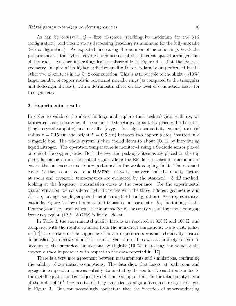
complexity, etc.). Figure 4 displays the total quality factor QLP of a hybrid PBG cavity
of size R = 5a as a function of the number of metallic rings for the geometries of
interest, at a temperature of operation of 30 K, assuming lossless plates and a dielectric
loss-tangent of 10−8 (which is a reasonable value for single-crystal sapphire at low
temperatures), so as to better highlight the role of the copper rods.
0 1 2 3 4 5104
105
106
107 triangular dodecagonal Penrose
number of metallic-rod rings
QL
P
Figure 4. Estimated total quality factor QLP as a function of the number of metallic
(copper) rod rings for triangular, dodecagonal, and Penrose PBG hybrid structures of
size R = 5a (with r/a = 0.2) at a temperature of 30 K, assuming lossless plates and
dielectric loss-tangent of 10−8. Dotted curves are guide-to-eye only.
Hybrid photonic-bandgap accelerating cavities 10
As can be observed, QLP first increases (reaching its maximum for the 3+2
configuration), and then it starts decreasing (reaching its minimum for the fully-metallic
0+5 configuration). As expected, increasing the number of metallic rings levels the
performance of the hybrid cavities, irrespective of the different spatial arrangements
of the rods. Another interesting feature observable in Figure 4 is that the Penrose
geometry, in spite of its higher radiative quality factor, is largely outperformed by the
other two geometries in the 3+2 configuration. This is attributable to the slight (∼10%)
larger number of copper rods in outermost metallic rings (as compared to the triangular
and dodecagonal cases), with a detrimental effect on the level of conduction losses for
this geometry.
3. Experimental results
In order to validate the above findings and explore their technological viability, we
fabricated some prototypes of the simulated structures, by suitably placing the dielectric
(single-crystal sapphire) and metallic (oxygen-free high-conductivity copper) rods (of
radius r = 0.15 cm and height h = 0.6 cm) between two copper plates, inserted in a
cryogenic box. The whole system is then cooled down to about 100 K by introducing
liquid nitrogen. The operation temperature is monitored using a Si-diode sensor placed
on one of the copper plates. Both the feed and pick-up antennas are placed on the top
plate, far enough from the central region where the EM field reaches its maximum to
ensure that all measurements are performed in the weak coupling limit. The resonant
cavity is then connected to a HP8720C network analyzer and the quality factors
at room and cryogenic temperatures are evaluated by the standard −3 dB method,
looking at the frequency transmission curve at the resonance. For the experimental
characterization, we considered hybrid cavities with the three different geometries and
R = 5a, having a single peripheral metallic ring (4+1 configuration). As a representative
example, Figure 5 shows the measured transmission parameter |S12| pertaining to the
Penrose geometry, from which the monomodality of the cavity within the whole bandgap
frequency region (12.5–18 GHz) is fairly evident.
In Table 3, the experimental quality factors are reported at 300 K and 100 K, and
compared with the results obtained from the numerical simulations. Note that, unlike
in [17], the surface of the copper used in our experiments was not chemically treated
or polished (to remove impurities, oxide layers, etc.). This was accordingly taken into
account in the numerical simulations by slightly (10 %) increasing the value of the
copper surface impedance with respect to the data reported in [17].
There is a very nice agreement between measurements and simulations, confirming
the validity of our initial assumptions. The data show that losses, at both room and
cryogenic temperatures, are essentially dominated by the conductive contribution due to
the metallic plates, and consequently determine an upper limit for the total quality factor
of the order of 104, irrespective of the geometrical configurations, as already evidenced
in Figure 3. One can accordingly conjecture that the insertion of superconducting

Hybrid photonic-bandgap accelerating cavities 11
13 14 15 16 17 18-110
-100
-90
-80
-70
-60
|S12
| [d
B]
Frequency [GHz]
Figure 5. Transmission parameter |S12| measured as a function of the frequency for a
Penrose (4+1) point-defect cavity. In the frequency region between the dashed-dotted
vertical line, the frequency sampling has been increased in order to capture the sharp
resonant peak.
Table 3. Measured total quality factor at room (300 K) and cryogenic (100 K)
temperatures for triangular, dodecagonal and Penrose PBG hybrid cavities with
R = 5a and a single peripheral metallic ring (i.e., 4+1 configuration).
Geometry Q100Kexp Q100K
sim Q300Kexp Q300K
sim
Triangular 1.84 × 10⁴ 1.90 × 10⁴ 1.14 × 10⁴ 1.05 × 10⁴
Dodecagonal 1.95 × 10⁴ 1.94 × 10⁴ 1.12 × 10⁴ 1.07 × 10⁴
Penrose 2.00 × 10⁴ 1.96 × 10⁴ 1.05 × 10⁴ 1.07 × 10⁴
plates, with the corresponding reduction of conduction losses of three or more orders
of magnitude, would have already for this configuration a tremendous impact on the
quality factor (and hence on the overall performance) of an accelerating cavity operating
at such high frequencies. Another interesting conclusion that can be drawn is that the
use of conventional low critical temperature materials like niobium, very common in the
development of superconducting accelerating cavities, in this case is unnecessary, since
the overall quality factor of hybrid cavities of such compact size would be inherently
limited (by radiation losses) to values on the order of 107 (see Figure 4). HTS materials
may be used instead, with an obvious simplification of the related cryogenic technology,
and corresponding cost reduction.
4. Conclusions
In this paper, we have explored hybrid configurations of point-defected PBG cavities,
showing that a clever blend of superconducting materials, low-loss dielectrics, and

Hybrid photonic-bandgap accelerating cavities 12
highly conducting metals may pave the way to the development of novel monomodal,
compact, high-performance, accelerating cavities. Via a systematic study of geometrical
configurations, size, and dielectric/metal fractions, we showed that suitably dimensioned
hybrid open structures may attain high in-plane EM radiation confinement, without
significant increase in the conduction losses. The exploitation of superconducting
materials (in the terminating plates) would render the fabrication of this new type of
resonators extremely rewarding, even if at the expense of a higher operational complexity
introduced by the cryogenic technology. Our preliminary experimental results at 100
K show that this route is technologically viable, especially for the development of very
compact, hybrid, PBG cavities based on HTS materials.
Acknowledgments
This work was supported in part by the Campania Regional Government via a 2006
grant (L.R. N. 5 - 28.03.2002) on “Electromagnetic-bandgap quasicrystals: Study,
characterization, and applications in the microwave region.” Stimulating discussions
with Prof. V. G. Vaccaro (University of Naples “Federico II”), as well as the technical
support of F. M. Taurino and S. Marrazzo, are gratefully acknowledged.
References
[1] B. Cowan, M. Javanmard, and R. Siemann. Photonic crystal laser accelerator structures. In Proc.
Particle Accelerator Conference, volume 3, pages 1855–1857, Portland, OR, USA, 2003.
[2] E. I. Smirnova, A. S. Kesar, I. Mastovsky, M. A. Shapiro, and R. J. Temkin. Demonstration
of a 17-GHz, high-gradient accelerator with a photonic-band-gap structure. Phys. Rev. Lett.,
95(7):074801, 2005.
[3] M. Masullo, A. Andreone, E. Di Gennaro, F. Francomacaro, G. Lamura, V. Palmieri, D. Tonini,
M. Panniello, and V. Vaccaro. PBG superconducting resonant structures. In Proc. European
Particle Accelerator Conf., pages 454–456, Edinburgh, Scotland, 2006.
[4] W. Steurer and D. Sutter-Widmer. Photonic and phononic quasicrystals. J. Phys. D, 40(13):R229–
R247, 2007.
[5] A. Della Villa, V. Galdi, S. Enoch, G. Tayeb, and F. Capolino. Photonic quasicrystals: Basics
and examples. In F. Capolino, editor, Metamaterials Handbook, vol. I, chapter 27. CRC Press,
Boca Raton, FL, USA, 2009.
[6] D. N. Chigrin and A. V. Lavrinenko. Photonic applications of two-dimensional quasicrystals. In
F. Capolino, editor, Metamaterials Handbook, vol. II, chapter 28. CRC Press, Boca Raton, FL,
USA, 2009.
[7] E. Macia. The role of aperiodic order in science and technology. Rep. Progr. Phys., 69(2):397–441,
2006.
[8] K. Nozaki and T. Baba. Quasiperiodic photonic crystal microcavity lasers. Appl. Phys. Lett.,
84(24):4875–4877, 2004.
[9] C. A Bauer, G. R. Werner, and J. R. Cary. Truncated photonic crystal cavities with optimized
mode confinement. J. Appl. Phys., 104:053107, 2008.
[10] E. Di Gennaro, S. Savo, A. Andreone, V. Galdi, G. Castaldi, V. Pierro, and M. R. Masullo. Mode
confinement in photonic quasicrystal point-defect cavities for particle accelerators. Appl. Phys.
Lett., 93(16):164102, 2008.

Hybrid photonic-bandgap accelerating cavities 13
[11] CST Microwave Studio. CST – Computer Simulation Technology, Wellesley Hills, MA, USA,
2008.
[12] A. Taflove and S. C. Hagness. Computational Electrodynamics: The Finite-Difference Time-
Domain Method, Third Edition. Artech House, Norwood, MA, USA, 2005.
[13] M. Oxborrow and C. L. Henley. Random square-triangle tilings: A model for twelvefold-symmetric
quasicrystals. Phys. Rev. B, 48(10):6966–6998, 1993.
[14] M. Senechal. Quasicrystals and Geometry. Cambridge University Press, Cambridge, UK, 1995.
[15] Harminv. http://ab-initio.mit.edu/harminv.
[16] M. R. Masullo, A. Andreone, E. Di Gennaro, F. Francomacaro, G. Lamura, V.G. Vaccaro,
G. Keppel, V. Palmieri, and D. Tonini. A study on a mono-modal accelerating cavity based on
photonic band gap concepts. In Proc. Int. Workshop on Physics at a multi-MW proton source,
pages 15–19, Firenze, Italy, 2004.
[17] S. Inagaki, E. Ezura, J.F. Liu, and H. Nakanishi. Thermal expansion and microwave surface
reactance of copper from the normal to anomalous skin effect region. J. Appl. Phys.,
82(11):5401–5410, 1997.