THÈSE DE DOCTORAT DE
106
T HÈSE DE DOCTORAT DE L’UNIVERSITÉ DE NANTES ÉCOLE DOCTORALE N O 601 Mathématiques et Sciences et Technologies de l’Information et de la Communication Spécialité : Électronique - Génie Électrique Par Safouane NOUBIR Evaluation and consideration of security in multi-core manage- ment systems Thèse présentée et soutenue à l’Université de Nantes, le 17 décembre 2021 Unité de recherche : IETR UMR 6164 Rapporteurs avant soutenance : M. BOSSUET Lilian Professeur, Université Jean Monnet, Saint-Étienne Mme. ENCRENAZ Emmanuelle Maître De Conférences/ HDR, Sorbonne Université, Paris Composition du Jury : Président : M. GOGNIAT Guy Professeur, Université Bretagne Sud, Lorient Examinateurs : M. BOSSUET Lilian Professeur, Université Jean Monnet, Saint-Étienne Mme. ENCRENAZ Emmanuelle Maître De Conférences/HDR, Sorbonne Université, Paris Dir. de thèse : M. PILLEMENT Sébastien Professeur, Ecole polytechnique de Université de Nantes Encadrante de thèse : Mme. MENDEZ REAL Maria Maître De Conférences, Ecole polytechnique de l’université de Nantes
-
Upload
khangminh22 -
Category
Documents
-
view
2 -
download
0
Transcript of THÈSE DE DOCTORAT DE

THÈSE DE DOCTORAT DE
L’UNIVERSITÉ DE NANTES
ÉCOLE DOCTORALE NO 601Mathématiques et Sciences et Technologiesde l’Information et de la CommunicationSpécialité : Électronique - Génie Électrique
Par
Safouane NOUBIREvaluation and consideration of security in multi-core manage-ment systems
Thèse présentée et soutenue à l’Université de Nantes, le 17 décembre 2021Unité de recherche : IETR UMR 6164
Rapporteurs avant soutenance :
M. BOSSUET Lilian Professeur, Université Jean Monnet, Saint-ÉtienneMme. ENCRENAZ Emmanuelle Maître De Conférences/ HDR, Sorbonne Université, Paris
Composition du Jury :
Président : M. GOGNIAT Guy Professeur, Université Bretagne Sud, LorientExaminateurs : M. BOSSUET Lilian Professeur, Université Jean Monnet, Saint-Étienne
Mme. ENCRENAZ Emmanuelle Maître De Conférences/HDR, Sorbonne Université, ParisDir. de thèse : M. PILLEMENT Sébastien Professeur, Ecole polytechnique de Université de NantesEncadrante de thèse : Mme. MENDEZ REAL Maria Maître De Conférences, Ecole polytechnique de l’université de Nantes

Les travaux de cette thèse ont été réalisés dans le cadre du projet SECURE IoT sélectionné par le RFI
WISE avec le soutien financier de la Région des Pays de la Loire.

ACKNOWLEDGEMENT
I would like to start this document by expressing my gratitude to all the people I metand received help during the course of my PhD.
First, I would like to thank both of my thesis supervisor Sébastien Pillement and MariaMendez Real for providing me with the opportunity to pursue my PhD. I am highly grate-ful for the guidance and the support they provided me through my work which helpedme better understand my subject and guided me in the right direction.
I would like to thank the reviewers and the jury committee Guy Gogniat, LilianBossuet and Emmanuelle Encrenaz for reviewing my thesis and accepting to evaluate mywork. I would also like to extend thanks to my CSI members Quentin Meunier and Ar-naud Tisserand for their constructive remarks that helped me complete my work.
Moreover, I would like to thank all the members of the IETR laboratory for theiradministrative and technical support. I would also like to address my gratitude to all mycolleagues and fellow PhD students as they have enriched my daily life during my PhD.
Finally, I would like to thank my parents and brother for their unconditional andunwavering support that helped greatly through this journey.
3

RÉSUMÉ LONG
Les architectures multi-cœurs présentent aujourd’hui une grande complexité du faitdu grand nombre de ressources les constituants. Afin de gérer cette complexité et derépondre à des contraintes de performances ou de consommation d’énergie, il est néces-saire d’implémenter des gestionnaires dynamiques (e.g., mapping de tâches, adaptationdynamique de la fréquence et de la tension). Par exemple, les smartphones ont été conçusen mettant des architectures complexes dans un espace limité tout en s’assurant du bonfonctionnement de l’appareil (i.e., durée de vie de la batterie, température du processeur).Cependant, dans la majorité des cas, ces gestionnaires n’ont pas été conçus pour la sécuritéet présentent des vulnérabilités.
Durant les dernières années, un grand intérêt s’est porté sur les vulnérabilités matériellesprésentes lors de la conception du circuit. Différents types d’attaques ont fait surfaces (e.g.,Meltdown [1], Spectre [2], Clkscrew [3]) dont le but principal est d’extraire une informationcachée (e.g., une clef de chiffrement). Ces attaques s’avèrent de plus en plus dangereusesétant donné que les systèmes embarqués (comme les smartphones) sont aujourd’hui utiliséspour des opérations sensibles, comme par exemple, des applications bancaires, paiementpar téléphone, suivi de santé, ou les véhicules autonomes.
Cette thèse vise donc d’une part à étudier les gestionnaires actuels des architecturesmulti et many-core et à évaluer de possibles vulnérabilités. Il existe peu des travauxétudiant ces gestionnaires dans le cadre de la gestion d’architectures simples qui nousont servis de base pour étudier leur pertinence/adaptation aux systèmes plus complexesde type many-core. D’autre part ces travaux visent à proposer et évaluer de possiblescontre-mesures adaptées à ce type d’architecture. Dans cette thèse, nous nous intéressonsà deux types de gestionnaire dynamique : le gestionnaire d’énergie et le gestionnaire detempérature. Trois attaques différentes sur ces deux gestionnaires sont ainsi présentéesainsi que de possibles contre-mesures.
Dans un premier temps, nous nous sommes intéressés à évaluer les vulnérabilités desgestionnaires d’énergie actuels. Ces gestionnaires permettent de réduire la consommationd’énergie en modifiant dynamiquement la tension et la fréquence de l’architecture, com-munément appelé DVFS (Dynamic Voltage and Frequency Scaling). Ce gestionnaire est
5

composé de deux parties : i) Une partie logicielle composée d’une application qui gère laconsommation énergétique de l’appareil en choisissant un couple de tension et fréquence.On retrouve aussi un driver kernel qui assure la communication entre l’application et lapartie matérielle. ii) Une partie matérielle composée de régulateurs fixant les tensionsd’alimentation des c/oe urs et de PLLs (Phase Locked Loop) fixant leurs fréquences.
Le contrôle sur la tension et la fréquence joue un grand rôle dans la gestion d’énergied’un appareil. Cependant, ces deux grandeurs sont liées à la stabilité du système, et unmicroprocesseur ne peut fonctionner correctement que lorsque la fréquence et la tensionrespectent certaines conditions. En effet, dans un système combinatoire, la période del’horloge doit être plus grande que le temps de propagation des signaux dans le circuitainsi que le temps de setup et de hold des bascules. Une modification malveillante detension sans adapter la fréquence peut donc rendre le système instable et générer deserreurs. Une première attaque sur la gestion malveillante de régulateurs DVFS a étépublié en 2017 [[3]] dans une architecture de ARM. Cette attaque se base sur le principeprécèdent et a pour but d’injecter des erreurs dans une tâche victime (e.g., chiffrementAES, RSA), ce qui permet de déduire les informations qui nous intéressent notamment laclef cryptographique secrète. Il existe aussi une autre attaque PlunderVolt [4] exploitantla même vulnérabilité sur une architecture Intel.
Le but principal de cette contribution est d’exploiter cette vulnérabilité différemment.En effet, des expérimentations ont démontrés qu’un changement malicieux de tensionbloque l’appareil complètement à partir d’un certain seuil. Il est donc possible d’utilisercette vulnérabilité comme une attaque par déni de service et peut même rendre un ap-pareil inaccessible. Dans un scénario d’exploitation possible, en considérant un smartphonecomme cible de l’attaque, un attaquant peut modifier la tension avec une application mali-cieuse et bloquer l’accès à l’appareil. Par la suite, l’attaquant peut demander une rançonà la victime pour débloquer son appareil.
Cette attaque a été implémentée sur une carte Odroid XU4 [5] équipée d’un Exynos5422 (ARM A7, A15) et une carte Hikey 960 équipée d’un Kirin 960 (A73 et A53). Cesdeux cartes récentes utilisent la technologie big.LITTLE de ARM. Cette dernière utilisedeux clusters séparés physiquement (un cluster big pour les hautes performances, et uncluster LITTLE pour l’optimisation de la consommation) chacun avec un régulateur detension et un générateur de fréquence.
Finalement, l’implémentation de l’attaque se fait en 4 étapes : 1) Il faut une applica-tion malicieuse avec un accès privilégié installée sur l’appareil victime. Cet accès privilégié
6

dans un téléphone peut s’être procuré facilement si la victime utilise une ROM customisée(e.g., Magisk) ou même en utilisant d’autres vulnérabilités classiques des téléphones. Cesutilisateurs seront la cible principale de cette attaque. 2) Un module afin de contrôler latension est nécessaire, dans un cas général, il suffit d’utiliser l’API kernel pour les régula-teurs. Celle-ci nous permet de contrôler les régulateurs justes en utilisant le nom assignépar le constructeur. Dans le cas de la Hikey960, un module permettant de contrôler latension est déjà présent. 3) En utilisant le module précédent, il est possible de bloquerl’appareil en changeant la valeur de la tension en dessous du seuil nécessaire pour le fonc-tionnement étant donné qu’il n’y a aucune limite logicielle ou matérielle. 4) Finalement,il suffit de bloquer l’appareil de manière permanente en chargeant le module à chaquedémarrage. Pour ce faire, il suffit d’utiliser l’application malicieuse pour détecter le dé-marrage et de charger le module malicieux avant même que la victime ne puisse débloquerson téléphone.
Cette attaque montre qu’il est possible d’utiliser malicieusement les gestionnairesd’énergie dans le cas où la précision n’est pas nécessaire pour injecter les fautes et extrairede l’information. La contre-mesure la plus directe de cette attaque serait de rajouter deslimites aux valeurs de tensions possibles en fonction de la fréquence. Une autre contre-mesure serait de limiter l’accès aux régulateurs et que seule une application exécutée dansun environnement sécurisé (TEE – Trusted Execution Environment) puisse changer latension.
Dans une deuxième partie, nous nous sommes intéressés aux gestionnaires de tem-pérature. Ces gestionnaires sont aujourd’hui présents dans tous les systèmes afin d’assurerque les processeurs restent dans une température idéale et ainsi éviter la surchauffe et ladétérioration des circuits intégrés. Normalement, des moyens de refroidissement actif (e.g.,radiateur, ventilateur) sont utilisés. Cependant, dans le cas d’un téléphone mobile ou desappareils qui priorisent la portabilité, il n’est pas possible d’implémenter ces moyens. Dansce cas, des outils de refroidissement passif sont utilisés, généralement, c’est la fréquencequi est réduite afin de refroidir le processeur.
Afin que les gestionnaires de température puissent prendre des décisions, ils doiventêtre capable de mesurer activement la température du processeur, pour ce faire, des cap-teurs de température ont été implémentés sur la plupart des processeurs modernes. Lescapteurs sont généralement utilisés pour aider les gestionnaires mais dans notre travail, ila été possible de les utiliser afin d’extraire de l’information d’un programme victime. Dansles travaux déjà publiés, la température est généralement utilisée comme canal caché [6]
7

afin de transmettre de l’information, dans ce cas aucune information n’est extraite, unautre travail a utilisé la température pour déduire le type d’applications qui est exécutéesur une architecture victime (e.g., explorateur internet, chiffrement RSA, . . . ) mais aucuneinformation au niveau des instructions ou opérandes n’a été extraite.
Dans notre scénario d’attaque, un attaquant doit caractériser l’effet d’une caractéris-tique d’une information secrète (une clef de chiffrement AES 128 bits dans notre étude)sur la température. Pendant la caractérisation, l’attaquant doit avoir accès à une copie del’architecture cible et d’être capable de modifier la clef de chiffrement. Pendant l’attaque,il doit réaliser des mesures de températures à distance sur un appareil victime lors del’exécution d’un chiffrement AES 128 bits avec une clef inconnue. L’attaquant peut parla suite analyser les mesures et les comparer à la caractérisation réalisée afin d’extrairedes caractéristiques de la clef lui permettant de réduire l’espace d’exploration et même deréaliser une force brute dans certains cas.
Afin d’implémenter cette attaque, il faut tout d’abord caractériser la cible. Pour cefaire, des mesures ont été réalisés afin d’observer l’effet des instructions et des opérandessur la température, la cible de cette expérimentation est le microprocesseur STM32F303 [7].Dans ce cas, l’accès au capteur de température a été fait par DMA (Direct Memory Ac-cess) afin de limiter les effets de la mesure. Dans le cas d’un processeur multicœurs, il estpossible de réaliser les mesures à partir d’un autre cœur.
Une première caractérisation a été d’observer l’effet de différentes instructions lorsqueles opérandes sont fixés, 3 instructions arithmétiques et logiques (multi, add et xor) en plusde 3 instructions de mémoires (load, write et mov) ont été exécutés dans une boucle et latempérature a été mesurée en parallèle afin de caractériser son évolution. Après l’analysedes mesures, il est possible de distinguer entre les différentes instructions de chaque type.En effet, même si la variation de température est petite, de l’ordre de 10 m°c, il esttoujours possible de distinguer les instructions en utilisant uniquement la température.Par la suite, l’effet des opérandes pour certaines instructions a été caractérisée, notammentl’effet du poids de Hamming dans les multiplications sur 32 bits. La même configurationde mesures a été réutilisée, en plus, on fixe un opérande de la multiplication et on faitvarier l’autre mais seulement pour des valeurs ayant les 3 poids de Hamming 8, 14 et 24.Cette limitation a été appliquée pour des raisons de temps de mesures. Après l’analysedes mesures, il est possible de clairement distinguer entre les 3 poids de Hamming dansla plupart des cas. Par la suite, nous nous sommes intéressés à caractériser l’effet desdeux premières instructions de l’AES, la SBOX et l’ADDKEY sur la température, pour
8

ce faire, la distance de Hamming (nombre de bits qui ont changé entre deux états d’unregistre) a été étudiée. Tout d’abord, l’ADDKEY est calculée entre une valeur fixée (celle-ci représente un octet de la clef de chiffrement) et une autre qui varie (celle-ci représenteun octet du texte à chiffrer), étant donné que les calculs se font sur 8 bits, il était possiblede faire les mesures pour toutes les valeurs possibles du deuxième opérande. Le résultatest enregistré dans un registre ‘r’ qui est par la suite utilisé pour calculer la SBOX et pourenregistrer les résultats de ce calcul. La distance de Hamming caractérisée est donc celleentre les deux états du registre ‘r’. Finalement, en observant les mesures de températureseffectuées, il est clairement possible de distinguer les 9 distances de Hamming possiblepour des opérandes de 8 bits.
La caractérisation a permis de corréler la température aux instructions et aux opéran-des, de plus, la dernière expérimentation nous a même permis de caractériser l’effet decertaines instructions d’AES sur la température, dans ce cas la clef de chiffrement étantconnue. Afin d’utiliser cette caractérisation dans une attaque sur un chiffrement AES,il faut que l’attaquant soit capable de re-exécuter indifféremment l’ADDKEY pour unoctet spécifique comme lors de l’expérimentation réalisée. Pour ce faire, nous avons utilisédes techniques similaires à SGXSTEP [8], le principe est de déclencher des interruptionspériodiquement à la fin de l’exécution des instructions à l’aide d’un compteur matériel. Fi-nalement, l’attaquant doit effectuer des mesures de température à distance sur l’appareilvictimes pendant un chiffrement à l’aide d’une application malicieuse ayant accès auxcapteurs. Dans ce cas, la clef n’est pas connue, cette mesure est donc comparée à la car-actérisation déjà réalisée (la clef était connue) et cette comparaison permet de déduirequelle distance de Hamming à une valeur de température proche ou égale. En utilisant ladistance de Hamming déduite, il a été possible de réduire l’espace d’exploration de 98.27%dans le meilleur des cas pour un octet de la clef et 74% dans le pire des cas.
Pour cette attaque, deux contre-mesures ont été proposé. La plus simple est de réduirela précision des capteurs de températures mais cela augmente seulement le nombre demesures nécessaires pour réaliser l’attaque, la deuxième contre-mesure serait de limiterl’accès aux capteurs à des applications fiables (en TEE par exemple) tout comme pourles régulateurs dans l’attaque sur les gestionnaires d’énergie.
La troisième contribution de cette thèse est de réaliser une attaque similaire avec lescapteurs de température sur une architecture plus complexe, la Hikey960 [9] présentéprécédemment, et un chiffrement RSA 2048 bits. Le scénario de l’attaque est le même, unattaquant caractérise la cible et identifie l’effet d’une certaine caractéristique de la clef de
9

chiffrement (dans ce cas, la clef est connue) sur la température. Par la suite, il effectue desmesures à distance et utilise ces mesures avec la caractérisation réalisée afin de déduiredes caractéristiques de clef et de réduire l’espace d’exploration.
Sur cette architecture complexe, une simple étude et comparaison de températuren’était pas suffisante, il a été nécessaire d’utiliser des analyses plus poussées, notamment,de l’apprentissage automatique. Deux algorithmes ont été utilisés : i) un premier algo-rithme qui filtre les mesures, VAE (Variational Autoencoder), ce dernier est composé dedeux réseaux de neurones entièrement connecté dont le but est de compresser l’informationet puis de la décompresser. Les neurones d’entrée et de sortie doivent donc avoir la mêmedonnée mais le nombre de neurones diminue progressivement jusqu’à 4 neurones dansnotre cas et puis augmente jusqu’à attendre le même nombre de neurones d’entrée. Cettephase permet d’éliminer le bruit. ii) Un deuxième algorithme pour clustériser les données,PCA (Principal Component Analysis), ce dernier traite les données filtrées précédemmentpar le VAE et forme des clusters en fonction de la caractéristique de la clef. Dans notre cas,la caractéristique utilisée est le poids de Hamming de la clef. Finalement, cette attaque aété validée sur certain poids de Hamming et en utilisant l’analyse proposée, il était pos-sible d’identifier cette caractéristique dans un scénario réel. Cependant, le nombre de caspossible restant ne permet pas de réaliser une brute-force et nécessite d’autres approchesadditionnelles pour identifier la clé secrète (de 2048 bits pour rappel).
Dans cette thèse, nous avons exploré de possibles vulnérabilités présentes dans les ges-tionnaires dynamiques requis par les architectures embarquées modernes. Il a été prouvéà travers trois attaques qu’il est possible de malicieusement exploiter ces gestionnaires, etquelques contre-mesures ont été proposés. Les analyses proposées peuvent être pousséesplus loin surtout dans la dernière contribution, le VAE peut-être aussi utiliser pour identi-fier l’effet d’une certaine caractéristique (un poids de Hamming spécifique) même si aucunemesure n’a été fait pour celle-là tant que l’on a assez de mesures pour les autres poids deHamming. Cette analyse peut être aussi utilisée pour les attaques de consommation dansle cas où le nombre de mesures est limité.
10

TABLE OF CONTENTS
Introduction 17
1 Background and state of the art 191.1 Energy managers . . . . . . . . . . . . . . . . . . . . . . . . . . . . . . . . 191.2 Side Channel Attacks . . . . . . . . . . . . . . . . . . . . . . . . . . . . . . 24
1.2.1 Differential fault analysis . . . . . . . . . . . . . . . . . . . . . . . . 251.2.2 Attacks exploiting DVFS . . . . . . . . . . . . . . . . . . . . . . . . 26
1.3 Temperature managers . . . . . . . . . . . . . . . . . . . . . . . . . . . . . 281.4 Temperature related vulnerabilities . . . . . . . . . . . . . . . . . . . . . . 291.5 Integrated Sensors and hardware counters . . . . . . . . . . . . . . . . . . 321.6 Power analysis based attacks . . . . . . . . . . . . . . . . . . . . . . . . . . 34
1.6.1 Power Analysis Attacks using embedded sensors . . . . . . . . . . . 361.6.2 Template attacks . . . . . . . . . . . . . . . . . . . . . . . . . . . . 361.6.3 Profiling attack with machine learning . . . . . . . . . . . . . . . . 37
1.7 Conclusion . . . . . . . . . . . . . . . . . . . . . . . . . . . . . . . . . . . . 38
2 Maliciously exploiting energy management 392.1 Scenario . . . . . . . . . . . . . . . . . . . . . . . . . . . . . . . . . . . . . 402.2 Target device . . . . . . . . . . . . . . . . . . . . . . . . . . . . . . . . . . 41
2.2.1 ARM architecture and big.LITTLE Technology . . . . . . . . . . . 412.2.2 Hikey960 & Odroid XU4 . . . . . . . . . . . . . . . . . . . . . . . . 42
2.3 Experimental Setup . . . . . . . . . . . . . . . . . . . . . . . . . . . . . . . 432.3.1 Accessing and controlling the voltage and the frequency . . . . . . . 432.3.2 Characterisation of the targets . . . . . . . . . . . . . . . . . . . . . 452.3.3 Conclusion on the characterisation . . . . . . . . . . . . . . . . . . 47
2.4 Malicious exploitation of the DVFS . . . . . . . . . . . . . . . . . . . . . . 482.4.1 Implementation steps . . . . . . . . . . . . . . . . . . . . . . . . . . 482.4.2 Implementation of the attack . . . . . . . . . . . . . . . . . . . . . 502.4.3 Discussion and counter-measures . . . . . . . . . . . . . . . . . . . 52
11
TABLE OF CONTENTS
2.5 Conclusion . . . . . . . . . . . . . . . . . . . . . . . . . . . . . . . . . . . . 53
3 Exploiting integrated temperature sensor 553.1 Methodology . . . . . . . . . . . . . . . . . . . . . . . . . . . . . . . . . . 563.2 Experimental setup . . . . . . . . . . . . . . . . . . . . . . . . . . . . . . . 57
3.2.1 Distinguishing instructions . . . . . . . . . . . . . . . . . . . . . . . 583.2.2 Distinguishing between operands . . . . . . . . . . . . . . . . . . . 603.2.3 Distinguishing operands based Hamming Distance . . . . . . . . . . 63
3.3 Extracting AES key characteristics using temperature sensors . . . . . . . 643.3.1 Methodology of the attack main steps . . . . . . . . . . . . . . . . . 643.3.2 AES reminder . . . . . . . . . . . . . . . . . . . . . . . . . . . . . . 663.3.3 Attack implementation and results . . . . . . . . . . . . . . . . . . 663.3.4 Offline Phase . . . . . . . . . . . . . . . . . . . . . . . . . . . . . . 683.3.5 Online Phase . . . . . . . . . . . . . . . . . . . . . . . . . . . . . . 693.3.6 Results analysis . . . . . . . . . . . . . . . . . . . . . . . . . . . . . 70
3.4 Discussion . . . . . . . . . . . . . . . . . . . . . . . . . . . . . . . . . . . . 723.5 Conclusion . . . . . . . . . . . . . . . . . . . . . . . . . . . . . . . . . . . . 73
4 Using machine learning to analyze temperature variation and extractsecret information 754.1 Attack scenario . . . . . . . . . . . . . . . . . . . . . . . . . . . . . . . . . 764.2 Experimental setup . . . . . . . . . . . . . . . . . . . . . . . . . . . . . . . 77
4.2.1 Distinguishing operands HWs . . . . . . . . . . . . . . . . . . . . . 784.3 Machine learning methods . . . . . . . . . . . . . . . . . . . . . . . . . . . 80
4.3.1 Variational Autoencoder . . . . . . . . . . . . . . . . . . . . . . . . 804.3.2 Principal Component Analysis . . . . . . . . . . . . . . . . . . . . . 82
4.4 Inferring the HW of RSA private key . . . . . . . . . . . . . . . . . . . . . 854.4.1 Main implementation steps of attack . . . . . . . . . . . . . . . . . 854.4.2 RSA reminder . . . . . . . . . . . . . . . . . . . . . . . . . . . . . . 864.4.3 Experimental setup . . . . . . . . . . . . . . . . . . . . . . . . . . . 874.4.4 Attack implementation and results . . . . . . . . . . . . . . . . . . 88
4.5 Discussion . . . . . . . . . . . . . . . . . . . . . . . . . . . . . . . . . . . . 904.6 Conclusion . . . . . . . . . . . . . . . . . . . . . . . . . . . . . . . . . . . . 91
Conclusion 93
12

TABLE OF CONTENTS
Bibliography 97
13
LIST OF FIGURES
1.1 The increase of microprocessor complexity over the years showing two sep-arate phases, the first phase focus on increasing the frequency while thesecond phase focus on increase the number of logical cores [13]. . . . . . . . 20
1.2 The hardware implementation of DVFS showing different elements neces-sary to the control of the frequency and voltage of a core or cluster . . . . 21
1.3 A general implementation of the software part of DVFS highlighting thethree different levels and its connection to the hardware part . . . . . . . . 22
1.4 The time constraints condition is represented through the schematic, byshowing how the frequency is dependant on the voltage . . . . . . . . . . 23
1.5 highlighting of two types of SCA, the Physical Extraction and FunctionalExtraction [18]. . . . . . . . . . . . . . . . . . . . . . . . . . . . . . . . . . 24
1.6 Clkscrew steps showing how the normal core running the malicious appli-cation faults the target running the encryption program while the normalcore stays protected from the changes of frequency . . . . . . . . . . . . . . 27
1.7 Thermal throttling for core 0, frequency and power are decreased to keeptemperature from going beyond junction temperature at 95°C. Results ofthis figure were presented in [27] . . . . . . . . . . . . . . . . . . . . . . . . 30
1.8 Different heat generated depending on the HW of the operand during theoperation ’mov’ [28] . . . . . . . . . . . . . . . . . . . . . . . . . . . . . . . 31
1.9 Transmitting data from one "secure" core to another "normal" core usingintensive processing to raise the temperature [6] . . . . . . . . . . . . . . . 31
1.10 Profiling the type of application the user is running based on the tem-perature measurements. This figure is one of results that were presentedin [6] . . . . . . . . . . . . . . . . . . . . . . . . . . . . . . . . . . . . . . . 32
1.11 Dynamic manager functions as an autonomous closed loop. The decision ismade based on the sensor’s measurement, the CPU switch to a new stateand the manager keeps monitoring ensuring the desired state is reached . . 33
1.12 The different steps and tools necessary to execute a classical power basedattack . . . . . . . . . . . . . . . . . . . . . . . . . . . . . . . . . . . . . . 35
14

LIST OF FIGURES
2.1 Summary of the scenario of the attack from both the attacker and thevictim point of view plus the conditions required to implement the attack 41
2.2 ARM big.LITTLE technology and DVFS implementation . . . . . . . . . . 422.3 The experimentation used to characterise the SoC. In this case, we char-
acterise the LITTLE cluster, but with the same methodology we can alsocharacterise the big cluster by switching voltage module to the LITTLEcluster and the victim app to the big cluster. . . . . . . . . . . . . . . . . . 45
2.4 Characterization of Exynos 5422 and Kirin 960 clusters effects of the themodification of voltage for each frequency level. . . . . . . . . . . . . . . . 47
2.5 The measured voltage at the output of PMIC for the Exynos shows anaverage minimum time of 2.5ms between each voltage changes . . . . . . . 48
2.6 Required steps from the attacker point of view . . . . . . . . . . . . . . . . 492.7 Summarized usage of intent used by android to ensure communication be-
tween applications . . . . . . . . . . . . . . . . . . . . . . . . . . . . . . . 512.8 Summarized steps performed by the attacker on the victim device . . . . . 51
3.1 Required steps for the proposed temperature driven attack from the at-tacker point of view. . . . . . . . . . . . . . . . . . . . . . . . . . . . . . . 57
3.2 Comparison of the integrated temperature values generated by each con-sidered arithmetic and logic instruction with the same operands . . . . . . 59
3.3 Comparison of the integrated temperature values generated by each con-sidered memory instruction with the same operands . . . . . . . . . . . . . 60
3.4 The main steps used for measuring the effect of the operands on the tem-perature . . . . . . . . . . . . . . . . . . . . . . . . . . . . . . . . . . . . . 61
3.5 Comparison of the temperature generated by 32-bit width multiplication,with the non-constant operand having HW of [8,16,24] and multiplied bythe constant value 23 . . . . . . . . . . . . . . . . . . . . . . . . . . . . . . 62
3.6 Comparison of the temperature depending on the HD between two statesof the same register after a xor and a load operation. . . . . . . . . . . . . 64
3.7 Operations in the first round of AES . . . . . . . . . . . . . . . . . . . . . 673.8 For the STM32F303 platform, the temperature characterization for two
arbitrary HDs of r (4 and 5) during the Offline Phase. There are 500 dotsin each graph and each point represents the mean value of 30,000 tem-perature measurements. The blue dotted line represents the temperaturemeasurement during the Online Phase. . . . . . . . . . . . . . . . . . . . . 69
15

LIST OF FIGURES
4.1 The main steps of the proposed temperature separated into the OfflinePhase where the attacker characterize the victim device and Online phasewhere the attacker access the temperature sensor on the victim device andmeasure the temperature remotely . . . . . . . . . . . . . . . . . . . . . . . 76
4.2 The 5 different temperature sensors on the Hikey960 board . . . . . . . . . 784.3 Comparison of the integrated temperature values generated by different
HW values of the secret (hidden operand). . . . . . . . . . . . . . . . . . . 794.4 The classic structure of an Autoencoder were the Encoder compress the
data into a 3 dimension layer Code (also called latent space), meanwhile,the Decoder reconstruct the data from the latent space. The reconstructeddata has its insignificant information filtered . . . . . . . . . . . . . . . . . 81
4.5 The structure of the VAE used during this work . . . . . . . . . . . . . . . 824.6 Comparison of the integrated temperature values generated by different
HW values of the secret after being filtered using a VAE . . . . . . . . . . 834.7 Different clusters are formed depending on the HW of the hidden operand
after using PCA on the dataset filtered by the VAE . . . . . . . . . . . . . 834.8 All the steps used in the characterization of the 2048 bits multiplication,
from measurement to identifying the HW of a fixed operand . . . . . . . . 844.9 The main step to generate the public and private key of the RSA algorithm 874.10 Temperature characterization of RSA2048, each trace shows a different HW
from (80 to 2000 with a step of 80). . . . . . . . . . . . . . . . . . . . . . . 884.11 Clusters for each HW (250, 650, 1050, 1450, 1850) of the private key formed
after executing the PCA on the dataset of RSA2048 using 200 keys per HW. 89
16

INTRODUCTION
Embedded systems architectures are becoming more and more complex to support theever increase of algorithmic complexity requirements. This led to an increase in the num-ber of transistors within chips, the number of logical cores and their running frequencieswhich gave rise to an increase in energy consumption and heat generated by the chips. Thisis problematic for devices such as smartphones, these devices were designed to fit complexarchitectures in the smallest space while ensuring that the processor runs in stable condi-tions. This includes maximizing the battery life and making sure that the processor doesnot overheat (Temperature goes beyond the limit specified by the manufacturer). Thisphenomenon is even more important for advanced 3D stacking technologies [10]. More-over, overheating also cause chip to age faster [11],[12]. Thus, it was necessary to manageboth of the temperature and power consumption, for this different dynamic managerswere deployed.
As for the increase of logical cores, it was also necessary to implement resources man-agers to optimise their usage and have a better scheduling. To summarize, it is necessaryto use dynamic managers to fully exploit state-of-art architectures. The goal of thesedynamic managers is either to optimize resources usage (e.g., cores, memory) and/or toreduce the energy consumption of the system under performance constraints. However,these managers have not been designed to be secure and present vulnerabilities.
In recent years, there has been an increase in the number of attacks based on hardwarevulnerabilities (e.g., Meltdown [1], Spectre [2], Clkscrew [3]). This type of attacks haveshown to be dangerous for everyone including mobile devices for example, this can highlyaffect the privacy of the users. Moreover, smartphone are used more and more for sensitiveoperations such as payment, banks applications and healthcare. Furthermore, this is notlimited to mobile phone and can be extended to IoT, connected devices (e.g., autonomouscar, smartTV) and even health electronics.
In this thesis, we aim at evaluating the security of different dynamic managers used intoday’s devices, study possible vulnerabilities and finally discuss some countermeasures.We are going to focus on two important managers present in almost every device today:energy and temperature managers. Three different attacks targeting the two managers
17

Introduction
are presented in this work and implemented on different target devices. Two of the tar-get devices are processors used by the smartphone industry, the Kirin960 [9] and theExynos5422 [5], these targets are heterogeneous octa-cores based on ARM architectureswhile the third target is an STM32F303 [7] single core mainly used for IoT.
The rest of the thesis is divided as follows:
— Chapter I: Background and State of art presents the context of our workand contains the basics functioning of the dynamic managers we target in the otherchapters. This chapter also presents related State-of-Art vulnerabilities and previousattacks on the managers.
— Chapter II: Maliciously exploiting energy management presents our firstcontribution. It presents a case of malicious usage of energy management, morespecifically, the Dynamic Voltage & Frequency Scaling mechanism (DVFS). Experi-mentations shows that it is possible to remotely lock out a device, denying access toall services and data, requiring for example the user to pay a ransom to unlock it. Asthe main target of this exploit is embedded systems, we demonstrate this work byits implementation on two different commercial ARM-based devices (Odroid XU4and Hikey960). Finally, some possible countermeasures were discussed.
— Chapter III: HEXotherm presents our second contribution. It targets IoT de-vices and uses the integrated temperature sensors to extract secret information. Wedemonstrate the feasibility of this attack and show that it is possible to use theextracted information to deduce characteristics on an AES secret key. Our differentexperiments on a real hardware platform show a reduction from 74% in the worstcase scenario to 98.27% of the exploration space for each byte of the 128 bits key inthe best case scenario.
— Chapter IV: Using machine learning with temperature sensors presents thelast contribution of this work. It is an extension of the previous work and it targeta more complex architecture. In this chapter, we prove through experimentationsthat it is possible to use machine learning techniques to analyze the temperatureissues from embedded sensors and use it to infer the hamming weight of the privatekey of the RSA algorithm.
— Conclusion: resume all the contributions of this thesis and propose possible furtherworks to perform.
18

Chapter 1
BACKGROUND AND STATE OF THE ART
Over the years, there has been a continuous increase in microprocessor’s performanceto follow up with the increase of application complexity as can be seen in Figure 1.1. Dur-ing a first phase, the focus was on increasing the performance of single cores/processorsand mainly through the increase of their frequency. However, due to the technologicalconstraints the increase in frequency stagnated, a second phase started where the focusswitched toward the increasing number of logical cores per microprocessor. During bothphases, the density of the integrated circuit and its energy consumption continued toincrease with the heat emitted. Moreover, with the continuous increase in available re-sources, it has been necessary to implement dynamic managers. Those managers have 3main usages and can be separated into the following types:
— Resources manager in order to optimize resources usage and increase generalperformance.
— Energy manager which intend to reduce energy consumption, improve systemportability and increase battery life.
— Temperature manager regulate temperature in order to avoid overheating andincrease the chip life time.
1.1 Energy managers
In the embedded system industry, energy management has become a necessity to opti-mize system performance and reduce energy consumption to improve system portability,and increase battery life.
An efficient energy manager is composed of a software part that controls a hard-ware dedicated block. The software is generally a decision-making algorithm monitoringdifferent parameters of the architecture (e.g., the CPU load, battery level and currentenergy consumption). On the other hand, the hardware part is responsible for applying
19

Chapter 1 – Background and state of the art
First phase focus onthe frequency
Second phasefocus on numberof logical cores
Figure 1.1 – The increase of microprocessor complexity over the years showing two sepa-rate phases, the first phase focus on increasing the frequency while the second phase focuson increase the number of logical cores [13].
the decisions and collecting information on the current state of the microprocessor usingembedded sensors.
The amount of energy consumed in a system is the product of power and time. Itrefers to the total amount of resources utilized by a system to complete a task over time.In the case of an integrated circuit, power P at the instant t is directly proportional tothe product of operating frequency F, voltage V and C the switching capacity of thecircuit [14]:
Pt ≡ C ∗ V 2t ∗ Ft. (1.1)
It is clear at this point that modifying the frequency and specially the voltage candrastically reduce the power consumption in exchange of reducing the computation speed.Nowadays, the most used energy management mechanism that implements this feature isthe Dynamic Voltage & Frequency Scaling (DVFS) [15]
20

1.1. Energy managers
DVFS
DVFS was first introduced in 1994 [15] and is one of the most used energy savingmechanisms today, especially in embedded systems such as in the smartphone industrywhere portability and increasing the device’s battery life is of most importance.
DVFS relies on the ability to control frequency and voltage levels of a core or a clusterof cores in a System On Chip (SoC) in order to dynamically trade processing speed forenergy consumption according to the system requirements. DVFS is based on several partas shown in Figure 1.2 and Figure 1.3.
Core orcluster
Core orcluster
Core orcluster
PLLs
Registers
PMIC
SPMI
Reg Reg Reg
Freq 1 Freq 3Freq 2
Volta
ge 1
Volta
ge 2
Volta
ge 3
Figure 1.2 – The hardware implementation of DVFS showing different elements necessaryto the control of the frequency and voltage of a core or cluster
Hardware part
In Figure 1.2, the hardware components required include at least one voltage regulatorand Phase Locked Loop (PLL). Voltage regulators are part of the Power ManagementIntegrated Circuit (PMIC), generally a dedicated component outside of the SoC due toanalog part in regulators, while PLL are more often within the SoC. There are differentimplementations of the hardware part depending on the architecture. For example, inARM big.LITTLE architecture, the PMIC and PLLs use the same voltage and frequencyfor the 4 cores within each cluster while in most INTEL and AMD processors each core’sfrequency and voltage values are independent from other core. This choice of having allcores independent is rarer in embedded systems, especially in ARM based architectures.However, it is still possible to find old devices using individual regulators for each core
21

Chapter 1 – Background and state of the art
(e.g., Qualcom implementation of Snapdragon 800 [16]). The frequency of core or clusteris controlled by the PLL circuit built in the SoC.
Energy aware application
UserSpace
KernelSpace
Software part
Kernel module, responsiblefor switching betweenoperating points
Kernel driver, responsiblefor communicating changesto the hardware
PMIC switch to the newvoltage level and PLLs tothe new frequency
Hardware part
Figure 1.3 – A general implementation of the software part of DVFS highlighting thethree different levels and its connection to the hardware part
Software part
The software part of the manager is generally composed of two different levels asshown in Figure 1.3. The first layer running in the user space represents the energy awareapplication which has a set of predefined frequency and voltage couples called OperatingPoints (OP) predefined by the manufacturer. The application will select between thoseOP depending on different parameters. For example, when the device is idle or the loadis low, both frequency and voltage are reduced to save energy. It also depends on thecurrent level of battery depletion and the energy governor chosen by the user (eitherprioritizing performance or battery life). The second layer running in the kernel space iscomposed of a kernel module and a driver responsible for communicating to the hardwarethe frequency and voltage of the chosen OP. Most of the manufacturers use their owndrivers for the PMIC, while the frequency is mostly controlled by open-source softwarelike cpufreq [cpufreq] available in Linux-based Operating Systems (OS).
The frequency and voltage are not independent from each other as they are together
22

1.1. Energy managers
responsible for the stability of the system. In a sequential system, the propagation timeTprop in the logic units highly depend on the voltage and the higher its value, the shorterthe propagation time is in the circuit. On the other hand, the period of the clock Tclock
is used by the FlipFlops (FF) to lock on the data. As shown in Figure 1.4, the circuithas logic units between two FFs. For the device to function properly, the second FF atthe output of the logic units must lock on the data one tick after the first FF at theinput. Thus, Tclock must be superior to the maximum Tprop in the circuit plus a Constant(to take into account possible variation due to temperature and other factors) to ensurethat both FFs are synchronized. In general, a device equipped with DVFS has predefined
Figure 1.4 – The time constraints condition is represented through the schematic, byshowing how the frequency is dependant on the voltage
OP predefined by the manufacturer to guarantee that the processor works in perfect andstable conditions. These OP can be changed in the kernel source code but the frequencyand voltage can be modified using specific Kernel API (e.g., Voltage and current regulatorAPI) or functionalities made available by the vendor. This make it possible to maliciouslychange the voltage or frequency beyond the recommended range. Thus, breaking thetiming constraints and introduce faults within a device. Using a type of Side ChannelAttack (SCA) called Differential Fault Analysis (DFA) [17] it was possible to exploitthose faults to extract secret from a device.
23

Chapter 1 – Background and state of the art
1.2 Side Channel Attacks
Side channel attacks are well known practices which goal aims at using different pos-sible sources of information to extract secret information (e.g., encryption keys). Thework [18] summarize the state-of-art of SCA methods and techniques in Figure 1.5
SCA method
Physical extraction
Functional extraction
Power Analysis
Fault injectionEM Analysis
Thermal AnalysisTiming analysis
Branch PredictionSpeculative Execution
Reverse EngineeringCryptoanalysisMemory Translation
Figure 1.5 – highlighting of two types of SCA, the Physical Extraction and FunctionalExtraction [18].
The most established methods among SCA are:
— Memory based attacks: attacks based on attacker’s ability to monitor cache or mem-ory accesses made by the target in a shared physical system.
— Timing attacks: attacks based on measuring the time required to perform certaincomputations.
— Power attacks: attacks that make use of the variation of the power consumptioninduced by the hardware during the computation of target programs like AES andRSA
— Electromagnetic attacks: attacks based on leaked electromagnetic radiation duringspecific operations..
— Differential fault analysis: in which secrets are discovered by introducing faults in acomputation.
All those attacks utilize information (leakage) created or induced by certain operations.Those leakages hide information about the current state of the processor and what is
24

1.2. Side Channel Attacks
being computed, thus, using specific analysis, it is possible to infer secret data such asencryption.
In the previous Section 1.1, it was shown that it is possible to inject fault within adevice by maliciously exploiting DVFS [4],[3],[19]. Thus, we will now focus on DFA as itused to recover secrets by introducing fault within the victim device.
1.2.1 Differential fault analysis
DFA is a type of side channel attacks using cryptanalysis. This attack uses fault injec-tion during the victim program execution, mainly encryption, to obtain faulted cypher-texts, this faulted date are then used to reveal the internal states of the target processor.The fault can be created using different methods such as high temperature, unsupportedsupply voltage or current, excessive overclocking, strong electric or magnetic fields, or evenionizing radiation to influence the operation of the processor. However, it is importantto have a certain control and precision over the fault injection in order to perform thisanalysis. In [17], the authors recovered an AES secret key using DFA. In this case, thefault must be injected during a specific part of the encryption computation to be able torecover the key. This targeted part varies depending on the byte of the encryption keywe wish to infer. For example, to infer the last 4 bytes of the 9th subkey a fault must beintroduced during the key expansion during the computation of 9th subkey, just beforethe computation of the 10th subkey.
In [17], the full AES key of 128 bits was obtained using around 250 faulted cyphertext.However, having the ability to inject faults does not guarantee a successful attack as acertain precision is required. This precision depends on the target device but as seenpreviously, the fault needs to introduce during dozens of operations within a specific partof the target program. In the case of the AES, the fault is generally injected during thekey expansion. Moreover, this type of attack usually requires a physical access to thetarget device, as most precise fault injection tools can only be used by interacting withthe target device, for example, injection by laser. However, recently, a new type of attacksproved that it is possible to successfully execute a remote DFA through the explorationof DVFS capabilities.
25

Chapter 1 – Background and state of the art
1.2.2 Attacks exploiting DVFS
As shown in Section 1.1, timing constraints conditions are required to ensure thestability and error free sequential circuits. However, when the frequency is too high, orthe voltage is too low the constraints can be broken. This will result in the input andoutput flip-flop desynchronization and in the introduction of faults (meta stability) duringthe execution of certain instructions in the CPU.
The work presented in [3] was the first to introduce this vulnerability and to exploit it,to remotely inject faults into a processor core. The authors fixed the voltage of the targetdevice and changed the frequency to break the timing constrains. Using this vulnerability,they prove that it is possible to use DFA to recover secret encryption keys. The targetof [3] is the smartphone Nexus 6, using 4 of Krait 450 cores based on the ARM CortexA53 architecture. The 4 cores have separate voltage and frequency islands, thus, whenthe attacker modifies the frequency to cause instability and to inject faults within acertain core (running the encryption), the attacker is not affected and continue runningon stable conditions. The study of the fault model is also provided, for this purpose,the authors used delay loops to control when the faults are injected and kept track onwhere the fault occurred. Using this data, they were able to establish a model showingthe most probable part to be affected of the AES encryption algorithm depending on thedelay before breaking the time constraints. Finally, the attack is executed as shown inFigure 1.6.
The first target of this work was an AES 128 encryption, using the embedded instruc-tion counter within the ARM cores, the attacker was able to have a certain control overthe fault injection. This attack is not guaranteed to work all the time as the fault doesnot always occur within the specific part of the victim program.
This technique was also used to corrupt the execution of an RSA signature [20] veri-fication algorithm by combining it with a cache side channel attack (Prime+Probe)é[21].Using this second attack, the authors were able to follow the execution of the RSA andfault certain parts of the verification causing it to allow the execution of a maliciousapplication within an ARM TrustZone [22] (trusted execution environment of ARM).
The previous work focused on fixing the voltage of the target core and modifying thefrequency, in another work [19], they proved also the feasibility of this attack by fixingthe frequency and modifying the voltage to fault the victim. However, they used the sametarget device and never proved its feasibility on more recent and complex SoCs. On theother hand, in [4], the authors extended this work to Intel processors as their architecture
26

1.2. Side Channel Attacks
Figure 1.6 – Clkscrew steps showing how the normal core running the malicious applicationfaults the target running the encryption program while the normal core stays protectedfrom the changes of frequency
uses separate frequency and voltage islands for each core and proved that it is possible toextract data using the same vulnerability.
This kind of fault injection does not require any kind of physical access to the systemas DVFS can be remotely manipulated. However, compared to classical fault injection,one of the main challenges of this technique is the necessity for very high fault injectionprecision. As seen in Section 1.2.1 faults must be injected within specific part during afew instructions. Furthermore, accessing the voltage and frequency regulators requires forthe attacker to have root privileges.
A different work in [23] uses the DVFS mechanism as covert channel. The main goal ofthis usage is to secretly transfer information from a malicious application being executedin the secure world of the ARM TrustZone (or from a non-secure third-party IP), toa malicious task executing in the "normal" (i.e., non-secure) world by using the DVFSmechanism as a hidden channel of communication. The data to be transmitted beingencoded into different levels of voltage or frequency. For example, the bit ‘0’ can beencoded into a low level of voltage, while ‘1’ can be encoded into a high level of voltage.The application on the normal world reads the current value of the voltage or the frequencyand infer if the transmitted bit is ‘0’ or ‘1’. This technique does not require any of theprevious attack precision as its goal is not to steal information, but an already corruptedtask is required to be executed within the secure world of the processor.
27

Chapter 1 – Background and state of the art
The same researcher group started to work on possible leads to prevent the malicioususage of energy managers. In 2019, they proposed a machine learning algorithm to de-tect malicious usage of the DVFS [24], this requires to add an integrated circuit whichseparate malicious changes to voltage and frequency from the rest, thus, protecting thepotential target program. Moreover, a different work proposed a chip called Fame [25],in order to detect and mitigate hardware faults which also applies to fault introducedby the malicious usage of the DVFS. Both solutions are interesting but require addingan integrated circuit to the SoC. These and other possible countermeasures are furtherdiscussed in Chapter 2. In this work we target very recent commercial devices, that donot encompass any additional hardware for fault injection mitigation.
In related works, when maliciously manipulating energy management mechanisms, itis necessary to have high precision to target specific instruction in the victim task whenintroducing faults. In Chapter 2, we explore the possibilities of a malicious manipulationof DVFS mechanisms on recent commercial devices under realistic conditions. Contraryto these previous works, our goal is not to steal secret information on the device but totake control and make every device service and data inaccessible.
1.3 Temperature managers
Same as energy management, temperature management has become a necessity toregulate the heat inside modern chips in order to ensure its functional stability [26] andmanage aging issues [11],[12]. This phenomenon is even more true for advanced 3D stackingtechnologies [10]. Thus, maintaining a safe operating temperature is crucial for long-termfunctioning SoC.
Usually, temperature managers are implemented using active hardware (e.g., fans).However, with continuous increase in-chip density and heat generation, these previoussolutions are not enough to keep high performing devices from overheating. Moreover, onembedded systems that prioritize portability (e.g., smartphones and IoT), active coolingcannot be used. Thus, these devices have to rely on other solutions such as passive cool-ing(e.g., radiators). In this case, the SoC itself monitors its own temperature and providesautomatic thermal throttling mechanisms to stay in stable conditions.
In general, modern chip contains multiple thermal sensors (e.g., one sensor per core)to keep track of its internal temperature. When a temperature is higher than the maxallowed temperature (junction temperature), the operating frequency is decreased to stay
28

1.4. Temperature related vulnerabilities
within thermal constraints. Mechanisms like DVFS previously introduced are used for thispurpose, thus along with frequency, the voltage is also reduced. If the junction temperatureis exceeded by a certain amount, a more aggressive throttling (typically to the minimumsupported frequency) is performed in order to quickly reduce the chip temperature. Thisis commonly referred to as a critical temperature event.
Beyond the junction temperature, each core is fused with a catastrophic trip tem-perature on its hardware. When the temperature exceeds this fused limit, the SoC willimmediately signals to the device that an immediate hardware shutdown (without OSintervention) should be performed. A dedicated asynchronous hardware is responsible forthis part and has priority over all other tasks. This mechanism is also intended to functionin all conditions even if other failures occur.
An example of thermal throttling is given in [27], Figure 1.7 shows the results of theirexperiments. Core 0 (also called Socket 0 in the figure) is pushed to its limit using heavyload application. The thermal throttling begins when the junction temperature reach 95°Cis reached. At this point, the frequency and power are decreased to keep the temperaturebelow its critical level. It is also possible to see that frequency keep fluctuating (up anddown) as a way to keep the temperature stable while the core is still running at a thehighest frequency. On the other hand, the Socket 1 has a stable frequency and powerconsumption as temperature never reaches the junction value for this core.
1.4 Temperature related vulnerabilities
Attacks based on temperature are rarer compared to power-based attacks. The tem-perature can always be used to cause faults by overheating and executing DFA strategy.However, only few works focused on extracting information by measuring the tempera-ture. In [28], authors showed through experimentation they were only able to distinguishbetween the Hamming Weight (HW) of the operands manipulated by a ’mov’ and anexternal sensor was used to measure the temperature. Their results are shown in Fig-ure 1.8, it is possible to easily distinguish between 7 of the HWs from the temperaturemeasurements and only the HW of 5 and 6 overlap with each other making it hard todistinguish between them. On other hand, in [6], the authors used the temperature tocreate a covert channel and transmit information from one "core running" in the TEE toanother core in the normal world as seen in Figure 1.9. This type of attack requires thesecure core to already be infected by a malicious application, this application execute an
29

Chapter 1 – Background and state of the art
Memory Allocation Execution-Heating Up Execution-Socket 0 Throttling
Freq
uenc
y (G
Hz)
Tem
pera
ture
(C)
Time (Seconds)
Time (Seconds)
Time (Seconds)
Thermal throttling
Socket 1 notimpacted
DTSMAX = 95°C
Power decrease toreduce temperatureSo
cket
Pow
er (W
)
Socket 0 Socket 1
Figure 1.7 – Thermal throttling for core 0, frequency and power are decreased to keeptemperature from going beyond junction temperature at 95°C. Results of this figure werepresented in [27]
30

1.4. Temperature related vulnerabilities
intensive task to raise the temperature to transmit a ‘1’ or stay idle for the temperatureto drop to transmit a ‘0’. Meanwhile, the application running on the normal world usessensors to monitor the emitted heat and decode the transmitted information by analyzingthe changes in temperature.
Figure 1.8 – Different heat generated depending on the HW of the operand during theoperation ’mov’ [28]
The malicious application running in a secureworld executes a heat-intensive task totransmit '1' or remains idle to transmit '0'
The malicious application running in a normalworld continuously reads the temperature anddecodes the information
Figure 1.9 – Transmitting data from one "secure" core to another "normal" core usingintensive processing to raise the temperature [6]
In the same work [6], it has also been proven that it is possible to use temperature todifferentiate between some applications running in a cloud as can be seen in Figure 1.10.In fact, different applications will cause the processor to emit a different amount of heatdepending on the instructions and operands. Within the cloud server where the sameprocessor is shared between different users, an attacker can use the integrated temperature
31

Chapter 1 – Background and state of the art
sensors to spy on the activity of another user (the victim) using the same processor. Thiswork do not extract any secret information. However, it can be used to affect the privacyof different users in the cloud.
Figure 1.10 – Profiling the type of application the user is running based on the temperaturemeasurements. This figure is one of results that were presented in [6]
In [29], authors were able to measure the temperature of the SoC without any sensorby using DRAM memory. Authors showed that by deactivating memory refresh thereis a correlation between bit flips in memory and the temperature. Same as before, theapplication of this attack is more focused on the privacy of users as those measurementswere used to read the ambient temperature of the room where an IoT device is located.Depending on the variation of the temperature, it was possible to infer whether a personwere present in the room where the device is located and detect event like entering andexiting the room.
For these works, the obtained results mainly focused on people privacy and behavioranalysis, but they did not extract any critical information from within the device.
1.5 Integrated Sensors and hardware counters
As seen in the two previous sections, both temperature and power managers work in aclosed loop as shown in Figure.1.11. Constant feedback is required from the hardware partto make the adequate decision and then ensure that the decision is correctly implemented.
32

1.5. Integrated Sensors and hardware counters
Different sources of feedback are usually used but the most popular and straightforwardare embedded sensors. The most used sensors are:
— Thermal sensors used to monitor the temperature of the chip to make sure it doesnot reach junction temperature. Those sensors are found within every device asthey are crucial to ensure its operation. Usually, sensors are implemented withinevery core and important components such as DRAM and GPU. They also requirea response time of a few µs to allow the managers to respond within appropriatetime.
— Current and voltage sensors are also used often in embedded system. However,compared to thermal sensor, they are rare as they are not as crucial. They areused to improve the response of the energy manager, for example, Odroid Xu3 usesvoltage sensor to monitor the energy consumption of each core. Moreover, in thesmartphone industry, voltage sensors are used in almost every device to keep trackof the battery level.
Figure 1.11 – Dynamic manager functions as an autonomous closed loop. The decision ismade based on the sensor’s measurement, the CPU switch to a new state and the managerkeeps monitoring ensuring the desired state is reached
The choice of feedback depends on the manufacturer and the mechanism they im-plement. For example, Intel Running Average Power Limit (RAPL) [30] mechanism is aclosed loop mechanism that keeps the CPU within desired thermal and power constraints.By design, the mechanism is similar as it modifies the voltage and the frequency. More-over, it includes power-measurement feedback by estimating the energy consumption inthe core using hardware counters. Main CPU manufacturers (e.g., AMD, ARM) havesimilar mechanisms, either through sensors or hardware counters to estimate the powerconsumption.
33

Chapter 1 – Background and state of the art
Those sensors provide crucial information on the current state of the SoCs, this in-formation is available through 3rd party software such as energy and temperature awareapplications. However, this information can be maliciously used to extract information.It was already shown and will be discussed in the next chapter, that energy consumptionis correlated to instructions and operands manipulated during the execution of victimprograms, making extraction of information possible (e.g., encryption keys).
1.6 Power analysis based attacks
Using power consumption to extract secrets from a device is not a new practice, aspresented previously in Section 1.2, Power Analysis based attack is a well-established fieldamong SCA and different types of attacks were proposed. Those attacks are built uponthe observation that the power consumption of CMOS digital circuits is data dependentby design. On any integrated circuit, a bit flip is represented by one or more voltagetransitions from low to high (or vice versa). Different data values and operations typicallyentail different numbers of bit flips and therefore produce very different power traces. Inprevious work [31], it was proved that the power generated by the transistors switchingfrom one level to another is more important than the passive consumption. Addition-ally, the power variation observed is correlated to execute operations and manipulatedoperands. Therefore, any circuit not designed to be resistant to power attacks has a data-dependent power consumption. However, if the circuit has a high complexity circuit or ifan attacker’s sampling rate is limited, it becomes harder to extract information from asingle power trace. Thus, it becomes important to use more analysis techniques such sta-tistical techniques such as Differential Power Analysis (DPA) [31] and Correlation PowerAnalysis (CPA) [32] across multiple power traces.
In Simple Power Analysis (SPA) attacks [31], the secret key is inferred by analysingthe power consumption differences during an operation (e.g., SBox in AES encryption).This attack consists of studying the detectable spike in power consumption as bits inthe key will have a different impact depending on their values. In this case, only a smallnumber of traces are required to infer the key. However, this approach is only possible ifthe secret has a significant impact on the power consumption of the device, and the tracesare relatively noise-free. Noise can be averaged by computing the mean of the multiplecollected traces.
DPA attacks [31] are based on a more complex approach and consists on statistical
34

1.6. Power analysis based attacks
analysing a larger number of traces with varying input data. This attack study the powerconsumption at fixed instants and how it is a function of the secret data being processed.In this case, smaller and less secret-dependent power variation can be detected evenin the presence of noise compared to SPA. However, DPA is also limited within noisyenvironment, it can be still used to recover parts of the secret key, but it becomes harderto recover the whole key. However, CPA [32] which is an extension of DPA, provides amore accurate analysis. As it correlates the variations in the set of traces and a leakagemodel depending on the characteristics of intermediate values.
The usual setup for this type of attacks is shown in Figure 1.12. Most often externalpower measuring tools are used to provide enough accuracy for this type of attacks,these tools requires a physical access to the target device. Especially with the differentcountermeasures implemented to reduce the power footprint of key-dependent instructionand the electronics to smooth power traces. However, with the introduction of sensorsfor energy managers, it was proven that state-of-art sensors have enough precision touse power analysis attack. Allowing to run those attacks remotely. Different works havealready shown the feasibility of such attacks.
Modify plaintexts
Energy probe
Side-channelTraces
Low NoiseAmplificator
Target device runningan encryption
Power tracesanalysis
Infering thecorrect secret
Figure 1.12 – The different steps and tools necessary to execute a classical power basedattack
35

Chapter 1 – Background and state of the art
1.6.1 Power Analysis Attacks using embedded sensors
Using sensors integrated in modern SoC is not a new practice, and it has been previ-ously exploited to extract different information depending on the used sensor. The mostpopular target is power sensors as they are more precise and easier to use compared toother sensors (e.g., temperature sensor). In [33], authors were able to distinguish betweendifferent RSA keys by measuring the system power consumption using the integratedpower sensors. It was proven that depending on the HW of the secret key the power con-sumption measured is different, however no full key were recovered or other characteristicsbeyond the HW.
In a more recent work [34], the authors went even further and were able to recoversecret keys of different encryption algorithms. In this case, the main target was an Intelprocessor, and they were able to use RAPL [30]. RAPL provides an approximate averagemeasurement for a period of time thus making the observable effect of the secret-dependentpower variation small. However, with enough measurements, they were able to successfullyrecover the AES secret key in around 10 days using CPA. On the other hand, to recoverRSA keys, another technique was used to measure more accurately specific part of theencryption. SGXSTEP [8] is a technique that allows the attacker to control the flow ofthe target program by re-executing instructions or pausing between each instruction. Thiscan be achieved by using well timed interruption and it was possible to isolate specificinstructions. Thus, instead of measuring the average power consumption of the wholeRSA decryption, the authors were able to measure the effect of each bit of the private keyon the power keys. Moreover, these attacks can be combined with other types of analysissuch as Template Attacks or Deep Learning based attacks.
1.6.2 Template attacks
Another form of SCA that focus on extracting information from power consumptionof a SoC is template attacks. It aims at creating a profile for a target device. In otherword, the attacker models the variation of power consumption depending on the secretand uses it later to recover the secret. In this case, the attacker needs a copy of the targetdevice and have full control over it. However, this attack requires a lot of traces to createthe profile but once the profile is created, it is viable for most of the devices with thesame processor model.
There are 3 main steps for a template attack:
36

1.6. Power analysis based attacks
— Creating a template of the device. This part consists of measuring the power fordifferent values of a known secret. For example, in the case of AES, the power ismeasured for different values of a subkey.
— Measuring the power consumption on the victim device. In this case, the secret is notknown, but it is possible to measure the power consumption during an encryption.Only a limited numbers of measurements are required.
— Using the template to infer the secret. By using the measurement on the victimdevice, it is possible to compute using the previous template the most probablyvalue of the secret key.
This attack requires a more complex setup compared to DPA and CPA. However,the number of traces required during the attack are lower as long as the template isalready established. Moreover, the noise is no more an obstacle as templates are createdby analyzing the variation of power and models the noise distribution using a Gaussiandistribution. The main drawback in this case, the important number of power tracesrequired for the characterization and the creation of the template. For example, in thecase of an AES128, each byte secret key is inferred separately, thus, it is necessary tohave at least 256 different measurements (1 for each possible value of the byte) for eachtemplate. Moreover, a total of 16 templates are required (1 for each byte of the secret key).The number of measurements can be reduced by inferring the HW of the byte instead ofits value as there is only 9 possibles values instead of 256.
1.6.3 Profiling attack with machine learning
Another type of profiling attacks which has gained a lot of popularity is deep learning-based side-channel attacks. This type of attacks are similar to the template attacks as theyrequire to create a profile of the target device for each secret. Moreover, deep learning-based attacks offer several types of analysis, depending on the use cases, different type ofmachine learning algorithms can be used.
— Unsupervised learning techniques such as clustering (e.g., K-means) and dimensionalreduction [35],[36](e.g., principal component analysis) were used to perform eitherkey recovery
— ML was also used to filter power traces [37],[38] and reduce the noise. In this case,the key is not directly guessed but it reduces the number of traces needed for CPAand DPA
37
Chapter 1 – Background and state of the art
— Supervised learning techniques such as support vector machines, self-organizingmaps, random forests and different types of artificial neural networks were suc-cessful in recovering the key [39],[40],[41],[42],[43],[44] not only from unprotected,but also from protected implementations of cryptographic algorithms.
— Multilayer perceptron and convolutional neuronal networks were also used to recoversecret key [45],[46],[47], they also outperform template attacks on noisy traces.
These methods rely on creating a model by either training neuronal networks to re-cover a key characteristic (e.g., subkey, HW) or by having a dataset large enough forunsupervised algorithms. This is not a problem for power-based attack as multiple publicdatasets are available such as DPAContest. These datasets have already been used bydifferent works to prove their implementation.
1.7 Conclusion
In the literature, there are different types of physical attacks, some requires physi-cal access, some are even invasive and cause permanent damage to the target devices.However, in this chapter, we only focus on attacks that has the following characteristics.
— Maliciously uses dynamic manages.
— Maliciously uses embedded sensors.
— No additional hardware or physical access was necessary for the attacks.
— Possible usage of ML.
These SCA are highly related to our work as we are going to present 3 different attacksthat share the same characteristics and they focus on maliciously exploiting dynamicmanagers.
38

Chapter 2
MALICIOUSLY EXPLOITING ENERGY
MANAGEMENT
In the works [3],[4],[19] presented in Section 1.2.2, DVFS has been used to force thedevice into an unstable operation mode in order to inject faults into the device. Thisallows to use DFA to extract information from the device. However, in recent SoC, DVFSdoes not have the required precision to use DFA.
In this work, we explore malicious usage of DVFS and we show that if stealing se-cret information exploiting energy management mechanisms is hardly possible in today’scommercial devices, it is still possible for an attacker to remotely lock out a device andpossibly ask for a ransom to make the device services and data accessible again. Thiswork is demonstrated through its implementation on two current commercial ARM-baseddevices The main contributions presented in this chapter are:
— The exploration of the feasibility of a malicious manipulation of DVFS in currentcommercial ARM-based devices for stealing secret data, highlighting the differentcrucial challenges.
— The introduction of a malicious exploitation of energy management mechanismsable to lock a device making services and data inaccessible.
— The implementation of this technique on two different recent and widely used com-mercial devices.
The remainder of this chapter is organized as follows: In Section 2.1 we explain themain goal of this chapter and the scenario of the targeted attack. In Section 2.2, the twochosen targeted devices are introduced and the ARM big.Little technology is presented. InSection 2.3 we show how to control the voltage and frequency and then we characterise theeffect of changing them on the target device. Next, in Section 2.4 we present an exploit ofDVFS by implementing the proposed technique on the two devices as well as the obtainedresults and possible mitigation. Finally, Section 2.5 concludes this chapter.
39

Chapter 2 – Maliciously exploiting energy management
2.1 Scenario
DVFS vulnerabilities have already been used on previous works to extract informa-tion from AES encryption [3],[4],[19] or to fault RSA signature verification allowing theexecution of a malicious application within a TEE. However, these previous works havetargeted Nexus 6 using the Qualcomm Snapdragon 805 quad-cores. While the attacksdescribed in previous works are feasible on this target, they may no longer still feasible onmore recent, state-of-the-art SoCs. As the smartphone industry focuses on power savingand portability of the devices, the focus shifted towards heterogeneous octa-cores ARMbig.LITTLE technology (used in 90% of SoCs of the smartphones industry). This technol-ogy is more complex compared to the Snapdragon 805 as it uses 2 types of core: one hashigh performances while the other has a lower performance but less power consumption.Thus, this modern SoC offers a better performance and energy trade-off.
In the first part of this chapter, we are going to study the feasibility of maliciouslyexploiting DVFS on state-of-art SoCs. This is done by characterizing the effect of pushingthe voltage and frequency beyond the recommended ranges on the target devices. For thiswork, we are going to develop a general kernel module, usable on most of UNIX basedOS to control the voltage. As we will show that it is not feasible to infer secrets for thetargeted devices, this work proposes a Denial-of-service attack (DOS), rendering currentsophisticated devices inaccessible (services and data). Possible exploitation scenario is aremote attacker able to remotely lock the target device, a smartphone for instance, andpossibly ask the smartphone owner for a ransom. The device owner (the victim) can thenwhether wipe out all the data and reset the device to factory settings (loosing all its data)or to pay a ransom to gain access to the device back. For the attack, the victim device hasto be equipped with a DVFS and the attacker requires privileged access. These conditionswill be detailed in later sections. The scenario is summarized in Figure 2.1.
It is worth noting that in this work, the attacker locks out the device by generating aremote hardware fault and not by encrypting any data. This gives a great advantage, asOS and antivirus are more and more resistant to encryption-based cyberattacks such asWannaCry [48].
Furthermore, in order to explore the possibilities of a normal, yet malicious user,we consider that the targeted device is a black-box for the attacker. This assumptionis realistic as SoC companies do not often release information about consumer devices.Therefore, only the publicly available information is used to perform the attack. Moreover,
40

2.2. Target device
Figure 2.1 – Summary of the scenario of the attack from both the attacker and the victimpoint of view plus the conditions required to implement the attack
physical access to the system is not required for the attacker, instead the attacker must beable to execute on the victim’s device a corrupted application. In the smartphone domainfor instance, this application could be downloaded on the phone. Finally, only access tovoltage and frequency regulators is required.
2.2 Target device
2.2.1 ARM architecture and big.LITTLE Technology
In today’s multi-core systems, cores are generally grouped according to their type intodifferent clusters and one of the most used architecture in industrial SoCs that implementsthis technology is ARM big.LITTLE.
This architecture includes 2 (or more) clusters, each containing homogeneous cores:
— the big cluster includes 4 high performance cores for heavy load tasks. These coreshave a high power consumption.
— the LITTLE cluster implements 4 small cores for low load and less power consumingtasks. These cores can save battery energy.
The main advantage of this architecture is it’s ability to dynamically swap workload
41

Chapter 2 – Maliciously exploiting energy management
between the two clusters as they have access to the same memory regions. Thus, it caneasily adapt the computation load to higher or lower performance cores according to theneeds, offering a better resource management and a reduced energy consumption.
Most of the SoCs using ARM big.LITTLE technology are equipped with per clusterDVFS (see Figure 2.2). Consequently, all cores within a cluster share the same voltage andfrequency level and are all impacted by voltage/frequency modifications. Implementationsthat do not use ARM big.LITTLE technology such as Qualcom Snapdragon 800 [16],implement per-core DVFS.
big clusterLITTLE cluster
Core 8Core 7
Core 5 Core 6Core 1 Core 2
Core 4Core 3
Software
PMIC
Reg Reg Reg
PLLs
Other devices
Hardware
Figure 2.2 – ARM big.LITTLE technology and DVFS implementation
2.2.2 Hikey960 & Odroid XU4
For this work, we chose two different recent commercial SoCs widely used in thesmartphone industry to prove the feasibility of our attack: The Odroid Xu4 board thatencompasses the Exynos 5422 [5], an octacore ARM big.LITTLE architecture (chip usedin Samsung S5 smartphones), and the Hikey960 board that uses a more recent chip, theKirin 960 [9] from 2018 (chip used in Huawei Mate P10 smartphones).
We can highlight an important difference between these two SoC related to our work,but that does not affect the results: in Odroid Xu4, it is possible to control the frequencyand the voltage independently. As for the Hikey board, the device voltage in the operat-
42

2.3. Experimental Setup
ing points can be modified but the frequency cannot be changed. This allows to choosewhich voltage value will correspond to a certain frequency. Thus when switching to anew frequency from the predefined value, the voltage will change accordingly to the valueconfigured previously. Moreover, the Hikey board is more recent and sophisticated andincludes a co-processor responsible for the dynamic frequency and voltage level selection.
These two environment are evaluation boards from smartphone manufacturers (Sam-sung and Huawei), we then choose to deploy the attack using an Ubuntu Mate and anAndroid software stack which is built on an UNIX-based OS (i.e., Linux).
2.3 Experimental Setup
After choosing the target devices, it is required to characterize the SoC. In orderto maliciously exploit DVFS mechanisms the first step is to determine the voltage andfrequency limits. These limits need to be determined experimentally.
For this purpose, the victim and the malicious applications must be executed on twodifferent voltage/frequency islands (cores or clusters). This will allow the malicious ap-plication to control the voltage/frequency level of the victim island, while malicious ap-plication itself is running in stable conditions without self-faulting. However, the victimapplication will run in unstable conditions due to the inadequate frequency/voltage cou-ple. For these experiments, the malicious application controls the victim’s cluster energymanagement by fixing the frequency to a certain value while setting the voltage levelbeyond the vendor limits, this choice will be explained in the following section.
2.3.1 Accessing and controlling the voltage and the frequency
To implement the attack it is required to control the voltage and the frequency.There are two ways to access voltage (and frequency) regulators in a Unix kernel-based
OS:
— By directly accessing the hardware voltage/frequency registers. This requires to havelow level information access of the SoC and their regulators such as their addresses.However, in most of the cases, commercial SoCs used in the smartphone industrylack from accessible technical documentation. Consequently, most of the registersaddresses are unknown. Moreover each device has its own configuration making itdifficult to generalise the access for multiple targets.
43

Chapter 2 – Maliciously exploiting energy management
— By using the Linux regulator APIs [49]: Linux based OS come with API allowing anapplication to control the voltage from the kernel space. The manufacturer assignsa name to each regulator on the board, as it makes it easier to access and canbe found in /sys/class/devices/regulator/regulator.number/name. This name can belater used by the API to access the regulator and change its settings value (voltage).
In Odroid XU4 board, the regulator for the big and LITTLE cluster are called “vdd_arm”and “vdd_kfc” respectively and the API is used as follows.
1 s t r u c t r e gu l a t o r ∗ reg ;2 reg = regu la tor_get ( Device , "vdd_arm" ) ; \\ get a c c e s s to the r e gu l a t o r3 r egu la tor_set_vo l tage ( reg , min_v , max_v) ; \\ s e t the maximum and minim
vo l tage in uV
It is also important for the malicious application to have an exclusive access to the reg-ulators and to ensure that any other thread will not be accessing them (e.g., cpufreq).Exclusive access to regulators is possible with the function regulator_get_exclusive() fromthe regulators API as long as no other modules are currently using it. In order to ensurethis last condition, modules using them must be first disconnected, for instance, by bindingand unbinding the PMIC driver. This procedure will reset the regulators class structure,and freed them. Finally, we put all these functions into a kernel module that will be calledvoltage module for the rest of this chapter and will be used as the main tool for accessingthe voltage in the following sections.
The implementation on the Hikey board is slightly different as the regulators are man-aged by a co-processor. However, it comes with an already set up communication channelbetween the co-processor and the SoC. Through maiblox it is possible to communicatenew values for voltage settings using messages without any further control.
As for accessing the frequency, it can also be done by accessing the PLL registers.However, in the case of a black-box, it is difficult to find the address of the correspondingregister. The most common way of controlling the frequency is through modules likecpufreq. This type of module can only be used through the user space which adds morelatency when trying to change the frequency compared to a change from the kernel space.Moreover, the transition time between frequency levels on ARM architecture is high andusually between 500µs and 3ms. This delay can not be ignored and for this reason wedecided to fix the frequency and focus on changing the voltage for this attack.
44

2.3. Experimental Setup
Additionally, accessing the voltage on the Hikey 960 can be done directly with built-insystem. This system allows to modify the modify voltage for a specific frequency within theoperating points. Each cluster has only 5 allowed frequencies values: (533MHz, 999MHz,1402MHz, 1709MHz, 1844MHz) for the LITTLE cluster and (903MHz, 1421MHz, 1805MHZ,2112MHz, 2362MHz) for the big cluster. To modify the voltage that goes with the firstfrequency of the LITTLE cluster, for instance, we need to write the new value in µV tothe kernel node located in /sys/devices/platform/soc/soc:hisi_trim/little_state0. The 0at the end of the kernel node name specifies the index of the frequency (from the lowest tothe highest) we are changing the voltage. The same method is used to change the voltageof the big cluster, but the name of the kernel node is big_state.
2.3.2 Characterisation of the targets
After successfully accessing the regulators and changing the voltage values, it is pos-sible to proceed with the experiment. First of all, we execute the voltage module on thebig cluster and the victim application on the LITTLE cluster as shown in Figure 2.3.
Figure 2.3 – The experimentation used to characterise the SoC. In this case, we charac-terise the LITTLE cluster, but with the same methodology we can also characterise thebig cluster by switching voltage module to the LITTLE cluster and the victim app to thebig cluster.
The target application is a program running an infinite loop that consists on multi-plying two fixed operands. In parallel, we do an exhaustive characterisation by fixing the
45

Chapter 2 – Maliciously exploiting energy management
frequency of the LITTLE cluster and changing the voltage until a change on the outputof the operation is observed (meaning a fault occurred during the operation) or when thedevice stops responding. We then restart the same process with the next frequency. Fi-nally, once we have finished characterising the LITTLE cluster, we switch to characterisethe big cluster.
Results, gathered in Figure 2.4 for Odroid and Hikey boards, show different behaviorsaccording to two distinct voltage thresholds:
— First critical threshold: the victim application execution is interrupted due to in-troduced faults, for example, this happen when the voltage reach 1.15V at thefrequency 1.5GHz for the LITTLE cluster of Exynos. In most of the cases, the ap-plication stop its execution due to segment faults showing an attempt to access filesin the memory with a NULL pointer. In rarer cases, the introduced faults entail il-legal instructions. Notice that these errors come from system calls and the maliciousapplication is unaffected with no fault during its processing.
— Second critical threshold: after a second threshold reached, the entire system nolonger responds making all services and data inaccessible until the system reboots,for example, this happen when the voltage reach 1.1V at the frequency 1.5GHz forthe LITTLE cluster of Exynos.
We can see through these results that it is possible to inject faults using DVFS. Beforethe first threshold, the fault does not affect the victim application in any crucial way.However, after the second threshold, it is possible to inject faults within the device. If wecan precisely control this fault and precisely inject it during the execution of the targetprogram (e.g., AES encryption), we can eventually use DFA to extract information. Forthis purpose, we need to determine the precision of the fault that we can inject. To inves-tigate, this point, we developed a kernel module to periodically modify the voltage levelfor a fixed frequency value and we monitored the SoC supply voltage with an oscilloscopeto determine the latency required between two consecutive voltage changes and measurethe minimal possible time between those two successive changes.
Figure 2.5 shows that a time of 2.5 ms is needed to change the voltage twice in a row.This period represents the duration of the fault during an attack, in this case, it does notchange even if we change the value of the frequency or the targeted cluster. If the victimprogram is an AES encryption, we would have no control over the fault injection as AEStakes dozens of µs to execute one encryption while the unstable state of the SoC will last2.5ms on the Odroid XU4. Thus, it is impossible to limit the faults to the targeted appli-
46

2.3. Experimental Setup
1
1.1
1.2
1.3
1.4
1.5
1
1.2
1.4
Voltage(V
)
a) LITTLE cluster - Exynos
Freeze Unstable Stable
1.5
1.6
1.7
1.8
1.9 2
0.8
1
1.2
1.4
b) Big cluster - Exynos
1.4 1.6 1.8
0.6
0.8
1
1.2
Frequency(GHz)
Voltage(V
)
c) LITTLE cluster - Kirin
1.4 1.6 1.8
0.6
0.8
1
1.2
Frequency(GHz)d) Big cluster - Kirin
Figure 2.4 – Characterization of Exynos 5422 and Kirin 960 clusters effects of the themodification of voltage for each frequency level.
cation. Additionally, at the lowest frequency (200 MHz) around 500.000 instructions areexecuted during this time. This is 10 times higher than the required amount of instruc-tions needed to succeed in classical fault injection attack. This experiment shows thatthere is no control nor high precision possible over the fault injection in this scenario.Making attack like Clkscrew impossible on the target SoC.
2.3.3 Conclusion on the characterisation
According to the previous experiments we show that, it is not possible to use theDVFS with DFA to extract information, as the precision of the fault injection is waybelow the required conditions for this type of attack to succeed. However, after furtherinvestigation we show that it is still possible to maliciously exploit DVFS on these devices.Indeed, if the device voltage is set to a value between the two thresholds in Figure 2.4,this will prevent some applications from working properly, and after the second voltage
47

Chapter 2 – Maliciously exploiting energy management
Figure 2.5 – The measured voltage at the output of PMIC for the Exynos shows an averageminimum time of 2.5ms between each voltage changes
threshold, for example the 1.1V for the LITTLE cluster at 1.5Ghz, all system’s servicesand applications stop working and become inaccessible until the system reboots. In thefollowing section, we are going to exploit the second threshold to implement a successfulattack.
2.4 Malicious exploitation of the DVFS
The previous section showed that stealing secret information with DVFS technique isunlikely in the devices using modern technology. In this section, we are going to implementthe proposed attack in Section 2.1.
This attack requires conditions and some important implementation challenges thatare discussed in the following sections.
2.4.1 Implementation steps
The main steps to implement the proposed attack are summarized in Figure 2.6.
— Installing malicious application: the proposed attack does not require any physicalaccess to the victim device. Instead the access to the device is done through a cor-rupted application which executes into the device. This application can be installedby the user (the victim), downloaded on an app’s store for example, the applicationwill act as a Trojan.
48
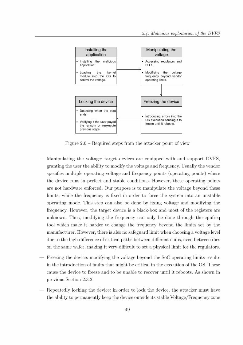
2.4. Malicious exploitation of the DVFS
Installing theapplication
Installing the maliciousapplication.
Loading the kernelmodule into the OS tocontrol the voltage.
Manipulating thevoltage
Accessing regulators andPLLs.
Modifiying the voltagefrequency beyond vendoroperating limits.
Freezing the device
Introducing errors into theOS execution causing it tofreeze until it reboots.
Locking the device
Detecting when the bootends.
Verifying if the user payedthe ransom or reexecuteprevious steps.
Figure 2.6 – Required steps from the attacker point of view
— Manipulating the voltage: target devices are equipped with and support DVFS,granting the user the ability to modify the voltage and frequency. Usually the vendorspecifies multiple operating voltage and frequency points (operating points) wherethe device runs in perfect and stable conditions. However, these operating pointsare not hardware enforced. Our purpose is to manipulate the voltage beyond theselimits, while the frequency is fixed in order to force the system into an unstableoperating mode. This step can also be done by fixing voltage and modifying thefrequency. However, the target device is a black-box and most of the registers areunknown. Thus, modifying the frequency can only be done through the cpufreqtool which make it harder to change the frequency beyond the limits set by themanufacturer. However, there is also no safeguard limit when choosing a voltage leveldue to the high difference of critical paths between different chips, even between dieson the same wafer, making it very difficult to set a physical limit for the regulators.
— Freezing the device: modifying the voltage beyond the SoC operating limits resultsin the introduction of faults that might be critical in the execution of the OS. Thesecause the device to freeze and to be unable to recover until it reboots. As shown inprevious Section 2.3.2.
— Repeatedly locking the device: in order to lock the device, the attacker must havethe ability to permanently keep the device outside its stable Voltage/Frequency zone
49

Chapter 2 – Maliciously exploiting energy management
either by changing them during boot or just after the booting phase. Thus, gainingthe ability to modify the voltage once the device just finishes booting.
2.4.2 Implementation of the attack
For the implementation of the attack, the voltage module developed previously (seeSection 2.3.1) for the characterisation is going to be reused as it allows to control thevoltage in most Unix based OS. As for the Hikey 960, we are going to continue using thebuilt-in system to change the voltage. The malicious application must be able to load thekernel module, consequently, the attacker application must have privileged access.
In android systems, the root mode is deactivated. However, rooting an android orjailbreaking an iPhone is a common and popular practice for users who want to gain fullcontrol on their smartphones and push them beyond their limits. This practice is a typeof hacking of consumer electronics.
For this purpose a great number of applications or custom ROMs were developed (e.g.,magisk [50]), able to unlock root privileges in the system without requiring any password.This consumer community can count up to hundreds of thousand users (e.g., up to 25million magisk downloads in the last 5 years [51]). These users can all be considered aspotential targets of this malicious usage of DVFS.
Finally, in order to prevent the device owner from taking control of the device afterrebooting, solutions were developed for each targeted board. First, for Odroid runningUbuntu OS, the malicious kernel module responsible for accessing the system regulatorsis permanently loaded during the booting process. This was implemented without any con-trol nor further required rights. Second, within the Hickey running Android Open SourceProject, it is not possible to permanently load a kernel module. However it can success-fully be loaded just after the booting process each time the system reboots preventingthe user to take control of the system. This has been implemented through the AndroidIntent functionality which allows communication between threads. Intent is an abstractdescription of an operation to be performed, it is used with the startActivity functionto launch an activity when a specific action is performed, this action can be detectedthrough the BroadcastReceiver. Usually, intents are used to communication between dif-ferent applications and background services, they work similarly to signal and in our casethe malicious application use this functionality to detect the action broadcasted when thebooting phase is complete providing the ACTION_BOOT_COMPLETED signal intentas shown in Figure 2.7.
50
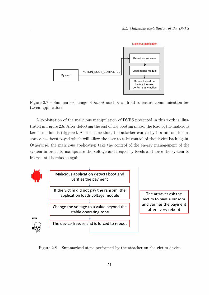
2.4. Malicious exploitation of the DVFS
System
Broadcast receiver
Load kernel module
Device locked outbefore the user
performs any action
Malicious application
ACTION_BOOT_COMPLETED
Figure 2.7 – Summarized usage of intent used by android to ensure communication be-tween applications
A exploitation of the malicious manipulation of DVFS presented in this work is illus-trated in Figure 2.8. After detecting the end of the booting phase, the load of the maliciouskernel module is triggered. At the same time, the attacker can verify if a ransom for in-stance has been payed which will allow the user to take control of the device back again.Otherwise, the malicious application take the control of the energy management of thesystem in order to manipulate the voltage and frequency levels and force the system tofreeze until it reboots again.
Figure 2.8 – Summarized steps performed by the attacker on the victim device
51

Chapter 2 – Maliciously exploiting energy management
2.4.3 Discussion and counter-measures
The main objective of this work is to highlight the security flaws in the usage of energymanagement of today’s commercial devices. In the case where stealing information is notpossible through the usage of DVFS, it was shown that it is still possible to implement asimple yet sophisticated attack to permanently lock a device, ideally until the user paysa ransom.
As we targeted a black-box, the necessary SoC documentation to access voltage andfrequency registers directly are not available, limiting the potential attack. In case theseregisters information are available, it is possible to deploy a more sophisticated and preciseattack. Notice that Unix cpufreq does not provide the required control for setting frequencyvalues (the minimum frequency step being 100 MHz). Moreover there is a higher accessdelay compared to a direct access to the PLL register if it was possible.
However, since we do not require the register addresses, it is thus possible to deploythe attack with the developed kernel module to any UNIX based OS and architectureusing DVFS, or similar energy managers, as long as the attacker can control the voltageand frequency and drive regulators beyond the recommended voltage/frequency operatingpoints through a kernel API. Therefore, the most straightforward countermeasure is toadd hardware or software limits. However, chips usually have different operating limitsand there are factors that might affect the critical path (e.g., temperature). Therefore,margins must be taken into account when voltage limits are fixed. Moreover, these limitswould require to be bond to given values of frequency for each board.
A second possible countermeasure would be to add more protection over the control ofthe DVFS. For example only trusted applications running on a higher privileged level thanthe root user or OS (in case TEE is supported) could access the voltage and frequencyregulators. In [52] a similar method is proposed to limit the access to the DVFS giving onlyan application from a secure environment the right to change the frequency and voltageof a core running in a TEE. This countermeasure will protect applications running in theTEE from leaking any secrets. However, the malicious usage of DVFS proposed in thischapter is still possible as it does not target TEE and can even be used during normalexecution.
On the other hand, some efforts have been done to propose more general solutions asadding additional chips in order to detect potential faults injections ([24][25]), they aimat classifying malicious glitches into different classes to distinguish the malicious glitchthat tries to gain access to secret data. However they do not aim at preventing them, and
52

2.5. Conclusion
therefore they do not have any impact on malicious manipulation of DVFS able to lockthe device such as the technique presented in this chapter.
2.5 Conclusion
Today’s embedded devices generally support advanced energy management mecha-nisms. The main objective of this work is to investigate the feasibility and the capabilitiesof malicious manipulation of DFVS in today’s commercial devices. We considered the ex-ample of smartphones. After the implementation of a technique on two recent, widespreadARM-based multi-core boards (Odroid and Hikey), our experiments show that it is possi-ble to maliciously manipulate DVFS mechanisms through software in order to introducefaults into the system operation, that can result in the lock out of a device making all sys-tem services and data completely inaccessible. With this work we highlighted importantsecurity flaws in the energy management supported by most energy constrained embeddedsystems and the necessity to address them.
53


Chapter 3
EXPLOITING INTEGRATED TEMPERATURE
SENSOR
In Section 1.6.1, energy consumption models have been maliciously used to infer in-formation from a victim program (e.g., AES, RSA) executed on a remote SoC. Few workshave tried to exploit temperature sensors to extract sensitive information as shown inSection 1.4, such as inferring the current status of the device, which application within aspecific set of applications is being executed on the target (e.g., Internet browser, RSAencryption) or using the temperature as a covert channel. Nonetheless, to the best of ourknowledge, this work is the first that shows the feasibility of distantly using embeddedtemperature sensors to infer information on the executed instructions and manipulatedoperands. Finally, in this chapter we demonstrate that on-chip temperature sensors canbe used to extract information on the execution of an AES encryption process, whichcan allow to deduce secret key characteristics for instance. The experiments presented inSection 3.3 show that it is possible to reduce the key exploration space down to 74% ofall the possible values of each bytes of the 128 bits key in the worst case scenario.
The key contributions of this chapter are:
— Showing through multiple experiments that different information (e.g., executedinstructions, manipulated operands) can be inferred through measurement of tem-perature using on-chip sensors.
— Maliciously exploiting temperature measurements though on-chip sensor to distin-guish important information during the execution of AES encryption. This infor-mation allows to reduce the exploration space and eventually, to brute-force thekey.
The remainder of this chapter is as follow. Section 3.1 presents the methodology withthe scenario of the proposed attack and its threat model. Section 3.2 presents the ex-perimental setup with the chosen target followed by necessary experimentation to prove
55

Chapter 3 – Exploiting integrated temperature sensor
the feasibility of this work and the possibility to correlate the temperature to specificinstructions and operands. Section 3.3 elaborates on the possibility of using the previousmethodology against AES encryption algorithm in order to extract specific characteristicsof the secret key. Section 3.4 discusses the limitations of this work and gives some leadsfor possible countermeasures. Finally, Section 3.5 draws some conclusions.
3.1 Methodology
The attack presented in this chapter, is the malicious exploitation of temperaturesensors data to infer information from a victim program. In our case, the victim programis an AES encryption and the objective is to significantly reduce the number of the possiblevalues of the secret key in the search space. In the best case scenario, it is possible tobrute-force the key and completely recover it.
To implement this attack, it is necessary to characterise the chosen target device.As each instruction and operand have different effects on the temperature, these effectsdepend on the target device, the voltage and frequency levels. Therefore, the characteri-sation has to be done for a set of specific parameters and is unique to the model of thetargeted device.
The main goal of this step is to correlate the temperature to a certain characteristic(e.g., Hamming Weight) of manipulated operands. The next step is to use this charac-terisation to implement a complete attack. The attacker in this case, knows the effect ofcertain characteristics on the temperature. During the attack, the temperature is mea-sured during the execution of the victim program and is compared to characterisationpreviously done. Using statistical methods, secret information can be inferred.
Threat model
For this attack to be successful, the attacker requires:
— To have remote access to the embedded temperature sensors of the targeted embed-ded device. Accessing the sensor from a 3rd party program is quite easy and realisticon nowadays SoCs as there is no limitation on reading the temperature value. How-ever, if possible, it is recommended to access temperature registers through a kernelmodule as it provides a lower latency.
56
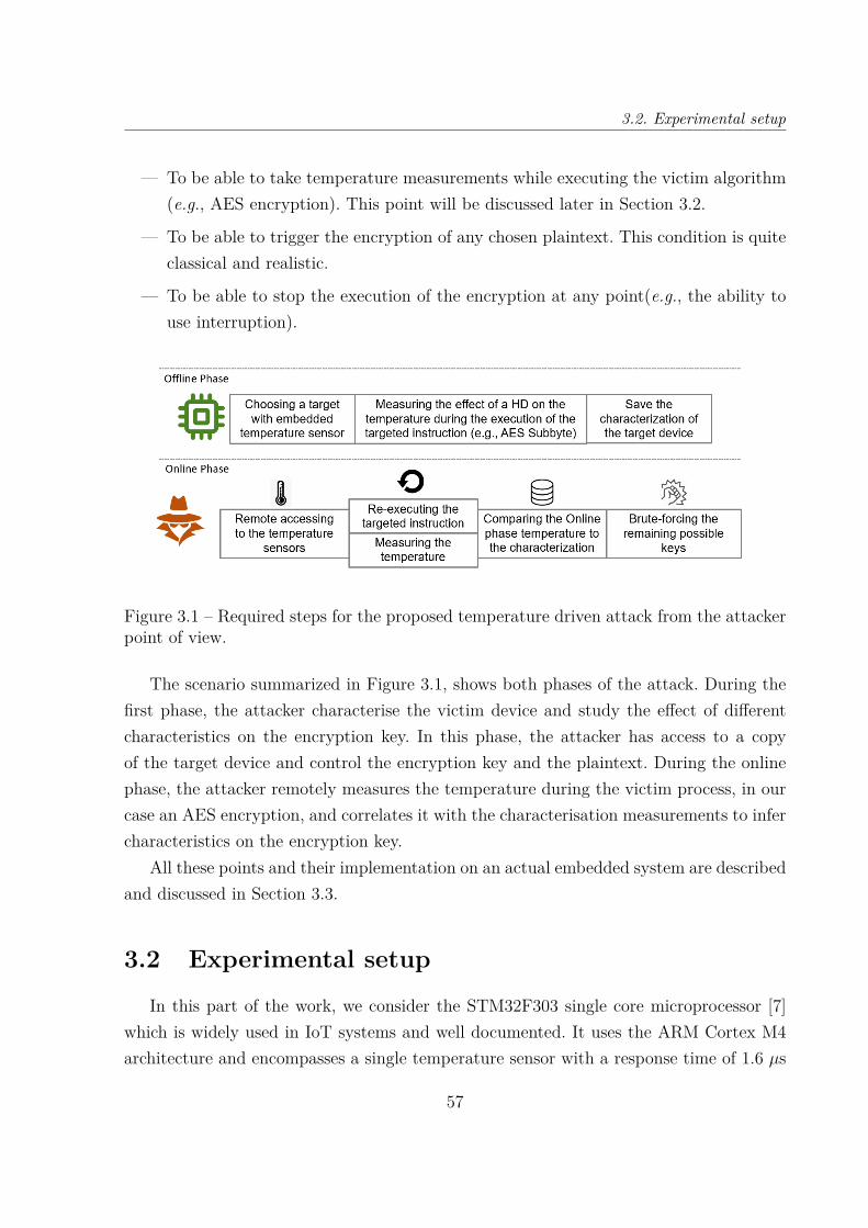
3.2. Experimental setup
— To be able to take temperature measurements while executing the victim algorithm(e.g., AES encryption). This point will be discussed later in Section 3.2.
— To be able to trigger the encryption of any chosen plaintext. This condition is quiteclassical and realistic.
— To be able to stop the execution of the encryption at any point(e.g., the ability touse interruption).
Figure 3.1 – Required steps for the proposed temperature driven attack from the attackerpoint of view.
The scenario summarized in Figure 3.1, shows both phases of the attack. During thefirst phase, the attacker characterise the victim device and study the effect of differentcharacteristics on the encryption key. In this phase, the attacker has access to a copyof the target device and control the encryption key and the plaintext. During the onlinephase, the attacker remotely measures the temperature during the victim process, in ourcase an AES encryption, and correlates it with the characterisation measurements to infercharacteristics on the encryption key.
All these points and their implementation on an actual embedded system are describedand discussed in Section 3.3.
3.2 Experimental setup
In this part of the work, we consider the STM32F303 single core microprocessor [7]which is widely used in IoT systems and well documented. It uses the ARM Cortex M4architecture and encompasses a single temperature sensor with a response time of 1.6 µs
57

Chapter 3 – Exploiting integrated temperature sensor
and a resolution of 18 m°C [7]. Finally, for these experiments, we consider that the deviceis running in bare metal and uses the HAL (Hardware Abstraction Layer) library [53] toaccess temperature sensors. The STM32 HAL is an abstraction layer embedded softwarethat provides drivers to interact with an upper level software (i.e., application, libraries).
We access the temperature level by directly reading the value from the correspondinganalog-to-digital converter (ADC) register. Temperature measurements have to be takenduring the execution of the victim program and the measurement application is requiredto have a minimum impact on the temperature. In order to achieve this objective, we usedDMA access on our single core target to save the measurements directly to the memoryand minimize the processor activities overhead. On sophisticated SoCs (e.g., Hikey960with big.LITTLE technology), a temperature sensor is usable for each cluster or core.Thus, we can simply execute the victim program on a specific cluster and read its tem-perature from another cluster to minimize interaction and optimize the performance ofthe method. It is worth to say that the attacker have a more accurate temperature readif the impact of the measurement is minimised. On the other hand, as the temperaturehas a high response time, it is necessary to re-execute the program multiple times untilthe temperature stabilises, then compute the mean of all measurements. This step statis-tically reduces the standard error in the distribution, accounting for low sensors accuracy.For this work, we are mainly targeting specific instructions within the program. Duringthe characterisation, it is important to re-execute them, however, during the completeattack, techniques like zero-steping [8] can be used to isolate the targeted instruction andre-execute it as many times as required. For the target device, we found out that a loopof 30,000 iterations is required to observe the effect of the instruction on the temperature.Finally, between each characterisation, a cooling time is required to avoid temperaturesaturation and/or previous experiments impact on the current measurements. By experi-ments, we defined that 300s are enough to have the same starting temperature for all themeasurements. It is also important to note that the experiments presented in the reminderof this chapter were executed on different boards of the same model to account for thedifference between each die during the manufacturing process. These setups are the samethroughout the whole chapter.
3.2.1 Distinguishing instructions
To investigate which characteristics of a program can have an effect on the tempera-ture, different experimentation were realised. The first step is to investigate the impact
58

3.2. Experimental setup
of executing different instructions, For these experiments we considered 3 arithmetic andlogic instructions: multi, add and xor, and 3 memory instructions: load, write and mov.These instructions were chosen as they are used within the AES encryption, except forthe multi, and this characterisation would help us decide which part of the AES to tar-get. Figure 3.2 shows the experiments’ results for the arithmetic and logic instructions,while Figure 3.3 presents the results for the memory instructions. These results show thefrequency of appearance of a given temperature value according to the related instruc-tion. Each dot on the trace represents the mean temperature during the 30,000 iterations,this step was repeated to finally obtain 600 means per instructions. The results of theexperiments are shown in Figure 3.2 and Figure 3.3.
Temperature(°C)
42.84 42.876 42.912 42.948 42.984
Freq
uen
cy o
fap
pea
rance
Figure 3.2 – Comparison of the integrated temperature values generated by each consid-ered arithmetic and logic instruction with the same operands
From these two figures, it can be seen that it is possible to distinguish most of the ex-ecuted instructions depending on the measured temperature. For instance, at the highesttemperature 42.9°C, the most likely executed instruction is the multiplication as it hasa higher load compared to other instructions (i.e., the greatest frequency of appearancecompared to the others). Moreover, xor and add instructions induce close temperaturesmaking them harder to distinguish but still possible as their temperature values varyaround 42.836°C and 42.852°C for xor and add respectively. The xor also generates theleast heat as it is a binary instruction and has the lowest load on the processor. On theother hand, for memory instructions, it is possible to see a clear distinction as mov, writeand load instructions entail temperature mean of 43.01°C, 43.15°C and 43.22°C respec-tively. As the temperature difference is higher, compared to the considered arithmetic
59

Chapter 3 – Exploiting integrated temperature sensor
Temperature(°C)
43.05 43.10 43.15 43.20
Freq
uen
cy o
fap
pea
rance
Figure 3.3 – Comparison of the integrated temperature values generated by each consid-ered memory instruction with the same operands
instructions, it is easier to distinguish these 3 instructions. Additionally, it can be noticedhere that these measurements enable also to distinguish between the type of instructions(i.e., separating arithmetic and memory instructions).
Therefore, we can conclude that for certain cases, instructions can be confidentlydistinguished through the integrated temperature sensor measurements. Moreover, it canbe seen that multi is the arithmetic instruction that statistically generates more heat as itrequires more energy compared to the add and the xor instructions. This is an expectedresult as the binary operation xor is the instruction that has the lowest complexity outof the three instructions, thus, it generates the least amount of heat compared to thetwo other instructions. From these measurements, we can also see that we can distinguishbetween simple instructions executed on the SoC using only temperature measurementsfrom the embedded sensors. In the next section, we focus on the investigation of thepossibility of distinguishing operands.
3.2.2 Distinguishing between operands
The second characteristic to study is the effect of the operands of the instructions.In previous experimentations, the same set of operands were used. Thus, their effect wasthe same on the different instructions. In this part, the instruction is fixed, we choose themultiplication as this arithmetic operation provides the highest heat based on the previousexperiments and therefore we expect it to be the easiest to be distinguished. We then vary
60

3.2. Experimental setup
the operand from one experiment to another. Since the target is an arithmetic instructionthat uses two operands, one of them has been fixed during the whole experimentation.
The same previous setup is used, each experiment consists on running the multi in-struction 30,000 times with two fixed operands while taking the temperature measure-ments. After the 30,000 iterations the second operand is changed while the first oneremains constant, and a new experiment is conducted. Figure 3.4 summarizes the mea-surement algorithm used for this experiment.
Repeat for 30.000iterations
Initialization of temperature sensor and DMA
Main loop Temperature m
easurement w
ith DM
A
Fixing target operation operands
Target operation
Change operand
Characterisation algorithm of the device STM32F303
Figure 3.4 – The main steps used for measuring the effect of the operands on the temper-ature
As the temperature has a high response time, it is not possible to distinguish betweenall possible values of the operand as their effect would be filtered. In this case, operandwith same or close characteristics has to be grouped into a set of values. One way togroup the non-constant operand is by their Hamming Weight (HW, i.e., the number of’1’ in the binary value) and it is expected that the higher HW the higher the effect onthe temperature.
As we used the STM32 processor, we worked with 32-bit width operands. For thesemeasurements, we choose to multiply a constant operand arbitrarily chosen (fixed to the
61

Chapter 3 – Exploiting integrated temperature sensor
decimal value 23). It is important to notice that further experiments with different con-stant values for the first operand showed that this latter has no impact on the obtainedresults. The second operand is variable, and without loss of generality, and to limit theexperiments time, we have chosen values that have certain selected HW. Indeed, consider-ing all HW values is not feasible as performing all experiments will be unreasonably timeconsuming. Therefore, we arbitrarily choose HWs of 8, 16, 24 as they allow to study verydifferent classes of values.
All the measurement are reported in Figure 3.5, with each dot representing the fre-quency of appearance of a specific temperature. It can be seen that different HW ofthe variable operands induces different temperature values. For example, we can see onthe figure that a temperature of 42,952°C corresponds to the highest probability of anon-constant operand HW of 8, as it is the highest frequency of appearance for this tem-perature. The same can be said for temperatures 42.968°C and 42.987°C as they bothcorrespond to HW 16 and 24 respectively. As expected the temperature grows up withthe HW of the variable operand.
Temperature(°C)
42.84 42.912 42.98442.876 42.948 43.02
Freq
uenc
y of
appe
aran
ce
Figure 3.5 – Comparison of the temperature generated by 32-bit width multiplication,with the non-constant operand having HW of [8,16,24] and multiplied by the constantvalue 23
Through this simple experiments, it is shown that operands HW has an impact onthe heat generated by the instruction, and that the difference in temperature is observ-able through the integrated sensor. But the HW is not sufficient if we consider multipleinstructions.
62
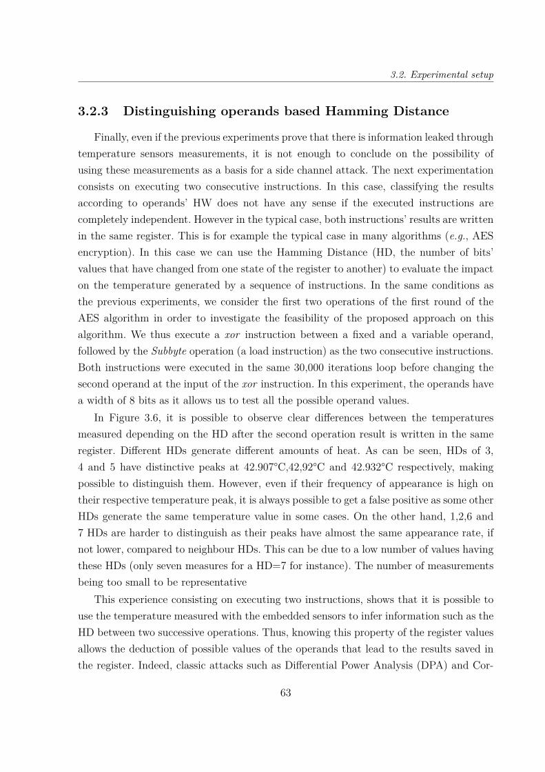
3.2. Experimental setup
3.2.3 Distinguishing operands based Hamming Distance
Finally, even if the previous experiments prove that there is information leaked throughtemperature sensors measurements, it is not enough to conclude on the possibility ofusing these measurements as a basis for a side channel attack. The next experimentationconsists on executing two consecutive instructions. In this case, classifying the resultsaccording to operands’ HW does not have any sense if the executed instructions arecompletely independent. However in the typical case, both instructions’ results are writtenin the same register. This is for example the typical case in many algorithms (e.g., AESencryption). In this case we can use the Hamming Distance (HD, the number of bits’values that have changed from one state of the register to another) to evaluate the impacton the temperature generated by a sequence of instructions. In the same conditions asthe previous experiments, we consider the first two operations of the first round of theAES algorithm in order to investigate the feasibility of the proposed approach on thisalgorithm. We thus execute a xor instruction between a fixed and a variable operand,followed by the Subbyte operation (a load instruction) as the two consecutive instructions.Both instructions were executed in the same 30,000 iterations loop before changing thesecond operand at the input of the xor instruction. In this experiment, the operands havea width of 8 bits as it allows us to test all the possible operand values.
In Figure 3.6, it is possible to observe clear differences between the temperaturesmeasured depending on the HD after the second operation result is written in the sameregister. Different HDs generate different amounts of heat. As can be seen, HDs of 3,4 and 5 have distinctive peaks at 42.907°C,42,92°C and 42.932°C respectively, makingpossible to distinguish them. However, even if their frequency of appearance is high ontheir respective temperature peak, it is always possible to get a false positive as some otherHDs generate the same temperature value in some cases. On the other hand, 1,2,6 and7 HDs are harder to distinguish as their peaks have almost the same appearance rate, ifnot lower, compared to neighbour HDs. This can be due to a low number of values havingthese HDs (only seven measures for a HD=7 for instance). The number of measurementsbeing too small to be representative
This experience consisting on executing two instructions, shows that it is possible touse the temperature measured with the embedded sensors to infer information such as theHD between two successive operations. Thus, knowing this property of the register valuesallows the deduction of possible values of the operands that lead to the results saved inthe register. Indeed, classic attacks such as Differential Power Analysis (DPA) and Cor-
63

Chapter 3 – Exploiting integrated temperature sensor
Temperature(°C)
42.876 42.912 42.948 42.98442.894 42.93 42.966
Freq
uenc
y of
appe
aran
ce
42.907°C 42.92°C 42.932°C
Figure 3.6 – Comparison of the temperature depending on the HD between two states ofthe same register after a xor and a load operation.
relation Power Analysis (CPA), presented in Section 1.6, are based on the principle ofcorrelating the HD between the AddRoundKey (xor) and the Subbyte (load) instructionsof the AES algorithm with the energy consumption that could be measured. Therefore,by distinguishing the HD from one state to another of the used register, we show thattemperature can be used as a side channel to extract secret information in specific con-ditions. Using a strategy similar to DPA and CPA, we used our approach to infer someinformation on the secret key of the AES algorithm.
3.3 Extracting AES key characteristics using tem-perature sensors
As seen before, it is clearly possible to use the temperature of the chip to infer certaininformation. In this section, the implementation of an attack based on the use of the inte-grated temperature sensors is detailed. The main objective is to investigate the feasibilityof significantly reduce the number of possible secret keys on AES encryption algorithmto eventually perform a brute-force attack to reveal the secret key.
3.3.1 Methodology of the attack main steps
The main steps of this attack are:
64

3.3. Extracting AES key characteristics using temperature sensors
Accessing the temperature sensors: The proposed attack does not require anyphysical access to the victim device. The only requirement is a remote access to thetemperature embedded sensor measurement results. This is possible through a 3rd partymalicious application or module installed on the targeted device. Under an embedded OS,accessing the temperature sensor may require privileged access.
Measuring the temperature during AES encryption: It is required that thetarget device has the capabilities to take temperature measurements in parallel with theAES encryption execution. In order to fulfil this condition, it is either required to havea multi-core SoC in which one core executes the victim AES encryption and a secondcore execute the attacker code responsible for triggering the temperature measurements,or having the ability to use a DMA controller to save measurements in parallel with theAES encryption execution.
Re-executing the targeted instruction(s) multiple times: The temperatureneeds time to propagate through the chip, it is thus important to be able to re-executethe same targeted instruction(s) multiple times as described in Section 3.2. In this work,we are going to focus on attacking the Subbyte operation on the first round of the AESencryption as the secret key has the most impact on this operation. One of the techniquesthat can be used for this purpose is the zero-stepping [8] as it was used in [34].
Offline Phase; Characterization of the device: The attacker has to first char-acterize the target device as well as the effect of specific keys characteristics (e.g., HW,intermediate result’s HD) on the temperature of the targeted device. The impact on tem-perature needs to be characterized in a first phase where the used key is known beforeperforming the actual attack (see Figure 3.1 in Section 3.1). This phase requires the at-tacker to have the same hardware as the victim targeted device. It has to be noticed thatthis characterization phase has to be driven only once for a specific device.
Online Phase; Deducing the possible secret key values: In the second phase,which actually corresponds to the attack, the used key is secret and thus not known by theattacker. The objective is to deduce indirect characteristics of the key which result on acertain HD after two specific consecutive operations of the algorithm (e.g., AddRoundKeyand Subbyte). This deduction will allow the attacker to infer the possible values of theencryption key significantly reducing the key exploration space. If the solution space issufficiently reduced, recovering the final key can be done through a brute-force attack. Inthis phase the encryption of a controlled message with the unknown secret key is triggered,and the temperature measurements are simultaneously taken. Finally, a comparison of
65

Chapter 3 – Exploiting integrated temperature sensor
the measurements during the actual attack with the Offline characterization phase resultsallows to deduce a classification of the most probable keys.
In the following sections the implementation of these steps is presented and obtainedresults are discussed.
3.3.2 AES reminder
In this work, we target an AES128 encryption and more specifically, the first roundas described in Figure 3.7. The diffusion of the cipher does not happen until the secondoperation of this round, thus, the complexity to infer information and recover the key isminimum at this stage. The first round takes as input a 4 by 4 matrix of 16 bytes and gothrough four operations SubBytes,ShiftRows,MixColumns and AddRoundKey.
— SubBytes uses a known 8-bit substitution box to substitutes each byte of thematrix with another byte from the box.
— ShiftRows shifts the rows of the input matrix by a fixed offset, the offset dependson which row is being shifted.
— MixColumns transforms each column using a fixed matrix. This operation pro-vides, with the ShiftRows operation, the diffusion of the cipher.
— AddRoundKey add the subkey K1 to the bytes of the matrix with the xor opera-tion.
The plaintext goes through AddRoundKey before the first round starts as seen in theFigure 3.7 which makes the results directly linked to the subkey K1. The plaintext isknown and controlled by the attacker and the complexity is the lowest during this stageas the diffusion does not happen until the ShiftRows operation. Thus, during the attack,we target the first AddRoundKey and SubBytes. If we infer the HD between the input andoutput of SubByte operation, we will be able to directly link it to only certain possiblevalues of the input, thus reducing the possible values of the subkeys.
3.3.3 Attack implementation and results
We continue using the same target device as for the previous experiments (i.e., theSTM32F303 device). We assume that the attacker can access the embedded temperaturesensor through DMA and is able to run temperature measurements during AES encryptiontargeted program. We assume that the attacker can also configure interruptions as they
66

3.3. Extracting AES key characteristics using temperature sensors
Figure 3.7 – Operations in the first round of AES
are crucial to isolate the target instruction and repeat it indefinitely. In this case, theattacker needs to configure a periodic interruption using, for example, an APIC (AdvancedProgrammable Interrupt Controller) timer. The interruption needs to happen during theexecution of the targeted instruction and before the program counter is updated. As were-execute the same instruction, delay between each interruption is the same. We focusedon the instruction Subbyte as explained before and shown in Algorithm 1.
Algorithm 1 Malicious application execution steps1: DMA initialization2: DMA start #Start measurement3: foreach plaintext p_i4: AES encryption #Start AES with an arbitrary plaintext p_i5: wait to reach the targeted instruction6: while Measurements do
#e.g.., 30,000 temperature measurements for this instruction in our case, whileexecution of targeted instruction
7: trigger interruption #An interruption stops the execution of the targeted instructionand thus it will be re-executed, e.g., zero stepping
As previously explained, this attack requires two main phases.
67
Chapter 3 – Exploiting integrated temperature sensor
3.3.4 Offline Phase
The whole process described in the previous section represents the Offline characteri-zation. We use known keys and plaintexts to characterise their effect on the temperature.In this case, we already observed a difference of temperature when the HD between twoconsecutive states of register r (i.e., the register where the results of the AddRoundKeyare written followed by the results of the SubBytes) varies. For the rest of the chapter,this Hamming Distance is designated by HD of r. During the Online Phase, the attackerwill use these observations and will compare them with the run-time measurements.
During the Offline Phase, an exhaustive characterization is done by measuring thetemperature of each possible plaintext/key combination for one byte which is a total of65536 possible values. This is a time consuming process and lasts approximately 3 weeks.However, the characterization will not change for the same target device model and canbe reused for the proposed attack on devices of the same model.
As we are using the same target as in Section 3.2.2, the previously measurementstargeting the instructions used in the AES 128bits are considered. The experiments arelimited to two HDs 4 and 5 of r as the attack can be easily generalised later. Figure 3.8shows two extracted HD from Figure 3.6 the characterisation of these two HDs and threedifferent areas can be distinguished:
— A first area (Area A) with temperature values of different plaintexts and keys, butresulting for the great majority of the cases on a HD of 4 between the two states ofthe register r.
— A second area (Area B) with temperature values of different plaintexts and keyswhere the resulting HD, of 4 or 5, is much harder to distinguish.
— A third area (Area C) with temperature values of plaintexts and keys where theresulting HD is predominantly 5.
During the implementation of the complete attack, all the zones (8 for each HDsplus the mingled zones) for the 8 possible HDs need to be distinguished. Finally, asFigure 3.8 shows the frequency of appearance for each temperature values, it is possibleto statistically compute the probability of the most likely HD of r as:
P (HDi) = Samples(HDi)∑8j=0 Samples(HDj)
68

3.3. Extracting AES key characteristics using temperature sensors
Figure 3.8 – For the STM32F303 platform, the temperature characterization for twoarbitrary HDs of r (4 and 5) during the Offline Phase. There are 500 dots in each graphand each point represents the mean value of 30,000 temperature measurements. The bluedotted line represents the temperature measurement during the Online Phase.
Where Samples(HDi) represents the number of measurements of the same temperaturefor the tested HDi over all the measurements for all the HDs.
3.3.5 Online Phase
Once the correlation between the temperature and the HD of r has been shown, itis possible to move to the second part of the attack which is the Online Phase. In thiscase, the attacker takes multiple temperature measurements with an unknown secretkey but with a known plaintext. These measurements are then projected on the offlinecharacterization areas, to finally compute the probability of having a specific HD, this isdone for each HD. This process can be repeated with different known plaintexts. Thus,it is possible to rank each possible HD by the highest probability (the most probable)each time. For the sake of understanding the presentation of this attack here, is limitedto only two HDs: 4 and 5. In Figure 3.8 the Offline Phase characterisation as well as thetemperature measurements during the Online Phase (the blue dotted line) of the attackare shown. In this example, the attacker measures a temperature of 42.833°C, for thismeasured value, there is a total of 61 offline measurements with the same temperature,
69

Chapter 3 – Exploiting integrated temperature sensor
18 of them correspond to the HD of 4 and 43 of them to the HD of 5. In this case, theprobabilities for the key to have resulted on a HDs = 4 or HDs = 5 are expressed as:
P (HD4) = Samples(HD4)Samples(HD4) + Samples(HD5)
=
P (HD4) = 4318 + 43 = 29.50%
P (HD5) = Samples(HD5)Samples(HD4) + Samples(HD5)P (HD5) = 70.49%
In this case, the HD between the two states of the register r has a high probabilityof being 5, by repeating the measurement and the process with different plaintexts, it ispossible to infer the possible values of HD of the register. As the plaintext is known bythe attacker, the possible value of the key can be computed.
3.3.6 Results analysis
Hammingdistance 0 1 2 3 4 5 6 7 8
Number ofpossible values 0 12 31 48 67 59 32 7 0
Table 3.1 – Number of possible values of the register r depending on the HD before andafter the Subbyte operation
The final step to deduce the correct AES key is by using a brute-force approach. Thepossible keys to test during this final step depend on the HD of each byte found in theprevious steps of the attack. As the operation of the Subbyte in AES is a substitution withknown values, it is possible to only select the inputs that lead to a specific HD. Therefore,it is possible to find all possible values of the register r that could have resulted in a givenHD.
Table 3.1 shows the number of the possible values of the register r depending on theHDs previously deduced. The HD of 4 represents the greater number of possible valuesof r (67). To find the correct value, all the 67 different numbers should be tested. On the
70

3.3. Extracting AES key characteristics using temperature sensors
other hand, HD 7 represents the easiest case since there are only 7 possible values of rthat need to be tested. To recover the entire key, the same operation on all the bytes ofthe subkeys need to be repeated, 16 times in the case of AES128. For sake of simplicityand in order to study the feasibility of the attack, the example was separated into twocases, the worst and the best case scenario. The worse case scenario is when all the keysubbytes lead to a HD of 4 (the greater number of values to test) while the best case scenariois when all the bytes lead to a HD of 7. With the data shown in Table 3.1, the time itwill take to brute-force a key for each scenario can be inferred. An AES encryption wouldapproximately take 1.3 clock cycles/byte according to [54]. This estimation is based onrecent Intel processors and it takes ≈ 433 ps to test one key using a CPU with a frequencyof 3 Ghz. In the best case scenario, it will take 1.6E−1 days to brute-force the entire key,and 8.26E18 days in the worst case scenario. The process can be generated to compute thetime needed for all possible combinations, but there is no simple representation to showthe data as there is a lot of possibilities. We give a simplified example in the case whereall the bytes leads to the same HD. The computation effort estimations are gathered inTable 3.2.
Hamming distance 0 1 2 3 4 5 6 7 8
Time to test all keys in days 09.26
E23.64
E93.97
E12
8.26E
181.08
E18
6.05
E13
1.6E-
10
Table 3.2 – Time to test all keys if all the bytes of the secret key lead to the same HD
The process of brute-forcing the key can be further simplified. The attacker is ableto change the plaintext used during the Online Phase. As the key is fixed and does notchange during the attack, the value of the register r will mainly depend on the plaintextthat is controlled by the attacker. This gives the attacker the possibility to change theresulting HD of r by choosing each time a different plaintext. And for each plaintext andHD of r, there is a set of identified possible keys. The intersection of these sets representsa reduced set of the possible keys. For example, finding two plaintexts, leading to a HDof 4 and 5 respectively, will give a set of 67 and 59 possible keys respectively. Therefore,the intersection of these sets will reduce the possible keys down to 23. In the same way,three plaintexts leading to HDs of 3, 4 and 5 respectively, will further reduce the numberof possible keys to only 9, making it possible to brute-force it in 9 days in our case usingthe same AES encryption speed in [54] used to compute the results of Table 3.2. It is also
71

Chapter 3 – Exploiting integrated temperature sensor
important to note that these results were computed using the information of one desktopCPU. It is thus possible to significantly reduce the time of brute-forcing if the tests areparallelized (e.g., using multiple CPUs, GPU).
3.4 Discussion
The work presented in this chapter shows that it is possible to maliciously exploitthe temperature measurements from embedded sensors to extract crucial informationand significantly reduce the AES key exploration space. In the considered scenario, wewere able to reduce the exploration space down to 96.47% for one byte in the best casescenario (9 out of all 255 possible values, requiring only 9 days to brute-force the key, seeSection 3.3.6). As for the worst case scenario, the reduction of exploration space is reducedby 74% (67 possible values over 255, see Table 3.1). These results can be extrapolatedto deduce the worst case scenario for the 16 bytes in AES128 in which the reduction ofthe exploration space could be theoretically reduced down to 99.9999999515% (16 bytesleading to the HD=4 of r) 6716 / 25516 which will theoretically take 8.26E 18 days tobruteforce the whole key according to Table 3.2. However, with further measurementsusing different plaintexts, the time to bruteforce the key can be reduced even further toless then a day in the best case scenario.
This work can be extended to other platforms as today’s embedded devices generallycome with temperature (and other) embedded sensors. There are possibly further waysto use sensors information. For example, in systems with multiple sensors, it is possibleto observe delays in the heat propagation as the sensors are geographically in differentpositions in the chip. This could be used to pin-point where certain registers are locatedor where certain instructions are executed. Finally, this work can be further extended bystudying its feasibility on protected AES algorithm and AES dedicated bloc (cryptographycores).
The most straightforward countermeasure would be to add access limitations to theintegrated sensors. In devices with an operating system, a limitation can be for example toalways limit sensor data access to privileged users only. Additionally, it is also possible toreduce the accuracy of the measurements as the attack requires to distinguish an averageof 100 m°C difference between the temperature peaks of each HD observed in Section 3.2.2,in order to distinguish the different HD values. Thus, reducing the measurement precisionwill make the number of false positive considerably increase, to the point where it is
72
3.5. Conclusion
impossible to find the correct HD. In case where there is no need to share the temperaturewith the user or the consumer, the access to the temperature sensor can be limited totrusted execution environment only.
3.5 Conclusion
Today’s embedded devices generally support temperature management mechanisms.This work investigates the feasibility of a remote malicious exploitation of embeddedtemepraturesensors used in these management systems. We considered the example ofIoT devices. The proposed technique was fully implemented in a real platform. Our ex-periments showed that integrated sensors can be remotely and maliciously exploited asmeasurements are sufficiently precise to extract information. Operands and executed in-structions are clearly distinguished in some cases. Finally, our technique has been used inorder to deduce AES encryption secret key characteristics reducing the key explorationspace down to 74% per key byte (in the worst case) making it feasible to brute force theremaining possible key values to deduce the exact key. With this work we highlightedimportant security flaws in the temperature management systems and the necessity toaddress them.
73

Chapter 4
USING MACHINE LEARNING TO ANALYZE
TEMPERATURE VARIATION AND EXTRACT
SECRET INFORMATION
In the work presented in Chapter 3, thermal sensors are used to extract informationfrom an STM32 micro-controller. Experiments shows that it is possible to infer certaincharacteristics from the execution of an AES128 and to use it to eventually brute-forcethe encryption key. In this chapter we also focus on extracting secret information usingthermal sensors. However, the target is the kirin960 a much more complex architecture.This target is a heterogeneous SoC with 8 cores and each core is more complex thanthe STM32 single core. The Kirin was designed for high end computing on smartphonedevices, contrary to the STM32 which was mainly designed for IoT. The main targetalgorithm of this chapter is the RSA2048 algorithm as its operations have a higher loadand generate more heat compared to AES. Thus, its thermal print is more visible whenmeasuring temperature. These experiments also show that the attack can be implementedon a different cryptography algorithm. Machine learning algorithms are used to analysethe measurements.
The key contributions of this chapter are:
— Using on-chip thermal sensors to infer some operands HW in 2048 bits multiplica-tions.
— Using machine learning with on-chip thermal sensors to distinguish HW of theprivate key during RSA decryption.
The remainder of this chapter is as follows: Section 4.1 presents the scenario of theattack and its threat model. In Section 4.2 the experimental setup is presented with thechosen target and the necessary experimentation to prove the feasibility of this work.Section 4.3 extends the previous section by presenting machine learning techniques and
75

Chapter 4 – Using machine learning to analyze temperature variation and extract secretinformation
using them to improve the analyze of the data. Section 4.4 elaborates on the possibilityto use the previous methodology against RSA decryption algorithm to extract the HW ofthe private key. Section 4.5 discusses the limitations of this work and gives some leads forpossible countermeasures. Finally, Section 4.6 draws conclusion and future work directionsto this work.
4.1 Attack scenario
In this chapter, we also try the previous method on a more complex platform, we focuson inferring the HW of the key from an RSA2048 decryption algorithm. The objective isto significantly reduce the number of the possible values for the secret key.
This attack is similar to the one described in Chapter 2 and its methodology is sum-marized in Figure 4.1.
Characterize the effect ofthe HW of the private keyon the target temperature Malicious application on the
victim device is able toaccess the temperature
The victim device
The attacker
The application doesmeasurement during an
RSA decryption launchedby the attacker remotely
Measurement are sentback to the attacker by the
malicious application
Train machine learningmodels for classification
depending on HW
Do measurements remotelyon the target
Use the measurementswith the previous model to
infer the HW
Cho
seci
pher
text
Offline Phase
Online Phase
Figure 4.1 – The main steps of the proposed temperature separated into the Offline Phasewhere the attacker characterize the victim device and Online phase where the attackeraccess the temperature sensor on the victim device and measure the temperature remotely
76

4.2. Experimental setup
The attacker needs to know beforehand the effect of some characteristics (operands andinstructions) on the heat generated within the chip. Thus, it is necessary to characterizethe target device and the effect instructions and operands have on the temperature. As theintended victim algorithm is an RSA-2048 decryption, the focus will be on characterizationof multiplications and exponents operations. Once this step is done, the attacker canmeasure temperature on the target device and infer secret information using the previouscharacterization.
For this attack to be successful, the attacker requires:— to have a remote access to the embedded temperature sensors of the targeted em-
bedded device core. This a classic and simple requirement for remote attacks asalready shown.
— to be able to take temperature measurements while executing the victim algorithm(e.g., RSA decryption). On the targeted MPSoC, it is possible to use one core orcluster running the malicious application to measure the temperature of anothercore or cluster running the victim program. This allows us to reduce the effectsof the measurement on the heat emitted by the core or cluster running the victimprogram.
— to be able to trigger the encryption of any chosen plaintext.All these points and their implementation on the Kirin960 embedded system are de-
scribed and discussed in Section 4.4.
4.2 Experimental setup
In this work we used the Hikey960 [9] evaluation board which embed the Kirin960 SoC,an octa-cores based on arm big.LITTLE technology. It uses the armv8 architecture andencompasses 3 temperature sensors within the SoC as shown in Figure 4.2 and another 2outside the SoC, within the Random Access Memory (RAM) and the modem. For the restof this chapter, the focus will be on the two sensors within each cluster. They both havea response time of 500ns and a resolution of 220m°C. For the following experimentation,the target device is running the Android Open Source Project (AOSP).
A kernel module was developed to access the temperature, it is done by reading thevalue from the register of the thermal sensor ADC of the cluster running the victimprogram. This kernel module must be executed in parallel of the target program as mea-surement requires minimum impact on the temperature compared to the victim program.
77
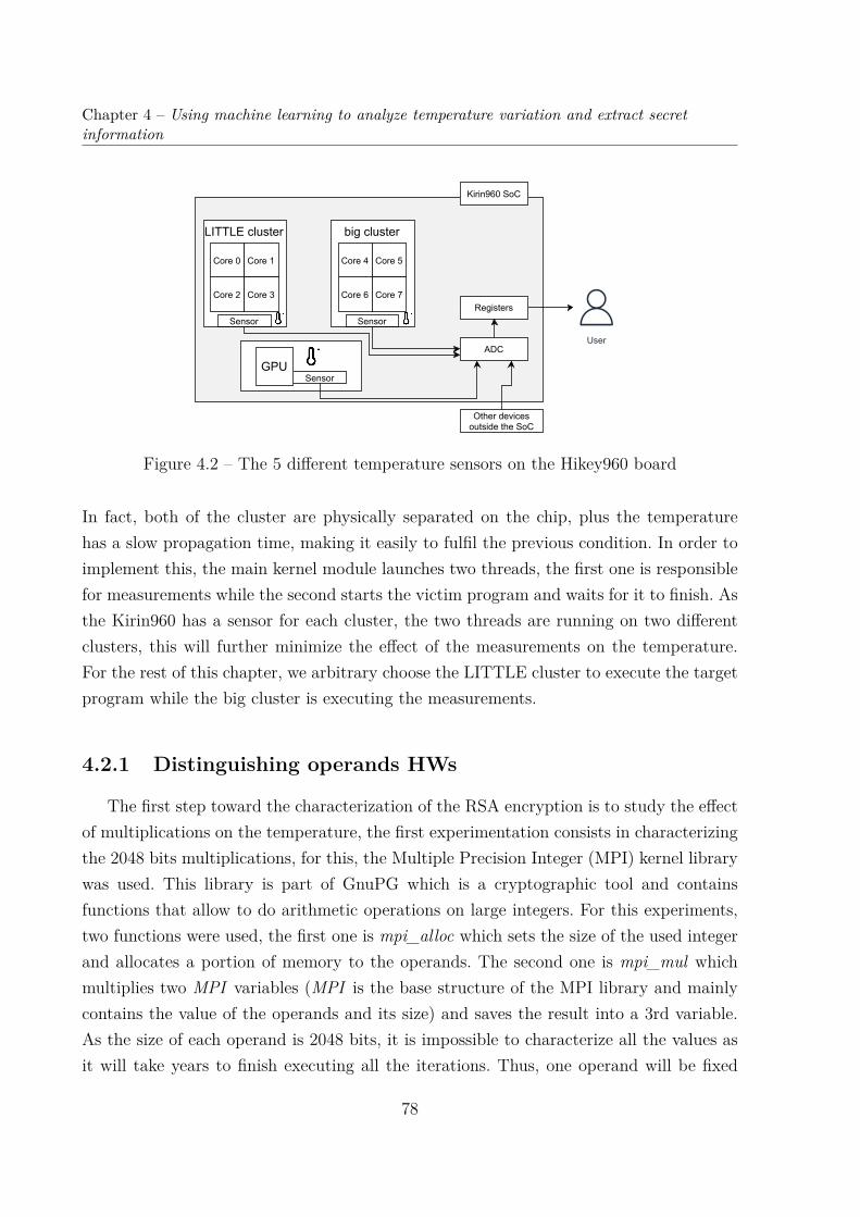
Chapter 4 – Using machine learning to analyze temperature variation and extract secretinformation
Registers
ADC
Sensor
Kirin960 SoC
SensorGPU
User
big cluster
Core 6
Core 4 Core 5
Core 7
Sensor
LITTLE cluster
Core 2
Core 0 Core 1
Core 3
Other devicesoutside the SoC
Figure 4.2 – The 5 different temperature sensors on the Hikey960 board
In fact, both of the cluster are physically separated on the chip, plus the temperaturehas a slow propagation time, making it easily to fulfil the previous condition. In order toimplement this, the main kernel module launches two threads, the first one is responsiblefor measurements while the second starts the victim program and waits for it to finish. Asthe Kirin960 has a sensor for each cluster, the two threads are running on two differentclusters, this will further minimize the effect of the measurements on the temperature.For the rest of this chapter, we arbitrary choose the LITTLE cluster to execute the targetprogram while the big cluster is executing the measurements.
4.2.1 Distinguishing operands HWs
The first step toward the characterization of the RSA encryption is to study the effectof multiplications on the temperature, the first experimentation consists in characterizingthe 2048 bits multiplications, for this, the Multiple Precision Integer (MPI) kernel librarywas used. This library is part of GnuPG which is a cryptographic tool and containsfunctions that allow to do arithmetic operations on large integers. For this experiments,two functions were used, the first one is mpi_alloc which sets the size of the used integerand allocates a portion of memory to the operands. The second one is mpi_mul whichmultiplies two MPI variables (MPI is the base structure of the MPI library and mainlycontains the value of the operands and its size) and saves the result into a 3rd variable.As the size of each operand is 2048 bits, it is impossible to characterize all the values asit will take years to finish executing all the iterations. Thus, one operand will be fixed
78

4.2. Experimental setup
wile the other will be varying within an arbitrary chosen set of HW. The first operandrepresents the hidden information and the goal of this experiments is to characterizethe effect that this operand’s HW has on the temperature. Thus, the value of the firstoperand is fixed depending on the HW while the second one vary within a set of 1000arbitrarily chosen values. Finally, for each couple, the multiplication is repeated in a 40,000measurements loop (enough measurements are done until the temperature stabilize) andthe mean of those measurements is computed to reduce the error and noise from OS otherbackground programs affecting the temperature. This provides 1000 mean of temperaturesmeasurement for each hidden operand value. This process is repeated for each hidden valuein the evaluation set.
Figure 4.3 shows the frequency of appearance of a given temperature value dependingon the HW of the hidden operand within 256, 768, 1280 and 1792 values.
42.820 46.920 51.020 55.120 59.220
Temperature (°C)
Freq
uenc
y of
app
eara
nce
41.65 42.2 43.22 46.7
Figure 4.3 – Comparison of the integrated temperature values generated by different HWvalues of the secret (hidden operand).
In this figure, it can be clearly seen that it is possible to distinguish the HW-768 andHW-1792. However, it is harder to distinguish the HW-256 and HW-1280 as they aresuperposed but it is still possible to separate them from the HW of 768 and 1792. Thisphenomenon is expected to occur more often as other HW graphs are added to the resultseven if the variation range of the temperature is large (between 34.620°C and 59.220°C).
79

Chapter 4 – Using machine learning to analyze temperature variation and extract secretinformation
In fact, different groups of overlapping temperature could be formed, it is possible todistinguish them visually and statistically but it would be difficult or near impossibleto distinguish HWs within the same group. For this, a different method had to be usedto analyze the temperature measurements. Moreover, as it is not possible to test all thevalues, it is important to interpolate the results based on the available data. Thus, it hasbeen decided to use dimension reduction algorithm and classification methods to imporvedata analysis.
4.3 Machine learning methods
Principal component analysis (PCA) is one of the techniques used to analyze largeand difficult to interpret dataset. This method is used to reduce the dimension of thesedatasets and make them more interpretive while minimizing information loss. It does soby creating new uncorrelated variables (principal components) that successively maximizethe variance of the data.
4.3.1 Variational Autoencoder
Before applying the PCA to our dataset, it is necessary to preprocess it to reduce thenoise. For this, different other methods were tested and we choose Variational Autoencoder(VAE) as it was the most efficient and fits our requirements.
VAE is an artificial neuronal network and a variation of the Autoencoder (AE). Bothare based on fully connected neuron networks. They can also be implemented using con-volution layers but the results using the first model were satisfactory and the convolutionneuronal network was not necessary. AE is composed of two parts as shown in Figure 4.4:
— Encoder : a fully connected neuron network which compresses the data and encodesit unto a smaller space by gradually reducing the number of neurons after eachlayers. the encoder generates a latent space (code).
— Decoder : a fully connected neuron network which decompresses the code and triesto reconstruct the encoded data to match the original data.
Both parts are linked as the output of the encoder is the input of the decoder. Thus,the data is forced to go through a smallest layer and then reconstructed it and doing so,reduces the non-significant information (noise). The neuron layer shared by the Encoderand Decoder is called latent space (Also referred to as Code in the Figure 4.4) as it
80

4.3. Machine learning methods
Figure 4.4 – The classic structure of an Autoencoder were the Encoder compress thedata into a 3 dimension layer Code (also called latent space), meanwhile, the Decoderreconstruct the data from the latent space. The reconstructed data has its insignificantinformation filtered
represents the compressed data, and the number of neurons in this layer represents thedegree of the compression.
For the VAE, the latent space is not formed by a layer of neurons. In fact, the output ofthe encoder is encoded into multivariate distribution (namely a Gaussian distribution) asshown in Figure 4.5. In the later, the mean µ and the variance σ are processed to computethe distribution, then, random samples are selected from the distribution (the number ofsamples depends on the dimension of the latent space and the degree of compression) andare used as the input of the decoder.
For our work, the VAE shown in Figure 4.5 was used to filter the input dataset.Different layer models have been tested experimentally and the most efficient one had aninput layer of 250 neurons, 2 hidden layers of 64 and 32 neurons and a latent layer of 4samples (randomly extracted from the distribution σ, µ). This model is used for the restof the experimentation. The dataset consist of the measurements done for the 2048 bitsmultiplication. Each input set is composed of 250 of the 1000 values. The VAE modelwas constructed using Keras library on python, the activation function of the neurons isthe ReLU (Rectified Linear Unit) which defined by equation 4.1. As for the optimizer(Optimizers are algorithms used to minimize the error function) Adam [55] is used.
f(x) = max(0, x) (4.1)
81

Chapter 4 – Using machine learning to analyze temperature variation and extract secretinformation
1
2
64
1
2
250
1
2
32
μ
σ
1
2
3
4
1
2
3264
1
2
1
2
250
Encoder Decoder
SamplesDistributionInput layer Output layerHidden layersHidden layersHidden operand
1st value
2nd operand 1st value
2nd operand 2nd value
2nd operand 250th
value
Hidden operand2nd value
ReLu activationfunction
Figure 4.5 – The structure of the VAE used during this work
The results of using the VAE to filter the measurements are shown in Figure 4.6. Itis possible to see a clear difference compared to the previous figure. The first main andimportant difference is the absence of mingled graphs and all of the 4 HW traces aredistinguishable. Additionally, we can observe that the difference between the temperatureof the traces is smaller. This makes it harder to distinguish them visually and increasesthe error of guessing the correct HW. However, when using a machine learning mechanismto differentiate between the traces, the effect is reduced and neglectable. As we will seein the following Section 4.3.2, the dataset is now ready to be used with PCA.
4.3.2 Principal Component Analysis
PCA is an orthogonal linear transformation that reduce the dimension of the data byprojecting them to a new dimension where the variance is maximized. The coordinatesin the new dimension are called principal component and the first coordinates (the firstprincipal component) represents the one with the maximal variance, the second coordinatecorresponds to the second greatest variance, and so on.
To implement this technique, the sklearn [56] library from python was used. Thedimension of our data was reduced to 250 to adapt it to the previously used VAE and itwas projected to a 2-dimensional space. At first, the goal was to increase the dimensionif it proved not enough to distinguish between the HW but, it was not necessary.
Figure 4.7 shows the results of the dimension reduction on the filtered data. It ispossible to see clusters forming depending on the HW of the hidden operand. The clusters
82

4.3. Machine learning methods
44.870
Temperature (°C)
Freq
uenc
y of
app
eara
nce
45.895 46.920 47.945 47.945 48.970
Figure 4.6 – Comparison of the integrated temperature values generated by different HWvalues of the secret after being filtered using a VAE
Cluster for HW768
Cluster for HW256Cluster for HW
1792
Cluster for HW1280
Principal component 1
Prin
cip
al co
mp
on
en
t 2
Figure 4.7 – Different clusters are formed depending on the HW of the hidden operandafter using PCA on the dataset filtered by the VAE
83
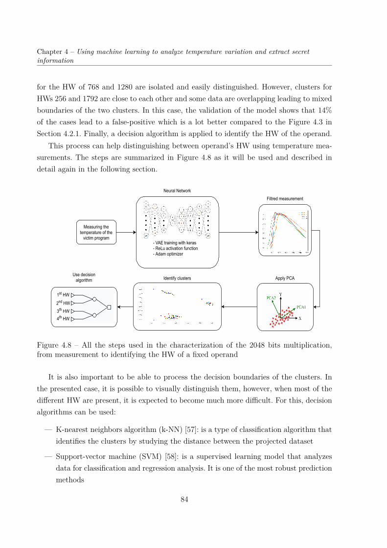
Chapter 4 – Using machine learning to analyze temperature variation and extract secretinformation
for the HW of 768 and 1280 are isolated and easily distinguished. However, clusters forHWs 256 and 1792 are close to each other and some data are overlapping leading to mixedboundaries of the two clusters. In this case, the validation of the model shows that 14%of the cases lead to a false-positive which is a lot better compared to the Figure 4.3 inSection 4.2.1. Finally, a decision algorithm is applied to identify the HW of the operand.
This process can help distinguishing between operand’s HW using temperature mea-surements. The steps are summarized in Figure 4.8 as it will be used and described indetail again in the following section.
Measuring thetemperature of the
victim program- VAE training with keras- ReLu activation function- Adam optimizer
Neural NetworkFiltred measurement
Apply PCAIdentify clusters
1st HW
Use decisionalgorithm
2nd HW3th HW4th HW
Figure 4.8 – All the steps used in the characterization of the 2048 bits multiplication,from measurement to identifying the HW of a fixed operand
It is also important to be able to process the decision boundaries of the clusters. Inthe presented case, it is possible to visually distinguish them, however, when most of thedifferent HW are present, it is expected to become much more difficult. For this, decisionalgorithms can be used:
— K-nearest neighbors algorithm (k-NN) [57]: is a type of classification algorithm thatidentifies the clusters by studying the distance between the projected dataset
— Support-vector machine (SVM) [58]: is a supervised learning model that analyzesdata for classification and regression analysis. It is one of the most robust predictionmethods
84

4.4. Inferring the HW of RSA private key
— Neuronal networks for classification [59]: it is also possible to use a classical percep-tron for automatically classifying the output of the PCA
These methods were not used in this chapter but represents future possible work toincrease the accuracy of finding the correct HW.
4.4 Inferring the HW of RSA private key
As seen in Section 4.2, it is possible to use the temperature of the chip to infer in-formation. The main objective of this section is then to infer information from an RSAdecryption and implement an attack on modern MPSoC (Hikey960 board as an example).Same as in the previous section, the focus will be on extracting the HW of the secret key.
4.4.1 Main implementation steps of attack
The main steps of this attack are similar to the attack presented in Chapter 3 withslight differences.
Accessing the temperature sensors: Accessing the temperature sensors does notrequire a physical access to the system. In modern MPSoC the devices run under anOS and it is still possible to access the sensors without privilege. However, having aprivileged access allows to read the temperature value directly from the register, thus, itreduces the latency and has higher sampling rate. Moreover, a privileged access will alsoallow the attacker to modify the working frequency. Running at the minimal frequency isrecommended for this attack as the junction temperature will not be reached and moremeasurements can be done within the same time span.
Measuring the temperature during RSA: In the target platform, the systemhas multiple cores and two clusters as opposite to the targeted platform of the previousChapter 3. Techniques like DMA are not necessary as measurements can be done fromone core while the target program is being executed on another one. For this attack, themeasurements are done from a big cluster core running at the highest frequency, whilethe victim target program is executed on a LITTLE cluster core running at its minimumfrequency (Similar to Chapter 2).
Launching an RSA decryption: It is important to be able to re-execute the RSAdecryption with the same ciphertext and the same key. Multiple iterations are necessary
85
Chapter 4 – Using machine learning to analyze temperature variation and extract secretinformation
as we need a sufficient number of measurements. The mean temperature for at least 100iterations were needed in our rest case scenario.
Offline Phase; Characterization of the device: In the first phase, the attackeris required to characterize the target device. Since the main objective is to uncover theHW of the private key, a characterization for every HW and its effect on the temper-ature of the targeted device is necessary. This process is time consuming but needs tobe accomplished only once per platform model. In this phase, the private key is known.Moreover, it is recommended to have different target hardware of the same model to takeinto consideration the variation introduced during the manufacturing process. Finally, thedataset obtained in this phase is used to train the VAE model previously presented.
Online Phase; Uncovering the HW for the private key: The second step rep-resents the real attack and its objective is to uncover the HW of the private key. Inthis phase, few measurements need to be done using a malicious application. These mea-surements are used with the previously trained VAE and are added to the Offline Phasedataset for clustering with PCA. The final step is to identify which cluster is the closest tothe measurements done during the Online Phase. The distance between the measurementand the cluster represents the probability of the key being of a specific HW.
4.4.2 RSA reminder
The main target of this part of the work is RSA 2048. It uses exponentiation operationto encrypt and decrypt information with both operands of the operation being long binarynumber (from 1024 bits and up to 4096 bits). Thus, it has long processing time and ahigh load on the SoC making it the perfect target for our proposed temperature attack.RSA is a public-key cryptosystem used to secure transmissions. In this case, a public keyis released and used to encrypt the information. However, this same key cannot be usedto decrypt the cipher, to decrypt the information, a private key, which is kept secret, isused. It is also important to note that both private and public keys are computed usingtwo distinct prime numbers (p and q). Any person in possession of these two numberscan recreate the private key.
The creation of both, a private and public key, is shown in Figure 4.9 and the mainsteps are as follow:
— Choosing two distinct prime numbers p and q. They should be random and keptsecret.
86

4.4. Inferring the HW of RSA private key
— Computing n = pq. n is the modulo for both the private and public key, it will beused during the encryption and decryption processes.
— Computing λ(n) where λ is Carmichael’s totient function. λ(n) should be kept secret.
— Choosing e where 1 < e < λ(n) and e should be coprime with λ(n). (e,n) is releasedas the public key.
— Computing d ≡ e−1(modλ(n)). (d,n) is the private key and kept secret.
Compute n=pqCompute λ(n)
λ is Carmichaelfunction
Choose e < λ(n) e and λ(n) should be
coprime
Compute dd ≡ e−1 (mod λ(n))
public key (e,n)
private key (d,n)
Prime numbers(p,q)
Figure 4.9 – The main step to generate the public and private key of the RSA algorithm
Finally, with the public and private key, it is possible to encrypt and decrypt theplaintext. The encryption of a message m into the cipher c is computed as follow:
me ≡ c ∗mod(n) (4.2)
The decryption of a ciphertext c into the plaintext m is computed as follow:
cd ≡ m ∗mod(n) (4.3)
In this work, the main goal is to infer the HW of the private key d. Thus, the maintarget is the decryption phase where d is used as an exponent of c, d being the secret.
4.4.3 Experimental setup
The target device is the Hikey board, as for the RSA implementation, the library MPIwas used. This library was originally created to be used for cryptography applications andcontains all the mathematical tools necessary for this case. For the RSA implementation,the function mpi_powm (MPI m, MPI c, MPI d, MPI n) is used. It is equivalent to m =cd ∗mod(n). n was arbitrary chosen and fixed for the whole attack. As for measurements,the previous setup used for the multiplication in Section 4.2 is reused.
87

Chapter 4 – Using machine learning to analyze temperature variation and extract secretinformation
4.4.4 Attack implementation and results
The first step toward implementing the attack is to complete the characterization. Theobjective of this phase, as previously stated, is to identify the effect of the RSA decryptionon the temperature when the private key HW is known. In our case, the size of d is 2048bits width meaning that there are 2048 possible HWs. As it is too time consuming tocharacterize all of them, it was decided to characterize 25 HW only. Moreover, enoughmeasurements are needed for training the VAE.
During the characterization, a set of 250 ciphertexts was arbitrary chosen and willnot change for the rest of the attack. For each HW, 20 private keys of this HW werearbitrary chosen. The characterization consists of re-executing the decryption ciphertextuntil 40.000 temperature measurements are obtained (same setup as in Section 4.2.1.The mean of those measurements is computed before moving on to the next ciphertext.At the end of this experiments, a matrix of 25*20*250 (25 HW, 20 private key and 250ciphertexts) measurements is obtained, it will represent the dataset for the rest of thechapter.
The next step is to train the VAE. The structure from Secion 4.2 shown in Figure 4.5is reused. The input of the VAE is the 250 measurements of each ciphertext for each key.
43.845
Temperature (°C)
Freq
uenc
y of
app
eara
nce
44.870 45.895 46.920 47.945 48.970 49.995
Figure 4.10 – Temperature characterization of RSA2048, each trace shows a different HWfrom (80 to 2000 with a step of 80).
The Figure 4.10 shows the filtered temperature measurements computing the RSA
88

4.4. Inferring the HW of RSA private key
decryption, each trace represents a different HW of a key set. The next step is to usethe PCA for clustering. However, the 20 private keys per HW were not enough, thus,the dataset for each class (HW) was not large enough to form clusters specially due tothe measurement time. For this reason, it was necessary to trade the number of HW tocharacterize for the number of private keys per HW. We decided to reduced the number ofHW to characterize to 5 (250, 650, 1050, 1450, 1850) and increase the number of privatekeys per HW to 200. Finally, the new dataset is processed again and the result of PCA isshown in Figure 4.11. It is possible to see the 5 clusters distinct from each other.
HW 250HW 650
HW 1050HW 1450HW 1850
Figure 4.11 – Clusters for each HW (250, 650, 1050, 1450, 1850) of the private key formedafter executing the PCA on the dataset of RSA2048 using 200 keys per HW.
With the PCA and identification of each clusters the Offline Phase is finished. Oncethe cluster are formed and distinguished, it is possible to move to the Online Phase.During this part, the attacker measure remotely the temperature during the decryptionof a set of ciphertexts. The set should be the same one that is used during the OfflinePhase. Measurements are also done in the same way, however, this time there is onlyone key and it is not known. By the end of this phase, a vector of 250 measurements forthe private key is obtained. It is then filtered using the VAE and added to the previousdataset for PCA. This projects the measurements done during the attack on the clusterspreviously formed. The HW is inferred by computing the closest cluster to this specificmeasurement. It has to be noticed that we need 250 measurements only in this phase. It is
89

Chapter 4 – Using machine learning to analyze temperature variation and extract secretinformation
still possible to increase the number of measurements in order to obtain a more accurateresults.
During the Online Phase, we did 50 tests of 250 measurements of the temperaturewith different keys and it was possible to infer the HW of the private key 95% of the time.Some measurements contained too much noise and were projected outside of the expectedclusters and when computing the closest cluster it leads to false-positive. Finally, furthertests were conducted to compare the recovery rate that is dependent on the HW of thesecret keys. The results summed up in Table 4.1 and Table 4.2 consist on comparingthe recovery rate for keys with high HW to keys with low HW. This shows that thereis no main difference, and that all recovery rate are higher than 90% with the highestbeing 96.8%. Those results were obtained by reducing the number of measurements perciphertext 30.000 instead of 40.000 and using the same setup as before (200 private keysper HW), we were able to collect enough measurement to form the table in 3 weeks.
TestedHW 20 40 60 80 100 120 140 160 180 200
Rate ofrecovery 95.6% 96.8% 94.3% 94% 95.5% 96% 94.1% 93.8% 95.9% 94.3%
Table 4.1 – Table summing up the success rate of recovering the HW of the secret keyswith a ’low’ HW.
TestedHW 1680 1720 1760 1800 1840 1880 1920 1960 2000 2040
Rate ofrecovery 93.1% 91% 95.6% 93.2% 96.3% 93.7% 95.2% 90.2% 95.9% 92.6%
Table 4.2 – Table summing up the success rate of recovering the HW of the secret keyswith a ’high’ HW.
4.5 Discussion
In this chapter we showed that it is possible to use integrated temperature sensorsto infer information over complex architectures. The victim program of this work is theRSA2048 algorithm, as this program has a high load on the cpu, it was possible to detect
90

4.6. Conclusion
a general variation of temperature depending on the HW of the private key. However,this may not be the case for encryption like AES as it requires to detect variation at afew instructions granularity level and before the key is diffused. However, it is possible toisolate the target instructions, but the variation of temperature is small compared to thenoise from the OS and other applications.
This attack also requires a lot of measurements, and the characterization is timeconsuming. However, once it is done, it is viable for most of the devices using the sameplatform model.
Finally, it may also be possible to use machine learning techniques to complete char-acterization for certain HW if the dataset is large enough. One of the reasons VAE wasused is because of its ability to generate new data. However, this was not tested on thedataset created during this work.
4.6 Conclusion
Temperature management mechanisms are nowadays omnipresent in every device. Afirst work proved the possibility of maliciously remotely using temperature sensors toextract information during AES encryption. That work mainly targeted IoT devices asthey are simple and was not proven on complex architectures. However, in this chapter,it is shown on a state-of-art high-end architecture used on the smartphone industry, thatit is still possible to maliciously exploit temperature sensors. Machine learning techniqueswere used to filter the measurements, reduce the noise and remove irrelevant information.Finally, PCA was used for clustering. The private key was not recovered but this workmay be combined with other works such us factorization of the key [60] as it may reducethe exploration space.
91


CONCLUSION
In this thesis, we evaluated possible vulnerabilities in today’s dynamic managers andtheir hardware implementation. We focused on the two most used managers: energy man-ager and thermal managers.
First, the importance of evaluating the security of those systems is highlighted inChapter 1. Previous vulnerabilities proven in different works in the literature are pre-sented. Energy managers were maliciously used to inject faults and extract secrets whileworks on thermal managers are limited. Most of the works have used heat as a covertchannel to transmit information. In Chapter 2, we presented a different way of exploitingthe same vulnerability presented using energy managers. In this case no secret informa-tion was extracted. However, it is possible to lock out the targeted device and to make itsdata inaccessible and service unusable, this was presented as a possible ransomware onsmartphone, but it can be extended to other targets such as autonomous car, IoT devicesor even temporally lock out companies’ servers with a DOS attack.
In Chapter 3, the internal temperature sensors present in today’s SoCs were used tocharacterize a target device and extract crucial information. This was done by measur-ing the heat generated by different instructions and operands and was used to infer acharacteristics of a secret key of an AES encryption. It was possible to reduce the explo-ration space by 74% for each byte of the encryption key, and it was proven that it canbe reduced even further, making possible to bruteforce the encryption key within 9 daystheoretically. This attack was implemented on an IoT SoC, as the temperature has a lowpropagation time, thus, a lot of information is lost and filtered due to the high frequencyof in state-of-art SoC. However, with application that has high load and generates moreheat it would be still possible to extract information for its execution and temperature,this possibility was explored in the following chapter.
In Chapter 4, we explored the possibility of using the temperature sensors in a morecomplex architecture running an OS. In this case, we target RSA encryption as it has ahigher load on the SoC and generate more energy than the AES encryption. However, itwas not enough to observe a correlation between operands and the temperature. Machinelearning techniques (VAE and PCA) are then used to analyze the temperature measure-
93
ments. The HW of the private key was inferred from the heat emitted during an RSAdecryption, .
Future possible work
This work focused on studying two different dynamic managers. Future work may alsofocus on other types of managers such as resource managers in order to identify furthervulnerabilities. This work can also be extended to different hardware performance countersand use them to extract information as different works [61][62][63][64] have studied theiruse in order to model the energy consumption from the obtained data. It is likely thatthis information can be used to study data-dependency and to extract secrets from thedevice.
It would also be important to study the feasibility of the approach presented in thiswork on different protected encryption systems integrating classical side-channel attackscountermeasures (e.g., AES with mask, random delays or RSA exponent blinding). Thestudy of the approach against dedicated hardware blocks for encryption is also a futurework. This work can also be extended and studied on different architectures (i.e., Intel,AMD).
Another interesting research lead would be extending the machine learning analysisusing VAE. Some literature work has already used AE to filter measurements and reducethe number of traces needed to recover secret information. However, VAE may also beused to predict the characterization of certain HW. For example, in our work we requiredthe characterization of every Hamming Weight (HW) of the private encryption key. In thiscase, VAE can be used to interpolate the characterization of a HW if we have enough tracesfor other characterized HWs. Finally, this approach could be applied to other templateattacks in order to reduce the time required for their characterization phase.
Scientific communication
International conferences
Published:1. S. NOUBIR, M. MENDEZ REAL and S. PILLEMENT, "Towards Malicious Exploita-tion of Energy Management Mechanisms," 2020 Design, Automation & Test in Europe
94

Conference & Exhibition (DATE), 2020, pp. 1043-1048, doi: 10.23919/DATE48585.2020.9116420.
95


BIBLIOGRAPHY
[1] Moritz Lipp et al. « Meltdown ». In: CoRR abs/1801.01207 (2018). arXiv: 1801.01207. url: http://arxiv.org/abs/1801.01207.
[2] Paul Kocher et al. « Spectre Attacks: Exploiting Speculative Execution ». In: CoRRabs/1801.01203 (2018). arXiv: 1801.01203. url: http://arxiv.org/abs/1801.01203.
[3] Adrian Tang, Simha Sethumadhavan, and Salvatore Stolfo. « CLKSCREW: Ex-posing the Perils of Security-Oblivious Energy Management ». In: 26th USENIXSecurity Symposium (USENIX Security 17). Vancouver, BC: USENIX Association,2017, pp. 1057–1074. isbn: 978-1-931971-40-9. url: https://www.usenix.org/conference/usenixsecurity17/technical-sessions/presentation/tang.
[4] Kit Murdock et al. « Plundervolt: Software-based Fault Injection Attacks againstIntel SGX ». In: 41st IEEE Symposium on Security and Privacy (S&P’20). 2020.
[5] Exynos 5422 reference. url: https://www.samsung.com/semiconductor/minisite/exynos/products/mobileprocessor/exynos-5-octa-5422/.
[6] Ramya Jayaram Masti et al. « Thermal Covert Channels on Multi-core Platforms ».In: 24th USENIX Security Symposium (USENIX Security 15). Washington, D.C.:USENIX Association, Aug. 2015, pp. 865–880. isbn: 978-1-939133-11-3. url: https:/ / www . usenix . org / conference / usenixsecurity15 / technical - sessions /presentation/masti.
[7] STM32F303 reference page. url: https://www.st.com/en/microcontrollers-microprocessors/stm32f303re.html.
[8] Jo Van Bulck, Frank Piessens, and Raoul Strackx. « SGX-Step: A Practical AttackFramework for Precise Enclave Execution Control ». In: 2nd Workshop on SystemSoftware for Trusted Execution (SysTEX). ACM, Oct. 2017, 4:1–4:6.
[9] Hikey 960 reference page. url: https://www.96boards.org/product/hikey960/.
97
[10] Bryan Black et al. « Die Stacking (3D) Microarchitecture ». In: 2006 39th AnnualIEEE/ACM International Symposium on Microarchitecture (MICRO’06). 2006, pp. 469–479. doi: 10.1109/MICRO.2006.18.
[11] Viswanathan Subramanian, Prem Kumar Ramesh, and Arun K. Somani. « Man-aging the Impact of On-chip Temperature on the Lifetime Reliability of ReliablyOverclocked Systems ». In: 2009 Second International Conference on Dependability.2009, pp. 156–161. doi: 10.1109/DEPEND.2009.30.
[12] Ayse K. Coskun et al. « Evaluating the Impact of Job Scheduling and Power Man-agement on Processor Lifetime for Chip Multiprocessors ». In: Proceedings of theEleventh International Joint Conference on Measurement and Modeling of Com-puter Systems. SIGMETRICS ’09. Seattle, WA, USA: Association for Comput-ing Machinery, 2009, pp. 169–180. isbn: 9781605585116. doi: 10.1145/1555349.1555369. url: https://doi.org/10.1145/1555349.1555369.
[13] 40 Years of Microprocessor Trend Data [Online]. url: https://www.karlrupp.net/2015/06/40-years-of-microprocessor-trend-data/.
[14] Dynamic Voltage and Frequency Scaling on ARM architectures [Online]. url: https://developer.arm.com/documentation/den0013/d/Power-Management/Dynamic-Voltage-and-Frequency-Scaling.
[15] DA Patterson JL Hennessy. « Computer Architecture: A Quantitative Approach.Morgan Kaufmann PublishersInc. » In: (1990).
[16] Snapdragon 800 reference. url: https://www.qualcomm.com/products/snapdragon-processors-800.
[17] Adi Shamir Eli Biham. « The next Stage of Differential Fault Analysis: How tobreak completely unknown cryptosystems ». In: (1996).
[18] Andrew Johnson and Richard Ward. « Introducing The ‘Unified Side Channel At-tack - Model’ (USCA-M) ». In: 2020 8th International Symposium on Digital Foren-sics and Security (ISDFS). 2020, pp. 1–9. doi: 10 . 1109 / ISDFS49300 . 2020 .9116291.
[19] Pengfei Qiu et al. « VoltJockey: Breaching TrustZone by Software-Controlled Volt-age Manipulation over Multi-Core Frequencies ». In: Proceedings of the 2019 ACMSIGSAC Conference on Computer and Communications Security. CCS ’19. London,United Kingdom: Association for Computing Machinery, 2019, pp. 195–209. isbn:
98

9781450367479. doi: 10.1145/3319535.3354201. url: https://doi.org/10.1145/3319535.3354201.
[20] RSA signature verification [Online]. url: https://www.cs.cornell.edu/courses/cs5430/2015sp/notes/rsa_sign_vs_dec.php.
[21] Anatoly Shusterman et al. « Prime+Probe 1, JavaScript 0: Overcoming Browser-based Side-Channel Defenses ». In: 30th USENIX Security Symposium (USENIX Se-curity 21). USENIX Association, Aug. 2021, pp. 2863–2880. isbn: 978-1-939133-24-3. url: https://www.usenix.org/conference/usenixsecurity21/presentation/shusterman.
[22] Arm TrustZone Technology [Online]. url: https://developer.arm.com/ip-products/security-ip/trustzone.
[23] Lilian Bossuet El Mehdi Benhani. « DVFS as a Security Failure of TrustZone-enabled Heterogeneous SoC ». In: 25th IEEE International Conference on Elec-tronics Circuits and Systems (2018).
[24] Sheng Zhang et al. « Blacklist Core: Machine-Learning Based Dynamic Operating-Performance-Point Blacklisting for Mitigating Power-Management Security Attacks ».In: Proceedings of the International Symposium on Low Power Electronics and De-sign. ISLPED ’18. Seattle, WA, USA: ACM, 2018, 5:1–5:6. isbn: 978-1-4503-5704-3.doi: 10.1145/3218603.3218624. url: http://doi.acm.org/10.1145/3218603.3218624.
[25] FAME, Fault-attack Awareness using Microprocessor Enhancements. url: https://sites.google.com/view/famechip/.
[26] Dan Kikinis. « Temperature management for integrated circuits ». US5502838A.1990. url: https://patents.google.com/patent/US5502838A/en.
[27] I. Steiner C. Gough and W. Saunders. Energy Efficient Servers, Apress. 2015.
[28] Michael Hutter and Jörn-Marc Schmidt. « The Temperature Side Channel and Heat-ing Fault Attacks ». In: Smart Card Research and Advanced Applications. Ed. byAurélien Francillon and Pankaj Rohatgi. Cham: Springer International Publishing,2014, pp. 219–235. isbn: 978-3-319-08302-5.
[29] W. Xiong et al. « Spying on Temperature using DRAM ». In: 2019 Design, Au-tomation Test in Europe Conference Exhibition (DATE). 2019, pp. 13–18. doi:10.23919/DATE.2019.8714882.
99

[30] Running Average Power Limit - Intel [Online]. url: https://01.org/blogs/2014/running-average-power-limit-%5C%E2%5C%80%5C%93-rapl.
[31] Paul Kocher, Joshua Jaffe, and Benjamin Jun. « Differential Power Analysis ». In:Advances in Cryptology — CRYPTO’ 99. Ed. by Michael Wiener. Berlin, Heidel-berg: Springer Berlin Heidelberg, 1999, pp. 388–397. isbn: 978-3-540-48405-9.
[32] Eric Brier, Christophe Clavier, and Francis Olivier. « Correlation Power Analysiswith a Leakage Model ». In: Cryptographic Hardware and Embedded Systems - CHES2004. Ed. by Marc Joye and Jean-Jacques Quisquater. Berlin, Heidelberg: SpringerBerlin Heidelberg, 2004, pp. 16–29. isbn: 978-3-540-28632-5.
[33] Heiko Mantel et al. « How Secure Is Green IT? The Case of Software-Based EnergySide Channels ». In: Computer Security. Ed. by Javier Lopez, Jianying Zhou, andMiguel Soriano. Cham: Springer International Publishing, 2018, pp. 218–239. isbn:978-3-319-99073-6.
[34] Moritz Lipp et al. « PLATYPUS: Software-based Power Side-Channel Attacks onx86 ». In: 2021 IEEE Symposium on Security and Privacy (SP). IEEE. 2021.
[35] Johann Heyszl et al. « Clustering algorithms for non-profiled single-execution at-tacks on exponentiations ». In: International Conference on Smart Card Researchand Advanced Applications. Springer. 2013, pp. 79–93.
[36] Youssef Souissi et al. « First Principal Components Analysis: A New Side Chan-nel Distinguisher ». In: Information Security and Cryptology - ICISC 2010. Ed. byKyung-Hyune Rhee and DaeHun Nyang. Berlin, Heidelberg: Springer Berlin Hei-delberg, 2011, pp. 407–419. isbn: 978-3-642-24209-0.
[37] C. Archambeau et al. « Template Attacks in Principal Subspaces ». In: Crypto-graphic Hardware and Embedded Systems - CHES 2006. Ed. by Louis Goubin andMitsuru Matsui. Berlin, Heidelberg: Springer Berlin Heidelberg, 2006, pp. 1–14.isbn: 978-3-540-46561-4.
[38] Lichao Wu and Stjepan Picek. « Remove Some Noise: On Pre-processing of Side-channel Measurements with Autoencoders ». In: IACR Transactions on Crypto-graphic Hardware and Embedded Systems 2020.4 (Aug. 2020), pp. 389–415. doi:10.13154/tches.v2020.i4.389-415. url: https://tches.iacr.org/index.php/TCHES/article/view/8688.
100

[39] Timo Bartkewitz and Kerstin Lemke-Rust. « Efficient Template Attacks Based onProbabilistic Multi-class Support Vector Machines ». In: Smart Card Research andAdvanced Applications. Ed. by Stefan Mangard. Berlin, Heidelberg: Springer BerlinHeidelberg, 2013, pp. 263–276. isbn: 978-3-642-37288-9.
[40] Annelie Heuser and Michael Zohner. « Intelligent Machine Homicide ». In: Con-structive Side-Channel Analysis and Secure Design. Ed. by Werner Schindler andSorin A. Huss. Berlin, Heidelberg: Springer Berlin Heidelberg, 2012, pp. 249–264.isbn: 978-3-642-29912-4.
[41] Gabriel Hospodar et al. « Machine learning in side-channel analysis: a first study ».In: Journal of Cryptographic Engineering 1.4 (Oct. 2011), p. 293. issn: 2190-8516.doi: 10.1007/s13389-011-0023-x. url: https://doi.org/10.1007/s13389-011-0023-x.
[42] Liran Lerman, Gianluca Bontempi, and Olivier Markowitch. « Power Analysis At-tack: An Approach Based on Machine Learning ». In: Int. J. Appl. Cryptol. 3.2(June 2014), pp. 97–115. issn: 1753-0563.
[43] Liran Lerman, Gianluca Bontempi, and Olivier Markowitch. « A machine learningapproach against a masked AES ». In: Journal of Cryptographic Engineering 5.2(June 2015), pp. 123–139. issn: 2190-8516. doi: 10.1007/s13389-014-0089-3.url: https://doi.org/10.1007/s13389-014-0089-3.
[44] Benjamin Timon. « Non-Profiled Deep Learning-based Side-Channel attacks withSensitivity Analysis ». In: IACR Transactions on Cryptographic Hardware and Em-bedded Systems 2019.2 (Feb. 2019), pp. 107–131. doi: 10.13154/tches.v2019.i2.107-131. url: https://tches.iacr.org/index.php/TCHES/article/view/7387.
[45] Baris Ege Guilherme Perin and Jasper van Woudenberg. « Lowering the bar: Deeplearning for side-channel analysis (white paper) ». In: JBlackHat. August 2018.
[46] Ryad Benadjila et al. « Study of deep learning techniques for side-channel analysisand introduction to ASCAD database ». In: ANSSI, France & CEA, LETI, MI-NATEC Campus, France. Online verfügbar unter https://eprint. iacr. org/2018/053.pdf, zuletzt geprüft am 22 (2018), p. 2018.
101

[47] Jaehun Kim et al. « Make Some Noise. Unleashing the Power of ConvolutionalNeural Networks for Profiled Side-channel Analysis ». In: IACR Transactions onCryptographic Hardware and Embedded Systems 2019.3 (May 2019), pp. 148–179.doi: 10.13154/tches.v2019.i3.148- 179. url: https://tches.iacr.org/index.php/TCHES/article/view/8292.
[48] « White Paper - The WannaCry Ransomware Attack ». In: (2017). url: http://cert-mu.govmu.org/English/Documents/White%20Papers/White%20Paper%20-%20The%20WannaCry%20Ransomware%20Attack.pdf.
[49] Voltage and current regulator API. url: https://www.kernel.org/doc/html/v4.15/driver-api/regulator.html.
[50] Magisk costum ROM. url: https://github.com/topjohnwu/Magisk.
[51] « Download counts of Magisk ». In: (2019). url: https://forum.xda-developers.com/apps/magisk/official-magisk-v7-universal-systemless-t3473445.
[52] Arnaud Rosay et al. Method of DVFS-Power Management and Corresponding Sys-tem. Apr. 2020.
[53] Description of STM32F4 HAL and low-layer drivers. url: https://www.st.com/resource/en/user_manual/dm00105879-description-of-stm32f4-hal-and-ll-drivers-stmicroelectronics.pdf.
[54] Kahraman Akdemir et al. « Breakthrough AES Performance with Intel® AES NewInstructions ». In: Intel. 2021.
[55] Diederik P. Kingma and Jimmy Ba. Adam: A Method for Stochastic Optimization.2017. arXiv: 1412.6980 [cs.LG].
[56] scikit-learn: Machine Learning in Python [Online]. url: https://scikit-learn.org/stable/.
[57] N. S. Altman. « An Introduction to Kernel and Nearest-Neighbor NonparametricRegression ». In: The American Statistician 46.3 (1992), pp. 175–185. doi: 10 .1080/00031305.1992.10475879. eprint: https://www.tandfonline.com/doi/pdf/10.1080/00031305.1992.10475879. url: https://www.tandfonline.com/doi/abs/10.1080/00031305.1992.10475879.
102

[58] Bernhard E. Boser, Isabelle M. Guyon, and Vladimir N. Vapnik. « A Training Algo-rithm for Optimal Margin Classifiers ». In: Proceedings of the Fifth Annual Workshopon Computational Learning Theory. COLT ’92. Pittsburgh, Pennsylvania, USA:Association for Computing Machinery, 1992, pp. 144–152. isbn: 089791497X. doi:10.1145/130385.130401. url: https://doi.org/10.1145/130385.130401.
[59] Yoav Freund and Robert E. Schapire. « Large Margin Classification Using the Per-ceptron Algorithm ». In: Machine Learning 37.3 (Dec. 1999), pp. 277–296. issn:1573-0565. doi: 10.1023/A:1007662407062. url: https://doi.org/10.1023/A:1007662407062.
[60] Factorization of RSA-250 [Online]. url: https://caramba.loria.fr/rsa250.txt.
[61] Dimitris Economou et al. « Full-System Power Analysis and Modeling for ServerEnvironments ». In: 2006.
[62] Muhammad Fahad et al. « A Comparative Study of Methods for Measurement ofEnergy of Computing ». In: Energies 12.11 (2019). issn: 1996-1073. doi: 10.3390/en12112204. url: https://www.mdpi.com/1996-1073/12/11/2204.
[63] Arsalan Shahid et al. « Additivity: A Selection Criterion for Performance Eventsfor Reliable Energy Predictive Modeling ». In: Supercomputing Frontiers and In-novations 4.4 (Nov. 2017), pp. 50–65. doi: 10.14529/jsfi170404. url: https://superfri.org/index.php/superfri/article/view/153.
[64] Kenneth O’brien et al. « A Survey of Power and Energy Predictive Models in HPCSystems and Applications ». In: ACM Comput. Surv. 50.3 (June 2017). issn: 0360-0300. doi: 10.1145/3078811. url: https://doi.org/10.1145/3078811.
103


Titre : Évaluation et considération de la sécurité dans les systèmes de gestion d’architecturesmulti-cœurs
Mot clés : Gestionnaires d’énergie, gestionnaires de température, attaque par déni de service,
attaque par canaux auxiliaires
Résumé : Les architectures multi-cœurs pré-sentent une grande complexité du fait dugrand nombre de ressources et de la com-plexité de l’infrastructure de communication.Afin de répondre à des contraintes de perfor-mance ou de consommation d’énergie, il estnécessaire d’implémenter des gestionnairesdynamiques (mapping de tâches, adaptationdynamique de la fréquence et de la tension(e.g., DVFS pour Dynamic Voltage and Fre-quency Scaling)). Par exemple, les smart-phones ont été conçus en intégrant des ar-chitectures complexes dans un espace limité
tout en s’assurant du bon fonctionnement del’appareil (i.e., durée de vie de la batterie,température du processeur). Cependant, dansla majorité des cas, ces gestionnaires n’ontpas été conçus pour la sécurité et sont vul-nérables. Dans cette thèse, on explore lespossibles vulnérabilités de sécurité présentesdans les gestionnaires d’énergie et de tem-pérature. Trois différentes attaques ont étédémontrées par une implémentation sur desSoCs (Systems-on-Chip) récents. Finalement,des contre-mesures à ces attaques ont étépréposées.
Title: Evaluation and consideration of security in multi-core management systems
Keywords: Energy manager, Thermal manager, Denial of Service Attack, Thermal Side-Channel
Attack
Abstract: Architectures have become moreand more complex to keep up with the in-crease of algorithmic complexity. To fully ex-ploit those architectures, dynamic managersare required. The goal of dynamic managersis either to optimize the resource usage (e.g.,cores, memory) or to reduce energy consump-tion under performance constraints. Taking asexample, smartphones, those devices weredesigned to fit complex architectures in thesmallest space while ensuring the device runsin stable conditions. This includes keepingthe SoC (System-on-Chip) in low temperature
level and maximizing the battery life. Thus,different dynamic managers are deployed forthis purpose. However, managers were de-veloped with performance optimization beingtheir main goal, they have not been designedto be secure and present security vulnerabil-ities. In this work, we evaluate the securityof both, energy and thermal managers. Threedifferent attacks are presented and validatedby an implementation on a state-of-art SoCs.Finally, for each attack, possible countermea-sures were discussed.