Structure determinations for random-tiling quasicrystals
19
arXiv:cond-mat/0004126v1 [cond-mat.mtrl-sci] 9 Apr 2000 Z. Kristallogr. 216 (2001) 1 – 14 c by R. Oldenbourg Verlag, M¨ unchen 1 Structure determinations for random-tiling quasicrystals C. L. Henley ∗ , V. Elser, and M. Mihalkoviˇ c ∗ LASSP, Cornell University, Ithaca NY 14853-2501. Received ; accepted Abstract. How, in principle, could one solve the atomic structure of a quasicrystal, modeled as a random tiling dec- orated by atoms, and what techniques are available to do it? One path is to solve the phase problem first, obtaining the density in a higher dimensional space which yields the averaged scattering density in 3-dimensional space by the usual construction of an incommensurate cut. A novel direct method for this is summarized and applied to an i(AlPdMn) data set. This averaged density falls short of a true structure determination (which would reveal the typical unaveraged atomic patterns.) We discuss the problematic validity of in- ferring an ideal structure by simply factoring out a “perp- space” Debye-Waller factor, and we test this using simula- tions of rhombohedral tilings. A second, “unified” path is to relate the measured and modeled intensities directly, by ad- justing parameters in a simulation to optimize the fit. This approach is well suited for unifying structural information from diffraction and from minimizing total energies derived ultimately from ab-initio calculations. Finally, we discuss the special pitfalls of fitting random-tiling decagonal phases. 1 Introduction The “random tiling” model of quasicrystals has specific and sometimes radical implications for the procedures that should be used to determine the atomic structures. This pa- per collects several kinds of answer to the question, “How should one modify the standard crystallographic procedures in order to solve the atomic structure of a random tiling quasicrystal?” (Notice that even the definition of “solve” is arguable in the case of an intrinsically random structure.) We intend this paper to encourage crystallographers to try random-tiling fits to diffraction data, by showing that a cou- ple of approaches have already been thought out in some de- tail. It also cautions against some common misunderstand- ings about this point, and collects three new (and imperfectly digested) numerical tests of our ideas. The discussion goes well beyond its antecedent in Sec. 7 of Ref. [1]. ∗ Correspondence author (e-mail: [email protected]) Please also note that M.M.’s present address is Materials Research and Liquids, Institute of Physics, TU Chemnitz, D-09107 Chemnitz, Germany; his permanent address, Institute of Physics, Slovak Academy of Sciences, 84228 Bratislava, Slovakia. 1.1 Perp space and diffraction The “perp” coordinate h ⊥ is a central notion in quasicrys- tallography. Before proceeding, we had better remind the reader that it has two definitions, which coincide for the case of an ideal tiling. Definition 1, valid for the usual higher-dimensional “cut” description [2] of any quasiperiodic struc- ture (e.g. an ideal tiling). The (periodic) higher- dimensional density consists of atomic surfaces ex- tending in the perp direction; then h ⊥ is the perp- space displacement from the intersection of the cut plane and the atomic surface, to a vertex of the higher- dimensional lattice. Definition 2, valid for any arbitrary (e.g. random) tiling. Any tiling can be “lifted” so that each tile ver- tex maps to a vertex of a periodic lattice in a higher dimension [1, 3]; then h ⊥ of each tile vertex is the difference between the perp component of its lattice vector and the mean value (“center-of-mass” in perp space). Consider the probability distribution of the Definition 2 h ⊥ values. It is easy to check that, as long as the physical (hyper)plane has an irrational orientation, and in the limit of a large physical-space volume V , there are n 0 Vd 3 h ⊥ possi- ble perp-space points in a perp volume element d 3 h ⊥ , where n −1 0 is the volume of the unit cell in the -dimensional lat- tice. The mean number of such points actually present in the tiling is defined to be ρ(h ⊥ )n 0 Vd 3 h ⊥ , so ρ(h ⊥ ) ∈ [0, 1] is a probability. In random tilings it is, in practice, a smooth function. (In the special case of an ideal tiling, ρ(h ⊥ ) is 1 within the “acceptance domain” where sites are sure to be occupied, and zero outside it.) Note h ⊥ , according to Defi- nition 1, or its mean h ⊥ ≡ d 3 h ⊥ h ⊥ ρ(h ⊥ ) according to Definition 2, plays the role for perp displacements that a crystal’s center-of-mass plays for ordinary displacements. Now, we may take an ensemble average of a ran- dom tiling ensemble, just constraining the value h ⊥ to be zero (without loss of generality). This gives, in real space, a nonzero density ρ(r) on a discrete (but dense) set of points r. It is a fact, natural though not rigorously proven, that ρ(r) depends only on the perp-coordinate h ⊥ of the point r. If so, it is easy to see ρ(r)= ρ(h ⊥ ) as defined in the last para- graph. In other words, starting with Definition 2, we found the averaged density ρ(r) is given by the cut construction of Definition 1, if the atomic surfaces are weighted by ρ(h ⊥ .
-
Upload
khangminh22 -
Category
Documents
-
view
0 -
download
0
Transcript of Structure determinations for random-tiling quasicrystals

arX
iv:c
ond-
mat
/000
4126
v1 [
cond
-mat
.mtr
l-sci
] 9
Apr
200
0Z. Kristallogr. 216 (2001) 1 – 14
c© by R. Oldenbourg Verlag, Munchen
1
Structure determinations for random-tiling quasicrystals
C. L. Henley∗, V. Elser, and M. Mihalkovic∗
LASSP, Cornell University, Ithaca NY 14853-2501.
Received ; accepted
Abstract. How, in principle, could one solve the atomicstructure of a quasicrystal, modeled as a random tiling dec-orated by atoms, and what techniques are available to doit? One path is to solve the phase problem first, obtainingthe density in a higher dimensional space which yields theaveragedscattering density in 3-dimensional space by theusual construction of an incommensurate cut. A novel directmethod for this is summarized and applied to ani(AlPdMn)data set. This averaged density falls short of a true structuredetermination (which would reveal the typicalunaveragedatomic patterns.) We discuss the problematic validity of in-ferring an ideal structure by simply factoring out a “perp-space” Debye-Waller factor, and we test this using simula-tions of rhombohedral tilings. A second, “unified” path is torelate the measured and modeled intensities directly, by ad-justing parameters in a simulation to optimize the fit. Thisapproach is well suited for unifying structural informationfrom diffraction and from minimizing total energies derivedultimately from ab-initio calculations. Finally, we discussthe special pitfalls of fitting random-tiling decagonal phases.
1 Introduction
The “random tiling” model of quasicrystals has specificand sometimes radical implications for the procedures thatshould be used to determine the atomic structures. This pa-per collects several kinds of answer to the question, “Howshould one modify the standard crystallographic proceduresin order to solve the atomic structure of a random tilingquasicrystal?” (Notice that even the definition of “solve” isarguable in the case of an intrinsically random structure.)We intend this paper to encourage crystallographers to tryrandom-tiling fits to diffraction data, by showing that a cou-ple of approaches have already been thought out in some de-tail. It also cautions against some common misunderstand-ings about this point, and collects three new (and imperfectlydigested) numerical tests of our ideas. The discussion goeswell beyond its antecedent in Sec. 7 of Ref. [1].
∗ Correspondence author (e-mail: [email protected]) Please alsonote that M.M.’s present address is Materials Research and Liquids,Institute of Physics, TU Chemnitz, D-09107 Chemnitz, Germany; hispermanent address, Institute of Physics, Slovak Academy ofSciences,84228 Bratislava, Slovakia.
1.1 Perp space and diffraction
The “perp” coordinateh⊥ is a central notion in quasicrys-tallography. Before proceeding, we had better remind thereader that it has two definitions, which coincide for the caseof an ideal tiling.
Definition 1, valid for the usual higher-dimensional“cut” description [2] of any quasiperiodic struc-ture (e.g. an ideal tiling). The (periodic) higher-dimensional density consists of atomic surfaces ex-tending in the perp direction; thenh⊥ is the perp-space displacement from the intersection of the cutplane and the atomic surface, to a vertex of the higher-dimensional lattice.Definition 2, valid for any arbitrary (e.g. random)tiling. Any tiling can be “lifted” so that each tile ver-tex maps to a vertex of a periodic lattice in a higherdimension [1, 3]; thenh⊥ of each tile vertex is thedifference between the perp component of its latticevector and the mean value (“center-of-mass” in perpspace).Consider the probability distribution of the Definition
2 h⊥ values. It is easy to check that, as long as the physical(hyper)plane has an irrational orientation, and in the limit ofa large physical-space volumeV , there aren0V d3h⊥ possi-ble perp-space points in a perp volume elementd3h⊥, wheren−1
0 is the volume of the unit cell in the -dimensional lat-tice. The mean number of such points actually present in thetiling is defined to beρ(h⊥)n0V d3h⊥, soρ(h⊥) ∈ [0, 1] isa probability. In random tilings it is, in practice, a smoothfunction. (In the special case of an ideal tiling,ρ(h⊥) is 1within the “acceptance domain” where sites are sure to beoccupied, and zero outside it.) Noteh⊥, according to Defi-nition 1, or its meanh⊥ ≡
∫
d3h⊥h⊥ρ(h⊥) according toDefinition 2, plays the role for perp displacements that acrystal’s center-of-mass plays for ordinary displacements.
Now, we may take an ensemble average of a ran-dom tiling ensemble, just constraining the valueh⊥ to bezero (without loss of generality). This gives, in real space, anonzero densityρ(r) on a discrete (but dense) set of pointsr. It is a fact, natural though not rigorously proven, thatρ(r)depends only on the perp-coordinateh⊥ of the pointr. Ifso, it is easy to seeρ(r) = ρ(h⊥) as defined in the last para-graph. In other words, starting with Definition 2, we foundthe averaged densityρ(r) is given by the cut construction ofDefinition 1, if the atomic surfaces are weighted byρ(h⊥.

2 Structure determinations for random-tiling quasicrystals
This shows thatρ(r) is quasiperiodic, since that term is,practically speaking,definedby the existence of a cut con-struction.1
These facts aboutρ(h⊥) easily generalize to atomicdecorations in which atoms sit on some of the tile vertices.Thus wherever the physical 3-plane cuts an atomic surface,ρ(h⊥) is the probability that an atom is present.
The Bragg component of the diffraction amplitudeFg
is defined as the part which scales asV with the volume.It is, in fact, simply the Fourier transform of the averageddensity: [3],
F (g⊥) =
∫
d3h⊥ρ(h⊥)e−ig⊥·h⊥ (1)
Here g⊥ is the perp-space partner of the reciprocal lat-tice wavevectorg. In cases other than icosahedral, “3” ineq. (1) is replaced by “d⊥”, the dimensionality of perp space.(However we shall assume the physical dimension is always3, since this paper considers determinations from Braggpeaks, but random tilings have no Bragg peaks in dimen-sion 1 or 2.) For a tiling decorated by real atoms, (1) can besuitably generalized by including form factors and allowingfor different classes of site (see eq. (27), below).
1.2 Random tilings and the cut description
Bragg diffraction amplitudes are always represented by aquasiperiodic density in higher-dimensional space, whichwhen cut by a 3-plane at the correct incommensurate ori-entation gives the diffracting density in physical space. [2]The crystallographic refinements done to date have presup-posed that the structure, ideally,is quasiperiodic. But an (atleast) equally plausible scenario is that the thermal equilib-rium structure is an intrinsically random tiling and so thatitslong-range quasiperiodic order is stabilized by the tiling’sconfigurational entropy. [5, 1] Notions concerning the freeenergy and elastic constants are central to thephysics[5, 1]but will not be repeated here since they are somewhat tan-gential to thecrystallography. Indeed, large parts of thispaper could be applied equally well to the cases of (i) the“icosahedral glass” [6], e.g.i(AlCuLi), or i(TiNiZr), whichis not thermodynamically stable; or (ii) the “weak matching-rule” quasicrystal [7], which is a slight generalization oftheideal, energetically stabilized quasicrystal that neverthelesshas a nonzero density of intrinsically random sites.
So, how does the cut description get modified in thecase of a random tiling? As just noted in Sec. 1.1, thephysical-space density giving rise to the Bragg amplitudesisthe ensemble average of the scattering density. This averageis perfectly quasiperiodic, and so even for a random tiling itis represented as a cut by a 3-plane through a function in ahigher-dimensional space.
However, the physical-space density will have a greatmany fractionally occupied atoms; even if there is no sub-stitutional disorder, since a given volume of space has prob-abilities to be divided into tiles in different ways and dif-ferent tiles have different decorations. A second effect is
1 In the case of the two-dimensional equilibrium random tiling or theicosahedral glass, the above arguments break down becauseρ(h⊥) =0, i.e. the distribution gets broader and broader with increasingV .
the “physical-space displacements” [8], the deviations ofanatom from ideal tiling vertex positions in response to forcesfrom neighboring atoms. In ideal structures, an atom’s lo-cal environment is a deterministic function ofh⊥. Then theatom’s equilibrium position isr0 + u(h⊥), also a functionof h⊥, and this is the parametrization of the atomic surface’sshape. In the random case, however, atoms correspondingto the sameh⊥ can have different local environments andhence different parallel-space displacements. This manifestsitself as split positions in the physical-space cut, or equiva-lently the atomic surface becomes an discrete family of sur-faces, displaced from each other by small offsets in parallelspace, and each having its own distributionρ(h⊥).
Crystallographers would sometimes argue that aFourier map reconstructing the correct ensemble-averagedensity is “the structure” and is the proper goal when wefit the diffraction. In other words, they would say the task isdone as soon as the phase problem is solved. We disagreestrongly with this viewpoint. The aim of structural studiesisto uncover the actual structure, which means understandingwhat a typical realization is like and not just the average overrealizations. If the averaged structure contains two nearby,half-occupied sites, does the actual structure contain exactlyone atom which can occupy either site at random? Or is itthat 50% of the timeboth sites are occupied, and at othertimes some other site is occupied? Spurious but rare siteshave negligible effect on theR-factor, but major effects onthe total energy and the electronic states computed from thestructure. Hence, the goal should be a proper description ofthe entire ensemble of configurations.
1.3 Outline of the paper
There are two alternate approaches for solving a randomtiling structure:
1. “Standard” approach. Break up the task into twostages. The first stage is to solve the phase problem with-out a complete model of the real-space structure. The (aver-aged) scattering densityρ(r) can then be constructed as anincommensurate cut in a high-dimensional space. The sec-ond stage is to relate this density to an atomic model.
2. “Unified” approach. Assume a particular kind ofrandom-tiling model, with variable parameters (such as thepositions and species of decorating atoms on the tiles, or co-efficients in the “tile Hamiltonian” that governs the statisticsof patterns in the random tiling). Simulate the tiling, calcu-late the Bragg intensities, and calculate anR factor to mea-sure its deviation from the measured intensities. Adjust theparameters in a direction that will reduceR and repeat thesimulation; iterate until a good fit is achieved. Following thispath, the phase solution is unified with the structure fitting;it is also natural to unify theR-factor from diffraction andthe total energy in a combined objective function to be min-imized by the fit.
Most of this paper is devoted to elaborating the twoapproaches. We begin with the “standard” path in sec. 2,focusing on the new “minimum-charge” method, a directmethod for determining the phases of a general structure.This method is not peculiar to quasicrystals, nor to randomstructures. However, the minimum-charge viewpoint is use-ful for random structures since it provides an inequality for

3
the diffuse scattering (Sec. 2.2) which allows us to quantifythe degree of disorder without solving the structure, evenpartially. Also, preliminary calculations using the minimum-charge approach have suggested the structure ofi(AlPdMn)is more disordered than any of us had believed.
As we have just argued, even a perfect solution of thephase problem is very far from giving a useful model of thestructure. This gap can be bridged by the brutally simple“factorization approximation”: assuming that the intensitiesare those of ideal structure apart from a (Gaussian) “perpDebye-Waller” factor. This is critiqued and tested by simu-lations in Sec. 3.
After Sec. 3 we turn to the “unified” path. We firstreview key notions of tile-decorations (Sec. 4), since theseare used to specify random-tiling structures, practicallybythe definition of a random tiling. Then Sec. 5 describes sev-eral fitting procedures, beginning with a recipe for discov-ering the appropriate random tiling model by simulations(provided a set of interatomic pair potentials is known). Fi-nally, we explain in Sec. 6 the special problems posed bydecagonal structures.
Our subject isnot the long-wavelength “phason” elas-ticity which produces diffuse wings around the Bragg peaks.These phenomena indeed characterize “random tiling” typebehavior, but as argued previously in Ref. [1], one shouldnot necessarily think this accounts for most of the disorder.A priori, one expects that the disorder is mostly correlatedat the scale of a tile edge or so; these correlations are con-trolled by the constraints of the tiling rules, and produce dif-fuse scattering which is not associated with particular Braggpeaks.
2 Solving the phase problem
The “standard” approach to structure solution begins by firstsolving the phase problem. This step is somewhat differentthan for ordinary crystals, but it seems not to matter muchwhether the quasicrystal is modeled as ideal or as a randomtiling.
We first mention a couple of well-known techniques.An old technique [9] takes advantage of the smooth depen-dence of the structure factorFg when plotted asF (g⊥),whereg⊥ is the perp-space partner ofg. Where|F (g⊥)|passes through a zero, one infers thatF (g⊥) must changesign. Another approach, described by Qiu and Jaric, was todiscover phases using known rational approximant crystals(by expressing them as rational cuts of a higher-dimensionalstructure). [10].
In the rest of this section, we first outline a new ap-proach, the “minimum-charge” method (Sec. 2.1). Quite in-dependent of this, we derive an inequality which is useful asa diagnostic of disorder (Sec. 2.2). Finally, we apply both ofthese ideas to a data set fori(AlPdMn), in Sec. 2.3.
2.1 “Minimum-charge” approach
A promising new “direct method” (not specific to quasicrys-tals) to solve the X-ray diffraction phase problem was sug-gested by one of us[11]. The key notion of this is to min-
imize the average electron charge density. Any periodic orquasiperiodic density has the form
ρ(r) = F0 +∑
g 6=0
|Fg| cos(g · r− φg), (2)
whereF0 is the average density;|Fg| ∝√
Ig andφg are themagnitudes and phases of structure factors. The former areobtainable from the measured intensitiesIg and the latterare to be determined. The “minimum charge” method[11]considers the reduced density
ρ(r) ≡ ρ(r) − F0, (3)
and seeks phasesφg which maximize the minimum value ofρ(r)
ρmin = minr
ρ(r). (4)
The minimum value ofF0 which makesρ(r) everywherenonnegative is thenF0 = −ρmin. It is straightforward toargue that at an optimal set ofN phases (whereF0 hasachieved a local minimum) the minimumρmin is attainedat N + 1 exactly degenerate local minima ofρ(r). Con-sequently, for optimal phases, the minimum “background”value of the density is found in large regions of the unitcell. If some phase assignment allows for the volume oc-cupied by this background density to be especially large, aswe expect when dealing with a true atomic density, the cor-responding value ofF0 will be especially low. This propertydistinguishes the global minimum ofF0 and provides for anunambiguous phase solution.
By samplingρ(r) on a “Fourier grid”[12] of a com-parable size, the charge minimization problem, say for acentrosymmetric space group, is cast into a mixed integerprogramming optimization[13] for the unknown (integer)signs and (real valued)F0. Because of linearity (of objectivefunction and constraints) there are efficient search strategiesfor this general class of problem. For thei(AlPdMn) x-rayphases (see Subsec. 2.3) the “branch and bound” techniquewas used, where the relaxation of the constraint|sg| = 1(on each of the signs) to the weaker statement|sg| ≤ 1 (ona subset of the signs) provides bounds on the objective func-tion (F0) that frequently are strong enough to eliminate largebranches of the search tree.
There is a similarity between the minimum charge(minQ) and the maximum entropy (maxS) methods. Bothsucceed in eliminating or minimizing wiggles in the electrondensity in regions where there should be no charge. The sim-ilarity is only superficial, however. On the one hand,maxSis fundamentally a strategy for refining phases which are al-ready approximately determined, but corrupted by noise; onthe other hand,minQ makes perfect sense in the context ofperfect data. Also,minQ was developed specifically forabinitio phase determination, whereas the application ofmaxSin this mode has no theoretical basis.
2.2 Inequalities for X-ray structure factors
The aim of this subsection is to place a lower bound onthe amount of disorder, taking advantage of the fact that the

4 Structure determinations for random-tiling quasicrystals
density of scattering electrons is nonnegative. This is com-pletely independent of the preceding section and, in particu-lar, all the conclusions of Subsec. 2.2 can be drawn withoutever determining or even considering a single phase factor.
The positivity ofρ(r) implies the inequality
|Fg| = |⟨
ρ(r)e−ig·r⟩
r| ≤ 〈|ρ(r)|〉r = F0, (5)
where〈. . .〉r means aspatial average. It should be empha-sized thatρ(r) already contains anensembleaverage: thatis just what the Bragg scattering represents, as we noted inSec. 1.1. Eq. (5) is the most trivial of the Harker-Kasper in-equalities [14]. Note, though, that in crystallography, these(and later inequalities) were always applied to the solutionof the phase problem assuming an ideal structure. We apply(5) instead as a rigorous diagnostic of adisorderedstructure,using only Bragg (not diffuse) scattering.
It follows very obviously from (5) that|Fg|/
√∑
|Fg|2 ≤ |F0|/√
∑
|Fg|2 which is convenientlywritten
|Fg|√
∑
g 6=0 |Fg|2≤ α (6)
where
α ≡F0
√
∑
g 6=0 |Fg|2. (7)
Note thatα just depends on the first two moments ofρ, since
〈ρ〉r = F0, (8)⟨
ρ2⟩
r= F 2
0 +∑
g 6=0
|Fg|2. (9)
The value of (6) is that both sides can be relatedto experimentally measurable data, as is evident for theBragg intensities in the left hand side. (The sum omitsF0,which is not measurable as a Bragg intensity.) The righthand side turns out to depend only on atomic parameterssuch as charges, number density, concentrations, etc., whichare known from the composition,provided we assume thediffracting material consists of a known density of definiteatomic species(well separated so overlaps of atomic chargedistributions are negligible). Specifically, suppose there isno disorder other than that due to thermal vibrations of theatoms. To a good approximation one may then represent theelectron density as a sum of non-overlapping distributionscentered around each atom,ρatom
i(r) wherei is the atomicspecies. Without knowing the atomic positions, it is possibleto evaluate the averages in (8) and (9):
〈ρ〉r = n∑
i
xiQi (10)
⟨
ρ2⟩
r= n
∑
i
xiPi, (11)
wheren is the number density of atoms,xi the atomic com-position, and
Qi =
∫
ρatomi(r)d
3r (12)
Pi =
∫
ρatomi(r)
2d3r. (13)
Inserting (10) and (11) into the earlier equations, (8)and (9), we concludeα = α0, where
α0 ≡1
√
∑
xiPi
n(∑
xiQi)2− 1
. (14)
is expressed purely in terms of the atomic parametersn, xi,Qi andPi,
Our inequality (6) is rigorous. If it is violated by thevalue ofα0 computed from the data, it means we were mis-taken in our assumption that the electron densityρ(r) has100% occupation of every site and no chemical disorder. Letus repeat the derivation above, assuming a distribution of oc-cupations (in the case of a single species for simplicity). Inplace of (14) we find
α ≃
√
nQ2
P 〈y〉z, (15)
in the case whereα ≪ 1. Herez(y) is the distribution ofthe fraction of charge from sites with fractional occupationy. Disorder decreases〈y〉 and thereby, according to (15), in-creasesα beyond the value in (14). If we allow for enoughoccupational disorder, inequality (6) will be satisfied.
2.3 Example: thei(AlPdMn) density map
Recently[15] the “minimum-charge” method was applied todetermine the phases fori(AlPdMn), which has the cen-trosymmetric space groupF 53 2
m , from the x-ray data ofBoudard et al.[16]. This data set has 503 symmetry inequiv-alent reflections, 360 havingσg/Ig < 0.5; we used all thereflections.
Figures 1 and 2 both show the reconstructed elec-tron density using signs obtained with the minimum chargemethod. Slices through physical space (Fig. 1), and alongrational planes (Fig. 2), both show disorder, as we argue inthe next two paragraphs. Disorder of this sort is expected ina random tiling, but our observations here do not rule outother origins.
Figure 1(a) shows the electron density in a 2-fold(mirror) plane of physical space, centered on the “n0”atomic surface. While a subset of the atoms corresponds ex-actly to the Mackay cluster second shell (12+30 atoms), wesee that there are also several pairs of well defined atomshaving unphysically short separations. Similar evidence ofsplit positions has been noted before by others, but wasnever ruled definitive because of the possibility of being atruncation artifact[17]. Because of the flatness of the back-ground in these reconstructed densities we feel that trunca-tion cannot be invoked to explain these examples of splitpositions. A preliminary survey of the reconstructed densitysuggests that split positions are actually quite common.
In the periodic 5-fold plane (Fig. 2) we see threeatomic surfaces centered at Wyckoff positions with icosa-hedral symmetry. The positions and net charge in these sur-faces are consistent with the “spherical model” of Boudardet al[16]. We observe, however, that the density profilesof all three surfaces are very rounded, rather than step-

5
function-like. 2 The width of the appropriate broadeningfunction in the factorization approximation (see eq. (19),below) would be comparable in magnitude to the diameterof the largest (ideal) atomic surface in the spherical model.This explains, for example, why the sizes of the largest(“n0”) and smallest (“bc1”) surfaces of Ref. [16] are com-parable in our image, whereas in the spherical model theirdiameters are in the ratio 2.3:1.
Even before determining the phases, the Boudarddata[16] can be manipulated to show (using the inequali-ties in Sec. 2.2) that thei(AlPdMn) phase possesses con-siderable partial/mixed occupational disorder. To evaluate αfrom eq. (14), we first approximated the atomic form factorfor each speciesi as a Gaussian,
ρatomi(q) = Qie
− 1
2Bi|q|
2
, (16)
with the parametersBi chosen to reproduce the integralsPi in (13) obtained using Hartree-Fock wavefunctions. ThisgaveBAl = 0.012, BPd = 0.0042, andBMn = 0.007 (inunits of A◦2). SinceBPd is close to the measured Debye-Waller factor for Pd[18],BDW = 0.0044, the thermally av-eraged distribution for Pd is better represented by a Gaussianwith B = 0.0086. Since Pd atoms make the main contribu-tion to α, we used the same Debye-Waller factor to correctthe Al and Mn distributions. Using the measured composi-tion and density[16], we finally arrive atα0 = 0.0439.
The sum∑
|Fg|2 in (6) is in principle determined by
a measurement of all the Bragg intensities. Barring surprisesin the unexplored regions of reciprocal space, we believe theintensities that have been measured exhaust this sum: theweaker measured peaks of our data set already make a negli-gible contribution to it, and peaks with largerg org⊥ are cutoff by Debye-Waller factors. Our conclusion about the dis-order follows from the fact If we assumed no disorder, thenα = α0 and the three most intense reflections (18/29,52/84,and 20/32) would violate inequality (6) by as much as 40%.Our estimate of disorder is certainly conservative since thereis no reason to expect that inequality (5) would be close toan equality. (Sec. 3.1.1 also indicates a large disorder in thismaterial.)
3 Factorization approximation
The determination of the phases, and hence of the averagedscattering density, is not the end of the structure determi-nation in the random-tiling case. A process of simulationand fitting is still called for. (See Sec. 5, below.) The fac-torization approximation – equivalently the “Phason Debye-Waller factor” – is a shortcut of dubious validity, which isnevertheless attractive since it offers the hope of relating thedata to an ideal model with much less effort.
2 We caution that some important details are lost when the weakreflections are omitted; in other words, truncation error may introduce aspurious apparent randomness. For example, with only 300 reflectionsthe profile of the atomic surface at the center of Fig. 2(b) looks quiteGaussian. (Its correct appearance is two-peaked because its center inperp space is occupied by Mn, while the rest of the atomic surface is Pdwhich possesse twice as many electrons as Mn.)
In fitting diffraction, it was natural to generalize theDebye-Waller factor to perp space and to assume
F randg = F ideal
g e−W (g) (17)
for the Fourier amplitudes of the random and ideal tilings(labeled by “rand” and “ideal” henceforth). Here the “perpDebye-Waller factor” is given by
W (g) = σ2|g⊥|2/2 (18)
whereg⊥ is the perp-space wavevector corresponding tog.We will call this the “factorization approximation”. In direct(perp) space, in view of (1), eq. (17) is equivalent, for anicosahedral quasicrystal, to
ρrand(h⊥) =
∫
d3u⊥w(u⊥)ρideal(h⊥ − u⊥) (19)
wherew(u⊥) is a (normalized) smearing function with aGaussian profile:
w(u⊥) = (2πσ2)−3/2 exp[−|u⊥|2/2σ2] (20)
Notice that it follows from (19) that the random tiling ver-tices have a perp variance increased over the ideal tiling by
〈|h⊥|2〉rand − 〈|h⊥|2〉ideal = 3σ2. (21)
For a general quasicrystal, “3” must be replaced by “d⊥”in eqs. (19) – (21). (We wrote them assuming perp space isthree-dimensional as in the icosahedral case.)
It must be borne in mind, however, that there isnoexact basis for the factorization approximation. One may bemisled because elastic theory tells us alllong wavelengthperp fluctuations are Gaussian.3 But this relation is not use-ful, since we expect much of the random-tiling disorder tobe short-range.
Another way one may be misled is that, when thehigher-dimensional cut construction is overemphasized, anatural cartoon of the random tiling is to take thesamehigher-dimensional crystal as in the ideal case, but to per-mit the cut-surface to undulate – to deviate from being a flatplane. If the cut-surface has Gaussian fluctuations that arecompletely uncorrelated with the atomic surfaces, then thefactorization approximation would become exact. This “un-dulating cut” notion was critiqued in Sec. 4 of Ref. [1].4
The factorization assumption is fundamentally ill-defined since the same random tiling (e.g., of Penroserhombi) may be obtained as the randomization ofvariousdifferent quasiperiodic tilings (e.g. the generalized Penrosetilings in two dimensions) – yet eq. (17) demands that weidentify a particular ideal tiling as the one which has been
3 This does imply a formula like (19) relatingρrand(h⊥) to thecoarse-grained distributionρshort(h⊥), obtained after averaging the“center-of-mass” in perp space locally, from a region several tiles wide,rather than over the entire system.4 In places where a straight cut would always cross exactly oneoutof two atomic surfaces, an undulating cut may cross both or neither ofthem, which produces an overlap or gap between parts of tiles. Addi-tionally, two slightly different undulating cuts often produce the samereal structure, so one must be careful in assigning a statistical weightingto the ensemble of undulating cut surfaces.

6 Structure determinations for random-tiling quasicrystals
randomized. The physical meaning of (19) is dubious, too: itsays that, when the tiling is randomized, the vertices with aprescribed local environment, which in the ideal tiling havea specifich⊥ value, now get shifted by a random offsetu⊥
which has a probability distribution (20). But there is no rea-son the random variableu⊥ should have the same variance(21), independent of what kind of local environment is inquestion or of how large is itsh⊥ location.
We claim the factorization approximation works triv-ially for sufficiently smallg⊥. After all, an integral of form(1) can always be written asexp(−C0 + 1
2C2|g⊥|2 + . . .),
whereC2k is thecumulantof order2k of the densityρ(h⊥).Then since the2k = 4 term in the exponent is of order(g⊥)4, it follows thatF (g⊥) has an roughly Gaussian shapeat smallg⊥, even for the ideal tiling (see Ref. [3]). The realtest of the factorization approximation is whether it worksfor largerg⊥, with the fittedσ2 in (18) being independent ofg⊥. Surprisingly, this seems to be true for our simulations,as the rest of this section shows.
3.1 Simulation tests
We carried out simulations of the completely random tilingof rhombohedra [20, 21, 22], as a toy model to test (for thefirst time) the relation between diffraction amplitudes in theideal and random tilings: in particular, to test the validityof Eq. (17). These measurements are preliminary; we hopethey can be repeated in the future, more systematically andperhaps on models closer to the real quasicrystals. The restof this section is devoted to these simulations.
We used the cell of the “8/5” cubic approximant withperiodic boundary conditions, which contains 10 336 ver-tices (an equal number of rhombohedra). For equilibrationwe allowed 500 Monte Carlo steps (MCS) / vertex (theseare flip attempts of which only17% cause flips), and thenour ensemble for diffraction consisted of 1000 sample takenat intervals of 250 MCS/vertex. (This is adequate to decor-relate this maximally random model,5
but quite inadequate when there is a Hamiltonian[22].)
A novel detail of our simulation is that periodicboundary conditions are also assumed, rather arbitrarily,intheperpdirection. Thus, only a finite set of(178)3 h⊥ val-ues is possible. In practice all vertices fall within a smallerdomain of these in perp-space –1303 points were used here– and configurations are efficiently represented as a latticegas on this grid.
3.1.1 Results on perp-space distribution
It is possible to visualize the smearing of eq. (19) directly,rather than through the perp Debye-Waller factor. On thetheory side, it is straightforward to construct a histogramof h⊥ values for the vertices of the random rhombohe-dral tiling (see Sec. 3.1, below). A random-tiling deco-ration model [38] has been proposed fori(AlCuFe) and
5 The relaxation time of the slowest Fourier mode in the 8/5 cell wasfound to be only 280 MCS/site [21]. Our Fig. 4 agrees well withFig. 1of Ref. [20]; furthermore, a different run with the same protocol yieldedelastic constants(K1, K2) = (0.84, 0.50) within 2% of the results forthe same size in Ref. [21], Fig. 2.
i(AlPdMn). This is based on the rhombohedral randomtiling, which has simple-icosahedral space group. However,the atomic decoration treats even and odd vertices inequiv-alently, so the atomic structure is face-centered icosahedral,like the real quasicrystals, and is similar to prior modelsbased on diffraction [9, 16] In particular, thebc1 atomic sur-face is (in this model) made up precisely of atoms that deco-rate theevenrhombohedron nodes and should have the sameperp-space distributionρ(h⊥) asall nodes do in the simu-lation (since even and odd nodes have the sameρ(h⊥) inthis model). In short, the experimental perp-space distribu-tion of thebc1 surface is just a section through the densitymap (Sec. 2).
Surprisingly, assuming the phase reconstruction iscorrect,i(AlPdMn) – the most perfectly ordered quasicrys-tal to date – appears “more random than random” as quanti-fied by the apparent value ofσ2 in Fig. 3. This conclusion isalso supported by the quite small numerical values of elasticconstants ini(AlPdMn), as measured from diffuse scatter-ing [19], in comparison to models [22]. We know only twopossible explanations of this disorder, neither of which isvery convincing:
Explanation (i):The true tiles are deflated comparedto the assumed ones by some factor likeτ2 (suchrescalings are discussed in Sec. 9.2.1 of Ref. [1]). Butfor i(AlPdMn) this seems impossible, as the true tileedge would be no larger than an interatomic spacing.Explanation (ii):The ratio of elastic constants is closeto K2/K1 = −0.75 at which a “phason instability”occurs, with a divergence of perp fluctuations [26].Within the entropic-stabilization scenario, such an in-stability is indeed expected when the temperature islowered [5] – but only near a critical temperature, notover a wide range.Further understanding awaits a better understanding
of the currently unsettled experimental situation. In partic-ular, Ref. [27] found that the diffuse scattering differed bya factor of 20 between two slightly different samples ofi(AlPdMn); it is unclear which of these is like the sampleof Ref. [16].
3.1.2 Computing Bragg and diffuse scattering
The rest of our studies in this section depend on the diffrac-tion. To compute this, each vertex was taken to be a pointscatterer with form factor unity. In the size 8/5 approximant,computing the Fourier transform ateverywavevector in theinteresting range would take weeks or years of CPU time, sowe used lists of selected wavevectors (see below).
When one uses periodic boundary conditions, ofcourse the real reciprocal-space vectors fall on a discretegrid. Due to our special adoption (see above) ofperp peri-odic boundary conditions, the perp reciprocal-space vectorsalso lie on a discrete grid. Indeedeachof our real reciprocal-space vectorsq is the projection of infinitely many 6Dreciprocal-lattice vectors, and can thus be considered as aBragg vector (with the appropriate distortion since this isanapproximant). We select the smallest of these to make thecorrespondence unique. In practice most of theq vectorscorrespond to such a largeg⊥ that the Bragg amplitude iszero to computer precision.

7
We defined the “Bragg” and “diffuse” parts of thediffraction according to their behavior in the infinite-sizelimit, so we need a new operational definition or procedureto separate the Bragg from the diffuse intensity in a fixed,finite lattice. This is easy to do, in view of the discussionin Sec. 1.1: the amplitude’s ensemble average is taken to bethe Bragg amplitude, while its variance is the diffuse inten-sity. However, even if each sample were very similar to theprevious one, it is offset by a random fraction of the sim-ulation cell, independent of the previous offset. Hence, be-fore taking the Fourier sum over each sample, we locatedthe “center-of-mass” of its perp-space coordinates, and thenuniformly shifted the vertex coodinates (by integer multiplesof the underlying grid of the lattice-gas) so as to make thiscenter-of-mass nearly zero.
In this fashion we could measure Bragg intensity evenon peaks where the diffuse intensity was perhaps∼ 10 timesas big.6 The results (along a twofold axis) are shown inFig. 4. Bragg peaks of the ideal tiling are identifiable downto amplitude10−4 relative to the maximum (far smallerthan experimentally measurable). Bragg amplitudes of order10−2 in the ideal tiling became of order10−4 in the randomtiling, which is about where they become lost in the diffusenoise. In the best experimental data sets, the smallest mea-sured Bragg amplitude is down about10−2 from the largestone.
3.2 Results: perp-space Debye-Waller factor
Fig. 5 shows the Bragg intensities plotted against|g⊥| forselected wavevectors; the amplitudes (same data, but withsigns) are plotted in the upper panels of Fig. 6. We can definethe ratio
2Weff ≡ − ln[
Irandom(g)/I ideal(g)]
(22)
which is plotted against|g⊥|2 in Fig. 6(a). The straight-linefit confirms (18) withσ2 = 0.145. On the other hand, thevariance〈|h⊥|2〉 has been (easily) measured for both ran-dom and ideal tilings: inserting these numerical values intoEq. (21) gives3σ2(1.670) − (1.236) = 3(0.148), in per-fect agreement. The only caution to be mentioned is that thedeviations which appear small because of the logarithmicscale of Fig. 6, may in fact be far greater than the measure-ment errors of the intensities. By the time the factorizationapproximation breaks down completely, at|g⊥|2 ≈ 25, therandom-tiling Bragg peaks (see top panel) are too small tomeasure in a real experiment.
Do the Bragg amplitudes behave differently whenthere are several orbits with different species of atoms, orwhen the atoms do not sit on vertices? To check this, we alsocalculated the diffraction from a decorated model in whichatoms with form factor+1 sit on all rhombohedron verticesand another species with−1 sits on mid-edges and also onprolate rhombohedron axes at ideal points corresponding to
6 If the system size were changed, then of course the Braggamplitudeand the diffuseintensityboth scale linearly with the system’s volume.
body centers of six-dimensional cubes.7 This places 54 120atoms in the “8/5” size simulation cell.
The answer – appearing in Figures 5, 6, and 7 – is thatthe decorated model is the same qualitatively – for example,σ2 is fit to 0.143, essentially the same value. (The fit is justa little bit worse.)
3.2.1 Correctness of the phase?
A special concern was whether the random-tiling amplitudealways has the samesignas the ideal-tiling. Recall that, as afunction of|g⊥|, the ideal-tiling amplitude oscillates and haszero crossings at certain wavevectors. The first zero-crossingof the random-tiling vertices agrees precisely with that oftheideal-tiling vertices; however, subsequent crossings at larger|g⊥| are noticeably different. This indicates that the perp-space profile of the atomic surface isnot exactly given by(19).
3.3 Integration over diffuse wings
Some of the intensity lost to diffuse scattering is recov-ered when one integrates over the diffuse wings around eachBragg peak;somesuch integration is always performed dueto the resolution function. We did another simulation to testwhether this, in some way, undoes the DW reduction.
We summed up the total intensity in a sphere centeredon each Bragg point. The sphere radius was 3 grid spac-ings of the lattice of allowed wavevectors, so it contains 123wavevectors. (The spacing of our grid of discreteq points isreciprocal to the cubic lattice constant 18.87 of the8/5 ap-proximant. i.e.|∆q| = 0.333 in units of inverse rhombohe-dron edge. As is visible in Fig. 4, the separation between no-ticeable Bragg peaks is 6 or 10 grid spacings, i.e.τ−1π or π,so these spheres do not overlap.) Due to computer time lim-itations, we only performed this computation for 27 Braggvectors, selected to be representative of the range ofg⊥ val-ues – a very small fraction of all the usable Bragg vectors.
Fig. 5 also shows these integrated results (crosses).Unexpectedly, the integration seems to restore the same frac-tion c of the lost intensity of every peakindependentof g⊥
– the same when|g⊥| is so small that the loss is invisible onthe figure, and out to peaks where the ideal intensity is downby∼ 10−2 and the random Bragg intensity is down a further∼ 10−2 from the ideal. (Obviously, though,c depends on theradius of our integration sphere.) The formula for this is
II,rand = cIB,ideal + (1 − c)IB,rand + D, (23)
whereIB,ideal andIB,rand are the Bragg intensities for theideal and random tilings, respectively, andII,rand is the in-tegrated intensity for the random tiling. To get a good fit, wehad to include the constantD which represents some diffuseintensity spread uniformly over reciprocal space.8 Formula
7 The positions are a simplification of Ref. [24], but the assignmentof species is different. Negative form factors are realizedby neutrondiffraction for some isotopes. We chose these form factors to make thisdiffraction pattern as different as possible from that of just the tile ver-tices.8 Uniform diffuse intensity implies, of course, a component of thedensity that is completely uncorrelated from point to point. We know

8 Structure determinations for random-tiling quasicrystals
(23) is plotted for comparison in Fig. 5; Fig. 7 confirms moredirectly its remarkable success (which is somewhat worse inthe decorated model).
It is intriguing to speculate how a fit using the inte-grated intensities would behave if (23) were exactly correctfor real experimental data, particularly if (due, say, to ex-tinction problems) the strong peaks at smallG⊥ were omit-ted from the fit. ThenIB,rand could be neglected in (23) andII,rand ∝ IB,ideal, i.e., the ideal structure would be recon-structed (apart from a wrong factor ofc in the absolute nor-malization of the density).
Note that, inserting the phason Debye-Waller hypoth-esis of (17) and (18) into (23) implies
II,rand/IB,ideal ≈ c + (1 − c)(
exp−σ2|g⊥|2)
(24)
Thus theintegrated intensities arenot expected to be fit-ted by the phason Debye-Waller formII,rand/IB,ideal ≈exp(−σ2
I |g⊥|2). However, if the|g⊥| values are so small
that exp(−σ2|g⊥|2) ≈ 1 − σ2|g⊥|2, the fit will give anapparentσ2
I ≈ (1 − c)σ2. Indeed, a smaller valueσ2 wasfitted by de Boissieu for low-resolution data than for high-resolution data in Ref. [28].
3.3.1 Overall transfer to diffuse intensity
A key issue in Sec. 2 was what fraction of intensity is trans-ferred to diffuse scattering in a random tiling. We investi-gated this using the same random rhombohedral tiling. Wesummed the total diffuse intensity and the total intensity forall wavevectors lying in the 2-fold plane. The fraction ofthe total intensity that was “diffuse” was 0.145 in the 3/2approximant and 0.095 in the 8/5 approximant: the 3/2 ap-proximant shows a strong finite-size effect. This fraction isartificially low in the 2-fold plane which contains many re-ciprocal lattice vectors with smallg⊥. The fraction ofallintensity which was diffuse was0.388 in the 3/2 approxi-mant; it was too much to compute in the 8/5 approximant,so we can merely guess it is∼ 0.25 (based on the trend inthe 2-fold plane).
3.3.2 Digression on diffuse wings
A great deal more can be learned if one measures the de-tailed shape of the diffuse wings at high resolution, in-stead of just integrating over them. Diffuse scattering, un-like Bragg scattering, depends on the spatial correlationsofdisorder.
Elastic theory governs the long-wavelength fluctua-tions of h⊥(r) in random-tiling-like quasicrystals; energy-stabilized models seemnot to predict a gradient-squaredelasticity [25]. Also, the shape of the diffuse wings of Braggpeaks is a key prediction of the elastic theory [26, 29, 30].Thus, the match between experiment and elastic theory ini-AlPdMn and ini-AlCuFe, [31] is evidence that these qua-sicrystals have a random-tiling nature. (Some of us recentlycommented on these experiments and calculated some elas-tic constants, in [22] and [32].)
no specific defect that does this in our random tiling; the alternationbetween the two ways of packing four rhombohedra into a rhombicdodecahedron might approximate this.
However, such analysis of diffuse scattering is out-side the scope of this paper, which is crystallographic inves-tigations based purely onBragg intensities of many peaks,aimed at discovering the microscopic atomic arrangements.
3.3.3 Global diffuse scattering?
An unresolved question, and of relevance to backgroundsubtraction, is the diffuse background far away from Braggpeaks. It has been suggested by Ref. [27] that one can ac-count for all of this by summing over the diffuse wings ofall Bragg peaks, as approximated by elastic theory [26, 29]),even from those that are farther away in reciprocal spacethan the typical separation of strong Bragg peaks. This issurprising since the elastic theory is a long-wavelength,coarse-grained theory that ought to break down at the cor-responding real-space distances (of the order of a tile edge).
In any case, this formula cannot be integrated over allof reciprocal space, since even a single diffuse wing has theschematic form
∫
d3q(1/K|q|2). It is of interest to write
〈|h⊥|2〉 = (2π)−3
∫ Qmax
0
d3q3e(K2/K1)
K1|q|2(25)
where the 3 comes from taking the trace of a3 × 3 ma-trix, and e(K2/K1) is a dimensionless factor which aver-ages out the angular dependences. ForK2/K1 ≪ 1, it canbe shown thate = 1 + (8/9)(K2/K1)
2 + . . ., while it di-verges forK2/K1 → 3/4 (the usual modulation instabil-ity [26]). Noting that(K1, K2) = (0.8, 0.5) for the rhom-bohedron tiling [20, 21] ande ≈ 2, we obtainQmax ≈ 3.5which is comparable toπ (the spacing between rather strongBragg peaks).
4 Review of tile decoration models
Before going on to the “unified” approach, we will needsome more terms and concepts – associated with tilings andtheir decorations (in real space) – to be used in the two sec-tions following. To start off, we imagine that an ensembleof certain “low-energy” atomic configurations adequatelyrepresents the states of the quasicrystal at temperatures be-low 1000K. Then we insist that every “low-energy” con-figuration must correspond to a unique tiling. (Hence wesometimes say “tiling” as a shorthand for “atomic config-uration represented by the tiling,”e.g., when we speak of“the tiling’s energy.”)
4.1 Decoration
The mapping from the tiling to an atomic configuration iscalled adecoration, since each tile of a given class has atomsplaced in the same sites on the tile. If necessary, this place-ment is allowed to havecontext dependenceon the neigh-boring tiles. But if the site issometimesfree to receive eitherof two species, depending on neighboring tiles, it may bepreferable to consider this tile as having two “flavors” eachwith a unique decoration. Sometimes atoms are assigned asdecorations of other “tile-objects” such as vertices, edges,or faces, in order to reduce the number of site classes and

9
numerical parameters (see Sec. II A of Ref. [33]). In all this,the principle is that all the constraints and correlations areascribed to the tiling level, so that the statistics of the tilingscontain implicitly all the statistics of the atom configura-tions.9
In random tilings, a rearrangement which turns onevalid tile configuration to another, while affecting only asmall cluster of tiles, is called atile flip. For a good deco-ration rule, such that all tilings in the ensemble have sim-ilar energies, there is a substantial agreement between theatomic configurations on those tiles before and after the tileflip. (If this weren’t so, one of the two configurations wouldhave a much higher energy due to interactions with atoms inneighboring unflipped tiles.) Often, only a couple of atomschange positions in a tile flip.
4.2 Supertiles
The close overlap between the “before-flip” and “after-flip”atom configurations often gives us freedom to change thesize of tile while only slightly changing the structure model.When switching from large tiles to smaller tiles, the priceof using small tiles is some simplifications in the decorationrule, and/or additional constraints among the tiles; the priceof using large tiles is having many sites on the tiles with in-dependent parameters. Replacing tiles by supertiles alwaysentails a rebinding [33] of their decorations.
The supertiling phenomenon is particularly prominentin decagonals and is already familiar experimentally – par-ticularly in the various subphases ofd(AlNiCo) [34] – andis also known as a cause of mis-indexing[35]. The “inflated”tiles in Penrose’s tiling are a special case of supertile, butmost supertiles are not literal inflations. Physically, startingfrom small tiles with a tile Hamiltonian, the small energydifferences between tilings favor a sub-ensemble of degen-erate lowest-energy configurations and often these may berepresented as tilings with bigger “supertiles”, each deco-rated in a single way with the original tiles; a special case isthe interactions which favor a local pattern or “cluster” [36].Further remarks on supertilings are in Ref. [37].
4.3 Recipe to discover basic structure
To proceed, one must first decide which tiling geometry bestrepresents the structure and its degrees of freedom. Table4.3 lists a menu of available random tilings which have beenused in decoration models of real materials. (Some of thedecorations were designed for a quasiperiodic tiling, but arecompatible with the random one.) For the tilings marked“no” in column 3 of the tableany simulation is just barelypractical, since each update move must involve anindefinitenumber of tiles. [22, 23, 50].
9 Decoration models have been formulated such that decorations ofdifferent tiles sometimes produce two atoms in the same position, therule being that these get replaced by one atom. We do not consider suchdecorations, because in analyzing or optimizing sums over the struc-ture, giving either diffraction amplitudes or total energies, it is awkwardwhen one cannot assign each atom to a well-defined tile-object that itdecorates.
Table 1. Important tilings for realistic structure models. Under “Lo-cal?”, a “yes” means alocal updateexists; only such tilings are easy tosimulate. (We have sometimes called the hexagon-boat-startiling “Two-level”, or the rhombohedral tiling “3DPT”; the latter may also containrhombic dodecahedra.) Under “symmetry”, ico, 10, and 12 areshort foricosahedral, decagonal, and dodecagonal, respectively. References areindicated for tilings and decorations.
Tiling Symm. Local? decorationsrhombohedral [20, 21] ico yes i(AlPdMn): [38]canonical cells [39, 40, 41] ico no i(AlMn): [33, 42]binary [43, 44] 10 yes d(AlCuCo): [45]hexagon-boat-star [46] 10 yes d(AlMn): [47]
d(AlPdMn): [47]d(AlCuCo): [48]d(AlNiCo): [49]
rectangle-triangle [50] 10 no d(AlPdMn): [50]d(AlNiCo) [51]
square-triangle [23, 52] 12 no dd(VNiSi) [53]dd(Ta1.6Te)[54]
The proper size of the tiles is not self-evident even if,say, one already knows the exact structure of a large approx-imant crystal. Consider the most extreme case, a structurethat looks just like the Penrose tiling. That structure maybe broken into tiles at any level of inflation; furthermore,at each level, the tiles may be represented as Fat/Skinnyrhombi, as Kites/Darts, as Hexagons/Boats/Stars, or in acouple of other ways. At which level can we break apart thetiles and put them together differently, to build other approx-imants or random tilings? Only a computation (or intuition)of the energies can tell us.
In the rest of this section, we outline a recipe to findthe right tiling, and a coarse version of the structure model,beforeusing any diffraction data, from simulations of latticegases [49], or of random tilings with small tiles, when mi-croscopic Hamiltonians are available. There are four or fivestages.
4.3.1 Total energy code
Before starting, one must have a means to compute a totalenergy for any plausible configuration of the atoms formingthe quasicrystal. Normally, the best choice is an effectivepair potential fitted to, or derived from, ab-initio data [55].In principle one can use ab-initio energies directly [56], butthese are limited to very small system sizes.
4.3.2 Lattice gas simulation
Construct a list of (available) sites, forming a quasilattice.The quasilattice constant should be smaller than the inter-atomic spacing, so that the occupied fraction of sites is fairlysmall compared to unity. A Monte Carlo simulation is car-ried out (using the Hamiltonian described in Stage 1), inwhich atoms are allowed to hop as a lattice-gas among thesediscrete sites; (usually) the temperature is gradually reducedto zero and the final configuration is examined by eye. [57].This annealing must be repeated over and over, since thesystem will end up in different final configurations. (That isnatural when there are many nearly degenerate states, sepa-rated by barriers.)
Although the states are not constrained to be tile deco-rations, it may turn out that the low-energy states can be rep-resented as such. Discovering this representation is an art,

10 Structure determinations for random-tiling quasicrystals
and there may be more than one correct answer (in that dif-ferent tiling/decoration combinations might generate iden-tical atomic structures.) The set of possible local patternsfound in the resulting tilings implicitly defines a packing ormatching rule for the tilings. Thus, the lattice gas simulationserves as a systematic procedure to discoverboththe “right”tiling (with its rules) and the “right” decoration (relating thetiling to atomic positions).
A hybrid random tiling-lattice gas simulation signifi-cantly improves on the plain lattice-gas simulation. The sys-tem has two kinds of degrees of freedom (both discrete). Thefirst kind is a random tiling (which doesnot need to be thesame as the random tiling we are trying to discover by thistechnique.) Each tile is decorated in a deterministic way bycandidate sites: these sites take the place of the quasilatticedefined in the plain lattice-gas technique. The second kind ofdegree of freedom is a lattice gas on these sites. The MonteCarlo simulation must allow tile flips as well as atom hops.
A different kind of hybrid simulation is to use a ran-dom tiling of rather small tiles, with a deterministic decora-tion by atoms. In effect, this is similar to a lattice-gas sim-ulation, in that (with around one atom per tile), practicallyevery topological arrangement of atoms is represented bysome tiling.
4.3.3 Simulations of decorated random tilings
At this stage, the degrees of freedom are tiles, and eachtiling is decorated deterministically with atoms. A MonteCarlo annealing is perfomed in which all tilings are allowed,but are weighted as usual by the interaction energy of theiratoms. Different variations of the decoration rule are triedout, in an attempt to find the rule which gives final stateswith the lowest energy. This stage, like stage 2, refinesdis-cretedegrees of freedom. Also like stage 2, it finds both adecoration rule and tile packing rules, but in a less tentativefashion.
Having carried out stage 3 in small approximant crys-tals, one then repeats it in larger approximant crystals. (Datafrom the small approximants could be misleading as thereare many local patterns of tiles which can fit in a large ap-proximant or an infinite tiling, but not in a small approxi-mant.)
4.3.4 Optimization of continuous parameters
In this final stage, the decoration is fixed, but decoration pa-rameters such as the atomic coordinates on the tiles are ad-justed so as to minimize the total energy. One should stilldecorate more than one of the final annealed tilings fromstage 3.
After stage 4, the decoration and its parameters are fi-nally fixed; the only degree of freedom is tile configurations.
4.3.5 Construction of tile Hamiltonian
The energy can be calculated for each possible tile configu-ration by decorating it with atoms and using the interatomicpair potentials, but this is time-consuming for a large-sizeapproximant. It may be possible to find, and use, a “tile-Hamiltonian” which is an explicit (and simple) function ofthe tiles or pairs of neighboring tiles, which accurately mim-ics the pair-potential energy [33, 42]. This stage could beskipped.
5 Unified fit from simulations
The “unified” approach is the second of the two paths forstructure determination described in this article. It may beapplied after one has a rough or moderately detailed pictureof the atomic structure and of the tile degrees of freedom(from related approximants, for example). As noted in thefirst path, the procedure for fitting the averaged density, af-ter the phase problem is solved, involves fits very similar tothose required by the “unified” method, and thus does notdeserve a separate discussion.
5.1 Random tiling simulation
An honest approach to a random tiling – more precise thanthe “factorization” approximation of Sec. 3 – requires a sim-ulation, which can be used in several different modes. Mode(i) would be to assumea priori a particular random tilingensemble (that means a fixed list of configurations sampledfrom a simulation); only the decoration parameters are var-ied. Mode (ii) would be to hold the decoration parametersfixed and vary the “tile Hamiltonian” parameters to con-trol tile correlations, until an optimum fit is achieved. Inthis case, every iteration requires a fully equilibrated MonteCarlo simulation of the random tiling; the approximant cellsize may be limited by time constraints since we must dorepeated Monte Carlo simulations. Mode (iii) would be a“simulated annealing” of the tiling: one performs a MonteCarlo simulation in which theR-factor itself replaces thetile Hamiltonian in the Boltzmann factor. As the tempera-ture is reduced, only the tile configurations which optimizetheR-factor will be represented.
5.1.1 Structure determination assisted by energycalculations
We strongly believe in the need to combine diffraction andenergy inputs to structure determination, because they con-tain complementary information.10 For example, some rareatoms are impossible to pin down by diffraction, but veryeasy to decide on the basis of energies. Again, transition-metal atoms from the same row ordinarily cannot be distin-guished by X-ray diffration, but they can be clearly assignedby the use of potentials[49].
In fact, exactly the same strategies can be applied ei-ther to the energy values or to the diffraction data. For ex-ample, one could run through all the steps of the “Recipe” inSubsec. 4.3 minimizing, instead of the total energy, theR-factor for the fit to a diffraction data set. (In a diffractionfit,the parameters appearing in the Stage 3 description might in-clude Debye-Waller factors or partial occupations.) Whileitis desirable to run energy and diffraction fits separately, the“most realistic” fit should do them in parallel, minimizingsome linear combination of the total energy and theR-factor(or theχ2) quantifying the mismatch to the measured Braggintensities. (This would be similar in spirit to the method of“least-squares with energy minimization” in ordinary crys-tallography [58].
10 The familiar invocation of “steric constraints” to rule outunphysi-cally close atoms could be considered an informal application of energyinformation.

11
5.2 Technical issues in simulations for diffractionfitting
Here we discuss how one might, in practice, do an iterativecalculation which combines (i) Monte Carlo reshuffling ofthe random tiling; (ii) computation of Fourier sums to obtainthe structure factors; and (iii) adjustment of parameters tooptimize the fit.
5.2.1 Simulation cell as an approximant
A simulation, of course, can only be done in a finite sys-tem, normally with periodic boundary conditions. Period-icity forces a net background phason strain; this is mini-mized when the simulation cell has the size and shape ofthe unit cell of a good rational approximant of the quasiperi-odic tiling. To calculate the diffraction, we repeat this cell’sconfiguration throughout space. Hence reciprocal space hasa very fine grid of Bragg peaks, but most of them havenegligible intensity even for an approximant of an idealquasiperiodic tiling. Of the Bragg peaks identifiable in theideal case, most are lost in the random-tiling case. (Theirintensity is greatly reduced by what is loosely called theperp-space Debye-Waller factor, while meanwhile a uniformdiffuse background appears almost everywhere in recipro-cal space; the Bragg intensity is overwhelmed if it is severaltimes smaller than the diffuse intensity.)
Each orbit of equivalent quasicrystal Bragg peaksbreaks up into several orbits of inequivalent Bragg peaksof the approximant. We should average their amplitudes, toreduce the systematic error (due to phason strain) and thestatistical error (from the finite size or time of the random-tiling simulation). Before doing such an averaging, one mustbe careful to shift the unit cell so that the different approx-imant amplitudes have the same phase. If the approximantis big enough, the inequivalent amplitudes should be nearlythe same.
The deviations from symmetry always grow with theperp-space reciprocal lattice vectorg⊥. Meanwhile, the in-tensities decrease withg⊥. So the simulation cell shouldpreferably be big enough so that, with increasingg⊥, theintensities become unmeasurable (or lost in the diffuse scat-tering) before the deviations from icosahedral symmetry be-come overwhelming. But often the simulation cell must besmall, for the technical reasons we turn to next.
5.2.2 Structure factor sum
In all cases, one must re-evaluate structure factors repeatedly– in the case of mode (iii), at everystepof the iteration. Evenif the cell has relatively few tiles, it still has more atoms thanany unit cell of a metal crystal. (For example, for the canon-ical cell tiling, the smallest reasonable approximant is the3/2 cubic cell, which contains typically 32 tile nodes (112tiles), but some 2500 atoms.) Summing the exponentials isrelatively expensive in computer time, and the Fast FourierTransform appears to be useless since the sites do not lie ona simple grid. Thus, the simulation cell size may be limitedby the diffraction sum.
One can save work by partially factorizing the sums.Let the indexµ label the type of tile (or tile-object), andlet the (many) allowed orientations of each tile-object be in-dexed byω. Let nµ be the number of site type on tile-object
µ, according to the decoration rule in use, and letν be theindex labeling them; also letMµν be the multiplicity of sitesof typeµν on tile-objectµ. Finally, letNµω be the numberof tile-objects of typeµ and orientationω in the tiling. Thenwe can define the “tile structure factors” as
F tileµω(q) =
Nµω∑
j=1
exp[iq ·Rµωj ] (26)
whereRµωj is the reference point of thej-th tile-object oftypeµ in orientationω.
Also, we can define the “decoration structure factors”as
F decoµνω =
Mµν∑
i=1
fa(µν)(q) exp[iq · uµωνi] (27)
Hereuµωi is the displacement of the decorating atom fromthe reference point of that tile-object,a(µν) is the atomspecies in orbitµν, andfa(q) is the form factor for speciesa. Note thatF deco
µνω for different orientationsω is triviallyobtained from some reference orientation simply by apply-ing the corresponding rotation or reflection toq. This sym-metry can reduce the labor, though, only if that rotation orreflection takes one of the allowedq vectors to another one.
The total structure factor then takes the form
F (q) =∑
µω
F tileµω(q)F deco
µνω(q). (28)
In a mode (i) process, the first factor remains fixedin every term; in mode (ii), the second factor remains fixed.Furthermore, it is easy to compute thechangein {F tile
µω}due to each Monte Carlo update move, and this usually af-fects relatively few of the differentµω types. Similarly, ifwe change a parameter in the decoration rule, we only needto updateF deco
µνω for the orbitµν which that parameterapplies to.
6 Decagonals
Decagonal materials present special problems.11 Thegreatest problem is the seductiveness ofapparent two-dimensionality, which makes it so much easier to visualizethe tile packings than in icosahedral cases. In fact, however,the stacking is crucial.Physically, it must amplify interac-tions within the layers and thus make the structure moreordered than a two-dimensional model could be (and per-haps more ordered than analogous icosahedral models are).In imagingof the structure, averaging may produce highlysymmetrical patterns even when these are not really presentin individual layers.
6.1 Stacking randomness
First of all, the equilibrium random tiling phase of adecagonalcannotbe modeled by a random two-dimensional
11 The same considerations would apply to the other stacked qua-sicrystals (octagonal and dodecagonal).

12 Structure determinations for random-tiling quasicrystals
tiling [1, 59]. The entropy, which is supposed to stabilizesuch a phase, would be proportional to the two-dimensionalextent of the system and (in the thermodynamic limit) wouldbe negligible compared to the volume. (A corollary of this isthat simulations of decagonals with simulation cells just onelattice constant thick in thec direction do not give a validpicture of the tiling randomness. However theyarevalid fordiscovering which atom arrangements are energetically fa-vored, and which tiling is appropriate to model that compo-sition.)
Instead, one must permit stacking randomness12 thatis, the tiling configuration is similar but not identical fromone layer to the next. The difference between adjacent lay-ers is constrained by rules exactly analogous to the pack-ing rules that determine how tiles may adjoin within a layer.Unfortunately, stacking randomness seems to be the leastunderstood aspect of decagonal structures, both experimen-tally [60, 61] and theoretically. [62] Like everything elseindecagonals, the stacking rules might depend sensitively oncomposition.
6.2 Images
We repeat an old warning about high-resolution transmis-sion electron microscope (HRTEM) images. When a sampleis thick enough that a typical vertical section crosses a stack-ing change, then the image becomes (roughly speaking, andignoring the dynamical effects) a two-dimensional projec-tion of the scattering density. That projection is always per-fectly quasiperiodic, and can not reveal the randomness ofindividual layers.[1, 21].
For this reason, we implore the practitioners ofHRTEM (and other techniques that project along the di-rection of the electron beam, such as the high-angle annu-lar dark-field method discussed elsewhere in this volume):please try to determine the thickness of the crystal! The per-fection of the image can be evidence for the perfection of thequasicrystal only to the extent that an upper bound is placedon the thickness.
Multi-layer simulations of a realistic model ofi(AlNiCo) are feasible [49] but not yet realized. We pro-pose that a superposition of time steps, as shown in Fig. 8,is a good ersatz for a superposition of layers. The reason isthat the 2D tilings in adjacent layers should differ by ele-mentary tile flips in isolated places, and the same thing ustrue for configurations of time-evolving 2D tilings separatedby small steps. (The main qualitative difference is that thesuperposition of layers islessrandom, at long wavelengths,than that of time steps, as discussed in Sec. 6.6 of Ref. [1].)
The point that Fig. 8 is intended to illustrate is thatclusters of (near) 10-fold symmetry emerge from the pro-jection which arenot present in any layer. Furthermore,to accomplish this, one does not need drastic differences
12 We used the term “randomness” rather than “disorder”, whichwould connote deviation from a particular, ideal structure. In the ran-dom tiling case, the ideal structure is inherently random. The stack-ing randomness is that a layer disagrees with the adjacent layers, notwith an ideal layer. We donot have in mind stacking disorder of theHendricks-Teller kind, e.g. adjacent layers of type A when the normalpattern alternates type A and type B layers.
from one layer to the next. This is intended to be a cautionabout structure models derived from electron microscopy,by assuming that the image can be interpreted as a two-dimensional structure (made of two layers). Even more so,it is a caution that the symmetrical ring motifs, which areso striking visually in the images, do not necessarily corre-spond to an atomic motif.
6.3 Supertilings
A final caution about interpreting HRTEM patterns will beobvious to most of the microscopists, but perhaps not to oth-ers.Supertiles(see Sec. 4) are much commoner in decagonalthan in icosahedral phases.13 Quite typically – in analyzingexperimental images or simulated configurations [49, 63] –the structure is manifestly a packing of certain small tiles(or clusters). Yet they are highly constrained, so one sus-pects that a description in terms of a supertiling would bemore economical. But which one is correct? From initialdata, perhaps, one can conjecture that certain configurationsare forbidden, and we can show this implies that the allowedconfigurations are exactly decorations of a certain simplesupertiling. Yet we then notice (in larger simulation cells)one or two exceptions, indicating that the real rule is morecomplicated. (Although wrong, the simple supertiling is notuseless – it might be quite adequate for a fit of the availablediffraction data.)
This observation is intended as a second caution aboutreducing HRTEM images to tilings by placing nodes at thecenters of pentagonal or decagonal rings of spots. In the ac-tual images, there is often a continuum of patterns between(say) symmetrical rings and distorted rings: one must almostarbitrarily include some nodes and exclude others. Smalldifferences in this rule, or errors in its application, may in-duce major changes in the rules of the inferred tiling, in thesense that a previously forbidden local pattern may start toappear, or vice versa.
7 Conclusion
All steps of the procedure for fitting a random-tiling struc-ture are now available in principle, but they have not yetbeen put into practice. Even though a new kind of “directmethod” may determine the phases of Bragg amplitudes(Sec. 2); this merely produces the ensemble-averaged scat-tering density; there remains the harder task of modeling therandom-tiling ensemble which has been averaged. In accom-plishing this, it seems hard to disentangle energy modelingfrom structure modeling. Indeed we suspect that the beststructure fits of the future will combine total energy calcula-tions and diffraction refinements in some fashion.
In principle, a simple perp-space Debye-Waller fac-tor shouldnot suffice to model the relation between theideal and random tilings, but in practice this seemed to work
13 One reason may be that the natural inflation scale for a decagonalis only τ = (
√5 + 1)/2 compared toτ 3 for a simple icosahedral,
which as mentioned in Sec. 3.1.1, is often appropriate in models offace-centered icosahedral structures.

13
rather well for the rhombohedron tiling (Sec. 3). More studyis needed: it would be interesting, for example, to apply the“minimum-charge” method of Sec. 2 to the Monte Carlo“data” of Sec. 3. And if one is given only the random-tilingdata, what sort of ideal tiling will be reconstructed from itifwe adopt the factorization approximation and divide out thebest-fit Debye-Waller factors?
Decagonal structures are deceptive. They are easy tovisualize using two-dimensional images, but the equilibriumrandom ensemble isneverrepresented by a two-dimensionaltiling, It should be a priority – both in experiment and intotal-energy modeling – to understand the stacking random-ness in decagonals.
At the very start of this paper, we demanded a modelwhich contains information beyond the averaged density:implicitly that means information about correlations. Yetweset “rules of the game” which restricted us to using onlyBragg data, discarding the diffuse intensity which is in factthe Fourier transform of the correlation function. So, an in-teresting question for the future is whether there is some sys-tematic way to incorporatediffusedata from all of reciprocalspace (not merely wings of Bragg peaks) in a quantitative fitof parameters of a random tiling structure model.
Acknowledgments.We thank K. Brown and A. Avanesov for help inthe phase computations and for producing figures 1 and 2. We thankthem, as well as R. Hennig, M. de Boissieu, E. Cockayne, M. Widom,and M. E. J. Newman, for discussions, comments, and collaborations.C.L.H. and M.M. were supported by DOE grant No. DE-FG02-89ER-45405. Computer facilities were provided by the Cornell Center for Ma-terials Research under NSF grant DMR-9632275. V. E. was supportedby NSF grant 9873214.
References
[1] Henley, C. L.: Random tiling models. Steinhardt, P. J., DiVin-cenzo, D. P. (Eds.):Quasicrystals: The State of the Art, p. 429.World Scientific, 1991.
[2] Janot, C.:Quasicrystals: a primer. Oxford University Press, 1994[3] Elser, V.: Indexing problems in quasicrystal diffraction. Phys. Rev.
B 32 (1985) 4892-4898.[4] Elser, V.: The diffraction pattern of projected structures. Acta
Crystallogr. A42 (1986) 36; Duneau, M., and Katz, A.: Quasiperi-odic patterns. Phys. Rev. Lett. 54 (1985) 2688-2691.
[5] Widom, M.: Entropically stabilized quasicrystals. Jaric, M. V. andLundqvist, S. (Eds.):Quasicrystals, p. 337 (World Scientific,1989); Henley, C. L., Random tilings and real quasicrystals. Ya-caman, M. Y., Romeu, D., Castano, V., Gomez, A. (Eds.):Qua-sicrystals and Incommensurate Structures in Condensed Matter,p. 152. (World Scientific, 1990).
[6] Stephens, P. W.: The icosahedral glass model. Jaric, M.V., Gratias,D. (Eds.):Aperiodic Crystals III: Extended Icosahedral Struc-tures, p. 37 (Academic Press, 1989).
[7] Socolar, J. E. S.: Locality constraints and 2D Quasicrystals. Jaric,M. V., Lundquist, S.:Quasicrystals, p. 182 (World Scientific, Sin-gapore, 1990).
[8] de Boissieu, M., Janot, C., Dubois, J.-M.: Quasi-crystal structure:cold water on the Penrose tiling scheme. J. Phys. Condens. Matt.2 (1990) 2499-2517.
[9] Cornier-Quiquandon, M., Quivy, A., Lefebvre, S., Elkaim, E.,Heger, G., Katz, A., Gratias, D.: Neutron-diffraction study oficosahedral Al-Cu-Fe single quasicrystals. Phys. Rev. B 44(1991)2071-2084. Cornier-Quiquandon,M., Gratias, D., Katz, A.:A ten-tative methodology for structure determination in quasicrystals.Perez-Mato, J. M., Zuniga, F. J., Madariaga, G. (Eds.):Methodsof structural analysis of modulated structures and quasicrystalspp. 313-332. (World Scientific, Singapore, 1991).
[10] Qiu, S.-Y., Jaric, M. V.: Quasicrystal structure determination: Al-Cu-Li. Jaric, M. V., Lundquist, S (Eds):Quasicrystals, p. 19(World Scientific, Singapore, 1990).
[11] Elser, V.: X-ray phase determination by the principle of minimumcharge. Acta Crystallogr. A55 (1999) 489.
[12] Elser, V., in preparation.[13] Nemhauser, G. L., Wolsey, L. A.Integer and Combinatorial Op-
timization(Wiley Interscience, 1988).[14] Harker, D., Kasper, J. S.: Phases of Fourier coefficients directly
from crystal diffraction data. Acta Crystallogr. 1 (1948) 70.[15] Avanesov, A., Brown, K., Elser, V., in preparation.[16] Boudard, M., deBoissieu, M., Janot, C., Heger, G., Beeli, C., Nis-
sen, H.-U., Vincent, H., Ibberson, R., Audier, M., Dubois, J.-M.:Neutron and X-ray single-crystal study of the AlPdMn icosahedralphase. J. Phys. Condens. Matter4 (1992) 10149-10168.
[17] DeBoissieu, M., Janot, C., Dubois, J.-M.: Diffractionstudies ofquasi-crystals: the truncation effects in six-dimensions. Europhys.Lett. 7 (1988) 593-598.
[18] de Boissieu, M., Stephens, P., Boudard, M., Janot, C., Chap-man, D. L., Audier, M.: Anomalous X-ray diffraction study ofthe AlPdMn icosahedral phase J. Phys. Condens. Matter6 (1994)10725-10745.
[19] Boudard, M., Letoublon, A., de Boissieu, M., Ishimasa,T., Mori,M., Elkaim, E., Lauriat, J. P.: Phase Transition and DiffuseScat-tering studies in the AlCuFe ternary system.Proceedings of ICQ7(1999), to appear.
[20] Tang, L.-H.: Random-Tiling Quasicrystal in Three DimensionsPhys. Rev. Lett.64 (1990) 2390-2393.
[21] Shaw, L. J., Elser, V., Henley, C. L.: Long-range order in a three-dimensional random tiling quasicrystal. Phys. Rev. B43 (1991)3423-3433.
[22] Mihalkovic, M., Henley, C. L., unpublished.[23] Oxborrow, M., Henley, C. L.: Random square-triangle tilings: A
model for twelvefold-symmetric quasicrystals. Phys. Rev.B 48(1993) 6966-6998.
[24] Henley, C. L., Elser, V.: Quasicrystal structure of(Al, Zn)49Mg32. Philos. Mag. Lett. B53 (1986) L59-66.
[25] Lubensky, T. C., Ramaswamy, S., Toner, J.: Hydrodynamicsof icosahedral quasicrystals. Phys. Rev. B32 (1985) 7444-7452.Lubensky, T. C.: Symmetry, elasticity, and hydrodynamics inquasiperiodic structures. M. V. Jaric (Ed.):Aperiodic Crystals I:Introduction to Quasicrystals, p. 199 (Academic Press, London,1988), and references therein.
[26] Widom, M.: Elastic stability and diffuse scattering inicosahedralquasicrystals. Philos. Mag. Lett. 64 (1991) (1991) 297-305. Ishii,Y.: Phason softening and structural transitions in icosahedral qua-sicrystals. Phys. Rev. B 45 (1991) 5228-5239.
[27] Capitan, M. J., Calvayrac, Y., Quivy, A., Joulaud, J. L., LeFebvre,S., Gratias, D.: X-ray diffuse scattering from icosahedralAl-Pd-Mn quasicrystals. Phys. Rev. B60 (1999) 6398-6404.
[28] de Boissieu, M., Stephens, P., Boudard, M., Janot, C., Chapman,D. L., Audier, M.: Disorder and complexity in the atomic struc-ture of the perfect icosahedral alloy Al-Pd-Mn. Phys. Rev. Lett72(1994) 3538-41; see Fig. 3 in particular.
[29] Jaric, M. V., Nelson, D. R.: Diffuse scattering from quasicrystals.Phys. Rev. B37 (1988) 4458-4472.
[30] Mori, M., Ishimasa, T., Kashiwase, Y.: X-ray diffuse scatteringof an Al-Cu-Fe single quasicrystal. Philos. Mag. Lett. 64 (1991)49-57.
[31] de Boissieu, M., Boudard, M., Hennion, B., Bellissent,R., Kycia,S., Goldman, A., Janot, C., Audier, M.: Diffuse scattering and pha-son elasticity in the AlPdMn icosahedral phase Phys. Rev. Lett. 75(1995) 89-92; Boudard, M., de Boissieu, M., Letoublon, A., Hen-nion, B., Bellissent, R., Janot, C.: Phason softening in theAlPdMnicosahedral phase. Europhys. Lett. 33 (1996) 199-204.
[32] Zhu, W.-J., Henley, C. L.: Phonon-phason coupling in icosahedralQuasicrystals. Europhys. Lett. 46 (1999) 748-754.
[33] Mihalkovic, M., Zhu, W.-J., Henley, C. L., Oxborrow, M.: Al-MnDecoration Models: I. Geometrical Principles. Phys. Rev. B53(1996) 9002-9020.
[34] Ritsch, S., Beeli, C., Nissen, H.-U., Godecke, T., Scheffer, M.,Luck, R.: The existence regions of structural modifications indecagonal AlCoNi. Philos. Mag. Lett. 78 (1998) 67-76.

14 Structure determinations for random-tiling quasicrystals
[35] Lancon, F., Billard, L., Burkov, S., de Boissieu, M.: On choos-ing a proper basis for determining structures of quasicrystals. J.Physique France I4 (1994) 283-301.
[36] Jeong, H.-C., Steinhardt,P. J.: Cluster Approach for Quasicrystals.Phys. Rev. Lett. 73 (1994) 1943-1946; Jeong, H.-C., Steinhardt,P. J.: Constructing Penrose-like tilings from a single prototile amdthe implications for quasicrystals. Phys. Rev. B55 (1997) 3520-3532. See also Henley, C. L.: Cluster maximization, non-locality,and random tilings. Takeuchi, S., Fujiwara, T. (Eds):Quasicrys-tals, p. 27 (World Scientific, 1998).
[37] Roth, J., Henley, C. L., Frank-Kasper decagonal quasicrystals:simulations and ideal models. Philos. Mag. A75 (1997) 861-887.
[38] Elser, V.: Random tiling structure of icosahedral quasicrystals.Philos. Mag. B 73 (1996) 641-656.
[39] Henley, C. L.: Cell geometry for cluster-based quasicrystal mod-els. Phys. Rev. B43 (1991) 993-1020.
[40] Mihalkovic, M., Mrafko, P.: Tiling of canonical cells: large Pa3approximants. Europhys. Lett. 21 (1993) 463-467.
[41] Newman, M. E. J., Henley, C. L., Oxborrow, M.: Construction ofperiodic approximants for the canonical-cellmodel of a quasicrys-tal. Philos. Mag. B 71 (1995) 991-1013.
[42] Mihalkovic, M., Zhu, W.-J., Henley, C. L., Phillips, R.: Al-MnDecoration Models: II. Optimization under Realistic Potentials.Phys. Rev. B 53 (1996) 9021-9045.
[43] Widom, M., Strandburg, K. J., Swendsen, R. H.: Quasicrystalequilibrium state. Phys. Rev. Lett.58 (1987) 706-709; Lancon, F.,Billard, L., Chaudhari, P.: Thermodynamical properties ofa two-dimensional quasicrystal from molecular dynamics calculations.Europhys. Lett.2 (1986) 625-629.
[44] Strandburg, K. J.: Random-tiling quasicrystal. Phys.Rev. B 40(1989) 6071-6084.
[45] Burkov, S. E.: Structure Model of the Al-Cu-Co Decagonal Qua-sicrystal. Phys. Rev. Lett. 67 (1991) 614-617.
[46] Tang, L.-H., Jaric, M. V.: Equilibrium quasicrystal phase of a Pen-rose tiling model. Phys. Rev. B41 (1990) 4524-4546.
[47] Li, X. Z., Kuo, K. H.: A new Al-Mn approximant and the struc-ture of the Al-Mn decagonal quasicrystal. Kuo, K. H., Ninomiya,T. (Eds.):Proc. of Chinese-Japan Seminars on Quasicrystals, pp.103-110 (World Scientific, 1991).
[48] Cockayne, E., Widom, M.: Ternary Model of an Al-C-Co Decago-nal Quasicrystal. Phys. Rev. Lett. 81 (1998) 598-601.
[49] Mihalkovic, M., Al-Lehyani, I., Widom, M., Henley, C.L., Mori-arty, J., Wang, Y., Magudam, N., in preparation.
[50] Oxborrow, M., Mihalkovic, M. Random-tiling disorderand thediffuse scattering of the decagonal AlPdMn quasicrystal. deBoissieu, M., Verger-Gaugry, J.-L., Currat, R. (Eds):Aperiodic’97, p. 451 (World Scientific, 1998). Note thatd(AlPdMn) ac-tually corresponds to a “constrained” variant of the rectangle-triangle tiling, as explained in the reference.
[51] Mihalkovic, M., unpublished.[52] Widom, M.: Bethe Ansatz Solution of the Square-Triangle Ran-
dom Tiling Model. Phys. Rev. Lett. 70 (1993) 2094-2097. Kalu-gin, P. A.: The square-triangle random-tiling model in the thermo-dynamic limit. J. Phys. A 27 (1994) 3599-3614. Kalugin, P. A.:Low-lying excitations in the square-triangle random tiling model.J. Phys. A 30 (1997) 7077-7087.
[53] Chen, H., Li, D. X., Kuo, K. H., New type of two-dimensionalquasicrystal with twelvefold rotational symmetry. Phys. Rev. Lett.60 (1988) 1645-1648.
[54] Krumeich, F., Conrad, M., Harbrecht, B.:Proc. 13th Intl. Con-ference on Electron Microscopy (ICEM 13) vol. 2, p. 752 (1994);Conrad, M., Harbrecht, B.: Structural properties ofTa97Te60 andTa181Te112, two approximants of a dodecagonal tantalum tel-luride. de Boissieu, M., Verger-Gaugry, J.-L., Currat, R. (Eds):Aperiodic ’97, p. 205 (World Scientific, 1998).
[55] Hafner, J.,The Structures of Binary Compounds, (Elsevier, 1989);Windisch, M., Hafner, J., Krajci, M., Mihalkovic, M.: Structureand lattice dynamics of rational approximants to icosahedral Al-Cu-Li. Phys. Rev. B49 (1994) 8701-8717; Zou, J., Carlsson,A. E.: Preferred Mn Spacing in Al-Mn Compounds. Phys. Rev.Lett. 70 (1993) 3748-3751; Moriarty, J. A., Widom, M.: First-principles interatomic potentials for transition-metal aluminides:
theory and trends across the 3d series. Phys. Rev. B56 (1997)7905-7917.
[56] Hennig, R. G., Majzoub, E. H., Carlsson, A. E., Kelton, K. F.,Henley, C. L., Yelon, W. B., Kresse, G., Hafner, J.: Constructingapproximants for the TiZrNi quasicrystals.Proc. ICQ7, to appear.
[57] Cockayne, E., Widom, M.: Structure and phason energetics of Al-Co decagonal phases. Philos. Mag. A77 (1998) 593-619.
[58] Jack, A., Levitt, M.: Refinement of large structures by simultane-ous minimization of energy and R factor. Acta Crystallogr. A34(1978) 931-935.
[59] Burkov, S.: Are layered two-dimensional quasicrystals periodic inthe third direction? J. Stat. Phys. 65 (1991) 395-401.
[60] Ritsch, S., Nissen, H.-U., Beeli, C.: Phason related stacking disor-der in decagonal Al-Co-Ni. Phys. Rev. Lett. 76 (1996) 2507-10.
[61] Wittmann, R.: Comparing different approaches to modeltheatomic structure of a ternary decagonal quasicrystal. Z. Kristal-logr. 214 (1999) 501-505.
[62] Shin, M., Strandburg, K. J.: Random tiling approach to the struc-ture of decagonal quasicrystals. J. Non-Cryst. Solids 153-154(1993) 253-257.
[63] Cockayne, E., personal communication (1999).

15
Fig. 1. Average electron densityρ(r) of i(AlPdMn) in physical space, reconstructed from 503 experimental x-ray structurefactors of [16] using signs obtained by the minimum charge algorithm of Sec. 2. The plane of the plot is an icosahedral mirrorplane (13A◦ × 13A◦) centered on a pseudo-Mackay cluster (n0 atomic surface). Charge density is represented by darknessin(a) and by height in (b). There are several instances of atoms(or partial atoms) at unphysically short separation.
Fig. 2. The same electron density plotted in Figure 1 but for the 5-fold periodic plane. The figure box is a unit cells of thisplane, so the physical and perp space directions run obliquely The n0 surface is centered at(0, 0) and(1/2, 1/2), n1 at(1/2, 0) and(0, 1/2), andbc1 at (1/4, 1/4) and(3/4, 3/4). A τ 3 inflation has been applied to both plots to make therounding of features in parallel and perp-space comparablein magnitude (i.e. so the respective Debye-Waller factors aresimilar); this is seen most clearly in the contour plot (a). The height plot (b) shows that the density profile of then0 “surface”even in the perp-direction, is rounded to an extent comparable to its entire width.

16 Structure determinations for random-tiling quasicrystals
Fig. 3. Cross sectionρ(h⊥) of atomic surface, for ideal and randomrhombohedron tilings. The horizontal axis is a one-dimensional sectionalong the twofold direction; the vertical scale is normalized so the in-tegral of the density
∫
d3h⊥ρ(h⊥), approximated as spherically sym-metric, is the same. The rectangular and the flat-topped curves are theideal and random rhombohedron tilings, respectively. The very broadGaussian is a scan through thebc1 atomic surface reconstructed fromBoudard’s data [16] using the minimum-charge method of Sec.2. (Thehorizontal scale is converted to units of rhombohedron edges assumingthe model of Ref. [38].) This last curve differs from a section of Fig. 2in that only 300 reflections are used here.
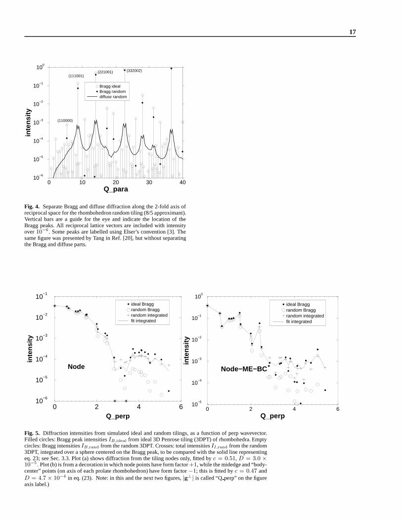
17
0 10 20 30 40Q_para
10−6
10−5
10−4
10−3
10−2
10−1
100
inte
nsity
Bragg idealBragg randomdiffuse random
(110000)
(111001)(221001) (332002)
Fig. 4. Separate Bragg and diffuse diffraction along the 2-fold axis ofreciprocal space for the rhombohedron random tiling (8/5 approximant).Vertical bars are a guide for the eye and indicate the location of theBragg peaks. All reciprocal lattice vectors are included with intensityover10−6. Some peaks are labelled using Elser’s convention [3]. Thesame figure was presented by Tang in Ref. [20], but without separatingthe Bragg and diffuse parts.
0 2 4 6Q_perp
10−6
10−5
10−4
10−3
10−2
10−1
inte
nsity
ideal Braggrandom Braggrandom integratedfit integrated
Node
0 2 4 6Q_perp
10−5
10−4
10−3
10−2
10−1
100
inte
nsity
ideal Braggrandom Braggrandom integratedfit integrated
Node−ME−BC
Fig. 5. Diffraction intensities from simulated ideal and random tilings, as a function of perp wavevector.Filled circles: Bragg peak intensitiesIB,ideal from ideal 3D Penrose tiling (3DPT) of rhombohedra. Emptycircles: Bragg intensitiesIB,rand from the random 3DPT. Crosses: total intensitiesII,rand from the random3DPT, integrated over a sphere centered on the Bragg peak, tobe compared with the solid line representingeq. 23; see Sec. 3.3. Plot (a) shows diffraction from the tiling nodes only, fitted byc = 0.51, D = 3.0 ×10⁻⁵. Plot (b) is from a decoration in which node points have form factor+1, while the midedge and “body-center” points (on axis of each prolate rhombohedron) have form factor−1; this is fitted byc = 0.47 andD = 4.7 × 10⁻⁴ in eq. (23). Note: in this and the next two figures,|g⊥| is called “Qperp” on the figureaxis label.)

18 Structure determinations for random-tiling quasicrystals
−0.02
−0.01
0.00
0.01
F
NODE
F(ideal)F(random)
0.0 10.0 20.0 30.0 40.0 50.0 60.0Q_perp^2
−5.0
−4.0
−3.0
−2.0
−1.0
ln(I
_ran
d/I_
idea
l)
−0.25
−0.15
−0.05
0.05
0.15
0.25
0.35
F
NODE−ME−BC
F(ideal)F(random)
0.0 10.0 20.0 30.0 40.0 50.0 60.0Q_perp^2
−5.0
−4.0
−3.0
−2.0
−1.0
ln(I
_ran
d/I_
idea
l)
Fig. 6. Perp Debye-Waller factor in random tiling. At top|F (g⊥)| is plotted for the ideal and the randomtiling, showing the intensity reduction. At bottom, the effective DW factor,2Weff from eq. (22), is plottedagainst|g⊥|2 (labeled “Qperp∧2” in the figure); its dependence is linear out to the second node ofF (g⊥),showing the validity of the simple formula (18) out to surprisingly large wavevectors. Plot (a) shows diffrac-tion from the tiling nodes only; plot (b) is from a decorationin which node points have form factor+1, whilethe midedge and “body-center” points (on the axis of each prolate rhombohedron) have form factor−1.
10−3
10−2
10−1
100
intensity (integrated)
10−3
10−2
10−1
100
inte
nsity
(fit
ted)
NODENODE−ME−BC
Fig. 7. The same data as in Fig. 5(a) are plotted here (circles) as a com-parison of the integrated intensity with the fit from eq. (23), using the co-efficientsc andD mentioned in the caption of Fig. 5(a). The crosses rep-resent a similar comparison for the decorated model shown inFigs. 5(b)and 6(b).

19
Fig. 8. Top, a snapshot from one time step in a simulation of the (maximally) random Hexagon-Boat-Startiling. The tiling is decorated with atoms (Ni and Co shown filled), as in thed(AlNiCo) model of Ref. [49].The tile edges are drawn in only in the left portion. Bottom, asuperposition of nine successive time steps; seehow clusters of tenfold symmetry emerge that are not presentin the snapshot. This is a poor man’s imitationof a superposition of different layers, as viewed in an HRTEMimage.