integrated methods for the determinations of corrosivity, aging
18
INTEGRATED METHODS FOR THE DETERMINATIONS OF CORROSIVITY, AGING, FINGERPRINTING AS WELL AS THE DIAGNOSIS, DECONTAMINATION, DEPOLARIZATION AND DETOXIFICATION OF MINERAL INSULATING OILS & TRANSFORMERS Vander Tumiatti (*), Michela Tumiatti (*), Riccardo Maina (*), Carlo Roggero (*) SEA MARCONI TECHNOLOGIES Sas ITALY Vander Tumiatti: Sea Marconi Technologies S.a.s. Via Ungheria, 20 10093 Collegno (TO) Italy [email protected] ; Michela Tumiatti: Sea Marconi Technologies S.a.s. Via Ungheria, 20 10093 Collegno (TO) Italy [email protected] ; Riccardo Maina: Sea Marconi Technologies S.a.s. Via Ungheria, 20 10093 Collegno (TO) Italy [email protected] , Carlo Roggero: Sea Marconi Technologies S.a.s. Via Ungheria, 20 10093 Collegno (TO) Italy [email protected]
-
Upload
khangminh22 -
Category
Documents
-
view
0 -
download
0
Transcript of integrated methods for the determinations of corrosivity, aging
INTEGRATED METHODS FOR THE DETERMINATIONS OF CORROSIVITY, AGING, FINGERPRINTING AS WELL AS THE DIAGNOSIS, DECONTAMINATION,
DEPOLARIZATION AND DETOXIFICATION OF MINERAL INSULATING OILS & TRANSFORMERS
Vander Tumiatti (*), Michela Tumiatti (*), Riccardo Maina (*), Carlo Roggero (*)
SEA MARCONI TECHNOLOGIES Sas
ITALY
� Vander Tumiatti: Sea Marconi Technologies S.a.s. Via Ungheria, 20 10093 Collegno (TO) Italy [email protected]; Michela Tumiatti: Sea Marconi Technologies S.a.s. Via Ungheria, 20 10093 Collegno (TO) Italy [email protected]; Riccardo Maina: Sea Marconi Technologies S.a.s. Via Ungheria, 20 10093 Collegno (TO) Italy [email protected], Carlo Roggero: Sea Marconi Technologies S.a.s. Via Ungheria, 20 10093 Collegno (TO) Italy [email protected]

Summary
This paper describes some corrosions phenomena involving copper, insulating oil and solid insulation of oil-immersed transformers and reactors. The paper reports evidences of presence, occurrence and effects of “DiBenzyDiSulfide (DBDS), other “Corrosive Sulfur” compounds and “No-Sulfur Corrosion” in insulating mineral oil. Both copper sulfide deposition and dissolved copper formation are investigated, giving evidences derived both from field experience and laboratory tests. A new diagnostic methods, called “Total Corrosive Sulfur”, to quantitatively detect the presence of corrosive sulfur compounds in the oil and “FingerPrint” are described.
The available techniques for diagnostic of corrosion phenomena and evaluation of the tendency of the oil to form conductive deposits are described. A review of the available mitigation techniques to reduce the effects of corrosion phenomena is reported hereby, with regards to their effectiveness. The removal of corrosive compounds or dissolved copper by mean of on-load and off-load “Selective Depolarisation” is compared with other mitigation techniques.
This methods are capable of drastically reducing the reaction times for the corrosivity test, typically from 72 to 12 hours, on passivated oils and from 500 to less than 24 hours for the aging test on inhibited oils and reducing the volume of oil used (typically from 250 ml to 15 – 30 ml for the test with copper strip) with a fast quantitative evaluation of the properties of the oil tested and the equipment with which the oil is in contact, such, for example, insulating paper in transformers. The methods include also tests capable of determining and implementing optimised formulations for the decontamination, depolarisation and detoxification treatments of the oils.
INTRODUCTION
This paper results from a four decades long expertise by Sea Marconi, an independent third party company with respect to electrical equipment and insulating fluid manufactures, in the field of diagnostics for the prevention of failures and integrated treatments of insulating liquids for Life Cycle Management of transformers.
An oil-immersed transformer is made of several materials, e.g. copper, iron, cellulose, wood, rubber, glues, polymers, and obviously mineral oil. Some of the chemical reactions which may occur between these material fall in the family of corrosion phenomena.
Three materials are mainly involved in corrosion reactions: oil, copper and paper. These materials may interact in different ways, which can be classified as follows:
• acid corrosion (oil to copper, oil to iron);
• formation of complexes (oil to copper, oil to iron);
• catalysis of redox reactions (acids, water, additives);
• oxidation (oxygen, peroxides to oil/cellulose);
• dissolution of soluble compounds (oil to rubber, oil to polymers).
Corrosion phenomena may cause the formation of contaminants, both dissolved in the bulk oil and forming deposits in the paper or insoluble compounds that precipitate as sludge.
A rough classification divides corrosion phenomena in two main families: copper sulfide formation and copper dissolution. The former causes copper sulfide growth on the conductor surface and on solid insulation, the latter forms dissolved and suspended copper compounds, which may be adsorbed and accumulated on the paper.
NORMATIVE REFERENCES-IEC & EN
The International Electrotechnical Commission (IEC) and European Standards (EN) cover terms and definitions, specification for mineral insulating oils.
IEC DICTIONARY IEV 21-08-21
“Corrosive sulfur: the free sulfur and corrosive sulfur compounds detected by subjecting copper to contact with an insulating liquid under standardized conditions” [1]
IEC & EN 60296 THIRD EDITION 2003-11
“Fluids for electrotechnical applications - Unused mineral insulating oils for transformers and switchgear.(…) [2].
-“3.1.Transformer oil: mineral insulating oil for transformer and similar electrical equipment where normal oxidation is required.(…).
-3.3. Additive: suitable chemical substance which is deliberately added to mineral insulating oil in order to improved certain characteristics.
NOTE . Examples include antioxidants, pour point depressant, electrostatic charging tendency depressants such as benzotriazole (BTA), anti-foam agents, refining process improvers, etc.
-3.4. Antioxidant additive: additive incorporated in an insulating oil to improve oxidation stability.
NOTE. A large number of antioxidant additives are available. For this standards, these are limited to those identified in IEC 60666.
-3.5. Uninhibited oil: mineral insulating oil, containing no antioxidant additives, but which may contain other additives.
-3.6 Trace oil inhibited oil: mineral insulating oil containing up to 0,08% antioxidant additives mentioned in 3.4.
-Art.3.7. Inhibited oil: mineral insulating oil containing a minimum of 0,08% and a maximum of 0,40%

antioxidant additive together with other additives as mentioned in 3.3.
-3.8. Unused mineral insulating oil: mineral insulating oil as delivered by the supplier.
NOTE. Such an oil not been used in, nor been in contact with electrical equipment or other equipment not required for manufacture, storage or transport. The manufacturer and supplier of unused oil will have taken all reasonable precautions to ensure that there is no contamination with polychlorinated biphenyls or terphenyls (PCBs, PCTs), used, reclaimed or dechlorinated oil or other contaminants.
-3.9. Reclaimed oil: mineral insulating oil used in electrical equipment which has been subject to chemical and/or physical processing to eliminate soluble and insoluble contaminants.
NOTE. A blend of unused and reclaimed oil in any proportion is regarded as being reclaimed.(…).
-5.4. Identification and general delivery requirements.(…)
c) Each oil delivery shall be accompanied by a document from the supplier specifying at least: suppliers designation, oil classification and compliance certificate. At the purchaser’s request, the supplier has to indicate the presence (type, concentration) of any additive.(…).
-6.9. Sulfur content: Different organo-sulfur compounds are present in transformer oils, dependent on the crude oil origin and degree and type of refining. Refining treats sulfur and aromatic hydrocarbons. As some sulfur compounds have an affinity to metals, they may act as copper passivators or they may promote corrosion.(…).
-6.10. Corrosive sulfur: Some sulfur compounds, e.g. mercaptans, are very corrosive to metal surfaces, i.e. steel, copper and silver (switchgear contacts) and shall not be present in new oil. (…)”.
IEC & EN 60422 THIRD EDITION 2005-10
“Mineral insulating oils in electrical equipment - Supervision and maintenance guidance (…)[3].
-1. Scope. This International Standard gives guidance on the supervision and maintenance of quality of the insulating oil in electrical equipment.
This standard is applicable to mineral insulting oils, originally supplied conforming to IEC 60296, and used in transformers, switchgears and other electrical apparatus where oil sampling is reasonably practicable and were the normal operating conditions specified in the equipment specifications apply.
This standard assists the power equipment operators to evaluate the condition of the oil and maintain it in a serviceable condition. It also provides a common basis for the preparation of more specific and complete local code practices.
This standard includes recommendations on tests and evaluation procedures and outlines methods for reconditioning and reclaiming oil and the decontamination of oils contaminated by PCBs.
NOTE. The condition monitoring of electrical equipment, for example by analysis of dissolved gases, furanic compounds or other means is outside the scope of this standard.(…).
-6.7. Corrosive sulfur. Sulfur is present in refined oil as sulfur-containing molecules. The amount depends on oil refining processes, degree of refining and crude oil type.
Due to poor refining or contamination, reactive compounds giving corrosion at normal operating temperature may be present.(…).
At high temperatures, > 300 °C, sulfur-containing oil molecules may decompose and react with metal surfaces to form metal sulfides. Such reactions may take place in switching equipment and will impact the conductivity of contacts”.
IEC & EN 62535 EDITION 1.0 2008-10
“Insulating liquids - Test methods for detection of potentially corrosive sulfur in used and unused insulating oil (…) [4].
-1. Scope. This International Standard specifies a test method for detection of potentially corrosive sulfur in used and unused mineral insulating oil.
Most recent failures due to corrosive sulfur are related to the formation of copper sulfide deposits in an on the surface of winding cellulosic paper.
The test method uses a copper conductor, wrapped with one layer of paper, immersed in the oil and heated to evaluate the capability of the yield copper sulfide and transfer it to paper layers.
The growth of copper sulfide on bare copper may cause the presence of conductive particulates in the oil, which can act as nuclei for electrical discharge and may lead to a fault. Other test methods exit using a bare copper strip immersed in oil and heated to detect the corrosive behavior of oil against copper. ASTM D1275 Method B is also used for this test and a modified procedure using low oil volume is included in Annex A.
Test with and without paper are considered as complementary and may lead to different results.(…).
-3.1. Potentially corrosive sulfur: organo-sulfur compounds present in transformer oils that may cause copper sulfide formation.
NOTE. Some of these compounds may be initially corrosive, or become corrosive under certain operating conditions.(…).
-6.4. Result. If, for both of the duplicate samples, a positive result is found for copper, or paper, or both, the oil shall be reported as potentially corrosive. If, for both samples, a negative result is obtained for both

copper and paper, the oil shall be reported as non-corrosive.
If the results for the duplicate sample are different, the test shall be repeated.
NOTE. If there are any doubts in the interpretation of the results of inspection of paper, the composition of precipitate should be analyzed by other methods (for examples by SEM-EDX). If the precipitate is identified as copper sulfide, the oil must be reported as potentially corrosive.(…)
CIGRE WORKING GROUP A2.32 APRIL 2009
“378 Copper sulphide in transformer insulation. Working Group A2.32 April 2009.(…) [5].
-1. Introduction. WG A2-32 was set up in 2005 to deal with the problem of the formation of copper sulfide (Cu2S) in transformer insulation.(…). In terms of applications identified as affected, at least initially, most failures were with shunt reactors, generator transformers, and HVDC converters. However, other applications for which there are official reports (or at least failures known to the WG members) include industrial rectifiers, traction line feeders and large distribution transformers.(…).
The existence of copper sulfide particles in oil has also recently started gaining attention. (…).
-2.1. Copper sulphide formation.
- 2.1.1..Mechanism. (…) The oil has been found playing a predominant role being a source of sulfur compounds able to react with copper. Oil containing reactive sulfur species identified in most cases as dibenzyldisulfide (DBDS) can react with copper to form copper sulfide on the surface of the conductors and on the paper insulation surfaces even under normal operating conditions of the transformers. (…). Moreover, this model proposes that dibenzylsulfide (DBS) and bisbenzyl (BiBZ) will be formed in insulating oil as by-products of copper sulfide formation between copper and DBDS. (…).
-2.1.2. Influential factors. A prerequisite for the formation of copper sulfide is the presence of corrosive or potentially corrosive sulfur species in the oil. (…). The corrosiveness of some oils may change during service.(…). Temperature is obviously a strong influential factor, since most chemical reaction rates are temperature dependant.(…). However, temperature is not the only factor to determine the occurrence, nor the location, of copper sulfide deposits. (…). On-load tap changers (OLTC) switching operations involving high stresses (arching) through the oil have led to extensive copper sulfide formation. This may affect the contact performance. (…) -3. Diagnostics. There are several different aspects under this heading. (…). -3.1 Oil testing. Due to the ease of sampling oil from transformers, much focus has been on chemical testing
of the oils. These can be either qualitative tests, aimed at detecting the presence of corrosive components by the visible effects they have on other materials, or by measuring specific chemical compounds or groups of compounds. -3.1.1 Qualitative tests to detect corrosive components in oil (…) IEC 62535 in October 2008 (…). - 3.1.2 Oil testing with the purpose of detecting Copper Sulfide formation To-date it seems no or few changes have been seen in the usual oil parameters tested, including DGA, even in samples taken only the day before failures (…). Nevertheless, it is still recommended to carry out regular DGA and oil analysis. Some irregularities which can be due to higher temperatures, and which may promote copper sulfide formation can be detected early enough (e.g. high CO and CO2 values), as discussed in section 3.1.4. (…). One possibility being explored is the determination of the byproducts from the reaction of DBDS with copper. Dibenzylsulfide (DBS) and bisbenzyl (BiBz) can both be detected by a gas-chromatography method, and their abundance may be indicative of the total amount of copper sulfide that may have been formed from reactions with DBDS. (…). - 3.1.3 Sulfur speciation (…). The analytical methods selected for evaluation included the analysis of insulating oils for : · Total sulfur content · Total mercaptans and disulfides · Dibenzyldisulfide (DBDS) · Other sulfur compounds: dibenzylsulfide (DBS), octadecylmercaptan (ODM) (…). The participating laboratories were asked to analyze each oil sample with analytical instruments at their disposal as follows: · Inductively coupled plasma (ICP) – total sulfur · Silver/Silver sulfide (Ag/Ag2S) electrode titration – total mercaptans and disulfides · Gas chromatography/electron capture detector (GC/ECD) – DBDS · Gas chromatography/atomic emission detector (GC/AED) – DBDS, DBS, ODS, other sulfur compounds · Gas chromatography/mass spectrometry (GC/MS) – DBDS, DBS, other sulfur compounds · Other methods as available. (…). - 3.1.4 DGA (dissolved gas analysis) (…) The presence of overheating and thermal faults in transformers detected by DGA, especially in cases of thermal degradation of solid insulation, elevated concentrations of carbon monoxide and carbon dioxide, followed by intensive oxidation, i.e. high consumption of oxygen, is observed to be a condition of concern, according to reported failure cases. A relevant and continuous formation of ethane and methane was detected in equipment where an internal post-failure inspection revealed a strong presence of copper sulfide. (…). - 4 Mitigation techniques. If the oil has been identified as corrosive, a risk assessment should be carried out. It

should include consideration of service conditions, design, age, system importance and manufacturer experience (…). If the result of this assessment is that the equipment is regarded as at risk, several mitigation techniques can be applied. (…). - 4.1 Metal passivators. The addition of metal passivator is today the mitigation technique that has been used to the largest extent (…). Several tens to 100 ppm of these substances are typically added to inhibit the reaction of copper with corrosive sulfur.(…). - 4.1.1 Experiences (…).. However, the addition of metal passivators is not a guarantee against failures. For instance, in Brazil, more than 200 shunt reactor oils in service were passivated (in most cases between ½ and 2 years after going into service). It has been reported that 9 of these units failed between one and 24 months after passivation. One explanation for these failures which led to very corrosive oils and high thermal loads, is that deposition took place very quickly (in the first months after start-up), following which passivation was ineffective.(…). - 4.1.3 Side effects (“stray gassing” etc.).There are a significant number of reports of increased hydrogen and carbon dioxide formation when the passivator is added to oil already in service. Similar effects have been observed also in accelerated laboratory experiments (…) reported with originally passivated oils, indicating that the status of the oil also has some influence.(…). -4.1.4 Other passivators The application of mixtures of inhibitors and metal deactivators is well known and has been used in the lubricant industry for the improvement of oil performance. Blends of different types of inhibitors are available, and have been used in transformer oils (…). One company has presented a blend under the label “sulfur inhibitor”, that is a liquid concentrate of blended metal passivators BTA/TTA derivatives, phenol or amine based oxidation inhibitors and “sulfur stabilizers”, i.e. components inhibiting the reactions of sulfur compounds. (…). - 4.1.6 Treatment of passivated oil. To date, there is little experience reported of passivator behavior during oil maintenance treatments, e. g. reclaiming and reconditioning. The first experiences from the field show that reclaiming results in heavy loss of passivator, due to its strongly polar nature. (…). However, should a passivated oil need to be treated, and it has not already been established that the treatment in question has no significant effect on the passivator, it is essential after the treatment to analyze the passivator content and to re-passivate to the original concentration if necessary, or at least to test the oil for corrosivity. (…). 4.2 Removal of corrosive sulfur from oil in service (…). Several techniques have been proposed, and in some cases are already being used for the removal of corrosive sulfur from oil. These include the use of : - continuous on-line treatment with sorbents; - “selective depolarisation” (a combination of reagents and sorbents);
- mobile on-line reclaiming, with reactivating sorbents ; - treatment with KOH/PEG, similar to established PCBs removal technology; - liquid-liquid extraction (…). Continuous on-line treatment, selective depolarisation and mobile on-line reclaiming have been applied for the treatment of oils in service (…). - 4.3 Oil exchange. Another successfully used technique for corrosion mitigation is the change of the original oil. In Brazil for instance, the oil of 45 shunt reactors has been changed without any failure after this process. In a population of 21 transformers, preventive action was taken in July and August 2005. Because of the shortage of safe oil, only five reactors could be retrofilled and the remaining 16 were passivated. As of December 2006, eight of the latter group failed in service, respectively at 33, 102,136, 168, 284, 363,478, and 590 days after passivation. No failure have so far occurred for any of the retrofilled units in this group. Some precautions should be considered when oil replacement is carried out (…). Experience with the refilling of power transformers filled with oil contaminated by PCBs, demonstrates that residual oil can be kept in the range 5-10 %. Exactly what level of exchange can be achieved depends on the design of the equipment.·Repeat the corrosion test after 30-90 days, in order to verify the effectiveness of process because a little release of original corrosive oil from paper can be expected.(…). - 5 Recommendations (…) -5.1 Oil for filling, topping up or exchange. All oils should be tested for corrosiveness according to IEC 62535 before being added to a transformer. Several oil specifications now also include ASTM D 1275B although experience so far indicates that an oil passing IEC 62535 is very unlikely to fail ASTM D1275B. It is important that contamination by corrosive oil is avoided at all stages of transportation and filling. Check for passivator content, and in the case of oil containing passivator, monitor the level by yearly oil samples -. 5.2 Supervision and maintenance of oil in use The following actions are recommended for any utility or owner of power transformers and shunt reactors who is concerned about the effect that copper sulfide has or will have on their transformers and reactors. For large transformer fleets it is recommended to focus first on the units delivered in the last 20 years and specially the GSUs, shunt reactors, HVDC transformers, industry transformers and highly loaded transmission transformers, and secondly, to focus on all other power transformers (…). For the prioritized units take oil samples, and analyze the oil: o To detect corrosive sulfur and potentially corrosive sulfur according to IEC 62535 (section 3.1.1) o In case of negative corrosiveness, check for the presence of passivators

(section 4.1.2) o To detect DBDS content in the oil in case of positive corrosiveness, or in case of negative corrosiveness due to the presence of passivators. (section 3.1.3).(…).Figure 9.
- Is DBDS content in oil > 10 mg/Kg ?; - Is total disulfides + mercaptans content in oil
> 5 mg (S)/Kg ?.(…).”
CORROSION SOURCE BY THE PRESENCE OF DBDS &
CORROSIVE SULFUR
DBDS & CORROSIVE SULFUR AND RELATED FAILURES
The corrosive sulfur phenomenon has been widely investigated in the last 15-20 years, due to the relevant number of observed cases of failures during service
[6][7][8]. Many utilities and research bodies worldwide denounced corrosive sulfur related failures, in which the common factor was the type of oil. In other cases, internal inspections performed for other reasons revealed a significant formation of copper sulfide on naked copper conductors and within the solid insulation of windings[9].
Copper sulfide formation has been found in several cases to be the main cause of the failure[10], with two different failure modes.
In most cases, the copper sulfide growth on wrapped conductors is accompanied by its migration within the layers of insulating paper. Copper sulfide has been found to pollute mostly the inner layers, likely diffusing from the innermost tape to the outers (fig. 1); less frequently, the observed pollution is not concentrated in the first inner layers, but is formed within intermediate and outer layers as well.
1° layer - contact
with copper
2° layer
3° layer
4° layer
1° layer of common
wrapping
Cu content: 100˙000 mg/kg (10% by weight)
4 individual
layers on
each
conductor
1° of 12
common
layers on twin
conductors Figure 1 – Papers contaminated by copper sulfide
deposits. The contamination grows from the innermost to outer
layers
In a lower number of cases, a detachment of the copper sulfide layer formed on the naked copper surfaces has caused the formation of suspended conductive particles, probably evolving into a discharge between leads and the grounded tank (fig. 2).
Figure 2 – Formation and detachment of copper
sulfide from a naked conductor
The action of corrosive sulfur may also act as a co-factor that contributes to cause a failure, but other faulty conditions are involved.
The dependency of copper sulfide formation rate from temperature is quite obvious, as well as for most of chemical reactions. Thus, thermal faults in transformers impregnated with corrosive oil should be considered as more worrying than in transformers where corrosive sulfur is not present. In presence of a thermal fault, even at low temperature, the activity of corrosive compounds is strongly enhanced and the deposition of copper sulfide may be dramatically accelerated.
Considerable amounts of copper sulfide were found in transformers where a T1-type thermal fault was ascertained. In those cases, the copper sulfide pollution probably did not act as a major cause of failure, but gave a relevant contribution in the weakening of the insulation. Figure 3 and 4 depict some evidence of copper sulfide formation found in units with thermal faults.
Figure 3 – Copper sulfide deposits in leads of a
overheated winding
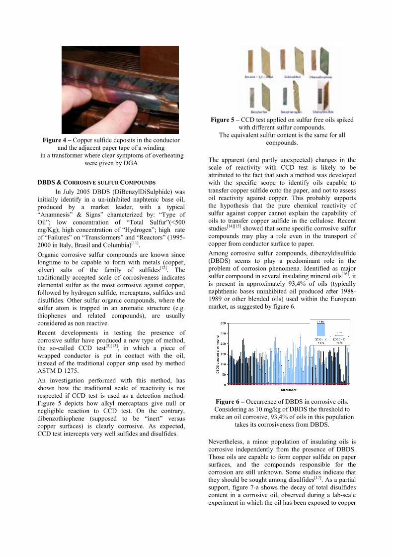
Figure 4 – Copper sulfide deposits in the conductor
and the adjacent paper tape of a winding in a transformer where clear symptoms of overheating
were given by DGA
DBDS & CORROSIVE SULFUR COMPOUNDS
In July 2005 DBDS (DiBenzylDiSulphide) was initially identify in a un-inhibited naphtenic base oil, produced by a market leader, with a typical “Anamnesis” & Signs” characterized by: “Type of Oil”; low concentration of “Total Sulfur”(<500 mg/Kg); high concentration of “Hydrogen”; high rate of “Failures” on “Transformers” and “Reactors” (1995-2000 in Italy, Brasil and Columbia)[11].
Organic corrosive sulfur compounds are known since longtime to be capable to form with metals (copper, silver) salts of the family of sulfides[12]. The traditionally accepted scale of corrosiveness indicates elemental sulfur as the most corrosive against copper, followed by hydrogen sulfide, mercaptans, sulfides and disulfides. Other sulfur organic compounds, where the sulfur atom is trapped in an aromatic structure (e.g. thiophenes and related compounds), are usually considered as non reactive.
Recent developments in testing the presence of corrosive sulfur have produced a new type of method, the so-called CCD test[5][13], in which a piece of wrapped conductor is put in contact with the oil, instead of the traditional copper strip used by method ASTM D 1275.
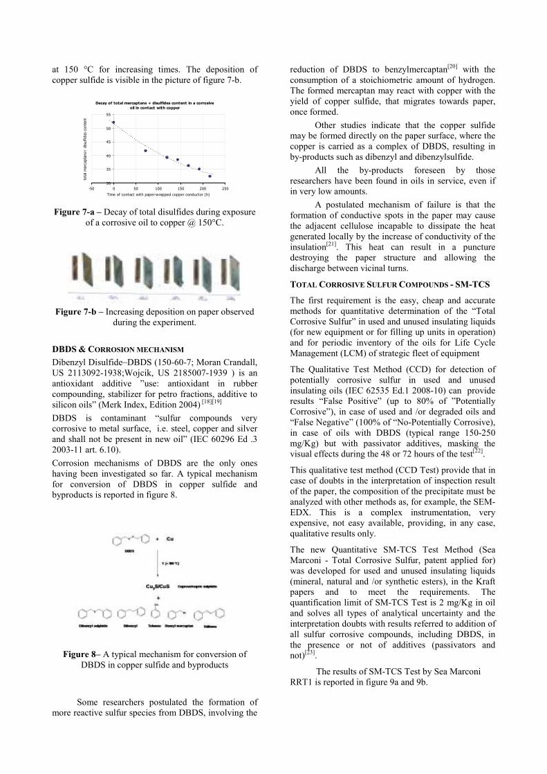
An investigation performed with this method, has shown how the traditional scale of reactivity is not respected if CCD test is used as a detection method. Figure 5 depicts how alkyl mercaptans give null or negligible reaction to CCD test. On the contrary, dibenzothiophene (supposed to be “inert” versus copper surfaces) is clearly corrosive. As expected, CCD test intercepts very well sulfides and disulfides.
Figure 5 – CCD test applied on sulfur free oils spiked
with different sulfur compounds. The equivalent sulfur content is the same for all
compounds.
The apparent (and partly unexpected) changes in the scale of reactivity with CCD test is likely to be attributed to the fact that such a method was developed with the specific scope to identify oils capable to transfer copper sulfide onto the paper, and not to assess oil reactivity against copper. This probably supports the hypothesis that the pure chemical reactivity of sulfur against copper cannot explain the capability of oils to transfer copper sulfide in the cellulose. Recent studies[14][15] showed that some specific corrosive sulfur compounds may play a role even in the transport of copper from conductor surface to paper.
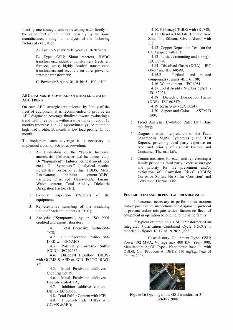
Among corrosive sulfur compounds, dibenzyldisulfide (DBDS) seems to play a predominant role in the problem of corrosion phenomena. Identified as major sulfur compound in several insulating mineral oils[16], it is present in approximately 93,4% of oils (typically naphthenic bases uninhibited oil produced after 1988-1989 or other blended oils) used within the European market, as suggested by figure 6.
Figure 6 – Occurrence of DBDS in corrosive oils. Considering as 10 mg/kg of DBDS the threshold to
make an oil corrosive, 93,4% of oils in this population takes its corrosiveness from DBDS.
Nevertheless, a minor population of insulating oils is corrosive independently from the presence of DBDS. Those oils are capable to form copper sulfide on paper surfaces, and the compounds responsible for the corrosion are still unknown. Some studies indicate that they should be sought among disulfides[17]. As a partial support, figure 7-a shows the decay of total disulfides content in a corrosive oil, observed during a lab-scale experiment in which the oil has been exposed to copper
at 150 °C for increasing times. The deposition of copper sulfide is visible in the picture of figure 7-b.
Decay of total mercaptans + disulfides content in a corrosive
oil in contact with copper
30
35
40
45
50
55
-50 0 50 100 150 200 250
Time of contact with paper-wrapped copper conductor (h)
total mercaptans+
disulfides content
Figure 7-a – Decay of total disulfides during exposure
of a corrosive oil to copper @ 150°C.
Figure 7-b – Increasing deposition on paper observed
during the experiment.
DBDS & CORROSION MECHANISM
Dibenzyl Disulfide–DBDS (150-60-7; Moran Crandall, US 2113092-1938;Wojcik, US 2185007-1939 ) is an antioxidant additive ”use: antioxidant in rubber compounding, stabilizer for petro fractions, additive to silicon oils” (Merk Index, Edition 2004) [18][19]
DBDS is contaminant “sulfur compounds very corrosive to metal surface, i.e. steel, copper and silver and shall not be present in new oil” (IEC 60296 Ed .3 2003-11 art. 6.10).
Corrosion mechanisms of DBDS are the only ones having been investigated so far. A typical mechanism for conversion of DBDS in copper sulfide and byproducts is reported in figure 8.
Figure 8– A typical mechanism for conversion of
DBDS in copper sulfide and byproducts
Some researchers postulated the formation of more reactive sulfur species from DBDS, involving the
reduction of DBDS to benzylmercaptan[20] with the consumption of a stoichiometric amount of hydrogen. The formed mercaptan may react with copper with the yield of copper sulfide, that migrates towards paper, once formed.
Other studies indicate that the copper sulfide may be formed directly on the paper surface, where the copper is carried as a complex of DBDS, resulting in by-products such as dibenzyl and dibenzylsulfide.
All the by-products foreseen by those researchers have been found in oils in service, even if in very low amounts.
A postulated mechanism of failure is that the formation of conductive spots in the paper may cause the adjacent cellulose incapable to dissipate the heat generated locally by the increase of conductivity of the insulation[21]. This heat can result in a puncture destroying the paper structure and allowing the discharge between vicinal turns.
TOTAL CORROSIVE SULFUR COMPOUNDS - SM-TCS
The first requirement is the easy, cheap and accurate methods for quantitative determination of the “Total Corrosive Sulfur” in used and unused insulating liquids (for new equipment or for filling up units in operation) and for periodic inventory of the oils for Life Cycle Management (LCM) of strategic fleet of equipment
The Qualitative Test Method (CCD) for detection of potentially corrosive sulfur in used and unused insulating oils (IEC 62535 Ed.1 2008-10) can provide results “False Positive” (up to 80% of ”Potentially Corrosive”), in case of used and /or degraded oils and “False Negative” (100% of “No-Potentially Corrosive), in case of oils with DBDS (typical range 150-250 mg/Kg) but with passivator additives, masking the visual effects during the 48 or 72 hours of the test[22].
This qualitative test method (CCD Test) provide that in case of doubts in the interpretation of inspection result of the paper, the composition of the precipitate must be analyzed with other methods as, for example, the SEM-EDX. This is a complex instrumentation, very expensive, not easy available, providing, in any case, qualitative results only.
The new Quantitative SM-TCS Test Method (Sea Marconi - Total Corrosive Sulfur, patent applied for) was developed for used and unused insulating liquids (mineral, natural and /or synthetic esters), in the Kraft papers and to meet the requirements. The quantification limit of SM-TCS Test is 2 mg/Kg in oil and solves all types of analytical uncertainty and the interpretation doubts with results referred to addition of all sulfur corrosive compounds, including DBDS, in the presence or not of additives (passivators and not)[23].
The results of SM-TCS Test by Sea Marconi RRT1 is reported in figure 9a and 9b.

GC – ECD Sample
No. DBDS
mg/kg
Lab. Lab. Lab. Lab. Lab.
A B C* D E
37 – A 129 116 126 141 144
37 – B 129 106 133 142 1031
37 – C 71 76 62 83 1431
37 – D 4.00 <2.0 <2.0 <10.0 <10.0
37 – F <2.0 3.00 N.R <10.0 <10.0
37 – G 24 56 N.R 31 80
37 – H 69 101 145 94 118
Figure 9 a – Results of IEC TC 10 WG 37
GC-MS
Sampl
e No. DBDS
mg/ kg
GC-AED
DBDS
mg/kg
SM-
TCS
DBDSe
q.
mg/Kg
Ave.
Lab
.
Lab
.
Lab
.
Lab. Lab.
A B C* F C*
37 – A 146 113 139 147 138 134
37 – B 143 113 141 165 135 131
37 – C 76 59 85 95 88 84
37 – D <9.0 <5.
0
11 14 11 -
37 – F <9.0 <5.
0
<10 <10.
0
N.A -
37 – G 31 19 14 <10.
0
N.A 36
37 – H 84 39 104 110 N.A 96
Figure 9b - Results of IEC TC 10 WG 37
OIL FINGERPRINT PROFILE - SM-IFED
The second requirement is the methods for quantitative and quantitative determination of univocal printing of the formulation of unused and used oils profiles “Integrated Fingerprint & Elemental Diagnostic” for new equipment or the topping-up of units in operation and for the inventory and/or periodic monitoring of the oils on a strategic fleets of equipment.
The current identification and classification methods of the oils are unspecific, since they are mainly based upon the generic characterization of the functional properties (viscosity, density, pour point, flash point, etc).
The new SM-IFED Test Method (Sea Marconi -Integrated Fingerprint & Elemental Diagnostic) solves all types of analytical uncertainty and interpretation doubts with results referred to a univocal comparison (Qualitative and Quantitative) of the “Data Base Profiles” of the Carbon (C) compounds with “hetero-atoms” present in the formulation of the oils, such as Sulfur (S) compounds, Nitrogen (N) compounds with correlated distillation curves of the oils being tested with the above mentioned protocol[23].
The typical results of SM-IFED Test by Sea Marconi are reported in figures 10,11,12,13.
Figure 10 SM-IFED Results:” Paraffin-Base Oil”- AGIP ITE 360-1989
Figure 11 SM-IFED Results: “Naphthenic Base Oil with DBDS”-NYNAS NYTRO 10 GBN

Figure 12 SM-IFED Results: “Naphthenic Base Oil with DBPC & NO-DBDS”-NYNAS 10 XN-2005
Figure 13 SM-IFED Results: “Naphthenic Base Oil with DBDS”- Oils Producer A & B
SPECIAL CASES:“CORROSIVE SULFUR NO-DBDS”
AND “NO SULFUR”.
It is reported special cases of mineral insulating oils “Corrosive Sulfur NO-DBDS”.
Example: a naphthenic oil with medium total sulfur content (SM-IFED); DBDS < 5 mg/Kg (GC/AED); “Positive-Potentially Corrosive Sulfur(CCD-IEC 62535); 8 mg/Kg of Total Corrosive Sulfur (SM-TCS) figure 14.
Figure 14 SM-IFED Results: “Naphthenic Base Oil with Medium Total Sulfur &NO-DBDS”-Oil Producer X
It is reported a special case of mineral insulating oils “NO-TOTAL SULFUR”.
Example: a hydrocracked oil “NO-SULFUR” (SM-IFED); DBDS < 5 mg/Kg (GC/AED); “Negative -
Potentially Corrosive Sulfur (CCD-IEC 62535); 2 mg/Kg of Total Corrosive Sulfur (SM-TCS) figure 14.
Figure 15 SM-IFED Results: “Hydrocracked Base Oil with No-Total Sulfur & NO-DBDS” - Oil Producer Y
“DBDS & CORROSION FREE PROGRAM” - KEY
FACTORS
The following actions are recommended for any utility or holder of power transformer, shunt reactors and strategic equipment filled with mineral insulating oils who is concerned about the “DBDS & Corrosion Free Program”.
For strategic equipment fleets, it is recommended the priority assessment of the key factors:
1- Age: from 1988;
2- Type of mineral insulating oils: naphthenic base uninhibited oil without antioxidant additives (DBPC ); other type of oils blended with naphthenic oil;
3- Type of equipment: GSU; Shunt Reactors, HVDC transformers; industry transformers (rectifier, furnace, etc); highly loaded transmission transformers and secondly on other power or strategic transformers; OLTC; Bushings; Instrument transformers;
4- Top-up or oil change: > 5- 10 %;
5- High load; High temperature;
6- Thermal fault: DGA (type:T1,T2,T3); trends in oxygen content symptoms of overheating;
7- Total Corrosive Sulfur Compounds (> 5 mg/kg) and or DBDS ( > 10 mg/Kg ) for unused oil. Typical concentration of DBDS: range 150-250 mg/Kg) and trends symptoms of formation of copper sulfide;
8- No spare part unit available;
9- Sister unit had suspect failure in the last 20 years;
10- Voltage level >220 KV.
ABC INVENTORY OF STRATEGIC UNITS BY
FAMILIES
Identify one strategic unit representing each family of the same fleet of equipment, possibly by the same manufacturer, through an analysis of the following factors of evaluation:
A- Age : < 5 years; 5-10 years; >10-20 years;
B- Type: GSU; Shunt reactors, HVDC transformers; industry transformers (rectifier, furnace, etc.); highly loaded transmission transformers and secondly on other power or strategic transformers;
C- Power (MVA): <10; 10-50; 51-100; >100.
ABC DIAGNOSTIC COVERAGE OF STRATEGIC UNITS -
ABC TREND
On each ABC strategic unit selected by family of the fleet of equipment, it is recommended to provide an ABC diagnostic coverage finalized toward evaluating a trend with three points within a time frame of about 12 months (months: 1, 6, 12 approximately). A: month at high load profile. B: month at low load profile. C: hot month.
To implement such coverage it is necessary to implement a plan of activities providing:
1 A– Evaluation of the “Family historical anamnesis” (failures, critical incidences etc.). B- “Equipment” (failures, critical incidences etc.). C- “Symptoms” (analytical results: Potentially Corrosive Sulfur; DBDS; Metal Passivators; Inhibitor content-DBPC; Particles; Dissolved Gases-DGA; Furans; Water content; Total Acidity; Dielectric Dissipation Factor; etc.).
2 External inspection (“Signs”) of the equipment;
3 Representative sampling of the insulating liquid of each equipment (A; B; C);
4 Analysis (“Symptoms”) by an ISO 9001 credited and expert laboratory:
4.1. Total Corrosive Sulfur-SM-TCS;
4.2. Oil Fingerprint Profile- SM-IFED with GC/AED
4.3. Potentially Corrosive Sulfur (CCD) –IEC 62535;
4.4. DiBenzyl DiSulfide (DBDS) with GC/MS & AED or ECD-IEC TC 10 WG 37;
4.5. Metal Passivator additives - Ciba Irgamet 39;
4.6. Metal Passivator additives - Benzotriazole-BTA;
4.7. Inhibitor additive content - DBPC-IEC 60666;
4.8. Total Sulfur Content with ICP; 4.9. Dibenzylsulfide (DBS) with
GC/MS &AED;
4.10. Bisbenzyl (BiBZ) with GC/MS; 4.11. Dissolved Metals (Copper, Iron,
Zinc, Tin, Silicon, Silver, Alum.) with ICP;
4.12 Copper Deposition Test (on the CCD paper) with ICP;
4.13 Particles (counting and sizing) - IEC 60970;
4.14 Dissolved Gases (DGA) - IEC 60657 and IEC 60599;
4.15.2 Furfural and related compounds (Furans)-IEC 61198;
4.16 Water content - IEC 60814; 4.17 Total Acidity Number (TAN) -
IEC 62021; 4.18 Dielectric Dissipation Factor
(DDF) - IEC 60247; 4.19 Resistivity - IEC 60247; 4.20 Aspect and Color — ASTM D
1500;
5 Trend Analysis, Evolution Rate, Data Base matching;
6 Diagnosis with interpretation of the Facts (Anamnesis, Signs, Symptoms ) and Test Reports, providing third party expertise on type and priority of Critical Factors and Consumed Thermal Life.
7 Countermeasures for each unit representing a family providing third party expertise on type and priority for the prevention and/or mitigation of “Corrosion Risks” (DBDS; Corrosive Sulfur; No-Sulfur Corrosion) and Consumed Thermal Life.
POST MORTEM AND/OR POST FAILURES DIAGNOSIS
It becomes necessary to perform post mortem and/or post failure inspections for diagnostic protocol to prevent and/or mitigate critical factors on fleets of equipment in operation belonging to the same family.
A typical example on a GSU Transformer of an Integrated Gasification Combined Cycle (IGCC) is reported in figures 16,17,18,19,20,21,22[24].
Case History: Equipment Type- GSU; Power 192 MVA; Voltage max 400 KV; Year-1998; Manufacture A; Oil Type - Naphthenic Base Oil with DBDS; Oil Producer A; DBDS 110 mg/kg; Year of Failure 2006.
Figure 16 Opening of the GSU transformer 3-4 October 2006
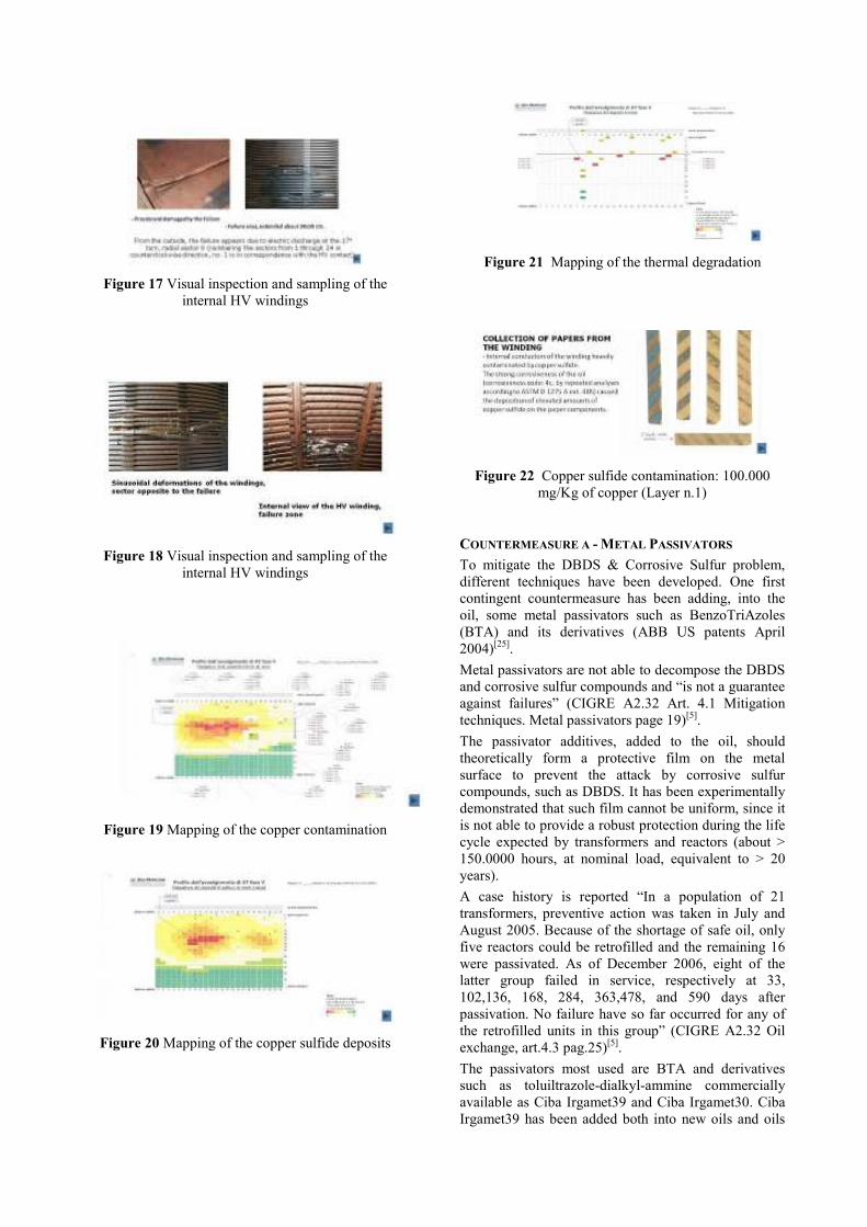
Figure 17 Visual inspection and sampling of the internal HV windings
Figure 18 Visual inspection and sampling of the internal HV windings
Figure 19 Mapping of the copper contamination
Figure 20 Mapping of the copper sulfide deposits
Figure 21 Mapping of the thermal degradation
Figure 22 Copper sulfide contamination: 100.000 mg/Kg of copper (Layer n.1)
COUNTERMEASURE A - METAL PASSIVATORS
To mitigate the DBDS & Corrosive Sulfur problem, different techniques have been developed. One first contingent countermeasure has been adding, into the oil, some metal passivators such as BenzoTriAzoles (BTA) and its derivatives (ABB US patents April 2004)[25].
Metal passivators are not able to decompose the DBDS and corrosive sulfur compounds and “is not a guarantee against failures” (CIGRE A2.32 Art. 4.1 Mitigation techniques. Metal passivators page 19)[5].
The passivator additives, added to the oil, should theoretically form a protective film on the metal surface to prevent the attack by corrosive sulfur compounds, such as DBDS. It has been experimentally demonstrated that such film cannot be uniform, since it is not able to provide a robust protection during the life cycle expected by transformers and reactors (about > 150.0000 hours, at nominal load, equivalent to > 20 years).
A case history is reported “In a population of 21 transformers, preventive action was taken in July and August 2005. Because of the shortage of safe oil, only five reactors could be retrofilled and the remaining 16 were passivated. As of December 2006, eight of the latter group failed in service, respectively at 33, 102,136, 168, 284, 363,478, and 590 days after passivation. No failure have so far occurred for any of the retrofilled units in this group” (CIGRE A2.32 Oil exchange, art.4.3 pag.25)[5].
The passivators most used are BTA and derivatives such as toluiltrazole-dialkyl-ammine commercially available as Ciba Irgamet39 and Ciba Irgamet30. Ciba Irgamet39 has been added both into new oils and oils

in service, usually at a concentration of 100 mg/kg, but higher concentration can also be found in oils passivated in service. The rough structure formula of Ciba Irgamet39 is in figure 23.
Figure 23 – Structure formula of Ciba Irgamet 39
The triazolic part of the molecule is likely oriented towards the conductor’s surface, shielding it against the chemical attack of corrosive sulfur compounds and acting only as a potentially protective agent.
The use of BTA and its derivatives can determine potentially risks for workers, public health and the environment, caused by mutagenic nature and correlated risks “Suspected Carcinogenic”
(National Cancer Institute Technical Report Series n.881978-US)[26][27].
The data sheet of Ciba Irgamet 39 reported: CAS n.80584-90 + 80595-74-0; Dangerous in accordance with EC Directives; Xì- Irritant; N- Dangerous for the environment.
Few years of experience with the use of passivators have shown some unexpected and undesired collateral effects. A number of passivated units (approx. 25-20%) give an abnormal stray gassing, forming mainly hydrogen and carbon oxides. This gassing, that was not observed in transformers passivated prior to energizing, was not correlated with faulty conditions, but it causes a certain concern because of the interference with DGA interpretation. An example of observed gassing is in figure 24.
Hydrogen
trend
Passivation
Figure 24 – Example of stray gassing following the
passivation with Irgamet39
Furthermore, there is a strong evidence of instability of the passivator while exposed to the thermal stress and to oxidation by-products of the oil. Several cases of decay of passivator concentration during the service were reported, mainly in highly loaded units and oils were the oxidation process already commenced. An initial estimation indicates that the passivator
instability can be observed in approximately 10-15% of passivated units.
Figure 25 reports a case of passivator depletion. It is noteworthy to see that the reduced content of passivator causes the oil to revert back to corrosive once the concentration of Irgamet39 is lowered below 25-30 mg/kg.
0
20
40
60
80
100
120
140
24/03/2006
13/05/2006
02/07/2006
21/08/2006
10/10/2006
29/11/2006
18/01/2007
Sampling date
Irgam
et 39 conc. (m
g/kg)
Figure 25 – Decay of Irgamet39 and its effect on oil’s
corrosiveness.
Another mitigation technique that was applied is the change of the oil with a new, non corrosive, oil.
COUNTERMEASURE B- OIL EXCHANGED
The recommendations for concentration limit for corrosive sulfur compounds in oils (CIGRE A2.32 figure 9, pag. 31)[5]:
- <10 mg/kg for DBDS (after 90 days);
- < 5 mg/Kg for the Total Corrosive Sulfur compounds (after 90 days).
The typical concentration of the DBDS in “Unused mineral insulating - Naphthenic Base with DBDS” is 150-250 mg/Kg. This oil change evidently reduces the corrosive compounds content of the oil, diluting them accordingly with the ratio between the new oil added and the remnant old oil (which results from the addition of the oil adsorbed on the active part and the oil remaining in the bottom of the tank). That typical ratio may be 10% (CIGRE A2.32-art.4.3.pag.25) or more, depending on the amount of paper and other adsorbing materials, and on the shape of the tank also. To guarantee DBDS concentration < 10 mg/kg (after 90 days) its necessary to change the oils twice. When the oil is to be changed, a preventive test of corrosive sulfur on a suitable mixture of the old and the new oil should clarify if the mitigation action will be adequate to obtain finally a non corrosive oil.
COUNTERMEASURE C- SELECTIVE DEPOLARISATION
DBDS and corrosive sulfur compounds can be decomposed from the oils with “Selective Depolarisation (a combination of reagents and sorbents)”.(…) in “Continuous on-line treatment” (CIGRE A2-32 art.4.2 page 25)[5].
The chemical decomposition of the DBDS from the oils, through “selective depolarisation process” has been applied to reduce the oil corrosiveness in transformers in service, both “On-Load and Off-Load”.

It allows the reduction of corrosive sulfur content, e.g. DBDS, down to < 5 mg/kg. It uses a combination of solid reagents, chemicals and sorbents. Figure 26 depicts the progressive removal of DBDS from an oil during the selective depolarisation process[23][28].
0
20
40
60
80
100
120
140
160
0 1 2 3 4 5 6 7 8 9 10
Number of treatment cyles
Concentration (m
g/k
g)
DBDS
Irgamet 39
Figure 26 –Chemical decomposition of DBDS
from the oil’s with selective depolarisation process
Typical on-site operations with DMU units and results are reported in figures 27,28,29,30.
Figure 27 –DMU (Decontamination Mobile Unit) for
“On Load selective depolarisation process”
Figure 28 Chemical decomposition of DBDS
with “selective depolarisation”
Figure 29 Typical results for “On-Load
selective depolarisation process” – GSU transformer 192 MVA 400KV
Figure 30 Case history > 100 transformers for “On-Load & Off-load selective depolarisation process”
Traditional on-line reclaiming using normally fuller earth and clays to reduce the content of polar compounds in oil, has been proven not effective to remove DBDS from the oils.
As general remark to the reduction of corrosive compounds in oils in service, it must be noted that, in the case of DBDS, its reduction involves also the residual oxidation stability of the oil. DBDS was demonstrated[28] to act as a oxidation inhibitor (it is a secondary antioxidant), and its removal may imply the necessity to re-inhibit the oil with a classical cresolic antioxidant, such as DBPC (di-tert-butyl-para-cresol).
The table in figure 31 gives some values of oxidation stability before, and after depolarisation, and the values obtained after re-inhibition.
< 1,20,781,55TAN (mg/g)
< 0,800,760,91%sludge (%)
IEC 60296
reference values
(for unused oil)
After re-
inhibition with DBPC 0.3%
(test duration: 500 h)
After On-Load
Depolarization(test duration:
164 h)
Oxidation
stability parameters,
according to IEC 61125
< 1,20,781,55TAN (mg/g)
< 0,800,760,91%sludge (%)
IEC 60296
reference values
(for unused oil)
After re-
inhibition with DBPC 0.3%
(test duration: 500 h)
After On-Load
Depolarization(test duration:
164 h)
Oxidation
stability parameters,
according to IEC 61125
Figure 31 – Oxidation stability after DBDS’
decomposition with “selective depolarisation”

Some others techniques was reported[29][30][31].
NO-SULFUR CORROSION - DISSOLVED COPPER
NO-SULFUR CORROSION AND EFFECTS ON LOSSES
The mechanism of copper formation in mineral oils is not yet ascertained. On the other hand, its effects on oil dielectric properties is well known: the presence of copper in oil (in both dissolved and suspended forms) contributes dramatically to the increment of oil losses. The graph in figure 32 depicts very clearly the dependence of tan from copper concentration, plotting both parameters in normalized values.
Figure 32 – Effects of copper in oil content on
oil losses
Copper in oil total content is given by two contributions: dissolved and suspended copper. According to method ASTM D 7151, the total copper content is detected by ICP/AES technique by direct injection of the oil, and the suspended copper is intended as the fraction being retained by a filter of 0,45 µm. Oils in service were observed to have up to 500 mg/kg of total copper content, and the tan may raise up to 4,0.
The occurrence of insulating oils with a remarkable copper content is apparently not related with the presence of corrosive sulfur in oils. Even if oils polluted by corrosive sulfur compounds are surely capable to form copper salts reacting with the conductors, the total copper content in corrosive oils is normally negligible. The graph in figure 31 shows the copper concentration in corrosive and non corrosive oils, plotting the first 30 samples of the observed population in order of decreasing copper content; as it can be seen, the copper concentration of non corrosive oils is higher for non-corrosive oils.
Figure 33 – Copper content in corrosive and
non-corrosive oils
The phenomenon of copper dissolution has been investigated on some oils, in a laboratory research. Three oils were subject to the following experiment: a 15 ml sample of each oil has been put in contact with a naked copper conductor and with a wrapped copper conductor, in a sealed headspace vial (20 ml total volume). The vials were heated in a ventilated oven at 150°C for 0, 72, 144, 216, 288 hours. The three oils used in this experience were:
• Oil 1 - A naphtenic, fully inhibited oil, non-corrosive according to CCD test
• Oil 2 - A paraffinic, uninhibited oil, non-corrosive according to CCD test
• Oil 3 - A naphtenic, uninhibited oil, corrosive according to CCD test ([DBDS] = 160 mg/kg)
The experiment conducted with a naked copper conductor, which results are shown in figure 32, put in evidence that a corrosive oil (oil 3) can form a significant amount of dissolved copper, differently from what the field experience indicated. A comparable amount of copper is formed by the paraffinic oil (oil 2). Oil 1, the fully inhibited, does not seem to form an appreciable amount of copper, until long contact times. It is interesting to note that oil 3, in presence of air (a capillary was introduced in the sealing septum to allow the access of air in the vial) gives a very low content of copper; in that case, a visible deposit was formed in the bottom of the vials, suggesting that the copper precipitates in some insoluble form during the test.
The same experiment conducted on wrapped copper gives the results depicted in the graph of figure 34. The presence of the paper wrapped around the conductor results in a reduction of the total copper found in the oil, of about 10-20 times. This suggests that the tape of paper acts as a mechanical filter or as an adsorption substrate, trapping most of the copper dissolved by the oil. It is noteworthy to see that the amount of copper formed by the corrosive oil in presence of air is approximately the same with and without paper, indicating that the forms of soluble copper compounds which are formed in presence of air cannot be trapped by paper as well as they do not precipitate in the oil.
Copper and oil, sealed vial:
0
1
2
3
4
5
6
7
0 50 100 150 200 250 300
time @ 150°C (hours)
Copper in oil after ageing (mg/kg)
Oil 1 - Naphtenic HG - Type I - NC
Oil 2 - Paraffinic StdG - Type U - NC
Oil 3 - Naphtenic StdG - Type U - C
Oil 3 - Naphtenic StdG - Type U - C (+ Air)
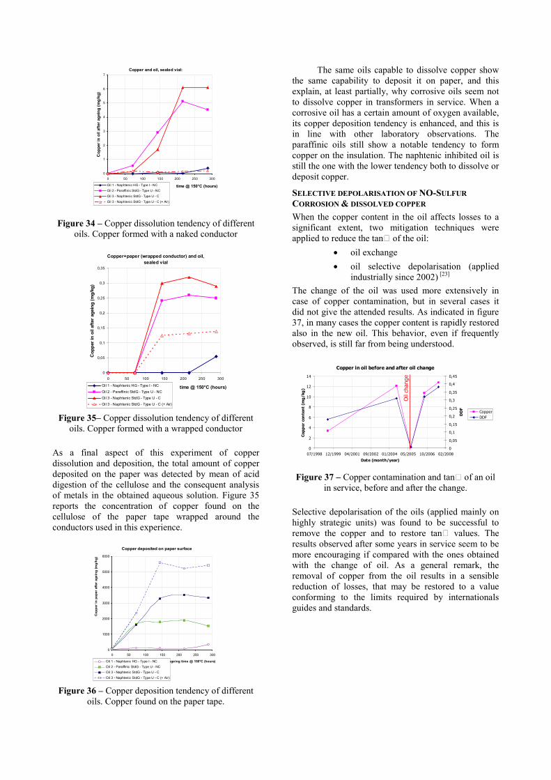
Figure 34 – Copper dissolution tendency of different oils. Copper formed with a naked conductor
Copper+paper (wrapped conductor) and oil,
sealed vial
0
0,05
0,1
0,15
0,2
0,25
0,3
0,35
0 50 100 150 200 250 300
time @ 150°C (hours)
Copper in oil after ageing (mg/kg)
Oil 1 - Naphtenic HG - Type I - NC
Oil 2 - Paraffinic StdG - Type U - NC
Oil 3 - Naphtenic StdG - Type U - C
Oil 3 - Naphtenic StdG - Type U - C (+ Air) Figure 35– Copper dissolution tendency of different
oils. Copper formed with a wrapped conductor
As a final aspect of this experiment of copper dissolution and deposition, the total amount of copper deposited on the paper was detected by mean of acid digestion of the cellulose and the consequent analysis of metals in the obtained aqueous solution. Figure 35 reports the concentration of copper found on the cellulose of the paper tape wrapped around the conductors used in this experience.
Copper deposited on paper surface
0
1000
2000
3000
4000
5000
6000
0 50 100 150 200 250 300
ageing time @ 150°C (hours)
Copper in paper after ageing (mg/kg)
Oil 1 - Naphtenic HG - Type I - NC
Oil 2 - Paraffinic StdG - Type U - NC
Oil 3 - Naphtenic StdG - Type U - C
Oil 3 - Naphtenic StdG - Type U - C (+ Air) Figure 36 – Copper deposition tendency of different
oils. Copper found on the paper tape.
The same oils capable to dissolve copper show the same capability to deposit it on paper, and this explain, at least partially, why corrosive oils seem not to dissolve copper in transformers in service. When a corrosive oil has a certain amount of oxygen available, its copper deposition tendency is enhanced, and this is in line with other laboratory observations. The paraffinic oils still show a notable tendency to form copper on the insulation. The naphtenic inhibited oil is still the one with the lower tendency both to dissolve or deposit copper.
SELECTIVE DEPOLARISATION OF NO-SULFUR
CORROSION & DISSOLVED COPPER
When the copper content in the oil affects losses to a significant extent, two mitigation techniques were applied to reduce the tan of the oil:
• oil exchange
• oil selective depolarisation (applied industrially since 2002) [23]
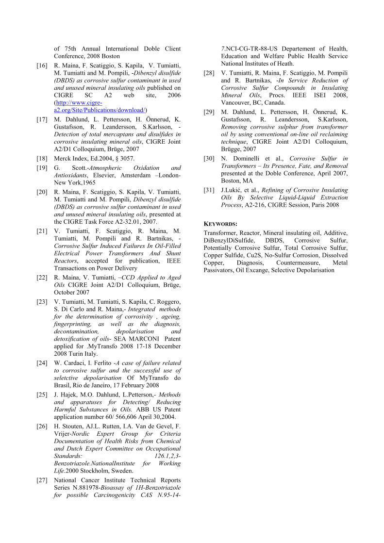
The change of the oil was used more extensively in case of copper contamination, but in several cases it did not give the attended results. As indicated in figure 37, in many cases the copper content is rapidly restored also in the new oil. This behavior, even if frequently observed, is still far from being understood.
Copper in oil before and after oil change
0
2
4
6
8
10
12
14
07/1998 12/1999 04/2001 09/2002 01/2004 05/2005 10/2006 02/2008
Date (month/year)
Copper conte
nt (m
g/kg)
0
0,05
0,1
0,15
0,2
0,25
0,3
0,35
0,4
0,45
DDF
Copper
DDF
Oil change
Figure 37 – Copper contamination and tan of an oil
in service, before and after the change.
Selective depolarisation of the oils (applied mainly on highly strategic units) was found to be successful to remove the copper and to restore tan values. The results observed after some years in service seem to be more encouraging if compared with the ones obtained with the change of oil. As a general remark, the removal of copper from the oil results in a sensible reduction of losses, that may be restored to a value conforming to the limits required by internationals guides and standards.

Copper in oil and DDF decay after oil depolarization
0
5
10
15
20
25
30
35
40
45
50
11/2001
05/2002
12/2002
06/2003
01/2004
08/2004
02/2005
09/2005
03/2006
10/2006
Date
Copper in
oil (m
g/kg)
0
0,2
0,4
0,6
0,8
1
1,2
1,4
DDF o
f oil
Copper in oil (mg/kg) DDF
Oil depolarisation
Figure 38 – Copper contamination and tan of an oil
in service, before and after the depolarisation.
CONCLUSIONS
As shown, “DBDS”, “Corrosive Sulfur” and “Copper Sulfide” formation are only one of the possible corrosion mechanisms involving the insulation and the active parts of a transformers and reactors. Also “No-Sulfur Corrosion” & Dissolved Copper and copper dissolution or copper-on-paper deposition under forms other than copper sulfide may occur, and were observed in transformers in service.
The formation of copper sulfide results from the presence of corrosive sulfur compounds, among which DBDS (dibenzyl disulfide) is the most frequently encountered, but surely not the unique one; other unidentified disulfides may form copper sulfide deposits on paper as well. The availability of new detection tests for corrosive sulfur, potentially corrosive sulfur, total corrosive sulfur oriented to the detection of the capability of the oil to form deposits on paper, may require to establish a new scale of reactivity of sulfur species, where mercaptans are unexpectedly not the most reactive, and thiophenes are capable to deposit copper sulfide as well as disulfides.
The formation of copper in oil is an oil characteristic, and different oils may show very different tendencies to dissolve copper. As a very provisional result, inhibited oils seem to dissolve less copper that uninhibited ones, and paraffinic oil have a dissolution tendency similar to oils containing corrosive sulfur. A high copper content is solved by corrosive oils too, in apparent contrast with field observations, but this may be probably explained by the fact that insoluble forms of copper are easily trapped onto paper tapes.
For both corrosions phenomena, some diagnostic and mitigation techniques were proposed, and are described in this paper. In general, chemical decomposition with selective depolarisation of polar compounds was found to be effective to remove both corrosive compounds and copper from the oil, giving results comparable or even better than oil exchange.
REFERENCES
[1] IEC, Dictionary IEV 21-08-21
[2] IEC, 60296 Third edition 2003-11- Fluids for
electrotechnical applications - Unused mineral
insulating oils for transformers and switchgear.
[3] IEC, 60422 Third edition 2005-10- Mineral
insulating oils in electrical equipment-
Supervision and maintenance guidance.
[4] IEC, 62535 First Edition 1.0 2008-10- Insulating
liquids-Test methods for detection of potentially
corrosive sulfur in used and unused insulating
oil
[5] CIGRE ,378 -Copper sulphide in transformer
insulation. Working Group A2.32 April 2009.
[6] A H. Rocha,- Faults In 500-Kv Shunt Reactors
Caused By Corrosive Sulfur In The Insulating
Oil, Procs. of the 2001 International Conference of Doble Clients - Sec 5-4
[7] C. Bengtsson, M. Dahlund, J. Hajek, L.F. Pettersson, K. Gustafsson, R. Leandersson, A. Hjortsberg, - Oil Corrosion And Conducting
Cu2S Deposition In Power Transformer
Windings, paper A2-111, CIGRÉ Main Session, 2006, Paris
[8] F. Scatiggio, V. Tumiatti, R. Maina, M. Tumiatti, M. Pompili, R. Bartnikas,- Corrosive
Sulfur in Insulating Oils: Its Detection and
Correlated Power Apparatus Failures, IEEE Transactions on Power Delivery, Volume 23, Issue 1, Jan. 2008 Page(s):508 – 509
[9] R. Maina,- Diagnostic on insulating liquids
during the operational life of electrical
equipment, Procs. Of MyTransfo Brasil, Rio de Janeiro, March 2007
[10] L.R. Lewand, - The negative effects of corrosive
sulfur on transformer components, Doble Engineering Company / NETA World, 2004.
[11] V. Tumiatti,- Condition monitoring by chemical
analysis Paper presented at CIGRE General Meeting Paris 30 August 2000.
[12] F.M. Clark and E.L. Raab, -The detection of
corrosive sulfur compounds in mineral
transformer oil, ASTM Symposium Publication, 1948, pp. 1201-1210; also presented at the Society Meeting, Philadelphia, June 21-25, 1948.
[13] CIGRE, SC A2 – TF A2.32.01, -Copper sulfide
in transformer insulation, Interim Report No. 1, Electra, September 2007.
[14] S. Toyama, J. Tanimura, N. Yamada, E. Nagao and T. Amimoto, High sensitive detection
method of dibenzyl disulfide and the elucidation
of the mechanism of copper sulfide generation in
insulating oil, Procs. of 75th Annual International Doble Client Conference, 2008 Boston
[15] T. Amimoto, E. Nagao, J. Tanimura, S. Toyama, Y. Fujita, H. Kawarai and N. Yamada, Identification of Contributing Factors of Copper
Sulfide Deposition on insulating Paper, Procs.
of 75th Annual International Doble Client Conference, 2008 Boston
[16] R. Maina, F. Scatiggio, S. Kapila, V. Tumiatti, M. Tumiatti and M. Pompili, -Dibenzyl disulfide
(DBDS) as corrosive sulfur contaminant in used
and unused mineral insulating oils published on CIGRE SC A2 web site, 2006 (http://www.cigre-a2.org/Site/Publications/download/)
[17] M. Dahlund, L. Pettersson, H. Önnerud, K. Gustafsson, R. Leandersson, S.Karlsson, -Detection of total mercaptans and disulfides in
corrosive insulating mineral oils, CIGRE Joint A2/D1 Colloquium, Brüge, 2007
[18] Merck Index, Ed.2004, § 3057.
[19] G. Scott.-Atmospheric Oxidation and
Antioxidants, Elsevier, Amsterdam –London- New York,1965
[20] R. Maina, F. Scatiggio, S. Kapila, V. Tumiatti, M. Tumiatti and M. Pompili, Dibenzyl disulfide
(DBDS) as corrosive sulfur contaminant in used
and unused mineral insulating oils, presented at the CIGRE Task Force A2-32.01, 2007.
[21] V. Tumiatti, F. Scatiggio, R. Maina, M. Tumiatti, M. Pompili and R. Bartnikas, - Corrosive Sulfur Induced Failures In Oil-Filled
Electrical Power Transformers And Shunt
Reactors, accepted for publication, IEEE Transactions on Power Delivery
[22] R. Maina, V. Tumiatti, –CCD Applied to Aged
Oils CIGRE Joint A2/D1 Colloquium, Brüge, October 2007
[23] V. Tumiatti, M. Tumiatti, S. Kapila, C. Roggero, S. Di Carlo and R. Maina,- Integrated methods
for the determination of corrosivity , ageing,
fingerprinting, as well as the diagnosis,
decontamination, depolarisation and
detoxification of oils- SEA MARCONI Patent applied for .MyTransfo 2008 17-18 December 2008 Turin Italy.
[24] W. Cardaci, I. Ferlito -A case of failure related
to corrosive sulfur and the successful use of
seletctive depolarisation Of MyTransfo do Brasil, Rio de Janeiro, 17 February 2008
[25] J. Hajek, M.O. Dahlund, L.Petterson,- Methods
and apparatuses for Detecting/ Reducing
Harmful Substances in Oils. ABB US Patent application number 60/ 566,606 April 30,2004.
[26] H. Stouten, AJ.L. Rutten, I.A. Van de Gevel, F. Vrijer-Nordic Expert Group for Criteria
Documentation of Health Risks from Chemical
and Dutch Expert Committee on Occupational
Standards: 126.1,2,3-
Benzotriazole.NationalInstitute for Working
Life.2000 Stockholm, Sweden.
[27] National Cancer Institute Technical Reports Series N.881978-Bioassay of 1H-Benzotriazole
for possible Carcinogenicity CAS N.95-14-
7.NCI-CG-TR-88-US Departement of Health, Education and Welfare Public Health Service National Institutes of Heath.
[28] V. Tumiatti, R. Maina, F. Scatiggio, M. Pompili and R. Bartnikas, -In Service Reduction of
Corrosive Sulfur Compounds in Insulating
Mineral Oils, Procs. IEEE ISEI 2008, Vancouver, BC, Canada.
[29] M. Dahlund, L. Pettersson, H. Önnerud, K. Gustafsson, R. Leandersson, S.Karlsson, Removing corrosive sulphur from transformer
oil by using conventional on-line oil reclaiming
technique, CIGRE Joint A2/D1 Colloquium, Brügge, 2007
[30] N. Dominelli et al., Corrosive Sulfur in
Transformers – Its Presence, Fate, and Removal presented at the Doble Conference, April 2007, Boston, MA
[31] J.Lukić, et al., Refining of Corrosive Insulating
Oils By Selective Liquid-Liquid Extraction
Process, A2-216, CIGRE Session, Paris 2008
KEYWORDS:
Transformer, Reactor, Mineral insulating oil, Additive, DiBenzylDiSulfide, DBDS, Corrosive Sulfur, Potentially Corrosive Sulfur, Total Corrosive Sulfur, Copper Sulfide, Cu2S, No-Sulfur Corrosion, Dissolved Copper, Diagnosis, Countermeasure, Metal Passivators, Oil Excange, Selective Depolarisation