Simulation and CompariSon of SpWm and SVpWm Control for ...
8
SIMULATION AND COMPARISON OF SPWM AND SVPWM CONTROL FOR TWO LEVEL INVERTER Shweta Singh 1 and A.N. Tiwari 2 1-2 Electrical Engineering Department, MMMUT, Gorakhpur, India. Email: 1 [email protected], 2 [email protected] Abstract: This paper shows a comparative studybetween Space-Vector Pulse Width Modulation (SVPWM) and Sinusoidal Pulse Width Modulation (SPWM) for three phase two level inverters. Various control and pulse width modulation (PWM) techniques are increasingly applied in many new industrial applications that require superior performance. The most widely applied PWM technique for three-phase voltage source inverters are Sine Pulse Width Modulation (SPWM), and Space Vector Pulse Width Modulation (SVPWM). Keywords: Space Vector PWM; three phase inverters; total harmonic distortion (THD); sinusoidal PWM. ISSN: 0973-5704 International Journal of Computing and Applications Volume 13, Number 2, (July-December 2018), pp 267-273 © Serials Publications, New Delhi (India) of using these modulating techniques is to have a better and controlled output from the inverters, free from harmonics and waveform distortion. PWM techniques can be classified on the basis of modulation output and scheme to be used in this process as Single pulse width modulation when just one pulse is modulated in one half cycle, multiple pulse width modulation when multiple pulses are modulated in a half cycle, SPWM, SVPWM, Hysteresis (Delta) PWM [3][4]. Sinusoidal PWM Fundamental Switching Frequency Multilevel Modulations Pulse Width Modulation Space Vector PWM Figure 1: Classification of Modulation Techniques In SPWM a three phase signal or three single phase signals of desired frequency known as reference signals are compared against a high frequency triangular or saw tooth wave also called carrier wave to generate PWM pulses. Pulses are generated by comparing the INTRODUCTION 1. Nowadays, AC drives are finding more applications and replacing DC drives for almost all the applications. This is all after the advancements in power electronic devices which makes it easier to use AC machines over DC machines. A variable supply is required for these AC drives which are provided by power electronic converters. Since the evolution of power electronics, the research in control of power electronic circuits has been done and various schemes have been proposed for modulating pulse width in the past couple of decade [1][2]. For DC-AC power conversion inverters has been extensively used. Different techniques have been proposed for modulating the gating pulse width to have an output voltage of variable amplitude and frequency. PWM techniques find a wide range of applications including the production of switching patterns for the operation of inverters. These inverters are than utilized in variable speed drives and various other applications as static frequency changers, standby power supplies, un-interruptible power supplies etc. These inverters perform well but produce harmonics in the output waveforms. PWM techniques can be used as a solution for reduction of these harmonics in high power applications. Hence it can be said that the aim
-
Upload
khangminh22 -
Category
Documents
-
view
0 -
download
0
Transcript of Simulation and CompariSon of SpWm and SVpWm Control for ...
Simulation and CompariSon of SpWm and SVpWm Control for tWo leVel inVerter
Shweta Singh1 and a.n. tiwari2
1-2Electrical Engineering Department, MMMUT, Gorakhpur, India. Email: [email protected], [email protected]
Abstract: This paper shows a comparative studybetween Space-Vector Pulse Width Modulation (SVPWM) and Sinusoidal Pulse Width Modulation (SPWM) for three phase two level inverters. Various control and pulse width modulation (PWM) techniques are increasingly applied in many new industrial applications that require superior performance. The most widely applied PWM technique for three-phase voltage source inverters are Sine Pulse Width Modulation (SPWM), and Space Vector Pulse Width Modulation (SVPWM).
Keywords: Space Vector PWM; three phase inverters; total harmonic distortion (THD); sinusoidal PWM.
iSSn: 0973-5704international Journal of Computing and applications Volume 13, Number 2, (July-December 2018), pp 267-273
© Serials Publications, New Delhi (India)
of using these modulating techniques is to have a better and controlled output from the inverters, free from harmonics and waveform distortion. PWM techniques can be classified on the basis of modulation output and scheme to be used in this process as Single pulse width modulation when just one pulse is modulated in one half cycle, multiple pulse width modulation when multiple pulses are modulated in a half cycle, SPWM, SVPWM, Hysteresis (Delta) PWM [3][4].
Sinusoidal PWM
Fundamental Switching Frequency
Multilevel Modulations
Pulse Width Modulation
Space Vector PWM
figure 1: Classification of modulation techniques
In SPWM a three phase signal or three single phase signals of desired frequency known as reference signals are compared against a high frequency triangular or saw tooth wave also called carrier wave to generate PWM pulses. Pulses are generated by comparing the
introduCtion1.
Nowadays, AC drives are finding more applications and replacing DC drives for almost all the applications. This is all after the advancements in power electronic devices which makes it easier to use AC machines over DC machines. A variable supply is required for these AC drives which are provided by power electronic converters. Since the evolution of power electronics, the research in control of power electronic circuits has been done and various schemes have been proposed for modulating pulse width in the past couple of decade [1][2]. For DC-AC power conversion inverters has been extensively used. Different techniques have been proposed for modulating the gating pulse width to have an output voltage of variable amplitude and frequency. PWM techniques find a wide range of applications including the production of switching patterns for the operation of inverters. These inverters are than utilized in variable speed drives and various other applications as static frequency changers, standby power supplies, un-interruptible power supplies etc.
These inverters perform well but produce harmonics in the output waveforms. PWM techniques can be used as a solution for reduction of these harmonics in high power applications. Hence it can be said that the aim
268 Shweta Singh and A.N. Tiwari
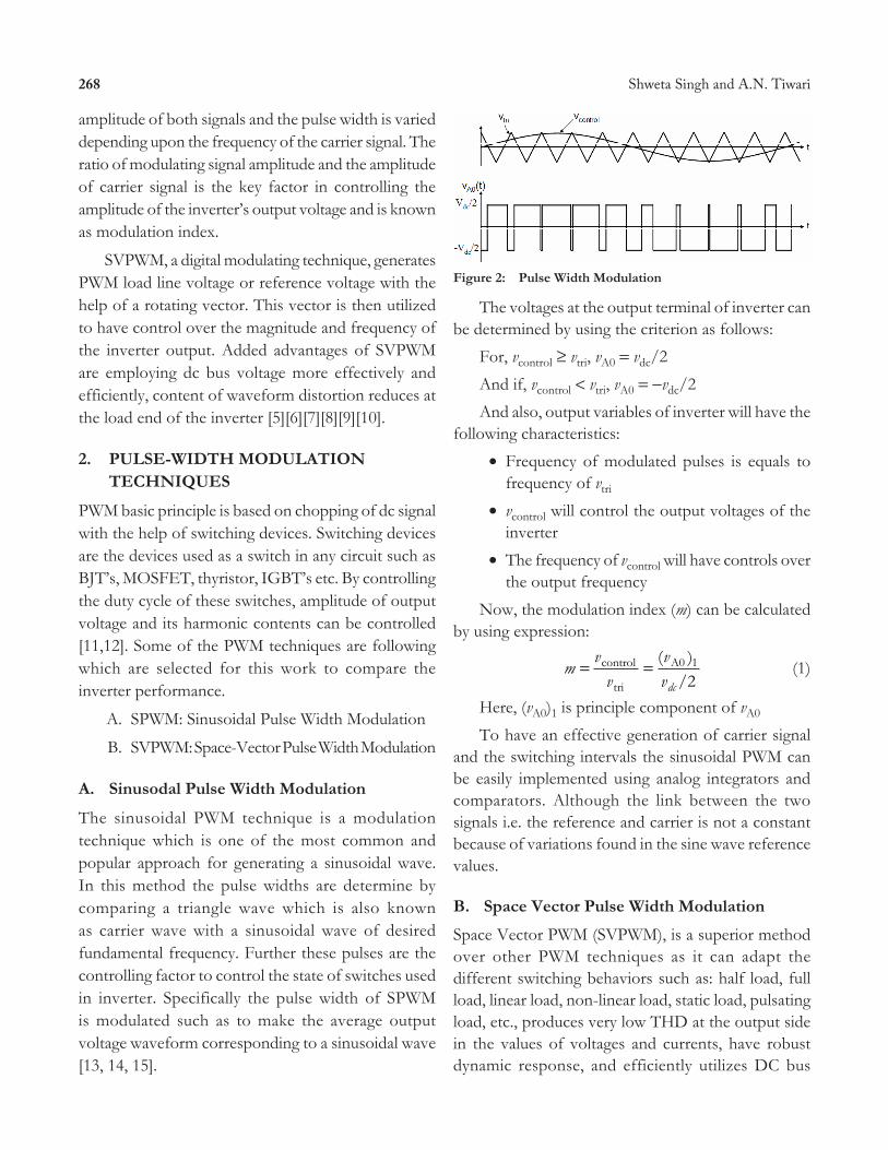
figure 2: pulse Width modulation
The voltages at the output terminal of inverter can be determined by using the criterion as follows:
For, vcontrol ≥ vtri, vA0 = vdc/2
And if, vcontrol < vtri, vA0 = -vdc/2
And also, output variables of inverter will have the following characteristics:
∑ Frequency of modulated pulses is equals to frequency of vtri
∑ vcontrol will control the output voltages of the inverter
∑ The frequency of vcontrol will have controls over the output frequency
Now, the modulation index (m) can be calculated by using expression:
mv
vvvdc
= =control
tri
A0
/( )1
2 (1)
Here, (vA0)1 is principle component of vA0
To have an effective generation of carrier signal and the switching intervals the sinusoidal PWM can be easily implemented using analog integrators and comparators. Although the link between the two signals i.e. the reference and carrier is not a constant because of variations found in the sine wave reference values.
B. Space Vector pulse Width modulation
Space Vector PWM (SVPWM), is a superior method over other PWM techniques as it can adapt the different switching behaviors such as: half load, full load, linear load, non-linear load, static load, pulsating load, etc., produces very low THD at the output side in the values of voltages and currents, have robust dynamic response, and efficiently utilizes DC bus
amplitude of both signals and the pulse width is varied depending upon the frequency of the carrier signal. The ratio of modulating signal amplitude and the amplitude of carrier signal is the key factor in controlling the amplitude of the inverter’s output voltage and is known as modulation index.
SVPWM, a digital modulating technique, generates PWM load line voltage or reference voltage with the help of a rotating vector. This vector is then utilized to have control over the magnitude and frequency of the inverter output. Added advantages of SVPWM are employing dc bus voltage more effectively and efficiently, content of waveform distortion reduces at the load end of the inverter [5][6][7][8][9][10].
pulSe-Width modulation 2. teChniqueS
PWM basic principle is based on chopping of dc signal with the help of switching devices. Switching devices are the devices used as a switch in any circuit such as BJT’s, MOSFET, thyristor, IGBT’s etc. By controlling the duty cycle of these switches, amplitude of output voltage and its harmonic contents can be controlled [11,12]. Some of the PWM techniques are following which are selected for this work to compare the inverter performance.
A. SPWM: Sinusoidal Pulse Width Modulation
B. SVPWM: Space-Vector Pulse Width Modulation
a. Sinusodal pulse Width modulation
The sinusoidal PWM technique is a modulation technique which is one of the most common and popular approach for generating a sinusoidal wave. In this method the pulse widths are determine by comparing a triangle wave which is also known as carrier wave with a sinusoidal wave of desired fundamental frequency. Further these pulses are the controlling factor to control the state of switches used in inverter. Specifically the pulse width of SPWM is modulated such as to make the average output voltage waveform corresponding to a sinusoidal wave [13, 14, 15].
269Simulation and Comparison of SPWM and SVPWM Control for Two Level Inverter
voltage. However SVPWM is a highly complicated technique than SPWM, but still the implementation is easier with control systems based on modern DSP [16][17][18].
SVPWM uses the rotating synchronous reference frame analogous to a stationary frame having three phase sinusoidal varying signals. The Space Vector PWM can be said as a unique switching sequence pattern developed for the three switches of an inverter located in upper half.
Let the components of three-phase sinusoidal voltage are defined for the stationary reference frame as,
va = vm sin(wt) (2)
vb = vm sin(wt - 2p/3) (3)
vc = vm sin(wt - 4p/3) (4)
When an AC machine is fed by three phase voltages a flux which is rotating in nature is being produced in the air gap linking the stator and rotor conductors. This flux can also be shown in voltage form as a vector which also rotates in a different frame known as dq frame by using Clark’s Transformation.
From Figure 3, the relation between these two reference frames is below:
fdq0 = Ks fabc (5)
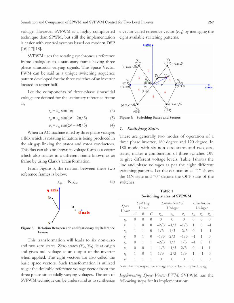
figure 3: relation Between abc and Stationary dq reference frame
This transformation will leads to six non-zero and two zero states. Zero states (V0, V7) lie at origin and gives null voltage as an output of the inverter when applied. The eight vectors are also called the basic space vectors. Such transformation is utilized to get the desirable reference voltage vector from the three phase sinusoidally varying voltages. The aim of SVPWM technique can be understand as to synthesize
a vector called reference vector (vref) by managing the eight available switching patterns.
figure 4: Switching States and Sectors
1. Switching States
There are generally two modes of operation of a three phase inverter, 180 degree and 120 degree. In 180 mode, with six non-zero states and two zero states, makes a combination of three switches ON to give different voltage levels. Table 1shows the line and phase voltages as per the eight different switching patterns. Let the denotation as “1” shows the ON state and “0” denote the OFF state of the switches.
table 1 Switching states of SVpWm
Space Vector
Switching Vector
Line-to-Neutral Voltages
Line-to-Line Voltages
A B C van vbn vcn vab vbc vca
v0 0 0 0 0 0 0 0 0 0v1 1 0 0 –2/3 –1/3 –1/3 1 0 –1v2 1 1 0 1/3 1/3 –2/3 0 1 –1v3 0 1 0 –1/3 2/3 –1/3 –1 1 0v4 0 1 1 –2/3 1/3 1/3 –1 0 1v5 0 0 1 –1/3 –1/3 2/3 0 –1 1v6 1 0 1 1/3 –2/3 1/3 1 –1 0v7 1 1 1 0 0 0 0 0 0
Note: that the respective voltage should be multiplied by vdc
Implementing Space Vector PWM: SVPWM has the following steps for its implementation:
270 Shweta Singh and A.N. Tiwari
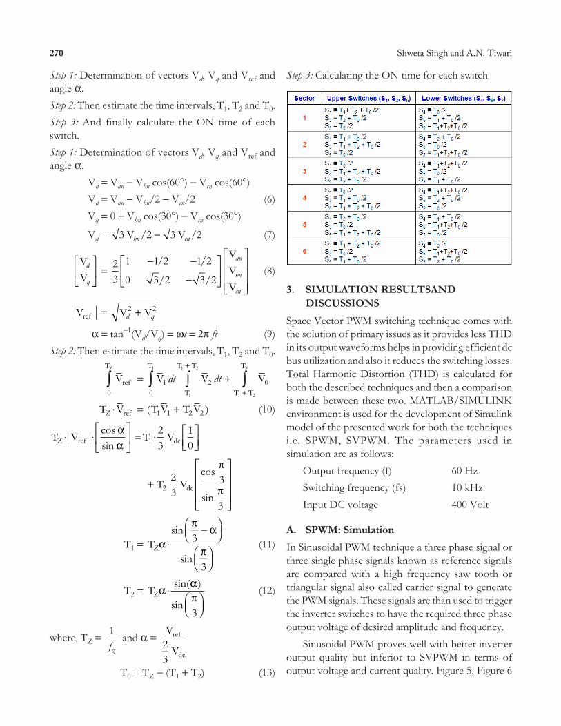
Step 3: Calculating the ON time for each switch
Simulation reSultSand 3. diSCuSSionS
Space Vector PWM switching technique comes with the solution of primary issues as it provides less THD in its output waveforms helps in providing efficient dc bus utilization and also it reduces the switching losses. Total Harmonic Distortion (THD) is calculated for both the described techniques and then a comparison is made between these two. MATLAB/SIMULINK environment is used for the development of Simulink model of the presented work for both the techniques i.e. SPWM, SVPWM. The parameters used in simulation are as follows:
Output frequency (f) 60 HzSwitching frequency (fs) 10 kHzInput DC voltage 400 Volt
a. SpWm: SimulationIn Sinusoidal PWM technique a three phase signal or three single phase signals known as reference signals are compared with a high frequency saw tooth or triangular signal also called carrier signal to generate the PWM signals. These signals are than used to trigger the inverter switches to have the required three phase output voltage of desired amplitude and frequency.
Sinusoidal PWM proves well with better inverter output quality but inferior to SVPWM in terms of output voltage and current quality. Figure 5, Figure 6
Step 1: Determination of vectors Vd, Vq and Vref and angle a.Step 2: Then estimate the time intervals, T1, T2 and T0.Step 3: And finally calculate the ON time of each switch.Step 1: Determination of vectors Vd, Vq and Vref and angle a.
Vd = Van - Vbn cos(60°) - Vcn cos(60°) Vd = Van - Vbn/2 - Vcn/2 (6) Vq = 0 + Vbn cos(30°) - Vcn cos(30°)
Vq = 3 2 3 2V / V /bn cn- (7)
VV
d
q
È
ÎÍ
˘
˚˙ =
23
1 1 2 1 2
0 3 2 3 2
- -
-È
ÎÍ
˘
˚˙
È
Î
ÍÍÍ
˘
˚
˙˙˙
/ /
/ /
VVV
an
bn
cn
(8)
Vref = V Vd q2 2+
a = tan-1(Vd/Vq) = wt = 2p ft (9)Step 2: Then estimate the time intervals, T1, T2 and T0.
Vref
TZ
0Ú = V V V1
T
2T
T T
0T T
T1
1
1 2
1 2
Z
dt dt0Ú Ú Ú
+
+
+
T VZ ref◊ = ( )T V T V1 1 2 2+ (10)
T VZ ref◊ ◊È
ÎÍ
˘
˚˙
cossin
aa
= T Vdc123
10
◊ ÈÎÍ
˘˚̇
+
È
Î
ÍÍÍ
˘
˚
˙˙˙
T Vdc223
3
3
cos
sin
p
p
T1 = TZa
p a
p◊
-ÊËÁ
ˆ¯̃
ÊËÁ
ˆ¯̃
sin
sin
3
3
(11)
T2 = TZa ap
◊ÊËÁ
ˆ¯̃
sin( )
sin3
(12)
where, TZ = 1fz
and a = V
V
ref
dc23
T0 = TZ - (T1 + T2) (13)
271Simulation and Comparison of SPWM and SVPWM Control for Two Level Inverter
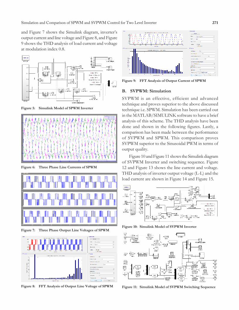
and Figure 7 shows the Simulink diagram, inverter’s output current and line voltage and Figure 8, and Figure 9 shows the THD analysis of load current and voltage at modulation index 0.8.
figure 5: Simulink model of SpWm inverter
figure 6: three phase line Currents of SpWm
figure 7: three phase output line Voltages of SpWm
figure 8: fft analysis of output line Voltage of SpWm
figure 9: fft analysis of output Current of SpWm
B. SVpWm: SimulationSVPWM is an effective, efficient and advanced technique and proves superior to the above discussed technique i.e. SPWM. Simulation has been carried out in the MATLAB/SIMULINK software to have a brief analysis of this scheme. The THD analysis have been done and shown in the following figures. Lastly, a comparison has been made between the performance of SVPWM and SPWM. This comparison proves SVPWM superior to the Sinusoidal PWM in terms of output quality.
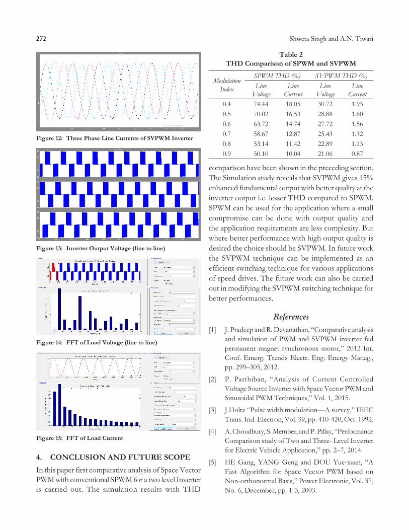
Figure 10 and Figure 11 shows the Simulink diagram of SVPWM Inverter and switching sequence. Figure 12 and Figure 13 shows the line current and voltage. THD analysis of inverter output voltage (L-L) and the load current are shown in Figure 14 and Figure 15.
figure 10: Simulink model of SVpWm inverter
figure 11: Simulink model of SVpWm Switching Sequence
272 Shweta Singh and A.N. Tiwari
figure 12: three phase line Currents of SVpWm inverter
figure 13: inverter output Voltage (line to line)
figure 14: fft of load Voltage (line to line)
figure 15: fft of load Current
ConCluSion and future SCope4. In this paper first comparative analysis of Space Vector PWM with conventional SPWM for a two level Inverter is carried out. The simulation results with THD
table 2 thd Comparison of SpWm and SVpWm
Modulation Index
SPWM THD (%) SVPWM THD (%)Line
VoltageLine
CurrentLine
VoltageLine
Current0.4 74.44 18.05 30.72 1.930.5 70.02 16.53 28.88 1.600.6 63.72 14.74 27.72 1.560.7 58.67 12.87 25.43 1.320.8 53.14 11.42 22.89 1.130.9 50.10 10.04 21.06 0.87
comparison have been shown in the preceding section. The Simulation study reveals that SVPWM gives 15% enhanced fundamental output with better quality at the inverter output i.e. lesser THD compared to SPWM. SPWM can be used for the application where a small compromise can be done with output quality and the application requirements are less complexity. But where better performance with high output quality is desired the choice should be SVPWM. In future work the SVPWM technique can be implemented as an efficient switching technique for various applications of speed drives. The future work can also be carried out in modifying the SVPWM switching technique for better performances.
ReferencesJ. Pradeep and R. Devanathan, “Comparative analysis [1] and simulation of PWM and SVPWM inverter fed permanent magnet synchronous motor,” 2012 Int. Conf. Emerg. Trends Electr. Eng. Energy Manag., pp. 299–305, 2012.
P. Parthiban, “Analysis of Current Controlled [2] Voltage Source Inverter with Space Vector PWM and Sinusoidal PWM Techniques,” Vol. 1, 2015.
J.Holtz “Pulse width modulation—A survey,” IEEE [3] Trans. Ind. Electron, Vol. 39, pp. 410-420, Oct. 1992.
A. Choudhury, S. Member, and P. Pillay, “Performance [4] Comparison study of Two and Three- Level Inverter for Electric Vehicle Application,” pp. 2–7, 2014.
HE Gang, YANG Geng and DOU Yue-xuan, “A [5] Fast Algorithm for Space Vector PWM based on Non-orthonormal Basis,” Power Electronic, Vol. 37, No. 6, December, pp. 1-3, 2003.
273Simulation and Comparison of SPWM and SVPWM Control for Two Level Inverter
Dae-Woong Chung, Joohn-Sheok Kim b and Seung-[6] Ki Sul, “Unified voltage modulation technique for real-time three-phase power conversion,” IEEE Transactions on Industry Applications, Vol. 34, Issue 2, pp. 374-380, March-April 1998.
K.S. Amit Kumar and G. Narayanan, “Simplified [7] implementation of space vector PWM strategies for a three level inverter,” 2012 IEEE 7th Int. Conf. Ind. Inf. Syst. ICIIS 2012.
Xu Qiang, Jia Zhengchun and Xiong Youlun, “A [8] Fast Algorithm of Space Vector PWM”, Power Electronics, No. 3, pp. 46-48, 2000.
Meng Yongqing, Liu Zheng and Su Yanmin, “Study [9] on a Novel SVM Method for Three-level PWM Voltage Source Inverter”, Electric Drive, Vol. 35, No. 7, pp. 35-38, 2005.
TANG Xiongmin, GONG Lizhuan and PENG [10] Yongjin, “New Fast Algorithm for Vector Control of Multilevel Inverter”, High Voltage Engineering, Vol. 32, No. 2, pp. 75-77, Feb. 2006.
Bose, B.K., “Modern Power Electronics and AC [11] Drives,” Prentice Hall PTR, 2002.
Rashid, M.H., “Power Electronics Handbook,” [12] Academic Press, 2001.
K.V. Kumar, P.A. Michael, J.P. John, and S.S. Kumar, [13] “Simulation and Comparison of Spwm and Svpwm Control for Three Phase Inverter,” ARPN J. Eng. Appl. Sci., Vol. 5, No. 7, pp. 61–74, 2010.
Y.N. Dementyev, N.V. Kojain, A.D. Bragin, and L.S. [14] Udut, “Control system with sinusoidal PWM three-phase inverter with a frequency scalar control of induction motor,” 2015 Int. Sib. Conf. Control Commun. SIBCON 2015 - Proc., pp. 1–6, 2015.
M. Mangal, and G. DE, “Novel Control Strategy [15] for Sinusoidal PWM Inverters” IEEE Trans. Industry application., Vol. 23, No. 3, may/june 1987.
Hariram, B., and Marimuthu, N.S.[16] , “Space Vector Switching Patterns for Different Applications a Comparative Analysis,” Proc. of 2005 IEEE International Conference on Industrial Technology ICIT, pp. 1444-1449, Hong Kong, Dec. 2005.
Wu Fengjiang, Gao Hanying, Sun Li and Wang [17] Youkun, “Research on Fast Algorithm of SVPWM Based on DSP”, Electric Drive, Vol. 36, No. 9, pp. 44-46, 2006.
K. Zhou and D. Wang, “Relationship between space-[18] vector modulation and three-phase carrier-based PWM: A comprehensive analysis,” IEEE Trans. Ind. Electron., Vol. 49, No. 1, pp. 186–196, 2002.
G.N. Goyal and M.V. Aware, “A comparative [19] performance of six-phase nine switch inverter operation with SPWM and SVPWM,” PEDES 2012 - IEEE Int. Conf. Power Electron. Drives Energy Syst., pp. 1–6, 2012.
N.S. Ting, “Comparison of SVPWM, SPWM and [20] HCC Control Techniques in Power Control of PMSG used in Wind Turbine Systems,” pp. 69–74, 2015.