DYNAMIC MODEL AND CONTROL OF DFIG WIND ENERGY SYSTEMS BASED ON POWER TRANSFER MATRIX USING SVPWM
10
DYNAMIC MODEL AND CONTROL OF DFIG WIND ENERGY SYSTEMS BASED ON POWER TRANSFER MATRIX USING SVPWM B. JHANSI BAI 1 & CH. RAJESH KUMAR 2 1 M.Tech Student, Department of EEE, Narayana Engineering College, S.P.S.R, Nellore, Andhra Pradesh, India 2 Associate Professor, Department of EEE, Narayana Engineering College, S.P.S.R, Nellore, Andhra Pradesh, India ABSTRACT This project proposes a power transfer matrix model and multivariable control method for a doubly-fed induction generator (DFIG) wind energy system using Svpwm (space vector pulse width modulation). The power transfer matrix model uses instantaneous real/reactive power components as the system state variables. The power transfer matrix model improves the robustness of controllers as the power wave forms are independent of a dq frameofre ference. The design controller includes six compensators for capturing the maximum wind power and supplying there quired reactive power to the DFIG. A power/current limiting scheme is also presented to protect power converters during a fault. The validity and performance of the proposed modeling and control approaches are investigated using a study system consisting of a grid-connected DFIG wind energy conversion system. This investigation uses the time-domain simulation of the study system to: 1) validate the presented model and its assumptions, 2) show the tracking and disturbance rejection capabilities of the designed control system, and 3) test the robustness of the designed controller to the uncertainties of the model parameters. KEYWORDS: Doubly Fed Induction Generator (DFIG), Dynamics Modeling, Instantaneous Power, Multivariable Control, Wind Energy Systems, Wind Power Control, Wind Turbine Generator I. INTRODUCTION Wind energy conversion systems are currently among economically available and viable renewable energy systems which have experienced rapid growth in recent years. Increasing the penetration level of wind farms highlights the grid integration concerns including power systems stability, power quality (PQ), protection, and dynamic interactions of the wind power units in a wind farm [1]–[3]. Wind energy systems based on doubly fed induction generators (DFIGs) have been dominantly used in high-power applications since they use power-electronic converters with ratings less than the rating of the wind turbine generators [4]–[8]. The scope of this project is dynamic modeling and control of DFIG wind turbine generators using svpwm. Modeling and control of DFIGs have been widely investigated based on well-established vector control schemes in a stator field-oriented frame of reference [7]–[9]. The vector control is a fast method for independent control of the real/reactive power of a machine. The method is established based on control of current components in a dq frame of reference using an abc/qd0 transformation. Since the dq components are not physically available, the calculation of these components requires a phase-locked loop (PLL) to determine synchronous angle [8], [9]. The dynamics of abc/qd0 transformations are often ignored in the procedure of control design. Thus, any control design approach must be adequately robust to overcome the uncertainties in estimation of machine parameters as well as unaccounted dynamics of the overall system. Direct torque control (DTC) and direct power control schemes (DPC) have been presented as alternative methods International Journal of Electrical and Electronics Engineering (IJEEE) ISSN(P): 2278-9944; ISSN(E): 2278-9952 Vol. 3, Issue 1, Jan 2014, 27-36 © IASET
Transcript of DYNAMIC MODEL AND CONTROL OF DFIG WIND ENERGY SYSTEMS BASED ON POWER TRANSFER MATRIX USING SVPWM

DYNAMIC MODEL AND CONTROL OF DFIG WIND ENERGY SYSTEMS BASED ON
POWER TRANSFER MATRIX USING SVPWM
B. JHANSI BAI1 & CH. RAJESH KUMAR
2
1M.Tech Student, Department of EEE, Narayana Engineering College, S.P.S.R, Nellore, Andhra Pradesh, India
2Associate Professor, Department of EEE, Narayana Engineering College, S.P.S.R, Nellore, Andhra Pradesh, India
ABSTRACT
This project proposes a power transfer matrix model and multivariable control method for a doubly-fed induction
generator (DFIG) wind energy system using Svpwm (space vector pulse width modulation). The power transfer matrix
model uses instantaneous real/reactive power components as the system state variables. The power transfer matrix model
improves the robustness of controllers as the power wave forms are independent of a dq frameofre ference. The design
controller includes six compensators for capturing the maximum wind power and supplying there quired reactive power to
the DFIG. A power/current limiting scheme is also presented to protect power converters during a fault. The validity and
performance of the proposed modeling and control approaches are investigated using a study system consisting of a
grid-connected DFIG wind energy conversion system. This investigation uses the time-domain simulation of the study
system to: 1) validate the presented model and its assumptions, 2) show the tracking and disturbance rejection capabilities
of the designed control system, and 3) test the robustness of the designed controller to the uncertainties of the model
parameters.
KEYWORDS: Doubly Fed Induction Generator (DFIG), Dynamics Modeling, Instantaneous Power, Multivariable
Control, Wind Energy Systems, Wind Power Control, Wind Turbine Generator
I. INTRODUCTION
Wind energy conversion systems are currently among economically available and viable renewable energy
systems which have experienced rapid growth in recent years. Increasing the penetration level of wind farms highlights the
grid integration concerns including power systems stability, power quality (PQ), protection, and dynamic interactions of
the wind power units in a wind farm [1]–[3]. Wind energy systems based on doubly fed induction generators (DFIGs) have
been dominantly used in high-power applications since they use power-electronic converters with ratings less than the
rating of the wind turbine generators [4]–[8]. The scope of this project is dynamic modeling and control of DFIG wind
turbine generators using svpwm.
Modeling and control of DFIGs have been widely investigated based on well-established vector control schemes
in a stator field-oriented frame of reference [7]–[9]. The vector control is a fast method for independent control of the
real/reactive power of a machine. The method is established based on control of current components in a dq frame of
reference using an abc/qd0 transformation. Since the dq components are not physically available, the calculation of these
components requires a phase-locked loop (PLL) to determine synchronous angle [8], [9]. The dynamics of abc/qd0
transformations are often ignored in the procedure of control design. Thus, any control design approach must be adequately
robust to overcome the uncertainties in estimation of machine parameters as well as unaccounted dynamics of the overall
system.
Direct torque control (DTC) and direct power control schemes (DPC) have been presented as alternative methods
International Journal of Electrical and
Electronics Engineering (IJEEE)
ISSN(P): 2278-9944; ISSN(E): 2278-9952
Vol. 3, Issue 1, Jan 2014, 27-36
© IASET
28 B. Jhansi Bai & Ch. Rajesh Kumar
which directly control machine flux and torque via the selection of suitable voltage vectors [3]–[4]. It has been shown that
DPC is a more efficient approach compared to modified DTC [5]–[7]. However, the DPC method also depends on the
estimation of machine parameters and it requires a protection mechanism to avoid over current during a fault in the system.
This project proposes a modeling and control approach which uses instantaneous real and reactive power instead of dq
components of currents in a vector control scheme.
The main features of the proposed model compared to conventional models in the dq frame of reference are as
follows.
Robustness: The waveforms of power components are independent of a reference frame; therefore, this approach
is inherently robust against unaccounted dynamics such as PLL.
Simplicity of Realization: The power components (state variables of a feedback control loop) can be directly
obtained from abc phase voltage/current quantities, which simplifies the implementation of the control system.
Using power components instead of current in the model of the system, the control system requires an additional
protection algorithm to prevent over current during a fault. Such an algorithm can be simply added to the control
system via measuring the magnitude of current. The sequential loop closing technique is adopted to design a
multivariable control system including six compensators for a DFIG wind energy system. The designed control
system captures maximum wind power via adjusting the speed of the DFIG and injects the required reactive
power to the system via a grid-side converter.
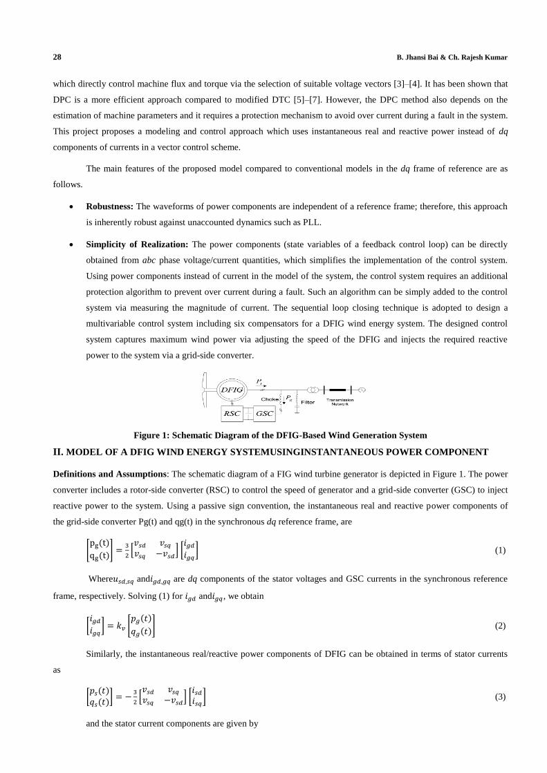
Figure 1: Schematic Diagram of the DFIG-Based Wind Generation System
II. MODEL OF A DFIG WIND ENERGY SYSTEMUSINGINSTANTANEOUS POWER COMPONENT
Definitions and Assumptions: The schematic diagram of a FIG wind turbine generator is depicted in Figure 1. The power
converter includes a rotor-side converter (RSC) to control the speed of generator and a grid-side converter (GSC) to inject
reactive power to the system. Using a passive sign convention, the instantaneous real and reactive power components of
the grid-side converter Pg(t) and qg(t) in the synchronous dq reference frame, are
(1)
Where and are dq components of the stator voltages and GSC currents in the synchronous reference
frame, respectively. Solving (1) for and , we obtain
(2)
Similarly, the instantaneous real/reactive power components of DFIG can be obtained in terms of stator currents
as
(3)
and the stator current components are given by
Dynamic Model and Control of DFIG Wind Energy Systems Based on Power Transfer Matrix Using SVPWM 29
(4)
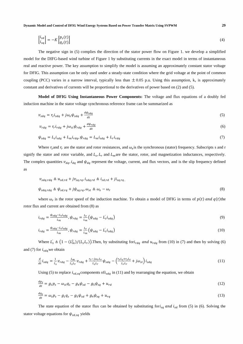
The negative sign in (5) complies the direction of the stator power flow on Figure 1. we develop a simplified
model for the DIFG-based wind turbine of Figure 1 by substituting currents in the exact model in terms of instantaneous
real and reactive power. The key assumption to simplify the model is assuming an approximately constant stator voltage
for DFIG. This assumption can be only used under a steady-state condition where the grid voltage at the point of common
coupling (PCC) varies in a narrow interval, typically less than 0.05 p.u. Using this assumption, kv is approximately
constant and derivatives of currents will be proportional to the derivatives of power based on (2) and (5).
Model of DFIG Using Instantaneous Power Components: The voltage and flux equations of a doubly fed
induction machine in the stator voltage synchronous reference frame can be summarized as
(5)
(6)
(7)
Where and are the stator and rotor resistances, and is the synchronous (stator) frequency. Subscripts s and r
signify the stator and rotor variable, and and are the stator, rotor, and magnetization inductances, respectively.
The complex quantities and represent the voltage, current, and flux vectors, and is the slip frequency defined
as
(8)
where is the rotor speed of the induction machine. To obtain a model of DFIG in terms of the
rotor flux and current are obtained from (8) as
(9)
(10)
Where
Then, by substituting for from (10) in (7) and then by solving (6)
and (7) for we obtain
(11)
Using (5) to replace components of in (11) and by rearranging the equation, we obtain
(12)
(13)
The state equation of the stator flux can be obtained by substituting for from (5) in (6). Solving the
stator voltage equations for yields
30 B. Jhansi Bai & Ch. Rajesh Kumar
(14)
(15)
The electromechanical dynamic model of the machine is
(16)
where P,J, and are the number of pole pairs, inertia of the rotor, and mechanical torque of the machine,
respectively
(17)
In (17), the mechanical torque is input to the model and , based on (16), can be expressed in terms of
instantaneous real and reactive power. Substituting for sdi and sdi from (5) in (18) and then replacing in (17), we deduce
The simplified model of the induction machine is presented in (2)–(6) and (9) which the
model of DFIG in (1) is a nonlinear dynamic model since the coefficients of the state variables are functions of the state
variables.
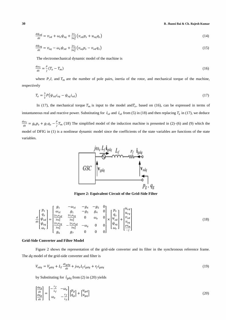
Figure 2: Equivalent Circuit of the Grid-Side Filter
(18)
Grid-Side Converter and Filter Model
Figure 2 shows the representation of the grid-side converter and its filter in the synchronous reference frame.
The dq model of the grid-side converter and filter is
(19)
by Substituting for gdqi from (2) in (20) yields
(20)
Dynamic Model and Control of DFIG Wind Energy Systems Based on Power Transfer Matrix Using SVPWM 31
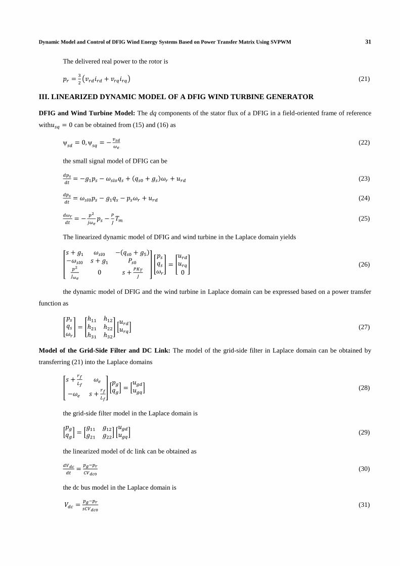
The delivered real power to the rotor is
(21)
III. LINEARIZED DYNAMIC MODEL OF A DFIG WIND TURBINE GENERATOR
DFIG and Wind Turbine Model: The dq components of the stator flux of a DFIG in a field-oriented frame of reference
with can be obtained from (15) and (16) as
(22)
the small signal model of DFIG can be
(23)
(24)
(25)
The linearized dynamic model of DFIG and wind turbine in the Laplace domain yields
(26)
the dynamic model of DFIG and the wind turbine in Laplace domain can be expressed based on a power transfer
function as
(27)
Model of the Grid-Side Filter and DC Link: The model of the grid-side filter in Laplace domain can be obtained by
transferring (21) into the Laplace domains
(28)
the grid-side filter model in the Laplace domain is
(29)
the linearized model of dc link can be obtained as
(30)
the dc bus model in the Laplace domain is
(31)
32 B. Jhansi Bai & Ch. Rajesh Kumar
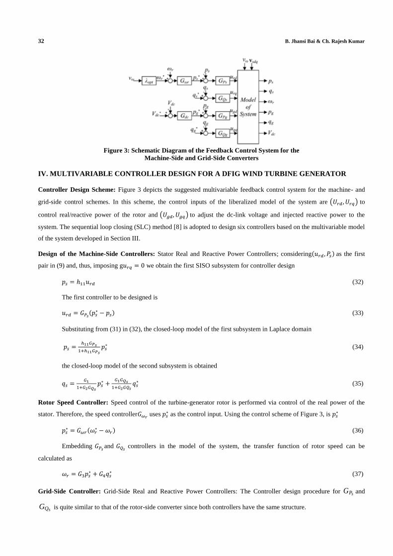
Figure 3: Schematic Diagram of the Feedback Control System for the
Machine-Side and Grid-Side Converters
IV. MULTIVARIABLE CONTROLLER DESIGN FOR A DFIG WIND TURBINE GENERATOR
Controller Design Scheme: Figure 3 depicts the suggested multivariable feedback control system for the machine- and
grid-side control schemes. In this scheme, the control inputs of the liberalized model of the system are to
control real/reactive power of the rotor and to adjust the dc-link voltage and injected reactive power to the
system. The sequential loop closing (SLC) method [8] is adopted to design six controllers based on the multivariable model
of the system developed in Section III.
Design of the Machine-Side Controllers: Stator Real and Reactive Power Controllers; considering as the first
pair in (9) and, thus, imposing g we obtain the first SISO subsystem for controller design
(32)
The first controller to be designed is
(33)
Substituting from (31) in (32), the closed-loop model of the first subsystem in Laplace domain
(34)
the closed-loop model of the second subsystem is obtained
(35)
Rotor Speed Controller: Speed control of the turbine-generator rotor is performed via control of the real power of the
stator. Therefore, the speed controller uses
as the control input. Using the control scheme of Figure 3, is
(36)
Embedding and
controllers in the model of the system, the transfer function of rotor speed can be
calculated as
(37)
Grid-Side Controller: Grid-Side Real and Reactive Power Controllers: The Controller design procedure for sPG and
sQG is quite similar to that of the rotor-side converter since both controllers have the same structure.
Dynamic Model and Control of DFIG Wind Energy Systems Based on Power Transfer Matrix Using SVPWM 33
Current Limiting during a Fault: During a fault and/or sever transients, additional protection algorithms, such as fault
ride through (FRT) and startup algorithms, must be added to the control system. Various algorithms, including active
crowbar [3], series dynamic restorer [2], and dynamic voltage restorer [3] have been suggested for FRT. These algorithms
are independent of the control approach during the normal operation; therefore, they can be used with the proposed transfer
power matrix method herein as well. In addition to FRT algorithms and to mitigate over current during a transient, an extra
feedback loop can be used to sense the converter currents and reduce the power reference commands during transients.
This extra loop only requires.
V. SIMULATION DIAGRAM AND RESULTS
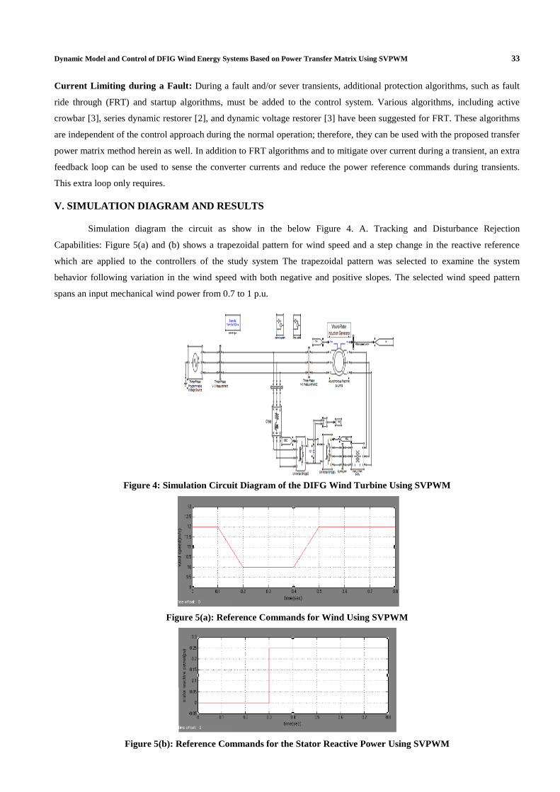
Simulation diagram the circuit as show in the below Figure 4. A. Tracking and Disturbance Rejection
Capabilities: Figure 5(a) and (b) shows a trapezoidal pattern for wind speed and a step change in the reactive reference
which are applied to the controllers of the study system The trapezoidal pattern was selected to examine the system
behavior following variation in the wind speed with both negative and positive slopes. The selected wind speed pattern
spans an input mechanical wind power from 0.7 to 1 p.u.
Figure 4: Simulation Circuit Diagram of the DIFG Wind Turbine Using SVPWM
Figure 5(a): Reference Commands for Wind Using SVPWM
Figure 5(b): Reference Commands for the Stator Reactive Power Using SVPWM
34 B. Jhansi Bai & Ch. Rajesh Kumar
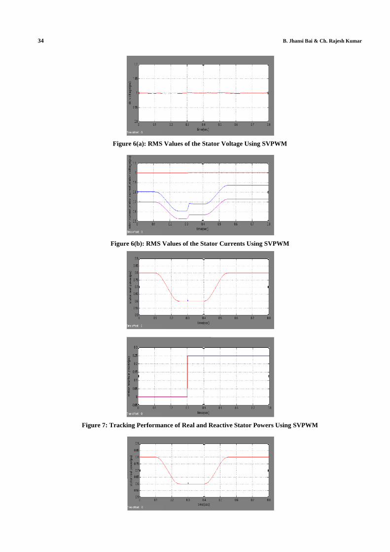
Figure 6(a): RMS Values of the Stator Voltage Using SVPWM
Figure 6(b): RMS Values of the Stator Currents Using SVPWM
Figure 7: Tracking Performance of Real and Reactive Stator Powers Using SVPWM
Dynamic Model and Control of DFIG Wind Energy Systems Based on Power Transfer Matrix Using SVPWM 35
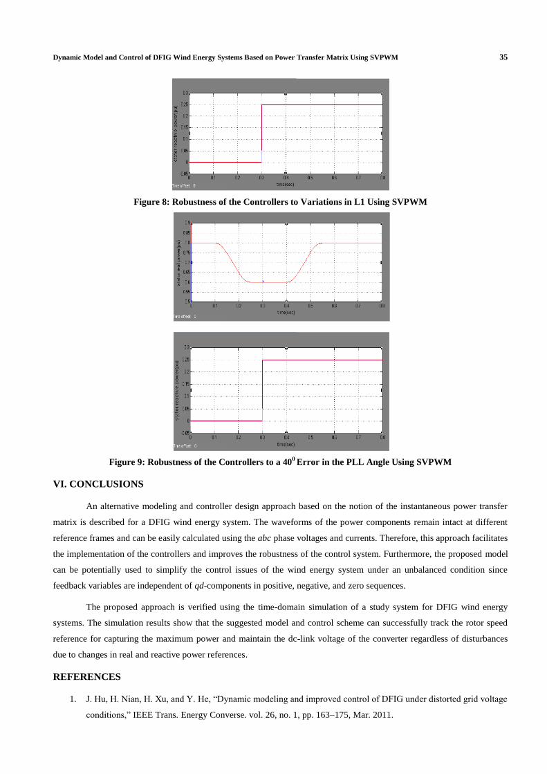
Figure 8: Robustness of the Controllers to Variations in L1 Using SVPWM
Figure 9: Robustness of the Controllers to a 400 Error in the PLL Angle Using SVPWM
VI. CONCLUSIONS
An alternative modeling and controller design approach based on the notion of the instantaneous power transfer
matrix is described for a DFIG wind energy system. The waveforms of the power components remain intact at different
reference frames and can be easily calculated using the abc phase voltages and currents. Therefore, this approach facilitates
the implementation of the controllers and improves the robustness of the control system. Furthermore, the proposed model
can be potentially used to simplify the control issues of the wind energy system under an unbalanced condition since
feedback variables are independent of qd-components in positive, negative, and zero sequences.
The proposed approach is verified using the time-domain simulation of a study system for DFIG wind energy
systems. The simulation results show that the suggested model and control scheme can successfully track the rotor speed
reference for capturing the maximum power and maintain the dc-link voltage of the converter regardless of disturbances
due to changes in real and reactive power references.
REFERENCES
1. J. Hu, H. Nian, H. Xu, and Y. He, “Dynamic modeling and improved control of DFIG under distorted grid voltage
conditions,” IEEE Trans. Energy Converse. vol. 26, no. 1, pp. 163–175, Mar. 2011.

36 B. Jhansi Bai & Ch. Rajesh Kumar
2. L. Fan, H. Yin, and Z. Miao, “On active/reactive power modulation of DFIG-based wind generation for interarea
oscillation damping,” IEEE Trans. Energy Convers., vol. 26, no. 2, pp. 513–521, Jun. 2011.
3. S. Chen, N. Cheung, K. Wong, and J. Wu, “Integral variable structure direct torque control of doubly fed
induction generator,” IET Renew. Power Gen.,, vol. 5, no. 1, pp. 18–25, 2011.
4. D. Zhi, L. Xu, and B. Williams, “Model-based predictive direct power control of doubly fed induction
generators,” IEEE Trans. Power Electron., vol. 25, no. 2, pp. 341–351, Feb. 2010
5. S. Chen, N. Cheung, K. Wong, and J. Wu, “Integral variable structure direct torque control of doubly fed
induction generator,” IET Renew. Power Gen., , vol. 5, no. 1, pp. 18–25, 2011.
6. J. Maciejowski, Multivariable Feedback Design, ser. Electron. Syst. Eng. Ser. Reading, MA: Addison-Wesley,
1989, vol. 1.
7. R. Fadaeinedjad, M. Moallem, and G. Moschopoulos, “Simulation of awind turbine with doubly fed induction
generator by fast and simulink,” IEEE Trans. Energy Convers., vol. 23, no. 2, pp. 690–700, Jun. 2008.
8. G. Pannell, D. Atkinson, and B. Zahawi, “Minimum-threshold crowbar for a fault-ride-through
grid-code-compliant DFIG wind turbine,” IEEE Trans. Energy Convers., vol. 25, no. 3, pp. 750–759, Sep. 2010.
9. A. Tables and R. Irvine, “Multivariable dynamic model and robust control of a voltage-source converter for
power system applications,” IEEE Trans. Power Del., vol. 24, no. 1, pp. 462–471, Jan. 2009.
AUTHOR’S DETAILS
B. Jhansi Bai received the B.Tech Degree, from Priyadarshini College of Engineering and Technology, Nellore
Affiliated to JNTU Ananthapur. Present she perceive M.Tech (Electrical Power Systems) from Narayana Engineering
College, Nellore Affiliated to JNTU Ananthapur. Current research interested Area are Power systems and Electrical
Machines.
Ch. Rajesh Kumar received the Master degree in power electronics and drives from Sree sastha institute of
engineering and technology Affiliated to Anna University Chennai, B.Tech degree from sri vidyanikethan engineering
college Affiliated to Jntu Ananthapur. Ragampet Tirupathi. Currently, He is Associate professor of electrical and
electronics engineering at Narayana Engineering College, Nellore, AP.