
CMS 50/63/71 Electric Cylinders / Catalogs / 2009-06 - SEW ...
Upload
khangminh22Category
view
0download
0
Drive Technology \ Drive Automation \ System Integration \ Services
Assembly and Operating Instructions
Industrial Gear UnitsPlanetary Gearmotors Sizes P.002 – P.102Torque Classes from 24 – 500 kNm
Edition 02/2012 19316828 / EN

SEW-EURODRIVE—Driving the world

Assembly and Operating Instructions – Planetary Gearmotor Sizes P.002 – P.102 3
Contents
Contents1 Important Notes................................................................................................... 5
1.1 How to use the operating instructions......................................................... 51.2 Structure of the safety notes ....................................................................... 51.3 Rights to claim under warranty ................................................................... 61.4 Exclusion of liability..................................................................................... 61.5 Copyright..................................................................................................... 6
2 Safety Notes ........................................................................................................ 72.1 Preliminary remark...................................................................................... 72.2 General information .................................................................................... 72.3 Target group ............................................................................................... 82.4 Designated use ........................................................................................... 82.5 Other applicable documentation ................................................................. 82.6 Safety symbols on the gear unit.................................................................. 92.7 Symbols on the packaging........................................................................ 102.8 Transport................................................................................................... 112.9 Storage and transport conditions .............................................................. 14
3 Gear Unit Structure ........................................................................................... 163.1 Planetary gear unit with primary gear unit combination ............................ 163.2 Nameplate and type designation ............................................................. 173.3 Mounting position...................................................................................... 213.4 Mounting position sheets .......................................................................... 223.5 Mounting positions of primary gear units .................................................. 273.6 Pivoted and variable mounting positions .................................................. 303.7 Coating and surface protection systems................................................... 323.8 Types of lubrication................................................................................... 33
4 Design of Options and Accessories................................................................ 364.1 Components on the input side .................................................................. 364.2 Torque arm ............................................................................................... 374.3 PT100 temperature sensor ....................................................................... 374.4 Oil drain..................................................................................................... 38
5 Installation/Assembly ....................................................................................... 395.1 Required tools/resources .......................................................................... 395.2 Tolerances ................................................................................................ 395.3 Notes on installation/mounting.................................................................. 405.4 Installation requirements........................................................................... 425.5 Planetary gear units delivered without oil fill (standard)............................ 435.6 Planetary gear units delivered with oil fill (option)..................................... 445.7 Installing the gear unit ............................................................................... 455.8 Gear unit with solid shaft........................................................................... 495.9 Couplings .................................................................................................. 515.10 AM adapter coupling ................................................................................. 525.11 AD input shaft assembly ........................................................................... 555.12 Flange-mounted gear units ....................................................................... 59

4 Assembly and Operating Instructions – Planetary Gearmotor Sizes P.002 – P.102
Contents
5.13 Torque arm .............................................................................................. 605.14 Output shaft as hollow shaft with shrink disk ............................................ 635.15 PT100 temperature sensor ....................................................................... 70
6 Startup................................................................................................................ 716.1 Important notes on startup ....................................................................... 716.2 Run-in period ............................................................................................ 726.3 Startup of gear units with long-term protection ......................................... 726.4 Backstop ................................................................................................... 736.5 Measuring surface and oil temperature .................................................... 746.6 Gear unit shutdown/conservation ............................................................. 75
7 Inspection/Maintenance ................................................................................... 777.1 Preliminary work regarding inspection/maintenance ................................ 777.2 Inspection and maintenance intervals....................................................... 787.3 Lubricant change intervals ........................................................................ 807.4 Checking the oil level ................................................................................ 817.5 Checking the oil consistency..................................................................... 827.6 Changing the oil ........................................................................................ 837.7 Refilling grease ......................................................................................... 887.8 Checking and cleaning the breather plug ................................................. 89
8 Lubricants.......................................................................................................... 908.1 Lubricant selection .................................................................................... 908.2 Lubricant table .......................................................................................... 918.3 Lubricant fill quantities .............................................................................. 938.4 Grease / rolling bearing grease: Planetary gear units............................... 968.5 Sealing grease: Primary gear units RF.. / KF../ K.. and motors ................ 96
9 Malfunctions ...................................................................................................... 979.1 Notes ........................................................................................................ 979.2 Customer service ...................................................................................... 979.3 Malfunctions of P.. planetary gear units.................................................... 989.4 Malfunctions of primary gear units RF.. / KF.. / K.. ................................... 999.5 AM/AL adapter malfunctions .................................................................... 999.6 Malfunctions of the motor ....................................................................... 1009.7 Malfunctions of the DR/DV brake............................................................ 1019.8 Disposal .................................................................................................. 101
10 Address List .................................................................................................... 102
Index................................................................................................................. 113

Assembly and Operating Instructions – Planetary Gearmotor Sizes P.002 – P.102 5
1How to use the operating instructionsImportant Notes
Planetary Gearmotor Sizes P.002 – P.102 1 Important Notes1.1 How to use the operating instructions
Operating instructions are an integral part of the product and contain important informa-tion for operation and service. The operating instructions are written for all employeeswho assemble, install, start up, and service the product.
The operating instructions must be legible and accessible at all times. Make sure thatstaff responsible for the plant and its operation, as well as persons who work indepen-dently on the unit, have read the operating instructions carefully and understood them.If you are unclear about any of the information in this documentation, or if you requirefurther information, contact SEW-EURODRIVE.
1.2 Structure of the safety notes1.2.1 Meaning of signal words
The following table shows the grading and meaning of the signal words for safety notes,notes on potential risks of damage to property, and other notes.
1.2.2 Structure of the section safety notesSection safety notes do not apply to a specific action, but to several actions pertainingto one subject. The used symbols indicate either a general or a specific hazard.
This is the formal structure of a section safety note:
1.2.3 Structure of the embedded safety notesEmbedded safety notes are directly integrated in the instructions just before the descrip-tion of the dangerous action.
This is the formal structure of an embedded safety note:
• SIGNAL WORD Type and source of danger.
Possible consequence(s) if disregarded.
– Measure(s) to prevent the danger.
Signal word Meaning Consequences if disregarded
DANGER Imminent danger Severe or fatalInjuries
WARNING Possible dangerous situation Severe or fatalInjuries
NOTICE Possible dangerous situation Minor injuries
NOTICE Possible damage to property Damage to the drive system or its environment
INFORMATION Useful information or tip: Simplifies the handling of the drive system.
SIGNAL WORDType and source of danger.
Possible consequence(s) if disregarded.• Measure(s) to prevent the danger.

6 Assembly and Operating Instructions – Planetary Gearmotor Sizes P.002 – P.102
1 Rights to claim under warrantyImportant Notes
1.3 Rights to claim under warrantyYou must comply with the information contained in these operating instructions toensure safe operation of the gear units and to achieve the specified product character-istics and performance features. SEW-EURODRIVE assumes no liability for injury topersons or damage to equipment or property resulting from non-observance of theseoperating instructions. In such cases, any liability for defects is excluded.
1.4 Exclusion of liabilityYou must comply with the information contained in these operating instructions toensure safe operation of the P.002 – P.102 series planetary gear units and to achievethe specified product characteristics and performance requirements. SEW-EURODRIVE assumes no liability for injury to persons or damage to equipment orproperty resulting from non-observance of these operating instructions. In such cases,any liability for defects is excluded.
1.5 Copyright© 2012 – SEW-EURODRIVE. All rights reserved.
Unauthorized duplication, modification, distribution or any other use of the whole or anypart of this documentation is strictly prohibited.

Assembly and Operating Instructions – Planetary Gearmotor Sizes P.002 – P.102 7
2Preliminary remarkSafety Notes
2 Safety NotesThe following basic safety notes must be read carefully to prevent injury to persons anddamage to property. The operator must ensure that the basic safety notes are read andadhered to. Make sure that persons responsible for the system and its operation, as wellas persons who work independently on the unit, have read through the operatinginstructions carefully and understood them. If you are unclear about any of the informa-tion in this documentation, or if you require further information, please contact SEW-EURODRIVE.
2.1 Preliminary remarkThe following safety notes are primarily concerned with the use of gear units. If usinggearmotors, also refer to the safety notes for motors in the corresponding operatinginstructions.
Also observe the supplementary safety notes in the individual sections of these operat-ing instructions.
2.2 General information
Refer to the documentation for additional information.
WARNINGDuring operation, the gear units can have movable or rotating parts as well as hotsurfaces.
Severe or fatal injuries• All work related to transportation, storage, installation, assembly, connection,
startup, maintenance and repair may only be carried out by qualified personnel, instrict observance of:– The relevant detailed operating instructions – Warning and safety signs on the gear unit– All other project planning documents, operating instructions and wiring
diagrams related to the drive– The specific regulations and requirements for the system– National/regional regulations governing safety and the prevention of accidents
• Never install damaged products
• Submit a complaint to the shipping company immediately in the event of damage.
• Removing covers without authorization, improper use or incorrect installation andoperation may result in severe injuries to persons or damage to machinery.

8 Assembly and Operating Instructions – Planetary Gearmotor Sizes P.002 – P.102
2 Target groupSafety Notes
2.3 Target groupAny mechanical work may only be performed by adequately qualified personnel. Quali-fied personnel in this context are persons who are familiar with the setup, mechanicalinstallation, troubleshooting and maintenance for this product. Further, they are qualifiedas follows:
• Training in mechanical engineering, e.g. as a mechanic or mechatronics technician(final examinations must have been passed).
• They are familiar with these operating instructions.
Any electronic work may only be performed by adequately qualified electricians. Quali-fied electricians in this context are persons who are familiar with the electronic installa-tion, startup, troubleshooting and maintenance for this product. Further, they are quali-fied as follows:
• Training in electrical engineering, e.g. as an electrician or mechatronics technician(final examinations must have been passed).
• They are familiar with these operating instructions.
All work in further areas of transportation, storage, operation and waste disposal mustonly be carried out by persons who are trained appropriately.
All qualified personnel must wear appropriate protective clothing.
2.4 Designated useP.002 – P.102 series planetary gear units are gear units driven by motors for industrialand commercial systems. The units may only be run at the speeds and powers shownin the technical data or on the nameplate. Implementing gear unit loads other than thepermitted values or operating the gear units in areas of application other than industrialand commercial systems is only permitted after consultation with SEW-EURODRIVE.
Using these products in potentially explosive atmospheres is prohibited, unless specifi-cally designated otherwise.
In compliance with the EC Machinery Directive 2006/42/EC, the planetary gear units arecomponents for installation in machinery and systems. In the scope of the EC directive,you must not take the machinery into operation in the designated fashion until you haveestablished that the end product complies with the Machinery Directive 2006/42/EC.
2.5 Other applicable documentationThe following publications and documents have to be observed as well:
• When operating gearmotors, also observe the safety notes for motors and primarygear units in the accompanying operating instructions.
• Operating instructions of any attached options
• Order-specific documents, such as dimension drawings

Assembly and Operating Instructions – Planetary Gearmotor Sizes P.002 – P.102 9
2Safety symbols on the gear unitSafety Notes
2.6 Safety symbols on the gear unit
The safety symbols on the gear unit must be observed. They have the followingmeaning:
CAUTIONSafety symbols or signs can become dirty or illegible over time.
Risk of injury due to illegible symbols.• Always make sure that safety, warning, and operating notes are legible.• Replace damaged safety symbols and signs.
Safety symbols Meaning
Oil fill plug
Oil drain
Oil dipstick
Oil sight glass
Breather plug
Regreasing point
Oil
Oil
Oil
Oil

10 Assembly and Operating Instructions – Planetary Gearmotor Sizes P.002 – P.102
2 Symbols on the packagingSafety Notes
2.7 Symbols on the packagingThe symbols on the packaging must be observed. They have the following meaning:
1811486091Up Keep dry Center of gravity
Fragile Protect from heat
Fasten here
Hand hooksprohibited

Assembly and Operating Instructions – Planetary Gearmotor Sizes P.002 – P.102 11
2TransportSafety Notes
2.8 Transport2.8.1 Notes on transport
• Inspect the shipment for any damage that may have occurred in transit as soon asyou receive the delivery. Inform the shipping company immediately. In the event of adamage, do not start up the unit.
• The weight of the gear unit is indicated on the nameplate or the dimension sheet.Observe the loads and specifications given on the nameplate.
• Pay attention to the center of gravity of the gear unit.
• Use suitable, sufficiently rated and undamaged handling equipment.
• If possible, transport the gear unit without oil fill.
• Transport the gear unit in such a way that the lifting gear is tensioned only vertically.
• The gear unit must be transported in a manner that prevents damage to the gear unit.For example, impacts against exposed shaft ends can damage the gear unit.
• Do not lift the gear unit on the piping.
• Secure the keys from falling out.
• Planetary gear units and planetary gearmotors are suspended from the transportpoints marked in the drawings below. Transport straps (indicated with dotted lines inthe figures below) help balance and support the planetary gear unit.
The following figures illustrate how to transport the gear unit.
WARNINGSuspended loads can fall.
Severe or fatal injuries.• Do not stand under the suspended load.• Secure the danger zone.
CAUTIONRisk of slipping due to lubricant leaking from damaged seals.
Minor injuries• Check the gear unit and mount-on components for leaking lubricant.
NOTICEImproper transport may result in damage to the gear unit.
Possible damage to property.
Note the following:

12 Assembly and Operating Instructions – Planetary Gearmotor Sizes P.002 – P.102
2 TransportSafety Notes
2.8.2 Foot-mounted planetary gear unit
The following figure shows a transport example.
2.8.3 Flange-mounted helical planetary gearmotorThe following figure shows a transport example.

Assembly and Operating Instructions – Planetary Gearmotor Sizes P.002 – P.102 13
2TransportSafety Notes
2.8.4 Planetary gear unit with torque arm (standard)
The following figure shows a transport example.
4269462795
14 Assembly and Operating Instructions – Planetary Gearmotor Sizes P.002 – P.102
2 Storage and transport conditionsSafety Notes
2.9 Storage and transport conditionsThe gear units can be provided with the following protection and packaging typesdepending on the storage and transport conditions.
2.9.1 Internal conservationStandard corrosion protection
After the test run, the test oil fill is drained out of the gear unit. The remaining oil filmprotects the gear unit against corrosion for a limited period of time.
Long-term corrosion protection
After the test run, the test oil fill is drained out of the gear unit and the interior space isfilled will a vapor phase inhibitor. The breather filter is replaced by a screw plug andenclosed with the gear unit.
2.9.2 External conservationThe following measures are generally taken for exterior corrosion protection:
• Corrosion protection is applied to bare, non-painted functional surfaces of shafts,flanges, mounting and foot surfaces on the gear unit. Remove it only using an appro-priate solvent which is not harmful to the oil seal.
• Small spare parts and loose pieces, such as bolts, nuts, etc., are packed in corrosionprotection plastic bags (VCI corrosion protection bags).
• Threaded holes and blind holes are covered by plastic plugs.
• If the gear unit is stored longer than six months, you must check the protective coat-ing of unpainted areas as well as the paint coating regularly. Areas in which the pro-tective coating and/or paint has been damaged may have to be repainted.
2.9.3 PackagingStandard packaging
The gear unit is delivered on a pallet without cover.
Application: Land transport
Long-term packaging
The gear unit is delivered in a wooden box that is also appropriate for sea transport.
Application: Sea transport and/or for long-term storage

Assembly and Operating Instructions – Planetary Gearmotor Sizes P.002 – P.102 15
2Storage and transport conditionsSafety Notes
2.9.4 Storage conditions
NOTICEImproper storage may result in damages to the gear unit.
Possible damage to property.• During storage up to startup, the gear unit must be stored in a shock-free manner
to prevent damage to the rolling bearing races.• The output shaft must be rotated at least one full rotation every six months so that
the position of the roller elements in the bearings of the input and output shaftschanges.
INFORMATIONThe gear units are delivered without oil; different protection systems are requireddepending on the storage period and storage conditions as shown in the table below.
Corrosion protection + packaging Storage location Storage duration
Standard corrosion protection+
standard packaging
Under roof, enclosed at constant temperature and atmospheric humidity (5 °C < ϑ < 60 °C, relative humidity < 50%).
No sudden temperature fluctuations. Controlled ventilation with filter (free from dust and dirt). Protected against aggressive
vapors and shocks.
Max. 6 months with intact surface corrosion protection
Long-term corrosion protection+
standard packaging
Under roof, enclosed at constant temperature and atmospheric humidity (5 °C < ϑ < 60 °C, relative humidity < 50%).
No sudden temperature fluctuations. Controlled ventilation of the storage room (free from dust and dirt). Protected against aggres-
sive vapors and shocks.
Max. 3 years with regular inspection and checking for intactness.
Long-term corrosion protection+
long-term packagingWith roof, protected against rain and shocks. Max. 3 years with regular inspection
and checking for intactness.
INFORMATIONIf stored in tropical zones, provide for sufficient protection against insect damage.Contact SEW-EURODRIVE for differing requirements.

16 Assembly and Operating Instructions – Planetary Gearmotor Sizes P.002 – P.102
3 Planetary gear unit with primary gear unit combinationGear Unit Structure
3 Gear Unit Structure3.1 Planetary gear unit with primary gear unit combination
The planetary gear units are a combination of
• P.. planetary gear unit output stage
• Primary gear unit RF.. or KF..
• Mount-on components: Motor, coupling, adapter and backstop
The following figure shows a sample combination of a planetary gear unit, a primarygear unit and a motor.
1044069259
P.. planetary gear unitRF.. helical gear unit (flange-mounted)KF.. bevel-helical gear unit (flange-mounted)
P..
RF..
KF..
Motor

Assembly and Operating Instructions – Planetary Gearmotor Sizes P.002 – P.102 17
3Nameplate and type designationGear Unit Structure
3.2 Nameplate and type designation 3.2.1 Planetary gear unit
The following example shows the structure of the nameplate.
9007202573749771
Typ Type designation
Nr. 1 Manufacturing number
PK1 [kW] Operating power on the input shaft (HSS)
MK2 [Nm] Gear unit output torque
n1 rpm Input speed (HSS)
n2 rpm Output speed (LSS)
norm. Normal operating point
min. Operating point at minimum speed
max. Operating point at maximum speed
i Exact gear unit reduction ratio
FS Service factor
FR1 [N] Actual overhung load acting on the input shaft
FR2 [N] Actual overhung load acting on the output shaft
FA1 [N] Actual axial load acting on the input shaft
FA2 [N] Actual axial load acting on the output shaft
Mass [kg] Weight of the gear unit
Qty of greasing points Number of regreasing points
Fans Number of installed fans
Oil grade and viscosity class / oil volume
Year Year of manufacture
IM Mounting position and mounting surface
SEW-EURODRIVE Bruchsal / Germany
Type
Nr. 1
PK1
norm. min. max.
MK2
n1
n2
Operation instruction have to be observed!Made in Germany
i
FS
FR1
FR2
FA1
1 :
[N]
[N]
[N]
[N]FA2
[kg]
Year
Mass
[kW]
[Nm]
[1/min]
[1/min]
Qty of greasing points Fans
PF042 KF97 DRE132 ML4 / TF
6.6
77000
1430
0.77
1.3
77000
285
0.15
6.6
77000
1430
0.77
0CLP HC VG220 synth. Oil - 29 ltr. 2010
840
50000
0
0
0
1.3
01.1101687801.0001.10 / 12345678
0
1880

18 Assembly and Operating Instructions – Planetary Gearmotor Sizes P.002 – P.102
3 Nameplate and type designationGear Unit Structure
The type designation of the gear unit is structured as follows:
P H F /T 032 RF 97 DRE 160M4
Size + number of polesMotor
Series
Size Primary gear unit
Series
Size
Planetary gear unit
Torque arm
Flange-mounted design
Hollow shaft for shrink disk
Gear unit type

Assembly and Operating Instructions – Planetary Gearmotor Sizes P.002 – P.102 19
3Nameplate and type designationGear Unit Structure
3.2.2 Primary gear unit
The following example shows the structure of the nameplate.
The type designation of the gear unit is structured as follows:
210927627
fb = Service factor
FRa max [N] = Maximum overhung load on the output side
FRe max [N] = Maximum overhung load on the input side (with input shaft assembly AD)
i = Gear unit reduction ratio
IM = Mounting position
IP.. = Degree of protection
ne max rpm = Maximum input speed
na rpm = Output speed
Memax [Nm] = Maximum input torque
Ma [Nm] = Output torque
MR [Nm] = Overload torque when using an AR adapter
MRS [Nm] = Locking torque of the backstop
RF 47 /A
For direct motor mounting
Gear unit size
Helical gear unit series (flange mounted)
0641 543 1
Made in Germany
kg
IM
IP
i
76646 Bruchsal / Germany
32
6519,34
665
M3B
CLP HC 220 Synth.Öl / 2,4L
232 4500
01.1234567890.0001.08K57 AQH140/1
r/minna pk r/minne pk NmMa pk
INFORMATIONFor a detailed overview of type designations and additional information, refer to thefollowing publications: • "Gear Units" catalog or • "Gearmotors" catalog
20 Assembly and Operating Instructions – Planetary Gearmotor Sizes P.002 – P.102
3 Nameplate and type designationGear Unit Structure
3.2.3 Primary gear unit with motor
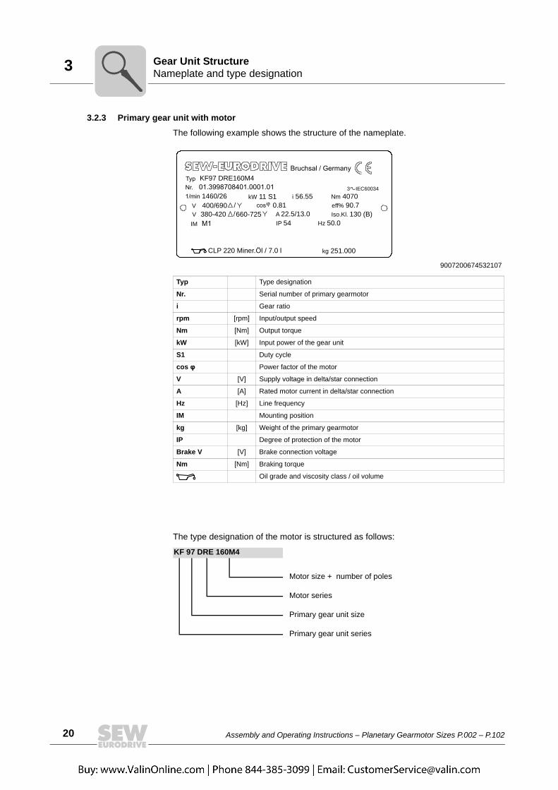
The following example shows the structure of the nameplate.
The type designation of the motor is structured as follows:
9007200674532107
Typ Type designation
Nr. Serial number of primary gearmotor
i Gear ratio
rpm [rpm] Input/output speed
Nm [Nm] Output torque
kW [kW] Input power of the gear unit
S1 Duty cycle
cos φ Power factor of the motor
V [V] Supply voltage in delta/star connection
A [A] Rated motor current in delta/star connection
Hz [Hz] Line frequency
IM Mounting position
kg [kg] Weight of the primary gearmotor
IP Degree of protection of the motor
Brake V [V] Brake connection voltage
Nm [Nm] Braking torque
Oil grade and viscosity class / oil volume
KF 97 DRE 160M4
Motor size + number of poles
Motor series
Primary gear unit size
Primary gear unit series
1460/26400/690V380-420V 660-725
kW 11 S1 i 56.55 Nm 40700.81 eff% 90.7A 22.5/13.0
3 IEC60034
Iso.Kl. 130 (B)IP 54 Hz 50.0
kg 251.000CLP 220 Miner.Öl / 7.0 l
IM
KF97 DRE160M4

Assembly and Operating Instructions – Planetary Gearmotor Sizes P.002 – P.102 21
3Mounting positionGear Unit Structure
3.3 Mounting positionThe mounting position defines the spatial orientation of the gear unit housing and isdesignated M1..M6.
The mounting positions apply to planetary gear units with solid shafts and hollow shafts.
9007200282889611
M4
M2
M6
M6
M5
M3
M1
M4
M2
M1
M5
M3
P..RF..
P..KF..

22 Assembly and Operating Instructions – Planetary Gearmotor Sizes P.002 – P.102
3 Mounting position sheetsGear Unit Structure
3.4 Mounting position sheetsThe following table shows the symbols used in the mounting position sheets and whatthey mean:
Symbol Meaning
Breather plug
Oil level plug
Oil drain plug
Breather
Oil dipstick
Oil sight glass

Assembly and Operating Instructions – Planetary Gearmotor Sizes P.002 – P.102 23
3Mounting position sheetsGear Unit Structure
3.4.1 P..RF..

24 Assembly and Operating Instructions – Planetary Gearmotor Sizes P.002 – P.102
3 Mounting position sheetsGear Unit Structure
3.4.2 PF..RF..

Assembly and Operating Instructions – Planetary Gearmotor Sizes P.002 – P.102 25
3Mounting position sheetsGear Unit Structure
3.4.3 P..KF..

26 Assembly and Operating Instructions – Planetary Gearmotor Sizes P.002 – P.102
3 Mounting position sheetsGear Unit Structure
3.4.4 PF.KF..

Assembly and Operating Instructions – Planetary Gearmotor Sizes P.002 – P.102 27
3Mounting positions of primary gear unitsGear Unit Structure
3.5 Mounting positions of primary gear units
3.5.1 KF.. primary bevel gear unitsFor the primary bevel gear units KF.., positions 0, 90, 180 or 270 are fixed.
The position of the mounting flange on the A or B side is also defined.
To reduce the churning losses in the primary gear unit to a minimum, SEW-EURODRIVE recommends to choose one of the standard mounting positions displayedbelow.
INFORMATIONIn addition to the mounting position, the following information is specified for planetarygearmotors.
1043984907
A
B
INFORMATIONContact SEW-EURODRIVE in case of deviating mounting conditions.

28 Assembly and Operating Instructions – Planetary Gearmotor Sizes P.002 – P.102
3 Mounting positions of primary gear unitsGear Unit Structure
Key
M1 / M2 / M3 / M4 / M5 / M6 = Mounting positions of planetary gear units
0° / 90° / 180° / 270° = Mounting positions of primary bevel gear units
A / B = Position of the mounting flange at the primary bevel gear unit
1) Example position; the position of the piping deviates from the figure.
M6
0° A 270° B
90° A 180° A
M4
0° A 270° A
90° A 180° A
M3
0° B 270° A
90° A 180° A
M5
0° A 270° A
90° B 180° A
M1
0° A 270° A
90° A 180° B
M2
0° A 270° A
90° A 180° A

Assembly and Operating Instructions – Planetary Gearmotor Sizes P.002 – P.102 29
3Mounting positions of primary gear unitsGear Unit Structure
3.5.2 RF.. primary helical gear unitsFor the primary helical gear units RF.., positions 0, 90, 180 or 270 are fixed.
To reduce the churning losses in the primary gear unit to a minimum, SEW-EURODRIVE recommends to choose one of the standard mounting positions shownbelow.
INFORMATIONContact SEW-EURODRIVE in case of deviating mounting conditions.
1043719691
Key
M1 / M2 / M3 / M4 / M5 / M6 = Mounting positions of planetary gear units
0° / 90° / 180° / 270° = Mounting position of primary helical gear unit
M1 0° M2 0°
M6 90° M5 270°
M4 0° M3 180°

30 Assembly and Operating Instructions – Planetary Gearmotor Sizes P.002 – P.102
3 Pivoted and variable mounting positionsGear Unit Structure
3.6 Pivoted and variable mounting positionsMounting positions other than standard mounting positions are referred to as pivoted orvariable mounting positions.
Gear units with pivoted mounting position have a fixed mounting position that differsfrom the standard.
Gear units with variable mounting position can change the mounting position variablyduring operation within the specified range.
The designation of pivoted and variable mounting positions is set up as follows:
The following figure shows some examples:
[1] Initial mounting position [3] Pivoting angle
[2] Required mounting position
[4] F = Fixed final position; V = Variable final position
M1 - M2/20°/V
[1] [2] [3] [4]
1002784267
20°
M5
M1M1 – M5 / 20°
20°
30° 30°
M6
M1 – M6 / 20°
M1
M1 – M4 / 30°
M2M4
M1 – M2 / 30°

Assembly and Operating Instructions – Planetary Gearmotor Sizes P.002 – P.102 31
3Pivoted and variable mounting positionsGear Unit Structure
All final positions have to be specified if the mounting position of the gear unit deviatesfrom standard mounting positions in several directions. Fixed and variable final positionscan be combined.
Example of a gear unit based on M1 that is tilted by ±20° around the drive shaft duringoperation and is mounted in a fixed angle of 30° around the longitudinal axis:
M1 - M2/20°/V - M4/20°/V - M5/30°/F
INFORMATIONPivoted and variable mounting positions might involve restrictions concerningaccessories and technical data. Also, delivery times might be longer. Consult SEW-EURODRIVE

32 Assembly and Operating Instructions – Planetary Gearmotor Sizes P.002 – P.102
3 Coating and surface protection systemsGear Unit Structure
3.7 Coating and surface protection systemsThe following table gives an overview of coating and surface protection systems.
SEW design OS 1Low environmental impact
OS 2Medium environmental impact
OS 3High environmental impact
Used as surface protection with typical ambient conditions Corrosion categories DIN EN ISO 12944-2
Suited for environments prone to condensation and atmospheres with low humidity or contamina-tion, such as outdoor applications under roof or with protection, unheated buildings where conden-sation can build up.According to corrosivity category: C2 (low)
Suited for environments with high humidity or moderate atmo-spheric contamination, such as applications outdoors subject to direct weathering.According to corrosivity category: C3 (moderate)
Suited for environments with high humidity and occasionally severe atmospheric and chemical con-tamination. Occasionally acidic or caustic wet cleaning. Also for applications in coastal areas with moderate salt load.According to corrosivity category: C4 (high)
Sample applications • Systems in saw mills• Agitators and mixers
• Applications in gravel plants• Cable cars
• Port cranes• Sewage treatment plants• Mining applications
Condensation testISO 6270 120 h 120 h 240 h
Salt spray test ISO 7253 – 240 h 480 h
Top coat color1) RAL 7031 RAL 7031 RAL 7031
Color according to RAL Yes Yes Yes
Uncoated parts, shaft end/flanges Water and hand perspiration repelling anticorrosion agent applied at the factory for external preservation.
1) Standard color
INFORMATIONSheet metal parts (e.g. protection covers, fan guard) are painted in RAL 1003.

Assembly and Operating Instructions – Planetary Gearmotor Sizes P.002 – P.102 33
3Types of lubricationGear Unit Structure
3.8 Types of lubricationDepending on the mounting position of the planetary gear unit, two different standardlubrication variants are possible.
3.8.1 Splash lubrication for horizontal mounting positions: M1 / M3 / M5 / M6The gear unit is half filled with oil. Gearing and bearing parts that are not immersed inthe oil bath are lubricated by splashing oil. The oil level is checked at the oil sight glasson the housing gear rim. The oil drain plug [2] can be replaced with an oil drain valve asan option. Oil is filled in via the breather valve [3].
4412712587
[3]
[1]
[2]
34 Assembly and Operating Instructions – Planetary Gearmotor Sizes P.002 – P.102
3 Types of lubricationGear Unit Structure
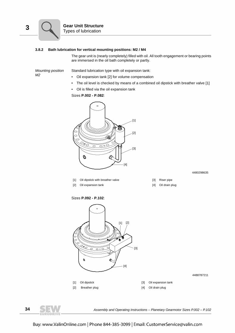
3.8.2 Bath lubrication for vertical mounting positions: M2 / M4
The gear unit is (nearly completely) filled with oil. All tooth engagement or bearing pointsare immersed in the oil bath completely or partly.
Mounting position M2
Standard lubrication type with oil expansion tank:
• Oil expansion tank [2] for volume compensation
• The oil level is checked by means of a combined oil dipstick with breather valve [1]
• Oil is filled via the oil expansion tank
Sizes P.002 - P.082:
Sizes P.092 - P.102:
4480298635
[1] Oil dipstick with breather valve [3] Riser pipe
[2] Oil expansion tank [4] Oil drain plug
4488787211
[1] Oil dipstick [3] Oil expansion tank
[2] Breather plug [4] Oil drain plug
[1]
[3]
[2]
[4]
[1] [2]
[3]
[4]

Assembly and Operating Instructions – Planetary Gearmotor Sizes P.002 – P.102 35
3Types of lubricationGear Unit Structure
Mounting position M4
Standard lubrication type without oil expansion tank:
• Oil level is checked using an oil dipstick.
• Separate breather valve
• Oil is filled in via the riser pipe
4490284299
[1] Breather valve [3] Riser pipe
[2] Oil dipstick [4] Oil drain plug
[4]
[3]
[2]
[1]
36 Assembly and Operating Instructions – Planetary Gearmotor Sizes P.002 – P.102
4 Components on the input sideDesign of Options and Accessories
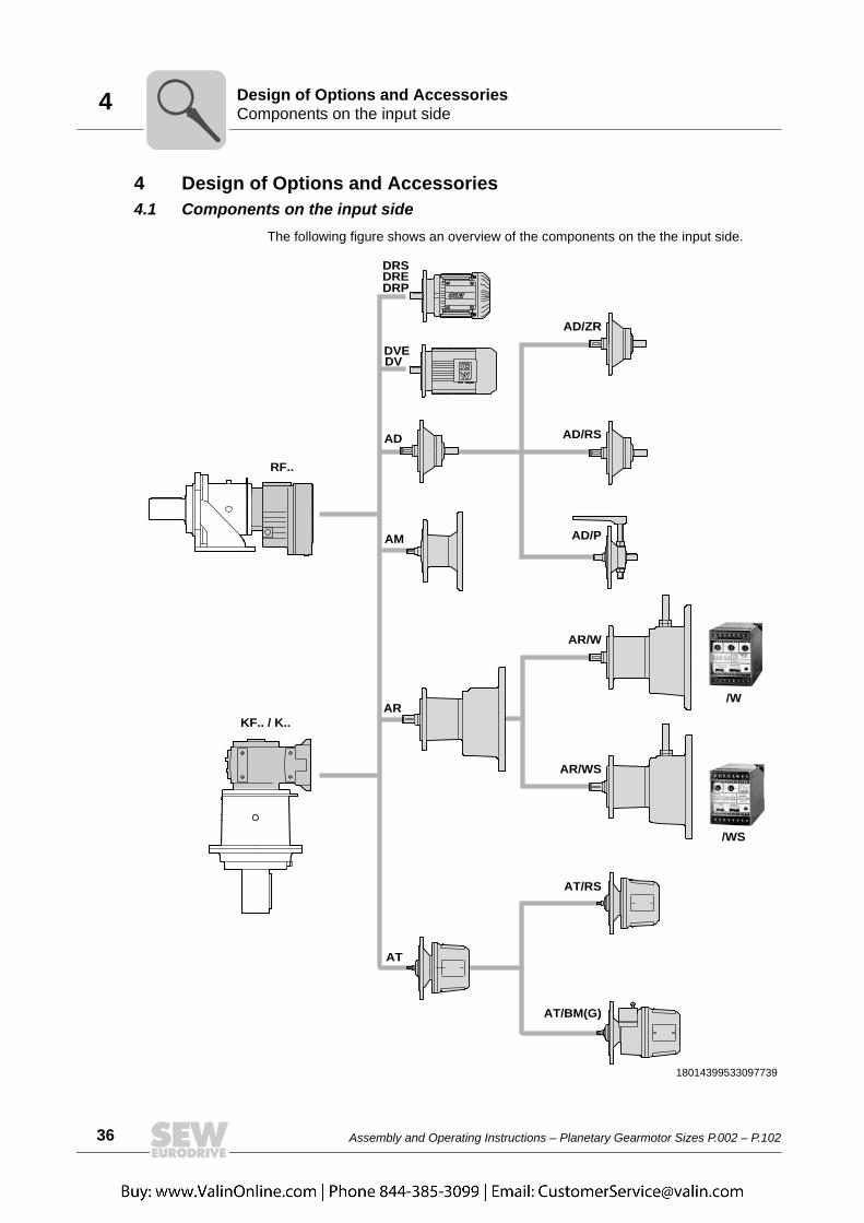
4 Design of Options and Accessories4.1 Components on the input side
The following figure shows an overview of the components on the the input side.
18014399533097739
AT/BM(G)
AT
AT/RS
AR
AR/W
AR/WS
AM
RF..
KF.. / K..
AD/P
AD/ZR
DV
DRE
AD/RS
/W
/WS
AD
DRS
DRP
DVE

Assembly and Operating Instructions – Planetary Gearmotor Sizes P.002 – P.102 37
4Torque armDesign of Options and Accessories
4.2 Torque armA torque arm is available to support the reaction torque of solid and hollow shaft gearunits in the shaft-mounted version.
Depending on the direction of the load and the type of the load carrying point on site, thereaction force either results in tensile force or pressure force depending on the reactiontorque.
4.2.1 Single-sided torque armThe torque arm is enclosed in the delivery or can be mounted according to customerrequirements. The retaining screws are included in the scope of delivery.
The following figure shows a sample combination of a planetary gearmotor with a torquearm on one side.
4.3 PT100 temperature sensorThe temperature sensor PT100 can be used to measure the temperature of the oil in thegear unit.
The temperature sensor is located in the gear unit's oil sump. The exact positiondepends on the gear unit variant.
1138611211
38 Assembly and Operating Instructions – Planetary Gearmotor Sizes P.002 – P.102
4 Oil drainDesign of Options and Accessories
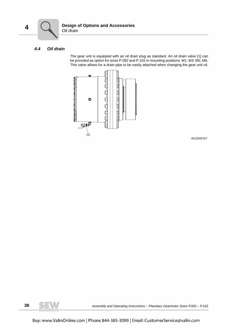
4.4 Oil drainThe gear unit is equipped with an oil drain plug as standard. An oil drain valve [1] canbe provided as option for sizes P.092 and P.102 in mounting positions M1; M3; M5; M6.This valve allows for a drain pipe to be easily attached when changing the gear unit oil.
4510205707[1]

Assembly and Operating Instructions – Planetary Gearmotor Sizes P.002 – P.102 39
5Required tools/resourcesInstallation/Assembly
5 Installation/Assembly5.1 Required tools/resources
Not included in the scope of delivery:
• Set of wrenches
• Torque wrench
• Mounting device
• Compensation elements (shims, spacing rings)
• Fasteners for input and output elements
• Lubricant (e.g. NOCO® fluid from SEW-EURODRIVE) → except for hollow shaft gearunits
• For hollow shaft gear units → aids for assembly/disassembly onto the machine shaft
• Fastening parts for the gear unit base
5.2 Tolerances5.2.1 Planetary gear units P..Shaft ends Diameter tolerance in accordance with DIN 748:
Center bores:
Mounting flange Centering shoulder tolerance: ISO f8
5.2.2 Primary gear units RF.. / KF.. / K..Shaft ends Diameter tolerance in accordance with DIN 748:
Center bores to DIN 332 D:
Keys according to DIN 6885 (domed type)
Mounting flange Centering shoulder tolerance: ISO f7
Ø > 50 mm → ISO m6
Ø 120…210 mm → M20Ø 240…290 mm → M24
Ø ≤ 50 mm → ISO k6Ø > 50 mm → ISO m6
Ø > 85...130 mm → M24Ø > 130...180 mm1)
1) Dimensions not according to DIN 332; the thread depth including the counterbore is at least twice that ofthe nominal thread diameter
→ M30

40 Assembly and Operating Instructions – Planetary Gearmotor Sizes P.002 – P.102
5 Notes on installation/mountingInstallation/Assembly
5.3 Notes on installation/mounting
WARNINGRisk of crushing if the drive starts up unintentionally.
Severe or fatal injuries.• De-energize the motor before you start working on the unit.• Secure the motor against unintended power-up.
WARNINGA customer machine that is not appropriately secured can fall during gear unit instal-lation or removal.
Severe or fatal injuries.• Safeguard the customer machine against unintentional movement when installing
or removing the gear unit.
WARNINGDanger of burns due to hot gear unit and hot gear unit oil.
Serious injury.• Let the gear unit cool down before you start working on it.• Carefully remove the oil level plug and oil drain plug.
CAUTIONDanger due to unsecured mount-on components, e.g. keys.
Minor injuries• Install appropriate protective devices.
CAUTIONRisk of slipping due to lubricant leaking from damaged seals.
Minor injuries• Check the gear unit and mount-on components for leaking lubricant.
CAUTIONRisk of injury due to protruding parts.
Minor injuries• Gear units and mount-on components must not protrude into footways.
NOTICEStarting up the gear unit below the permitted minimum temperature may damage theunit.
Possible damage to property.• Before startup, the oil must be heated up to the specified temperature.

Assembly and Operating Instructions – Planetary Gearmotor Sizes P.002 – P.102 41
5Notes on installation/mountingInstallation/Assembly
• Strictly observe the safety notes in the individual chapters.
• Planetary gear units are delivered without oil fill as standard.
• Primary gear units RF.. / KF.. /K have a lubricant fill in accordance with their mountingposition.
• The oil chambers of both gear units are separate. Exceptions are specifically identi-fied as such.
• The most important technical data is provided on the nameplate. Additional datarelevant for operation is available in drawings, the order confirmation or any order-specific documentation.
• The mounting position may only be changed after consultation with SEW-EURODRIVE. The warranty will become void without prior consultation.
Oil expansion tanks and/or an oil riser pipe are required if you change to a verticalmounting position. Adjust the lubricant fill quantity and the position of the breathervalve accordingly.
• Install/mount the gear unit only in the specified mounting position on a level, vibra-tion-damping, and torsionally rigid support structure. Do not twist housing legs andmounting flanges against each other.
• Work on the gear unit only when the machine is not in use. Secure the drive unitagainst unintentional power-up. Place an information sign near the ON switch towarn that the gear unit is being worked on.
• The plugs for checking and draining oil and the breather plug must be freely acces-sible.
• Use plastic inserts (2 to 3 mm thick) if there is a risk of electrochemical corrosionbetween the gear unit and the driven machine (connection between different metalssuch as cast iron and high-grade steel). Also fit the bolts with plastic washers. Alwaysground the gear unit housing.
• It is important that only authorized personnel is allowed to assemble gear head unitswith motors and adapters. Consult SEW-EURODRIVE.
• Do not weld anywhere on the drive. Do not use the drive as a ground point for weldingwork. Welding may destroy gearing parts and bearings.
• Protect rotating drive parts, such as couplings, gears, or belt drives using suitabledevices that protect from contact.
• Units installed outdoors must be protected from the sun. Suitable protective devicesare required, such as covers or roofs. When using protective devices, avoid heataccumulation. The operator must ensure that foreign objects do not impair the func-tion of the gear unit (e.g. falling objects or coverings).
• Protect the gear unit from direct cold air currents. Condensation may cause water toaccumulate in the oil.
• With standard mounting positions, the breather plug on planetary gear units ismounted at the factory and activated if the gear unit is supplied without oil fill. Checkthat the breather plug is mounted correctly and functions properly.
NOTICEImproper installation and mounting may result in damage to the gear unit.
Possible damage to property.
Note the following:

42 Assembly and Operating Instructions – Planetary Gearmotor Sizes P.002 – P.102
5 Installation requirementsInstallation/Assembly
• For planetary gear units that get their oil fill already at the factory, check whether thebreather plug is installed before you start up the gear unit.
• Gear units are supplied with a coating suitable for use in damp areas or in the openair. Repair any damage to the paint work (e.g. on the breather).
5.4 Installation requirementsCheck that the following conditions have been met:
• The information on the motor's nameplate must match the voltage supply system.
• The drive has not been damaged during transportation or storage.
• The ambient temperature matches the information in the order documents.
• No harmful oils, acids, gases, vapors, radiation etc. in the vicinity
• You must clean the output shafts and flange surfaces thoroughly to ensure they arefree of anti-corrosion agents, contamination or similar. Use a commercially availablesolvent. Do not expose the sealing lips of the oil seals to the solvent – damage to thematerial.
5.4.1 Extended storageNote: The service life of the lubricant in the bearings is reduced if the unit is stored for≥ 1 year (applies only to bearings with grease lubrication).
Replace the breather plug with the screw plug.

Assembly and Operating Instructions – Planetary Gearmotor Sizes P.002 – P.102 43
5Planetary gear units delivered without oil fill (standard)Installation/Assembly
5.5 Planetary gear units delivered without oil fill (standard)Planetary gear units are delivered without oil fill as standard. Note the following:
• Fill in the oil only when the gear unit is in the intended mounting position.
• Make sure that the oil has room temperature when filling the gear unit.
• Observe the additional notes depending on the lubrication type in the followingchapters.
• The oil grade and quantity must correspond to the data on the nameplate and theinformation in chapter "Changing the oil" (page 83).
• Check the oil level using the oil level glass, oil dipstick, or oil sight glass. Refer tochapter "Checking the oil level" (page 81) for more information.
WARNINGRisk of crushing if the drive starts up unintentionally.
Severe or fatal injuries.• De-energize the motor before you start working on the unit.• Secure the motor against unintended power-up.
NOTICEImproper oil filling may cause damage to the gear unit.
Possible damage to property.• Note the following:

44 Assembly and Operating Instructions – Planetary Gearmotor Sizes P.002 – P.102
5 Planetary gear units delivered with oil fill (option)Installation/Assembly
5.6 Planetary gear units delivered with oil fill (option)If the planetary gear unit is delivered with oil fill, the breather plug must be installed priorto startup. The breather plug is enclosed with the delivery.
The following illustration serves as an example. The position of the breather plug isspecified in the order documents.
1. Remove the closing plug.
2. Insert the breather plug [1].
3. Check the oil level. Refer to the chapter "Checking the oil level" (page 81).
4247802123
[1]
Assembly and Operating Instructions – Planetary Gearmotor Sizes P.002 – P.102 45
5Installing the gear unitInstallation/Assembly
5.7 Installing the gear unit5.7.1 Foot-mounted gear units
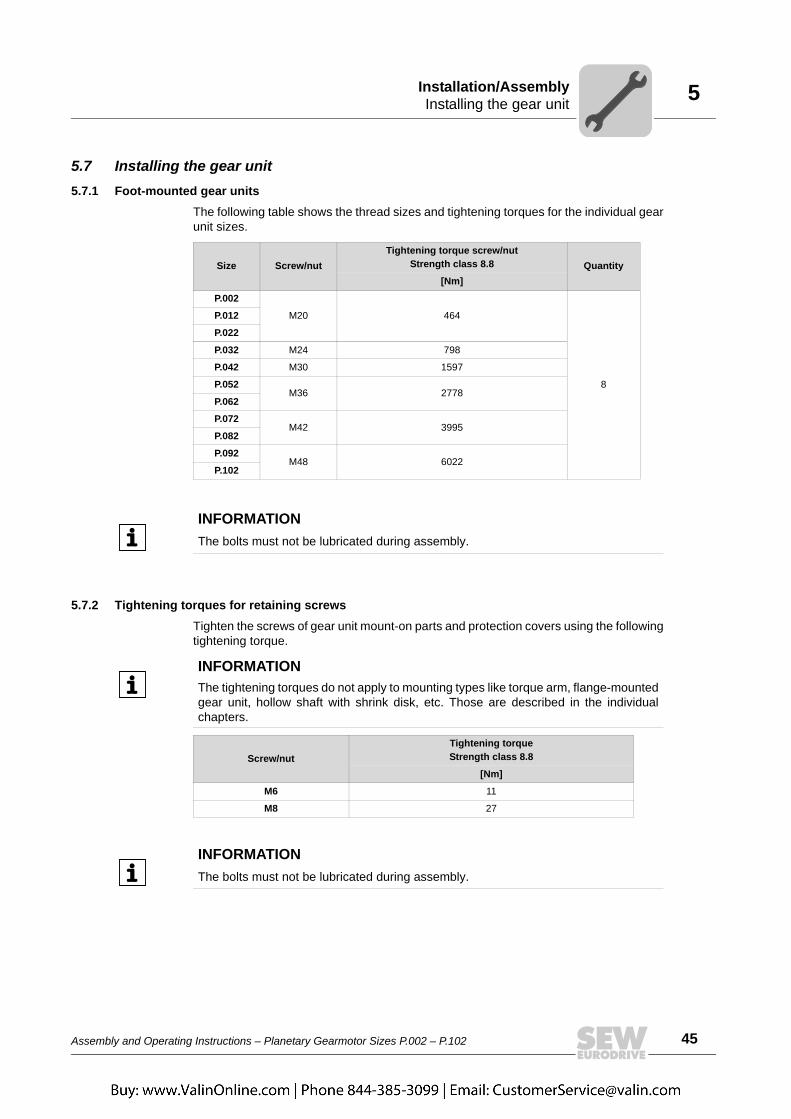
The following table shows the thread sizes and tightening torques for the individual gearunit sizes.
5.7.2 Tightening torques for retaining screwsTighten the screws of gear unit mount-on parts and protection covers using the followingtightening torque.
Size Screw/nutTightening torque screw/nut
Strength class 8.8 Quantity[Nm]
P.002
M20 464
8
P.012
P.022
P.032 M24 798
P.042 M30 1597
P.052M36 2778
P.062
P.072M42 3995
P.082
P.092M48 6022
P.102
INFORMATIONThe bolts must not be lubricated during assembly.
INFORMATIONThe tightening torques do not apply to mounting types like torque arm, flange-mountedgear unit, hollow shaft with shrink disk, etc. Those are described in the individualchapters.
Screw/nutTightening torque Strength class 8.8
[Nm]
M6 11
M8 27
INFORMATIONThe bolts must not be lubricated during assembly.
46 Assembly and Operating Instructions – Planetary Gearmotor Sizes P.002 – P.102
5 Installing the gear unitInstallation/Assembly
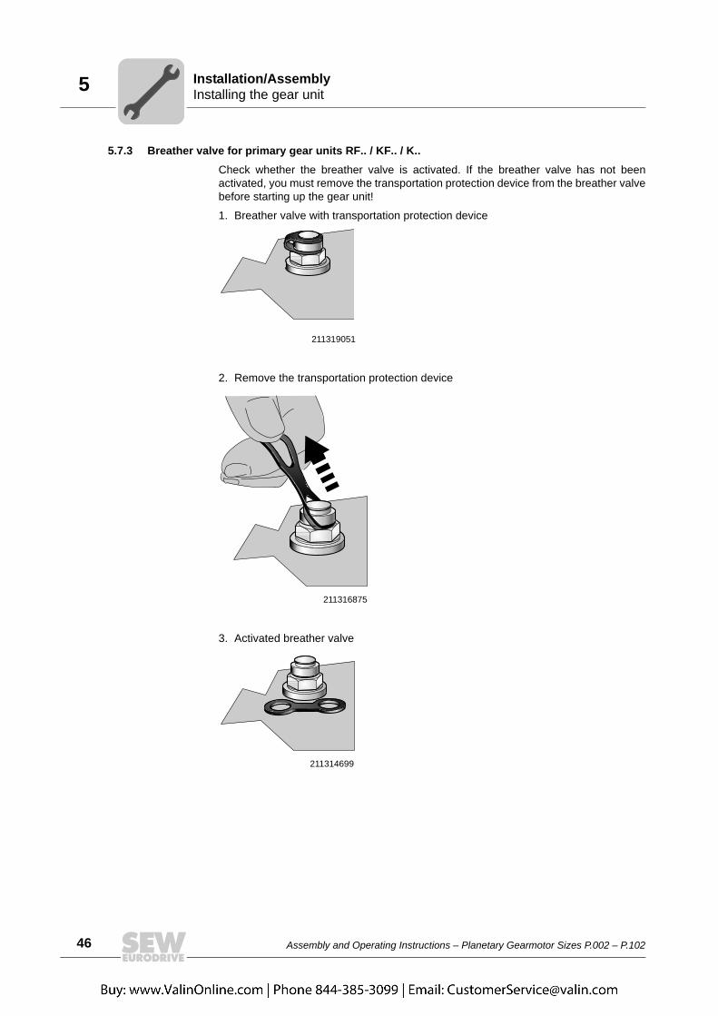
5.7.3 Breather valve for primary gear units RF.. / KF.. / K..Check whether the breather valve is activated. If the breather valve has not beenactivated, you must remove the transportation protection device from the breather valvebefore starting up the gear unit!
1. Breather valve with transportation protection device
2. Remove the transportation protection device
3. Activated breather valve
211319051
211316875
211314699

Assembly and Operating Instructions – Planetary Gearmotor Sizes P.002 – P.102 47
5Installing the gear unitInstallation/Assembly
5.7.4 Foot-mounted gear unit with primary gear unit RF.. / KF.. / K..
With the following combinations of foot-mounted planetary gear units with primary gearunits RF.. / KF.. / K.., the primary gear unit might protrude under the mounting surface.
The following figure shows a planetary gear unit with RF. primary gear unit.
INFORMATIONFor the following gear unit combinations, take account of dimension A. The customerbase construction must be prepared accordingly.
In addition, you need enough room to perform an oil change. The customer has tospecify a dimension B for this purpose.
Size/combinations Dimension A[mm]RF.. KF.. / K..
P.002 - 97 10
P.012 - 107 32.5
P.022 - 107 2.5
P.022 137 - 7.5
P.032 147 - 18.5
P.092 - 187 15
3319218827
A B

48 Assembly and Operating Instructions – Planetary Gearmotor Sizes P.002 – P.102
5 Installing the gear unitInstallation/Assembly
5.7.5 Foundation
To ensure quick and successful mounting, the type of foundation should be correctlyselected and the mounting carefully planned in advance. Foundation drawings with allnecessary construction and dimension details should be available.
To avoid harmful vibrations and oscillations, adequate rigidity must be ensured whenmounting the gear unit on a steel construction. The foundation must be dimensionedaccording to weight and torque of the gear unit by taking into account the forces actingon the gear unit.
Tighten retaining screws or nuts to the specified torque. Use the screws and tighteningtorques specified in chapter "Gear unit mounting" (page 45).
5.7.6 Aligning the shaft axis
The service life of the shafts, bearings and couplings depends on the precision of thealignment of the shaft axes with each other.
Always try to achieve zero misalignment. When doing so, you should also consult thespecial operating instructions regarding the requirements of the couplings, for example.
NOTICEAn improper foundation may result in damage to the gear unit.
Possible damage to property.• The foundation must be level and flat; the gear unit may not be deformed when the
retaining screws are tightened. Unevenness must be leveled out appropriately.• Observe the weight specified on the nameplate.
WARNINGShafts can break if shaft axes are not aligned exactly.
Severe or fatal injuries.• Refer to the separate operation instructions regarding the requirements of the
couplings.

Assembly and Operating Instructions – Planetary Gearmotor Sizes P.002 – P.102 49
5Gear unit with solid shaftInstallation/Assembly
5.8 Gear unit with solid shaft5.8.1 Assembling the input and output components
Assembly with mounting device
The following figure shows a mounting device for installing couplings or hubs on gearunit or motor shaft ends. Should you be able to tighten the screw without any problems,you may not need the thrust bearing on the mounting device.
NOTICEBearing, hosing or shaft may be damaged due to improper assembly.
Possible damage to property.• Only use a mounting device for installing input and output elements. Use the center
bore and the thread on the shaft end for positioning.• Never force belt pulleys, couplings, pinions, etc. onto the shaft end by hitting them
with a hammer. This may damage the bearing, the housing and the shaft.• If belt pulleys are used, make sure the belt is tensioned correctly in accordance with
the manufacturer's instructions.
211368587
[1] Gear unit shaft end[2] Thrust bearing[3] Coupling hub
[1]
[3]
[2]

50 Assembly and Operating Instructions – Planetary Gearmotor Sizes P.002 – P.102
5 Gear unit with solid shaftInstallation/Assembly
Avoid excessive overhung loads
Avoid high overhung loads by: Installing the gear or chain sprocket according to figureA if possible.
1055550219
[1] Hub[A] Correct[B] Wrong
X1
FX1
X1
[1]
[1]
[B]
[A]
FX1
INFORMATIONMounting is easier if you first apply lubricant to the output element and/or heat it upbriefly (to 80 ... 140 ˚C).
Assembly and Operating Instructions – Planetary Gearmotor Sizes P.002 – P.102 51
5CouplingsInstallation/Assembly
5.9 Couplings
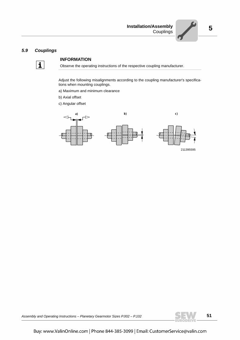
Adjust the following misalignments according to the coupling manufacturer's specifica-tions when mounting couplings.
a) Maximum and minimum clearance
b) Axial offset
c) Angular offset
INFORMATIONObserve the operating instructions of the respective coupling manufacturer.
211395595
a) b) c)
52 Assembly and Operating Instructions – Planetary Gearmotor Sizes P.002 – P.102
5 AM adapter couplingInstallation/Assembly
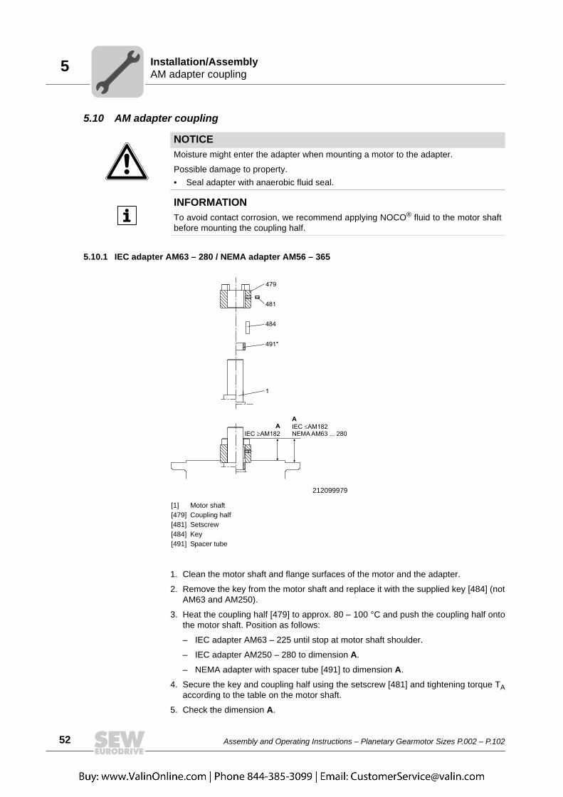
5.10 AM adapter coupling
5.10.1 IEC adapter AM63 – 280 / NEMA adapter AM56 – 365
1. Clean the motor shaft and flange surfaces of the motor and the adapter.
2. Remove the key from the motor shaft and replace it with the supplied key [484] (notAM63 and AM250).
3. Heat the coupling half [479] to approx. 80 – 100 °C and push the coupling half ontothe motor shaft. Position as follows:
– IEC adapter AM63 – 225 until stop at motor shaft shoulder.
– IEC adapter AM250 – 280 to dimension A.
– NEMA adapter with spacer tube [491] to dimension A.
4. Secure the key and coupling half using the setscrew [481] and tightening torque TAaccording to the table on the motor shaft.
5. Check the dimension A.
NOTICEMoisture might enter the adapter when mounting a motor to the adapter.
Possible damage to property.• Seal adapter with anaerobic fluid seal.
INFORMATIONTo avoid contact corrosion, we recommend applying NOCO® fluid to the motor shaftbefore mounting the coupling half.
212099979
[1] Motor shaft[479] Coupling half[481] Setscrew[484] Key[491] Spacer tube

Assembly and Operating Instructions – Planetary Gearmotor Sizes P.002 – P.102 53
5AM adapter couplingInstallation/Assembly
6. Seal the contact surfaces between the adapter and motor using a suitable sealingcompound.
7. Mount the motor on the adapter. Ensure that the coupling claws of the adapter shaftare engaged in the plastic cam ring.
Permitted loads
IEC AM 63 / 71 80 / 90 100 / 112 132 160 / 180 200 225 250 / 280A 24.5 31.5 41.5 54 76 78.5 93.5 139TA 1.5 1.5 4.8 4.8 10 17 17 17Thread M4 M4 M6 M6 M8 M10 M10 M10NEMA AM 56 143 / 145 182 / 184 213 / 215 254 / 256 284 / 286 324 / 326 364 / 365A 46 43 55 63.5 78.5 85.5 107 107TA 1.5 1.5 4.8 4.8 10 17 17 17Thread M4 M4 M6 M6 M8 M10 M10 M10
NOTICEImpermissibly high loads may occur when mounting a motor.
Potential damage to property• The load data specified in the following table are not to be exceeded.
Adapter type Fq1) [N]
IEC NEMA x1) [mm] IEC adapter NEMA adapter
AM63/71 AM56 77 530 410
AM80/90 AM143/145 113 420 380
AM100/112 AM182/184 144 2000 1760
AM1322) AM213/21522)186
1600 1250
AM132.. AM213/215 4700 3690
AM160/180 AM254/286 251 4600 4340
AM200/225 AM324-AM365 297 5600 5250
AM250/280 - 390 11200 -
1) The maximum permitted weight of the attached motor Fqmax must be reduced linearly as the center of gravity distance x increases. If this distance is reduced, the maximum permitted weight Fqmax cannot be increased.
2) Diameter of the adapter output flange: 160 mm
X
Fq

54 Assembly and Operating Instructions – Planetary Gearmotor Sizes P.002 – P.102
5 AM adapter couplingInstallation/Assembly
AM adapter with AM../RS backstop
Check the direction of rotation of the drive prior to assembly or startup. Inform the SEW-EURODRIVE service in the case of incorrect direction of rotation.
The backstop is maintenance-free in operation, and does not require any further main-tenance work. Backstops have a minimum lift-off speed depending on the size (seefollowing table).
.
NOTICEIf the actual speed level is below the minimum lift-off speed level, the backstops aresubject to wear, and the resulting friction causes the temperature to increase.
Possible damage to property• In rated operation, the lift-off speeds must not drop below the minimum values. • During startup or braking, the lift-off speeds may drop below the minimum levels.
Type Maximum locking torque of the backstop[Nm]
Minimum lift-off speedrpm
AM80/90/RS,AM143/145/RS 45 800
AM100/112/RS,AM182/184/RS 200 670
AM132/RS,AM213/215/RS 470 660
AM160/180/RS,AM254/286/RS 630 550
AM200/225/RS, AM324-365/RS 1430 600

Assembly and Operating Instructions – Planetary Gearmotor Sizes P.002 – P.102 55
5AD input shaft assemblyInstallation/Assembly
5.11 AD input shaft assemblyObserve chapter "Mounting the input and output elements" (see chapter 5.6) whenmounting input elements.
5.11.1 Cover with motor mounting platform AD.. / PMounting the motor and adjusting the motor mounting platform.
1. Set the motor mounting platform to the required mounting position by evenly tighten-ing the adjusting nuts. Remove the lifting eyebolt from helical gear units to achievethe lowest adjustment position. Touch up any damage to the paint work.
2. Align the motor on the motor mounting platform (shaft ends must be in alignment)and secure it.
3. Mount the input elements on the input shaft end and the motor shaft, line them upwith one another and correct the motor position again, if necessary.
4. Put on the traction elements (V-belt, chain, etc.) and apply a preload by evenly ad-justing the motor mounting platform. Do not stress the motor mounting platform andthe columns against each other when doing this.
5. Tighten all the nuts not used for adjustment in order to fix the threaded columns.
212119307
[1] Motor mounting platform[2] Stud bolt (only AD6/P / AD7/P)[3] Support (only AD6/P / AD7/P)
[4] Nut[5] Threaded column

56 Assembly and Operating Instructions – Planetary Gearmotor Sizes P.002 – P.102
5 AD input shaft assemblyInstallation/Assembly
5.11.2 Only AD6/P and AD7/P
Unscrew the nuts on the stud bolts before adjustment to allow the stud bolts to moveaxially in the support without restriction. Do not tighten the nuts until the final adjustmentposition has been reached. Do not adjust the motor mounting platform using the support.
5.11.3 Input shaft assembly with centering shoulder AD.. / ZRMounting applications on the input shaft assembly with centering shoulder.
1. Retaining bolts of a suitable length must be used to secure the application. Thelength l of the new bolts is calculated as follows:
Round down the calculated screw length to the next smallest standard length. 2. Remove the retaining screws from the centering shoulder.
3. Clean the contact surface and the centering shoulder.
4. Clean the threads of the new bolts and apply a bolt locking compound (e.g. Loctite®
243) to the first few threads.
5. Attach the application to the centering shoulder and tighten the retaining screws withthe specified tightening torque TA (see table).
212121483
[l] t+a[t] Screw-in depth (see table)[a] Thickness of the application[s] Retaining thread (see table)
Type Screw-in depth t [mm]
Retaining thread s
Tightening torque TA for connection screws of strength class
8.8 [Nm]
AD2/ZR 25.5 M8 27
AD3/ZR 31.5 M10 54
AD4/ZR 36 M12 93
AD5/ZR 44 M12 93
AD6/ZR 48.5 M16 230
AD7/ZR 49 M20 464
AD8/ZR 42 M12 93

Assembly and Operating Instructions – Planetary Gearmotor Sizes P.002 – P.102 57
5AD input shaft assemblyInstallation/Assembly
Permitted loads
NOTICEImpermissibly high loads may occur when mounting a motor.
Potential damage to property• The load data specified in the following table are not to be exceeded.
1178977035
Type x1)
[mm]Fq
1)
[N]
AD2/ZR 193 330
AD3/ZR 274 1400
AD4/ZR2)361
1120
AD4/ZR 3300
AD5/ZR 487 3200
AD6/ZR 567 3900
AD7/ZR 663 10000
AD8/ZR 516 4300
1) Maximum load values for connection screws of strength class 8.8. The maximum permitted weight of the attached motor Fqmax must be reduced linearly as the center of gravity distance x increases. When this distance is reduced, Fqmax cannot be increased.
2) Diameter of the adapter output flange: 160 mm
x
Fq

58 Assembly and Operating Instructions – Planetary Gearmotor Sizes P.002 – P.102
5 AD input shaft assemblyInstallation/Assembly
5.11.4 Input shaft assembly with backstop AD.. /RS
Check the direction of rotation of the drive prior to assembly or startup. Inform the SEW-EURODRIVE service in the case of incorrect direction of rotation.
The backstop is maintenance-free in operation, and does not require any further main-tenance work. Backstops have a minimum lift-off speed depending on the size (seefollowing table).
NOTICEIf the actual speed level is below the minimum lift-off speed level, the backstops aresubject to wear, and the resulting friction causes the temperature to increase.
Possible damage to property• In rated operation, the lift-off speeds must not drop below the minimum values. • During startup or braking, the lift-off speeds may drop below the minimum levels.
Type Maximum locking torque of the backstop[Nm]
Minimum lift-off speedrpm
AD2/RS 45 800
AD3/RS 200 670
AD4/RS 470 660
AD5/RS 630 550
AD6/RS 1430 600
AD7/RS 1430 600
AD8/RS 1430 600
Assembly and Operating Instructions – Planetary Gearmotor Sizes P.002 – P.102 59
5Flange-mounted gear unitsInstallation/Assembly
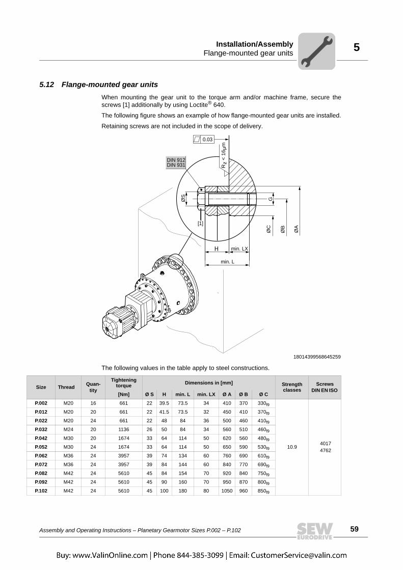
5.12 Flange-mounted gear unitsWhen mounting the gear unit to the torque arm and/or machine frame, secure thescrews [1] additionally by using Loctite® 640.
The following figure shows an example of how flange-mounted gear units are installed.
Retaining screws are not included in the scope of delivery.
The following values in the table apply to steel constructions.
18014399568645259
H
ØC
ØS
Rz
< 16
µm
ØB
ØA
G
0.03
DIN 912DIN 931
[1]
min. LX
min. L
Size Thread Quan-tity
Tightening torque Dimensions in [mm] Strength
classesScrews
DIN EN ISO [Nm] Ø S H min. L min. LX Ø A Ø B Ø C
P.002 M20 16 661 22 39.5 73.5 34 410 370 330f9
10.9 4017 4762
P.012 M20 20 661 22 41.5 73.5 32 450 410 370f9
P.022 M20 24 661 22 48 84 36 500 460 410f9
P.032 M24 20 1136 26 50 84 34 560 510 460f9
P.042 M30 20 1674 33 64 114 50 620 560 480f9
P.052 M30 24 1674 33 64 114 50 650 590 530f9
P.062 M36 24 3957 39 74 134 60 760 690 610f9
P.072 M36 24 3957 39 84 144 60 840 770 690f9
P.082 M42 24 5610 45 84 154 70 920 840 750f9
P.092 M42 24 5610 45 90 160 70 950 870 800f9
P.102 M42 24 5610 45 100 180 80 1050 960 850f9

60 Assembly and Operating Instructions – Planetary Gearmotor Sizes P.002 – P.102
5 Torque armInstallation/Assembly
5.13 Torque arm 5.13.1 Notes on installation
WARNINGInsufficiently secured gear units can fall down during disassembly and assembly.
Severe or fatal injuries.• Secure the gear unit during assembly and disassembly. Support the gear unit using
appropriate tools.
NOTICEDeforming the torque arm leads to constraining forces on the output shaft, which maynegatively influence the service life of the output shaft bearings.
Possible damage to property.• Do not deform the torque arm.
NOTICEStrain on the torque arm might break the housing.
Possible damage to property.• Adhere to the specified screw size, tightening torques and required screw strength.
INFORMATIONRetaining screws are included in the scope of delivery.

Assembly and Operating Instructions – Planetary Gearmotor Sizes P.002 – P.102 61
5Torque armInstallation/Assembly
5.13.2 Single-sided torque arm (standard)Installation on site Taking account of the order-specific design, the torque arm can be mounted in mounting
position 0°... 360°.
The reactive force resulting from the gear unit torque is absorbed via the torque arm withlever arm A. The figure on the next page shows an example of a customer fixture in awelded structure. Two supporting plates are welded on the machine design with thesuggested dimensions. Once the gear unit has been mounted, a connecting cover plateis welded onto the two supporting plates. The force of the gear unit torque acts on thesupport, divided by the length of the lever arm A. The reaction force also acts on the gearunit and machine shafts.
The following figure shows a sample mounting position and the combination of a plane-tary gear unit with torque arm.
4236822795
90°
270°
180°
0°

62 Assembly and Operating Instructions – Planetary Gearmotor Sizes P.002 – P.102
5 Torque armInstallation/Assembly
Dimensions The following figure shows a sample torque arm with dimensions.
Tightening torques
1143100811
TA
B
S X
O C
D5
D1
D2
SizeDimensions in [mm] Quantity Weight
A B C D1 D2 O S T X [Kg]
P.002 650 60 50 334 370 25 22 880 16 25
P.012 700 70 60 374 410 30 22 955 20 35
P.022 750 90 70 414 460 35 22 1035 24 48
P.032 800 110 90 464 510 35 26 1125 20 58
P.042 900 150 120 484 560 40 33 1270 20 93
P.052 1000 160 130 534 590 40 33 1390 24 102
P.062 1200 180 150 614 690 50 39 1655 24 183
P.072 1500 230 200 694 770 60 39 2020 24 317
P.082 1600 230 200 754 840 70 45 2160 24 420
P.092 1650 250 220 804 870 70 45 2235 24 440
P.102 1700 250 220 854 960 70 45 2335 24 510
Size Thread QuantityTightening torque
Strength classes DIN screws[Nm]
P.002 M20 16 661
10.9DIN EN ISO 4017DIN EN ISO 4762
P.012 M20 20 661
P.022 M20 24 661
P.032 M24 20 1136
P.042 M30 20 2274
P.052 M30 24 2274
P.062 M36 24 3957
P.072 M36 24 3957
P.082 M42 24 5610
P.092 M42 24 5610
P.102 M42 24 5610
Assembly and Operating Instructions – Planetary Gearmotor Sizes P.002 – P.102 63
5Output shaft as hollow shaft with shrink diskInstallation/Assembly
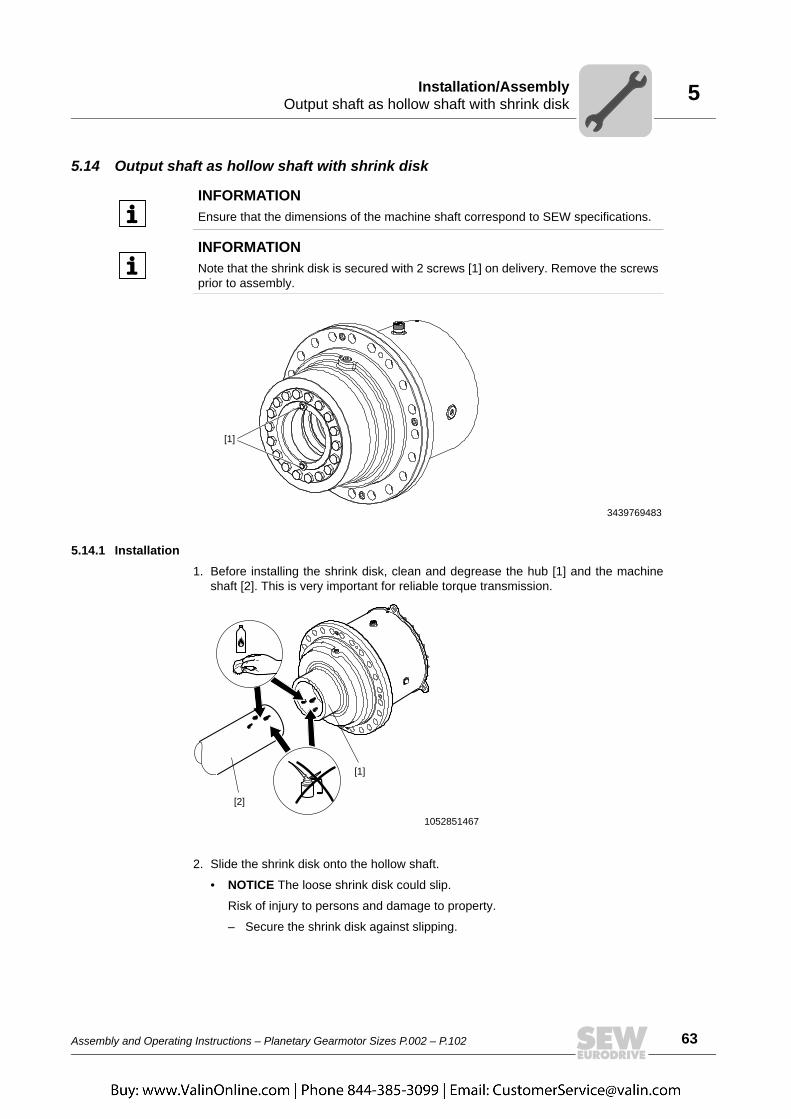
5.14 Output shaft as hollow shaft with shrink disk
5.14.1 Installation1. Before installing the shrink disk, clean and degrease the hub [1] and the machine
shaft [2]. This is very important for reliable torque transmission.
2. Slide the shrink disk onto the hollow shaft.
• NOTICE The loose shrink disk could slip.
Risk of injury to persons and damage to property.
– Secure the shrink disk against slipping.
INFORMATIONEnsure that the dimensions of the machine shaft correspond to SEW specifications.
INFORMATIONNote that the shrink disk is secured with 2 screws [1] on delivery. Remove the screwsprior to assembly.
3439769483
[1]
1052851467
[1]
[2]

64 Assembly and Operating Instructions – Planetary Gearmotor Sizes P.002 – P.102
5 Output shaft as hollow shaft with shrink diskInstallation/Assembly
3. Check the correct position of the shrink disk [3]. The shrink disk is positionedcorrectly when it is in contact with the shaft shoulder [8].
• NOTICE Tightening the screws [4] without installed shaft may result in the hollowshaft being deformed.
Possible damage to property.
– Never tighten the locking screws [4] without the shaft installed [2].
4. Install the machine shaft [2] or push the gear unit [5] on the machine shaft [2] untilthe stop. Carry out the individual installation steps slowly to allow the compressed airto escape around the outside of the shaft.
1053533067
1053536267
[1]
[3][4]
A
A
[8]
[2]
[5]

Assembly and Operating Instructions – Planetary Gearmotor Sizes P.002 – P.102 65
5Output shaft as hollow shaft with shrink diskInstallation/Assembly
5. Tighten the locking screws [4] manually first. Tighten all locking screws by workinground equally (not in diametrically opposite sequence) in 1/4 turn increments.
1053539467
1
2 1513
11
9
7
5316
1412
10
8
64
1
9 87
6
5
4
3216
1514
13
1211
10
[4]

66 Assembly and Operating Instructions – Planetary Gearmotor Sizes P.002 – P.102
5 Output shaft as hollow shaft with shrink diskInstallation/Assembly
6. Adhere to the tightening torque in the table below. Tighten the locking screws [4] bycontinuing to work round in 1/4 turns until you reach the tightening torque. Addition-ally, you can visually check to see that the front lateral surfaces are aligned to theinner [9] and outer rings [10].
Verify the type information on your shrink disk and choose the tightening torque.
1053543307
1
215
13
11
9
7
5
316
14
12
10
8
6
4
1
98
7
6
5
4
3
216
15
14
13
12
11
10
90°
[4]
[9]
[10]
Shrink disk type Size Screws Rated torque [Nm] Tightening torque [Nm] ± 20%
3191 P.002 M16 41000 250
3181
P.012 M16 75500 290
P.022 M16 95500 290
P.032 M20 134000 570
P.042 M20 194000 570
P.052 M20 255000 570
P.062 M24 405000 980
P.072 M24 525000 980
P.082 M24 720000 980
P.092 M27 906000 1450
P.102 M27 1320000 1450
INFORMATIONIf the taper (outer ring) and the taper bushing (inner ring) cannot be aligned on the facethat holds the screws, disassemble the shrink disk again and carefully clean/lubricateit as shown in the next chapter.

Assembly and Operating Instructions – Planetary Gearmotor Sizes P.002 – P.102 67
5Output shaft as hollow shaft with shrink diskInstallation/Assembly
NOTICEImproper assembly of the protection cover may result in risk of injury due to rotatingparts.
Risk of injury to persons and damage to property.• After assembly, check to see that the protection cover is properly attached.

68 Assembly and Operating Instructions – Planetary Gearmotor Sizes P.002 – P.102
5 Output shaft as hollow shaft with shrink diskInstallation/Assembly
5.14.2 Removal
1. Loosen the locking screws [4] by a quarter turn one after the other to avoid strainingthe connecting surface.
• INFORMATION If the bevel (outer ring) and the taper bushing (inner ring) [9b] donot separate by themselves:
Take the necessary number of retaining screws and screw them into the removalbores evenly. Tighten the retaining screws in several steps until the tapered bush-ing separates from the bevel ring.
NOTICEImproper disassembly may damage bearings and other components.
Possible damage to property.• You may only use the hollow shaft as a support for disassembly. Note that support-
ing on any other parts of the gear unit may damage the material.• Remove the shrink disk properly. Never completely unscrew the retaining screws
because the shrink disk might jump off and cause an injury.• Shrink disks and corresponding parts of different gear units must not be swapped.
1056915211
1
215
13
11
9
7
5
316
14
12
10
8
6
4
1
98
7
6
5
4
3
216
15
14
13
12
11
10
90°
[4]

Assembly and Operating Instructions – Planetary Gearmotor Sizes P.002 – P.102 69
5Output shaft as hollow shaft with shrink diskInstallation/Assembly
2. Remove the machine shaft [2] or pull the hub [1] off the customer shaft (first, removeany corrosion, which may have formed between the hub and the shaft end).
3. Remove the shrink disk [3] from the hub [1].
5.14.3 Cleaning and lubrication
• If the tapered surfaces of the shrink disk are damaged, the shrink disk can no longerbe used and must be replaced.
• Do not disassemble and regrease the removed shrink disk before installing it again.Clean the shrink disk only when it is contaminated.
• Next, regrease only the inner sliding surfaces of the shrink disk.
• Use a solid lubricant with a friction factor of µ = 0.04.
1056918411
[1] [3]
[2]
INFORMATIONYou must perform the following steps carefully to ensure proper functioning of theshrink disk. Use only products that are comparable to the specified lubricant.
Lubricant Sold as
Molykote 321 R (lube coat) Spray
Molykote spray (powder spray) Spray
Molykote G Rapid Spray or paste
Aemasol MO 19R Spray or paste
Molykombin UMFT 1 Spray
Unimoly P5 Powder

70 Assembly and Operating Instructions – Planetary Gearmotor Sizes P.002 – P.102
5 PT100 temperature sensorInstallation/Assembly
5.15 PT100 temperature sensor5.15.1 Dimensions
5.15.2 Electrical connection
5.15.3 Technical data• Design with thermometer pocket and changeable measuring insert
• Sensor tolerance [K] ± (0.3 + 0.005 x T), (corresponds to DIN IEC 751 class B),
T = Oil temperature [°C]
• Plug connector: DIN EN 175301-803 PG9 (IP65)
• The tightening torque for the retaining screw in the back of the plug connector forelectrical connection is 0.25 Nm.
359154443
24Ø
8150
G1/2"
35PG9, PG11
34
359158539
[1] [2] Resistor element connection
32 1

Assembly and Operating Instructions – Planetary Gearmotor Sizes P.002 – P.102 71
6Important notes on startupStartup
6 Startup6.1 Important notes on startup
• Primary gear units RF.. / KF.. / K.. are usually delivered without oil fill. Refer to theorder documents for discrepancies.
• Check the thermal rating/heating for the following operating conditions:
• High ambient temperatures (over 45 °C).
• Mounting position M2/M4 and/or motor speed above 1800 rpm.
Contact SEW-EURODRIVE.
• The most important technical data is provided on the nameplate. Additional datarelevant for operation is available in drawings, the order confirmation or any order-specific documentation.
• Before startup, check that the oil level is correct. Refer to the unit's nameplate forlubricant fill quantities.
• Once you have installed the gear unit, make sure all retaining screws are tightlysecured.
• Make sure that the orientation has not changed after tightening the mountingelements.
• It is essential that there is no open fire or risk of sparks when working on the gear unit.
• Ensure that rotating shafts as well as couplings are equipped with suitable protectivecovers.
• If there are any oil drain valves, ensure that they cannot be opened unintentionally.
• Protect the oil sight glass against damage.
• Protect the gear unit from falling objects.
• For gear units with long-term protection: Replace the screw plug at the locationindicated on the gear unit with a breather plug (position → see order documents).
• Before you start up the unit, make sure the monitoring devices are functioning.
• Strictly adhere to the safety notes in the individual chapters.
NOTICEImproper startup may result in damage to the gear unit.
Possible damage to property.
Note the following:
00
I
72 Assembly and Operating Instructions – Planetary Gearmotor Sizes P.002 – P.102
6 Run-in periodStartup
6.2 Run-in periodSEW-EURODRIVE recommends running-in the gear unit as the first phase of startup.Increase the load and speed of revolutions in two to three steps up to maximum level.The run-in phase takes approx. 10 hours.
Note the following during the running-in phase:• Verify the power values specified on the nameplate at startup because their level and
frequency may be a decisive factor for the service life of the gear unit.
• Does the gear unit run smoothly?
• Are there vibrations or unusual running noises?
• Are there signs of leakage (lubricants) on the gear unit?
• Check to be sure that the additional devices (such as oil pump, cooler, etc.) arefunctioning properly.
6.3 Startup of gear units with long-term protectionAdhere to the following points for gear units with long-term protection:
6.3.1 Anti-corrosion agentYou must clean the output shafts and flange surfaces thoroughly to ensure they are freeof anti-corrosion agents, contamination or similar. Use a commercially available solvent.Do not expose the sealing lips of the oil seals to the solvent – damage to the material.
6.3.2 Breather plugReplace the screw plug with the provided breather filter.
INFORMATIONFor further information and troubleshooting measures, refer to the "Malfunctions"chapter.
00
I

Assembly and Operating Instructions – Planetary Gearmotor Sizes P.002 – P.102 73
6BackstopStartup
6.4 Backstop
The backstop is integrated in the AD.. /RS input shaft assembly. The purpose of it is toprevent undesirable reverse rotation. During operation, the backstop permits rotation inone specified direction of rotation only.
The direction of rotation is specified as viewed onto the output shaft (LSS):
• Clockwise (CW)
• Counterclockwise (CCW)
The permitted direction of rotation is indicated on the housing.
NOTICEOperating the motor in the blocking direction might destroy the backstop.
Possible damage to property• Do not start up the motor in the blocking direction. Make sure that the motor power
supply is correctly attached so that the motor rotates in the required direction.Operating the motor in the blocking direction might destroy the backstop.
• The backstop can be operated in blocking direction with half the output torque oncefor control purposes.
1044634507
CCW
CW
00
I

74 Assembly and Operating Instructions – Planetary Gearmotor Sizes P.002 – P.102
6 Measuring surface and oil temperatureStartup
6.5 Measuring surface and oil temperature6.5.1 Measuring the surface temperature
It is essential to measure the surface temperature under maximum load when startingup the gear unit.
The measurement can be made using commercially available thermometers. Thesurface temperature must be measured in a steady state condition. The temperaturemust not exceed 100 ˚C.
Stop the drive immediately if the temperature is above this value. Consult SEW-EURODRIVE
The measuring of the surface temperature depends on the mounting position of theplanetary gear unit. The area marked in gray shows where the surface temperature ofthe gear unit must be measured.
Mounting position
Measuring point of the surface temperature
M1
1407712779
M3 M5 M6
1407716363
M2
1407720075
M4
9007200662502667
00
I
Assembly and Operating Instructions – Planetary Gearmotor Sizes P.002 – P.102 75
6Gear unit shutdown/conservationStartup
6.5.2 Measuring the oil temperature
The oil temperature must must be measured to determine the oil change intervals. Seechapter 7.3 "Lubricant change intervals" for details. Measure the temperature at thebottom of the gear unit. If the gear unit has an oil drain plug, measure the temperatureon this plug. Add 10 K to the measured value. This value is the basis for the oil changeintervals.
6.6 Gear unit shutdown/conservation
Additional conservation measures are required if the gear unit is to be shut-down for alonger period. Depending on the location, the ambient conditions, and the lubricationstate, even a few weeks of downtime might require conservation measures.
6.6.1 Internal conservation• New or hardly used gear units:
• For internal conservation, SEW-EURODRIVE recommends the VCI conserva-tion method.
• Apply the required amount of VCI anti-corrosion agent to the inside of the gearunit (e.g. FUCHS LUBRITECH Anticorit VCI UNI IP-40, www.fuchs-lubritech.com). The amount depends on the free space inside the gear unit.Usually any existing oil may remain in the drive.
• Replace the breather filter with a screw plug and close the gear unit so that itis air tight. The breather filter must be installed correctly again before startup.
• After longer gear unit operation:• As the oil might be contaminated after longer operating periods (oil sludge,
water, etc.), drain the oil and thoroughly rinse the inside of the gear unit withnew oil prior to conservation. Observe the information in section "Changing theoil" in the corresponding operating instructions. The inside of the gear unit canthen be conserved as described above.
WARNINGRisk of crushing if the drive starts up unintentionally.
Severe or fatal injuries.• De-energize the motor before you start working on the unit.• Secure the motor against unintended power-up.
00
I

76 Assembly and Operating Instructions – Planetary Gearmotor Sizes P.002 – P.102
6 Gear unit shutdown/conservationStartup
6.6.2 External conservation• Clean the respective surfaces.
• Grease the shaft near the sealing lip to separate the sealing lip of the oil seal and thesealing compound.
• Apply a wax-based protective coating to shaft ends and unpainted surfaces asexternal corrosion protection (e.g. Herm Hölterhoff Hölterol MF 1424, www.hoelter-hoff.de).
INFORMATIONFor gear units with contactless sealing systems, consult SEW-EURODRIVE.
For gear units without contactless sealing systems, you may also use the oil typeindicated on the nameplate to perform the conservation. In this case, the gear unitmust be completely filled with clean oil. Replace the breather filter with a screw plugand fill in the oil from the highest point of the gear unit. In order to provide for sufficientconservation, all the gearing and bearing components must be completely covered inoil.
Prior to startup, re-install the breather filter. Observe the information on the nameplateregarding the oil grade and quantity.
INFORMATIONConsult the respective supplier regarding the compatibility with the oil that is used andthe length of corrosion protection for your particular gear unit version.
Observe the information in chapter "Storage and Transport Conditions" in the corre-sponding operating instructions. This section provides information on the possiblestorage periods in conjunction with adequate packaging – depending on the storagelocation.
Prior to re-startup, observe chapter "Startup" in the corresponding operating instruc-tions.
00
I
Assembly and Operating Instructions – Planetary Gearmotor Sizes P.002 – P.102 77
7Preliminary work regarding inspection/maintenanceInspection/Maintenance
7 Inspection/Maintenance7.1 Preliminary work regarding inspection/maintenance
Observe the following notes before you start with the inspection/maintenance work.
• Strict adherence to the inspection and maintenance intervals is absolutely necessaryto ensure safe working conditions.
• Observe the tightening torques.
• When using primary gearmotors, also observe the maintenance notes for motors andprimary gear units in the accompanying operating instructions.
• For the position of the oil level plug, oil drain plug and breather valve, refer to themounting position sheets (page 22).
• Use only original spare parts according to the delivered spare and wear parts lists.
• Before releasing shaft connections, be sure that there are no active torsionalmoments present (tensions within the system).
WARNINGRisk of crushing if the drive starts up unintentionally.
Severe or fatal injuries.• De-energize the motor before you start working on the unit.• Secure the motor against unintended power-up.
WARNINGA customer machine that is not appropriately secured can fall during gear unit instal-lation or removal.
Severe or fatal injuries.• Safeguard the customer machine against unintentional movement when installing
or removing the gear unit.
WARNINGDanger of burns due to hot gear unit and hot gear unit oil.
Serious injury.• Let the gear unit cool down before you start working on it.• Carefully remove the oil level plug and oil drain plug.
NOTICEFilling in the wrong oil may result in significantly different lubricant characteristics.
Possible damage to property.• Do not mix different synthetic lubricants and do not mix synthetic with mineral
lubricants.
NOTICEImproper maintenance may result in damage to the gear unit.
Possible damage to property.
Note the following:

78 Assembly and Operating Instructions – Planetary Gearmotor Sizes P.002 – P.102
7 Inspection and maintenance intervalsInspection/Maintenance
• Note that planetary gear units and primary gear units have two separate oilchambers.
• Prevent foreign bodies from entering into the gear unit during the following work.
• Do not clean the gear unit with a high-pressure cleaning system as water might enterthe gear unit and the seals might be damaged.
• Perform safety and function tests following all maintenance and repair work.
• Strictly adhere to the safety notes in the individual chapters.
7.2 Inspection and maintenance intervals7.2.1 P.. planetary gear unit
Time interval What to do?
• Daily
• Check the housing temperature:• With mineral oil: max 90 ˚C• With synthetic oil: max 100 ˚C
• Check gear unit noise
• Monthly • Check gear unit for signs of leakage• Check the oil level (chapter 7.4)
• After 500 hours of operation • First oil change after initial startup (chapter 7.6)
• Every 3000 operating hours, at least every 6 months • Check the oil consistency (chapter 7.5)
• Depending on the operating conditions, at least every 6 months
• Fill regreasable sealing systems with grease (chapter 7.8).
• Depending on the operating conditions, at least every 12 months
• Check whether retaining screws are tightly secured
• Clean oil filter, replace filter element if necessary• Check breather plug, replace it if required
(chapter 7.7)• Check the alignment of the input and output shafts
(chapter 5.6)
• Depending on the operating conditions (see chapter 7.3), every 3 years at the latest.
• Change mineral oil
• Depending on the operating conditions (see chapter 7.3), every 5 years at the latest.
• Change synthetic oil
• Varying (depending on external factors) • Touch up or renew the surface/anticorrosion coating

Assembly and Operating Instructions – Planetary Gearmotor Sizes P.002 – P.102 79
7Inspection and maintenance intervalsInspection/Maintenance
7.2.2 RF/KF primary gear units
7.2.3 AL/AM adapters
7.2.4 Cover AD
Time interval What to do?
• Every 3000 operating hours, at least every 6 months
• Check oil and oil level• Check running noise for possible bearing
damage• Visually check the seals for leakage
• Depending on the operating conditions, every 3 years at the latest
• According to oil temperature
• Change mineral oil
• Replace rolling bearing grease (recommendation)
• Replace oil seal (do not install it in the same track)
• Depending on the operating conditions, every 5 years at the latest
• According to oil temperature
• Change synthetic oil
• Replace rolling bearing grease (recommendation)
• Replace oil seal (do not install it in the same track)
• Varying (depending on external factors) • Touch up or renew the surface/anticorrosion coating
Time interval What to do?
• Every 3000 operating hours, at least every 6 months
• Check torsional play• Visually check the elastic annular gear• Check running noise for possible bearing
damage• Visually check the adapter for leakage
• After 25,000 – 30,000 hours of operation • Renew the anti-friction bearing grease• Replace oil seal (do not install it in the
same track)• Change the elastic annular gear
Time interval What to do?
• Every 3000 operating hours, at least every 6 months
• Check running noise for possible bearing damage
• Visually check the adapter for leakage
• After 25,000 – 30,000 hours of operation • Renew the anti-friction bearing grease
• Replace the oil seal

80 Assembly and Operating Instructions – Planetary Gearmotor Sizes P.002 – P.102
7 Lubricant change intervalsInspection/Maintenance
7.3 Lubricant change intervalsChange the oil more frequently when using special designs subject to more severe/aggressive ambient conditions.
INFORMATIONMineral CLP lubricants and synthetic polyalphaolefin-based (PAO) lubricants are usedfor lubrication. The synthetic lubricant CLP HC (according to DIN 51502) shown in thefollowing illustration corresponds to the PAO oils.
[1] Operating hours[2] Sustained oil bath temperature
Average value per oil type at 70 °C
CLP HC
CLP
30000
25000
20000
15000
10000
5000
070 80 90 100 110 120
[2]
[1]
[h]
[°C]
[A]
[A]
INFORMATIONSEW-EURODRIVE recommends that the gear unit oil is analyzed regularly (seechapter 7.5) to optimize the lubricant change intervals.

Assembly and Operating Instructions – Planetary Gearmotor Sizes P.002 – P.102 81
7Checking the oil levelInspection/Maintenance
7.4 Checking the oil level7.4.1 Notes
Example of using M1 as initial mounting position:
7.4.2 Gear units with oil dipstick1. Observe the notes in chapter "Preliminary work regarding inspection/maintenance"
(page 77).
2. Unscrew and remove the oil dipstick.
3. Clean the oil dipstick and re-insert it by turning it hand-tight into the gear unit up tothe stop.
4. Remove the oil dipstick and check the oil level.
5. Proceed as follows if the oil level is too low:
• Open the oil fill plug.
• Fill in new oil of the same type via the oil fill plug up to the mark.
• Screw in the oil fill plug.
6. Re-insert the oil dipstick.
NOTICEImproper checking of the oil level may result in damage to the gear unit.
Possible damage to property.• Check the oil level only when the gear unit has cooled down.• When the gear unit is equipped with an oil level glass and an oil sight glass, refer
to the oil level glass to check the oil level. The value of the oil sight glass is only aguide value.
• Check the oil level for standard mounting positions and pivoted mountingpositions with the gear unit in the final mounting position. With variable mounting positions, have the gear unit in the initial mountingposition prior to checking the oil level and observe the information provided on thedrive and in the order-specific documentation.
3319952011
0° 0°
[1] The oil level must be within this range
[1]

82 Assembly and Operating Instructions – Planetary Gearmotor Sizes P.002 – P.102
7 Checking the oil consistencyInspection/Maintenance
7.4.3 Gear units with oil sight glass
1. Observe the notes in chapter "Preliminary work regarding inspection/maintenance"(page 77).
2. Check the oil level according to the following figure.
3. Proceed as follows if the oil level is too low:
• Open the oil fill plug.
• Fill in new oil of the same type via the oil fill plug up to the mark.
• Screw in the oil fill plug.
7.5 Checking the oil consistency1. Observe the notes in chapter "Preliminary work regarding inspection/maintenance"
(page 77).
2. Determine the position of the oil drain plug and place a container underneath.
3. Unscrew the oil drain plug slowly and take an oil sample.
4. Re-insert the oil drain plug.
5. Check the oil consistency:
• For more detailed information on checking the oil for water content and viscosity,contact your lubricant manufacturer.
• If the oil is heavily contaminated, change the oil even if this is outside the specifiedoil change intervals.
460483980
[1] The oil level must be within this range
[1]

Assembly and Operating Instructions – Planetary Gearmotor Sizes P.002 – P.102 83
7Changing the oilInspection/Maintenance
7.6 Changing the oil7.6.1 Notes
• Perform the oil change quickly after you have switched off the gear unit to preventsolids from settling. You must drain the oil while it is still warm. Avoid oil temperaturesof more than 50 °C.
• When changing the oil, always refill the gear unit with the grade of oil that was usedbefore. Mixing oils of different grades and/or manufacturers is not permitted. Espe-cially synthetic oils may not be mixed with mineral oils or other synthetic oils. Whenswitching from mineral oil and/or when switching from synthetic oil of one basis tosynthetic oil of another basis, thoroughly flush the gear unit with the new oil grade.
• Refer to the lubrication table in chapter 8.2 to determine which oils from the variouslubricant manufacturers can be used.
• Information such as the oil grade, oil viscosity and required oil quantity is given onthe nameplate of the gear unit. The oil quantity specified on the nameplate is anapproximate quantity. The mark on the oil sight glass or oil dipstick is the decisiveindicator of the correct oil level.
• When changing the oil, flush the gear unit interior thoroughly with oil to remove oilsludge, oil residue, and abrasion. Do this with the same grade of oil that is used tooperate the gear unit. Fill in fresh oil only after all residues have been removed.
• For the position of the oil level plug, oil drain plug and breather plug, refer to the orderdocuments.
• Clean the magnetic oil drain plugs if applicable.
• Replace any damaged gaskets of the oil drain plug.
• Dispose of the used oil in accordance with applicable regulations.
NOTICEImproper oil change may result in damage to the gear unit.
Possible damage to property.• Note the following:

84 Assembly and Operating Instructions – Planetary Gearmotor Sizes P.002 – P.102
7 Changing the oilInspection/Maintenance
7.6.2 ProcedureSizes P.002 - P.102 with splash lubrication in mounting positions M1 / M3 / M5 / M6
1. Observe the notes in chapter "Preliminary work regarding inspection/maintenance"(page 77).
2. Place a suitable container underneath the oil drain plug [1].
3. Remove the oil drain plug [1].
4. Remove the oil fill plug or the breather plug [2].
With gear units that are not equipped with an oil fill plug due to their mountingposition, the breather valve is used as oil filling hole.
5. Drain all the oil.
6. Re-insert the oil drain plug [1].
7. Fill in new oil of the same grade via the oil filling hole.
• Use a funnel to fill the oil (max. filter mesh 25 µm).
• Fill the oil according to the quantity specified on the nameplate. The oil quantityspecified on the nameplate is an approximate value.
• The proper oil level is checked using the oil sight glass/oil dipstick [2/3].
8. Screw in the oil fill plug or breather plug [2].
4237479051[1]
[2]
[3]
INFORMATIONRemove any dripping oil immediately with an oil binding agent.

Assembly and Operating Instructions – Planetary Gearmotor Sizes P.002 – P.102 85
7Changing the oilInspection/Maintenance
Sizes P.002 - P.082 with bath lubrication in mounting positions M2/M4
1. Observe the notes in chapter "Preliminary work regarding inspection/maintenance"(page 77).
2. Place a suitable container underneath the oil drain plug [4].
3. Remove the oil drain plug [4].
4. Remove the oil dipstick/breather plug [1].
5. Drain all the oil.
6. Re-insert the oil drain plug [4].
7. Fill in new oil of the same grade via the oil filling hole [1].
• Use a funnel to fill the oil (max. filter mesh 25 µm).
• Fill the oil according to the quantity specified on the nameplate. The oil quantityspecified on the nameplate is an approximate value.
• Use the oil dipstick [1] to check whether the oil level is correct.
8. Screw in the oil fill plug/breather plug [1].
4480298635
[1] Oil dipstick with breather valve [3] Riser pipe
[2] Oil expansion tank [4] Oil drain plug
[1]
[3]
[2]
[4]
INFORMATIONRemove any dripping oil immediately with an oil binding agent.

86 Assembly and Operating Instructions – Planetary Gearmotor Sizes P.002 – P.102
7 Changing the oilInspection/Maintenance
Sizes P.092 - P.102 with bath lubrication in mounting position M2
1. Observe the notes in chapter "Preliminary work regarding inspection/maintenance"(page 77).
2. Place a suitable container underneath the oil drain plug [4].
3. Remove the oil drain plug [4].
4. Remove the oil dipstick [1].
5. Drain all the oil.
6. Re-insert the oil drain plug [4].
7. Fill in new oil of the same grade via the oil filling hole [1].
• Use a funnel to fill the oil (max. filter mesh 25 µm).
• Fill the oil according to the quantity specified on the nameplate. The oil quantityspecified on the nameplate is an approximate value.
• Use the oil dipstick [1] to check whether the oil level is correct.
8. Insert the oil dipstick [1].
4488787211
[1] Oil dipstick [3] Oil expansion tank
[2] Breather plug [4] Oil drain plug
[1] [2]
[3]
[4]
INFORMATIONRemove any dripping oil immediately with an oil binding agent.

Assembly and Operating Instructions – Planetary Gearmotor Sizes P.002 – P.102 87
7Changing the oilInspection/Maintenance
Sizes P.002 - P.102 with bath lubrication in mounting position M4
1. Observe the notes in chapter "Preliminary work regarding inspection/maintenance"(page 77).
2. Place a suitable container underneath the oil drain plug [4].
3. Remove the oil drain plug [4].
4. Remove the oil dipstick [2].
5. Drain all the oil.
6. Re-insert the oil drain plug [4].
7. Fill in new oil of the same grade via the oil filling hole [2].
• Use a funnel to fill the oil (max. filter mesh 25 µm).
• Fill the oil according to the quantity specified on the nameplate. The oil quantityspecified on the nameplate is an approximate value.
• Use the oil dipstick [2] to check whether the oil level is correct.
8. Insert the oil dipstick [2].
4490284299
[1] Breather valve [3] Riser pipe
[2] Oil dipstick [4] Oil drain plug
[4]
[3]
[2]
[1]
INFORMATIONRemove any dripping oil immediately with an oil binding agent.

88 Assembly and Operating Instructions – Planetary Gearmotor Sizes P.002 – P.102
7 Refilling greaseInspection/Maintenance
7.7 Refilling grease
1. Observe the notes in chapter "Preliminary work regarding inspection/maintenance"(page 77).
2. Open the screw [2] so that old excess grease can escape.
3. Use moderate pressure to force grease into each lubrication point [1] until greaseleaks out of the bore [2].
4. Tighten the screw [2].
WARNINGRisk of crushing due to rotating parts.
Severe or fatal injuries.• Make sure to provide for sufficient safety measures for relubrication.
INFORMATIONTurn the shaft slowly when you relubricate the labyrinth gasket. Doing so provides fora better grease distribution.
4235132939
[1]
[2]
INFORMATIONImmediately remove the old grease that leaked out.

Assembly and Operating Instructions – Planetary Gearmotor Sizes P.002 – P.102 89
7Checking and cleaning the breather plugInspection/Maintenance
7.8 Checking and cleaning the breather plug
1. Observe the notes in chapter "Preliminary work regarding inspection/maintenance"(page 77).
2. Remove any deposits located near the breather plugs.
3. Replace clogged breather plugs with new ones.
NOTICEImproper cleaning may result in damages to the gear unit.
Possible damage to property• Prevent foreign objects from entering into the gear unit.
90 Assembly and Operating Instructions – Planetary Gearmotor Sizes P.002 – P.102
8 Lubricant selectionLubricants
8 Lubricants8.1 Lubricant selection
• The oil viscosity and type (mineral/synthetic) to be used are determined by SEW-EURODRIVE specifically for each order. This information is noted in the orderconfirmation and on the gear unit's nameplate.
You must contact SEW-EURODRIVE in case of a deviation from this specification.
The lubricant recommendation in the lubricant table in no way represents a guaran-tee regarding the quality of the lubricant delivered by each respective supplier. Eachlubricant manufacturer is responsible for the quality of its product.
• Before startup, ensure that the planetary gear unit and the primary gear unit are filledwith the correct oil grade and quantity. You can obtain the corresponding informationfrom the gear unit nameplate and the lubricant table on the following page.
• The lubricant fill quantity and viscosity of planetary gearmotors with common oilchamber depend only on the information on the nameplate of the planetary gear unit.Planetary gear units and primary gear units are delivered without oil fill.
• Do not mix different synthetic lubricants and do not mix synthetic with minerallubricants.
• Check the compatibility of the greases and oils used.
NOTICESelecting improper lubricants may damage the gear unit.
Possible damage to property.• Note the following:

Assembly and Operating Instructions – Planetary Gearmotor Sizes P.002 – P.102 91
8Lubricant tableLubricants
8.2 Lubricant tableThe lubricant table shows the permitted lubricants for SEW-EURODRIVE industrial gearunits. Consider the used abbreviations, meaning of shading and notes.
CLP = Mineral oilCLP HC = Synthetic polyalphaolefin
E = Ester oil (water hazard classification 1)= Mineral lubricant = Synthetic lubricant
3) = Lubricants may only be used if service factor Fs ≥ 1.3 4) = Take into account critical startup behavior at low ambient temperatures6) = Ambient temperature
= Lubricant for the food industry (food grade oil)
= Biodegradable oil (lubricant for agriculture, forestry, and water management)OilOil
NOTICESelecting improper lubricants may damage the gear unit.
Possible damage to property.• Contact SEW-EURODRIVE if you operate the unit under extreme conditions, such
as cold, heat, or if the operating conditions have changed since project planning.

92 Assembly and Operating Instructions – Planetary Gearmotor Sizes P.002 – P.102
8 Lubricant tableLubricants
-10
+60
-20
-20
-20
+20
+10
-10
+50
-25
+40
-10
3)
Oil
Oil
Oil
VG
320
VG
150
VG
220
0+1
00+5
0
6)
-10
-50
DIN
(IS
O)
ISO
,NL
GI
470490405
CL
P C
C
CL
P C
C
CL
PC
C
VG
460
VG
680
CL
P C
C
Alp
ha
SP
32
0
Trib
ol 11
00
/32
0G
oy
a N
T 3
20
Go
ya
NT
15
0
Go
ya
NT
22
0
Go
ya
NT
46
0
Go
ya
NT
68
0
Alp
ha
SP
15
0
Trib
ol 11
00
/15
0
Alp
ha
SP
22
0
Trib
ol 11
00
/22
0
Alp
ha
SP
46
0
Trib
ol 11
00
/46
0
Alp
ha
SP
68
0
Trib
ol 11
00
/68
0
Trib
ol 11
00
/10
00
Ren
olin
CL
P 3
20 P
lus
Ren
olin
Hig
h G
ear
320
Ren
olin
CL
P 1
50 P
lus
Ren
olin
Hig
h G
ear
150
Ren
olin
CL
P 2
20 P
lus
Ren
olin
Hig
h G
ear
220
Ren
olin
CL
P 4
60 P
lus
Ren
olin
Hig
h G
ear
460
Ren
olin
CL
P 6
80 P
lus
Ren
olin
Hig
h G
ear
680
Ca
rte
r E
P
32
0
Ca
rte
r E
P
22
0
Ca
rte
r E
P
46
0
Ca
rte
r E
P
68
0
Op
tig
ear
BM
32
0
Op
tig
ear
BM
15
0
Op
tig
ear
BM
22
0
Op
tig
ear
BM
46
0
Op
tig
ear
BM
68
0
Me
ro
pa
32
0
Me
ro
pa
15
0
Me
ro
pa
22
0
Me
ro
pa
46
0
Me
ro
pa
68
0
Sh
ell O
mala
F 3
20
Sh
ell O
mala
F 2
20
Sh
ell O
mala
F 4
60
Klü
bero
il
GE
M 1
-32
0 N
Klü
bero
il
GE
M 1
-15
0 N
Klü
bero
il
GE
M 1
-22
0 N
Klü
bero
il
GE
M 1
-46
0 N
Klü
bero
il
GE
M 1
-68
0 N
BP
En
erg
ol
GR
-XP
-32
0
BP
En
erg
ol
GR
-XP
-15
0
BP
En
erg
ol
GR
-XP
-22
0
BP
En
erg
ol
GR
-XP
-46
0
BP
En
erg
ol
GR
-XP
-68
0
Mo
bilg
ear
600X
P 3
20
Mo
bilg
ear
600X
P 1
50
Mo
bilg
ear
600X
P 2
20
Mo
bilg
ear
600X
P 4
60
Mo
bilg
ear
600X
P 6
80
°CT
O T
A L
O T
A L
Trib
ol
Op
tim
ol
Sh
ll
e
AR
AL
AR
AL
FUCHS
TE
XA
CO
TE
XA
CO
LUBR
ICATION
-20 -5
+50
0C
LP
CC
VG
10
00
CL
P C
C
+45
+5+6
0
-15
+30
+40
+20
Q8
bp
Mo
bil
®
4)
3)
3)
VG
320
VG
68
VG
150
El G
re
co
32
0
El G
re
co
15
0
El G
re
co
22
0
El G
re
co
46
0
El G
re
co
68
0
Alp
ha
sy
n
EP
32
0
Alp
ha
sy
n
EP
15
0
Alp
ha
sy
n
EP
22
0
Alp
ha
sy
n
EP
46
0
Ren
olin
Un
isyn
CL
P 3
20
Ren
olin
Hig
h G
ear
Syn
th 3
20
Ren
olin
Un
isyn
CL
P 2
20
Ren
olin
Hig
h G
ear
Syn
th 2
20
Ren
olin
Un
isyn
CL
P 4
60
Ren
olin
Hig
h G
ear
Syn
th 4
60
Ca
rte
r S
H
32
0
Ca
rte
r S
H
15
0
Ca
rte
r S
H
22
0
Ca
rte
r S
H
46
0
Ca
rte
r S
H
68
0
Op
tig
ear
Syn
theti
c
X 3
20
Op
tig
ear
Syn
theti
c
X 6
8
Reo
lin
Un
isyn
CL
P 6
8
Reo
lin
Un
isyn
CL
P 1
50
Reo
lin
Un
isyn
CL
P 6
80
Cassid
a
Flu
id G
L 4
60
Cassid
a
Flu
id G
L 2
20
Cassid
a
Flu
id G
L 6
8
Op
tig
ear
Syn
theti
c
X 1
50
Op
tig
ear
Syn
theti
c
X 2
20
Op
tig
ear
Syn
theti
c
X 4
60
Op
tig
ear
Syn
theti
c
X 6
80
Pin
nacle
EP
32
0
Pin
nacle
EP
15
0
Pin
nacle
EP
22
0
Pin
nacle
EP
46
0
Pin
nacle
EP
68
0
Sh
ell O
mala
S4
GX
32
0
Sh
ell O
mala
S4
GX
68
Sh
ell O
mala
S4
GX
15
0
Sh
ell O
mala
S4
GX
22
0
Sh
ell O
mala
S4
GX
46
0
Sh
ell O
mala
S4
GX
68
0
Sh
ell
Na
ture
lle
Ge
ar F
luid
EP
46
0
BP
En
ers
yn
EP
-XF
-32
0
BP
En
ers
yn
EP
-XF
-68
BP
En
ers
yn
EP
-XF
-15
0
BP
En
ers
yn
EP
-XF
-22
0
BP
En
ers
yn
EP
-XF
-46
0
BP
En
ers
yn
EP
-XF
-68
0
Klü
be
rs
yn
th
GE
M 4
-32
0 N
Klü
be
rs
yn
th
GE
M 4
-68
N
Klü
be
rs
yn
th
GE
M 4
-15
0 N
Klü
be
rs
yn
th
GE
M 4
-22
0 N
Klü
be
rs
yn
th
GE
M 4
-46
0 N
Klü
be
rs
yn
th
GE
M 4
-68
0 N
Klü
be
rs
yn
th
GE
M 4
-10
00
N
Mo
bil S
HC
Gear
1000
Mo
bil S
HC
639
Mo
bil S
HC
Gear
680
Mo
bil S
HC
636
Mo
bil S
HC
Gear
460
Mo
bil S
HC
634
Mo
bil S
HC
Gear
220
Mo
bil S
HC
630
Mo
bil S
HC
Gear
150
Mo
bil S
HC
629
Mo
bil S
HC
Gear
320
Mo
bil S
HC
632
Mo
bil
SH
C 6
26
E
Op
tile
b
HY
68
Op
tile
b
GT
220
Op
tile
b
GT
460
Klü
be
rö
l
4U
H1
-46
0 N
Klü
be
rö
l
4U
H1
-22
0 N
Klü
be
rö
l
4U
H1
-68
N
Klü
berb
io
CA
2-4
60
Oil
Oil
CL
P H
C
NS
F H
1
CL
P H
C
CL
P H
C
3)
4)
3)
4)
3)
VG
32
Mo
bil
SH
C 6
24
CL
P H
C
CL
P H
C
CL
P H
C
CL
P H
C
CL
P H
C
VG
220
VG
460
VG
460
VG
680
CL
P H
CV
G 1
00
0
VG
68
VG
220
VG
460
+40
-40
+30
0+7
0
+20
Pla
nto
gear
460
S
-35 -30
+30
-40
-40
-10
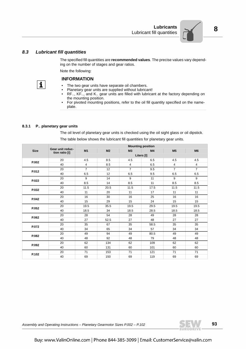
Assembly and Operating Instructions – Planetary Gearmotor Sizes P.002 – P.102 93
8Lubricant fill quantitiesLubricants
8.3 Lubricant fill quantitiesThe specified fill quantities are recommended values. The precise values vary depend-ing on the number of stages and gear ratios.
Note the following:
8.3.1 P.. planetary gear unitsThe oil level of planetary gear units is checked using the oil sight glass or oil dipstick.
The table below shows the lubricant fill quantities for planetary gear units.
INFORMATION• The two gear units have separate oil chambers.• Planetary gear units are supplied without lubricant!• RF.., KF.., and K.. gear units are filled with lubricant at the factory depending on
the mounting position.• For pivoted mounting positions, refer to the oil fill quantity specified on the name-
plate.
Size Gear unit reduc-tion ratio [i]
Mounting positionM1 M2 M3 M4 M5 M6
Liters [l]
P.00220 4.5 8.5 4.5 6.5 4.5 4.540 4 8.5 4 6.5 4 4
P.01220 7 12 7 9.5 7 740 6.5 12 6.5 9.5 6.5 6.5
P.02220 9 14 9 11 9 940 8.5 14 8.5 11 8.5 8.5
P.03220 11.5 20.5 11.5 17.5 11.5 11.540 11 20 11 17 11 11
P.04220 16 30 16 25 16 1640 15 29 15 24 15 15
P.05220 19.5 35.5 19.5 29.5 19.5 19.540 18.5 34 18.5 28.5 18.5 18.5
P.06220 28 54 28 49 28 2840 27 52.5 27 48 27 27
P.07220 35 67 35 58.5 35 3540 34 65 34 57 34 34
P.08220 49 94 49 80.5 49 4940 48 92 48 79 48 48
P.09220 62 134 62 109 62 6240 60 131 60 101 60 60
P.10220 71 153 71 121 71 7140 69 150 69 119 69 69

94 Assembly and Operating Instructions – Planetary Gearmotor Sizes P.002 – P.102
8 Lubricant fill quantitiesLubricants
8.3.2 Primary gear unitsBevel (KF/K) primary gear units
The table below shows the lubricant fill quantities.
INFORMATION• The lubricant fill quantity depends on the mounting position of the planetary gear
unit and the mounting position of the KF and K primary gearmotor.• For notes on the mounting positions of KF and K primary gear units, see chapter
3.5.1.• The oil level of primary gear units is checked using the oil level plug.
Size
Fill quantities in litersM1 M2 M3
0° A 90° A 180° B 270° A 0° A 90° A 180° A 270° A 0° B 90° A 180° A 270° AKF67 1.1 2.4 1.1 3.7 2.7 2.7 2.7 2.7 1.1 3.7 1.1 2.4KF77 2.1 4.1 2.1 5.9 4.5 4.5 4.5 4.5 2.1 5.9 2.1 4.1KF87 3.7 8.2 3.7 11.9 8.4 8.4 8.4 8.4 3.7 11.9 3.7 8.2KF97 7 14.7 7 21.5 16.5 16.5 16.5 16.5 7 21.5 7 14.7KF107 10 21.8 10 35.1 25.2 25.2 25.2 25.2 10 35.1 10 21.8KF127 21 41.5 21 55 41 41 41 41 21 55 21 41.5KF157 31 62 31 92 62 62 62 62 31 92 31 66K167 33 95 33 123 95 84 84 84 105 33 105 85K187 53 152 53 200 152 143 143 143 167 53 167 143
Size
Fill quantities in litersM4 M5 M6
0° A 90° A 180° B 270° A 0° A 90° B 180° A 270° A 0° B 90° A 180° A 270° BKF67 2.7 2.7 2.7 2.7 2.4 1.1 3.7 1.1 3.7 1.1 2.4 1.1KF77 4.5 4.5 4.5 4.5 4.1 2.1 5.9 2.1 5.9 2.1 4.1 2.1KF87 8.4 8.4 8.4 8.4 8.2 3.7 11.9 3.7 11.9 3.7 8.2 3.7KF97 15.7 15.7 15.7 15.7 14.7 7.0 21.5 7 21.5 7.0 14.7 7KF107 25.2 25.2 25.2 25.2 21.8 10 35.1 10 35.1 10 21.8 10KF127 41 41 41 41 41.5 21 55 21 55 21 41.5 21KF157 62 62 62 62 66 31 90 31 92 31 66 31K167 123 123 123 123 85 33 123 33 84 33 95 33K187 200 200 200 200 143 53 200 53 143 53 152 53
Key:
M1 / M2 / M3 / M4 / M5 / M6 = Mounting positions of planetary gear units
0° / 90° / 180° / 270° = Mounting positions of bevel (KF/K) primary gear units
A / B = Position of the mounting flange at the primary bevel gear unit

Assembly and Operating Instructions – Planetary Gearmotor Sizes P.002 – P.102 95
8Lubricant fill quantitiesLubricants
Helical (RF) primary gear units
The table below shows the lubricant fill quantities.
INFORMATION• The lubricant fill quantity depends on the mounting position of the planetary gear
unit and the mounting position of the RF primary gear unit.• For notes on the mounting positions of RF primary gear units, see chapter 3.5.2.• The oil level of primary gear units is checked using the oil level plug.
Size
Fill quantities in litersM1 M2 M3 M4 M5 M60° 0° 180° 0° 270° 90°
RF77 1.2 3.10 3.30 3.60 2.40 3.00RF87 2.4 6.4 7.1 7.2 6.3 6.4RF97 5.1 11.9 11.2 14.0 11.2 11.8RF107 6.3 15.9 17.0 19.2 13.1 15.9RF137 9.5 27.0 29.0 32.5 25.0 25.0RF147 16.4 47.0 48.0 52.0 42.0 42.0RF167 26.0 82.0 78.0 88.0 65.0 71.0
Key:
M1 / M2 / M3 / M4 / M5 / M6 = Mounting positions of planetary gear units
0° / 90° / 180° / 270° = Mounting positions of helical (RF) primary gear units

96 Assembly and Operating Instructions – Planetary Gearmotor Sizes P.002 – P.102
8 Grease / rolling bearing grease: Planetary gear unitsLubricants
8.4 Grease / rolling bearing grease: Planetary gear unitsThe table shows the grease types recommended by SEW-EURODRIVE for operatingtemperatures from -20 °C to 100 °C.
8.5 Sealing grease: Primary gear units RF.. / KF../ K.. and motorsThe rolling bearings of primary gear units RF.. / KF.. / K.. and motors are filled at thefactory with the greases listed below. SEW-EURODRIVE recommends regreasingrolling bearings with a grease fill at the same time as changing the oil. Observe theseparate operating instructions for primary gear units RF.. / KF.. / K.. and motors
Manufacturer Grease
ARAL ARALUB HLP 2
BP Energrease LS-EPS
Castrol Spheerol EPL2
Fuchs Renolit CX TOM 15 OEM
Klüber Centoplex EP2
Kuwait Q8 Rembrandt EP2
Mobile Mobilux EP 2
Shell Alvania EP2
Texaco Mulifak EP 2
Total Multis EP 2
CastrolObeen FS2
FuchsPlantogel 2S
OilOil
INFORMATIONIf the lubricant used is not listed in the above table, you have to make sure that it issuitable for the intended application.
Ambient temperature Manufacturer TypeGear unit rolling bearings –40 °C ... +80 °C Fuchs Renolit CX-TOM 15
–30 °C ... +40 °C Castrol Obeen F82
–20 °C ... +40 °C Aral Aralube BAB EP2OilOil
INFORMATIONThe following grease quantities are required:• For fast-running bearings (gear unit input end): Fill the cavities between the rolling
elements one-third full with grease.• For slow-running bearings (gear unit output end): Fill the cavities between the
rolling elements two-thirds full with grease.
Assembly and Operating Instructions – Planetary Gearmotor Sizes P.002 – P.102 97
9NotesMalfunctions
9 Malfunctions9.1 Notes
Read the following notes before you proceed.
9.2 Customer servicePlease have the following information available if you require customer serviceassistance:• Complete nameplate data
• Type and extent of the problem
• Time the problem occurred and any accompanying circumstances
• Assumed cause
• A digital photograph if possible
WARNINGRisk of crushing if the drive starts up unintentionally.
Severe or fatal injuries.• De-energize the motor before you start working on the unit.• Secure the motor against unintended power-up.
WARNINGDanger of burns due to hot gear unit and hot gear unit oil.
Serious injury.• Let the gear unit cool down before you start working on it.• Carefully remove the oil level plug and oil drain plug.
NOTICEImproper handling of the gear unit and the motor may lead to damage.
Possible damage to property.• Only qualified personnel is permitted to separate drive and motor and to carry out
repair work on SEW drives. • Consult the SEW-EURODRIVE customer service.

98 Assembly and Operating Instructions – Planetary Gearmotor Sizes P.002 – P.102
9 Malfunctions of P.. planetary gear unitsMalfunctions
9.3 Malfunctions of P.. planetary gear units
Malfunction Possible cause Remedy
Unusual, irregular running noise
• Meshing/grinding noise: Bearing damage• Knocking noise: Irregularity in the gearing• Deformation of the housing upon
tightening• Noise generation caused by insufficient
rigidity of the gear unit foundation
• Check oil consistency (see chapter 7.5), replace bearings
• Contact customer service• Check the gear unit mounting for possible
deformation and correct if necessary• Reinforce the gear unit foundation
Unusual, irregular running noise • Foreign objects in the oil • Check the oil consistency (see chapter 7.5)
• Stop the drive, contact customer service
Unusual noise in the area of the gear unit mounting • Gear unit mounting has loosened
• Tighten retaining screws and nuts to the specified torque
• Replace the damaged/defective retaining screws or nuts
Operating temperature too high
• Too much oil• Oil too old• The oil is heavily contaminated• Ambient temperature too high
• Check the oil level, correct if necessary (see chapter 7.4)
• Check when the oil was last changed; change the oil if necessary (see chapter 7.6)
• Protect from external heat sources (e.g. provide shade)
• Change oil (see chapter 7.6)
Bearing point temperatures too high
• Not enough oil• Oil too old• Bearing damaged
• Check the oil level, correct if necessary (see chapter 7.4)
• Check when the oil was last changed; change the oil if necessary (see chapter 7.6)
• Check bearing and replace if necessary, contact customer service
Oil leaking1)
1) During the run-in phase (24-hour runtime), it is normal for (small amounts of) oil/grease to leak from the oil seal (see also DIN 3761).
• Gasket on the gear unit is not tight• Sealing lip of the oil seal turned up• Oil seal damaged/worn• Too much oil• Drive installed in incorrect mounting
position• Frequent cold starts (oil foams) and/or
high oil level
• Vent the gear unit, observe the gear unit. If oil still leaks: Contact customer service
• Check oil seals; replace if necessary• Contact customer service• Check oil level (see chapter 7.4)• Install the breather plug correctly

Assembly and Operating Instructions – Planetary Gearmotor Sizes P.002 – P.102 99
9Malfunctions of primary gear units RF.. / KF.. / K..Malfunctions
9.4 Malfunctions of primary gear units RF.. / KF.. / K..
9.5 AM/AL adapter malfunctions
Malfunction Possible cause Remedy
Unusual, regular running noise
Meshing/grinding noise: Bearing damage Check the oil → replace the bearing
Knocking noise: Irregularity in the gearing Contact customer service
Unusual, irregular running noise
Foreign objects in the oil • Check the oil• Stop the drive, contact customer service
Oil leakage1)
• From inspection cover• From the motor flange• From the motor oil
seal• From the gear unit
flange• From the output end
oil seal.
1) Short-term oil / grease leakage at the oil seal is possible in the run-in phase (48-hour runtime).
Rubber seal on the inspection cover leaking Tighten the screws on the gear cover plate and observe the gear unit. If oil still leaks: Contact customer service
Seal defective Contact customer service
Gear unit not ventilated Vent gear unit
Oil leaking from breather valve
Too much oil Correct the oil quantity
Drive operated in incorrect mounting position • Install the breather valve correctly • Correct the oil level
Frequent cold starts (oil foams) and/or high oil level
Install oil expansion tank.
Output shaft does not turn although the motor is running or the input shaft is rotated
Shaft/hub connection interrupted in gear unit Send in the gear unit/gearmotor for repair
Operating temperature at backstop too high • Damaged/defective backstop • Check backstop; replace if necessary
• Contact customer serviceNo blocking function
Malfunction Possible cause Remedy
Unusual, regular running noise
Meshing/grinding noise: Bearing damage Contact SEW-EURODRIVE customer service
Oil leaking Seal defective Contact SEW-EURODRIVE customer service
Output shaft does not turn although the motor is running or the input shaft is rotated
Connection between shaft and hub in gear unit interrupted
Send in gear unit to SEW-EURODRIVE for repair
Change in running noise and/or vibrations
Annular gear wear, short-term torque transfer through metal contact
Change the annular gear
Bolts to secure hub axially are loose Tighten the screws
Premature wear in annular gear
• Contact with aggressive fluids/oils; ozone influence; excessive ambient tempera-tures, etc. that can change the physical properties of the annular gear.
• Impermissibly high ambient/contact tem-perature for the annular gear; maximum permitted temperature: -20 °C to +80 °C
• Overload
Contact SEW-EURODRIVE customer service

100 Assembly and Operating Instructions – Planetary Gearmotor Sizes P.002 – P.102
9 Malfunctions of the motorMalfunctions
9.6 Malfunctions of the motor
Malfunction Possible cause Remedy
Motor does not start up
Supply cable interrupted Check connections, correct if necessary
Brake does not release → see the motor operating instructions
Fuse has blown Replace fuse
Motor protection has triggered Check motor protection for correct setting, correct fault if necessary
Motor protection does not switch, error in control Check motor protection control, correct error if necessary
Motor only starts with difficulty or does not start at all
Motor designed for delta connection but used in star connection Correct connection
Voltage or frequency deviate considerably from setpoint, at least while being switched on
Provide better power supply system; check cross section of supply cable
Motor does not start in star connection, only in delta connection
Star connection does not provide sufficient torque
Switch on directly if delta inrush current is not too great; else, use a larger motor or a special design (contact SEW-EURODRIVE)
Contact fault on star/delta switch Rectify fault
Incorrect direction of rotation Motor connected incorrectly Swap over two phases
Motor hums and has high current consumption
Brake does not release → see the motor operating instructions
Winding defective Send motor to specialist workshop for repair
Rotor rubbing
Fuses blow or motor protection trips immediately
Short circuit in line Repair short circuit
Short circuit in motor Send motor to specialist workshop for repair
Lines connected incorrectly Correct connection
Ground fault on motor Send motor to specialist workshop for repair
Severe speed loss under load
Overload Measure power, use larger motor or reduce load if necessary
Voltage drops Increase cross section of incoming cable
Motor heats up excessively (measure temperature)
Overload Measure power, use larger motor or reduce load if necessary
Insufficient cooling Correct cooling air supply or clear cooling air passages, retrofit forced cooling fan if necessary
Ambient temperature too high Comply with permitted temperature range
Motor in delta connection instead of star connection as provided for Correct connection
Loose contact in supply cable (one phase missing) Rectify loose contact
Fuse has blown Look for and rectify cause (see above); replace fuse
The line voltage deviates from the rated motor voltage by more than 5%. A higher voltage has a particularly unfavorable effect in motors with a low-speed winding since in these, the no-load current is already close to the rated current even when the voltage is normal.
Adjust motor to line voltage.
Rated operation type (S1 to S10, DIN 57530) exceeded, e.g. through excessive starting frequency
Adjust the rated operating mode of the motor to the required operating conditions; consult a professional to determine the correct drive if necessary
Excessively loud
Ball bearing compressed, dirty or damaged Re-align motor, inspect ball bearing, re-grease, if necessary, replace
Vibration of rotating parts Rectify cause, possible imbalance
Foreign bodies in cooling air passages Clean the cooling air passages

Assembly and Operating Instructions – Planetary Gearmotor Sizes P.002 – P.102 101
9Malfunctions of the DR/DV brakeMalfunctions
9.7 Malfunctions of the DR/DV brake
9.8 Disposal• Housing parts, gears, shafts and roller bearings of the gear units must be disposed
of as steel scrap. This also applies to gray-cast iron parts if there is no specialcollection.
• Collect waste oil and dispose of it according to the regulations in force.
Malfunction Possible cause Remedy
Brake does not release
Incorrect voltage on brake control unit Apply correct voltage
Brake control unit failed Install a new brake control system, check internal resis-tance and insulation of brake coil, check switchgear
Max. permitted working air gap exceeded because brake lining worn down. Measure and set working air gap
Voltage drop along supply cable > 10% Ensure correct connection voltage; check cable cross section
Inadequate cooling, brake overheats Replace type BG brake rectifier with type BGE
Brake coil has interturn short circuit or a short circuit to frame
Replace complete brake and brake control system (specialist workshop), check switchgear
Rectifier defective Replace the rectifier and brake coil
Motor does not brake
Working air gap not correct Measure and set working air gap
Brake lining worn Replace entire brake disk
Incorrect braking torque.
Change the braking torque (→ see motor operating instructions)• By the type and number of brake springs• Brake BMG 05By installing the same brake coil body
design as in brake BMG 1• Brake BMG 2By installing the same brake coil body
design as in brake BMG 4
BM(G) only: Working air gap so large that setting nuts come into contact. Setting the working air gap
BR03, BM(G) only: Manual brake release device not set correctly Set the setting nuts correctly
Brake is applied with time lag Brake is switched on AC voltage side Switch on DC and AC voltage sides (e.g. BSR); refer to
wiring diagram
Noises in vicinity of brake Gearing wear caused by jolting startup
Check configuration
-> see motor operating instructions

Assembly and Operating Instructions – Planetary Gearmotor Sizes P.002 – P.102 113
Index
Index
AAD adapter .............................................................36AD input shaft assembly ........................................55AD../ZR input shaft assembly with centering
shoulder .............................................................56Aligning the shaft axis ............................................48Alvania ...................................................................96AL/AM adapter .......................................................79AM adapter ............................................................36Ambient conditions.................................................42AM../RS adapter AM with backstop .......................54AR adapter .............................................................36Assembly ...............................................................39Assembly notes......................................................40AT adapter .............................................................36
BBackstop ................................................................73Bath lubrication ......................................................34Belt pulley ..............................................................49Breather valve..................................................40, 46
CCentering shoulder tolerance
...........................................................................39Changing the oil .....................................................83Check the oil consistency.......................................82Checking and cleaning the breather plug...............89Checking the oil level .............................................81Churning losses .....................................................27Coating systems ....................................................32Combination of planetary gear unit with primary gear
unit .....................................................................16Components on the input side ...............................36Copyright..................................................................6Corrosion ...............................................................40Coupling.................................................................51Coupling of AM adapter .........................................52Cover AD .........................................................55, 79Cover with backstop AD../RS.................................58Customer service ...................................................97
DDiameter tolerance.................................................39Disposal ...............................................................101
EEmbedded safety notes ...........................................5Exclusion of liability..................................................6External conservation ............................................14
FFlange-mounted design .........................................59Foot-mounted ........................................................45Foot-mounted variant with primary gear unit .........47Foundation.............................................................48
GGear unit mounting ................................................45Gear unit structure .................................................16Gear unit with solid shaft .......................................49
HHollow shaft ...........................................................63Hollow shaft gear unit with torque arm ..................60
IIEC adapter AM63 - 280 ........................................52Inspection ..............................................................77Inspection intervals ................................................78Installation..............................................................39Installation Notes ...................................................40Installing the coupling ............................................51Installing the gear unit............................................45Internal conservation .............................................14
LLubricant change intervals.....................................80Lubricant fill quantities ...........................................93Lubricants ..............................................................90Lubricating greases ...............................................96
MMaintenance ..........................................................77Maintenance intervals............................................78Malfunctions...........................................................97Mobilux ..................................................................96Mounting output elements .....................................49Mounting position...................................................21

114 Assembly and Operating Instructions – Planetary Gearmotor Sizes P.002 – P.102
Index
Mounting position sheetsPF..RF................................................................24PK..KF................................................................26P..KF.. ................................................................25P..RF..................................................................23
Mounting positions of the primary gear units .........27M1...M6 ..................................................................21
NNameplate..............................................................17NEMA adapter AM56 - 365....................................52
OOil drain plug..........................................................38Oil drain valve ........................................................38Oil expansion tank
...........................................................................34Oil seals .................................................................42Oil temperature ......................................................74Options...................................................................36OS1, OS2, OS3 .....................................................32
PPackaging ..............................................................14Pinion .....................................................................49Pivoted mounting position......................................30Preliminary work.....................................................42Protection devices..................................................40PT100 ....................................................................37PT100 temperature sensor ....................................37
RRefilling grease ......................................................88Removing the shrink disk.......................................68Renolit ....................................................................96Riser pipe...............................................................35Rolling bearing greases .........................................96Run-in period .........................................................72
SSafety notes
Designation in the documentation .......................5Structure of the embedded safety notes..............5Structure of the section safety notes ...................5
Safety symbols ........................................................9Sealing grease.......................................................96Sealing lips ............................................................42Section safety notes ................................................5Shaft axis ...............................................................48Shrink disk .............................................................63Shutting down gear units .......................................75Signal words in safety notes ....................................5Solid shaft ..............................................................49Splash lubrication ..................................................33Startup ...................................................................71Sticker on the gear unit ............................................9Storage conditions ...........................................14, 15Surface temperature ..............................................74Symbols on the gear unit .........................................9
TTemperature sensor PT100
Dimensions ........................................................70Electrical connection..........................................70Technical data ...................................................70
Tightening torques .................................................45Tightening torques for gear unit mounting .............45Tightening torques for the torque arm ...................60Tolerances .............................................................39Tool........................................................................39Torque arm ......................................................37, 60Transport ...............................................................11Transport conditions ..............................................14Transportation damage..........................................11Type designation ...................................................17
WWarning notes on the gear unit................................9
Copyright © 2022 FDOKUMEN