[p[Lffi~V~@ [p~[p~
176
HE ROLE : Of IN COMMU l' ITY WATER UPP I I , DEVEtOPI G COU TRI -S
-
Upload
khangminh22 -
Category
Documents
-
view
2 -
download
0
Transcript of [p[Lffi~V~@ [p~[p~

HE ROLE :Of
[p[Lffi~V~@ [p~[p~ IN COMMU l'ITY WATER UPP I
I , DEVEtOPI G COU TRI -S

Storage
LIBRARIES

ROLE OF PLASTIC PIPE
IN
COMMUNITY WATER SUPPLIES
IN
DEVELOPING COUNTRIES
-.
\,H.$.
..'Aifg;_¢%p<5'nBy r
Frederick E. Mqj'{fi{inri and“-Charles s. Pineo‘ ‘i
Department of Environmental Sciences and EngineeringSchool of Public HealthUniversity of North~Car0linaChapel Hill, North Carolina
To The
Office of HealthBureau of Technical Assistance
Agency for International DevelopmentWashington, D.C.
Contract AID/csd-1888 Task Order No.3Storage
300S r;.2.:p M/e
1969
For sale by the Superintendent of Documents, U.S. Government Printing OfficeWashington, D.C. 20402- Price $1Stock Number 4401-0033
jharold
Rectangle
jharold
Rectangle
jharold
Rectangle
jharold
Rectangle
jharold
Rectangle
jharold
Rectangle
jharold
Rectangle
jharold
Rectangle
jharold
Rectangle
jharold
Rectangle
jharold
Rectangle

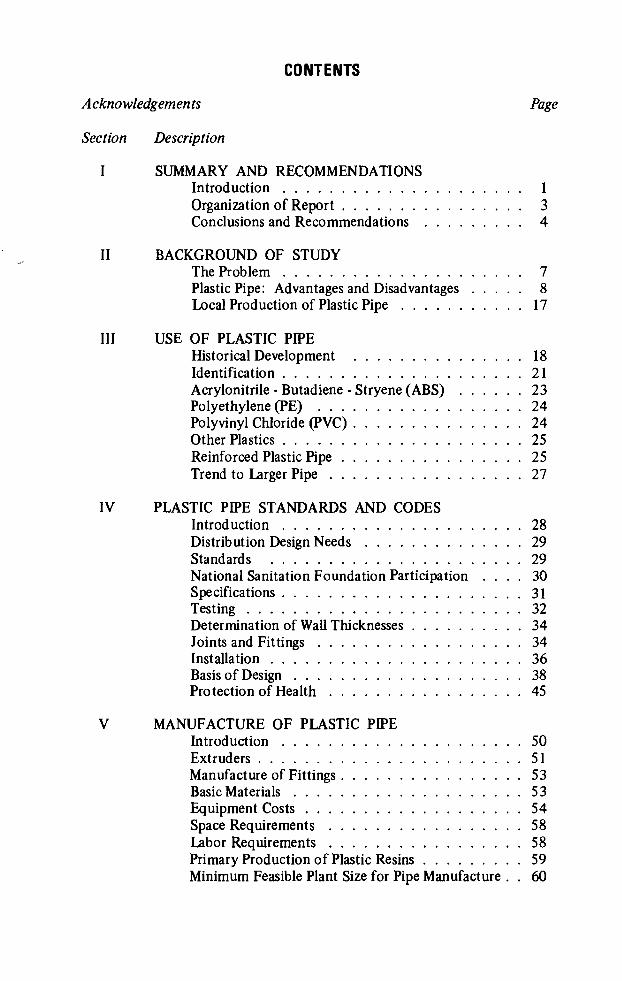
CONTENTS
Acknowledgements
Section Description
I SUMMARY AND RECOMMENDATIONS
II
III
IV
V
Introduction . . . . . . . . . . . . . . . . . . . .
Organization of Report . . . . . . . . . . . . . . .Conclusions and Recommendations . . . . . . . .
BACKGROUND OF STUDYThe Problem . . . . . . . . . . . . . . . . . . . .
Plastic Pipe: Advantages and Disadvantages . . . .
Local Production of Plastic Pipe . . . . . . . . . .
USE OF PLASTIC PIPEHistorical Development . . . . . . . . . . . . . .
Identification . . . . . . . . . . . . . . . . . . . .Acrylonitrile-Butadiene-Stryene (ABS) . . . . .Polyethylene (PE) . . . . . . . . . . . . . . . . .Polyvinyl Chloride (PVC) . . . . . . . . . . . . . .Other Plastics . . . . . . . . . . . . . . . . . . . .Reinforced Plastic Pipe . . . . . . . . . . . . . . .Trend to Larger Pipe . . . . . . . . . . . . . . . .
PLASTIC PIPE STANDARDS AND CODESIntroduction . . . . . . . . . . . . . . . . . . . .
Distribution Design Needs . . . . . . . . . . . . .
Standards . . . . . . . . . . . . . . . . . . . . .
National Sanitation Foundation ParticipationSpecifications . . . . . . . . . . . . . . . . . . . .Testing . . . . . . . . . . . . . . . . . . . . . . .Determination of Wall Thicknesses . . . . . . . . .
Joints and Fittings . . . . . . . . . . . . . . . . .Installation . . . . . . . . . . . . . . . . . . . . .Basis of Design . . . . . . . . . . . . . . . . . . .
Protection of Health . . . . . . . . . . . . . . . .
MANUFACTURE OF PLASTIC PIPEIntroduction . . . . . . . . . . . . . . . . . . . .
Extruders . . . . . . . . . . . . . . . . . . . . . .Manufacture of Fittings . . . . . . . . . . . . . . .Basic Materials . . . . . . . . . . . . . . . . . . .
Equipment Costs . . . . . . . . . . . . . . . . . .
Space Requirements . . . . . . . . . . . . . . . .Labor Requirements . . . . . . . . . . . . . . . .Primary Production of Plastic Resins . . . . . . . .Minimum Feasible Plant Size for Pipe Manufacture . .
Page
17
21
23
24
24
25
25
27
28
29
29
.3031
32
34
34
36
38
45
50
51
53
53
54
58
58
59

VI MARKET FOR PLASTIC PIPEDemographics . . . . . . . . . . . . . . . . . . . . 61
Dollar Volume . . . . . . . . . . . . . . . . . . . . 63
Role of U_.S. Industry . . . . . . . . . . . . . . . . . 65Sale ofPipe . . . . . . . . . . . . . . . . . . . . . 65
Sale of Fittings . . . . . . . . . . . . . . . . . . . . 65Sale of Plastic Resins and Compounds . . . . . . . . 65Sale ofMachinery . . . . . . . . . . . . . . . . . . 66
Provision of Capital and Know-How . . . . . . . . . 66
Overseas Business Assistance . . . . . . . . . . . . . 66

10
ll
12
13
14
15
16
17
18
19
TABLES
Cost Comparison of Plastic and Metal Pipe inDollars Per Linear Foot (1967) . . . . . . . . . . . . . .
Cost Breakdown for Drain, Waste, Vent Installation
Water Service Line Material and Installation Costsfor Plastic and Copper Pipe . . . . . . . . . . . . . . . .
Plastic Pipe in Water Supplies . . . . . . . . . . . . . . .
Thermoplastics Pipe - Properties and Uses . . . . . . . .
Tests on Plastic Pipe During Manufacture . . . . . . . .
Material Requirements and Pipe Classification forABS, PE, and PVC Pipe . . . . . . . . . . . . . , . . . .
Illustrative Dimensions and Pressures for Plastic Pipe . . . .
Available Diameters (Nominal) in Plastic Pipe . . . . . .
Hydrostatic Design Stresses and 50-Year Strength Data . .
Temperature Expansion and Contraction of Plastic Pipe . .
Extruder Sizes Commonly Used in Manufacture ofPlastic Pipe . . . . . . . . . . . . . . . . . . . . . . . .
Material Prices for Plastic Pipe . . . . . . . . . . . . . .
Comparative Production - Nominal Outputs at MaximumSpeeds in Pounds Per Hour . . . . . . . . . . . . . . . .
Extrusion Time and Labor for ABS Plastic Pipe(Class 40 IPS) . . . . . . . . . . . . . . . . . . . . . .
Space Requirements in Square Feet . . . . . . . . . . . .
Capital Cost Data (1967) Polyethylene Plants . . . . . .
Estimated Availability of Water Service . . . . . . . . .
Four Year Projections 1968-1971 Water Supply inLatin America Similar Increase in Services in Other Areas. .
Page
11
ll
12
13
22
33
39
40
43
44
44
51
54
56
57
58
59
62
64

ILLUSTRATIONS
Page
Figure 1 Average Installed Costs of Water Mains inIllinois FHA Projects from 1965 to 1968 . . . . . . . . . . 10
Figure 2 Plastic Pipe Prices in Central and South America1968-1969 - (Local and USA Manufacture) . . . . . . . . . 14
Figure 3 Weight Comparison for Pressure Pipe in PVC,Asbestos Cement, and Cast Iron in LB-YD forPressures from 65 to 173 PSI . . . . . . . . . . . . . . . . 15
Figure 4 1967 U.S. Plastics Pipe Production by End Use . . . . . . . 19
Figure 5 Plastics Pipe Production by Major Categories . . . . . . . . 21
Figure 6 Nomograph for Hazen-Williams Equation(English Units) . . . . . . . . . . . . . . . . . . . . . . . 41
Figure 7 Nomograph for Hazen-Williams Equation
(Metric Units) . . . . . . . . . . . . . . . . . . . . . . . 42
Figure 8 Vented Single Screw Extruder . . . . . . . . . . . . . . . . 50
Figure 9 Average Extruder Output . . . . . . . . . . . . . . . . . . 52

Appendices
A
B
ABBREVIATIONS
BIBLIOGRAPHY
STANDARDS AND SPECIFICATIONS FOR PLASTICPIPE
A GLOSSARY OF PLASTICS PIPING TERMS
OTHER INFORMATION SOURCES
DIRECTORY OF MANUFACTURERS
NATIONAL SANITATION FOUNDATION STANDARDNUMBER 14 FOR THERMOPLASTIC MATERIALS,PIPE, FITTINGS, VALVES, TRAPS, JOININGMATERIALS AND APPURTENANCES
INSTALLATION OF PLASTICS PIPE
PLASTIC PIPE FOR SEWERS
PLASTIC PIPE FOR GAS SERVICE

ACKNOWLEDGEMENTS
The authors wish to express their appreciation for the cooperation andassistance received from many individuals in the plastics and plastics pipeindustries, the international agencies and banks, universities, and water supplyagencies at home and abroad.
Special acknowledgement must go to Messrs. Arthur H. Holloway,Environmental Engineer, and A. Dale Swisher, P.E., Sanitary Engineer, Agencyfor International Development; Dr. Daniel A. Okun, Professor and Head,Department of Environmental Sciences and Engineering, University of NorthCarolina; Mr. Charles A. Farish, Executive Director, National SanitationFoundation, and his assistant, Mr. Tom S. Gable; Dr. Frank W. Reinhart,Technical Director, Plastics Pipe Institute; and to Ing. Humberto Olivero,Chief, Sanitation Section, Inter-American Development Bank.
Also to Mr. G. R. Munger, Executive Director, Plastics Pipe Institute;Mr.
Bryce Batzer, President, President, Plastiline, Inc.; Mr. Lewis J. Adams,General Manager, Olin-Evanite Plastics; Mr. W. A. Mitchell, Area SalesManager (Latin America) and Mr. Gerald Cohan, “Geon” Sales Manager, B. F.Goodrich Chemical Co.; and Mr. J. M. Bunge, Commercial Director,Chemidus Plastics, Limited.
The cooperation of the World Health Organization, Geneva, and the PanAmerican Health Organization, Washington, was also helpful.

SUMMARY AND RECOMMENDATIONS
Introduction
Fundamental premises of the AID-WHO global community water supplyprogram in developing countries are that water should be treated as acommodity, that water systems should be managed on a businesslike basisand essentially pay their own way, and that the present level of building newsystems and strengthening and extending existing systems needs to be greatlyexpanded in order to overcome present backlogs and keep pace with urbangrowth.*Since there is little evidence of present over-capacity of production withinthe developing countries themselves of the basic or finished materials whichgo into the construction of urban water supply systems, and none whateverwhen regional trade needs are taken into account, the foregoing premisescollectively suggest the need for expanding these production capacities withinthe utilizing areas. Such expanded production capacity should be centered onthose components of water supply systems which make up the greater part ofthe materials and equipment elements of construction cost. Expandedinternational trade between the more highly industrialized countries and
developing countries arising from expanded rates of water supplydevelopment in the latter would tend to be concentrated on the morespecialized and complicated materials and equipment items and on items onlyoccasionally required or used only in small quantities.The alternative to this concept would be for these expanded needs to bemet entirely rather than only partly, by increased imports from the moreindustrialized areas of the world. This alternative is difficult to rationalizeeither with the introductory fundamental premises or with the realities ofinternational finance and trade economics.That the major portion of urban U.S. water supply construction costsconsists of non-labor items (materials, installed equipment, construction
*For background see Mcjunkin, Frederick E., “Community Water Supply in DevelopingCountries: A Quarter Century of United States Assistance,” AID, 95 pp., 1969, andU.S. Public Health Service, “Guidelines and Criteria for Community Water Supplies inthe Developing Countries,” 10] pp.,‘ 1969.
1

equipment, etc.) is well-known. High wage rates are offset in part byextensive use of labor-saving equipment, especially in earthwork and pipeinstallations. Although the ratio of non-labor to labor costs in water supplyvaries from country to country as well as for different elements of watersystems, non-labor project-site costs also represent most of the cost of urbanpiped water supply construction in developing countries as a group, as well as
in the U.S.A. In fact, for those job items which require non-skilled labor usingthe ordinary tools of the trade, labor costs in other countries usuallycomprise a smaller proportion of total project cost than in the U.S.A.This means, simply, that materials and equipment produced within the
individual countries of regions must be utilized in urban water supplyconstruction if major savings in hard currency requirements are to be realizedby consuming and lending countries.
Secondly, it means that these materials must be important elements of theconstruction cost breakdown if the impact of this contribution is to amountto much.
This line of reasoning invites attention to pipe, since pipe of one type oranother usually is the most important single non-labor cost item in water
supply construction. In the case of new systems, for example, the distributionsystem usually is more expensive than treatment plant and source of supplydevelopment. Furthermore, pipe used in treatment plants, wells andtransmission lines is always a significant element and can be the principalelement in the combined costs of treatment plant and source of supplydevelopment.The significance of pipe as a cost element is obviously more variable
where improvements to existing urban water systems are involved. Most
projects of this type require individual analysis, with the proportionate costof pipe ranging from very minor to almost all of the non-labor project costs.However, by far the commonest type of improvement is the extension ofdistribution systems.The proportionate cost of pipe to the total non-labor cost of such systems
is substantially higher, on average, in developing countries than in the U.S.A.In the U.S.A., for example, the cost of valves, fittings, and hydrants can varyfrom 5 percent to about 35 percent of the total cost of distribution systemgrids, exclusive of elevated storage. A “typical” system in a developingcountry tends to require more limited investment in these components,including elevated storage. Primarily this is due to lower fire-flow values or noprovision for fire flow, with consequent reduction in elevated storage, firehydrants and in distribution system grids with their valve and fittingsrequirements.
At present, the choice of pipe materials overseas in the larger sizes of streetmains (4-inch and larger) in community water supply systems lies betweencast-iron and asbestos-cement pipe, with use of cast-iron pipe generallypredominating. Some plastic pipe is manufactured in diameters up to 8-inch,and infrequently, 12-inch. In the smaller sizes of street mains and in houseconnection lines and house supply systems (l/4-inch to 3-inch), galvanizedsteel pipe predominates with plastic pipe developing as a competitive product.Copper pipe is occasionally competitive. These size classifications are
2

somewhat arbitrary since cast-iron pressure pipe is known to be made indimensions down to 2-inch and asbestos-cement pipe down to 1 1/2-inch,while both galvanized steel and plastic pipe of some types are made in 6-inchdiameters or larger.
In some areas the cost of plastic pipe is as low as half that of galvanizediron in small diameters. With 1.5 billion people to be served, even pennies perfoot represents millions of dollars (or millions more people served).Unfortunately, these savings are not always realized since a high-profit,low-volume philosophy prevails in many foreign countries. In some others
monopolistic pricing destroys the cost differential.The cost of bathrooms and of house connection lines in post-war U.S.houses probably equals or exceeds the residential customer’s share in the
combined construction cost of public water and sewerage systems. Thisstatement is probably true even when only residential plumbing costs areconsidered in the comparison (i.e., structure cost excluded).In developing countries, the proportionate cost of plumbing fixtures andhouse connection lines in the simplest type of residential service in urbanwater systems is obviously very much less (such as where service is limited toa yard faucet or porch faucet services with no sewerage) and materials
logistics and economic cost considerations are almost entirely limited to
prospects for substituting plastic pipe for metal pipe. However, the extent towhich bathroom facilities are provided and their cost relative to per capitaincome and to the cost of public water supplies can vary widely by size ofcity and in different areas of a city in many developing countries. Thissituation suggests that the cost of piping and fixtures involved in supplyingwater from the street main and in water use and disposal within the premisesoccasionally can exceed that of the public property lines in water supplylogistics and financing.
Pipe is a major cost element of community and household water systems.In the most common diameters pipe made of plastics is competitive in costand performance, and in many circumstances, costs less than pipe of othermaterial. Plastic pressure pipe can be readily manufactured in developingcountries with a minimum of hard-currency capital investment, skilled laborrelative to other forms of pipe, and expenditure for imported materials,relative to production of other pipe.
Organization of Report
The basic intent of the report was preparation of a document, complete initself, which would enable engineers, administrators, public officials,industrialists, personnel from AID, WHO-PAHO, the international banks, andothers to review the role of plastic pipe in community water supply indeveloping countries, and further, to provide a resource document to supportfurther technical or administrative action. In order to serve such a wideclientele and to keep the required reading effort within manageableproportions, extensive use has been made of specialized appendices. The text,combined with the appendices, should enable the reader to (1) weigh the
3

merits of plastic as a pipe material, (2) quickly acquire an awareness of thestate of the art, (3) prepare design criteria and standards and specificationsfor manufacture, testing, and installation of plastic pipe, (4) organize a testingprogram, and (5) undertake preliminary feasibility studies of manufactureand marketing of plastic pipe.The supplemental role of the appendices may be ascertained from thefollowing brief descriptions.
Appendix A: “Abbreviations.” A dictionary of the more often usedabbreviations in the text and appendices. All abbreviations are defined whenfirst used. Also see Appendix D.
Appendix B: “Bibliography.” Contains complete bibliographic citations toall authorities specifically mentioned in the report plus general references andthe majority of published documents relevant to the topic at hand. Over 120references.
Appendix C: “Standards and Specifications for Plastic Pipes.” A list of allmajor U.S. standards and specifications (over 120) relevant to plastic pressurepipe plus numerous (over 30) foreign ones.
Appendix D: “A Glossary of Plastic Piping Terms.” Plastic pipe has its owntechnical vocabulary, much of which is new to the waterworks industry andto some readers of this report. This appendix should provide a workingvocabulary for those officials and engineers with new responsibilities orinterest in plastic pipe.
Appendix E: “Other Information Sources.” A listing of further sources ofgeneral and technical information on plastic pipe. Also an extensive listingand description of resources available for overseas assistance to U.S. business.
Appendix F: “Directory of Manufacturers.” A listing of U.S. manufacturersand suppliers of plastic materials, plastic pipe and fittings, and productionmachinery who supply the water supply industry.
Appendix G: “NSF Std. No. 14 for Thermoplastic Materials, Pipe, Fittings,Valves, Traps, and Joining Materials.” Excerpts.
Appendix H: “Installation of Plastics Pipe.” A manual.
Appendix 1: “Plastic Pipe for Sewers” and Appendix J: “Plastic Pipe for GasService.” Brief descriptions of two products that are readily produced withsame plant required for pressure pipe for water service.
Conclusions and Recommendations
1. Plastic pipe is already a successful material as evidenced by its widespreaduse in the U.S., Europe, and Japan and limited use in Latin America.
2. Plastic pipe offers several advantages: light weight, longer length,depending on type, lower coefficient of hydraulic friction, resistance to
4

corrosion, et al. However, the principal advantage is lower cost. Savings are
possible in both local and foreign currencies.
3. Properly manufactured plastic pipe poses no danger to health. Leadstabilizers are used in some European and in Japanese PVC* formulationswithout apparent il
l effect, but are not used in U.S. PVC pipe for watersupply. Thus, the use or non-use of lead stabilizers is a local decision,
although the use of known toxic additives in pipe compounds cannot beencouraged.
4. The basic work of developing standards has already been done in the U.S.and Europe. A country using or contemplating use of plastic pipe can studyexisting standards and prepare standards most suitable to local conditions.
5. A quality control program is essential to successful manufacture and use
of plastic pipe. This need not be expensive or complex. Expert assistance is
readily available from the U.S. (e .g., the National Sanitation Foundation).
6. Plastic pipe is suitable for use in tropical conditions.
7. Plastic pipe can be readily manufactured abroad. A viable localmanufacturing plant can be established with less than $100,000 invested in
equipment. Raw materials, formulated for extrusion, are readily available inan extensive international trade. New or existing plants are easily expandedwith growing demand.
8. Production of pipe fittings should be undertaken only by well-financed,
experienced producers.
9. Potential pipe sales in the developing countries are in the hundreds of
millions of dollars annually. The variation, however, in national markets is
extreme. Markets for gas, sewerage, and irrigation pipe and electrical conduitshould not be overlooked.
10. Shipping costs are likely to inhibit any widespread direct sale ofU.S.-manufactured pipe. This is a minor factor, however, in sale of plasticcompounds for extrusion.
11. The primary market for U.S. sales is in plastic compounds for extrusion.This is a global, capital-intensive industry. Sales of U.S. equipment and pipefittings and molds offer a small, specialized market.
12. Establishment of plants for production of primary plastic materials willbe limited to those developing countries with large population bases,relatively high economic development, and-or local oil resources. The
*Abbreviation of polyvinyl chloride, a plastic polymer. See Appendix D, “A Glossary ofPlastic Piping Terms.”

economies of scale of these plants are such that sales to pipe producers arelikely to take only a minor fraction of output.
13. International agencies should adopt the technical assistance strategyoutlined below. The lever of capital assistance can also be influential in localadoption of the recommended actions. These activities are not expensive andpotentially may return their costs many times.
3. Encourage adoption of plastics as alternative pipe materials for publicwater supplies.
. Encourage adoption of national standards for plastic pipe where noneexist.
. Encourage a national quality control program for plastic pipe.
. Prepare, publish, and distribute a country-by-country market analysiswith special attention to the more promising markets.
. Encourage establishment of plastic pipe extrusion plants in thosecountries with sufficient demand as indicated by (d).
Encourage competitive pricing of plastic pipe.
. Make training and demonstration opportunities available to thoseindividuals interested in manufacturing, testing, or installing plasticpipe.
. Provide short-term consultants to those manufacturers, testing laboratories, and water supply and construction agencies initiating useof plastic pipe. Technical help is particularly needed in the first phasesto set up plants and get them operating properly.
Support local short courses on plastic pipe.

BACKGROUND OF STUDY
The Problem
Environmental deficiencies, exemplified by poor water supplies, led thelist of the world’s major health problems in order of importance assignedthem by 90 governments reporting in the Third Report on the World Health,Situation recently published by the World Health Organization (WHO).Although all nations have deficiencies in providing adequate supplies ofpotable water for domestic use, the problem is most critical among the
developing countries. A 1962 WHO study of the world-wide problems ofurban community water supply may still be considered representative ofconditions of the 75 developing countries included. The distressing findingsof this study were that, in these countries, only about one-third of the urbanpopulation and less than 10 per cent of the total population are supplied withpiped water in or near their homes. Even where piped supplies exist, theirsafety is limited by the intermittent nature of the service and their failure tomeet even minimum hygiene standards.The existing tremendous backlog of needs for water supply is not only aserious problem in itself but is aggravated by growing population pressures.United Nations demographers predicted in 1965 that, if the presentpopualtion growth continues, world population will reach 7.4 billion by theyear 2000, more than doubling the 3.3 billion population at the time of theprediction. Over 85 percent of the increase will be in the high birth-ratedeveloping countries of Asia, Africa and Latin America where more thanfour-fifths of the world population will be living by the year 2000. The trendis even more evident in urban centers where migration is responsible for anurban population growth rate about 250 per cent that of the rate of ruralgrowth. When it is considered that less than 10 percent of the existingdeveloping world population are supplied with piped water, the rapidlyincreasing size of the problem can be appreciated.The magnitude in monetary terms of the water supply needs is not reallyknown. Estimates by authoritative sources range from 6 billion to 25 billiondollars as the cost of the work that urgently needs to be done. It is probablynearer the upper figure and may well be much more—in the first 50 years of
7

this century the United States alone spent over 20 billion dollars(replacement value) on public water supplies.With such large sums of money involved, it is self-evident that anypercentage of savings however small which may be effected in materials or thedesign and construction of water supply systems will in itself result in overallsavings which will be substantial. Waterworks materials and equipment that
can be locally produced are especially desirable due to thebalance-of-payments problems of most developing countries.An analysis of the elements of a water supply system reveals that pipe isusually the single most important non-labor cost item. Although the ratio ofnon-labor to labor costs in water supply construction varies from country to
country as well as for different elements of water systems, it is generallyrecognized that non-labor project-site costs represent most of the cost ofurban piped water supply construction particularly in the developingcountries.
In the case of new systems, the distribution system usually is moreexpensive than the treatment plant and source of supply development.Moreover a typical system in a developing country tends to require moreinvestment in pipe and less in valves, fittings and hydrants primarily due tolower fire-flow values or no provision at all for fire protection. Pipe used intreatment plants and transmission lines is always a significant element and canbe the principal element in the combined costs of treatment plant and sourceof supply development.Because of the overall importance of pipe as an element in water supplysystem costs, attention is focused on the properties of plastic pipe and thecontribution it can make to the water and sewerage fields in the developingcountries of the world.
Plastic Pipe: Advantages and Disadvantages
Plastic pipe has been singled out for attention because of a number ofphysical properties which make its use advantageous from various points ofview and also because it may be produced in comparatively inexpensive,
uncomplicated plants, opening up the possibility of manufacturing the pipe inthe developing countries, thus avoiding the importation of one of the majorelements of water supply systems.Some of the advantages of plastic pipe over pipe of traditional materialsmay be summarized as follows:
(1) Favorable initial and maintenance costs.
(2) Light weight resulting in lower handling and transportation costs.
(3) Longer length, depending on type, and ease of joining pipe reducejointing costs.
(4) Lower coefficient of friction permitting greater flows through aparticular pipe size.

(5) Resistance to corrosion and build-up of deposits.
(6) Good chemical resistance with non-absorbent walls.
(7) Freedom from galvanic or electrolytic action.
(8) Lower modulus of elasticity giving an advantage where there is soilmovement or vibration.
(9) Good tensile strength.
(10) Thermal and electric insulator.
(1 l) A good combination of properties-many of which can be controlledduring the manufacturing process.
As might be expected, there are also some disadvantages, actual andrumored.
Included are:
(1) Lower mechanical strength.
(2) Higher thermal expansion
(3) Being a non-conductor of electricity, it cannot be used to groundelectrical equipment nor traced by electro-magnetic methods when itis buried. A plastic-coated steel tape or copper wire is sometimesattached to plastic pipe for this purpose.
(4) Sensitive to temperature, becoming brittle and difficult to handle atlow termperature, and losing strength at high temperature. Thetemperatures are generally outside the normal ranges for public watersystems.
(5) Classified as a slow-burning material—not a fire hazard. Some plasticsare self-extinguishing.
(6) Rats can bite through it-but do not prefer it to other materials.
Some of these characteristics will be discussed individually beforeconsidering the types of plastic pipe most frequently used in water supplyand sewerage system applications.
Favorable cost: When plastic pipe first came into general use for water supplysystems it was competitive with other pipe only in the smaller sizes up toabout 2-inch diameter. With the decrease in costs of the basic materials(resins) and the increase in the cost of other pipe materials, plastic pipe isnow competitive up to 12 inches in diameter, particularly when installationcosts are taken into consideration.Installed costs of various sizes of cast iron, asbestos cement and PVCplastic pipe for rural Illinois installations are compared in Figure 1. Acomparative cost analysis for smaller pipe sizes is shown in Table 1 and Table2.

L
OJ
installed
Cost-Dollars/Linear
Foot
_
2 4 6 8
Diameter in Inches
Figure 1
AVERAGE INSTALLED COSTS OF WATER MAINSIN ILLINOIS FHA PROJECTS FROM
1965 to 1968
10

TABLE 1
COST COMPARISON OF PLASTIC AND METAL PIPE IN DOLLARSPER LINEAR FOOT (1967)
Use And Size Copper Galv. Steel E PVC 160
Interior Supply
%in. 0.26 0.18 0.05 0.11
1 in. 0.62 0.33 0.15 0.17
2 in. 1.72 0.72 0.60 0.45
Drain, Waste, Vent
2% in. 1.23 1.08 0.69 0.65
4 in. 2.55 2.16 1.60
Source: Pierce, Jack W. “Plastic Pipe - A Progress Report.” Civil Engineering,Vol.37, No.2, pp. 61-64 (February 1967.)
TABLE 2
COST BREAKDOWN FOR DRAIN, WASTE, VENT INSTALLATION
(Labor and materials for typical one family dwelling - 1967)California - U.S.A.
Galv. Steel
ABS or PVC Copper or Cast Iron
Labor
Time (Man hours) 4% 12 22
Cost 17.32 48.90 89.65
Materials
Cost 97.85 114.91 115.99
Total Cost $115.17 $163.81 $205.64
Source: Pierce, Jack W. “Plastic Pipe - A Progress Report.” Civil Engineering,Vol 37, No. 2, pp. 61-64 (February 1967.)
ll

There are substantial variations in material and installation costs as
illustrated by the following comparison for plastic and copper water service
line installation.
TABLE 3
WATER SERVICE LINE
MATERIAL AND INSTALLATION COSTS FORPLASTIC AND COPPER PIPE
Material Costs Installation Costs
Pipe Plastic Pipe Copper Pipe Plastic Pipe Copper PipeDia.
(in) Lowest Highest Lowest Highest Lowest Highest Lowest HighestCost Cost Cost Cost Cost Cost Cost Cost
Dollars per foot Dollars per installation
% 0.12 0.22 0.47 0.62 30.00 58.69 26.00 38.75
1 0.20 0.33 0.57 0.60 37.00 57.29 37.00 56.16
ll/2 0.31 1.00 89.00* 100.0*2 0.50 1.51 l56.00* l50.00*
*One utility reporting
Source: “AWWA Committee Progress Report - Plastic Pipe and Fittings.”Journal American Water Works Association, Vol. 59, No. 10, pp.1238-1248 (October 1967.)
As might be expected there is a rather wide spread in the prices of plasticpipe from one country to another. The data from 16 countries as reported atthe Sixth Congress of the International Water Supply Association in 1964 aretabulated in Table 4. 1-inch low density PE varies from 3 cents a foot inJapan to 18 cents in Ireland with an average of 8 cents. 3-inch PVC pipevaried from 21 cents to 58 cents a foot with an average of 38 cents.Recent prices for plastic pipe in Latin America are shown in Figure 2.
Light weight: Plastic pipe has a tremendous advantage weight-Wise which isparticularly important in transportation cost and ease of handling to job siteswhich are often remote in the developing countries. A mile of 4-inch 130 psiPVC pipe weighs 4.3 tons compared with 18 tons for asbestos cement pipeand 55 tons for cast iron. One man could easily carry two 20-foot lengths of4-inch PVC pipe but with the same effort could carry less than 5 feet of
12

TABLE 4
PLASTIC PIPE IN WATER SUPPLIES
Miles in Service - End of 1962 Unit Price (U.S. S-lin. ft.)
Polyvinyl Polyvinyl
COUNTRY Polyethylene Chloride Polyethylene Chloride
Low High
Low High Density DensityDensity Density diam. 1" diam. l" diam. 3"
AUSTRALIA 930 5 0.092 - -
BELGIUM 620 little 140 0.049 - 0.366
CZECHOSLOVAKIA Several Several
DENMARK I 2 26
(Odense only) 0.064 0.335
FRANCE 1,900 5,000 0.061 0.058 0.518
GREAT BRITAIN 80,000 3,100 5,000 0.073 0.079 0.213
HUNGARY 85 3 - - 0.182
IRELAND 125 little 440 0.183 0.61
JAPAN 10 75 0.031 0.029 0.213
LUXEMBURG 85 3 0.092 0.072 0.488
NETHERLANDS 1,060 7,200
POLAND - ~ 11 50% cm. Pipe
SOUTH AFRICA 5,600 IIIIIC
SWEDEN 40,000 little 1,500 0.073 0.396 to 0579
USA 0.065 0.093
USSR Tens of thousands 61% of 38% of 88% ofGalv. Steel Galv. Steel Galv. Steel
WEST GERMANY 370 420 520
Source: International Water Supply-Association (l964.)Note: Prices are for pipe only and do not include installation costs. “Density”
is classified differently in U.S. than in Europe.
13

Z00
6.00
orO0
:5OO
DollarsperLinealMeter9‘OO
2.00
I.O0
I
4
I /
I/
250psiLo):o|
I /\SouthAmerica
,
———___
PipeDiameter
in
Inches
PLASTIC
PIPEPRICESINCENTRAL
&
SOUTH
AMERICA
Figure
2
1968-1969
(Local
&
USAmanufacture)
/140psiLocal\//
/
J:
I
/’4
TA’,
//1
V,’
I
//4
/ Z/7
r'/
,/r°\//_
AI
_
you/'
\
/'¢
/,
5-\
»O-3-I160-Y-f
/j/
,e°f/’
/./‘_
05$
"fI
's\
/.¢.<,-\;,’
,-;_/
Q
44/-'_'_:_'.;-PX
CentralAmerica
I
|
2
3
4
VI

4-inch cast iron pipe. A 300 foot coil of 1-inch PE pipe weighs about 40pounds. This extremely light weight makes it easier to install the plastic pipe,particularly in the larger sizes which can be installed without the use oftripods or lowering equipment. Figure 3 shows the comparative weights for arange of sizes and pressures for British Standards.
500400
300
2OO
'22 -O
'U TO>- so\ 50
-5 40
5 30
E 20.5?Q
B
9
.0
e
7
6
5
4
3
____ 2
Plastics (London)August967
3456 7 E9-o-2-4-e-e
Diameter in Inches
Figure 3
WEIGHT COMPARISON FOR PRESSURE PIPE IN PVC, ASBESTOSCEMENT, AND CASTIRON IN LB-YD FOR PRESSURES
FROM 65 to 173 PSI
15

Longer lengths: PVC Type I (unplasticized) pipe comes in lengths up to40 feet and PVC, Type II, and PE pipe can be obtained in 1500 foot coils of3/4-inch and 200-foot coils of 2-inch pipe. This reduces the number of jointsvery materially from the number required on other types of pipe. Pipes mayalso be joined at the trench side and then lowered into the trench with ropesmaking it possible to use a much narrower trench. For instance, a 4-inch
plastic pipe can be laid in a 6-inch trench, whereas a cast iron pipe will requirefrom 18 to 30 inches.
Joining the ends of plastic pipe has been improved and simplified. Inaddition to joining the pipe by insert fittings, by flaring, by solvent
cementing, or by threading (which is acceptable for some material and pipesizes), and by mechanical joints, PVC pipe has recently been made availablewith a bell-end formed as an integral part of the pipe on sizes from 1 1/2 to6-inches in diameter. A multi-ribbed rubber ring provides the seal and makesa flexible installation eliminating the need to “make” the pipe in the trenchto allow for expansion and contraction. Another distinct advantage is thatthe joints may be handled immediately and the line can be filled, tested andplaced in service immediately without waiting for solvent cement to dry.
Lower coefficient of friction: The relatively high value of “C” (150 forplastic pipe versus 120 for galvanized iron) for the Hazen-Williams formula‘used in calculating the flow of various types of pipe indicates the advantage inusing plastic pipe because of its lower coefficient of friction. Because of itsnonscaling, hydrophobic surface and resistance to corrosion andtuberculation, plastic pipe maintains its high “C” whereas the “C” of some ofthe other materials is reduced in time as evidenced by the very appreciablereduction between new and old unlined cast iron pipe.
Resistance to corrosion: This characteristic is important both on the insideand outside of plastic pipe. Its resistance to corrosive soils is of great value inmany areas where the soil is aggressive. Long range burial tests have shownpractically no effect on the plastic pipe. Experiments carried out todetermine the susceptibility of plastic pipe to bacterial growth have shownthat the number of bacteria adhering to the internal surfaces of plastic pipe isno greater than that adhering to other pipe. In fact disinfection experimentswith very high doses of chlorine showed that plastic pipe could be disinfectedcomparatively better than old and new galvanized iron pipe.*
Good chemical resistance: The chemical resistance of plastics pipe variesfrom good for PE and ABS to excellent for PVC and CPVC. Lists are availableof the effects of large numbers of reagents on plastic pipe. One list is headedby the statement that PVC has outstanding resistance to a wide range ofchemical reagents in temperatures up to l40°f. Normally plastic pipe is
4
‘N. U. Rao, R. P. Mishra, K. Subba Rao and C. S. G. Rao. “Suitability of Plastic Pipesfor Conveying Drinking Water”. Environmental Health (Nagpur), Vol. 10, pp. 68-82(1968).
16

resistant to all chemicals found or used in homes but for industrialapplications a special study should always be made of the short- andlong-term effects of the fluid being transported. PVC pipe is being used withoutstanding savings in cost and maintenance time in water treatment plantsfor alum solution lines, sodium silicofluoride lines, prechlorination andpost-chlorination lines, and to carry carbon dioxide and highly corrosivecarbon slurry.
Local Production of Plastic Pipe
The principal potential advantage of use of plastic pipe is favorable costs.In developing countries, costs have two significant components: localcurrency and foreign exchange. Local manufacture of plastic pipe is relativelyeasily and inexpensively established, in comparison to other forms of pipe.This aspect is discussed in detail in Sections V and VI.
17

USE OF PLASTIC PIPE
Historical Development
The economical and efficient transportation of water for personal andhousehold needs from distant sources to convenient use points has been a
continuing challenge to the ingenuity of man since he first started to live incommunities. The open trench was followed by the hollowed log, masonrychannels, pierced stones cemented together, tunnels and aqueducts. Ancientpipes made of baked clay have been found in such widely scattered places asMesopotamia and Tula, seat of the empire of Quetzalcoatl in Mexico. TheNabatoeans of Petra in Transjordan used clay pipe probably about the secondcentury B. C. Their Roman contemporaries were using lead pipe.A major break-through in development of a satisfactory pressure waterpipe occured about 1664 when King Louis XIV of France ordered theconstruction of a cast iron main extending 15 miles from a pumping stationat Marly-on-Seine to Versailles to supply water for the town and thefountains. The bell and spigot joint, invented in England in 1785, soonreplaced the original flanged joint with lead gaskets and has been extensivelyused ever since.
Asbestos cement pipe, developed in Europe prior to World War I, wasintroduced into the United States in 1929 and has steadily encroached on thefield once nearly dominated by cast iron pipe particularly in the diametersfrom 4 inches to 24 inches.
About the same time, another newcomer—plastics—entered the field withfar-reaching results that have astonished even the developers of the material.Whereas some of the other materials used for piping have had one or twosuperlative characteristics to recommend them, plastics combine a goodcombination of properties rather than extremes of any single property(except extreme resistance to corrosion). It is the only material that may besimultaneously strong, light, flexible and comparatively inexpensive.One of the first commercial plastics was cellulose nitrate, popularly known
as celluloide, developed in 1860 as an ivory substitute. Cellulose acetate wasdeveloped in 1890 and bakelite—a thermosetting polymer—was produced in1905. These were the forerunners of the plastics commonly used at the
18

present time for production of pipe—namely, polyvinyl chloride (PVC);polyethylene (PE); acrylonitrile butadiene styrene (ABS); styrene-rubber
(SR) and polybutylene (PB).1931 PVC compounds were developed by German scientists who
proceeded to produce millions of pounds, some of it for pipes. PE plastic wasdeveloped on an experimental basis in Great Britain in 1940 and was beingextruded into pipe by 1948. The first production of thermoplastic pipe in theUnited States was in 1941. In 1948 the output was valued at $500,000. In1957, output of thermoplastic pipe and fittings was 62,400,000 poundsvalued at approximately $50,000,000 The more than 300,000,000 poundsproduced in 1967 consisted of 0.9 to 1 billion feet of pipe valued at$187,000,000. Water supply and distribution systems are the largest users ofplastic pipe (36 percent). Other major uses include gas distribution, sewer and
drainage systems, electrical conduit, chemical processing industries, and drain,waste, and vent plumbing. (See Figure 4.)
Total 1967 Production 341,000,000 pounds(Source Plastics Pipe Institute)
Miscel loneous
(includes fittings) Sewerand
|9% Drainage|2% Oil and Gas
Production
Water Supplyand
Distribution
123,000,000 pounds
36% of total
Gas Distribution
ElectricalConduc
. Drain,Waste and Vent
\_.Chemical Processing
Figure 4
1967 U.S. PLASTICS PIPE PRODUCTION BY END USE
19

Conservative estimates predict an annual production in the U. S. valued at$350,000,000 by 1972 doubling the 1967 production within 5 years.*Behind this picture of accelerated growth of the use of plastic pipe aresuch factors as continuing standardization programs; more and more code
approvals; advanced manufacturing techniques and improved joiningmaterials; advent of new materials with greater impact strength and highertemperature resistance; continuing and increasing understanding andacceptance by designers, contractors and purchasing agents of the differentkinds of plastics pipe available, how they may be specified and how theyshould be used.
There have been some failures in the use of plastic pipe—some caused bypoor materials, others by the use of materials under conditions beyond theirdesign capabilities, others by improper installation. Unfortunately, failure ofnew products seems to be well-remembered, whereas successful usage is often
ignored. However, with more experience in the use of plastic pipe and abetter understanding of the varied characteristics of the different types ofplastics, an “improved image” is emerging. New markets are opening up and itis quite likely that the predicted 1972 market of $350 million will beexceeded.
Increasingly the frontrunner in the plastics piping field is polyvinylchloride (PVC) which, on a poundage basis began outstripping polyethylene
(PE) in 1964-1965 and has continued to increase. Skyrocketing in volumefrom 16.5 million pounds in 1962 to 112 million in 1967, PVC pipe hasaveraged an annual growth rate of 47 percent for the six-year period comparedto PE'S 9 percent.A breakdown of the 1967 total of 318.5 million pounds** by resin type
shows PVC in the lead with 112 million pounds followed by PE with 75million pounds, SR with 45 million pounds, and ABS with 37 million pounds.Fittings accounted for 40 million pounds and 9 million pounds of othermiscellaneous types of plastic pipe were produced for the total of 318.5million pounds**. (See Figure 5.)PVC’s range of useful properties is felt by many to make it the mostversatile of all the plastics used in pipe, a fact attested to by the variety ofapplications and number of markets served by pipe made of this material.The big growth market for PVC is water supply, particularly water mainsand other large-diameter water pipe. Another promising outlet for PVC isdrain, waste and vent (DWV) installation which some observers believe may inthe future tend to favor PVC rather than ABS, now widely used for thispurpose. -
Table 5 is a summary comparison of the material, properties, application,allowable maximum use, temperature, and standards for the several types ofplastics of most interest in the water supply and sewerage fields. The manyother uses for plastic type are also outlined.
‘Production estimates are by the Plastics Pipe Institute. Plastic pipe will be issued aseparate Standard Industrial Code (SIC) classification by the Department of Commercebeginning January 1, 1970." *Excluding electrical conduit.
20'

MillionPounds
SR\
ABS Miscella
I962 I963 I964 I965 I966 I967
YGCY
Figure 5
PLASTICS PIPE PRODUCTION BY MAJOR CATEGORIES
Identification
Plastics pipe materials are designated in the United States by anabbreviation indicating the type of material used (ABS, PE, PVC, et al)*followed by a four number code. The first numeral designates the type, thesecond the grade, and the last two numerals the recommended design stress to
the nearest 100 psi at 73°F. Types and grades do not refer to quality but to
classification systems given in ASTM standards and are based on properties.ABS 1316 is Type 1
,
grade 3 with a recommended design stress of 1600 psi.ABS Type 1 grade 3 is the strongest of the ABS compounds.PE 3306 is Type 3, grade 3 with a recommended design stress of 630 psi.This is a high molecular weight pipe material. There is also a higher molecularweight polyethylene material with the same designation which has a greaterability to withstand repeated applications of stress. The designation of thesematerials is being changed to PE 3406. Three of the compounds have designstresses of 630 psi: PE 2306, 3306, and PE 3406, and are the most used bywater utilities.PVC 1120 is type 1
,
grade 1 having a recommended design stress of 2000psi. PVC type 1
,
grade 1 and PVC type 1,
grade 2 have design stress values
higher than other PVC compounds.
*PVC, PE, and ABS, in that order, are the major plastics material used for pressure pipefor potable water service.
21


As a basis of specification development, the user may refer tomanufacturer’s specifications, to the plastics industry voluntary commercialstandards published by the U.S. Department of Commerce, the Standards ofThe National Sanitation Foundation (see Appendix G), and the standards andspecifications of the American Society for Testing and Materials. A completelist of relevant published specifications appears in Appendix C, “Standardsand Specifications for Plastic Pipe.” Appendix H, “Installation of PlasticPipe,” may also be useful.
Acrylonitrile-Butadiene-Stryene (ABS)
ABS pipe is a tough material which offers excellent impact-resistance, evenat low temperatures. It has good dimensional stability and is one of the higherheat-resistant plastics with an upper temperature limitation of l60°f,depending on the compound. There is one being used at l80°f. Thehydrostatic design stresses (the estimated maximum stress in the wall of thepipe in the circumferential orientation due to internal hydrostatic pressurethat can be applied continuously with a high degree of certainty that failureof the pipe will not occur)* for water at 73°F are 1000, 1250, and 1600 psi.ABS pipe is produced under Product Standards PS18-69 and PS19-69.Materials are referenced in ASTM D2282-67 to three ABS plastics. It hasexcellent corrosion and chemical resistance to non-oxidizing chemicals. It canbe joined by solvent cementing, or when wall thicknesses are adequate, it canbe threaded with standard pipe threads. Heat forming of this material tomake bends in the field is not considered good practice.**ABS pipe began moving toward large scale production in 1965 shortlyafter it and PVC were accepted by the Building Officials Conference ofAmerica (BOCA) for drain, waste and vent pipe (DWV). It is particularlyuseful for this type of application where the so-called DWV “trees” can befactory built and delivered to the job to be put in place before kitchen andbathroom fittings are installed. The pipe tree with all connectionspreassembled is carried to the point of installation by one man instead of thetwo or three required for a similar tree made of metal pipe. In 1966 it wasestimated that 1 in 10 of the new houses built used ABS pipe for their DWVinstallations and virtually all of the 200,000 mobile homes produced thatyear were so equipped.
ABS has some disadvantages. It is available only in relatively short lengths -
normally 20 feet. It is subject to attack by some organic solvents and is not asflexible as PE pipe. It is affected by sunlight on long-term exposure with itsimpact strength and elongation properties being materially decreased ondirect exposure. Carbon black is usually added to the ABS compounds tominimize the effects of ultraviolet exposure and to color it.
*See Appendix D, “A Glossary of Plastic Piping Terms,” for definitions.
**See Appendix H, “Installation of Plastic Pipe,” for further information.
23

Polyethylene (PE)
PE plastics vary from soft to rather hard products extremely resistant tochemicals. They are so resistant that they cannot be joined by solventcementing to produce strong bonds. PE pipe is usually joined by flaring,insert fittings, or heat fusion.PE pipe is normally produced under the requirements of ProductStandards PS 10-69 and PS 11-69. Materials are referenced in ASTM 2239-67to three types of PE plastics all of which are considered flexible but thehigher the density the more rigid the pipe; in fact, tensile strength, surfacehardness, softening temperature and chemical resistance all increase with
density and molecular weight. PE pipe may be manufactured from any of thethree types of raw materials available and in design stresses (normally 80 psi,100 psi, 125 psi, and 160 psi) and Schedule 40 dimensions. PE pipe producedfrom any of the resin types according to the Commercial Standards* willperform on a comparative basis from a working pressure standpoint. The onlyvariation will be the flexibility of the pipe.Confusion may result when American and European polyethylenes are
compared. In Europe they are classified into two groups, high and low
density whereas in the United States there were three groups sometimescalled low, medium and high, and more recently a breakdown of “high” intotwo, giving four.
Among the decided advantages of PE pipe are its low cost, its light weightwhich makes it easy to handle, and its flexibility which makes it possible in
the lower densities to coil it into extremely long lengths from 100 to 2000feet. It is produced in sizes from 1/2-inch to 6-inch with perhaps the greatestvolume in the Type II or medium density material. The pipe is available incopper tubing sizes which can be flared with the application of a moderateamount of heat and connected to water works fittings using the standardcopper flare nut. It is also made in iron pipe I.D. and O.D. sizes which can beconnected to water works fittings using special adapter flare nuts, bronzeinsert fittings or compression type fittings.**The disadvantages of PE pipe are its low hydrostatic design stress andrelatively poor rigidity. The temperature limitation varies from 100 to l80°f,depending on density. Polyethylene pipe is sensitive to light, although it maybe left in the open a month or more. This is offset by the addition of carbonblack in the amount of 2 to 2.5 percent during compounding. It is flammableand burns steadily although the flame can be easily extinguished.
Polyvinyl Chloride (PVC)
PVC pipe is rigid and has operating temperature limitations of aboutl50°f . It has good dimensional stability and excellent weatheringcharacteristics. Unlike ABS and PE which are usually produced as black pipe,PVC is produced in many colors. It is extremely resistant to chemicals such as
*Now known as Product Standards (see Appendix C).
"See Appendix H, “Installation of Plastic Pipe,” for further information.
24

oils and has excellent mechanical strength and rigidity. PVC is selfextinguishing.
It may be obtained with plain or a bell end. Also it may be joined by heatfusion or solvent cementing, mechanical joints of various design, and can bereadily threaded if the wall thickness permits. (Schedule 80).* It is producedin sizes %-inch through 12-inch with some pipe being produced up to 16-inch
diameter. It is furnished in lengths of 20 to 40 feet. Some Type Ii's can becoiled. It is available in a complete range of iron pipe and copper tubediameters together with valves and fittings.PVC pipe is generally extruded against Product Standards or thosepublished by the American Society for Testing and Materials (ASTM). (SeeAppendix C.) Extrusion of PVC pipe (as with ABS and PE pipe) inaccordance with these standards assures that the working pressures for a given
schedule or pressure rating are comparable. ASTM D2241-67 covers four PVCplastics. Type I PVC is a material with high resistance to chemicals and theType II compound has high impact characteristics. The Type IV PVCcompound which is a Polyvinyl-dichloride (CPVC) has high temperatureresistance. PVC pipe is produced to perform over a wide range of workingpressures.
As with the other types of plastic pipe, there are a few disadvantages: thefact that it is readily softened by ether, ketones, and chlorinated hydro
carbons, and, compared to PE and ABS, it is a heavier material.Because of the many advantages of PVC pipe, it is outstripping all theother plastics on a poundage basis. On a footage basis PE still leads because itslower specific gravity results in the production of more pipe per pound ofresin than with PVC.
Other Plastics
While not in wide scale production, numerous other plastic materials areused in fittings or in special piping applications. Some of these materials suchas the polybutylene, polypropylene and others have higher tensile strengthand higher temperature characteristics. Polypropylene is reported towithstand temperatures up to 300°F without loss of physical properties.Plastic resins and compounds are constantly being improved and new oneswill be produced which will permit the expansion and broadening of the useof plastics in the potable water and sewage disposal fields. Suchimprovements will make plastic pipe more economical in both pressure andnon-pressure systems.
Reinforced Plastic Pipe
One of the most important developments in plastic piping in the chemicalindustry has been an increasing trend toward the use of large diameter plasticpipe. A number of companies, responding to the demand, are activelyengaged in the production of such pipe. One major fabricator, for instance,
*See Appendix H, “Installation of Plastic Pipe,” for further information.
25

has recently installed several miles of 48 to 54-inch diameterglass-fiber-reinforced polyester (FRP) pipe on the ocean floor for the wastedisposal of paper mill effluents. Another company announced recently that ithad manufactured 6000 ft. of 42-inch diameter FRP pipe as a service line tohandle highly corrosive chlorine, chlorine dioxide and hypochlorite.Similarly, a third company is manufacturing glass filament-wound reinforced
pipe up to diameters of 12 feet and in sections up to 60 feet long.The industry at large appears to be quite interested in the application ofsuch large diameter pipe. The M. L. Sheldon Corp. recently used lightweightflexible 12-inch polyethylene pipe for handling a pulp mill effluent crossingthe harbor between Watson Island and Rodney Island in Prince Rupert,British Columbia. They reported that the 12-inch pipe was first fused
together by field crews into continuous sections, one of 165 feet and three of800 feet, with flanged fittings on either end. Concrete collars each weighing
450 pounds were fixed at 10 feet intervals to adjust the buoyancy of thepipe, which weighs 6 lb-ft., so it would sink when filled with liquor.The sections were assembled at dockside in preparation for floating acrossthe harbor. Then, the 2,560-ft. line was towed across the harbor by a smallboat, the entire operation requiring only one day in spite of the strong windsand tides. At dockside the line was fixed to the stainless-steel pipe fromthe pulp mill. Finally, the pipe was simple filled with seawater to sink itto the bottom and allow it to follow the contours of the harbor bed; and theeffluent red liquor from the pulp mill displaced the seawater as it left the
plant.
Recently, United Technology Center, Division of United Aircraft Corp.,announced development of a composite-structure sewer pipe, called Techite.This pipe, fabricated of polyester resin and sand mortar reinforced withcontinuous fiber-glass filaments, withstands severe earth loads resulting from
high earth cover or unstable soil conditions. It is manufactured in 10-ft.
lengths, in diameters of 8 to 41 inches. Larger diameters can be customfabricated. Present use is largely in non-pressure installations.
A number of other companies currently manufacure a similar type ofpolyester or epoxy sand-mortar glass fiber composite in very large diameterpipes.
Probably one of the most unique piping innovations for corrosion-resistantapplications was the introduction by American Cyanamid Corp. of a coiled,uncured, polyester pipe, called Cychem, which can be field-inflated andsteam-cured in 500-ft. lengths. This pipe is constructed of four distinct layers:an internal chemical-resistant barrier of synthetic-fiber-reinforcedhydrogenated bisphenol-A polyester resin, a layer of highlyirnpermeable-plastic film, a multiple continuous filament winding thatprovides high burst strength, and an external layer similar to the internallayer. The piping is able to follow any ground contours, be stretched betweenvarious levels through congested piping or sewers, thus eliminating the timeand expense of excavation, and then cured to a rigid pipe by steam in onehour. It is available in 2 to 6 inch diameters and operating pressures to 150 psi.Another ingenious use of plastic for the manufacture of pipe is the “TrussPipe” which derives its name from its cross-sectional configuration with the
26

concentric inner and outer wall of ABS plastic connected in trusslike fashionby webs of the same material with intervening spaces filled by lightweightconcrete. The ABS walls carry tensile and compressive stresses while theconcrete helps to maintain the truss shape, and carry the compressive stresses
as well as provide local support against impact load. This pipe, developed forsewer use, is lightweight and exhibits a practical balance of stiffness andflexibility. It has tight but simple solvent cemented joints, the ability to betapped, low-resistance to flow and high resistance to grease and slimeaccumulation. Joints are made with a sleeve-type coupling attached to oneend of each pipe section. The insides of the coupling and the plain end of thenext piece of pipe are coated with a primer and then with a cement consistingof ABS in methylethyl- ketone after which the plain end is stabbed into thecoupling.
The American Society of Testing Materials has issued a standard, ASTMD-2680-67T, for this type of material. The pipe, available in 8, 10, 12, and15-inch diameters, has been approved for FHA-insured construction.
Trend to Larger Pipe
Perhaps the most significant recent development is the introduction of thelarger diameters in the pressure pipe range. As a result of research, and newtooling design, pipes of 12, 14, 16, and 18-inch diameters have beencommercially produced, not only for water use, but also for use for sewageand effluent pumping mains including marine outfalls. Pipe up to 72 inches indiameter is forecast within several years.
27

IV
PLASTIC PIPE STANDARDS AND CODES
Introduction
Standards are of mutual advantage to all users. Purchasers benefit because:
(1) Standards assist the purchaser in evaluating differences that exist in
materials in which he has no particular competence or experience.
(2) Purchasers can select from a number of suppliers all of whom have metthe same minimum requirements.
(3) Standards reduce cost as well as raise quality through the eliminationof special designs.
(4) Purchases by reference to standards by number and title save time,money and effort, and reduce chance of error.
Producers benefit because:
(1) They can produce to a standard at less cost and deliver a superior
product. They are prerequisites for the mass-production assembly line.
(2) Without standards producers would be called upon to meet anunlimited number of special requirements. They create stability andregularize techniques of measurement.
(3) Adherence to standards in purchasing protects ethical manufacturersfrom unscrupulous competition.
The public benefits from the assurance that purchases made under theapproved standards will result in satisfactory performance at reasonable,competitive prices.
Pipe and material specifications and dimensions in the United States arelargely the province of the American Society for Testing and Materials
28

(ASTM), American Water Works Association (AWWA), U.S. Department ofCommerce Product Standards (PS), National Sanitation Foundation (NSF),and the American National Standards Institute (ANSI). A complete list of U.S. standards and specifications for plastic piping and components appears in
Appendix C. Many foreign specifications are also listed.
Distribution Design Needs
The major stress encountered in water distribution service is that causedby internal water pressure. The challenge that faced the plastics industry wasto develop test and evaluation methods to obtain useful and properinformation for the design and rating of plastic pipe so that it could copewith these stresses for suitably long lengths of time. An entirely new methodhad to be developed.
First, the various plastic pipe materials had to be defined; ASTMspecifications served this purpose. The “Hydrostatic Design Stress TestMethod” itself was developed jointly by the ASTM and the Plastics PipeInstitute* as was a refined raw-material designation to classify the materialsin terms of pressure pipe use.This method uses long-term burst test data, requiring testing for a periodof more than a year, which is used to provide a reliable and statisticallysignificant basis for extrapolation. A hydrostatic design strength is thenobtained and it together with the service factor provides a hydrostatic designstress for safe operation over a long period of time.From this information and the use of ANSI preferred numbers series, pipewall thicknesses can be determined for each evaluated material to giveestablished pipe pressure ratings.There are today 200 separate types and grades of plastics compounds ofmore than 100 trade name materials, with more than 20,000 stress-rupture
points that have been analyzed by this method, and the quantity of datastudied is continually increasing.
Standards
The primary result of this work has been the establishment of plastic pipecomponent standards for standard dimension ratio pressure-rated plastic pipe.These standards form a sound basis for end use standards.
The adoption of these commercial standards and the resulting simplificationof some series to iron pipe size outside diameters means that the use of plasticpipe can be tied into existing pipe systems and practices, including the use ofcompression, threaded, or flanged fittings for transition from other materialswith no change in accepted practices and stocking programs.Additional work on standards now underway includes impact and crushtest methods, revision of all schedule size standards to include performancerequirements, industry approved revisions of fitting standards, and a cyclingpressure test method. There are over 50 individual standards projects under
*See Appendix B for references.
29
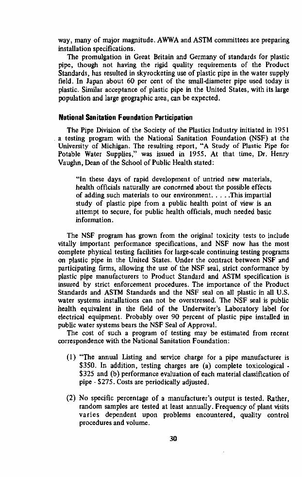
way, many of major magnitude. AWWA and ASTM committees are preparinginstallation specifications.The promulgation in Great Britain and Germany of standards for plasticpipe, though not having the rigid quality requirements of the ProductStandards, has resulted in skyrocketing use of plastic pipe in the water supplyfield. In Japan about 60 per cent of the small-diameter pipe used today isplastic. Similar acceptance of plastic pipe in the United States, with its largepopulation and large geographic area, can be expected.
National Sanitation Foundation Participation
The Pipe Division of the Society of the Plastics Industry initiated in 1951a testing program with the National Sanitation Foundation (NSF) at theUniversity of Michigan. The resulting report, “A Study of Plastic Pipe forPotable Water Supplies,” was issued in 1955. At that time, Dr. HenryVaughn, Dean of the School of Public Health stated:
“In these days of rapid development of untried new materials,health officials naturally are concerned about the possible effectsof adding such materials to our environment. . . . .This impartialstudy of plastic pipe from a public health point of view is anattempt to secure, for public health officials, much needed basicinformation.
The NSF program has grown from the original toxicity tests to includevitally important performance specifications, and NSF now has the mostcomplete physical testing facilities for large-scale continuing testing programson plastic pipe in the United States. Under the contract between NSF andparticipating firms, allowing the use of the NSF seal, strict conformance byplastic pipe manufacturers to Product Standard and ASTM specification isinsured by strict enforcement procedures. The importance of the ProductStandards and ASTM Standards and the NSF seal on all plastic in all U.S.water systems installations can not be overstressed. The NSF seal is publichealth equivalent in the field of the Underwiter’s Laboratory label forelectrical equipment. Probably over 90 percent of plastic pipe installed inpublic water systems bears the NSF Seal of Approval.The cost of such a program of testing may be estimated from recentcorrespondence with the National Sanitation Foundation:
(1) “The annual Listing and service charge for a pipe manufacturer is$350. In addition, testing charges are (a) complete toxicological -
$325 and (b) performance evaluation of each material classification ofpipe - $275. Costs are periodically adjusted.
(2) No specific percentage of a manufacturer’s output is tested. Rather,random samples are tested at least annually. Frequency of plant visitsvaries dependent upon problems encountered, quality controlprocedures and volume.
30

(3) We have no knowledge as to the percentage or proportion of plasticpipe in the United States which is produced under the NSF program.We have been advised, however, that 90 to 95% of all plastic pipemanufacturers are participants.
(4) We do no testing overseas; however; we do have plastic companies inEurope who are participants in the program insofar as those productsthat they manufacture for import into the United States areconcerned. Special conditions may be considered, however.
(5) We are in a position to extend our services to those foreign firms who
import to the United States. The testing and listing charges areidentical. The only additional cost being that for transportation andexpenses. We have not seen fit at this point to franchise overseaslaboratories. Although this may be considered when volume reaches apoint which deems it feasible.”
In 1965 the NSF published its Standard No. 14 for ThermoplasticMaterials, Pipe, Fittings, Traps and Joining Materials. Its purpose is “toestablish the necessary public health and safety requirements forthermoplastic materials, pipe, fittings, valves, traps and joining materialsbased on specific end use and application, and to provide for conditions andprovision of evaluation thereof.” It is reproduced in part as Appendix G.As mentioned above plastic pipe and fitting standards have been or are
being developed by many countries. The International StandardsOrganization has developed several recommendations including R330, Pipesfor Plastic Materials for the Transport of Fluids (Outside Diameter andNormal Pressures.) This recommendation carries the following statement onthe cover sheet. . .“For each individual country the only valid standard is thenational standard of that country.”
'
Japan has its Japanese Industrial Standards including one for RigidPolyvinyl Chloride Pipes for Water Works - JIS K 6742-1965. Israel’sstandards include one for Hard Polyvinyl Chloride Pipes for carrying DrinkingWater, S.I.532. The British Standards Institution has a number of standardsor specifications for plastic pipe including one for unplasticized PVC Pipe(Type 1140) for Cold Water Supply. The Instituto Nacional de NormasTecnicos y Comerciales (INANTIC) of Peru has issued standards for PVC Pipefor the Conduction of Fluid Under Pressure, No. 399-002 and PVC Pipe forWastewater. In Mexico the Institute for Engineering will issue “QualityStandard and Methods of Testing PVC Pipe” in January 1969. Other foreignspecifications are listed in Appendix C.
Specifications
Specifications and standards are required to insure that the purchaserobtains the quality of material having the correct dimensions which herequires. A specification for‘ plastic pipe for a potable water use wouldinclude the following: (1) that the pipe be manufactured from PVC, PE, ABS
31

or some other known material with the characteristics that the user has
selected, (2) the required pressure rating, (3) for each kind of material, thespecific designation, e.g., PVC 1120, must be specified, (4) quality ofmaterial, (5) workmanship, (6) approval for potable water, (7) pipe dimen
sions and tolerances, (8) pipe requirement such as minimum bursting pressureand sustained pressure, test requirements, packaging, (9) qualification for
manufacturing and rejection. It is important to note the wording of theProduct Standards and the ASTM specifications: “All pipe intended for usewith potable water shall meet the specifications of the National SanitationFoundation Testing Laboratories, Inc., or other accredited laboratories
recognized by Public Health Officials.” (This is applicable in the UnitedStates and may be paralleled by similar requirements in other countries.)Some users require that the manufacturer be able to demonstratesuccessful use of his pipe in water service for a number of years. This mayassure the user that the manufacturer’s past record is satisfactory, but itbecomes somewhat restrictive upon manufacturers who are new in thebusiness. There is no substitute for an actual inspection of themanufacturer’s plant and a check upon his in-plant quality controls. Somemanufacturers furnish a full guarantee on their material.
Testing
In the United States in 1955 when the National Sanitation Foundation
(NSF) Research Study on Plastics was completed and it was determined thatpipe made from virgin thermoplastic resins and compounds would not
produce deleterious effect to drinking water, the number of manufacturerswho offered plastic pipe for potable water uses began to increase. It was soonrecognized by the plastics industry and by health and water works officialsthat there was a need for a testing and identification program of plastic pipeon a continuing basis. The plastics industry askedthe National SanitationFoundation to establish a continuing testing and certification program toassure the suitability of plastic pipe for drinking water purposes. Certainunscrupulous manufacturers were using scrap plastic and reclaimed materialsfrom unknown sources for the production of plastic pipe which was beingoffered for potable water service with no assurance of its meeting therequirements of that service.The NSF brought together a Public Health Advisory Committee to meetwith the plastics industry leaders to outline a program for continuous testingand certification of plastic pipe for cold water service. It was agreed by thisCommittee that the Product Standards of the U.S. Department of Commerceshould be used as a basis for physical testing. The Product Standardsreference acceptable ASTM test procedures which are used by the NSF TestingLaboratory. The performance specifications of the Product Standards andASTM specifications are based insofar as possible on a 50-year life andinclude, as required by the applicable standard, test requirements forsustained pressure (1,000 hours), quick burst, impact resistance, dimensionsand tolerances, and other quality control requirements. Plastic pipe issubjected to the tests shown in Table 6 during manufacture.
32

TABLE 6
TESTS ON PLASTIC PIPE DURING MANUFACTURE
Test A-BS E M ASTM Designation
Carbon black x D 1603Ballooning x x x D 1598
Burst pressure x x x D 1599
Density x PE SpecificationsEccentricity x x x D 2122Environmental stress cracking x PE SpecificationsExtrusion quality x x D 1939/ D 2152Failure x x x D 1598Flattening x D 2241Inside diameter measure x D 2122Outside diameter measure x x D 2122
Seepage or weeping x x x D 1598
Sustained pressure x x x D 1598Wall thickness x x x D 2122
All tests are conducted under rigid controls at the standard testtemperature of 23° C (73.4° F). Sustained pressure test for PE is alsoconducted at 100° F. For recommended test frequencies, see appendix A-4,ASTM D 2513.
These tests are added to those related to the toxicological and organolepticaspects of the pipe involving tests of toxicity, taste and odor and theresistance of plastic pipe to use conditions.Before any plastics pipe compounds, proposed for use in pressure pipingapplications, can be accepted by the NSF, it is necessary that themanufacturer of the compound develop design stress data and furnishevidence that the design stress has been developed in conformance with thetentative Method for Estimating Long-Term Strength and Working Stress ofThermoplastic Pipe prepared by the Plastics Pipe Institute. The above data are
developed according to the standard procedure over a period of 10,000 hourstesting. The data may then be used to project the 100,000 hour design stressof the material.The NSF makes first-hand inspection of plastic production and collectssamples of pipe from the extruders, from storage, from warehouses and frompoints of installation for control testing. The sampling of plastics materialsand pipe is carried out on a surprise visit basis. These unscheduled visits aremade of plants where the NSF Seal is being placed on plastic pipe. State andlocal health department engineers are also helpful in collecting and submittingsamples of pipe from points of installation.The NSF insignia on plastic pipe of all types manufactured under thepresent Seal of Approval Program signifies that the pipe is safe for potable
33

water uses and that it conforms with the physical specifications of theapplicable Commercial Standard hr the material concerned. In thoseinstances where there is no standard, the pipe is tested against the hoop
stresses recommended and proven by the material manufacturers and usingthe ISO* formula to determine the test pressure.In early 1964 a survey by NSF indicated that better than 90% of thepopulation of the United States were served by health agencies utilizing orrequiring the NSF insignia on plastic pipe as being evidence of the pipe’ssuitability for potable water uses. Numerous governmental agencies,municipalities, water districts and similar jurisdictions utilize the NSF Seal asa means of assuring themselves of the public health safety and performancecapabilities of plastic pipe.The testing laboratory facilities of NSF are being used by some foreignmanufacturers of thermoplastic pipe to earn the right to distribute theirproduct in the United States with the NSF Seal affixed. NSF has expressed awillingness to assist other countries to develop programs for testing andcertification of plastic pipes manufactured in those countries. Some
preliminary discussions are actually underway in Latin America. A formalquality control program is necessary to assure the physical, toxicological andorganoleptic qualities of the plastic pipe used in potable water supplysystems.
Determination Di Wall Thicknesses
When equations relating design stress to pressure rating are used or
schedule size pipe is pressure rated, the rating decreases as the pipe size
increases because the diameter-to-wall thickness ratio increases as the pipesize increases. Thus a piping system must be designed for the largest size pipeand is overdesigned for the smaller sizes. To correct this engineering problem,the plastic pipe industry devised a series of wall thicknesses such that thediameter-to-wall thickness ratios (Standard Dimension Ratio, SDR) areconstant, resulting in the same pressure rating for all pipe sizes in any oneseries. This resulted in the addition of pressure rating tables for water at 73°Fto the ASTM and Commercial Standards. From these tables, for example, inSDR21 pipe for PVC 1120 plastic material, the pressure rating is 200 psi forwater 73°F regardless of the size of the pipe. For Schedule 40 pipe (which isnot SDR) the pressure ratings for PVC 1120 plastic material for water at73°F are 220 psi for 4-inch and 450 for 1-inch pipe.
Joints and Fittings
Much harm has resulted from the belief that the installation of plastic pipeis a do-it-yourself job. This leads workmen and some engineers to believe thatanyone can do a good job, regardless of the way he does it. Nothing can befarther from the truth as evidenced by some of the early failures of plasticpipe installations. Like any other piping, a satisfactory installation is obtained
*International Organization for Standardization. See Appendix H, Par. 3.14, Pressure
Rating, for further information.
34

only when the system is designed properly and the specified components areused. Workmen must be trained, both by instruction and field experience, sothat they know how to make a proper installation. Good workmanship is thefinal step in achieving a satisfactory piping system.Fundamental to the proper installation is a realization that the type ofjoint used with plastic piping and fittings depends on the type of materialsinvolved and on the particular application. Detailed information on joints andjoining appears in Appendix H. A few highlights follow.PVC material may be joined by any of several different methods. PVC pipemay be obtained with plain or bell end and may be jointed by fusion orsolvent cementing or may be readily threaded if the wall thickness permits.For solvent cementing, the solvent should be that specified by the pipe
manufacturer and care must be taken to prevent use of excessive amounts ofsolvent. Such excessive amounts result in buildup of material inside the jointand may cause a weakening of the sidewall. Insufficient solvent may result ina weak and leaking joint. Proper curing time, approximately 24 to 48 hours,must be allowed before pressure can be applied. The joints should be left
uncovered for observation and testing. Solvent cemented joints must be free ofmoisture, oil, or other foreign material. Temperature has a definite effect onthe time it takes for a solvent joint to attain its full strength.The following conclusions were drawn by the Water Research Association
of England from strength tests on 3/4 inch and 1 inch spigot and socket jointson PVC pipe:
(1) Differences in strength due to the different cements (four were used)are probably too small to be of practical importance. Carefulpreparation of the mating surfaces, together with use of an adequateamount of cement are more important than choice of cement.
(2) Strength of taper socket joints is superior to that of parallel socketjoints.
(3) For maximum joint strength, parallel socket joint clearances should beless than one or two thousandths of an inch and the taper socketjoints should be less than one degree.
(4) The lengths of commercially available parallel sockets are adequate togive satisfactory joint strengths provided the clearance is kept smalland the joints are made in a workmanlike manner.
*(5) Joints reach approximately half their ultimate stength after fourhours, but they are still not fully matured after one week.
If heat forming is used, care must be taken. Unevenly heated areas andareas heated beyond the point of softening may be permanently damaged.
*“Necessary cure time can vary from minutes to days depending on conditions and the
solvent cement used. . ASTM D2855-70
35

This pipe can be crimped-off in the thinner-wall small diameters, but the
crimped area must be straightened and reinforced, usually with a solvent
cemented collar.In heavy-wall pipe such as Schedule 80 of Class T, threaded fittings may beused in iron pipe size. Teflon pipe tape may be applied to help assure a
watertight connection.
When bell ended pipe is used, a multi-ribbed rubber ring provides the seal
and makes a flexible joint installation. This can be compared to theconventional bell and spigot rubber ring push-on joint. This type ofconnection offers a further advantage of permitting the line to be filled,tested and placed in service without waiting for solvent cemented joints to
set.
PE pipe cannot be connected by solvent cementing or by the use ofthreaded fittings. Plastic or metal insert fittings using high-quality stainlesssteel clamps or compression-flared connections may be used. Insert fittingsplace a restriction in the line which increases the head loss - consequentlydelivering a smaller quantity of water. Where low pressures obtain in thewater system or high delivery of water is required, insert fittings are notrecommended.
A moderate amount of heat is required for flaring operation. Heatingshould be carefully controlled to avoid uneven heating or over-heating.Heating beyond the point of softening, when making flares, may result inchanges of dimensions and may cause permanent damage, although PEmaterial does not appear to be as adversely affected by heat as PVC or ABS.On sizes 1‘/5-inch in diameter or larger where insert fittings are used,consideration may be given to the use of double clamps. Clamps should be ofhigh quality stainless steel. Clamps made of inferior material may result inearly failure of the clamp. Material should be allowed to cool before thecoupling is tightened and the material stressed.This PE material may be crimped off with no damage to the pipe and nostraightening or reinforcing required. Reasonable care should be used in
handling and installing. PE material is more resistant to impact than eitherPVC or ABS but is more easily cut by sharp objects.Fittings for the pipe should be constructed of the same material used forthe pipe except for insert fittings. Fittings should be of the molded typeinjected from molding compound.*
lnstallation**
Effective specifications on the installation of plastic pipe are as importantas adequate material specifications. The importance of proper installationprocedures for pipes of other materials has long been recognized. Plastic pipeis no exception--it is just slightly different in its requirements.For all plastic pipe materials usually used for potable water installation,
care is required in bedding and backfilling practices. Reasonable care should
*For further information on jointing, see Appendix H.**A complete guide and outline specification for installation are given in Appendix H.
36

be used in handling and installing. PVC pipe must be stored away from heatand sunlight. If exposed to direct sunlight, bowing is likely to occur becauseof the temperature differential between the top and the bottom of the pipe.In the case of bellended pipe, the bell is apt to deform. ABS and PVC can bedamaged by the impact of hard, sharp backfill material. PE has moreresistance to such impact but is more easily cut by sharp edges. There is also
the possibility of imposing secondary stresses that may cause failuresometime far in the future. In any event trench preparation and backfillingspecifications should be somewhat similar to those used for asbestos cement
pipe, namely that fine granular material should be used until the pipe is well
covered.
Another problem is that when PE tubing is unrolled it tends to coil.*When bent for installation as when making the bend from the trench up to
the angle stop or curb stop it tends to straighten out. A means must beemployed to keep the bend in place until the final connection is made andbackfill is placed. Backfill, alone however does not ensure that the tubing will
stay in place. It is recommended that the tubing be tied with twine or ropeacross the bend or be tied to a stake. Heat should never be used in making abend because the tubing may be weakened and early failure may occur.In the case of non-end-load-bearing joints pipelines must be anchored atchanges of direction, also at valves and tees, etc. The size of the thrust blockwill depend on the bearing capacity of the soil and should be assessed as forpipes of other materials. When placing concrete on a plastic pipeline careshould be taken to avoid encasing the pipe completely. This is because of theslight flexibility of plastic pipe when it is in concrete or when it is clear of theconcrete may cause a tendency for it to shear at the interface betweenconcrete anchor and the backfill, unless the pipe is properly supported. Athin membrane such as kraft paper, plastic sheet, or unbituminized roofingfelt should be used between the concrete and the plastic pipe.
Pipes may be joined at the side of the trench and then placed in the trenchby lowering with ropes. Pipes should never be dropped into the trench. Caremust be taken during this operation to avoid excess strain on pipes or joints.Solvent cemented pipelines should not be snaked into the trench until the
joints develop sufficient strength (see Appendix H for details). If rubber ringjoints are used they should be checked after the pipe is fully positioned in thetrench to ensure that they are still fully engaged. When laying pipe in atrench, a small amount of slack should be provided to allow for temperaturecontraction. The final connection should not be made until the pipe is atground temperature.
One advantage of using plastic pipe, which can be joined at the edge of thetrench and lowered into place, is that width of the trench may thereby bereduced. For instance, a 6-inch trench may be used for a 4-inch plastic pipewhile a 15 or 18-inch trench will be required for a 6-inch cast iron pipe with33-inch excavations for the bells. This often represents approximately athree-fold savings in excavation and backfill quantities.
*Also true for tubing and some pipe made of Type II PVC and PB.
37

Additional savings are sometimes possible through use of the technique oflaying pipe by mole-plow. This technique, developed in England and now
practiced successfully in the U.S. on large rural projects, employs a
modification of the drain-type mole-plow which is either pulled directlybehind a tractor, or, the tractor is anchored and pulls the plough towards it
by means of a winch and a cable. Attached immediately behind themole-plow is an expander larger than the overall diameter of the joints on thepipe and the leading end of the pipe to be installed is shackled to the back ofthe expander so that the pipe is installed as the mole-plow is pulled fowrard.The mole-plow technique eliminates trenching but, although it is quickand economically attractive, ground conditions must be appropriate for theuse of this method. A soil survey is essential before deciding to use it andother underground services, if any, in the area in which it is intended to laythe pipe must be identified and located.
Basis of Design
The hydraulic calculations required in pipeline design are brief. Once themaximum required capacity has been estimated it is only necessary to feedflow, head loss and estimated friction factor into an empirical formula or
design chart to arrive at a pipe diameter. While for most pipe materials it is
advisable to allow a margin of overcapacity for deterioration or buildup in theinner wall of the pipe, this is not the case with plastic pipe which is noted formaintaining its original flow characteristics. Generally a limiting maximumvelocity of five feet per second is recognized.Tables 7 and 8 are included to assist the designer in making preliminarycalculations. Note that the inside diameters vary considerably from thenominal pipe size, for instance the ID for 1/2-inch PVC 200 pipe is 0.72inches. The tabulated ID can be used with Hazen-Williams nomographs(Figure 6 for English units, Figure 7 for metric) to determine relative headloss, flow, or velocity. A Hazen-Williams “coefficient” of 150 is commonlyused for plastic pipe.In the United States there are three different physical sizing systemscommonly used for plastic pipe. The Schedule system was the initialdimensioning system adopted by the plastics pipe industry. It is still in usetoday. It is based on outside diameters and wall thicknesses.The newer* SDR-PR (standard dimension ratio-pressure rated) systemdiffers from the Schedule system in that pipe of any size made to the SDRbasis has the same pressure rating if made of identical material. That is, theuser may purchase ABS or PVC pipe, for instance, with a 160 psi pressurerating in all sizes ranging from 1/é-inch to 6-inch diameters. Using the Schedulesizing system, this is not possible because of the decrease in pressure ratingwith increasing pipe diameter, i.e., there is not a constant relationshipbetween pipe diameter and wall thickness as in the SDR system.The third pipe sizing system, Tubing, is based on copper tubing sizes
(outside diameter) and is associated with pipe made exclusively of PE, PVC,
*The diameter of a pipe divided by its wall thickness is its dimension ratio.
38

'
TABLE
7
MATERIAL
REQUIREMENTS
ANDPIPECLASSIFICATION
FOR
ABS,PE,ANDPVCPIPE
Hydro
static
design
stress
Compound
(psi)
ABS1106
630
ABS12101000
ABS2112
1250
PE2305
500
PE2306
630
PE3206
630
PE3306
630
PVC11202000
PVC12202000
PVC2110
1000
PVC4116
1600
Pressure
rating(psi)
SDR7
SDR9
SDRL1.5
SDRL3.5
SDRL5
SDR17
SDR2L
125
100
125
125
125
80
100
100
SDR25SDR32.5
SDR41SDR64
ACRYLONITRILE-BUTADIENE-STYRENE
(ABS)
100
1 60
200
315
160
250
80
125
100
80
160
125
100
POLYETHYLENE
(PE)
80
80
80
POLYVINYL
CHLORIDE
(PVC)
250
200
160
125
100
63
250
200
160
125
100
63
125
100
80
63
50
200
160
125
100
80
50

TABLE 8
ILLUSTRATIVE DIMENSIONS AND PRESSURES FOR PLASTIC PIPE
Compound ABS PE PVCABS 1210 PE 2306 PVC 2110
*Pressure SDR-21 SDR-1 1.5 SDR-21Rating 100 psi 100 psi 100 psi
Nominal Wall Wall WallDiameter ID Thickness ID Thickness ID Thicknessinch (inch) (inch) (inch) (inch) (inch) (inch)
% - - 0.622 0.060 0.720 0.060% 0.930 0.060 0.824 0.072 0.930 0.0601 1 .189 0.063 1.049 0.091 1.189 0.0631% 1.502 0.079 1.380 0.120 1.502 0.079
1% 1.720 0.090 1.610 0.140 1.720 0.0902 2.149 0.113 - - 2.149 0.1132% 2.601 0.137 - - 2.601 0.1373 3.166 0.167 - - 3.166 0.1674 4.072 0.214 - - 4.072 0.2146 5.993 0.316 - - 5.993 0.316
Source: U.S. Dept. Commerce Commercial Standards (See Appendix C).
*The SDR system makes possible a constant pressure rating over alldiameters. For Class T, ABS 1210, the pipe pressure rating ranges from 250psi (%-inch) to 50 psi (6-inch) and wall thicknesses vary from above. Similarvariation exists for other Schedule sized ABS, PE, and PVC pipe.
or PB (polybutylene). The popularity of this system has greatly decreasedwith the advent of the SDR system. Its principal usage is in small wellsequipped with submersible or jet-pumps.There are numerous methods of joining plastic pipe and fittings. The majormethods are described in some detail in Appendix H. It should be noted thatplastic pipe and fittings can be readily joined to pipe and fittings made ofother plastics materials or of non-plastic material. Specific information andprocedures can be obtained from the pipe manufacturer or supplier.Plastic pipe for water supply system use is available in a wide range ofsizes. The largest diameter commonly maintained in stock is about 8-inch,with a few manufacturers stocking pipe up to 12-inch diameter. 16-inchdiameter pipe is occasionally used in Japan and one British firm markets an18-inch diameter pipe. The nature of the manufacturing process is such thatequipment changeovers from inch to metric units is relatively simple for pipeproduction. The same cannot be said, however, for fittings. A few of thelarger pipe manufacturers could probably produce pipe up to 48-inches indiameter if a demand arose.
40

0 0 v c H
._ 500
0-3‘: 300 -_30.0o0— _= 5
g 0.4 i 220.000— -1
5
2 0.5-? '°° °-'°‘2 8° E
96-: 0: 0.6 -; so -1e4 -j ,2 5 so —. /
8,000: 605 0.8‘.“ 3°
:-_ 54.2 0.9-: O 8 2 _—
_
-3.000... 481 H, -' 3/5'OoO_ 42 : 5 5 m10 E00|_ . 2 : .
4.0003 2
364
Q _
(C23
zouu:
X 8 j
1:
3.000%
2 3°. 33
'
15131, 8/5 g::
3
5 24— 5 I 0: 2 u. 4; in
: Q _ Z 2; E 50 Z -U2 ooo—‘ 20 — -— - 2 —, 3 —. _' I w |e~ 2 : i- /S 0 5 5
'
I Z _ - _- U-I IOO—-I 4 2 _: <1- O 1 Q _ Lu :1 w : mI -I |4 U 1
IL 150; I -. Q
4 2;’ 1 E 3.: 2 200' u. E 7'T
(9 12" 0-
E _/ 2 O I E 0.00110003 E |0- l<
'5
i/> iii
0* 0.8 :2
ado-1''
- m 41 *—'
<1 8 0.6 —I_.\;
m
/5‘ 0 I _l O 5 -- 3\ 8“ t O
'4
-
600: ii \\~iéi /5_§d <8-3 -
500- 6-i\_< 00 Q> -
ON , £1‘ 6—f _'
40011:5_ \V E I:
02
2
300% 4_ \/\ E
_= I/2 _ \ _ 9 01:: 0.0001
5
3
9 -\ 5 0-08 E
200-; 3*|0—" \ 3 8.8%
—I
1 2|/2— “ 0 ' ‘‘ - 0.04 —_
1 24 ‘ S 003-.. 51 P
5
|()()--_- H/2 _ I 8 0.02
-5
e0:; 20-: Qo.0|—_i 0.0000:
601 |_ 5 o.ooe::_ 25 — 0006-‘so - 1 0005-‘1
Figure6NOMOGRAPH FOR HAZEN—WILLIAMS EQUATION
(English Units)
41

500 -11 400 —_
2000 01; 30°‘;
2 ei 200-;
1 3 I. O 1 I
|ooo—; 300°? E I "§Sg°-'°
:88‘ 5 g 3 60
‘I : l-- _ 1
700 j : 0.2 — 50 '2
eoo - 200°‘; 5 401
50°“: 5 E’3°2
30° IOOO-: '3 5 °.5\i 9005 2- 0-4 s 8 ".3::°-°' "1
200 5 O-\ 8°01 5 ‘€20 I or E ‘L
’
: Q \ 700- >- 0.5 _ O {.5
gt 4 o
I o ' “J _ 3 O ; ,f
F’,
-I 8
60*5 0.6 _ 1 50
0
10!) / U
3"’ 5°°‘='\°-at -:5 ,’¥"~,-3 2 3
|oo'5 ‘E \ 01%’ |oo<_i w 2-‘. 3-I A 400.. \ C I (D .1 5 = m90 I 5 Z "\ 0- : $ 150 -1
‘
z -I Q80 I Q '31“;
\s_9\—I- 2003 "_ E E
70 : gr 300-; %
'
_;_I-El~ -Z 0 13: 0.00|
60 -_' 3 5 LL- Z \ H 3
1
8-83-I 1 _ -g I _6.;‘5° - 5 1 Z - > 5:‘ ll 0.5-I
40 -= g 2001 g -5 ° o.4—
: -' _ m -l
.1 3 L; .3 m 0.3130 -: u‘ -I <
-1
lg 3 :
I 5 I 0-2
20 3
25 R’
:
'°9°o-__ 5 5 0| 5 0.000:
I 80:. E 2 0.08?- ; 3 : I— 0.06-_
;
TO _ E m 0.051
|O—3 so-_
4 E o.o4-3
-0: 1 .
E I 40-. 5 —- S O'02_E
5: 6 : 3
255 7 —U o.ooe -
3_= 8; 0.00650.005
Figure 7
NOMOGRAPH FOR HAZEN—WILLIAMS EQUATION(Metric Units)
42

Plastic pipe for water supply system use is available in a wide range ofsizes. Those in English units are shown in Table 9.
TABLE 9
*AVAILABLE DIAMETERS (NOMINAL) IN PLASTIC PIPE
PipeDiameter
(inches) 1/6 % 1 11/4 1% 2 21/2 3 3% 4 5 6 10 12 16
ABS XXXX X X X X X XXXXX X
PE XXXX X X X X X X
PVC XXXX X XXXXXXXXXX X
*There are smaller sizes available but these are not used for house servicelines. Larger sizes of plastic pipe may be obtained (up to possibly 48-inchdiameter.) There are some exceptions to the above listing in some of theSDR categories particularly in ABS and PVC pipe.
For some years the major technical problem in the design of thermoplasticpipe and in preparing satisfactory specifications for these products has beenthe selection of hydrostatic design stresses for long-term applications such asare required for water and gas distribution systems both inside and outsidebuildings. Short-term burst and other properties measured during short-termloading have been shown repeatedly to be unreliable for this purpose.Members of the plastic pipe industry operating through the'Plastics PipeInstitute developed a method for determining hydrostatic strength and designstresses for thermoplastic pipe from engineering test data and with the
cooperation of approximately 45 laboratories analyzed over 800 sets ofengineering test data. Recommendations were developed for hydrostatic
design stresses for water at 23° C (73° F) for a number of plastic pipematerials. Some of the more common are shown in Table 10. Europeandesign stresses have been added to the table by way of comparison. Theirbasic compounds may be different from U. S. compounds (different
formulation).Plastic pipe is pressure rated at a standard temperature of 73.4° F andpressure rating decreases with temperature increase until a critical point is
reached, depending on the specific compound. Temperature for pipe inburied applications is not critical for most situations once the pipe is buriedand full of water as water temperatures generally run near or below 100° F.The critical time for temperature consideration is during installation periods.All of the thermoplastic materials used in the manufacture of pipe have a
greater degree of expansion and contraction due to temperature variationsthan steel pipe. This movement is independent of the diameter of the pipe.Table 11 is illustrative.
43

TABLE 10
HYDROSTATIC DESIGN STRESSES AND50-YEAR STRENGTH DATA
Water at 23°C (73°F)
*EuropeanHydrostatic 50-Year 100,000 Hr. HydrostaticDesign Stress Strength Strength Design Stress
psi. psi. psi. psi.
PVC 1120 2000 4010 4250 1400
PVC 1220 2000 3790 4070 1400
PVC 2110 1000 2110 2370PVC 2116 1600 3620 3800
PVC 4116 1600 3640 3800
PE 1404 400 820 870 425PE 2305 500 1000 1090 425PB 2306 630 1230 1300 710PE 3206 630 1200 1280 710PE 3306 630 1270 1350 710
ABS 1208 800 1440 1670ABS 1210 1000 1890 2070ABS 1316 1600 2930 3160ABS 2112 1250 2260 2510
CAB MH08 800 1450 1580
*The hydrostatic design stresses used for plastic pipe in Europe are 50-yearstrength predictions obtained on an entirely different basis than those shownabove and divided by a factor. A move is underway (1965) to raise the 1400ratings to 1800 psi.
TABLE 1 l
TEMPERATURE EXPANSION AND CONTRACT ION OFPLASTIC PIPE
Material Coefficient Expansion and Contraction(In-In-Of) (per 100 ft. per 10°F
Temperature Change)
PVC — Type 1 4.1 X 10‘5 0.492 inchesPVC — Type 2 5.3 x 10'5 0.636 inchesABS — Type 1 5.7 x 10'5 0.684 inchesPE — Types 2 and 3 8.9 x 10'5 1.068 inches
Techniques for handling this expansion are outlined in Appendix H.
44

Protection of Health
Another important specification is assurance that plastic pipe presents no
public health hazard.In addition to the basic resins, plastics compounds ready for extrusioncontain certain additives. A brief consideration of these additives in pipe willclarify the reason for concern about the suitability of plastic pipe,particularly PVC pipe for potable water use.The formulated compound from which PVC pipe is made contains
pigments, lubricants and stabilizers in addition to the basic polymer,
polyvinylchloride. The pigment is incorporated to render the pipe opaqueand, in water pipe, carbon black or titanium oxide is commonly used for this
purpose. Lubricants serve to reduce the adherence of the pipe material to theextrusion tools during the manufacturing process and quite a range ofmaterials are used for this purpose including stearic acid, calcium stearate,
glycerol monosterate, polyethylene wax and montan wax. Stabilizers are
incorporated in PVC compounds because the temperatures used for extrusionand injection molding (100° to 200° C) are such that detrimentaldecomposition of PVC takes place with the liberation of hydrogen chloride.In the presence of oxygen the reaction is autocatalytic, but it can be reducedto a slow uniform rate by the incorporation of a substance that caneffectively remove the hydrogen chloride as it is formed. White lead, for
example, a basic lead carbonate that is commonly used as a stabilizer has beenshown to react in this way. During the heat processing of PVC compounds, itis converted to lead chloride.Many other substances have been used as stabilizers including compoundsof lead, cadmium, borium, tin, calcium, and zinc. In contrast to the polymers,pigments, and lubricants, which in general are physiologically and chemicallyinert, many of these stabilizers are toxic or suspect.The choice of a stabilizer is dictated by technical and economicconsiderations. A well-stabilized PVC compound produces a pipe with betterstress characteristics and impact resistance than one in which the stabilizationis inferior. Unfortunately however, many of the non-toxic stabilizers aremarkedly less effective in performance or are much more expensive than
stabilizers based on, for example, lead compounds.Lead stabilizers are by far the most widely used in PVC extrusion
generally, but are not used in the United States in pipe intended for potablewater use. Lead stabilizers are used, however, in pipe manufactured in Europeand in Japan and intended for potable water use. Tin stabilizers are theleading stabilizers, in frequency of use, for water supply pipe manufactured inthe United States. Their cost per pound is about four times that of leadstabilizers.
Tin stabilizers are widely used in the production of pipe fittings, includingdrain, waste, and vent (DWV) piping, by injection molding, products wherethe material costs are less important as part of the cost of the final product.Numerous investigators* have shown that lead stabilizers and their
reaction products can transfer to and dissolve in water in contact with PVC.
*Boelens, Boone, Bracale, Chuy, Donovan, Niklas and Meyer, Tiedemand and Milone,et al. See Appendix B for complete bibliographic references.
45

The extractable lead in a PVC pipe is apparently confined to a surface film
that is rapidly removed as the pipe is flushed out. In several static
experiments on PVC pipes filled with water, the majority of the lead wasgiven off in the first two or three days of standing. After this time leachingrapidly decreased and showed little further change after ten or fifteen days.
The total quantity of lead extracted in this period is small relative to the totalinitial lead content of the pipe. Migration of lead from the bulk of the PVCapparently takes place slowly, if at all. If the pipe is pre-treated with certainacidic solutions, the film of lead stabilizer may be completely removed;subsequent extraction of the pipe with water gives no trace of lead even aftera period of several months contact.***Concern about possible leaching of lead from plastic pipe is due to lead’shistory as a cumulative poison which tends to be deposited in the bones. Lead
poisoning usually results from cumulative toxic effects of lead aftercontinuous consumption over a long period of time, rather than fromoccasional small doses. Immunity to lead cannot be acquired, but sensitivityto lead seems to increase. The intake that can be regarded as safe for everyonecannot be stated definitely because the sensitivity of individuals to leaddiffers considerably.Lead may enter the body through food, air and tobacco smoke as well asfrom water and other beverages. Consequently the total intake of lead mustbe considered in setting standards for water. The exact level at which theintake of lead by the human body will exceed the amount excreted has notbeen established but it probably lies between 0.3 and 1.0 milligram per day.The mean daily lead intake by adults in North America is about 0.33
milligram per day. Of this quantity, 0.01 to 0.03 milligram per day is derivedfrom water used for cooking and drinking. A total intake of lead appreciablyin excess of 0.06 milligram per day may result in accumulation of a dangerousquantity of lead during a lifetime. Lead in an amount of 0.1 milligramingested daily over a period of years has been reported to cause leadpoisoning.
For many years the mandatory limit for lead in the U.S. Public HealthService Drinking Water Standards was 0.1 milligram per liters; however, owingto the fact that the total intake of lead from food, inhaled atmosphere andtobacco smoke in industrial urban areas appears to be increasing with littlechance of regulation and diminution, and inasmuch as the concentration oflead in drinking water can be controlled without undue hardship on waterpurveyors, the USPHS Drinking Water Standard for lead was lowered in 1962to 0.05 mg-litre. It is significant to note that the U.S. Government has alsoestablished a tolerance of lead in food at 7 milligrams per kilograms, morethan 100 times the limit for drinking water.The limit of 0.1 mg-liter in the WHO International Standards for Drinking
Water was lowered to 0.05 mg-liter in 1963. In the past the Netherlands and
***Research now in progress at the National Sanitation Foundation, Ann Arbor,Michigan, U.S.A. directly contradicts these earlier studies. The authors of this report aregrateful to Mr. Charles Farish for bringing these studies to our attention. Concernedreaders are advised to contact Mr. Farish directly.
46

Germany have permitted a temporary lead concentration up to 0.3 mg-liter in
water that has been in pipes for 24 hours. Uruguay, on the other hand, has
used a standard as low as 0.02 mg/l. Several countries use 0.1 mg-liter as astandard. The British Standard 3505 amended in 1966 specifies that lead
extracted from the internal walls of PVC pipe shall not exceed 1.0 mg-liter inthe first wash and 0.3 mg-liter in the third wash. It states that conformitywith this will ensure that the 1963 WHO recommendations concerning toxic
contaminants of drinking water are not exceeded. The 1964 standards ofIsrael have a similar standard.
Some countries minimize the health hazards resulting from the use ofplastic pipe by regulating the type and quantity of stabilizers that may beincroporated into the pipe material. For instance Peru specifies that only
calcium and zinc may be used as stabilizers for pipe to be used in potablewater installations. However, tests conducted in Peru (Bracale, Chuy) in 1967lead the researchers to conclude:
(1) For PVC pipe stabilized with lead the concentration of lead in theextracting water is extremely low and is much below that permitted
by the standards for potable water.
(2) The quantity of lead extracted decreases with time; it having beenproved experimentally in the laboratory and by analysis of samplestaken from distribution systems that the total amount of extractablelead is depleted in a period no greater than 90 days.
(3) It is considered that these pipes under normal service conditions offerno risk whatever to the health of the users of the potable watersystems.
It is not known whether the standards in Peru have been changedaccordingly.In the United States the ASTM specifications for Plastic Pipe include anote stating the . . .“pipe to be used for the transportation of potable watershould be tested and approved for that purpose by the regulatory bodies
having such jurisdiction. Information regarding the special requirement for
such pipe can be obtained from the National Sanitation Foundation
Laboratory or other accredited laboratory.” Standard No. 14 of NSFstates . . .“The toxicological and organoleptic evaluation of the analysesspecified in appendix B shall meet minimum public health requirements . . .”
and Appendix B.2 reads, . . .“The maximum acceptable concentrations ofchemical substance permissible in the extractant water shall be as set forth in
Public Health Service Drinking Water Standards - namely 0.05 mg-liter."The NSF, after extensive tests of the extractant water from plastic pipemade with lead stabilizers, has concluded that data acquired to date do not
support the use of lead stabilized plastic pipe for transporting potable water.All pipe formulations now approved by NSF contain no lead stabilizers.Whether the use of toxic stabilizers in plastic pipe is controlled by directlimitations on the composition of the pipe material or by standards limiting
47

‘
the amount of extractable material present, the ultimate objective is to insurethat the quality of the drinking water that comes into contact with the pipewill not be adversely affected in any way that is injurious to health.It is suggested that the developing countries will want to consider all of themany factors involved before deciding on the controls they may wish toestablish for plastic pipe stabilizers to insure the quality of water passingthrough those pipes. One of the first considerations is the amount of leadbeing ingested already from other sources such as food and air. If this iscomparatively low the decision may be reached to allow the use of leadstabilizers with controls limiting the extractable material present in the water
as is done in Great Britain, the Netherlands, Germany, Israel, Japan and someother countries. The use of lead stabilizers will probably make it possible tolower the cost of the plastic pipe and may also produce a pipe with betterstress characteristics and impact resistance. These will be importantconsiderations in developing countries where funds are extremely limited and
much remains to be done to provide adequate water supply and sewerage
services.
The cost differential is difficult to determine. Lead stabilizers cost$0.35-0.40 per pound versus about $1.50 per pound for tin. Tin stabilizersrun around $0.02 per pound in extruded PVC pipe. However the lowerspecific gravity of tin eliminates possibly half of lead’s price advantage.Extruder retention time and temperature, extruder design, output rate,compound synergism, length of runs, level of regrinding, et al, all play a rolein prohibiting direct cost comparison. All aspects considered, the use of tin,rather than lead costs an additional $0.01-0.02 per pound, more or less. This
may seem insignificant as a percentage of installed cost (negligible to 2percent depending on diameter, pressure rating, and installation costs), butmay represent as much as 25 percent of the producer’s profit margin. Thusnon-lead stabilized pipe will not be competitive in an unrestricted market.Incidentally, U.S. plastic producers have sold both lead and non-leadstabilized compounds to overseas pipe manufacturers.The Central Public Health Engineering Research Institute (CPHERI)Nagpur, India recently investigated (a) the bacteriological quality of watertransported through PVC and PE pipe; (b) whether the plastic pipes harborlarger numbers of bacteria on their interior surfaces; and (c) whether problemsof disinfection are encountered with the pipe. The experiments were designedto test whether any nutrient materials could be released to water from plasticpipe, under normal conditions, which might support the growth of bacteria,particularly under tropical conditions. In the studies no significant increase inthe number of bacteria was observed in water passing through or stagnant inPE and PVC pipe as compared to those of galvanized iron and asbestoscement pipes.
The experimental findings were that plastic pipes neither harbor largenumbers of bacteria on their internal surfaces as compared to other pipematerials nor do they pose problems in disinfection. From a bacteriologicalpoint of view it was concluded that plastic pipes are safe for use in India inthe conveyance of potable waters.
48
Tiedeman and Mi1one* reported that plastic pipe systems can be
satisfactorily disinfected following standard disinfection procedures. In
experiments using high concentrations of chlorine on various plastic pipematerials, no adverse effects were noted on the plastics after 20 hours
exposure at 10° C. Adverse effects on copper and galvanized steel specimenswere noted, however, when they were held under similar conditions. Higherthan usual concentrations of chlorine may be used in the disinfection ofplastic pipe without damage.The same report points out clearly that there is no evidence that rats eatplastic pipe nor that they gnaw it in preference to other substances. It wasfound that rats could gnaw through plastic, lead or copper pipe when any ofthese presented a barrier to food or water. PE pipe was slightly moresusceptible than other plastic pipe, possibly because of the softer nautre ofthe pipe. There is no evidence of rats attacking ABS pipe in any of the morethan 1% million DWV residential installations made up to 1967.Plastic pipe also resists attack by bacteria, fungi, and termites. (A literaturereview may be found in PPI Technical Report 11*).
*See Appendix B for bibliographic citations.
49

MANUFACTURE OF PLASTIC PIPE
IntroductionPlastic pipe is made by extrusion of compounded thermoplastic materialsthrough specially designed annular dies, followed by take-off and postforming
equipment to size, calibrate, cool, and cut the pipe. A typical extruderconsists of a rotating screw enclosed in a cylindrical barrel. The propercombination of screw, barrel, and heating-cooling system should produce afully plasticated, thermally homogeous melt, and uniform flow rate throughthe die.
The material, in pellet or powder form, is fed from a feeding mechanism(hopper) into the machine cylinder. One or more longitudinal screws rotatinginside the heated cylinder forces the heated plastic through a die orifice whichhas approximately the shape of the pipe. The heated cylinder and rotatingscrew work to produce a completely plasticized and thermally homogeousfluid, provide the force necessary to extrude the material through the die, andmaintain the material at uniform termperature, viscosity, homogeneity andvelocity through the die. (See Figure 8).
~— Hopper loader—->From resin supply
Breaker plateand‘— Hopper Screen pack
Feed ve ''Controller .
""001 ponrt thermocouple Adjustable
Q I \ \_ valveRotary JOIDI ’
_ Die
._Feed throat
I
TolvocuumDie
Water Gear MOM, cooling locketDump \ heatersoutlet reducer drive Melt pressure
Water inlet
H
Heater bands transducerfof screw -— (barrel cooling not shown)cooking
Figure 8VENTED SINGLE SCREW EXTRUDER
50

Pipe sections are extruded with undersized diameters (internal and
outside) and inflated as they leave the die orifice. The technique has atwo-fold purpose - as well as producing pipe of accurate diameter it provides asimple method of preventing the tube from collapsing while hot.Sizing can be achieved by supplying compressed air to the extrusionthrough the die head or by applying a vacuum to the outside of the pipe, asthe extrusion passes through a cooled sizing die. Use of compressed air ischeaper and easier, vacuum sizing is more accurate.
Extruders
Extruders are available with either single or multiple screws which can bevented for removal of volatiles. The vent can be plugged and, normally, thescrew changed for non-vented operation. Vented single or multi-screwextruders are useful to remove volatiles from resins, such as monomers,moisture, and trapped air which might otherwise cause bubbles or otherdefects in finished parts. The vented extruder is sometimes more difficult todesign and operate due to the balancing necessary to avoid plugging or
escaping from the vent. The vent can be operated at atmospheric pressure,but vacuum is more common.Extruders are specified by barrel inside diameter (ID), length to diameterratio (L/D), and capacity. Standard sizes of the single screw extruder are 1%,2, 2%, 3%, 4%, 6 and 8 in. ID, with larger diameters available on special order.The general relationship of extruder size to pipe size is shown in Table 12.
TABLE 12
EXTRUDER SIZES COMMONLY USED IN MANUFACTUREOF PLASTIC PIPE
Pipe Size Extruder Size
$6’! 2!! 2%"
11/1" to 8" 31/1"
4" to 16" 4%"
The average output for a variety of plastics and applications increases withextruder diameter and L/D, as shown in Figure 9. Actual output can differdepending on compound, drive hospower, screw design, screw speed,termperature limitations, etc.The L/D ratio, defined as the screw length with flights divided by barrelID, has an important relation to available barrel surface area and residencetime of the plastic within the extruder. The calculation of L/D is notstandard, as some count only the flighted length of the screw after the feedhopper section, and others the entire flighted length. The difference usually isabout 1.5 diameters. An L/D of 24:1 is quite popular, although ratios of 16:1to over 30:1 are available. The trend has been to higher L/D to achieve higheroutputs and better uniformity.
51

50
Extrudercapacity,lb./hr.
N
S
‘‘
I I I I I I
- ‘
2 3 4 6 8 10
Extruder diameter, in.
Figure 9
AVERAGE EXTRUDER OUTPUT
The hollow cylinder, or barrel, in which the screw turns is usually
designed to withstand 10,000 p.s.i. Wear resistance and hardness of the barrelinterior are generally provided by nitriding in Europe, and by alloy liners
(usually “Xaloy”) in the U.S. Higher pressures often require shrink fitting a
steel tube with a cast-in liner into an outer barrel. Special corrosion resistantformulations and various thicknesses of lining are available.Most extruders have heating and-or cooling provisions on their barrels to
adjust operating conditions. Heat is most often applied by external electricalresistance or induction heaters arranged in several groups or zones along the
barrel.
Cooling of the extruder barrel is sometimes required to permit rapidchanges in temperature, or to remove excess heat from the polymer melt.
High output extruders usually receive most of their heat from the screw,rather than from the barrel heaters, once the extruder is in operation.
Sometimes the screw working adds too much heat, especially at higher screw
speeds, and the ability to cool can extend the capability of the extruder.
A screenpack is placed just after the screw to remove gross contaminationfrom the melt stream. It often has several wire screens in series. Thescreenpack is backed by a breaker plate which has a number of passages,usually many round holes ranging from 1/8-3/16-inch diameter. The breakerplate serves as a seal between the extruder and adapter, as a support for thescreens, and to reduce the circular motion of the melt.Other elements required include a motor drive, preferably with variable
speed; a gear transmission which permits operation of the screw in its properrange of speed; a thrust bearing assembly to absorb the screw thrust; and
52

monitoring devices for melt temperature and pressure, screw speed, powerconsumption, and product dimensions.Many plastics absorb moisture or contain volatiles or entrapped air whichmay result in surface blemishes, porosity or roughness of the extruded pipe.Vented extruders with two-stage screws permit continuous removal of thesevolatiles but non-vented extruders require that the materials be predried in
ovens or hopper dryers. Reference is made to both types of equipment in thesection on equipment costs, one with hopper driers and the other with a
vented screw.
Another accessory essential for efficient operation of a plastic pipe plant isa machine for grinding plastic material. Plastic pipe or fittings found
dimensionally defective may be ground up and mixed with new material ofthe same type, density and general specifications to produce new pipe and
fittings. All such material must be properly identified to prevent mixingmaterials with different characteristics. Addition of low grade materials tohigher specification mixes has led to the production of pipe which has failedand was responsible for many criticisms of plastic pipe for potable water use.Some manufacturers prefer to process the ground material through theextruder first and then pass it through a granulating machine to make pelletsof a uniform size which may be mixed with new material for use in theextruder.
Manufacture of Fittings
The accessories, connections and fittings used with plastic pipe are
generally manufactured with the same type of material used for the pipe,using injection molding. The extruder melts and pumps the hot plasticmaterial directly into molds. The molds may be arranged on an indexingmechanism such as a vertical or horizontal turntable or may be located instationary clamping mechanisms. In the latter case the plastic is pumpedthrough valved manifold outlets which open and close in sequence. Manydifferent modifications of the injection molding method are being developedand perfected for more economical production of the fittings used withplastic pipe.
The design and production of fittings is much more complex, difficult, andcostly than is pipe. Many U.S. manufacturers make pipe but not fittings. Fewof those who make fittings make their own molds, the key to successfulfittings production. As an industry rule of thumb, a good line of molds fordrain, waste, and vent fittings (tees, elbows, etc.) will cost a million dollars.The design and machining of molds for pipe fittings in the U.S. is dominatedby only three firms and considering the experience and capital required andthe size of the market, the outlook for additional firms in the market is notpromising. Incidentally, all three U.S. moldmakers lease molds to overseasaffiliates.
Basic Materials
Basic compounds, except PVC, are not generally manufactured by pipeproducers but are purchased from the chemical industry. Most plastic
53

materials used for pipe extrusion are purchased either in pellets or fine
powder. They may be obtained in 50 pound bags, 200 pound drums, in 1,000
to 2,000 pound boxes or even in sealed tanks containing commonly 30,000
pounds (truck lot) of material.Many operators feel that plastic material in the form of pellets is moreadvantageous than in the powder form. The pellets are cleaner to handle and
produce less dust in the feeder hopper. They tend less to clog the extruder. Ifthe powder form is used it is advisable to install a vacuum hopper to reduceair entrapment in the extrusion. Unless the extruder is ventilated this air may
pass through the extruder and appear in the pipe as imperfections or surface
bubbles.
Stabilizers, plasticizers, lubricants, pigments, and other additives are mixedwith the resins before pipe extrusion. These may be added by the pipeproducer or the resin supplier. The mixed materials, ready for feeding theextruder, are known as “formulated bulk compounds.”The U.S. price range for materials is shown in Table 13.
TABLE 13
MATERIAL PRICES FOR PLASTIC PIPE*
Compound Basic Resin Formulated Bulk Compound
PE 10%-11¢lb. 19%-21%¢lb.ABS - 28 - 33¢ lb.PVC 10-12¢lb. 13-22¢lb.
*Based on representative quotations. Price increases with pressure range.
Equipment Costs
The outstanding favorable characteristic of basic plastic pipe production isthe low capital investment required for manufacture of small-diameterpressure pipe, as little as $50,000 according to industry sources. A recentquotation on a facility for production of %-inch through 4-inch diameter pipeillustrates detailed costs for an actual facility:
Item No. Specification Cost
1 Extruder: 2%-inch bore, 24:1 L/D with horizontalgear case vented with solid vent plug. $12,800
A. Crown shaven helical gearing having a doublereduction of 17.21 :1 rated at 66 HP 100 RPM and aservice factor of 1.25. Open gap ring to provide
54

Item No.
1 (cont. }
Specification
thermal isolation between the gear case and feedsection and to allow easy access to feed section
bushing or seal. Feed section is jacketed for watercooling, having a round center opening greater than
the barrel bore and an oversize hopper of stainlesssteel with shut-off, level indicator and dump chute.Water piping and catch installed. One piece alloysteel barrel with integral Xaloy liner. Front flangeto be quick opening clamp type with dual swing boltclamp. Barrel heated with therma-fin heaters in 5zones, 5 KW per zone and cooled by %-HP blower ineach zone capacity at 1% inches static pressure of 325CFM per zone. Heater voltage 220 volts. Barrelcovered by insulated hood. Extruder mounted onbase of modular design providing for a centerlineheight of 42% inches. Accessories include: plugplate;head hinge support; stock screw cooling pipe withrotating union; breaker plate; pressure gauge installedon barrel; stock screw removal Jack assembly; motorbase, bolts and sheaves and vacuum compactor.
B. Vent Plug - slotted vent plug for operatingextruder under vented condition.
C. Compactor - vacuum compactor feed hopper.Constructed of heavy gauge stainless steel in a conicalshape with air tight cover rigidly supported to feedsection of extruder and reinforced for vacuumoperation. Vacuum is maintained by a vacuum pumpincluded with compactor.
D. Mixing Screw -2%-inch 24:1 mixing screw with
single flight cored for cooling, electrolized withstandard removable tip.
E. Pipe Head - PVC pipe head complete with one sizeand one schedule of tooling - 1A-inch through 2-inchcapacity. Includes head to extruder adapter.
F. Pipe Head - PVC pipe head complete with one sizeand one schedule of tooling - 2-inch through 4-inchcapacity. Includes head to extruder adaptor.
Two-Stage Vacuum Sizer and Vacuum Pump - withstainless steel tank and sump.
Cost
$ 240.
$ 7,145.
$ 2,060.
$ 3,000.
$ 5 ,000.
$ 2,700.
55

Item No. Specification Cost
Sizing Sleeves, 3A-inch, 1-inch through 1%-inch,2
inch through 4-inch. $80 to $125each size.
3 20 foot open immersion cooling tank to 6-inchnominal size.
Stainless steel construction. $ 2,400.
4 Take-off Unit Capacity to 8-inch nominal plastic pipe $ 4,225.
5 Automatic traveling cut-off saw, capacity % inch to6inch. $ 2,210.
6 Temperature control unit for extruder 7 $ 1,800.
7 Independent extruder and compactor drive withcombination drive and heater panel--aircooledEddy-current--adjustable torque, speed limitedcompactor drive. $14,600.
TOTAL ESTIMATED PRICE FOB CONNECTICUT $56,580.
A 3%-inch extruder, capable of producing 6-inch pipe would cost about50 percent more than the 2%-inch extruder just described. Similarly a 4%inch extruder would cost about 100 percent more. With the appropriate pipehead, the larger extruders can, of course, also produce smaller diameter pipeand at higher output rates. Table 15, showing extrusion rates, time, and laborfor an ABS pipe facility, is illustrative. Output also depends on the compoundbeing extruded. Table 14 is illustrative.
TABLE 14
COMPARATIVE PRODUCTION
NOMINAL OUTPUTS AT MAXIMUM SPEEDS INPOUNDS PER HOUR
Extruder Size L/D PE PVC ABS
2% inch 23/1 190 270 160
3% inch 24/1 370 550 310
4% inch 25/ 1 555 840 430
Source: Bulletin 483 11-63, Royal Spirod Extruders, John Royle & Sons,Paterson, New Jersey.
56

EXTRUSION
TIME
ANDLABOR
FORABSPLASTIC
PIPE(Class40IPS)*
TABLE
15
2%inchExtruder
3%inchExtruder
4%inchExtruder
Nominal
Outside
Wall
Weight
Diameter
Diameter
Thick-
lbs/
Machine
ManHours
Machine
ManHours
Machine
ManHours
ness
1000ft
Hours
Per
Hours
Per
Hours
Per
Inches
Inches
Inches
Per1000
1000
Per1000
1000
Per1000
1000
feet
feet
feet
feet
feet
feet
(l40lb/
(1.5men/
(2l0lb/
(1.5men/
(320Lb/
(1.5men/
hr)
hr)
hr)
hr)
hr)
hr)
1
1.315
0.133
222
1.6
2.4
1.05
1.6
1.5
2.3
1%
1.660
0.140
301
2.1
3.2
1.4
2.1
1%
1.900
0.145
360
2.6
3.9
1.7
2.6
2
2.375
0.154
485
3.5
5.2
2.3
3.5
1.5
2.3
3
3.500
0.216
1005
4.8
7.2
3.1
4.7
4
4.500
0.237
1430
6.8
10.2
4.5
6.7
6
6.625
0.280
2520
12.0
18.0
7.9
11.8
*From
Parish,“Tuberias
Plasticas.”
LS

None of the above prices includes the cost of such articles as hand tools,storage racks, equipment for handling material, and other items necessary for
operation of the plant. The price of equipment required for injection moldingof fittings is also not included.A partial list of manufacturers of extruders, molds, and other equipmentrequired in the production of plastic pipe and fittings is included in AppendixF.
Space Requirements
The following table is given to assist in estimating the space required for a
plastic pipe plant. It is based on the space required for each extruder andshould be multiplied by the number of extruders of each size to be installed.Space is provided for storage of the raw material required for two weeksproduction per extruder plus the space for storing the pipes produced. No
space is included for office, laboratory, tool storage, or personnel. Provision
should be made for these needs as well as for possible future expansion of thefacilities.
TABLE 16
SPACE REQUIREMENTS IN SQUARE FEET
Extruder Size 2% inch 3% inch 4% inch
Space for each extruder 75 x 16 = 1200 80 x 18 = 1440 85 x 20 = 1700
Storage for 2 weeks
supply of raw material 1,000 1,500 2,300
Storage for raw materialat extruder 400 600 800
Storage for 2 weeks
pipe production 800 to 1,000 1,200 to 1,500 1,800 to 2,250
Total for each extruder 3,600 5,040 7,050
Labor Requirements
The basic manpower requirement for extruder operation is one skilled
operator plus a laborer. With multiple extruder operations, one laborer canservice several machines, resulting in some economy of scale. With a limitednumber of employees, one operator can serve as foremen. Management, sales,and other overhead personnel will be required commensurate with the scale
of the business. A laboratory technician will be required for other thandimensional tests.
American industry has demonstrated its interest and willingness to open itsdoors to AID or WHO—sponsored international participants for observationand experience. Some U.S. firms are directly providing “knowhow” to
58

affiliated overseas firms or through technical assistance and training toequipment or resin purchasers.
Formal training is also available in the U.S., ranging from one-week shortcourses (International Plastics Industry Consultants, Inc., Hotel Manhattan,N.Y., N. Y. 10036; courses offered in New York or on-site), to one- andtwo-year technician training programs at several colleges and technical
institutes, to regular college curricula in plastics technology.
Primary Production of Plastic Resins
Generally in the developing countries the raw materials for extrudingplastic pipe will be imported. However some of the larger countries withpetro-chemical developments, e.g., Brazil, may be producing or consideringthe production of the raw material. In a plant-investment cost study, thereare three categories for capital projects: grass-roots, new unit on anestablished site, and enlargement of an existing unit. The data quoted beloware based on the second category--i.e., a production unit constructed on apreviously developed plant site. If the plant fell into the so-called grass-rootcategory, the total cost would have to include all off-site facilities such asutility buildings, general services, etc., and the final investment figures wouldbe roughly 30% to 40% more than those shown. The third major categorywhich is simply the enlargement of an existing plant is 20% to 30% less thanfor the category shown.
TABLE 17
CAPITAL COST DATA (1967) POLYETHYLENE PLANTS***
Compound Typical Plant * * Investment Investment Size *
Size Cost Cost/ Annual Factor
Tons-Yr. (Dollars) Ton “L”
PolyethyleneHigh Pressure 200,000 14,000,000 70 0.70Low Pressure 50,000 22,000,000 440 0.70
* “L” = Lang Factor. To obtain investment for a capacity other than theone shown, multiply the stated investment cost by the ratio of the desiredcapacity to the stated capacity, raised to the power “L”.***
** Compared with total U.S. production (1967) of all types of PE pipe ofabout 50,000 tons (PPI estimates). Total U.S. PE plant capacity (1969)exceeds 3,000,000 tons (Modern Plastics estimate).
***Source: Haselbarth, J . E. “Updated Investment Costs for 60 Types ofChemical Plants.” Chemical Engineering, Vol. 74, pp. 214-215(December 4, 1967).
59

A decision to build a basic resin plant in a developing country will have tobe supported by a wider market than that for pipe alone. Considering the
high capital investment required and the major economies of scale in plantsize, the market in any developing country is too small to sustain a basic resin
plant solely on sales to the pipe industry (assuming competition with worldresin prices). However in some countries with larger populations (or regionalmarkets), petroleum resources, and reasonable hope of economicdevelopment, primary production exists or can be anticipated.
Minimum Feasible Plant Size For Pipe Manufacture
The following is based on a Plastic Investment Survey of the Philippines,Taiwan and Thailand prepared in 1963 for the Agency of InternationalDevelopment. Company X of the U.S.A. is currently earning net profits aftertaxes in excess of 10 percent on investment capital and can find additionaldomestic applications for funds which will provide this return in existingbusiness. Therefore any foreign investment must necessarily provide a returnon invested capital equal to domestic alternatives plus an additional riskincrement. Therefore any investment consideration must return on
investment capital a minimum real (constant dollars) profit of 15 percent peryear. The desired return is 20 percent.Absolute return is just as important as rate of return since total dollarprofits must be sufficient to justify the owner’s time and effort for enteringthe project. Therefore the potential yearly profit returns after taxes,determined rather subjectively, must be at least $100,000. This indicates thatthe firm should not enter into a project requiring an investment less than$700,000. Such a facility would have a capacity of 1,000 ton-year.An economic plant size is important for technological reasons also. Theeconomics of scale in plastics fabrication and distribution indicate a minimumplant of 500 tons-year capacity for PVC pipe. Sizeable continuous runs arealso important in injection molding to justify the cost of expensive qualitydies and to minimize set-up time in change-over.Also essential is that the proposed plastic pipe project have the support ofthe foreign government officials and qualify for preferred status under theinvestment laws. The availability of AID political insurance is also important.Finally it is necessary that the factors of production be available on suitableterms.
_
According to the estimates in Table 14, one 3%-inch extruder wouldproduce approximately 500 tons of PVC pipe in a year of 230 eight-hourworking days, two 3%-inch extruders would produce 1,000 tons per year.

MARKET FOR PLASTIC PIPE
Demographics
The potential markets for plastic pipe in the developing countries dwarfthe domestic U.S. market. In addition to the extensive market for pressure
pipe for water supply, the potential use of plastic pipe in irrigation, gas,electrical, and sewerage installations is largely untapped.Table 18 approximates the current water supply status of the developingworld. The tabulation shows only numbers served but gives no indication ofthe quality of service nor of how many of the services badly needinprovement.
A brief analysis of the information reveals that Northern Africa and LatinAmerica are roughly comparable in percentage of people served, 45 percentand 46 percent respectively. The Near East and South Asia are at the other
end of the scale with probably less than 16 percent of the population servedin both areas.While percentages are interesting, the estimated numbers of peoplewithout water supply service are revealing from the point of view of need forpipe and fittings. Of the roughly 1.5 billion people in the developing world,more than a billion do not have water supply service either by house
connections nor from public outlets. This demonstrates the urgent need for
water supply systems designed to provide services at the lowest possible cost.Any saving in per capita cost is multiplied by millions in overall savings.Plastic pipe offers one way of cutting these costs, particularly in the smallersizes. When savings in handling and installation costs are also considered the
savings become even more important.Plastic pipe production offers the additional advantage of comparativelylow-cost capital investment and low operation costs which make it feasible to
install plants at strategic points to supply the needs of regions as a whole.Market studies could determine the logical locations for these plants. Theneed for standardization and of quality control becomes all the moreimportant to assure that plastic pipe, which can be made to meet the needs ofpotable water supply service, is actually produced.The population figures in the following table and the numbers of peopleserved are estimated for the years indicated at the top of the tabulation. Toget the true picture, consideration must be given to population increases
61
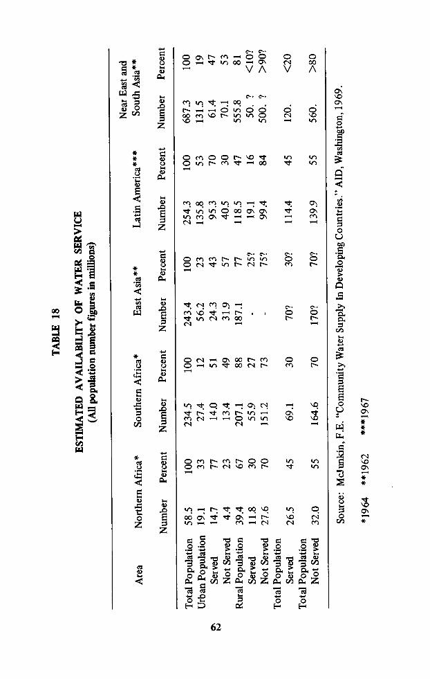
TABLE
18
ESTIMATED
AVAILABILITY
OFWATER
SERVICE
(Allpopulation
numberfiguresinmillions)
NearEastand
Area
Northern
Africa*
Southern
Africa*
EastAsia**
LatinAmerica***
SouthAsia**
Number
Percent
Number
Percent
Number
Percent
Number
Percent
Number
Percent
TotalPopulation
58.5
100
234.5
100
243.4
100
254.3
100
687.3
100
UrbanPopulation
19.1
33
27.4
12
56.2
23
135.8
53
131.5
19
Served
14.7
77
14.0
51
24.3
43
95
.370
61.4
47
NotServed
4.4
23
13.4
49
31.9
57
40.5
30
70.1
53
RuralPopulation
39.4
67
207.1
88
187.1
77
118.5
47
555.8
81
Served
11.8
30
55.9
27
-25?
19.1
16
50.
‘?
<10?
NotServed
27.6
70
151.2
73
-75?
99.4
84
500.
‘?
>90?
TotalPopulation
Served
26.5
45
69.1
30
70?
30?
114.4
45
120.
<20
TotalPopulation
NotServed
32.0
55
164.6
70
170?
70?
139.9
55
560.
>80
Source:
Mcjunkin,
F.E.“Community
WaterSupplyInDeveloping
Countries.”
AID,Washington,
1969.
*1964
**1962
***1967
Z9

which are highest, percentage wise, in these same developing areas of theworld. The United Nations estimates that the world population will reach 7.4billion by 2000, and increase of 4.1 billion over the 3.3 estimated in 1965.Over 85 percent of the increase will be in the high-birth-rate developingcountries of Asia, Africa and Latin America. So that it is not only a questionof improving present inadequate services and catching up in providing servicesfor people not now served, but also of providing for the billions who arebeing added to existing population.Tremendous strides have been made in Latin America since the start of theAlliance for Progress Decade in 1961 and progress in providing water supplyservices is keeping ahead of population increase. In 1961 60 percent of theurban population had water supply service by house connections or publichydrants. By the end of 1969 72 percent of the urban population was beingserved. The rural population with water supply services increased from 7percent to 16 percent during the same period.
Dollar Volume
The Latin American progress was possible because of the existence of acadre of well-trained sanitary engineers, officials who were and are convincedof the need for potable water facilities, and the willingness of government andinternational lending agencies to make funds available for these facilities.From 1961 through 1969 it is estimated that nearly 1.7 billion dollars havebeen allocated for water supply and sewerage facilities in Latin America, 37.5
percent of the money ($637 million) coming from international agencies.Unfortunately international sources have not provided this amount ofassistance for other areas of the world where it is so desperately needed. Totalworldwide international capital assistance for water supplies has been aboutone billion dollars. However, a change in attitude by international lendersmay be underway.
A recent conference on international development agreed that a “markedchange in emphasis was essential for future development.” In the past policyrecommendations have focussed almost exclusively on enlarging the flow ofgoods and services. Little attention has been paid to who was receiving them.Now there is a new recognition that even enlarged output may have littleeffect on the lives of the landless laborers in Bihar or slum dwellers -inCalcutta. The new style calls for “social growth” programs to promoteemployment, provide clean water and sanitary drains to the bustees ofCalcutta, more schooling, a more equal distribution of the gains fromexpanded output.The president of the World Bank publicly made the new style officialpolicy for the lending institutions over which he presides. He suggested thatloans would flow more freely to “nations building local irrigation worksrather than large dams, schools instead of steel mills.”This new style policy could be instrumental in making more moneyavailable for water supply construction in the areas where it is so urgentlyneeded.
63

In 1967 the countries of Latin America, with PAHO assistance, developedprojections of the amounts of money they would allocate during the period1968 through 1971 for water supply and sewerage construction to providenew or improved services. Their projections are shown in Table 19.The second part of the table has been developed to ascertain what mightbe involved if other areas of the world could increase the numbers of peopleserved in urban and rural areas by the same percentage as the Latin American
area plans during the four-year period 1968-71. Approximately 200 millionmore people would be served at a cost of nearly U.S.$5-6 billion. Purchases ofpipe could be as much as 25 percent of all expenditures.While this may not be possible during the same four-year period, it will be
possible over a longer period of time. It gives some idea of the possibilities forwater supply construction in the developing world and of possible marketsfor plastic pipe and plastic pipe production in those areas.While this document is primarily concerned with production and use ofplastic pipe for water supply, sewerage systems, and related uses, it should beborne in mind that a plastic plant can be used to manufacture other types of
TABLE 19FOUR YEAR PROJECTIONS 1968-1971
WATER SUPPLY IN LATIN AMERICA
URBAN RURAL
Population Add. % Est. Add. % Est.and Costs People 1967 Cost People 1967 Costin Millions to be Pop. to be Pop.
Served Served Served Served
LATIN AMERICA 34.7 45 $1348 10.5 55 $ 226
SIMILAR INCREASE IN SERVICES IN OTHER AREAS
AFRICA-NORTH 6.6 45 $ 256 6.5 55 $ 140
SOUTH 6.2 45 $ 241 30.8 55 $ 662
EAST ASIA 11.0 45 $ 427 25.9 55 $ 557
NEAR EASTANDSOUTH ASIA 27.6 45 $1073 27.5 55 $ 592
TOTALS 51.4 $1997 90.7 $1951
GRAND TOTAL $5522
64

products. Any market study carried out to determine the feasibility ofestablishing a plastic plant should consider the market for other possibleproducts as well. A plant for manufacturing pipe fittings could easily adapt toproduction of sandals, for example.
Role of U.S. Industry
The U.S. plastic pipe industry has five principal opportunities inpromoting plastic pipe in the developing countries: (1) sale of pipe, (2) sale offittings, (3) sale of plastic resins and compounds, (4) sale of machinery andmolds, and (5) provision of capital and-or technical assistance.
&hMHmThe potential market for sale of pipe is limited by shipping costs, localcompetition (plastic and non-plastic pipe), and third-country competition.To ship small diameter pipe (4-inch or less) to the Caribbean costs 4t-lb.For larger diameters, a rule of thumb is to add lyfi-lb. per inch in diameter. Toship 18-inch pipes to Asia costs about 30¢/lb., more than the cost of the pipeitself. Large resin shipments, on the other hand, can be negotiated at com
modity rates; e.g., resin shipments have gone to New Zealand at 3¢/lb.Shipping costs would seem to limit sale of U.S. manufactured pipes to theWestern hemisphere. However, plastic pipe is manufactured locally, often byU.S. owned or affiliated firmsin Mexico, Honduras, El Salvador, Nicaragua,Costa Rica, Panama, Puerto Rico, Jamaica, Columbia, Peru, Brazil, and
possibly others. A thorough search of Commerce Department data failed todisclose any significant U.S. plastic pipe exports. This is not a promisinglong-run market.
Sale of Fittings
The difficulty and expense (see previous section on “Manufacture ofPlastic Pipe”) of producing quality fittings make this a potential specialtymarket. The higher unit sales prices somewhat negate shipping costs. All threemajor U.S. fittings and mold producers are active internationally. The metricbarrier is a major obstacle to these firms.
Sale of Plastic Resins and Compounds
Several major U.S. producers are active in Latin America both in sale ofU.S. produced resins and in Mexico, their manufacture as well. One U.S. firmproduces resins in Iran and in India.This is a promising market: (1) economics of scale and high fixed costslimit basic production plants to the major countries and, except for Japanand Europe, those with oil resources, (2) capital-intensive characteristics ofproduction, automation, and proximity to petrochemicals, enable the U.S. tocompete in the world market, (3) all U.S. producers maintain large, active
marketing staffs, (4) the U.S. tradition of customer assistance, and (5) therelatively small investment required for an extrusion plant will result in
growing demand.
65

One manufacturer of both resins and pipe sums up the prospects thusly:
“. . . I am certain that this is a sharply growing market. as the supply of water tohouseholds and its disposal once used is possibly the most acute need that one can
observe in the developing countries. To what heights it can go it is difficult tospeculate.
We are contemplating establishment of our own wholly owned subsidiaries. I feel itmore logical, in the long term, to export knowhow rather than pipe for it is part ofthe pipe makers art that he sell the maximum of fresh air surrounded by a minimumof material and this makes for exceedingly heavy shipping costs!
Normally we do not export the raw materials for the use of others in extruding plasticpipes but it might be that in overseas plants we would be in a position to feed themwith correctly mixed and formulated raw materials so that such export mightcommence based upon overseas plants.”
The one area that is perhaps being overlooked is Africa, south of theSahara. Except for exports of plastics materials to South Africa, there is littleplastic pipe production or use. Nigeria, with the largest population on thecontinent, has an active water supply program, an oil refinery, and is
receptive to foreign investment. Other likely candidates for plastic pipeproduction might be the Congo (Kinshasha), Ghana, and the East African
Community (Uganda, Kenya, and Tanzania). These countries are virtually as
close by sea to New York as to London.
Sale of Machinery
At least two U.S. firms have made sales in Latin America. Nearly alldeveloping countries will of necessity be importing their extruders, injectionmolders, molds, etc. for many years to come. Joint efforts with major resinproducers would appear to be mutually beneficial.
Provision of Capital and Know-How
The American business tradition of providing capital and technicalassistance to its customers is definitely a promotional strongpoint in thisindustry.
Overseas Business Assistance
Both the U.S. Department of Commerce and the Agency for InternationalDevelopment conduct a number of programs and provide a number ofservices to assist U.S. businesses abroad. These are detailed in Appendix E.Information sources, financial assistance, and investment guaranties areamong the topics covered.
66

ABSA.C., A.C.P.A.G.A.AIDASCEASTMAWWA
BSIC.I., C.IP.CS
DWV
FHA
HDSIDISOKIWA
NSFOD
PAHOPEPPI
PS
PSIPSIGPVC
RHDS
APPENDIX A
ABBREVIATIONS
acrylonitrile-butadiene-styrene plastics
asbestos cement, asbestos cement pipe
American Gas Association
Agency for International DevelopmentAmerican Society for Civil EngineersAmerican Society for Testing and MaterialsAmerican Water Works Association
British Standards Institutioncast iron, cast iron pipeCommercial Standard, see Product Standard
drainage, waste, and vent (pipe)Federal Housing Administration or,Farmers Home Administration
hydrostatic design stressinside diameter
International Standards OrganizationInstitution for the Testing of Waterworks Materials, Ltd.
(Dutch)National Sanitation Foundationoutside diameter
Pan American Health Organizationpolyethylene plastic or resin
Plastics Pipe Institutepolystyrene when in reference to a plastic materialProduct Standard when in reference to a specification for
plastic pipe and fittings. These specifications are promulgatedby the U.S. Department of Commerce and were formerly known asCommercial Standards.
pounds per square inch
gage pressure in pounds per square inchpoly (vinyl chloride) plastic or resin
recommended hydrostatic design stress
A-l

SCS
SDRSPL
SR
UPVCUSASI
USPHS
WHO
Soil Conservation Servicestandard dimension ratioThe Society of the Plastics Industry, Inc.styrene-rubber plastic
unplasticized PVCUnited States of America Standards Institute (formerlyAmerican Standards Association)U.S. Public Health Service
World Health Organization
APPENDIX B
BIBLIOGRAPHY
Adlemann, Charles B. “How to Specify and Use Plastic Pipe for Water Utilities,”Water and Wastes Engineering, Vol.5, No. 7, pp. 61-63 (July 1968).
Adelmann, Charles B. “The Case for Plastic Pipe,” Journal American Water WorksAssociation, Vol.58, No. 7, pp. 905-910 (July 1966).
Agency for International Development. AID and Private Enterprise: Private Resourcesfor International Development, Foreign Aid and the American Economy. Agency forInternational Development, Washington, D.C. (May 1967).
Agency for International Development. “Commodity Transactions Financed by A.l.d.,"FederalRegister, Vol.32, No. 101, Part II, (May 25, 1967).
Agency for International Development. Specific Risk Investment Guaranty Handbook,Agency for International Development, Washington, D.C. (October 1966).
Agency for International Development. Aids to Business §Overseas Investment), Agencyfor International Development, Washington, D.C., Sept. 1966.
Agency for International Development. Foreign Aid Through Private Initiative, Reportof the Advisory Committee on Private Enterprise in Foreign Aid, Agency forInternational Development, Washington, D.C., July 1965.
Agency for International Development. Extended Risk Guarantees of Loans for PrivateProjects (other than Housing Projects). Agency for International Development,Washington, D.C. Dec. 1964.
American Society for Testing and Materials. ASTM and the Voluntary StandardizationSystem. American Society for Testing and Materials, Philadelphia, Pa., June 1968.
American Water Works Association. “Plastic Pipe in Distribution Systems, ASymposium,” Journal American Water Works Association, Vol. 50, No. 11, pp.1438-1542 (November 1958).
Anderson, A. Gordon. “Selection and Use of Pipeline Materials,” U.S. Department ofAgriculture, Farmers Home Administration, Wenatchee, Washington. No date.
Boelens, A.H.M. “Lead Release of Hard Polyvinyl Chloride Pipe,” Report No. 5a,Committee for Plastic Water Pipes, presented at meeting of International StandardsOrganization, Paris, 1962.
B-1

Bolton, P.D., and Morgan, F.R. “Strength Tests on Solvent Welded (Cemented) Jointsfor PVC Pipes - 1,” Technical Paper No. 42, Water Research Association,Medmenham, Marlow, Bucks (England), April 1965.
Boone, R. “Plastic Pipes,” Special Subject No. 5, General Reports and Papers on SpecialSubjects, Sixth Congress of International Water Supply Association, Stockholm,(June 15-19, 1964).
Bracale Delgado, Leopoldo. “lnvestigacion Sobre el Contendo de Plomo en las AguasQue Han Estado en Contacto con Las Tuberias de Plastico 0 PVC ,” thesis de bachillery grado, Facultad de Ingenieria Sanitaria, Universidad Nacional de Ingenieria, Lima,Peru, 1966.
Building Research Advisory Board, National Research Council. “Federal AgencyPractices on Use of Piping, Publication 1572, National Academy ofSciences - National Academy of Engineering. Washington, D.C. 1967.
Building Research Advisory Board, National Research Council. “Rigid ThermoplasticPipe and Fittings for Residential Drain-Waste and Vent Systems,” Publication 140 7,National Academy of Sciences - National Academy of Engineering, Washington, D.C.,1966.
Canham, W.G. “Piping Codes and the Chemicals Plant,” Chemical Engineering, Vol. 73,pp. 199-204 (October 10, 1966).
Cavalier & Otto, Inc. “Plastic Investment Survey: Philippines, Taiwan, Thailand,”Private Investment Center, Agency for International Development, Washington, D.C.,Investment Survey Report, manuscript, circa 1964.
Chuy, Fernando. “Extraccion dc Plomo por Aguas en Contacto con Tuberias dePolicloruro de Vinilo No Plastificado,” Facultad de Ingeniera Sanitaria, Universidad
Nacional de Ingenieria, Lima, Peru, Deciembre de 1967. A 42-page report.
Cast Iron Pipe Research Association. A Guide for Installation of Cast Iron Water Mains,Chicago, 111.No date.
Clark, William W. “Plastic Pipe and Plumbing Codes,” (Market Research Note), PlasticsPipe Institute, New York, 6 pp., mirneo. (1963).
Cryor, Robert E. “Asbestos-Reinforced Plastic Pipe,” Chemical Engineering, Vol. 72,No. 16, pp. 134-137 (August 2, 1965).
Ettinger, Morris B. “Lead in Drinking Water,” in Symposium on Environmental LeadContamination, U.S. Public Health Service, Dec. 13-15, 1965, pp. 21-27. Availablefrom U.S. Government Printing Office, Washington, D.C., (March 1966).
Executive Order 11387. “Foreign Direct Investment Program,” Federal Register, Vol.33, No. 1, Part 11, (January 3,1968).
Farish, Charles A. “Effects of Plastic Pipe on Water Quality,” unpublished paper, 1969.
Farish, Charles A. “Plastics in Water Distribution Systems,” paper presented at 158thNational Meeting, American Chemical Society, New York, N.Y. (September 1969).
Farish, Charles A. “Plastic Pipe and Water Quality,” Journal American Water WorksAssociation, Vol. 61, No. 9, pp. 480-482 (September 1969).
B-2

Farish, Charles A. “Developing and Testing Plastics for Water Distribution Systems,”Journal Southeastern Section, American Water Works Association, Vol. 29, pp. 65-77(1965).
Farish, Charles A. “Utiliacion de Tuberias Plasticas en Abastecimientos de AguaPotable,” papers presented at symposium in Caracas, Venezuela, October21 - November 1, 1963. Published by Organization Panamericana de la Salud. (PanAmerican Health Organization), Publication No. 113, Washington, D.C., May 1965.
Farish, Charles A. “Plastic Pipe for Potable Water Supply Applications,” VIII CongresoAsociacion Interamericana de Ingenieria Sanitaria, pp. 71-79, Washington, D.C., 1962.
Feimer, Otto H. “Plastic Materials of Construction,” Chemical Engineering, Vol. 75, No.24, pp. 126-138 (November 4, 1968).
Foden, J.B. “Rigid PVC Pipe as Sewers,” Water Pollution Control (Brit. ) Vol. 66, pp.272ff. (1967).
Fraser, David A. “A Laboratory Study of the Uptake of Lead from Lead-StabilizedPlastic Pipe,” tentative research proposal, Department of Environmental Sciences andEngineering, University of North Carolina, Chapel Hill, N.C., 6 pp. unpublished(September 1967).
Ghatpande, M.M., and Dhekane, N.Y. “Pipe Friction Coefficient,” EnvironmentalHealth, (Nagpur, India), Vol. 10, No. 3, pp. 163-176 (July 1968).
Glass, Donald L. “Experiences with Plastic Pipe,” Public Works, Vol. 98, No. 12, pp.84-85 (December 1967).
Haselbarth, John E. “Updated Investment Costs for 60 Types of Chemical Plants,”Chemical Engineering, Vol. 74, pp. 214-215 (December 4, 1967).
Henderson, John M. “Development of Within-Country Production of Materials andEquipment for Community Water Supply Systems,” International CooperationAdministration, Washington, D.C., 38 pp., mimeo. (January 1961).
Hoyle, N. “Pipeline Materials, Design and Construction,” Water and Water Engineering,Vol.73, No. 879, pp. 193-196 (May 1969).
Institution for the Testing of Waterworks Materials, Ltd. (KIWA). “The Admissibility ofWorking Toxic Substances into the Material Used for the Manufacture of Pipes forDrinking Water,” Communication No. 3 of the Committee for Plastic Water Pipes,Delft, The Netherlands. No date.
Instituto de Ingenieria, UNAM (Mexico). “Normas de Calidad y Métodos de Pruebapara Tuberias de Policloruro de Vinilo,” patrocinado por Oficina SanitariaPanamericana, Enero de 1969.
Jacobson, Walter E. “The Inside Story of Plastic Pipe,” paper presented at AnnualMeeting of American Society of Sanitary Engineering, Honolulu, Hawaii, 12 pp.,mimeo. (1963).
Joint Committee on Plastics. Thermoplastic Materials, Pipe, Fittings, Valves, Traps, andJoining Materials. Standard No. 14. National Sanitation Foundation Standards.National Sanitation Foundation, Ann Arbor, Mich. October 1965.
Kallberg, William C. “Plowing-in Pipelines,” Civil Engineering, Vol. 37, No. 1, pp.48-49(January 1967).
B-3

Kenck, J .E. “Plastic Pipe Gives Service in San Francisco,” Water and WastesEngineering, Vol. 6, No. 5, pp. 57-59 (May 1969).
Look, Edward H. “Industry Developments in Plastic Pipe for Water Systems,” JournalAmerican Water Works Association, Vol. 57, No. 11, pp. 1385-1389 (November1965).
Leininger, R.l. “Plastic Pipe for Water and Gas Distribution,” Journal Pipeline Division,Proceedings American Society of Civil Engineers, Vol. 91, No. PLI, pp. 1-14 (July1965).
Mcjunkin, Frederick E. Community Water Supply in Developing Countries: AQuarter-Century of United States Assistance, Agency for International Development,Washington, D.C. (in press).
McKee, Jack Edward., and Wolf, Harold W. Water Quality Criteria, State Water QualityControl Board, Sacramento, Calif ., 1962.
McQuade, Lawrence C. “Expand Overseas Sales with Commerce Department Help,”Management Aids No. 199, Small Business Administration, U.S. Department ofCommerce, Washington, D.C., (October 1968).
Mallinson, John H. “Plastic Pipe: lts Performance and Limitations,” ChemicalEngineering, Vol. 73, pp. 180-185 (February 14, 1966).
Mallinson, John H. “Reinforced Plastic Pipe: Joining and Supporting,” ChemicalEngineering, Vol. 73, pp. 168-174 (January 17, 1966).
Mallinson, John H. “Reinforced Plastic Pipe: A User’s Experiences,” ChemicalEngineering, Vol. 72, pp. 124-134 (December 20, 1965).
Mamrelli, E.S. “Plastic Pipe and Fittings, Committee Progress Report,” JournalAmerican Water Works Association, Vol. 59, No. 10, pp. 1238-1248 (October 1967).
Moore, Edward W. Private communication.
National Sanitation Foundation. “NSF Goes International,” News from N.S.F.(Newsletter), Ann Arbor, Mich., (Fall 1968).
National Sanitation Foundation Testing Laboratory. Seal of Approval Listing ofPlasticMaterials, Pipe, Fittings and Appurtenances for Potable Water and Waste Water.National Sanitation Foundation, Ann Arbor, Mich. Revised annually.
Neale, Lawrence C., and Price Robert E. “Flow Characteristics of PVC Sewer Pipe,”Journal of the Sanitary Engineering Division, Proceedings of the American Society ofCivil Engineers, Vol. 90, No. SA3, Part I, pp. 109-129 (June 1964).
Nielsen, Louis B. “Recommendations Re Use of Plastic Piping for Drainage and VentSystems in Building,” Technical Report No. 3, New York Building Code Council,New York, N.Y. (August 1966).
Niklas, Hans, and Meyer, Walter. “Auswanderung von Blei Aus BleistabiliziertenPVC—Rohren [The Migration of Lead from Lead-Stabilized PVC Pipes] ,” Kunstoffe(Germany), Vol. 51, pp. 2-6 (1961).
Oleesky, Samuel S., and Mohr, J. Gilbert. Handbook of Reinforced Plastics of theSociety of the Plastics Industry, Van Nostrand Reinhold Co., New York, N.Y., 1964.

Pawson, J .M. “PVC Water Mains in Great Britain, the First Ten Years,” Water and WaterEngineering, Vol. 71, No. 858, pp. 326-330 (August 1967).
Pierce, Jack W. “Plastic Pipe - A Progress Report,” Civil Engineering, Vol. 37, No. 2, pp.61-64 (February 1967).
Plastics Pipe Institute. “Recommended Service (Design) Factors for PressureApplications of Thermoplastic Pipe Materials,” PPI-TR9 (October 1969).
Plastics Pipe Institute. “Standards for Plastics Piping,” Technical Report PPI-TR5
(March 1969).
Plastics Pipe Institute. “Recommended Practice for Making Solvent Cemented Jointswith Polyvinyl Chloride Plastic (PVC) Pipe and Fittings,” PPI-TRIO (February 1969).
Plastics Pipe Institute. “Resistance of Thermoplastic Piping Materials to Micro- andMacro-Biological Attacks,” Technical Report PPI-Trll (February 1969).
Plastics Pipe Institute. “Recommended Hydrostatic Design Stresses for ThermoplasticPipe Compounds for Water,” Technical Report PPI-TR4 (September 1967, February1968, and December 1968).
Plastics Pipe Institute. “A Glossary of Plastics Piping Terms,” Technical Report PPI-TRI(November 1968).
Plastics Pipe Institute. “Recommended Method for Obtaining Hydrostatic Design Basisfor Thermoplastic Pipe,” Technical Report PPI-TR2 (October 1968).
Plastics Pipe Institute. “Policies and Procedures for Developing RecommendedHydrostatic Design Stresses for Thermoplastic Pipe,” Technical Report PPI-TR3 (July
1968).
Plastics Pipe Institute. “Installation Procedures for Polyethylene (PE) Plastic Pipe,”PPI-TR8 (April 1968).
Plastics Pipe Institute. “Recommended Method for Calculation of Nominal Weight ofPlastic Pipe,” Technical Report PPI-TR7 (March 1968).
Plastics Pipe Institute. “Recommended Standard Dimensional Terminology for PlasticsPipe Fittings,” PPI-TR6 (February 1968).
Plastics Pipe Institute. “Modern Piping with Plastics,” Society of the Plastics Industry,Inc., New York, N.Y., pamphlet, no date.
Plastics Pipe Institute. “Market Research News Release on Building Code Acceptance ofPlastic Pipe,” Plastics Pipe Institute, New York, N.Y., (1964).
Plastics Pipe Institute. “Market Research News Release on Sales of Plastic Pipe andFittings in 1963,” (and other years), Plastics Pipe Institute, New York, N.Y., (1964and other years).
Plastic Pipe Research Council, Society of the Plastics Industry, Inc. “Suggestions forInclusion of Plastic Pipe and Fittings in Governmental, State, Municipal and OtherRegulatory Body Plumbing Codes,” Society of the Plastics Industry, Inc., New York,periodically revised. 16 pp. booklet with a model plumbing code.
Public Works. “The Plastics Pipe Institute,” Public Works, Vol. 94, No. 10, pp. 108-109,(July 1963).

Remirez, Raul. “Dilute Ethylene Opens Door to Vinyl Chloride Production in SmallPlants,” Chemical Engineering, Vol. 75, No. 9, pp. 142-144 (April 22, 1968).
Rao, N.U., Mishra, R.P., Rao, K. Subba., and Rao, C.S.G. “Suitability of Plastic Pipesfor Conveying Drinking Water,” Environmental Health (Nagpur, India), Vol. 10, No.1, pp. 68-82 (January 1968).
Reiff, Fred M. A Report on the Use ofPlastic Pipe in the Construction Activities UnderPublic Law 86-121. U.S. Dept. of Health, Education and Welfare, Public HealthService, Division of Indian Health, Washington, D.C., February 1968.
Reinhart, Frank W. “Recent Developments in Thermoplastic Piping,” Journal AmericanWater Works Association, Vol. 60, No. 12, pp. 1404-1410 (December 1968).
Reinhart, Frank W. “Engineering Properties of Plastics Applicable to Water Piping,”Journal American Water Works Association, Vol. 59, No. 4, pp. 447-456 (April1967).
Reinhart, Frank W. “Long-Term Hydrostatic Strength Characteristics of ThermoplasticsPipe,” Polymer Engineering and Science, Vol. 6, No. 4, pp. 1-11 (reprint) (October1966).
Reinhart, Frank W. “Hydrostatic Strength and Design Stresses for Thermoplastic Pipewith Water,” in Simulated Service Testing in the Plastic Industry, Special TechnicalPublication No. 375, American Society for Testing and Materials, Philadelphia, Pa.,pp. 30-48 (1965).
Roberts, Neil C. “Parts for Special Purposes Fabricated from Plastics,” Water andSewage Works, Vol. 114, No. 2, pp. 69-70 (February 1967).
Sarvetnick, Harold. Polyvinyl Chloride, Van Nostrand Reinhold Co., New York, N.Y.,1969.
Shelburn, Ralph. “Plastic Pipe Fittings,” Farmers Home Administration, U.S. Dept. ofAgriculture, Indianapolis, Ind., 8 pp., mimeo. (1965).
Skeat, William Oswald., and Dangerfield, Bernard John, (Editors). Manual of BritishEngineering Practice, Institution of Water Engineers, London, 3 Vols., 1969.
Society of the Plastics Industry, Inc. See Plastics Pipe Institute; Plastic Pipe ResearchCouncil.
Society of the Plastics Industry. Plastics Engineering Handbook, Van Nostrand ReinholdCo., New York, N.Y., several editions.
Stahl, William H., and Pessen, Helmut. “The Microbiological Degradation ofPlasticizers,”Applied Microbiology, Vol. 1, pp. 30-35 (January 1953).
Stoltenberg, David H., “Construction Costs of Rural Water Systems,” Public Works,Vol. 100, No. 8, pp. 94-96, 130-131 (August 1969).
Sweitzer, Robert J. “Developments in Plastics and Plastic Pipe,” Journal AmericanWater Works Association, Vol. 52, No. 10, pp. 1251-1262 (October 1960).
ThermoP1astics Corporation. “A Marketing Guide Analysis of Key Markets forThermoplastics Pipe and Fittings,” Charlotte, N.C. No date.

Tiedeman, Walter D., and Milone, Nicholas A. “Effects of Plastic Pipe on WaterQuality,” Journal American Water Works Association, Vol. 48, No. 8, pp. 1019-1023(August 1956).
Tiedeman, Walter D., and Milone, Nicholas A. A Study ofPlastic Pipe for Potable WaterSupplies, National Sanitation Foundation, School of Public Health, University ofMichigan, Ann Arbor, Mich., June 1955.
USA Standards Institute. “What Is the USA Standards Institute?” U.S.A. StandardsInstitute, New York, N.Y. No date.
U.S. Department of Commerce, Office of Foreign Direct Investments. “Foreign DirectInvestment Regulations - Miscellaneous Amendments; General Authorization No. 1,”Federal Register, Vol. 33, No. 15, (January 23, 1968).
U.S. Department of Commerce, Office of Technical Services. “Equipment for PVC HoseManufacture,” Technical Inquiry Service No. IR3139 7, Agency for InternationalDevelopment, Washington, D.C., (October 21, 1963).
U.S. Department of Commerce, Office of Technical Services. “Extruder for PlasticHose,” Technical Inquiry Service No. IR309I6, Agency for InternationalDevelopment, Washington, D.C. (July 1965).
U.S. Department of Commerce, Office of Technical Services. “Plastic Pipe Fittings andGutters and Downspouts,” Technical Inquiry Service No. IR30524, Agency forInternational Development, Washington, D.C., (March 1963).
U.S. Department of Commerce, Bureau of International Commerce. “SemiannualChecklist International Business Publications,” Washington, D.C., semiannual.
U.S. Public Health Service. “Drinking Water Standards, 1962,” USPHS Pub. No. 956,Public Health Service, U.S. Government Printing Office, Washington, D.C., 1962.
Water Research Association (Brit.). Private communication.
Webster, Irving S. “Plastics Pipes in Gas Distribution,” unpublished memorandumavailable from Plastics Pipe Institute, 16 pp., mimeo. (December 15, 1964).
Willhoff, T.L. “ABS Truss Pipe for Sewers,” Water and Wastes Engineering, Vol. 6, No.3, pp. 40-42 (March 1969).
Wilson, Harold E. “The Case for Non-Metallic Pipe,” paper presented at Calif. SectionMeeting, American Water Works Association, Los Angeles, Calif. October 26, 1967.Also see “Performance of Construction Materials for Domestic Water PipingSystems,”Materials Protection, pp. 24-28 (January 1968).
World Health Organization. “International Standards for Drinking Water,” Geneva, 2ndEd., 1963.
Anonymous. “Plastic Drainage Pipe Makers Defend Product Before Congress,”Environmental Health Letter, Vol. 6, No. 24, p. 3 (December 15, 1967).
Anonymous. “The Plastics Pipe Industry is Booming, But. . .,”Modern Plastics, Reprint(October 1967).
Anonymous. “Trenchless Pipe-Laying for AIR Water Scheme,” Water and WaterEngineering, Vol. 71, No. 859, pp. 372-373 (September 1967).
B-7

Anonymous. “U.S. Investment Guaranties,” World Business (Chase Manhattan Bank),pp. 4-7 (July 1966).
Anonymous. “Plastics Pipes and Fittings-A Definitive Guide,” Water and WasteEngineering, Vol. 68, No. 822, p. 339 (August 1964).
ADDENDUM
American Society of Civil Engineers, Committee on Pipeline Planning, Task Committeeon Bibliography of Pipeline Design Reference Material. “List of Sources ofInformation on Pipeline Design,” Journal of the Pipeline Division, Proceedings of theAmerican Society ofCivil Engineers, Vol. 93, No. PL2, pp. 103-139 (July 1967).
Agency for International Development, Communications Resources Division. “Checklistfor Feasibility Appraisal of a Proposed Industrial Establishment,” Washington, D.C.,No date.
Donovan, J .S. “Stabilizers, the Non-toxic Situation,” British Plastics, Vol. 42, No. 10,pp. 95-98 (October 1969).
Modern Plastics Encyclopedia (annual), published as second issue in October ofModernPlastics (monthly), McGraw-Hill, Inc., P.O. Box 430, Hightstown, N.J. 08520.
Plastics Pipe Institute. "Acrylonitrile-Butadiene-Styrene Plastic (ABS) PipingInstallation Procedures,” PPI Technical Report TR12 (September 1969).
Plastics Pipe Institute. “Sealants for Acrylonitrile-Butadiene-Styrene (ABS) PlasticPiping,” PPI Technical Note TN1 (March 1970).
Plastics Pipe Institute. “Sealants for Polyvinyl Chloride (PVC) Plastic Piping.” PPITechnical Note TN2 (March 1970).
PVC Pipelaying Group, The. PVC Pipelaying Manual, Her Majesty’s Stationery Office,London, March 1967.

APPENDIX C
STANDARDS AND SPECIFICATIONS FOR PLASTIC PIPE
ANSI
ASTM
D 702-64T
D 709-66T
D 1180-57(1961)
D 1238-65T
D 1248-69
D 1503-68
D 1527-69
D 1598-67
D 1599-69
D 1694-67
D 1784-68
D 1785-68
D 1788-68
D 1939-67
D 2104-68
United States
American National Standards Institute, Inc. (See USASI).
American Society for Testing and Materials1916 Race Street
Philiadelphia, Pennsylvania 19103
Cast Methacrylate Plastic Sheets, Rods, Tubes and Shapes
Laminated Thermosetting Materials
Test for Bursting Strength of Round Rigid Plastic Tubing
Measuring Flow Rates of Thermoplastics by ExtrusionPlastometer
Polyethylene Molding and Extrusion Materials
Cellulose Acetate Butyrate (CAB) Plastic Pipe,Schedule 40
Acrylonitrile-Butadiene-Styrene (ABS) Plastic Pipe,Schedule 40 and 80
Time-to-Failure of Plastic Pipe Under Long-TermHydrostatic Pressure
Short-Time Rupture Strength of Plastic Pipe, Tubing andFittings
Threads for Reinforced Thermosetting Plastic Pipe
Polyvinyl Chloride (PVC) Compounds and ChlorinatedPolyvinyl Chloride (CPVC) Compounds, Rigid
Po1y(Vinyl Chloride)(pvc) Plastic Pipe, Schedules 40,80, and 120
Rigid Acrylonitrile-Butadiene-Styrene (ABS) Plastics
Quality of Extruded Acrylonitrile-Butadiene-Styrene(ABS) Pipe by Acetic Acid Immersion
Polyethylene (PE) Plastic Pipe, Schedule 40

ASTM (Cont’d)
D 2105-67
D 2122-67
D 2143-63T
D2152-67
D 2153-67
D 2235-67
D 2239-67
D 2241-67
D 2282-69a
D 2290-64T
D 2310-64T
D 2321-67
D 2412-68
D 2444-67
D 2446-68
D 2447-68
D 2464-67
D 2465-68
D 2466-67
D 2467-67
D 2468-68
D 2469-68
Longitudinal Tensile Properties of Reinforced ThermosettingPlastic Pipe and Tube
Determining Dimensions of Thermoplastic Pipe
Cyclic Pressure Strength of Reinforced, ThermosettingPlastic Pipe
Quality of Extruded Poly(Vinyl Chloride) Pipe by AcetoneImmersion
Calculating Stress in Plastic Pipe Under Internal Pressure
Solvent Cement for Acrylonitrile-Butadiene-Styrene(ABS) Plastic Pipe and Fittings
Polyethylene (PE) Plastic Pipe (SDR-PR)
Poly(Vinyl Chloride) (PVC) Plastic Pipe (SDR-PR andClass T)
Acrylonitrile-Butadiene-Styrene (ABS) Plastic Pipe(SDR-PR and Class T)
Apparent Tensile Strength of Parallel Reinforced Plasticsby Split Disk Method
Reinforced Thermosetting Plastic Pipe
Underground Installation of Flexible ThermoplasticSewer Pipe
External Loading Properties of Plastic Pipe byParallel-Plate Loading
Impact Resistance of Thermoplastic Pipe and Fittings byMeans of a Tup (Falling Weight)
Cellulose Acetate Butyrate (CAB) Plastic Pipe (SDR-PR)and CAB Plastic Tubing
Polyethylene (PE) Plastic Pipe, Schedules 40 and 80 Basedon Outside Diameter
Threaded Poly(Vinyl Chloride) (PVC) Plastic Pipe Fittings,Schedule 80
Threaded Acrylonitrile-Butadiene-Styrene (ABS) PlasticPipe Fittings, Schedule 80
Socket-Type Poly(Vinyl Chloride) (PVC) Plastic PipeFittings, Schedule 40
Socket-Type Poly(Vinyl Chloride) (PVC) Plastic PipeFittings, Schedule 80
Socket-Type Acrylonitrile-Butadiene-Styrene (ABS)Plastic Pipe Fittings, Schedule 40
Socket-Type Acrylonitrile-Butadiene-Styrene (ABS)Plastic Pipe Fittings, Schedule 80
C-2

ASTM (Cont'd)
D 2513-68
D 2517-67
D 2560-67
D 2564-67
D 2581-67
D 2609-68
D 2610-68
D2611-68
D 2657-57
D 2661-68
D 2662-68
D 2665-68
D 2666-67T
D 2672-68a
D 2680-68T
D 2683-68T
D 2729-68
D 2736-69T
D 2737-68T
D 2740-68
D 2749-68
D 2750-69
D 2751-69
D 2774-69
D 2837-69
Thermoplastic Gas Pressure Pipe, Tubing, and Fittings
Reinforced Thermosetting Plastic Gas Pressure Pipe andFittings
Solvent Cements for Cellulose Acetate Butyrate (CAB)Plastic Pipe and Fittings
Solvent Cements for Poly(Vinyl Chloride) (PVC) PlasticPipe and Fittings
Polybutylene-PB) Plastics
Plastic Insert Fittings for Polyethylene (PE) Plastic Pipe
Butt Fusion Polyethylene (PE) Plastic Pipe Fittings,Schedule 40
Butt Fusion Polyethylene (PE) Plastic Pipe Fittings,Schedule 80
Heat Joining of Thermoplastic Pipe and Fittings
Acrylonitrile-Butadiene-Styrene (ABS) Plastic Drain,Waste, and Vent Pipe and Fittings
Polybutylene (PB) Plastic Pipe (SDR-PR)
Po1y(Vinyl Chloride) (PVC) Plastic Drain, Waste, andVent Pipe and Fittings
Polybutylene (PB) Plastic Tubing
Bell End PVC Plastic Pipe
Acrylonitrile-Butadiene-Styrene (ABS) Composite Pipe
Socket Type Polyethylene (PE) Fittings for SDR 1 1.0 PEPipe
Polyvinyl Chloride (PVC) Sewer Pipe and Fittings
Filled-Polyvinyl Chloride (PVC) Sewer Pipe and Fittings
Polyethylene (PE) Plastic Tubing
Polyvinyl Chloride (PVC) Plastic Tubing
Standard Definitions of Terms Relating to Plastic PipeFittings
Acrylonitrile-Butadiene-Styrene (ABS) Plastic UtilitiesConduit and Fittings
Acrylonitrile-Butadiene-Styrene (ABS) Sewer Pipe andFittings
Recommended Practice for Underground Installation ofThermoplastic Pressure Piping
Obtaining Hydrostatic Design Basis for ThermoplasticPipe Materials
C-3

ASTM (Cont'd)
D 2846-69T
D 2852-69T
D 2855-70
Commercial andProduct Standards
PS1 0-69
PS11-69
PS12-69
PS18-69
PS19-69
PS2 1-70
PS22-70
CS270-65
CS272-65
Department ofAgriculture
Chlorinated Polyvinyl Chloride (CPVC) Plastic Hot WaterDistribution Systems
Styrene-Rubber (SR) Plastic Drain and Building SewerPipe and Fittings
Making Solvent Cemented Joints with Polyvinyl Chloride
(PVC) Pipe and Fittings
Superintendent of DocumentsU.S. Government Printing OfficeWashington, D. C. 20402
Polyethylene (PE) Plastic Pipe (Schedule 40 InsideDiameter Dimensions), Supersedes CS197-60
Polyethylene (PE) Plastic Pipe (SDR), Supersedes CS255-63
Polyethylene (PE) Plastic Pipe (Schedule 40 and 80Outside Diameter Dimensions)
Acrylonitrile-Butadiene-Styrene (ABS) Plastic Pipe(Schedules 40 and 80), Supersedes Cs2l8-59.
Acrylonitrile-Butadiene-Styrene (ABS) Plastic Pipe(Standard Dimension Ratio ), Supersedes CS254-63
Polyvinyl Chloride (PVC) Plastic Pipe (Schedules 40, 80,and 120), Supersedes CS207-60
Polyvinyl Chloride (PVC) Plastic Pipe (Standard DimensionRatio), Supersedes CS256-63
Acrylonitrile-Butadiene-Styrene (ABS) Plastic Drain,Waste and Vent Pipe and Fittings
Polyvinyl Chloride (PVC) Plastic Drain, Waste and VentPipe and Fittings
U.S. Department of AgricultureSoil Conservation ServiceWashington, D.C. 20250
SDS National Engineering Handbook, Section 2, Part 1, Engineering PracticeStandards
No. 432-D
No. 432-E
Department ofDefense MilitaryStandards
MIL-C-23 57 la
MIL-A-22010A(l)
High Pressure Underground Plastic Irrigation Pipelines(February 1967)
Low Head Underground Plastic Irrigation Pipelines(February 1967 with amendment of June 14, 1967)
Commanding OfficerNaval Publications and Form Center5801 Tabor AvenuePhiladelphia, Pennsylvania 19120
Conduit and Conduit Fittings, Plastic, Rigid (11-8-68)
Adhesive, Solvent-type, Polyvinyl Chloride (6-9-61)
C-4

Department of Defense Military Standards (Cont ’d)
MIL-P-5431A(1)
MIL-P-14529A
MIL-P-l9l19B(1)
MIL-P-2201 IA
MIL-P-21 92 2A
MIL-P-22 245A( 1)
MIL-P-26692
MIL-P-8205 6
FederalSpecifications
L-P-0031 5b
L-P-320a
L-P-322a
L-P-1036( 1)
L-T-00790
L-P-001221
FHA
Plastic, Phenolic, Graphited, Sheets, Rods, Tubes andShapes (2-29-68)
Pipe, Extruded, Thermoplastic (12-18-62)
Pipe, Plastic, Rigid, Unplasticized, High Impact, PolyvinylChloride (6-28-65)
Pipe Fittings, Plastic, Rigid, High Impact, PolyvinylChloride (PVC) and Poly 1, 2 Dichlorethylene(1-13-69)
Plastic Rods and Tubes, Polyethylene (7-1 1-66)
Pipe and Pipe Fittings, Polyethylene, for Low-pressureWaste and Drainage Systems (2-1 1-66)
Plastic Tubes and Tubing, Polyethylene
Pipe and Pipe Fittings, Plastic for Drain, Waste and VentService (1-29-68)
Specifications ActivityPrinted Materials Supply DivisionBuilding 197Naval Weapons Plant
Washington, D.C. 20407
Pipe, Plastic (Polyethylene, PE, SDR-PR) (12-7-67)
Pipe and Fittings, Plastic (PVC, Drain, Waste and Vent)(1 1-25-66)
Pipe and Fittings, Plastic (ABS, Drain, Waste and Vent)(1-12-66)
Plastic Rod, Solid; Plastic Tubes and Tubing, HeavyWalled; Polyvinyl Chloride, Rigid (6-26-67) Amendment1 (1-29-68)
Tubing, Thermoplastic (Laboratory and Medical) (6-30-61)
Pipe and Fittings, Plastic, Rigid (Styrene Rubber, Drainand Sewer) (3-1 -67)
Architectural Standards DivisionFederal Housing AdministrationWashington, D.C.
FHA Minimum Property Standards Interim Revision No. 31 (June, 1966)
FHA UM-26b
FHA UM-31 e
FHA UM-41
FHA UM-43
Plastic Drain and Sewer Pipe and Fittings (5-15-67)
Polyethylene Plastic Pipe and Fittings for DomesticWater Service (9-1 -66)
PVC Plastic Pipe and Fittings for Domestic Water Service(8-1 -66)
Acrylonitrile-Butadiene-Styrene Plastic Pipe and Fittingsfor Domestic Water Service (1 l-1-66)
C-5

FHA (Cont'd)
FHA UM-49
FHA MR-562
FHA MR-563
IAPMO
IAPMO (WPOA)TSC 6-61
IAPMO (WPOA)PS 17-66
IAPMO (WPOA)is 5-66
IAPMO IS 8-67
IAPMOIS 1O-69T
IAPMOPS30-69T
IAPMOIS1l-69T
IAPMO 19-68
NSF
NSF StandardNo. 14:
NSF StandardNo. 1 5:
NSF Seal of Approval Listing of Plastic Materials, Pipe, Fittings and appurte
ABS and PVC Plastic Drainage and Vent Pipe andFittings, FHA 4550.49 (5-1-68)
Rigid Chlorinated Polyvinyl Chloride (CPVC)Hi-Temp. Water Pipe and Fittings (1 1-3-67)
PVC Plastic Drainage and Vent Pipe and Fittings(1 1-6-67)
International Association of Plumbing and MechanicalOfficials (formerly WOPA)5032 Alhambra StreetLos Angeles, California 90032
Plastic Drain and Vent Pipe—Drainage Fittings forTrailer Coach Drainage and Vent Systems ABS -
Type 1 and 1A
Materials and Property Standards for AcrylonitrileButadiene-Styrene (ABS) Plastic Drain, Waste andVent Pipe and Fittings
Installation Standard for ABS Drain, Waste and VentPipe and Fittings
Installation Standard for Solvent Cemented PVCPipe for Water Service and Yard Piping
Installation Standard for Thermoplastic Yard GasPiping
Supplemental Standard to ABS Sewer Pipe andFittings Standard ASTM D2751
Installation Standard for ABS Sewer Pipe andFittings
Installation Standard for PVC Drain, Waste and VentPipe and Fittings
National Sanitation FoundationSchool of Public HealthUniversity of MichiganAnn Arbor, Michigan
Thermoplastic Materials, Pipe, Fittings, Valves, Trapsand Joining Materials (October 1965)
Thermoset Plastic Pipe, Fittings, Valves, Tanks,Appurtenances, Joining Materials and ThermosetPlastic Coatings for Use in Potable Water Systems
nances for Potable Water and Waste Water (NSF Testing Laboratory)(3-1-69)
PPI Plastics Pipe Institute250 Park AvenueNew York, New York 10017
C-6

PPI (Cont’d)
SIA
See bibliography in Appendix B for several recommended practices and procedures.
Sprinkler Irrigation Association1028 Connecticut Avenue, N.W.,Washington, D.C. 20036
Minimum Standards for Irrigation Equipment (March 1959)
UL
UL65L
UL514
USASI
USAS A1 19.2-1963
USAS B16.27-1962
USAS B72.1-1967
USAS B72.2-1967
USAS B72.3-1967)
USAS B3l.8-1968
USAS C59.40-1967
ISO
Underwriters Laboratories, Inc.207 East Ohio StreetChicago, Illinois 60611
Rigid Nonmetallic Conduit (September 1968)
Outlet Boxes and Fittings (March 1951-withamendments of 2-28-67)
United States of America Standards Institute10 East 40th StreetNew York,N.Y. 10016
Note: Effective October 6, 1969, the USASI changesits name to American National Standards Institute,Inc., and its address to 1430 Broadway, New York,N.Y. 10018. “USA Standards” will then become“American National Standards.” USASI was thesuccessor (1966) of the American StandardsAssociation (ASA).
Plumbing, Heating and Electrical Systems for TravelTrailers
Plastic Insert Fittings for Flexible Polyethylene Pipe
Specification for Polyethylene (PE) Plastic Pipe(SDR-PR) (ASTM D2239-67)
Specification for Polyvinyl Chloride (PVC) Plastic Pipe(SDR-PR) ASTM D2241 -67)
Specification for Acrylonitrile-Butadiene-Styrene (ABS)Plastic Pipe (SDR-PR and Class T) ASTM D2282-66)USA Standard Code for Pressure Piping, GasTransmission and Distribution Piping Systems
Polyethylene Molding and Extrusion Materials
Foreign
(Partial Listing)
International
*International Organization for StandardizationISO Central Secretariat1, Rue de Varembe1211 Geneva 20, SWITZERLAND
*ISO Recommendations are available in English, French, and Russian. Copies may beobtained through the member bodies (USASI for the U.S.).
C-7

ISO (Cont'd)
R 161-1960
R 264-1962
R 265-1962
R 330-1963
R 580-1967
R 727-1968
* *DR 1330
**DR 1331
**DR 1332
**DR 1333
**DR 1334
S.I.
S.l. No. 498-1963
S.I. No. 499-1963
S.I. No. 532-1964
S.I. No. 576-1965
S.I. No. 645-1967
Pipes of Plastics Materials for the Transport of Fluids(Outside Diameters and Nominal Pressures). Part 1:Metric Series
Pipes and Fittings of Plastics Materials. SocketFittings for Pipes Under Pressure. Basic Dimensions.Metric Series
Pipes and Fittings of Plastics Materials. SocketFittings with Spigot Ends for Domestic and IndustrialWaste Pipes, Basic Dimensions. Metric Series
Pipes of Plastics Materials for the Transport of Fluids(Outside Diameters and Nominal Pressures). Part 11:Inch Series
Oven Test for Moulded Fittings in Unplasticized Polyvinyl Chloride (PVC) for Use Under Pressure.
Socket Fittings for Pipes Under Pressure. UnplasticizedPVC Fittings with Plain Sockets. Metric Series
Plastics Pipes for the Transport of Fluids. UnplasticizedPolyvinyl Chloride Pipes. Tolerance on OutsideDiameters.
Plastics Pipes for the Transport of Fluids. PolyethylenePipes. Tolerance on Outside Diameters.
Plastics Pipes for the Transport of Fluids. UnplasticizedPolyvinyl Chloride Pipes. Tolerances on Wall Thicknesses up to 6mm.
Plastics Pipes for the Transport of Fluids. PolyethlenePipes. Tolerances on Wall Thicknesses up to 6 mm.
Plastics Pipes for the Transport of Fluids. Determination of the Burst Strength.
Israel
The Standards Institute of IsraelUniversity StreetRamat AvivTel Aviv, Israel
Flexible Polyvinyl Chloride Pipe
Low Density Polythene Pipe
Hard Polyvinyl Chloride Pipe for Drinking Water
Hard Polyvinyl Chloride Pipe for Domestic Waste andSewage Water
Hard Polyvinyl Chloride Fittings for Pipes CarryingDrinking Water
**DR - Abbreviation for “Draft Recommendation”
C-8
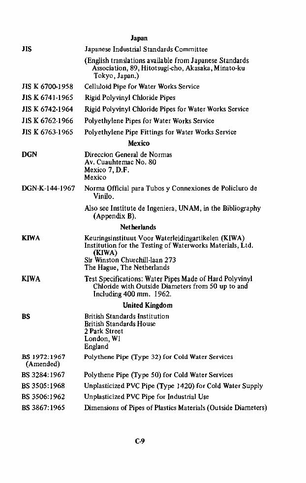
JIS
JIS K 6700-1958
JIS K 6741-1965
JIS K 6742-1964
JIS K 6762-1966
JIS K 6763-1965
DGN
DGN-K-144-1967
KIWA
KIWA
BS
BS 1972; 1967(Amended)
BS 3284:1967
BS 3505:1968
BS 3506:1962
BS 3867:1965
Japan
Japanese Industrial Standards Committee
(English translations available from Japanese StandardsAssociation, 89, Hitotsugi-cho, Akasaka, Minato-kuTokyo , Japan.)
Celluloid Pipe for Water Works Service
Rigid Polyvinyl Chloride Pipes
Rigid Polyvinyl Chloride Pipes for Water Works Service
Polyethylene Pipes for Water Works Service
Polyethylene Pipe Fittings for Water Works Service
Mexico
Direccion General de NormasAv. Cuauhtemac No. 80Mexico 7, D.F.Mexico
Norma Official para Tubos y Connexiones de Policluro deVinilo.
Also see Institute de Ingeniera, UNAM, in the Bibliography(Appendix B).
Netherlands
Keuringsinstituut Voor Waterleidingartikelen (KIWA)Institution for the Testing of Waterworks Materials, Ltd.(KIWA)Sir Winston Churchill-laan 273The Hague, The Netherlands
Test Specifications: Water Pipes Made of Hard PolyvinylChloride with Outside Diameters from 50 up to andIncluding 400 mm. 1962.
United Kingdom
British Standards InstitutionBritish Standards House2 Park StreetLondon, W1England
Polythene Pipe (Type 32) for Cold Water Services
Polythene Pipe (Type 50) for Cold Water Services
Unplasticized PVC Pipe (Type 1420) for Cold Water Supply
Unplasticized PVC Pipe for Industrial Use
Dimensions of Pipes of Plastics Materials (Outside Diameters)
C-9

BS (Cont’d)
BS 4159:1967 Colour Marking of Plastics Pipes to IndicatePressure Ratings
West Germany
DIN Deutscher Normenausschuss
English translations available fromBeuth-Vertrieb Gmbtt1 Berlin 30West Germany
DIN 8061 Tubes of Pipes of Rigid PVC (Rigid PolyvinylChloride); Technical Conditions of Delivery
DIN 8062 Tubes of Pipes of Rigid PVC (Rigid PolyvinylChloride); Dimensions
DIN 8072 Tube and Piping of Flexible PE (Polyethylene);Dimensions
DIN 8074 Tube and Piping of Rigid PE (Polyethylene);Dimensions
DIN 16933 Tube and Piping of PE (Polyethylene); Directionsfor Use
Others
Other countries with standards or semi-official rules or both includeAustria, Belgium, Czechoslovakia, Denmark, France, Hungary, Ireland,Norway, Pakistan, Peru, Poland, South Africa, Sweden, and the SovietUnion.
Some countries publish no local standards but use ISO Recommendations (note that these cover only dimensions and working pressures). TheIndian Standards Institute, for example, lists ISO Recommendations 161,264, and 330 as its standards for plastic pipe. Some importing countriesuse the standards of those countries supplying the pipe, principally theU.S., Britain, and Japan. Note that the latter two allow use of leadstabilizers.
C-10

APPENDIX D
A GLOSSARY OF PLASTICS PIPING TERMS
Foreword
Plastics piping has its own technical vocabulary, much of which is new tothe water works industry and to some readers of this report. This appendix isintended to provide a working vocabulary for those public officials andengineers with new responsibilities or interest in use of plastics pipe and forthose who seek to improve their knowledge through further study of thevoluminous literature (see Appendix B) of the subject or communication withthe plastics industry.
The majority of these definitions are extracted from publications of theAmerican Society for Testing Materials (ASTM), Plastics Pipe Institute, andthe Handbook of Reinforced Plastics of the Society of the Plastics Industry.
Nomenclature
ABS truss pipe - pipe that derives its name from its cross-sectionalconfiguration of concentric inner and outer walls of ABS connected intruss-like fashion by webs of the same material with lightweight concretefilling the intervening spaces to maintain the truss shape. Seeacrylonitrile-butadiene-styrene (ABS) pipe.Acceptance test -an investigation performed on an individual lot of apreviously qualified product, by, or under the observation of, the
purchaser to establish conformity with a purchase agreement.Acrylonitrile-butadiene-styrene (ABS) pipe and fitting plastics - plasticscontaining polymers and-or blends of polymers, in which the minimumbutadiene content is 6 percent, the minimum acrylonitrile content is 15
percent, the minimum styrene and-or substituted styrene content is 15percent, and the maximum content of all other monomers is not morethan 5 percent, and lubricants, stabilizers and colorants.Aging, n.- (1) The effect on materials of exposure to an environment for aninterval of time.
(2) The process of exposing materials to an environment for an intervalof time.
D-1

Antioxidant - a compounding ingredient added to a plastic composition to
retard possible degradation from contact with oxygen (air), particularly in
processing at or exposures to high temperatures.Bell end - the enlarged portion of a pipe that resembles the socket portion ofa fitting and that is intended to be used to make a joint by inserting apiece of pipe into it. Joining may be accomplished by solvent cements,adhesives, or mechanical techniques.
Burst strength - the internal pressure required to break a pipe or fitting. Thispressure will vary with the rate of build-up of the pressure and the timeduring which the pressure is held. See burst strength, fiber stress, hoopstress, hydrostatic design stress, long-term hydrostatic strength, hydrostatic
strength (quick), long-term burst, ISO equation, pressure, pressure rating,quick burst, service factor, strength, stress, and sustained pressure test arerelated terms.
Cement - See adhesive and solvents, cement.
Chemical resistance - (1) the effect of specific chemicals on the properties ofplastic piping with respect to concentration, temperature and time ofexposure.
-(2) the ability of a specific plastic pipe to render service for a usefulperiod in the transport of a specific chemical at a specified concentrationand temperature.
Cold flow - See Creep.
Compound - the intimate admixture of a polymer or polymers with otheringredients such as fillers, softeners, plasticizers, catalysts, pigments, dyes,curing agents, stabilizers, antioxidants, etc.Creep, n.- the time-dependent part of strain resulting from stress, that is, thedimensional change caused by the application of load over and above theelastic deformation and with respect to time.Cure,v.- to change the properties of a polymeric system into a final, morestable, usable condition by the use of heat, radiation, or reaction withchemical additives.
Deflection temperature - the temperature at which a specimen will deflect agiven distance at a given load under prescribed conditions of test. SeeASTM D648. Formerly called heat distortion.Degradation, n.- a deleterious change in the chemical structure of a plastic.See also Deterioration.Deterioration -a permanent change in the physical properties of a plasticevidenced by impairment of these properties.Dimension ratio - the diameter of a pipe divided by the wall thickness. Eachpipe can have two dimension ratios depending on whether the outside orinside diameter is used. In practice, the outside diameter is used if thestandards requirement and manufacturing control are based on thisdiameter. The inside diameter is used when this measurement is thecontrolling one.
Elasticity - that property of plastics materials by virtue of which they tend torecover their original size and shape after deformation.
D-2
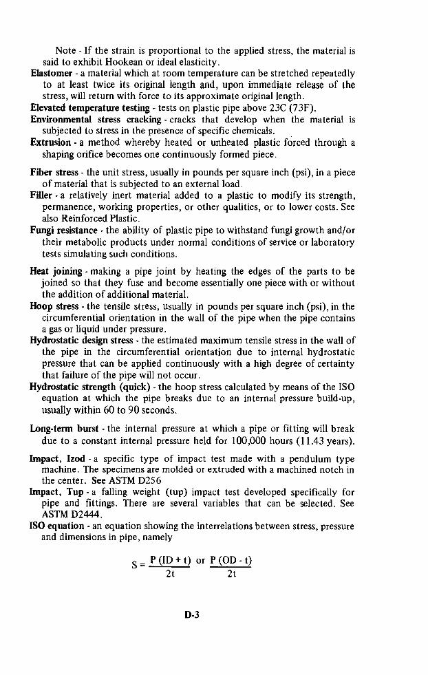
Note - If the strain is proportional to the applied stress, the material issaid to exhibit Hookean or ideal elasticity.Elastomer - a material which at room temperature can be stretched repeatedlyto at least twice its original length and, upon immediate release of thestress, will return with force to its approximate original length.Elevated temperature testing - tests on plastic pipe above 23C (73F).Environmental stress cracking - cracks that develop when the material issubjected to stress in the presence of specific chemicals. _
Extrusion - a method whereby heated or unheated plastic forced through a
shaping orifice becomes one continuously formed piece.
Fiber stress - the unit stress, usually in pounds per square inch (psi), in a pieceof material that is subjected to an external load.Filler - a relatively inert material added to a plastic to modify its strength,permanence, working properties, or other qualities, or to lower costs. Seealso Reinforced Plastic.
Fungi resistance - the ability of plastic pipe to withstand fungi growth and-ortheir metabolic products under normal conditions of service or laboratorytests simulating such conditions.
Heat joining - making a pipe joint by heating the edges of the parts to bejoined so that they fuse and become essentially one piece with or withoutthe addition of additional material.Hoop stress - the tensile stress, usually in pounds per square inch (psi), in thecircumferential orientation in the wall of the pipe when the pipe containsa gas or liquid under pressure.Hydrostatic design stress - the estimated maximum tensile stress in the wall ofthe pipe in the circumferential orientation due to internal hydrostaticpressure that can be applied continuously with a high degree of certaintythat failure of the pipe will not occur.Hydrostatic strength (quick) - the hoop stress calculated by means of the ISOequation at which the pipe breaks due to an internal pressure build-up,
usually within 60 to 90 seconds.
Long-term burst - the internal pressure at which a pipe or fitting will breakdue to a constant internal pressure held for 100,000 hours (11.43 years).
Impact, Izod - a specific type of impact test made with a pendulum typemachine. The specimens are molded or extruded with a machined notch inthe center. See ASTM D256Impact, Tup - a falling weight (tup) impact test developed specifically forpipe and fittings. There are several variables that can be selected. See
ASTM D2444.ISO equation - an equation showing the interrelations between stress, pressureand dimensions in pipe, namely
S: P(ID+t) or P(OD-t)2t 2t

where S = stress
P = pressureID = average inside diameterOD = average outside diametert = minimum wall thickness
Reference: ISO R161-1960 Pipes of Plastics Materials for theTransport of Fluids (Outside Diameters and Nominal Pressures) Part 1,Metric Series.
Joint - the location at which two pieces of pipe or a pipe and a fitting areconnected together. The joint may be made by an adhesive, asolvent-cement or a mechanical device such as threads or a ring seal.
Long-term hydrostatic strength - the estimated tensile stress in the wall of thepipe in the circumferential orientation (hoop stress) that when appliedcontinuously will cause failure of the pipe at 100,000 hours (11.43 years).These strengths are usually obtained by extrapolation of log-log regressionequations or plots.
Molding, compression - a method of forming objects from plastics by placingthe material in a confining mold cavity and applying pressure and usuallyheat.
Molding, injection -a method of forming plastic objects from granular orpowdered plastics by the fusing of plastic in a chamber with heat andpressure and then forcing part of the mass into a cooler chamber where itsolidifies.Note - This method is commonly used to form objects fromthermoplastics.
Monomer - a relatively simple chemical which can react to form a polymer.See also Polymer.
Nonrigid plastic -a plastic which has a stiffness or apparent modulus ofelasticity of not over 10,000 psi at 23°C, when determined in accordancewith the Standard Method of Test for Stiffness in Flexure of Plastics(ASTM Designation: D 747).
Olefin plastics - plastics based on resins made by the polymerization of olefinsor copolymerization of olefins with other unsaturated compounds, theolefins being in greatest amount by weight. Polyethylene, polypropyleneand polybutylene are the most common olefin plastics encountered inpipe.
Outdoor exposure - plastic pipe placed in service or stored so that it is notprotected from the elements of normal weather conditions, i.e., the sun’srays, rain, air and wind. Exposure to industrial and waste gases, chemicals,engine exhausts, etc. are not considered normal “outdoor exposure.”
Permanence -the property of a plastic which describes its resistance toappreciable changes in characteristics with time and environment.

Plastic, n.- a material that contains as an essential ingredient an organic
substance of large molecular weight, is solid in its finished state, and, atsome stage in its manufacture or in its processing into finished articles, can
be shaped by flow.Plastic, adj. -the adjective indicates that the noun modified is made of,consists of, or pertains to plastic.Note 1 - The above definition may be used as a separate meaning to the
definitions contained in the dictionary for the adjective “plastic.”Note 2 - The plural form may be used to refer to two or more plasticmaterials, for example, plastics industry. However, when the intent is to
distinguish “plastic products” from “wood products” or “glass products,”the singular form should be used. As a general rule, if the adjective is torestrict the noun modified with respect to type of material, “plastic”should be used; if the adjective is to indicate that more than one type ofplastic material is or may be involved, “plastics” is permissible.Plastic, rigid - a plastic which has a stiffness or apparent modulus of elasticitygreater than 100,000 psi at 23°C, when determined in accordance with theStandard Method of Test for Stiffness in Flexure of Plastics (ASTMDesignation: D 747).Plastic, semirigid -a plastic which has a stiffness or apparent modulus ofelasticity of between 10,000 and 100,000 psi at 23°C, when determined inaccordance with the Standard Method of Test for Stiffness in Flexure ofPlastics (ASTM Designation: D 747).Plasticizer - a material incorporated in a plastic to increase its workability and
its flexibility or distensibility.Note - The addition of the plasticizer may lower the melt viscosity, thetemperature of the second-order transition, or the elastic modulus of theplastic.
Plastics conduit - plastic pipe or tubing used as an enclosure for electricalwrrmg.
Plastic pipe - a hollow cylinder of a plastic material in which the wallthicknesses are usually small when compared to the diameter and in whichthe inside and outside walls are essentially concentric. See plastics tubing.Plastics tubing - a particular size of plastics pipe in which the outside diameteris essentially the same as that of copper tubing. See plastics pipe.Polyethylene, n.- a polymer prepared by the polymerization of ethylene asthe sole monomer. See Polyethylene Plastics and Ethylene Plastics.Polyethylene plastics -plastics based on polymers made with ethylene as
essentially the sole monomer. Note: In common usage for this plastic,essentially means no less than 85% ethylene and no less than 95% total
olefins.Polymer - a compound formed by the reaction of simple molecules havingfunctional groups that permit their combination to proceed to highmolecular weights under suitable conditions. Polymers may be formed bypolymerization (addition polymer) or polycondensation (condensationpolymer). When two or more monomers are involved, the product is calleda copolymer.
D-5
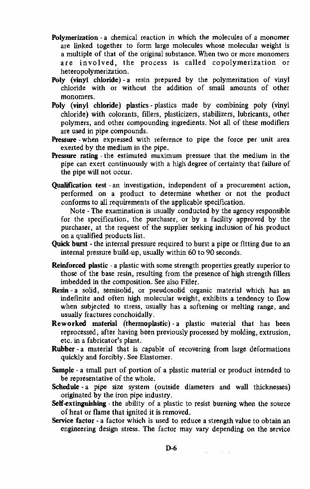
Polymerization - a chemical reaction in which the molecules of a monomerare linked together to form large molecules whose molecular weight isa multiple of that of the original substance. When two or more monomersare involved, the process is called copolymerization orheteropolymerization.Poly (vinyl chloride)-a resin prepared by the polymerization of vinylchloride with or without the addition of small amounts of othermonomers.
Poly (vinyl chloride) plastics - plastics made by combining poly (vinyl
chloride) with colorants, fillers, plasticizers, stabilizers, lubricants, other
polymers, and other compounding ingredients. Not all of these modifiersare used in pipe compounds.Pressure -when expressed with reference to pipe the force per unit areaexerted by the medium in the pipe.Pressure rating -the estimated maximum pressure that the medium in thepipe can exert continuously with a high degree of certainty that failure ofthe pipe will not occur.
Qualification test -an investigation, independent of a procurement action,performed on a product to determine whether or not the productconforms to all requirements of the applicable specification.Note - The examination is usually conducted by the agency responsiblefor the specification, the purchaser, or by a facility approved by thepurchaser, at the request of the supplier seeking inclusion of his producton a qualified products list.
Quick burst - the internal pressure required to burst a pipe or fitting due to aninternal pressure build-up, usually within 60 to 90 seconds.
Reinforced plastic - a plastic with some strength properties greatly superior tothose of the base resin, resulting from the presence of high strength fillersimbedded in the composition. See also Filler.Resin - a solid, semisolid, or pseudosolid organic material which has anindefinite and often high molecular weight, exhibits a tendency to flowwhen subjected to stress, usually has a softening or melting range, andusually fractures conchoidally.
Reworked material (thermoplastic) - a plastic material that has beenreprocessed, after having been previously processed by molding, extrusion,etc. in a fabricator’s plant.Rubber -a material that is capable of recovering from large deformationsquickly and forcibly. See Elastomer.
Sample - a small part of portion of a plastic material or product intended tobe representative of the whole.Schedule - a pipe size system (outside diameters and wall thicknesses)originated by the iron pipe industry.Self-extinguishing - the ability of a plastic to resist burning when the sourceof heat or flame that ignited it is removed.Service factor - a factor which is used to reduce a strength value to obtain anengineering design stress. The factor may vary depending on the service
D-6

conditions, the hazard, the length of service desired, and the properties ofthe pipe.
Softening range - the range of temperature in which a plastic changes from arigid to a soft state.Note -Actual values will depend on the method of test. Sometimesreferred to as softening point.Solvent cement - in the plastic piping field, a solvent adhesive that contains asolvent that dissolves or softens the surfaces being bonded so that the
bonded assembly becomes essentially one piece of the same type ofplastic.
Solvent cementing - making a pipe joint with a solvent cement. See Solventcement.
Specimen - an individual piece or portion of a sample used to make a specifictest. Specific tests usually require specimens of specific shape anddimensions.
Stabilizer-a compounding ingredient added to a plastic composition toretard possible degradation on exposure to high temperatures, particularlyin processing. An antioxidant is a specific kind of stabilizer.Standard dimension ratio - a selected series of numbers in which thedimension ratios are constants for all sizes of pipe for each standarddimension ratio and which are the USASI Preferred Number Series 10modified by +1 or -1. If the outside diameter (OD) is used the modifier is+1. If the inside diameter (ID) is used the modifier is -1.Some of the numbers are as follows:
USASI PREFERRED OD IDNUMBER SERIES 10 CONTROL CONTROL
5. 6. 4.
6.3 7.3 5.3
8. 9. 7.
10. ll. 9.
12.5 13.5 11.5
16. 17. 15.
20. 21. 19.
25. 26. 24.
31.5 32.5 30.5
40. 41. 39.
50. 51. 49.63. 64. 62.
Reference: USASI Preferred Numbers, Z17.1-1958, UDS 389.17.
Standard thermoplastic pipe materials designation code - a means for easilyidentifying a thermoplastic pipe material by means of three elements. Thefirst element is the abbreviation for the chemical type of the plastic inaccordance with ASTM D1600. The second is the type and grade (basedon properties in accordance with the ASTM materials specification); in thecase of ASTM specifications which have no types and grades or those in
D-7

the cell structure system, two digit numbers are assigned by the PPI thatare used in place of the larger numbers. The third is the recommendedhydrostatic design stress (RHDS) for water at 23C (73F) in pounds persquare inch divided by 100 and with decimals dropped, e.g. PVC 1120indicates that the plastic is poly (vinyl chloride), Type 1 Grade 1 accordingto ASTM D1784 with a RHDS of 2000 psi for water at 73F. PE 3306indicates that the plastic is polyethylene, Type III Grade 3 according toASTM D1248 with a RHDS of 630 psi for water at 73F. PP 1208 ispolypropylene, Class I-19509 in accordance with ASTM D2146 with aRHDS of 800 psi for water at 73F ; the designation of PP12 forpolypropylene Class I-19509 will be covered in the ASTM and ProductStandards for polypropylene pipe when they are issued.
Stiffness factor - a physical property of plastic pipe that indicates the degreeof flexibility of the pipe when subjected to external loads. See ASTMD2412.Strain - the ratio of the amount of deformation to the length being deformedcaused by the application of a load on a piece of material.Strength - the stress required to break, rupture or cause a failure.
Stress - when expressed with reference to pipe the force per unit area in the
wall of the pipe in the circumferential orientation due to internalhydrostatic pressure.Stress-crack - external or internal cracks in a plastic caused by tensile stresses
less than that of its short-time mechanical strength.Note - The development of such cracks is frequently accelerated by theenvironment to which the plastic is exposed. The stresses which cause
cracking may be present internally or externally or may be combinationsof these stresses. The appearance of a network of fine cracks is calledcrazing.
Styrene plastics -plastics based on resins made by the polymerization ofstyrene or copolymerization of styrene with other unsaturatedcompounds, the styrene being in greatest amount by weight.Styrene-rubber plastics - compositions based on rubbers and styrene plastics,the styrene plastics being in greatest amount by weight.Styrene-rubber (SR) pipe and fitting plastics - plastics containing at least 50
percent styrene plastics combined with rubbers and other compoundingmaterials, but not more than 15 percent acrylonitrile.
Thermoplastic, n.- a plastic which is thermoplastic in behavior.Thermoplastic, adj. -capable of being repeatedly softened by increase oftemperature and hardened by decrease of temperature.Note -Thermoplastic applies to those materials whose change uponheating is substantially physical.
Thermoset,n.-a plastic which, when cured by application of heat orchemical means, changes into a substantially infusible and insolubleproduct.Thermoset,adj. -pertaining to the state of a resin in which it is relativeinfusible.
D-8

Thermosetting -capable of being changed into a substantially infusible orinsoluble product when cured under application of heat or chemicalmeans.
Vinyl Chloride plastics - plastics based on resins made by the polymerizationof vinyl chloride or copolymerization of vinyl chloride with otherunsaturated compounds, the vinyl chloride being in greatest amount by
weight.
Virgin material - a plastic material in the form of pellets, granules, powder,floc, or liquid that has not been subjected to use or processing other thanthat required for its original manufacture.
D-9

APPENDIX E
OTHER INFORMATION SOURCES
General Information
The principal industry association is the Plastics Pipe Institute of the
Society of the Plastics Industry, Inc. Its address is 250 Park Avenue, NewYork, N.Y. 10017. G.R. Munger is Executive Director. Dr. Frank W.Reinhart, 9918 Sutherland Road, Silver Spring, Md., serves as the Plastics
Pipe Institute’s Technical Director.
Testing Programs
Virtually all plastics pipe used in public water systems in the United States
carries the “Seal of Approval” of the National Sanitation Foundation TestingLaboratory, Inc., Ann Arbor, Michigan, including imported pipe of foreignmanufacture. The NSF has under consideration several proposals forextending their seal program to other countries. Somewhat similar programsare offered by British (BSI) and Dutch (KIWA) organizations.
Overseas Business Assistance
The U.S. Department of Commerce conducts a number of programs andprovides extensive services which can be of material assistance to U.S. firmsinterested in expanding their operations through overseas investments,
particularly in the less-developed countries.In the main, these programs and services—which do not include, however,financial assistance or credit facilities—consist of :The Office of International Investment, which has as a primary mission thepromotion of U.S. investment abroad. Its staff is prepared to advise and assistU.S. firms contemplating overseas investment. It is in direct contact with allU.S. Foreign Service Posts and arranges for prompt publication of all specificinvestment opportunities reported by these Posts and by U.S. Trade andInvestment Missions to particular countries. A copy of the A.I.D. Catalog ofInvestment Information and Opportunities is available in this Office as well asin each of the 42 regional Commerce Field Offices. Firms seeking counsel inrespect to investing abroad should contact the Investment Resources Division,Office of International Investment, Bureau of International Commerce,Department of Commerce, Washington, D.C. 20230;
E-1

The network of Commercial Officers assigned to our diplomatic andconsular establishments abroad;
Field Offices in 42 cities of the United States (see below);The Office of International Regional Economics, which puts out the
Overseas Business Reports (a series of pamphlets providing basic andauthoritative information on specific countries) useful to exporters,
importers, manufacturers and researchers as well as investors, and all who are
concerned with international trade or otherwise require information abouteconomic conditions throughout the world;The Commercial Intelligence Division, which can furnish World TradeDirectory Reports containing commercial and financial information on
specific foreign firms or individuals;The Business and Defense Services Administration, which providesguidance on and analyses of the economic factors relating to the sale,purchase or marketing of a specific commodity in foreign countries, or toinvestment in production facilities for specific commodities;The Checklist, a bibliography and handy reference to the hundreds ofpublished reports available to the U.S. business community interested inworld trade and overseas investment;International Commerce, the leading weekly periodical published in theInternational Affairs area of the Department of Commerce. InternationalCommerce contains practical and concise international marketinginformation, news and reports explaining potential advantages to U.S.businessmen in profitable international sales of U.S. products, and regularlylists new investment opportunities around the world.
A Businessmen’s Information Center has been established in the Agencyfor International Development to provide assistance to potential investors andother interested businessmen, and to guide them to other appropriate offices
and individuals. The Center is located in Room 2926, New State Department
Building, 21st and Virginia Avenue, N.W., Washington, D.C., 20523,
telephone DUd1ey 3-4291.
AID has authority under Section 231 of the Foreign Assistance Act of1961 to share (up to 50%) in the cost of surveys of investment opportunities.Under Sections 221-224 of the Foreign Investment Act of 1961, AID isauthorized to guarantee investments in the economies of friendlyless-developed countries against certain political and business risks; includinginconvertibility of foreign currency, loss by expropriation or confiscation,and loss due to war, revolution, or insurrection.Under Section l04(e), Title I of Public Law 480, certain of the foreigncurrencies received by the U.S. Government in payment for agriculturalcommodities may be lent to U.S. businesses to develop business and expandtrade. These “Cooley” funds are currently (1969) available in Korea, India,Israel, Pakistan, Congo, Ghana, Morocco, and Tunisia.If dollar financing is not available on reasonable terms from private orother public sources, AID has authority under Sections 201 and 251 to makedollar loans to private (as well as public) enterprise, both U.S. and foreign.The Export-Import Bank of Washington may extend long-term direct loans tocover the dollar costs of equipment and services of U.S. origin. The manual
E-2

entitled “Feasibility Studies, Economic and Technical Soundness Analysis,
Capital Projects” is available from AID as a guide for use in preparingfeasibility studies for loan applications.
Inquiries regarding these AID programs should be addressed to the PrivateInvestment Center, Agency for International Development, Washington, D.C.
20523.
U.S. Department of Commerce Field Offices
Alburquerque, New Mexico 87101U.S. CourthouseArea Code 505 Tel. 247-0311
Anchorage, Alaska 99501
306 Loussac-Sogn BuildingArea Code 907 Tel. 272-6331
Atlanta, Georgia 303034th Floor, Home Savings Building75 Forsyth Street, N.W.Area Code 404 Tel. 526-6000
Chicago, Illinois 606041486 New Federal Building219 South Dearborn Street
Area Code 312 Tel. 828-4400
Cincinnati, Ohio 452028028 Federal Office Building550 Main Street
Area Code 513 Tel. 684-2944
Baltimore, Maryland 21202305 U.S. CustomhouseGay and Lombard StreetsArea Code 301 Tel. Plaza 2-8460
Birmingham, Alabama 35205Suite 200-201, 908 South 20th StreetArea Code 205 Tel. 325-3327
Boston, Massachusetts 02110Room 230, 80 Federal StreetArea Code 617 Tel. CA 3-2312
Buffalo, New York 14203504 Federal Building117 Ellicott StreetArea Code 716 Tel. 842-3208
Charleston, South Carolina 29403Federal Building, Suite 631334 Meeting Street
Area Code 803 Tel. 747-4171
Charleston, West Virginia 253013002 New Federal Office Building500 Quarrier Street
Area Code 304 Tel. 343-6196
Cheyenne, Wyoming 82001
6022 Federal Building2120 Capitol AvenueArea Code 307 Tel. 634-5920
Cleveland, Ohio 441014th Floor, Federal Reserve Bank Bldg.East 6th Street and Superior AvenueArea Code 216 Tel. 241-7900
Dallas, Texas 75202Room 1200, 1114 Commerce StreetArea Code 214 Tel. Rlverside 9-3287
Denver, Colorado 8020216407 Federal Building20th and Stout StreetsArea Code 303 Tel. 297-3246
Des Moines, Iowa 503091216 Paramount Building509 Grand AvenueArea Code 515 Tel. 284-4222
Detroit, Michigan 48226445 Federal BuildingArea Code 313 Tel. ‘226-6088
Greensboro, North Carolina 27402412 U.S. Post Office BuildingArea Code 919 Tel. 275-9111
Hartford, Connecticut 0610318 Asylum StreetArea Code 203 Tel. 244-3530
Honolulu, Hawaii 96813202 International Savings Building1022 Bethel Street
Tel. 588977
E-3

Houston, Texas 770025102 Federal Building515 Rusk AvenueArea Code 713 Tel. 228-0611
Jacksonville, Forida 32202512 Greenleaf Building208 Laura StreetArea Code 904 Tel. 354-7111
Kansas City, Missouri 64106Room 2011, 911 Walnut Street' Area Code 816 Tel. FR 4-3141
Los Angeles, California 90015Room 450, Western Pacific Building1031 South BroadwayArea Code 213 Tel. 688-2833
Memphis, Tennessee 38103345 Federal Office Building167 North Main StreetArea Code 901 Tel. 534-3214
Miami, Florida 33130928 Federal Office Building51 S.W. First AvenueArea Code 305 Tel. 350-5267
Milwaukee, Wisconsin 53203Straus Building238 West Wisconsin AvenueArea Code 414 Tel. BR 2-8600
Minneapolis, Minnesota 55401306 Federal Building110 South Fourth StreetArea Code 612 Tel. 334-2133
New Orleans, Louisiana 70130909 Federal Office Building, South610 South StreetArea Code 504 Tel. 527-6546
New York, New York 1000161st Floor, Empire State Building350 Fifth AvenueArea Code 21 2 Tel. LOngacre 3-3377
Philadelphia, Pennsylvania 19107Jefferson Building1015 Chestnut StreetArea Code 215 Tel. 597-2850
Phoenix, Arizona 850255413 New Federal Building230 North First AvenueArea Code 602 Tel. 261-3285
Pittsburgh, Pennsylvania 152222201 Federal Building1000 Liberty AvenueArea Code 412 Tel. 644-2850
Portland, Oregon 97204217 Old U.S. Courthouse520 S.W. Morrison StreetArea Code 503 Tel. 226-3361
Reno, Nevada 895022028 Federal Building300 Booth StreetArea Code 702 Tel. 784-5203
Richmond, Virginia 232402105 Federal Building400 North 8th StreetArea Code 703 Tel. 649-3611
St. Louis, Missouri 631032511 Federal Building1520 Market StreetArea Code 314 Tel. MA 2-4243
Salt Lake City, Utah 841113235 Federal Building125 South State StreetArea Code 801 Tel. 524-5116
San Francisco, California 94102Federal Building, Box 36013450 Golden Gate AvenueArea Code 415 Tel. 556-5864
Santurce, Puerto Rico 00907Room 628, 605 Condado AvenueTel. 7234640
Savannah, Georgia 31402235 U.S. Courthouse andPost Office Building125-29 Bull StreetArea Code 912 Tel. 232-4321
Seattle, Washington 98104809 Federal Office Building909 First AvenueArea Code 206 Tel. 583-5615

APPENDIX F
DIRECTORY OF MANUFACTURERS
N.B. No warranty is made regarding the completeness or accuracy of this list.
Inclusion or rejection implies neither endorsement nor rejection by the
authors or by the Agency for International Development.
Ref No. Ref No.
2 A. B. & I. Plastics 2
7091 Central AvenueNewark, California 94560
2 ASC Plastics, Inc. 4N. 800 Fancher WaySpokane, Washington 99211
2 Adams Brothers Co., Inc.P. O. Box 63Eads, Tennessee 38028
2
1 Airco Chemicals and Plastics150 East 42nd StreetNew York, New York 10017
4 Akron Extruders4
1119 Milan StreetCanal Fulton, Ohio 44614
1 Allied Chemical Corp.Plastics Div., Columbia Rd. 1
Morristown, N. J . 07960
1 American Chemical Corp.P. O. Box 9247Long Beach, California 90810
21
2 Amoco Chemicals CorporationIndustrial Products Division1530 Commerce DriveStow, Ohio 44224
Note: See Reference Numbers at End of Appendix F.
Anesite Division, Clow Corp.6200 Mulford StreetChicago , Illinois 60648
Anger APMU.S. Anger, Inc.8255 West 20th AvenueP. O. Box 4246Hialeah, Florida 33104
Arrow Industries44 East 6th Avenue
P. O. Box 217Midvale, Utah 84047
Bolling, Stewart, & Co.3190 E. 65th StreetCleveland, Ohio 44127
Borden Inc-Chemical Div.Thermoplastic Products511 Lancaster Street
Leominster, Mass. 01453
Borg-Warner Pipe & ProductsDept. of Fabricated ProductsDiv. of Borg-Warner Corp.1524 Crystal AvenueKansas City, Missouri 64126
F-1

Ref No.
2 ,5 Cabot Piping SystemsPlastics Div., Cabot Corp.P. O. Box 1032Louisville, Kentucky 40201
Can-Tex IndustriesDivision of Harsco Corp.Plastic Pipe DivisionMineral Wells, Texas 76067
Cardinal Plastics, Inc.P. O. Box 7197Denver, Colorado 80207
Carlon ProductsConoco Plastics, Div. ofContinental Oil CompanyP. O. Box 236, Cottage RowWilton, Connecticut 06897
Carmel Industries, Inc.4851 N. W. 36th AvenueMiami, Florida 33142
Celanese Plastics Company
550 Broad StreetNewark, New Jersey 07102
Celanese Plastics Company4550 Cemetery RoadHilliard, Ohio 43026
Certain-Teed Products Corp.Certain-Teed Asbestos andPlastics Division500 W. First StreetP. O. Box 988McPherson, Kansas 67460
Charlotte Pipe & Foundry Co.P. O. Box 991Monroe, North Carolina 28110
Colonial Plastics Mfg. Co.P. O. Box 15415 Hilldale Sta.5128 W. Hanna AvenueTampa, Florida 33614
Conoco PlasticsDiv. Continental Oil Co.P. O. Box 236 Cottage RowWilton, Connecticut 06897
Continental PlasticsIndustries, Inc.1300 40th StreetDenver, Colorado 80205
Ref No.
Cresline Plastic Pipe
Company, Inc.955 Diamond AvenueEvansville, Indiana 47711
Crown-Line Plastics, Inc.Industrial Site
Nebraska City, Nebraska 68410
Davis-Standard/GouldingCrompton & Knowles Corp.Rte. 1,Pawcatuck, Connecticut 02891
Diamond Shamrock Corp.Union Commerce Bldg.Cleveland, Ohio 44115
Dixie Plastics Mfg.Company, Inc.P. O. Box 52769New Orleans, La. 70150
The Dow Chemical Co.P. O. Box 467Midland, Michigan 48641
E. I. dupont de Nemours& Co., Plastics Dept.Wilmington, Delaware 19898
Durapipe & Fittings Ltd.Bentinck RoadWest Drayton, Middx.England
Eastman Chemical Products, Inc.Sub. of Eastman Kodak Co.Kingsport, Tenn. 37662
Egan Machinery Co.S. Adamsville RoadSomerville, N. J. 08876
Electric Hose & Rubber Co.Wilmington, Delaware 19899
Empresas Rasado, Inc.P. O. Box 952Carolina, Puerto Rico 06630
Escambia Chemical Corp.P. O. Box 467Pensacola, Florida 32502
Ethyl CorporationResearch and Development
P. O. Box 341Baton Rouge, La. 70821
F-2

R efno.Ethyl CorporationPlastics DivisionPipe ProductsEthyl Tower, 451 Florida St.Baton Rouge, La. 70821
Fellows Gear Shaper Co.78 River St.Springfield, Vermont 05156
Fibre-Tek Corporation171 1 Anaheim AvenueCosta Mesa, Calif. 92627
Firestone Plastics CompanyChemicals DivisionP. O. Box 699Pottstown, Pennsylvania 19464
The Flintkote CompanyPipe Products GroupOrangeburg, N. Y. 10962
Florida Extrusion Corp.120 N.W. 1 1th StreetP. O. Box 758Boca Raton, Florida 33432
Four D Mfg. Company209 1/2 Fourth StreetParkersburg, W. Va. 26101
Four D West, Inc.Morgan, Utah 84050
Gaspro, Ltd.P. O. Box 2454Honolulu, Hawaii 96804
The General Tire & RubberCompany
Chemical-Plastics Div.P. O. Box 951Akron, Ohio 44309
Genova Products
300 Rising Street
Davison, Michigan 48423
Getty Machine & Mold, Inc.384 Getty AvenueClifton, N. J. 07015
Gifford-Hill Western Dev.Gifford-Hill & Co., Inc.2425 Marshall Street
P. O. Box 2748Lubbock, Texas 79408
R ef No.
Glamorgan Plastics
A Div. of Glamorgan Pipeand Foundry Co.P. O. Box 740Lynchburg, Virginia 24505
Goodall Rubber CompanyPlastics Division2320 E. State StreetTrenton, New Jersey 08604
B. F. Goodrich Chemical Co.3135 Euclid AvenueCleveland, Ohio 44115
The Goodyear Tire &Rubber CompanyChemical DivisionAkron, Ohio 44316
Gulf Oil CompanyU. S. Chemicals DepartmentPlastics DivisionP. O. Box 2100, Gulf Bldg.Houston, Texas 77001
Harvel Plastics Inc.P. O. Box 757Easton, Pa. 18042
Haskon IncorporatedMiddletown Industrial ParkMiddletown, Delaware 19709
Hercules IncorporatedWilmington, Delaware 19899
Hobbs Mfg. Co.666 Lincoln St.Worcester, Mass. 01605
Hurricane Pipe Mfg. Inc.1250 N.W. 23rd AvenueFt. Lauderdale, Florida 33311
Induplas de Carolina, Inc.P. O. Box 243 La FatimaPonce, Puerto Rico 00731
Interstate Plastic Inc.P. O. Box 942Coeur D’Alene, Idaho 83814
Jet Stream PlasticsDiv. of Ralph Jones Co., Inc.
P. O. Box 190Siloam Springs, Ark. 72761
F-3

Ref No.
Johns-Manville Sales Corp.Pipe Division22 E. 40th StreetNew York, New York 10016
Johnson Div./Leesona Corp.P. O. Box 490Chippewa Falls, Wisconsin 54729
Kerona, Inc.2547 W. Jackson StreetPhoenix,Arizona 85009
Kerona Plastic Extrusion, Co.2050 East Fremont StreetStockton, Calif. 95205
Lasco Industries1561 Chapin RoadMontebello, Calif. 90054
Linehan Plastic Corp.2062 Irving Blvd.Dallas, Texas 75207
Marbon DivisionBorg-Warner Corp.P. O. Box 68Washington, W. Va. 26181
Micro Tool CompanyDura Plastic Products533 East Third StreetBeaumont, California 92223
Mid-American Industries, Inc.P. O. Box 13224Memphis, Tennessee 38113
Mirada Enterprises
P. O. Box 392La Mirada, Calif. 90638
Mobil Chemical Company150 East 42nd StreetNew York, New York 10017
Modern Plastic Machinery Corp.64 Lakeview AvenueClifton, N. J. 07105
Monsanto CompanyPlastics Division
_P.O.Box1531Springfield, Mass. 01101
Ref No.
H. Muehlstein & Co., Inc.475 Steamboat RoadGreenwich, Connecticut 06830
NRM Corp.47 W. Exchange St.Akron, Ohio 44308
Nalgene Piping SystemsDiv. of Nalge Co., Inc.75 Panorama Creek Drive
P. O. Box 365Rochester, New York 14602
Nebraska Plastics, Inc.Cozad, Nebraska 69130
Olin Evanite PlasticsP. O. Box 217Carrollton, Ohio 44615
Pacific Plastic Pipe CompanyP. O. Box 399Beaverton, Oregon 97005
Pacific Western ExtrudedProducts, Inc.9750 Firestone Blvd.Downey, Calif. 90241
Peerless Plastics, Inc.P. O. Box 956Garden City, Kansas 67846
Perma-Pipe Corp.1609 Stoneridge Drive
Stone Mountain, Ga. 30083
Phillips Petroleum CompanyChemical Dept., Plastics Div.Bartlesville, Oklahoma 74003
Phillips Products Co., Inc.Sub. of Phillips PetroleumCompanyBartlesville, Oklahoma 74003
The Plastex DivisionWistron Corporation3232 Cleveland AvenueColumbus, Ohio 43224
Plastic Industries, Inc.2615 N. E. 5th AvenuePompano Beach, Florida 33064
F-4

R ef No.
2,5
RefNo.
Plastics Industries of 4
Delaware, Inc.Heller RoadInterstate Industrial ParkBellmawr, New Jersey 08030 4
Plasticos Metropolitanos, Inc.P. O. Box 21031Rio Piedras, Puerto Rico 00928
Plastic Specialties
Manufacturing Corp.4000 Metzger RoadFort Pierce, Florida 33450 2
Plastiline, Inc.1251 N. E. 48th StreetPompano Beach, Florida 33064
Portco CorporationVancouver, Washington 98660
Precision Polymers, Inc. 4
P. O. Box 237Rockaway, New Jersey 07886
Prodex Div. 2
Koehring Co.King George Post RoadFords, New Jersey
Pyramid Industries Inc. 4P. O. Box 321Erie, Pennsylvania 16505
Pyramid South, Inc. 2
P. O. Box 848Benton, Arkansas 72015
Race & Race, Inc. 2
P. O. Box 1400Winterhaven, Florida 33880
Ralon Products, Inc. 2
635 E. Edna PlaceCovina, Calif. 91722
Razorback Plastic Products, Inc. 1
3730 Wheeler AvenueFort Smith, Arkansas 72901
2,5
Rea Plastics, Inc.P. O. Box 766Kingsport, Tennessee 37662
Reifenhauser, U.S. Sales Corp.60 E. 42nd StreetNew York, New York 10017
Reliable Rubber & PlasticMachinery Company2014 Union Tpk.N. Bergen, New Jersey 07047
Richco Plastic Company5825 N. Tripp AvenueChicago, Illinois 60646
Ridge Plastics CompanyP. O. Box 2205Highway 18 EastJonesboro, Arkansas 72401
Rite-Flo Mfg. Corp.13020 S. W. 87th AvenueMiami, Florida 33156
Royle, John, & Sons10 Essex Street
Patterson, N. J. 07501
Ruth-Berry Pump Company341 E. Brooks RoadP. O. Box 9056Memphis, Tennessee 38109
Sakas, Inc.P. O. Box 158Somerset, Ohio 4 3783
Sedco CorporationP. O. Box 365Auburndale, Florida 33823
Silver-Line Plastics Corp.Post Office Box 1806Asheville, N. Carolina 28802
Simpson Timber CompanyPlastics Division4421 Nugget Way
Eugene, Oregon 97403
Sinclair-Koppers CompanyPittsburgh, Pa. 15 219
R. & G. Sloane Mfg. Div.The Susquehanna Corp.7606 N. Clybourn AvenueSun Valley, Calif. 91352
F-5

Ref No.
A. O. Smith-Inland Inc.Reinforced Plastic Division2700 West 65th StreetLittle Rock, Arkansas 72209
Stauffer Chemical CompanyPlastics DivisionPost Office Box 320Delaware City, Del. 19706
Sterling Extruder Corp.1537 W. Elizabeth AvenueLinden, N. J. 07036
Superlon-Pipe Corporation401 Alexander AvenueBuilding 323Tacoma, Washington 98421
The Swanson Company3747 Buckeye RoadP. O. Box 6557Phoenix, Arizona 85005
Telsco Industries
P. O. Box 18205Dallas, Texas 75218
Tennant, C., Sons & Co.of New York,Omni Div.100 Park Avenue
New York, N. Y. 08903
Tenneco Plastics DivisionTenneco Manufacturing Co.
P. O. Box 2Piscataway, N. J. 08854
Thermoplastics Corp.1 Rodney Blvd.Southland Industrial ParkCharlotte, N. C. 28210
Thogus Products Company
1374 W. 117th StreetCleveland, Ohio 44107
Thompson PlasticsOlin CorporationAssonet, Massachusetts 02702
Triangle Conduit & CableCo., Inc.Plastic Pipe DivisionTriangle & Jersey AvenuesNew Brunswick, N. J. 08903
R ef No.
Typhoon ProductsP. O. Box 477Miami Springs, Florida 33166
U. S. Industrial ChemicalsCompany, Div. of Nat’lDistillers & Chemical Corp.Tuscola, Illinois 6 1953
U. S. Plastics, Inc.P. O. Box 152Houston, Mississippi 38851
Union Carbide Corp.Plastics Div., 270 Park Ave.New York, New York 10017
Union Malleable Mfg. Co.Plastic DivisionAshland, Ohio 44805
Uniroyal ChemicalDivision of Uniroyal, Inc.Naugatuck, Conn. 06770
United Technology CenterDiv. of United Aircraft Corp.P. O. Box 5 222Sunnyvale, Calif. 94088
Universal Pipe & Plastics,Inc.P. O. Box 356Hillsboro, Texas 76645
Vinylite Corporation3121 South Oak StreetSanta Ana, Calif. 92707
Virginia Plastics CompanyP. O. Box 165Roanoke, Virginia 24002
Waldron-Hartig Div.Medland-Ross Corp.Web Processing Section
P. O. Box 791New Brunswick, N. J. 08903
Welding Engineers, Inc.P. O. Box 391Norristown, Pa. 19404
Welex, Inc.100 Queens DriveKing of Prussia, Pa. 19406
F-6

Ref No. Ref No.
4 Werner & Pfleiderer Corp. 2 Western Plastics Corp.160 Hopper Avenue 2330 Port of Tacoma RoadWaldwick, N. J . 07463 Tacoma, Washington 98421
2 Wesflex Manufacturing Co. 2 Woodward CorporationP. O. Box 1009 Woodward, Alabama 35189Richmond, California 94 802
2 Western Plastics Corp.East 7th St. Road atProspect Avenue
P. O. Box 249Hastings, Nebraska 68901
Reference Numbers
1Manufacturer of plastic materials for pipe for potable water.
2Manufacturer of plastic pipe and-or fittings for potable water.
3Manufacturer of plastic materials and plastic pipe and-or fittings for potable water.
4Manufacturer of extruders, injection molders, postforming, or other equipment formanufacture of plastic pipe or fittings.
5Manufacturer of molds for plastic pipe fittings.
F-7

APPENDIX G
*NATlONAL SANITATION FOUNDATION
STANDARD NUMBER 14for
Thermoplastic Materials, Pipe, Fittings, Valves,Traps, Joining Materials and Appurtenances
Section 1. GENERAL
1.01 PURPOSE: To establish the necessary public health and safetyrequirements for thermoplastic materials, pipe, fittings, valves, traps, joiningmaterials and appurtenances based on specific end use and application, and to
provide for conditions and provisions of evaluation therefor.
1.02 COVERAGE: Coverage shall include, but not be limited to,thermoplastic materials, pipe, fittings, valves, traps, joining materials andappurtenances intended for use in:1.021 Potable water systems.
1.022 Drainage and vent systems.
1.03 MINIMUM REQUIREMENTS: The requirements and conditions setforth in this Standard are the minimum necessary to adequately protect andinsure the continued protection of the public’s health and safety. These areminimum requirements and variations may be approved when they tend tomake items more resistant to use conditions, corrosion, or more suitable forthe intended end use. Units which have components or parts which arecovered under existing NSF Standards or Criteria shall comply with theapplicable requirements thereof, but shall be evaluated under the provisionsof said other Standard or Criteria.
1.04 STANDARD REVIEW: A complete review of the Standard shall beconducted at intervals of not more than three years to determine whatchanges, deletions or additions if any, are necessary to maintain current andeffective requirements consistent with new technology and progress. These
*Note: This extract is not complete and is presented for information only. Manufacturers, users, and others interested in the National Sanitation Foundation (NSF) Seal ofApproval Program should contact NSF directly. Use of the NSF Seal is solely controlledby the NSF.
G-1

reviews shall be conducted by appropriate representatives from the industry,public health, and user groups. Final adoption of revision shall be inaccordance with the procedures established by the National SanitationFoundation Joint Committee on Plastics.
1.05 AMENDMENTS AND ADDITIONAL REQUIREMENTS:Amendments to and additional requirements in this Standard may be effected inaccordance with the procedures established by the National SanitationFoundation Joint Committee on Plastics. Prior to their adoption allamendments and-or additional requirements shall be reviewed by appropriaterepresentatives from the industry, public health and user groups. Adoptionshall be in accordance with the established procedures and at therecommendation of the National Sanitation Foundation Joint Committee onPlastics.
Section 2. DEFINITIONS
2.00 APPURTENANCE: The word “appurtenance” shall be defined toinclude, but not limited to, water conditioning tanks, dip tubes, reservoirfloats and storage tanks.
2.01 CHEMICAL ANALYSIS: The term “chemical analysis” shall mean andinclude such qualitative and-or quantitative analysis of chemicals present inthermoplastic materials, pipe, fittings, valves, traps, joining materials and
appurtenences or in the extracted waters therefrom; as may be deemednecessary.
2.02 COMPOUND: An intimate admixture of a resin with other ingredients,such as fillers, softeners, stabilizers, plasticizers, catalysts, pigments, and-ordyes.
2.03 COMPOUNDER: A corporation, company or individual, who underthe provisions of this Standard, further blends, mixes, or otherwise modifiesListed materials as supplied by a raw material manufacturer.
2.04 CONTAMINATION: The presence of foreign materials, impurities, ordilutions which might affect one or more of the physical, chemicaltoxicological, or taste and odor properties of the thermoplastic material, pipe,fittings, valves, traps, and/ or joining materials.
2.05 DRAINAGE SYSTEM: The piping within public or private premiseswhich conveys sewage, rain water, or other liquid wastes to a legal point ofdisposal, but does not include the mains of a public sewer system or privateor public sewage treatment or disposal plant.
2.06 FITTING: A device used to join or terminate sections of pipe.
2.07 HYDROSTATIC DESIGN STRESS: The maximum long term stressconsidered safe in the wall of the pipe in the circumferential orientation dueto internal hydrostatic pressure as determined by the method presented inAppendix A.
G-2

2.08 JOINING MATERIAL: A substance which will effect a weld or bondbetween two parts.
2.09 MANUFACTURER (EXTRUDER-MATERIAL SUPPLIERMOLDER): A corporation, company, or individual, who under theprovisions of the Standard, manufactures thermoplastic materials, pipe,fittings, valves, traps, joining materials and appurtenances.
2.10 ORGANOLEPTIC: The work “organoleptic” shall mean pertaining toevaluation of taste and odor producing properties.
2.11 PLASTIC: A material that contains as an essential ingredient an organicsubstance of high molecular weight, is solid in its finished state, and, at somestage in its manufacture or in its processing into finished articles, can be
shaped by flow.
2.12 PLASTIC PIPE: A hollow cylinder of plastic compound in which thewall thicknesses are usually small in comparison with the diameter, and in
which the outside and inside walls are essentially concentric* and which is
covered by an applicable physical standard.
2.13 POTABLE WATER SYSTEMS: Potable Water Systems shall refer tothose water systems intended to convey drinking water or water for culinary
and-or food processing purposes. It shall include pipe, fittings, valves, andother accessories as are normally considered a part of a water supply system.
2.14 RESIN: A solid, semisolid, or pseudosolid organic material which hasan indefinite and often high molecular weight, exhibits a tendency to flowwhen subjected to stress, usually has a softening or melting range, and usuallyfractures conchoidally. As used herein, resin shall mean the basicthermoplastic which must be mixed with other ingredients before it issuitable for the manufacture of finished product.
2.15 SPECIAL ENGINEERED: The term “special engineered” shall meanspecifically designed for a particular end use or application.
2.16 THERMOPLASTIC: A plastic which is capable of being repeatedlysoftened by an increase of temperature and hardened by a decrease oftemperature.
2.17 TOXIC: The word “toxic” shall refer to the adverse physiologicaleffect to man.
2.18 TRAP: A fitting or device so designed and constructed as to provide,when properly vented, a liquid seal which will prevent the back passage of airwithout materially affecting the flow of liquid through it.
2.19 VALVE: A device used to regulate flow of liquids or gases.
*Note: Plastic pipe shall be considered to mean any cylindrical conduit having a nominaldiameter of 1/
2
inch or greater; provided, however, that when applicable, U.S. Dept. ofCommerce Commerical Standards specifically provide for plastic pipe of smaller nominaldiameter, the smallest diameter specified therein, shall govern.
G-3

2.20 VENT SYSTEM: Pipe or pipes installed to provide a flow of air to orfrom a drainage system, to provide a circulation of air within such system andto protect trap seals from siphonage and back pressure by limiting air pressuredifferentials to plus or minus 1 inch of pressure measured in inches ofwater.
Section 3. MATERIALS
3.00 GENERAL: Materials used in manufacture of pipe, fittings, valves,traps, joining materials and appurtenances covered by this Standard shall
meet the specific public health and safety as well as performance
requirements as established herein for the intended end use or application. Allsuch materials shall be manufactured in a manner which will preventintroduction of possible contamination thereto.
3.001 Such quality procedures and reports are as deemed necessary to
continued uniform quality of the materials and continued compliance withthe applicable ASTM requirements for said material may be required.3.002 The addition of innocuous tracers to materials covered by thisStandard may be required when so recommended by the NSF JointCommittee on Plastics.
3.003 The manufacturer shall submit, at the time of requesting evaluationand qualification of a thermoplastic material and-or joining material,complete formulation information for such material. When any change ismade in the formula or in the source of supply of ingredients therein, suchadditional information shall also be submitted. Said information shall be
retained on a confidential basis.
3.01 HYDROSTATIC DESIGN STRESS: Each manufacturer of a materialintended for use in the manufacturing of plastic pipe intended for pressureapplications under the provisions of this Standard shall submit evidence ordata to permit the assignment of a design stress in conformance with“Methods for Estimating Long-Term Strength and Working Stress ofThermoplastic Pipe” (Appendix A). The assignment of design stress under theprovision of this requirement shall not constitute acceptance of pipe extrudedfrom the same material by others.
3.02 POTABLE WATER APPLICATION: Thermoplastic materials for pipe,fittings, valves, joining materials and-or appurtenances for potable waterapplications shall contain no ingredients in an amount which has beendemonstrated to migrate into water in quantities which are considered toxicand shall conform to the following specific requirements:
3.021 TOXICOLOGICAL AND ORGANOLEPTIC* The toxicologicaland organoleptic evaluations of the analyses specified in Appendix B shallmeet minimum public health requirements.
*The procedures established in Appendix B and as reported in “A Study of Plastic Pipefor Potable Water Supplies,” are based upon long term evaluation of thermoplasticmaterials for potable water applications as to their suitability from a public health anduse standpoint.
o-4

3.022 PHYSICAL REQUIREMENTS: Thermoplastic materials shallcomply with the physical, chemical and performance requisites of thelatest applicable Standard(s) of the American National Standards Institute(ANSI); American Society of Testing Materials (ASTM); or theCommodity Standards Division of the U.S. Department of Commerce(CS); as determined by the NSF Joint Committee on Plastics.
3.03 DRAINAGE AND VENT SYSTEM APPLICATIONS: Thermoplasticmaterials for pipe, fittings, traps, valves, joining materials and appurtenancesshall comply with the physical, use resistant and application requirements ofthe latest applicable ANSI, ASTM, or CS Standard(s) as determined by theNSF Joint Committee on Plastics.
3.04 MATERIALS PRODUCED BY COMPOUNDER: Thermoplasticmaterials produced by a compounder shall meet all of the applicableforegoing requirements of this Standard and shall in addition, meet thefollowing specific requirements:
3.041 Samples for toxicological and organoleptic evaluation may becollected from each batch of compound made from separate lots ofmaterial received from the material suppliers. Not less than two completetoxicological and organoleptic evaluations shall be conducted within theperiod of one year.3.042 Such quality control procedures and reports may be required as aredeemed necessary to assure continued uniform quality of the materials andcontinued compliance with the latest applicable ANSI, ASTM, or CS
Standard(s) as determined by the NSF Joint Committee on Plastis.3.043 Periodic reports from,the compounder shall be required as to thequantity of basic resin purchased, products sold, produced, and in stock.The compounder shall also permit requests for similar information relativeto'the quantity of basic resin and other ingredientsipurchased from primesuppliers.
Section 4. REQUIREMENTS FOR PIPE, FITTINGS,
VAL VES & TRAPS
4.00 GENERAL: Thermoplastic pipe, fittings, valves, traps andappurtenances shall be produced only from virgin materials meeting the
requirements of this Standard for the use intended. Clean rework material, ofthe same virgin ingredients generated from the manufacturer’s own
production may be used by the same manufacturer provided that the finished
products are equal in quality to products manfactured from virgin material.
4.01 TOXICOLOGICAL AND ORGANOLEPTIC REQUIREMENTS:Thermoplastic pipe, fittings, valves, and appurtenances, intended for potablewater application shall conform to the toxicological and organoleptic requirements established in Items 3.02, 3.021, and 3.022 for the thermoplasticmaterials used for potable water applications.
G-5

4.02 PHYSICAL, PERFORMANCE, AND DIMENSION REQUIREMENTS:All pipe, fittings, valves, and traps under this standard, shall comply with thephysical, performance, and dimension requirements of the latest applicableANSI, ASTM, or CS Standard(s) as determined by the NSF Joint Committeeon Plastics. When such Standards are not available for a particular category ofend use, the NSF Joint Committee on Plastics shall consider the problem andmake proper recommendations in the best interests of the public’s health.
4.03 MARKING AND CODING OF PIPE*, FITTINGS AND TRAPS, ANDAPPURTENANCES: The manufacturer shall place on all thermoplastic pipe,fittings, valves and traps, and appurtenances, the designations and identification required in the lastest applicable ANSI, ASTM, or CS Standard(s) asdetermined by the NSF Joint Committee on Plastics. PROVIDED, HOWEVER, THAT FITTINGS AND VALVES OF SUCH SIZE AND/ORCONFIGURATION AS TO PRECLUDE USE OF THE COMPLETEMARKING SHALL BE AT LEAST IDENTIFIED AS TO MANUFACTURERAND TYPE OF MATERIAL.
_
4.031 All required markings shall be legible and so applied as to remainlegible under normal handling and installation practices.
4.032 Thermoplastic pipe, in addition to the above, shall bear an
appropriate code which will assure identification on the pipe as to the
month of production and resin formulas used in the production of saidpipe. Manufacturer shall maintain such additional records as are necessaryto confirm identification of all pipe so coded. Such records shall be madeavailable to the Laboratory upon request.
4.04 SPECIAL ENGINEERED PIPE, FITTINGS, VALVES AND TRAPS:Variations in design of thermoplastic pipe, fittings, valves and traps may bepermitted when the requirements of the intended end use dictate saidvariance and when thermoplastic pipe, fittings, valves, traps manufactured inconformance with existing standards will not provide a product satisfactoryfor said intended use. The variation shall be permitted only upon specificapplication by the manufacturer. The manufacturer of proposed specialengineered pipe, fittings, valves and traps, shall submit complete designengineering considerations for said special engineered items.
4.041 Special testing may be required of the pipe, fittings, valves, traps,and appurtenances submitted under the provisions of Item 4.04. Suchspecial testing shall be in keeping with the most applicable requirements ofItem 4.02.
4.042 Special engineered products shall be identified by the symbol “SE”immediately following the appropriate product identification.
*NOTE: The following indicates the required markings and code information:
Pipe Type Pressure Commercial Trade nsfSize Material PSI Std. No. Name Code Logo
Example:
2" PVC 1120 200 psi CS256-63 JCY 1510A nsf
G-6

4.05 SPECIAL TEST REQUIREMENTS: Special tests may be required onthermoplastic pipe, fittings, valves, traps and appurtenances whenrecommended by the NSF Joint Committee on Plastics, when deemednecessary to assure adequate protection of the public’s health and safety.
Section 5. JOINING MATERIALS
5.00 GENERAL: Joining materials covered in the Standard shall, underconditions of use application, conform to the material requirements set forthin Section 3 of this standard for the appropriate intended end use. Joiningmaterials covered by this Standard shall, in addition, comply with the
pertinent requirements of the latest applicable ANSI, ASTM, or CS
Standard(s) as determined by the NSF Joint Committee on Plastics.
5.01 PHYSICAL AND PERFORMANCE REQUIREMENTS: Joiningmaterials shall, when used as directed by the manufacturer and under use
conditions, result in a satisfactory joint, bond, or weld, meeting the physicaland performance requirements of pipe, fittings, valves, and-or traps beingjoined as established in the latest applicable ANSI, ASTM, or CS Standard(s)as determined by the NSF Joint Committee on Plastics.
5.02 PACKAGING AND IDENTIFICATION: Joining materials shall bepackaged in containers which shall beidentified as to content, manufacturer,and intended end use.
Section 6. QUALITY CONTROL
6.00 GENERAL: The manufacturer shall provide and maintain qualitycontrol testing facilities at each production facility.
6.01 RECORDS: The manufacturer shall maintain a record of all qualitycontrol tests conducted for a period of not less than two years.
RECOMMENDA TION FOR INS TA LLA TION
Thermoplastic pipe, fittings, valves, traps, and joining materials meetingthe requirements of this Standard will perform satisfactorily when they havebeen selected to meet the conditions of end use and installation, and havebeen installed in accordance with the manufacturer’s recommendations.
A. Selection. The selection of appropriate thermoplastic pipe, fittings, valves,traps, and joining materials must take into account the following factors:
1. Pressure requirements, including water hammer effects.2. Type of liquid to be conveyed.3. Conditions of installation, i.e. type of soil, over-head loads, terrain,wear conditions, depth of installation, and the like.
4. Expansion and contraction of materials.5. Method of installation. Solvent weld, threaded, insert fittings, orcombination.
G-7

B. As a general guide, the recommendations of the Plastics Pipe Institute forthe installation of thermoplastic pipe, fittings, valves, and-or traps shouldbe followed.
C. Installation. Installation of thermoplastic pipe, fittings, valves, and trapsshould be in conformance with state and local laws, ordinances, codes and
regulations.
D. Caution should be exercised in the use of joining materials in order toprevent harm or injury to workmen during their use. The manufacturer’sdirections and cautions should be followed.
NSF Standard No. 14
Appendix A
METHODS FOR ESTIMATING LONG TERM STRENGTH ANDWORKING STRESS OF THERMOPLASTIC PIPE
NOTE:The “Tentative Method for Estimating Long-Term Strength andWorking Strength of Thermoplastic Pipe” as developed by theThermoplastic Pipe Division of the Society of the Plastics Industryhas been adopted by the NSF Joint Committee on Plastics and ishereby designated as the method to be used in determining thedesign stress of Thermoplastic materials to be used in pressure pipingapplications. The Manufacturer shall furnish evidence of design stressassignment in accordance with the provisions set forth in Item 3.01of this Standard.
Appendix B
PROCEDURES FORCHEMICA L—PHYSICAL—ORGANOLEP'TIC—SPECTROGRAPHIC
ANALYSIS OF PLASTICS
1. Specific procedures used are as reported in “A Study of Plastic Pipe forPotable Water Supplies,” published by the National Sanitation Foundation,1955.
2. The maximum acceptable concentrations of chemical substancepermissible in the extractant water shall be as set forth in Public HealthService Drinking Water Standards—1962, (PHS Publication No. 956).
G-8

Policy A
National Sanitation Foundation Testing Laboratory, Inc.
January 1964
STATEMENT OF POLICY RELATING TOINSPECTION OF FACILITIES AND RECORDS
1. Actual physical inspection is required of each plant manufacturingcompounds, plastic pipe, fittings, valves, traps, and-or joining material, priorto the granting of the right to use the Seal of Approval.2. The National Sanitation Foundation Testing Laboratory reserves the rightto make an inspection of a plant manufacturing materials in connection withany investigations that may be necessary relating to such materials. It is alsounderstood that representatives may be sent to such manufacturers’
warehouses to collect samples of materials bearing the National SanitationFoundation Testing Laboratory’s Seal of Approval.
'
3. It is understood that material manufacturers authorized to use the Seal ofApproval on certain “Listed” materials will furnish the National SanitationFoundation Testing laboratory, upon request, with information relative to
quantities, dates of delivery and like information on “Listed” raw materialspurchased by any manufacturer producing “Listed” items.
4. A minimum of one inspection is required each year of product controlprocedures at the plant of each “Listed” manufacturer. Such additionalinspections are to be made as deemed necessary by the Executive Director ofthe National Sanitation Foundation Testing Laboratory.
5. The Laboratory may make reasonable inspection, with or without notice,of the place or places at which “Listed” or unlisted items are made byManufacturer and of such places under the controlof the Manufacturer,including all facilities for storing, mixing, grinding, making pellets, extruding,molding, and shipping; except where Manufacturer is precluded from doing so
by agreement with third parties or by government regulations and theLaboratory has been satisfied as to the validity of these restrictions.The Laboratory shall be permitted reasonable interrogation during the
inspection of persons engaged in the handling, manufacture, or procurementof a Listed item. This shall include the examination of the Listed itemsmanufactured by others that may be in storage for resale. Access for
inspections by authorized representatives of the Laboratory shall be grantedby Manufacturer during production hours without undue delay. Nothingherein contained shall be construed as obligating the Manufacturer to discloseto the Laboratory or its representatives any confidential or proprietaryinformation with respect to the Manufacturer’s process or “Know-how.” Inthe event that such confidential or proprietary information is disclosed to
Laboratory, it is understood that there will be no publication of disclosure ofsuch information without the consent of the Manufacturer.
6. The Manufacturer of products (pipe, fittings, valves, traps, and joiningmaterials, and similar items) authorizes the Laboratory to request any and all
G-9

manufacturers of National Sanitation Foundation Testing Laboratory Listedmaterials (resins, compounds, and similar materials) for the production ofplastic pipe, fittings, valves, traps, and-or joining materials, to reveal to theLaboratory its records of sales of plastic materials to the Manufacturer ofsuch products.
7. The Manufacturer of products agrees to keep up-to-date records ofreceipts, sales, and stock on hand of Listed items, and upon demand by theLaboratory agrees to furnish such records to the Laboratory, within five (5)days after such demand, or at the option of the Laboratory agrees to permitprompt and full access to such records by the laboratory at any time. TheLaboratory agrees that information obtained shall be treated as confidential.
8. The Manufacturer of materials will submit to the Laboratory promptly ondemand, an accurate and complete report of the number of pounds of Listedmaterials sold to any manufacturer having items Listed with the Laboratoryduring any prescribed period of time. Authorization for said Manufacturer toreveal this information to Laboratory is a requirement between the
Laboratory and Manufacturer of Listed products. Such information receivedfrom Manufacturer of materials shall be held in confidence by the Laboratoryexcept that reports of sales to a particular manufacturer of products may berevealed to that manufacturer, and when relevant, in any court action inwhich manufacturer and the Laboratory are adverse parties.
Policy B
National Sanitation Foundation Testing Laboratory, Inc.
January 1964
STATEMENT OF POLICY RELATING TOSAMPLE COLLECTlON—TESTING—REPORTING
SAMPLES REQUIRED
1. Actual laboratory examination of specimens of materials offered for use inthe extrusion of plastic pipe is required and actual laboratory examination ofspecimens of extruded plastic pipe also is required before the right to use theSeal of Approval on such materials and pipe is initially granted, and at leastonce a year thereafter.
2. A sample of each “Listed” raw material for making plastic pipe, fittings,valves, and-or traps will be tested at least once a year and, in addition, asfrequently as may be deemed necessary by the Executive Director of the NSFTesting Laboratory. Such testing shall be at a uniform charge per sample tosuch material manufacturer or compounder. Provided, however, the
maximum test charge per year for a listed item shall not exceed $1,000.00. Asample of each “Listed” type of Listed plastic item or joining material fromeach manufacturer will be tested each year at the expense of saidmanufacturer. Samples of Listed raw materials and Listed items may beobtained by the National Sanitation Foundation Testing Laboratory from
any source deemed advisable. Required samples are to be supplied by themanufacturers of Listed materials and products without charge to the
G-10

National Sanitation Foundation Testing Laboratory. Laboratory may test andretest such samples, and those which Laboratory obtains from time to timefrom other sources, in the best interests of the public.
3. Compounders of polyethylene shall be limited to the use of onlypolyethylene resins which contain the raw material manufacturer’s innocuoustrace element.
4. Compounders shall be required to provide at least two (2) toicological andorganoleptic samples per year, for each item Listed which is manufacturedfrom the materials “compounded.”
5. For each Listed item for which performance testing is required, onesample shall be required per year for each resin type and of each hydrostaticdesign stress of a given material. Blends of two (2) or more compounds in themanufacture of a product shall be considered a new compound. The sampleshall be selected and prepared in accordance with the requirements of theLaboratory.
6. There shall be a distinct understanding that all samples of Listed itemsproduced from any one general classification of materials, collected each yearunder all such Listed trade names, may be composited at the request of themanufacturer and examined as a single sample; in which event all productscomposited will be approved or disapproved on the basis of the single testresult. In the event that the Laboratory accepts for Listing two (2) or moreplastics as sufficiently similar for compositing and testing for toxicologicaland organoleptic evaluation as one sample, it is understood that all productscomposited will be disapproved on the basis of the single test result.
PREFORMANCE TESTING
7. Laboratory will make with reasonable promptness the performance teststo determine the physical characteristics of the pipe, fittings, valves or trapsas required in the latest applicable ANSI, ASTM, or CS Standard(s) asdetermined by the NSF Joint Committee on Plastics.
8. Pipe, valves, fittings and traps of a material, resin type, schedule or series,pressure rating or dimension not covered by the Standard(s) enumeratedabove, shall meet interim performance requirements of the most applicableANSI, ASTM, or CS Standard(s) as determined by the Laboratory and asrecommended by the NSF Joint Committee on Plastics. Test pressures shallbe determined on the ISO Formula and the material manufacturer’srecommended stresses for short term rupture (ASTM 1599-58T) and-or1000-hour sustained pressure tests (ASTM 1598-58T). Each separate pipe ofthe jet well twin pipe with the web or weld section in place shall be testedindependently against the requirements of the latest applicable ANSI, ASTM,or CS Standard(s) as determined by the NSF Joint Committee on Plastics.
METHOD OF COLLECTION AND SUBMISSION
9. Toxicological and organoleptic evaluation and performance test samplesshall be collected by authorized representatives of the National SanitationFoundation Testing Laboratory.
G-11

10. Samples shall be collected at random by the authorized representativefrom current production, warehouse stocks, or from the field.
11. Samples shall be properly identified by an identifying stamp at the timeof collection and forwarded “prepaid” by the manufacturer to theLaboratory.
REPOR TING OFRESUL TS AND RETESTING
12. Immediately upon completion of toxicological and organolepticevaluation and-or performance testing, the Laboratory shall report to theManufacturer whether the results thereof are “Satisfactory” or“Unsatisfactory.” In the case the results are “Unsatisfactory” the Laboratoryshall advise the manufacturer thereof, of the details of the adverse results andall particulars relating thereto that are known to the Laboratory.
13. When toxicological and-or organoleptic evaluation, or performance test isdeemed “Unsatisfactory” and subsequently reported to the Manufacturerthereof, said Manufacturer shall take immediate steps to determine the causeof said “Unsatisfactory” results. The finding of said Manufacturer shall bereported to the Laboratory together with the evidence of corrective actiontaken within a period of not more than 30 days.14. Retest samples may be required by the Laboratory when the results ofthe initial sample are deemed “Unsatisfactory.” When the retest results oftoxicological and/ or organoleptic evaluations and/ or performance samples are
“Unsatisfactory,” the Laboratory shall remove from its Approved-List the
item(s) in question and said manufacturer shall cease to use the nsf Seal ofApproval thereon. The item(s) may be reinstated on the Approved-List uponresubmission of samples as required by the Laboratory, and “Satisfactory”results are obtained upon completion of toxicological and-or organolepticevaluations and-or performance testing thereof.
Policy C
National Sanitation Foundation Testing Laboratory, Inc.
January 1964
STATEMENT OF POLICY RELATING TOUSE OF THE SEAL OF APPROVAL
1. Acting upon the report of the Executive Director covering requiredlaboratory examinations of materials and inspections, the Board of Directorsof the National Sanitation Foundation Testing Laboratory may authorize“Listing” of plastic materials or plastic items as eligible for the Seal ofApproval. Manufacturers of such materials and plastic items will be advised ofsuch “Listing” in writing and the “Listing” will be sent to health and other
governmental authorities and otherwise publicized.
2. The Board of Directors of the National Sanitation Foundation TestingLaboratory reserves the right to withdraw the “Listing” of any item at anytime for cause. Upon notice of the removal of an item of equipment orproduct from the National Sanitation Foundation Testing Laboratory’s
G-12

3’“Listing, the manufacturer shall immediately stop applying the Seal ofApproval to such “unlisted” product.
3. The Seal of Approval may be applied to cartons or other containers for“Listed” materials in the form, size, and color approved by the Laboratory.On all “Listed” plastic pipe, the Seal of Approval shall be applied to everypiece at intervals of twenty-four (24) inches or less, along the length of thepipe in the size and as prescribed by the laboratory. DWV pipe shall have theprescribedSeal applied at 24 inch intervals or less along the entirelength of two sides of the pipe at 180° (degrees) apart or shall be markedspirally. The above insigne shall be placed at least once on each fitting in suchmanner as to be legible. Each Listed item, other than pipe, shall bear the Sealof Approval in the size and as prescribed by the Laboratory.
4. The National Sanitation Foundation Testing Laboratory, Inc. will use
every legal means available to prevent the unauthorized use of its Seal ofApproval on “unlisted” items or on “Listed” items found to be substandard.
5. When Laboratory determines, after testing, that a plastic item is incompliance with applicable requirements of the Standard, it will thereuponList said item in its public Listing of such products. In the event that removalfrom Listing is necessary, the Laboratory may not publish, without the
express consent of the Manufacturer, any information concerning the Listeditem other than such things as general composition, type, and trade name orsymbol and the fact that the item has been found unsatisfactory, upon test,for use; or that the item does not conform to the requirements of theStandard.
6. Laboratory agrees to List without chemical evaluation and without extracharge, the trade name or names of items manufactured from any one of thegeneral classifications of materials (such as polyethylene, PVC, or ABS) whichis the same as that of a plastic item already Listed andpaid for, unless testingof such products has already been completed for the year; in which casecharges will be made for testing of new products offered for Listing.7. Items of a material, resin type, schedule or series, pressure rating anddimension not covered by an ANSI, ASTM, or CS Standard(s) deemedapplicable by the NSF Joint Committee on Plastics, shall have such aStandard under development as evidenced in a manner satisfactory to theLaboratory. Provided, however, that the Laboratory may waive said
provisions when the production and use of the item in question is so limitedas to make such action impractical.
8. When the provisions of Paragraph 7 of this Policy apply, the item shallmeet, on an interim basis, the performance requirements of the mostapplicable Standard(s) of the ANSI, ASTM, or CS, as determined by theLaboratory.
9. When the most applicable Standard of ANSI, ASTM, or CS specifies onlydimension and tolerance requirements, then the test pressures (if indicated),shall be determined based on the ISO formula and the manufacturer’srecommended stresses for short-term rupture (ASTM 1599-58T) and-or1000-hour sustained pressure tests (ASTM 1590-58T).
G-13

ISO Stress Formula:
P(d-t)=-- Where S = hoop stress
2t P = internal pressure(1 = outside diameter
t = wall thickness of the pipe
Policy D
National Sanitation Foundation Testing Laboratory, Inc.
December 1969
QUALITY CONTROL TESTING
Equipment to perform the following tests shall be in evidence and the
following indicated quality control tests are required on all listed pipe,
fittings, and solvent cements (See Item 5.00).
POTABLE WATER PIPETest Material
ABS PE PB PVCDimensions X X X XWeight X x x xShort-Term Rupture X X X XSustained Pressure X X X XAcetone XFlattening Resistance X X
POTABLE WATER FITTINGSTest ABS PVC INSERT FITTINGS
Dimensions X X XShort-Term Rupture X X X
DWV PIPE AND FITTINGSTest ABS PVC
Dimensions X XWeight - pipe only X XImpact -40° & 73°F. 73°F. - (and 32°F. if proShort-Term Rupture X X duced against ASTMDeflection Load and Crush Resistance X X D2665)Flattening Resistance (oven test) X X
G-14

SOLVENT CEMENTSTest ABS PVC
Viscosity X X
The weight of pipe per coil or per specific length is a general guide as towhether or not the pipe contains an adequate amount of material to providethe minimum wall thickness if properly extruded.Qualification test only. An independent laboratory may be used.
G-15

Section
s»
APPENDIX H
INSTALLATION OF PLASTICS PIPE
CONTENTS
Description
INTRODUCTIONLIBRARYGENERALHandling and StoringTrench Preparation and BeddingPipelayingSidefillingBackfillingBackfill MaterialsMole PlowingElectrical ConsiderationsBracing and Thrust BlockingPressure Testing
Disinfecting Water MainsTolerancesPressure DropPressure RatingPOLYETHYLENE (PE) PIPEProperties
Handling and StoringInstallingJoiningJet Pump Water WellsSubmersible Pump InstallationsPOLYVINYL CHLORIDE (PVC) PIPEProperties
Handling and StoringInstallingJoiningDisinfectionInstalling Submersible PumpsACRYLONITRILE-BUTADIENE-STYRENE (ABS) PIPEProperties
Handling and StoringJoiningABS for Drain, Waste and Vent (DWV) Installation
Page
H-10
H-11H-12H-12H-12
H-14
H-14
H-15H-15H-16H-18
H-19
H-19
H-19
H-20H-20H-20H-28H-29H-31H-31
H-32
H-32
H-33

1. INTRODUCTION
This compilation of information from industry sources, water utilities,manufacturers’ literature and catalogs, American Society for Testing andMaterials (ASTM) standards, Plastics Pipe Institute (PPI) reports andpublications, technical journals, and personal experience is intended as aguide and checklist for those waterworks considering or using plastics pipes,particularly those waterworks, such as in developing countries, which maynot have ready access to such information. Surprisingly enough, no
comprehensive manual on plastics pipe for water supply use exists (or isknown to the authors) although committees of both the American WaterWorks Association (AWWA) and the Plastics Pipe Institute (PPI) have been atthis task for several years. Pending publication of these more authoritativedocuments, this interim report may be of some value.
2. LIBRAR Y
The following abbreviated list of publications (see Appendices B and C formore complete listings) should be acquired in order to design a localspecification:
Adelmann, Charles B. “How to Specify and Use Plastic Pipe for WaterUtilities,” Water and Wastes Engineering, Vol. 5, No. 7, pp. 61-63 (July
1968).
Farish, Charles A. “Utiliacion de Tuberias Plasticas en Abastecimientos deAgua Potable,” papers presented at symposium in Caracas, Venezuela,October 2l—November 1, 1963. Published by Organization Panamericanade la Salud. (Pan American Health Organization), Publication No. 113,
Washington, D.C., May 1965.
Mamrelli, E.S. “Plastic Pipe and Fittings, Committee Progress Report,”Journal American Water Works Association, Vol. 59, No. 10, pp.1238-1248 (October 1967).
*Plastics Pipe Institute. “Recommended Service (Design) Factors for Pressure
Applications of Thermoplastic Pipe Materials,” PPI-TR9 (October 1969).
*Plastics Pipe Institute. “Standards for Plastics Piping,” Technical ReportPPI-TR5 (March 1969).
*Plastics Pipe Institute. “Recommended Practice for Making Solvent
Cemented Joints with Polyvinyl Chloride Plastic (PVC) Pipe and Fittings,”PPI-TR I 0 (February 1969).
*Plastics Pipe Institute. “Recommended Hydrostatic Design Stresses for
Thermoplastic Pipe Compounds for Water,” Technical Report PPI-TR4(September 1967, February 1968, and December 1968).
*Plastics Pipe Institute. “A Glossary of Plastics Piping Terms,” TechnicalReport PPI-TR1 (November 1968).
H-2

*Plastics Pipe Institute. “Policies and Procedures for DevelopingRecommended Hydrostatic Design Stresses for Thermoplastic Pipe,”Technical Report PPI-TR3 (July 1968).
*Plastics Pipe Institute. “Installation Procedures for Polyethylene (PE) PlasticPipe,” PPI-TR8 (April 1968).
*Plastics Pipe Institute. “Recommended Standard Dimensional Terminologyfor Plastics Pipe Fittings,” PPI-TR6 (February 1968).
*Note: Technical Reports of the Plastics Pipe Institute are available at$1.00 each from 250 Park Avenue, New York, N.Y. 10017, U.S.A.
PVC Pipelaying Group, The. PVC Pipelaying Manual, Her Majesty’sStationery Office, London, March 1967.
Reinhart, Frank W. “Recent Developments in Thermoplastic Piping,” JournalAmerican Water Works Association, Vol. 60, No. 12, pp. 1404-1410(December 1968).
Reinhart, Frank W. “Engineering Properties of Plastics Applicable to WaterPiping,” Journal American Water Works Association, Vol. 59, No. 4, pp.447456 (April 1967).
Reinhart, Frank W. “Hydrostatic Strength and Design Stresses forThermoplastic Pipe with Water,” in Simulated Service Testing in thePlastic Industry, Special Technical Publication No. 375, American Societyfor Testing and Materials, Philadelphia, Pa., pp. 3048 (1965).
Tiedeman, Walter D., and Milone, Nicholas A. A Study of Plastic Pipe forPotable Water Supplies, National Sanitation Foundation, School of PublicHealth, University of Michigan, Ann Arbor, Michigan, June 195 5.
*ASTM 1248-6ST Polyethylene Molding and Extrusion Materials
*ASTM 1784-65T Rigid Poly (Vinyl Chloride) and Poly-1, 2- Dichloroethylene Compounds
*ASTM 1788-62T Rigid Acrylonitrole-Butadiene-Styrene (ABS) Plastics
*ASTM 2235-67 Solvent Cement for Acrylonitrile-Butadiene-Styrene (ABS)Plastic Pipe and Fittings
*ASTM 2239-76 Polyethylene (PE) Plastic Pipe (SDR-PR)
*ASTM 2241-67 Poly (Vinyl Chloride) (PVC) Plastic Pipe (SDR-PR andClass T)
*ASTM 2282-66 Acrylonitrole-Butadiene-Styrene (ABS) Plastic Pipe (SDRPR and Class T)
*ASTM 2564-67 Solvent Cements for Poly(Vinyl Chloride) (PVC) PlasticPipe and Fittings
*ASTM 2657-67 Heat Joining of Thermoplastic Pipe and Fittings

*ASTM 2774-69T Recommended Practice for Underground Installation ofThermoplastic Pressure Piping
*Available from American Society for Testing Materials, 1916 Race Street,
Philadelphia, Pa. 19104, U.S.A.
*N SF Standard No. 14: Thermoplastic Materials, Pipe, Fittings, Valves,Traps, and Joining Materials (October 1965)
*NSF Standard No. 15: Thermoset Plastic Pipe, Fittings, Valves, Tanks,Appurtenances, Joining Materials and ThermosetPlastic Coatings for Use in Potable Water Systems
*Available from National Sanitation Foundation, School of Public Health,University of Michigan, Ann Arbor, Michigan
Those utilities using metric units might wish to review the ISO (InternationalOrganization for Standardization) recommendations on page C-8, AppendixC.
3. GENERAL
Information generally applicable to all plastics pressure pipes for water is
given here with specific instructions for PE, PVC, and ABS plastics pipepresented under those headings.
3.01 Handling and StoringPlastics pipe should be handled and stored in such a manner that it will notcome in contact with materials that may damage or penetrate the plasticmaterial. Such materials may produce deterioration of the pipe, reducing itshydrostatic pressure qualities or imparting taste and odor to water flowing
through the pipe. The following materials, common to the building trades,may affect plastic pipe adversely:
Gasoline Aromatic compoundsLubricating oil Synthetic paint solventsMuriatic acid Turpentine
Liquid or gaseous fuels Paints
Acid solders Hot water or steam
Plastic pipe damaged by such materials should be rejected.Plastic pipes are made of strong though lightweight materials about onefifth the weight of steel or cast iron. As a result pipes made of this materialare very easily handled and there is a tendency for them to be thrown aboutmuch more than their metal counterparts. This should be discouraged to
prevent damage to the pipes.
Straight lengths of pipe should be given adequate support al all times.They should not be stacked in large piles, especially under warm temperatureconditions, as the bottom pipes may distort, thus giving rise to difficulty in
pipe alignment and jointing. When socketed and spigoted, pipes should bestacked in layers with sockets placed at alternate ends of the stack and withthe sockets protruding, so as to avoid lop-sided stacks and the imparting of apermanent set to the pipes.
H-4

For long-term storage, pipe racks should preferably provide continuoussupport but, if this is not possible, then timber supports of at least 3 inchesbearing width, at spacings not greater than 3 feet on centers should be placedbeneath the pipes and, if the stacks are rectangular, at twice this spacing atthe side. In such pipe racks, pipes may be stored not more than seven layershigh, but if different classes of pipe are kept in the same racks then thethickest classes must always be at the bottom.For temporary field storage where racks are not provided, care should betaken that the gound is level and free from loose stones. Pipes stored thusshould not exceed three layers high and should be staked to preventmovement.
In tropical conditions stack heights should be reduced and pipes stored inthe shade. In extreme conditions pipes may be stored under water. Stackheights should also be reduced if pipes are nested. (i.e. pipes stored insidepipes of larger diameter). Reduction in height should be proportional to thetotal weight of the nested pipes compared with the weight of pipes normallycontained in such stowages.Since the soundness of any joint depends on the condition of the spigot
and the socket, special care should be taken in transit, handling and storage toavoid damage to these ends.The impact strength of plastics pipe is reduced somewhat in cold weather,therefore rather more care in handling should be exercised in wintryconditions. At 40°F the reduction has become marked, particularly for PVC,and it should not be laid in such conditions.When loading pipes on vehicles, care should be taken not to allow them to
come into contact with any sharp corners such as loose nail heads or the like,as pipes may be damaged by being rubbed against these during transit.While in transit, pipes should be well secured and supported over theirentire length. For instance, pipes should not be allowed to wave about bybeing left projecting unsecured over the tailboard.Pipes may be off-loaded from vehicles by rolling them gently downtimbers, care being taken to ensure that pipes do not fall one upon anothernor on to any hard or uneven surface.
Plastic pipe in coils should be stored with the coils laid flat with no pile inexcess of 10 feet—less in tropical countries. Heavy material should not bestored on top of the pipe.If, due to unsatisfactory storage or handling, a pipe is damaged or kinked,
the damaged portion should be cut out completely.
3.02 Trench Preparation and BeddingThe trench should not be opened too far in advance of pipe laying, andshould be backfilled as soon as possible. The trench bottom should becarefully examined for the presence of hard objects such as large stones,rocky projections, or large tree roots. In uniform, relatively soft, finegrainedsoils found to be free of such objects, and where the trench bottom canreadily be brought to an even finish providing a uniform support for the pipesover their length, the pipes may normally be laid directly on the trenchbottom. In other cases the trench should be cut correspondingly deeper and
H-5

the pipes laid on a prepared underbedding, which may be taken from theexcavated material if suitable.Ideally the prepared underbed should consist of a free-running granular
material passing a 3/1-inch sieve; there should be insufficient fine particles or
silt to prevent freedom of drainage or to interfere with its easycompactibility. Where the pipe is not under a road and is at a cover depth not
exceeding 5 feet and where it will not be subjected to heavy surcharge loads,some departure from this requirement may be allowed, but the material
should be selected to be free from large stones, boulders and other hard
objects. A simple test to determine the suitability of soil for backfillingpurposes is described in Par. 3.06.The thickness of the prepared underbed should be at least 4 inches. Itshould be well compacted and brought to a level surface so as to provideuniform support for the pipe. Pipes should be laid directly on this bedding.Bricks or other hard material must not be placed under the pipe for
temporary support.Clay should never be used immediately around the pipe, for bedding,sidefill or backfill. It is not possible to compact it sufficiently and it is liableto swell, shrink and erode.
3.03 PipelayingThe pipe should be positioned in the trench so as to avoid any inducedstress due to deflection. For sirni-rigid pipe, any deviation required should be
obtained by using preformed pipe bends or, in the cases of small or slowdirectional changes, by the use of joints which are designed to allowdeflection (e.g. certain types of rubber ring joints). Manufacturers’ guidanceshould be sought before using joints for this purpose.Pipes may, however, be joined at the trench side and, then placed into thetrench, and the utmost care must be exercised during this operation to avoid
straining pipes or joints. The pipes must be lowered by ropes into the trench,not dropped.Solvent welded* pipelines should not be snaked into a trench less than onehour after jointing. In wintry conditions this time should at least be doubled.If rubber ring joints are used they should be checked after the pipe ispositioned in the trench to ensure that they still fully engaged.At all times during the handling and jointing of pipes, every effort should
be made to prevent dirt or any foreign matter entering the pipe. If laying isstopped for a time the end of the last pipe should be blanked off temporarily.
3.04 SidefillingWith flexible pipes it is of great importance that the sidefill should befirmly compacted between the sides of the pipe and the soil sides of thetrench. Any trench sheeting should be partially withdrawn to allow this to bedone. Before backfilling, any levelling pegs or temporary packing should beremoved. After the pipes have been laid and tested, further bedding materialshould be placed around the pipe and be thoroughly compacted in 3-inch
*The term, “solvent cemented,” is preferred by many authorities as more truly
descriptive and less confusing.

layers by careful tamping up to the crown of the pipe, eliminating all cavitiesunder the two lower quadrants of the pipe.The same material should then be placed over the crown of the pipe fornot less than two thirds of the diameter, with a minimum height of 4-inches,and thoroughly compacted. The process of filling and tamping shouldproceed equally on either side of the pipe, so as to maintain equal pressure onboth sides.
3.05 BackfillingPlastic pipes are able to carry the external loads imposed upon them in
underground laying because, being able to deform to a considerable degreewithout fracture, they derive additional supporting strength from the lateralrestraint afforded by the soil at the sides of the pipe which opposes anyincrease in the horizontal diameter of the pipe. This lateral support is ofprime importance in enabling the pipe to carry the external loads withoutexcessive deformation. It is therefore important when laying such pipes totake adequate precaution to ensure that, by satisfactory compaction of thebackfill, the lateral support is effective. In designing pipelines of rigid plasticpipe, deflections up to 5 percent of the outside diameter of the pipes arepermissible. Where it is foreseeable that pipe trenches may flood, then
backfilling at least in part, should be carried out immediately after pipelaying,to prevent pipes floating out of position.As with pipes of other materials it is necessary to ensure that sharp objectssuch as large stones do not bear directly upon them, and also that they arenot placed where they may come into contact with them after the passage oftime.
Where plastic pipes pass over other services and ground movement couldcause these pipes to come into contact, a separator made of somenon-abrasive material should be inserted between the two. A suitableseparator would be a piece cut from the pipe itself.It may be helpful, with thin-walled pipe, to fill it with water and lightlypressurize during the initial backfilling operation.Normal filling of the trench should proceed in layers not exceeding 12inches in thickness, each layer being well rammed. Heavy mechanical rammersshould not be used until the fill has reached a depth of 12 inches above thetop of the pipe.Special consideration and selection of backfilling material will be necessaryif the risk of surface subsidence is an important consideration, for exampleunder roads.
3.06 Backfill Materials*Soil TypesA soil is considered stable if it provides dependable support to the pipeand undergoes only slight volume change with variation in its moisturecontent. The ability of a soil to provide support depends upon its resistanceto consolidation and its shear strength. In general, coarse grained soils areconsidered stable; in the Unified Soil Classification these are defined as soils
*Excerpted from ASTM Tentative Recommended Practice D-2774-69T
H-7

of which 50 percent or less pass U.S. Standard No. 200 sieve. (The particlepassing through No. 200 sieve is about the smallest size visible to the nakedeye.)
Using the group symbols of the Unified Soil Classification (see below) thefollowing are considered stable backfill: GW, GP, GM, GC, SW, SP, providedthat maximum particle size is not greater than 1
/2 inch.
It terms of over-all use, gravels with fines and sand are the best backfillmaterials for pressure pipe. Sand or gravel mixed with silts or clays, in whichthe sand or gravel constitute at least 50 percent of the mixture, are alsosuitable. Certain soils should not be used as backfill material; these includehighly organic soils, identified by odor or spongy feel, and fat, highly plasticexpansive clay. Frozen soil should not be placed in contact with the pipe.
Field Identification of SoilsGravel - Minimum grain size ‘A inch.Sand - Individual grains visible to the naked eye with maximum particlesize about 0.25 inch. Fine sands display dilatancy and are nonplastic. (To testfor dilatancy, place a pat of moist soil on the palm of the hand. If the soildisplays dilatancy, water will appear at the surface of the pat on shaking anddisappear when the pat is compressed by the fingers.)Silt - Individual grains difficult to see with the naked eye. May be slightlyplastic. Displays dilatancy. Easily washed from fingers. Low dry-strength.Lean C7ay - Individual grains difficult to see with the naked eye. Drylumps have moderate to high strength. Can be rolled into a 1/8-inch thread
having low to moderate strength. Does not display dilatancy.Fat Clay - Shows no or very slow dilatancy and should not be used unlessmixed with coarse grained material. Has high dry-strength. Has soapy feel andshiny streak results if fingernail is run over damp surface. Can be rolled into1/8-inch threads having relatively high strength.
Unified Soil Classification—Group SymbolsGW Well-graded gravels, gravel-sand mixtures, little or no fines.GP Poorly graded gravels, gravel-sand mixtures, little or no fines.GM Silty gravels, poorly graded gravel-sand-silt mixtures.GC Clayey gravels, poorly graded gravel-sand-clay mixtures.
SW Well-graded sands, gravelly sands, little or no fines.
SP Poorly graded sands, gravelly sands, little or no fines.
SM Silty sands, poorly graded sand-silt mixtures.
3.07 Mole-PlowingThe technique of laying pipes by mole-plow has been successfully appliedto plastic pipe. This technique employs a modification of the drain-typemole-plow which is either pulled directly behind a tractor or, the tractor is
anchored and pulls the plow towards it by means of a winch and cables. Pitsare dug at directional changes, or closer, if long straight runs are to beinstalled, and the pipe is jointed on the day before installation, using thesolvent weld technique for PVC pipe. Immediately behind the mole is an
expander larger than the overall diameter of the joints on the pipe, and theleading end of the pipe to be installed is shackled to the back of theexpander. The plow blade is lowered irito one of the pits and the plow is
H-8

pulled to the next pit, the pipe train being pulled in at the selected level untilits leading end enters the second pit. The mole-hole should be kept as small asis consistent with the easy passage of the pipe.The mole-plow technique eliminates trenching but, although it is quickand economically attractive, ground conditions could limit the laying of thepipes by this method. It is therefore essential to carry out a soil survey before
deciding to use it and to establish carefully what other underground services
pass through the area. Although plastic pipe has been widely laid by mole
plowing in size ranges up to and including 6-inch nominal diameter with
marked success, and although recent advances have enabled pipes of up to10-inch diameter to be laid successfully by this method, it should beappreciated that mole plowing of large diameter pipe calls for expertknowledge, skill and equipment designed and used by specialist contractors.
3.08 Electrical Considerations
Being a non-conductive material, plastic pipelines cannot be located byelectrical means. Where provision for detection by such methods is required,copper tracer cables may be buried in the pipe trench or wrapped around the
pipe. Where plastic pipe replaces an existing pipe which has been used for
electrical earthing a warning should be given to the electrical undertakingconcerned.
3.09 Bracing and Thrust BlockingThrust blocking prevents the pipeline from moving when the pressure loadis applied. In effect the thrust block transfers the load from the pipe to awide load-bearing area of the solid trench wall. Thrust blocks are required atpoints where the pipe changes direction, e.g. tees, elbows, wyes, caps, valves,hydrants, and reducers. Thrust blocks should be constructed so that the
bearing surface directly opposes the major force created by the pipe orfitting.The size and type of thrustblock depends on pipe size, line pressure, typeof fitting, degree of bend and type of soil. For small pipe (2-inch diameter orless), a bearing area of one-half square foot is generally adequate and can beprovided with lumber if properly braced. Bends in small-diameter pipe (2-inchor less) laid in long lengths or coils, particularly with solvent welded joints,may not require thrust blocking depending on local conditions (waterpressures, soils, joints).For 6-inch pipe, 4 to 5 square feet of bearing area is adequate exceptunder unusual conditions (high pressures, poor soils). Blocks for larger pipeshould be individually sized by the local engineer. An excellent reference isSmith, Wayne W., “How to Anchor Mains Against Thrust Forces,” WaterWorks Engineering, pp. 96-100 (February 1963).The recommended blocking for larger pipes (4 inches or more diameter) is2,000 psi (compressive strength) concrete. One mix is one part cement, twoparts washed sand, and five parts gravel. Water should be limited to thatamount needed to wet the mix. Only rough forming is necessary.When placing concrete on a plastic pipeline care should be taken to avoidencasing the pipe completely. This is because the slight flexibility of theplastic material may cause pulsing under pressure variation which will not
H-9

harm the pipe within the concrete or clear of the concrete, but may cause atendency for the pipe to shear at the interface between the concrete blocksand the backfill. A thin membrane (nonbitumized paper, thin roofing felt, orpolyethylene film applied to a thickness of about 0.1 inch) should be placedbetween the concrete and the pipe.
3.10 Pressure TestingThe purpose of the pressure test is to establish beyond doubt that thepipe, joints, and fittings comprising the installation under test will satisfylocal conditions. There is
,
therefore, no merit in testing at excessively highpressure which may serve only to blow gaskets, strain anchors and perhapscause the failure of items which would have been perfectly satisfactory forthe working conditions.
A variety of test specifications is in use, but for normal waterworkspractice test pressures need not exceed twice the safe working pressure of thepipe.At or below the maximum design pressure rating there shall be noobjectionable surge or water hammer. To be objectionable there shall beeither (1) continuing unsteady delivery of water, (2) damage to the pipingsystem or (3) detrimental overflow from any control valves.Where a pressure test is conducted on a pipeline jointed throughout withend-load bearing joints, e.g. spigot and socket solvent weld, it is notabsolutely necessary to backfill the pipe before applying the pressure test,
although it will probably be more convenient to do so. In any case, the jointsthemselves should not be covered until after the test has been applied, jointsinspected and the test judged satisfactory.
Solvent welded pipelines should not be pressure-tested until at least 24hours after the last solvent-welded joint has been made.In the case of pipelines which are jointed with non-end-load bearing joints,
e.g. rubber ring insertion type, each pipe length must be backfilled, except forthe joint itself. This is also true of fittings such as valves which may beconnected to the pipeline by a similar type of joint.Where incomplete runs of pipe are to be tested, ends may be temporarilyblanked off using, for example, flange adaptors and similar detachablecouplings. It will be necessary for these to be braced against the veryconsiderable thrust developed by test pressures. As an alternative method ofblanking off , a flange may be solvent welded to the pipe end. This may beconveniently accomplished where a flanged fitting e.g. a valve, is subsequentlyto be inserted in the line. For bracing or thrust blocking, it will normally benecessary to cut a short trench at right angles to the pipe trench and to insert
railway sleepers or other strong bracing. It may also be necessary to strut thepipe to prevent vertical or lateral movement if the pipe end is more than 2
feet clear of the compacted backfill. In no circumstances should a blanked-offend be bracing against the end of another pipe in the line. The practice ofpressure testing against closed valves is to be discouraged unless the valves are
known to be suitable for pressure testing.
If a pressure test is carried out on a pipeline not completely filled withwater, surge pressures of sufficient magnitude to cause bursts may be set up
(an explosion hazard may exist, see Section 5.04). Therefore all air should be
H-10

purged from the line, and this may be done through air bleed valves placed atthe highest points. It is also desirable to fill lines from their lowest point, andin any case, a foam plastic pig forced through the line under the pressure ofthe incoming water will force out air from the line.If it is suspected during the early stages of a pressure test that the pipeline
has not been completely filled with water, then the test must be discontinuedand steps taken to purge the line.As in the case of test pressures, there is also a number of acceptedspecifications for applying a pressure test to pipelines. One in common use is
filling the pipe with water, taking care to evacuate any entrapped air andslowly raising the system to the appropriate test pressure. From a timingpoint of view, the test has now started.After the specified test time has elapsed, usually one hour, a measured
quantity of water is pumped into the line to bring it to the original testpressure, if there has been a loss of pressure during the test. The pipe shall bejudged to have passed the test satisfactorily if the quantity of water requiredto restore the test pressure does not exceed the amount calculated by theformula: 1 gallon per mile of pipe, per inch of nominal diameter, per 100 feethead of test pressure per 24 hours.Because of its slightly elastic nature, plastic pipe under prolonged testpressure may tend to expand, slightly but sufficiently to give a fall in the
pressure reading, thus giving the false impression that there has been a loss ofwater. Similarly, reference has been made to the high thermal expansion andcontraction of plastic pipe. Therefore, if prolonged pressure tests areconducted on exposed pipes in widely varying ambient temperatures, thetemperature change will cause fluctuation of the pressure, e.g. temperaturedrop, increase in pressure and vice versa.Variations of this type will be much more marked in the case of exposedpipes under free end conditions, than in the case of backfilled pipes.Nevertheless, one or both of these conditions will probably apply to someextent to nearly all pressure tests. For this reason, testing periods should notbe prolonged.Where leaks are discovered they should be repaired promptly and the line
retested.
Drain, waste, vent and other non-pressure piping: All openings should beclosed and the system subjected to an internal pressure (either water or air) of5 psi, held for 15 minutes, and then inspected while still under pressure. Ifany leaks or other defects are found, they should be corrected and a retestmade.
3.11 Disinfecting Water MainsSee “AWWA Standard for Disinfecting Water Mains,” AWWA C601-68,American Water Works Association, Inc., 2 Park Avenue, New York, N.Y.10016, U.S.A. Also published in September 1968 issue of Journal AWWA.An explosion hazard may exist during disinfection procedures (see Section
5.04).

3.12 Tolerances
Satisfactory installation and performance of all pipe requires a certaindimensional uniformity. U.S. practice is shown in Table H-1 below:
Table H-I: Manufacturing Tolerance Ranges for Plastic PipeABS PE PVC
Measurement Min. Max. Min. Max. Min. Max.
Out-ofroundness (in.) i0.008 i0.75
Wall thickness 0.10 0.606 0.06 0.404 0.06 0.75
Tolerance (in.) i0.020 i0.73 i0.020 i0.048 +0.02 +0.09
Inside diameter (in.) 0.622 6.065
Tolerance (in.) -0.035 +0.020
Outside diameter (in.) 0.405 12.75
Tolerance (in.) i0.008 +0.075
A tolerance ofi 1 inch is allowed in pipe lengths of ABS and PVC pipe.
3.13 Pressure DropThe pressure drop or head loss is commonly calculated using aHazen-Williams coefficient (C) of 150. Nomographs for rapid determination ofpressure drop or head loss for various flows and pipe diameters are in
widespread use, but the user of plastics pipe is warned that the nominaldiameters shown on charts may differ significantly from the actual diameterof plastics pipe. A few examples for PVC pipe from Commercial StandardCS256-63: A nominal 1/Q-inch (0.500") pipe may have an average insidediameter (ID) ranging from 0.716" to 0.800" depending on its pressure rating,material specification, and whether threaded or not. Similarly the ID of a1-inch pipe may vary from 1.195" to 1.263"; a 12-inch pipe from 12.352" to12.676".
The significant difference in hydraulic capacity between the nominal andactual diameters is obvious. Therefore when calculating head losses, the actual
average diameter should be determined. Many manufacturers have publishedHazen-Williams tables or charts for their own pipe products. An example isshown in Figure H-1.
3.14 Pressure RatingPlastic Pipe is pressure-rated at a standard temperature of 73.4°F.Although pressure resistance decreases with temperature rise, temperature isnot critical for water pipe in buried applications because most water
temperatures run below 73.4°F. The only critical time for temperatureconsiderations is during installation.The pressure rating (PR or P) is the estimated maximum operating internalwater pressure (psi) at which the pipe can function without failure.To provide a basis for a constant pressure rating over all sizes the industry
has adopted the standard dimension ratio-pressure rated (SDR-PR) system.
H-12

The standard dimension ratio is the ratio of pipe diameter to minimum wallthickness (t
,
inches). In the case of ABS and PVC pipe, the outside pipediameter (OD, inches) is used; for PE pipe, the inside pipe diameter (ID,
inches) is used.
The relation between SDR, hydrostatic design stress (S, psi), and pressurerating is given by the equations:for ABS and PVC pipe:
28- §_(EP—SDR-lorP- t
-1
forPEpipe:
-2§=SDR-lor-%=%-1These are commonly known as the ISO equations. Pressure ratings forvarious SDR’s and pipe materials appear in the ASTM standards previouslycited.
PRESSURE DROP CHARTPVC-J60PVC-$cI'u40 --—--PVC-SCIMBO ----——_
8 8 00808 33 oo 08 8 8- 4,21)».-e-.-'.<.=.e2'."-.:9__ :9'0
~---—' - 7-' no'n~'|t§' T§"§'nnn 00"
DD1‘I
L0
0.00.70.‘
0.0
PRESSUREDROPPER100FT.0'RIP!IRPSI
0.3
0.28
25 30 00 50 607000100I 1.5 2 1.53 4 5 670910 15 20
GALLONS PER MINUTE
'lLLIAlI$MAZEN FORMULA, C=\50
Figure H-1: TYPICAL HEAD LOSS CHART FOR PLASTIC PIPE
6-100
150 200250300400500600 0001000
H-13

4. INSTALLA TION OF POL YETHYLENE (PE) PLASTIC PIPE
4.01 Properties
Among the properties of polyethylene which make it an excellent pipematerial are its flexibility, its high strength to weight ratio, and its chemicalinertness. As a result, polyethylene pipe is lightweight, coilable, and quiteresistant to corrosive environments. The pipe can be joined by fusiontechniques, and by mechanical insert or compression fittings. Polyethylene’slow temperature properties and toughness make the pipe resistant to rupturefrom mechanical shock, freeze-thaw conditions, and abrupt changes in
operating pressures.Some properties of polyethylene may detract from its fully satisfactoryservice as pipe unless the user and contractor consider them properly. Becauseof its flexibility and low surface hardness, proper support and burial of thepipe to minimize sag or cutting by sharp objects is essential. Its relatively low
softening point makes it necessary to avoid installation and service at hightemperatures. Polyethylene is not a conductor of electricity, so it cannotserve as an electrical ground.
Polyethylene is a ductile material which can resist considerable bendingstresses without damage. However, kinking of the pipe during installationmust be avoided. As a general rule, polyethylene pipe can be bent to a radius
of curvature about ten times the outside diameter of the pipe. Duringinstallation of coiled pipe, the pipe should be uncoiled and laid to follow itsnatural curvature.
Since polyethylene is thermoplastic, its stiffness and tensile propertiesdepend on the temperature. At low temperatures, polyethylene pipe is moredifficult to uncoil and install than at higher temperatures. Its design pressureratings also depend on temperature, and unless otherwise specified, apply to73°F. Polyethylene pipe can generally be used for continuous service attemperatures between -40 and l20°f. Specific information should beobtained from the manufacturer.Polyethylene is classified as “slow burning” under ASTM ProcedureD-635. Because it tends to soften at elevated temperatures, exposure in
unusually warm locations, near steam pipes or near furnaces should beavoided.
Polyethylene pipe has excellent chemical resistance to most organicsolvents, aqueous salt solutions, mineral acids, and alkalis. Somehydrocarbons are absorbed by polyethylene and cause swelling and some loss
of strength, but the properties are largely restored when the hydrocarbons areallowed to evaporate from the pipe. The low density polyethylene (Type I)may also swell in oils and greases, but the medium (Type II) and high (TypeIII) density resins used in pipe are more resistant to these materials.Polyethylene is virtually unaffected by water and absorbs only 0.005% by
weight in a 24-hour immersion test.Polyethylenes are sometimes subject to a type of chemical attack called“stress cracking”. Stress cracks develop in polyethylene when the material isstressed (bent, twisted, cut, etc.) and then exposed to some chemicalenvironments. The rate and degree of attack is a function of the stress leveland the chemical environment and is specific for each combination. For this
H-14

reason, it is recommended that unusual applications be investigated, either bytests or by inquiry of those experienced in the use of polyethylene inchemical piping, or both.Polyethylene pipe resists attack by termites, fungi, insects, or otherbiological agents when buried in soil. Rodents will sometimes gnaw on buriedplastic pipe to get at food or water. Also, if the soil around the pipe is looseand therefore easy for the rodent to burrow in, the pipe may be gnawed if itis in the way. Rodent repellents may be effective in preventing damage of thistype.
4.02 Handling and StoringPolyethylene without stabilizers has a limited life outdoors in directsunlight due to the deterioration caused by the ultra-violet rays of the sun.Polyethylene pipe usually is manufactured with a stabilizer system thatprotects it from harmful radiation. If the pipe is to be used in above-groundservice for extended periods, it should be stabilized with suitable additives,one of which is carbon black. At ambient temperatures and protected fromdirect sunlight, polyethylene has an indefinite storage life. Polyethyleneshould be protected from prolonged exposure to elevated temperatures andfrom direct sunlight. Non-weather resistant polyethylene pipe, however, mustbe stored under cover and protected from direct sunlight.Coils may be stored either on edge or stacked flat one on top of the other,but in either case they should not be allowed to come into contact with hotwater or steam pipes and should be kept away from hot surfaces. Coils oflarge diameter (1% inch up) should not be stored on edge in hot weather ordirect sun.
Straight lengths should be stored on horizontal racks giving continuoussupport to prevent the pipe taking on a permanent set.Polyethylene is a tough resilient material which may be handled easily.However, because it is softer than metals it is more prone to damage byabrasion and by objects with a cutting edge. Such practices as dragging coilsover rough ground should therefore be avoided.
If, due to unsatisfactory storage or handling, a pipe is damaged or‘kinked’,the damaged portion should be cut out completely.The material is not affected by low temperatures as much as are some
other plastics materials, and there is no need for more cautious handlingduring cold weather.
4.03 InstallingThe pipe is supplied in coils or straight lengths. When pipe is cut from acoil it should be mounted to minimize stresses in installation. In no caseshould the pipe be subjected to reverse curvature.Polyethylene plastic pipe may be cut to length with either a handsaw orknife. The pipe should be snaked in the ditch to allow for expansion andcontraction; for each 10°F temperature change anticipated, an allowance of 1inch per 100 feet of pipe installed should be made. In a typical temperatureclimate with the pipe buried below the frost line and summer groundtemperatures of 60°F, the temperature range would be from 40 to 60°F , or20°F variation. Thus for each 100 feet of pipe installed at the summer
H-15

temperature, at least an additional 2" of pipe would be laid by snaking thepipe from side to side in the ditch. If the pipe is being installed at a lowertemperature, less additional pipe would be necessary. The slack should beintroduced uniformly along the length of the pipe run. In short runs, changesin direction of the pipelines will often give sufficient allowance for expansionand contraction stresses.The minimum burial depth for installations of polyethylene pipe is 12 to
18 inches. When crossing under roads which are not self-supporting a steel orconcrete conduit to prevent collapse due to the continual packing action ofmoving vehicles is necessary. In areas where ground frost penetrations occurthe polyethylene plastic pipe should be buried at least 12 inches belowtypical ground frost penetration. If frost penetrations are erratic the pipeshould be buried 4 inches below the maximum recorded frost penetration.Maximum burial depth should not exceed 7.7 feet for 75-pound pipe and
12.7 feet for 100-pound pipe.Polyethylene pipe may be cold bent without injury to a radius equal tothat of the inside wraps of the coil in which it was shipped. These radii are asfollows:
1/2" pipe ----------- --7-1/2" radius
3/4" pipe ----------- --10" radius1" pipe ----------- --10" radius
1-1/4" pipe ----------- --12" radius
1-1/2" pipe ----------- --16" radius
2" pipe ----------- --20" radius
Elbows should be used for sharp bends.When polyethylene pipe is installed above ground or in buildings, plasticpipe hangers may be used to support the pipe. Care should be taken not toovertighten and cause the hanger clamps to cut into the pipe. Pipe hangersshould be correctly aligned and should provide a flat smooth surface for
contact with the pipe. Supports having sharp edges should be avoided. Alltypes of manual controls, and valves in particular, should be firmly anchoredso as to prevent imparting any turning movement to the pipe by operation ofthe valve control.Polyethylene pipe should not be installed in contact with or close to hotsurfaces.
When not supported continuously in horizontal runs hangers and brackets
should be used at approximately the spacings given in Table H-2.
4.04 JoiningPolyethylene (PE) pipe (or tubing) can be joined to other PE pipe orfittings or to pipe or appurtenances of other materials by selecting one ormore of the following joining systems. (Further information and specificprocedures may be obtained from the pipe manufacturer.) PE pipe cannot be
joined by solvent welding or by the use of threaded fittings.Insert fittings are available for PE pipe (not for tubing sizes) in plastics ormetallic materials and in a variety of styles—couplings, tees, ells, adapters.Pressure ratings for pipe and fittings should be the same. Insert fittings place a
. restriction in the line which increases head loss, consequently delivering a
H-16

Table H-2. Support Centers for Horizontal Polyethylene Pipes*
Nominal PE 2305, Nominal PE 2305,Size PE 1404 2306, 3306 Size PE 1404 2306, 3306
Inches Foot Inch Foot Inch Inch Foot Inch Foot Inch
1/4 I O 1 6 2 1/2 1 9 2 9
3/8 1 0 1 6 3 2 O 3 0
1/2 1 3 2 O 4 2 3 3 6
3/4 1 3 2 0 6 2 9 4 3
1 1 3 2 O 8 3 6 5 3
1 1/4 1 6 2 3 10 4 3 6 6
1 1/2 1 6 2 3 12 5 0 7 6
2 1 9 2 9 - - - - -
*For water at 70F. For temperature above 70F closer supports are required. At 100Fand above continuous support is necessary. These support spacings apply to pipe withwater pressure ratings of 80 psi or more.
smaller quantity of water. Where low pressures obtain in a water system orwhere high delivery of water is required this method is not recommended.For attaching plastic lines to metallic systems, it is recommended that aninsert adapter be used. This is attached to the plastic pipe in the same manneras other plastic insert fittings. Threaded end only of the adapter is coatedwith a plastic joint compound and tightened into the female connections. Donot use joint compound on the plastic pipe itselfThe pipe should be cut square using a hacksaw or knife and deburred. Twoall stainless steel clamps are slipped over the end of the pipe. The end of thepipe is forced over the barbs of the fitting until it makes contact with theshoulder of the fittings. (The end of the pipe may be softened by immersingin hot water to permit the pipe to slip on more easily. Under nocircumstances should pipe dope, gasket cement, detergents, or petroleumlubricants be used.) The clamps are then tightened to provide a leakproofconnection. Care should be taken to see that the clamp screw positions areoffset.Flared fittings are available. Standard AWWA stops, fittings and couplingnuts commonly used with copper tubing may be used by heat flaring theplastic pipe with a simple flaring tool.A moderate amount of heat is required for flaring operations. Heatingshould be carefully controlled to avoid uneven heating or over-heating.Heating beyond the point of softening, when making flares may result in
H-17

changes of dimension and may cause permanent damage, although PEmaterial does not appear to be as adversely affected as ABS or PVC.One manufacturer gives the following instructions for installation of PEpipe with the compression-flare system: ,
Use with 1" Flare-Tube and 3/4" AWWA Copper outlet stops andfittings - requires special nut.1. First use a tube cutter to get a square end on the pipe. Then slip the
compression nut over pipe and heat pipe with torch, concentrating on top
l/2-inch of pipe. If pipe smokes or flames, flame is too close, or not movingfast enough around pipe. Heat only outside.2. The glossy pipe will first mist. Then it will appear glossy again, and willflare out around the edge. When the gloss reappears, feel inside the pipe untilthe upper edge is flexible (an indentation can be made with a fingernail).Apply heat once more around the pipe.3. Pull nut up so that the top of the pipe is even with the upper edge ofthe bottom thread of the nut. Then bring the compression clamp into placeand lock the clamp. Note that a shoulder in the clamp allows both nut andpipe to be locked.4. Now turn compression flare tool into nut. Make it hand tight. Theninsert the wrench and make the flare wrench tight. Extra muscle is not
required. As soon as it is wrench tight, wait five seconds, then unscrew
compression flare.
Compression fittings are available for both PE pipe and for PE tubing.Joints can be made either pipe end to pipe end or pipe end to socketfitting by a heat fusion method. This method involves heating the surfaces tobe joined to a temperature that will permit fusion of the surfaces whenbrought into intimate contact. Special tools are required for this method andthe procedure is outlined in ASTM D2657-67. Care should be taken to insurethe compatibility of the PE plastics in the pipe and fittings.
4.05 Jet Pump Water WellsFlexible polyethylene pipe may be used for single and two-pipe jet wellinstallations. It is also recommended as a suction pipe for wells of less than 25feet in depth. For this purpose 75 psi or Series 2 pipe should be employed. Itis recommended that polyethylene pipe be used down to depths as indicatedin Table H-3 for the appropriate cutoff pressure of the system. It should notbe used for deep well turbine i-"stallations.
Table H-3
Maximum Depth Settings for Jet and Submersible Pump Well Installations
(73°F) Using Polyethylene Pipe
At Shut-Off Pressure of
lggelfiisuge ltimng30 psi 40 psi 50 psi 60 psi
p ’ pFeet Feet Feet Feet
80 1 16 93 69 - -
100 162 139 1 15 92
125 219 196 173 150
160 300 277 254 231
H-18

4.06 Submersible Pump InstallationsFor submersible pump installations, these general instructions should be
followed:a. Use brass adapters at both the well seal and the pump outlet.
b. Double clamp both joints, using all stainless steel clamps.c. Use snubbers at the pump, at the static water level, and at about
half-way between to avoid abrasion of the pump housing, the pipe orthe power cable against the casing.
(1.
Tape the power cable to the pipe about every 5 feet.
e. Attach a stainless steel cable (1000 lb. test) to the well seal and to the
pump adapter; this prevents loss of pump and will assist in raising thepump in case of pump failure.
5. INSTALLING POL YVINYL CHLORIDE (PVC) PLASTIC PIPE
5.01 PropertiesMost polyvinyl chloride pipe is made of rigid unplasticized PVC, gray incolor and has a maximum operating temperature of approximately 150°F.PVC has a relatively high tensile strength and modulus of elasticity and is,therefore, more rigid and stronger than most thermoplastics. It is chemicallyresistant to many corrosive fluids but may be damaged by ketones, aromatics,
and chlorinated hydrocarbons. It can be used for all types of water, includinghighly chlorinated water.PVC is subject to abrasion and is notch-sensitive in thin-wall pipe. Inheavy-wall pipe, such as Schedule 80 or Class T, notches or scratches, unlessquite deep, are not significant. Even in heavy-wall pipe however, notchesbecome significant if the pipe is pressured to a point near its rated capacity.For pressure purposes, PVC has the highest design stress value of anyplastic material available for tubing and pipe.PVC pipe material comes in three types. Type I pipe material, sometimescalled rigid PVC, contains no plasticizer and a minimum amount ofcompounding ingredients, so that it is the closest to base PVC resin. Thisgroup of PVC plastic has a hydrostatic design stress (not the design service
stress*) for water at 73°F of 2000 psi. They are useful up to l40°f. Thehydrostatic design stress for water is probably 1600 psi at 100°F.
Type II PVC plastics, sometimes called high-impact or modified PVCplastics, cover a very wide range of materials with hydrostatic design stressesof 1000, 1250, 1600 and 2000 psi for water at 73°F. The 1000 psi materialhas high impact strength and is much more flexible than Type 1. Type II PVCpipe materials consist of PVC resin plasticized by rubbers or elastomers andother compounding materials. A wide range of products is obtained byvarying the amount and kind of rubber or plasticizer as well as the base PVCresin.
Type IV PVC is modified Type I. Its base resin has a higher chlorinecontent. It has a hydrostatic design stress of 1600 psi for water at 73°F and is
*The design service stress is the product of the hydrostatic design stress and the servicefactor. The service factor is specific for a specific medium at a specific temperature.
H-19

useful up to l80°f under pressure. Formerly known as PVDC it is now calledPVC 4116.Within each type there are several grades. Types and grades do not refer to
quality but to ASTM classification systems as given in their standards.Selection of type and grade is based on application.
5.02 Handling and StoringSee Par. 3.01.
5.03 Installing
Pipes installed underground are not normally subjected to a large
temperature variation and in such cases when positive joints are used, the
temperature movement can usually be taken up as elastic strain in the pipe.
Linear expansion of PVC in practice may be taken as 7% inches per 100 feetlength per 10°F change. For a 10°F temperature variation using solvent weld
joints on buried pipelines, a stress of about 85 Lbf-in2 will be developedlongitudinally in the pipe. This is about one-sixth of the long-termcircumferential stress of the material and may safely be ignored. There maybe an exceptionally large change of temperature immediately after backfillingor on filling the pipe with liquid as, for example, when work is being carriedout in hot sunshine. Trouble from this may be minimized by deferring finalconnection at any fixed point until the majority of the line has been coveredwith backfill.For exposed piping, considerations for expansion and contraction must begiven, especially in long runs or where a pronounced temperature variation isto be encountered. In such installations the pipe in overhead installationsmust be permitted to float in the hangers and its lateral movement must notbe confined. In supporting an overhead or elevated PVC line the following
spacing between supports should be observed:
Table H-4. Support of Elevated PVC Pipe
Pipe Size Supports on Centers
1/2" through 1" 4 ft.
1 1/4" through 2" 5 ft.2 1/2" through 6" 6 ft.
Where temperatures exceed 130°F continuous support is recommended.
Although PVC pipe is impervious to ultraviolet light and general weatherconditions, outdoor installations should be buried to prevent physical andmechanical damage. PVC pipe, filled with water, will not withstand repeatedfreeze-thaw cycling, thus, earth cover or thermal protection must be providedin freezing climates .
5.04 JoiningThe most commonly used line joints on unplasticized PVC are the solventweld joint, using a pre-formed socket on the pipe; and the push-on joints ofthe rubber ring type using either a socket integral with the pipe, or of theloose collar type with two rubber rings.
H-20

There are two basic systems of pipe end preparation for solvent weldedjoints.In the Taper/ Taper System, both the spigot and the socket of the pipes areshaped, the former in a taper and the latter in a bellmouth. The included
angle of the taper is often 2 degrees.The Taper-Parallel System requires the shaping of the pipe at one endonly. This end is formed to a socket which is tapered and included angles of
1/2 degree to 1 degree are usual. The spigots in this system are unshaped, that
is,
they are the parallel body of the pipe itself.Joints made with the above-systems are fully end-load bearing.The solvent cement used with any given pipe-joint system should be theone recommended by the manufacturer of the pipe and fittings being used,and his instructions should be closely followed.
Since solvent cement is aggressive to PVC, care must be taken to avoidapplying excessive cement to the inside of the pipe socket, as any surpluscannot be wiped off after jointing. Surplus cement should be cleaned off alljoints after making, and spillage of cement on the ground, and especially onto pipe or into the trench should be avoided as far as possible and in any casecleaned up immediately.Empty cement tins, brushes, rags or papers impregnated with cementshould not be buried in the trench. These should be gathered up, not leftscattered about, as they are a hazard to animals which may chew them.The following material is quoted from Plastics Pipe Institute TechnicalReport PPI-TR10 (Feb. 1969):
Recommended Practice for MakingSolvent Cemented Joints with Polyvinyl Chloride
Plastic (PVC) Pipe and Fittings
Scope
A procedure is described for making joints with polyvinyl chloride plastic(PVC) pipes, both plain ends and fittings, and bell ends, by means of solventcements, sometimes called solvent welding. These procedures are general ones
for PVC piping. Manufacturers should supply additional specific detailedinstructions for their particular products, if and when it seems necessary.The techniques covered are applicable only to PVC pipe, both plain andbell-end, and fittings of the same type and grade as described in Specificationfor Rigid Polyvinyl Chloride Compounds (ASTM Designation: D1784-68).Pipe and fittings are manufactured within certain tolerances to provide forthe small variations in the extrusion, belling and molding processes and not toexact size. A partial list of standards for PVC pipe, fittings and cementssuitable for use in making solvent cemented joints is given in Appendix C.
Significance
The techniques described herein can be used to produce strongpressure-tight joints between PVC pipe and fittings, either in shop operationsor in the field. However, skill and knowledge on the part of the operator arerequired to obtain a good quality joint. This skill and knowledge can be
H-21

obtained by making joints under the guidance of skilled operators and testingthem until good quality joints are obtained.
Materials
Pipe and Fittings. - The pipe and fittings should meet the requirements ofcurrent applicable PVC piping standards. A list of these standards is given inAppendix C.Solvent Cement -
Definition. - A solvent cement is an adhesive made by dissolving theplastic in suitable solvent or mixture of solvents. The solvent cement dissolvesthe surfaces of the coated pipes and fittings to form a continuous bondbetween the mating surfaces so that the joined parts become essentially one,
provided the proper cement is used for the particular materials and propertechniques are followed.Specification. - The solvent cement should meet all the requirements of
ASTM Specification for Solvent Cement for Polyvinyl Chloride (PVC) PlasticPipe and Fittings. ASTM Designation: D2564-67.Selection. - PVC solvent cements are available in two general viscosity
categories, namely, light and standard, the first having a lower viscosity thanthe second. The light cements are intended for use with pipes and fittings upthrough 2-inch in nominal size and for pipes and fittings where interferencefits between the parts to be joined occurs. Light cements exhibit a wet filmthickness of less than 0.012 inch when measured with a Nordson Wet FilmThickness Gage or equivalent (Note 1). Standard cements, although primarilyintended for use with pipes and fittings over 2-inch in nominal size and forpipe and fittings where gaps between the parts to be joined occurs, are alsosatisfactory for use with smaller sizes. The gap may be as large as 0.020 inchon a side. Standard cements exhibit a wet film thickness of 0.012 to 0.036inch when measured with a Nordson Wet Film Thickness Gage or equivalent.
(Note 1.) The procedure supplied with the gage shall be followed in makingthese determinations.
Storage. -PVC solvent cements should be stored in a cool place exceptwhen actually in use at the job site. These cements have a limited shelf lifewhen not stored in hermetically sealed containers. Screw top containers arenot considered to be hermetically sealed. Consult the cement manufacturerfor specific storage recommendations on storage conditions and shelf life.The cement is unsuitable for use on the job if it exhibits an appreciablechange from the original viscosity, or if a sign of gelation is apparent.Restoration of the original viscosity or removal of gelation by adding solventsor thinners is not recommended.
Note 1. Available from Nordson Corp., Amherst, Ohio, as Nordson No. WFG-100B. Touse this gage, dip a short length of 1-inch pipe vertically into the cement at a temperature of approximately 23°C (73°F) to a depth of 1.5 to 2 inches for a period of 15seconds. Remove the pipe from the cement and hold the pipe horizontally for 45seconds. Measure the wet film thickness on the top surface of the pipe with the end ofthe gage about 1A-inch form the end of the pipe. With a little care and experience the wetcement layer can be readily measured to$0.002 inch.
H-22

Cleaners. - Cleaners, sometimes called primers, are of two types, chemicalsand mechanical (abrasives).
Chemical Cleaners. - The chemical cleaners are as follows:
. Methyl ethyl ketone (MEK). Methyl isobutyl ketone (MIBK). Tetrahydrofurane (THF). Cyclohexanone. Dimethyl formamide (DMF) mixed with THFCyclohexanone mixed with DMF. Acetone
Mechanical Cleaners. - The mechanical cleaners are as follows:
a. Fine abrasive paper or cloth (180 grit or finer)b; Clean, oil-free, steel wool
Procedure
Cutting the Pipe. - Pipe is cut square with the axis, using a fine tooth handsaw and a miter box, or a fine toothed power saw with a suitable guide. Wood
working blades may be used. A rotary cutter may be used if the cuttingblades are specifically designed for cutting plastic pipe in such a way as‘ not toraise a burr or ridge (flare) at the cut end of the pipe. If other tools are notavailable, a standard rotary metal pipe cutter may be used, provided greatcare is taken to remove all of the ridge raised at the pipe end by the wedgingaction of the cutting wheels. Failure to remove the ridge will result in thecement in the fitting socket being scraped from the socket surface, producinga dry joint with a high probability of joint failure. All burrs are to be removedwith a knife, file or abrasive paper.Test Fit the Joint. - Wipe both the outside of the pipe and the socket ofthe fittings with a clean, dry cloth to remove foreign matter Mate the twoparts without forcing. Measure and mark to indicate when the socket depthof the fitting on the outside of the pipe (do not scratch or damage pipesurface) to indicate when the pipe end will be bottomed. The pipe shouldenter the fitting, especially on sizes 3-inch and larger, at least 1/3 of thesocket depth. If the pipe will not enter the socket by that amount, thediameter may be reduced by sanding or filing. Extreme care should be takennot to gouge or flatten the pipe end when reducing the diameter.Joint Preparation. -Surfaces to be joined should be clean and free ofmoisture before application of the cement. The outside surface of the pipe(for the socket depth) and the mating socket surface shall be cleaned and the
gloss removed with one of the chemical cleaners listed in paragraph 1 aboveapplied with a clean, dry cloth. An equally acceptable substitute is toremove the gloss from the mating surfaces (both pipe and socket) withabrasive paper or steel wool). Wipe off all particles of abrasive and-or PVCbefore applying the cement.
Application of Cement -
Handling Cement. - Keep cement can closed and in a shady place whennot actually in use. Discard the cement when an appreciable change inviscosity takes place, or at the first sign of gelation. The cement should not bethinned. Keep brush immersed in cement between applications. Note: A gel
on:-'-roc:..ocJ"a>
H-23

condition is indicated when the cement does not flow freely from the brushor when the cement appears limpy and stringy.Brush Size. -The cement is applied with a natural bristle or nylon
brush, using 1/2-inch brush for nominal pipe sizes 1/2-inch and less, 1-inchwide brush for pipe up through 2-inch nominal pipe size, and brush width atleast 1/2 of nominal pipe size for sizes above 2-inch except that for pipe sizes6-inch and larger a 2 1/2-inch brush is adequate.Application of Cement. - PVC solvent cement is fast drying and
therefore the cement shall be applied as quickly as possible, consistent with
good workmanship. It may be necessary for two workers to perform this
operation for larger sizes of pipe. Under conditions of high atmospherichumidity, quick application is important to minimize condensation ofmoisture from the air on the cement surface. The surface temperature of themating surfaces should not exceed 1 10°F at the time of assembly. In ambienttemperatures above l10°f, or in direct sunlight on hot days, the pipetemperature may be reduced by swabbing the surfaces to be cemented withclean wet rags provided all water is removed before the cement is applied.
First, apply a full even coat of cement to the pipe surface, to the depth of thefitting socket. Next, apply a uniform, thin coating of cement to the interiorof the fitting socket, including the shoulder at the socket bottom. Recoat thepipe with a second uniform coat of cement, including the cut end of the pipe.Special Instructions for Bell End Pipe. - The preceding procedure may be
followed in the case of bell end pipe except that great care should be takennot to apply an excess of cement in the bell socket, nor should any cement beapplied on the bell-to-pipe transition area. This precaution is particularlyimportant for installation of bell end pipe with a wall thickness of less than1/8 inch.Assembly of Joint. -Immediately after applying the last coat of cement tothe pipe, insert the pipe into the fitting until it bottoms at the fitting
shoulder. Turn the pipe or fitting 1/4 turn during assembly (but not after the
pipe is bottomed) to evenly distribute the cement. Assembly should be
completed within 20 seconds after the last application of cement. The pipeshould be inserted with a steady even motion. Hammer blows should not be
used. If there is any sign of drying of the cement surfaces, due to delay inassembly, the surfaces should be recoated, taking care again not to apply a
surplus of cement to the inside of the socket, particularly in bell end pipe. Aslarge axial forces are necessary for the assembly of interference fit joints inlarge size pipe, two or more men are needed for such joints. Mechanicalforcing equipment - “Come-alongs”, or levers and braces may also benecessary. Until the cement is set in the joint, the pipe may back out of thefitting socket if not held in place for approximately one minute afterassembly. Care should be taken during assembly not to disturb or apply anyforces to joints previously made. Fresh joints can be destroyed by early roughhandling. After assembly, wipe excess cement from the pipe at the end of thefitting socket. A properly made joint will normally show a bead around itsentire perimeter. Any gaps at this point may indicate a defective assemblyjob, due to insufficient cement, or use of light bodied cement on a gap fitwhere heavy bodied cement should have been used.
H-24

Set Time. - Handle the newly assembled joints carefully until the cement
has gone through the set period. Recommended set time is related to
temperature as follows:
30 minutes minimum at 60° to 100°F1 hour minimum at 40°F to 60°F2 hours minimum at 20°F to 40°F4 hours minimum at 0°F to 20°F
After the set period, the pipe can be carefully placed in prepared ditch and
snaked from side to side. Prior to backfilling, the pipe shall be brought to
approximate operating temperature by either shade backfilling, or by filling
with water, or by allowing to stand overnight. The pipe system should beallowed to stand vented to the atmosphere prior to pressure testing. The set
period before the system is pressure tested will depend on the specificcement, the size of the pipe, the ambient temperature, and the dry-jointtightness. Necessary cure time can vary from minutes to days depending on
conditions and the solvent cement used. Table H-5 shows cure schedules forseveral ranges of pipe sizes and temperatures. As a general rule, relativelyshort cure periods are satisfactory for high-ambient temperatures with low
humidity, small pipe sizes, quick-drying cements, loose joints, and relatively
high humidity. Shade backfill, leaving all joints exposed so that they can be
examined during pressure tests. On long runs pressure tests should be
performed on sections no longer than 5,000 feet. Test pressure should be
150% of system design pressure and held at this pressure until the system ischecked for leaks, or follow requirements of applicable code, whichever ishigher.
Table H-5. Joint Cure Schedule
The following cure schedules are suggested as guides. They are based onlaboratory test data, and should not be taken to be the recommendations ofall cement manufacturers. Individual manufacturer’s recommendations fortheir particular cement should be followed.
Test Pressures Test Pressures Test Pressures
For Pipe Sizes For Pipe Sizes For Pipe Sizes
1/2" to 1 1/4" 1-1/2" to 3" 3-1/2" to 8"
Above Above Above
Temperature Range Up to 180 Up to 180 Up to 180
During Cure Period 180 psi to 180 psi to 180 psi to370 315 315
psi psi psi
60° - l00°F 1 Hr. 6 Hr. 2 Hr. 12 Hr. 6 Hr. 24 Hr.
40° - 60°F 2 Hr. 12 Hr. 4 Hr. 24 Hr. 12 Hr. 48 Hr.
10° - 40°F 8 Hr. 48 Hr. 16 Hr. 96 Hr. 48 Hr. 8 Days
H-25

Above cure schedules are based on laboratory test data obtained on NETFit Joints (NET FIT = in a dry fit the pipe bottoms snugly in the fittingsocket without meeting interference).Relative humidity conditions in these tests were 50 percent or less. Higher
relative humidities may require longer cure periods.
The same PPI Report contains an excellent series of illustrative cartoonsshowing the basic steps of jointing with solvent welds. (Copies may beordered from the Plastics Pipe Institute, Division of the Society of the PlasticsIndustry, 250 Park Avenue, New York, New York 10017.) The cartoon seriesis ideal for field instruction and training.Both PVC and ABS plastic pipe joints are field welded with a solvent. Thissolvent is usually methyl ethyl ketone (CH3 COQCHQCH3) or a comparablesubstance. Most of the solvent volatilizes and some of the vapor is entrapedwithin the pipe. At atmospheric pressure and room temperature methyl ethylketone vapor in air is combustible if present within the range of 1.8 to 9.5percent by volume bases. The liquid is also flammable, having a flash point ofapproximately 25°F. Thus a potential explosion hazard exists when the vaporfrom the solvent remains in the pipe. Moreover, if upon completion of thepipeline the water is turned on quickly, the gaseous mixture in the pipeline is
compressed and the chance of explosion is increased. Thus an explosion mayoccur even though calcium hypochlorite granules or tablets are not inserted inthe pipeline.*
Hypochlorites are powerful oxidants and react readily with foreignsubstances. They must be handled and stored in strict conformance with themanufacturer’s instructions. With calcium hypochlorite in solid form,implements used must be clean and dry; if they are contaminated by oil andgrease or by various other substances, combustion could result. Insertion ofgranular or tablet calcium hypochlorite in the pipeline would increase boththe chance and magnitude of a violent combustion.The following safety precautions, therefore, should be observed inconjunction with the use of solvent weld plastic pipe:a. Calcium hypochlorite in granular or tablet form should not be insertedin PVC or ABS plastic pipe.b. Air should be permitted to circulate through the pipeline to permit thesolvent vapor to escape.
c. Upon completion of the pipeline the water should be admitted slowlyto prevent compression of the gases within the pipe.Such procedures will require the use of chlorine in solution, rather thanthe solid form of hypochlorites, for disinfecting the pipe and carefulattention to forcing all air and gases from the pipe.The backfilling of solvent welded lines should be progressive, i.e. the fillshould be applied continuously from one end. Adjacent sections of line mayof course, be filled simultaneously, if the final interconnection is left untilbackfilling is almost complete. Where a non-positive joint is used (e.g. at a
valve) in an otherwise positively jointed line, it must be remembered that
*Only one instance, involving incredible carelessness, is known to the authors. If AWWAStd. C601-68 is followed, the hazard is no greater than for pipe of other material.
H-26

temperature movement will tend to accumulate at that point. Care should be
taken to ensure that movement does not exceed the maximum telescopic
movement afforded by the joint. Where rubber ring joints are used, the
temperature movement of each pipe length is absorbed within that length.An exception to the foregoing might be pipes carrying hot industrialeffluent where temperature variation might necessitate special provision for
expansion and contraction. In such cases guidance should be sought from themanufacturer.
There are two categories of rubber ring joints: those of the loose collartype where the collars are double ended with a rubber ring located in a groove
at each end, used in conjunction with pipes which have chamfered spigots at
each end; and the other type which has a socket either affixed to the pipe by
the manufacturer, or factory-formed on one end of the pipe from the parentmaterial of the pipe itself. The socket contains a groove in which a rubberring is placed and the joint is made by inserting the spigot of the next pipe.Such joints often require the application of a lubricating paste and this isnormally supplied by the pipe manufacturer. Where natural rubber rings are
supplied, mineral oils must not be used as a lubricant. Rubber ring joints are
not end-load bearing.When it is necessary to cut plastic pipe in the field, square cuts are
essential. A conventional saw and a 90° miter box may be used when care isexercised or a pipe cutter with special blades for plastic material.If a field cut is made, be sure to copy the guide mark provided on eachpipe joint end. This mark allows you to know that you have inserted the pipeto the fitting stop.The best field bevels are quickly made with a manual beveling tool. The
nature of PVC piping material does allow hand beveling with a file, but thefactory bevel angle should be maintained if assembly effort is to beminimized.Fittings and rings (rubber rings should conform to ASTM D-1869) aredelivered in boxes to assure a clean, undamaged joint. String the fittings only
shortly before joining. To make a clean and unobstructed joint, it is necessaryto wipe the ring, groove, and pipe spigot free from all foreign materials at thetime of assembly. Dirt may collect on joining areas if this practice is notfollowed.Install the ring with the holes on the flat surface facing inside the fitting
and the radius surface facing the fitting entrance. Make sure the ring is not
twisted or turned to prevent proper seating in the groove.Apply the lubricant to the ring surface that is now exposed (never to the
groove) and to the pipe spigot. Smear the lube on the pipe from the taper tothe guide mark. Use only approved lubricant supplied or recommended by
pipe manufacturer. Manufacturers can supply estimates of lubricantrequirements.
Push the pipe and fitting together with one quick easy motion. The guidemark on the pipe should reach the end of the fitting. This guide is placed onmany pipes 3 7/8" (plus or minus 1/8") from the end.
Two men may install PVC pipe of 6-inch or less diameter with ease--oneman to apply the lubricant and one man to push from the unjoined end of
H-27

the pipe. Greater speed may be attained if a third man assists in lubricantapplication.If trench width permits, PVC pipe may be assembled in the trench. Pipejoined above the trench may be lowered by either of two methods.a. It may be lowered into the trench by propping the last joint up with aboard and moving it down to the next joint as assembly is made. This
technique facilitates alignment for joining and places the completed joint in
the trench. This practice is recommended for 5" and 6" diameter PVC pipe.
b. Pipe sizes up through 4" may be assembled into 200-foot long strips at
ground level and rolled into the trench. During the lowering operation, one
man should apply pressure against the unjoined end of the string to insurethat none of the pipe ends slip back from the seating. After lowering,examine the end of the coupling to see that the guide mark on the pipe hasnot moved more than 1/4" from the end of the fitting.To facilitate alignment for assembly, the last joint assembled must bepropped up by a timber to keep it from dropping into the trench.PVC pipe with rubber-ring joints can be laid on a curve with up to 5°deflection at each joint, allowing a minimum radius of about 250 feet forpipe lengths of 20 feet. Manufacturers should be consulted for permissiblecurvature for given joints and pipe.A wide range of injection molded PVC fittings for use with PVC pipe isavailable in sizes up to and including 6 inch nominal diameter bends (90degree and 45 degree) and reducers. A limited range of 8-inch PVC fittings isavailable at present. Certain limitations in regard to pressure rating are
applicable.
PVC adaptors are available which, when solvent welded to the ends of PVCpipes, bring the outside diameters of the pipe ends to that of cast iron orasbestos cement. This enables connections to be made readily to thesematerials and allows special fittings, made primarily for these materials, to beused in PVC pipelines. Care must be taken to avoid overtightening bolted orscrewed mechanical joints, as this may cause necking of thin-walled pipes overa long period.PVC pipes must not be used with run lead joints.To make service connections a range of saddles, of both the wedge andbolted type is available. Normal tapping methods and machines, but with
special cutters for PVC pipes, may be used together with a range of ferrulesgiving outlets to pipes of polyethylene, copper, stell, PVC, etc.
5.05 DisinfectionThere are a few instances where difficulties have been experienced in thedisinfection of new PVC water mains incorporating mechanical joints, beforeputting these into service. The difficulty sometimes arises because thedisinfecting agent does not penetrate into the annual space on the pressureside of the rubber jointing ring. If a greasy lubricant is used to assist in slidingthe rubber ring into position, or if the end of the pipe has been wetted withwater from the trench for the same purpose, these would compound the
problem, but there must always be some risk of contamination from thehandling of the ring and pipe spigot during laying. One precaution would
H-28

seem to be the application of chloride of lime powder or solution during theforming of the joint, or the use of a lubricant containing a sterilizing agent.
5.06 Installing Submersible PumpsThe following instructions are extracted from a manufacturer’s (Yardley)
catalog:
Materials
Pipe: PVC 160 or ABS Sch. 160, 20 ft. lengths, plain end or coupled oneend with fabricated fittings. (Molded fittings not recommended for
vertical settings.)
Fittings: Fabricated fittings, couplings, male and female adapters.Installation Instructions1. Inspect pipe and fittings carefully before assembly to detect anydamage that may have occurred by improper handling or storage.
2. Lay out required amount of pipe in a string on the ground.3. Begin assembly at the top of the string by inserting pipe through thewell seal. To insure tight fit of pipe to seal, use a brushing between thepipe and the seal.
4. Cement a male or female adapter above the well seal.
5. Begin assembly of pipe from the well seal down by cementing coupledlengths together.
6. Before cementing on the third length of pipe from the pump, slide a4" or 6" Tork Stop on the pipe.
7. On the first length of pipe above the pump, slide on two Tork Stops.One will be under the coupling between the first and second joints;the other to be fastened in place as close to the pump as possible. (Seedrawing.)
8. Screw a fabricated male adapter into pump outlet.9. Cement pump male adapter to pipe and pipe string is complete.10. String the power cable through the Tork Stops and tape to pipecolumn on spacings not less than ten feet apart.
1 1. Fasten support and pull-wire or rope to neck of pump. Many installerstie support cable to pipe column the same as power cable. String cablethrough Tork Stops and bring through the well seal or up the outside.
12. You are now ready to install the assembly, as illustrated. A notchedwood block under a coupling will support the assembly if necessary.
Support Cable or RopeThis serves two purposes:1. To give added safety factor and to protect against loss of pump ifimproper joints are made.
11. As an aid in raising or lowering the pump if repairs are necessary. (Besure cable is fastened securely to pump and top of well.)
Tork StopsThis device will not stop the pump torque. It will, however, keep thepower cable from abrading against the casing or rock sides of the well. Aminimum of three should be used; one at the pump; one at the top of thefirst joint; one at the top of the second joint. Location of Tork Stops over orunder coupling is important--they are made of polyethylene and will float.
H-29

Powercable———a_—Fasten cable or rope tolaterallineor pumpbase
Well seol L T
If bleedertee is re- Jqulred —' '
Posltlon Tori Stopabove coupling,above water level
Cementtypecoupling
Posltlon Torlr Stopbelowcoupling,below water level
Tapepowercabletopipe everyfive teet__.—use rubber Orplastictape
Use aclamp or Waterproof tape to holdTori Stop in place.
Mollrnurn I H.P.even
Mi J rvc no
\Usefabricatedmaleorfemale adopter.
Use stainless steel3/32" cableor 1/4"braided plastic ropebetweenpumpandtopof well. Tape to pipecolumnit desired.
Mal. allowableleer to lowestwaterlevelinwell.Water. 60' I.TANK"ES. 40# 50* 60#
NOrso270’ 250’ no’
Cementtypecoupling
20 FEET
- PUMPING WATERLEVEL(Staticplusdrawdown=lowestwaterlevel)
TorkStop.3 onlyrequired
20 FEET
Muleadapter
._-‘Fasten cable or rope totop of pump.
Figure H-2
Tip In SubmersibleInstallation
Ii-_|
MALE ADAPTER FEMALEADAPTER
COUPLING TOIK STOPFor4 and6 Inchwells.
INSTALLATION OF A SUBMERSIBLE PUMP USING PLASTIC PIPE
H-30

Cementing RecommendationsThe cement recommended is PVC cement, a special solvent welding liquidmade specifically for PVC or ABS pipe. (Use K Cement and Thinner withABS.) It is furnished with a viscosity of molasses. It is highly volatile. Cansmust be kept closed or evaporation will thicken the solution.The set up time is very rapid. Be prepared to make the assembly before
applying the cement joint, fitting by fitting. If the following steps arefollowed a permanent leakproof joint will result.1. Make certain there is a tight fit between pipe and fitting before
applying cement. Pipe should not enter fitting more than one-quarterof the socket depth. Fitting and pipe must be free of moisture and dirt.
2. Apply cement to end of pipe with a pure bristle brush in a continuousband approximately the length of the fitting socket.
3. Apply cement to the inside of the fitting socket same as above.4. Push pipe into fitting with a rotating motion until it meets stop infitting to insure complete cement coverage.
5. Wipe off any push back that forms a bead between pipe and coupling.6. When above instructions are followed, the resulting joint will besufficiently strong in approximately ten minutes from time of joiningthe pipe and fitting to withstand 40-50 psi. NOTE: Dampness in air hasa tendency to “slow” the rate of cement evaporation, thus lengtheningthe time interval from connection of pipe and fittings to pressureapplication.
7. Before starting tip-in installation wait at least 30 minutes to be sure lastjoint is thoroughly set up. This time can be used for installing thepower and support cables.
INSTALLING A CR YL ON]TRILE—BUTADIENE —STYRENE(ABS) PLASTIC PIPE
6.0] PropertiesAcrylonitrile-butadiene-styrene (ABS) material is medium in design stressbetween PE and PVC . It offers greater resistance to mechanical shock thanPVC. It has excellent corrosion and mechanical resistance. It is notch sensitivein thin-wall pipe, as is PVC, and may be damaged by sharp rocks or objects.The pipe is rigid and comes in lengths of approximately 20 feet. It islightweight (sp. gr. 1.1) and is available in both iron pipe and steel water pipesizes. It is sensitive to ultraviolet light but with the addition of carbon blackan opaque pipe is produced which has excellent weathering ability.It is suitable for transmitting potable water, shows excellent resistance tosalts and alkalis and to a large number of organic compounds. Resistance tomost acids is excellent although high concentrations of some of the strongeracids show some attack. It is readily attacked by aromatic hydrocarbons,halogenated carbons as well as by the esters and ketones.ABS plastics (ASTM D 1788) cover a wide variety of materials that arerelatively rigid, easy to mold and extrude and have a high impact strength atboth room and low temperature. The hydrostatic design stresses for water at73°F are 800, 1000, 1250 and 1600 psi. These materials are useful at
H-3 1

temperatures of 140°F and somewhat higher depending on the compound.There is one being used at 180°F.The pipe is available with fittings of all types and connecting joints may bemade by screw-threaded couplings, solvent welds, or Dresser-type joints,among others, ABS pipe with special fitting requirements include:
ABS-SWP: SWP denotes that this pipe is of a special outside diameter nototherwise found in piping materials. Only solvent welded fittings markedSWP can be joined to this pipe. Threaded or grooved joints are made with
adapters.
Sch. 160: I.P.S. OD has standard iron pipe outside diameters but is not
recommended for threading, except in sizes 3" and 4". For smaller sizes
use solvent welded fittings marked IPS.Sch. 80 is manufactured to iron pipe Schedule 80 or extra steel pipedimensions. Fittings can be joined to Sch. 80 by threading, grooving or
solvent cement methods. Those fittings designated threaded or IPS can be
used with Sch. 80.
6.02 Handling and StoringSame requirements as for PVC (see Sections 3.01, 5.02).The following spacing between supports is recommended for overhead or
elevated ABS lines.
Table H-6. Support of Elevated ABS Pipe
Pipe Size Supports on Centers
1" or less 48" maximumLarger than 1" 24" maximum
6.03 JoiningWith ABS material, essentially the same methods of installation andprecautions apply as for PVC material, with the exception that ABS pipeappears to be more adversely affected by heat than PVC. It is suggested that
heat forming be avoided.
In cementing ABS pipe*:
1. Pipe should be cut square and burrs removed. Be sure pipe end and
fitting socket are clean and dry.2. Try fitting on pipe, dry. Use pure bristle brush to apply even cementcoat to fitting socket. Flow a generous flood of cement onto end ofpipe. Most joint failures are caused by insufficient cement on pipe.
3. Insert pipe into fitting immediately using twisting motion (% turn)until pipe bottoms in socket. Wipe off excess cement. If cement haspartially dried reapply as in Step 2.
4. After 10 minutes joint will be sufficiently strong to permit limitedhandling. Avoid twisting or distorting the joint during this time. Do notditch before at least 4 hours.
*See ASTM D 2235-63T for tentative specification for solvent cement for ABS plasticpipe and fittings.
H-32
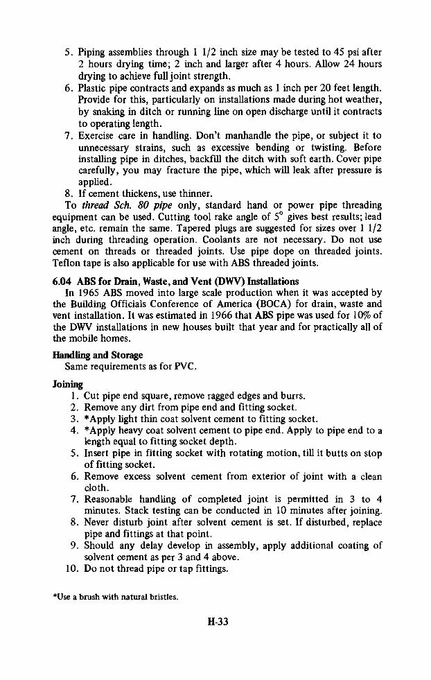
5. Piping assemblies through 1 1/2 inch size may be tested to 45 psi after2 hours drying time; 2 inch and larger after 4 hours. Allow 24 hoursdrying to achieve full joint strength.
6. Plastic pipe contracts and expands as much as 1 inch per 20 feet length.Provide for this, particularly on installations made during hot weather,
by snaking in ditch or running line on open discharge until it contracts
to operating length.
7. Exercise care in handling. Don’t manhandle the pipe, or subject it to
unnecessary strains, such as excessive bending or twisting. Beforeinstalling pipe in ditches, backfill the ditch with soft earth. Cover pipecarefully, you may fracture the pipe, which will leak after pressure is
applied.
8. If cement thickens, use thinner.To thread Sch. 80 pipe only, standard hand or power pipe threadingequipment can be used. Cutting tool rake angle of 5° gives best results; leadangle, etc. remain the same. Tapered plugs are suggested for sizes over 1 1/2inch during threading operation. Coolants are not necessary. Do not usecement on threads or threaded joints. Use pipe dope on threaded joints.Teflon tape is also applicable for use with ABS threaded joints.
6.04 ABS for Drain, Waste, and Vent (DWV) InstallationsIn 1965 ABS moved into large scale production when it was accepted bythe Building Officials Conference of America (BOCA) for drain, waste andvent installation. It was estimated in 1966 that ABS pipe was used for 10% ofthe DWV installations in new houses built that year and for practically all ofthe mobile homes.
Handling and StorageSame requirements as for PVC.
Joining1. Cut pipe end square, remove ragged edges and burrs.2. Remove any dirt from pipe end and fitting socket.3. *Apply light thin coat solvent cement to fitting socket.4. *Apply heavy coat solvent cement to pipe end. Apply to pipe end to alength equal to fitting socket depth.
5. Insert pipe in fitting socket with rotating motion, till it butts on stopof fitting socket.
6. Remove excess solvent cement from exterior of joint with a cleancloth.
7. Reasonable handling of completed joint is permitted in 3 to 4minutes. Stack testing can be conducted in 10 minutes after joining.
8. Never disturb joint after solvent cement is set. If disturbed, replacepipe and fittings at that point.
9. Should any delay develop in assembly, apply additional coating ofsolvent cement as per 3 and 4 above.
10. Do not thread pipe or tap fittings.
*Use a brush with natural bristles.
H-33

Use of Thread LubricantPetroleum jelly (Vaseline) or teflon tape thread lubricants arerecommended for use on male or female plastic fitting threads. These pipedopes are known to be applicable for use with ABS Type I and IA plasticfittings. The use of pipe dope facilitates the removal of threaded joints. Anyother thread lubricant (pipe dope) should be checked for compatibility with
ABS 1 and IA before use.
Pipe SuspensionAll DWV piping should be supported at intervals of not more than four (4)feet. Trap arms should always be supported as close as possible to the trap.
Pipe should also be supported at all branch ends and at all points in change ofdirection. Strap type metal hangers are recommended. Care should be used
when applying hangers to avoid compression or distortion of pipe.
General
DWV drainage fittings are molded with a pitch to effect a 1/4" slope perfoot.Connect traps to DWV with male or male fitting adapters which aresolvent welded to the plastic fixture drain.DWV pipe and fittings are marked on both sides of pipe barrel and fittingwhere possible.
Solvent Cement
Follow pipe manufacturers recommendation on solvent cement to be used
with his pipe and fittings.Solvent cement is packaged ready for use from its original container.Apply it with a natural bristle brush.Solvent cement is inflammable and should not be used near a fire or flame.
Prevent prolonged contact with skin and it should not be inhaled. Use solvent
cement in ventilated area. The minimum time before initial set should be 3minutes at 50°F, 2 minutes at 70°F, and 1 minute at 90°F.
ThinnerThinner is used to thin solvent cement to its original state. Solvent cement
is in its proper state when it has a viscosity of 100 to 115 KREBS units whendetermined with a Stormer Viscosimeter at 77°F. This thinner may be usedto clean brushes used with solvent cement.
Storage
Outdoor storage of pipe is satisfactory but should be protected fromsunlight. Most satisfactory results are obtained if pipe and fittings are keptclean and brought to room temperature before use. Pipe should have 100%support in stock. Use no spacers.
H-34

APPENDIX I
PLASTIC PIPE FOR SEWERS
IntroductionPlastic sewer and drain pipe, first produced in 1946, grew rapidly in
acceptance and by 1961 there were over 50 million feet of such pipe inservice in the United States alone. During 1961 an estimated 25 million feet
were shipped, accounting for some 20 million pounds of raw material andrepresenting a sales volume of about $8 million (including fittings). Thisgrowth is continuing with annual sales volume doubling within this decade.Plastic pipe has many advantages for use as sewer pipe. It is not affectedby corrosive soils, aggressive waters, domestic sewage and most industrial
wastes. A glassy smooth interior surface free from encrustation or attackassures a permanently high carrying capacity. Plastic pipe’s low “n” factorallows pipe to be laid on flatter grades. Diameter for diameter it will carrymore sewage than pipe of most other materials laid to the same grade. Tightjoints eliminate infiltration and leakage; also root penetration. A wide rangeof fittings is available.The pipe is light in weight - two 20 foot lengths of 4-inch diameter plasticpipe weighs less than 5 feet of the same diameter cast iron pipe. Long lengthsare avialable up to 35 feet reducing the number of joints. Jointing is simpleand fast, also the installation of fittings, using either solvent welds orrubber-ring gasket joints. Adapters are available to other sewer pipe materials.Saddle type branch connections are quickly made without delay of otherinstallation operations and they can be placed exactly where needed. The
impact resistance of plastic pipe materially reduces breakage. Narrowertrenches may be used with plastic pipe which may be joined on the groundsurface beside the trench and then lowered into place.Until recently the use of plastic pipe in sewer systems was limited tobuilding and house sewers primarily because 6-inch diameter was the largestsize available. In 1963 a specially designed plastic pipe, termed truss pipe, wasintroduced in sizes of 8-, 10-, 12- and 15-inch diameter. By August, 1968nearly 3 million feet of truss pipe had been installed for sanitary sewers in 37states in the United States. In 1967 a British manufacturer announced theproduction of extruded PVC pipe in diameters up to 16-inch with futurepossibility of producing 20-, 24-, and 30-inch pipe. Reinforced plastic mortar(RPM) sewer pipe composed of a mixture of mineral aggregate and polyester
I-1

resin with continuous glass filaments is available in diameters from 8 to 48
inches. These developments have lead to the wider use of plastic pipe forsewers.
In addition to PVC and ABS, plastic sewer pipe is also made of styrenerubber covered by Commercial Standards CS-228-61. It is available in 2-, 3-,4- and 6-inch diameters in 10 foot lengths and has a crushing strength of1,000 pounds per linear ft. See Appendix C for other pertinent standards andspecifications including those for ABS and PVC pipe.Plastic pipe for sewers is available for non-pressure and pressure
installations. Perforated plastic pipe may be obtained for use in septic tank
drainage fields.
Approximate prices, quoted in 1967, are included in Table 1-1 for
comparative purposes.
Table 1-1
Price of Plastic Pipe(Approximate 1967 U.S. Prices for Uninstalled Pipe Only)
Diameter Sewer Pipe Pressure Pipe Irrigation Pipe Perforated
(inches) Std. Grade (100 psi) Lowhead (100 ft) Drain
(Prices - Dollars per lineal foot)
2 0.28
3 0.37 0.25
4 0.46 0.37
6 1.00
12 2.50 3.40 2.60
24 8.50 7.90 6.70
36 14.80 13.20 11.90
48 22.50 18.70 17.75
Plastic pipe has been used effectively to reline sewer pipe which hasbecome corroded, porous and leaks at the joints. A number of lengths ofplastic pipe are solvent welded together above ground and mounted on rollers
ready to be pulled down an excavated slope to the steel entrance. A woodenplug is secured to the leading end of the line and then a steel cable is fastenedto the plug, threaded through the existing sewer line and fastened to a winch.The pipe is pulled into the sewer line as additional lengths are added, solventwelded and allowed to set.
Flow Characteristics of PVC Sewer PipeThe most commonly used formula in sewer design has been the Manningformula and its reliability and usefulness has been proven by tests on all typesof sewer pipe from clay to concrete. The Manning formula is valid, however,only for rough turbulent flow in which the surface roughness of the pipe
I-2

itself is the prime factor in resistance to flow. On the other hand, for designpurposes in pressure piping PVC pipe has been assumed to be a “smooth”pipe. The Hazen-Williams formula is used for designing flow of water underpressure in PVC pipe as this formula was designed for use with relativelysmooth pipe flowing either full or partly full rather than for sewerage or
drainage work in which, in the past, the pipe has been relatively rough.The recent adaptation of PVC and other plastics for the manufacture ofsewer pipe necessitated the determination of its flow characteristcs for designpurposes. Tests performed in 1962* on PVC sewer pipe in 8- and 12-inchdiameters indicated that for design purposes, conservative results are obtained
by using the Manning formula with n = 0.009. The Hazen-Williams formulawith a friction coefficient (C) of 155 gives results only slightly less accurate.
Handling, Storage, InstallationThe same suggestions apply for the handling, storage and installation ofABS, PVC and SR plastic sewer pipe as for similar plastic pipe for waterservice. (See Appendix H)
Plastic Truss PipePlastic truss pipe consists of two interconnected walls ofacrylonitrile-butadiene-styrene (ABS) resin tied together by a truss of thesame material, with the voids filled with lightweight concrete. The lightweightconcrete in the voids of truss-type plastic pipe helps to carry the compressiveload and provides lateral support for the truss members. Tensile stresses arecarried by the pipe wall.
Characteristics
Truss-type plastic pipe is relatively light in weight and, because of itscomposition, is quite durable for sewer installations. It has a high resistanceto abrasion, freezing, and thawing, and is not affected structurally attemperatures up to l30°f. Thermal expansion is not significant over normalinstallation ranges. This type of pipe is chemically resistant to hydrogensulfide and acids in concentrations up to 5 percent.Minimum specification (ASTM D-18617) for crushing strength is 1,500 lbper lin ft, but tests on 8-inch pipe show that between 60 and l30°f, thecrushing strength ranges from 2,100 to 1,650 lb per lin ft.Good hydraulic flow characteristics result from the smooth surface of theinterior wall of the pipe. As produced, this type of pipe is stated to have aManning n value of 0.010.
Manufacture and TestingTruss-type plastic pipe is made by an extrusion process that forms boththe walls and the truss arrangement simultaneously. Data on pipe sizes and
weights are given in the following table.
*Neale, Lawrence C. and Price, Robert E. “Flow Characteristics of PVC Sewer Pipe.”ASCE Proceedings, Vol. 90, No; AS3, pp. 109-129 (Jan, 1964). This publication alsocontains design formulas and graphs.
I-3

Table 1-2
Data on Truss-Type Plastic Pipe
Pipe Size
Regular ExtraStrength Strength Length Weight
(in.) (in.) (Lb-Lin ft)
4 6 1/4, 12 1/2
6 61/4,121/2
_8 61/4,121/2 8
10 61/4,121/2 11
12 61/4,121/2 15
15 61/4,121/2 26
JointingJointing is accomplished by solvent welding to produce a sewer that isleakproof and resists root penetration and infiltration. A sleeve type couplingcomes attached to one end of each pipe. To join the sections, the middle ofthe coupling and the plain end of another pipe section are coated first with aprimer and than with a cement consisting of ABS in methyl-ethyl-ketone.Then the plain end is stabbed into the coupling. The only tool required is acommon paint brush; should it be necessary to cut a length of pipe in theprocess, a hand saw will do the job.A similar principal underlies the attaching of lateral connections. Aftercutting a hole into the main with a keyhole saw, primer and cement are usedto fix a stub-saddle to the pipe and to connect to succeeding sections of thelateral house line to the saddle.
ASTM has issued a standard entitled ABS Composite Pipe (ASTMD-2680-67T) and this type of pipe has been approved for use in FHA-insuredconstruction.
Reinforced Plastic Mortar (RPM) Sewer PipeRPM sewer pipe is made of a mixture of natural sand aggregate andpolyester resin reinforced with continuous glass filaments. It is manufacturedin the following nominal diameters: 8, 10, 12, 15, 18, 21, 24,27, 30, 33, 36,39, 42 and 48 inches. It is made with bell and spigot ends and joined with arubber gasket.The pipe is significantly lighter in weight than other materials. Forinstance a 24-inch diameter RPM sewer pipe weighs 32 lbs-ft compared to155 lbs-ft for cast iron pipe, an advantage in handling, shipping andinstallation.
InstallationConventional concrete pipe installation procedures are utilized, with the
following major exceptions:
a) Since the wall thickness of RPM pipe is much less than that ofreinforced concrete pipe, trench width for 24" diameter pipe is only 36"instead of the normal 48''.
1-4

b) Due to the above, it is possible to use a 36" trencher rather than the
slower backhoe normally used by a contractor for 48" widths.
c) Due to the light weight of RPM pipe, several handling operations areperformed by hand rather than by a boom.
d) Again due to the light weight, it is possible for one man to make upjoints in a matter of seconds using only a prybar, as compared with themachine or power-assisted methods normally required.On one typical installation of 24-inch diameter RPM sewer pipe a total of
5 hours working time was required as compared with a normal working timeof 8 hours for the same length of reinforced concrete pipe.
Plastic-lined pipeSteel pipe that has a plastic lining may be considered as plastic lined steel
pipe; it also may be considered as steel armored plastic pipe.The greatest used of plastic-lined pipe is in handling corrosive chemicals.Currently, the most important application of plastic-lined pipe in thewastewater field is in the disposal of chemical wastes into underground wells.
Design and ManufacturePlastic-lined steel pipe is produced with three types of extruded liners,namely, saran, Penton, and polypropylene. These liners are tough andstabilized; they range in thickness from 5/32 to 9/ 32 in. They are locked inplace on the inside of the steel pipe walls by a force of several thousandpounds per square inch. The result is a thick-walled pipe with a heavy steelshell, the two layers being virtually monolithic. The pipe thus produced issuitable for use at temperatures from -20 to 200°F or higher. Pipe is availablein sizes from 1 to 8 in., weighing from 2.4 to 28.6 lb per ft; it is made in 10 ftlengths.
In another manufacturing process, a special polyethylene Co-polymer isbonded to both the inside and outside of steel pipe. This type of pipe isproduced in approximately 30-ft lengths, with coatings of plastic 30 milsthick. Pipe sizes (diameters) available include 2, 3, 4, 6, and 8 in. The weightof this pipe ranges from 1.73 to 10.7 lb per ft. Joints are couplings or flanges.
I-5

APPENDIX J
PLASTIC PIPE FOR GAS SERVICE
IntroductionThe increasing use of plastic pipe in the gas industry is due to its favorablecost, ease of handling and installation, light weight, flexibility, flowcharacteristics, freedom from corrosion, rust, and galvanic and electrolyticaction, and low cost maintenance (estimated by some to be as much as 60%less than for metal pipe).The mounting popularity of plastics piping by gas distribution companies
is illustrated by an industry survey showing that in 1955, twenty-nine gascompanies used 500,000 feet; in 1966, eighty-five companies used11,200,000 feet. Plastic pipe was used in 48.9% of new mains in 1965.An editorial comment in the Plastics magazine (English) of August, 1967stated: “Swifter changeover to PVC instead of steel and cast iron pipe byBritain’s gas boards could save the country at least £27 million per year. 8%of total gas supplies is lost per day between gas holder and user. That is 160
million cubic feet or 800,000 therms equal; at ls 10d per therm to just under£27 million per year. It cannot be claimed that large scale changeover to PVCwould entirely eliminate this loss - which is generally thought to be due to
leaking joints, corrosion and subsidence - but new pipes of PVC which hasalready proved its suitability in Britain and other European countries for both
town and natural gas, would go a long way toward solving the problem. These
figures leave out of consideration the large savings derived not only throughthe much simpler installation techniques associated with plastic pipe, but alsoits other inherent advantages such as resistance to corrosion, light weight andso on.”
Piping SystemsPiping systems in the gas industry consist of (a) gas mains, or distributionlines, commonly run under the street, parallel to the curb, and ranging in sizefrom 2-inch to 12-inch diameters; and (b) service lines run perpendicular tothe curb, connecting the distribution main to the customer service, and
ranging in size from 3/4-inch to 1 1/2-inches. Distribution lines are usuallyclassified into three categories: 2 psi or less, generally referred to asutilization pressure; 60 psi and 120 psi. The latter two categories mostlycomprise the longer lines supplying the regulation which reduces the pressureto the utilization value. Distribution lines are not to be confused with
J-I

cross-country transmission lines which include pipes 36 inches in diameter
operating at pressures of up to 1,000 psi.Rigid, long lengths (20 to 40 feet) of pipe are preferred for mains. Therigidity aids in maintaining the slight grade or slope that is required to avoid
the pockets or bellies that collect condensates containing water, anti-freeze,
odorants and hydrocarbons. These condensiates could block off or retard theflow of gas.
Early Use of Plastics PipeThe earliest commercial use of plastic pipe in the gas industry predatedgeneral recognition of the advantages of these materials. It arose out ofnecessity during World War II due to growth brought about by the war effortand the short supply of cast iron, steel and copper piping. Pipe made ofcellulose acetate butyrate (CAB) was available and over 3 million feet wasused by one west coast company in 1943.
Some failures were encountered during early installation. These were
attributed by an American Gas Association survey to (a) 55% due toimproper design, improper installation procedure and poor workmanship; (b)25% due to defects in the plastic pipe material and fabrication; (c) 8% due toenvironmental effects and (d) 12% which could not be properly identified.
Current PracticeSince that time a very considerable amount of experience and technicaldata have been amassed; ASTM D2513-68, “Standard Specification forThermoplastic Gas Pressure Pipe, Tubing and Fittings”, as well as AmericanStandards Association ASAB 31.8, “Code for Pressure Piping, GasTransmission and Distribution Piping Systems”* have been issued; extensive
plastic pipe studies have been carried out by the Batelle Memorial Institutewhich have led to the development of lists of criteria by which the suitabilityof plastic pipe for gas may be judged. (A copy of the list is included at theend of this Appendix).ABS, CAB, PVC and high-density PE plastic pipe are usually recommendedfor natural gas distribution. The long term effect of natural gas has beenshown to be essentially equivalent to that of water for four kinds of plasticpipe, ABS 1210, PVC 2110, PB 3306 and CAB MHO8 (See ASTM 2513-68,A2.4 Environmental Effects). Because the major thermoplastics are affectedby aromatics, concern exists over the possible effects of the use of synthesisgases (gases reformed from oil stock) to supplement natural gas requirementsduring peak load periods. These synthesis gases contain benzene, toluene, andother aromatics. Where such constituents may be present, the choice of aplastic must be made with greater care and if sufficiently high concentrationsare present, aromatic-resistant plastics will have to be used. In those areaswhere anti-freezes are either added to the gas to prevent freeze-ups or used in
*In 1967 plastic pipe was included officially and specifically in ASA B31.8. Beforethat it was not mentioned in the Code but included under a clause allowing installationof pipe on a limited experimental basis.Reference is made to ASTM D 2513-68 and ASA B31.8 for standards, specifications,
test methods, preferred practices installation procedures, design procedures forvarious end-use conditions, safe working conditions and other detailed information.
J-2
concentrated form to defrost a frozen section, the choice of plastics must bemade with greater care. Certain polyethylenes, for example, will crack ifstressed while exposed to the anti-freezes or other substances that induce
environmental stress cracking.
American Gas Association Subcommittee on Plastic Pipe Standards
Criteria for Evaluation of Plastic Pipe andFittings Intended for Transport of Gas
March 23, 1964
The following criteria have been stipulated as being desirable of acandidate plastic pipe for use in gas distribution systems. The sub-Committeerecognizes that not all of these factors are equally important for each kind ofplastic pipe. It also recognizes that no numerical limits can be set for any new
pipe. However, presentation of all these data to the sub-Committee willundoubtedly speed the committee’s action regarding the pipe in question.1. Long-term strength with gas (methane), at 73°F and, at least, one highertemperature (100°F). If data for gas are not available, report data forwater. PPI method plus ASTM D1598 with proposed gaseous fluidmodification. Report type and change in fracture pattern or behavior.Creep (cold flow), compressive.. Burst pressure with water, ASTM D1599, 60 to 90 seconds.. Flattening, extent or degree without rupture. CS 256 (PVC Pipe) orproposed ASTM-PPI parallel plate test when approved.
5. Crush properties, parallel plate, stiffness factor and crush load. ProposedASTM-PPI parallel plate test when approved.
6. Impact resistance, dropweight on pipe, -10°F, 32°F and 73°F. ProposedASTM-PPI Pipe and Fitting Impact Test when approved.
7. Linear coefficient of thermal expansion, at least over the range of -40°Fto +120°F.
8. Water absorption. ASTM D570.9. Methane permeability.10. Chemical resistance, immersion, effect on one or more sensitive
properties.
10.1 All materials, ASTM D543 procedure with the following chemicals:heptane, toluene, methanol, isopropanol, t-butyl mercaptan,ethylene glycol, strong acids, and strong bases. (See Note 1.)
10.2 Specific materials, as indicated by the following: PVC acetoneimmersion ASTM D2195; ABS acetic acid immersion ASTMD1939; PE environmental stress cracking test in ASTM D2104-62;CAB acetone immersion; and other materials with any chemical orchemicals believed to be pertinent.Note 1. Toluene and t-butyl mercaptan will dissolve some plastic
pipe materials; these should simply be noted.11. Effects of weathering, actual outdoor exposure and laboratory tests.12. Effects of aging under stress (internal gas pressure).
_
J-3

13.
14.
15.
any
16.
17.
18.
Fabrication peculiarities and tests for same (See Item 10.2).Methods of joining and tests for same. Test for fusion.ASTM materials specifications, designation number, type and grade, if
Standards for pipe and fittings: Is enough known to prepare reasonablygood standards for the product?Pipe and fittings for which data are submitted herein; dimensions (sizes),color, trade or commercial designation.Any other property values or data deemed to be pertinent. Considerchemical nature of plastic material and characteristics peculiar to theplastic from which the pipe and fittings are made.
tr U, 5. GOVERNMENT PRINTING OFFICE : 1972O - 453- 895
J-4