
Port City Factors and Port Production: Analysis of Chinese Ports
Upload
khangminh22Category
view
0download
0
l- t!
\*-i
:( ì
(,
{.
t-
City of Port Angeles
i
I
furt
P,ilant t*,p\.]
.','
Volume 5 o17Part B: Specifications, Divisions 1:G-17
August1.gg1:ordot6
aó{(t\o\rô!t
Bt!ét Brown and Caldwell Consultants

\
ll/il

Vo1une No.
LofT
2of7
3of7
4of7
5of7
6of7
7of7
INDEX OF CONTRÀCT DOCT'I{ENTS
PORT ÀI{GELEST{ÀSTET{ÀTER TREATI,ÍENT PI,AI.TT EXPAI{SION
PLÀ}TS il{D SPECIFICATIONS
Volume Contents
Table of Contents for Entire Project lrfanualPart À: tegal and Procedural Documents
Part B: lechnical Specifications,Divisions 1 through 10
Part B: Technical Specifications,Divisions 11 through 14
Part B: Technical Specifications,Division 15
Part B: Technical Specifications,Divisions 16 and 17
Part C: Plans--General/Civi1, Process,Àrchitectural, and Structural
Part C: P1ans--Mechanical, Electrical,and Instrumentation
May 15, 1991 4:09 PM-pofann/index/sþ

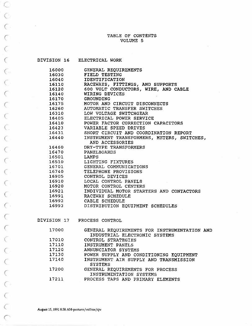
TABLE OF CONTENTSVOLUME 5
DTVISION 16 ELECTRICÀL Í{ORK
160001603016040161101612016140L6L7 O
L6t75162 60163 10164 05164 10t6423L643tt6440
16460t647 016501165r.0t67 01-t67 40169 0s169r_0L6920L692]-1699r.16992L6993
DIVISION 17 PROCESS CONTROL
17 000
17 01017 110L7LzO171_3 0L7t40
L7200
t72t1-
GENERÀL REQUTREMENTSFIELD TESTINGIDENTIFICÀTIONRÀCEWAyS, FITTINGS, Àt{D SIIPPORTS600 voLT coNDUcToRs, WIRE, ÀÌ¡D CÀBLEI{IRING DEVICESGROI'NDINGIUOTOR AND CTRCUIT DTSCONNECTSAUTOMATIC TRANSFER SWITCHESLOW VOLTÀGE SVIITCHGEARELECTRICAL POWER SERVICEPOWER FÀCTOR CORRECTION CAPACIÎORSVARÏABLE SPEED DRTVESSHORT CTRCUIT ÀND COORDINÀTION REPORTINSTRUMENT TRANSFORMERS, METERS, SWTTCHES,
AND ÀCCESSORIESDRY-TYPE TRANSFORMERSPANELBOARDSLAMPSLIGHTING FIXTURESGENERAL COMMUNICÀTIONSTELEPHONE PROVISTONSCONTROL DEVICESLOCAL CONTROL PANELSMOTOR CONTROL CENTERSINDIVÏDUAL MOTOR SÎARTERS ÀND CONT.â,CTORSRACEWAY SCHEDULECABLE SCHEDULEDISTRTBUTION EQUIPMENT SCHEDULES
GENERAL REQUTREMENTS FOR INSTRT'MENTATION ÀNDINDUSTRIAL ELECTRONTC SYSTEMS
CONTROL SÎRÀTEGTESINSTRI'MENT PÀNELSÀNNUNCIATOR SYSTEMSPOT{ER SUPPLY AND CONDITIONING EQUIPMENTTNSTRIJMENT ATR SUPPLY AND TRANSMISSION
SYSTEMSGENERAL REQUTREMENTS FOR PROCESS
INSTRUMENTATION SYSTEMSPROCESS TAPS AND PRIMÀRY ELEMENTS
August 15, 1991 8:58 AM-portann/vol5toc/sjw

2
iÌ
\)
¡)
/ -l\
()
il
{l/l
¡l'l,l(l,ì
r1l
{l{l)
'.)
.)
,lI
,.)
)
'f/J
'J,)
¡]}
DMSION 17 PROCESS CONTROL, continued
17910
L7912
TRÀNSMITTERSPROCESS FLUID ÀNALYZERSPROCESS SWTTCHEST'NIVERSAL CASE INSTRT'MENTSSIGNAL CONDITTONING I,IODULESIIIINIATT'RE CASE ELECTRONIC PÀNEL INSTRT,IIIENTSUISCELI,ANEOUS PÀNEL INSTRT'II{ENTSTHROTTLING VALVES FOR PROCESS CONTROL LOOPSAUTOMATIC TELEPHONE DIÀLERDÀTA ACQUISITION ÀND IIIÀNAGEI,ÍENT SYSTE¡.ÍSGENERÀL REQUIREIIÍENTS FOR PROGRÀI'IMÀBLE LOGIC
CONTROLLERS (PLcs) AND DÀTÀ ACQUISITION Al{D!,ÍANÀGEMENT SYSTEI{S TNTEGRÀTION
GENERÀL REQUIREMENTS FOR PROGRÀM¡{ÀBLE LOGICCONTROLLERS (PLcs)
MEDII,M CAPACTTV PROGRAMMABLE LOGICCoNTROLLERS (PLC)
L72L2t72L5L72L6L7230L727tL727 4t7275T7ALL177 6t1781017900
August 15, 1991 8:58 AM-portann/vol5toc/sjw

t"
(
:
I
(
I
t-
\;
Section
160001603 01604016110161201614016170L6T75t6260163 1016405164 10]-6423L643tL6440
16460t647 01650116510L67 OLL67 4016905169 10]-6920 /t692LL699Lt6992L6993
DIVISION 16
ELECTRICÀL I{ORK
TitIeGENERAL REQUIREI.ÍENTSFIELD TESTINGIDENTIFICÀTIONR.ACEÍ{AYS, FITTINGS, Àt{D SITPPORTS600 voLT coNDUcToRs, wrRE, Àt{D cÀBL8T{TRING DEVICESGROI'NDINGI,ÍOTOR AND CIRCUIT DISCONNECTSAUTOI4ÀTIC TRANSFER SWITCHESLO!ü VOLTÀGE S!{ITCHGEARELECTRICAL POVÍER SERVICEPO!{ER FACTOR CORRECTION CÀPACTTORSVÀRIABLE SPEED DRIVESSHORT CIRCUIT AND COORDINÀTION REPORTINSTRI'MENT TRANSFORMERS, METERS, ST{ITCHES,
AND ÀCCESSORIESDRY-TYPE TRANSFORMERSPÀNELBOARDSLÀMPSLIGHTTNG FIXTURESGENERÀL COMMUNICATIONSTELEPHONE PROVISIONSCONTROL DEVTCESLOCÀL CONTROL PÀNELSMOTOR CONTROL CENTERSINDTVTDUAL MOTOR STÀRTERS AND CONTACTORSRÀCEVTAY SCHEDULECÀBLE SCHEDULEDTSTRÏBUTION EQUIPMENT SCHEDULES
August 15, 1991 8:50 AM-portann/flp/sjw


/-
i
SECTION 16000
GENERAL REQUIREMENTS
PART I--GENERÀL
1.01 SCOPE
This section specifies general requirements for electricalwork. Detailed requirements for specific electrical items arespecified in other sections but are subject to the generaJ.requirements of this section.
L.O2 REI,ATED !{ORK
Refer to the following sections for requirements relating toDivision 16:
i,
(
\
I
(
C
(
{
(
t
SectionSectionSectionSectionSectionSection
007 1O--SubstitutionsO13 O0--Sub¡nittals01605--Shiprnent, Protection, and Storage01730--Operation and Maintenance Information059lO--Hot.-Dip Zinc Coating099O0--Coating Systerns
1.03 DESCRIPTION
À. GENER.A,L:
The erectricar drawings and schedules incruded in thisproject manual are functional in nature and do not specify exactlocations of equiprnent or equipment terrninations
B. DEFINITTONS:
l-. ELEMENTARY OR SCHEMÀTIC DIAGRÀM: Àn elementary orschematic diagram shows aII circuits and device eLements oi anequiprnent itern or assembry or any defined functional portionthereof. such a diagram enphasizes the device elemenÈs of acircuit and their functions as distinguished from the physicalarrangement of the conductors, devices, or device elements of acircuit systern.
2. ONE-LINE DIAGRÀM:of single lines and graphicalcircuit or system of circuitsparts used therein. physicaldisregarded.
A one-line diagram shows by meanssyrnbols the course of an electricaland the components, devices orrelationships are usual.ly
16000-l-

L.03 8.3.
3. BLOCK DIAGRAM: A block diagram is a diagram of asystem, instrument, computer, or program in which selectedportions are represented by annotated boxes and interconnectingIines.
4. WIRING DrAGRÀM oR CONNECTION SYSTEM: A wiring orconnection diagram includes all of the devices in a system andshows their physical relationship to each other includingterminals and interconnecting wiring in an assembly. Thisdiagran shall be (a) in a forrn showing interconnecting wiringonly by terninaL designation (wireless diagram), or (b) a panellayout diagram showing the physical location of devices plus theelementary diagrarn.
5. fNTERCONNECTION DIAGRAM: An interconnection diagrarnis a special form of wiring diagran that shows only the externalconnections between motor control centers, control panels andassociated equipment, machinery, terrninaL boxes and externalcomponents.
6. ARRANGEMENT, LÀYOUT, OR OUTLINE DIAGRÀMS: ANarrangement, layout, or outline drawing is one which shows thephysical space and mounting requirements of a piece of equipment.It nay also indicate ventilation requirements and space providedfor connections or the location to which connecÈions are to bemade.
1.04 QUALITY ASSURÀNCE
A. REFERENCES:
Division 16 contains references to the following docu¡nents.They are a part of this division as specified and nodified. Incase of conflict between the requirements of this section andthose of the listed documents, the requirements of this sectionshall prevail.
Reference TitleANSI À58.L-82 Minimurn Design Loads for Buildings
and other Structures
NFPA 70-90 NationaL Electrical Code (NEC)
NFPA 820-90 Fire Protection in WastewaterTreatment Plants
UBC-L988 Uniforrn Building Code
IJl,lC-1985 Uniforn Mechanical Code
À11 applicable state and local codes.
{l
( ')
,:]
r-\
i)
t,j
(:
,,--l
,1,
\)
{.' j
{-l
L)
i)
-
)
-\
t-60 00-2

B. LISTING OF PRODUCTS:
Erectrical equipment and materiars shall be risted by anindependent testing laboratory for the purpose for which they areto be used. The independent testing raborãtory sharr beacceptable to the inspection authority having jurisdiction.Three such organizations are underwrilers taboiatories (uL),canadian stanåards Association (csÀi, å"a Electricar reètiiriLaboratories (ETL). A certified label or stamp shall be afiixedto each product upon delivery.
. tfhen a product is not available with a testing laboratorylisting.for the purpose for which it is to serve, the producÉ, maybe required by the inspection authority to undergo a sþeciarinspection at the manufacturer's place of assernbÍy. Ail costsand expenses incurred for such inspections shall be included inthe-originar contract price. Listing sharr not be reguired foreguiprnent and materials considered eiernpt by the authðrity havingjurisdiction.
L. 04 B.
C. FÀCTORY TESTS:
l{here specified in the individuar product specificationsection, factory tests shall be perforrned at thä place offabrication and performed on cornpletion of manufaãture orassembly. The costs of factory tests sharl included in thecontract price.1.05 SUBMTTTALS
À. GENERAL:
subnittars and product data shalr be provided for ar1erectricar equipment and materiars in accórdance withsection 01300. I¡Ihere applicable, submittals shalI be identifiedby the specified equipment number and specification section.B. SUBSTITUTIONS:
rf the contractor elects to provide or use an equal to thena¡ned material or equipment, the Contractor shall ¡nãXe writtenapprication in accordance with section ooz10. where singlesource products are specified, they shall be provided in-accordance with paragraph OO71.O-4.06.
C. CONTRÀCTOR DRÀIfINGS:
where the contractor provides drawings as part of thespecified work, such drawings sharl ue piepareä on ANSI size A,B, or D media (nultipres of 8 L/2 by 11 inóhes¡. Drafting nediashall be either polyester pì.astic (My1ar) or vellurn compléte withborders and titLe blocks clearly iaeñtirying the projecL name,the equipment, and the scope of the drawing. Drar.¡iné quality and
16 0 00-3

The Contractor shall prepare interconnection diagramsdepicting all cable requÍ;ements together with their actualterminations as specified below.
Interconnection diagrams shall be drawn similar to thetypicat interconnection diagram specified on the drawings. -Theiirlerconnection diagrams shall indicate wiring between panels,ter¡ninal boxes, remótely mounted devices, and motor controlcenters. The diagrams shalt interface with the manufacturertsinternal connectión diagrams for panel-s. The diagrams shallindicate the terminatioñs to ter¡ninal blocks of field devices ateach end of the cabIe, the number of conductors in the cable, thesize of wire, and the number of spare conductors. For eachtermination, the diagrams shall indicate the terminal number,wire color, and wire nunber as it appears on the wire marker.ÀI1 terminal blocks, including spares, shall be indicated on thediagrams. Interconnection diagrams shall be provided to theConãtruction Manager prior to install-ation of equipment.
1. 05 C.
size of presentation shail ¡neet ÀNSI standards to permit 50percent ieduction of such drawings for insertion into operationand maintenance nanuals.
D. INTERCONNECTION DIAGRÀMS:
1. 06 PROJECT/SrTE CONDTTTONS
A. GENERÀL:
Unless otherwise specified, equipnent and materials shall besized and derated for the arnbient-conditions specified in SectionO18OO, but not less than an ambient temperature of 40 degrees C
at an elevation ranging from sea leve1 to 30OO feet withoutexceeding the manufacturer's stated tolerances.
B. CORROSIVE AREAS:
The following areas are designated as corrosive:
À11 outdoor locationsPrimary GalleryDigester Control BuildingThickened Sludge PunPing StationDisinfection BuildingChlorine Contact TankBeLt Filter Press Room
ir
a()
\/
il
(
(
(
1234567
\
\
16000-4

1. 06 C.
c. HAZARDOUS (CLASSIFIED) ÀREAS:
In the wastewater treatment process, certain areas areclassified as hazardous locations by NFPA 82o, requiring ratedelectrical materials and installation procedures specified in theNEC, Chapter 5. Classification at this project applies, but isnot linited, to the fol-lowing areas:
1. C1ass I, Division 1, Group D:
Envelope above and around top of the digesters.
Interior of the sludge storage tank.
2. Class T, Division 2, Group D:
a. Envelope above and around the headworks andprinary clarifier.
Envelope above and around the existing gravitythickener.
Envelope above and around the existing prinaryclarifier.
a
b
b
c
d
(
(
¡
(
(
1,
I
(
(
(
(
t
(
(
(
Sludge punping room,
e. Gas compressor room,
digester control building.
digester control building.
D. SETSMIC:
Electrical equipment and supports shall be braced inaccordance with UBC Section 23]-2 for Seismic Zone 3.
1.07 STORÀGE OF MÀTERTALS AND EQUTPMENÎ
Materials and equipment shall be stored as specified inSection 01605.
Equipnent and materials to be }ocated indoors shall be storedindoors and sealed with plastic film râtrap.
PART 2--PRODUCTS
2.01 EQUIPMENT AND MÀTERIALS
À. GENERAL:
Equiprnent and materials shall be new and free from defects.AII ¡naterial and equipment of the same or a similar type shall beof the same rnanufacturer throughout the work. Standardproduction materials shall be used wherever possible.
16000-s
2.01 B.
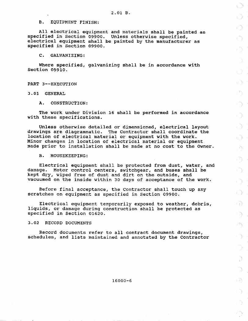
B. EQUIPMENT FINISH:
AII electrical equipnent and materials shalL be painted asspecified in Section O99OO. Un1ess otherv¡ise specified,electrical equipment shall be painted by the nanufacturer asspecified in Section 09900.
C. GÀLVANIZING:
l{here specified, galvanizing shall be in accordance withSection 05910.
PART 3--EXECUTION
3.01 GENERÀL
À. CONSTRUCTION:
The work under Division 16 shall be perforrned in accordancewith these specifications.
Unless otherwise detailed or dirnensioned, electrical 1ayoutdrawings are diagrammatic. The Contractor shall coordinate thelocation of electrical material or equipment with the work.Minor changes in location of electrical material or equipmentmade prior to installation shall be rnade at no cost to the Owner.
B. HOUSEKEEPTNG:
Electrical equipment shall be protected from dust, water, anddarnage. Motor control centers, switchgear, and buses shall bekept dry, wiped free of dust and dirt on the outside, andvacuumed on the inside within 30 days of acceptance of the work.
Before final acceptance, the Contractor shall touch up anyscratches on equipment as specified in Section 09900.
Electrical equipment temporarily exposed to weather, debris,Iiquids, oF damage during construction shall be protected asspecified in Section 01620.
3.O2 RECORD DOCTIMENTS
Record documents refer to all contract document drawings,schedules, and lists maintained and annotated by the Contractor
\)
,'l
')
)
l; ì
'l
l;\
rì
r)
I
-\
/l
16000-6

(.
Ç:
{\J,
(_
\
(l
t
a
(
I
(
{
(
t\
3.02
during construction. As a minimum, the Contractor shall providethe folrowing record documents after final acceptance testing:
Record Drawings (OL7?O)Interconnection Diagrarns (16001, part Z)Originat Sub¡nittal Drawings (16001, part 1)
*'IEND OF SECTfON*¡I
1
(_
16000-7


SECTION 16030
FIELD TESTING
PÀRT I--GENERAL
1.01 DESCRIPTION
This section specifies the acceptance testing of electricalmateriaì-s, equipment and systems. Contractor shall provide alllabor, tools, naterial, power, and other services necessary toprovide the specified tests.I.02 REFERENCES
3.23 16030-1 Paragraph L.O2, REFERENCES. ÀDD:ITNETA ATS-1991, International ElectricalTest,ing Association, Àcceptance TestingSpecificationsr .
1.03 ÀPPLICATTON
Requirements for testing in accordance with this section arespecified in this and other sections of Division 16. Wheretesting in accordance with this section is required, the requiredtests, including correction of defects where found, andretesting, shall be completed prior to enerqization of material,equipment, or systems.
]-. 04 SUBMIÎTALS
The following information shall- be provided as a subnittal inaccordance with Section O]-3OO:
L. Cornpleted test report for each test specified. The
Reference
NFPÀ-70-87
3.24 16030-1
The following inin accordance with S
Functional c.shal1 be pro'
TitleNational ELectrical Code (NEc)
1
Paragraph 1.04-1. DELETE the secondsentencê and ÀDD the following:rrsuggested test forms with requiredinfóination are contained in Section01999. The Contractor may subnit thetest forms cont,ained, or an equivalentform containing the requiredinformation. rl
160 3 0-1

t)(_)
(-
t.
(_.
(=
(-
(-
L-r
(,t
L)
L)
L)
(r(t
.i)
L)
(_r
(¡
t)
a
olt
¡t'
L)'
(l ,
(¡
tr,
Q'

sEclroN 16040
TDENTIFICÀTION
PART I--GENERÀL
1.01 WORK INCLUDED
This section specifies identification of electrical equipnentand materials, including nameplates, labe1s, wire markers,raceway marking, and circuit directories.1.02 DESCRIPTION
Electrical equipnent and materials shall be clearlyidentified for easy location and reference. Nameplates shallidentify each iteur of distribution equipment and each overcurrentdevice within distribut,ion equipment. I{ire markers shallidentify all cables and conductors. Circuit directories shallidentify branch circuits of all panelboards. PuII and junctionboxes shall be identified with'the system function and circuitnunber(s) contained.
1. O3 SUBI.ÍITTÀ,LS
The following inforrnation shall be provided as a suburittal inaccordance with Section O13oo:
Layout and exact spelling of nameplates and legendplates. For MCCs, etc., this may be included with theequipment subnittal.
The following infornation shall be provided as product datain accordance with Section 01300:
1. llanufacturer's descriptive literature for all materialsspecified in this section.
PART 2--PRODUCTS
2.OL NÀI4EPI,AIES
Unless otherwise specified, narneplates shall be made fromlaminated phenolic plastic or photo-etched aluminum. Unlessotherwise specified, the norninal size of the nameplates shall be314 inch high by 2 inches long. Nameplates shall have 3/16-inch
1
16040-1
2.Ol
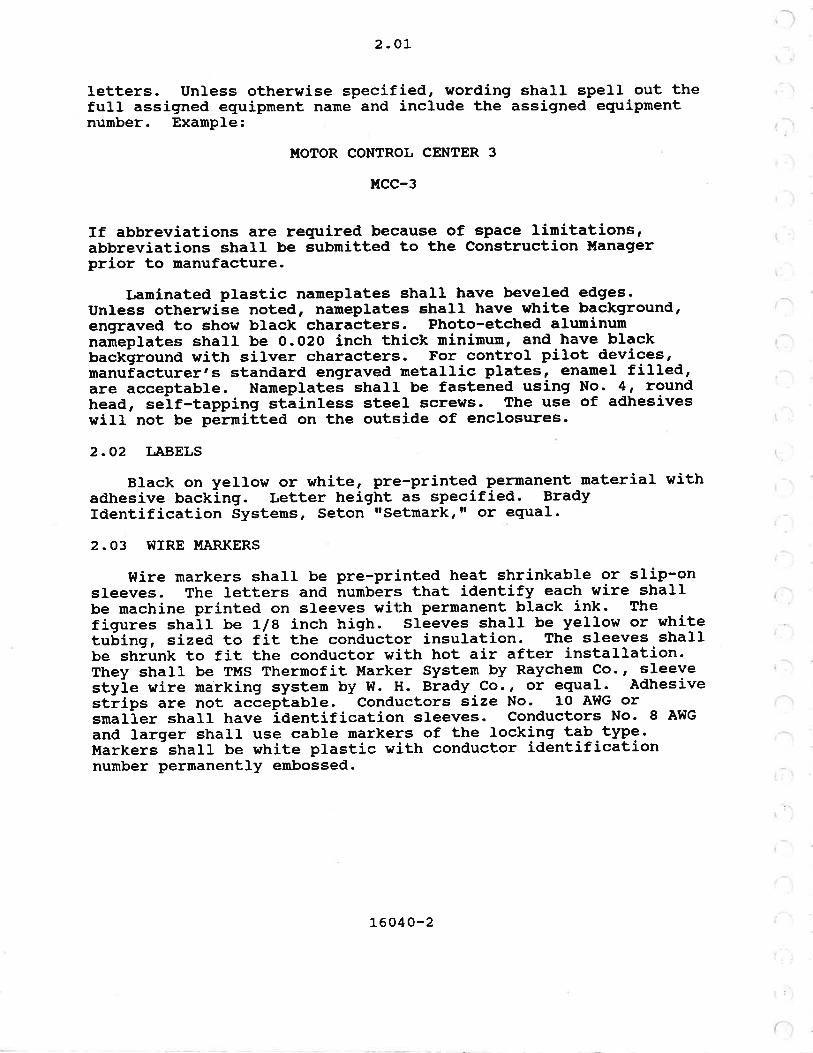
letters. Unless otherwise specified, wording shall spell out thefull assigned equipment name and include the assigned equipmentnumber. ExampLe:
ITIOTOR CONTROL CENTER 3
ucc-3
If abbreviations are required because of space linitations,abbreviations shall be submitted to the Construction ltfanagerprior to nanufacture.
taminated plastic nameplates shall have beveled edges.Unless otherwile noted, nameplates shall have white background,engraved to show black characters. Photo-etched aluminumnarneplates shall be O.O2O inch thick minimun, and-have blackbackground with silver characters. For control pilot devices,manuiacturerts standard engraved metallic plates, enanel filIed,are acceptable. Nameplates shall be fastened using N9. 4, roundhead, seif-tapping stáintess steel screws. The use of adhesiveswill not be permitted on the outside of enclosures.
2.O2 IÀBELS
B1ack on yellow or white, pre-printed pernanent material withadhesive backing. Letter height as specified. BradyIdentification Systems, Seton rrsetmarkrrr or equal-
2.O3 WTRE MARKERS
Wire markers shall be pre-printed heat shrinkable or slip-onsleeves. The letters and numbers that identify each wire shallbe machine printed on sleeves with permanent black ink. Thefigures shail ¡e Lle inch high. Sleeves shall be yellow or whitetubing, sized to fit the conductor insulation. The sleeves shaLlbe shiunk to fit the conductor with hot air after installation.They shall be TMS Thermofit Marker System by Raychem Co., sleevestyie wire marking system by I{. H. Brady,Co., or equal. Àdhesivestlips are not acceptable. Conductors size No. 1O Àl{G orsmaller shall have identification sleeves. Conductors No. 8 .âWG
and larger shall use cable narkers of the locklng t?Þ.typg.Markers shall be white plastic with conductor identificationnumber permanently enbossed.
L6040-2

Part 3
PART 3--EXECUTION
3. 01 DTSTRTBUTTON EQUrP!{ENT
At the project main switchboard or notor control center,provide a project master nameplate indicating the company namesof the consulting engineer, the electrical contractor, and thedate installed.
Àt all switchboards, motor control centers, and distributionpanelboards, instaLl nameplates adjacent to each main and feederprotective device and MCC unit indicating the function or theIoad name and eguiprnent number served.
Provide labels for all bussed spaces indicating size offuture breaker or sr¡itch that may be installed in the spacereserved.
3.02 EQUIPMENT
fnstall nameplates on aII equipnent including disconnectswitches, individual motor starters, motors, relays, contactors,time switches, etc. Naneplates shall indicate the equipmentnumber, the number of the distribution assembly providing power,and the circuit number.
Transformers and busways shall be identified with black andyellow labels | 4-Il2 inch high, pre-printed on adhesive-backedmaterial.
3. 03 SYSTEMS
Complex control circuits shall be identified with wraparoundnumbers or letters using any combination of colors, with eachconductor identified throughout. Match the characters used onthe manufacturer's control drawings and operation and maintenancedat,a.
Identify fire aLarm zones, controls, indicators, etc., withmachine printed Labels or indicators appropriate for theequiprnent installed, as supplied or recommended by the equiprnentmanufacturer.
3.O4 PULL ÀND JUNCTION BOXES
Label all pull boxes and junction boxes for fire alarm,telephone, security, surveillance, and eomrnunications systemswith stencil painted letters to identify systen. l{here boxes arerecessed in finished areas, mount label on inside of cover.
Label all boxes for power and control circuits with thecircuit number and equipment served.
a
1604 0-3

3. 05
3. 05 PULL T¡IRES
Label each end of puII wires or lines teft in ernpty conduitswith tags or tape indicating location of other end of wire.
3.06 RÀCET{ÀY ÀND CONDUCTOR IDENTIFICATION
Raceways and conductors shall be identified. Refer toSection 16110 for raceway numbers. Refer to Section 16120 forconductor nurnbers.
3.O7 EXISTING EQUIPUENT
For new circuits, provide new labels or namePlates forexisting switchgear anã panelboard circuits in accordance withdescriptions specified.
l{here feeder and circuiting changes are made in existingdistribution equipment, motor control centers, ald branchcircuits panel6oa-rds provide new, accurate circuit directories.
f-\
i
/'\
**END OF SECTION*II
1604 0-4

sEcTroN 16110
RÀCEWÀYS, FTTTINGS, ÀND SUPPORTS
PART I--GENERÀL
1.01 DESCRIPTION
This section specifies raceways for electrical conductorsincluding fittings and supports. Raceways shall be provided forpower, control, instrunentation, grounding, lighting,receptacles, and signaling systerns. Raceways consist ofconduits, tubing, and tray systems. For the purpose of thisspecification, conduit and tubing is described collectively asconduit.
L.02 REFERENCES
This section contains references to the following docurnents.They are a part of this section as specified and modified. Incase of conflict between the requirements of this section and thelisted documents, the require¡nents of this section shall prevail.
Reference TitIeANSI C80.1-83 Rigid Steel Conduit-Zinc Coated
ÀNSI C80.3-83 Electrical Metallic Tubing-ZincCoated
ASTM À48-83
ASTM A193/À193M-89
FEDSPECww-c-581E.-77
FEDSPECt{-c-1094À'-7s
JIC EMP-I-67
NEMÀ VE1-84
NFPA 79-87
Gray Iron Castings
Alloy-Steel and Stainless SteelBolting Materials for HighTemperature Service
Conduit, Metal, Rigid andIntermediate; and Coupling, Elbow,and Nipple, Electrical Conduit; ZíncCoated
Conduit and Conduit Fittings,P1astic, Rigid
Electrical Standards for l{assProduction Equipment
Cab1e Tray Systems
Electrical Standards for IndustrialMachinery
161_10-1
1. 02
Reference
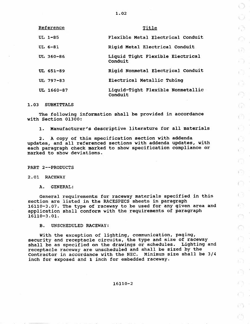
uL 1-85
uL 6-81
ItL 360-86
uL 651-89
rJL 797-83
uL 1660-87
TitleF1exible lfetal Electrical Conduit
Rigid Metal Electrical Conduit
Liquid Tight Flexible EÌectricalConduit
Rigid Nonmetal Electrical Conduit
Electrical lIetallic Tubing
Liquid-Tight Ftexible NonmetallicConduit
requirements for raceway materials specified in thisIisted in the RÀCESPECS sheets in paragraphthe type of raceway to be used for any given area andshall conform with the requirernents of paragraph
i\
I1. 03 SUBIT{ITTÀLS
The following information shall be provided in accordancewith Section 013O0:
1. l[anufacturer's descriptive ]iterature for all materials
2. À copy of this specification section with addendaupdates, and a1I referenced sections with addenda updates, witheach paragraph check marked to show specification compliance ormarked to shol¡ deviations.
PARÎ 2--PRODUCIS
2.OL RÀCEV¡ÀY
À. GENERÀL:
Generalsection are16110-3. 07.application16110-3.01.
IB. UNSCHEDULED RACEI{AY:
I{ith the exception of J-ighting, conmunication, paging,security and receptacle circuits, the type and size of racewayshall be as specified on the drawings or schedules. Lighting andreceptacle raceway are unscheduled and shall be sized by theContractor in accordance with the NEC. Mininum size shall be 314inch for exposed and 1 inch for embedded raceway.
(16110-2
2.01 B.
The number and size of communication, paging, and securityraceways shall be as required for the particular equiprnentprovided subject to the rninimum sizes specified above. The typeof raceway shall be in accordance with paragraph 16110-3.01.
C. SCHEDULED RÀCET{ÀY:
The size and type of raceway shall be as specified on thedrawings or schedules. In case of conf}icts between the drawingsand paragraph 3.01, the drawings shall prevail.
2.O2 BOXES ÀND FITTTNGS
À. TERT.ÍINÀL CABINETS:
Terminal cabinets located indoors shall be NEIîA 12. Cabinetslocated outdoors and in corrosive areas shall be NEI'IA 4X.Cabinets shall be provided with hinged doors. Àdjustableterrninal strip mounting accessories shall be provided. Cabinetsshall be provided nrith channel mounted terminal blocks rated 30amperes, 600 volt ÀC. Terminals shall be No. 8 mininurnstrap-screw type, suitable for ring tongue or locking spadeterrninals.
B. HÀNDHOLES:
Handholes shal1 be precast concrete with checker plate,galvanized, traffic covers designed for H-20 loading. Dimensionsshall be as specified on the drawings. Handholes shalI beprovided with precast solid concrete slab bottoms with sumps.Handholes shall be constructed of 3000 psi reinforced concrete.
C. MÀNHOLES:
Manholes shall be precast concrete, 3000 psi strength at 28days, with reinforcing and cover designed for H-20 bridgeloading. WaII thickness shall be 6 inches ninimum. Necking andshaft shall have 36-inch minimum clear opening.
Manhole cover and frame sha1l be C1ass 3OB grey cast iron perÀSTM 448 with rnachine finished flat bearing surfaces.
Duct entries shall be no less than 14 inches above floor andbelow ceiling. Cables supports, clamps or racks shaÌl beprovided. Floor shall slope 2 percent in all directions to asump. Sump shall be a ¡nini¡nurn of 12 inch diameter.
f
(
(
i
I
16r-10-3

2.03
2.O3 RÀCEWAY SUPPORTS
À. CONDUIT SUPPORTS:
Hot-dip galvanized framing channel shall be used to support-groups ot èoáauit. Individual conduit supports shall be one-holeiafvänized malleable iron pipe straps _used wit! galvanized clampÉacks and nesting backs whére required. Conduit supports for PVC
or epoxy-coated iigia steel and PVC conduit fYstems shall be one-hole PVê or epoxy èoated clanps or PVC conduit waLl hangers.
B. CEILING HÀNGERS:
Ceiling hangers shall be adjustable galvanized carbon steelrod trangerã as ãpecified. Straps or hangers of plumbertsperforai,ed tape ãre not acceptaLle. Unlãss otherr¡ise specifi:9'irang"r rods sñaII be Ll2-inch a1l-thread rod and shall meet ASTM
419a. Hanger rods in corrosive areas and those exposed toweather or noisture shall be stainless steel.
c. STRUCTURAL ÀTTÀCHI{ENTS (RACKS} :
Structural attachrnents shall be constructed from hot-dipgalvanized framing channeL as specified. ÀI1 field cuts shall betreated with zínc enriched Paint.
2.O4 DUCT BANKS
Concrete used for duct banks shall be Class E with red oxideadded as specified in section 03300.
2.O5 ITNDERGROITND MÀRKTNG TAPE (DETECTABLE TYPE)
Underground marking tape sha1l be for location and earlywarning piotection of ¡uriea poner and cornnunication lines. Tapeshall be- detectable by a pipe/cable locator or metal detectorfrom above the undistürbeá ground. Tape shall be norninally 2
inches wide with a type B72l aluminum foil core larninated betweentwo layers of 5 nil Lñi"Xtt"=s polyester plastic. _ Th9 plasticcolor énaff be red for electriòa1 lines, orange for teLephoneIines. A warning shall be imprinted continuously along thelength, with me=ãage reading sinilar to: I'CAIIIION - STOP DIGGING
- BURIED ELECTRIC itelnpHOHn) LINE BELOI{.|' Tape shall be Bradyrf Detectable Identoiine"; Services and Material-s rBuriedUnderground tape, Detectablerr; or equal.
2.06 NÀI.{EPLÀTES
Narneplates shall be provided for all boxes in accordance withthe requirements of paragraph 16000-2.04.
'_,1
I
r-l
Iì
l
ì
16110-4

(
I
\
¡
I
(
2.07
2.O7 FIRESTOPS
Firestops and seals shall be Flamemastic 77, Vimasco No. 1-À,or equal, a;d shall be applied in accordance vith manufacturer'srecomnendations. Products which are affected by water are notacceptable.
2.O8 RÀCEWÀY IDENTIFICATION
Raceways number tags shall be brass with stainless steelattachment ¡tire. Raceway nunber shall be embossed onto the taghrith l/4-inch letters.
PART 3--EXECUTION
3.01 GENERÀL
Tab}e À specifies the type of raceway required for eachIocation and äpplication Uy-nACESPEC sheet. Unless otherwisespecified, in iãUte a, unsóheduled conduit shaLl be rigid steel,RACESPEC t1r¡pe RS.
Table À
Àppl icat ion / cond itionLocation
General
À11, nonhazardous
Process Àreas
Nonhazardous,corrosive, ornoncorrosive
Hazardous,noncorrosive
ÀI1 racewaYapplications notspecified below
Embedded in concretestructure or beneathslab on grade
Encased in concrete,ductbank
Exposed
Fina1 connection toequipnent
Exposed
Finat connection toequipnent
RÀCESPEC
RS
FLS
RS
FSX
RN
RN
RS
16110-5

Location
Hazardous andcorrosive
Nonprocess Àreas
Nonhazardous,noncorrosive
3. O1
Tal'¡le À lcontinuedì
Àpol ication / cond it ion
Exposed
Final connection toequipnent
Concealed in franedwalls and in ceilingspaces (lighting andreceptacle circuitsonly)
Concealed in concreteblock (Cl{U) walls
RÀCESPEC
RSP
FSX
EMT
RN
Final connection to Fsequipment and lightfixtures
Raceway in existing areas of the plant shall be installed asspecified. Raceway in areas of new construction shall becónsidered diagrammatic unless dimensioned.
3.O2 CONDUIT
À. GENERAL:
1. CONDUIT RttNS BETWEEN BOXES: The contractor shallIimit the number of directional changes of the conduit to totalnot rnore than 270 degrees in any run between pull boxes. Conduitruns shall be lirniteã to 4OO feét, Iess 1OO feet or fractionthereOf, for every 9O degrees of change in direction. Bends andoffsets shall be avoided where possible but, where necessary,shall. be made without flattening or kinking, or shall be factorypreformed bends. Turns shal,l bã rnade with cast ¡retal fittings orconduit bends. welding, brazing or otherwise heating of conduitis not acceptable.
2. JUNCTION ÀND PULL BOXES: I{here required for pullingcable and as necessary to meet the requirements of paragraph16110-3.01 4.1, the Cäntractor shall þrovide cast junction orpull boxes. pull boxes used for multiple conduit runs shall notèonbine circuits fed from different MCCs, switchboards, oE
switchgear.
(l
(
i\
(
I
(.
(
\
)
)
16110-6

I
I
I
i
I
i
I
3.02 À.3.
3. CONDUIT TERMINATIONS: Conduit entering NEMA 1 typesheet steel boxes or cabinets shall be secured by locknuts onboth the interior and exterior of the box or cabinet and shallhave an insulating grounding or bonding bushing constructed overthe conduit end. Conduit entering all other boxes shaLl beterminated with a threaded hub. Cast boxes and nonmetallicenclosures shall have threaded hubs. Joints shall be made withstandard couplings or threaded unions. lfetal parts ofnonmetallic boxes and plastic coated boxes shall be bonded to theconduit systern. Running threads shall not be used in lieu ofconduit nipples, nor shall excessive thread be used on anyconduit. The ends of conduit shall be cut square, reaned, andthreaded with straight threads.
Unless otherwise specified, conduit entering field equiprnentenclosures shall enter the bottom or side of the box. lfhereconduit comes from above, it shall be run down beside theenclosure and a tee condulet and drip leg installed.
4. I'ÍATCHING EXfSTING FÀCILITIES: I{hen new conduit isadded to areas which are already painted, the conduit and itssupports shall be painted to match the existing facilities. Wherenew conduit is used to replace existing conduit, the existingconduit and supports shall be removed, resulting blernishes shallbe patched and repainted to match original conditions.Similarly, if existing conduits are to be reused and rerouted,resulting blernishes shall be corrected in the same manner.Coating system shall be in accordance with Section O99OO.
B. CONDUIT SUPPORT:
Exposed conduit shall be run on supports spaced not more than10 feet apart and shall be constructed with runs parallel orperpendicular to waIls, structural membersr oE intersections ofvertical planes and ceiling. No conduit shall approach closerthan 6 inches to any object operating above 30 degrees C.
Where three or more conduits are located in a parallel run,they shall be spaced out from the wa1l using framing channel.Where conduits are suspended from the ceiling, support systernsshall cornply with the requirements of paragraph 16000-1.05 D.Support systems shall be galvanized steel unless otherwisespecified.
Conduit rack and tray supports shall be secured to concretewalls and ceilings by means of cast-in-place anchors. Individualconduit supports shall use cast-in-place anchors, die-cast, rust-proof alloy or expansion shields. Wooden plugs, plastic insertsor gunpowder-driven inserts are not acceptable as a base tosecure conduit supports.
\
t
(
i
16110-7

3.O2 C.
C. CONDUIÎ ENCÀSEMENT OR E!{BEDMENT(STRUCTURES ÀND DUCT BÀNKS):
Conduit constructed in concrete which is in contact with theearth shall be separated from the earth by at least 3 inches ofconcrete. Clearances equal to the noninal conduit dianeter, butnot less than 2 inches, shall be maintained between conduitsencased in slabs. Clearances of less than 2 i-nches at conduitcrossing and terminating locations are acceptable. Concrete forduct banks shall be as specified in Paragraph 16110-2.O4.
Expansion fittings shall be provided whenever enbeddedconduit crosses building expansion joints, between two adjacentstructures, and between a duct bank and structure.
Duct banks sha1l be placed on an undisturbed soil base. AType B backfill as specified in Section O22OO shall be used as abááe when an undistul¡ea soil base is not available. Backfillover the duct bank shall cornply with Section O22OO. The fillshall be brought up to finish grade.
Plastic conduit spacers shall be located 5 feet on centers.The spacers shall be secured to the conduits by wire ties. Theduct bank shalt be securely anchored to prevent conduit flotationwhite the concrete is being placed. Conduit runs shall bewatertight.
The ends of conduiÈs shall be protected from damage duringconstruction by using plastic p1ugs. À 1/4-inch hole shall bedrilled in the Lower portion of the plug to provide drainage.
À11 raceways installed under this contract which are withoutconductors shall be provided with a nylon pull rope. Theseraceways include raceways identified as rrspare.rl
Conduits shall be thoroughly swabbed inside irn¡nediately uponcompletion of pouring concrete. After the c-oncrete has set, butbefore backfilling, a mandrel having a diameter equal to thenominal conduit iñside diameter minus Ll2 inch, and not less than4 inches Iong, shall be pulled through each conduit. The mandrelshall be tead covered or-painted white to indicate any protrusionon the inside of the conduit.
D. CONDUIT PENETRÀTÏONS:
Unless otherwise specified, conduit routed perpendicularthrough floors, walls or other concrete structures shall passthrough cast-in-place openings wherever possible. In cases wherecast-ln-pIace opãnings áre not possible, apPropriate size holesshall be bored Ltrrouõn the conciete to accommodate the conduitpassage. The size añd location of the holes shall not irnpair thestructurers integrity. Àfter completion, grout or calk around
16110-8
l: I
iì

I
(
3.O2 D.
conduit and finish to match existing surroundings. unlessotherwise protected, conduits that rise verticalry through thefloor shall be protected by a 3 Ll2-inch high concrete páa witn asloping top.
Conduits entering manholes and handholes shall be horizontal.Conduits shall not enter through the concrete botton of handholesand nanholes.
l{herever conduits penetrate outdoor concrete watls orceilings berow grade, the contractor shalr provide a watertightseal as manufactured by o. z. Gedney co., Type csMc; ThunderrineCorp., Link Seali or equal.
E. CONDUIT SEPARÀTTON:
Signal conduits shall be separated fron ÀC power or controlconduits. The separation shall be a minimum of L2 inches formetallic conduits and 24 inches for nonmetallic conduits.
F. CONDUIT SEALS FOR HÀZÀRDOUS OR CORROSIVE AREÀS:
Each conduit passing fro¡n a hazardous or corrosive area intoa nonhazardous or noncorrosive area shall be provided with asealing fitting which may be located on either side of theboundary. The seal shall be located at the boundary inaccordance with NEC.
a
(.
t.
1
i
I
SeaI fittings for conduit systerns in hazardouslocations shall be hot-dip galvanized cast ferrouscompound shall be hard type, Chico A, or equal, ULexplosionproof sealing fittings. Sealing cornpoundnonhardening type for corrosive areas.
atrnospherealIoy. Sealinglisted forshall be
3 . 03 II{.ANHOLES ÀND HÀNDHOLES:
Manholes and handholes sha1l be set plunb to limit the depthof standing water to a maximun of 2 inches. Manhole covers,unless otherwise specified, shatl be set at grade.
3.04 CÀBLE TRAY
Unless otherwise specified, cable trays shall be supported atintervars not exceeding 5 feet. corners shall be supported bytwo supports instarled as close as possible to the corner, withone support on each side of the corner, except where specifiedotherwise. ÀI1 field cuts shall be painted with zinc-rich paint.
Expansion-joint splice plates shall be used to allow 11/2-inch free movement between adjacent trays when crossing abuilding expansion joint.
16110-9

3. 04
Unless otherwise specified, a minimum clearance of 314 inchshall be maintained between trays and concrete surfaces. Àminirnun spacing of L2 inches shall be maintained between trays,¡reasured iron the top of the upper tray to the top of the lowertray. The top of the tray shall be not less than 9 inches fromthe ceiling.
Covers of the solid or louvered tlpe shall be provided onsignal trays.
Each tray shall be provided with No. 2lO AWG nininunr barecopper equipinent ground conductor unless otherr¡ise specified.eróund cõnductor ènall be attached to the outside of eactr traysection using a bolted bronze or brass ground clamp.
power cables shall not be placed in cable trays rnore than twoIayers deep. Cab1es shall be árranged in trays so as to providea minimum of cable cross-overs.
)
r; ,l
)
'l
r)
t\,
{
/'I
(,
(',
3. 05 RACEWAY NT'MBERING
Each conduit shall be provided with a number tag at each endand in each manhole and/or pullbox. Trays shall be identified bystencils at intervals not exceeding 50 feet, ât intersections,and at each end.
3. 06 RÀCET{ÀY SCHEDI'LE
The Raceway Schedule is included in Specification Section16991.
3.07 RÀCESPECS SHEETS
The following RÀCESPECS are included in this section:
16110-10

(
3. 07
3.O7 RÀCEWÀY SPECIFICATTON SHEETS (RÀCESPEC)
RacewayIdentif ication: Et{T
Description: ELectrical Metallic Tubing
Compliance: ÀNSf C80.3, tJL 797
Finish: Electro-galvanized steel
(.
(
t
\
a
(
Mininum size:
Fittings:
Indoor:
Boxes
314 inch
Compression t1pe. Fittings for E!flIinside concrete block (CT.ÍU) walls shallbe concrete-tight.
Electro-galvanized sheet steel. EtÍTshall be provided with ground wire.NEMA Class 1 stanped or form-bent steelwith screw covers.
(
(
(
\
\
C
a
(
(
(
(
a
a
a
C.
16110-11
3.O7
3.07 RÀCE!{ÀY SPECIFICÀTION SHEETS (RÀCESPEC)
f-)
(ì
o(l
(l
(-l
(-¡?-'(r
co(-r
(ì
(''
()
l-'(-)
(')
r-ì,
rì
r-_)
',)
.)
,. I )
)
,)
t .)
.l
RacewayIdentification:
Description:
Àpplication:
Compliance:
Construction:
Itininun size:
Fittings:
Installation:
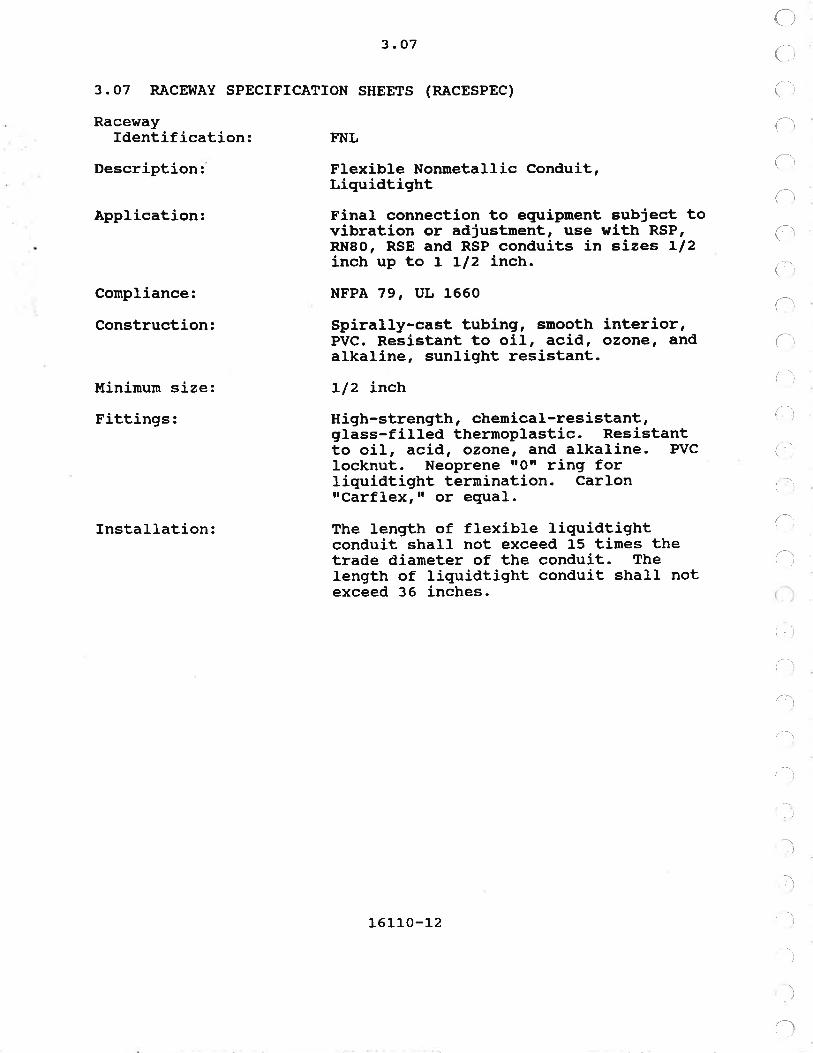
FNL
Flexible Nonnetallic Conduit,LiguidtightFina1 connection to equipment subject tovibration or adjustnent, use with RSP,RN8o, RsE and RsP conduits in sizes 1/2inch up to 1 Ll2 inch.
NFPA 79, t IJ 1660
Spirally-cast tubing, smooth interior,PVc. Resistant to oil, acid, ozone, andalkaline, sunlight resistant.
Ll2 inch
High-strength, cheurical-resistant,glass-filled thermoplastic. Resistantto oil, acid, ozone, and alkaline. PvcIocknut. Neoprene rrorr ring forliquidtight terraination. CarlonrrCarflexrrr or equal.
The length of flexible liquidtightconduit shall not exceed 15 tines thetrade diarneter of the conduit. Thelength of liquidtight conduit shall notexceed 36 inches.
16110-12

3.O'I
3.O7 RACEWAY SPECTFTCATTON SHEETS (RÀCESPEC)
RacewayIdentification: FS
Description: Flexible Steel Conduit
Àpplication: Final connectior.r to equipnent subject tovi.bration or adjustment, for use ¡¡ithEl[T only.
Cornpliance:
Construction:
Mínimum size:
Fittings:Other:
uL1
Spirally wound galvanized steel stripwith successive convolutions securelyinÈerlocked.
L/2 inch
Cornpression type
FS shall be provided with an internalground wire.
16110-13

3.07
3.O7 RACEI{ÀY SPECTFICÀTrON SHEEÎS (RÀCESPEC)
RacevrayIdentification: FsL
Description: Flexible Steel Conduit, Liquidtight
Application: Fina1 connection to equipment subject tovibration or adjustment, use with RS.
)
,lI
)
.)
)
I,l
,lI
)
L)
)
,ìì
)
II
.\
t\)
I
)
Compliance:
Construction:
llini¡nun size:
Fittings:
fnstallation:
UL 360
Spirally wound galvanized steel stripwith successive convolutions securelyinterlocked and jacketed withliquidtight plastic cover.
Llz inch
Cadmium-plated nalIeable iron body andgland nut with cast-in Iug, brassgrounding ferrule threaded to engageðonduit spiral and o-ring seals aroundthe conduit and box connection andinsulated throat. FortY-five and9o-degree fittings shall be used whereapplicable.
The length of flexible liquidtightconduit shall not exceed 15 ti¡nes thetrade diameter of the conduit. Thelength of liquidtigtrt conduit shall notexceed 36 inches.
-l
l
-\
16110-14

a
i
3.07
3. 07 R.à,CE!{AY SPECTFTCATTON SHEETS (RACESPEC)
RacewayIdentification: FSX
Description: Flexible Steel Conduit, Explosionproof
Application: FSX Conduit shall be used for finalconnections to motors and otherequipnent subject to vibration oradjustment in Class 1 Division 1hazardous areas
Conpliance:
Minimum size:
FSX shall be suitable for use in ClassT, Division 1, Groups C and D hazardousareas as specified in the NEC and sha}lbe watertight.
Ll2 inch
16r_10-15

3.O7
3.O7 RÀCEWÀY SPECTFICÀTrON SHEEÎS (RÀCESPEC)
(.)
1ì
{
1l
Racewayfdentification:
Description:
Compliance:
Construction:
lfinimun size:
Fittings:Boxes:
Indoor:
Outdoor andcorrosive:
Installation:
RN
Rigid Nonmetallic Conduit, heavy wallthickness for direct bury, concreteencasement or surface nounting where notsubject to physical damage.
NEX'ÍA TC2, UL 651
Schedule 40, high-inpact,polyvinylchloride (Pvc)
314 inch exposed; 1 inch embedded orencased
PVC solvent weld tYPe
NEI.{A Class 4, nonmetallic
NEUA C1ass 4X, nonmetallic
PVC conduit entering fiberglass boxes orcabinets shall be secured by threadedbushings on the interior of the box andshall be terminated with a threaded naleterrninal adapter having a neopreneo-ring. Joints shall be made withstandard PVC couplings.
/-r
16110-16

\-
(
I
3.07
3.07 RÀCEWÀY SPECTFICÀTrON SHEETS (RACESPEC)
lRaceway
Identification:Description:
Conpliance:
Construction:
Minimum size:
Fittings:Boxes:
Indoor:
Outdoor andcorrosive:
fnstallation:
RNSO
Rigid Nonmetallic Conduit, extra heavywaLl thickness for all locationsincluding direct bury under roadways andwhere exposed to physical damage
NH{A TC2, UL 651
Schedule 80, high-inpact,polyvinylchloride (Pvc)
3/4 inch exposed; 1 inch embedded orencased
PVC solvent weld type
NEMÀ Class 4, nonmetallic
NEI.IA C1ass 4X, nonmetallic
Exposed PVC conduit shall be run onsupports spaced not more than 3 feetapart for conduits up to 1 inch 5 feetapart for conduits 1 L/4 inches to 2inches and 6 feet apart for conduits 2L/2 inches and larger. PVC conduitshall not be provided where it will bedamaged by heat.
t
16110-17

3.07
3.07 RACEI{ÀY SPECIFICATION SHEETS (RACESPEC)
RacewayIdentification: RS
Description: Rigid Steel Conduit
Conpliance: Àl{SI C8O.1, ItL 6
Finish: Tot-dip galvanized after fabrication,inside and outside. Smooth finishedsurfaces.

{
Fittings:Hubs:
Boxes:
Indoor:
Outdoor:
Corrosive:
Hazardous:
Elbows:
(3 I 4" thru L-1- | 2tt I
(2t' thru 6rr)
Conduit Bodies:
(3/4" thru 4r)
(5" and 6il)
3. 07
Hubs for connection of conduit tojunction, device, or terminal boxesshall be threaded and made of castferrous alloy. Hubs shall beelectroplated with zinc and haveinsulating bushings. The hubs shallutilize a neoprene ilor ring and sha}lprovide a watertight connection.
Type FD cast ferrous for all deviceboxes and for junction boxes less than 6inches square. NEIIA Class 12 weldedsteel with threaded hubs for 6 inchessquare and larger. Boxes in wetlocations shall be NEtltA Class 4watertight.
i
(.
!
Type FD cast ferrous for allboxes and for junction boxesinches square. NEMA Class 4steel with threaded hubs forsquare and larger.
deviceless than 6welded6 inches
NEMÀ Class 4X stainless steel ornonrnetallic.
NEMA Class 7 cast ferrous.
Factory fabricated or field bent
Factory fabricated only
Malleable iron, hot dip galvanized,unless otherwise noted. NeoPrenegaskets for aII access plates. Taperedthreads for all conduit entrances.
Electro-galvanized iron or cast ironbox.
Appleton, Crouse-Hinds, Hubbell, o.Z.Gedney, or equal.
Manufacturers:
16t t-o-L9

Installation:
3.O7
RigÍd steel conduit sha1l be made uptight and without thread conpound.Exposed nale threads on rigid steelcoñauit shall be coated with zinc-richpaint.
Steel conduit shall be supported awayfron the structures using hot-diPgatvanized malleable iron straps witttnesting backs.
)
)
)
I
)
t. . )
Ir)
.,1
I-l
)
'\
16110-2 0

3.07
3.O7 RACEWÀY SPECTFTCATTON SHEETS (RACESPEC)
RacewayIdentification:
Description:
Compliance:
Finish:
lÍinimum size:
Hubs:
Boxes:Nonhazardous:
Hazardous:
Manufacturers:
RSE
Rigid Steel Conduit, corrosion-Resistant, Epoxy Coated
At{sr c80.1, ttl, 6
RSE shall be non-galvanized rigid steelconduit, blasted to white metal, towhich a lo-niL-thick thermo-settingfusion bonded epoxy coating has beenbonded to the outside and a similar7-nil mininr¡m coating bonded to theinside. Coating shall be free ofpinholes. Bond strength shall exceedthe tensile strength of the epoxy coat.Elbows shall be factory made and coated.Coating strength shall be such thatconduit may be bent without cracking ofthe coating.
3/4-inch
Siurilarly coated to the same thicknessas the conduit and provided with type3o4 stainless steel hardware. Conduitand fittings sha1l be manufactured bythe same company.
Hubs for connection of conduit tojunction, device, oF terminal boxesshall be threaded and made of castferrous aIloy. Hubs shall beelectroplated with zínc and haveinsulating bushings. The hubs shallutilize a neopre¡s rtQtt ring and shallprovide a watertight connection.
NEMÀ Class 4X stainless steel ornonmetallic.
Epoxy coated NE!,IÀ Class 7 cast ferrousor welded stee1.
Coating process shall be by PowderCoating Southwest Inc. of Houston,Texas; Linduit of Boise, Idahoi orequal.
tingsFir
16110-21

Installation:
3.O7
Epoxy coated conduit shall be supportedaway from the structure using epoxycoated conduit wall hangers.
Epoxy coated conduit shalI be made uptight with strap wrenches. AIl conduitthreads shall be covered by an epoxyoverlap which shaIl be coated and sealedper manufacturerts recomnendations. Pipewrenches and channel locks shalL not beused for tightening plastic coatedconduits. Danaged areas shall bepatched, using manufacturer'srecommended material. The area to bepatched shall be buiLt up to the fullthickness of the coating.
I
I
;'.)
L6LLO-22

/-
/-
3. 07
3.07 RÀCEr{Ày SPECIFICATION SHEETS (RÀCESPEC)
RacewayIdentification: RSP
Description: Rigid Steel Conduit, Corrosion-Resistant, Polyvinyl Chloride (PVC)Coated
Compliance:
Finish:
Àt{sI c80.1, uL 6
RSP shall be hot, dipped galvanized rigidsteel conduit, to which a minimun 4o-nilthick PVC coating has been bonded to theinside and outside of the conduit.Coating shall be free of pinholes. Bondstrength shall exceed the tensilestrength of the PVC coat. Elbows shallbe factory rnade and coated.
3 / 4-inch
Sinilarly coated to the same thicknessas the conduit and provided with type316 stainless steel hardware. Conduitand fittings sha1l be manufactured bythe same company.
Hubs for conneetion of conduit tojunction, device, or terminal boxesshall be threaded and made of castferrous alloy. Hubs shal} beelectroplated with zinc and haveinsulating bushings. The hubs shaLlutilize a neoprene [Orr ring and shallprovide a watertight connection.
NEMA Class 4X stainless steel ornonmetall-ic.
NEMÀ Class 7 cast ferrous.
PVC coated conduit shall be by RobroyIndustries, Occidental Coating Company,or equal.
Itinimum size:
Fittings:
Hubs
Boxes:Nonhazardous:
Hazardous:
Manufacturers:
L6rro-23

3. 07
PVC coated conduit shall be supportedahray from the structure using PVC coatedconduit wall hangers.
Plastic coated conduit sha1l be made uptight with strap wrenches. AII conduittbreads shall be covered by a plasticoverlap which shall be coated and sealedper manufacturerts reconmendations. Piperrrenches and ctrannel locks shall not beused for tightening plastic coatedconduits. Damaged areas shall bepatched, using nanufacturertsrecommended material. The area to bepatched shall be built up to the fullthickness of the coating. PaÍntedfittings are not acceptable.
Installation:
ìa
\
1
,]
161r.0-24

3.07
3.07 RÀCEWAY SPECTFTCATTON SHEETS (RACESPEC)
RacewayIdentification:
Description:
Conpliance:
Loading and deflectionrequirements:
Dimensions:
Finish:
Accessories:
Àpplication:
TRÀY
Cable Tray, steeL, Iadder tYPe witÞrungs and side rails. Botton to siderail connections shaIl be positivemechanical joints to assure lateral andIonqritudinal stability.
NE!{A VE1
The trays shall be designed andconstructed to support a uniformlydistributed load of 5o pounds per linearfoot with a maximum deflection of 0-57inch when tested as a single 10-footspan, sirnple bean.
3 inch minimum interior depth - 4 inchmaximum outside depth. Ì{idth shall beas specified. Tray components shall befabricated to a Ll16-inch tolerance-
Hot-dip galvanized after fabrication.Snooth finished surfaces.
Fittings, barriers and covers sþaII beof the same tnåi"ii"r=, finish ándconstruction as the straight trays- Theminimum radius of side rails onhorizontal elbows, vertical risers, teesand crosses shall be 9 inches exceptwhere specified otherwise.
As indicated on the drawings.
16110-25

3.O7
3.O'7 R;ACEWAY SPECTFTCÀTION SHEETS (RÀCESPEC)
RacewayIdentification:
I
(r
i
il
(. 't
Description:
Conpliance:
tlinimum size:
Finish:
Application:
ww
I{ireway and Auxiliary Gutter, flanged,oiltight type with hinged covers
JIC EX,IP-I
I inch by I inch
Hot-dip galvanized after fabrication,inside and outside. Smooth finishedsurfaces.
Às indicated on the drawings.
**END OF SECTION¡I*
16110-2 6

SECTION L6L2O
600 voLT coNDuqroRs, !ÍIRE, ÀND CÀBLE
PÀRT I--GENERÀL
1.01 DESCRIPTION
This section specifies conductors and cables rated 600 voltsused for power, lighting, receptacle, signal, and controlcircuits.1 .O2 REFERENCES
This section contains references to the following documents.They are a part of this section. In case of conflict between thereguirements of this section and those of the listed documents,the requirernents of this section sha1l prevail.
Reference
ASTU B3-74
ÀsT!{ 88-86
ÀsTM 833-81
ICEA S-68-516
IEEE 383-74
NEI.{A WC7-82
NFPA 7A-9O
uL 44-83
uL 83-83
TitleSoft or Annealed Copper [{ireConcentric-Lay-Stranded Copper Conductors,Hard, Medium-Hard, or Soft
Tinned Soft or Annealed Copper l{ire forElectrical Purposes
Ethylene-Propylene-Rubber-f nsulated Wire
Type Test of Class IE Electric Cables, FieldSp1ices, and Connections for Nuclear PowerGenerating Stations
Cross-Linked-Thermosetting Insulated Wire andCable for the Transnission and Distributionof Electric Energy
National Electric Code (NEC)
Rubber-Insulated Wires and Cables
Thermoplastic-Insulated Wires and Cables
1.03 SUBMITTALS
The following information shaIl be provided in accordancewith Section O13OO:
16120-r_

1. 03
Catalog cuts showing general information of theconductors and cable.
À copy of this specification section with addendaupdates, and all referenced sections withaddenda updates, with each paragraph checknarked to show specification compliance ornarked to show deviations.
PART 2--PRODI'CTS
2.01 GENERÀL
À. T'NSCHEDULED CONDUCTORS ÀND CÀBLES:
with the exception of lighting, communication, paging'security and receptacle circuits, the type, síze and number ofconductors shall be as specified on the drawings or schedules.Lighting and receptacle circuit conductors are unscheduled andshall be sized by the Contractor in accordance with the NEC tolirnit voltage drop to 3 percent. Minimu¡r size of lighting andreceptacle circuits shall be 12 ÀWG. Number and types ofcommunication, paging, and security cables shalI be as reguiredfor the particular eguipment provided. Lighting and receptaclecircuit conductors shal} be provided in accordance with CÀBLESPECrrPVCrr, unless otherwise specified.
B. CÀBLE SPECIFICÀTION SHEETS (CÀBLESPEC):
General requirements for conductors and cables specified inthis Section are listed on CABLESPEC sheets in paragraph 16120-3.06.
2.O2 COLOR CODING
A. CONTROL CONDUCTORS:
Control conductors color coding shall be manufacturer'sstandard.
B. POWER CONDUCTORS:
Single-conductor por{er conductors shal} have the followingcolors for the indicated voltage:
6OOV õr less
1
2
Phase ÀPhase BPhase CGroundNeutral-
BIackRedBlueGreentlhite
L6L20-2
2.O2 B.
llulticonductor poner cabre colors shalr be manufacturerrsstandard.
Cables sized No. 4 ÀWc and larger may be black with colored3/4-inch vinyl plastic tape applied in 3-inch tengths around thecable at each end. The cables shall be tagged at terninationsand in pull boxes, handholes and manholes.
C. SIGNÀL CONDUCTORS:
Unless otherwise specified, cables shall be color coded blackand white for pairs or b1ack, white, and red for triads.2.O3 POWER ÀND CONTROL CONDUCTORS Àl{D CABLE, 600 VOLT
A. SINGLE CONDUCTOR:
Sing1e conductor cable shal1 be stranded and shall be used inconduits for power and control circuits. Single conductor cableshaLl be provided in accordance with CÀBLESPEC rrEPRr rr unlessotherwise specified.
B. MULTTCONDUCTOR CÀBLE:
üulticonductor cable shal1 be used for power and controlcircuits routed in cable tray. Cab1es shall be UL labeled, TypeTC, designed for cable tray installation in accordance with NEC340. The type of insulation, nurnber of conductors, and size ofconductor shall be as specified. Multiconductor power andcontrol cable sha1l be provided in accordance with CÀBLESPECtrEPR/Ir{, rr unless otherwise specified.
1. POWER CÀBLE: Multiconductor po$¡er cable shallcontain three or four conductors, as specified, plus an equipmentgrounding conductor.
2. CONTROL CABLE: Un1ess otherwise specified nulti-conductor control cable shall be size 14 ÀWG.
2.04 DIRECT BURTÀL
Direct burial shall be nutticonductor type in accordance withCÀBLESPEC rrEPR/M, rr unless otherwise specif ied.
2.05 SIGNÀL CÀBLES
À.
Signal cable shal1 be provided for instrument signaltransmission, alarm, communication and other circuits asspecified. Circuit shielding shall be provided in additj-on to
GENERÀL
16 12 0-3

2. 05 A.
cable shielding. Circuits for type a and b signals specified inparagraph 17ooó-1.01 C.8 shalt be provided in compliance with theinstrument manufacturerts recomtrtendations-
Sing1e circuit signal cable shall be provided in accordancewith CÀãLESPEC lrINSrr, unless otherwise specified. Multicircuitsignal cable shall be provided in accordance with CABLESPECtrINS/Utt, unless otherwise specif ied.
B. COI,IIIÍT'NICATION, PAGING, Àl{D SECURITY SYSTEIII CABLES:
Conmunicatíon, paging, and security systen cables shall be asspecified in Division 17.
2.06 PORTABLE CORD
portable cord shall be provided in accordance with CABLESPECnCORDrrr unless otherwise spècified. Cords shall contain anequipnrent grounding conductor.
2.O7 SPLICING AND TERMINATTNG I{ATERIALS
Connectors shall be tool applied compression type of correctsize and UL listed for the specific application. Connectorsshalt be tin-plated high conãuctivity-óopper. Connectors forwire sizes No-. 10 AI{G ánd snaller shall be nylon self-insulated,flat spade terrninals. Connectors for wire sizes No. 8 ÀVIG andIarger shall be one-hole lugs up to size No. 3/0 Al{G, andtwo-hole or four-hole lugs for size No. 4/o and larger.Mechanical clamp, dimple, screw-type connectors are notacceptable.
In-l-ine splices and taps shall be used only where specified,or by written consent of the Construction Manager. When used,they-shall be of the same construction as other connectors.Splices shall be compression tyPe, made with a compression tooLdie approved for the purpose, âs made by Thomas and Betts Corp.,or eqirãf . Splice shalL te covered with a heat-shrinkabl-e sleeveor boot.
Motor connection kits shal-l consist of heat-shrinkable,polyrneric insulating material over the connection area and a highãieiectric strength mastic to seal the ends against ingress of¡noisture and contamination. Motor connection kits shallaccommodate a range of cable sizes for both in-line and stub-typeconfigurations. õonnection kits shalt be independent of cablemanufacturer's tolerances.
i.,
(:
L6]-20-4

Part 3
PÀRT 3--EXECUTION
3. 01 GENER.A,L
Each power and control conductor shall be identified at eachterminal to which it is connected. The marking system shal1conply with Section 16000.
Pulting wire and cable into conduit or trays shall becompleted without darnaging or putting undue stress on the cableinsulation. Soapstone, talc or UL listed pulling conpounds areacceptable lubricants for pulling vire and cable. Grease is notacceptable. Raceway construction shalL be complete, cleaned, andprotected from the weather before cable is placed.
l{henever a cable leaves a racet¡ay, a cable support shall beprovided.
I{hen flat bus bar connections are made with unplated bar, theContractor shall scratch-brush the contact areas. Bo1ts shall betorqued to the bus manufacturerts recommendations.
3.O2 600 VOLT CONDUCTOR ÀND CÀBLE
Conductors in panels and electrical equipment, No. 6 AWG andsmaller, shall be bundled and laced at intervals not greater than6 inches, spread into trees and connected to their respectiveterminals. Lacing shall be ¡nade up with plastic cable ties.Lacing is not necessary in plastic panel wiring duct. Conductorscrossing hinges shall be bundled into groups not exceeding 12 andshall be so arranged that they will be protected from chafingwhen the hinged rnember is moved.
Slack shall be provided in junction and putl boxes, handholesand manholes. S1ack shaLl be sufficient to allow cables orconductors to be routed along the walls of the box. Amount ofslack shall be equal to largest dimension of the box. Whereplastic panel wifing duct is provided for r¡ire runs, lacing.isnot required. Plastic panel wiring duct shall not be used inmanholes and handholes.
Stranded conductors shall be terminated as described inparagraph L6L2O-2.07 A, except where terminals will not acceptsuch terminations. In these cases, the conductors shall beterminated directly on the terminal block. Compression lugs andconnectors shall be installed using manufacturer's recommendedtools.
Raceway fiII linitations shall be as defined by NEC and thefollowing:
Lighting and receptacle circuits rnay be inthè same conduit in accordance with derating
16120-5

3.02
requirements of the NEc. However, lightingand receptacle circuits shall not be inconduits with power or control conductors-
Solid wire shall not be lugged nor shall electricat springconnectors be used on any except for solid wires in lighting andreceptacle círcuits. f,ugs and connectors shall be installed witha compression tool.
À11 splices and terminations are subject to-inspection by.theConstruction lrlanager prior to and after insulating. Terninationsat 460 volt ¡rotoré strátt be made by bolt-connecting the luggedconnectors. Connections shall be insulated and sealed withfactory-engineered kits. Bolt connection area shall be kept freeof ¡nas[ics and fillers to facilitate rapid stripping andre-entry.
In-line splices and tees, where approved, shall be made withtubular comprässion connectors and insulated as specified formotor terurinations, except that conductors No. 10 Al{G and snallermay be spliced using sel?-insulating connectors as specified inpaiagraptr fefZO-2.O1 A. Splices and tees in undergroundLandhofês or pult boxes shall be insulated using Scotch-castepoxy resin splicing kits.
Terrninations at solenoid valves, 120 volt motors, and otherdevices furnished with pigtail leads shall be made using self-insulating tubular compression connectors.
Conductor and cable rnarkers shall be provided at splicepoints.
l.
3.03 SIGNAL CABLE
Circuits shall be run as individually shielded twisted pairsor triads. In no case shall a circuit be rnade up usingconduetors from different pairs or triads. Triads shall be usedwherever 3-wire.circuits ale required. Terminal blocks shall beprovided at instrument cable junctions, and circuits shall beiaentified at such junctions unless otherwise specified. Signalcircuits shall be run without splices between instruments,terrninal boxes, ot panels.
shields are not acceptable as a signal path, except forcircuits operating at raäio frequencies and utilizing coaxialcables.
Un1ess specifically stated or scheduled for joint occupanCY,signal cableä shall noL be installed together in any conduitcoñtaining other signal cables or systems, particulaTly AC poweror control conductors. Nonmetallic conduits containinq signal
L6L20-6

3. 03
circuits shalI be separated from conduits containing ÀC polter orcontrol conductors by at least 12 inches. Refer to paragraph17000-3.o1 8.3.b.
Con¡non ground return conductors for two or more circuits arenot acceptable.
Unless otherwisesignal ground bus atand other shields atprovided for runningjunction boxes.
specified, shields shall be bonded to thethe control panel and isolated from groundother locations. Terminals shall. besignal leads and shield drain wires through
i.
Spare circuits and the shield drain wire shall be tenninatedon terminal blocks at both ends of the cable run and beelectrically continuous through terninal boxes. Shield drainwires for spare circuits shall not be grounded at either end ofthe cable run.
Terninal boxes shall be provided at instrument cable splices.If cabl-e is buried or in raceway below grade at splice, aninstrument stand sha1l be provided as specified with ter¡nina1 boxmounted approximately 3 feet above grade.
Cable for paging, telephone, and security systems shall beinstalled and terminated in cornpliance with the manufacturer'sreconmendations
3.04 PORTÀBLE CORD
Portable cord feeding permanent equiprnent, such as pendantcords, pumps, cranes, hoists, and portable items shall have awire mesh cord grip of flexible stainless steel wire to take thetension from the cable termination. Connection of portable cordsto pernanent wiring shall be accomplished with the use ofterninals. In-line taps and splices shall be used only wherespecified.
3.05 TESTING
A. GENERÀL:
The Contractor shal1 test conductors and cable in accordancewith paragraph 16000-3.02 B and Section 16030.
B. SIGNAL CABLE:
Each signal pair or triad shall be tested for electricalcontinuity. Any pair or triad exhibiting a loop resistance ofless than or equal to 50 ohms shall be deemed satisfactorywithout further test. For pairs with greater than 50 ohm loopresistance, the Contractor shall calculate the expected loop
(
!
iL6L20-7

3.05 B.
resistance considering loop length and intrinsic safety barriersif present. Loop resistance shall not exceed the calculatedvalue by nore than 5 percent.
Each shield drain conductor shall be tested for continuity.Shie1d drain conductor resistance shall not exceed the loopresistance of the pair or triad.
Each conductor (signal and shield drain) shall be tested forinsulation resistance with all other conductors in the cablegrounded.
Instrunents used for continuity measurements strall have aresolution of 0.J ohms and an accuracy of better than O.1 percentof readÍng plus O.3 ohms. À 500 volt megohnrneter shall be usedfor insulation resistance measurements.
3.06 SCHEDULES
Cables are scheduled in Section L6992.
3.O7 CABLE SPECIFICÀÎrON SHEETS (CÀBLESPEC)
A. GENERAL:
Conductor and cable tlpes for different locations, serviceconditions and raceway systens are specified on individual cablespecification sheets (CABLESPECS). Scheduled and unscheduledconductors and cables shall be installed in accordance with theCÀBLESPECS.
B. CABLESPEC SHEETS:
The following CABLESPEC sheets are included in this section:
{
:-
I
.\
l
l
.l
ì',
.)
,)
16120-8

3. 07 B.
3.07 B. CABLE SPECIFICATION SHEEI--CÀBLESPEC
Cable SystenIdentification: CORD
Description: Portable Cord, 10 AI{G and smaller, ULlisted, type SO; Iarger than 10 AwG, ULlisted tlpe G
Voltage:
Conductor Material:
Insulation:
Jacket:
Manufacturer (s) :
Execution:
Installation:
Testing:
6OO voltsFlexible rope stranded per ASTI{ 8189 and833. Conductors shall be coated exceptground conductors may be uncoated.
Bare annealed copper; stranded inaccordance with ÀSTl{ 88. Insulationshall be ethylene propylene (EPR) as perICEÀ 5-68-516 and rated for continuousoperation at 9O degrees C.
Heavy-duty neoprene as per ICEÀ 5-68-516.
okonite, okocord; or equal
Install in accordance with paragraphL6L20-3.02.
Test in accordance with paragraph 16000-3.02 and Section 16030.
16L20-9

(
3. 07 B.
3.O7 B. CÀBLE SPECIFICATION SHEET--CABLESPEC
Cable SysternIdentification: EPR
Description: Ethylene Propylene Rubber insulatedsingle conductor, for power and control
(
/: \
('
(
Voltage:
Conductor I'laterial:
Insulation:
Jacket:
Flarne Resistance:
Manufacturer (s) :
Execution:
Installation:
Testing:
60O voltsBare annealed copper; stranded inaccordance with ÀSTU 88
RI{N/RHH, 9O degree C dry, 75 degree cwet, conposite of ethylene propylenerubber (EPR) and chl-orosulfonatedpolyethylene (CSPE) per fCEÀ, ûL +4 andNEMA WC-7.
Chlorosulfonated polyethylene (CSPE)
IEEE 383
Okonite, Okonite-Okolon, series 112-11-XXXX; Cablec, Durasheath EPi or equal.
Install in accordance with paragraphL6L20-3.02.
Test in accordance with Paragraph 16000-3.o2 and Section 1603O.
(,,
()L6120-10

3. 07 B.
3.07 B. CÀBLE SPECIFICATTON SHEET--CABLESPEC
Cable SysternIdentif ication: EPR/I.{
Description: Ethylene propylene Rubber insulated
(l
tì
t
/-\
r)
3. 07 B.
3.07 B. CABLE SPECIFICÀTION SHEET--CÀBLESPEC
Cable SystemIdentification: INS
Description: Instn¡nentation cabÌe, single circuit,twisted shielded pair or triad, 16 ÀWGmininum
Voltage:
Conductor Material:
Insulation:
Lay:
Shie1d:
Jacket:
Flame Resistance:
Manufacturer (s) :
Execution:
Installation:
Testing:
6OO voltsBare annealed copperi stranded inaccordance with AST!{ Bg
15 nil, 9o degree C, polyviny(PVC) t¡ith 4 nil nylon condui
Twisted on a 2-inch lay
Ichloridet or jacket
100 percent, 1.35 nil aluninun-My1ar tapewith 18 Àl{c 7-strand tinned copper drainwire
45 nril Polyvinylchloride (PVC)
vL L277
Okonite, Okoseal-N type P-oSi or equal
InstalL in accordance with paragraph16120-3.03 .
Test in accordance with paragraph 16120-3 .05.
)
L6L20-L2

3.07 B.
3.O7 B. CABLE SPECIFICATION SHEEI--CABLESPEC
Cable SystemIdentification: INS/M
Description: fnstrunentat,ion cable, t{ultiple circuit,twisted shielded pairs or triads, 18 À!{Gninimum
(
Voltage:
Conductor Material:
Insulation:
Lay:
ShieId:
Overall Shie1d:
Jacket:
F1ame Resistance:
Manufacturer ( s) :
Execution:
Installation:
Testing:
60O voltsBare annealed copperi stranded inaccordance with ÀSTl{ 88
15 nil, 90 degree C, polyvinylchloride(PVC) with 4 ¡ni} nylon conduit or jacket
ßvisted on a 2-inch lay
100 percent, 1.35 mi1 aluninun-Mylar tapewith 18 A!{c 7-strand tinned copper drainwire
2.35 rnil aluninun-Mylar tape with a No.20 ÀWc 7-strand tinned copper drail wire
45 nil Polyvinylchloride (Pvc)
ÍJL T277
Okonite, Okoseal-N type SP-OS; or equal
Install in accordance with paragraph16120-3.03.
Test in accordance with paragraph 16120-3.05.
16L20-13

3.O7 B.
3.07 B. CÀBLE SPECIFICAÎION SHEET--CÀBLESPEC
Cable SystemIdentification: PVC
Description: PolyVinylChloride insulated singleconductor, for non-process branchcircuits such as lighting and receptacles
Voltage:
Conductor l¡[aterial:
Insulation:
Jacket:
Flarne Resistance:
l[anufacturer (s) :
Uses Pernitted:
Execution:
Installation:
Testing:
6O0 voltsBare anneal.ed copperi stranded inaccordance with ÀSTM Bg
THWN/THHN, 90 degree C dry, 75 degree Cwet, polyvinylchloride (Pvc) per UL 83.
Nylon
UL 83
Okonite, Okoseal-N, series 116-67-XXXX;or equal.
Lighting, receptacle and appliancecircuits
Install in accordance with paragraph16L20-3.02.
Test in accordance with paragraph 16000-3.O2 and Section 16030.
I
)
1t
/1
I
(
r'\
L6L20-14

3. 07 B.
3.07 B. CÀBLE SPECIFICÀTION SHEET--CABLESPEC
Cable SysternIdentification: PVC/U
Description: PolyVinylChloride insulatedl[ulticonductor cable for non-processbranch circuits such as lighting andreceptacles
Voltage:
Conductor Material:
Insulation:
Jacket:
Flame Resistance:
lfanufacturer (s) :
Execution:
Installation:
lesting:
600 voltsBare annealed copperi stranded inaccordance with AST!{ Bg
THWN/THHN, 90 degree C dry, 75 degree Cwet, polyvinylchloride (PVC) withindividual nylon jacket in accordancewith IcEÀ s-61-402
Polyvinylchloride (PVC)
vL L277
Okonite, Okoseal-N; or equal
Install in accordance with paragraph76L20-3.02.
Test in accordance with paragraph 16000-3.A2 and Sectíon 16030.
(
a
1
l
I
1
L6L20-15
3. 07 B.
3.07 B. CABLE SPECIFICÀTION SHEET--CABLESPEC
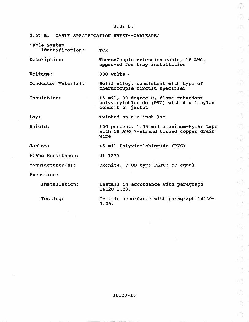
Cable SystenIdentification: TCX
Description: ThermoCouple extension cable, 16 ÀI{G,approved for tray installation
--l
Voltage:
Conductor Material:
Insulation:
Lay:
Shield:
Jacket:
F1ame Resistance:
Manufacturer (s) :
Execution:
Installation:
Testing:
3OO volts .
Solid alloy, consistent with type ofthermocouple circuit specified
15 ¡nil, 9O degree C, flame-retarda¡rtpolyvinylchloride (PVC) with 4 uril nylonconduit or jacket
Twisted on a 2-inch lay
100 percent, 1.35 mil aluninun-Mylar tapewith 18 ÀWG 7-strand tinned copper drainwire
45 niI Polyvinylchloride (Pvc)
vL L277
Okonite, P-oS type PLTci or equal
Install in accordance with paragraph16120-3.03.
Test in accordance with paragraph 16120'3 .05.
\
l
r. i
-\
)
16120-16

3.07 B.
3.07 B. CÀBLE SPECIFTCATION SHEET--CABLESPEC
Cab1e SystenIdentification: XLP
Description: Cross-Linked Polyethylene insulatedsingle conductor, for power and control
Voltage:
Conductor 
3.07 B.
3.07 B. CABLE SPECTFICÀTION SHEET--CÀBLESPEC
Cable SystenrIdentification: XLP/A
Description: cross-Linked polyethylene insulated,Ar¡nored multiconductor cable, for powerand control, 14 ÀWG mininum
Voltage:
Conductor ttaterial:
Insulation:
Assembly:
Sheath:
Jacket:
F1arne Resistance:
Manufacturer ( s) :
Uses Permitted:
Execution:
Installation:
Testing:
60O voltsBare annealed copperi stranded inaccordance with ASTM 88
XHHIü, 90 degree C dry, 75 degree C wet,crosslinked polyethylene in accordancewith NE¡.{A WC7 , UL 44 and ICEA S-66-524.
Individual conductors cabled togetherwith nonhydroscopic fillers and bindingtape.
Impervious, continuous, corrugatedalurninum welded over cable core. sheathshall meet the grounding conductorrequirenents of NEC table 250-95
5O ¡ni1 minirnum, Polyvinylchloride (pVC)in accordance with UL 1569
IEEE 383
Okonite, C-L-X; or equal.
Direct buriat, encased in concrete innormal or Class t, Division 2atrnospheres.
Install in accordance with paragraphJ.6L20-3.02.
Test in accordance with paragraph 16000-3.O2 and Section 16030.
16120-18

(
a
{
3. 07 B.
3.07 B. CABLE SPECIFICATION SHEET--CABLESPEC
Cab1e SystenIdentification: XLP/M
Description: Cross-Linked Polyethylene insulatedüulticonductor cable, for power andcontrol po¡rer and control, 14 À!{G minimum
Voltage:
Conductor lfaterial:
fnsulation:
Jacket:
Flame Resistance:
Manufacturer (s) :
Execution:
fnstallation:
Testing:
6OO voltsBare annealed copper; stranded inaccordance with ASTM Bg
RIIW/RHH, 90 degree C dry, 75 degree C
wet, cross-linked potyethylene (XLP), inaccordance with ICEA 5-66-524
Polyvinylchloride (Pvc)
IEEE 383, 21O,OO0 Btu/hr flame test
Rome Cable Corp., ROME FR-XLP; or equal
Install in accordance with paragraphL6]-20-3. 02.
Test in accordance with paragraph 16000-3.O2 and Section 16030.
¡t:IEND OF SECTION'I,t
16120-19

SECTION 16140
WIRTNG DEVICES
PÀRÎ I--GENERÀL
1.01 SCOPE
This section specifies branch circuit outlets and wiringdevices, including receptacles, plugs, switches, and finishplates.
L.02 REFERENCES
This section references the following documents. They are apart of this section as specified and modified. In case ofconflict between the requirements of this section and those ofthe listed documents, the requirements of this section shallprevail.
Reference TitleFS WC-596 Receptacles, P1ugs, Connectors
FS I{S-896 Switches
NEMÀ I{D-1-1974 General Purpose Wiring Devices
NFPA No. 7O-L984 National Electric Code (NEC)
UL 20 Switches
UL 498 Receptacles, Plugs, Connectors
1. O3 SUBI.{ITTÀLS
The following information shall be provided as a submittal inaccordance with Section O13OO:
Manufacturer's descriptive literature for each devicetype to be used on this project.
PART 2--PRODUCIS
2.OT GENERÀL
l{iring devices shall be UL approved for the current andvoltage specified and shall conply with NEMÀ l{D-l. Devices shallcontain provisions for back wiring and side wiring with captively
1
1614 0-1

2.Ot
held binding screws. Device color sha}l be gray, unlessotherwise noted. Sr¡itches and receptacles shall be manufacturedby Àpp1eton, Crouse-Hinds, General Electric, Hubbell, or equal.
2.O2 RECEPTÀCLES ÀND PLUGS
A. GENERJAL:
Unless otherwise noted, receptacles shall be straight blade,grounding type, heavy duty prenium specification grade.
B. 12OV RECEPTÀCLES:
1. INDOOR, CLE.AN ÀREAS: Receptacles shalÌ be duplex20-anp NEMA 5-2OR and shall accept NElfÀ 5-15P or 5-20P plug caps.Receptacles shall be industry class 5262.
2. OIIIDOOR, PROCESS, OR CORROSM ÀREÀS: Receptaclesshall be duplex 2O-amp l{EIr{A 5-2OR and shall accept NElt[A 5-15P or5-20P plug caps. Receptacle and plug caps shall be corrosionresistant/marine duty sith yellow polycarbonate weatherproof tifecovers. Hubbell 53CM62l53C}l2lr or Àrrow-Hart 5739CR17879-î5-CR.
C. 2sOV RECEPTACTES:
Receptacles shall be duplex 15-anp NEMÀ 6-15R and shallaccept NEMA 6-15P plug caps. Receptacles and plug caps shall beindustry class 5662, oÍ egual.
Male plug caps for l2OV and 25oV receptacles shall be of thecord grip armored type with heavy phenolic housing, at the sau¡emanufacture as the receptacle. PIug caps shall be rated 15 amps.One plug cap shall be provided for every four receptaclesfurnished, with a minimum of two plug caps being provided. PIugcaps shall be delivered to the Construction l{anager.
D. THREE PHÀSE RECEPTACLES ÀND PLUGS:
Receptacles shall be suitable for 480V, 3 phase, 4 wireservice, with ampere ratings as specified. Receptacles and plugsshall be designed so that the grounding pole is permanentlyconnected to the housing. The grounding pole shall nake contactbefore the line poles are engaged when the plug is connected tothe receptacle housing. The plug sleeve shall also make contactwith the receptacle housing before the line and load poles makecontact. Receptacles shalL be provided complete with cast backbox, angle adapter, gaskets, and a gasketted screw-type,weathertight cap with chain fastener. Each receptacle shall beprovided with one plug. Receptacles shall be Crouse-HindsrtÀrktite, rf AppLeton IPowertitertt or equal.
, t\\
(.
L6l.40-2

2.O2 E.
E. RECEPTÀCLES FOR HÀZARDOUS AREAS:
Receptacles for use in hazardous areas shall be rated inaccordance with NEC for the area for which they are to be locatedand shall be factory sealed. Receptacles shaLl be designed sothe plug must be inserted and turned before load is energized.Receptacles shall be provided with mounting box, sealing chamber,and compatible plug. Voltage and current ratings shall be I2OV,2O-amp. Receptacles shall be Àppleton rrU-Linerr, Crouse-HindsrfÀrk-Gard 2, rr or equal.
2.O3 SWITCHES
À. GENERAL PITRPOSE/CLEAN ÀREAS:
Unless otherwise noted, general purpose switches shall bequiet ÀC type, heavy duty specification grade, and shall beprovided in accordance with rated capacities as required.Switches shall match receptacles in color.
B. SWITCHES FOR HAZÀRDOUS ÀREÀS:
Switches for controÌ of tighting and sma1l single-phase powerloads in hazardous areas shall consist of a factory assembled andsealed conbination general purpose type switch in an explosion-proof housing. The switch shall be rated in accordance with NECfor the area in which it is to be installed. The externaloperating mechanism shall consist of a wing-type handle havingthe rrONr and rrOFFrr positions visible from the front. Unlessotherwise specified, switches shalI be Crouse-Hinds EFSC2129,Àppleton EFSCI7S-FI, or equal.
c SWITCHES FOR I{EATHER-EXPOSED, PROCESS, OR CORROSTVEÀREAS:
Switches shall be 2o-amp pressvritch type withweatherproof/corrosion resistant neoprene plate as ¡nanufacturedby Hubbell or Àrror¡-Hart as follows:
Switches shall be mounted in [FSrr type copper-free alu¡ninumor PVC mounting boxes.
Receptacles and switches shal-I be provided with weatherprooflift covers.
2.04 DEVICE PLÀTES
Device plates shall be provided with switches. Innoncorrosive indoor areas, receptacle device plates shall be rnadeof sheet steel, zinc electroplated with chrome finish asmanufactured by Crouse-Hinds, Appleton, or equal.
16 14 0-3

2.04
Device plates in corrosive or outdoor areas shall becorrosion-resistant/marine-duty type. Device plates forexplosionproof equiprnent shall be factory provided with theequipment.
Device plates shall be provided with engraved laninatedphenolic nameplates with l/8-inch white characters on blackbackground.
Naneplates for switches shall identify panel and circuitnumber and area served. Nameplates for receptacles shallidentify circuit and also voltage if other than 120 volts, singlephase.
PÀRT 3--EXECTITION
3.01 INSTALLATION
Boxes shall be independently and securely supported bygalvanized brackets, expansion bolts, toggle bolts, o! machine orwood screws as required. tùooden plugs inserted in nasonry orconcrete shall not be used as a base to secure boxes, nor shallwelding or brazing be used for attachment.
Receptacles and switches provided in architecturally finishedareas shall be flush mounted in sheet steel outlet boxes. Otherreceptacles and switches in nonhazardous areas shall be mountedin cást metal boxes and provided as specified. Receptacles inhazardous areas shatl be rnounted in metal boxes, which are partof the receptacle assemblies. Blank covers shall be provided forunused openings.
**END OF SECTION**
16 14 0-4

SECTION 16170
GROUNDING
PART I--GENERÀL
1.01 SCOPE
This section specifies the systern for grounding electricalequipment, exposed non-energized ¡reta1 surfaces of equipment, andmetal structures.
L.02 SYSTEM DESCRTPTION
This project shall have a grounding and bonding systen(s)provided in cornpliance with the NEC. Requirements of thissection shall be additional.1.03 REFERENCES
This section references the following documents. They are apart of this section as specified and modified. In case ofconflict between the requirements of this section and those ofthe listed docurnents, the requirernents of this section shallprevail.
Reference
IEEE Standard 81-83
TitleGuide for Measuring EarthResistivity, Ground Impedance, andEarth Surface Potentials of a GroundSystem
IEEE Standard L42-72 Recommended Practice for Grounding ofIndustrial and Commercial PowerSysterns
PÀRT 2--PRODUCTS
2.01 CÀBLE
Ground cable shall be annealed bare copper, concentricstranded as specified. Unless otherwise specified, the rninimumsizes shall be as follows:
5 and 15 kV switchgear15 kV - skv transformers5 kV - 480V transformers480V switchgear
ÀwGÀwGAI{GAhTG
4/o4lo4lo4/o
16170-1

2.OL
Duct Banks 4/0 AwG480V MCC and switchboards 2/0 ÀWG
Cable tray 2/O ÀWG
Lighting panels 2 ÀwGExposed netal 2 ÀWG
Other grounding conductors shall be in accordance with NECTab1es 250-94 and 250-95.
2.O2 GROI'NDING ELECTRODES
À. GROT'ND RODS:
Ground rods shatl be copper or copper covered steel, 314 inchdiameter and 1O feet long. Rods shalI have threaded removablecaps so that extension rods of same diameter and length nay beadded where necessary.
B. CONCRETE-ENCÀSED ELECTRODE:
Where shown, provide one No. 4lO solid bare copper conductor.Locate within and near the bottom of concrete foundation orfooting in accordance with NEC 250-81(c). Connect to steelreinforcing bars, where available, one or more times.
2.O3 EXOTHERMIC CONNECTORS
Exothermic connectors shall be as manufactured by Thernoweld,Cadweld by Erico Products Inc., or equal.
2.O4 BOLTED CONNECTORS
Bolted connectors shaLl be Burndy, 0. Z. Gedney, or equal-
PART 3--EXECTITION
3.01 GENERÀL
E¡nbedded and buried ground connections shall be made byexothermic connectors. Conductors and molds shall be prepared inaccordance with the nanufacturerts instructions. Exposed groundconnections to eguiprnent shall be ¡nade by bolted clamps unlessotherwise specified. No solder shalÌ be used in any part of theground circuits.
Embedded ground cables and fittings shall be securelyattached to concrete reinforcing steel with tie wires andprevented from displacement during concrete placenent. As eachþart of the grounding systern which is laid below finished gradeis completed, the Construction trianager shall be notified 2 hoursprior to backfilling.
16L70-2

3. O1
Grounding conductors which are extended beyond concretesurfaces for later connection shall be extended a sufficientlength to reach the final connection point without splicing.t¡inirnun extension shall be 3 feet. Grounding conductors whichproject from a concrete surface shall be located as close asþossiUte to a corner, protected by conduit, or terminated in aflush grounding plate. Exposed grounding conductors shall besupported by noncorrosive ¡retallic hardware at 4-foot intervalsor less.
Ground conductors, except signal conductor shields, enteringenclosures shall be bonded together, to the enclosure if it ismetallic, and to netallic raceways within or terninating at theenclosure. Prior to making ground connections or bonds, thenetal surface at the point of connection shall be cleaned.
Compression-t1pe }ugs shall be used in accordance v:ithmanufacturer' s recomnendations .
Grounding conductor shall not be used as a system neutral.
Lightning arresters shall be directly connected to the groundsystem using copper conductors, sized as specified.
l,letallic sheaths or shields of shielded poh¡er cable shall beterminated by a copper grounding strip provided with cableconnection for connection to the grounding system.
Grounding system shal-l be provided in compliance withNFPA-7O.
3.02 INSTALLATÏON
À. BONDING:
I{here available on the premises, bond together the followingin accordance with NEC 250 G.
Metal water pipe.Building metal frame.Encased electrode.Ground ring.
B. GROUNDING ELECTRODES:
Install rnade electrodes in addition to available electrodesas shown. Bond a1l electrodes together in accordance with NEC2s0 H.
1234
16170-3

3.O2 C.
C. GROUNDING CONDUCTORS:
connect to service equipment ground bus in accordance withNEC 250 J.
3. 03 RACEWAY GROIJND
I'letallic conduits shall be assenbled to provide a continuousground path. Metallic conduits shall be bonded using insulatedgrounding bushings. Grounding bushings shall be connected to thegrounding system using conductors sized in courpliance with theNEC. ALl conduits carrying power conductors shall contain aninsulated ground conductor. Non¡netallic conduits shall containan insuLated ground conductor. Cab1e trays shal1 have No. 2lOAWG bare copper ground conductor run on the outside of each tray.Conductor sha1l be connected to each section or fitting using acarriage L'o1t and clamp.
3. 04 EQUIP!{ENT ÀI{D ENCI,OSURE GROUND
Electrical and distribution equipment shatl be connected tothe grounding system. Cables shall be sized as specified.
Non-electrical equipment with metallic enclosures shall beconnected to the grounding systern.
3.05 TESTING
À. GROUNDING ELECTRODE CONDUCTOR:
l,{easure resistance between service equipment ground bus andeach grounding electrode, using a Megger and a single length ofadditional wire, if necessary.
Measure resistance between both ends of the additional wireused. Grounding electrode conductor resistance is the differencebetween readings 1 and 2. Isolate and correct any poorconnections as indicated.
B. SYSTEM GROUND CONTINUITY:
Àt panels and selected outlets, measure the ground Loopresistance between the neutral conductor and raceway using aMegger or equivalent.
Or, at selected outlets, measure the ground loop impedanceusing a ground loop impedance tester such as the Daniel l{oodheadilGLIT. rl
t-6l_7 0-4

(
3.05 B.
Ground loop ímpedance shaLl not exceed a value in oh¡ns thatis the voltage to ground divided by five times the rated current.
If readings exceed the maximum allowed, isolate and correctthe cause of the couplings and connections can be readily foundand corected. If the source of the high reading cannot bepractically corrected, puIl a separate ground conductor into theraceway and retest.
**END OF SECIION**
\
I
L
1
I(
(
16170-5


{
I
sEcTroN t6r.7s
MOTOR AND CIRCUIT DISCONNECTS
P.ART I--GENERÀL
1.01 SCOPE
This section specifies individually-nrounted safety switchesfor the manual disconnection of notors and circuits.L.O2 GENERAL REQUTREI{ENTS
Furnish and install disconnects as shown, âs required byapplicable codes, and as reguired by equipnent manufaeturer.
Disconnects shall include enclosure, nameplate, nountingstands, brackets, hardware, and accessories for a completeinstallation.
If not shown, the disconnect voltage, amperage rating, numberof poles, and other configuration options shall be suitable forthe feeder, circuits, ot equipment served.
1. 03 QUÀLITY ÀSSI'RÀNCE
A. REFERENCES
This section references the following documents. They are apart of this section as specified and modified. In case ofconflict between the requirements of this section and those ofthe tisted documents, the requirernents of this section shaIlprevail.
Reference TitleFed. Spec. l{5-865NEMÀ ICS-1978NEtfA KS-1975
Safety Sr¡itchesIndustrial Controls and SystemsEnclosed Switches
1. 04 SUBIIIIÎTALS
The following information shall be provided as product datain accordance with Section 01300:
Manufacturer's descriptive Iiterature, includingelectrical ratings and specifications.
operation and maintenance infornation as specified inSection 01730.
1
2
t-6175-t-

Part 2
PART 2--PRODUCTS
2. 01 ACCEPTÀBLE I,IÀNUFACTURERS
General Electric, ltill Duty, Type TH; Square D, Heavy Duty;Westinghouse, Type H-6OO or equal.
2.O2 HEÀVY DUTY SAFETY SWITCHES
Disconnect switches shalr be hearry-duty safety type rated 6oovorts AC. switches shaIl be horsepower rated for notòrs andshall courpry with NEMA Ks-l. switches sharl have the visibreblades line terminal shields and arc suppressors.
The operating handle shall have positions that are easilyrecognizable and capable of being padlocked in either the troñú oriloffrr position. Except for but small starting switches andstarters, the operating handle shall accept three 3/8-inchshackle padlocks to lock the disconnect in the desired position.The operator shall be a non-teasible, positive, quick-make,quick-break nechanism.
Switches shall be provided with a door interlock thatprevents the door from opening when the operating handle is inthe ,on* position, and prevent closing the switch when the dooris open. À defeater to perrnit authorized personnel to open doorand inspect switch when trs¡r rr or to operate the switct¡ wittr coveropen.
safety switches shalr be non-fusible type unress otherwisespecified or required. Fusible switcnes shãlt be equipped ¡¡ithclass R fuses. circuit breakers sharr be ther¡nal nãgnétic type.
I{here specified, the switch mechanism shall be provided withone auxiliary contact that opens before the switch ttades. Thisauxiriary contact shall be rated 8150, pêE NEMÀ rcs, z-L2s. Lineand load lugs for copper wire shall be set-screvr or compressiontype. Lugs for aluminum wire shall be cornpression type only.2.O3 ENCLOSURES
Disconnect switches shall be enclosed in housings suitablefor their environment. unless otherwise specified, enclosuresshall be provided as specified in Table A.
'\
ì
t6L75-2

2.03
lable À, Enclosure Requirements
LocationEnclosure tvpe
Nn{À 1
NE¡,fÀ 3R
NEI{A 4
NEMÀ 4X
NE}Í,A 7
NElr{À 9
NEtttA 12
fndoor, dry, heated, Do process ormanufacturing
outdoorr ho process or manufacturing
Indoor, wet or open process ormanufacturing. Outdoor, process ormanufacturing.
Indoor or outdoor, corrosive
Class I hazardous locatÍons
Class II hazardous locations
Indoor, dry, closed process andmanufacturing
Enclosures sha1l be finished in the manufacturer's standardprotective coating. NEMÀ 1, 3, and L2 enclosures shall be primedwith a rust-inhibiting phosphate primer, painted with grayenamel, and baked.
NEII{À 4X enclosures shall be reinforced fiberglass. AllenBradley rrRositerrr Crouse Hinds rrKrydonril or egual.
2.O4 IDENTIFICÀTION
À. MANUFÀCTURER'S NÀMEPLÀTE:
Switch type, catalog nurnber, Amp/Hp ratings.
B. EQUIPMENT NAI{EPLATE:
Provide a nameplate per Section 16040' with the wording:ff DIScONNEcTrr rrXXXX, rt ItBLowER B24LO,t' nELEVATOR' Í etc. FilI inassigned number. If abbreviations are required because of spacelirnitations, abbreviations shall be submitted to the ConstructionManager for approval prior to manufacture.
16175-3

Part 3
PART 3--EXECUTION
3.01 TNSTALI,ÀTION
Locate disconnects as near equipnent as possible. !Íaintaincode clearances. Finnty mount and anchor disconneets as follows:
1. Concrete: 
\
I
I
/-
(
a
I
\
i
SECTION l.6260
ATITOMÀTIC TRÀNSFER SWITCHES
PART I--GENERAL
1.01 DESCRTPTION
This section specifies automatic transfer switches rated600 volts and less ÀC for lighting, heating, and motor loads.
L.02 REFERENCES
This section contains references to the following documents.They are a part of this section as specified and modified. Incase of conflict between the requirements of this section andthose of the listed d.ocuments, the require¡nents of this sectionshall prevail.
Reference TitleEnclosures for Industrial Controls andSystems
Automatic Transfer Switches
NEI{A ICS 6-88
uL 1008-89
1. O3 SUBI'ÍITTÀLS
The following subrnittals shal-l be provided in accordance withSection 01300:
1. Arrangement drawings of the transfer switch enclosureindicating the front door and rear panel eguiprnentarrangement and dimensions. À list of materials andcomponents shall accompany the arrangement drawing.
2. Elementary and internal connection diagrams.
3. Manufacturers data indicating momentary,interrupting, and continuous current ratings of allreÌevant equipment, components, and devices.
The automatic tracontactors to provnumber of poles ascontacts shall be ca
t6260-t

2.01
heating loads. The contactors shall be mechanically held, andthe transfer nechanism shall be electrically operated. Unlessotherwise specified, the enclosure shall be rated NEMÀ 1. Theswitches shall comply with UL 1OO8. Automatic transfer switchesshall be Asco, Kohl-er, Onan, Russelectric, Square D, Zenith, orequal.
2.O2 RATTNG
The voltâ9e, current,as specified.
frequency and number of poles shall be
2.O3 CONTROL
The switch shall contain the fotlowing devices in the controlcircuit:
1. Pickup relays: Voltage pickup relay, adjustable 85to 10o percent. Frequency pickup re1ay, adjustable9O to 100 pereent.
2. Time delay relay, normal to emergency (TDNE);adjustable from 0.2 to 50 seconds.
3. Time delay re1ay, emergency to normal (TDEN);adjustable fron O to 30 minutes.
4. Test switch mounted on equipment cover.
5. Switch position indicating lights; green light fornorrnal source and red light for emergency source.
2.04 TERII{INÀIIONS
The terminations shall be suitable for copper conductors.
2.O5 NAMEPLATES
The switch sha1l be identified as specified. Naneplatesshall be provided in accordance with the requirements ofparagraph 16000-2.04.
2.06 PRODUCT DATÀ
The following infornation shall be provided in accordancewith Section O13oo:
1. Catalog cuts describing the features of the switch.
2. Àpplicable operation and rnaintenance information asspecified in Section 01730.
]-6260-2

Part 3
PART 3--EXECUTION
3.01 FIELD ADJUSTMENTS
Unless otherwise specified, the time delay relays shall beadjusted to the following values:
1234
Normal to emergency tine delay:Energency to normal time delaY:Voltage pickup:Frequency pickup:
O seconds30 minutes90 percent95 percent
3.02 FIELD TESTS
The autonatic transfer switch shall be field tested inaccordance with Section 16030.
*rtEND OF SECTION*¡I
162 60-3


sEclION 16310
LOI{ VOLTAGE SWITCHGEÀR
PART I--GENERÀL
1.01 DESCRTPTION
This section specifies switchgear rated 600 volts.L.Oz QUALITY ASSURÀNCE
À. REFERENCES:
This seciion contains references to the following documents.They are a part of this section as specified and nodífied. rncase of conflict between the requirenents of this section andthose of the listed documents, the requirenents of this sectionshall prevail.
Reference TitIeÀNSI C37.20-74 Switchgear Àssemblies Including Metal
Enclosed Bus
Àl,fsl c57.13-78
B. FÀCTORY TESTS:
Requirements for Instru¡nent Transformers
After assembly, switchgear sharl be tested for operation atthe specified voltage and current ratings. The main-circuitssha1l be given a dielectric test of 22OoY for 1 minute between1it9 parts and ground, and betr¡een opposite porarities. Thewiring and control circuits shall Ue-given a-dielectric test of1500V for 1 minute between live parts and ground.
rnstrument transformers sharr have ratio and phase angletests rnade in conformance with ÀNSI C52.13.
Three copies of test resurts shalr be provided to theConstruction Manager.
1. O3 SUBII{ITTALS
The following subrnittals shal-I be provided in accordance withSection 01300:
1. Electrical elementary diagrarns and internalconnection diagrams.
2. Manufacturer's data indicating interrupting,163 10-1
r,. 03
PART 2--PRODUCTS
z.OL ÀCCEPTABLE
Switchgear shall shall be GeneralPower-Gear, I{estinghouse DS, or equal.
2.O2 I{.ANUFACTURE
A. ENCI,OSI]RE:
Switchgear sha]I be factory assembled and metal enclosed.Each unit snaff consist of a stationary structure assembly andone or more air circuit breaker units, disconnecting devices, andother specified equipnent. Switchgear shall be suitable for6oov, 3 phase ¡naxi¡nuin service. eaðh unit shall be provided witha breakel f¡oist for removing the breaker for maintenance.
B. STÀTIONARY STRUCTURE:
Stationary structure shall be a self-contained steel unithousing one or more individual breakers or instrumentcompartments and a rear compartment for buses and outgoing cableconnections. Structure shall be provided with removable steelplates on the top and sides, and each breaker compartment shallte equipped with- primary and secondary contacts, rails, andstationãiy levering mechanism. A rear hinged cover shall beprovided ior each cable compartment, and a front hinged doorênatt be provided for each breaker and metering cornpartment.
Structures shall be provided with horizontal and verticalbarriers to separate different voltage classes, buses andincoming cables.
C. FINISH:
The finish shall conply with paragraph 16000-2.01.8.
2.O3 BUS BÀRS
A. GENERAL:
Buses shall be copper.
163 10-2

2.O3 B.
section.
As a minÍmum, main bus shall have a continuous rating atleast equal to the main circuit breaker or the pohrer source andshall be braced to withstand stresses resulting from the maxinumshort-circuit current available. 
2.O4 B.
B. DISCONNECTING DEVICES AND DRÀ!{OUT MECHÀNTSM:
Disconnecting devices shall be the self-aligning type withthe disconnecting fingers nounted on the breaker. The drawoutmechanism shall rigidly hold the circuit breaker in the fullyconnected, fest, and fully disconnected positions. Interlocksshall be provided to prevent moving the circuit breaker from thefully connected, test, or fully disconnected positions unless thebreaker is open. Interlocks shall also prevent closing thebreaker between any of these positions.
The drawout mechanism shalÌ be designed so that the breakercan be racked to any position without opening the door. A haspon the breaker escutcheon shall be provided that can receivethree padlocks when the breaker is in the open position.
C. ÀUXILTÀRY SWITCHES:
Unless otherwise specified, breakers- shall be equipped withone normally open and one normally closed auxiliary switch.Switches shall be rated 10 amperes, 6OO volts ÀC and wired toterminal blocks.
D. SOLTD STÀTE TRTPPING DEVICES:
So1id state tripping devices shall consist of current sensorstogic assembly, magnetic latch release, and requiredinterconnecting wiring. Tripping devices shall be automatic andself-contained within the breaker frame, and shall not requireany external relaying or power supplies.
Tripping device shall be provided with manually resettablefault indicators. Às a rninirnurn, fault indicators shalL provideindication of tripping caused by overload, short circuit orground fault.
Tripping funct.ions shalI be field adjustable and shallprovider âs specified, the following tripping characteristics:
1. OVERLOAD TRTPPING:a. Adjustable ampere settingb. Àdjustable long-time delay
2 SHORT CTRCUIT TRIPPING:a. Àdjustable short-tirne pick-upb. Adjustable short-time delayc. Àdjustable instantaneous pick-up
3. GROT'ND FAULT TRIPPING:
..)
a AdÀd
ustable ground fault pick-upustable ground fault delayb
)j
163l_O-4

2.O5
2. 05 PÀNEL INSTRI'MENT ÀND ÀCCESSORIES
Panel instrument and accessories shall be as specified. Theyshall be provided in accordance vith Section 16440.
2.06 PROTECTIVE REIÀYING
Protective relaying shall be as specified.
The tripping devices and instrument transforner ratiosspecified are pretiminary and are subject to confirnation withthe coordination study in Section 16431.
2.O7 EQUTPUENT TDENTIFTCÀTTON
À. NÀIIEPI,ATES:
In addition to the manufacturer's identification, switchgearshall be provided with phenolic nameplates showing switchgear,main breaker, and feeder breaker designations as specified.Nameplates shall comply with paragraph 16000-2.04.
B. CONDUCTOR }Í,ARKERS:
Conductor markers shall comply with paragraph 16000-2.o2.
2.O8 WIRTNG
À. CONDUCTORS:
Internal switchgear wiring shall consist of single conductor9O degree C copper wire and UL listed for panel wiring. The wiresha}l be sized to suit load requirements. Mini¡nurn size shall beNo. 14 ÀWG.
B. TERMTNAL BLOCKS:
Terminal blocks shall cornply with paragraph 16000-2.04.
C. CABLE CONNECTORS:
Cable connectors for outgoing power cables shall be suitablefor use with aluminum or copper conductors. They shall be ULIisted as a compression connector and shal1 be sized for thespecified conductor.
Conical washers shaÌt be used for each connection.
2.O9 PRODUCT DÀTA
The following information shaIl be provided in accordancewith Section 01300:
163 10-5

2.O9
1. ÀrrangemenÈ and layout drawings of the switchgearenclosures depicting equipment and bus arrangementand dimensions including areas of pernissible cableentries. A list of material and components shallaccompany the layout drawings.
2. Catalog data and instruction manuals on allelectrical devices and components mounted on orwithin the switchgear.
3. Results of factory tests and field breaker settingtests as specified in paragraphs 16310-1.02.8 and16310-3.02.
4 Applicable operation and maintenance information asspecified in Section 01730.
5. Manufacturer's product infor¡¡ation.6. Manufacturer's certification and calculations that
the equipment meets the seisrnic requirenents ofparagraph 16000-1.05 D.
2.LO ÀCCESSORIES
Provide one breaker lifting device that is mountable from anextension rail above each section front. Provide one set ofcircuit breaker testing and calibration equipment. Provide oneset of any specíal tools required and one set of spare parts.
PART 3--EXECUTION
3.01 PROTECTIVE DEVTCE SETTINGS
The protective devices shall be adjusted to the settingsspecified in the coordination study in Section 16431 prior toenergizing the switchgear.
3.02 FIELD TESTS
Each switchgear breaker shall be tested in accordance withSection 16030.
¡t*END OF SECTION:I*
163 10-6

SECTION 16405
ELECTRICAL POT{ER SERVICE
PART I--GENERÀL
1.01 SCOPE
this section identifies the serving electric utility companyand specifies the coordination of responsibilities between theutility company and the contractor.
L.Oz SERVTNG ELECTRIC UTILTTY
City oÍ Port Àngelescity Light321 East Fifth StreetP.O. Box 1150Port Àngeles, WA 98362
Telephone: (206) 457-0411
Contact: ür. Steven E. Hursh,Engineering ttfanagêF, Ext. L92
1.03 DESCRIPTION
À. WÀSTEWATER TREÀTMENT PI,ANT:
The existing plant site is located within the city limits onEnnis Creek Road. The existing plant is presently fed from a2O8Y/L2O volt, 3-phase underground pohrer service from City LightTransformer #2, and meter located at the Sw corner of theÀdninistration Building. The billing schedule is City LightSchedule cD-90.
Under this plant expansion, the existing service will bereplaced with a nel¡ 480 volt, 3-phase, 4-wire service. Theexisting plant distribution systern will be replaced with new andany remaining plant equiprnent wiLl be sub-fed from the newsystem..
B. PIIMPTNG STÀTTON NO. 4Z
The project site is located within the city linits on MarineDrive neàr the intersection with Front Street. This existingstation has a 480 vol-t, 3-phase, 4-wire underground power servicefrom city Light 150 kva pad lransforner #14.
Under this phase of construction, the existing service willremain unchanged. The remainder of this section applies only tothe l{astewater Treatment Plant site.
16405-1

1. 04 À.
1. 04 CITY LIGHÎ TO FT'RNISH ÀND TNSTÀLL
À. OFF SITE:
AII work offsite, outside the plant property line. Shaltconsist of two new underground L2.47 kv services to the site.One from the Valley Substation to the southwest, paralleling theexisting plant underground service; and one new service fron thel{ashington Substation to the east. The t{ashington Substationshall serve as the normal or preferred source with the ValleySubstation serving as the aLternate or backup source.
B. PRI!{,ARY CÀBLE:
All tenporary and permanent primary conductors, includingthose between existing Valley and t{ashington Substations and thepad transformer prinary lugs. À11 primary cable terminations andstrain reliefs. AIl trenching and backfill.
C. SERVICE TRÀNSFORMER:
lwo new pad-mounted outdoor transformers, L2.47 kilovolt,3-phase to 480 volt, 3-phase, 4-wire, with concrete vaults andpads.
D. METERING EQUIPMENT:
A1l required watthour and demand meters, currenttransformers, pri.mary transformers, and test blocks, in the newswitchboard metering conpartment and in the outdoor meter socket.
E. METERING CONDUCTORS:
Required conductors between the CT compartment and themetering equipment.
1.05 CrTY LIGHT TO FIRNISH, FOR CONTRÀCÎOR TO INSTALL
À. Current transformers, window type.
1. 06 CONTRÀCTOR TO FT'RNTSH AND INSTÀLL
À. ONSITE TRENCHING ÀND BÀCKFILLTNG:
À11 trenching and backfilling inside the property Ìine forunderground conduits which are installed under this expansion.
, :.
t6405-2

1.06 B.
B. SECONDÀRY DISTRIBUTION SYSTEM:
Everything specified and shown on the site downstream of thesecondary.lugs of the service transformer, including sub- feedingtÌe eïisting plant service, site porrer connections, and sitelightins.
C. CT CO!.TPARTMENT:
I{ithin the main switchboard, with l-inch conduit to neterbases.
D. UETERING RÀCEWÀYS:
Betr¡een the main switchboard and the netering encrosure.
E. GROT'NDTNG:
Grounding of each buitding service at the ¡rain switchboard orpanelboard of each building, with bonding to the buirdingstructural and reinforcing stee1.
1.06 OWNER TO PAY FOR:
Àny utility charges by City Light, such ascontribution-in-aide to construction costs for service andmetering, sharl be birled to and paid for directry by the owner.
PART 2--PRODUCTS
2.OI TRÀNSF'ORMER VAULT .â,ND PAD
Pre-cast or poured in place, reinforced concrete inaccordance with City Light specifications. City Light to furnishand install two vaults and pads.
2.02 UETERING EQUIPMENÎ
The following shall meet City Light specifications.À. UETER BÀSES:
Provide two within the rnetering encLosure. one for KwH/Iffenergy and one for KVÀR porárer factor. 13 jaw, 4g0 voLt, threephase, four wire. Mitbank catalog no. lrc7449wL, with room fortest switch.
I
16405-3

Part 3
PÀRT 3--EXECUTION
3.01 TRENCHTNG ÀND BÀCKFILL
Primary.cable conduit shall have 48-inch minimum cover depth.
3.02 CT'RRENI TRÀNSFORI,ÍER INSTÀtI,ATION
City tight to furnish sindow-type CIs for instalLation intothe service switchboard. À suitable access door shall be locatedon the switchboard front, equipped with tamper provisions.Contractor shall coordinate City Light requirenents with theswitchboard manuf acturer .
3.03 COORDTNÀTION
Coordinate any work involving City Light.
** END OF SECTION **
(
\
',
L6405-4

PÀRT I--GENERÀL
1.01 DESCRTPTTON
À. SCOPE:
SECTION 16410
POI^7ER FACTOR CORRECTION CAPACITORS
This section specifies power factor correction capacitors formotors or load centers up to 5OOO voltsB. DESCRIPTION OF SYSTEM:
3.29 16410-1 Paragraph 1.01, DESCRIPTION: ADD newparagraph as follows:
¿¡¡psq¿¡.Ër¡ cru sqv¡¡ pw¡LCl ..^centers and connected tc
xc. PERFORIT{ÀNCE ÀND DESIGN REQUTREI{ENTS:
disconnect units 'This project will be equipped with a
1.02 REFEREN.ES large connected component of variablefrequency drives. Refer to Section
3 - 30 16410-1 i tf;i3';"":iåi"Èi:íl'ùå'åã3r"ni:å':3u under
þecr,reen Ène requlreme¡ ( assemblies by the manufactúrer to providedocument, th; reguirer ( pol¡er factor correction in applications
Reference subject to the effects of harmonics'rrThe filter assemblies shall consist of
NEc 460-1984 capa, pohrer factor correct.ion capacitors inuL B'o-1es1 ð";; ;::*:":å.*riilui;:"::"i:å"i_Bä:îll ".1.03 ITNDERWRITER5 LABOR harmonic frequencies. The assemblies
shall serve as low-pass filters, tuned toUnless otherwisê spêr allow unimpeded power current flow at 60
shal1 be lisred and late li;.il";"Hïi3" (iãä'ili ii-:å:3,::"::"(uL)' with IEEE-519. A shunt resistor shall be
1.04 sUBMITTALS installed across the inductors to act as
rhe rorrowins inrorr* ãJliiä-3?ïinfålT;"Ëi:i:îå:e,,criticalaccordance with Section OI-3OO:
1. Manufacturer's descriptive literature, includingelectrical ratings anã specifications: -
164l-0-1

PÀRÎ 2--PRODUCTS
2.Ot GENERÀL
The capacitor units shall be designed for correcting power
factor for i"á"=Ltiãi apprications. rrrey shall comply with therequirements of UL 810. See drawings foi schedule of sizes'
PART 3--EXECUTION
Part 2
PART 2--PRODUCTS: ADD NEW Sfollows:
-êÞ
3.01 I{OTOR OVERLOAD PROI II2.O4 ACCEPTABLE PRODUCTS
where a capacitor is rrThe power.factor correction capacitors/overload proteätion devic náinoiric filter assemblies shall be
protection device shall t nã¡icon rrlnductocaprrt or.-equal, modifiediùe reauction' ;-*;t;'-"u ï:"*:::=i# * i::ït3i"lT?r3å"ä:i:tr,,n
conditions. rl
*
t64LO-2

SECTION L6423
VÀRIÀBLE SPEED DRIVES
PÀRT I--GENERÀL
1.01 SCOPE
This section specifies 3-phase, low voltage variable speeddrive (VsD) systems of the electronic variable frequency tlpe formotor sizes to 800 horsepower. The VSD systen shall includeincoming line filters, rectifier units, inverter units, controlcircuitry, protective equipurent, and accessories as necessary toprovide the specified functions.
L.02 SYSTEM DESCRIPTION
A. GENERÀL REQUTRET-{ENTS:
The VSD system shall convert 460 volt, 3-phase, 60 Hertznorninal utility pohrer to a adjustable voltage (o-460V) andfrequency (0-60 Hz.) 3-phase, ÀC pohrer for stepless rnotor speedcontrol. The VSD shal1 be suitable for use with any standardNEMÀ-B squirrel-cage induction motor. The VSD shall control themotor to run at a speed proportional to a 4 to 20 ¡tilliamperesignal from the instrumentation system specified in Division 17.
B. EQUIPI,IENT LIST:
Drive Nominalnumber HP Mountincr
I{a1IWal1FloorFloorFloorI{aI1VlaLII{a11
Drivename
Reclaimed Water Punp 1Reclaimed Water Purnp 2Trickling Filter Circ Punp 1Trickling Filter Circ Punp 2Trickling Filter CÍrc Punp 3Digester Transfer PumpBeIt Filter Press Feed Pumpodor -Reduction Tower Fan
vsD-2 1s0vsD-2160vsD-2210vsD-2220vsD-2230vsD-4040vsD-5402vsD-5601
3030
100100100
403020
C. VSD BÀSIC FE.ATURES:
The VSDs shall be provided with the following basic features:
1. Door-mounted manual speed control potentiometer,3-position node selector switch marked tt¡¡¡1¡þ-OFF-AUTOMÀTIC|r,
"POÍ{ER ONrt light, VSD fault light, and VSD fault resetpushbutton.
L6423-L

L.02 C.2.
2. Automatic restart after drive trip or utilitySoftware selectable if not desired.
)
failure.
rl
3. Speed profile. Individual adjustable setting forstart, stop, entry, slope, and mininun and naximum speed points.
4. Process signal inverter. Software selectable toallow speed of drive to vary inversely with input signal.
5. Proportional, integral, and derivative (PID) processcontroller with menu driven selection and prograñming viadoor-mounted keypad.
6. Pick up a spinning load. VSD shall be able todeternine the motor speed and resume control of a motor which isspinning in either direction.
7. Door-rnounted digital display/keypad unit capable ofcontrolling the VSD and setting drive parameters. Display unitsha1l display diagnostic messages and parameter values whenaccessed.
8. Digital display shall normally display:in percent, output current in amperes, frequency incontrol rnode: Manual/Àutonatic and total 3-phase Kgl.
speed de¡nandhertz,
9. Digita1 keypad shall allowing entry of exactnumerical setting in English engineering units. A user menushalL provide a guide to parameter setting. Coded messages onthe keypad will not be acceptable. Drive parameters are to befactory set in EEPROI! and resettable in the field through thekeypad. Six (6) Ieve1s of password security shall be availableto protect drive parameters from unauthorized personnel. TheEEPROII-stored drive variables must be able to be transferred tonew boards to reprogram spare boards.
10. Display/keypad shall have a key switch to controloperation of the keypad. Key to be removable in either rrEnabredflor rDisabledt' positions. Keypad module shalL contain a self-testsoftware program that can be activated to verify proper keypadoperations.
D. FI'NCTIONÀL REQUIREMENTS:
1. SUPPLY POWER: The VSD shaLl operate continuously asspecified with supply pohrer of 460 volts plus or minus 10percent, 60 hertz plus or rninus 5 percent. VSDs shall notdistort the supply power wave-form by more than 5 percent totatharmonic distortion based on motor naneplate load. The VSD shall
]-6423-2

L.O2 D.1.
remain on line and operate without damage to either the VSD orits connected load during a supply power variation of plus 50percent lasting for a period of up to 0.01 seconds and ninus 100percent lasting for a period of up to 0.5 seconds.
2. ÀI,IBIENT CONDITfONS: The VSDs shall operatecontinuously as specified in an anbient temperature of -5 to +5Odegrees C and an ambient hunidity of O to 100 percent.
3. LOÀD: The VSD systen sha1l be capable ofcontinuously driving the specified maximun motor naneplate loadunder the conditions specified herein. It shall be capable ofdelivering 110 percent of the specified load for up to 6O secondsin any one incident and up to 240 seconds per hour for variabletorque appLications (150 percent for constant torqueapplications) .
4. POWER FÀCTOR: VSD systems driving motors 10 horse-power and larger shall be provided with pos/er factor correction.Input power factor shall be not less than 0.95 at rated basespeed and 1oad. The VFD manufacturer shall provide power factorcorrection capacitors, resonance filters, contactors, andcontrols as required to neet this power factor requirement.
5. EFFICIENCY: Efficiency of VSD systems ratedhorsepower and greater shall be not less than 95 percentHertz output driving the specified maximum load.
6. FREQUENCY ÀND VOLTAGE REGUI,ÀIION: VSD inverteroutput frequency shall be regulated to within 0.6 hertz of thespecif ied instru¡nentation signal/output frequency relationship.VSD inverter output voltage shall be regulated to within 1.0percent of that value which will produce ¡ninimum motor heating atany operating frequency within the specified range.
7. FREQUENCY RANGE: VSD shall be capable of continuousoperation with the specified load at any freguency between 6 and66 hertz. Above 60 Hz the output voltage shall remain constantat the motor design voltage.
6040at
8. SPACE: VSD system size shall not exceed the sizeallotrnents specified on the drawings nor shall any portion ofVSD system exceed a height of 90 inches. VSD system shall befront accessible and shall not require rear access. The VSDequipment shall be suitable for nounting directly against thewall without any clearance for ventitation or other purposes.VSD units shall be arranged for either top or botton entry ofincorning line cables and outgoing load cables.
the
L6423-3

L.02 D.9.
9. ÀIÍBIENT NoIsE: Free field noise generated by the VSDsha1l not exceed 85 dBA at 3 feet out fro¡n any point on the VSDcabinet under any normal operating condition.
E. PROTECTION ÀI{D ÀI.INI'NCIÀTION:
1. OVERCITRRENT PROTECTION: The VSD systen shall provideelectronic current linit at 110 percent of motor nameplatecurrent. Current linit shall be accurate to within 1.0 percentand shall s¡roothly linit motor speed at whatever value isnecessary to linit motor current to that value.
The VSD shall also provide motor running overcurrentprotection in cornpliance with NFPÀ 70.
2. SHORT CIRCUIT PROTECTION: ThE VSD ShATI bE fUllYprotected against load faults. Bo1ted faults, phase to phase orphase to ground shatl not damage the unit. Fault protectionshall be based on a porrer source short circuit capacity of 301000amperes RltS symmetrical (unless otherwise noted) at the VSD powerinput terminals. Any inpedance or other current linitingnecessary to meet this requirement shall be provided as part ofthe VSD system, and any losses caused by current liniting devicesshall be included in efficiency calculation for the VSD system.
3. LINE VOLTAGE: The VSD shall be protected againsthigh and low line voltage on one or more phases.
4. INTERNAL FÀULTS: The VSD shall incorporate aninternal fauLt monitoring system to detect malfunctions. Thissystem shall be designed to protect the VSD from transient andsustained faults and to limit damage that rnay be caused by thesefaults.
5. It{OTOR OVERTEII{PERÀTURE: The VSD shall interface tomotor positive temperature coefficient thermistor (PTC) over-tenperature devices and shalL shut down if the rnotor becomesoverheated. The VSD shall include all components necessary tosense an increase in PTC resistance, or an open overtemperatureswitch, and to disconnect the affected motor if the notor windingtemperature exceeds maximum rated operating tenperature.
6. ANNUNCIÀTOR: The VSD shall be provided with a faultannunciation system which sha1l indicate the cause of anyshutdown. Annunciator shall identify the first fault in thosecases where urultiple faults occur between nanual or automatic
L6423-4

L.02 8.6.
resets and shall be visible without opening the VSD cabinet.a mininum, the following faults shall be annunciated:
Às
l{otor overtemperatureMotor overcurrentVSD overtenperatureLine over/under/unbalanced-voltageVSD overvoltageVSD control failure
If an English language annunciator is not provided, an engravednameplate shall be provided on the cabinet face with explanationsof each fault code.
7. ÀUTOI,IATIC RESTART: ÀuÈomatic restart shall beprovided allowing the VSD to resu¡re operation without operatoraction after externaL faults such as power loss or power dip.Àutomatic speed search shalÌ be provided to prevent out-of-phasere-energization of motor on power return. llanua1 reset at theVSD shall be required after any internal fault or other faultthat could indicate drive or rnotor problem including motorovercurrent, motor winding overtemperature, VSD overvoltâgê, andVSD control failure.
F. EXTERNAL CONTROL AND I{ONITORING:
1. GENERÀL: Control and signal wiring in the VSD thatconnects external to the VSD shall be twisted shielded pairs andshall be separated frorn any VSD wiring that may contain voJ.tageand/or current harmonics inherent in inverter operation by notless than 4 inches except at 9O-degree crossings. VSD contactsfor external monitoring shall be isolated and shall be rated notless than NEMÀ ICS 2, À300. AC coils in the VSD shall besuppressed to limit inductive switching surges to less than 200volts peak. DC coils shall be provided with free-wheeling diodesto li¡nit inductive surges to 28 volts peak.
2. SPEED REFERENCE: The VSD shal1 accept a 4 to 20nillianpere direct current speed reference signal from theinstrurnentation system specified in Division 17. Speed referenceinput shall be galvanically isolated and input resistance shallnot exceed 250 ohms. Calibration adjustnents shall be availableto perrnit 4 tnÀ to produce any speed between 10 percent and 65percent of maxirnum; and permit 20 nÀ to produce any speed between80 percent and 125 percent of rnaximun.
abcdef
I
I
I
(.
/'
L6423-5

L.O2 F.3.
3. READY SIGNÀL: The VSD shall provide a contactclosure which indicates that the controlrér line power supply iswithin acceptabLe tolerances, the control circuitè are nornar,and there are no internal or external fault condit,ions. Presenceof this signal indícates that the controller should startnornal.ly if the master control relay is energized.
4. RITNNING SfcNÀL: The VSD shall provide a contactclosure which indicates that the controller is running.
5. TROITBLE: The VSD shall provide an isolated nornallyclosed contact for remote fault annunciation. Contact shall openunder fault conditions. External contacts shall be wired toterninal blocks which are labeled and identified.1. 03 QUALITY ÀSSI'RANCE
A. UANUFACTURER QUALIFICATTONS:
The VF'D shall be furnished by a single vendor who hasactively been manufacturing variable frequency drives for aperiod of at least ten (10) years.
B. REFERENCES:
This section contains references to the fotlowing documents.They are a part of this section as specified and modified. Incase of conflict between the requirenents of this section andthose of the listed documents, the requirements of this sectionshall prevail.
Reference
IEEE 519-81
NEt{À 250-85
NEII{À ICS 2-88
NH.ÍÀ ICS 3-83
NFPA 7O-9O
TitleGuide for Harmonic Control and ReactiveCompensation of Static Power Converters
Enclosures for Industrial Control and Systems
Industrial Control Devices, Controllers andÀssemblies
Industrial Systems
National Electrical Code (NEC)
L6423-6

1. 03 C.
C. TNDUSTRY STÀNDÀRDS:
The VSD shall comply with the applicable requirements of NEMÀ
ICs 3 and additional standards referenced by ICs 3.
D. COORDINÀTION RESPONSIBILITY:
The VSDs specified in this section shall be the product of asingle manufacturer. The Contractor shall assign unitresþonsibility for the variable speed drives in this section asspeéifiea in þaragraph 11oo0-1.02 C. The Contractor shall subnita letter of certification with the shop drawings frorn the VSDmanufacturer stating that they have reviewed the motor and thedriven equipment for each application and that the VSD willsatisfy the application duties reguired for the actual notorsizes and tlpes required, regardless of deviations fro¡n thescheduled rñominal horsepowerrr listed in the driven equipmentspecification.1.04 PRODUCT HANDLING
VSD units shall be shipped in air-cushion vans. I{herenecessary to ensure against shipping darnage, electronicassemblies or other fragile parts shall be removed from the VSDassembly and packed in suitable protective containers. Storeunits in an enclosed area. Maintain enclosure and componenttenperature above the dew point.
1.05 SUBMITTÀLS
The following information shall be provided in accordancewith Section 01300:
1. Catalog and technical data, bilt of material.
outline dimensions, shipping section dimensions, weight,and foundation requirernents for all assemblies.
External connection diagram showing function andidentification of all ter¡ninals requiring fieldconnections.
2
3
4
5.
3.33
Certification specified in paragraph L6423-1.04 D.
Line harmonic distortion calculations and filter designif appticable.
L6423-7 Paragraph 1.07, PRODUCT HANDLING.REPLACE the first sentence with thefollowing:rrEach variable speed drive container orerate shall be shipped with a recordingaccelerometer attached in accordance withparagraph 01605-3.0 G. rr

Part 2
PART 2--PRODUCIS
z.3a ,'6423-s i:lîi::,'.:;:;l"'"îåSf,'iiijlåïffffi:;,ooo
Louis ariiãl' ;;äå;-5=i::i';:åt?I"Y::=ïäå"î;;d ro provaoe b.--specified features and to neet the specified design requirements.
2.O2 ENCLOSTTRES
A. GENERÀL:
Encl.osures shall be indoor service. the VSD enclosure shallbe NEDIA 12 supplied with ventilation filters and gasketed doors.UL approved Class 1 filters shall be provided on ventilationopenings. Cabinets shall be fabricated from 16-gage minimumthickness sheet steel. Cabinet shall be provided with aninterior frame or otherwise formed so as to provide a rigidstructure. Doors shalt be hung on removable-pin hinges andequipped with vault-t1pe latch capable of accepting a 3/8-inchshackle padlock. Three-point latch hardware shall be provi.ded.Door width shall not exceed 30 inches.
The VFD shaIl have conplete front accessibility with easilyrenovable assemblies. VFD units 75 HP and below sha1l be wallmounted. Units above 75 HP shal1 be floor nounted.
B. FINISH:
VSD system enclosures shall be finished in compliance withparagraph 09900-3.03 H.
2.03 FREQUENCY CONVERTER
À. GENERÀL:
Frequency converter shall include the following assemblies:
Disconnect switchCircuit. breakerLine input filter and power factor correction networkRectifierDirect current bus filterInverterControl circuitry
1234567
L6423-8

2. 03 B.
B. DISCONNECT AND CIRCUIT BREÀKER:
A door interlocked disconnect switch/circuit breaker shall beprovided to protect the converter against internal faults and asa backup for external load faults. Load faults shall nornally becleared by the inverter assenbly
C. LINE INPUT FILTER ÀI{D POI{ER FAETOR CORRECTION NETWORK:
An isolation transformer or a series reactor shall beprovided on the input power source to the Rectifier of each VSDto reduce notching of the power source.
A tine input fitter network shall be provided on each VSD andin accordance with IEEE 519 to reduce total harnonic distortionof the power source. Tota1 harmonic distortion of the stationbus wave form, including contribution of notching, and with allVSDs in operation shall not exceed 3 percent when calculated inaccordance with IEEE 519. Shunt components of the input filternetwork shall be disconnected by a contactor when the drive isshut down. A transient voltage surge suppressor network shall beprovided on the input pohrer source of the rectifier of each VSDto elininate the effects of utility switching transients.Transient voltage surge suppressors shall be Leviton Tvss,catalog no. 5248-DM3, ot equivalent systern designated by the VSDmanufacturer.
D. RECTTFIER:
If rectification stage is controlled, it shall be a 3-phasefull-wave bridge with silicon-controlled diodes in all six legs.
E. INVERTER:
Power seniconductor devices shall be provided in all six legsof the inverter bridge. The output voltage of the inverter shallbe adjustable and controlled by the value of output frequency touraintain a constant ratio of volts per hertz throughout theoperating range, üp to 60 Hz. Àbove 6O Hz, voltage shall bemaintained at constant nameplate voltage.
2.04 CONTROL DEVICES
The following control devices shall be front mounted on theVSD enclosure between 36 inches and 72 inches above the floor foreach unit:
Ammeter calibrated in DC amps (DC bus).Blown fuse indicator lamps.Fault annunciator specified in paragraph L6423-L.01 F.6.Itîanual speed control potentiometer.
1234
L6423-9

2.04
5. lfanual/remote speed control selector switch.6. Irlotor speed indicating meter calibrated in rpm.7. Àmber fight to indicate VSD running.8. creen light to indicate converter ready to run.
Control devices shall þe as specified in Sections 16904 and16440. Indicating lanps shall be push-to-test type or have atest pushbutton.
2.O5 TIIANUÀL BYPASS
Constant speed bypass shall be provided to allow the motor torun across the line in the event of VSD shutdown. The transferfrom the VSD to the line shall be accomplished manuaÌIy by meansof a selector switch. The blpass cabinet shall include a doorinterlocked input circuit breaker, a VFD output contactor, and afull-voltage starting contactor (both contactors electricallyinterlocked), a therrnal overload relay to provide motorprotection, and a control power transformer. Mounted on thecabinet door shall be the bypass selector switch, motor faultlight, power ON light, motor on VFD light, and motor on linelight. The ¡nanual blpass systen shall be provided by the VSDnanufacturer.
2.06 ÀDJUSTI,ÍENTS
The VSD shall have the following adjustrnents available,accessible through a display/keypad unit or serial communicationsIink:
1.
2.
3.
4.
5.
6.
7.
8.
o
10.
Speed: frequency-rninimumi frequency-maximum.
Independent acceleration/deceleration rates: 4 to 300seconds.
Voltage paraneter: V-rnininun; V-maximun.
Current linit: 50 to 110 percent of VSD rating.Inverse time overload, Iimit, tirne.
Current boost.
Speed shedding current linit.Speed profile: entry, exit, ninimum speed, naximum speed.
Àuto start: delay on/off, on/off levels.
Inverse profile.
16423-10

2.06
11. Selectable follower (O-IOV ot 4-2O na).
L2. Internal PID controller: proportional, integral,derivative terms.
AII drive setting adjustrnents and operation parameters shallbe stored in a parameter log which lists allowable maximum andminimum points as well as the current set values.
2.O7 DIÀGNOSTTC FEÀTURES Àl.TD FÀI'LT IIÀI{DLING
The VSD shall include a comprehensive microprocessor-baseddigital diagnostic systen which monitors its own controlfuñctions aña disptays faults and operating conditions. A trfaultlogtt shall record the VSD operating node, elapsed tine, reset,and mode of fault for the 50 most recent events.
2.O8 PRODUCT DATA
The following information shall be provided in accordancewith Section 01300:
1. Applicable operation and maintenance information asspecified in Section 01730.
2. Component fabricat,ion drawings consisting of detailedciròuit schematics, printed circuit board drawings, andchassis layouts for alI electrical and electroniccomponents.
(.
\
3 üanufacturer's certification that controller canwithstand fault conditÍons specified in paragrapht6423-t.O2 F.2.
Manufacturer's certification that VSD can withstandenvironmental conditions specified in paragraph L6423-L.02 8.2.
Installation certification Form 11000-A as specified inparagraph L6423-3.OL.
Training certification Form 11Ooo-B as specified inparagraph L6423-3.02.
l
4
5.
6.
PÀRT 3--EXECUTION
3.01 FIELD INSTALLATION
Each adjustable speed controller shall be installed andtested by the Contractor with the assistance of factory-trained
].6423-rt

3.01
engineers in accordance with the manufacturer's specificationsand Section 01660. The installation shall be certified on Form11000-À specified in Section 01999.
3.A2 TESTING AI{D TRAINING
Testing and training for this equipnent shalL be provided inaccordance with Sections 01660 and O1664. Installed test andperformance testing shall be conducted as part of the assoeiatedpunp tests.
A one day training course for owner,s personnel shalI bepresented by representatives of the nanufacturer at the jobsite.Training shall be certified on Form 11OOO-B specified in Section01999.
3. 03 AARIT{ONIC AI{ÀLYSIS
Harmonic analysis shall be performed at each drive using aharmonic analyzer (Hewlett Packard, Tektronics, or equal). theanalyzer shall be connected to the line side of the VSD, upstreamof any dedicated filter network or isolation transformer.Ànalysis shall be perforned twice: once with the drive offline tomeasure the percentage of source distortion; and once with thedrive at 60 Hertz output driving the specified maximum load.Results shall be the difference between the two readings. Testsshall prove that sufficient filtering and isolation has beenprovided to linit the harmonic distortion contributed back to thepower line by the VSD to a magnitude of 5 percent of thefundamentaL.
3.04 SPÀRE PARTS
For every five drives of each drive size, or portion thereof,provide one set of spare parts of all logic and semiconductorcomponents and uroving or poner-consuming parts. Spare partsshall consist of the following as a rninimum:
1 - each printed circuit board type1 - converter assembly1 inverter power assembly (+ bus)1 - inverter power assembly (- bus)1 - each relay type1 - set each fuse size and type10 - pilot light bulbs1 - cool.ing fan or blower1 - digital display/keypad
Spare parts shall be tagged and stored in accordance withprovisions of paragraph 11000-2.L2.
**END OF SECTION¡I'I
I
t6423-I2

1.
SECTION 16431
SHORT CIRCUIT ÀND COOFDINÀÎION REPORÎ
PART I-.GENERAL
1.01 DESCRIPTION
À. GENERÀL:
This section specifies that the Contractor prepare a shortcircuit and coordination study for the electrical power system.The short circuit and coordination study report shall provide anevaluation of the electrical power systen and the model nunbersand settings of the protective devices.
L.02 REFERENCES
this section contains references to the following documents.They are a part of this section as specified and modified. Incasã of conflict between the requirements of this section andthose of the listed documents, the require¡nents of this sectionshall prevail.
Reference TitIe
rEEE t-41-86 Recommended Practice for Electric PowerDistribution for Industrial Plants
IEEE 242-86 Recommended Practice for Protection andCoordination of Industrial and Com¡nercialPower Systems
1.03 SCHEDULE
The report shall be completed and a copy sent to theswitchgear manufacturers 60 days before the switchgear is shippedto the job site. The report shall be provided to theConstruction Manager 180 days before the switchgear is shipped tothe job site.1. 04 SUBt'frTlALS
The report specified in paragraph L6431-2.01 shall beprovided in accordance with Section 01300.
1643 1-1

2.Or
PART 2--PRODUCTS
2.01 REPORT
. TÞ" product shal1 be a certified report surnmarizing the shortcircuit'and coordination study and conclusions or recoñmendationst¡hich may affect the integrity of the etectric power distributionsystem. As a ninimun, the report sharr include the following:
1. The equipnent nanufacturerrs information used toprepare the study.
2. Assunptions nade during the study.
3 Short circuit calculations listing short circuitlevels at each bus.
4 Coordination study time-current curves including theinstrurnent transformer ratios, nodel numbers of theprotective relays, and the reiay settings associatedwith each breaker.
Comparison of short circuit duties of each bus to theinterupting capacity of the equipnent protectingthat bus.
ÀlI data which were used as input to the report.These data shall include cable impedances, sourceimpedances, equipment ratings, etc.
PÀRT 3--EXECUTION
3. 01 GENEFå,L
Provide a short circuit and coordination study on theerectricar power distribution system as specified. ?he studiesshall be performed in accordance with IEEE Standards t4L and 242and shart utilize the ÀNsr,'method of short circuit anatysis inaccordance with ANsr c37.010. The studies shalr be performedusing actual equipment data for both existing and new equipnent.The coordination study shall use the data from the sarne¡nanufacturer of protective relay devices as being provided by theswitchgear ¡nanuf acturer .
5
6
L643t-2

3.02
3.02 QUÀLIFICATIONS
The short circuit and coordination report shall be performedby the manufacturer of the switchgear or by an electrical testingservice who is regularly engaged in polrer system studies. Thestudies shall be signed by the professional electrical engineer,registered to practice engineering in the state in which theproject is located, responsible for the studies.
3.03 SHORT CTRCUIT STUDY
The Contractor shall be responsible to obtain and verify alldata needed to perfor¡n the study.
As a minimurn, the short circuit study shall include thefollowing:
À. ONE-LTNE DIÀGRAM:
Location and function of each protective device inthe systern, such as relays, direct-acting trips,fuses, etc.
Type designation, current rating, range oradjustment, manufacturerts style and catalog nurnberfor all protective devices.
Power, voltage ratings, impedance, prirnary andsecondary connections of all transformers.
Type, manufacturer, and ratio of aII instrumenttransformers energizing each relay.
Nameplate ratings of all motors and generators withtheir subtransient reactances. Transient reactancesof synchronous motors and generators and synchronousreactances of all generators.
Sources of short circuit currents such as utilityties, generators, synchronous utotors, and inductionmotors.
À11 significant circuit elements such astransformers, cables, breakers, fuses, reactors, etc.
Emergency as well as normal switching conditions.
The tine-current setting of existing adjustablerelays and direct-acting trips, if applicable.
1
2
3.
4
5
6
7
8
9
1643 1-3
3.O3 B.
B. fI.{PEDÀNCE DIÀGRAM:
Àvailable l{VÀ or impedance from the utility cornpany.
Local generated capacity inpedance.
Bus impedance.
Transfor:mer and/or reactor inpedances.
Cable inpedances.
Equipnent impedances.
System voltages.
Grounding scheme (resistance grounding, solidgrounding, or no grounding).
1.
2.
3.
4.
5.
6.
7.
8.
C. CALCT'LÀTIONS:
1. Deterr¡ine the paths and situations where shortcircuit currents are the greatest. Assume boltedfaults and calculate the 3-phase and line-to-groundshort circuits of each case.
2. Calculate the maximum and nrinimum fault currents.3.04 COORDINATTON STÜDY
Às a minimurn, the coordination study for the povrerdistribution systern shall include the following oñ s-cycle, 1og-log graph paper:
1. Time-current for each protective relay or fuseshowing graphically that the settings will provideprotection and selectivity within industry standards.Each curve shall be identified, and the tap and tinedial settings shall be specified.
2. Time-current curves for each device shall bepositioned to provide for maximun selectivity tominimize systern disturbances during fault clearing.I{here selectivity cannot be achieved, theConstruction Manager shall be notified as to thecause.
3. Time-current curves and points for cable andequiprnenÈ damage.
L643t-4

a
(
3. 04
4. Circuit interrupting device operating andinterrupting tines.
5. Indicate maximum fault values on the graph.
6. Sketch of bus and breaker arrangement.
**END OF SECTION**
164 3 1-5


sEcTroN 16440
INSTRUMENT TRANSFORMERS' UETERS,SI{ITCHES, AND ÀCCESSORIES
PÀRT I--GENERÀL
1.01 DESCRIPTION
Reference
ANSr C37.20-74( 1e81)
ÀNSI C39.1-81
ANSI C57.13-78
Title
Switchgear Assemblies IncludingMetal-Enclosed Bus
Reguirements for ELectrical Analog¡ndicating Instruments
Requirements for InstrumentTransformers
This section specifies accessories for switchgear assemblies'
L.02 REFERENCES
This section contains references to the following documents'They are a p.it of this section as specified and ¡rodified' Incase of conflict between the requireinents of this section and
those of the listed docurneni=, -€ft" requirements of this section
shall prevail-.
PÀRT 2--PRODUCTS
2. 01 INSTRI]}{ENT TRÀNSFORMERS
À. GENERAL:
Instrument transforrners shall be molded dry-type inaccordance with AI.¡SI C57.13. lransf ormer volt:ampere rating;h;i1 be suitable for carrying the specified 1oad withoutávãrneating oi-ãxceeding tire lerrnissible accuracy for thetransformer.
B. POTENUAL TRÀNSFORMERS:
Potential transformers shall have an ÀNSI accuracy class of0.3. They snaii Ue equipped with current lirniting fuses'
16440-1

2. 01 C.
C. CT'RRENT TRANSFORIT{ERS:
Current transformers shall be furnished with the specifiedratios. the accuracies shall conforn to Àl{SI C37.2O.
2.O2 PÀT.IEL II{ETERS Àl{D INSTRI'I{ENT S¡{ITCHES
Indicating meters shall be in the forn of a singlestand-alone, digital, nicroprocessor-based three-phase circuitnonitor. ttonitor shall selectively indicate anperes, volts,watts, Vars, kVa, porrer factor, frequency, demand amperes, demandkW, watthours, and varhours in one integrated display. Thedisplay shall be a six digit light enitting diodes (LED).Circuit monitor shatl be equipped with a standard RS485communications port for connection to plant instrumentation, dataacquisition system, or personal conputer. The case shatl begray. The meters shalL be listed in accordance with uL.
The circuit nonitor shall be provided with contact blocks andpositions specified. Cursor keys shal1 allow the selection ofthree, phase viewing choices and the stepping-through of thedisplay parameters. The circuit monitor shall maintainhistorical data for peak demand poner, peak demand amperes,watthours, and varhours with a current and voltage accuracy ofplus or minus 1 percent. Circuit monitors shall Square D rrPowerLogicrf model Cl't250, o! equal
2.O4 KEY INTERLOCK
l{here specified, the key interlock shall consist of two ormore identically keyed brass bolt locks. The bolt on the lockshall prevent the operation of the electrical equipment. Onebrass key shall be provided for each group of identical locks.the key shall be held captive when the lock is positioned toallow equipment operation.
2.05 INDICATING LIGHTS
Switchboard indicating lights shall be resistor type of thevoltage specified. Bu1bs shal1 be the telephone tlpe with aslide base.
2.06 NAI{EPLÀTES
Naneplates shall be provided in accordance with paragraph16000-2.04.
L6440-2

2.O7
2.O7 PRODUCT DAÎA
The following information shall be provided in accordancewith Section 01300:
1. Àpplicable operation and maintenance items asspecified in Section 01730.
2. üanufacturer,s product data indicating the generalfeatures and dinensions of devices.
3. Burden, accuracy class and ratio data for instrumenttransformers.
PÀRT 3--EXECUTTON
À11 accessories and devices shaII be installed per theswitchgear manufacturerrs instructions.
*¡kEND OF SECTION**
1644 0-3


SECTION 16460
DRY-TYPE TR;ANSFORMERS
PÀRT I--GENERAL
1.01 DESCRIPTION
This section specifies dry-t1pe transformers 600 volts andIess used for power distribution, lighting and control purposes.
t.o2 QUÀLrrY ASSURÀNCE
À. REFERENCES:
This section contains references to the fol-lowing docunents.They are a part of this section as specified and modified. Incasè of conflict between the requirements of this section andthose of the listed documents, the requirernents of this sectionshall prevail.
Reference TitleGeneral Requirenents for Dry-TypeDistribution and Power Transformers
Transformers
ANSI/IEEE C57 . 12. OL-79
ÀNSr/UL s06-'7e
1.03 SUBMITTALS
The following information shalt be provided as a subnittal inaccordance r¡ith Section 01300:
Ìtanufacturer's product literature, including electricalratings and specifications.
Manufacturer's verification that the unit has been builtand tested in accordance with the specified ÀNSIstandards.
1
2
164 60-1

Part 2
PART 2--PRODUCTS
2.01 GENERÀL
Transformers rated 1o-KvÀ and snaller shall be single phaseunless otherwise specified on the drawings. Transformers rated15-KVA and greater shal} be 3-phase unless otherr¡ise specified.Transformers shall confom to ANSI/fEEE C57.12.01, and À¡¡SI/ttL506. The voltâ9ê, freguency, number of phases, and KVA ratingshall be as specified on the drawings.
2.O2 INSUI,ÀTION
Transformers shall have a Class 220 insulation system.Transformers less than 25-KVÀ shall be designed not to exceed al5o-degree C temperature rise. Transformers 25-KVA and greatershall be designed not to exceed 80 degrees C temperature rise.
2.O3 COILS
Transformer coils shall be copper or alurninum. Transformercoils above 15-KVÀ shalt be impregnated with varnish.Transformer coils IO-KVÀ and below shall be encapsulated.
2.O4 WINDING CONFIGT'RÀTION
Transformers shal} have electricatty isolated primary andsecondary windings. Primary and secondary winding configurationsshall be as specified. Provisions shall be ¡nade to permitseparate grounding of the neutral conductor and the enclosure.Single-phase transformers shall be the four winding type.
2.O5 TRÀNSFORMER TÀPS
Transformers shall be provided with tcuro 2-L/2 percent fu1lcapacity taps above normal voltage and four 2-ll2 percent fullcapacity taps below rated voltage on the primary winding.
2.06 ÎERMINÀL COMPARTI.IENTS
TermÍnal compartment shall be sized to permit termination ofcables specified. Terminal connections shall be rnade in thebottom third of the enclosure. The terninals shall be copper andsized for the cable specified on the drawings.
L6460-2

2.07
2.O7 ENCLOST'RES
Transformers rated 15-KVA and smaller shall be provided withnonventilated enclosures.
Indoor transformers rated greater than 15-KVÀ shall beprovided with dripproof, ventilated enclosures. outdoortransformers shall have veatherproof enclosures.
2.OB trîOItNTING
Transformers IO-KVÀ and below strall be suitable for waIlmounting. Transformers 15-K\¡À and larger shall be floor mountingtype.
PÀRÎ 3--EXECUTION
3.01 GENERÀL
Transformer enclosures and neutrals shall be bonded togetherand grounded.
*'IEND OF SECTION¡I*
164 60-3


SECTION L647O
PÀNELBOÀRDS
PART I--GENERÀL
1.01 SCOPE
This section specifies panelboards for distribution ofIighting and power branch circuits at 600 volts and less.
1.02 REFERENCES
This section references the following documents. They are apart of this section as specified and modified. In case ofäonflict between the requirements of this section and those ofthe listed documents, the reguirements of this section sha1lprevail.
Reference
ÍlL 67
Itern
Underwriters Laboratories, ElectricPanelboards
UL 489 Underwriters Laboratories, CircuitBreakers, llolded Case and Circuit BreakerEnclosures
1.03 SUBMTTTALS
The following infornation shall be provided as a subrnittal inaccordance with Section 01300:
1. Manufacturer's shop drawings and schedules.
The foltowing information shall be provided as product datain accordance with Section 01300:
1. Manufacturer's product literature, including electricalratings and specifications.
PÀRT 2--PRODUCTS
2.OL GENERÀL
Panelboards shall be circuit breaker, dead front type, withbus bar construction.
t6470-L

2.OL
Panelboards shall be provided with panel back box,flush-hinged door, cylinder door lock, bus bars, circuitbreakers, directoFy, and trirn.
Panelboards shall conform to NFPÀ 7O and shall bear the ULIabel
2.O2 ÀRRÀNGET.IENI ÀND CONSTRUCTION
Panelboard bus assembly shall be enclosed in a steel cabinet.
Fronts shall include doors and have flush, stainless steel,cylinder turnbler-type locks with catches and spring-Ioaded doorpulls. The flush lock shall not protrude beyond the front of thedoor. ÀIl panelboard locks shaLl be keyed alike. Fronts shallhave adjustable indicating trin clamps which shall be completelyconcealed when the doors are closed. Doors shall be mounted bycompletely concealed steel hinges. Fronts shall not be removablewith door in the locked position.
Panelboard shall be fabricated with top, bottom, and sidewiring gutters'
Panelboard shall be composed of individually mounted circuitbreakers designed to be removable without disturbing otherbreakers.
À directory holder with clear plastic plate and metal frameshall- be mounted on the inside of the door.
2.O3 BUS
Bus shall be tin plated copper, sized in accordance withIJL 67. Minimurn bus size shall be for 100 amperes. Bus andbracing shall be sized for the interrupting rating of thesmallest circuit breaker in the panel.
Panelboards shall be provided with a separate ground bus and,where specified, with a ful} capacity neutral bus.
2.04 CIRCUIT BREÀKERS
Circuit breaker shall be molded-case type provided for thecurrent ratings and pole configurations specified. Circuitbreakers rated l2Olzll-volt and 120/24O-volt alternating currentshall have a minimum interrupting current rating of 10'oooamperes (symrnetrical). Circuit breakers rated 277 l490-vo1talternating current shall have a rninimum interrupting currentrating of 14,ooo amperes (symrnetrical), or as specified.
]-647 0-2

2.04
Circuit breakers shall be bol-ted to the busr oE may beplugged into the bus if the plug design causes increasedconnection pressure under short-circuit conditions.
Load terminals of circuit breakers shall be solderLessscrew-type connectors.
2.05 FINISH
Panelboard boxes shall be fabricated from hot-dip galvanizedsteel. Paint finish shall consist of one priner coat, one fillercoat, and a finish coat of enamel. The panelboard exterior andinterior shall be painted by the manufacturer as specified inSection o99oo. Touch-up paint shall be provided.
PÀRT 3--EXECIITION
3.O1 IDENTTFICATION
The contractor shall type in the circuit description on thecircuit directory as shown on the final record drawings or panelschedule.
À. NÀTITEPLAÎES:
Each panelboard shall have a nameplate per Section 16040.Nameplate shall read IIPÀNELBOARD XXXX. rr FiIl in the assignednumber. l¡lount centered on the inside of the door in finishedcornmercial spaces; and centered on the outside top of the doortrinr in service spaces and industrial areas.
B. CIRCUIT DIRECTORIES:
Provide typewritten panel directories, with protective cleartransparent covers, accurately identifying each breakerinstalled, including spares. Schedules shall use the designatedroom name or number assigned at occupancy tirne, not the spacedesignation shown on the construction drawings.
3.O2 PÀNELBOÀRD SCHEDULES
Panelboards are scheduled in Section 16993.
*rtEND OF SECTION**
1,647 0-3


PÀRT I--GENER¡,L
1.01 SCOPE
This section specifies lamps for lighlitg-fixtures' I''arnps
shalt ne turnished- and installäd in all lighting fixtures, unlessotherwise noted, and furnished as extra stock for the Owner'sreplacement use after construction.
1. 02 REI,ATED WORK
À. SECTION 1651O--LIGHTING FIXTURES
Lanps shall be as specified in the applicable IILTGHTSPECS.TT
1.03 DEFINITTONS
A. CONDTTIONED SPACES:
conditioned spaces are indoor spaces in which the airtenpãiãi";ã is rnaintained above 6o ãegrees F and air flow isconlrolled by a heating and ventilating systern'
B. NON-CONDITIONED SPACES:
Non-conditioned spaces are all outdoor spaces and thoseindoor spaces in whicir air temperature and air flow are notcontrollèa Uy ã neating and veirtitating system, and lamp ambienttemperatures can be below 6O degrees F or subjected touncontrolled drafts.
1. 04 SUBI'{ITTALS
The following information shall be provided as a sub¡nittal inaccordance with Section o1300:
1. Manufacturer,s descriptive literature and catalognumber f or each larnP tYPe.
PART 2--PRODUCTS
z.OL ACCEPTABLE PRODUCTS
Lamps shal] be General E}ectric, North American Philips(t¡ore1cð), Sylvania, Venture Lighting International, or equal'
sEcTroN 16501
I,AMPS
16501-1

2.Ot
Where a lamp is specified by specific manufacturer, suchdesignation is to establish the standard of desired color orquality and shal-I be furnished under the contract unless changedbe written agreement of the Construction Manager and theContractor. Lamps of each type shall be furnished by a singJ.emanufacturer.
2.O2 INCA}¡DESCENT T,ÀI{PS
Incandescent lamps shall be rated 130 volts. Unlessotherwise noted, lamp shape shall be standard nÀtr or ilPSrfl andenvelopes shall be frosted inside.
2.O3 FLUORESCENT I"ÀI{PS
À. NON-CONDITIONED SPACES:
Unless otherwise specified, fluorescent lamps innon-conditioned spaces shaÌI be of the standard type, have acorrelated color tenperature of 4,2Ao deqrees Kelvin(cool white color), ninimum CRI of 62, and be in accordance withTab1e A.
Table À. Standard Fluorescent Lamps
Current,Maximumwatts
20304075601101152L5
BuIbshape
1-L2T-1,2T-L2T-12T-t2T-L21-r2T-12
mÀ
4304304304308008001r5001r500
RatedIumens
L r2602,3OO3,1506, 3OO4r3009, Ooo6, 8oo15, Ooo
Length,inches Tvpea
2436489648964896
PHRSRSSLHOHOVHOHO
aAbbreviationsPH = preheat, RS = rapid start, SL = slimline,Ho = trigh output, VHo = vetY high output, oc = octic
B. CONDITIONED SPÀCES:
Unless otherwise specified, fluorescent lamps in conditionedspaces shall be of the energy saving type, have a correlatedcòIor temperature of 3,500 degrees Kelvin (white deluxe color),minimum côtor rendering index (CRI) of 69, and be in accordancewith Table B.
L650L-2

2.O3 B.
Tab1e B. Energy Saving Fluorescent Larnps
Maximumwatts
L7253225346095195
Bulbshaoe
T-8T-8T-8T-L2T-L2T-L2T-L2r-L2
Length,i nr':hes
2436483648969696
TvpeaCurrent, Rated
mA lumens
ocococRSRSSLHOvHo
26s2652654304304308001, 500
1r 3502,LsO2 r9OO2 tOSO2,9255, 6008,37514 r 9O0
2.O4 UERCT'RY VÀPOR I,AMPS
Unless other¡¡ise specified, mercury vapor lanps shall bephosphor coated, have a correlated color temperature of4,000 degrees Kelvin (deluxe white color), and minirnum CRI of 45.
2.O5 UETÀL HALIDE I,ÀI{PS
Unless otherwise specified, metal halide lanps shall beclear, have a correlated color ternperature of 31200 to4r5OO degrees Kelvin, and minimum CRI of 65.
2.06 HIGH PRESSURE SODTI'II{ I,ÀMPS
Unless otherwise specified, high pressure sodium lamps shallbe c1ear, correlated color temperature of 11800 to 21100 degreesKelvin, and minirnum CRI of 20.
PART 3--EXECUTION
3.01 LAMP USE DURING CONSTRUCTION
Operation of permanent lighting fixtures and lanps duringconstruction which benefits the owner, by allowing betterillunination of finish work than temporary lighting, isauthorized. However, operation shall be nrininized to the extentreasonably needed.
3 . 02 BIJRNOUT REPI,ACEII{ENT
Lighting fixtures and larnps shal1 be fully operational at thedate of substantial conpletion and Owner acceptance. Until tttistine, the Contractor shall replace any failed lanps with nehr.Replacements shall be furnished by the Contractor, and not takenfrom the extra stock.
16501-3

3.03
3.03 EXTRÀ STOCK/SPÀRE PÀRTS
Spares shall be provided of each lanp type used on theproject. Number of spares shalt be equal to the followingpercentages of the initial lanrp quantities for each size andtype, with a minimun of one standard package: incandescent--25 percent; â11 other tlpes--S percent. t{here a fraction occurs,the quantity shalt be rounded up to the next larger integer.Near the tirne of substantial completion, the Contractor shalldeliver the lanps to the Construction Uanager in exchange for anitemized, signed receipt.
**END OF SECTION**
16501-4

(-
SECTION 16510
LIGHTING FIXTI'RES
PÀRT I--GENERÀL
1.01 SCOPE
This section specifies lighting fixtures and theirinstallation.1. 02 REI,ÀTED WORK
Section 16501--Lamps. Unless otherwise specified, lampsshall be provided for á1I }ightÍng fixtures.
1.03 REFERENCES
This section references the following documents. They are apart of this section as specified and modified. In case ofèonflict between the requirements of this section and those ofthe listed documents, the reguirements of this document shallprevail.
Reference
NEC-87NETITA LEl
Title
National El-ectrical Code (NFPA 70)Fluorescent Luminaries
/-
I
1. 04 REGUI,ÀTORY ÀGENCY ÀPPROVÀLS
Unless otherwise specified, the complete lighting fixtureshalL be listed and laLeled by the Underwriters Laboratories Inc.(UL). Ballasts shalt be listãd and labeled by the CertifiedBallast Manufacturers Àssociation (CBU) .
1.05 SUBMITTALS
The following sub¡nittals shaIl be provided as a subrnittal inaccordance with Section 01300:
1. Þlanufacturerrs descriptive literature, includingnumbers, materials, dimensions, and all specifiedfeatures, for each fixture tYPe.
2. Table of utitization factors for calculation ofillunination levels by the zonal cavíty ¡nethod.
16510-1

Part 2
PÀRT 2--PRODUCTS
2.OL LIGHTTNG MAÎERIÀLS
Unless otherwise specified, lighting materials, includingfixtures, accessories, and hardware, shall conforrn with thedetailed requirements specified on the applicable LIGHTSPECS inparagraph 16500-3.02. Lighting fixtures shall be provided wherespecified on the drawings.
2.O2 BÀLIÀSTS
A. FLUORESCENT, IIAGNHTIC:
Ballasts for fluorescent lamps shall be non-leaking, filledt¡ith thermoset';ing compound, rated for l2o-vo1t service, unlessotherwise specified. Trro larnp ballasts shall be used whereapplicable. Ballasts in conditioned spaces shall reliably startstandard lamps at 50 degrees F and above; and energy saving lampsat 60 degrees F and above. Ballast for fixtures located innon-conditioned spaces or areas shall reliably start standardIamps at O degrees F and above. Ballasts shall be Class P,protected type, high pohrer factor and sha1l carry the CBM and ULlabel. Ballasts shall be designed for case temperature lowerthan the nominal UL 9o degrees c requirement.
Rapid-start and slimline fixtures shall be provided withultra-prerniun grade, energy-saver ballasts with fuIl lightoutput. Àpproved rrseriesrr with 2-î4O Rapid Start 12OV (277V1example:
1. Àdvance frMark III KooI-KoiI,rr #R-2S4O-TP (#V-ZS¿O-TP).
2. General Electric [Super Premium Maxi-]liser f rrl#8gto24 (#AerO:S¡.
3 Universal rfl{att Reducer, rr #446-L-SLH-XXTC-P,Gq+t-t-sLH-Tc-P) .
B. HIGH INTENSITY DISCHÀRGE:
BalLasts for high pressure sodium, rnetal halide, and mercuryvapor lamps shall be autotransformer regulator or isolationtransforner type with high poner factor. Starting current shallnot exceed normal running current.
t
16510-2

2.03
2.O3 PHOTOELECTRIC CONTROL I'NITS
Photoelectric control- units shall consist of a cad¡niumsulfide cell housed in a plug receptacle assembly. The plugreceptacle assembly shall be three-Prong polarized locking tyPe.assernbly shalt be suitable for outdoor mounting and shall berated fór 18OO VÀ at 12OV maximum capacity. Precision, Tork, orequal.
2.O4 EI{ERGENCY POI{ER SI'PPLY
Sealed battery, invertor, and automatic transfer switch shallbe rated to start one lamp inunediately and maintain a lamp outputof at least 600 lumens for 90 minutes following Polrer failure.The energency power supply shal1 be instalted at factory, andshall be integrally mounted inside the fixture ballastcompartment. External status pilot light and manual test buttonshall be provided.
Àcceptable nanufacturers: Bodine, Day-Brite, Guth, Lithonia,Siltron, or equal.
PÀRT 3--EXECUTION
3.01 GENERÀL
The location, type of fixtures, and receptacles are shown onthe drawings. Raceways and wire shall be provided from thefixtures añd receptacles to the panelboard or lighting controlpanel in accordanóe with the NEC. Raceways shall be provided inàccordance with Section 16110. Wire shall be provided inaccordance with Section L6t2o.
Conductors installed inside lighting fixtures, and installedbetween a lighting fixture and the nearest branch circuitjunction box, shall have a ternperature rating equal to thatiequired by the fixture labeI. (i.e., 90 degrees C rating forfluorescent fixture ballast compartments. )
Fixture conductors with a ternperature rating exceeding75 degrees C shall be spliced to branch circuit conductors in aseparately mounted junction box. Fixture shall be connected tothe junction box with flexible conduit.
Photoelectric cells sha1l be oriented toward the north.
Labe1s and marks, except the UL label, shall be rernoved fro¡nexposed parts of the fixtures. Fixtures shall be cleaned whenthe project is ready for acceptance.
16510-3

3. O1
I{here recessed fixtures are specified, the fixture shall beprovided with mounting hardware for the ceiling system specified.A concealed latch and hinge nechanism shaLl be provided to perrnitaccess to the lanps and ba]lasts and for removaÌ and replacementof the diffuser without removing the fixture from ceitiñg panels.Fixtures recessed in concrete shall have a protective coãt-ing otbituninous paint.
Fixtures shall be aligned and directed to illuurinate the areashown. Fixtures shall be directly and rigidly mounted on theirsupporting structures. Unless otherwise specified, racehraysystem shall not be used to support fixtures. I{here brackets orsupports for righting fixtures are welded to steer members, thewelded area sharr be treated with rust-resistant primer andfinish paint.
À11 underground wire splices for outdoor lighting shall beencapsulated with potting compound, 3M Brand or equal.
3.O2 LTGHTTNG FTXTURE SPECIFTCÀTIONS SHEETS (LTGHTSPECS)
Lighting fixtures, including their related accessories,options, and hardware, are specified on individual specificationsheets (LIGHTSPECS) beginning on the next page.
The manufacturers catalog nurnbers listed are examples of thebasic model or series only, to depict the overall guatityrequired. Àccessories and rnodifications such as voltage,nounting styre, finish, color, and other speciar features uray notbe incruded. The contractor, supplier, and manufacturer strallverify 3nd provide all of the specified requirements.
16510-4
tl

3.O2 C.
3.O2 LIGHTING FIXTTTRE SPECIFICATION SHEET--LIGHISPEC
Fanily group:
Description:
Construction:
Lighting:
Lamps:
Directional arrows:
Electrical:
ltounting:
Special:
Acceptable products:
ÀX--Àtomic Exit Sign
Self-illuminating exit sign requiring noelectrical energy source, external orbattery. Green letters and directionalarro!ùs.
Housincr: Mo1ded black ABS.Stencil faceplate: Opaque l/S-inchthick high-inpact ÀBS, with stencil-cutIetters 6 inches high and 3/4-inchstroke.
Signs shall neet .IuIy 1, 1987 ULvisibility requirenents. Effective lifeshall be U.S. listed as 10 yearsminimum. Initial brightnesã shallaverage 330 nicrolanberts (Scotopic) .Sign shatl be visible at 225 feet,legible at 140 feet. Diffusion panel:1/8-inch thick acrylic, non-reflectivenatte surface.
None. Sea1ed glass Tritiun gas tubebehind each letter, enitting a greenlight.Universal direction arrows--1eft, right,or both, adjusted as shown.
None.
Surface ceiling or wall mounting--seeslznbols. Provide hardware and canopiesas required for back, ceiling, or endwall nounting.
Corrosion-proof , explosion-proof ,suitable for damp locations.American Àtomics, nodel 1OO; PentecoPermex rnodel P-160-R, or equal.
16510-5

3.O2 C.
3.O2 LIGHTING FIXTURE SPECIFTCATTON SHEET--LTGHTSPEC
Lighting FixtureIdentification: FC
Fixture Type: F).uorescent, Corrosion-resistant
Description: Industrial indoor, enclosed, surface andpendant, vaterproof and chenical-resístant. Noninal l-foot wide by 4feet long.
GeneralIocations used: Non-conditioned spaces, chemicaÌ areas,
wet areas, tunnels.
Construction: Housinq: Non-netallic housing,injection-molded, high-inpactthermoplastic.Einish: Any interior netallic partsshal} be stainless steel or zinc-phosphated steel painted with powder-coat white epoxy finish.Gasketing: Between housing anddiffuser.
Lighting: Distribution: General downward.Shietdincr: Irnpact-resistant patternedacrylic diffuser.
Lanps: Two 4O-r¡att standard, rapid start, T-Lzshape, cool white color.
Electrical: Input voltacre: 120Ballasts: Ultra-premium grade,magnetic.
Special:
Acceptable products:
Mounting Condition:
Pendant:
UL Wet Location label.
Àppleton FRS, Day-Brite Vaporlume,Holophane Prismatite, Lithonia DL,Metalux VT, or equal.
1/2-inch RSC threaded stems. outletboxes for pendants shall be cast metalwith threaded conduit entries. BalIaligners shall be provided. See detailon drawings.
-)'
16510-6

3.O2 C.
3.02 LIGHTING FIXÎURE SPECIFICAÎION SHEET--LIGHTSPEC
a
a
(
Family group:
croup description:
Construction
Manufacturers:
Lamps:
Electrical:
FH--Fluorescent, Hazardous location
Enclosed and gasketed flourescent,fixture for Class I, Division 2, GroupsA, B, c, and D hazardous environments.
Housinq: 20-gage steel reflectorDoor frarne: 16-gage steel, die castaluminun suspension hubs, vhite ureaplastic lanpholders.Shieldingz 3lL6t' clear tempered glassIens.Finish: I{hite plasticized reflectorhousing inside and out.
Appleton catalog no. VRS-240-118, orequal.
Two standard grade, 4o-watt rapid-start,cool white.
Input voltaqe: 120Ballasts: Ultra-prernium grade,magnetic.
(
(-
(
(
('
(
a
\
a
(
I
16510-7

3.O2 C.
3.02 LTGHTING FIXTT'RE SPECIFICATION SHEET--LIGHTSPEC
Fanily. Group: FL--Fluorescent, Louver lens
Group description:
Construction:
Lighting:
Lamps:
Electrical-:
Àcceptable products:
Farnily me¡nbers:
No. larnpsTvpe wattaqeFLR 3l4O
FLS 3l4OMounting styles:
Recessed fluorescent, parabolic louverlens, static airHousing: Die-forned code gage steelFinish: lthite high gloss baked enameÌ.Door frame: Mitred aluminum, hinged andIatchedGasketina: Light leak, door frame toIouver.
Distribution: Direct downlight,rrbatwingrr shaped, 1.33 spacing tomounting height ratio.Reflector: Parabolic, semi specularanodized aluminum with anodic oxidecoating.Shieldincl: Parabolic louver with cross-Iouvers. 3[ louver depth. Made ofsemi-specular anodized aluu¡inu¡n, 0. 025rrthickness, anodic oxide coating. 3rrlouver depth.Trin: Mitred 318" aluminum flange,flush with ceiling.
Energy saving, T-LZ shaPe.
Input voltaqe: 12OBaltasts: 430 nilliamp, ultra-preniungrade, magnetic.
Colunbia P3 Parabolume, DaY-BriteParalouver IfI, Lithonia Paramax PM3,Metalux Paralux IfI, or equal.
llountinqRecessed
Surface
ceiling/wa11
I
Nominalsize
2t x4'2t x4tG
l
)
)
'-\
\
)
T Recessed nounting style shall be forsuspended rrTrr grid ceiling with lay-intiIe.
Gypsurn board on wood furring.
r_6510-8
G

3.O2 C.
3.02 LIGHTING FIXTURE SPECIFICÀTION SHEET--LIGHTSPEC
Fanily group:
croup description:
Construction:
Lighting:
Lamps:
Electrical:
Mounting:
Manufacturer:
Family members:
Spec ial:
FU--Fluorescent, Under-cabinet
Linear horizontal under-cabinet light'L-Llzrr to 2rr high, solid front withbuitt-in switch
Housinq: Die-forned code gage steel.finisn: Whíte high gloss baked enamel
Liqhtino distribution: Downward.neitector: t{hite baked enamel fixtureinterior.Shieldinq: Prisnratic acrylic, lay-in
Standard, cool white color.
Input voltaoez L2OBallast: Manufacturerts standard-
Surface to bottom of wood cabinet-
IntegraL rocker switch.
Àlkco ÍSuper Inchrr, or egual
Tvpe
FU
FU
FU
No. Iamps/wattsLl tsL/30Ll40
Lamp code
F15T8
F3OT8
F40T12
Noninal length18rr
36ll
48rr
16510-9

3. 02 C.
3.02 LTGHTTNG FIXTT'RE SPECIFICATION SHEET--LIGHTSPEC
Fanily Group:
Group Description:
IE--Incandescent Ehergency
Battery-powered emergency lightÍng unit.Integral power unit wittr batteries,poner supply, and charger. Corrosionresistant. 9O-ninute mininun lightoutput.
Housinc¡: Non-metallic, FRP or equa}.NEI{À 4X rating.Adjustable light heads mounted on top ofbattery/changer assembly. Tr¡o 25 watt,12 volt sealed-beam incandescent.
Input voltaoe: 120. Integral 12 volttransformer and battery changer.Batteries: Sealed, maintenance-freenickel-cadmiurn, premium grade. l5-yearlife expectancy.
UL listed frsuitable for Wet Locations.rl
Power unit waIl nrounted in factory-madewall bracket assembly with bottorn at+7t-6tt r ot as shown.
Chloride NMÀ seriesDual-Lite 4X seriesDynaray DR-707 seriesEnergi-Lite KS seriesLithonia NEl,fÀ series
Construction:
Lanps:
Electrical:
Special:
Mounting:
Itlanuf acturers:
-'
.\
:
--\
-
16510-10

3.O2 C.
3.02 LIGHTING FIXTURE SPECTFICÀTION SHEET--LIGHTSPEC
Fanily Group: Ml--tr[etal halide, Low bay
Description:
Construction:
Lighting:
Electrical:
Mounting:
Industriat high intensity dischargefixture with widespread lightdistribution for use at mountingheights of 15 feet or less.
Housincr: Copper-free cast aluminumwith heat-dissipating fins.Finish: Electrostatically appliedpolyester paint.Gaskets: Silicone. Enclosed andgasketed optical assemblY.
Distribution: Symmetrical downlightwith about 10 percent uplight. tlidespread distribution for spacing/mountingheight, ratio of 1.8 to 1 minirnum.Reflector: Spun aluminum withanodized or white polyester enamelfinish.Refractor: Prismatic glass enclosingthe bottom of the reflector, gasketed tothe reflector.Metal halide, guantity and wattage asshown. General Electric rrMulti-Vaporrrlor Sylvania rrMetalarcrr onlY.
Input voltacre z L2OBa}lasts: Integral high pob¡er factorconstant wattage autotransformer.
sLarnp
Pendant. Quick disconnect power hanger-Universal power hook ¡nounted tostructure, with hook for suspendingfixture, and receptacle for acceptingfixture plug. Top of fixture stemequipped with loop hook' power cord, andnã1e- Lwist-lock plug. Rigid conduitstems with lengths as required to attainmounting height specified.
16510-11

3.O2 C.
3.O2 LIGHTING FIXTTIRE SPECIFICATION SHEET--LTGHTSPEC
Fanily group üL, continued
Special: UL listed |tsuitabLe for t{et Locationstl
t{anufacturers: Day-Brite nIJBr seriesHolophane rtobay ffn series
¡l
:\')
\
1(,'
¡\
.')
rt
l)
r-l
)
l,
,l
I
l
16510-12

t
3.O2 C.
3.O2 LIGHTING FTXTI]RE SPECIFICÀTTON SHEET--LIGHTSPEC
Fanily group:
Group descriptj.on:
General unitconstruction:
SA--Sodiun, Area lighting
Exterior area lighting for outdoorprocess areas and roadrtays. Labeledenclosed and gasketed, and suitable forwet locations.
Single cast-aluninu¡r housing and housingdoor assenbly. The housing shallcontain the optical conponents and arenovable ballast drawer assembly. Theunit shall be supPorted bY a cast-aluninun, adjustable-mounting fj.tter.No weep or drain hol.es shall beperrnitted. The entire unit shall beclassified as a sealed tYPe.Housincr: Single-piece aluninum casting,forming a watertight shell. It shallcontain the electrical- and optical-component conpartnents. It shall be ULwet label-listed bY itself.Housinq Door: Cast-aluminum holding atempered, heat- and inpact-resistantglaês lens. It shall be gasketed withhigh temperature-resistant gasket andsfrátt be hinged to the fixture housingwith a non-corrosive hinge assembly. Itsha}l be held closed with corrosion-resistant captive screws latches.Gasketing: Gasketing material shall behigh temperature-resistant rubber.Areas that are gasketed shall be ofrnetal-to-metal or metal-to-glassinterface-contact design, to preventgasket deterioration from exposure toatmospheric conditions. Gasketing shallprovide component-cornpartment sealing,to prevent external atmosPhericcontaminant intrusion.
I
16510-13

:.\l
3.O2 C.
3.O2 LTGHTING FIXTURE SPECIFICÀTION SHEET--LIGHTSPEC
Fanily group: SA--Sodium, Àrea ligrhting, continued
General unitconstruction:
Finish: Painted parts shall be coatedwith powder-coat thernoset acrylicenamel, fornulated to provide noappreciable fading characteristicswithin five (5) years. Coating shall be2 to 4 nils in thickness and shall havethe following characteristics:1. Salt-Spray Test #4s11.18117-64: 1000
Hrs.2. t{ater-Immersion Test fÀsTMD-8'7o-54:
lOO Hrs.3. Condensing-Hunidity Test{Ieveland
Spec. #1'ZAA; 1O0o Hrs.4. Gardner Impact{tlodif ied GE Blunt
Impact Spec. #748: lOo-in./Ibs.Direct.
5. Gloss Initial: 10-2086. Crosshatch Tape Àdhesior¡{oil
coaters Association (NccÀ) BulLetin#tL-L6: 1oo* Àdhesion.
The coating sha1l be applied after thesurface has been thoroughly cleaned andtreated in a five-stage chomateconversion coating-system process.Color shall be bronze.Fitter Àssemblv: Cast-aluminumconstruction in two sections. Topsection, attached to floodlight housing,shaLl be of striated-knuckle design,with positive-Iock position/stopcapability. Lower section shall havematching striations and shall beattached to the upper section by meansof a l/2-L3 hexhead bolt with tighteningtorque range of 360 to 500-in./1bs.Lower section shall be cast-aluminurn ofthe following types as required by theinstallation shown.
16510-14

3.O2 C.
3.02 LIGHTING FTXTI'RE SPECIFICÀTION SHEET--LTGHTSPEC
Fanily group: SA--Sodium, Àrea lighting, continued
General unitconstruction:
Wall-Mountincr Fitter: Shall mount on avertical, flat surface and shall havemounting holes for two (2') 3/8-inchbolts. It shall contain a gasketedwiring compartrnent, accessible by meansof a removable cover-p1ate. Provisionsfor external wiring shall consist of two(21 3/4-inch, removable pipe-plugs thatsbalt forn a weatherproof joint with themounting of the fitter over a 4-inchsquare or round electrical box. CatalogNo. FÀ66.Multiple-Unit. Tenon-MountinctSlipfitters: ShaII have the same basicconstruction as the single-tenonslipfitter. Fitters for twin, triple,or quadruple fixtures all have quadfitters at 9Oo apart and shall- have aninternal, concealed, clamping-assenblythat will fit either a 3rr o.D. or 4 Ll2"o.D. pole tenon. Unused fixturepositions sha}I be fitted with blankcovers for future.Power Drawer Ballast Àssemblv: Shall bea sel-f-contained, removable trayassembly of modular design and shallcontain all electrical components of theballast. It shall have a polarized,quick-disconnect, -mate and -lock power-input plug. It shall be UL labeled byitself and shall be field-interchangeable with any unit of thesame size, without requiring thelurninaire to be renoved from thesupporting attachments or structures.The baLlast shall be specificallydesigned for the lanp-type specified andat the voltage specified. Provide two(2) spare ballast assemblies to theproject.
\
16510-15

3.O2 C.
3.02 LIGHTTNG FIXTT'RE SPECIFICATION SHEET--LIGHTSPEC
Fanily group: SÀ--Sodiun, Area lighting, continued
Lamps: High pressure sodium, clear envelope.Hiqh-Pressure Sodium Lanp Ballastz 70-watt through 150-watt units shalt behigh-reactance autotransformer, highpower-factor type. 200-watt through1000-watt units shall be constant-vattage autotransforner, high power-factor t1pe, with starting current lessthan operating current. 480 volt input,for -2oo F.Ot¡tical Compartnent: Shatl contain thesocket-and-reflector assemble and shallbe encLosed by the lens-and-housing-doorassembly and housing.Socket: Shall be porcelain-enclosed andshall have a spring-Ioaded, centercontact. ft shall be properlypositioned to allow correct location ofthe laurp in the reflector assembly. Itsha1I be specificaLly designed towithstand the high-voltage irnpulseneeded to start the lamp.
Light Distribution: Reflector Àssenblies: Shall beconstructed of Alzak-finished, high-purity, reflective aLuminum material,shall be designed to provide optimunphotouretric results in conjunction withthe fixtures and light sources for whichthey are designed, and shall be for thefollowing fixture types (specify).Site Liaht: ShaLl consist of separatelyformed, top-and-back main-reflectors andend-reflectors. The optical assernblyshaLl provide characteristics pernittingthe vertical-beam component to be frcut-offrr at 80 degrees above nadir, oF less.Light shal1 be evenly distributed toprovide a total vertical-bea¡n spread of
degrees and a total horizontal-beam spread of _ degrees. l{hen aimedat maximum angle of 97.5 degrees abovenadir, light shall be cut off at 10degrees below horizon.
16510-16

(
3.O2 C.
3.02 LIGHTING FIXTURE SPECIFICÀTTON SHEET--LIGHTSPEC
Fanily group: SA--Sodiun, Area lighting, continued
Light, Distribution(cont,inued): Site Light fcontinuedl: Optical design
shall provide naximum tight sourceconcealment. À11 400-, 1000-, and 1500-watt units shall have an insulated lanp-stabilizer that shall cushion the laurpfrom shock or vibration to elininatebreakage. In conjunction with thesocket, it shall maintain precise lamp-alignnent in the optical assenbly
llanufacturer:
Poles:
3.O2 C.
3.02 LIGHTING FIXTURE SPECIFICÀTION SHEET--LTGHTSPEC
Lighting FixtureIdentification: Sl{--Sodiuur, Iilal}-mounted
Fixture Type: Sodiun, Area lightcroup Description: Exterior area light.Construction: Housincr: Cast aluninun.
Finish: Bronze.
Lighting:
Lanps
Electrical:
llanufacturers:
Mounting Condition:
I{all:
Distribution: tlidespread areadistribution.Shielding: Glass patterned lens withcontrolled downlight.
High pressure sodium, quantity andwattage as shown.
Input voltacre: 120.Ballasts: High power factor premiumballast, for -20 degrees F operation.
Crouse-Hinds #wAL7 0SPNXXDevine rrl{all-PacrlHolophane trWP-2rr series
Surface mounting over a cast box inconcrete or concrete block waLl, withgasketing between box and fixture.
'l'tEND OF SECTION'I*
16510-18

sEcTroN 16701
GENERAL COM¡'{T'NICÀTIONS
PÀRT I--GENERÀL
1.01 WORK INCLÌ'DED
Furnish and install all equipment, Iabor, accessories andinstallation ¡naterials for a ðourþtete and satisfactory operatingsysten.
I{here system components are specified in following sections,material= sñ"if not Le linited to those components only. It fsintended that these components be utilized to perform the basic;t¡a; intt"tiott=. all äquipnent, accessories and installation¡nåterials required to tuififf the operational requirements shallbe provided, whether or not specifically enumerated or shown'
1. 02 QUALITY ASSI'RANCE
A. QUÀLIFICÀTIONS OF !{ÀNUFÀCTIIRERS:
Systerns and equiprnent shall be produced by manufacturers ofestabiished reputátiän and experienðe, who shall have producedsimilar apparatus for at leasL 3 years and who can refer tosinilar i-n-staffations rendering satisfactory service.
Manufacturer shall be a fir¡n with fulI-tirne authorized dealerhaving a parts and service facility within 150 ¡riles of theproject.
Systems to be installed and tested under the direction of aquatiiied rnanufacturers representative or contractor withéxpertise in that particular specialty-
Each system to be the product of one manufacturer with solerespãnsiUiiity for system þerformance, unì.ess approved otherwise'
1.03 SUBMTTTALS
The following information shall be provided as product datain accordance with Section 01300:
1. l¡lanufacturer's descriptive literature for each productused on this Project.
16701-1

1. 04
1. 04 JOB CONDITTONS
À. DELIVERY:
AII equipment to be delivered in original containers withmanufactuierTs label intact.
PÀRT 2--PRODUCTS
2.OL TERUINÀL CÀBINETS
UL telephone and equipment cabinet with door and latch.3/4-inch plyrood backboard. L2 inches wide x 15 inches highx 4 inches deep, ninimum, or as specified. Surface or flush asshovn. Sane brands as Panelboards.
2.O2 CONNECTOR BLOCKS
Punch-on type, No. 66 industry standard. Amphenol or equal.Exanple: No. 66U150 with No. 898 bracket terminates 25 pair.2.03 TERMINÀL BOÀRDS
3/4-inch plywood, shop grade or better. Size as shown.Center at plus 4 feet, O inches, unless otherwise shown. paintwith 2 coats gray enamel. Secure to wall with screhrs, expansionor toggle bolts2.04 IDENTTFICÀTTON
A. GENERAL:
Nameplates; see Section 16040.
B. CONTROL PANELS:
1. I{ANUFÀCTURERS NÀMEPLATE: Indicating make, model,serial number and other system identifiers.
2. PROJECT NAüEPLÀTE: Provide a project narneplate foreach.
a. WORDTNG: II CONTROL PANEL.II Insertsystem name and cabinet numËffiñffi
b. LOCATION: Center of front face, near top.
C. TERMÏNÀL CÀBINETS:
Provide a nameplate for each.
L67 0L-2

2.04 C.1.
1. T{ORDING: II TERITIINåL CÀBINET.II Insert systemname and cabinet numberEõn.
2. LOCÀTION: Center of front face,
D. TERMINÀL BOÀRDS:
Provide a nameplate for each.
1. WORDING: " TERI{INÀL BOÀRD. rr
and cabinet number showñ.-
2. LOCÀTfON: Center of front face,
near top.
Insert systen name
near top.
PÀRT 3--EXECUTION
3.01 TNSTÀLLATTON
Conduit shall be installed for all cornmunications systensthroughout the project, unless otherwise noted.
**END OF SECTION**
L6701-3


SECTION L6740
TELEPHONE PROVISIONS
PART I--GENERÀL
1.O1 WORK INCLUDED
Furnish and install conduits, outlets, terminal boards, andother ite¡ns necessary for a telephone system as specified andshown.
Al-1 system wire, cables, terminals, and instruments furnishedand installed by the local telephone utility conpany.
PÀRT 2--PRODUCTS
2.OL I{ÀLL OUTLETS
A. BOX:
4 inches sguare by L-Ll2 inches with single-gang device ring-
B. WÀLL PI.ATES:
Blank, satin stainless steel where no phone installed. SeeSection 16140 for finish.2.O2 HOME RI'NS
1. 3/4-inch conduit from each outlet to ter¡ninal board. Twooutlets may be conbined in a l-inch conduit.
2. Conduit:
a. In walls, ceilings: EMT with standard fittings.
b. In concrete floors and walÌs: EMT withconcrete-tight f ittings.
c. Underground or under floors on grade: NM or Rs.
2.03 TERMINAL BOARDS
Refer to Section 16701.
L67 40-L

2.04
2.O4 FEEDER ÀND SERVICE CONDUITS
À. srzEs:
As shown.
B. TYPE:
1. Inside building: ElffI, up through 2 inches.
2. Outside building includinqr under slabs on grade: Nll.
C. PULL LINES:
Install and leave pull line in each conduit run for use byutility company. No. 12 Al{c steel wire or equivalent nylon ropeapproved by utility company.
2.O5 GROI'ND
Àt main terminal board, provide a No. 6 bare copper groundwire connected to the building ground systern, for system ground.
PÀRT 3--EXECUTION
3.01 COORDTNÀTION
Supervise and coordinate a1l work with the serving utility.
**END OF SECTION¡I*
-\,
,-' \
t67 40-2

sEcTroN 16905
CONTROL DEVICES
PART I--GENERÀL
1.01 SCOPE
This section specifies control stations, relay and controlpanel inserts, and control devices for electrical control panels.
L.Oz QUÀLITY ÀSST'RÀNCE
À. REFERENCES:
This section references the following documents' They are apart of this section as specified and nodified. In case ofconflict between the require¡oents of this section and those ofthe listed documents, the requirements of this section shallprevail.
Reference Title
JIC El,fP-l Electrical Standards for llass ProductionEquipment NEMÀ ICS2 Industrial ControlDevices, Controllers and Assemblies
Section ],25 Contacts for control circuit devicesSection 212 Magnetic control relaysSection 216 Pushbuttons, selector switches, indicating
Iights, and pushbutton stationsSection 218 Ti¡ne-de1ay relaysSection 225 Industrial Ii¡nit switchesNEMA ICs4 Ter¡ninal blocks for industrial control
equipnent and systemsNEMA Ics6 Enclosures for industrial controls and
systemsNFPÀ 79 El-ectrical Standard for Industriat Machinery
B. ELECTRICÀL CONTROL PÀNELS:
Control panels (devices and wiring) shall be built inaccordance with Jfc EMP-I and wiring diagrams shall have sirnilarformat to that shown in Àppendix B of that standard.
1.03 SUBMITTALS
The following information shall be provided as a subrnittal inaccordance with Section 01300:
16905-1

1. 03
1. Manufacturerrs descriptive literature, inctudingelectrical ratings and specifications for each i,ype ofdevice used for this project.
PART 2--II¡ÀTERTÀLS
2. 01 CONTROL REI,ÀYS
A. I,OAD-SWTTCHING CONTROL REIÀYS:
Control relays used for switching loads (solenoids,actuators, contactors, motor starter coils, etc.) shatl behearry-duty nachine tool type. Relays that have contacts used forremote interlocking or for which the switching load is not shownshall also be heavy-duty machine tool type.
Contacts shall, âs a minimum, be 4-pole and be fieldinterchangeable to either normalry open or normarry closed.Relay shall accept a 4-pole adder.
ÀC relays shall have NE!{À À600 contact ratings and electricaLclearances for up to 6Oo volts. Dc relays shall have NE!{À P3OOcontact ratings and electrical clearances of up to 2so vorts.
Relays shall be Àllen-Bradley BuIletin-7OO, or equal.
B. LOGIC ST{ITCHTNG CONTROL REI,AYS:
Control relays used for switching logic (other relays, etc. )shall be Potter Blumfierd series KUp, struthers-Dunn frame 219,or equar. Relays shall have a minimum of three spDT contactsrated 1o amps resistive at l2ov Àc or 2gv Dc. Reray shalr beplugr-in type with heavy-duty, barrier-protected scráw terminalsockets and clear polycarbonate dust cover with crip fastener.ÀC models shall have neon larnp indicator wired in parallel withcoil.
C. SIGNAL-LEVEL ST{ITCHING CONTROL REI,ÀYS:
Control relays used for switching Dc niltiarnp signals shallbe Potter Blunfierd series KHS, Magnecraft crass 78, or equal.Relays shall have a minimurn of 2 SPDT, hermetically sealed,gold-flashed bifurcated contacts rated 3 amps resistive at 12OVÀC or 28V DC. Relay shall be plug-in type with heavy-duty,barrier-protected screw terninal sockets. Cover sna1l be-eithermetal or clear polycarbonate.
16905-2

D. TIMING RELAYS:
Tining relays shall be electropneumatic and be of the sealedtiming treãa typè having a linear variable orifice timing system-e visible tirná- dial shall be provided for adjustrnent of thesetting. Setting ranges shatl be as called out or as requiTeg.Double head unitã sfraff have the same contact tine on energizingand deenergizing of the single coil and shall provide individualadjustment for ãach functioñ. Contact ratings sha1l be listedunder the IIL ComPonent Recognition Progran for IrOOO'OOOoperations at 12oV Ac, 15 aurps with a resistive load.niectropneumatic timing relays shall be Àgastat 7000 series orequal.
2. FLIP/FLoP REPEAT-CYCLE TrMER: Sinilar to (1) aboveexcept timer ranges shall be nutti-adjustable between 1 secondand 1O hours and the timer shall operáte continuously through itstwo tining ranges.
2. 01 D.
2.O3 CONTROL UNÏTS
À. GENERÀL:
Control units shall be heavy duty type and shall consist ofan operator, a legend plate, aná conLact btocks or a pilot lightand iegend plate. - Conlrol units sha}I be mounted in eithercontrol panãls or operator control stations. Contacts shall berated NEMÀ A600.
2.O2 TII{ERS
A. II{OTOR-DRIVEN:
Motor-driven ti¡ners shatl be synchronous motor-driven withprogress time pointer. Repeat cycle timers shall also have a settine pointer. Reset timers shall have two instantaneous and twodelayéd SPDT contacts. Repeat timers shall two delayed SPDT
contácts. Contacts shall be rated 10 amps resistive at I2OV AC.Timers shall be as manufactured by ATC, Eagle Signal, ot equal.
B. SOLID STÀTE:
1. ON/OFF REPEAT CYCLE TIMER: rrONn or $OFFrr timingperiods shal-I be independently adjustable. Tiurer shallãlternately time its iOFF" aná üOÑú period as long as por¡er isapplied. iimer shall reset upon loss of pohter. Timer shall havea- rnini¡num of two SPDT contacts rated 5 amps resistive at 12OV AC-Pilot lights shaIl be provided to indicate 'ON'r and rrOFFrr
periods.
t_6905-3

2.O3 B.
B. PUSHBUTTONS:
Pushbuttons shall be momentary or maintained contact, fLushhead, heavy-duty, oiltight, NE!{.A 4l4X vith extended red buttonfor stop functions and flush black button for start functions.Pushbuttons sha1l be hearry-duty, oiltight rated at 600 volts,1O amps continuous. tegend plate engravings shall be asspecified or shown.
C. SELECÎOR SI{ITCHES:
Selector switches shall be maintained or spring returncontacts, with operating knob, contact blocks and positions asrequired to perform the specified operations. Selector switchesshall be heavy-duty, oiltight NEXI{À 4l4X rated at 6O0 volts, 10amps continuous. tegend plate engravings shall be as specifiedor shown.
D. TNDICATING LIGHTS:
Indicating lights shall be 6-vo1t transformer type,hearry-duty, oiltight NEI{A 414X. Unless otherwise shown,indicating lights shall be push-to-test type. Pilot indicatinglights specified for remote test shall be the diode isolatingtype. 120 Vac control units shall be heavy-duty type Allen-Bradley 8OOH, or equal. t{iniature pilot lights tor 24 Vdc shalLbe Àllen-Bradley 8OOT, Square D Class 9001 IYpe J, or equal.
Indicating lights shall be equipped with color lenses inaccordance with NEI{A 79 and sumrnarized in the the followingtable:
Color Tvpical function Examr¡1es
Red Danger or alarrn.Àbnormal conditionreguiringi¡nnediateattention.
Indication that aprotective devicehas stopped thenrachine, e.g. ¡overload. Failureof equipnent,fault condition.
16905-4

Color
Yellow (anber)
Green
Ì{hite or clear
2. 03 D.
Tvpical function
Àttention,caution/ marginalcondition. Changeor impendingchange ofconditions.
l[achine ready;safety
Normal conditionconfirmation
Examoles
Àuto¡natic cycì.e ormotors running;some value(pressure,temperature) isapproaching itspernissible li¡nit.Ground faultindication.overload that ispermitted for alinited time.Open valve.
Indication of safecondition orauthorization toproceed. Machineready foroperation with allconditions normalor cycle completeand nachine readyto be restarted.Closed valve.
Norma1 pressure,temperature.Control power on,status OK.
Blue or gray Àttention, caution Motors running atslow speed or inreverse.
E. ELAPSED TTME METERS:
Elapsed time meters shall record the running tine of theconnected load and shall be 2-L/z-inch square case type for flushpanel mounting. The rneter face shall- have black trin on white oraluminized face. The meters shall have a 6-digit non-resetregister with the last digit indicating tenths of an hour.
2.04 CONTROL STÀTTONS
Control stations in indoor non-process areas shall beheavy-duty industrial units, NEMA 12 oiltight and dusttightcast-aÌuminum enclosures unless otherwise specified or shown.Control station boxes shall have rnounting ears for exteriornounting purposes.
16905-5

2.04
Control stations in alÌ other locations except hazardous,shall be NEtrtÀ 4X of fiberglass reinforced high-inpact plastic,Àllen Bradley SOOH series NEMÀ 4X rating, or Sguare D Class 9001Type SK. Pushbutton shall be protected with a synthetic rubberboot.
Control stations located in areas clasified as hazardousshall be rated NEI{À 7, croup D unless otherwise specified.
Legend plates (xSToPrr, nÀIIIOrr, etc.) shall be as shown andnameplates shaLl be as specified in paragraph 16900-2.06.
2.O5 TERMINÀL BLOCKS
Unless otherwise specified, terminal blocks shall be pan headcaptive screw type as manufactured by Phoenix Contact, Buchanan,or equal. Terminal blocks shall be provided r¡ith integralnarking strips so each individual terninal can be assignedterninal identification. Terurinal blocks shall be rail or panelmounted.
The metal parts of the terminal block shall be made of85 percent, copper alloy with a nickel plating. Terminal blockhousings shall be high temperature thernoplastic or nylon.
Terurinals used for control circuits shall have a minimumrating of. 25 amp at 60O Vac and shall accept two 14 AWG, or one12 AWG, or one 10 AÌ{c stranded conductors. Terminals used forpower circuits shall have a rating equal to, or greater than, theNEC rating of the connecting conductor with a minimum rating of25 anp at 600 Vac. Terminals used for signal circuits shall havea minimurn rating of 25 amp at 300 Vac and shall accept two 16 ÀWGstranded conductors.
2.06 NÀII{EPLÀTES AND LABELS
À. GENERå,L:
Each panel, control station, instrument, control device, itemof mechanical plant, oF other components having designatingslnnbol or other identification as shor¡n shall have a nameplate orbe labeled.
Each nameplate shall be located such that it is visible froma normal observing position and clearly associated with thecomponent, or group of eomponents, it identifies. Narneplatesshall be positioned i¡nnediately below the cornponents forequipnent rnounted 4 feet, 6 inches or more above the ground andin all other cases on the component. I{here there is access to
16905-6
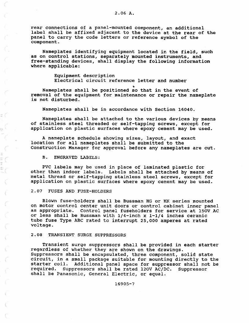
2. 06 A.
rear connections of a panel-mounted component, an additionalIabel shall be affixed adjacent to the device at the rear of thepanel to carry the code l-etters or reference symbol of thecomponent.
Nameplates identifying equiprnent located in the field, suchas on control stations, separately mounted instruments, andfree-standing devices, shall display the following informationwhere applicable:
Equipnent descriptionElectrical circuit reference letter and number
Nameplates shalÌ be positioned so that in the event ofremoval of the equipnent for maintenance or repair the nameplateis not disturbed.
Nameplates shall be in accordance with Section 16040.
Nameplates shall be attached to the various devices by meansof stainless steel threaded or self-tapping screws, except forapplication on plastic surfaces where epoxy cement rnay be used.
A nameplate scheduLe showing sizes, Iayout, and exactlocation for all nameplates shall be subnitted to theConstruction Manager for approval before any nameplates are cut.
B. ENGRÀVED LABELS:
PVC labels rnay be used in place of laminated plastic forother than indoor labe1s. Labe1s shall be attached by means ofmetal thread or self-tapping stainless steel screhrs, except forapplication on plastic surfaces where epoxy cement may be used.
2.O7 FUSES AND FUSE-HOLDERS
Blown fuse-holders shall be Bussman HG or HK series mountedon motor control center unit doors or control cabinet inner panelas appropriate. Control panel fuseholders for service at 15OV ÀCor less shall be Bussman with 1/4-inch x L-Ll4 inches ceramictube fuse Type ABC rated to interrupt 25,000 amperes at ratedvoltage.
2.08 TRANSIENT SURGE SUPPRESSORS
Transient surge suppressors shall be provided in each starterregardJ.ess of whether they are shown on the drawings.Suppressors shall be encapsulated, three component, solid statecircuit, in a small package suitable for mounting directly to thestarter coi1. Àdditional panel space for suppressor shall not bereguired. Suppressors shall be rated I2OV ÀC/DC. Suppressorshall be Panasonic, General Electric, or equal.
]-6905-7

)
Part 3
PART 3--EXECUTION
3.01 GENERAL
Control devices shall be provided where shown or reguired.
3.O2 CONTROL CIRCUIT FUSING
Fuseholders and fuses shall be provided as shown for theprotection of all control circuits and instruments. Blor¡nfuse-holders shall be provided where shown.
Spare fuses shall be provided in quantities of 10 percent butnot less than 10 of each type and current rating used.
**END OF SECTION**
I
')
.)
)
I
16905-8

sEcTroN 16910
LOCÀL CONTROL PÀNELS
PÀRT I--GENERÀL
1.01 DESCRIPTION
A. SCOPE:
This section specifies local control panels used for housingelectrical control equipment.
B. EQUTPUENT LIST:
The following local control panels (LCP) are specified underthis section:
Item Ecruinment No.
PRIMÀRY SCT'!,Í P['II!P P1320 LCP PNL1321
PRII{ÀRY GÀLLERY SUMP PI'},IP LCP PNL133O
TANK DRATN PT'MPING STATION LCP PNL1343
THTCKENED SLUDGE PT'MP P].62O LCP PNL1621
THICKENED SCUU PT'UP P1630 LCP PNL1631
AERÀTION BLOWER 82110 LCP PNL2114
ÀERÀTION BLOWER B212O LCP PNL2124
ÀERÀTION BLOI{ER 82130 LCP PNL2134
INSTRITMENT ÀTR COMPRESSOR LCP PNL2173
SECONDARY CONTROL BLDG. ST'UP PT'MP LCP PNL218O
PNL3411SNÀIL Pt'l,fP P3410 LCP
DIGESTER 1 GÀS CTRC. COMP. CP4O1O LCP PNL4O1O
DIGESTER 2 GÀS CIRC. COMP. CP4O2O LCP PNL4O2O
BELT FILTER PRESS FEED PT'MP P54O2LCP PNL5412
DEI{ÀTERING BUILDING ST]MP PT'MP LCP PNL55O5
t_6910-1

1.01 B.
The following local control panels (LcP) are specified underother sections, in compliance with the requirements of thissection:
Item
BÀR SCREEN SCNl1O1
Eouipment No.
PNLl1O3
PNL4O15
PNL4O57
PNLs104
PNL5211
PNLs212
PNL5213
PNL541O
Soec.
1112 1
11550
15565
tL622
LL77I
LL77T
1a77L
11117
DIG. GÀS CIRC. ROTÀRY DIST. VALVE LCP
WASTE SLUDGE G^âS BT'RNER LCP
BELT FILTER PRESS BFP51O1 LCP
DRY POLYMER PREPÀRÀTION SYSTE¡{ LCP
LIQUID POLYMER FEEDER CFR52O2 LCP
LIQUID POLYMER FEEDER CFR52O3 LCP
SOLTDS GRINDER GDR54O1 LCP
C. OPERÀTTNG REQUIREMENTS:
1. GENERÀL: Local control panels shall be constructedas necessary to perforn all- of the functions specified in Section17010, Control strategies and/or shown on the Control Diagrams,and/or P&f Diagrams. Àny conflicts between the aforementioneddocuments shall be brought Èo the attention of the Constructionllanager.
2. LocIc: Logic for all local control panels shall bedesigned for trfail-safex operation. Prirnary sensing devicesshall be supervised, with alarms and safety related interlocksinitiated by the opening of any associated contact or circuit.Relay coils shall be de-energized upon the occurrence of an alarmor abnormal condition.
L.Oz QUÀLITY À,SST'RÀNCE
À. REFERENCES:
This section contains references to the following documents.They are a part of this section as specified and rnodified. Incase of conflict between the requirements of this section andthose of the listed documents, the requirernents of this sectionshalL prevail.
Reference TitleElectrical Standards for General PurposeMachine Tools
JÏC EGP-L-67
L69LO-2

Reference
NEIr{À 250-79
NFPÀ 70-87
1. 02 A.
TitleEncÌosures for ElectricaJ. Equipment (1oooVolts Maximum)
National Electrical Code (NEC)
B. ÀSSEI,IBLY:
The local control panels shall conform to the requirements ofJIC, EGP-1-67.
C. FÀCÎORY TESTING:
Prior to shipnent, the manufacturer shall test the functionaloperation of the local control panel.
1.03 SUBMITÎÀLS
The foltowing subnittals shall be provided in accordance withSection O13OO:
Arrangement drawings of the local control panel enclosureindicating the front door and rear panel equipmentarrangement and dimensions. A list of materials andcomponents shall accompany the layout drawings.
2. Elementary and internal connection diagrams.
PART 2--PRODUCTS
2.01 GENERÀL
Local control panels shall comprise enclosures, wiring,process and electrical control devices.
2.O2 ENCLOSURES
À. GENERÀL:
Enclosures shall comply with the reguirements of NEIIA 25O.
B. MÀNUFÀCÎTJRER:
The enclosures shall be made by Hoffnann Engineering Cornpany,Bulletin A; E. M. t{iegrman and Co., Inc.; or equal.
C. CLÀSSTFICÀÎION:
Unless otherwise specified, enclosures installed indoorsshall be NEMA 12. Enclosures installed outdoors or in corrosive
1
I
16910-3

2.O2 C.
areas shalÌ be NElt[À 4X, nonrneta]Iic. Enclosures installed inhazardous areas shall meet the NEC reguirenent for that area.
D. SIZE:
Un1ess otherwise specified, the ninimu¡n enclosure area,height by width, shall be twice the sun of the area of theindividual components mounted on the back panel. The encÌosuredepth shall depend on the type of conponents used but shall be noless than 6 inches.
E. COLOR:
The enclosure shall be the manufacturerts standard color.
F. }IOIINTTNG:
Unless othern¡ise specified, the enclosures shall haveprovisions for wall mounting.
Internal wiring shall be color coded as follows:
Tvpe CoIor
Power (Ac) BlackNeutral WhiteControl RedForeign voltage Yellow (inboard of terminal blocks only)DC BlueGround Green
B. WIRE I{,ARKERS:
l{ire narkers shall conp}y with paragraph 16000-2.O2.
C. WIRTNG METHODS:
Plastic wireway with covers shall be used to route groups ofwires. Plastic spiral wrap shall be used for exposed wires.
I{ires that cross door hinges shall be enclosed in plasticspiral ¡rrap.
\,
,-,1
:l
)
, r)
r .l
-l
il
')
1l
jl
_1
il
)
)
16910-4

I
\
i
I
2.04
2.O4 CONTROL DEVICES
Control devices sha1l cornply with Section 16905.
2.05 TNDICÀTING LIGHTS
Indicating lights shall be equipped with colored lenses inaccordance with paragraph 16905-2.03.
2.06 TERMINÀL BLOCKS
Terminal blocks shall be provided in accordance with Section16905-2.05 and shall be channel mounted. The terminal blockassembly shall be nounted on channel standoffs. There shall be15 percent,, but no less than 8, spare terminals available forfuture use.
2 . 07 I,ÀBELING ÀND NÀI{EPI,ÀTES
À. I,ÀBELING:
Local control panel components shall be labeled to match thedescription on the elementary diagrarn. Internal cornponents ofthe local control panel on the back side of the door shall belabeled with the same description as provided on the front side.
Labeling sha1l be permanently marked on or near eachcornponent. Plastic embossed labels such as trDymotr tape will notbe accepted.
B. NÀMEPLATES:
External door-mounted components and the local control paneldescription shall be identified with plastic narneplates providedin accordance with Section 16040.
2.08 GROI'NDÏNG
Neutrals of locally derived control circuits shall begrounded to the mounting plate using a copper bus or groundingIug. À grounding lug for a size No. 2 ÀI{G bare copper conductorshall be provided to ground the panel to the plant's groundingsysten.
2.O9 PRODUCT DATÀ
The following inforrnation shall be provided in accordancewith Section 00710:
1. À written description of the elementary diagrof operationrr (Reference JIC, EGP 1, Àppendixexample) .
am rrseguenceB, for an
16910-5

2.O9
Operations and maintenance information ltems 1 through 9as specified in Section 01730.
PART 3--EXECTITION
3. 01 GENER.A,L
Àlternating current control circuits shall be 120 volts orless and grounded. one terninal of each road device strall beconnected to the grounded conductor. Control contacts shall beinstalled in the ungrounded side of the circuit.
Signal and control wiring shall be separated and installedin separate wireways.
The panel shall be grounded to the plant grounding system asspecified.
Local control panel centers shall be mounted at 48 inchesabove the floor.
À copy of the record elementary and wiring diagrams shall beplaced on the inner paner door. Drawings shart be enclosed in atransparent, protective jacket. À metal pocket measuring notless than 10 inches wide by 8 inches high by 314-ínch deep shallbe provided on the inside of the door for the placement of thedrawings.
3.O2 FIELD TESTING
Local control panels shall be tested in accordance withSection 16030.
*:IEND OF SECTION**
2
16910-6

SECTION L692O
ItÍOTOR CONTROL CENTERS
PÀRT I--GENERÀL
1.01 DESCRIPTION
This section specifies free-standing, factory-assembled600-volt notor control centers (UcCs), including starter units.
L.O2 REI,ÀTED WORK
Section 164 15--Ir{etering
1.03 QUÀLTTY ASSI'R,ANCE
À. REFERENCES:
This section references the following documents. they are apart of this section as specified and modified. In case ofconflict between the requirements of this section and those ofthe listed documents, the require¡nents of this section shallprevail.
Reference
NEUA rCS 2
NEI,IA ICS 3
NEt{À ST 20
vL 67
UL 845
TitIefndustrial ControÌ Devices, Controllersand Assenblies
Industrial Systems
Dry Type Transformers for GeneralÀpplication
Electric Panelboards
Motor Control Centers
B. IDENTIFTCATION OF LISTED PRODUCTS:
ltCCs shall cornply with NEI.{A ICS 2-322, ÀC General-Purposel{otor Control Centers, and UL 845. Main circuit disconnect shallbe UL labeled for service entrance duty.
16920-1

1. 04
1. 04 SUB¡.ÍITTÀLS
The following infornration shall be provided as a subnittal inaccordance with Section 01300:
1. Irfanufacturer's descriptive literature, includingspecifications applicable to all llCCs for the project.
2. Electrical wiring diagrans appropriate for the tlpe andclass of MCC defined by ICS2-322.O9 and as specifiedherein. I{iring diagrans include elementary, connection,and interconnection diagrams as applicable.
3. Front view arrangement drawings showing unit arrangenentand identification.
4 Manufacturer's documentation that the following itenrshave short-circuit ratings in rms synnretrical amperes tomatch or exceed the fault current available at theinconing tine terminals.
The bus structure.The motor control units.The feeder tap units.
The following inforuration shall be provided as product datain accordance with Section O13OO
1. operation and maintenance infor¡nation as specified inSection 01730
2. lr[anufacturerrs product literature. ,
lation
\::
abc
-\
)
l
.:-\
ì
nstal
imens
ID
T
.ÞffiPTABLE
2.gg L692O-2 Paragraph z.OL, ÀCCEPTmanufacturer, nl{estinghouse, Advarrtagreseries; r
and operating requiremen ts.-rea
1,6920-2
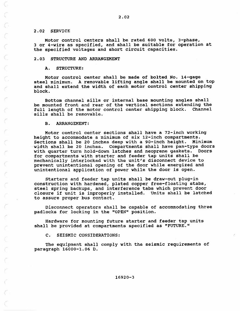
2.O2
2.02 SERVTCE
Irfotor control centers shall be rated 600 volts, 3-phase,3 or 4-wire as specified, and shall be suitable for operation atthe specified voltages and short circuit capacities.
2.O3 STRUCTURE A¡{D ÀRR,ÀNGEI,TENT
A. STRUCTTTRE:
Motor control center shall be nade of bolted No. 14-gagesteel mininum. A removable Iifting angle shall be mounted on topand shall extend the width of each motor control center shippingblock.
Bottorn channel sills or internal base mounting angles shallbe ¡nounted front and rear of the vertical sections extending thefull length of the motor control center shipping block. Channelsills shaLl be removable.
B. ÀRRÀNGE¡.{ENT:
llotor control center sections shall have a 72-inch workingheight to accommodate a minimum of six 12-inch compartrnents.Sect,ions shaLl be 20 inches deep with a 9o-inch height. Minirnunwidth shall be 20 inches. Compartments sha1l have pan-type doorswith quarter turn hold-down latches and neoprene gaskets. Doorsfor compartments with starter and feeder tap units shall bemechanically interlocked with the unit's disconnect device toprevent unintentional opening of the door while energized andunintentional application of power while the door is open.
Starters and feeder tap units shall be draw-out plug-inconstruction with hardened, plated copper free-floating stabs,steel spring backups, and interference tabs which prevent doorclosure if unit is irnproperly installed. Units shall be latchedto assure proper bus contact.
Disconnect operators shall be capable of accommodating threepadlocks for locking in the rroPEN[ position.
Hardware for mounting future starter and feeder tap unitsshalL be provided at compartments specified as ItFUTtRE.rr
C. SEISMIC CONSIDERÀTIONS:
The equipment sha1l conply vith the seismic requirements ofparagraph 16000-1.06 D.
L6920-3

2.04
2.O4 FINISH AND COI,OR
The MCC exterior and interior shall be painted by themanufacturer as specified in Section o99oo.
2.O5 BUS
Bus shall be tin-plated copper r¡ith connections betweenvertical and horizontal power bus bars made with 3/8-inch boltsand conical dished steel washers. Access for tightening theseconnections sha1l be from the front, without the need for toolson the rear of the connection.
A. HORIZONTÀL BUS:
Unless otherwise specified, main horizontal bus sha1l berated a minimult¡ 600 amperes continuous.
B. VERTICÀL BUS:
Unless otherwise specified, vertical bus shall be rated aminimum 300 anperes continuous.
C. NEUTRÀL BUS:
I{here specified, a full capacity neutral bus shall beprovided. Neutral bus shall be mounted in close proximity to andrated the same as main horizontaL bus
D. GROT'ND BUS:
À 3oo ampere ¡ninimum un-plated copper ground bus shall beprovided the full length of the motor control center. Ground busshall be located at the bottom of the motor control center andshall contain lugs to terninater âs a minimum, two (one at eachend of ground bus) No. 4/0 AI{G bare copper ground conductors-
2.06 WIRING
À. GENERÀL:
!¡lotor control centers shall be provided sith NEMA Class II,Type B wiring. À11 starter units shall have terminal blocks forcontrol wiring. Terninal bl.ocks shall be provided for ponerwiring for starters size 3 and smaller. llotor control centerssha1l be provided with aI1 necessary interconnecting wiring andinterlocking. Provide elementary and connection diagrarns foreach startei unit and an interconnection diagrarn for the entirenotor control center.
L6920-4

2. 06 À.
Terminal blocks shall be pull-apart type mounted at the rightrear side of the unit. Front bottom location or terninal blockswhich require removal of any wires before unit can be removedfrom MCC shall not be accePtable.
Full height vertical wireway, 20 square-inch minirnum, shallbe provided for each vertical motor control center section.Wiréway shall contain fuLl heigbt removable doors. Horizontalwireways sha1l be provided top and bottom, extending the lengthof motor control centers.
B. POTIER WIRE:
Power wire shall be copper 90 degrees C rrl{llfrr insulated,sized to suit load; minimum power wire size shall be No. 12 ÀI{Gcopper stranded.
C. CONTROL T{IRE:
Control wire shall be copper 90 degrees C, rr¡{TWrr insulated'No. 16 ÀWc stranded.
D. TERMINÀLS:
Terminals for use with stranded copper wire, sizes frornNo. 16 to No. 10 ÀV¡G, shall be flat spade, crinp type, made fromelectrolytic copper, tin-plated. Terminals used in conjunctionwith pull-apart terminal- blocks rnay be the box-Iug type.
Insulation for terrninals shall be rated equal to or greaterthan the insulation rating of the conductor being terminated.
E. CÀBLE CONNECTORS:
Cable connectors for use with stranded copper wire, sizesfrom No. I AWG to 1OOO MCIÍ, shall be UL listed. Dished conicalwashers shall be used for each bolted connection. ConnectorsshaIl be reusable and shall be rated for use with copperconductors. fncoming line and outgoing feeder conpartnents shallbe provided with crirnp type }ugs, 3M, Burndy or eguaÌ.
2.O7 UOTOR AND FEEDER BRÀNCH CIRCUIT PROTECTION
À. GENER.AL:
Motor and feeder branch circuit protection shall consist offused disconnect switches or ¡nolded case, magnetic only orthermal magnetic circuit breakersr âs specified.
L6920-5

2.O7 B.
B. FUSES:
Fuses shall be used in conjunction r¡ith visible blade fusibledisconnect switches or circuit-interrupters. Fuse clips shall beclass R rejection type. continuous arnþere ratings or Lne switchand the nunber of poles shall be as shówn on the drawings. Fusessharr be Bussman duar erement type RKI and rated for notor-running overload proÈection. fuse sizes shall be based on motornameplate in accordance with NFPA 20-430-6. Irtininun shortcircuit capacity uhen coordinated with the starter shall be22 rOOO amps synmetrical.
C. UOLDED CASE UAGNETIC ONLY CIRCUIT BRE.N(ERS:
Ìlolded case, magnetic only, circuit breakers shalr be used asbranch circuit protection for notors onry. Breakers sharl beadjustable, instantaneous trip, designed-specificalry for theprotection of motor branch ciicuits. - ttagnätic trip êetting forthe three circuit breaker poles shall be accomplisired by a singledial with locking pin. l¡axi¡nurn trip setting sirarl be 13oopercent of motor fuII load current. l¡liniururn short circuitcapacity when coordinated with the starter shall be 22,ooo ampsslnnmetrical.
D. MOLDED CÀSE THERMÀL-IIÍAGNETIC CIRCUIT BREÀKERS:
Main and branch feeder protection shall be provided by moldedcase type, thermal uragnetic circuit breakers. Breakers shall beequipped with.toggre type handre, quick-¡nake, quick-break overcenter switching nechanisn that is-trip-free-sð ttrat breakercannot be held closed against short ciicuits and abnormarcurrents. All pores sharl open, crose, and trip simultaneousry.Minimun short circuit capacily shall tä zz, ooo ãrnps slznmetric"i.
E. CONTROL FUSES:
Each control transformer shal1 be provided r¡ith a tine-delay,slow-blow secondary fuse rated to intelrupt 10,ooo amperes shor[circuit at 250 volÈs Àc. secondary fuses shalr be sized at nogreater than 125 percent of the coñtrol transformer rating.2.08 CONTROL TRÀNSFORMERS
Each co¡nbination motor control unit shall be provided with anindividual control transformer rated 4Bo-120v, siirgle-phase,2-wire, 60 Hz. The transformer shalr be sizea for the road itfeeds but shall not be less than the urinimum ratings as follows:
L6920-6

2. 08
NEII{Astarter size
llininun transformervolt-ampere ratinq
100150200300
Control circuit configuration shall be as shown.
2.O9 STÀRTERS
A. CONÎÀCTORS:
The basic full voltage, non-reversing starter shall consistof a 3-pole, 600-vo1t AC contactor. Contactors shall be NElt[Asize 1 mininurn. Contacts shall be double break, silver-cadmiurnoxide, and weld resistant. Contacts shall be isolated to preventarcing.
Reversing, multispeed, and reduced voltage starters shallhave additional contactors, overload relays, and auxiliary relaysas required, and shall have rnechanically interlocked coils toprevent simultaneous engagement.
B. OVERLOÀD RELÀYS:
Overload relays shall be provided in each pole of thecontactor and shall be directly heated eutectic alloy, ratchetprinciple, manual reset type providing CJ.ass 2o operation inaccordance with NEMÀ ICS 2-222.
Heaters will be sized in accordance with manufacturertsselection tables for an ambient ternperature of 4O degrees C andthe motor nameplate data.
C. TRÀNSIENT ST'RGE SUPPRESSOR:
Transient surge suppressor shall be provided in each starterregardless of whether they are shown on the drawings or not.Suppressor shall be encapsulated, three cornponent, solid statecircuit, in a small package suitable for nounting directly to thestarter coil. Additional panel space for suppressor shal1 not berequired. Suppressor shall be rated 120V AC/DC.
1234
L6920-7

2.09 D.
D. AUXILTÀRY CONTACTS:
Starters shall be equipped with auxiliary contacts, rated1o amperes at 120 volts ÀC. As a minimun, each starter shall beequipped wj.th two normally open and two normally closed auxiliarycontacts. Auxiliary contacts shall be wired out to terminalblocks. Refer to electrical drawings for actual guantitiesrequired.
2.10 DRY TYPE TR.AI{SFORMERS
Distribution transforner with prinary disconnect, shall befurnished within the llCC where indicated on the drawings.Ratings and sizes are as shown on the drawings. Unless otherwisenoted, transformers shall be dry type with 22O d.egrees c ttl,component insulation system and have a maximun tenperature riseof 115 degrees C in a 40 degrees C ambient. Pri¡nary andsecondary disconnect sha1l be molded case thernral magneticcircuit breakers.
2.LL PÀNELBOÀRDS
ûfhere specified, panelboards nounted in motor control centersshall be flush mounted and shall have the quantity and size ofbranch circuit breakers specified. The panelboard shall meet therequirements of Section 16440.
2. 12 ÀUXrLIÀRY SECTION (S)
Un-bussed (no vertical bus--check drawings for horizontal busrequirernent) vertical sections shall be provided as required bythe drawings to house auxiLiary control devices. Constructionshall be sirnilar to the rest of the l{CC, except panel doors shallbe fuII height with vault-type handle. A nounting pan sha1l beprovided the full length of the section to facilitate componentmounting. Àuxiliarlr control pohrer shall be provided to the panelby a separate po$rer source as shown. Control devices shall notbe mounted higher than 70 inches from the base plate.
2.L3 CONTROL SVüITCHES ÀND INDICATING LIGHTS (FOR nNrT MOI'NTTNG)
Refer to Section 16905.
2.T4 NAI{EPI.ATES
À. LABELS:
The assigned MCC equipnent number shal1 be located on thecenter front of the inconing line unit compartment. Example:nUCc-2Art. The MCC section number shall be located on the centerfront of each section top wirel^tay. Letter height shall be 1.5inches. Letter color shall be orange. Provide labels in
1692 0-8

2.L4 A.
accordance hrith Section 16040. Spray-painted letters areaLlowable in lieu of labels if done neatly with machine-cutstencils.
B. NAT{EPI,ATES:
one nameplate shall be provided for each unit door.naneplates sirall be noninally l-inch by 3-5l8 inches.naneþlates in accordance with Section 16040.
UnitProvide
2.L5 SPÀRE PARTS
One set consisting of the following spare parts shall beprovided:
I--set each fuse size and tlPelO--indicating light' bulbs
PÀRT 3--EXECUTTON
3.01 GENERAL
The MCCs shall be erected in accordance with thereco¡nmendations of the ¡nanufacturer and with the detailsspecified herein. MCCs shall be securely bolted to theslructural floor or wall in a manner sufficient to withstand theseismic forces defined in 16001-1.06 D.
Field wiring shall meet the requirements of paragraphL6t2O-3.02. CaÉles laiger than No.- 6 AÍ{G which hang frorn theirvertical connections shall be supported within 2 feet of theconnection.
The overload relay heater elements shall be provided by theContractor and sized based on the actual full load amperes of themotor connected to the starter.
3.O2 FIELD INSPECÎION AND TESTING
on-site inspection, testing, and certification of thecompleted installations shal1 be provided by a qualified fieldserïic" engineer. À ¡ninimum of two days of on-site field servicesha1l be piovided. MCCs sha1l be tested in accordance with Form1603 0-D.
3.03 TRÀINTNG
A minirnum of I hours on site shall be provided for trainingthe Ownerrs personnel in the proper operation of the equipment.Training shall be certified on Form 11010-8 specified inSection 16030.
L6920-9

3. 04
3.O4 UOTOR CONTROL CENTER SCHEDI'LES
Schedules describing MCC reguirements are included in Section16993.
**END OF SECTION**
(, i
t..r
,
rì,
(l
r-)
/ì
f-\
')
,\
16920-10
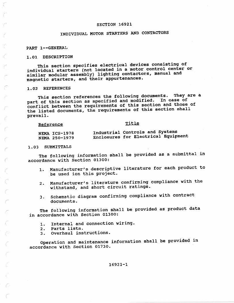
I
INDIVIDUÀL TTIOTOR STARTERS ÀI{D CONTÀCTORS
This section specifies electrical devices consisting ofindividuat stailer's (not tocated in a motor control center orsimilar noaurar-"=r"ti¡fy) lighting contactors, manual andmagnetic starters, and their appurtenances'
PART I--GENERÀL
1.01 DESCRIPTION
L.02 REFERENCES
Reference
NEt{À ICS-1978NEl,tÀ 250-L979
This section references the foLlowing-documents- They are apart-õ--tñis section as specified and modified. In case ofconflict Uetwáãn-tñã i"q"irements of this section and those ofthe listed documents, ttie reguirements of this section shalLprevaiL.
TitIe
Industrial Controls and SYstensEnclosures for Electrical Eguipment
(
i
1. 03 ST'BI{ITTÀLS
The following information shall be provided as a submittal inaccordance with Section 01300:
1. Manufacturer's descriptive literature for each product tobe used ion this Project.
2. Dlanufacturer's literature confirnring compliance ¡¡ith thewithstand, and short circuit ratings'
3. Schenatic diagram confirning compliance nith contractdocuments.
The following information shall be provided as product datain accordance with Section 01300:
1. Internal and connection wiring'2. Parts lists.3. overhaul instructions.
Operation and maintenance infor¡nation shall be provided inaccordance with Section 01730.
L692L-L

Part 2
)
.ì
\,
PÀRT 2--PRODUCTS
2.OL UANUÀL STÀRTERS
À. ÀC FR,ACTIONÀ,L HORSEPO!ÙER I,TÀNUAL SÎ.àRTER:
Fractional horsepower manual starting switch shall consist ofa manuarry operated toggle switch eguippãa vitn a nelting arloytype thermal overload reray in each poiã. starting switérresshall be rated t horsepower naxiroum át singte phasé 120 or 24o vÀc.
options shall include ngon pirot light, flush mounting,,hand-off-auto, selector switch, and tr¡õ-speed operation. squareD Class 2510, Àllen Bradtey Bulletin 600 oi equai.B. ÀC INTEGRÀL HORSEPOT{ER MÀNUAL STÀRTER:
fntegral horsepower manual starting switch shall consist of atog-gle- or pusþbutton-operated two- or three-pore switch equippedwith_melting alloy type-therrnat overload retals in eãch pof"...overload relays shall be trip free. starter snall be Ínãperat,ivei! l"V thernai unit is renoväa. starting s¡¡itchãs strarr be rated10_hp, 3 phase, 3 po1e, 4BO V ÀC rnaxinurn] or 5 hp, l phase, 2pglg, L2ol24o v Àc maximurn. options strait incruãå neõn piiotlight,.pushbutton or toggte switch operator, and two-speèd orreversing operation. square D class zsto, Àllen BradreyBulletin 609, or egual.
2.02 I.{ANUAL STARTTNG ST{ITCHES
I{here motor is provided integrrar NEC-recognized overroadprotection, manual-shorting switch may be useá in place of manualstarter described in paragraph 16155-2.ot. Manual startingswitch shall be squarã o crass 2s10 or Alren Bradrey eurle{.in609, or equal.
2.O3 ÀC I{ÀGNETIC COI{BINÀTION STÀRTERS
À. GENERÀL:
combination motor starter shalr consist of disconnectingmeans, branch circuit protection, contactor, overroad proteótion,and control devices. unless othern¡ise specified, motor startershall be factory instalred in a NEltÀ ratäa encrosure withdisconnecting means interlocked r¡ith the door. Conbination notorstarter shall be UL listed as a unit and shall be rnanufactured inaccordance with the latest pubtished NEt{À standards, sizes, andhorsepower ratings. co¡nbinàtion motor starter shali have anintegrar withstand and interrupting rating egual to, or greaterthan, the -system fault level in nUs sl.mneiriðal amps shown in thecontract documents.
t692L-2
-\
I

2. 03 À.
Combination starters are 3 phase devices but may be nodifiedto serve 1 and 2 phase loads by using 2 pole branch circuitprotection and wiring 2 poles of the overload relay in series inaccordance with manufacturers recommendations. Acceptablealternative is to provide separate branch circuit protection andmotor starter which together meet the requirements of thisspecification.
B. DISCONNECTING }IE,AI.IS:
Disconnecting means shall be provided to isolate the power tothe motor and to isolate the control circuit transformer suppliedwith the controller. Disconnecting means shall have a ratingsufficient to safely interrupt the maximum overload current of amotor of the same horsepower rating as the conbination motorstarter at rated voltage. Disconnecting means shall be eitherdisconnect switch or circuit breaker. Disconnecting means shallbe operated frorn the exterior of the unit by an integralmechanisn via a door cutout. Disconnecting means shall isolateaII current-carrying poles and, if the contract documentsrequire, the neutral pole.
Handles of disconnects shall be identified to indicateelectrical position. Starters and switches shall have provisionfor padlocking. Disconnect operator on aII but snall startingswitches and starters shall accept three 3/8-inch shacklepadlocks to lock the disconnect in the open position.
C. BRJANCH CIRCUIT PROTECTION:
Branch circuit protection shall be provided in accordancewith NEC Article 430 and shall be either nolded case circuitbreaker of fuses. Refer to contract documents for selectedmethods and number of poles requiring protection.
llolded case circuit breaker shall be instantaneous trip motorcircuit protector (MCP) type. Continuous ampere rating shall beas shown on contract docu¡nents. Each pole shall be equipped withan instantaneous trip unit, adjustable from 7OO percent to 11300percent of motor full load amperes. Unit shal1 be shipped withadjustrnent in the lowest position. Minimu¡n syrnnetrical RllScurrent interrupting and withstand rating of lÍCP, when tested asa unit, shaLl be as shown on the contract docunents and in nocase shall be less than 22,OOO amps RMS syrnnetrical. FaultIevels in excess of 22,AOO amps RtrÍS syrunetrical shall require acurrent liniting module (CLùf) to limit let-through current tobelow the available fault level and to within the rating of theunit.
1692]--3

2.O3 C.
Fuses shall be dual element UL Tlpe RK1 with Class Rrejection fuse crips and used in conjunction with fusibredisconnect switch or circuit interrupters. Fuses shall be ratedfor motor-running overload backup protection and fuse size shallbe based on motor nameprate fulr road amps in accordance withÀrticle 430-6 of the NEC.
D. CONTÀCTORS:
Combination starters shall have as a nininum a 3 polecontactor for singre speed non-reversing motors. uulLi-speed,reversing, and reduced voltage contactors shall be proviaea sitnpoles for every current-carrying conductor plus trañsition poleswhere required. Contactors shall be nechanically interlocXea toprevent simurtaneous operation of conflicting fuñctions.contactors shall be rated in accordance with NElr[A rcs 2-231except that minimum size perrnitted on 480 volt systerns shall besize 1 and systems with voltage less than 480 VAC minimurn sizeshall. be size O.
E. OVERLO.â,D PROTECTTON:
Overload protection of the urotor shall be provided by amanuar-reset, bimetartic, ambient-conpensating overload ielay.one pole shall be provided for each current-carrying conductor.Àdditional relays shall be provided for nulti-spèed-applicati.ons.Heater erenents sharl be interchangeable and shall be sized bythe contractor and be based on notor nameplate full load amps- inaccordance with Article 430-6 of the NEC.
overload contact sharr be connected in the grounded reg ofthe control circuit.F. CONTROL CIRCUTT:
Control circuit shall be as shown on the contract documents.control voltage shalr be either L2o vAC or 24 vAc as selected bythe contract documents. Ì{here 120 VÀc or 24 VÀC is not availableat the combination motor starter ter¡ninals, a control transformershall be provided r¡ithin the same encrosure as the ite¡nsdescribed in B through F above. contror transformer shalr besingle phase, 2 wire, 6O hertz and shall be, as a minirnum, over-sized with extra capacity above the manufacturer's recommended¡ninimun vort-ampere rating in accordance with the valuestabulated below unless shown otherwise:
NEIIIÀ starter size Extra transformer volt-ampere ratincr
0 (not perrnitted on 480 VÀC)123
+50+50+50+50
1692l.-4

2.O3 F.
Control transformer with 120 VAC secondaries shall have onesecondary leg fused and the other leg shall be grounded. Fuseshall be sized to protect the transformer against sustainedoverloads and short circuiting. I{here Ehown on the contractdocunents, the fuse shall be housed in a holder mounted on theunit door and provided with a neon indicating light to detect ablown fuse condition. Fuseholder sha1l be Bussman HGB-C, fuseshall be Bussman ABC ceramic or equal.
Pushbuttons, selector switches, indicating lights, elapsedtime meters, reset buttons, meters, etc., shall be flush-mountedin the enclosure door. Control devices shall be as specifÍed inSection 16900 and shall match the enclosure rating specified inparagraph 16155-1.03. NEIt{À 12 enclosures sha}I have heavy dutyóiftight devices as a minimun. Indicating lights shall be push-to-test type.
Auxiliary contacts from each contactor coil (including nulti-speed and reversing) shall be provided as shown but one N.O. andone N.C. contact (ilolated) strátt be provided as a urinimum inaddition to the seal-in contact.
2.04 CONTÀCTORS
Lighting contactors shall be 1OO percent rated for ballastand tungsten lighting, resistance and motor loads.
Contractor shall be rated 6OOV, 6O hz with the ampere ratingand number of poles as shown. À mini¡num of 2 poles shall beprovided.
Contactor shall be designed in accordance with NEMA fCS-2118for industrial-duty applications.
The following options shall be available and shall beprovided when shown:
1. Auxiliary contacts rated 5 arnps at 60OV AC.Timer or time clock attachment.
2. Transient suppression module for 120V AC controlcircuits.
Contactors sha1l beas specified or shown.
Contactors shall bedisconnecting means andsame enclosure.
Contactors shall beSquare D Class 8903, or
either electrically or mechanically held
available in co¡nbination withover-current protection mounted in the
ÀIlen Bradley Bulletin 500L or 5O0LP,equal.
L692t-5

2.O5
2.O5 ENCLOSURES
Unless otherwise specified, enclosures for equipraentspecified in this section shall be suitable for the environnentin which they are to be installed in accordance with Table À.
Table A, Industrial Enclosures, Ng.ÍA 25O
1. NElt{A 4X
2. NEUÀ 7/9
3. NE[,tÀ 12
a)b)
c)
a)
a)
outdoor, non-hazardous areas.Indoor, non-hazardous process areas orareas where washdown water is used.Indoor, iron-hazardous, corrosive areas.
Hazardous areas.
Indoor, where NEl.lA 4X or 7\9 does notapply.
2.06 NÀ¡{EPI,ATES
Local electrical devices shal.l be provided with laminatedphenolic naneplates. Naneplates sha1l be black, with ¡rininum3/16-inch white letters. Nominal size sha1l be 314 inch high by2 inches long. If abbreviations are required because of spaceIinitations, abbreviations shall be subnitted to the Constructionllanager prior to nanufacture.
2.O7 CONTROL DEVICES, INDICATING LIGHTS, ETC.
Control devices, indicating lights, etc.,Section 16905 of the specifications.
shall comply with
PÀRT 3--EXECUTION
3.01 FIELD TESTING
't{iscellaneous electrical devices sha1l be tested as specifiedin Section 16001 and deficiencies recorded and provided to theConstruction Manager.
**END OF SECTION**
]-692L-6

SECTION 16991
RÀCEWÀY SCHEDULE
PÀRT I--GENERÀL
1.01 DESCRIPTTON
A. SCOPE:
This section specifies the racehray schedule for conduits,wireways, and cable trays specified in Section 16110.
B. DEFINITTONS:
The raceway schedule contains the following infor¡ration:
1 Raceway number: A unique number assigned to asingle raceway.
2. Fro¡n and To:
3. Type:
4.
5. Voltage:
6. Contains:
Size:
The equipment designations at r¡hichthe raceway ends are terminated.
Type of raceway defined by theRÀCESPEC sheets and specified inSection 16110.
Nominal trade size of raceway.
Voltage level of cables included inthe racerray.
List of cables routed through thereferenced raceway.
A plan drawing on which the racewayis shown. À single racelray maypass through area shown on otherdrawings than the one referenced.
7. Reference dwg:
1. 02 R.ACEWÀY NT'MBERS
Raceway numbers are assigned in the raceway schedule inaccordance with the following system:
16991-1

L.02
Racewav Prefix Tvpe of Function
Control and/or 120V or less powerPor¡er above 600VPneurnatic tubingPower 208V to 600VLow level signal (Iess than
90 volt communication or lessthan 3O volt instrunentation)
Spare
Prefixes are followed by a 3- or 4-digit nunber. tlhere thereis nore than one raceway associated with a particular piece ofequipment., a letter suffix is added to distinguish the raceways.
l\cHNPs
x
Example:
Raceway nu¡nber
where:
P3109
A
P3109À
= conduit contains pohrer= unique a-digit nunber= letter to distinguish racev¡ay from
other raceways associated with thesame equiprnent
PART 2--PRODUCIS
No products are included in this section.
PART 3--EXECUTION
The raceway schedule consists of the following:
L699L-2

ELECÎRICAL RACEYAY SCIIEDULE 9t9t91Port Angetes l¡tllP
laceHayurùer Fidr To
Si ze,iræhes TYæ
tâyor¡tdr¡rim
ICabtce conteincd Iotes
c 00r l,lCC-ZB-38 Photo Control g.f5 Rt¡ E205 cool
t 00t Iray PCS2100 Each site tighting Pote t.00 Rt¡ É91-94 1001
ll 003^
city Light Tl city Light Tz 6.00 Ril EgZ By city lightH 005 B city tight Tl city Lisht T2 ó.00 Rt{ Ê92 L
H 003 c City LiEht Il City Light 12 ó.00 Rl¡ 892 By City Lightlt 005 D City Light Tl city Light T2 ó.00 Rfl 892 ts 100 A fray PCS2100 f8x- 1^ 2.00 Rl¡ E10Z sî00A s1008 s100c
H tot^
or.ltside S. prop. tine Pad transfomer T1 4.00 Rt¡ 892 HlOTA
il t0t B Outside S. prop. tine Pad transformer l1 4.00 Ril 892 il1018 pârc
P 101 A UtiLity Transfompr I1 lray PCS2100 4.00 Ril 892 PIOIA
P tol B Utitity Transfomþr Tl lray PCS2100 4.00 RN 892 PTOIB
P I0t c Utitity lransformer Tl Tray PCS2100 4.00 Rl¡ E9Z P101C
T 101 TBX - 21 TBX-1T1 1.50 Rt¡ E10Z y Tetco
x t0t A Utitity Transforlrler fl Tray Pcs2100 4.00 Rt¡ E81 Eltrpty Spsrcg
x 10I B Utitity Transforner fl Tray PGS2I00 4.00 Ril E81 Emty Spares
ll 1oa^
outside E. prop. tine E. vautt/j-box 4.00 RI E93 fi102A
lt 102 B outside E. prop. tine Ê. vautt/j-box ó.00 Ril E95 parc
lt 102 c E. vautt/j-box Pad trônsformer Tz 4-00 Rl¡ 892193 HIOZA
lt loz D E. vautt/i-box Pad trsnsfornìer Tz 4.00 NT 892t93 SÞarê
P 102 A Utitity fransfor¡nr l? Tray PCS2100 4-00 Ril E93 P102Â
P 102 B utitity lransfornnr f2 Tray PCS2'100 4.00 Rt¡ 895 PIO2B
P 102 c Utitity Transformer 12 Tray PCS2100 4.00 Ril E95 PtozcI 102 TBX- 1 T1 Phorìe (UT-toZ 0.75 Rll E102 By Tetco
x 102^
Utitity lransfomËr fZ ray PCS2100 4.00 nil E8î Erpty SpÛêg
x 102 B Utitity lransfoÌrÊr fZ lray PCSZl00 4.00 RT E8l mty Sparês
I r05^
Utitity Transfonner Tl Utitity lransformer 12 ó.00 RI e9z tlt 105 B Utitity lransfompr fl Utitity lransformer fZ ó.00 nI EgZ
lt r05 c Utitity Transfompr Tî Utitity lransforner 12 ó.00 Rlr 892 c
lt 103 D Utitity Trônsforner Tl Utitity lransformer Í2 ó.00 RI Ê92 By City lishts 105 scR-ll cT cqrpart. lleterbâse 1.25 RI EZ05 s103
l( 105 Tray PCS2|00 l{efl Primary Gattery 2.00 Rr¡ E8T Erpty sÞarcs for future Primsry Z
PS 104 Tray PCS2100 LSH- I 04 1.00 Ril 8101 Pt04 s10ó
x 104 Tray PCSZI00 Ìler Prinery cattery 2.00 RI EET Enl'ty Sparcs for future Primary 2
x 105 Tray PCS2100 Ner Prin6ry Gâtteîy 2.00 Rr¡ E8î Emty p¡rcg for future Prlnary Z
x lfb Iray PCs2100 ller Primary Gallery 2.00 Ril E8'.l Emty Sparcs for future Prinary Z
x 107 Tray PCS2100 ller Primâry Galtery 2.00 Rlt EET Emtv sprrês for future Prinrary 2
x 10E lray PCS2100 ller Primary Gatlery 2.00 RN EEl Emty Pr
x 1f¡9 Tray PCS?100 ller Primary Galtery 2.00 Rt¡ E81 Emty Pr
s tto Iray PCS2100 ttormeters F¡T-110, F¡T-112 1.00 Ril E101 s1 10 sl 12
x il0 Tray PCS2100 ller Primary G6ttery 2.00 Rlt 881 Emty Speres for future Primary z
ï tlt TBX- 2T TBX- 1 T2 1.50 Ril E10Z y lelcox 111 ray PCS2100 l{eH Primåry Gattery u.00 Rr¡ 881 Emtyx 112 Íray PCSZl00 tler Primary Gattery 2-00 Rlt E81 Emty Spares for future Primåry z
P 136 PBD-2A-27 CcD Panet AISH-136 1.00 Ri¡ E102 P13ó
tó991 - 3

Port Angetes LtllP
n
ELECTRICAL RACEVAY SCHEDULE
L699l.-4
16991 - 4
9t9t91
RACEWAY SCHEDULE. ADD Raceways nunbersT2O1A and T2018, from Telephone lerminalCabinet to property line at pl-ant entry,2.OOI size, tYPe RN, Dwgs. 881 andA/E?OL. Both are ernpt'y; cables in T2014by Telco; T2018 is spare.
råy2 .40
It4CC-24 mô nL
) ) t ) ) ..,.) '..) ) , ) ,) ,.) ) , ) ., ) .., J
s2144EZ04Rito-75Ftorfieter FI-214Flor etement FE-214A214sPZI 1C8203Rr¡4.00ilCC-ZB main tugs 1Tray PCSZ'I00F211P
P21 T8E203RI4.00I4CC-ZB main tuss 1Tray PCS2100E211P
PZl 1AE205Rt¡4.00ËCC-ZB main tugs 1Irôy Pcs2100D211P
PzllCÊ203Ril4.00Trây PCS2100sGR-lt-1I02c211P
PZl 1BE205RI4.00rây PCSZI00SGR-l'l- 1 IOZB2ilP
PZt 1AEZ05Rlt4.00Tray PCS2100scR-il- 1 102A211P
Branch cabtes822Rl¡2.00ïray PCSZ|00PBD-ZBIzo7P
Brârich câbtês822Ril2.00Trây PCSZIooPBD.28A207P
PZ0óEZZRilz.ooPBD.28Tray PCS2100B2(bP
P206Ê25RI2.00Tî6y?CS2100PBD.ZA2úP
Bl"anch csbles822Rl¡2.00Tray PCSZ100PBD-2AD205P
Branch câbtêsEZZRilz.ooTray PCS2I00PBD-2Ac205P
P205Ê22Rt¡2.00PBD.2AIrsy PCSZ100B205P
P205Ê25Rlt2.00Tray PCSZI00PBD.ZAz05P
sz04ezo4RI0.50Ft-zo4FE-2042UsPZO4EZO4Rilo.75Ft-204fray PCsZl002WP
Rl¡0.50Fl,or etenent FE-zOf,Fl,olrneter Fl-205m3sE203RI0.75FtoHrÞter FI-203rôy PCSZ100zotP
RIo.75tray PCSZl00PSL-Z0Z¿92sRll4.OOËCC-ZA nåin tuqs Zray PCS2100F202P
EZ0:Rit4.00ttCC-z nain tuss 2ray PCS2100E202P
Tray PCS2100D202P
ilcc-zB-41c202P
Tray PCSZ10fHCC-ZB-41Bzo2P
itcc-28-4t^
zozP
ray PCS2100F201P
PZOIBE203Rt¡4.00llCC-zA msin tugsTrsy PCs2100E20tP
PzOlAE205Rltó-00¡lCC-24 msin tussTray PCS2100D20tP
P201CEZ05Rl¡4.00Tray PCSZ100SGR-tl-1101czolP
P20t88203RI4.00Trey PCS2100scR-il- 1 101B201P
P20tAE205RI4.00Trcy PCS2100scR-H- r 101A201P
sló58Et41Rt¡0.75EteilÞnt DE-ló5Controtter DC-1ó5Btó5ss1ó54Ptó5E141RI1.00Controtter DC-165lray PCS2100tó5PS
Þâres, as needed for existingEmtyE8tRlt2.00Existins Str¡dse Pum Stãtionïray PCS2100156xSoeres, ¡s needed for existingnptyEElRI2.00Existins Str¡dge PLÍp StationTray PCSZI00r55xSÞôrcB, rs nccded for existingEmty881Ril2.00ExistinE StrdEe Pum StationIray PCS2100t56xoarcs. 06 needed for existimEmtyE61Rt¡2.00Existing Str¡dse Ptm StationTray PCSZ100r55x
SÞares. es needed for existinEmtvE8lRr¡2.00Existing Strdge Purlp StationIray PCS2100152xSÞarcg, es need€d for êxistinEmtyE81Rlt2.00Existins SLt¡dse PLm StationTray PCSZ!00151x
sl51Csl51 Bsr5tAE141Ril2.00T8X- 1 Blrây Pcs2100A151sst50AEgZRt¡1.00fray PCs2100Grav. Ihickener Pt¡L-1505A150sst5ó8E10ZRl¡0.75Detector AE-15ó8CGD Panet AISII-15óBt3ósst5óAEt02Rl¡0.75Detector AE-f3ó^CGD Pônct A¡SH-1!ó
^t5ós
XotesI
G¡blcs cqrt¡lncdLsyor¡tdrtrimfYDe
st ze,irchcsloFra
RAcerayrr¡ùcr

Port Angetes tltlTP ELECTRICAI RACEUAY SCI{EDULE 9t9t91
Raceflaynuùer FrÇ To
s¡ze,iræhc¡ 1væ
Layor¡tdrarim
IC$lcs cdrtainêd lotcs
s zl4 B FtorfiEter Íl-214 Tray PCSZ100 0.75 nì¡ EZO4 s2t4Bs 214 c rransmittcr Pll-214 Tray PCS2!00 9.75 Ril 8204 s214cs 214 D SHitch PSt-214 Tray PCSZ|00 0.75 Rr¡ 8204 szt4Ds 220 Iray PCS2100 rv-220 o.75 Rt¡ 8204 s220P 221 ilcc-2^-5ó cAP-Z^I 1.25 Rt¡ 822 PZZlP 222 tlCC-24-37 cAP-2A2 1.00 Rt¡ EZz PZ22P zz5 l,lCC-28-17 c^P-z8z 1.25 RI 822 PZZSP ?31 sGR-ü- I 105 ATS-2 source 1 2.50 RI E25 PZ51P 232 sGR-il- t 108 ATS-2 source 2 2.50 Rlt 825 P232P 255 ATS-2 tosd TFR-Z primary 2.50 Rl{ 825 PZ55P 234 lFR-2 secondary PBD.Z 3.00 Rr¡ EZ5 P234
PS 240 FIT-240 Tray PCS2í00 o.75 Rt¡ 8204 P240 PZ4OBs 24lJ
^FE-240 F¡1-240 o-75 RX Ê204 sz40A
s 257 tÊ-257 Ftr -z5f o.75 RI E204 s257s 254 FE-258 F I T-258 0.75 Ril EZO4 s258s 300 t ïray PCSZI00 IBX-5A 2.00 Ri¡ Etl I s500A s300cs 500 B Tray PCS2100 T8X-3A 2.00 Rlt E3t I s3008P 501 ïrây PCSZ100 PBD-54, Disinfect. Btdg. R¡¡ 831 I P50tï 501 T8X-2r TBX-57 1.50 RI E5t 1 By Tetcox 301 Tray PCS2I00 RsS Pøpins Station 2.00 RI E81 Elttrty iprrcs for futurex ray PCSZIoO RSS Prrping Station 2.00 RI E81 E[þty Sparès for futureT 5tl TBX.5T Phone üJr-301 1.00 Rlt E301 y Tetcox 51t Tray PCSZ100 Di sinfecti on Bui tcling 2.00 Rt¡ EEI mtv Paî?B for futurcx tI2 T Dislnfection Euitding 2.00 Ril EEl Eípty parcS for futurax Îr€y PCS2100 Disinfection Buitdins 2.00 Rr¡ EET Eltlrty iporcs for futurc
PS v2 Iray PCS2100 ¡fi-342 1.00 Rlr E91 P342 s54Zs *¿ t I T-542 FE-342 o.75 RX E91 s54ZB
PS 55ó T
^tT-55ó1.00 RI E9t Pf,5ó s55ó
s t56 AtT-^E-55ó
o.75 Rr¡ E91 s35óBs 400 A Tray PCS2100 lBx-4A 2.00 nx €402 s400^ s400cs 600 B Trây PCSZI00 lBX-4A 2.00 nlr e402 s4008P PBO.z PBD-44, Digester Btds. 1.50 RX É402 P401s A TBX-4A J8-403 1.00 Ril 8402 s401 s402 s405s 401 B JB-405 Trrnsmitter LIT-401 0.50 RX E402 s401T 401 tBx TBX-47 1.50 Rr{ E401 By letcos 402
^JB- Vatvè LV-402 0.75 Rlt 8402 s402^ s45(D
s 40? JB-405 Transnitter tIT-402 0.50 Rlt E4gZ s40zs 403 J8-405 Transnìitter Ltf-401 0.50 RX 8402 s405
PS 4Ot+ Transmltter FIT-404 rBx-4A (PilL-2200) 0.75 Rt¡ 8402 s604c P4t 4As 4o,4 A Etement FE-404 Iransmitter FIT-404 o.75 Ril É.402 s4044s 4V B Transmitter FIT-404 vsD-4040 o.75 Rt¡ 8402 s4048P 412 PBo-4A CGD panet AISH-412 0.75 Rlt E40Z P412s 412 A cas detector AE-4124 G6s detector AE-4120 o.75 Rl¡ 8402 s4t2As 41z, B Gas detector AE-4128 CGD panel AISH-412 0.75 Ril 8402 s412c s4tzB
'tó991 - 5

Port Angetes ¡J¡|TP EIECTRICAL RACEITAY SCHEDUTE 9t9t91
s5518c55 IE50óR¡Io.75TBX - 5AFlometer FIT-551B551ss551DE504FI¡L0.75JB-551Transnitter LIT-551
^55ts
s55tAE50óRl¡o-75El.eíEnt FE-551Flo$neter FIT-551A55tsP551E50óRl¡0.75Fto$rÞter FII-551PBD.5A55rP
c551E50óFIIL0-75Vatve FV-551FLomteter tlT-551551cs545cs5458E505Rlt0.75tBx-5AFlorileter Fll-545I5¿5s
s545AE50óFIIL0-50Fto¡meter Fl-545Etement FE-545l545sP545E505Rt¡0.75Ftometer FIT-545PBD.5A545P
s5448E50ón¡to.75TBX-54Fl.ormeter Fl-544I,44ss5444E50óFT¡L0.50Fto|'neter FI-544Etenent FE-544l544sP544E50óRilo.75Ftoræter F¡-544PBD.5A544P
C5r.48504RT0.50BFP PI¡L-5104S¡itch PS[-544544cCSI,2B542PC
c5402^c54028s54ZP542E50óRil1.50FSt-542PXr-5412542PC
c5428E5lróRt¡o.75PSH-542tst -542B5&2cc5425E505Rr¡o.f,Pressure sHitch PsH-542FtoH sr.itch FSL-542B542c
s560cs5408s5404E504Rt¡1.00rBx-5AJB-540c560ss540cs5408E504FI¡L0.75JB-540Sritch LSH-540B540s
s540AE504FI¡Lo.75JB-540Trsnemitter tlI-540t560sP521824Rt¡1.00cAP-54t{cc-5A- 15521P
P512E505Rt¡1 -50PBt -54IFR.5A,12P
P5l 1E505RI1.25TFR-5Ailcc-545ttP
peres for futureEîlptyE61Rl¡2.00teriTrEy PCSZl00505xSp¡rcs for futurcnDtyE61RIe.00Dere n9Tray PCS2100502x
P502E505Ril5,00I{CC-5A main tws 2Trsy PCS2100SrrzP
Sperês for futureEnptyE8lRl¡2.00Studge oeHateririg Bui tdinglray PCS210050txBy TelcoE502nil1.50T8X-57lBX-21501rs50l^E505Rl¡2.00lrcc-54tBx-5AA50tsP5018505RI5.00l,lCC-5^ main tuss ITrsy PCS2100501P
s5008E505Rt¡2.00TBX-5ATray PCSZ!00B500ss500cs5004E505RI2.00T8X-5ATray PCSZI00A500s
s45frDE40ZRI0.50lransnitter PIT-450Vatve LV-402D450ss45(Ds4024s4508Et 02Rlt1.00TBX-44 (Pt¡L-2200JB-450c450s
s45088402Ril0.50J8-450lransmitter F¡T-450B4ross450^E40ZRT0.50Trônsmitter F¡l-450Etement FE-450
^450s
P4508402Rl,l0.75Tråßmitter F¡I-450PBD.4A450P
s459E4gZRT0.50JB-439S¡ritch ZSH-459^
439sc4059c4058s459s458É.402nlt1.00TBX-4A (PXL-2200)JB-438I438s
s456E40ZRil0.50JB-438Sritch ZSH-458t45Ess4558s4l5A8402Rl¡0.50Tr8nsmi tter Fll IFA'ß'ELement FE-435A43's
P455E402NT0.75Tr.nsmitter Fll IFA'435PBO.4A435P
s43588402Rlt1.00TBX-4A (PXt-2200'Trsnsmi tter FITIFO-435B435cs41æs412AE40ZRl¡0.75CGD pårìet
^lSll-412Gas detector AE-4120D41¿s
s4lZCE40ZRlt0.75Gas detector AE-4IZBGas dctèctor AE-4tZCc412sIotar
IC¡blcs cqrtaincd
Leyor¡td¡oliruIyDC
st ze,incherroFra
Rocdayn¡.úcr
16991 - 6
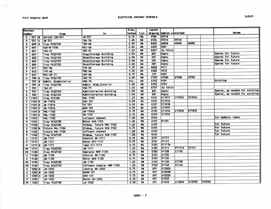
Port Angetes l¡uTP ELECTRICAL RACEI'AY SCHEDUTE 9t9t91
laceraayrüùer Fril To
Si ze,inche¡ Ty".
Layoutdr¡rirr
,lC$tcs cmteincd Iotcs
s 551 B Sritch LSH-551 JB-551 9.75 FXL 8504 s5518
s 551 c JB-551 rBx-54 1.00 RX E504 s55tD s551E
s ó00^
Tray PCS2100 T8X-óA 2.00 Ri¡ EæZ só004 só008 só{r0c
P ó01 scR-ü-110ó ilcc'óA 2.00 RX Eû2 Pó01
T ó01 TBX-27 TBX.óT 1.50 Ril Eó01 By Tetco
x óo1 lray PCS2100 rop/storage Buitding 2.00 Ri¡ E8l Erþtyx &2 Iray PCS2100 shoD/Storase 8ui tding 2.00 Ril EET mtvx ó{r5 Ìray PCS2100 shop/storage Bui tding 2.00 RI E81 imty Spa¡es for futurex 6h lray PCS2100 Shop/Storage Bui tding 2.00 Ril E81 :mty pares for futureP ót'l ücc-ó TFR.óA 1.25 NT 8602 PóT IP 612 TFR.óA PBo-óA 1.50 RI 8602 P612
P 621 l,lCC-64-'l I cAP-6A o.75 Rt¡ 825 P621
s 700 A lray PCS2100 rBx-7A 2.00 Rt¡ 8702 s7004 s7008 s700c
701 B Adnin. Bl,dsExtePior PBD-7A vfy. RS 8702 P70t Exi stinsP m1 A lray PCS2100 Adnin. Btds.Exterior 2.00 Ril Ê702 P701
T TIrt tBx-27 lBX-77 1 -50 Rl¡ 8701 y Ïetcox mI Tray PCS2100 Adninistråtion 8ui tding 2-00 Rt¡ E81 Emtv 6S
x m2 fray PCSZ100 Adnini strat i on Bui tding 2.00 RI E81 Ermty as st
c I 10t f¡ay Pc2100 PXL- 1 103 1.25 Ril 8101 ct 101 F ct 101G sl l0tAc I 101
^J8- I 101A zsH- 101 0.50 Ril El0t cl 101^
c Itot B J8- I 10lA YS- 101 0.50 Ri¡ E10t cl 1018
c t 101 c JB- 1 101A usH- 101 0-50 nt Et01 cI 10tcc I tol D Pl¡t- I t05 JB- 1 10fA 9.75 Rl¡ E101 cl t01A cl 1018 cl 101c
c I 10t E PIL-'.| 105 flK- 1 101 o.75 Rt¡ E101 ct t0tEt I rol Pr¡r- 1 105 lnf luent chamel 1.00 Rt¡ E10l
P I tol Tr6y PCs2l00 ilotor scl¡-1101 1.00 RI Et0t Pt 101
c I 102 Tray PCS2100 StrôLp, future PtlL'll0z 1.25 RI Et0t For futureG I t02
^Future PllL-I104 Str^ùLp. future Scil-l102 0.75 NT El01 For futurê
T 1102 tuture PIL-1104 lnftuent channet 1.00 RT E101 For futureP 1 toz Tray Pcs2100 strår/p, future scl-1,l02 1.00 RX Et01 tor futurac 1t1t JB-1111 Control HK-1111 0.75 Rt¡ E101 c1111
P Itlt JB-11il Iotor CPI-1111 0.õ Rt¡ Et01 P11t1
P ltrl A J8-1111 Tape tlIT- 1111 0.75 RI Et0t P11l1A
PC Itfi ray PcS2100 JB-11tt 1.25 Ril Et0t Piltt Pî1t1A cl 111
PC 1120 lray PCS2100 perator llOP-1120 1.50 Rl¡ E204 Plt20 cl 120
G I t50 J8- I 130 Control llK-1130 0.75 Ri¡ Et01 ct 1t0
P t 150 J8- 1 130 t{otor HsH-1130 0.75 Rt¡ E101 Pî 150
PC I t30 Tray PCSZI00 JS- 1 130 1.25 RI Et01 Pt 150 cl 150
PS I I40 Tray PCS2100 lnf tuent Sanpter sllP' 1140 1 -50 Ril F-102 Pt 140 sl 140
c 1202^
JB- t Z0Z Cont¡oL Hl(-1202 o.75 Rt{ E91 c1202A
c 1202 B JB- 1202 r¿sHH- 121 0.75 R¡I E9t cl2028G lZOZ c JB- 1202 gsH- 1 21 0.75 Rlt E9t st202A
P 1202 JB- t20Z llotor 0U-1202 o.75 Rt¡ E91 P1202
PC 1202 Tray PCsZloo JB-t202 2.00 Ril E9t P1202 c1202A ct20zB stz0z^
16991 - 7

Port Angetes tt¡lÎp ELECTRICAL RACETIAY SCHEDULE 9t9t91
c150zAE9tRt{o.75Cont HK.J8- 1502^
1502cc1393P1393E102R¡¡o.75Starter l,ls- l59lstarte¡ ils-1391r593PC
P1595AEt02Rt¡0.75ilotor F-1393Stsrter lls-1393159f,PP1392E102Rl¡r.00lleater Ull-15921592Pc1392E102Rt¡o.75TSL- 1392Hester ull-13921392cP1591^E10ZRil0.75liotor F-1391Stârter lls-1391A1591PP1391Ê,102Rltt.00starter ils-139f'ray PCSZI001591P
ct595c139tE102Rt¡0.75coñtrol Hs-1391Stôrter l{S-1391cct545CE102RI0.75LC-134A, 8, CPXL- 1541ct545c
c13438c1343AE101Rlr2.00PrL - 1343Tray PCSZl00A1JÉ'cP1342El0ZRt¡0.75iotor P-1342JB- 1341PPIJóTE102Rilo.75üotor P-1541JB- 134îlt541P
P1342P1341E102RI1.25JB- t54tTray PCS2100t54tPP1332El0ZRil0.75l{otor P- 1332JB- 1551PPl55t8102RI0.75l{otor P-1331J8- 1
^P
P1532P13318102RI1.25JB- 1551Tray PCs21001551Pc1550^E102Rl¡1.OOLC-1554,8,C, tSX-135Pt¡L - 1550
^r550c
cl552ctl3lc1530Er0znil2.00PXt- 1330Íray PCSZ'100t5J0cc15200c1520P13ZOEt02RI1 -50JB- 1320rôy PCS2100IPC
PISZOÊ102Rt¡o.75trlotor P-1320JB- 1520Pct320D8102RT0.75Vatve SV-1320JB- t320D1f.20cc1520CEl0ZRlto.7,FSt- 152PIL- 1521cr5z0cc15208Er0zRl¡0.75PSlt- tJzPl¡t- 1521I13ZOcc1520e102Rl¡0.75controI HK-1302, HS-1328PilL- tSZtI15ZOccl5zoE102Ril1.25Plrt- 1521JB- 13201320c
c15'.t0BctStoP1310E102RI1 .50JB- 1510lray PCS2100PCP1510Et02Ril0.75ilotor P-1310JB.t5t0Pc15t0BEt0zRlt0.75Vatve SV-13t0JB- 1510Bt5toccrJt0ÂE102Rilo.75controt Ht(-1310J8- t5t0t1510cP1505't505PC
c15050c1505Cct50lBc15054E10tRr¡2.00Js- l!0Iråy PCSZI001505PCP1505Et01RXo.75ilotor COL-1303JB- 1303IPc150JD8101Rl¡0.50YS- tl0JBD150fcct505cEt01RT0.50vsHH- 150JB- tt05c1505cc15058Et01RI0.50t slt-130JB- r505Bcc1305AEt0tRlto.t5Control llK-1505J8-A130Jc
c1502AP1502El0lRI1.25JB- 1302Tray PCS21001302PCP1302Et01Rt¡0.75I,lotor CoL- 1302JB.lrozPc1502AEt0tR¡I0.75Controt HK-1502, HS-151JB- t502r302c
ct2ótP12618892RltI.00JB- tZótstôrter lls- 12ó'l1¿61PCP1261EgZRT0.75Ëotor P-lZó1JB- 12ó11261PPrzó1^RI1.00l,ls- 12ó1Existing ilCC-2l1261Pc1261892Rt¡0.75Coñtrot )lK-1261Existing ilCC-21261cP1253892RI0.75lotor P-1255Existing PBD-D (in ilCC-Z)1253P
IotêgI
Cabtes containcdLayoutdrarimfvæ
st ze,iæhe¡ToFr6t
Rocerayn¡ùer
1ó991 - I

9t9t91Port Angetes tlgTP ETECIRTCAL RACET'AY SCIIEDULE
fra loSi ze,imhec Iy"e
Layq.¡tdrarilr C¡btes cqìtalncd Iotcs
c 1'ÍtZ B JB- 1502 o.75 R¡I E9t
c 1502 c J8- .l502 0.75 Rt¡ 891 c1502C
P 1502 JB- 1502 DU 0.75 RI E91 P1502
PC 1502 Tray PCS2100 2.00 Rl¡ 891 P1502 ct50zA c150zc
c 150ó JB- 1 504 Controt HS-1504 0.75 FIIL E9r c1504
P 15t¡4 1 oRl-JB
o.75 Filt E9t P1504
c 1610 JB-',|ó10 Coîtrot HK-1ó10 o.75 Ril E',|41 c1ó10
? 1ó10 JB- 1ó10 ltotoi p-teto 0-75 Rr¡ E14l P1ó10
PC 1ó10 Tray PCS2!00 J8- 1ó1 0 1.25 Ril E141 P1ó10 c1ó10
c 1620^
JB- 1620 Pr¡t- 1ó21 1.00 Rt¡ E14t cróz0A s16208
c 16?.0 B Pl¡t- 1ó21 o.75 Rt¡ 8141 ctó208
c 1620 c Pr¡L - 1ó21 FSL. 0.75 Ril E 141 c1ó20c
c 1ó20 0 JB- 1ó20 Vatve SV-1620 0.75 Rll E14t c162(þ
P lózo JB- 1ó20 iotor P-1620 0.75 Rt{ El41 P1ó20
PC 1&O Trry Pcs2'100 JB- tó20 2.00 Rlr 8'.|41 P1620 c1ó2(þ
c tóõ0 A JB- 1ó30 Pr¡t- 1ó31 1.00 RI Et4t c1ó30A s1ó508
c 1ó30 B Pr¡L- ló31 PSH - 1ó5 0.75 Rt¡ E141 c1ó308
c tó30 c Pr¡L- 1ó31 FSL-'.|ó3 o.75 nl E141 c1ó30c
c tó50 D JB- tó30 Vatve SV-ló30 o.7, Ril E141 ctó50t
P
PC
tóõo [otor P-1630 0.75 Rlt
Rl¡
E141 P1ó30c
P tó91^
Starter tls'1ó91 l{otor F- 1691 0.75 nI Et4t P1ó91A
PC 1601 stårter ¡,lS- 1ó93 starter lls-1ó91 o.75 nl E14t P1ó91
c t6\12 Thernostat TSL-1ó92 Heôter uil-1692 o.75 RI E14l cl69?,
P 16ç12 lray PCSZ|00 tlcater UH'1692 1.00 RI 8141 P16.12
c tó95 Controt HS'1ó95 JB- 1ó93 0.75 RI E14T c1ó95 c1ó91
P 1ó95 Iray PCS2100 JB- 1ó93 1.00 RI E141 P1ó93
P tó93^
stsrter LIS-1ó93 l,lotor F-1695 0.75 RI 8141 P1ó95
PC tó95 JB- 1ó95 Starter lls-1ó93 1.00 Rl¡ Et41 Ptó95 c1ó93
PCS
czlor¡ Duct banks 3ó.00 lray
RIE10t Varies
cãm^c 2110 B lray PCS2100 PSlr-211 0.75 RI 8204 czt 108
P 2110 Trsy PcS2100 liotor B-2110 3.00 Rlt EZO4 P21 10^ P21 t 0B
c 21m l Tray PCS2100 Plr_-2124 2.00 Rit 8204 c2l20A c21208 s2t20^
c zlzo B Tray PcS2100 PSH-212 0.75 RI 8204 czte08
P zlzo Iray PCS2100 ilotor 8-2120 5.00 Ril Êzo4 P2120A PztZ0B
c 2t30^
Trey Pcs2100 PflL-2134 2.00 Ril 8204 c21504 c21308 s2t50A
c 2t50 B Iray PcS2100 Pslr-213 0.75 RI 8204 c21308
P 2150 Tray PCS2100 l,lotor 8-2130 5.00 Ril EZO4 P2130A P21508
c 2150^
vsD-2150 Tray PCS2|00 1.25 RI 8204 c2t50A s2150A
c 2150 B lray PCS2100 Vatve SV-2150 0.50 Rlt 8204 c2l50B
P 2150 l lray PCS2100 vsD-2150 2.00 Rt¡ EZO4 Pz150A P21508
P 2150 B Tray PCS2100 notor P-2150 1.00 RI 8204 P21508
1ó991 - 9

Port Angeles lltllP ETECTRICAT RACEYAY SCIIEOUTE 9t9t91
fptyE¿O5Ril1.50Futu¡e motor P-2240Future VSD-2240B2240PEflrtyE205Rt¡?.50Future VSD-2240Tråy PCS2|00A2240P
PZ?3OBEZ05RI1.50llotor P-2230vsD-2250B2230P
cszz50^czz50P2230AEZO5Ril2.50vsfr-2230roy Pcs2100^
2230Ps22258205Rl¡1.25Pl¡t-2225Tray PCS21002225sPZ¿ZOAEZ05Rt¡1.50[otor P-2220vso-uzzoB2z,20P
cs2220Ac2220^P2220AE203Rlt2.50vsD-zzz0Tray PCS2100^
2220P
PZ210AE205Ril1.50llotor P-2210vsD-22I0B2210P
cszztoAczzl0AP¿ZlgAEZ05Ril2.50vs¡r-2210Tray PCSZt00A?21lJP
c2250^E205tltt0.75vatve SV-2250JB-2210D2210cczz20AE205F}IL0.75Våtve SV-2220JB-2210c2210cczzlnAEZO5FIIL0.75Vatve SV-2210JB-2210B¿210c
c2230^c2220^c2210AE205Rl¡1.50JB-ZZt0Tray PCS2100^
2210cAs requiredE205Rl¡4.00ray PCS2100Pl¡L-2200E2200csAs requiredEZ05RI4.00Tray PCS2100P[L-2200D2200csAs recr¡iredE203Rt{4.00Tray PCSZI00Pr¡L-2200caaofJcsAsE205RI4.00ray PCSZl00PitL-2200BzzlÛGS
AsE205Rt¡4.00rây PCSZIOOPrL-2200A2200cscz19zP219z'ezo4RI1.25Jg-2192Tray Pcs21002192PC
PZl92É,294Rl¡0.75llotor F-2192J8-21922192P
czl9zA8204Rl¡o.f5Control Hs-2192Tråy PCSZI00z19ZcP21918204Rlto.75lotor AilU-2191ïray PCSZI002191P
c2t9tA8204Rl¡o.75Controt HS-Zt9tIray PCS21002191cPZIA28204Rilg.T5flotor P-zl8zIray Pcs210021E2P
P2161EZO4Rx0.75ilotor P-2181Tray PCS21002t8tP
szlEoAcztðoB8204RI1.00LC-217A. B, C, tsfl-217Pl¡L-2180B2tE{tcszr60Ac2182c21E1EzOl.Rt{2.00PXL-2t80ray PCSZI00tzlE{'cszt7:tczl7?cc217282lTtcs
c?lfzlc2171Cczl718cz171A8204Rl¡2.50PilL-2173Tray PCS21002173csc217t8204RI1 -00PC-250A. B. CPt¡t-zt 152173c
P2172c?t72Cczl728E?OIIRil1.25JB-2172Tray PCSZ1002172pcP2172EZO4RX0.75tloto¡ CP-2172JB-217221T2P
c?172c8204RI0.50fsH-232JA-ä72c2l12cc21728E?OttRlt0.50PSL-Z5ZJ8-2172B2172c
P2171czl71CczlflaEZO6RI1.25J8-2171Iray PCS21002171PC
P21718204RI0.75i.lotor CP-2171J8-21f1z1f1P
cz17lC8204Rt{0.50TSil-231JB-U t71c2171cc217lsE?OttRt¡0.50PSt-Z5tJA-?171B2171cP21708204RIo.75lir Dryer DRY-2170Iray PCS2100xmP
PZtó088204Rr¡1.00tlotor P-21ó0Tray PCSZ100I216oP
PU ló08P2tó0^8204RX2.00vsD-21ó0Tray PCSZI00A2160P
c2tó088204Rt¡0.50Vrtvc Sv-21ó0Iråy PCS2100B21æcszró04c2tó{rAEZO4Rt{1.25'rey PCSZ100vsD-ztó0A2160cs2155P2155EZ05Ril1.00Eff Luent SoÍpter Sl,lP-2155Tray PCS21002155P
IotcgI
Crbtcc cqrtcincdLoyor¡tdrarimT}Dc
Si ze,iæhe¡1oFro
Raceraay
nröer
16991 - 10

Port Angetes tlttÎP 9t9t91
(ocetaay
ruùer Fra ïost ze.irrhe¡ Tyæ
Lryot¡tdralirr
ICabtes cot¡inêd Iotês
P 226'J Boi tcr Pl{[-22ó7 Boi ter Btorer 8-2?ó0 o.t5 FSL EZ05 P2260c 22üì JA-2z.62 Coñtrol |lK-2262 0.75 FI E203 c2262P 2262 JB-2262 Hotor P-22ó2 o.75 Fll EZ05 P2262.
PC 2262 Tray PCS2100 Js-2262 1.25 Ril E205 P2262 c2262c zz6f A Boi ter PIL-22ó7 rsL-zó0 0.75 Fltt EZOS czz6tA
PC 2267 lray PCSZ|00 Boi ter Ptl[-22ó7 1.00 RI 8205 P?267 s2267Ac 2274 JB-2274 Controt )lK-2274 o-75 FTIL E203 c2274P 2?74 JB-2274 Âotor P-2274 o.75 FTIL E205 PZ27h
PC 2274 frðy Pcs2100 J8-2274 1.25 RI E205 P2274 c2274P 22æ Boi ter PHL-ZZó7 Boiler Fue[ Pte P-2280 0.75 FXt EZ05 PZZõ0
P zzal PBD-ZA Softener tlilE-2281 0.75 Rt¡ 8203 P2241p 22At Tray PCS2100 lJåter Heater UH-2289 o-75 Rt¡ E20t P2289
PC 2æO t Iray PCS2100 HVAC Pr¡t-2290 2.00 Ril E203 PZzrm cz19l8 cz19z8 c¿z918PC zzs,{J l czzgta cza5a c2z97Bc zÐ1 A JB-2291 control llK-2291 0.75 Rr¡ E205 c2291AP 2?91 J8-2291 Hotor P-2291 0.75 FIIL E203 P2291
PC 2æt Tray PCS2100 JB-2291 1.25 Rt¡ EZ05 PZ?91 czæl4P 2Ð3 conrot llK-2295 lotor AHU-2295 o.t5 FIIL EZ05 PZZ95
PC zzsrt Tray PCSZIOo Conrol. ilK-2295 1-25 Rlt E205 P2293 c22934c ?'?9,5 J8-?295 Controt )lK-2?95 o.75 Rit EZ05 c2æ5AP 2?95 JB-2295 ilotor AHU-2295 0.75 FIIL E203 P2295
PC ?4,5 HCC-28 JB-2?9' 1.25 Ril E205 PZ¿95 c¿z95AP 2T)7 Controt nK-2297 ilotor F-U297 0.75 FTL EZ05 PZZ9f
PC z8f Tray PCSZl00 Corìrot ilK-2297 1.25 Rt¡ E205 P2A7 c2?97Ac 5to0 A JB-5100 Controt HK-1100 o.75 RI/Fr¡t E9l c5100^1c 5to0 I JB-5100 rrsr{-310 0-75 Rr/FXr 893 cl100A2 c5100El cll0082c 5to0 c ysil-310 vslrH-310 o.75 Ril/FIL E95 c5IOOAZ c5lo0Bzc 3t00 D vsilH-Jlo YS-5tO o.75 RX/Fl¡t E93 c5100BzP 5100 JB-5100 noto¡. DU-5100 0.75 RTI/FXL E95 P5100
PC 5100 ïrây PCSZ100 J8-3t00 1.50 RT E93 P5100 c5100A c3t00Bc 5tt0 J8-51 10 Cont¡ot HK-3110 0.75 Ril E50t c51r0P 31 10 JB.Jl IO ilotor, P-5110 1.00 Rr¡ E501 P3fi0
PC 5r t0 Trsy PCSZI00 JB-5î t0 1.50 Rt¡ E301 Pttl0 c5110 P5111c 3ilt HTR-51 I 1 Terç, sritch TC-31 I 0.50 RÎ{L E50t c5fitP 311t J8-31 10 HTR-3î 1 t 0.75 R}IL E50t P5111c 5tzo JB-5120 controt HK-5120 0.75 Ril E301 c3120P 5120 JB-5120 Hotor, P-5120 t.00 RT E501 P5120
PC 5120 Tray PCSZ100 JB-5120 1.50 Rt¡ E301 P3120 c5120 PStZtc 5121 Htn-1t21 lenp. sritch rC-312 o.50 RIIL E50t c5lZlP t121 JB-3120 HTR-51 Zl 0.75 RI{L 850'.| P5tU 1
x 5r50 Iray PCSZl00 Stubout, future P-31f0 1.50 nil E301 Eípty Leave buried and caÞc 5200 t JB-5200 controt HK-3200 o.75 RX/FXt E95 c5z00Alc 3200 I J8-3200 vslt-520 0.75 RX/FXL E95 c5200A2 c5u008t c5z00B2c 5Uü' c ¡JSH-t20 r,,sHil-320 0.75 Rlr/Fr¡L E95 c3200^2 c320082
ELECTRICÂI RACEI'AY SCIIEDUTE
1ó991 - il

Port Angetes lltllP ELECÎRICAL RACESAY SCHEDULE 9t9t91
c37938c3793AE31 IRN1.25Controt Hl(-3793JB-5795Af793cP37918E5t 1RH0.75l.lotor P-:¡791Starter lls-5791Btl91P
P37\l1AE5T 1Rl¡0.75Starter lls-5791P8D-3AA3791P
c3791AE31 IRXo.75Starter lls-3791HV C Pr¡L-3790A,791cc3742P3742Ell 1RI2.00PXL-3742Trsy PCSZ1005742PC
Ptt4zE5t 1Rfl1.00ilotor l,lltE-5742Plr-37425t42.P
c3742E31 1Rl¡t.00Controt llK-r742PlrL-5742t742cc5741Pt741E51 1Rt¡2.00PilL-5741Tray PCSZ1003741PC
P3741Ê31 1Rl¡r.00Ilotor I'll,lE-5741Pl¡L-37415741P
ct741E51 1RN1.00Control tlK-3741Pt¡L-f,741t741cs5r50E51 tRl¡0.50JB-5Zto/Servo 5õ0JB-57"20j5730sP37308Ê31 IRIo.t5llotor P-5nt0Starter l,ls-3730B5150P
PtT'0Al8E5t 1Rlt1.25rls-3?.50rJv-3710At730P
s5r50s5r¿0E5t 1RH0.75JB-5nolservo 5720JB-f710t720sP57204E5t tRllo.75notor P-5720Stârter ËS-5f20I5T¿OP
Pr720^lsE3l IRt¡1.25r{s-3720rJrJ-3710A5f2ítP
c5ztoc5720ct7t0Etl 1R¡I1.50HS-5710, irs-5720, r,rs-5730Pr¡L-5700At720cx5710s57f,0s5r¿0E51 1Rl¡1.00J8-f710PXL-f7003710scI730c5r?I)c57lo5710P
P}TS0AlBP3720AlsP3710A18E31 IHgóxólls' 571 0, lls' J7Z0, r,ls - 5f50PBD5710P
P57108E31 IRt¡0.75ilotor P-3710Stârter tls-57r0I5710P
P37104/9E31 IRI1.2't{s-1710¡JrJ-3710A3710P
c5705P5705E5',r rRt¡1.25JB-5703lray PCS210037r¡¡PC
P5705E5t 1Rt¡0.75tlotor P-5705JB-570337{r3P
c5705E5l 1Rtao.f5control ilK-5705JB-57055ru5cs3700E31 IRlt1.50T8X-3APt{L-57005n0sPC54t08204RI1.25Hotor P-3410JB-5410J410PC
P5410Ê204R¡¡1.00JB-1410Tray PCS21003410P
s5410c54108Ézo3Rlt1.2'Plr-541 1lray PCS21003410csc3410AE2g4Rlt0.75PlrL-1411J8-5410AfÉl0c
Lcavc buried and capE[DtyE501Rl¡1.50stubout. future P-3210Tr'ay PCSZ1005250xPt221E30tR¡¡To.75HlR-3221JB-52203221P
ctzzlE50tRXLo.50Îeîp. sr.itch TC'5ZZHrR-5221t221cPr221c3220P3220E301Rt¡t.50J8-3220Tray PCSZl00,z2gPC
P3220E30lnl1.00ilotor, P-J220JB-32203220P
cSzzoE50tRNo.75Control HK-5220JB-52203220cP321 IE301RXL0.75flTR-321 1JB-52105ZtlP
c3211E501RIIL0.50Tem. slitch TC'J21flTR-321 13211cPtzllc5zr0P5Zt0E301Ril1.50JB-3210Tray PCSZl0052I0PC
P5210E501RI1 .00l{otor. P-5210JB-3210f,210P
c5210E50TRl¡0.75Control lll(-3210JB-52t05210cc32008c3200AP5200E95Rt¡1.50J8-5200lrey PCS21003200PC
P5ZOOE9lRX/FIIL0.75ilotor, DU-5200JB-52005200P
cl200B2E95RX/FXto.75YS-320tasflH-520D5200cIotcg
Ic¡btcs cdrtrinêd
Lsyor¡tdr¡rir¡TyÊ
st ze,irrchc¡ToF¡6
laceraayuúer
16991 - 12

r I r '-
\
Port Angetes ¡¡uTP ETECTN¡CAI RACE¡¿AY SCHEOULE 9t9t91
Ræe¡.aynuúer F16 To
sr ze,iræhe¡ ïyæ
Layoutdraline
IC$tcs cdrt¡inGd Iotcg
c'õr:t
B JB-3793 ÞrL-5æil 0.75 Rl¡ E5t 1 c3æ38
P 5795 J8-5793 tlotor AtlU-3793 0.75 Rì¡ 851 1 P5iÆ)3
PC t7\B Tray PCS2100 1.50 RI E3l I P5793 c57934
c'Vr4
A JB-3æ4 contiõt l{K-3i94 0.75 Rl¡ E5t 1 c3794A c37948
c 3Tr4 B JB-t794 PrL-3790 0.75 Rl¡ E31 1 c57948
P 57Æ.4 JB-3æ4 l,lotor t-3794 0.75 R!¡ E5r 1 P37!)4
PC 37\14 lrey PCS2100 JB-3794 't.50 Ril Ell 1 P3ß)4 Ct7ÃrI.A
c 4010^
Tray PCS2100 40 t.50 Rt¡ 8402 c4010A c¿0108
c 4010 c Pilt-4010 PSL-4010 0.75 FIIL Ê40?. c40l0c c4010D
c 4010 D TSH-4010 0.50 FI¡L Ê402=w- c40î0t)
P 4015 l ray PCS2100 PilL-4015 1.00 RI E40Z PóO154
P 4015 B PilL-4015 zv-4015 0.50 FT¡L Ê402 P40t58
c 4020 A Trey PCS2100 Pt¡t-4020 1.50 RI 8402 c4020A c40z0B
c 4020 c Pr¡t-4020 PSL-4020 0- 75 FI¡L 840" c4020c c4020D
c rtOZO D PSL-4020 TSÍ-4020 0.50 FIIL E40Z c4020c
P 4020 A Iray PCS2100 llotor CP-4020 2.00 Rt¡ 8402 P40204 P40208
P 4025 Pl¡L-4015 2V-4025 0.50 F}IL 8402 P4025
P 4028 PtlL-4015 HTR-4028 0-50 FtIL 8402 P4028
c 4032 c seat ¡.ater CU-401 JB-40328 0.75 R¡¡ E40Z c4032c c40l3c c4040c
c 40J.2 JB-4032 Control llK-4032 0.75 FIIL 8402 c405zA
P 405? JB-4032 llotor P-4032 0.75 FtIL E40Z P4052
PC 40t2 T¡ay PCS2100 JB-4032 t.5 RI 8402 P40f.2 c4052
c ¿033 c JB-40328 JB-40338 0.75 Rt¡ 8402 c4055C c4040c
c 4033 J8-4033 Controt llK-4055 0.75 FTIL E40Z c4033A
P 40.55 JB-4053 llotor P-4033 0.75 FI¡L 8402 P4055
PC 4055 rav PCS2Í00 JB-4033 1.5 Rt{ 8402 P4055 c4033A
c 403ó B Thermostat TC'4364, g J8-4032 0.50 Rt¡ Ê,402 c403ó8
c 40tó JB-403ó control HK-405ó 0.75 Rl¡ E40Z c403ó
P 405ó JB-403ó ilotor P-403ó 0.75 F}¡L 8402 P403ó
PC l.Oß Tray PCSZl00 JB-403ó t.25 Ril 8402 P405ó c403ó
c 4017 B lherrþstat IC-44ó4, B JB-4033 0.50 RX e402 c40578
c 405t JB-4057 Controt HK-4057 0.75 Ril E40Z c4037
P 4037 JB-4037 l,lotor P-4037 0.75 F}IL Ê402 P4037
PC 4037 Tray PCS2100 JB-4037 1.25 Rl¡ e402 P40t7 c40t7
c 4054 JB-348 Vatve FV-4038 0.05 Ril 840? c4038
c 4039 JB-438 Valve FV-4039 0.50 Rt¡ 8402 c4059
c 4040 C JB-40338 vsD-4040 0.50 Rl¡ E4gZ c4040c
P 6t)óo B vsD-4040 llotor P-4040 1.25 Rlt 8402 p40408
PC 4040 A Tray PCS2100 vsD-4040 1.50 Rt¡ 8402 P4040A c4040A
c 4051 A Burner Pllt-4057 Sotenoid sv-4051 o.75 nil E9t c405tA c40518
c 405I B Sotenoid SV-4051 Vetve FV-402 0-75 FIIL E9t c405I8
c 4057 A Eurner Px1.4057 ¡Enitor BE-450 0.75 FI¡L E9l c4057^
P 4057 Js-4057 P8D-4A 0.75 Rt¡ E91 P4057
1ó991 - 15

Port ^ngetes
¡lllTP ELECTRICAL RACEI'AY SCI{EDULE
16991 - 14
))
9t9t91
P51048504Rr¡0.75PBD-54BFP PIIL.51045t04P
s551Cs545Ds5 t 01cs510tAE504Rilu.00TBX.5ABFP PI¡L.5T04A5t0tsc5I01C8504RI2.00fBx-5ABFP PIIL-5I04A5101sP51018E505Rt¡1.00BFP l{otor l,lo-5101vsD-5101B5101P
P5t01AE505Rt¡1.00vsD-5101ncc-5AA5101P
c510îDE505R1{t.25Ì8X-5AvsD-510tD5101cc510tBE505Rlt1.50f8x-54ilvAcPrL-5090B5101cc5t0tAE504Rlt1.00BFP PIIL.5î04vsD-510tA5totcP5091E505Rl¡0.75totor P-5091l,lcC-545091P
P50925085P
P5OE9P5067P506óP5OE5E504l¡tjóxó¡rs - 5085/8ó187 t89 192PBD-545085P
P5085AE504Rlt1.25stårterl,ls- 5085l¿i rera)rP5065A5fr85P
SpercEmtyE505RI2.00T8X-54HCC-5AB5000cs54044t5000c
c54116cs5403Ac5403cc54038E505Ril2-00t8x-5A,tcc-5^A5000cP42358402Rlt1.00lJoter heater ùll{-4255lray PCS21004¿55P
c6t¡9EBc4098P4O9E8402Rl¡t.50J8-4098Tray PcS21004ft98PC
P4O9E8402Ril0.75lotor AilU-4098JB-40986ofr8P
G4I¡9EBe4gzRT0.75ltv^c PIL-4090JB-4098B409Ecc4098A8402Rl¡o.75Control HK-4098JB-409EA4094c
c4089AP40898P4ft9óA8402Ril1.00Stårter t'ls-409óStarter tls-4089A409óPC
P409ólc4o8frP4o9ó8P40698E40ZRI1.00iotor F-4095stårter I'ls-409ó^
409óP
c4095P4W)5E40ZRI1.50JB-4095lray PcS21006095PC
P4lJf)5E40ZRft1.00Hotor t-4096JB-409541t15P
c40958402Rt¡1.00J8-4095HVAC P¡tL-40904úr5cc40948c4094APt o948402Rx1.25llotor F-4094Tray PCSZI0o41Xt4PC
P4ú)48402Rl¡0.75I,lotor F-4094J8-40944rn4P
c40948E40ZRTo.75J8-4094JB-408óB4094cc409448402Rl¡0.75Controt H(-4094J8-4f194A4rn4c
c4993P4091e40zRt¡1.50J8-4095ray PCSZ!o04úrJPC
P4095E40ZRt¡r.00llotor AHU-4095JB-40934093pc409t8402NT1.00lrv c PIL-4090JB-4095409tcPóO9IBEOZRlto.f5tiotor P-409tstartcr tS-4091I4091P
P4{r9tAE40ZRil0.75Stârter tls-4091PBD-4At409tP
c409te402Ril0.75t{vAc P}¡L-4090Startêr ¡lS-409t4091cP4OEgBE40ZRt¡o.75üotor F-4089ilotor F-409óB408P
P409óP4OEgAÊ402RI0.75Starter ils-4089PBD-4AA4fr89P
c409ó^c4089AE402R¡¡I -00Control llK-409óItlotor t-409ó^
60E9cc408óBP406óÊ.402R1{1.25ilotor F-408óTray PCS2100408óPC
P408óÊ,402Rl¡0.75HV C P[L-4090B-408ól,lotor F-408ó406óP
c40948c408óB8402Rlto.75JB-4OEóB408ócc408ó^8402RI0.75Coñtrot HK-408óJ8-408ói40&tcs4057E9lRil0.75fBx-44JB-40174057s
s4057P4O5TE9tRil1.00Eurner PilL-4057J8-40574057PS
IotۧI
Cútce cmtrincdLayor¡tdr¡¡lng1Yæ
Si re,iæhc¡1oFrc
Racdsyru¡ùer
)

l' i !'
ELECÎR¡CAI RACEIJAY SCIIEDUIEPort Angetes IJIJTP9t9t91
P
P 51 10P
P
I A
P
Fr6 I
BFP PltL-5104 IffiffiiffiffiPffiffi
To
llotor
orst H-
JB-P}¡L
st ze,iræhes lyDe
Layor¡tdraniru
ICebtes cmtaincd Iotes
ssP
sP
sP
P
P
PC
52015Zõîwmîw32õ3w32õ63m3¡õT
TBX.JB-
JB.JB'
s
PBD
PIIL5A
JB-5201 B
PXr-521 IPr¡L-521 2
PXt-5212Plr-5213PxL -5213
ffiReceo. t{X-5208llotor GDR'5401
PilL-5410
1.25 |
o.T5o.75
-õ.78---ilñ-_TT-îT-õ;E--õ.ñ--î¡r
Rl¡
Rt¡
Rr¡
Rt¡
RX
Rt¡
Rt¡
Rt¡
Rt¡
P5207 P5208
c5401A
sc 5l.Oz
A
B vsD-5402
-5A2
1.25-T5õ- RI 850ó c54028 P542 s54Z c5402A
P 5402^
ücc-5A vsD-540200
Ril
Rr¡
RT
E50ó-Tt6--8505-
P540ZA
scP
54o23A0t5¿õt J8-5403
ltK-P 0.75 RH E50ó P5403
PC
cP
5403EMEM
rcc-5A JB-5403 1.00NT-t7
RIRt¡
Rll
E50ó-Ttõ3---E 05-
P5405
PC
cs54lJ435õt55õ3
A
ilcc-5AI'ICC-54t{cc-54
Pr¡L -55051.00
-t7FT3õ-
Rl,t- nll
E505
-ï5õt--Eo5-
P5404c55o-t^Þ55õ3-
c54044c5'o4^-F rõa-
P
P 55fr4 JB-5503 ¡lotor P-5504 0.75 Rlr E505 P5504
cs
550555õt
A
^
PxL-5505 LSll- 1.00 E505 c55054s55o-5Ã-
P 55tú s¡.itch FSt-544 BFP Pl¡t-5104 0.75 Rt¡ E504 P5546
c 5ó01 A
c
vsD-5601JB-5ó01AJB-5ó0tA
JB-5ó01A 1.00 Rt¡
RX
E505 c5ó014cB6o-fsc5eõiA-ÞSaO¡r-
c560lB
P
5ó015õl5õ07õõî
lrcc-5^vsD-5ó01ilcc-5^ilcc-óA
vsD-5ó01llotor F-5601¡ilotor AHU-5ó91
Hoist ll-600,|
1.00-cõo-T¡O--õ:ñ-
Rll
Rt¡
8505
E505--E5-05---TfñE-
P5ó018ÞS6ei_*-Þãõõi-
cc
óo't tó0tt c Rott-up door PllL'ó011
controt H(-ó011Sr¡itches ZS.ó011^, B
0 75-õ:ã- Rl¡/Fr¡[Eó02*TðõZ_
có01 1C
1ô991 - 15

PEO04E60tRt¡1.00JB-8004PõO.LE004PcE00tBPEOOlBEEOTRl¡r.50J8-6001starter lls-8001BE001PC
P80018E801FITL1.25ilotor P-8001JB-6001c6{XrlPc8001cE80tRl¡0.75stårter ils-8001Alarm sritch LsH-801cE00tccE00rBE601Rlt0.75Control HK-8001JB-8001BE{ro1c
c80018c8001^E801Rl¡1 -00RS Prrp PXL-8001Stârter l,lS-E001A8{r0tcPó099có099EóOZRt¡1.25stôrter l,ls-ó099tlireray P6090Aó099PC
Pó0998Eó02Ril0.75ileater UH-ó099Starter l,ls-ó099BóftrnPPó098Acó098Eó02RI1.25starter l{s-ó098reray?ó090Aó096PC
PóT¡988E60ZRI0.75Heater uH-6098Starter ,,ls-ó098Bóõr8P?6(n7^c6097EóOZRt¡1.25stsrter lls-ó097l,li reray Pó090Aælr7PC
P60978Eó02Rl¡0.75Heater UH-ó097Stårter lls-ó097Bñr7PPó09óAc609óEó02Ril1.25Starter l,ls-ó09óHireHôy Pó090Aó09óPC
Pó09óBEóOZRìIo.75Heater Uil-6096Starter tls-ó09óI6{X}6PPó0954cóo95EóOZRX1.25stô¡ter lls-ó095llireway P6090
^ffisPC
Pó0958Eæ2Rl¡o-75ileater UH-ó095Starter tls-ó095I6{r.15PPó0948602nl0.75gater heater ¡JH--ó094,{cc-óA6{n4P
Pó093Acó093Eó02Rì¡1.¿5Stårter ilS-6093Hi re¡.ayPó090A6{n5PCPóO958e60zRTo.75lleater ull-ó093Starter lls-ó095Bó[n5PPóOgTE602RI0.75tlotor P-ó091ilcc-óAó091P
có099có09Ec6lJ97cóo9óó090PCcóft95có095Pó099Pó098Aó090PCP6rn7APó09óPóÛ95APó095^Ê602UTJóxóÂs - 6093 I 95 I 96 t 97 t 98 t 99P8D.óA6{19ÍlPC
có{115^Pó0154É,602Rlt1.25Rot t -r.p door Plll-ó0l5ilcc-óAóot5PCPóO1588602FI¡Lf.00t{otor HilE-ó015Rott-up door PllL-ó015ó015Pcó0r5cEóOZRl¡/FltLo.75seitches zs-ó015A, BRotl-rþ door PtlL-ó015có015ccó0158EóOZRI0.75Control llK-ó015Rott-trp door PIL-ó015Bó{rt5c
có0t44Pó014^E60Zn)¡1.25Rol. I -up door PllL-ó014r|cc-óAæ14PCPó0148EóOZFIILt.00llotor lll,lE-ó014Rott-rþ door PtlL-ó014óo14P
có0t4cEóOZRr¡/Fnt0.75S¡{itches ZS-ó0144, BRott-Lp door PIL-ó014có0t6ccó01488602Rt¡o.75Controt llK-ó014Rott-np door PllL-ó014B&14c
có0,l3APó013AEó02RI1.25Rott-ç door PllL-ó013ilcc-óAó015PCPó0158E6gZFr¡tr.00lotor l.l¡lE-ó01JRott-up door PllL-ó0156013Pc6013cEó02R[/Ft¡Lo.75Sritches ZS-ó0134, BRott-rp door PllL-ó013có0t3ccó01J8E60ZNT0.75Control HK-ó013Rott-ræ door PtlL-ó013B60ßc
có0124Pó012AEó02Ril1.25Rott-r¡p door PIL-ó0lZilcc-ó^6012PCPó0128Eæ2FXt1.00l{otor l{ilE-ó012Rott-up door PtlL-ó0126)12P
có012c8602Ril/Fr¡Lo.75Sr{itches ZS-ó0124, BRot l,-t¡c door PtlL-ó012cóo12ccó01288602RIo.7,Controt HK-óOIZRott-rp door PllL-ó0t2B6)12c
có01 1^Pó01.1AEóOZRt¡1-25Rott-up door PilL-óol1ilcc-óó0t tPCPóOT IB8602F}IL1.00¡lotor ililE-óol1Rott-up door PilL-ó011ó011P
IotcsI
Cúlcs cqrteincdLayor¡tdna¡lmT}DC
sr ze,imhe¡ToFl.a
lacflayruùcr
Port Angetes ¡ñllP ELECTRICAL RACE¡'AY SCIIEDUTE
RACEWAY AIi¡D CABLE SCHEDULES FOR SLUDGE HOLDING POND ARE CONTAINED ON DRA$'ING 895.fiEXD OF SCHEDULE ff
9t9t91
1ó991 - t6

sEcTroN L6992
CÀBLE SCTTEDT'LE
PART I--GENERÀL
1.01 DESCRIPTTON
À. SCOPE:
This section specifies the cable schedule for conductors andcables specified in Sections 16120 and 16125.
B. DEFTNITTONS:
The cable schedule contains the following information:
1. Cable number À unique number assigned to a cableor group of conductors associatedwith a single piece of equipment andwith the same from and to location.
2. From and To the equipnent designations in whichthe location cable is terminated ateach end.
3. Type
4. Quantity
5. Cond size
6. Grd size
7. Via
Type of conductor and insulationdefined and specified in theCABLESPEC sheets in Sections 16120and 16125.
Nunber of conductors, Pairs, triads,and/or multiconductor cables.
C = ConductorsPR = PairTR = Triad
Size of each current carrYingconductor in Al{G or kCMIL.
Size of the grounding conductorincluded in the cable.
A list of raceways through which thecable is routed between the Fro¡n andTo location of the utilizationequipnent.
t6992-L

L.02
t. 02 CABLE NT]II{BERTNG
cabre numbers are prefixed for one or more of the followingfunctions:
Power 2OBV to 6O0V
Low level signal (Iess than 90V)connunication or less than 3OVinstrumentation
I TeJ.ephone
Y Non-electrical signal
Prefixes are followed by a three- or four-digit number.I{here there is more than onã cable associated wi.õ,u particularpiece of equipment, a letter suffix rnay be added to distinguishthe cables.
Example:
Cabl-e number = P3009 A
where:
Cable prefix
c
P
s
P=3OO9 =A=
Tvoe of function
Control and/orl2OV or less porrer
pohrer cableunique a-digit numberLetter to distinguish cable from other cablesassociated with the same equiprnent.
PART z--PRODUCTS
No products are included in this section.
PART 3--EXECTJITION
The cable schedule consists of the following:
t6992-2

9t9t91Port Angetes gtlTP ELECIRICAL CABLE SCHEDULE
t
Fîil
ant contro
lo
site t ngT8X-
vot ts,phese Lpc
Terp,oc
e dt VitRæmy rq.¡tino Iôteeoty
3- 1C
-ì:3c--12-PR
Size1'-T0--ìã-
Sporcs0---0-
-F-
TIPCEPR
EPR/IIn¡s/ll
GSr I0.091 I
0-2ó I
0.471s
s
100-l0o-100
A
cPtant Controt Pt¡L-2200Ptsnt Controt PtlL-2200Vattey substation
TBX- 1Â
TSX- lAûtilfty Jrañõf o-rntfTf 1îî
14
LicoAx
0.
AflP
F
101 A
Utitity lrsnsforner Tl scR-lr- 1001 480 35
75 I -3C
1¡c500 ¿
0EPR/Ë 4.01
u;õîPl0tAFmis-
Pcs2100
P
lt
P
P
lt
102
cA
A
B
c
^
Istl¡stat on
Ut tyÙti t i ty rransformr T2
ûtlGttÏtnõTonner-f2Pâd rransfonner l1SGR-l,l CT section
scR-il-'1001uIîätyTrana?õr"rer-i2scR-l,t- 1002scR-il- 1002sGR-Ë- 1UO¿
Pad lransformer TZ
I,leterbsse
12.5 By City LishtEPR/II
Plotc I
lr102^ I
P102A I
P1028 I
Pr02c Ims^-ls103 l
PCsz100tfiõæ-tisã¡O-Fcsmõ-FéSãrõõ-
P
sss
ss
112
PBD - 28- 1
-Ptan-t-tcontrãl-Pt¡L?ãmfransmitter tlT-110Trânsmitter FIT-112PBD-2A-¿ZDetector AE'11ó^oetector AE-15óB
S¡.itch LSfi-104LSfl - î04r8x-1A (Pr¡L-2200)îBx.i^ lPnf¿-zõõ)ccDTãneiTt sH:î36-CGD Panet A¡Stl-13óCGD Panet Alsll'15ó
120 1.5
75-6---6---E---E---T0--lõ--
1 -5C-?-PR-l -PR--GPR--1-2C
I:ZFR-TrãFR
12
12
Tñiã-sFiasma--11-TñicisñI-d-
0
EPN/il¡xs/tt--ïxs
--lrs-EFR/rt
txs/rtrr¡s/it
0.19T:11T:õl.;õtT;rõ--õ:tç--õ:1t-67ã
PCSZtO0
Fcsãîõõ-STîõ-sm-Pcs2l00sîñ-Eîffi-siEm-
ssss
t50-ß1--ì6î--iEî-
A
B̂
PitL-1505, LC-1504, B
Þiant contrõi-TtF22õõPtånt Controt PXL-2200Ptant Controt Ptlt-2200PBD-28.2
18X- 1 B
75
-ß---z-759f)
7-1CTtpn-i:î0c---T--1:E-
14 1tIrs/r,lEPR/II 0.54 sî51^
P
s165
A
B
^
Controtter Dc-1ó5Etenent DE-1ó5sGR-ll- 1 t0tSGR-l,l'1101
controtter DC-ló54 90
--Tõ--tõ---Þõ--
1 -2PR-TT'_
I -3c-T-t-
1E-my-35õ-Ttil
shtdT?Y
3-T-
IvilD
0.05õ:it3ïõ-T:6-
PSló5S¡õEBPã^-Þæ'ß- 00
P
P
P
z0t-zõi-_M_M
cA
scR-il-1101HCC-28-43lrcc-28-45
tlcc-zA nsin tugs
480
90-lõ---Tõ--
1 -3C--i:3c_TT- 350
5--t---5- 0 EPR/II 5.08 PzO?,. PC32t00 P20?o
s 202 PSL-202 Plânt Control PllL-2200, PAL-? 4-Zün 75
1 -3C-1:4c-7:E- 14
0--z---õ--EPR/}I
1.08õrõ-T:ieT.ì5
s202 PCSzt00
s2V
Ftoræter Fl-205P8D-24FE-ZO4
Flormeter Fl-204 120 75 2-IC 1Z 12 0 EPR/I{vltD
0. tó PCSzl00
205 PBO.2 PBD-2A 208 100.0 90 5- 1C 2 ó 0 EPR 0.595 P205^ PCS2I00 P205B
P 2ú PBD.2nt
208 100-0 90 3- 1c z-3SO-
ó 0 EPR 0.595ïõd
P20ó8
P
P 211 B scR-r{- 1 102 l,lCC-zB main lugs 480 90 1 -lc 550 3 0 EPR/II 5.08 P21 1B PCS2l00 P21 1E
ßn2-l

Port Angetes l,¡l¡TP ELECTR¡CAL CABIE SCIIEDUTE 9t9t91
s412Cs61280. 15lxs/r|0shtdt8I -zPR9024CGD Panel AISH-412Detector AE-412Cc41?'ss4lzB0.15¡]ts/H0sh tdt8T -ZPR9024CGD Panel AISH-412Detector AE-4128B412s
s4t2Ds4tzA0. t5ms/il0shLd18I.zPR9024CcD P6net ^lSH-412
Detector AE-412^A412sP4120.1óEPR0121Z2-lC901.5r20CGD Panet A¡SH-412PBD-44-20412PP54040.05mstsh tdtóI -PR904-20mTBX-44 (Pr¡L-2200)F¡ T-404c4Vs40480.05It¡sIshtd161 -PR904-ZomvsD-4040FIT-404B4úss40440. t5vl¡Dvfvvfyvlv90Fn-404FE-404AsPSó040.1óEPR01Z122-1c901.0tz0Ílt lttc-4o4PBD.4A.21A4WP
s40tAs405o.05¡IS0sh td16T.PR754 - ZornlPrL-2200)rBx-4AL ¡ T-405ss4014s4020.05ll¡s0shtd161 -PR754-20mTBX-4A (P[L-2200)ur-402402s402As450c0.05¡IS0shtdtó1.PR754-zflnVatve LV-402ïBX-4A (PXL-2200)
^402
s4018s6014o.05IilS0sh td16I -PRT54-20nPflL-2200)rBx-4AL ¡ T.401P40tPCSZTOO0.595EPR/II06zt -5c75100.0204PB0-44, Digester Bldg401
s400^0.t4coxzshtd18275TBX-44Ptânt Controt P¡lL-2200c4{X¡s40081.05EPR/II25141-t7C75TBX-4APtant Controt PXL-2200Bóoos400o.9tms/il1?sh td1E24.PR75TBX-4Aant Contro Pl¡Aó00s35ó0. tlvxDvfyvfyVfy754-2ùîAE-35óA¡ 1-35óB35ó
P555óPCS2|000.05¡IS0shtd16I.PR754-ZûnATT.55óPtant Controt PtlL-2200l55óPS55óPCSzt(N¡0.t9EPR/f{01212't -3cf5t.5120Transmitter AII-55óPBD-2A-555ó
s542o.ttvrDYÍYvfvvfvf54-20mtE-t42Ftt -342B*¿ P5542PCSZ100o.05llts0shtdtóT.PR754-z(hrt r T-342Cont¡o Pt¡tA*z PS542PCSZt000.1óEPR/I.I01Z1Zt -2c751?OF r T-542Ptånt Controt PtlL-2200P501PCSZI000.595EPR/II06?1 -3C90r00.0208PBD.5A
s500^0. tócoxzshtd18275T8X-54Ptant Controt PtlL-2200c50tss50081.05EPR/IIf3141-57CT5TBX-54Ptant Controt PXt-2200B5(x¡ss500o.9ttxs/il1Zsh tdIEZ4.PR75TBX-3^Ptant Controt Pl¡L-2200A5ü'sszSE0.15vt¡DvfyvfyVfy754-20mF r T-258FE-25Ess2570. t5vtDVfvVfyvfy754-ZOnFtT-258FE-258257s
PCS¿100PS2400.19¡xs/il2shtd184-PR754-ZomPtânt Co¡troI Pllt-2200Ftt -240B240ss240o. t5vttDvfyvfvvry754-20rnFtf -z40FÊ.-240A240
PSZ40PCSZ1000.1óEPR/II01Z1Z1-2c75r.5120Ft 1-240P8D-Z240PZt41.EZZEPR042505- tc90¿50.0208PBD-2TFR-2 secondary?3P7331.445EPR044to5- rc90200.0480ÂTS-Z tord255PZSZ1.44'EPR044to3- 1c90200.0480ATS-2 source 2sGR-il- 1 t0E232PZ5l1.445EPR044tO5- 1C9{'200.0480ATS-Z source IscR-r{- 1105231PZZtO.4TóEPN0I45- tc90ó0. t4E0cAP-28ilcc-28-592åPZZZo.223EPR0t0I3- 1c9050. I480c P-2^22æP221o.416EPR0I45- lc90ó0.1480cAP-24îHCC-ZA-3ózz1P
s220PCSZ1000.05¡xs0IE1ó1 -PR754-2ùtLu-2208nt PtltsPCSZt00szl4D0.15IXS/il1sh tdt82-PR75124Ptant Cont¡ot P¡¡L-2200sritch PSL-214D214sPCSZ100szt4c0. t5rxs/r1shtdIE2-PRv54-2ûnPlsnt control Pl¡L-2200tter P¡Tc214sPCSZt00szl4B0.1óEPR/IIz14141-4CT5120Pl6nt Control PllL-2200tlolrneter FIS-214¡214
s214^0. t5vxDvfyFlorneter F¡S-214El,e¡pnt FE-214APZIIFPC32t00PZt 1C5.06EPR/II05350t -5c90480¡ICC-ZB main lugssGR-Ë- t tozc211
YtâIrcct !y tq.¡tlntcsïvæSËrcsGrdSizeQtv
IenP,oc
^rE
Vot ts,phase1oF¡a
DAÞteluùcr
rtimC
16992 - 4

Port Angetes lJlllP 9t9t91ETECTR¡CAL CABLE SCIIEDULE
;8bteluúer F16 lo
Vot ts,phase læo
Terp,oc
e ViaRlcüy rq¡tim IotcaQtv si2e GrÉ s:qtrc8 Tyæ cs
412 D Detector AE-41Ð cGD Pânet AlSll-412 24 11 90 T -ZPR t8 shtd 0 txs/H 0. t5 s4lZD
P 455 PBD-4^-22 F ¡ T/FO-435 r20 lr 1.0 90 2-1C 12 12 0 EPR 0.1ó P455
435 A El.ement FE-455 Transmitter FIT-435 vfv vfv vfv vt¡D 0.15 s4554
435 B F T T8X-4A (PflL-2200) z4 11 90 4-PR 18 sh td 2 n¡s/tl 0.19 s455^
456 FV-405E/ZSH-456 fBx-4A (PXr-2200) r20 t1 90 4- IC 14 z EPR 0.1ó s4388 s4598
s Ittg FV-4039/ZSH-439 ÎBX-4A (Pr¡t-2200) rzo l1 90 4- 1c 14 2 EPR 0.1ó s45E s4588
P 450 P8D-4A-7 t ¡ T-450 120 l1 1.0 90 z- 1c 1¿ 1Z 0 EPR 0. t6 P450
s 450 A Etement FE-450 Transmitter F¡T'450 vfv vfv vfv vilD 0.15 s4504
s 450 B Frr-450 TBX-4A (Pl¡L-2200) 4-ZOn 90 1.PR 16 shl.d 0 It¡s 0.05 s4508 s450c
s 450 D Transmitter P¡T-450 TBX-4^ (Pr¡L-2200) 4-20m 75 T -PR tó shtd 0 Ills 0.05 s45(þ s402A s450c
s 500 A Ptånt Controt PllL-2200 TBX-5^ 75 24-PR 18 shtd 12 ItlS/l,l 0.91 s5004
s 500 B Ptant Controt PllL-2200 TBX-5A T5 I -37c 14 25 EPR/II 1.05 s5008
s 5fxt c Plant Controt Pt¡L-2200 TBX-5A 75 z 1E sh rd 2 c0x 0.14 s500A
P 501 SGR-l,l- 1105 ilcc-sA måin tuEs I 480 15 200.0 75 1 -5C 4lo 4 0 EPR/I,I 1.44' P501
s 501 A T8X-5A (Pì¡L-2U00) [cc-54 90 50- 1C 14 25 EPR 1.155 só0tAP 502 scR-ü- 1
,l04 ¡lCC-54 nåin tugs 2 460 15 200.0 75 f -3c 4t0 4 0 EpR/tl 1.4t5 P502
P 51t r,rcc-5A- 16 fFR-54 primåry 480 15 ó0-0 90 5- tc 6 6 0 EPR 0.35 P5l 1
P 512 TFR. PBD-54 msin cB 208 15 100.0 90 5- 1C t 6 0 EPR o.E05 P51Z
P 521 l{cc-54- 15 cAP-54 480 13 30. f 90 5- 1C I t0 0 EPR o.zz5 P5Z1
s 540 A frsnsmitter Ltl-540 fBx-54 (Pl¡L-2200) 4-Zom 90 2- lPR 1ó sht d 1 IilS 0.1 s5404 s540c
s 540 B Svitch [SH-540 tBx-5A (Pl¡L-Z?00) 24 11 90 Z. lPR tó shtd I n¡s 0.t s5408 s540c
s 540 c Sritch [SH-540 fBx-5A (Pr¡L-5104) 120 ll 90 4- rc 14 z EPR 0.09 s5408 s540c
c 54? I PSH-542 120 lr 90 4- lC 14 z EPR o.09t PCr42 c5428
P 542 vsD-5402 FSL - 542 120 tl 1.5 90 2-1C 12 12 0 EPR 0.065 c540zB PC54¿
s 542 vsD-5402 teed Præ PtL-5412 rz0 lr 90 l.-1C 14 2 EPR 0.091 c540¿B PC542
c s44 s¡itch Pst-544 BrP Prr-5t04 120 lr t.5 90 4-tc 14 2 EPR 0.09r c544P 544 PBD.5A-25 Fto¡ilÞtcr Fl-544 120 l1 1.5 90 1-2C 1Z 1Z 0 EPR 0.1ó P544
s 544 A Fe,-544 Fto$rÞter Fl -544 90 YÍv vfv vfv VTD 0. l5 s544^s 544 B Ft-544 TBX-5^ (PIL-2200 4-zln 90 2.PR 18 shtd 2 txs/il 0. t5 s5448
P 545 PBD-5A-Zl t¡ï-545 120 lr 1.5 90 z-lc 1Z 12 0 EPR 0. ró P545
545 i FE-545 Fn-545 90 vfy vfv vfy YIID 0.15 s545^545 B F¡ T-545 T8X-5A (PXr-5104 4-Zth 90 2.PR 18 shtd t lllS/t'l 0.15 s5458
545 c FO-565 ïBX-5^ (P¡t-2200) 4-20ír 90 Z.PR 18 shtd I txs/il 0. t5 s5458
s 545 D TBX-5A (PlL-2200' BFP PT¡L.5I04 4-20m 90 2.PR 18 shtd I ¡xs/il 0.15 s5101^
c 551 T8X-54 (PilL-2200 vatve tv-55l 24 11 90 2-PR 18 shtd 2 txs/il 0. t5 s55tB G55t
P 551 PBD.5A.22 Transmitter Flf-551 120 l1 1.5 90 z-Ic 1Z 12 0 EPR 0.085 P551
s 551 A fransmitte¡ F¡l-551 Etement FE-551 vfy vfv vfv vltD 0.15 s55lAs 55I B frânsmitter FIT-55t TBX-54 (PilL-5104) 4-ZlÌrt 90 Z.PR 18 sh td 2 tils/il 0.15 s55tBs 551 c tBx-5A (Pr¡t-2200) BFP PXt-5104 4-20¡ 90 2.PR 18 sh td z It¡s/f| 0.15 s51014s 551 D Transmitter L¡1-55,| 18X-5^ (Pilt-2200:
I 4-Zom 90 2- lPR 1ó shtd 1 tl¡s o.1 s551A s551C
551 E Síitch LSH-551 TBX-54 (Pr¡L-2200) 24 11 90 2.1PR tó shtd t ¡t¡s 0.I s55tB s551C
ó(n I Plant Controt PXt-2200 TBX-óA I 75,I2.PR t8 shtd 6 rxs/l,l 0.47 s600A
ó(x¡ B Plânt controt PIL-2200 TBX-óA I 75 t-t9c 14 It EPR/I,I 0.54 só00A
6{t0 c Ptônt Controt Pl¡t-2200 TBX.óA I 75 z t6 shtd 2 co^x 0. t4 só00
16992 - '

Port Angetes lJlllP ELECTRICAL CABLE SCHEDULE 9t9t91
ns
c15108PC15t0PCSZ1000.12EPR/I,I0141 -ZCVatve SV-1510ircc-2A-8B1310ccl510APCß10Pcsz1000.18EPR/ü5141 -5cControt l{K-1510l,lCC-ZA-8A1310cP1505PC1505PCSzt000.19EPR/l,l01Z1?t -5c480[otor DU-1303r,tcc-24-7tf05P
PCSZt000.1óEPR/II2141 -4Cr¡L -Ptant Controt Pl{L-2200[cc-2A-7E1505c
c15050PC1505PCSz1000.1óEPR/'I214t -4c75lZgYS- 150r,tcc-2A-7D1303c
c1505CPC1505PCSZt000. róEPR/'I2141 -4C75t20vsHH- 1 30ilcc-24-7c1505
cl1038PC1505PCS21000. tóEPR/il2141 -4C751ZOrJsfl- 150Ptant Controt PllL-2200B1505
c15054PCt50lPCSZ1000.18EPR/iIz141- 5C75120Controt HK-1505lilcc-24-7^
1305
P1302PCt50ZPCSZt000.19EPR/iI0121Z1 -5C75480tlotor COL-1302ilcc-2A-61502
c1502PC1302PCs2l000.18EPR/t'l2141 -5c75120controt HK-1102ilcc-2A-óAI50Z
PCS21000.1óEPR/IIz141 -4C751?OPtônt Controt PìlL-2200ilcc-2A-ó1302
PtzórPCtZót0.152EPR010105- tc7516.7208l.lotor P- 12ó1Starter l,ls-12ó1B1261
PlzótA0.152EPR010103- 1Cf516.7208Starter lls-12ótExisting ¡lCC-zAlzó1ctzólBPCt2ót0.114EPR0145- 1C75IZ0ControI llK-leólstârtcr l.ls- 12ót1261
Pt2550.1t4EPR01Z1Z5- 1C750.5120l{otor P- 1255Existing PBD-D (llCC-Z)1255P
clzozaPCTZOZPCSZ1000. tEEPR/l,l5141 -5C75120r¡sl{- 121Ptant Controt PI{L-2200A1202sP1202PCl?0ePCSZt000. t9EPR/II01212I -3C75480[otor DU-1202ncc-2A-51z.02P
cleouBPC1202PCS2100o.lõEPR/II5141 -5C75rz0t¿silH- 121ircc-2A-5B1¿OZcc1zo2PCt20ZPCS2100o.22EPR/TI5141-7C75tz0Coñtrot HK-tZoZHCC-2A-5A1202c
PCSZI00PSI t400.15ms/ilIsh ldIEZ-PR904-20nPl¡L-2200, FY-110Sarmter SllP-1140I 140sPSt t40PCSZt000.19EPR/II01212I -5C7510.0120Sarmler StlP-1140PBD-28.5I 140
Pt 130PCt I50PCSZt000.19EPR/I{01212I -lCf54E0ilotor USH-1130r,rcc-2A-41 150
ct 150Pcl ll0PCSZl00o.laEPR/I|514t -5c75rz0Control l{K-1150ircc-2A-4t 150
PCt 120PCSz100o. t9EPR/il01¿12I -5C75480operator KrP-1120ircc-2A-3I rzoPCt 120PCSZ1000.52EPR/IIz14t -9c75120ope¡ator l,tOP- 1120Ptânt Controt PllL-22001120
,lltlAPCtlttPCSz1000. t2EPR/I{0141-ZC75120Tape HTT-1111PBD.2AAt1fiPî11 IPCltltPCSZI000.19EPR/II01Z121 -3c75480l4otor CPT-1111HCC-ZA-Z11flcÎ1 1lPCl111PCSZr00o.zzEPR/II0141-7c75120controt tlK- 1111HCC-2A-21111
PCSz100ct 1010.15Ils/ü1t82.PR75120Pt¡L-2200, US-t0tBPl¡L- 1103^
t rotPI TOIPC32t000.19EPR/II012tzt -5cf5480tlotor SCll-1101titcc-2A- lI 101
PCS2100ct r0t0. tóEPR/I,Izt41 -4c15tz0ilcc-2A-ZPr¡t- l l0lGt10tPCSZt00ct t010.19EPR/'IJ141-7C7'120r{cc-24-zPXL- 1 101F1101
cl 10tE0. 16EPR2141 -5C75î20Controt HK-1101PXr- I î05Ett0tct t01Dct 10rc0.045EPR0142- 1c75lZOrJsil-1101Pr¡r- 1101ctt0rct't0tDcl 10tBo.o45EPR0142-1C75120YS- 1 01Pr¡t- t 103BI 101
cl 1010c1 t01A0.045EPR014z-1c75120zsr{- t01Pt¡L - 1105^
t totPTOTBP7OlA0.ðEPR/iI0621 -3C75100.0z0EPBO.7APBO.27rtl
s700A0.14coAxzsh td1E?75lBX-7APlônt Controt PXL-2200c700
s700^0.54EPR/II11141-19c75TBX.7APtant Controt Pt¡L-2200I700
s700o.47¡xs/il6sh td18I2.PRT5TBX-7APtânt Controt PXt-2200^
7Ir0s
P6210.114EPR012125- 1c902.4480cAP-6AHCC-óA- I Iæ1
P6120.805EPR0ót5-'.lc90100.0z0EPBD.óATFR-óA612
PóI To.55EPR0I65- 1C90ó0.0480TFR.óAl,lCC-óA6t1Pó010.EEPR/r{06zI -3Cr5100.0480llCC-óA mein tuEssGR-il- t 10óó01
IotGiVirl¡ccsv m¡tlmcsrvæS:DOTCBGrdsi zeQtv
Teíp,ocþ
vott3,dr¡ccloFra
;aDteluùcr
dt
16992 - 6

Port Angetes l¿llTP ELECÎR¡CAL CABTE SCHEDULE 9t9t91
qaÞteluùer Fi6 To
Yol ts,drase fG
Teñp.oc
caÞte dl qt YioR¡GHY rn¡tlm Iotcaety Si 2e crd Særca fYæ cs
P tSto tlcc-24-E llotor P-lfl0 t -5c t0 10 0 EPR/}I o.26 PCSZt00 PClJt0 Pt5r0s t310
^HCC-2A-8 Ptant Controt Ptlt-2200 1-4C 14 2 EPR/I.I 0. tó PCSz100
c 1320 lrcc-zA-9 PltL- t521 t-tzc 14 2 EPR/II 0.40 PCSz100 PC1520 c1320c 1520 A PXL - 1321 Controt l{X-1502 l -5c 11. l EPR/I.I 0.16 ct5z0Ac 1520 B Pr¡L- 1321 PSH- 152 1-ZC 14 0 EPR/I.I 0. t2 ct5208c 132o c Pt¡L - t521 FSL-152 1-2C 14 0 EPR/II 0.12 c15Z0Cc t520 D HCC-2A-9 Vatve SV-1320 1-2c 14 0 EPR/I,I 0.12 PCSz100 PC1520 ct52(þP 1320 ücc-uA-9 llotor P- 1520 I -5C 1Z 1Z 0 EPR/il 0.19 PCSz100 PCl520 P1320s 1520 ilcc-zA-9 Plant Control. PXL-2200 1 -4C 't4 2 EPR/l'l 0.1ó PCSZ100c r5t0 Ptânt Controt PllL-2200 Pl¡L- 1330 t -4c 14 z EPR/il 0.1ó PCSzt00 c1550c 1350 A Pi¡L- I550 LC-1554, B, C, LSH-155 10- tc 14 2 EPR o.227 ct550Ac 1551 t{cc-zA- 10 Prr- 1350 1 -9C 14 5 EPR/II 0.32 PCSZt00 c1550P 1331 r,rcc-2A- 10 Hotor P-13f,1 480 3.4 75 I -3c 12 12 0 EPR/II 0.19 PCSZ100 Pt551 P155rAc 1332 ilcc-28-2 PHt- 1550 1 -9C 1rt 5 EPR/II 0.52 PCSzt00 c1350P 135z' ilcc-28-5 ilotor P-1552 4E0 3.4 75 1 -5C 12 12 0 EPR/II 0.19 PCSz100 P1151 P1t32P t54t ltcc-28-3 llotor P- 1341 480 4.8 75 1 -3C 12 12 0 EPR/II o.19 PGSZIO0 Pr54t P1141^P 13É.2 t¡lCC-24- 11 I,lotor P- 1342 1 -3c 12 12 0 EPR/'I o.19 PCSZt00 Pt56t P1342c lfÉ,t A ilcc-28-3 PrL- 1343 1 -9C 14 5 EPR/II o.52, PCSZI00 c1545^c 1343 B ilcc-z^- l 1 Pitt- 1545 1 -9C 14 5 EPR/I{ 0.52 PCS2100 ct343Ac 1f,ú.s c PtL- t345 tc-1544, 8, C 8-rc 14 2 EPR 0.1E2 ct54lcc 1591 Starter l,ls- 1591 Control HS-1391 2- tc 12 12 0 EPR 0.tó :139tP t591 PBO-ZA Starters fS-1591, t{S-1593 1 -3c 12 12 0 EPR/fI o. t9 PCSZt00 PI59I PCt595P t591 A Starter l{S-1591 ilotor F-1591 z- Ic 12 1Z 0 EPR 0.ró Pt591Ac 1392 uH- 1392 Therrþstat TSt-1392 4-1C 14 z EPR 0.091 cltgzP 1392 r,rcc-zB-4 Heateî UH-1592 4E0 9.0 75 1 -5C 12 12 0 EPR/II 0.19 PCSZ100 P1592c 1595 Starter tls-1595 controt llK- 1591 t20 2-1C 12 12 0 EPR 0.1ó c1391 PCt595P 1595 Starter lls-159î Stsrtêr l{S-1393 120 2-lc 12 12 0 EPR o.ló PClJ95P 1393
^Stârtcr ilS-1393 [otor F-f393 z- lc 1Z 1Z 0 EPR 0. ró P1595
c 1502 A l,lCC-24- tz Control tlK- 1302 1 -5C 14 2 EPR/I{ 0. tE PCSZ100 PCt50Z ct502Ac t50z I ilcc-zA- 1e ¡tsHH- t 50 1 -4C 14 2 EPR/II 0.1ó PCSZl00 PC1502 ct502Bc 1502 c Ptsnt Controt PllL-2200 vsH-t50 I -4C 14 ? EPR/II 0.1ó PGSZt00 PCr50Z ct50zcc 1502 D lrcc-zA- 1z Plant Controt Pl¡L-2200, llL-130 1 -4C 14 z EPR/il 0. tó PCSZt00 PCt50Z ct5ozDP 15o.2 r,rcc-2A- 12 ilotor DU- l50Z 1 -5C 12 12 0 EPR/'I 0.19 PCSzt00 PCî502 P1502c 15f¡4 ilcc-zB-5 ControI lls-1504 120 5.0 1 -4C 14 2 EPR/II 0.1ó Pcszl00 PCî504 c1504P 1504 r,rcc-28-5 ilotor ORT-1504 4E0 4.6 1 -5C 12 1Z 0 EPR/I| 0.I9 PCSZr00 PCr504 P1504s 1504 r,rcc-28-5 Ptant Controt PXL-2200 120 15.0 I -4c 14 2 EPR/II 0.1ó PC32100c tó10 ircc-zB-ó Control HK-1ó10 t -4c 14 z EPR/I,I 0.1ó PCSz100 PCt610 ctó10c tót0 A r{cc-28-ó Ptant Controt Pl¡L-2200 1-7C 14 5 EPR/II o.2z PCSZt00P t610 l,lcC-ZB-ó ¡lotor P- 1ó10 480 3 21.0 75 1 -3c 10 10 0 EPR/II 0.26 PC32100 PClót0 Ptó10c ró20 A ilcc-24- t3 Pì¡L- tó2'.1 1 -9C 14 5 EPR/I.I 0.52 PCSZ100 PCló20 ctóz0Ac 1ó20 B Plrt - 1ó21 PSH- tóZ 4- 1c 14 2 EPR 0.091 cróuoB
tó20 c PIIL. Tó21 tsL- 1ó2 ó- tc 14 z EPR o.t5ó ctózoctózo D [cc-24- t5 Vatve SV-1ó20 1-¿C l4 0 EPR/II 0. t2 PCSZt00 PCtó20 c1ózoD1620 ircc-?A- 13 ilotor P-ló20 I -3c 12 12 0 EPR/II 0, t9 PCS2100 PCtó20 P1ó?0
16992 - 7

Port Angetes lltlTP ELECIRICAL CAELE SCIIEDUTE
16992 - I
/ _.) ) j ) ...,.) ,, . ,) ,.) .) )
9t9191
czló080.045EPR0142- 1CttVatve SV-21ó0vsD-21ó0B216u
PCS2100c21ó0A0.40EPR\II414'l-12cttPtant Controt PNL-2200vsD-21ó0A21fiPCSZt00P32t550.15rlts/r,lIsh td182-PR90I I 4-z0mPtL-2200, FY-1098Sanpler Sl,lP-21552155
PSz155PCSZIO00.19EPR/II0121Z1 -5C90f20 l1l 10.0Sanpter StlP-zl55PBo-2A-62155
c2150PCS21000.15Il¡s/f,ltsh ld182.PR75| | 4-z0mvsD-2150Ptant Controt Pt¡L-2200Azt50P21508PCSZl00P21500.54EPR\II0t0I1 -5C75480 l31 34.0l,lotor P-2150vsD-2150B2150
P2150APCS21000.54EPR\II0108I -5C90480 l51 5ó.óvsD-2150r{cc-2A- 1óA2150
c215080.045EPR0142-ICVatve SV-2150vsD-2150B2150c
PCS2l00czr50A0.40EPR\I,I4141-1ZCPtant Controt PNL-2200vsD-2150A2150c
PCS2100o.zzEPR/II5\41-7CttPlant Controt PNL-2200HCC-2A- 15B2150s
PCSZt00c21300.1óEPR/IIz141 -4CttPlant Controt PÌ{L-2200PilL-2134^
2150s
PZI50PCSZr00t.0zEPR/II061| -5C75480 l3l 9ó.0llotor B-2130r,rcc-2A- 15B2130P
P21t0PCS21001.02EPR/II06I1 -3C75480 l5l 9ó.0ilotor 8-2130[cc-2A- 15A2130
c2t50BPCSz100c2l30A0.1óEPRfiq2141 -4CttPSlt-213Pr{t-2154I2150
cz150APCSZt00EPR/II2141-10CttPIL-2154l,lCC-24'15^
zt50PCSZr00o.z2EPR/II514t -7cttPtant Coritrot PllL-2200ircc-28-9B2120
PC32t00c2120Ao.tóEPR/f{2141 -4CttPtânt Controt PtlL-2200PtaL-2124t2120s
P2120PCSzt001.02EPR/II061t -3c754E0 l5l eó.0l,lotor B-2120ircc-28-9B2120P
PZlZOPCSzt00t.0?EPR/I{06I1 -5C75480 lll 9ó.0l,lotor B-2120ircc-28-9AzlzoP
c21208PCSZr00cztz00. tóEPR/II214t -4cttPSH-212Pilr-2124Izlzoc
czlzglPCSZtO00.4EPR/'{4141-lZCttPilL-2124lrcc-28-9A2120c
PCSZt00o.zzEPR/l,l3141-7cttPtant controt PNL-2200t{cc-2A- 14B21 t0s
PCS2t00c21 10^0. lóEPR/IIz141 -4cttPlant Controt Pl¡L-2?00Pl¡L-2114A2t tos
P21 l0PCSz1001.02EPR/iI06t't -3c75480 lrl 9ó.0l,lotor B-2110ttCC-24- 14B?1 10P
PZl 10PCSz1001.02EPR/II0611 -5C75480 l3l 96.0ilotor B-2110HCC-2A- 14let toP
c21 l0BPCSZl00czl t0A0. tóEPR/II214I -4CltPSH-21 IPxr-21 14Bzl1ttc
c21 10^PCSZl000.6EPR/'{4141-12CttPl¡L-2114ltcc-2A- 14A2110c
Ptó95^0.0ö5EPR01Z122-1Cttllotor F-1ó95starter tls-tó95A1693P
PCló95P1ó95PC32î000. t9EPR/II01Z1Zt -fcttStarter lls-1ó95PBD.2Ató95P
PCtó95ctó950.t¡91EPR014144- ÎCttcontrot lls-1693Starter l.ls-1ó95Tó95c
P16.12PCSz1000.19EPR/II01212I -lc75480 l5l ó.0Heater UH'1ó92ncc-28-81692P
c16920.091EPRz14ó- lcttTherñþstât TSL'tó92uH- 1692169;2cPtó9IA0. tóEPR01212z- tcttÈ{otor F'ló91Startcr lls-1ó91A1ó91P
PCIó910.tóEPR01Z1Z2-1CtlStarter lls-ló9.|st8rter lls-ló951ó9tP
PCró9tPCtó95ctó950.ætEPR014144- tcttControt Hs-1ó91Stârter lls-1ó91tó91c
ctó30APCló50PCSZTO0o.2zEPR/II3141-7CttPXL- 1ó31Ptant Controt Pl¡L-2200Btó30s
PCS2f000. róEPR/IIz14't -4cIPtant Controt P¡¡L-2200r{cc-28-7^
tó50s
P1ó50PCló50PCSzr000. t9EPR/'I0121Z1 -5C75480 l51 11.0l{otor P-ló30t{cc-28-71630P
c1ó3(þPC1630PCSZ1000. tzEPR/II0141-2CllVatve SV-1ó30ncc-28-7Dtó50c1ó50c0.13óEPR214ó- 1CFSr- 163PXr- 1ó31c1ó30cctó5080.091EPR2144- 1CPSlr- 1ó3Pì¡L- tó5tBtó50
ctó50APCló30PCS2l000.32EPR/l,l5141 -9CttPl¡t- 1631llcc-28-7At630c1ó20PCtó20PCSZt00o.22EPR/II51l+1-7cttPlt- 1ó21Ptant Controt PllL-2200B1620
PCSZ100o.tóEPR/II2141-4CIPtant corìtrot PllL-2200llcc- 2A- 15At6z.l¡
lotcsVirlæmv ra¡tlrrGStTyrEreSGrÉsi zeety
Ïellp,ocToF16
;Ðteluùcr
e

ELECIRICAI CABTE SCIIEDULE 9t9t91Port Angetes ¡lllÏP
dìIotca
filrlrcÐY rqrtlfü
Teíp,oc QtY Sizc Grd DlreS TYDC cs
votts.dra¡e lßloFrc
P2tó{¡^t -5c I t0 0 EPR\II 0.54 PCSZr00480 15 36.6 90vsD-21ó0P zló{t A [cc-28- I I10 0 EPR\¡I 0.54 P2tó{r PCS210054.0 T5 I -5C IItlotor P-2,ló0 480 13P 2161t B vsD-ztó{t
PCSzl00 c2ló0^75 2-PR 18 shtd 1 I t¡s/fi 0.15I
l.-2ùl,s 2160^
Plant Control Pl¡t-2200 vsD-21ó01? 12 t EPR/II 0.19 PCSZI00 P21701 -3CDnY-21 7021m PBD-2A
0.32 PCS2100 cszt751-9C 14 5 EPR/l,l2171^
t{cc-2A- 17 P[r-el7JPCS2l00 PC2171 c217lB14 0 EPR/1,1 0.12 cszlrS
I 1-2cPSL-23tc 2171 I Pilt-217Jc0 EPR/II 0.12 cser7f, PCSZt00t -zc 14Tsl{-231 Ic 2171 c PttL-zt15
0. t9 PCsz100 PCZ171 P21711 -5C 12 12 0 EPR/IIIP 2171 r{cc-2A- t7 ilotor CP-217114 l EPR/II o.zz PCSZr00I t -9cPXL-2î13c 21T2 A ¡{cc-28- 12
?c2172 c21TZAEPR/II 0.12 csztzt PCSZ1001-2C 14 0PSL-252 Ic 2172 B PXL-2,l 73c2172C0.12 csz173 PCS21001-2c 14 0 EPR/tl
Ic 2172 c Pr¡L-21i'5 tsH-232I12 12 0 EPR/II 0.19 PCSZI00480 13 tt.0 90 1 -5Cllotor CP-2172P 21îZ ilcc-28- 12
2 EPR 0. tEz c21758-tc 14PC-250A. B. C Ic 2173 Pl¡L-217JEPR/I,I 0.1ó PCSZ100 cszI751 -4C 14 zPl¡r-2173s 2175 Plânt Controt PllL-2200
0.182 PCS2100 c218{rB8- 1c 14 2 EPRLC-217A, B, C, LSH-2172tE0 A PXL-2180cc2180A PCSz10018 sh td 1 ll¡S/l,l 0.15 c2l80BZ-PRPilL-2200, LAll-2178s ztE{, A LSH-21 7c2t80A3 EPR/II o.t2 PCSz1001 -9C 14Pr¡L-2t80c ztEl lrcc-2A- 18
EPR/l,l 0.19 PCSzt00 PZ'IE13.4 90 I -3C 1Z 1¿ 0llotor P-2181 480 15P 2141 ilcc-zA- lE0.52 PCSzl00 c2tE{rA1 -9c 1lt 5 EPR/üPXr-2180c na2 ilcc-28- t30. t9 PCS2100 P?lA212 12 0 EPR/il480 15 3-4 90 1 -5Czlaz itcc-28- 15 l,lotor P-2182P
PCSZ100l4 2 EPR/II 0.lEt -5cl,lCC-28- 14 Contîot HS-Ztgtc 2191 APC2290A2 EPR/I.I 0.1ó PCSZr00t -4c 14ltvAc PIL-2290c 2191 B HCC-28- 14
0 EPR/I.I 0. t9 PCSzt00 PZt9t1.4 90 I -3C 12 1ZHotor AHU-?I91 480 15P 2191 ilcc-28- 14cz19zEPRI]I 0.18 PCSz100 PC219Zl -5c 14 zcorìtrot Hs-2192c 2192
^Itcc-28- l5
0.1ó PCS2t00 PC229flA14 2 EPR/IIt -4cz19Z I r,rcc-28- î5 HV C Plr-2290cPcs2l001Z 12 0 EPR/II 0.19480 t3 1-4 90 t -5cl,lCC- 28'l5 lotor F-Z19ZP 219¿
PCS2200 c2210A czz10B2 EPR/II 0.tó PZZl0A90 1 -4C 14vel,Yê SV-2210 lZO lr2210^
vsD-2210EPR/II 0.5e P22104 PCSZZ0090 t -9c 14 5Ptrnt Corìtrot PxL-2200 rz0 llcs 2210 A vsD-2210
0.8 PCS2?00 P2Z10A2 6 0 EPR/1'IvsD-2210 480 15 105.2 90 1 -3cP 2210 A r{cc-28- tóP221086 0 EPR 0.6480 t3 9ó,0 T5 5-tc zvso-2210 l,lotor P-ZZl0P zz1lJ B
PCS21002 EPn/il 0. ró PZZZOA90 1-4C 14vâtvê sV-2220 120 l1c 2?'20 A vsD-2220cs PCSZIOO5 EPR/II 0.32 PZz¿OA90 I -9C l4Ptsnt Controt PxL-2200 rz0 l12220 A vsD-2220
0.E PCS2Z00 PZZZO1 -3c 2 6 0 EPR/I,IvsD-2220 480 15 t05.0 90P 2220 A l,lCC- 28- t8o.ð6 0 EPR480 t3 9ó.0 90 5- 1C zl{otor P-ZZZoP aZZO B vsD-2220
2 IIS/il 0. t5 szzzS75 4-PR IE shtdPlant controt PllL-2200 24 11 4-ZgÍt2?25 TF Circ Pwp PXL-22250.1ó P2250 PCSZZOO c2210A14 z EPR/l,lVatve SV-2230 120 l1 90 1 -4c
^vsD-2250c 2?5,O
P2250A PCSZZ005 EPR/I4 o.5z90 I -9C 14Ptant Controt PtlL-2200 lZO lr223fJ A vsD-2230EPR/II 0,8 PCSZt00 P2230^2 ó 0vsD-2230 480 15 105.0 90 I -3cP zzto A ilcc-2A- 19
0.8 P22308ó 0 EPR480 13 9ó.0 90 5-'tc zvsD-2230 Hotor P-2230P 225lJ BEPR 0.114 P22ñ3- 1c 12 1Z 0Boiler Etorer g'2?60 {E0 15 l.E 90P 22û Boi ter Pl{L-22ó7
0.1ó PCS2t00 PCaZ6ZEPR/I,Ir20 lt 90 t -4c 14C 22&¿ r,rcc-2A-25 coñtrot tlK-22620 EPR/'I 0.1990 ,| -lc 12. 12Itotor P-ZZóZ 480 13P ?'?.62, l,rcc-2A-23
EPR/II 0.1ó PCS2t0014Plant Control, PxL'2200 24 11 90 1-4cs 2262 l,rcc-2A-230.19 PCS2100 PCZZ6712 0 EPR/tl480 15 90 t -5c 12P 2267 tccc-2A-22 Boi ter PllL-2267
rf,HI
169.t2 - 9

Port Angetes lJtlfP ETECTR¡CAL CABLE SCHEDULE 9t9t91
c52000c5200cc320080.045EPR142- 1c7524 11YS-320J8-3200DC3200cc520080.045EPN1lt2-IC7524 l1HSlr-520JB-5200BI5Z(nc
Pc3200PCSzl000.22EPR/II3141-7cf524 ltJB-5200Ptant Controt Pxt-2200B5?00cc5200cc5z00B0.045EPR11.2-lC75r20 l1rrslrH-520JB-32001200c
c5z00A0.0óEEPR145- tc75r20 lfControt llK-5200JB-5200At5200cPC3200PCSz1000.22EPR/}I214141-7c75120 ltJB-5200lrcc-zA-zóÀ5200c
P5t21PC51Z0PCSZt000. tóEPR/II01Z121-2C75120 l1HTR-il21ircc-28-225121P
c31210.085EPR01Z1Z1-ZCf5120 l1Teíp. s¡.itch fC-312ltTR-5tZt5tztPCSzt000.1óEPR/II014t -4c7524 11Ptant Control PtlL-2200)qcc-28-223120
P5tZ0PCJIZ0PCSZr000.19EPR/II01Z1¿t -óc7511 .04ð0 15ilotor P-3120tccc-28-225120c3120PC5120PCSz1000.18EPR/II2141 -5c75120 t1Controt HK-5120|4CC-ZS-ZZtI20P5111PCSÍ 10PCSz1000. tóEPR/II012121-ZC75r20 l1HTR-51 t tilcc-zA-zó51t I
c5tIt0.065EPR01Z1ZI -ZC75rz0 lrfeop. s¡itch fC-311r{TR-31t t3t1tPCSZl000. róEPR/TI014I -4c7524 t1Pl6nt coñtrol P]¡L-2200[cc-2^-2ó5tt0
P51 10PC51 10PCSzt000. t9EPR/II01212I -óC7511.0480 15llotor P-5I10xcc-zA-zó5t 10c51 t0PCS.I t0PCS2t000.18EPR/IIz141 -5C75120 llcontrot ilK-5110lrcc-zA-zó5t r0P5100PC5t00PCSZ1000. 19EPR/II01Z1Zt -5c75t.ó660 lJllotor DU-3100xcc-2^-253100c5r0r¡0c5100cc510080.tt¡t5EPR142-1cv524 t1YS-3t0JB-3t00DZ5',t00c
c310080.045EPN142-1C7524 11yslt-510JB-5100BT5t(x,PC5t00PCS2!00o.22EPR/'I5141-7C7524 11JB-5r00Ptant Control. PXL-220035100cc3t00cc510080.045EPR014z-lc75120 lrrrsillt-510JB-JIOOÃ<5r0{,
c5t00A0.0óEEPN0145-lcf,120 lrControt llK-3100JB-3f00m3100PC5l00PCSZI00o.zzEPR/I{ztó14I -7c75120 l1JB-5100¡tcc-2A-25t3100
PZ4tfPCZ4rfPCSZt000.19EPR/¡,101212l -lc901.0480 15l,lotor F-2297ilcc-28-212æ7PCz?fnlPCS21000.1óEPR/X0141-4C90rz0 l1HV C PIt-2290ilcc-zB-ztBzæ7PCZæ7PCS2t000.lEEPR/Xz14t-5c90120 llCofltrot HX.-2297lcc-e8-zt
^zæf
PZ?95PC2?lr5PCSU 1000. t9EPR/iIo1?1Zt -5c90t.04õO 15l{otor ÂHU-2295lrcc-28-202æ5PCZãNAPCSztOOo. tóEPR/II0141-4c90120 l1HV C PXL-2290ilcc-28-20B2295
czz95PC2?95PCszl000.18EPR/IIz14t -5c90120 llControt llK-2295l,lCC-28-20A2z95p2?95PC2?9!PC321000.19EPR/II01Z1Z1 -5C901.0480 15Èlotor AHU-2295ilcc-zB- l92295
PCZTDAPCSZt000.1óEPRI]I0141-4C90120 t1lrv^c Pxr-2290HCC-28- 19Bz8tPCZZ9SPCSZt000.18EPN/il2141 -5C90120 llcontrol nK-2293ilcc-28- t9Az8t
P2291PCaæ1PCSz1000.19EPR/'I01Z1Z1 -5C901.0480 15l{otor P-ZZ91ilcc-¿B- r62?91P
PC2Z90APCSZt000. tóEPR/l,l0141 -4C90120 tlHVAC PXL-2290ilcc-28- t8B2æ1czzgtAPCZæ1PCSZ100o. tBEPR/II214| -5c90120 l1control llK-2291ilcc-28- 18lzÐ1
PC2290^PCSzt000.1óEPR/II012121-2C90rz0 l1HV C Pl¡L-2290PBD.ZA2?90P
P224.'PC32t000.1óEPR/II01Z1Z1-2c909.4480 tlYste¡ Heeter Ull-?289ilcc-2A-24226f'P
PZZA1PCSZI000.1óEPR/II01Z121-2C90120 ISoftener tÇlE-ZZEtP8D-ZA2¿AlP
P22U)0.tt4EPR01Z1Z5- tc90480 IEoiler Fæt Pt.m P-228Boiter P)lL-226722U'P
PCSZI000.1óEPR/I{141 -4C9024 IPlant Contro[ PllL-2200[cc-zA-25a?t4sP2274PC2274PCSz1000.19EPR/II01Z1Z1 -5C902.64ðo I)lotor P-2274[cc-2A-252274P
c2274PC2274PCSZt000.1óEPR/II141-4C90120 l1ControI nK-2274ncc-zA-252274c?c2267c2267^0.15EPR/ÍtshtdIEZ.PR90z4 11Ptant Controt Pl¡L-2200Ther¡þstat ISL-2óO
^2267
czz67A0. t5óEPR414ó- 1C900.5120 t1Ihenmstat TSt-2ó0Boi têr PII-?Zó7A?,267Iotce
Yttl¡cuy rq¡tlnocsAlyrSpcresGrdSizcQtv
T€rP,octrB
Yolts,drc¡cToFra
;aoteIl'ùêT
)ticle
16992 - 10

t:ETECTNTCAI CABLE SCHEDUIE
9t9t91Port Angetes lluTP
e
P
c
s321
P
c3220
sc
cc
3410
ss
cP
F16
l,tcc-ltcc-
HTR
J8--14
)
Process
ils
HK
0
ant controstal tc-
ilK
tant Cont L
TC
HTR-
J8-
0ant cont
l{K-
StrrtcrSta¡ter 0
Yolts,phase tæ
T€'P,"c
cabFe ilescriptiqt
00
er 3
I
1 -4C
4- 1C
VFY
4C
c-1C
si2ê I
12 I
14 I--Tr111, I
12 I
12 I
14 I
12 I
1ôl12 1
12 I
12
1tt12I vFY
[14118l1ó112I 11.L112itz
12
1
VFY
smîcsltd2l0l
J ololol2l0lol00
2--õ-
VFY---T-9
--õ--ì---õ--
0
EPR/II
EPR
EPR/II
EPR
EPR/IIEPR/II
IEPR/II
cs
16
P
P
P
sc
P
sc
cP
P
P
c
ccP
f710 I
3710 I
3T2ol3720 I
t720 I
tf20 I
3730 I
3730 I
szro l
37303741
I t741
13742I 3742I 3?911379rI 379r
| 3?e3
I 37er| 37e3l 37rrhL
l3'F)ttI 37e4
B
lB
B
TBX. )
rter lls'(PilL-
Process
ter lls-(PilL-
28-llCC-HVAC P}¡1.
3A-arter
ro
l,lotor F-3794
I
t
2
I
7
4
I
90
75
clc
2 c
-3C
2- c
c
4- 1C
18 I
14 I
12 I
12 I
14 I
14 I
12 I
12 1
14 1la-l
12
114-1î-I 1t,
t12112l1¿114n7114114112
2
12
0
0
2
3
3
ms/¡r
EPR
EPR/II
EPR/II
EPR
EPR
EPR
EPR
0.r5 |
0. I 141
0-0851
0.08510.1 141
0.1 141
0.08510.0851
I 0.1 141
I 0.32 |
I 0-19I 0.32I 0-19I 0.085I 0.085
| 0.085
| 0.22| 0.oelI 0.19I o-22I 0.09tI 0.19
16992 - 11

Port Angetes glllP ELECTRICAL CABLE SCHEDUTE 9t9t91
c4057A0.15vl¡Dvfv75HVIgnitor BE-450Burner PllL-40574057cc40518c405îA0.0E5EPR01Z122-\C750.5r20Vatve FV-402Burner PilL-4057B4051c
c405tA0.085EPR012122-1c750.5tz0Sotenoid YV-4051Burner PllL-4057^
405tPC4040^PCSzt000.1IilS1sh tdtó2.1PR754-ZonvsD-4040HCC-2A-35A4úO
P40408o.225EPR010E5- 1C9040.0480l{otor P-4040vsD-4040B4040PPC4040APGSZt000.34EPR/II0t0Il -3c7545.0480vsD-4040HCC-ZA-55
^4040P
c4040cc4055Cc405?c0. l2EPR0141 -ZC90120Sotenoid SV-4040vsD-4040c4060cPC4040APCSZ1000. t6EPR/IIz14I -5c75120vsD-4040HCC-24-55A4040cc4039s43880.045EPR0142-1C90lZOVatve FV-4059T8X-44 (PitL-2200)4o.59cc40t8s45880.045EPR014z- 1c90120Vatve FV-403818X-4A (PXr-2200)405Ec
PCS¿I00o. t5IIS/ilIsh td182.PR7524Ptant Controt Pt¡L-2200l,lcc-28-504057sP4057PC4057PCS21000,19EPR/II01212r -5cf5480llotor P-4037HCC-ZB-504g5fP
c4057tPC40t50. î8EPR/IIz14t -5c75120ltcc-28-50TC-44óA. BB4037cc4037PC4037PGSZ1000.16EPR/IIz141 -5c75120coñtrot lll(-4057HCC-28-30
^4037c
PGSZIOO0.15lxs/rl1shtd182-PR75?4Ptðnt Controt Pl¡L-2200tlCC-ZA-5440JÉsP405óPC405óPCSzl000.19EPR/I{01Z12t -5c752.6480l,lotor P-405óilcc-zA-54605óP
có05ó3PC40t20. tEEPR/I{z141 -5c75120t{cc-zA-J4rc-43óA, BB60tócc403óPC405óPCSZ1000.18EPR/'I214| -5c751ZOcontrot llK-405ót{cc-2A-34l40fÉ,c
PCSZl00o. t5tÍs/ilIshtd't82.PR9024Ptônt Controt Pt¡L-2200t{cc-28-294055sP4055PC4055PCSZl000.19EPR/II01212t -5c751t .0480,{otor P-4033i|cc-zB-2940J5PPC4055c4055Gc4032C0.12EPR0141-ZC90120Sotenoid sv-4033HCC-28-29c6055c
PCSzt000.1óEPR/1Iz141-4c75120¡rcc-zB-51r{cc-28-29B4033cc4055PC4035PCSzt000.16EPR/X514t -5c75120Controt HK-4055r,rcc-28-29t4033c
PCSZt000. r5IflS/ËIsh td182.PR9024Ptant controt Pl¡L-2200I'lcc-2A-3340t2sP4052PC405ZPCSZt00EPR/il01212r -5c75t1.0480[otor P-4032ilcc-24-514052,P
PC4o'32c405zc0.12EPR0141-ZC90120Sotenoid SV-4032r,rcc-zA-55c4o.t2cPCSz1000.1óEPR/II214I -4c75120ncc-24-25[cc-zA-55B4032
c4052PC4052PCSz1000. t8EPR/II5141 -5c75120ControI llK-4052r,rcc-2A-33^
4032P40240. t9EPR01212t -3c75t.64E0HÏR.4026PilL-401 54024P4025o.rt4EPR012.125- tcf54-64802V-4025PilL-40154025
Hi SpeedP4020APCS21000.54EPR/I,I0t0Et -3c7534.04E0llotor cP-4020HCC-28-ZEB40zgLor SpccdP4020PCSZl000.54EPR/T0t06r -5cf554.0460llotor CP-4020l,lCC.28-ZE
^4020
G40200c4020c0.12EPR0141-ZC90120PSL-4020Pl¡L-4020D4020c40z0c0. t2EPR0141-2c90120TSH-4020PxL-4020E4020
c40z0APCSz1000. 15EPN,NI14141 -5Cf5tzoP)¡L-4020ltcc-28-28B4020c40z0APCszl000.40EPR/II4141-12c75lZOPilL-4020
^C
P401580.1t4EPR012125- 1C754.6460zv-4015PXL -4015B40t5PP40t5APCSZt000. t9EPR/II01¿12t -5cf54.6480PilL-4015ücc-zB-52AP
Hi SpeedP4010PCSZI000.34EPR/II010E1 -3c75t4.0480ilotor CP-4010r,rcc-2A-11BPLoH Soe€(P4010APCSz1000.54EPR/II0t0It -fc7534.O480l,lotor CP-4010ilcc-24-5tA40t0P
có0ilþc4010c0. tzEPR0141-ZC90120lSH-4010D4010cc40t0c0.12EPR0141-ZC90120PSL-40r0PXL-4010c60t0
c40t0APC32t000. t5EPR/II11414r -5cf51120PrL-4010r,tcc-zA-51B60toc40t0PCSZ1000.40EPR/II4141-12C75120PllL-4010Äcc-¿^-zzA40t0
IotGcYirRrceny rartlmcsTvæsD!rcaGrdSi zeQtv
Teip,ocâc
Yott9,rñascToFrc
gâble
luùcr,tiqr
16992 - 12

Port Angetes lllllP
\\\
ELECTRICAL CABLE SCHEDULE 9t9t91
g8öte
lu¡ùer Fril 1oYotts,oàcse rG
Ieíp.oc
m VitRrcmy rq¡tirf lotctQty si ze cnd sÉrc8 TYDê cs
P 4057 PBD-44 Eurner Pllt-4057 'tz0 20.0 75 1-¿C 1Z 1Z 0 EPR/I,I 0, tó P4057 P54057
s 60s7 r8x-4^ Burn€r PllL-ó057 120 1.5 75 ó- 1C 14 2 EPR o.æ s4057 PS4057
4OEó A ilcc-28-51 Controt HK-408ó 120 90 t -5c 14 5 EPR/II o. ta PCS2100 PC408ó c408ó
408ó I l,lCC-ZB-51 ilv c PIt-4090 120 90 1-4C 14 2 EPR/II 0. tó PCSzt00 PC4OEó c408óB
P 408ó ilcc-28-31 ilotor F-406ó 480 1.0 75 I -3c 12 12 0 EPR/I{ 0. î9 PCSz100 pc40Eó P408ó
4089 A Starter l,ls-4089 Control HK-409ó 120 90 2-IC 12 1Z 0 EPR 0.0E5 PC409ó P409ó c4089A
4089 A PBD-4A-2 Starter l,ls-4089 1ZO I 7.? 90 2-1c 12 12 0 EPR 0.085 P4089^ PC4o9óA
4o8ff B Stârter I,lS-4069 ilotor t-4089 120 7.2 90 z-1c 1¿ 1Z 0 EPR 0.065 PC409óA P409óA P40E98
409t Starter l{S-4091 HV C Pr¡L-4090 120 90 4- 1C 14 0 EPR 0.091 c409r4091 A PBD.¿A-4 Sterter lls-4091 1?O 7.2 90 2- rc 12 12 0 EPR 0.085 P4091^
P 4091 B Stârter lls-4091 Llotor P-4091 120 7.2 90 z- rc 1Z 1Z 0 EPR 0.065 P40918
c 4rn3 t{cc-28-J2 rv^c PxL-4090 120 90 t -9c 14 5 ÉPs,fi4 o.5z PCSZI00 PC4095 c4093
P 4093 lrcc-28-32 ilotor AHU-4095 4ð0 1.4 75 I -óc 12 12 0 EPR/I{ o.29 PCS2100 PC4095 P4095
c 41n4 A ircc-28-33 Controt llK-4094 120 90 5- tc 14 3 EPR 0. 114 PCSzt00 PC4094 c40944
c 4Vr4 I r,tcc-zB-55 ilvAc PilL-4090 120 90 t -4c 14 z EPR/II O. Tó PC52100 PC4A94 c40948 c408óB
P 6rn4 r,rcc-28-55 llotor F-4094 480 t-0 T5 t -3c 12 12 0 EPR/II 0. t9 PCSZ|00 PC4094 P4094
c ¿095 ¡tcc-28-34 ilv c PilL-4090 120 75 1 -9C 14 1 EPR/II 0.52 PCSZl00 PC4ü95 c4095
P 40p5 HCC-28-34 Itotor F-4095 480 't.E 75 l -óc 12 12 0 EPR/il 0.29 PCS2100 PC4o95 P4095
c 409ó A startêr ilS-409ó Controt HK-409ó I20 90 z-Ic 12 1? o EPR 0.085 P409óA c4089A
P 4gt 6^
PBD-4A-5 Starter l{S-409ó 120 4.4 90 2- 1C 1Z 12 0 EPR o.oE5 P4irð9 PC409óA P4o9óA
P 4rr.t6 B Starter lls-4O9ó ilotor F-409ó 120 4-4 90 2-lC 1Z 12 0 EPR 0.08 P409ó
c 6Gt8 A HCC-28-55 Controt HK-4098 120 90 | -5C 14 2 EPR/TI 0. tE PCSZ100 PC4096 c60964
c 4m8 B llcC-28-35 xv c P[L-4090 tzo 90 I -5c 14 I EPR/I{ 0.18 PCSz100 PC4098 c40988
P 4096 r,rcc-28-55 l,lotor AHU-4098 4E0 1.0 75 t -5c 1Z 1¿ o EPR/l,l 0.19 PCSzt00 PC4098 P4098
P 4255 HCC-28-3ó llcter hester W-4235 480 5.ó 75 t -5c 1Z 1Z t EPR/I{ 0,r9 PCS2100 P42t5P 5085 A PBD.5A Stsrter lls-5085 r20 7.2 90 2-1C 12 12 0 EPR 0.085 P50ð5 P5085A
5085 I Starter fls-5045 ilotor AHV-5085 lz0 7.2 90 2-Ic 1Z 1Z EPR 0.085 P50658
5091 ircc-5^- ,| l,lotor P-5091 4E0 2.6 90 I -5C 12 12 0 EPR 0.19 P5091
5tol l BtP PXt-5104 vsD-5101 120 75 10- tc 14 ó EPR 0.227 c5t01A5101 B HVAC PXt-5090 lBx-5A 120 90 24-IC 14 E EPR 0.545 c510185t01 c vsD-5101 BtP PXL-51i4 4-Zom 75 2- lPR 16 shtd 1 txs 0.1 51014
c 5101 D vsD-5101 TBX-5^ (P[t-?200) 90 1Z-1C t4 5 EPN o.2TZ c51010
P 5101 A ilcc-5A-2 vsD-5101 480 8.2 90 f- 1c 1Z 1Z 0 EPR o.It4 P5101A
P 5t0t B vsD-5101 liotor BFP-5101 480 7.6 75 3-1c 12 12 0 EPR o.tt4 P5t0tBs 510'l
^BFP PT¡L-5104 ÌBX-5^ (Pt{L-2200) 120 m 12-IC 14 5 EPR o.2rz s510tA
s 5t0t c BFP PXL.5104 IBX-5A (PXL-2200) 75 ó. TPR 1ó sht d 5 ¡[s 0,3 s5101A
P 5tfl4 PBD-54-ó BFP PXL.51O4 1ZO 90 3- 1c 12 12 EPR 0.114 P5104
C 5105 BrP PXt-5104 soterþids cÎ-5105 120 75 E- tc 14 4 EPR 0.182 c5r05P 5iltó ircc-5A-3 llotor COI-510ó 480 t.4 90 3- lc 12 1Z 0 EPR 0.114 p510ó
P 51 10 l,lCC-54-4 ilotor HPU-5110 4E0 ?.6 9f¡ 5- tc 12 12 0 EPR 0.114 P51 t0P 5192 A PBD-5A.7 starter f,ls-5192 120 7.2 m 2-IC 12 12 0 EPR 0.08 P519?A
P 5192 I starter lls-5192 ilotor F-5192 120 t.z 90 2- 1C 12 12 0 EPR 0.085 P519¿
16992 - 13

ETECÎRICAL CABLE SCHEDULE 9t9t91Port Angetes lltllP
c5ó01Ao.zz7EPR51410- 1c90HVAC Pl¡L-5090vsD-5ó01B5ó01c
Ao.zztEPR51410- 1C90TBX-sA (PilL-2200)vsD-5ó01A5ó01c
P55460.09'lEPRz144- tc90120BFP PT¡L-5104Sxitch FSL-54ó5546P
s5505A0.091EPR2144- 1C75't20TBX-5A (Pilt-2200)Srnp PLm Pl¡L-5505A5505s
c5505^0.182EPR0148- 1C75120-553sræ PLm Ptlt-5505A5505P
c
P55040.114EPR012125- 1C903.44E0Itlotor P-5504r4cc-5A- 12
P55t¡4P5503^0.114EPR01Z123- 1c903.4480llotor P-5504l{cc-5A- 125504P
PCS2100cs5505AEPR2149-lc75120Èrcc-5^- 12Sr,np Ptry PtlL-5505^
5504c
P55058P5503A0.114EPR012125- 1C903.44EOl,lotor P-5505r,rcc-5A- 115505P
PCSZt00cs5505A0.204EPRz149- 1C75120l,lCC-5^- 1 I^
5505c
EPR2144-1C901ZOTBX-5A (PilL-5104)ircc-5A-9A54lJ4s
P5404PC54040.114EPR012125- 1C9011 .04ð0ilotor P'5404ilcc-54-95404P
c5000A0.091EPR2144-1C90120TBX-54 (PtL-5410lrcc-5A-9c5404
EPR214ó-'tc90120Pr¡t-2200)TBX.5A ,l,lCC-54'9B5404
c5404A0.114EPR2145- lC90tz0Controt HK-5404r{cc-5A-9^
540úc
c500040.091EPR2144- 1c90120r8x-5^ (PilL-5104)l,lCC-54'8l5405s
PC54050.152EPR010t03- tc9021 .0480notor P'5403llcc-5A-85401
o.ir9tEPR2144- 1C90t?0PXL-54f0)TBX-54 |I'ICC-54'8c5405c
c50000.EPRz14ó-tc901ZOlBX-5A (PXL-2200)r{cc-5^-8B5405c
c5403APC54050.1t4EPRzt45- lc90lZOControt llK'5405ìlCC-5A-8A5405c
s5402^0.15óEPR214ó- 1c90120rBx-54 (PIL-5I04vsD-5402B56nZs
s5402A0.15óEPR214ó- 1C90120TBX-54 (PrL-2200vsD-5402A5402
o.¿25EPR010E3- 1C90z7.o480l{otor P-5402vso-5402B5402P
P5402o.223EPR0t085- rc90Ð.0480vsD-5402lrcc-5A-7A5402cP
c540zBo.204EPRz149- tc90lZOPTIL.vsD-5402
c5402Âc540zB0.091EPR2144- 1c90120Vatve SV-5402vsD-5402A
s s5401^0.15óEPR214ó- 1C90t20TBX-5A (PXL-5104)Grinder PXt-5410c5401
0.091EPR2144- 1C90tz02,Grinder Ptlt-54,l0B5401s
s540140. t5óEPRz14ó- 1C90140P[L-2200)18x-54 iGrinder Pt¡L'5410A5401s
0.114EPN01Z1Zl- 1c904.64E0ttotor P-5401crinder PXl.5410B5401
PC540lPC540t0.il4EPR012125- 1C904.8460Grlnder PXt.5410itcc-5A-ól540rP
PC540t0.09tEPR2l44-1c90120TBX-'^ (ilCC'5^-8)ßrindcr Ptlt-5410tP52070.085EPR01¿12z- lc909.ó120Recep, l{ixer llX-5208P8D-5t-245208P
P5ZO7P52060.0ð5EPR01212z-lc909.6120Recep, llixer )qx-5207PBD.5A.235207sP
s5205s5z01A0.091EPRz144- 1C90120F¿eder Pt¡t'5213rBx-5^ (Pr¡r-2200)
P5201^0.114EPR112125.1C9016.0120Feeder DFR-5203PBD-5A- I f5293P
0.091EPR2144- 1c90120Feeder PllL'5212rBx-s^ (PXL-2200)5ZOZs
P5202P520tA0.114EPR,|
1Z123- lc901ó.0120teeder OFR-5202PBo- 5A- 1 05202P
B0.091EPR?144- 1C90120teeder Ptlt-5211rBx-5A (Pilr.-2200)5Z0ts
P5Z01BP520rA0.152EPRt10103- 1c901A-7480
-TzoPoty prep l,fl,lE-5201PBD-5A-95201P
P52000.t16EPR01Z125- tc903.4tloist H-5200HCC-5A-55200P
Cord Þ/marufacturerlloñavt¡DvfyvfyvfyvfvI120Controt llX'5200lloist ll-52005ãr0c
XotccúieR.cflv rq¡tim
e2e
Teilp,ocÂßïoFrd
l:,)
16992 - 14
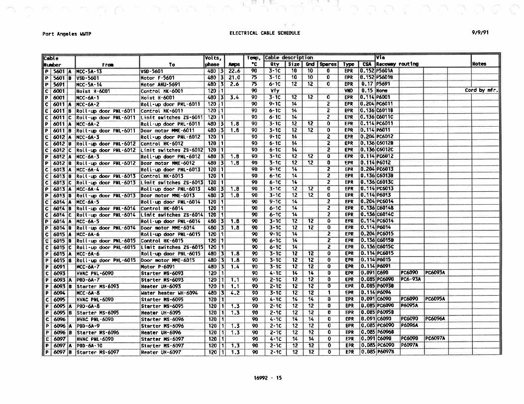
Po¡t Angetes t¡lllP ELECTRICAL CABLE SCHEDULE 9t9t91
Cabtet¡¡¡ùer Fra lo
Volts,Dheee læo
TcrP,oc
e YietrccsY rq¡tim IotcßetY Size Grrl SËrcg fvæ cs
P 5óOl A tlCC- 5A- 13 vsD-5ó01 480 15 22.6 90 5- 1C 10 10 0 EPR 0.152 P5ó01^
P 5ó0t B vsD-5ó{¡t ilotor F-5ó01 480 15 21.0 75 5- tc 10 10 0 EPR o.152 P5ó0tB
P 5ó9t r,rcc-5A- 14 È{otor AHU-5ó91 480 13 2.6 75 ó-tc 12 12 0 EPR 0.17 P5691
c ó001 Hoist il-ó001 Control tlK-ó001 120 ll 90 vÍv vltD 0. t5 loñe Cord Þy mfr.P óo01 ilcc-ó -1 Hoist H-ó001 480 t3 3.4 90 3- 1C 12 12 0 EPR 0.114 PóOO1
c ó011^
tlCC-óA-2 Rott-rp door PIL-ó011 120 ll 90 9-1c 14 ? EPR 0.204 PCó0t tc ó01 I B Rott-r¡p door PIL-ó011 Controt HK-ó01'l 120 l1 90 ó- tc 14 z EPR 0.15ó có01 1B
c óo11 c Rot t -ræ door PllL-ó0l l Limit s¡ritches Zs-óotl 120 t1 90 ó- 1C 14 2 EPN 0. t5ó có01 1c
P ó011 A tlCC-ó^-a Rott-Ð door P¡¡L-ó0ll 480 15 t.E 90 5- IC 12 12 0 EPR 0.114 PCó01 1
P ó01 I B Rot t -r.¡p door PilL-ó011 Door [þtor l,ltlE-601I 480 15 t-8 90 5- tc lz 1Z 0 EPR o.114 Pó01 1
c æ12 A f.tcc-ó -3 Rott-qr door PllL-ó0tz 120 t1 90 9- 1C 14 2 EPR 0.204 PCóotz
c 6012 B Rotl-ræ door PtlL'ó012 Controt HK-ó012 rz0 ll 90 ó-lc 14 2 EPR 0. t3ó có0128c 6n12 c Rot t-r.p door Pl¡L-ó012 Limit sritches ZS-ó012 120 ll 90 ó-tc 14 z EPR 0. t5ó c6012cP 6{J12 A ilcc-ó -5 Rot t-r.p door Pl¡t-6012 480 t5 1.8 90 3-tc 12 1Z 0 EPR 0.1t4 PCó0rzP 6012 B Rol, t -ræ door Ptl['ó012 Door motor ifiE'ó012 480 15 1.8 90 3- 1c 12 12 0 EPR 0.1 t4 PóOIZ
c ó013 A r{cc-óA-4 Rot t -r.p door PtlL-ó015 120 ll 90 9- tc 14 2 EPR o.2u PCóo15
c óoI5 B Rott-rp door Pl{t-6013 Controt llK-ó015 120 lr 90 ó- 1C 14 z EPR 0. t5ó có0138
c ó{,l5 c Rot l, -r.rp (þor PilL-ó015 Limit s¡.itches ZS-ó013 120 ll 90 ó- lc 14 z EPR 0. t5ó có0t5cP óo15 l ncc-ó -4 Rott-rp door PtlL-ó0r5 680 15 1-8 9f) 5- 1C 12 12 0 EPR 0.114 PCó015
P 60t3 B Rott-ræ door Pl¡L-ó015 Door motor tlllE-ó015 460 15 1.8 90 3- 1c 12 12 0 EPN 0.114 Pó{'I5c ó0t4 A ücc-óA-5 Rot t -r.p door PllL-ó014 rz0 lr 90 9-tc 14 2 EPR 0.204 PCóo14
G ó{¡t6 B Rott-ræ door PllL-ó014 Control HK-ó014 120 ll 90 ó-1C 14 z EPR 0.15ó có0148
c 6)14 c Rott-up door PilL-ó016 Limit sritches 25-6014 120 lr 90 ó- 1C 14 z EPR 0.15ó có014cP æ14 A ncc-ó -5 Rott-rp (þor PIL-ó014 480 13 1.8 90 3- lc 12 12 0 EPR 0.114 PCóOt4
P 6014 I Rott-ræ door PLL-ó014 Door Íþtor ffiE-ó014 480 15 t.E 90 3- 1c 12 12 0 EPR 0.114 PóOI4
c ó015 A trcc-óA-ó Rott-ræ (þor PIL-ó0I5 120 l1 90 9-tc 14 2 EPR 0.204 PCóot5
c ó{rt5 B Rolt-ræ door PxL'ó015 Controt Hf-ó015 rz0 l1 90 ó-1C 14 z EPR 0.15ó có{rt58
c ó0r5 c Rol. t -rrp cþor PllL-óot5 Limit s¡itches ZS-ó015 120 tl 90 ó-tc 14 z EPR 0. t5ó c6015cP ó0r5 A [cc-óA-ó Rol, t -rlc door PtlL-óOt5 4EO 15 t.E 90 3- 1C 12 12 0 EPR 0.1 14 PCóO15
ó015 B Rott-r¡p door PIL-ó015 Door mtor ¡'fiE-ó015 480 15 t.E 90 J. TC 1Z 12 0 EPR 0.1t4 PóOI'P ó091 ¡rcc-óA-7 ilotor P-ó091 480 15 1.4 90 5- lC 1Z 1Z o EPR 0.114 PóI'91
c ó095 HV C Pr¡L-ó090 Starter lls-ó093 120 l1 90 4- 1C 14 14 0 EPR 0.09I có90 PCó090 PCó095^
P ó095^
P8D-ó -7 Stôrter lts-ó095 120 lr 1.1 90 2- 1c 12 12 0 EPR 0.085 PCó{¡90 PCó-95Ä
P æ9t I Starter lls-ó095 lleater Ull-ó095 120 l1 1.1 90 2-1C 1Z 1Z 0 EPR 0.0E5 Pó0958
P 6(nL tlCC-óA-8 lJôt$ heater YH-ó094 480 13 4.2 90 3- 1C 1Z 12 1 EPR 0.t14 Pó094
c ñ95 ilvAc Pxt-ó090 Starter lls-ó095 rz0 lr 90 4-tc 14 14 0 EPR 0.t¡91 có{¡90 PCó{r90 PCó095^
P 60y5 A PBo-óA-8 Starter ils-ó095 120 t1 1.3 90 2-lC 12 1Z o EPR 0.085 PCó090 Pó09:tA
P ó095 B Stårter l,ls-ó095 Heâter uH-ó095 120 l1 1.5 90 2- 1c 12 12 0 EPR 0.085 PóOO5B
c 61116 ltvAc Pl¡L-ó090 Starter lls-ó09ó 120 l1 90 4- tc 14 14 0 EPR 0.09t có090 PCó{¡90 PCó09óA
P 609ó t PBD.óA.9 Starter l,ls-ó09ó 120 t1 1.3 90 2-1c 12 12 0 EPR 0.o85 PC6090 Pó09óA
P ñ{16 B Stârter l{S-ó09ó Heeter uH-ó09ó 120 l1 1.5 90 z-Ic 1Z 12 0 EPR 0.0E5 PóÍI9ó8
c ñ97 luvAc PilL-ó090 Starter lls-ó097 120 l1 90 4- 1C 14 14 0 EPR 0.091 có090 PCó{r90 PCó097
P 6W A PBD-ó -tO StartÊr tls-ót)97 120 lr 1.5 90 2- 1C 12 12 0 EPR 0.065 PCó090 P6097A
P $n7 B St6rter lls-ó097 Heater UH-ó097 120 ll 1.5 90 z-Ic 1Z 1? 0 EPR 0.085 Pó0978
16992 - 15
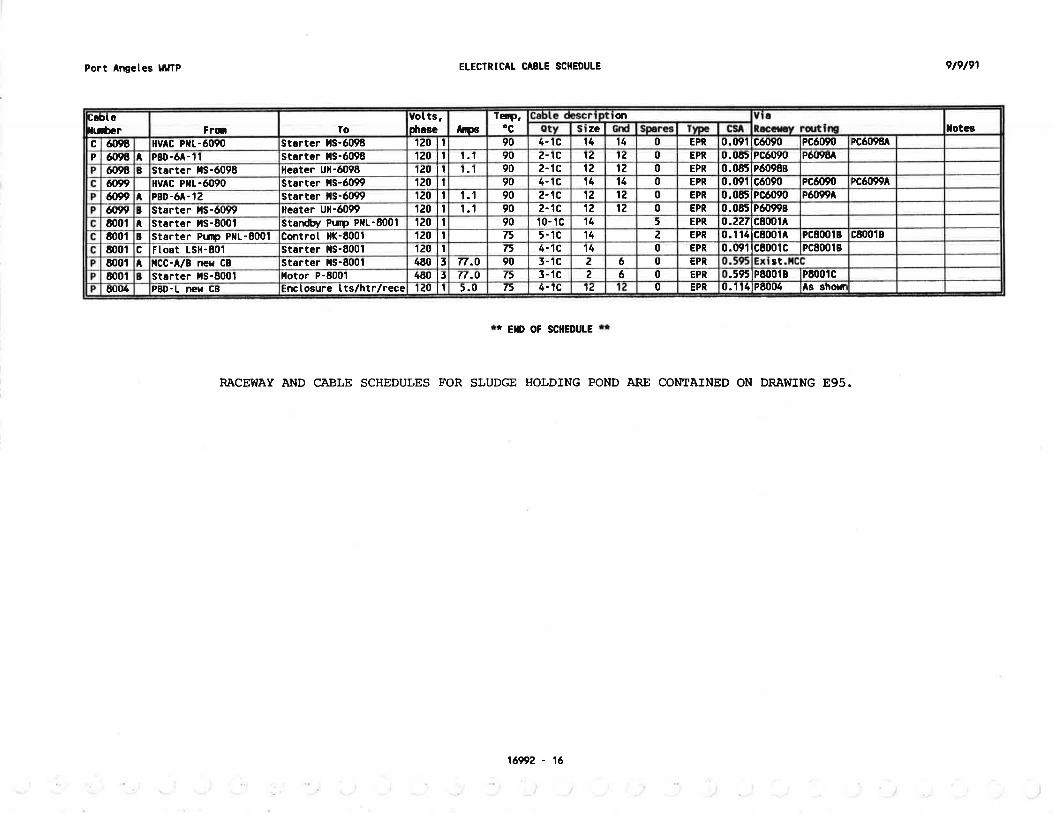
Port ^ngeles
tllJTP ETECTRICÀt CABTE SCH€DULE
*r E¡D OF SCIIEDUIE rt
RACEWAY AI¡D CABLE SCHEDULES FOR SLUDGE HOLDING POND ARE CONTAINED ON DRA!{ING 895.
169p2 - 16
9t9tgl
As shollr0. t 14 tPE004EPR0't¿4- tct>5.0120 t1:nclosure t ts/htr/receP8D.L NET CBð{r(ró
PE00tc.5951P8{¡0rBEPR0623- 1cf5(7.O480 15Hotor P-8001Starter lls-8001BaootstEPR062l- 1c90n.o480 t3Stârter lls-8001I{CC-A/B ner cBA800t
PC8001B0.rr91tc8001cEPR0144-tc75120 lrstârter lls-8001Fl.oat LSH'601c6001
cE001BPC8001B0. t 141c8001^EPN2145- 1c75120 lrControl Íf-8001starter Pum PtlL-8001B8001
0.2271c6001^EPR514t0- tc90r20 t1Stanôy Plm PXL-8001Starter l,ls-600'l^
8001
0.065tPó{lçç8EPR012122-tc901.1rz0 lrHêater Ull'6099Stsrter l,ls-ó099BófrnPó09940.0E5lPcó090EPR012122.-lC90t.l120 t1Starter lls-ó099PBD-ó^- 1 2A6rn
PCó099APCó{¡900.0911cófr90EPR01414ó- 1C90lzo l1Starter l,ls-ó099HV C PIL-ó090ffin0.n65lPó09E8EPR012122-1C90t.'t120 llHcater Ull-ó098stðrter lls-ó098Ió094
Pó0960.0651Pcó090EPR01Z1Zz- tc90t.t120 t1startcr tls-ó098PBD-óA- I tló098P
PCófr98PCóf¡900.t 91 lcó090EPR0t4144-tG90120 lîstårtcr tls-ó098[v c P1{L-ó0908mclotcs
dìze
reilp,ocftB
votts,phaseToFra
DoÞtelurùcr

SECTION L6993
DISTRIBUTION EQUIPMENT SCHEDULES
PART I--GENER,AL
1.01 DESCRTPTION
This section specifies the schedules for low voltageswitchgear specifiêd in Section 16310, panelboards speðified inSection L647O, and motor control centers specified in SectionL6920.
PÀRT 2--PRODUCTS
No products are specified in this section.
PART 3--EXECUTTON
The following Motor Control Center Schedules are inctuded inthis section:
16993-1

Port Angetes t¡t¿lP
IIAIIEPIAIE:
LOCAÏ IOII:VOLTAGE:
FED FRq{:I¡EI,IA H¡RIIIG:EIICLOSURE:
REiIARKS:
DISTRIN'TTü Eq'TPilEXT SCIIEDUTES 9t7t91
lfATT| 8'ITCtrGEARSecondary Control Buitding llCC Room
480V, 3 Phase, 3 llire, ó0 Hz AC
Utitity service transformers (2)Ctass ¡¡¡lEllA 12, lnú¡strietService Entrance Labeted
EOI.IIPüEilÎ IIIJIIBER:
SPEC¡ ilCAïlolr SECïtOlr:AVAILABTE FAUTT CURREIIÏ
IIAIII 8REÂKER SIZE:ilIXIN,il BUS SIZE:IIEUTRAL BUS:
GROJ}ID BUS:
AüPS RilS SYt+rETRtC^[A¡rPS
AltPs
gGR-ü1ó1105000012001200
il0YES
t051.701136.7)1394-46103ó.ó8c¡ârìd lotats. Future oesign:
220.6920?.10250.22172.92Totåls. Future DesiEn:
480Spåcet 110
Ê21480Distribution Panetboard 2 StandbyP8D-21 108
EZl0.000.000.00460Spåret 107
8210.000.000.000.00480l{otor Controt Center óAICC-óA1 10ó
82116.8715.0118.0ó6-42480Distribution Panelboard 2 llornatP8D.21 t058210.000.000.00480I'lotor Control Center 5A Stanùyilcc-5AI 104
EZI0.000-000.000.004E0llotor control Center 5A llorflatilcc-5AI 103
E21107.0091.62111.7784.00480ilotor Controt Center 28ilcc-zB1 102
82196.4295.47fi8.3982.50480ilotor Controt Center 2Ailcc-z1 10I
FUTURE tüDS
851 -01934.691144.24æ3.76Totats, Present oesign:
58000.000.000.003480Space1110
É215u00lcB0.000.000.000.003480Distribution Panetboard 2 StancbyPBD-21 108
82.158000.000.000.003480Spâre1107
8215100ACB8.7711.47t 5.5ó7 -753480ilotor controt center óArcc-6A1 10ó
8213200ACB67.49ó0.0572.2525.óE3480Dist¡ibution Panetboard 2 ilormalPBD-21 105
8215200AC80.000.000.000.003480ilotor Controt Center 5A Standbyícc-5Â1 104
8215200ACB112.9595.84115.2484.5E5480ilotor controt Center 5A lormatilcc-511 103
É2131000^cs
369.27376.97469.56549.005480schedutesilotor Control Center 28ilcc-281102
Ê2151000^cB
272.54390.34480.60396.753480Seel,lotor Control Center 2Âxcc-2^1 101
CflTROLDIAGRAI
IIGT,
rrcilEsITPESTZEpot-Es
^llPSIYPE
DESIGT
AllPS
STAflD
BY?rv^IPS
HpPt{volftoDUXTT
toDstzE
EOI'IPTIEXT Xtl{E (ntüD DESCntPrtil
EEUIPIIEXT
XTTIBER
CKT
xo.
STARTERD¡SC(nXECT'I()TOR DATA.otIIAIIEPLATE E¡GRAVIXG/CIRCU¡I DIRECT(XY
Page 1ó993 - 2
,) .') )).i.) lt: '/

9t7t91DTSTNIB'I¡il Eq,IPIGTT SCIIEDT'TESPort Angetes IâJTP
IIÂIIEPLATE:
IOGAIlol:VOLÎAGE:FED FR$I:IIEI¡IA IIIRI}IG:EIICLOSURE:
REI4ARKS:
llOTOR COIITROI¡ CETTTER 2ASecondary Controt Buitding llCC Roorfl
480V, 3 Phase, 3 Uirc, ó0 Hz AC
tiain Sritchgeôr sGR'ilCtass 2, Tlpe B
tlEtlA 12, lndustrial
Eot tPllEt T tlti,lBER: llCC-2AsPEclFlC^TlOtl SECTlOtl: 16920
^VAILABLE FAULÍ cURRElr 25000 tllPs Rl{S SYI'i'IETRICAL
ilAltl BREAKER SIZE: LUGS OI¡LY
illfllnt{ BUS SIZE: 1000 AI|PS
iIEUTRAL 8US: l¡0
GRCullD BUS: YES
rD¡ lf)ToR I IAlAsrA¡0
BY?
ltoto
DESTGT
lllPs
DI icT0ülnotDtAGml
A
E32A
cÍI.¡0.
EeutPfiEllfXt.HEER
EOt tPtGXr xilÉ mIOTD DESCRIPII(T
LüDstzE
totDulil1 VOLT
480
P] ltP
1 50t¡tPs
4
rv lYPE^ps
7
POùES s¡zE TYPG
FVR
FVR
llGI,Itc[Es
34
CPÌ.xp-¡tsx- 1130
1202cot-
Grit gâsher0
I1
HP
ilp 48035
0.25-- 1.00
-Too- 0.50
f.80 I 5016
ìtor¡0
llo
0.001.80
ICPl,lCP
ilcP
3-T--5---3-
5I TWR
tvt¡RFVI¡R
12
E33A
-14^- E35A-Tt4B-
67I
coL-1505----Fì5iõP-1320
--P:i$l
Pr st ector
ScrnGå
Sanitary Dra Præ
15
7 .52
IPilPHP
¿804SO-
-¿õo-¡80-aão
33 1
7 502 00
21.00 17.46 IoIOI0l¡0
221.00
00
ilcPltcPl,lCP
ilcP
3-To
-7--5-
53 2 FVt¡R 12
2
E55B
et6^-E BA-- E 9A--- EA5^
1
12
13
P
DU-P.B-21 tB-2130
Gravi Thickener Cotl. Drive Units
Aeråt orer IAeration Btorer 3
Rectaimed tater PrrrP 1 VSO
7575
HP
ltP
ilP 4E0 3
t.uu---l.ri---7.5õ---fr;õõ
75.00-zE.oo9ó.00
I .ló---T.î5--ñ.¡î--79Í1-- 5d3t
lto
loYES
lto
1.40-1ilõõ---ø;oo---õ.oo-ß36
ilcPICPilcPCB
3-T5-T50-T5õ-Tõ_
3 4
FVIIR
FVXR
2Wrãsewt
vsDFVln
3ó E48^
1718
- cP-2171----F:2r-Bîvso-225õ
- P-m
instnmnt Air Conprcssor 1.Sec controt Btdg Sl4 PwP ITrickting Fitter Circ Pu¡tP VSrD
Eoiter Circutation PUP I75
HP
ltP
ltP
ilP
480-¡õo-æo-¡ãõ-
3
7.50---ã - oo
75.00
--l.oo103.23
9. t5--:st---65;sã--1.50 YES
lto0.00
ltcPCB
rcPCB
t57
Ttõ--T--TI
IvsDFVI¡R
vilD
óE42A- EEE^
-5AAtlonePnL-2267
---1.?2ÆBoi ler Contro
er Btoraer llotorBo
500
-1vt{P 480 3 1.00 1.80 1.50 il0 1.80 r/flD fictd
P-22Ut--n:ñ4
Boiler Fuet Oit Pt4 1.5 HP 480 5 1.50 2.ó0 2.16 IOt{o
2.60---zà ücP20
Ir/t¡D
FVIIR
f ietd
24 ¡fl-zz89-- Du-tìõP-31 10
¡¿ater Heater
Return SecondarY Stt¡dge PutP 1
4I ltP
HP
480
-480--æo-5 1.00
9.38--- 1.80
11.001.50 xo
lt01.80 ücP
ilcP3 I t FYIIR 12
nla
E35B-E ñ---E5ñ-
HTR
P-3210I
P-31 10cssing Heater,7.5
U
HP
t20480120
5 7.504.17-11-oo
----4Jî 9. r5 I0 11.00 f,lCP t5 I I zszl¡vT 24 E57A--EE7Ã-
28 P-f,410n9
Snai t Sutp 7.5 HP 480 5 7.50 11-00 9.15 x0 11.00 ilcp 15 3 1 FVIIR 12 E57B
29 P-5703INE
te lrsnsferisinfect 0oor 1on
0.75 HP
HP
480480
3 0.75 1.40 1 1 6-l:50
ta0
xo1 -40 ilcP
l{cP5 I I tvr{R
tvR12 E59
l03i- cP-4010 Oisester I Gas C@ressor 25 HP 480 5 25.00 54.00 28.27 i¡0 34.00 l,lCP 50 z 2sAflr 24 E47A
Page 16993 - 3

Port Angetes $tÏp
IAI4EPIAIE¡ l,IOTOn CON'lttROfr CEttrEn 2A
DISTRIET'TTil Eq'IPIIETT SCIIÊDUTES
EQTJ¡PI{ETT TLiIBER: Itcc-2A
9t7/91
(coN
Port Angeles lJl¿lP
}IAI,IEPLATE:
LOCÂTIOI:VOLIAGE:
FED FRO,I:
T{EHA H¡R¡IIG:EIICLOSURE:
REIIARKS:
ItoToR coltlt'Rofr CENTER 28Secondery Controt Euilding llCC Room
480V, 3 Phâse, I tlire, ó0 Hz AC
l{ain Sritchgear SGR-}l
Ctass 2, TlDe B
tlÊl{A ,l2, lndustriat
DtsTRtEt ttü EqrtpilExT SCIEDUIES
EeUlPllEllT [uü8ER: IiICC-2BSPECIFICAÌI$¡ SECTIOII: 16920AVA¡IABLE TAULI CURREIIT 25OOf) AI|PS RIIS SYII{ETRICALll¡tl BREAKER SIZE: LUcs ütYl,llHru[ BUS SIZE: 1000 A]|PSI{EUTRAL BUS: t¡O
GR(UllD BUS: YES
9t7te1
cxÎ.xo.
c(txEctED Lo I /rcÌ0n tT^sT^n,
BY?
DES¡GillfiPs
DI ;C(TXECI STARTER
OflTROLDI^GR I
EOT'IPTIEXT
TI;BEREqflPflEXf XÆG mLOII' DESCRIPTIfl
toDstzE
LOAD
uf,t T Y P11 HP
^psnA IYPE tps POT ES STZE TYP€
[Gr,¡rorEs
2 P-1332 Primary cattery St¡p Purp 2 2 HP 480 l 2.00 3.40 2.83 YES 0.00 l,lCP 7 3 1 FV[R 12 E39A5 P- 1141 Tank Drain Puìp l HP 480 3.00 4.80 t.91) YES 0.00 l,lCP 7 5 1 FVTR 12 E44A4 uH-1392 Primary Gattery Unit Heater 7.5 K¡J 480 9.O2 7.50 [0 9.02 CB 20 5 65 F- 1504 Grôvity Thickener ORI tsn 3 HP 480 5 5.00 4.80 3.99 t¡o 4.80 llcP 7 3 1 FVI¡R 1Z E54A6 P-1ó10 Primary Slr¡dEe Pr¡m 2 t5 HP 480 3 15.00 21.00 17.46 r¡o 2r.00 l,lCP 30 3 ¿ FVXR 12 E3óB7 P-1ó30 Thickened Scrm Præ 7.5 HP 480 3 7.r0 11.00 9.15 l¡o 11.00 ,lcP 15 5 1 FVIIR 12 E41A8 un-ló92 Thick. Str¡dge PS Unit [eater 5 K¡J 680 3 ó.01 5.00 I0 ó.01 CB 20 I 69 Aeration Blorer Z 75 HP 480 5 75.00 9ó.00 79.81 xo 9ó.00 ltcP 150 5 4 2sz¡¡vT 3ó E47A11 YSD-21ó0 Reclai¡red ¡Jster Pl¡lp 2 VsD 25 HP 480 3 25.00 3ó.5ó 30.39 YES 0.00 CB 50 3 vsD 6 E55A12 cP-2172 Instrment Air Ccnpressor 2 7.5 ltp 480 5 7.50 11-00 9. 15 YES 0.00 ilcP I5 3 I FV[R 12 853^15 P-2182 Sec Controt Btdg Sr¡rp PLm 2 2 HP 480 3 2.00 5.40 2.At YES 0-00 ltcP 7 5 I FVXR 12 E42A14
^[u-219îEtorer Rocnr Air Handting Unit 0.75 HP 680 3 0.75 1.40 1.tó ilo 1.40 ÍcP 5 5 1 FVXR 12
t5 r-2192 Bto¡Je¡ Rocllr Exh6ust Frn 0.75 HP 480 5 0.75 r.40 I .16 to 1.40 l,lCP 5 5 I FVIIR 1216 vsD-2210 Trickting Fitte¡ Circ. PLm I VSD 75 IP 480 5 75.00 103.23 85.82 to t05.25 CB 150 3 vsD 6 E55A17 vsD-2220 Trickl,ing Fitter Circ. Ptm 2 VSD 75 ltP 480 3 75.00 103.23 E5.EZ I0 t05.23 CB 150 3 vsD ó E55^18 Sec. Cont Btdg ilcating Yâter Puqt 0.5 HP 480 3 0.50 1.00 0.85 IO 1.00 ilcP 3 3 1 FVIR 1219 Anu-229t Toitet/Storoge Air Handting Unit 0.5 HP 480 3 0.50 1.00 0.81 to t.00 tcP 5 5 t FVIIR 1220 Alru-2295 ÈlCC Rooír Air Handting Unit 0.5 HP 480 5 0.50 1.00 0.83 xo 1.00 itcP 5 f t FVI¡R 1221 Í-zÐ7 Toi Let,/Storage Exhâust Fan 0.5 HP 480 3 0.50 1.00 0.83 t{o 1.00 l{cP 5 5 I FVTR 1Z22 P-3120 Return Secondary Stdge Pum 2 7.5 IP 480 3 7.50 î 1.00 9.15 YES 0.00 ltcP 15 3 ,| zszuvT 24 E57A
ltrR-3121 Casing Heater, P3120 500 t 120 f 4.17 0.50 YES 0.00 857^23 DU-3200 Co êctor Drive I t{P 480 1.00 1.80 1.50 t¡0 1.80 HCP 5 5 I FVXR 12 E55824 P-J.¿20 Return Secondary Stt¡dge Pum 4 7.5 ltP 480 7.50 11.00 9.15 YES ilcP t5 t I 2szrlvÏ 24 E57A
Casirg Heotèr, P3220 500 ¡t 120 4.17 0.50 YES 0.00 5 E57A25 t¡E-3742 Disinfection Btdg Rott-r¡p Door 2 I HP 480 1.00 1.80 1.50 YES 0.00 ilcP 5 5 1 FVR 18 Éó0A26 Disinfec Btdg Ai¡ Handling Unit 0.75 HP 480 0.75 1.40 1.1ó xo 1.40 l,lCP 5 3 I FViln 12 E5ó27 F Disinfec 8td9 Exhaust Fan 0.5 HP 480 3 0.50 1 -00 0.83 I0 1.00 l,lCP 3 3 I FlTR 12 E5ó^28 cP-4020 Digester 2 cas Cdpressor 25 HP 480 5 25.00 34.00 28.27 lto 54.00 ilcP 50 5 z 2SzuvT 24 846^
P-4033 Digester 2 Stt¡dge Circ. Pum 7.5 HP 480 3 7.50 11-00 9.15 lto 11.00 llcP 15 3 I FVIIR 1Z30 P-4037 Digester 2 HRS Circ. PUrp 1.5 HP 480 5 1.50 2.60 2.16 t¡0 2.& ilcP 5 5 1 FV[n 1231 F Fan 0.50 HP 480 3 0.50 1.00 0.83 l¡0 1 -00 ícP 5 t I FYIIR 12 Eó3A32 Âir Handt t o.75 ilP 480 3 0.75 1.40 r .1ó [0 1.40 ilcP 3 3 t Éùctt I 24 E47A3l Í-4t94
F
Laboratory Fme Hood Exhaust Fan 0.5 ltP 480 5 0.50 1.00 0.83 t¡o f.00 ilcP 5 5 t FVTIR 12 E5óAFan I HP 460 5 I -00 1.80 t.50 ilo 1.E0 ücP 5 5 1 2Szt|T 21. E4óA
Page î6993 - 5

Port Angetes ¡JlJlP
t¡^ilEPL^TE: tdOTOR CONIROL CEIÍTER 28
DtslRtn rl(t Eqfi PllErr. scllEDu[Es
EOt.lIPilEilT IIIJiIBER:
Page 1ó993 - ó
[cc-28 (coNr I D'
9t7t91
)) )l
502.O7490-U5ó00.154f,5.00
Isections:25.8121.4625.815480t{P75+251 oî largest toad:
72107.0091 .62113.7784.00subtotâts, Future Desi gn:
E57A0.00YES0.504.17t120t¿500Casins lleater, P3230ltrR-3231
Êr7A24zszt¿\rT1315¡tcP11.00[09.15It-007.503480ltP7.56P-f,25040
EZst6CJCÍY I45150ícP9ó.00lt079.819ó.0075.003480ilP75a-214010
Ezt1ZFVTIRI55TCP0.00YES2.162.60't.50l4E0ltP1.5l,lechanicat Bar Screen 2scx- r 102I
FUÍtnE I(nDS
ISactloms558,69.27376.914ó0.5ót49.00Subtotats, Present Dcsign:
54Space42
1851000c8YESsource t{o. 2 feeder to l{cc-zA41
82312TVNRI37CBSpare59
E32B12corr30A330CB6.71xo5.586.713480r(t5.58Area/Roadray Lightinstrc-00138
63100c8-60.14t¡o-50.00-60.14480KVAR50Porer Factor Correction capacitorcAP-2837
520c85.ó1il05.003.611480KU3Laboratory llater lleatert¿u-423'3ó
E5óA1ZFViIR135ËcP1.00t¡o0.851.000.503480HP0.5Stt¡dse PLm Room Air tlandting UnitAHt -609E55
oftï¡oLDtAcmll
llGT,txcilEslYPÉslzEPd.ESApsÏTPE
DESIGX
tltPsSTATO
BY?K'AANPSIPPltYf¡tïtotttt t¡T
totDstzE
EqrIPilEXf I ffi mLOTD DESCR¡PTI(il
Eq,lPilE]tïntßER
crT -
xo.
STANIERiT'mÎm D TAc(txEcfED l

DISTRTN'TIü Eq'IPTGxl SCIIEI'UIES 9t7t91Port Angetes tllJlP
IIAIIEPLÂTE:
IOGAT 10il:VOTÏAGE:FED IROI:[Et{A !ilRiltG:EIICLOSURE:
REiIARKS:
IIOTOR COITTROI¡ CEITTER 5AStudge Deråtering Suitding l'lcC Rooíl
480V, 3 Phase, 3 tlirc, 60 llz AC
ilain Sritchgear sGR-l,l
Ctass 2, TlDe ItlEl,lA 12, lndustrial
Ec[J¡Pl{ExT llu{BER: llCC-sâSPECIttCÂr¡Ol¡ SEGTlOtl! 16920
Av ltABtE FAULI CURRET¡T 25000 lllPs RltS SYt'llETRlC^t
ilAltl BRE^XER SIZE: 225 lllPsl,llllnfi 8US SIZE: ó00 AIIPS
I¡EUTRAL BUS: t¡0
GROTJND BUS: YES
/I|()TOR DAIAsÎ^¡o
BY?
DESTGX
ltPs
Dtscüxr SÏARTEIcillnotD
CKT
xo,EOrrtPüElrTlrtflBER
E(I,IPIIEXT XAfiE (N
L(uO DESCRIPTT(T
LOÀtt
stzELOAD
uIIl v ilP IilPS rv^ lYPC lps POTES s¡zE ÏYPEllcl,
t¡cilEs
1 P-51¡91 er lleat l¿ater t-5 HP 480 5 1.50 2.60 2.16 il0 z.ó0 ICP 3 5 t tvt¡R 12
2 YSD-5101 tt ter Press Drive l{otor VSD 5 flP 480 5 5.00 8.t 4 7.02 t¡0 8.44 c8 20 3 vsD 12
5 cfl-51(b fhickened Stt¡dge Scre¡¡ Conveyor z HP 480 3 2,00 5.40 2.83 il0 3.40 ICP 7 3 I tvltR 12 E59^
4 ilru-5110 BFP tlydrautic Porer Unit 1.5 HP 480 3 1 -50 2.60 2.16 ìto 2.60 ilcP 5 5 I FVIIR 12 Eó38
5 ll-5200 Bui tdi Ho st 2 l{P 480 3 2.00 3.40 2.83 t¡o 5.40 CB 20 3 1 vrD 6
6 cDR-5401 So 3 HP 480 5 3.00 4. E0 3.9) l¡o ó.80 ilcP 7 3 1 FVIIR 12 E67A
7 vsD-5402 BFP Feed Pr.m P-5402 vSD zo HP 480 3 20.00 29.03 24.14 l¡0 29.03 CB 50 3 vstt E55A
I P-5403 BFP Str¡dge Recircutation Pu¡tP 15 HP 480 3 15-00 21.00 17.46 ilo 21.00 HCP l0 5 2 FVIIR 12 Eó98
9 P-5406 llashrater Booster Plæ 7.5 HP 460 3 7.50 11-00 9.15 l¡0 1 1.00 ilcP 15 5 1 FVXR 12
10 Spåre I'lCP 3 5 1 tvtR 12 ez4
11 P-5503 Delatering Euitding SurP Pt4 I 2 ltP 480 3 2.00 3.40 2.45 IO 5.40 HCP 7 3 t FWR 12 E45A
1Z P-5504 OeHâtering Buitding sutp Pt tP 2 z HP 480 2.00 3.40 2.85 YES 0.00 ilcP 7 3 I FVIIR E45A
1l vsD-5601 odor Reduction To¡.er Fan VSD t5 HP
HP
480 3 15.00 22.58 18.77 Ioxo
22.r8 C8 30 5--- vsD 6 E71A
15 c P-54 Po¡ei Factor correction capacitor 25 KVAR 480 5 -30.07 - 25.00 t¡o -50.07 CB 50 3 6 8?4
16 PBD-5A Transfonner 5A and Panelboard 5A See schedu ¿80 5 ó.58 27.10 22.55 l¡o 28.16 c8 60 I 6 824
17 Spare CB zo 3 6 824
18 Spacetð
19 Þace
Subtotats, Present Design: 84.58 I 15.28 95.84 112.1ü 246.00Scctions: 4
FUNNE tüDS
Subtotats, Future Design: 0.00 0.00 0.00 0.00 0
+251 oî targest toad: 20 HP 480 3 7.26 ó.03 ó.03
Totats, tuture Design: 84.58 122.51t 101.88 1 18.98 246Sêctions:
Pase 1ó993 ' 7

Port ^ngetes
ut¿ÎP
}IAIIEPLAIE:
IOCATIOII:VOLÎAGE:FED FROI:[Er{A utRt}tG:E}ICLOSURE:
REHARKS:
DISTRTN'TIil Eq'IPIGXT SCIIEDUTES 9t7t91
üoron corlrRol¡ cEtûrEn 6AShop/Storege Bui tding storage Room
480V, 3 Phasc, 3 lJire, ó0 Hz Ac
tlain Sri tchgear scR-ftlctoss 2, Type B
l¡EllA 12, lndustrial
EOt.lI PilEtIT III.}IBER :SPECI F ICATIOI SECÎIOI :AVAILABLE FAULÎ CURREIIT
IIAII¡ EREAKER SIZE:iltltnH BUs s¡zE:}IEUTRAL BUS:
GR(U}ID BUS:
Page 16993 - 8
AIPS RilS SYilEntC^tAilPSAilPS
ucc-6â1692025000225ó00il0YES
))
5ons14412.1714.3018.967.75Totats, Future DesiEn:
5.402.855.405480HP2+254 oÍ tarEest load:00.000.000.000.00Subtotats, Future Design:
FUITNE LOIDS3Sectims:
1448-Tl11.4715.5ó7 -75Subtotâts, Present Design:
156520CBSpare126320c8-2.00x0-2.00-2.413480KVARzPoHer Factor Correction CåpacitorcAP-óA11
12FVIIRI315HCPSpåre1065ó0CB0.00IO0.000.000.00See scheduteTFR.óA ônd PBO-óArFR-óB9
E5óC6520c84.17il02.004.17t4AOtct2Yater lleaterylt-ó094IE5óA12FV¡IRI55,tcPt.40t¡01.161.400.753480HP0.75Shop/StoraEe HeâtinE ¡Jâter PtmP-ó09t7EóOA18FVRt33ilcP0.00YES1 -501.801.003480t{P1shop/storôge Btds. Rott-up Door 5nE-ó0156EóOA18tvRI55rcP0.00YES1 -50t.801.005480ilPIshop/Storage Btdg. Rott-up Door 4ilE-ó0145
EóOA1EFVRI55ltcP0.00YES1.501.801.003480HPIShop/Storase 8lds. Rott-tp Door 3nE-ó0134EóOATEFVRI,5ilcP0.00YES1.50t.80t.003480HP1Shop/Storoge Btdg. Rott-l.[' Door 2ilE-ó0t2lEóOA18tvRI33ilcPt.E0xot.501.80t.00460HPtShop/Storage Btdg. Rott-r.p Door Ir€-ó0tl2Eó546vl¡DI5zoCB5.40[02.83t.402.005480HPzLlaintenrncc Shop lloietfi-ó{ntt
oilIROtDIAGRAII
llcl,trcHEslYPEstzEFf,tESlplslYPE
DES¡GT
AIIPSSTATD
BY?nt^tPs
lrPPllvLOtO
UXITtoDstzE
Eot lPtExÌ x^ll€ mlo l, DEscRtPrtil
€qJIPTIEXTIIIIBER
DKT.
IO.
SÎARlERDISCilXEGIITA)/ñ)Tfr IXGRAVIXG/CIRCT'I T DI RECT(nYItAIEPtATE

\ -t
Port ^nsetes
t¿t TP
}IAIIEPIA1E:
LOCAÌ tOll:VOLÎAGE:FED FROII:
FEEDER EIITRY:llcjilïtltG:REI,IARKS:
DtsrRln Tt(t EqrlPtrtT sctlElxr[Es 9t7t91
PIT¡EÍ,BOARD 2Secondary Controt Building tlCC Rooít
20811120v, 3 Phase, 4 gire, ó0 Hz AC
sGR-il, TFR-2ï0PSURFACE
Eot tPüEtlT tltllEEn: PBD-2SPECIF¡CAItol SECÌlOt{: 1&70AVÂTLABLE FAUTT CURREilT <22,000
^l{PS nilS SYlll{Elnlc^t
l{Altl BREAKER SIZE: 250 AHPS
tllllll,ltt'l BUS SIZE: 250 AIIPS
IIEUTRAL BUS: YES
GRÜ}ID BUS: YES
cxT.xo.
lDt 'iloTm DATA
STAXD
8Y?DESTGT
kY
DtscüxEcr 'ARTER
cfiTROtDlAGRlll
EOTJIPIIEXT
ltfi8EREeJIPilEXf XAtft mLOTD DESCRIPII(T
to t)stzE
LO^D
uttl v Plr ÍP ITPS rY ÏYP€ tps POLES stzE fTPEllcï.
trcilEs1 P8D-2A PBD-ZA, Secondary Controt Btdg. See schedute 0.00 32.17 11.59 13.tt4 CB 100 3
2 PBD-28 PBD-28, secondsry controt Btdg. See schedute 1.43 24.38 8.78 10-34 CB t00 3
5 PBI'.3A PBD-34, Disinfection Btds. See schedute 2.00 1ó-Et ó.06 7.27 c8 100 5
4 PBO-4A PBD-44, Digester Controt Btdg. See schedule 21 .54 59.80 21 .54 23.39 CB 100 5
5 PBD-7A PBD-74, Adninistration Btdg. See schedule 0.70 33.55 12-O9 15.05 CB 100 3
6 CB 100 3
7 Space CB 100 5
I SÞace CB 100 5
91011
1?
Iotal present toad: ?5.68 1éó.70 60.05 67.49 24.00
Ptus sro¡th factor of: 25 r 6-42 41.67 15.01 1ó.E7
Totå[ future load: 52.10 208.37 75.O7 &.36
Desiqn m [oad: 208 5 zg['.5t 234.16 A[ps
Pcge 1ó993 . 9

Port Angetes ¡tlTP
IIAIIEPIATE:
LOGAÎ I OII:VOLTAGE:
FED FRO{:FEEDER EilTRY:ilct ilT r ¡rc:REiIARKS:
PAIIET¡BOÀND 2ASecondary Control Buitding ilCC Rocln
20811120V,3 Phase, 4 tlire, ó0 Hz Ac
PSD.2801rotSURFACE
DtsTR¡n Ìtü Eqr¡PtEtr scÍÉDt tEs
Eot lPilEtT tltfiBER: PBD-24SPEC¡FlC^ll0ll SECTIOI: 16470AV TLABLE FAULT CURREilt <22,000 A'{ps Rils syffiETntc^tIIAIII BREAKER SIZE: LUGS Oû¡LY
l,l¡tllnfi 8US SIZE: 225 ^llPSIIEUIRAL BUS: YES
GRCIJIID BUS: YES
9t7t91
r)
tz0CBpare30t20CBSpare29I20CBSparè2At20CBSp6re27I20CBSpare26Ie0CBSpôre25I20CBipare24I¿gCBSpare23t20c8SÞare22I20c80.18¡¡o0.181.50I120VA180CoÍthJstibte Gas Detection PanelArstl-13ó21120c80.20lro0.201.67I120VA200CPT-1111 lleat Tapeiltr-l1l120tzoc80.90xo0.907.r0I1ZOVA900Rccepe-ilCc Room a¡ea19120c80.90xo0.907.501120v900Receps-Storage ôreat8I20CB1.0Ef,o't.089.00trz0v1080Reccpa-Restroom sreâ17I20CBo.72l¡0o.7zó.00I120VA720Recêps-Btorer Roqn16t20CB0.51YES0.252.08I120v25015120c81.8YES1.038.ó01120VAt0t2Lights-Storage, Boi ler Rom1lt1zoCB1.29YES1.038.ó01120VAt05zLishts-ilCc Room13120CB1.8YES1.058.571tz0VA1028LiEhts-Restrooors and Exterior12I20CB1.45YES1 .'.tó9.ó8T120VAI îó1Lights-BtoHer Room11I20c81.vYES1.088.9ó1't20VA1075Lights-8tor.er Roont0Iz0CB0.25YES0.18't.501120VA180Sec Cont Btdg Control PanetPXt-22909120CB0.20ilo0.201.671120v200llster SoftenerrE-2281I1z0c80.25YES0.201.671120VA200lnstrunent Air DryerDRY-2î707I20CBt.50YES't.2010.00I120A10Eff tueît Comosite SamtersrP-2t556I20c80.06YES0.050.1.2It20VA50Efft. Chtorine Residual AnelyzerAIT-35ó5t20CB0.0óYES0,050.42120VA50Rcturn Secondary Str¡dEc Fto$nctcrFtt-'¿.24I20c¡0.0óYES0.050.42120v50lrtstc Secondary Studse tlonneterÍtt-2403t20CB0.0óYES0.050.42120VA50Solids Contact Bôsin Air FtosneterÍt-20ß2t20CB0.0óYES0.050.421ZOVA50Studse Reaeration Air Fto¡meterÍt-2031
cüTno[DTAGRAII
IIGT,ItcIESIYPEs¡zEPOIEStmsÏYPE
DESIGX
rv
oftII-rurusto D?nAAltpsflPPtlY
LOAD
t x¡TLO t)stzE
Eqr¡nlElf XAffi (nLOID DESCRTPT¡fl
Eq,IPTEXTXI,TBER
CKÏ
xo.
D¡SCflTECI/TOT(n DATAcqxËclEDXGRAYIXG/CIRCUI I DIRECT(XYXAIIEPLATE I
.)
Pase f6995 - 10

,\ '\-\
tr
Port ^ngetes
lllJTP
rlArlEPlATE: PÀltEfrBOAnD 2A
DISTRIBT'TTü Eq'IPTEXT SCIIEDT'IES
EOU¡PtlEt¡T llullBER: PBD-24 (coilr I D,
9t7t91
crï.xo.
XAIIEPTAÍE EXGNAVIIG/CTRCUIÌ DIRECIÍNY /t)ïm DAït CüTI-nft!;torD?
DES¡GT
ut^
DTSC(TXECT SIARTER
oilTtü.D¡AGNü
Eq,¡PIIEXT[rtßER
Eq,¡PilEXT XATE (nto t DEscRtPTt(t
tmDs¡zE
tmDuxtT v Plt ilP tms Kì'A WPC lps POIES stzE TYPE
IIGT,TXGIIES
31 Space12 Spsce55 Space34 Space35 Spåce!6 SÞoce37 Sþ€cet8 Soace59 Space40 Space41 Space42 påce
Total present toad: 0.00 11.59 13-4L 30
Ptus Erorth factor of 25 T 0.00 2.90 3.36Totat future to6d: 0.00 14.49 1ó.80
esion a¡n toad: 208 3 40.21 46.6t Amca
PaEe 1693 . ll

Port Angetes I¡UTP
}IAI{EPLATE:
LOGATIOII:VOIÍAGE:FED FROIi:
FEEDER E}IÏRY:r,{(Ijllf ttlG:REIIARKS:
DrsrRrErrTt(t Eq,lPrGxT scllElxrtEs 9t7t91
PI¡TBT¡EOIRD 28secorìdrry Controt BuitdirU llCC Rocn20811120V, 3 Phese, 4 llire, ó0 Hz AC
PBO.2B0lTOtSURFACE
Eot ¡P,lEl¡T IttlBER: PED-28SPEC¡FICAT¡OI| SECTlOtl: 1&70AVAILABLE FAULI CURREI¡T <22,000 Al,lPS RllS SYilETRIC^IIIAIII BREÂKER SIZE: LUGS OILYllltlllull 8US SIZE: 225 AIIPS
IIEUTRAL 8US: YES
GR(IJi|D BUS: YES
Page 16993 - 12
))|j) )j)l
oece50Space29Space28Sþace27
f20CBSpâre26
1?0CBSpâre25
Iz0CBpare24
I20CBSpare23
120CBSpare22
tzoCBSpare21
I20CBSÞare20
I20CBSpare19
I20c8Spare18
tu0CBSpare17
t20CB0-00l¡o0.000.001120VA0'r.mi¡rs Station16
120CB0. tElto0.181.5011ZOVA180Receps-Rss Pr^npins stât ionRCP-501t5I20CB0.45YES0.542.87I120v344Li Stet oñrrc-301t4
FVI¡RIt20CB0.6óto0.8ó7.200.33I120HP0.55TSPS Stm PræP-14113
I20CB0.49YES0.595-28I't20VAt94.s Stat onRCP-14112
120CB0.45xo0.455.711t20VA445L ton[fG- l6l11
FVIIRtt20CB0.40YES0.322.&0.1011ZOHP0-1¡e PS SuÞoty FsnIhick. Stt¡dF- 1ó9510
FVI¡RIIz0CBt.0EYES0.8ó7.200.33Itz0HP0.55Ihick. studEe Ps Exhaust FanF- 1ó919
I20c80.40YES0.522.67I120VA320t i shts-Pr imôry €mergency/exter i ortrc- 1018
t20c81.08ilo1.089.001t20v1080PrRCP- 1017
t20CB1. t6YES0.957.88I120v946LIG- t0t6
FVIIRII20CB1.08YESO.Eó7.200.551tz0HP0.33Prinary Gattc¡y Suppty FanF- 13955
FVTR1t20c81.08YES0.8ó7.200.551t?0HP0.35tery Exhaust FanPrinery G¡F- t59t4
tzoCBr.50YES1.2010.00It20At0nf uent itasrP-t140JI20CB0.0óYES0.05o.4z1120VA50DengDC- ló52
120CB0.0óYES0.05o.4z1120VA50lnft. Byp6ss Chamet Level SritchLSH- 1041
c(fTRorDt^Gr^r
llGT,¡rc[EsfYPEstzEPOLESlpslYPE
DESIGilÍìr
c(tl¡-ruusLOID?rYAlpslrPPtlv
LOI'D
t xlfLOAD
stzEEq,lPfiEXt ¡trE mro t DEscRtPTtil
EEUIPIIEXIxtfi8ER
:TTxo.
TARTERCIDtsc(txtCOTXECTED LOAD/H)TOR DATATIAIIEPIAIE EXCRAVIIG/CIRCUII DIRECT(nY
..))l

l
DtSTRIA'l¡(n EqrtPtExT scllEDt tEs
EqrlPl,lEtlT llullBER : PBD-28 (colflrr D'
9t7t91Port Angeles tltllP
]{AiIEPLATE: Pâ¡tEtEOlRD 2E
cxTxo-
c(xltE ;TED /H'lm DATI CüTT.xulrsto D?
DESIGT
KV
D¡SCüXEGTCilTROLDt^GRAll
Eq,lPtEtrII;BER
EqrtPllExT xl,llE mr(nD DESCRIPIl(t
toDstzE
toÆ,UXIT v Plt ltP lltps rv ilP€ Æ?s potEs stzE lYPE
IIGT,txcltEs
5',| Spâce
32 Sp€ce33 Space34 SÞâce
35 Space
36 Space37 ;pace38 Spsce39 Spåce40 Space41 Þace42 Spåce
Totå[ present [oad: 1.43 8.78 10.34 26
us factor of: 25 r 0-ló 2.20 ?.58
Iotat future toad: 1.7c) 10.98 12.92
ês on m toad: 208 5 30.47 55.8ó A[ps
Page 16993 - 13

Port ^ngetes
IHTP
IIAIIEPLATE:
LOCAI IOII:VOLTÂGE:
FED TR(I{:FEEDER EIITRY:
ilOulT r ilG:REI.IARKS:
Drsrttðrr1ril Eq,lPlGrT scllEoutEs 9t7t91
PÀIIEI¡BOARD 3ADisinfection Buitding208Y/120V, 3 Phase, 4 llire,P80.2BOTT(I'l
SURFACE
EOt IPüEIT ltUrBER:
SPECtilCATtOlt SECTtOil:
AVAILABLE FAULT CURREI¡T
l,lAltl BREAKER SIZE:ilTITru[ BUS SIZE:IIEUÎRAL BUS:
GRCTJ}ID BUS:
000 ^iPs
Rils sYräElR¡cAL
^ilPS^ilPS
PBD-3416470
ó0 Hz AC <22,t00100YES
YES
A[Ds25.24zl.ot3208Desiqn 8[þ load:
9.097.572.50Totat future to6d:
1.621.510.50x25Ptus oro¡.th factor of:
97.276.0ó2-00lotal present toad:242322?.1
2019
18
17tó15
14
13
12
1tt0
t20CBo.&r¡00.645.550.331120U&oReceps/Emerg. LightsRCP-5029
tzoCB1.77YES1.4?11.830.331120t,1419LiEhts-HlD & Ftt¡or.rrc-501IFVt¡RII15c81.06YES0.867.200.331120HP0-13Buitding Heat 9ãter Pt¡pP-37917
t20CB0.18I00.181.50I120VAtE0Buitdins IIVAC Control PanelPXt-5?906
8598FVI¡R1t15c81.08YES0.8ó7.200.351120HP0.3tt te ileterP-37305
8598twnItt5CB1.08YES0-8ó7.200.33t1?OHP0.55te ileter 2P-37204
E59BtvilRII15CBt.0EYES0-8ó7.200.331120ilP0.55te lleteriP-5710ft24120CB0.18xo0. 161.501120VA180Disinfection Process cont¡ot PanetPXt-37002
1241zoCB0. 16t¡00. l81.50t120VAr80Disinfection Process Controt PonelPXt-57001
cilTnolDIAGRAT
[Gr,txclrEsTTPESTZEÞfltEs
^lrPslYPE
DES¡GT
lv
c(tTI -xltustfnD?rYÆtPsltPPliY
to ¡,uIrT
totDstzE
EOT'IPflETT XAfiE MLMD DESCR¡PT¡il
Eq,IPTEXTIUTBER
CKT.
xo.
SIARTERDtscüxEcT¡toT(n DAT^EXGRAV¡
Page 1ó993 - 14

9t7t91Port Angetes lJllTP
I¡AilEPLATE:
LOCÂT IOII:VOLTÂGE:
FED FR$I:FEEDER EilTRY:t{üjilït}tG:REI4ARKS:
DTSTRTS'TIil Eq,IPfrXI SCIIEDT'LES
PAI¡EÍ,BOARD lâDigester control 8ui tding2OgYl12W, 3 Phase, 4 9irc, ó0 Hz AC
PBO.2B0TTCl,l
SURTACE
EruIPllEIIT ilI'IBER! PBD-IâSPECIFICII¡Oll SECTl0tl: 1&70AV ILAELE F^ULÏ CURREIIT <22,000 tllPs Rlls sYtllETR¡C^t
üAItl BREAKER S¡ZE: 100 AilPS
illlllllut{ BUS SIZE: 100 AIIPS
IIEUTRAL BUS: YES
GR(tJilD BUS: YES
cflxEcTED to DA c(trt-ruustüD?
DCSIGT
Kì'A
DtscüxEcr STTRTERcilrnolDr^GmlEEU¡PIIETT
XI.IIBER
ECT'IPHEXT XI'IEtu,D
LOAD
slzELO t'IJf,TT Y IP lilPs xY TYPE lrPs PfT.ES stzE TYPE
ilGr,IICIIES
1 PXr-4057 ¡¿asté Cas Burner Controt Panet 180
0.33t80
VA
ltP
v
120 I0
1.50 0.180.8ó0 18
YES
YES
YES
0.23 CB
CB
20 II FVIIR
E69^
45
PXr-4f190PZæIF-4ffi----e-ñ
nT-450
8ui tdi Heat Uote¡Roooì Fan
tlor 1 tter, Gas
0.17 l{P
HP
VA
1201
1
0.55---õ.17---6:n
4.400.6ó
---õ.s3----õ.5i--õ.ro
YES
1 -080.6ó
---0.óó--õtî3
CB
CB
CB
20-ão.T--2õ-
I 1 tvt¡R E46A
I9
rlG-401
-Lîc:AõãL iohts-LsboratorvL i shts-ilechani cat/Sto¡aEe 87 IJ 120 I
10.,.73 0.ó9 YES
1 59--- 0:só c8 20 I
10 rrc-403 t-i g.]rts-stt¡dge PwPing nomLights-Conpressor Room
Receps'Laboratory
1461429
¡tut
120 1 12.18 1.46 YES
YES
t¡0
1 -83 CB
CB
CB
20-6--?f=-?0
I
14
t5
ncP-4(}óRcP-¿07--- RcPaos 1080
Hg 120
It 9.00 1.08 ì¡0 1.08 CB 20 t
1ó U i Sfits/ptu$ot¿-f orth La¡.L i shts/ptusnotd-llorth Lab.L i Ehts/ptnslfrotd- south Lôb.
2954 IJg
120 I 24.62 2.952.95
-73r
t0tox0
2.95 CB
CB
z0-ñ--u0-
I
19
^tsr-4FIT -435colltr¡stiUte Gas Detection Panet 180
gVA
VA
120 1
16.43_-I:Eõ----õ.s3
1.97---T.iE--Tm YES
YES
1.97
-tz---õ= CB
20 1
23 Spare CB 20
20
I
26
?9 Spsre
CB
CB
CB
20-ã--Zo
I
I
30 SÞareCB ¿o t
Pasa tó991 . 15

Port Angetes UlllP
tlAr,lEPLAlE: PâNEI¡BOÀRD lA
T'TSTRTU'TIfl Eq'TPIIEIT SCIIEH'LES
EOtJIPilEilT I{IJ}IBER: PBD-IA (coN!r D,
9t7t91
Allrts81.1474.75zoa,esign ailþ toad
29.2326.9t26.93Totat future toad:5.855.395.39z25gro¡,th factor of:
5023.3921 .5421.54Totsl present [oad:Space42Spâce41
pace40spacêf9SprceSpece37space36lpace55
specG34pacc55
space
pÐce51
Gf[lRttDTAGMil
IIGT,trcltEsIYPEstzEPOTEStl?SlYPE
DESTGT
rUA
c(xT¡-ltuusto tt?KVArpsilPP}v
tilouttT
rmDstzE
Eq,TNGXI XÆIE MLOAD DESCRIPTIil
Eq,IPTEXTxtfi8ER
crI.M'.
tTt.otc(nxEclED IYIXG/C¡RCUIÏ DIRECI(NYf,^trEPt^rE
Page 1ó993 - 16

') 'ì
Port lngetes lJlrTP
IIÂIIEP[AÏE:
IOCÂT TOII:
VOIÌAGE:FED FROI:FEEDER EIITRY:il(u[TtilG:REIIARKS:
DTSTRTB'TIil Eq'IPffiXI SCHEDUTES 9t9t91
På!¡EI¡EOIRD 5âSotids Handting BuitditU ICC Rom208Y1120U, 3 Phese, 4 llire, ó0 tlz Âc
ilcc-54T(ÞSURFACE
Eot lPllEtl t{tt{BER: PBD-51SPECIFIC^T!Oil SECllOl: 1&70AV ¡IABLE FAUtr CURREI|T <22,000 AþS RilS SYti,tETRtCAtil lt¡ BRE^NER slZE: 100
^llPSll¡llllltilBUSSIZE: 100 AiIPS
iIEUTRAL BUS: YES
GRCIJIID BUS: YES
cxT.xo-
/t)T(x I ofilil-mltstilD?
DESIGX
rYA
DtscüxEcTciltRltDt^GRt'lt
Eq,TPilEXTTI;BER
ECI'TPIIEXT XIilE (nLOID DESCR¡PTI(N
[oDstzE
L(NDI'TTT v Pll HP AtPS rY ÏYPC ttPs POTES stzE IYPE
IIGT
trcilEs,l AflU-50i85 HCC Rm Air tlandtins Unit 0.55 HP 120 1 0-33 7.20 0.8ó YES 1.0E CB ¿o 1 1 tvilR Eó08
z F.5OEó Potyre¡ nm Exhåust Fan o.25 HP 120 I 0.25 5.80 0.70 YES 0.67 c8 20 1 I FVIIR EóOB
3^ltt
-50E7 Potyme¡ Rm Air llartdting Unit 0.33 ilP 120 1 0.55 7.20 0-8ó YES 1.08 CB 20 I t FVln E6OB
4 AHU-5089 Pum Rocm Âir Handtins Unit 0.33 ilP 120 I 0.55 7.20 0.8ó YES 1.08 CB 20 I I FVI¡R EóOB
5 PXL-5090 Delater Btds controt Pânel 150 VA 120 I 1.25 0.15 YES 0.19 CB 20 t6 PXt-5104 Eett Fitter Press Controt Panet 200 vA 120 t 1.67 0.20 YES 0.25 CB 50 1
7 Í-5192 BFP Roclrr Exhaust Fan 0.33 HP 120 1 0.55 7.¿O 0.8ó YES 1.08 CB 20 I t FVIIR EóOB
I rE-5195 LiEhts-BFP Exhaust llood 500 tt 120 I 4.17 o.50 YES 0.ó5 CB 20 II nE-5201 Dry PolyîÞr Preporation system <5 HP 208 I 3.00 18.70 3-89 YES 4.ú CB 50 2
10 cFR-5202 Liquid Potymer Feeder xo. 1 <'l l{P lZO I 1.00 1ó.00 1.92 YES 2.40 CB 20 z11 cFR-5205 Lior¡id Potyrner Feeder tlo. 2 <1 ltP 120 I 1.00 16.00 1.92 YES 2.40 CB z0 2
12 rrG-501 Liqhts-BFP no<¡r 1075 I 120 1 E.9ó t.0E YES 1.34 CB 20 I15 rrc-502 Lights-Ground Lcvct 1075 l 120 I 8.9ó 1.08 YES 1.t4 c8 20 ,|
14 trc-505 L ights-Stai rs 450 u 120 I 3.58 0.43 YES 0.54 CB zo I15 trc-504 Lishts-Lorer Level 8ó0 IJ tz0 7.17 0.8ó YES 1.08 CB 20 I16 ncP-50r ReceÞc/EÍËrs. tts.'BFP Ro<rn 820 g 120 6.83 0.82 YES 1.05 c8 20 t17 RCP-502 Receoe-Ground Levet 1230 g 120 t0.25 1.25 YES 1.54 c8 20 I18 ncP-505 Reccpc-Grormd Levet 590 g 120 4.92 0.59 YES o.74 c8 20 î19 RCP-504 Recepo-Lorer Levet 410 v 120 1 3.42 0.41 YES 0.51 CB zo I20 Hrr-50m PiÞe ilcat Tape under 8FP Rom 804 u 120 1 6.70 0.80 YES 1.01 c8 20 t21 Ftt-545 BFP Fto¡ilÞter 50 u 120 1 o.42 YES 0.0ó c¡ 20 1
22 F¡T.557 Fi Itrate FloHneter 50 u 120 I 0.42 0.05 YES 0.0ó c8 20 I23 n(-5207 lrlixer receptacte 0.5 HP 120 1 9.80 1.18 YES 1.47 CB 20 I24 llx-5208 l,lixer receptacte 0.5 ÍP 120 1 9.80 1.tE YES 1.47 CB z0 Iz, Fl'st+t+ vashrater flormeter 50 ¡l 120 I 0.42 0.05 YÊS 0.0,ó CB 20 I26 Spa¡e CB zo t27 Spare CB 20 ,|
28 Spare c8 20 I29 Spare CB 20 t50 Þare CB 20 1
Page 16993 - 17

Port Angetes lltlTP
TIATIEPLATE: PAIÍII¡BOâRD 5A
D¡STRln rtfl EqrPfGrÌ scflEDt tEs
EOI'T PIIEI¡T IItf,IBER :
Page 1ó993 - 18
PBD.5A (corrr Dl
9t7t91
) i)
A'ID39f-tg78. ró5z0Eesion ano [oed:
35.2028.16E.25lotal future load:
7.O45.ó31.ó5z25Ptus qro¡th factor of
t828.1622.53ó.58lotât present toâd:Soace42Space41
Space40Space59Spâce38Space37
Þ6Ce3óI20CBSpare35t20CBSpârea4IzoCBSpåre33I20CBSpare32t20CBpare51
cilTR{nDIAGNAI
IIGT,trcflEsTYPEstzEpot-EstpsrTP€
DESIGT
w
CfiT¡.trnstmD?ut^
^tPsilPPltY
!o t,t t¡T
tüDstzE
Eq,IPIIEIT XÆG fi[üD DESCNIPÏ¡il
ECt IPirEXrlut8ER
CKT.
to.
STANTERDtscilxEcÌ'H)I(n DATA
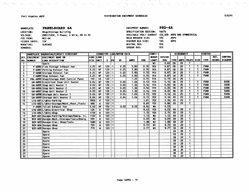
I
Port Angeles l¿lrÏP
IIAIIEPIATE:
LOCATIOII:VOLTAGE:
FED FROI:FEEDER EiITRY:r{o.JilïmG:REI,IARKS:
DISTRIN'TIil Eq'IPTETÍ SCHEDT'LES 9t9t91
PAI¡EI,BOAND 6AShop/Storag. BuitdírU208Y1120v, 3 Phase, 4 9ire, ó0 Hz Ac
tlCC-óATOP
SURFACE
EOt'TPIIEIIT ilIIIBER:
sPECtFtC^TtOt SECilOil:AVAITABLE FAUIT CURREIIT
IIAIII BREAKER SIZE:I,lIIIII{IJI¡I BUS SIZE :IIEUÎRÂL BUS:
GR(UilD BUS:
,000 AilPs RilS SYÍil|ETR¡CAL
^fiPSAÍPS
PBD-6À1&70<22
100100YES
YES
cxTxo.
IA'IEPIAÏE EIGRAVIXG/CIRCU¡T DIRECTfrY oorrEcrED to D/t()lm DATA c(tTI-ruusLOID?
DESIGX
nA
DISOilil IT
cilTROLDIAGRAII
Eq,IPIIETTnIEER
Eq,IPIIEXT TIfiE (nt(n,D DESCRIPTI(X
tuostzE
[o t)tfflÌ v PI IP
^llPSKYA TYPE ITPS ÞotEs STZE TYPE
HGT,
rxcÍEs1 Spare l¡o 0.00 c8 20 I2 F-óOEó Ftail Storage Exhaust Fan 0.25 HP 120 1 o.25 5.80 0.70 YES 0.E7 CB 20 I t FV}IR
3 Í-60E7 Perkinq Exhaust Fan 0.25 HP 120 I 0.25 5.80 0.70 YES 0.87 CB 20 1 I FVTR
4 F-óOEE itoraEe Exhaust Fan o.?5 HP 120 1 0.25 5.80 0.70 YES 0.87 CB zo I I FVIIR
5 F-ó089 rop Exhaust Fan 0.25 t{P 120 1 0.25 5.80 0.70 YES 0.87 CB 20 I I FVXR
6 Prr-ó{r90 shop/storaEe HVAC Controt Pånet 150 VA 120 I 1.25 0. t5 YES 0. î9 c8 zo t7 ull-ó093 Etectricat Room Unit lleater 0.0ó HP î20 I 0.04 1.0ó 0, t3 YES 0.1ó CB 20 1 1 FVXR EóOB
E ufi-ó095 rop Unit Heater I 0.05 ltP tz0 T 0.05 1.32 0.16 YES 0.20 CB 20 t 1 FVTR Eó08
9 ufl-ó09ó roo Unit Heater 2 0.05 HP 120 t 0.05 1.52 0.1ó YES 0.20 CB 20 I 1 FVIIR Êó{tB
10 u$-6tçt7 rop Unit lleater 3 0.05 HP 120 1 0.05 1.t2 0.1ó YES 0.20 CB 20 I I FVIIR Eó08
11 ull-ó{196 StoraEe Unit lleoter 1 0-0¿ HP 120 I 0.04 1.0ó 0.15 YES 0.1ó c8 zo t 1 FVXR EóOB
12 ull-6099 Stoiage Unit Heâter 2 0.04 HP 120 I 0.04 1.0ó 0.13 YES 0.1ó CB 20 t I FVI¡R EóOB
15 LTG-ó{'I Liqhts-P6rkins t80ó g rz0 r 1.81 YES 2.26 CB 20 t14 LTG-óO2 L i Ehts- storase/,lech. /Rcst ./Toots 688 IJ 120 1 0.ó9 YES 0.8ó c8 20 I
F-ót 85 loitet Exhaust Fôn 0.02 HP 120 I 0.02 0-53 0.0ó xo 0.55t5 trG-ó05 L i ghts-Etectricat shop tt26 v 120 1 0.45 YES 0.55 CB zo 1
1ó LrG-ó{t4 tishts-Shop 17ZO ta tz0 I 1.72 YES 2.15 CB 20 I17 RCP-óO1 ecees-Pârkim/storrgê/E[Ërg. It. 1 tt0 t¡ t20 t 1.15 xo 1.15 CB 20 I18 RCP-ó02 Recepe-llech. /storage/Too I s/Ennrg. 590 t 120 I 0.59 to 0.59 CB 20 I19 ncP-ó05 Receps-Etec. Shop/loots 1080 IJ 120 I 1.08 xo t.0E CB zo I20 RcP-ó04 Receps-Shop 720 IJ 1U0 I o.f2 l¡0 o.T2 c8 20 1
21 RCP-ó05 Receos-Shop no U 120 I o.T7 r¡0 0.n CB 20 I22 Spâre CB 20 I23 Spare CB zo t24 Spere c8 20 I25 Sp6re CB 20 I26 Spare CB 20 t27 Spare CB 20 I28 Spare CB z0 I¿9 Spare CB zo 1
50 pare t
Page 1ó993 - 19

D¡STRIBI'T¡fl Eq'IPIIEXY SCXEDT'LES
Eot ¡Pf.lEtl llullBER:
Page 16993 - 20
PBD.6A (coNlfrD,
9t7t91Port Angeles llllTP
llAr{EPLÂTE: Pl¡tEI¡BOlnD 6A
) ;) )
A[D3'5.2ö
44.55520Eed:on ÉttDDes
19.1915.981.61fotat future load:
5.643.20o.32z25us of:
5015.3512.781.29rotat pres€,Trt toad:Space42Space41
SÞocê40SÞ¡cc39Þtca
'E
spacet7Space36Space55
Space34¡oace55Space32Space3tSp€ce
cülR)tDIAGRIT
IIGT,trcilEsTTPEstzEFoLEslp,sTYPE
DESIGilfv
CilTT.nlustotD?Klr^llæsflPPllv
tuf,I'XIÏ
torostzE
Eq,IPTEXT TAilE ilLÍIAD DESCRIPTI(T
SIARIERiTD]/X'IffiUII DIRECT(nYIAIIEPLATE I
l

i 'l
Port Angetes lltllP
IIAIIEPLATE:
LOCAT IOiI:VOLTAGE:
FED FRdI:FEEDER ÊIIÏRY:I{üJIIIIilG:REI4ARKS:
DISTRIU'TI(T Eq'TPîGTT SCHEDUIES 9t9t91
PÀITBIJBOARD 7â
^dÌinistration Bui tding
20811120V,3 Phase, 4 tlire, ó0 Hz AC
PBD-2
EOTTq'lRECESSED
Reptace existing 18 circuit
EeUlPllEtlT llLf,iBEtr: PBD-71SPECIF¡CATtOtl SECTlOll: 1&70AV ¡tABtE F^Utr CURREIT <22,000
^[pS RltS SytilETRtC^t
llAlx BREÂKER SIZE: 100 AIIPStlll¡¡l,ijll 8US SIZE: 100
^llPSI{EUTRAL BUS: YES
GRCullD BUS: YES
XA'IEPLATE cilxEctED to ,D/x)rm DATA DT :T
PI
crTxo.
EEUIPIIEXT
XI.;EERE4,lPilEXT XilG (nt(nD DESCR¡PΡ(N
[oDstzE
[oDUXIÏ v IP
^tlPSxY
cfitr-HIUStm¡r?
DES¡GT
xY TYPE lprs POTES stzE ÏYPGllcï,
¡xotEsofnrR tDIAGRâT
1 LtG-7t¡1 L i ghts-Of f i ces/Restroom/Foyer 720 t. 120 1 ó-00 o.72 YES 0.90 c8 20 1
ç-7tJl,4 Adnin. Toitet Exhaust Fan 0.02 HP f20 1 0.02 0.55 0.0ó YES 0.08 CB 20 I2 tlc-7fr2 Lights-Conference Rocrn u7 IJ 120 0.85 YES î.0ó CB zo 1
3 RCp-701 ce 720 v lZO o.7¿ lto o.T2 CB 20 t4 RCP-7| Z Receps-Of f i ce 1O2/Conf erence 820 H 120 0.82 xo 0.82 CB 20 I5 RCP-703 Recepc-Of f ice 101/Conference 820 t¡ 120 I 0.82 t¡o 0.82 CB 20 I6 RCP-7{r4 540 ¡J 120 I 0.54 t¡o 0.54 CB zo 1
7 ult-7W7 Yater Heater ¡J î20 t 4.50 lto CB 504500 4.50 28 PXt-n¡90 IIVAC Contron 150 VA 120 I 1.25 0.15 YES 0.19 CB 20 1
9 P-7lt9t n lleât l¿ater 0.31 flP 120 1 0.33 7.20 0.8ó YES 1.08 CB 20 t I tvilR10 Altu-7lxr3 Uni tnA r llandl i 0.u5 HP 120 0.25 5.80 0.70 YES 0.87 CB 20 I I tvrRt1 î-7ú5 Adnin Conf. Exhâust Fan 0.1 HP 120 I 0.10 2-& 0.32 YES 0.40 c8 zo I 1 FV}IR
15 RCP-71¡5 t v 0.E2 0.62 CB 20 IEZ0 120 t ¡o16 rrc-7Í15 or 210 u 120 1 o.z1 YES o-26 CB 20 I17 Spåre 0.00 l¡0 0.00 CB 20 I18 Spåre 0.00 t¡0 0.00 CB 20 I19 Spare 0.00 IO 0,00 CB 20 I20 CB zo 1Spare 0.00 xo 0.0021 Spare 0.00 t¡0 0.00 CB 20 t22 Spare 0.00 lr0 0.00 CB 20 I2t Space24 Space25 Space26 Space27 Space28 Space29 Space30 Space
Total present toad 0.70 12.09 15.05 ?1
Ptus groxth factor of: 25 z 0.18 5.02 5.26Total future toâd: 0.88 t5-1t 16.32
ês ON âTD oad: 206 5 41 .94 45.29 Anpo
Page 1ó993 - 21

Port Angetes ¡tÍTP
IIAiIEPLATE:
LOC^T tOt¡:VOIÎÂGE:FÊD FRO{:TIEIIA IJIRIIIG:E}ICIOSURE:
REI,IARI(S:
DtsIRtn TI(t EqilPtE[Î SCilEDt IES 9t7t91
ldCIfOR COIIIROI¡ CEIITER A/BPt¡p Station [o. 4480V, 3 Phasc, 4 uire, ó0 llz AC
Service transfomnrCtass 2, Tne B
llEl{A 12, lndustriatExisting tlCC. llake revisions onty.Revigiom shor¡r botdt
Eot lPllEl¡r tlttlEER: llCC-A/BSPECIFIC^T¡Ol SECTlOil: Existing
^V ILABLE F^ULï CURREXI: ÂllPS nffi SYIIIETRIC^I
HAlil BREAKER SIZE: 400.00 ^llPSlllllll,tll BUS SIZE: 400 tllPs
IIEUTRAL BUS: tlO
GRütlD BUS: YES
Page 'ló993 - 22
--) -) -..1' ) -) ,) ) ,' .,J / '/
17O.t 4195.74235.44170.75Totats. Futu¡e Desion:19.253480ilP60+251 of tarsest toad:
0.000.000.000.00Subtotsts, Future DesiEn:
FUNNE LOIDS
170.44195.74235.44170.75Sr¡btotâts. Present Desiqn:
11
10FYTN55iltorcP0.lnYES54.Wó5.fr(¡50.0054A{¡fiP50Stañüy Rsr Sflåge Pl¡tpP-80019
¡tH- tE Exi stinró.011{05.00ó.013480Ktt5gåter HeâterExi stinr9.02l¡o7.509.02I480KVÂ7.5TFR-84 and PBD-84PBD.8A7E¡i stinr1 -40l¡01 .1ó1.40o-755480HP0.75Seat llater Præs¡JP-56
T7.OOl¡05480ilPRer SeHage Pl¡p ZRSP.25 Exi st in&.02n.ooó0.00ó0Existiftn.00t¡0&.02n.00ó0.00I480flPó0Rar Seraqe Pum IRSP. l4Exi stin24.06l¡020.0024.065480Kl¿20Unit Heater 2UH.25
24.06460Unit lleater IUH-Iz Exi stiril020.0024.063KU20Exi st i n¡1.00x00-83t.000 .503¿80HP0.5Exheust Fan IEF- 1I
IIcIESIIGT,
lYPEstzEÞot_EstpslTPEtotDstzE
Eq,TPIIEXT TAfiE (nLOID DESCRTPII(T
Eq,IPIIEITXTTBER rvAnPSIPP11Y
!mDt tll
oilInotDTAGRAT
;ïDIiluxEAps
sT^xoBY?
;fED,VIf,G/CIRCUIÏ DIRECTfrY
ro.crT
.-,/

I
Port Arigetes lJl¿ÎP
IIAIIEPTAf E:
r0cA1tOil:VOLTAGE:
FED FR(l{:FEEDER EIIÎRY:t{ülITmG:
REIIARKS:
DISIRT&'TTil Eq'IPTEXT SCIIEIX'IES 917191
PÀ¡IEI¡BOIRD f¡Pre Station ilo. 4240112Ov, I Phase, 3 llire, ó0 Hz AC
ilcc-A/BRearilccExisting panclboard-make revi sionsonty. Revisions shorn botdty.
Eot lPl{EllT }ltllBER: PBD-LSPEC!FlCAll0ll SECTlOll: 1&70
^V ILABLE FAUII GURREIIT <22,000
^llps Rl|S SYl,ilEIRlCAt
ilAIl¡ BREAKER SIZE: IUGS otlLYillx¡nfi BUS SIZE: 100 ÂllPS
IIEUIRAL BUS: . YES
GR(UIID BUS: YES
rr EID 0F SCilEDUIES ü
CKT.
xo.
C(TXECTED LOAD 't{oToR DATA cftïI-nlusLOTD?
DESIGXfv^
DISOÍTXECT SIARÏERoilÍRoLDIAGRAI
EqJIPfiEXTXt.HBER
ECT'IPIIEXÏ TAilE (nLOt¡' DESC¡¡PÎI(il
LOAD
s¡zEtotT'TII v Pil $p AÍPS rv^ IYPE Aps Pd-ES stzE fYPE
lcr,trcIEs
1 Existing loads2 Existins loads3 Existiru loads4 Existing loads5 Existing loads6 Existins loads7 Existins toadsE Existinq toads9 Existino toads10 Existins toads11 ÍT-E{Xr4 Præ Srætim llert Tiacing 72 ll 120 0.ó0 0.07 YES 0.09 GB zo t
HT-8005 Pr¡p Dischortc lleôt lrccim 152 u 120 1-27 o.t5 YES 0.t9L i chts/Receg-Stmôy Elr losure 172 v 120 1.43 o.17 YES o.?2
12 flT-E0(b stôrìôv Prm Erclosuîe lle8ter 1500 t, 120 12.50 t.50 YES I.EE CB æ ITotat present toad: 0.00 1.90 2.37
Ptus gror,th factor of 0 z 0.00 0.00 0.00
lotat future [oad: 0.00 1.90 2.37
DesiEn flp tosd: z4g T f -glJ 9.88 AnÞß
Pasc tó991 - 23


DIVISION 17
PROCESS CONTROL{
\) Section
17000
1701017110L7LzO1713017140
L7200
Title
GENERAT, REQUIREI{ENTS FOR INSTRI'UENTATION AND--iñousmrar srncrRourc sYsrEttsCONTROL STRATEGIESINSTRI'UEI{T PAT{EI.,S
À}TNUNCIATOR SY STE¡'ISfór{ER supPLv etro cor¡prrronrnc EQUTPUENT
iñsrnrilgNt ArR suPPLY el¡D TRÀI{surssroNsvsrEils
cÑin¡r REQUTREI.IENTs FoR PRocEssINSTRI'UENTATION SYSTE!{S
pnõôgés TAPs A¡{D PRn'IARY ELEllENTsTRN{SI{ITTERSPROCESS FLUID ANALYZERSPROCESS SWITCHESI'NIVERSAT, CASE INSTRT'MENTSérei¡er, coNDrrronrNc uoDItLEsUINIATI,RE CASE_biNCTNONTC PAI{EL INSTRUIT{ENTS
uiscnm¡¡Eous Pat{EL rNsrRUl¡[ENTsTHROTTI,INE VET,VES FOR PROCESS CONTROL LOOPS
AUTO!{ATIC TELEPHONE DIALERôÃie AceursrrroN AI'ID lrANAcn.tENr -sIiTryg^GENERÄL NEOUTRE,TENTS FOR PROGRÀI-ÍMÀBLE LOGIC
coNTROLLnns- tplcsl Àl{D DÀTA ACQUrSrrroN Al{D
T.ÍANAGS{ENT STSTNUS INTEGRATIONcENERAL n¡eurneueÑrs FoR PRoGRAl{lfaBLE Locrc
CoNTRoLLERS (PLcs)I.rnDrttu capacrri pnocn¡r'rulBLg Locrc
CoNTROLLERS (PLC)
tL7zLLL72L2L72L5t72L6L7230L727LL727 4L7275t74tLt776L1781017900
17910
L79L2
:
May 15, 1991 ?:35 P\l-portann/lP/sjw


)
')
sEcTroN 17ooo
INSTRUMENTÀTIXEJXHååï%'Äïïïï"ï"Å"NTCSYSTEIIIS
PART I--GENERÀL
1.01 DESCRTPTTON
A. SCOPE:
This section specifies general requirements which areapplicable to arl iroðãss- controÌ, iñr'ir,rr"ntation,com¡rrunication, and signãi systens.B. DESCRTPTTON OF SYSTE}I:
llajor constituents of this.system sharr incrude, but are nottimited ro, 1J_r y!ã;i.i;, equipi;r-;;ä labor required toiutplenent a complete
""ã-åp"rat'ing sy;t;, of instiunrentation andcontrors. rhe Ëvsrern srraii inciuãe-åãit.or pã;i;;ãnraininenicroprocessor-bãsea ai=pi.v and coniior aevices, erectronicsignal conditioning-equiãi"ñt, nrãgf";.ur" _togið conrrolters,data acquisition añd ñanägene"t-rvétãrË, and power suppJ.ies.Fierd mounted equipmeni--sñarr in"iuãã-ãíectroñic and pneumatictransmitters -and cðntrãr-ãevicãs-;=;"ii as f inar controlelements' and. prinary ãiernents roi-prããåss variable measurements.Process variables snåri-incruae-iioil'íà*r"r, pressure,ternperature and .r.ivii"ãï r""=,rrements.
C. DEFTNTTTONS:
1' GENERAL: The definitions of terminol0gy used inthese specificarions rñ"i:.'ue aãiin;ã il rs^ standard s51.1unless otherwis" "p".iiiãã.
Z. SOLID STÀTE: Circuitry or components of the typer¡hich convey erectiãnr-ú" i".n= of solid material such ascrystars or which work oi r"gtr.ti; ;;i;Jipr", such as ferritecores' vacuun tubes, gâs tuÉes, -Àriãã'îir"=, ^stepping motors, orother devices are not ácceptablå .ù¡=ii[,utes for soriã statecomponents or circuitry.
3. TNTE.RÀTED CrRCUrr: A number of circuit ele¡nentsåil:.Ëli3f Ìå" ": ; ":
t:i::" ii"ãr r¡i th i"-';;;;t i,,,,õü
"
-tåày-to perr orm
4. TI{O-IÍrRE TRÀNSUITÎER: A transducer which derivesoperatins por:î_lypprv ';ü
tne sign.i-Ë.r,=nission circuir andtherefore recruires no separl!! pã"år-.ypprv connections. Às usedin this =p".iri-ããiä",-iãälrire rransmiller rerers ro a
17000-1
)
t

1.01 c.4.
transmitter t¡hich produce? a 4 to 20 nilliampere current
requlated signat in a serieË Ëiiã"ii tittt ^ i¿ volt directcuírent driving potentiaf aãa-ã-tãiitot ciicuit resistance of 600
ohms.
5. GALvN{rc ISoI,ATIoN: Pertaining t9 ?" ?I::trical node
traving no aireãt "ott".t p"[ft-io another-eiectrical node' As
used in this specirication. ä.i""ñïã-iEorã[ion refers to a device
with erectricãi- i"nqts. ana/oï-iiö;tt-t¡¡"tt are garvanicalrv
isolated fron ground, trre aãii;'ã;ã, alt" proceãs fluid' and any
separate pot.t'ãt'ppri t"ttiiåi;; ñt i":i-iñputs and/or outputs
are capabre ol bãñg "*t"rrräiii'slã""áãa tititout affectins the
characteristiãs oe €,fre devices- oi proviainã-path for circulationof ground currents'
6. PN{EL: An instrr¡ment support system whict'¡ may be
either a fIaL surface, " pãttiár "nciósure,
oE a complete
enclosure for l"ãti.-ä"t=- åiã-ãtnãi devices used in process
control systerns. ianets råï-pi"vide mechanical protection'erectricar i=äîåtiã"l "t9 ;1"'¿;ii;lj::t dust' dirt' and
chemicar "o.iãiîi;{å 't'i"ñ-t"v P? present in the atmosphere'
Paner shalr ñ;i;ãã-consotãs' Ëa¡inéts and racks'
7. DATA SHEETS: Data sheets as used in thisspecific"ii"l-ãt'al1 refer to rsA s20'
8. SIGNAL TYPES: Ttre follo¡ring types of signals are
used ir, =v=tåiã"õ;iiied in this division'
a' Low LEVEL Al'¡ALoG: -À signal'thi:-lls'a fuIIourpur lev"I'åf îõô ãirii.rorlã ot less.- Thi" group includes
thermocouptes-ãnã- i"=irt.nãã temperature detectors'
b. DIGITAL CODE: Coded information such as that
derived fro¡n the out-p"t. oã-ã" ""árog to ãigital converter or the
coded output Ë;r-;-ãisitår-ãonputei gt otñer disitaltransmission iãrri""i. - di=-ãî;ã-itt"rnaes those cases where
direct line driving i= ,rtïi-irãä-ãna not those cases where the
signal is modulated'
c. PI¡LSE FREQUENCY: Counting pulses such as those
enitted from speed transmitters'
d. HIGH LEVEL AITALOG: signals with full output
revel greatei'tnäi-ïoõ-riirî"ãri=-¡"i í"== than 30 volts'inciuaíng 4-2o nA transmission'
e. !{oDUI.ÀTED STGNALS: _ signars e¡nanating from modems
or low revel audio =igr,"í=i'-äälãår ;iä;l lever is plus 4 dBm to
minus 22 dBn. Frequencv-Iå"gã-is 3oo Éo ro,0oo hertz'
f. DISCRETE EVENTS: Dry-contact closures monitored
by sol,id state equipment. il-.i" ""ita"ãtãrs connecting to dry
17000-2

1.01 C.8.contacts enter encl.sures^_containing porfer or contror. circuitsand cannot be isorated iiot such ciícüits in accordance with NEcÀrticte 72s, this signai-sharl b"-t;;;¿ed as row vortage contror.
bv . re l avs,
"f _ ""ï3i"T"3i33i r :3.313;':., li"li "ï" :3 ïi:; ", ä"iåll:"uand 250 nillianperes
exceedinn nrl; n "åSf , "iT:i"åT3å"r:i5IË:i."o:ii:"iåg:., =
:i*,1ã.i ll;*F' 3, äü13"iü" "ffiå"ïå".iî"Fiä:$ "î"Ji". t",
9' sysr'lrfs HousE: .An organization engaged in thebusiness or derair ""gi"ãå1inö, ;äË;"i¡ n,r."rr?ég, assemblv,program¡ning and inpreñenting proces! contror and industrialeLectronic systens-.
D. REIÀTED T{ORK:
="..T3Tånli"lrîî:ïff"íå:s and wirins shalt conpry wirh applicable
L.Oz QUÀLITY ASSURÀNCE
À. REFERENCES:
1. coDES: This section contains references to thefollowing documelll: _in.t'are a part of this section asspecified and nodified. -i" case óf confrict between therequirernents of this section and thos"- ãr trr" ri;a;ã àocuments,the requirements or tñÀ-¡nãie restrictivÀ docurnent shalr. prevail.
Reference TitleNFPA ZO-90 National Electric Code (NEC)
UBC-BB Uniforrn Building Code
2- s'ÀNDÀRDS: This section contains references to thefollowing docunents. rnãv are a part of this section asspecified and ¡rodified.- -Í" case óf confrict between therequirenents of this sectiän and thos" ãi the ris[ãâ ãà",rrenrs,the requiremenrs or tñis-.ãittiä" Jt;ii iievair.Reference
ANSr À58.1-82Title
Ìfininun Desicrn Loads for Buildings andother structúres
Pipe Flanges and Flanged FittingsÀNSr 816.5-88
17000-3

Reference
Àt{SI C57 -L3-78
N{Sr uc96 -L-82
API RP55O-86
ÀsuE L97L
ASI'M A1O5/À1051{-87
ÀsÎl{ 4240-90
ASTI{ A269-90
ÀsTlll A27 6-90
ASTM 4312/À312It{-89
ASTI{ 4515/4515I'182
ASTU 868-86
ASTI'{ D883-89
ÀwwA C203-86
ISÀ RP7.1-56
ISÀ s5.4-89
ISÀ s7.3-81
rsA s7.4-91
L.02 4.2.
TitIe
Requirements for Instn¡ment Transforners
Tenperature t¡leasurement Thermocouples
ltanual on Installation of Refineryrnstrument= anã-õãniror systems' Part r -Process rnstnüettiãtiott ald controlsãctions 1 Through 13
ilFluid l¡leters'rr Report of ASME Research
cãrnnitt"e on F1uid Ìleters
Forgings, Carbon Steel for PiPinqComPonents
Heat-Resisting Chromiurn-?"9 Chronium-
Nickel stainlås;'ï;;i Prate' sheet' and
Ëliïp-r"r Pressure Vessels
Seamless and l{elded Àustenitic Stainlessilääi-Ñbins iãi c"tt"ral service
Stainless and Heat Resisting Steel Bars
and ShaPes
Searnless and l{elded Austenitic Stainl-essSteel PiPe
PressureVesselPlates,CarbonStee]-forInter¡nediate- ána Higher-TernperatureService
Seamless CoPPer lube' Bright Annealed
Definition of Terrns Relating to Plastics
CoaI Tar Protective Coatings and Liningsfor steer watái-iip"ii""s-lEnarner and
iape--ttot-APPIied
Pneumatic Control Circuit Pressure Test
Instrument LooP Diagrarns
Quality Standard for Instrurnent Air
Air Pressures for Pneumatic Controllers'Transmitters, ãnã irans¡nission systens
:\
17000-4

\.-
Reference
ISÀ s20-75
rsÀ s51.t_79
UTLSPECurL-r-46058C_80
NEDTA 250-85( le88 )
SÀI.IA plrfC5-10-63
sÀIrfA PIr{C6-10_63
sÀt'{A PIrÍc8-10_63
SÀII{A pl,tc17-10-63
L.02 A.2.
TitLeSpecification Forms For processl{easurement and c""trãi iilarrrr"nrarion.Prinary Elenenrs, ãñã-ð";Ë;;iïï;:;.",,,Process fnstrumentation TerninologyElectrical Insulating Conpound
Enclosures for fndustrial Controlsand System
Resistance Thernometers
Filled Systen Thermometers
Thernocouple Thermoneters
Bushings and t{ells for Teurperaturesensing ELements -vu¡¡'
sAIr{A plrfc2l-4-66 Temperature-Resistance values forFï:; i:*:".i1;:î:':ff t":#äãì. I "ä,
B. SYSTEMS RESPONSTBÏLTTY:
All instrumentation and industrial electronic systems shallbe provided unde:- ri;. ;"iär"i=io;-;;*; :_trgr:_ svstãirs house whichrs regurarry. engaged in [,tre -a"sign-år,ä ir,=tarration of suchsvstems or simiÍ"í r"ðp"-;*;;ËïJï;y: rhe conrracror is#:iiä:å"* ;:.:|:#*i,fia,ïiã;ffi;ä or ari-siåËã,=
""C. TDENTIFTCÀTTON OF LTSTED PRODUCTS:
Electricar.equip¡nent and materials sharr be listed, for thepurpose ror n¡hict, ú"v ur;'-p, :;iiål-ir-an__inããp;;ã# resrinslaboratory' Three -J"ån-åiganization=-år..
underwriters Laboratorv(uL) , canadian. stanãirä.ïÃ=o.i;ri;;-f Ëiel , and Erecrricalrestins Laboraroli;i. ?Ëõ"i.. rhe rnãeÈãiä"rt raboraroiy unaer:lff3,î.iïlii:, t"ilÈii:.i* :i=o:"::::;laure _ùã _ir,r_i,,,pecrion
I{hen a nroduct is not avai}able with.a testing laboratorylisting for the. purpose ior wrriõñ-it-iJ. to serve, the product rnaybe required by. tir. in=p"åËion authority,'ao undergo a Lpeciatinspecrion ar'rh. uã""ãããiür"r,s prããã'åf .=="rnbry. À1r cosrs3lîrïi:ï":ff.:::.Ul"j:Jiä"ti"n=-!iãir"üe incruaäa in tr,"
17000-5

1. 02 D.
D. FACTORY TESIS:
tthenspecifiedinthe.individual-productspecificationsecrions, ractåii-tããts st"ii-¡ã-ferrärrned at Lhe place of
fabricarior, "i-il"-ããiãrãii; ;; ñã""¡1"¡'otà ot as-sernblv' All
cosrs ana expá;;; iã;- sucr,-i"ã[t =ñàrr be included in the
ãiiõinar conlract Price'
1.03 ENITIRONI'IENTÀI., CONDITIONS
A. GENERAL:
Specifiedconmunicationandproc:":--:ottrolequiproentshallbe nodif ied, if necessary, .'tã'ta-fã it -suiiãble foi oþeration in
rhe forlorins'årËi;;ã-õ;åiãi""ã. lndooi-and outdoor field
Iocation tenpeiatures "rra tåiãiI"" f,r-iaities are specified in
Section 018OO.
B. ALL ÀRE,AS:
AtmosPheric conta¡ninants :
l
:
Electro¡ragnetic radiation :
27-5oo Wz 1o volts/rn
C. CONTROL ROOMS:
TernPerature 60 to 8o degrees F'
HurniditY 2o to 80 Percent
D. INDOOR FIELD LOCATIONS:
TemPeratureHurniditY
E. OUTDOOR FIELD I.'OCÀTIONS:
TenPeratureHurniditY
F. HAZARDOUS LOCATIONS:
Hazardous locations shall be as specified in paragraph
Hydrogen sulfideChlorineAmmoniaDust
0.1 n9/1o. 01 !ûg/ I0.5 ng/I50. O ttglrn'
40 to 120 degrees F'10 to 100 Percent
o to 1O5 degrees F'1O to 1OO Percent
16000-1.05.
17000-6

subnittars sharl- be.provided in accordance with section01300' orreri of suustifuãiã"-i"i"i;;;-specified by name sharlbe subniËed in acððrãã""ã ,lth Section 0o710.
1. 03 G.
G. CORROSTVE LOCÀTTONS:
,.oo3lil3;:"" locations sha1l be as speciried in parasraph
1. 04 SUB}TTTALS
GENERAL:A
B. DRÀWTNGS:
1' GENERÀL: The drawings incruded in this projectnanual are functional in natgr" á"a-äã not show exacL rocationsof equipmenr or inteicãnnectiã"r-Ëãtiãen eguipment. Detairedconstruction_drawings as specitieã-ùåiãw snalr be provided.Drawinss shall ue píepãi"å-ott zã:i"ãtr-iy 3a-inch diafting media.Itfedia shalr ue veriurn-ãt ryràt:- D;;iñgs shall have borders and:å:i:r:i3"H iaenõiiv+"ã l¡," _p'.iã.Il-=i=."., orisinar dare,
¡;$Ëîårs ï;iii*:""1,
itË+,;':'¡ir}ff *;¡ili;:$:: ::. :,wire nunbers and terurinãr-uroði'r,üruäi!' i' compriance withparagraph 17110_2.05.
2. ELE''ENTÀRY AND-LOOP DIÀGRÀMS: .ÀN EIEMCNtArY diAgrANfor each discrere.l.óp "ïã1r_gg ;;;ilr.d. Loop diagrams shalr beprepared in cornpriancã wiitr rs¡ Ëã.¿-;;ä sharr be provided forarl analog roops. Ele¡nentary aiagrãurs-'ãna loop diagrarns shal1show circuits ánd deviããs-or-. ;t;aãill -rn"="
diagrãrns shalr bearranged to enphasize device ereñents and their rúnðËion" as anaid to understänalnõ-tt¡ã'åp.rution oi i"systern and naintaining ortroubleshooting thaÉ ;v.tãl: _nrenenãaiy ana roop diagrans shallË¡;flï'oîåIi iüi:=;
-;i;" cor.or coaeÉ, =ig.ãi-pãiäiiti"=, and
3 . coNNECTToN DTAGR.AMS: connection_ diagra¡ns for panetssharr be provided- cà""ããii""-åi.õi;l-shar1 shów componenrs ofa contror panel in an ."rãng"rent éiniiar to trrã-å"ãùär rayout ofthe paner. r:.::":] "i;il;-between-il;ä"= wirhin rhe panelshalL be shown_on thes. ãiåg..*=. connection diagrams sharr showalL terurinar brocks
"rr"ttãI used ror lniernar o, tiãlã wiring.those used ro1_r].erg-;i;{{,; sharr uã õïãàrly idenririecr as such.wiring diagrams shalr inãiðate in=uiaiiãn coror code, signalffiffi:i::"=, and sharr =üãr "ir"-""iiãiå-.r,a rerminar brock
4- TNTERCONNECTTON DrAcRÀIr{s: rnterconnection diagramssharl be proviaed roi ii;tä "$ñ;-'rniär.onnecrion diasrarns
17000-7

1.04 8.4.
shallshoweachpanelandfielddevíces.l{írenurnbers,cablenunbers, racerlay n'nbers, tãrninaf box numbers' panel numbers'
;äÏi;itã;"i;å t"g ttotüers sharr be shown'
componentsofstandard-e}ectronicasse¡rbliesshallnotbereplaced wfth componenE ?: ãiiiãiã"t cnarããi"ristics in order to
neer the performance requireiliã-ãï-tñi=-ipecification' Parts
shall be as =ú;;"r; tt å i"=iiuction manual-s and shall be
replacea¡re wiãü stãnaara cã¡nrnãrcial comPonents of the same
descriptior,,oiüi";;-il;;ãaiãg "thá-pãrtor¡nãtt"" of the compreted
PÀRT 2--PRODUCTS
2 . OL UATERIALS Àl{D QUALITY
À. GENERÀL:
l[aterialshallbenew,freefromdefects,andoftlrequalitys¡¡ecified. Each tlpe of in;lñl0;iãl in=trunent accessory' and
dãvice strall be by the same-nánuracturer throughout the work'
Etecrroni" "qiIpñäni-:stratt bË;;-;ãiia -stãte cónstruction unress
orherwis" "p"äïlËä: -i;ti"tãã ãt ãt"u"a ðiicuit boards strall be
glass epoxy ";-;Ficiãnt_ttri"ir,"t= to piãvent warping' solder
shart be rin-read p1ate, sá'ï;;;-ó"t""iti-¿ñ' eteätró-deposited
foltowed by tin emãrsion and-iefloi tfusingÍ" Printed wiring
shatr have "oiä"i"'ii;r;ü ;iih "ã-ãipò=ed
cópper on.surface'
edges, of, i' iäiå.-;-;i"i=iãa pt"dî¡ct.- piiitted circuit boards
in fíeld nounted equipnent-Ëtt"fi-¡ã coated with 2 nils of a
solderabre conforrnãt êoatinl"tfprVittg-*'ltn !{rLsPEc urL-r-46058c'
ÀIignment and adjustme"!=-. súaff Ée- noncriticar' stable with
remperature chanses or "giiä-åia-ãcäãlpli;ñãã i'itrt prernium srade
potentiometers.
assemblY.
B. }[ÀJOR EQUIPUENT I'IN{UFACTIJRER:
Eachtypeofinstrurnent,instrumentaccessory,anddevicesharr be the piãauct of a =i";i;-;:-"1t"::"rer'
ihe rnajor
equiprnent ..r,üi]:ä;";-=t"ii ú".r" been rãõurarrv^enqaçted in the
manufacture of the tvpe "i "ä"ip1t"1!^:*Ëiii"a- for a period of
not less than five years ana ánai1 proauãã-lft" equiprnent in his
own facil-ities.2.O2 PRODUCT DÀTA
A. GENERÀL:
lhefollowingdatashallbeprovidedinaccordancewít.hSection 01300 as-proviaeA iãr unãer paragraph 00710-4'02'
17000-8

B. UÀTERIAL LIST:
within 60 days after r.Notice to procegd,,, a rist of thenanufacturer and noder seriãs-iãr-ã"åi' naior. category ofSiËåiii:å: svsrem, anã instr.*ãni r;-;" provided õr¡a¡.r ¡"
C. CATÀLOG CTITS:
cataloo cuts showinq pertinent infornation and features forthe prop"=ãa-"qi;;;;;":r¡ãrr. rêî;r;ïåàa. cararos inrornarionshalr incrude tecîrnicãr-speciii"ãti;;; and appricarioninfor¡rarion for "âärtìi"ãä or 9eüipräãt, _ catarog cuts shatr beedited ." il?i:"!_: ãlir -tr,"¡!_ iù';;;;åa"r ði-ÀãiiãJ' or equipnenrwhich are being proviaêa. Àlr
"*ciånããus materiars shar.r becrossed our or olherwise obtite;;üãl-'D. COIIfPONENT FABRTCÀTTON DRÀWTNGS:
Detailed circuit schematics, printed circuit board drawings,and chassis layouts srrali- æ próvîããä-ã", erectricar andelectronic conponents.
E. CERTIFICÀÎION:
1. TEIr{PERÀTURE: T?:t_data, certified by themanufacturerr..:lilr_ be proviaea-ið-å"ããr,=tr"re rhar rierdelectronic devices are ãuitablà ;;"-;il;'specified anbienttemPeratures s'¿s rv! L¡re
2. coRRosroN: D"r:_.:l:11_p" provided showins desisnfeatures of the erecironlã*equipment piovided to protect againstdamage bv the specitiãã--ãLoJprrãric cãnianinanrs and specificevidence rh"l., :-iTrlãa_it. fioteðt.ã-ãrããIionic esuipnenr hasoperated in si¡nilar enviionments roi ã perioa ór irot ress than 5years without failure a"ã-t" corrosion.
F. RECORD DOCI,MENTÀTrON:
. Drawings specified undeschedures ínerüa"ã- i,, -oi;i:i"1"í?nli3Ïr'í3'3;å;Îå"å :3u,ååå,udrawings in accoraance-r¡i[tr secti"n oiizb. .Fo].rowing start_up,
i:i"Ë:t:; :ï.."""eptance or- the ",õ'i, -iúir-=ize
reproáucible mylarq i ãq"ã'; - ;å -i;Tï::i;
" I !31 i " "!ll;::i:i,l:',ii*i;ã1"#:P
r E ¡r'¡v r ardrawinss sharr u" piãviããã. ooèunenrãaià,, sharl refrecr rhe:i3i:r::nstructea 3iÀtã-ãF'tn. i""iiùrÀiàation and conrrol
G. OPERÀTTON ÀND ''ÀTNTENANCE
TNFORI{ATTON:
operation and rnaintenance information sharr be provided inaccordance with Section oii¡0.
2.O2 B.
17000-9

2.O2 tt.
Theresultsoftestsprefornedinaccordancewiththisandsubsequent secfi;;=-&-lni=
-ãi"i=i"n shall be provided'
H. TEST RESIILTS:
PART 3--EXECTITTON
3. 01 INSTALI,ATION
A. GENER,LL:
Installationshallbeinaccordancewithsection0]662,thisEection, subsequent sectionä ;i-ihit division, and as Ehown on
the drawings-
Eouipmentshallbelocatedsothatitisreadilyaccessiblefor oferãtion and maintenance'
B. FIELD EQUIPMENT:
l.GENERÀL:Equiprnentshallbeprovidedas-specifiedonrhe drawings liãü-tn"t óoriä-ã"a-ãài"stme-nts are accessible for
in-prace t"=tiiã""iä-ã"îiLiãti"". l{here possible ' -
equiprnent
shall be tocateá between 48 i;ãn"= and 6O'inches above the flooror a permanen;-;";i-platfor¡n. Instrumetti"iiott equiprnent shall be
mounted for unobstruêted ""äå=", but ¡rounii"g snãff- not obstruct
warkways. Eöi;tã"t shall-;;t-;" mounted where shock or
vibration wirl impair its opãttlloir-.::nnétt systems' shall not
be attached to hairdrairs, pioc"== piping'ãr ne"i.anicar equiprnent
excepr for ¡neãsüii.g "r"r"t',iã;ã iãi"ã-pãáitiotttt:-'-, rtt=truments
and cabinets supported dirãctly by "orr"tãt" or concrete block
walls shal' be êpaced out. "ãi-i""-= than. 5/8 inch by framing
channer between instru¡nent"ãia-wãrr. st;äi used fór support of
eguipnent snárï uã ¡ro staiiïãss- steer, unless otherwise
specified. support. sy=t-ro3ï-i"ãl"aifø' nãnãis, shall be designed
in accordance i¡ittr the Uniiått -ã"ifaiñg--ðoae ior seisrnic zo¡.e 3 '
and to pt".,"it"ããïoi*"tiott-õiË"tã1 ¡1i1t tle inch under the
attached equipment load and an external iäáa "t 2OO pounds in any
direction-2.ELECTRICALPoI{ERI{IRING:Electricpower-wiringand
equipnent snãir-ùe in "o-prï.nãà wittr Division 16' Power
disconnect switches shal+ -Ë;;ãvided ttitñitt sight of equipment
and sharl be tabeted to inãicãlã ãp"tt"a-ãlã croéed positions and
specific "qriiããr,[-ãeiv"a.--;wittti-tt-il'gÌtt or" is defined as
having a creãi'ùno¡structåa "iãto from trtã "q"ipnent
served and
within 5O feet of the "qoiit"ti served. Oiiconnect switches
shall be mounted betwe"" äãï;;!ii-111.72 inches above the froor
or perman"nt'-wãik platfornr. l{here equiprnent locatign is such
that the above requir"*"r,|å cánnot ue nèt by a singre disconnect
switctrT trro switches, orr"-ãt-IË-;q;ip¡nãnt-änd one at the work
platforrn, =rrãîi-¡ã-plo.,ia"ä] -Ëã"tt'alè"ãtttt""t switch serving
17 000-10

3. 01 8.2.equipmenr tocared ourdooi: :lr?ll_þe provided r¡ith a surgearresror, cenerat Etecrric sLrsccÈõoîl o.
"q,råi].. it" surgeffäï::: :3;åå,":"1åig;:"-ü;ií;;Ë'e'',,,d srid 'ìtn a ño. e
3. SIGNÀL T{TRTNG:
Electrical signar wiring-?rg eguipnent-shatl be in compliancewith Division 16'- greãiric-signar'ðõñnections to ãquipment shatlbe made on rerni".r-¡iãJxs. gr tv roãiir,'. prgg "r,ã "ã""pracre
assembries- Jackered riáxiùie-¿;ilîr sharr be used berweeneguipment and rigiã-t"ããt"v systems except that flexÍbre cableassembries may be used wrtgle Ë]"n ãr,ã--r"""ptac1e assenbries areprovided and Lhe insiiliãtion-iJ'r,ãt-r,ruiããr-ü;äãñ.r,i""r damasein normat
"::: .r¡e-iãngit, "i ii"ii¡rã'conduir or cord assembriesshatl not ex-ceed 3 reÀi] rrexiùiã-ã"ur", receptacre and prugassembties shatl be useá oniv "ñãi"-!õå"ified.4' rDENTrFrcÀTroN_TAgs: Each field mounted instrumentor device sharr ¡" prôviãed with "-iã"q.rge stainless steelidentification. ras.' - iå;;;^ìrid!:ö'i"3." ãnarr ùäã.-ir,e complereinstrument nunber-a= ii=Ë"a in paragr.ó! .t7200-3.03. charactersshatl be L/4 inch, -ãiã-Jiàrnpea.-
raér,tíricarion rags sharr be;:iä":I"î:T::3"3.::,.1:,ji!'*.*i;::'å read'y .,iËi¡r" iõ".iio,,C. INSTR'"EN' SUPPLY ÀND SIGNÀL ÀTR CONNECTTONS:
,r.ntlllliffirlrìi3:t" and sisnal air connecrions shatr compty
D. PROCESS CONNECTTONS:
Process connections shal1 cornply with section L72La.3.O2 TESTS ÀND TNSPECTTONS
À. GENER.A,L REQUIREMENTS:
Material=,-,"qYiplenç, and construction included under thisspecif ication. snárr'uã ii=p"-clear ir,-aã"ãrdance with section oo71oand subsequent sectiãns-oi'ttri= aiïi=iãi. Testing sharr beperformed in accordan"" "'itrr se"iioi-õiäeo, this section andsubsequenr secriot= ôi-ttià ai"i;i;;. -ñã
,"quired resr shall beapplied r¡ithout. prior-nãti;" to the- óor,ãt.uðtion rqanãe.., who has:|il:i3*.ff ::.:::;:;i-Ëå"t. ¡c-rã;;ã 14 days beroie rhetest- pið;;il,::_:3ï,Tï:'*T:i:!å;*3';": r;!"iiå3,ã;;i=:r.Ë!:lresutts in accordanäe witü-su¡=.q,rãr,i-r"àtior," oã-tüí= divisionshalt be provided' -Àri-àä"iprã"Ëì;;;;;rv
ro.perrorn rhe resrs;:ffiå$] t" subsequã;t ;å;ai;;= -";ì;il'ai.,i=ion sharr be
17000-11

B. PIPING TESTING:
l.PNEUuÀTICPIPINGsYsTBts:Pneumaticpipingsystemsshall ¡e testeä-'Ëi-i";i;-il ããrpri""ce with section L7L4o'
2- LIQUID PIPING sysTElt[S: Liquid piping-systems shallbe tested for'i;i=- ir, "orpiiance
r¡ith section 15050
3. 03 1TRÀINING
3.02 B.
**END OF SECTION**
operation and maintenance training _for ttre equiplent provided
under this division sharl b"-p;ã;ided-for-ttré owñer7s personnel
ar rhe owner,E facíriry ¡T ;"ã;;ä;ãã *ittt section o1664 and
subsequett ""ótiãns or-this division'
I:
)
\
)
-\
I
ìr
17000-12

sEcTroN 17010
CONTROL STRÀTEGIES
These controÌ strategies are not intended to apportion workor responsibility for wori among subcontractors, suppriers andnanufacturers, but are offered.ãs i-gñ¿ for progrãnning, startup, and check-our. They aescriuã ñoõ-ü; systèn í= iã operare,and do not necessarily inciuae-ãir--ãåriäients reguired to makethe system function.ControlStrategyNumber
PageNumber
7
10
74
TitIe
INFLUENT FLOW CONÎROL AND II{ECHÀNTCÀL BARSCREEN
GRTT COLLECTTON ÀND RE!{OVÀL
PRII.IARY SLUDGE ÀND SCT'I{ PUUPING
GRÀVTTY THTCKENER AND THTCKENED SLUDGE ANDSCUItl PI'UPTNG
TÀNK DRÀIN prlr! sTÀTroN, PRIMARY cÀLLERy srrMpptr{ps, DEr{^TERrNc gurroiNe sulr{p purpõ,-a¡¡pSECONDARY coNTRoL BUTLDTNG stITtÍP PT,MPS
TRICKLTNG FTLTER CTRCUI,ATTON PT,MPTNG
BLOI{ERS ÀND ÀER.â,TrON SYSTETI{S
SECONDÀRY TREÀTItÍENT
SOLTDS CONTÀCT AND SLUDGE REAERATTON BÀSTNS
DIGESTER SLUDGE FEEDTNG
DTGESÎER SLUDGE TRå,NSFER
DTGESTER HEÀTTNG ÀND CTRCUIÀÎTON
BOTLER AND HEÀÎ RESERVOTR SYSTE}Í
DIGESÎER GÀS MTXTNG
LSG GAS I{ANÀGEII{ENÎ SYSTEM
3
6
1
2
3
4
5
6
7
I
9
10
11
L2
13
L4
15
L7
2t
24
27
30
32
34
36
40
44
17010-1

ControlStrategYNumber
16
L7
18
19
20
2L
22
23
24
25
26
PageNumber
47
53
56
61
63
67
70
72
74
75
76
TitleHYPOCHI,ORITE DISINFECTION SYSIE¡'I
SLUDGE STORAGE
SLUDGE DEIIATERING
FIT,TRÀTE STORÀGE
POLYT¡IER FEED SYSTruS
TNSTRI'UENT AIR SYSTN'T
RECI,ÀN,TED WATER SYSTE}Í
HE.ATING Àl{D VENTII"ATING SYSTE}TS
CONTINUOUS VENTII,ATION SYSTn{S
INTERI,TITTENT VENTII,ATION SYSTEIT{S
PU!{PING STÀTION 4 BÀCKUP RAV{ SEI{ÀGE PI'I{P
I
-
I
\
.l
1
--l\.
1"
L70LO-2

CONTROL STRÀTEGY NO. 1
--- TNFLUENT FLOT{ CONÎROL ÀNDuEcHÀNrcAL BÀR scREEñ õãnñïrro¡¡
A.
D. EQUTPMENT:
Equipment no.
PNLl1O3scN1101scN1102cPT1111GT1120
OPERÀTOR CONTROLS:
Location
PNLl103
PNL11O3
PNL11O3
PNL11O3
Drive
Description
Bar Screen Local Control panellfechanical Bar ScreenHand-raked Bar ScreenScreenings Courpactorsrrcular prirnary Isolation Gate
PURPOSE
To control the operation 9f the nechanical bar screen andscreenings conpactorl ilã-i". aivãii ;;ü'rhe rrorr ro rhe ordcrrcutar orinaiy craiiilãr whgn iãt.ï-;io", "ï""eds 6.2 ngd.ii:":":5:*.:i:"";;;i;Eåa ",r,ð,,
-ãËöiitti,,e or blpass around
B. REFERENCES:
Drawing p101, Headworks process and rnstrumentation Diagran.c. sYslE!{ DESCRTPITON:
The headworks consists of two parallel screen channels, onevith a mechani""rrv-äiåãiãa screen and one wirh a hand_rakedscreen. À third "ñannei--"Jrr", as the eni:'$:":îä :f.'l:"ïi*:;,;f.g;,::i:':iï'?îffiI"olÍîff d i scharse
E
Controls
Hs-101À, Bar Screen rHand/Off/Àu¿e,,Selector SwitchHS-1018, Bar ScreentrForward /Otf lReversef, Selector SwitchHs-lolc, Bar Screen "nãrãIiPushbuttonHS-101D, Bar Screen rfLocaJ./RemoterlSelector Switch - ---Y¿''HS-1018, Bar ScreentrForward/Off/Reverser
Selector Switch
17010-3

E. OPER,ATOR CONTROI'S:
Location
Drive
Drive
PNL,2200
Gate OPerator
Gate OPerator
F. INSTRT'UENTATION:
Taq. no'
KIC-101I,DSH-101LDSHH-101
wsH-101zsH-101r,sH-104FC-109FE-110
KC-111FE-112KIC-120.AKIC-1208zsH-120
zsHH-120
?.SL-L2O
G. AI,ARMS:
Tacr no.
uÀ-101ÀUA-1018
LAH-1044IÀH-1048
zN{-120À
(continued)
9ç¡ntrols
BS-111À, Screenings ComPagtor
ü;ã7õitTautã" sãrector switchnJ-irig, bcreenings comPactorrForsard/off iñ;;íãe" sèIector switchHs-12o4, citåiIåi-Þtit"ty rsoration Gate
lResetn PushbuttonHs-l2oB, cirãüiãi--ptit"ry rsotation Gate
õ;;i7ñenotãl-serector switchHs-1208, cirãofãt-irinary- rsolation Gate
;õP;;iõi"ããã;-õ"=b¡"tto" switch
Descriotion
Bar Screen CYcIe TinerBar scre"r, niqi=oiiiãt"":1:1 Level switch
Bar screen Hid; óiii"t"tttiar Level Alarm
switchiåi-ãËt"en Hish rorque lwitchä; õ;ããtt nttå--of liaver switch
ms: "*lt";î #¿:"!:îî: :iiîä': l:i
Rectangur"t piiä"tv--i"truent Parshall
Ëllä3"t"ss compactor shutdown rirnercircurar "titäii-iiir"-""t
Parsharl Flurne
;il;i;; Þil'ãií shutdown limercircular pri^äii lïü=rri"g water Timer
circurar "tttålí i;;r;tïón Gate Position
:îi:it.l"Biil.', rsoration Gate Position
tll"*,t::t;;t,::i"llo r.tion Gate Pos it ion
Switch (closed)
DescriPtion
Bar Screen Trouble (DAS SYstem)
Bar scre"r, Tr"üiiã iu"i" êontrol Paner
3Ë333'àhanner ïiql l:y.:l Í3iî,'Ë::;if'Bvpass "n.r,,'"'i
üiö lãver iuain controrpäiref PNL2zoo) ¡arla nñêñ tDÀf'circuLar rrirnåry Isolation Gate open (DAs
Systen) -r ¡l i an êat-e oÞenCircular Prrurary Isolation-Gate OPen
iä;;-ä;"ltãr Pãner PNL2zoo)zÀIl-1208
17010-4

H. OPERÀTTON:
1. SPLIT SIREÀI{ FLOT{:
a. 
CONTROL STRJATEGY NO. 2
GRTT COLLECTION Al{D RE}ÍOVÀL
To remove the grit from the prinary- sludge and remove the
fine particul"iã-tíon ttre soiïã"-¡i wa-stting before removal'
A. PTJRPOSE:
B. REFERENCES:
Ecruipment , no.
sEP1131sEP1132r{HRl130
OPERÀTOR CONTROLS:
Location
Drive
Controls
HS-113, Grit Tfasher ItOn/Off rr SelectorSwitch
1. Drawins-pl'l 1-p:i1"îi=ili*$Jti:i"3î:9,:lî Grit Removar.
SYstem Process ancl
2. Control Strategy No' 3' Prinary Sludge Punping'
C. SYSTE¡.Í DESCRIPTION:
Primarysludgeispurnpedfromthepriuraryclarifierthroughacvcrone separatoi. rtre grif ãi=äh"rgeè to a-grit washer,.ln"tälãi;"i";;ï-;;;når_;;;-ãi;p"".r. one cyclone separator as
dedicated to each clarifier'
D. EQUIPIIENT:
Ðescriotion
Cyclone SeParatorCyclone SeParatorGrit !{asher
E
i
F.
ts.
H.
INSIRUII{ENTATION:
None required.
ÀI,ARMS:
None required.
OPERATION:
TheGritWasherrunscontinuouslywhenthe||on/offl'selectorswitãtr-is in the .onrt position'
17010-6

the sludde pumps remove the prinary stud-ge from the new andexistins priñarv ciaririã;; ;ã õ"ifr-;¿ lo- trre new srir removalã1fi13'i. i3"d:"ä'!HlJ:Tã'". scun- rion tr'"- i",-"råiïrier and
A. PTIRPOSE:
B. REFERENCES:
1.
2.
3
c. SYSTÐlf DESCRTPITON:
D. EQUTPMENT:
Equipment no.
coI,l302col,1303P13 10Pl320P1610
OPERÀTOR CONTROLS:
Location
Drive
Drive
PNL1321
Scum pit
PNL1321
CONTROL STRÀTEGY NO. 3
PRT}ÍARY SLT'DGE ÀIüD SCI'I,T PT,MPTNG
Description
Rectangular primary Scum ColLectorRectangutar prim".i, õiüä'gã-colLecrorPrirnary Sludge punË 1---z-Prlrnary Scurn punpPrimary Sludge pùmp 2
3iili:fl. P101, Headworks Process and rnsrrumenrarion
Drawing p102, priTary Sedinentation process andrnstrumentation oi"gí".]---'Drawing P1o3' Primary sludge thickening and Grit Removalsysrem proceås
""ä-ii=ãiilËit"Ii;;=i;il;.å..
sr"d;:"$ffiotì.punped continuoyslv from rhe recransular by prinarv:ï: _iiúäïí å;"*:iiü" :: iiiË:_ üit=!ü i:**i:j:ijí.ü'íåi'ii'crrcular cLarifiei ¡i, r.iiJry Sludge purnp 2.
E
Controls
HS-130, Rectangular prinrary Sludgecoltecror'fon7õf¡r, såiãäIåi srit"r,Hs-131, Rectangular piirãiv scumcottecror'Hanã/o!f/À;üi-ðerector switchHs-132À, primary scun purnp ron/off,,Selector Switch
HS-1328, Primary Scun purnp ,r6nrPushbuttonHS-132C, Prinary Scum purnp rResetf,Pushbutton
L7070-7

E. OPERÀTOR CONTROLS:
Location
Drive
Drive
continuouslY.
(continued)
Controls
Hs-135, Primary Sludge Pump 1 tron/offrl
Selector Switchñ:;;i;-riinarY srudse PunP 2ïã"iá7óti¡aotoi' sereótor switch
F. INSTRT'UENIATION:
gaq. no. LescriPtion
KIC-1204 Circular Prinary Shutdown linerzsHtL-L2o cirãiiãi Þiin"ry Ë;i;'i;n Gate Position
SwitchKrc-131i*:Ït"rarPrimarvscumcorlectorRunFsL-132 itüãtv qcun tYP L'ow FIow switch
PsH-132 Þtfi;;i é"t't Puú nigtt Discharge Pressure
SwitchG. AI,ÀRI¡ÍS:
Tacr no' DescriPtion
t{AIl-130ä:*i:n"IarPri¡rarySludgeCollectorHighyÀ-130 HlÏIgllï"îïàiït- "::se
co*ector
uA-132 ptltãty-scum Purnp Trouble
H. OPERÀTION:
1. GENERAL: Each-PunP is-suppJ-i:1, titn seal r¡ater' The
seal water sãtenoid valve ior the- t"tp""iive Pr¡mP oPens wbenever
Itt" potP is running'
2.RECTANGuI,ÀRCI,ARIFIERPWPINGSYSTET¡I:l{i!hthel|on/offllselector switch in the "e"i-fo=i!1:ft ptlt"iv sludge' Pump P1310
runs continuously: t{-irh..it"-iórr¡orr;' ";il;lår-iwi€cn' located at
the punp, ir,-õ;'i" it'" ':ä; pãäîiiã"f -;; the üon'r pushbutton
rocared "t tnã"!"oo, pir aåör"ãããã,-ptitãrv scum Pump P1320 runs :\
3.RECTÀI{GUI,ARCT'ARIFIERSLUDGECOLLECTIONSYSTEI¡I:ron/off' sereci;;ärt"h-i"-ïnã-ión" position, Rectangu
Primary sroagá-óãriããtot cor.,i¡o¡ runs continuously'
With thelar
17010-8

H. OpERÀTfON: (continued)
4' RE.'ÀNGUT,AR cr,ARrFrER sctlr coLl'crroN sysrEl{:a' UANUÀL: ¡fith !!e. "Hald/offlAuterr selector switch in:*="::lii"üff:Ti:", ñãõI."s,'r.i-i-'í'åií r.o,o c"ilãJt"r col13o2
b' Àüror[^rrc: ni!l_!h"- rf'and/offlÀute, selector switchin the rtÀutorf p""itiã", äå"t"ngurai-nrír""y scum correctorcol1302 runs on a perióaiã'¡asís-ããtåiiîr,"d by ti¡rer Krc_131.5. CTRCUI,ÀR CI,ÀRIFrER PT'UPING SYSTEITÍ:
a' I'ANUÀL: wit'h the-trHand/offlAuter selector srritch inthe r'and" positiõn, irü.iy stüã;;' ;;;i' prero-iùns-ããntinuousty.b' ÀurolrrÀTrc: wit!_lle_r'and/offl^utor seÌector switchin the ftÀutof' posiiiðn, öiir""y. srrrajã'õi*p p16ro runs whenever:*rï::!tåirii"ririãr''"i!. -^
irre nùñn là."it= o. "r-ilãpen,,sisnaltne tírnã; iiË:Î8ð^ i:: lTi:"=::p= ãrtã'-àn. s.iä r,." ãio=ea-ãnã-
i
17010-9

CONTROL STRATEGY NO' 4
G,AVITY THICKENER À!{D
THICKEÑED SLUDGE Ar{D SCT'M PT'UPING
À. PI]RPOSE
TheGravitylhickenerservestoT.hickenanixtureofflowsincruding wastä secondary r;;åõ, -prir"ry-"r,tag"r an9 secondary
effruenr. The Giavity rtriciãnäi'oñit pró"iãã=-tim" for settring
of rhe solids'";;äñåa-in-lÍä-åliäõã ñiit"i", and provides for
removar of trre-ãüiãiã"ãa-srùãse and scul'Iã-ür" disêsters and the
clarif iea erriuãni--i" -itt" nããät"ix=. The thickening Process
provides "or,"åitiãtio' or rãîïäã-tñåt tr'rãüãiiciar-tó subsequenr
þrocesses, arrowing ttrose "ÏiË!-tã"Ëã ãi'ãá snarler and operate
iore efficiently'B. REFERENCES:
l.DrawingPlo3,PrinrarySludgeThickeningandGritRemovalsystern-trocess ana i'nstrurnãntation Diagram'
2. Drawing P1O4' Thickened Sludge and Scurn Purnping'
C. SYSTEI'Í DESCRIPTION:
I.THICKENER:lhetyPgofgravity-thickenerusedemploysacircular tank, wirþ_a rotatlné-síuaq"-ê"iïããiion nechanism' the
tank design iå sinilar to "iüËt-ãiróular-tãait"tttation units'
Thedilutesludgeisfedintoacenterfeedwell.Thefeedwetr provides-=oiiiói".t *roî,riäl-.,,a-9'1tiãtã- orientated to allow
dissipation ot vãiãcitv 9"JËî-å"ã'-:ll!:tt-t""átent of the dilute
srudge inro tie-tã"r. -rh9-ãíiut" sruage ïr-'ãiiór"d to settle and
compact. trre iesurting th-i;;;;ãá sruaé" iã withdrawn from the
ñîã;t of the tank bY gravitY '
Thesludgeco}Iector-mechanismassiststhisprocessbycontinually raking the fr;;";-[-rt" ianr with squeegees' rnoving
the thickened srudge tor.rä'ttå ãã"t"i ai=ãrrãtgå. óewatering is
aided by the -"áiioñ ot verfiããi picr"t=-'iããtãnéa to the top of
rhe correcror arms to gentïi"3ii;-tüã-ár"ããã-uranret, providing
p"ttt" for the water to escaPe'
2. sr.,uDGE ptMprNc: srudgg i= puurpgd from the gravity
rhickener uy--nã thickenea--rúage punp ;; ;-tiureTaensitv basis'
17 010-10

3- sculrr pttlÍprNc: scum is pumped frorn the gravity thickenersggm pit by th-e thicx"nãi-Ë"urn.pumþ based_on rhã revei in rhepar- The rhickener scum nrrp ËËpä-ãiq varvÀa-tå-ia"x up rhe;iï"li: ;ii:,1fta;-=r;d;"T.,p aná Lne it i"¡.ã,,"ã-rüaõ" pu¡np.{T"' .Ë; il;ËiËi :;"inilil:d: :gi:9"=åijtj¿,f;";iiaõä"äå'""digesters. rn this-;"ã;-; op"..tioi,-ãn" p,,mp operates on atine/density basis ttã-r.ãå as the sludge p,rnp.
C. SYSTE}I DESCRTPTTON: (continued)
D. EQUIPIIENT:
Eouioment no.
P1620P1630col1501DUl502
OPERÀTOR CONTROLS:
Location
Drive
Drive
Drive
l{cc
Drive
IrÍcc
PNLz2OOPNL22OO
TNSTRU}ÍENTATTON:
Tacr. no.
¡fsH-160
T{AHH-160
FSL-162PSH-162
FSL-163PSH-163
Descriotion
Thickener Scum punpThickened Sludge i"r,pGravity Thickeñer Stüage Col1ector3;îI:-.r rhickener srudie õ;ii;;;i o.i.,"
Controls
HS-160À, Gravity Thickener Sludgecollector Drive "on/óãii'--õerector switchHs-1608, Gravity rniciãnel' sr.,ag"Collector Drive- rReseti- pushbuttonll-s--1924' Thickenea_ si"ag"irrrp::I"ry19f f /Àuro', serããiði-si,it.r,HS-1628, thickenea Sf"ãg"-Ë,rrp rResetrlPushbuttonH_S-163À, Thickener scum punpj:I.lg19f f /Àuro,, sèrããiòr- ðö:.t.r,IS-l-638, Thickener Scum punp ,fResetffPushbuttonI!-1644, I'Density/Tinre,' Selector SwitchHS-1648, Sludge Þunp/Scur-p,rrp SelectorSwitch
Description
Gravity Thickener- S1udge Collector DriveHigh Torque Switch -z-Gravity Thickener_Sludge Co1lector DriveHigh-High Torque sh,itcñ'r'ntcJ(ened Sludge punp Low Flow SwitchThickened studie p"rõ ñrön'DischargePressure SwitchThickener Scurn pump Low Flow SwitchThickener scum. numþ lriõr,- õIscnargePressure Switch
17010_11
E
F

F. INSTRT'T'{ENTÀTION:
Taq. no.
KIC-164ÀKrc-1648KC-164DC-165
G. ÀI,ARMS:
Tacr no.
wÀI¡-160
lÍAIl-320
uÀ-162uÀ-163
H. OPERÀTION:
(continued)
Descriotion
PumPing Sequence Interval Timer;"¡þiné sequence Run-tine TineróenËity BlPass Timerilõiä"ã'Èr"ag" Density controller
DescriPtion
Gravity Thickener Sludge Collector DriveHiqh Torque;;ä"ãã;f crarit ier 2 srudse collectorDrive High Torqueñi;i;ãá sruase PunP rroubreThickener Scun PumP Trouote
I.GRAVITyTHICKENERSLUDGECOLLECTOR:Thedriveunitsor¡erates continuously whe1.[ñã-;o" loÍ.,Íltt säiector switch is in the
,õnu position."-;;-;ütónatic shutdown on overload is provided
when torque exceeds rzs perã"ttt of maxi¡rum rating'
2. SLUDGE/SCUU PUIÍPrNG:
a. GENER'IL: Each punP- is supplied with seal water' The
seal warer ="Ë;;iã-*r"ir" tãi in" resþéctive p'mp gPeP whenever
rhe pump i= ,,ri.iõ. 8.91, ã".p- i=-prätectea irorn high discharge
pressure and-iãt-ii"t' rne-püin."!üi: lown on hish discharse
Dressure or rolr frow (after îtîii"r ti¡ne-ãêr.v foi purnp prirninq) ;
ñánuar reset is required'
b. IIIANUAL: with the rrHand/off/Aut9] -::f":!9t switch in
ttre rgand,, p"ä;ñ;, ihi"f"ned sludge Pumo PL62o runs
conrinuously.--wiih' the "náiã7oii/Àúto"sãiector switch in theilHandil position, Thicker,"r-ððû.-pürp P1630 runs continuously'
17010-12

i
l.
(
H. OpERÀTION: (continued)
c. ÀUTOIrfå,TfC:
(1-) . SLUDGE pUIrÍpING: I{ithserecror swiÈcir in-tr,ã-ñei:::-pã=_itiå;; ti: ;ffi"f:î:Í*å.;,Hs-1648 ro oump sru_dge lriezo.ð, pi;ãôí operáteÀ or, á rining anddensity s"qüenc". wtren'rDensity/iñ;; serector switch is in thetrDensityrr position, trr. p"rp stãits or ã tine sequence and shutsttor¡n on eirher slr¡áge roõìãnsi[i-ãr-tii". The densiry isignored ror rhe fji;a rh;; ninuÉ,"s-tJ-ärro' sufficienr rine roenpty the pipe of row aã"riti-;i;ã;":- Ãrt", rhis seqruence rimeso9t, the pump srops on a i:y_u:":iËv-riõ"ãil -ï;-.ïå; densirysisnal is nor recéived ,i[rrin a preser éffi; iii.ï"iîv ser ar 1ominutes, the tiner-ov;t;iàä" tne'ããnsiti'sç9p sequencä and sropsthe purnp' I{hen "oensiãy7rir"" sereciãr'switch iJ in trre trTimerl
3::::Ëïå"T* #'ff:a;É!-;" ' aiñ-;ãi,ä,,"" and runs ror a
(2). sculr ptlfprNc: I{ith the ,Hand/offl^uto, ser.ectorswitch in the _rÀuto, ú;iai""r tþ" lurnp--serected by HS_r.648 topunp scum (p1620 0r pre¡o) operate=-on'a start/stop signaJ. from abubbler in the.thicken"r-å"r, pit.. _The pur¡p starts when thelevel in the oit risã;-i"-; preset lever, and stops rrhen theLevel in rhe irit iãri; ä ä preset tever.
I
i
I
{
{
\
(
(
17010-13

CONTROL STR,ATEGY NO. 5
TAI{K DF"AIN PI'}'!P STATION'PRIUARY GALI,ERY SItt'lP luuPs'
ogweinRrNc BUTLDTNc snuP PUUPs' Al{D
sãõôñõanv coNrRoL BUTLDTNG suuP Ptn¡Ps
À. PTIRPOSE:
Topunptankdrainage,.secondaryscr¡mandsanitarydrainageback to the headworks añd tã-tãüã"ã wgsh
-aown drainagè from the
sumps and purnp it to "" """ãpláur" point of disposal'
B. REFERENCES:
l.DrawingPlos,TankDrainPunpingStation,PrinaryGallerysump pumps and seco;ã;;t.óonlroÍ Building sunP Punps
pto""""-ãtta rt'=trunentation Diagram'
2. Drawing P5o3, Filtrate Storage Process and
Instrumentation Diagram'
C. SYSTEM DESCRIPTION:
1. TAI'¡K DRÀIN PL!{PING qTÀTI9I:-i:?k drainage', secondarv
scum and sanitary drainage itot by graviiv to the tank drain pump
station. Vatves tocated ?t ãá"n tañX control drainage' Thro
subrnersible sewage pumps rirl-[it"-iã"x drainage, secondary scum
and sanitary drainage _into-å-=iãñapip" "t i,ãtt áiåctrarges into rhe
headvorks. The ran[ drain ;;;;tã[i""-h.= " wall height above
the highest wãier surfac. iã-äãv talk to be drained, and is
deeper rhan äã-Iol'àst araiï ;ï;,.-;i any tank to be drained'
2.PRI!{ÄRYGALLERyDEWATERING-BUILDING,À}¡DSECoNDARYqONTR9L BUILDING SUI.{PS, rvã-iããnii""f sutnärsible pumos and
motors are locared in eacú";"r¡. The Ñõ;-ãPerate aulonaticallyin lead/fof rãw-iãshion to
-rãrnàîe water tttã aräinage frorn the
sump. one Punp.o-perate= t;-;;;ã"ii the design capacitv' the
other Punp ptäîiãã= back ;; ããPt"itv:- opãiáúi"n is controrred bv
dispracet =tii"ñã=, also lócated in the sump'
l
I
':
l
)
ì
)
)
D. EQUIPMENT:
EouiPment no-
)
)
P1331P1332P134 1PL342P2181P2L82P5503P5504
DescriPtion
PrimarY GaIlerY SurnP PumP I;;ñ;;í Garter! sumP PurnP 2
Tank Drain PunP 1Tank Drain PunP 2
iã;"ãã;v cottiiol Buitdins sunp Puutp 1
ãã;;ü;i c""itãr s"iraine sumP PumP 2
õã"ãtãiiits suirains sunP lumP 1
óãrãi"iini auirains sumP PumP 2
I
17010-14

E OPER.ÈTOR CONTROLS:
Location
PNL133O
PNL133O
PNL133O
PNLl343
PNL1343
PNL218O
PNL218O
PNL218O
PNLs5O5
PNLs5O5
PNLs5O5
Hs-133À, prinary Gallery su¡np punp 1"Hand/offlÀuro"' sãiã.iåí ãwitchHs-1338, Þrinary Gallery õrrp punp 2rrHand/of f /Àurs,,' sÀiã"tåí ãwitchHS-133c, Þrin';!";ãi;år i;;fïIr::lå:'å"ii:i PumpsH_s-134A, Tank Drain ñr;"irnand/off/auro'i ilï"åi# ËwitcrrHs-1348, Tank Drain-;"r; ;',Hand/offlÀu¡err ilï;Ë; ãwitcrrHs-217À, becondart-õ;;;;"i's.rirains
sunpP,'mp 1',Handlorf/Áuiãii-Ëãr^""ror switchHs-2 178, secänaaii -õã"tiãt'= B,li tding sunpPunp 2 frxand/offiÁut;;-ðãt^"".o,
SwitchHs-217c, secänaaiy cã"tlãi-",rilains sumpPurnps',Lead/Forrãú"-s;i;;Ë"r swirchHs-ss3À, Der¡areri"g B;iiãiig ",rrp
pump 1f'Hand/of f /Àuron s"í"ãIãi-Ërit"r,Ils-ss3B, Dewareri"õ-i"Iiaïig sump pump 2lrnand/of f /euron ilí";r;;-Ërit"r,Hs-ss3c, Dewareri"õ-s,;iiaii9 r.,rp pumps'rr,ead/Fottow,' sereétãr-iliit"
Controls
F. TNSTRUMENTATION:
Îag. no.
LC-133À
LC-1338
LC-133C
LSH-133LC-134ÀLC-1348LC-134C
LC-2T7A
LC-2L78
Le-2]-7c
LSH-217
LC-553À
Descrintion
ïii:ír Gal.tery surnp Forlow pump srarr
ffïi:ír Galtery sunp Lead pu¡np srarr
!;ii:í" Gattery sunp À11 pumps sropPrirnary Gallery !:rp High Level switchT.ttT Drain purnp Start SwitchSanitary Drain furnp Start Sn¡itch3;il"lr"in punpi"s-srJiiån arr pumps sropSecondary Control Buildinç, surnp FollowPumP start shritch ----s4'¡ìt
ff::i.$I.Ei".r"t Buirdins sunp Lead puurp
:::;'!;i¿"f;o"'ot Buitdins surnp Àrr punps
iff:i.$y.conrrol Buitdins sunp Hieh
#:::"I*lg"i"ttuins sunp Forrow pump
17010-1s

F. INSTRI'I'IENTATION:
Tao- no'
LC-5538
LC-553C
r.,sH-553
ÀI,ÀRMS:
Tacr no.
I,ATI-1334
LAtl-1338
I,AIT-2174
I,ATT-2178
I,AH-5534
I,AH-5538
(continued)
DescriPtion
Dewatering Building Surnp Lead Purop Startswitchiäråläting Building surnp Alr Punps stop
Switchiåiåiätins Buirdins sunp High LevelSwitch
G
DescriPtion
Prinary Gallery Sump High Level (DAs
3ii::il' Garrerv !ry!^ïieh r'ever (ltain¿;ñ;ói Panel PNL22oo) -.secondarv cottttãî-s"iiai"9 sump High
ievet (oÁs sYsten)secondary co"ãiãî' sttitaing-sunp lighñ;ï-ilräin cãniiol Paner -PNL22o0)Dewaterinq ""iiãñ;
ê"*P High r'ever (DÀs
35:;:ltns Buildins surnp Hieh Lever (Main
õãniror PáneI PNLz2oo)
H. OPERÀTION:
1. TANK DRÀIN PUI'{PING STATION:
a.I¡IANUAL:withthe||Hand/off/Auto||selectorswitchinthe rHandn pssition, pumps run continuously'
b.ÀI]TOIIIATIC:tÛiththe||Hand/off/Auto||selectorswitchin the nAutor,-pã"ilior,, t¡e--pùrng: "t:-::nllorrea
by the r¡ater
level in the pï'tpi"g station-' ãt a pt"tåi- iãver ' Lhe- sanitary
drain purnp sü;L^s' At " niäitt-ntã:Þ!-t;;"r; the tank drain purnp
starts.BothPumpsstop't,å"thäwaterleveifallsþelowapreset low Point'
2.PRII,!ÀRYGALLERYANDsEcoNDARYcoNTRoLBuILDINGSIJMPS:
a.I¡IÀNUÀL:withthe||Hand/offlAuto||selectorswitchinthe rHandil position, Pumps run continuously'
b.AIItoll!.ATIC:withthe|lHand/off/Auto||selectorswitchin rhe uootoi-i;;iii;", trrã--purnp: "t:-:gnlloDea
bv the r¡ater
l:Sl, :" lt" ""ä:ilåïiiru ;::åf ;ç;'.*";i'i"ï "l:i" "iåÏå' =
acruared. A; ;ï;ï;å,--hí;Ë'-iiãã"t revel rhe rolrow
starts. Both PumPs stop #;; -tne water leve]. falls below a
preset' Iow Point'
17010-16

CONTROL STRå,ÎEGY NO. 6TRTCKLTNG F'TLTER CTRCUI,ATTON PUMPTNG
To circur-ate prinary effluent over the trickling firter,eLevate the hvdr3;i+:ñ"ãå ri"ä-to'ü.-!""o.d"ry rrearnenr|il::::'
and L¡4eass triõñ-irows around rh¿ secondary rrearmenr
B. REFERENCES:
. Drawing p201, Trickring Filter and Trickling Filtercrrculation Pumping rrôðãsé ana r"riiürånration Diagran.C. SYSTEIII DESCRIPTION:
1- TRTCKLTNG FTLTER pwprNc: Three vertical turbine solidshandtins (vrs') p"ñ;-;;;'rocãlãå G'ï; punpins srarion in rhesecondarv conrioi-Ëiirãìig. -one of tùä p.*p= is provided forstandbv service'
. Each p"rp i: -ãnõioiäã
witrr a vaiiabie speeadrive' The operatin;:Ë;ä rangá "i[ãr,a= rrom a naximum of aboure'o rpm' where ,T:l p"i;- ni.1g:;ä-ã:;ïöa, ro a nininoü¡o speed orabout 7Bo rpm, where
""än-!,rrp deliverä-2.g mgd.The trickling filters operate over a range of 2.9 mgd to 10.6
Ëiil""il"î=o:::T,:liÍ.iåj:", than z' õ mea, -*ickri,,! r't",e'cess or 10,6,s..r_ bt;;=älþil::i:_iTiitlfr;!:!i:il ;f#'i,,directty ro rhe chlo;i;;-ããntracr basin..
À. PURPOSE:
D. EQUTPMENT¡
Equipment no.
P2270P222AP2230vsD221ovsD2220vsD223o
OPERÀTOR CONTROLS:
Location
PNL22OO
vsD2210
Description
TrickLing Filter Circulation pump 1TrickLÍns Filrer ci.ð"i"tiår, p,rrp zlricktins Fitrer ciiã"i"Èiãr, ".rrnp
,Variable Speed privå i----'vartabte Speed Drive 2varrabLe Speed Drive 3
Controls
Hs-220, Trickling Filter purnp'rLead/Fotlow/srañauy; -ããråät"r
swirchHs-221À, rriärrinj-Éirããi=ãirculationPunp 1 r'and/ofrrÃuiã"-ããrã"tor
swirch
I
E
L70]-0-L7

E OPER,ATOR CONTROLS:
Location
vsD2210
vsD2210
vsD2220
vsD2220
vsD2220
vsD2230
vsD2230
vsD2230
F. INSTRUUENTÀTION:
Taq. no'
I,fc-220
t¡SH-220
I,V-220
LV-340
G. AI,ARMS:
Taq no'
LÀI{-2204
LÀH-2208
UA-2214
VA-22L8
rJA-2224'
rJA-2228
uA-z234
UA-2238
DescriPtion
Trickling Filter Circulation Puurping
;i;tï;; íevel controllerrrickring Firt;;"õirãuration Purnping
;äiï;; -úish iãver Àlarrn- switch
rrickrine Fil;;;-i;i;¿"ration control
(continued)
Controls
Hs-2218, Trickling FiIt"T -git"olationpunp 1 "r,ocaliiãiåt"; selector switchsc-22L, lrickri"ö-iirt:l cit"oration Pump
i-uã""år sPeed controrrer
rffiä:ï iwt*Íl"i¡1¡i'Ëî:Ï::iiiþHs-2zza, triciifË-il tfer
- circulation
pump 2 rrr,ocaliiãitãtä;r serector switchsc-222, rricxliiä-iir1ãr--circulation Pump
ã-uã""är sPeed controrrerHs-223A' ttt"iriiä-iiit"t- circurationpunp 3 rrnand/ô;;ii"Lãl-selector switchHs-2238, tt'"iiiítï-iit:er -circurationpr¡mp 3 '¡,ocar?ñãtãtã; selector switclrsc-22s, tricrliiö-itr13r-circuration Pump
ã-uãttoär sPeed controlrer
-\
-r
ValveSecondarY BYPass Control Va1ve
')
'
DescriPtion
Trickting Filter Circulation Purnping
å¿;iï;; úish iãv"r (DAs systen)rrickrins ririãi-õiùã"r"tlon Pumpine
station High ;ä"1- (loãin control Panel
åü3íiile Firter circuration Puurp 1 vsD
iãii"'" iplf -ïtj.Ëil"urarion pump 1.vsDTrickling FilFairure (uain-õå"ã;;I Paner PNLz2oo)
rrickling rirtãI"ðiiã"rttion Purnp 2 vsD
iãii"'" iery- ?åitËT}"""rion PumP 2. vsDrrickline F+r i"pÑijäool;;tÑ;á iu"in contror lal?'rrickrins riitãi"ðitã"ràtion Pump 3 vsD
illilf"å"å"tit"iEil9"y1ion Purnp 3 - vsD
Failure tuain-õãnùrol Panel PNL22o0)
1?010-18

H OPERÀTION:
1. TRICKLTNG FTLTER PT,},ÎP OPERÀTTON:
a. GENERÀL: Each Trickling Filter circulation puurp issupplied with seal r¡atãi.-- rne JÀãl-rå[åt sorenoid valve for therespective pump opens whenever trre puñp-is running.b.
'{ÀNUAL: I{hen the ,Hand/off/agfon selector switch isin the 'Hand" po"itionl-ä"i a gÍven'riiålring Filter circurat,ionPump, that Dump runs continuouãry. irrã-åp""d is adjusted asdescribed i; paragraphs d and e below.
c. Àüror[ATrc: I{hen_the rf'and/off/Àuton serector switchis in the ilÀuto" pó=iii"i, for " gi.rär,'Trickling FirtercircuLation .punp,' r¡;i-;qlp ry"r,
-in rhe-foll9rllg sequence, ronatch punping cäpacity õitn the prant influent f10r¡:The Trickling Filter circulation pump selected as ,Leadrf runscontinuouslv. rã-tne liant $-i;;;Ë iìo, exceeds 6.2 msd,Fc-1098 croses and the p"rp serected ãs rForrow, is started. rfthe forrow pump does noã-=L".t ¡erðie-ic-zzo tines-oùt, the punpselected as rsLandbyu i; startea.. -ñ; i'o"" than two-purnps run ata siven ri¡ne. r{hen trrã-riow rare räilr-¡ãrãï-tnå-J"l po'r,r ofFc-1098, the second p.*p-=top=. --rñã-Ji""a
is adjusted asdescribed in paragraphs d and e below-d- LOCAL CONTROL: I{hen the rrLocar/Renote. selectorswitch is in rhe "Loc;ï;;osiiion,-'In"îrickting Filrercirculation Pump
"pÀãã-i='_:.a ¡v årrã- manuat speed controlrerl-ocated on the resþective VSD
e- REIrrorE CoNTROL: when the rflocal/Remote, selectorswitch is in the "nãrãiär-p"=i[i"r,-'rrr"'Trickring Filtercirculation Purnp :;ã;ã-is èontroriåa;; " 4 ro zo naac sisnaì.from level contioli"i-riõ-zzo. rne rrãier surface in the punp wetrrett is conrrorred to [rrã ser poini åiã".tiðn-ãã-¡ã..-s rt. byvariation of gþ-" plrplsf-speea. rne fùrnp¡s¡ operates inconjunction with tnã-ùtí"kiiü' riiiãr"Ëäci.rcurãrion conrrol valvein a "sprir 1a1ve]'..-iã"õär.ti. rrrã-pùñprsl çroes from minimu¡n tomaximum speed.aé tne cðnËror_r"r.=ifr,.î-îr,""""ses from 12 to 2o¡nÀdc' The lrickling riiiãr neciiõúïãliãn conrror varve goes rromf:å*trï];ïl i"Jå:i"- õ;' as rhe "o,,i"ã'., ,iõ,,.i-åà""".="=
2' TRT.KLTNG FTLTER REcrRcur,ÀTroN coNTRoL vÀLVE:Recircur'ation is. oniy-;;.ä'to ¡raintãir, ãi.tributor arm rotationand a ¡rinimurn we*ini ã;; tor itä-itï"iring filrers. For allflor¡s in excess of tñ" ri"i¡ng1 froy,-ah; prinary effruent makesonly one pass over the triè*rinã-iiít"r=. r{hen the prant frowfatls below rl: Ti"l;;*;;ping-rãIå;-i.? nsa, rhe levet in rhewet welr' beøins ro fati iãï¿" ine sãt-ioînt eÍevarion or 3s.s fr.Àccordingrv, the.sign;i ;;;, controrr"i-irc_zzo farls berow 11.sHff.:Ti tff :::';:Íållúi-conrror valve- srarrs to-mãau:.are rõ
17010-19

3.sEcoNDARYBYPAsscoNTRoLvÀLvE:-Tbesecondarytreatnentprocess is aesigned for " räiïrrr flow of 10.6 ¡ngd. As flowthrough the secondary process increases, the secóndary clarifierflow distribution flr¡mes ".1ã"-[nã-fevei
in the aeration basin to
rise. t{hen túã-iev"l ttrrouth-th; flP:-_t"aches the elevationcorresponding
-io-iO. 6 ngd, -Ëft"-t""ondary blpass moduÌating valve
starts to open. As plant qiow increaseè, Lhe secondary blpass
valve continues to open "na-rinit" any furttrer rise in the
aeration basin water level. -Thã syst-ên response is verv slow'
The control system Elowly noaiïãtãå-ttre 5vp-¿5; valve to-maÍntainstable operation. Because'tñ;;ã-i= no tii'à*ing filter recycleat 10.6 ngd, only primary eiifuent blpasses the secondary
treatnent Process.
4.E{ERGENCYBYPÀss:Iftheplant.ftouexceedsthepunpingcapacity , ot lrr-trr" event oË'"-äãrãi-ïãii"t", the wet^ welr levelrises to elevation 3g.7g ""ã ã"ãiflows the energency blpass 'telr'Àtarn r.,AÍt-z2o iã-ãctuat"a :i=i'Ë;;;ã-the overflow weir isovertoPPed.
)
17010-20

À. PURPOSE:
B. REFERENCES:
C. SYSTE}T DESCRTPTTON:
D. EQUTPMENT:
Ecruipment no.
82110sLR211LsLR2112PSV2113
PNL2114F2]20sLR2121sLR2122PSV2123
CONTROL STRÀTEGY NO. 7BLOT{ERS AND ÀERÀTION SYSTEITIS
Description
Àeration Blower 1Àeration Blower 1 fntake SilencerAeration Brower 1 Di;;il;rlå sir"ncerÀeration BÌower 1 Di;;i;;rlà n""=sureSafety ValveÀeration Bl.ower 1 Local control panelÀeration Blower 2Àeration Blower 2 Intake SilencerAeration Btower 2 Di;;i;;riå sir"ncerÀeration Blower 2 Dis;ir-;;;ã p""r"rrr"Safety ValveÀeration B1ower 2 Local controL panel
To provid:,:!"y,el agitallo. air and aeration air to thestudge reaeration basin-ã;ã tne sãrial'îontacr tank.
""=.3í'3i13"33'3;"^ff3tiff"iå:iîff ;friff:e secondarv sludse
Àeration air and channer agitation air are-provided by two1'000 scr¡n browers. - Ã-'ü;i"a iãã"iiããï urorer ié provided forbackup service. Each urorer i:_{iüeä_witrr a tio_speed mororthat operares -at ruil ;;-;b percerir .i"Àa. speed Àeiåction andthe number or ¡rowãrs i; ;".îi;-ï; ,iãiI.l. rhe operaroråi:::T*:;="ifn:i"Í*.f*"t :Ëi:l:.|ä"t3i:: bv neasurine rhe
3îi:":::g:'"# :'åilff:.îå.f,:l=ilå":.fåli"i;,*:1". and discharse
For noise control, the br.on¡ers are r.ocated in an encr.osedarea of the rower tevår-ôã tn. "ãã"r,ãJ.i.cont"ol building. sound;ffi::'i3=::"ii: l¡¡¡"i:ãr.
F:!¡Ë.rr= :ltn:.:"å"r=r:r:r,;.oïnin"
buildins ro rinir ¡iã'ñä"iül="tiã"-Irãi-i"ins nori"ãã-i' orherparts of the buildinõ. --aiJo, the uiãrär= have been serected fora ¡naximum speed or-äËåut"ilooo ro 1 ,2oo rpm.
PNL2124
t70to-2]-

D.
Equir¡ment no'
82130sLR2131sLR2132PSV2133
PNL2134
E. OPERÀTOR CONTROLS:
Location
PNLz114
PNL2114
PNL2114
PNL2124
PNr.,2124
PNLz124
PNL2134
PNL2134
PNLz134
F. INSTRI,It{ENTATION:
Taq. no.
PSL-z02PSH-211
PSH-212
PSH-213
EQUIPIIIENT: (continued)
DescriPtion
Aeration Blo¡rer 3
;;;;ii;" Blower 3 rntake silencer;;;ii;; Brower 3 Discharse sirencerïãtãií"" Blower 3 Discharqe PressureSafÀer
etv ValveIii"i-iiãt"t 3 r''ocal control Paner
DescriPtion
Aeration Air Header Low Pressureä"tãii"" Brower 1 High DischargeSwitchaåiãii"" Blower 2 High DischargeSwitchÃåtãii"" Blower 3 High DischarseSwitch
Controls
HS-2114, Aeration Blower 1 rrOn/Offrl
Selector SsitchHs-2118, aeraiïon Blower 1 rrFast/Slowrr
Selector Switchñ:ãiið; À"t"iiot Blower I ,Reset''
PushbuttonHS-2LLA' Àeration Blower 2 rron/offrl
Selector SwitchHs-2128, a"t"ãïon Blower 2 r¡Fast/Slottrl
Selector SwitchHs-212c, aerailon Blower 2 rrResetrl
PushbuttonHS-2134' Àeration Blower 3 rrOn/Offrr
Selector SwitchHS-2138, a"t"ãïon Blower 3 rrFast/Slowrf
Selector St¡itchHs-213c' eeraãïon Blower 3 rrResetrl
Pushbutton
SwitchPressure
Pressure
Pressure
t70Lo-22

G. ÀLÀRUS:
Tacr. no.
PAL-z02PÀH-211PÀH-212PÀH-213
H. OPERÀÎrON:
Descriotion
Aeration Àir Heade_r.Low pressure Sr¡itchAeration Btower 1 ligñ--oilãh""g" pressureAeration Btower ? High õiããn""ge pressureÀeration Btower 3 Hiéh õiãIrr."qe pressure
The nuurber. of bl0wers op"rltrlgr and the operating speed areiiiiiiå{, ïi:Tï3;""3ill"tt le"/öãå";;i";c;"-ili;;"ïn rhe,,on,,;"iã;üä' ui'ir,. "r",irÃi;J"3:ì:ïå:tg"lt"rããt-å; ;i"i speed as
If the blower s-tops due to high dischnot resrarr unrir tr'ã-inäJãt' ñ;üu;i;;"î:r;":::ä:"", it wirr
L70LO-23

À. PTIRPOSE:
The secondary treat¡nent process accepts gravity flow of mixed
tiquor from d;-åoiia= "o't"ËL";;"k;-ãiã'iiriãs nixed liquor;
contrors rare -of
f row or t"iün-ããcänaary-ãiua9e (lgsl to the
solids conracr i"ããiåtiãr, ¡i!iï;-ããtttt"ú ;ã'ã-of 'froir' of waste
secondary "r.rãså-õ;st-¿" ;äilåti;;-ãld'"ã"ii"rs discharse of
secondarv ertiiã"ù'-ãã' chlorination tank'
B. REFERENCES:
l.DrawingP2o2,AerationBlowersandt{asteSecondarySludgesystelr.rrocess"''a-i''Ëtir¡mentationDiagram.
2-DrawingP3ol'SggondqyclltifierandRsSSystemsProcessana rnátrumentation Diagram'
3.DrawingP3o2,SolidsContact-andS}udgeReaerationBasinsProcesã and Instrumentation Díagram'
CONTROL STRATEGY NO' 8
SECONDARY TRE.ATI{ENT
C. SYSTEI'T DESCRIPTION:
l.sEcoNDARYCI,ÀRIFIER:Thesecondaryclarifiersludgecorrecror= opáî.i"-ãonlirrro,Fr|.
- ét,ras"'ãårrããllãn is hvdrauric'
with no scraPing of the tank floor
2.RETURNsEcoNDÀRYSLI'DGEPI'I{PING:TheRssPunpingstationis rocared u"irãã.- rhe rwo_';;;"ã;y crariil"t" ' rhere is two
pumps per ctaiî;i;':- -ttre.nãã-;!_puirngd-i;;;; wetwell in the RSS
pumpins =.".r.åi';;-; =tár,apîã":- õn" nss-liän-ttows bv sravitv !o
rhe sorids conracr/sluds" ;åä;"ti;; ïã"xi' Each set of pumps rs
hydrauricauy"ãããib"ãa ãor'ã*ããti*"t "t ilås ¡nsa ana ninimum of
O.33 mqd.
Gorman.Rupp6-inchcentrifugalself-prirningpumPsareused.Each punp is'ããnnected to å-[iã:"p""a-¡0"ããi thiough a v-belt
drive which runs the pump=-"i"ãilît"t 7OO-;; 470 RÞI'{' " The maxirnum
prining lifr iä-¿.ã-räet. rt" potp? are ãã"ipp"a with casins
heaters to prãvent freezinql"-riãt i=.t"tlütã-cl-with a magnetic
ftow meter ir,-å-ïãriicar "!å.iåi-är-piËå near the solids
;;;ä";itsrudie reaeration tanks'
3.wAsTEsEcoNDARYSLUDGE:Thewastesecondarysludge(wss)system consists of a prr"otã-ically op"tåiãa-ãpãn-cfõse control
valve, a manuarlY on"t11"{-;r;;ñ-î11i::' rlow -erement' rrow
indicato, toiãiiàer-, ana a=ãó"i.t"a contiór eguipment' The
sysrem pro.,rãã-ã-¡.å"r, conlror for sraviií-tiii .fry1- either the
solids conract or sludg" rãããi.tion-¡asi" t" the gravity
rhickener. The manuarry.õäËã-pi"q! .'.it" is provided to
allow trr" opåiãtäl"tã-ãäi"ãt the l{ss flotr rate'
tTaLO-24

D. EQUIPI{ENT:
Equio. No.
KV2140coL3100
P3110P3120col,3200
P3210P3220
E. OPERÀTOR CONTROLS:
Location
Drive
Drive
Drive
Drive
Drive
Drive
Drive
Drive
Drive
Drive
F. INSTRUII{ENTÀTToN:
Tag. No.
Krc-240FrT-240I{SH-310
I{SHH-310
I{SH-320
I{SHH-320
Description
I{aste secondary_sludge contror. valveffi;:u"'y clarifi"i-í-süäe"
"orrecrorReturn Secondary Sludge punp 1Return Second¿
i:ü:ffi '8iliil' ii"3'Sriuîå 3o *ectorReturn Secondary Sludge puurp 3Rerurn secondari sr"ãõã i,iib ¿
Controls
Hs-31oA, Secondary Clarifier 1 Sludcrecotrecror Drive ;é"/õri;'Ëãi"åtãi-älÏt"nrls-3108, Secondary êiirirler r Sludqecotlecror Drive rñeaãi;-püJr,uüt;;;*"=Hs-311À, *"a":l^_r""or,á"r|-irrrag" pump 1tron/Offr! Selector switcñ.Hs-3118, Return Seconããry Sludge punp 1'rFâst/Sts¡r,r sereãiãr"iliå";Hs-312À, *"ao:l_seconãårV-ir,rag" punp 2rrOn/Of¡tr Selector Switãfr,Hs-3128, Return Secondaiy S1udge purnp 2frFasr/S1own s"r"ãi"."ili¿";Hs-321À, *"a.:l_s""onãåry-öfuag" punp 3rron/Offr Selector Switãtr,Hs-3218, Return Secondaiy Sludge purnp 3rrFast/slohr,' sereãiãi"ili¿";Hs-322A, Rerul¡^s""""ãåiy-ör.,ag" purnp 4rron/Offrr Selector Switch.HS-3228, Return Secondaiy S1udge punp 4I'Fast/Slos, sef eciãr"ili¿";
Description
I{aste Secondary S1udge Cycle TimerI{aste secondary_sruaià ;i;; Transmitrersecondary clariri"i-í-si;ã;" col.lecrorDrive _High rorquÀ -õritãfr-*,öecondary Clarifier 1 Sludge CollectorDrive _Hieh-Higr¡ rorqü"-ËJiË"n;;ï:ïiä"iåIåiå¿i,i.:i;åie co1 recrorsecondary ctaririer -ã-õirag"
corlectorDrive High-Higrr rorque-Ëiïë"n
17010-25

F. INSTRWENTATION:
Taa. No.
FQC-340Qr-340FÍT-342FIR-342Qf-342
G. ALARIÍS:
Ta<¡. No.
YINI-310
wNr-320
DescriPtion
Secondary Clarífier 1 Sludge CollectorDrive High ToroueSecondary cfariiler z Studge CollectorDrive High Torque
(continued)
DescriPtion
Waste Secondary Sludge Batch Controllerwaste s""otiãií ãiuaée Flgt rotalizerReturn s"."iä-"iv-õi"ág" 11"' TransmitterReturn s""""ããtv ôr"aé" Ilow RecorderReturn s"""iããli él"aé" Frow rotalizer
H. OPER,ÀTION:
I.sEcoNDARYCI.,ARIFIERSLI'DGEcoL-LEcToRs:Thedriveunitsoperates contí'ñi;oirv.whel tË-;ó;lóli-:-Íit"t' i" in'the rtQ¡rt
posirion. a1'äiããrãii" shutdown on oo'"tiáãa it provided when
torque "*"""ot-;;;;;"ent of maxirnum rating'
2. RETURN SECONDÀRY SLUDGE PI]IITPS: ThE NUTNbCT Of PUMPS
ooerating, the operating d;ã; ãnd the operating period are
nãnuatly setecteä. ".mps áIã-årtävs staiãèã ott triãtr speed to
iacilitáte Priming'
3.wÀsTEsEcoNDARYSLfJDGE:Sludge.wastingisinitiatedbyariner w*h an adjustable. iiããi".r-fr9ñ 1--ñãu; ío za hours' rhe
timer autornaticatty resetsï--i"itiãtion- opens solenoid valve
sv2141 providing air to opån ñ;-õ;"aro} ialve I(/2140' The
wasting cycre sLops yhen "=ptäããti:lt=l vorume' a? neasured by
the ftow toratizer, ha:-pu=ããa. The tt=tå-"õftit" is adjustable
fro¡n 100 ro 1oo, ooo garronSl=*rt"-ïI"tt-1"ãi"ãtot and-totalizerprovide inaiåáiiãr, oi trre
'õås iïãt rate -ãtta ttt" curnulative
voLume.
operatorcontrolis'providedbyadjustnentofthefrequencyofthewastingcyc}e,"a:oãiiã;tãitnã-wssflowrate,andããiùãùt"nt oï'thä uti:ctt waste volume'
17010-26

CONTROL STRÀTEGY NO. gSOLTDS CONTACT AND SLUDGE REÀERÀTTON BÀSTNS
À. PURPOSE:
The sc/sR basin is a biol0gical and physical process thatprovides conracr ana ãerari;;-å;-Ifr"-tli"kring firter erfruenrand return seconaary ;i;ü;.B. REFERENCES:
Drawincr p302, sorids contact and srudge Reaeration BasinsProcess aná lnsti".."tiãiãn oiagram.C. SYSTEII DESCRTPTTON:
1. sc/sn TANK¡ The sc/sR tank is designed as a two_basintank with """1*l:=_i" trävin! a_votur" õt-iso,ooo garr.ons. Eachbasin is desisrgd.": ? prué rrow-iäa"iãr'naiinõ ã-i;:ä"or deprh,lo-foot widrh' ana rzs-iããË rong.--Thil-size meets therequiremenrs å:: ry¡L tiã-i.., ãoro desiqn and furure expansion.Future ex¡ransion of trre seéã;ã.õ-;räïåå". process wirl beaccomprished bv expanaint-trre r;i"iiüð*iirt"r=.
The basir i= eguipped *i!1, slide gates to alrow the sludge::ff:::lon basin to oþäratå either-ir'.irdse reaerarion or soridsAn equal flow split between the secondary clarifiers isachieved bv creari"ã-ñ".ã-i:::_3.:]t;;; rrume leadins ro eachclarifier.- rr-,+;-r,äãa"iäJ"'rui="s thã aeration basin watersurface elevation as piãnt ftory i"ã.ã.1ã=. The maximum basinlevel chanse, from ,úirüln tð-p.ãü-;ü;;,is abour 18 inches.2- ÀrR DTFFUST.N sysr'l{: .Each basin of the sc/sR basin isequipped wirh rine-uüu¡iã'il"*iÈiã-rãi;;;rr" dise dihrusers. rhediffusers are mounted on a furi:ii"ãt"ãåi.r.ge grid fixed to thebasin floor. Each u.=i" is aiviã;ã-irü three eguar size grids.The air distribution line to each basin is eguipped with aflow indicator and . rã"uiirv op.iitäaï.r..erfry varve roradjustins the air riow-l'ä-å.¿n È"-il:- ññe rrow indicaror enabresthe operator to ¡nonitor-ãeration-ãir-uså"and provide anindication of ¡on'-trte-lil-iio", i"-ãi.riããa u"t.r"en the basins.
L7010-27

C. SYSTEIÎ.{ DESCRIPTION: (continued)
3.SNAII,REl{ovALSYSTE}I:Theinlet.ofthesolidscontactbasin is designed to !r"p riåif=--ã1óughed from the tricklinqfilters. The-basin floor iË-ãfóped-tó a-dãpressed^area that isequipped with ã-ã"ütátsiut'e-purnt' *!: aeration diffusers are
located to induce a role and- enäourage snail deposition similarto the action L'-"" ããiateJs;It-Ëã;i1,. rhe reêessed imperrer
!ãr iãã r,ã,,ãr i,,äi:$*lli;tk¿;,ti:,;u:îi"iÏîIå.'1":":.i:;ffi"seParator uselprinarY.
D
E
EQUIPIIIENT:
EcruiPment no.
P3410
OPER.ATOR CONTROLS:
Location
PNL3411
PNL3411
PNL3411
F. INSTRUMENTATION:
Taq. no.
Lrc-340Krc-341FE-342
G. AI,ARMS:
UA-3414uÀ-3418
DescriPtion
Snail PumP
Controls
Hs-3414, Snail Purnp [Hand/off/AutorlSelector Switchnõ:iórs, snail PurnP rrstartrrPushbuttonis:ïõic, snail PurnP rrResetrl
Pushbutton
DescriPtion
Solids Contact Basin Level ControLlerSnail PurnP Run Tinerã;ñ;"- õãäonaarv sludge Flow l¡reter
Snait PumP Trouble (DAS System)snair Pump rt"ü¡iã iu"in éontror Paner
PNL22O0)
H. OPEP"ATION:
1.sc/sRTN{K:Ttrepossibleoperatingmodesareasfol}ows:one basin in sludge reaeratiã"-ã"a-ãne ¡asín in soLids contact;
rwo basins in sotlds contacäi""iti";";;i;-in solids contact with
[üã ãtn"r basin out of service'
17010-28

H. OpERÀTION: (continued)
. 2' ÀrR DTFFUSToN syslElrf: The air distribution between gridsrs manuartv adjusrable by 1 uutiãrrif-.,år.," ;;-;;;; ãrop pipe.The operatór cãn aajù=t-årt" air aistiiu,ìlio' to provide thedesired dissolveg ;dõãf,-ïevel in-trrrãuinor,t the_ basin. There;3:"à'un*"":n$:t#'ijå:;r.ü.;i;'äi;l.i¡ùtiäi ãärä ir is ser
3. SNAIL RE.TOVÀL SYSTEIÍ :
a' üANUAL: I{hen lh:_n'and/off/¡lutor serector switch isin the ,Handfr po"ltion,-tnà snail nürn-;;"s continuousry.
i: in_trr3'"oll3?,T3llir"l}"n the "Hand/orr/Auto' selecror swirchrhe ;ñ;; püJr,ù,,tã;;. -^;hå
ü:iiïiirlsj"å JtH*i"lï;i'#ir;the tine sèt on rhe run IIr::_l_l=:Fi";à. v"r.,"s are posirioned3li::iii ff.n:;:î::"":t,.f;:r!*iiil¡::-å"a, riå-t,,åî ï ¡ r,,,,v _
i"ã".
17070-29

A. PI'RPOSE:
To maintain similar -conditions in eaclr digester b-¡r equalizing
the amount of s'udge fed-to-åããl-ãt-ihe-two digesters'. It
volumetrically divides tne-cãi[ïnãã feea--sludgã- consisting of
primary rhicxånãã studge, ;ä;ätV ttti"rãnãã-srudge' and primary
ãã"t bãtween the two digesters'
B. REFERENCES:
Drawing P4O1, Digester Sludge System Process and
itttttnñ"ntation Diagran'
Drawing P4o3, Digester-r -!]udge.Heatilq-Td Circulation
system Process ãñã rnstrumentation Diagram'
Drawing P404, Digester. z !|u9g:.H"":ilg-and circulation
system Process ãñã rnstrumentation Diagram'
control Strategy No' 4' Thickened Sludge and Scum
1
2.
3.
PurnPing.
SYSTEI{ DESCRIPTION:
EQUIPMENT:
Ec¡uiPment no.
FV4038FV4039
CONTROI., SÎRATEGY NO' 10
DIGESTER SLUDGE FEEDING
DescriPtion
Diqester 1 Sludge Feed Va1ve
;ïËil;; ã éiuaé" Feed varve
4
c.]\Primarythickeneds}udgeandprirnaryscumarepumpedtothe
Disester conr;;;"ã"iiai"g il";-[hã prirnãrv area' rhev are
carried in separate pipe= "ã-tttãi eãcfr nt"i inaividually be
bypassed to atñ;; îããai"g-station a" r"äu"sted by prant
or¡erarions. S'udge is fed t;;;ã-eigestái-ãl " tiire' enterins
tñe circulating sludge roop-õriãr to-the diqester's heat
exchanger and Étot there i"tã-iñå ãig;ter' varves directiáeainé of each digester'
Sludgecanbesanpledfro¡nthefeedsludgelineorthesludgecircuiãiíon rôop of eitrrer digester'
Feed srudge nornarry.frows through the srudge flow elernent'
rhe f row "r"oiåit"äî:Ë' iil;;;"J-ã"ã-"- fulr rinè size valve
opened to ariãï-pîãäins. or-itã-ãr,iit" r""ã[n of sludse line from
rhe prim.ry "iå"-iñío,rér, tnã"ñeå[ excrranlárs at each digester'
D.
17010-30

E
F.
OPERÀTOR CONTROLS:
None
TNSTRT'UENTÀTION:
Tacr. no.
FE-435FIT-435FQC-43s
Qr-435ÀQr-4358zsH-438
zsH-439
Description
Digester Feed Sludge Flor¡ üeterDigester Feed srudie iiow öransnitterDisester Feed srudéà ir; iatcrrControllerDigester I Feed Sludge Flow TotalizerDigester 2 Feed studõ; ii; roratizerDisester 1 studse Fããã v;I;" ,,ope¡,,SwitchDigester 2 Sludge Feed Valve ,,Ope¡,,Switch
G. ÀIÀRMS :
None
H. OPERå,TION:
Prinary scum or thÍckened prinrary sludge can be var.ved to atruck roadincr srarion ã"[=ia" ii-tú'oîi"ster coniroi-Buirding,but normarry] these trã-ãrårs are conbiñed and jointly rneteredprror to being directed to eithã; õüãåi!" , or Digesrer 2. Àvorume set point ranging i-9r lrooo ão rsrooo garlõns is preseton the barch controríeil -sr"agå i= ããa-io rhe-cuiiãr,t disesrer,say Digester 1 ror purpose-of .Éni=-aã=ãription, untir the setpoinr is reached. ãa-iür timãl-vaiiã-ñ¿osg firsr opens andthen varve Fv4o.3g "t;=;;-rhereúy-r;;;=;;;;ile'Ëïä ;å Disesrer2 - Valve operatiotr o.rãrí.i"
".r.f, that ,ràf.r"= 4O3g and 4039 areîs"Ëä.!Ìï:å.ar rhe same iir". Frow to ãach inaiviãüJr aieester
Fro¡n the operatorrs terminar in the Administration.Buirding,instantaneous,il0w, ;ú"i;¿i"ä-irãr, -äia'a 3'_day runnr.ng averagehvdrauric reside""á tir"-tàsea. F;r'oläã=t" r r/2 volumes or
3åk333122o, ooo earrons-rãJpecti""lv-iË-àvairabr.e ro rhe
17010-3 1

CONTROL STF"ATEGY NO. 11
DIGESTER SL'UDGE TR,ÀI{SFER
A. PURPOSE:
During normar operation of the digesters, srudge pumped intoa digester aispiã"ã'= sludge iñiãü-"""íflowt irre aigester and then
flows ¡y gravi[y-ä-då-riüaöã--tor.s" lTk at the sludse
Der¡arerir,s ",riiåiiã. -'õlããt-!p"ãiar éircumstances, such as
digesrer "r""iiiôï'ån"-ãi;"=tã; iransfer pumP can be used to
enþty either digester'
B. REFERENCES:
1. Drawing P4o1, Digester Sludge Systen Process and
Instrunentation Diaqram'
2.DrawingP4o5,DigesterGasManagernentsystemProcessandInstrumentation Diagram'
3.DrawingPsol,sludgeStorageProcessandlnstrumentationDiagram.
C. SYSTEI{ DESCRIPTION:
Bothdigestersarenormallyfutl..t{henitisdesiredtorower rhe srudge rever i. oiå-åf-ä;-aigãiiers or to enpty itcornpretely, tné digester srüãgã-tT""?f:; p"top't3Y b:-used' This
recessed inpeller pttp i" "äiiãpãã-"itft "-tt"ii"U1e speed drive
unit and a dedicatäd sludge'flãi.t neter. Transfer rate' 100 to?OO gpn maximum, is select"a-ål'-tirã-ãrive unit and operation
manuarty initläåeãl -The tíãw-ãontrol loop naintains Pump
discharge ar the preset flów rate uy varying punp-tp?:?:- *b"
conrror roop ;;pä;ãies roi rhe faãr.purnping.head 1T'esdrarnaricalry as riquia revái iü-trtã aiiesler-is puurped down'
ilanualvalvi.ngcanalso-beusedtoernptyadigestercompletelytothe headworks or partially [ã-ãitn"r itrã io"tÍ sludge loading
station or the sludge stora!ã ñk:- Tþis ¡nethod of sludge
rransfer withdraws sludge :ä=;;iäiv i-trãt a vacuum can be pulled
on the aig"rtä-r-å"4-ã:.i-it[ioãüããã into ih" aisester causins an
explosion nazãia if adequ.Ë;;;ãoiiott" have ñot been taken'
Transfer l¡=rrrä-[nã-tiã"ir"r pirurp is recornmended.
D EQUTPI{ENT:
Eouipment no.
P4040vsD4041
DescriPtion
Digester Transfer PuutP
óié""t"t Transfer Purnp variable Frequency
Drive
17010-32

I
F
E. OPERÀTOR CONTROLS:
Location
Drive
TNSTRT'I.{ENTÀTION:
!Fa
FE-404FrT-435FQC-435
PTT-45ALSH-540
G. AI,ARMS:
None
H. OPERÀTTON:
HS-404, Diqester Transfer pump r6n/OffrSelector súitctr
Descriotion
Digester Trans fer SJ.udge Flow DteterDigester Transfer at;dõ iio, TransmifterDisester rransfei õr;õ; iio*, RareControllerDigester Gas pressure Trans¡ittersludge storage ranx-niõrr-iã.r"r switch
Controls
1. GENERAL: The Digester Transfer l.rp runs continuouslywhen the ron/o¡¡r, Àäi"ãËãi'switct -ï=-ii trr" ,,on,, positron. Thepunp is suppiiãã "iüïäi water. -rnã"=ear
warer sorenoid varveopens whenever the punl-is running.2' FLOW ..NTROL: The desired f10w rate is manually set onthe frow rate controrl"ir- rhe riãw-;;Ë"'controrràr-senas a speedsigna' to the varia¡iã-ir"qrr^"r,cy drive -rrri"t varieã Iñ" ,p..d ofl3i"ïtn so as t"-rãiitåii=tr," Êr"r-i"tå'at rhe conrrorrer ser
3' TNTERLOCKS: The Digester Transfer l.rp automaticallystops if rhere is-1ow-öi.ãå;r" in iñ"--ãii"rtgr sas manasemenrsvstem as measured- bv Þir:;;õ, ;; iä=ttå'=ludse rever in rhesludge srorage rank ;.;;;"; a high level
17010-33
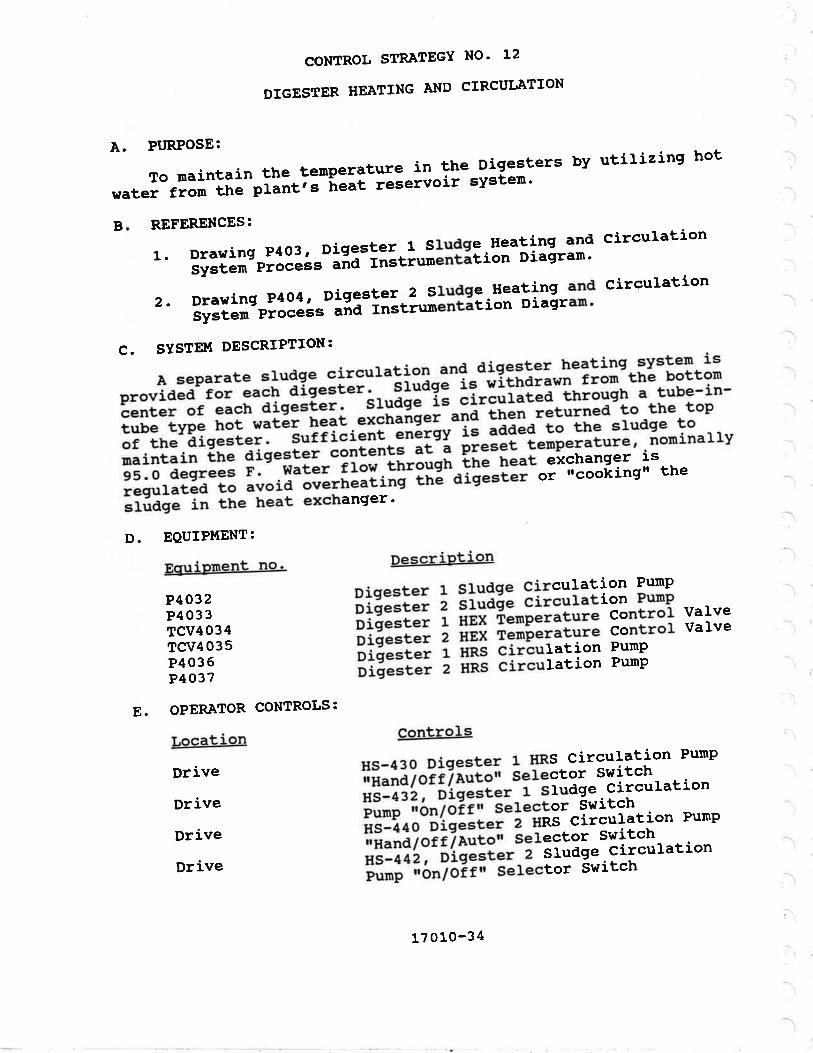
-l
CONTROL STR,ATEGY NO' L2
DIGESTER HE.ATING A}{D CIRCUI'ATION
A. PTJRPOSE:
To maintain the tenperature in the Digesters by utirizing hot
water fron tnå"piäitiãîãat reservoir systen'
REFERENCES:
1. Drarring P403, Digest:I^l Sludge'Heating and circul'ationsystem ptåãáå"-ãña rnstiunentátion Diasram'
2. Drawing P4o4, Digestret--Z Studge'Heating and Circulation
system ptåååå=-ãia rnstir¡nentátion Diagram'
B
C. SYSTEI¡T DESCRIPTION:
Àseparatesludgecirculationanddigesterheating,systemisr¡rovided for each digester."!iiägã"i"-rítnãtãr" from the botton
èenrer or each disesùer. _s_roãõ;-í; ãir.úiä[ãã-[ni""e] " tube-in-
rube rype rrot-wãtár heat."tää;"i-uia inãn-r"turned to the top
of rhe disestel:-:'T;iãi,"r,i'^äTåIät-ï! ããããa to the sl'udse to
maintain tne aigester contents at-ã pt""åi-ienperatutg''norninally95.0 degrees ;:"-;;Ë'-il"î..;['ã"gh-lhe h"at exchanger ls
requlared ro å""iä-ãrãrrreatiiä-itä-aiõ""iãi ot r¡cookingr' the
;iüõã in the treat exchanger'
Description
Diqester 1 Sludqe Circulation Punp
;iäË; z éiuaé" circulation PunP
Diåester r ngi-óã¡nperature control Valve
oiãester 2 HEi rãtnþ"1a9ure control Valve
;i;;;;; r nns circuration PumP
;i;ä;; z nns circuration PuntP
Controls
Hs-430 Digester 1 HRS Circulation Pump
iiñ."áToiife,tton serector switchtts- 432, oigesi"t-i-ãitdge .
circulationñr;-ió"7óit" selector switchãË'jãn o-ö'iéããt"t-ã
- nns circulation Purnp
iiã"nå7oiile"tá; serector switcttHs-442, oigesi"t-ã-siodge .
circulationiii';-;5"7óir" serector switch
D. EQUIPTIIENT:
Ec¡uiprnent no'
P4032P4033TCV4034TCV4035P4036P4037
E. OPERÀTOR CONTROLS:
Location
Drive
Drive
Drive
Drive
:-\
17010-34

F. TNSTRI'IIîENTÀTTON:
Ta
TC-436À
TC-4368
TC-446À
TC-4468
G. AT.ÀRTI{S:
None
H. OPERå,TION:
1. HRS CTRCUI,ATTON:
Description
Digester 1 Circulating Sludge TemperatureSn¡itch
3*ff:i"r 1 circularins studse renperarureDigester 2 Circulating Sludge TemperatureSwitchDigester 2 Circulating Sludge TenperatureSwitch
a. 'ÀNUÀL:
I{hen tle_]nand/off/Auto, selector switch isin the ,Handrr p"=iiiäü,"ti" punps iun äontinuously.b. ÀurolrtÀTrc: when the ,Hand/offlAuto, selector switchis in the "Àuto" põ"iii""ï
-t$.'i"=;äËí;" disesrer Hear Reservoirsupply (HRs) hot ivatèi-õïícuration punp srarts when thecrrculatincr sludge tenpe"ãù,.rr"r âs ineaèurea by Tc-436A orrc-446À' rárrs-tó- a-p;ã;;;'varúe-1i"itiãlry s4.5 desrees F). rhepump is sropp:3^yh:"'ãiõã"t., tenieiãiùi" .= measured by rc_4368or rc-4468, rises ro a freset varüå-ri"iti.il;;ã:;-äesrees r¡.rhe HRS circulari"n-pürni!-à"".intãrràãüåa so Èhar rhey wirr noriil"ìln:utonaric ir ãr'ä-ã=Io"iã[Àã-;ñõ: ãirãüî.tîäi'p,.rp is nor
rnlet water to each sludge r::t exchanger i: tempered by theË:iSï.S5rÎ ffåf ;i*lil;ã t"'p"'atuiã'iåeuratin!-'ãi.," (rcv4o34aajustãã-;å ü'" conrror .,ãti"l'"ff: *iË::::iï :H:,:î";:ï""=--are usually set at ras degiees F. settîng= gr"uter than ls'oegrees F. are not r."otorårrded beca""ã-Ëï"age caking can occur.
2' SLUD.E crRCUr,ATroNi-__slug?e is normally circulatedcontinuousrv by oigestãi-äir""ratíon-prrp= p4o32 and p4033.Ìtanuar varvins- arróws -i"ri=-;¿ôiã-ãüa-Ëäb* ro be isorated andthe studse ro be circui;ãå
"=irõ ðiî.=i", Transrer purnp p4o4o.
r"*,"1n3"3*"ï:;:: i;'ffi:"är]"'o can rake sucrion rrom rhe upper
ii'irg" l.r,i Ui*; i lti¡qiå{ilïf,:Ëi hlåi ::'$il:*!ii *,
Ë iiöåiidi¡:liiii,f .i.:tåt :;jr:il"FiË;1,åii:g;"Ë:î:å.n,.,disester HRS circ"i;aí;r"iurp.
17010-3s

CONTROL STRATEGY NO' 13
BOILER À¡{D HEJLT RESERVOIR SYSTEII{
ThepurposeoftheBoilersandHeatReservoirSystemistoburnsludgegas.producedby-thetwoanaerobicdigesters.Theheat generated-iã-used to Þrãäi"ã-'tt"t water which is then
circulatea around t-tre ptant-ãiã-"=ãa to rrããt the digesters and
provide space heating^-in the-ôhop/stor399, Digester control'Äaninistration, and srudge óewatäling buildings-
A. PTJRPOSE:
B. REFERENCES:
1. Drawing rl2[3, Boiler System Process and Instrumentation
2
Diagran-
Drawing P2O4Instrurnentat
PlantHeatReservoirSystemProcessand,1on Diagram.
3.DrawingP4o3,Digesterlsludge.HeatingandCirculationSystem9 P;äå =-
;iã_ i ñ"t'unentãt ion D i agrarn .
4.DrawingP4o4,Digester2Sludge'HeatingandCirculationsyst"#r;;;å"- ãñá- i"ãtrurnentátion Diasran.
C. SYSTEI'Í DESCRIPTION
I.BOILER:Theboilerisa4-pass'scotchmarine'firetubetype boiler. ifr.-¡oiler ".rr-f,"-opeiateå
ãn tow pressure sludge
Íi::, iffii,ti:îHi":å ;:: Îi'i:ii*¡! -"4'lg:1.?"i:i! iiiiil'år$:ï:Ë:'1ãTr':"{üi!:"1:if i*i!ï":::i:: :T'?iäi';: =
ãliprv-iã not-äiairable in Port Ànseles'
TheLsGfueltrainfortheboilerisspecifica}}y-designedtoor¡erate with a low pres=,rr"-i¿.s inch watãi column) gas supply'
rîre LSG ruer train is r'R'; ì;;á;Ë;ï"i-ãlãr-insurärá) approved
and contains two separate,'"ùiäilti;-;h"Iótt vatves and a low
Dressure switch that ""o=""*f;;'-ñli"r tã-ãwitch to -operation
on
'nurnber z fuel oil. tr¡e ¡oirãi is also swilcr¡ea to fuel 0i1
operation by -pó-¿Sos
when-tñã g"".pt""""iã-i"-itt" dígesters is
row as sensed by prr-450 rãäãtËã-i'n ttre LSG gas maniford'
17 010-3 6

C. SySTE¡r{ DESCRfPTION: (continued)The boiler is a steam boirer that uses a separatesteam-to-hot ¡sater nãat-exctrangãr,--ãJ
"tea, "ãr,iãii"., to producehor warer- a sreãn-ùãir"r, ..-opioÀãa-to " h;r--;;;:,, boiler,generarrv operates at trighår i"iãi".i-t"rp"r.tures and isnainrainèa i"-ãïã.iåa"ål:Iã_¡õ;;äî;., or road on rhe hearreservoir' Tlgse op"i"titg chaíactãristiã=-;;; Iäïån..geous whenoperatine on- aisestãi-ri"aõ" ;;-d;;å it is desir.ul" tonainrain hieh eÍrrausl ãiå"¡ tË"õ"ilã"f"r,_9ve! under low loadcondirions ro nininiãe-Jåna"n=;ãi;;;
-surfuric acid in rheboiler tubes ana extrãù=ã-stack. --;t'"ã; boirers operate tonaintain a preset ,d;;.essure range.
The boiler is provided.with pressure eafety relief valves, abtowdown rank.tõ-"ããi'tiãrra"*r,; ã-Ë;i_ breaker ro prevenr rhe3:*åït:i:ä':å:9":È::"Jif*püå"î"'irËå="", and a chenicarly2. sT'Àlr coNvERTER: The- converte, i: a shell and tube heatexchanger r¡ith =teãrn-ãn the sheri-.iàãl .I{ater fro¡n the nainptant heat reservoir i""p'i=-ãi.!.i;;;å through the converrer robe heared. e cirãui.;ññ punp (p22621ìaintaln= conàranr ftovthroush rhe converrer- i l--Ët]äËí"rure conrrol varve(To'2268) is proviaeã ro conträr ãóî.rãit", heat output so as tonaintain rhe--inain-r,""t-i"=¡ry9i; ;;;i| t"rp.rarure- ar 1eodesrees F. glaçi õià rrãåt
""="rvoii-åonaitions, remperarureswitch rsL-260 i" ãð[ü.iãå-".r"i;;-i;"-toirer ro mainrain anininurn firing rate ""iii-tt. ið=Ëriäir'temperatuiã-rises to t7tdesrees F, trrús ri"rrïãiin an";;;i-;Ë;=s damase ro rhe boiler.an" ål'iål:;l"rse valve and vacuum breaker valve are provided on
3- HEÀT RESERVOTR DrsrRïBUTroN: Hot water is circulated ininsulated pipes tnroùlnãiã trr" pi;¿ ir,-". conrinuous hearreservoir loop. rn" ñui" treat i"=ãi*rãi, is provided r¡ith aîåffT:i:åï rïï*li::*; ä:ï:r:""i:.:;"iå#ïi.i"5i rîr..,,,separator (sEP227Gl rtri.ñ-arso-rris-"n-îit"gral strainer thatshould be Èrown aorvn ;;;;=i"narIyl -i Ëï"aaer-rype ãxfansion rankÍ:33:') and a pressure rerief_rãir" lrã'prorrided ro piotecr rhe4. HEATIN. AppLfcÀTfoNS:. Al1 heating applications are inseries alon.' trre rråãi-;;;ä""ir--ãs lî;ii'on drawi ng p2o4. Eachapptication-ooint-ñI. iil=år' purnped secondary roop thatwirhdraw= .nä returns ;;;.; ¡."'ir,ãì"iiï".t reservoi.r.Àpproxirnarerv
!'.:irr.trär"ãä tne pianl-ü"ät.10ad is rããuired for3|3::ï:"fi|}:"n wicñ-iñe-i"mainîü";"äïhird beins ujed ror
L70LO-37

D. EQUIPI{ENT:
EquiPment no'
Location
Drive
Drive
F. INSTRUI.IENTATION:
Taq. No.
BI,R2260HEX2261P2262PV2264v2265T2266PNL2267rc\I2268T2269$ìqE,2270úìtE,227tvrrE2272wIE2273P2274sE'P227 6T2277cFP.2278PSV2279P2280tflr{E2281Po'l2282
OPERATOR CONTROLS:
TI-260TSL-260TT-26LtI--z62xT-263PT.-264Pf-27LPf-272PÍ.-27 4Pr.-27 6
E
Description
BoilerStean Convertergãir"t circulation PunP
siã"t vacuum BreakerAir Vent for SteamBlowdown Tankãõirãt contror PanelConverter tenperã€"t" Control ValveFueI OiI Tanklõt Pt"tsure DriP TraPLSG Flane TraPPropane Flame TraPsáii"t vent Flame TraPË;Ë-ã;ãivoir circulation PunP
üããt Reservoir Àir seParatorHeat Reservori nxP"nsion Tank
Chenical FeederHeat neservoii-Pt"=t"re Re1ief Valve
Fuel Oil PunPWater SoftenerHeat Reservoíi pt"t="re Control Valve
Controls
Íls-274, Heat Reservoir Circulation Pump
iló"7ori" serector switchtls-262, goirer-ðitã"iáiiott Purnp rron/offrl
Selector Switch
DescriPtion
HRR TernPeratureúnn ¡,o* TemPerature Switchä;;"ã;i"r rirtet remPeratureõ;;;;i¿i o,ttt"t remPeratureBRS TernPeratureõt""t cónverter Pressureisð- Pt"=sure llanometeräãiråi'-Þiiãt .
Pt"="ote lrano¡neterHeat Reservo:'t-óii"' Pump Suction Press'
Heat Reservort óit"' Pump Disch' Press'
17010-38

G. ÀIÀRMS :
uÀ-275ÀuÀ-2758
Description
Boiler TroubleBoiler TroublePNL2200)
(DÀS Systen)(l{ain ControL panel
H. OPERÀTTON:
1' sranf u!; The sysren is started llrLrrr by srarting theHeat Reservoir circulatién.punp, aù;;i;g on rhe Boi'ercircularion punp.-;ã-;;ining trre soiià, on.. 2 ' BOTLER opERÀTroN:_^contrors fo"_!!g. boiler are instalredrn a vendor suppried coniror_p""ãr-riñizzez) nounteã-o' the frontlå.lliriïff:"i::S r*,*"!;iåï, :å=åãiå."a å rã,iä
_;;" a rso
The boiler consurnes dig_ester sÌudge.-gas as the prirnary fuel.*hen rhe boi_1"r_"""ii"i Ëå;;;;;-;;;:3=tr,.t r,sc ãù"i pressure arthe boirer is too. row,-oi'wrreñ..-;ïñ;r frorn digester LSGpressure rransnirter órr-eso.sijn;i:"i;" r,se .ãii;;iã pressure arthe disesrers, ¡ojiãr-ãp"i"tior,-"îlãråËicarrv =rritãrrã= ro fueloit operarion. _Transrãi-Ëacr f".;õ;;iio. on LSG sas occursautomatically_artei ã-pi"!"t ,ir,:.iüi-;ú", and afrãr tocal andremote low pressure siõnãr, have been removed.
.n " l"fí:g:'T"äi:å"iå::';ñ _-iË ::édi3Iiåln;"ä: :*"f å lg_.,co¡nbustion Durge: rt shuis aown'it¡e-ãüår suppry to tr¡e burner inthe event oi iõ"itiåi, -ää,io,r=tiãr,-äi"'äån,
pliot,, -ãrãctric por¡er,or main frame iairuie, ãi*"r, row nãiãr]-o, high or row gasiã!!33li; .3n"' one oi ttre-iuãJ; ;;;ååh¡ns occurs, ir is
tr¡e - sñüiåoJi,':ffi tl:"nä:ï:J:ïî;;:*3.ï,': Tiîi¡*å,:f,:i$;.
:'Ifhen the boiler is on_line.it plgar.rces_hot r¡ater. The boiterhas a row fire hold pr""ï=i"n that'ii;it" firing r.i" duringinitial warm up_of tñã-¡ãii.r. rhe burn95 and the motorizedco¡nbusrion air- aarnpeis ãpåi"t". o' irrã-iüir_rr.me noduiationprinciple. rr¡e-Ëäii;; ;ilåratrãarivliîi"n"= :o on_oir ririns irload de¡nand is r"=À-iia;-ü" ,i.irrrå ãilirrg lare for rhe boirer.åT:ïffi
.i!.1'lä",,'3:i,jlij*,;nïï"å:ffË:åróviããã iã- vJry trr"
3' s'ur D'I{N: The boirer, heat reservoir and boirercirculation purnps are afi-iurned off nanua1ly.
17010-39
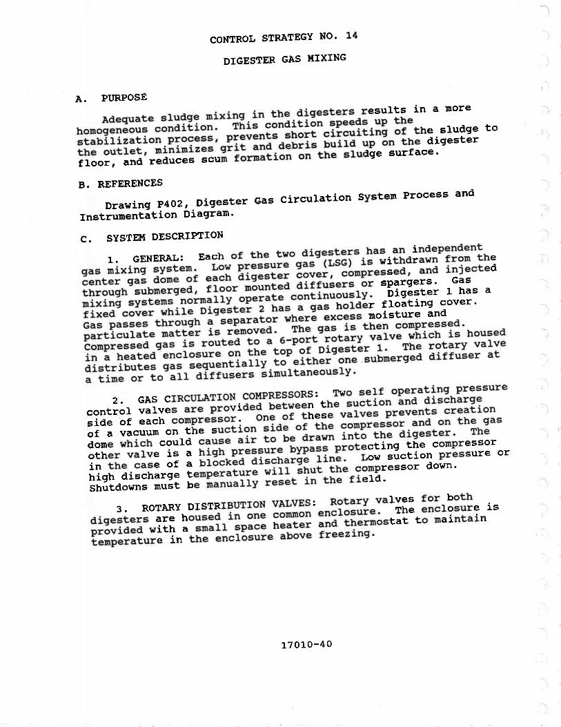
A. PURPOSE
Adequate sludge nixing.in the digesters results in a more
homoseneo.rt "åiãiËi"ã' rúis--cãnditión ?Peeds up tbe
stabirization process, pt""ã"i;':il;t "#;itinã or the sludge to
rhe ourrer, ,iü;;ã'qiir'Ii'ä-aãË;G b"liã ''p ón the disester
floor, and ,"åïããã-!"oñ r"tiäliãtt ott ttre sludge surface'
B. REFERENCES
DrawingP4o2,.DigesterGasCirculationSysternProcessandInstrumentátion Diagram'
C. SYSTE}I DESCRIPÎION
l.GENERÀI,:Eachofthetwodigestershasanindependentgas urixing sysrem. Low ptãËã"iå gas-(rcãt-iË-withdrawn from the
cenrer q", ooiå-äi "ããt, äiqester cover, ãåtpi"iãea' -]ld
injected
throush submerqed, f ]gor-tå;;Ëã ãiii"å"ts ðr sparsers' Gas
mixing ,yrt"i=-noinarry "Ëäã-"ã"ãl""ousry' -oigester t has a
fixed cover Jniïã-óiq"êt"l-ä-ñã=-á gas holdêr floatÍng cover'
Gas passes through ? separator where excess moisture and
particul"t" ¡,ãi[ái ir ränovea. The gas'is then compressed'
conpress"o gåË'i=-rã,rt"a t;-;' s-pãit-f"tåiv'ïãï*'"-titi"h is housed
in a heated ãnctosure oT ti"*tåp-ãi-p-iqãtlät r' The rotary valve
distribures sas sequenri"iï; tã-"itt:::#-;ubnerged dif fuser at
a time or to-ãit airtusers ãimurtaneously'
2.GAScIRcuIÀTIoN.couPRESsoRs:..Twose}foperatingpressurecontrol varvãã are provid;ä'-Uãltã"" the suction ànd discharge
side ôf each compressor. -or,ã of rhese ;i;;-;r:":ll= creation
of a vacuum on the suctlon =iaã-of the conpre-sËo1.and on the gas
dome which could cause aii lã be drawn i;iã-the digester' The
other varve is a high p."ãrrrr" bypa?? piotecting the compressor
in the case ãt " b'ócked ãi;;";äã-!r1þ: r'ow suction pressure or
high discnarlã t"rp"raturä-ilïi-Étt"t !h" compressor down'
shurdown= l[tú:; Ëï;Grry reset in the field'
3.RoTARYDISTRIBIIIIONVALVES:Rotaryvalvesforbothdiqesrers are housed ln oiä ;ã;;; enclosuie' The enclosure Is
próvided wiir, ã snalr =p";; ;ä¿;; .".-ã[ãttostat to maintain
temperature-ïn-ttrã- ãncrä="t" above freezing'
CONTROL STRATEGY NO' L4
DIGESTER GAS UIXING
17010-40

E. OPERÀÎOR CONTROLS:
Location
PNL4OlO
PNL4OlO
PNL4OlO
PNL4027
PNL4027
Descriotion
Digester 1 Gas Circulation ConpressorSedinent TrapDigester z cãs Circulation conpressorSedinent TrapDigester 1 cãs Circulation conpressorDisester 1 Gas ciiõt;;iã" corpressorIntake SilencerDigester 1 Gas Circulation ConpressorDischarge SilencerDigester 1 Gas Circulation Conpressor Lowsuction pressure neriài-ùärveDigesrer 1 cas ci.ã"rã[iåi' co¡¡pressorHigh Discharcre pressù"ãìãri"f valveDigester r nótary cãr-õi'.iriurrtion vatveDigester 2 Gas cirðuraãiãi'corpressorDisester 2 Gas ci;õi;;iã" corpressorfntake SilencerDigester 2 Gas Circulation ConpressorDischarge SilencerDigester 2 Gas Circulation Cornpressor LowSuction pressure Relief ùälrr"Digester 2 Gas cfõi;riåi*corpressorHigh Discharoe pressur"-ñäfi"f valveDigester z Rótary Gas DistiiUution ValveRotary Gas DistriUution-v"i"" EnclosureRotary Gas Distri¡utiãn vii"" controlPanelRotary Gas Distribution Valve EnclosureHeater
Controls
HS-410A, Digester 1 Gas CirculationCornpressor rfon/Off[ Sài""Iã, SwitchHs-4108, Disester 1 ¿;;-ði;"u1arionCompressor'iFast/s1"";-sãiãctor switchHs-410c, Digestei r ða=-ðiJculationcompressor rReset'r pusfrUùilonHs-41sÀ, Digester r nãtãrv casDisrriburioñ varve-"iã Ãâ7'oæ t ouro,lSelector SwitchHS-41S8, Digester 1 Rotary GasDisrriburioñ va rve - "ï/ i7ài n' t u/ 6,' pos irionSel.ector Switch ' -'
D. EeUfpIrtENT:
Eouiprnent no.
sEP4002
sEP4003
cP4010s4011
s4012
PCV4013
PCV4014
zv40L5cP4020s4021
s4022
PCV4023
PCV4024
2v4025IrtME4026PNL4027
HTR4028
17010-4 1

E.
F.
OPER.ATOR CONTROLS:
Location
PNL402O
PNI,402O
PNL402O
PNL4O27
PNL4027
INSTRUUENTATION:
lacr. no.
TC-401
PSL-410
TSH-410
Krc-415
PSL-420
TSH-420
KIC-425
ÀL,ÀRMS:
Eaq no.
uA-410
uA-420
(continued)
Controls
HS-42O4, Digester 2 Gas Circulationðã."i"=åor ion/off'r serector switchË:äõ;;-óie"=t"r 2 Gas circulationË;d;;=åot írá=t/sloî" selector switch;s:ããóõ, oígestel 2 Gas circurationäãtoi""åor lResetr' Pushbutton¡ré-'¿zse, Dígester 2 RotarY Gas
öi"¿;$útioñ varve tnand/of f /Autor'Selector Switchllé-¿zsg, Digester 2 RotarY Gas
Distribution l;i;"- "ll z tt1 e I s I 6" PositionSelector Switch
DescriPtion
Rotary Gas Distribution Valve EnclosureHeatei ther¡nostatöiõããt"t 1 Gas circulation corapressor Low
InÍet Pressure Switchõïõãit"t 1 Gas circuration compressorãiétr-oitcharge ternperature switch;iñtG;- r nótarv èat Distribution varveClcle Timeróiéã=t"t 2 Gas circulation courpressor Low
InÍet Pressure Switchõïõã=t.t 2 Gas circulation conpressorni,ótt-oi"charge temperature switchDigester z noiaiy èas Distribution ValveCycle Tirner
G
DescriPtion
Digester 1 Gas Circulation CornpressorTroubleõiéã=i". 2 Gas circulation cornpressorTrouble
L70LO-42

H. OPERÀTTON:
1. cÀs crRcur.ÀlroN cor{pRESSORS¡ The.Gas circulationff'Ëí:=;8ff iå3r;ï:;F"iJit when ihe ,öi7orr,, sereãiðr switch is
The operalor can eLect to run the Gas circulation compressorsat eithet-" hi;¡ tiä"ã'Fãr uraxinu¡¡îi*i.g and scum brankerconrror-r of ar--row'rpã"ã-t"; il;;-"äåiåri".l 0perarior. rhespeed is nanuarrv seiã;i.à. Ãi-irr;-í;;"" speed, rhere is srearerinternar srip- i"-tñJ-Jãiir..=o., and discharge tenperatures witlä:"ii$å:;'ållï"3t*;L"iliiit.:miË'"n tãnperaãùi"= shou rd be
Autonatic shutdown of the conpressors occurs upon row suctionpressure or high aiscrráije temperature.2. ROTÀRY DTSTRTBUTTON VALVES:
a- GENERÀL: The Rotary Distribution var.ves direct thesequential discharge tã--it" .r.rior=-ãi"åh""ge diffusers. Àverticar, inrernarl roi"i!ø sreevã rãIàt"r:¡";-ËiE..to porr,driven bv a gear notor "o'tioiiãã-ãr,ä-Ji aajustabie trmer. This
!ii:l="iiï:lî:?if;l¡*r;*1,;::.;'ff 'l p""a"t"ininãa i ã,,gth"åã:i:"$i:;: t". tne rãiali'ï.r.,"' .i:.ãJ-;ã; ,5ü:i"å: åil;**î"ot
b' rf'aNUÀL: with r*-{Hand/off/Àutsrr selector switch inthe r'andf' o"sitiãn, lfrJ"operator =ärããt= w]ich port the valvedischarg"= Lo rittr"ln"'roJiaion selector switch.
c. ÀUTo'tÀTrC: with,!l:-:,rr"ld/offTau¡s,r setector switchin the r^uto'f po=iirãn, ä;_rength or åperation at eaðrr diffuseris conrrolled pr ã-ri;år-äia-päËitiãi Jiit.r, inresral ro rhevendor supplied- """i.äi-pläx.g"
r. SPECTAL CONSTDERÀTTONS:
,o' 3tår:$'fî"il1"î3i.;'lt:;+ï,3ffi";ü:t"sion-proor, crassiried
17010-43

CONTROL STRATEGY NO' 15
LSG GAS UANAGEßTENT SYSTEI{
Íhe purpose or the low Pressure-:1::e;Ji="["if;1 ãîã"r."t-el:::ç:sli"ã*:îrÏ":i :li::'"äi=:iË-ü"*";;tã-e"' guiñer' sãse
srudse 9"= proäoãõiãr,-i" "oiãitåã-at ttre-¡ãirer to-produce hot
warer which rîü!åä-ï"t-aigä;Ë;-;ã buildins heatins'
À. PT'RPOSE
B. REFERENCES
1. Drawing P2O3 'Diagram'Boiler Systen Process and Instrumentation
2. Drawing P4o1' Digester S1udge Systern Process and
lnstruñentation Diagram'
3.DrawingP4o5,DigesterGasManagementsystemProcessandInstrumentation Diagram'
C. SYSTEI'T DESCRIPTION
1. SLUDGE GAS STORÀGE: Sludge'gas'is produced by'the
anaerobic aiqãs-érs' cas proã;;á iñ'either digester rs
accunutatea uiãã;-ih" ti=tñ;l-ãi"ãiils;;s hoider cover or
Diqester 2. Às gas i= a""rriüiåtãa, tÞ? "åt"t rises rerative to
rhé rop or tn3-rîäüiã-r"rfJ;ä^î;-[ú"-ãisããt"t' rhe floatinscover has s rã"Ë'äî*;";;;-i;ã.rãr between iii-rot"st position
(resrins o. "ãiårãi"-ãoi¡"i;t and upp"ttoãi-position (hitting
ètops on guides) '
The existing gas holder floatllg-di?"ster cover'is ballasted
so that the norrnaL operating-pre"=11:-i:-ãbout z's inches of
water column (wc) . This. piá"-=tre remains fairly constant over
rhe furr ,"r,gà-'ãi "or"r *åiãîl--wrtã" tnã ãover reaches itsuppermost riråit-är"[iãr"il the pressure'ã""ii""es to rise until
evenrualry, ;;; i; vãntea'tõlã i'cnes wcl-it9T pt:::tt" reliefvarves t"runéiì åia'iävãõ¿àí'|"ãät"a on the disester covers'
The gas from both digesters is routed to a separator
(s'p4o16l wiin-ãrip trap t[ãi"-toisture-]"ã-aã¡rii carrvover frorn
rhe dieesrer-is r"i,oved. -ñ;-;;bined sã;-r'ã" i:..:1"" netered
(FE-450) . A iãr'ãrãt"t ler-aso¡ .measureå-ln" pressure in the Low
Pressure Gas (LSG) Iine and inaicates locally'
2- SLUDGE GAs IIIILIZATION: Stored gas can be-used by the
plantrs boiler, BLR226O. -ii-üåt used' "i""=t
gas-must be burned
at the waste Gas Burner' õp"iãii"n oi itre waste Gas Burner can
be in*iared in rwo ways, ;ä;-;i;;=;;t-ã-tiá"ti'ne cover travel
õãtiii"" or from excess LsG pressure'
17 010-44

D. EQUTPITIENÎ:
Equioment no.
sEP4016LV4043PC-V4044PVL4049PCV4050w4051ltuE4052üIrtE4053I{Ir{84054¡.ll'fE4 055BNR4056PNL4057
Description
LSG Sediment Trap!1:t" Sludge Gas ValveLSG Gas pressure Regulating ValvePropane Tank .'l
Propane pressure Regulating vaLveBurner pitor sorenóíãi;ilåVent F1ame CheckBurner pilot FLame CheckLow pressure Drip T;;p-"lasle Studge eas'rtãnã rr"oüasEe S1udge Gas Burner r-
waste Gas Burner control PanelE OPER.å,TOR CONTROLS:
Location
PNL4057
PNL4O57
Controls
HS-450À, Burner Control power ,,On7Of¡nSelector SwitchHS-4508, Burner rHand/Off/Àuterr SelectorSwitch
F. TNSTRUMENTATION:
Ta N
LfT-402LIC-402BE-450BC-450
FT-450Pr-450PrT-450PC-450À
PC-4508PC-450c
G. ÀLÀRMS:
Tacr no.
uÀ-450P.A,H-450PÀL-450
Descriotion
Digester 2 Cover pssition TransmitterDigester 2 cover positiãn ðontrollerI{aste studae eas gurnãr-Ëfà." DetectorIi:¡. studie e.= ãùr"ãi iöiitionControll.erLSG Gas Flow TransrnitterLSG pressure GageLSG pressure TrãnsnitterLSG Low pressure Controller and LowPressure Àlarn SwitchLSG Inter¡nediate prãssure ControllerLsG High pressure.Controllãr ana HighPressure Alarnr Switch-----v¡
Description
Burner TroubleLSG High pressureLSG Low pressure
L70j-o-45
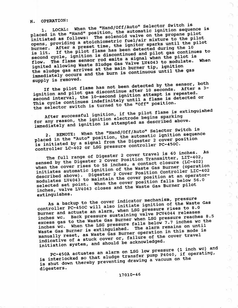
H. OPERATION:
1. LOCAL: When the.ilHand/Off/au!9]'Selector Switch is
oraced in rhe'"Hä;ã;; pãlitiãitl' iñ"' automatic isnition sequence rs
iniriared as eoliãrr: .rl¡? !äi"iäia-"ãi"" on tñe Propane pilotopens, providil;^;-;ioi;hio;;Ë;ï;-;"¿r7.i'-'ixturã tó-ttre Pilotbürner. afrei--á pr"""I-tijä;-üã is"ttfi-tpãix= until the piLot
is t*. rr tie-pîrót rr"ri=ír"!'^i";í'ã;¿¿"tãa aurins the 10
second cycle,--igãition i1^fiäããr,ãino"a anã-pilot. gas-continues to
ftow. rhe frané sensor toá^ãiitã-ã-ãig"äi iñ"" túe Pilot isisnled a'o!rÏ;; tû;r" ,r,rås;-nãã v"r.'ã ii¿õãs to noautate' when
rñe sruds" s"ä"å';î;; i!-ËË äi"-;"'l?i"li:'"iliìtliå n"'innediat"rv oã"il-s-ana the burn is conti-upprY is iemoved'
rf the pilot flame has not been detected by tfe sensor' both
icrnftion ana-piior gas-aiscäitñ;ã arter-ió-sãäonas' Àfter a 3-
sácond intervãiî-inå-io-t"Iãïã-ïõ"i[i"" atienpt is repeated'
rhis cycre J;Ëi";ã. ina"ri;Ï"ii--¡"¿i1, ã-ii"i" is detected or
rhe selector-äiII;h-is turiäã-[;'tñã "orrn position'
Àfter successful_ignition, if the pirot flame is extinguished
for any r""=!ïl-iiå-iõñïãiäi"åråãtiãã"- beqins spar)<ins
inmediately anå ignition i;"";tãPled as áescribed above'
2.REll[oTE:Whenthe,l|Hand/off/AutotrSelector.Switchisotaced in thå-;o,rlä;"pðÊitiä"1-tùã âutonatic isnition sequence
is in*iared by a signal ;;;;'tñä-piqestãr z cóver position
conrrorl", iclioã or-Lse ;;äJ;; ãoñtrorrer PC-450c'
ThefullrangeofDigeslet2cgvgrtravelis60inches.Assensed by the Digester z-ãã"ã-t ãoãitiot'-rians¡nitter ' Lrl-4oz'
when tlre cover rises.to.sé inches, " "o,,tãct closure (Lc-402)
iniriare" "ü[ãrå;i;-isnitiol-áÏ tú" wasle Gas Burner (operatron
described above). Uigeståi Z óover p""iãiã" Controlter LIC-402
modulates LV4O43 to maintain the cover-õã=iii"n at an operator-
selected set point. vllren the covet p-o=iiión falls below 56'0
inches, valve LV4o43 "fo="J--ãr,á tn" istãtã-ets Burner piJ'ot
extinguishes'
ÀsabackuptotÞe-coverindicatornechanisrn,pressureconrrotr", ãô--¿sõc ri1r-ái;; ir,iii"tt iË"iii"" "f -!1"
waste Gas
Burner ana ããtuate an "råñ; ,rrã".r,sc--píessure rises to 8'o
inches wc. Back pr"==rrrä-Ëú=iãi"in9- vãtve PCV4o44 releases
excess gas to the t{ast" -ã"ã-ãü;;; ^únen-l'sG pressure reaches 8 ' 5
inches wc' -wr'"" the r.,sG ;;;;;;-tariä pãiÑ:1l*i:"h"= wc the
traste cas eui;ãi i= "tti""sli:Ëä;^-;lt-ttarm rernains on until
manualry reset, ai waste éas Burner d";;liãn-in this mode is
indicative of a stuck "otãî-o-rl-iaifuiã-ãe the cover travel
initiation system' and =ttã"fá-üe acknowledged'
Pc-4soAactuatesanalarmonL,sGlowpres::T:(linchwc)andis interlocked so that "î;ä;ä
i;:=-t:i-ö"ñp-Þno1o1-ir operatins'
is shut down thereby prá.rã"Éing drawittg- " ïacuum on the
digesters ' rT0'0-46

and neter sodiun hy¡gochlorite solution to the plantdisinfectant ana cå-ãtüåJ-å""as for odor conrrol.
1' Draving P303, Hyp?:llo_rite storage process andrnstrumentation- br.agrarn .
2' Drauing p304, H'¡pochl0rite rrtetering process andrnstrumentat,ion- ôiãôiãi. ib ¡asLr
3' Draning p305, Reclaimed '{atet "rg chl0rine contact Tanksystens process ana tnst.ùiãitltion Diagran.
C. SYSTET,î DESCRTPTTON:
1. HypocHLORrrE sroR^c': The sodium hlpochl0rite (Naocl)used ror disinrectiãn-iJ'Ët"r"a-äiaïäË"r"a in a one_roombuitdinqr- rw9 4,ooo gãirãr, storàgã ä;i= rocared wirhin a;::3:uïI";"lt"tnrnent-;;; :upplv-;ri-är rhe plant ñypocuorirei"ãi å"t í;;ïi_ !i"i =":llå#"i?î¡T:, u¡;l:"ii.::Jt"ii:::il, j:disconnect connection -on"J riri-pipå"ioåated at the tank.Filtins operarioil-;;;'pi"." ir,ãiã" iñã u,rirdins wirh accessthroush rhe rorr-rp-ãäJ.ã'io".iäã-i; i.ãr,t or eaãh tanr. Eachff;l"iï";iËå'Ëa:*:i:¡Ït*f ,ÏË¡,"¡Ir zu,.åtî åît:,':äi =,ä!","
capable of transteriing-liå- contents or-one tank to another or to;"åï'::ol:n::3l"jt" ãií"J"àr," ci.t-ã"ïse Nao* .ù-tiäir swinnins
. À11 drainage within the, building is routed to a sump l0catedrn the containment arãa. --'itr" =rr-p--í"-ãq.ripp"a with ã-¡wHp wateroperated educror^p"rp-"åpqËr." ãi-ñ"iãlilrn -" L2.s percenr Naoclsolution' rhis
"àu"ioi-ãiãcnarõ";-t;-üå neaaworÈs and diruresthe wasre srrea¡n to reãu""-trr"-õããriiiiïit g, shock loadinq rheplant' rhe eauctãr i;ï;".rrv-ããr,iiåiiàa_¡y.openinõ-o, crosincri.i$n'i'il:' ""1Ë'fr:igË.jï:'fifr#1, u,' i=-J"Ëüå*ã i;-ää,
À PTIRPOSE:
1o diluteeffluent as a
B. REFERENCES
CONTROL SÎRATEGY NO. 16
HYPOCHLORITE DTSTNFECTTON SYSTEM
t70]-O-47

C. SYSTE!'Í DESCRIPTION: (continued)
2.HYPoCHLoRITEüETERING:Threediaphragmpì¡mpsmetertheNaocr f row. Two of rhg pud!'"r"
-iãroterT-áaíus-taure variable
srroke rensrh'åIiiã rritã aËãiäåi"ã-[;-¿iiro"ár disinrection'pump stroke r"iã[rr-iã contrãir"a ¡y ? conpound loop control]er
receivins rhe =iiîIït-toããI - rîåi-"iãi"i r rJãi-ñ"-itt'tto"nt Parsharr
flurne) and theoåìïi"ã"t residual sígnal'
rhe rema inine nerer ins :ffin",ï"i rliï"1'i:iiîiàt;!1i3i'"ot" ^:iî:Ïi"];i3:ï :trpË:q*ii;;;ú;' - varüiiä-;ilIå= this puurp to
be used as a second uacrug-ät-¡ãã" flo1'unít for effluentdisinfecrion. Each punp i="äõîi;:ã_Ild--ã-"ãu¡ration chamber'
discharge pursation ãanp""át'-ai-sèlarg" ;tã=t"T"-?1?:' back
pressure '"g,,iãiing varie,
-ii""_'witcú, änd rotameter flow
indicator.Dor¡nstream of the metering pynp a!:_ttypochrorite is mixed
with 3W water to an "ppto*itaíi Z þ"t"""ï'ããf"tiott' .Solution
water nerering is manuar,.iäi"ã ioiaut"t"t=-iãi flow indication'
uixins talces þra9e- i" 1-*tiiiö"tãã' s"iit[iã" water backup is
proviáed bY the 2W sYscem'
rhe chlorine solution ::J"lå:lrt3rll3"itï:i3:ftË::';1fi:;i."È;riåiÏ=l$lilFrãIiiäiäã' "iiriäiË-tr'ã"
frõi¡s into the
ãttiãri-n" contact channer '
D. EQUIPI¡IENT:
EquiPment no'
T3701t3702INJ37O4
P3703P3710P3720P3730
E. OPERATOR CONTROLS:
Location
Drive
Drive
Drive
DescriPtion
Hypochlorite Storage T""lt 1liiiocnrorite storage T?$ ?
;tiffiäii;; Buildlne chenicar sump
Eductorñvpãcrrrorite Transfer lttPüíñ;i;lãti-t" Meterins PumP 1
üñär;iit" Meterins PurûP 2
üi'ñäi;iit" trreterine PUIûP 3
Controls
HS-355, Hypochlorite .Transfer Puutp
iió"7óii,,'sètector switchñ'jå;i; nvpãåúiãtit" rrreterine Pump 1
iiñ"nã7ötr7ãutó; serect-or ^switchtË:ääil-iió""nr"tit" Meterine Punp 1
;;";ãl' stiãr" rensth controrrer
1?010-48

E OPERÀTOR CONTROLS:
Location
Drive
Drive
Drive
Drive
(continued)
Controls
ïi¡üió,!ru:¡¡"3:ï:"ï::"3*is"i",n,i¡;üÍ,,iIff:niïåff ä:ffiåîi"j*n,i!,iii;,!ffiiirir"rjjïiis"i -"'ff;;:i,,ËI3ilnÌffiff äff:Iåii"þ'
F. fNSTRUI.íENTÀTION:
LSH-351
LSL-351
LSH-352
LSL-352
LSH-353
FSL-354
Àr-356ÀrT-356Àrc-356ÀsH-356
ASL-356
FSL-361
FSL-362
FSL-363
G. ÀI,ARI{S:
IÀH-351A
I,AH-3518
LAH-351C
Descriotion
ä;lrlllt"rire srorase rank 1 Hish LevelHypochlorite Storage Tank I Lc¿w LevelSwitch
!lï:l."rire srorase rank 2 Hieh LeveLHypochlorite Storage Tank 2 Low LevelSwitch
l$åirffï:il Buildins che¡rical sump HishHypochlorite Dilution l{ater Low FlowSwitchResidual Chlorine Local IndicatorResidual chlorine ñ;i;";;"Residual Chlorrne ControllerResiduar chrorine Hiõ-õ;;åentrationSwitchResidual Chlorine Low ConcentrationSwitchHypochlorite lrietering purnp L Lot¡ FlowSwitchHypochlorite Metering punp 2 Lon¡ FlowSwitchHypochlorite Metering purnp 3 Loh, FIowSwitch
Description
HypochLorite Storage Tank 1 High Level(DAS System)Hypochloritä Storage Tank 1 High Level(Main conrrot
-paneí pñiäâoolHypochlorire storate Tffi-; High Level(LocaI)
L7 olo-4e

f.t . AI,ÀRMS:
Tact no.
I,AL-3514
LÀ1,-3518
LÀL-351C
LåIT-3524
I,A¡T-3528
rÀ¡t-352C
I,AL-3524
(continued)DescriPtion
Hlpochloritg Storage Tank 1 Low Level
ä3"# *å,ïï:1" "îtë, î, ::: ::::iåüäËniãïil"-siãiase rank 1 Low Levet
*H::il"ritg storase rank 2 Hish r'ever
åiå:"iT::iiL- storase T11¡^? Hieh r'ever(!taÍn Contror Panel PNL2-200)
åiiåäniã;iiã-siãiãle rar* 2 Hish Lever
rl$::ll"ritg storase rank 2 Low Level
åiå:"iT::ità- storaee -r3s^? r''ow 'eve'
Itrtain contror PaneÍ PNL22oo)
t!äå:ni;ïiiã-siã;;;" lank 2 Low Levet
Ái:iilL"tion Buildins chemicar sunP Hieh
lãver (DAs sYsten)Disinfecrionrãiiîåi"g chenical surnp High
Level (üain cã"tiãf ianet PNL22o0)
Disinfection-ãüirál"g chemical sump High
Lever (r,ocar õ;;t;;i-e1n9r PNL3Too)
Hypochlorite ;;ï;ii;" water Low Frow (DAs
iË::ill"rite Dilution î1!:' Low Flow
l
I. SPECIAI, CONSIDER'ATIONS:
TheHlpoclrloriteStorageBuildingmeetstherequirementsofrrBC Group H Division 7 o".,rã"iãi- tñãá"tdous nateriãIs storage) 'The building iå-ãã"Ëtructed'ãï-ioàãot¡"stible materials' the
building i" piã.riããá-ritrt rr."lii"lion to- meet the UFC 80
requirements. - -tãnperatures=ï;-ñ;;¿--¡uifãing will be maintained
within the 55 degrees r wintãI ;ã-go a"éiãeé r summer standards
set for unoccuPied Process areas'
)
)
)
)
)
)
-)
)
.,)
)
)
)
)
-)
)
)
)
,)
)
)
)
I
L70]-0-52

\ G
Descriotion
Hypochlorite lrfetering punp 2 Low FIow(DAS Systen)Hlpochlorite lr[etering punp 2 Low Flow(ltain ControL panel É¡¡r,zzõolHlpochlorite ltetering punp 2 Lovr Flor¡(Local Control panel -pff,¡iOO)Hllpochlorite Dtetering prrmp 3 Low Flow(DÀS systen)H¡pochlorite ttetering punp 3 Low Flow_(!fain conrrot panet iuiããõolHlpochlorite tr[etering pu¡np 3 Low Flow(Loca1 Control panel -pni:iool
H. OPERATTON:
1. HYPOCHLORTTE TRÀNSFER PTIMP: ThE HYPOChIOTitE TTANSfETPunp operates continuously when th; r'õ;7off,, selector switch isin the rOnrr position2. HYPOCHLORTTE TIIETERTNG PTTMPS:
a. HYPOCHLORITE II{ETERING PTJMP 1:(1) IIANUAL: with the 'Hand/off/Au¡sn serectorswitch in rhe '!rHand,tr_positiãn,
"i;õ""üiäIit. rrrerering pump 1 runscontinuousr-v- The rrðw iãL" ir åã;üãri.a nanuarry by rhe srrokelength adjuSter at the pürnp.
er ÀurortArrc: with the rrHand/off/Àutotr ser.ectorswitch in the i'Àuto' p""rii"",.Hypochroiite Metering punp 1 runscontinuouslv, as long .=-itt. åi=åñãräã-ãror switch ãetecrs ftow.The rtow rare is conÉràrrãä il;";iiy'Iy-lrr" srroke rensrhadjuster at the punp
b. HYPOCHLORTTE I.IETERING PI,ItIPS 2 ÀND 3:r1)
'!ÀNUÀL: t{ith the rfHand/offlÀutotr selectorswitch in thè ftHa;d;r -pã.itïot
, Hypochro.i.t" tr[etering pumps 2 and3 run continuouily. ine iiow ralè is controrred ,.ñ,r"rrv by thestroke rengrh adjuster at-irre. ññ ;; ü' compound roop controllerArc-3s6. The coñtrolrer rãceives'thã ãåt"r prant frol signal(fron the influent parsñari frume),--ã"ã-å" effluent residualchLorine signal
(2) AIrroMATrc: with. the.'r'and/offlÀuterr selector switchin the rrAuto'!r position, nvp""¡rroritãiãt,ãring punps 2 and 3 runcontinuouslv, ãs rong å= É,ñ" aisãñãigã-ãi"r switch detects frow.The florr¡ rate is conõ.rorrãâ manuarry-uy-irre stroke tengthadjuster at the punp or by compound loop controrler elö-¡se.
ÀI,ÀRMS:
Taq no.
FAL-362A
FAL-3628
FÀL-362C
FÀL-363À
FAL-3638
FAL-363C
(continued)
L
(.
l
(
\-
I
\
(.
(
17010-51

À. PTJRPOSE:
- Tþ" srudge storage system acts as a buffer between theexisting anaerobic digesLers and the new sludge dewatãringsysten. À solids grinder reduces the size of any large párticlesand a recirculation punp provides a werl nixed riuãqã-ro,dewatering.
B. REFERENCES:
CONTROL STR.ETEGY NO. L7
SLUDGE STORÀGE
Sludge Storage process and Instrunentation1. Drawing P501,Diagran.
2. Drawing pS02, Sludge Dewatering process andInstrunentation Diagrarn.
C. SYSTEIì{ DESCRTPTION:
Digested sludge flows by gravity frorn the existing anaerobicdigesters into the sludge sloiage tänk. sludge is ràñovea fromthe bottom of the tank by sludgã storage Reciícuration purnpP-5403, passes through Solids ciinaer eóns¿or and is returned tothe tank below the water surface.D. EQUIPMENT:
Ecruipnent no. DescriptionT5400GDRs4O1P54 03
E. OPERÀTOR CONTROLS:
Location
PNL541O
Drive
Sludge Storage TankSolids GrinderSludge Storage Recirculation punp
Controls
HS-541, Solids Grinder rlocal/OfflRenote[Selector Switchïq-511, _S1udge Storage Recirculation pumpItHand/OfflÀutor Selector Switch
17010-53

F INSTRT'!{ENTÀTION:
Tao. no.
Lr-540À
LI-5408
LIl-s4OtsH-s40LSL-540LSII-540
ALÀRIIS:
Tao no.
IÀTT-5404
LAH-5408
IÀL-s40Â'
IÀL-s408
uÀ-541ÀUÀ-5418
)
DescriPtion
Studge Storage Tank Level Indicator (DAsSysten)Siuage'storage Tank Level Indicator (üainControl Panel PNL220O)Studge Storage Tank L,evel Transmittersludée Storage Tank High Level Switchsiuaie Storage Tank Low Level Switchsiuaée Storafe Tank llid Level Switch
G
Descriotion
Sludge Storage Tank High Level (DÀsSysten)siudge'Storage Tank High Level (
shritchleveL ilevel.
c. Àuror[ATrc: rùith the *Local/offlRernotE, serectorin the 'Remote, position, the soiia='ê-rînaer stops if then the srudse srorase ranÈ is berow tnã-nïnird-;Ëråiiis
| .-
2. SLUDGE STORÀGE RECIRCUI,ATION PTJ}TP:
a. GENERAL: The sludge storage Recircuration punp issupplied with sear water. The sear rãtã, sorenoid rãi.r" openswhenever the punp is running.
b- üÀNUÀL: with the rHand/offlÀutom selector switch inthe trHand" posirion, rhe sludg" scãlitã'ie"ir""iãiiã" punp runscontinuously.
c. ÀurouAÎIc: with_the frHand/off/Àutox serector switchin the "Àurof'-position, [ñã sr,tag" s[ãlãje'necir".riããio. punpstops if rhe sòrias crinder i;-;ãr ;õ;üs.
17010-55

A. PIIRPOSE:
To dewater anaerobicall.y digested srudge, to.a concentrationof 1? to zz p.tã-à"i-ããria" ä"i-ãisposal in-a sanitary landfill'or to a concentration of 6 ió-e peicent solids for I'and
application.
B. REFERENCES:
l.DrawingPsol,sludgeStorageProcessandlnstrumentationDiagram
2. Drawing P5O2, Sludge Dewatering Process and
Instrumentation Diagran
Polyrner Systerns Process and Instrumentation3. Drawing P504,
Diagram
CONTROL STRÀTEGY NO. 18
SLUDGE DEIIÀTERING
C. SYSTE!{ DESCRIPTION:
FilterPressFeedPunpPs4o2,Iocatedinthebasementofthedewatering building, witnarãws siudge from the Sludge Storage
r.|i-"'.ã áir"úãiéãá'ott Belr Firter Press BFP5101.
LiquidpollrurerisaddedtothesludgebyLiquidPollrmerFeeder cFR52o2 at one ot tnrãã ããaiti-ott-points provided in thefeed punp aisåhãigã--pipi"g.- one poinr i: "t the filter Pressjusr prior t"-äiããrr.iginq-ontó-'irrã-travity belt. Another polytner
feed point is upstream of tüã-piã=i-î!:I"-the pollmer-and sludqe
are rnixed in Stätic In-Line -lfiier
ItÍX5102. The- f iñal feed pointis upstr""r oi-iftã second p"ï"t-"ftãiã-nixing is done in StaticIn-Line Mixers II{X51O2 ana f'fiSiO¡. The.Iocation of polymer
application and the numb"t'äã-=iåtiã mixers in operation isdetermined by the operator t; õiñize pol'mer usage for a given
cake drYness and tlPe of Polymer'
the operator has the option to either thicken or dewater the
sludge. The press is capaúiã-ãt producins a dewatered sludge
with a concenlration of Ll'l; áá -9át9"nt áolids for disposal in a
sanitary landfill. By aiscñárgini t¡g sludge fron the gravitydewaterirrg ="--ion of ttt" prããÉ' á ttti"X"ned sludge with a
concentration of 6 to e p"iããñL'"õflá. is available for land
application. óãwaterea Ër"ããä-a!;n!-1lló " hopper at one end ofthe press, and through ff"ppãi-eãLe'CTSfO5, into-a truck under the
filter press room. screw õã""ãi"t coN51O6 transports thethickenea rr,rãõã-;" ;;-tia" of- the Press where it drops into a
truck under the Press'
-\
17010-56

C. SYSTEIÍ DESCRIPTION: (continued)
The belt filter press requires a continuous flow of washwaterto crean the beIts. I{ashwater Booster pump p5404 boosts thepressure of the water from the plant water (3I{Hp) syÀ[en tomaintain a mininum.of BS psig fär the ¡.rt ¡iash.' Tñe-supptypressure to p5404 is set at 40 psig and naintainea-¡y p."=",rr"regrulating valve PCVS44O.
D. EQUTPüENT:
E. OPERÀTOR CONTROLS:
Location
PNLs104
PNLs1O4
PNLs104
Drive
Drive
PNLs104PNL5104
PNLs1O4
PNLs412
PNLs412
vsD
PNLs104
Description
Belt Filter pressStatic Sludge lrtixer 1Static Sludge ltixer 2BFP Control panetSludge Hopper GateThickened Sludge Screw ConveyorHydraulic power UnitPress Feed pumpI{ashwater Booster pumpI{ashwater Pressure Regulating Valve
Controls
HS-511À, BeIt Filter press Drive SystemrrHand/Off/Àutoil Selector SwitchHS-5118, Belt Filter press SysternrrStart/Stop" pushbuttonsHS-511C, BeIt Fi1ter press Driverf Start/ Stopt' pushbuttonsHSS-5114, BeIt Filter press SystenilEmergency StopÍ Switch 1HSS-5118, BeIt Filter press SystemrrBmergency Stoprt Switch 2SC-511, Belt Filter press Speed ControlHS-515, Sludge Hopper Gate rfOpen/CloseflSelector Switch!S;5f6, Sludge Conveyor ron/Offr SelectorSwitchHS-542À, Belt Fi1ter press Feed purnprrHand/OfflAutotr Selector SwitchHS-5428, Belt Filter press Feed purnpfrResetrr PushbuttonHS-542C, Bett Filter press Feed pumpnI,ocal/Remote[ Speed Signal Selecto]SwitchSC-542À, Belt Filter press Feed punpRemote Speed Control
Ecruioment no.
BFPs1O1l{xs102tD(5103PNLs104GTs105coNs106HPUs110P5402Ps404PCV5440
I
17010-57

E. OPERATOR CONTROLS:
Location
vsD
Drive
F. INSTRT'UENTATION:
Tag. no.
ssI,-s114ssL-s118zs-511Àzs-5118FSr,-s42
PSH-s42
us-542
PSL-s44FE-s45FIT-s45Fr-545À
FI-5458
Fr-545C
Fr-544
AI,ARMS:
Taq no.
HSL-s11
sLL-511
UÀ-5114UÀ-5118
ZL-5LL
FLL-542
PÍ-&l-s42
DescriPtion
BeIt Filter Press Zero Speed Switch 1
ñia rift"t Press Zero speed switch 2
ããft Filter Press BeIt elignnent switch 1
ããlt Filter Press BeIt Alignnent switch 2
gãft Filter Press Feed Punp Lov FlowSwitchgãit Filter Press Feed PurnP HighOischarge Pressure Switchéãit riíter Press Feed Pump vsD FailureSwitchwããnwater low Pressure Switchgãft Filter Préss Feed FIow Metergãit Filter piess Feed Flow Transmitteréãit Filter Press Feed Flow rndicator(DÀs SYstem)Èãit ritter-Press Feed FIow rndicator(l¡.itt Control- Panel PNL22oo)Èãit Filter Press Feed Flow rndicator(Local Control Panel PNL5401Washwater FIow Indicator
(continued)
Controls
SC-5428, Belt Filter Press Feed Pump
L,oca1 SPeed ControLHS-544, l{ashwater Booster PunPiinana/örf/Autorr serector switch
DescriPtion
BeIt Fílter Press Emergency Stop (BFP
Control Panel PNLS1O4)Belt Filter Press BeIt Loss of Motiontuiã"ri (BFP control Panel PNL51o4)Èãft rifÈer Press Trouble (DAS systen) -BeIt Filter Press Trouble (lrain ControlPanel PNL220O)gàft Filter Press BeIt Misalignnent (BFP
Control Panel PNLS1o4)i.it Filter Press Feed Purnp P5402 Low
li;; (srP control Panel PNL51o4) .
Bãi¿ Èitt"t piãss Feed Punp P54o2 Highóisctrarge Pressure (BFP Control PanelPNL5104 )
-l
þ
I
'-
-l
I
17010-58

G AI,ÀRI{S:
Tacr no.
uÀ-542À
uÀ-5428
PLL-544
FLL-546
H. OPERÀTTON:
(continued)
Descriotion
Belt Filter Press Feed punp p5402 Trouble(DÀS systern)Belt Filter Press Feed pump PS4OZ Trouble(Main Controt panel pNL22oõ)Belt Filter press l{ashwater Low pressure(BFP Control panel PNL51O4)BeIt Filter press pollmer íow Flow (BfpControl Panel pNLstO4)
The belt fitter press systen includes the solids Grinder{GDR5401) , the. press- feed purnp (ps4o2) | the l{ashwater Booster:iTp- !p:!oe) , .rhe Liquid pórú¡er reedäi (cFRs2o2l anã rhe berrllrter press (8FP5101). The press operates in either a N9RMÀL orÀLTERNATE mode-_ The press prãduces ä cake rrith it ü 22 percentsolids in NoRMÀr, operãtion.- Thickenea stuage with 6 to I percentsolids is produced- in ALTERNÀTE operatiãn.
The system is placed in the ready mode from the belt filterpress control_panel (pNL51o4) .by-depiessing the ,isv=[ã. startrlpushbutton. À. I'Readytr right is-illüninateã when tÍtã-p"missiveconditions listed below aie satisfiedi1- There ng_=!__bg polymer avairabre from the porymer feedsystem (LsH-521). rf no porlmer is avairä¡iå, then thedewatering system waits uirtii it is ""ããy.---'2- I{ashwater pressure must not be row (psl-s44).3- There must be no bert rnisarignnent (zs-511).4. Jhe nr,9s.= tÎ"d- punp rnust have frow (FsL-s42) and must nothave high dischargé pressure (pSH_s¿2).
once the systern is in the ,Ready, mode, the press is startedby.pushi!9 the 'Drive start' pusnuuit"".- This initiates anadjustabte (o !o.15 minutg) .bãrt pr"-nãi cycre by starting p5404irunediately and the belt aiive atlãi ã-tir" detay of o to 60seconds. The Liquid Polymer Feeder (cFR52o2) and F|54o2 starts atthe end of the pre-wet clcle- _rhe sieed of ltre ¡ett drive,cFR5202 and p5402 is controlled by ¡nästàr and slavepotentiometers. The_slave potentioneters aajusi-the speea of theindividuar notors. rhe syslem nastãi-pã["ntíometei aájusts thespeed of the motors proportionately to'ttrÃir-iäãi"ia".i settings.
17010-s9

Normal shutdown is accomplished by. depressing t!:. rrsystem
Stop,, pushbutr;;-;; ifr" U"tt'pt"== coñtrol panel' This stopscFR52o2 ana psãöz-ätrã--initiãtã=-ãn aajustabie o to 15 minute bertposr-wasn cycråi-e[ ú¡ã ena-õi-tñls cÍcre the main belt drive and
P5404 stoP.
H. OPERATIoN: (continued)
Emergencystrutdownoccursifeither||EhergencyStopl|switch(Hss-sllÀ or Hs:;iiBi is acluatéa, aff equipnént ãEsociated witht¡e dewatering system except (GDRå4O1) stops inrnediately'
ÀIarm conditions 1 and 6 stop both-cFRsz}z and P54O2' Àlarru
condition 2 stops cFR52O2, lsióz' and p54o4- Àr1 equipnentassociated with the dewatering systen, except GDR5401, stops on
alarm conditions 3 and 4'
The studge Hopper Gate (GT51O5) and the Thickened sludge
screw conveyor (coN51O6) arè-ópèratea_nanually from PNL51O4'
cÎ5losisopenedandclosedbydepressing-th:-:9P:n/Closerlpushbutton wnäi-sFiãról it'"õätã!iln in i'ne NoRMÀt node' coNsloø
is started and stopped ¡v "é[ãit7stóp" pushbuttons when BFP5101
i; ó;ã;"tins in thé-ALTERNATE mode'
BFPslolisoperatednanuallybydepressingthe||DriveStart/Stop,, púsrr-¡ù[i"" wittr-iñã' unäna/öff /autó'r selector switchin the ,¡¡"¡6,, !ä;iii;;.
-"ianã/off/Àutotr selector switches are
provided at psioz and at p5404 for manual operation with theappropriate,,ãånãloiile"tol
-swiú"tt in the nHandrr position'
I. SPECIÀL CONSIDERATIONS:
PNL5104 also contains the following:
1.sTÀTUsandÀLARMlightsfortheso}idsgrinder.2. STÀTUS light ror tttå--Àruaqe storage recirculation pump'
3.Flowindicatorandsetpolnt.stationforFE-545.4. HïcH LEVEL ALÀRM li;hi 'ior the sludge storage tank'
LSL-540 stops CFR52O2 and P5402 when the 1evel in the sludge
storage tank reaches EI' 38'1'
17010-60
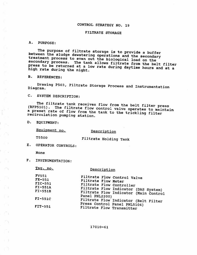
The purpose of filtrate storage is to provide a bufferbetween the srudge dewaterint ãóãiitiã"J "r,a
ttre sàcór,a"rytreatnent procesé to even oui, tire-uiãiäõicar road on thesecondary Process. The tank arrows-iiiËrate from the bert filterpress to be returned at a lorr rate auiing daytine hours and at ahigh rate during ttre nigtrt.B. REFERENCES:
Drawing P503, FiJ.trate storage process and rnstrumentationDiagrarn.
C. SYSTEI{ DESCRIPTTON:
The filtrate tank receives flow from the bert firter press(8FP5101) ' The filtrate flow control varve operates to maintaina preset rate of flow from the tank [" [ir" trîciiinõ iirt..recirculation pumping station.
A. PURPOSE:
EQUIPMENT:
Ecruipment no.
T5500
OPERÀTOR CONTROLS:
None
INSTRT'TI{ENTATTON:
Tact. no.
FV551rE-551FIC-551FI-551ÀFr-5518
Fr-551C
CONTROL STR.àIEGY NO. 19
FILTRÀTE STORAGE
Description
Filtrate Holding Tank
Descriotion
Filtrate Flow Control ValveFiltrate FLow lfeterFiltrate Flow ControllerFiltrate FIow Indicator (DÀS Systen)Filtrate Frow rndicaror il¡"i.r, ôã"iiårPanel PNL22OO)Filtrate Flow Indicator (Belt Fi1terPress Control panel pNLsio4)Filtrate FIow Transmitter
D
E
F
FrT-s51
17010-61

F INSTRUUENTÀTION:
Taq. no.
Lr-551À
LI-5518
Lrl-s51LSH-s51
AIÀR}IS:
cr no.
IÀH-551À
LA}T-5518
H. OPERATION:
DescriPtion
Filtrate Storage Tank High LevelSysten)iiftt"t" storage Tank lrigh Leve1Control Panel PNL22oo)
(continued)
DescriPtion
Filtrate Storaqe Tank Level Indicator(DÀS SYsten)ùiiit.t" stãrage lank Level rndicatorluãi" control Þanel PNL22oo)ÈÏiirate stoi"g" Tank L9v9I TransuritterFiltrate stotãé" Tank High Level Switch
G
(DÀS
(üain
Flowcontro1lerFIC-S51hasahighandalowsetpoint.Thecontrorter auromaticarly ="rãã["-wttión set poin! !9 use depending
on the time of day. F'-ssr-nãåsures the rate of flow and sends a
signal to gc-SSi'wtricn ¡,oauîãiá= WSSr to maintain the set flow
rate. As the level in the iiiii.t" tank.rises' the flow through
FE-ssl increases and rv-551 ;iããã=-tã-táitttti'n the set rate offlow; as the íãvei- iarrs, the flow decreases and Fv-551 opens'
L70LO-62

CONTROL STRÀTEGY NO. 20
POLYI,IER FEED SYSTEIITS
A. PTJRPOSE:
The purpose of the pollzner feed systems is to provide acontinuous supply of coagrulant to the belt filter press (BFP51O1)for dewatering of the digested sludge, and to the gravitythickener to enhance settling of sludge.
B. REFERENCES:
1. Drawing P103, Prinary Sludge thickening and Grit RemovalSystern Process and Instrunentation Diagram.
Drawing P502, Sludge Dewatering Process andf nstrumentation Diagran.
3 Drawing P504, Polyner Systems Process and InstrunentationDiagram.
C. SYSTET.Í DESCRIPTION:
The polymer feed system for dewatering consists of two basicparts, a dry pollmer preparation component and a liquid pollmerfeed conponent. The system is located in the polyner room of thesludge dewatering building.
The dry polyner system (CFR5201) consists of sub-units,including a dry feeder component, a dispersion unit, a urixingtank with nixing system and a holding tank. Dry polyrner from thefeeder is diluted with water in the dispersion unit. Thedispersion unit discharges the solution into the mixing tankwhere the mixing system blends the liquid to a consistentsolution. The liquid pollaner is autornatically transferred to theholding tank when the level in the holding tank gets too Iow.CFR5201 is capable of diluting up to 22.5 pounds of polyner perhour to a solution concentration of as low as 0.5 percent byweight.
the liquid polyner feeder (CFR5202) transfers liguid pollnnerto the dewatering system fro¡n either the holding tank of Mü85201or a 350 gallon nini-bulk storage container provided by thepolymer n¡anufacturer. The feeder blends the poJ-yner with waterto produce a solution with a concentration as low as O.1 percent.
The pollnner feed systen for the gravity thickener is a liguidpolyner feeder (CFR5203) sinilar to that provided for thedewatering polyrner sysÈem. CFR52O3 withdraws neat pollmersolution (10 to 3O percent concentration) frorn a S5-gallon drun,dilutes the neat polyrner to a 0.1 percent solution, and feeds thedilute solution to the thickener at a rate of up to 1O pounds ofpolyner per day.
2
17010-63

)
D. EQUTPüENT:
Equipment no.
cFR5201cFR5202cFR5203PNL5211PNLs212PNL5213w5220
E. OPERÀTOR CONTROLS:
Location
PNL5211
PNL5211
PNLs212
PNL5212
PNL5212
PNLs104
PNLs213
PNL5213
PNLs213
Description
Dry Polyner SystenLiquid Pollmer Feeder 1Liguid Pollmer Feeder 2Dry Pollmer Feeder Control PanelPollmer Feeder Control Panel 1Pollmer Feeder Control Panel 2Ìlix Tank Transfer Valve
Controls
HS-520À, Dry Pollmer Systen nOn/OffrlSelector SwitchHs-5208, Dry Polyner Systenr DisperserItHand/Off/Autorr Selector SwitchHs-5224, Liquid Pollmer Feeder 1ItLocal./Off /Remoterr Selector SwitchHs-522B , Liquid Pol¡mer Feeder 1trStart/Stop" Pushbuttonsse-522e-, Liquid Pollmer Feeder 1 LocalSpeed ControllerSC-5228, Liquid Polyner Feeder 1 RemoteSpeed ControllerHS-5234, Liquid Polymer Feeder 2 SystemnOn/off[ Selector S¡¡itchHs-5238, Liquid Polyner Feeder 2ItStart/Stoptt PushbuttonsSC-523, Liquid Polymer Feeder 2 LocalSpeed Controller
Descriotion
Volumetric Feeder limerüix Tank High Leve1 Switchl¡fix Tank Low Level SwitchHolding Tank High Level SwitchHolding lank Low Level Switch
Description
Polymer Holding Tank Low Level
)
F. INSTRI'I{ENTATTON:
Taq. no.
KIC-520LSH-s20LSL-s20LSH-s21LSL-521
G. AI,ÀRMS:
aP¡rr nr-r
T,LL-52L
17010-64

H. OPERATTON:
the dry polyrner system (CFR5201) is started and stoppedmanually by the system ilOn/offrf selector switch. The unitautonatically mixes the dry pollmer into solution when therrHand/off/Àuto" selector switch for the dispersion unit and thenixing system is in the nÀutorr position. CFR5201 starts a batchcycle when LSL-520 indicates a low level in the nix tank.
The transfer valve (W5220) closes and the solenoid valve onthe dispersion unit opens. The volumetric feeder, dispersionunit and nixing system start. The volumetric feeder operates forthe period of time set on KIC-520 to feed the correct volume ofdry polyner for the solution concentration recommended by tbepofyner-nanufacturer. the dispersion unit operates for a timeperiod set by the system manufacturer to flush any pollmer fromthe unit. t{hen the dispersion unit stops, a blpass valve opensto continue feeding water to the nix tank until LSH-520 indicatesthat the tank is ful1. The dispersion unit solenoid valve thencloses.
The unit continues nrixing the pollmer solution until LSL-521indicates a low level in the holding tank. YV5220 opens and thepolymer solution is transferred frorn the nix tank to the holdingtank. The batch cycle begins again when LSL-520 indicates a lowlevel in the mix tank.
t{hen liquid polymer is being used, the Systern rrOn/Offrr switchremains in the I'Off'r position.
Liquid polymer feeder no. 1 (CFR52O2) ¡nay be operated eitherlocally from PNL5212, oE remotely from the belt filter presscontrol panel (PNL51O4). In the rrLocalrr mode, the liquid polynerpunp is be manually started and stopped by the trstart/Stopt'pushbuttons in PNL5212. The speed of the purnp is set by a manualþotentiorneter located in PNL5212. In the rrRemoter mode, a signalfrom PNL5104 starts the punp at the end of the belt pre-wetcycle. The speed of the puÍtp is controlled by master and slavepotentiometers in PNL5104. A water inlet solenoid valve openswhen the }iquid polymer punp starts, to provide dilution water tothe feeder. The rate of dilution water flow is controlled by ananual rate adjusting valve.
CFR52O2 automatically stops when the belt filter press beginsits normal shutdown cycle or when the alarn conditions describedin Paragraph f occur.
Polyner for CFR5202 is supplied from either the holding tankon CFR52O1 or a mini-bulk storage container. If dry pollmer isbeing used, HV523o is opened to provide solution polyner fromCFR52O1, IfV5231 is closed. HV523o is closed and Hv5231 is openwhen liquid polymer from a nanufacturerts urini-bu1k storagecontainer is used
17010-65

H. OPERÀTION: (continued)
Liquid pollnrer feeder no. 2 (CFR5203) is nanually started andstopped frour PNL5213. The speed of the liquid pollnrer punp is becontrolled by a manual potentiometer located in PNL5213. A waterinlet solenoid valve opens when the punp starts. The dilutionwater flos rate is controlled by a manual rate adjusting valve.
I. SPECIÀL CONSIDERATIONS:
CFR5202 automatically stops on the following alarm conditionsfron PNL51O4:
1. Low Level in S1udge Storage Tank (LSL-540)2. Low Belt Washwater Pressure (PSL-544)3. BeIt Ìlisalignment (ZS-5114/ZS-5118)4. BeIt Loss of llotion (sSL-5114/sSL-5118)5. Filter Press hergency Stop (HSS-5114/HSS-5118)6. Press Feed Punp Àlarm (UÀ-542)
17010-66

CONÎROL STRATEGY NO. 2L
INSTRI'I{ENT ÀTR SYSTEI{
À. PT]RPOSE:
The instrument air systen provides oil-free air required forplant air-operated instruments and valves. The desiccant dryerunit is inténded to remove aII moisture vapor down to a pressuredew point of -40 degrees F, in order to meet ISÀ requirements forinstrument quality air.B. REFERENCES:
Drawing P205, Instrument Air System Process andInstrumentation Diagram.
C. SYSTEI{ DESCRIPTION:
1. INSTRITI,IENT ÀIR COMPRESSORS: The compressors are oil-free, single-stage, single-acting, type with extended cross heador distance piece, providing positive separation of the oil-lubricated crankcase and the oil-free cylinder. Aftercoolers areprovided on each compressor, and are air-cooled by air noved bythe compressor f1ywheel.
2. INSTRIJI,IENT ÀfR DRYER: The dryer consists of twodesiccant towers, a 4-way switching valve, and a timer circuitthat establishes the regeneration cyc1e.
In order to preserve operating efficiency, a coalescingprefilter is installed upstrearn of the dryer, provided with 3-waynanual bypass valving. Likewise, due to adsorbent ¡rediarrdustingrr, a f inal particulate f ilter is installed on thedischarge, again piped and valved with a 3-way manual bypass.
D. EQUIPMENT:
Eauipment no. Description
DRY2 170PVL2170cP2t7LcP2A72FLT2178FLT2179
fnstrument Àir DryerInstrunent Air ReceiverInstrunent Air compressor 1Instrument Air Coropressor 2Coalescing PrefilterParticulate Filter
17010-67

E OPERÀTOR CONTROTS:
Location
PNL217O
PNL217O
PNL217O
PNL217O
PNL217O
INSTRI'IIÍENTÀTION:
Tacr. no.
PSL-231
TSH-231
PSL-232
TSH-232
PC-230À
PC-z308
PC-230C
AI,ARMS:
rT¡acr no -
uA-230PÀL-233
F.
G.
Controls
HS-230, Instrument Air CompressorrrLead/Followrr Selector Sr¡itchHS-2314, Instrunent Air Cornpressor 1rrHand/Off/Àutorr Selector SwitchHS-2318, Instrument Àir Conpressor 1mResettr PushbuttonHS-2324, Instrument Air Conpressor 2rrHand/OfflÀutor Selector SwitchHS-2328, Instrunent å,ir Conpressoî 2trResetrr Pushbutton
Description
Instrument Air Compressor 1 Low OiIPressure SwitchInstrument Àir Compressor 1 HiqhDischarge Àir Temperature SwitchInstrument Àir Compressor 2 Low oilPressure SwitchInstrunent Àir compressor 2 HighDischarge Àir Temperature SwitchLead Instrument Àir compressor StartPressure SwitchFollow Instrunent Àir Compressor StartPressure SwitchInstrument Àir Compressor Stop PressureSwitch
Description
fnstrument Àir Systen TroubleInstrument Air Pressure Low
H. OPERÀTION:
1. INSIRT'}IENT ATR COMPRESSORS:
a. GENERjAL: The instrument air courpressors are providedas a prewired, prepiped package, skid mounted with a single aírreceiver.
b. tifÀNUAL: With the ilHand/off/Àutorrselector sr¡itch inthe rrHandrr position, the respecÈive compressor runs continuously.The cornpressors stop on low oil pressure or high discharge airtemperature. llanual reset is required.
)
17010-68

H. OPERjÀTION: (continued)
c. AIIIOIIATIC: I{ith the rrHand/OfflÀuto[selector switchin the trAutotr position, the compressors are controlled bypressure sr¡itches PC-230À, PC-2308, AND PC-230C. The leadcompressor starts when the pressure falls to a prescribed lowpressure set point (PC-230À). On further drop in pressure to asecond low pressure set point, the follor¡ compressor also starts(PC-2308). lthen the pressure in the receiver reaches the highpressure set point, both compressors stop (PC-230C). theþressure set points are adjustable. The conpressors stop on 1o¡roil pressure ór high discharge air temperature. l,tanual reset isrequired.
2. fNSTRTUENT ÀIR DRYER: During half of the control cyc1e,one of the towers acts as the drying tower. À11 system airpasses through the adsorbent nedia. At the same ti¡ne, a snallportion of the dry air is bled off and routed backwards throughthe off-line towei, thus purging the moisture from the media.The purge air is vented to the room. The cycle tiure isadjustable. 11O volt singLe phase polter is required for thecyðte tiurer, controller, and solenoid valve that switches theflow direction.
17010-69

CONTROL STRATEGY NO. 22
RECLAIUED WÀTER SYSTEI
A. PTIRPOSE:
To provide a supply of pressurized water for process, wash-down, and irrigation uses.
B. REFERENCES:
Drawing P305, Reclaimed t{ater and Chlorine Contact TankSystems Process and Instrumentation Diagram.
C. SYSTEX,{ DESCRIPTION:
Trro horizontal, split case, single stage centrifugal punpsare located in the Secondary Control Building. Each punp iseguipped with a variable speed drive. The operating speed rangeranges from a maxinun of about 3,550 rptnr where each pulnpproduces 300 gpn at 75 psig to a mininrum speed where each pumpdelivers 100 gpn at 75 psig.
D. EQUTPMENT:
Eouioment no. Descriotion
P2150 Reclaimed l{ater Punp 1P2160 Reclaimed Water Puurp 2VSD215O Variable Speed Drive 1VSD216O Variable Speed Drive 2
E. OPERATOR CONTROLS:
Location Controls
PNL2200 HS-214 Reclaiured !{ater Punp rrI,ead/FollowrlSelector Switch
VSD2150 HS-215À, Reclaimed l{ater Pump 1ItHand/off/Autorr Selector Switch
VSD2150 HS-2158, Reclairned t{ater Pump 1rrl,ocal/Remote[ Selector Switch
VSD2150 SC-215, Reclaimed tfater Puutp 1 llanualSpeed Controller
VSD2160 HS-216À, Reclaimed !{ater Punp 2[Hand/off/Auto[ Selector SwitchVSD2160 HS-2168, Reclaimed tVater Punp 2
ItLoca1/Remoterr Selector SwitchVSD2160 SC-2L6, Reclaimed l{ater Puutp 2 }Íanual
Speed Controller
17010-70

F. INSTRT]I{ENTATTON:
Tacr- no-
PIC-214PTT-214PSL-214
G. ÀI,ÀRMS:
Taq no.
PÀL-214
I Description
Reclaimed l{ater Pressure ControllerReclaimed lùater Pressure Trans¡ritterReclaimed !{ater Low Pressure Àlarm Switch
Description
Reclained l{ater Low Pressure
H. OPERJATION:
1. GENERJ\L: Each Reclaimed l{ater PunP is supplied with sea}water. The seal water solenoid valve for the respective pumpopens whenever the punp is running.
2. lfÀNUÀL: I{hen the I'Hand/off/Autorr selector switch is inthe trHandtr position, for a given Reclairned Water Pump, that pumPruns continuously. The speed is adjusted as described inparagraphs 4 and 5 below.
3. AIIIOIÍATIC: When the frHand/Off/Àuto" selector switch isin the rrÀutorr position, for a given Reclained l{ater Purnp, thatpunp runs, Ín the following seguence, to match punping capacitywith reclaimed water demand:
The Reclaimed l{ater Pump selected as rrl,eadrr runscontinuously. ff the pressure falls to a preset point below theset point, of PT.C-2LA, the follord pump starts. When the waterdemand falls to a preset point FIS-214 contacts oPen and thefollow punp stops. The speed is adjusted as described inparagraphs d and e below.
4. LOCÀL CONTROL: l{hen the trlocal/Remotefr selector switctris in the rrLocalil position, the Reclaimed Water Purnp speed is setby the nanual- speed controller located on the respective VSD.
5. REMOTE CONTROL: When the |tl,ocal/Remoterr selector switchis in the rrRemotert position, the Reclained l{ater Pump speed iscontrolled by a 4 to 20 ¡nÀdc signal from pressure controllerPIC-214.
17010-7 1

CONTROL STRÀTEGY NO. 23
HEATING ÀI{D VENTIIÀTTNG SYSTEI{S
À. PT]RPOSE:
To provide heating and ventilation for occupant safety andcomfort.
This control strategry is for eguipnent and systens notspecified for control in Section 15951.
B. REFERENCES:
1. Prinary Gallery Air Flow Schematic, Drawing U1O3
2. Thickened Sludge Punping Station Àir Flow Schenatic,Drawing l{141
3. Drawing 1,f411, Digester Building Àir FIow Schematic andControl Diagranr
C. SYSTETI! DESCRTPTION:
The heating and ventilating systems are composed of electricunit heaters and exhausts fans. the unit heaters operate fro¡ntheir space thermostats. The exhaust fans operate from ¡nanualswitches. Fresh air comes into the buildings through doorlouvers.
D. EQUIPI{ENT:
1. PRIUÄRY GALLERY:
Ecruipment no. Description
ì
-l
:\
'.1
Fl391ItHl392Fl393
Equipment no.
F1691
ttH1692
Fl693
Primary Gallery Exhaust FanPrimary GaIIery Unit HeaterPrinary Gallery Supply Fan
2. THICKENED SLT,DGE PT,T,{PING STÀTION:
Description
Thickened Sludge Punping Station ExhaustFanThickened Studge Punping Station UnitHeaterThickened Sludge Punping Station SupplyFan
L7 0to-72

E.
F.
3. DIGESTER CONTROL BUILDING:
Eauipnent no. Description
F4089 ConPressor Room Exhaust FanF4096 ComPressor Room SuPPIY Fan
OPER.ATOR CONIROLS:
1. PRIIIARY GÀLLERY:
Location Controls
Drive Ventilation Systen rrOn/Offrt SelectorSwitch
2. THICKENED SLUDGE PT'MPING STATION:
Drive Ventilation System rrOn/Offrr SelectorSwitch
3. DIGESTER CONTROL BUILDING:
Drive Ventilation system rrOn/Offrr SelectorSwitch
INSTRT'I{ENTATTON:
1. PRII{ARY GALLERY:
lacr. no. Description
TC-114 Spaee Heating Thermostat
2. THICKENED SLUDGE PI'I{PING STÀTION:
TC-166 Space Heating Thermostat
G. AI,ÀRMS:
None
H. OPERATION:
1. VENTILATfON SYSTEI{: With the ventilation system rrOn/Offrrselector switch in the ronrr position, the supply and exhaust fanrun continuously.
2. HEÀTING SYSTEII: The unit heaters operate at the commandof their respective space heating thermostats. Below thethermostat set point, the unit heater fan and electric coiLoperate. Àt or above the set point, the fan and coil do notoperate. The set point is 50 oF.
L70LO-73

CONÎROL STRÀTEGY NO. 24
CONTINUOUS VENTII,ATION SYSTEIT{S
À. PTIRPOSE:
To provide continuous ventilation to remove potential harnfulvapors for occupant safety.
This control strategy is for equipment and systems notspecified for control in Section 15951.
B. REFERENCES:
Heating and Ventilating slrstem Gallery Air Flow Schematic,Drawing t[601
C. SYSTEIIÍ DESCRIPTION:
The ventilation systems are composed of exhaust fans. Theexhaust fans operate conÈinuously. Fresh air cones into thebuildings through cracks around the doors.
D. EQUIPMENT:
Equipment no. Descriotion
F6086 Flannable Storage Exhaust FanF6087 Parking Exhaust Fan
E. OPERÀTOR CONTROLS:
None
F. INSTRI'MENTÀTION:
None
G. ÀI,ARMS:
None
H. OPER,ATION:
1. FÀ¡f OPERATION: The fans are intended to operatecontinuously. l{ith the respective fan rrOn/Offrt selector switchin the trOnn position, the fan runs continuously.
L7 0LO-7 4

CONTROL STRÀTEGY NO. 25
INTERMITÎENT VENTII,ATION SYSTEMS
À. PT'RPOSE:
1o provide internittent ventilation for occupant comfort.
This control strategy is for eguipnent and systens notspecified for control in Section 15951.
B. REFERENCES:
Heating and Ventilating systen GaIIery Àir FIow Schematic,Drawing 1,t601
C. SYSTEI{ DESCRTPTION:
The ventilation systems are composed of exhaust fans. Theexhaust fans operate irom manual switches. Fresh air cornes intothe buildings through spaces around the doors.
D. EQUIPMENT:
Equipment no. Descriotion
F6O88 Storage Exhaust FanF6089 ShoP Exhaust Fan
E. OPERÀTOR CONTROLS:
Location Controls
Drive Storage Exhaust Fan rOn/Offrr Selector SwitchDrive Shop Exhaust Fan ffOn/Offtt Selector Switch
F. INSTRT]I{ENTÀTION:
None
G. AI,ARMS:
None
H. OPERJATION:
With the respective fan frOn/Offtr selector switch in the ronrrposition, tbe fan runs continuousLy.
(
l
i
17010-75

CONTROL STRÀTEGY NO. 26
PT'II{PING STÀTION 4 BÀCKUP RAW SEWÀGE PT,!,ÍP
A. PIIRPOSE¡
To start, start, and control Backup Raw Sewage Pump P8001 inthe event of a duty punp failure.B. REFERENCES:
1. Drawing l.t8o1, Pumpíng Station 4 Plans
2. Drawing 8801, Pumping Station 4 Electrical Plans
3. Specification Section 11344, Self-prining, Nonclog Punps
4. Control Diagram E54B
C. SYSIEI,Í DESCRTPTION:
Standby Raw senage Punrp P8001 Provides fixed capacity backuppunping to Purnping Station 4 in the event of a duty pump failure.the pre-existing punping station had two variable speed driveduty punps, each with a capacity of 2,000 gpn at 70 ft. TDH. Thestandby punp has been installed as a temporary unit. ft hassimilar operating characteristics to the pre-existing duty punpsand runs only if one of the duty pu¡ûps fails and the wetwellIevel is high.
D. EQUIPMENT:
Eouipment no. Description
P8001ARV8002
E. OPERATOR CONTROLS:
Location
PNLSOOl
F. INSTRI'!{ENTÀTTON:
aFa ar ?r ¡.r
LSH-801LSL-801
Backup Rahr Sewage PunpÀir Release Valve
Controls
Backup Raw Sewage Punp [Hand/off/ÀutorlSelector Switch
Description
I{etweII High LeveL SwitchI{etwelL Low Level Switch
I
17010-76
Copyright © 2022 FDOKUMEN