MOVIDRIVE® compact / System Manuals / 2002-04 - SEW ...
396
MOVIDRIVE ® compact Edition 04/2002 System Manual 1053 3818 / EN
-
Upload
khangminh22 -
Category
Documents
-
view
4 -
download
0
Transcript of MOVIDRIVE® compact / System Manuals / 2002-04 - SEW ...

MOVIDRIVE® compactEdition
04/2002
System Manual1053 3818 / EN

SEW-EURODRIVE

MOVIDRIVE® compact System Manual 3
1
2
3
4
5
6
7
8
9
10
11
12
13
14
1 Important Notes...................................................................................................... 6
2 System Description................................................................................................ 8
3 Technical Data and Dimensions ......................................................................... 20
4 Parameters............................................................................................................ 86
5 Project Planning................................................................................................. 152
6 Serial Communication ....................................................................................... 233
7 Safety Notes ....................................................................................................... 234
8 Unit Design ......................................................................................................... 235
9 Installation .......................................................................................................... 246
10 Startup................................................................................................................. 291
11 Operation and Service ....................................................................................... 356
12 Index of Changes ............................................................................................... 370
13 Abbreviation Key and Index.............................................................................. 371
14 Adress List.......................................................................................................... 377
Pi
fkVA
Hz
n
P6..
P60.
P600
00
I

4 MOVIDRIVE® compact System Manual
1 Important Notes...................................................................................................... 6
2 System Description................................................................................................ 82.1 Overview of the system................................................................................................ 82.2 Functions / features ................................................................................................... 142.3 Additional functions of the application version ........................................................... 162.4 Application modules................................................................................................... 18
3 Technical Data and Dimensions ......................................................................... 203.1 CE-marking, UL approval and unit designation.......................................................... 203.2 General technical data ............................................................................................... 213.3 MOVIDRIVE® compact MC_4_A...-5_3 (400/500 V units)......................................... 223.4 MOVIDRIVE® compact MC_4_A...-2_3 (230 V units)................................................ 323.5 Additional functions in the application type ................................................................ 403.6 MOVIDRIVE® compact MCF/MCV/MCS electronics data ......................................... 423.7 MOVIDRIVE® compact MCH electronics data........................................................... 463.8 MOVIDRIVE® compact dimensions ........................................................................... 493.9 IPOSplus® ................................................................................................................... 543.10 DBG11B keypad option ............................................................................................. 553.11 Serial interface option type USS21A (RS-232 and RS-485) ...................................... 563.12 5 V encoder power supply option type DWI11A......................................................... 573.13 MOVITOOLS software ............................................................................................... 583.14 Application modules for MOVIDRIVE® compact........................................................ 593.15 Braking resistor option type BW................................................................................. 633.16 Line chokes option type ND... .................................................................................... 693.17 NF...-... line filter option.............................................................................................. 703.18 Output choke option type HD... .................................................................................. 723.19 Output filter option type HF... ..................................................................................... 733.20 Pre-fabricated cables ................................................................................................. 76
4 Parameters............................................................................................................ 864.1 Menu structure ........................................................................................................... 864.2 Overview of parameters ............................................................................................. 874.3 Explanation of the parameters ................................................................................... 91
5 Project Planning................................................................................................. 1525.1 Schematic procedure ............................................................................................... 1525.2 Control characteristics.............................................................................................. 1535.3 Description of applications ....................................................................................... 1545.4 Motor selection for asynchronous AC motors (VFC)................................................ 1565.5 Motor selection for asynchronous servomotors (CFC)............................................. 1635.6 Motor selection for synchronous servomotors (SERVO) ......................................... 1845.7 Load capacity of the units at low output frequencies ............................................... 1925.8 Overload capacity of the inverter ............................................................................. 1935.9 Overload capacity of the inverter for short overload duration .................................. 2045.10 Selecting the braking resistor................................................................................... 2105.11 Connecting AC brake motors................................................................................... 2155.12 Permitted voltage systems for MOVIDRIVE® .......................................................... 2165.13 Mains contactor and mains fuses............................................................................. 2165.14 Power cables and motor cables............................................................................... 2175.15 Group drive in VFC mode ........................................................................................ 2215.16 Connecting explosion-proof AC motors ................................................................... 2225.17 Components for EMC compliant installation ............................................................ 2235.18 Connecting the optional power components............................................................ 2255.19 Electronics cables and signal generation................................................................. 2285.20 External 24 VDC voltage supply ............................................................................... 2295.21 Parameter set switchover......................................................................................... 2305.22 Priority of operating states and logic gating of control signals ................................. 2315.23 Limit switches........................................................................................................... 232

MOVIDRIVE® compact System Manual 5
1
2
3
4
5
6
7
8
9
10
11
12
13
14
6 Serial Communication ....................................................................................... 233
7 Safety Notes ....................................................................................................... 234
8 Unit Design ......................................................................................................... 2358.1 Unit designation, nameplates and scope of delivery................................................ 2358.2 Unit design MCF/MCV/MCS4_A.............................................................................. 2368.3 Unit design MCH4_A ............................................................................................... 241
9 Installation .......................................................................................................... 2469.1 Installation instructions for basic unit ....................................................................... 2469.2 Installation instructions for PROFIBUS-DP interface (MC_41A).............................. 2509.3 Installation instructions for INTERBUS FO interface (MCH42A).............................. 2549.4 UL compliant installation .......................................................................................... 2589.5 Power shield clamp.................................................................................................. 2599.6 Touch guard............................................................................................................. 2609.7 Wiring diagram, basic unit........................................................................................ 2619.8 Removing the terminal unit ...................................................................................... 2699.9 Assignment of braking resistors, chokes and filters ................................................. 2709.10 System bus (SBus) installation ................................................................................ 2739.11 Connection of option USS21A (RS-232 and RS-485).............................................. 2759.12 Connection of motor encoder and external encoder ................................................ 276
10 Startup................................................................................................................. 29110.1 General startup instructions ..................................................................................... 29110.2 Preliminary work and resources............................................................................... 29310.3 Startup with the DBG11B keypad ............................................................................ 29410.4 Startup with a PC and MOVITOOLS........................................................................ 30110.5 Starting the motor .................................................................................................... 30210.6 Startup for positioning tasks (MCH4_A)................................................................... 30510.7 Complete parameter list ........................................................................................... 30610.8 Starting up the inverter with PROFIBUS-DP (MC_41A) .......................................... 31310.9 Starting up the inverter with INTERBUS (MCH42A) ................................................ 328
11 Operation and Service ....................................................................................... 35611.1 MC_40A operating displays (without fieldbus) ......................................................... 35611.2 MC_41A (PROFIBUS-DP) operating displays ......................................................... 35711.3 MCH42A operating displays (INTERBUS FO) ......................................................... 35811.4 DBG11B keypad ...................................................................................................... 36111.5 Fault information ...................................................................................................... 36511.6 List of faults .............................................................................................................. 36611.7 SEW electronics service .......................................................................................... 369
12 Index of Changes ............................................................................................... 370
13 Abbreviation Key and Index.............................................................................. 37113.1 Abbreviation key ...................................................................................................... 37113.2 Index ........................................................................................................................ 372
14 Address List ....................................................................................................... 377

1
6 MOVIDRIVE® compact System Manual
1 Important Notes
Safety and warn-
ing instructions
Always follow the safety and warning instructions contained in this publication!
A requirement of fault-free operation and fulfillment of any rights to claim under guar-
antee is that you adhere to the information in the operating instructions. Consequent-
ly, read the operating instructions before you start working with the unit!
The operating instructions contain important information about servicing; as a re-
sult, they should be kept in the vicinity of the unit.
Designated use
MOVIDRIVE® compact drive inverters are units intended for stationary installation in
switch cabinets. Observe all instructions referring to the technical data and the permitted
conditions where the unit is operated.
Do not start up the unit (take into operation in the designated fashion) until you have es-
tablished that the machine complies with the EMC Directive 89/336/EEC and that the
conformity of the end product has been determined in accordance with the Machinery
Directive 89/392/EEC (with reference to EN 60204).
Electrical hazard
Possible consequences: Severe or fatal injuries.
Hazard
Possible consequences: Severe or fatal injuries.
Hazardous situation
Possible consequences: Slight or minor injuries.
Harmful situation
Possible consequences: Damage to the unit and the environ-ment.
Tips and useful information.
MOVIDRIVE® compact drive inverters are intended for use in industrial and commercial
systems for the operation of AC asynchronous motors or permanent-field AC synchro-
nous motors. These motors must be suitable for operation with frequency inverters. No
other loads may be connected to the units.

MOVIDRIVE® compact System Manual 7
1
1
Application envi-
ronment
The following uses are forbidden unless measures are expressly taken to make
them possible:
Safety functions
Waste disposal Please follow the current instructions: Dispose in accordance with the material structure
and the regulations in force, for instance as:
• Electronics scrap (printed-circuit boards)
• Plastic (housing)
• Sheet metal
• Copper
etc.
• Use in explosion-proof areas
• Use in areas exposed to harmful oils, acids, gases, vapors, dust, radiation, etc.
• Use in non-stationary applications which are subject to mechanical vibration and
shock loads in excess of the requirement in EN 50178
MOVIDRIVE® compact drive inverters are not allowed to perform any safety functions
unless the inverters are monitored by other safety systems.
Use superordinate safety systems to guarantee the protection of machinery and people.

2
8 MOVIDRIVE® compact System Manual
Overview of the system
2 System Description
2.1 Overview of the system
Power components
02603BEN
Figure 1: Overview of the system, MOVIDRIVE® compact MC_4_A power components
3 x 380...500 VAC
3 x 200...240 VAC
MOVIDRIVEMC_40/41/42A...-5_3
® compact MOVIDRIVEMC_40/41/42A...-2_3
® compact
Output filteroption
Output chokeoption
Braking resistoroption
Input filteroption
Line chokeoption
DC link
MOVIDRIVE MDR60A
Regen. power supply unit option
®

MOVIDRIVE® compact System Manual 9
2Overview of the system
2
Communications components
02604AEN
Figure 2: Overview of the system, MOVIDRIVE® compact MC_4_A communications components

2
10 MOVIDRIVE® compact System Manual
Overview of the system
General descrip-
tion
MOVIDRIVE® compact is the term for compact and high-performance drive inverters
from SEW. MOVIDRIVE® compact units are precisely tailored to your requirements. You
can use them for AC drives in the power range from 1.5 to 90 kW (2.0 to 120 HP). They
satisfy the most exacting requirements for dynamic properties and control quality thanks
to the most modern inverter technology combined with tried-and-tested SEW control
processes.
Range of units The MOVIDRIVE® compact range of units includes four series:
Unit variants The MCF, MCV and MCS series are available in two variants:
• MCF/MCV/MCS40A: Control via binary inputs and setpoint selection via analog set-
point input.
• MCF/MCV/MCS41A: Control either via PROFIBUS interface or binary inputs. Set-
point selection via PROFIBUS-DP interface.
The MCH series is available in three variants:
• MCH40A: Control via binary inputs and setpoint selection via analog setpoint input.
• MCH41A: Control either via PROFIBUS interface or binary inputs. Setpoint selection
via PROFIBUS-DP interface.
• MCH42A: Control either via INTERBUS FO interface or binary inputs. Setpoint se-
lection via INTERBUS FO interface.
Unit versions MOVIDRIVE® compact drive inverters are each available in two versions, namely the
standard version and the technology version.
Standard version As standard, the units are equipped with the IPOSplus® integrated positioning and se-
quence control system. They can also be expanded with the available options.
The standard version is indicated by the '00' digits at the end of the unit designation.
Technology
version
In addition to the features of the standard version, these units include the technology
functions of 'electronic cam' and 'internal synchronous operation'. Furthermore, you can
use all the application modules available in the MOVITOOLS software package with the
units in technology version.
The technology version is indicated by the '0T' characters at the end of the unit desig-
nation.
• MOVIDRIVE® compact MCF: Drive inverter for asynchronous AC motors without encoder feedback, VFC control mode
• MOVIDRIVE® compact MCV: Drive inverter for asynchronous AC motors with encoder feedback, either VFC or CFC control mode.
• MOVIDRIVE® compact MCS: Drive inverter for synchronous servo motors with resolver, CFC control mode.
• MOVIDRIVE® compact MCH: Drive inverter for asynchronous AC motors, asynchronous servo motors or synchronous servo motors. Encoder feed-back with Hiperface encoder, sin/cos encoder or TTL sen-sor.

MOVIDRIVE® compact System Manual 11
2Overview of the system
2
Overview of the
series and ver-
sions
The following table presents an overview of the series and versions:
Control mode VFC (Voltage Flux Control) and CFC (Current Flux Control) control modes are features
of MOVIDRIVE® compact drive inverters. Continuous calculation of the complete motor
model forms the basis for both control modes.
System bus
(SBus)
The system bus (SBus) is available as standard. It permits several MOVIDRIVE® drive
inverters to be networked together. As a result, data can be exchanged rapidly between
the units. MOVILINK® is the uniform SEW unit profile used for communication via the
SBus.
MOVILINK® MOVILINK® means the same message structure is always used, regardless of the in-
terface selected (SBus, RS-232, RS-485, fieldbus interfaces). As a result, the control
software is independent of the selected interface.
IPOSplus® A significant feature of MOVIDRIVE® drive inverters is that the IPOSplus® positioning
and sequence control system is integrated as standard. IPOSplus® enables you to con-
trol sequences of motion directly in the inverter, right on the plant floor. This concept
takes the load off the master controller and allows modular concepts to be implemented
more easily.
Without
encoder input
With encoder input
for sin/cos and incre-
mental encoders
With resolver
input
With encoder input for
Hiperface, sin/cos and
incremental encoders
Without field-bus
MCF40A MCV40A MCS40A MCH40A
With PROFI-BUS-DP
MCF41A MCV41A MCS41A MCH41A
With INTER-BUS FO
- - - MCH42A
VFC (Voltage Flux Control) control mode CFC (Current Flux Control) control mode
Voltage-controlled control mode for AC asynchro-nous motors with and without encoder feedback.• With encoder feedback
–At least 150% torque, even with the motor stopped
–Servo-like characteristics
• Without encoder feedback–At least 150 % torque up to 0.5 Hz
Current-controlled control mode for AC asynchro-nous motors and permanent-field AC servomotors. Encoder feedback is always required.• At least 160 % torque, even with the motor
stopped• Maximum precision and concentric running
characteristics right down to standstill• Servo characteristics and torque control even
for asynchronous AC motors• Reacts to load changes within a few millisec-
onds

2
12 MOVIDRIVE® compact System Manual
Overview of the system
The units at a glance
MOVIDRIVE® compact for 3 × 380 500 VAC supply voltage (400/500 V units):
MOVIDRIVE® compact for 3 × 200 240 VAC supply voltage (230 V units):
MOVIDRIVE® MDR60A regenerative power supply units for 400/500 V units:
Recommended motor power (VFC)(at Vin = 3 × 400 VAC)
Continuous output cur-rent
MOVIDRIVE® compact type Size
(CFC)
MCF4_AAsynchronous
withoutencoder
MCV4_AAsynchronouswith encoder
MCS4_ASynchronouswith resolver
MCH42AAsynchronous/synchronouswith encoder
(Techn.data)
1.5 kW (2.0 HP) 2.2 kW (3.0 HP) 4.0 AAC 0015-5A3-4-.. 0015-5A3-4-.. 0015-5A3-4-.. 0015-5A3-4-..
1(→ page 22)
2.2 kW (3.0 HP) 3.0 kW (4.0 HP) 5.5 AAC 0022-5A3-4-.. 0022-5A3-4-.. 0022-5A3-4-.. 0022-5A3-4-..
3.0 kW (4.0 HP) 4.0 kW (5.0 HP) 7.0 AAC 0030-5A3-4-.. 0030-5A3-4-.. 0030-5A3-4-.. 0030-5A3-4-..
4.0 kW (5.0 HP) 5.5 kW (7.5 HP) 9.5 AAC 0040-5A3-4-.. 0040-5A3-4-.. 0040-5A3-4-.. 0040-5A3-4-..
5.5 kW (7.5 HP) 7.5 kW (10 HP) 12.5 AAC 0055-5A3-4-.. 0055-5A3-4-.. 0055-5A3-4-.. 0055-5A3-4-..2
(→ page 24)7.5 kW (10 HP) 11 kW (15 HP) 16 AAC 0075-5A3-4-.. 0075-5A3-4-.. 0075-5A3-4-.. 0075-5A3-4-..
11 kW (15 HP) 15 kW (20 HP) 24 AAC 0110-5A3-4-.. 0110-5A3-4-.. 0110-5A3-4-.. 0110-5A3-4-..
15 kW (20 HP) 22 kW (30 HP) 32 AAC 0150-503-4-.. 0150-503-4-.. 0150-503-4-.. 0150-503-4-..3
(→ page 26)22 kW (30 HP) 30 kW (40 HP) 46 AAC 0220-503-4-.. 0220-503-4-.. 0220-503-4-.. 0220-503-4-..
30 kW (40 HP) 37 kW (50 HP) 60 AAC 0300-503-4-.. 0300-503-4-.. 0300-503-4-.. 0300-503-4-..
37 kW (50 HP) 45 kW (60 HP) 73 AAC 0370-503-4-.. 0370-503-4-.. 0370-503-4-.. 0370-503-4-.. 4(→ page 28)45 kW (60 HP) 55 kW (75 HP) 89 AAC 0450-503-4-.. 0450-503-4-.. 0450-503-4-.. 0450-503-4-..
55 kW (75 HP) 75 kW (100 HP) 105 AAC 0550-503-4-.. 0550-503-4-.. 0550-503-4-.. 0550-503-4-.. 5(→ page 30)75 kW (100 HP) 90 kW (120 HP) 130 AAC 0750-503-4-.. 0750-503-4-.. 0750-503-4-.. 0750-503-4-..
Recommended motor power (VFC)(at Vin = 3 × 230 VAC)
Continuous output cur-rent
MOVIDRIVE® compact type Size
(CFC)
MCF4_AAsynchronous
withoutencoder
MCV4_AAsynchronouswith encoder
MCS4_ASynchronouswith resolver
MCH42AAsynchronous/synchronouswith encoder
(Technical data)
1.5 kW (2.0 HP) 2.2 kW (3.0 HP) 7.3 AAC 0015-2A3-4-.. 0015-2A3-4-.. 0015-2A3-4-.. 0015-2A3-4-..1
(→ page 32)2.2 kW (3.0 HP) 3.7 kW (5.0 HP) 8.6 AAC 0022-2A3-4-.. 0022-2A3-4-.. 0022-2A3-4-.. 0022-2A3-4-..
3.7 kW (5.0 HP) 5.0 kW (6.8 HP) 14.5 AAC 0037-2A3-4-.. 0037-2A3-4-.. 0037-2A3-4-.. 0037-2A3-4-..
5.5 kW (7.5 HP) 7.5 kW (10 HP) 22 AAC 0055-2A3-4-.. 0055-2A3-4-.. 0055-2A3-4-.. 0055-2A3-4-.. 2(→ page 34)7.5 kW (10 HP) 11 kW (15 HP) 29 AAC 0075-2A3-4-.. 0075-2A3-4-.. 0075-2A3-4-.. 0075-2A3-4-..
11 kW (15 HP) 15 kW (20 HP) 42 AAC 0110-203-4-.. 0110-203-4-.. 0110-203-4-.. 0110-203-4-.. 3(→ page 36)15 kW (20 HP) 22 kW (30 HP) 54 AAC 0150-203-4-.. 0150-203-4-.. 0150-203-4-.. 0150-203-4-..
22 kW (30 HP) 30 kW (40 HP) 80 AAC 0220-203-4-.. 0220-203-4-.. 0220-203-4-.. 0220-203-4-.. 4(→ page 38)30 kW (40 HP) 37 kW (50 HP) 95 AAC 0300-203-4-.. 0300-203-4-.. 0300-203-4-.. 0300-203-4-..
Regenerative power supply units1)
1) Technical data → 'MDR60A Regenerative Power Supply Unit' manual
MOVIDRIVE® MDR60A Size
1.5 ... 37 kW (20 ... 50 HP) Iin = 66 AAC, IDCL = 70 ADC 0370-503-00 3
15 ... 75 kW (20 ... 100 HP) Iin = 117 AAC, IDCL = 141 ADC 0750-503-00 4

MOVIDRIVE® compact System Manual 13
2Overview of the system
2
Block wiring dia-
gram
The following block wiring diagram shows the configuration principles and theory of
operation of MOVIDRIVE® compact drive inverters taking the example of the MOVI-
DRIVE® compact MCV41A.
05291AEN
Figure 3: MOVIDRIVE® compact MCV41A block circuit diagram

2
14 MOVIDRIVE® compact System Manual
Functions / features
2.2 Functions / features
Unit properties • Wide voltage range
–400/500 V units for the voltage range 3 × 380 ... 500 VAC
–230 V units for the voltage range 3 × 200 ... 240 VAC
• High overload capacity
–150 % IN short-term operation
–125 % IN sustained for operation without overload (pumps, fans)
• In VFC mode and at IN = 100 % permitted ambient temperature up to ϑ = 50° C
• 4Q capability thanks to integrated brake chopper fitted as standard
• Compact unit mounting position for minimum switch cabinet space requirement and
optimum utilization of switch cabinet volume
• Integrated input filter fitted as standard in sizes 1 and 2, adherence to class A limit
on the input side without any additional measures
• Six isolated binary inputs and three binary outputs, one of which is a relay output,
programmable inputs/outputs
• One TF/TH input for the motor protection involving a PTC thermistor or thermocon-
tact
• 3-color LED to display operating and fault states.
• Separate 24 VDC voltage input for powering the inverter electronics (parameter set-
ting, diagnostics and data storage even with the supply system switched off)
• Removable connection unit and, in addition with MOVIDRIVE® compact MCH4_A,
separable electronics terminals
• Power terminals of size 1 units can be disconnected
Control functions • VFC or CFC control processes for field-oriented operation (asynchronous servo)
• With MCH4_A: Either asynchronous or synchronous AC motors can be operated.
• IPOSplus® positioning and sequence control system integrated as standard
• Two complete parameter sets
• Automatic motor calibration
• Automatic brake control by the inverter
• DC braking to decelerate the motor even in 1Q mode
• Slip compensation for high static accuracy of speed, even without encoder feedback
• Flying restart circuit for flying restart of the inverter
• Hoist capability with all motor systems which can be connected
• Motor pull-out protection by sliding current limitation in the field weakening range
• Speed window masking to avoid mechanical resonance ranges
• Heating current to prevent condensation forming in the motor
• Factory settings can be reactivated
• Parameter lock to protect against parameter changes
• Speed controller and encoder input in types MCV (optionally sin/cos encoder, TTL
sensor or HTL sensor), MCS (resolver) and MCH (optionally Hiperface encoder, sin/
cos encoder or TTL sensor), user-friendly controller setting tool in the user interface

MOVIDRIVE® compact System Manual 15
2Functions / features
2
• Protective feature for complete protection of the inverter and motor (short-circuit,
overload, overvoltage/undervoltage, ground fault, excess temperature in the inverter,
motor pull-out protection, excess temperature in the motor)
• Temperature-controlled power unit fan, i.e. no disruptive fan noise in most cases.
• Speed monitoring and monitoring of the motor and regenerative limit power
• Programmable signal range monitoring (speed, current, maximum current)
• Memory for storing x/t diagrams which can be displayed using the SCOPE process
data visualization software (four channels, real-time capable)
• Fault memory (five memory locations) with all relevant operating data at the moment
of the fault
• Elapsed-hour counter for ON-hours (unit connected to supply system or 24 VDC) and
enable hours (output stage energized)
• Uniform operation, identical parameter setting and the same unit connection technol-
ogy for the entire MOVIDRIVE® unit series
Setpoint technol-
ogy
• Ramp switch mode (total of four ramps)
• Motor potentiometer, can be combined with analog setpoint and internal fixed set-
points
• External setpoint selections: 0 ... +10 V, ±10 V, 0 ... 20 mA, 4 ... 20 mA or fieldbus
• S-pattern for jerk-free speed changes
• Programmable input characteristics for flexible setpoint processing
• Six bipolar fixed setpoints which can be mixed with external setpoints and motor po-
tentiometer function
Communication /
operation
• System bus for networking up to 64 MOVIDRIVE® units to one another
• PROFIBUS-DP interface (max. 12 Mbaud) in MC_41A and INTERBUS FO interface
in MCH42A
• Straightforward startup and parameter setting using keypad or PC
System expan-
sion
• Extensive range of expansion options, for example:
–Removable plain text keypad with parameter memory
–RS-232 and RS-485 serial interfaces
–Braking resistors, input filters, line chokes, output chokes, output filters
• MOVITOOLS software package with SCOPE process data visualization
• Technology version with access to technology functions and application modules for
user-friendly application solutions
• MOVIDRIVE® MDR60A regenerative power supply unit
–Regenerative energy is fed back into the supply system
–This reduces the thermal load in the switch cabinet and helps to cut costs
Standards / certif-
icates
• UL, cUL and C-Tick approved
• Safe separation of power and electronic connections according to EN 50178
• Compliance with all the requirements for CE certification of machines and plant
equipped with MOVIDRIVE® on the basis of the EC Low-voltage Directive 73/23/
EEC and the EMC Directive 89/336/EEC. Compliance with EMC product standard
EN 61800-3

2
16 MOVIDRIVE® compact System Manual
Additional functions of the application version
2.3 Additional functions of the application version
SEW offers additional functions for special applications. You can use these additional
functions with MOVIDRIVE® units in technology version (...-0T).
The following additional functions are available:
• Electronic cam
• Internal synchronous operation
Please refer to the 'Electronic Cam' and 'Internal Synchronous Operation' manuals for
detailed information about the additional functions. These manuals form part of the
'Technology Version' documentation package available from SEW.
Electronic cam You can use the MOVIDRIVE® range of units with the 'electronic cam' whenever you
need to harmonize complex sequences of motion in cyclical machines. This solution
gives you much greater flexibility in comparison to the mechanical cam. As a result, it
meets the needs of modern production and processing lines.
A user-friendly cam editor helps you during startup. You can also import existing cam
data. You can also set application-specific parameters for the engagement and disen-
gagement phases using the cam editor.
Example The figure below displays a typical application for the 'electronic cam'. Freshly filled yo-
gurt jars are transported for further processing. The 'electronic cam' makes it possible
for movement to take place smoothly, which is an important requirement for this appli-
cation.
03672AXX
Figure 4: Typical application for the 'electronic cam'

MOVIDRIVE® compact System Manual 17
2Additional functions of the application version
2
Internal synchro-
nous operation
You can always use the MOVIDRIVE® range of units with 'internal synchronous opera-
tion' whenever a group of motors have to be operated at a synchronous angle in relation
to one another or with an adjustable proportional ratio (electronic gear). A user-friendly
monitor helps you during startup.
Example The figure below displays a typical application for the 'internal synchronous operation'.
Extruded material has to be cut to length. The saw receives a start signal and synchro-
nizes itself with the extruded material. The saw moves synchronously to the extruded
material as it cuts. The saw returns to its starting position at the end of the sawing oper-
ation.
03866AXX
Figure 5: Typical application for the 'internal synchronous operation'

2
18 MOVIDRIVE® compact System Manual
Application modules
2.4 Application modules
The application Usually, the application involves more than adjusting the speed of a motor. Often, the
inverter is also required to control sequences of motion and undertake typical PLC tasks.
More and more complex drive applications have to be carried out without this resulting
in lengthy project planning and startup routines.
The solution with
MOVIDRIVE®
SEW offers various standardized control programs specifically for 'positioning', 'winding'
and 'controlling' applications. These programs are called application modules. The ap-
plication modules form part of the MOVITOOLS software package and can be used with
units in technology version.
A user-friendly user interface leads you through the process of setting the parameters.
All you have to do is enter the parameters you need for your application. The application
modules turns this information into the control program and loads it into the inverter.
MOVIDRIVE® then undertakes all the movement control functions. This takes the load
off the master controller and allows decentralized concepts to be implemented more
easily.
The benefits at a
glance
• Wide range of functions
• User-friendly user interface
• You only have to enter the parameters needed for the application
• User-friendly application programs guide you through the process of setting param-
eters, so there is no need for complicated programming
• No programming experience necessary
• No lengthy learning curve, therefore quick project planning and startup
• Control of all movement functions is performed directly in MOVIDRIVE®
• Decentralized concepts can be implemented more easily
Available applica-
tion modules
The application modules currently available for MOVIDRIVE® compact are listed below.
These application modules are explained in the 'Technical Data and Dimensions' chap-
ter.
Positioning Linear movement, the movement records are administered in the inverter:
• Table positioning with bus control
Linear movement, the movement records are administered in the PLC:
• Positioning via bus
• Extended positioning via bus
Rotational movement:
• Rotary axis
Winding • Constant tension center winder
• Winder with jockey roll control
Controlling • Flying saw

MOVIDRIVE® compact System Manual 19
2Application modules
2
Application The following figure shows an example for how the various SEW applications modules
are used in a block warehouse.
1. Hoist: Table positioning
2. Travel axis: Absolute value or bus positioning
3. Rotary distributor: Rotary axis
04008AXX
Figure 6: Application in a block warehouse
1.
2.
3.

3
20 MOVIDRIVE® compact System Manual
CE-marking, UL approval and unit designation
3 Technical Data and Dimensions
3.1 CE-marking, UL approval and unit designation
CE-marking • Low Voltage Directive
MOVIDRIVE® compact drive inverters comply with the regulations of the Low Volt-
age Directive 73/23/EEC.
• Electromagnetic compatibility (EMC)
MOVIDRIVE® compact drive inverters are designed as components for installation
in machinery and plant. They comply with the EMC product standard EN 61800-3
'Variable-speed electrical drives'. Provided the installation instructions are complied
with, they satisfy the appropriate requirements for CE-marking of the entire machine/
system in which they are fitted, on the basis of the EMC Directive 89/336/EEC.
MOVIDRIVE® compact drive inverters of size 1 and 2 are fitted with an input filter as
standard. These units comply with limit value class A to EN 55011 and EN 55014 on
the line side without further measures.
The CE-mark on the nameplate indicates conformity with the Low-voltage Directive 73/
23/EEC and the EMC Directive 89/336/EEC. We can issue a declaration of conformity
to this effect on request.
UL approval UL and cUL approval has been granted for the entire MOVIDRIVE® range of units. cUL
is equivalent to CSA approval.
C-Tick C-Tick approval has been granted for the entire MOVIDRIVE® compact range of units.
C-Tick certifies conformity with the requirements of the ACA (Australian Communica-
tions Authority).
Unit designation The following example illustrates the unit designation of MOVIDRIVE® compact:
UL®C UL®
05292AEN
Pi
fkVA
Hz
n

MOVIDRIVE® compact System Manual 21
3General technical data
3
3.2 General technical data
The following table lists the technical data applicable to all MOVIDRIVE® compact drive
inverters, irrespective of their type, version, size and performance.
MOVIDRIVE®
compact unit
series
MOVIDRIVE® compact All sizes
Interference immunity To EN 61800-3
Interference emission with EMC-com-pliant installation
According to class B limit to EN 55011 and EN 55014To EN 61800-3Sizes 1 and 2 on line side according to class A limit to EN 55011 and EN 55014 without further measures
Ambient temperature ϑamb
Derating ambient temperatureClimate class
0 °C...+50 °C at ID = 100 % IN and fPWM = 4 kHz0 °C...+40 °C at ID = 125 % IN and fPWM = 4 kHz0 °C...+40 °C at ID = 100 % IN and fPWM = 8 kHzPN reduction: 3.0 % IN per K to max. 60 °CEN 60721-3-3, class 3K3
Storage temperature1) ϑL
1) Connect to supply voltage for min. 5 minutes every 2 years if stored for long periods, otherwise the unit
service life may be reduced.
-25 °C...+70 °C (EN 60721-3-3, class 3K3)DBG keypad: -20 °C...+60 °C
Type of cooling (DIN 51751) Forced coolingTemperature-controlled fan, response threshold at ϑ = 45 °C
Enclosure Sizes 1 to 3EN 60529 Size 4 and 5(NEMA1)
IP20IP00 (power connections); IP10 with Plexiglas cover mounted (supplied as standard)
Operating mode DB (EN 60149-1-1 and 1-3)
Installation altitude h ≤ 1000 m (3300 ft)IN reduction: 1 % per 100 m (330 ft)from 1000 m (3300 ft) to max. 2000 m (6600 ft)
02531AXX
Figure 7: MOVIDRIVE® compact unit series
Pi
fkVA
Hz
n

3
22 MOVIDRIVE® compact System Manual
MOVIDRIVE® compact MC_4_A...-5_3 (400/500 V units)
3.3 MOVIDRIVE® compact MC_4_A...-5_3 (400/500 V units)
Size 1
02570AXX
Figure 8: Size 1
MOVIDRIVE® compact 0015-5A3-4-0_ 0022-5A3-4-0_ 0030-5A3-4-0_ 0040-5A3-4-0_
INPUT
Supply voltage Vmains 3 × 380 VAC -10 %...3 × 500 VAC +10 %
Supply frequency fmains 50 Hz...60 Hz ±5 %
Rated system current1)Imains 100 %(at Vmains = 3 × 400 VAC) 125 %
3.6 AAC
4.5 AAC
5.0 AAC
6.2 AAC
6.3 AAC
7.9 AAC
8.6 AAC
10.7 AAC
OUTPUT
Rated output power2) PN(at Vmains = 3 × 400...500 VAC)
2.8 kVA 3.8 kVA 4.9 kVA 6.6 kVA
Rated output current1) IN(at Vmains = 3 × 400 VAC)
4.0 AAC 5.5 AAC 7.0 AAC 9.5 AAC
Current limitation Imax Motor and regenerative 150 % IN, duration depending on the capacity utilization
Internal current limitation Imax = 0...150 % can be set in menu (P303 / P313)
Minimum permitted brake RBWminresistance value (4Q operation)
68 Ω
Output voltage Vout max. Vin
PWM frequency fPWM Adjustable: 4/8/16 kHz (P860 / P861)
Speed range / resolution nA / ∆nA -5000...0...+5000 rpm / 0.2 rpm across the entire range
GENERAL
Power loss at PNPVmax 85 W 105 W 130 W 180 W
Cooling air consumption 40 m3/h (24 ft3/min)
Weight 2.8 kg (6.16 lb)
Dimensions W × H × D MCF/MCV/MCS: 105 × 315 × 155 mm (4.13 × 12.40 × 6.10 in)MCH: 105 × 315 × 161 mm (4.13 × 12.40 × 6.34 in)
1) The system and output currents must be reduced by 20 % from the nominal values for Vmains = 3 × 500 VAC.
2) The performance data apply to fPWM = 4 kHz (factory setting in VFC operating modes).
Pi
fkVA
Hz
n

MOVIDRIVE® compact System Manual 23
3MOVIDRIVE® compact MC_4_A...-5_3 (400/500 V units)
3
MCF4_A standard type (VFC) 0015-5A3-4-00 0022-5A3-4-00 0030-5A3-4-00 0040-5A3-4-00
MCF40A part numbers (without fieldbus) 826 738 3 826 739 1 826 740 5 826 741 3
MCF41A part numbers (with PROFIBUS-DP) 826 835 5 826 836 3 826 837 1 826 838 X
MCF4_A technology type (VFC) 0015-5A3-4-0T 0022-5A3-4-0T 0030-5A3-4-0T 0040-5A3-4-0T
MCF40A part numbers (without fieldbus) 827 426 6 827 427 4 827 428 2 827 429 0
MCF41A part numbers (with PROFIBUS-DP) 827 449 5 827 450 9 827 451 7 827 452 5
Constant loadRecommended motor power Pmot 1.5 kW (2.0 HP) 2.2 kW (3.0 HP) 3.0 kW (4.0 HP) 4.0 kW (5.0 HP)
Variable torque load or constantload without overloadRecommended motor power Pmot 2.2 kW (3.0 HP) 3.0 kW (4.0 HP) 4.0 kW (5.0 HP) 5.5 kW (7.5 HP)
Continuous output current = 125 % IN ID(at Vmains = 3 × 400 VAC and fPWM = 4 kHz)
5.0 AAC 6.9 AAC 8.8 AAC 11.9 AAC
MCV4_A standard type (VFC/CFC) 0015-5A3-4-00 0022-5A3-4-00 0030-5A3-4-00 0040-5A3-4-00
MCV40A part numbers (without fieldbus) 826 908 4 826 909 2 826 910 6 826 911 4
MCV41A part numbers (with PROFIBUS-DP) 826 928 9 826 929 7 826 930 0 826 931 9
MCV4_A technology type (VFC/CFC) 0015-5A3-4-0T 0022-5A3-4-0T 0030-5A3-4-0T 0040-5A3-4-0T
MCV40A part numbers (without fieldbus) 827 472 X 827 473 8 827 474 6 827 475 4
MCV41A part numbers (with PROFIBUS-DP) 827 495 9 827 496 7 827 497 5 827 498 3
VFC operating mode Recommended motor power → MCF4_A
CFC operating mode (fPWM = 8 kHz)Continuous output current = 100 % IN ID 4.0 AAC 5.5 AAC 7.0 AAC 9.5 AAC
Recommended motor power → Sec. Project Planning, CFC motor selection
MCS4_A standard type (SERVO) 0015-5A3-4-00 0022-5A3-4-00 0030-5A3-4-00 0040-5A3-4-00
MCS40A part numbers (without fieldbus) 827 060 0 827 061 9 827 062 7 827 063 5
MCS41A part numbers (with PROFIBUS-DP) 827 077 5 827 078 3 827 079 1 827 080 5
MCS4_A technology type (SERVO) 0015-5A3-4-0T 0022-5A3-4-0T 0030-5A3-4-0T 0040-5A3-4-0T
MCS40A part numbers (without fieldbus) 827 518 1 827 519 X 827 520 3 827 521 1
MCS41A part numbers (with PROFIBUS-DP) 827 541 6 827 542 4 827 543 2 827 544 0
SERVO operating mode (fPWM = 8 kHz)Continuous output current = 100 % IN ID 4.0 AAC 5.5 AAC 7.0 AAC 9.5 AAC
Recommended motor power → Sec. Project Planning, SERVO motor selection
MCH4_A standard type(VFC/CFC/SERVO)
0015-5A3-4-00 0022-5A3-4-00 0030-5A3-4-00 0040-5A3-4-00
MCH40A part numbers (without fieldbus) 827 603 X 827 604 8 827 605 6 827 606 4
MCH41A part numbers (with PROFIBUS-DP) 827 649 8 827 650 1 827 651 X 827 652 8
MCH42A part numbers (with INTERBUS FO) 827 565 3 827 566 1 827 567 X 827 568 8
MCH4_A technology type(VFC/CFC/SERVO)
0015-5A3-4-0T 0022-5A3-4-0T 0030-5A3-4-0T 0040-5A3-4-0T
MCH40A part numbers (without fieldbus) 827 626 9 827 627 7 827 628 5 827 629 3
MCH41A part numbers (with PROFIBUS-DP) 827 672 2 827 673 0 827 674 9 827 675 7
MCH42A part numbers (with INTERBUS FO) 827 158 5 827 159 3 827 160 7 827 161 5
VFC operating mode Recommended motor power → MCF4_A
CFC/SERVO operating mode (fPWM = 8 kHz)Continuous output current = 100 % IN ID 4.0 AAC 5.5 AAC 7.0 AAC 9.5 AAC
Recommended motor power → Sec. Project Planning, CFC/SERVO motor selection
Pi
fkVA
Hz
n

3
24 MOVIDRIVE® compact System Manual
MOVIDRIVE® compact MC_4_A...-5_3 (400/500 V units)
Size 2
02571AXX
Figure 9: Size 2
MOVIDRIVE® compact 0055-5A3-4-0_ 0075-5A3-4-0_ 0110-5A3-4-0_
INPUT
Supply voltage Vmains 3 × 380 VAC -10 %...3 × 500 VAC +10 %
Supply frequency fmains 50 Hz...60 Hz ±5 %
Rated system current1)Imains 100 %(at Vmains = 3 × 400 VAC) 125 %
11.3 AAC
14.1 AAC
14.4 AAC
18.0 AAC
21.6 AAC
27.0 AAC
OUTPUT
Rated output power2) PN(at Vmains = 3 × 400...500 VAC)
8.7 kVA 11.2 kVA 16.8 kVA
Rated output current1) IN(at Vmains = 3 × 400 VAC)
12.5 AAC 16 AAC 24 AAC
Current limitation Imax Motor and regenerative 150 % IN, duration depending on the capacity utilization
Internal current limitation Imax = 0...150 % can be set in menu (P303 / P313)
Minimum permitted brake RBWminresistance value (4Q operation)
47 Ω 22 Ω
Output voltage Vout max. Vin
PWM frequency fPWM Adjustable: 4/8/16 kHz (P860 / P861)
Speed range / resolution nA / ∆nA -5000...0...+5000 rpm / 0.2 rpm across the entire range
GENERAL
Power loss at PNPVmax 220 W 290 W 400 W
Cooling air consumption 80 m3/h (48 ft3/min)
Weight 5.9 kg (12.98 lb)
Dimensions W × H × D MCF/MCV/MCS: 130 × 335 × 207 mm (5.12 × 13.19 × 8.15 in)MCH: 130 × 335 × 213 mm (5.12 × 13.19 × 8.39 in)
1) The system and output currents must be reduced by 20 % from the nominal values for Vin = 3 × 500 VAC.
2) The performance data apply to fPWM = 4 kHz (factory setting in VFC operating modes).
Pi
fkVA
Hz
n

MOVIDRIVE® compact System Manual 25
3MOVIDRIVE® compact MC_4_A...-5_3 (400/500 V units)
3
MCF4_A standard type (VFC) 0055-5A3-4-00 0075-5A3-4-00 0110-5A3-4-00
MCF40A part numbers (without fieldbus) 826 742 1 826 743 X 826 744 8
MCF41A part numbers (with PROFIBUS-DP) 826 839 8 826 840 1 826 841 X
MCF4_A technology type (VFC) 0055-5A3-4-0T 0075-5A3-4-0T 0110-5A3-4-0T
MCF40A part numbers (without fieldbus) 827 430 4 827 431 2 827 432 0
MCF41A part numbers (with PROFIBUS-DP) 827 453 3 827 454 1 827 455 X
Constant loadRecommended motor power Pmot 5.5 kW (7.5 HP) 7.5 kW (10 HP) 11 kW (15 HP)
Variable torque load or constantload without overloadRecommended motor power Pmot 7.5 kW (10 HP) 11 kW (15 HP) 15 kW (20 HP)
Continuous output current = 125 % IN ID(at Vmains = 3 × 400 VAC and fPWM = 4 kHz)
15.6 AAC 20.0 AAC 30.0 AAC
MCV4_A standard type (VFC/CFC) 0055-5A3-4-00 0075-5A3-4-00 0110-5A3-4-00
MCV40A part numbers (without fieldbus) 826 912 2 826 913 0 826 914 9
MCV41A part numbers (with PROFIBUS-DP) 826 932 7 826 933 5 826 934 3
MCV4_A technology type (VFC/CFC) 0055-5A3-4-0T 0075-5A3-4-0T 0110-5A3-4-0T
MCV40A part numbers (without fieldbus) 827 476 2 827 477 0 827 478 9
MCV41A part numbers (with PROFIBUS-DP) 827 499 1 827 500 9 827 501 7
VFC operating mode Recommended motor power → MCF4_A
CFC operating mode (fPWM = 8 kHz)Continuous output current = 100 % IN ID 12.5 AAC 16 AAC 24 AAC
Recommended motor power → Sec. Project Planning, CFC motor selection
MCS4_A standard type (SERVO) 0055-5A3-4-00 0075-5A3-4-00 0110-5A3-4-00
MCS40A part numbers (without fieldbus) 827 064 3 827 065 1 827 066 X
MCS41A part numbers (with PROFIBUS-DP) 827 081 3 827 082 1 827 083 X
MCS4_A technology type (SERVO) 0055-5A3-4-0T 0075-5A3-4-0T 0110-5A3-4-0T
MCS40A part numbers (without fieldbus) 827 522 X 827 523 8 827 524 6
MCS41A part numbers (with PROFIBUS-DP) 827 545 9 827 546 7 827 547 5
SERVO operating mode (fPWM = 8 kHz)Continuous output current = 100 % IN ID 12.5 AAC 16 AAC 24 AAC
Recommended motor power → Sec. Project Planning, SERVO motor selection
MCH4_A standard type(VFC/CFC/SERVO)
0055-5A3-4-00 0075-5A3-4-00 0110-5A3-4-00
MCH40A part numbers (without fieldbus) 827 607 2 827 608 0 827 609 9
MCH41A part numbers (with PROFIBUS-DP) 827 653 6 827 654 4 827 655 2
MCH42A part numbers (with INTERBUS FO) 827 569 6 827 570 X 827 571 8
MCH4_A technology type(VFC/CFC/SERVO)
0055-5A3-4-0T 0075-5A3-4-0T 0110-5A3-4-0T
Part numbers (without fieldbus) 827 630 7 827 631 5 827 632 3
Part numbers (with PROFIBUS-DP) 827 676 5 827 677 3 827 678 1
Part numbers (with INTERBUS FO) 827 162 3 827 163 1 827 164 X
VFC operating mode Recommended motor power → MCF4_A
CFC/SERVO operating mode (fPWM = 8 kHz)Continuous output current = 100 % IN ID 12.5 AAC 16 AAC 24 AAC
Recommended motor power → Sec. Project Planning, CFC/SERVO motor selection
Pi
fkVA
Hz
n

3
26 MOVIDRIVE® compact System Manual
MOVIDRIVE® compact MC_4_A...-5_3 (400/500 V units)
Size 3
02572AXX
Figure 10: Size 3
MOVIDRIVE® compact 0150-503-4-0_ 0220-503-4-0_ 0300-503-4-0_
INPUT
Supply voltage Vmains 3 × 380 VAC -10 %...3 × 500 VAC +10 %
Supply frequency fmains 50 Hz...60 Hz ±5 %
Rated system current1)Imains 100 %(at Vmains = 3 × 400 VAC) 125 %
28.8 AAC
36.0 AAC
41.4 AAC
51.7 AAC
54.0 AAC
67.5 AAC
OUTPUT
Rated output power2) PN(at Vmains = 3 × 400...500 VAC)
22.2 kVA 31.9 kVA 41.6 kVA
Rated output current1) IN(at Vmains = 3 × 400 VAC)
32 AAC 46 AAC 60 AAC
Current limitation Imax Motor and regenerative 150 % IN, duration depending on the capacity utilization
Internal current limitation Imax = 0...150 % can be set in menu (P303 / P313)
Minimum permitted brake RBWminresistance value (4Q operation)
15 Ω 12 Ω
Output voltage Vout max. Vin
PWM frequency fPWM Adjustable: 4/8/16 kHz (P860 / P861)
Speed range / resolution nA / ∆nA -5000...0...+5000 rpm / 0.2 rpm across the entire range
GENERAL
Power loss at PNPVmax 550 W 750 W 950 W
Cooling air consumption 180 m3/h (108 ft3/min)
Weight 14.3 kg (31.46 lb)
Dimensions W × H × D MCF/MCV/MCS: 200 × 465 × 227 mm (7.87 × 18.31 × 8.94 in)MCH: 200 × 465 × 233 mm (7.87 × 18.31 × 9.17 in)
1) The system and output currents must be reduced by 20 % from the nominal values for Vin = 3 × 500 VAC.
2) The performance data apply to fPWM = 4 kHz (factory setting in VFC operating modes).
Pi
fkVA
Hz
n

MOVIDRIVE® compact System Manual 27
3MOVIDRIVE® compact MC_4_A...-5_3 (400/500 V units)
3
MCF4_A standard type (VFC) 0150-503-4-00 0220-503-4-00 0300-503-4-00
MCF40A part numbers (without fieldbus) 826 745 6 826 746 4 826 747 2
MCF41A part numbers (with PROFIBUS-DP) 826 842 8 826 843 6 826 844 4
MCF4_A technology type (VFC) 0150-503-4-0T 0220-503-4-0T 0300-503-4-0T
MCF40A part numbers (without fieldbus) 827 433 9 827 434 7 827 435 5
MCF41A part numbers (with PROFIBUS-DP) 827 456 8 827 457 6 827 458 4
Constant loadRecommended motor power Pmot 15 kW (20 HP) 22 kW (30 HP) 30 kW (40 HP)
Variable torque load or constantload without overloadRecommended motor power Pmot 22 kW (30 HP) 30 kW (40 HP) 37 kW (50 HP)
Continuous output current = 125 % IN ID(at Vmains = 3 × 400 VAC and fPWM = 4 kHz)
40.0 AAC 57.5 AAC 75.0 AAC
MCV4_A standard type (VFC/CFC) 0150-503-4-00 0220-503-4-00 0300-503-4-00
MCV40A part numbers (without fieldbus) 826 915 7 826 916 5 826 917 3
MCV41A part numbers (with PROFIBUS-DP) 826 935 1 826 936 X 826 937 8
MCV4_A technology type (VFC/CFC) 0150-503-4-0T 0220-503-4-0T 0300-503-4-0T
MCV40A part numbers (without fieldbus) 827 479 7 827 480 0 827 481 9
MCV41A part numbers (with PROFIBUS-DP) 827 502 5 827 503 3 827 504 1
VFC operating mode Recommended motor power → MCF4_A
CFC operating mode (fPWM = 8 kHz)Continuous output current = 100 % IN ID 32 AAC 46 AAC 60 AAC
Recommended motor power → Sec. Project Planning, CFC motor selection
MCS4_A standard type (SERVO) 0150-503-4-00 0220-503-4-00 0300-503-4-00
MCS40A part numbers (without fieldbus) 827 067 8 827 068 6 827 069 4
MCS41A part numbers (with PROFIBUS-DP) 827 084 8 827 085 6 827 086 4
MCS4_A technology type (SERVO) 0150-503-4-0T 0220-503-4-0T 0300-503-4-0T
MCS40A part numbers (without fieldbus) 827 525 4 827 526 2 827 527 0
MCS41A part numbers (with PROFIBUS-DP) 827 548 3 827 549 1 827 550 5
SERVO operating mode (fPWM = 8 kHz)Continuous output current = 100 % IN ID 32 AAC 46 AAC 60 AAC
Recommended motor power → Sec. Project Planning, SERVO motor selection
MCH4_A standard type(VFC/CFC/SERVO)
0150-503-4-00 0220-503-4-00 0300-503-4-00
MCH40A part numbers (without fieldbus) 827 610 2 827 611 0 827 612 9
MCH41A part numbers (with PROFIBUS-DP) 827 656 0 827 657 9 827 658 7
MCH42A part numbers (with INTERBUS FO) 827 572 6 827 573 4 827 574 2
MCH4_A technology type(VFC/CFC/SERVO)
0150-503-4-0T 0220-503-4-0T 0300-503-4-0T
MCH40A part numbers (without fieldbus) 827 633 1 827 634 X 827 635 8
MCH41A part numbers (with PROFIBUS-DP) 827 679 X 827 680 3 827 681 1
MCH42A part numbers (with INTERBUS FO) 827 165 8 827 166 6 827 167 4
VFC operating mode Recommended motor power → MCF4_A
CFC/SERVO operating mode (fPWM = 8 kHz)Continuous output current = 100 % IN ID 32 AAC 46 AAC 60 AAC
Recommended motor power → Sec. Project Planning, CFC/SERVO motor selection
Pi
fkVA
Hz
n

3
28 MOVIDRIVE® compact System Manual
MOVIDRIVE® compact MC_4_A...-5_3 (400/500 V units)
Size 4
02573AXX
Figure 11: Size 4
MOVIDRIVE® compact 0370-503-4-0_ 0450-503-4-0_
INPUT
Supply voltage Vmains 3 × 380 VAC -10 %...3 × 500 VAC +10 %
Supply frequency fmains 50 Hz...60 Hz ±5 %
Rated system current1)Imains 100 %(at Vmains = 3 × 400 VAC) 125 %
65.7 AAC
81.9 AAC
80.1 AAC
100.1 AAC
OUTPUT
Rated output power2) PN(at Vmains = 3 × 400...500 VAC)
51.1 kVA 62.3 kVA
Rated output current1) IN(at Vmains = 3 × 400 VAC)
73 AAC 89 AAC
Current limitation Imax Motor and regenerative 150 % IN, duration depending on the capacity utilization
Internal current limitation Imax = 0...150 % can be set in menu (P303 / P313)
Minimum permitted brake RBWminresistance value (4Q operation)
6 Ω
Output voltage Vout max. Vin
PWM frequency fPWM Adjustable: 4/8/16 kHz (P860 / P861)
Speed range / resolution nA / ∆nA -5000...0...+5000 rpm / 0.2 rpm across the entire range
GENERAL
Power loss at PNPVmax 1200 W 1450 W
Cooling air consumption 180 m3/h (108 ft3/min)
Weight 26.3 kg (57.86 lb)
Dimensions W × H × D MCF/MCV/MCS: 280 × 522 × 227 mm (11.02 × 20.55 × 8.94 in)MCH: 280 × 522 × 233 mm (11.02 × 20.55 × 9.17 in)
1) The system and output currents must be reduced by 20 % from the nominal values for Vin = 3 × 500 VAC.
2) The performance data apply to fPWM = 4 kHz (factory setting in VFC operating modes).
Pi
fkVA
Hz
n

MOVIDRIVE® compact System Manual 29
3MOVIDRIVE® compact MC_4_A...-5_3 (400/500 V units)
3
MCF4_A standard type (VFC) 0370-503-4-00 0450-503-4-00
MCF40A part numbers (without fieldbus) 826 748 0 826 749 9
MCF41A part numbers (with PROFIBUS-DP) 826 845 2 826 846 0
MCF4_A technology type (VFC) 0370-503-4-0T 0450-503-4-0T
MCF40A part numbers (without fieldbus) 827 436 3 827 437 1
MCF41A part numbers (with PROFIBUS-DP) 827 459 2 827 460 6
Constant loadRecommended motor power Pmot 37 kW (50 HP) 45 kW (60 HP)
Variable torque load or constantload without overloadRecommended motor power Pmot 45 kW (60 HP) 55 kW (75 HP)
Continuous output current = 125 % IN ID(at Vmains = 3 × 400 VAC and fPWM = 4 kHz)
91 AAC 111 AAC
MCV4_A standard type (VFC/CFC) 0370-503-4-00 0450-503-4-00
MCV40A part numbers (without fieldbus) 826 918 1 826 919 X
MCV41A part numbers (with PROFIBUS-DP) 826 938 6 826 939 4
MCV4_A technology type (VFC/CFC) 0370-503-4-0T 0450-503-4-0T
MCV40A part numbers (without fieldbus) 827 482 7 827 483 5
MCV41A part numbers (with PROFIBUS-DP) 827 505 X 827 506 8
VFC operating mode Recommended motor power → MCF4_A
CFC operating mode (fPWM = 8 kHz)Continuous output current = 100 % IN ID 73 AAC 89 AAC
Recommended motor power → Sec. Project Planning, CFC motor selection
MCS4_A standard type (SERVO) 0370-503-4-00 0450-503-4-00
MCS40A part numbers (without fieldbus) 827 070 8
MCS41A part numbers (with PROFIBUS-DP) 827 087 2
MCS4_A technology type (SERVO) 0370-503-4-0T 0450-503-4-0T
MCS40A part numbers (without fieldbus) 827 528 9 827 529 7
MCS41A part numbers (with PROFIBUS-DP) 827 551 3 827 552 1
SERVO operating mode (fPWM = 8 kHz)Continuous output current = 100 % IN ID 73 AAC 89 AAC
Recommended motor power → Sec. Project Planning, SERVO motor selection
MCH4_A standard type(VFC/CFC/SERVO)
0370-503-4-00 0450-503-4-00
MCH40A part numbers (without fieldbus) 827 613 7 827 614 5
MCH41A part numbers (with PROFIBUS-DP) 827 659 5 827 660 9
MCH42A part numbers (with INTERBUS FO) 827 575 0 827 576 9
MCH4_A technology type(VFC/CFC/SERVO)
0370-503-4-0T 0450-503-4-0T
MCH40A part numbers (without fieldbus) 827 636 6 827 637 4
MCH41A part numbers (with PROFIBUS-DP) 827 682 X 827 683 8
MCH42A part numbers (with INTERBUS FO) 827 168 2 827 169 0
VFC operating mode Recommended motor power → MCF4_A
CFC/SERVO operating mode (fPWM = 8 kHz)Continuous output current = 100 % IN ID 73 AAC 89 AAC
Recommended motor power → Sec. Project Planning, CFC/SERVO motor selection
Pi
fkVA
Hz
n

3
30 MOVIDRIVE® compact System Manual
MOVIDRIVE® compact MC_4_A...-5_3 (400/500 V units)
Size 5
02574AXX
Figure 12: Size 5
MOVIDRIVE® compact 0550-503-4-0_ 0750-503-4-0_
INPUT
Supply voltage Vmains 3 × 380 VAC -10 %...3 × 500 VAC +10 %
Supply frequency fmains 50 Hz...60 Hz ±5 %
Rated system current1)Imains 100 %(at Vmains = 3 × 400 VAC) 125 %
94.5 AAC
118.1 AAC
117.0 AAC
146.3 AAC
OUTPUT
Rated output power2) PN(at Vmains = 3 × 400...500 VAC)
73.5 kVA 91.0 kVA
Rated output current1) IN(at Vmains = 3 × 400 VAC)
105 AAC 130 AAC
Current limitation Imax Motor and regenerative 150 % IN, duration depending on the capacity utilization
Internal current limitation Imax = 0...150 % can be set in menu (P303 / P313)
Minimum permitted brake RBWminresistance value (4Q operation)
6 Ω 4 Ω
Output voltage Vout max. Vin
PWM frequency fPWM Adjustable: 4/8/16 kHz (P860 / P861)
Speed range / resolution nA / ∆nA -5000...0...+5000 rpm / 0.2 rpm across the entire range
GENERAL
Power loss at PNPVmax 1700 W 2000 W
Cooling air consumption 360 m3/h (216 ft3/min)
Weight 34.3 kg (75.46 lb)
Dimensions W × H × D 280 × 610 × 330 mm (11.02 × 24.02 × 12.99 in)
1) The system and output currents must be reduced by 20 % from the nominal values for Vin = 3 × 500 VAC.
2) The performance data apply to fPWM = 4 kHz (factory setting in VFC operating modes).
Pi
fkVA
Hz
n

MOVIDRIVE® compact System Manual 31
3MOVIDRIVE® compact MC_4_A...-5_3 (400/500 V units)
3
MCF4_A standard type (VFC) 0550-503-4-00 0750-503-4-00
MCF40A part numbers (without fieldbus) 826 750 2 826 751 0
MCF41A part numbers (with PROFIBUS-DP) 826 847 9 826 848 7
MCF4_A technology type (VFC) 0550-503-4-0T 0750-503-4-0T
MCF40A part numbers (without fieldbus) 827 438 X 827 439 8
MCF41A part numbers (with PROFIBUS-DP) 827 461 4 827 462 2
Constant loadRecommended motor power Pmot 55 kW (75 HP) 75 kW (100 HP)
Variable torque load or constantload without overloadRecommended motor power Pmot 75 kW (100 HP) 90 kW (120 HP)
Continuous output current = 125 % IN ID(at Vmains = 3 × 400 VAC and fPWM = 4 kHz)
131 AAC 162 AAC
MCV4_A standard type (VFC/CFC) 0550-503-4-00 0750-503-4-00
MCV40A part numbers (without fieldbus) 826 920 3 826 921 1
MCV41A part numbers (with PROFIBUS-DP) 826 940 8 826 941 6
MCV4_A technology type (VFC/CFC) 0550-503-4-0T 0750-503-4-0T
MCV40A part numbers (without fieldbus) 827 484 3 827 485 1
MCV41A part numbers (with PROFIBUS-DP) 827 507 6 827 508 4
VFC operating mode Recommended motor power → MCF4_A
CFC operating mode (fPWM = 8 kHz)Continuous output current = 100 % IN ID 105 AAC 130 AAC
Recommended motor power → Sec. Project Planning, CFC motor selection
MCS4_A standard type (SERVO) 0550-503-4-00 0750-503-4-00
MCS40A part numbers (without fieldbus)
MCS41A part numbers (with PROFIBUS-DP)
MCS4_A technology type (SERVO) 0550-503-4-0T 0750-503-4-0T
MCS40A part numbers (without fieldbus) 827 530 0 827 531 9
MCS41A part numbers (with PROFIBUS-DP) 827 553 X 827 554 8
SERVO operating mode (fPWM = 8 kHz)Continuous output current = 100 % IN ID 105 AAC 130 AAC
Recommended motor power → Sec. Project Planning, SERVO motor selection
MCH4_A standard type(VFC/CFC/SERVO)
0550-503-4-00 0750-503-4-00
MCH40A part numbers (without fieldbus) 827 615 3 827 616 1
MCH41A part numbers (with PROFIBUS-DP) 827 661 7 827 662 5
MCH42A part numbers (with INTERBUS FO) 827 577 7 827 578 5
MCH4_A technology type(VFC/CFC/SERVO)
0550-503-4-0T 0750-503-4-0T
MCH40A part numbers (without fieldbus) 827 638 2 827 639 0
MCH41A part numbers (with PROFIBUS-DP) 827 684 6 827 685 4
MCH42A part numbers (with INTERBUS FO) 827 170 4 827 171 2
VFC operating mode Recommended motor power → MCF4_A
CFC/SERVO operating mode (fPWM = 8 kHz)Continuous output current = 100 % IN ID 105 AAC 130 AAC
Recommended motor power → Sec. Project Planning, CFC/SERVO motor selection
Pi
fkVA
Hz
n

3
32 MOVIDRIVE® compact System Manual
MOVIDRIVE® compact MC_4_A...-2_3 (230 V units)
3.4 MOVIDRIVE® compact MC_4_A...-2_3 (230 V units)
Size 1
02570AXX
Figure 13: Size 1
MOVIDRIVE® compact 0015-2A3-4-0_ 0022-2A3-4-0_ 0037-2A3-4-0_
INPUT
Supply voltage Vmains 3 × 200 VAC -10 %...3 × 240 VAC +10 %
Supply frequency fmains 50 Hz...60 Hz ±5 %
Rated system current Imains 100 %(at Vmains = 3 × 230 VAC) 125 %
6.7 AAC
8.4 AAC
7.8 AAC
9.8 AAC
12.9 AAC
16.1 AAC
OUTPUT
Rated output power1) PN(at Vmains = 3 × 230...240 VAC)
2.7 kVA 3.4 kVA 5.8 kVA
Rated output current IN(at Vmains = 3 × 230 VAC)
7.3 AAC 8.6 AAC 14.5 AAC
Current limitation Imax Motor and regenerative 150 % IN, duration depending on the capacity utilization
Internal current limitation Imax = 0...150 % can be set in menu (P303 / P313)
Minimum permitted brake RBWminresistance value (4Q operation)
27 Ω
Output voltage Vout max. Vin
PWM frequency fPWM Adjustable: 4/8/16 kHz (P860 / P861)
Speed range / resolution nA / ∆nA -5000...0...+5000 rpm / 0.2 rpm across the entire range
GENERAL
Power loss at PN PVmax 110 W 126 W 210 W
Cooling air consumption 40 m3/h (24 ft3/min)
Weight 2.8 kg (6.16 lb)
Dimensions W × H × D MCF/MCV: 105 × 315 × 155 mm (4.13 × 12.40 × 6.10 in)MCH: 105 × 315 × 161 mm (4.13 × 12.40 × 6.34 in)
1) The performance data apply to fPWM = 4 kHz (factory setting in VFC operating modes).
Pi
fkVA
Hz
n

MOVIDRIVE® compact System Manual 33
3MOVIDRIVE® compact MC_4_A...-2_3 (230 V units)
3
MCF4_A standard type (VFC) 0015-2A3-4-00 0022-2A3-4-00 0037-2A3-4-00
MCF40A part numbers (without fieldbus) 826 752 9 826 753 7 826 754 5
MCF41A part numbers (with PROFIBUS-DP) 826 853 3 826 854 1 826 855 X
MCF4_A technology type (VFC) 0015-2A3-4-0T 0022-2A3-4-0T 0037-2A3-4-0T
MCF40A part numbers (without fieldbus) 827 440 1 827 441 X 827 442 8
MCF41A part numbers (with PROFIBUS-DP) 827 463 0 827 464 9 827 465 7
Constant loadRecommended motor power Pmot 1.5 kW (2.0 HP) 2.2 kW (3.0 HP) 3.7 kW (5.0 HP)
Variable torque load or constantload without overloadRecommended motor power Pmot 2.2 kW (3.0 HP) 3.7 kW (5.0 HP) 5.0 kW (6.8 HP)
Continuous output current = 125 % IN ID(at Vmains = 3 × 230 VAC and fPWM = 4 kHz)
9.1 AAC 10.8 AAC 18.1 AAC
MCV4_A standard type (VFC/CFC) 0015-2A3-4-00 0022-2A3-4-00 0037-2A3-4-00
MCV40A part numbers (without fieldbus) 826 922 X 826 923 8 826 924 6
MCV41A part numbers (with PROFIBUS-DP) 826 942 4 826 943 2 826 944 0
MCV4_A technology type (VFC/CFC) 0015-2A3-4-0T 0022-2A3-4-0T 0037-2A3-4-0T
MCV40A part numbers (without fieldbus) 827 486 X 827 487 8 827 488 6
MCV41A part numbers (with PROFIBUS-DP) 827 509 2 827 510 6 827 511 4
VFC operating mode Recommended motor power → MDF60A
CFC operating mode (fPWM = 8 kHz)Continuous output current = 100 % IN ID 7.3 AAC 8.6 AAC 14.5 AAC
Recommended motor power → Sec. Project Planning, CFC motor selection
MCH4_A standard type(VFC/CFC)
0015-2A3-4-00 0022-2A3-4-00 0037-2A3-4-00
MCH40A part numbers (without fieldbus) 827 617 X 827 618 8 827 619 6
MCH41A part numbers (with PROFIBUS-DP) 827 663 3 827 664 1 827 665 X
MCH42A part numbers (with INTERBUS FO) 827 588 2 827 589 0 827 590 4
MCH4_A technology type(VFC/CFC)
0015-2A3-4-0T 0022-2A3-4-0T 0037-2A3-4-0T
MCH40A part numbers (without fieldbus) 827 640 4 827 641 2 827 642 0
MCH41A part numbers (with PROFIBUS-DP) 827 686 2 827 687 0 827 688 9
MCH42A part numbers (with INTERBUS FO) 827 579 3 827 580 7 827 581 5
VFC operating mode Recommended motor power → MCF4_A
CFC/SERVO operating mode (fPWM = 8 kHz)Continuous output current = 100 % IN ID 7.3 AAC 8.6 AAC 14.5 AAC
Recommended motor power → Sec. Project Planning, CFC/SERVO motor selection
Pi
fkVA
Hz
n

3
34 MOVIDRIVE® compact System Manual
MOVIDRIVE® compact MC_4_A...-2_3 (230 V units)
Size 2
02571AXX
Figure 14: Size 2
MOVIDRIVE® compact 0055-2A3-4-0_ 0075-2A3-4-0_
INPUT
Supply voltage Vmains 3 × 200 VAC -10 %...3 × 240 VAC +10 %
Supply frequency fmains 50 Hz...60 Hz ±5 %
Rated system current Imains 100 %(at Vmains = 3 × 230 VAC) 125 %
19.5 AAC
24.4 AAC
27.4 AAC
34.3 AAC
OUTPUT
Output rated power1) PN(at Vmains = 3 × 230...240 VAC)
8.8 kVA 11.6 kVA
Output rated current IN(at Vmains = 3 × 230 VAC)
22 AAC 29 AAC
Current limitation Imax Motor and regenerative 150 % IN, duration depending on the capacity utilization
Internal current limitation Imax = 0...150 % can be set in menu (P303 / P313)
Minimum permitted brake RBWminresistance value (4Q operation)
12 Ω
Output voltage Vout max. Vin
PWM frequency fPWM Adjustable: 4/8/16 kHz (P860 / P861)
Speed range / resolution nA / ∆nA -5000...0...+5000 rpm / 0.2 rpm across the entire range
GENERAL
Power loss at PN PVmax 300 W 380 W
Cooling air consumption 80 m3/h (48 ft3/min)
Weight 5.9 kg (12.98 lb)
Dimensions W × H × D MCF/MCV: 130 × 335 × 207 mm (5.12 × 13.19 × 8.15 in)MCH: 130 × 335 × 213 mm (5.12 × 13.19 × 8.39 in)
1) The performance data apply to fPWM = 4 kHz (factory setting in VFC operating modes).
Pi
fkVA
Hz
n

MOVIDRIVE® compact System Manual 35
3MOVIDRIVE® compact MC_4_A...-2_3 (230 V units)
3
MCF4_A standard type (VFC) 0055-2A3-4-00 0075-2A3-4-00
MCF40A part numbers (without fieldbus) 826 755 3 826 756 1
MCF41A part numbers (with PROFIBUS-DP) 826 856 8 826 857 6
MCF4_A technology type (VFC) 0055-2A3-4-0T 0075-2A3-4-0T
MCF40A part numbers (without fieldbus) 827 443 6 827 444 4
MCF41A part numbers (with PROFIBUS-DP) 827 466 5 827 467 3
Constant loadRecommended motor power Pmot 5.5 kW (7.5 HP) 7.5 kW (10 HP)
Variable torque load or constantload without overloadRecommended motor power Pmot 7.5 kW (10 HP) 11 kW (15 HP)
Continuous output current = 125 % IN ID(at Vmains = 3 × 230 VAC and fPWM = 4 kHz)
27.5 AAC 36.3 AAC
MCV4_A standard type (VFC/CFC) 0055-2A3-4-00 0075-2A3-4-00
MCV40A part numbers (without fieldbus) 826 925 4 826 926 2
MCV41A part numbers (with PROFIBUS-DP) 826 945 9 826 946 7
MCV4_A technology type (VFC/CFC) 0055-2A3-4-0T 0075-2A3-4-0T
MCV40A part numbers (without fieldbus) 827 489 4 827 490 8
MCV41A part numbers (with PROFIBUS-DP) 827 512 2 827 513 0
VFC operating mode Recommended motor power → MCF4_A
CFC operating mode (fPWM = 8 kHz)Continuous output current = 100 % IN ID 22 AAC 29 AAC
Recommended motor power → Sec. Project Planning, CFC motor selection
MCH4_A standard type(VFC/CFC)
0055-2A3-4-00 0075-2A3-4-00
MCH40A part numbers (without fieldbus) 827 620 X 827 621 8
MCH41A part numbers (with PROFIBUS-DP) 827 666 8 827 667 6
MCH42A part numbers (with INTERBUS FO) 827 591 2 827 592 0
MCH4_A technology type(VFC/CFC)
0055-2A3-4-0T 0075-2A3-4-0T
MCH40A part numbers (without fieldbus) 827 643 9 827 644 7
MCH41A part numbers (with PROFIBUS-DP) 827 689 7 827 690 0
MCH42A part numbers (with INTERBUS FO) 827 582 3 827 583 1
VFC operating mode Recommended motor power → MCF4_A
CFC/SERVO operating mode (fPWM = 8 kHz)Continuous output current = 100 % IN ID 22 AAC 29 AAC
Recommended motor power → Sec. Project Planning, CFC/SERVO motor selection
Pi
fkVA
Hz
n

3
36 MOVIDRIVE® compact System Manual
MOVIDRIVE® compact MC_4_A...-2_3 (230 V units)
Size 3
02572AXX
Figure 15: Size 3
MOVIDRIVE® compact 0110-203-4-0_ 0150-203-4-0_
INPUT
Supply voltage Vmains 3 × 200 VAC -10 %...3 × 240 VAC +10 %
Supply frequency fmains 50 Hz...60 Hz ±5 %
Rated system current Imains 100 %(at Vmains = 3 × 230 VAC) 125 %
40.0 AAC
50.0 AAC
49.0 AAC
61.0 AAC
OUTPUT
Output rated power1) PN(at Vmains = 3 × 230...240 VAC)
17.1 kVA 21.5 kVA
Output rated current IN(at Vmains = 3 × 230 VAC)
42 AAC 54 AAC
Current limitation Imax Motor and regenerative 150 % IN, duration depending on the capacity utilization
Internal current limitation Imax = 0...150 % can be set in menu (P303 / P313)
Minimum permitted brake RBWminresistance value (4Q operation)
7.5 Ω 5.6 Ω
Output voltage Vout max. Vin
PWM frequency fPWM Adjustable: 4/8/16 kHz (P860 / P861)
Speed range / resolution nA / ∆nA -5000...0...+5000 rpm / 0.2 rpm across the entire range
GENERAL
Power loss at PN PVmax 580 W 720 W
Cooling air consumption 180 m3/h (108 ft3/min)
Weight 14.3 kg (31.46 lb)
Dimensions W × H × D MCF/MCV/MCS: 200 × 465 × 227 mm (7.87 × 18.31 × 8.94 in)MCH: 200 × 465 × 233 mm (7.87 × 18.31 × 9.17 in)
1) The performance data apply to fPWM = 4 kHz (factory setting in VFC operating modes).
Pi
fkVA
Hz
n

MOVIDRIVE® compact System Manual 37
3MOVIDRIVE® compact MC_4_A...-2_3 (230 V units)
3
MCF4_A standard type (VFC) 0110-203-4-00 0150-203-4-00
MCF40A part numbers (without fieldbus) 826 757 X 827 263 8
MCF41A part numbers (with PROFIBUS-DP) 826 858 4 827 266 2
MCF4_A technology type (VFC) 0110-203-4-0T 0150-203-4-0T
MCF40A part numbers (without fieldbus) 827 445 2 827 446 0
MCF41A part numbers (with PROFIBUS-DP) 827 468 1 827 469 X
Constant loadRecommended motor power Pmot 11 kW (15 HP) 15 kW (20 HP)
Variable torque load or constantload without overloadRecommended motor power Pmot 15 kW (20 HP) 22 kW (30 HP)
Continuous output current = 125 % IN ID(at Vmains = 3 × 230 VAC and fPWM = 4 kHz)
52.5 AAC 67.5 AAC
MCV4_A standard type (VFC/CFC) 0110-203-4-00 0150-203-4-00
MCV40A part numbers (without fieldbus) 826 927 0 827 269 7
MCV41A part numbers (with PROFIBUS-DP) 826 947 5 827 272 7
MCV4_A technology type (VFC/CFC) 0110-203-4-0T 0150-203-4-0T
MCV40A part numbers (without fieldbus) 827 491 6 827 492 4
MCV41A part numbers (with PROFIBUS-DP) 827 514 9 827 515 7
VFC operating mode Recommended motor power → MCF4_A
CFC operating mode (fPWM = 8 kHz)Continuous output current = 100 % IN ID 42 AAC 54 AAC
Recommended motor power → Sec. Project Planning, CFC motor selection
MCH4_A standard type(VFC/CFC)
0110-203-4-00 0150-203-4-00
MCH40A part numbers (without fieldbus) 827 622 6 827 623 4
MCH41A part numbers (with PROFIBUS-DP) 827 668 4 827 669 2
MCH42A part numbers (with INTERBUS FO) 827 593 9 827 594 7
MCH4_A technology type(VFC/CFC)
0110-203-4-0T 0150-203-4-0T
MCH40A part numbers (without fieldbus) 827 645 5 827 646 3
MCH41A part numbers (with PROFIBUS-DP) 827 691 9 827 692 7
MCH42A part numbers (with INTERBUS FO) 827 584 X 827 585 8
VFC operating mode Recommended motor power → MCF4_A
CFC/SERVO operating mode (fPWM = 8 kHz)Continuous output current = 100 % IN ID 42 AAC 54 AAC
Recommended motor power → Sec. Project Planning, CFC/SERVO motor selection
Pi
fkVA
Hz
n

3
38 MOVIDRIVE® compact System Manual
MOVIDRIVE® compact MC_4_A...-2_3 (230 V units)
Size 4
02573AXX
Figure 16: Size 4
MOVIDRIVE® compact 0220-203-4-0_ 0300-203-4-0_
INPUT
Supply voltage Vmains 3 × 200 VAC -10 %...3 × 240 VAC +10 %
Supply frequency fmains 50 Hz...60 Hz ±5 %
Rated system current Imains 100 %(at Vmains = 3 × 230 VAC) 125 %
72 AAC
90 AAC
86 AAC
107 AAC
OUTPUT
Output rated power1) PN(at Vmains = 3 × 230...240 VAC)
31.8 kVA 37.8 kVA
Output rated current IN(at Vmains = 3 × 230 VAC)
80 AAC 95 AAC
Current limitation Imax Motor and regenerative 150 % IN, duration depending on the capacity utilization
Internal current limitation Imax = 0...150 % can be set in menu (P303 / P313)
Minimum permitted brake RBWminresistance value (4Q operation)
3.0 Ω
Output voltage Vout max. Vin
PWM frequency fPWM Adjustable: 4/8/16 kHz (P860 / P861)
Speed range / resolution nA / ∆nA -5000...0...+5000 rpm / 0.2 rpm across the entire range
GENERAL
Power loss at PN PVmax 1100 W 1300 W
Cooling air consumption 180 m3/h (108 ft3/min)
Weight 26.3 kg (57.86 lb)
Dimensions W × H × D MCF/MCV/MCS: 280 × 522 × 227 mm (11.02 × 20.55 × 8.94 in)MCH: 280 × 522 × 233 mm (11.02 × 20.55 × 9.17 in)
1) The performance data apply to fPWM = 4 kHz (factory setting in VFC operating modes).
Pi
fkVA
Hz
n

MOVIDRIVE® compact System Manual 39
3MOVIDRIVE® compact MC_4_A...-2_3 (230 V units)
3
MCF4_A standard type (VFC) 0220-203-4-00 0300-203-4-00
MCF40A part numbers (without fieldbus) 827 264 6 827 265 4
MCF41A part numbers (with PROFIBUS-DP) 827 267 0 827 268 9
MCF4_A technology type (VFC) 0220-203-4-0T 0300-203-4-0T
MCF40A part numbers (without fieldbus) 827 447 9 827 448 7
MCF41A part numbers (with PROFIBUS-DP) 827 470 3 827 471 1
Constant loadRecommended motor power Pmot 22 kW (30 HP) 30 kW (40 HP)
Variable torque load or constantload without overloadRecommended motor power Pmot 30 kW (40 HP) 37 kW (50 HP)
Continuous output current = 125 % IN ID(at Vmains = 3 × 230 VAC and fPWM = 4 kHz)
100 AAC 118 AAC
MCV4_A standard type (VFC/CFC) 0220-203-4-00 0300-203-4-00
MCV40A part numbers (without fieldbus) 827 270 0 827 271 9
MCV41A part numbers (with PROFIBUS-DP) 827 273 5 827 274 3
MCV4_A technology type (VFC/CFC) 0220-203-4-0T 0300-203-4-0T
MCV40A part numbers (without fieldbus) 827 493 2 827 494 0
MCV41A part numbers (with PROFIBUS-DP) 827 516 5 827 517 3
VFC operating mode Recommended motor power → MCF4_A
CFC operating mode (fPWM = 8 kHz)Continuous output current = 100 % IN ID 80 AAC 95 AAC
Recommended motor power → Sec. Project Planning, CFC motor selection
MCH4_A standard type(VFC/CFC)
0220-203-4-00 0300-203-4-00
MCH40A part numbers (without fieldbus) 827 624 2 827 625 0
MCH41A part numbers (with PROFIBUS-DP) 827 670 6 827 671 4
MCH42A part numbers (with INTERBUS FO) 827 595 5 827 596 3
MCH4_A technology type(VFC/CFC)
0220-203-4-0T 0300-203-4-0T
MCH40A part numbers (without fieldbus) 827 647 1 827 648 X
MCH41A part numbers (with PROFIBUS-DP) 827 693 5 827 694 3
MCH42A part numbers (with INTERBUS FO) 827 586 6 827 587 4
VFC operating mode Recommended motor power → MCF4_A
CFC/SERVO operating mode (fPWM = 8 kHz)Continuous output current = 100 % IN ID 80 AAC 95 AAC
Recommended motor power → Sec. Project Planning, CFC/SERVO motor selection
Pi
fkVA
Hz
n

3
40 MOVIDRIVE® compact System Manual
Additional functions in the application type
3.5 Additional functions in the application type
Electronic cam Refer to the 'Electronic cam' manual for detailed information. This manual forms part of
the 'application version' documentation package which you can order from SEW.
Please note the following points:
• The 'electronic cam' can only be implemented on MOVIDRIVE® units in application
version (...-0T).
• It is essential for the 'electronic cam' to have the current-controlled control mode and,
therefore, encoder feedback. As a result, the 'electronic cam' can only be implement-
ed with type MCV in CFC operating modes, with type MCS in SERVO operating
modes and with type MCH in CFC or SERVO operating modes. The 'electronic cam'
cannot be implemented with type MCV/MCH in VFC and VFC-n-CONTROL operat-
ing modes or with type MCF.
• The 'electronic cam' is available in parameter set 1 only.
Motor and encoder Use the following motor types:
• For operation with MOVIDRIVE® compact MCV4_A...-5_3-4-0T:
–Asynchronous servomotor CT/CV with high-resolution sin/cos encoder.
–AC motor DT/DV/D with incremental encoder option, preferably high-resolution sin/
cos encoder.
• For operation with MOVIDRIVE® compact MCS4_A...-5_3-4-0T:
–Synchronous servomotor CM with AS1H (Hiperface encoder).
–Synchronous servomotor DS/DY with resolver.
• For operation with MOVIDRIVE® compact MCH4_A...-5_3-4-0T:
–Asynchronous servomotor CT/CV with AV1H option (Hiperface encoder).
–AC motor DT/DV/D with AV1H option (Hiperface encoder).
–Synchronous servomotor CM with AS1H/ES1H (Hiperface encoder).
High-resolution speed detection is required for optimum operation of the cam disk. The
encoders installed as standard on CT/CV, CM and DS/DY motors fulfill these require-
ments. SEW recommends using high-resolution sin/cos encoders ES1S, ES2S or EV1S
as incremental encoders if DT/DV/D motors are used.
MASTER
SLA
VE
Pi
fkVA
Hz
n

MOVIDRIVE® compact System Manual 41
3Additional functions in the application type
3
Internal synchro-
nous operation
Refer to the 'Internal Synchronous Operation' manual for detailed information. This man-
ual forms part of the 'Additional Functions and Application Modules' documentation
package which you can order from SEW.
Please note the following points:
• 'Internal synchronous operation' can only be implemented on MOVIDRIVE® units in
application version (...-0T).
• It is essential for 'internal synchronous operation' to have the current-controlled con-
trol mode and, therefore, encoder feedback. As a result, 'internal synchronous oper-
ation' can only be implemented with type MCV in CFC operating modes, with type
MCS in SERVO operating modes and with type MCH in CFC or SERVO operating
modes. 'Internal synchronous operation' cannot be implemented with type MCV/
MCH in VFC and VFC-n-CONTROL operating modes or with type MCF.
• 'Internal synchronous operation' is available in parameter set 1 only.
Motor and encoder Use the following motor types:
• For operation with MOVIDRIVE® compact MCV4_A...-5_3-4-0T:
–Asynchronous servomotor CT/CV with high-resolution sin/cos encoder.
–AC motor DT/DV/D with incremental encoder option, preferably high-resolution sin/
cos encoder.
• For operation with MOVIDRIVE® compact MCS4_A...-5_3-4-0T:
–Synchronous servomotor CM with AS1H (Hiperface encoder).
–Synchronous servomotor DS/DY with resolver.
• For operation with MOVIDRIVE® compact MCH4_A...-5_3-4-0T:
–Asynchronous servomotor CT/CV with AV1H option (Hiperface encoder).
–AC motor DT/DV/D with AV1H option (Hiperface encoder).
–Synchronous servomotor CM with AS1H/ES1H (Hiperface encoder).
High-resolution speed detection is required for optimum operation of internal synchro-
nous operation. The encoders installed as standard on CT/CV, CM and DS/DY motors
fulfill these requirements. SEW recommends using high-resolution sin/cos encoders
ES1S, ES2S or EV1S as incremental encoders if DT/DV/D motors are used.
Pi
fkVA
Hz
n

3
42 MOVIDRIVE® compact System Manual
MOVIDRIVE® compact MCF/MCV/MCS electronics data
3.6 MOVIDRIVE® compact MCF/MCV/MCS electronics data
MOVIDRIVE® compact Setpoint processing and speed ramps
MCF/MCV/MCS40Aand MCV/MCS41A
Version with analog setpoint input
Voltage supply X10:1for setpoint input X10:3
REF1: +10 VDC +5 % / -0 %, Imax = 3 mAREF2: -10 VDC +0 % / -5 %, Imax = 3 mA
Reference voltages for setpoint potentiom-eter
Setpoint input n1 X10:2/X10:4 AI11/AI12: Voltage or current input, can be set with S11 and P11_, sampling interval 1 ms
(Differential input)Operating mode AI11/AI12ResolutionInternal resistance
Voltage input:n1 = 0...+10 V or -10 V...0...+10 V12 bitsRi = 40 kΩ (external voltage supply)Ri = 20 kΩ (supply from REF1/REF2)
Current input:n1 = 0...20 mA or 4...20 mA11 bitsRi = 250 Ω
MCF/MCV/MCS41A (X10:2 and X10:4 ineffective with MCF41A)
Version with PROFIBUS-DP interface. There is no analog setpoint input n1 (AI11/AI12) in MCF41A, setpoint specification only via PROFIBUS-DP interface.
Protocol optionBaud rateConnection systemBus terminationStation addressName of the GSD fileDP identity number
PROFIBUS-DP acc. to IEC 61158Automatic detection of baud rate from 9.6 kbaud to 12 Mbaud9-pin sub D connector, pin assignment to IEC 61158Can be activated for cable type A to IEC 611580...125, can be set using DIP switchSEW_6002.GSD6002hex (24578dec)
Applies to all versions
Setpoint input n2 X10:6TF/TH input
Analog input 0...10 V or optionally (→ P120) TF/TH inputwith response threshold at RTF ≥ 2.9 kΩ ±10 %
Internal setpointsParameter set 1: n11/n12/n13 = -5000...0...+5000 rpmParameter set 2: n21/n22/n23 = -5000...0...+5000 rpm
Time ranges of speed rampsat ∆n = 3000 rpm
1st ramp t11/t21 Up: 0.0...2000 s Down: 0.0...2000 s2nd ramp t12/t22 Up = down: 0.0...2000 sStop ramp t13/t23 Down: 0...20 sEmergency ramp t14/t24 Down: 0...20 sMotorized potentiometert3 Up: 0.2...50 s Down: 0.2...50 s
Pi
fkVA
Hz
n

MOVIDRIVE® compact System Manual 43
3MOVIDRIVE® compact MCF/MCV/MCS electronics data
3
MOVIDRIVE® compact Other electronics data
Auxiliary voltage output1) X10:16 VO24: VOUT = 24 VDC, maximum current carrying capacity Imax = 200 mA
Ext. voltage supply1) X10:24 VI24: VIN = 24 VDC -15 % / +20 % (range: 19.2...30 VDC) to EN 61131-2
Binary inputs X10:9...X10:14Internal resistance
DIØØ...DIØ5: Isolated (optocoupler), PLC-compatible (EN 61131), sampling interval 5 msRi ≈ 3.0 kΩ, IE ≈ 10 mA
Signal level+13 V...+30 V = '1' = Contact closed-3 V...+5 V = '0' = Contact open
To EN 61131
Function X10:9X10:10...X10:14
DIØØ: With fixed assignment '/Controller inhibit'DIØ1...DIØ5: Selection option → Parameter menu P60_
Binary outputs1) X10:21/X10:19 DBØØ/DOØ2: PLC compatible (EN 61131-2), response time 5 ms
Signal level '0' = 0 V '1' = +24 V Important: Do not apply external voltage!
Function X10:21X10:19
DBØØ: With fixed assignment '/Brake', Imax = 150 mA, short-circuit proofDOØ2: Selection option → Parameter menu P62_, Imax = 50 mA, short-circuit proof
Only in MCF/MCV/MCS40AX10:19Analog output
AOØ1: → Menu P64_, resolution 8-bit, Imax = 20 mA (short-circuit proof)
Relay output X10:18/20/22 DOØ1: Load capacity of the relay contacts Vmax = 30 VDC, Imax = 800 mA
Function X10:18X10:20X10:22
DOØ1-C: Shared relay contactDOØ2-NO: NO contactDOØ2-NC: NC contact
Selection option → Parameter menu P62_
System bus (SBus) X10:5X10:7
SC11: SBus highSC12: SBus low
CAN bus to CAN specification 2.0, parts A and B, transmission technology to ISO 11898, max. 64 stations, terminating resistor (120 Ω) can be activated using DIP switches
Motor encoder input1) X15:not with type MCF4_A
Encoder with type MCV4_APermitted encoder types:• sin/cos encoder 1 VSS• 5 V TTL sensors• 24 V HTL sensors
Encoder power supply: +24 V, Imax = 180 mA
Resolver with type MCS4_A2-pole, 7 VAC_r.m.s., 7 kHz
Output encoder X14:simulation orinput external encoder1)
not with type MCF4_A
Output encoder simulation:Signal level to RS-422 (5 V TTL)Number of pulses as on X15: (MCV4_A) or fixed 1024 pulses/revolution (MCS4_A)
Input external encoder (max. 200 kHz):Only encoder with signal level to RS-422(5 V TTL) should be connected!Encoder power supply: +24 V, Imax = 180 mA
Reference terminals X10:8X10:17/X10:23
X10:15
AGND: Reference potential for analog signals n1 and n2 and terminals X10:1 and X10:3DGND: Reference potential for binary signals, system bus (SBus), encoder and resolver.DCOM: Reference potential for binary inputs X10:9...X10:14 (DIØØ...DIØ5).
Permitted line cross sectionone core per terminal: 0.20...2.5 mm2 (AWG 24...12)two cores per terminal: 0.20...1 mm2 (AWG 24...17)
1) MCF/MCV/MCS40A (without fieldbus): The unit provides a current of Imax = 400 mA for the +24 V outputs (VO24, DBØØ, DBØ2, encoder supply). If this value is insufficient, a 24 VDC power supply unit must be connected to X10:24 (VI24). This exter-nal 24 VDC power supply must be capable of supplying a continuous power of 50 W and a peak power (1 s) of 100 W.
MCF/MCV/MCS41A (with PROFIBUS-DP): SEW recommends always supplying these units with 24 VDC at terminal X10:24 (VI24). This external 24 VDC power supply must be capable of supplying a continuous power of 50 W and a peak power (1 s) of 100 W.The maximum total current which may be applied to the 24 VDC outputs X10:16 (VO24), X10:21 (DBØØ) and X10:19 (DOØ2) is Imax = 400 mA.
Pi
fkVA
Hz
n

3
44 MOVIDRIVE® compact System Manual
MOVIDRIVE® compact MCF/MCV/MCS electronics data
Front view of MCF40A, MCF41A control unit
03381AXX
Figure 17: Front view of MCF40A, MCF41A control unit
X10 X10MCF40A MCF41A
REF1
REF2
SC11
SC12
DIØØ
DIØ2
DIØ4
DCOM
DGND
DOØ2
DBØØ
DGND
REF1
SC11
SC12
DIØØ
DIØ2
DIØ4
DCOM
DGND
DOØ2
DBØØ
DGND
AI11
AI12
AI21
AGND
DIØ1
DIØ3
DIØ5
VO24
DOØ1-C
DOØ1-NO
DOØ1-NC
VI24
AI21
AGND
DIØ1
DIØ3
DIØ5
VO24
DOØ1-C
DOØ1-NO
DOØ1-NC
VI24
1
3
5
7
9
11
13
15
17
19
21
23
1
3
5
7
9
11
13
15
17
19
21
23
2
4
6
8
10
12
14
16
18
20
22
24
2
4
6
8
10
12
14
16
18
20
22
24
1
5
6
9
PROFIBUS DPX30
RUN BUSFAULT
Pi
fkVA
Hz
n

MOVIDRIVE® compact System Manual 45
3MOVIDRIVE® compact MCF/MCV/MCS electronics data
3
Front view of MCV/MCS40A, MCV/MCS41A control unit
03383AXX
Figure 18: Front view of MCV/MCS40A, MCV/MCS41A control unit
X10 X10MCV40A MCV41A
REF1
REF2
SC11
SC12
DIØØ
DIØ2
DIØ4
DCOM
DGND
DOØ2
DBØØ
DGND
REF1
REF2
SC11
SC12
DIØØ
DIØ2
DIØ4
DCOM
DGND
DOØ2
DBØØ
DGND
AI11
AI12
AI21
AGND
DIØ1
DIØ3
DIØ5
VO24
DOØ1-C
DOØ1-NO
DOØ1-NC
VI24
AI11
AI12
AI21
AGND
DIØ1
DIØ3
DIØ5
VO24
DOØ1-C
DOØ1-NO
DOØ1-NC
VI24
1
3
5
7
9
11
13
15
17
19
21
23
1
3
5
7
9
11
13
15
17
19
21
23
2
4
6
8
10
12
14
16
18
20
22
24
2
4
6
8
10
12
14
16
18
20
22
24
1
5
6
9
PROFIBUS DPX30
RUN BUSFAULT
1
5
6
9
5
1
9
6
X15ENCODER IN
X14ENCODER I/O
1
5
6
9
5
1
9
6
X15ENCODER IN
X15ENCODER I/O
Pi
fkVA
Hz
n

3
46 MOVIDRIVE® compact System Manual
MOVIDRIVE® compact MCH electronics data
3.7 MOVIDRIVE® compact MCH electronics data
MOVIDRIVE® compact Setpoint processing and speed ramps
MCH40A Version without fieldbus interface.
MCH41A Version with PROFIBUS-DP interface.
Protocol optionBaud rateConnection systemBus termination
Station addressName of the GSD fileDP identity number
PROFIBUS-DP acc. to IEC 61158Automatic detection of baud rate from 9.6 kbaud to 12 Mbaud9-pin sub D connector, pin assignment to IEC 61158not integrated, implement using suitable PROFIBUS plug with terminating resistors that can be switched on0...125, can be set using DIP switchSEW_6003.GSD6003hex (24579dec)
MCH42A Version with INTERBUS fiber optic (FO) interface.
Protocol optionBaud rateConnection system
INTERBUS to prEN 50254 (DIN 19258) with optically controlled FO interface500 kbaud and 2 Mbaud, changeover via DIP switch4 F-SMA plugs (2 × remote bus input and 2 × remote bus output)
Applies to all versions
Voltage supply X10:1for setpoint input X10:6
REF1: +10 VDC +5 % / -0 %, Imax = 3 mAREF2: -10 VDC +0 % / -5 %, Imax = 3 mA
Reference voltages for setpoint potentiom-eter
Setpoint input n1 X10:2/X10:3 AI11/AI12: Voltage or current input, can be set with S11 and P11_, sampling interval 1 ms
(Differential input)Operating mode AI11/AI12ResolutionInternal resistance
Voltage input:n1 = 0...+10 V or -10 V...0...+10 V12 bitsRi = 40 kΩ (external voltage supply)Ri = 20 kΩ (supply from REF1/REF2)
Current input:n1 = 0...20 mA or 4...20 mA11 bitsRi = 250 Ω
Setpoint input n2 X10:4TF/TH input
Analog input 0...10 V or optionally (→ P120) TF/TH inputwith response threshold at RTF ≥ 2.9 kΩ ±10 %
Internal setpointsParameter set 1: n11/n12/n13 = -5000...0...+5000 rpmParameter set 2: n21/n22/n23 = -5000...0...+5000 rpm
Time ranges of speed rampsat ∆n = 3000 rpm
1st ramp t11/t21 Up: 0.0...2000 s Down: 0.0...2000 s2nd ramp t12/t22 Up = down: 0.0...2000 sStop ramp t13/t23 Down: 0...20 sEmergency ramp t14/t24 Down: 0...20 sMotorized potentiometert3 Up: 0.2...50 s Down: 0.2...50 s
The PROFIBUS-DP interface of the MOVIDRIVE® MCH41A unit corresponds to the
state-of-the-art in PROFIBUS technology. The new, ground-breaking PROFIBUS-ASIC
technology has been used for these units.
The concept of the MCH41A PROFIBUS-DP interface is the same as the MOVIDRIVE®
MD_60A option 'PROFIBUS fieldbus interface type DFP21A'. As a result, both PROFI-
BUS interfaces can be used with the same PROFIBUS project planning.
Pi
fkVA
Hz
n

MOVIDRIVE® compact System Manual 47
3MOVIDRIVE® compact MCH electronics data
3
MOVIDRIVE® compact Other electronics data
Auxiliary voltage output1) X11:8 VO24: VOUT = 24 VDC, maximum current carrying capacity Imax = 200 mA
Ext. voltage supply1) X12:6 VI24: VIN = 24 VDC -15 % / +20 % (range: 19.2...30 VDC) to EN 61131-2
Binary inputs X11:1...X11:6Internal resistance
DIØØ...DIØ5: Isolated (optocoupler), PLC-compatible (EN 61131), sampling interval 5 msRi ≈ 3.0 kΩ, IE ≈ 10 mA
Signal level+13 V...+30 V = '1' = Contact closed-3 V...+5 V = '0' = Contact open
To EN 61131
Function X11:1X11:2...X11:6
DIØØ: With fixed assignment '/Controller inhibit'DIØ1...DIØ5: Selection option → Parameter menu P60_
Binary outputs1) X12:1/X12:5 DBØØ/DOØ2: PLC compatible (EN 61131-2), response time 5 ms
Signal level '0' = 0 V '1' = +24 V Important: Do not apply external voltage!
Function X12:1X12:5
DBØØ: With fixed assignment '/Brake', Imax = 150 mA, short-circuit proofDOØ2: Selection option → Parameter menu P62_, Imax = 50 mA, short-circuit proof
Analog output X12:5 AOØ1: → Menu P64_, resolution 8-bit, Imax = 20 mA (short-circuit proof)
Relay output X12:2/3/4 DOØ1: Load capacity of the relay contacts Vmax = 30 VDC, Imax = 800 mA
Function X12:2X12:3X12:4
DOØ1-C: Shared relay contactDOØ2-NO: NO contactDOØ2-NC: NC contact
Selection option → Parameter menu P62_
System bus (SBus) X10:7/10X10:8/11
SC11/21: SBus highSC12/22: SBus low
CAN bus to CAN specification 2.0, parts A and B, transmission technology to ISO 11898, max. 64 stations, terminating resistor (120 Ω) can be activated using DIP switches
Motor encoder input1) X15: Permitted encoder types:• Hiperface encoders• sin/cos encoder 1 VSS• TTL sensor
Encoder power supply: +12 V, Imax = 180 mA
Output encoder X14:simulation orinput external encoder1)
Output encoder simulation:Signal level to RS-422 (5 V TTL)The number of pulses is as follows:• 1024 pulses/revolution (Hiperface encoder
on X15)• as on X15: Motor encoder input (sin/cos
encoder or TTL sensor on X15)
Input external encoder (max. 200 kHz):Permitted encoder types:• Hiperface encoders• sin/cos encoder 1 VSS• TTL sensor
Encoder power supply: +12 V, Imax = 180 mA
Reference terminals X10:5X10:9/X11:9/X12:7
X11:7
AGND: Reference potential for analog signals n1 and n2 and terminals X10:1 and X10:6DGND: Reference potential for binary signals, system bus (SBus), encoder and resolver.DCOM: Reference potential for binary inputs X10:9...X10:14 (DIØØ...DIØ5).
Permitted line cross sectiononly one core per terminal: 0.20...1.5 mm2 (AWG 24...16)Use right-angled crimping pliers with 1.5 mm2 (AWG16)
1) MCH40A (without fieldbus): The unit provides a current of Imax = 400 mA for the +24 V outputs (VO24, DBØØ, DBØ2, encoder supply). If this value is insufficient, a 24 VDC power supply unit must be connected to X10:24 (VI24). This external 24VDC power supply must be capable of supplying a continuous power of 50 W and a peak power (1 s) of 100 W.
MCH41A (with PROFIBUS-DP) or MCH42A (with INTERBUS FO): SEW recommends always supplying these units with 24VDC at terminal X10:24 (VI24). This external 24 VDC power supply must be capable of supplying a continuous power of 50 W and a peak power (1 s) of 100 W.The maximum total current which may be applied to the 24 VDC outputs X10:16 (VO24), X10:21 (DBØØ) and X10:19 (DOØ2) is Imax = 400 mA.
Pi
fkVA
Hz
n

3
48 MOVIDRIVE® compact System Manual
MOVIDRIVE® compact MCH electronics data
Front view of MCH42A control unit
05294AXX
Figure 19: Front view of MCH42A control unit
V1
X1
4E
nco
de
rI/
OX
15
En
co
de
rIN
X10
X11
X12
Remote INX30 IN
Remote INX31 OUT
Remote OUTX32 IN
Remote OUTX33 OUT
1234567891011
123456789
1234567
U CC
BA
RD
TR
FO
1F
O2
L
123456789
1011
123456789
1234567
REF1AI11AI12AI21AGNDREF2SC11SC12DGNDSC21SC22
DIØØDIØ1DIØ2DIØ3DIØ4DIØ5DCOMVO24DGND
DBØØDOØ1-CDOØ1-NODOØ1-NCDOØ2VI24DGND
X1
0X
11
X1
2
MCH 42A
Pi
fkVA
Hz
n

MOVIDRIVE® compact System Manual 49
3MOVIDRIVE® compact dimensions
3
3.8 MOVIDRIVE® compact dimensions
Dimensions, size 1 (0015...0040-5A3 and 0015...0037-2A3)
02490AXX
Figure 20: Dimensions, size 1, in mm (in)
* Power shield clamp
** Unit dimension with power terminals attached
82
(3.2
3)
54 (2.13)
85 (3.35)
105 (4.13)
6(0.24)
30
0(1
1.8
1)
31
5(1
2.4
0)
MCF/MCV/MCS: 155 (6.10)
MCH: 161 (6.34)
34
5**
(13
.58
**)
*
Provide at least 100 mm (4 in) clearance above and below the unit to ensure adequate
cooling! No lateral clearance required; the units can be lined up side-by-side.
Pi
fkVA
Hz
n

3
50 MOVIDRIVE® compact System Manual
MOVIDRIVE® compact dimensions
Dimensions, size 2 (0055...0110-5A3 and 0055 / 0075-2A3)
02578AXX
Figure 21: Dimensions, size 2, in mm (in)
* Power shield clamp
130 (5.12)
105 (4.13)
MCF/MCV/MCS: 207 (8.15)
300
(11.8
1)
315
(12.4
0)
335
(13.1
9)
6.5 (0.26)
32
(1.6
0)
120 (4.72)
*
MCH: 213 (8.39)
Provide at least 100 mm (4 in) clearance above and below the unit to ensure adequate
cooling! No lateral clearance required; the units can be lined up side-by-side.
Pi
fkVA
Hz
n

MOVIDRIVE® compact System Manual 51
3MOVIDRIVE® compact dimensions
3
Dimensions, size 3 (0150...0300-503 and 0110 / 0150-203)
02579AXX
Figure 22: Dimensions, size 3, in mm (in)
465
(18.3
1)
44
5(1
7.5
2)
7(0.28)105 (4.13)
200 (7.87)
173 (6.81)
MCF/MCV/MCS: 227 (8.94)
MCH: 233 (9.17)
Provide at least 100 mm (4 in) clearance above and below the unit to ensure adequate
cooling! No lateral clearance required; the units can be lined up side-by-side.
Pi
fkVA
Hz
n

3
52 MOVIDRIVE® compact System Manual
MOVIDRIVE® compact dimensions
Dimensions, size 4 (0370 / 0450-503 and 0220 / 0300-203)
02593AXX
Figure 23: Dimensions, size 4, in mm (in)
52
2(2
0.5
5)
50
2(1
9.7
6)
140 (5.51)
7(0.28)
280 (11.02)
160 (6.30)
MCF/MCV/MCS: 227 (8.94)
MCH: 233 (9.17)
Provide at least 100 mm (4 in) clearance above and below the unit. No clearance is re-
quired at the sides; the units can be lined up side-by-side.
Do not install any components which are sensitive to high temperatures within 300 mm
(11.81 in) of the top of the unit (e.g. contactors or fuses).
Pi
fkVA
Hz
n

MOVIDRIVE® compact System Manual 53
3MOVIDRIVE® compact dimensions
3
Dimensions, size 5 (0550 / 0750-503)
02594AXX
Figure 24: Dimensions, size 5, in mm (in)
61
0(2
4.0
2)
59
0(2
3.2
3)
140 (5.51)
7(0.28)
280 (11.02)
160 (6.30)
330 (12.99)
Provide at least 100 mm (4 in) clearance above and below the unit. No clearance is re-
quired at the sides; the units can be lined up side-by-side.
Do not install any components which are sensitive to high temperatures within 300 mm
(11.81 in) of the top of the unit (e.g. contactors or fuses).
Pi
fkVA
Hz
n

3
54 MOVIDRIVE® compact System Manual
IPOSplus®
3.9 IPOSplus®
Description The IPOSplus® positioning and sequence control system is integrated into every MOV-
IDRIVE® inverter as standard. With IPOSplus®, control functions and positioning tasks
can be performed either simultaneously or independently of one another.
The IPOSplus® sequence control system makes it possible to run a user program, re-
gardless of any encoder feedback or the selected control mode (VFC, CFC, SERVO).
In conjunction with encoder feedback (MCV, MCS, MCH), the IPOSplus® positioning
control provides a high-performance point-to-point positioning capability. The IPOSplus®
program is written using the MOVITOOLS software. Startup of the inverter, accessing
parameters and editing variables are possible either with the software or the DBG11B
keypad. (Note: The DBG11B can only be used for startup in VFC mode.)
Properties • Program execution independent of encoder feedback and operating mode.
• The user program is continued even if the unit develops a malfunction (troubleshoot-
ing is possible in the user program).
• Two user programs can be run in parallel and independently of one another (task 1,
interrupt-capable, and task 2).
• The user programs programmed in assembler can contain up to 800 program lines.
• User-friendly and comprehensive control options for the inverter.
• Extensive options for communication via system bus (SBus), RS-485, RS-232 and
fieldbus (direct communication with MOVIMOT® is possible).
• Processing of digital and analog input/output signals.
With MCV/MCS/
MCH only
• Positioning with selectable travel speed and positioning ramp.
• Feedforward for position, speed and torque control loops with minimized lag error.
• Two touch probe inputs.
• LINEAR, SINUSOIDAL and SQUARED ramp functions.
• Status and monitoring functions: Lag error monitoring, position signal, software and
hardware limit switches.
• Eight possible reference travel types.
• Possibility of changing the target position, travel speed, positioning ramp and torque
while movement is in progress.
• 'Endless positioning' is possible.
• Override function.
Technical data
Max. program length of task 1 and task 2 approx. 800 program lines in total (assembler programming)
Command processing time per program line Task 1: 1.0 ms; Task 2: 0.5 ms
Variables 512, of which 128 (0...127) can be stored to non-volatile memory; range of val-ues: -231...+(231-1)
Touch probe inputs 2 inputs, processing time < 100 µs
Sampling interval of digital and analog inputs 1...5 ms
Digital inputs/outputs 6 inputs / 3 outputs
Analog inputs/outputs 1 input (0...10 V, ±10 V, 0...20 mA, 4...20 mA)1 input (0...10 V)1 output (0...20 mA, 4...20 mA)
Pi
fkVA
Hz
n

MOVIDRIVE® compact System Manual 55
3DBG11B keypad option
3
3.10 DBG11B keypad option
Description The keypad is used for startup and for service. The basic version of MOVIDRIVE® does
not have a keypad but can be upgraded.
Equipment • Illuminated plain text display, five languages can be set.
• Membrane keypad with 6 keys.
• Selection between the quick menu, detailed parameter menu and startup menu in
VFC mode (CFC and SERVO startup is not possible with the DBG11B).
• Can be plugged onto the inverter (TERMINAL option slot).
• Connection possible via FKG11A extension cable (part number 822 101 4).
• Enclosure IP40 (EN 60529)
Note The DBG11B keypad option and the USS21A serial interface option are connected to
the same inverter slot (TERMINAL) and cannot therefore be used at the same time.
Functions • Displays of process values and status displays.
• Status displays of the binary inputs/outputs.
• Fault memory inquiry and fault reset.
• Displaying and setting the operating parameters and service parameters.
• Saving data and transferring parameter sets to other MOVIDRIVE® units.
• User-friendly startup menu for VFC mode.
• Storing a curve for the electronic cam.
Dimensions
1. Cut-out for the plug in the mounting plate
2. DBG11B-MOVIDRIVE® communications cable
3. Holes for tapping screws 3.5 × 9.5 mm (0.14 × 0.37 in)
Keypad Language Part number
DBG11B-08 DE/EN/FR/ES/PT (German/English/French/Spanish/Portuguese) 824 154 6
DBG11B-09 EN/IT/SV/DA/FI (English/Italian/Swedish/Danish/Finnish) 824 155 4
DBG11B-11 ES/DE/EN/FR/PT (Spanish/German/English/French/Portuguese) 824 156 2
DBG11B-12 SV/EN/IT/DA/FI (Swedish/English/Italian/Danish/Finnish) 824 157 0
DBG11B-13 EN/ES/DE/FR/PT (English/Spanish/German/French/Portuguese) 824 158 9
DBG11B-14 FR/IT/ES/PT/EN (French/Italian/Spanish/Portuguese/English) 824 248 8
04030AXX
Figure 25: Dimensions, DBG11B and FKG11A, in mm (in)
11
0(4
.33
)
12
(0.4
7)1
.
75 (2.95)
40 (1.57)1.
85 (3.35)
12
0(4
.72
)
18
00
(70
.87
)
82
21
01
4
28.5 (1.12)1.5 (0.06)
FKG11A2.DBG11B
3.
Pi
fkVA
Hz
n

3
56 MOVIDRIVE® compact System Manual
Serial interface option type USS21A (RS-232 and RS-485)
3.11 Serial interface option type USS21A (RS-232 and RS-485)
Part number 822 914 7
Description MOVIDRIVE® can be equipped with isolated RS-232 and RS-485 interfaces. The RS-
232 interface is configured as a 9-pin sub D female connector (EIA standard) and the
RS-485 interface as a terminal connection. The interfaces are accommodated in a hous-
ing for plugging onto the inverter (TERMINAL option slot). The option can be plugged on
during operation. The transmission rate of both interfaces is 9600 baud.
Startup, operation and service are possible from the PC via the serial interface. The
SEW MOVITOOLS software is used for this. It is also possible to transfer parameter set-
tings to several MOVIDRIVE® drive inverters via PC.
Note DBG11B and USS21A are connected to the same inverter slot (TERMINAL) and cannot
be used at the same time.
RS-232 interface To connect a PC to the MOVIDRIVE® USS21A option, use a commercial shielded serial
interface cable with a 1:1 connection assignment.
RS-485 interface You can network up to 16 MOVIDRIVE® units for communications purposes (max. total
cable length 200 m (660 ft)) via the RS-485 interface of the USS21A. Dynamic terminat-
ing resistors are permanently installed, so do not connect any external terminating re-
sistors.
Unit addresses 0...99 are permitted with multipoint connections. In this case, the 'point
to point connection' must not be selected in MOVITOOLS. The communications address
in MOVITOOLS and the RS-485 address of the MOVIDRIVE® unit (P810) must be the
same.
Dimensions
02399AEN
Figure 26: USS21A-PC connection cable (1:1 connection assignment)
RxD
TxD2233
55
max. 5 m (16.5 ft)
USS21A PC COM 1-4
55
3322 2
3
55
32
9-pin sub D connector (female)9-pin sub D connector (male)
GND (ground)
01003BXX
Figure 27: Dimensions, USS21A, in mm (in)
85 (3.35)
120
(4.7
2)
RS232
RS4850V5 - +
28.5 (1.12)1.5 (0.06)
Pi
fkVA
Hz
n

MOVIDRIVE® compact System Manual 57
35 V encoder power supply option type DWI11A
3
3.12 5 V encoder power supply option type DWI11A
Part number 822 759 4
Description If you are using an incremental encoder with a 5 VDC encoder power supply, install the
5 V encoder power supply option type DWI11A between the inverter and the incremental
encoder. This option provides a regulated 5 VDC power supply for the encoder. This in-
volves converting the 24 VDC power supply for the encoder inputs to 5 VDC by means of
a voltage controller. The supply voltage at the encoder is measured using a sensor line
and the voltage drop along the encoder cable is compensated.
Do not connect incremental encoders with 5 VDC encoder power supply directly to the
encoder inputs X14: and X15:. Such a connection would result in irreparable damage to
the encoders.
Technical data
Recommendation Use prefabricated cables from SEW for connection of the encoder.
Dimensions
The DWI11A option is mounted on a support rail (EN 50022-35 × 7.5) in the switch cab-
inet.
Note that in the event of a short circuit on the sensor line, the connected encoder may
be subjected to a voltage in excess of its permitted voltage.
Option 5 V encoder power supply type DWI11A
Part number 822 759 4
Voltage input +24 V to EN 61131-2, 18...30 VDC, Imax = 120 mA
Encoder power supply +5 V (up to Vmax ≈ +10 V), Imax = 300 mA
Max. line length which can be con-nected
100 m (330 ft) totalUse a shielded twisted-pair cable (A and A, B and B, C and C) for connecting the encoder to the DWI11A and the DWI11A to MOV-IDRIVE®.
01315BXX
Figure 28: Dimensions, DWI11A, in mm (in)
68 (2.68)
73 (2.87)
5 (0.20)
22.5 (0.89)
75 (
2.96
)
X2:
Enc
oder
X1:
MO
VID
RIV
E
DWI
Pi
fkVA
Hz
n

3
58 MOVIDRIVE® compact System Manual
MOVITOOLS software
3.13 MOVITOOLS software
Part number 0918 5054
Description MOVITOOLS is a program package comprising SHELL, SCOPE, IPOSplus® Compiler
and LOGODrive. You can use MOVITOOLS to address either of the three ranges of
units MOVIDRIVE® MD_60A, MOVIDRIVE® compact and MOVITRAC® 07.
• SHELL can be used for starting up the drive and setting its parameters in a conve-
nient fashion.
• SCOPE provides extensive oscilloscope functions for diagnostics of the drive.
• IPOSplus® Compiler provides a convenient way of writing programs for applications
in a high-level language.
• The assembler enables you to write programs directly on the machine.
• LOGODrive allows you to write applications with graphics support.
• Device status displays the status of the connected unit.
Various application modules, e.g. table positioning, are stored in MOVITOOLS in ad-
vance as IPOSplus® programs and can be activated using units in application version.
MOVITOOLS is supplied on a CD-ROM and can also be downloaded from the SEW
homepage (http://www.sew-eurodrive.com). MOVITOOLS can be used with the follow-
ing operating systems:
• Windows® 95
• Windows® 98
• Windows NT® 4.0
• Windows® 2000 (from version 2.60)
• Windows® Me (from version 2.60)
02719AEN
Figure 29: MOVITOOLS window
Pi
fkVA
Hz
n

MOVIDRIVE® compact System Manual 59
3Application modules for MOVIDRIVE® compact
3
3.14 Application modules for MOVIDRIVE® compact
In the past, it was necessary to write complicated control programs for the machine con-
trol in order to implement applications such as bus positioning. All movements were con-
trolled by the machine control.
IPOSplus® SEW MOVIDRIVE® compact drive inverters with integrated IPOSplus® positioning and
sequence control systems are capable of controlling all movements themselves. The
control program runs in the inverter. The major advantages are:
• Decentralized concepts can be implemented more easily.
• Movements are controlled closer to the machine, i.e. response times are shorter.
• The machine control does not have to perform as many functions.
Users do not have to go to the trouble of writing the IPOSplus® control program them-
selves. SEW offers application modules for MOVIDRIVE® compact units in application
version. The application modules form part of the MOVITOOLS software package.
Advantages The application modules offer the following benefits:
• Wide range of functions
• User-friendly user interface
• You only have to enter the parameters needed for the application
• User-friendly application programs guide you through the process of setting param-
eters, i.e. there is no need for complicated programming
• No programming experience necessary
• Steep learning curve
Scope of supply
and documenta-
tion
The application modules form part of the MOVITOOLS software package and can be
used with units in application version (MOVIDRIVE® compact...-0T). All manuals relat-
ing to the application modules are contained in the 'Additional Functions and Application
Modules' documentation package. You can order this documentation package from
SEW.
The individual manuals (files in PDF format) can also be downloaded from the SEW
homepage (http://www.sew-eurodrive.com).
MOVITOOLS
Pi
fkVA
Hz
n

3
60 MOVIDRIVE® compact System Manual
Application modules for MOVIDRIVE® compact
Positioning The application modules for the 'Positioning' application are suited to all applications
which involve target positions being specified and then movement taking place to those
positions. The sequence of motion can be linear or rotational.
These include trolleys, hoists, gantries, rotary tables, swiveling devices and storage and
retrieval units for high-bay warehouses.
Linear position-
ing
In the case of linear positioning application modules, SEW distinguishes between
whether the movement records are managed in the inverter or in the master PLC.
Movement records
in the inverter
• Table positioning with bus control
You can manage up to 32 movement records in the inverter with this application module.
A movement record is made up of the destination, speed and ramp. The destination to
which movement is to take place is selected using binary code, by means of virtual ter-
minals (fieldbus, system bus). The application module comes with the following range
of features:
• 32 table positions can be defined and selected.
• The travel speed can be selected as required for each positioning movement.
• The ramp can be set separately for each positioning movement.
• Software limit switches can be defined and evaluated.
• Menu system for startup and diagnostics
–Freely definable user travel units
–Calculation of position resolution during positioning via the motor encoder
–Graphical position display
This application module is suited to applications in which movement has to take place
to a limited number of different destinations only and that require the highest possible
degree of independence from the machine control.
There are four operating modes for controlling the machine:
• Jog mode: The machine can be moved manually.
• Reference travel: The machine zero is determined automatically with incremental po-
sition measurement.
• Teach-in: The stored position can be corrected without a programming unit.
• Automatic mode: Automatic sequence controlled by the master PLC.
Movement records
in the PLC
• Positioning via bus
• Extended positioning via bus
In these application modules, the movement records are managed in the PLC. The des-
tination and travel speed are specified via the fieldbus or system bus. The application
modules come with the following range of features:
• Any number of target positions can be defined and selected by means of a fieldbus/
system bus.
• The travel speed can be selected as required via the fieldbus/system bus for each
positioning movement.
• Software limit switches can be defined and evaluated.
• Straightforward connection to the machine control.
Pi
fkVA
Hz
n

MOVIDRIVE® compact System Manual 61
3Application modules for MOVIDRIVE® compact
3
• Menu system for startup and diagnostics
–Freely definable user travel units
–Calculation of position resolution during positioning via the motor encoder
–Jog mode with variable speed
–Fieldbus monitor
These application modules are suited for applications in which movement has to take
place to a large number of different target positions.
There are three operating modes for controlling the machine:
• Jog mode: The machine can be moved manually.
• Reference travel: The machine zero is determined automatically with incremental po-
sition measurement.
• Automatic mode: Automatic sequence controlled by the master PLC.
Rotational posi-
tioning
• Rotary axis
You can manage up to 16 movement records in the inverter with this application module.
A movement record is made up of the destination, speed and ramp. The destination to
which movement is to take place is selected using binary code, by means of the binary
inputs of the inverter or via virtual terminals (fieldbus, system bus). The position mea-
surement can only take place with incremental encoders. The application module comes
with the following range of features:
• 16 table positions can be defined and selected.
• The travel speed can be selected as required for each positioning movement.
• The ramp can be set separately for each positioning movement.
• Flying referencing when using a non-whole number ratio.
• Positioning with position optimization or positioning with a predefined direction of ro-
tation.
• Pulse mode with 16 step widths.
• External encoder for position detection possible.
• Menu system for startup and diagnostics
–Calculation of position resolution during positioning via the motor encoder
–Graphical position display
This application module is suited for applications in which rotational movements or sim-
ilar endless movements are required. These include rotary tables, circular indexing ta-
bles, swiveling devices or cyclic belts.
The following operating modes are available for controlling the machine:
• Jog mode: The machine can be moved manually.
• Reference travel: The machine zero is determined automatically.
• Teach-in: The stored position can be corrected without a programming unit.
• Positioning with position optimization
• Positioning with a fixed direction of rotation
• Cyclical operation
Pi
fkVA
Hz
n

3
62 MOVIDRIVE® compact System Manual
Application modules for MOVIDRIVE® compact
Winding • Constant tension central winder (short: central winder)
In this application, the web tension is set for winding or unwinding using the setpoints,
the mechanical friction values, the winding diameter and the winding characteristics.
Control takes place either via the binary inputs of the inverter or the virtual terminals
(fieldbus, system bus). The application module comes with the following range of fea-
tures:
• Calculation of the reel diameter and the tensile force.
• Material tear monitoring.
• Material length counter.
• Straightforward connection to the machine control.
• Menu system for startup and diagnostics
–Adjustable winding curve
–Display of web speed and current diameter
This application module is suited for applications in which an endless material, e.g. pa-
per, film, foam, textiles or sheet metal is wound for further processing.
There are four operating modes for controlling the machine:
• Jog mode: The machine can be moved manually.
• Teach-in: The speed-dependent friction values are determined automatically.
• Automatic mode with constant torque.
• Automatic mode with constant web tension.
Controlling • Flying saw
In this application module, the sequence of motion is controlled according to specifica-
tions. The application module comes with the following range of features:
• Cut edge protection or singling using the 'Draw gap' function.
• Immediate cut function by manual interrupt.
• Material length counter.
• Straightforward connection to the machine control.
• Menu system for startup and diagnostics
–Display of the current cut length and the material speed
–Display of the saw drive speed
This application module is suited for applications in which endless material has to be cut,
sawn or pressed, e.g. diagonal saws or flying punches.
There are two operating modes for controlling the machine:
• Jog mode: The machine can be moved manually.
• Reference travel: The reference point of the machine is determined.
• Positioning mode
• Automatic mode
Pi
fkVA
Hz
n

MOVIDRIVE® compact System Manual 63
3Braking resistor option type BW...
3
3.15 Braking resistor option type BW...
General informa-
tion
The braking resistors in the BW... series are adapted to the technical characteristics of
MOVIDRIVE® drive inverters.
Flat-type braking
resistor
• Shockproof (IP54)
• Internal thermal overload protection (fuse which cannot be replaced)
• Touch guard and mounting rail mounting available from SEW as accessories.
Wire and grid
resistors
• Perforated sheet cover (IP20) open towards the mounting surface.
• The short-time load capacity of the wire and grid resistors is greater than in the flat-
type braking resistors (→ power diagrams).
SEW recommends protecting the wire and grid resistors against overload using a bime-
tallic relay. Set the trip current to the value IF in the table. Do not use any electronic or
electromagnetic fuses since even the brief excess currents which are still permitted may
cause them to trip.
The surfaces of the resistors get very hot if loaded with PN. Bear this aspect in mind
when selecting the installation location. As a rule, braking resistors are mounted on the
switch cabinet roof.
The performance data listed in the tables below show the load capacity of the braking
resistors according to their cyclic duration factor (cyclic duration factor = cdf of the brak-
ing resistor in % in relation to a cycle duration ≤ 120 s).
Parallel connec-
tion
Two braking resistors must be connected in parallel in the case of some inverter/resistor
combinations. In this case, the trip current must be set on the bimetallic relay to twice
the value of IF entered in the table.
Assignment to 400/500 V units (...-5_3)
Braking resistor type BW100-005 BW100-006 BW168 BW268 BW147 BW247 BW347
Part number 826 269 1 821 701 7 820 604 X 820 715 1 820 713 5 820 714 3 820 798 4
Load capacity 100 % cdfat 50 % cdf1)
25 % cdf12 % cdf6 % cdf
1) cdf = Cyclic duration factor of the braking resistor in relation to a cycle duration TD ≤ 120 s.
0.45 kW0.60 kW0.83 kW1.11 kW2.00 kW
0.6 kW1.1 kW1.9 kW3.5 kW5.7 kW
0.8 kW1.4 kW2.6 kW4.7 kW7.6 kW
1.2 kW2.2 kW3.8 kW6.7 kW10 kW2)
2) Physical power limit due to the DC link voltage and the resistance value.
1.2 kW2.2 kW3.8 kW7.2 kW11 kW
2.0 kW3.8 kW6.4 kW12 kW
14.4 kW2)
4.0 kW7.6 kW
12.8 kW14.4 kW2)
14.4 kW2)
Note the regenerative power limit of the inverter!(= 150 % of the recommended motor power → Technical Data)
Resistance value RBW 100 Ω ±10 % 68 Ω ±10 % 47 Ω ±10 %
Trip current (of F16) IF 0.8 ARMS 1.8 ARMS 2.5 ARMS 3.4 ARMS 3.5 ARMS 4.9 ARMS 7.8 ARMS
Type Flat type Wire resistor on ceramic core
Connections Cable Ceramic terminals 2.5 mm2 (AWG12)
Enclosure IP54 IP20 (when mounted)
Ambient temperature ϑamb -20...+45 °C
Type of cooling KS = Self-cooling
for MOVIDRIVE® 0015/0022 0015...0040 0055/0075
Pi
fkVA
Hz
n

3
64 MOVIDRIVE® compact System Manual
Braking resistor option type BW...
Braking resistor type BW039-012 BW039-026 BW039-050 BW018-015 BW018-035 BW018-075
Part number 821 689 4 821 690 8 821 691 6 821 684 3 821 685 1 821 686 X
Load capacity 100 % cdfat 50 % cdf1)
25 % cdf12 % cdf6 % cdf
1.2 kW2.1 kW3.8 kW7.0 kW11.4 kW
2.6 kW4.6 kW8.3 kW
15.3 kW17.3 kW2)
5.0 kW8.5 kW
15.0 kW17.3 kW2)
17.3 kW2)
1.5 kW2.5 kW4.5 kW6.7 kW11.4 kW
3.5 kW5.9 kW
10.5 kW15.7 kW26.6 kW
7.5 kW12.7 kW22.5 kW33.7 kW
37.5 kW2)
Note the regenerative power limit of the inverter!(= 150 % of the recommended motor power → Technical Data)
Resistance value RBW 39 Ω ±10 % 18 Ω ±10 %
Trip current (of F16) IF 4.2 ARMS 7.8 ARMS 11 ARMS 4.0 ARMS 8.1 ARMS 14 ARMS
Type Wire resistor Grid resistor
Connections Ceramic terminals 2.5 mm2 (AWG12)
Enclosure IP20 (when mounted)
Ambient temperature ϑamb -20...+45 °C
Type of cooling KS = Self-cooling
for MOVIDRIVE® 0110 0150/0220 and 2 × parallel with 0370/0450
1) cdf = Cyclic duration factor of the braking resistor in relation to a cycle duration TD ≤ 120 s.
2) Physical power limit due to the DC link voltage and the resistance value.
Braking resistor type BW915 BW012-025 BW012-050 BW012-100 BW106 BW206
Part number 821 260 0 821 680 0 821 681 9 821 682 7 821 050 0 821 051 9
Load capacity 100 % cdfat 50 % cdf1)
25 % cdf12 % cdf6 % cdf
16 kW27 kW
45 kW2)
45 kW2)
45 kW2)
2.5 kW4.2 kW7.5 kW11.2 kW19.0 kW
5.0 kW8.5 kW
15.0 kW22.5 kW38.0 kW
10 kW17 kW30 kW45 kW
56 kW2)
13 kW24 kW40 kW66 kW
102 kW
18 kW32 kW54 kW88 kW
112 kW2)
Note the regenerative power limit of the inverter!(= 150 % of the recommended motor power → Technical Data)
Resistance value RBW 15 Ω ±10 % 12 Ω ±10 % 6 Ω ±10 %
Trip current (of F16) IF 28 ARMS 6.1 ARMS 12 ARMS 22 ARMS 38 ARMS 42 ARMS
Type Grid resistor
Connections M8 stud Ceramic terminals 2.5 mm2 (AWG12) M8 stud
Enclosure IP20 (when mounted)
Ambient temperature ϑamb -20...+45 °C
Type of cooling KS = Self-cooling
for MOVIDRIVE® 0220 0300 0370...0750
1) cdf = Cyclic duration factor of the braking resistor in relation to a cycle duration TD ≤ 120 s.
2) Physical power limit due to the DC link voltage and the resistance value.
Pi
fkVA
Hz
n

MOVIDRIVE® compact System Manual 65
3Braking resistor option type BW...
3
Assignment to 230 V units (-2_3)Braking resistor type BW039-
003BW039-
006BW039-
012BW039-
026BW027-
006BW027-
012BW018-
015BW018-
035
Part number 821 687 8 821 688 6 821 689 4 821 690 8 822 422 6 822 423 4 821 684 3 821 685 1
Load capacity 100 % cdfat 50 % cdf1)
25 % cdf12 % cdf6 % cdf
1) cdf = Cyclic duration factor of the braking resistor in relation to a cycle duration TD ≤ 120 s.
0.3 kW0.5 kW1.0 kW1.7 kW2.8 kW
0.6 kW1.1 kW1.9 kW3.5 kW5.7 kW
1.2 kW2.1 kW3.8 kW
5.9 kW2)
5.9 kW2)
2) Physical power limit due to the DC link voltage and the resistance value.
2.6 kW4.6 kW
5.9 kW2)
5.9 kW2)
5.9 kW2)
0.6 kW1.2 kW2.0 kW3.5 kW6.0 kW
1.2 kW2.3 kW5.0 kW7.5 kW
8.5 kW2)
1.5 kW2.5 kW4.5 kW6.7 kW11.4 kW
3.5 kW5.9 kW
10.5 kW15.7 kW
25.6 kW3)
3) Physical power limit due to the DC link voltage and the resistance value.
Note the regenerative power limit of the inverter!(= 150 % of the recommended motor power → Technical Data)
Resistance value RBW 39 Ω ±10 % 27 Ω ±10 % 18 Ω ±10 %
Trip current (of F16) IF 2.0 ARMS 3.2 ARMS 4.2 ARMS 7.8 ARMS 2.5 ARMS 4.4 ARMS 4.0 ARMS 8.1 ARMS
Type Wire resistor Grid resistor
Connections Ceramic terminals 2.5 mm2 (AWG12)
Enclosure IP20 (when mounted)
Ambient temperature ϑamb -20...+45 °C
Type of cooling KS = Self-cooling
for MOVIDRIVE® 0015/0022 0015...0037 2 × parallel with 0110
Braking resistor type BW018-075 BW915 BW012-025 BW012-050 BW012-100 BW106 BW206
Part number 821 686 X 821 260 0 821 680 0 821 681 9 821 682 7 821 050 0 821 051 9
Load capacity 100 % cdfat 50 % cdf1)
25 % cdf12 % cdf6 % cdf
7.5 kW12.7 kW22.5 kW
25.6 kW2)
25.6 kW2)
16.0 kW27.0 kW
30.7 kW2)
30.7 kW2)
30.7 kW2)
2.5 kW4.2 kW7.5 kW11.2 kW19.0 kW
5.0 kW8.5 kW
15.0 kW19.2 kW2)
19.2 kW2)
10 kW17 kW
19.2 kW2)
19.2 kW2)
19.2 kW2)
13 kW24 kW
38.4 kW2)
38.4 kW2)
38.4 kW2)
18 kW32 kW
38.4 kW2)
38.4 kW2)
38.4 kW2)
Note the regenerative power limit of the inverter!(= 150 % of the recommended motor power → Technical Data)
Resistance value RBW 18 Ω ±10 %15 Ω
±10 %12 Ω ±10 % 6 Ω ±10 %
Trip current (of F16) IF 14 ARMS 28 ARMS 10 ARMS 19 ARMS 27 ARMS 38 ARMS 42 ARMS
Type Grid resistor
Connections2.5 mm2 (AWG12)
M8 stud Ceramic terminals 2.5 mm2 (AWG12) M8 stud
Enclosure IP20 (when mounted)
Ambient temperature ϑamb -20...+45 °C
Type of cooling KS = Self-cooling
for MOVIDRIVE® 2 × parallel with 0110 0055/00750150 and 2 × parallel with
0220/0300
1) cdf = Cyclic duration factor of the braking resistor in relation to a cycle duration TD ≤ 120 s.
Pi
fkVA
Hz
n

3
66 MOVIDRIVE® compact System Manual
Braking resistor option type BW...
Touch guard Touch guard is available for braking resistors in flat-pack design.
All dimensions in mm (in):
Mounting rail
installation
A mounting rail attachment is available from SEW as an accessory, part number 822
194 4, for mounting the touch guard on a mounting rail.
Touch guard BS005
Part number 813 152 X
For braking resistor BW100-005
00524BEN
Figure 30: Dimensions, touch guard
Touch guard Main dimensions Fixing dimensions Weight
W H D a a1 b b1 x kg (lb)
BS00560
(2.36)160
(6.30)252
(9.92)125
(4.92)40
(1.57)20
(0.79)6
(0.24)17.5
(0.69)0.5
(1.1)
ax
b1b
a1 H
W D
Grommet
Mounting rail attachment
Pi
fkVA
Hz
n

MOVIDRIVE® compact System Manual 67
3Braking resistor option type BW...
3
DKB11A heat sink for brake resistors in flat-pack design
Part number 814 345 5
Description The DKB11A heat sink for brake resistors in flat-pack design provides a space-saving
means of mounting braking resistors in flatpack design (BW100-005) below MOVID-
RIVE® size 1 (400/500 V units: 0015...0040; 230 V units: 0015...0037). The resistor is
inserted into the heat sink and attached using the supplied screws (M4 × 20).
1) Mounting surface for the braking resistor
2) Retaining screws, not included in scope of delivery
03826AEN
Figure 31: Dimensions, DKB11A heat sink for brake resistors in flatpack design in mm (in)
814 345 5
BW...-005
BW...-003
300
(11.
81)
315
(12.
40)
85 (3.35)
105 (4.13)
10 (0.39)
185 (7.28)
30(1.18)
9(0.35)
M4 x 202)
1)
4 x M5 x 12
PE screw M5
4 x Spacer bolt4 x Pan head screw
Pi
fkVA
Hz
n

3
68 MOVIDRIVE® compact System Manual
Braking resistor option type BW...
Dimensions,
BW...
Mounting position as required
00523BEN
Figure 32: Dimensions, BW... braking resistors
b a x1 c
b1
ab
c
a
b
x1
x212(0.47)
1 2
M4
Flat-pack design
Wire-wound resistor
Steel grid resistor
H
DW
W
D
H
H D
WConnecting cable, length 500 mm (19.69 in)
4 M4 threaded bushings,types 1 and 2 are supplied
All dimensions in mm (in):
BW... Main dimensions Fixing dimensions Hole dimension
Weight
Type W H D a b/b1 x1 x2 c kg (lb)
BW100-005 216 (8.50) 80 (3.15) 15 (0.59) 204 (8.03) 60 (2.36) 6 (0.24) 10 (0.39)4 threaded
bushes0.6 (1.3)
BW100-006 486 (19.13)
120 (4.72)
92 (3.62) 426 (16.77) 64 (2.52)
10 (0.39)
-
5.8 (0.23)
2.2 (4.9)
BW168 365 (14.37)
185 (7.28)
326 (12.83)
150 (5.91)
3.6 (8.0)
BW268465 (18.31) 426 (16.77)
4.3 (9.5)
BW147 4.3 (9.5)
BW247 665 (26.18) 626 (24.65) 6.1 (13.5)
BW347 670 (26.38) 145 (5.71) 340 (13.39) 630 (24.80) 300 (11.81) 13.2 (29.1)
BW039-003 286 (11.26)
120 (4.72)
92 (3.62)226 (8.90)
64 (2.52)1.5 (3.3)
BW039-006486 (19.13) 426 (16.77)
2.2 (4.9)
BW039-012 185 (7.28) 150 (5.91) 4.3 (9.5)
BW039-026 586 (23.07) 275 (10.83) 530 (20.87) 240 (9.45) 7.5 (16.6)
BW039-050 395 (15.55) 260 (10.24) 490 (19.29) 370 (14.57) 380 (14.96) - 10.5 (0.41) 12 (26.5)
BW027-006486 (19.13)
120 (4.72)
92 (3.62)426 (16.77)
64 (2.52)
10 (0.39) 5.8 (0.23)
2.2 (4.9)
BW027-012 185 (7.28) 150 (5.91) 4.3 (9.5)
BW018-015 600 (23.62) 92 (3.62) 540 (21.26) 64 (2.52) 4.0 (8.8)
BW018-035 295 (11.61)
260 (10.24) 490 (19.29)
270 (10.63)
380 (14.96) - 10.5 (0.41)
9.0 (19.8)
BW018-075 595 (23.43) 570 (22.44) 21 (46.3)
BW915 795 (31.30) 770 (30.31) 26 (57.3)
BW012-025 295 (11.61) 270 (10.63) 9.0 (19.8)
BW012-050 395 (15.55) 370 (14.57) 12 (26.5)
BW012-100 595 (23.43) 570 (22.44) 21 (46.3)
BW106 795 (31.30) 770 (30.31) 32 (70.5)
BW206 995 (39.17) 970 (38.18) 43 (94.8)
Pi
fkVA
Hz
n

MOVIDRIVE® compact System Manual 69
3Line chokes option type ND...
3
3.16 Line chokes option type ND...
• To increase the overvoltage protection
• To limit the charging current when several inverters are connected together in parallel on the input end with a shared supply system contactor (rated current of line choke = total of inverter rated currents)
Line choke type ND020-013 ND045-013 ND085-013 ND1503 ND200-0033
Part number 826 012 5 826 013 3 826 014 1 825 548 2 826 579 8
Rated voltage VN 3 × 380 VAC -10 %...3 × 500 VAC +10 %, 50/60 Hz
Rated current1) IN
1) If more than one MOVIDRIVE® is connected to a line choke, the total value of the rated currents of the connected units must not
exceed the rated current of the line choke!
20 AAC 45 AAC 85 AAC 150 AAC 200 AAC
Power loss at IN PV 10 W 15 W 25 W 65 W 100 W
Inductance LN 0.1 mH 0.03 mH
Ambient temperature ϑamb -25...+45 °C
Enclosure IP 00 (EN 60529)
ConnectionsModular terminal
blocks4 mm2 (AWG 10)
Modular terminal blocks
10 mm2 (AWG 8)
Modular terminal blocks
35 mm2 (AWG 2)M10 stud / PE: M8 stud
Assignment to 400/500 V units (...-5_3)
In rated operation (100 %) 0015...0075 0110...02200300...0450 and MDR60A0370
0550/0750MDR60A0750
With increased power (VFC, 125 %) 0015...0075 0110/0150 0220...0370 0450...0750
Assignment to 230 V units (...-2_3)
In rated operation (100 %) 0015...0055 0075/0110 0150/0220 0300 -
With increased power (VFC, 125 %) 0015...0037 0055/0075 0110/0150 0220/0300 -
00526BEN
Figure 33: Dimensions, ND... line chokes
Mounting position as required
H
ac
bc
D
W
Space for terminals (safe to touch)
All dimensions in mm (in):
Line choke
type
Main dimensions Fixing dimensions Hole dim. Weight
W H D a b c kg (lb)
ND020-013 85 (3.35) 60 (2.36) 120 (4.72) 50 (1.97) 31 (1.22) 5-10 (0.20-0.39) 0.5 (1.1)
ND045-013 125 (4.92) 95 (3.74) 170 (6.69) 84 (3.31) 55-75 (2.17-2.95) 6 (0.24) 2.5 (5.5)
ND085-013 185 (7.28) 115 (4.53) 235 (9.25) 136 (5.35) 56 (2.20) 7 (0.28) 8 (17.6)
ND1503 255 (10.04) 140 (5.51) 230 (9.06) 170 (6.69) 77 (3.03) 8 (0.31) 17 (37.5)
ND200-0033 250 (9.84) 160 (6.30) 230 (9.06) 180 (7.09) 98 (3.86) 8 (0.31) 15 (33.1)
Pi
fkVA
Hz
n

3
70 MOVIDRIVE® compact System Manual
NF...-... line filter option
3.17 NF...-... line filter option
• To suppress interference emissions on the line side of inverters
Input filter typeNF009-
503
NF014-
503
NF018-
503
NF035-
503
NF048-
503
NF063-
503
NF085-
503
NF115-
503
NF150-
503
Part number 827 412 6 827 116 X 827 413 4 827 128 3 827 117 8 827 414 2 827 415 0 827 416 9 827 417 7
Rated voltage VN 3 × 380 VAC -10 %...3 × 500 VAC +10 %, 50/60 Hz
Rated current IN 9 AAC 14 AAC 18 AAC 35 AAC 48 AAC 63 AAC 85 AAC 115 AAC 150 AAC
Power lossat INPV 6 W 9 W 12 W 15 W 22 W 30 W 35 W 60 W 90 W
Earth-leakage cur-rent at VN
< 25 mA < 25 mA < 25 mA < 25 mA < 40 mA < 30 mA < 30 mA < 30 mA < 30 mA
Ambienttemperatureϑamb
-25...+40 °C
Enclosure IP 20 (EN 60529)
ConnectionsL1-L3/L1’-L3’ 4 mm2 (AWG 10) 10 mm2 (AWG 8) 16 mm2
(AWG 6)35 mm2
(AWG 2)50 mm2
(AWG1/0)95 mm2
(AWG4/0)
PE M5 stud M5 stud M6 stud M6 stud M8 stud M10 stud M10 stud
Assignment to 400/500 V units (...-5_3)
In rated operation(100 %)
0015...0040
0055/0075
-0110/0150
0220 03000370/0450
0550 0750
With increased power(VFC, 125 %)
0015...0030
0040/0055
0075 0110 0150 02200300/0370
04500550/0750
Assignment to 230 V units (...-2_3)
In rated operation(100 %)
0015/0022
0037 -0055/0075
0110 0150 0220 0300 -
With increased power(VFC, 125 %)
0015 0022 00370055/0075
-0110/0150
-0220/0300
-
The effectiveness of input filters is restricted in IT systems.
Pi
fkVA
Hz
n

MOVIDRIVE® compact System Manual 71
3NF...-... line filter option
3
Mounting position as required
05233AEN
Figure 34: Dimensions, NF input filters
a
H b
c
LINE
L3 L2 L1
L3' L2' L1'
LOAD
D
W
All dimensions in mm (in):
Input filter
type
Main dimensions Fixing dimensionsHole
dimension PE connec-
tion
Weight
W H D a b c kg (lb)
NF009-50355 (2.16)
195 (7.67)
80 (3.15) 20 (0.79)
180 (7.09)
5.5 (0.22)M5
0.8 (1.8)
NF014-503 225 (8.85) 210 (8.27) 0.9 (2.0)
NF018-503 50 (1.96) 255 (10.04) 240 (9.45) 1.1 (2.4)
NF035-50360 (2.36)
275 (10.83)
100 (3.93)30 (1.18)
255 (10.04) 1.7 (3.7)
NF048-503 315 (12.40) 295 (11.61)M6
2.1 (4.6)
NF063-50390 (3.54)
260 (10.24)60 (2.36)
235 (9.25)
6.5 (0.26)
2.4 (5.3)
NF085-503 320 (12.60) 140 (5.51)
255 (10.04)
M8 3.5 (7.7)
NF115-503100 (3.93) 330 (13.00) 155 (6.10) 65 (2.56) M10
4.8 (10.6)
NF150-503 5.6 (12.3)
Pi
fkVA
Hz
n

3
72 MOVIDRIVE® compact System Manual
Output choke option type HD...
3.18 Output choke option type HD...
Mounting position as required
• To suppress radiated interference from the unshielded motor cable. We recommend routing the motor cable through the output choke with five loops. Less than five loops are possible if the cable has a large diameter. To make up for this, two or three output chokes should be connected in series. Two output chokes should be connected in series if there are four loops, and three output chokes in series if there are three loops.
Output chokes are allocated on the basis of the cable cross sections of the motor feeders. Consequently, there is no separate allocation table for the 230 V units.
Output choke type HD001 HD002 HD003
Part number 813 325 5 813 557 6 813 558 4
Dimensions W × H × D121 × 64 × 131 mm
(4.76 × 2.52 × 5.16 in)66 × 49 × 73 mm
(2.60 × 1.93 × 2.87 in)170 × 64 × 185 mm
(6.69 × 2.52 × 7.28 in)
Inside diameter d 50 mm (1.97 in) 23 mm (0.91 in) 88 mm (4.46 in)
Max. power loss PVmax 15 W 8 W 30 W
Weight 0.5 kg (1.1 lb) 0.2 kg (0.44 lb) 1.1 kg (2.42 lb)
For cable cross sections1.5...16 mm2
(AWG 16...6)≤ 1.5 mm2 (AWG 16) ≥ 16 mm2 (AWG 6)
00570CEN
Figure 35: Dimensions, HD... output chokes
d
abc
D
W
H
All dimensions in mm (in):
Output choke
type
Main dimensions Fixing dimensions Inside ∅ Hole dimen-
sion
W H D a b d c
HD001 121 (4.76) 64 (2.52) 131 (5.16) 80 (3.15) 50 (1.97) 50 (1.97)5.8 (0.23)
HD002 66 (2.60) 49 (1.93) 73 (2.87) 44 (1.73) 38 (1.50) 23 (0.91)
HD003 170 (6.69) 64 (2.52) 185 (7.28) 120 (4.72) 50 (1.97) 88 (3.46) 7.0 (0.28)
Pi
fkVA
Hz
n

MOVIDRIVE® compact System Manual 73
3Output filter option type HF...
3
3.19 Output filter option type HF...
Sine filter for smoothing the output voltage of inverters. They are used:
• In group drives (several motor feeders in parallel); the discharge currents in the motor cables are suppressed.• To protect the motor winding insulation of non-SEW motors which are not suitable for use with PWM inverters and
could be damaged by voltage spikes in long motor feeders (> 100 m).
• Output filters are only allowed to be used with 400/500 V units type MCF, MCV and
MCH in VFC operating modes. Do not use with 230 V units, do not use with type MDV
in CFC operating modes, do not use with type MCH in CFC or SERVO operating
modes and do not use with type MDS.
• Output filters are not allowed to be used in hoists.
Output filter type HF015-503 HF022-503 HF030-503 HF040-503 HF055-503
Part number 826 030 3 826 031 1 826 032 X 826 311 6 826 312 4
Rated voltage VN 3 × 380 VAC -10 %...3 × 500 VAC +10 %, 50/60 Hz1)
Voltage drop at IN ∆V < 6.5 % (7.5 %) at 400 V / < 4 % (5 %) at 500 V and fAmax = 50 Hz (60 Hz)
Rated throughput current2)IN 400 V(at Vmains = 3 × 400 VAC)Rated throughput current2)IN 500 V(at Vmains = 3 × 500 VAC)
4 AAC
3 AAC
6 AAC
5 AAC
8 AAC
6 AAC
10 AAC
8 AAC
12 AAC
10 AAC
Earth-leakage current at VN ∆I 0 mA
Power loss at IN PV 35 W 55 W 65 W 90 W 115 W
Emitted interference via unshielded motor lead
According to class B limit to EN 55011 and EN 55014Complies with EN 50081, parts 1 and 2
Ambient temperature ϑamb 0...+45 °C (reduction: 3.0 % IN per K to max. 60 °C)
Enclosure (EN 60529) IP 20
Connections M4 connection studs: 0.5...6 mm2 (AWG 20...10) 10 mm2 (AWG 8)
Weight 4.4 kg (9.68 lb) 10.8 kg (23.76 lb)
For MOVIDRIVE® MD_60A...-5_3In rated operation (100 %) 0015 0022 0030 0040 0055
With increased power (125 %) - 0015 0022 0030 0040
Output filter type HF075-503 HF450-503 HF023-403 HF033-403 HF047-403
Part number 826 313 2 826 948 3 825 784 1 825 785 X 825 786 8
Rated voltage VN 3 × 380 VAC -10 %...3 × 500 VAC +10 %, 50/60 Hz1)
Voltage drop at IN ∆V < 6.5 % (7.5 %) at 400 V / < 4 % (5 %) at 500 V and fAmax = 50 Hz (60 Hz)
Rated throughput current2)IN 400 V(at Vmains = 3 × 400 VAC)Rated throughput current2)IN 500 V(at Vmains = 3 × 500 VAC)
16 AAC
13 AAC
90 AAC
72 AAC
23 AAC
19 AAC
33 AAC
26 AAC
47 AAC
38 AAC
Earth-leakage current at VN ∆I 0 mA
Power loss at IN PV 135 W 400 W 90 W 120 W 200 W
Emitted interference via unshielded motor lead
According to class B limit to EN 55011 and EN 55014Complies with EN 50081, parts 1 and 2
Ambient temperature ϑamb 0...+45 °C (reduction: 3.0 % IN per K to max. 60 °C)
Enclosure (EN 60529) IP 20 IP 10 IP 20
Connections 10 mm2 (AWG 8) 35 mm2 (AWG 2) 25 mm2 (AWG 4)
Weight 10.8 kg (23.76 lb) 32 kg (70.58 lb) 15.9 kg (35.0 lb) 16.5 kg (36.3 lb) 23 kg (50.6 lb)
For MOVIDRIVE® MD_60A...-5_3In rated operation (100 %) 0075
0370/0450/05503)/07503) 0110 0150/03003) 0220
With increased power (125 %) 00550300/0370/0450/
0550/07500075 0110/02203) 0150
1) A reduction of 6 % IN per 10 Hz applies above fAN = 60 Hz for the rated throughput current IN.
2) Only applies to operation without UZ connection. For operation with UZ connection, observe the project planning instructions in the
MOVIDRIVE® compact System Manual, Sec. 'Project Planning/Connecting the optional power components'.
3) Connect two HF... output filters together in parallel for operation with these MOVIDRIVE® units.
Pi
fkVA
Hz
n

3
74 MOVIDRIVE® compact System Manual
Output filter option type HF...
Dimensions, output filter HF...-503, in mm (in)
HF015/022/030-503 HF040/055/075-503
00527BEN
Figure 36: Dimensions, output filter HF015...075-503
Only the mounting position shown in the dimensions diagram is permitted
Output filter typeMain dimensions Fixing dimensions
Hole dimen-sion
Ventilation clearance1)
1) No clearance is required at the sides; the units can be lined up side-by-side.
W H D a b c Top Bottom
HF015/022/030-503 80 (3.15) 286 (11.26) 176 (6.93) - 265 (10.43)7 (0.28) 100 (3.94) 100 (3.94)
HF040/055/075-503 135 (5.31) 296 (11.65) 216 (8.50) 70 (2.76) 283 (11.14)
HF450-503
03388BEN
Figure 37: Dimensions, output filter HF450-503
Only the mounting position shown in the dimensions diagram is permitted
Output filter typeMain dimensions Fixing dimensions
Hole dimen-sion
Ventilation clearance
W H D a b c Top Bottom
HF450-503 465 (18.31) 385 (15.16) 240 (9.45) 436 (17.17) 220 (8.66) 8.5 (0.33) 100 (3.94) 100 (3.94)
b b
c ac
H
W DDW
H
a
b
H
c
W D
Pi
fkVA
Hz
n

MOVIDRIVE® compact System Manual 75
3Output filter option type HF...
3
Dimensions, output filter HF...-403, in mm (in)
00528BEN
Figure 38: Dimensions, output filter HF...-403
Type
Main dimensions
Fixing dimensions Hole
dimen
sion
Ventilation clearanceStandard installa-
tion
Crossways mount-
ing position
W H D/D1 a b a1 a2 c At side TopBot-
tom
HF023-403 145(5.71)
284(11.18)
365/390(14.37/15.35)
268(10.55)
60(2.36) 210
(8.27)334
(13.15)6.5
(0.26)30 each(1.18 ea)
150(5.91)
150(5.91)
HF033-403
HF047-403190
(7.48)300
(11.82)385/400
(15.16/15.57)284
(11.18)80
(3.15)
b
c
a
4567UVW
b1
a1
c
H
W D
D1
Pi
fkVA
Hz
n

3
76 MOVIDRIVE® compact System Manual
Pre-fabricated cables
3.20 Pre-fabricated cables
Overview SEW offers cable sets and prefabricated cables for straightforward and error-free con-
nection of various system components to MOVIDRIVE®. Specifically, these are:
1. Cable sets for DC link connection MDR → MCF/MCV/MCS/MCH
2. Motor cables and extension cables for connecting CM motors to MCS and MCH
3. Motor cables for connecting DS/DY motors to MCS
4. Hiperface cables, resolver cables and extension cables (plug and terminal box ver-
sions) for CM/DS/DY motors
5. VR forced cooling fan cables and extension cables
6. Brake cables
7. Encoder cables for connecting the motor encoder to encoder input X15 of the MCV
basic unit or to 'X2: Encoder' of the 5 V encoder power supply type DWI11A
8. Encoder connection 'X1: MOVIDRIVE' of the DWI11A and X15 MCV basic unit
9. Encoder cables for connecting an external encoder or a control (encoder simulation
output) to X14 of the MCV/MCS basic unit
10.Encoder connection (MCV/MCS: master X14 → slave X14)
It is necessary to differentiate between whether the cables are intended for fixed routing
or for use in cat tracks. The cables are pre-fabricated in 1 m steps for the required length.
05297AEN
Figure 39: Cable sets for the MOVIDRIVE® compact system
MOVIDRIVEMDR60A
® 1.
3.2. 4.4. 6.5.
MOVIDRIVE
MCS4_AMCH4_A
®
compactMOVIDRIVE
MCS4_A
®
compact
BMKbrake rectifier
to th
esw
itch
cabi
net
Pi
fkVA
Hz
n

MOVIDRIVE® compact System Manual 77
3Pre-fabricated cables
3
05298AXX
Figure 40: Motor encoder connection
05299AXX
Figure 41: Connection of external encoder and master/slave connection
X2: E
ncod
erX1
: MOV
IDRI
VE
DWI
7.
8.
7.
MOVIDRIVE
MCV4_A
®
compactMOVIDRIVE
MCV4_A
®
compact
MOVIDRIVE
MCV4_AMCS4_A
®
compactMOVIDRIVE
MCV4_AMCS4_A
®
compact
10.
X14: Master X14: Slave
9.
Pi
fkVA
Hz
n

3
78 MOVIDRIVE® compact System Manual
Pre-fabricated cables
1. Cable sets for DC link connection MDR → MCF/MCV/MCS/MCH
Description SEW strongly recommends that the cable sets named below are used, because they
possess the relevant dielectric strength and are also color-coded. This is necessary be-
cause cross-polarity and ground faults could cause irreparable damage to the connect-
ed equipment.
The length of the cables restricts the DC link circuit connection to the permitted five
meters (16.4 ft), whilst they can also be cut to length by the customer for connecting sev-
eral units. The lugs for connecting to the regenerative power supply unit and an inverter
are supplied with the cable set. Use commercial lugs for connecting additional inverters.
The inverters must then be connected to the regenerative power supply unit in a star
configuration. Use a busbar subdistributor if the DC link terminals of the regenerative
power supply unit are not sufficient.
Type of routing Only fixed routing is possible.
2. Motor cables for connecting CM motors to MCS or MCH and extension cables
Motor cables The cables are equipped with a plug for the motor connection and conductor end
sleeves for the inverter connection.
Cable set type DCP12A DCP13A DCP15A
Part number 814 567 9 814 250 5 814 251 3
For connecting MOV-IDRIVE®
0015...0110 0150...0300 0370...0750
Number of cores and line cross section Part number Type of routing For motor
4×1.5 mm2 (AWG 16) 199 179 5
Fixed routing
CM..SM51
4×1.5 mm2 (AWG 16) + 3×1.0 mm2 (AWG 17) 199 189 2 CM..BR SB51
4×2.5 mm2 (AWG 12) 199 181 7 CM..SM52
4×2.5 mm2 (AWG 12) + 3×1.0 mm2 (AWG 17) 199 191 4 CM..BR SB52
4×4 mm2 (AWG 10) 199 183 3 CM..SM54
4×4 mm2 (AWG 10) + 3×1.0 mm2 (AWG 17) 199 193 0 CM..BR SB54
4×6 mm2 (AWG 10) 199 185 X CM..SM56
4×6 mm2 (AWG 10) + 3×1.5 mm2 (AWG 16) 199 195 7 CM..BR SB56
4×10 mm2 (AWG 8) 199 187 6 CM..SM59
4×10 mm2 (AWG 8) + 3×1.5 mm2 (AWG 16) 199 197 3 CM..BR SB59
Number of cores and line cross section Part number Type of routing For motor
4×1.5 mm2 (AWG 16) 199 180 9
Cat track routing
CM..SM51
4×1.5 mm2 (AWG 16) + 3×1.0 mm2 (AWG 17) 199 190 6 CM..BR SB51
4×2.5 mm2 (AWG 12) 199 182 5 CM..SM52
4×2.5 mm2 (AWG 12) + 3×1.0 mm2 (AWG 17) 199 192 2 CM..BR SB52
4×4 mm2 (AWG 10) 199 184 1 CM..SM54
4×4 mm2 (AWG 10) + 3×1.0 mm2 (AWG 17) 199 194 9 CM..BR SB54
4×6 mm2 (AWG 10) 199 186 8 CM..SM56
4×6 mm2 (AWG 10) + 3×1.5 mm2 (AWG 16) 199 196 5 CM..BR SB56
4×10 mm2 (AWG 8) 199 188 4 CM..SM59
4×10 mm2 (AWG 8) + 3×1.5 mm2 (AWG 16) 199 198 1 CM..BR SB59
Pi
fkVA
Hz
n

MOVIDRIVE® compact System Manual 79
3Pre-fabricated cables
3
Extension cables The cables are equipped with a plug and coupling for extending the CM motor cable.
3. Motor cables for connecting DS/DY motors to MCS
Description The cables are equipped with a plug for the motor connection and conductor end
sleeves for the inverter connection.
Number of cores and line cross section Part number Type of routing For motor
4×1.5 mm2 (AWG 16) 199 549 9
Fixed routing
CM..SM51
4×1.5 mm2 (AWG 16) + 3×1.0 mm2 (AWG 17) 199 199 X CM..BR SB51
4×2.5 mm2 (AWG 12) 199 551 0 CM..SM52
4×2.5 mm2 (AWG 12) + 3×1.0 mm2 (AWG 17) 199 201 5 CM..BR SB52
4×4 mm2 (AWG 10) 199 553 7 CM..SM54
4×4 mm2 (AWG 10) + 3×1.0 mm2 (AWG 17) 199 203 1 CM..BR SB54
4×6 mm2 (AWG 10) 199 555 3 CM..SM56
4×6 mm2 (AWG 10) + 3×1.5 mm2 (AWG 16) 199 205 8 CM..BR SB56
4×10 mm2 (AWG 8) 199 557 X CM..SM59
4×10 mm2 (AWG 8) + 3×1.5 mm2 (AWG 16) 199 207 4 CM..BR SB59
Number of cores and line cross section Part number Type of routing For motor
4×1.5 mm2 (AWG 16) 199 550 2
Cat track routing
CM..SM51
4×1.5 mm2 (AWG 16) + 3×1.0 mm2 (AWG 17) 199 200 7 CM..BR SB51
4×2.5 mm2 (AWG 12) 199 552 9 CM..SM52
4×2.5 mm2 (AWG 12) + 3×1.0 mm2 (AWG 17) 199 202 3 CM..BR SB52
4×4 mm2 (AWG 10) 199 554 5 CM..SM54
4×4 mm2 (AWG 10) + 3×1.0 mm2 (AWG 17) 199 204 X CM..BR SB54
4×6 mm2 (AWG 10) 199 556 1 CM..SM56
4×6 mm2 (AWG 10) + 3×1.5 mm2 (AWG 16) 199 206 6 CM..BR SB56
4×10 mm2 (AWG 8) 199 558 8 CM..SM59
4×10 mm2 (AWG 8) + 3×1.5 mm2 (AWG 16) 199 208 2 CM..BR SB59
Number of cores and line cross section Part number Type of routing For motor
4×1.5 mm2 (AWG 16) 198 669 4
Fixed routing
DS56 / SM11
4×1.5 mm2 (AWG 16) + 2×0.75 mm2 (AWG 18) 198 670 8 DS56..B / SM11
4×1.5 mm2 (AWG 16) 198 683 X DY71 / SM21
4×2.5 mm2 (AWG 12) 198 684 8 DS71 / SM22
4×2.5 mm2 (AWG 12) 198 685 6 DY90/112 / SM32
4×4 mm2 (AWG 10) 198 686 4 DY90/112 / SM34
4×6 mm2 (AWG 10) 198 687 2 DY90/112 / SM36
4×6 mm2 (AWG 10) 198 688 0 DY112 / SM46
4×10 mm2 (AWG 8) 198 689 9 DY112 / SM41
Pi
fkVA
Hz
n

3
80 MOVIDRIVE® compact System Manual
Pre-fabricated cables
4. Hiperface cables, resolver cables and extension cables
Hiperface cables for CM motors with plug connection:
Extension cables for Hiperface cables (CM motors with plug connection):
Number of cores and line cross section Part number Type of routing For motor
4×1.5 mm2 (AWG 16) 198 741 0
Cat track routing
DS56 / SM11
4×1.5 mm2 (AWG 16) + 2×0.75 mm2 (AWG 18) 198 742 9 DS56..B / SM11
4×1.5 mm2 (AWG 16) 198 734 8 DY71 / SM21
4×2.5 mm2 (AWG 12) 198 735 6 DS71 / SM22
4×2.5 mm2 (AWG 12) 198 736 4 DY90/112 / SM32
4×4 mm2 (AWG 10) 198 737 2 DY90/112 / SM34
4×6 mm2 (AWG 10) 198 738 0 DY90/112 / SM36
4×6 mm2 (AWG 10) 198 739 9 DY112 / SM46
4×10 mm2 (AWG 8) 198 740 2 DY112 / SM41
Part number 199 488 3 199 320 8
Routing Fixed routing Cat track routing
For Hiperface encoder AS1H/ES1H in motor
CM71...112
Line cross section 6 × 2 × 0.25 mm2 (AWG 23)
Conductor colors
cos+: Red (RD)cos-: Blue (BU)
sin+: Yellow (YE)sin-: Green (GN)D+: Black (BK)D-: Violet (VT)
TF/TH/KTY+: Brown (BN)TF/TH/KTY-: White (WH)
GND: Grey/pink + pink (GY-PK + PK)US: Red/blue + gray (RD-BU + GY)
Manufacturer and type Lapp, PVC/C/PP 303 028 1 Nexans, 493 290 70
Connection to encoder / motorMOVIDRIVE® compact MCH4_A
With 12-pin round connector plug (Intercontec, type ASTA021NN00 10 000 5 000)With 15-pin sub D plug
Part number 199 539 1 199 540 5
Routing Fixed routing Cat track routing
For Hiperface encoder AS1H/ES1H in motor
CM71...112
Line cross section 6 × 2 × 0.25 mm2 (AWG 23)
Conductor colors
cos+: Red (RD)cos-: Blue (BU)
sin+: Yellow (YE)sin-: Green (GN)D+: Black (BK)D-: Violet (VT)
TF/TH/KTY+: Brown (BN)TF/TH/KTY-: White (WH)
GND: Grey/pink + pink (GY-PK + PK)US: Red/blue + gray (RD-BU + GY)
Manufacturer and type Lapp, PVC/C/PP 303 028 1 Nexans, 493 290 70
Connection to encoder / motorHiperface cable
With 12-pin round connector plug (Intercontec, type ASTA021NN00 10 000 5 000)With 12-pin round connector plug (Intercontec, type AKUA20)
Pi
fkVA
Hz
n

MOVIDRIVE® compact System Manual 81
3Pre-fabricated cables
3
Hiperface cables for CM motors with terminal box:
Resolver cables for DS56 and CM motors with plug connection:
Extension cables for resolver cables (DS56 and CM motors with plug connection):
Part number 199 591 X 199 592 8
Routing Fixed routing Cat track routing
For Hiperface encoder AS1H/ES1H in motor
CM71...112
Line cross section 6 × 2 × 0.25 mm2 (AWG 23)
Conductor colors
cos+: Red (RD)cos-: Blue (BU)
sin+: Yellow (YE)sin-: Green (GN)D+: Black (BK)D-: Violet (VT)
TF/TH/KTY+: Brown (BN)TF/TH/KTY-: White (WH)
GND: Grey/pink + pink (GY-PK + PK)US: Red/blue + gray (RD-BU + GY)
Manufacturer and type Lapp, PVC/C/PP 303 028 1 Nexans, 493 290 70
Connection to encoder / motorMOVIDRIVE® compact MCH4_A
With conductor end sleevesWith 15-pin sub D plug
Part number 199 487 5 199 319 4
Routing Fixed routing Cat track routing
For RH1M resolver in motor DS56, CM71...112
Line cross section 5 × 2 × 0.25 mm2 (AWG 23)
Conductor colors
Ref.+: Pink (PK)Ref.-: Gray (GY)cos+: Red (RD)cos-: Blue (BU)
sin+: Yellow (YE)sin-: Green (GN)
TF/TH/KTY+: Brown + pink (BN + PK)TF/TH/KTY-: White + black (WH + BK)
Manufacturer and type Lapp, PVC/C/PP Nexans
Connection to resolver/motorMOVIDRIVE® compact MCS4_A
With 12-pin round connector plug (Intercontec, type ASTA021NN00 10 000 5 000)With 9-pin sub D plug
Part number 199 542 1 199 541 3
Routing Fixed routing Cat track routing
For RH1M resolver in motor DS56, CM71...112
Line cross section 5 × 2 × 0.25 mm2 (AWG 23)
Conductor colors
Ref.+: Pink (PK)Ref.-: Gray (GY)cos+: Red (RD)cos-: Blue (BU)
sin+: Yellow (YE)sin-: Green (GN)
TF/TH/KTY+: Brown + pink (BN + PK)TF/TH/KTY-: White + black (WH + BK)
Manufacturer and type Lapp, PVC/C/PP Nexans
Connection to resolver/motorResolver cables
With 12-pin round connector plug (Intercontec, type ASTA021NN00 10 000 5 000)With 12-pin round connector plug (Intercontec, type AKUA20)
Pi
fkVA
Hz
n

3
82 MOVIDRIVE® compact System Manual
Pre-fabricated cables
Resolver cables for DY71...112 motors with plug connection:
Resolver cables for DS56 and DY71...112 motors with terminal box:
5. VR forced cooling fan cables and extension cables
VR forced cooling fan cables:
Extension cables for VR forced cooling fan cables:
Part number 198 827 1 198 812 3
Routing Fixed routing Cat track routing
For RH1M resolver in motor DY71...112
Line cross section 4 × 2 × 0.25 mm2 (AWG 23)
Conductor colors
Ref.+: Pink (PK)Ref.-: Gray (GY)cos+: Red (RD)cos-: Blue (BU)
sin+: Yellow (YE)sin-: Green (GN)
TF/TH: Brown (BN)TF/TH: White (WH)
Manufacturer and typeLapp, Unitronic Li2YCY (TP)Helukabel, Paar-Tronic-CY
Lapp, Unitronic FD CP (TP)Helukabel, Super-Paar-Tronic-C-PUR
Connection to resolver/motorMOVIDRIVE® compact MCS4_A
With 12-pin round connector plug (Framatome Souriou, type GN-DMS2-12S)With 9-pin sub D plug
Part number 199 589 8 199 590 1
Routing Fixed routing Cat track routing
For RH1M resolver in motor DS56, DY71...112
Line cross section 5 × 2 × 0.25 mm2 (AWG 23)
Conductor colors
Ref.+: Pink (PK)Ref.-: Gray (GY)cos+: Red (RD)cos-: Blue (BU)
sin+: Yellow (YE)sin-: Green (GN)
TF/TH/KTY+: Brown + pink (BN + PK)TF/TH/KTY-: White + black (WH + BK)
Manufacturer and type Lapp, PVC/C/PP Nexans
Connection to resolver/motorMOVIDRIVE® compact MCS4_A
With conductor end sleevesWith 9-pin sub D plug
Part number 199 559 6 199 560 X
Routing Fixed routing Cat track routing
Line cross section 3 × 1 mm2 (AWG 17)
Connection VR forced cooling fanSwitch cabinet
With plug STAK 200With conductor end sleeves
Part number 199 561 8 199 562 6
Routing Fixed routing Cat track routing
Line cross section 3 × 1 mm2 (AWG 17)
Connection VR forced cooling fanVR forced cooling fan
cables
With plug STAK 200with plug connection
Pi
fkVA
Hz
n

MOVIDRIVE® compact System Manual 83
3Pre-fabricated cables
3
6. Brake cables
7. Motor encoder cables, connection to MCV4_A, X15
Cables for TTL sensors and sin/cos motor encoders (TTL sensors and sin/cos encoders)
Cables for HTL motor encoders (HTL encoders)
Part number 198 633 3 198 745 3
Routing Fixed routing Cat track routing
Line cross section 4 × 1.5 mm2 (AWG 16)
Connection to DY motorBrake rectifier
With plugWith conductor end sleeves
Part number 198 829 8 198 828 X
Routing Fixed routing Cat track routing
For encoderES1T, ES2T and EV1T via option DWI11A and cable 814 344 7
ES1S, ES2S, EV1S, ES1R, ES2R and EV1R directly to X15 (MCV)
Line cross section 4 × 2 × 0.25 mm2 (AWG 23) + 1 × 0.25 mm2 (AWG 23)
Conductor colors
A: Yellow (YE)A: Green (GN)B: Red (RD)B: Blue (BU)C: Pink (PK)C: Gray (GY)
UB: White (WH)⊥ : Brown (BN)
Sensor line: Violet (VT)
Manufacturer and typeLapp, Unitronic Li2YCY (TP)Helukabel, Paar-Tronic-CY
Lapp, Unitronic FD CP (TP)Helukabel, Super-Paar-Tronic-C-PUR
Connection To encoder/motor
To MCV4_A, X15 or DWI11A
With conductor end sleevesOn ES1T, ES2T and EV1T, connect the violet conductor (VT) on the encoder to UB
On ES1S, ES2S, EV1S, ES1R, ES2R and EV1R,cut off the violet conductor (VT) at the encoder end
With 9-pin sub D plug
Part number 198 932 4 198 931 6
Routing Fixed routing Cat track routing
For encoder ES1C, ES2C and EV1C
Line cross section 5 × 0.25 mm2 (AWG 23) + 1 × 0.25 mm2 (AWG 23)
Conductor colors
A: Yellow (YE)B: Green (GN)C: Gray (GY)
UB: White (WH)⊥ : Brown (BN)
Manufacturer and typeLapp, Unitronic LiYCYHelukabel, Tronic-CY
Lapp, Unitronic FD CPHelukabel, Super-Tronic-C-PURö
Connection To encoder/motorTo MCV4_A, X15
With conductor end sleevesWith 9-pin sub D plug
Pi
fkVA
Hz
n

3
84 MOVIDRIVE® compact System Manual
Pre-fabricated cables
8. Encoder connection
9. Cable for external encoder (TTL encoder) or encoder simulation, connection on X14
This cable is intended for the following connections:
• MOVIDRIVE® compact MCV 'Encoder In' (X15) → 5 V encoder power supply option type DWI11A
Part number 814 344 7
Routing Fixed routing
For encoder with 5 V encoder power sup-ply
ES1T, ES2T and EV1T via option DWI11A
Line cross section 4 × 2 × 0.25 mm2 (AWG 23) + 1 × 0.25 mm2 (AWG 23)
Conductor colors
A: Yellow (YE)A: Green (GN)B: Red (RD)B: Blue (BU)C: Pink (PK)C: Gray (GY)
UB: White (WH)⊥ : Brown (BN)
Sensor line: Violet (VT)
Manufacturer and typeLapp, Unitronic Li2YCY (TP)Helukabel, Paar-Tronic-CY
Connection to To DWI11AX15
With 9-pin sub D socketWith 9-pin sub D plug
This cable is provided for connecting an external encoder or evaluation of encoder simulation on MCV/MCS4_A.
Part number 815 354 X -
Routing Fixed routing -
For encoder ES1R, ES2R and EV1R or evaluation of encoder simulation
Line cross section 4 × 2 × 0.25 mm2 (AWG 23) + 1 × 0.25 mm2 (AWG 23)
Conductor colors
A: Yellow (YE)A: Green (GN)B: Red (RD)B: Blue (BU)C: Pink (PK)C: Gray (GY)
UB: White (WH)⊥ : Brown (BN)
Switch mode: Violet (VT)
Manufacturer and typeLapp, Unitronic Li2YCY (TP)Helukabel, Paar-Tronic-CY
-
Connection To encoder/to theEvaluation unit
To MCV/MCS4_A, X14
With conductor end sleeves
External encoder: cut off the violet conductor (VT) at the encoder endEvaluation unit: jumper the violet conductor (VT) with the brown conductor (BN)
With 9-pin sub D socket
Pi
fkVA
Hz
n

MOVIDRIVE® compact System Manual 85
3Pre-fabricated cables
3
10. Encoder connection MCV/MCS4_A X14: Master → MCV/MCS4_A X14: Slave
This cable is provided for the master/slave connection of two MCV/MCS4_A units.
Part number 815 355 8
Routing Fixed routing
For master/slave connection X14: Master → X14: Slave
Line cross section 4 × 2 × 0.25 mm2 (AWG 23) + 1 × 0.25 mm2 (AWG 23)
Conductor colors
A: Yellow (YE)A: Green (GN)B: Red (RD)B: Blue (BU)C: Pink (PK)C: Gray (GY)
UB: White (WH)⊥ : Brown (BN)
Sensor line: Violet (VT)
Manufacturer and typeLapp, Unitronic Li2YCY (TP)Helukabel, Paar-Tronic-CY
Connection to X14: Master1)
X14: Slave1)
1) Important: Connect the socket marked 'Master' to X14: Master and the socket marked 'Slave' to X14: Slave!
With 9-pin sub D socketWith 9-pin sub D socket
Pi
fkVA
Hz
n

4
86 MOVIDRIVE® compact System Manual
Menu structure
4 Parameters
Generally speaking, the parameters menu is only required for startup and when servic-
ing is undertaken. Consequently, the basic unit of MOVIDRIVE® is configured without a
keypad; it can be supplemented with the appropriate communications facility as an op-
tion.
There are various ways of setting MOVIDRIVE® parameters:
• With the optional keypad type DBG11B.
• With the MOVITOOLS PC program (includes SHELL, SCOPE and IPOS program-
ming). PC connection via the USS21A serial interface.
• Using the serial interfaces, programming by the customer.
• Using the fieldbus interfaces, programming by the customer.
• Using IPOSplus®, programming by the customer.
The latest version of the MOVITOOLS PC program can be downloaded from the SEW
homepage (www.sew-eurodrive.com).
4.1 Menu structure
02407AEN
Figure 42: Menu structure
[ ]↑
[ ]↑
[ ]↑
[ ]↓
[ ]↓
[ ]↓
[ ]←
[ ]←
[ ]←
[ ]→
[ ]→
[ ]→
1st Menu levelMain menu
2nd Menu levelSubmenu
3rd Menu levelParameters Editing mode
11 1A11 SCALING0
11 REF. NMAXA11 OPERAT. MODE2
11 0 VA11 V-OFFSET3
11 0 /MA11 n-OFFSET4
11 1.89 msETPOINT FILTER5
11 0 mVA11 OFFSET1 111 mV
A11 OFFSET0
0.. DISPLAYVALUES
CONTR. INHIBITCURR.: 0 A
1 . SETPOINTSELECTION
0
1.. SETPOINTS/RAMP GENERATORS
1 . ANALOG INP. 1(+/- 10 V)
1
1 . ANALOGINPUT AI2
2
3.. MOTORPARAMETERS
1 . SPEEDRAMPS 1
3
4.. REFERENCESIGNALS
1 . SPEEDRAMPS 2
4
5.. MONITORINGFUNCTIONS
1 . MOTOR. POT.5
6.. TERMINALASSIGNMENT
1 . FIXEDSETPOINTS 1
6
7.. CONTROLFUNCTIONS
1 . FIXEDSETPOINTS 2
7
8.. UNITFUNCTIONS
9.. IPOSPARAMETERS
P6..
P60.
P600

MOVIDRIVE® compact System Manual 87
4Overview of parameters
4
4.2 Overview of parameters
The following table lists all parameters with their setting range and the factory settings (in bold):0__ DISPLAY VALUES → page 91 08_ Fault memory
00_ Process values 080...084 Fault t-0...t-4
000 Speed 09_ Bus diagnosis
001 User display 090 PD configuration
002 Frequency 091 Fieldbus type
003 Actual position 092 Fieldbus baud rate
004 Output current 093 Fieldbus address
005 Active current 094...096 PO1...PO3 setpoint
006 Motor utilization 1 097...099 PI1...PI3 actual value
007 Motor utilization 2 1__ SETPOINTS / RAMP GENERATORS → page 94
008 DC link voltage 10_ Setpoint selection
009 Output current 100 Setpoint source UNIPOL/FIX.SETPT
01_ Status displays 101 Control signal source TERMINALS
010 Inverter status 11_ Analog input AI1
011 Operational status 110 AI1 scaling -10...-0.1 / 0.1...1...10
012 Fault status 111 AI1 offset -500...0...500 mV
013 Active parameter set 112 AI1 operation mode Ref. N-MAX
014 Heat sink temperature 113 AI1 voltage offset -10...0...10 V
015 Mains ON operation time 114 AI1 speed offset -5000...0...5000 rpm
016 Operating time (enabled) 115 Filter setpoint 0...5...100 ms, 0 = OFF
017 Electrical energy 12_ Analog inputs (optional)
02_ Analog setpoints 120 AI2 operation mode NO FUNCTION
020/021 Analog input AI1/AI2 13_/14_ Speed ramps 1 / 2
022 External current limit 130/140 Ramp t11/t21 UP CW 0...2...2000 s
03_ Binary inputs basic unit 131/141 Ramp t11/t21 DOWN CW 0...2...2000 s
030...035 Binary input DIØØ...DIØ5 132/142 Ramp t11/t21 up CCW 0...2...2000 s
036 Status binary inputs 133/143 Ramp t11/t21 down CCW 0...2...2000 s
04_ Binary inputs option 134/144 Ramp t12/t22 UP=DOWN 0...2...2000 s
040...047 Binary inputs DI1Ø...DI17 135/145 S pattern t12/t22 0...3
048 Status binary inputs 136/146 Stop ramp t13/t23 0...2...20 s
05_ Binary outputs basic unit 137/147 Emergency ramp t14/t24 0...2...20 s
050 Binary output DBØØ 138 Ramp limit NO = 0 / YES = 1
051/052 Binary output DOØ1/DOØ2 15_ Motorized potentiometer
053 Status binary outputs 150 Ramp t3 UP 0.2...20...50 s
06_ Binary outputs option 151 Ramp t3 DOWN 0.2...20...50 s
060...067 Binary outputs DO1Ø...DO17 152 Save last setpoint ON / OFF
068 Status binary outputs 16_/17_ Fixed setpoints 1 / 2
07_ Unit data 160/170 Internal setpoint n11/n21 -5000...150...5000 rpm
070 Unit type 161/171 Internal setpoint n12/n22 -5000...750...5000 rpm
071 Output rated current 162/172 Internal setpoint n13/n23 -5000...1500...5000 rpm
072 Option 1
073 Option 2
074 Firmware option 1
075 Firmware option 2
076 Firmware basic unit
077 Technology function
P6..
P60.
P600

4
88 MOVIDRIVE® compact System Manual
Overview of parameters
2__ CONTROLLER PARAMETERS → page 107 42_ Speed setp./act. val. comp.
20_ Speed control 420 Hysteresis 0...100...300 rpm
200 P gain speed controller 0.1...2...32 421 Delay time 0...1...9 s
201 Time constant n-control. 0...10...300 ms 422 Signal = '1' if: n ≠ nsetpt / n = nsetpt
202 Gain accel. feedforward 0...32 43_ Current reference signal
203 Filter accel. feedforward 0...100 ms 430 Current reference value 0...100...150 % IN
204 Filter speed actual value 0...32 ms 431 Hysteresis 0...5...30 % IN
205 Load feedforward CFC 0...150 % 432 Delay time 0...1...9 s
206 Sample time n-control. 1 ms = 0 / 0.5 ms = 1 433 Signal = '1' if: I < Iref / I > Iref
207 Load feedforward VFC 0...150 % 44_ Imax signal
21_ Hold controller 440 Hysteresis 0...5...50 % IN
210 P-gain hold controller 0.1...2...32 441 Delay time 0...1...9 s
22_ Internal synchronous operation 442 Signal = '1' if: I = Imax / I < Imax
228 Feedforward filter (DRS) 0...100 ms 5__ MONITORING FUNCTIONS → page 117
3__ Motor parameters → page 110 50_ Speed monitoring
30_/31_ Limits 1 / 2 500/502 Speed monitoring 1/2 OFF/MOT/GEN/MOT& GEN
300/310 Start/stop speed 1/2 0...60...150 rpm 501/503 Delay time 1/2 0...1...10 s
301/311 Minimum speed 1/2 0...60...5500 rpm 52_ Mains OFF monitoring
302/312 Maximum speed 1/2 0...1500...5500 rpm 520 Mains OFF response time 0...5 s
303/313 Current limit 1/2 0...150 %IN 521 Mains OFF response CONTROL.INHIBIT/EMER-GENCY STOP
304 Torque limit 0...150 % 6__ TERMINAL ASSIGNMENT → page 118
32_/33_ Motor compensat. 1/2 (asynchr.) 60_ Binary inputs basic unit
320/330 Automatic adjustment 1/2 ON / OFF 600 Binary input DIØ1 CW/STOP
321/331 Boost 1/2 0...100 % 601 Binary input DIØ2 CCW/STOP
322/332 I×R compensation 1/2 0...100 % 602 Binary input DIØ3 ENABLE/RAP.STOP
323/333 Premagnetizing time 1/2 0...0.1...2 s 603 Binary input DIØ4 n11/n21
324/334 Slip compensation 1/2 0...500 rpm 604 Binary input DIØ5 n12/n22
34_ Motor protection 62_ Binary outputs basic unit
340/342 Motor protection 1/2 ON / OFF 620 Binary output DOØ1 READY
341/343 Cooling type 1/2 FAN / FORCED 621 Binary output DOØ2 NO FUNCTION
35_ Motor sense of rotation 64_ Analog output
350/351 Change direction of rota-tion 1/2
ON / OFF 640 Analog output AO1 ACTUAL SPEED
36_ Startup (only available in DBG11B) 641 Scaling AO1 -10...0...1...10
360 Startup YES / NO 642 Operating mode AO1 OFF/±10 V/0(4)..20 mA
4__ REFERENCE SIGNALS → page 114 7__ Control functions → page 122
40_ Speed reference signal 70_ Operating modes
400 Speed reference value 0...1500...5000 rpm 700/701 Operating mode 1/2 VFC 1 / 2
401 Hysteresis 0...100...500 rpm 71_ Current at standstill
402 Delay time 0...1...9 s 710/711 Standstill current 1/2 0...50 % Imot
403 Signal = '1' if: n < nref / n > nref 72_ Setpoint stop function
41_ Speed window signal 720/723 Setpoint stop function 1/2 ON / OFF
410 Window center 0...1500...5000 rpm 721/724 Stop setpoint 1/2 0...30...500 rpm
411 Range width 0...5000 rpm 722/725 Start offset 1/2 0...30...500 rpm
412 Delay time 0...1...9 s 73_ Brake function
413 Signal = '1' if: INSIDE / OUTSIDE 730/733 Brake function 1/2 ON / OFF
731/734 Brake release time 1/2 0...2 s
732/735 Brake application time 1/2 0...0.2...2 s
1 2
1 2
1 2
1 2
1 2
1 2
1 2
P6..
P60.
P600

MOVIDRIVE® compact System Manual 89
4Overview of parameters
4
74_ Speed skip 86_ Modulation
740/742 Skip window center 1/2 0...1500...5000 rpm 860/861 PWM frequency 1/2 4 / 8 / 16 kHz
741/743 Skip width 1/2 0...300 rpm 862/863 PWM fix 1/2 ON / OFF
75_ Master-Slave function 864 PWM frequency CFC 4 / 8 / 16 kHz
750 Slave setpoint MASTER-SLAVE OFF 87_ Process data description
751 Scaling slave setpoint -10...0...1...10 870 Setpoint description PO1 CTRL. WORD 1
8__ UNIT FUNCTIONS → page 139 871 Setpoint description PO2 SPEED
80_ Setup 872 Setpoint description PO3 NO FUNCTION
800 Quick menu ON / OFF 873 Actual value description PI1 STATUS WORD1
801 Language DE / EN / FR 874 Actual value description PI1 SPEED
802 Factory setting YES / NO 875 Actual value description PI1 OUTPUT CURRENT
803 Parameter lock ON / OFF 876 PO data enable ON / OFF
804 Reset statistic dataNO / FAULT / KWH /OPERATING HOURS
877 DeviceNet PD configuration PARAM+1PD
806 Copy DBG → MDX YES / NO 88_ Manual operation
807 Copy MDX → DBG YES / NO 880 Manual operation ON / OFF
81_ Serial communication 9__ IPOS PARAMETERS → page 148
810 RS485 address 0...99 90_ IPOS Reference travel
811 RS-485 group address 100...199 900 Reference offset -(231-1)...0...231-1 inc
812 RS485 timeout delay 0...650 s 901 Reference speed 1 0...200...5000 rpm
813 SBus address 0...63 902 Reference speed 2 0...50...5000 rpm
814 SBus group address 0...63 903 Reference travel type 0...7
815 SBus timeout delay 0...650 s 904 Reference travel to zero pulse
Yes / No
816 SBus baud rate 125/250/500/1000 kB 91_ IPOS Travel parameter
817 SBus synchronization ID 0...1023 910 Gain X controller 0.1...0.5...32
818 CAN synchronization ID 0...1...2047 911 Positioning ramp 1 0...1...20 s
819 Fieldbus timeout delay 0...0.5...650 s 912 Positioning ramp 2 0...1...20 s
82_ Brake operation 913 Travel speed CW 0...1500...5000 rpm
820/821 4-quadrant operation 1/2 ON / OFF 914 Travel speed CCW 0...1500...5000 rpm
83_ Fault response915 Speed feedforward
-199.99...0...100...199.999 %
830 Response EXT. FAULT EMERG.STOP/FAULT 916 Ramp type LINEAR/SINE/SQUARED
831 Response FIELDBUS TIME-OUT
RAPID STOP/FAULT 92_ IPOS Monitoring
832 Response MOTOR OVER-LOAD
EMERG.STOP/FAULT 920 SW limit switch CW -(231-1)...0...231-1 inc
833 Response RS485 TIMEOUT RAPID STOP/WARNG 921 SW limit switch CCW -(231-1)...0...231-1 inc
834 Response DRS LAG ERROR EMERG.STOP/FAULT 922 Position window 0...50...32767 inc
835 Response TF sensor SIG-NAL
NO RESPONSE 923 Lag error window 0...5000...231-1 inc
836 Response SBus TIMEOUT EMERG.STOP/FAULT 93_ IPOS Special functions
84_ Reset response 930 Override ON / OFF
840 Manual reset YES / NO 931 CTRL word Task 1 START / STOP
841 Auto reset ON / OFF 932 CTRL word Task 2 START / STOP
842 Restart time 1...3...30 s
85_ Scaling speed actual value
850 Scaling factor numerator 1...65535
851 Scaling factor denominator 1...65535
852 User dimension 1 rpm
1 2 1 2
1 2
P6..
P60.
P600

4
90 MOVIDRIVE® compact System Manual
Overview of parameters
94_ IPOS Encoder
940 IPOS variables edit ON / OFF
941 Source actual positionMOTOR ENC. (X15)/EXTERN.ENC (X14)/ABSOL.ENC. (DIP)
942 Encoder factor numerator 1...32767
943 Encoder factor denominator 1...32767
944 Encoder scaling ext. encoder
×1/×2/×4/×8/×16/×32/×64
945 Encoder type (X14) TTL / SIN/COS / HIPERFACE
95_ DIP
950 Encoder type NO ENCODER
951 Counting direction NORMAL / INVERTED
952 Cycle frequency 1...200 %
953 Position offset -(231-1)...0...231-1 inc
954 Zero offset -(231-1)...0...231-1 inc
955 Encoder scaling ×1/×2/×4/×8/×16/×32/×64
96_ IPOS Modulo Function
960 Modulo function OFF/SHORT/CW/CCW
961 Modulo numerator 0...231
962 Modulo denominator 0...231
963 Modulo encoder resolution 0...4096...20000
P6..
P60.
P600

MOVIDRIVE® compact System Manual 91
4Explanation of the parameters
4
4.3 Explanation of the parameters
The parameters are explained below. The parameters are divided into 10 groups. The
names of the parameters correspond to their representation in the MOVITOOLS\SHELL
PC program. The factory setting is underlined in each case.
Symbols The following symbols are used to assist understanding:
Parameters which can be switched over, i.e. they are available in parameter sets 1 and
2.
Parameters which can only be changed with INHIBITED inverter status (= output stage
at high resistance).
Parameter is automatically changed by the startup function.
PARAMETER GROUP 0__, DISPLAY VALUES
This group of parameters contains information about process values and status conditions of the basic unit
and the installed options. Furthermore, the fault memory and the fieldbus parameters can be called up.
00_ Process values
000 Speed [rpm]
Resolution with DBG11B: ±1 rpm; with MOVITOOLS\SHELL: ± 0.2 rpm
The speed is established by taking the rated speed and the set slip compensation in
VFC mode without an encoder connection. The speed is established from the encod-
er or resolver signals and displayed when there is an encoder connection.
001 User display [text]
Speed value weighted by the scaling factors (→ P850/P851) in the user dimension
(→ P852).
002 Frequency [Hz]
Output frequency of the inverter.
003 Actual position [inc] (4096 increments/motor revolution)
Position of the drive as a value in increments observing the signs in the range
0...±231-1 inc (with encoder connection). The value is zero without an encoder con-
nection.
004 Output current [%In]
Apparent current in the range 0...200 % of the rated unit current.
005 Active current [%In]
Active current in the range 0...200 %IN. The displayed value is positive when the
torque is in the positive sense of rotation; the displayed value is negative when the
torque is in the negative sense of rotation.
006 Motor utilisation 1 [%] (applies to parameter set 1)
007 Motor utilisation 2 [%] (applies to parameter set 2)
Parameters P006 and P007 show the thermal utilisation of the connected motor in
the range 0...200 % (→ P340/P341).
008 DC link voltage [V]
009 Output current [A]
Apparent current, displayed in AAC.
12
AUTO
P6..
P60.
P600

4
92 MOVIDRIVE® compact System Manual
Explanation of the parameters
01_ Status displays
010 Inverter status
Status of the unit output stage (INHIBITED, ENABLED).
011 Operational status
The following operational states are possible:
24 V OPERATION, CONTROLLER INHIBIT, NO ENABLE, CURRENT AT STAND-
STILL, ENABLE (VFC), ENABLE (N-CONTROL), TORQUE OPERATION, HOLD
CONTROL, FACTORY SETTING, LIMIT SWITCH, TECHNOLOG.OPTION, FAULT,
REFERENCE MODE, FLYING START.
012 Fault status
Fault number and fault in plain text. The operation LED V1 lights up red to indicate a
fault.
013 Active parameter set
Parameter set 1 or 2.
014 Heat sink temperature [°C]
Heat sink temperature of the inverter in the range -40...0...125 °C.
015 Mains ON operation time [h]
Total number of hours for which the inverter has been connected to the mains or a
24 VDC external supply. Storage cycle every 15 min.
016 Operating time (enabled) [h]
Total number of hours for which the inverter has been at ENABLE operating status.
Storage cycle every 15 min.
017 Electrical energy [kWh]
Cumulated electrical watt-hours used by the motor. Storage cycle every 15 min.
02_ Analog setpoints (020...022)
020/021 Analog input AI1 [V] / Analog input AI2 [V]
Voltage (0...10 V) at analog input AI1 (020) and at the optional analog input AI2 (021).
If P112 'AI1 operation mode' is set to 'N-MAX, 0(4)...20mA' and S11 = ON, P020 dis-
plays 0(1)...5 V = 0(4)...20 mA.
022 External current limit [%]
If analog input AI2 is set to the '0..10V I-limit' operation mode (→ P120, 0...10 V =
0...100 %), 022 displays which external current limit is in effect.
03_ Binary inputs basic unit (030...035)
04_ Binary inputs option (040...047)
05_ Binary outputs basic unit (050...052)
06_ Binary outputs option (060...067)
Status ('0' or '1') of the binary inputs/outputs and programmed function (menu selec-
tion → P6__). Note that binary input DIØØ (030) is fixed at /CONTROLLER INHIBIT
and binary output DBØØ (050) is fixed at /BRAKE in the programming. They cannot
be reprogrammed.
P6..
P60.
P600

MOVIDRIVE® compact System Manual 93
4Explanation of the parameters
4
07 Unit data (070...076)
Unit type, rated unit current, firmware part number, type (standard or application ver-
sion).
08_ Fault memory (Fault t-0...t-4)
There are 5 fault memories (t-0...t-4). The faults are stored in a chronological se-
quence with the most recent fault event being held in fault memory t-0. If there are
more than 5 faults, the fault event of longest standing, stored in t-4, is deleted (fault
response → P83_).
080...084 Faults which have occurred t-0...t-4.
At the time of the fault, the following information is stored and can be displayed using
P080...P084 in the event of a fault:
Status ('0' or '1') of the binary inputs/outputs, operational status of the inverter, invert-
er status, heat sink temperature [°C], speed [rpm], output current [%In], active current
[%], unit utilization [%], DC link voltage [V], mains on operation time [h], operating
time (enabled) [h], parameter set [1/2] and motor utilization 1 and 2 [%].
09_ Bus diagnostics
090 Set process data word configuration.
091 Installed fieldbus type
CAN, PROFIBUS FMS/DP, PROFIBUS DP, INTERBUS, INTERBUS with FO, De-
viceNet, CAN, CANopen, NO FIELDBUS
092 Active baud rate.
093 Address of the inverter on the fieldbus.
094...096 Process data setpoints from the fieldbus master.
097...099 Process data actual values to the fieldbus master.
→ P87_ 'Process data description' for the meaning of the process data.
P6..
P60.
P600

4
94 MOVIDRIVE® compact System Manual
Explanation of the parameters
PARAMETER GROUP 1, SETPOINTS / RAMP GENERATORS
10_ Setpoint selection
100 Setpoint source
This parameter is used for setting the source from which the inverter obtains its setpoint.
BIPOL./FIX.SETPT
The setpoint comes from the analog inputs (AI1/AI2) or the fixed setpoints (P16_), if
these are selected via a binary input (→ P60_/P61_). The setpoints are processed
as signed setpoints. A positive setpoint causes CW rotation; a negative setpoint pro-
duces CCW rotation.
UNIPOL/FIX.SETPT
The setpoint is provided by the analog inputs or the fixed setpoints. Negative analog
setpoints result in a setpoint of zero. The fixed setpoints are processed in accor-
dance with their value. The direction of rotation is specified using binary inputs (→ P
60_).
RS-485
The setpoint comes from the RS-485 interface.
FIELDBUS
The setpoint comes from the fieldbus interface.
MOTOR POT (→ P15_)
The setpoint is defined by the internal motor potentiometer. To enable this, one bina-
ry input must be programmed to MOTOR.POT. UP and another binary input to MO-
TOR.POT. DOWN, and the binary inputs must be activated accordingly. The direc-
tion of rotation is specified by the clockwise/stop and counterclockwise/stop binary
inputs.
MOTOR.POT.+ANALOG1 (→ P15_)
The setpoint is defined by the total of the motorised potentiometer and the setpoint
selection at analog input AI1. The analog setpoint is processed as a signed setpoint.
nmin takes effect if the total is negative. The direction of rotation is specified using bi-
nary inputs. Also, the settings of AI1 operation mode apply (→ P112).
FIXED SETPOINT+ANALOG1 (→ P16_)
The setpoint is defined by the total of the selected fixed setpoint and the setpoint se-
lection at analog input AI1. The fixed setpoint is processed without its sign (= accord-
ing to its value) and the analog setpoint is processed as a signed setpoint. nmin is in
effect if the total is negative or if no fixed setpoint is selected. The direction of rotation
is specified using binary inputs.
FIXED SETPOINTx ANALOG1 (→ P16_)
The value at analog input AI1 serves as the evaluation factor (0...10 V = 0...100 %)
for the selected fixed setpoint. The fixed setpoint is processed without its sign (= ac-
cording to its value). nmin is in effect if the voltage at analog input AI1 is negative or
if no fixed setpoint is selected. The direction of rotation is specified using binary in-
puts.
MASTER SBus (→ P75_)
The setpoint comes from the master in master/slave mode via the system bus.
MASTER RS-485 (→ P75_)
The setpoint comes from the master in master/slave mode via the RS-485 interface.
SBus (→ IPOSplus® manual)
The setpoint selection is made via the system bus.
P6..
P60.
P600

MOVIDRIVE® compact System Manual 95
4Explanation of the parameters
4
101 Control signal source
This parameter sets the source from which the inverter obtains its control commands
(CONTROLLER INHIBIT, ENABLE, CW, CCW, etc.). Control via IPOSplus® is taken into
account regardless of P101.
TERMINALS
Control is via the binary inputs.
RS-485
Control is via the RS-485 interface and the binary inputs.
FIELDBUS
Control is via the fieldbus and the binary inputs.
SBus
Control is via the system bus and the binary inputs.
P100 and P101 can also be used for selecting a communications port as the setpoint or
control signal source. However, the interfaces are not automatically deactivated with
these parameters because the drive inverter must remain ready to receive via all inter-
faces all the time.
If the drive inverter is in 't = Timeout active' status, please check the timeout times of
parameters P812, P815 and P819 and, if necessary, switch off timeout monitoring by
entering 0 s or 650 s.
P6..
P60.
P600

4
96 MOVIDRIVE® compact System Manual
Explanation of the parameters
11_ Analog input AI1
110 AI1 scaling
Setting range: -10...0...1...10
The slope of the setpoint characteristic is defined. When AI1 scaling = 1 and the input
voltage VE is ±10 V, the setpoint is defined as ±3000 rpm or ±nmax depending on the
set operating mode of analog input AI1 (→ P112).
Only the 1st quadrant can be used with a unipolar setpoint source (→ P100); negative
setpoint selections then produce the setpoint zero. P110 does not have any effect if cur-
rent input is set in the AI1 operation mode (→ P112).
111 AI1 offset compensation [mV]
Setting range: -500...0...500 mV
When the setpoint selection is made by an external controller, it is possible to com-
pensate for a fault voltage present at analog input AI1 when the setpoint selection is
zero. The setting of this parameter causes the co-ordinate zero point in Figure 43 to
be calibrated. This setting is in effect in all AI1 operating modes.
01259BEN
Figure 43: Slope of the setpoint characteristic
n
10V
10
10
2
2
1
1
0.5
0.5
0.1
0.1
-10
-10
-2
-2
-1
-1
-0.5
-0.5
-0.1
-0.1
-10V -5V 5V
VI
n
3000 rpmmax
n /2
1500 rpmmax
-n
-3000 rpmmax
-n /2
-1500 rpmmax
01292BXX
Figure 44: Effect of the AI1 offset
AI1
P111 P110
n+
P6..
P60.
P600

MOVIDRIVE® compact System Manual 97
4Explanation of the parameters
4
112 AI1 operation mode
The selection for the AI1 operating mode differentiates between various characteristic
curves and voltage/current input.
Ref. N-MAX
Voltage input with reference nmax (→ P302/P312). The characteristic can be adapted
with AI1 scaling (→ P110). AI1 voltage offset (→ P113) and AI1 speed offset (→P114) do not have any effect.
Ref. 3000 rpm
Voltage input with reference 3000 rpm. The characteristic can be adapted with AI1
scaling. AI1 voltage offset and AI1 speed offset do not have any effect.
U-Off., N-MAX
Voltage input with reference nmax. The characteristic can be adapted with AI1 voltage
offset. AI1 scaling and AI1 speed offset do not have any effect.
N-Off., N-MAX
Voltage input with reference nmax. The characteristic can be adapted with AI1 speed
offset. AI1 scaling and AI1 voltage offset do not have any effect.
Expert charact.
There is a free choice of reference between setpoint voltage and speed. The character-
istic can be adapted with AI1 scaling (reference 3000 rpm), AI1 voltage offset and AI1
speed offset (→ Figure 49). The following structural diagram shows how the speed set-
point is created from the expert characteristic.
N-MAX, 0-20mA
Current input 0...20 mA = 0...nmax, no setting possibilities (P110 ineffective). Set the
internal load (250 Ω) 'S11 = ON'.
N-MAX, 4-20mA
Current input 4...20 mA = 0...nmax, no setting possibilities (P110 ineffective). Set the
internal load (250 Ω) 'S11 = ON'.
02162BEN
Figure 45: 'Expert characteristic' structural diagram
P6..
P60.
P600

4
98 MOVIDRIVE® compact System Manual
Explanation of the parameters
113 AI1 voltage offset [V]
Setting range: -10...0...10 V
The zero passage of the setpoint characteristic can be moved along the UE axis.
01260BEN
Figure 46: AI1 voltage offset
10V-10V -8V -6V -4V
-7.5V -5V 5V 7.5V
-2V 0V 2V 4V 6V 8V
n
P302/P312max
-n
P302/P312max
n
VI
Reference pointfor positive offset
Reference pointfor negative offset
(P113)V offset
P6..
P60.
P600

MOVIDRIVE® compact System Manual 99
4Explanation of the parameters
4
114 AI1 speed offset [rpm]
Setting range: -5000...0...5000 rpm
The zero passage of the setpoint characteristic can be moved along the n axis.
115 Filter setpoint [ms]
Setting range: T = 0...5...100 ms (0 = filter setpoint off)
The speed ramp is filtered. This can be used for dampening stepped setpoint selec-
tions, e.g. from external controllers, or interference pulses at the analog input. Also
effective in torque control.
01261BEN
Figure 47: AI1 speed offset
01265BEN
Figure 48: Effect of the setpoint filter
P6..
P60.
P600

4
100 MOVIDRIVE® compact System Manual
Explanation of the parameters
Sample expert characteristics (P112 = Expert charact.):
There is a free choice of reference between setpoint voltage and speed in the expert
characteristic. Set parameter P100 'Setpoint source' to 'BIPOL./FIX.SETPT' in order to
exploit the possibilities of the expert characteristic to the full.
One point on the characteristic (marked by o in Figure 49) is specified by AI1 voltage
offset and AI1 speed offset, then the slope is specified with AI1 scaling. Reference 3000
rpm always applies to scaling with the expert characteristic.
The speed range is restricted by P302/P312 'Maximum speed 1/2'. P302 is set to 4000
rpm. Setting the maximum speed does not alter the slope.
The voltage value of the x-axis must be converted to a speed value for calculating the
slope triangulation function ∆y/∆x = slope = setting value for P110 'Scaling'. The follow-
ing applies: 10 V = 3000 rpm.
The following slope triangulation functions are calculated for characteristic curves 2 and
4 in Figure 49 below. This determines the settings for P110 'Scaling'.
Char. curve 2: ∆y2 = 2500 rpm, ∆x2 = 6 V = 1800 rpm, ∆y2/∆x2 = 2500/1800 = 1.39
Char. curve 4: ∆y4 = -3000 rpm, ∆x4 = 8 V = 2400 rpm, ∆y4/∆x4 = -3000/2400 = -1.25
The expert characteristics displayed in Figure 49 are created as follows:
01264CEN
Figure 49: Samples of expert characteristics with P100 'Setpoint source' = 'BIPOL./
FIX.SETPT'
Char.P113
AI1 voltage offset [V]
P114
AI1 speed offset [rpm]
P110
AI1 scaling (slope)
1 0 0 1
2 4 500 1.39
3 0 1500 1
4 0 3000 -1.25
10V-10V
1
2
3
4
2V 4V 6V 8V-2V-4V-6V-8V 0V
n =4000max
5000
5500
2000
3000
1000
-2000
-1000
-n =-4000
max
-5000
-5500
-3000
0
n P114
∆x4
∆x2
∆y4
∆y2
VP113
I
[rpm]
P6..
P60.
P600

MOVIDRIVE® compact System Manual 101
4Explanation of the parameters
4
The expert characteristic can also be used with P100 'Setpoint source = UNIPOL/
FIX.SETPT'. The direction of rotation is then specified using binary inputs. The expert
characteristic is mirrored on the x-axis. The section below the x-axis causes the speed
setpoint to be 0. If the direction of rotation 'CW' is specified, then movement is only pos-
sible at speeds in the range 0...nmax, while the range 0...-nmax applies if the direction of
rotation 'CCW' is specified. Figure 50 shows the expert characteristics from Figure 49
with the setting P100 'Setpoint source = UNIPOL/FIX.SETPT'.
The expert characteristics displayed in Figure 49 are created as follows:
02143BEN
Figure 50: Samples of expert characteristics with P100 'Setpoint source' = 'UNIPOL/
FIX.SETPT'
Char.P113
AI1 voltage offset [V]
P114
AI1 speed offset [rpm]
P110
AI1 scaling (slope)
1 0 0 1
2 4 500 1.39
3 0 1500 1
4 0 3000 -1.25
P6..
P60.
P600

4
102 MOVIDRIVE® compact System Manual
Explanation of the parameters
Expert characteristic with current setpoints:
Voltage signals are required at the AI11/AI12 analog input for the expert characteristic
function. Switch S11 (changeover I signal ↔ V signal) must be set to ON and the current
signal routed to AI11 if an impressed current of 0(4)...20 mA is available as the setpoint.
The internal load (250 Ω) converts the 0(4)...20 mA setpoints into 0(1)...5 V voltage sig-
nals.
You have to set the expert characteristic as follows if you want to achieve speeds of
1000...4000 rpm, for example, with 0(4)...20 mA:
Set P100 'Setpoint source' to 'UNIPOL/FIX.SETPT'. The direction of rotation is then
specified using binary inputs.
02165BEN
Figure 51: Samples of expert characteristics with current setpoints
for 0...20 mA: P110 = 2 P113 = 0 V P114 = 1000 rpm P302 (nmax
) = 4000 rpm
for 4...20 mA: P110 = 2.5 P113 = 1 V P114 = 1000 rpm P302 (nmax
) = 4000 rpm
P6..
P60.
P600

MOVIDRIVE® compact System Manual 103
4Explanation of the parameters
4
12_ Analog inputs AI2
120 AI2 operation mode (optional)
Analog input AI2 is available with the optional terminal expansion board (DIO11A) only.
NO FUNCTION
The setpoint at AI2 is not used; the external current limitation is set to 100 %.
0...10 V+Setpt1
The setpoint at AI2 is added to setpoint 1 (=AI1) observing the signs; the external cur-
rent limitation is set to 100 %. ±10 V = ±nmax (reference nmax).
0...10 V I-limit
The input is used as an external current limitation. 0...10 V = 0...100 % of the internal
set current limit (→ P303/P313).
TF sensor
Analog input AI2 can also be used as a TF/TH input.
13_/14_ Speed ramps 1 (parameter set 1) / Speed ramps 2 (parameter set 2)
130/140 Ramp t11 UP CW [s] / Ramp t21 UP CW [s]
131/141 Ramp t11 DOWN CW [s] / Ramp t21 DOWN CW [s]
132/142 Ramp t11 up CCW [s] / Ramp t21 up CCW [s]
133/143 Ramp t11 down CCW [s] / Ramp t21 down CCW [s]
Setting range: 0...2...2000 s
The ramp times refer to a setpoint step change of ∆n = 3000 rpm. The ramp takes
effect when the speed setpoint is changed and the enable is withdrawn via the CW/
CCW terminal.
134/144 Ramp t12 UP=DOWN [s] / Ramp t22 UP=DOWN [s] (2nd ramp of parameter set 1/2)
Setting range: 0...10...2000 s
The following applies to this ramp: UP = DOWN and CW = CCW.
12
01293BEN
Figure 52: Separately adjustable speed ramps
P6..
P60.
P600

4
104 MOVIDRIVE® compact System Manual
Explanation of the parameters
135/145 S pattern t12 / S pattern t22
Setting range: 0 / 1 / 2 / 3 (0 = off, 1 = weak, 2 = medium, 3 = strong)
The 2nd ramp of parameter set 1 and 2 can be rounded with 3 pattern grades in order
to achieve a smoother acceleration of the drive.
136/146 Stop ramp t13 [s] / Stop ramp t23 [s]
Setting range: 0...2...20 s
The stop ramp is activated by withdrawing the ENABLE terminal or by a fault (→P83_).
137/147 Emergency ramp t14 [s] / Emergency ramp t24 [s]
Setting range: 0...2...20 s
The emergency ramp is activated by a fault (→ P83_). The system monitors whether
the drive reaches zero speed in the set time. The output stage is inhibited and the
brake is applied after the set time has elapsed; this is the case even if zero speed
has not yet been reached.
138 Ramp limit
Setting range: NO = 0 / YES = 1
The ramp limit restricts the smallest possible ramp time to 100 ms in VFC operation
modes (→ P700, reference: ∆n = 3000 rpm). Settings less than 100 ms are ignored
and the ramp time 100 ms applies. The ramp limit limits the maximum output current
to 185 % of the rated output current. An active pull-out protection for the connected
motor is implemented using the current limiting controller when ramp limitation is ac-
tivated.
01266BEN
Figure 53: Effect of the S pattern
A started S pattern is interrupted by the stop ramp t13/t23 and a changeover to ramp
t11/t12. Withdrawing the setpoint or a stop via the input terminals causes the started
S curve to be completed. This means the drive can still accelerate in spite of the with-
drawal of the setpoint.
AUTO
There is no active pull-out protection for the connected motor when ramp limitation
is deactivated and ramp times of less than 100 ms are used. Parameters P303/313
'Current limit 1/2' are not effective then. If a maximum output current of 185 % of the
rated output current is exceeded for more than 60 ms, the inverter switches off with
fault message F01 'Overcurrent' and the 'Immediate switch-off' fault response.
P6..
P60.
P600

MOVIDRIVE® compact System Manual 105
4Explanation of the parameters
4
15_ Motor potentiometer (parameter set 1 and 2)
The ramp times refer to a setpoint change of ∆n = 3000 rpm.
150/151 Ramp t3 UP / Ramp t3 DOWN
Setting range: 0.2...20...50 s
The ramp is active when the setpoint source (→ P100) is set to MOTOR POT or
MOT.POT. +AI1 and an input terminal programmed to MOTOR POT UP or MOTOR
POT DOWN (→ P6__) has a '1' signal.
152 Save last setpoint
ON
If MOTOR POT UP and MOTOR POT DOWN = '0', the last applicable motorized po-
tentiometer setpoint is stored in the permanent memory 2 s afterwards. The last mo-
torized potentiometer setpoint is reactivated following mains power off/power on.
OFF
The inverter starts with nmin (→ P301/P311) following a mains power off/power on or
after withdrawal of the enable.
12
The motorized potentiometer function is used for continuous speed control. Conse-
quently, set P152 to OFF otherwise the EEPROM fault message may appear after about
100,000 storage procedures.
01294BEN
Figure 54: Motorized potentiometer function
P6..
P60.
P600

4
106 MOVIDRIVE® compact System Manual
Explanation of the parameters
16_/17_ Fixed setpoints 1 (parameter set 1) / Fixed setpoints 2 (parameter set 2)
160/170 Internal setpoint n11 (parameter set 1) / n21 (parameter set 2)
161/171 Internal setpoint n12 (parameter set 1) / n22 (parameter set 2)
162/172 Internal setpoint n13 (parameter set 1) / n23 (parameter set 2)
Setting range: 0...5000 rpm
Factory setting: n11/n21 = 150 rpm, n12/n22 = 750 rpm, n13/n23 = 1500 rpm
3 internal setpoints (= fixed setpoints) can be set separately for each of parameter
sets 1 and 2. The internal setpoints are active when the setpoint source (→ P100) is
set to BIPOL./FIX.SETPT, UNIPOL/FIX.SETPT, FIX SETP+AI1 or FIX SETP*AI1
and an input terminal programmed to n11/n21 or n12/n22 (→ P6__) has a '1' signal.
The fixed setpoints of the currently inactive parameter set come into effect when this
terminal is actuated (= '1') if an input terminal is programmed to FIX SETPT SW.OV.
This changeover is possible whether the unit is inhibited or enabled.
12
ResponseTerminal
n11/n21 n12/n22 Enable/rapid stop Parameter set 1/2
Rapid stop X X '0' X
Fixed setpoint not active
'0' '0' '1' '0'
n11 in effect '1' '0' '1' '0'
n12 in effect '0' '1' '1' '0'
n13 in effect '1' '1' '1' '0'
n21 in effect '1' '0' '1' '1'
n22 in effect '0' '1' '1' '1'
n23 in effect '1' '1' '1' '1'
P6..
P60.
P600

MOVIDRIVE® compact System Manual 107
4Explanation of the parameters
4
PARAMETER GROUP 2__, CONTROLLER PARAMETERS
20_ Speed control (parameter set 1 only)
The speed controller of the MOVIDRIVE® is a PI-controller and is active when the fol-
lowing operating modes are set:
• All operating modes with VFC-n-CONTROL
• CFC operating modes: The speed controller is only active in 'CFC & M-CONTROL'
when speed limiting is active (→ P70_)
• Servo operating modes: The speed controller is only active in 'SERVO & M-CTRL'
when speed limiting is active (→ P70_).
The setting of all parameters relevant for speed control is supported by the startup func-
tions of the MOVITOOLS\SHELL or the DBG11B keypad (VFC only). Direct alterations
to individual controller parameters are reserved for optimisation by specialists.
200 P gain speed controller
Setting range: 0.1...2...32
Gain factor of the P-component of the speed controller.
201 Time constant n-control.
Setting range: 0...10...300 ms (0 = no I-component)
Integration time constant of the speed controller. The I-component reacts inversely
proportionate to the time constant, i.e. a large numerical value results in a small
I component, although 0 = no I-component.
202 Gain accel. feedforward
Setting range: 0...32
Gain factor of the acceleration feedforward. It influences the control response of the
speed controller.
203 Filter accel. feedforward
Setting range: 0...100 ms
Filter time constant of the acceleration feedforward. It influences the control re-
sponse of the speed controller. The differentiator is fixed in the programming.
204 Filter speed actual value
Setting range: 0...32 ms
Filter time constant of the speed actual value filter.
01312BEN
Figure 55: Structural principles of the speed control loop
+
-
+
Filter speedactual value
P204
Gain accel. feedforwardP202
Filter accel. feedforwardP203
Filter setpointP115
Speedsetpoint
Accelerationfeedforward
Torquesetpoints
PI-controllerP200/P201
Speedactualvalue
Encoder/Resolver
Signalprocessing
AUTO
AUTO
AUTO
AUTO
AUTO
P6..
P60.
P600

4
108 MOVIDRIVE® compact System Manual
Explanation of the parameters
205 Load feedforward CFC (effective in CFC and SERVO operating modes only)
Setting range: -150...0...150 %
This parameter determines the initial value and the direction of the torque setpoint
on enable. The parameter must be set if an increased initial torque is required after
the enable. For example, setting the value to greater than 0 % makes it possible to
prevent the unwanted sagging of hoists when the brake is released.
Recommended setting: Value of the active current (P005 [% In]) when n = 0 rpm is
specified.
206 Sample time n-control (effective in CFC and SERVO operating modes only)
Setting range: 1 ms = 0 / 0.5 ms = 1
The setting 0.5 s improves speed control in dynamic drives with a low inherent mo-
ment of inertia.
207 Load feedforward VFC (effective in VFC-n-CTRL operating modes only)
Setting range: -150...0...150 %
This parameter determines the initial value and the direction of slip control on enable.
A setting greater than 0 % causes slip control to be pre-stressed, which means the
motor develops more torque when enabled. For example, this makes it possible to
prevent the unwanted sagging of hoists when the brake is released.
Setting values greater than 150 % switches off the function (no pre-stressing).
Recommended setting:
Irms × IN / IMot_N × cos phi
Irms= Value of the active current (P005 [% In]) when n = 0 rpm is specified.
IN = Rated output current (P071 [A])
IMot_N = Rated motor current (motor nameplate [A])
cos phi = Power factor (motor nameplate)
In VFC & HOIST and VFC-n-CTRL.&HOIST modes and with load feedforward
switched off (value > 150 % set), pre-stressing of 0.5 × sN is in effect. Pre-stressing
then takes place in the direction of the applied setpoint.
21_ Hold controller (parameter set 1 only)
The hold control function is used for drift-free standstill control of the drive and can only
be activated in operating modes with speed control (encoder feedback). Hold control is
active when an input terminal programmed to /HOLD CONTROL (→ P6__) has a '0' sig-
nal. The unit then performs a stop using the t11 DOWN or t21 DOWN ramp. The position
applicable at the moment when the speed of the drive reaches zero is held. The gain
factor setting is supported in the startup function of the speed controller in MOVI-
TOOLS\SHELL or in the DBG11B keypad.
210 P gain hold controller
Setting range: 0.1...0.5...32
The parameter corresponds to the proportional gain of a position controller and is ef-
fective in conjunction with the activated 'Hold control' function only.
AUTO
P6..
P60.
P600

MOVIDRIVE® compact System Manual 109
4Explanation of the parameters
4
22_ Internal synchronous operation (effective with the 'Internal Synchronous Opera-
tion' technology function only)
(Detailed description → 'Additional Functions and Application Modules' documentation
package)
228 Feedforward filter (DRS)
Setting range: 0...100 ms
Setpoint filter for feedforward of synchronous operation control.
P6..
P60.
P600

4
110 MOVIDRIVE® compact System Manual
Explanation of the parameters
PARAMETER GROUP 3, MOTOR PARAMETERS
This group of parameters is used for adapting the inverter to the motor. The parameters
can be set separately for parameter set 1 and 2. This means two different motors can
be operated alternately on the same inverter without any new setting having to be made.
30_/31_ Limits 1 (parameter set 1) / Limits 2 (parameter set 2)
300/310 Start/stop speed 1/2
Setting range: 0...60...150 rpm
Only in effect in VFC mode, without function in CFC and SERVO mode. This entry
defines the smallest speed request which the inverter sends to the motor when en-
abled. The transition to the speed determined in the setpoint selection is made using
the active acceleration ramp.
When a stop command is performed, this setting also defines the slowest speed at
which the motor energization is switched off or at which post-magnetization takes ef-
fect and the brake is applied, if appropriate.
301/311 Minimum speed 1/2 (nmin)
Setting range: 0...60...5500 rpm
The speed value below which it is not possible to go, even when zero is selected as
the setpoint. The minimum speed also applies when nmin < nstart/stop has been set.
Important: The slowest speed is 15 rpm when the hoist function is active, even if
nmin has been set to a lower value.
302/312 Maximum speed 1/2 (nmax)
Setting range: 0...1500...5500 rpm
The value set here cannot be exceeded by a setpoint selection. nmax applies if nmin
is set > nmax.
303/313 Current limit 1/2
Setting range: 0...150 %IN
The internal current limitation refers to the apparent current. It is superordinate to the
external current limitation (→ P120). Consequently, the entry determines the 100 %
value within which the external current limitation can take effect. The current limit is
automatically reduced in the field weakening range above the frequency of 1.15 ×ftrans. This provides protection against the motor pulling out.
The current limit in effect in the field weakening range can be calculated using the
following formula:
Current limit [%] = (1.15 × ftrans / fact) × Setting value of P303/P313 [%]
fact is the current rotating field frequency.
304 Torque limit (only effective in CFC and SERVO operating modes)
Setting range: 0...150 %
The parameter limits the maximum torque of the motor. The entry acts on the set-
point of the motor torque (kT × IN_inverter). Refer to the 'Project Planning' chapter for
detailed information about calculating the setpoint torque (Motor selection for asyn-
chronous servomotors (CFC) and Motor selection for synchronous servomotors
(SERVO)).
12
AUTO
AUTO
AUTO
AUTO
AUTO
The current limit comes into effect before the torque limit is reached if the current limit
(P303) is set to a lower value than the torque limit.
P6..
P60.
P600

MOVIDRIVE® compact System Manual 111
4Explanation of the parameters
4
32_/33_ Motor compensat. 1 (asynchr.) / Motor compensat. 2 (asynchr.)
320/330 Automatic adjustment 1/2
This is only in effect in VFC modes. The function only makes sense with single motor
operation. The inverter sets P322/P332 'I×R 1/2' automatically at each enable and
stores the value. The inverter thereby determines a basic setting which is suitable for
many different drive tasks. The connected motor is calibrated during the last 20 ms of
the pre-magnetization phase. The motor is not calibrated if
• P320/P330 = OFF,
• Operating mode (P700/P701) VFC & GROUP or VFC &FLY.START selected,
• Pre-magnetization time (P323/P333) ≤ 100 ms set,
• Operating mode VFC-n-CONTROL selected and brake function P730 = OFF set.
In such cases, the set I×t value is used for calculating the winding resistance.
ON
Automatic adjustment
OFF
No automatic calibration
321/331 Boost 1/2
Setting range: 0...100 %
With VFC & GROUP: Manual setting for increasing the starting torque by increasing
the output voltage in the range below the transition speed.
With VFC: Manual setting normally not required. In exceptional cases, manual set-
ting may be necessary to increase the breakaway torque. In this case set to max.
10 %.
322/332 I×R compensation 1/2
Setting range: 0...100 %
In VFC operating mode, this parameter acts on the parameters of the calculated mo-
tor model which establish the torque. Automatic setting takes place when P320/P330
= ON. Manual alterations to this parameter are reserved for optimization by special-
ists.
12
01295BEN
Figure 56: Working principle of boost (drawing not to scale)
0 00 0n n
100% Boost 100% Boost0% Boost 0% Boost
50V 50V
nb a se nb a senb a se/10
V VVmax Vmax
Setting range Setting rangeBoost Boost
outp. outp.VFC & GROUP VFC
AUTO
P6..
P60.
P600

4
112 MOVIDRIVE® compact System Manual
Explanation of the parameters
323/333 Premagnetizing time 1/2
Setting range: 0...0.1...2 s Pre-magnetization serves to establish a high motor torque
and it starts when the inverter is enabled.
324/334 Slip compensation 1/2
Setting range: 0...500 rpm
Slip compensation increases the speed accuracy of the motor. The rated slip of the
connected motor should be entered if the entry is made manually. A setting range of
20 % of the rated slip is permitted if a value other than the rated slip is entered in
order to compensate for fluctuations between various motors.
34_ Motor protection
340/342 Motor protection 1/2
Recommendation: Only use in VFC modes. Ensure motor protection through the
project planning in CFC and SERVO operating modes.
When this function is activated, MOVIDRIVE® takes over the thermal protection of the
connected motor by electronic means. In most cases, the motor protection function is
comparable to standard thermal protection (motor protection switch) and, furthermore,
it takes account of speed-dependent cooling by the integral fan. The motor utilization is
determined on the basis of the inverter output current, the type of cooling, the motor
speed and the time. The thermal motor model is based on the motor data entered during
commissioning (MOVITOOLS\SHELL, DBG11B) and on maintaining the operating con-
ditions specified for the motor. If the motor also has to be protected against failure of the
ventilation, blockage of air ducts, etc., it is also necessary to employ protection in the
form of a positive temperature coefficient thermistor TF or bimetallic switch TH.
The following signaling and indication functions are available in conjunction with motor
protection:
ON
Motor protection function is active.
OFF
Motor protection function is not active.
341/342 Cooling type 1/2
Setting range: FAN COOLED / FORCED COOLING
It is necessary to know the motor cooling type in order to calculate the thermal load
of the motor as exactly as possible, as described in P340/P342.
AUTO
12
P006/P007 Motor utilization 1/2 Display of the motor utilization for parameter set 1/2
P832 Response MOTOR OVER-LOAD
Fault response of the inverter when 110 % of motor utilization 1/2 (P006/007) is reached. Factory setting: EMERG.STOP/FAULT
Binary output programmable to:/Motor utilization 1/Motor utilization 2
Prewarning if motor utilization 1/2 (P006/007) exceeds a value of 100 %. In this case, the programmed output is set to '0' = 0 V.
Isolating the inverter (mains and 24 V external) always resets the motor utilization to ze-
ro, i.e. any motor heating existing when the motor is switched back on is not taken into
account. The motor protection function processes the utilization of the connected motors
separately for both sets of parameters. The motor protection function must not be used
if only one motor is permanently connected to the inverter and the 'parameter set
changeover' function is only used for control purposes. Equally, the motor protection
function must not be used with group drives since it is not possible to protect each indi-
vidual motor reliably.
P6..
P60.
P600

MOVIDRIVE® compact System Manual 113
4Explanation of the parameters
4
35_ Motor sense of rotation
SEW-EURODRIVE defines the sense of rotation looking onto the drive side of the motor.
A clockwise turn (positive) is defined as to the right and a counterclockwise turn as to
the left. This definition is implemented in the configuration of the motor connection in ac-
cordance with the SEW designation.
350/351 Change direction of rotation 1/2
ON
The above definition is reversed. The assignment of limit switches is maintained in
all cases. When the sense of rotation is CW, the drive is stopped properly if move-
ment results in contact with the right limit switch. It is necessary to check carefully
that the limit switches are connected correctly and also that the reference point and
the travel positions are defined correctly during the use of and just after the
changeover of this parameter.
OFF
The SEW definition applies.
35_ Startup (available in DBG11B only)
360 Startup
YES
Begins the startup function with the DBG11B keypad.
NO
The startup function is not begun.
12
Change direction of rotationPositive setpoint
(positive travel direction)
Negative setpoint
(negative travel direction)
OFF Motor turns CW Motor turns CCW
ON Motor turns CCW Motor turns CW
Altering the 'Change direction of rotation' parameter after the system has been
moved to its reference point causes the system to lose its reference point for the ab-
solute position. This may result in undesirable travel movements of the axis.
With P360, MOVIDRIVE® can only be started up in VFC operating modes. Startup in
CFC and SERVO operating modes requires MOVITOOLS/SHELL.
P6..
P60.
P600

4
114 MOVIDRIVE® compact System Manual
Explanation of the parameters
PARAMETER GROUP 4__, REFERENCE SIGNALS
The following reference values are used for recording and signaling certain operational
states. All signals in parameter group 4__ can be output via binary outputs (→ P62_/
P63_).
Important: The signals are only valid if the inverter has signaled 'ready' after switch-on
and there is no fault display.
40_ Speed reference signal
Signal if the speed is less than or greater than the set reference speed.
400 Speed reference value
Setting range: 0...1500...5000 rpm
401 Hysteresis
Setting range: 0...100...500 rpm
402 Delay time
Setting range: 0...1...9 s
403 Signal = '1' if:
n<nref / n>nref
41_ Speed window signal
Signal if the speed is within or outside the set window range.
410 Window center
Setting range: 0...1500...5000 rpm
411 Range width
Setting range: 0...5000 rpm
412 Delay time
Setting range: 0...1...9 s
413 Signal = '1' if:
INSIDE / OUTSIDE
01619BEN
Figure 57: Speed reference signal
P6..
P60.
P600

MOVIDRIVE® compact System Manual 115
4Explanation of the parameters
4
42_ Speed setp./act. val. comp.
Signal if the speed is equal to or not equal to the setpoint speed.
420 Hysteresis
Setting range: 0...100...300 rpm
421 Delay time
Setting range: 0...1...9 s
422 Signal = '1' if:
n = n setpt / n <> n setpt
43_ Current reference signal
Signal if the output current is greater than or less than the reference value.
430 Current reference value
Setting range: 0...100...150 %IN
431 Hysteresis
Setting range: 0...5...30 %IN
432 Delay time
Setting range: 0...1...9 s
433 Signal = '1' if:
I < Iref / I > Iref
01625BEN
Figure 58: Speed setp./act. val. comp.
P6..
P60.
P600

4
116 MOVIDRIVE® compact System Manual
Explanation of the parameters
44_ Imax signal
Signal if the inverter has reached the current limitation
440 Hysteresis
Setting range: 0...15...50 %IN
441 Delay time
Setting range: 0...1...900 s
442 Signal = '1' if:
I<Imax / I=Imax
01623BEN
Figure 59: Current reference signal
P6..
P60.
P600

MOVIDRIVE® compact System Manual 117
4Explanation of the parameters
4
PARAMETER GROUP 5__, MONITORING FUNCTIONS
The following monitoring functions have been implemented in order to monitor what
happens to drive-specific parameters in the specific application and to be able to react
in case of impermissible deviations. Some of the monitoring functions are available sep-
arately in both parameter sets. It is possible to set the reaction to the triggering of mon-
itoring functions using the parameters in group P83_ (Fault response).
50_ Speed monitoring
500/502 Speed monitoring 1/2
Setting range: OFF / MOTOR MODE / REGENERAT. MODE / MOT.& RE-
GEN.MODE
The speed required by the setpoint can only be achieved if there is sufficient torque
available to meet the load request. If the set current limit (P303 and external current
limitation) is reached, MOVIDRIVE® assumes that the torque has reached the max-
imum limit and the desired speed cannot be attained. Speed monitoring is triggered
if this situation persists for the duration specified in P501/P503.
501/503 Delay time 1/2
Setting range: 0...1...10 s
The set current limit may be reached briefly during acceleration and deceleration pro-
cedures or when load peaks occur. An unintentionally sensitive response by the
speed monitoring function can be prevented by setting the delay time accordingly.
The current limit must be attained uninterruptedly for the duration of the delay time
before the monitoring function responds.
504 encoder monitoring (from firmware version 822 660 0.18 for sin/cos encoders and from
firmware version 823 854 5.10 for TTL sensors and sin/cos encoders)
Setting range: ON / OFF
TTL sensors and sin/cos encoders are monitored for function and voltage supply.
The encoder monitoring is triggered in the event of a malfunction or if there is no volt-
age supply. Fault F14 'Encoder' is generated. The drive is stopped with a rapid stop.
52_ Mains OFF monitoring
The setting of P520/P521 is significant when a binary input is programmed to 'MAINS
ON' and MOVIDRIVE® regenerative mode is used (→MOVIDRIVE® regenerative
power unit MDR manual).
520 Mains OFF response time
Setting range: 0...5 s
521 Mains OFF response
CONTROL.INHIBIT / EMERGENCY STOP
12
12
Encoder monitoring is not a safety function!
P6..
P60.
P600

4
118 MOVIDRIVE® compact System Manual
Explanation of the parameters
PARAMETER GROUP 6__, TERMINAL ASSIGNMENT
60_ Binary inputs basic unit
Binary input DIØØ with fixed assignment '/CONTROLLER INHIBIT'
600...604 Binary inputs DIØ1...DIØ5
The binary inputs can be programmed to the following functions:
FunctionEffect of
Effective in
Inverter statusFac-
tory
setting
See also
'0' signal '1' signal Inhibit enabled
NO FUNCTION - - - -
ENABLE/RAP.STOP Rapid stop on t13/t23 Enable • DIØ3
P13_/P14_
CW/STOP Stop on t11/t21 or t12/t22 Enable CW running • DIØ1
CCW/STOP Stop on t11/t21 or t12/t22 Enable CCW running • DIØ2
n11/n21n13/n33
External setpoints only n11/n21n13/n23
• DIØ4
P16_/P17_
n12/n22 External setpoints only n12/n22 • DIØ5
FIX SETPT SW.OVFixed setpoints of active parameter set selected
Fixed setpoints of inactive parameter set selected
• •
PAR. SWITCHOVER Parameter set 1 Parameter set 2 •
RAMP SWITCHOVER 1st ramp (t11/t21) active 2nd ramp (t12/t22) active • • P13_/P14_
MOTOR POT UP - Increase setpoint •P15_
MOTOR POT DOWN - Reduce setpoint •
/EXT. FAULT External fault - •
FAULT RESET Reset on positive edge ('0' → '1') • •
/HOLD CONTROL Hold control active - • P210
/LIM. SWITCH CW CW limit switch reached Not reached •
/LIM. SWITCH CCW CCW limit switch reached Not reached •IPOS INPUT Function depends on IPOS program
IPOS-plus® man-
ual
REFERENCE CAM Not actuated Actuated •
REF TRAVEL START -Start of reference travel for
IPOS•
SLAVE FREE RUNN. Master/slave mode Slave free running • •
SETPOINT HOLD Do not take over Take over setpoint •
MAINS ON → P521 Ext. signal MAINS ON • • P52_
DRS SET ZERO PT. '1' → '0': Sets new zero point Delete angular misalignment • •Synchro-nous run-
ning manual
DRS SLAVE START no enable Enable •
DRS TEACH-IN - Take on position • •DRS MASTER STOPPED
Master turning Master at standstill • •
P6..
P60.
P600

MOVIDRIVE® compact System Manual 119
4Explanation of the parameters
4
62_ Binary outputs basic unit
Binary output DBØØ with fixed assignment '/BRAKE'
620/621 Binary outputs DOØ1-NO/DOØ1-NC/DOØ2
The binary outputs can have the following functions assigned to them:
FunctionBinary output has factory set-
tingSee also
'0' signal '1' signal
NO FUNCTION Always '0' signal - DOØ2
/FAULT Collective fault signal -
READY Not ready Ready DOØ1
OUTP. STAGE ON Unit inhibitedUnit enabled and motor is ener-
gized
ROT. FIELD ON No rotating field Rotating field
BRAKE RELEASED1)
1) Use binary output DBØØ for activating the brake. This binary output has the fixed assignment of the '/BRAKE' function. The 'BRAKE
RELEASED' and 'BRAKE APPLIED' signals are intended to be passed on to a master controller.
Brake is applied Brake is released
BRAKE APPLIED1) Brake is released Brake is applied
MOTOR STANDSTILL Motor turning Motor at standstill
PARAMETER SET Parameter set 1 active Parameter set 2 active
SPEED REFERENCEP403 = n < nref (n > nref)
n > nref (n < nref) n < nref (n > nref) P40_
SPEED WINDOWP413 = INSIDE (OUTSIDE)
Speed is outside (inside) speed window
Speed is inside (outside) speed window
P41_
SP/ACT.VAL.COMP.P422 = n = n setpt (n <> nsetpt)
n <> nsetpt (n = nsetpt) n = n setpt (n <> n setpt) P42_
CURR. REFERENCEP433 = I < Iref (I > Iref)
I > Iref (I < Iref) I < Iref (I > Iref) P43_
Imax-SIGNALP442 = I = Imax (I < Imax)
I < Imax (I = Imax) I = Imax (I < Imax) P44_
/MOTOR UTILIZ.1100 % prewarning of motor pro-
tection in parameter set 1-
P34_
/MOTOR UTILIZ.2100 % prewarning of motor pro-
tection in parameter set 2-
/DRS PREWARN.Value for prewarning lag error
(P511) exceeded-
Synchronous running man-
ual/DRS LAG ERROR Lag error limit (P512) exceeded -
DRS SLAVE IN POS Position not reached Position reached
IPOS IN POSITION Position not reached Position reached
IPOSplus® manual
IPOS REFERENCE No reference travel Reference travel completed
IPOS OUTPUT Depends on IPOS program
/IPOS FAULT Fault signal IPOS program -
The binary signals are only valid if the inverter has signaled 'READY' after switch-on and
there is no fault display. Binary signals have '0' status while MOVIDRIVE® is being ini-
tialized.
Several terminals can be programmed with the same function.
P6..
P60.
P600

4
120 MOVIDRIVE® compact System Manual
Explanation of the parameters
64_ Analog output
640 Analog output AO1
The signal range is 0...20 mA or 4...20 mA depending on the set operating mode (→P642).
The analog output can have the following functions assigned to it:
641 Scaling AO1
Setting range: -10...0...1...10
The slope of the characteristic for the analog output is defined.
Function
Scaling (with P641 = 1)
Explanationfactory set-
tingReference
valueOutput value
NO FUNCTION 0 mA -
RAMP INPUT ± 3000 rpm 20 mA Setpoint speed at input of internal ramp generator
SPEED SETPOINT ±3000 rpm 20 mAValid setpoint speed (output ramp generator or cor-
recting variable of master controller)
ACTUAL SPEED ±3000 rpm 20 mA Actual speed AO1
ACTUAL FREQUENCY ±100 Hz 20 mA Rotating field frequency
OUTPUT CURRENT 150 % IN 20 mA Apparent current
ACTIVE CURRENT ±150 % IN 20 mAActive current, pos. with torque in pos. direction of rotation, neg. with torque in neg. direction of rota-
tion.
RELATED TORQUE ±150 % IN 20 mAActive current which forms the torque; the value '0'
is always output in VFC operating modes.
UNIT UTILIZATION 150 % 20 mA Momentary unit utilization
IPOS OUTPUT ±10,000 digit 20 mA Internal IPOS values (→ IPOSplus® manual)
IPOS OUTPUT 2 ±10,000 digit 20 mA Internal IPOS values (→ IPOSplus® manual)
05593AEN
Figure 60: Slope of the characteristic for the analog output
P6..
P60.
P600

MOVIDRIVE® compact System Manual 121
4Explanation of the parameters
4
642 Operating mode AO1
OFF
The value zero is always output.
0...20 mA
Output of the value of the reference value as current value 0...20 mA on AOC1, the
voltage output AOV1 is not valid. The scaling AO1 (P641) is evaluated on the basis
of the value.
4...20 mA
Output of the value of the reference value as current values 4...20 mA on AOC1, the
voltage output AOV1 is not valid. The slope of the characteristics is flatter than in
0...20 mA operating mode. The characteristic has an offset of 4 mA and the value of
the scaling AO1 (P641) refers to the value range of 16 mA.
01306BEN
Figure 61: Characteristic of 0...20 mA operating mode
01307BEN
Figure 62: Characteristic of 4...20 mA operating mode
P6..
P60.
P600

4
122 MOVIDRIVE® compact System Manual
Explanation of the parameters
PARAMETER GROUP 7__, CONTROL FUNCTIONS
All settings with regard to the fundamental control properties of the inverter are defined
within parameter group 7__. These are all functions which the inverter performs auto-
matically upon activation and which influence its behavior in certain operating modes.
70_ Operating modes
700/701 Operating mode 1/2
This parameter sets the basic operating mode of the inverter for parameter set 1 and
2. In particular, this comprises defining the motor system, the encoder feedback and
corresponding control functions. When MOVIDRIVE® inverters are delivered, their
parameters are set to the specific motor which matches the power of the motor.
All operating modes can be set for parameter set 1. Only operating modes without
encoder feedback can be set for parameter set 2 (→ following table).
700/701 VFC 1 / 2
Default setting for asynchronous motors without encoder feedback. Suited to general
applications such as conveyor belts, trolleys and hoists with a counterweight. A flux-
oriented motor model is used. This is optimally adapted to the motor after the com-
missioning function in MOVITOOLS or in the DBG11B keypad has been carried out.
It is necessary to input the motor type (SEW motor) or the nameplate data (motor
from another manufacturer) as part of the startup function. The following parameters
are preset (parameter set 1/2):
12
Parameter set 1/2700/701 Operating mode 1/2
Unit type and option Motor
VFC 1 / 2VFC 1/2 & GROUPVFC 1/2 & HOISTVFC 1/2 & DC BRAK.VFC 1/2 &FLY.START
MCF, MCV or MCH DT/DV/D without incremental encoder
VFC-n-CONTROLVFC-n-CTRL&GROUPVFC-n-CTRL&HOISTVFC-n-CTRL& IPOS
MCV or MCH DT/DV/D with incremental encoder
CFCCFC & M-CONTROLCFC & IPOS
MCV or MCHDT/DV/D with incremental encoder
or CT/CV (incremental encoderinstalled as standard)
SERVOSERVO & M-CTRL.SERVO&IPOS
MCS or MCHCM (as standard with Hiperface
encoder) or DFY (as standard with resolver)
12
Settings after the startup function
P303/P313 Current limit 1/2 Imax (inverter) = 150 % IN_mot
P302/P312 Maximum speed 1/2Depending on number of poles and rated motor frequency
e.g. 2-pole / 50 Hz → 3000 rpm e.g. 4-pole / 60 Hz → 1800 rpm
P301/P311 Minimum speed 1/2 15 rpm
P130...P133/P140...P143 Ramp t11/t21 2 s
P136/P146 Stop ramp t13 / t23 2 s
P137/P147 Emergency ramp t14 / t24 2 s
P500/P502 Speed monitoring 1/2 MOT.& REGEN.MODE
P501/P503 Delay time 1/2 1 s
P100 Setpoint source UNIPOL/FIX.SETPT
P101 Control signal source TERMINALS
P730/P733 Brake function 1/2 ON
P731/P734 Brake release time 1/2 With SEW motors: Setting in accordance with motor data.With non-SEW motors: Set the correct value by hand!P732/735 Brake application time 1/2
P300/P310 Start/stop speed 1/2 15 rpm
P6..
P60.
P600

MOVIDRIVE® compact System Manual 123
4Explanation of the parameters
4
700/701 VFC 1/2 & GROUP
Set this if a group of asynchronous motors is to be operated on one inverter. All mo-
tors in the group must have the same rated voltage and rated frequency. The brake
is controlled in accordance with P730/P733. Set the data for the largest motor in the
group during commissioning (→ VFC 1). Once startup is finished, adapt the current
limit P303/P313 to the total current of all connected motors. We recommend a basic
setting of P321/P331 'Boost 1/2' to the same value as P322/P332 'IxR compensation
1/2'.
P820/P821 4-quadrant operation 1/2 ON
P324/P334 Slip compensation 1/2 Setting in accordance with specified motor data
P321/P331 Boost 1/2 0
P322/P332 IxR compensation 1/2 Setting in accordance with specified motor data
P320/P330 Automatic adjustment 1/2 ON
P323/P333 Premagnetizing time 1/2 Setting in accordance with specified motor data
Settings after the startup function
• SEW recommends using the P320/P330 'Automatic adjustment' parameter acti-
vated in the factory setting. This means the P322/P332 'IxR compensation 1/2'
parameter is set automatically during the pre-magnetization time through the cal-
ibration of the motor.
• SEW recommends not changing the P321/P331 'Boost 1/2' parameter from its
factory setting (=0).
12
Settings after the startup function
P303/P313 Current limit 1/2 Imax (inverter) = 150 % IN_mot
P302/P312 Maximum speed 1/2Depending on number of poles and rated motor frequency
e.g. 2-pole / 50 Hz → 3000 rpme.g. 4-pole / 60 Hz → 1800 rpm
P301/P311 Minimum speed 1/2 15 rpm
P130...P133/P140...P143 Ramp t11/t21 2 s
P136/P146 Stop ramp t13 / t23 2 s
P137/P147 Emergency ramp t14 / t24 2 s
P500/P502 Speed monitoring 1/2 MOT.& REGEN.MODE
P501/P503 Delay time 1/2 1 s
P100 Setpoint source UNIPOL/FIX.SETPT
P101 Control signal source TERMINALS
P730/P733 Brake function 1/2 ON
P731/P734 Brake release time 1/2 With SEW motors: Setting in accordance with motor data.With non-SEW motors: Set the correct value by hand!P732/P735 Brake application time 1/2
P300/P310 Start/stop speed 1/2 Setting in accordance with specified motor data
P820/P821 4-quadrant operation 1/2 ON
• Do not use this operating mode for hoist applications!
• The pre-magnetization current is adapted to the largest motor in the group during
startup. Whenever motors are taken out of the group by being switched off, it may
be necessary to reduce the current limitation to a current appropriate to the re-
maining combination of motors.
• Slip compensation is not in effect. This means load-dependent speeds are estab-
lished on the motors.
P6..
P60.
P600

4
124 MOVIDRIVE® compact System Manual
Explanation of the parameters
700/701 VFC 1 / 2 & HOIST
700 VFC-n-CTRL&HOIST (only parameter set 1)
The hoist function automatically provides all functions required for operating a non-
balanced hoist. In particular, monitoring functions are activated for safety reasons.
These may prevent the drive from starting. They are in particular:
• Monitoring the output current during the pre-magnetization phase.
• Avoiding sag when the brake is released by load feedforward (→ P207).
• Monitoring that the pre-magnetization time is set to an adequate value
700/701 VFC 1 / 2 & DC BRAK.
The DC braking function permits the asynchronous motor to be braked using a cur-
rent injection. In this case, the motor can be braked on the inverter without a braking
resistor.
A constant current with a rotating field frequency of 5 Hz is impressed during the
braking process. The braking torque equals 0 at a standstill. A greater braking torque
acts at a slower speed; the braking torque drops as the speed increases. The braking
time, and thus the duration of the braking current, depends on the load on the motor.
If the rotating field frequency of the motor reaches 5 Hz, DC braking is cancelled and
the motor is stopped with the rapid stop ramp. The current injection occurs at rated
motor current in accordance with the startup function. In all cases, the inverter limits
the current to max. 125 % IN. See the brake function regarding activation of the
brake.
12
Constellations which can be recognized as incorrect Fault triggered
2 or 3-phase motor phase interruption F82 = Output open
Pre-magnetization time too short, or incorrect motor/inverter combination.
F81 = Fault start condition
Failure of a motor phase through active speed monitoring (factory setting) P500/501, P502/503
F08 = Fault n-monitoring
• A single-phase motor phase failure cannot always be reliably detected.
• SEW strongly recommends activating speed monitoring (factory setting).
• Correct performance of the hoist function requires the motor brake to be con-
trolled via the inverter.
12
02167BEN
Figure 63: DC braking: Braking torque profile
It is not possible to enable a directed stop or to observe a certain ramp using
DC braking. The main application of this parameter is to drastically reduce
coasting of motors.
P6..
P60.
P600

MOVIDRIVE® compact System Manual 125
4Explanation of the parameters
4
700/701 VFC 1/2 &FLY.START (from firmware version .15)
The flying restart circuit makes it possible to lock the inverter onto a rotating motor.
This applies in particular to drives which are not braked actively, which run on for a
long time or which are turned by a flowing medium, e.g. pumps and fans. The maxi-
mum flying start time is approx. 200 ms.
The flying restart circuit does not function if there is an output filter connected to the
inverter.
01313BEN
Figure 64: DC braking: Braking profile
5 Hzt
"0"
"1"
t
nRapid stop rampt13/t23
nset p
Enable Braking phase
• The braking procedure is interrupted if the 'Enable' binary input receives a '1' sig-
nal again during the braking phase. DC braking is completed and the drive is only
accelerated afterwards.
• The drive stops with ramp t11/t21 or t12/t22 if a binary input is programmed to the
'CW/STOP' ('CCW/STOP') function in 'VFC 1/2 & DC BRAK.' operating mode and
'CW/STOP' ('CCW/STOP') receives a '0' signal. The stop is continued and no DC
braking initiated if the 'Enable' binary input is switched from '1' to '0' during the ramp
time.
To start DC braking, it is first necessary for 'Enable' to be switched from '1' to
'0', and this must happen at least 10 ms prior to 'CW/STOP' ('CCW/STOP') is
switched from '1' to '0'.
12
01308BEN
Figure 65: VFC & flying start function
Never use the flying restart circuit with hoist applications!
P6..
P60.
P600

4
126 MOVIDRIVE® compact System Manual
Explanation of the parameters
700 VFC-n-CONTROL (parameter set 1 only)
This operating mode builds on VFC mode to make it possible to have speed con-
trolled operation with an incremental encoder mounted on the motor shaft. The fol-
lowing encoders can be used as incremental encoders:
1. RS-422 / TTL incremental encoder
2. HTL incremental encoder (only with MCV, not with MCH)
3. High resolution incremental encoder with sinusoidal tracks 1 VSS
4. Hiperface encoder (only with MCH, not with MCV)
SEW recommends the use of encoders with 1024 increments/revolution by default.
The following properties derive from the speed feedback:
• Increase in the static control accuracy and greater control dynamics.
• Hold control: Programming a binary input to '/Hold control' (P60_/P61_) enables
the motor to be brought to a standstill with position control even when under load.
Set the hold controller (gain) using P210.
The startup function of MOVITOOLS/SHELL not only supports motor startup (VFC)
but also the additional controller setting of the speed controller. The following param-
eters are set which are relevant to n-control:
The setting of the 4-quadrant operation (P820) is ignored; 4-quadrant operation is al-
ways active.
Settings after the startup function
P303 Current limit 1 Imax (inverter) = 150 % Imotor
P302 Maximum speed 1Depending on number of poles and rated motor frequency
e.g. 2-pole / 50 Hz → 3000 rpme.g. 4-pole / 60 Hz → 1800 rpm
P301 Minimum speed 1 0 rpm
P500 Speed monitoring 1 MOT.& REGEN.MODE
P501 Delay time 1 0.1 s
P100 Setpoint source UNIPOL/FIX.SETPT
P101 Control signal source TERMINALS
P730 Brake function 1 ON
P731 Brake release time 1 With SEW motors: Setting in accordance with motor data.With non-SEW motors: Set the correct value by hand!P732 Brake application time 1
P323 Premagnetizing time 1 Setting in accordance with specified motor data
Settings after the startup function of the speed controller
P200 P gain speed controller
Setting in accordance with specified data
P201 Time constant n-control.
P202 Gain accel. feedforward
P204 Filter speed actual value
P115 Filter setpoint
P203 Filter accel. feedforward
P210 P gain hold controllerPosition controller gain for the hold control
Hold control
P910 Gain X controllerPosition controller gain for IPOSplus®
(positioning mode)
P130...P133/P140...P143 Ramp t11/t21
Setting in accordance with specified dataP136/P146 Stop ramp t13 / t23
P137/P147 Emergency ramp t14 / t24
P6..
P60.
P600

MOVIDRIVE® compact System Manual 127
4Explanation of the parameters
4
700 VFC-n-CTRL&GROUP (parameter set 1 only)
Set this if a group of asynchronous motors is to be operated on one inverter. All mo-
tors in the group must have the same rated voltage, rated frequency and rated pow-
er. One motor in the group is operated with speed control and must be equipped with
an incremental encoder connected to X15. The following encoders can be used as
incremental encoders:
1. RS-422 / TTL incremental encoder
2. HTL incremental encoder (only with MCV, not with MCH)
3. High resolution incremental encoder with sinusoidal tracks 1 VSS
4. Hiperface encoder (only with MCH, not with MCV)
SEW recommends the use of encoders with 1024 increments/revolution by default.
The other motors in the group follow the speed controlled motor in a slip-dependent
function.
The startup function of MOVITOOLS not only supports motor startup (VFC) but also
the additional controller setting of the speed controller. The following parameters are
set which are relevant to n-control:
The setting of the 4-quadrant operation (P820) is ignored; 4-quadrant operation is al-
ways active.
700 VFC-n-CTRL& IPOS (only parameter set 1)
Must be set if IPOSplus® positioning commands are to be processed. Refer to the 'IP-
OSplus® Positioning and Sequence Control System' manual for detailed descriptions
of IPOSplus®. This manual can be obtained from SEW.
Settings after the startup function
P303 Current limit 1 Imax (inverter) = 150 % IN_mot
P302 Maximum speed 1Depending on number of poles and rated motor frequency
e.g. 2-pole / 50 Hz → 3000 rpme.g. 4-pole / 60 Hz → 1800 rpm
P301 Minimum speed 1 0 rpm
P500 Speed monitoring 1 MOT.& REGEN.MODE
P501 Delay time 1 0.1 s
P100 Setpoint source UNIPOL/FIX.SETPT
P101 Control signal source TERMINALS
P730 Brake function 1 ON
P731 Brake release time 1 With SEW motors: Setting in accordance with motor data.With non-SEW motors: Set the correct value by hand!P732 Brake application time 1
P323 Premagnetizing time 1 Setting in accordance with specified motor data
Settings after the startup function of the speed controller
P200 P gain speed controller
Setting in accordance with specified data
P201 Time constant n-control.
P202 Gain accel. feedforward
P204 Filter speed actual value
P115 Filter setpoint
P203 Filter accel. feedforward
P210 P gain hold controllerPosition controller gain for the hold control
Hold control
P910 Gain X controllerPosition controller gain for IPOSplus®
(positioning mode)
P130...P133/P140...P143 Ramp t11/t21
Setting in accordance with specified dataP136/P146 Stop ramp t13 / t23
P137/P147 Emergency ramp t14 / t24
P6..
P60.
P600

4
128 MOVIDRIVE® compact System Manual
Explanation of the parameters
700 CFC (parameter set 1 only)
CFC operating mode makes it possible to operate an asynchronous motor with real
servo properties, i.e. high control dynamics, very good smooth running properties
and controlled operation even when at a standstill. This is achieved because the CFC
procedure enables direct control over the magnetic flux in the motor and, therefore,
over the torque. Operation in conjunction with speed feedback via incremental en-
coder is obligatory. The following encoders can be used as incremental encoders:
1. RS-422 / TTL incremental encoder
2. HTL incremental encoder (only with MCV, not with MCH)
3. High resolution incremental encoder with sinusoidal tracks 1 VSS
4. Hiperface encoder (only with MCH, not with MCV)
SEW recommends using type 3 encoders with a resolution of 1024. These encoders
achieve the best possible control characteristics.
The MOVITOOLS startup function requires the motor type to be entered (SEW mo-
tor). No startup can be performed with the DBG11B keypad in CFC mode. The fol-
lowing parameters are set by default (parameter set 1):
CFC always requires the speed controller to be started up as well.
The setting of the 4-quadrant operation (P820) is ignored; 4-quadrant operation is al-
ways active.
The following parameters do not have any effect: slip compensation (P324), boost
(P321) and IxR compensation (P322).
Settings after the startup function
P303 Current limit 1 Imax (inverter) = 150 % Imotor
P302 Maximum speed 1Depending on number of poles and rated motor frequency
e.g. 2-pole / 50 Hz → 3000 rpme.g. 4-pole / 60 Hz → 1800 rpm
P301 Minimum speed 1 0 rpm
P500 Speed monitoring 1 MOT.& REGEN.MODE
P501 Delay time 1 0.1 s
P100 Setpoint source UNIPOL/FIX.SETPT
P101 Control signal source TERMINALS
P730 Brake function 1 ON
P731 Brake release time 1Setting in accordance with specified motor data
P732 Brake application time 1
P323 Premagnetizing time 1 Setting in accordance with specified motor data
Settings after the startup function of the speed controller
P200 P gain speed controller
Setting in accordance with specified data
P201 Time constant n-control.
P202 Gain accel. feedforward
P204 Filter speed actual value
P115 Filter setpoint
P203 Filter accel. feedforward
P210 P gain hold controllerPosition controller gain for the hold control
Hold control
P910 Gain X controllerPosition controller gain for IPOSplus®
(positioning mode)
P130...P133/P140...P143 Ramp t11/t21
Setting in accordance with specified dataP136/P146 Stop ramp t13 / t23
P137/P147 Emergency ramp t14 / t24
P6..
P60.
P600

MOVIDRIVE® compact System Manual 129
4Explanation of the parameters
4
700 CFC & M-CONTROL (only parameter set 1) → Sec. 4.5
This operating mode allows the torque of the asynchronous motor to be controlled
directly. The setpoint is standardized on the following torque:
3000 rpm = 150 % output current × torque constant.
The torque values should be entered directly as fixed setpoints in the unit [%In] (P
16_, P 17_). The set processing (P11_) also applies to the torque control if the set-
point selection is made by way of an analog input.
The torque constant (motor-specific parameter) is defined by: kT = MN / Iq_n
The setting of the 4-quadrant operation (P820) is ignored; 4-quadrant operation is al-
ways active.
• If P500 'Speed monitoring 1' is active, the drive is monitored according to the
P500 parameter description (→ page 117).
• If P500 'Speed monitoring 1' = OFF is set, the drive reacts as follows if its speed
is faster or slower than nmax (P302) and -nmax:
– Motor mode: The available motor torque is reduced to zero with a linear func-
tion above nmax and below -nmax. As a result, there is no active speed control.
– Regenerative mode: No response; the master drive must prevent the drive los-
ing position.
• M-control is also in effect in the range -nmin...n...nmin.
• The current is always limited to the set current limit (P303).
Settings after the startup function
P303 Current limit 1 Imax (inverter) = 150 % Imotor
P302 Maximum speed 1Depending on number of poles and rated motor frequency
e.g. 2-pole / 50 Hz → 3000 rpme.g. 4-pole / 60 Hz → 1800 rpm
P301 Minimum speed 1 0 rpm
P500 Speed monitoring 1 MOT.& REGEN.MODE
P501 Delay time 1 0.1 s
P100 Setpoint source UNIPOL/FIX.SETPT
P101 Control signal source TERMINALS
P730 Brake function 1 ON
P731 Brake release time 1Setting in accordance with specified motor data.
P732 Brake application time 1
P323 Premagnetizing time 1 Setting in accordance with specified motor data
Settings after the commissioning function of the torque controller
P200 P gain speed controller
Setting in accordance with specified data
P201 Time constant n-control.
P202 Gain accel. feedforward
P204 Filter speed actual value
P115 Filter setpoint
P203 Filter accel. feedforward
P210 P gain hold controllerPosition controller gain for the hold control
Hold control
P910 Gain X controllerPosition controller gain for IPOSplus®
(positioning mode)
P130...P133/P140...P143 Ramp t11/t21
Setting in accordance with specified dataP136/P146 Stop ramp t13 / t23
P137/P147 Emergency ramp t14 / t24
P6..
P60.
P600

4
130 MOVIDRIVE® compact System Manual
Explanation of the parameters
700 CFC & IPOS (parameter set 1 only)
Must be set if IPOSplus® positioning commands are to be processed. Refer to the 'IP-
OSplus® Positioning and Sequence Control System' manual for detailed descriptions
of IPOSplus®. This manual can be obtained from SEW.
700 SERVO (parameter set 1 only)
SERVO operating mode makes it possible to operate a synchronous motor (servo-
motor) with a permanent field.
MCS4_A: The motor must be equipped with a resolver.
MCH4_A: The motor must be equipped with a Hiperface encoder.
The MOVITOOLS startup function requires the motor type to be entered (SEW mo-
tor). No startup can be performed with the DBG11B keypad in SERVO mode. The
following parameters are set by default (parameter set 1):
SERVO always requires the speed controller to be started up as well.
The setting of the 4-quadrant operation (P820) is ignored; 4-quadrant operation is al-
ways active.
Settings after the startup function
P303 Current limit 1 Imax (inverter) = 3 × motor current at standstill
Torque limitThe value of the motor torque can be limited. The maximum
value (= 3 × motor standstill torque) is determined by the motor type. Do not alter P303 'Current limit'!
P302 Maximum speed 1 Rated motor speed (2000 rpm, 3000 rpm, 4500 rpm)
P301 Minimum speed 1 0 rpm
P500 Speed monitoring 1 MOT.& REGEN.MODE
P501 Delay time 1 0.1 s
P100 Setpoint source UNIPOL/FIX.SETPT
P101 Control signal source TERMINALS
P730 Brake function 1 ON
P731 Brake release time 1Setting in accordance with specified motor data
P732 Brake application time 1
Settings after the startup function of the speed controller
P200 P gain speed controller
Setting in accordance with specified data
P201 Time constant n-control.
P202 Gain accel. feedforward
P204 Filter speed actual value
P115 Filter setpoint
P203 Filter accel. feedforward
P210 P gain hold controllerPosition controller gain for the hold control
Hold control
P910 Gain X controllerPosition controller gain for IPOSplus®
(positioning mode)
P130...P133/P140...P143 Ramp t11/t21
Setting in accordance with specified dataP136/P146 Stop ramp t13 / t23
P137/P147 Emergency ramp t14 / t24
P6..
P60.
P600

MOVIDRIVE® compact System Manual 131
4Explanation of the parameters
4
700 SERVO & M-CTRL. (only parameter set 1) → Sec. 4.6
This operating mode allows the torque of the servomotor to be controlled directly.
The setpoint is standardized on the following torque:
3000 rpm = 150 % output current × torque constant
The torque values should be entered directly as fixed setpoints in the unit [%In]
(P16_, P17_). The set processing (P11_) also applies to the torque control if the set-
point selection is made by way of an analog input.
The torque constant (motor-specific parameter) is defined by: ke = M0 / I0
700 SERVO & IPOS (only parameter set 1)
Must be set if IPOSplus® positioning commands are to be processed. Refer to the 'IP-
OSplus® Positioning and Sequence Control System' manual for detailed descriptions
of IPOSplus®. This manual can be obtained from SEW.
71_ Standstill current (parameter set 1/2)
710/711 Current at standstill
Setting range: 0...50% Imot
The standstill current is used for injecting an adjustable current into the motor when
the motor is at a standstill and the brake is applied. The standstill current can be
switched off by /CONTROLLER INHIBIT = 0. This allows the following functions to
be carried out:
• At low ambient temperatures of the motor, it is possible to prevent the danger of
condensation formation and freezing (in particular of the disc brake). Setting the
current level avoids overheating of the motor. Recommendation: The motor
housing should be hand-hot.
• It is possible to perform a rapid motor start when standstill current is activated be-
cause the motor is kept in an excited state. This means the motor can be started
without having to wait for the premagnetizing time. Recommendation: Set to
45...50 % for hoists.
The standstill current function is deactivated by P710/P711 = 0. The setting is made
in % of the rated motor current. The standstill current is monitored for current limit 1/
2 (P303/P313) in every case.
In CFC mode, the amount of magnetization current injected is always at least that
required on the basis of the motor model. The higher value applies if P710 is set high-
er. This function does not have any effect in SERVO (MDS) operating mode.
• If P500 'Speed monitoring 1' is active, the drive is monitored according to the
P500 parameter description (→ page 117).
• If P500 'Speed monitoring 1' = OFF is set, the drive reacts as follows if its speed
is faster or slower than nmax (P302) and -nmax:
– Motor mode: The available motor torque is reduced to zero with a linear func-
tion above nmax and below -nmax. As a result, there is no active speed control.
– Regenerative mode: No response; the master drive must prevent the drive los-
ing position.
• M-control is also in effect in the range -nmin...n...nmin.
• The current is always limited to the set current limit (P303).
12
P6..
P60.
P600

4
132 MOVIDRIVE® compact System Manual
Explanation of the parameters
72_ Setpoint stop function (parameter set 1/2)
The setpoint stop function makes possible an enable function generated automati-
cally by the inverter depending on the main setpoint. There is an enable with all re-
quired functions such as pre-magnetization, brake control system, etc. In all cases,
there must be an additional enable via terminals.
720/723 Setpoint stop function 1/2
Setting range: ON / OFF
721/724 Stop setpoint 1/2
Setting range: 0...30...50 rpm
722/725 Start offset 1/2
Setting range: 0...30...50 rpm
There is no enable if stop setpoint + start offset (start setpoint) > nmax.
Movement with nmin is never possible if the stop setpoint is > nmin.
12
01638BEN
Figure 66: Setpoint stop function
"1"
"1"
"1"
"1"
"0"
"0"
"0"
"0"
120
60
120
60
30
0
0
t11 t11
t13
/Controllerinhibit
CW/stop
Enable/rapid stop
Stopsetpoint
n [1/min]setp
n [1/min]act
/Brake
Input rampgenerator
Output rampgenerator t11 CW up t11 CW down
Stopramp t13
Premagnet.-time
Premagnet.-time
Brakerelease time
Brakerelease time
Brake appli-cation time
Brake appli-cation time
Startoffset
P6..
P60.
P600

MOVIDRIVE® compact System Manual 133
4Explanation of the parameters
4
73_ Brake function (parameter set 1/2)
MOVIDRIVE® inverters are capable of controlling a brake fitted on the motor. The
brake function acts on the binary output DBØØ which has the fixed assignment of the
'/BRAKE' function (24 V = brake released). In drives with encoder feedback (speed
control), this makes it possible to select between electrical holding of the load and
mechanical application of the brake in halt condition.
→ Sec. 7.11.1 regarding wiring of the brake control system.
12
Operating mode P700(The same applies to parameter set 2 /P701, however in this case VFC operating modes are possible with-out encoder feedback)
Brake function P730 (P733) ON/OFF
1) VFC, VFC & GROUP,VFC & DC BRAK.,VFC & FLYING START
P730 = ONBrake control in accordance with Figure 67.Effective parameters:P300/P310 Start/stop speed 1/2P323/P333 Premagnetizing time 1/2P731/P734 Brake release time 1/2P732/P735 Brake application time 1/2P730 = OFFIn this case too, post-magnetization takes place with the set brake application time in order to improve positioning of the drive.
2) VFC & HOIST See 1)The brake function is automatically always active when the hoist function is activated, even if P730 = OFF.
3) VFC-n-CONTROLVFC-n-CTRL&GROUPVFC-n-CTRL&HOIST
P730 = ONSee 1)P730 = OFFThe speed setpoint of 0 rpm is specified in the inverter when the start/stop speed is reached. See 'HOLD CONTROL' if real hold control (position control) is required.
4) CFC See 3): Pre-magnetization is carried out.
5) Servo See 3)
6) CFC & M-CONTROL The brake is controlled in accordance with P730.
7) SERVO & M-CTRL. The brake is controlled in accordance with P730.
8) VFC/CFC/ SERVO & IPOS See IPOSplus® manual
The brake is always applied when /CONTROLLER INHIBIT = 0.
P6..
P60.
P600

4
134 MOVIDRIVE® compact System Manual
Explanation of the parameters
74_ Speed skip (parameter set 1/2)
The 'Speed skip' function makes it possible to prevent the motor speed from remain-
ing within a certain speed window. This suppresses vibration and noise, in particular
in machines with pronounced mechanical resonances.
740/742 Skip window center 1/2
Setting range: 0...1500...5000 rpm
741/743 Skip width 1/2
Setting range: 0...300 rpm
The skip window center and skip width are values and automatically have an effect
on positive and negative setpoints when activated. The function is deactivated by
setting skip width = 0.
01316BEN
Figure 67: Inverter response when the brake function is activated
t0
t
t
t
t
t
t
"1"
"1"
"1"
"1"
"0"
"0"
"0"
"0"
Rotating field on
Brakerelease time
Brake appli-cation time
Output stage enable
Premagnet. time
/BRAKE
Enable
nsetp
nstart-stop
n
12
01310BEN
Figure 68: Speed skip
P6..
P60.
P600

MOVIDRIVE® compact System Manual 135
4Explanation of the parameters
4
75_ Master-Slave function
Master-slave function offers the opportunity to implement functions such as synchro-
nous speed running, load share and torque control (slave). The RS-485 interface
(USS21A) or the system bus interface (SBus) can be used as the communications
link. Both interfaces can also send setpoints. Note that a slave can only be served
from one interface. Sending setpoints from both interfaces makes sense when some
slaves are connected to the RS-485 interface and other slaves to the SBus. P100
'Setpoint source' must then be set to MASTER-SBus or MASTER-RS-485. By pro-
gramming a binary input to 'SLAVE FREE RUNN.' (P60_/P61_), it is possible to sep-
arate the slave from the master setpoint of the master and switch it to a local control
mode.
*) DIØØ '/Controller inhibit' and the programmed binary inputs Enable, CW and CCW
must also get a '1' signal.
Connection check System bus (SBus):
Parameter P815 'SBus timeout delay' is in effect when there is a communications link
via the SBus. If P815 is set to '0', there is no monitoring of data transmission via the
SBus.
RS-485 interface:
A connection check is always in effect if the communications link is via the RS-485
interface (USS21A), parameter P812 'RS-485 timeout delay' does not have any func-
tion. The slave inverters must receive a valid RS-485 telegram within the fixed time
interval of t = 500 ms. If the time is exceeded, the slave drives are stopped with the
emergency stop ramp and fault message F43 'RS-485 timeout' is signaled.
01311BEN
Figure 69: Master-Slave function
RS-485 group addresses (P811) and SBus group addresses (P814) must be set to the
same value in the master and the slave. Set a group address (P811) greater than 100
for master/slave operation via the RS-485 interface. Activate the bus terminating resis-
tors on the master and slave (S12 = ON) for master/slave operation via the system bus.
Important: The fault is automatically reset and the drives are enabled when the
slave inverters once again receive a valid telegram.
P6..
P60.
P600

4
136 MOVIDRIVE® compact System Manual
Explanation of the parameters
Overview of functions, master/slave mode
750 Slave setpoint
The setpoint which is sent to the slave is set on the master. The 'MASTER-SLAVE
OFF' setting must be retained on the slave.
MASTER-SLAVE OFF
SPEED (RS-485)
SPEED (SBus)
SPEED (485+SBus)
TORQUE (RS-485)
TORQUE (SBus)
TORQUE(485+SBus)
LOAD SHAR(RS-485)
LOAD SHARE (SBus)
LOAD S(485+SBus)
FunctionMaster Slave
Slave setpoint P750 Operating mode P700 Setpoint source P100 Operating mode P700
Synchronous speed operation:Master controlledSlave controlled
SPEED (RS485)SPEED (SBus)
SPEED (485+SBus)
VFC, VFC & GROUP,VFC & HOIST
MASTER SBusMASTER RS-485
VFC, VFC & GROUP,VFC & HOIST
Synchronous speed operation:Master speed controlledSlave controlled
SPEED (RS485)SPEED (SBus)
SPEED (485+SBus)
VFC-n-CONTROLVFC-n-CTRL. & ...
CFCCFC/SERVO & IPOS
MASTER SBusMASTER RS-485
VFC, VFC & GROUP,VFC & HOIST
Synchronous speed operation:Master speed controlledSlave speed controlledDrives without rigid mechanical connection!
SPEED (RS485)SPEED (SBus)
SPEED (485+SBus)
VFC-n-CONTROLVFC-n-CTRL. & ...
CFCCFC/SERVO & IPOS
MASTER SBusMASTER RS-485
VFC-n-CONTROLVFC-n-CTRL&GROUPVFC-n-CTRL&HOIST
CFCSERVO
Synchronous speed operation:Master controlledSlave speed controlledDrives without rigid mechanical connection!
SPEED (RS485)SPEED (SBus)
SPEED (485+SBus)
VFC, VFC & GROUPVFC & HOIST
MASTER SBusMASTER RS-485
VFC-n-CONTROLVFC-n-CTRL&GROUPVFC-n-CTRL&HOIST
CFCSERVO
Load share:Master controlledSlave controlled
LOAD SHAR(RS-485)LOAD SHARE (SBus)LOAD S(485+SBus)
VFC, VFC & GROUPVFC & HOIST
MASTER SBusMASTER RS-485
VFC, VFC & GROUPVFC & HOIST
Load share:Master speed controlledSlave controlled
LOAD SHAR(RS-485)LOAD SHARE (SBus)LOAD S(485+SBus)
VFC-n-CONTROLVFC-n-CTRL. & ...
CFCCFC/SERVO & IPOS
MASTER SBusMASTER RS-485
VFC, VFC & GROUPVFC & HOIST
VFC & FLYING START
Load share:Master speed controlledSlave speed controlled
Not possible in control system
Load share:Master controlledSlave speed controlled
Not possible in control system
Torque control of slave:Master speed controlledSlave torque controlled
TORQUE (RS-485)TORQUE (SBus)
TORQUE(485+SBus)
CFC/SERVOCFC/SERVO & IPOS
MASTER SBusMASTER RS-485
CFC/SERVO &M-CONTROL
P6..
P60.
P600

MOVIDRIVE® compact System Manual 137
4Explanation of the parameters
4
751 Scaling slave setpoint
Setting range: -10...0...1...10
The setpoint sent from the master is multiplied by this factor which is set in the slave.
Speed synchronization (SPEED (RS-485) / SPEED (SBus) / SPEED
(485+SBus)):
The speed of the inverter which is parameterized as the slave follows the speed of
the master inverter. Set the speed ratio using parameter P751 'Scaling slave set-
point' on the slave inverter. The slip compensation (P324/P334) of the slave should
be left at the startup setting.
Example:
Load share (LOAD SHAR(RS-485) / LOAD SHARE. (SBus) / LOAD
S(485+SBus)):
This function allows two inverters to operate at the same load. It is assumed in this
case that the shafts of the motors corresponding to the master and the slave are rig-
idly connected together. You are recommended to use the same motors with the
same gear ratios, otherwise different delays may result during starting/stopping due
to the pre-magnetizing time and the brake release/application time. Set the speed ra-
tio (recommendation: 1) using parameter P751 'Scaling slave setpoint'.
Example:
Parameters Setting on master Setting on slave
P100 Setpoint source E.g. UNIPOL/FIX.SETPT MASTER SBus
P101 Control signal source E.g. TERMINALS Not effective
P700 Operating mode VFC-n-CONTROL VFC 1
P750 Slave setpoint SPEED (SBus) MASTER-SLAVE OFF
P751 Scaling slave setpoint Not effective 1 (then 1:1)
P811 RS-485 group address Not effective
P814 SBus group address Set the same value (0...63)
P816 SBus baud rate Set the same value (125, 250, 500 or 1000 kbaud)
The slip compensation (P324 / P334) of the slave must be set to 0.
Parameters Setting on master Setting on slave
P100 Setpoint source E.g. BIPOL./FIX.SETPT MASTER-RS-485
P101 Control signal source E.g. TERMINALS Not effective
P324 Slip compensation 1 Do not alter 0
P700 Operating mode VFC 1 VFC 1
P750 Slave setpoint LOAD SHAR(RS-485) MASTER-SLAVE OFF
P751 Scaling slave setpoint Not effective 1 (then 1:1)
P811 RS-485 group address Set the same value (101...199)
P814 SBus group address Not effective
P816 SBus baud rate Not effective
P6..
P60.
P600

4
138 MOVIDRIVE® compact System Manual
Explanation of the parameters
Torque control of the slave (TORQUE (RS-485) / TORQUE (SBus) / TORQUE
(485+SBus)):
The slave inverter receives the torque setpoint of the master directly (the correcting
variable of the speed controller). This also enables a high quality load share to be
achieved, for example. This setting should be preferred over 'Load share' if the drive
configuration permits it. Set the torque ratio using parameter P751 'Scaling slave set-
point'.
Example:
Parameters Setting on master Setting on slave
P100 Setpoint source E.g. UNIPOL/FIX.SETPT MASTER-RS-485
P101 Control signal source E.g. TERMINALS Not effective
P700 Operating mode CFC CFC
P750 Slave setpoint TORQUE (RS-485) MASTER-SLAVE OFF
P751 Scaling slave setpoint Not effective 1 (then 1:1)
P811 RS-485 group address Set the same value (101...199)
P814 SBus group address Not effective
P816 SBus baud rate Not effective
P6..
P60.
P600

MOVIDRIVE® compact System Manual 139
4Explanation of the parameters
4
PARAMETER GROUP 8__, UNIT FUNCTIONS
80_ Setup
800 Quick menu (with DBG11B only)
Setting range: ON / OFF
P800 enables the DBG11B keypad to be changed over between the factory-set quick
menu and the detailed parameter menu. The fact that the quick menu is activated is
indicated by a slash following the parameter number. The parameters contained in
the quick menu are identified by a '/' in the parameter list. The previously selected
menu is active after MOVIDRIVE® has been switched off and on again.
801 Language (with DBG11B only)
Setting range DBG11B-08: DE / EN / FR / ES / PT
P801 enables the DBG11B keypad to be changed over between various languages.
The language setting is not altered by the factory setting.
802 Factory setting
Setting range: YES / NO
P802 can be used to reactivate the factory settings for almost all parameters; these
are stored in the EPROM. Startup data, statistical data and language are not reset.
The statistical data must be reset separately using P804. The factory settings are re-
stored if the parameter is set to 'YES'. The operation LED V1 flashes yellow during
this period. After the factory settings have been set, the operation LED V1 shows the
previous operating status of the inverter again and P802 automatically reverts to
'NO'.
803 Parameter lock
Setting range: ON / OFF
Setting parameter 803 to 'ON' makes it possible to prevent any change to the param-
eters (except for parameter 841 'Manual reset' and the parameter lock itself). This
makes sense, for example, after the MOVIDRIVE® setting has been optimized. Pa-
rameter 803 must be restored to 'OFF' in order to permit changes to parameters
again.
Important: The parameter lock also acts on the RS-485, fieldbus and SBus interfac-
es and on IPOSplus®.
Almost all parameter values are overwritten when the factory setting is activated.
However, the unit is not returned to its original delivery condition. Store the set pa-
rameter values (MOVITOOLS) before you activate the factory setting. The startup
parameters are not altered by activating the factory setting, which means the startup
procedure for the drive does not have to be repeated. We recommend checking the
following parameters after activating the factory setting and setting them again if nec-
essary:
•P100 Setpoint source
•P101 Control signal source
•P13_/P14_ Speed ramps
•P16_/P17_ Fixed setpoints
•P5__ Monitoring functions
•P6__ Terminal assignment
P6..
P60.
P600

4
140 MOVIDRIVE® compact System Manual
Explanation of the parameters
804 Reset statistic data (with MOVITOOLS/Shell only)
Setting range: NO / FAULT MEMORY / KWH-METER / OPERATING HOURS
P804 permits the statistical data stored in the EEPROM, namely the fault memory,
kilowatt-hour meter and operating hours counter, to be reset. These data are not af-
fected when the factory setting function is activated.
806 Copy DBG → MDX (with DBG11B only)
Setting range: YES / NO
The parameter data in the DBG11B are transmitted to MOVIDRIVE®.
807 Copy MDX → DBG (with DBG11B only)
Setting range: YES / NO
The parameter data set in MOVIDRIVE® are transmitted to the DBG11B keypad.
81_ Serial communication
810 RS485 address
Setting range: 0...99
P810 sets the address by means of which communication can take place with MOV-
IDRIVE® via the RS-485 serial interface (USS21A). Max. 32 participants can be net-
worked together.
811 RS-485 group address
Setting range: 100...199
P811 makes it possible to group together several MOVIDRIVE® units for communi-
cation via the serial interface. All MOVIDRIVE® units with the same RS-485 group
address can thus be addressed using a multicast telegram via this address. The data
received via the group address are not acknowledged by MOVIDRIVE®. For exam-
ple, the RS-485 group address makes it possible to send setpoint selections to a
group of MOVIDRIVE® inverters simultaneously. Group address 100 means that the
inverter is not assigned to any group.
812 RS485 timeout delay
Setting range: 0...650 s
P812 sets the monitoring time for data transmission via the serial interface. MOVID-
RIVE® performs the fault response set in P833 if there is no cyclical process data ex-
change via the serial interface for the period set in parameter 812. No monitoring of
serial data transmission takes place when P812 is set to the value 0. Monitoring is
activated with the first cyclical data exchange.
813 SBus address
Setting range: 0...63
P813 sets the system bus address of MOVIDRIVE®. The MOVIDRIVE® unit can
communicate with other MOVIDRIVE® units using the system bus (SBus) by means
of the address set here.
On delivery, the MOVIDRIVE® address is always 00. You are recommended not to
use the 00 address in order to avoid collisions during data transfer when several in-
verters are involved in serial communication.
P6..
P60.
P600

MOVIDRIVE® compact System Manual 141
4Explanation of the parameters
4
814 SBus group address
Setting range: 0...63
P814 sets the system bus group address (for multicast telegrams) of MOVIDRIVE®.
815 SBus timeout delay
Setting range: 0...650 s
P815 sets the monitoring time for data transmission via the system bus. MOVID-
RIVE® performs the fault response set in P836 if there is no data traffic via the sys-
tem bus for the period set in P815. No monitoring of data transmission via the system
bus takes place when P815 is set to the value 0.
816 SBus baud rate
Setting range: 125 / 250 / 500 / 1000 kbaud
P816 sets the transmission speed of the system bus.
817 SBus synchronization ID
Setting range: 0...2047
A synchronization between the drives can take place for transmitting process data
and parameter data via the system bus. To do this, the master control has to send a
synchronization message to the connected inverters at specific intervals. Thus, the
inverters synchronize themselves with the master controller. P817 is used for setting
the identifier (address) of the synchronization signal in the inverter for the internal
system bus. Make sure there is no overlap between the identifiers for the process
data or parameter data telegrams.
818 CAN synchronization ID
Setting range: 0...1...2047
A synchronization between the drives can take place for transmitting process data
and parameter data via the optional CAN bus. To do this, the master control has to
send a synchronization message to the connected inverters at specific intervals.
Thus, the inverters synchronize themselves with the master controller. P818 is used
for setting the identifier (address) of the synchronisation signal in the inverter for the
optional CAN bus. Make sure there is no overlap between the identifiers for the pro-
cess data or parameter data telegrams.
819 Fieldbus timeout delay
Setting range: 0...0.5...650 s
P819 sets the monitoring time for data transmission via the existing fieldbus
(MC_41A → PROFIBUS-DP or MCH42A → INTERBUS FO). MOVIDRIVE® per-
forms the fault response set in P831 if there is no data traffic via the fieldbus for the
period set in P819. No monitoring of data transmission via the fieldbus takes place
when P819 is set to the value 0 or 650. The timeout time is automatically specified
by the DP master with PROFIBUS-DP. Changing this parameter does not have any
effect and it is overwritten whenever the PROFIBUS-DP is started up again.
P6..
P60.
P600

4
142 MOVIDRIVE® compact System Manual
Explanation of the parameters
82_ Brake operation
820/821 4-quadrant operation 1/2
Setting range: ON / OFF
This is only taken into account in VFC operating mode without encoder feedback; 4-
quadrant operation is assumed in all other operating modes. P820 enables 4-quad-
rant operation to be switched on and off for parameter set 1/2. 4-quadrant operation
is possible if a braking resistor or a regenerative power supply unit is connected to
MOVIDRIVE® (CCW/CW; motor/regenerative). P820/P821 must be set to 'NO' if
there is neither a braking resistor nor a regenerative power supply unit connected to
MOVIDRIVE®, which means regenerative operation is not possible. In this operating
mode, MOVIDRIVE® attempts to extend the deceleration ramp so the generated
power is not too great and the DC link voltage remains below the switch-off threshold.
Despite the fact that the deceleration ramps are automatically extended by MOVID-
RIVE®, it is possible that the generated power during braking may be too great, lead-
ing to MOVIDRIVE® switching itself off and issuing fault message F07 (DC link over-
voltage). In such a case, the deceleration ramps must be extended manually.
83_ Fault response
830 Response EXT. FAULT
The fault is only triggered in the ENABLED inverter status. P830 programs the fault
response which is triggered by an input terminal programmed to '/EXT. FAULT'. The
following responses can be programmed:
12
Response Description
NO RESPONSENo fault is displayed and no fault response is undertaken. The fault which is signaled
is completely ignored.
DISPLAY FAULT
The fault is displayed (operation LED V1 and MOVITOOLS), although the unit does not implement any other fault response. The fault can be reset (terminal, RS-485,
fieldbus, auto-reset).
IMM. STOP/FAULT
The inverter performs an immediate switch-off and a fault is signaled. The output stage is inhibited and the brake is applied. The ready signal is revoked and the fault
output is set, if programmed. A restart is only possible after a fault reset has been per-formed during which the inverter is reinitialized.
EMERG.STOP/FAULT
The drive is braked with the set emergency stop ramp. Once the stop speed is reached, the output stage is inhibited and the brake is applied. The fault is signaled
immediately. The ready signal is revoked and the fault output is set, if programmed. A restart is only possible after a fault reset has been performed during which the inverter
is reinitialized.
RAPID STOP/FAULT
The drive is braked with the set rapid stop ramp. Once the stop speed is reached, the output stage is inhibited and the brake is applied. The fault is signaled immediately.
The ready signal is revoked and the fault output is set, if programmed. A restart is only possible after a fault reset has been performed during which the inverter is reinitial-
ized.
IMM. STOP/WARNG
The inverter performs an immediate switch-off and a fault is signaled. The output stage is inhibited and the brake is applied. A fault message is issued via the terminal, if programmed. The ready signal is not revoked. The drive restarts without a unit re-
initialization if the fault is rectified by an internal procedure or by a fault reset.
EMERG.STOP/WARNG
The drive is braked with the set emergency stop ramp. Once the stop speed is reached, the output stage is inhibited and the brake is applied. The fault is signaled immediately. A fault message is issued via the terminal, if programmed. The ready
signal is not revoked. The drive restarts without a unit re-initialization if the fault is rec-tified by an internal procedure or by a fault reset.
RAPID STOP/WARNG
The drive is braked with the set rapid stop ramp. Once the stop speed is reached, the output stage is inhibited and the brake is applied. The fault is signaled immediately. A
fault message is issued via the terminal, if programmed. The ready signal is not revoked. The drive restarts without a unit re-initialization if the fault is rectified by an
internal procedure or by a fault reset.
P6..
P60.
P600

MOVIDRIVE® compact System Manual 143
4Explanation of the parameters
4
831 Response FIELDBUS TIMEOUT
See P830 for the responses which can be programmed. Factory setting: RAPID
STOP/WARNG
The fault is only triggered in the ENABLED inverter status. P831 programs the fault
response which is triggered by the fieldbus timeout monitoring. The reaction time for
the monitoring can be set using P819 (see P819 and the 'Fieldbus Unit Profile' man-
ual for a more detailed description of the 'Fieldbus timeout').
832 Response MOTOR OVERLOAD
See P830 for the responses which can be programmed. Factory setting:
EMERG.STOP/FAULT
P832 programs the fault response which is triggered by the motor protection function
(see P340 for a more detailed description of 'Motor overload').
833 Response RS-485 TIMEOUT
See P830 for the responses which can be programmed. Factory setting: RAPID
STOP/WARNG
The fault is only triggered in the ENABLED inverter status. P833 programs the fault
response which is triggered by the RS-485 timeout monitoring. The reaction time for
the monitoring can be set using P812 (see P812 for a more detailed description of
the 'RS-485 timeout').
834 Response DRS LAG ERROR (IPOSplus®)
See P830 for the responses which can be programmed. Factory setting:
EMERG.STOP/FAULT
P834 programs the fault response which is triggered by the lag error monitoring of
the positioning mode with IPOSplus®. It is possible to make various settings for this
in parameter group 51_.
835 Response TF sensor SIGNAL
See P830 for the responses which can be programmed. Factory setting: NO RE-
SPONSE
P835 programs the fault response which is triggered by the temperature sensor mon-
itoring of the TF which may be incorporated in the motor winding.
836 Response SBus TIMEOUT
See P830 for the responses which can be programmed. Factory setting:
EMERG.STOP/FAULT
P836 programs the fault response which is triggered by the system bus timeout mon-
itoring. The reaction time for the monitoring can be set using P815 (see P815 for a
more detailed description of the 'SBus timeout').
84_ Reset response
840 Manual reset
YES
The fault in MOVIDRIVE® is reset. In case of a fault, it is possible to press the [E] key
on the DBG11B to access P840 directly.
Also, P840 is listed in the 'Main menu' under 'Parameters' in MOVITOOLS as well.
P840 automatically reverts to NO following a reset. Activating the manual reset does
not have any effect if there is no fault present.
NO
No reset.
P6..
P60.
P600

4
144 MOVIDRIVE® compact System Manual
Explanation of the parameters
841 Auto reset
ON
The auto-reset function is activated. In the event of a fault, this function automatically
resets the unit after an adjustable restart time (P842). Up to five auto-resets are pos-
sible in one auto-reset phase. Should five faults occur which are reset by an auto-
reset, no more auto-resets are possible until:
–a manual reset is performed using the input terminal,
–a manual reset is performed using the serial interface (MOVITOOLS/Shell,
DBG11B, master controller),
–there is a transition to 24 V backup mode or the inverter is completely switched off.
Following this, five auto-resets are possible once again.
OFF
No auto-reset.
842 Restart time
Setting range: 1...3...30 s
P842 sets the waiting time which has to elapse after a fault occurs before an auto-
reset is performed.
85_ Scaling actual speed value
Scaling actual speed value defines a user-specific display parameter (→ P001 User
display). For example, the user display is to be shown in 1/s. A scaling factor of 1/60
is required for this. The scaling factor numerator must therefore be set to 1 and the
scaling factor denominator to 60. The scaling unit 1/s is entered in P852.
850 Scaling factor numerator
Setting range: 1...65535 (can only be set using MOVITOOLS/Shell)
851 Scaling factor denominator
Setting range: 1...65535 (can only be set using MOVITOOLS/Shell)
852 User dimension (can only be set using MOVITOOLS/Shell)
Factory setting: 1 rpm
Up to eight ASCII characters; is displayed in P001 'User display'.
Do not use auto-reset with drives where an automatic restart could represent
a danger to people or units.
01640BEN
Figure 70: Scaling actual speed value (example)
P6..
P60.
P600

MOVIDRIVE® compact System Manual 145
4Explanation of the parameters
4
86_ Modulation
860/861 PWM frequency 1/2 (parameter set 1/2)
Setting range: 4 / 8 / 16 kHz
P860/P861 can be used in VFC modes to set the switching frequency at the inverter
output for parameter set 1/2. The inverter automatically switches back to lower
switching frequencies when the unit utilization reaches a specific level if the clock fre-
quency for parameter set 1/2 is not fixed to the set value using P862/P863. This re-
duces switching losses in the output stage and, consequently, unit utilization.
862/863 PWM fix 1/2 (parameter set 1/2)
ON
P862/P863 = ON for parameter set 1/2 enables the PWM frequency set in P860/
P861 to be fixed when an automatic reduction in the PWM frequency is not permitted
(e.g. when output filters with DC link are used).
OFF
MOVIDRIVE® automatically reduces the set output frequency (down to minimum 4
kHz) when there is a high level of thermal load on the output stage, in order to avoid
a switch-off with the 'Unit utilization' fault.
864 PWM frequency CFC (effective in CFC and SERVO operating modes)
Setting range: 4 / 8 / 16 kHz
The switching frequency at the inverter output can be set using P864 in CFC and
SERVO operating modes (only possible in parameter set 1). 'PWM fix 1 = ON' is al-
ways in effect in the settings 8 kHz (= factory setting) and 16 kHz. Note that the in-
verter must be of an adequate size in order to supply the increased power demand
at higher switching frequencies.
87_ Process data description
870 Setpoint description PO1; Factory setting: CTRL. WORD 1
871 Setpoint description PO2; Factory setting: SPEED
872 Setpoint description PO3; Factory setting: NO FUNCTION
P870/P871/P872 define the content of the process output data words PO1/PO2/
PO3. This is necessary so MOVIDRIVE® can allocate the appropriate setpoints. The
following process output assignments are available:
→ 'Fieldbus Unit Profile' manual for additional explanations
12
12
Assignment Description
NO FUNCTION The content of the process output data word is ignored.
SPEED Speed setpoint selection in rpm.
CURRENT Current setpoint selection (for torque control)
POSITION LO Position setpoint low word
POSITION HI Position setpoint high word
MAX. SPEED Maximum system speed (P302/P312)
MAX. CURRENT Current limitation in % of IN of the inverter (P303/P313)
SLIP Slip compensation (P324/P334)
RAMP Ramp time for setpoint selection
CTRL. WORD 1 Control signals for start/stop, etc.
CTRL. WORD 2 Control signals for start/stop, etc.
SPEED [%] Selection of a speed setpoint in % of nmax
IPOS PO data Specification of a 16-bit-coded value for IPOSplus®
P6..
P60.
P600

4
146 MOVIDRIVE® compact System Manual
Explanation of the parameters
873 Actual value description PI1; Factory setting: STATUS WORD1
874 Actual value description PI2; Factory setting: SPEED
875 Actual value description PI3; Factory setting: NO FUNCTION
P873/P874/P875 define the content of the process input data words PI1/PI2/PI3.
This is necessary so MOVIDRIVE® can allocate the appropriate actual values. The
following process input assignments are available:
* Both assignments must always be set.
→ 'Fieldbus Unit Profile' manual for additional explanations
876 PO data enable
ON
The process output data sent most recently by the fieldbus controller come into ef-
fect.
OFF
The process output data which were most recently valid remain in effect.
877 DeviceNet PD configuration
Setting range: 1...24 PD / Param + 1...24 PD
This parameter sets the process data configuration for the DFD11A DeviceNet inter-
face.
88_ Manual mode (only available in DBG11B keypad)
The inverter can be controlled using the DBG11B keypad using the manual operation
function. The inverter must be in 'No enable' status in order for manual operation to
be started. 'No enable' status means DIØØ /Controller inhibit = '1' and binary inputs
DIØ1 CW/STOP, DIØ2 CCW/STOP and DIØ3 Enable/Rapid stop = '0' which are pro-
grammed in the factory settings.
Binary input DIØØ /Controller inhibit is also effective in manual operation. The other
binary inputs are ineffective during manual operation. Binary input DIØØ '/Controller
inhibit' must get a '1' signal to enable the drive to be started in manual operation. The
drive can also be stopped in manual operation by DIØØ = '0'. The direction of rotation
is not determined by the 'CW/stop' or 'CCW/stop' binary inputs. Instead, you select
the direction of rotation using the keypad (→ Figure 71).
Assignment Description
NO FUNCTION The content of the process input data word is 0000hex
SPEED Current actual speed value of the drive in rpm.
OUTPUT CURRENT Momentary output current of the system in % of IN
ACTIVE CURRENTMomentary active current of the system in % of IN:
Positive sign = Positive torqueNegative sign = Negative torque
POSITION LO* Current actual position low word The actual position is read from: P941 'Source actual position'POSITION HI* Current actual position high word
STATUS WORD1 Status information of the inverter
STATUS WORD2 Status information of the inverter
SPEED [%] Current actual speed value in % of nmax.
IPOS PI-DATA Checkback of a 16-bit-coded value for IPOSplus®
P6..
P60.
P600

MOVIDRIVE® compact System Manual 147
4Explanation of the parameters
4
Manual operation remains active even after the supply system power has been
switched off/on. The inverter is then inhibited, however. A change of direction com-
mand using the → or ← key produces an enable and a start in the selected sense of
rotation at nmin. The speed is increased and decreased using the ↑ and ↓ keys. The
modification speed is 150 rpm per second.
Connection check In manual mode, a connection check is always active between the DBG11B and the in-
verter or between the USS21A and the inverter. Parameter P812 'RS-485 timeout delay'
does not have any function. The inverter must receive a valid RS-485 telegram within
the fixed time interval of t = 500 ms. If the time is exceeded, the drive is stopped with the
emergency stop ramp and fault message F43 'RS-485 timeout' is signaled.
880 Manual operation
ON
Manual mode is activated.
OFF
No manual mode.
02406AEN
Figure 71: Manual mode with DBG11B
↓ -key: decrease speed↑ -key: increase speed
Q-keyQ-key
E-key ↑ ↓- or -key
→-key
880 _OFF
MANUAL OPERATION
88 OFF
MANUAL OPERATION
0
_ DIR. OF ROTATION
L <E>=EXIT R
_ 0%In 0 rpm
<Q>=STOP R
_ 0%In 0 rpm
L <Q>=STOP
←-key
←-key
←-key
→-key
→-key
The signals at the binary inputs take effect as soon as manual operation is finished.
Binary input DIØØ '/Controller inhibit' does not have to be switched from '1' to '0' and
back to '1'. The drive can start according to the signals at the binary inputs and the
setpoint sources.
Note that the binary inputs DIØ1 CW/STOP, DIØ2 CCW/STOP and DIØ3 Enable/
Rapid stop which are programmed in the factory settings receive a '0' signal when
you end manual operation.
Important: The fault is automatically reset and the drive is enabled when the inverter
once again receives a valid telegram.
P6..
P60.
P600

4
148 MOVIDRIVE® compact System Manual
Explanation of the parameters
PARAMETER GROUP 9__, IPOS PARAMETERS
The IPOS parameters are described in detail in the IPOSplus® manual.
90_ IPOS Reference travel
The purpose of reference travel is to establish a machine zero to which all absolute
positioning commands refer. It is possible to select from various strategies, referred
to as reference travel strategies, for this purpose (→ P903 Reference travel type).
These define appropriate travel modes, for example to search for a reference cam.
Starting from the reference point located using reference travel, P900 Reference
offset permits the machine zero point to be moved in accordance with the following
equation:
Machine zero = Reference position + Reference offset
The speeds of the travel movements required on the basis of the reference travel
type are set using P901 Reference speed 1 and P902 Reference speed 2.
In addition, P904 can be used for specifying whether the zero pulse should be used
for reference travel.
91_ IPOS Travel parameter
910 P910 Gain X controller
Setting range: 0.1...0.5...32
Setting value for the P controller of the position control loop in IPOSplus®. The value
from P210 (P gain hold controller) is adopted here in the default setting.
911/912 Positioning ramp 1/2
Setting range: 0.01...1...20 s
Setting value for the ramp which is used during the positioning operation. The same
ramp (positioning ramp 1) is always used for acceleration and deceleration when the
ramp type setting (P916) is SINE and SQUARED. Deceleration takes place in accor-
dance with positioning ramp 2 when a LINEAR ramp type is set.
913/914 Travel speed CW / CCW
Setting range: 0...3000...5000 rpm
Specifies the speed with which positioning should occur. The setting must be
matched to the maximum motor speed.
Be aware that modifying these parameters without knowledge of the IPOS pro-
gram which may be active can give rise to unexpected movements and place un-
desirable loads on the mechanical driveline. Knowledge of the IPOSplus® manual
is an essential prerequisite for setting these parameters.
P302/P312 limit P913/P914, so consequently always set P302/P312 greater than
P913/P914 (by approx. 10 %). Otherwise, there may be a lag error!
P6..
P60.
P600

MOVIDRIVE® compact System Manual 149
4Explanation of the parameters
4
915 Speed feedforward
Setting range: -199.99...0...100...199.99 %
With a value of 100 %, the drive operates with a linear speed profile optimized in re-
spect of time. If a value less than 100 % is specified, a larger gap between position
setpoint and actual position occurs (lag distance) during a positioning operation. This
results in a 'soft' run-in to the target position for the acceleration procedure.
916 Ramp type
This parameter specifies the type of positioning ramp. This has an effect on the
speed or acceleration characteristic during positioning.
92_ IPOS Monitoring
920/921 SW limit switch CW/CCW
Setting range: -(231-1)...0...231-1 inc
The software limit switches permit the user to restrict the range in which travel com-
mands are accepted. This is done via the software. The limits of the movement range
are specified using these two parameters (software limit switches). If P941 'Source
actual position' is set to MOTOR ENC. (X15) or EXTERN.ENC (X14), then these do
not take effect until after performance of a reference travel. If the software limit
switches are in effect, the system checks whether the target position (H492) of the
current movement command is beyond the software limit switches. The movement
command is not performed if the target position is beyond. If a drive is already in mo-
tion, it is decelerated using the emergency stop ramp. Fault message F78 (IPOS SW
limit switch) is generated. The fault response is an emergency stop followed by an
inhibit. The drive no longer has a reference point after the fault is reset!
Reset options:
•1-signal at the 'reset' input
•Mains power OFF / ON (not in 24 V backup mode)
•Manual reset via MOVITOOLS/Shell
•Reset using IPOSplus® control word (H484)
Deactivation: Set both parameter values to 0 during uni-directional operation. This
deactivates the software limit switch function.
This function is inoperative with 'sine' and 'squared' acceleration types!
Ramp type Positioning performance
LINEAR Optimum time, however block-shaped acceleration characteristic
SQUARED Smoother acceleration characteristic than LINEAR
SINEVery smooth acceleration characteristic; higher torque requirement
than with SQUARED
BUSRAMP Setpoint interpolation for SBus.
CAM-CONTROLOnly available in the technology version.
I-SYNCHR.OPERAT.
Following a fault reset (F78), the monitoring function for the software limit switches
is not reactivated until the drive has been moved to its reference point again!
P6..
P60.
P600

4
150 MOVIDRIVE® compact System Manual
Explanation of the parameters
922 Position window
Setting range: 0...5...32767 inc
The parameter defines a distance range (position window) around the target position
of a travel or STOP command. The 'Axis in position' = YES condition applies if a drive
is inside the position window around the current target position (H492). The 'Axis in
position' information is used as a final condition for waiting positioning commands. It
can be used further as an output terminal function.
923 Lag error window
Setting range: 0...5000...231-1 inc
The lag error window defines a permitted difference in values between the setpoint
and actual positions. A lag error message or lag error response is triggered if the limit
is exceeded. You can set the responses with P834 'Response DRS LAG ERROR'.
Deactivation: Setting value = 0 deactivates lag error monitoring
93_ IPOS Special functions
930 Override
Setting range: ON / OFF
The override function makes it possible to change the travel speed for positioning op-
erations which is programmed in the IPOSplus® program. The speed can be altered
within the range from 0 to 150 % of the specifically programmed speed. The analog
input (X11:2/3) is used for this purpose. As such, 0 to 150 % corresponds to 0...10 V
on the analog input. However, the maximum value for the speed is always restricted
by P302, 'Maximum speed'.
931 CTRL word Task 1 (only in the DBG11B keypad, not in MOVITOOLS)
Setting range: START / STOP
Task 1 of the IPOSplus® program is started or stopped.
932 CTRL word Task 2 (only in the DBG11B keypad, not in MOVITOOLS)
Display parameter, cannot be set using DBG11B.
Indicating range: START / STOP
START = Task 2 of the IPOSplus® program is currently being processed.
STOP = Task 2 of the IPOSplus® program is stopped.
94_ IPOS Encoder
940 IPOS Variables edit (only in the DBG11B keypad, not in MOVITOOLS)
Setting range: ON / OFF
The IPOS variable can be altered if P940 is set to 'ON'.
941 Source actual position
Setting range: MOTOR ENC. (X15) / EXTERN.ENC (X14) / ABSOL.ENC. (DIP)
Defines the encoder to which IPOSplus® positions.
Only the settings P941 = MOTOR ENC. (X15) and P941 = EXTERN.ENC (X14) are
permitted with MOVIDRIVE® compact.
P6..
P60.
P600

MOVIDRIVE® compact System Manual 151
4Explanation of the parameters
4
942/943 Encoder factor numerator/denominator
Setting range: 1...32767
In the event of positioning to an external encoder (X14), then these two parameters
for used for adapting the resolution to the motor encoder (X15).
944 Encoder scaling ext. encoder
Setting range: ×1 / ×2 / ×4 / ×8 / ×16 / ×32 / ×64
The significance of the travel resolution of the external encoder (incremental encoder
on basic unit: X14) is adapted using this parameter.
945 Encoder type (X14)
Setting range: TTL / SIN/COS / HIPERFACE
946 Counting direction X14 (effective with MCH4_A only)
Setting range: NORMAL / INVERTED
Determines the counting direction of the Hiperface encoder connected to X14. The
setting must be done so that the counting direction of motor encoder (X15) matches
the one of the external encoder (X14).
96_ IPOS Modulo function
The IPOS modulo function is used for endless positioning, for example with circular in-
dexing tables or chain conveyors. Refer to the IPOS manual for detailed information.
960 Modulo function
OFF
The modulo function is switched off.
SHORT
The 'short travel' modulo function is active. The drive moves from its actual position
to the target position by the shortest possible route. Both directions of rotation are
possible.
CW
The 'clockwise' modulo function is active. The drives moves from its actual position
to the target position with the 'CW' direction of rotation, even if this means moving a
longer distance. The 'CCW' direction of rotation is not possible.
CCW
The 'counterclockwise' modulo function is active. The drives moves from its actual
position to the target position with the 'CCW' direction of rotation, even if this means
moving a longer distance. The 'CW' direction of rotation is not possible.
961 Modulo numerator
Setting range: 0...231
Numerator value for simulating the ratio (gear unit + additional gear).
962 Modulo denominator
Setting range: 0...231
Denominator value for simulating the ratio (gear unit + additional gear).
963 Modulo encoder resolution
Setting range: 0...4096...20000
Resolution of the selected IPOS encoder system in increments.
P6..
P60.
P600

5
152 MOVIDRIVE® compact System Manual
Schematic procedure
5 Project Planning
5.1 Schematic procedure
Drive properties The required drive properties are the chief factors determining the selection of the in-
verter. The following figure is intended to provide assistance.
Key
System selection
Positioning accuracy of the motor shaft
Setting range (reference 3000 rpm) Control
< ±360° < ±5°...45° < ±1° 1:200 1:800 > 1:800 Pos. ctrl. n-ctrl. M-ctrl.
Voltage-controlled flux vector control (VFC) without encoder
Voltage-controlled flux vector control (VFC) with encoder
Current-controlled flux vector control (CFC or SERVO) with encoder or resolver
MOVIDRIVE® compact MCF4_A with asynchronous AC motor (DR, DT, DV, D) without speed feedback
MOVIDRIVE® compact MCV4_A with asynchronous AC motor (DR, DT, DV, D) and speed feedback
– MOVIDRIVE® compact MCV4_A with asynchronous servomotor (CT, CV)
– MOVIDRIVE® compact MCS4_A with synchronous servomotor (CM, DS, DY)
– MOVIDRIVE® compact MCH4_A with asynchronous servomotor (CT, CV, CM)
Motor selection for VFC– Max. torque < 150 % MN
– Max. speed < 140 % ntransition– Thermal loading (setting range, cyclic duration factor)– Selection of the correct encoder (if necessary)
Motor selection for CFC and SERVO– Max. torque < 300 % MN
– R.m.s. torque < MN at average speed– Torque characteristic curves– Selecting the correction encoder, for example Hiperface
encoder only with MCH4_A
Selecting the MOVIDRIVE®
– Unit without fieldbus (MC_40A), with PROFIBUS-DP (MC_41A) or Hiperface and INTERBUS FO (MCH42A)– Standard type or technology type– Motor/inverter assignment– Continuous power and peak power in voltage-controlled flux vector control (VFC)– Continuous current and peak current in current-controlled flux vector control (CFC or SERVO)
Selecting the braking resistor– On the basis of the calculated regenerative power and the intermittency factor cdf
Options– EMC measures (NF, HD, shielded motor feeder)– Operation/communication (keypad, serial interfaces)
Pos. ctrl. = Positioning control
n-ctrl. = Speed control
M-ctrl. = Torque control
VFC = Voltage-controlled flux vector control (voltage flux control)
CFC = Current-controlled flux vector control (current flux control) for asynchronous servomotors
SERVO = Current-controlled flux vector control for synchronous servomotors
MN = Rated torque of the motor
ntrans = Rated speed (transition speed) of the motor

MOVIDRIVE® compact System Manual 153
5Control characteristics
5
5.2 Control characteristics
Characteristic
parameters
MOVIDRIVE® drive inverters achieve excellent control characteristics thanks to their op-
timally adapted control algorithms. The following characteristic parameters apply to op-
eration with four-pole SEW motors and synchronous SEW servomotors.
The following values apply to MOVIDRIVE® inverters in combination with motors of the
same power:
The defined control characteristics are maintained in the specified speed range.
Control response By way of example, the following table shows the differences in control characteristics
between the MCF and MCV MOVIDRIVE® compact types.
Settings • Set speed nset = 1000 rpm
• Step change in load ∆M = 80 % of rated motor torque
• Torsion-free load with mass inertia ratio JL/JM = 1.8
01762BEN
Figure 72: Characteristic parameters for the control characteristics
MOVIDRIVE® compact typeContinuous speed range
nmax = 3000 rpmStatic control accuracy1) withreference to nmax = 3000 rpm
1) = Deviation from speed actual value - speed mean value to setpoint speed
MCF, VFC without encoder 1:200 0.30%
MCV/MCH, VFC with encoder (1024 inc.) 1:800 0.01%
MCV/MCH, CFC with encoder (1024 inc.) 1:3000 0.01%
MCV/MCH, CFC with sin/cos encoder 1:5000 0.01%
MDS, SERVO with resolver > 1:3000 0.01%
MCH, CFC/SERVO with Hiperface encoder 1:5000 0.01%
t
t
n
M
Transient recovery time
Maximumspeed deviation
Rotational accuracy
Step change in load M = 80%of rated motor torque
∆
nsetp
MOVIDRIVE® compact type
Transient recovery time in relation to the
value of MCF
Max. speed deviation at∆M = 80 %, with
reference to n = 3000 rpm
True-running accuracy at M = const. in relation to
n = 3000 rpm
MCF, VFCWithout encoder
100% 1.8% ≤ 0.20%
MCV, VFC with encoder (1024 increments)
90% 1.5% ≤ 0.17%
MCV, CFC with encoder (1024 increments)
35% 1.0% ≤ 0.07%
MCV, CFC withsin/cos encoder
25% 0.7% ≤ 0.03%
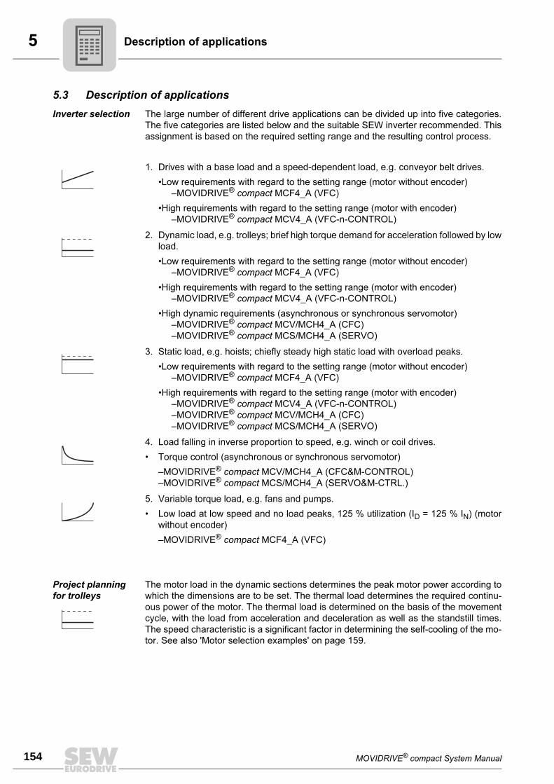
5
154 MOVIDRIVE® compact System Manual
Description of applications
5.3 Description of applications
Inverter selection The large number of different drive applications can be divided up into five categories.
The five categories are listed below and the suitable SEW inverter recommended. This
assignment is based on the required setting range and the resulting control process.
1. Drives with a base load and a speed-dependent load, e.g. conveyor belt drives.
•Low requirements with regard to the setting range (motor without encoder)
–MOVIDRIVE® compact MCF4_A (VFC)
•High requirements with regard to the setting range (motor with encoder)
–MOVIDRIVE® compact MCV4_A (VFC-n-CONTROL)
2. Dynamic load, e.g. trolleys; brief high torque demand for acceleration followed by low
load.
•Low requirements with regard to the setting range (motor without encoder)
–MOVIDRIVE® compact MCF4_A (VFC)
•High requirements with regard to the setting range (motor with encoder)
–MOVIDRIVE® compact MCV4_A (VFC-n-CONTROL)
•High dynamic requirements (asynchronous or synchronous servomotor)
–MOVIDRIVE® compact MCV/MCH4_A (CFC)
–MOVIDRIVE® compact MCS/MCH4_A (SERVO)
3. Static load, e.g. hoists; chiefly steady high static load with overload peaks.
•Low requirements with regard to the setting range (motor without encoder)
–MOVIDRIVE® compact MCF4_A (VFC)
•High requirements with regard to the setting range (motor with encoder)
–MOVIDRIVE® compact MCV4_A (VFC-n-CONTROL)
–MOVIDRIVE® compact MCV/MCH4_A (CFC)
–MOVIDRIVE® compact MCS/MCH4_A (SERVO)
4. Load falling in inverse proportion to speed, e.g. winch or coil drives.
• Torque control (asynchronous or synchronous servomotor)
–MOVIDRIVE® compact MCV/MCH4_A (CFC&M-CONTROL)
–MOVIDRIVE® compact MCS/MCH4_A (SERVO&M-CTRL.)
5. Variable torque load, e.g. fans and pumps.
• Low load at low speed and no load peaks, 125 % utilization (ID = 125 % IN) (motor
without encoder)
–MOVIDRIVE® compact MCF4_A (VFC)
Project planning
for trolleys
The motor load in the dynamic sections determines the peak motor power according to
which the dimensions are to be set. The thermal load determines the required continu-
ous power of the motor. The thermal load is determined on the basis of the movement
cycle, with the load from acceleration and deceleration as well as the standstill times.
The speed characteristic is a significant factor in determining the self-cooling of the mo-
tor. See also 'Motor selection examples' on page 159.

MOVIDRIVE® compact System Manual 155
5Description of applications
5
Project planning
for hoists
In practice, the question of setting the size of hoists is addressed with regard to special
thermal and safety-critical criteria.
Thermal consider-
ations
In contrast to trolleys, hoists require approx. 70...90 % of the rated motor torque assum-
ing constant speed upwards or downwards and the standard configuration.
Starting torque The highest operating torque is required in the event of acceleration with maximum load
in the UPWARDS hoisting direction.
VFC&HOIST The 4-pole geared motor should always be designed for a maximum speed of 2100 rpm
(70 Hz) with a transition speed of 1500 rpm (50 Hz) and 2500 rpm (83 Hz) at a transition
speed of 1800 rpm (60 Hz). This means the gear unit input speed is increased by a factor
of 1.4. Consequently, it is also necessary to choose a gear ratio which is higher by a
factor of 1.4. This measure means that no torque is lost on the output shaft in the field
weakening range (50...70 Hz or 60...83 Hz), since the higher gear ratio compensates for
the inversely proportionate fall in torque in relation to speed (frequency). Furthermore,
the startup torque is 1.4 times greater in the range from 0...1500 rpm (0...50 Hz) or
0...1800 rpm (0...60 Hz). Other advantages are that the speed range is greater and the
self-cooling of the motor more powerful.
The motor power for hoists is selected according to the load type.
• S1 (100 % c.d.f.): Motor power 1 level higher than the selected inverter power, e.g.
for lengthy upwards travel or continuous elevators.
• S3 (40 % c.d.f.): Motor power according to the selected inverter power.
The hoist function on the inverter should be activated irrespective of the above guide-
lines. See also 'Motor selection examples' on page 159.
Encoder monitor-
ing
MOVIDRIVE® compact has encoder monitoring for TTL sensors, sin/cos and Hiperface
encoders (only MCH). There is no encoder monitoring for HTL sensors.
Variable torque
load (pumps,
fans)
In these applications, there is no chance of the motor suffering a thermal overload at low
speeds. The maximum load occurs at the maximum speed; there are no overload peaks.
As a result, the dimensions of MOVIDRIVE® and the motor can be selected so the con-
tinuous motor current is less than or equal to the continuous output current (VFC oper-
ating mode, 125 % of the nominal output current at fPWM = 4 kHz) of the MOVIDRIVE®.
This means MOVIDRIVE® can operate a motor whose power is one level greater. See
also 'Motor selection examples' on page 159.
04949AEN
Figure 73: a = Recommended voltage/speed characteristics and resultant torque characteristic
00
00 1500
(1800)2100
(2500)1500
(1800)2100
(2500)
a
aa
a
1.0
M/MN1.4
n[rpm]
n[rpm]
Vmax
VMot
Torque reserve range
nbase
SEW recommends using TTL sensors or sin/cos encoders for speed controlled hoist
drives and activating encoder monitoring.
Avoid using an HTL sensor if possible.

5
156 MOVIDRIVE® compact System Manual
Motor selection for asynchronous AC motors (VFC)
5.4 Motor selection for asynchronous AC motors (VFC)
Basic recommen-
dations
• Only use motors with a thermal classification of F at least.
• Use TF thermistor sensors or TH winding thermostats. TH should be preferred in the
case of multi-motor drives on one inverter. The series connection of TH contacts (NC
contacts) is not subject to any restriction if joint monitoring is provided.
• For multi-motor drives, we recommend that the motors should not differ from one an-
other by more than 3 type levels.
• 4-pole motors should be preferred. This particularly applies to geared motors which
are operated with a high oil filling level as a result of their vertical mounting position.
• Generally speaking, the motor can be operated at its listed power without forced
cooling if the operating conditions differ from S1-mode, e.g. positioning drive with
1:20 speed range in S3-mode.
• Avoid selecting a motor which is too large, especially in case of a delta connection.
Otherwise, the inverter may trigger a short circuit detection function due to the small
winding resistance of the motor (1/3 that of a star connection).
• A MOVIDRIVE® compact MCV4_A (with encoder connection) is required for speed
control. The motor must then be equipped with an incremental encoder, preferably
with 1024 increments/revolution.
Voltage/fre-
quency charac-
teristic
The asynchronous motor follows a load-dependent voltage/frequency characteristic in
VFC operating mode. It is possible to achieve full motor torque down to minimum speeds
because the motor model is continuously calculated. This characteristic curve is set by
entering the rated motor voltage and the rated frequency of the motor in the startup func-
tion. The setting determines the speed-dependent torque and power characteristics of
the asynchronous motor.
Sample asynchro-
nous motor 230/
400 V, 50 Hz
1 Star connection; 400 V, 50 Hz
2 Delta connection: 230 V, 50 Hz
3 Delta connection: 400 V, 87 Hz
The inverter output voltage VA is limited by the supply voltage which is connected. The
'nominal system voltage' input value in the startup function limits the effective value of
the maximum output voltage. This restriction is used whenever the connected motor has
a lower design voltage than the power supply of the inverter. The maximum permitted
motor voltage should be entered. Furthermore, make sure that the 'nominal system volt-
age' input value is less than or equal to the supply voltage of the inverter.
01650BEN
Figure 74: Voltage/frequency characteristics of the asynchronous motor
0
230
400
0 f [Hz]50 87
1 3
2
Voutp [V]

MOVIDRIVE® compact System Manual 157
5Motor selection for asynchronous AC motors (VFC)
5
Speed/torque
characteristics
The field weakening range starts when the set maximum output voltage of the inverter
is reached. As the speed increases, the motor generates:
• constant torque with increasing power in the basic speed range,
• constant power with an inversely proportionate decrease in torque in the field weak-
ening range.
When determining the maximum speed in the field weakening range, note that the rated
torque MN (in relation to the rated speed, e.g. nN = 1500 rpm) falls in inverse proportion
and the breakdown torque MK is reduced in an inverse quadratic relationship. The MK/
MN ratio is a motor-specific parameter. The MOVIDRIVE® pull-out protection limits the
speed when the maximum possible torque is reached.
With geared motors, the maximum motor speed is dependent on the size and mounting
position of the gear unit. The speed should not exceed 3000 rpm due to the resulting
noise and oil churning losses.
Dynamic applica-
tions (Pinverter
greater than Pmo-
tor)
• The startup function sets the current limit of the inverter (P303/P313) to 150 % of the
rated motor current. The value of the current limit refers to the rated inverter current.
As a result, 150 % of the rated motor current is less than 150 % of the rated inverter
current (value of P303/P313). This parameter must be set to a higher value manually
for dynamic applications.
• The startup function sets the slip compensation parameter (P324/P334) to the nom-
inal slip of the motor. In the case of VFC-n-CONTROL, the internal slip limiting func-
tion allows the slip to reach max. 150 % of this setting. Consequently, the motor de-
velops at most 150 % of the nominal motor torque. The slip compensation parameter
(P324) must be increased accordingly for greater torques.
Combinations
with Pinverter
greater than 4 ×
Pmotor
The large difference between the rated inverter current and the rated motor current
means that these combinations cannot be started up without taking special measures:
• Project planning for connecting the motor in a delta connection. This means the mo-
tor current is increased by a factor √3 and the unfavorable ratio is reduced.
• The motor must be started up in VFC & GROUP operating mode if this measure does
not suffice. In this operating mode, the inverter operates without slip compensation
and simulates a constant-voltage constant-frequency system (system with a con-
stant U/f ratio).
01729BEN
Figure 75: Quadratically falling breakdown torque
0 1500 1800 2100 2400 2700 3000 3300 36000
MN
MMN
M = 1.8 MK N
M = 2.2 MK N
M = 2.5 MK N
M = 2.8 MK N
M = 3.0 MK N
0.5
1.0
1.5
2.0
2.5
3.0
Armature range Field weakening range
n / rpm
Set parameter P324 'Slip compensation' to max. 130 % of the nominal slip of the
motor for stable operation.

5
158 MOVIDRIVE® compact System Manual
Motor selection for asynchronous AC motors (VFC)
Motor selection in delta/star topology (230/400 VAC / 50 Hz)
Motors for 380 VAC / 60 Hz can also be allocated on the basis of this selection table.
Pmax [kW (HP)] for operation on MOVIDRIVE® compact MCF/MCV/MCH 4_A...-5_3 (400/500 V units)
Connection / 400 VAC1)
1) Also applies to motors with rated voltage 460 V or 500 V and to 400 V / 690 V motors with ∆ connection.
∆ / 230 VAC2)
2) Also applies to motors with rated voltage 266 V or 290 V.
Cooling Self-cooling Forced Self-cooling Forced
fmin...fmax [Hz]10 - 506 - 60
5 - 70 / 5.5 - 80≤ 2.5 - 50 / ≤ 3 - 603)
3) The following applies to MCF, MCV and MCH without speed control: fmin = 0.5 Hz
9 - 87 ≤ 2.5 - 873)
nmin...nmax [rpm]300 - 1500180 - 1800
150 - 2100 / 165 - 2400≤ 75 - 1500 / ≤ 90 - 1800 270 - 2610 ≤ 75 - 2610
Setting range1:5
1:101:15
≥ 1:20 1:10 ≥ 1:20
Motor typeRated power Pn
[kW (HP)]
P = Preduced P = Pn P = Pincreased4)
4) Pincreased means that the motor is operated at the power of the next larger motor (1 frame size), rather than with the √3-fold power.
[kW (HP)]With MCF/
MCV/MCH5)
4_A...-5_3
5) The devices listed here permit intermittent loads of up to 1.5 times the nominal load in the specific application. With variable torque
load and constant load without overload, each inverter can also be operated with an increased continuous output power (→ Sec. Tech-
nical Data). The continuous output current of 125 % of the rated unit current is only available at fPWM = 4 kHz in the VFC operating
modes.
[kW (HP)]With MCF/
MCV/MCH5)
4_A...-5_3[kW (HP)]
With MCF/MCV/MCH5)
4_A...-5_3
DT71D4 0.37 (0.5) 0.25 (0.33)
0015
0.37 (0.5)
0015
0.55 (0.75)
0015DT80K4 0.55 (0.75) 0.37 (0.5) 0.55 (0.75) 0.75 (1.0)
DT80N4 0.75 (1.0) 0.55 (0.75) 0.75 (1.0) 1.1 (1.5)
DT90S4 1.1 (1.5) 0.75 (1.0) 1.1 (1.5) 1.5 (2.0)
DT90L4 1.5 (2.0) 1.1 (1.5) 1.5 (2.0) 2.2 (3.0) 0022
DV100M4 2.2 (3.0) 1.5 (2.0) 2.2 (3.0) 0022 3.0 (4.0) 0030
DV100L4 3.0 (4.0) 2.2 (3.0) 0022 3.0 (4.0) 0030 4.0 (5.4) 0040
DV112M4 4.0 (5.4) 3.0 (4.0) 0030 4.0 (5.4) 0040 5.5 (7.5) 0055
DV132S4 5.5 (7.5) 4.0 (5.4) 0040 5.5 (7.5) 0055 7.5 (10) 0075
DV132M4 7.5 (10) 5.5 (7.5) 0055 7.5 (10) 0075 9.2 (12.5)0110
DV132ML4 9.2 (12.5) 7.5 (10) 0075 9.2 (12.5)0110
11 (15)
DV160M4 11 (15) 9.2 (12.5)0110
11 (15) 15 (20) 0150
DV160L4 15 (20) 11 (15) 15 (20) 0150 18.5 (25) 0220
DV180M4 18.5 (25) 15 (20) 0150 18.5 (25)0220
22 (30) 0300
DV180L4 22 (30) 18.5 (25)0220
22 (30) 30 (40)0370
DV200L4 30 (40) 22 (30) 30 (40) 0300 37 (50)
DV225S4 37 (50) 30 (40) 0300 37 (50) 0370 45 (60) 0450
DV225M4 45 (60) 37 (50) 0370 45 (60) 0450 55 (75) 0550
DV250M4 55 (75) 45 (60) 0450 55 (75) 0550 75 (100) 0750
DV280S4 75 (100) 55 (75) 0550 75 (100) 0750-
D280M4 90 (120) 75 (100) 0750 -

MOVIDRIVE® compact System Manual 159
5Motor selection for asynchronous AC motors (VFC)
5
Examples for motor selection delta/star topology 230/400 V
Trolley
drive
Constant load with overload (acceleration) and low load when in motion:
• Ptravel = 1.3 kW
• Pmax = 13 kW
• nmin = 270 rpm, setting range 1:10
• nmax = 2610 rpm
In inverter mode with adapted power (P = Pn), the motor output can be 150 % of its listed
power during the acceleration phase. Consequently:
PMot = Pmax : 1.5 = 13 kW : 1.5 = 8.67 kW
A DV132M4 with delta connection (Pn = 9.2 kW) is selected.
The selection table (→ page 158) allocates a MOVIDRIVE® compact MCF60A0110 (P =
Pn).
Hoist
drive
High constant load with intermittent overload (acceleration):
• Pmax = 26 kW
• Psustained = 20 kW
• Speed range 1:15, low speed only for positioning
• Brake applied when stationary
• Load type S3 (40 % c.d.f.)
The inverter output can be 150 % of its rated current during acceleration. Consequently,
a MOVIDRIVE® compact MCF60A0220 is selected.
In view of the load type (S3, 40 % c.d.f.), the selection table allocates motor type
DV180L4 (Pn = 22 kW) in a star connection.
→ Sec. Project planning for hoists on page page 155 for more information.
Fan/
pump
Variable torque load with the following power values:
• Pmax = 4.8 kW
• nmax = 1400 rpm, continuous duty with nmax
The motor can be operated at its listed power (P = Pn) even without forced cooling due
to the quadratically falling torque. This means the DV132S4 motor type with star con-
nection (Pn = 5.5 kW) is adequate.
The selection table allocates a MOVIDRIVE® compact MCF60A0055 (P = Pn). Howev-
er, the inverter can be operated with an increased output power because this case in-
volves a variable torque load without overload. Consequently, a MOVIDRIVE® compact
MCF60A0040 is sufficient.

5
160 MOVIDRIVE® compact System Manual
Motor selection for asynchronous AC motors (VFC)
Motor selection in double-star/star topology (230/460 VAC / 60 Hz)
Pmax [kW (HP)] for operation on MOVIDRIVE® compact MCF/MCV/MCH 4_A...-5_3 (400/500 V units)
Connection / 460 VAC / 230 VAC
Cooling Self-cooling Self-cooling Forced Self-cooling Forced
fmin...fmax [Hz] 6 - 90 10 - 60 0 - 601)
1) The following applies to MCF, MCV and MCH without speed control: fmin = 0.5 Hz
10 - 120 0 - 1201)
nmin...nmax [rpm] 180 - 2700 200 - 1800 0 - 1800 200 - 3600 0 - 3600
Setting range 1:15 1:6 ≥ 1:15 1:12 ≥ 1:20
Motor typeRated power Pn
[kW (HP)]
P = Preduced P = Pn P = Pincreased2)
2) Pincreased means that the motor is operated at the power of the next larger motor (1 frame size), rather than with the √3-fold power.
[kW (HP)]With MCF/
MCV/MCH3)
4_A...-5_3
3) The devices listed here permit intermittent loads of up to 1.5 times the nominal load in the specific application. With variable torque
load and constant load without overload, each inverter can also be operated with an increased continuous output power (→ Sec. Tech-
nical Data). The continuous output current of 125 % of the rated unit current is only available at fPWM = 4 kHz in the VFC operating
modes.
[kW (HP)]With MCF/
MCV/MCH3)
4_A...-5_3[kW (HP)]
With MCF/MCV/MCH3)
4_A...-5_3
DT71D4 0.37 (0.5) 0.25 (0.33)
0015
0.37 (0.5)
0015
0.75 (1.0)
0015DT80K4 0.55 (0.75) 0.37 (0.5) 0.55 (0.75) 1.1 (1.5)
DT80N4 0.75 (1.0) 0.55 (0.75) 0.75 (1.0) 1.5 (2.0)
DT90S4 1.1 (1.5) 0.75 (1.0) 1.1 (1.5) 2.2 (3.0) 0022
DT90L4 1.5 (2.0) 1.1 (1.5) 1.5 (2.0) 3.0 (4.0) 0030
DV100M4 2.2 (3.0) 1.5 (2.0) 2.2 (3.0) 0022 4.0 (5.4) 0040
DV100L4 3.7 (5.0) 2.2 (3.0) 0022 3.0 (4.0) 0030 5.5 (7.5) 0055
DV112M4 4.0 (5.4) 3.0 (4.0) 0030 4.0 (5.4) 0040 7.5 (10) 0075
DV132S4 5.5 (7.5) 4.0 (5.4) 0040 5.5 (7.5) 0055 9.2 (12.5)0110
DV132M4 7.5 (10) 5.5 (7.5) 0055 7.5 (10) 0075 11 (15)
DV132ML4 9.2 (12.5) 7.5 (10) 0075 9.2 (12.5)0110
15 (20) 0150
DV160M4 11 (15) 9.2 (12.5)0110
11 (15) 18.5 (25)0220
DV160L4 15 (20) 11 (15) 15 (20) 0150 22 (30)
DV180M4 18.5 (25) 15 (20) 0150 18.5 (25)0220
30 (40) 0300
DV180L4 22 (30) 18.5 (25)0220
22 (30) 37 (50) 0370
DV200L4 30 (40) 22 (30) 30 (40) 0300 45 (60) 0450
DV225S4 37 (50) 30 (40) 0300 37 (50) 0370 55 (75) 0550
DV225M4 45 (60) 37 (50) 0370 45 (60) 0450 75 (100) 0750
DV250M4 55 (75) 45 (60) 0450 55 (75) 0550
-DV280S4 75 (100) 55 (75) 0550 75 (100) 0750
D280M4 90 (120) 75 (100) 0750 -

MOVIDRIVE® compact System Manual 161
5Motor selection for asynchronous AC motors (VFC)
5
Motor selection with the delta topology (230 VAC / 50 Hz)
Pmax [kW (HP)] for operation on MOVIDRIVE® compact MCF/MCV/MCH 4_A...-2_3 (230 V units)
Connection ∆ / 230 VAC
Cooling Self-cooling Forced
fmin...fmax [Hz]10 - 506 - 60
5 - 70 / 5.5 - 80≤ 2.5 - 50 / ≤ 3 - 601)
1) The following applies to MCF, MCV and MCH without speed control: fmin = 0.5 Hz
nmin...nmax [rpm]300 - 1500180 - 1800
150 - 2100 / 165 - 2400≤ 75 - 1500 / ≤ 90 - 1800
Setting range1:5
1:101:15
≥ 1:20
Motor type2)
2) In load type S3 (40 % c.d.f.), the motor must not be operated at its listed power (P = Pn) even without forced-cooling. Example: Pstat
= 2 kW, Pdyn = 2.5 kW → selected motor DV100M4 (Pn = 2.2 kW).
Rated power Pn[kW (HP)]
P = Preduced P = Pn
[kW (HP)]With MCF/
MCV/MCH3)
4_A...-2_3
3) The devices listed here permit intermittent loads of up to 1.5 times the nominal load in the specific application. With variable torque
load and constant load without overload, each inverter can also be operated with an increased continuous output power (→ Sec. Tech-
nical Data). The continuous output current of 125 % of the rated unit current is only available at fPWM = 4 kHz in the VFC operating
modes.
[kW (HP)]With MCF/
MCV/MCH3)
4_A...-2_3
DT71D4 0.37 (0.5) 0.25 (0.33)
0015
0.37 (0.5)
0015
DT80K4 0.55 (0.75) 0.37 (0.5) 0.55 (0.75)
DT80N4 0.75 (1.0) 0.55 (0.75) 0.75 (1.0)
DT90S4 1.1 (1.5) 0.75 (1.0) 1.1 (1.5)
DT90L4 1.5 (2.0) 1.1 (1.5) 1.5 (2.0)
DV100M4 2.2 (3.0) 1.5 (2.0) 2.2 (3.0) 0022
DV100L4 3.0 (4.0) 2.2 (3.0) 0022 3.0 (4.0) 0030
DV112M4 4.0 (5.4) 3.0 (4.0) 0030 4.0 (5.4) 0040
DV132S4 5.5 (7.5) 4.0 (5.4) 0040 5.5 (7.5) 0055
DV132M4 7.5 (10) 5.5 (7.5) 0055 7.5 (10) 0075
DV132ML4 9.2 (12.5) 7.5 (10) 0075 9.2 (12.5)0110
DV160M4 11 (15) 9.2 (12.5)0110
11 (15)
DV160L4 15 (20) 11 (15) 15 (20) 0150
DV180M4 18.5 (25) 15 (20) 0150 18.5 (25) 0220
DV180L4 22 (30) 18.5 (25)0220
22 (30)0300
DV200L4 30 (40) 22 (30) 30 (40)
DV225S4 37 (50) 30 (40) 0300 -

5
162 MOVIDRIVE® compact System Manual
Motor selection for asynchronous AC motors (VFC)
Motor selection with the double-star topology (230 VAC / 60 Hz)
Pmax [kW (HP)] for operation on MOVIDRIVE® compact MCF/MCV/MCH 4_A...-2_3 (230 V units)
Connection / 230 VAC
Cooling Self-cooling Self-cooling Forced
fmin...fmax [Hz] 6 - 90 10 - 60 0 - 601)
1) The following applies to MCF, MCV and MCH without speed control: fmin = 0.5 Hz
nmin...nmax [rpm] 180 - 2700 200 - 1800 0 - 1800
Setting range 1:15 1:6 ≥ 1:15
Motor typeRated power Pn
[kW (HP)]
P = Preduced P = Pn
[kW (HP)]With MCF/
MCV/MCH2)
4_A...-2_3
2) The devices listed here permit intermittent loads of up to 1.5 times the nominal load in the specific application. With variable torque
load and constant load without overload, each inverter can also be operated with an increased continuous output power (→ Sec. Tech-
nical Data). The continuous output current of 125 % of the rated unit current is only available at fPWM = 4 kHz in the VFC operating
modes.
[kW (HP)]With MCF/
MCV/MCH3)
4_A...-2_3
DT71D4 0.37 (0.5) 0.25 (0.33)
0015
0.37 (0.5)
0015
DT80K4 0.55 (0.75) 0.37 (0.5) 0.55 (0.75)
DT80N4 0.75 (1.0) 0.55 (0.75) 0.75 (1.0)
DT90S4 1.1 (1.5) 0.75 (1.0) 1.1 (1.5)
DT90L4 1.5 (2.0) 1.1 (1.5) 1.5 (2.0)
DV100M4 2.2 (3.0) 1.5 (2.0) 2.2 (3.0) 0022
DV100L4 3.7 (5.0) 2.2 (3.0) 0022 3.0 (4.0) 0030
DV112M4 4.0 (5.4) 3.0 (4.0) 0030 4.0 (5.4) 0040
DV132S4 5.5 (7.5) 4.0 (5.4) 0040 5.5 (7.5) 0055
DV132M4 7.5 (10) 5.5 (7.5) 0055 7.5 (10) 0075
DV132ML4 9.2 (12.5) 7.5 (10) 0075 9.2 (12.5)0110
DV160M4 11 (15) 9.2 (12.5)0110
11 (15)
DV160L4 15 (20) 11 (15) 15 (20) 0150
DV180M4 18.5 (25) 15 (20) 0150 18.5 (25) 0300
DV180L4 22 (30) 18.5 (25)0220
22 (30)0370
DV200L4 30 (40) 22 (30) 30 (40)
DV225S4 37 (50) 30 (40) 0300 -

MOVIDRIVE® compact System Manual 163
5Motor selection for asynchronous servomotors (CFC)
5
5.5 Motor selection for asynchronous servomotors (CFC)
Motor character-
istics
The drive in CFC operating modes is characterized by its ability to control torque directly
and rapidly. This means it achieves a high level of dynamic overload capacity (up to 3 ×MN) and a very high speed and control range (up to 1:5000). Smooth running at speed
and positioning accuracy fulfill the exacting requirements of servo systems. This behav-
ior is achieved by the field-oriented control function. The current components for mag-
netization (Id) and torque generation (Iq) are controlled separately. A feature of the CFC
operating modes is that there must always be an encoder on the motor.
The inverter needs exact data about the connected motor in order to calculate the motor
model. These data are made available by the MOVITOOLS software with the startup
function. CFC operating modes are only possible with 4-pole SEW-motors (CT/CV or
DT/DV/D), not with the other SEW motors or non-SEW motors. The necessary motor
data for the CFC operating modes are stored in MOVIDRIVE® for the 4-pole SEW mo-
tors.
Typical speed-
torque characteris-
tic
MN is determined by the motor. Mmax and ntransition depend on the motor/inverter com-
bination. You can refer to the motor selection tables for CFC mode for the values of ntran-
sition, MN and Mmax.
The torque limit (M limit) is set automatically by the startup function of the MOVITOOLS
software package. Do not alter this automatically set value!
We recommend always using the latest version of MOVITOOLS (2.70 or later) for star-
tup. The latest MOVITOOLS version can be downloaded from our homepage
(www.sew-eurodrive.de).
01651BEN
Figure 76: Speed/torque characteristic curve in CFC operating mode
1 With integrated cooling
2 With forced cooling
3 Maximum torque
0
Mmax
0
2
1
3
n
M
nbase
Mrated
1.4 n× base

5
164 MOVIDRIVE® compact System Manual
Motor selection for asynchronous servomotors (CFC)
Magnetization
current
Dynamic drives which are supposed to accelerate without a time lag are also energized
when at a standstill without load. This means the magnetization current Id is flowing. The
inverter must be able to supply this current constantly in applications in which the output
stage is permanently enabled, e.g. in CFC & M-CONTROL mode. In particular in the
case of large motors with a slip frequency ≤ 2 Hz, you must refer to the diagrams in Sec.
'Load capacity of the units at low output frequencies' (→ page 192) to check whether the
inverter can supply the current. Also check whether the thermal characteristics of the
motor are suitable for this mode of operation (forced cooling fan). Refer to the motor ta-
bles (CT/CV → page 167, DT/DV/D → page 172) for the magnetization current Id.
Basic recommen-
dations
CFC operating modes are only possible with SEW-motors (CT/CV or DT/DV/D series),
not with non-SEW motors. The necessary motor data for the CFC operating modes are
stored in MOVIDRIVE® for the SEW motors.
Speed is the correcting variable in the CFC modes with speed control. Torque is the cor-
recting variable in the CFC modes with torque control (CFC & M-CONTROL).
CFC mode with
speed control
There is no reason to differentiate between quadratic, dynamic and static load types
when configuring a system for CFC mode. Project planning for an asynchronous motor
in CFC mode is undertaken in accordance with the following requirements:
1. Effective torque demand at the average speed of the application.
Mr.m.s. < Mn_mot
The point must lie below the characteristic curve for the continuous torque (Figure
76, curve 2). No forced cooling is required if this operating point lies below the char-
acteristic curve for forced cooling (Figure 76, curve 1).
2. Maximum torque required across the speed characteristic.
Mmax < Mdyn_mot
This operating point must lie below the characteristic curve for the maximum torque
of the motor-MOVIDRIVE® combination (Figure 76, curve 3).
3. Maximum speed
The maximum speed of the motor should not be configured higher than 1.4 times the
transition speed. The maximum torque available will then still be approx. 100 % of
the rated continuous torque of the motor; the input speed for the gear unit connected
to the motor output will still be less than 3000 rpm with delta connection.
nmax < 1.4 × ntransition < 3000 rpm
Motor cooling Self-cooling of asynchronous motors is based on the integrated fan, and consequently
depends on the speed. The integrated fan does not provide any cooling at low speeds
and when the motor is stopped. Forced cooling may be required in case of a high static
load or a high effective torque.

MOVIDRIVE® compact System Manual 165
5Motor selection for asynchronous servomotors (CFC)
5
CFC mode with
torque control
(CFC & M-CON-
TROL)
This operating mode permits direct torque control of the asynchronous motor in the ba-
sic speed range (n ≤ ntransition). The setpoint sources of the speed controlled CFC mode
can also be used for torque control. All speed setpoint sources are interpreted as current
setpoint sources. The settings for evaluating the analog input (→ P11_, parameter de-
scription) also remain in effect. The fixed setpoints (P16_, P17_) can be entered either
in the unit [rpm] or [%IN_inverter] (→ MOVITOOLS).
The following relationship applies between the units:
3000 rpm = 150 % rated inverter current
The torque on the output shaft can then be calculated for the basic speed range (n ≤ntransition) using the following formulae:
Specification of a setpoint for the motor torque in %In_inverter:
Specification of a setpoint for the motor torque in rpm:
In addition to the current Iq for creating the torque, the inverter also needs to supply the
magnetization current Id. The inverter output current Itot which actually flows can be cal-
culated using the following formulae:
Specification of a setpoint for the motor torque in %In_inverter:
Specification of a setpoint for the motor torque in rpm:
04972AEN
04973AEN
In_inverter = Rated output current of the inverter
kT = Torque constant = Mn / Iq_n
Mn and Iq_n are motor-specific parameters. Refer to the motor tables (DT/DV/D → page 172, CT/CV → page 167) for the values of the torque constants kT and the motor-specific parameters Mn and Iq_n.
04974AEN
04975AEN
Iq_n = Nominal value for the current which generates the torque, according to the motor table
Id_n = Nominal value for the magnetization current, according to the motor table
M k I SetpoT n inverter= × ×_ int
M k ISetpo
rpmT n inverter= × × ×1 5
3000.
int_
I Setpo I Itot n inverter d N= × +int _ _d i2 2
I Setpo Irpm
Itot n inverter d N= × × ×FHG
IKJ
+int . _ _1 51
3000
22

5
166 MOVIDRIVE® compact System Manual
Motor selection for asynchronous servomotors (CFC)
CT/CV asynchro-
nous servomo-
tors
SEW offers series CT/CV asynchronous servomotors especially for operation with
MOVIDRIVE® compact in the CFC operating modes. These motors have the following
characteristics:
High power yield The optimum winding of CT/CV motors permits a high power yield.
Organization into
speed categories
CT/CV motors are supplied in four speed categories. This ensures optimum utilization
of torque and speed.
With sin/cos
encoder as stan-
dard
As standard, CT/CV motors are equipped with a high-resolution sin/cos encoder (ES1S,
ES2S, EV1S).
As standard, with
TF or TH motor
protection
The winding temperature of the three motor phases is monitored using thermistor sen-
sors (TF). The thermistor sensor can be connected to the TF/TH input of MOVIDRIVE®
compact. Thermal monitoring is then undertaken by MOVIDRIVE® compact; no addi-
tional monitoring unit is required.
Bimetallic switches (TH) can also be used instead of thermistor sensors. The bimetallic
switches are also connected to the TF/TH input.
Thermal classifica-
tion F as standard
As standard, CT/CV motors are built using thermal classification F materials. The max-
imum permitted temperature rise is therefore 105 K.
Reinforced pinion
spigot
CT/CV motors can generate up to three times their rated motor torque during dynamic
operation. For this reason, these motors are fitted with reinforced pinion spigots for di-
rect mounting to gear units. These spigots enable these motors to transmit the high
torque levels reliably.
Either DT/DV/D motors or CT/CV motors can be used in CFC mode. SEW recommends
using CT/CV motors in order to achieve optimum benefit from the advantages of CFC
mode.
Advantage Disadvantage
CFC mode with DT/DV/D motorMotor selection → page 175
Standard version of motor
Slower transition speed than the CT/CV motor.
The power yield of the motor is less than the rated motor power.
In terms of the power yield, the mass inertia is greater than the
CT/CV motors.
In some inverter/motor combina-tions, the maximum torque is lim-ited by the mechanical strength.
CFC mode with CT/CV motorMotor selection → page 168
Faster transition speed than DT/DV/D motor.
Not an IEC standard motorUsually with a power yield one
level higher.
Lower mass inertia in relation to the power yield.
Higher current consumption due to the higher power yield, there-
fore a larger inverter must be assigned.
Motor is designed for dynamic operation.

MOVIDRIVE® compact System Manual 167
5Motor selection for asynchronous servomotors (CFC)
5
Motor table CT/CVnN Motor MN IN Iq_n Id_n kT UN Jmot JBmot
[rpm] [Nm] [A] [A] [A] [A] [V] [10-4 kgm2]
1200
CT80N4 5 2.0 1.52 1.30 2.50 350 8.7 9.6
CT90L4 10 3.5 2.95 1.89 2.86 345 34 39.5
CV100M4 15 4.7 4.13 2.25 3.19 345 53 59
CV100L4 26 8.9 8.30 3.21 2.92 310 65 71
CV132S4 37 11.1 9.99 4.83 3.33 340 146 158
CV132M4 50 15.5 14.2 6.18 3.23 340 280 324
CV132ML4 61 17.6 16.0 7.43 3.47 345 330 374
CV160M4 73 22.5 20.3 9.73 3.24 335 400 440
CV160L4 95 29 25.3 14.2 3.28 330 925 1030
CV180M4 110 34 27.7 19.7 3.24 330 1120 1226
CV180L4 125 35 28.4 20.5 3.57 345 1290 1396
CV200L4 200 58 52.9 23.7 3.45 330 2340 2475
1700
CT80N4 5 2.8 2.15 1.79 2.33 350 8.7 9.6
CT90L4 10 4.8 4.03 2.61 2.48 345 34 39.5
CV100M4 15 6.5 5.71 3.10 2.63 345 53 59
CV100L4 26 13.6 12.9 4.41 2.02 315 65 71
CV132S4 37 15.2 13.7 6.67 2.70 340 146 158
CV132M4 48 20.8 18.9 8.70 2.54 335 280 324
CV132ML4 58 24.4 21.7 11.2 2.67 320 330 374
CV160M4 71 29.8 26.6 13.4 2.67 340 400 440
CV160L4 89 37.5 32.0 19.5 2.78 330 925 1030
CV180M4 105 44.5 35.2 27.2 2.98 335 1120 1226
CV180L4 115 48.5 37.5 30.7 3.07 325 1290 1396
CV200L4 190 77 69.4 33.4 2.74 330 2340 2475
2100
CT71D4 2.5 2.0 1.60 1.20 1.56 340 4.6 5.5
CT80N4 5 3.5 2.67 2.26 1.87 340 8.7 9.6
CT90L4 10 6.1 5.14 3.29 1.95 335 34 39.5
CV100M4 15 8.1 7.09 3.91 2.12 335 53 59
CV100L4 25 14.8 13.7 5.56 1.82 305 65 71
CV132S4 37 19.2 17.3 8.41 2.14 335 146 158
CV132M4 48 26 23.7 10.7 2.03 335 280 324
CV132ML4 58 29 26.0 12.9 2.23 340 330 374
CV160M4 70 37 33.9 16.9 2.13 330 400 440
CV160L4 88 46 38.9 24.6 2.26 330 925 1030
CV180M4 100 53 40.5 34.2 2.47 330 1120 1226
CV180L4 115 56 43.4 35.4 2.65 345 1290 1396
CV200L4 175 88 77.8 41.2 2.25 325 2340 2475
3000
CT71D4 2.4 2.6 2.01 1.65 1.19 345 4.6 5.5
CT80N4 4.5 4.3 2.97 3.11 1.52 350 8.7 9.6
CT90L4 9.5 7.9 6.47 4.54 1.47 345 34 39.5
CV100M4 15 11.3 9.93 5.39 1.51 345 53 59
CV100L4 21 17.0 15.2 7.65 1.38 310 65 71
CV132S4 35 25.0 22.1 11.6 1.58 340 146 158
CV132M4 45 34 30.5 15.1 1.48 335 280 324
CV132ML4 52 38 32.7 19.3 1.59 320 330 374
CV160M4 64 47 40.8 23.3 1.57 345 400 440
CV160L4 85 62 51.9 33.9 1.64 335 925 1030
CV180M4 93 68 49.0 47.2 1.90 340 1120 1226
CV180L4 110 81 61.2 53.1 1.80 325 1290 1396
CV200L4 145 102 84.0 57.8 1.73 330 2340 2475

5
168 MOVIDRIVE® compact System Manual
Motor selection for asynchronous servomotors (CFC)
CT/CV motor selection
1. Rated speed nN = 1200 rpm:
CT/CV motors in the four speed categories are designed for operation with 400/500 V
units. Please contact SEW concerning operation with 230 V units.
MotorMOVIDRIVE® compact MCV/MCH4_A...-5_3 (400/500 V units) in CFC operating modes (P700)
0015 0022 0030 0040 0055 0075 0110 0150 0220 0300 0370 0450 0550 0750
CT80N4
Mmax[Nm]([lb.in])
15.6 (138)
ntransition[rpm] 540
CT90L4
Mmax [Nm]([lb.in])
18.2 (160)
25.7 (227)
30.5 (270)
ntransition[rpm] 928 781 685
CV100M4
Mmax [Nm]([lb.in])
29.0 (256)
37.0 (327)
45.0 (398)
ntransition[rpm] 883 781 680
CV100L4
Mmax [Nm]([lb.in])
32.6 (288)
45.3 (400)
60.0 (530)
75.0 (663)
ntransition[rpm] 1062 947 813 675
CV132S4
Mmax [Nm]([lb.in])
64.0 (565)
84.0 (743)
110 (972)
ntransition[rpm] 992 915 1175
CV132M4
Mmax [Nm]([lb.in])
82.0 (725)
125 (1105)
150 (1326)
ntransition[rpm] 1011 877 770
CV132ML4
Mmax [Nm]([lb.in])
126 (1114)
169 (1495)
183 (1617)
ntransition[rpm] 922 819 725
CV160M4
Mmax [Nm]([lb.in])
125 (1105)
169 (1495)
219 (1936)
ntransition[rpm] 986 909 840
CV160L4
Mmax [Nm]([lb.in])
163 (1440)
240 (2121)
294 (2600)
ntransition[rpm] 1043 954 1240
CV180M4
Mmax [Nm]([lb.in])
241 (2130)
320 (2828)
360 (3183)
ntransition[rpm] 1050 986 1005
CV180L4
Mmax [Nm]([lb.in])
231 (2042)
308 (2723)
360 (3183)
ntransition[rpm] 1018 973 980
CV200L4
Mmax [Nm]([lb.in])
326 (2882)
402 (3554)
494 (4367)
567 (5013)
ntransition[rpm] 1011 986 947 940
P700: CFC...
E QQ
3 400/500 V× AC
CT/CV: n = 1200 rpmN
MCV/MCH4_A...-5_3(400/500 V)

MOVIDRIVE® compact System Manual 169
5Motor selection for asynchronous servomotors (CFC)
5
2. Rated speed nN = 1700 rpm:
MotorMOVIDRIVE® compact MCV/MCH4_A...-5_3 (400/500 V units) in CFC operating modes (P700)
0015 0022 0030 0040 0055 0075 0110 0150 0220 0300 0370 0450 0550 0750
CT80N4
Mmax [Nm]([lb.in])
12.6 (111)
15.6 (138)
ntransition[rpm] 1150 980
CT90L4
Mmax [Nm]([lb.in])
18.0 (159)
23.5 (208)
30.5 (270)
ntransition[rpm] 1400 1280 1150
CV100M4
Mmax [Nm]([lb.in])
25.7 (227)
36.0 (318)
45.0 (398)
ntransition[rpm] 1402 1274 1150
CV100L4
Mmax [Nm]([lb.in])
32.9 (290)
44.2 (390)
57.0 (504)
75.0 (663)
ntransition[rpm] 1510 1402 1274 1090
CV132S4
Mmax [Nm]([lb.in])
59.0 (522)
91.0 (805)
110 (972)
ntransition[rpm] 1470 1330 1280
CV132M4
Mmax [Nm]([lb.in])
89.0 (787)
121 (1070)
150 (1326)
ntransition[rpm] 1440 1330 1250
CV132ML4
Mmax [Nm]([lb.in])
83.0 (734)
114 (1008)
166 (1468)
183 (1618)
ntransition[rpm] 1562 1485 1331 1325
CV160M4
Mmax [Nm]([lb.in])
120 (1060)
176 (1555)
219 (1936)
ntransition[rpm] 1420 1310 1250
CV160L4
Mmax [Nm]([lb.in])
170 (1503)
226 (2000)
277 (2450)
294 (2600)
ntransition[rpm] 1470 1400 1330 1380
CV180M4
Mmax [Nm]([lb.in])
168 (1485)
226 (2000)
280 (2475)
345 (3050)
360 (3183)
ntransition[rpm] 1550 1510 1460 1400 1490
CV180L4
Mmax [Nm]([lb.in])
217 (1918)
269 (2378)
332 (2935)
360 (3183)
ntransition[rpm] 1450 1420 1370 1420
CV200L4
Mmax [Nm]([lb.in])
353 (3120)
420 (3713)
524 (4632)
ntransition[rpm] 1421 1395 1344
P700: CFC...
E QQ
3 400/500 V× AC
CT/CV: n = 1700 rpmN
MCV/MCH4_A...-5_3(400/500 V)

5
170 MOVIDRIVE® compact System Manual
Motor selection for asynchronous servomotors (CFC)
3. Rated speed nN = 2100 rpm:
MotorMOVIDRIVE® compact MCV/MCH4_A...-5_3 (400/500 V units) in CFC operating modes (P700)
0015 0022 0030 0040 0055 0075 0110 0150 0220 0300 0370 0450 0550 0750
CT71D4
Mmax [Nm]([lb.in])
7.7 (68)
ntransition[rpm] 1280
CT80N4
Mmax [Nm]([lb.in])
9.7 (86)
13.8 (122)
15.6 (138)
ntransition[rpm] 1754 1510 1400
CT90L4
Mmax [Nm]([lb.in])
18.3 (162)
25.5 (225)
30.5 (270)
ntransition[rpm] 1843 1677 1625
CV100M4
Mmax [Nm]([lb.in])
28.0 (248)
38.1 (337)
45.0 (398)
ntransition[rpm] 1760 1626 1550
CV100L4
Mmax [Nm]([lb.in])
33.7 (298)
44.0 (390)
67.0 (592)
75.0 (663)
ntransition[rpm] 2003 1894 1645 1550
CV132S4
Mmax [Nm]([lb.in])
72.0 (637)
97.0 (858)
110 (972)
ntransition[rpm] 1850 1722 1730
CV132M4
Mmax [Nm]([lb.in])
95.0 (840)
138 (1220)
150 (1326)
ntransition[rpm] 1850 1670 1670
CV132ML4
Mmax [Nm]([lb.in])
139 (1230)
183 (1618)
ntransition[rpm] 1715 1574
CV160M4
Mmax [Nm]([lb.in])
138 (1220)
183 (1618)
219 (1936)
ntransition[rpm] 1792 1690 1625
CV160L4
Mmax [Nm]([lb.in])
177 (1565)
218 (1927)
268 (2370)
294 (2600)
ntransition[rpm] 1882 1824 1740 1760
CV180M4
Mmax [Nm]([lb.in])
218 (1927)
270 (2387)
322 (2847)
360 (3183)
ntransition[rpm] 1939 1894 1836 1930
CV180L4
Mmax [Nm]([lb.in])
260 (2300)
310 (2740)
360 (3183)
ntransition[rpm] 1824 1786 1840
CV200L4
Mmax [Nm]([lb.in])
329 (2910)
412 (3642)
ntransition[rpm] 1830 1792
P700: CFC...
E QQ
3 400/500 V× AC
CT/CV: n = 2100 rpmN
MCV/MCH4_A...-5_3(400/500 V)

MOVIDRIVE® compact System Manual 171
5Motor selection for asynchronous servomotors (CFC)
5
4. Rated speed nN = 3000 rpm:
MotorMOVIDRIVE® compact MCV/MCH4_A...-5_3 (400/500 V units) in CFC operating modes (P700)
0015 0022 0030 0040 0055 0075 0110 0150 0220 0300 0370 0450 0550 0750
CT71D4
Mmax [Nm]([lb.in])
6.6 (58)
7.7 (68)
ntransition[rpm] 2280 2080
CT80N4
Mmax [Nm]([lb.in])
9.7 (86)
12.7 (112)
15.5 (137)
ntransition[rpm] 2560 2350 2200
CT90L4
Mmax [Nm]([lb.in])
12.7 (112)
18.0 (160)
24.0 (212)
30.5 (270)
ntransition[rpm] 2790 2650 2490 2360
CV100M4
Mmax [Nm]([lb.in])
26.5 (235)
34.6 (305)
45.0 (398)
ntransition[rpm] 2620 2490 2425
CV100L4
Mmax [Nm]([lb.in])
31.8 (281)
49.0 (433)
66.0 (583)
75.0 (663)
ntransition[rpm] 2800 2600 2380 2290
CV132S4
Mmax [Nm]([lb.in])
51.0 (450)
69.0 (610)
101 (893)
110 (972)
ntransition[rpm] 2740 2650 2455 2580
CV132M4
Mmax [Nm]([lb.in])
67.0 (592)
99.0 (875)
131 (1158)
150 (1326)
ntransition[rpm] 2750 2600 2450 2400
CV132ML4
Mmax [Nm]([lb.in])
94.0 (830)
124 (1096)
152 (1343)
183 (1618)
ntransition[rpm] 2765 2656 2547 2400
CV160M4
Mmax [Nm]([lb.in])
98.0 (866)
131 (1158)
161 (1423)
198 (1750)
219 (1936)
ntransition[rpm] 2630 2550 2470 2370 2380
CV160L4
Mmax [Nm]([lb.in])
124 (1096)
155 (1370)
192 (1697)
228 (2015)
286 (2528)
ntransition[rpm] 2720 2680 2620 2545 2440
CV180M4
Mmax [Nm]([lb.in])
150 (1326)
191 (1690)
228 (2015)
289 (2555)
ntransition[rpm] 2790 2745 2700 2635
CV180L4
Mmax [Nm]([lb.in])
182 (1610)
220 (1945)
276 (2440)
ntransition[rpm] 2620 2580 2540
CV200L4
Mmax [Nm]([lb.in])
293 (2590)
ntransition[rpm] 2573
P700: CFC...
E QQ
3 400/500 V× AC
CT/CV: n = 3000 rpmN
MCV/MCH4_A...-5_3(400/500 V)

5
172 MOVIDRIVE® compact System Manual
Motor selection for asynchronous servomotors (CFC)
DT/DV/D motor tables
Characteristic values for delta/star 230/400 V / 50 Hz
Motor
MN
Mass moment of inertia JM Star (400 V) Delta ∆ (230 V)
Without
brakeWith brake In Iq_n
1)
1) Applies in the basic speed range up to ntransition.
Id_n1) kT
1) In Iq_n1) Id_n
1) kT1)
[Nm
(lb.in)][10-4 kgm2 (10-3 lb.ft2)] [A] [A] [A] [Nm/A] [A] [A] [A] [Nm/A]
DT71D42.6 (23)
4.6 (10.4) 5.5 (12.5) - - - - 2.15 1.82 1.14 1.43
DT80K43.9 (34)
6.6 (15.6) 7.5 (17.7) - - - - 3.03 2.53 1.67 1.54
DT80N45.2 (46)
8.7 (20.7) 9.6 (22.8) 2.15 1.72 1.29 3.02 3.72 2.99 2.21 1.74
DT90S47.5 (66)
25 (59.4) 31 (72.2) 2.80 2.39 1.46 3.13 4.85 4.17 2.48 1.80
DT90L410.2 (90)
34 (78.9) 40 (93.6) 3.7 3.18 1.89 3.21 6.41 5.51 3.28 1.85
DV100M415.0 (133)
42 (101) 48 (114) 4.95 4.37 2.32 3.43 8.57 7.57 4.02 1.98
DV100L420.5 (181)
53 (126) 59 (139) 6.7 5.89 3.19 3.48 11.6 10.2 5.52 2.01
DV112M426.9 (238)
98 (233) 110 (262) 8.7 7.85 3.75 3.43 15.2 13.6 6.79 1.98
DV132S436.7 (324)
146 (416) 158 (445) 11.4 10.3 4.89 3.56 19.8 17.9 8.46 2.05
DV132M450.1 (443)
280 (655) 330 (769) 15.5 14.2 6.21 3.53 27.0 24.6 11.1 2.04
DV132ML461.0 (539)
330 (769) 380 (887) 18.7 17.1 7.57 3.57 32.5 29.6 13.4 2.06
DV160M472.9 (644)
398 (945) 448 (1049) 22.5 20.3 9.70 3.59 39.0 35.1 17.0 2.08
DV160L498.1 (867)
925 (2197) 1060 (2449) 31.0 27.6 14.1 3.55 54.0 47.8 25.1 2.05
DV180M4121
(1070)1120 (2660)
1255/15202) (2912/31642))
2) Double disk brake
38.5 33.1 19.7 3.66 67.0 57.3 34.7 2.11
DV180L4143
(1264)1290 (3064)
1425/15202) (3316/35672))
46.0 40.7 21.4 3.51 80.0 70.4 38.0 2.03
DV200L4195
(1724)2340 (5558)
2475/25702) (5809/60612))
57.0 51.8 23.8 3.76 99.0 89.8 41.7 2.17
DV225S4240
(2122)3010 (7149)
3145/32402) (7400/76522))
70.0 64.5 27.2 3.72 122 112 48.4 2.14
DV225M4292
(2581)3570 (8479)
3705/38002) (8730/89822))
86.0 77.6 37.1 3.76 149 134 65.2 2.18
DV250M4356
(3147)6300 (14950)
6600/67302) (15550/159082))
102 91.7 44.7 3.88 - - - -
DV280S4483
(4270)8925 (21180)
9225/93552) (21737/221122))
142 124 68.9 3.90 - - - -
D280M4580
(5127)14500
(34409)3)
3) On request
155 147 49.2 3.95 - - - -

MOVIDRIVE® compact System Manual 173
5Motor selection for asynchronous servomotors (CFC)
5
Characteristic values for double-star/star 230/460 V / 60 Hz
(according to MG1, NEMA design B up to DT80K4, NEMA design C up to DT80N4)
Motor
Mass moment of inertia JM Star (460 V) Double-star (230 V)
Without brake With brakeMN at
1000 rpmIn Iq_n
1)
1) Applies in the basic speed range up to ntransition.
Id_n1) kT
1) MN at2400 rpm
In Iq_n1) Id_n
1) kT1)
[10-4 kgm2 (10-3 lb.ft2)] [Nm (lb.in)] [A] [A] [A][Nm/A
(lb.in/A)][Nm (lb.in)] [A] [A] [A]
[Nm/A(lb.in/A)]
DT71D4 4.6 (10.4) 5.5 (12.5) 2.60 (23.0) 1.15 0.95 0.652.74
(24.2)2.60 (23.0) 2.30 1.90 1.30
1.37 (12.1)
DT80K4 6.6 (15.6) 7.5 (17.7) 3.90 (34.5) 1.67 1.35 0.982.89
(27.3)3.90 (34.5) 3.34 2.70 1.96
1.44 (12.8)
DT80N4 8.7 (20.7) 9.6 (22.8) 5.20 (46.0) 2.11 1.72 1.223.03
(26.8)5.20 (46.0) 4.21 3.44 2.44
1.51 (13.4)
DT90S4 25 (59.4) 31 (72.2) 7.50 (66.3) 2.94 2.33 1.803.21
(28.4)7.50 (66.3) 5.89 4.66 3.60
1.61 (14.2)
DT90L4 34 (78.9) 40 (93.6) 10.2 (90.2) 3.57 3.06 1.843.35
(29.6)10.2 (90.2) 7.13 6.11 3.68
1.67 (14.8)
DT100LS4 42 (101) 48 (114) 15.0 (133) 5.00 4.47 2.253.34
(29.5)15.0 (133) 10.1 9.00 4.50
1.66 (14.7)
DT100L4 53 (126) 59 (139) 20.5 (181) 7.92 7.32 3.023.45
(30.5)20.5 (181) 15.8 14.6 6.05
1.72 (15.2)
DV112M4 98 (233) 110 (262) 26.9 (238) 8.20 7.47 3.373.60
(31.8)26.9 (238) 16.4 14.9 6.74
1.80 (15.9)
DV132S4 146 (416) 158 (445) 36.7 (324) 11.0 10.3 3.773.55
(31.4)36.7 (324) 22.0 20.7 7.54
1.78 (15.7)
DV132M4 280 (655) 330 (769) 50.0 (442) 15.9 14.3 6.873.46
(30.5)50.1 (443) 31.8 28.7 13.7
1.77 (15.3)
DV132ML4 330 (769) 380 (887) 61.0 (539) 18.6 16.9 7.693.61
(31.7)61.0 (539) 37.2 33.9 15.4
1.80 (15.8)
DV160M4 398 (945) 448 (1049) 71.0 (628) 22.7 20.4 9.933.47
(30.7)71.0 (628) 45.4 40.8 19.9
1.74 (15.4)
DV160L4 925 (2197) 1060 (2449) 96.0 (849) 30.7 27.4 13.73.51
(31.0)96.0 (849) 61.3 54.8 27.5
1.75 (15.5)
DV180M4 1120 (2660)1255/15202)
(2912/31642))
2) Double disk brake
120 (1060) 36.5 33.6 14.33.57
(31.6)120 (1060) 72.9 67.1 28.6
1.79 (15.8)
DV180L4 1290 (3064)1425/15202)
(3316/35672))130 (1150) 42.7 37.6 20.2
3.46 (30.6)
130 (1150) 85.4 75.1 40.51.73
(15.3)
DV200L4 2340 (5558)2475/25702)
(5809/60612))190 (1680) 54.6 52.1 16.2
3.65 (32.3)
190 (1680) 109 104 32.51.82
(16.2)
DV225S4 3010 (7149)3145/32402)
(7400/76522))235 (2078) 67.9 64.5 21.0
3.64 (32.3)
235 (2078) 136 129 42.01.83
(16.2)
DV225M4 3570 (8479)3705/38002)
(8730/89822))280 (2475) 78.8 74.1 27.0
3.78 (33.5)
260 (2300) 148 138 54.01.89
(16.8)
D250M4 7300 (17323) 3)
3) On request
356 (3147) 102 95.6 36.43.73
(33.0)- - - - -
D280S4 12000 (28476) 3) 483 (4270) 135 128 45.23.77
(33.3)- - - - -
D280M4 14500 (34409) 3) 580 (5128) 162 153 51.73.79
(33.5)- - - - -

5
174 MOVIDRIVE® compact System Manual
Motor selection for asynchronous servomotors (CFC)
Characteristic values for JEC motors
Motor
MN
Mass moment of inertia JM
400 V / 60 Hz
440 V / 60 Hz
400 V / 50 Hz
200 V / 60 Hz
220 V / 60 Hz
200 V / 50 Hz
Without
brakeWith brake In Iq_n
1)
1) Applies in the basic speed range up to ntransition.
Id_n1) kT
1) In Iq_n1) Id_n
1) kT1)
[Nm
(lb.in)][10-4 kgm2 (10-3 lb.ft2)] [A] [A] [A]
[Nm/A
(lb.in/A)][A] [A] [A]
[Nm/A
(lb.in/A)]
DT80K42.71 (24)
6.55 (15.5) 7.45 (17.7)1.35 ()
0.96 0.952.82
(24.9)2.70
()1.92 1.90
1.41 (12.5)
DT80N44.97 (44)
8.7 (20.6) 9.6 (22.8)2.20 ()
1.72 1.372.88
(25.5)4.40
()3.45 2.73
1.44 (12.7)
DT90L410.0 (88)
34 (80.7) 39.4 (93.5)3.85 ()
3.29 2.003.04
(26.9)7.70
()6.58 3.99
1.52 (13.4)
DV100M414.9 (131)
53 (126) 58.4 (139)4.70 ()
4.13 2.253.60
(31.8)9.40
()8.25 4.50
1.80 (15.9)
DV112M424.4 (215)
98 (233) 110.2 (262)8.50 ()
7.55 3.933.24
(28.6)17.0
()15.1 7.85
1.62 (14.3)
DV132S436.7 (324)
146 (346) 158.0 (375)12.0 (∆)
10.9 5.103.38
(29.9)24.0 (∆∆)
21.7 10.21.69
(14.9)
DV132M448.8 (431)
280 (664) 323.7 (768)16.0 (∆)
14.6 6.503.34
(29.5)32.0 (∆∆)
29.2 13.01.67
(14.8)
DV160M470.4 (622)
398 (944) 441.7 (1048)23.0 (∆)
20.6 10.33.42
(30.2)46.0 (∆∆)
41.2 20.51.71
(15.1)
DV160L496.6 (854)
925 (2195) 1031 (2447)32.3 (∆)
28.6 14.93.38
(29.9)64.5 (∆∆)
57.2 29.81.69
(14.9)
DV180M4120
(1060)1120 (2658)
1226/13322) (2909/31602))
2) Double disk brake
40.5 (∆)
34.8 20.73.46
(30.6)81.0 (∆∆)
69.6 41.41.73
(15.3)
DV180L4140
(1237)1290 (3060)
1396/15022) (3313/35642))
47.8 (∆)
42.0 22.73.34
(29.5)95.5 (∆∆)
84.1 45.31.67
(14.8)
DV200L4194
(1714)2340 (5553)
2446/25522) (5804/60562))
60.0 (∆)
54.5 24.93.56
(31.5)120 (∆∆)
109 49.91.78
(15.7)
DV225S4234
(2068)3010 (7143)
3116/32222) (7394/76452))
72.0 (∆)
66.0 28.73.54
(31.3)144 (∆∆)
132 57.31.77
(15.6)
DV225M4284
(2510)3570 (8472)
3676/37822) (8723/89752))
88.5 (∆)
79.5 38.93.58
(31.6)177 (∆∆)
159 77.91.79
(15.8)

MOVIDRIVE® compact System Manual 175
5Motor selection for asynchronous servomotors (CFC)
5
DT/DV/D motor selection with the delta/star topology (230/400 VAC / 50 Hz)
1. Star connection 400 V / 50 Hz or 400/690 V / 50 Hz motors in ∆ connection:
Motor MOVIDRIVE® compact MCV/MCH4_A...-5_3 (400/500 V units) in CFC operating modes (P700)
400 V / 50 Hz 0015 0022 0030 0040 0055 0075 0110 0150 0220 0300 0370 0450 0550 0750
DT80N4
Mmax[Nm]([lb.in])
9.3 (82)
ntransition [rpm] 908
DT90S4
Mmax [Nm]([lb.in])
13.5 (120)
13.5 (120)
ntransition [rpm] 1011 1011
DT90L4
Mmax [Nm]([lb.in])
18.2 (161)
18.3 (162)
18.3 (162)
ntransition [rpm] 928 1049 1056
DV100M4
Mmax [Nm]([lb.in])
26.8 (236)
26.8 (236)
26.8 (236)
ntransition [rpm] 940 1043 1056
DV100L4
Mmax [Nm]([lb.in])
36.8 (325)
36.8 (325)
36.8 (325)
ntransition [rpm] 889 1004 1011
DV112M4
Mmax [Nm]([lb.in])
47.1 (416)
48.4 (427)
48.4 (427)
ntransition [rpm] 915 1030 1062
DV132S4
Mmax [Nm]([lb.in])
64.4 (569)
66.1 (584)
66.1 (584)
ntransition [rpm] 992 1132 1196
DV132M4
Mmax [Nm]([lb.in])
81.7 (722)
90.2 (797)
90.2 (797)
ntransition [rpm] 1011 1145 1152
DV132ML4
Mmax [Nm]([lb.in])
110 (972)
110 (972)
ntransition [rpm] 1043 1132
DV160M4
Mmax [Nm]([lb.in])
124 (1096)
131 (1157)
131 (1157)
ntransition [rpm] 986 1132 1196
DV160L4
Mmax [Nm]([lb.in])
163 (1440)
177 (1565)
177 (1565)
ntransition [rpm] 1043 1248 1312
DV180M4
Mmax [Nm]([lb.in])
217 (1917)
217 (1917)
217 (1917)
ntransition [rpm] 1164 1395 1465
DV180L4
Mmax [Nm]([lb.in])
230 (2033)
258 (2280)
258 (2280)
258 (2280)
ntransition [rpm] 1017 1152 1299 1369
DV200L4
Mmax [Nm]([lb.in])
325 (2873)
351 (3100)
351 (3100)
351 (3100)
ntransition [rpm] 1011 1126 1299 1420
DV225S4
Mmax [Nm]([lb.in])
Please note: The maximum torque Mmax is limited to 180 % of the rated motor torque MN.
395 (3490)
433 (3826)
433 (3826)
433 (3826)
ntransition [rpm] 947 1030 1164 1312
DV225M4
Mmax [Nm]([lb.in])
482 (4260)
526 (4648)
526 (4648)
ntransition [rpm] 1030 1100 1299
DV250M4
Mmax [Nm]([lb.in])
587 (5188)
641 (5665)
ntransition [rpm] 1017 1133
DV280S4
Mmax [Nm]([lb.in])
711 (6283)
ntransition [rpm] 1075
D280M4
Mmax [Nm]([lb.in])
745 (6583)
ntransition [rpm] 1107
P700: CFC...
E QQ
3 400/500 V× AC
DT/DV/D: 400 V/50 Hz
MCV/MCH4_A...-5_3(400/500 V)

5
176 MOVIDRIVE® compact System Manual
Motor selection for asynchronous servomotors (CFC)
2. Delta connection ∆ 230 V / 50 Hz:
Motor MOVIDRIVE® compact MCV/MCH4_A...-5_3 (400/500 V units) in CFC operating modes (P700)
∆ 230 V / 50 Hz 0015 0022 0030 0040 0055 0075 0110 0150 0220 0300 0370 0450 0550 0750
DT71D4
Mmax [Nm]([lb.in])
4.6 (40.5)
ntransition [rpm] 1958
DT80K4
Mmax [Nm]([lb.in])
6.9 (61)
6.9 (61)
ntransition [rpm] 1849 1868
DT80N4
Mmax [Nm]([lb.in])
9.3 (82)
9.3 (82)
9.3 (82)
ntransition [rpm] 1817 2054 2054
DT90S4
Mmax [Nm]([lb.in])
13.5 (120)
13.5 (120)
13.5 (120)
ntransition [rpm] 1971 2246 2304
DT90L4
Mmax [Nm]([lb.in])
18.3 (162)
18.3 (162)
18.3 (162)
ntransition [rpm] 1843 2240 2329
DV100M4
Mmax [Nm]([lb.in])
26.8 (236)
26.8 (236)
26.8 (236)
ntransition [rpm] 1862 2214 2297
DV100L4
Mmax [Nm]([lb.in])
36.8 (325)
36.8 (325)
36.8 (325)
ntransition [rpm] 1779 2080 2188
DV112M4
Mmax [Nm]([lb.in])
45.5 (402)
48.4 (427)
48.4 (427)
ntransition [rpm] 1779 2163 2195
DV132S4
Mmax [Nm]([lb.in])
66.1 (584)
66.1 (584)
66.1 (584)
ntransition [rpm] 1996 2374 2444
DV132M4
Mmax [Nm]([lb.in])
90.2 (797)
90.2 (797)
ntransition [rpm] 1939 2310
DV132ML4
Mmax [Nm]([lb.in])
110 (972)
110 (972)
ntransition [rpm] 2105 2246
DV160M4
Mmax [Nm]([lb.in])
131 (1157)
131 (1157)
131 (1157)
ntransition [rpm] 1894 2246 2348
DV160L4
Mmax[Nm]([lb.in])
Please note: The maximum torque Mmax is limited to 180 % of the rated motor torque MN.
177 (1565)
177 (1565)
177 (1565)
177 (2496)
ntransition [rpm] 1881 2208 2451 2496
DV180M4
Mmax [Nm]([lb.in])
217 (1917)
217 (1917)
217 (1917)
217 (1917)
ntransition [rpm] 1952 2336 2611 2809
DV180L4
Mmax [Nm]([lb.in])
258 (2280)
258 (2280)
258 (2280)
ntransition [rpm] 1836 2131 2457
DV200L4
Mmax [Nm]([lb.in])
329 (2908)
351 (3100)
ntransition [rpm] 1830 2092
DV225S4
Mmax [Nm]([lb.in])
405 (3580)
ntransition [rpm] 1708
P700: CFC...
E QQ
3 400/500 V× AC
DT/DV: 230 V/50 Hz∆
MCV/MCH4_A...-5_3(400/500 V)

MOVIDRIVE® compact System Manual 177
5Motor selection for asynchronous servomotors (CFC)
5
DT/DV/D motor selection with the double-star/star topology (230/460 VAC / 60 Hz)
1. Star connection 460 V / 60 Hz:
Motor MOVIDRIVE® compact MCV/MCH4_A...-5_3 (400/500 V units) in CFC operating modes (P700)
460 V / 60 Hz 0015 0022 0030 0040 0055 0075 0110 0150 0220 0300 0370 0450 0550 0750
DT80N4
Mmax [Nm]([lb.in])
9.3 (82)
ntransition [rpm] 1145
DT90S4
Mmax [Nm]([lb.in])
13.5 (120)
ntransition [rpm] 1312
DT90L4
Mmax [Nm]([lb.in])
18.3 (162)
18.3 (162)
ntransition [rpm] 1152 1318
DT100LS4
Mmax [Nm]([lb.in])
26.5 (234)
27.0 (238)
ntransition [rpm] 1100 1222
DT100L4
Mmax [Nm]([lb.in])
28.2 (250)
36.8 (325)
36.8 (325)
ntransition [rpm] 1171 1075 1120
DV112M4
Mmax [Nm]([lb.in])
35.8 (316)
48.4 (427)
48.4 (427)
ntransition [rpm] 1196 1139 1312
DV132S4
Mmax [Nm]([lb.in])
48.7 (430)
65.1 (575)
66.1 (584)
ntransition [rpm] 1068 992 1100
DV132M4
Mmax [Nm]([lb.in])
80.0 (705)
90.2 (797)
ntransition [rpm] 1088 1222
DV132ML4
Mmax [Nm]([lb.in])
110 (972)
110 (972)
ntransition [rpm] 1196 1299
DV160M4
Mmax [Nm]([lb.in])
120.3 (1062)
131 (1157)
131 (1157)
ntransition [rpm] 1132 1260 1318
DV160L4
Mmax [Nm]([lb.in])
161 (1422)
177 (1565)
ntransition [rpm] 1158 1370
DV180M4
Mmax [Nm]([lb.in])
164 (1448)
217 (1917)
217 (1917)
ntransition [rpm] 1140 1177 1350
DV180L4
Mmax [Nm]([lb.in])
228 (2015)
258 (2280)
258 (2280)
ntransition [rpm] 1081 1196 1324
DV200L4
Mmax [Nm]([lb.in])
323 (2845)
351 (3100)
351 (3100)
ntransition [rpm] 1024 1107 1248
DV225S4
Mmax[Nm]([lb.in])
Please note: The maximum torque Mmax is limited to 180 % of the rated motor torque MN.
318 (2815)
391 (3456)
433 (3826)
433 (3826)
ntransition [rpm] 1100 1075 1145 1286
DV225M4
Mmax [Nm]([lb.in])
401 (3542)
494 (4364)
526 (4648)
526 (4648)
ntransition [rpm] 1081 1056 1139 1324
D250M4
Mmax [Nm]([lb.in])
570 (5040)
640 (5656)
ntransition [rpm] 1300 1395
D280S4
Mmax [Nm]([lb.in])
717 (6335)
ntransition [rpm] 1345
D280M4
Mmax [Nm]([lb.in])
712 (6290)
ntransition [rpm] 1337
P700: CFC...
E QQ
3 460 V× AC
DT/DV/D: 460 V/60 Hz
MCV/MCH4_A...-5_3(400/500 V)

5
178 MOVIDRIVE® compact System Manual
Motor selection for asynchronous servomotors (CFC)
2. Double-star connection 230 V / 60 Hz:
Motor MOVIDRIVE® compact MCV/MCH4_A...-5_3 (400/500 V units) in CFC operating modes (P700)
230 V / 60 Hz 0015 0022 0030 0040 0055 0075 0110 0150 0220 0300 0370 0450 0550 0750
DT71D4
Mmax [Nm]([lb.in])
4.6 (40.5)
ntransition [rpm] 2988
DT80K4
Mmax [Nm]([lb.in])
7.0 (62)
7.0 (62)
ntransition [rpm] 2688 2822
DT80N4
Mmax [Nm]([lb.in])
8.3 (73)
9.3 (82)
9.3 (82)
ntransition [rpm] 2585 2873 2969
DT90S4
Mmax [Nm]([lb.in])
11.9 (105)
13.5 (120)
13.5 (120)
ntransition [rpm] 2636 2931 3462
DT90L4
Mmax [Nm]([lb.in])
16.4 (145)
18.3 (162)
18.3 (162)
ntransition [rpm] 2604 3014 3353
DT100LS4
Mmax [Nm]([lb.in])
22.5 (200)
27.0 (238)
27.0 (238)
ntransition [rpm] 2592 2732 3104
DT100L4
Mmax [Nm]([lb.in])
32.5 (287)
36.8 (325)
ntransition [rpm] 2592 2912
DV112M4
Mmax [Nm]([lb.in])
41.4 (365)
48.4 (427)
ntransition [rpm] 2534 2988
DV132S4
Mmax [Nm]([lb.in])
62.4 (550)
66.1 (585)
ntransition [rpm] 2233 2572
DV132M4
Mmax [Nm]([lb.in])
80.0 (705)
90.2 (797)
ntransition [rpm] 2348 2707
DV132ML4
Mmax [Nm]([lb.in])
110 (972)
110 (972)
ntransition [rpm] 2566 2944
DV160M4
Mmax [Nm]([lb.in])
115 (1015)
131 (1157)
131 (1157)
ntransition [rpm] 2451 2688 2963
DV160L4
Mmax [Nm]([lb.in])
150 (1325)
177 (1565)
177 (1565)
ntransition [rpm] 2457 2512 2918
DV180M4
Mmax[Nm]([lb.in])
Please note: The maximum torque Mmax is limited to 180 % of the rated motor torque MN.
189 (1670)
217 (1917)
217 (1917)
217 (1917)
ntransition [rpm] 2355 2457 2771 3040
DV180L4
Mmax [Nm]([lb.in])
220 (1943)
258 (2280)
258 (2280)
ntransition [rpm] 2284 2291 2720
DV200L4
Mmax [Nm]([lb.in])
281 (2482)
350 (3092)
ntransition [rpm] 2208 2163
DV225S4
Mmax [Nm]([lb.in])
346 (3056)
ntransition [rpm] 2291
DV225M4
Mmax [Nm]([lb.in])
354 (3127)
ntransition [rpm] 2278
P700: CFC...
E QQ
3 460 V× AC
DT/DV: 230 V/60 Hz
MCV/MCH4_A...-5_3(400/500 V)

MOVIDRIVE® compact System Manual 179
5Motor selection for asynchronous servomotors (CFC)
5
DT/DV/D motor selection with the double-star/star or double-delta/delta topology
(200/400 VAC / 50 Hz)
1. Star connection or delta connection ∆ 400 V / 50 Hz:
Motor MOVIDRIVE® compact MCV/MCH4_A...-5_3 (400/500 V units) in CFC operating modes (P700)
, ∆ 400 V / 50 Hz1)
1) The values also apply to 400 V / 60 Hz and 440 V / 60 Hz.
0015 0022 0030 0040 0055 0075 0110 0150 0220 0300 0370 0450 0550 0750
DT80K4
Mmax [Nm]([lb.in])
6.9 (61)
ntransition [rpm] 748
DT80N4
Mmax [Nm]([lb.in])
9.3 (82)
ntransition [rpm] 985
DT90L4
Mmax [Nm]([lb.in])
17.2 (152)
18.3 (162)
18.3 (162)
ntransition [rpm] 1011 1120 1145
DV100M4
Mmax [Nm]([lb.in])
26.8 (236)
26.8 (236)
26.8 (236)
ntransition [rpm] 940 1043 1056
DV112M4
Mmax [Nm]([lb.in])
44.5 (393)
48.4 (427)
48.4 (427)
ntransition [rpm] 992 1088 1145
DV132S4
Mmax [Nm]([lb.in])
61.0 (540)
66.1 (584)
66.1 (584)
ntransition [rpm] 1068 1177 1280
DV132M4
Mmax [Nm]([lb.in])
77.3 (683)
90.2 (797)
90.2 (797)
ntransition [rpm] 1088 1210 1228
DV160M4
Mmax [Nm]([lb.in])
118 (1042)
131 (1157)
131 (1157)
ntransition [rpm] 1056 1177 1273
DV160L4
Mmax [Nm]([lb.in])
154 (1363)
177 (1565)
177 (1565)
ntransition [rpm] 1113 1292 1401
DV180M4
Mmax[Nm]([lb.in])
Please note: The maximum torque Mmax is limited to 180 % of the rated motor torque MN.
217 (1917)
217 (1917)
217 (1917)
ntransition [rpm] 1177 1440 1561
DV180L4
Mmax [Nm]([lb.in])
218 (1930)
258 (2280)
258 (2280)
258 (2280)
ntransition [rpm] 1088 1177 1344 1452
DV200L4
Mmax [Nm]([lb.in])
308 (2730)
351 (3100)
351 (3100)
351 (3100)
ntransition [rpm] 1075 1139 1331 1472
DV225S4
Mmax [Nm]([lb.in])
374 (3307)
433 (3826)
433 (3826)
433 (3826)
ntransition [rpm] 1004 1043 1190 1363
DV225M4
Mmax [Nm]([lb.in])
456 (4037)
526 (4648)
526 (4648)
ntransition [rpm] 1094 1113 1324
P700: CFC...
E QQ
3 400 V× AC
DT/DV: , 420 V / 50 Hz ∆
MCV/MCH4_A...-5_3(400/500 V)

5
180 MOVIDRIVE® compact System Manual
Motor selection for asynchronous servomotors (CFC)
2. Double-star connection or double-delta ∆∆ 200 V / 50 Hz:
Motor MOVIDRIVE® compact MCV/MCH4_A...-5_3 (400/500 V units) in CFC operating modes (P700)
, ∆∆ 200 V / 50 Hz1)
1) The values also apply to 200 V / 60 Hz and 220 V / 60 Hz.
0015 0022 0030 0040 0055 0075 0110 0150 0220 0300 0370 0450 0550 0750
DT80K4
Mmax [Nm]([lb.in])
6.9 (61)
6.9 (61)
ntransition [rpm] 2035 2112
DT80N4
Mmax [Nm]([lb.in])
9.3 (82)
9.3 (82)
9.3 (82)
ntransition [rpm] 2483 2624 2624
DT90L4
Mmax [Nm]([lb.in])
18.3 (162)
18.3 (162)
18.3 (162)
ntransition [rpm] 2521 2924 2963
DV100M4
Mmax [Nm]([lb.in])
24.4 (215)
26.8 (236)
26.8 (236)
ntransition [rpm] 2124 2419 2732
DV112M4
Mmax [Nm]([lb.in])
48.4 (427)
48.4 (427)
ntransition [rpm] 2457 2796
DV132S4
Mmax [Nm]([lb.in])
58.3 (515)
66.1 (585)
66.1 (585)
ntransition [rpm] 2355 2656 3052
DV132M4
Mmax [Nm]([lb.in])
77.3 (683)
90.2 (797)
90.2 (797)
ntransition [rpm] 2361 2688 2886
DV160M4
Mmax [Nm]([lb.in])
112 (995)
131 (1157)
131 (1157)
131 (1157)
ntransition [rpm] 2265 2470 2784 2918
DV160L4
Mmax [Nm]([lb.in])
Please note: The maximum torque Mmax is limited to 180 % of the rated motor torque MN.
177 (1565)
177 (1565)
177 (1565)
177 (1565)
ntransition [rpm] 2316 2726 2995 3084
DV180M4
Mmax [Nm]([lb.in])
217 (1917)
217 (1917)
217 (1917)
ntransition [rpm] 2406 2803 3251
DV180L4
Mmax [Nm]([lb.in])
252 (2233)
258 (2280)
ntransition [rpm] 2240 2662
DV200L4
Mmax [Nm]([lb.in])
336 (2975)
ntransition [rpm] 2233
DV225S4
Mmax [Nm]([lb.in])
330 (2917)
ntransition [rpm] 2112
P700: CFC...
E QQ
3 400 V× AC
DT/DV:, 210 V / 50 Hz ∆∆
MCV/MCH4_A...-5_3(400/500 V)

MOVIDRIVE® compact System Manual 181
5Motor selection for asynchronous servomotors (CFC)
5
DT/DV motor selection with the delta connection type (230 VAC / 50 Hz)Motor MOVIDRIVE® compact MCV/MCH4_A...-2_3 (230 V units) in CFC operating modes (P700)
∆ 230 V / 50 Hz 0015 0022 0037 0055 0075 0110 0150 0220 0300
DT80K4
Mmax [Nm]([lb.in])
6.9(61)
ntransition [rpm] 812
DT80N4
Mmax [Nm]([lb.in])
9.3(82)
ntransition [rpm] 908
DT90S4
Mmax [Nm]([lb.in])
13.5(120)
13.5(120)
ntransition [rpm] 1011 1011
DT90L4
Mmax [Nm]([lb.in])
18.3(162)
18.3(162)
18.3(162)
ntransition [rpm] 953 1024 1056
DV100M4
Mmax [Nm]([lb.in])
25.5(225)
26.8(236)
ntransition [rpm] 921 1056
DV100L4
Mmax [Nm]([lb.in])
36.8(325)
36.8(325)
ntransition [rpm] 972 1011
DV112M4
Mmax [Nm]([lb.in])
48.4(427)
48.4(427)
ntransition [rpm] 1036 1062
DV132S4
Mmax [Nm]([lb.in])
65.3(577)
66.1(584)
66.1(584)
ntransition [rpm] 992 1152 1196
DV132M4
Mmax [Nm]([lb.in])
85.4(755)
90.2(797)
90.2(797)
ntransition [rpm] 998 1152 1152
DV132ML4
Mmax [Nm]([lb.in])
110(972)
110(972)
110(972)
ntransition [rpm] 1050 1132 1132
DV160M4
Mmax [Nm]([lb.in])
126(1110)
131(1157)
131(1157)
ntransition [rpm] 980 1120 1196
DV160L4
Mmax [Nm]([lb.in])
158(1395)
177(1565)
177(1565)
ntransition [rpm] 1050 1248 1312
DV180M4
Mmax [Nm]([lb.in])
Please note: The maximum torque Mmax is limited to 180 % of the rated motor torque MN.
217(1917)
217(1917)
ntransition [rpm] 1165 1325
DV180L4
Mmax [Nm]([lb.in])
231(2042)
258(2280)
ntransition [rpm] 1017 1068
DV200L4
Mmax [Nm]([lb.in])
295(2605)
ntransition [rpm] 1025
P700: CFC...
E QQ
3 230 V× AC
DT/DV: 230 V/50 Hz∆
MCV/MCH4_A...-2_3(230 V)

5
182 MOVIDRIVE® compact System Manual
Motor selection for asynchronous servomotors (CFC)
DT/DV motor selection with the double-star topology (230 VAC / 60 Hz)Motor MOVIDRIVE® compact MCV/MCH4_A...-2_3 (230 V units) in CFC operating modes (P700)
230 V / 60 Hz 0015 0022 0037 0055 0075 0110 0150 0220 0300
DT80K4
Mmax [Nm]([lb.in])
7.0(62)
ntransition [rpm] 1100
DT80N4
Mmax [Nm]([lb.in])
9.3(82)
ntransition [rpm] 1145
DT90S4
Mmax [Nm]([lb.in])
13.5(120)
13.5(120)
ntransition [rpm] 1267 1337
DT90L4
Mmax [Nm]([lb.in])
17.2(152)
18.3(162)
18.3(162)
ntransition [rpm] 1145 1210 1325
DT100LS4
Mmax [Nm]([lb.in])
20.1(178)
27.0(238)
ntransition [rpm] 1190 1228
DT100L4
Mmax [Nm]([lb.in])
29.2(258)
36.8(325)
36.8(325)
ntransition [rpm] 1158 1113 1120
DV112M4
Mmax [Nm]([lb.in])
37.2(328)
48.4(427)
48.4(427)
ntransition [rpm] 1190 1248 1337
DV132S4
Mmax [Nm]([lb.in])
57.0(504)
66.1(585)
66.1(585)
ntransition [rpm] 1030 1062 1120
DV132M4
Mmax [Nm]([lb.in])
71.7(633)
90.2(797)
90.2(797)
ntransition [rpm] 1113 1165 1222
DV132ML4
Mmax [Nm]([lb.in])
109(970)
110(972)
ntransition [rpm] 1100 1260
DV160M4
Mmax [Nm]([lb.in])
104(920)
131(1157)
131(1157)
ntransition [rpm] 1165 1145 1318
DV160L4
Mmax [Nm]([lb.in])
133(1178)
177(1565)
177(1565)
ntransition [rpm] 1190 1267 1395
DV180M4
Mmax [Nm]([lb.in])
Please note: The maximum torque Mmax is limited to 180 % of the rated motor torque MN.
208(1840)
217(1917)
ntransition [rpm] 1100 1203
DV180L4
Mmax [Nm]([lb.in])
236(2087)
ntransition [rpm] 1075
DV200L4
Mmax [Nm]([lb.in])
210(1860)
253(2235)
ntransition [rpm] 1080 1062
P700: CFC...
E QQ
3 230 V× AC
DT/DV: 230 V/60 Hz
MCV/MCH4_A...-2_3(230 V)

MOVIDRIVE® compact System Manual 183
5Motor selection for asynchronous servomotors (CFC)
5
DT/DV motor selection with the double-star or double-delta topology (200 VAC / 50 Hz)Motor MOVIDRIVE® compact MCV/MCH4_A...-2_3 (230 V units) in CFC operating modes (P700)
, ∆∆ 200 V / 50 Hz1)
1) The values also apply to 200 V / 60 Hz and 220 V / 60 Hz.
0015 0022 0037 0055 0075 0110 0150 0220 0300
DT80K4
Mmax [Nm]([lb.in])
6.9(61)
ntransition [rpm] 748
DT80N4
Mmax [Nm]([lb.in])
9.3(82)
ntransition [rpm] 985
DT90L4
Mmax [Nm]([lb.in])
15.5(137)
18.3(162)
18.3(162)
ntransition [rpm] 1049 998 1145
DV100M4
Mmax [Nm]([lb.in])
26.8(236)
26.8(236)
ntransition [rpm] 1050 1056
DV112M4
Mmax [Nm]([lb.in])
48.4(427)
48.4(427)
48.4(427)
ntransition [rpm] 1017 1132 1145
DV132S4
Mmax [Nm]([lb.in])
66.1(585)
66.1(585)
ntransition [rpm] 1107 1280
DV132M4
Mmax [Nm]([lb.in])
90.2(797)
90.2(797)
90.2(797)
ntransition [rpm] 1139 1228 1228
DV160M4
Mmax [Nm]([lb.in])
131(1157)
131(1157)
ntransition [rpm] 1050 1273
DV160L4
Mmax [Nm]([lb.in])
Please note: The maximum torque Mmax is limited to 180 % of the rated motor torque MN.
177(1565)
177(1565)
ntransition [rpm] 1177 1312
DV180M4
Mmax [Nm]([lb.in])
195(1723)
217(1917)
ntransition [rpm] 1145 1216
DV180L4
Mmax [Nm]([lb.in])
226(2000)
ntransition [rpm] 1080
P700: CFC...
E QQ
3 200 V× AC
DT/DV:, 210 V / 50 Hz ∆∆
MCV/MCH4_A...-2_3(230 V)

5
184 MOVIDRIVE® compact System Manual
Motor selection for synchronous servomotors (SERVO)
5.6 Motor selection for synchronous servomotors (SERVO)
Motor character-
istics
The requirements made of a servo drive include speed dynamics, stable speed and po-
sitioning accuracy. CM/DFS/DFY motors with MOVIDRIVE® meet these requirements.
Technically speaking, these are synchronous motors with permanent magnets on the
rotor and an integrated resolver. The required characteristics, namely a constant torque
over a wide speed range (up to 4500 rpm), a high speed and control range (up to 1:3000)
and a high overload capacity (3 × M0), are achieved using control by MOVIDRIVE®. The
servomotor has a lower mass moment of inertia than the asynchronous motor. This
means it is optimally suited to applications requiring dynamic speeds.
M0 is determined by the motor. Mmax is 3 × M0 of the motor. The attainable Mmax may
also be less, depending on the inverter.
Refer to the motor table (CM → page 186, DFS/DFY → page 189) for the values for M0.
Refer to the motor table (CM → page 187, DFS/DFY → page 190) for the values for M0.
The torque limit (M limit) is set automatically by the startup function of the MOVITOOLS
software package. Do not alter this automatically set value!
We recommend always using the latest version of MOVITOOLS (2.70 or later) for star-
tup. The latest MOVITOOLS version can be downloaded from our homepage
(www.sew-eurodrive.de).
01652CEN
Figure 77: Speed/torque characteristic curve of the DFY servomotor
1 Continuous torque
2 Maximum torque
0
Mmax
0
1
2
M0
M [lb.in]
n [rpm]nrated

MOVIDRIVE® compact System Manual 185
5Motor selection for synchronous servomotors (SERVO)
5
Basic recommen-
dations
SERVO operating modes are only possible with SEW motors (CM/DFS/DFY), not with
non-SEW motors. The necessary motor data for the SERVO operating modes are
stored in MOVIDRIVE® for the SEW motors.
Speed is the correcting variable in the SERVO modes with speed control. Torque is the
correcting variable in the SERVO modes with torque control (SERVO & M-CONTROL).
SERVO mode with
speed control
There is no reason to differentiate between quadratic, dynamic and static load types
when configuring a system for SERVO mode. Project planning for a synchronous motor
is undertaken in accordance with the following requirements:
1. Effective torque demand at the average speed of the application.
Mr.m.s. < Mn_mot
The point must lie below the characteristic curve for the continuous torque (Figure
77, curve 1). The continuous torque of the DFY series can be increased by 60 % by
forced cooling if this operating point lies above the characteristic curve for self-cool-
ing.
2. Maximum torque required across the speed characteristic.
Mmax < Mdyn_mot
This operating point must lie below the characteristic curve for the maximum torque
of the motor-MOVIDRIVE® combination (Figure 77, curve 2).
3. Maximum speed
The maximum speed must not be configured higher than the rated speed of the mo-
tor. Planetary gear units should be used for speeds greater than 3000 rpm as a result
of the high input speed.
nmax ≤ nN
SERVO mode with
torque control
(SERVO & M-
CTRL.)
This operating mode allows the torque of the servomotor to be controlled directly. The
setpoint sources of the speed controlled SERVO mode can also be used for torque con-
trol. All speed setpoint sources are interpreted as current setpoint sources. The settings
for evaluating the analog input (→ P11_, parameter description) also remain in effect.
The fixed setpoints (P16_, P17_) can be entered either in the unit [rpm] or [%IN_inverter]
(→ MOVITOOLS).
The following relationship applies between the units:
3000 rpm = 150 % rated inverter current
You can calculate the torque at the output shaft of the servomotor using the following
formula:
04976AEN
M0 Continuous static torque according to the motor table DFS/DFY (→ page 189)
I0 Continuous static torque according to the motor table DFS/DFY (→ page 189)
MM
I
I n
rpm
n inverter set= ×× ×
0
0
150%
3000
_

5
186 MOVIDRIVE® compact System Manual
Motor selection for synchronous servomotors (SERVO)
Motor table CM
Characteristic values at Vmax = 400 VAC
Additional project planning notes and information about the type CM synchronous ser-
vomotors can be found in the 'Geared Servo Motors' catalog. This can be ordered from
SEW.
nNMotor
Without forced cooling
fan
With forced cooling fan
VRImax
Mass moment of inertia
JM
M0 I0 M0_VR I0_VRWithout
brakeWith brake
[rpm] [Nm (lb.in)] [A] [Nm (lb.in)] [A] [A] [10-4 kgm2 (10-3 lb.ft2)]
2000
CM71S 5.0 (44) 2.2 7.3 (64) 3.2 8.8 4.85 (11.4) 6.89 (16.2)
CM71M 6.5 (57) 2.9 9.4 (83) 4.2 11.6 6.27 (14.7) 8.31 (19.5)
CM71L 9.5 (84) 4.2 13.8 (122) 6.1 16.8 9.1 (21.4) 11.1 (26.1)
CM90S 11.0 (97) 4.9 16.0 (141) 7.1 20.0 14.3 (33.6) 19.8 (46.5)
CM90M 14.5 (128) 6.9 21.0 (185) 10.0 28.0 18.6 (43.7) 24.1 (56.7)
CM90L 21.0 (185) 9.9 30.5 (270) 14.4 40.0 27.1 (63.7) 32.6 (76.7)
CM112S 23.5 (207) 10.0 34.0 (300) 14.5 40.0 67.4 (159) 87.5 (206)
CM112M 31.0 (274) 13.5 45.0 (397) 19.6 54.0 87.4 (206) 108 (254)
CM112L 45.0 (397) 19.1 65.0 (574) 29.0 80.0 128 (301) 148 (348)
3000
CM71S 5.0 (44) 3.3 7.3 (64) 4.8 13.2 4.85 (11.4) 6.89 (16.2)
CM71M 6.5 (57) 4.3 9.4 (83) 6.2 17.2 6.27 (14.7) 8.31 (19.5)
CM71L 9.5 (84) 6.2 13.8 (122) 9.0 25.0 9.1 (21.4) 11.1 (26.1)
CM90S 11.0 (97) 7.3 16.0 (141) 10.6 30.0 14.3 (33.6) 19.8 (46.5)
CM90M 14.5 (128) 10.1 21.0 (185) 14.6 40.0 18.6 (43.7) 24.1 (56.7)
CM90L 21.0 (185) 14.4 30.5 (270) 21.0 58.0 27.1 (63.7) 32.6 (76.7)
CM112S 23.5 (207) 15.0 34.0 (300) 22.0 60.0 67.4 (159) 87.5 (206)
CM112M 31.0 (274) 20.5 45.0 (397) 30.0 82.0 87.4 (206) 108 (254)
CM112L 45.0 (397) 30.0 65.0 (574) 44.0 120 128 (301) 148 (348)
4500
CM71S 5.0 (44) 4.9 7.3 (64) 7.2 20.0 4.85 (11.4) 6.89 (16.2)
CM71M 6.5 (57) 6.6 9.4 (83) 9.6 27.0 6.27 (14.7) 8.31 (19.5)
CM71L 9.5 (84) 9.6 13.8 (122) 14.0 39.0 9.1 (21.4) 11.1 (26.1)
CM90S 11.0 (97) 11.1 16.0 (141) 16.2 45.0 14.3 (33.6) 19.8 (46.5)
CM90M 14.5 (128) 14.7 21.0 (185) 21.5 59.0 18.6 (43.7) 24.1 (56.7)
CM90L 21.0 (185) 21.6 30.5 (270) 31.5 86.0 27.1 (63.7) 32.6 (76.7)
CM112S 23.5 (207) 22.5 34.0 (300) 32.5 90.0 67.4 (159) 87.5 (206)
CM112M 31.0 (274) 30.0 45.0 (397) 44.0 120 87.4 (206) 108 (254)
CM112L 45.0 (397) 46.0 65.0 (574) 67.0 184 128 (301) 148 (348)

MOVIDRIVE® compact System Manual 187
5Motor selection for synchronous servomotors (SERVO)
5
CM motor selection
1. Rated speed nN = 2000 rpm:
2. Rated speed nN = 3000 rpm:
MotorMOVIDRIVE® compact MCS/MCH4_A...-5_3 (400/500 V units) in SERVO operating modes (P700)
0015 0022 0030 0040 0055 0075 0110 0150 0220 0300 0370 0450 0550 0750
CM71SM
max[Nm]([lb.in])
13.0(115)
16.0(141)
16.5(145)
CM71MM
max[Nm]([lb.in])
13.0(115)
16.9(149)
19.8(175)
21.5(190)
CM71LM
max[Nm]([lb.in])
18.5(163)
22.8(201)
28.5(252)
31.4(278)
CM90SM
max[Nm]([lb.in])
18.5(163)
23.3(206)
30.8(272)
38.0(336)
39.6(350)
CM90MM
max[Nm]([lb.in])
22.5(199)
30.5(269)
39.2(346)
47.9(423)
52.2(461)
CM90LM
max[Nm]([lb.in])
31.9(282)
41.4(366)
52.5(464)
72.5(640)
75.6(668)
CM112SM
max[Nm]([lb.in])
35.3(312)
45.8(405)
57.3(506)
77.6(686)
81.1(717)
CM112MM
max[Nm]([lb.in])
45.9(405)
58.3(515)
84.3(745)
102.3(904)
107.0(945)
CM112LM
max[Nm]([lb.in])
87.4(772)
112.8(997)
150.4(1329)
161.2(1425)
P700: SERVO...
E QQ
3 400/500 V× AC
CM: n = 2000 rpmN
MCS/MCH4_A...-5_3(400/500 V)
MotorMOVIDRIVE® compact MCS/MCH4_A...-5_3 (400/500 V units) in SERVO operating modes (P700)
0015 0022 0030 0040 0055 0075 0110 0150 0220 0300 0370 0450 0550 0750
CM71SM
max[Nm]([lb.in])
9.0(80)
11.9(105)
14.3(126)
16.5(145)
16.5(145)
CM71MM
max[Nm]([lb.in])
12.2(107)
14.8(130)
18.9(167)
21.5(190)
21.5(190)
CM71LM
max[Nm]([lb.in])
15.8(140)
20.6(182)
26.1(230)
30.5(270)
31.4(278)
CM90SM
max[Nm]([lb.in])
21.2(187)
27.0(238)
33.6(297)
39.6(350)
CM90MM
max[Nm]([lb.in])
27.4(242)
34.4(304)
48.1(425)
52.2(461)
CM90LM
max[Nm]([lb.in])
36.5(322)
53.1(469)
67.6(597)
75.0(663)
CM112SM
max[Nm]([lb.in])
39.0(344)
56.6(500)
71.7(633)
80.6(712)
CM112MM
max[Nm]([lb.in])
55.8(493)
72.9(644)
98.0(866)
106.3(940)
CM112LM
max[Nm]([lb.in])
77.6(686)
109.0(963)
137.2(1213)
157.5(1392)
162.6(1437)
P700: SERVO...
E QQ
3 400/500 V× AC
CM: n = 3000 rpmN
MCS/MCH4_A...-5_3(400/500 V)

5
188 MOVIDRIVE® compact System Manual
Motor selection for synchronous servomotors (SERVO)
3. Rated speed nN = 4500 rpm:
MotorMOVIDRIVE® compact MCS/MCH4_A...-5_3 (400/500 V units) in SERVO operating modes (P700)
0015 0022 0030 0040 0055 0075 0110 0150 0220 0300 0370 0450 0550 0750
CM71SM
max[Nm]([lb.in])
8.0(70)
10.0(88)
13.0(115)
15.7(138)
16.5(145)
CM71MM
max[Nm]([lb.in])
9.9(87)
13.3(117)
16.7(147)
19.8(175)
21.5(190)
CM71LM
max[Nm]([lb.in])
18.1(160)
22.1(195)
29.8(263)
31.4(277)
CM90SM
max[Nm]([lb.in])
18.4(162)
23.1(204)
33.6(297)
39.6(350)
39.6(350)
CM90MM
max[Nm]([lb.in])
24.1(213)
34.9(308)
45.2(400)
52.2(461)
CM90LM
max[Nm]([lb.in])
36.5(322)
47.9(423)
65.5(580)
75.6(668)
75.6(668)
CM112SM
max[Nm]([lb.in])
39.2(346)
51.2(452)
70.0(618)
81.1(716)
81.1(716)
CM112MM
max[Nm]([lb.in])
52.7(465)
73.5(650)
90.5(800)
104.2(921)
107.0(945)
CM112LM
max[Nm]([lb.in])
73.8(652)
94.0(830)
112.8(997)
133.0(1175)
150.4(1330)
162.2(1434)
P700: SERVO...
E QQ
3 400/500 V× AC
CM: n = 4500 rpmN
MCS/MCH4_A...-5_3(400/500 V)

MOVIDRIVE® compact System Manual 189
5Motor selection for synchronous servomotors (SERVO)
5
Motor table DFS/DFY
Characteristic values at Vmax = 400 VAC
Additional project planning notes and information about the type DFS/DFY synchronous
servomotors can be found in the 'Geared Servo Motors' catalog. This document can be
ordered from SEW.
nNMotor
Without forced cooling fan With forced cooling fan VY
Imax
Mass moment of inertia JM
M0 I0 M0_VY I0_VYWithout brake
With brake
[rpm] [Nm (lb.in)] [A] [Nm (lb.in)] [A] [A] [10-4 kgm2 (10-3 lb.ft2)]
2000
DFY71S 2.5 (22) 1.25 4.0 (35) 2.0 3.75 3.42 (8.12) 5.46 (13.0)
DFY71M 3.7 (33) 1.8 5.9 (52) 2.9 5.4 4.85 (11.5) 6.89 (16.3)
DFY71ML 5.0 (44) 2.5 8.0 (71) 4.0 7.5 6.27 (14.9) 8.31 (19.7)
DFY71L 7.5 (66) 3.7 12 (106) 5.9 11.1 9.1 (21.6) 11.1 (26.3)
DFY90S 9.0 (80) 4.0 14.4 (127) 6.4 12 14.3 (34.0) 19.8 (47.0)
DFY90M 12 (106) 5.3 19.2 (170) 8.5 15.9 18.6 (44.1) 24.1 (57.2)
DFY90L 18 (159) 8.0 28.9 (255) 12.9 24 27.1 (64.3) 32.6 (77.4)
DFY112S 12 (106) 5.5 19.2 (170) 8.8 16.5 47.2 (112) 67.4 (160)
DFY112M 17.5 (155) 8.0 28 (248) 12.8 24 67.4 (160) 87.5 (208)
DFY112ML 24 (212) 11 38.5 (340) 17.6 33 87.4 (207) 108 (256)
DFY112L 35 (309) 16 56 (495) 25.5 48 128 (304) 148 (351)
3000
DFS56M 1.0 (8.8) 1.55 - - 4.65 0.47 (1.12) 0.85 (2.02)
DFS56L 2.0 (18) 2.22 - - 6.66 0.82 (1.95) 1.2 (2.85)
DFY71S 2.5 (22) 1.85 4.0 (35) 3.0 5.55 3.42 (8.12) 5.46 (13.0)
DFY71M 3.7 (33) 2.7 5.9 (52) 4.3 8.1 4.85 (11.5) 6.89 (16.3)
DFY71ML 5.0 (44) 3.8 8.0 (71) 6.1 11.4 6.27 (14.9) 8.31 (19.7)
DFY71L 7.5 (66) 5.5 12 (106) 8.8 16.5 9.1 (21.6) 11.1 (26.3)
DFY90S 9.0 (80) 5.9 14.4 (127) 9.4 17.7 14.3 (34.0) 19.8 (47.0)
DFY90M 12 (106) 7.9 19.2 (170) 12.6 23.7 18.6 (44.1) 24.1 (57.2)
DFY90L 18 (159) 12 29 (256) 19.7 36 27.1 (64.3) 32.6 (77.4)
DFY112S 12 (106) 8.0 19.2 (170) 12.8 24 47.2 (112) 67.4 (160)
DFY112M 17.5 (155) 12 28 (248) 19.2 36 67.4 (160) 87.5 (208)
DFY112ML 24 (212) 16.5 38.5 (340) 26.5 49.5 87.4 (207) 108 (256)
DFY112L 35 (309) 24 56 (495) 38 72 128 (304) 148 (351)
4500
DFS56M 1.0 (8.8) 1.55 - - 4.65 0.47 (1.12) 0.85 (2.02)
DFS56L 2.0 (18) 2.22 - - 6.66 0.82 (1.95) 1.2 (2.85)
DFY71S 2.5 (22) 2.8 4.0 (35) 4.5 8.4 3.42 (8.12) 5.46 (13.0)
DFY71M 3.7 (33) 4.1 5.9 (52) 6.6 12.3 4.85 (11.5) 6.89 (16.3)
DFY71ML 5.0 (44) 5.8 8.0 (71) 9.3 17.4 6.27 (14.9) 8.31 (19.7)
DFY71L 7.5 (66) 8.2 12 (106) 13.1 24.6 9.1 (21.6) 11.1 (26.3)
DFY90S 9.0 (80) 9.0 14.4 (127) 14.4 27 14.3 (34.0) 19.8 (47.0)
DFY90M 12 (106) 11.6 19.2 (170) 18.6 34.8 18.6 (44.1) 24.1 (57.2)
DFY90L 18 (159) 18 29 (256) 29 54 27.1 (64.3) 32.6 (77.4)
DFY112S 12 (106) 11.7 19.2 (170) 18.7 35.1 47.2 (112) 67.4 (160)
DFY112M 17.5 (155) 18 28 (248) 28.8 54 67.4 (160) 87.5 (208)
DFY112ML 24 (212) 24.5 38.5 (340) 39.2 73.5 87.4 (207) 108 (256)
DFY112L 35 (309) 36.5 56 (495) 58.4 109 128 (304) 148 (351)

5
190 MOVIDRIVE® compact System Manual
Motor selection for synchronous servomotors (SERVO)
DFS/DFY motor selection
1. Rated speed nN = 2000 rpm:
2. Rated speed nN = 3000 rpm:
MotorMOVIDRIVE® compact MCS/MCH4_A...-5_3 (400/500 V units) in SERVO operating modes (P700)
0015 0022 0030 0040 0055 0075 0110 0150 0220 0300 0370
DFY71SM
max[Nm]([lb.in])
7.5(66.3)
DFY71MM
max[Nm]([lb.in])
11.1(98.1)
DFY71MLM
max[Nm]([lb.in])
12.0(106)
15.0(133)
DFY71LM
max[Nm]([lb.in])
12.2(108)
16.7(148)
21.3(188)
22.5(199)
DFY90SM
max[Nm]([lb.in])
13.5(119)
18.6(164)
23.6(209)
27.0(238)
DFY90MM
max[Nm]([lb.in])
18.7(165)
23.7(210)
32.2(285)
36.0(318)
DFY90LM
max[Nm]([lb.in])
32.1(284)
42.2(373)
54.0(477)
DFY112SM
max[Nm]([lb.in])
18.0(159)
22.9(202)
31.1(275)
36.0(318)
DFY112MM
max[Nm]([lb.in])
31.2(276)
41.0(362)
52.5(464)
DFY112MLM
max[Nm]([lb.in])
40.9(362)
52.3(462)
72.0(636)
DFY112LM
max[Nm]([lb.in])
52.5(464)
78.8(697)
105(928)
P700: SERVO...
E QQ
3 400/500 V× AC
DFY: n = 2000 rpmN
MCS/MCH4_A...-5_3(400/500 V)
MotorMOVIDRIVE® compact MCS/MCH4_A...-5_3 (400/500 V units) in SERVO operating modes (P700)
0015 0022 0030 0040 0055 0075 0110 0150 0220 0300 0370
DFS56MM
max[Nm]([lb.in])
3.0(26.5)
DFS56LM
max[Nm]([lb.in])
5.0(44.2)
6.0(53.2)
DFY71SM
max[Nm]([lb.in])
7.5(66.4)
DFY71MM
max[Nm]([lb.in])
8.2(72.7)
11.1(97.9)
DFY71MLM
max[Nm]([lb.in])
7.9(69.8)
10.9(96.0)
13.8(122)
15.0(133)
DFY71LM
max[Nm]([lb.in])
11.2(99.4)
14.3(127)
19.4(172)
22.5(199)
DFY90SM
max[Nm]([lb.in])
16.0(142)
21.7(192)
27.0(238)
DFY90MM
max[Nm]([lb.in])
21.6(191)
28.5(252)
36.0(318)
DFY90LM
max[Nm]([lb.in])
28.1(249)
36.0(318)
54.0(477)
DFY112SM
max[Nm]([lb.in])
21.4(189)
28.1(249)
36.0(318)
DFY112MM
max[Nm]([lb.in])
27.3(242)
35.0(309)
52.5(464)
DFY112MLM
max[Nm]([lb.in])
52.4(463)
69.8(617)
72.3(639)
DFY112LM
max[Nm]([lb.in])
52.4(463)
70.0(619)
100(890)
105(928)
P700: SERVO...
E QQ
3 400/500 V× AC
DFS/DFY: n = 3000 rpmN
MCS/MCH4_A...-5_3(400/500 V)

MOVIDRIVE® compact System Manual 191
5Motor selection for synchronous servomotors (SERVO)
5
3. Rated speed nN = 4500 rpm:
MotorMOVIDRIVE® compact MCS/MCH4_A...-5_3 (400/500 V units) in SERVO operating modes (P700)
0015 0022 0030 0040 0055 0075 0110 0150 0220 0300 0370
DFS56MM
max[Nm]([lb.in])
3.0(26.5)
DFS56LM
max[Nm]([lb.in])
5.0(44.2)
6.0(53.2)
DFY71SM
max[Nm]([lb.in])
5.4(47.4)
7.4(65.1)
7.5(66.3)
DFY71MM
max[Nm]([lb.in])
7.4(65.8)
9.5(83.8)
11.1(97.8)
DFY71MLM
max[Nm]([lb.in])
9.1(80.0)
12.3(109)
15.0(132)
DFY71LM
max[Nm]([lb.in])
13.0(115)
17.1(152)
22.0(194)
22.5(199)
DFY90SM
max[Nm]([lb.in])
14.3(126)
18.8(166)
24.0(212)
27.0(238)
DFY90MM
max[Nm]([lb.in])
19.4(171)
24.8(219)
36.0(318)
DFY90LM
max[Nm]([lb.in])
36.0(318)
48.0(424)
53.8(576)
DFY112SM
max[Nm]([lb.in])
19.2(170)
24.6(218)
36.0(318)
DFY112MM
max[Nm]([lb.in])
35.0(309)
46.7(413)
52.3(463)
DFY112MLM
max[Nm]([lb.in])
47.0(416)
67.6(598)
71.7(634)
DFY112LM
max[Nm]([lb.in])
66.2(585)
86.3(763)
105(928)
P700: SERVO...
E QQ
3 400/500 V× AC
DFS/DFY: n = 4500 rpmN
MCS/MCH4_A...-5_3(400/500 V)

5
192 MOVIDRIVE® compact System Manual
Load capacity of the units at low output frequencies
5.7 Load capacity of the units at low output frequencies
The thermal model in MOVIDRIVE® implements dynamic limiting of the maximum out-
put current. Consequently, the thermal model only permits less than 100 % output cur-
rent at output frequencies less than 2 Hz if the capacity utilization is high.
This can occur in the case of:
• electrically stopping hoists,
• torque control at low speeds or when stopped.
Guaranteed sustained output currents ID depending on the output frequency fA:
In the case of dynamic applications (CFC and SERVO operating modes) with a brief
overload duration (< 1 s), please refer to the information in Sec. 5.9 (page 204).
05568AXX
Figure 78: Sustained output currents ID
ϑamb = Ambient temperature ID = Sustained inverter output current
V1 = Supply voltage Iout 1 = Time-limited overload current of the inverter
fA = Inverter output frequency IN = Rated inverter output current according to technical data

MOVIDRIVE® compact System Manual 193
5Overload capacity of the inverter
5
5.8 Overload capacity of the inverter
Sustained output
current and heat
sink time con-
stant
MOVIDRIVE® drive inverters permanently calculate the load on the inverter output stage
(unit utilization). Consequently, they enable the maximum possible power to be output
in each operating status.
Unit utilization If 'P860/P861 PWM frequency 1/2' > 4 kHz is set in the VFC modes and 'P862/P863
PWM fix 1/2' is set to off, the inverter automatically reduces the PWM frequency in the
event of a unit overload. The PWM frequency stays at the same setting in CFC and
SERVO modes. The inverter does not reduce the PWM frequency in case of a unit over-
load. The inverter reacts to a higher than permitted load by outputting the 'F44 Unit uti-
lization' fault message and an immediate switch-off.
Temperature-con-
trolled fan
The fans of the power section heat sink are temperature-controlled. The fan is not
switched on until above a heat sink temperature of ϑ = 45 °C.
Load cycle The required load cycle is the basis for ascertaining the overload capacity of the inverter.
The following conditions must be met so that a load cycle can be repeated periodically:
• The temperature must be just below the critical heat sink temperature at the end of
the overload time t1.
• During the subsequent low-load time t2, the heat sink temperature must fall far
enough so that a renewed overload for duration t1 is possible.
Figure 79 shows an example of a load cycle of this type. The temperature profiles of the
heat sink for the overload time t1 and the low-load time t2 are shown under the load cy-
cle. If you arrange the temperature profiles as shown in Figure 79, you can check wheth-
er the overload limit is being exceeded.
Sample load cycle:
• Overload current Iout 1 = 120 % ID
• Low-load current Iout 2 = 40 % ID
• Overload time t1 = 0.75 × T
• Low-load time t2 = 1.5 × T
The sustained output current ID is the reference parameter for ascertaining the overload
capacity. The permitted continuous output current depends on the ambient temperature,
the supply voltage, the output frequency and the PWM frequency. The current Iout 1 dur-
ing the overload phase and the current Iout 2 during the low-load phase are specified as
a function of the sustained output current ID. The time unit used for ascertaining the
overload capacity is the heat sink time constant T of the inverter. This time constant is
different for each size.
Heat sink time constant T for inverter size
1 2 3 4 5
T = 3.5 min = 210 s T = 5 min = 300 s T = 4 min = 240 s T = 9 min = 540 s T = 5 min = 300 s

5
194 MOVIDRIVE® compact System Manual
Overload capacity of the inverter
Determining the
overload capacity
You can determine the overload capacity in two ways depending on the length of the
overload time t1:
1. Overload time t1 ≥ 0.25 × T: based on diagrams.
2. Overload times t1 < 0.25 × T: using a formula.
1. Diagrams Overload times t1 ≥ 0.25 × T:
05550AXX
Figure 79: Sample load cycle
05551AXX
Figure 80: Sample overload diagram

MOVIDRIVE® compact System Manual 195
5Overload capacity of the inverter
5
The time axis is separated. The left-hand area shows the overload time t1 and the right-
hand area shows the low-load time t2. The temperature profile of the maximum permit-
ted overload current Iout 1 is shown above t1 for the corresponding peripheral conditions.
The temperature profiles of the various low-load currents Iout 2 are shown in a series of
curves above t2.
The overload capacity is ascertained as follows using the load cycle from Figure 79:
• At overload time t1 = 0.75 × T vertically upwards until the intersection with Iout 1.
• Horizontally to the right until the intersection with Iout 2 = 0.4 × ID.
• Vertically downwards and read off the minimum low-load time t2 → t2 = 1.25 × T.
In the load cycle from Figure 79, t2 = 1.5 × T, which means the overload capacity is giv-
en.
For overload times t1 < 0.25 × T, the reading accuracy of the diagrams is inadequate.
Furthermore, the curves are almost linear in this area. This means you can use a linear
formula for overload times t1 < 0.25 × T instead of the diagrams.
Formula At overload times t1 < 0.25 × T, it is possible to calculate the overload capacity using the
following formula:
t2 > k × t1 k = Overload factor
The values for overload factors k are given on page 196 to page 202 as a function of the
supply voltage V1, ambient temperature ϑ and cycle frequency fPWM.
Example for MOVIDRIVE® compact MCF40A0055 (size 2):
• Operation with supply voltage V1 = 3 × 400 VAC, ambient temperature ϑ = 40 °C and
cycle frequency fPWM = 4 kHz.
• Rated unit current IN = 12.5 AAC and sustained output current ID = 125 % × IN = 15.6
AAC (→ Figure 78)
• Overload time t1 = 30 s = 0.1 × T
• Low-load current Iout 2 = 6 A = 0.4 × ID → k = 0.778
• The low-load time must be t2 > k × t1 > 0.778 × 30 s > 23.34 s.
Cycle fre-quencyfPWM
Sustained out-put current ID
(fA > 2 Hz)
Overload cur-rent Iout 1
Overload factor k at low-load current Iout 2 =
0 0.2 × ID 0.4 × ID 0.6 × ID
4 kHz 125 % IN 120 % ID 0.411 0.538 0.778 1.407

5
196 MOVIDRIVE® compact System Manual
Overload capacity of the inverter
Overload capac-
ity at 400 V / 25 °C
The overload capacity of the inverter is derived from the overload time t1 using a formula
or the diagrams. The time unit used to determine the overload capacity is the heat sink
time constant T of the inverter. This time constant is different for each size.
t1 < 0.25 × T For overload times t1 < 0.25 × T, use the formula t2 > k × t1 to determine the overload
capacity (→ page 194). The following table shows the overload factor k for various low-
load currents:
t1 ≥ 0.25 × T For overload times t1 ≥ 0.25 × T, use the following diagrams to determine the overload
capacity (→ page 194).
Cycle frequency fPWM = 4 kHz:
Heat sink time constant T for inverter size
1 2 3 4 5
T = 3.5 min = 210 s T = 5 min = 300 s T = 4 min = 240 s T = 9 min = 540 s T = 5 min = 300 s
Cycle fre-quencyfPWM
Sustained out-put current ID
(fA > 2 Hz)
Overload cur-rent Iout 1
Overload factor k at low-load current Iout 2 =
0 0.2 × ID 0.4 × ID 0.6 × ID 0.8 × ID
4 kHz 144 % IN 104 % ID 0.085 0.107 0.145 0.226 0.508
8 kHz 112 % IN 114 % ID 0.314 0.408 0.582 1.016 4.160
16 kHz 78 % IN 110 % ID 0.235 0.303 0.427 0.720 2.324
05552AXX
Figure 81: Overload capacity at fPWM = 4 kHz (400 V / 25 °C)

MOVIDRIVE® compact System Manual 197
5Overload capacity of the inverter
5
Cycle frequency fPWM = 8 kHz:
Cycle frequency fPWM = 16 kHz:
05553AXX
Figure 82: Overload capacity at fPWM = 8 kHz (400 V / 25 °C)
05554AXX
Figure 83: Overload capacity at fPWM = 16 kHz (400 V / 25 °C)

5
198 MOVIDRIVE® compact System Manual
Overload capacity of the inverter
Overload capac-
ity at 400 V / 40 °C
The overload capacity of the inverter is determined from the overload time t1 using a for-
mula or the diagrams. The time unit used to determine the overload capacity is the heat
sink time constant T of the inverter. This time constant is different for each size.
t1 < 0.25 × T For overload times t1 < 0.25 × T, use the formula t2 > k × t1 to determine the overload
capacity (→ page 194). The following table shows the overload factor k for various low-
load currents:
t1 ≥ 0.25 × T For overload times t1 ≥ 0.25 × T, use the following diagrams to determine the overload
capacity (→ page 194).
Cycle frequency fPWM = 4 kHz:
Heat sink time constant T for inverter size
1 2 3 4 5
T = 3.5 min = 210 s T = 5 min = 300 s T = 4 min = 240 s T = 9 min = 540 s T = 5 min = 300 s
Cycle fre-quencyfPWM
Sustained out-put current ID
(fA > 2 Hz)
Overload cur-rent Iout 1
Overload factor k at low-load current Iout 2 =
0 0.2 × ID 0.4 × ID 0.6 × ID
4 kHz 125 % IN 120 % ID 0.411 0.538 0.778 1.407
8 kHz 100 % IN 125 % ID 0.678 0.928 1.473 3.639
16 kHz 68 % IN 126 % ID 0.676 0.922 1.448 3.438
05555AXX
Figure 84: Overload capacity at fPWM = 4 kHz (400 V / 40 °C)

MOVIDRIVE® compact System Manual 199
5Overload capacity of the inverter
5
Cycle frequency fPWM = 8 kHz:
Cycle frequency fPWM = 16 kHz:
05557AXX
Figure 85: Overload capacity at fPWM = 8 kHz (400 V / 40 °C)
05558AXX
Figure 86: Overload capacity at fPWM = 16 kHz (400 V / 40 °C)

5
200 MOVIDRIVE® compact System Manual
Overload capacity of the inverter
Overload capac-
ity at 500 V / 25 °C
The overload capacity of the inverter is determined from the overload time t1 using a for-
mula or the diagrams. The time unit used to determine the overload capacity is the heat
sink time constant T of the inverter. This time constant is different for each size.
t1 < 0.25 × T For overload times t1 < 0.25 × T, use the formula t2 > k × t1 to determine the overload
capacity (→ page 194). The following table shows the overload factor k for various low-
load currents:
t1 ≥ 0.25 × T For overload times t1 ≥ 0.25 × T, use the following diagrams to determine the overload
capacity (→ page 194).
Cycle frequency fPWM = 4 kHz:
Heat sink time constant T for inverter size
1 2 3 4 5
T = 3.5 min = 210 s T = 5 min = 300 s T = 4 min = 240 s T = 9 min = 540 s T = 5 min = 300 s
Cycle fre-quencyfPWM
Sustained out-put current ID
(fA > 2 Hz)
Overload cur-rent Iout 1
Overload factor k at low-load current Iout 2 =
0 0.2 × ID 0.4 × ID 0.6 × ID 0.8 × ID
4 kHz 134 % IN 112 % ID 0.245 0.316 0.443 0.741 2.287
8 kHz 100 % IN 114 % ID 0.286 0.369 0.522 0.888 3.040
16 kHz 67 % IN 109 % ID 0.182 0.232 0.321 0.521 1.385
05561AXX
Figure 87: Overload capacity at fPWM = 4 kHz (500 V / 25 °C)

MOVIDRIVE® compact System Manual 201
5Overload capacity of the inverter
5
Cycle frequency fPWM = 8 kHz:
Cycle frequency fPWM = 16 kHz:
05562AXX
Figure 88: Overload capacity at fPWM = 8 kHz (500 V / 25 °C)
05563AXX
Figure 89: Overload capacity at fPWM = 16 kHz (500 V / 25 °C)

5
202 MOVIDRIVE® compact System Manual
Overload capacity of the inverter
Overload capac-
ity at 500 V / 40 °C
The overload capacity of the inverter is determined from the overload time t1 using a for-
mula or the diagrams. The time unit used to determine the overload capacity is the heat
sink time constant T of the inverter. This time constant is different for each size.
t1 < 0.25 × T For overload times t1 < 0.25 × T, use the formula t2 > k × t1 to determine the overload
capacity (→ page 194). The following table shows the overload factor k for various low-
load currents:
t1 ≥ 0.25 × T For overload times t1 ≥ 0.25 × T, use the following diagrams to determine the overload
capacity (→ page 194).
Cycle frequency fPWM = 4 kHz:
Heat sink time constant T for inverter size
1 2 3 4 5
T = 3.5 min = 210 s T = 5 min = 300 s T = 4 min = 240 s T = 9 min = 540 s T = 5 min = 300 s
Cycle fre-quencyfPWM
Sustained out-put current ID
(fA > 2 Hz)
Overload cur-rent Iout 1
Overload factor k at low-load current Iout 2 =
0 0.2 × ID 0.4 × ID 0.6 × ID
4 kHz 144 % IN 104 % ID 0.662 0.897 1.395 3.176
8 kHz 112 % IN 114 % ID 0.745 1.022 1.627 4.103
16 kHz 78 % IN 110 % ID 0.595 0.803 1.234 2.695
05564AXX
Figure 90: Overload capacity at fPWM = 4 kHz (500 V / 40 °C)

MOVIDRIVE® compact System Manual 203
5Overload capacity of the inverter
5
Cycle frequency fPWM = 8 kHz:
Cycle frequency fPWM = 16 kHz:
05565AXX
Figure 91: Overload capacity at fPWM = 8 kHz (500 V / 40 °C)
05566AXX
Figure 92: Overload capacity at fPWM = 16 kHz (500 V / 40 °C)

5
204 MOVIDRIVE® compact System Manual
Overload capacity of the inverter for short overload duration
5.9 Overload capacity of the inverter for short overload duration
Overload dura-
tion t1 < 1 s
In dynamic applications (CFC and SERVO modes) with a short overload duration t1, the
inverter can output overload currents up to 150 % IN even at PWM frequencies of 8 kHz
and 16 kHz.
The overload time t1 must be less than 1 second in order for this high overload capacity
to be achieved.
Ascertaining the
overload capacity
The overload capacity for the short overload duration (t1 < 1 s) must be ascertained us-
ing appropriate diagrams. The mean inverter output current Iout RMS during the load cy-
cle must not exceed a certain value.
The time axis is separated. The left-hand area shows the overload time t1 and the right-
hand area shows the low-load time t2. The temperature profiles for various overload cur-
rents Iout 1 are shown in a series of curves above t1. The temperature profiles for various
low-load currents Iout 2 are shown in a series of curves above t2.
05573AXX
Figure 93: Sample overload diagram for short overload duration

MOVIDRIVE® compact System Manual 205
5Overload capacity of the inverter for short overload duration
5
Example:
• Following specifications:
–Overload current Iout 1 = 140 % ID–Overload time t1 = 0.3 s
–Low-load current Iout 2 = 40 % ID–Low-load time t2 = 1.0 s
• At overload time t1 = 0.3 s vertically upwards until the intersection with Iout 1 = 140 %
ID.
• Horizontally to the right until the intersection with Iout 2 = 0.4 × ID.
• Vertically downwards and read off the minimum low-load time t2 → t2 = 0.13 s.
The overload capacity is given according to the diagram. In addition to the diagram, it is
now necessary to check that the permitted mean inverter output current Iout RMS is not
exceeded:
The permitted mean inverter output current is Iout RMS ≤ 65 % ID. In the specified load
cycle, Iout RMS = 63.08 % ID. This means the load cycle is just permitted.
05574AXX

5
206 MOVIDRIVE® compact System Manual
Overload capacity of the inverter for short overload duration
Overload capac-
ity at 400 V / 25 °C
Cycle frequency fPWM = 8 kHz:
The permitted mean inverter output current is Iout RMS ≤ 79 % ID.
Cycle frequency fPWM = 16 kHz:
The permitted mean inverter output current is Iout RMS ≤ 81 % ID.
05575AXX
Figure 94: Brief overload capacity at fPWM = 8 kHz (400 V / 25 °C)
05576AXX
Figure 95: Brief overload capacity at fPWM = 16 kHz (400 V / 25 °C)

MOVIDRIVE® compact System Manual 207
5Overload capacity of the inverter for short overload duration
5
Overload capac-
ity at 400 V / 40 °C
Cycle frequency fPWM = 8 kHz:
The permitted mean inverter output current is Iout RMS ≤ 65 % ID.
Cycle frequency fPWM = 16 kHz:
The permitted mean inverter output current is Iout RMS ≤ 69 % ID.
05577AXX
Figure 96: Brief overload capacity at fPWM = 8 kHz (400 V / 40 °C)
05578AXX
Figure 97: Brief overload capacity at fPWM = 16 kHz (400 V / 40 °C)

5
208 MOVIDRIVE® compact System Manual
Overload capacity of the inverter for short overload duration
Overload capac-
ity at 500 V / 25 °C
Cycle frequency fPWM = 8 kHz:
The permitted mean inverter output current is Iout RMS ≤ 80 % ID.
Cycle frequency fPWM = 16 kHz:
The permitted mean inverter output current is Iout RMS ≤ 82 % ID.
05579AXX
Figure 98: Brief overload capacity at fPWM = 8 kHz (500 V / 25 °C)
05580AXX
Figure 99: Brief overload capacity at fPWM = 16 kHz (500 V / 25 °C)

MOVIDRIVE® compact System Manual 209
5Overload capacity of the inverter for short overload duration
5
Overload capac-
ity at 500 V / 40 °C
Cycle frequency fPWM = 8 kHz:
The permitted mean inverter output current is Iout RMS ≤ 67 % ID.
Cycle frequency fPWM = 16 kHz:
The permitted mean inverter output current is Iout RMS ≤ 69 % ID.
05581AXX
Figure 100: Brief overload capacity at fPWM = 8 kHz (500 V / 40 °C)
05582AXX
Figure 101: Brief overload capacity at fPWM = 16 kHz (500 V / 40 °C)

5
210 MOVIDRIVE® compact System Manual
Selecting the braking resistor
5.10 Selecting the braking resistor
High voltage
Line length
Parallel connec-
tion
Two braking resistors must be connected in parallel in the case of some inverter/
resistor combinations. In this case, the trip current must be set on the bimetallic relay
to twice the value of IF entered in the table.
Peak braking
power
The DC link voltage and the resistance value mean the peak braking power may be less
than the load capacity of the braking resistor. This peak braking power is calculated as
follows:
VDC is the switch-in threshold of the brake chopper. Its value is
– VDC = 822 VDC in MOVIDRIVE® compact MC_4_A...-5_3 (400/500 V units) and
– VDC = 480 VDC in MOVIDRIVE® compact MC_4_A...-2_3 (230 V units).
The following table lists the peak braking power levels which are possible for the differ-
ent resistance values.
The connection leads to the braking resistor carry a high DC voltage (approx. 900 V).
The braking resistor lines must be suitable for this high DC voltage.
The maximum permitted line length between MOVIDRIVE® and the braking resistor
is 100 m (330 ft).
04994AXX
Resistance valuePeak braking power
MC_4_A...-5_3 (400/500 V units) MC_4_A...-2_3 (230 V units)
100 Ω 6.7 kW -
68 Ω 10.0 kW -
47 Ω 14.4 kW -
39 Ω 17.3 kW 5.9 kW
27 Ω - 8.5 kW
18 Ω 37.5 kW -
15 Ω 45 kW -
12 Ω 56 kW 19.2 kW
9 Ω (2 × BW018 parallel) 75 kW 25.6 kW
7.5 Ω (2 × BW915 parallel) - 30.7 kW
6 Ω 112 kW 38.4 kW
3 Ω (2 × BW106/206 parallel) - 76.8 kW
PU
R
DCmax =
2

MOVIDRIVE® compact System Manual 211
5Selecting the braking resistor
5
Power diagrams In the case of braking operations within the cycle duration TD (standard: TD ≤ 120 s), the
cdf braking power can be used to ascertain the resulting continuous resistor dissipation
(100 % cdf power) with reference to the power diagrams. The right-hand y axis shows
the 100 % cdf power.
Power diagrams for MOVIDRIVE® compact MC_4_A...-5_3 (400/500 V units):
Example When an intermittent braking power of 7 kW is needed with a cyclic duration factor of
30 %, it requires a braking resistor with a continuous power of 2 kW, e.g. BW247.
01043BEN
Figure 102: Power diagram for flat-type braking resistor 400/500 V units (BW100-005)
01042BEN
Figure 103: Power diagram for wire resistors 400/500 V units
6 7 8 9 1003 4 5 10 20 30 40 50 60 70 80
6 7 8 9 1003 4 5 10 20 30 40 50 60 70 80
2
4
6
1
0.4
0.6
0.8
2
4
6
1
0.4
0.6
0.8
Sho
rt-t
erm
bra
king
pow
er [k
W]
Con
tinuo
us b
r aki
ngpo
wer
(10
0% c
df)
[kW
]
Cyclic duration factor of the braking resistor cdf [%]
6 7 8 9 1003 4 5 10 20 30 40 50 60 70 80
2
20
4
40
6
8
1
10
2
20
4
40
6
8
1
10
6 7 8 9 1003 4 5 10 20 30 40 50 60 70 80
0.4
0.6
0.8
0.4
0.6
0.8
P @ 100max Ω
P @ 68max Ω
P @ 47max ΩP @ 39max Ω
Sho
rt-t
erm
bra
king
pow
er [k
W]
Con
tinuo
us b
r aki
ng p
ower
(10
0% c
df)
[kW
]
Cyclic duration factor of the braking resistor cdf [%]
Braking resistor type BW100-005 BW100-006 BW168 BW268 BW147 BW247 BW347
Load capacity 100 % cdf 0.45 kW 0.6 kW 0.8 kW 1.2 kW 1.2 kW 2.0 kW 4.0 kW
Resistance value RBW 100 Ω ±10 % 68 Ω ±10 % 47 Ω ±10 %
Trip current of F16 IF 0.8 ARMS 1.8 ARMS 2.5 ARMS 3.4 ARMS 3.5 ARMS 4.9 ARMS 7.8 ARMS
Enclosure IP54 IP20 (when mounted)
for MC_4_A...-5_3 0015/0022 0015 ... 0040 0055/0075

5
212 MOVIDRIVE® compact System Manual
Selecting the braking resistor
Example When an intermittent braking power of 3 kW is needed with a cyclic duration factor of
40 %, it requires a braking resistor with a continuous power of 1.5 kW, e.g. BW018-015.
01516BEN
Figure 104: Power diagram for grid resistors 400/500 V units
6 7 8 9 1003 4 5 10 20 30 40 50 60 70 80
2
20
4
40
6
60
8
80
1
10
100
150
200
2
20
4
40
6
60
8
80
1
10
100
150
2006 7 8 9 1003 4 5 10 20 30 40 50 60 70 80
P @ 6 Ω
P @ 12 Ω P @ 15 Ω
P @ 18 Ω
P @ 39 Ω
Shor
t-ter
m b
raki
ng p
ower
[kW
]
Cont
inuo
us b
raki
ng p
ower
(100
% c
df) [
kW]
Cyclic duration factor of the braking resistor cdf [%]
Braking resistor type BW039-012 BW039-026 BW039-050 BW018-015 BW018-035 BW018-075
Load capacity 100 % cdf 1.2 kW 2.6 kW 5.0 kW 1.5 kW 3.5 kW 7.5 kW
Resistance value RBW 39 Ω ±10 % 18 Ω ±10 %
Trip current of F16 IF 4.2 ARMS 7.8 ARMS 11 ARMS 4.0 ARMS 8.1 ARMS 14 ARMS
Enclosure IP20 (when mounted)
for MC_4_A...-5_3 0110 0150/0220 and 2 × parallel with 0370/0450
Braking resistor type BW915 BW012-025 BW012-050 BW012-100 BW106 BW206
Load capacity 100% cdf 16 kW 2.5 kW 5.0 kW 10 kW 13 kW 18 kW
Resistance value RBW 15 Ω ±10 % 12 Ω ±10 % 6 Ω ±10 %
Trip current of F16 IF 28 ARMS 6.1 ARMS 12 ARMS 22 ARMS 38 ARMS 42 ARMS
Enclosure IP20 (when mounted)
for MC_4_A...-5_3 0110 0300 0370 ... 0750

MOVIDRIVE® compact System Manual 213
5Selecting the braking resistor
5
Power diagrams for MOVIDRIVE® compact MC_4_A...-2_3 (230 V units):
02773BEN
Figure 105: Power diagram for wire resistors 230 V units
6 7 8 9 1003 4 5 10 20 30 40 50 60 70 80
2
4
6
8
1
10
2
4
6
8
1
10
6 7 8 9 1003 4 5 10 20 30 40 50 60 70 80
0.2
0.4
0.6
0.8
0.2
0.4
0.6
0.8
P @ 27 Ω
P @ 39 Ω
max
max
Sho
rt-t
erm
bra
king
pow
er [k
W]
Con
tinuo
us b
r aki
ng p
ower
(10
0% c
df)
[kW
]
Cyclic duration factor of the braking resistor cdf [%]
Braking resistor type BW039-003 BW039-006 BW039-012 BW039-026 BW027-006 BW027-012
Load capacity 100 % cdf 0.3 kW 0.6 kW 1.2 kW 2.6 kW 0.6 kW 1.2 kW
Resistance value RBW 39 Ω ±10 % 27 Ω ±10 %
Trip current of F16 IF 2.0 ARMS 3.2 ARMS 4.2 ARMS 7.8 ARMS 2.5 ARMS 4.4 ARMS
Enclosure IP20 (when mounted)
for MC_4_A...-2_3 0015/0022 0015 ... 0037

5
214 MOVIDRIVE® compact System Manual
Selecting the braking resistor
02774BEN
Figure 106: Power diagram for grid resistors 230 V units
6 7 8 9 1003 4 5 10 20 30 40 50 60 70 80
2
20
4
40
6
60
8
80
1
10
100
150
200
2
20
4
40
6
60
8
80
1
10
100
150
2006 7 8 9 1003 4 5 10 20 30 40 50 60 70 80
P @ 3 (2 )max Ω ×6 Ω
P @ 7.5 (2 15 )max Ω × Ω
P @ 9 (2 18 )max Ω × Ω
P @ 12max Ω
P @ 6max Ω
Sho
rt-t
erm
bra
king
pow
er [k
W]
Con
tinuo
us b
r aki
ng p
ower
(10
0% c
df)
[kW
]
Cyclic duration factor of the braking resistor cdf [%]
Braking resistor type BW018-015 BW018-035 BW018-075 BW915
Load capacity 100 % cdf 1.5 kW 3.5 kW 7.5 kW 16 kW
Resistance value RBW 18 Ω ±10 % 18 Ω ±10 % 15 Ω ±10 %
Trip current of F16 IF 4.0 ARMS 8.1 ARMS 14 ARMS 28 ARMS
Enclosure IP20 (when mounted)
for MC_4_A...-2_3 2 × parallel with 0110
Braking resistor type BW012-025 BW012-050 BW012-100 BW106 BW206
Load capacity 100 % cdf 2.5 kW 5.0 kW 10 kW 13 kW 18 kW
Resistance value RBW 12 Ω ±10 % 6 Ω ±10 %
Trip current of F16 IF 10 ARMS 19 ARMS 27 ARMS 38 ARMS 42 ARMS
Enclosure IP20 (when mounted)
for MC_4_A...-2_3 0055/0075 0150 and 2 × parallel with 0220/0300

MOVIDRIVE® compact System Manual 215
5Connecting AC brake motors
5
5.11 Connecting AC brake motors
Refer to the 'Geared Motors' catalog for detailed information about the SEW brake sys-
tem. This document can be ordered from SEW.
SEW brake systems are DC operated disc brakes which are released electromagneti-
cally and applied by spring force. A brake rectifier supplies the brake with DC voltage.
Switching off the
brake rectifier
The brake rectifier can be switched off thereby causing the brake to be applied in two
ways:
1. Cut-off in the AC circuit
2. Cut-off in the DC and AC circuit (faster cut-off)
Always switch off the brake on the DC and AC sides under the following conditions:
– all hoist applications,
– in CFC (MCV) and SERVO (MCS, MCH) operating modes.
Activating the
brake
Always operate the brake via DBØØ, not via the PLC!
The startup function in the DBG11B keypad and in the MOVITOOLS software sets the
brake parameters for the 2 and 4-pole SEW motors. The brake parameters (P73_) must
be set manually in the case of SEW motors with a higher number of poles.
Brake parameters
The brake rectifier must have its own supply system cable for inverter operation;
supply from the motor voltage is not permitted!
The binary output DBØØ '/Brake' is configured as an output for operating a relay with a
control voltage of +24 V / max. 150 mA / 3.6 W. This means a power contactor can be
controlled directly with a 24 VDC coil voltage. The brake is switched using this power
contactor.
The brake parameters are adapted to the brake activation arrangement shown in the
wiring diagram. Hoists may sag, for example, if the brake release and application time
is set too short, e.g. in the event of long response times in the brake control system.

5
216 MOVIDRIVE® compact System Manual
Permitted voltage systems for MOVIDRIVE®
5.12 Permitted voltage systems for MOVIDRIVE®
5.13 Mains contactor and mains fuses
Mains contactor • Only use mains contactors in utilization category AC-3 (IEC 158-1).
• Do not use the K11 mains contactor for setup mode, but only for switching the invert-
er on and off. Use the 'Enable/RAPID STOP', 'CW/STOP' or 'CCW/STOP' com-
mands for jog mode.
Mains fuse types Line protection types in utilization categories gL, gG:
• Rated fuse voltage ≥ Power supply voltage
• Rated fuse currents must be configured to 100 % or 125 % of the rated inverter cur-
rents depending on the inverter capacity utilization.
Circuit breakers with characteristics B, C:
• Rated circuit breaker voltage ≥ Power supply voltage
• Rated circuit breaker currents must be 10 % above the rated inverter current.
MOVIDRIVE® is intended to be operated on voltage supply systems with a directly
grounded star point (TN and TT power systems). Operation on voltage supply systems
with a non-grounded star point (for example IT power systems) is permitted. In such a
case, SEW recommends using earth-leakage monitors employing pulse-code measure-
ment. This avoids mis-tripping of the earth-leakage monitor due to the earth capacitance
of the inverter.
Observe a minimum switch-off time of 10 s for the mains contactor K11.

MOVIDRIVE® compact System Manual 217
5Power cables and motor cables
5
5.14 Power cables and motor cables
Special regula-
tions
Comply with the regulations issued by specific countries and for specific machines
regarding fusing and the selection of line cross sections. Also comply with the instruc-
tions for UL-compliant installation if necessary.
Line cross sec-
tions and fusing
SEW proposes the following line cross sections and fusing, assuming the use of single-
core copper cables with PVC insulation laid in cable ducts, an ambient temperature of
25 °C and rated system currents of 100 % of the rated inverter current:
400/500 V units metric, Vin = 3 × 400 VAC:
230 V units metric, Vin = 3 × 230 VAC:
MC_4_A...-5A3 0015 0022 0030 0040 0055 0075 0110
Size 1 2
Fuses F11/F12/F13 IN 16 A 16 A 25 A
Power cable L1/L2/L3 1.5 mm2 1.5 mm2 4 mm2
PE conductor2 × 1.5 mm2
1 × 10 mm22 × 1.5 mm2
1 × 10 mm22 × 4 mm2
1 × 10 mm2
Motor cable U/V/W 1.5 mm2 1.5 mm2 2.5 mm2 4 mm2
Unit terminal cross section of the power section
Disconnectable terminal strip4 mm2 conductor end sleeve DIN 46228
Screw and washer assembly M4 with termi-nal clip
4 mm2 conductor end sleeve DIN 462286 mm2 crimp cable connector DIN 46234
MC_4_A...-503 0150 0220 0300 0370 0450 0550 0750
Size 3 4 5
Fuses F11/F12/F13 IN 35 A 50 A 63 A 80 A 100 A 125 A
Supply system lead L1/L2/L3 6 mm2 10 mm2 16 mm2 25 mm2 35 mm2 50 mm2
PE conductor2 × 6 mm2
1 × 10 mm2 1 × 10 mm2 1 × 16 mm2 1 × 16 mm2
Motor cable U/V/W 6 mm2 10 mm2 16 mm2 1) 25 mm2 1) 35 mm2 50 mm2
Unit terminal cross section of the power section
Screw and washer assembly M6 with washer max. 25 mm2
Crimp cable connector DIN 46234
Bolt M10 with nutmax. 70 mm2
Crimp cable connector DIN 46235
1) Use a motor feeder with a 10 mm2 cross section with MCS and MCH (SERVO) due to the connector on the CM/DFY motor!
MC_4_A...-2_3 0015 0022 0037 0055 0075
Size 1 2
Fuses F11/F12/F13 IN 16 A 25 A 25 A 35 A
Supply system lead L1/L2/L3 1.5 mm2 4 mm2 4 mm2 6 mm2
PE conductor2 × 1.5 mm2
1 × 10 mm22 × 4 mm2
1 × 10 mm22 × 4 mm2
1 × 10 mm22 × 6 mm2
1 × 10 mm2
Motor cable U/V/W 1.5 mm2 4 mm2 4 mm2 6 mm2
Unit terminal cross section of the power section
Disconnectable terminal strip4 mm2 conductor end sleeve DIN 46228
Screw and washer assembly M4 with ter-minal clip
4 mm2 conductor end sleeve DIN 462286 mm2 crimp cable connector DIN 46234
MC_4_A...-2_3 0110 0150 0220 0300
Size 3 4
Fuses F11/F12/F13 IN 50 A 63 A 80 A 100 A
Supply system lead L1/L2/L3 10 mm2 16 mm2 25 mm2 35 mm2
PE conductor 1 × 10 mm2 1 × 16 mm2 1 × 16 mm2 1 × 16 mm2
Motor cable U/V/W 10 mm2 16 mm2 25 mm2 35 mm2
Unit terminal cross section of the power section
Screw and washer assembly M6 with washermax. 25 mm2
Crimp cable connector DIN 46234
Bolt M10 with nutmax. 70 mm2
Crimp cable connector DIN 46235

5
218 MOVIDRIVE® compact System Manual
Power cables and motor cables
400/500 V units to USA NEC, Vin = 3 × 460 VAC:
230 V units to USA NEC, Vin = 3 × 230 VAC:
MC_4_A...-5A3 0015 0022 0030 0040 0055 0075 0110
Size 1 2
Fuses F11/F12/F13 IN 6 A 10 A 15 A 20 A 30 A
Supply system lead L1/L2/L3 AWG14 AWG12 AWG10
PE conductor AWG14 AWG12 AWG10
Motor cable U/V/W AWG14 AWG12 AWG10
Unit terminal cross section of the power section
Disconnectable terminal stripAWG10 conductor end sleeve
Screw and washer assembly M4 with termi-nal clip
AWG10 conductor end sleeveAWG10 crimp cable connector
MC_4_A...-503 0150 0220 0300 0370 0450 0550 0750
Size 3 4 5
Fuses F11/F12/F13 IN 40 A 60 A 80 A 90 A 110 A 150 A 175 A
Supply system lead L1/L2/L3 AWG8 AWG6 AWG4 AWG4 AWG3 AWG1 AWG2/0
PE conductor AWG10 AWG8 AWG8 AWG6 AWG6
Motor cable U/V/W AWG8 AWG61) AWG41) AWG41) AWG3 AWG1 AWG2/0
Unit terminal cross section of the power section
Screw and washer assembly M6 with washer
max. AWG4 crimp cable connector
Bolt M10 with nutmax. AWG2/0 crimp cable connector
1) Use a motor feeder with an AWG8 cross section with MCS and MCH (SERVO) due to the connector on the CM/DFY motor!
MC_4_A...-2_3 0015 0022 0037 0055 0075
Size 1 2
Fuses F11/F12/F13 IN 16 A 25 A 25 A 35 A
Supply system lead L1/L2/L3 AWG14 AWG12 AWG10
PE conductor AWG14 AWG12 AWG10
Motor cable U/V/W AWG14 AWG12 AWG10
Unit terminal cross section of the power section
Disconnectable terminal stripAWG10 conductor end sleeve
Screw and washer assembly M4 with ter-minal clip
AWG10 conductor end sleeveAWG10 crimp cable connector
MC_4_A...-2_3 0110 0150 0220 0300
Size 3 4
Fuses F11/F12/F13 IN 50 A 60 A 80 A 90 A
Supply system lead L1/L2/L3 AWG6 AWG4 AWG4 AWG3
PE conductor AWG10 AWG8 AWG8 AWG6
Motor cable U/V/W AWG6 AWG4 AWG4 AWG3
Unit terminal cross section of the power section
Screw and washer assembly M6 with washermax. AWG4 crimp cable connector
Bolt M10 with nutmax. AWG2/0 crimp cable connector
AWG = American Wire Gauge

MOVIDRIVE® compact System Manual 219
5Power cables and motor cables
5
Permitted motor
cable lengths
The maximum motor cable length is dependent on:
• cable type
• voltage drop in the cable,
• only in VFC operating mode: Set PWM frequency P860/P861.
• only in VFC operating mode: Connecting an HF... output filter.
• with an encoder connected: the maximum cable length for the encoder connection is
100 m (330 ft) with a capacitance per unit length of ≤ 120 nF/km (193 nF/mile).
The following information provides approximate values:
MOVIDRIVE® compact MC_4_A...-5_3:
MOVIDRIVE® compact MC_4_A...-2_3:
MC_4_A...-5_3
at Vin = 3 × 400 VAC
0015 0022 0030 0040 0055 0075 ... 0750
Recommended maximum motor cable length [m (ft)]
Shielded cable
VFC operating mode1)4 kHzPWM frequency 8 kHz(P860/P861) 12 kHz
16 kHz
1) An output filter is only permitted in VFC mode and with an unshielded motor feeder. If an HF... output filter is connected, the cable
length is not restricted by these limiting values, but exclusively by the voltage drop along the motor feeder.
120 (396)80 (264)50 (165)40 (132)
200 (660)120 (396)80 (264)60 (198)
250 (825)150 (495)120 (396)100 (330)
300 (990)250 (825)200 (660)150 (495)
300 (990)250 (825)200 (660)150 (495)
400 (1320)300 (990)250 (825)200 (660)
CFC and SERVO modePWM frequency fixed at 8 kHz
100 (330)
Unshielded cable
VFC operating mode1)4 kHzPWM frequency 8 kHz(P860/P861) 12 kHz
16 kHz
360 (1188)240 (792)150 (495)120 (396)
600 (1980)360 (1188)240 (792)180 (594)
750 (2475)450 (1485)360 (1188)300 (990)
900 (2970)750 (2475)600 (1980)450 (1485)
900 (2970)750 (2475)600 (1980)450 (1485)
1200 (3960)900 (2970)750 (2475)600 (1980)
CFC and SERVO modePWM frequency fixed at 8 kHz
100 (330)
MC_4_A...-2_3
at Vin = 3 × 230 VAC
0015 0022 0037 0055 0075 0110 ... 0300
Recommended maximum motor cable length [m (ft)]
Shielded cable
VFC operating mode1)4 kHzPWM frequency 8 kHz(P860/P861) 12 kHz
16 kHz
1) No output filter is allowed to be connected to MOVIDRIVE® MD_60A...-2_3!
120 (396)80 (264)50 (165)40 (132)
200 (660)120 (396)80 (264)60 (198)
250 (825)150 (495)120 (396)100 (330)
300 (990)250 (825)200 (660)150 (495)
300 (990)250 (825)200 (660)150 (495)
400 (1320)300 (990)250 (825)200 (660)
CFC operating modePWM frequency fixed at 8 kHz
100 (330)
Unshielded cable
VFC operating mode1)4 kHzPWM frequency 8 kHz(P860/P861) 12 kHz
16 kHz
360 (1188)240 (792)150 (495)120 (396)
600 (1980)360 (1188)240 (792)180 (594)
750 (2475)450 (1485)360 (1188)300 (990)
900 (2970)750 (2475)600 (1980)450 (1485)
900 (2970)750 (2475)600 (1980)450 (1485)
1200 (3960)900 (2970)750 (2475)600 (1980)
CFC operating modePWM frequency fixed at 8 kHz
100 (330)

5
220 MOVIDRIVE® compact System Manual
Power cables and motor cables
Voltage drop The line cross section of the motor cable should be selected so the voltage drop is as
small as possible. An excessively high voltage drop means that the full motor torque
is not achieved.
The expected voltage drop can be determined with reference to the following tables (the
voltage drop can be calculated in proportion to the length if the cables are shorter).
Line
cross section
Load with I [A] =
4 6 8 10 13 16 20 25 30 40 50 63 80 100 125 150
Copper Voltage drop ∆U [V] with length = 100 m (330 ft) and ϑ = 70 °C
1.5 mm2 5.3 8 10.6 13.3 17.3 21.3 1) 1) 1) 1) 1) 1) 1) 1) 1) 1)
2.5 mm2 3.2 4.8 6.4 8.1 10.4 12.8 16 1) 1) 1) 1) 1) 1) 1) 1) 1)
4 mm2 1.9 2.8 3.8 4.7 6.5 8.0 10 12.5 1) 1) 1) 1) 1) 1) 1) 1)
6 mm2 4.4 5.3 6.4 8.3 9.9 1) 1) 1) 1) 1) 1) 1)
10 mm2 3.2 4.0 5.0 6.0 8.2 10.2 1) 1) 1) 1) 1)
16 mm2 3.3 3.9 5.2 6.5 7.9 10.0 1) 1) 1)
25 mm2 2.5 3.3 4.1 5.1 6.4 8.0 1) 1)
35 mm2 2.9 3.6 4.6 5.7 7.2 8.6
50 mm2 4.0 5.0 6.0
1) Loading not permitted, in accordance with VDE 0100 part 430
Line
cross section
Load with I [A] =
4 6 8 10 13 16 20 25 30 40 50 63 80 100 125 150
Copper Voltage drop ∆U [V] with length = 100 m (330 ft) and ϑ = 70 °C
AWG16 7.0 10.5 1) 1) 1) 1) 1) 1) 1) 1) 1) 1) 1) 1) 1) 1)
AWG14 4.2 6.3 8.4 10.5 13.6 1) 1) 1) 1) 1) 1) 1) 1) 1) 1) 1)
AWG12 2.6 3.9 5.2 6.4 8.4 10.3 12.9 1) 1) 1) 1) 1) 1) 1) 1) 1)
AWG10 5.6 6.9 8.7 10.8 13.0 1) 1) 1) 1) 1) 1) 1)
AWG8 4.5 5.6 7.0 8.4 11.2 1) 1) 1) 1) 1) 1)
AWG6 4.3 5.1 6.9 8.6 10.8 13.7 1) 1) 1)
AWG4 3.2 4.3 5.4 6.8 8.7 10.8 13.5 1)
AWG3 2.6 3.4 4.3 5.1 6.9 8.6 10.7 12.8
AWG2 3.4 4.2 5.4 6.8 8.5 10.2
AWG1 3.4 4.3 5.4 6.8 8.1
AWG1/0 2.6 3.4 4.3 5.4 6.8
AWG2/0 2.7 3.4 4.3 5.1
1) More than 3 % voltage drop in relation to Vin = 460 VAC.

MOVIDRIVE® compact System Manual 221
5Group drive in VFC mode
5
5.15 Group drive in VFC mode
In VFC & GROUP operating mode, a group of asynchronous motors can be operated
on one inverter. In this operating mode, the inverter operates without slip compensation
and with a constant U/f ratio. The motors are operated without encoder feedback.
Motor currents The total of the motor currents must not exceed the output rated current of the inverter.
Motor lead The permitted length of all motor leads connected in parallel is determined as follows:
ltot= Total length of the motor leads connected in parallel
lmax= Recommended maximum motor lead length (→ page 219)
n = Number of motors connected in parallel
Only use unshielded motor leads.
Motor size The motors in a group must not be more than three levels apart.
Output filter Usually, there is no need for an output filter with small groups of 2 to 3 motors. An output
filter HF... is required if the maximum motor lead length (lmax) given in the table is not
adequate. This may be the case in large groups (n) or when there are long motor lead
lengths connected in parallel (ltot). The maximum motor lead length is then no longer re-
stricted by the limit given in the table, but instead by the voltage drop on the motor lead.
The total value of the rated motor currents must not exceed the rated throughput current
of the output filter.
The parameter settings apply to all connected motors.
04999AXX
II
nges ≤ max
No flying restart circuit is possible with an output filter!

5
222 MOVIDRIVE® compact System Manual
Connecting explosion-proof AC motors
5.16 Connecting explosion-proof AC motors
Comply with the following instructions when connecting explosion-proof AC motors to
MOVIDRIVE® drive inverters:
• The inverter must be installed outside the potentially explosive atmosphere.
• Comply with regulations specific to the industry and country.
• Comply with the regulations and instructions issued by the motor manufacturer with
regard to operation on a frequency inverter, e.g. requirement for a sine filter.
• In future, all tools and fixtures in the potentially explosive atmosphere must comply
with directive 94/9/EC (ATEX 100a).
• The TF/TH input on the MOVIDRIVE® must not be used for thermal monitoring of the
motor. Use a TF/TH trip switch which is approved for use in potentially explosive at-
mospheres for thermal monitoring.
• In the case of motors with speed feedback, the tachometer must also be approved
for use in potentially explosive atmospheres. The tachometer can be directly con-
nected to MOVIDRIVE®.

MOVIDRIVE® compact System Manual 223
5Components for EMC compliant installation
5
5.17 Components for EMC compliant installation
The designated use of MOVIDRIVE® drive inverters and regenerative power supply
units is as components for installation in machinery and systems. They comply with the
EMC product standard EN 61800-3 'Variable-speed electrical drives'. Provided the in-
formation relating to EMC compliant installation is complied with, they satisfy the appro-
priate requirements for CE-marking of the entire machine/system in which they are fit-
ted, on the basis of the EMC Directive 89/336/EEC.
MOVIDRIVE® compact MC_4_A drive inverters of size 1 and 2 are fitted with an input
filter as standard. These units comply with limit value class A to EN 55011 and EN 55014
on the line side without further measures.
Interference
immunity
With regard to interference immunity, MOVIDRIVE® meets all the requirements stipu-
lated in EN 50082-2 and EN 61800-3.
Interference
emission
Higher levels of interference are permitted in industries. In such an environment, it may
be possible to dispense with the measures described below depending on the situation
of the supply system and the machine configuration.
Limit value class A Two options are available for EMC compliant installation in accordance with EN 55011,
limit value class A, depending on the machine configuration:
Class B limit Two options are available for EMC compliant installation in accordance with EN 55011,
limit value class B, depending on the machine configuration:
IT systems
Limit value class AOn the motor On the power system
Sizes 1 to 5 Sizes 1 and 2 Sizes 3 to 5
1st option HD... output choke No action needed NF...-... input filter
2nd option Shielded motor feeder No action needed NF...-... input filter
Class B limitOn the motor On the power system
Sizes 1 to 5 Sizes 1 to 5
1st option HD... output choke NF...-... input filter
2nd option Shielded motor feeder NF...-... input filter
No EMC limits are specified for interference emission in voltage supply systems without
an earthed star point (IT systems). The effectiveness of input filters is severely limited.

5
224 MOVIDRIVE® compact System Manual
Components for EMC compliant installation
Block diagram of
limit value class
B
Refer to the publication entitled 'Drive Engineering - Practical Implementation, Electro-
magnetic Compatibility' for more information. This document can be ordered from SEW.
05000AXX
Figure 107: Installation with consideration for EMC, in accordance with limit value
class B
(1) = 1st possible solution with HD... output choke
(2) = 2nd possible solution with shielded motor lead
MOVIDRIVE®
L1 L2 L3
L1' L2' L3'
4
U
45
V
56
W
6
X10
1 2 3
8 +R
9 -R
L1L2L3PE
F11 F12 F13
K11
NF...-...
HD...
(1) (2)
n=5
≤ 400 mm (15 in)
M M

MOVIDRIVE® compact System Manual 225
5Connecting the optional power components
5
5.18 Connecting the optional power components
Series ND... line
choke
Series NF...-... line
filters
Series HD... out-
put chokes
05001AXX
Figure 108: Connecting ND... line chokes
05002AXX
Figure 109: Connecting NF...-... line filters
05003AXX
Figure 110: Connecting HD... output chokes
(1) = Motor cable
4 5 6
MOVIDRIVE®
U V WPEn=5
HD...
(1)
Only route the 3 phases U, V and W through the output choke! Do not route the PE con-
ductor through the output choke!
Output choke type HD001 HD002 HD003
For cable cross sections 1.5...16 mm2 (AWG16...6) ≤ 1.5 mm2 (≤ AWG16) ≥ 16 mm2 (≥ AWG6)

5
226 MOVIDRIVE® compact System Manual
Connecting the optional power components
Series HF... out-
put filters
• Output filters are allowed to be used in:
• Restrict the length of the cable between the inverter and the output filter to the abso-
lute minimum needed. Maximum 1 m (3.3 ft) with an unshielded cable and 10 m (33
ft) for a shielded cable.
• Several motors can be connected jointly to one output filter when multiple motors are
operated on one inverter. The total value of the rated motor currents must not exceed
the rated throughput current of the output filter.
• It is acceptable for two identical output filter to be connected in parallel to one inverter
output in order to double the rated throughput current. To do this, all connections with
the same name should be connected to the output filters in parallel.
• Output filter connection V5 (with HF...-503) or 7 (with HF...-403) must not be connect-
ed (no DC link) when the inverter is operated with fPWM = 4 or 8 kHz.
Operating modeMOVIDRIVE® compact
MCF MCV MCS MCH
VFC Yes Yes X Yes
CFC X No X No
SERVO X X No No
• Install output filters next to the corresponding inverter. Leave a ventilation space of
at least 100 mm (4 in) below and above the output filter. No clearance is required to
either side.
• An unshielded motor lead is sufficient when using an output filter. Note the following
instructions when you are using an output filter together with a shielded motor lead:
–DC link required (→ page 227)
–Set P860/P861 PWM frequency 1/2 = 16 kHz
–Set P862/P863 PWM fix 1/2 = ON
–The DC link increases the inverter load.
05004AXX
Figure 111: HF...-... output filter connection without DC link
MOVIDRIVE®
1 2 3 4 5 6PE
8PE PE U V W
L1 L2 L3 PE
U1 V1 W1 U2 V2 W2V5 PE PE4 5 6 U V W7 PE PE HF...-403
HF...-503
HF...M

MOVIDRIVE® compact System Manual 227
5Connecting the optional power components
5
DC link Operation without DC link (standard):
• Permitted for all PWM frequencies (4, 8, 16 kHz).
• Improved filter effect in the low-frequency range (≤ 150 kHz).
• Only the PWM frequency 16 kHz is permitted. Note the power reduction of units as
a function of the PWM frequency!
• Set P862/P863 'PWM fix' = ON!
• With HF...-403: Only permitted with Vin ≤ 400 VAC.
The DC link connection increases the required inverter output current in relation to the
rated output current of the inverter in accordance with the following table.
Failure to comply with this may result in the inverter shutting down due to an overload.
Operation with DC link
(Connection of inverter tl. 8 to HF...-503 tl. V5 or HF...-403 tl. 7):
fPWM Vin = 3 × 400 VAC Vin = 3 × 500 VAC
16 kHz 8% 12%
05504AXX
Figure 112: HF...-... output filter connection with DC link

5
228 MOVIDRIVE® compact System Manual
Electronics cables and signal generation
5.19 Electronics cables and signal generation
• The electronics terminals are suitable for the following cross sections:
MCF/MCV/MCS: Single core 0.20...2.5 mm2 (AWG24...12)
Double core 0.20...1 mm2 (AWG24...17)
MCH: Only single core 0.20...1.5 mm2 (AWG24...16)
Use right-angled crimping pliers with 1.5 mm2 (AWG16)
Route electronics cables separately from power cables and contactor control cables
or braking resistor cables. If using shielded electronics cables, earth the shield at
both ends.
• Use a setpoint potentiometer with R = 5 kΩ.
• If necessary, potentiometer setpoints are switched using the 10 V voltage rather than
via the wiper lead.
• 0 V cables (AGND, DGND, DCOM) are never connected for generating signals. The
0 V cables of several electrical units which are connected together should not be
looped from unit to unit, but rather wired up in a star configuration. This means:
–Install the units in adjacent switch cabinet compartments rather than distributing
them widely.
–Lay the 0 V cables with 1.5 mm2 (AWG16) cross section from a central point to each
individual unit by the shortest possible route.
• If coupling relays are used, they should always be ones with encapsulated, dust-pro-
tected electronics contacts, which are suitable for switching small voltages and cur-
rents (5...20 V, 0.1...20 mA).
• Binary inputs/outputs
The binary inputs are electrically isolated by optocouplers. Binary input commands
can also be issued directly as a 0/1 command from the PLC instead of using a cou-
pling relay (signal level → electronics data).
The binary outputs are short-circuit proof, although they are not interference-voltage-
proof. Applying an external voltage to the binary outputs may destroy them!
• The inverter starts a self-test (approx. 3 s) when the power system or the 24 V supply
is switched on. All signal outputs have the level '0' throughout the self-test.
• 24 V power supply VI24:
To EN 61131-2, VN = +24 V -10 %/+20 %. A total AC voltage component with a peak
value of 5 % of the rated voltage (+24 V) is permitted in addition to the specified volt-
age tolerances.
05304AXX
Figure 113: Switching the potentiometer setpoint
-10V
+10V +10V
-10V
+-+-
+-+-n1 n1
X10:MCF/MCV/MCS MCH
X10:REF1AI11REF2AI12SC11AI21SC12AGND
REF1AI11AI12AI21
AGNDREF2
12345678
123456
R11 R11

MOVIDRIVE® compact System Manual 229
5External 24 VDC voltage supply
5
5.20 External 24 VDC voltage supply
MOVIDRIVE® compact units have an internal 24 VDC supply with a maximum continu-
ous power of 50 W. The units can be operated without an external 24 VDC voltage sup-
ply. An external 24 VDC power supply unit with minimum 50 W continuous output power
must be connected to VI24 if the control electronics of the inverter should remain oper-
ational even when the power system is switched off. The permitted peak output power
must be at least 100 W for 1 s. This power supply unit then takes over the complete 24
VDC power supply for MOVIDRIVE® compact.
SEW recommends that units with a fieldbus (MC_41A and MCH42A) should always be
operated with an external 24 VDC voltage supply.
05305AXX
Figure 114: Connecting the external 24 VDC voltage supply
X10:
MCF/MCV/MCS MCH
24 V
123456789
101112131415161718192021222324
REF1AI11REF2AI12SC11AI21SC12AGNDDIØØDIØ1DIØ2DIØ3DIØ4DIØ5
DCOMVO24DGND
DOØ1-CDOØ2
DOØ1-NODBØØ
DOØ1-NCDGNDVI24
X12:
24 V
1234567
DBØØ
DOØ2VI24
DOØ1-CDOØ1-NODOØ1-NC
DGND

5
230 MOVIDRIVE® compact System Manual
Parameter set switchover
5.21 Parameter set switchover
This function allows two motors to be operated with two different parameter sets on the
same inverter in the VFC modes without speed control (→ P700).
The parameter set switchover occurs by means of a binary input. A binary input must be
programmed to the 'PARAM. SWITCHOVER' function (→ P60_/P61_) for this purpose.
It is possible to switch between parameter set 1 and 2 in the BLOCKED inverter status.
Only VFC operating modes without speed control are possible with parameter set 2.
Speed control or CFC and SERVO operating modes are not possible.
FunctionEffect of
'0' signal '1' signal
PARAM. SWITCHOVER Parameter set 1 active Parameter set 2 active
A changeover contactor should be provided for each of the two motor leads when two
motors are operated alternately on the same inverter with the parameter set switchover
function in use (→ P60_/P61_ PARAM. SWITCHOVER). Do not switch the switchover
contacts unless the unit is inhibited!

MOVIDRIVE® compact System Manual 231
5Priority of operating states and logic gating of control signals
5
5.22 Priority of operating states and logic gating of control signals
Priority of operat-
ing states
Logic gating of
control signals
The following table shows the logic gating of control signals. '/Controller inhibit' is pro-
grammed to binary input DIØØ and cannot be changed. The other control signals are
only in effect if a binary input is programmed to this function (→ parameter P60_).
05306AEN
Figure 115: Priority of operating states
Controller inhibit
Hold control
Stop
Enable
Rapid stop
high
low
Priority
/Controller
inhibit
(DIØØ)
Binary input is programmed to
Inverter statusEnable/rapid
stop/Hold control CW/STOP CCW/STOP
'0' 1)
1) Not relevant if '/Controller inhibit (DIØØ)' = '0'
1) 1) 1)
Inhibit'1' '0' 2)
2) Not relevant if 'Enable/Rapid stop' = '0'
2) 2)
'1' '1' '0' 3)
3) Not relevant if '/Hold control' = '0'
3)
'1' '1' '1' '1' '0'CW running
enabled
'1' '1' '1' '0' '1'CCW running
enabled
02210BEN
Figure 116: Logic gating of control signals
* If a binary input is programmed to this function.
=1&
&&
CW*
CCW*
/HOLD CONTROL*
ENABLE*
/CONTROLLER INHIBIT
DRIVE CONTROL

5
232 MOVIDRIVE® compact System Manual
Limit switches
5.23 Limit switches
Limit switch pro-
cessing
Limit switch processing ensures that a drive does not move outside its travel range. To
do this, it is possible to program the binary inputs to the functions /LIM. SWITCH CW
and /LIM. SWITCH CCW. The limit switches are connected to these binary inputs. The
limit switches must be '0' active and continuously actuated in the limit switch area
(= movement up to limit switch).
'0' active means:
•Limit switch not contacted (= not actuated) → 24 V signal
•Limit switch contacted (= actuated) → 0 V signal
Limit switch con-
tacted ('0' signal)
• The drive is stopped with the emergency ramp t14/t24.
• The brake is then applied if the brake function is activated.
• In IPOS operating modes, contacting a limit switch generates a fault message. A re-
set is then required in order to move clear (→ IPOS manual).
Moving the drive
clear
• The inverter must be enabled via the binary inputs.
• Hold control must not be active.
• The inverter receives a setpoint from the setpoint source leading in the direction for
moving clear.
• If the setpoint stop function is activated: setpoint > start setpoint
Behavior of the
drive when mov-
ing clear
• When the brake function is activated, the brake is first released and then the drive is
moved clear ('0' → '1' signal). The limit switches must supply a '1' signal continuously
in the travel range.
If movement clear of the limit switch area takes place without a move-clear phase, for
example by moving the drive manually, then it is possible to continue moving in normal
operating status.
Limit switch mon-
itoring
• The inverter monitors whether the limit switches are missing, if there is an open cir-
cuit or if the limit switches have been swapped over. If this is the case, the inverter
triggers an emergency stop and displays fault F27, 'Limit switches missing.'

MOVIDRIVE® compact System Manual 233
6
5
6 Serial Communication
MOVILINK® pro-
tocol
The MOVILINK® profile enables the uniform transmission of user data between SEW in-
verters as well as via various communications interfaces to higher-level automation
equipment. Consequently, MOVILINK® guarantees a control and parameter setting con-
cept that can be used regardless of the fieldbus for all current bus systems, such as:
• PROFIBUS-DP
• INTERBUS with fiber optic cable
• CAN
• RS-232
• RS-485
The MOVILINK® protocol for serial interfaces in the new SEW range of inverters, MOV-
IDRIVE® and MOVIMOT®, enables you to set up a serial bus connection between a
higher-level master and several SEW inverters. For example, masters may take the
form of programmable logic controllers, PCs or even SEW inverters with PLC functions
(IPOSplus®). Generally speaking, the SEW inverters function as slaves in the bus sys-
tem.
The MOVILINK® protocol allows both of the following applications to be implemented:
automation tasks such as control and parameter setting of the drives by means of cycli-
cal data exchange, startup and visualization tasks.
Features The principal features of the MOVILINK® protocol are:
• Support for the master/slave structure via RS-485 with one master (single master)
and at most 31 slave stations (SEW inverters).
• Support for point-to-point connection via RS-232.
• User-friendly implementation of the protocol in a straightforward and reliable mes-
sage structure with fixed message lengths and a unique start identifier.
• Data interface to the basic unit in accordance with the MOVILINK® profile. This
means the user data sent to the drive are transmitted to the inverter in the same way
as via the other communications interfaces (PROFIBUS, INTERBUS, CAN etc.).
• Access to all drive parameters and functions, so they can be used for startup, ser-
vice, diagnostics, visualization and automation tasks.
• Startup and diagnostic tools on the basis of MOVILINK® for PC (e.g. MOVITOOLS/
SHELL and MOVITOOLS/SCOPE).
Please refer to the 'Serial Communication and System Bus (SBus)' manual for a detailed
description of the MOVILINK® protocol. This manual is available from SEW-EURO-
DRIVE.

7
234 MOVIDRIVE® compact System Manual
7 Safety Notes
Installation and
startup
• Never install damaged products or take them into operation. Please submit a
complaint to the shipping company immediately in the event of damage.
• Installation, startup and service work may only be performed by trained person-
nel observing applicable accident prevention regulations and operating instructions!
The regulations in force (e.g. EN 60204, VBG 4, DIN-VDE 0100/0113/0160) must
also be complied with.
• Follow the specific instructions during installation and startup of the motor and
the brake!
• The unit meets all requirements for reliable isolation of power and electronics
connections in accordance with EN 50178. All connected circuits must also satisfy
the requirements for reliable isolation so as to guarantee reliable isolation.
• Take suitable measures to ensure that the connected motor does not start up au-
tomatically when the inverter is switched on.
Suitable measures are:
–With MCF/MCV/MCS4_A: Connect terminal X10:9 '/CONTROL. INHIBIT' to DGND.
–With MCH4_A: Disconnect the electronics terminal block X11.
Operation and
service
• Disconnect the unit from the power supply system prior to removing the pro-
tective cover. Dangerous voltages may still be present for up to 10 minutes after
mains disconnection.
• Dangerous voltages are present at the output terminals and the cables and mo-
tor terminals connected to them when the unit is switched on. This also applies
even when the unit is inhibited and the motor at a standstill.
• Just because the operation LED and other display elements have gone out does
not mean that the unit has been disconnected from the supply system and is de-en-
ergized.
• Switch the inverter output only when the output stage is inhibited.
• Make sure that preventive measures and protection devices correspond to the
applicable regulations (e.g. EN 60204 or EN 50178).
Necessary protection measures: Grounding the unit
Necessary protection device: Overcurrent protection devices
• The unit has IP 00 enclosure with the protective cover removed. Dangerous volt-
ages are present at all subassemblies except for the control electronics. The unit
must be closed during operation.
• Safety functions inside the unit or a mechanical blockage may cause the motor
to stop. The removal of the source of the malfunction or a reset can result in an
automatic restart of the drive. If, for safety reasons, this is not permitted for the
driven machine, the unit must be disconnected from the supply system before
correcting the fault. In such cases, it is also forbidden for the 'Auto reset' function
(P841) to be activated.

MOVIDRIVE® compact System Manual 235
8Unit designation, nameplates and scope of delivery
8
8 Unit Design
8.1 Unit designation, nameplates and scope of delivery
Sample unit designation
Sample name-
plate
The overall nameplate is attached to the side of the unit.
Furthermore, a type label is attached to the front of the control unit (above the TERMI-
NAL option slot).
Scope of delivery • MCH: Connector housing for signal terminals (X10...X12), connected.
• In addition, with size 1: Plug housing for the power terminals (X1...X4), connected.
• In addition, with sizes 1 and 2: Power shield clamp.
• In addition, with sizes 4 and 5: Touch guard for the power terminals.
05292AEN
01318AXX
Figure 117: Overall nameplate
01322AXX
Figure 118: Type label
C82674804
C82674804

8
236 MOVIDRIVE® compact System Manual
Unit design MCF/MCV/MCS4_A
8.2 Unit design MCF/MCV/MCS4_A
Size 1 MCF/MCV/MCS4_A...-5A3 (400/500 V units): 0015...0040
MCF/MCV/MCS4_A...-2A3 (230 V units): 0015...0037
05417AXX
Figure 119: Unit design, MOVIDRIVE® compact MCF/MCV/MCS4_A, size 1
1. X1: Mains connection L1 (1) / L2 (2) / L3 (3), separable2. X4: DC link connection -UZ / +UZ and PE connection, separable3. X2: Motor connection U (4) / V (5) / W (6), separable4. Connection for power shield clamp (not visible)5. X3: Braking resistor connection R+ (8) / R- (9) and PE connection, separable6. TERMINAL: Option slot for DBG11B keypad or USS21A serial interface7. V1: Operating LED and PROFIBUS-DP diagnostic LEDs (only with MCF/MCV/MCS41A)8. Retaining screw A for terminal unit9. Flap on terminal unit with labeling tile10. X10: Electronics terminal strip11. Retaining screw B for terminal unit12. Screw for electronics shield clamp13. Terminal unit, removable14. Only with MCV/MCS4_A X15: Motor encoder input (9-pin sub D socket)15. Only with MCV/MCS4_A X14: Incremental encoder simulation output or external encoder
input (9-pin sub D plug)16. Only in MCF/MCV/MCS41A X30: PROFIBUS-DP connection (9-pin sub D socket)

MOVIDRIVE® compact System Manual 237
8Unit design MCF/MCV/MCS4_A
8
Size 2 MCF/MCV/MCS4_A...-5A3 (400/500 V units): 0055...0110
MCF/MCV/MCS4_A...-2A3 (230 V units): 0055 / 0075
05418AXX
Figure 120: Unit design, MOVIDRIVE® compact MCF/MCV/MCS4_A, size 2
1. X1: Mains connection L1 (1) / L2 (2) / L3 (3)2. X4: DC link connection -UZ / +UZ and PE connection3. X2: Motor connection U (4) / V (5) / W (6)4. X6: Connection for power shield clamp (not visible)5. X3: Braking resistor connection R+ (8) / R- (9) and PE connection6. TERMINAL: Option slot for DBG11B keypad or USS21A serial interface7. V1: Operating LED and PROFIBUS-DP diagnostic LEDs (only with MCF/MCV/MCS41A)8. Retaining screw A for terminal unit9. Flap on terminal unit with labeling tile10. X10: Electronics terminal strip11. Retaining screw B for terminal unit12. Screw for electronics shield clamp13. Terminal unit, removable14. Only with MCV/MCS4_A X15: Motor encoder input (9-pin sub D socket)15. Only with MCV/MCS4_A X14: Incremental encoder simulation output or external encoder
input (9-pin sub D plug)16. Only in MCF/MCV/MCS41A X30: PROFIBUS-DP connection (9-pin sub D socket)

8
238 MOVIDRIVE® compact System Manual
Unit design MCF/MCV/MCS4_A
Size 3 MCF/MCV/MCS4_A...-503 (400/500 V units): 0150...0300
MCF/MCV/MCS4_A...-203 (230 V units): 0110 / 0150
05419AXX
Figure 121: Unit design, MOVIDRIVE® compact MCF/MCV/MCS4_A, size 3
1. PE connections2. X1: Mains connection L1 (1) / L2 (2) / L3 (3), separable3. X4: DC link connection -UZ / +UZ
4. PE connections5. X2: Motor connection U (4) / V (5) / W (6)6. X3: Braking resistor connection R+ (8) / R- (9)7. TERMINAL: Option slot for DBG11B keypad or USS21A serial interface8. V1: Operating LED and PROFIBUS-DP diagnostic LEDs (only with MCF/MCV/MCS41A)9. Retaining screw A for terminal unit10. X10: Electronics terminal strip11. Flap on terminal unit with labeling tile12. Retaining screw B for terminal unit13. Screw for electronics shield clamp14. Terminal unit, removable15. Only with MCV/MCS4_A X15: Motor encoder input (9-pin sub D socket)16. Only with MCV/MCS4_A X14: Incremental encoder simulation output or external encoder
input (9-pin sub D plug)17. Only in MCF/MCV/MCS41A X30: PROFIBUS-DP connection (9-pin sub D socket)

MOVIDRIVE® compact System Manual 239
8Unit design MCF/MCV/MCS4_A
8
Size 4 MCF/MCV/MCS4_A...-503 (400/500 V units): 0370 / 0450
MCF/MCV/MCS4_A...-203 (230 V units): 0220 / 0300
05420AXX
Figure 122: Unit design, MOVIDRIVE® compact MCF/MCV/MCS4_A, size 4
1. PE connections2. X1: Mains connection L1 (1) / L2 (2) / L3 (3), separable3. X4: DC link connection -UZ / +UZ
4. PE connections5. X2: Motor connection U (4) / V (5) / W (6)6. X3: Braking resistor connection R+ (8) / R- (9)7. TERMINAL: Option slot for DBG11B keypad or USS21A serial interface8. V1: Operating LED and PROFIBUS-DP diagnostic LEDs (only with MCF/MCV/MCS41A)9. Retaining screw A for terminal unit10. X10: Electronics terminal strip11. Retaining screw B for terminal unit12. Screw for electronics shield clamp13. Terminal unit, removable14. Only with MCV/MCS4_A X15: Motor encoder input (9-pin sub D socket)15. Only with MCV/MCS4_A X14: Incremental encoder simulation output or external encoder
input (9-pin sub D plug)16. Only in MCF/MCV/MCS41A X30: PROFIBUS-DP connection (9-pin sub D socket)

8
240 MOVIDRIVE® compact System Manual
Unit design MCF/MCV/MCS4_A
Size 5 MCF/MCV/MCS4_A...-503 (400/500 V units): 0550 / 0750
05421AXX
Figure 123: Unit design, MOVIDRIVE® compact MCF/MCV/MCS4_A, size 5
1. PE connections2. X1: Mains connection L1 (1) / L2 (2) / L3 (3), separable3. X4: DC link connection -UZ / +UZ
4. PE connections5. X2: Motor connection U (4) / V (5) / W (6)6. X3: Braking resistor connection R+ (8) / R- (9)7. TERMINAL: Option slot for DBG11B keypad or USS21A serial interface8. V1: Operating LED and PROFIBUS-DP diagnostic LEDs (only with MCF/MCV/MCS41A)9. Retaining screw A for terminal unit10. X10: Electronics terminal strip11. Retaining screw B for terminal unit12. Screw for electronics shield clamp13. Terminal unit, removable14. Only with MCV/MCS4_A X15: Motor encoder input (9-pin sub D socket)15. Only with MCV/MCS4_A X14: Incremental encoder simulation output or external encoder
input (9-pin sub D plug)16. Only in MCF/MCV/MCS41A X30: PROFIBUS-DP connection (9-pin sub D socket)

MOVIDRIVE® compact System Manual 241
8Unit design MCH4_A
8
8.3 Unit design MCH4_A
Size 1 MCH4_A...-5A3 (400/500 V units): 0015...0040
MCH4_A...-2A3 (230 V units): 0015...0037
05193AXX
Figure 124: Unit design, MOVIDRIVE® compact MCH4_A, size 1
1. X1: Mains connection L1 (1) / L2 (2) / L3 (3), separable2. X4: DC link connection -UZ / +UZ and PE connection, separable3. X2: Motor connection U (4) / V (5) / W (6), separable4. Connection for power shield clamp (not visible)5. X3: Braking resistor connection R+ (8) / R- (9) and PE connection, separable6. TERMINAL: Option slot for DBG11B keypad or USS21A serial interface7. V1: Operation LED8. Retaining screw A for terminal unit9. Flap on terminal unit with labeling tile10. X10: Electronics terminal strip, separable11. X11: Electronics terminal strip, separable12. X12: Electronics terminal strip, separable13. Retaining screw B for terminal unit14. Screw for electronics shield clamp15. Terminal unit, removable16. Diagnostic LEDs INTERBUS-FO17. Only with MCH42A X30...X33: INTERBUS-FO connections18. X14: Incremental encoder simulation output or external encoder input (15-pin sub D plug)19. X15: Motor encoder input (15-pin sub D socket)20. Only with MCH41A X30: PROFIBUS-DP connection (9-pin sub D socket)

8
242 MOVIDRIVE® compact System Manual
Unit design MCH4_A
Size 2 MCH4_A...-5A3 (400/500 V units): 0055...0110
MCH4_A...-2A3 (230 V units): 0055 / 0075
05194AXX
Figure 125: Unit design, MOVIDRIVE® compact MCH4_A, size 2
1. X1: Mains connection L1 (1) / L2 (2) / L3 (3)2. X4: DC link connection -UZ / +UZ and PE connection3. X2: Motor connection U (4) / V (5) / W (6)4. X6: Connection for power shield clamp (not visible)5. X3: Braking resistor connection R+ (8) / R- (9) and PE connection6. TERMINAL: Option slot for DBG11B keypad or USS21A serial interface7. V1: Operation LED8. Retaining screw A for terminal unit9. Flap on terminal unit with labeling tile10. X10: Electronics terminal strip, separable11. X11: Electronics terminal strip, separable12. X12: Electronics terminal strip, separable13. Retaining screw B for terminal unit14. Screw for electronics shield clamp15. Terminal unit, removable16. Diagnostic LEDs INTERBUS-FO17. Only with MCH42A X30...X33: INTERBUS-FO connections18. X14: Incremental encoder simulation output or external encoder input (15-pin sub D plug)19. X15: Motor encoder input (15-pin sub D socket)20. Only with MCH41A X30: PROFIBUS-DP connection (9-pin sub D socket)

MOVIDRIVE® compact System Manual 243
8Unit design MCH4_A
8
Size 3 MCH4_A...-503 (400/500 V units): 0150...0300
MCH4_A...-203 (230 V units): 0110 / 0150
05195AXX
Figure 126: Unit design, MOVIDRIVE® compact MCH4_A, size 3
1. PE connections2. X1: Mains connection L1 (1) / L2 (2) / L3 (3)3. X4: DC link connection -UZ / +UZ
4. PE connections5. X2: Motor connection U (4) / V (5) / W (6)6. X3: Braking resistor connection R+ (8) / R- (9)7. TERMINAL: Option slot for DBG11B keypad or USS21A serial interface8. V1: Operation LED9. Retaining screw A for terminal unit10. X10: Electronics terminal strip, separable11. X11: Electronics terminal strip, separable12. X12: Electronics terminal strip, separable13. Retaining screw B for terminal unit14. Screw for electronics shield clamp15. Flap on terminal unit with labeling tile16. Terminal unit, removable17. Diagnostic LEDs INTERBUS-FO18. Only with MCH42A X30...X33: INTERBUS-FO connections19. X14: Incremental encoder simulation output or external encoder input (15-pin sub D plug)20. X15: Motor encoder input (15-pin sub D socket)21. Only with MCH41A X30: PROFIBUS-DP connection (9-pin sub D socket)

8
244 MOVIDRIVE® compact System Manual
Unit design MCH4_A
Size 4 MCH4_A...-503 (400/500 V units): 0370 / 0450
MCH4_A...-203 (230 V units): 0220 / 0300
05196AXX
Figure 127: Unit design, MOVIDRIVE® compact MCH4_A, size 4
1. PE connections2. X1: Mains connection L1 (1) / L2 (2) / L3 (3)3. X4: DC link connection -UZ / +UZ
4. PE connections5. X2: Motor connection U (4) / V (5) / W (6)6. X3: Braking resistor connection R+ (8) / R- (9)7. TERMINAL: Option slot for DBG11B keypad or USS21A serial interface8. V1: Operation LED9. Retaining screw A for terminal unit10. X10: Electronics terminal strip, separable11. X11: Electronics terminal strip, separable12. X12: Electronics terminal strip, separable13. Retaining screw B for terminal unit14. Screw for electronics shield clamp15. Terminal unit, removable16. Diagnostic LEDs INTERBUS-FO17. Only with MCH42A X30...X33: INTERBUS-FO connections18. X14: Incremental encoder simulation output or external encoder input (15-pin sub D plug)19. X15: Motor encoder input (15-pin sub D socket)20. Only with MCH41A X30: PROFIBUS-DP connection (9-pin sub D socket)

MOVIDRIVE® compact System Manual 245
8Unit design MCH4_A
8
Size 5 MCH4_A...-503 (400/500 V units): 0550 / 0750
05322AXX
Figure 128: Unit design, MOVIDRIVE® compact MCH4_A, size 5
1. PE connections2. X1: Mains connection L1 (1) / L2 (2) / L3 (3)3. X4: DC link connection -UZ / +UZ
4. PE connections5. X2: Motor connection U (4) / V (5) / W (6)6. X3: Braking resistor connection R+ (8) / R- (9)7. TERMINAL: Option slot for DBG11B keypad or USS21A serial interface8. V1: Operation LED9. Retaining screw A for terminal unit10. X10: Electronics terminal strip, separable11. X11: Electronics terminal strip, separable12. X12: Electronics terminal strip, separable13. Retaining screw B for terminal unit14. Screw for electronics shield clamp15. Terminal unit, removable16. Diagnostic LEDs INTERBUS-FO17. Only with MCH42A X30...X33: INTERBUS-FO connections18. X14: Incremental encoder simulation output or external encoder input (15-pin sub D plug)19. X15: Motor encoder input (15-pin sub D socket)20. Only with MCH41A X30: PROFIBUS-DP connection (9-pin sub D socket)

9
246 MOVIDRIVE® compact System Manual
Installation instructions for basic unit
9 Installation
9.1 Installation instructions for basic unit
Tightening
torques
• Only use genuine connection elements. Note the permitted tightening torques
of MOVIDRIVE® power terminals.
–Size 1 → 0.6 Nm (5.3 lb.in)
–Size 2 → 1.5 Nm (13.3 lb.in)
–Size 3 → 3.5 Nm (31 lb.in)
–Sizes 4 and 5→14 Nm (124 lb.in)
Minimum clear-
ance and mount-
ing position
• Leave 100 mm (4 in) clearance at the top and bottom for optimum cooling. No lat-
eral clearance required; the units can be lined up side-by-side. With sizes 4 and 5,
do not install any components which are sensitive to high temperatures within 300
mm (11.81 in) of the top of the unit. Only install the units vertically. Do not install the
units horizontally, tilted or upside down.
It is essential to comply with the safety notes during installation!
02475AXX
Figure 129: Note the tightening torques
Nm (lb.in)!
02474AXX
Figure 130: Minimum clearance and installation position of the units
E Q E QQ
EQQ
100 mm(4 in)
100 mm(4 in)
EQQ
EQQ
EQQ

MOVIDRIVE® compact System Manual 247
9Installation instructions for basic unit
9
Separate cable
ducts
• Route power cables and electronics cables in separate cable ducts.
Input fuses and
earth-leakage cir-
cuit breakers
• Install the input fuses at the beginning of the supply system lead after the supply
bus junction (→ Wiring diagram for basic unit, power section and brake).
• Using an earth-leakage circuit breaker as the sole protection device is not per-
mitted. Earth-leakage currents > 3.5 mA can arise during normal operation of the
inverter. Use universal current-sensitive earth-leakage circuit breakers only.
Supply system
and brake contac-
tors
• Use only contactors in utilization category AC-3 (IEC 158-1) as supply system
and brake contactors.
More than four
units
• With more than four units on a supply system contactor designed to cope with
the total current: Insert a 3-phase line choke in the circuit to limit the inrush cur-
rent.
PE mains con-
nection (→ EN
50178)
• With a supply system lead < 10 mm2 (AWG 8): Lay a second PE conductor with
the cross section of the supply system lead in parallel to the protective earth via
separate terminals or use a copper protective earth with a cross section of 10
mm2 (AWG 8).
• With a supply system lead ≥ 10 mm2 (AWG 8): Lay a copper protective earth
with the cross section of the supply system lead.
IT systems • SEW recommends using earth-leakage monitors with a pulse code measuring
process in voltage supply systems with a non-earthed star point (IT systems). This
avoids mis-tripping of the earth-leakage monitor due to the earth capacitance of the
inverter.
Cross sections • Supply system lead: Cross section according to rated input current Imains at rated
load.
• Motor lead: Cross section according to rated output current IN.
• Electronics cables:
MCF/MCV/MCS: Single core 0.20...2.5 mm2 (AWG24...12)
Double core 0.20...1 mm2 (AWG24...17)
MCH: Only single core 0.20...1.5 mm2 (AWG24...16)
Use right-angled crimping pliers with 1.5 mm2 (AWG16)
Unit output • Connect ohmic/inductive loads (motors) only. Never connect capacitive loads!
02476AXX
Figure 131: Connect ohmic/inductive loads only; do not connect capacitive loads
E QQ

9
248 MOVIDRIVE® compact System Manual
Installation instructions for basic unit
Connecting brak-
ing resistors
• Use two closely twisted cables or a 2-core shielded power cable. Cross section
according to the rated output current of the inverter.
• Protect the braking resistor with a bimetallic relay / thermal overload relay (→ Wir-
ing diagram for basic unit, power section and brake). Set the trip current according
to the technical data of the braking resistor.
Operating brak-
ing resistors
• The connection leads to the braking resistors carry a high DC voltage (approx. 900
V) during rated operation.
• The surfaces of the braking resistors get very hot when the braking resistors are
loaded with PN. Select a suitable installation position. As a rule, braking resistors
are mounted on the switch cabinet roof.
• Install the flat-type braking resistors together with the appropriate touch guard.
Binary inputs /
binary outputs
• The binary inputs are electrically isolated by optocouplers.
• The binary outputs are short-circuit proof, although they are not interference-
voltage-proof (exception: relay output DOØ1). External voltage can cause irrepara-
ble damage to the binary outputs.
Shielding and
earthing
• Use shielded control cables only.
• Connect the shield by the shortest possible route and make sure it is earthed
over a wide area at both ends. You can ground one end of the shield via a suppres-
sion capacitor (220 nF / 50 V) to avoid ground loops. If using double-shielded cables,
ground the outer shield on the inverter end and the inner shield on the other end.
• Shielding can also be achieved by laying the cables in grounded sheet metal
ducts or metal pipes. In this case, the power cables and control cables should
be laid separately.
• Provide high frequency compatible grounding for the inverter and all additional
units (wide area metal-on-metal contact between the unit housing and ground, e.g.
unpainted switch cabinet mounting panel).
00755BXX
Figure 132: Example of correct shield connection with metal clamp (shield clamp) or metal
cable gland

MOVIDRIVE® compact System Manual 249
9Installation instructions for basic unit
9
Line filter • Sizes 1 and 2 are fitted with an line filter as standard. This line filter ensures that
limit value class A is maintained on the supply side. Use an NF...-... line filter as
an option to maintain the class B limit.
• The NF...-... line filter option is required for sizes 3 to 5 to maintain class A and B
limits.
• Install the line filter close to the inverter, but outside the minimum clearance re-
quired for cooling.
• Restrict the cable between the line filter and the inverter to the absolute mini-
mum length required, and never more than 400 mm (15.8 in). Unshielded, twisted
cables are sufficient. Also use unshielded cables as the supply system lead.
• This line filter must be installed either directly at the entry point into the switch
cabinet or in the immediate vicinity of the inverter if several inverters are con-
nected to the same line filter. The line filter must be chosen on the basis of the total
current of the connected inverters.
• No EMC limits are specified for interference emission in voltage supply sys-
tems without an earthed star point (IT systems). The effectiveness of line filters
in IT systems is severely limited.
Interference
emission
SEW recommends the following EMC measures on the output side to maintain the
class A and B limits:
• Shielded motor feeder
• HD... output choke option
HD... output choke • Install the output choke close to the inverter, but outside the minimum clearance
required for cooling.
• Route all three phases together through the output choke. Do not route the PE
conductor through the output choke!
03973AEN
Figure 133: Connecting HD... output chokes
4 5 6
MOVIDRIVE®
U V WPEn=5
HD... output choke
to the motor
motor cable

9
250 MOVIDRIVE® compact System Manual
Installation instructions for PROFIBUS-DP interface (MC_41A)
9.2 Installation instructions for PROFIBUS-DP interface (MC_41A)
Pin assignment Connection to the PROFIBUS network using a 9-pin sub D plug according to IEC 61158.
The T-bus connection must be made using a plug with the corresponding configuration.
As a rule, the MOVIDRIVE® compact drive inverter is connected to the PROFIBUS sys-
tem using a shielded twisted-pair cable. Note the maximum supported transmission rate
when you are selecting the bus connector.
The two-core cable is connected to the PROFIBUS connector using pin 3 (RxD/TxD-P)
and pin 8 (RxD/TxD-N). Communication takes place via these two contacts. The RS-485
signals RxD/TxD-P and RxD/TxD-N must be connected to the same contacts in all
PROFIBUS stations. Otherwise, communication via the bus will not function.
The PROFIBUS interface sends a TTL control signal via pin 4 (CNTR-P) for a repeater
or FO adapter (reference = pin 9).
Shielding and
routing bus
cables
The PROFIBUS interface supports RS-485 transmission technology and requires the
cable type A to IEC 61158 specified as the physical medium for PROFIBUS. This cable
must be a shielded, twisted-pair two-core cable.
Having the bus cable correctly shielded cuts out parasitic interference which can occur
in an industrial environment. The following measures enable the best possible shielding
to be achieved:
• Tighten the retaining screws of plugs, modules and equipotential bonding conductors
until finger-tight.
• Only use connectors with a metal housing or a metallized housing.
• Connect the shield in the connector over a large surface area.
• Apply the bus cable shielding on both ends.
• Do not route the signal and bus cables in parallel to the power cables (motor feed-
ers); use separate cable ducts if at all possible.
• Only use metal, grounded cable racks in industrial environments.
• Join the signal cables and the associated equipotential bonding together at closely
spaced intervals by the shortest route.
• Avoid using plug connections to extend bus cables.
• Route the bus cables closely adjacent to available grounding surfaces.
02893AEN
Figure 134: Assignment of 9-pin sub D plug to IEC 61158
In the event of fluctuations in the ground potential, a compensating current may flow
along the shield which is connected at both ends and to the ground potential (PE). In this
case, make adequate provision for equipotential bonding in accordance with the rele-
vant VDE regulations.

MOVIDRIVE® compact System Manual 251
9Installation instructions for PROFIBUS-DP interface (MC_41A)
9
Bus termination
with MCF/MCV/
MCS41A
If the MOVIDRIVE® compact drive inverter is located at the start of or the end of a
PROFIBUS segment, then the connection to the PROFIBUS network is not generally
made using a T-bus connection with an incoming and outgoing PROFIBUS cable. In-
stead, the connection is a direct one with only one PROFIBUS cable. In order to prevent
malfunctions in the bus system due to reflections, etc., the PROFIBUS segment must
be terminated using bus terminating resistors at the first and last physical stations.
It is not necessary to use a sub D plug with integrated terminating resistors because the
bus terminating resistors on the inverter can be switched on (DIP switches below the
connection unit → Sec. 'Removing the connection unit' on page 269).
Bus termination is implemented for cable type A to IEC 61158.
Bus termination
with MCH41A
MCH41A is not provided with bus terminating resistors so that the bus system can be
taken into operation more easily and in order to reduce the number of error sources.
Use a plug with an integrated bus terminating resistor if the inverter is at the start or finish
of a PROFIBUS segment and only one PROFIBUS cable is leading to the inverter.
Switch on the bus terminating resistors on this PROFIBUS plug.
02894AEN
Figure 135: Activating the bus termination using DIP switches with MCF/MCV/MCS41A
1 1
34
56
78
910 20
21
22
23
24
25
26
nc
TERMINATION TERMINATION
R RON ONOFF OFF
PROFIBUS-DP PROFIBUS-DP
ON
12 R ON
mA V
2 2
S12
S11
Bus termination= OFF
Bus termination= ON
Both DIP switches (TERMINATION 1 and 2) must always be switched!
Do not switch on the terminating resistors on the inverter if you are using sub D plugs
with integrated bus terminating resistors!

9
252 MOVIDRIVE® compact System Manual
Installation instructions for PROFIBUS-DP interface (MC_41A)
Setting the sta-
tion address with
MCF/MCV/
MCS41A
The PROFIBUS station address is set using DIP switches 4...10 (valency 26...20) below
the connection unit (→ Sec. 'Removing the connection unit' on page 269). MOVIDRIVE®
compact supports the address range 0...125.
The PROFIBUS station address can only be set using the DIP switches when the con-
nection unit has been removed. This means the address cannot be altered during ongo-
ing operation. The change comes into effect when the drive inverter is switched back on
(power system + 24 V OFF/ON). The drive inverter displays the current station address
in fieldbus monitor parameter P092 'Fieldbus address' (display with DBG11B or MOVI-
TOOLS/SHELL).
For example: Setting station address 17
02895AEN
Figure 136: Setting the PROFIBUS station address with MCF/MCV/MCS41A
03003AEN
Figure 137: Setting station address 17
12
34
56
78
910 20
21
22
23
24
25
26
nc
TERMINATION
R ON OFF
ON
12 R ON
mA V
S12
S11
Significance: 1 x 0 = 0
Significance: 2 x 0 = 0
Significance: 4 x 1 = 4
Significance: 8 x 0 = 0
Significance: 16 x 0 = 0
Significance: 32 x 0 = 0
Significance: 64 x 0 = 0
Factory setting:Address = 4
Not connected, position OFF
PROFIBUS-DP Bus termination
Significance ON
12
34
56
78
910 20
21
22
23
24
25
26
nc
TERMINATION
R ON OFF
ON
12 R ON
mA V
S12
S11
1 x 1 = 1
2 x 0 = 0
4 x 0 = 0
8 x 0 = 0
16 x 1 = 16
32 x 0 = 0
64 x 0 = 0
Significance:
Significance:
Significance:
Significance:
Significance:
Significance:
Significance:
For example:Set address = 17
Not connected, position OFF
PROFIBUS-DP Bus termination
Significance ON

MOVIDRIVE® compact System Manual 253
9Installation instructions for PROFIBUS-DP interface (MC_41A)
9
Setting the sta-
tion address with
MCH41A
The PROFIBUS station address is set using DIP switches 1...8 (valency 20...26) below
the connection unit (→ Sec. 'Removing the connection unit' on page 269). MOVIDRIVE®
compact supports the address range 0...125.
The PROFIBUS station address can only be set using the DIP switches when the con-
nection unit has been removed. This means the address cannot be altered during ongo-
ing operation. The change comes into effect when the drive inverter is switched back on
(power system + 24 V OFF/ON). The drive inverter displays the current station address
in fieldbus monitor parameter P092 'Fieldbus address' (display with DBG11B or MOVI-
TOOLS/SHELL).
For example: Setting station address 17
05527AEN
Figure 138: Setting the PROFIBUS station address with MCH41A
05528AEN
Figure 139: Setting station address 17

9
254 MOVIDRIVE® compact System Manual
Installation instructions for INTERBUS FO interface (MCH42A)
9.3 Installation instructions for INTERBUS FO interface (MCH42A)
Bus connection
via fiber optic
cable (FO)
The bus connection uses fiber optic cables. You can use either polymer fiber cables or
HCS cables.
Polymer fiber
cables
This type of cable is used for distances of up to 70 meters between two INTERBUS sta-
tions. Various types are available depending on the application. This cable type offers
straightforward and inexpensive installation.
HCS cables This type of cable can be used over distances of up to 500 m, since it has much lower
light attenuation values than polymer fiber cable.
The bus cable must be at least 1 meter long. Cable bridges from Phoenix Contact must
be used for shorter distances.
Checklist for installing FO cables
Routing FO cables • Do not exceed the maximum cable length
• Note the permitted bending radii
• Do not crush or kink FO cables
• Do not exceed the strain limit when routing
• When unreeling FO cables for installation, always use an unreeling fixture
Protective mea-
sures for FO
cables
• Protect them from strain and impermissibly small bending radii
• Route them without loops
• Protect them against sharp edges
• Use a special cable type when routing in special areas (e.g. laying underground or
in proximity to welding robots)
Pre-fabricating FO
cables
• Strip the insulation off the outer sheath and the individual cores without damaging
them
• Fix the individual core in the plug (strain relief)
• Polish and install the end of the plug in accordance with the guidelines
Calibrating FO
cables
• Check the light intensity complies with the limit values (optical diagnosis with CMD
tool or FO measuring instrument)
Connecting FO
plugs
The fiber optic cable is connected to MOVIDRIVE® compact MCH42A using plugs called
F-SMA plugs. You need a pair of plugs for the incoming and outgoing remote bus (trans-
mitter and receiver). SEW recommends using F-SMA plugs with an anti-kinking sleeve
to ensure that the optimum bending radius is maintained.
Order data for F-SMA plugs (e.g. Phoenix Contact)
Please refer to Phoenix Contact’s fiber optic cable installation guidelines (art. name IBS
SYS FOC ASSEMBLY) for further information about the correct routing of fiber optic ca-
bles.
Article name Name
F-SMA plug set for polymer fiber cables (4 pieces) with anti-kinking sleeve PSM-SET-FSMA/4-KT

MOVIDRIVE® compact System Manual 255
9Installation instructions for INTERBUS FO interface (MCH42A)
9
Pin assignment for INTERBUS remote bus with FO
Length of the fiber
optic cable
Use fiber optic cables with different lengths so as to avoid impermissible bending radii
in the fiber optic cables. Refer to the length data in the figure below in this regard.
Connection Signal Direction FO core color
X30 FO remote IN(incoming remote bus)
Receive data Orange (OG)
X31 Send data Black (BK)
X32 FO remote OUT(continuing remote bus)
Receive data Black (BK)
X33 Send data Orange (OG)
05208AXX
Figure 140: FO connection assignment
X1
4X
15
X10
X11
X12
X30
X31
X32
X33
1234567891011
123456789
1234567
U CC
BA
RD
TR
FO
1F
O2
L
X1
4X
15
X30
X31
X32
X33
U CC
BA
RD
TR
FO
1F
O2
L
OG
OG
OG
BK
BK
BK
50589AXX
Figure 141: Different lengths of fiber optic cables

9
256 MOVIDRIVE® compact System Manual
Installation instructions for INTERBUS FO interface (MCH42A)
Setting the DIP
switches
The six DIP switches S1 to S6 on the underside of the connection unit are used for set-
ting the process data length, the PCP length and for selecting the baud rate.
The drive inverter signals the 'Microprocessor not ready' ID code (38 hex) if the DIP
switch settings are not correct.
The DIP switches can only be accessed when the connection unit has been removed
(→ Sec. 'Removing the connection unit' on page 269). Switch off the supply system and
the 24 VDC backup voltage before you remove the connection unit. This means the set-
tings of the DIP switches cannot be changed during ongoing operation.
05216AXX
Figure 142: DIP switches S1...S6 on the underside of the connection unit
05215AXX
Figure 143: Assignment of DIP switches S1...S6
[1] Number of process data items (1...6 PD), for example 2 PD[2] Number of PCP words (1, 2 or 4), for example 2 PCP words[3] Baud rate (ON = 0.5 Mbaud, OFF = 2 Mbaud), for example 2 Mbaud
X1
1 2 3 4 5 6
ON
1 2 3 4 5 6
ON
1 2 3 4 5 6
ON
[1] [2] [3]
0.5 MBaud
2 MBaud
20 2221 2
1 4

MOVIDRIVE® compact System Manual 257
9Installation instructions for INTERBUS FO interface (MCH42A)
9
Setting the process
data and PCP
lengths
Up to six INTERBUS data words can be exchanged between the INTERBUS interface
and the inverter. These data words can be split between the process data channel and
the PCP channel using DIP switches S1 to S5. Because of the restriction to six data
words, there are some settings which cannot be reproduced on the INTERBUS.
The inverter signals the 'Microprocessor not ready' IC code (38hex) if the setting is in-
correct. Its red TR LED indicates that the setting is incorrect. The following figure shows
the peripheral conditions for setting the process data and PCP lengths. The following
limits apply in principle:
Examples:
All settings which have not been named result in the 'Microprocessor not ready' ID code.
The inverter then signals 0PD in parameter P090 'PD configuration' and indicates that
the setting is incorrect by means of the red TR LED.
05217AXX
Figure 144: Settings for operating the inverter with 6 process data items
[1] The PCP settings with S4 and S5 are ineffective.
1 2 3 4 5 6
ON
6 PD [1]
20 2221 2
1 4
ID: 03hex (3dez)
Process data length in words PCP length ID code
6 PCP setting ineffective;no PCP channel can be used
03hex (3dec)
05218AXX
Figure 145: Examples for setting the PCP length and the maximum process data length
PCP length Maximum process data length ID code
1 word 5 words E3 hex (227dec)
2 words 4 words E0 hex (224dec)
4 words 2 words E1 hex (225dec)
If the max. length is exceeded or the setting is 0 or 7 PD
38 hex (56dec) = 'Microprocessor not ready'
1 2 3 4 5 6 1 2 3 4 5 6 1 2 3 4 5 6
ON ON ON
5 PD 4 PD 2 PD1 PCP 2 PCP 4 PCP
20 20 2022 22 2221 21 212 2 2
1 1 14 4 4
ID: E3hex (227dez) ID: E0hex (224dez) ID: E1hex (225dez)

9
258 MOVIDRIVE® compact System Manual
UL compliant installation
9.4 UL compliant installation
Please note the following points for UL compliant installation:
• Only use copper cables with the following temperature ranges as connection
leads:
–For MOVIDRIVE® compact MC_4_A0015...0300 temperature range 60/75 °C
–For MOVIDRIVE® compact MC_4_A0370...0750 temperature range 75/90 °C
• The permitted tightening torques for MOVIDRIVE® compact power terminals are:
–Size 1 → 0.6 Nm (5.3 lb.in)
–Size 2 → 1.5 Nm (13.3 lb.in)
–Size 3 → 3.5 Nm (31 lb.in)
–Sizes 4 and 5→14 Nm (124 lb.in)
• MOVIDRIVE® compact drive inverters are suitable for operation in voltage power
systems with an earthed star point (TN and TT systems) which can supply a max.
current in accordance with the following tables and which have a max. voltage of 240
VAC for MOVIDRIVE® compact MC_4_A...2_3 (230 V units) and 500 VAC for MOV-
IDRIVE® compact MC_4_A...-5_3 (400/500 V units). The performance data of the
fuses must not exceed the values in the tables.
400/500 V units
230 V units
• Only use tested units with a limited output voltage (Vmax = 30 VDC) and limited out-
put current (I ≤ 8 A) as an external 24 VDC voltage source.
MOVIDRIVE® compact
MC_4_A...5_3
Max. supply current Max. supply voltage Fuses
0015/0022/0030/0040 10000 AAC 500 VAC 30 A / 600 V
0055/0075/0110 10000 AAC 500 VAC 30 A / 600 V
0150/0220 5000 AAC 500 VAC 175 A / 600 V
0300 5000 AAC 500 VAC 225 A / 600 V
0370/0450 10000 AAC 500 VAC 350 A / 600 V
0550/0750 10000 AAC 500 VAC 500 A / 600 V
MOVIDRIVE® compact
MC_4_A...2_3
Max. supply current Max. supply voltage Fuses
0015/0022/0037 5000 AAC 240 VAC 30 A / 250 V
0055/0075 5000 AAC 240 VAC 30 A / 250 V
0110 5000 AAC 240 VAC 175 A / 250 V
0150 5000 AAC 240 VAC 225 A / 250 V
0220/0300 10000 AAC 240 VAC 350 A / 250 V
UL certification does not apply to operation in voltage supply systems with a non-
earthed star point (IT systems).

MOVIDRIVE® compact System Manual 259
9Power shield clamp
9
9.5 Power shield clamp
For size 1 A power shield clamp is supplied as standard with MOVIDRIVE® compact size 1. Install
this power shield clamp together with the retaining screws of the unit.
1. Shield clamp
2. PE connection ()
For size 2 A power shield clamp with 2 retaining screws is supplied as standard with MOVIDRIVE®
compact size 2. Install this power shield clamp together with the two retaining screws on
X6.
1. Shield clamp
2. PE connection ()
Power shield clamps provide you with a very convenient way of installing the shield for
the motor and brake leads. Fit the shield and PE conductor as shown in the figures.
02012BXX
Figure 146: Power shield clamp for MOVIDRIVE® compact size 1
1
2
01469BXX
Figure 147: Power shield clamp for MOVIDRIVE® compact size 2

9
260 MOVIDRIVE® compact System Manual
Touch guard
9.6 Touch guard
Two touch guards with eight retaining screws are supplied as standard with MOVID-
RIVE® compact sizes 4 and 5. Install the touch guard on the two hood covers for the
power section terminals.
With installed touch guard, MOVIDRIVE® compact size 4 and 5 units achieve IP10 en-
closure, IP00 without touch guard.
01470BXX
Figure 148: Touch guard for MOVIDRIVE® compact sizes 4 and 5

MOVIDRIVE® compact System Manual 261
9Wiring diagram, basic unit
9
9.7 Wiring diagram, basic unit
Connection of the power section and brake
Always switch off the brake on the DC and AC sides under the following conditions:
– all hoist applications,
– drives which require a rapid brake reaction time and
– in CFC and SERVO operating modes.
Brake rectifier in
switch cabinet
Route the connection cables between the brake rectifier and the brake separately from
other power cables when installing the brake rectifier in the switch cabinet. Joint routing
is only permitted if the power cables are shielded.
05149AEN
Figure 149: Wiring diagram, power section and brake
* With sizes 1 and 2, there is no PE connection next to the mains connection terminals. In this case, use the PE terminal next to the DC link connection.
** Important:It is essential to adhere to the sequence of connections. Incorrect connection will lead to irreparable damage to the brake.
A separate supply system lead is required for connecting the brake rectifier. Pow-
ering it from the motor voltage is not permitted!
BW...
X1:
X2: X3:
F14/F15F14/F15
L1 L2 L3
L1' L2' L3'
F11/F12/F13
K11(AC-3)
L1L2L3PE
L1 L2 L3
U V W +R -R PE
1 2 3 7 8
4 5 6 8 9
12345
12345
K12(AC-3)
K12(AC-3)
DBØØDBØØDBØØ
DGNDDGND
DGND
BGBGE
BGBGE
F16
*
F14/F15
K11(AC-3)
K11(AC-3)
K11(AC-3)
1234
131415
BMK
3 (3)CM (DY)
4 (2)5 (1)
PE
DC link
DC link
CM71...112: simultaneous switch-off in the AC and DC circuits
VAC VAC VAC
Brake connector**M
3-phase
affectsK11
DC-linkconnection
Option NF... line filter
CT/CV/DT/DV/D:switch-off in the AC circuit
CT/CV/DT/DV/D:simultaneous switch-offin the AC and DC circuits
white
red
blue
white
red
blue
-V PE+V
Power section X4:
Protective earth conductor (shield)
K11mustbeopened incaseF16 triggersandreceivea“0”signal.Donot separatethe resistor circuit!
DIØØ"/Controller Inhibit"must

9
262 MOVIDRIVE® compact System Manual
Wiring diagram, basic unit
MCF/MCV/MCS4_A: Control unit connection
03828AEN
Figure 150: Wiring diagram for MCF/MCV/MCS4_A control unit
• MCF/MCV/MCS41A (with PROFIBUS-DP): SEW recommends always supplying
these units with 24 VDC at terminal X10:24 (VI24). This external 24 VDC power supply
must be capable of supplying a continuous power of 50 W and a peak power (1 s) of
100 W.
• Analog input AI21 (X10:6) can be used either as a 10 V voltage input or as a TF/TH
input. It is changed over using parameter P120.
• DIP switches S11, S12 and 1...10 can only be accessed when the connection unit
has been removed (→ Sec. 'Removing the connection unit' on page 269).
• The function of DIP switches 1...10 is explained in Secs. 'Bus termination' and 'Set-
ting the station address' on page 251 and page 252.
• The TF/TH line must either be shielded or laid at a distance of at least 0.2 m (8 in)
from power cables (e.g. motor or brake cables). The TF/TH line must be separately
shielded if hybrid cables are used for the motor and TF/TH connection.

MOVIDRIVE® compact System Manual 263
9Wiring diagram, basic unit
9
MCF/MCV/MCS4_A: Description of terminal functions on the basic unitTerminal Function
X1:1/2/3X2:4/5/6X3:8/9X4:
L1/L2/L3U/V/W+R/-R+UZ/-UZ
Mains connectionMotor connectionBraking resistor connectionDC link connection
X10:1X10:2/4X10:3X10:5/7X10:6X10:8
REF1AI11/12REF2SC11/SC12AI21AGND
+10 V (max. 3 mA) for setpoint potentiometerSetpoint input n1 (differential input or input with AGND reference potential), signal form → P11_ / S11-10 V (max. 3 mA) for setpoint potentiometerSystem bus (SBus) high/lowEither setpoint input n2 (0...10 V) or TF/TH input, setting → P120Reference potential for analog signals (REF1, REF2, AI..)
X10:9X10:10X10:11X10:12X10:13X10:14
DIØØDIØ1DIØ2DIØ3DIØ4DIØ5
Binary input 1, with fixed assignment '/Controller inhibit'Binary input 2, factory setting 'CW/stop'Binary input 3, factory setting 'CCW/stop'Binary input 4, factory setting 'Enable/rapid stop'Binary input 5, factory setting 'n11/n12'Binary input 6, factory setting 'n12/n22'
• The binary inputs are electrically isolated by opto-couplers.
• Selection options for binary inputs 2 to 6 (DIØ1...DIØ5) → Parameter menu P60_
X10:15 DCOM Reference for binary inputs DIØØ to DIØ5 (X10:9 to X10:14)• Switching of binary inputs with +24 V external voltage: DCOM (X10:15) must be connected to the refer-
ence potential of the external voltage.–Without jumper DCOM-DGND (X10:15-X10:17) → Isolated binary inputs–With jumper DCOM-DGND (X10:15-X10:17) → Non-isolated binary inputs
• Switching of binary inputs with +24 V from VO24 (X10:16) → DCOM-DGND jumper required.
X10:18X10:19
X10:20X10:21X10:22
X10:23X10:24
DOØ1-CDOØ2/AO1
DOØ1-NODBØØDOØ1-NC
DGNDVI24
Shared contact binary output 1, factory setting: 'Ready'Binary output 2, factory setting: 'No function', load capacity max. 50 mA (short-circuit proof)can also be used as analog output AO1 (not with MCF41A), switchover with P621 and P642Normally open contact binary output 1, load capacity of the relay contacts max. 30 VDC and 0.8 ABinary output 0, with fixed assignment '/Brake', load capacity max. 150 mA (short-circuit proof)NC contact binary output 1Selection options for binary outputs 1 and 2 (DOØ1 and DOØ2) → Parameter menu P62_Do not apply an external voltage to binary outputs DBØØ (X10:21) and DOØ2/AO1 (X10:19)!Reference potential for binary signalsInput +24 V voltage supply (backup voltage, unit diagnosis when supply system off)
X14:1X14:2X14:3X14:4X14:5X14:6X14:7X14:8X14:9
Input of external encoder or output of incremen-tal encoder simulation
Signal track A (K1)Signal track B (K2)Signal track C (K0)SwitchoverRef. potential DGNDSignal track A (K1)Signal track B (K2)Signal track C (K0)+24 V (max. 180 mA)
The following encoders are allowed to be connected as external encoders:• 5 V TTL sensor with 24 VDC voltage supply type ES1R, ES2R or EV1R• 5 V TTL sensor with 5 VDC voltage supply type ES1T, ES2T or EV1T via
DWI11A option
If X14: is used as an incremental encoder simulation output, the switchover (X14:4) must be jumpered with DGND (X14:5).
X15:1X15:2X15:3X15:4X15:5X15:6X15:7X15:8X15:9
Motor encoder input
MCV4_A:Signal track A (K1)Signal track B (K2)Signal track C (K0)N.C.Ref. potential DGNDSignal track A (K1)Signal track B (K2)Signal track C (K0)+24 V (max. 180 mA)
MCS4_A:sin+ (S2)cos+ (S1)Ref.+ (R1)N.C.REF1 (+10 V for TF/TH)sin- (S4)cos- (S3)Ref.- (R2)AI21 (TF/TH connection)
The following encoders are allowed to be connected:With MCV4_A:• sin/cos encoder type ES1S, ES2S or EV1S• 5 V TTL sensor with 24 VDC voltage supply type
ES1R, ES2R or EV1R• 5 V TTL sensor with 5 VDC voltage supply type
ES1T, ES2T or EV1T via DWI11A option• 5 V HTL sensor with 24 VDC voltage supply type
ES1C, ES2C or EV1C
With MCS4_A:• 2-pole resolver, 7 VAC_r.m.s. / 7 kHz
X30: MCF/MCV/MCS41A: PROFIBUS-DP connection, 9-pin sub D socket, pin assignment → page 250
1...10 DIP switches for PROFIBUS settings → page 251
S11:S12:
Switch mode I signal (0(4)...20 mA) ↔ V signal (-10 V...0...10 V, 0...10 V), factory setting: V signalSwitch system bus terminating resistor on or off, factory setting: switched off
TERMINAL Option slot for DBG11B keypad or serial port USS21A (RS-232 and RS-485)
Important with MCS4_A: If a TF/TH is connected to X15:5 and X15:9 then no TF/TH
connection is permitted on X10:1 and X10:6! Terminal X10:6 is not allowed to be used
in this case, not even as a 10 V voltage input.

9
264 MOVIDRIVE® compact System Manual
Wiring diagram, basic unit
Analog output
AO1
With MCF40A and MCV/MCS40/41A, binary output DOØ2 (X10:19) can also be used
as a 0(4)...20 mA analog output AO1. It is changed over using parameters P621 'Binary
output DOØ2' and P642 'Operating mode AO1'.
MCV41A: Assignment of electronics terminals and labeling tile
Function of X10:19 P621 'Binary output DO02' P642 'Operating mode AO1'
Binary output DOØ2 ≠ Set to NO FUNCTION Set to OFF
Analog output AO1Set to NO FUNCTION ≠ Set to OFF
≠ Set to NO FUNCTION ≠ Set to OFF
NO FUNCTION Set to NO FUNCTION Set to OFF
03044AXX
Figure 151: Electronics terminals and labeling tile, example of MCV41A

MOVIDRIVE® compact System Manual 265
9Wiring diagram, basic unit
9
MCH4_A: Control unit connection
05209AEN
Figure 152: Wiring diagram, MCH4_A control unit

9
266 MOVIDRIVE® compact System Manual
Wiring diagram, basic unit
Analog output
AO1
With MCH4_A, binary output DOØ2 (X12:5) can also be used as a 0(4)...20 mA analog
output AO1. It is changed over using parameters P621 'Binary output DOØ2' and P642
'Operating mode AO1'.
• MCH41A (with PROFIBUS-DP) / MCH42A (with INTERBUS FO): SEW recom-
mends always supplying these units with 24 VDC at terminal X10:24 (VI24). This ex-
ternal 24 VDC power supply must be capable of supplying a continuous power of 50
W and a peak power (1 s) of 100 W.
• Analog input AI21 (X10:4) can be used either as a 10 V voltage input or as a TF/TH
input. It is changed over using parameter P120.
• DIP switches S11, S12, 1...8 and S1...S6 can only be accessed when the connection
unit has been removed (→ Sec. 'Removing the connection unit' on page 269).
• The function of DIP switches 1...8 is explained in Secs. 'Bus termination with
MCH41A' and 'Setting the station address with MCH41A' on page 251 and page 252.
• The function of DIP switches S1...S6 is explained in Sec. 'DIP switch settings' on
page 256.
• The TF/TH line must either be shielded or laid at a distance of at least 0.2 m (8 in)
from power cables (e.g. motor or brake cables). The TF/TH line must be separately
shielded if hybrid cables are used for the motor and TF/TH connection.
If a TF/TH is connected to X15:6 and X15:14 then no TF/TH connection is permitted on
X10:1 and X10:4! However, terminal X10:4 can be used as a 10 V voltage input.
Function of X12:5 P621 'Binary output DO02' P642 'Operating mode AO1'
Binary output DOØ2 ≠ Set to NO FUNCTION Set to OFF
Analog output AO1Set to NO FUNCTION ≠ Set to OFF
≠ Set to NO FUNCTION ≠ Set to OFF
NO FUNCTION Set to NO FUNCTION Set to OFF

MOVIDRIVE® compact System Manual 267
9Wiring diagram, basic unit
9
MCH4_A: Description of terminal functions on the basic unitTerminal Function
X1:1/2/3X2:4/5/6X3:8/9X4:
L1/L2/L3U/V/W+R/-R+UZ/-UZ
Mains connectionMotor connectionBraking resistor connectionDC link connection
X10:1X10:2/3X10:4X10:5X10:6
REF1AI11/12AI21AGNDREF2
+10 V (max. 3 mA) for setpoint potentiometerSetpoint input n1 (differential input or input with AGND reference potential), signal form → P11_ / S11Either setpoint input n2 (0...10 V) or TF/TH input, setting → P120Reference potential for analog signals (REF1, REF2, AI..)-10 V (max. 3 mA) for setpoint potentiometer
X10:7/8X10:9X10:10/11
SC11/SC12DGNDSC21/SC22
System bus high/low, direct electrical connection to SC21/SC22 (X10:10/X10:11)Reference potential system busSystem bus high/low, direct electrical connection to SC11/SC12 (X10:7/X10:8)
X11:1X11:2X11:3X11:4X11:5X11:6
DIØØDIØ1DIØ2DIØ3DIØ4DIØ5
Binary input 1, with fixed assignment '/Controller inhibit'Binary input 2, factory setting 'CW/stop'Binary input 3, factory setting 'CCW/stop'Binary input 4, factory setting 'Enable/rapid stop'Binary input 5, factory setting 'n11/n12'Binary input 6, factory setting 'n12/n22'
• The binary inputs are electrically isolated by opto-couplers.
• Selection options for binary inputs 2 to 6 (DIØ1...DIØ5) → Parameter menu P60_
X11:7 DCOM Reference for binary inputs DIØØ to DIØ5 (X11:1 to X11:6)• Switching of binary inputs with +24 V external voltage: DCOM (X11:7) must be connected to the reference
potential of the external voltage.–Without jumper DCOM-DGND (X11:7-X11:9) → Isolated binary inputs–With jumper DCOM-DGND (X11:7-X11:9) → Non-isolated binary inputs
• Switching of binary inputs with +24 V from VO24 (X11:8) → DCOM-DGND jumper required.
X11:8X11:9
VO24DGND
Auxiliary supply output +24 V (max. 200 mA) for external command switchesReference potential for binary signals
X12:1X12:2X12:3X12:4X12:5
X12:6X12:7
DBØØDOØ1-CDOØ1-NODOØ1-NCDOØ2/AO1
VI24DGND
Binary output 0, with fixed assignment '/Brake', load capacity max. 150 mA (short-circuit proof)Shared contact binary output 1, factory setting: 'Ready'Normally open contact binary output 1, load capacity of the relay contacts max. 30 VDC and 0.8 ANC contact binary output 1Binary output 2, factory setting: 'No function', load capacity max. 50 mA (short-circuit proof)can also be used as analog output AO1, switchover with P621 and P642Selection options for binary outputs 1 and 2 (DOØ1 and DOØ2) → Parameter menu P62_Do not apply an external voltage to binary outputs DBØØ (X12:1) and DOØ2/AO1 (X12:5)!Input +24 V voltage supply (backup voltage, unit diagnosis when supply system off)Reference potential for binary signals
X14:1X14:2X14:3X14:4X14:5/6X14:7X14:8X14:9X14:10X14:11X14:12X14:13/14X14:15
Input of external encoder or output of incremen-tal encoder simulation
Signal track A (K1)Signal track B (K2)Signal track C (K0)DATA+ReservedSwitchoverRef. potential DGNDSignal track A (K1)Signal track B (K2)Signal track C (K0)DATA-Reserved+12 V (max. 180 mA)
The following encoders are allowed to be connected as external encoders:• Hiperface encoder type AS1H, ES1H or AV1H• sin/cos encoder type ES1S, ES2S or EV1S• 5 V TTL sensor with 24 VDC voltage supply type ES1R, ES2R or EV1R• 5 V TTL sensor with 5 VDC voltage supply type ES1T, ES2T or EV1T via
DWI11A option
If X14: is used as an incremental encoder simulation output, the switchover (X14:7) must be jumpered with DGND (X14:8).The 12 VDC supply from X14 and X15 is sufficient to operate SEW encoders with a 24 VDC supply.
X15:1X15:2X15:3X15:4X15:5X15:6X15:7X15:8X15:9X15:10X15:11X15:12X15:13X15:14X15:15
Motor encoder input
Signal track A (K1)Signal track B (K2)Signal track C (K0)DATA+ReservedTF2ReservedRef. potential DGNDSignal track A (K1)Signal track B (K2)Signal track C (K0)DATA-ReservedTF2+12 V (max. 180 mA)
The following encoders are allowed to be connected:• Hiperface encoder type AS1H or ES1H• sin/cos encoder type ES1S, ES2S or EV1S• 5 V TTL sensor with 24 VDC voltage supply type ES1R, ES2R or EV1R• 5 V TTL sensor with 5 VDC voltage supply type ES1T, ES2T or EV1T via
DWI11A option
The 12 VDC supply from X14 and X15 is sufficient to operate SEW encoders with a 24 VDC supply.
S1...S6 DIP switches for INTERBUS settings → Sec. 'Setting the DIP switches' (page 256)
S11:S12:
Switch mode I signal (0(4)...20 mA) ↔ V signal (-10 V...0...10 V, 0...10 V), factory setting: V signalSwitch system bus terminating resistor on or off, factory setting: switched off
TERMINAL Option slot for DBG11B keypad or serial port USS21A (RS-232 and RS-485)

9
268 MOVIDRIVE® compact System Manual
Wiring diagram, basic unit
MCH42A: Assignment of electronics terminals and labeling tile
05183AXX
Figure 153: Electronics terminals and labeling tile, example of MCH42A

MOVIDRIVE® compact System Manual 269
9Removing the terminal unit
9
9.8 Removing the terminal unit
You can remove the entire terminal unit completely from the control unit in order to fa-
cilitate installation of the control cables. You have to remove the terminal unit in order to
set the DIP switches for PROFIBUS (1...10), INTERBUS (S1...S6), signal switchover n1
(S11) and SBus terminating resistor (S12). Proceed as follows to do this:
1. Open the flap on the terminal unit.
2. Unscrew retaining screws A and B; they are captive screws and cannot fall out.
3. Remove the terminal unit from the control unit.
Follow the instructions in reverse order when installing the terminal unit.
First switch off the supply system and the 24 VDC backup voltage, then remove the ter-
minal unit.
03045AXX
Figure 154: Removing the terminal unit, for example with MCV41A
A
B
1.
3.
2.
2.
S12
S11ON OFF
RUN
BUS
FAULT

9
270 MOVIDRIVE® compact System Manual
Assignment of braking resistors, chokes and filters
9.9 Assignment of braking resistors, chokes and filters
400/500 V units, sizes 1 and 2
MOVIDRIVE® compact MC_4_A...-5A3 0015 0022 0030 0040 0055 0075 0110
Size 1 2
Braking resistors Trip current Part number
BW100-005 IF = 0.8 ARMS 826 269 1
BW100-006 IF = 1.8 ARMS 821 701 7
BW168 IF = 2.5 ARMS 820 604 X
BW268 IF = 3.4 ARMS 820 715 1
BW147 IF = 3.5 ARMS 820 713 5
BW247 IF = 4.9 ARMS 820 714 3
BW347 IF = 7.8 ARMS 820 798 4
BW039-012 IF = 4.2 ARMS 821 689 4
BW039-026 IF = 7.8 ARMS 821 690 8
BW039-050 IF = 11 ARMS 821 691 6
Line chokes Part numbers
ND020-013 ΣImains = 20 AAC 826 012 5
ND045-013 ΣImains = 45 AAC 826 013 3
Line filters Part number
NF009-503
Vmax = 550 VAC
827 412 6 A
NF014-503 827 116 X B A
NF018-503 827 413 4 B
NF035-503 827 128 3
Output chokes Inside diameter Part number
HD001 d = 50 mm (1.97 in) 813 325 5 For cable cross sections 1.5...16 mm2 (AWG 16...6)
HD002 d = 23 mm (0.91 in) 813 557 6 For cable cross sections ≤ 1.5 mm2 (AWG 16)
HD003 d = 88 mm (4.46 in) 813 558 4 For cable cross sections > 16 mm2 (AWG 6)
Output filters (in VFC mode only) Part number
HF015-503 826 030 3 A
HF022-503 826 031 1 B A
HF030-503 826 032 X B A
HF040-503 826 311 6 B A
HF055-503 826 312 4 B A
HF075-503 826 313 2 B A
HF023-403 825 784 1 B A
HF033-403 825 785 X B
A In rated operation (100 %)
B With variable torque load in VFC mode (125 %)

MOVIDRIVE® compact System Manual 271
9Assignment of braking resistors, chokes and filters
9
400/500 V units, sizes 3 to 5
MOVIDRIVE® compact MC_4_A...-503 0150 0220 0300 0370 0450 0550 0750
Size 3 4 5
Braking resistors Trip current Part number
BW018-015 IF = 4.0 ARMS 821 684 3 C C
BW018-035 IF = 8.1 ARMS 821 685 1 C C
BW018-075 IF = 14 ARMS 821 686 X C C
BW915 IF = 28 ARMS 821 260 0
BW012-025 IF = 6.1 ARMS 821 680 0
BW012-050 IF = 12 ARMS 821 681 9
BW012-100 IF = 22 ARMS 821 682 7
BW106 IF = 38 ARMS 821 050 0
BW206 IF = 42 ARMS 821 051 9
Line chokes Part numbers
ND045-013 ΣImains = 45 AAC 826 013 3 A
ND085-013 ΣImains = 85 AAC 826 014 1 B A
ND1503 ΣImains = 150 AAC 825 548 2 B
Line filters Part number
NF035-503
Vmax = 550 VAC
827 128 3 A
NF048-503 827 117 8 B A
NF063-503 827 414 2 B A
NF085-503 827 415 0 B A
NF115-503 827 416 9 B A
NF150-503 827 417 7 B
Output chokes Inside diameter Part number
HD001 d = 50 mm (1.97 in) 813 325 5 For cable cross sections 1.5...16 mm2 (AWG 16...6)
HD003 d = 88 mm (4.46 in) 813 558 4 For cable cross sections > 16 mm2 (AWG 6)
Output filters (only in VFC mode) Part number
HF033-403 825 785 X A B / D A / D
HF047-403 825 786 8 B A
HF450-503 826 948 3 B E D D
A In rated operation (100 %)
B With variable torque load in VFC mode (125 %)
C Connect two braking resistors in parallel and set twice the trip current on F16 (2 × IF)
D Connect two output filters in parallel
EIn rated operation (100 %): One output filterWith variable torque load (125 %): Connect two output filters in parallel

9
272 MOVIDRIVE® compact System Manual
Assignment of braking resistors, chokes and filters
230 V units, sizes 1 to 4
MOVIDRIVE® compact MC_4_A...-2_3 0015 0022 0037 0055 0075 0110 0150 0220 0300
Size 1 2 3 4
Braking resistors Trip current Part number
BW039-003 IF = 2.0 ARMS 821 687 8
BW039-006 IF = 3.2 ARMS 821 688 6
BW039-012 IF = 4.2 ARMS 821 689 4
BW039-026 IF = 7.8 ARMS 821 690 8
BW027-006 IF = 2.5 ARMS 822 422 6
BW027-012 IF = 4.4 ARMS 822 423 4
BW018-015 IF = 4.0 ARMS 821 684 3 C C C C
BW018-035 IF = 8.1 ARMS 821 685 1 C C C C
BW018-075 IF = 14 ARMS 821 686 X C C C C
BW915 IF = 28 ARMS 821 260 0 C C C C
BW012-025 IF = 10 ARMS 821 680 0
BW012-050 IF = 19 ARMS 821 681 9
BW012-100 IF = 27 ARMS 821 682 7
BW106 IF = 38 ARMS 821 050 0 C C
BW206 IF = 42 ARMS 821 051 9 C C
Line chokes Part numbers
ND020-013 ΣImains = 20 AAC 826 012 5 A
ND045-013 ΣImains = 45 AAC 826 013 3 B A
ND085-013 ΣImains = 85 AAC 826 014 1 B A
ND1503 ΣImains = 150 AAC 825 548 2 B
Line filters Part number
NF009-503
Vmax = 550 VAC
827 412 6 A
NF014-503 827 116 X B A
NF018-503 827 413 4 B
NF035-503 827 128 3
NF048-503 827 117 8 A
NF063-503 827 414 2 B
NF085-503 827 415 0 A
NF115-503 827 416 9 B
Output chokes Inside diameter Part number
HD001d = 50 mm(1.97 in)
813 325 5For cable cross sections 1.5...16 mm2 (AWG 16...6)
HD002d = 23 mm(0.91 in)
813 557 6For cable cross sections ≤ 1.5 mm2
(AWG 16)
HD003d = 88 mm(4.46 in)
813 558 4For cable cross sections > 16 mm2
(AWG 6)
A In rated operation (100 %)
B With variable torque load in VFC mode (125 %)
C Connect two braking resistors in parallel and set twice the trip current on F16 (2 × IF)

MOVIDRIVE® compact System Manual 273
9System bus (SBus) installation
9
9.10 System bus (SBus) installation
MOVIDRIVE® compact MCF/MCV/MCS4_A
MOVIDRIVE® compact MCH4_A
Only when P816 'SBus baud rate' = 1000 kbaud:
MOVIDRIVE® compact MCH4_A units are not to be combined with other MOVIDRIVE®
units in the same system bus combination.
The units can be combined at baud rates ≠ 1000 kbaud.
02411AEN
Figure 155: System bus connection MOVIDRIVE® compact MCF/MCV/MCS4_A
X10: X10: X10:
17 17 17
S 12S 11
S 12S 11 S 11
S 12ON OFF ON OFF ON OFF
1234567
1234567
1234567
SC11
SC12
DGND
SC11
SC12
DGND
SC11
SC12
DGND
Controlunit Controlunit Controlunit
Referencepotential
Referencepotential
Referencepotential
System bus high System bus high System bus high
System bus low System bus low System bus low
System busTerminating resistor
System busTerminating resistor
System busTerminating resistor
05210AEN
Figure 156: System bus connection MOVIDRIVE® compact MCH4_A
SBus MCH4_A: Connect the terminating equipment to SC11/SC12. SC21/SC22 are only active when S12 = OFF.

9
274 MOVIDRIVE® compact System Manual
System bus (SBus) installation
Cable specifica-
tion
• Use a 2-core twisted and shielded copper cable (data transmission cable with shield
comprising copper braiding). The cable must meet the following specifications:
–Conductor cross section 0.75 mm2 (AWG 18)
–Cable resistance 120 Ω at 1 MHz
–Capacitance per unit length ≤ 40 pF/m (12 pF/ft) at 1 kHz
Suitable cables are CAN bus or DeviceNet cables, for example.
Shield contact • Connect the shield at either end to the electronics shield clamp of the inverter or the
master control and ensure the shield is connected over a large area. Also connect
the ends of the shield to DGND.
Line length • The permitted total cable length depends on the baud rate setting of the SBus
(P816):
–125 kbaud→320 m (1056 ft)
–250 kbaud→160 m (528 ft)
–500 kbaud→80 m (264 ft)
–1000 kbaud→40 m (132 ft)
Terminating
resistor
• Switch on the system bus terminating resistor (S12 = ON) at the start and finish of
the system bus connection. Switch off the terminating resistor on the other units (S12
= OFF).
• There must not be any potential displacement between the units connected using the
SBus. Take suitable measures to avoid a potential displacement, e.g. by connecting
the unit ground connectors using a separate lead. Do not use the shield of the SBus
cable for equipotential bonding!

MOVIDRIVE® compact System Manual 275
9Connection of option USS21A (RS-232 and RS-485)
9
9.11 Connection of option USS21A (RS-232 and RS-485)
Part number USS21A: 822 914 7
RS-232 connec-
tion
• Use a shielded standard interface cable with 1:1 connection assignment for connect-
ing to the RS-232 interface.
RS-485 connec-
tion
Please observe the following connection instructions:
• Use a 2-core twisted and shielded copper cable (data transmission cable with shield
comprising copper braiding). The cable must meet the following specifications:
–Conductor cross section 0.5...0.75 mm2 (AWG 20...18)
–Cable resistance 100...150 Ω at 1 MHz
–Capacitance per unit length ≤ 40 pF/m (12 pF/ft) at 1 kHz
The following cable is suitable, for example:
–BELDEN (www.belden.com), data cable type 3105A
• Connect the shield at either end to the electronics shield clamp of the inverter and
ensure the shield is connected over a large area. Also connect the ends of the shield
to DGND.
EIA standard The RS-485 interface of the USS21A corresponds to the EIA standard:
• Max. transmission rate 9600 baud
• Max. 32 stations (each unit with USS21A counts as 2 stations)
• Max. cable length 200 m (660 ft) in total
• Dynamic terminating resistor with fixed installation
02399AEN
Figure 157: USS21A-PC connection cable (1:1 connection assignment)
RxD
TxD2233
55
max. 5 m (16.5 ft)
USS21A PC COM 1-4
55
3322 2
3
55
32
9-pin sub D connector (female)9-pin sub D connector (male)
GND (ground)
00997CXX
Figure 158: RS-485 interface of the USS21A
+ +- -0V5 0V5USS21A USS21A
123 123

9
276 MOVIDRIVE® compact System Manual
Connection of motor encoder and external encoder
9.12 Connection of motor encoder and external encoder
The 'SEW Encoder Systems' manual contains detailed information. This manual can be
obtained from SEW.
General installa-
tion notes
• Max. line length (inverter-encoder): 100 m (330 ft) with a capacitance per unit length
≤ 120 nF/km (193 nF/mile).
• MCV/MCS4_A: Conductor cross section 0.20...0.5 mm2 (AWG 24...20)
• MCH4_A: Core cross section
–Hiperface encoder, sin/cos encoder and TTL sensor with 5 VDC supply (via
DWI11A): 0.25...0.5 mm2 (AWG 23...20)
–TTL sensor with 12...24 VDC supply: 0.5 mm2 (AWG 20)
• If you cut off a core of the encoder cable: Isolate the cut-off end of the core.
• Use shielded cables with twisted pairs of insulated conductors and connect the shield
at both ends:
–to the encoder in the cable screw fitting or in the encoder plug
–to the inverter in the housing of the sub D plug and to the electronics shield clamp
of the inverter
• Use encoder plugs and sub D plugs with a metal housing.
• Route the encoder cable separately from the power cables.
• Encoder with cable gland: Please note permitted diameter of the encoder cable for
correct function of cable gland.
Shield contact Connect the shield of the encoder cable over a large area.
On the inverter Connect the shield on the inverter end in the housing of the sub D plug.
On the encoder Connect the shield on the encoder end in the cable screw fitting or in the encoder plug.
01939BXX
Figure 159: Connect the shield in the sub D connector
01948AXX
Figure 160: Connect the shield in the cable screw fitting of the encoder

MOVIDRIVE® compact System Manual 277
9Connection of motor encoder and external encoder
9
Pre-fabricated
cables
• SEW offers pre-fabricated cables for connecting encoders. We recommend using
these pre-fabricated cables.
Motor encoder The following motor encoders have been approved for connection to X15: of MOVID-
RIVE® compact units:
• MCV4_A
–High-resolution sin/cos encoders with signal voltage 1 VSS
–TTL sensors with signal level to RS-422
–HTL sensors
• MCS4_A
–2-pole resolvers, 7 VAC_r.m.s. / 7 kHz
• MCH4_A
–Hiperface encoders
–High-resolution sin/cos encoders with signal voltage 1 VSS
–TTL sensors with signal level to RS-422
Voltage supply Encoders with 12...24 VDC voltage supply (max. 180 mA) are connected directly to X15:.
These encoders are then powered by the inverter.
Encoders with a 5 VDC voltage supply must be connected via the '5 V encoder power
supply type DWI11A' option (part number 822 759 4).
• The conductor colors specified in the connection figures are in accordance with IEC
757 and correspond to the conductor colors used in the pre-fabricated cables from
SEW.
05232AXX
Figure 161: SEW encoders with plug connection or connection terminals

9
278 MOVIDRIVE® compact System Manual
Connection of motor encoder and external encoder
sin/cos encoders High-resolution sin/cos encoders ES1S, ES2S or EV1S are recommended for operation
with MOVIDRIVE® compact MCV4_A. Sin/cos encoders have also been approved for
connection to MOVIDRIVE® compact MCH4_A. Connect the sin/cos encoder as fol-
lows:
Connection to
MCV4_A
Cut off the violet conductor (VT) of the cable at the encoder end.
Part numbers of the pre-fabricated cables:
• For fixed routing: 198 829 8
• For cat track routing: 198 828 X
Connection to
MCH4_A
03021AXX
Figure 162: Connecting sin/cos encoders to MCV4_A as a motor encoder
162738954
YEGNRDBUPKGYWHBNVT
1
5
6
9
X15:max. 100 m (330 ft)
A (K1)( )
B (K2)( )
C (K0)( )UB
A K1
B K2
C K0
⊥
ES1S / ES2S / EV1SES1R / ES2R / EV1R
UB K1 K2 K0⊥ K1 K2 K0
UB A B C⊥ A B C
05212AXX
Figure 163: Connecting sin/cos encoders to MCH4_A as a motor encoder
ES1S / ES2S / EV1SES1R / ES2R / EV1R
UB K1 K2 K0⊥ K1 K2 K0UB A B C⊥ A B C
192
103
1115
81
8
9
15
X15:max. 100 m (330 ft)
A (K1)( )
B (K2)( )
C (K0)( )UB
A K1
B K2
C K0
⊥

MOVIDRIVE® compact System Manual 279
9Connection of motor encoder and external encoder
9
TTL sensors TTL sensors from SEW are available with a 12...24 VDC voltage supply and a 5 VDC volt-
age supply.
12...24 VDC volt-
age supply
Connect TTL sensors with 12...24 VDC voltage supply ES1R, ES2R or EV1S in the same
way as the high-resolution sin/cos encoders.
5 VDC voltage sup-
ply
TTL sensors with a 5 VDC voltage supply ES1T, ES2T or EV1T must be connected via
the '5 V encoder power supply type DWI11A' option (part number 822 759 4). The sen-
sor cable must be connected as well in order to correct the supply voltage of the encod-
er. Connect these encoders as follows:
Connection to
MCV4_A
* Connect the sensor line (VT) on the encoder to UB, do not jumper on the DWI11A!
Part numbers of the pre-fabricated cables:
• MOVIDRIVE® compact MCV4_A, X15: → DWI11A X1:MOVIDRIVE
–Fixed routing only:814 344 7
• Encoder ES1T / ES2T / EV1T → DWI11A X2:Encoder
–For fixed routing:198 829 8
–For cat track routing:198 828 X
03023AXX
Figure 164: Connecting TTL sensors via DWI11A to MCV4_A as a motor encoder
1
5
5
1
6
9
9
6
DWI11A
X2:
Enc
oder
X1:
MO
VID
RIV
E
max. 5 m (16.5 ft)
max. 100 m (330 ft)
1
5
6
9
X15:
ES1T / ES2T / EV1T
162738954*
YEGNRDBUPKGYWHBNVT*
162738954
A (K1)( )
B (K2)( )
C (K0)( )UB
A K1
B K2
C K0
⊥
A (K1)( )
B (K2)( )
C (K0)( )UB
N.C.
A K1
B K2
C K0
⊥
162738954
YEGNRDBUPKGYWHBNVT
UB K1 K2 K0⊥ K1 K2 K0UB A B C⊥ A B C

9
280 MOVIDRIVE® compact System Manual
Connection of motor encoder and external encoder
Connection to
MCH4_A
* Connect the sensor line (VT) on the encoder to UB, do not jumper on the DWI11A!
Part numbers of the pre-fabricated cables:
• Encoder ES1T / ES2T / EV1T → DWI11A X2:Encoder
–For fixed routing:198 829 8
–For cat track routing:198 828 X
HTL sensors (on
MCV4_A only)
If you are using an HTL sensor ES1C, ES2C or EV1C, do not connect the negated
channels A (K1), B (K2) and C (K0).
Part numbers of the pre-fabricated cables:
• For fixed routing: 198 932 4
• For cat track routing: 198 931 6
05214AXX
Figure 165: Connecting TTL sensors via DWI11A to MCH4_A as a motor encoder
1
5
5
1
6
9
9
6
DWI11A
X2:
Enc
oder
X1:
MO
VID
RIV
E
max. 5 m (16.5 ft)
max. 100 m (330 ft)ES1T / ES2T / EV1T
162738954*
YEGNRDBUPKGYWHBNVT*
16273895
A (K1)( )
B (K2)( )
C (K0)( )UB
A K1
B K2
C K0
⊥
A (K1)( )
B (K2)( )
C (K0)( )UB
A K1
B K2
C K0
⊥
19210311158
UB K1 K2 K0⊥ K1 K2 K0UB A B C⊥ A B C
1
8
9
15
X15:
03022AXX
Figure 166: Connecting HTL sensors to MCV4_A as a motor encoder
1N.C. 6
2N.C. 7
3N.C. 8
95
N.C. 4
YE
GN
GY
WHBN
1
5
6
9
X15:max. 100 m (330 ft)
A (K1)( )
B (K2)( )
C (K0)( )UB
A K1
B K2
C K0
⊥
ES1C / ES2C / EV1C
UB K1 K2 K0⊥ K1 K2 K0
UB A B C⊥ A B C

MOVIDRIVE® compact System Manual 281
9Connection of motor encoder and external encoder
9
Hiperface encod-
ers (on MCH4_A
only)
Hiperface encoders AS1H, ES1H and AV1H are recommended for operation with MOV-
IDRIVE® compact MCH4_A. Depending on the motor type and motor configuration, the
encoder connection takes the form of a plug connection or terminal box.
CM71...112 with
plug connection
Connect the Hiperface encoder as follows:
Part numbers of the pre-fabricated cables:
• For fixed routing: 199 488 3
• For cat track routing: 199 320 8
Part numbers of the pre-fabricated extension cables:
• For fixed routing: 199 539 1
• For cat track routing: 199 540 5
05211AXX
Figure 167: Connecting Hiperface encoders to MCH4_A as a motor encoder

9
282 MOVIDRIVE® compact System Manual
Connection of motor encoder and external encoder
CM71...112 with
terminal box
Connect the Hiperface encoder as follows:
Part numbers of the pre-fabricated cables:
• For fixed routing: 199 591 X
• For cat track routing: 199 592 8
05556AXX
Figure 168: Connecting Hiperface encoders to MCH4_A as a motor encoder

MOVIDRIVE® compact System Manual 283
9Connection of motor encoder and external encoder
9
Resolvers (only
on MCS4_A)
Depending on the motor type and motor configuration, the resolver connection takes the
form of a plug connection or terminal box.
DS56, CM71...112
with plug connec-
tion
The resolver connections are housed in a plug connection.
Plug connection DS56, CM: Intercontec, type ASTA021NN00 10 000 5 000
Part numbers of the pre-fabricated cables:
• For fixed routing: 199 487 5
• For cat track routing: 199 319 4
Part numbers of the pre-fabricated extension cables:
• For fixed routing: 199 542 1
• For cat track routing: 199 541 3
DS56, DY71...112
with terminal box
The resolver connections are accommodated in the terminal box on the 10-pin Phoenix
terminal strip.
Cut off the violet conductor (VT) of the cable at the encoder end.
Part numbers of the pre-fabricated cables:
• For fixed routing: 199 589 8
• For cat track routing: 199 590 1
05524AXX
Figure 169: Resolver connection DS56 and CM motors with plug connection
05525AXX
Figure 170: Resolver connection DS and DY motors with terminal box

9
284 MOVIDRIVE® compact System Manual
Connection of motor encoder and external encoder
DY71...112 with
plug connection
The resolver connections are housed in a plug connection.
Plug connection DY71...112: Framatome Souriou, type GN-DMS2-12S
Cut off the violet conductor (VT) of the cable at the encoder end.
Part numbers of the pre-fabricated cables:
• For fixed routing: 198 827 1
• For cat track routing: 198 812 3
05526AXX
Figure 171: Resolver connection DY motors with plug connection

MOVIDRIVE® compact System Manual 285
9Connection of motor encoder and external encoder
9
External encod-
ers
The following motor encoders are allowed to be connected to X14: of MOVIDRIVE®
compact units:
• MCV/MCS4_A
–5 V TTL sensors with signal level to RS-422
• MCH4_A
–Hiperface encoders
–High-resolution sin/cos encoders with signal voltage 1 VSS
–5 V TTL sensors with signal level to RS-422
Voltage supply Encoders with 12/24 VDC voltage supply (max. 180 mA) are connected directly to X14:.
These encoders are then powered by the inverter.
Encoders with a 5 VDC voltage supply must be connected via the '5 V encoder power
supply type DWI11A' option (part number 822 759 4).
5 V TTL sensors 5 V TTL sensors from SEW are available with a 24 VDC voltage supply and a 5 VDC volt-
age supply.
24 VDC voltage
supply
Connection to MCV/MCS4_A:
Cut off the violet conductor (VT) of the cable at the encoder end.
Part numbers of the pre-fabricated cables:
• Fixed routing only: 815 354 X
03776AXX
Figure 172: Connecting TTL sensors to MCV/MCS4_A as an external encoder
162738954
YEGNRDBUPKGYWHBNVT
5
1
9
6
MOVIDRIVEX14:
®max. 100 m (330 ft)
A (K1)( )
B (K2)( )
C (K0)( )UB
A K1
B K2
C K0
⊥
ES1R / ES2R / EV1R
UB K1 K2 K0⊥ K1 K2 K0
UB A B C⊥ A B C

9
286 MOVIDRIVE® compact System Manual
Connection of motor encoder and external encoder
Connection to MCH4_A:
5 VDC voltage sup-
ply
5 V TTL sensors with a 5 VDC voltage supply ES1T, ES2T or EV1T must be connected
via the '5 V encoder power supply type DWI11A' option (part number 822 759 4). The
sensor cable must be connected as well in order to correct the supply voltage of the en-
coder.
Connection to MCV/MCS4_A:
* Connect the sensor line (VT) on the encoder to UB, do not jumper on the DWI11A!
Part numbers of the pre-fabricated cables:
• Encoder ES1T / ES2T / EV1T → DWI11A X2:Encoder
–For fixed routing:198 829 8
–For cat track routing:198 828 X
05220AXX
Figure 173: Connecting TTL sensors to MCH4_A as an external encoder
ES1S / ES2S / EV1SES1R / ES2R / EV1R
UB K1 K2 K0⊥ K1 K2 K0UB A B C⊥ A B C
192
103
1115
8
X14:max. 100 m (330 ft)
A (K1)( )
B (K2)( )
C (K0)( )UB
A K1
B K2
C K0
⊥
1
8
9
15
03777AXX
Figure 174: Connecting TTL sensors via DWI11A to MCV/MCS4_A as an external encoder
1
5
5
1
6
9
9
6
DWI11A
X2:
Enc
oder
X1:
MO
VID
RIV
E
max. 5 m (16.5 ft)
max. 100 m (330 ft)
5
1
9
6
ES1T / ES2T / EV1T
162738954*
YEGNRDBUPKGYWHBNVT*
162738954
A (K1)( )
B (K2)( )
C (K0)( )UB
A K1
B K2
C K0
⊥
A (K1)( )
B (K2)( )
C (K0)( )UB
N.C.
A K1
B K2
C K0
⊥
162738954
UB K1 K2 K0⊥ K1 K2 K0UB A B C⊥ A B C
MOVIDRIVEX14:
®

MOVIDRIVE® compact System Manual 287
9Connection of motor encoder and external encoder
9
Connection to MCH4_A:
* Connect the sensor line (VT) on the encoder to UB, do not jumper on the DWI11A!
Part numbers of the pre-fabricated cables:
• Encoder ES1T / ES2T / EV1T → DWI11A X2:Encoder
–For fixed routing:198 829 8
–For cat track routing:198 828 X
Hiperface encod-
ers (on MCH4_A
only)
Hiperface encoders AS1H are recommended for operation with MOVIDRIVE® compact
MCH4_A. Connect the Hiperface encoder as follows:
05221AXX
Figure 175: Connecting TTL sensors via DWI11A to MCH4_A as an external encoder
1
5
5
1
6
9
9
6
DWI11A
X2:
Enc
oder
X1:
MO
VID
RIV
E
max. 5 m (16.5 ft)
max. 100 m (330 ft)ES1T / ES2T / EV1T
162738954*
YEGNRDBUPKGYWHBNVT*
16273895
A (K1)( )
B (K2)( )
C (K0)( )UB
A K1
B K2
C K0
⊥
A (K1)( )
B (K2)( )
C (K0)( )UB
A K1
B K2
C K0
⊥
19210311158
UB K1 K2 K0⊥ K1 K2 K0UB A B C⊥ A B C
X14:
1
8
9
15
05219AXX
Figure 176: Connecting SEW Hiperface encoders to MCH4_A as an external encoder
X14:
1
8
9
15
192
104
1215
8
max. 100 m (330 ft)
COSREFCOS
SINREFSIN
DATA+DATA-
US
⊥
345687
1211
AS1H
34 5
6
9
10
11
12
1
2 7
8

9
288 MOVIDRIVE® compact System Manual
Connection of motor encoder and external encoder
sin/cos encoders
(on MCH4_A
only)
Connect the sin/cos encoder as follows:
05220AXX
Figure 177: Connecting sin/cos encoders to MCH4_A as an external encoder
ES1S / ES2S / EV1SES1R / ES2R / EV1R
UB K1 K2 K0⊥ K1 K2 K0UB A B C⊥ A B C
192
103
1115
8
X14:max. 100 m (330 ft)
A (K1)( )
B (K2)( )
C (K0)( )UB
A K1
B K2
C K0
⊥
1
8
9
15

MOVIDRIVE® compact System Manual 289
9Connection of motor encoder and external encoder
9
Incremental
encoder simula-
tion
You can also use X14: as an incremental encoder simulation output. To do this, you
must jumper 'switchover' (X14:4 on MCV/MCS4_A, X14:7 on MCH4_A) with DGND
(X14:5 on MCV/MCS4_A, X14:8 on MCH4_A). X14: then supplies incremental encoder
signals with a signal level according to RS-422 (5 V TTL). The number of pulses is as
follows:
• With MCV4_A as on X15: Input motor encoder
• With MCS4_A 1024 pulses/revolution
• With MCH4_A with Hiperface encoder 1024 pulses/revolution
• With MCH4_A with sin/cos encoder or TTL sensor as on X15: Input motor encoder
Connection to
MCV/MCS4_A
Part numbers of the pre-fabricated cables:
• Fixed routing only: 815 354 X
Connection to
MCH4_A
03818AXX
Figure 178: Incremental encoder simulation connection to MCV/MCS4_A
162738954
YEGNRDBUPKGYWHBNVT
5
1
9
6
MOVIDRIVEX14:
®
max. 100 m (330 ft)
A (K1)( )
B (K2)( )
C (K0)( )UB
A K1
B K2
C K0
⊥
Umschaltung
05223AXX
Figure 179: Incremental encoder simulation connection to MCH4_A

9
290 MOVIDRIVE® compact System Manual
Connection of motor encoder and external encoder
Master/slave con-
nection
X14-X14 connection (= master/slave connection) of two MOVIDRIVE® compact units.
MCV/MCS4_A
Part numbers of the pre-fabricated cables:
• Fixed routing only: 815 355 8
MCH4_A
05036AXX
Figure 180: X14-X14 connection MCV/MCS4_A
162738954
162738954
55
11
99
66
MOVIDRIVEX14:
®MOVIDRIVE
X14:
®
SlaveMaster
max. 100 m (330 ft)
The sub D sockets on the ends of the cable are marked with 'MASTER' and 'SLAVE'.
Make sure that you connect the socket marked 'MASTER' to X14: of the master unit and
the socket marked 'SLAVE' to X14: of the slave unit.
05222AXX
Figure 181: X14-X14 connection MCH4_A
192
103
1115
87
192
103
1115
87
MOVIDRIVEMCH42A
X14:
®compactMOVIDRIVE
MCH42AX14:
®compact
SlaveMaster
max. 100 m (330 ft)
1
8
9
15
1
8
9
15

MOVIDRIVE® compact System Manual 291
10General startup instructions
10
10 Startup
10.1 General startup instructions
Prerequisite Correct project planning of the drive is the prerequisite for successful startup. Refer to
the MOVIDRIVE® compact System Manual for detailed project planning instructions and
an explanation of the parameters (chapters 4 and 5).
VFC operating
modes without
speed control
MOVIDRIVE® compact drive inverters are factory set to be taken into operation with the
SEW motor (MC_4_A...-5_3: 4-pole and rated voltage 3 × 400 VAC / 50 Hz or
MC_4_A...-2_3: 4-pole and rated voltage 3 × 230 VAC / 60 Hz) which is adapted to the
correct power level. The motor can be connected and the drive started immediately in
accordance with Sec. 'Starting the motor' (→ page 302).
Inverter/motor
combinations
The following tables indicate the applicable inverter/motor combinations.
400/500 V units
It is essential to comply with the safety notes during startup!
MOVIDRIVE® compact MCF4_A
or MCV/MCH4_A in VFC modeSEW motor
0015-5A3-4 DT90L4
0022-5A3-4 DV100M4
0030-5A3-4 DV100L4
0040-5A3-4 DV112M4
0055-5A3-4 DV132S4
0075-5A3-4 DV132M4
0110-5A3-4 DV160M4
0150-503-4 DV160L4
0220-503-4 DV180L4
0300-503-4 DV200L4
0370-503-4 DV225S4
0450-503-4 DV225M4
0550-503-4 D250M4
0750-503-4 D280S4
00
I

10
292 MOVIDRIVE® compact System Manual
General startup instructions
230 V units
Hoist applica-
tions
MOVIDRIVE® compact MCF4_A
or MCV/MCH4_A in VFC modeSEW motor
0015-2A3-4 DT90L4
0022-2A3-4 DV100M4
0037-2A3-4 DV100L4
0055-2A3-4 DV132S4
0075-2A3-4 DV132M4
0110-203-4 DV160M4
0150-203-4 DV180M4
0220-203-4 DV180L4
0300-203-4 DV225S4
The startup functions described in this section are used for setting the inverter so it is
optimally adapted to the motor which is actually connected and to the given operating
conditions. It is essential to perform a startup as described in this section for the VFC
operating modes with speed control, all CFC operating modes and SERVO operating
modes.
Do not use MOVIDRIVE® compact drive inverters for any safety functions in connection
with hoist applications.
Use monitoring systems or mechanical protection devices as safety features in order to
avoid possible damage to property or injury to people.
00
I

MOVIDRIVE® compact System Manual 293
10Preliminary work and resources
10
10.2 Preliminary work and resources
• Check the installation.
• Take suitable measures to prevent the motor starting up inadvertently. Further-
more, additional safety precautions must be taken depending on the application in
order to avoid endangering people and machinery.
Suitable measures are:
–With MCF/MCV/MCS4_A: Connect terminal X10:9 '/CONTROL. INHIBIT' to DGND.
–With MCH4_A: Disconnect the electronics terminal block X11.
• For startup with the DBG11B keypad:
Connect the DBG11B keypad to the TERMINAL option slot.
• For startup with a PC and MOVITOOLS:
Connect the USS21A option to the TERMINAL option slot and use an interface cable
(RS-232) to connect it to the PC. MOVIDRIVE® and the PC must be de-energized
when you do this, otherwise undefined states may be adopted. Then switch on both
units. Install MOVITOOLS on the PC if you have not already done so. Start the pro-
gram.
• Switch on the power supply and the 24 V supply, if necessary.
If you are using the DBG11B keypad, the following message appears for about 13 s:
• Undertake the correct preliminary parameter setting (e.g. factory setting).
• Check the set terminal assignment (→ P60_).
SELFTEST
MOVIDRIVE
Startup automatically changes a group of parameter values. The parameter descrip-
tion P700 'Operating modes' explains which parameters are affected by this step. Refer
to the MOVIDRIVE® compact System Manual, Sec. 4 'Parameters', for a parameter de-
scription.
00
I

10
294 MOVIDRIVE® compact System Manual
Startup with the DBG11B keypad
10.3 Startup with the DBG11B keypad
General informa-
tion
Startup with the DBG11B keypad is possible with MCF and MCV/MCH in VFC op-
erating modes only. Startup in CFC and SERVO operating modes is possible using the
MOVITOOLS software only.
Data required The following data are required for successful startup:
• Motor type (SEW motor or non-SEW motor)
• Motor data
–Rated voltage and rated frequency.
–In addition, with a non-SEW motor: Rated current, rated power, power factor cosϕand rated speed.
• Power supply voltage
The following information is also required for startup of the speed controller:
• Incremental encoder type
• Encoder type and resolution of the incremental encoder:
• Motor data
–SEW motor: Brake yes or no and flywheel fan (Z fan) yes or no
–Non-SEW motor: Mass moment of inertia [10-4kgm2] of the motor, brake and fan
• Stiffness of the closed-loop control system (factory setting = 1; can be used as an
initial value in most applications)
If the drive tends to vibrate → setting < 1
If the transient recovery time is too long → setting > 1
Setting range for most applications: 0.70...1...1.40
• Mass moment of inertia [10-4kgm2] of the load (gear unit + driven machine) extrapo-
lated for the motor shaft. If the mass moment of inertia of the load cannot be deter-
mined → use 1 to 20 times the value of the mass moment of inertia of the motor.
• Time for the shortest ramp required.
SEW encoder typeStartup parameters
Encoder type Encoder resolution
AS1H, ES1H, AV1H HIPERFACE 1024
ES1S, ES2S, EV1 SINE ENCODER 1024
ES1R, ES2R, EV1RES1T1), ES2T1), EV1T1)
1) 5 V TTL sensors ES1T, ES2T and EV1T must be connected via the DWI11A option (→ Sec. Installation).
INCREM. TTL SENSOR 1024
ES1C, ES2C, EV1C INCREM. HTL SENSOR 1024
If you are using a TTL sensor (encoder type INCREM. TTL SENSOR), a sin/cos encoder
(encoder type SINE ENCODER) or a Hiperface encoder (encoder type HIPERFACE):
• Activate encoder monitoring (P504 = 'ON') after completing the startup. The function
and voltage supply of the encoder are then monitored.
Important: Encoder monitoring is not a safety function!
00
I

MOVIDRIVE® compact System Manual 295
10Startup with the DBG11B keypad
10
Startup functions
of the DBG11B
Detailed description of the keypad → Sec. 'Operating displays':
Language selec-
tion on DBG11B
keypad
01406AXX
← and → at the same time
Commence startup.
↑ key Next menu command or increase value in edit mode.
↓ keyPrevious menu command or decrease value in edit mode.
→ keyOne menu level down or activate edit mode for the menu command.
← keyOne menu level up or deactivate edit mode for the menu command.
Q key Cancel startup and return to main display.
E key Cancel startup and return to main display.
E Q
• The main display of the keypad is in German. REGLERSPERRESTROM: 0 A
• Press the ↓ key twice to display parameter group 8... 8.. GERAETE-FUNKTIONEN
• Press the → key twice and the ↑ key once to display parame-ter 801 'Language'. Press the → key to activate edit mode. Press the ↓ or ↑ key to select the language you want and then press the ← key to exit edit mode.
801 GERMANLANGUAGE
• Press the Q key to return to the main display.
00
I

10
296 MOVIDRIVE® compact System Manual
Startup with the DBG11B keypad
Structure of the
startup menu
02400AEN
Figure 182: Structure of the startup menu
[ ]→
[ ]→
[ ]→
[ ]←
[E]
[Q]
ca. 3 s
[ ]↑
[ ] [ ]↑ ↓
[ ]↑
[ ]↑
[ ]↑
[ ]↑
[ ]↑
[ ]↑
[ ]↓
[ ]↓
[ ]↑
[ ]↑
C0 * PARAM. SET 1
STARTUP
0
C01* _ VFC1
OPER. MODE 1
C0 * VFC1
OPER. MODE 1
1
C0 * DV112M4
MOTOR TYPE 1
2
C0 * 400 V
MOT. RATED VOLT. 1
3
C0 * 50 HZ
MOT. RATED FREQ. 1
4
C0 * 400 V
MAINS RAT. VOLT. 1
5
83 * NO RESPONSE
RESP. TF-SIGNAL
5
C0 * NO
CALCULATION
6 C06* _ NO
CALCULATION
C08* _ NO
SAVE
C08* _ YES
SAVE
C08* _ NO
SAVE
C06* _ YES
CALCULATION
[ ] and [ ]simultaneously← →
PREPARE FOR
STARTUP
COPYING
DATA ...
STARTUP ->
IPOS_VARIABLES <-
CONTR. INHIBIT
CURR.: 0 A
CONTR. INHIBIT
CURR.: 0 A
00
I

MOVIDRIVE® compact System Manual 297
10Startup with the DBG11B keypad
10
Startup proce-
dure1. '0' signal at terminal DIØØ '/CONTROLLER INHIBIT'. CONTROL.INHIBIT
CURRENT: 0 A
2. Activate the startup menu by pressing the ← and → keys on the DBG11B at the same time.
STARTUP →IPOS_VARIABLES ←
3. Press the → key to commence the startup. The first window of the startup menu appears. The menu commands are identified by an * in the 4th position. Menu commands which only appear in the startup menu start with 'C', the other menu commands have the number in the parameter list (page 306). Press the ↑ key to jump to the next menu command when you have worked through a menu command.
STARTUP ISBEING PREPARED
4. Select a parameter set, e.g. parameter set 1. C00* PARAM. SET 1STARTUP
5. Set the operating mode, e.g. VFC1. C01* VFC1OPER. MODE 1
6. Select the connected motor. If a 2 or 4-pole SEW motor is con-nected, select the correct motor from the list. In the case of a non-SEW motor or an SEW motor with more than four poles, choose 'NON-SEW MOTOR' in the selection list.
C02* DV112M4MOT. TYPE 1
C02* NON-SEW MOT.MOT. TYPE 1
7. Refer to the nameplate of the motor and enter the rated motor voltage for the selected connection type.
Example: Nameplate 230∆/400 50 Hz connection → Enter 400 V.∆ connection, transition point at 50 Hz → Enter 230 V.∆ connection, transition point at 87 Hz → Also enter 230 V, however after startup first set parameter P302 'MAXIMUM SPEED 1' to the value for 87 Hz and then start the drive.
Example: Nameplate 400∆/690 50 HzOnly ∆ connection possible → Enter 400 V. connection is not possible.
C03* 400 VRATED MOT. VOLT. 1
8. Enter the rated frequency specified on the motor nameplate.Example: 230∆/400 50 HzEnter 50 Hz in a and ∆ connection.
C04* 50 HzRATED MOT. FREQ. 1
WITH SEW MOTORS
9. The motor values are stored for SEW 2 and 4-pole motors and do not have to be entered.
WITH NON-SEW MOTORS
9. Enter the following data from the motor nameplate:• Rated motor current, note the connection type ( or ∆).• Rated power of the motor• Power factor cos ϕ• Rated speed of the motor
10. Enter the rated voltage of the supply system C05* 400 VRATED SYS. VOLT. 1
00
I

10
298 MOVIDRIVE® compact System Manual
Startup with the DBG11B keypad
11. If no TF/TH is connected → Set 'NO RESP.'. Set the required fault response if a TF/TH is connected.
835* NO RESP.RESP. TF sensor SIG-NAL
12. Commence the startup calculation by selecting 'YES'. C06* NOCALCULATION
WITH SEW MOTORS
13. The calculation is performed.
WITH NON-SEW MOTORS
13. The calculation for non-SEW motors requires a calibration pro-cedure:• When prompted, give a '1' signal on terminal DIØØ '/CON-
TROL.INHIBIT'.• Give a '0' signal on terminal DIØØ '/CONTROL.INHIBIT'
again after the calibration is complete.• The motor parameters are estimated if it is not possible to
calibrate (energize) the motor.
14. The 'SAVE' menu command appears automatically. The key-pad is already in edit mode.
C08* _NOSAVE
15. Set 'SAVE' to 'YES'. The data (motor parameters) are copied into the non-volatile memory of MOVIDRIVE®.
DATA ARE BEINGCOPIED...
16. This completes the startup. Press the E or Q key to exit the startup menu. The main display then appears.
CONTROL.INHIBITCURRENT: 0 A
• Copy the parameter set from MOVIDRIVE® into the DBG11B keypad after complet-
ing the startup (P807 'MDX → DBG'). In this way, it is possible to use the DBG11B
to transfer the parameter set to other MOVIDRIVE® units (P 806 'DBG → MDX').
• Enter any parameter settings which differ from the factory settings in the parameter
list (→ page 306).
• In the case of non-SEW motors, set the correct brake reaction time (P732 / P735).
• Refer to the information in Sec. 'Starting the motor' (→ page 302) for starting the mo-
tor.
• With ∆ connection and transition point at 87 Hz → Set parameter P302/312 'Maxi-
mum speed 1/2' to the value for 87 Hz.
00
I

MOVIDRIVE® compact System Manual 299
10Startup with the DBG11B keypad
10
Startup of speed
controller
Startup is performed without the speed controller first.
Structure Structure of the startup menu for the speed controller:
Important: Set VFC-n-CONTROL operating mode. C01* VFC-n-CTRL.
OPER. MODE 1
03025AEN
Figure 183: Structure of startup with the speed controller
00
I

10
300 MOVIDRIVE® compact System Manual
Startup with the DBG11B keypad
Startup proce-
dure1. Press 'YES' to commence the speed controller startup. All mass moments of inertia must be
entered in the unit [10-4 kgm2].
2. Press the ↑ key to move on to the next menu item each time.
3. Enter the correct encoder type.
4. Enter the correct encoder resolution.
WITH SEW MOTORS
5. Enter whether the motor has a brake.
6. Set the stiffness of the closed-loop control system.
7. Enter whether the motor has a flywheel fan (Z fan).
WITH NON-SEW MOTORS
5. Enter the moment of inertia of the motor.
6. Set the stiffness of the closed-loop control system.
7. Set the moment of inertia of the brake and the fan.
8. Enter the mass moment of inertia of the load (gear unit + driven machine) extrapolated for the motor shaft.
9. Enter the time for the shortest ramp you want.
10. Commence the speed controller startup calculation by selecting 'YES'.
11. The 'SAVE' menu command appears automatically. Set 'SAVE' to 'YES'. The data are cop-ied into the non-volatile memory of MOVIDRIVE®.
12. The 'SAVE' menu command appears again. Press the E or Q key to exit the startup menu. The main display then appears.
• Copy the parameter set from MOVIDRIVE® into the DBG11B keypad after complet-
ing the startup (P807 'MDX → DBG'). In this way, it is possible to use the DBG11B
to transfer the parameter set to other MOVIDRIVE® units (P 806 'DBG → MDX').
• Enter any parameter settings which differ from the factory settings in the parameter
list (→ page 306).
• In the case of non-SEW motors, set the correct brake reaction time (P732 / P735).
• Refer to the information in Sec. 'Starting the motor' (→ page 302) for starting the mo-
tor.
• With ∆ connection and transition point at 87 Hz → Set parameter P302/312 'Maxi-
mum speed 1/2' to the value for 87 Hz.
• Activate encoder monitoring for TTL sensors, sin/cos and Hiperface encoders
(P504='ON'). Encoder monitoring is not a safety function.
00
I

MOVIDRIVE® compact System Manual 301
10Startup with a PC and MOVITOOLS
10
10.4 Startup with a PC and MOVITOOLS
General informa-
tion
• Terminal DIØØ '/CONTROL.INHIBIT' must get a '0' signal!
• Start the MOVITOOLS program.
• Set the language.
• Select the PC port (PC COM) to which the inverter is connected.
• Select <Update> to display the connected inverter.
Commencing
startup
• Click on <Shell> in 'Execute Program'. The Shell program is started.
• Select the [Startup] / [Startup...] menu command. MOVITOOLS opens the startup
menu.
• Select asynchronous or synchronous as the motor type.
• Select the parameter set. With speed-controlled drives, the speed controller can be
selected separately when startup is repeated (only possible with parameter set 1).
• Set the operating mode.
• Select SEW motor or non-SEW motor. 2 and 4-pole SEW motors can be selected in
VFC operating modes. Only 4-pole SEW motors can be selected in CFC and SERVO
operating modes. SEW motors with different numbers of poles must be set as non-
SEW motors.
• Enter the motor type data and, if speed control is being used, the speed controller
data as well.
• Press <Finish> to complete the startup.
• Make any necessary parameter settings using the main menu or the user menu.
• Save the parameter set. The parameter set can be transferred to other MOVIDRIVE®
units.
• Print out the set parameters using [File] / [Print Data].
• Refer to the information in Sec. 'Starting the motor' (→ page 302) for starting the mo-
tor.
05407AEN
Figure 184: MOVITOOLS startup window
00
I

10
302 MOVIDRIVE® compact System Manual
Starting the motor
10.5 Starting the motor
Analog setpoint
specification
The following table shows which signals must be present on terminals AI1 and
DIØØ...DIØ3 when the 'UNIPOL/FIX.SETPT' setpoint is selected (P100), in order to op-
erate the drive with an analog setpoint entry.
The following travel cycle shows by way of example how the motor is started with the wiring of terminals DIØØ...DIØ3 and analog setpoints. Binary output DBØØ '/Brake' is used for switching brake contactor K12.
FunctionAI11
Analog input n1DIØØ
/Controller inhibitDIØ1
CW/STOPDIØ2
CCW/STOPDIØ3
Enable/rapid stop
Controller inhibit X '0' X X X
Rapid stop X '1' X X '0'
Enable and stop X '1' '0' '0' '1'
Clockwise at 50 % nmax
5 V '1' '1' '0' '1'
Clockwise at nmax
10 V '1' '1' '0' '1'
Counterclockwise at 50 % n
max
5 V '1' '0' '1' '1'
Counterclockwise at nmax
10 V '1' '0' '1' '1'
05033AEN
Figure 185: Travel cycle with analog setpoints
The motor is not energized in the event of controller inhibit (DIØØ = '0'). A motor without
a brake then coasts to a halt.
"1"
"1"
"1"
"1"
"1"
"0"
"0"
"0"
"0"
"0"
0
10V
5V
0V
nmax
50% nmax
-50% nmax
-nmax
nminstart-stopn
n [rpm]
Input DIØØ/Controller inhibit
Input DIØ1CW/stop
Input DIØ2CCW/stop
Input DIØ3Enable/Rapid stop
Output DBØØ/Brake
Analoginput n1 (AI11)
Speed
t11 CW up
t11 CW up
t11 CW upt11 CW down
t11 CW down
t11 CCW up t13 stop ramp
00
I

MOVIDRIVE® compact System Manual 303
10Starting the motor
10
Fixed setpoints The following table shows which signals must be present on terminals DIØØ...DIØ5
when the 'UNIPOL/FIX.SETPT' setpoint is selected (P100) to operate the drive with the
fixed setpoints.
The following travel cycle shows by way of example how the drive is started with the wiring of terminals DIØØ...DIØ5 and the internal fixed setpoints. Binary output X10:3 (DBØØ '/Brake') is used for switching brake contactor K12.
FunctionDIØØ
/Controller inhibitDIØ1
CW/STOPDIØ2
CCW/STOPDIØ3
Enable/rapid stopDIØ4
n11/n21DIØ5
n12/n22
Controller inhibit '0' X X X X X
Rapid stop '1' X X '0' X X
Enable and stop '1' '0' '0' '1' X X
Clockwise at n11 '1' '1' '0' '1' '1' '0'
Clockwise at n12 '1' '1' '0' '1' '0' '1'
Clockwise at n13 '1' '1' '0' '1' '1' '1'
Counterclockwise at n11 '1' '0' '1' '1' '1' '0'
05034AEN
Figure 186: Travel cycle with internal fixed setpoints
The motor is not energized in the event of controller inhibit (DIØØ = '0'). A motor without
a brake then coasts to a halt.
"1"
"1"
"1"
"1"
"1"
"1"
"0"
"0"
"0"
"0"
"0"
"0"
n13
n12
-n12
-n13
0
"1"
"0"
n11
-n11
n [rpm]
Input DIØØ/Controller inhibit
Input DIØ1CW/stop
Input DIØ2CCW/stop
Input DIØ3Enable/Rapid stop
Input DIØ4n11/n21
Input DIØ5n12/n22
Speed
Output DBØØ/Brake
t11 CW up
t11 CW up
t11 CW upt11 CW down
t11 CCW up t13 stop ramp
00
I

10
304 MOVIDRIVE® compact System Manual
Starting the motor
Manual operation The inverter can be controlled using the DBG11B keypad with the manual operation
function. The inverter must be in 'No enable' status to start manual operation. 'No en-
able' status means DIØØ /Controller inhibit = '1' and binary inputs DIØ1 CW/STOP,
DIØ2 CCW/STOP and DIØ3 Enable/Rapid stop = '0' which are programmed in the fac-
tory settings.
Binary input DIØØ /Controller inhibit is also effective in manual operation. The other bi-
nary inputs are ineffective during manual operation. Binary input DIØØ '/Controller inhib-
it' must get a '1' signal to start the drive in manual operation. The drive can also be
stopped in manual operation by DIØØ = '0'. The direction of rotation is not determined
by the 'CW/stop' or 'CCW/stop' binary inputs. Instead, you select the direction of rotation
using the keypad (→ Figure 187).
Manual operation remains active even after the supply system power has been switched
off/on. The inverter is then inhibited, however. A change of direction command using the
→ or ← key produces an enable and a start in the selected sense of rotation at nmin. The
speed is increased and decreased using the ↑ and ↓ keys. The modification speed is
150 rpm per second.
02406AEN
Figure 187: Manual mode with DBG11B
↓ -key: decrease speed↑ -key: increase speed
Q-keyQ-key
E-key ↑ ↓- or -key
→-key
880 _OFF
MANUAL OPERATION
88 OFF
MANUAL OPERATION
0
_ DIR. OF ROTATION
L <E>=EXIT R
_ 0%In 0 rpm
<Q>=STOP R
_ 0%In 0 rpm
L <Q>=STOP
←-key
←-key
←-key
→-key
→-key
The signals at the binary inputs take effect as soon as manual operation is finished. Bi-
nary input DIØØ '/Controller inhibit' does not have to be switched from '1' to '0' and back
to '1'. The drive can start according to the signals at the binary inputs and the setpoint
sources.
Note that the binary inputs DIØ1 CW/STOP, DIØ2 CCW/STOP and DIØ3 Enable/Rapid
stop which are programmed in the factory settings receive a '0' signal when you end
manual operation.
00
I

MOVIDRIVE® compact System Manual 305
10Startup for positioning tasks (MCH4_A)
10
10.6 Startup for positioning tasks (MCH4_A)
A Hiperface encoder connected to the MOVIDRIVE® compact MCH4_A provides abso-
lute position values and is a suitable device for positioning tasks. This statement holds
true for connection as motor encoder to X15 and as external encoder to X14.
A single reference travel is required to set up the absolute position.
Positioning with
the Hiperface
encoder as motor
encoder
The motor encoder can be used for positioning tasks for slip-free applications, i.e. a pos-
itive connection between drive and driven machine. Proceed as follows:
• Set parameter P941 "Source Actual Position = Motor Encoder (X15)."
• Set parameter P900 "Reference Offset." The following formula applies: machine zero
= reference point + reference offset.
• Set the reference travel parameters P901, P902, P903 and P904 according to your
application.
• Execute a reference travel. The reference travel can take place in two ways:
–Go to the manual operation menu in the MOVITOOLS operating software and start
the function "Reference travel."
–Writ an IPOS program for the reference travel and start this program.
Positioning with
the Hiperface
encocer as exter-
nal encoder
Use an external encoder for positioning in case of slip-prone applications, i.e. non-pos-
itive connection between drive and driven machine. Proceed as follows:
• Connect the Hiperface encoder to X14.
• Set the parameter P900 "Reference offset." The following formula applies: machine
zero = reference point + reference offset.
• Set the parameter P941 "Source Actual Position = Ext. Encoder (X14)."
• Set the reference travel parameters P901, P902, P903 and P904 according to your
application.
• Set parameter P945 "Synchronous encoder type (X14) = Hiperface."
• Execute a reference travel.
00
I

10
306 MOVIDRIVE® compact System Manual
Complete parameter list
10.7 Complete parameter list
The parameters of the short menu are identified by a '/' (= displayed on the DBG11B keypad).Par. Name Value range Par. Name Value range
DISPLAY VALUES 07_ Unit data
00_ Process values 070 Unit type
000 Speed -5000...0...5000 rpm 071 Rated output current
001/ User display [Text] 076 Firmware basic unit
002 Frequency 0...400 Hz 077 Technology function
003 Actual position 0...231-1 inc 08_ Fault memory
004 Output current 0...200 % IN 080/ Fault t-0
005 Active current -200...0...200 % IN 081 Fault t-1
006/ Motor utilization 1 0...200 % 082 Fault t-2
007 Motor utilization 2 0...200 % 083 Fault t-3
008 DC link voltage 0...1000 V 09_ Bus diagnostics
009 Output current A 090 PD configuration
01_ Status displays 091 Fieldbus type
010 Inverter status 092 Fieldbus baud rate
011 Operational status 093 Fieldbus address
012 Fault status 094 PO1 setpoint
013 Active parameter set 1/2 095 PO2 setpoint
014 Heat sink temperature -20...0...100 °C 096 PO3 setpoint
015 Mains ON operation time 0...25000 h 097 PI1 actual value
016 Operating time (enabled) 0...25000 h 098 PI2 actual value
017 Electrical energy kWh 099 PI3 actual value
02_ Analog setpoints
020 Analog input AI1 -10...0...10 V
021 Analog input AI2 -10...0...10 V
022 External current limit 0...100 %
03_ Binary inputs basic unit
030 Binary input DIØØ /CONTROL.INHIBIT
031 Binary input DIØ1
032 Binary input DIØ2
033 Binary input DIØ3
034 Binary input DIØ4
035 Binary input DIØ5
036/ Status binary inputs basic unit
05_ Binary outputs basic unit
050 Binary output DBØØ /BRAKE
051 Binary output DOØ1
052 Binary output DOØ2
053/ Status binary outputs basic unit
00
I

MOVIDRIVE® compact System Manual 307
10Complete parameter list
10
Par. NameSetting rangeFactory setting
Afterstartup
Par.
NameSetting rangeFactory setting
Afterstartup
Variable par.Parameter set 1
Parameter set 2
1__ SETPOINTS / RAMP GENERATORS
10_ Setpoint selection
100/ Setpoint source UNIPOL/FIX.SETPT
101 Control signal source TERMINALS
11_ Analog input AI1
110 AI1 scaling -10...-0.1 / 0.1...1...10
111 AI1 offset -500...0...500 mV
112 AI1 operation mode Ref. N-MAX
113 AI1 voltage offset -10...0...10 V
114 AI1 speed offset -5000...0...5000 rpm
115 Filter setpoint0...5...100 ms 0 = Filter off
12_ Analog input AI2
120 AI2 operation mode NO FUNCTION
13_ Speed ramps 1 14_ Speed ramps 2
130/ Ramp t11 UP CW 0...2...2000 s 140 Ramp t21 UP CW 0...2...2000 s
131/ Ramp t11 DOWN CW 0...2...2000 s 141 Ramp t21 DOWN CW 0...2...2000 s
132/ Ramp t11 UP CCW 0...2...2000 s 142 Ramp t21 UP CCW 0...2...2000 s
133/Ramp t11 DOWN CCW
0...2...2000 s 143Ramp t21 DOWN CCW
0...2...2000 s
134/ Ramp t12 UP=DOWN 0...2...2000 s 144 Ramp t22 UP=DOWN 0...2...2000 s
135 S pattern t12 0...3 145 S pattern t22 0...3
136/ Stop ramp t13 0...2...20 s 146 Stop ramp t23 0...2...20 s
137/ Emergency ramp t14 0...2...20 s 147 Emergency ramp t24 0...2...20 s
15_ Motorized potentiometer (parameter set 1 and 2)
150 Ramp t3 UP 0.2...20...50 s
151 Ramp t3 DOWN 0.2...20...50 s
152 Save last setpoint ON / OFF
16_ Fixed setpoints 1 17_ Fixed setpoints 2
160/ Internal setpoint n11-5000...0...150...5000 rpm
170 Internal setpoint n21-5000...0...150...5000 rpm
161/ Internal setpoint n12-5000...0...750...5000 rpm
171 Internal setpoint n22-5000...0...750...5000 rpm
162/ Internal setpoint n13-5000...0...1500...5000 rpm
172 Internal setpoint n23-5000...0...1500...5000 rpm
2__ CONTROLLER PARAMETERS
20_ Speed control (parameter set 1 only)
200P-gainspeed controller
0.1...2...32
201Time constant n-con-trol.
0...10...300 ms
202Gainaccel. feedforward
0...32
203Filter accel. feedfor-ward
0...100 ms
204Filter speed actual value
0...32 ms
205 Load feedforward 0...150 %
206 Sample time n-control. 1 ms = 0 / 0.5 ms = 1
207 Load feedforward VFC 0...150 %
21_ Hold controller
210 P gain hold controller 0.1...2...32
22_ Synchr. oper. control (only parameter set 1)
228Feedforward filter (DRS)
0...100 ms Only with MOVITOOLS. Not visible on the DBG11B keypad.
00
I

10
308 MOVIDRIVE® compact System Manual
Complete parameter list
3__ MOTOR PARAMETERS
30_ Limits 1 31_ Limits 2
300/ Start/stop speed 1 0...60...150 rpm 310 Start/stop speed 2 0...60...150 rpm
301/ Minimum speed 1 0...60...5500 rpm 311 Minimum speed 2 0...60...5500 rpm
302/ Maximum speed 1 0...1500...5500 rpm 312 Maximum speed 2 0...1500...5500 rpm
303/ Current limit 1 0...150 %IN 313 Current limit 2 0...150 %IN
304 Torque limit 0...150 %
32_ Motor compensat. 1 (asynchr.) 33_ Motor compensat. 2 (asynchr.)
320/Automatic adjustment 1
ON / OFF 330Automatic adjustment 2
ON / OFF
321 Boost 1 0...100 % 331 Boost 2 0...100 %
322 IxR compensation 1 0...100 % 332 IxR compensation 2 0...100 %
323 Premagnetizing time 1 0...0.1...2 s 333 Premagnetizing time 2 0...0.1...2 s
324 Slip compensation 1 0...500 rpm 334 Slip compensation 2 0...500 rpm
34_ Motor protection
340 Motor protection 1 ON / OFF 342 Motor protection 2 ON / OFF
341 Cooling type 1FAN COOLED / FORCED COOLING
343 Cooling type 2FAN COOLED / FORCED COOLING
35_ Motor sense of rotation
350Change direction of rotation 1
ON / OFF 351Change direction of rotation 2
ON / OFF
360 Startup YES / NO Only available in DBG11B, not in MOVITOOLS/SHELL!
4__ REFERENCE SIGNALS
40_ Speed reference signal
400 Speed reference value 0...1500...5000 rpm
401 Hysteresis 0...100...500 rpm
402 Delay time 0...1...9 s
403 Signal = '1' if: n < nref / n > nref
41_ Speed window signal
410 Window center 0...1500...5000 rpm
411 Range width 0...5000 rpm
412 Delay time 0...1...9 s
413 Signal = '1' if: INSIDE / OUTSIDE
42_ Speed setp./act. val. comp.
420 Hysteresis 1...100...300 rpm
421 Delay time 0...1...9 s
422 Signal = '1' if: n <> nsetpt / n = nsetpt
43_ Current reference signal
430Current reference value
0...100...150 % IN
431 Hysteresis 0...5...30 % IN
432 Delay time 0...1...9 s
433 Signal = '1' if: I < Iref / I > Iref
44_ Imax signal
440 Hysteresis 0...5...50 % IN
441 Delay time 0...1...9 s
442 Signal = '1' if: I = Imax / I < Imax
Par. NameSetting rangeFactory setting
Afterstartup
Par.
NameSetting rangeFactory setting
Afterstartup
Variable par.Parameter set 1
Parameter set 2
00
I

MOVIDRIVE® compact System Manual 309
10Complete parameter list
10
5__ MONITORING FUNCTIONS
50_ Speed monitoring
500 Speed monitoring 1OFF / MOTOR MODE / REGENERAT. MODE / MOT.& REGEN.MODE
502 Speed monitoring 2OFF / MOTOR MODE / REGENERAT. MODE / MOT.& REGEN.MODE
501 Delay time 1 0...1...10 s 503 Delay time 2 0...1...10 s
504 Encoder monitoring ON / OFF
52_ Mains OFF monitoring
520Mains OFF response time
0...5 s
521 Mains OFF responseCONTROL.INHIBIT EMERGENCY STOP
6__ TERMINAL ASSIGNMENT
60_ Binary inputs basic unit
- Binary input DIØØWith fixed assignment: /CON-TROL.INHIBIT
600 Binary input DIØ1 CW/STOP The following functions can be programmed: NO FUNCTION • ENABLE/RAP.STOP • CW/STOP • CCW/STOP • n11(n13) • n21(n23) • n12(n13) • n22(n23) • FIX SETPT SW.OV. • PAR. SWITCHOVER • RAMP SWITCHOVER • MOTOR POT UP • MOTOR POT DOWN • /EXT. FAULT • FAULT RESET • /HOLD CONTROL • LIM. SWITCH CW • /LIM. SWITCH CCW • IPOS INPUT • REFERENCE CAM • REF.TRAVEL START • SLAVE FREE RUNN. • SETPOINT HOLD • MAINS ON • DRS SET ZERO PT. • DRS SLAVE START • DRS TEACH IN • DRS MAST.STOPPED
601 Binary input DIØ2 CCW/STOP
602 Binary input DIØ3 ENABLE/RAP.STOP
603 Binary input DIØ4 n11/n21
604 Binary input DIØ5 n12/n22
62_ Binary outputs basic unit The following signals can be programmed: NO FUNCTION • /FAULT • READY • OUTP. STAGE ON • ROT. FIELD ON • BRAKE RELEASED • BRAKE APPLIED • MOTOR STANDSTILL • PARAMETER SET • SPEED REFERENCE • SPEED WINDOW • SP/ACT.VAL.COMP. • CURR. REFERENCE • Imax-SIGNAL • /MOTOR UTILIZ.1 • /MOTOR UTILIZ.2 • DRS PREWARN. • /DRS LAG ERROR • DRS SLAVE IN POS • IPOS IN POSITION • IPOS REFERENCE • IPOS OUTPUT • /IPOS FAULT
- Binary output DBØØ With fixed assignment: /BRAKE
620 Binary output DOØ1 READY
621 Binary output DOØ2 NO FUNCTION
64_ Analog output
640 Analog output AO1 ACTUAL SPEED The following functions can be programmed: NO FUNCTION • RAMP INPUT • SPEED SETPOINT • ACTUAL SPEED • ACTUAL FREQUENCY • OUTPUT CURRENT • ACTIVE CURRENT • UNIT UTILIZATION • IPOS OUTPUT • RELATED TORQUE
641 Scaling AO1 -10...0...1...10
642 Operating mode AO1OFF / -10...+10V / 0...20mA / 4...20mA
7__ CONTROL FUNCTIONS
70_ Operating modes
700 Operating mode 1
VFC 1 VFC 1 & GROUPVFC 1 & HOISTVFC 1 & DC BRAK.VFC 1 &FLY.STARTVFC-n-CONTROLVFC-n-CTRL&GROUP VFC-n-CTRL.&HOIST VFC-n-CTRL& IPOSCFCCFC & M-CONTROLCFC & IPOSSERVOSERVO & M-CTRL. SERVO&IPOS
701 Operating mode 2
VFC 2 VFC 2 & GROUPVFC 2 & HOISTVFC 2 & DC BRAK.VFC 2 &FLY.START
71_ Current at standstill
710 Standstill current 1 0...50 % Imot 711 Standstill current 2 0...50 % Imot
Par. NameSetting rangeFactory setting
Afterstartup
Par.
NameSetting rangeFactory setting
Afterstartup
Variable par.Parameter set 1
Parameter set 2
00
I

10
310 MOVIDRIVE® compact System Manual
Complete parameter list
72_ Setpoint stop function
720Setpoint stop function 1
ON / OFF 723Setpoint stop function 2
ON / OFF
721 Stop setpoint 1 0...30...500 rpm 724 Stop setpoint 2 0...30...500 rpm
722 Start offset 1 0...30...500 rpm 725 Start offset 2 0...30...500 rpm
73_ Brake function
730 Brake function 1 ON / OFF 733 Brake function 2 ON / OFF
731 Brake release time 1 0...2 s 734 Brake release time 2 0...2 s
732Brake application time 1
0...0.2...2 s 735Brake application time 2
0...0.2...2 s
74_ Speed skip
740 Skip window center 1 0...1500...5000 rpm 742 Skip window center 2 0...1500...5000 rpm
741 Skip width 1 0...300 rpm 743 Skip width 2 0...300 rpm
75_ Master-Slave function
750 Slave setpoint
MASTER-SLAVE OFF SPEED (RS-485) SPEED (SBus) SPEED 485+SBus) TORQUE (RS-485) TORQUE (SBus) TORQUE(485+SBus) LOAD SHAR (RS-485) / LOAD SHARE (SBus) LOAD S(485+SBus)
751 Scaling slave setpoint -10...0...1...10
8__ UNIT FUNCTIONS
80_ Setup
802/ Factory setting YES / NO
803/ Parameter lock ON / OFF
804 Reset statistic data
NO FAULT MEMORYKWH METEROPERATING HOURS
800/ Quick menu ON / OFF
These parameters are only available in the DBG11B keypad, not in MOVITOOLS!
801/ Language DE / EN / FR
806 Copy DBG→MDX YES / NO
807 Copy MDX→DBG YES / NO
81_ Serial communication
810 RS485 address 0...99
811 RS-485 group address 100...199
812 RS485 timeout delay 0...650 s
813 SBus address 0...63
814 SBus group address 0...63
815 SBus timeout delay 0...0.1...650 s
816 SBus baud rate125/250/500 / 1000 kbaud
817SBus synchronization ID
0...1023
818CAN synchronization ID
0...1...2047
819 Fieldbus timeout delay 0...0.5...650 s
82_ Brake operation
820/4-quadrantoperation 1
ON / OFF 8214-quadrantoperation 2
ON / OFF
Par. NameSetting rangeFactory setting
Afterstartup
Par.
NameSetting rangeFactory setting
Afterstartup
Variable par.Parameter set 1
Parameter set 2
00
I

MOVIDRIVE® compact System Manual 311
10Complete parameter list
10
83_ Fault response
830ResponseEXT. FAULT
EMERG.STOP/FAULT
The following fault responses can be programmed: NO RESPONSE DISPLAY FAULT IMM. STOP/FAULT EMERG.STOP/FAULT RAPID STOP/FAULT IMM.STOP/WARNG EMERG.STOP/WARNG RAPID STOP/WARNG
831ResponseFIELDBUS TIMEOUT
RAPID STOP/WARNG
832ResponseMOTOR OVERLOAD
EMERG.STOP/FAULT
833ResponseRS485 TIMEOUT
RAPID STOP/WARNG
834ResponseDRS LAG ERROR
EMERG.STOP/FAULT
835/ResponseTF sensor SIGNAL
NO RESPONSE
836ResponseSBus TIMEOUT
EMERG.STOP/FAULT
84_ Reset response
840/ Manual reset YES / NO
841 Auto reset ON / OFF
842 Restart time 1...3...30 s
85_ Scaling speed actual value
850Scaling factor numera-tor
1...65535
851Scaling factor denomi-nator
1...65535
852 User dimension 1 rpm Can only be set using MOVITOOLS
86_ Modulation
860 PWM frequency 1 4/8/16 kHz 861 PWM frequency 2 4/8/16 kHz
862 PWM fix 1 ON / OFF 863 PWM fix 2 ON / OFF
864 PWM frequency CFC 4/8/16 kHz
87_ Process data description
870Setpoint description PO1
CTRL. WORD 1
871Setpoint description PO2
SPEED
872Setpoint description PO3
NO FUNCTION
873Actual value descrip-tion PI1
STATUS WORD1
874Actual value descrip-tion PI2
SPEED
875Actual value descrip-tion PI3
OUTPUT CURRENT
876 PO data enable ON / OFF
877DeviceNet PD configu-ration
0...3...5
88_ Manual operation
880 Manual operation ON / OFF
Par. NameSetting rangeFactory setting
Afterstartup
Par.
NameSetting rangeFactory setting
Afterstartup
Variable par.Parameter set 1
Parameter set 2
00
I

10
312 MOVIDRIVE® compact System Manual
Complete parameter list
9__ IPOS PARAMETERS
90_ IPOS Reference travel
900 Reference offset -231...0...231-1 inc
901 Reference speed 1 0...200...5000 rpm
902 Reference speed 2 0...50...5000 rpm
903 Reference travel type 0...7
904Reference travel to zero pulse
Yes / No
91_ IPOS Travel parameter
910 Gain X controller 0.1...0.5...32
911 Positioning ramp 1 0...1...20 s
912 Positioning ramp 2 0...1...20 s
913 Travel speed CW 0...1500...5000 rpm
914 Travel speed CCW 0...1500...5000 rpm
915 Speed feedforward-199.99...0...100...199.99 %
916 Ramp typeLINEAR / SINE / SQUARED / BUSRAMP
92_ IPOS Monitoring
920 SW limit switch CW -231...0...231-1 inc
921 SW limit switch CCW -231...0...231-1 inc
922 Position window 0...50...32767 inc
923 Lag error window 0...231-1 inc
93_ IPOS Special functions
930 Override ON / OFF
931 CTRL word Task 1 START / STOP Only available in DBG11B, not in MOVITOOLS/SHELL!
932 CTRL word Task 2 START / STOPOnly available in DBG11B, not in MOVITOOLS/SHELL!Display parameter, cannot be edited using DBG11B.
94_ IPOS Variables/Encoder
940 IPOS variables edit ON / OFFThis parameter is only available in the DBG11B keypad, not in MOVITOOLS!
941 Source actual positionMOTOR ENC. (X15) EXTERN.ENC (X14) ABSOL.ENC. (DIP)
942 Enc. factor numerator 1...32767
943Encoder factor denom-inator
1...32767
944Encoder scaling ext. encoder
x1/x2/x4/x8/x16/x32/x64 Only with MOVITOOLS. Not visible on the DBG11B keypad.
945 Encoder type (X14)TTL / SIN/COS / HIPER-FACE
946 Zählrichtung X14 NORMAL/INVERTIERT
95_ DIP
950 Encoder type NO ENCODER
951 Counting direction NORMAL/INVERTED
952 Cycle frequency 1...200 %
953 Position offset -(231-1)...0...231-1
954 Zero offset -(231-1)...0...231-1
955 Encoder scaling x1/x2/x4/x8/x16/x32/x64
96_ IPOS Modulo Function
960 Modulo function OFF/SHORT/CW/CCW
961 Modulo numerator 0...231
962 Modulo denominator 0...231
963Modulo encoder reso-lution
0...4096...20000
Par. NameSetting rangeFactory setting
Afterstartup
Par.
NameSetting rangeFactory setting
Afterstartup
Variable par.Parameter set 1
Parameter set 2
00
I

MOVIDRIVE® compact System Manual 313
10Starting up the inverter with PROFIBUS-DP (MC_41A)
10
10.8 Starting up the inverter with PROFIBUS-DP (MC_41A)
Configuring the
PROFIBUS-DP
interface
It is necessary for the DP master to send a certain DP configuration to the drive inverter
to define the type and number of input and output data used for transfer. In doing this,
you have the opportunity to
• control the drive using process data
• read and write all drive parameters using the parameter channel.
The following figure shows a schematic of the data exchange between the programma-
ble controller (DP master) and the MOVIDRIVE® drive inverter (DP slave) with the pro-
cess data and parameter channel.
Process data con-
figuration
MOVIDRIVE® compact drive inverters make it possible to have different DP configura-
tions for exchanging data between the DP master and the inverter. The following table
provides additional information about all possible DP configurations for the MOVID-
RIVE® compact range. The 'Process data configuration' column lists the names of the
configurations. These texts also appear as a selection list in your project planning soft-
ware for the DP master. The DP configurations column shows which configuration data
are sent to the inverter when the PROFIBUS-DP connection is established.
01065BEN
Figure 188: Communication via PROFIBUS-DP
E Q
Parameter channel
Parameter channel
Process data channel
Process data channel
Process data configuration
Meaning / informationDP configurations
0 1
1 PD Control by 1 process data word 240dec -
2 PD Control by 2 process data words 241dec -
3 PD Control by 3 process data words 242dec -
6 PD Control by 6 process data words 0dec 245dec
10 PD Control by 10 process data words 0dec 249dec
Param + 1 PDControl by 1 process data word
Parameter setting using 8-byte parameter channel243dec 240dec
Param + 2 PDControl by 2 process data words
Parameter setting using 8-byte parameter channel243dec 241dec
Param + 3 PDControl by 3 process data words
Parameter setting using 8-byte parameter channel243dec 242dec
Param + 6 PDControl by 6 process data words
Parameter setting using 8-byte parameter channel243dec 245dec
Param + 10 PDControl by 10 process data words
Parameter setting using 8-byte parameter channel243dec 249dec
00
I

10
314 MOVIDRIVE® compact System Manual
Starting up the inverter with PROFIBUS-DP (MC_41A)
'Universal configu-
ration' DP configu-
ration
Selecting the 'Universal configuration' DP configuration gives you two DP identifiers de-
fined as 'blank spaces' (often referred to as DP modules) with the entry 0dec. You can
now configure these two identifiers individually, although you must comply to the follow-
ing operating conditions:
Module 0 (DP identifier 0) defines the parameter channel of the inverter:
Module 1 (DP identifier 1) defines the process data channel of the inverter:
The following figure shows the structure of the configuration data defined in EN 50170
(V2). These configuration data are transferred to the inverter when the DP master is
starting up.
Data consistency Consistent data are data that have to be transmitted between the programmable con-
troller and the drive inverter as one block at all times and are not to be transmitted sep-
arately from one another.
Data consistency is very important for transmitted position values or complete position-
ing tasks. The reason being that data not transmitted consistently could be from different
program cycles of the programmable controller, which would lead to undefined values
being transmitted to the drive inverter.
In the case of PROFIBUS-DP, data communication always takes place between the pro-
grammable controller and the inverter using the 'Data consistency throughout entire
length' setting.
Length Function
0 Parameter channel switched off
8 bytes or 4 words Parameter channel is being used
Length Function
2 bytes or 1 word 1 process data word
4 bytes or 2 words 2 process data words
6 bytes or 3 words 3 process data words
12 bytes or 6 words 6 process data words
20 bytes or 10 words 10 process data words
00087BEN
Figure 189: Format of the Cfg_Data identifier byte according to EN 50170 (V2)
7 6 5 4 3 2 1 0
MSB LSB
Data length0000 = 1 byte/word1111 = 16 byte/word
Input/output00 = special identifier formats01 = input10 = output11 = input/output
Format0 = byte structure1 = word structure
Consistency over0 byte or word1 complete length
Please note for MCF/MCV/MCS41A (does not apply to MCH41A):
'Special identifier formats' coding is not supported! Only use the 'Consistency through-
out entire length' setting for data transmission!
00
I

MOVIDRIVE® compact System Manual 315
10Starting up the inverter with PROFIBUS-DP (MC_41A)
10
External diagnos-
tics
For MOVIDRIVE® compact, it is possible to activate automatic generation of external di-
agnostic alarms via PROFIBUS-DP during the project planning in the DP master. If this
function has been activated, MOVIDRIVE® compact sends an external diagnostic signal
to the DP master every time a malfunction occurs. It is then necessary to program cor-
responding algorithms in the program of the DP master system to evaluate the diagnos-
tic information. These algorithms can sometimes be quite complex.
Recommendation It is basically not necessary to activate the external diagnostic function because MOV-
IDRIVE® compact transmits the current drive status in status word 1 during every
PROFIBUS-DP cycle.
Note regarding
Simatic S7 master
systems
Diagnostic alarms may be triggered by the PROFIBUS-DP system in the DP master at
any time even when external diagnostic signal generation is inactive. This means the
corresponding operation blocks (e.g. OB84 for S7-400 or OB82 for S7-300) should al-
ways be created in the controller.
For more information, please refer to the Readme file included with the GSD file.
Identity number Each DP master and DP slave must have its individual identity number which is as-
signed by the PROFIBUS user organization. This number uniquely identifies the con-
nected unit. When the PROFIBUS-DP master starts up, it compares the identity num-
bers of the connected DP slaves with the identity numbers the user has entered in the
project planning. User data transfer is not activated until the DP master has made sure
that the connected station addresses and unit types (identity numbers) correspond to
the project planning data. As a result, this process provides a high degree of protection
against project planning mistakes.
The identity number is defined as an unsigned 16-bit number. The PROFIBUS user or-
ganization has defined the following identity numbers for the MOVIDRIVE® compact
drive inverter unit series.
• MOVIDRIVE® compact MCF/MCV/MCS41A → 6002hex (24578dec)
• MOVIDRIVE® compact MCH41A → 6003hex (24579dec)
00
I

10
316 MOVIDRIVE® compact System Manual
Starting up the inverter with PROFIBUS-DP (MC_41A)
Control via
PROFIBUS-DP
The drive inverter is controlled via the process data channel which is one, two or three
I/O words in length. These process data words are reproduced in the I/O or peripheral
area of the controller, for example when a programmable logic controller is used as the
DP master. As a result, they can be addressed in the usual manner (see the following
figure).
Control example
for Simatic S5
While the process input data (actual values) are being read in, e.g. using load com-
mands with the Simatic S5, it is possible to send the process output data (setpoints) us-
ing the transfer commands. Starting from Figure 190, the example shows the syntax for
processing the process input data and process output data of the MOVIDRIVE® drive
inverter. The factory setting for the process data channel is specified in the remark.
Sample STEP5
program
In this example, the project planning for MOVIDRIVE® has the process data configura-
tion '3 PD' on input addresses PW156...161 and output addresses PW156...161. In this
case, consistent access takes place in the 'last byte first' sequence.
02906AEN
Figure 190: Assignment of the I/O area of the PLC
PW160PW158PW156PW154PW152PW150PW148
PO1 PO2 PO3
PI1 PI2 PI3
PW160PW158PW156PW154PW152PW150PW148
E QParameter channel
Parameter channelPLC
address area
Out
put d
ata
Inpu
t dat
a
In the Simatic S5, data consistency is principally determined by the CPU type. Please
refer to the manuals for the CPU or the DP master module of the Simatic S5 for infor-
mation about correct programming with data consistency.
//Read in actual values consistentlyL...PW 160 //Load PI3 (no function)L...PW 158 //Load PI2 (speed actual value)L...PW 156 //Load PI1 (status word 1)
//Output setpoints consistentlyL...KH 0T PW 160 //Write 0hex to PO3 (no function)
L KF +1500T...PW 158 //Write 1500dec to PO2 (speed setpoint = 300 rpm)
L KH 0006T...PW 156 //Write 6hex to PO1 (control word = enable)
00
I

MOVIDRIVE® compact System Manual 317
10Starting up the inverter with PROFIBUS-DP (MC_41A)
10
Control example
for Simatic S7
The drive inverter is controlled using Simatic S7 in accordance with the selected process
data configuration either directly using load and transfer commands or by means of spe-
cial system functions, SFC 14 DPRD_DAT and SFC15 DPWR_DAT.
In principle with S7, data lengths of 3 bytes or more have to be transferred as 4 bytes
using the SFC14 and SFC15 system functions. The following table applies:
Sample STEP7
program
In this example, the project planning for MOVIDRIVE® compact has the process data
configuration '3 PD' on input addresses PIW576...and output addresses POW576 . A
data block DB3 is created with about 50 data words.
When SFC14 is called up, the process input data are copied into data block DB3, data
words 0, 2 and 4. When SFC15 is called up after the control program has been pro-
cessed, the process output data are copied from data words 20, 22 and 24 into output
address POW 576 .
Note the length information in bytes in case of the RECORD parameter. This value must
correspond to the configured length.
Please refer to the online help for STEP7 for further information about the system func-
tions.
Process data configuration Program access
1 PD Load/transfer commands
2 PD Load/transfer commands
3 PD System functions SFC14/15 (length 6 bytes)
6 PD System functions SFC14/15 (length 12 bytes)
10 PD System functions SFC14/15 (length 20 bytes)
Param + 1 PDParameter channel: System functions SFC14/15 (length 8 bytes)
Process data: Load/transfer commands
Param + 2 PDParameter channel: System functions SFC14/15 (length 8 bytes)
Process data: Load/transfer commands
Param + 3 PDParameter channel: System functions SFC14/15 (length 8 bytes)
Process data: System functions SFC14/15 (length 6 bytes)
Param + 6 PDParameter channel: System functions SFC14/15 (length 8 bytes)
Process data: System functions SFC14/15 (length 12 bytes)
Param + 10 PDParameter channel: System functions SFC14/15 (length 8 bytes)
Process data: System functions SFC14/15 (length 20 bytes)
00
I

10
318 MOVIDRIVE® compact System Manual
Starting up the inverter with PROFIBUS-DP (MC_41A)
//Start of cyclical program processing in OB1BEGINNETWORKTITLE = Copy PI data from inverter to DB3, word 0/2/4CALL SFC...14 (DPRD_DAT) //Read DP slave record
LADDR...:= W#16#240 //Input address 576RET_VAL:= MW 30 //Result in flag word 30RECORD := P#DB3.DBX 0.0 BYTE 6 //Pointer
NETWORKTITLE = PLC program with drive application// PLC program uses the process data in DB3 for// controlling the driveL DB3.DBW 0 //Load PI1 (status word 1)L...DB3.DBW 2 //Load PI2 (speed actual value)L...DB3.DBW 4 //Load PI3 (no function)
L W#16#0006T...DB3.DBW 20 //Write 6hex to PO1 (control word = enable)L...1500T DB3.DBW 22 //Write 1500dec to PO2 (speed setpoint = 300 rpm)L W#16#0000T...DB3.DBW 24 //Write 0hex to PO3 (no function)
//End of cyclical program processing in OB1NETWORKTITLE = Copy PO data from DB3, word 20/22/24 to inverterCALL SFC...15 (DPWR_DAT) //Write DP slave record
LADDR...:= W#16#240 //Output address 576 = 240hexRECORD := P#DB3.DBX 20.0 BYTE 6 //Pointer to DB/DWRET_VAL:= MW 32 //Result in flag word 32
Please refer to the Fieldbus Unit Profile manual (available from SEW) for more detailed
information and sample applications for control via the process data channel, in partic-
ular concerning the coding of the control and status word.
00
I

MOVIDRIVE® compact System Manual 319
10Starting up the inverter with PROFIBUS-DP (MC_41A)
10
Parameter set-
ting via PROFI-
BUS-DP
With PROFIBUS-DP, the drive parameters are accessed via the MOVILINK® parameter
channel. This offers extra parameter services in addition to the conventional READ and
WRITE services.
Structure of the
parameter channel
In order to set the parameters of peripheral units via fieldbus systems which do not pro-
vide an application layer, it is necessary to recreate the most important functions and
services such as READ and WRITE for reading and writing parameters. To do this with
PROFIBUS-DP, define a parameter process data object (PPO). This PPO is transmitted
cyclically. In addition to the process data channel, it contains a parameter channel for
the exchange of acyclical parameter values (→ Figure 191).
The structure of the parameter channel is shown below. In principle, it is made up of a
management byte, an index word, a reserved byte and four data bytes.
01065BEN
Figure 191: Parameter process data object for PROFIBUS-DP
Byte 0 Byte 1 Byte 2 Byte 3 Byte 4 Byte 5 Byte 6 Byte 7
Manage-ment
Reserved Index high Index low Data MSB Data Data Data LSB
Parameter index 4 byte data
E Q
Parameter channel
Parameter channel
Process data channel
Process data channel
00
I

10
320 MOVIDRIVE® compact System Manual
Starting up the inverter with PROFIBUS-DP (MC_41A)
Administration of
the parameter
channel
The entire parameter setting sequence is coordinated with 'Byte 0: Management'. This
byte is used for providing important service parameters such as service identifier, data
length, version and status of the service performed. Bits 0, 1, 2 and 3 contain the service
identifier. These bits define which service is performed. Bit 4 and bit 5 specify the data
length in bytes for the write service. This should be set to 4 bytes for all SEW drive in-
verters.
Bit 6 is used as an acknowledgment between the controller and the drive inverter. It trig-
gers the implementation of the transferred service in the drive inverter. In particular with
PROFIBUS-DP, the parameter channel is transmitted cyclically with the process data.
For this reason, the implementation of the service in the drive inverter must be triggered
by edge control using handshake bit 6. To permit this, the value of this bit is altered for
each new service to be performed (toggle). The drive inverter uses the handshake bit to
signal whether the service was performed or not. The service has been performed as
soon as the handshake bit received in the control corresponds to the one which was
sent. Status bit 7 indicates whether it was possible to carry out the service properly or if
there were errors.
Index addressing 'Byte 2: Index high' and 'Byte 3: Index low' determine the parameter which is to be read
or written via the fieldbus system. The parameters of a drive inverter are addressed with
a uniform index regardless of the connected fieldbus system. Byte 1 should be viewed
as reserved and must always be set to 0x00.
Byte 0: Management
MSB LSB
Bit: 7 6 5 4 3 2 1 0
Service identifier:0000 = No service0001 = Read parameter0010 = Write parameter0011 = Write parameter volatile0100 = Read minimum0101 = Read maximum0110 = Read default0111 = Read scale1000 = Read attribute1001 = Read EEPROM
Data length:00 = 1 byte01 = 2 bytes10 = 3 bytes11 = 4 byte (must be set!)
Handshake bit:Must be changed on every new job in cycli-cal transmission.
Status bit:0 = No error during execution of service1 = Error during execution of service
00
I

MOVIDRIVE® compact System Manual 321
10Starting up the inverter with PROFIBUS-DP (MC_41A)
10
Data range The data are located in byte 4 to byte 7 of the parameter channel. This means up to 4
bytes of data can be transmitted per service. The data are always entered with right-jus-
tification, i.e. byte 7 contains the least significant data byte (data-LSB) whereas byte 4
is the most significant data byte (data-MSB).
Incorrect perfor-
mance of service
The status bit in the management byte is set to signal that a service has been performed
incorrectly. The service was performed by the drive inverter if the received handshake
bit is the same as the sent handshake bit. If the status bit now signals an error, the error
code is entered in the data range of the parameter message. Bytes 4...7 send back the
return code in a structured format (→ Sec. 'Return codes for parameter setting' on page
322).
Byte 0 Byte 1 Byte 2 Byte 3 Byte 4 Byte 5 Byte 6 Byte 7
Manage-ment
Reserved Index high Index low Data MSB Data Data Data LSB
High byte 1 Low byte 1 High byte 2 Low byte 2
High word Low word
Double word
Byte 0 Byte 1 Byte 2 Byte 3 Byte 4 Byte 5 Byte 6 Byte 7
Manage-ment
Reserved Index high Index low Error class Error codeAdd. code
highAdd. code
low
↓Status bit = 1: Incorrect performance of service
00
I

10
322 MOVIDRIVE® compact System Manual
Starting up the inverter with PROFIBUS-DP (MC_41A)
Return codes for
parameter setting
In the event of an incorrect parameter setting, the drive inverter sends back various re-
turn codes to the master which set the parameters. These codes provide detailed infor-
mation about the cause of the error. All of these return codes are structured in accor-
dance with EN 50170. The system distinguishes between the following elements:
• Error class
• Error code
• Additional code
These return codes apply to all communications interfaces of MOVIDRIVE®.
Error class The error class element classifies the type of error more precisely. MOVIDRIVE® com-
pact supports the following error classes as defined in EN 50170 (V2):
The error class is generated by the communications software of the fieldbus interface if
there is an error in communication. This statement does not apply to error class 8, 'Other
error.' Return codes sent from the drive inverter system are all in error class 8, 'Other
error.' The error can be more precisely identified using the additional code element.
Error code The error code element provides a means for more precisely identifying the cause of the
error within the error class. It is generated by the communications software of the field-
bus interface in the event of an error in communication....Only error code 0 (Other error
code) is defined for error class 8, 'Other error.' In this case, detailed identification is
made using the additional code.
Class (hex) Name Meaning
1 vfd-state Status error of the virtual field unit
2 application-reference Error in application program
3 definition Definition error
4 resource Resource error
5 service Error when performing service
6 access Access error
7 ov Error in object list
8 other Other error (see additional code)
00
I

MOVIDRIVE® compact System Manual 323
10Starting up the inverter with PROFIBUS-DP (MC_41A)
10
Additional code The additional code contains the return codes specific to SEW dealing with incorrect pa-
rameter settings of the drive inverter. They are sent back to the master in error class 8,
'Other error.' The following table shows all possible codings for the additional code.
Error class: 8 = 'Other error'
Special return
codes (special
cases)
Faults in parameter settings which cannot be identified either automatically by the appli-
cation layer of the fieldbus system or by the system software of the drive inverter are
treated as special cases. This refers to the following possible faults:
• Incorrect coding of a service via parameter channel
• Incorrect length specification of a service via parameter channel
• Internal communications error
Incorrect service
coding in the
parameter channel
A non-defined coding was specified in the management or reserved byte during param-
eter setting via the parameter channel. The following table shows the return code for this
special case.
Correcting the fault:
Check bytes 0 and 1 in the parameter channel.
Add. code
high (hex)
Add. code low
(hex)
Meaning
00 00 No fault
00 10 Invalid parameter index
00 11 Function/parameter not implemented
00 12 Read access only
00 13 Parameter lock is active
00 14 Factory setting is active
00 15 Value for parameter too large
00 16 Value for parameter too small
00 17 Option card required for this function/parameter is missing
00 18 Error in system software
00 19 Parameter access via RS-485 process interface on X13 only
00 1A Parameter access via RS-485 diagnostic interface only
00 1B Parameter has access protection
00 1C Controller inhibit required
00 1D Impermissible value for parameter
00 1E Factory setting was activated
00 1F Parameter was not saved in EEPROM
00 20 Parameter cannot be changed with output stage enabled
Code (dec) Meaning
Error class: 5 Service
Error code: 5 Illegal parameter
Add. code high: 0 -
Add. code low: 0 -
00
I

10
324 MOVIDRIVE® compact System Manual
Starting up the inverter with PROFIBUS-DP (MC_41A)
Incorrect length
specification in
parameter channel
A data length other than 4 data bytes was specified in a write service during parameter
setting via the parameter channel. The following table displays the return code.
Correcting the fault:
Check bit 4 and bit 5 for the data length in the management byte of the parameter chan-
nel.
Internal communi-
cations error
The return code listed in the following table is sent back if a communications error has
occurred within the system. The requested parameter service may not have been per-
formed and should be repeated. If this error reoccurs, it is necessary to switch off the
drive inverter completely and then back on again so it is re-initialized.
Correcting the fault:
Repeat the parameter service. De-energize the drive inverter if the error reoccurs (sup-
ply voltage + ext. 24 VDC) and then switch it back on. Contact SEW Service for advice
if this error occurs continuously.
Code (dec) Meaning
Error class: 6 Access
Error code: 8 Type conflict
Add. code high: 0 -
Add. code low: 0 -
Code (dec) Meaning
Error class: 6 Access
Error code: 2 Hardware fault
Add. code high: 0 -
Add. code low: 0 -
00
I

MOVIDRIVE® compact System Manual 325
10Starting up the inverter with PROFIBUS-DP (MC_41A)
10
Reading a param-
eter with PROFI-
BUS-DP (Read)
In order to perform a READ service using the parameter channel, the handshake bit
must not be changed until the entire parameter channel has been prepared in accor-
dance with the service. This is because cyclical transfer takes place on the parameter
channel. As a result, adhere to the following sequence in order to read a parameter:
1. Enter the index of the parameter to be read in byte 2 (Index high) and byte 3 (Index
low).
2. Enter the service identifier for the read service in the management byte (byte 0).
3. Transfer the read service to the inverter by changing the handshake bit.
Since this is a read service, the sent data bytes (bytes 4...7) and the data length (in the
administration byte) are ignored and consequently do not need to be set.
The inverter now processes the read service and sends the service confirmation back
by changing the handshake bit.
The data length is not relevant; only the service identifier for the READ service should
be entered. This service is now activated in the drive inverter when the handshake bit
changes. For example, it would be possible to activate the read service with the man-
agement byte coding 01hex or 41hex.
Byte 0: Management
7 6 5 4 3 2 1 0
0 0/1 X X 0 0 0 1
Service identifier:0001 = Read
Data length:Not relevant for READ service
Handshake bit:Must be changed with every new job.
Status bit:0 = No error during execution of service1 = Error during execution of service
X = Not relevant0/1 = Bit value is changed
00
I

10
326 MOVIDRIVE® compact System Manual
Starting up the inverter with PROFIBUS-DP (MC_41A)
Writing a parame-
ter with PROFI-
BUS-DP (Write)
In order to perform a WRITE service using the parameter channel, the handshake bit
must not be changed until the entire parameter channel has been prepared in accor-
dance with the service. This is because cyclical transfer takes place on the parameter
channel. As a result, adhere to the following sequence in order to write a parameter:
1. Enter the index of the parameter to be written in byte 2 (Index high) and byte 3 (Index
low).
2. Enter the data to be written in bytes 4...7.
3. Enter the service identifier and the data length for the write service in the administra-
tion byte (byte 0).
4. Transfer the write service to the inverter by changing the handshake bit.
The inverter now processes the write service and sends the service confirmation back
by changing the handshake bit.
The data length is 4 bytes for all parameters in SEW drive inverters. This service is now
transferred to the drive inverter when the handshake bit changes. As a result, a write
service on SEW drive inverters always has the management byte coding 32hex or 72hex.
Byte 0: Management
7 6 5 4 3 2 1 0
0 0/1 1 1 0 0 1 0
Service identifier:010 = Write
Reserved
Data length:11 = 4 bytes
Handshake bit:Must be changed with every new job.
Status bit:0 = No error during execution of service1 = Error during execution of service
0/1 = Bit value is changed
00
I

MOVIDRIVE® compact System Manual 327
10Starting up the inverter with PROFIBUS-DP (MC_41A)
10
Procedure for
programming
with PROFIBUS-
DP
Taking the example of the WRITE service, is intended to represent a process of setting
parameters between the control and the drive inverter via PROFIBUS-DP (→ Figure
192). To simplify the sequence, Figure 192 only shows the management byte of the pa-
rameter channel.
The parameter channel is only received and returned by the drive inverter while the con-
troller is preparing the parameter channel for the write service. The service is not acti-
vated until the handshake bit is changed (in this example, when it changes from 0 to 1).
The drive inverter now interprets the parameter channel and processes the write ser-
vice; however, it continues to respond to all messages with handshake bit = 0. Confir-
mation that the service has been performed occurs when the handshake bit in the re-
sponse telegram of the drive inverter is changed. The controller now detects that the re-
ceived handshake bit is once again the same as the one which was sent. It can now pre-
pare another parameter setting procedure.
Parameter data
format
When parameters are set via the fieldbus interface, the same parameter coding is used
as with the serial RS-485 interfaces or the system bus.
The data formats and ranges of values for the individual parameters can be found in the
'MOVIDRIVE® Serial Communication' manual which can be ordered from SEW.
00152BEN
Figure 192: Parameter setting procedure
0 1100100
0 1100100
0 1100100
0 1100100
0 1100101
0 1100100
0 1100101
0 1100100
0 1100101
0 1100101
0 1100101
Higher level automatic system
RS-485
Drive Inverter(Slave)
Parameter settingchannel is preparedfor WRITE service.
Handshake bit istoggled and servicetransferred todrive inverter.
Service acknowledgereceived, as send andreceive handshakebits the same again.
Parameter settingchannel is receivedbut not evaluated.
Write service is executed,handshake bit is toggled.
Write serviceis processed.
Parameter settingchannel is receivedbut not evaluated.
00
I

10
328 MOVIDRIVE® compact System Manual
Starting up the inverter with INTERBUS (MCH42A)
10.9 Starting up the inverter with INTERBUS (MCH42A)
The parameters of the MOVIDRIVE® compact MCH42A inverter can be set straight
away via INTERBUS without any further settings once the INTERBUS interface has
been installed. As a result, all parameters can be set by the master automation system
after switch-on.
To do this, the "Control signal source" must be set to FIELDBUS in the inverter (P100 =
FIELDBUS and P101 = FIELDBUS). The FIELDBUS setting means the inverter param-
eters are set for control and setpoint entry via INTERBUS. The inverter then responds
to the process output data transmitted from the programmable master controller.
Activation of the control signal source/setpoint source FIELDBUS is signaled to the ma-
chine control using the 'Fieldbus mode active' bit in the status word. For safety reasons,
the inverter must also be enabled on the terminal side for control via the fieldbus system.
Accordingly, the terminals must be wired up or programmed in such a way that the in-
verter is enabled via the input terminals.
The simplest way of enabling the inverter on the terminal side is to connect the DIØØ (/
CONTROLLER INHIBIT) input terminal to a '1' signal and to program input terminals
DIØ1...DIØ3 to 'NO FUNCTION'.
Preliminary work
for startup
1. Enable the inverter on the terminal side. To do this, apply a '1' signal to X11:1 (DIØØ
'/CONTROLLER INHIBIT'), for example using a jumper to X11:8 (VO24).
2. Only switch on the 24 VDC voltage supply; do not switch on the supply voltage yet.
You can now set the parameters of the inverter without the connected motor starting
up inadvertently.
3. Set the setpoint source and control signal source to FIELDBUS (P100 = FIELDBUS
and P101 = FIELDBUS).
4. Set binary inputs DIØ1...DIØ3 to 'NO FUNCTION' (P600...P602 = 'NO FUNCTION').
00
I

MOVIDRIVE® compact System Manual 329
10Starting up the inverter with INTERBUS (MCH42A)
10
Configuring the
INTERBUS sys-
tem
There are two configuration steps for the inverter in the INTERBUS interface module us-
ing the 'CMD Tool' project planning software (CMD = Configuration Monitoring Diagnos-
tics).
1. Create the bus structure
2. Station description and address setting for process data
The figures below show the settings in the CMD Tool for an inverter configured with 3PD
+ 2PCP as shown in Figure 193, with input/output addresses 144...149 in the control.
Configuring the
bus structure
The bus structure can be configured online or offline using the CMD Tool.
Offline configura-
tion: Insert with ID
code
In offline status, the inverter is configured in the CMD Tool using the 'Edit / Insert with
ID code' menu command. When doing this, you must enter the values for the ID code,
process data channel and station type as shown in Figure 194.
03713AXX
Figure 193: Project planning example for 3PD + 2PCP
PAW 144
PAW 146
PAW 148
PEW 144
PEW 146
PEW 148
PA1 PA2 PA3
...
L PEW 144
L PEW 146
L PEW 148
...
PE1 PE2 PE3
PA1
PA2
PA3
PE1
PE2
PE3
...
T PAW 144
T PAW 146
T PAW 148
...
PLC
INTERBUS
1 2 3 4 5 6
ON
3 PD 2 PCP
20 2221 2
1 4
03714AXX
Figure 194: Offline configuration with CMD Tool
00
I

10
330 MOVIDRIVE® compact System Manual
Starting up the inverter with INTERBUS (MCH42A)
The following table shows the possible settings. The ID code setting must match the DIP
switches S4 and S5. The process data channel setting must match the DIP switches S1
to S3. Otherwise, INTERBUS operation is not possible.
Information for
offline configura-
tion in CMD Tool
Online configura-
tion: Configuration
frame / Read in
The INTERBUS system can also be fully installed first and then DIP switches S1 to S6
set. Following this, the entire bus structure can be read in with the CMD Tool (configu-
ration frame). All stations are automatically detected with their data width settings.
Note!
Not all combinations are possible, because the inverter can occupy up to six words in
the INTERBUS!
Program setting Function (MOVIDRIVE display)
ID code 227 dec (E3 hex) Parameter channel: 1 word
Process data chan-nel:
16 bits 1 process data word (Param+1PD)
32 bits 2 process data words (Param + 2 PD)
48 bits 3 process data words (Param +3 PD)
64 bits 4 process data words (Param + 4 PD)
80 bits 5 process data words (Param + 5 PD)
ID code 224 dec (E0 hex) Parameter channel: 2 words
Process data chan-nel:
16 bits 1 process data word (Param + 1PD)
32 bits 2 process data words (Param + 2 PD)
48 bits 3 process data words (Param + 3 PD)
64 bits 4 process data words (Param + 4 PD)
ID code 225 dec (E1 hex) Parameter channel: 4 words
Process data chan-nel:
16 bits 1 process data word (Param + 1 PD)
32 bits 2 process data words (Param + 2 PD)
ID code 3 dec (03 hex) Parameter channel: -
Process data chan-nel:
96 bits 6 process data words (6PD)
00
I

MOVIDRIVE® compact System Manual 331
10Starting up the inverter with INTERBUS (MCH42A)
10
Creating a station
description
The INTERBUS stations can be identified and described uniquely using an individual
station description created for the inverter in the INTERBUS system.
The following entries are significant:
Station description The 'Manufacturer Name' and 'Device Type' must have the following entries:
• Manufacturer name:SEW-EURODRIVE
• Device type:MOVIDRIVE
Once these entries have been made, the drive parameters can be set using a manage-
ment PC from the management level via the INTERBUS interface module (Figure 195).
Interface type Select 'Fiber optic remote bus' as the interface type.
03715AXX
Figure 195: Station description for MOVIDRIVE® compact MCH42A
00
I

10
332 MOVIDRIVE® compact System Manual
Starting up the inverter with INTERBUS (MCH42A)
Representation You can copy your own ICO files into the '.\IBSCMD\PICT32\' directory as of CMD Tool
4.50 for easy identification of the inverter (Figure 196). The INTERBUS description files
for the CMD Tool are available on the SEW website at http://www.SEW-EURO-
DRIVE.com in the 'Software' section.
03716AXX
Figure 196: Linking the station description with the ICO file
00
I

MOVIDRIVE® compact System Manual 333
10Starting up the inverter with INTERBUS (MCH42A)
10
Parameter channel You must make the following settings for the parameter channel if you want to use the
PCP channel for setting the inverter parameters in your application.
• Telegram lengths / Transmit / Receive:
243 bytes each
• Supported parameter channel services (standard): Read / Write
Assigning process
data
INTERBUS process data of the inverter are assigned to the program addresses of the
control system using the 'Process Data' shortcut menu.
Refer to the chapter for a sample program (STEP7) for controlling the inverter using the
INTERBUS process data.
03717AXX
Figure 197: Setting the parameter channel (PCP)
03718AXX
Figure 198: Assigning INTERBUS process data and PLC program addresses
00
I

10
334 MOVIDRIVE® compact System Manual
Starting up the inverter with INTERBUS (MCH42A)
Testing the PCP
connection
You can use the MONITOR mode of the CMD Tool for testing the PCP connection to
the inverter. The following figures illustrate the PCP test procedure. Basically, this meth-
od involves establishing a PCP connection to the unit and reading the parameter list (ob-
ject list) stored in the unit.
Set the CMD Tool to 'Monitoring' status.
Click the inverter to which you want to establish a PCP connection. Press the right
mouse button to open the shortcut menu and select the 'Device Parameterization' menu
command.
03719AXX
Figure 199: Setting CMD Tool to 'MONITORING' status
03721AXX
Figure 200: Testing the PCP device parameterization
00
I

MOVIDRIVE® compact System Manual 335
10Starting up the inverter with INTERBUS (MCH42A)
10
In the 'Device Parameterization' window, select the 'Device / Read Parameter List' menu
command.
The configuration of the PCP channel has been performed correctly once the device pa-
rameters have been imported. You can break off the read-in procedure.
Check the PCP configuration and the assignment of CRs if you get an error message
instead of the progress bar. If necessary, reformat the parameterization memory of the
interface module and then write the current project into the parameterization memory
again. Now run the parameterization procedure for the interface module again and re-
peat this test sequence to check the PCP connection.
03722AXX
Figure 201: Window for device parameterization using the CMD Tool
03723AXX
Figure 202: CMD Tool is reading in device parameters, i.e. PCP communication is OK
00
I

10
336 MOVIDRIVE® compact System Manual
Starting up the inverter with INTERBUS (MCH42A)
Overview of basic
structure
The MOVIDRIVE® compact MCH42A inverter offers a standardized interface for param-
eterization using the 'Peripherals Communication Protocol' (PCP). This INTERBUS
communications channel gives you complete access to all MOVIDRIVE® drive parame-
ters.
The PCP channel must be configured with the corresponding ID code so you can access
parameter values in the inverter. There are one, two or four words available in the IN-
TERBUS protocol for the PCP channel. Changing the number of PCP words varies the
access speed to parameter values via the PCP channel.
Additional PCP
channel for startup
and diagnostics
The PCP interface is implemented using PCP version 3. In addition to the familiar PCP
channel between the control system (PLC) and the inverter, it is now possible to estab-
lish an additional (logical) PCP channel between the interface module and the inverter.
This additional PCP channel can be used by a supervisory computer to access the in-
verter parameter values via the Ethernet / INTERBUS communications pathway.
Figure 203 shows a sample system topology with an Ethernet TCP/IP layer and an IN-
TERBUS layer. In this case, an INTERBUS interface module is used with an Ethernet
TCP/IP interface. This module functions as the gateway between the two communica-
tions layers.
In addition to the 'CMD Tool,' the supervisory computer also runs INTERBUS '@utoma-
tionXplorer' and 'MOVITOOLS' for programming and setting the parameters of the SEW
inverter on the INTERBUS. This arrangement means existing bus infrastructures can be
used for startup and maintenance. This setup facilitates startup and diagnostics of the
entire automation system because the INTERBUS cable is now not only used for con-
trolling but for startup and diagnostics of all components used on the fieldbus.
03725AXX
Figure 203: Communications channels with PCP version 3
Ethernet TCP/IP
PLC
-CMD Tool
-@X
-MOVITOOLS
PD
PLC + MOVIDRIVE ®
PCP
PLC
INTERBUS LWL 2MBd
MOVIDRIVE®
MOVIDRIVE®
MOVIDRIVE®
00
I

MOVIDRIVE® compact System Manual 337
10Starting up the inverter with INTERBUS (MCH42A)
10
PCP services The MOVIDRIVE® compact MCH42A inverter supports the PCP services shown in Fig-
ure 204. However, only the following services are of significance for setting the inverter
parameters:
• Initiate
• Read
• Write
• Abort
Refer to the PCP communication user manual for your INTERBUS interface module for
a detailed description of the PCP services.
03727AXX
Figure 204: PCP services supported by MOVIDRIVE®
I B MasterNTER US I B SlaveNTER US
Initiate
Abort
Abort/Reject
Identify
Get-OV
Status
Read
Write
I BNTER US
E Q
00
I

10
338 MOVIDRIVE® compact System Manual
Starting up the inverter with INTERBUS (MCH42A)
Establishing the
communications
link with 'Initiate'
The 'Initiate' PCP service establishes a communications link for exchanging parameters
between an INTERBUS interface module and the MOVIDRIVE® inverter. Communica-
tion is always established from the INTERBUS interface module. Various arrangements
relating to the communications link are checked during establishment of the connection,
such as supported PCP services, user data length, etc. The inverter responds with a
positive initiate response if the connection is established successfully. If the connection
could not be established, then the arrangements for the communications link on the IN-
TERBUS interface module do not match those on the MOVIDRIVE® inverter. The invert-
er responds with an initiate error response. In this case, compare the configured com-
munications relationship list in the INTERBUS interface module with that in the inverter.
As a rule, an attempt to re-establish an existing communications link leads to an abort.
The communications link is then dropped, which means the 'Initiate' PCP service has to
be run for a third time in order to re-establish the communications connection.
Breaking off the
communications
link with 'Abort'
The 'Abort' PCP service breaks off an existing communications link between the INTER-
BUS interface module and the MOVIDRIVE® inverter. Abort is an unconfirmed PCP ser-
vice and can be triggered either from the INTERBUS interface module or from MOVID-
RIVE®.
Reading parame-
ter values with
'Read'
The 'Read' PCP service gives the INTERBUS interface module read access to all com-
munications objects (drive parameters) of the MOVIDRIVE® inverter. All drive parame-
ters and their coding are presented in detail in the Fieldbus Unit Profile documentation
and the list of MOVIDRIVE® parameters.
Writing parameter
values with 'Write'
The 'Write' PCP service gives the INTERBUS interface module write access to all MOV-
IDRIVE® drive parameters. The inverter generates a write error response if incorrect ac-
cess is made to a drive parameter (e.g. the written value is too great). Precise informa-
tion is given relating to the cause of the error.
00
I

MOVIDRIVE® compact System Manual 339
10Starting up the inverter with INTERBUS (MCH42A)
10
Parameters in the
object list
The 'Read' and 'Write' PCP services give the INTERBUS interface module access to all
parameters defined in the object list. All drive parameters which can be accessed via the
bus system are described as communications objects in the static object list. All objects
in the static object list are addressed using indices. The following table shows the struc-
ture of the object list for the MOVIDRIVE® compact MCH42A inverter.
The index range is subdivided into three logical areas. The drive parameters are ad-
dressed using indices 8300...8800dec. Refer to the MOVIDRIVE® parameter list in the
SEW documentation for information about the parameter index. Indices below 8300dec
are handled directly on the INTERBUS interface and are not to be viewed as drive pa-
rameters.
Object description
of the drive param-
eters
The drive parameters of the MOVIDRIVE® inverter are described in detail in the MOV-
IDRIVE® parameter list in the SEW documentation. In addition to the parameter index,
you will receive additional information about coding, the range of values and the mean-
ing of the parameter data.
The object description in the object list is identical for all drive parameters. Even those
parameters which can only be read are given the Read all/Write all attribute in the object
list, because the inverter undertakes the corresponding check itself and sends back a
return code if necessary. The following table shows the object description of all drive pa-
rameters.
Parameter index (decimal) Name of the communications object
8296 Download parameter block
8297 Last PCP index
8298 MOVILINK® parameter channel cyclical
8299 MOVILINK® parameter channel acyclical
8300...8800 Drive parameter for MOVIDRIVE® (can be accessed directly with the 'Read' and 'Write' PCP services, see the MOVIDRIVE® parameter list in the SEW documentation for information about the parameter index)
8801...9999 Drive parameters for MOVIDRIVE® (these parameters can only be accessed via the MOVILINK® parameter channel)
>10000 Table, program and variable memory (these parameters can only be accessed via the MOVILINK® parameter channel)
Index: 8300...8800
Object code: 7 (simple variable)
Data type index: 10 (octet string)
Length: 4
Local address:
Password:
Access groups:
Access rights: Read all/Write all
Name[16]: -
Extension length: -
00
I

10
340 MOVIDRIVE® compact System Manual
Starting up the inverter with INTERBUS (MCH42A)
'Download param-
eter block' object
The 'download parameter block' object lets you write up to 38 MOVIDRIVE® drive pa-
rameters at the same time with only one write service. As a result, this object gives you
the opportunity to set the parameters of the inverter in the startup phase, e.g. by calling
up the write service only once. As a rule, it is only necessary to change a few parame-
ters. As a result, this parameter block with its max. 38 parameters is sufficient for almost
all applications. The user data area is defined as 38 x 6 + 2 bytes = 230 bytes (octet
string type). The following table shows the structure of the 'download parameter block'
object.
The 'download parameter block' object is only handled locally on the INTERBUS inter-
face and is defined as in the following table.
Octet Meaning Note
0 reserved (0)
1 Number of parameters 1...38 parameters
2 Index high 1. Parameters
3 Index low
4 Data MSB
5 Data
6 Data
7 Data LSB
8 Index high
... ...
223 Data LSB
224 Index high 38. Parameters
225 Index low
226 Data MSB
227 Data
228 Data
229 Data LSB
Index: 8296
Object code: 7 (simple variable)
Data type index: 10 (octet string)
Length: 230
Local address:
Password:
Access groups:
Access rights: Write all
Name[16]: -
Extension length: -
00
I

MOVIDRIVE® compact System Manual 341
10Starting up the inverter with INTERBUS (MCH42A)
10
The WRITE service on the 'download parameter block' object starts a parameter setting
mechanism on the INTERBUS interface. This step puts all parameters specified in the
user data area of the object into the DPRAM and therefore sets the parameters of the
inverter. The write service is terminated with a positive write response once the down-
load parameter block has been processed successfully, i.e. all parameters transmitted
by the INTERBUS interface module have been written. A negative write response is re-
turned in case of an error. The return code contains more detailed information about the
type of error as well as the number of the parameter (no. 1...38) where the error occurred
(see example).
Example: Write error response for an error when writing the 11th param-
eter:
Error class: 8 Other
Error code: 0 Other
Additional code high: 11dec Error when writing parameter 11
Additional code low: 15hex Value too large
'Last PCP index'
object
This object is 4 bytes long and, when read access is made, returns the numerical value
of the last index which can be addressed directly using the PCP services. PCP accesses
to indices greater than this numerical value must be made using the 'MOVILINK® pa-
rameter channel acyclical' object.
Note the following points when using the download parameter block:
• Do not perform a factory setting within the download parameter block!
• All parameters written after the parameter lock has been activated will be rejected.
Index: 8297
Object code: 7 (simple variable)
Data type index: 10 (octet string)
Length: 4
Local address:
Password:
Access groups:
Access rights: Read all
Name[16]: -
Extension length: -
00
I

10
342 MOVIDRIVE® compact System Manual
Starting up the inverter with INTERBUS (MCH42A)
'MOVILINK®
parameter chan-
nel cyclical'
This object is 8 bytes in length and contains the cyclical MOVILINK® parameter channel.
All MOVILINK® communications services can be performed by cyclically alternating
reading and writing of this object. The communications service is not performed until the
handshake bit in the management byte has changed. The MOVILINK® parameter chan-
nel grants access to all indices and therefore also to the IPOS variable and program
memory.
The following table shows the structure of this communications object. Refer to the
'MOVIDRIVE® Fieldbus Unit Profile and Parameter List' document for information about
the structure of the parameter channel.
The 'MOVILINK® parameter channel cyclical' object is only handled locally on the IN-
TERBUS interface.
The following table shows the procedure involved in a parameter access via the cyclical
MOVILINK® parameter channel. The performance of the service is not started in the in-
verter until the control has changed the handshake bit in the parameter channel. To do
this, the control program must read the parameter channel at the start of the parameter
setting process to obtain the current status of the handshake bit in the inverter. Now, the
master can initiate evaluation of the parameter channel in the inverter when the hand-
shake bit changes.
Octet 0 1 2 3 4 5 6 7
Meaning Manage-ment
Reserved
Index high
Index low
Data MSB
Data Data Data LSB
Note Manage-ment
Reserved
Parameter index 4 bytes data
Index: 8298
Object code: 7 (simple variable)
Data type index: 10 (octet string)
Length: 8
Local address:
Password:
Access groups:
Access rights: Read all/Write all
Name[16]: -
Extension length: -
00
I

MOVIDRIVE® compact System Manual 343
10Starting up the inverter with INTERBUS (MCH42A)
10
The inverter now performs the service coded in the parameter channel and enters the
service confirmation back in the parameter channel. The control program receives the
service confirmation the next time it makes read access to the 'MOVILINK® parameter
channel cyclical'. The following tables displays the procedure of the cyclically called
read/write services for the 'MOVILINK parameter channel cyclical'.
Control (master) MOVIDRIVE® (slave)
1. 'READ MOVILINK parameter channel cyclical', to evaluate the status of the handshake bit.
READ 8298 (parameter channel)
Data = Parameter channel
2. Initiate the service coded in the parameter channel by means of a WRITE to the 'MOVILINK® parameter channel cyclical' object and toggling the handshake bit.
WRITE 8298 (parameter channel)
OK
3. READ 'MOVILINK parameter channel cyclical' and evaluation of the service confirmation in the parame-ter channel.
READ 8298 (parameter channel)
Data = Parameter channel with result
00
I

10
344 MOVIDRIVE® compact System Manual
Starting up the inverter with INTERBUS (MCH42A)
'MOVILINK param-
eter channel acy-
clical' object
The 'MOVILINK parameter channel acyclical' object is 8 bytes long and contains the
MOVILINK parameter channel. This object can be used for acyclical parameter access,
i.e. the inverter processes the service coded in the parameter channel every time a
WRITE service is received on this object. The handshake bit is not evaluated! The fol-
lowing table shows the structure of the 'MOVILINK parameter channel acyclical'. Refer
to the 'MOVIDRIVE® Fieldbus Unit Profile and Parameter List' document for information
about the structure of the parameter channel.
There are two different procedures involved in setting the inverter parameters via the
acyclical MOVILINK parameter channel:
• Parameter channel performs a write type service
• Parameter channel performs a read type service
Parameter chan-
nel performs a
write type service
If a write type service is performed via the acyclical parameter channel (e.g. write pa-
rameter or write parameter volatile), the inverter responds with the current service con-
firmation when the service has been performed. The corresponding error code is re-
turned if the write access is not correct.
This variant offers the advantage that the write services are processed by simply send-
ing a WRITE 'MOVILINK parameter channel' once and the service confirmation can take
place by evaluating the 'write confirmation.' The following table shows how write servic-
es are performed via the acyclical MOVILINK parameter channel.
The WRITE service coded in the parameter channel is performed and the service con-
firmation is returned directly as the response.
Octet 0 1 2 3 4 5 6 7
Meaning Manage-ment
Reserved
Index high
Index low
Data MSB
Data Data Data LSB
Note Manage-ment
Reserved
Parameter index 4 bytes data
Control (master) MOVIDRIVE® (slave)
1. Initiate the service coded in the parameter channel by means of a WRITE to the 'MOVILINK® parameter channel cyclical' object.
WRITE 8298 (parameter channel)
Service confirmation (OK/error code)
00
I

MOVIDRIVE® compact System Manual 345
10Starting up the inverter with INTERBUS (MCH42A)
10
Parameter chan-
nel performs a
read type service
A PCP WRITE service has to be performed before a parameter can be read via the pa-
rameter channel. The PCP WRITE service defines where the inverter data should be
available. A read service must take place on the acyclical parameter channel in order
for these data to get to the master. As a result, a PCP WRITE and a PCP READ are
always required for performing read services via the parameter channel. The following
table shows how read services are performed via the acyclical MOVILINK parameter
channel.
1. Reception is confirmed immediately, the parameter channel is evaluated and the re-
quested service performed.
2. Service confirmation is entered in the parameter channel and can be evaluated by
READ access in the master.
The acyclical MOVILINK® parameter channel is only handled locally on the INTERBUS
interface and is defined as in the following table.
Control (master) MOVIDRIVE® (slave)
1. Initiate the service coded in the parameter channel by means of a WRITE to the 'MOVILINK® parameter channel cyclical' object.
WRITE 8298 (parameter channel)
OK
2. READ 'MOVILINK parameter channel cyclical' and evaluation of the service confirmation in the parame-ter channel.
READ 8298 (parameter channel)
Data = Parameter channel with result
Index: 8299
Object code: 7 (simple variable)
Data type index: 10 (octet string)
Length: 8
Local address:
Password:
Access groups:
Access rights: Read all/Write all
Name[16]: -
Extension length: -
00
I

10
346 MOVIDRIVE® compact System Manual
Starting up the inverter with INTERBUS (MCH42A)
Return codes for
parameterization
In the event of an incorrect parameter setting, the inverter sends back various return
codes to the master which set the parameters. These codes provide detailed information
about the cause of the error. All of these return codes are structured in accordance with
EN 50170. The system distinguishes between the following elements:
• Error class
• Error code
• Additional code
These return codes apply to all MOVIDRIVE communications interfaces.
Error class The error class element classifies the type of error more precisely. In accordance with
EN 50170, the system differentiates between the error classes listed in table 1.
The error class is generated by the communications software of the fieldbus interface if
there is an error in communication. This does not apply to error class 8, Other error. Re-
turn codes sent from the inverter system are all in error class 8, Other error. The error
can be more precisely identified using the additional code element.
Error code The error code element provides a means for more precisely identifying the cause of the
error within the error class. It is generated by the communications software of the field-
bus card in the event of an error in communication. Only error code 0 (Other error code)
is defined for error class 8, Other error. In this case, detailed identification is made using
the additional code.
Class (hex) Name Meaning
1 vfd-state Status error of the virtual field unit
2 application-reference Error in application program
3 definition Definition error
4 resource Resource error
5 service Error when performing service
6 access Access error
7 ov Error in object list
8 other Other error (see additional code)
00
I

MOVIDRIVE® compact System Manual 347
10Starting up the inverter with INTERBUS (MCH42A)
10
Additional code The additional code contains the return codes specific to SEW dealing with incorrect pa-
rameter settings of the inverter. They are sent back to the master in error class 8, Other
error. Table 2 shows all possible codings for the additional code.
'Internal communi-
cations error' spe-
cial case
The return code listed in the following table is sent back if a communications error has
occurred between the INTERBUS interface and the inverter system. The PCP service
transferred via the fieldbus may not have been performed and should be repeated. If this
error reoccurs, it is necessary to switch off the inverter completely and then back on
again so it is re-initialized.
Correcting the fault Repeat the read or write service. If this error occurs again, switch the inverter off com-
pletely and back on again. Contact the SEW Electronics Service for advice if this error
occurs continuously.
Add. code
high (hex)
Add. code low
(hex)
Meaning
00 00 No fault
00 10 Invalid parameter index
00 11 Function/parameter not implemented
00 12 Read access only
00 13 Parameter lock is active
00 14 Factory setting is active
00 15 Value for parameter too large
00 16 Value for parameter too small
00 17 Option card required for this function/parameter is missing
00 18 Error in system software
00 19 Parameter access only via RS-485 process interface on X13
00 1A Parameter access only via RS-485 diagnostic interface
00 1B Parameter has access protection
00 1C Controller inhibit required
00 1D Impermissible value for parameter
00 1E Factory setting was activated
00 1F Parameter was not saved in EEPROM
00 20 Parameter cannot be changed with output stage enabled
Code (dec) Meaning
Error class: 6 Access
Error code: 2 Hardware fault
Add. code high: 0 -
Add. code low: 0 -
00
I

10
348 MOVIDRIVE® compact System Manual
Starting up the inverter with INTERBUS (MCH42A)
Control via pro-
cess data
The inverter is controlled using the process data simply by reading/writing the program
addresses where the INTERBUS process data of the inverter are replicated. The follow-
ing is an example for a simple STEP7 program for the Simatic S7:
L...W#16#0006
T...PAW...144... //Write 6hex on PO1 (control word = enable)
L...1500
T...PAW...146... //Write 1500dec on PO2 (speed setpoint = 300 rpm)
L...W#16#0000
T...PAW...148...//Write 0hex on PA3 (no function after factory setting)
Please refer to the Fieldbus Unit Profile manual for more information about controlling
the inverter via the process data channel, in particular regarding the coding of the control
and status word.
Setting parame-
ters via the PCP
interface
This chapter describes how parameters and IPOS variables can be read and written us-
ing the standardized INTERBUS PCP ‘Read' and 'Write' services. The example applies
to all 4th generation (G4) INTERBUS interface modules and is explained using PHOE-
NIX terminology.
The coding examples shown in the following chapters are shown in the same way as in
the 'Peripherals Communication Protocol (PCP)' INTERBUS user manual produced by
Phoenix Contact.
Prerequisite You should have the following user manuals:
• 'Peripherals Communication Protocol (PCP)' INTERBUS user manual, PHOENIX
CONTACT, IBS SYS PCP G4 UM
• MOVIDRIVE® Fieldbus Unit Profile manual
00
I

MOVIDRIVE® compact System Manual 349
10Starting up the inverter with INTERBUS (MCH42A)
10
Presentation of
coding examples
The coding examples shown in the following chapters are shown in the same way as in
the 'Peripherals Communication Protocol (PCP)' INTERBUS user manual produced by
Phoenix Contact.
All information in a PCP service is presented word-by-word in column format. As a re-
sult, you can think of a word as a PLC word (e.g. Simatic data word). There is a coding
example for the MOVIDRIVE® inverter on the right-hand side in each case.
The communication reference (CR) is used for selecting the inverter for which the pa-
rameters should be set. In the examples below, CR = 02 hex was assigned to the invert-
er in the CMD Tool. The index defines the drive parameter which should be accessed.
Station description
of the inverter in
the CMD Tool
Before you can use the PCP channel of the inverter, you have to configure the station
description in the CMD Tool for the inverter.
Process of a
parameterization
sequence
The peripherals communication protocol (PCP) of the INTERBUS standardizes access
to the parameter data of INTERBUS stations and prescribes the following procedure:
• Initialization of the PCP connection with the 'Initiate' service
• Reading or writing with the 'Read' and 'Write' services.
• The communications link can be broken off with the 'Abort' service if it is no longer
required (this is not explained here because there is often no need for it, see the PCP
manual).
• Initialization of the PCP connection with the 'Initiate' service
The drive parameters of the inverter are not accessed until the PCP connection has
been established with 'Initate_Request,‘ e.g. once during the system startup.
You should receive the positive 'Initiate_Confirmation' message after the service has
been sent (see the PCP manual in case of a negative message).
Word Meaning Coding (hex)
1 Command_Code = Initiate_Request 00 8B
2 Parameter_Count 00 02
3 - Comm._Reference 00 02
4 Password Access_Groups 00 00
Bits 15...8 7...0
00
I

10
350 MOVIDRIVE® compact System Manual
Starting up the inverter with INTERBUS (MCH42A)
Reading a drive
parameter
The 'Read' service is used for reading a drive parameter (with index ≤ 8800). All the drive
parameters are 4 bytes long (1 double word).
Example Reading from P130 Ramp t11 UP CW (index 8470dec = 2116hex)
You should receive the positive 'Read_Confirmation' message after this service has
been sent.
The parameter data are represented as follows in Motorola format (Simatic format):
00 00 07 D0 hex = 2000 dec (= 2000 ms ramp)
Refer to the appendix of the 'Fieldbus Unit Profile' manual for more information about
coding the drive parameters.
The table shows the 'Value for parameter too great' return code, by way of example.
Word Meaning Coding (hex)
1 Command_Code = Read_Request 00 81
2 Parameter_Count 00 03
3 Invoke_ID Comm._Reference 00 02
4 Index 21 16
5 Subindex - 00 00
Bits 15...8 7...0
Word Meaning Coding (hex)
1 Message_Code = Read_Confirmation (+) 80 81
2 Parameter_Count 00 05
3 Invoke_ID Comm._Reference 00 02
4 Result (+) 00 00
5 - Length 00 04
6 Data [1] Data [2] 00 00
7 Data [3] Data [4] 07 D0
Bits 15...8 7...0
Data [1] = High byte Data [2] = Low byte Data [3] = High byte Data [4] = Low byte
00 hex 00 hex 07 hex D0 hex
Word Meaning Coding (hex)
1 Message_Code = Read_Confirmation 80 81
2 Parameter_Count 00 03
3 Invoke_ID Comm._Reference 00 02
4 Error_Class Error_Code 08 00
5 Additional_Code 00 10
Bits 15...8 7...0
00
I

MOVIDRIVE® compact System Manual 351
10Starting up the inverter with INTERBUS (MCH42A)
10
Writing a drive
parameter
The 'Write' service is used for writing a drive parameter (with index ≤ 8800). All drive pa-
rameters are 4 bytes long (1 double word).
Example Writing the ramp time 1.65 s to P130 'Ramp t11 UP CW'
Index: 8470 dec = 2116 hex
Value: 1.65 s = 1650 ms = 1650 dec = 0000 0672 hex
The parameter data are represented as follows in Motorola format (Simatic format):
Refer to the appendix of the 'Fieldbus Unit Profile' manual for more information about
coding the drive parameters.
You should receive the positive 'Write_Confirmation' message after this service has
been sent.
The table shows the 'Value for parameter too great' return code, by way of example
Data [1] = High byte Data [2] = Low byte Data [3] = High byte Data [4] = Low byte
00 hex 00 hex 06 hex 72 hex
Word Meaning Coding (hex)
1 Command_Code = Write_Request 00 82
2 Parameter_Count 00 05
3 Invoke_ID Comm._Reference 00 02
4 Index 21 16
5 Subindex Length 00 04
6 Data [1] Data [2] 00 00
7 Data [3] Data [4] 06 72
Bits 15...8 7...0
Word Meaning Coding (hex)
1 Message_Code = Write_Confirmation (+) 80 82
2 Parameter_Count 00 02
3 Invoke_ID Comm._Reference 00 02
4 Result (+) 00 00
Bits 15...8 7...0
Word Meaning Coding (hex)
1 Message_Code = Write_Confirmation (-) 80 82
2 Parameter_Count 00 03
3 Invoke_ID Comm._Reference 00 02
4 Error_Class Error_Code 08 00
5 Additional_Code 00 15
Bits 15...8 7...0
00
I

10
352 MOVIDRIVE® compact System Manual
Starting up the inverter with INTERBUS (MCH42A)
Writing IPOS vari-
ables / parame-
ters via MOVI-
LINK®
The inverters offer special parameter access via the MOVILINK® parameter channel for
universal write access to all inverter data (parameters, IPOS variables, IPOS program
code, etc.). The following section illustrates the mechanism by which IPOS variables
can be changed via the parameter channel.
The acyclical parameter channel can be used above 8299 dec (206B hex).
Example Writing the value 74565 of the IPOS variable H0 = Index 11000 dec (2AF8 hex)
Value to be written = 74565 dec (0001 2345 hex)
You receive the 'Write_Confirmation' after this service is sent. Once again, you can use
the return codes for evaluating a negative message.
Word Meaning Coding (hex)
1 Command_Code = Write_Request 00 82
2 Parameter_Count 00 07
3 Invoke_ID Comm._Reference 00 02
4 Index = MOVILINK parameter channel 20 6B
5 Subindex Length 00 08
6 Data [1] = Management byte Data [2] = Reserved 32 00
7 Data [3/4] = Index (e.g. IPOS variable) 2A F8
8 Data [5] Data [6] 00 01
9 Data [7] Data [8] 23 45
Bits 15...8 7...0
00
I

MOVIDRIVE® compact System Manual 353
10Starting up the inverter with INTERBUS (MCH42A)
10
Reading IPOS
variables / param-
eters via MOVI-
LINK®
The inverters offer special parameter access via the MOVILINK® parameter channel for
universal read access to all inverter data (parameters, IPOS variables, IPOS program
code, etc.). The following section illustrates the mechanism by which IPOS variables
can be read via the parameter channel. A two-stage procedure is required:
• Writing the MOVILINK parameter channel with the 'Read IPOS variable H0' job
• Reading the MOVILINK parameter channel
The MOVILINK parameter channel (acyclical) can be used above 8299 dec (206B hex).
Example Reading the IPOS variable H0 = Index 11000 dec (2AF8 hex)
Refer to the 'Fieldbus Unit Profile' manual for a detailed description of the MOVILINK
parameter channel.
Once the positive 'Write_Confirmation (+)' has been received, read access takes place
on the MOVILINK parameter channel; this involves reading the data into the interface
module which were read during the previous read job defined by 'Write_Request'.
Word Meaning Coding (hex)
1 Command_Code = Write_Request 00 82
2 Parameter_Count 00 07
3 Invoke_ID Comm._Reference 00 02
4 Index = MOVILINK parameter channel 20 6B
5 Subindex Length 00 08
6 Data [1] = Management byte Data [2] = Reserved 31 00
7 Data [3/4] = Index (e.g. IPOS variable) 2A F8
8 Data [5] Data [6] 00 00
9 Data [7] Data [8] 00 00
Bits 15...8 7...0
Word Meaning Coding (hex)
1 Command_Code = Read_Request 00 81
2 Parameter_Count 00 03
3 Invoke_ID Comm._Reference 00 02
4 Index = MOVILINK parameter channel 20 6B
5 Subindex - 00 00
Bits 15...8 7...0
00
I

10
354 MOVIDRIVE® compact System Manual
Starting up the inverter with INTERBUS (MCH42A)
You should receive the positive 'Read_Confirmation' message after this service has
been sent.
You can use the return codes for evaluating a negative message.
Word Meaning Coding (hex)
1 Message_Code = Read_Confirmation (+) 80 81
2 Parameter_Count 00 07
3 Invoke_ID Comm._Reference 00 02
4 Result (+) 00 00
5 - Length 00 08
6 Data [1] = Management byte Data [2] = Reserved 31 00
7 Data [3/4] = Index (e.g. IPOS variable) 2A F8
8 Data [5] Data [6] 00 01
9 Data [7] Data [8] 23 45
Bits 15...8 7...0
Word Meaning Coding (hex)
1 Message_Code = Read_Confirmation 80 81
2 Parameter_Count 00 03
3 Invoke_ID Comm._Reference 00 02
4 Error_Class Error_Code 08 00
5 Additional_Code 00 10
Bits 15...8 7...0
00
I

MOVIDRIVE® compact System Manual 355
10Starting up the inverter with INTERBUS (MCH42A)
10
Writing IPOS vari-
ables / parame-
ters using the
download param-
eter block
MOVIDRIVE® inverters let you download the parameter block to write several IPOS vari-
ables and parameters at the same time using one PCP service.
The download parameter block is always 230 bytes long. It is possible to write up to 42
drive parameters and IPOS variables in one block.
Example Three values of the inverter are to be written with one 'Write_Request':
You receive the 'Write_Confirmation' after this service is sent. Once again, you can use
the return codes for evaluating a negative message. The individual parameters of the
download parameter block in the inverter are written one after the other. This means if
there is a negative 'Write_Confirmation' in the high part of the additional code, the pa-
rameter number at which the error occurred is entered.
Parameter/variable name Index Value to be written
IPOS variable H0 11000 dec (2AF8 hex) 1 dec (1 hex)
IPOS variable H1 11001 dec (2AF9 hex) -40000 dec (FFFF63C0 hex)
P130 Ramp t11 UP CW 8470 dec (2116 hex) 1500 dec (05DC hex)
Word Meaning Coding (hex)
1 Command_Code = Write_Request 00 82
2 Parameter_Count = 118 words (= 76 hex) 00 76
3 Invoke_ID Comm._Reference 00 02
4 Index = Download parameter block 20 68
5 Subindex Length = 230 bytes (= E6 hex) 00 E6
6 Data [1] = Reserved Data [2] = Number of parame-ters
00 03
7 Data [3/4] = Index of the 1st parameter (e.g. IPOS variable H0) 2A F8
8 Data [5] Data [6] 00 00
9 Data [7] Data [8] 00 01
10 Data [9/10] = Index of the 1st parameter (e.g. IPOS variable H1) 2A F9
11 Data [11] Data [12] FF FF
12 Data [13] Data [14] 63 C0
13 Data [15/16] = Index of the 1st parameter (P130 Ramp t11) 21 16
14 Data [17] Data [18] 00 00
15 Data [19] Data [20] 05 DC
... ... ... ...
Bits 15...8 7...0
00
I

11
356 MOVIDRIVE® compact System Manual
MC_40A operating displays (without fieldbus)
11 Operation and Service
11.1 MC_40A operating displays (without fieldbus)
The operational status of MOVIDRIVE® compact MC_40A is displayed on LED V1.
1. Operation LED V1 (three colors: green/red/yellow)
Operation LED V1 The operational states of MOVIDRIVE® compact MC_40A are displayed using the
three-color LED V1 (green/red/yellow).
05428AXX
Figure 205: MOVIDRIVE® compact MC_40A operating display
1
Color Operational status Description
- OFF No voltageNo supply voltage and no 24 VDC backup
voltage.
Yellow Steady lightController inhibit or
no enableUnit ready but controller inhibit active
(DIØØ = '0') or no enable.
Green Steady light Enable Motor is energized.
Red Steady lightSystem error leading to
interlockError leads to unit being switched off.
Yellow Flashing Unit not readyFactory setting in progress or 24 VDC backup mode without supply voltage.
Green Flashing Flying start in progressOperating mode VFC & FLYING START is
set and inverter connected to a rotating motor.
Green/redFlashing0.5 s green / 0.5 s red
Limit switch reachedLimit switch reached in ”enable” operating
status.
Yellow/red
Flashing0.5 s yellow / 0.5 s red
Limit switch reachedLimit switch reached in 'controller inhibit'
operating status.
Green/redFlashingGreen - green - red - red
System error leading to display or wait status
Fault in 'enable' operating status which is only displayed and does not lead to a
switch-off.
Yellow/red
FlashingYellow - yellow - red - red
System error leading to display or wait status
Fault in 'controller inhibit' operating status which is only displayed and does not lead
to a switch-off.
Green/yel-low
0.75 s green /0.75 s yellow
Timeout activeEnable ineffective, inverter is waiting for a
valid message.

MOVIDRIVE® compact System Manual 357
11MC_41A (PROFIBUS-DP) operating displays
11
11.2 MC_41A (PROFIBUS-DP) operating displays
The following LEDs are on the MOVIDRIVE® compact MC_41A to display its operating
status.
1. Operation LED V1 (three colors: green/red/yellow)
2. PROFIBUS-DP LED 'RUN' (green)
3. PROFIBUS-DP LED 'BUS-FAULT' (red)
Operation LED V1 The operational states of MOVIDRIVE® compact MC_41A are displayed using the
three-color LED V1 (green/red/yellow).
PROFIBUS-DP
LEDs
The 'RUN' LED (green) indicates that the bus electronics are operating correctly. The
'BUS FAULT' LED (red) indicates a PROFIBUS-DP fault.
02902AXX
Figure 206: MOVIDRIVE® compact MC_41A operating displays
RUN BUSFAULT
1 2 3
Color Operational status Description
- OFF No voltageNo supply voltage and no 24 VDC backup
voltage.
Yellow Steady lightController inhibit or
no enableUnit ready but controller inhibit active (DIØØ
= '0') or no enable.
Green Steady light Enable Motor is energized.
Red Steady lightSystem error leading to
interlockError leads to unit being switched off.
Yellow Flashing Unit not readyFactory setting in progress or 24 VDC backup
mode without supply voltage.
Green Flashing Flying start in progressOperating mode VFC & FLYING START is set
and inverter connected to a rotating motor.
Green/red
Flashing0.5 s green / 0.5 s red
Limit switch reachedLimit switch reached in ”enable” operating
status.
Yellow/red
Flashing 0.5 s yellow / 0.5 s red
Limit switch reachedLimit switch reached in 'controller inhibit'
operating status.
Green/red
Flashing Green - green - red - red
System error leading to display or wait status
Fault in 'enable' operating status which is only displayed and does not lead to a switch-off.
Yellow/red
Flashing Yellow - yel-low - red - red
System error leading to display or wait status
Fault in 'controller inhibit' operating status which is only displayed and does not lead to a
switch-off.
Green/yellow
0.75 s green /0.75 s yellow
Timeout activeEnable ineffective, inverter is waiting for a
valid message.
RUN BUS FAULT Meaning
ON ONConnection to the DP master has failed, check the bus connection.
Unit does not detect a baud rate, check the setting in the DP master.Bus interruption or DP master not functioning.
ON OFF Unit is currently exchanging data with the DP master (data exchange).
ON FLASHING
Unit has detected the baud rate, however it is not being addressed by the DP mas-ter. Make sure the address set on the unit (P092) matches the address set in the
project planning software of the DP master.Unit was not configured in DP master or configured incorrectly. Check the configu-
ration, use the SEW_6002.GSD GSD file.
OFF -Hardware defect in the bus electronics. Switch the unit off and on again. Contact
SEW Service for advice if this reoccurs.
FLASH-ING
- PROFIBUS address is set higher than 125. Set address ≤ 125.

11
358 MOVIDRIVE® compact System Manual
MCH42A operating displays (INTERBUS FO)
11.3 MCH42A operating displays (INTERBUS FO)
The following LEDs are on the MOVIDRIVE® compact MCH42A to display its operating
status.
1. Operation LED V1 (three colors: green/red/yellow)
2. INTERBUS FO LEDs
Operation LED V1 The operational states of MOVIDRIVE® compact MCH42A are displayed using the
three-color LED V1 (green/red/yellow).
05225AXX
Figure 207: MOVIDRIVE® compact MCH42A operating displays
V1
X10
123456789
1011
U CC
BA
RD
TR
FO
1F
O2
L
123456789
REF1AI11AI12AI21AGNDREF2SC11SC12DGND
Remote INX30 IN
X1
0
1.
2.
Color Operational status Description
- OFF No voltageNo supply voltage and no 24 VDC backup
voltage.
Yellow Steady lightController inhibit or
no enableUnit ready but controller inhibit active
(DIØØ = '0') or no enable.
Green Steady light Enable Motor is energized.
Red Steady lightSystem error leading to
interlockError leads to unit being switched off.
Yellow Flashing Unit not readyFactory setting in progress or 24 VDC backup mode without supply voltage.
Green Flashing Flying start in progressOperating mode VFC & FLYING START
is set and inverter connected to a rotating motor.
Green/red
Flashing0.5 s green / 0.5 s red
Limit switch reachedLimit switch reached in ”enable” operating
status.
Yellow/red
Flashing0.5 s yellow / 0.5 s red
Limit switch reachedLimit switch reached in 'controller inhibit'
operating status.
Green/red
FlashingGreen - green - red - red
System error leading to display or wait status
Fault in 'enable' operating status which is only displayed and does not lead to a
switch-off.
Yellow/red
FlashingYellow - yellow - red - red
System error leading to display or wait status
Fault in 'controller inhibit' operating status which is only displayed and does not lead
to a switch-off.
Green/yellow
0.75 s green /0.75 s yellow
Timeout activeEnable ineffective, inverter is waiting for a
valid message.

MOVIDRIVE® compact System Manual 359
11MCH42A operating displays (INTERBUS FO)
11
INTERBUS FO
LEDs
The INTERBUS FO LEDs display the current status of the fieldbus interface and the IN-
TERBUS system:
The following figure shows frequently occurring INTERBUS FO LED patterns. The
meanings are described in detail in the tables below.
LED UL 'U Logic'
(green)
LED CC 'Cable
Check' (green)
LED BA 'Bus
Active' (green)
UL Logic Voltage (green = OK)
CC Cable Check (green = OK)
BA Bus Active (green = OK)
RD Remote Bus Disabled (red = OFF)
TR Transmit (green = PCP active)
FO1 Fiber Optic 1 (yellow = not OK)
FO2 Fiber Optic 2 (yellow = not OK)
05226AEN
Figure 208: Frequently occurring LED patterns
[A] Inverter power-on (INTERBUS not yet active)
[B] Incorrect DIP switch setting (INTERBUS not yet active)
[C] Initialization phase of the INTERBUS system
[D] Correct INTERBUS operation
[E] Incorrectly set baud rate
Status Meaning Fault rectification
On Supply voltage applied to bus ECU
-
Off No supply voltage for bus ECU Check that the terminal unit is correctly seated and the 24 VDC voltage supply for the inverter is present.
Status Meaning Fault rectification
On Incoming remote bus connec-tion OK
-
Off Incoming remote bus connec-tion not OK
Check the incoming remote bus fiber optic cable and LED FO1.
Status Meaning Fault rectification
On Data transfer active on INTER-BUS
-
Off No data transfer; INTERBUS stopped
Check the incoming remote bus cable. Use the diagnostic display of the INTERBUS interface module (master) for fur-ther fault localization.

11
360 MOVIDRIVE® compact System Manual
MCH42A operating displays (INTERBUS FO)
LED RD 'Remote
Bus Disable' (yel-
low)
LED FO1 'Fiber
Optic 1' (yellow)
LED FO2 'Fiber
Optic 2' (yellow)
LED TR 'Transmit'
(green)
LED TR 'Transmit'
(yellow or red)
Status Meaning Fault rectification
On Outgoing remote bus switched off -
Off Outgoing remote bus not switched off -
Status Meaning Fault rectification
On Monitoring of the incoming fiber optic cable section. If the previous station• has an optical section diagnostic function,
then the power is below the system reserve level for optical transmission
• does not have an optical section diagnostic function, then the optical transmission power cannot be controlled
Check the incoming FO cable for cable quality, correct plug mounting, bending radii, etc. Use the optical diagnostic function of CMD Tool or an FO measuring instrument to localize the fault further.
Off Incoming fiber optic section OK -
Status Meaning Fault rectification
On Monitoring of the outgoing fiber optic cable sec-tion. If the next station• has an optical section diagnostic function,
then the power is below the system reserve level for optical transmission
• does not have an optical section diagnostic function, then the optical transmission power cannot be controlled
Check the outgoing FO cable for cable quality, correct plug mounting, bending radii, etc. Use the optical diagnostic function of CMD Tool or an FO measuring instrument to localize the fault further.
Off Outgoing fiber optic section OK -
Status Meaning Fault rectification
The color of the LED TR corresponds to the INTERBUS standard.
Off No PCP communication -
Green PCP communication active or INTERBUS startup (parameter access via INTERBUS PCP channel)
-
Status Meaning Fault rectification
When the LED TR is yellow or red, this indicates states within the system which do not occur as a rule during INTERBUS operation.
Off or green Normal mode (see table for TR = green) -
YellowFlashing
Inverter in initialization phase -
RedSteady
Incorrect DIP switch configuration selected, no INTERBUS operation possible.
Check the settings of DIP switch S1. Correct the DIP switch settings if necessary and switch the unit on again.
Red flash-ing
Incorrect DIP switch configuration or INTER-BUS interface defective, no INTERBUS opera-tion possible.
Check the setting of DIP switches S1 to S6. Contact SEW Electronics Service if the setting is correct.

MOVIDRIVE® compact System Manual 361
11DBG11B keypad
11
11.4 DBG11B keypad
Basic displays
Copy function of
the DBG11B
The DBG11B keypad can be used for copying parameter sets from one MOVIDRIVE®
unit to other MOVIDRIVE® units. To do this, copy the parameter set onto the keypad us-
ing P807 (MD_ → DBG). Connect the keypad to another MOVIDRIVE® unit and copy
the parameter set onto the MOVIDRIVE® using P806 (DBG → MD_). The keypad can
be disconnected and plugged in during operation.
No connection
between inverter
and DBG11B
One of the following error messages may appear if no communication can be estab-
lished with the inverter after the supply system or the 24 VDC power supply is switched
on and the keypad is connected.
Try to establish the connection by disconnecting the keypad and reconnecting it. Return
the unit to SEW for repair or replacement if you cannot establish the connection.
CONTROL.INHIBITCURRENT: 0 A
Display when X11:1 (DIØØ '/CONTROL.INHIBIT') = '0'.
NO ENABLECURRENT: 0 A
Display when X11:1 (DIØØ '/CONTROL.INHIBIT') = '1' and inverter is not enabled ('ENABLE/RAPID STOP' = '0').
SPEED 942 rpmCURRENT: 2.51 A
Display when inverter enabled.
NOTE XXXXXXXXXXXXXXXXXXXXX
Information message
FAULT XXXXXXXXXXXXXXXXXXXXX
Fault indication
Not all parameters are copied with the DBG11A keypad. Use the new DBG11B keypad
to ensure that all parameters are copied.
COMMUNIC. ERRORNO SERIAL LINK
Maybe error in MOVIDRIVE® unit
ERROR WHILE COPYFLASH ERR. XX
Error in DBG11B keypad
FATAL ERROR!CODE CRC WRONG

11
362 MOVIDRIVE® compact System Manual
DBG11B keypad
Selected via menu
02407AEN
Figure 209: Menu structure
01406AXX
← or → key
Change menu level, in 3rd menu level (parameter) entry to (→) or exit from (←) edit mode. The parameter can only be changed in edit mode. Startup is commenced if the ← and → keys are pressed at the same time (→ Sec. 'Startup').
↑ or ↓ key
Select menu command, increase or decrease value in edit mode. The new value comes into effect in edit mode when the ↑ or ↓ key is released.
Q key Back to main display; in startup mode, cancel startup.
E key Startup: Cancel startup
Normal operation:Signature display; the signature can only be entered or edited with MOVITOOLS/SHELL and is used for identifying the parameter set or the unit.
Manual mode: Exit manual mode
Malfunction: Call up reset parameter P840
[ ]↑
[ ]↑
[ ]↑
[ ]↓
[ ]↓
[ ]↓
[ ]←
[ ]←
[ ]←
[ ]→
[ ]→
[ ]→
1st Menu levelMain menu
2nd Menu levelSubmenu
3rd Menu levelParameters Editing mode
11 1A11 SCALING0
11 REF. NMAXA11 OPERAT. MODE2
11 0 VA11 V-OFFSET3
11 0 /MA11 n-OFFSET4
11 1.89 msETPOINT FILTER5
11 0 mVA11 OFFSET1 111 mV
A11 OFFSET0
0.. DISPLAYVALUES
CONTR. INHIBITCURR.: 0 A
1 . SETPOINTSELECTION
0
1.. SETPOINTS/RAMP GENERATORS
1 . ANALOG INP. 1(+/- 10 V)
1
1 . ANALOGINPUT AI2
2
3.. MOTORPARAMETERS
1 . SPEEDRAMPS 1
3
4.. REFERENCESIGNALS
1 . SPEEDRAMPS 2
4
5.. MONITORINGFUNCTIONS
1 . MOTOR. POT.5
6.. TERMINALASSIGNMENT
1 . FIXEDSETPOINTS 1
6
7.. CONTROLFUNCTIONS
1 . FIXEDSETPOINTS 2
7
8.. UNITFUNCTIONS
9.. IPOSPARAMETERS
E Q

MOVIDRIVE® compact System Manual 363
11DBG11B keypad
11
Quick menu of
the DBG11B
The DBG11B keypad has a detailed parameter menu and a clearly structured quick
menu with the most frequently used parameters. It is possible to switch between both
menus using P800 ('Quick menu'). This can be done in any operating status. The default
setting is for the quick menu to be active. The quick menu is shown on the display by a
'/' after the parameter number. The parameters in the quick menu are identified by a '/'
in the parameter list.
IPOSplus® MOVITOOLS is required for programming IPOSplus®. The DBG11B keypad only makes
it possible to edit and modify IPOSplus® parameters (P9__).
The IPOSplus® program is also stored in the DBG11B keypad when it is saved. It is
transferred as well when the parameter set is copied to another MOVIDRIVE® unit.
Parameter P931 can be used for starting and stopping the IPOSplus® program from the
DBG11B keypad.
02408AEN
Figure 210: DBG11B quick menu
[ ]↓ [ ]↓
[ ]↓
[ ]↓
[ ]↑ [ ]↑
[ ]↑
[ ]↑
SETPOINTS /RAMP GENERATORS
DISPLAY VALUES
MOTOR PARAMETERS
UNIT FUNCTIONS
BASIC DISPLAY
001/ 0USER [rpm ]
SPEED: 942 rpmCURR.: 2.51 A
006/ 0 %MOTOR UTIL. 1
036/ 000000INPUT DIO: 012345
048/ 00000000INPUT DI1:01234567
053/ 001OUT. TERM.DOØ: 012
068/ 00000000OUTP. D1: 01234567
080/ FAULT t-ØNO FAULT
100/ UNIPOL./FIXSETPOINTS SOURCE
130/ 2 sT11 UP CW
131/ 2 sT11 DOWN CW
132/ 2 sT11 UP CCW
133/ 2 sT11 DOWN CCW
134/ 10 sT12 UP=DOWN
136/ 2 sRAP. STP. RAMP T13
137/ 2 sEMERG. RAMP T14
160/ 150 rpmINTERNAL SP N11
161/ 750 rpmINTERNAL SP N12
162/ 1500 rpmINTERNAL SP N13
300/ 0 rpmST/STOP SPEED 1
301/ 0 rpmMINIMUM SPEED 1
302/ 1500 rpmMAXIMUM SPEED 1
303/ 150 %CURRENT LIMIT 1
320/ ONAUTOMAT. ADJUST. 1
800/ ONSHORT MENU
801/ ENGLISHLANGUAGE
802/ NOFACTORY SETTING
803/ OFFPARAMETER LOCK
820/ ON4-QUADR-OPER. 1
835/ NO RESPONSERESP. TF-SIGNAL
840/ NOMANUAL RESET

11
364 MOVIDRIVE® compact System Manual
DBG11B keypad
Information mes-
sages
Information messages on the DBG11B (approx. 2 s in duration) or in MOVITOOLS/
SHELL (message which can be acknowledged):
No. Text DBG11B/SHELL Description
1 ILLEGAL INDEX Index addressed via interface is not available.
2 NOT IMPLEMENTED• Attempt to execute a non-implemented function.• An incorrect communication service has been selected.• Manual mode selected via impermissible interface (e.g. fieldbus).
3 READ ONLY VALUE Attempt to edit a read only value.
4 PARAM. LOCKED Parameter lock P803 = 'ON'. Parameter cannot be altered.
5 SETUP ACTIVE Attempt to alter parameters during active factory setting.
6 VALUE TOO LARGE Attempt to enter a value which is too large.
7 VALUE TOO SMALL Attempt to enter a value which is too small.
8 REQ. PCB MISSING The option card required for the selected function is missing.
--
--
11 TERMINAL ONLYManual mode must be completed using TERMINAL (DBG11B or USS21A).
12 NO ACCESS Access to selected parameter refused.
13 NO CTRLER. INHIBIT Set terminal DIØØ '/Controller inhibit' = '0' for the selected function.
14 INVALID VALUE Attempt to enter an invalid value.
--
16 PARAM. NOT SAVEDEEPROM buffer overrun, e.g. due to cyclical write accesses. Parameter is saved in EEPROM and is not protected against loss following POWER OFF.

MOVIDRIVE® compact System Manual 365
11Fault information
11
11.5 Fault information
Fault memory The fault memory (P080) stores the last five fault messages (faults t-0 t-4). The fault
message of longest standing is deleted whenever more than five fault messages have
occurred. The following information is stored when a malfunction takes place: Fault
which occurred • Status of the binary inputs/outputs • Operational status of the inverter
• Inverter status • Heat sink temperature • Speed • Output current • Active current • Unit
utilization • DC link circuit voltage • ON hours • Enable hours • Parameter set • Motor
utilization.
Switch-off
responses
There are three switch-off responses depending on the fault; the inverter is inhibited
when in fault status:
Immediate switch-
off
The unit can no longer brake the drive; the output stage goes to high resistance in the
event of a fault and the brake is applied immediately (DBØØ '/Brake' = '0').
Rapid stop The drive is braked with the stop ramp t13/t23. Once the stop speed is reached (→P300/P310), the brake is applied (DBØØ '/Brake' = '0'). The output stage goes to high-
resistance after the brake reaction time has elapsed (P732 / P735).
Emergency stop The drive is braked with the emergency ramp t14/t24. Once the stop speed is reached
(→ P300/P310), the brake is applied (DBØØ '/Brake' = '0'). The output stage goes to
high-resistance after the brake reaction time has elapsed (P732 / P735).
Reset A fault message can be acknowledged by:
• Switching the supply system off and on again.
Recommendation: Observe a minimum switch-off time of 10 s for the supply system
contactor K11.
• Reset via input terminals, i.e. via an appropriately assigned binary input.
• Manual reset in SHELL (P840 = 'YES' or [Parameter] / [Manual reset]).
• Manual reset using the DBG11B (pressing the <E> key in the event of a fault gives
direct access to parameter P840).
Timeout active If the inverter is controlled via a communications interface (fieldbus, RS-485 or SBus)
and the power was switched off and back on again or a fault reset was performed, then
the enable remains ineffective until the inverter once again receives valid data via the
interface which is monitored with a timeout.
• Auto reset performs up to five unit resets with an adjustable restart time. Not to be
used with drives where an automatic restart represents a risk of injury to people or
damage to equipment.

11
366 MOVIDRIVE® compact System Manual
List of faults
11.6 List of faults
A dot in the 'P' column means that the response is programmable (P83_ Fault re-
sponse). The factory set fault response is listed in the 'Response' column.
Fault code
Name Response P Possible cause Action
00 No fault -
01 Over-currentImmediate switch-off
• Short circuit on output• Motor too large• Defective output stage
• Rectify the short circuit• Connect a smaller motor• Contact SEW Service for advice if the out-
put stage is defective
03 Ground faultImmediate switch-off
Ground fault• in the connecting harness• in the inverter• in the motor
• Eliminate ground fault• Contact SEW Service for advice
04 Brake chopperImmediate switch-off
• Regenerative power excessive• Braking resistor circuit interrupted• Short circuit in braking resistor circuit• Excessively high braking resistance• Brake chopper defective• Possibly also ground fault
• Extend deceleration ramps• Check feeder to braking resistor• Check technical data of braking resistor• Fit a new MOVIDRIVE® if the brake chop-
per is defective• Check for ground fault
07DC link over-voltage
Immediate switch-off
• DC link voltage too high• Possibly also ground fault
• Extend deceleration ramps• Check connecting harness for braking
resistor• Check technical data of braking resistor• Check for ground fault
08 n-monitoringImmediate switch-off
• Speed controller or current controller (in VFC operating mode without encoder) operating at setting limit due to mechani-cal overload or phase fault in the power system or motor.
• Encoder not connected correctly or incor-rect direction of rotation.
• nmax is exceeded during torque control.
• Reduce load• Increase deceleration time setting (P501
or P503).• Check encoder connection, possibly swap
over A/A and B/B in pairs• Check encoder voltage supply• Check current limitation• Extend ramps if appropriate• Check motor feeder and motor• Check supply system phases
09 StartupImmediate switch-off
Inverter startup not yet performed for selected operating mode.
Perform startup for appropriate operating mode.
10 IPOS-ILLOPEmergency stop
• Incorrect command detected during run-ning of IPOS program.
• Incorrect conditions during command exe-cution.
• Function not in inverter.
• Check program memory content and cor-rect if necessary.
• Load correct program into program mem-ory.
• Check program sequence (→ IPOS man-ual)
• Use another function.
11Overtempera-ture
Emergency stop
Thermal overload of inverter. Reduce load and/or ensure adequate cooling.
13Control signal source
Immediate switch-off
Control signal source not defined or defined incorrectly.
Set correct control signal source (P101).
14 EncoderImmediate switch-off
• Encoder cable or shield not connected correctly
• Short circuit/open circuit in encoder cable• Encoder defective
Check encoder cable and shield for correct connection, short circuit and open circuit.
15 24 V internalImmediate switch-off
No internal 24 V supply voltage.Check the mains connection. Contact SEW Service for advice if this reoccurs.
17-24 System faultImmediate switch-off
Inverter electronics disrupted. Possibly due to effect of EMC.
Check ground connections and shields; improve them if necessary. Contact SEW Ser-vice for advice if this reoccurs.
25 EEPROM Rapid stop Fault when accessing EEPROMCall up default setting, perform reset and set parameters again. Contact SEW Service for advice if this reoccurs.
26External termi-nal
Emergency stop
• Read in external fault signal via programmable input.
Eliminate specific cause of fault; reprogram terminal if appropriate.

MOVIDRIVE® compact System Manual 367
11List of faults
11
27Limit switches missing
Emergency stop
• Open circuit/both limit switches missing• Limit switches are swapped over in rela-
tion to direction of rotation of motor
• Check wiring of limit switches.• Swap over limit switch connections.• Reprogram terminals
28Fieldbustimeout
Rapid stop •No master-slave communication took place within the configured response monitoring period.
• Check master communication routine• Extend fieldbus timeout time (P819) or
switch off monitoring
29Limit switch reached
Emergency stop
Limit switch was reached in IPOS operating mode.
• Check travel range.• Correct user program.
30Emergency stoptimeout
Immediate switch-off
• Drive overloaded• Emergency stop ramp too short.
• Check project planning• Extend emergency stop ramp
31 TF sensorNoresponse
•
• Motor too hot, TF sensor has tripped• TF sensor of motor not connected or not
connected properly• MOVIDRIVE® connection and TF connec-
tion on motor interrupted
• Let motor cool down and reset fault• Check connections/link between MOVID-
RIVE® and TF.• Set P835 to 'NO RESPONSE'.
32IPOS index overrun
Emergency stop
Basic programming rules violated causing stack overflow in system.
Check IPOS user program and correct if nec-essary (→ IPOS manual).
33Setpoint source
Immediate switch-off
Setpoint source not defined or defined incor-rectly
Set correct setpoint source (P100).
35Operating mode
Immediate switch-off
Operating mode not defined or defined incor-rectly
Use P700 or P701 to set correct operating mode
37System watch-dog
Immediate switch-off
Fault in system software procedure Contact SEW Service for advice.
38System soft-ware
Immediate switch-off
System fault Contact SEW Service for advice.
39Reference travel
Immediate switch-off
• Reference cam missing or does not switch• Limit switches not connected correctly• Reference travel type changed during ref-
erence travel
• Check reference cam• Check connection of limit switches• Check reference travel type setting and
the parameters required for it
42 Lag errorImmediate switch-off
•
• Incremental encoder connected incorrectly• Accelerating ramps too short• P-component of positioning controller too
small• Speed controller parameters set incor-
rectly• Value of lag error tolerance too small
• Check rotary encoder connection• Extend ramps• Set P-component to higher value• Set speed controller parameters again• Increase lag error tolerance• Check encoder, motor and mains phase
wiring• Check mechanical components can move
freely, possibly blocked up
43RS-485timeout
Rapid stop • Communication between inverter and PC interrupted
Check connection between inverter and PC. Contact SEW Service for advice if necessary.
44 Unit utilizationImmediate switch-off
Unit utilization (IxT value) exceeds 125 %
• Reduce power output• Extend ramps• Use a larger inverter if the specified points
are not possible.
45 InitializationImmediate switch-off
• No parameters set for EEPROM in power section or parameters set incorrectly.
• Option pcb not in contact with backplane bus.
• Restore factory settings. Call SEW Ser-vice for advice if the fault still cannot be reset.
• Insert the option pcb correctly.
47System bus timeout
Rapid stop • Fault during communication via system bus. Check system bus connection.
77IPOS control word
Noresponse
Only in IPOS operating mode:• Attempt was made to set an invalid auto-
matic mode (via external control).• P916 = BUSRAMP set.
• Check serial connection to external con-trol.
• Check write values of external control.• Set P916 correctly.
78IPOS SW limit switches
Noresponse
Only in IPOS operating mode:Programmed target position is outside travel range delimited by software limit switches.
• Check user program• Check position of software limit switches
81 Start conditionImmediate switch-off
Only in 'VFC hoist' operating mode:Current during premagnetization phase could not be injected into motor at a high enough level:• Motor rated power too small in relation to
inverter rated power.• Motor cable cross section too small.
• Check startup data and repeat startup pro-cedure if necessary.
• Check connection between inverter and motor.
• Check cross section of motor cable and increase if necessary.
Fault code
Name Response P Possible cause Action

11
368 MOVIDRIVE® compact System Manual
List of faults
82 Output openImmediate switch-off
Only in 'VFC hoist' operating mode:• Two or all output phases interrupted.• Motor rated power too small in relation to
inverter rated power.
• Check connection between inverter and motor.
• Check startup data and repeat startup pro-cedure if necessary.
84Motor protec-tion
Emergency stop
• Motor utilization too high.• Reduce load.• Extend ramps.• Observe longer pause times.
85 CopyImmediate switch-off
Fault when copying parameters. Check connection between inverter and PC.
87Technology function
Immediate switch-off
Attempt made to load the parameter set for a technology version unit with the technology function activated into a standard version unit.
Activate the factory settings (P802 = YES) and perform a reset.
88 Flying startImmediate switch-off
Only in 'VFC n-CTRL' operating mode:Actual speed > 5000 rpm when inverter enabled.
Enable only at actual speed≤ 5000 rpm.
94EEPROM checksum
Immediate switch-off
Inverter electronics disrupted, possibly due to effect of EMC or a defect.
Send the unit in for repair.
99IPOS ramp calculation fault
Immediate switch-off
Only in IPOS operating mode:Attempt made to alter ramp times and travel-ing velocities when the inverter is enabled, with a sine or squared positioning ramp.
Rewrite the IPOS program so that ramp times and traveling velocities can only be altered when the inverter is inhibited.
Fault code
Name Response P Possible cause Action

MOVIDRIVE® compact System Manual 369
11SEW electronics service
11.7 SEW electronics service
Send in for repair Please contact the SEW electronics service if a fault cannot be rectified (→ 'Cus-
tomer and spare parts service').
When contacting the SEW electronics service, please always quote the digits of your
service code to enable our service personnel to assist you more effectively.
Service label MOVIDRIVE® units have service labels attached to them; one for the power section and
another for the control unit. These are located on the side next to the nameplate.
Please provide the following information if you are sending the unit in for repair:
• Serial number (→ nameplate)
• Unit designation
• Standard type or technology type
• Digits of the service code
• Brief description of the application (application, control via terminals or serial)
• Connected motor (motor type, motor voltage, or ∆ circuit)
• Nature of the fault
• Peripheral circumstances
• Your own presumption of what has happened
• Any unusual events, etc. preceding the fault
05227AEN
Figure 211: Service label
MCH42A-00
Service code data
Sub-assemblies / Components
Type identification
Power section
Control unit

12
370 MOVIDRIVE® compact System Manual
12 Index of Changes
This edition of the MOVIDRIVE® compact includes the following amendments and chan-
ges compared to the preceding edition 10/2000:
• The functionality of the MOVIDRIVE® drive inverter is represented in form of a block
diagram in the seciton "System Description."
• We distinguish tow versions of the MOVIDRIVE® compact drive inverters. These are:
– standard version, corresponds to the units sold so far.
– application version, includes technology functions and application modules.
• Technology functions "Electronic Cam" and "Internal Synchronous Operation" are
available with units in application version.
• Application modules for the applications "Positioning", "Winding" and "Controlling"
are available with units in application version.
• The 230 V units (MOVIDRIVE® compact MC_4_A...-2_3) are now available with
power ratings up to 30 kW (40 HP).
• New type series, i.e. MOVIDRIVE® compact MCH with HIPERFACE interface. You
can connect asynchronous motors and synchronous motors to these MCH units in
connection with HIPERFACE encoders.
• New pre-fabricated cables, e.g. for connection of CM motors and MOVIDRIVE®
master-slave connection.
• New parameters:
– P138 "Ramp limit"
– P205 "Load precontrol"
– P206 "Scanning time n-controller"
– P207 "Load precontrol VFC"
– P304 "Torque limit"
– P96_ "IPOS Modulo function"
• The DT/DV motors from SEW are also available in JEC design. The section "Project
Planning" includes a JEC motor table and motor selection tables.
• The new synchronous SEW servomotors of the CM Series can be connected to
MOVIDRIVE® compact units. The section "Project Planning" includes a CM motor
table and motor selection tables.
• The sections "Overload capacity of inverters" and "Load capacity of the units at small
output frequencies" have been completely revised.

MOVIDRIVE® compact System Manual 371
13Abbreviation key
13
13 Abbreviation Key and Index13.1 Abbreviation key
cosϕ Power factor of motor
FA Axial force acting on the output shaft [N]
fin Supply frequency [Hz]
H Installation altitude [m ü. NN]
η Efficiency
Id Magnetizing current [A]
Iin Input current [A]
IF Trip current [A]
IN = In Rated current [A]
Iq Torque-forming current [A]
Iges Current in total [A]
IP.. Enclosure
itot Gear ratios in total
ϑUmg Ambient temperature [°C]
JLast Mass moment of inertia to be driven [10-4 kgm2]
JMot Mass moment of inertia of motor [10-4 kgm2]
JX Mass moment of inertia reduced to motor shaft [10-4 kgm2]
JZ Mass moment of inertia of heavy fan [10-4 kgm2]
kT Torque constant [Nm/A]
Ma Output torque [Nm]
MB Braking torque [Nm]
MH/MN Ratio acceleration torque / rated torque motor
MS Starting torque [Nm]
nA Output speed [1/min]
nEck Base speed [1/min]
nE Input speed [1/min]
nM Motor speed [1/min]
nN Rated speed [1/min]
Pa Output power [kW]
Pe Mathematical input power of gear unit [kW]
PN Rated power [kW]
Preduziert Power reduced in relation to rated power [kW]
Pv = Ploss Power loss [kW]
RBWmin Minimum braking resistance value for 4Q operation [Ω]
S.., %ED Duty type and relative cyclic duration factor cdf
T Cycle duration [min]
t1 Response time of motor brake [10-3 s]
t2 Reaction time of motor brake [10-3 s]
Uin Supply voltage [V]
UN Rated voltage [V]
Uout Output voltage [V]
Z Starting frequency [1/h], [c/h]
Z0 No-load starting frequency [1/h], [c/h]

13
372 MOVIDRIVE® compact System Manual
Index
13.2 Index
5 V encoder power supply DWI11ATechnical Data 57
AAbort 337, 338
Additional code 347
Analog input AI1 96
Analog outputs 120
Application modulesTechnical Data 59
Application versionAdditional functions 16Application modules 18
Assigning process data 333
Assignment braking resistors, chokes and filters230 V units 272400/500 V units 270
BBA 359
Basic displays of DBG11B keypad 361
Baud rate 256
Binary inputs 118
Binary outputs 119
Block wiring diagram MOVIDRIVE® 13
Brake function 133
Brake operation 142
Braking resistor BWAssignment 270Technical Data 63
Braking resistor, connection 248
Braking resistor, selectionGeneral notes 210Peak braking power 210Power diagrams 211
Breaking off the communications link 337, 338
Bus Active 359
Bus connection via fiber optic cable 254
Bus diagnostics 93
CCable Check 359
Cable types 254
CC 359
CE marking 20
CMD Tool 329
Coding examples 349
Communications error 347
Configuration Monitoring Diagnostics 329
Configuration of bus structure 329
Configuration offline 329
Configuration online 330
Configuring the bus structure 329
Connecting AC brake motors 215
Connecting explosion-proof AC motors 222
ConnectionExternal encoder 285HTL encoder 280Incremental encoder simulation 289Master/slave connection 290Resolver 283
Connection basic unitControl unit MCF/MCV/MCS4_A 262Control unit MCH4_A 265Power section and brake 261
Control characteristicsCharacteristic parameters 153Control response 153
Control functions 122
Control mode, General description 11
Control signals, Logic gating 231
Controller parameters 107
Copy function of the DBG11B keypad 361
Cross sections 247
C-Tick approval 20
DDBG11A keypad
Technical Data 55
DBG11BLanguage selection 295Startup functions 295Startup of speed controller 299Startup procedure 297Structure of the startup menu 296
DBG11B keypad, basic displays 361
DBG11B keypad, Copy function 361
DBG11B keypad, Menu 362
DBG11B keypad, Quick menu 363
Description of applicationsProject planning for hoists 155Project planning for pumps and fans 155Project planning for trolleys 154
Description, General 10
Descripton of applicationsInverter selection 154
Device Parameterization 334, 335
Device type 331
Dimension drawings5 V encoder power supply DWI11A 57Basic unit size 1 49Basic unit size 2 50Basic unit size 3 51Basic unit size 4 52Basic unit size 5 53Braking resistors BW.. 68DBG11B keypad 55

MOVIDRIVE® compact System Manual 373
13Index
13
Heat sink DKB11A for braking resistors in flat-packdesign 67
Line choke ND.. 69Line filter NF.. 71Output choke HD.. 72Output filter HF.. 74Serial interface USS21A 56Touch guard for braking resistors in flat-pack design
66
DIP switches 256
Display values 91
Download parameter block 340, 355
Drive parameters 339
EEarth leakage circuit breaker 247
Earthing 248
Earth-leakage current 247
Electronic CamDescription 16
Electronic camDescription 40
Electronics cables 228
EMC compliant installationComponents 223
EMV compliant installationBlock diagram of limit value class B 224
Error class 346
Error code 346
Establishing the communications link 337, 338
Expert characteristics 100
External 24 VDC voltage supply 229
External encoderConnection 285General installation notes 276
FFault memory 93, 365
Fault response 142
Features of the units 14
Fiber Optic 1 360
Fiber Optic 2 360
Fiber optic plugs 254
Fixed setpoints 106
FO1 360
FO2 360
Functions of the units 14
Fuses 247
GGroup drive (VFC) 221
HHCS cables 254
Hold controller 108
IID code 330
Ident code 329
Incremental encoder simulationConnection 289
Information messages 364
Initiate 337, 338
Installation instructions 246
Installation of fiber optic cables 254
Installing fiber optic cables 254
INTERBUS FO LEDs 359
Interface type 331
Internal communications error 347
Internal synchronous operationDescription 17, 41
IPOS Encoder 150
IPOS Modulo function 151
IPOS Monitoring 149
IPOS parameters 148
IPOS Reference travel 148
IPOS Special functions 150
IPOS Travel parameter 148
IPOSplus®
General description 11Technical Data 54
LLabeling tile MCH42A 268
Labeling tile MCV41A 264
Last PCP index 341
LED BA 359
LED CC 359
LED FO1 360
LED FO2 360
LED RD 360
LED TR 360
LED UL 359
Limit switches 232
Limits motor parameters 110
Line choke NDConnection 225Technical Data 69
Line filter 249
Line filter NFConnection 225Technical Data 70
List of faults 366
Load capacity at low output frequenciesSustained output current 192
MMains contactor, Notes 216
Mains fuse types, Notes 216

13
374 MOVIDRIVE® compact System Manual
Index
Mains OFF monitoring 117
Manual mode 146
Manufacturer name 331
Master/slave connection 290
Master-Slave function 135
MCH42A operating displays 358
Menu of the DBG11B keypad 362
Menu structure of parameters 86
Minimum clearance 246
Modulation 145
Monitoring 334
Monitoring functions 117
Motor compensation 111
Motor encoderConnection 277General installation notes 276
Motor parameters 110
Motor potentiometer 105
Motor protection 112
Motor selection asynchronous AC motors (VFC)Basic recommendations 156dynamic applications 157Examples for delta/star topology 230/400 V / 50 Hz
159Motor selection delta topology 230 V / 50 Hz 161Motor selection delta/star topology 230/400 V / 50 Hz
158Motor selection double star/star topology 230/460 V /
60 Hz 160Motor selection double-star topology 230 V / 60 Hz
162Speed/torque characteristics 157Voltage/frequency characteristics 156
Motor selection asynchronous servomotors (CFC)Basic recommendations 164CT/CV motor selection delta/star topology 167/290 V /
50 Hz 168DT/DV motor selection delta 230 V / 50 Hz 181DT/DV motor selection double-star or double-delta
topology 200 V / 50 Hz 183DT/DV motor selection double-star topology 230 V / 60
Hz 182DT/DV/D motor selection delta/star topology 230/400 V
/ 50 Hz 175DT/DV/D motor selection double-star/star or double-
delta/delta topology 200/400 V / 50 Hz 179DT/DV/D motor selection double-star/star topology
230/460 V / 60 Hz 177Magnetization current 164Motor characteristics 163Motor tabeles DT/DV/D 172Motor table CT/CV 167Notes CT/CV motors 166Torque control 165
Motor selection synchronous servomotors (SERVO)Basic recommendations 185CM motor selection 187DFS/DFY motor selection 190
Motor characteristics 184Motor table CM 186Motor table DFS/DFY 189Torque control 185
Mounting position 246
MOVILINK parameter channel 352
MOVILINK® parameter channel 353
MOVILINK® parameter channel acyclical 344
MOVILINK® parameter channel cyclical 342
MOVILINK®, General description 11
MOVITOOLSTechnical Data 58
NNameplate 235
Number of PCP words 256
Number of process data 256
OObject description 339
Object list 339
Offline configuration 329
Online configuration 330
Operating displays MC_40A 356
Operating displays MC_41A 357
Operating modes 122
Operating states, Priority 231
Operation LED V1 356, 357, 358
Output choke 249
Output choke HDConnection 225Technical Data 72
Output filter HFConnection 226Technical Data 73
Overload capacityat 400 V and 25°C 196at 400 V and 40°C 198at 500 V and 25°C 200at 500 V and 40°C 202Determining the overload capacity 194for dynamic applications 204Load cycle 193Sustained output current 193Temperature-controlled fan 193Unit utilization 193
Overview MOVIDRIVE® units 12
Overview of the systemCommunications and application components 9Power components 8
PParameter channel 333
Parameter descriptionIntroduction 86Menu structure of parameters 86

MOVIDRIVE® compact System Manual 375
13Index
13
Overview in table form 87P0__, Display values 91P1__, Setpoints/Ramp Generators 94P2__, Controller parameters 107P3__, Motor parameters 110P4__, Reference signals 114P5__, Monitoring functions 117P6__, Terminal assignment 118P7__, Control functions 122P8__, Unit functions 139P9__, IPOS parameters 148
Parameter list 306
Parameter set switchover 230
Parameterization sequence 349
Parameterization, Return codes 346
Parameters in object list 339
Parameterwerte schreiben 338
PCP connection 334
PCP length 256, 257
PCP services 337
PE mains connection 247
Pin assignment 255
Plugs for fiber optic cable connection 254
Polymer fiber cables 254
Positioning tasks, Startup 305
Power cables and motor cablesLine cross sections and fusing 217Permitted motor cable length 219Special regulations 217Voltage drop 220
Power shield clamp 259
Pre-fabricated cablesTechnical Data 76
Process data channel 329, 330
Process data description 145
Process data length 256, 257
Process data manager 333
Process values 91
PROFIBUS-DP LEDs 357
Program setting 330
Project Planning 329Hoists 155Inverter selection 154Pumps and fans 155Schematic procedure 152Trolleys 154
QQuick menu of the DBG11B keypad 363
RRamp generators 94
RD 360
Read 337, 338, 345, 350, 353
Read in bus structure 330
Read in configuration frame 330
Read parameter list 335
Read parameter values 337, 338
Reading a drive parameter 350
Reading IPOS variables 353
Reading parameters 353
Reference signals 114
Remote Bus Disable 360
Removing the terminal unit 269
Reset 365
Reset response 143
ResolverConnection 283
Return codes 346
SSafety instructions 6Safety Notes 234
Scaling actual speed value 144
Schreiben 338
Scope of delivery 235
Serial Communication 233
Serial communication 140
Serial interface USS21A, Technical Data 56
Serial interface, Connection 275
Service label 369
Service, Repair 369
Setpoint selection 94
Setpoint stop function 132
Setpoints 94
Setup 139
SEW Icons 332
Shielding 248
Speed control 107
Speed monitoring 117
Speed ramps 103
Speed skip 134
Standstill current 131
Starting the motorAnalog setpoint specification 302Fixed setpoints 303Manual operation 304
StartupGeneral startup instructions 291Preliminary work and resources 293With DBG11B keypad 294with PC and MOVITOOLS 301
Startup for positioning tasks 305
Startup with INTERBUS 328
Startup with INTERBUS, Preliminary work 328
Startup with PROFIBUS-DP 313
Station description 331
Station type 329

13
376 MOVIDRIVE® compact System Manual
Index
Status displays 92
Supporte parameter channel services 333
Switch-off responses 365
System bus (SBus)General description 11Technical Data 47Technical data 43
System bus installation 273
TTechnical Data
230 V unitsSize 1 32Size 2 34Size 3 36Size 4 38
400/500 V unitsSize 1 22Size 2 24Size 3 26Size 4 28Size 5 30
5 V encoder power supply DWI11A 57Application modules 59Braking resistor BW 63DBG11B keypad 55Electronics data basic units 42, 46General technical data 21IPOSplus® 54Line choke ND 69Line filter NF 70MOVITOOLS operating software 58Output choke HD 72Output filter HF 73Pre-fabricated cables 76Serial interface USS21A 56System bus (SBus) 43, 47
Telegram length 333
Terminal assignment 118
Terminals, Description of functions MCH4_A 267
Terminals, Description of terminal functions MCF/MCV/MCS4_A 263
Tightening torques 246
Timeout 365
Touch guard 260
TR 360
Transmit 360
UU Logic 359
UL 359
UL approval 20
Unit design MCF/MCV/MCS4_A, Size 1 236
Unit design MCF/MCV/MCS4_A, Size 2 237
Unit design MCF/MCV/MCS4_A, Size 3 238
Unit design MCF/MCV/MCS4_A, Size 4 239
Unit design MCF/MCV/MCS4_A, Size 5 240
Unit design MCH42A, Size 1 241
Unit design MCH42A, Size 2 242
Unit design MCH42A, Size 3 243
Unit design MCH42A, Size 4 244
Unit design MCH42A, Size 5 245
Unit designation 20, 235
Unit functions 139
Unit properties 14
Unit versionsGeneral description 10
VVoltage systems, permitted 216
WWarning instructions 6Write 337, 338, 344, 351, 352, 355
Write parameter values 337
Write parameters 352
Writing a drive parameter 351
Writing IPOS variables 352, 355
Writing parameters 355

08/2002 377
14 Address List
14 Address ListGermany
HeadquartersProductionSalesService
Bruchsal SEW-EURODRIVE GmbH & CoErnst-Blickle-Straße 42 D-76646 BruchsalP.O. BoxPostfach 3023 · D-76642 Bruchsal
Tel. +49 (0) 72 51 / 75-0Fax +49 (0) 72 51 / 75-19 70http://[email protected] Electronics:Tel. +49 (0) 1 71 / 7 21 07 91Service Gear Units and Motors:Tel. +49 (0) 1 72 / 7 60 13 77
Production Graben SEW-EURODRIVE GmbH & CoErnst-Blickle-Straße 1 D-76676 Graben-NeudorfP.O. BoxPostfach 1220 · D-76671 Graben-Neudorf
Tel. +49 (0) 72 51 / 75-0Fax +49 (0) 72 51 / 75-29 70Telex 7 822 276
AssemblyService
Garbsen (near Hannover)
SEW-EURODRIVE GmbH & CoAlte Ricklinger Straße 40-42 D-30823 GarbsenP.O. BoxPostfach 110453 · D-30804 Garbsen
Tel. +49 (0) 51 37 / 87 98-30Fax +49 (0) 51 37 / 87 [email protected]
Kirchheim (near München)
SEW-EURODRIVE GmbH & CoDomagkstraße 5D-85551 Kirchheim
Tel. +49 (0) 89 / 90 95 52-10Fax +49 (0) 89 / 90 95 [email protected]
Langenfeld (near Düsseldorf)
SEW-EURODRIVE GmbH & CoSiemensstraße 1D-40764 Langenfeld
Tel. +49 (0) 21 73 / 85 07-30Fax +49 (0) 21 73 / 85 [email protected]
Meerane(near Zwickau)
SEW-EURODRIVE GmbH & CoDänkritzer Weg 1D-08393 Meerane
Tel. +49 (0) 37 64 / 76 06-0Fax +49 (0) 37 64 / 76 [email protected]
Technical Offices Augsburg SEW-EURODRIVE GmbH & CoMax-von-Laue-Str. 9 D-86156 Augsburg
Tel. +49 (0) 8 21 / 2 27 79-10Fax +49 (0) 8 21 / 2 27 [email protected]
Berlin SEW-EURODRIVE GmbH & CoLilienthalstraße 3a D-15732 Waltersdorf
Tel. +49 (0) 3 37 62 / 22 66 30Fax +49 (0) 3 37 62 / 22 66 [email protected]
Bodensee SEW-EURODRIVE GmbH & CoBurgbergring 91D-88662 Überlingen
Tel. +49 (0) 75 51 / 92 26-30Fax +49 (0) 75 51 / 92 [email protected]
Bremen SEW-EURODRIVE GmbH & CoKohlhökerstr.48 D-28203 Bremen
Tel. +49 (0) 4 21 / 3 39 18-0Fax +49 (0) 4 21 / 3 39 [email protected]
Dortmund SEW-EURODRIVE GmbH & CoChemnitzer Straße 130 D-44139 Dortmund
Tel. +49 (0) 2 31 / 91 20 50-10Fax +49 (0) 2 31 / 91 20 [email protected]
Dresden SEW-EURODRIVE GmbH & CoHauptstraße 32 D-01445 Radebeul
Tel. +49 (0) 3 51 / 2 63 38-0Fax +49 (0) 3 51 / 2 63 [email protected]
Erfurt SEW-EURODRIVE GmbH & CoBlumenstraße 70 D-99092 Erfurt
Tel. +49 (0) 3 61 / 2 17 09-70Fax +49 (0) 3 61 / 2 17 [email protected]
Güstrow SEW-EURODRIVE GmbH & CoThünenweg 19 D-18273 GüstrowP.O. BoxPostfach 1216 · D-18262 Güstrow
Tel. +49 (0) 38 43 / 85 57 80Fax +49 (0) 38 43 / 85 57 [email protected]
Hamburg SEW-EURODRIVE GmbH & CoWohldorfer Straße 5 D-22081 HamburgP.O. BoxPostfach 7610 07 · D-22060 Hamburg
Tel. +49 (0) 40 / 29 81 09-60Fax +49 (0) 40 / 29 81 [email protected]
Hannover/Garb-sen
SEW-EURODRIVE GmbH & CoAlte Ricklinger Str.40-42 D-30823 GarbsenP.O. BoxPostfach 1104 53 · D-30804 Garbsen
Tel. +49 (0) 51 37 / 87 98-10Fax +49 (0) 51 37 / 87 [email protected]

378 08/2002
14 Address List
Heilbronn SEW-EURODRIVE GmbH & CoZeppelinstraße 7 D-74357 BönnigheimP.O. BoxPostfach 68 · D-74355 Bönnigheim
Tel. +49 (0) 71 43 / 87 38-0Fax +49 (0) 71 43 / 87 [email protected]
Herford SEW-EURODRIVE GmbH & CoRadewiger Straße 21 D-32052 HerfordP.O. BoxPostfach 4108 · D-32025 Herford
Tel. +49 (0) 52 21 / 91 41-0Fax +49 (0) 52 21 / 91 [email protected]
Karlsruhe SEW-EURODRIVE GmbH & CoEttlinger Weg 2 D-76467 Bietigheim P.O. BoxPostfach 43 · D-76463 Bietigheim
Tel. +49 (0) 72 45 / 91 90-10Fax +49 (0) 72 45 / 91 [email protected]
Kassel SEW-EURODRIVE GmbH & CoWaldauer Weg 80 D-34253 Lohfelden
Tel. +49 (0) 5 61 / 9 51 44-80Fax +49 (0) 5 61 / 9 51 [email protected]
Koblenz SEW-EURODRIVE GmbH & CoBahnstraße 17a D-56743 Mendig
Tel. +49 (0) 26 52 / 97 13-30Fax +49 (0) 26 52 / 97 [email protected]
Lahr SEW-EURODRIVE GmbH & Co Europastraße 3D-77933 Lahr / Schwarzwald
Tel. +49 (0) 78 21 / 9 09 99-60Fax +49 (0) 78 21 / 9 09 [email protected]
Langenfeld SEW-EURODRIVE GmbH & Co Siemensstraße 1 D-40764 Langenfeld
Tel. +49 (0) 21 73 / 85 07-10Fax +49 (0) 21 73 / 85 [email protected]
Magdeburg SEW-EURODRIVE GmbH & CoBurgstraße 7 D-39326 Wolmirstedt
Tel. +49 (0) 3 92 01 / 70 04-1Fax +49 (0) 3 92 01 / 70 [email protected]
Mannheim SEW-EURODRIVE GmbH & CoRadeberger Straße 2 D-68309 Mannheim
Tel. +49 (0) 6 21 / 7 16 83-10Fax +49 (0) 6 21 / 7 16 [email protected]
München SEW-EURODRlVE GmbH & Co Domagkstraße 5 D-85551 Kirchheim
Tel. +49 (0) 89 / 90 95 51-10Fax +49 (0) 89 / 90 95 [email protected]
Münster SEW-EURODRIVE GmbH & CoVon-Vincke-Straße 14 D-48143 Münster
Tel. +49 (0) 2 51 / 4 14 75-11Fax +49 (0) 2 51 / 4 14 [email protected]
Nürnberg SEW-EURODRIVE GmbH & CoAn der Radrunde 168 D-90455 Nürnberg
Tel. +49 (0) 9 11 / 98 88 45-0Fax +49 (0) 9 11 / 98 88 [email protected]
Regensburg SEW-EURODRIVE GmbH & CoIm Gewerbepark A15 D-93059 Regensburg
Tel. +49 (0) 9 41 / 4 66 68 68Fax +49 (0) 9 41 / 4 66 68 [email protected]
Rhein-Main SEW-EURODRIVE GmbH & CoNiederstedter Weg 5 D-61348 Bad Homburg
Tel. +49 (0) 61 72 / 96 17-0Fax +49 (0) 61 72 / 96 [email protected]
Stuttgart SEW-EURODRIVE GmbH & CoFriedrich-List-Straße 46D-70771 Leinfelden-Echterdingen
Tel. +49 (0) 7 11 / 1 60 72-0Fax +49 (0) 7 11 / 1 60 72 [email protected]
Ulm SEW-EURODRIVE GmbH & CoHauffstraße 21 D-89160 Dornstadt
Tel. +49 (0) 73 48 / 98 85-0 Fax +49 (0) 73 48 / 98 [email protected]
Würzburg SEW-EURODRIVE GmbH & CoWerner-von-Siemens-Straße 55a D-97076 Würzburg-Lengfeld
Tel. +49 (0) 9 31 / 2 78 86-60Fax +49 (0) 9 31 / 2 78 [email protected]
Zwickau / Meerane
SEW-EURODRIVE GmbH & Co Dänkritzer Weg1 D-08393 Meerane
Tel. +49 (0) 37 64 / 76 06-0Fax +49 (0) 37 64 / 76 [email protected]
Germany

08/2002 379
14 Address List
France
ProductionSalesService
Haguenau SEW-USOCOME 48-54, route de Soufflenheim B. P. 185F-67506 Haguenau Cedex
Tel. +33 (0) 3 88 73 67 00 Fax +33 (0) 3 88 73 66 00http://[email protected]
AssemblySalesService
Bordeaux SEW-USOCOME Parc d’activités de Magellan62, avenue de Magellan - B. P. 182F-33607 Pessac Cedex
Tel. +33 (0) 5 57 26 39 00Fax +33 (0) 5 57 26 39 09
Lyon SEW-USOCOME Parc d’Affaires RooseveltRue Jacques TatiF-69120 Vaulx en Velin
Tel. +33 (0) 4 72 15 37 00Fax + 33 (0) 4 72 15 37 15
Paris SEW-USOCOME Zone industrielle 2, rue Denis Papin F-77390 Verneuil I’Etang
Tel. +33 (0) 1 64 42 40 80Fax +33 (0) 1 64 42 40 88
Technical Offices Alsace Franche-Comté
SEW-USOCOME51, rue de Mulhouse F-68210 Balschwiller
Tel. +33 (0) 3 89 25 91 01Fax +33 (0) 3 89 25 91 21
Alsace Nord SEW-USOCOME32, rue Jeanne d’ArcF-67250 Surbourg
Tel. +33 (0) 3 88 54 74 44Fax +33 (0) 3 88 80 47 62
Aquitaine SEW-USOCOMEParc d‘activités de Magellan 62, avenue de Magellan B.P.182F-33607 Pessac Cedex
Tel. +33 (0) 5 57 26 39 00Fax +33 (0) 5 57 26 39 09
Ardennes Lorraine
SEW-USOCOME7, rue de Prény F-54000 Nancy
Tel. +33 (0) 3 83 96 28 04Fax +33 (0) 3 83 96 28 07
Bourgogne SEW-USOCOME10, rue de la PosteF-71350 St. Loup de la Salle
Tel. +33 (0) 3 85 49 92 18Fax +33 (0) 3 85 49 92 19
Bretagne Ouest SEW-USOCOME4, rue des ChâtaigniersF-44830 Brains
Tel. +33 (0) 2 51 70 54 04Fax +33 (0) 2 51 70 54 05
Centre Pays de Loire
SEW-USOCOME9, rue des ErablesF-37540 Saint Cyr sur Loire
Tel. +33 (0) 2 47 41 33 23Fax +33 (0) 2 47 41 34 03
Centre Auvergne
SEW-USOCOME17, boulevard de la libertéF-63200 Riom
Tel. +33 (0) 4 73 64 85 60Fax +33 (0) 4 73 64 85 61
Champagne SEW-USOCOME139, rue ThiersF-10120 Saint André les Vergers
Tel. +33 (0) 3 25 79 63 24Fax +33 (0) 3 25 79 63 25
Lyon Nord-Est SEW-USOCOMEParc d’Affaires RooseveltRue Jacques TatiF-69120 Vaulx en Velin
Tel. +33 (0) 4 72 15 37 03Fax +33 (0) 4 72 15 37 15
Lyon Ouest SEW-USOCOMEParc d’Affaires RooseveltRue Jacques TatiF-69120 Vaulx en Velin
Tel. +33 (0) 4 72 15 37 04Fax +33 (0) 4 72 15 37 15
Lyon Sud-Est SEW-USOCOME4, Montée du PavéF-26750 Génissieux
Tel. +33 (0) 4 75 05 65 95Fax +33 (0) 4 75 05 65 96
Nord SEW-USOCOME348, rue du CalvaireF-59213 Bermerain Cidex 102
Tel. +33 (0) 3 27 27 07 88Fax +33 (0) 3 27 27 24 41
Normandie SEW-USOCOMELes Courtillages Hameau de CoupignyF-14370 Airan
Tel. +33 (0) 2 31 78 99 70Fax +33 (0) 2 31 78 99 72

380 08/2002
14 Address List
Paris Est SEW-USOCOMERésidence Le Bois de Grâce 2, allée des Souches VertesF-77420 Champs sur Marne
Tel. +33 (0) 1 64 68 40 50Fax +33 (0)1 64 68 45 00
Paris Ouest SEW-USOCOME1, rue Matisse F-78960 Voisins le Bretonneux
Tel. +33 (0) 1 30 64 46 33Fax +33 (0) 1 30 57 54 86
Paris Picardie SEW-USOCOME25 bis, rue KléberF-92300 Levallois Perret
Tel. +33 (0) 1 41 05 92 74Fax +33 (0) 1 41 05 92 75
Paris Sud SEW-USOCOME6. chemin des BergersLieu-dit MarchaisF-91410 Roinville sous Dourdan
Tel. +33 (0) 1 60 81 10 56Fax +33 (0) 1 60 81 10 57
Provence SEW-USOCOMEChemin Les Grands VallonsF-13100 St Marc Jaumegarde
Tel. +33 (0) 4 42 24 90 05Fax +33 (0) 4 42 24 90 13
Pyrénées SEW-USOCOME271, Lieu-dit NinautF-31190 Caujac
Tel. +33 (0) 5 61 08 15 85Fax +33 (0) 5 61 08 16 44
Sud-Atlantique SEW-USOCOME12, rue des PinsonsF-44120 Vertou
Tel. +33 (0) 2 40 80 32 23Fax +33 (0) 2 40 80 32 13
Algeria
Technical Office Alger Réducom 16, rue des Frères ZaghnounBellevue El-Harrach16200 Alger
Tel. +213 (0) 2 82 22 84Fax +213 (0) 2 82 22 84
Argentina
AssemblySalesService
Buenos Aires SEW EURODRIVE ARGENTINA S.A.Centro Industrial Garin, Lote 35Ruta Panamericana Km 37,51619 Garin
Tel. +54 (0) 33 27 45 72 84Fax +54 (0) 33 27 45 72 [email protected]
Australia
AssemblySalesService
Melbourne SEW-EURODRIVE PTY. LTD.27 Beverage DriveTullamarine, Victoria 3043
Tel. +61 (0) 3 99 33 10 00Fax +61 (0) 3 99 33 10 03http://[email protected]
Sydney SEW-EURODRIVE PTY. LTD.9, Sleigh Place, Wetherill Park New South Wales, 2164
Tel. +61 (0) 2 97 25 99 00Fax +61 (0) 2 97 25 99 [email protected]
Technical Offices Adelaide SEW-EURODRIVE PTY. LTD. Unit 1/601 Anzac HighwayGlenelg, S.A. 5045
Tel. +61 (0) 8 82 94 82 77Fax +61 (0) 8 82 94 28 [email protected]
Perth SEW-EURODRIVE PTY. LTD. 105 Robinson Avenue Belmont, W.A. 6104
Tel. +61 (0) 8 94 78 26 88Fax +61 (0) 8 92 77 75 [email protected]
Brisbane SEW-EURODRIVE PTY.LTD.1 /34 Collinsvale StRocklea, Queensland, 4106
Tel. +61 (0) 7 32 72 79 00Fax +61 (0) 7 32 72 79 [email protected]
Austria
AssemblySalesService
Wien SEW-EURODRIVE Ges.m.b.H. Richard-Strauss-Strasse 24A-1230 Wien
Tel. +43 (0) 16 17 55 00-0Fax +43 (0) 16 17 55 00-30http://[email protected]
France

08/2002 381
14 Address List
Technical Offices Linz SEW-EURODRIVE Ges.m.b.H. Reuchlinstr. 6/3A-4020 Linz
Tel. +43 (0) 7 32 65 51 09-0Fax +43 (0) 7 32 65 51 [email protected]
Graz SEW-EURODRIVE Ges.m.b.H.Grabenstraße 231A-8045 Graz
Tel. +43 (0) 316 68 57 56-0Fax +43 (0) 316 68 57 [email protected]
Bangladesh
Dhaka Triangle Trade InternationalBldg-5, Road-2, Sec-3, Uttara Model TownDhaka-1230 Bangladesh
Tel. +880 (0) 28 91 22 46Fax +880 (0) 28 91 33 44
Belgium
AssemblySalesService
Brüssel CARON-VECTOR S.A.Avenue Eiffel 5B-1300 Wavre
Tel. +32 (0) 10 23 13 11Fax +32 (0) 10 2313 36http://[email protected]
Technical Office Vlaanderen CARON-VECTOR S.A.Industrieweg 112-114B-9032 Gent (Wondelgem)
Tel. +32 (0) 92 27 34 52Fax +32 (0) 92 27 41 55
Bolivia
La Paz GRUPO LARCOS LTDA.Av. Jose Carrasco Not. 1398Entre Hugo Estrada Y Av. Busch La Paz
Tel. +591 (0) 2 34 06 14Fax +591 (0) 2 35 79 17
Brazil
ProductionSalesService
Sao Paulo SEW-EURODRIVE Brasil Ltda.Avenida Amâncio Gaiolli, 50Caixa Postal: 201-07111-970Guarulhos - Cep.: 07251-250
Tel. +55 (0) 11 64 89 90 00Fax +55 (0) 11 64 89 90 09http://[email protected]
Additional addresses for service in Brazil provided on request!
Bulgaria
Sales Sofia BEVER-DRIVE GMBHBogdanovetz Str.1BG-1606 Sofia
Tel. +359 (0) 9 29 53 25 65Fax +359 (0) 9 29 54 93 [email protected]
Cameroon
Technical Office Douala Electro-ServicesRue Drouot AkwaB.P. 2024Douala
Tel. +237 (0) 43 22 99Fax +237 (0) 42 77 03
Canada
AssemblySalesService
Toronto SEW-EURODRIVE CO. OF CANADA LTD. 210 Walker Drive Bramalea, Ontario L6T3W1
Tel. +1 (0) 905 7 91-15 53Fax +1 (0) 905 7 91-29 99http://[email protected]
Vancouver SEW-EURODRIVE CO. OF CANADA LTD.7188 Honeyman Street Delta. B.C. V4G 1 E2
Tel. +1 (0) 604 9 46-55 35Fax +1 (0) 604 [email protected]
Montreal SEW-EURODRIVE CO. OF CANADA LTD.2555 Rue Leger Street LaSalle, Quebec H8N 2V9
Tel. +1 (0) 514 3 67-11 24Fax +1 (0) 514 3 67-36 [email protected]
Additional addresses for service in Canada provided on request!
Austria

382 08/2002
14 Address List
Chile
AssemblySalesService
Santiago de Chile
SEW-EURODRIVE CHILEMotores-Reductores LTDA.Panamericana Norte No 9261Casilla 23 - Correo QuilicuraRCH-Santiago de Chile
Tel. +56 (0) 26 23 82 03 + 6 23 81 63Fax +56 (0) 26 23 81 [email protected]
China
ProductionAssemblySalesService
Tianjin SEW-EURODRIVE (Tianjin) Co., Ltd.No. 46, 7th Avenue, TEDA Tianjin 300457
Tel. +86 (0) 22 25 32 26 12Fax +86 (0) 22 25 32 26 11http://www.sew.com.cn
Technical Offices Beijing SEW-EURODRIVE (Tianjin) Co., LTD Room 1205/1206, Golden Corner Building, No. 129XuanwumenXidajie, Xicheng DistrictBeijing 100031
Tel. +86 (0) 10 66 41 20 26Fax +86 (0) 10 66 41 10 [email protected]
Chengdu SEW-Eurodrive (Tianjin) Co. Ltd.Room 715, Sichuan International BuildingNo. 206, Shun Cheng AvenueChengdu 610015
Tel. +86 (0) 2 86 52 15 60Fax +86 (0) 2 85 52 15 [email protected]
Fuzhou SEW-Eurodrive (Tianjin) Co. Ltd.Unit D, 15/F, Oriental Hotel FujianFuzhou 350001
Tel. +86 (0) 59 17 50 75 96Fax +86 (0) 59 17 50 72 [email protected]
Guangzhou SEW-EURODRIVE Pte.Ltd.Rm 1702, No. 138, Tiyudong RoadGuangzhou, Guangdong, 510620
Tel. +86 (0) 20 38 78 00 12Fax +86 (0) 20 38 78 00 [email protected]
Jinan SEW-Eurodrive (Tianjin) Co.Ltd.Room 2008-2009, Liang You Fu Lin HotelNo. 5, Luo Yuan AvenueJinan 250063
Tel. +86 (0) 53 16 41 26 22Fax +86 (0) 53 16 41 24 [email protected]
Kunming SEW-EURODRIVE (Tianjin) Co., Ltd Room 1401 Dong Yuan Business Building No. 464Tuodong Road, KunmingYunnan Province 650011
Tel. +86 (0) 87 13 11 36 77Fax +86 (0) 87 13 15 44 [email protected]
Nanjing SEW-Eurodrive (Tianjing) Co.Ltd.Room 710, Jianda PlazaNo. 223, North Zhongshan RoadNanjing 210009
Tel. +86 (0) 2 53 34 67 68Fax +86 (0) 2 53 34 68 [email protected]
Shanghai SEW-EURODRIVE (TIANJIN) CO., Ltd 16/F, E Block, Jinxuan BuildingNo. 238 South Dandong RoadXuhui DistrictShanghai 200030
Tel. +86 (0) 21 64 69 35 34Fax +86 (0) 21 64 69 55 [email protected]
Shenyang SEW-EURODRIVE (Tianjin) Co., Ltd Shenyang OfficeRoom 0605 Koh Brother Buil-dingNo. 21 Beijing StreetShenhe District Shenyang City, 110013
Tel. +86 (0) 24 22 52 15 96Fax +86 (0) 24 22 52 15 [email protected]
Wuhan SEW-Eurodrive (Tianjin) Co.Ltd.Room 911, Tai He PlazaWusheng RoadWuhan 430033
Tel. +86 (0) 27 85 71 22 93Fax +86 (0) 27 85 71 22 [email protected]
Xian SEW-EURODRIVE (TIANJIN) CO., LtdRm 611, Fan Mei BuildingNo. 1 Nan Guan Main StreetXian 710068, Shanxi Province
Tel. +86 (0) 2 97 81 13 27Fax +86 (0) 2 97 81 13 [email protected]
Colombia
AssemblySalesService
Bogotá SEW-EURODRIVE COLOMBIA LTDA. Calle 22 No. 132-60Bodega 6, Manzana BSantafé de Bogotá
Tel. +57 (0) 5715 47 50 50Fax +57 (0) 5715 47 50 [email protected]

08/2002 383
14 Address List
Croatia
SalesService
Zagreb KOMPEKS d. o. o.PIT Erdödy 4 IIHR 10 000 Zagreb
Tel. +385 (0) 14 61 31 58Fax +385 (0) 14 61 31 [email protected]
Czech Republic
Sales Praha SEW-EURODRIVE CZ S.R.O.Business Centrum Praha Luná 591CZ-16000 Praha 6 - Vokovice
Tel. +420 (0) 2 20 12 12 34 + 2 20 12 12 36Fax +420 (0) 2 20 12 12 37http://[email protected]
Technical Offices Brno SEW-EURODRIVE CZ S.R.O.Zvonarka 16CZ-61700 Brno
Tel. +420 (0) 5 43 25 61 51 + 5 43 25 61 63Fax +420 (0) 5 43 25 68 45
Hradec Kralove SEW-EURODRIVE CZ S.R.O.Technicka Kancelar - vychodni CechySmermovaCZ-53374 Horni Jeleni
Tel. +420 (0) 6 02 41 03 88Fax +420 (0) 4 56 89 36 34
Denmark
AssemblySalesService
Kopenhagen SEW-EURODRIVEA/SGeminivej 28-30, P.O. Box 100DK-2670 Greve
Tel. +45 (0) 43 95 8500Fax +45 (0) 43 95 8509http://[email protected]
Technical Offices Aarhus SEW-EURODRIVEA/SBirkenhaven 45DK-8520 Lystrup
Tel. +45 (0) 86 22 8344 Fax +45 (0) 86 22 8490
Helsingør SEW-EURODRIVEA/SRømøvej 2DK-3140 Ålsgårde
Tel. +45 (0) 49 75 5700Fax +45 (0) 49 75 5800
Odense SEW-EURODRIVEA/SLindelyvei 29, Nr. SøbyDK-5792 Arslev
Tel. +45 (0) 65 90 2070Fax +45 (0) 65 90 2309
Egypt
Cairo Copam Egypt for Engineering & Agencies33 EI Hegaz ST, Heliopolis, Cairo
Tel. +20 (0) 22 56 62 99 + 22 41 06 39Fax +20 (0) 22 59 47 57 + 22 40 47 [email protected]
Estonia
Sales Tallin ALAS-KUUL ASPaldiski mnt.125EE 0006 Tallin
Tel. +372 (0) 6 59 32 30Fax +372 (0) 6 59 32 31
Finland
AssemblySalesService
Lahti SEW-EURODRIVE OYVesimäentie 4FIN-15860 Hollola 2
Tel. +358 (0) 3 589 300Fax +358 (0) 3 780 6211http://[email protected]
Technical Offices Helsinki SEW-EURODRIVE OYLuutnantinaukio 5C LT2 FIN-00410 Helsinki
Tel. +358 (0) 3 589 300Fax + 358 (0) 9 566 6311
Vaasa SEW-EURODRIVE OYKauppapuistikko 15 AFIN-65100 Vaasa
Tel. +358 (0) 3 589 300Fax +358 (0) 6 312 7470
Gabon
Technical Office Libreville Electro-ServicesB.P. 1889Libreville
Tel. +241 (0) 73 40 11Fax +241 (0) 73 40 12

384 08/2002
14 Address List
Great Britain
AssemblySalesService
Normanton SEW-EURODRIVE Ltd.Beckbridge Industrial Estate P.O. Box No.1GB-Normanton, West- Yorkshire WF6 1QR
Tel. +44 (0) 19 24 89 38 55Fax +44 (0) 19 24 89 37 02http://[email protected]
Technical Offices London SEW-EURODRIVE Ltd.764 Finchely Road, Temple FortuneGB-London N.W.11 7TH
Tel. +44 (0) 20 84 58 89 49Fax +44 (0) 20 84 58 74 17
Midlands SEW-EURODRIVE Ltd.5 Sugar Brook court,Aston Road,Bromsgrove, WorcsB60 3EX
Tel. +44 (0) 15 27 87 73 19Fax +44 (0) 15 27 57 52 45
Scotland SEW-EURODRIVE Ltd.Scottish OfficeNo 37 Enterprise HouseSpringkerse Business ParkGB-Stirling FK7 7UF Scotland
Tel. +44 (0) 17 86 47 87 30Fax +44 (0) 17 86 45 02 23
Greece
SalesService
Athen Christ. Boznos & Son S.A.12, Mavromichali StreetP.O. Box 80136, GR-18545 Piraeus
Tel. +30 (0) 1 04 22 51 34 Fax +30 (0) 1 04 22 51 59http://[email protected]
Technical Office Thessaloniki Christ. Boznos & Son S.A.Maiandrou 15562 24 Evosmos, Thessaloniki
Tel. +30 (0) 3 10 70 54 00Fax +30 (0) 3 10 70 55 15
Hong Kong
AssemblySalesService
Hong Kong SEW-EURODRIVE LTD.Unit No. 801-806, 8th FloorHong Leong Industrial ComplexNo. 4, Wang Kwong Road Kowloon, Hong Kong
Tel. +852 (0) 2-7 96 04 77 + 79 60 46 54Fax +852 (0) 2-7 95-91 [email protected]
Hungary
SalesService
Budapest SEW-EURODRIVE Kft.H-1037 BudapestKunigunda u. 18
Tel. +36 (0) 1 437 06 58Fax +36 (0) 1 437 06 [email protected]
Iceland
Hafnarfirdi VARMAVERK ehfDalshrauni 5IS - 220 Hafnarfirdi
Tel. +354 (0) 5 65 17 50Fax +354 (0) 5 65 19 [email protected]
India
AssemblySalesService
Baroda SEW-EURODRIVE India Pvt. Ltd.Plot No. 4, GidcPor Ramangamdi · Baroda - 391 243Gujarat
Tel. +91 (0) 265-83 10 86Fax +91 (0) 265-83 10 [email protected]
Technical Offices Calcutta SEW EURODRIVE INDIA PVT. LTD.Juthika Apartment, Flat No. B111/1, Sunny ParkCalcutta - 700 019
Tel. +91 (0) 33-4 85 39 18Fax +91 (0) 33-4 85 38 [email protected]
Chennai SEW-EURODRIVE India Private Limited2nd Floor, Hariram BuildingChennai - 600 006, Tamil Nadu
Tel. +91 (0) 44-8 21 44 71Fax +91 (0) 44-8 21 44 73
New Delhi SEW-EURODRIVE India Private Limited303 Kirti Deep,2-Nangal Raya Business CentreNew Delhi 110 046
Tel. +91 (0) 11-5 61 15 66Fax +91 (0) 11-5 51 34 94
Pune SEW-EURODRIVE India Private Limited206, Metro House 7Mangaldas RoadPune 411001, Maharashtra
Tel. +91 (0) 20 60 10 54Fax +91 (0) 20 63 13 65 [email protected]

08/2002 385
14 Address List
Indonesia
Technical Office Jakarta SEW-EURODRIVE Pte Ltd.Jakarta Liaison Office, Menara Graha KencanaJl. Perjuangan No. 88, LT 3 B, Kebun Jeruk, Jakarta 11530
Tel. +62 (0) 21 535-90 66/7Fax +62 (0) 21 536-36 86
Ireland
SalesService
Dublin Alperton Engineering Ltd. 48 Moyle RoadDublin Industrial EstateGlasnevin, Dublin 11
Tel. +353 (0) 18 30 62 77Fax +353 (0) 18 30 64 58
Israel
Tel-Aviv Liraz Handasa Ltd. Ahofer Str 34B / 22858858 Holon
Tel. +972 (0) 3-5 59 95 11Fax +972 (0) 3-5 59 95 [email protected]
Italy
AssemblySalesService
Milano SEW-EURODRIVE di R. Blickle & Co.s.a.s.Via Bernini,14 I-20020 Solaro (Milano)
Tel. +39 (0) 2 96 98 01Fax +39 (0) 2 96 79 97 [email protected]
Technical Offices Bologna SEW-EURODRIVE di R. Blickle & Co.s.a.s. Via Emilia,172 I-40064 Ozzano dell’Emilia (Bo)
Tel. +39 (0) 51 79 66 60Fax +39 (0) 51 79 65 95
Caserta SEW-EURODRIVE di R. Blickle & Co.s.a.s. Viale Carlo III-Parco Matilde A I-81020 S. Nicola la Strada (Caserta)
Tel. +39 (0) 8 23 45 06 11Fax +39 (0) 8 23 42 14 14
Firenze RIMAVia Einstein, 14I-50013 Campi Bisenzio (Firenze)
Tel. +39 (0) 5 58 98 58 21 /-22 Fax +39 (0) 5 58 98 58 30
Roma ElettromecVia Castel Rosso, 10 I-00144 Roma
Tel. +39 (0) 65 92 45 30Fax +39 (0) 65 92 45 30
Torino SEW-EURODRIVE di R. Blickle & Co.s.a.s. Corso G. Ferraris,146 I-10129 Torino
Tel. +39 (0) 1 13 18 66 06Fax +39 (0) 1 13 19 0115
Verona SEW-EURODRIVE di R. Blickle & Co.s.a.s. Via P. Sgulmero, 27/AI-37132 Verona
Tel. +39 (0) 45 97 77 22Fax +39 (0) 45 97 60 79
Ivory Coast
Technical Office Abidjan SICASte industrielle et commerciale pour l’Afrique165, Bld de MarseilleB.P. 2323, Abidjan 08
Tel. +225 (0) 25 79 44Fax +225 (0) 25 84 36
Japan
AssemblySalesService
Toyoda-cho SEW-EURODRIVE JAPAN CO., LTD 250-1, Shimoman-no,Toyoda-cho, Iwata gunShizuoka prefecture, 438-0818
Tel. +81 (0) 53 83 7 3811-13Fax +81 (0) 53 83 7 [email protected]
Technical Offices Fukuoka SEW-EURODRIVE JAPAN CO., LTD.C-go, 5th-floor, Yakuin-Hiruzu-Bldg. 1-5-11, Yakuin, Chuo-kuFukuoka, 810-0022
Tel. +81 (0) 92 713 69 55Fax +81 (0) 92 713 68 [email protected]
Osaka SEW-EURODRIVE JAPAN CO., LTD. B-Space EIRAI Bldg., 3rd Floor 1-6-9 Kyoumachibori,Nishi-ku, Osaka, 550-0003
Tel. +81 (0) 6 64 44-83 30Fax +81 (0) 6 64 44-83 [email protected]
Tokyo SEW-EURODRIVE JAPAN CO., LTD.Izumi-Bldg. 5 F 3-2-15 Misaki-cho Chiyoda-ku, Tokyo101-0061
Tel. +81 (0) 3 32 39-04 69Fax +81 (0) 3 32 39-09 [email protected]

386 08/2002
14 Address List
Korea
AssemblySalesService
Ansan-City SEW-EURODRIVE KOREA CO., LTD. B 601-4, Banweol Industrial Estate Unit 1048-4, Shingil-DongAnsan 425-120
Tel. +82 (0) 3 14 92-80 51Fax +82 (0) 3 14 92-80 [email protected]
Technical Offices Busan SEW-EURODRIVE KOREA Co., Ltd.No. 407, Samjoo officetel. 116-7, Kamjun-2-dong, Sasang-kuBusan 617-724
Tel. +82 (0) 5 13 13 48 04Fax +82 (0) 5 13 13 48 [email protected]
Daegu SEW-EURODRIVE KOREA Co., Ltd.No.1108 Sungan officetel 87-36, Duryu 2-dong, Dalseo-kuDaegu 704-712
Tel. +82 (0) 5 36 50-7111Fax +82 (0) 5 36 [email protected]
DaeJeon SEW-Eurodrive KOREA Co., Ltd.No. 2017, Hongin offictel536-9, Bongmyung-dong, Yusung-kuDaejeon 305-710
Tel. +82 (0) 4 28 28-64 61Fax +82 (0) 4 28 28-64 [email protected]
Kwangju SEW-EURODRIVE KOREA Co., Ltd. 4fl., Shinhyun B/D 96-16 Unam-dong, Buk-kuKwangju 500-170
Tel. +82 (0) 62 511-9172Fax +82 (0) 62 [email protected]
Seoul SEW-EURODRIVE KOREA Co., Ltd. No.1104 Sunkyung officetel 106-4 Kuro 6-dong, Kuro-kuSeoul 152-056
Tel. +82 (0) 28 62-80 51Fax +82 (0) 28 62-81 [email protected]
Lebanon
Technical Office Beirut Gabriel Acar & Fils sarlB. P. 80484Bourj Hammoud, Beirut
Tel. +961 (0) 1 49 47 86 +961 (0) 1 49 82 72+961 (0) 3 27 45 39Fax +961 (0) 1 49 49 71 [email protected]
Luxembourg
AssemblySalesService
Brüssel CARON-VECTOR S.A.Avenue Eiffel 5B-1300 Wavre
Tel. +352 (0) 10 23 13 11Fax +352 (0) 10 2313 36http://[email protected]
Macedonia
Sales Skopje SGS-Skopje / Macedonia"Teodosij Sinactaski” 6691000 Skopje / Macedonia
Tel. +389 (0) 9 91 38 43 90Fax +389 (0) 9 91 38 43 [email protected]
Malaysia
AssemblySalesService
Johore SEW-EURODRIVE SDN BHD No. 95, Jalan Seroja 39, Taman Johor Jaya81000 Johor Bahru, JohorWest Malaysia
Tel. +60 (0) 73 54 57 07 + 73 54 94 09Fax +60 (0) 73 5414 [email protected]
Technical Offices Kota Kinabalu SEW-EURODRIVE Sdn Bhd (Kota Kinabalu Branch) Lot No. 2,1st Floor, Inanam BaruPhase III, Miles 5.1 /2, Jalan Tuaran, Inanam89350 Kota KinabaluSabah, Malaysia
Tel. +60 (0) 88-42 47 92Fax +60 (0) 88-42 48 07
Kuala Lumpur SEW-EURODRIVE Sdn. Bhd. No. 2, Jalan Anggerik Mokara 31/46 Kota Kemuning Seksyen 3140460 Shah AlamSelangor Darul Ehsan
Tel. +60 (0) 35 22 96 33Fax +60 (0) 35 22 96 [email protected]
Penang SEW-EURODRIVE Sdn. Bhd.No. 38, Jalan Bawal Kimsar Garden13700 Prai, Penang
Tel. +60 (0) 43 99 93 49 + 43 99 98 35Fax +60 (0) 43 99 93 [email protected]

08/2002 387
14 Address List
Mexico
Tultitlan SEW-EURODRIVE, Sales and Distribution, S.A.de C.V.Boulevard Tultitlan Oriente #2 "G"Colonia Ex-Rancho de SantiaguitoTultitlan, Estado de Mexico, Mexico 54900
Tel. +52 (0) 55 58 88 29 76Fax +52 (0) 55 58 88 29 [email protected]
Morocco
Technical Office Casablanca S. R. M.Société de Réalisations Mécaniques 5, rue Emir Abdelkader05 Casablanca
Tel. +212 (0) 2 61 86 69 + 61 86 70 + 61 86 71Fax +212 (0) 2 62 15 [email protected]
Netherlands
AssemblySalesService
Rotterdam VECTOR Aandrijftechniek B.V. Industrieweg 175 NL-3044 AS RotterdamPostbus 10085NL-3004 AB Rotterdam
Tel. +31 (0) 10 44 63 700Fax +31 (0) 10 41 55 552http://[email protected]
New Zealand
AssemblySalesService
Auckland SEW-EURODRIVE NEW ZEALAND LTD. P.O. Box 58-428 82 Greenmount driveEast Tamaki Auckland
Tel. +64 (0) 9-2 74 56 27Fax +64 (0) 9-2 74 01 [email protected]
Christchurch SEW-EURODRIVE NEW ZEALAND LTD. 10 Settlers Crescent, FerrymeadChristchurch
Tel. +64 (0) 3-3 84 62 51Fax +64 (0) 3-3 85 64 [email protected]
Technical Office Palmerston North
SEW-EURODRIVE NEW ZEALAND LTD. C/-Grant Shearman, RD 5, Aronui RoadPalmerston North
Tel. +64 (0) 6-3 55 21 65Fax +64 (0) 6-3 55 23 [email protected]
Norway
AssemblySalesService
Moss SEW-EURODRIVE A/SSolgaard skog 71N-1599 Moss
Tel. +47 (0) 69 2410 20Fax +47 (0) 69 2410 [email protected]
Pakistan
Technical Office Karachi SEW-EURODRIVE Pte. Ltd.Karachi Liaison Office A/3,1 st Floor, Central Commercial AreaSultan Ahmed Shah RoadBlock7/8, K.C.H.S. Union Ltd., Karachi
Tel. +92 (0) 92-21-43 93 69Fax +92 (0) 92-21-43 73 65
Paraguay
Asunción EQUIS S. R. L. Avda. Madame Lynchy y SucreAsunción
Tel. +595 (0) 21 67 21 48Fax +595 (0) 21 67 21 50
Peru
AssemblySalesService
Lima SEW DEL PERU MOTORES REDUCTORES S.A.C.Los Calderos # 120-124Urbanizacion Industrial Vulcano, ATE, Lima
Tel. +51 (0) 511 349-52 80Fax +51 (0) 511 349-30 [email protected]
Philippines
Technical Office Manila SEW-EURODRIVE Pte LtdManila Liaison OfficeSuite 110, Ground FloorComfoods BuildingSenator Gil Puyat Avenue1200 Makati City
Tel. +63 (0) 2-8 94 27 52 54Fax +63 (0) 2-8 94 27 [email protected]

388 08/2002
14 Address List
Poland
Sales Lodz SEW-EURODRIVE Polska Sp.z.o.o.ul. Techniczna 3/5 PL-92-519 Lodz
Tel. +48 (0) 4 26 77 10 90Fax +48 (0) 4 26 77 10 99http://[email protected]
Technical Office Katowice SEW-EURODRIVE Polska Sp.z.o.o.ul. Nad Jeziorem 87PL-43-100 Tychy
Tel. +48 (0) 3 22 17 50 26 + 3 22 17 50 27Fax +48 (0) 3 22 27 79 10 + 3 22 17 74 68 + 3 22 17 50 26 + 3 22 17 50 27
Bydgoszcz SEW-EURODRIVE Polska Sp.z.o.o.ul. Fordonska 246PL-85-959 Bydgoszcz
Tel. +48 (0) 5 23 60 65 90Fax +48 (0) 5 23 60 65 91
Szczecinek SEW-EURODRIVE Polska Sp.z.o.o.ul. Mickiewicza 2 pok. 36PL-78-400 Szczecinek
Tel. +48 (0) 9 43 72 88 20Fax +48 (0) 5 23 72 88 21
Portugal
AssemblySalesService
Coimbra SEW-EURODRIVE, LDA. Apartado 15 P-3050-901 Mealhada
Tel. +351 (0) 2 31 20 96 70Fax +351 (0) 2 31 20 36 85http://[email protected]
Technical Offices Lisboa TertirEdificio LisboaGabinete 119P-2615 Alverca do Ribatejo
Tel. +351 (0) 2 19 58 01 98Fax +351 (0) 2 19 58 02 [email protected]
Porto AV. D. AFONSO HENRIQUES, 1196-9°Sala 909 - Edificio AciaP- 4450 Matosinhos
Tel. +351 (0) 2 29 35 03 83Fax +351 (0) 2 29 35 03 84MobilTel. +351 (0) 9 33 2 55 91 [email protected]
Romania
SalesService
Bucuresti Sialco Trading SRL str. Madrid nr.4 71222 Bucuresti
Tel. +40 (0) 2 12 30 13 28Fax +40 (0) 2 12 30 71 70 [email protected]
Russia
Sales St. Petersburg ZAO SEW-EURODRIVE P.O. Box 263 RUS-195220 St. Petersburg
Tel. +7 (0) 812 5 35 71 42 + 812 5 35 04 30Fax +7 (0) 812 5 35 22 [email protected]
Technical Office Moskau ZAO SEW-EURODRIVE RUS-113813 Moskau
Tel. +7 (0) 9 52 38 76 11Fax +7 (0) 9 52 38 04 22
Senegal
Technical Office Dakar SENEMECA Mécanique GénéraleKm 8, Route de Rufisque B.P. 3251, Dakar
Tel. +221 (0) 849 47 70Fax +221 (0) 849 47 [email protected]
Singapore
AssemblySalesService
SEW-EURODRIVE PTE. LTD. No 9, Tuas Drive 2 Jurong Industrial Estate Singapore 638644
Tel. +65 (0) 68 62 17 01 ... 17 05Fax +65 (0) 68 61 28 27Telex 38 659 [email protected]
Slovenia
SalesService
Celje Pakman - Pogonska Tehnika d.o.o.UI. XIV. divizije 14SLO – 3000 Celje
Tel. +386 (0) 3 490 83 20Fax +386 (0) 3 490 83 [email protected]

08/2002 389
14 Address List
South Africa
AssemblySalesService
Johannesburg SEW-EURODRIVE (PROPRIETARY) LIMITEDEurodrive House Cnr. Adcock Ingram and Aerodrome RoadsAeroton Ext. 2Johannesburg 2013P.O.Box 90004Bertsham 2013
Tel. + 27 (0) 11 248 70 00Fax +27 (0) 11 494 23 [email protected]
Capetown SEW-EURODRIVE (PROPRIETARY) LIMITED Rainbow ParkCnr. Racecourse & Omuramba RoadMontague GardensCape TownP.O.Box 36556Chempet 7442 Cape Town
Tel. +27 (0) 21 552 98 20Fax +27 (0) 21 552 98 30Telex 576 [email protected]
Durban SEW-EURODRIVE (PROPRIETARY) LIMITED2 Monaceo PlacePinetownDurbanP.O. Box 10433, Ashwood 3605
Tel. +27 (0) 31 700 34 51Fax +27 (0) 31 700 38 [email protected]
Technical Offices Nelspruit SEW-EURODRIVE (PTY) LTD.7 Christie CrescentVintoniaP.O.Box 1942Nelspruit 1200
Tel. +27 (0) 13 752 80 07Fax +27 (0) 13 752 80 [email protected]
Port Elizabeth SEW-EURODRIVE PTY LTD.5 b Linsay RoadNeave Township6000 Port Elizabeth
Tel. +27 (0) 41 453 03 03Fax +27 (0) 41 453 03 [email protected]
Richards Bay SEW-EURODRIVE PTY LTD.25 Eagle Industrial Park AltonRichards BayP.O. Box 458Richards Bay 3900
Tel. +27 (0) 35 797 38 05Fax +27 (0) 35 797 38 [email protected]
Spain
AssemblySalesService
Bilbao SEW-EURODRIVE ESPAÑA, S.L. Parque Tecnológico, Edificio, 302E-48170 Zamudio (Vizcaya)
Tel. +34 (0) 9 44 31 84 70Fax +34 (0) 9 44 31 84 [email protected]
Technical Offices Barcelona Delegación Barcelona Avenida Francesc Maciá 40-44 Oficina 3.1 E-08206 Sabadell (Barcelona)
Tel. +34 (0) 9 37 16 22 00Fax +34 (0) 9 37 23 30 07
Lugo Delegación NoroesteApartado, 1003E-27080 Lugo
Tel. +34 (0) 6 39 40 33 48Fax +34 (0) 9 82 20 29 34
Madrid Delegación MadridGran Via. 48-2° A-D E-28220 Majadahonda (Madrid)
Tel. +34 (0) 9 16 34 22 50Fax +34 (0) 9 16 34 08 99
Sri Lanka
Colombo 4 SM International (Pte) Ltd254, Galle Raod Colombo 4, Sri Lanka
Tel. +94 (0) 941-59 79 49Fax +94 (0) 941-58 29 81
Sweden
AssemblySalesService
Jönköping SEW-EURODRIVE ABGnejsvägen 6-8S-55303 JönköpingBox 3100 S-55003 Jönköping
Tel. +46 (0) 36 34 42 00Fax +46 (0) 36 34 42 80http://[email protected]

390 08/2002
14 Address List
Technical Offices Göteborg SEW-EURODRIVE ABGustaf Werners gata 8 S-42131 Västra Frölunda
Tel. +46 (0) 3 17 09 68 80Fax +46 (0) 3 17 09 68 93
Malmö SEW-EURODRIVE AB Borrgatan 5S-21124 Malmö
Tel. +46 (0) 4 06 80 64 80Fax +46 (0) 4 06 80 64 93
Stockholm SEW-EURODRIVE AB Björkholmsvägen 10 S-14125 Huddinge
Tel. +46 (0) 84 49 86 80Fax +46 (0) 84 49 86 93
Skellefteå SEW-EURODRIVE AB Trädgårdsgatan 8S-93131 Skellefteå
Tel. +46 (0) 9 10 71 53 80Fax +46 (0) 9 10 71 53 93
Switzerland
AssemblySalesService
Basel Alfred lmhof A.G.Jurastrasse 10 CH-4142 Münchenstein bei Basel
Tel. +41 (0) 6 14 17 17 17Fax +41 (0) 6 14 17 17 00http://[email protected]
Technical Offices Suisse romande André Gerber Es Perreyres1436 Chamblon
Tel. +41 (0) 2 44 45 38 50Fax +41 (0) 2 44 45 48 87
Bern Rudolf BühlerAllerheiligenstraße 97d 2540 Grenchen
Tel. +41 (0) 3 26 52 23 39Fax +41 (0) 3 26 52 23 31
Luzern Beat Lütolf Baumacher 116244 Nebikon
Tel. +41 (0) 6 27 56 47 80Fax +41 (0) 6 27 56 47 86
Zürich René RothenbühlerNörgelbach 78493 Saland
Tel. +41 (0) 5 23 86 31 50Fax +41 (0) 5 23 86 3213
Taiwan (R.O.C.)
Nan Tou Ting Shou Trading Co., Ltd.No. 55 Kung Yeh N. RoadIndustrial DistrictNan Tou 540
Tel. +886 (0) 49-255-353Fax +886 (0) 49-257-878
Taipei Ting Shou Trading Co., Ltd. 6F-3, No. 267, Sec. 2 Tung Hwa South Road, Taipei
Tel. +886 (0) 27 38 35 35 Fax +886 (0) 27 36 82 68Telex 27 [email protected]
Thailand
AssemblySalesService
Chon Buri SEW-EURODRIVE (Thailand) Ltd.Bangpakong Industrial Park 2700/456, Moo.7, Tambol DonhuarohMuang DistrictChon Buri 20000
Tel. +66 (0) 38 21 40 22Fax +66 (0) 38 21 45 [email protected]
Technical Offices Bangkok SEW-EURODRIVE PTE LTDBangkok Liaison Office TPS Building, Room No. 5/41023, Phattanakarn RoadKlongtan, Phrakanong, Bangkok,10110
Tel. +66 (0) 2717 81 51Fax +66 (0) 2717 81 [email protected]
Hadyai SEW-EURODRIVE (Thailand) Ltd.Hadyai Country Home Condominium59/101 Soi.17/1Rachas-Utid Road. Hadyai, Songkhla 90110
Tel. +66 (0) 74-35 94 41Fax +66 (0) 74-35 94 [email protected]
Khonkaen SEW-EURODRIVE (Thailand) Ltd.4th Floor, Kaow-U-HA MOTOR Bldg,359/2, Mitraphab Road.Muang DistrictKhonkaen 40000
Tel. +66 (0) 43-22 57 45Fax +66 (0) 43-32 48 [email protected]
Lampang SEW-EURODRIVE (Thailand) Ltd.264 Chatchai Road, sub-tuy,Muang, Lampang 52100
Tel. +66 (0) 54-31 02 41Fax +66 (0) 54-31 02 [email protected]
Sweden

08/2002 391
14 Address List
Tunisia
Technical Office Tunis T. M.S. Technic Marketing Service7, rue Ibn EI Heithem Z.I. SMMT2014 Mégrine Erriadh
Tel. +216 (0) 1 43 40 64 + 1 43 20 29Fax +216 (0) 1 43 29 76
Turkey
AssemblySalesService
Istanbul SEW-EURODRIVE Hareket Sistemleri Sirketi Bagdat Cad. Koruma Cikmazi No. 3 TR-81540 Maltepe ISTANBUL
Tel. +90 (0) 216 4 41 91 63 + 216 4 41 91 64 + 216 3 83 80 14Fax +90 (0) 216 3 05 58 [email protected]
Technical Offices Ankara SEW-EURODRIVE Hareket Sistemleri SirketiEhlibeyt Mah. Ceyhun Atif Kansu Cad. 12. Sok.Tepe Apt. No. 7/12TR-06520 Balgat-Ankara
Tel. +90 (0) 312 286 80 14Fax +90 (0) 312 286 80 15
Izmir SEW-EURODRIVE Hareket Sistemleri Ticaret Ltd. Sirketi1203/11 Sok. No. 4/613Hasan Atli Is MerkeziTR-35110 Yenisehir-Izmir
Tel. +90 (0) 232 4 69 62 64Fax +90 (0) 232 4 33 61 05
Uruguay
Montevideo SEW-EURODRIVE S. A. Sucursal UruguayGerman Barbato 1526CP 11200 Montevideo
Tel. +598 (0) 2 9018 189Fax +598 (0) 2 9018 [email protected]
USA
ProductionAssemblySalesService
Greenville SEW-EURODRIVE INC. 1295 Old Spartanburg Highway P.O. Box 518Lyman, S.C. 29365
Tel. +1 (0) 864 4 39 75 37Fax Sales +1 (0) 864 439-78 30Fax Manuf. +1 (0) 864 4 39-99 48Fax Ass. +1 (0) 864 4 39-05 66Telex 805 550 http://[email protected]
AssemblySalesService
San Francisco SEW-EURODRIVE INC. 30599 San Antonio St.Hayward, California 94544-7101
Tel. +1 (0) 510 4 87-35 60Fax +1 (0) 510 4 87-63 [email protected]
Philadelphia/PA SEW-EURODRIVE INC. Pureland Ind. Complex 200 High Hill Road, P.O. Box 481Bridgeport, New Jersey 08014
Tel. +1 (0) 856 4 67-22 77Fax +1 (0) 856 8 45-31 [email protected]
Dayton SEW-EURODRIVE INC.2001 West Main Street Troy, Ohio 45373
Tel. +1 (0) 9 37 3 35-00 36Fax +1 (0) 9 37 4 40-37 [email protected]
Dallas SEW-EURODRIVE INC.3950 Platinum Way Dallas, Texas 75237
Tel. +1 (0) 214 3 30-48 24Fax +1 (0) 214 3 30-47 [email protected]
Additional addresses for service in the USA provided on request!
Venezuela
AssemblySalesService
Valencia SEW-EURODRIVE Venezuela S.A.Av. Norte Sur No. 3, Galpon 84-319Zona Industrial Municipal NorteValencia, Estado Carabobo
Tel. +58 (0) 241 8 32 98 04Fax +58 (0) 241 8 38 62 [email protected]@cantv.net


MOVIDRIVE® compact System Manual
MCF/MCV/MCS4_A: Control unit connection
03828AEN
Figure 212: Wiring diagram for MCF/MCV/MCS4_A control unit
• MCF/MCV/MCS41A (with PROFIBUS-DP): SEW recommends always supplying
these units with 24 VDC at terminal X10:24 (VI24). This external 24 VDC power supply
must be capable of supplying a continuous power of 50 W and a peak power (1 s) of
100 W.
• Analog input AI21 (X10:6) can be used either as a 10 V voltage input or as a TF/TH
input. You can change the setting by using parameter P120.
• DIP switches S11, S12 and 1...10 can only be accessed once the connection unit has
been removed.
• The TF/TH line must either be shielded or routed at a distance of at least 0.2 m (8 in)
from power cables (e.g. motor or brake cables). The TF/TH line must be shielded
separately if hybrid cables are used for the motor and TF/TH connection.

MOVIDRIVE® compact System Manual
MCH4_A: Control unit connection
05209AEN
Figure 213: Wiring diagram, MCH4_A control unit
• MCH41A (with PROFIBUS-DP) / MCH42A (with INTERBUS FO): SEW recom-
mends always supplying these units with 24 VDC at terminal X10:24 (VI24). This ex-
ternal 24 VDC power supply must be capable of supplying a continuous power of 50
W and a peak power (1 s) of 100 W.
• Analog input AI21 (X10:4) can be used either as a 10 V voltage input or as a TF/TH
input. You can change the setting by using parameter P120.
• DIP switches S11, S12, 1...8 and S1...S6 can only be accessed once the connection
unit has been removed.
• The TF/TH line must either be shielded or routed at a distance of at least 0.2 m (8 in)
from power cables (e.g. motor or brake cables). The TF/TH line must be shielded
separately if hybrid cables are used for the motor and TF/TH connection.

MOVIDRIVE® compact System Manual
Connection of the power section and brake
Always switch off the brake on the DC and AC sides under the following conditions:
– all hoist applications,
– drives which require a rapid brake reaction time and
– in CFC and SERVO operating modes.
Brake rectifier in
switch cabinet
Route the connection cables between the brake rectifier and the brake separately from
other power cables when installing the brake rectifier in the switch cabinet. Joint routing
is only permitted if the power cables are shielded.
05149AEN
Wiring diagram, power section and brake
* With sizes 1 and 2, there is no PE connection next to the mains connection terminals. In this case, use the PE terminal next to the DC link connection.
** Important:It is essential to adhere to the sequence of connections. Incorrect connection will lead to irreparable damage to the brake.
A separate supply system lead is required for connecting the brake rectifier. Pow-
ering it from the motor voltage is not permitted!
BW...
X1:
X2: X3:
F14/F15F14/F15
L1 L2 L3
L1' L2' L3'
F11/F12/F13
K11(AC-3)
L1L2L3PE
L1 L2 L3
U V W +R -R PE
1 2 3 7 8
4 5 6 8 9
12345
12345
K12(AC-3)
K12(AC-3)
DBØØDBØØDBØØ
DGNDDGND
DGND
BGBGE
BGBGE
F16
*
F14/F15
K11(AC-3)
K11(AC-3)
K11(AC-3)
1234
131415
BMK
3 (3)CM (DY)
4 (2)5 (1)
PE
DC link
DC link
CM71...112: simultaneous switch-off in the AC and DC circuits
VAC VAC VAC
Brake connector**M
3-phase
affectsK11
DC-linkconnection
Option NF... line filter
CT/CV/DT/DV/D:switch-off in the AC circuit
CT/CV/DT/DV/D:simultaneous switch-offin the AC and DC circuits
white
red
blue
white
red
blue
-V PE+V
Power section X4:
Protective earth conductor (shield)
K11 mustbeopened incase F16 triggersandreceivea“0”signal.Donot separatethe resistor circuit!
DIØØ "/Controller Inhibit" must

SEW-EURODRIVE GmbH & Co · P.O. Box 3023 · D-76642 Bruchsal/Germany · Phone +49-7251-75-0Fax +49-7251-75-1970 · http://www.sew-eurodrive.com · [email protected]