Operating Instructions – MOVIFIT® FC - SEW-EURODRIVE ...
200
Drive Technology \ Drive Automation \ System Integration \ Services Operating Instructions Decentralized Drive Systems MOVIFIT ® FC Edition 07/2012 17060826 / EN
-
Upload
khangminh22 -
Category
Documents
-
view
4 -
download
0
Transcript of Operating Instructions – MOVIFIT® FC - SEW-EURODRIVE ...

Drive Technology \ Drive Automation \ System Integration \ Services
Operating Instructions
Decentralized Drive Systems MOVIFIT® FC
Edition 07/2012 17060826 / EN

SEW-EURODRIVE—Driving the world

Operating Instructions – MOVIFIT® FC 3
Contents
Contents1 General Information ............................................................................................ 6
1.1 How to use this documentation................................................................... 61.2 Structure of the safety notes ....................................................................... 61.3 Rights to claim under warranty ................................................................... 71.4 Exclusion of liability..................................................................................... 71.5 Copyright..................................................................................................... 71.6 Product names and brands......................................................................... 7
2 Safety Notes ........................................................................................................ 82.1 Preliminary information ............................................................................... 82.2 General information .................................................................................... 82.3 Target group ............................................................................................... 82.4 Designated use ........................................................................................... 92.5 Other applicable documentation ................................................................. 92.6 Transportation and storage....................................................................... 102.7 Installation................................................................................................. 102.8 Electrical connection ................................................................................. 102.9 Safe disconnection.................................................................................... 102.10 Operation .................................................................................................. 11
3 Unit Structure .................................................................................................... 123.1 MOVIFIT® FC............................................................................................ 123.2 Overview of connection configurations ..................................................... 133.3 EBOX (active electronics unit) .................................................................. 153.4 ABOX (passive connection unit) ............................................................... 163.5 Hygienicplus variant (optional) ................................................................... 173.6 MOVIFIT® with L10 PROFINET interface SCRJ/POF .............................. 193.7 Type designation MOVIFIT® FC ............................................................... 20
4 Mechanical Installation..................................................................................... 244.1 General information .................................................................................. 244.2 Permitted mounting position ..................................................................... 254.3 Installation................................................................................................. 264.4 Central opening/closing mechanism ......................................................... 324.5 Tightening torques .................................................................................... 354.6 MOVIFIT® Hygienicplus variant ................................................................. 37

4 Operating Instructions – MOVIFIT® FC
Contents
5 Electrical Installation ........................................................................................ 405.1 General information .................................................................................. 405.2 Installation planning taking EMC aspects into account............................. 405.3 Installation instructions (all variants) ......................................................... 425.4 Additional installation instructions for group drives ................................... 495.5 Installation topology (example) ................................................................. 505.6 Standard ABOX MTA...-S02.-...-00........................................................... 515.7 Hybrid ABOX MTA...-S42.-...-00 ............................................................... 695.8 Hybrid ABOX MTA...-S52.-...-00 ............................................................... 725.9 Hybrid ABOX MTA...-S533-...-00/L10 ....................................................... 755.10 Hybrid ABOX MTA...-S62.-...-00 ............................................................... 795.11 Hybrid ABOX MTA...-I55.-...-00, MTA...-G55.-...-00 ................................. 825.12 Hybrid ABOX MTA...-I65.-...-00, MTA...-G65.-...-00 ................................. 855.13 Electrical connections ............................................................................... 885.14 Encoder connection .................................................................................. 985.15 Power bus connection examples ............................................................ 1015.16 Fieldbus systems connection examples ................................................. 1025.17 Hybrid cables .......................................................................................... 1055.18 Wiring notes ............................................................................................ 1105.19 Wiring check ........................................................................................... 111
6 Startup.............................................................................................................. 1126.1 General information ................................................................................ 1126.2 Requirements.......................................................................................... 1136.3 Description of the DIP switches .............................................................. 1136.4 Startup procedure ................................................................................... 1216.5 Startup of MOVIFIT® on the fieldbus ...................................................... 1226.6 Starting up the MOVIFIT® frequency inverter ......................................... 126
7 Operation ......................................................................................................... 1297.1 MOVIFIT® FC status LEDs ..................................................................... 1297.2 Manual operation using the DBG keypad ............................................... 144
8 Service ............................................................................................................. 1458.1 Unit diagnostics....................................................................................... 1458.2 Error table .............................................................................................. 1458.3 Inspection/maintenance .......................................................................... 1488.4 SEW Electronics Service ........................................................................ 1498.5 Shutdown ................................................................................................ 1498.6 Storage ................................................................................................... 1508.7 Extended storage.................................................................................... 1508.8 Disposal .................................................................................................. 150

Operating Instructions – MOVIFIT® FC 5
Contents
9 Technical Data................................................................................................. 1519.1 CE marking, UL approval and C-Tick ..................................................... 1519.2 Variant with operating point 400 V / 50 Hz.............................................. 1529.3 Variant with operating point 460 V / 60 Hz.............................................. 1539.4 Electronics data ...................................................................................... 1549.5 Binary inputs ........................................................................................... 1549.6 Binary outputs DO00 – DO03 ................................................................. 1559.7 Binary output DB00................................................................................. 1559.8 Interfaces ................................................................................................ 1559.9 Hybrid cables – cable type "A" ................................................................ 1599.10 Braking torques....................................................................................... 1619.11 4Q operation for motors with mechanical brake ..................................... 1629.12 Internal braking resistors......................................................................... 1639.13 External braking resistors ....................................................................... 1649.14 Hygienicplus variant: ............................................................................... 1659.15 Options and accessories......................................................................... 1679.16 Dimension drawings................................................................................ 168
10 Declaration of Conformity .............................................................................. 176
11 Address List .................................................................................................... 178
Index................................................................................................................. 190

6 Operating Instructions – MOVIFIT® FC
1 How to use this documentationGeneral Information
1 General Information1.1 How to use this documentation
This documentation is an integral part of the product and contains important informationon operation and service. The documentation is intended for all employees who performassembly, installation, startup and service work on the product.
The documentation must be kept accessible and legible. Ensure that persons responsi-ble for the system and its operation, as well as persons who work independently on theunit, have read through the entire documentation and have understood it. If you are un-clear about any of the information in this documentation or require further information,please contact SEW-EURODRIVE.
1.2 Structure of the safety notes1.2.1 Meaning of signal words
The following table shows the grading and meaning of the signal words for safety notes,warnings regarding potential risks of damage to property, and other notes.
1.2.2 Structure of the section-related safety notesSection-related safety notes do not apply to a specific action, but to several actions per-taining to one subject. The used symbols indicate either a general or a specific hazard.
This is the formal structure of a section-related safety note:
1.2.3 Structure of the embedded safety notesEmbedded safety notes are directly integrated in the instructions just before the descrip-tion of the dangerous action.
This is the formal structure of an embedded safety note:
• SIGNAL WORDNature and source of danger.Possible consequence(s) if disregarded.
– Measure(s) to avoid the danger.
Signal word Meaning Consequences if disregardedDANGER Imminent danger Severe or fatal injuries
WARNING Possible dangerous situation Severe or fatal injuries
CAUTION Possible dangerous situation Minor injuries
NOTICE Possible damage to property Damage to the drive system or its envi-ronment
INFORMATION Useful information or tip: Simpli-fies handling of the drive sys-tem.
SIGNAL WORDNature and source of danger.
Possible consequence(s) if disregarded.• Measure(s) to avoid the danger.

Operating Instructions – MOVIFIT® FC 7
1Rights to claim under warrantyGeneral Information
1.3 Rights to claim under warrantyA requirement of fault-free operation and fulfillment of any rights to claim under limitedwarranty is that you adhere to the information in the documentation. Read the documen-tation before you start working with the unit.
1.4 Exclusion of liabilityYou must comply with the information contained in this documentation to ensure safeoperation and to achieve the specified product characteristics and performance fea-tures. SEW-EURODRIVE assumes no liability for injury to persons or damage to equip-ment or property resulting from non-observance of these operating instructions. In suchcases, any liability for defects is excluded.
1.5 Copyright© 2012 – SEW-EURODRIVE. All rights reserved.
Copyright law prohibits the unauthorized reproduction, modification, distribution, anduse of this instruction manual, in whole or in part.
1.6 Product names and brandsThe product names mentioned in this documentation are brands or registered brands ofthe titleholders.

8 Operating Instructions – MOVIFIT® FC
2 Preliminary informationSafety Notes
2 Safety NotesThe following basic safety notes must be read carefully to prevent injury to persons anddamage to property. The operator must ensure that the basic safety notes are read andadhered to. Ensure that persons responsible for the system and its operation, as well aspersons who work independently on the unit, have read through the operating instruc-tions carefully and understood them. If you are unclear about any of the information inthis documentation, or if you require further information, please contact SEW-EURODRIVE.
2.1 Preliminary informationThe following safety notes are primarily concerned with the use of MOVIFIT® units. Ifyou use other SEW components, also refer to the safety notes for the respective com-ponents in the corresponding documentation.
Please also observe the supplementary safety notes in the individual chapters of thisdocumentation.
2.2 General informationNever install damaged products or take them into operation. Submit a complaint to theshipping company immediately in the event of damage.
During operation, MOVIFIT® units can have live or bare parts as well as hot surfaces,depending on their enclosure.
Removing covers without authorization, improper use or incorrect installation and oper-ation may result in severe injuries to persons or damage to machinery.
Refer to the documentation for additional information.
2.3 Target groupOnly qualified electricians are authorized to install, start up or service the units or cor-rect unit faults (observing IEC 60364 or CENELEC HD 384 or DIN VDE 0100 andIEC 60664 or DIN VDE 0110 as well as national accident prevention guidelines).
Qualified personnel in the context of these basic safety notes are persons familiar withinstallation, assembly, startup and operation of the product who possess the necessaryqualifications.
All persons involved in any other work, such as transportation, storage, operation anddisposal, must be trained appropriately.

Operating Instructions – MOVIFIT® FC 9
2Designated useSafety Notes
2.4 Designated useMOVIFIT® is a component intended for installation in electrical systems or machines.
In case of installation in machines, startup of MOVIFIT® units (i.e. start of designatedoperation) is prohibited until it is determined that the machine meets the requirementsstipulated in the Machinery Directive 2006/42/EC.
Startup (i.e. the start of designated use) is only permitted under observance of the EMCDirective 2004/108/EC.
MOVIFIT® comples with the low voltage directive 2006/95/EC. The standards given inthe declaration of conformity are used for MOVIFIT®.
You must observe the technical data and information on the connection requirementsas provided on the nameplate and in the documentation.
2.4.1 Safety functionsMOVIFIT® may not perform any safety functions unless they are described and ex-pressly approved.
For safety applications, ensure that the information in the following publication is ob-served.
• MOVIFIT® MC/FC – Functional Safety
Use only those components in safety applications that were explicitly designed and de-livered for this purpose by SEW-EURODRIVE.
2.4.2 Hoist applicationsHoist applications with MOVIFIT® FC are only permitted if a special hoist startup proce-dure has been carried out.
MOVIFIT® FC must not be used as a safety device in hoist applications. Use monitoringsystems or mechanical protection devices as safety equipment to avoid possible dam-age to property or injury to people.
2.5 Other applicable documentationNote also the following documentation:
• "DR.71 – 225, 315 AC Motors" operating instructions
• and the manual of the fieldbus interface
e.g. "MOVIFIT® Function Level "Classic" .."
e.g. "MOVIFIT® Function Level "Technology" .."

10 Operating Instructions – MOVIFIT® FC
2 Transportation and storageSafety Notes
2.6 Transportation and storageYou must observe the notes on transportation, storage and proper handling. Observethe climatic conditions as stated in the "Technical Data" sections.
2.7 InstallationThe units must be installed and cooled according to the regulations and specificationsin the corresponding documentation.
Protect MOVIFIT® from improper strain.
The following applications are prohibited unless explicitly permitted:
• Use in potentially explosive atmospheres.
• Use in areas exposed to harmful oils, acids, gases, vapors, dust, radiation, etc.
• Use in non-stationary applications with strong mechanical oscillation and impactloads; see chapter "Technical Data".
2.8 Electrical connectionObserve applicable national accident prevention guidelines (e.g. BGV A3) when workingon a live MOVIFIT® unit.
Perform electrical installation according to the pertinent regulations (e.g. cable crosssections, fusing, protective conductor connection). For any additional information, referto the applicable documentation.
For notes on EMC compliant installation, such as shielding, grounding, arrangement offilters and routing of lines, refer to chapter "Installation instructions". The manufacturerof the system or machine is responsible for maintaining the limits established by EMClegislation.
Protective measures and protection devices must comply with the regulations in force(e.g. EN 60204-1 or EN 61800-5-1).
2.9 Safe disconnectionMOVIFIT® meets all requirements for safe disconnection of power and electronics con-nections in accordance with EN 61800-5-1. All connected circuits must also satisfy therequirements for safe disconnection.
Operating Instructions – MOVIFIT® FC 11
2OperationSafety Notes
2.10 OperationSystems into which MOVIFIT® is installed must, if necessary, be equipped with addi-tional monitoring and protection devices according to applicable safety regulations, ac-cident prevention regulations, etc. Additional protective measures may be necessary forapplications with increased potential risk. Changes to MOVIFIT® using the operatingsoftware are permitted.
Do not touch live components or power connections immediately after disconnectingMOVIFIT® from the supply voltage because some capacitors may still be charged. Waitat least for 1 minute after having switched off the supply voltage.
As soon as supply voltage is present at the MOVIFIT®, the ABOX must be closed (i.e.,the MOVIFIT® EBOX and any hybrid cable connector must be connected and screwedon).
Do not disconnect the EBOX of the MOVIFIT® or any power plug connectors during op-eration. Doing so can lead to dangerous electric arcs forming, which can cause irrepa-rable damage to the unit (fire risk, irreparable contacts).
Important: The MOVIFIT® aintenance switch only disconnects the integrated frequencyinverter from the power supply. The terminals of the MOVIFIT® unit are still connectedto the power supply after the maintenance switch is activated.
The unit may still be live and connected to the supply system, even if the operation LEDsand other display elements are no longer illuminated.
Mechanical blocking or internal safety functions of the unit can cause a motor standstill.Eliminating the cause of the problem or performing a reset may result in the drive re-starting automatically. If, for safety reasons, this is not permitted for the driven machine,disconnect the unit from the supply system before correcting the error.
Caution: Danger of burns: The surface temperature of MOVIFIT® and the external op-tions (e.g. the braking resistor heat sink) can exceed 60 °C during operation.

12 Operating Instructions – MOVIFIT® FC
3 MOVIFIT® FCUnit Structure
3 Unit Structure3.1 MOVIFIT® FC
MOVIFIT® FC is a decentralized drive controller with integrated frequency inverter forcontrolling gearmotors.
The following figure shows a standard MOVIFIT® FC unit of size 1:
3.1.1 MOVIFIT® FC characteristicsMOVIFIT® FC is characterized by the following features:
• Parameterizable open-loop frequency inverter
• Power range from 0.37 to 4 kW (in two sizes)
• Integrated energy distribution
• Integrated brake management
• Optional braking resistor
• Optional maintenance switch
• Integrated fieldbus interface
– PROFIBUS
– PROFINET
– PROFINET POF
– DeviceNet
– EtherNet/IP
– Modbus/TCP
• Optional design without fieldbus interface as SBus slave
• Binary inputs/outputs
• CAN/SBus interface
• "Safe torque off" STO function
• Optional PROFIsafe extension /S11
With 4 safe inputs and 2 safe outputs
• Simple and fast parameter setting via DIP switches (Easy mode)
• Extended parameter setting via fieldbus or diagnostic interface (Expert mode)
4285335307
[1] EBOX (active electronics unit)[2] ABOX (passive connection unit)
[1]
[2]

Operating Instructions – MOVIFIT® FC 13
3Overview of connection configurationsUnit Structure
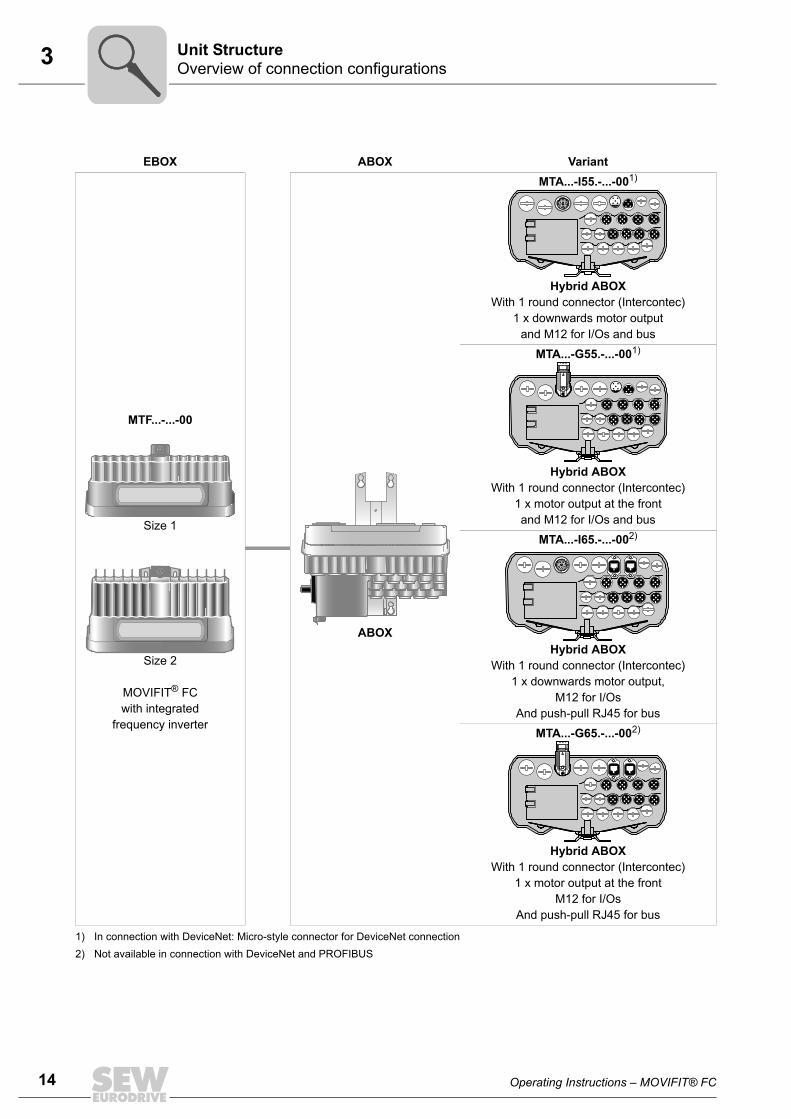
3.2 Overview of connection configurationsThe following figures show the MOVIFIT® FC variants described in these operating in-structions:
More variants are listed on the next page.
EBOX ABOX Variant
MTF...-...-00
Size 1
Size 2
MOVIFIT® FC with integrated
frequency inverter
ABOX
MTA...-S02.-...-001)
Standard ABOX With terminals and cable bushings
MTA...-S42.-...-002)
Hybrid ABOX With M12 for I/Os
MTA...-S52.-...-001)
Hybrid ABOX With M12 for I/Os and bus
MTA...-S53.-...-00 / L103)
Hybrid ABOX With POF option L10,
With M12 for I/Os, bus and 24 V output
MTA...-S62.-...-003)
Hybrid ABOX With M12 for I/Os and push-pull RJ45 for bus
[A] The 3 M12 plug connectors (bus + 24 V) for connecting the POF option L10 are assigned at the factory.
1) In connection with DeviceNet: Micro-style connector for DeviceNet connection2) Not available in connection with DeviceNet3) Not available in connection with DeviceNet and PROFIBUS
X31
X30
[A]
14 Operating Instructions – MOVIFIT® FC
3 Overview of connection configurationsUnit Structure
EBOX ABOX Variant
MTF...-...-00
Size 1
Size 2
MOVIFIT® FC with integrated
frequency inverter
ABOX
MTA...-I55.-...-001)
Hybrid ABOX With 1 round connector (Intercontec)
1 x downwards motor outputand M12 for I/Os and bus
MTA...-G55.-...-001)
Hybrid ABOX With 1 round connector (Intercontec)
1 x motor output at the frontand M12 for I/Os and bus
MTA...-I65.-...-002)
Hybrid ABOX With 1 round connector (Intercontec)
1 x downwards motor output,M12 for I/Os
And push-pull RJ45 for bus
MTA...-G65.-...-002)
Hybrid ABOX With 1 round connector (Intercontec)
1 x motor output at the frontM12 for I/Os
And push-pull RJ45 for bus
1) In connection with DeviceNet: Micro-style connector for DeviceNet connection2) Not available in connection with DeviceNet and PROFIBUS
Operating Instructions – MOVIFIT® FC 15
3EBOX (active electronics unit)Unit Structure
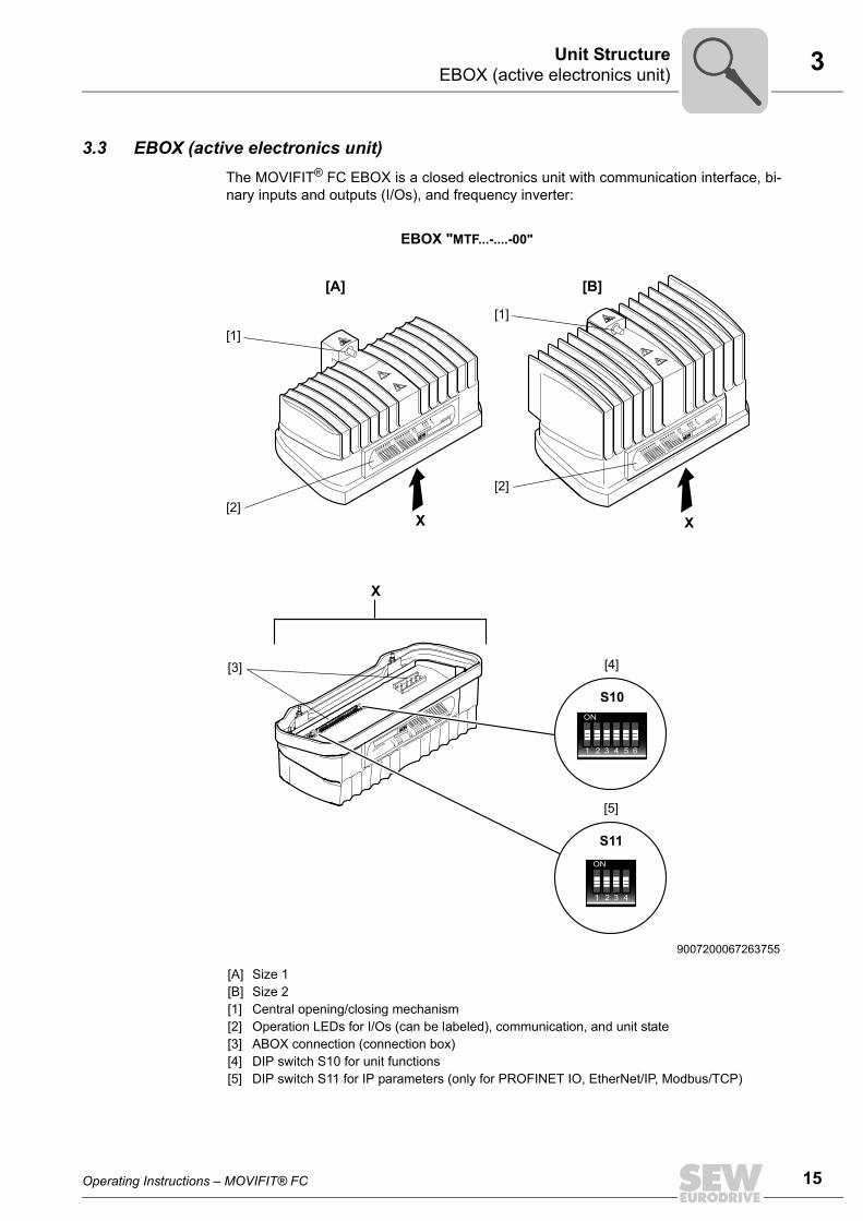
3.3 EBOX (active electronics unit)The MOVIFIT® FC EBOX is a closed electronics unit with communication interface, bi-nary inputs and outputs (I/Os), and frequency inverter:
9007200067263755
[A] Size 1[B] Size 2[1] Central opening/closing mechanism[2] Operation LEDs for I/Os (can be labeled), communication, and unit state[3] ABOX connection (connection box)[4] DIP switch S10 for unit functions[5] DIP switch S11 for IP parameters (only for PROFINET IO, EtherNet/IP, Modbus/TCP)
DI03DI01
DI02DI00
DI04DI05
DI06DI07
DI08DI09
DI11DI12/
DO00
DI13/DO01
DI14/DO02
DI15/Do03
SYS-FBUS-F
24V-C24V
-SRUN
RUN-PSMOVIFIT®
X
X
ON
1 2 3 4 5 6
S10
EBOX "MTF...-....-00"
X
DI03DI01DI02DI00
DI04DI05
DI06DI07
DI08DI09
DI10DI11
DI12/DO00
DI13/DO01
DI14/DO02
DI15/Do03
SYS-FBUS-F
24V-C24V-S
RUN
RUN-PSMOVIFIT
®
[2]
[3] [4]
[1]
[A] [B]
DI03DI01DI02DI00
DI04DI05
DI06DI07
DI08DI09
DI10DI11
DI12/DO00
DI13/DO01
DI14/DO02
DI15/Do03
SYS-FBUS-F
24V-C24V-S
RUN
RUN-PSMOVIFIT
®
[2]
[1]
[5]
S11ON
1 2 3 4
16 Operating Instructions – MOVIFIT® FC
3 ABOX (passive connection unit)Unit Structure
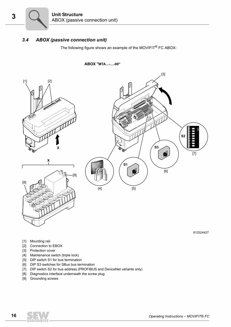
3.4 ABOX (passive connection unit)The following figure shows an example of the MOVIFIT® FC ABOX:
812524427
[1] Mounting rail[2] Connection to EBOX[3] Protection cover[4] Maintenance switch (triple lock)[5] DIP switch S1 for bus termination[6] DIP S3 switches for SBus bus termination[7] DIP switch S2 for bus address (PROFIBUS and DeviceNet variants only)[8] Diagnostics interface underneath the screw plug[9] Grounding screws
X
ON
12
34
56
78
S2
S1X
[7]
[5][4]
[6]
[8]
[9]
S3
[1] [2]
[3]
I ON
0 O
FF
ABOX "MTA...-....-00"

Operating Instructions – MOVIFIT® FC 17
3Hygienicplus variant (optional)Unit Structure
3.5 Hygienicplus variant (optional)3.5.1 Properties
The Hygienicplus variant has the following characteristics:
• IP66 in accordance with EN 60529 and IP69K according to DIN 40050-9 (MOVIFIT®
housing closed and all cable bushings sealed according to the relevant degree ofprotection)
• Easy-to-clean housing (self-draining design)
• Surface with non-stick properties
• High impact resistance of the surface against mechanical damage
• Compatibility with cleansing agents having the following properties:
– Alkaline
– Acidic
– Disinfectant
Do not mix cleaning and disinfecting agents under any circumstances!Never mix acids and chloralkalis, as poisonous chlorine gas will result.Strictly observe the safety instructions of the cleaning agent manufacturer.
• Resistant to temperature fluctuations
• Resistant to condensation due to coated connection boards
INFORMATIONThe Hygienicplus design is only available in connection with the standard ABOX,"MTA12...-S02.-...-00".
For additional features of the Hygienicplus variant, refer to the next page and chapter"Technical Data".

18 Operating Instructions – MOVIFIT® FC
3 Hygienicplus variant (optional)Unit Structure
The following figure shows the additional features of MOVIFIT® units in the optionalHygienicplus variant:
9007200067232139
[1] EBOX with special surface treatment (only available in one color)[2] Signal plug connector with gasket[3] Gasket between ABOX and cover plate[4] Power plug connector with gasket[5] Screws with thread sealant[6] Replaceable profile seal[7] Mounting rail with surface coating (only available in one color)[8] Connection board with increased resistance to moisture condensation (coated)[9] ABOX with special surface treatment (only available in one color)[10] In connection with the Hygienicplus variant: Generally without maintenance switch[11] Stainless steel screw plugs (optionally available)
Y
X
DI03DI01
DI02DI00
DI04DI05
DI06DI07
DI08DI09
DI11DI12/
DO00
DI13/DO01
DI14/DO02
DI15/Do03
SYS-FBUS-F
24V-C24V
-SRUN
RUN-PSMOVIFIT®
X
DI03DI01DI02DI00
DI04DI05
DI06DI07
DI08DI09
DI10DI11
DI12/DO00
DI13/DO01
DI14/DO02
DI15/Do03
SYS-FBUS-F
24V-C24V-S
RUN
RUN-PSMOVIFIT
®
[1] [2] [4] [6][5][3]
[11]
Y
[9]
[8][7]
[10]
ABOX "MTA12...-S02.-...-00"
EBOX "MTF12...-....-00"

Operating Instructions – MOVIFIT® FC 19
3MOVIFIT® with L10 PROFINET interface SCRJ/POFUnit Structure
3.6 MOVIFIT® with L10 PROFINET interface SCRJ/POF3.6.1 Unit structure
The following figure shows MOVIFIT® with L10 PROFINET interface SCRJ/POF (POFoption L10):
3.6.2 Functional descriptionThe POF option L10 converts the optical signals that are transmitted via polymer opticalfiber cables (POF) into electrical signals with PROFINET IO protocol and vice versa.
The POF option L10 makes it possible to connect the ABOX to the optical PROFINETIO.
9007202682186763
[1] MOVIFIT®
[2] Special mounting rail[3] POF option L10 (POF = Polymer Optical Fiber)[4] Status LEDs[5] X30 / X31 connections PROFINET POF[6] Electrical connections between the POF option L10 and the ABOX
These connections are installed at the factory.
[1] [3][2]
[4]
[6]
[5]
20 Operating Instructions – MOVIFIT® FC
3 Type designation MOVIFIT® FCUnit Structure
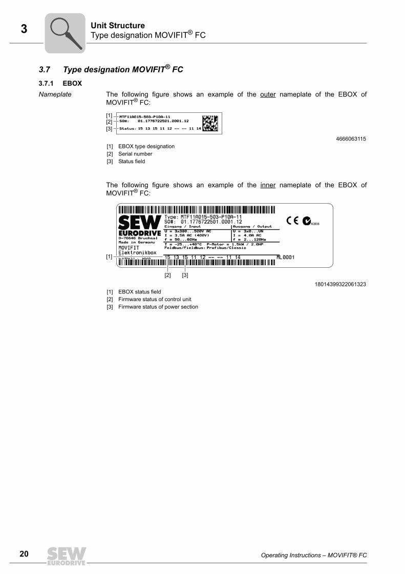
3.7 Type designation MOVIFIT® FC3.7.1 EBOXNameplate The following figure shows an example of the outer nameplate of the EBOX of
MOVIFIT® FC:
The following figure shows an example of the inner nameplate of the EBOX ofMOVIFIT® FC:
4666063115[1] EBOX type designation[2] Serial number[3] Status field
18014399322061323[1] EBOX status field[2] Firmware status of control unit[3] Firmware status of power section
[1][2][3]
[1]
[2] [3]

Operating Instructions – MOVIFIT® FC 21
3Type designation MOVIFIT® FCUnit Structure
Type designation The following table shows an example of the type designation of the EBOX of MOVIFIT®
FC:
MT F 11 A 015- 50 3 - P1 0 A - 00 / S11EBOX optionS11 = PROFIsafe option S111)
1) Only available in connection with PROFIBUS or PROFINET IO
EBOX design00 = DT/DV motor 400 V, 50 Hz01 = DAS motor 400 V, 50 Hz10 = DRS motor 400 V, 50 Hz11 = DRE motor 400 V, 50 Hz15 = DRS-DRE 50 – 60 Hz (global motor)
A = Version
Function level 0 = Classic1 = Technology
Fieldbus P1 = PROFIBUS E2 = PROFINETD1 = DeviceNet Z1 = SBus slaveE3 = EtherNet/IP2), Modbus/TCP 2)
2) Available only in connection with "Technology" function level.
Connection type3 = 3-phase
Supply voltage50 = AC 380 – 500 V
Unit power003 = 0.37 kW005 = 0.55 kW007 = 0.75 kW011 = 1.1 kW015 = 1.5 kW022 = 2.2 kW030 = 3.0 kW040 = 4.0 kW
Version A
Series11 = Standard (IP65)12 = Hygienicplus (IP69K)
Unit typeF = MOVIFIT® FC (frequency inverter)
MT = MOVIFIT® unit series

22 Operating Instructions – MOVIFIT® FC
3 Type designation MOVIFIT® FCUnit Structure
3.7.2 ABOXNameplate The following figure shows an example nameplate of the ABOX of MOVIFIT® FC:
Nameplate of POF option L10
The following figure shows the nameplate of the POF option L10:
27021598576803979[1] ABOX status field
[1]
9007203097977995
Made inGermany
39 / 11 835
L10 (POF-Option)P : 18246761S : 0001536Status : 71
For use with MOVIFIT only

Operating Instructions – MOVIFIT® FC 23
3Type designation MOVIFIT® FCUnit Structure
Type designation The following table shows an example of the type designation of the ABOX of MOVIFIT®
FC:
MTA11A - 503 - S021 - D01 - 00 / BW1 / M11ABOX option 2M11 = Stainless steel mounting railL10 = PROFINET interface SCRJ / POF (POF option L10) 1)
ABOX option 1BW1 / BW2 = Integrated braking resistor
ABOX design 00 = Series
Maintenance switch D01 = Load disconnectorM11 = Load disconnector and line protection up to 4 A2)
M12 = Load disconnector and line protection up to 9 A 2)
Fieldbus 1 = PROFIBUS2 = DeviceNet3 = EtherNet/IP, PROFINET, Modbus/TCP
Connection configurationS02 = Standard ABOX with terminals and cable glandsS42 = Hybrid ABOX with M12 for I/OsS52 = Hybrid ABOX with M12 for I/Os + busS53 = Hybrid ABOX with M12 for I/Os + bus + 24 V output 1)
S62 = Hybrid ABOX with M12 for I/Os, push-pull RJ45 for busI55 = Hybrid ABOX with round connector (Intercontec), 1x downward motor
output, M12 for I/Os + busG55 = Hybrid ABOX with round connector (Intercontec), 1x motor output at the
front, M12 for I/Os + busI65 = Hybrid ABOX with round connector (Intercontec), 1x downward motor
output, M12 for I/Os, push-pull RJ45 for busG65 = Hybrid ABOX with round connector (Intercontec), 1x motor output at the
front, M12 for I/Os, push-pull RJ45 for bus
Connection type3 = 3-phase
Supply voltage 50 = 380 V – 500 V:
A = Version
Series 11 = Standard (IP65)12 = Hygienicplus (IP69K)
Unit type A = ABOX (connection box)
MT = MOVIFIT® unit series
1) The POF option L10 and the S53 connection configuration are only available in combination with each other.2) Only available in connection with UL.

24 Operating Instructions – MOVIFIT® FC
4 General informationMechanical Installation
4 Mechanical Installation4.1 General information
Observe the following notes on mechanical installation:
• Observe the general safety notes.
• Only install MOVIFIT® on a level, low-vibration, and torsionally rigid support struc-ture, see "Mounting position" chapter.
• Comply with all instructions referring to the technical data and the permissible condi-tions where the unit is operated.
• Do only use provided attachment options when mounting the unit.
• When selecting and dimensioning the mounting and safety elements, observe theapplicable standards, the technical data of the unit, as well as local circumstances.
• Use suitable screw fittings for the cables (use reducing adapters if necessary). Usesuitable mating connectors for plug connectors.
• Cover the unused cable glands with screw plugs.
• Cover the unused plug connectors with blind caps.
CAUTIONRisk of injury due to protruding parts, especially the mounting rail.
Risk of cutting or crushing.• Cover sharp and protruding parts, especially the mounting rail, to protect against
injury and damage.• MOVIFIT® may only be installed by qualified personnel.

Operating Instructions – MOVIFIT® FC 25
4Permitted mounting positionMechanical Installation
4.2 Permitted mounting positionMOVIFIT® is attached by means of a mounting platform using the 4 screws already in-stalled in the mounting surface. For detailed information, refer to chapter "Mounting"(page 26).
The following figure shows the permitted mounting positions for MOVIFIT®:
5151839243
[0] Mounting position 0 (standard)[1] Mounting position 1 (tilted)[2] Mounting position 2 (tilted)
0°
90°
90°90°
[2]
[1]
[2][0]
INFORMATIONIn this chapter, the standard variant with terminals and cable glands will be illustratedas an example. However, the installation notes appy to all variants.
All tilted mounting positions between mounting positions 0, 1, and 2 are permitted.
For MOVIFIT® with EBOX MTF11A-040-503.., the nominal output current IN is re-duced in tilted mounting positions, see chapter "Technical data".

26 Operating Instructions – MOVIFIT® FC
4 InstallationMechanical Installation
4.3 Installation4.3.1 Mounting rail
MOVIFIT® is equipped with a mounting rail to attach the unit to a level, low-vibrationmounting surface using M6 bolts. For bore dimensions of the respective type of fixture,see the following figures.
Drilling template for standard mounting rail
For detailed dimension drawings, see the section "Technical data" / "Dimension draw-ings".
27021598522763275
66
334.5
304.
1280
140
37,5
min
. 40
15
min. 50
[1]
[2]
7.0 (6x)
13.9 (6x)
[3]
min
. 104
INFORMATION• [1] Observe the minimum installation clearance so that the EBOX can be removed
from the ABOX.• [2] Observe the minimum installation clearance required to operate the mainte-
nance switch and to ensure heat dissipation for the unit.• Make sure that the permitted bending radii of the cables used is not exceeded
when connecting the cables.• [3] Observe the minimum clearance of 104 mm at the bottom for all ABOXes with
round connector (Intercontec) and downward motor output. • Observe the minimum clearance of 191 mm at the front for all ABOXes with round
connector (Intercontec) and motor output at the front.

Operating Instructions – MOVIFIT® FC 27
4InstallationMechanical Installation
Drilling template for optional mounting rail /M11
For detailed dimension drawings, see the section "Technical data" / "Dimension draw-ings".
18014399308791819
334.4
66
min
. 40
min. 50
[1]
[2]
15
37.5
4050
50
7.0 (8x)
13.9 (8x)
[3]
min
. 104
INFORMATION• [1] Observe the minimum installation clearance so that the EBOX can be removed
from the ABOX.• [2] Observe the minimum installation clearance required to operate the mainte-
nance switch and to ensure heat dissipation for the unit.• [3] Observe the minimum clearance of 104 mm at the bottom for all ABOXes with
round connector (Intercontec) and downward motor output. • Observe the minimum clearance of 191 mm at the front for all ABOXes with round
connector (Intercontec) and motor output at the front.

28 Operating Instructions – MOVIFIT® FC
4 InstallationMechanical Installation
Drilling template for mounting rail (POF option L10)
The MOVIFIT® unit with the special mounting rail is mounted analogously to a unit withmounting rail /M11.
However, an additional retaining screw behind the POF option is necessary for thismounting rail, see following figure.
For detailed dimension drawings, see the section "Technical data" / "Dimension draw-ings".
4763117579
63
6613614
040
50
50
15
37.5
410.3
min. 50
min
. 40
[2]
[1]
332.
3
INFORMATION• [1] Observe the minimum installation clearance so that the EBOX can be removed
from the ABOX.• [2] Observe the minimum installation clearance required to operate the mainte-
nance switch and to ensure heat dissipation for the unit.• Make sure that the permitted bending radii of the cables used is not exceeded
when connecting the cables.

Operating Instructions – MOVIFIT® FC 29
4InstallationMechanical Installation
4.3.2 Fastening
1. Bore the holes required for mounting at least 4 bolts into the mounting surface ac-cording to the previous figures. SEW-EURODRIVE recommends bolts of size M6and suitable dowel pins, if necessary.
2. Mount at least 4 screws on the mounting surface.
Use appropriate washers or screw and washer assemblies for the mounting plateswith special surface treatment on the Hygienicplus variant.
CAUTIONRisk of crushing if the load falls.
Severe or fatal injuries.• Do not stand under the load.• Secure the danger zone.
CAUTIONRisk of injury due to protruding parts.
Risk of cutting or crushing.• Cover sharp and protruding parts.• The installation must only be carried out by qualified personnel.
758550411
min.
4 x M6

30 Operating Instructions – MOVIFIT® FC
4 InstallationMechanical Installation
3. Attach the ABOX to the screws with the mounting plate
758565899
1.2.

Operating Instructions – MOVIFIT® FC 31
4InstallationMechanical Installation
4. Tighten the screws.
CAUTION Risk of injury if the load falls.
Minor injuries
• Tighten at least 4 wall screws to ensure a secure fit after mounting.
758590731

32 Operating Instructions – MOVIFIT® FC
4 Central opening/closing mechanismMechanical Installation
4.4 Central opening/closing mechanism
4.4.1 OpeningYou need a socket wrench (SW8) for the central retaining screw.
1. Loosen the central retaining screw and continue to turn in counterclockwise directionuntil the EBOX does not move further up.
WARNINGDanger of burns due to hot surfaces of the MOVIFIT® unit.
Severe injuries.• Do not touch the MOVIFIT® until it has cooled down sufficiently.
CAUTIONRisk of injury if the EBOX falls.
Minor injuries.• Make sure that the EBOX cannot fall down when you are opening or closing it.
NOTICEThe enclosure specified in the technical data only applies when a unit is mounted cor-rectly. MOVIFIT® can be damaged by moisture, dust or foreign particles when theEBOX is removed from the ABOX.• Protect the ABOX and the EBOX when the unit is open.
NOTICEThe central opening/closing mechanism may be damaged.
The central opening/closing mechanism may be destroyed.• When opening/closing the EBOX in tilted mounting positions, make sure that the
EBOX is aligned properly; guide the EBOX with your hand.
813086859
EBOX
ABOX

Operating Instructions – MOVIFIT® FC 33
4Central opening/closing mechanismMechanical Installation
2. Remove the EBOX from the ABOX by lifting it upwards. Align the EBOX correctly.
4.4.2 ClosingYou need a socket wrench (SW8) for the central retaining screw.
1. NOTICE An improperly seated seal in the EBOX creates a strong counterforcewhen closing the MOVIFIT® unit.
The central opening/closing mechanism may be damaged.
• Make sure that the seal is properly seated in the groove of the EBOX.
This means that
– the seal is inserted into the groove over the entire circumference
– and does not protrude from the groove.
2. Position the EBOX on the ABOX.
• Align the EBOX correctly.
• Only hold the EBOX on both sides.
(See following figure).
813353099
EBOX
ABOX
90°
813362059
90°

34 Operating Instructions – MOVIFIT® FC
4 Central opening/closing mechanismMechanical Installation
3. Check the EBOX for the correct position.
NOTICE The central opening/closing mechanism may be damaged.
The central opening/closing mechanism may be destroyed.
• In all tilted mounting positions, you must guide the EBOX manually when you areclosing it.
• Make sure that the EBOX is aligned correctly.
4. Tighten the retaining screw up to the stop using a tightening torque of 7 Nm.
NOTICE If the torque is too high, the central opening/closing mechanism can bedestroyed.
• Tighten the retaining screw with a maximum tightening torque of 7 Nm.
• If there is a noticeable counter torque, remove the EBOX again and checkwhether the gasket is seated properly. If necessary, press the gasket firmly intothe groove.
• Never tighten the retaining screws with impermissibly high tightening torques.
5. MOVIFIT® is properly closed when the redirector of the closing mechanism [2]touches the mounting plate [1].
813384075
813392395
EBOX
ABOX
0
Z
Z
[1]
[1]
[2] [2]
Operating Instructions – MOVIFIT® FC 35
4Tightening torquesMechanical Installation
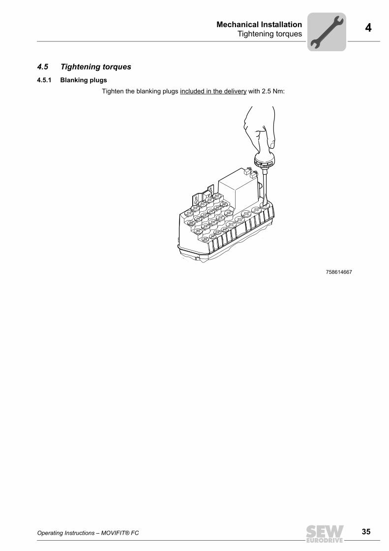
4.5 Tightening torques4.5.1 Blanking plugs
Tighten the blanking plugs included in the delivery with 2.5 Nm:
758614667

36 Operating Instructions – MOVIFIT® FC
4 Tightening torquesMechanical Installation
4.5.2 EMC cable glands
Tighten the EMC cable glands optionally supplied by SEW-EURODRIVE with the follow-ing torques:
The cable retention in the cable gland must withstand the following removal force of thecable from the cable gland:
• Cable with outer diameter > 10 mm: ≥ 160 N
• Cable with outer diameter < 10 mm: = 100 N
758624523
Screw fitting Part number Size Tightening torqueEMC cable glands (nickel-plated brass)
1820 478 3 M16 x 1.5 3.5 Nm to 4.5 Nm
1820 479 1 M20 x 1.5 5.0 Nm to 6.5 Nm
1820 480 5 M25 x 1.5 6.0 Nm to 7.5 Nm
EMC cable glands (stainless steel)
1821 636 6 M16 x 1.5 3.5 Nm to 4.5 Nm
1821 637 4 M20 x 1.5 5.0 Nm to 6.5 Nm
1821 638 2 M25 x 1.5 6.0 Nm to 7.5 Nm
Operating Instructions – MOVIFIT® FC 37
4MOVIFIT® Hygienicplus variantMechanical Installation
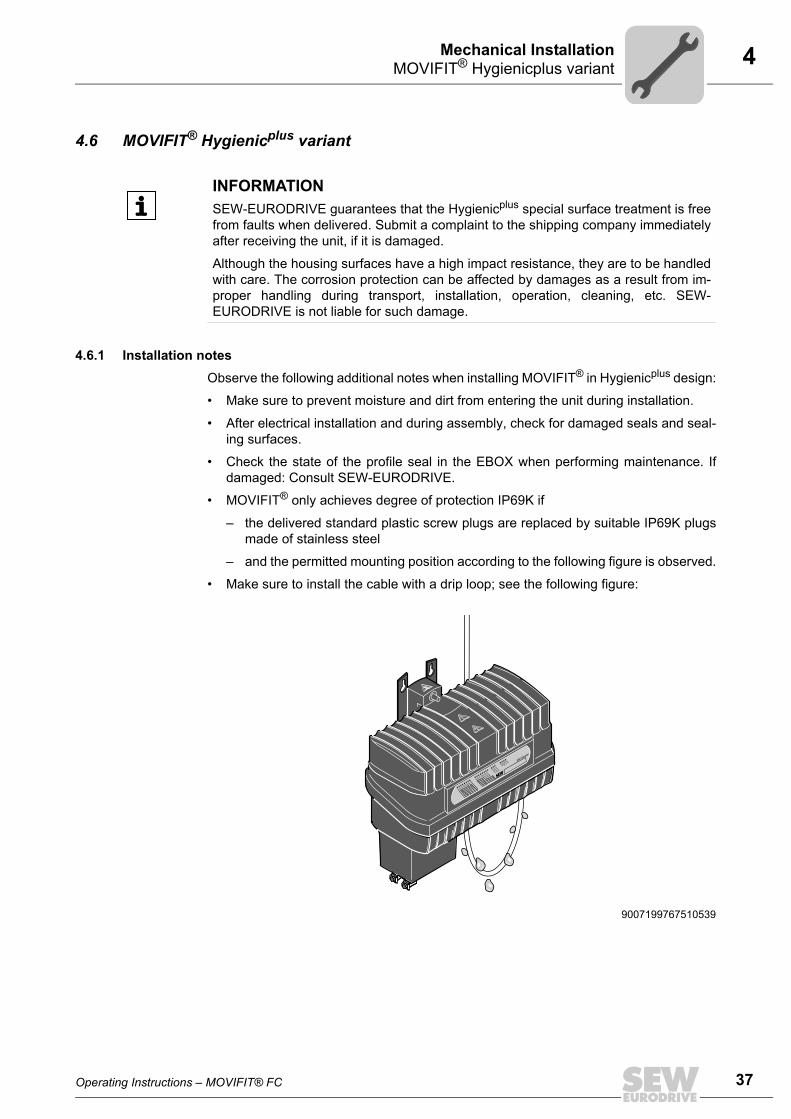
4.6 MOVIFIT® Hygienicplus variant
4.6.1 Installation notesObserve the following additional notes when installing MOVIFIT® in Hygienicplus design:
• Make sure to prevent moisture and dirt from entering the unit during installation.
• After electrical installation and during assembly, check for damaged seals and seal-ing surfaces.
• Check the state of the profile seal in the EBOX when performing maintenance. Ifdamaged: Consult SEW-EURODRIVE.
• MOVIFIT® only achieves degree of protection IP69K if
– the delivered standard plastic screw plugs are replaced by suitable IP69K plugsmade of stainless steel
– and the permitted mounting position according to the following figure is observed.
• Make sure to install the cable with a drip loop; see the following figure:
INFORMATIONSEW-EURODRIVE guarantees that the Hygienicplus special surface treatment is freefrom faults when delivered. Submit a complaint to the shipping company immediatelyafter receiving the unit, if it is damaged.
Although the housing surfaces have a high impact resistance, they are to be handledwith care. The corrosion protection can be affected by damages as a result from im-proper handling during transport, installation, operation, cleaning, etc. SEW-EURODRIVE is not liable for such damage.
9007199767510539
DI01DI02
DI03DI00
DI05DI06
DI07DI04
DI09DI10
DI03DI08
DI13/DO01
DI14/DO02
Ethernet1
Ethernet2
Ethernet3
COMRUN2
NET324V3
DI12/DO00
SNI-Master
38 Operating Instructions – MOVIFIT® FC
4 MOVIFIT® Hygienicplus variantMechanical Installation
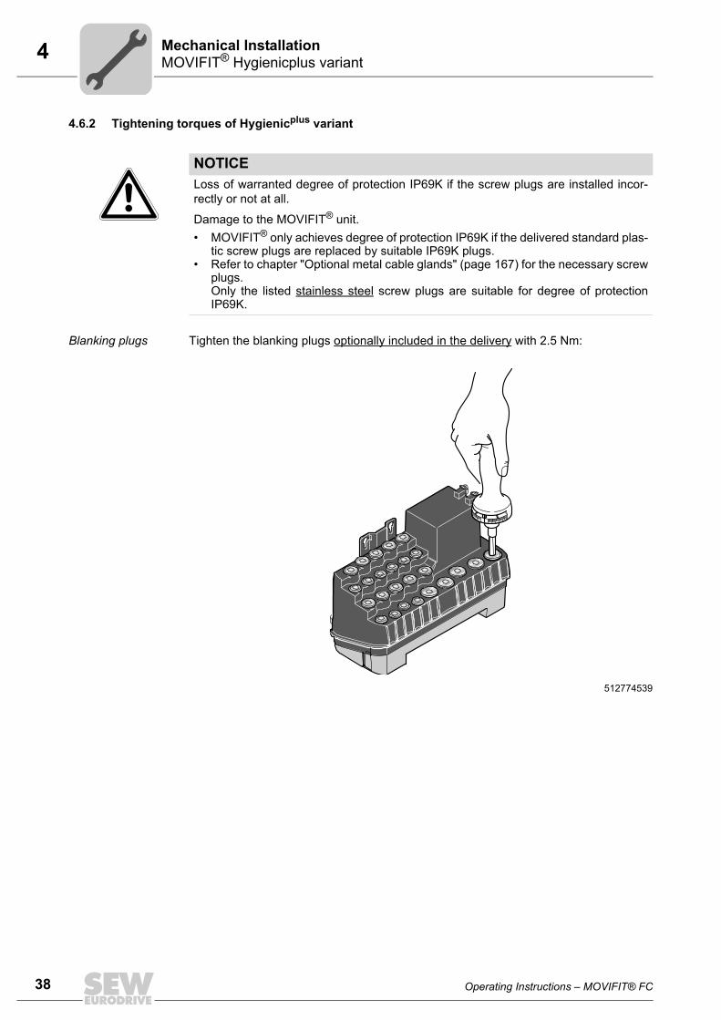
4.6.2 Tightening torques of Hygienicplus variant
Blanking plugs Tighten the blanking plugs optionally included in the delivery with 2.5 Nm:
NOTICELoss of warranted degree of protection IP69K if the screw plugs are installed incor-rectly or not at all.
Damage to the MOVIFIT® unit.• MOVIFIT® only achieves degree of protection IP69K if the delivered standard plas-
tic screw plugs are replaced by suitable IP69K plugs.• Refer to chapter "Optional metal cable glands" (page 167) for the necessary screw
plugs. Only the listed stainless steel screw plugs are suitable for degree of protectionIP69K.
512774539

Operating Instructions – MOVIFIT® FC 39
4MOVIFIT® Hygienicplus variantMechanical Installation
EMC cable glands Tighten the EMC cable glands optionally supplied by SEW-EURODRIVE with the follow-ing torques:
The cable retention in the cable gland must withstand the following removal force of thecable from the cable gland:
• Cable with outer diameter > 10 mm: ≥ 160 N
• Cable with outer diameter < 10 mm: = 100 N
512772875
Screw fitting Part number Size Tightening torqueEMC cable glands (nickel-plated brass)
1820 478 3 M16 x 1.5 3.0 Nm to 4.0 Nm
1820 479 1 M20 x 1.5 3.5 Nm to 5.0 Nm
1820 480 5 M25 x 1.5 4.0 Nm to 5.5 Nm
EMC cable glands (stainless steel)
1821 636 6 M16 x 1.5 3.5 Nm to 4.5 Nm
1821 637 4 M20 x 1.5 5.0 Nm to 6.5 Nm
1821 638 2 M25 x 1.5 6.0 Nm to 7.5 Nm

40 Operating Instructions – MOVIFIT® FC
5 General informationElectrical Installation
5 Electrical Installation5.1 General information
Observe the following notes on electrical installation:
• Observe the general safety notes.
• Strictly observe all instructions as to the technical data and the permissible condi-tions regarding the place of installation.
• Use suitable screw fittings for the cables (use reducing adapters if necessary). Withconnector plug versions, you must use a suitable mating connector.
• Seal open cable entries with screw plugs.
• Use protective caps to seal plug connectors not in use.
5.2 Installation planning taking EMC aspects into account
For detailed information on EMC compliant installation, refer to the SEW publicationDrive Engineering – Practical Implementation, "Electromagnetic Compatibility in DriveEngineering".
Successful installation of decentralized drives depends on selecting the correct cables,providing correct grounding and a functioning equipotential bonding.
Always apply the relevant standards.
Observe the notes in the following chapters in particular.
INFORMATIONThis drive system is not designed for operation on a public low voltage supply systemthat supplies residential areas.
MOVIFIT® units can cause EMC interference within the permitted limit range accord-ing to EN 61800-3. In this case, it is recommended for the operator to take suitablemeasures.
Operating Instructions – MOVIFIT® FC 41
5Installation planning taking EMC aspects into accountElectrical Installation
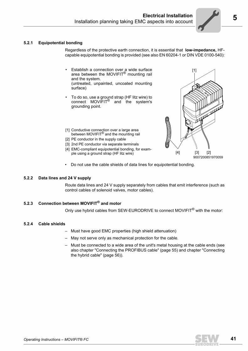
5.2.1 Equipotential bonding
Regardless of the protective earth connection, it is essential that low-impedance, HF-capable equipotential bonding is provided (see also EN 60204-1 or DIN VDE 0100-540):
• Do not use the cable shields of data lines for equipotential bonding.
5.2.2 Data lines and 24 V supplyRoute data lines and 24 V supply separately from cables that emit interference (such ascontrol cables of solenoid valves, motor cables).
5.2.3 Connection between MOVIFIT® and motorOnly use hybrid cables from SEW-EURODRIVE to connect MOVIFIT® with the motor:
5.2.4 Cable shields– Must have good EMC properties (high shield attenuation)
– May not serve only as mechanical protection for the cable.
– Must be connected to a wide area of the unit's metal housing at the cable ends (seealso chapter "Connecting the PROFIBUS cable" (page 55) and chapter "Connectingthe hybrid cable" (page 56)).
• Establish a connection over a wide surfacearea between the MOVIFIT® mounting railand the system.(untreated, unpainted, uncoated mountingsurface)
• To do so, use a ground strap (HF litz wire) toconnect MOVIFIT® and the system'sgrounding point.
9007200851970059
[1] Conductive connection over a large area between MOVIFIT® and the mounting rail
[2] PE conductor in the supply cable[3] 2nd PE conductor via separate terminals[4] EMC-compliant equipotential bonding, for exam-
ple using a ground strap (HF litz wire)
[1]
[3] [2][4]

42 Operating Instructions – MOVIFIT® FC
5 Installation instructions (all variants)Electrical Installation
5.3 Installation instructions (all variants)5.3.1 Connecting supply system leads
• The rated voltage and frequency of the MOVIFIT® frequency inverter must corre-spond to the data for the supply system.
• Cable cross section according to input current Iline for rated power (see chapter"Technical Data").
• Install line fuses at the beginning of the supply system line behind the supply busjunction. Use D, D0, NH fuses or circuit breakers. Select the fuse size according tothe cable cross section.
• Use contactor switch contacts from utilization category AC-3 according to EN 60947-4-1 to connect MOVIFIT® drives.
• Switch the MOVIFIT® FC output with inhibited output stage only.
5.3.2 Residual current device
• Do not use a conventional RCD as a protective device. Universal current-sensitiveRCDs (tripping current 300 mA) are permitted as a protective device. During normaloperation of MOVIFIT®, leakage currents ≥ 3.5 mA can occur.
• SEW-EURODRIVE recommends that you do not use RCDs. However, if an RCD isstipulated for direct or indirect protection against contact, observe the note above inaccordance with EN 61800-5-1.
5.3.3 Line contactor• Use contactor switch contacts of utilization category AC-3 according to EN 60947-4-
1 to connect the supply system cable.
WARNINGElectric shock due to incorrect RCD type.
Severe or fatal injuries.
MOVIFIT® can cause direct current in the protective earth conductor. In cases wherea residual current device (RCD) is used for protection against direct or indirect contact,only install a type B RCD on the power supply end of the MOVIFIT®.

Operating Instructions – MOVIFIT® FC 43
5Installation instructions (all variants)Electrical Installation
5.3.4 Notes on PE connection and/or equipotential bonding
Earth-leakage currents ≥ 3.5 mA may occur during normal operation. To meet the re-quirements of EN 61800-5-1, observe the following notes:
• The protective earth (PE) connection must meet the requirements for plants with highearth-leakage currents.
• This usually means
– installing a PE connection cable with a minimum cross section of 10 mm2
– or installing a second PE connection cable in parallel with the original PE connec-tion.
WARNINGElectric shock due to incorrect connection of PE.
Severe, fatal injuries• The permitted tightening torque for the retaining screws is 2.0 – 2.4 Nm.• Observe the following notes regarding the PE connection:
Prohibited assembly Recommendation: Assembly with forked cable lugPermitted for all cross sections
Assembly with solid connecting wirePermitted for cross sections up to Max. 2.5 mm2
323042443 323034251 323038347
[1] Forked cable lug suitable for M5 PE screws
[1]
M5
2.5 mm²
M5
44 Operating Instructions – MOVIFIT® FC
5 Installation instructions (all variants)Electrical Installation
5.3.5 Definition PE, FE
• PE refers to the mains-side protective earth connection. The PE conductor in themains connection cable may only be connected with terminals marked with "PE".These are dimensioned for the max. permitted line connection cross section.
• FE refers to connections for "functional ground". You can connect any existinggrounding conductor in the 24 V connection cable.
5.3.6 Meaning of the 24 V voltage levelsMOVIFIT® FC has a total of 4 different 24 V potential levels, which are electrically iso-lated from each other:
• 1) 24V_C: C = Continuous
• 2) 24V_S: S = Switched
• 3) 24V_P: P = Power section
• 4) 24V_O: O = Option
Depending on the requirements of the application, these can either be isolated, suppliedexternally, or connected to each other via a X29 distributor terminal.
1) 24V_C = Elec-tronics and sensor supply
The 24V_C voltage level supplies:
• The MOVIFIT® control electronics
• The sensors connected to the sensor supply outputs VO24_I, VO24_II and VO24_III.
Do not disconnect the 24V_C voltage level during operation. If you do this, you can nolonger control the MOVIFIT® unit via fieldbus or network, and the sensor signals are nolonger processed.
When restarted, the MOVIFIT® unit needs a certain amount of time to boot.
2) 24V_S = Actua-tor supply
The 24V_S voltage level supplies:
• The binary outputs DO..
• The connected actuators
• The VO24_IV sensor supply output
The binary inputs DI12 – DI15 are connected to the reference potential 0V24_S (asthese can be connected to the same connections as an alternative to the outputs).
To centrally deactivate the actuators of the plant, you can disconnect the 24V_S voltagelevel during operation, if required.
WARNING Electric shock due to incorrect connection of PE to the terminals marked with "F"(functional ground). The FE connections are not designed for this purpose. Thismeans electrical safety is not guaranteed.
Severe or fatal injuries.• The permitted tightening torque for the retaining screw is 2.0 – 2.4 Nm.• Observe the following notes regarding the PE connection:

Operating Instructions – MOVIFIT® FC 45
5Installation instructions (all variants)Electrical Installation
3) 24V_P = Inverter supply
The 24V_P voltage level supplies the integrated inverter with 24 V.
Depending on the application, the 24V_P voltage level can be supplied by 24V_C or24V_S (via jumpers at X29) or externally. The required jumpers are included in thescope of delivery.
Note that the integrated frequency inverter is no longer supplied with 24 V in case of safedisconnection. It will issue an error message.
4) 24V_O = Option supply
The 24V_O voltage level supplies:
• The integrated S11 option card
• the sensor/actuator interfaces on the S11 option card.
With PROFIsafe option S11, the complete safety electronics and the safe inputs/outputsare supplied from 24V_O.
Depending on the application, the 24V_O voltage level is supplied by:
• The 24V_C voltage level
• The 24V_S voltage level (via jumpers at terminal X29)
• An external source.
Note that the entire S11 option card with the connected sensors and actuators is no lon-ger supplied when the voltage level is disconnected. This causes an error message.
Connection of volt-ages
Connect the 24V_C and 24V_S voltage levels to terminal X20 with a large cable crosssection. Loop the 24V_C and 24V_S voltage levels through to the next MOVIFIT® unitas "24 V power bus" with a large cable cross section.
Connect the 24V_P and 24V_O voltage levels to terminal X29.
WARNINGDuring safe disconnection, 24V_P must be connected over a suitable emergency stoprelay or a safety control.
Severe or fatal injuries.• Note the wiring diagrams and the safety conditions of the "MOVIFIT® MC/FC –
Functional Safety" manual.
WARNINGDanger due to improper safety shutdown when PROFIsafe option S11 is used.
Severe or fatal injuries.• When using the PROFIsafe option S11, note the permitted wiring diagrams and
safety conditions in the "MOVIFIT® MC/FC – Functional Safety" manual.
INFORMATION• For connection examples, refer to chapter "Power bus connection examples"
(page 101).• For the permitted connection cross sections, refer to chapter "Permitted connection
cross sections" (page 53).

46 Operating Instructions – MOVIFIT® FC
5 Installation instructions (all variants)Electrical Installation
5.3.7 Plug connectorsAll MOVIFIT® plug connectors are illustrated in these operating instructions with view onthe contact end.
5.3.8 Operating braking resistorsBraking resistors dissipate the energy generated during braking operations and get hotin the process.
The supply cables to the braking resistors carry a high pulsed DC voltage during normaloperation.
5.3.9 Protection devicesMOVIFIT® drives are equipped with integrated protective overload devices, which makeexternal devices obsolete.
5.3.10 EMC-compliant installation
With respect to the EMC regulation, frequency inverters cannot be operated as stand-alone units. Regarding EMC, they can only be evaluated when they are integrated in adrive system. Conformity is declared for a described, CE-typical drive system. These op-erating instructions contain further information.
WARNINGDanger of burns due to hot surfaces of the braking resistors when loaded with PN.
Severe burns.• Choose a suitable installation location for the braking resistors.• Do not touch the braking resistors until they have cooled down sufficiently.
INFORMATIONThis drive system is not designed for operation on a public low voltage supply systemthat supplies residential areas.
This is a product with restricted availability in accordance with IEC 61800-3. This prod-uct may cause EMC interference. In this case, it is recommended for the operator totake suitable measures.
For detailed information on EMC compliant installation, refer to the publication "Elec-tromagnetic Compatibility in Drive Engineering" from SEW-EURODRIVE.
Operating Instructions – MOVIFIT® FC 47
5Installation instructions (all variants)Electrical Installation
5.3.11 UL-compliant installationPower terminals Note the following points for UL-compliant installation:
• Use only 75 °C copper wire.
• MOVIFIT® uses cage clamp terminals.
Short circuit cur-rent rating
Suitable for use in circuits that deliver a maximum of 200,000 A rms:
• MOVIFIT® FC, the max. voltage is limited to 500 V.
Branch circuit pro-tection
Integral solid state short circuit protection does not provide branch circuit protection.Branch circuit protection must be provided in accordance with the National ElectricalCode and any applicable local codes.
The following table lists the maximum fuse rating.
Motor overload protection
• MOVIFIT® FC is equipped with motor overload protection with a trip current adjustedto 140% of the rated motor current.
Unit and line pro-tection
• MOVIFIT® units in connection with ABOX MTA...-M11-.. or MTA....-M12-.. areequipped with unit and line protection.
Ambient tempera-ture
• MOVIFIT® FC (except MTF1.A040-503...) is suitable for operation at an ambienttemperature of 40 °C, max. 60 °C with derated output current. To determine the out-put current rating at higher than 40 °C, the output current should be derated 3.0% per°C between 40 °C and 60 °C.
• MOVIFIT® FC (MTF1.A040-503... only) is suitable for operation at an ambient tem-perature of 35 °C, max. 55 °C with derated output current. To determine the outputcurrent rating at higher than 35 °C, the output current should be derated 3.0% per °Cbetween 35 °C and 55 °C.
ABOX-EBOX com-bination
• For UL-compliant installation, only the ABOX listed on the ABOX nameplate may beinstalled to the ABOX. UL certification only applies to the ABOX-EBOX combinationlisted on the nameplate.
Series Max. fuse ratingMOVIFIT® FC 25 A / 600 V
INFORMATIONThe UL certification only applies to operation on voltage supply systems with voltagesto ground of max. 300 V. The UL-certification does not apply to operation on voltagesupply systems with a non-grounded star point (IT systems).

48 Operating Instructions – MOVIFIT® FC
5 Installation instructions (all variants)Electrical Installation
5.3.12 Installation altitude higher than 1000 m above sea level
MOVIFIT® units with supply voltages of 380 to 500 V can be used at altitudes above1000 m asl up to 4000 m asl under the following conditions:
• The nominal continuous power is reduced due to the reduced cooling above 1000 m(see chapter "Technical Data").
• Above 1000 m asl, the air and creeping distances are only sufficient for overvoltageclass 2. If the installation calls for overvoltage class 3, you will have to install addi-tional external overvoltage protection to limit overvoltage peaks to 2.5 kV phase-to-phase and phase-to-ground.
• If safe electrical disconnection is required, it must be implemented outside the deviceat altitudes of more than 2000 m above sea level (safe electrical disconnection in ac-cordance with EN 61800-5-1 and EN 60204-1, motor connector (Intercontec), ac-cording to EN60664-1 (DIN VDE 0110-1).
• At installation altitudes up to 2000 m asl, the permitted nominal line voltage is 3 ×500 V. Between 2000 m and 4000 m asl, the permitted line voltage is reduced by 6V per 100 m.

Operating Instructions – MOVIFIT® FC 49
5Additional installation instructions for group drivesElectrical Installation
5.4 Additional installation instructions for group drivesThe following figure shows the prescribed installation for group drives with MOVIFIT®
FC:
When installing such group drives, also follow the installation instructions below:
• The total of the nominal motor currents must not exceed the nominal output currentof MOVIFIT® FC.
• Connect no more than 3 motors in series connection to the MOVIFIT® FC. The sumof the nominal motor currents may not exceed the nominal unit current ofMOVIFIT® FC.
• The sum of all cable sections between MOVIFIT® FC and the motors must not ex-ceed 15 m.
• Temperature monitoring of 2 motors is permitted with a TF temperature sensor foreach motor.
If you are using more than 2 motors, each motor must be equipped with a TH tem-perature switch.
Connect those TFs/THs to the MOVIFIT® FC in series connection.
• The motor brakes may be controlled using constant voltage only (alternative brakecontrol system at startup using MOVITOOLS® MotionStudio). The rated voltage ofall connected brakes must be equal.
1240954123
MOVIFIT®
INFORMATION• For more information on motor/brake startup, refer to the manual "MOVIFIT® func-
tion level "Classic"..." or "MOVIFIT® function level "Technology" ...".• When several motors are controlled via a MOVIFIT® FC drive (group drive), the in-
ternal motor protection model does not protect the connected motors against over-heating.This is why the drive must be equipped with an internal or external braking resistor.The braking resistor dissipates the regenerative power during deceleration.

50 Operating Instructions – MOVIFIT® FC
5 Installation topology (example)Electrical Installation
5.5 Installation topology (example)The following figure shows the general installation topology of MOVIFIT® FC:
5068774155
MOVIFIT®
PLC
MOVIFIT®
DR.. DR..
24 V400 V
BUS24 V400 V
Operating Instructions – MOVIFIT® FC 51
5Standard ABOX MTA...-S02.-...-00Electrical Installation
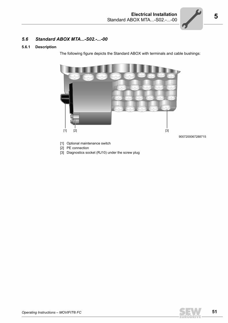
5.6 Standard ABOX MTA...-S02.-...-005.6.1 Description
The following figure depicts the Standard ABOX with terminals and cable bushings:
9007200067288715
[1] Optional maintenance switch[2] PE connection[3] Diagnostics socket (RJ10) under the screw plug
[2][1] [3]

52 Operating Instructions – MOVIFIT® FC
5 Standard ABOX MTA...-S02.-...-00Electrical Installation
5.6.2 Variants
The following variants of the standard ABOX are available for MOVIFIT® FC (MTF):
• MTA11A-503-S02.-...-00:
– Optional internal or external braking resistor
– Optional load break switch
– Load break switch and line protection
The following figure shows the screw connections and plug connectors of the standardABOX depending on the fieldbus interface:
9007200277091083
M25 M16
M20
M20
M16
M25 M16
M20
M20
M16
Micro-Style-Connector X11
PROFIBUSPROFINETEthernet/IPModbus/TCP
MTA11A-503-S022-...-00DeviceNet
MTA11A-503-S021-...-00
MTA11A-503-S023-...-00

Operating Instructions – MOVIFIT® FC 53
5Standard ABOX MTA...-S02.-...-00Electrical Installation
5.6.3 Additional installation instructions for MTA...-S02.-...-00Permitted connection cross-section and current carrying capacity of the terminals
Conductor end sleeves
Use conductor end sleeves without insulating shrouds for terminals X1, X20, X8, and X9(DIN 46228-1, material E-CU).
Terminal data X1 / X20 X8 / X9 X25 / X30 / X31 / X35 / X45 / X81 / X91
X29
Connection cross section
0.2 – 6 mm2 0.08 – 41) mm2
1) The maximum permitted cross-section is reduced by one unit when using conductor end sleeves (e.g.2.5 mm2 → 1.5 mm2)
0.08 – 2.51) mm2 0.2 – 1.51) mm2
AWG 24 –AWG10
AWG 28 –AWG121) AWG 28 – AWG141) AWG 24 –
AWG161)
Current carrying capacity (max. con-tinuous current)
X1: 32 AX20: 16 A
20 A 10 A 10 A
Conductor stripping length 13 – 15 mm 8 – 9 mm 5 – 6 mm 9 – 10 mm

54 Operating Instructions – MOVIFIT® FC
5 Standard ABOX MTA...-S02.-...-00Electrical Installation
Actuating the ter-minals
Terminals X1, X20 Connect the conductorwithout screwdriver 1)
1) Single-wire conductors and flexible conductors with conductor end sleeves can be installed directly (with-out using a tool) up to two cross section sizes below the rated cross section.
Connect the conductorwith screwdriver 2)
2) Untreated, flexible conductors or conductors with small cross sections cannot be directly inserted into theterminal. To open the clamping spring when you want to connect such conductors, push a screwdriverfirmly into the actuation opening.
812406283 812407947
Terminals X8 / X81 / X9 / X91 / X29 / X45 / X25 / X30 / X31 / X35 1)
1) With these terminals, the conductor is always connected with a screwdriver irrespective of its type.
812404619
2.
1.
2.
1.
3.

Operating Instructions – MOVIFIT® FC 55
5Standard ABOX MTA...-S02.-...-00Electrical Installation
Connecting the PROFIBUS cable in MOVIFIT®
Observe the following guidelines of the PROFIBUS user organization (Internet:www.profibus.com) for your PROFIBUS installation:
• "Installation guidelines for PROFIBUS DP/FMS", order number 2.111 (German) or2.112 (English)
• "Installation recommendations for PROFIBUS", order number 8.021 (German) or8.022 (English)
Apply the cable shield of the PROFIBUS cable as follows:
812446219
INFORMATION• Note that the PROFIBUS connector cores inside the MOVIFIT® must be kept as
short as possible and are always of equal length for the incoming and outgoing bus.• The PROFIBUS is not interrupted when you remove the EBOX from the ABOX.

56 Operating Instructions – MOVIFIT® FC
5 Standard ABOX MTA...-S02.-...-00Electrical Installation
Connecting the hybrid cables
• SEW-EURODRIVE recommends using the shielded and prefabricated SEW hybridcables specifically designed for connecting MOVIFIT® to the motor.
See chapter "Electrical Installation" / "Hybrid cables".
• The outer shield of the hybrid cable must be attached to the housing of the unit usinga suitable EMC cable gland.
• The inner shield of the hybrid cable must be connected via a shield plate in theMOVIFIT® ABOX as follows:
812434571
ABOX
INFORMATION• In contrast to the standard ABOX, the hybrid ABOXes MTA...-I..-...-00 and MTA...-
G..-...-00 have no shield plates. Here, the cable shields must be connected viaEMC cable glands.

Operating Instructions – MOVIFIT® FC 57
5Standard ABOX MTA...-S02.-...-00Electrical Installation
5.6.4 Terminal positionsThe following figure shows the position of the terminals in the ABOX:
3633204619
[1] X1 Supply system terminals[2] X8 Terminals motor 1, motor phases and brake[3] X81 Terminals motor 1, TH/TF and brake output[4] X29 24 V distributor terminals[5] X30, (X31) Fieldbus terminals or plug connectors, depending on the fieldbus
The areas depending on the fieldbus system are shown hatched. [6] X35 SBus terminals CAN[7] X50 Diagnostics interface (RJ10, female)[8] X25 I/O terminal for binary inputs/outputs (connection of sensors + actuators) [9] X45 I/O terminals for safety-related, binary inputs/outputs
(only in connection with PROFIsafe option card S11)[10] X20 24 V supply terminal (24 V power bus)[11] X91 Reserved[12] X9 Braking resistor connection terminals
1 2 3 4 5 6
161514131211
1 2 3 4 5 6 7 8
1817161514131211
1 2 3 4
14131211
1 2 3 4
1 2 3 4
765
1 2 3 4
765
1 2 3 4
[2]X8
[3]X81
[4]X29
[1]X1
[11]X91
[12]X9
[10]X20
[9]X45
[8]X25
[6] X35
[5] X30 (X31)
[7] X50

58 Operating Instructions – MOVIFIT® FC
5 Standard ABOX MTA...-S02.-...-00Electrical Installation
5.6.5 Terminal assignment
X1: Line terminals (power bus)
WARNINGElectric shock due to dangerous voltages in the ABOX.
The maintenance switch only disconnects the integrated frequency inverter from thepower supply. Voltage is still present at the terminals of MOVIFIT®.
Severe or fatal injuries.• Switch off the power to the MOVIFIT® unit using a suitable external disconnecting
device, and wait at least 1 minute before opening the wiring space.
The terminal diagrams depicted in this chapter differ depending on the fieldbus systemused. The area dependent on the fieldbus is therefore represented as hatched and is de-scribed in the following sections.
812531083
Line terminal (power bus)No. Name FunctionX1 1 PE Line connection PE (IN)
2 L1 Line connection phase L1 (IN)
3 L2 Line connection phase L2 (IN)
4 L3 Line connection phase L3 (IN)
11 PE Line connection PE (OUT)
12 L1 Line connection phase L1 (OUT)
13 L2 Line connection phase L2 (OUT)
14 L3 Line connection phase L3 (OUT)
1111 12121313141415151616
2 3 4 5 6171718187 8
X29
S3
5 6 7X81
X91X20
X45 X25
X351 2 3 4
11
1 2 3 4 5 6 7 8
12 13 14 1516 17 18
31 3233 34 35 36 37 38
21 22 2324 25 26 27 28
11
1 2 3 4 5
12 13 14 15
31 32 33 34 35
21 22 23 24 25
1
11 12 13 14 15 16
2 3 4 5 6
5 6 7
1 2 3 4
1 2 3 4
1 2 3 4
X50
11
1 2 3 4 5
12 13 14 15
X8
X9
1 2 3 4
11 12 13 14
X1

Operating Instructions – MOVIFIT® FC 59
5Standard ABOX MTA...-S02.-...-00Electrical Installation
X20: 24 V supply terminal (24 V power bus)
812532747
24 V supply terminal (24 V power bus) No. Name FunctionX20 1 FE Functional earth (IN)
2 +24V_C +24 V continuous voltage supply (IN)
3 0V24_C 0V24 reference potential – continuous voltage (IN)
4 FE Functional earth (IN)
5 +24V_S +24V supply – switched (IN)
6 0V24_S 0V24 reference potential – switched (IN)
11 FE Functional earth (OUT)
12 +24V_C +24V continuous voltage supply (OUT)
13 0V24_C 0V24 reference potential – continuous voltage (OUT)
14 FE Functional earth (OUT)
15 +24V_S +24V supply – switched (OUT)
16 0V24_S 0V24 reference potential – switched (OUT)
1111 12121313141415151616
2 3 4 5 6171718187 8
X29
S3
1 2 3 4
11 12 13 14
X1
5
1
1 2 3 4
5 6 7
1 2 3 4
2 3 4
1 2 3 4
6 7
X81
X91
X45 X25
X35
X50
11
1 2 3 4 5 6 7 8
12 13 14 1516 17 18
31 3233 34 35 36 37 38
21 22 2324 25 26 27 28
11
1 2 3 4 5
12 13 14 15
31 32 33 34 35
21 22 23 24 2511
1 2 3 4 5
12 13 14 15
X8
X9
1
11 12 13 14 15 16
2 3 4 5 6
X20

60 Operating Instructions – MOVIFIT® FC
5 Standard ABOX MTA...-S02.-...-00Electrical Installation
X8, X81, X9 and X91: Motor connection terminals
WARNINGRisk of crushing due to incorrect parameterization of the binary output DB00.
Severe or fatal injuries.• If binary output DB00 is used to control the brake, do not change the parameters
that define the functions of the binary output.• Check the parameter settings before using the binary output to control the brake.
812534411
Motor connection terminals (connection via hybrid cable)No. Name Function for motor with SEW
standard brakeFunction for motor with 2-wire con-stant DC brake 1)
1) Before starting up the MOVIFIT® FC drive with constant DC brake, you must connect an additional external braking resistor to theMOVIFIT®. The braking resistor is used to dissipate the regenerative energy.
X8 1 PE PE connection motor
2 U Motor phase U output
3 V Motor phase V output
4 W Motor phase W output
5 15 SEW brake terminal 15 (blue) DC brake connection (+)
6 14 SEW brake terminal 14 (white) No function
7 13 SEW brake terminal 13 (red) DC brake connection (-)
X81 1 TF+ Connection for TF temperature sensor / TH temperature switch (+) motor
2 TF- Connection for TF temperature sensor / TH temperature switch (-) motor
3 DB00 Binary output "Brake released" = Factory setting (switching signal 24 V)
4 0V24_C 0V24 reference potential for brake output
X9 1 PE PE connection
2 - Reserved
3 - Reserved
4 - Reserved
5 -R Braking resistor connection "-R"
6 - Reserved
7 +R Braking resistor connection "+R"
X91 1 – 4 - Reserved
1111 12121313141415151616
2 3 4 5 6171718187 8
X29
1 2 3 4
X91S3
1
11 12 13 14 15 16
2 3 4 5 6
X20
1 2 3 4
11 12 13 14
X1
11
1 2 3 4 5 6 7 8
12 13 14 1516 17 18
31 3233 34 35 36 37 38
21 22
11
1 2 3 4 5
12 13 14 15
31 32 33 34 35
21 22 23 24 2511
1 2 3 4 5
12 13 14 152324 25 26 27 28
X45 X25
X35
X50
5 6 7
5
1
1 2 3 4
2 3 4
1 2 3 4
6 7
X81X8
X9

Operating Instructions – MOVIFIT® FC 61
5Standard ABOX MTA...-S02.-...-00Electrical Installation
X29: 24 V distributor terminals
WARNINGDanger through unexpected unit behavior. When you use terminals X29/5, X29/6,X29/15, and X29/16 for a safe disconnection, you must observe the SEW manual"MOVIFIT® MC/FC – Functional Safety".
Severe or fatal injuries.• Note the wiring diagrams and the safety conditions of the "MOVIFIT® MC/FC –
Functional Safety" manual.
812536075
24 V distributor terminal (distribution of supply voltage(s) to the integrated frequency inverter and option card) No. Name FunctionX29 1 +24V_C +24 V supply for binary inputs – continuous voltage (jumpered with X20/2)
2 0V24_C 0V24 reference potential for binary inputs – continuous voltage (jumpered with X20/3)
3 +24V_S +24 V supply for binary outputs – switched (jumpered with X20/5)4 0V24_S 0V24 reference potential for binary outputs – switched (jumpered with X20/6)5 +24V_P +24 V supply for integrated frequency inverter (IN)6 0V24_P 0V24 reference potential for integrated frequency inverter (IN)7 +24V_O +24V supply for option card, supply8 0V24_O 0V24 reference potential for the option card, supply11 +24V_C +24 V supply for binary inputs – continuous voltage (jumpered with X20/2)12 0V24_C 0V24 ref. potential for binary inputs – continuous voltage (jumpered with X20/3)13 +24V_S +24 V supply for binary outputs – switched (jumpered with X20/5)14 0V24_S 0V24 reference potential for binary outputs – switched (jumpered with X20/6)15 +24V_P +24 V supply for integrated frequency inverter (OUT)16 0V24_P 0V24 reference potential for integrated frequency inverter (OUT)17 +24V_O +24V supply for option card, supply18 0V24_O 0V24 reference potential for the option card, supply
INFORMATION• The terminal assignment "X29" illustrated here applies as of status 11 of the wiring
board. If you use a wiring board with another status, consult SEW-EURODRIVE.• The status of the wiring board is indicated in the first status field of the ABOX name-
plate:
• You can find a nameplate example in chapter "Type designation" / "ABOX".
S3
5 6 7
5
1
1 2 3 4
2 3 4
1 2 3 4
6 7
X81X8
X9
1 2 3 4
X91
1
11 12 13 14 15 16
2 3 4 5 6
X20
1 2 3 4
11 12 13 14
X1
11
1 2 3 4 5 6 7 8
12 13 14 1516 17 18
31 3233 34 35 36 37 38
21 22
11
1 2 3 4 5
12 13 14 15
31 32 33 34 35
21 22 23 24 2511
1 2 3 4 5
12 13 14 152324 25 26 27 28
X45 X25
X35
X50
1111213141516
2 3 4 5 617187 8
X29
Status: 11 11 -- 10 -- 10 10 -- --
Status of the wiring board

62 Operating Instructions – MOVIFIT® FC
5 Standard ABOX MTA...-S02.-...-00Electrical Installation
X25: I/O terminals
812537739
I/O terminal for binary inputs/outputs (connection of sensors + actuators) No. "Technology" function level with
• PROFIBUS• DeviceNet• PROFINET, EtherNet/IP or Modbus/TCP"Classic" function level with• PROFINET
"Classic" function level with • PROFIBUS• DeviceNet
Name Function Name FunctionX25 1 DI00 Binary input DI00 (switching signal) DI00 Binary input DI00 (switching signal)
2 DI02 Binary input DI02 (switching signal) DI01 Binary input DI01 (switching signal)3 DI04 Binary input DI04 (switching signal)
Encoder 1 connection, track ADI02 Binary input DI02 (switching signal)
4 DI06 Binary input DI06 (switching signal)Encoder 2 connection, track A
DI03 Binary input DI03 (switching signal)
5 DI08 Binary input DI08 (switching signal)Encoder 3 connection, track A
DI04 Binary input DI04 (switching signal)
6 DI10 Binary input DI10 (switching signal) DI05 Binary input DI05 (switching signal)7 DI12 / DO00 Binary input DI120 / binary output DO00
(switching signal)DI06 / DO00 Binary input DI06 / binary output DO00
(switching signal)8 DI14 / DO02 Binary input DI14 / binary output DO02
(switching signal)DI07 / DO01 Binary input DI07 / binary output DO01
(switching signal)11 DI01 Binary input DI01 (switching signal) Terminals X25/11 to X25/18 are reserved with func-
tion level "Classic" (PROFIBUS or DeviceNet).12 DI03 Binary input DI03 (switching signal)13 DI05 Binary input DI05 (switching signal)
Encoder 1 connection, track B14 DI07 Binary input DI07 (switching signal)
Encoder 2 connection, track B15 DI09 Binary input DI09 (switching signal)
Encoder 3 connection, track B16 DI11 Binary input DI11 (switching signal)17 DI13 / DO01 Binary input DI13 / binary output DO01
(switching signal)18 DI15 / DO03 Binary input DI15 / binary output DO03
(switching signal)
S3
1111 12121313141415151616
2 3 4 5 6171718187 8
X29
5 6 7
5
1
1 2 3 4
2 3 4
1 2 3 4
6 7
X81X8
X9
1 2 3
X91
4 1
11 12 13 14 15 16
2 3 4 5 6
X20
1 2 3 4
11 12 13 14
X1
11
1 2 3 4 5
12 13 14 15
31 32 33 34 35
21 22 23 24 25
X45
X35
X50
11
1 2 3 4 5
12 13 14 15
11
1 2 3 4 5 6 7 8
12 13 14 1516 17 18
31 3233
21 22 23
X25
34 35 36 37 38
24 25 26 27 28

Operating Instructions – MOVIFIT® FC 63
5Standard ABOX MTA...-S02.-...-00Electrical Installation
812537739
I/O terminal for binary inputs/outputs (connection of sensors + actuators) No. "Technology" function level with
• PROFIBUS• DeviceNet• PROFINET, EtherNet/IP or Modbus/TCP"Classic" function level with• PROFINET
"Classic" function level with • PROFIBUS• DeviceNet
Name Function FunctionX25 21 VO24-I +24 V sensor supply, group I (DI00 – DI03)
from +24V_C+24 V sensor supply, group I (DI00 – DI01)from +24V_C
22 VO24-I +24 V sensor supply, group I (DI00 – DI03) from +24V_C
+24 V sensor supply, group I (DI00 – DI01)from +24V_C
23 VO24-II +24 V sensor supply, group II (DI04 – DI07) from +24V_C
+24 V sensor supply, group II (DI02 – DI03)from +24V_C
24 VO24-II +24 V sensor supply, group II (DI04 – DI07) from +24V_C
+24 V sensor supply, group II (DI02 – DI03)from +24V_C
25 VO24-III +24 V sensor supply, group III (DI08 – DI11)from +24V_C
+24 V sensor supply, group III (DI04 – DI05)from +24V_C
26 VO24-III +24 V sensor supply, group III (DI08 – DI11)from +24V_C
+24 V sensor supply, group III (DI04 – DI05)from +24V_C
27 VO24-IV +24 V sensor supply, group IV (DI12 – DI15)from +24V_S
+24 V sensor supply, group IV (DI06 – DI07)from +24V_S
28 VO24-IV +24 V sensor supply, group IV (DI12 – DI15)from +24V_S
+24 V sensor supply, group IV (DI06 – DI07)from +24V_S
31 0V24_C 0V24 reference potential for sensors32 0V24_C 0V24 reference potential for sensors33 0V24_C 0V24 reference potential for sensors34 0V24_C 0V24 reference potential for sensors35 0V24_C 0V24 reference potential for sensors36 0V24_C 0V24 reference potential for sensors37 0V24_S 0V24 reference potential for actuators or sensors group IV38 0V24_S 0V24 reference potential for actuators or sensors group IV
S3
1111 12121313141415151616
2 3 4 5 6171718187 8
X29
5 6 7
5
1
1 2 3 4
2 3 4
1 2 3 4
6 7
X81X8
X9
1 2 3
X91
4 1
11 12 13 14 15 16
2 3 4 5 6
X20
1 2 3 4
11 12 13 14
X1
11
1 2 3 4 5
12 13 14 15
31 32 33 34 35
21 22 23 24 25
X45
X35
X50
11
1 2 3 4 5
12 13 14 15
11
1 2 3 4 5 6 7 8
12 13 14 1516 17 18
31 3233
21 22 23
X25
34 35 36 37 38
24 25 26 27 28

64 Operating Instructions – MOVIFIT® FC
5 Standard ABOX MTA...-S02.-...-00Electrical Installation
X35: SBus terminals
X50: Diagnostic interface
812539403
SBus terminals CANNo. Name FunctionX351)
1) The X35 terminals can only be used with function level "Technology".
1 CAN_GND 0V reference potential for SBus (CAN)2 CAN_H SBus CAN_H – incoming3 CAN_L SBus CAN_L – incoming4 +24V_C_PS +24 V supply - continuous voltage for peripheral devices5 0V24_C 0V24 reference potential – continuous voltage for peripheral devices (jump-
ered with X20/3)11 CAN_GND 0V reference potential for SBus (CAN)12 CAN_H SBus CAN_H – outgoing13 CAN_L SBus CAN_L – outgoing14 +24V_C_PS +24 V supply – continuous voltage for peripheral devices15 0V24_C 0V24 reference potential – continuous voltage for peripheral devices (jump-
ered with X20/3)
FunctionDiagnostic interfaceConnection typeRJ10, femaleWiring diagram
2354433675AssignmentNo. Name FunctionX50 1 +5V 5 V supply
2 RS+ RS485 diagnostics interface3 RS- RS485 diagnostics interface4 0V5 0 V reference potential for RS485
1111 12121313141415151616
2 3 4 5 6171718187 8
X29
X45
11
1 2 3 4 5
12 13 14 15
31 32 33 34 35
21 22 23 24 25
11
1 2 3 4 5 6 7 8
12 13 14 1516 17 18
31 3233
21 22 23
X25
34 35 36 37 38
24 25 26 27 28
5 6 7
5
1
1 2 3 4
2 3 4
1 2 3 4
6 7
X81X8
X9
1 2 3 4
X91
1
11 12 13 14 15 16
2 3 4 5 6
X20
1 2 3 4
11 12 13 14
X1
X50
11
1 2 3 4 5
12 13 14 15
X35
S3
1 2 3 4

Operating Instructions – MOVIFIT® FC 65
5Standard ABOX MTA...-S02.-...-00Electrical Installation
X45: I/O terminals for safety-related inputs/outputs
(only in connection with PROFIsafe option card S11)
WARNINGDanger through unexpected unit behavior When you are using terminals X45 for safedisconnection, you must observe the "MOVIFIT® MC/FC – Functional Safety" manual.
Severe or fatal injuries.• When using the PROFIsafe option S11, note the permitted wiring diagrams and
safety conditions in the "MOVIFIT® MC/FC – Functional Safety" manual.
812541067
I/O terminals for safety-related inputs/outputs (only in connection with PROFIsafe option card S11)No. Name FunctionX45 1 F-DI00 Safety-related binary input F-DI00 (switching signal)
2 F-DI02 Safety-related binary input F-DI02 (switching signal)3 F-DO00_P Safety-related binary output F-DO00 (P switching signal)4 F-DO01_P Safety-related binary output F-DO01 (P switching signal)5 F-DO_STO_P Safety-related binary output F-DO_STO (P switching signal) for safe dis-
connection (STO)11 F-DI01 Safety-related binary input F-DI01 (switching signal)12 F-DI03 Safety-related binary input F-DI03 (switching signal)13 F-DO00_M Safety-related binary output F-DO00 (M switching signal)14 F-DO01_M Safety-related binary output F-DO01 (M switching signal)15 F-DO_STO_M Safety-related binary output F-DO_STO (M switching signal) for safe dis-
connection (STO)21 F-SS0 +24 V sensor supply for failsafe inputs F-DI00 and F-DI0222 F-SS0 +24 V sensor supply for failsafe inputs F-DI00 and F-DI0223 F-SS1 +24 V sensor supply for failsafe inputs F-DI01 and F-DI0324 F-SS1 +24 V sensor supply for failsafe inputs F-DI01 and F-DI0325 F-SS1 +24 V sensor supply for failsafe inputs F-DI01 and F-DI0331 0V24_O OV24 reference potential for failsafe binary inputs/outputs32 0V24_O OV24 reference potential for failsafe binary inputs/outputs33 0V24_O OV24 reference potential for failsafe binary inputs/outputs34 0V24_O OV24 reference potential for failsafe binary inputs/outputs35 0V24_O OV24 reference potential for failsafe binary inputs/outputs
X50
S3
11
1 2 3 4 5
12 13 14 15
X35
1111 12121313141415151616
2 3 4 5 6171718187 8
X29
11
1 2 3 4 5 6 7 8
12 13 14 1516 17 18
31 3233
21 22 23
X25
34 35 36 37 38
24 25 26 27 28
5 6 7
5
1
1 2 3 4
2 3 4
1 2 3 4
6 7
X81X8
X9
1 2 3 4
X91
1
11 12 13 14 15 16
2 3 4 5 6
X20
1 2 3 4
11 12 13 14
X1
11
1 2 3 4 5
12 13 14 15
31 32 33 34 35
21 22 23 24 25
X45

66 Operating Instructions – MOVIFIT® FC
5 Standard ABOX MTA...-S02.-...-00Electrical Installation
X30 and X31: PROFIBUS terminals
(only for PROFIBUS variants)
812542731
PROFIBUS terminalsNo. Name FunctionX30 1 A_IN PROFIBUS cable A – incoming
2 B_IN PROFIBUS cable B – incoming
3 0V5_PB 0V5 reference potential for PROFIBUS (for measuring purposes only)
X31 1 A_OUT PROFIBUS cable A – outgoing
2 B_OUT PROFIBUS cable B – outgoing
3 +5V_PB +5 V output PROFIBUS (for measuring purposes only)
S3
X50
11
1 2 3 4 5
12 13 14 15
X35
1111 12121313141415151616
2 3 4 5 6171718187 8
X29
11
1 2 3 4 5
12 13 14 15
31 32 33 34 35
21 22 23 24 25
X45
11
1 2 3 4 5 6 7 8
12 13 14 1516 17 18
31 3233
21 22 23
X25
34 35 36 37 38
24 25 26 27 28
5 6 7
5
1
1 2 3 4
2 3 4
1 2 3 4
6 7
X81X8
X9
1 2 3 4
X91
1
11 12 13 14 15 16
2 3 4 5 6
X20
1 2 3 4
11 12 13 14
X1S1
S21 2 3
1 2 3
X30
X31

Operating Instructions – MOVIFIT® FC 67
5Standard ABOX MTA...-S02.-...-00Electrical Installation
X30 and X31: Ethernet plug connector
(only for PROFINET-IO, EtherNet/IP or Modbus/TCP variants)
812544395
FunctionEthernet connection• PROFINET IO• EtherNet/IP• Modbus/TCP
Connection typeRJ45
Wiring diagram
2354433675
AssignmentNo. Name FunctionX30 1 TX+ Transmit line (+) Ethernet port 1
2 TX- Transmit line (-)
3 RX+ Receive line (+)
4 res. On 75 ohm discharge
5 res. On 75 ohm discharge
6 RX- Receive line (-)
7 res. On 75 ohm discharge
8 res. On 75 ohm discharge
X31 1 TX+ Transmit line (+) Ethernet port 2
2 TX- Transmit line (-)
3 RX+ Receive line (+)
4 res. On 75 ohm discharge
5 res. On 75 ohm discharge
6 RX- Receive line (-)
7 res. On 75 ohm discharge
8 res. On 75 ohm discharge
X50
11
1 2 3 4 5
12 13 14 15
X35
1111 12121313141415151616
2 3 4 5 6171718187 8
X29
11
1 2 3 4 5
12 13 14 15
31 32 33 34 35
21 22 23 24 25
X45
11
1 2 3 4 5 6 7 8
12 13 14 1516 17 18
31 3233
21 22 23
X25
34 35 36 37 38
24 25 26 27 28
5 6 7
5
1
1 2 3 4
2 3 4
1 2 3 4
6 7
X81X8
X9
1 2 3 4
X91
1
11 12 13 14 15 16
2 3 4 5 6
X20
1 2 3 4
11 12 13 14
X1
S3
X31
X30
1 8

68 Operating Instructions – MOVIFIT® FC
5 Standard ABOX MTA...-S02.-...-00Electrical Installation
X11 / X30: DeviceNet plug connectors / terminals
(only for DeviceNet variants)
812546059
FunctionDeviceNet connection
Connection typeX30 terminals or X11 micro-style connector (A-coded)
AssignmentNo. Name Function Color codingX11 1 X30 3 DRAIN Equipotential bonding Brown
2 5 V+ DeviceNet voltage supply +24 V White
3 1 V- DeviceNet reference potential 0V24 Blue
4 4 CAND_H CAN_H data line Black
5 2 CAND_L CAN_L data line Green/yellow
S3
X50
11
1 2 3 4 5
12 13 14 15
X35
1111 12121313141415151616
2 3 4 5 6171718187 8
X29
11
1 2 3 4 5
12 13 14 15
31 32 33 34 35
21 22 23 24 25
X45
11
1 2 3 4 5 6 7 8
12 13 14 1516 17 18
31 3233
21 22 23
X25
34 35 36 37 38
24 25 26 27 28
5 6 7
5
1
1 2 3 4
2 3 4
1 2 3 4
6 7
X81X8
X9
1 2 3 4
X91
1
11 12 13 14 15 16
2 3 4 5 6
X20
1 2 3 4
11 12 13 14
X1
2 1
43
S2
1 2 3 4 5
X30
Micro-Style-Connector
X11

Operating Instructions – MOVIFIT® FC 69
5Hybrid ABOX MTA...-S42.-...-00Electrical Installation
5.7 Hybrid ABOX MTA...-S42.-...-00
5.7.1 DescriptionThe following figure shows the hybrid ABOX with M12 plug connectors for connectingbinary inputs/outputs:
INFORMATION• The hybrid ABOX is based on the standard ABOX MTA...-S02.-...-00. The following
therefore only describes the additional plug connectors in comparison with thestandard ABOX.
• For a description of the terminals, refer to chapter "Standard ABOX MTA...-S02.-...-00. (page 51)
• Customers cannot use terminal strip X25 in the ABOX because the described plugconnectors are assigned to it.
9007200170028939
[1] Optional maintenance switch[2] PE connection[3] M12 plug connector for binary inputs/outputs[4] Diagnostics socket (RJ10) under the screw plug
[2][1] [3] [4]
X21
X25 X26 X27 X28
X22 X23 X24

70 Operating Instructions – MOVIFIT® FC
5 Hybrid ABOX MTA...-S42.-...-00Electrical Installation
5.7.2 Variants
The following variants of the hybrid ABOX are available for MOVIFIT® FC (MTF):
• MTA11A-503-S42.-...-00:
– Optional internal or external braking resistor
– Optional load break switch
– Load break switch and line protection
The following figure shows the cable glands and plug connectors of the hybrid ABOX:
9007200170058763
M25 M16
M20
M12, A-codiert, female
M12, A-codiert, female
M20
M16
PROFIBUSPROFINETEtherNet/IPModbus/TCP
MTA11A-503-S423-...-00
MTA11A-503-S421-...-00

Operating Instructions – MOVIFIT® FC 71
5Hybrid ABOX MTA...-S42.-...-00Electrical Installation
5.7.3 Plug connector positions
The following figure shows the plug connectors of the hybrid ABOX:
3570049547
[1] X21 – X28 Binary inputs/outputs (M12, 5-pole, female, A-coded)
[2] X50 Diagnostic interface (RJ10, female, under the screw plug)
[1] X21 – X24
[1] X25 – X28
[2] X50
INFORMATION• The built-in M12 plug connectors have no specific alignment. This is why you
should only use straight M12 mating connectors.• You find the pin assignment of the plug connectors in the "Electrical Connections"
chapter.• To connect 2 sensors/actuators with an M12 plug connector, use the Y adapter with
extension cable, see chapter "Y adapter" (page 92).

72 Operating Instructions – MOVIFIT® FC
5 Hybrid ABOX MTA...-S52.-...-00Electrical Installation
5.8 Hybrid ABOX MTA...-S52.-...-00
5.8.1 DescriptionThe following figure shows the hybrid ABOX with M12 plug connectors for connectingbinary inputs/outputs and the fieldbus:
INFORMATION• The hybrid ABOX is based on the standard ABOX MTA...-S02.-...-00. The following
therefore only describes the additional plug connectors in comparison with thestandard ABOX.
• For a description of the terminals, refer to chapter "Standard ABOX MTA...-S02.-...-00 (page 51).
• Customers cannot use terminal strips X25, X30 and X31 in the ABOX because thedescribed plug connectors are assigned to them.
9007200189509131
[1] Optional maintenance switch[2] PE connection[3] M12 plug connector for binary inputs/outputs[4] Diagnostics socket (RJ10) under the screw plug[5] M12 plug connector for the fieldbus connection
[2][1] [3] [4] [5]
X21
X25 X26 X27 X28
X22
X11 X12
X23 X24

Operating Instructions – MOVIFIT® FC 73
5Hybrid ABOX MTA...-S52.-...-00Electrical Installation
5.8.2 Variants
The following variants of the hybrid ABOX are available for MOVIFIT® FC (MTF):
• MTA11A-503-S52.-...-00:
– Optional internal or external braking resistor
– Optional load break switch
– Load break switch and line protection
The following figure shows the cable glands and plug connectors of the Hybrid ABOXdepending on the fieldbus interface:
9007200170423819
M12, A-codiert, female
M12, A-codiert, female
M20
M16
M12, B-codiert, male / female
M25 M16
M20
M12, A-codiert, female
M12, A-codiert, female
M20
M16
M12, D-codiert, female
M25
M20
M12, A-codiert, female
M12, A-codiert, female
M20
M16
M16
Micro-Style-Connector X11
PROFIBUS MTA11A-503-S521-...-00
PROFINETEtherNet/IPModbus/TCP
MTA11A-503-S523-...-00
DeviceNet MTA11A-503-S522-...-00
M25 M16
M20

74 Operating Instructions – MOVIFIT® FC
5 Hybrid ABOX MTA...-S52.-...-00Electrical Installation
5.8.3 Plug connector positionsThe following figure shows the plug connectors of the hybrid ABOX:
3570202635
[1] X11 PROFIBUS input (M12, 5-pole, male, B-coded)
[2] X12 PROFIBUS output (M12, 5-pole, female, B-coded)
[3] X11 Ethernet interface, port 1(PROFINET, EtherNet/IP, Modbus/TCP)
(M12, 4-pole, female, D-coded)
[4] X12 Ethernet interface, port 2(PROFINET, EtherNet/IP, Modbus/TCP)
(M12, 4-pole, female, D-coded)
[5] X11 DeviceNet interface (Micro-style connector, male, A-coded)
[6] X21 – X28 Binary inputs/outputs (M12, 5-pole, female, A-coded)
[7] X50 Diagnostic interface (RJ10, female, under the screw plug)
DeviceNet:
[6] X21 – X24
[6] X25 – X28
[7] X50
[2] X12
[4] X12
[1] X11
[3] X11
PROFIBUS:
Ethernet:
[5] X11
INFORMATION• The built-in M12 plug connectors have no specific alignment. This is why you
should only use straight M12 mating connectors.• You find the pin assignment of the plug connectors in the "Electrical Connections"
chapter.• To connect 2 sensors/actuators with an M12 plug connector, use the Y adapter with
extension cable, see chapter "Y adapter" (page 92).

Operating Instructions – MOVIFIT® FC 75
5Hybrid ABOX MTA...-S533-...-00/L10Electrical Installation
5.9 Hybrid ABOX MTA...-S533-...-00/L10
5.9.1 DescriptionThe following figure shows
• the hybrid ABOX with
– M12 plug connectors for connecting PROFINET IO (plugged at the factory)
– M12 plug connectors for DC 24 V supply of the POF option L10 (plugged at thefactory)
– M12 plug connectors for connecting binary inputs/outputs
• and the POF option L10 with
– push-pull plug connectors for connecting the PROFINET POF:
INFORMATION• The hybrid ABOX is based on the standard ABOX MTA...-S02.-...-00. The following
therefore only describes the additional plug connectors in comparison with thestandard ABOX.
• For a description of the terminals, refer to chapter "Standard ABOX MTA...-S02.-...-00 (page 51).
• Customers cannot use terminal strips X25, X30, X31 and terminals X35/4, X35/5in the ABOX because the described plug connectors are assigned to them.
• All electrical connections of the POF option L10 are installed at the factory.
9007204313304587[2][1] [3] [4] [5] [7][6]
X21
X25 X26 X27 X28
X22
X11 X12 X13
X23 X24
X31
X30
[1] Optional maintenance switch[2] PE connection[3] M12 plug connector for binary inputs/outputs[4] Diagnostics socket (RJ10) under the screw plug[5] M12 plug connectors for the PROFINET IO interface and the DC 24 V supply (plugged at
the factory)[6] Push-pull SCRJ plug connector for the PROFINET POF interface, port 2[7] Push-pull SCRJ plug connector for the PROFINET POF interface, port 1

76 Operating Instructions – MOVIFIT® FC
5 Hybrid ABOX MTA...-S533-...-00/L10Electrical Installation
The following figure shows the mounting rail and POF option L10 from the back:
5057677451
[1] DC 24 V supply Cable gland (connected at the factory)[2] PROFINET IO, port 1 Cable gland (connected at the factory)[3] PROFINET IO, port 2 Cable gland (connected at the factory)[4] POF option L10[5] Mounting rail[6] ABOX
X11X12X13
[1]
[5]
[4]
[6]
[2]
[3]
X11X12
X13
INFORMATIONThe plug connectors of the POF option L10 must be plugged in to connectors X11, X12and X13 of the ABOX as shown in the figure above.
If plug connectors X11 and X12 are swapped, the network topology is not properly rec-ognized by the higher-level controller.

Operating Instructions – MOVIFIT® FC 77
5Hybrid ABOX MTA...-S533-...-00/L10Electrical Installation
5.9.2 Variants
The following variants of the hybrid ABOX are available for MOVIFIT® FC (MTF):
• MTA11A-503-S53.-..-00/L10:
– Optional internal or external braking resistor
– Optional load break switch
– Optional load break switch and line protection1)
The following figure shows the cable glands and plug connectors of the hybrid ABOXwith POF option L10:
1) In preparation
5671013515
X31
X30
M12, A-coded, female
M12, A-coded,
female
M20
M16
M12, D-coded,
female
PROFINET MTA11A-503-S533-...-00/L10
M25M16
Push-pull SCRJ
Push-pull SCRJ
M20

78 Operating Instructions – MOVIFIT® FC
5 Hybrid ABOX MTA...-S533-...-00/L10Electrical Installation
5.9.3 Plug connector positions
The following figure shows the plug connectors of MOVIFIT® with POF option L10:
5048967563
[1] X11 PROFINET IO interface, port 1 (plugged at the factory)
M12, D coding, female
[2] X12 PROFINET IO interface, port 2 (plugged at the factory)
M12, D coding, female
[3] X13 DC 24 V supply of the POF option L10 (plugged at the factory)
M12, A-coded, female
[4] X21 – X28 Binary inputs/outputs M12, A-coded, female
[5] X30 PROFINET POF interface, port 1 Push-pull SCRJ
[6] X31 PROFINET POF interface, port 2 Push-pull SCRJ
X31
X30
[1]MTA11A-503-S533-...-../L10 [2] [3] [4] [5] [6]
INFORMATION• The built-in M12 plug connectors have no specific alignment. This is why you
should only use straight M12 mating connectors.• You find the pin assignment of the plug connectors in the "Electrical Connections"
chapter.• To connect 2 sensors/actuators with an M12 plug connector, use the Y adapter with
extension cable, see chapter "Y adapter" (page 92).

Operating Instructions – MOVIFIT® FC 79
5Hybrid ABOX MTA...-S62.-...-00Electrical Installation
5.10 Hybrid ABOX MTA...-S62.-...-00
5.10.1 DescriptionThe following figure shows the hybrid ABOX with M12 plug connectors for connectingbinary inputs/outputs and push-pull RJ45 plug connectors for Ethernet:
INFORMATION• The hybrid ABOX is based on the standard ABOX MTA...-S02.-...-00. The following
therefore only describes the additional plug connectors in comparison with thestandard ABOX.
• For a description of the terminals, refer to chapter "Standard ABOX MTA...-S02.-...-00 (page 51).
• Customers cannot use terminal strips X25, X30 and X31 in the ABOX because thedescribed plug connectors are assigned to them.
9007200170414987
[1] Optional maintenance switch[2] PE connection[3] M12 plug connector for binary inputs/outputs[4] Diagnostics socket (RJ10) under the screw plug[5] Push-pull RJ45 plug connector for Ethernet interfaces
[2][1] [3] [4] [5]
X21 X22 X23 X24
X25 X26 X27 X28
X11 X12
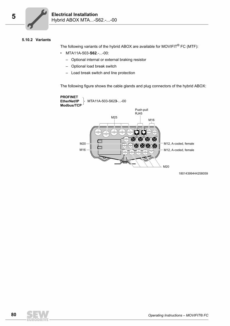
80 Operating Instructions – MOVIFIT® FC
5 Hybrid ABOX MTA...-S62.-...-00Electrical Installation
5.10.2 Variants
The following variants of the hybrid ABOX are available for MOVIFIT® FC (MTF):
• MTA11A-503-S62.-...-00:
– Optional internal or external braking resistor
– Optional load break switch
– Load break switch and line protection
The following figure shows the cable glands and plug connectors of the hybrid ABOX:
18014399444258059
M12, A-coded, female
M12, A-coded, female
M20
M16
Push-pullRJ45
PROFINETEtherNet/IPModbus/TCP
MTA11A-503-S623-...-00
M16
M20
M25

Operating Instructions – MOVIFIT® FC 81
5Hybrid ABOX MTA...-S62.-...-00Electrical Installation
5.10.3 Plug connector positions
The following figure shows the plug connectors of the hybrid ABOX:
NOTICEThe RJ45 socket can be damaged by inserting commercially available RJ45 patch ca-bles without push-pull connector housing.
Damage to the RJ45 socket.• Only plug suitable push-pull RJ45 mating connectors according to IEC PAS 61076-
3-117 into push-pull RJ45 sockets.• Never use commercially available RJ45 patch cables without push-pull connector
housing. These plug connectors do not snap in place when they are plugged. Theymay damage the socket and are therefore not suited.
3570215051
[1] X11 Ethernet interface, port 1(PROFINET, EtherNet/IP, Modbus/TCP)
(Push-pull RJ45, female)
[2] X12 Ethernet interface, port 2(PROFINET, EtherNet/IP, Modbus/TCP)
(Push-pull RJ45, female)
[3] X21 – X28 Binary inputs/outputs (M12, 5-pole, female, A-coded)
[4] X50 Diagnostic interface (RJ10, female, under the screw plug)
[3] X21 – X24
[3] X25 – X28
[4] X50
[1]X11
[2]X12
INFORMATION• The built-in M12 plug connectors have no specific alignment. This is why you
should only use straight M12 mating connectors.• You find the pin assignment of the plug connectors in the "Electrical Connections"
chapter.• To connect 2 sensors/actuators with an M12 plug connector, use the Y adapter with
extension cable, see chapter "Y adapter" (page 92).

82 Operating Instructions – MOVIFIT® FC
5 Hybrid ABOX MTA...-I55.-...-00, MTA...-G55.-...-00Electrical Installation
5.11 Hybrid ABOX MTA...-I55.-...-00, MTA...-G55.-...-00
5.11.1 DescriptionThe following figure shows the hybrid ABOX with:
• 1 round connector (Intercontec):
– Motor output pointing downward (only for MTA...-I55.-...-00)
– Motor output pointing forward (only for MTA...-G55.-...-00)
• M12 plug connectors for binary inputs/outputs
• M12 plug connectors for the fieldbus
INFORMATION• The hybrid ABOX is based on the standard ABOX MTA...-S02.-...-00. The following
therefore only describes the additional plug connectors in comparison with thestandard ABOX.
• For a description of the terminals, refer to chapter "Standard ABOX MTA...-S02.-...-00 (page 51).
• In contrast to the standard ABOX, the hybrid ABOXes MTA...-I55.-...-00 andMTA...-G55.-...-00 have no shield plates. Here, the cable shields must be con-nected via EMC cable glands.
• Customers cannot use terminal strips X8, X81, X25, X30 and X31 in the ABOX be-cause the described plug connectors are assigned to them.
9007204010651915
[2][1] [3]
X
X80
[2][1] [4][3] [5] [6]
X21
X25 X26 X27 X28
X22
X11X80 X12
X23 X24
MTA...-G55.-...-00MTA...-I55.-...-00
[1] Optional maintenance switch[2] PE connection[3] Plug connector for motor[4] M12 plug connector for binary inputs/outputs[5] Diagnostics socket (RJ10) under the screw plug[6] M12 plug connector for the fieldbus connection
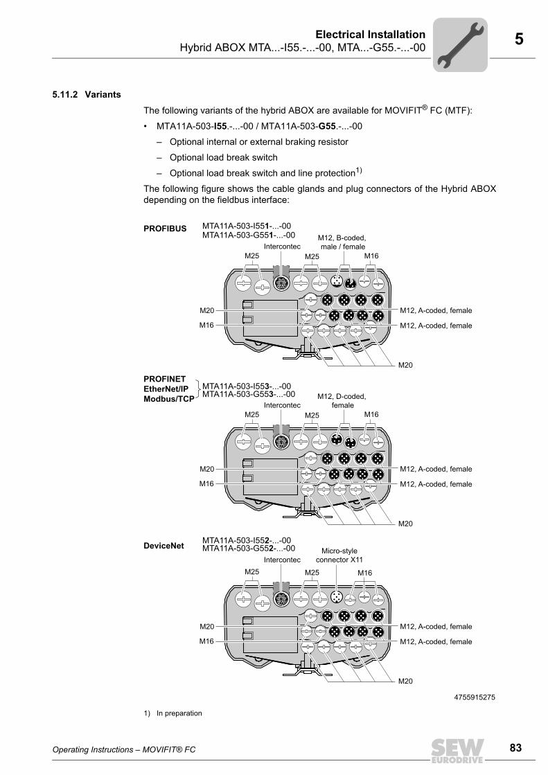
Operating Instructions – MOVIFIT® FC 83
5Hybrid ABOX MTA...-I55.-...-00, MTA...-G55.-...-00Electrical Installation
5.11.2 Variants
The following variants of the hybrid ABOX are available for MOVIFIT® FC (MTF):
• MTA11A-503-I55.-...-00 / MTA11A-503-G55.-...-00
– Optional internal or external braking resistor
– Optional load break switch
– Optional load break switch and line protection1)
The following figure shows the cable glands and plug connectors of the Hybrid ABOXdepending on the fieldbus interface:
1) In preparation
4755915275
M12, A-coded, female
M12, A-coded, female
M20
M16
M12, B-coded, male / female
M16
M20
M12, A-coded, female
M12, A-coded, female
M20
M16
M12, D-coded, female
M20
M12, A-coded, female
M12, A-coded, female
M20
M16
M16
Micro-styleconnector X11
PROFIBUS MTA11A-503-I551-...-00MTA11A-503-G551-...-00
PROFINETEtherNet/IPModbus/TCP
MTA11A-503-I553-...-00MTA11A-503-G553-...-00
DeviceNet MTA11A-503-G552-...-00MTA11A-503-I552-...-00
M16
M20
M25 M25Intercontec
M25 M25
Intercontec
M25 M25Intercontec

84 Operating Instructions – MOVIFIT® FC
5 Hybrid ABOX MTA...-I55.-...-00, MTA...-G55.-...-00Electrical Installation
5.11.3 Plug connector positionsThe following figure shows the plug connectors of the hybrid ABOX:
4758230795
[1] X11 PROFIBUS input (M12, 5-pole, male, B-coded)
[2] X12 PROFIBUS output (M12, 5-pole, female, B-coded)
[3] X11 Ethernet interface, port 1(PROFINET, EtherNet/IP, Modbus/TCP)
(M12, 4-pole, female, D-coded)
[4] X12 Ethernet interface, port 2(PROFINET, EtherNet/IP, Modbus/TCP)
(M12, 4-pole, female, D-coded)
[5] X11 DeviceNet interface (Micro-style connector, male, A-coded)
[6] X80 Motor connection (Intercontec 723 H-Tec, 7 + 3-pole, female)
[7] X21 – X28 Binary inputs/outputs (M12, 5-pole, female, A-coded)
[8] X50 Diagnostic interface (RJ10, female, under the screw plug)
DeviceNet:
[7] X21 – X24
[7] X25 – X28
[8] X50
[2] X12
[4] X12
[1] X11
[3] X11
PROFIBUS:
Ethernet:
[5] X11
MTA11A-503-G55.-...-00:
MTA11A-503-I55.-...-00:
[6] X80
[6] X80
INFORMATION• The built-in M12 plug connectors have no specific alignment. This is why you
should only use straight M12 mating connectors.• You find the pin assignment of the plug connectors in the "Electrical Connections"
chapter.• To connect 2 sensors/actuators with an M12 plug connector, use the Y adapter with
extension cable, see chapter "Y adapter" (page 92).

Operating Instructions – MOVIFIT® FC 85
5Hybrid ABOX MTA...-I65.-...-00, MTA...-G65.-...-00Electrical Installation
5.12 Hybrid ABOX MTA...-I65.-...-00, MTA...-G65.-...-00
5.12.1 DescriptionThe following figure shows the hybrid ABOX with:
• 1 round connector (Intercontec):
• Motor output pointing downward (only for MTA...-I65.-...-00)
• Motor output pointing forward (only for MTA...-G65.-...-00)
• M12 plug connectors for binary inputs/outputs
• Push-pull RJ45 plug connector for Ethernet connection
INFORMATION• The hybrid ABOX is based on the standard ABOX MTA...-S02.-...-00. The following
therefore only describes the additional plug connectors in comparison with thestandard ABOX.
• For a description of the terminals, refer to chapter "Standard ABOX MTA...-S02.-...-00 (page 51).
• In contrast to the standard ABOX, the hybrid ABOXes MTA...-I65.-...-00 andMTA...-G65.-...-00 have no shield plates. Here, the cable shields must be con-nected via EMC cable glands.
• Customers cannot use terminal strips X8, X81, X25, X30 and X31 in the ABOX be-cause the described plug connectors are assigned to them.
9007204012975883
[2][1] [3]
X80
[2][1] [4] [5] [6]
X21 X22 X23 X24
X25 X26 X27 X28
X11 X12
[3]
X80
MTA...-G65.-...-00MTA...-I65.-...-00
[1] Optional maintenance switch[2] PE connection[3] Plug connector for motor[4] M12 plug connector for binary inputs/outputs[5] Diagnostics socket (RJ10) under the screw plug[6] Push-pull RJ45 plug connector for Ethernet connection
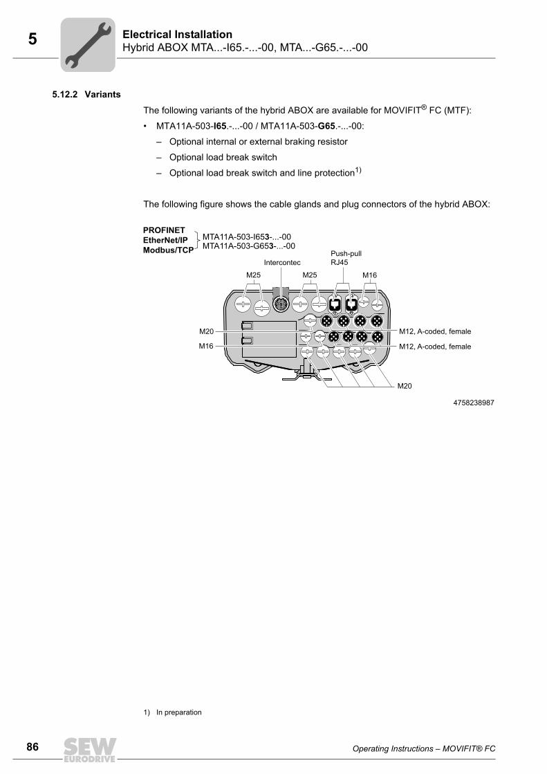
86 Operating Instructions – MOVIFIT® FC
5 Hybrid ABOX MTA...-I65.-...-00, MTA...-G65.-...-00Electrical Installation
5.12.2 Variants
The following variants of the hybrid ABOX are available for MOVIFIT® FC (MTF):
• MTA11A-503-I65.-...-00 / MTA11A-503-G65.-...-00:
– Optional internal or external braking resistor
– Optional load break switch
– Optional load break switch and line protection1)
The following figure shows the cable glands and plug connectors of the hybrid ABOX:
1) In preparation
4758238987
M12, A-coded, female
M12, A-coded, female
M20
M16
Push-pullRJ45
M16
M20
M25 M25
PROFINETEtherNet/IPModbus/TCP
MTA11A-503-I653-...-00MTA11A-503-G653-...-00
Intercontec

Operating Instructions – MOVIFIT® FC 87
5Hybrid ABOX MTA...-I65.-...-00, MTA...-G65.-...-00Electrical Installation
5.12.3 Plug connector positions
The following figure shows the plug connectors of the hybrid ABOX:
NOTICEThe RJ45 socket can be damaged by inserting commercially available RJ45 patch ca-bles without push-pull connector housing.
Damage to the RJ45 socket.• Only plug suitable push-pull RJ45 mating connectors according to IEC 61076-3-
117 into push-pull RJ45 sockets.• Never use commercially available RJ45 patch cables without push-pull connector
housing. These plug connectors do not snap in place when they are plugged. Theymay damage the socket and are therefore not suited.
4758511883
[1] X80 Motor connection (Intercontec 723 H-Tec, 7 + 3-pole, female)
[2] X11 Ethernet interface, port 1(PROFINET, EtherNet/IP, Modbus/TCP)
(Push-pull RJ45, female)
[3] X12 Ethernet interface, port 2(PROFINET, EtherNet/IP, Modbus/TCP)
(Push-pull RJ45, female)
[4] X21 – X28 Binary inputs/outputs (M12, 5-pole, female, A-coded)
[5] X50 Diagnostic interface (RJ10, female, under the screw plug)
[4] X21 – X24
[4] X25 – X28
[5] X50
[2]X11
[3]X12
MTA11A-503-G65.-...-00:
MTA11A-503-I65.-...-00:
[1] X80
[1] X80
INFORMATION• The built-in M12 plug connectors have no specific alignment. This is why you
should only use straight M12 mating connectors.• You find the pin assignment of the plug connectors in the "Electrical Connections"
chapter.• To connect 2 sensors/actuators with an M12 plug connector, use the Y adapter with
extension cable. See chapter "Y adapter" (page 92).

88 Operating Instructions – MOVIFIT® FC
5 Electrical connectionsElectrical Installation
5.13 Electrical connections5.13.1 Connection cables
Connection cables are not included in the scope of delivery.
Prefabricated cables for connection between SEW components can be ordered fromSEW-EURODRIVE at any time. They are described in the following sections. Specifythe part number and length of the required cable in your order.
The number and type of required connection cables depend on the design of the unitsand the components to be connected. This is why not all cables in the list are actuallyrequired.
The following figures show the various cable types:
Cables Length Installation type
Fixed length
Suitable for cable carrier installation
Not suitable for cable carrier installation
Variable length

Operating Instructions – MOVIFIT® FC 89
5Electrical connectionsElectrical Installation
5.13.2 X80: Motor connection
(ABOX MTA...I55.-..., MTA...G55.-..., MTA...I65.-..., MTA...G65.-...)The following table shows information about this connection:
FunctionMotor connection
Connection typeIntercontec 723 H-Tec, 7 + 3-pole, female (downward or to the front)
Wiring diagram
4312557451
AssignmentNo. Name FunctionPE PE PE connection
A U Motor phase U output
B V Motor phase V output
C W Motor phase W output
D 13 SEW brake 13 (red)
E 14 SEW brake 14 (white)
F 15 SEW brake 15 (blue)
1 +24 V Connection for temperature sensor TF/TH (+)
2 n.c. Not connected
3 TF - Connection for temperature sensor TF/TH (-)
PE
A
1
B
C2
D
E
3
F

90 Operating Instructions – MOVIFIT® FC
5 Electrical connectionsElectrical Installation
5.13.3 X21 – X28: Binary inputs/outputsVariants The number and assignment of binary inputs/outputs depends on
• the function level
• and the fieldbus interface of the MOVIFIT® unit.
I/O variant MOVIFIT® variantFunction level Fieldbus
12 DI + 4 DI/O
Technology
• PROFIBUS• PROFINET• EtherNet/IP• Modbus/TCP• DeviceNet
Classic• PROFINET• EtherNet/IP• Modbus/TCP
6 DI +2 DI/O Classic • PROFIBUS
• DeviceNet
4 DI None • SBus slave

Operating Instructions – MOVIFIT® FC 91
5Electrical connectionsElectrical Installation
Assignment The following table shows information about these connections:
FunctionBinary inputs/outputs of the hybrid ABOXConnection typeM12, 5-pole, female, A-codedWiring diagram
2264816267I/O variant Assignment
12 DI4 DI/O
No. X21 X22 X23(Encoder 1 connection)
X24(Encoder 2 connection)
1 VO24-I VO24-I VO24-II VO24-II2 DI01 DI03 DI05
Track BDI07Track B
3 0V24_C 0V24_C 0V24_C 0V24_C4 DI00 DI02 DI04
Track ADI06Track A
5 n.c. n.c. n.c. n.c.No. X25
(Encoder 3 connection)
X26 X27 X28
1 VO24-III VO24-III VO24-IV VO24-IV2 DI09
Track BDI11 DI13 / DO01 DI15 / DO03
3 0V24_C 0V24_C 0V24_S 0V24_S4 DI08
Track ADI10 DI12 / DO00 DI14 / DO02
5 n.c. n.c. n.c. n.c.
6 DI+ 2 DI/O
No. X21 X22 X23 X241 VO24-I VO24-I VO24-II VO24-II2 res. res. res. res.3 0V24_C 0V24_C 0V24_C 0V24_C4 DI00 DI01 DI02 DI035 n.c. n.c. n.c. n.c.No. X25 X26 X27 X281 VO24-III VO24-III VO24-IV VO24-IV2 res. res. res. res.3 0V24_C 0V24_C 0V24_S 0V24_S4 DI04 DI05 DI06 / DO00 DI07 / DO015 n.c. n.c. n.c. n.c.
4 DI
No. X21 X22 X23 - X281 VO24 VO24 res.2 DI101 DI103 res.3 0V24_C 0V24_C res.4 DI100 DI102 res.5 n.c. n.c. res.
1
4 3
2
5
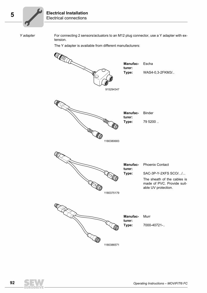
92 Operating Instructions – MOVIFIT® FC
5 Electrical connectionsElectrical Installation
Y adapter For connecting 2 sensors/actuators to an M12 plug connector, use a Y adapter with ex-tension.
The Y adapter is available from different manufacturers:
915294347
Manufac-turer:
Escha
Type: WAS4-0,3-2FKM3/..
1180380683
Manufac-turer:
Binder
Type: 79 5200 ..
1180375179
Manufac-turer:
Phoenix Contact
Type: SAC-3P-Y-2XFS SCO/.../...
The sheath of the cables ismade of PVC. Provide suit-able UV protection.
1180386571
Manufac-turer:
Murr
Type: 7000-40721-..

Operating Instructions – MOVIFIT® FC 93
5Electrical connectionsElectrical Installation
5.13.4 X11: PROFIBUS input
(ABOX MTA...S52.-..., MTA...I55.-..., MTA...G55.-...)The following table shows information about this connection:
5.13.5 X12: PROFIBUS output(ABOX MTA...S52.-..., MTA...I55.-..., MTA...G55.-...)The following table shows information about this connection:
FunctionPROFIBUS input
Connection type(M12, 5-pole, male, B-coded)
Wiring diagram
2461813259
AssignmentNo. Name Function1 res. Reserved
2 A_IN PROFIBUS data line A
3 res. Reserved
4 B_IN PROFIBUS data line B
5 res. Reserved
43
2
5
1
FunctionPROFIBUS output
Connection type(M12, 5-pole, female, B-coded)
Wiring diagram
2461813259
AssignmentNo. Name Function1 +5V DC 5 V output
2 A_OUT PROFIBUS data line A
3 0V5 0V5 reference potential
4 B_OUT PROFIBUS data line B
5 res. Reserved
4 3
2
5
1

94 Operating Instructions – MOVIFIT® FC
5 Electrical connectionsElectrical Installation
5.13.6 X11: DeviceNet interface(ABOX MTA...S52.-..., MTA...I55.-..., MTA...G55.-...)The following table shows information about this connection:
5.13.7 X11, X12: Ethernet interface(ABOX MTA...S52.-..., MTA...S53.-..., MTA...I55.-..., MTA...G55.-...)The following table shows information about this connection:
FunctionDeviceNet interface
Connection type(Micro style connector, male, A-coded)
Wiring diagram
2264818187
AssignmentNo. Name Function1 Drain Shield/equipotential bonding
2 V+ DC 24 V input
3 V- Reference potential
4 CAN_H CAN data line (high)
5 CAN_L CAN data line (low)
2 1
543
Function• PROFINET IO interface• EtherNet/IP interface• Modbus/TCP interface
Connection typeM12, 4-pole, female, D-coded
Wiring diagram
2464600971
AssignmentNo. Name Function1 TX+ Transmit line (+)
2 RX+ Receive line (+)
3 TX- Transmit line (-)
4 RX- Receive line (-)
2
4
31
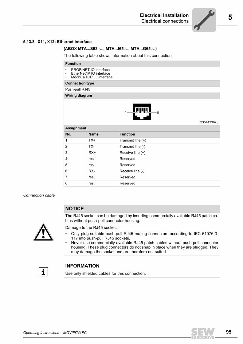
Operating Instructions – MOVIFIT® FC 95
5Electrical connectionsElectrical Installation
5.13.8 X11, X12: Ethernet interface(ABOX MTA...S62.-..., MTA...I65.-.., MTA...G65.-..)The following table shows information about this connection:
Connection cable
Function• PROFINET IO interface• EtherNet/IP IO interface• Modbus/TCP IO interface
Connection typePush-pull RJ45
Wiring diagram
2354433675
AssignmentNo. Name Function1 TX+ Transmit line (+)
2 TX- Transmit line (-)
3 RX+ Receive line (+)
4 res. Reserved
5 res. Reserved
6 RX- Receive line (-)
7 res. Reserved
8 res. Reserved
1 8
NOTICEThe RJ45 socket can be damaged by inserting commercially available RJ45 patch ca-bles without push-pull connector housing.
Damage to the RJ45 socket.• Only plug suitable push-pull RJ45 mating connectors according to IEC 61076-3-
117 into push-pull RJ45 sockets.• Never use commercially available RJ45 patch cables without push-pull connector
housing. These plug connectors do not snap in place when they are plugged. Theymay damage the socket and are therefore not suited.
INFORMATIONUse only shielded cables for this connection.
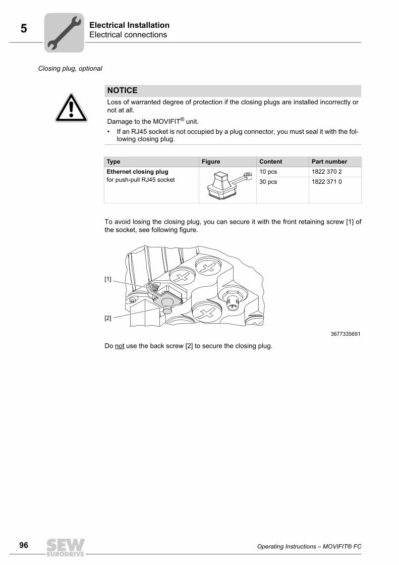
96 Operating Instructions – MOVIFIT® FC
5 Electrical connectionsElectrical Installation
Closing plug, optional
To avoid losing the closing plug, you can secure it with the front retaining screw [1] ofthe socket, see following figure.
Do not use the back screw [2] to secure the closing plug.
NOTICELoss of warranted degree of protection if the closing plugs are installed incorrectly ornot at all.
Damage to the MOVIFIT® unit.• If an RJ45 socket is not occupied by a plug connector, you must seal it with the fol-
lowing closing plug.
Type Figure Content Part numberEthernet closing plugfor push-pull RJ45 socket
10 pcs 1822 370 2
30 pcs 1822 371 0
3677335691
[1]
[2]

Operating Instructions – MOVIFIT® FC 97
5Electrical connectionsElectrical Installation
5.13.9 X30, X31: PROFINET POF interface
(ABOX MTA...S533-...-00/L10)The following table shows information about this connection:
5.13.10 X13: DC 24 V supply(ABOX MTA...S533-...-00/L10)The following table shows information about this connection:
FunctionPROFINET interface SCRJ / POF (at POF option L10)
Connection typePush-pull SCRJ
Wiring diagram
3419100299
AssignmentNo. Name Function1 TX Transmitting line (POF)
2 RX Receiving line (POF)
1 2
FunctionDC 24 V supply of POF option L10 (at the ABOX, plugged at the factory)
Connection typeM12, 5-pole, female, A-coded
Wiring diagram
2264816267
AssignmentNo. Name Function1 +24V_C 24 V supply
2 res. Reserved
3 0V24_C Reference potential
4 res. Reserved
5 res. Reserved
1
4 3
2
5

98 Operating Instructions – MOVIFIT® FC
5 Encoder connectionElectrical Installation
5.14 Encoder connection5.14.1 NV26 proximity sensorProperties The NV26 proximity sensor offers the following features:
• 2 sensors with 6 pulses/revolution
• 24 increments/revolution with 4-fold evaluation
• Encoder monitoring and evaluation is possible with MOVIFIT® function level "Tech-nology".
There must be a 45° angle between the sensors.
Installation • Use shielded cables to connect the NV26 proximity sensor to the matching encoderinputs of MOVIFIT®.
– For standard ABOX, see chapter "Terminal assignment" / "X25: I/O terminals".
– For hybrid ABOX, see chapter "Electrical Connections" / "X21 – X28: binary in-puts/outputs".
Wiring diagram
940059275[1] Encoder input MOVIFIT® track B[2] Encoder input MOVIFIT® track A
NV26
DI01
DI00
DI02
DI03
DI04
DI05
DI06/D
O00
DI07/D
O01
SYS-F
BU
S-F
24V-C
24V-S
RU
N
RU
N-P
S
MOVIFIT®
[2][1]
940197899[1] +24 V supply voltage [2] 0V24 reference potential [3] Encoder input MOVIFIT® track A or track B
3 PNP
1
2 4
NV26
B
(GND)[1]
[2]
[3](A / B)
(U )
DI01
DI00
DI02
DI03
DI04
DI05
DI06/DO00DI07/DO01SYS-FBUS-F
24V-C24V-SRUNRUN-PS
MOVIFIT®

Operating Instructions – MOVIFIT® FC 99
5Encoder connectionElectrical Installation
5.14.2 ES16 incremental encoderProperties The ES 16 incremental encoder offers the following features:
• 6 pulses/revolutions for each track
• 24 increments/revolution with 4-fold evaluation
• Encoder monitoring and evaluation is possible with MOVIFIT® function level "Tech-nology".
Installation • Use a shielded cable to connect the ES16 incremental encoder to the matching en-coder inputs of MOVIFIT®.
– For standard ABOX, see chapter "Terminal assignment" / "X25: I/O terminals".
– For hybrid ABOX, see chapter "Electrical Connections" / "X21 – X28: binary in-puts/outputs".
Wiring diagram
940193803
ES16
DI01
DI00
DI02
DI03
DI04
DI05
DI06/D
O00
DI07/D
O01
SYS-F
BU
S-F
24V-C
24V-S
RU
N
RU
N-P
S
MOVIFIT®
940061195[1] Encoder input MOVIFIT® track A[2] Encoder input MOVIFIT® track B[3] +24 V supply voltage[4] 0V24 reference potential
[1]
[2]
[3]
[4]
A (K1)
B (K2)
UB
ES16
UB K1 K2 K0 K1 K2 K0
UB A B
DI01
DI00
DI02
DI03
DI04
DI05
DI06/D
O00
DI07/D
O01
SYS-F
BU
S-F
24V-C
24V-S
RU
N
RU
N-P
S
MOVIFIT®

100 Operating Instructions – MOVIFIT® FC
5 Encoder connectionElectrical Installation
5.14.3 EI7. incremental encoder Properties The EI7. incremental encoder offers the following features:
• HTL or sin/cos interface (MOVIFIT® does not evaluate sin/cos signals)
• Encoder monitoring and evaluation is possible with MOVIFIT® function level "Tech-nology".
Installation • Use a shielded cable to connect the EI7. incremental encoder to the matching en-coder inputs of MOVIFIT®.
– For standard ABOX, see chapter "Terminal assignment" / "X25: I/O terminals".
– For hybrid ABOX, see chapter "Electrical Connections" / "X21 – X28: binary in-puts/outputs".
Wiring diagram
• EI71: 1 pulse/revolution => 4 increments/revolution1)
EI72: 2 pulses/revolution => 8 increments/revolution1)
EI76: 6 pulses/revolution => 24 increments/revolution1)
EI7C: 24 pulses/revolution => 96 increments/revolution1)
1) due to 4-fold evaluation
995367179
EI7.
DI01
DI00
DI02
DI03
DI04
DI05
DI06/D
O00
DI07/D
O01
SYS-F
BU
S-F
24V-C
24V-S
RU
N
RU
N-P
S
MOVIFIT®
991622027[1] +24 V supply voltage[2] 0V24 reference potential[3] Encoder input MOVIFIT® track A[4] Encoder input MOVIFIT® track B
[1]
[2]
[3]
[4]
5 : +UB
6 : GND
7 : A
9 : B
EI7.
10987654321
DI01
DI00
DI02
DI03
DI04
DI05
DI06/D
O00
DI07/D
O01
SYS-F
BU
S-F
24V-C
24V-S
RU
N
RU
N-P
S
MOVIFIT®
1 10

Operating Instructions – MOVIFIT® FC 101
5Power bus connection examplesElectrical Installation
5.15 Power bus connection examples5.15.1 Connection example with a common 24 V voltage circuit
The following figure depicts a basic connection example for the power bus with a com-mon 24 V voltage circuit for sensor/actuator supply. In the example, the integrated fre-quency inverter is supplied by the voltage 24V_C:
5.15.2 Connection example with two separate 24 V voltage circuitsThe following figure depicts a basic connection example for the power bus with two sep-arate 24 V voltage circuits for sensor/actuator supply. In the example, the integrated fre-quency inverter is supplied by the voltage 24V_C:
9007200067298699
[1] Example (fuse 24 V / 4 A) for UL-compliant installation[2] Example for integrated frequency inverter supply via 24V_C
1 2 3 4 5 6 11 12 13 14 15 16
1 2 3 4 11 12 13 14
PE
L1 L2 L3 PE
L1 L2 L3
L3L2L1PE
L3L2L1PE
X1
1 2 3 4 5 6 7 8 11 12 13 14 15 16 17 18X29
X20
MOVIFIT®-FC
FE+24V
0V24V
FE+24V 0V24V
11 12 13 14 15 1618
17
5
121
34
67 8
X1
X29
X20
[2][1]
24V/4A
9007200067300363
[1] Example (fuse 24 V / 4 A) for UL-compliant installation[2] Example for integrated frequency inverter supply via 24V_C
1 2 3 4 5 6 11 12 13 14 15 16
1 2 3 4 11 12 13 14
PE
L1 L2 L3 PE
L1 L2 L3
L3L2L1PE
L3
L2
L1
PE
0V24V_C
FE+24V_C0V24V_C
+24V_S0V24V_S
FE
X1
1 2 3 4 5 6 7 8 11 12 13 14 15 16 17 18X29
X20
[2][1]
MOVIFIT®-FC
11 12 13 14 15 1618
17
5
121
34
67 8
X1
X29
X20
FE+24V_C
+24V_S0V24V_S
FE
24V/4A

102 Operating Instructions – MOVIFIT® FC
5 Fieldbus systems connection examplesElectrical Installation
5.16 Fieldbus systems connection examples5.16.1 PROFIBUS via terminals
The following illustration shows the PROFIBUS connection via terminals:
• If the MOVIFIT® unit is located at the end of a PROFIBUS segment, the unit can onlybe connected to the PROFIBUS network via the incoming PROFIBUS line.
• To prevent malfunctions in the bus system due to reflections, etc., the PROFIBUSsegment must be terminated using bus terminating resistors at the first and last sta-tions.
• The bus terminating resistors are already installed in the MOVIFIT® ABOX and canbe activated using switch S1.
INFORMATIONThe example applies for the following ABOXes:• Standard ABOX MTA...-S02.-...-00• Hybrid ABOX MTA...-S42.-...-00
812474507
[1] DIP switch S1 = "ON" for bus termination[2] Shield plate, see chapter "Connecting the PROFIBUS line" (page 55)
MOVIFIT®
X30
S1
MOVIFIT®
X30
S1[1][1]
MOVIFIT®
A_INX30
X31 X31 X31
B_IN
A_OUTB_OUT
123
123
123
123
123
123
[2] [2] [2] [2] [2]
PROFIBUS DP PROFIBUS DP PROFIBUS DP
IN
OUT
IN
OUT
IN
OUT
S1[1]
AB
A_INB_IN
A_OUTB_OUT
A_INB_IN
A_OUTB_OUT
ON

Operating Instructions – MOVIFIT® FC 103
5Fieldbus systems connection examplesElectrical Installation
5.16.2 PROFIBUS via M12 plug connectors
The following figure shows the basic connection topology for PROFIBUS via M12 plugconnectors:
• For the PROFIBUS connection, the ABOXes have M12 plug connectors. They com-ply with the recommendations of PROFIBUS directive no. 2.141 "Connection tech-nology for PROFIBUS".
• To prevent malfunctions in the bus system due to reflections, etc., the PROFIBUSsegment must be terminated using bus terminating resistors at the first and last sta-tions.
• The bus terminating resistors are already installed in the MOVIFIT® ABOX and canbe activated using switch S1.
INFORMATIONThe example applies for the following ABOX:• Hybrid ABOX MTA...-S52.-...-00• Hybrid ABOX MTA...-I65.-...-00• Hybrid ABOX MTA...-G55.-...-00
9007200067225483
[1] Bus terminating resistor on the controller[2] DIP switch S1 = "ON" for bus termination
MOVIFIT® MOVIFIT® MOVIFIT®
PROFIBUS DP
[1]
S1[2]
ON
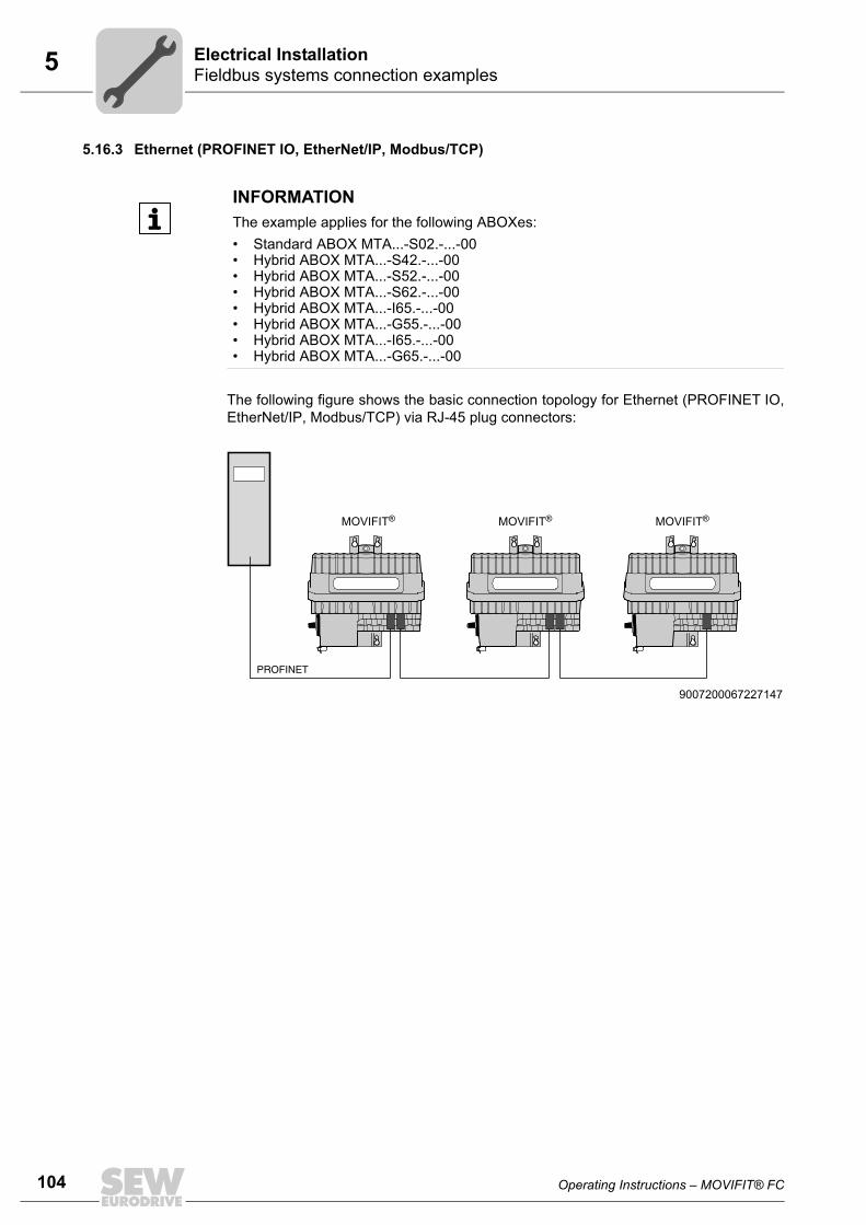
104 Operating Instructions – MOVIFIT® FC
5 Fieldbus systems connection examplesElectrical Installation
5.16.3 Ethernet (PROFINET IO, EtherNet/IP, Modbus/TCP)
The following figure shows the basic connection topology for Ethernet (PROFINET IO,EtherNet/IP, Modbus/TCP) via RJ-45 plug connectors:
INFORMATIONThe example applies for the following ABOXes:• Standard ABOX MTA...-S02.-...-00• Hybrid ABOX MTA...-S42.-...-00• Hybrid ABOX MTA...-S52.-...-00• Hybrid ABOX MTA...-S62.-...-00• Hybrid ABOX MTA...-I65.-...-00• Hybrid ABOX MTA...-G55.-...-00• Hybrid ABOX MTA...-I65.-...-00• Hybrid ABOX MTA...-G65.-...-00
9007200067227147
MOVIFIT® MOVIFIT® MOVIFIT®
PROFINET

Operating Instructions – MOVIFIT® FC 105
5Hybrid cablesElectrical Installation
5.17 Hybrid cables5.17.1 Overview
Hybrid cables are available for connecting MOVIFIT® FC and motors. The followingtable shows the available hybrid cables:
MOVIFIT® FC Hybrid cable Length Cable type
Drive
Standard ABOX:
MTA...-S02.-...-00
Hybrid ABOX:
MTA...-S42.-...-00
MTA...-S52.-...-00
MTA...-S62.-...-00
Part No. DR63 / DT71-90 ():Part No. DR63 / DT71-90 ():Part No. DV100, DV112 DR.71-132 ():Part No. DV100, DV112 DR.71-132 ():
0819 967 10819 969 80819 970 10819 874 8
Variable A Motor with ISU4 (02CI) plug connector
Part No.: 0819 972 8 Variable A Motor with ASB4 (BA01AB04DA) plug con-nector
Part No.: 0819 875 6 Variable A Motor with plug connectorAMB4 (MA01AB04DA)
Part No.: 0819 973 6 Variable A Motor with APG4 plug con-nector
Part No. DR.71-100 (M4 ring cable lug):Part No. DR.112-132 (M5 ring cable lug):
0819 975 21814 319 9
Variable A Motor with cable glands
Part No.: 0817 953 0 / 30 mPart No.: 0817 953 0 / 100 m
(Hybrid cable roll)
30 m100 m
A Motor with cable glandsDAS ASEPTIC motor
Part No.: 1172 378 5 (cable roll) 30 m - External braking resistor

106 Operating Instructions – MOVIFIT® FC
5 Hybrid cablesElectrical Installation
MOVIFIT® FC Hybrid cable Length Cable type
Drive
Hybrid ABOX:
MTA...-I55.-...-00MTA...-G55.-...-00MTA...-I65.-...-00MTA...-G65.-...-00
Part No. DR63 ():Part No. DR63 ():Part No. DR.71-132 ():Part No. DR.71-132 ():
1813 841 11813 843 81813 833 01813 836 5
Variable A Motor with ISU4 (02CI) plug connector
Part No. DR.71-100 (M4 ring cable lug)Part No. DR.112-132 (M5 ring cable lug)
1814 187 01814 223 0
Variable A Motor with cable glands
Part No.: 1814 105 6 (= Extension cable) Variable A Hybrid cable

Operating Instructions – MOVIFIT® FC 107
5Hybrid cablesElectrical Installation
5.17.2 Hybrid cable connectionWith open cable end (MOVIFIT® end) and plug con-nector (motor end)
The table shows the assignment of the following hybrid cables:
• Part number: 0819 967 1
0819 969 8
0819 970 1
0819 874 8
• Part number: 0819 972 8
• Part number: 0819 875 6
• Part number: 0819 973 6
MOVIFIT® FC connecting terminal Hybrid cableColor coding/marking
X8/1 Green/yellow
X8/2 Black/U1
X8/3 Black/V1
X8/4 Black/W1
X8/5 Blue/15
X8/6 White/14
X8/7 Red/13
X81/1 Black/1
X81/2 Black/2
The inner shield is connected via a shield plate, and the overall shield is connected via an EMC cable gland to the housing of the MOVIFIT® ABOX, see chapter "Connecting the hybrid cables" (page 56).
Shield end
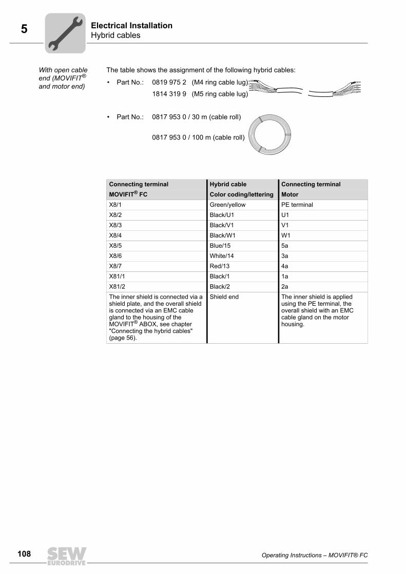
108 Operating Instructions – MOVIFIT® FC
5 Hybrid cablesElectrical Installation
With open cable end (MOVIFIT® and motor end)
The table shows the assignment of the following hybrid cables:
• Part No.: 0819 975 2 (M4 ring cable lug)
1814 319 9 (M5 ring cable lug)
• Part No.: 0817 953 0 / 30 m (cable roll)
0817 953 0 / 100 m (cable roll)
Connecting terminal Hybrid cable Connecting terminalMOVIFIT® FC Color coding/lettering MotorX8/1 Green/yellow PE terminal
X8/2 Black/U1 U1
X8/3 Black/V1 V1
X8/4 Black/W1 W1
X8/5 Blue/15 5a
X8/6 White/14 3a
X8/7 Red/13 4a
X81/1 Black/1 1a
X81/2 Black/2 2a
The inner shield is connected via a shield plate, and the overall shield is connected via an EMC cable gland to the housing of the MOVIFIT® ABOX, see chapter "Connecting the hybrid cables" (page 56).
Shield end The inner shield is applied using the PE terminal, the overall shield with an EMC cable gland on the motor housing.

Operating Instructions – MOVIFIT® FC 109
5Hybrid cablesElectrical Installation
Plug connector (MOVIFIT® end) and open cable end (motor end)
The table shows the assignment of the following hybrid cables:
• Part No.: 1814 187 0 (M4 ring cable lug)
1814 223 0 (M5 ring cable lug)
Hybrid cable Connecting terminalColor coding/lettering MotorGreen/yellow PE terminal
Black/U1 U1
Black/V1 V1
Black/W1 W1
Blue/15 5a
White/14 3a
Red/13 4a
Black/1 1a
Black/2 2a
Shield end The inner shield is applied using the PE terminal, the overall shield with an EMC cable gland on the motor housing.

110 Operating Instructions – MOVIFIT® FC
5 Wiring notesElectrical Installation
5.18 Wiring notes5.18.1 Wiring notes for connecting the motor
• The motor phases U, V, W must be connected correctly to the terminals X8 / X81 ofthe ABOX so that the motor runs in the desired direction. The motor and temperaturesensor must be connected to terminals X8 and X81 of the ABOX.
WARNING Risk of crushing due to reversed motor phases. Incorrect connectionof the motor phases will result in a wrong direction of rotation of the motor and/or un-controlled motor startup.
Severe or fatal injuries.
– Check the wiring before starting the motor.
5.18.2 Wiring notes for brakes• Brakes with voltages below 40 V cannot be used in connection with MOVIFIT® FC.
• With SEW motors, the brake must be connected to the brake connection terminalsof the ABOX without any other measures (no brake rectifier). This requires connect-ing an SEW brake for a voltage of 110 V, 120 V, 230 V, or 400 V.
• Non-SEW motors with a brake can be controlled with binary output DB00 and appro-priate additional measures (e.g. brake rectifier).
WARNING Risk of crushing due to incorrect parameterization of the binary outputDB00.
Severe or fatal injuries.
• If binary output DB00 is used to control the brake, do not change the parametersthat define the functions of the binary output.
• Check the parameter settings before using the binary output to control the brake.

Operating Instructions – MOVIFIT® FC 111
5Wiring checkElectrical Installation
5.19 Wiring checkBefore connecting the system to the power source for the first time, you must perform awiring check to prevent damage to persons, systems, and equipment caused by incor-rect wiring:
• Remove the EBOX from the ABOX
• Check the insulation of the wiring in accordance with applicable national standards
• Check the grounding.
• Check the insulation between the supply system cable and the DC 24 V cable.
• Check the insulation between the supply system cable and the communication cable.
• Check the polarity of the DC 24 V cable
• Check the polarity of the communication line
• Ensure equipotential bonding between the MOVIFIT® units
5.19.1 After the wiring check• Push the EBOX onto the ABOX and screw it on
• Seal all cable openings and plug connections that are not in use.

112 Operating Instructions – MOVIFIT® FC
6 General informationStartup
6 Startup6.1 General information
INFORMATIONYou must comply with the general safety notes in chapter "Safety Notes" duringstartup.
WARNINGElectric shock due to dangerous voltages in the ABOX.
Severe or fatal injuries.• Before removing or installing the EBOX, de-energize the MOVIFIT® unit using a
suitable external cut-off device.• Wait for at least 1 minute before removing the EBOX.
WARNINGDanger of burns due to hot surfaces of the MOVIFIT® unit.
Severe injuries.• Do not touch the MOVIFIT® until it has cooled down sufficiently.
WARNINGUncontrolled unit behavior due to ineffective emergency stop circuit.
Severe or fatal injuries.• Comply with the installation notes.• The installation must only be carried out by qualified personnel.
WARNINGUnit malfunction due to incorrect unit setting.
Severe or fatal injuries.• Observe the startup notes.• The installation must only be carried out by qualified personnel.• Check the parameters and data sets. • Use only settings that are consistent with the function.
NOTICEDanger due to arcing.
Damage to electrical components.• Do not unplug the power connectors during operation. Do not plug in the power
connectors during operation.• Never remove the MOVIFIT® EBOX during operation.
INFORMATIONTo ensure fault-free operation, do not disconnect or connect the signal cables duringoperation.
00
I

Operating Instructions – MOVIFIT® FC 113
6RequirementsStartup
6.2 RequirementsThe following conditions apply to startup:• MOVIFIT® and the drive units must be installed correctly both mechanically and elec-
trically.
• Appropriate safety measures prevent the drives from starting up unintentionally.
• Appropriate safety measures must be taken to prevent risk of injury or damage to themachine.
The following hardware is required for startup:• PC or laptop
• Interface adapter
• Connection cable between PC and MOVIFIT®
The following software is required on the PC or laptop:• MOVITOOLS® MotionStudio version 5.60 and higher.
6.3 Description of the DIP switches
6.3.1 DIP switch S1Bus terminating resistor for PROFIBUS• DIP switch S1 = OFF: Bus terminating resistor is not active.
• DIP switch S1 = ON: Bus terminating resistor is active.
INFORMATIONFor information about the position of DIP switches S10 and S11, refer to the "EBOX"chapter.
For information about the position of DIP switches S1, S2 and S3, refer to the "ABOX"chapter.
NOTICEHazard caused by unsuitable tools.
Damage to the DIP switches.• To set the DIP switches use only suitable tools, such as a slotted screwdriver with
a blade width smaller than 3 mm.• The force used for setting the DIP switches must not exceed 5 N.
00
I

114 Operating Instructions – MOVIFIT® FC
6 Description of the DIP switchesStartup
6.3.2 DIP switch S2
The function of DIP switch S2 depends on the type of fieldbus.
Function of DIP switch S2 for PROFIBUS
PROFIBUS addressYou can set the PROFIBUS address at the DIP switches S2/1 – S2/7.
Function of DIP switch S2 for DeviceNet
DeviceNet address (MAC ID) and baud rateYou can set the DeviceNet address (MAC ID) at the DIP switches S2/1 – S2/6.
You can set the DeviceNet baud rate at the DIP switches S2/7 – S2/8.
9007200092252555[1][2]
Example: Address 17Switch 8 = Reserved
Addresses 1 to 125: Addresses 0, 126, 127:
valid addressesare not supported
S2
20 x 1 = 121 x 0 = 022 x 0 = 023 x 0 = 0
25 x 0 = 026 x 0 = 0
24 x 1 = 16
17[2]
[1]
ON
12
34
56
78
9007200092311435[1] DeviceNet address setting[2] Baud rate setting
S2
20 x 1 = 121 x 0 = 022 x 0 = 0
24 x 0 = 023 x 1 = 8
25 x 0 = 0
21 x 1 = 220 x 0 = 0
9
[1]
2[2]
ON1
23
45
67
8
00
I

Operating Instructions – MOVIFIT® FC 115
6Description of the DIP switchesStartup
6.3.3 DIP switch S3
Bus terminating resistor for SBus• DIP switch S3 = OFF: Bus terminating resistor is not active.
• DIP switch S3 = ON: Bus terminating resistor is active.
6.3.4 DIP switch S10You can set the unit parameters at the DIP switches S10/2 – S10/6.
9007203904936587
S10 1 2 3 4 5 6Meaning Startup
modeOperat-
ing modeMotor/brake
typeMotor con-
nection typeMotor power
Hoist
ON Expert mode V/f
Motor type 2 / optional brake
DeltaOne power
rating lower
VFC & Hoist
OFF Easy mode
VFC oper-ation (only for 4-pole
SEW motors)
Motor 1 / standard
brakeStar Adjusted S10/2
active
ON
1 2 3 4 5 6
S10
00
I

116 Operating Instructions – MOVIFIT® FC
6 Description of the DIP switchesStartup
DIP switch S10/1
Startup mode• DIP switch S10/2 = ON: Expert mode
In "Expert" startup mode, an extended scope of parameters is available. You can usethe MOVITOOLS® MotionStudio software to adjust the parameters to the application.
• DIP switch S10/2 = OFF: Easy mode
When selecting the "Easy" startup mode, you can start up MOVIFIT® quickly andeasily using DIP switches S10/2 – S10/6.
DIP switch S10/2
Operating mode• DIP switch S10/2 = ON: V/f operation for other motors
• DIP switch S10/2 = OFF: VFC operation for 4-pole motors
DIP switch S10/3
Motor/brake type• When you are using IEC or NEMA motors (DT/DV), DIP switch S10/3 must always
be set to OFF.
• For DX/DZ motors with rated voltages of 220/380 V, 60 Hz (only available in Brazil),and for aseptic motors (DAS), DIP switch S10/3 must be set to ON.
• When you are using DR motors with MOVIFIT® standard brakes, DIP switch S10/3must always be set to OFF.
• When you are using DR motors with option brakes, DIP switch S10/3 must alwaysbe set to ON.
DIP switch S10/4
Motor connection type• DIP switch S10/4 = ON: You must select this setting if the motor is operated in delta
connection (refer to the tables on the following pages).
• DIP switch S10/4 = OFF: You must select this setting if the motor is operated in starconnection (refer to the tables on the following pages).
00
I

Operating Instructions – MOVIFIT® FC 117
6Description of the DIP switchesStartup
DIP switch S10/5
Lower motor power rating• When activated, this DIP switch enables MOVIFIT® to be assigned to a motor with a
lower power rating. The nominal unit power is not affected.
• When using a motor with a lower power rating, the MOVIFIT® unit is one power levelabove the motor. This is why you can increase the overload capacity of the drive. Ahigher current can be provided briefly, leading to higher torque ratings.
• The aim of switch S10/5 is to achieve short-term utilization of the motor's peaktorque. The unit's current level remains the same regardless of the switch setting.Blocking protection for the motor is adjusted depending on the switch position.
• When DIP switch S10/5 is activated, the motor cannot be operated with stall protec-tion.
DT / DV V = AC 3 x 400 V, 50 HzMOVIFIT® Assigned DT/DV motor and brake1)
S10/5 = OFF S10/5 = ON
connection connection connection connection
Motor Brake Motor Brake Motor Brake Motor Brake
MTF..003..00 DT71D4 BMG05 DR63L4 BR03 DR63L4 BR03 - -
MTF..005..00 DT80K4 BMG1 DT71D4 BMG05 DT71D4 BMG05 DR63L4 BR03
MTF..007..00 DT80N4 BMG1 DT80K4 BMG1 DT80K4 BMG1 DT71D4 BMG05
MTF..011..00 DT90S4 BMG2 DT80N4 BMG1 DT80N4 BMG1 DT80K4 BMG1
MTF..015..00 DT90L4 BMG2 DT90S4 BMG2 DT90S4 BMG2 DT80N4 BMG1
MTF..022..00 DV100M4 BMG4 DT90L4 BMG2 DT90L4 BMG2 DT90S4 BMG2
MTF..030..00 DV100L4 BMG4 DV100M4 BMG4 DV100M4 BMG4 DT90L4 BMG2
MTF..040..00 DV112M4 BMG8 DV100L4 BMG4 DV100L4 BMG4 DV100M4 BMG4
1) Possible brake voltages: 110 V, 230 V, 400 V
DAS V = AC 3 x 400 V, 50 HzMOVIFIT® Assigned DAS motor and brake1)
S10/5 = OFF S10/5 = ON
connection connection connection connection
Motor Brake Motor Brake Motor Brake Motor Brake
MTF..003..01 DAS80N4 BR1 DAS80K4 BR1 DAS80K4 BR1 - -
MTF..005..01 DAS90S4 BR2 DAS80N4 BR1 DAS80N4 BR1 DAS80K4 BR1
MTF..007..01 DAS90L4 BR2 DAS90S4 BR2 DAS90S4 BR2 DAS80N4 BR1
MTF..011..01 DAS100M4 BR2 DAS90L4 BR2 DAS90L4 BR2 DAS90S4 BR2
MTF..015..01 DAS100L4 BR2 DAS100M4 BR2 DAS100M4 BR2 DAS90L4 BR2
MTF..022..01 - - DAS100L4 BR2 DAS100L4 BR2 DAS100M4 BR2
MTF..030..01 - - - - - - DAS100L4 BR2
MTF..040..01 - - - - - - - -
1) Possible brake voltages: BR1 : 230 V, BR2: 230 V and 400 V
00
I

118 Operating Instructions – MOVIFIT® FC
6 Description of the DIP switchesStartup
DRS V = AC 3 x 400 V, 50 HzMOVIFIT® Assigned DRS motor and brake1)
S10/5 = OFF S10/5 = ON
connection connection connection connection
Motor Brake Motor Brake Motor Brake Motor Brake
Stan-dard
Option Stan-dard
Option Stan-dard
Option Stan-dard
Option
MTF..003..10 DRS71 S4
BE05 BE1 DR63 L4
BR03 - DR63 L4
BR03 - - - -
MTF..005..10 DRS71 M4
BE1 BE05 DRS71 S4
BE05 BE1 DRS71 S4
BE05 BE1 DR63 L4
BR03 -
MTF..007..10 DRS80 S4
BE1 BE05 DRS71 M4
BE1 BE05 DRS71 M4
BE1 BE05 DRS71 S4
BE05 BE1
MTF..011..10 DRS80 M4
BE2 BE1 DRS80 S4
BE1 BE05 DRS80 S4
BE1 BE05 DRS71 M4
BE1 BE05
MTF..015..10 DRS90 M4
BE2 BE1 DRS80 M4
BE2 BE1 DRS80 M4
BE2 BE1 DRS80 S4
BE1 BE05
MTF..022..10 DRS90 L4
BE5 BE2 DRS90 M4
BE2 BE1 DRS90 M4
BE2 BE1 DRS80 M4
BE2 BE1
MTF..030..10 DRS100M4
BE5 BE2 DRS90 L4
BE5 BE2 DRS90 L4
BE5 BE2 DRS90 M4
BE2 BE1
MTF..040..10 DRS100 LC4
BE5 BE2 DRS100 M4
BE5 BE2 DRS100 M4
BE5 BE2 DRS90 L4
BE5 BE2
1) Possible brake voltages: 120 V, 230 V, 400 V
DRE V = AC 3 x 400 V, 50 HzMOVIFIT® Assigned DRS motor and brake1)
S10/5 = OFF S10/5 = ON
connection connection connection connection
Motor Brake Motor Brake Motor Brake Motor Brake
Stan-dard
Option Stan-dard
Option Stan-dard
Option Stan-dard
Option
MTF..003..11 DRE80 S4 0.37 kW
BE05 BE1 DRE80 S4 0.25 kW
BE05 BE1 DRE80 S4 0.25 kW
BE05 BE1 - - -
MTF..005..11 DRE80 M4 0.55 kW
BE1 BE05 DRE80 S4 0.37 kW
BE05 BE1 DRE80 S4 0.37 kW
BE05 BE1 DRE80 S4 0.25 kW
BE05 BE1
MTF..007..11 DRE80 M4 0.75 kW
BE1 BE05 DRE80 M4 0.55 kW
BE1 BE05 DRE80 M4 0.55 kW
BE1 BE05 DRE80 S4 0.37 kW
BE5 BE1
MTF..011..11 DRE90 M4
BE2 BE1 DRE80 M4 0.75 kW
BE1 BE05 DRE80 M4 0.75 kW
BE1 BE05 DRE80 M4 0.55 kW
BE1 BE05
MTF..015..11 DRE90 L4
BE2 BE1 DRE90 M4
BE2 BE1 DRE90 M4
BE2 BE1 DRE80 M4 0.75 kW
BE1 BE05
MTF..022..11 DRE100 M4
BE5 BE2 DRE90 L4
BE2 BE1 DRE90 L4
BE2 BE1 DRE90 M4
BE2 BE1
MTF..030..11 DRE100LC4
BE5 BE2 DRE100 M4
BE5 BE2 DRE100 M4
BE5 BE2 DRE90 L4
BE2 BE1
MTF..040..11 DRE132 S4
BE5 BE11 DRE100 LC4
BE5 BE2 DRE100 LC4
BE5 BE2 DRE100M4
BE5 BE2
1) Possible brake voltages: 120 V, 230 V, 400 V
00
I

Operating Instructions – MOVIFIT® FC 119
6Description of the DIP switchesStartup
DIP switch S10/6
Hoist application• DIP switch S10/6 = ON: You must select this setting when MOVIFIT® is to be used
in a hoist application. The control mode is VFC mode for the hoist and 4-pole SEWmotors.
• DIP switch S10/6 = OFF: The operating mode is selected according to DIP switchS10/2.
DRS – DRE (global motor) V = AC 3 x 400 V, 50 Hz or AC 3 x 460 V, 60 HzMOVIFIT® Assigned DR motor and brake1)
S10/5 = OFF S10/5 = ON
connection connection connection connection
Motor Brake Motor Brake Motor Brake Motor Brake
Stan-dard
Option Stan-dard
Option Stan-dard
Option Stan-dard
Option
MTF..003..15 DRS71 S4
BE05 BE1 DR63 L42)
BR03 BR03 DR63 L42)
BR03 BR03 - - -
MTF..005..15 DRS71 M4
BE1 BE05 DRS71 S4
BE05 BE1 DRS71 S4
BE05 BE1 DR63 L42)
BR03 BR03
MTF..007..15 DRE80 M4
BE1 BE05 DRS71 M4
BE1 BE05 DRS71 M4
BE1 BE05 DRS71 S4
BE05 BE1
MTF..011..15 DRE90 M4
BE2 BE1 DRE80 M4
BE1 BE05 DRE80 M4
BE1 BE05 DRS71 M4
BE1 BE05
MTF..015..15 DRE90 L4
BE2 BE1 DRE90 M4
BE2 BE1 DRE90 M4
BE2 BE1 DRE80 M4
BE1 BE05
MTF..022..15 DRE100 L4
BE5 BE2 DRE90 L4
BE2 BE1 DRE90 L4
BE2 BE1 DRE90 M4
BE2 BE1
MTF..030..15 DRE100LC4
BE5 BE2 DRE100 L4
BE5 BE2 DRE100 L4
BE5 BE2 DRE90 L4
BE2 BE1
MTF..040..15 DRE132 S4
BE5 BE11 DRE100 LC4
BE5 BE2 DRE100 LC4
BE5 BE2 DRE100L4
BE5 BE2
1) Possible brake voltages: 120 V, 230 V, 400 V2) Incorporated in the data set, but only available as IEC motor (no global motor)
INFORMATIONThe type of connected brake can be found on the nameplate of the motor.
The braking torque of the brake is listed in chapter "Braking torques".
00
I

120 Operating Instructions – MOVIFIT® FC
6 Description of the DIP switchesStartup
6.3.5 DIP switch S11
IP parameters for PROFINET IO, EtherNet/IP and Modbus/TCPYou can set the IP parameters for PROFINET IO, EtherNet/IP and Modbus/TCP at DIPswitches S11/1 – S11/2.
9007200422438795
S11/1"DHCP"
S11/2"DEF IP"
Status
ON ON This combination of settings is not permitted. ???
ON OFF The MOVIFIT® unit awaits the IP parameter being assigned by a DHCP server.
OFF ON The IP parameters are set to the following default values when the DC 24 V voltage is switched on:
• IP address: 192.168.10.4
• Subnet mask: 255.255.255.0
• Default gateway: 1.0.0.0 with EtherNet/IP
• DHCP / Startup Configuration: Saved IP parameters (DHCP is deactivated)
OFF OFF The IP parameters set in the parameter tree are used On delivery, the above-mentioned default values are set.
S11D
HC
PD
EF
IPre
s. (O
FF)
res.
(OFF
)
ON
1 2 3 4
00
I

Operating Instructions – MOVIFIT® FC 121
6Startup procedureStartup
6.4 Startup procedure
The following illustration gives an overview of the MOVIFIT® FC startup procedure andlists other applicable documentation:
WARNINGDanger due to improper safety shutdown in applications with safe disconnection.
Severe or fatal injuries.• For systems with safe disconnection, observe the startup notes and safety condi-
tions in the "MOVIFIT® MC/FC – Functional Safety" manual.
[1] Motor startup
→ For information, refer to: • the "DR.71-225, 315 AC Motors" operating instructions.• or "DR/DV/DT/DTE/DVE AC Motors, CT/CV Asynchronous
Servomotors" operating instructions
[2] MOVIFIT® startup
→ For information, refer to:• Chaper "Startup" / "General information"• Chapter "MOVIFIT® on the fieldbus"• Chapter "Startup of the MOVIFIT® inverter"
[3]
Parameter set-ting1) Program-ming with MOVITOOLS® MotionStudio
→ For information, refer to: • Chapter "First steps with MOVITOOLS® MotionStudio"• The "MOVIFIT® Function Level Classic .." manual 2)
• The "MOVIFIT® Function Level Technology .." manual 2)
• The "MOVI-PLC® Programming in the PLC Editor" manual
[4] Fieldbus configu-ration
→ For information, refer to:• Chapter "MOVIFIT® on the fieldbus"• The "MOVIFIT® Function Level Classic .." manual 2)
• The "MOVIFIT® Function Level Technology .." manual 2)
1) Parameters can only be set in "Expert mode".2) The "MOVIFIT® Function Level Classic" and "MOVIFIT® Function Level Technology" manuals are available in several fieldbus-specific
variants.
00
I
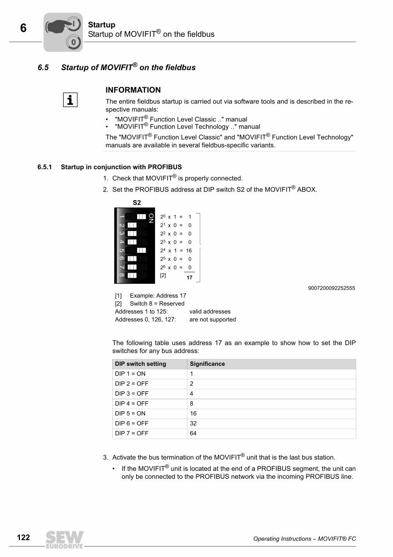
122 Operating Instructions – MOVIFIT® FC
6 Startup of MOVIFIT® on the fieldbusStartup
6.5 Startup of MOVIFIT® on the fieldbus
6.5.1 Startup in conjunction with PROFIBUS1. Check that MOVIFIT® is properly connected.
2. Set the PROFIBUS address at DIP switch S2 of the MOVIFIT® ABOX.
The following table uses address 17 as an example to show how to set the DIPswitches for any bus address:
3. Activate the bus termination of the MOVIFIT® unit that is the last bus station.
• If the MOVIFIT® unit is located at the end of a PROFIBUS segment, the unit canonly be connected to the PROFIBUS network via the incoming PROFIBUS line.
INFORMATIONThe entire fieldbus startup is carried out via software tools and is described in the re-spective manuals:• "MOVIFIT® Function Level Classic .." manual• "MOVIFIT® Function Level Technology .." manualThe "MOVIFIT® Function Level Classic" and "MOVIFIT® Function Level Technology"manuals are available in several fieldbus-specific variants.
9007200092252555[1] Example: Address 17[2] Switch 8 = ReservedAddresses 1 to 125: valid addressesAddresses 0, 126, 127: are not supported
DIP switch setting SignificanceDIP 1 = ON 1
DIP 2 = OFF 2
DIP 3 = OFF 4
DIP 4 = OFF 8
DIP 5 = ON 16
DIP 6 = OFF 32
DIP 7 = OFF 64
S2
20 x 1 = 121 x 0 = 022 x 0 = 023 x 0 = 0
25 x 0 = 026 x 0 = 0
24 x 1 = 16
17[2]
ON
12
34
56
78
00
I

Operating Instructions – MOVIFIT® FC 123
6Startup of MOVIFIT® on the fieldbusStartup
• To prevent malfunctions in the bus system due to reflections, etc., the PROFIBUSsegment must be terminated at the first and last stations.
4. Start up the MOVIFIT® frequency inverter, see chapter "Startup of the MOVIFIT® in-verter" (page 126).
5. Place the EBOX onto the ABOX and close it.
6. Switch on the 24V_C and 24V_S supply voltage(s). The corresponding control LEDsshould now light up green.
Bus termination The bus terminating resistors are already installed in the ABOX and can be activatedusing switch S1.
The following table shows the functional principle of the bus termination switch:
INFORMATIONThe PROFIBUS is not interrupted when you remove the EBOX (electronics unit)from the ABOX (connection unit).
Bus termination ON = on Bus termination OFF = off (factory setting)
837515659 837519755
Bus termination switch S1Bus termination ON = on Bus termination OFF = off
837562251 837566347
ON
S1
ON
S1
ON
OFF
Bustermination
Incomingcable
Outgoingcable
Switch
ON
OFF
Bustermination
Incomingcable
Outgoingcable
Switch
00
I

124 Operating Instructions – MOVIFIT® FC
6 Startup of MOVIFIT® on the fieldbusStartup
6.5.2 Startup with PROFINET IO, EtherNet/IP, or Modbus/TCP
1. Check that MOVIFIT® is properly connected.
2. Start up the MOVIFIT® frequency inverter, see chapter "Startup of the MOVIFIT® in-verter" (page 126).
3. Set DIP switch S11/2 "DEF IP" to "ON".
This sets the address parameters to the following default values:
4. Place the EBOX onto the ABOX and close it.
5. Switch on the 24V_C and 24V_S supply voltage(s). The corresponding control LEDsshould now light up green.
9007200422438795
IP address: 192.168.10.4
Subnet mask: 255.255.255.0
Gateway: 1.0.0.0
S11
DH
CP
DE
F IP
res.
(OFF
)re
s. (O
FF)
ON
1 2 3 4
00
I
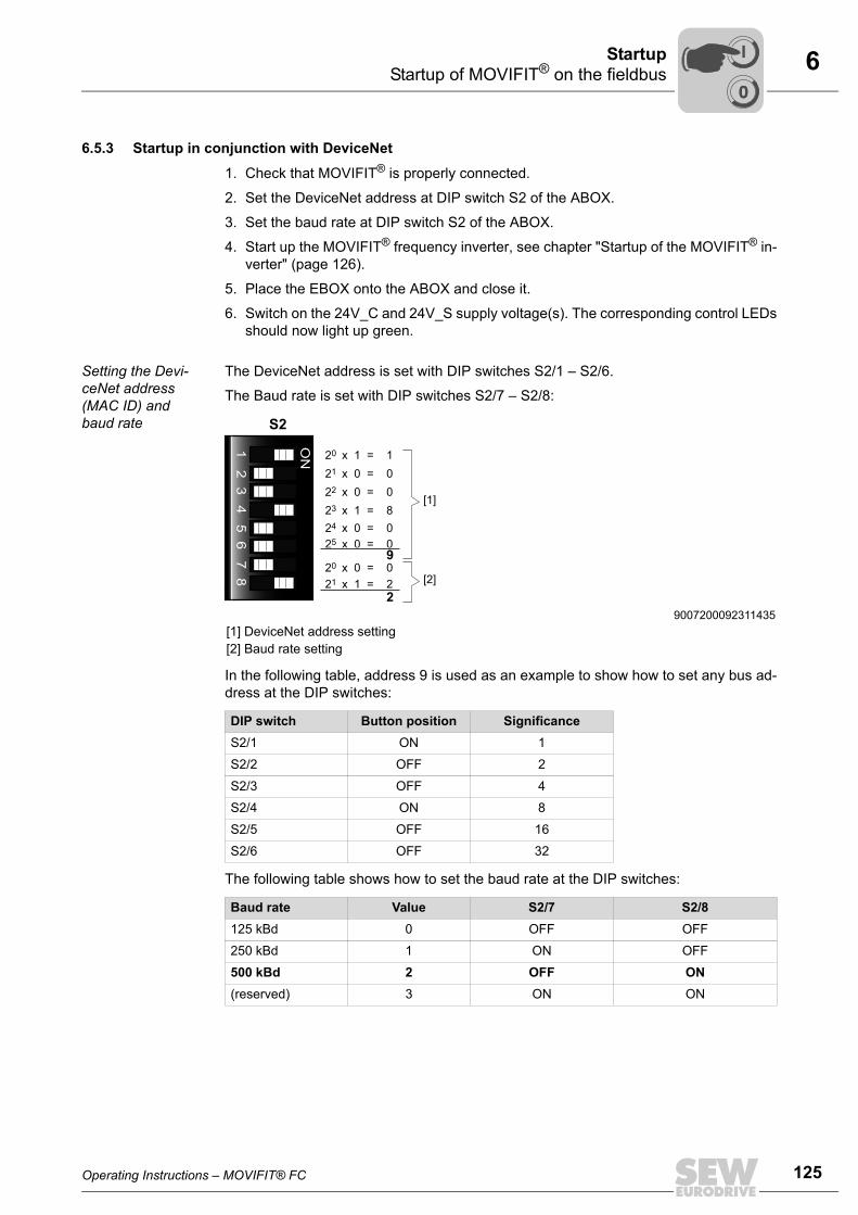
Operating Instructions – MOVIFIT® FC 125
6Startup of MOVIFIT® on the fieldbusStartup
6.5.3 Startup in conjunction with DeviceNet
1. Check that MOVIFIT® is properly connected.
2. Set the DeviceNet address at DIP switch S2 of the ABOX.
3. Set the baud rate at DIP switch S2 of the ABOX.
4. Start up the MOVIFIT® frequency inverter, see chapter "Startup of the MOVIFIT® in-verter" (page 126).
5. Place the EBOX onto the ABOX and close it.
6. Switch on the 24V_C and 24V_S supply voltage(s). The corresponding control LEDsshould now light up green.
Setting the Devi-ceNet address (MAC ID) and baud rate
The DeviceNet address is set with DIP switches S2/1 – S2/6.
The Baud rate is set with DIP switches S2/7 – S2/8:
In the following table, address 9 is used as an example to show how to set any bus ad-dress at the DIP switches:
The following table shows how to set the baud rate at the DIP switches:
9007200092311435[1] DeviceNet address setting[2] Baud rate setting
DIP switch Button position SignificanceS2/1 ON 1
S2/2 OFF 2
S2/3 OFF 4
S2/4 ON 8
S2/5 OFF 16
S2/6 OFF 32
Baud rate Value S2/7 S2/8125 kBd 0 OFF OFF
250 kBd 1 ON OFF
500 kBd 2 OFF ON(reserved) 3 ON ON
S2
20 x 1 = 121 x 0 = 022 x 0 = 0
24 x 0 = 023 x 1 = 8
25 x 0 = 0
21 x 1 = 220 x 0 = 0
9
[1]
2[2]
ON
12
34
56
78
00
I
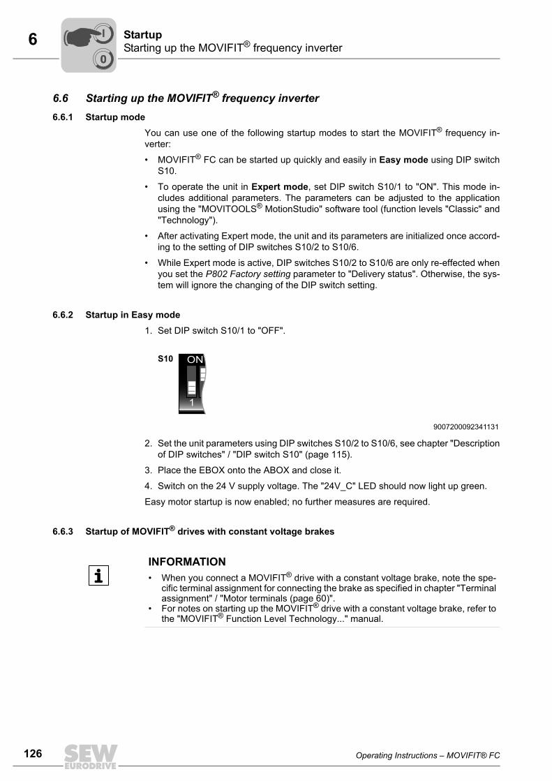
126 Operating Instructions – MOVIFIT® FC
6 Starting up the MOVIFIT® frequency inverterStartup
6.6 Starting up the MOVIFIT® frequency inverter6.6.1 Startup mode
You can use one of the following startup modes to start the MOVIFIT® frequency in-verter:
• MOVIFIT® FC can be started up quickly and easily in Easy mode using DIP switchS10.
• To operate the unit in Expert mode, set DIP switch S10/1 to "ON". This mode in-cludes additional parameters. The parameters can be adjusted to the applicationusing the "MOVITOOLS® MotionStudio" software tool (function levels "Classic" and"Technology").
• After activating Expert mode, the unit and its parameters are initialized once accord-ing to the setting of DIP switches S10/2 to S10/6.
• While Expert mode is active, DIP switches S10/2 to S10/6 are only re-effected whenyou set the P802 Factory setting parameter to "Delivery status". Otherwise, the sys-tem will ignore the changing of the DIP switch setting.
6.6.2 Startup in Easy mode1. Set DIP switch S10/1 to "OFF".
2. Set the unit parameters using DIP switches S10/2 to S10/6, see chapter "Descriptionof DIP switches" / "DIP switch S10" (page 115).
3. Place the EBOX onto the ABOX and close it.
4. Switch on the 24 V supply voltage. The "24V_C" LED should now light up green.
Easy motor startup is now enabled; no further measures are required.
6.6.3 Startup of MOVIFIT® drives with constant voltage brakes
9007200092341131
ON
1 2 3 4 5 6
S10
INFORMATION• When you connect a MOVIFIT® drive with a constant voltage brake, note the spe-
cific terminal assignment for connecting the brake as specified in chapter "Terminalassignment" / "Motor terminals (page 60)".
• For notes on starting up the MOVIFIT® drive with a constant voltage brake, refer tothe "MOVIFIT® Function Level Technology..." manual.
00
I

Operating Instructions – MOVIFIT® FC 127
6Starting up the MOVIFIT® frequency inverterStartup
6.6.4 Advanced startup and parameter setting in Expert modeConnecting the PC The following figure shows the connection of a a PC/laptop to the diagnostic interface
X50 of MOVIFIT®:
The diagnostic interface is located under the screw plug shown in the following figure.
You must remove the screw plug before plugging in the connector into the diagnosticinterface.
DANGER Danger of burns due to hot surfaces of the MOVIFIT® or external options,e.g. braking resistor.
Severe injuries.
• Do not touch the MOVIFIT® unit and external options until they have cooled downsufficiently.
The diagnostic interface can be connected to a PC using one of the following options:
• USB11A with USB interface, part number 0 824 831 1
• UWS21B with serial interface RS232, part number 1 820 456 2
Activating Expert mode
1. Check that MOVIFIT® is properly connected.
2. Set DIP switch S10/1 to "ON".
3. Place the EBOX onto the ABOX and close it.
4. Switch on the 24 V supply voltage. The "24V_C" LED should now light up green.
27021598576667531
UWS21BRS232
USBUSB11A
RJ10
RS485
RS485
X50
RJ10
MOVIFIT ®
4961269899
ON
1 2 3 4 5 6
S10
00
I

128 Operating Instructions – MOVIFIT® FC
6 Starting up the MOVIFIT® frequency inverterStartup
First steps with MOVITOOLS® MotionStudioStarting the soft-ware and creating a project
Proceed as follows to start MOVITOOLS® MotionStudio and create a project:
1. Start the MOVITOOLS® MotionStudio from the Windows start menu via:
[Start]/[Programs]/[SEW]/[MOVITOOLS MotionStudio]/[MOVITOOLS MotionStudio]
2. Create a project with name and storage location.
Establishing com-munication and scanning the net-work
Proceed as follows to establish a communication with MOVITOOLS® MotionStudio andto scan your network:
1. Set up a communication channel to communicate with your units.
For additional information, refer to the manual "MOVIFIT® Function Level Classic.."or "MOVIFIT® Function Level Technology ..".
2. Scan your network (unit scan). To do so, click the [Start network scan] button [1] inthe toolbar.
Startup with MOVITOOLS® MotionStudio
The next steps for startup/parameter setting in Expert mode differs according to theMOVIFIT® function level selected. See the following manuals for more information:
• "MOVIFIT® Function Level "Classic" .." 1)
• "MOVIFIT® Function Level "Technology" .." 1)
9007200387461515
[1]
1) The "MOVIFIT Function Level Classic" and "MOVIFIT Function Level Technology" manuals are availablein several fieldbus-specific variants.
00
I
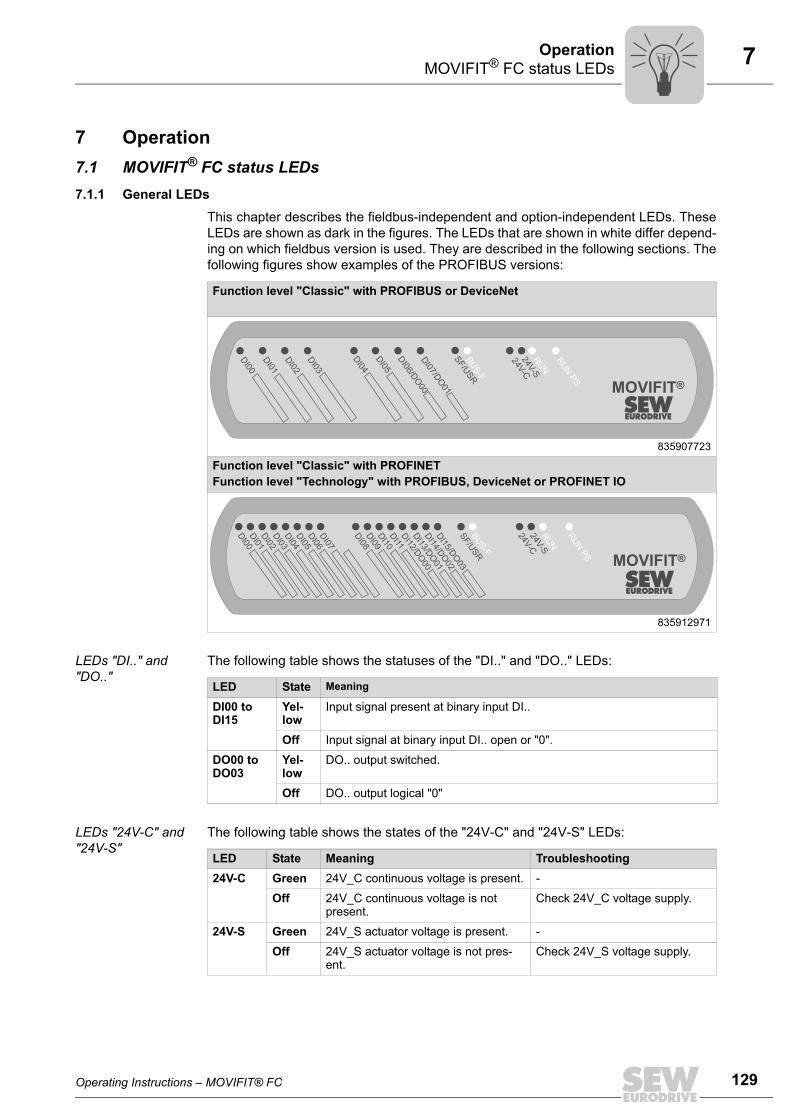
Operating Instructions – MOVIFIT® FC 129
7MOVIFIT® FC status LEDsOperation
7 Operation7.1 MOVIFIT® FC status LEDs7.1.1 General LEDs
This chapter describes the fieldbus-independent and option-independent LEDs. TheseLEDs are shown as dark in the figures. The LEDs that are shown in white differ depend-ing on which fieldbus version is used. They are described in the following sections. Thefollowing figures show examples of the PROFIBUS versions:
LEDs "DI.." and "DO.."
The following table shows the statuses of the "DI.." and "DO.." LEDs:
LEDs "24V-C" and "24V-S"
The following table shows the states of the "24V-C" and "24V-S" LEDs:
Function level "Classic" with PROFIBUS or DeviceNet
835907723
Function level "Classic" with PROFINETFunction level "Technology" with PROFIBUS, DeviceNet or PROFINET IO
835912971
DI02
DI01
DI00
DI03
DI04
DI06/D
O00
DI07/D
O01
SF/U
SR
BU
S-F
24V-C
24V-S
RU
N
DI05
RU
N P
S
MOVIFIT®
DI03
DI01
DI02
DI00
DI04
DI05
DI06
DI07
DI08
DI09
DI10
DI11
DI12/D
O00
DI13/D
O01
DI14/D
O02
DI15/D
O03
SF/U
SR
BU
S-F
24V-C
24V-S
RU
N
RU
N P
S
MOVIFIT®
LED State Meaning
DI00 to DI15
Yel-low
Input signal present at binary input DI..
Off Input signal at binary input DI.. open or "0".
DO00 to DO03
Yel-low
DO.. output switched.
Off DO.. output logical "0"
LED State Meaning Troubleshooting24V-C Green 24V_C continuous voltage is present. -
Off 24V_C continuous voltage is not present.
Check 24V_C voltage supply.
24V-S Green 24V_S actuator voltage is present. -
Off 24V_S actuator voltage is not pres-ent.
Check 24V_S voltage supply.

130 Operating Instructions – MOVIFIT® FC
7 MOVIFIT® FC status LEDsOperation
LED "SF/USR" The "SF/USR" LED indicates various statuses depending on the function level.
The following table shows the states of the "SF/USR" LED:
SF/USR Function level
Meaning Troubleshooting
C TOff • Standard operating state.
MOVIFIT® is exchanging data with the connected drive system (integrated inverter).
-
Red • MOVIFIT® cannot exchange data with integrated inverter.
Check the DC 24 V supply of the inte-grated inverter.
Flash-ing red(2 s cycle)
• MOVIFIT® initialization error or serious unit error
Incorrect card ID. Switch on MOVIFIT® again. If the fault is still present, replace the EBOX or contact SEW Service.
Flash-ing red
• Other unit fault Use MOVITOOLS® MotionStudio to read out the error status.Eliminate the cause of the fault and acknowledge this fault.
Off • IEC program is running. -
Green • IEC program is running. The green lit LED is con-trolled by the IEC program.
Refer to the IEC program documenta-tion for more information
Red • Boot project has not been started or has been can-celled due to an error.
Log in via MOVITOOLS® / PLC-Editor / Remote tool and start the boot proj-ect.
• MOVIFIT® initialization faultWrong EBOX/ABOX combi-nation
Incorrect card ID. Check the type of the MOVIFIT® EBOX. Use the correct EBOX on the ABOX and perform a complete startup procedure.
Flash-ing red
• No IEC application program loaded.
Load an IEC application program and, if necessary, restart the integrated PLC.
Flash-ing yel-low
• The IEC application program has been loaded but is not executed (PLC = stop).
Check the IEC application program using MOVITOOLS® MotionStudio and, if necessary, restart the inte-grated PLC.
Flash-ing 1 x red and n xgreen
• Fault status reported by the IEC program.
Refer to the IEC program documenta-tion for more information on the sta-tuses and the corresponding remedy
• Valid for selected function level:C = Function level "Classic"T = Function level "Technology"

Operating Instructions – MOVIFIT® FC 131
7MOVIFIT® FC status LEDsOperation
7.1.2 Bus-specific LEDs for PROFIBUS
This section describes the bus-specific LEDs for PROFIBUS. In the following figure, theLEDs are shown as dark:
"BUS-F" LED The following table shows the statuses of the "BUS-F" LED:
"RUN" LED The following table shows the statuses of the "RUN" LED:
836104971
DI03
DI01
DI02
DI00
DI04
DI05
DI06
DI07
DI08
DI09
DI10
DI11
DI12/D
O00
DI13/D
O01
DI14/D
O02
DI15/D
O03
SF/U
SR
BU
S-F
24V-C
24V-S
RU
N
RU
N P
S
MOVIFIT®
BUS-F RUN Meaning TroubleshootingOff Green MOVIFIT® is exchanging data with
the DP master.-
Flash-ing red
Green • The baud rate is detected. How-ever, MOVIFIT® is not addressed by the DP master.
• MOVIFIT® was not configured in the DP master or configured incorrectly.
• Check configuration of the DP master.
• Check whether all the modules configured during project plan-ning are permitted for the MOVIFIT® versions (MC, FC, SC).
Red Green • Connection to the DP master has failed.
• MOVIFIT® does not detect baud rate.
• Bus interruption• DP master not in operation
• Check the PROFIBUS-DP con-nection of MOVIFIT®.
• Check the DP master.• Check all cables in your PROFI-
BUS DP network
BUS-F RUN Meaning TroubleshootingX Off • MOVIFIT® not ready.
• No 24 V power supply.• Check DC 24 V supply.• Switch MOVIFIT® back on.
Replace EBOX if problem occurs several times.
X Green MOVIFIT® componentshardware OK.
-
Off Green • Correct MOVIFIT® operation• MOVIFIT® is currently exchang-
ing data with the DP master and all subordinate drive systems.
-
X Flashing green
PROFIBUS address is set equal to 0 or higher than 125.
Check the PROFIBUS address set in the MOVIFIT® ABOX.
X Yel-low
MOVIFIT® is currently in the initial-ization phase.
-
X Red Internal unit error Switch MOVIFIT® back on. Replace EBOX if problem occurs several times.
X Any state

132 Operating Instructions – MOVIFIT® FC
7 MOVIFIT® FC status LEDsOperation
7.1.3 Bus-specific LEDs for DeviceNet
This section describes the bus-specific LEDs for DeviceNet. In the following figure, theLEDs are shown as dark:
"Mod/Net" LED The function of the "Mod/Net" LED described in the following table is defined in theDeviceNet specification.
836125963
DI02
DI01
DI00
DI03
DI04
DI06/D
O00
DI07/D
O01
DI05
RU
N P
S
MOVIFIT®24V
-C24V
-S
SF/U
SR
BU
S-F
Mod/N
et
PIO
BIO
Mod/Net Status Meaning TroubleshootingOff Not switched
on / offline• Unit is offline.• Unit is performing a DUP-MAC
check.• Unit is switched off.
• Apply supply voltage via DeviceNet connec-tor.
Flash-ing green (1 s cycle)
Online and in operational mode
• The unit is online and no connec-tion has been established.
• DUP-MAC check performed suc-cessfully.
• A connection has not yet been established with a master.
• Missing (incorrect) or incomplete configuration.
• Include the station in the master's scan list and start communica-tion in the master.
Green Online, oper-ational mode and con-nected
• Unit is online.• Connection is active (established
state).
-
Flash-ing red (1 s cycle)
Minor fault or connection timeout
• A correctable fault has occurred.• Polled I/O and/or bit-strobe I/O
connections are in the timeout sta-tus.
• A correctable error has occurred in the unit.
• Check the DeviceNet cable.
• Check the timeout response (P831). If a response with error is set, reset the unit once the error has been cor-rected.
Red Critical error or critical link failure
• An error that cannot be corrected has occurred.
• BusOff status.• DUP-MAC check has detected an
error.
• Check the DeviceNet cable.
• Check the address (MAC ID). Is another unit already using the same address?

Operating Instructions – MOVIFIT® FC 133
7MOVIFIT® FC status LEDsOperation
"PIO" LED The "PIO" LED checks the polled I/O connection (process data channel).
The functionality is described in the following table.
PIO Status Meaning TroubleshootingFlash-ing green(500 ms cycle)
DUP-MAC check
• Unit is performing DUP-MAC check.
• If the station does not leave this state after approx. 2 s, no other station has been found.
• Activate at least one other DeviceNet station in the network.
Off Not switched on /Offline but no DUP-MAC check
• Unit is switched off.• Unit is in offline status.
• Switch on the unit.• Check whether the PIO
connection type was activated in the master.
Flash-ing green (1 s cycle)
Online and inoperational mode
• Unit is online.• DUP-MAC check performed suc-
cessfully.• A PIO connection is being estab-
lished with a master (configuring state).
• Missing, incorrect or incomplete configuration.
• Check the unit configu-ration in the master.
Green Online, oper-ational mode and con-nected
• Unit is online.• A PIO connection has been estab-
lished (established state).
-
Flash-ing red(1 s cycle)
Minor fault or connection timeout
• A correctable fault has occurred.• Invalid baud rate set at the DIP
switches.• Polled I/O connection is in timeout
status.
• Check the DeviceNet cable.
• Check the positions of the DIP switches for the baud rate.
• Check the timeout response (P831). If a response with error is set, reset the unit once the error has been cor-rected.
Red Critical error orCritical link failure
• An error that cannot be corrected has occurred.
• BusOff status.• DUP-MAC check has detected an
error.
• Check the DeviceNet cable.
• Check the address (MAC ID). Is another unit already using the same address?
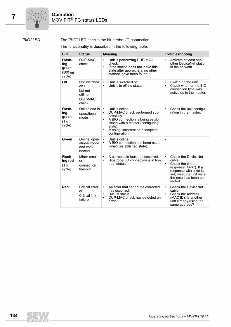
134 Operating Instructions – MOVIFIT® FC
7 MOVIFIT® FC status LEDsOperation
"BIO" LED The "BIO" LED checks the bit-strobe I/O connection.
The functionality is described in the following table.
BIO Status Meaning TroubleshootingFlash-ing green (500 ms cycle)
DUP-MAC check
• Unit is performing DUP-MAC check.
• If the station does not leave this state after approx. 2 s, no other stations have been found.
• Activate at least one other DeviceNet station in the network.
Off Not switched on /but not offlineDUP-MAC check
• Unit is switched off.• Unit is in offline status.
• Switch on the unit.• Check whether the BIO
connection type was activated in the master.
Flash-ing green (1 s cycle)
Online and inoperational mode
• Unit is online.• DUP-MAC check performed suc-
cessfully.• A BIO connection is being estab-
lished with a master (configuring state).
• Missing, incorrect or incomplete configuration.
• Check the unit configu-ration in the master.
Green Online, oper-ational mode and con-nected
• Unit is online.• A BIO connection has been estab-
lished (established state).
-
Flash-ing red(1 s cycle)
Minor error orconnection timeout
• A correctable fault has occurred.• Bit-strobe I/O connection is in tim-
eout status.
• Check the DeviceNet cable.
• Check the timeout response (P831). If a response with error is set, reset the unit once the error has been cor-rected.
Red Critical error orCritical link failure
• An error that cannot be corrected has occurred.
• BusOff status.• DUP-MAC check has detected an
error.
• Check the DeviceNet cable.
• Check the address (MAC ID). Is another unit already using the same address?
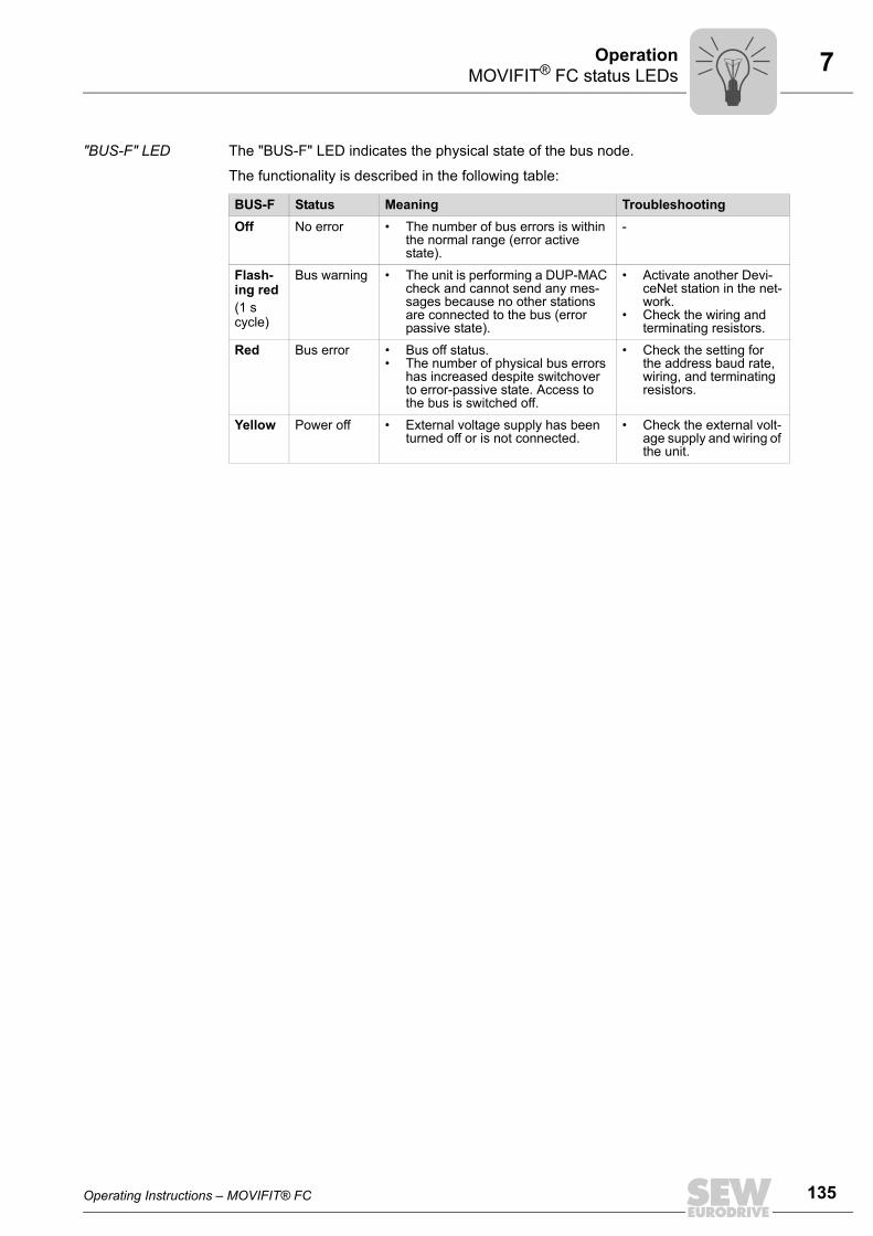
Operating Instructions – MOVIFIT® FC 135
7MOVIFIT® FC status LEDsOperation
"BUS-F" LED The "BUS-F" LED indicates the physical state of the bus node.
The functionality is described in the following table:
BUS-F Status Meaning TroubleshootingOff No error • The number of bus errors is within
the normal range (error active state).
-
Flash-ing red(1 s cycle)
Bus warning • The unit is performing a DUP-MAC check and cannot send any mes-sages because no other stations are connected to the bus (error passive state).
• Activate another Devi-ceNet station in the net-work.
• Check the wiring and terminating resistors.
Red Bus error • Bus off status.• The number of physical bus errors
has increased despite switchover to error-passive state. Access to the bus is switched off.
• Check the setting for the address baud rate, wiring, and terminating resistors.
Yellow Power off • External voltage supply has been turned off or is not connected.
• Check the external volt-age supply and wiring of the unit.
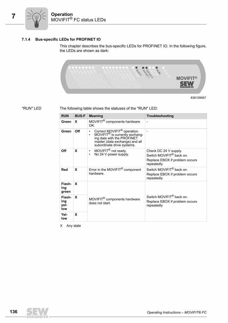
136 Operating Instructions – MOVIFIT® FC
7 MOVIFIT® FC status LEDsOperation
7.1.4 Bus-specific LEDs for PROFINET IO
This chapter describes the bus-specific LEDs for PROFINET IO. In the following figure,the LEDs are shown as dark:
"RUN" LED The following table shows the statuses of the "RUN" LED:
836109067
RU
N P
S
MOVIFIT®
SF/U
SR
BU
S-F
24V-C
24V-S
RU
N
link/act 1link/act 2
DI03
DI01
DI02
DI00
DI04
DI05
DI06
DI07
DI08
DI09
DI10
DI11
DI12/D
O00
DI13/D
O01
DI14/D
O02
DI15/D
O03
RUN BUS-F Meaning TroubleshootingGreen X MOVIFIT® components hardware
OK.-
Green Off • Correct MOVIFIT® operation.• MOVIFIT® is currently exchang-
ing data with the PROFINET master (data exchange) and all subordinate drive systems.
-
Off X • MOVIFIT® not ready.• No 24 V power supply.
Check DC 24 V supply.Switch MOVIFIT® back on. Replace EBOX if problem occurs repeatedly
Red X Error in the MOVIFIT® component hardware.
Switch MOVIFIT® back on. Replace EBOX if problem occurs repeatedly
Flash-ing green
X
MOVIFIT® components hardware does not start.
Switch MOVIFIT® back on. Replace EBOX if problem occurs repeatedly
Flash-ing yel-low
X
Yel-low
X
X Any state

Operating Instructions – MOVIFIT® FC 137
7MOVIFIT® FC status LEDsOperation
"BUS-F" LED The following table shows the statuses of the "BUS-F" LED:
LEDs "link/act 1" and "link/act 2"
The following table lists the states of the "link/act 1" and "link/act 2" LEDs:
RUN BUS-F Meaning TroubleshootingGreen Off MOVIFIT® is currently exchanging
data with the PROFINET master (data exchange).
-
Green Yel-low, flash-ing yellow
The STEP 7 hardware configuration contains a module that is not per-mitted.
Switch the STEP 7 hardware configu-ration to ONLINE and analyze the component status of the slots of the MOVIFIT® units.
Green Flash-ing green, flash-ing green/red
The flashing function in the PROFI-NET master configuration is acti-vated to visually localize the station.
-
Green Red • Connection to the PROFINET master has failed.
• MOVIFIT® does not detect a link.
• Bus interruption.• PROFINET master not in opera-
tion.
• Check the PROFINET connection of the MOVIFIT®
• Check the PROFINET master.• Check all cables in your PROFI-
NET network.
LED Status Meaning link/act 1 Ethernet port 1
link = greenact = yellow
• link = Ethernet cable connects device with other Ethernet stations.
• act = active, Ethernet communication active.
link/act 2 Ethernet port 2link = greenact = yellow

138 Operating Instructions – MOVIFIT® FC
7 MOVIFIT® FC status LEDsOperation
7.1.5 Bus-specific LEDs for Modbus/TCP and EtherNet/IP
This section describes the bus-specific LEDs for Modbus/TCP and EtherNet/IP. In thefollowing figure, the LEDs are shown as dark:
LEDs "MS" and "NS"
The following table lists the statuses of the LEDs "MS" (Module Status) and "NS" (Net-work Status):
829213195
STO
MOVIFIT®
SF/U
SR
MS
24V-C
24V-S
NS
link/act 1link/act 2
DI03
DI01
DI02
DI00
DI04
DI05
DI06
DI07
DI08
DI09
DI10
DI11
DI12/D
O00
DI13/D
O01
DI14/D
O02
DI15/D
O03
MS NS Meaning Troubleshooting
Off• MOVIFIT® not ready.• No DC 24 V supply.
• Check DC 24 V supply.• Switch MOVIFIT® back on. • Replace EBOX if problem occurs
several times.
Flashing Red/green
• MOVIFIT® performs an LED test.
• This status should only be acti-vated briefly during startup.
-
Flash-ing red
Red • Conflict detected while assign-ing the IP address.Another station in the network uses the same IP address.
• Check whether there is a unit in the network with the same IP address.
• Change the IP address of the MOVIFIT® components
• Check DHCP settings for IP address assignment of the DHCP server(only if a DHCP server is used).
Red X Error in the MOVIFIT® component hardware.
• Switch MOVIFIT® back on.• Restore MOVIFIT® factory set-
tings.• Replace EBOX if problem occurs
several times.
Flash-ing green
Flash-ing green
Application has been started. -
Flash-ing green
Off • MOVIFIT® does not have any IP parameters yet.
• Starting TCP IP stack.• If the status continues and the
DHCP DIP switch is activated, MOVIFIT® waits for data from the DCHP server
• Set DIP switch S11/1 of the DHCP server to "OFF".
• Check the DHCP server connec-tion (only if DHCP is activated and the status continues).
Green X MOVIFIT® components hardware OK.
-
X Flash-ing red
• Timeout delay of the controlling connection has expired.
• The state is reset by restarting communication.
• Check the bus connection on the unit MOVIFIT®.
• Check the master/scanner.• Check all the cables in the Ether-
net.
X Flash-ing green
• No controlling connection. -

Operating Instructions – MOVIFIT® FC 139
7MOVIFIT® FC status LEDsOperation
LEDs "link/act 1" and "link/act 2"
The following table lists the states of the "link/act 1" and "link/act 2" LEDs:
7.1.6 "RUN PS" LED (frequency inverter status LED)The following figure shows the "RUN PS" LED (shown unlit). In the sample figure, thePROFIBUS version is shown with "Technology" function level:
X Green • There is no controlling connec-tion to a master/scanner.
-
X Any state
MS NS Meaning Troubleshooting
LED Status Meaning link/act 1 Ethernet port 1
link = greenact = yellow
• link = Ethernet cable connects device with other Ethernet stations.
• act = active, Ethernet communication active.
link/act 2 Ethernet port 2link = greenact = yellow
836134539
LED color
LED status Operating state Description
- Off Not ready for operation.
No 24 V power supply.
Yel-low
Flashes steadily Not ready for operation.
Self-test phase active or 24 V power supply present but supply voltage not OK.
Yel-low
Flashing steadily, fast
Ready for opera-tion.
Brake release without drive enable active.
Yel-low
Steady light Ready, but unit inhibited.
24 V power supply and supply voltage OK, but no enable signal.
Yel-low
2x flashing, break
Ready, but man-ual operation with-out unit enable.
24 V power supply and supply voltage OK. Stop manual mode to activate automatic mode.
Green/yel-low
Flashing with alternating col-ors
Ready, but time-out.
Faulty communication with cyclical data exchange
Green Steady light Unit enabled. Motor in operation.
Green Flashing evenly, fast
Current limit active.
Drive operating at current limit.
Green Flashes steadily Ready for opera-tion.
Standstill current function active
DI03
DI01
DI02
DI00
DI04
DI05
DI06
DI07
DI08
DI09
DI10
DI11
DI12/D
O00
DI13/D
O01
DI14/D
O02
DI15/D
O03
SF/U
SR
BU
S-F
24V-C
24V-S
RU
N
RU
N P
S
MOVIFIT®

140 Operating Instructions – MOVIFIT® FC
7 MOVIFIT® FC status LEDsOperation
Red Steady light Not ready for operation.
Check 24 V supply. Make sure that there is a smoothed DC voltage with low ripple (resid-ual ripple max. 13%) present.
MOVIFIT® detected a non-plausible combi-nation of DIP switch settings. Check 24V_C supply.
Red 2x flashing, break
Error 07 DC link voltage too high.
Red Flashing slowly Error 08 Speed monitoring error
Error 09 Incorrect startup/parameter settings.
Error 15 24 V supply voltage too low.
Faults 17-24, 37 CPU error
Error 25 EEPROM error
Error 26 Fault at external terminal (only at slave unit)
Error 38, 45 Unit/motor data error
Error 90 Incorrect assignment of motor/inverter; Invalid DIP switch setting
Error 94 Checksum error
Error 97 Copy error
Red 3x flashing, break
Error 01 Overcurrent in output stage
Error 11 Overtemperature in output stage
Red 4x flashing, break
Error 31 Temperature sensor tripped.
Error 84 Motor overload
Red 5x flashing, break
Error 4 Overcurrent in brake chopper
Error 89 Overtemperature in brake Incorrect assignment of motor-frequency inverter
Red 6x flashing, break
Error 06 Line phase failure
Error 81 Start condition (only in hoist operation mode)
Error 82 Open output
LED color
LED status Operating state Description

Operating Instructions – MOVIFIT® FC 141
7MOVIFIT® FC status LEDsOperation
7.1.7 Option-specific LEDsPROFIsafe option S11
This section describes the option-specific LEDs for PROFIsafe option S11. In the follow-ing figure, these LEDs are shown as dark. In the sample figure, the PROFIBUS versionis shown with "Technology" function level:
LEDs "FDI." and "FDO."
The following table shows the statuses of the "FDI." and "FDO." LEDs:
WARNINGObserve the "MOVIFIT® MC / FC – Functional Safety" manual when using thePROFIsafe option S11.
Severe or fatal injuries.• If you are using the PROFIsafe option S11, observe the additional notes on diag-
nostics and operation as well as the safety conditions specified in the "MOVIFIT®
MC / FC – Functional Safety" manual.
WARNINGDanger due to incorrect interpretation of the "FDI.", "FDO.", "STO" and "F-STATE"LEDs.
Severe or fatal injuries.• The LEDs are not safety-oriented and may not be used as a safety device.
836130059
DI03
DI01
DI02
DI00
DI04
DI05
DI06
DI07
DI08
DI09
DI10
DI11
DI12/D
O00
DI13/D
O01
DI14/D
O02
DI15/D
O03
SF/U
SR
BU
S-F
24V-C
24V-S
RU
NF-S
TATE
STO
FD
I00FD
I01FD
I02FD
I03FD
O00
FD
O01
MOVIFIT®
RU
N P
S
LED State MeaningFDI00 Yel-
lowHIGH level at input F-DI0
Off LOW level at input F-DI0 or open
FDI01 Yel-low
HIGH level at input F-DI1
Off LOW level at input F-DI1 or open
FDI02 Yel-low
HIGH level at input F-DI2
Off LOW level at input F-DI2 or open
FDI03 Yel-low
HIGH level at input F-DI3
Off LOW level at input F-DI3 or open
FDO00 Yel-low
Output F-DO0 active
Off Output F-DO0 inactive (switched off)

142 Operating Instructions – MOVIFIT® FC
7 MOVIFIT® FC status LEDsOperation
"STO" LED The following table shows the statuses of the "STO" LED:
"F-STATE" LED The following table shows the statuses of the "F-STATE" LED:
FDO01 Yel-low
Output F-DO1 active
Off Output F-DO1 inactive (switched off)
LED State Meaning
LED State MeaningSTO Yel-
low• Drive has stopped safely ("STO active").
Off • Drive has not stopped safely ("STO inactive").
LED State Meaning TroubleshootingF-STATE Green • The S11 Option is currently per-
forming a cyclical data exchange with the F-Host.
• Standard operating state.
-
Red • Fault status in the safety part.• 24V_O supply voltage not avail-
able.
• Read diagnostics in F-Host.• Eliminate the cause of the
fault and acknowledge in the F-Host.
Off • S11 option is currently in the ini-tialization phase.
• S11 option is not available or is not configured in the bus master (slot 1 is empty).
• Check voltage supply.• Check configuration of the
bus master.
Flash-ing red/ green
A fault occurred in the safety part; cause of the fault already remedied – acknowledgement required.
Acknowledge fault in the F-Host (reintegration).

Operating Instructions – MOVIFIT® FC 143
7MOVIFIT® FC status LEDsOperation
LEDs of POF option L10
This chapter describes the status LEDs of the POF option L10:
"24V" LED The "24V" LED indicates the status of the 24 V supply.
"FO2" LED The "FO2" LED indicates the status of the FO diagnostics at port 2 (X31).
"FO1" LED The "FO1" LED indicates the status of the FO diagnostics at port 1 (X30).
4961760011
24V
FO2 (X31)
FO1 (X30)1824
676
1
LED status Meaning TroubleshootingOff 24 V supply for the POF option is not
available.• Check whether MOVIFIT® is
switched on.• Check the connections between
MOVIFIT® and the POF option L10.
Green 24 V supply for the POF option is available.
–
LED status Meaning TroubleshootingOff POF port 2 is ok. –
Red Maintenance for POF port 2 required. Perform maintenance for POF port 2, e.g. replace the POF cable.
LED status Meaning TroubleshootingOff POF port 1 is ok. –
Red Maintenance for POF port 1 required. Perform maintenance for POF port 1, e.g. replace the POF cable.

144 Operating Instructions – MOVIFIT® FC
7 Manual operation using the DBG keypadOperation
7.2 Manual operation using the DBG keypad7.2.1 Connection
MOVIFIT® units are equipped with an X50 diagnostics interface (RJ10 plug connector)for parameterization and manual operation.
The X50 diagnostic interface is located under the screw plug shown in the following fig-ure.
You must remove the screw plug before plugging in the connector into the diagnosticinterface.
DANGER Danger of burns due to hot surfaces of the MOVIFIT® or external options,e.g. braking resistor.
Severe injuries.
• Do not touch the MOVIFIT® unit and external options until they have cooled downsufficiently.
You can also connect the DBG keypad to the MOVIFIT® using option DKG60B (5 m ex-tension cable).
NOTICE Loss of the ensured degree of protection if the screw plug of the diagnostic in-terface X50 is not installed or not installed correctly.
Damage to the MOVIFIT® unit.
• Make sure the screw plug of the diagnostic interface has a seal and screw it in.
7.2.2 Operation
793024907DBGDKG60B
INFORMATIONFor notes on operating the MOVIFIT® drive in manual operation, refer to the"MOVIFIT® Function Level 'Technology..'" or "MOVIFIT® Function Level 'Classic..'"manual.

Operating Instructions – MOVIFIT® FC 145
8Unit diagnosticsService
8 Service8.1 Unit diagnostics
8.2 Error table
INFORMATIONDepending on the function level in use, further diagnostic tools are available viaMOVITOOLS® MotionStudio. These are described in the respective manuals:• "MOVIFIT® Function Level Classic .." manual • "MOVIFIT® Function Level Technology .." manualThese manuals are available in several, fieldbus-specific variants.
Error Cause SolutionCommunication timeout (motor stops)
Error during communication via internal SBus
Check internal SBus connection.
DC link voltage too low, supply system off was detected(motor stops, without error code)
Supply voltage not present. Check supply system leads, supply system voltage and 24 V electronics voltage for interruption.
24 V electronics supply voltage not OK.
Check the 24 V electronics supply voltage. Permitted voltage: DC 24 V ± 25%, EN 61131-2. Residual ripple max. 13%.
Motor restarts automatically as soon as the voltage reaches normal values.
Error code 01 Overcurrent in output stage
Short circuit on inverter output Check the connection between the inverter and the motor as well as the motor winding for short circuits.Reset the fault by switching off the DC 24 V supply volt-age or using communication.
Error code 04 Brake chopper
Overcurrent in brake output, resistor damaged, resistance too low.
Check the connection of the resistor/replace it.
Error code 06 Phase failure
Phase failureThe error can only be detected when the drive is running under load.
Check the supply system cable for phase failure. Reset the fault by switching off the DC 24 V supply volt-age or using communication.
Error code 07 DC link voltage too high
Ramp time too short. Extend the ramp time.Reset the fault by switching off the DC 24 V supply volt-age or using communication.
Faulty connection between brake coil/braking resistor
Check the braking resistor/brake coil connection. Cor-rect, if necessary.Reset the fault by switching off the DC 24 V supply volt-age or using communication.
Incorrect internal resistance of brake coil/braking resistor
Check internal resistance of brake coil/braking resistor (see chapter "Technical Data").Reset the fault by switching off the DC 24 V supply volt-age or using communication.
Thermal overload in braking resistor → Wrong size of brak-ing resistor selected.
Dimension the braking resistor correctly.Reset the fault by switching off the DC 24 V supply volt-age or using communication.
Invalid voltage range of supply input voltage
Check supply input voltage for permitted voltage range.Reset the fault by switching off the DC 24 V supply volt-age or using communication.

146 Operating Instructions – MOVIFIT® FC
8 Error tableService
Error code 08Speed monitoring
Speed deviation due to opera-tion at the current limit
Reduce the load on the driveIncrease the n-monitoring delay time.Reset the fault by switching off the DC 24 V supply volt-age or using communication.
Error code 09Startup
Faulty startup/parameteriza-tion (e.g. with MOVITOOLS® MotionStudio).
Repeat startup with correct settings.If this does not work (e.g. in Expert mode):• Set parameter P802 Factory setting to "Delivery
state" once.• Switch to Easy mode once (DIP switch S10/2 =
OFF).Reset the fault by switching off the DC 24 V supply volt-age or using communication.
Error code 11 Thermal overload of the output stage or internal unit error
Ambient temperature too high. Lower ambient temperatureReset the fault by switching off the DC 24 V supply volt-age or using communication.
Heat build-up in the MOVIFIT® Prevent heat build-upReset the fault by switching off the DC 24 V supply volt-age or using communication.
Drive load too high. Reduce the load on the driveReset the fault by switching off the DC 24 V supply volt-age or using communication.
Error code 15 24 V supply
Supply voltages 24V_C and/or 24V_P are too low.
Check 24 V supply voltages 24V_C and/or 24V_P.Reset the fault by switching off the DC 24 V supply volt-age or using the communication.
Error codes 17 to 24, 37CPU error
CPU error Reset the fault by switching off the DC 24 V supply volt-age or using communication.
Error code 25EEPROM error
Fault when accessing EEPROM
Set parameter P802 to "Delivery state".Reset the error by switching off the DC 24 V supply voltage.Re-parameterize the unit.Consult SEW Service if the error re-occurs.
Error code 26External terminal
Low signal on the terminal that was programmed with the "/External fault" function (only with SBus slave).
Remove/reset the external fault that is causing the sig-nal at the "External fault" terminal.
Error code 38System software
Unit data error Contact SEW Service.
Error code 45Initialization
Motor data error Contact SEW Service.
Error code 47SBus communication
Error during communication via internal SBus
Check voltage supply of control unit.
Error code 81Start condition
The motor could not be sup-plied with the correct amount of current during the pre-magne-tizing time.
Check connection between MOVIFIT® inverter and motor.
2 or all output phases inter-rupted.
Error code 82Open output
The motor could not be sup-plied with the correct amount of current during the pre-magne-tizing time.
Check connection between MOVIFIT® inverter and motor.
Rated motor power too small in relation to rated inverter power.
Error Cause Solution

Operating Instructions – MOVIFIT® FC 147
8Error tableService
Error code 84Thermal overload of motor
Motor ambient temperature too high.
Reduce motor ambient temperature.Reset the fault by switching off the DC 24 V supply volt-age or using communication.
Heat build-up at the motor. Prevent heat build-up at the motor.Reset the fault by switching off the DC 24 V supply volt-age or using communication.
Motor load too high. Reduce the load on the motor Reset the fault by switching off the DC 24 V supply volt-age or using communication.
Motor speed too low. Increase speed.Reset the fault by switching off the DC 24 V supply volt-age or using communication.
Error code 89 Thermal overload of brake coil or brake coil defec-tive, brake coil connected incorrectly
Set ramp time is too short. Increase the set ramp time.Reset the fault by switching off the DC 24 V supply volt-age or using communication.
Brake inspection of motor nec-essary.
Brake inspection (see the motor operating instructions)Reset the fault by switching off the DC 24 V supply volt-age or using communication.
Brake is connected incorrectly. Check brake coil connection.Reset the fault by switching off the DC 24 V supply volt-age or using communication.
Combination of drive (brake coil) and MOVIFIT® FC fre-quency inverter not possible.
Check the combination of drive (brake coil) and MOVIFIT® FC frequency inverter if the error is signaled shortly after the first enable.Reset the error by switching off the DC 24 V supply voltage or via communication.
Incorrect setting of DIP switch S10/5 for combinations of "MOVIFIT®" and "Motor with a lower power rating".
For combinations of "MOVIFIT® FC" and "motor with a lower power rating", check/correct the setting of DIP switch S10/5. Reset the error by switching off the DC 24 V supply voltage or via communication.
Contact SEW Service
Error code 90Output stage detection
Incorrect assignment of motor/inverter; invalid DIP switch setting.
Correct the DIP switch settings.Reset the error by switching off the DC 24 V supply voltage or via communication.
Error code 94EEPROM error
Defective EEPROM Contact SEW Service.
Error code 97Copy error
Error during data transmission. Repeat copying process.Restore the delivery status and re-parameterize the unit.
Error Cause Solution
148 Operating Instructions – MOVIFIT® FC
8 Inspection/maintenanceService
8.3 Inspection/maintenance8.3.1 MOVIFIT® unit
The MOVIFIT® unit does not require maintenance. SEW-EURODRIVE does not pre-scribe any inspection or maintenance work for the MOVIFIT® unit.
8.3.2 MotorThe controlled motor requires regular inspection and maintenance work.
Observe the notes and instructions in chapter "Inspection/Maintenance" of the motor op-erating instructions.
8.3.3 Gear unit (only for gearmotors)The gear unit of the controlled motor requires regular inspection and maintenance work.
Observe the notes and instructions in chapter "Inspection/Maintenance" of the gear unitoperating instructions.

Operating Instructions – MOVIFIT® FC 149
8SEW Electronics ServiceService
8.4 SEW Electronics ServiceIf a fault cannot be solved, please contact the SEW-EURODRIVE Service (see the sec-tion "Address List").
Please have the following information at hand when you consult the SEW Service:
• EBOX type designation [1]
• Serial number [2]
• Digits in the status field [3]
• Brief description of the application
• Nature of the fault
• Accompanying circumstances (e.g. initial startup)
• Your own assumptions
• Any unusual events preceding the problem, etc.
8.5 ShutdownTo shut down the MOVIFIT® unit, de-energize the unit using appropriate measures.
4666063115[1] EBOX type designation[2] Serial number[3] Status field
[1][2][3]
WARNINGElectric shock due to charged capacitors.
Severe or fatal injuries.• Observe a minimum switch-off time of 1 minute after disconnecting the power sup-
ply.
150 Operating Instructions – MOVIFIT® FC
8 StorageService
8.6 StorageObserve the following instructions when shutting down or storing MOVIFIT® units:
• If you shut down and store the MOVIFIT® unit for a longer period, you must closeopen cable entries and cover contacts with protective caps.
• Make sure that the unit is not subject to mechanical impact during storage.
Observe the notes on storage temperature in section "Technical Data".
8.7 Extended storageIf the unit is stored for a long time, connect it to the supply system voltage for at least 5minutes every 2 years. Otherwise, the unit's service life may be reduced.
8.7.1 Procedure when maintenance has been neglectedThe capacitors used in the inverters are subject to aging effects when de-energized.This effect can damage the capacitors if the unit is connected using the nominal voltageafter a longer period of storage. If you have not performed maintenance regularly, SEW-EURODRIVE recommends that you increase the line voltage slowly up to the maximumvoltage. This can be done, for example, by using a variable transformer for which theoutput voltage has been set according to the following overview. After you have com-pleted the regeneration process, the unit can be used immediately or stored again foran extended period with maintenance.
The following stages are recommended:
AC 400/500 V units:
• Stage 1: AC 0 V to AC 350 V within a few seconds
• Stage 2: AC 350 V for 15 minutes
• Stage 3: AC 420 V for 15 minutes
• Stage 4: AC 500 V for 1 hour
8.8 DisposalThis product consists of:
• Iron
• Aluminum
• Copper
• Plastic
• Electronic components
Dispose of all components in accordance with applicable regulations!
Operating Instructions – MOVIFIT® FC 151
9CE marking, UL approval and C-TickTechnical Data
9 Technical Data9.1 CE marking, UL approval and C-Tick9.1.1 CE marking
• Low voltage directive:
The MOVIFIT® drive system complies with the regulations of Low Voltage Directive2006/95/EC.
• Electromagnetic compatibility (EMC):
MOVIFIT® FC units are designed for use as components for installation in machineryand systems. They comply with the EMC product standard EN 61800-3 "Variable-speed electrical drives". Provided that you comply with the installation instructions,the CE marking requirements for the entire machine/system in which they are in-stalled are satisfied on the basis of EMC Directive 2004/108/EC. For detailed infor-mation on EMC-compliant installation, refer to the publication "Electromagnetic Com-patibility in Drive Engineering" from SEW-EURODRIVE.
The CE mark on the nameplate indicates conformity with the Low Voltage Directive2006/95/EC and the EMC Directive 2004/108/EC.
9.1.2 UL approvalUL and cUL approval has been granted for the MOVIFIT® FC unit series.
9.1.3 C-TickC-Tick approval has been granted for the MOVIFIT® FC unit series. C-Tick certifies con-formity with ACA (Australian Communications Authority) standards.
Pi
fkVA
Hz
n

152 Operating Instructions – MOVIFIT® FC
9 Variant with operating point 400 V / 50 HzTechnical Data
9.2 Variant with operating point 400 V / 50 HzMOVIFIT® type MTF11A
003-503MTF11A 005-503
MTF11A 007-503
MTF11A 011-503
MTF11A 015-503
MTF11A 022-503
MTF11A 030-503
MTF11A 040-503
Size 1 Size 2Apparent output power at Vline = AC 380 – 500 V
SN 1.1 kVA 1.4 kVA 1.8 kVA 2.2 kVA 2.8 kVA 3.8 kVA 5.1 kVA 6.7 kVA
Supply voltagesPermitted range
Vline AC 3 x 380 V / 400 V / 415 V / 460 V / 500 VVline = AC 380 V -10 % – AC 500 V +10 %
Line frequency fline 50 – 60 Hz ± 10 %Nominal line current (with Vline = AC 400 V)
Iline AC 1.3 A AC 1.6 A AC 1.9 A AC 2.4 A AC 3.5 A AC 5.0 A AC 6.7 A AC 7.3 A
Output voltage VO 0 – VlineOutput frequencyResolutionOperating point
fA 2 – 120 Hz0.01 Hz400 V at 50 Hz / 100 Hz
Nominal output current IN AC 1.6 A AC 2.0 A AC 2.5 A AC 3.2 A AC 4.0 A AC 5.5 A AC 7.3 A AC 8.7 AMotor power S1
PMot0.37 kW0.5 HP
0.55 kW0.75 HP
0.75 kW1.0 HP
1.1 kW1.5 HP
1.5 kW2.0 HP
2.2 kW3.0 HP
3.0 kW4.0 HP
4.0 kW5.2 HP
PWM frequency 4 / 8 / 161) kHz (factory setting: 16 kHz)
1) 16 kHz PWM frequency (low-noise): The unit switches to lower cycle frequencies depending on the heat sink temperature and load.
Current limitation Imax Motor and regenerative: 160 % at and External braking resistor Rmin 150 Ω 68 ΩCable length between MOVIFIT® and motor
Max. 15 m (with SEW hybrid cable, type A)
Hybrid cable shielding Connect outer shield via EMC cable glands, connect inner shield via EMC shield clamps (not for ABOX with Intercontec round connector), see chapter "Installation instructions"
Interference immunity Meets EN 61800-3Interference emission Limit value class C3 to EN 61800-3Motor protection ThermistorDuty type S1 (EN 60034-1), S3 max. cycle duration 10 minutesCooling type (DIN 41751) Self-coolingDegree of protection Standard: IP65 in accordance with EN 60529 (MOVIFIT® housing closed and all cable
entries and plug connections sealed)Hygienicplus variant:IP66 in accordance with EN 60529 and IP69K according to DIN 40050-9 (MOVIFIT® housing closed and all cable bushings sealed according to the relevant degree of protection)
Ambient temperature -25 – +40 °C (PN derating: 3% IN per K to max. 60 °C)Climate class EN 60721-3-3, class 3K3Storage temperature2)
2) If the unit is stored for a long time, connect it to the supply system voltage for at least 5 minutes every 2 years. Otherwise, the unit'sservice life may be reduced.
-25 – +85 °C (EN 60721-3-3, class 3K3)Permissible oscillation and impact load
According to EN 50178
Overvoltage category III according to IEC 60664-1 (DIN VDE 0110-1)Pollution class 2 according to IEC 60664-1 (DIN VDE 0110-1) within the housingInstallation altitude.(see chapter "Electrical Installation – Installation instructions")
h h ≤ 1000 m: no deratingh > 1000 m: IN derating by 1% per 100 mh > 2000 m: Vline derating by AC 6 V per 100 mhmax = 4000 m
Derating for tilted mounting positions (see chapter "Mechanical Installation" / "Mounting position")
S1 duty: IN = 100 % S1 duty: IN = 90 %
S3 duty: IN = 100 %
Mass EBOX "MTF...-....-00" (MOVIFIT® FC) size 1: about 3.5 kgEBOX "MTF...-....-00" (MOVIFIT® FC) size 2: about 5.6 kgStandard ABOX: about 4.5 kgHybrid ABOX: about 4.8 kg
Pi
fkVA
Hz
n
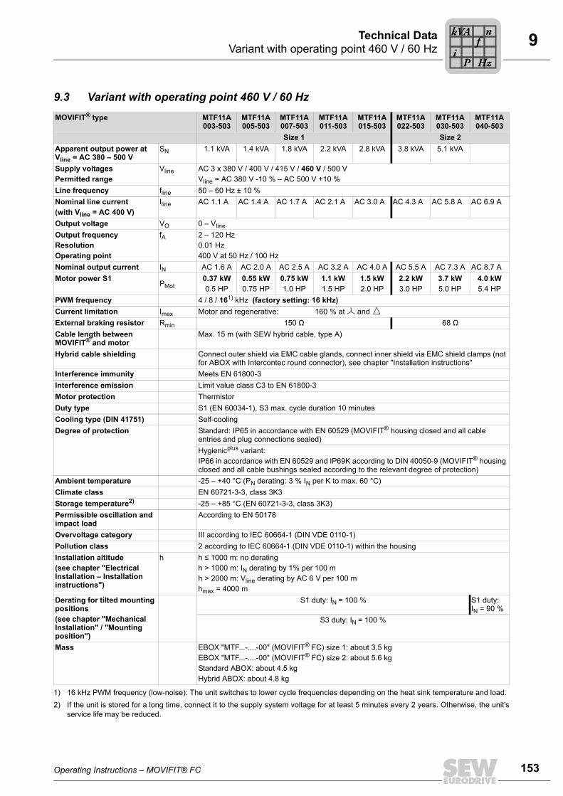
Operating Instructions – MOVIFIT® FC 153
9Variant with operating point 460 V / 60 HzTechnical Data
9.3 Variant with operating point 460 V / 60 HzMOVIFIT® type MTF11A
003-503MTF11A 005-503
MTF11A 007-503
MTF11A 011-503
MTF11A 015-503
MTF11A 022-503
MTF11A 030-503
MTF11A 040-503
Size 1 Size 2Apparent output power at Vline = AC 380 – 500 V
SN 1.1 kVA 1.4 kVA 1.8 kVA 2.2 kVA 2.8 kVA 3.8 kVA 5.1 kVA
Supply voltagesPermitted range
Vline AC 3 x 380 V / 400 V / 415 V / 460 V / 500 VVline = AC 380 V -10 % – AC 500 V +10 %
Line frequency fline 50 – 60 Hz ± 10 %Nominal line current (with Vline = AC 400 V)
Iline AC 1.1 A AC 1.4 A AC 1.7 A AC 2.1 A AC 3.0 A AC 4.3 A AC 5.8 A AC 6.9 A
Output voltage VO 0 – VlineOutput frequencyResolutionOperating point
fA 2 – 120 Hz0.01 Hz400 V at 50 Hz / 100 Hz
Nominal output current IN AC 1.6 A AC 2.0 A AC 2.5 A AC 3.2 A AC 4.0 A AC 5.5 A AC 7.3 A AC 8.7 AMotor power S1
PMot0.37 kW0.5 HP
0.55 kW0.75 HP
0.75 kW1.0 HP
1.1 kW1.5 HP
1.5 kW2.0 HP
2.2 kW3.0 HP
3.7 kW5.0 HP
4.0 kW5.4 HP
PWM frequency 4 / 8 / 161) kHz (factory setting: 16 kHz)
1) 16 kHz PWM frequency (low-noise): The unit switches to lower cycle frequencies depending on the heat sink temperature and load.
Current limitation Imax Motor and regenerative: 160 % at and External braking resistor Rmin 150 Ω 68 ΩCable length between MOVIFIT® and motor
Max. 15 m (with SEW hybrid cable, type A)
Hybrid cable shielding Connect outer shield via EMC cable glands, connect inner shield via EMC shield clamps (not for ABOX with Intercontec round connector), see chapter "Installation instructions"
Interference immunity Meets EN 61800-3Interference emission Limit value class C3 to EN 61800-3Motor protection ThermistorDuty type S1 (EN 60034-1), S3 max. cycle duration 10 minutesCooling type (DIN 41751) Self-coolingDegree of protection Standard: IP65 in accordance with EN 60529 (MOVIFIT® housing closed and all cable
entries and plug connections sealed)Hygienicplus variant:IP66 in accordance with EN 60529 and IP69K according to DIN 40050-9 (MOVIFIT® housing closed and all cable bushings sealed according to the relevant degree of protection)
Ambient temperature -25 – +40 °C (PN derating: 3 % IN per K to max. 60 °C)Climate class EN 60721-3-3, class 3K3Storage temperature2)
2) If the unit is stored for a long time, connect it to the supply system voltage for at least 5 minutes every 2 years. Otherwise, the unit'sservice life may be reduced.
-25 – +85 °C (EN 60721-3-3, class 3K3)Permissible oscillation and impact load
According to EN 50178
Overvoltage category III according to IEC 60664-1 (DIN VDE 0110-1)Pollution class 2 according to IEC 60664-1 (DIN VDE 0110-1) within the housingInstallation altitude(see chapter "Electrical Installation – Installation instructions")
h h ≤ 1000 m: no deratingh > 1000 m: IN derating by 1% per 100 mh > 2000 m: Vline derating by AC 6 V per 100 mhmax = 4000 m
Derating for tilted mounting positions (see chapter "Mechanical Installation" / "Mounting position")
S1 duty: IN = 100 % S1 duty: IN = 90 %
S3 duty: IN = 100 %
Mass EBOX "MTF...-....-00" (MOVIFIT® FC) size 1: about 3.5 kgEBOX "MTF...-....-00" (MOVIFIT® FC) size 2: about 5.6 kgStandard ABOX: about 4.5 kgHybrid ABOX: about 4.8 kg
Pi
fkVA
Hz
n

154 Operating Instructions – MOVIFIT® FC
9 Electronics dataTechnical Data
9.4 Electronics data
9.5 Binary inputs
General electronics data
Electronics and sensor supply 24V_C (continous)
VIN = DC 24 V -15% / +20% according to EN 61131-2Current consumption:IE ≤ 500 mA, typically 200 mA (for MOVIFIT® electronics) • Plus up to 1500 mA (for sensor supply depending on the number and type of sensors)• Plus up to 2000 mA (4 with 500 mA each or 1 sensor supply 1))• Plus up to 250 mA, (for inverter electronics) 1)
1) If 24V_S and 24V_P are supplied via 24V_C, these currents must be added up!
Actuator supply 24V_S (switched) VIN = DC 24 V -15% / +20% according to EN 61131-2IE ≤ 2000 mA (4 outputs with 500 mA or 1 sensor supply – group 4 with 500 mA)
Inverter supply 24V_P VIN = DC 24 V -15% / +20% according to EN 61131-2IE ≤ 250 mA, typically 180 mA
Option supply 24V_OOwn consumptionTotal current consumption
VIN = DC 24 V -15% / +20% according to EN 61131-2IE ≤ 250 mAOwn consumption + output current FDO00 + FDO01 + STO + F sensor supply
Electrical isolation Separate potentials for:• Fieldbus connection (X30, X31) potential-free• SBUS connection (X35/1-3) potential-free• 24V_C for MOVIFIT® electronics, diagnostics interface (X50) and digital inputs (DI..) -
group I to III• 24V_S for binary outputs (DO..) and binary inputs (DI..) – group IV• 24V_P for integrated frequency inverters• Isolation between safety electronics (24V_O) and all other supply voltages
Shielding of bus cables Apply using EMC metal cable glands or EMC shield clamps(see chapter "Installation instructions")
Binary inputs Function level "Classic" with PROFIBUS or DeviceNet
Function level "Technology" with PROFIBUS or DeviceNet
Function level "Classic" or "Technology" with PROFINET, EtherNet/IP, or Modbus/TCP
Number of inputs 6 – 8 12 – 16
Input type PLC-compatible according to EN 61131-2 (digital inputs type 1)Ri about 4 kΩ, sampling cycle ≤ 5 msSignal level:
+15 V – +30 V -3 V – +5 V
"1" = contact closed"0" = contact open
Number of simultaneously controlla-ble inputs
8 16 at 24 V 8 at 28.8 V
Sensor supply (4 groups)
Rated currentPermitted total currentInternal voltage drop
DC 24 V to EN 61131-2, interference voltage proof and short circuit proof
500 mA per group2 A / 1 A at ambient temperatures above 30 ˚CMax. 2 V
Potential reference Group IIIGroup IV
→ 24V_C→ 24V_S
Pi
fkVA
Hz
n

Operating Instructions – MOVIFIT® FC 155
9Binary outputs DO00 – DO03Technical Data
9.6 Binary outputs DO00 – DO03
9.7 Binary output DB00
9.8 Interfaces9.8.1 SBus interface
9.8.2 RS485 interface
Binary outputs Function level "Classic" with PROFIBUS or DeviceNet
Function level "Technology" with PROFIBUS or DeviceNet
Function level "Classic" or "Technology" with PROFINET, EtherNet/IP, or Modbus/TCP
Number of outputs 0 – 2 0 – 4
Output typeRated currentPermitted total currentLeakage currentInternal voltage drop
PLC-compatible to EN 61131-2, interference voltage proof and short-circuit proof500 mA2 A / 1 A at ambient temperatures above 30 ˚CMax. 0.2 mAMax. 2 V
Potential reference 24V_S
Binary output
Output typeRated currentLeakage currentInternal voltage drop
PLC-compatible to EN 61131-2, interference voltage proof and short-circuit proof150 mAMax. 0.2 mAMax. 2 V
Potential reference 24V_C
SBus
SBus interface(not with function level "Classic")
Interface to other SBUS-capable SEW unitsCAN bus to CAN specification 2.0, parts A and B
Connection technology Terminals M12
Transmission technology ISO 11898 compliant
Bus termination 120 Ω terminating resistor, can be activated using DIP switch S3.
RS485
RS485 interface Diagnostic interface, not electrically isolated from MOVIFIT® electronics
Connection technology RJ10 socket
Pi
fkVA
Hz
n

156 Operating Instructions – MOVIFIT® FC
9 InterfacesTechnical Data
9.8.3 Fieldbus interfaces
One of the following protocols can be used for communication depending on the EBOXand ABOX variants:
PROFIBUS interface
PROFINET IO interface
PROFIBUS
Function level Classic Technology
PROFIBUS protocol option PROFIBUS-DP/DPV1
Supported baud rates 9.6 kBd – 1.5 MBd / 3 – 12 MBd (with automatic detection)
Bus termination Can be activated via DIP switch S1
Maximum line length
9.6 kBd: 1200 m
19.2 kBd: 1200 m
93.75 kBd: 1200 m
187.5 kBd: 1000 m
500 kBd: 400 m
1.5 MBd: 200 m
12 MBd: 100 mTo extend the length, several segments can be coupled using repeaters. The max. expan-sion/cascading depth can be found in the manuals for the DP Master or the repeater mod-ules.
Address setting Addresses 1 to 125 can be set using DIP switches in the connection box.
DP ID number Classic600Ahex (24586dec)
Technology600Bhex (24587dec)
GSD file name ClassicSEW_600A.GSD
TechnologySEW_600B.GSD
Bitmap file name ClassicSEW600AN.BMP SEW600AS.BMP
TechnologySEW600BN.BMP SEW600BS.BMP
PROFINET
Function level Classic Technology
PROFINET protocol option PROFINET IO RT
Supported baud rates 100 Mbit/s (full duplex)
SEW ID number 010Ahex
Device ID number 2
Connection technology M12, RJ45 (push-pull) and RJ45 plug connector (in ABOX)
Integrated switch Supports auto-crossing, auto-negotiation
Permitted cable types Category 5 and higher, class D according to IEC 11801
Maximum line length(from switch to switch)
100 m according to IEEE 802.3
GSD file name GSDML-V2.2-SEW-MTX-yyyymmdd.xml GSDML-V2.1-SEW-MTX-yyyymmdd.xml
Bitmap file name SEW-MTX-Classic.bmp SEW-MTX-Technology.bmp
Pi
fkVA
Hz
n

Operating Instructions – MOVIFIT® FC 157
9InterfacesTechnical Data
POF option L10
EtherNet/IP interface
Modbus/TCP interface
Option POF option L10Function Interface adapter
Input voltage DC 24 V ±25 % (supplied by the ABOX from 24_C)
Current consumption Typically 150 mAMax. 300 mA
Optical interfaces X30 and X31 Transmission according to IEEE 802-3Ethernet 100BASE-TX full duplex and Ethernet 100BASE-FX
Maximum segment length 50 m distance between MOVIFIT® units
Degree of protection IP65
Ambient temperature -25 – +50 °C
Storage temperature -25 – +85 °C
EtherNet/IP
Function level Technology
Automatic baud rate detection 10 MBd / 100 MBd
Connection technology M12, RJ45 (push-pull) and RJ45 plug connector (in ABOX)
Integrated switch Supports auto-crossing, auto-negotiation
Maximum line length 100 m according to IEEE 802.3
Addressing 4 byte IP address or MAC ID (00-0F-69-xx-xx-xx)configurable via DHCP server or MOVITOOLS® MotionStudio version 5.5 and higher,Default address 192.168.10.4 (depending on S11 DIP switch setting)
Manufacturer ID (vendor ID) 013Bhex
Name of EDS files SEW_MOVIFIT_TECH_ENIP.eds
Name of icon files SEW_MOVIFIT_TECH_ENIP.ico
Modbus/TCP
Function level Technology
Automatic baud rate detection 10 MBd / 100 MBd
Connection technology M12, RJ45 (push-pull) and RJ45 plug connector (in ABOX)
Integrated switch Supports auto-crossing, auto-negotiation
Maximum line length 100 m according to IEEE 802.3
Addressing 4 byte IP address or MAC ID (00-0F-69-xx-xx-xx)configurable via DHCP server or MOVITOOLS® MotionStudio version 5.5 and higher,Default address 192.168.10.4 (depending on S11 DIP switch setting)
Manufacturer ID (vendor ID) 013Bhex
Supported services FC3, FC16, FC23, FC43
Pi
fkVA
Hz
n

158 Operating Instructions – MOVIFIT® FC
9 InterfacesTechnical Data
DeviceNet interface
DeviceNet interface
Function level Classic Technology
Protocol variant Master-slave connection set with polled I/O and bit-strobe I/O
Supported baud rates 500 kBd250 kBd125 kBd
DeviceNet cable length500 kBd250 kBd125 kBd
See DeviceNet specification V 2.0100 m250 m500 m
Bus termination 120 Ω (switch on externally)
Process data configuration See "MOVIFIT® Classic .. function level" manual
See "MOVIFIT® Technology .. function level" manual
Bit-strobe response Checkback signal of the unit status via bit-strobe I/O data
Address setting DIP switch
Name of EDS files SEW_MOVIFIT_Classic.eds SEW_MOVIFIT_TECH_DNET.eds
Name of icon files SEW_MOVIFIT_Classic.ico SEW_MOVIFIT_TECH_DNET.ico
Pi
fkVA
Hz
n
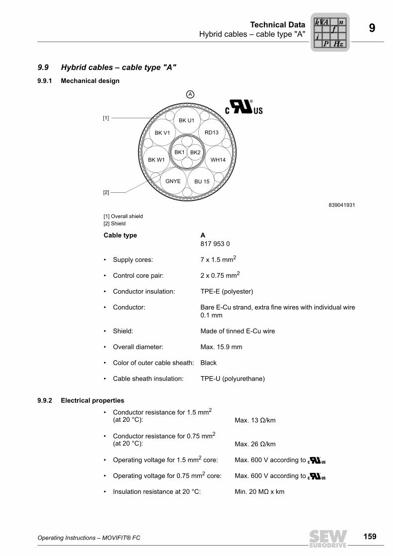
Operating Instructions – MOVIFIT® FC 159
9Hybrid cables – cable type "A"Technical Data
9.9 Hybrid cables – cable type "A"9.9.1 Mechanical design
9.9.2 Electrical properties
839041931
[1] Overall shield [2] Shield
Cable type A817 953 0
• Supply cores: 7 x 1.5 mm2
• Control core pair: 2 x 0.75 mm2
• Conductor insulation: TPE-E (polyester)
• Conductor: Bare E-Cu strand, extra fine wires with individual wire0.1 mm
• Shield: Made of tinned E-Cu wire
• Overall diameter: Max. 15.9 mm
• Color of outer cable sheath: Black
• Cable sheath insulation: TPE-U (polyurethane)
• Conductor resistance for 1.5 mm2 (at 20 °C): Max. 13 Ω/km
• Conductor resistance for 0.75 mm2 (at 20 °C): Max. 26 Ω/km
• Operating voltage for 1.5 mm2 core: Max. 600 V according to
• Operating voltage for 0.75 mm2 core: Max. 600 V according to
• Insulation resistance at 20 °C: Min. 20 MΩ x km
[1]
[2]
A
GNYE
BK U1
RD13
WH14
BK V1
BK W1
BU 15
BK1 BK2
Pi
fkVA
Hz
n

160 Operating Instructions – MOVIFIT® FC
9 Hybrid cables – cable type "A"Technical Data
9.9.3 Mechanical properties
9.9.4 Thermal properties
9.9.5 Chemical properties• Oil-resistant according to DIN VDE 0472 part 803 method B
• General fuel resistance (such as diesel, gasoline) according to DIN ISO 6722 parts1 and 2
• General resistance to acids, alkalis, cleaning agents
• General resistance against dusts (e.g. bauxite, magnesite)
• Insulation and cable jacket material is halogen free according to DIN VDE 0472 part815
• Within the specified temperature range, free from substances interfering with wettingagents (silicone-free)
• Suitable for cable carriers– Bending cycles > 2.5 million– Travel speed ≤ 3 m/s
• Bending radius
in the cable carrier:
for fixed routing:
10 x diameter
5 x diameter
• Torsional strength (e.g. rotary table applications)– Torsion ±180° for a cable length of > 1 m– Torsional cycles > 100.000
INFORMATIONYou will have to check the mechanical marginal conditions if you encounter reversedbending and high torsional load for a length of < 3 m. Please contact SEW-EURO-DRIVE in such cases.
• Processing and operation: –30 °C – +90 °C (load capacity according toDIN VDE 0298-4)
–30 °C – +80 °C according to
• Transport and storage: –40 °C – +90 °C (load capacity according toDIN VDE 0298-4)
–30 °C – +80 °C according to
• Flame-retardant according to UL1581 Vertical Wiring Flame Test (VW-1)
• Flame-retardant according to CSA C22.2 Vertical Flame Test (FT-1)
Pi
fkVA
Hz
n

Operating Instructions – MOVIFIT® FC 161
9Braking torquesTechnical Data
9.10 Braking torquesThe following table shows the technical data of the brakes. The type and number ofbrake springs determines the level of the braking torque. Maximum braking torqueMB max is installed as standard, unless specified otherwise in the order. Other brakespring combinations can produce the reduced braking torque values MB red.
BrakeType
For motorsize
MB max[Nm]
Reduced braking torques MB red[Nm]
BMG02 DT56 1.2 0.8
BR03 DR63 3.2 2.4 1.6 0.8
BMG05 DT71 / DT80 5.0 4 2.5 1.6 1.2
BMG1 DT80 10 7.5 6
BMG2 DT90 / DV100 20 16 10 6.6 5
BMG4 DV100 40 30 24
BMG8DV112M 55 45 37 30 19 12.6 9.5
DV132S 75 55 45 37 30 19 12.6 9.5
BE05 DRS71S4 5.0 3.5 2.5 1.8
BE1 DRS71M4 – DRP90M4 10 7.0 5.0
BE2 DRS80M4 – DRP100M4 20 14 10 7.0
BE5 DRS90L4 – DRS112M4DRE100M4 – DRE132S4DRP100L4 – DRP112M4
55 40 28 20
BE11 DRS132S4 110 80 55 40
MB max Maximum braking torque MB red Reduced braking torque
Pi
fkVA
Hz
n

162 Operating Instructions – MOVIFIT® FC
9 4Q operation for motors with mechanical brakeTechnical Data
9.11 4Q operation for motors with mechanical brake• The brake coil can be used as a braking resistor in 4-Q operation.
• Brake voltage is generated internally within the unit, which means it is grid-indepen-dent.
• The following figures show the regenerative load capacities of the internal brakecoils. If the regenerative load capacity is not sufficient for the application, connect anadditional braking resistor (see the following chapter).
• The following figure shows the load capacity of the DR motor brake coils:
• The following figure shows the load capacity of the DT/DV motor brake coils:
1583372939
1609476875
20.000
25.000
10.000
15.000
5.000
0101 100 1.000 10.000
BE5 (120V)
BE2 (230V)
BE05 (230V)
BE1 (230V)
[J]
[c/h]
20.000
15.000
10.000
5.000
0
10 100 1.000 10.000
[J]
[c/h]
BMG2 / BMG4 (110V)
BMG2 (230V)
BMG 1 (230V)
BMG05 (230V)
Pi
fkVA
Hz
n

Operating Instructions – MOVIFIT® FC 163
9Internal braking resistorsTechnical Data
9.12 Internal braking resistors9.12.1 Assignment
9.12.2 Regenerative load capacity
839084939
MOVIFIT® type Braking resistor Part number
MFT11A003... to MFT11A015... BW1T 1820 705 7
MFT11A022... to MFT11A040... BW2T 1820 754 5
839089035
[c/h] cycles per hour[1] Brake ramp 10 s[2] Brake ramp 4 s[3] Brake ramp 0.2 s
200400
300600
400800
5001000
6001200
[J]
BW2 BW1
[1]
[2]
[3]
00
100200
0 10 50 100 200 500 1000 2000 3000 4000 5000 6000[c/h]
Pi
fkVA
Hz
n
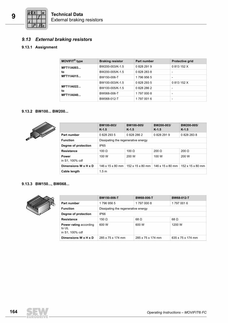
164 Operating Instructions – MOVIFIT® FC
9 External braking resistorsTechnical Data
9.13 External braking resistors9.13.1 Assignment
9.13.2 BW100... BW200...
9.13.3 BW150..., BW068...
MOVIFIT® type Braking resistor Part number Protective grid
MFT11A003...to MFT11A015...
BW200-003/K-1.5 0 828 291 9 0 813 152 X
BW200-005/K-1.5 0 828 283 8 -
BW150-006-T 1 796 956 5 -
MFT11A022...to MFT11A040...
BW100-003/K-1.5 0 828 293 5 0 813 152 X
BW100-005/K-1.5 0 828 286 2 -
BW068-006-T 1 797 000 8 -
BW068-012-T 1 797 001 6 -
BW100-003/K-1.5
BW100-005/K-1.5
BW200-003/K-1.5
BW200-005/K-1.5
Part number 0 828 293 5 0 828 286 2 0 828 291 9 0 828 283 8
Function Dissipating the regenerative energy
Degree of protection IP65
Resistance 100 Ω 100 Ω 200 Ω 200 Ω
Powerin S1, 100% cdf
100 W 200 W 100 W 200 W
Dimensions W x H x D 146 x 15 x 80 mm 152 x 15 x 80 mm 146 x 15 x 80 mm 152 x 15 x 80 mm
Cable length 1.5 m
BW150-006-T BW68-006-T BW68-012-T
Part number 1 796 956 5 1 797 000 8 1 797 001 6
Function Dissipating the regenerative energy
Degree of protection IP66
Resistance 150 Ω 68 Ω 68 Ω
Power rating according to ULin S1, 100% cdf
600 W 600 W 1200 W
Dimensions W x H x D 285 x 75 x 174 mm 285 x 75 x 174 mm 635 x 75 x 174 mm
Pi
fkVA
Hz
n
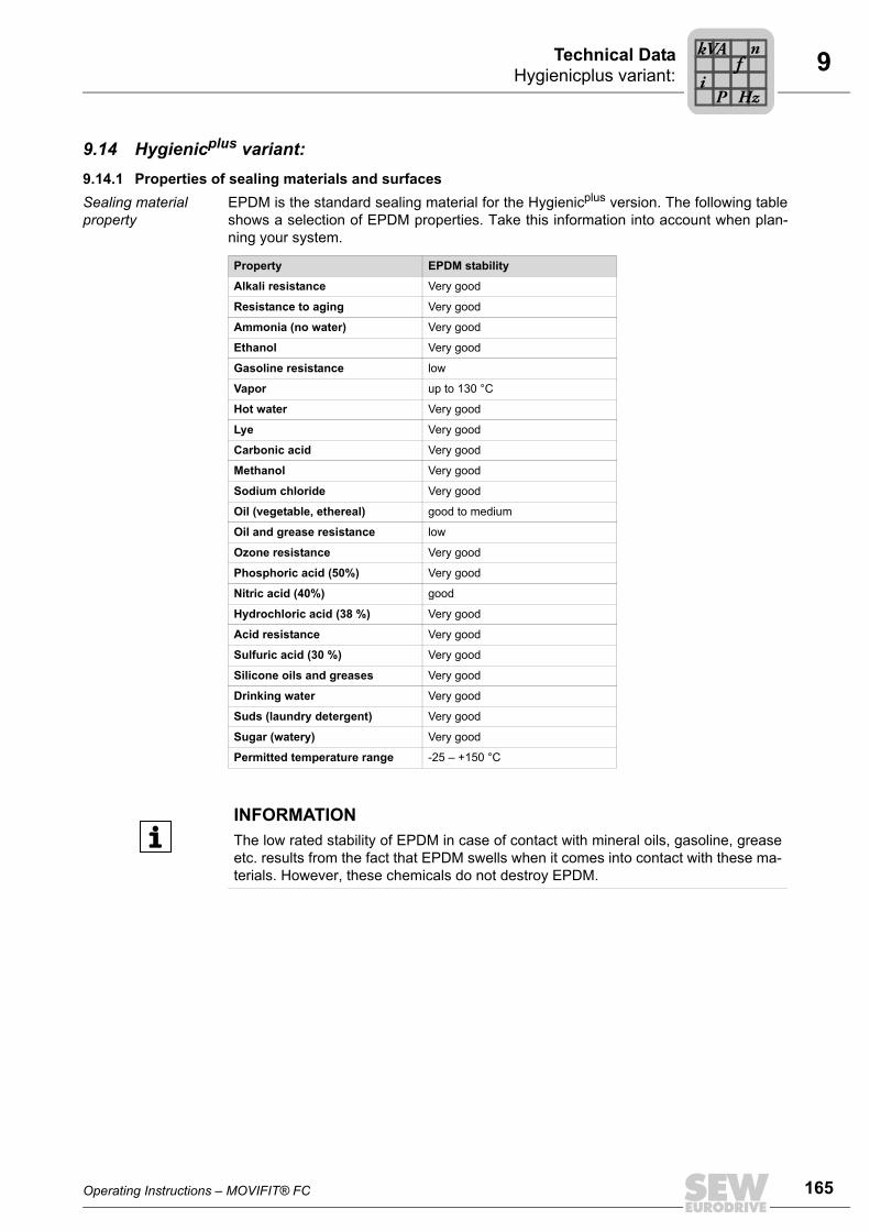
Operating Instructions – MOVIFIT® FC 165
9Hygienicplus variant:Technical Data
9.14 Hygienicplus variant:9.14.1 Properties of sealing materials and surfacesSealing material property
EPDM is the standard sealing material for the Hygienicplus version. The following tableshows a selection of EPDM properties. Take this information into account when plan-ning your system.
Property EPDM stability
Alkali resistance Very good
Resistance to aging Very good
Ammonia (no water) Very good
Ethanol Very good
Gasoline resistance low
Vapor up to 130 °C
Hot water Very good
Lye Very good
Carbonic acid Very good
Methanol Very good
Sodium chloride Very good
Oil (vegetable, ethereal) good to medium
Oil and grease resistance low
Ozone resistance Very good
Phosphoric acid (50%) Very good
Nitric acid (40%) good
Hydrochloric acid (38 %) Very good
Acid resistance Very good
Sulfuric acid (30 %) Very good
Silicone oils and greases Very good
Drinking water Very good
Suds (laundry detergent) Very good
Sugar (watery) Very good
Permitted temperature range -25 – +150 °C
INFORMATIONThe low rated stability of EPDM in case of contact with mineral oils, gasoline, greaseetc. results from the fact that EPDM swells when it comes into contact with these ma-terials. However, these chemicals do not destroy EPDM.
Pi
fkVA
Hz
n

166 Operating Instructions – MOVIFIT® FC
9 Hygienicplus variant:Technical Data
Surface properties • Advanced antistick surface properties
• Surface roughness
– Ra < 1.6 to 2
• Resistance to acidic and alkaline cleaning agents
– Sulfuric acid (10 %)
– Caustic soda (10%)
Do not mix cleaning and disinfecting agents under any circumstances!Never mix acids and chloralkalis, as poisonous chlorine gas will result.Strictly observe the safety instructions of the cleaning agent manufacturer.
• Resistance to materials at the place of installation
– Grease
– Mineral oils
– Edible oils
– Gasoline
– Alcohol
– Solvent
• Resilient against shock and impact load
• Impact-resistant
• Resistant to temperature change
– -25 – 60 °C
– Increased temperature for cleaning processes: 80 ˚C
• Water jet resistant
– Approx. 100 l/min
• Steam cleaning (according to DIN 40050 part 9)
– Max. 80 – 100 bar (approx. 15 l/min)
– Max. 80 °C (30 seconds)
• Light resistant
– Direct sunlight
Pi
fkVA
Hz
n

Operating Instructions – MOVIFIT® FC 167
9Options and accessoriesTechnical Data
9.14.2 Optional metal cable glands and protective caps
9.15 Options and accessories
Type Degree of protec-tion
Figure Content Size Part number
Stainless steel screw plugs IP69K 10 pcs M16 x 1.5 1820 223 3
10 pcs M20 x 1.5 1820 224 1
10 pcs M25 x 1.5 1820 226 8
EMC cable gland (brass, nickel plated)
IP66 10 pcs M16 x 1.5 1820 478 3
10 pcs M20 x 1.5 1820 479 1
10 pcs M25 x 1.5 1820 480 5
EMC cable gland (stainless steel)
IP69K 10 pcs M16 x 1.5 1821 636 6
10 pcs M20 x 1.5 1821 637 4
10 pcs M25 x 1.5 1821 638 2
Type Figure Content Part number
Ethernet closing plugfor push-pull RJ45 socket
10 pcs 1822 370 2
30 pcs 1822 371 0
RJ45-M12 Ethernet adapterRJ45 (internal)M12 (external)2 required for each unit.
1 pc 1328 168 2
Pi
fkVA
Hz
n

168 Operating Instructions – MOVIFIT® FC
9 Dimension drawingsTechnical Data
9.16 Dimension drawings9.16.1 MOVIFIT® FC, (0.37 – 1.5 kW) with standard mounting rail
18014399348645003[1] The clearance of 104 mm below is only necessary for ABOXes with round connector (Intercontec) motor output pointing downward.[2] The clearance of 191 mm at the front is only necessary for ABOXes with round connector (Intercontec) motor output pointing forward.
328.
830
4.1
min
. 40
min
. 104
min. 50
12
37.5
15
140
280
334.4
66
[1] 179.7
25.6
317.
3
Z
Z
140
min. 191
[2]
Pi
fkVA
Hz
n
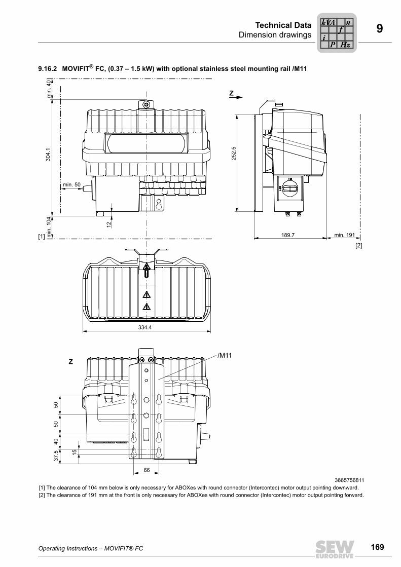
Operating Instructions – MOVIFIT® FC 169
9Dimension drawingsTechnical Data
9.16.2 MOVIFIT® FC, (0.37 – 1.5 kW) with optional stainless steel mounting rail /M11
3665756811[1] The clearance of 104 mm below is only necessary for ABOXes with round connector (Intercontec) motor output pointing downward.[2] The clearance of 191 mm at the front is only necessary for ABOXes with round connector (Intercontec) motor output pointing forward.
252.
5189.7
66
15
37.5
304.
1m
in. 4
0m
in. 1
04
min. 50
12
334.4
Z
/M11Z
4050
50
[1] min. 191
[2]
Pi
fkVA
Hz
n

170 Operating Instructions – MOVIFIT® FC
9 Dimension drawingsTechnical Data
9.16.3 MOVIFIT® FC, (2.2 – 4 kW) with standard mounting rail
18014399348649355[1] The clearance of 104 mm below is only necessary for ABOXes with round connector (Intercontec) motor output pointing downward.[2] The clearance of 191 mm at the front is only necessary for ABOXes with round connector (Intercontec) motor output pointing forward.
334.4
317.
3
179.712
332.
5m
in. 4
0m
in. 1
04
min. 50
Z
37.5
15
140
280
66
25.6
Z
140
[1]min. 191
[2]
Pi
fkVA
Hz
n

Operating Instructions – MOVIFIT® FC 171
9Dimension drawingsTechnical Data
9.16.4 MOVIFIT® FC, (2.2 – 4 kW) with optional stainless steel mounting rail /M11
3713271179[1] The clearance of 104 mm below is only necessary for ABOXes with round connector (Intercontec) motor output pointing downward.[2] The clearance of 191 mm at the front is only necessary for ABOXes with round connector (Intercontec) motor output pointing forward.
334.4
12
332.
5m
in. 4
0
min. 50
Z
Z
66
15
37.5
4050
50
252.
5
189.7
/M11
min
. 104
[1] min. 191
[2]
Pi
fkVA
Hz
n
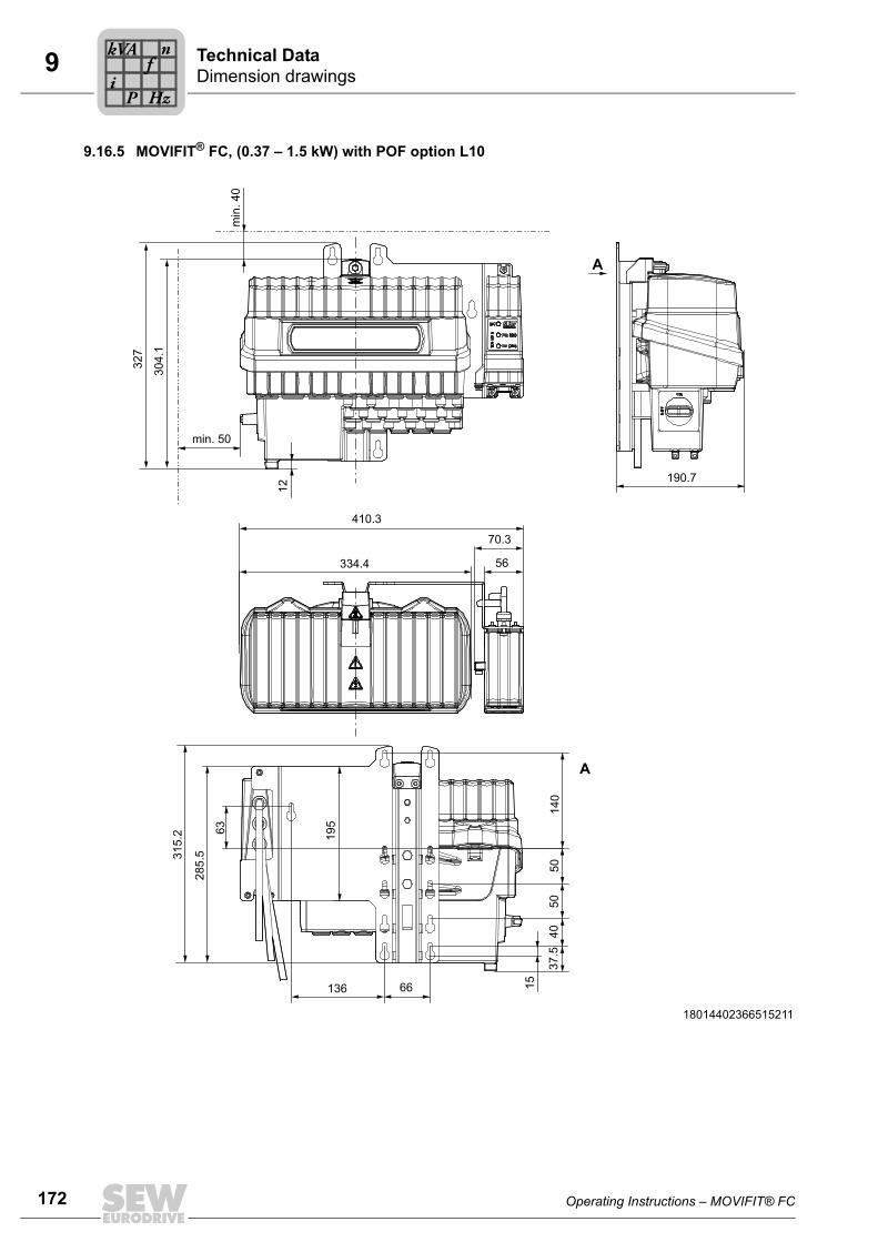
172 Operating Instructions – MOVIFIT® FC
9 Dimension drawingsTechnical Data
9.16.5 MOVIFIT® FC, (0.37 – 1.5 kW) with POF option L10
18014402366515211
A
190.7
A
285.
5315.
2 63
66136
195
140
40
5050
15
37.5
334.4 56
70.3
410.3
min. 50
304.
1
327
12
min
. 40
Pi
fkVA
Hz
n

Operating Instructions – MOVIFIT® FC 173
9Dimension drawingsTechnical Data
9.16.6 MOVIFIT® FC, (2.2 – 4 kW) with POF option L10
4385759883
332.
3
12
A
A
190.7
334.4 5670.3
410.3
285.
5315.
2 63
66136
195
140
37.5
4050
15
min
. 40
min. 50
50
Pi
fkVA
Hz
n

174 Operating Instructions – MOVIFIT® FC
9 Dimension drawingsTechnical Data
9.16.7 ABOX with round connector (Intercontec), motor output pointing downward
The following figure shows the minimum installation clearance of the hybrid ABOX withround connector and motor output pointing downward.
36028801787793163[1] Smallest permitted pending radius of bulk cable: 75 mm[2] Minimum distance to the bottom of the ABOX: 104 mm
104
[2]
75
R75[1]
113
Pi
fkVA
Hz
n

Operating Instructions – MOVIFIT® FC 175
9Dimension drawingsTechnical Data
9.16.8 ABOX with round connector (Intercontec), motor output pointing forward:
The following figure shows the minimum installation clearance of the hybrid ABOX withround connector and motor output pointing forward.
9007204023573387[1] Smallest permitted pending radius of bulk cable: 75 mm[2] Minimum distance to the front of the ABOX: 191 mm
[1] R75
[2] 191
75
127
Pi
fkVA
Hz
n

176 Operating Instructions – MOVIFIT® FC
10 Declaration of Conformity
10 Declaration of Conformity
3122942731
EC Declaration of Conformity
BruchsalJohann Soder
Place Date Managing Director Technology a) b)
a) Authorized representative for issuing this declaration on behalf of the manufacturer b) Authorized representative for compiling the technical documents
900070010
11.12.09
SEW-EURODRIVE GmbH & Co KGErnst-Blickle-Straße 42, D-76646 Bruchsaldeclares under sole responsibility that the
units of the series MOVIFIT® FCMOVIFIT® MC
are in conformity with
Machinery Directive 2006/42/EC 1)
Low Voltage Directive 2006/95/EC
EMC Directive 2004/108/EC 4)
applied harmonized standards EN 13849-1:2008 5)EN 61800-5-1:2007EN 61800-3:2007
1) These products are intended for installation in machines. Startup is prohibited until it has beenestablished that the machinery into which these products are to be incorporated complies with theprovisions of the aforementioned Machinery Directive.
4) According to the EMC Directive, the listed products are not independently operable products. EMCassessment is only possible after these products have been integrated in an overall system. Theassessment was verified for a typical system constellation, but not for the individual product.
5) All safety-relevant requirements of the product-specific documentation (operating instructions,manual, etc.) must be met over the entire product life cycle.

Operating Instructions – MOVIFIT® FC 177
10Declaration of Conformity
3122944651
EC Declaration of Conformity
BruchsalJohann Soder
Place Date Managing Director Technology a) b)
a) Authorized representative for issuing this declaration on behalf of the manufacturer b) Authorized representative for compiling the technical documents
900080010
21.12.09
SEW-EURODRIVE GmbH & Co KGErnst-Blickle-Straße 42, D-76646 Bruchsaldeclares under sole responsibility that the
units of the series MOVIFIT® FCMOVIFIT® MC
in connection with S11 PROFIsafe®
are in conformity with
Machinery Directive 2006/42/EC 1)
Low Voltage Directive 2006/95/EC
EMC Directive 2004/108/EC 4)
applied harmonized standards EN 13849-1:2008 5)EN 62061: 2006 5)EN 61800-5-1:2007EN 61800-3:2007
1) These products are intended for installation in machines. Startup is prohibited until it has beenestablished that the machinery into which these products are to be incorporated complies with theprovisions of the aforementioned Machinery Directive.
4) According to the EMC Directive, the listed products are not independently operable products. EMCassessment is only possible after these products have been integrated in an overall system. Theassessment was verified for a typical system constellation, but not for the individual product.
5) All safety-relevant requirements of the product-specific documentation (operating instructions,manual, etc.) must be met over the entire product life cycle.

178 Operating Instructions – MOVIFIT® FC
11 Address List
11 Address List
Germany
HeadquartersProductionSales
Bruchsal SEW-EURODRIVE GmbH & Co KGErnst-Blickle-Straße 42 D-76646 BruchsalP.O. BoxPostfach 3023 • D-76642 Bruchsal
Tel. +49 7251 75-0Fax +49 7251 75-1970http://[email protected]
Production / Indus-trial Gears
Bruchsal SEW-EURODRIVE GmbH & Co KGChristian-Pähr-Str.10D-76646 Bruchsal
Tel. +49 7251 75-0Fax +49 7251 75-2970
Service Compe-tence Center
Central SEW-EURODRIVE GmbH & Co KGErnst-Blickle-Straße 1 D-76676 Graben-Neudorf
Tel. +49 7251 75-1710Fax +49 7251 [email protected]
North SEW-EURODRIVE GmbH & Co KGAlte Ricklinger Straße 40-42 D-30823 Garbsen (near Hannover)
Tel. +49 5137 8798-30Fax +49 5137 [email protected]
East SEW-EURODRIVE GmbH & Co KGDänkritzer Weg 1D-08393 Meerane (near Zwickau)
Tel. +49 3764 7606-0Fax +49 3764 [email protected]
South SEW-EURODRIVE GmbH & Co KGDomagkstraße 5D-85551 Kirchheim (near München)
Tel. +49 89 909552-10Fax +49 89 [email protected]
West SEW-EURODRIVE GmbH & Co KGSiemensstraße 1D-40764 Langenfeld (near Düsseldorf)
Tel. +49 2173 8507-30Fax +49 2173 [email protected]
Electronics SEW-EURODRIVE GmbH & Co KGErnst-Blickle-Straße 42 D-76646 Bruchsal
Tel. +49 7251 75-1780Fax +49 7251 [email protected]
Drive Service Hotline / 24 Hour Service +49 180 5 SEWHELP+49 180 5 739435714 euro cents/min on the German land-line network. Max 42 euro cents/min from a German mobile network. Prices for mobile and international calls may differ.
Additional addresses for service in Germany provided on request!
France
ProductionSalesService
Haguenau SEW-USOCOME 48-54 route de Soufflenheim B. P. 20185F-67506 Haguenau Cedex
Tel. +33 3 88 73 67 00 Fax +33 3 88 73 66 00http://[email protected]
Production Forbach SEW-USOCOME Zone industrielle Technopôle Forbach SudB. P. 30269F-57604 Forbach Cedex
Tel. +33 3 87 29 38 00
AssemblySalesService
Bordeaux SEW-USOCOME Parc d'activités de Magellan62 avenue de Magellan - B. P. 182F-33607 Pessac Cedex
Tel. +33 5 57 26 39 00Fax +33 5 57 26 39 09
Lyon SEW-USOCOME Parc d'affaires RooseveltRue Jacques TatiF-69120 Vaulx en Velin
Tel. +33 4 72 15 37 00Fax +33 4 72 15 37 15

Operating Instructions – MOVIFIT® FC 179
11Address List
Nantes SEW-USOCOME Parc d’activités de la forêt4 rue des FontenellesF-44140 Le Bignon
Tel. +33 2 40 78 42 00Fax +33 2 40 78 42 20
Paris SEW-USOCOME Zone industrielle 2 rue Denis Papin F-77390 Verneuil I'Etang
Tel. +33 1 64 42 40 80Fax +33 1 64 42 40 88
Additional addresses for service in France provided on request!
Algeria
Sales Algiers REDUCOM Sarl 16, rue des Frères ZaghnouneBellevue16200 El Harrach Alger
Tel. +213 21 8214-91Fax +213 21 [email protected]://www.reducom-dz.com
Argentina
AssemblySales
Buenos Aires SEW EURODRIVE ARGENTINA S.A.Centro Industrial Garin, Lote 35Ruta Panamericana Km 37,51619 Garin
Tel. +54 3327 4572-84Fax +54 3327 [email protected]://www.sew-eurodrive.com.ar
Australia
AssemblySalesService
Melbourne SEW-EURODRIVE PTY. LTD.27 Beverage DriveTullamarine, Victoria 3043
Tel. +61 3 9933-1000Fax +61 3 9933-1003http://[email protected]
Sydney SEW-EURODRIVE PTY. LTD.9, Sleigh Place, Wetherill Park New South Wales, 2164
Tel. +61 2 9725-9900Fax +61 2 [email protected]
Austria
AssemblySalesService
Wien SEW-EURODRIVE Ges.m.b.H. Richard-Strauss-Strasse 24A-1230 Wien
Tel. +43 1 617 55 00-0Fax +43 1 617 55 00-30http://[email protected]
Belarus
Sales Minsk SEW-EURODRIVE BYRybalkoStr. 26BY-220033 Minsk
Tel.+375 17 298 47 56 / 298 47 58Fax +375 17 298 47 54http://[email protected]
Belgium
AssemblySalesService
Brussels SEW-EURODRIVE n.v./s.a.Researchpark Haasrode 1060Evenementenlaan 7BE-3001 Leuven
Tel. +32 16 386-311Fax +32 16 386-336http://[email protected]
Service Compe-tence Center
Industrial Gears SEW-EURODRIVE n.v./s.a.Rue de Parc Industriel, 31BE-6900 Marche-en-Famenne
Tel. +32 84 219-878Fax +32 84 219-879http://[email protected]
Brazil
ProductionSalesService
São Paulo SEW-EURODRIVE Brasil Ltda.Avenida Amâncio Gaiolli, 152 - Rodovia Presi-dente Dutra Km 208Guarulhos - 07251-250 - SPSAT - SEW ATENDE - 0800 7700496
Tel. +55 11 2489-9133Fax +55 11 2480-3328http://[email protected]
France

180 Operating Instructions – MOVIFIT® FC
11 Address List
AssemblySalesService
Rio Claro SEW-EURODRIVE Brasil Ltda.Rodovia Washington Luiz, Km 172Condomínio Industrial Conparq13501-600 – Rio Claro / SP
Tel. +55 19 3522-3100Fax +55 19 [email protected]
Joinville SEW-EURODRIVE Brasil Ltda.Rua Dona Francisca, 12.346 – Pirabeiraba89239-270 – Joinville / SC
Tel. +55 47 3027-6886Fax +55 47 [email protected]
Indaiatuba SEW-EURODRIVE Brasil Ltda.Estrada Municipal Jose Rubim, 205Rodovia Santos Dumont Km 4913347-510 - Indaiatuba / SP
Tel. +55 19 [email protected]
Bulgaria
Sales Sofia BEVER-DRIVE GmbHBogdanovetz Str.1BG-1606 Sofia
Tel. +359 2 9151160Fax +359 2 [email protected]
Cameroon
Sales Douala Electro-ServicesRue Drouot AkwaB.P. 2024Douala
Tel. +237 33 431137Fax +237 33 [email protected]
Canada
AssemblySalesService
Toronto SEW-EURODRIVE CO. OF CANADA LTD. 210 Walker Drive Bramalea, ON L6T 3W1
Tel. +1 905 791-1553Fax +1 905 791-2999http://[email protected]
Vancouver SEW-EURODRIVE CO. OF CANADA LTD.Tilbury Industrial Park7188 Honeyman Street Delta, BC V4G 1G1
Tel. +1 604 946-5535Fax +1 604 [email protected]
Montreal SEW-EURODRIVE CO. OF CANADA LTD.2555 Rue Leger Lasalle, PQ H8N 2V9
Tel. +1 514 367-1124Fax +1 514 [email protected]
Additional addresses for service in Canada provided on request!
Chile
AssemblySalesService
Santiago SEW-EURODRIVE CHILE LTDA.Las Encinas 1295Parque Industrial Valle GrandeLAMPARCH-Santiago de ChileP.O. BoxCasilla 23 Correo Quilicura - Santiago - Chile
Tel. +56 2 75770-00Fax +56 2 75770-01http://[email protected]
China
ProductionAssemblySalesService
Tianjin SEW-EURODRIVE (Tianjin) Co., Ltd.No. 46, 7th Avenue, TEDATianjin 300457
Tel. +86 22 25322612Fax +86 22 [email protected]://www.sew-eurodrive.cn
AssemblySalesService
Suzhou SEW-EURODRIVE (Suzhou) Co., Ltd.333, Suhong Middle RoadSuzhou Industrial ParkJiangsu Province, 215021
Tel. +86 512 62581781Fax +86 512 [email protected]
Brazil

Operating Instructions – MOVIFIT® FC 181
11Address List
Guangzhou SEW-EURODRIVE (Guangzhou) Co., Ltd.No. 9, JunDa RoadEast Section of GETDDGuangzhou 510530
Tel. +86 20 82267890Fax +86 20 [email protected]
Shenyang SEW-EURODRIVE (Shenyang) Co., Ltd.10A-2, 6th RoadShenyang Economic Technological Develop-ment AreaShenyang, 110141
Tel. +86 24 25382538Fax +86 24 [email protected]
Wuhan SEW-EURODRIVE (Wuhan) Co., Ltd.10A-2, 6th RoadNo. 59, the 4th Quanli Road, WEDA430056 Wuhan
Tel. +86 27 84478388Fax +86 27 [email protected]
Xi'An SEW-EURODRIVE (Xi'An) Co., Ltd.No. 12 Jinye 2nd RoadXi'An High-Technology Industrial Development ZoneXi'An 710065
Tel. +86 29 68686262Fax +86 29 [email protected]
Additional addresses for service in China provided on request!
Colombia
AssemblySalesService
Bogotá SEW-EURODRIVE COLOMBIA LTDA. Calle 22 No. 132-60Bodega 6, Manzana BSantafé de Bogotá
Tel. +57 1 54750-50Fax +57 1 54750-44http://[email protected]
Croatia
SalesService
Zagreb KOMPEKS d. o. o.Zeleni dol 10HR 10 000 Zagreb
Tel. +385 1 4613-158Fax +385 1 [email protected]
Czech Republic
SalesAssemblyService
Prague SEW-EURODRIVE CZ s.r.o.Lužná 59116000 Praha 6 - Vokovice
Tel. +420 255 709 601Fax +420 220 121 237http://[email protected]
Drive Service Hotline / 24 Hour Service
HOT-LINE +420 800 739 739 (800 SEW SEW) Servis:Tel. +420 255 709 632Fax +420 235 358 [email protected]
Denmark
AssemblySalesService
Copenhagen SEW-EURODRIVEA/SGeminivej 28-30DK-2670 Greve
Tel. +45 43 9585-00Fax +45 43 9585-09http://[email protected]
Egypt
SalesService
Cairo Copam Egypt for Engineering & Agencies33 EI Hegaz ST, Heliopolis, Cairo
Tel. +20 2 22566-299 +1 23143088Fax +20 2 22594-757http://www.copam-egypt.com/ [email protected]
Estonia
Sales Tallin ALAS-KUUL ASReti tee 4EE-75301 Peetri küla, Rae vald, Harjumaa
Tel. +372 6593230Fax +372 [email protected]
China
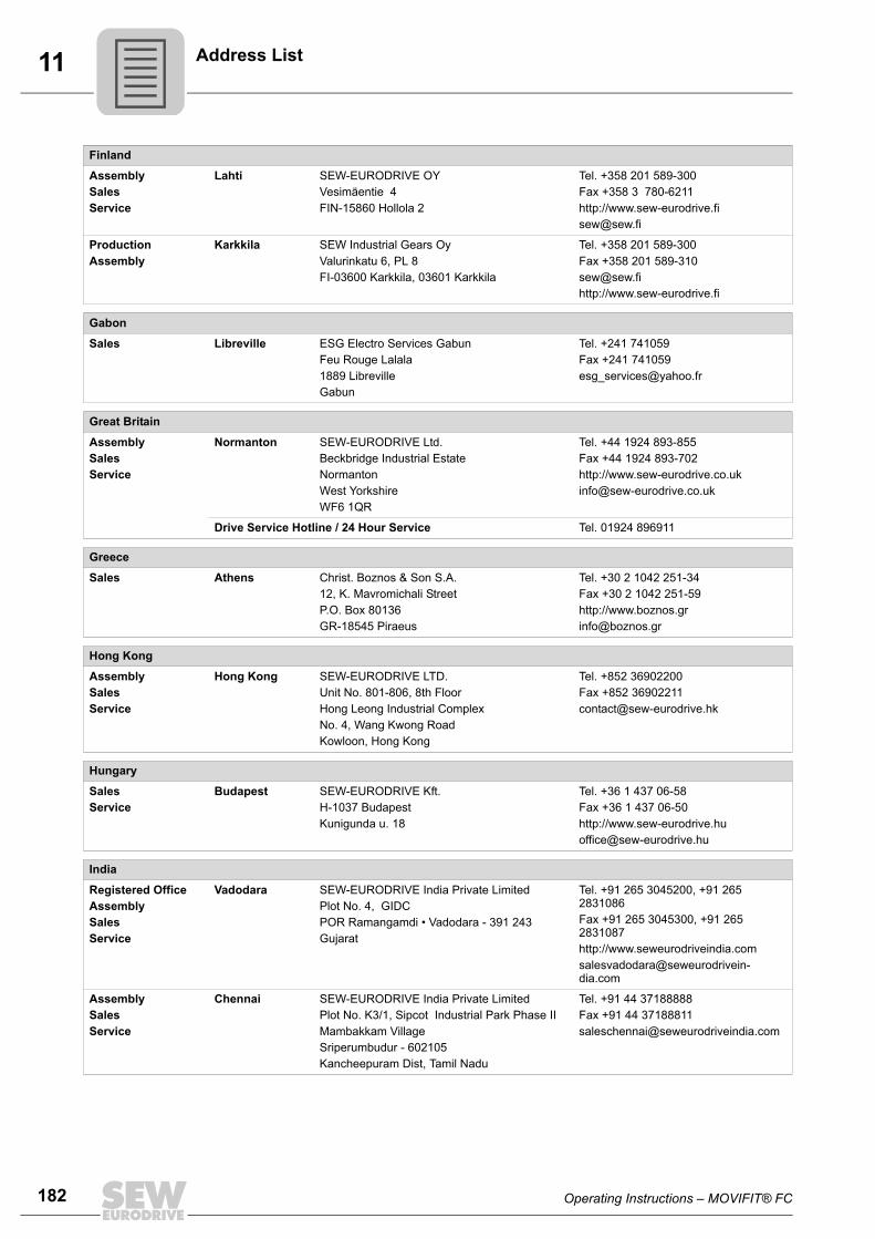
182 Operating Instructions – MOVIFIT® FC
11 Address List
Finland
AssemblySalesService
Lahti SEW-EURODRIVE OYVesimäentie 4FIN-15860 Hollola 2
Tel. +358 201 589-300Fax +358 3 780-6211http://[email protected]
ProductionAssembly
Karkkila SEW Industrial Gears OyValurinkatu 6, PL 8FI-03600 Karkkila, 03601 Karkkila
Tel. +358 201 589-300Fax +358 201 [email protected]://www.sew-eurodrive.fi
Gabon
Sales Libreville ESG Electro Services GabunFeu Rouge Lalala1889 LibrevilleGabun
Tel. +241 741059Fax +241 [email protected]
Great Britain
AssemblySalesService
Normanton SEW-EURODRIVE Ltd.Beckbridge Industrial Estate NormantonWest Yorkshire WF6 1QR
Tel. +44 1924 893-855Fax +44 1924 893-702http://[email protected]
Drive Service Hotline / 24 Hour Service Tel. 01924 896911
Greece
Sales Athens Christ. Boznos & Son S.A.12, K. Mavromichali StreetP.O. Box 80136GR-18545 Piraeus
Tel. +30 2 1042 251-34 Fax +30 2 1042 251-59http://[email protected]
Hong Kong
AssemblySalesService
Hong Kong SEW-EURODRIVE LTD.Unit No. 801-806, 8th FloorHong Leong Industrial ComplexNo. 4, Wang Kwong Road Kowloon, Hong Kong
Tel. +852 36902200Fax +852 [email protected]
Hungary
SalesService
Budapest SEW-EURODRIVE Kft.H-1037 BudapestKunigunda u. 18
Tel. +36 1 437 06-58Fax +36 1 437 06-50http://[email protected]
India
Registered OfficeAssemblySalesService
Vadodara SEW-EURODRIVE India Private LimitedPlot No. 4, GIDCPOR Ramangamdi • Vadodara - 391 243Gujarat
Tel. +91 265 3045200, +91 265 2831086Fax +91 265 3045300, +91 265 2831087http://[email protected]
AssemblySalesService
Chennai SEW-EURODRIVE India Private LimitedPlot No. K3/1, Sipcot Industrial Park Phase IIMambakkam VillageSriperumbudur - 602105Kancheepuram Dist, Tamil Nadu
Tel. +91 44 37188888Fax +91 44 [email protected]

Operating Instructions – MOVIFIT® FC 183
11Address List
Ireland
SalesService
Dublin Alperton Engineering Ltd. 48 Moyle RoadDublin Industrial EstateGlasnevin, Dublin 11
Tel. +353 1 830-6277Fax +353 1 [email protected]://www.alperton.ie
Israel
Sales Tel-Aviv Liraz Handasa Ltd. Ahofer Str 34B / 22858858 Holon
Tel. +972 3 5599511Fax +972 3 5599512http://[email protected]
Italy
AssemblySalesService
Solaro SEW-EURODRIVE di R. Blickle & Co.s.a.s.Via Bernini,14 I-20020 Solaro (Milano)
Tel. +39 02 96 9801Fax +39 02 96 799781http://[email protected]
Ivory Coast
Sales Abidjan SICASociété Industrielle & Commerciale pour l'Afrique165, Boulevard de Marseille26 BP 1173 Abidjan 26
Tel. +225 21 25 79 44Fax +225 21 25 88 [email protected]
Japan
AssemblySalesService
Iwata SEW-EURODRIVE JAPAN CO., LTD 250-1, Shimoman-no,IwataShizuoka 438-0818
Tel. +81 538 373811Fax +81 538 373855http://[email protected]
Kazakhstan
Sales Almaty ТОО "СЕВ-ЕВРОДРАЙВ"пр.Райымбека, 348050061 г. АлматыРеспублика Казахстан
Тел. +7 (727) 334 1880Факс +7 (727) 334 1881http://[email protected]
Kenya
Sales Nairobi Barico Maintenances LtdKamutaga PlaceCommercial StreetIndustrial AreaP.O.BOX 52217 - 00200Nairobi
Tel. +254 20 6537094/5Fax +254 20 [email protected]
Latvia
Sales Riga SIA Alas-KuulKatlakalna 11CLV-1073 Riga
Tel. +371 6 7139253Fax +371 6 7139386http://[email protected]
Lebanon
Sales Lebanon Beirut Gabriel Acar & Fils sarlB. P. 80484Bourj Hammoud, Beirut
Tel. +961 1 510 532Fax +961 1 494 [email protected]
After Sales Service [email protected]

184 Operating Instructions – MOVIFIT® FC
11 Address List
Sales Jordan / Kuwait / Saudi Ara-bia / Syria
Beirut Middle East Drives S.A.L. (offshore)Sin El Fil.B. P. 55-378Beirut
Tel. +961 1 494 786Fax +961 1 494 [email protected]://www.medrives.com
After Sales Service [email protected]
Lithuania
Sales Alytus UAB IrsevaStatybininku 106CLT-63431 Alytus
Tel. +370 315 79204Fax +370 315 [email protected]://www.sew-eurodrive.lt
Luxembourg
AssemblySalesService
Brussels SEW-EURODRIVE n.v./s.a.Researchpark Haasrode 1060Evenementenlaan 7BE-3001 Leuven
Tel. +32 16 386-311Fax +32 16 386-336http://[email protected]
Madagascar
Sales Antananarivo Ocean TradeBP21bis. AndraharoAntananarivo.101 Madagascar
Tel. +261 20 2330303Fax +261 20 [email protected]
Malaysia
AssemblySalesService
Johor SEW-EURODRIVE SDN BHD No. 95, Jalan Seroja 39, Taman Johor Jaya81000 Johor Bahru, JohorWest Malaysia
Tel. +60 7 3549409Fax +60 7 [email protected]
Mexico
AssemblySalesService
Quéretaro SEW-EURODRIVE MEXICO SA DE CVSEM-981118-M93Tequisquiapan No. 102Parque Industrial QuéretaroC.P. 76220Quéretaro, México
Tel. +52 442 1030-300Fax +52 442 1030-301http://[email protected]
Morocco
SalesService
Mohammedia SEW EURODRIVE SARLZ.I. Sud Ouest - Lot 282ème étageMohammedia 28810
Tel. +212 523 32 27 80/81Fax +212 523 32 27 [email protected]://www.sew-eurodrive.ma
Namibia
Sales Swakopmund DB Mining & Industrial ServicesEinstein StreetStrauss Industrial ParkUnit1Swakopmund
Tel. +264 64 462 738Fax +264 64 462 [email protected]
Netherlands
AssemblySalesService
Rotterdam SEW-EURODRIVE B.V.Industrieweg 175 NL-3044 AS RotterdamPostbus 10085NL-3004 AB Rotterdam
Tel. +31 10 4463-700Fax +31 10 4155-552Service: 0800-SEWHELPhttp://[email protected]
Lebanon

Operating Instructions – MOVIFIT® FC 185
11Address List
New Zealand
AssemblySalesService
Auckland SEW-EURODRIVE NEW ZEALAND LTD. P.O. Box 58-428 82 Greenmount driveEast Tamaki Auckland
Tel. +64 9 2745627Fax +64 9 2740165http://[email protected]
Christchurch SEW-EURODRIVE NEW ZEALAND LTD. 10 Settlers Crescent, FerrymeadChristchurch
Tel. +64 3 384-6251Fax +64 3 [email protected]
Norway
AssemblySalesService
Moss SEW-EURODRIVE A/SSolgaard skog 71N-1599 Moss
Tel. +47 69 24 10 20Fax +47 69 24 10 40http://[email protected]
Pakistan
Sales Karachi Industrial Power DrivesAl-Fatah Chamber A/3, 1st Floor Central Com-mercial Area,Sultan Ahmed Shah Road, Block 7/8, Karachi
Tel. +92 21 452 9369Fax +92-21-454 [email protected]
Peru
AssemblySalesService
Lima SEW DEL PERU MOTORES REDUCTORES S.A.C.Los Calderos, 120-124Urbanizacion Industrial Vulcano, ATE, Lima
Tel. +51 1 3495280Fax +51 1 3493002http://[email protected]
Poland
AssemblySalesService
Lodz SEW-EURODRIVE Polska Sp.z.o.o.ul. Techniczna 5 PL-92-518 Łódź
Tel. +48 42 676 53 00Fax +48 42 676 53 49http://[email protected]
Service Tel. +48 42 6765332 / 42 6765343Fax +48 42 6765346
Linia serwisowa Hotline 24HTel. +48 602 739 739
(+48 602 SEW SEW)[email protected]
Portugal
AssemblySalesService
Coimbra SEW-EURODRIVE, LDA.Apartado 15 P-3050-901 Mealhada
Tel. +351 231 20 9670Fax +351 231 20 3685http://[email protected]
Romania
SalesService
Bucharest Sialco Trading SRL str. Madrid nr.4 011785 Bucuresti
Tel. +40 21 230-1328Fax +40 21 230-7170 [email protected]
Russia
AssemblySalesService
St. Petersburg ZAO SEW-EURODRIVE P.O. Box 36 RUS-195220 St. Petersburg
Tel. +7 812 3332522 +7 812 5357142Fax +7 812 3332523http://[email protected]
Senegal
Sales Dakar SENEMECA Mécanique GénéraleKm 8, Route de Rufisque B.P. 3251, Dakar
Tel. +221 338 494 770Fax +221 338 494 [email protected]://www.senemeca.com

186 Operating Instructions – MOVIFIT® FC
11 Address List
Serbia
Sales Beograd DIPAR d.o.o.Ustanicka 128aPC Košum, IV spratSRB-11000 Beograd
Tel. +381 11 347 3244 / +381 11 288 0393Fax +381 11 347 [email protected]
Singapore
AssemblySalesService
Singapore SEW-EURODRIVE PTE. LTD. No 9, Tuas Drive 2 Jurong Industrial Estate Singapore 638644
Tel. +65 68621701Fax +65 68612827http://[email protected]
Slovakia
Sales Bratislava SEW-Eurodrive SK s.r.o.Rybničná 40SK-831 06 Bratislava
Tel. +421 2 33595 202Fax +421 2 33595 [email protected]://www.sew-eurodrive.sk
Žilina SEW-Eurodrive SK s.r.o.Industry Park - PChZulica M.R.Štefánika 71SK-010 01 Žilina
Tel. +421 41 700 2513Fax +421 41 700 [email protected]
Banská Bystrica SEW-Eurodrive SK s.r.o.Rudlovská cesta 85SK-974 11 Banská Bystrica
Tel. +421 48 414 6564Fax +421 48 414 [email protected]
Košice SEW-Eurodrive SK s.r.o.Slovenská ulica 26SK-040 01 Košice
Tel. +421 55 671 2245Fax +421 55 671 [email protected]
Slovenia
SalesService
Celje Pakman - Pogonska Tehnika d.o.o.UI. XIV. divizije 14SLO - 3000 Celje
Tel. +386 3 490 83-20Fax +386 3 490 [email protected]
South Africa
AssemblySalesService
Johannesburg SEW-EURODRIVE (PROPRIETARY) LIMITEDEurodrive House Cnr. Adcock Ingram and Aerodrome RoadsAeroton Ext. 2Johannesburg 2013P.O.Box 90004Bertsham 2013
Tel. +27 11 248-7000Fax +27 11 494-3104http://[email protected]
Cape Town SEW-EURODRIVE (PROPRIETARY) LIMITED Rainbow ParkCnr. Racecourse & Omuramba RoadMontague GardensCape TownP.O.Box 36556Chempet 7442 Cape Town
Tel. +27 21 552-9820Fax +27 21 552-9830Telex 576 [email protected]
Durban SEW-EURODRIVE (PROPRIETARY) LIMITED2 Monaco PlacePinetownDurbanP.O. Box 10433, Ashwood 3605
Tel. +27 31 700-3451Fax +27 31 [email protected]
Nelspruit SEW-EURODRIVE (PTY) LTD.7 Christie CrescentVintoniaP.O.Box 1942Nelspruit 1200
Tel. +27 13 752-8007Fax +27 13 [email protected]

Operating Instructions – MOVIFIT® FC 187
11Address List
South Korea
AssemblySalesService
Ansan SEW-EURODRIVE KOREA CO., LTD. B 601-4, Banweol Industrial Estate #1048-4, Shingil-Dong, Danwon-Gu,Ansan-City, Kyunggi-Do Zip 425-839
Tel. +82 31 492-8051Fax +82 31 492-8056http://[email protected]
Busan SEW-EURODRIVE KOREA Co., Ltd.No. 1720 - 11, Songjeong - dongGangseo-kuBusan 618-270
Tel. +82 51 832-0204Fax +82 51 [email protected]
Spain
AssemblySalesService
Bilbao SEW-EURODRIVE ESPAÑA, S.L. Parque Tecnológico, Edificio, 302E-48170 Zamudio (Vizcaya)
Tel. +34 94 43184-70Fax +34 94 43184-71http://[email protected]
Swaziland
Sales Manzini C G Trading Co. (Pty) LtdPO Box 2960Manzini M200
Tel. +268 2 518 6343Fax +268 2 518 [email protected]
Sweden
AssemblySalesService
Jönköping SEW-EURODRIVE ABGnejsvägen 6-8S-55303 JönköpingBox 3100 S-55003 Jönköping
Tel. +46 36 3442 00Fax +46 36 3442 80http://[email protected]
Switzerland
AssemblySalesService
Basel Alfred lmhof A.G.Jurastrasse 10 CH-4142 Münchenstein bei Basel
Tel. +41 61 417 1717Fax +41 61 417 1700http://[email protected]
Thailand
AssemblySalesService
Chonburi SEW-EURODRIVE (Thailand) Ltd.700/456, Moo.7, DonhuarohMuang Chonburi 20000
Tel. +66 38 454281Fax +66 38 [email protected]
Tunisia
Sales Tunis T. M.S. Technic Marketing ServiceZone Industrielle Mghira 2Lot No. 392082 Fouchana
Tel. +216 79 40 88 77Fax +216 79 40 88 66http://[email protected]
Turkey
AssemblySalesService
Istanbul SEW-EURODRIVE Hareket Sistemleri Sanayi Ticaret Limited ŞirketiGebze Organize Sanayi Bölgesi 400.Sokak No:401TR-41480 Gebze KOCAELİ
Tel. +90-262-9991000-04Fax +90-262-9991009http://[email protected]
Ukraine
AssemblySalesService
Dnipropetrovsk SEW-EURODRIVEStr. Rabochaja 23-B, Office 40949008 Dnepropetrovsk
Tel. +380 56 370 3211Fax +380 56 372 2078http://[email protected]

188 Operating Instructions – MOVIFIT® FC
11 Address List
United Arab Emirates
SalesService
Sharjah Copam Middle East (FZC)Sharjah Airport International Free ZoneP.O. Box 120709Sharjah
Tel. +971 6 5578-488Fax +971 6 [email protected]
USA
ProductionAssemblySalesService
Southeast Region
SEW-EURODRIVE INC. 1295 Old Spartanburg Highway P.O. Box 518Lyman, S.C. 29365
Tel. +1 864 439-7537Fax Sales +1 864 439-7830Fax Manufacturing +1 864 439-9948Fax Assembly +1 864 439-0566Fax Confidential/HR +1 864 949-5557http://[email protected]
AssemblySalesService
Northeast Region
SEW-EURODRIVE INC. Pureland Ind. Complex 2107 High Hill Road, P.O. Box 481Bridgeport, New Jersey 08014
Tel. +1 856 467-2277Fax +1 856 [email protected]
Midwest Region SEW-EURODRIVE INC.2001 West Main Street Troy, Ohio 45373
Tel. +1 937 335-0036Fax +1 937 [email protected]
Southwest Region
SEW-EURODRIVE INC.3950 Platinum Way Dallas, Texas 75237
Tel. +1 214 330-4824Fax +1 214 [email protected]
Western Region SEW-EURODRIVE INC. 30599 San Antonio St.Hayward, CA 94544
Tel. +1 510 487-3560Fax +1 510 [email protected]
Additional addresses for service in the USA provided on request!
Venezuela
AssemblySalesService
Valencia SEW-EURODRIVE Venezuela S.A.Av. Norte Sur No. 3, Galpon 84-319Zona Industrial Municipal NorteValencia, Estado Carabobo
Tel. +58 241 832-9804Fax +58 241 838-6275http://[email protected]@cantv.net
Vietnam
Sales Ho Chi Minh City All sectors except for ports, mining and off-shore:Nam Trung Co., Ltd250 Binh Duong Avenue, Thu Dau Mot Town, Binh Duong ProvinceHCM office: 91 Tran Minh Quyen StreetDistrict 10, Ho Chi Minh City
Tel. +84 8 8301026Fax +84 8 [email protected]@[email protected]
Ports, mining and offshore:DUC VIET INT LTDIndustrial Trading and Engineering ServicesA75/6B/12 Bach Dang Street, Ward 02,Tan Binh District, 70000 Ho Chi Minh City
Tel. +84 8 62969 609Fax +84 8 62938 [email protected]
Hanoi Nam Trung Co., LtdR.205B Tung Duc Building22 Lang ha StreetDong Da District, Hanoi City
Tel. +84 4 37730342Fax +84 4 [email protected]

Operating Instructions – MOVIFIT® FC 189
11Address List
Zambia
Sales Kitwe EC Mining LimitedPlots No. 5293 & 5294,Tangaanyika Road, Off Mutentemuko Road,Heavy Industrial Park,P.O.BOX 2337Kitwe
Tel. +260 212 210 642Fax +260 212 210 [email protected]://www.ecmining.com

190 Operating Instructions – MOVIFIT® FC
Index
Index
AABOX
Combinations with EBOX...................................13Hybrid.................................................................13Hybrid, actuating the terminals ..........................54Hybrid, bus systems.............70, 73, 77, 80, 83, 86Hybrid, description .........16, 69, 72, 75, 79, 82, 85Hybrid, dimension drawings.............................168Hybrid, hybrid cable connection.........................56Hybrid, variants ....................70, 73, 77, 80, 83, 86MTA...-G55.-...-00, description...........................82MTA...-G55.-...-00, plug connector positions .....84MTA...-G55.-...-00, variants ...............................83MTA...-G65.-...-00, description...........................85MTA...-G65.-...-00, plug connector positions .....87MTA...-G65.-...-00, variants ...............................86MTA...-I55.-...-00, description ............................82MTA...-I55.-...-00, plug connector positions .......84MTA...-I55.-...-00, variants .................................83MTA...-I65.-...-00, description ............................85MTA...-I65.-...-00, plug connector positions .......87MTA...-I65.-...-00, variants .................................86MTA...-S02.-...-00, description ...........................51MTA...-S02.-...-00, variants................................52MTA...-S42.-...-00, description ...........................69MTA...-S42.-...-00, variants................................70MTA...-S52.-...-00, description ...........................72MTA...-S52.-...-00, variants..........................73, 77MTA...-S53.-...-00/L10, description ....................75MTA...-S53.-...-00/L10, plug conn. positions......78MTA...-S62.-...-00, description ...........................79MTA...-S62.-...-00, variants................................80Nameplate..........................................................22Standard ............................................................13Standard, actuating the terminals ......................54Standard, bus systems ......................................52Standard, description ...................................16, 51Standard, dimension drawings.........................168Standard, hybrid cable connection.....................56
Standard, PROFIBUS connection......................55Standard, variants..............................................52Type designation................................................23Variants, overview..............................................13
AccessoriesCables................................................................88
Activating Expert mode........................................127Actuating the terminals ..........................................54Address setting
DeviceNet ........................................................114Addressing
PROFIBUS ......................................................114
BBaud rate, DeviceNet...........................................114BF/NS ..................................................................143Binary inputs ........................................................154Binary outputs......................................................155BIO.......................................................................134Blanking plugs .......................................................35Blanking plugs (Hygienicplus) .................................38Braking resistor
BW150, BW068 ...............................................164Braking resistors, external ...................................164Braking resistors, internal ....................................163Braking resistors, operation ...................................46Brands .....................................................................7Bus termination, PROFIBUS ...............................123BUS-F ..................................................131, 135, 137BW100-BW200, braking resistor .........................164BW150, BW068
Braking resistor................................................164
CCE marking ..........................................................151Conductor end sleeves ..........................................53Connecting supply system leads ...........................42

Operating Instructions – MOVIFIT® FC 191
Index
ConnectionDBG .................................................................144DeviceNet ..........................................................68Diagnostic interface ...........................................64EI7. encoder.....................................................100ES16 encoder ....................................................99Ethernet fieldbus interface .................................67EtherNet/IP ................................................67, 104EtherNet/IP terminal...........................................67Fieldbuses........................................................102Hybrid cable ...............................................56, 107Installation topology ...........................................50I/O terminal ..................................................62, 63I/O terminal with PROFIsafe option S11 ............65Line terminal ......................................................58Modbus/TCP ..............................................67, 104Modbus/TCP terminal ........................................67Motor terminal ....................................................60NV26 encoder ....................................................98PC ....................................................................127PE ......................................................................43Power bus, terminal connection, 1 x 24 V........101Power bus, terminal connection, 2 x 24 V........101PROFIBUS.........................................................55PROFIBUS terminal...........................................66PROFIBUS via M12 plug connectors...............103PROFIBUS via terminals .................................102PROFINET IO ............................................67, 104PROFINET terminal ...........................................67PROFIsafe option S11, I/O terminals.................65SBus terminal.....................................................6424 V distributor terminal .....................................6124 V terminal......................................................5924 V voltage levels.............................................45
Connection cable ...................................................88Constant voltage brake ........................................126Copyright..................................................................7C-Tick...................................................................151
DDBG
Connection.......................................................144Manual mode ...................................................144Operation .........................................................144
DBG keypad, manual operation...........................144Declaration of conformity .....................................176Derating .................................................................48
Designated use........................................................9DeviceNet
Addressing.......................................................114Baud rate .........................................................114Connection.........................................................68LEDs................................................................132Setting the baud rate .......................................125Setting the MAC ID ..........................................125Startup .............................................................125Technical data .................................................158
DeviceNet interface .............................................158Diagnostic interface, connection............................64Dimension drawings ............................................168DIP switch
S1 ......................................................................16S10 ....................................................................15S11 ....................................................................15S2 ......................................................................16S3 ......................................................................16
Disposal ...............................................................150DI.. .......................................................................129DO.. .....................................................................129Drilling template
Size 1 with standard rail.....................................26Size 1 with /M11 stainless steel rail ...................27
EEasy mode...........................................................126Easy mode, setting ..............................................116EBOX
Combinations with hybrid ABOX........................13Combinations with standard ABOX ...................13Description.........................................................15Nameplate .........................................................20Type designation ...............................................21Variants, overview .............................................13
EI7.Connection.......................................................100Properties ........................................................100Wiring diagram.................................................100
Electrical connection..............................................10Electrical installation ..............................................40Electronics data ...................................................154Embedded safety notes ...........................................6EMC cable glands..................................................36EMC cable glands (Hygienicplus) ...........................39EMC-compliant installation ....................................46

192 Operating Instructions – MOVIFIT® FC
Index
Encoder............................................................98, 99EI7., connection ...............................................100ES16, connection...............................................99NV26, connection...............................................98
Equipotential bonding ......................................41, 43Error table ............................................................145Establishing communication.................................128ES16 ......................................................................99
Connection.........................................................99Properties...........................................................99Wiring diagram...................................................98
Ethernet closing plug ...........................................167Ethernet fieldbus interface .....................................67EtherNet/IP
Connection.........................................................67LEDs ................................................................138Technical data..................................................157Topology ..........................................................104
EtherNet/IP interface............................................157EtherNet/IP terminal, connection ...........................67EtherNet/IP, startup with ......................................124Exclusion of liability ..................................................7Expert mode.........................................................127Expert mode, setting ............................................116Extended storage.................................................150External braking resistors.....................................164
FFDI. ......................................................................141FDO. ....................................................................141FE, definition ..........................................................44FI ............................................................................42F-STATE ..............................................................142
GGeneral LEDs ......................................................129Group drive, installation instructions ......................49
HHoist applications.....................................................9Hoist application, setting ......................................119
Hybrid ABOXActuating the terminals ......................................54Additional installation instructions......................53Bus systems, available ........70, 73, 77, 80, 83, 86Conductor end sleeves ......................................53Connection for diagnostic interface ...................64Connection for EtherNet/IP terminal ..................67Connection for I/O terminal with option S11 ......65Connection for Modbus/TCP terminal................67Connection for motor terminal .....................59, 60Connection for PROFINET terminal ..................67Connection for 24 V distributor terminal ............61Connection of line terminal ................................58Description...........................69, 72, 75, 79, 82, 85Dimension drawings ........................................168Hybrid cable connection ....................................56SBus terminal ....................................................64Variants................................70, 73, 77, 80, 83, 86
Hybrid cableConnection of...................................................107Overview..........................................................105
Hybrid cablesCable type "A"..................................................159
Hygienicplus variantProperties ..........................................................17
Hygienicplus variant ................................................37Installation notes................................................37Optional metal fittings ......................................167Sealing materials and surfaces........................165Technical data .................................................165Tightening torques .............................................38
IInputs ...................................................................154Inspection ............................................................148Installation........................................................10, 24
Blanking plugs ...................................................35Blanking plugs (Hygienicplus) .............................38EMC cable glands..............................................36EMC cable glands (Hygienicplus) .......................39Hygienicplus variant ............................................37
Installation altitude .................................................48

Operating Instructions – MOVIFIT® FC 193
Index
Installation instructionsActuating the terminals ......................................54Additional for standard ABOX ............................53Braking resistors, operation ...............................46Conductor end sleeves ......................................53Connecting supply system leads .......................42Derating .............................................................48EMC-compliant installation ................................46Equipotential bonding ........................................43FE, definition ......................................................44Hybrid cable connection.....................................56Installation altitude .............................................48Line contactor ....................................................42PE connection....................................................43PE, definition......................................................44Plug connectors .................................................46PROFIBUS connection ......................................55Protection devices..............................................46Residual current device .....................................42UL-compliant installation....................................47Wiring check ....................................................11124V_C, meaning ................................................4424V_O, meaning ................................................4524V_P, meaning ................................................4524V_S, meaning ................................................4424 V voltage levels, connection .........................4524 V voltage levels, meaning .............................44
Installation instructions, general.............................42Installation instructions, mechanical installation.....24Installation planning, EMC-compliant.....................40Installation topology ...............................................50Installation (electrical) ............................................40
Installation topology ...........................................50Installation (mechanical) ........................................24
Hygienicplus variant ............................................37Installation notes ................................................26Opening/closing mechanism..............................32Tightening torques .............................................35Tightening torques (Hygienicplus).......................38
Interfaces .............................................................155DeviceNet interface..........................................158EtherNet/IP interface........................................157Modbus/TCP interface .....................................157PROFIBUS interface........................................156PROFINET interface ........................................156SBus interface..................................................155
Internal braking resistors......................................163Assignment ......................................................163
IP parameters for EtherNet/IP .............................120IP parameters for Modbus/TCP ...........................120IP parameters for PROFINET IO .........................120I/O terminal with PROFIsafe option, connection....65I/O terminal, connection...................................62, 63
LLED......................................................................129
For DeviceNet..................................................132For EtherNet/IP................................................138For Modbus/TCP .............................................138For option S11 .................................................141For PROFIBUS................................................131For PROFINET ................................................136For PROFIsafe.................................................141General ............................................................129POF option.......................................................143
Line contactor ........................................................42Line terminal, connection.......................................58link/act 1.......................................................137, 139link/act 2.......................................................137, 139Load capacity, regenerative.................................163Lower motor power rating, setting .......................117
MMaintenance ........................................................148Maintenance neglected........................................150Manual operation with DBG.................................144Mechanical installation...........................................24
Installation specifications ...................................24Permitted mounting position ..............................25
Metal cable glands...............................................167Modbus/TCP
Connection.........................................................67Interface...........................................................157LEDs................................................................138Startup with......................................................124Technical data .................................................157Topology ..........................................................104
Mod/Net ...............................................................132Motor connection type, setting.............................116Motor terminal, connection ....................................60Motor/brake type, setting .....................................116Mounting
Opening/closing mechanism..............................32Mounting position, permitted..................................25MOVIFIT®
With constant voltage brake ............................126

194 Operating Instructions – MOVIFIT® FC
Index
MOVIFIT® FCStartup .............................................................121
MOVIFIT® frequency inverter, startup..................126MOVI-PLC®..........................................................128MOVITOOLS® MotionStudio
Establishing communication ............................128First steps ........................................................128Scan network ...................................................128Unit programming ............................................128
MS........................................................................138MTA...-G55.-...-00
Connection for diagnostic interface....................64Connection for I/O terminal with option S11 ......65Connection for SBus terminal ............................64Connection for 24 V distributor terminal.............61Connection for 24 V terminal .............................59Connection of line terminal ................................58Description .........................................................82Plug connector positions....................................84Variants..............................................................83
MTA...-G65.-...-00Connection for diagnostic interface....................64Connection for I/O terminal with option S11 ......65Connection for SBus terminal ............................64Connection for 24 V distributor terminal.............61Connection for 24 V terminal .............................59Connection of line terminal ................................58Description .........................................................85Plug connector positions....................................87Variants..............................................................86
MTA...-I55.-...-00Connection for diagnostic interface....................64Connection for I/O terminal with option S11 ......65Connection for SBus terminal ............................64Connection for 24 V distributor terminal.............61Connection for 24 V terminal .............................59Connection of line terminal ................................58Description .........................................................82Plug connector positions....................................84Variants..............................................................83
MTA...-I65.-...-00Connection for diagnostic interface ...................64Connection for I/O terminal with option S11 ......65Connection for SBus terminal ............................64Connection for 24 V distributor terminal ............61Connection for 24 V terminal .............................59Connection of line terminal ................................58Description.........................................................85Plug connector positions....................................87Variants..............................................................86
MTA...-S02.-...-00Actuating the terminals ......................................54Additional installation instructions......................53Conductor end sleeves ......................................53Connection
PROFIBUS terminal..................................66Connection for diagnostic interface ...................64Connection for I/O terminal..........................62, 63Connection for I/O terminal with option S11 ......65Connection for motor terminal ...........................60Connection for SBus terminal ............................64Connection for 24 V distributor terminal ............61Connection for 24 V terminal .............................59Connection of line terminal ................................58Description.........................................................51Ethernet fieldbus interface ...........................67, 68Hybrid cable connection ....................................56Variants..............................................................52
MTA...-S04.-...-00Ethernet fieldbus interface .................................67
MTA...-S42.-...-00Actuating the terminals ......................................54Additional installation instructions......................53Conductor end sleeves ......................................53Connection for diagnostic interface ...................64Connection for I/O terminal with option S11 ......65Connection for motor terminal ...........................60Connection for SBus terminal ............................64Connection for 24 V distributor terminal ............61Connection for 24 V terminal .............................59Connection of line terminal ................................58Description.........................................................69Hybrid cable connection ....................................56Variants..............................................................70
Operating Instructions – MOVIFIT® FC 195
Index
MTA...-S52.-...-00Actuating the terminals ......................................54Additional installation instructions ......................53Conductor end sleeves ......................................53Connection for diagnostic interface....................64Connection for I/O terminal with option S11 ......65Connection for motor terminal............................60Connection for SBus terminal ............................64Connection for 24 V distributor terminal.............61Connection for 24 V terminal .............................59Connection of line terminal ................................58Description .........................................................72Hybrid cable connection.....................................56Variants........................................................73, 77
MTA...-S53.-...-00Connection for diagnostic interface....................64Connection for motor terminal............................60Connection for SBus terminal ............................64Connection for 24 V distributor terminal.............61Connection for 24 V terminal .............................59Connection of line terminal ................................58
MTA...-S53.-...-00/L10Description .........................................................75Plug connector positions....................................78
MTA...-S62.-...-00Actuating the terminals ......................................54Additional installation instructions ......................53Conductor end sleeves ......................................53Connection for diagnostic interface....................64Connection for I/O terminal with option S11 ......65Connection for motor terminal............................60Connection for SBus terminal ............................64Connection for 24 V distributor terminal.............61Connection for 24 V terminal .............................59Connection of line terminal ................................58Description .........................................................79Hybrid cable connection.....................................56Variants..............................................................80
NNameplate
ABOX .................................................................22EBOX .................................................................20
NS ........................................................................138NV26 ......................................................................98
Connection.........................................................98Properties...........................................................98Wiring diagram...................................................98
OOpening/closing mechanism..................................32Operating displays ...............................................129Operating mode, setting ......................................116Operation .............................................................129Operation with DBG keypad ................................144Operation, safety notes..........................................11Optional metal fittings ..........................................167Options ................................................................167Other applicable documentation ..............................9Outputs ................................................................155
PPC connection .....................................................127PE connection........................................................43Permitted mounting position ..................................25PE, definition..........................................................44PIO.......................................................................133Plug connectors .....................................................46POF option L10
Dimension drawing, size 1...............................172Dimension drawing, size 2...............................173Functional description........................................19Technical data .................................................157Unit structure .....................................................19
Power busConnection examples ......................................101
Prerequisites for startup.......................................113Product names.........................................................7PROFIBUS
Addressing.......................................................114LEDs................................................................131Technical data .................................................156Terminating resistor .........................................113Topology with plug connectors ........................103Topology, terminal connection.........................102
PROFIBUS interface............................................156PROFIBUS terminal connection ............................66PROFIBUS, startup with ......................................122PROFINET
Connection.........................................................67LEDs................................................................136LEDs (POF) .....................................................143Technical data .................................................156Topology ..........................................................104
PROFINET interface............................................156PROFINET IO, startup with .................................124PROFINET terminal, connection ...........................67

196 Operating Instructions – MOVIFIT® FC
Index
PROFIsafeLEDs ................................................................141
PROFIsafe option S11, I/O terminal connection ....65Programming .......................................................128Protection devices..................................................46Protective cover .....................................................60Proximity sensor...............................................98, 99Putting into storage ................................................10
RResidual current device..........................................42Rights to claim under warranty.................................7RJ45-M12 Ethernet adapter.................................167RUN PS ...............................................................139RUN .............................................................131, 136
SSafe disconnection.................................................10Safety functions .......................................................9Safety Notes
Identification in the documentation ......................6Structure of the embedded ..................................6Structure of the section-related............................6
Safety notesDesignated use ....................................................9Electrical connection ..........................................10General information .............................................8Installation..........................................................10Operation ...........................................................11Other applicable documentation ..........................9Safe disconnection.............................................10Target group ........................................................8Transportation, storage......................................10
SBusTechnical data..................................................155Terminating resistor .........................................115
SBus interface......................................................155SBus terminal, connection .....................................64Scan network .......................................................128Sealing materials .................................................165Section-related safety notes ....................................6Service .................................................................145
Disposal ...........................................................150Extended storage.............................................150SEW Electronics Service .................................149Unit diagnostics................................................145
Setting the baud rate............................................125
Setting the MAC ID ..............................................125SEW Electronics Service .....................................149SF/USR................................................................130Shielding ................................................................41Shutdown.....................................................149, 150Signal words in safety notes ....................................6SNI cable ...............................................................41Standard ABOX
Actuating the terminals ......................................54Additional installation instructions......................53Bus systems, available ......................................52Conductor end sleeves ......................................53Connection
DeviceNet interface...................................68PROFIBUS terminal..................................66RJ45 Ethernet fieldbus interface...............67
Connection for diagnostic interface ...................64Connection for EtherNet/IP terminal ..................67Connection for I/O terminal..........................62, 63Connection for I/O terminal with option S11 ......65Connection for Modbus/TCP terminal................67Connection for motor terminal ...........................60Connection for PROFINET terminal ..................67Connection for SBus terminal ............................64Connection for 24 V distributor terminal ............61Connection for 24 V terminal .............................59Connection of line terminal ................................58Description.........................................................51Dimension drawings ........................................168Hybrid cable connection ....................................56PROFIBUS connection ......................................55Variants..............................................................52
Startup .................................................................112Advanced.........................................................127Bus termination, PROFIBUS ...........................123In Easy mode...................................................126In Expert mode ................................................127MOVIFIT® ........................................................122MOVIFIT® FC ..................................................121MOVIFIT® frequency inverter ..........................126MOVIFIT® with constant voltage brake ...........126Prerequisites....................................................113Startup mode ...................................................126With DeviceNet ................................................125With EtherNet/IP ..............................................124With Modbus/TCP............................................124With PROFIBUS ..............................................122With PROFINET IO..........................................124

Operating Instructions – MOVIFIT® FC 197
Index
Startup mode .......................................................126Easy .................................................................126Expert...............................................................127
Startup mode, setting...........................................116Startup notes........................................................112
Wiring notes for brakes ....................................110Wiring notes for the motor................................110
Storage ..........................................................10, 150STO......................................................................142Surfaces...............................................................165S10, DIP switch......................................................15S11
LEDs ................................................................141S11 option
LEDs ................................................................141S11, DIP switch......................................................15S1, DIP switch........................................................16S2, DIP switch........................................................16S3, DIP switch........................................................16
TTarget group ............................................................8Technical data......................................................151
Binary inputs ....................................................154Binary outputs DO00 – DO03 ..........................155CE marking ......................................................151C-Tick...............................................................151Dimension drawings.........................................168External braking resistors ................................164Hygienicplus variant ..........................................165Interfaces .........................................................155UL approval......................................................151Variant with operating point 460 V / 60 Hz.......153Variant with 400 V / 50 Hz operating point.......152
Terminating resistorPROFIBUS.......................................................113SBus ................................................................115
Tightening torquesBlanking plugs....................................................35Blanking plugs (Hygienicplus) .............................38EMC cable glands..............................................36EMC cable glands (Hygienicplus) .......................39
TipsIdentification in the documentation ......................6
Topology ................................................................50EtherNet/IP ......................................................104Modbus/TCP....................................................104PROFIBUS via M12 plug connectors ..............103PROFIBUS via terminals .................................102PROFINET IO..................................................104
Transport ...............................................................10Type code
ABOX.................................................................23EBOX.................................................................21
Type designationABOX.................................................................23EBOX.................................................................21
UUL approval .........................................................151UL-compliant installation........................................47Unit design
EBOX (electronics) ............................................15Overview............................................................13Type designation ...............................................20
Unit diagnostics ...................................................145Error table ........................................................145
Unit programming ................................................128Unit structure .........................................................12
ABOX (passive connection unit) ........................16Hygienicplus variant ............................................17
USB11A ...............................................................127UWS21B ..............................................................127
VVariants
MTA...-G55.-...-00..............................................83MTA...-G65.-...-00..............................................86MTA...-I55.-...-00................................................83MTA...-I65.-...-00................................................86MTA...-S02.-...-00 ..............................................52MTA...-S42.-...-00 ..............................................70MTA...-S52.-...-00 ........................................73, 77MTA...-S62.-...-00 ..............................................80
Voltage levels 24 V, meaning ................................44
WWiring check ........................................................111Wiring notes
Brakes..............................................................110Motor................................................................110

198 Operating Instructions – MOVIFIT® FC
Index
XX11, DeviceNet plug connectors / terminals ..........68X1, line terminals ...................................................58X20, 24 V supply terminals ....................................59X25, I/O terminals ..................................................62X29, 24 V supply terminals ....................................61X30, DeviceNet plug connectors / terminals ..........68X30, Ethernet plug connector ................................67X30, PROFIBUS terminals.....................................66X30, X31 Ethernet fieldbus interface .....................67X31, Ethernet plug connector ................................67X31, PROFIBUS terminals.....................................66X35, SBus terminals ..............................................64X50, diagnostics interface......................................64X81, motor connection terminals............................60X8, motor connection terminals..............................60X91, motor connection terminals............................60X9, motor connection terminals..............................60
YY adapter ...............................................................92
0 ... 924V-C...................................................................12924V-S...................................................................12924V_C voltage .......................................................4424V_O voltage .......................................................4524V_P voltage .......................................................4524V_S voltage .......................................................4424 V distributor terminal, connection .....................6124 V terminal, connection ......................................5924 V voltage levels, meaning.................................44
Symbols(PROFINET network status) ................................143


SEW-EURODRIVE—Driving the world
SEW-EURODRIVEDriving the world
www.sew-eurodrive.com
SEW-EURODRIVE GmbH & Co KGP.O. Box 3023D-76642 Bruchsal/GermanyPhone +49 7251 75-0Fax +49 7251 [email protected]